
SECTION 6B2 - ENGINE COOLING -
V6 SUPERCHARGED ENGINE
IMPORTANT
Before performing any Service Operation or other procedure described in this Section, refer to Section
00 CAUTIONS AND NOTES for correct workshop practices with regard to safety and/or property damage.
CONTENTS
1. GENERAL INFORMATION
2. SERVICE OPERATIONS
2.1 SERVICE NOTES
2.2 COOLANT MAINTENANCE
TOPPING UP THE COOLING SYSTEM
2.3 DRAINING AND FILLING COOLING SYSTEM
DRAINING THE COOLING SYSTEM
REFILLING AND BLEEDING THE COOLING SYSTEM
2.4 COOLING SYSTEM HOSES
SOME SERVICE NOTES
2.5 THERMOSTAT
REMOVE
REINSTALL
2.6 RADIATOR INLET PIPE
REMOVE
REINSTALL
3. SPECIFICATIONS
4. TORQUE WRENCH SPECIFICATIONS
5. SPECIAL TOOLS
1. GENERAL INFORMA TION
The cooling system for MY 2003 VY and V2 Series vehicles, fitted with the V6 Supercharged engine differs from
naturally aspirated V6 eng i nes with re vise d p lum bing and additiona l ble eder po in ts.
The radiator and fan module has been completely re-designed and, in this respect, is the same as the standard
assem bly fitted to V6 e ngined ve hicles, wit h automatic transm ission. T herefore, f or all service operatio ns related to
the radiator and/or cooling fans, refer to Section 6B1 ENGINE COOLING – V6 ENGINE.
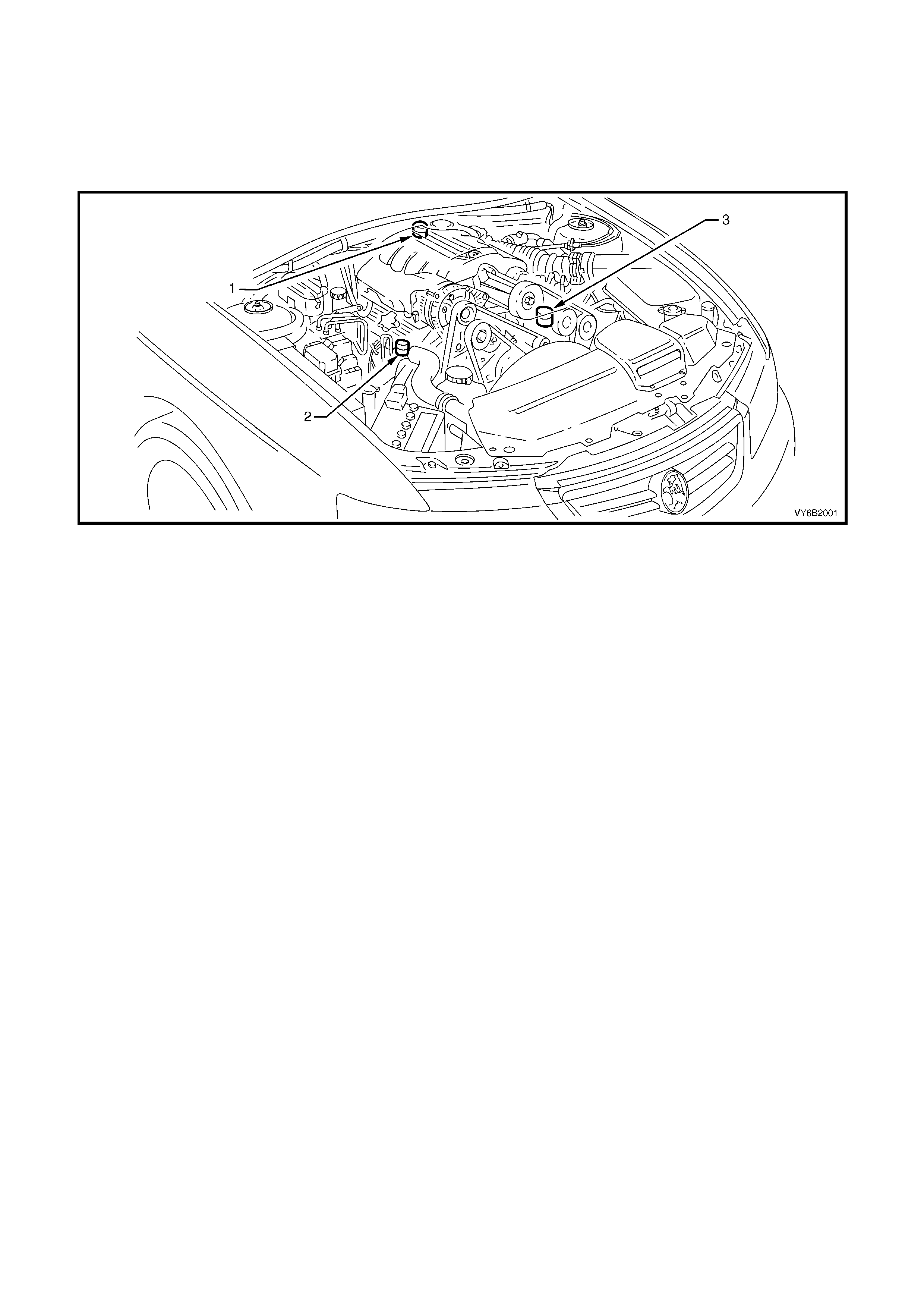
Figure 6B2-1
Legend:
1. Thermostat Cover Bleeder Screw
2. Radiator Inlet Pipe Bleeder Screw
3. Coolant Bypass Housing Bleeder Screw

2. SERVICE OPERATIONS
Cooling system service operations carry over in general from those described in Section 6B1-1 ENGINE
COOLING - V6 ENGINE, except for the following operations.
2.1 SERVICE NOTES
1. Before removing the radiator cap, allow the engine to cool, then place a shop rag over the radiator cap and
then slowly turn the cap anti-clock wise, without pressing down until the cap reac hes the first 'stop'. T his is the
pressur e relief st op, which will al low any rem aining pres sure within the s ystem to es cape. Then pr ess down on
cap and continue to rotate it anti-clockwise until it can be removed.
2. The vehicle is fitted with radiator electric cooling fans. W hen working around the engine com partment with the
engine running or with the ignition 'ON', keep clear of the fan as it may start operating without warning.
3. The cooling system requires little care except for maintaining the coolant to the correct level in the recovery
reservoir and periodic servicing at the time or distance intervals as outlined in the MY 2003 VY and V2 Series
Owner's Handbook.
Periodic servicing includes:
a. Checking coolant level, refer 3.3 CHEC KING AND FILLING COOLING SYSTEM in Section 6B1 ENGIN E
COOLING – V6 ENGINE.
b. Checking coolant concentration, refer 3.2 COOL ANT M AINTEN ANCE – Testing Coolant Concentration
in Section 6B1 ENGINE COOLING – V6 ENGINE.
c. Pressure test cooling system and radiator cap, refer 3.7 PRESSURE TESTING in Section 6B1 ENGINE
COOLING – V6 ENGINE.
d. Tighten hose clamps and inspect all hoses, refer 3.6 COOLANT HOSES in Section 6B1 ENGINE
COOLING – V6 ENGINE. Replace hoses if swollen or deteriorated.
CAUTION: Always wear protective safety glasses when working with spring type hose clamps.
Failure to do so could result in eye injury.
e. Clean out cooling system, refer 3.4 CLEANING COOLING SYSTEM – COOLING SYSTEM FLUSH, in
Section 6B1 ENGINE COOLING – V6 ENGINE and refill cooling system, refer 3.3 CHECKING AND
FILLING COOLING SYSTEM in Section 6B1 ENGINE COOLING – V6 ENGINE.
4. To reduce environm ental impact and m aintenance cost, whenever the coolant is drained f rom any engine, the
service records are to be checked to determine when the coolant was last changed. If more than six months life
is left before the next coolant change, then the following procedure is to be followed:
a. When draining the coolant from the engine, use a clean container of at least 12 litres capacit y and ensure
that the coolant is not contaminated in the draining process.
b. After repairs have been completed, refill the engine cooling system with the drained coolant.
c. Top up as required, using a 50/50 m ix of clean water and the recomm ended coolant, which is either ‘Ne w
Formula Long Life All Seasons Coolant’ or DEX-COOL® coolant (to GM 6277M Specification). Refer to
3.2 COOLANT MAINTENANCE and 3.3 CHECKING AND FILLING COOLING SYSTEM in Section 6B1
ENGINE COOLING – V6 ENGINE, for the necessary procedures and further information.
2.2 COOLANT MAINTENANCE
IMPORTANT: Do not mix different types of anti-freeze or corrosion inhibitors as they may be incompatible. If a
different type has been used in the cooling system, flush the system with clean water, refer 3.4 CLEANING
COOLING SYSTEM – COOLING SYSTEM FLUSH in Section 6B1 ENGINE COOLING – V6 ENGINE and refill
cooling system with the correct coolant, refer 3.3 CHECKING AND FILLING COOLING SYSTEM in Section 6B1
ENGINE COOL ING – V6 ENGINE.
The cooling system is designed to use a coolant (a mixture of ethylene glycol antifreeze with added corrosion
inhibitors, and water), rather than plain water. The use of glycol also raises the boiling point and increases the
cooling s ystem efficienc y. For this r eason, it is of the utm ost impor tance to m aintain the c orrect concentra tion leve l
of ethylene glycol in the cooling system.
Addition of plain water into the cooling system when 'topping-up' may dilute the coolant mixture to a point where the
antifreeze/anti-boil and corrosion inhibitor properties of ethylene glycol become ineffective.
The coolant should comprise of a mixture 50% ethylene glycol antifreeze/inhibitor with 50% clear, clean water.
Ethylene glycol conforming to the correct specification is either named 'New Formula Long Life All Seasons
Coolant' or, DEX-COOL ® and are both available in a number of different quantities. Check the current release of
PartFinder® for specific details.
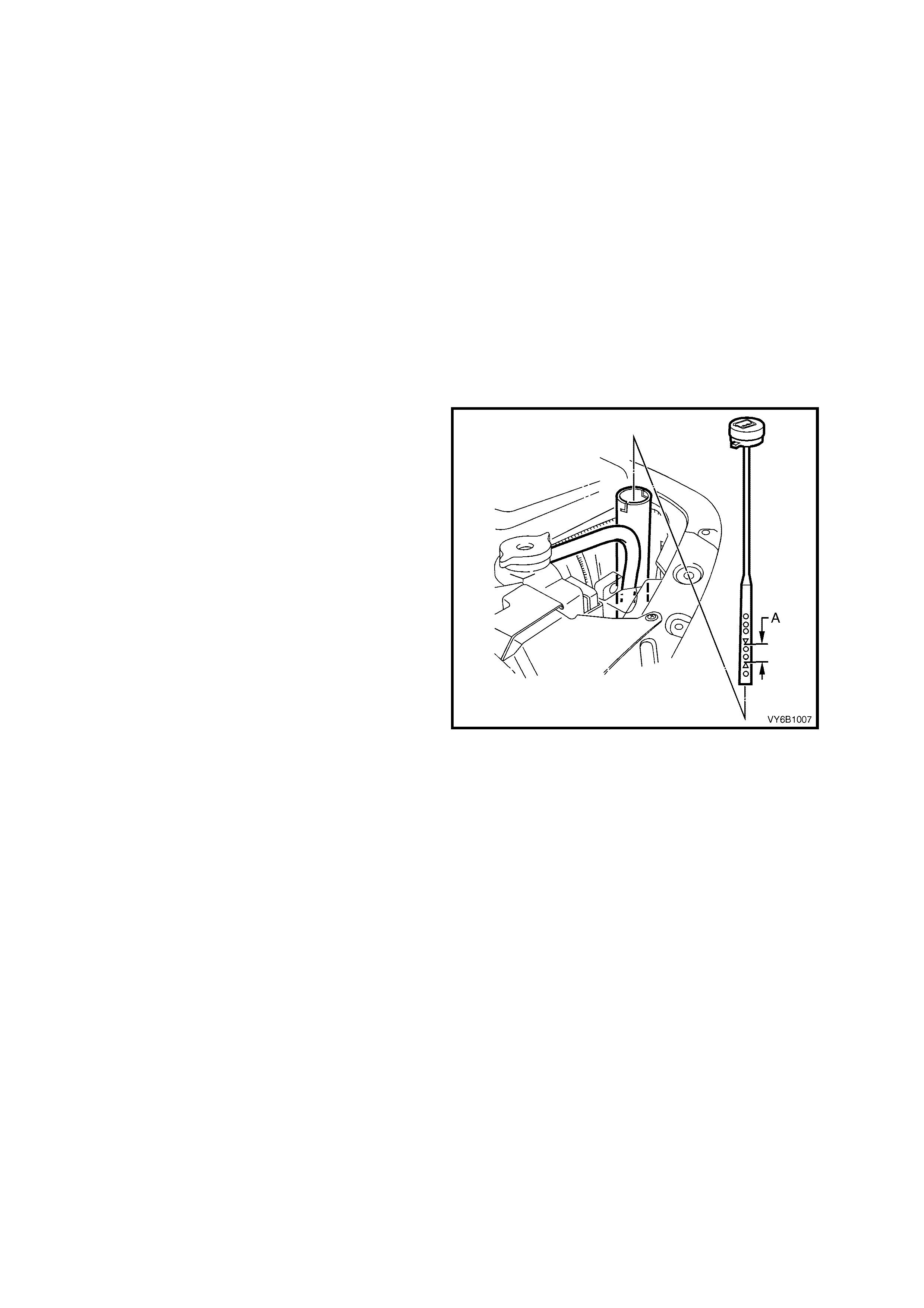
TOPPING UP THE COOLING SYSTEM
Under normal operating conditions, the cooling
system should not be topped up at the radiator
filler. The level can be checked at the coolant
recovery reservoir, and coolant (in the correct
concentration with clear, clean water) added as
necessary to bring the level to between the
indicator arrows (‘A’) on the coolant recovery
reservoir dipst ic k when the engine is col d.
Figure 6B1-2
2.3 DRAINING AND FILLING COOLING SYSTEM
During any service operation that requires the cooling system to be partly or completely drained, the following
instructions must be followed.
DRAINING COOLING SYSTEM
CAUTION: To avoid serious personal injury, never remove the radiator cap or open the air vent valve on the
coolant outlet when the engine is hot, even if the cooling system should require filling. Sudden release of
cooling system pressure is very dangerous.
1. Before removing the radiator cap, allow the engine to cool, then place a shop rag over the radiator cap and
then slowly turn the cap anti-clock wise, without pressing down until the cap reac hes the first 'stop'. T his is the
pressur e relief st op, which will al low any rem aining pres sure within the s ystem to es cape. Then pr ess down on
cap and continue to rotate it anti-clockwise until it can be removed.
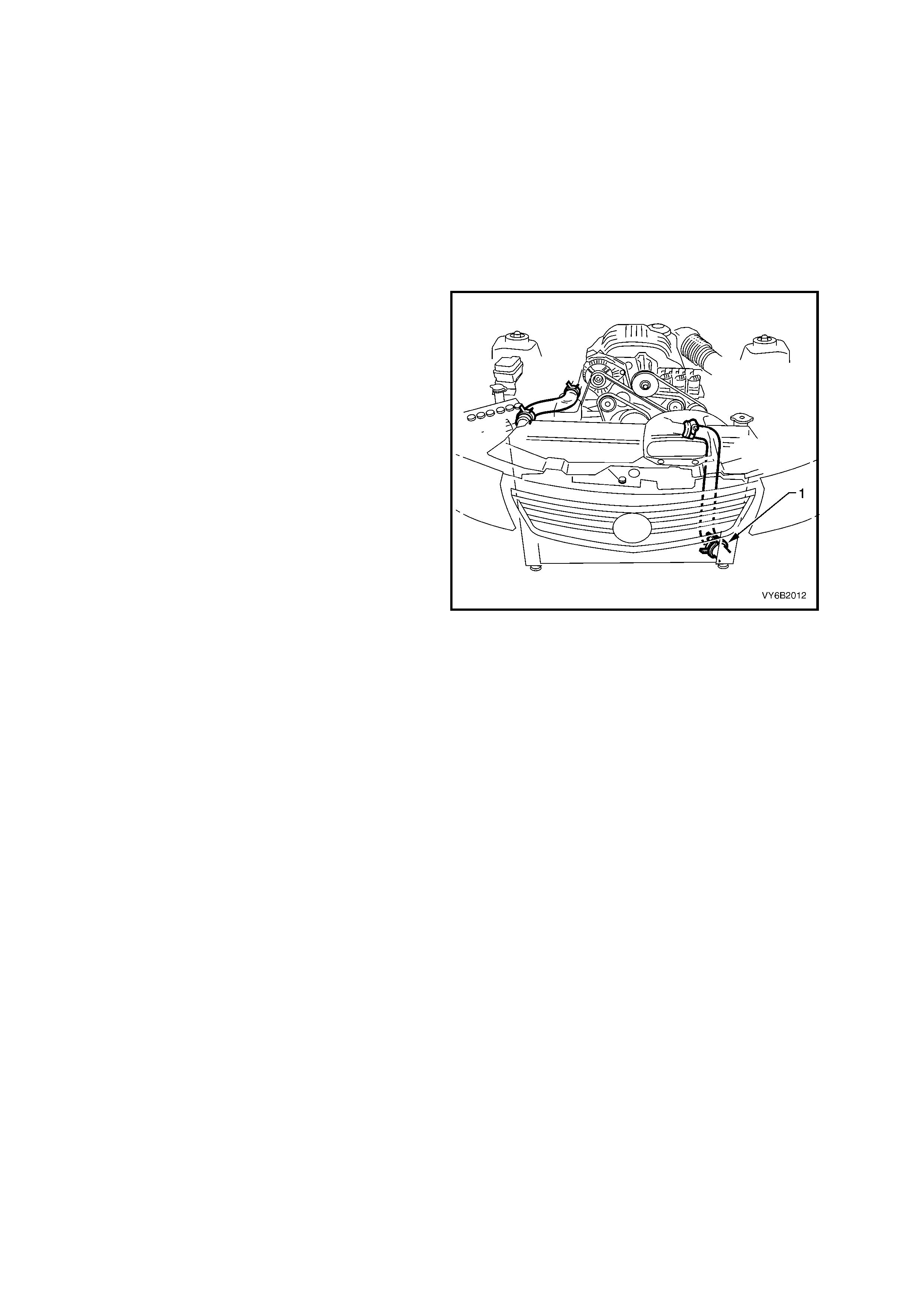
2. Place a clean drain tray capable of collecting
12 litres of coolant, under the front of the
vehicle.
IMPORTANT: Refer Note 4 in 2.1 SERVICE
NOTES, in this Section.
3. Disconnect the lower radiator hose at the
radiator end (1) and drain coolant into
container.
NOTE: Should the total cooling system require
draining, remove both knock sensors. Refer
3.4 CLEANING COOLING SYSTEM in
Section 6B1 ENGINE COOLING – V6 ENGINE.
Figure 6B2-3
REFILLING AND BLEEDING THE COOLING SYSTEM
The following procedure requires the use of Tool No. AU 425 to fill the cooling system.
1. Set heater control to maximum.
2. Mix a coolant mixture consisting 50% ethylene glycol antifreeze/inhibitor with 50% clear, clean water.
NOTE 1: Ethylene glycol conforming to the correct specification is either named 'New Formula Long Life All
Seasons Coolant' or, DEX-COOL® and are both available in a number of different quantities. Check the current
release of PartFinder® for specific details. As either of these coolants may be specified, refer to the MY 2003 VY
and V2 Series Owner’s Handbook to ensure that the correct type is used.
NOTE 2: Do not mix different types of anti-freeze or corrosion inhibitors as they may be incompatible. If
a different type has been used in the cooling system, flush the system with clean water, refer to
3.4 CLEANING COOLING SYSTEM in Section 6B1 ENGINE COOLING – V6 ENGINE.
3. If cooling system was completely drained, add a pack of pellets (three pellets) P/N M40124 to cooling system
by disconn ecting radiator upper h ose from engine coolant outlet and placing pellets inside radiator hose. Refit
hose to coolant outlet and tighten hose clamp.
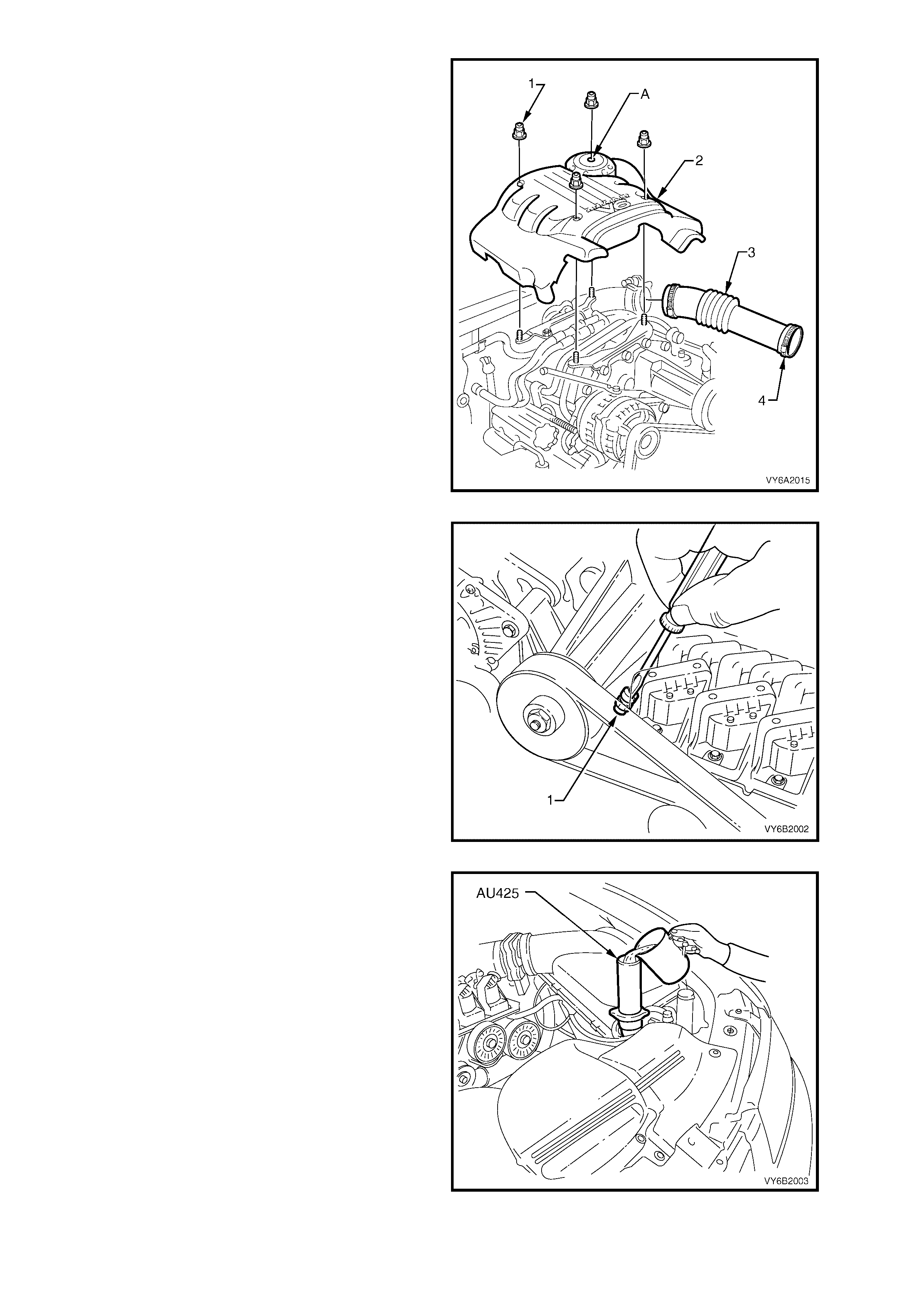
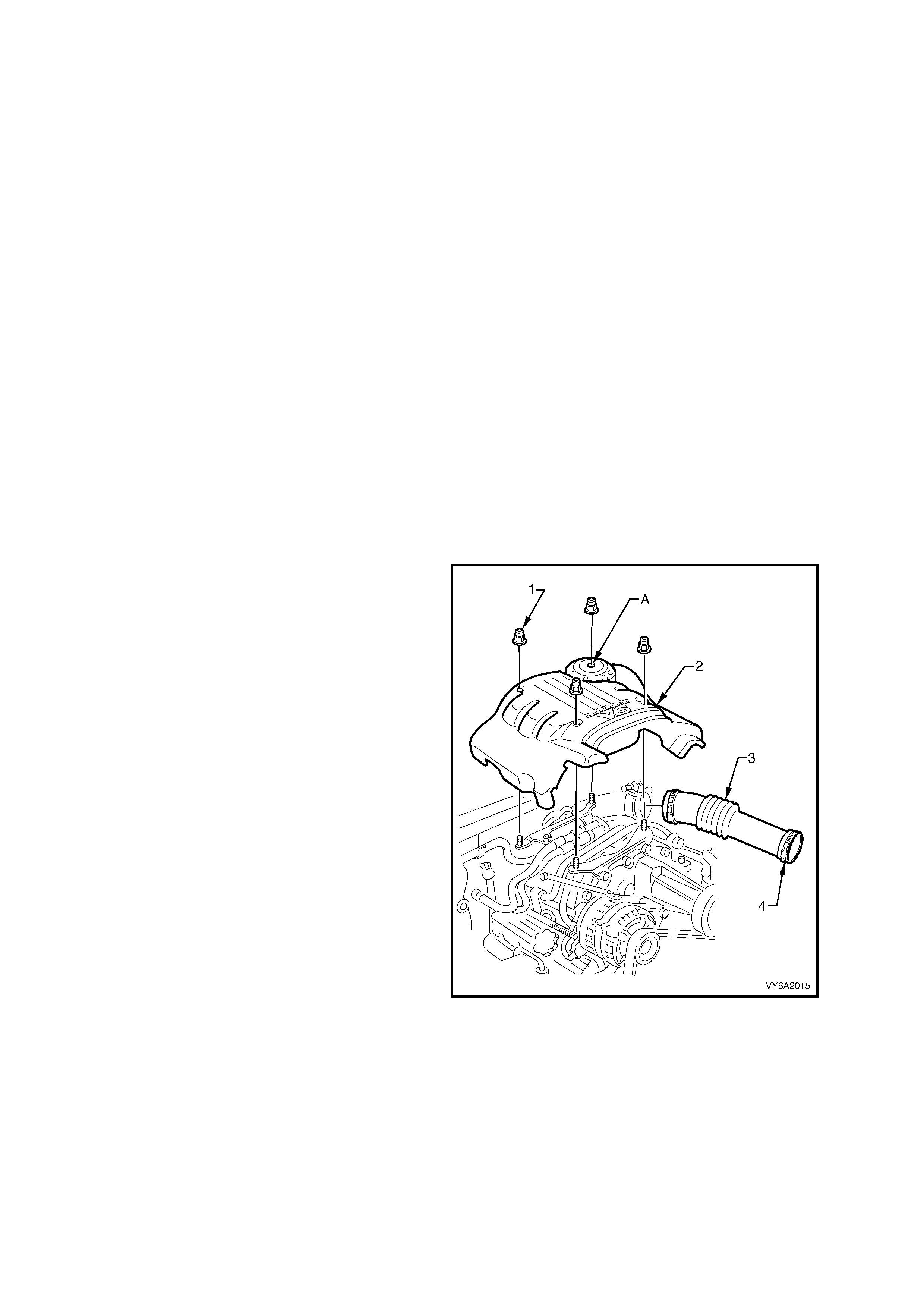
4. Remove the four engine dress cover dome
nuts (1), then remove the cover (2).
5. Remove radiator cap and install Tool No.
AU425 to radiator filler neck.
Figure 6B1-4
NOTE: Commence bleeding the cooling system
using the air vent bleeder screw (1) located in the
water bypass housing.
6. Using a screwdriver, open air vent bleeder
screw (1) at water bypass housing.
Figure 6B2-5
7. Fill cooling system using coolant mixture via
Tool No. AU 425 until coolant flows from air
vent bleeder screw at water bypass housing
and all air is expelled. Close air vent bleeder
screw.
Figure 6B2-6
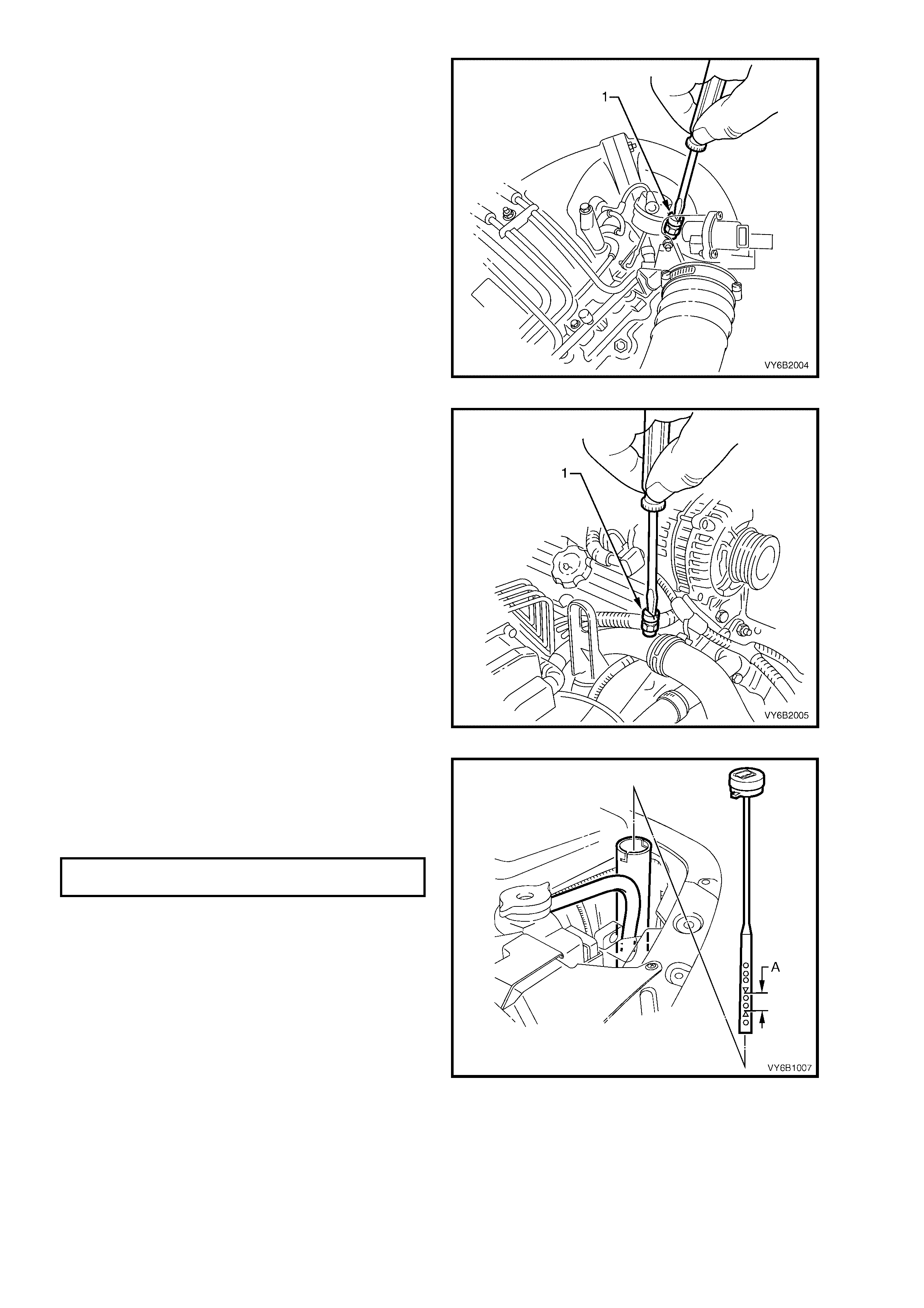
8. Cont inue bleed ing cool ing s ystem from air vent
bleeder ( 1) loc at ed in ther mostat hous ing c ove r
until indications of air stop. Close air vent
bleeder screw.
Figure 6B2-7
9. Comm ence bleeding system from radiator inlet
pipe air vent bleeder screw (1) until indications
of air stop. Close air vent bleeder screw.
Repeat operations 6 to 9 until all air is
exhausted from cooling system.
Figure 6B2-8
10. Ensure air vent bleeder screws are closed,
then remove AU425 from radiator.
11. Reinstall the engine dress cover and retain
with the four decorative nuts, tightened to the
correct torque specification.
ENGINE DRESS COVER NUT
TORQUE SPECIFICATION 5 Nm
NOTE: Use the hole at the left rear of the dress
cover (‘A’) to assist in aligning the mounting studs
with the cover holes. Refer to Figure 6B2-4.
12. If necessary, remove coolant dipstick from
recovery tank and fill tank to between the
indicator arrows (‘A’), then refit recovery tank
dipstick.
13. Pressure test cooling system, refer to
3.7 PRESSURE TESTING in Section 6B1
ENGINE COOL ING – V6 ENGINE.
14. Refit radiator cap.
Figure 6B2-9
15. Start engine and run at idle until operating temperature is reached (thermostat is open).
16. Repeat bleeding procedure as outlined in steps 6-9 until all air is exhausted from cooling system.
17. Top up cooling system using coolant mixture as described in step 2 and refit radiator cap.
18. Check coolant concentration. Refer to Testing Coolant Concentration, in 3.2 COOLANT MAINTENANCE,
Section 6B1 ENGINE COOLING – V6 ENGINE.
2.4 COOLING SYSTEM HOSES
LT Section No. – 01-160
SOME SERVICE NOTES:
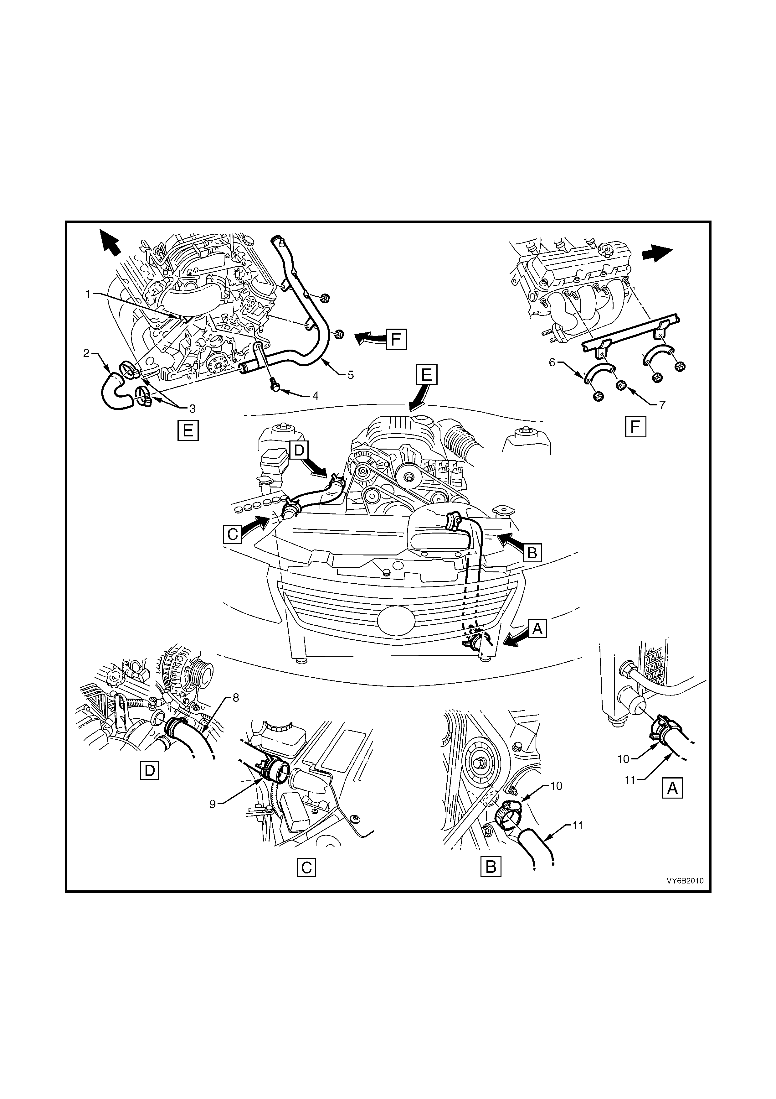
1. Coolant hoses are installed as shown in the following illustration.
2. Hose connections should be thoroughly cleaned before installing any new hose.
3. Following hose/s installation, always refill the cooling system with the correct type and concentration of
coolant. Refer to 2.3 DRAINING AND FILLING COOLING SYSTEM, in this Section.
CAUTION: Always wear protective safety glasses when working with spring type hose clamps. Failure to
do so could result in eye injury.
Figure 6B2-10
Legend
1. Coolant Outlet
2. Coolant Outlet Hose
3. Hose Clamps
4. Screw
5. Radiator Inlet Pipe
6. Plate
7. Plate Nut
8. Radiator Inlet Hose
9. Radiator Inlet Hose Clamps (2 places)
10. Radiator Outlet Hose Clamps (2 places)
11. Radiator Outlet Hose
2.5 THERMOSTAT
LT Section No. – 00-350
REMOVE
1. Remove the four engine dress cover dome
nuts and remove the cover.
2. Remove 2 b olts (3) securing rear engine cover
bracket assembly (4) and remove bracket.
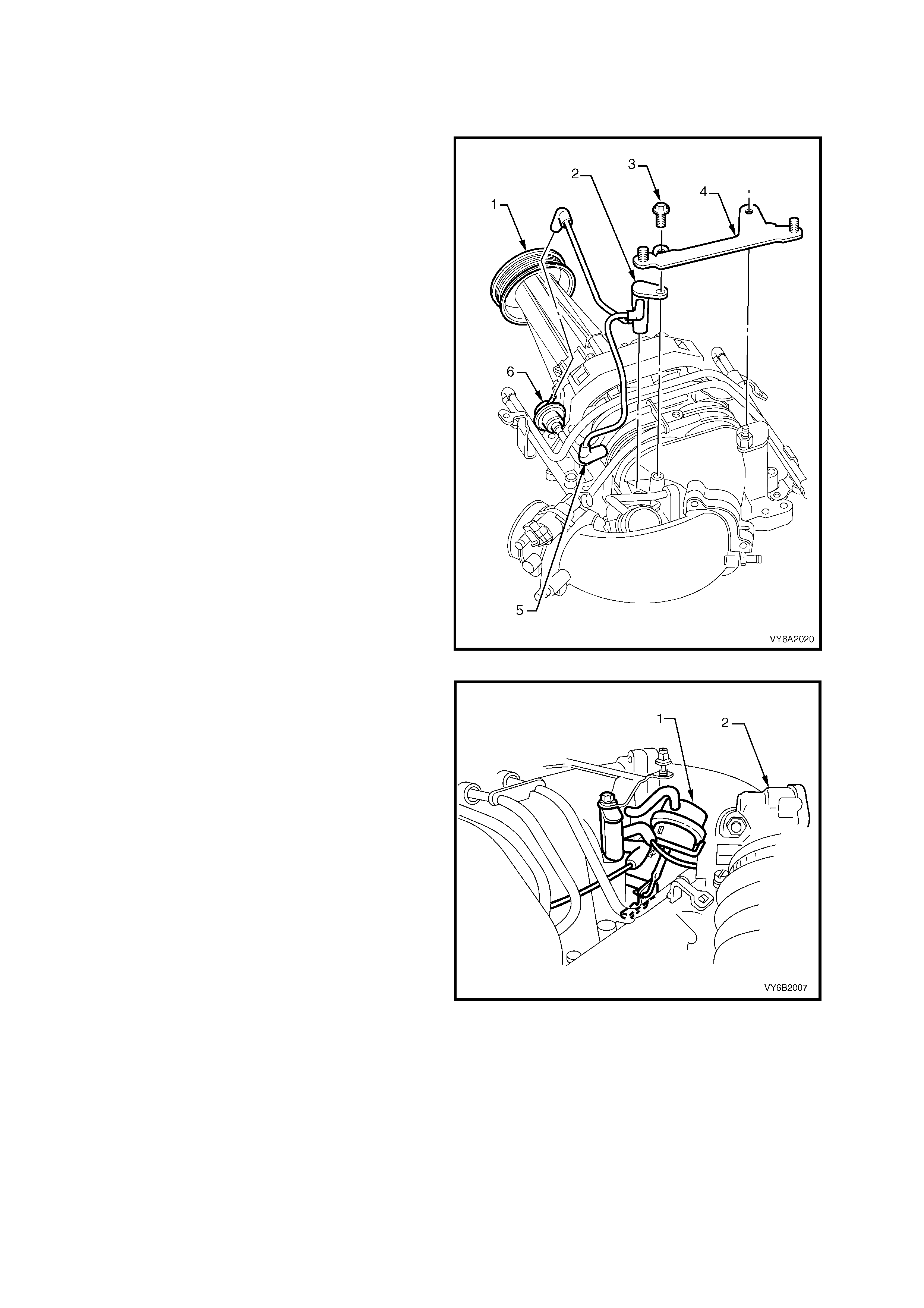
3. Tag and disconnect vacuum connections from
fuel pressure regulator (6) and bypass
solenoid, lift out the boost control solenoid
harness assembly (5).
Legend:
1. Supercharger Assembly
2. Boost Control Solenoid Harness
3. Screw (2 places)
4. Engine Dress Cover, Rear Mounting Bracket
5. Vacuum Connection to Boost Control Solenoid
6. Fuel Pressure Regulator
Figure 6B2-11
4. Remove bolts attaching bypass valve actuator
(1) and swing actuator to one side to gain
access to thermostat front bolt.
5. Remove air intake duct, throttle body (2) and
throttle cable mounting bracket, refer to
Section 6A2 ENGINE MECHANICAL – V6
SUPERCHARGED ENGINE.
6. Remove the water outlet hose from the
thermostat housing cover.
Figure 6B2-12
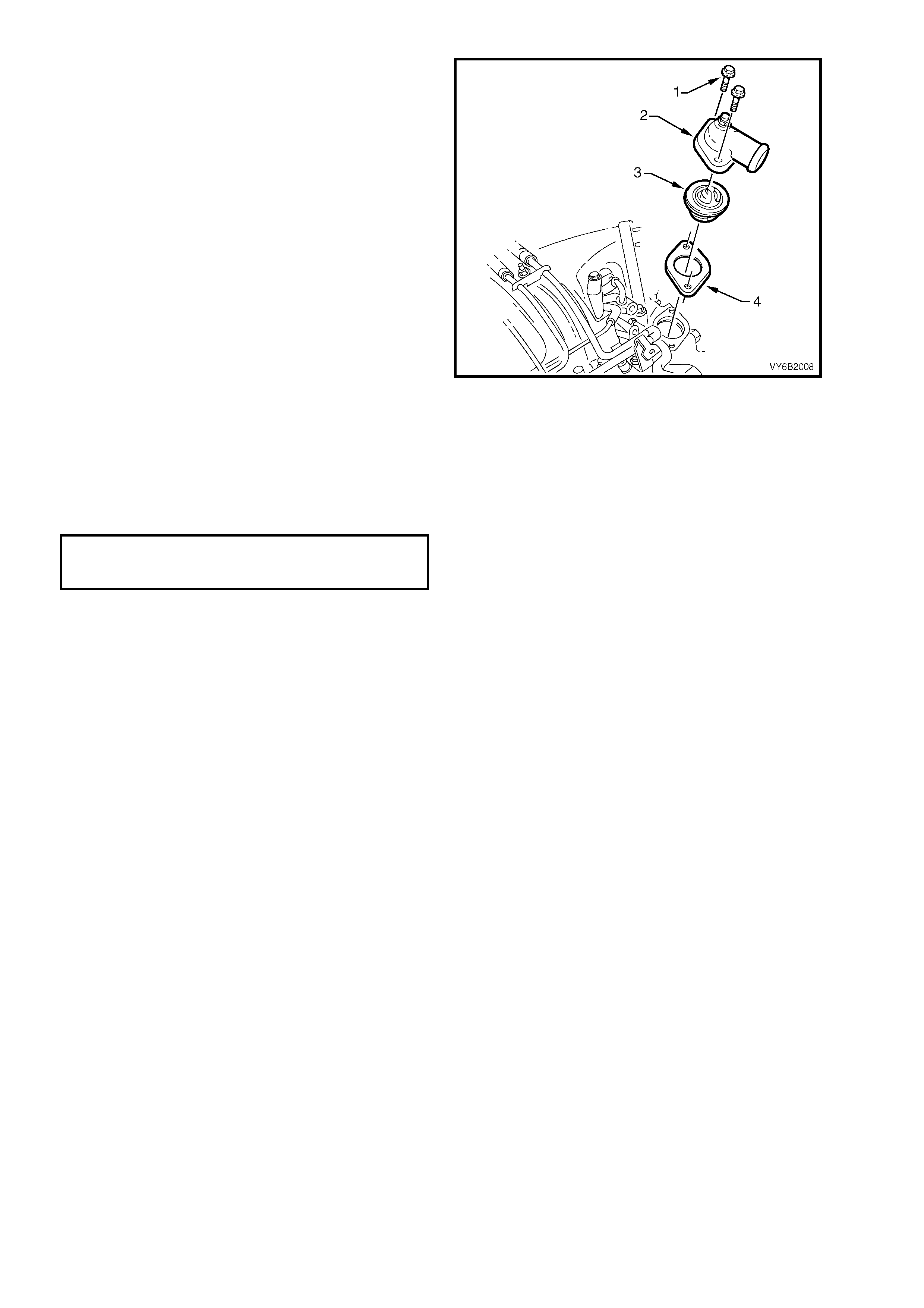
7. Remove the two screws (1) securing the
thermostat housing cover (2), remove cover,
thermostat (3) and gasket (4), discarding the
rem oved gask et. T he rear bolt c an be rem oved
by reaching around from behind supercharger
(using short open-ended spanner) and the front
bolt removed by using a socket ratchet with
extension. The wiring harness located in front
of the rear firewall, ma y need to b e temporaril y
shifted in order to gain access to rear bolt.
Figure 6B2-13
REINST ALL
Reinstallation of the thermostat is the reverse of
removal procedures noting the following.
1. Ensure all gasket surfaces are clean.
2. Tighten th ermostat hous ing c over s c rews ( 1) to
the correct torque specification
THERMOSTAT HOUSING
COVER SCREWS
TORQUE SPECIFICATION 28 Nm
3. Ensure the cooling system is bled correctly,
refer to 2.3 CHECKING AND FILLING
COOLING SYSTEM in this Section.
4. If the wiring harness was moved during
removal, reposition to original location.
2.6 RADIATOR INLET PIPE
LT Section No. – 01-160
REMOVE
1. Disconnect the negative cable from the
battery.
IMPORTANT: Disconnection of the battery affects
certain vehicle electronic systems. Refer to Section 00
CAUTIONS, 5. BATTERY DISCONNECTION
PROCEDURES before disconnecting the battery.
CAUTION: To avoid serious personal injury,
never remove the radiator cap or open the air
vent valve on the coolant outlet when the
engine is hot, even if the cooling system
should require filling. Sudden release of
cooling system pressure is very dangerous.
2. Before removing the radiator cap, allow the
engine to cool, then place a shop rag over the
radiator cap and then slowly turn the cap anti-
clockwise, without pressing down until the cap
reaches the first 'stop'. This is the pressure
relief stop, which will allow any remaining
pressure within the system to escape. Then
press down on cap and continue to rotate it
anti-clockwise until it can be removed.
3. Drain coolant. Refer 2.3 DRAINING AND
FILLING COOLING SYSTEM, in this Section.
4. Remove the four engine dress cover dome
nuts (1) and remove the cover (2).
Figure 6B1-14
5. Remove the coolant outlet hose from the
radiator inlet pipe.
6. Disconnect the wiring harness from the
retainer brackets on the radiator inlet pipe.
7. Remove the screws securing the radiator inlet
pipe to the engine assembly removing the
pipe.
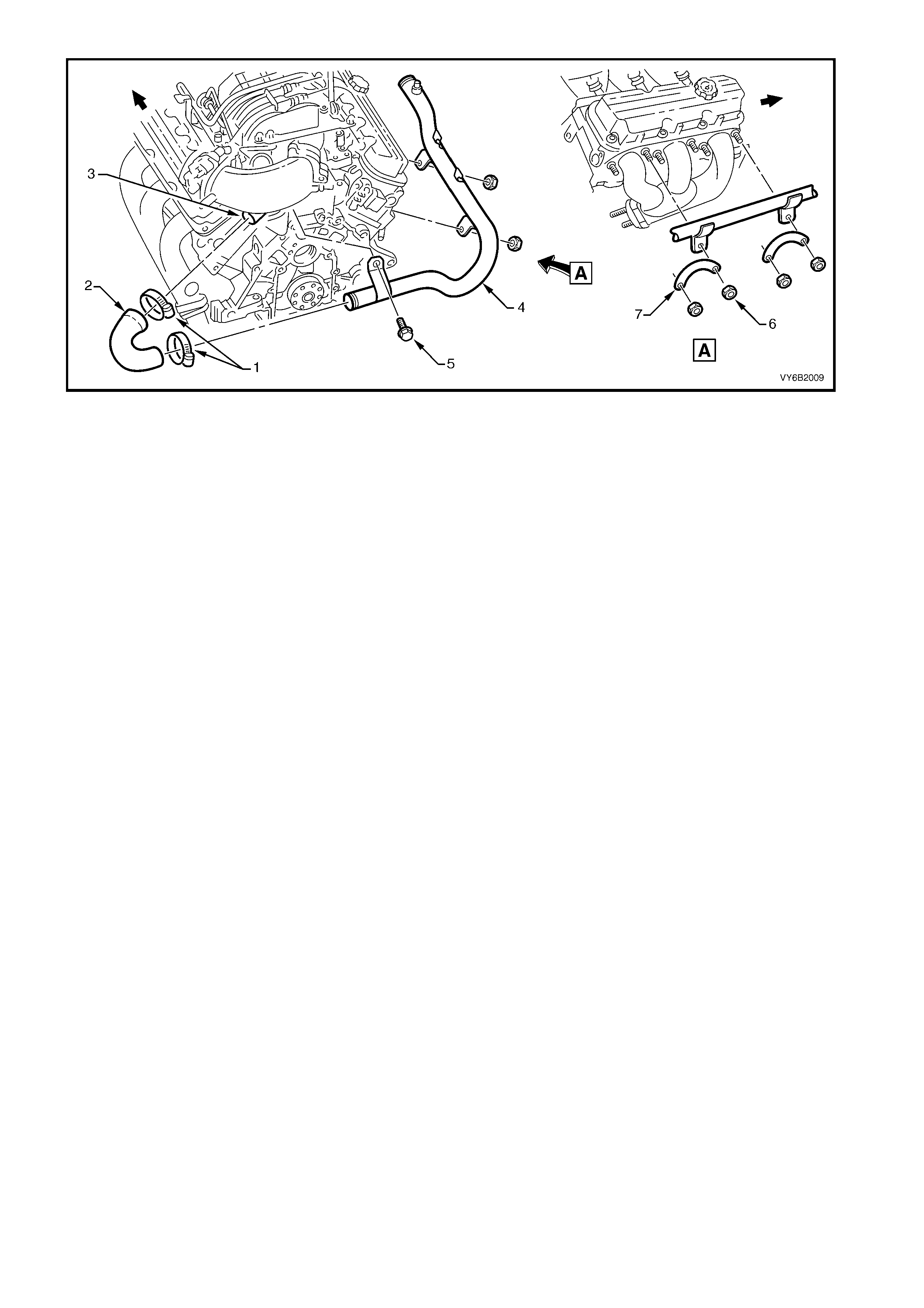
Figure 6B2-15
Legend
1. Clamps
2. Coolant Outlet Hose
3. Coolant Outlet
4. Radiator Inlet Pipe
5. Screw
6. Plate Nut
7. Plate
REINST ALL
Reinstallation of the radiator inlet pipe is the reverse of removal operations noting the following points.
1. Use the hole at the left rear of the dress cover (‘A’) to assist in aligning the mounting studs with the cover holes.
Refer to Figure 6B2-14.
2. Ensure the cooling system is bled correctly, refer to 2.3 CHECKING AND FILLING COOLING SYSTEM in this
Section.
3. Tighten all fasteners to the correct torque specification. Refer 4. TORQUE SPECIFICATIONS in this Section,
for details.

3. SPECIFICATIONS
GENERAL
Radiator cap pressure rating................................... 135 kPa
Cooling system capacity ......................................... 12 Litres
Coolant corrosion inhibitor ...................................... 'New Formula Long Life All Seasons Coolant' or;
DEX-COOL® (depending on vehicle specification)
THERMOSTAT
Type ........................................................................ Power element (wax pellet)
Start to open............................................................ 89° – 93° C
Fully open at............................................................ 106° C max
WATER PUMP
Type ........................................................................ Centrifugal
Drive........................................................................ V-belt
Bearing type............................................................ Double Row Ball Bearin g
RADIATOR
Core type................................................................. Aluminium crossflow core
Overall width (including side tanks) ........................ 826 mm
Core width............................................................... 675 mm
Overall height.......................................................... 507 mm
Core height.............................................................. 430.5 mm
Core thickness ........................................................ 16 mm
Plastic tanks............................................................ Nylon 6,6
RADIATOR HOSE S
Lower
Number and type ............................................... One, Moulded
Inside diameter .................................................. 38.5 mm
Upper
Number and type ............................................... One, Moulded
Inside diameter .................................................. 34.0
RIGHT ENGINE COOLING FAN
Number of blades.................................................... 8
Spacing ................................................................... Symmetrical
Material.................................................................... Polypropylene (20% glass filled)
Diameter.................................................................. 268 mm
Electric motor drive ................................................. 120 Watts (nominal)
LEFT ENGINE COOLING FAN
Number of blades.................................................... 8
Spacing ................................................................... Symmetrical
Material.................................................................... Polypropylene (20% glass filled)
Diameter.................................................................. 370 mm
Electric motor drive ................................................. 160 Watts (nominal)

4. TORQUE WRENCH SPECIFIC ATIONS
Nm
Thermostat housing cover retaining bolts............................. 28
Radiator inlet pipe retaining nuts and screw......................... 25
Coolant Hose Clam ps........................................................... 3
Engine dress cover attaching nut ......................................... 5
Rear engine cover bracket assembly securing bolts............ 18
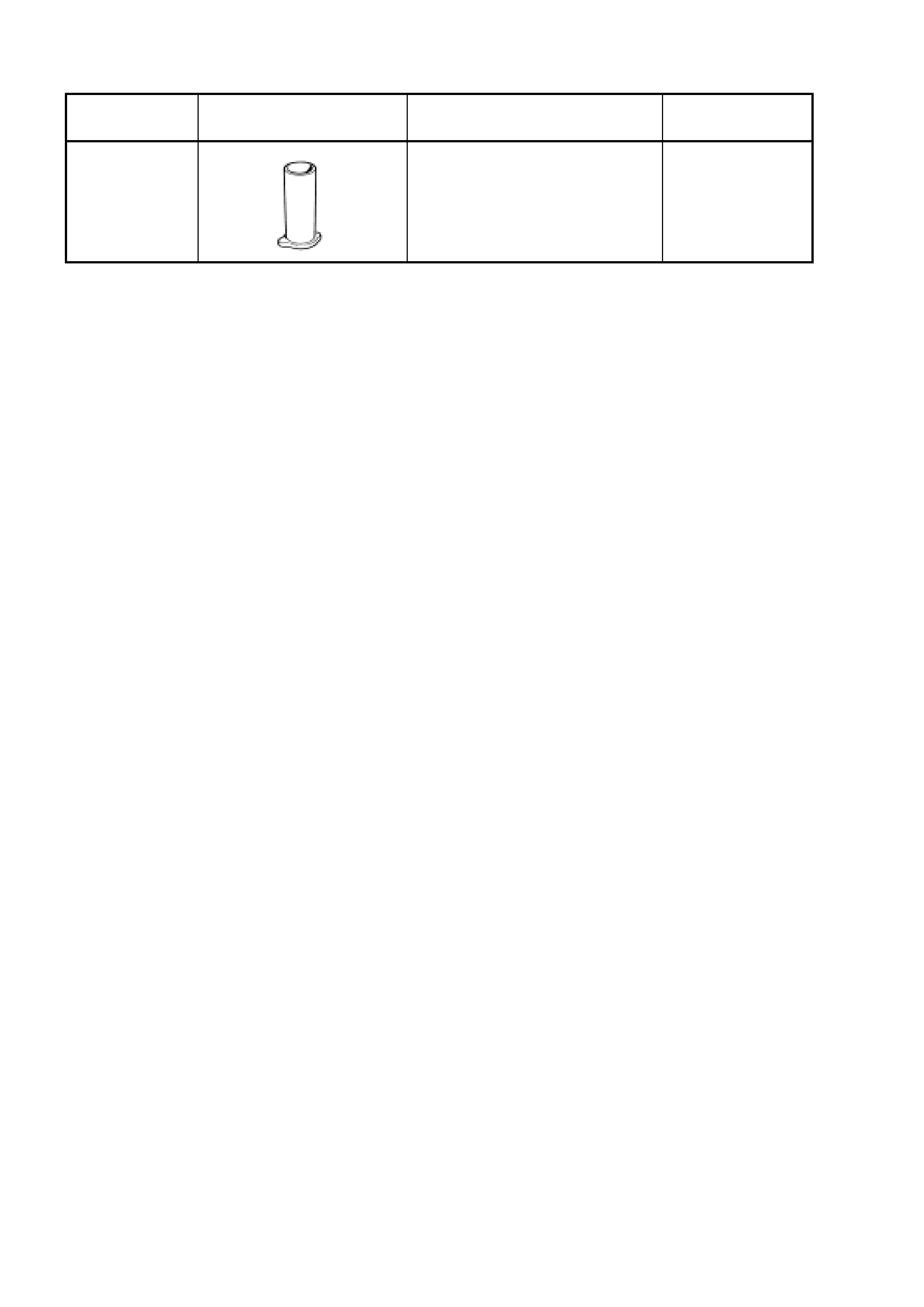
5. SPECIAL TOOLS
TOOL
NUMBER ILLUSTRATION DESCRIPTION CLASSIFICATION
AU425 COOLING SYSTEM FILLER
TUBE
Previously released
Mandatory