
SECTION 6B3 - ENGINE COOLING –
GEN III V8 ENGINE
IMPORTANT
Before performing any Service Operation or other procedure described in this Section, refer to Section 00
CAUTIONS AND NOTES for correct workshop practices with regard to safety and/or property damage.
CONTENTS
1. GENERAL INFORMATION
1.1 GENERAL DESCRIPTION
RADIATOR
COOLING FANS
COOLANT PUMP
THERMOSTAT
SCREW-ON PRESSURE CAP
COOLANT SURGE TANK
VAPOUR VENT SYSTEM
AIR BAFFLES AND DUCTS
COOLANT TEMPERATURE SENSOR
2. SERVICE OPERATIONS
2.1 SERVICE NOTES
SAFETY
PERIODIC SERVICING
ENVIRONMENTAL ISSUES
2.2 COOLANT MAINTENANCE
TOPPING UP THE COOLING SYSTEM
TESTING COOLANT CONCENTRATION
2.3 DRAINING AND FILLING COOLING SYSTEM
DRAINING
FILLING
2.4 COOLANT HOSES
2.5 CLEANING COOLING SYSTEM
COOLING SYSTEM REVERSE FLUSH
2.6 ENGINE ACCESSORY DRIVE BELT TENSION
2.7 ENGINE ACCESSORY DRIVE BELT
REMOVE
INSPECT
REINSTALL
2.8 PRESSURE TESTING
SCREW-ON PRESSURE CAP TESTING
COOLING SYSTEM PRESSURE TESTING
2.9 THERMOSTAT
REMOVE
TEST
DISMANTLE
REASSEMBLE
REINSTALL
2.10 COOLANT RECOVERY SURGE TANK
REMOVE
INSPECT
REINSTALL
2.11 ENGINE COOLANT LEVEL SWITCH
REMOVE
INSPECT
REINSTALL
2.12 OIL PAN UNDER-TRAY
REMOVE
REINSTALL
2.13 AIR BAFFLES
REPLACE
2.14 COOLANT PUMP
REMOVE
DISMANTLE
CLEAN AND INSPECT
REASSEMBLE
REINSTALL
2.15 COOLING FANS & SHROUD ASSEMBLY
REMOVE
DISASSEMBLE
REASSEMBLE
REINSTALL
2.16 RADIATOR
REMOVE
REINSTALL
RADIATOR REPAIR PROCEDURE9
3. ENGINE COOLING SYSTEM DIAGNOSIS
3.1 ENGINE OVERHEATING
3.2 L OSS OF COOLANT
3.3 ENGINE FAILS TO REACH NORMAL OPERATING
TEMPERATURE
3.4 BLACK LIGHT AND DYE LEAK DIAGNOSIS
METHOD
4. SPECIFICATIONS
5. TORQUE WRENCH SPECIFICATIONS
6. SPECIAL TOOLS
Techline
Techline

1. GENERAL INFORMAT ION
The c ooling system f or MY 2003 V Y and V 2 Seri es vehicles wit h the G EN II I V8 e ngi ne, co ns is ts of t wo, two-s peed
electric cooling fans mounted behind the radiator. Fan operation is dependent on engine coolant temperature,
vehicle speed, A/C request (where fitted) and A/C system pressure. Refer to Section 6C3 POWERTRAIN
MANAGEMENT – GEN III V8 ENGINE for further information.
1.1 GENERAL DESCRIPTION
RADI ATOR
The radiator (1) is of the crossflow design and consists of an aluminium core with plastic side tanks attached to
each end of the c ore. For vehicl es with autom atic transmiss ion, a transmiss ion oil cooler is loca ted in the left hand
side tank.
Pegs are attached to the lower frame and the upper area of each side tank. These pegs are used to support the
radiator in four rubber mounts. The assembly is held in position by two spring clips at the upper mounting locations.
The radiator core side tanks and/or transm ission oil cooler CANNO T be replaced separ ately. If there is a f ault with
any of these components, the radiator assembly must be replaced. Small core repairs can be made using an
Aluminised Silicon based liquid repair agent, refer to RADIATOR REPAIR PROCEDURE, in 2.16 RADIATOR, in
this Section.
COOLING FANS
The cooling system for the GEN III V8 engine, includes two, double speed, engine cooling fan motors, both of
which, drive fans with five, asymmetrical blades, to reduce air noise. The larger, right fan is 342 mm in diameter
and has a m otor rated at 2 20 Watts , while the sm aller, left fan is 29 3 mm in diam eter with a m otor power rat ing of
180 Watts.
With 12 volts applied and the fans mounted to the radiator with a condenser fitted, the operating speeds are:
Stage 1 Stage 2
Large Fan 2,350 ± 150
rpm 2,750 ± 150
rpm
Small Fan 2,050 ± 150
rpm 2,300 ± 150
rpm
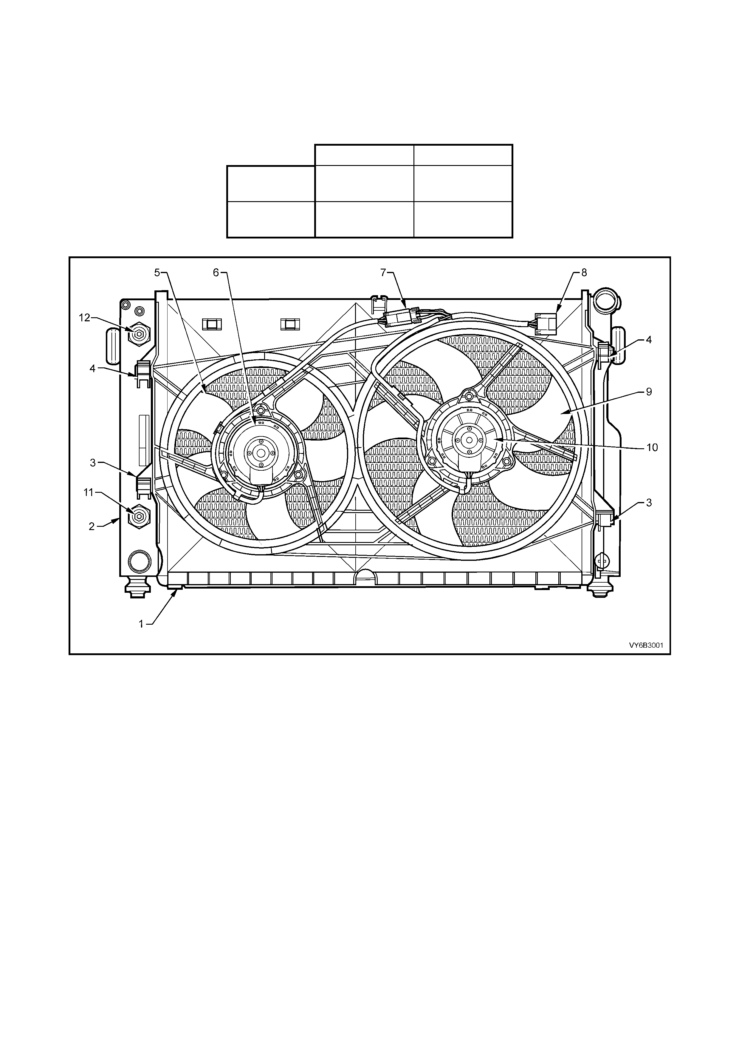
Figure 6B3-1 – Cooling Fans, GEN III V8
Legend
1. Fan Shroud
2. Radiator
3. Fan Shroud Lower Support
4. Fan Shroud Upper Support/Locking Retainer
5. Small, Left Fan – 5 Blade, 293 mm Diameter
6. Small, Left Fan Motor – 180 Watt, Double Speed
7. Left Fan Motor Harness Connector (3 Terminal)
8. Left and Right Fan Motor Harness Connector (5 terminal)
9. Large, Right Fan – 5 Blade, 342 mm Diameter
10. Large, Right Fan Motor – 220 Watt, Double Speed
11. Oil Cooler, Lower Quick Connect Fitting (Auto. Trans Only)
12. Oil Cooler, Upper Quick Connect Fitting (Auto. Trans Only)
Operation
To achieve the dual speed requirement, the e lectrical circuitry for the GEN III V8 each of the cooling fans has two
negative and one positive terminal. To reduce the heat burden on the electrical connectors, the current draw is
directed through separate negative terminals at the jo int connector (‘8’ in Figure 6B3-1), for each f an motor, when
operating on low speed. When operating at high speed, only one negative terminal is required.
The positive terminals are permanently connected
to battery voltage, via fusible links F101 (large fan)
and F107 (small fan).
The eng ine c oo li ng f an r ela y 1 ( R7) is e nerg is ed by
the BCM. When the PCM determines that the
engine cooling fan relay 1 should be enabled, the
PCM will send a message on the Class 2 serial
data circuit to the PIM. The PIM will then convert
the PCM Class 2 message to a UART message
and supply this UART message to the BCM, via a
serial data Normal Mode Message to the BCM on
circuit 800 (Red/Black wire). This message will
request the BCM to supply the needed ground
signal for the engine cooling fan relay 1 to operate.
After the BCM provides the ground signal for the
engine cooling fan relay 1, the BCM will send a
message back to the PIM confirming that the
ground signal was commanded.
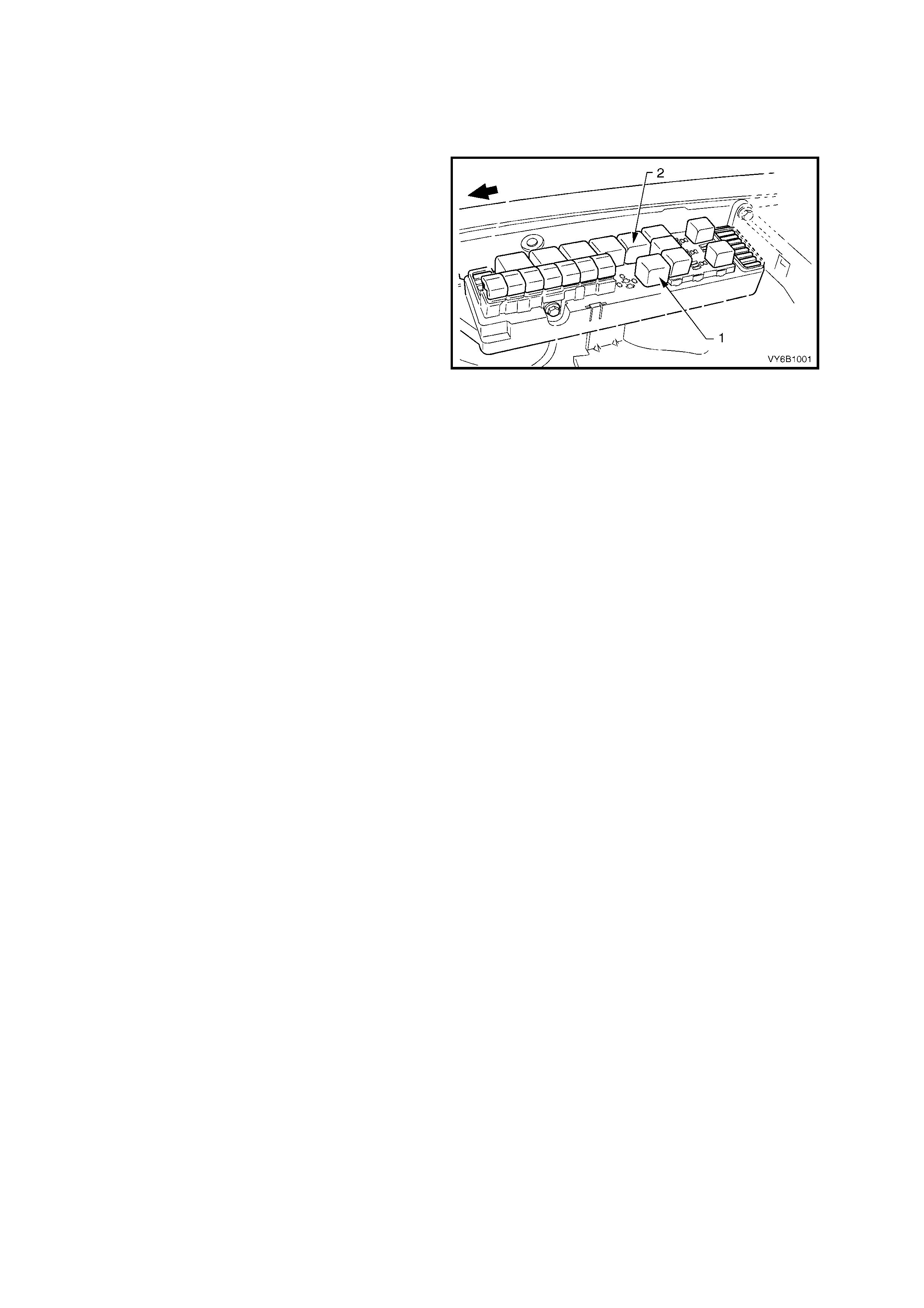
Figure 6B1-2 – Underhood Fuse & Rela y Centre
A failure in this BCM response communication, will cause a PIM DTC B2002 to set.
The PCM determines when to enable stage 1, based on inputs from the A/C request signal, Engine Coolant
Temperature (ECT) sensor and the Vehicle Speed Sensor (VSS).
There are also suppression capacitors incorporated into the fan motor, located on the brush holders. These
suppression capacitors help eliminate fan motor noise through the radio speakers. As these capacitors are not
serviced separately, should a problem occur with either capacitor, then the motor assembly must be replaced.
Stage One Fan Operation
The engine cooling fan relay 1 (R7) will be turned ON when:
• The A/C request indicated (YES) and either:
• the vehicle speed is less than 30 km/h.
or
• A/C pressure is greater than 1500 kPa
or
• The coolant temperature is greater than 98° C.
• or
• If the coolant temperature is greater than 113° C, when the ignition is switched off, the relay is energised
for approximately four minutes, this is known as Low Fan Run On.
• or
• If an engine c oola nt temperatur e s ensor f ault is det ec ted and a DT C s uc h as DTC P011 7, P 011 8, P1 114 or
P1115 is set.
The engine cooling fan relay 1 will be turned OFF when any of the following conditions have been met:
• An A/C request is not indicated (NO) and the coolant temperature is less than 95° C.
or
• An A/C requ est is indicate d ( YES) a nd the ve hicle s peed is greater than 50 k m /h and A/C press ure is les s th an
1,170 kPa and the coolant temperature is less than 98° C.
Stage Two Fan Operation
The engine cooling fan relay 2 (R5) is controlled by the PCM. The PCM will only activate stage 2 fan operation, if
the engine cooling fan relay 1 has been “ON” for two seconds and the following conditions are satisfied.
• There is a BCM message response fault which will cause a PIM DTC B2002.
• An eng ine coolant t emperature sens or fault is d etected and a DT C such as DTC P01 17, P0118, P 1114 or
P1115 is set.
• Coolant temperature greater than 108° C.
• The A/C refrigerant pressure is greater than 2400 kPa.
If the e ngine cool ing fan re lay 1 was OFF when the cr iteria was met to ac tivate e ngine co oling fan r ela y 2, stage 2
fan operation will occur, 5 seconds after the engine cooling fan relay 1 is turned ON. If both engine cooling fan
relays are ON, the PCM will turn OFF engine cooling fan relay 2 when:
• The engine coolant temperature is less than 102° C.
• A/C request not indicated ( NO ).
• A/C request indicated (YES) and A/C pressure is less than 1900 kPa.
NOTE: Both cooling fans will be turned off if the vehicle speed is greater than 104 km/h.
The PCM determines operation of the two, two-speed engine cooling fans based on A/C request, A/C system
pressure (where fitted), engine coolant temperature and vehicle speed signal inputs. For further details of the
engine coo ling fan operat ion and d iagnosis of the system , see Section 6C3 POW ERTRAIN MANAGEMENT – GEN III
V8 ENGINE.
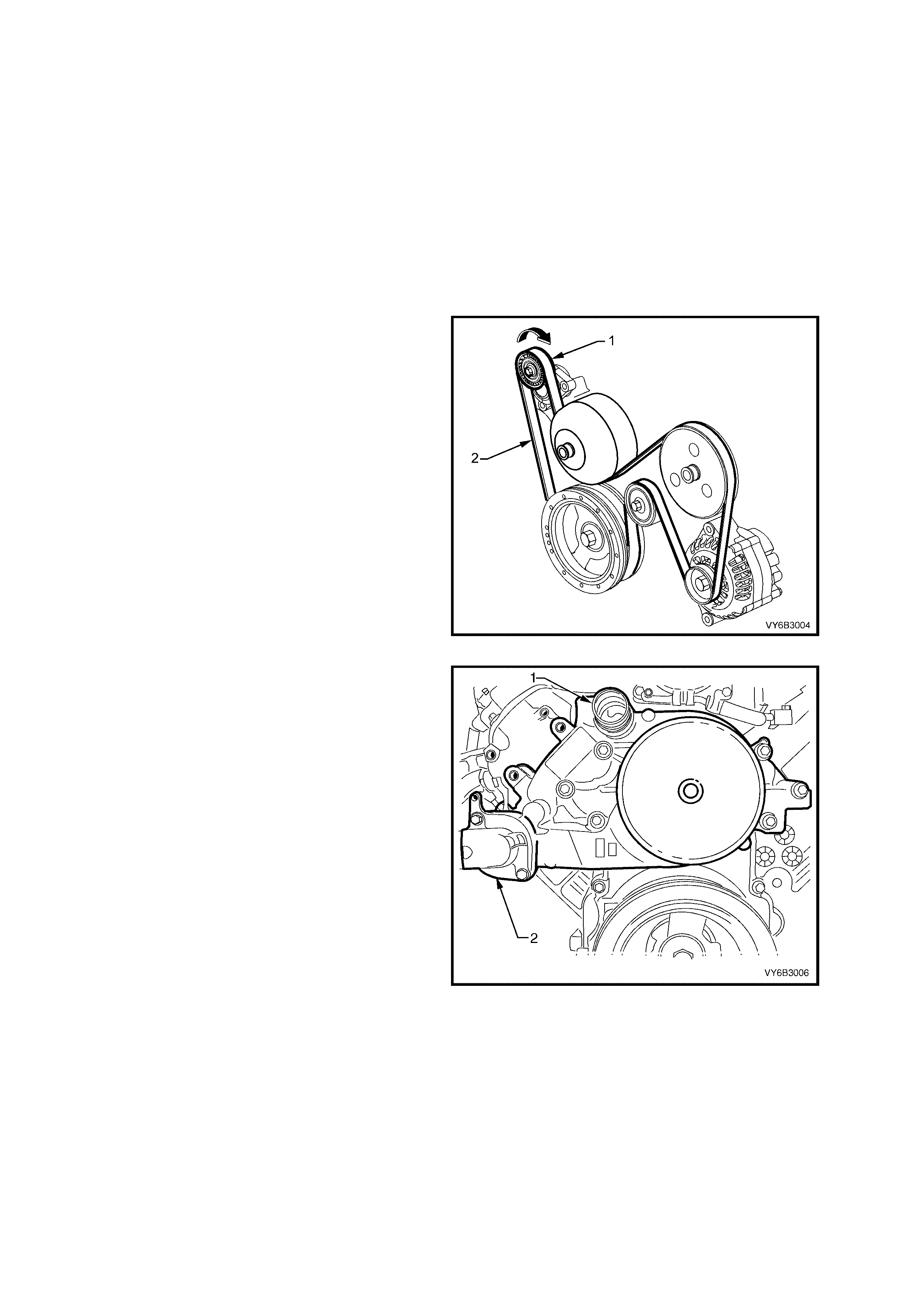
COOLANT PUMP
The c oolant p um p (1) is m ount ed to th e fr ont of th e
cylinder b lock and is dri ven by the ser pentine drive
belt (2). Coolant passes through the engine from
the coolant pump inlet, and exits via the coolant
outlet, located at the top of the coolant pump
housing.
Figure 6B3-3
The coolant outlet (1) is located at the top of the
coolant pump housing.
The therm ostat is also located in the coolant pum p
housing, at the coolant inlet fitting (2).
Figure 6B3-4
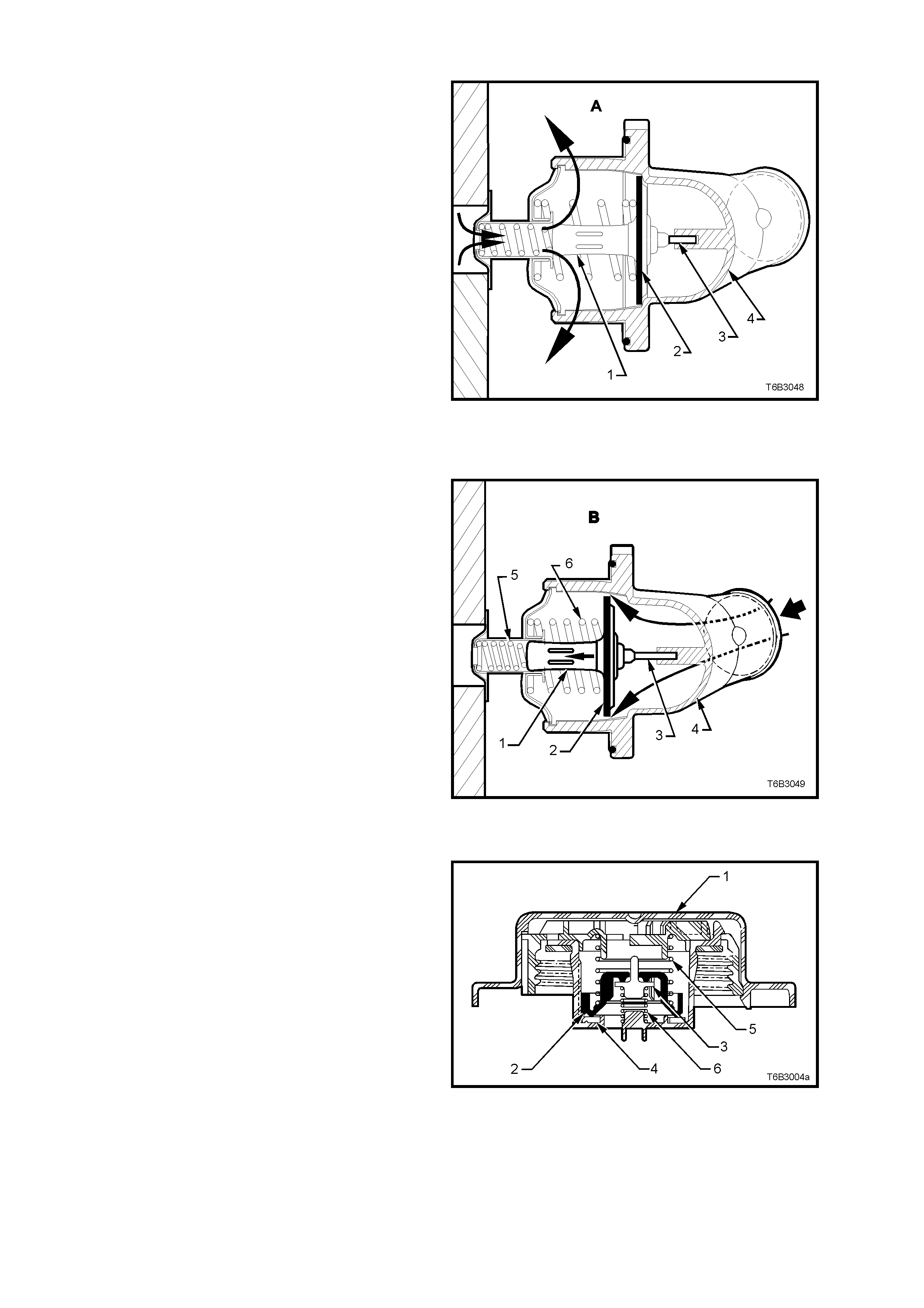
THERMOSTA T
A wax pellet type therm ostat is used in the coolant
inlet passage to control the flow of coolant,
providing fast engine warm up and regulating
coolant temperature.
The wax pellet or power el ement in t he therm ostat,
expands when heated and contracts when cooled.
The wax pellet is located inside the brass body (1)
that forms an integral part of the flow control valve
(2). When the pellet is heated, pressure is exerted
against a piston and pin (3) that reacts against the
thermostat housing (4).
With cold coolant (view ‘A’), the flow control valve
(2) remains closed, preventing coolant flow from
the radiator to enter but coolant in the engine still
circulates, with hotter coolant from the cylinder
heads being directed through the end of the
thermostat, flowing over the wax pellet body.
This results in warming of the wax pellet at the
same r ate as the temper ature rise of the co olant in
the engine.
Figure 6B3-5
As the coolant warms up (view ‘B’), the wax pellet
expands, causing the bras s body (1) to move back
into the sm aller spring cavity due to the reaction of
the piston and pin (3) against the thermostat
housing (4). As the body (1) moves back (bold
arrow), less of the engine bypass coolant flows
over the bod y, warming the wax ins ide but the flow
control valve (2) now opens, allowing coolant to
flow from the radiator and into the engine.
The rate that the control valve (2) opens, is
balanced between the force exerted by the
expanding wax and the co mbined force exerted b y
the two springs (5 and 6).
This controlled flow of coolant during a cold start
and initial warming of the engine, provides a
controlled warming cycle, necessary to control
exhaust emissions during this critical period.
Figure 6B3-6
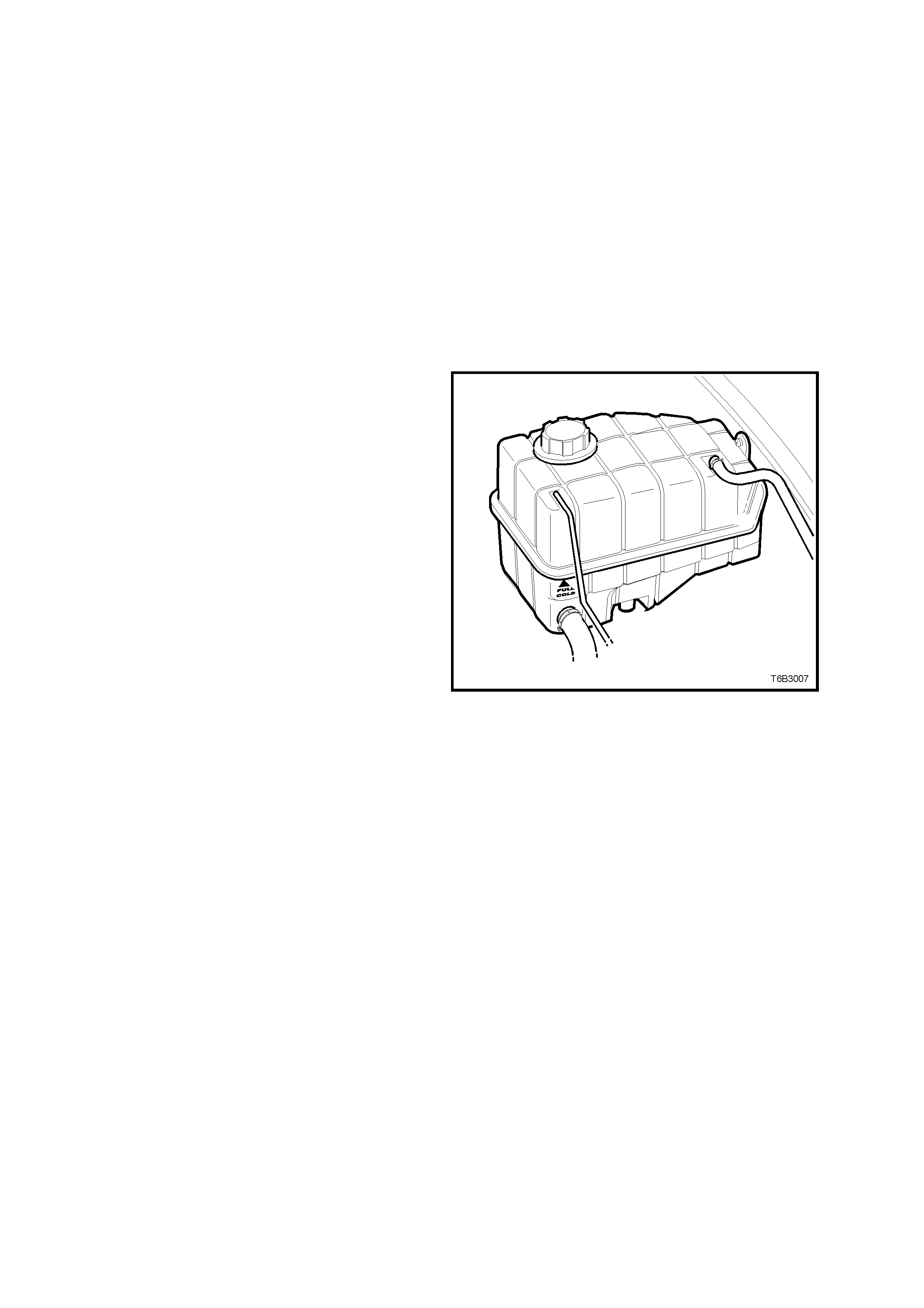
SCREW-ON PRESSURE CAP
A screw-on pressure cap (1), fitted to the coolant
surge tank, causes the cooling system to operate
at higher than atmospheric pressure. This higher
pressure, raises the boiling point of the coolant,
resulting in increased engine cooling efficiency.
The pres sure cap (1) c ontains a press ure valve ( 2)
and a vacuum (atmospheric) valve (3). The
pressure valve is held against its seat (4) by a
spring (5) which determines the maximum
operating pressure range of the cooling system
(from 96.5 – 124 kPa: nominal 103 kPa). The
vacuum valve (3) is held against its seat by a light
spring (6). T he vacuum created during coo lant cool
down over-comes the vacuum valve spring force
and opens the valve (3), preventing the radiator
hoses from collapsing.
The coolant is maintained at the ideal level by the
pressure cap and the coolant surge tank, resulting
in an increased cooling efficiency.
Figure 6B3-7
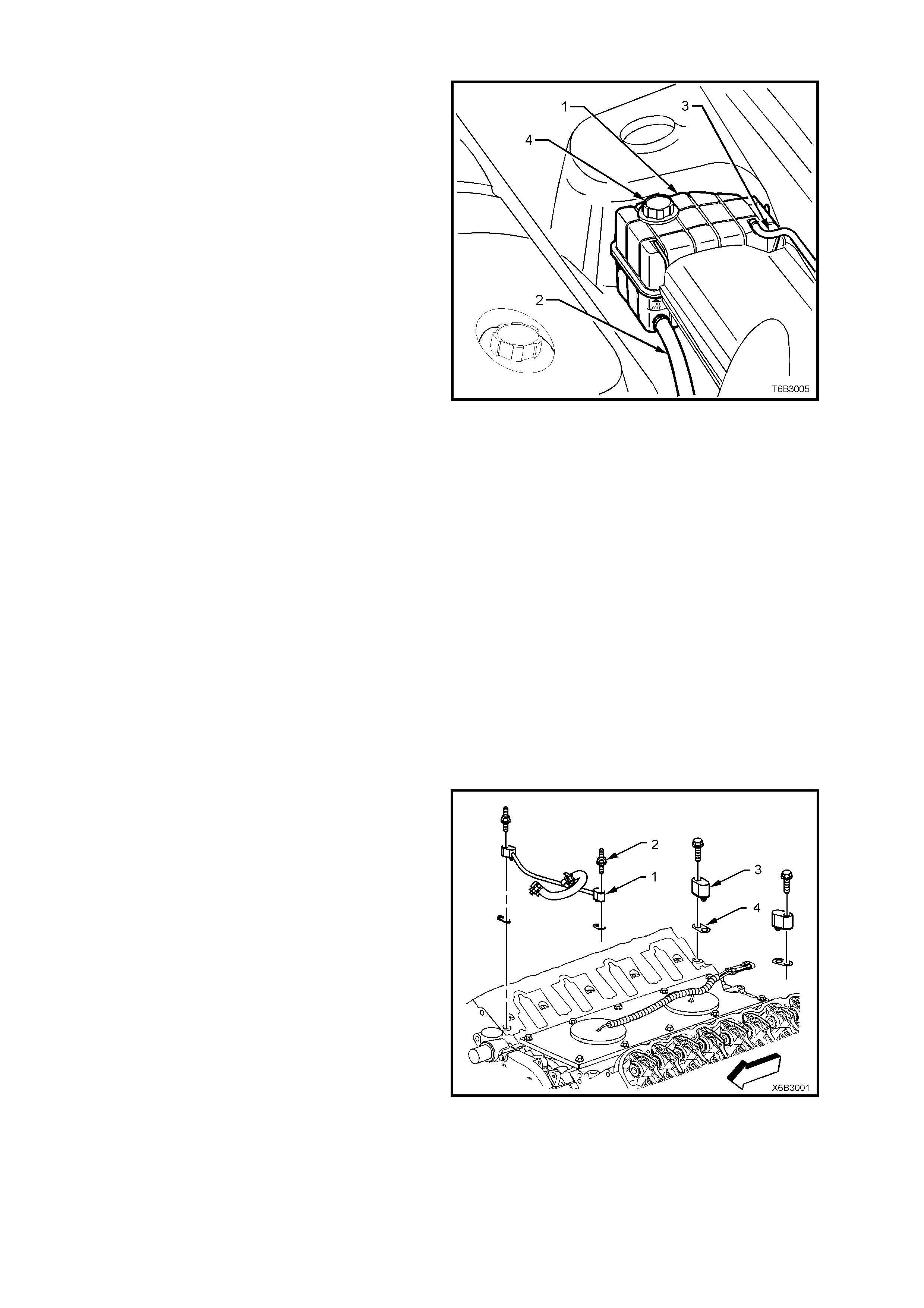
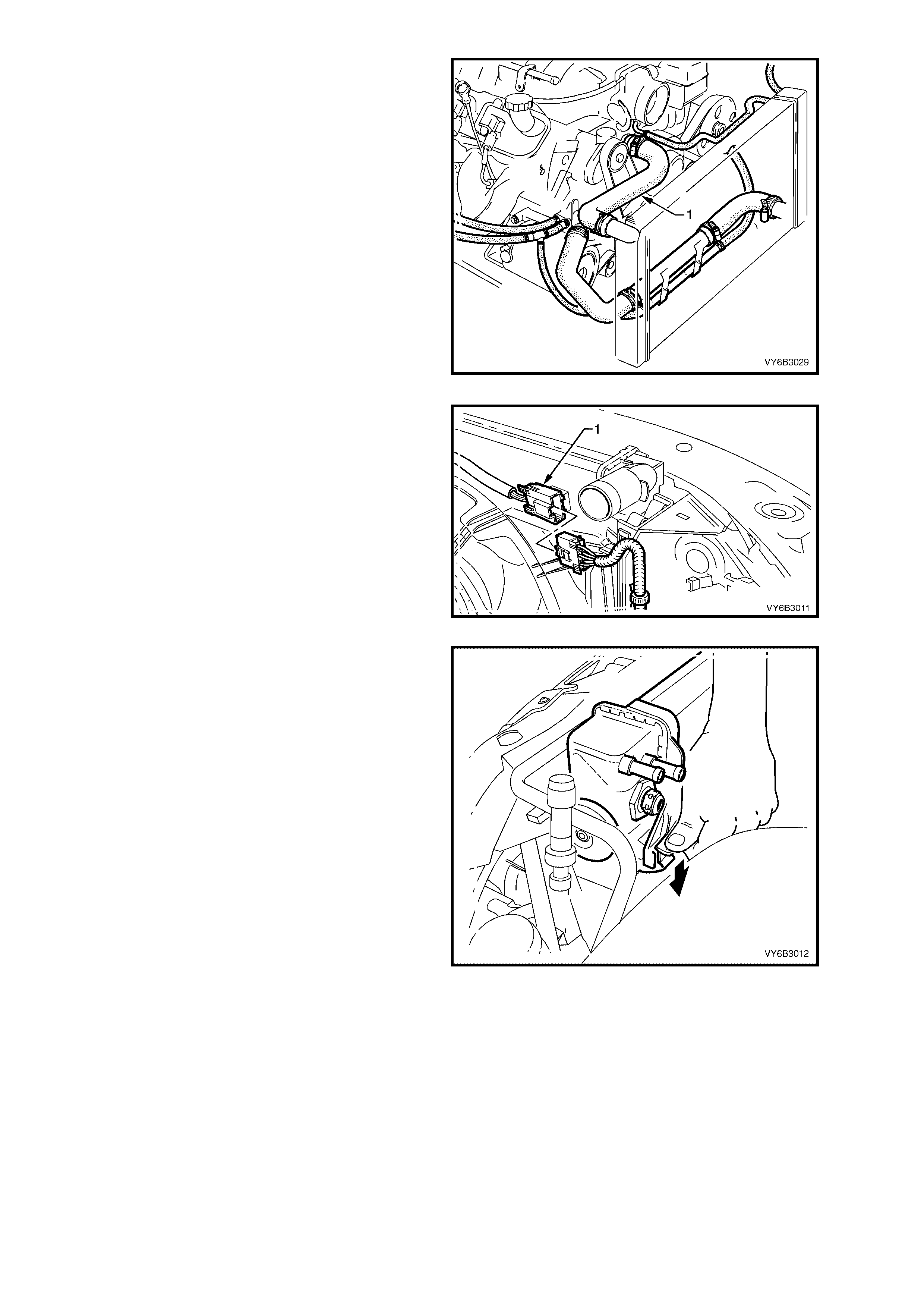
COOLANT SURGE TANK
Located on the left hand inner fender skirt behind
the air cleaner as shown in Figure 6B3-7, the
coolant surge tank (1) is connected to the engine
cooling s ystem by a pressu re hose from the h eater
connection at the coolant pump (2) and a vapour
hose (3) from the left hand radiator side tank.
As the engine tem perature rises, the coolant heats
and expands. The fluid displaced by expansion
flows into t he coolant sur ge tank. W hen the engine
is turned off, the coolant contracts as it cools and
the pressure in the surge tank returns to
atmo spheric, by the unseating of the vacuum valve
in the screw-on pressure cap (4), if necessary.
Coolant le vel sh ould be m ainta ined at t he indic ated
point on the side of the surge tank, when the
engine is cold, by sighting the level externally. A
coolant l evel switc h is insta lled in the sur ge tank to
alert the operator if the coolant level gets too low.
The cooling system is designed to use extended
life anti-freeze coolant (conforming to GM6277M)
in a concentration level of 50% extended life
anti-freeze coolant (conforming to GM6277M) to
50% good quality, clean water. This mixture is
required to maintain the integrity of the cooling
system, and to prevent oxidation occurring within
the engine.
Figure 6B3-8
CAUTION: Because the surge tank is
pressuris ed , th e temperatu re of th e coo lant c an
be considerably higher than 100°
°°
° C, without
boiling. Removing the screw-on pressure cap
when the engine is hot (high cooling system
pressure), will cause the coolant solution to
boil instantaneously.
This will result in the coolant spewing out over
the engine, fenders and the person removing
the cap, resulting in possible serious scalding.
VAPOUR VENT SYSTEM
Any vapour that develops in the engine (or air
when the cooling system is being filled), is routed
back to the coolant surge tank, through a vapour
vent pipe (1), fastened to the front of the cylinder
heads in two places, by double ended studs (2).
The rear locations are blocked by two vapour vent
covers (3). All four locations are sealed by gaskets
(4).
Vapour then flows via hoses, through the throttle
body, to the left hand radiator side tank. Another
vent hose t hen connects th e left hand rad iator side
tank with the coolant surge tank, thereby directing
vapour to that point.
Figure 6B3-9

A IR BAFFLES AND DUCTS
Air baffles and side chutes are fitted to the front end of the vehicle to direct and promote air flow through the
radiator to provide maximum cooling.
The purpos e of the air baf fles is to create a l ow pres sur e area behi nd the r adiator and a hig h press ure area in f ront
of the radiator, when the vehicle is at speed.
This enables additional air flow through the radiator core to maintain the desired engine cooling.
The air baffles or side chutes should never be removed unless for service work. If either the air baffles or side
chutes are damaged, this will reduce the cooling system efficiency, and therefore they must be replaced.
Figure 6B3-10 – All GEN III V8 Except SS Models
Legend
1. Left Hand Side Air Chute (View ‘A’)
2. Right Hand Side Air Chute (View ‘B’)
3. Lower Front Air Chute Baffle (View ‘C’)
4. Fastener (4 places)
5. Lower Rear Air Chute Baffle
6. Screw (2 places)
All ‘SS’ pack vehicles (including Utility) have a front
air duct (1) fitted, in addition to the lower air chute
baffle (2), to concentrate more air flow through the
radiator core.
The two central ‘scrivets’ (3), secure both the air duct
and the chute baffle to the front crossmember.
Figure 6B3-11 – SS Models (Including Utility)
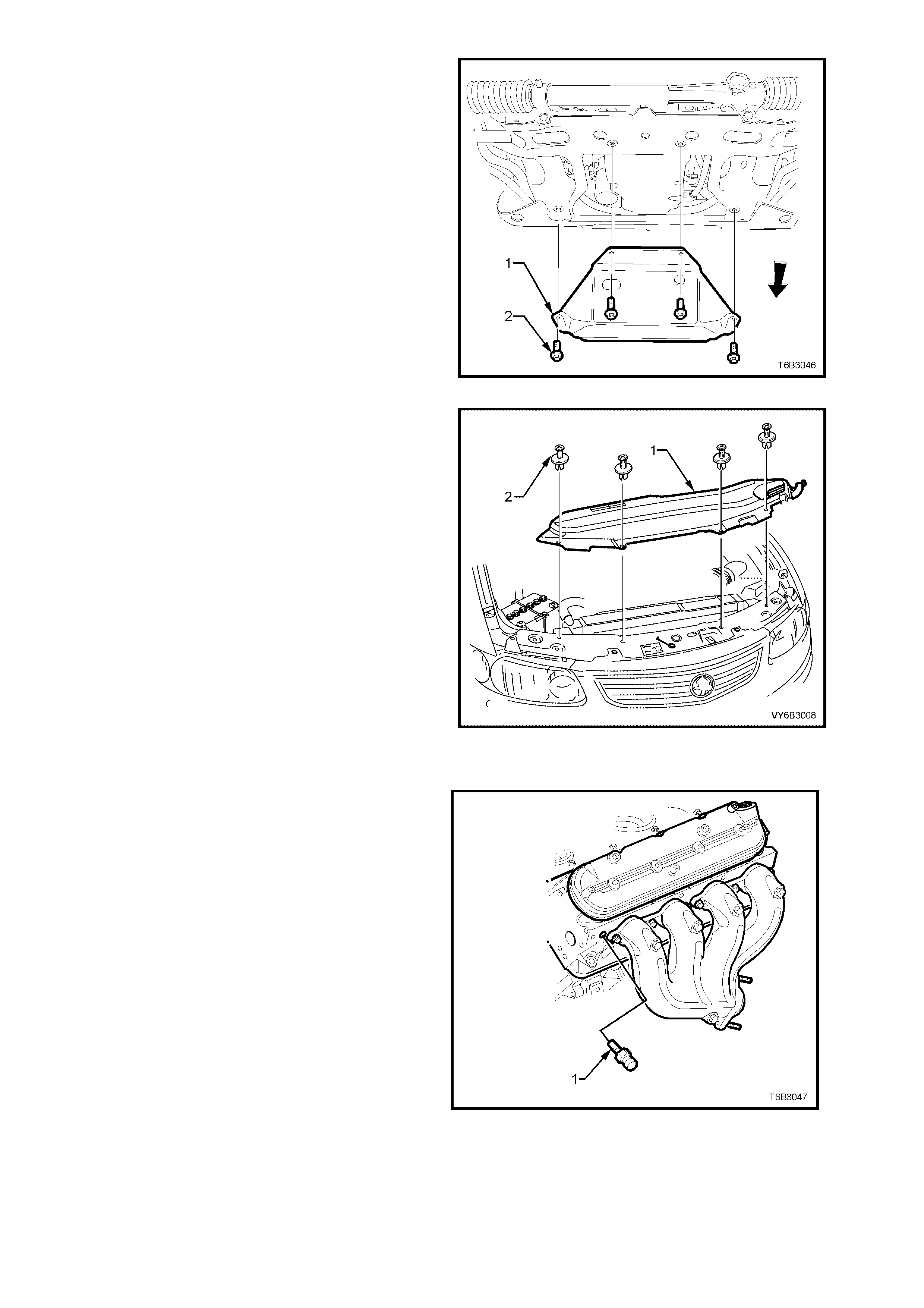
An oil pan under-tray (1) also forms an integral part
of the air flow system around the GEN III V8 engine
and must always be reinstalled after removal fo
r
service operations, such as engine oil draining and
oil filter replacement.
NOTE: This tray is not designed as an oil pan stone
guard.
Figure 6B3-12
A
n upper radiator shroud is fitted between the upper
radiator support panel and the radiator assembly, to
minimise the recirculation of hot air from the rear o
f
the radiator back over the core.
Figure 6B3-13
COOLANT TEMPERATURE SENSOR
A coolant tem perature s ensor ( 1) is mounted in th e
front of the left hand cylinder head.
The c oolant tem peratur e s ensor ge nerates a signa l
which is used by the Powertrain Control Module
(PCM) for calculation of the various powertrain
management functions. This information is
transmitted to other control modules, e.g.
Instrum ents for the temperatur e gauge function, on
the serial data bus.
Figure 6B3-14

2. SERVICE OPERATIONS
2.1 SERVICE NOTES
SAFETY
Before removin g the surge tank cap, allow the engine to cool, then place a shop rag over the surge tank cap and
then slo wly turn the cap anti-c lockwise, to lo osen. DO NOT SPIN T HE CAP OFF! If there is any residu al pressur e
in the coo ling system , it can then be r eleased into t he dam under the cap and out through the dr ain hose onto the
ground. When all pressure has been dispersed in this way, the cap can then be fully removed.
CAUTION: TO AVOID SERIOUS PERSON AL IN JURY, NEVE R REM OVE THE SCREW-ON SURG E T ANK CAP
WHEN THE ENGINE IS HOT, EVEN IF THE COOLING SYSTEM SHOULD REQUIRE FILLING. SUDDEN
RELEASE OF COOLING SYSTEM PRESSURE IS VERY DANGEROUS.
The vehic le is fitte d with twin r adiator el ectric c ooling fans. W hen work ing around the engine c ompartm ent with the
engine running or with the ignition on, keep clear of the fan as it may start operating without warning.
PERIODIC SER VICING
The cooling system requires little care except for maintaining the coolant to the correct level in the coolant surge
tank and periodic servicing at the time or distance intervals as outlined in the Owner's Handbook.
Periodic servicing includes:
1. Checking coolant level, refer to 2.3 DRAINING AND FILLING COOLING SYSTEM this Section.
2. Checking coolant concentration, refer to 2.2 COOLANT MAINTENANCE - TESTING COOLANT
CONCENTRATION this Section.
3. Pressure test cooling system and radiator cap, refer to 2.8 PRESSURE TEST ING in this Section.
4. Check/tighten hose clamps and inspect all hoses, refer to 2.4 COOLANT HOSES in this Section. Replace
hoses if swollen or deteriorated.
CAUTION: ALWAYS WEAR PROTECTIVE SAFETY GLASSES WHEN WORKING WITH SPRING TYPE HOSE
CLAMPS. FAILURE TO DO SO COULD RESULT IN EYE INJURY.
5. Clean out cooling system, refer 2.5 CLE ANING COO LING SYSTEM , in this Sec tion and refill cooling s ystem ,
refer to 2.3 DRAINING A ND FILLING COOLING SYSTEM in this Section.
ENVIRONMENTAL ISSUES
To reduce the impact on the environment and the maintenance cost, whenever the coolant is drained from the GEN
III V8 engine, t he service records are to be check ed to determine when the coolant was last change d. If more than
six months life is left before the next coolant change, then the following procedure is to be adhered to:
1. W hen draining the coo lant from the engine, use a c lean container of at least 15 litres c apacity and ensure that
the coolant is not contaminated in the drai ni ng pr oces s .
2. After repairs have been completed, refill the engine cooling system with the drained coolant.
3. Top up as required , using a 50% m ixture of extended li fe anti- free ze coolant ( conf orm ing to GM6277 M) to 50%
clean, good qualit y water. Refer 2.2 COOL ANT M AIN TEN ANCE and 2.3 DR AINING AND FILLING COOLING
SYSTEM in this Section.
2.2 COOLANT MAINTENANCE
The c ooling system is designed to use a s pecif ic cool ant (a m ixture of extended lif e anti-f ree ze coolant (c onform ing
to GM6277M) and water), rather than plain water.
The use of this orange coloured coolant additive also raises the boiling point and increases the cooling system
efficiency. For this reason, it is of the utmost importance that the correct concentration level of extended life anti-
freeze coolant (conforming to GM6277M) is maintained in the cooling system.
Addition of plain water into the cooling system when 'topping-up' may dilute the coolant mixture to a point where the
specific properties of the extended life anti-freeze coolant (conforming to GM6277M) become ineffective.
The coolant should comprise of a mixture 50% extended life anti-freeze coolant (conforming to GM6277M) with
50% clean, good quality water.
NOTE: Do not mix different types of antifreeze or corrosion inhibitors as they may be incompatible. If a different
type has been used in the cooling system, flush the system with clean water, refer to
2.5 CLEANING COOLING SYSTEM in this Section and refill the cooling system with the correct coolant, refer to
2.3 DRAINING AND FILLING COOLING SYSTEM in this Section.
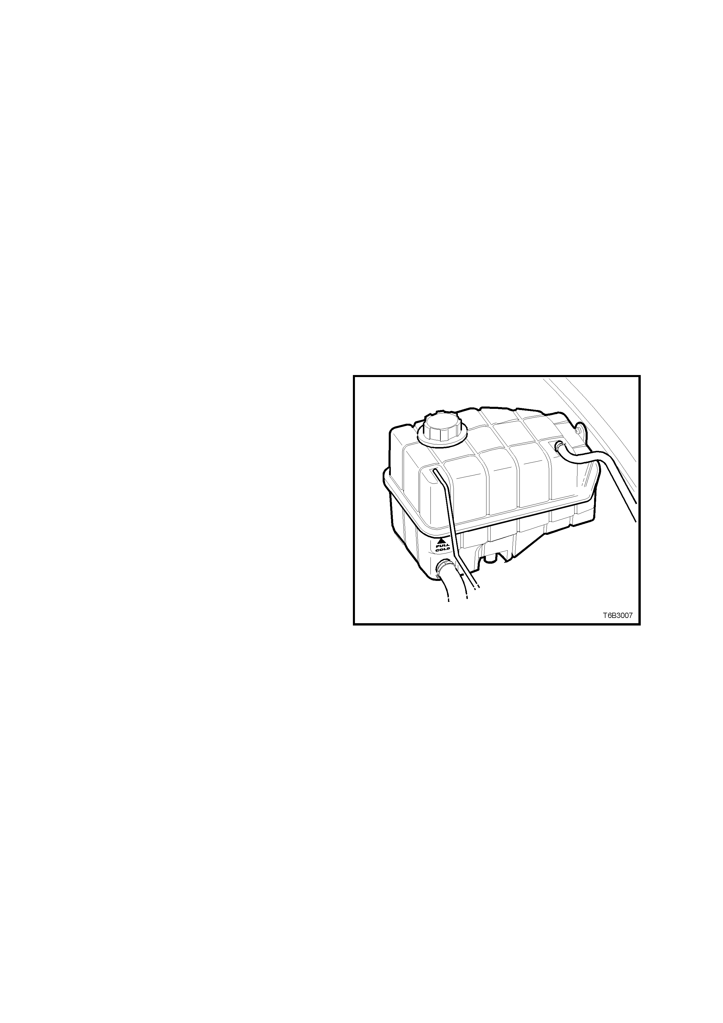
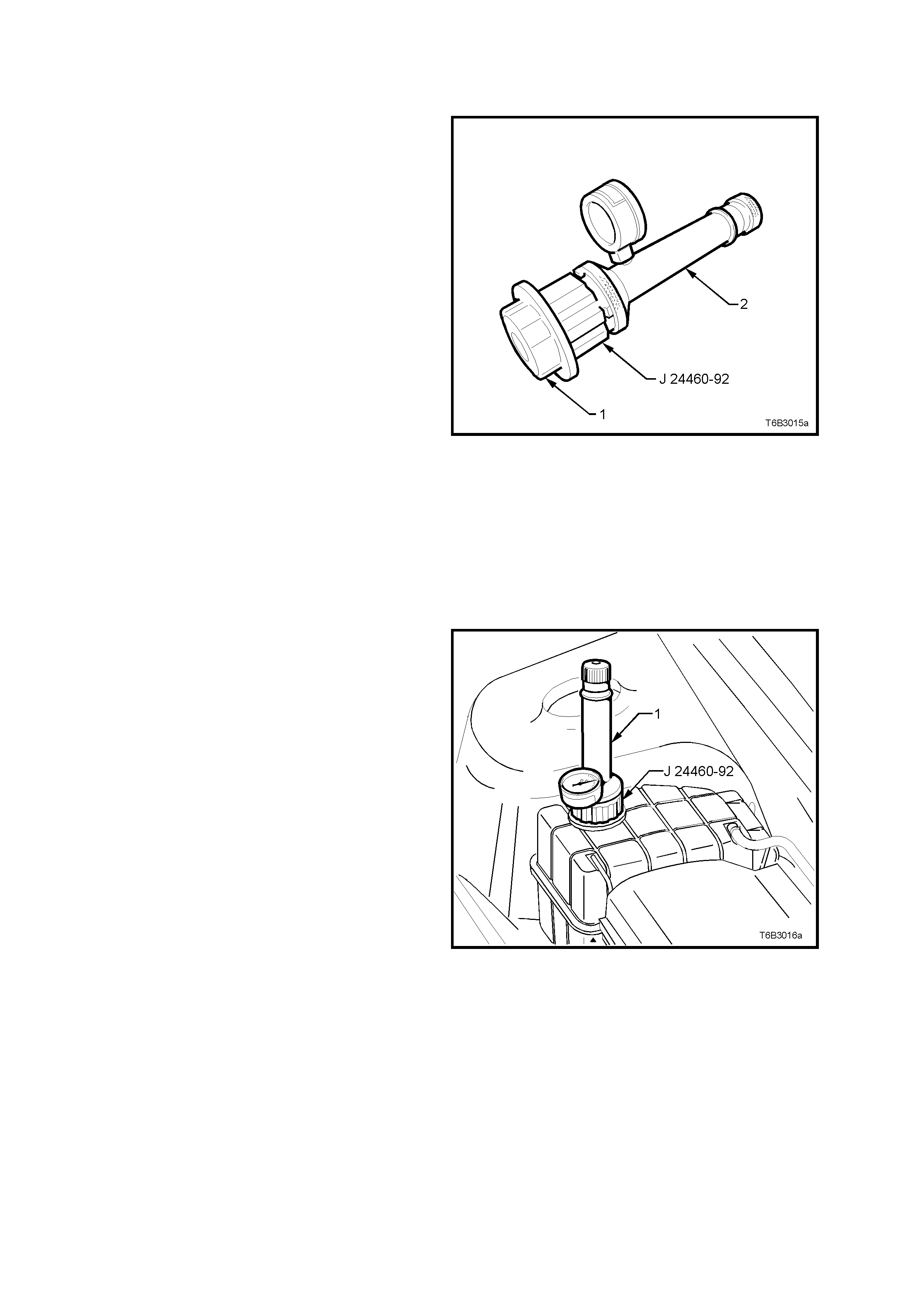
TOPPING UP THE COOLING SYSTEM
The coolant level can be externally checked at the
coolant surge tank.
Pre-mixed coolant (50% extended life anti-freeze
coolant ( conform ing to GM6277M) with 50% c lean,
good qualit y water) m ay be added as necessary to
bring the level s ho wn on the c oolant su rge tank but
only when the engine is cold.
Figure 6B3-15
TESTING COOLANT CONCENTRATION
To ensure the specified ethylene glycol concentration is maintained in the engine coolant, the coolant concentration
must be checked at the time or distance intervals outlined in the MY 2003 VY and V2 Series Owner's Handbook.
While a number of coolant concentration measuring devices are available, the two preferred types are as
described. Check coolant concentration as follows:
Method 1 – Refractometer
NOTE 1: Coolant tester, Tool No. J 26568, automatically compensates for temperature.
NOTE 2: Ensure that the eyepiece of the tester is free of coolant before looking through it.
NOTE 3: Before each use, swing back the plastic cover at the slanted end of the coolant tester, exposing the
measuring window and the bottom of the plastic cover. Carefully wipe the measuring window dry with a tissue or
clean, soft cloth. Close the plastic cover.
1. Check the calibration of the coolant tester as follows:
a. Place a few drops of distilled water (between 21 – 29° C) onto the measuring window, then close the
plastic cover.
b. Point the tester toward any light source, look into the eyepiece and check that the indicated reading is zero.
If not, then re-calibrate the tester as detailed in the next service operation - Calibrating the Tester.
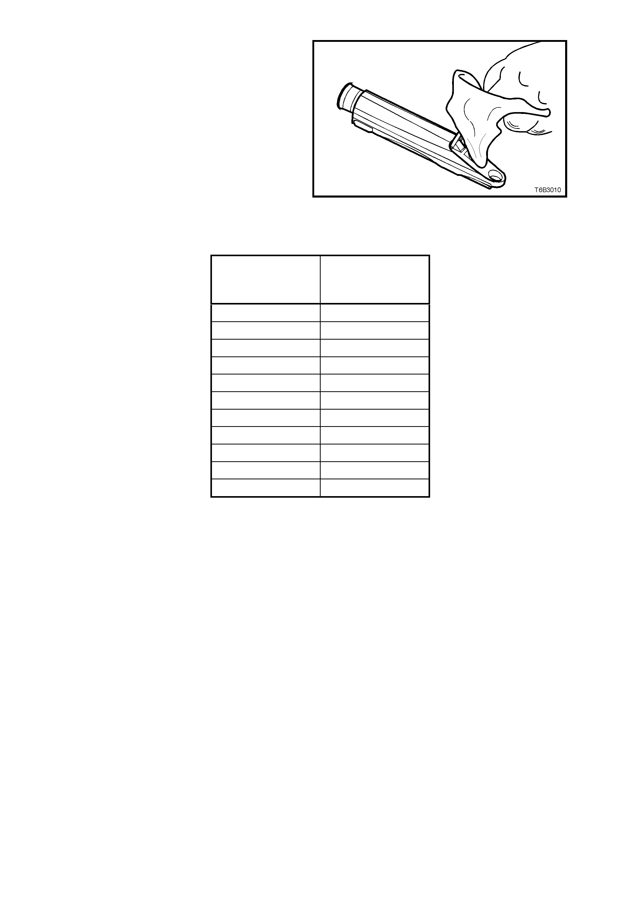
2. Release the tip of the bulb pump from under
the refractometer body. It is not necessary to
remove the complete pump from the tool.
3. Carefully remove the screw-on coolant surge
tank cap, refer to 2.1 SERVICE NOTES for
important safety items.
4. Insert the tube of the pump into the coolant,
then press the bulb to obtain a sample.
5. Bend the tube around and insert the end into
the cover plate opening.
6. Press the pum p bulb to deposit a few drops of
coolant onto the measuring surface. Do not
open the plastic cover when taking readings,
as water evaporation will change the reading
obtained.
Figure 6B3-16
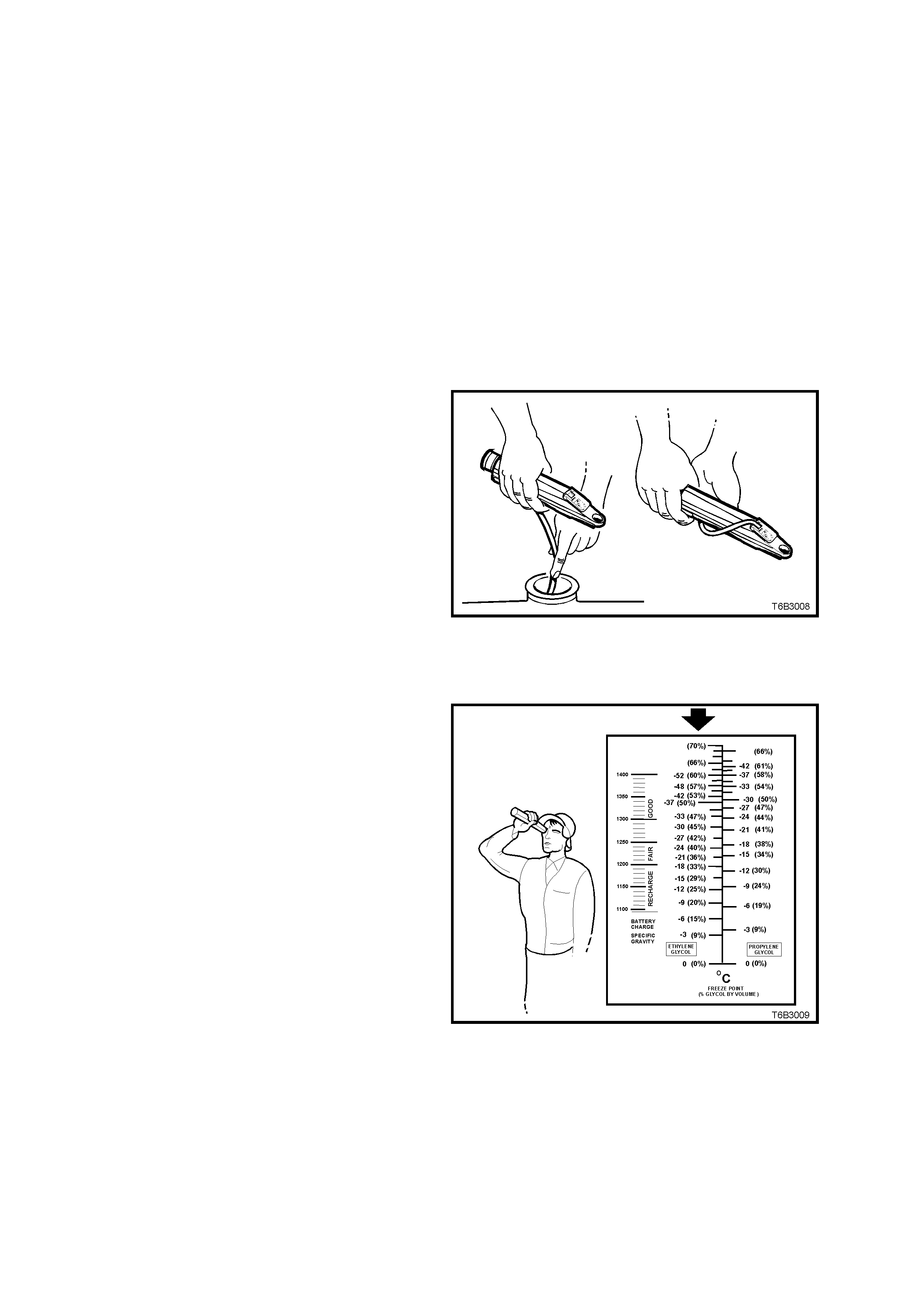
7. Point the coolant tester toward any light
source, looking into the eyepiece.
a. The coolant protection reading is at the
point where the dividing line between the
light and dark, crosses the scale.
b. The scale for ethylene glycol (bold arrow)
is the ref er ence s c ale f or ex tende d lif e ant i-
freeze coolant (conforming to GM6277M).
NOTE: The temperature scale is reversed from
that of a conventional thermometer. Readings
below zero are on the upper half of the scale.
8. A reading between –30 and –52° C
(corresponding to a coolant concentration
between 45 – 60%), is s atis fac tory for the G EN
III V8 engine cooling system.
Figure 6B3-17
NOTE: If the reading is not clear, then properly
clean and dr y the m easuring s urface, then conduct
another test. Also ensure that there is sufficient
fluid on the measuring prism.
9. If the reading shows that the concentration
level of the coolant is inadequate, refer to the
following table to determine the amount of
extended life anti- fr eeze coola nt (c onforming to
GM6277M) that needs to be added to the
surge tank.
10. Start and run the engine u ntil norm al operatin g
temperature is reached, to allow the added
coolant to be distributed throughout the engine
cooling system.
Figure 6B3-18
CONCENTRATION
READING % LITRES OF
COOLANT TO BE
ADDED
0 7.2
5 6.8
10 6.3
15 5.8
20 5.3
25 4.7
30 4.1
35 3.4
40 2.6
45 1.5
50 0
Table 1
Calibrating the Tester
While the coolant tester calibration is checked at manufacture, if the calibration check detailed in step 1 of this
method shows that the instrument is not reading correctly, then conduct the following re-calibration procedure;
1. Remove the sealant covering the adjustment screw on the underneath of the tester.
2. With a distilled water sample on the measuring surface, carefully adjust the screw until a zero reading is
obtained.
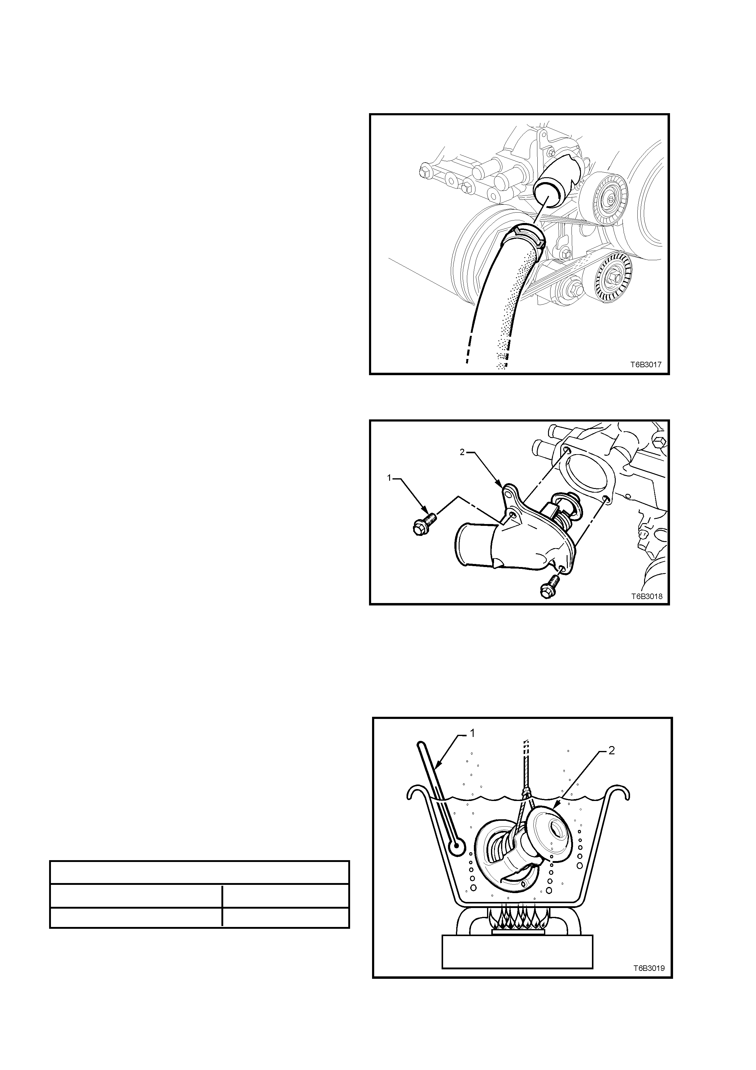
NOTE: DO NOT completely remove the screw.
3. After re-calibration, reseal the screw with a small amount of silicone sealant.
Method 2: – Hydrometer
1. Cooling system should be at or close to ambient temperature.
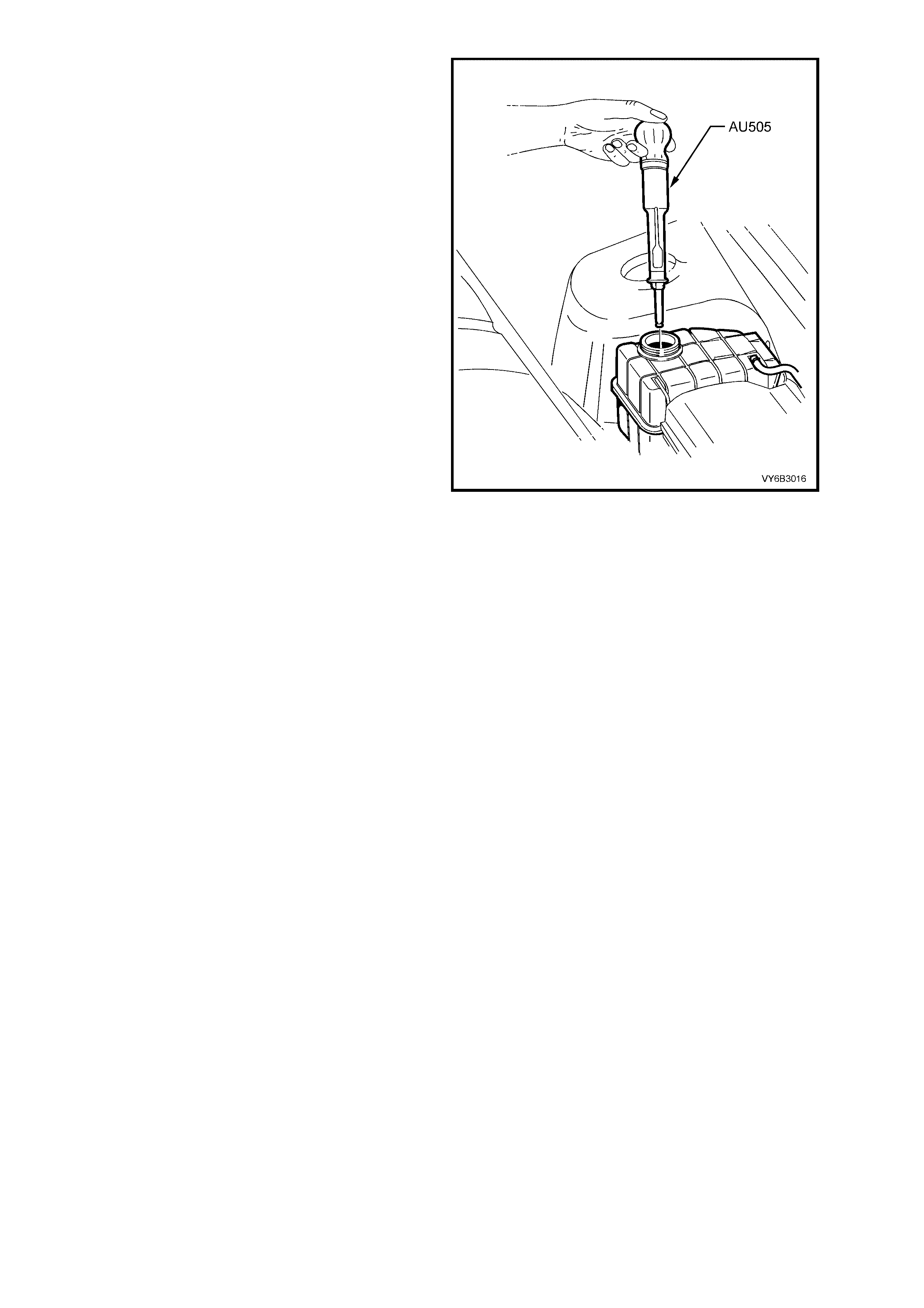
2. Carefully remove the screw-on pressure cap
from the surge tank and, while holding the
rubber bulb squeezed, insert nozzle of coolant
tester hydrometer, Tool No. AU505 into
coolant. Releasing the rubber bulb will then
draw sufficient coolant into the tester to float
hydrometer bulb freely.
3. Hold tester at eye level and read scale on
hydrometer bulb at coolant level.
The reading shows the percentage of ethylene
glycol antifreeze contained in the engine
coolant.
4. The hydrometer reading should show 50% if
the coolant concentration is correct.
If a reading of less than 50% is achieved, the
cooling system requires topping up with
extended life anti- fr eeze coola nt (c onforming to
GM6277M).
Refer to the chart shown for the previous
method to determine how much extended life
anti-freeze coolant (conforming to GM6277M)
is required to add to the cooling system to
bring the coolant to the specified concentration.
5. Drain s ufficient quantit y of coolant f rom cooling
system to allow top-up with extended life anti-
freeze c oolant (conf orming to GM6277 M), then
add the required amount. Install screw-on
pressure cap.
6. Start and run th e engine un til norm al operating
temperature is reached, to allow the added
coolant to be distributed throughout the engine
cooling system.
Figure 6B3-19
2.3 DRAINING AND FILLING COOLING SYSTEM
DRAINING
CAUTION: To avoid the possibility of scalding, it is recommended that this operation is only carried out
when the engine is cold.
The recommended method of draining the G EN III V8 engine cooling system, is to remove the screw-on pr essure
cap from the surge tank, then remove the hose clamp from the radiator hose at the lower left hand radiator side
tank, dr aining the c oo li ng syst em contents into a s uit a ble c lean c ont ain er , with a c apac ity of at least 15 l itres. Refer
to ‘ENVIRONMENTAL ISSUES’, in 2.1 SERVICE NOTES, in this Section.
FILLING
As the GEN III V8 engine has a vapour pipe attached to each cylinder head, that releases any air in the cooling
system, no special bleeding procedure is required, apart from the following simple points:
1. Set the heater control to maximum.
2. Reinstall hose to radiator lower outlet on the left hand side tank and tighten hose clamp.
3. Mix 7.2 litres of ex tended life anti- fr eeze coola nt (c onform ing to GM627 7M) with 7.1 litr es of c lean, good qua lity
water.
NOTE 1: Do not mix different t ypes of antifreeze or c orrosion inhibitors as the y m ay be incompatible. If a dif ferent
type has been used in the cooling system, flush the system with clean water, refer to 2.5 CLEANING COOLING
SYSTEM in this Section.
NOTE 2: When using extended life anti-freeze coolant (conforming to GM6277M) DO NOT add a pack of cooling
system pellets to the cooling system.
4. Carefully fill the cooling system by pouring the
pre-mixed coolant into the surge tank opening
until the level is correct.
5. Pressure test cooling system, refer to
2.8 PRESSURE T EST ING in this Section.
6. Reinstall the screw-on pressure cap to the
reservoir.
7. Start and run th e engine un til norm al operating
temperature is reached, at which time the
added quantity of extended life anti-freeze
coolant (conforming to GM6277M) will have
dispersed through the engine’s cooling system.
Figure 6B3-20
2.4 COOLANT HOSES
LT SECTION NO. – 01-160
1. Coolant hoses are installed as shown in the following illustrations.
NOTE: The engine cooling fans, motors and shroud are shown removed in Figure 6B3-20, to more clearly
show hose routing.
2. Hose connections should be thoroughly cleaned before installing any new hose.
NOTE: Because of the productio n method of inst alling the sprin g type hose clam ps, access to the clamp ends
may not be possible. Particularly for the clamps securing the hoses to the lower bridging piece of the coolant
intake and coolant surge tank hoses, it may be necessary to remove the complete hose assembly from the
vehicle.
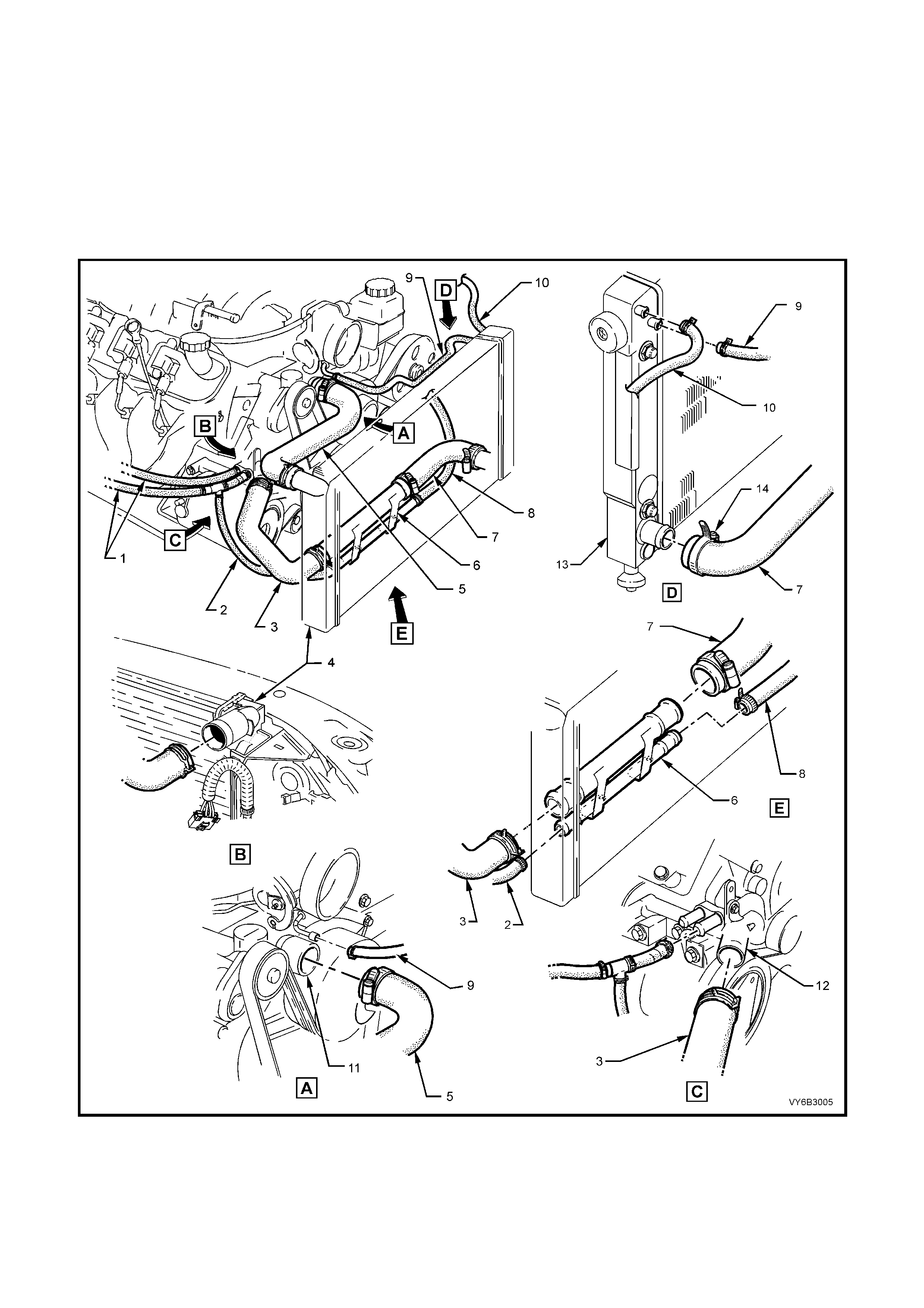
Figure 6B3-21 - Cooling System Hose Layout - GEN III V8 Engine – RHD and LHD Applications
Legend
1. Hoses – Heater
2. Hose – To Coolant Surge Tank 1 of 2
3. Hose – Radiator Lower 1 of 2
5. Hose – Radiator Upper
6. Bridging Pipe – Radiator Hoses
7. Hose – Radiator Lower 2 of 2
9. Hose – Vapour to Radiator
10. Hose – Vapour to Surge tank
11. Pump Coolant
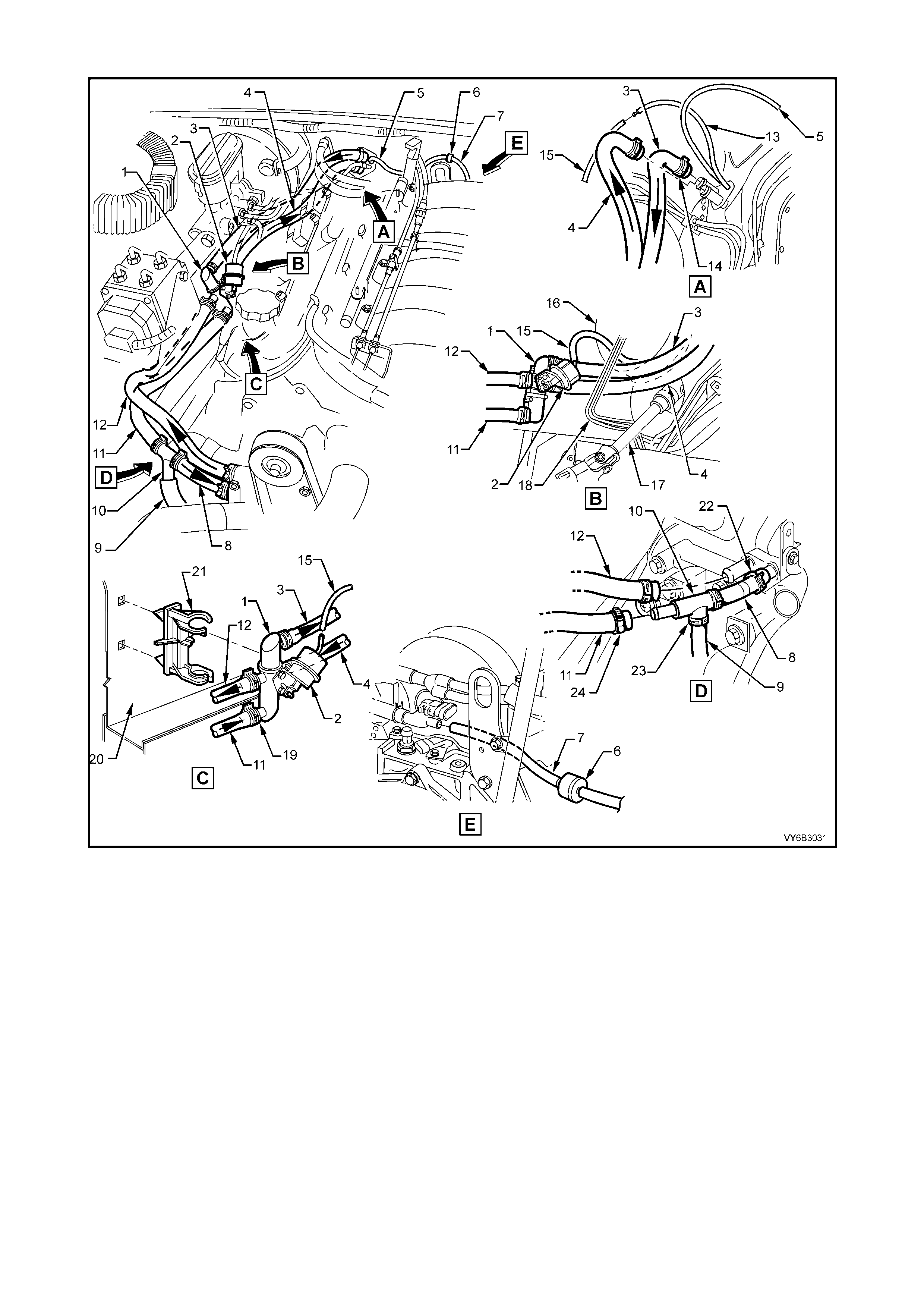
4. Radiator 8. Hose – To Coolant Surge Tank 2 of 2 12. Housing – Thermostat
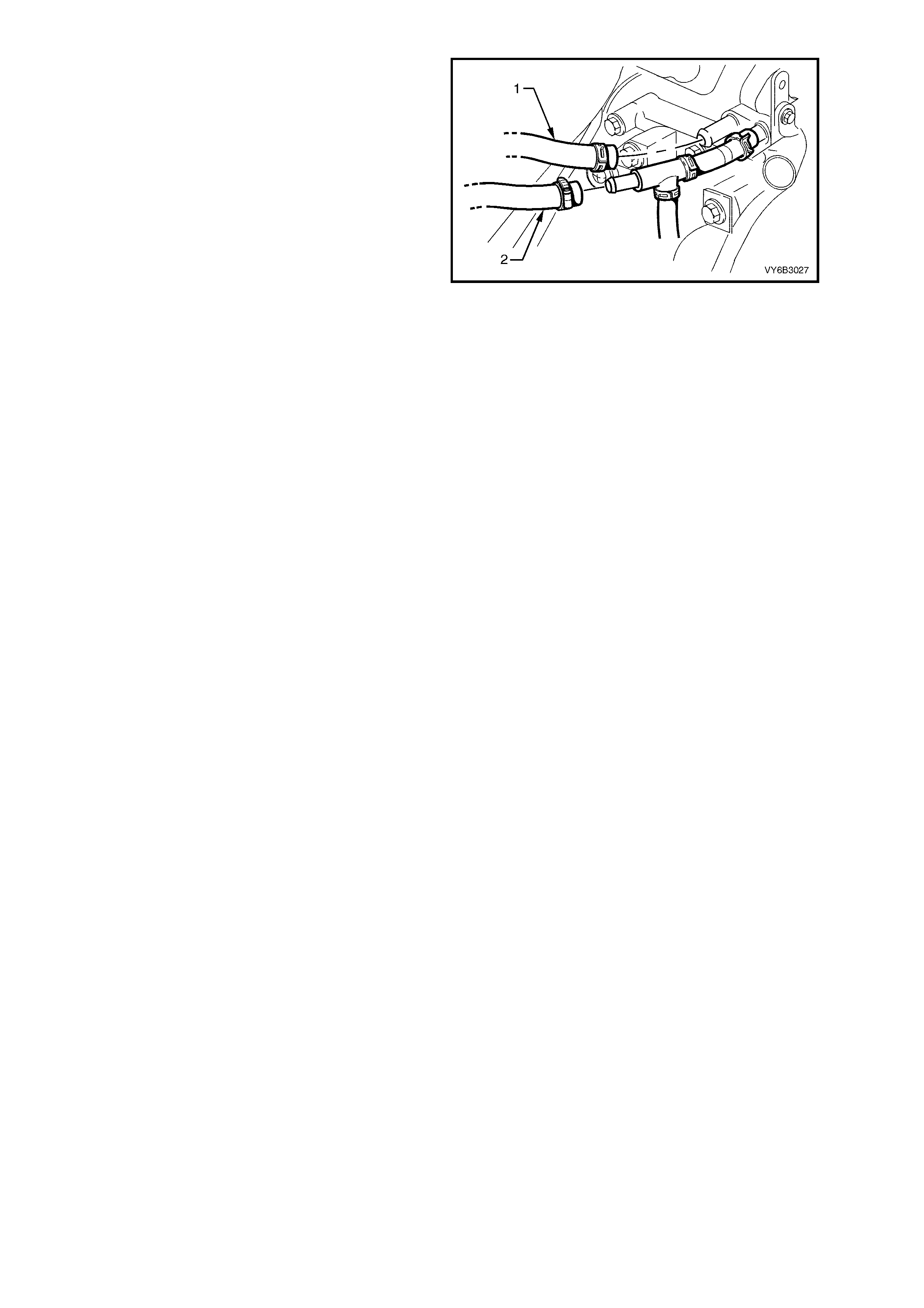
Figure 6B3-22 - Heater Hose Arrangement - GEN III V8 Engine – RHD Application
Legend
1. Coolant Valve
2. Coolant Valve Actuator
3. Heater Hose to Interior Heater Core
4. Heater Hose from Interior Heater Core
5. Vacuum Hose – HVAC Supply
6. One-Way Check Valve
7. Vacuum Hose to Intake Manifold
8. Heater Hose to Engine
9. Hose to Coolant Surge Tank
10. Heater Hose T-piece
11. Heater Hose to T-piece
12. Heater Hose from Engine
13. Vacuum Hose to Interior Control Valve
14. Heater Hose Clamps (2 places)
15. Vacuum Hose to Coolant Valve Actuator
16. Brake Booster
17. Steering Shaft
18. Brake Lines
19. Coolant Valve Hose Clamps (4 plac es)
20. Right Side Wheelhouse
21. Clip - Coolant Flow Control Valve
22. Heater Hose Clamps to Engine (2 places)
23. T-piece Hose Clamps (2 places)
24. T-piece Hose Worm Drive Clam p (1 place)
NOTE: Heater and vacuum hoses to be routed under Brake Pipes – refer View B
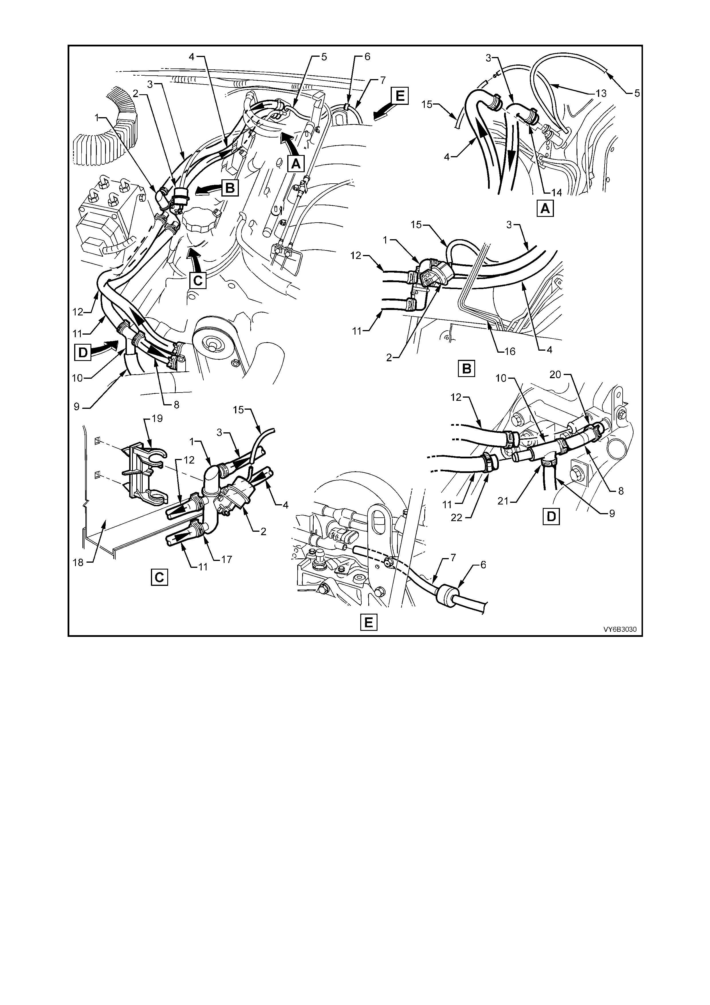
Figure 6B3-23 - Heater Hose Arrangement - GEN III V8 Engine – LHD Application
Legend
1. Coolant Valve
2. Coolant Valve Actuator
3. Heater Hose to Heater Core
4. Heater Hose from Heater Core
5. Vacuum Hose – HVAC Supply
6. One-Way Check Valve
7. Vacuum Hose to Intake Manifold
8. Heater Hose to Engine
9. Hose to Coolant Surge Tank
10. Heater Hose T-piece
11. Heater Hose to T-piece
12. Heater Hose from Engine
13. Vacuum Hose to Interior Control Valve
14. Heater Core Hose Clamps (2 places)
15. Vacuum Hose to Coolant Valve Actuator
16. Brake Lines
17. Coolant Valve Hose Clamps (4 plac es)
18. Right Side Wheelhouse
19. Clip - Coolant Flow Control Valve
20. Heater Hose Clamps to Engine (2 places)
21. T-piece Hose Clamps (2 places)
22. T-piece Worm Drive Hose Clamp (1 place)
NOTE: Heater and vacuum hoses to be routed under Brake Pipes – refer View B
2.5 CLEANING COOLING SYSTEM
NOTE: Before carrying out reverse flushing procedures, it is recommended that a cleaning solution be used to
loosen scale and corrosion. Use an approved radiator cleaner, such as P/N M39304, following the instructions on
the container.
COOLING SYSTEM REVERSE FLUSH
CAUTION: This operation should only be carried out when the engine and radiator are at room
temperature.
When using specialised cooling system flushing equipment, only connect as recommended by the manufacturer.
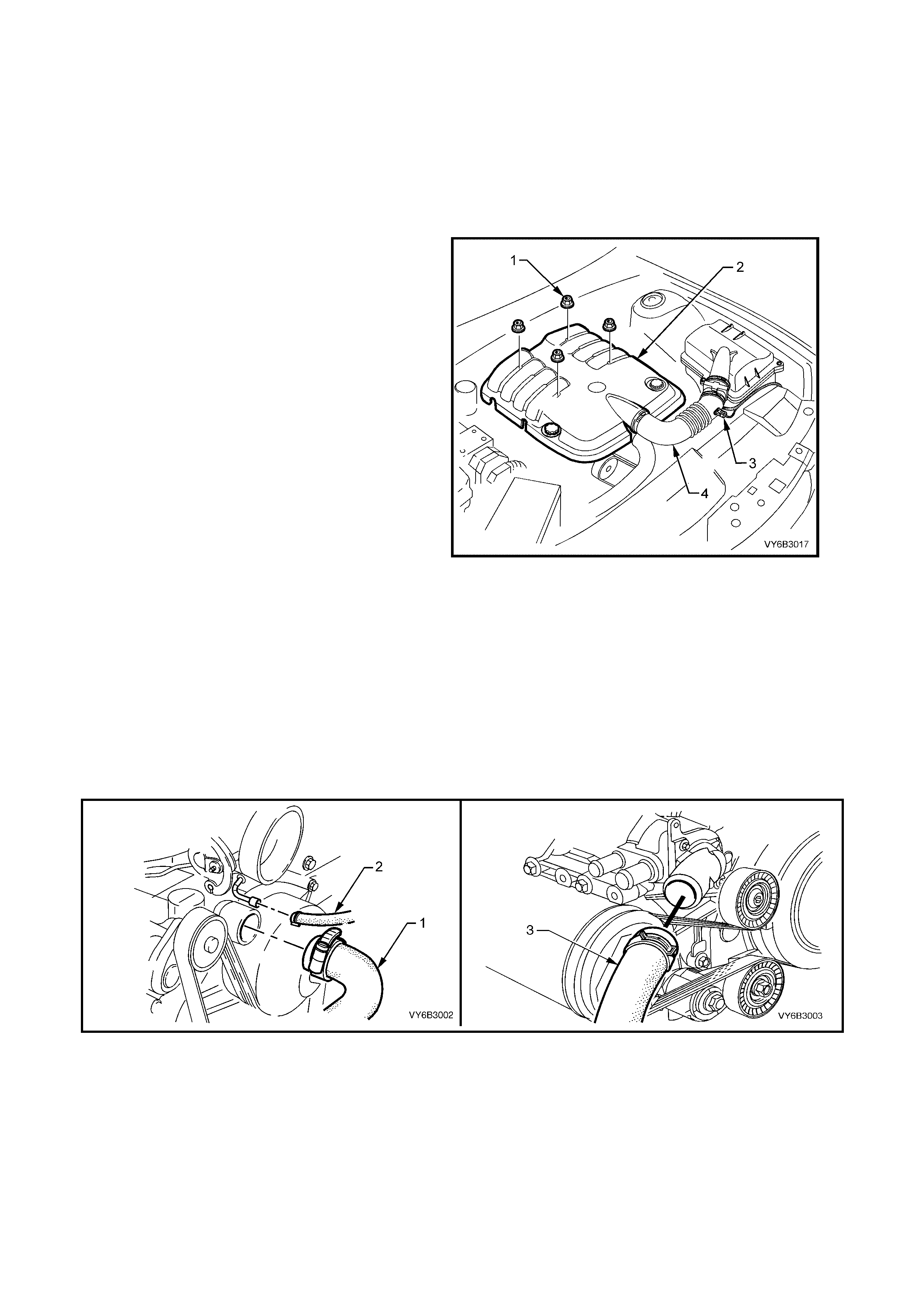
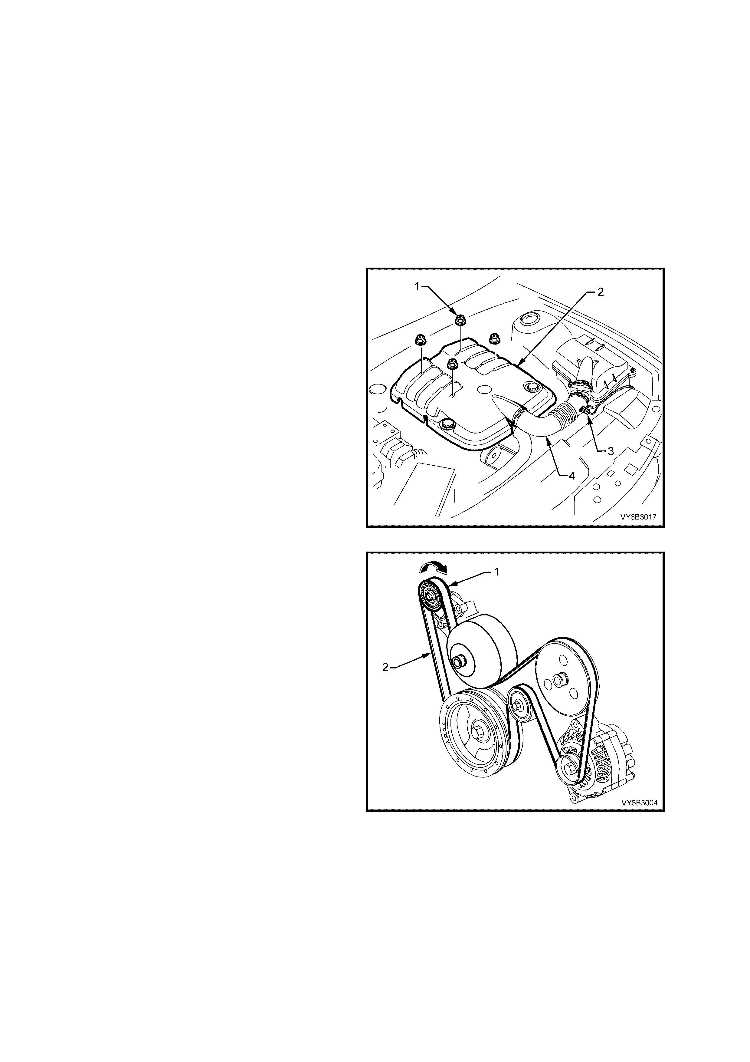
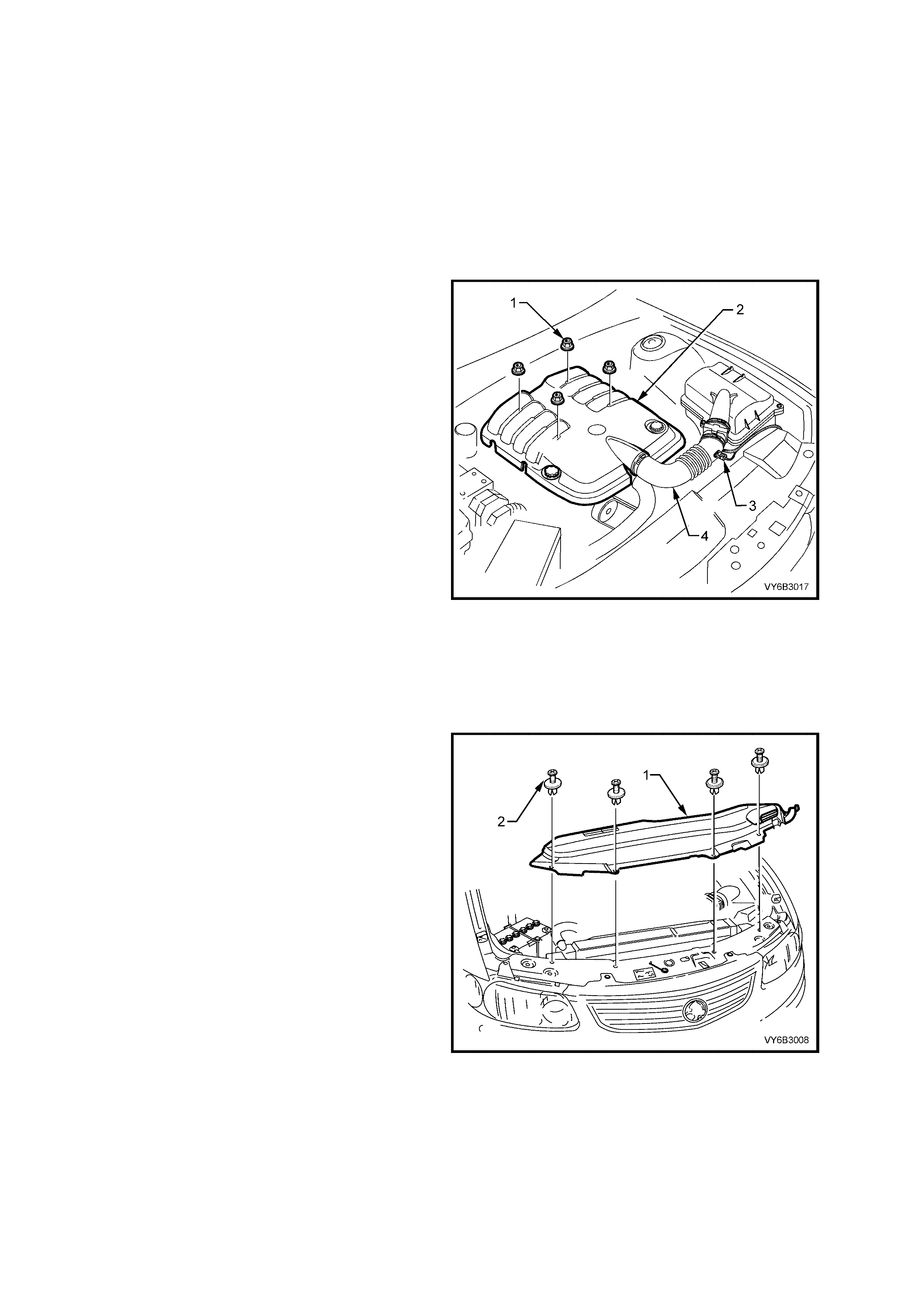
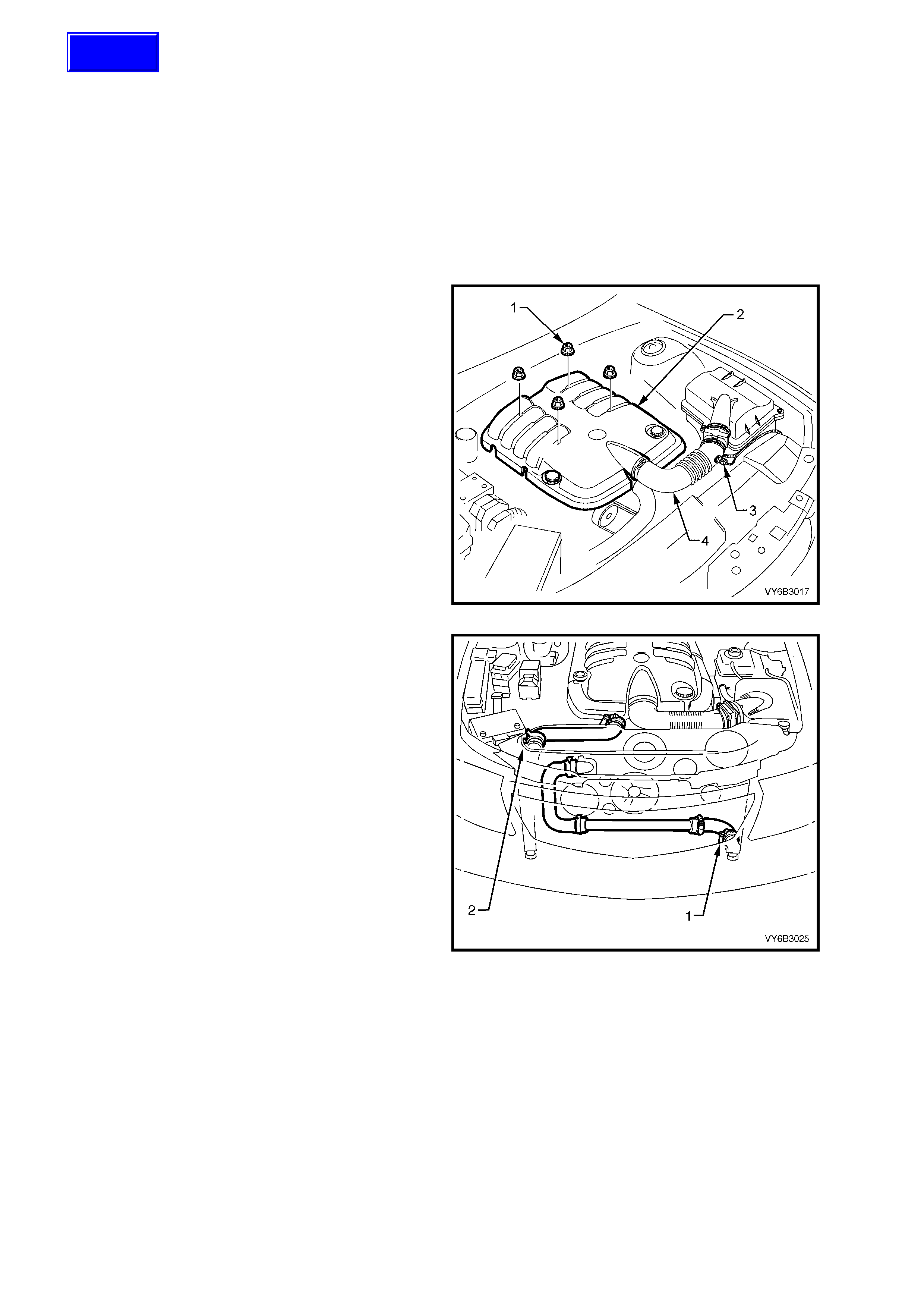
1. Remove engine dress cover decorative nuts
(1), then remove the cover (2).
Figure 6B3-24
Radiator:
1. Place suitable, clean, drain tray beneath vehicle.
2. Rem ove the screw-on pressure cap from the coolant surge tank, taking care to release any residual pressure
before fully removing.
3. Loosen the worm drive radiator hose clamp from the lower left hand side radiator tank, disconnect the hose and
drain the coolant into the container.
4. Reinstall the hose and tighten the clamp.
5. Remove the upper and lower radiator hoses (1 and 3) from the coolant pump connections.
CAUTION: Always wear protective safety glasses when working with spring type hose clamps. Failure to
do so could result in eye injury.
Figure 6B3-25
6. Rem ove the vapour hos e to coolant s urge ta nk
connection at the radiator left hand tank.
7. Disconnect the vapour hose at the throttle body
(‘2’ in Figure 6B3-24 and reconnect to the
radiator tank.
8. Attach a lead-away hose at the radiator upper
hose outlet.
9. Attach a piece of hose between the flushing
gun and the radiator lo wer hose.
10. Connect and operate the flushing equipment
as recommended by the manufacturer.
IMPORTANT: App ly air pre ssure gr aduall y and not
in excess of 110 kPa. Otherwise radiator damage
will result.
11. Continue flushin g until the water from the lead-
away hose runs clear.
12. Reinstall all disconnected hoses, ensuring that
spring hose clamps are positioned correctly
and/or tightened.
Figure 6B3-26
13. Fill the cooling system. Refer 2.3 DRAINING AND FILLING COOLING SYSTEM, in this Section.
14. Pressure test the cooling system to check for leaks. Refer to 2.8 PR ESSURE TE ST ING , in this Section.
Engine:
1. With the coolant drained from the engine and both radiator hoses disconnected, remove the thermostat from
the coolant pump housing. Refer to 2.9 THERMOSTAT - REMOVE, in this Section and dismantle from the
thermostat housing. Reinstall the thermostat housing cover to the coolant pump.
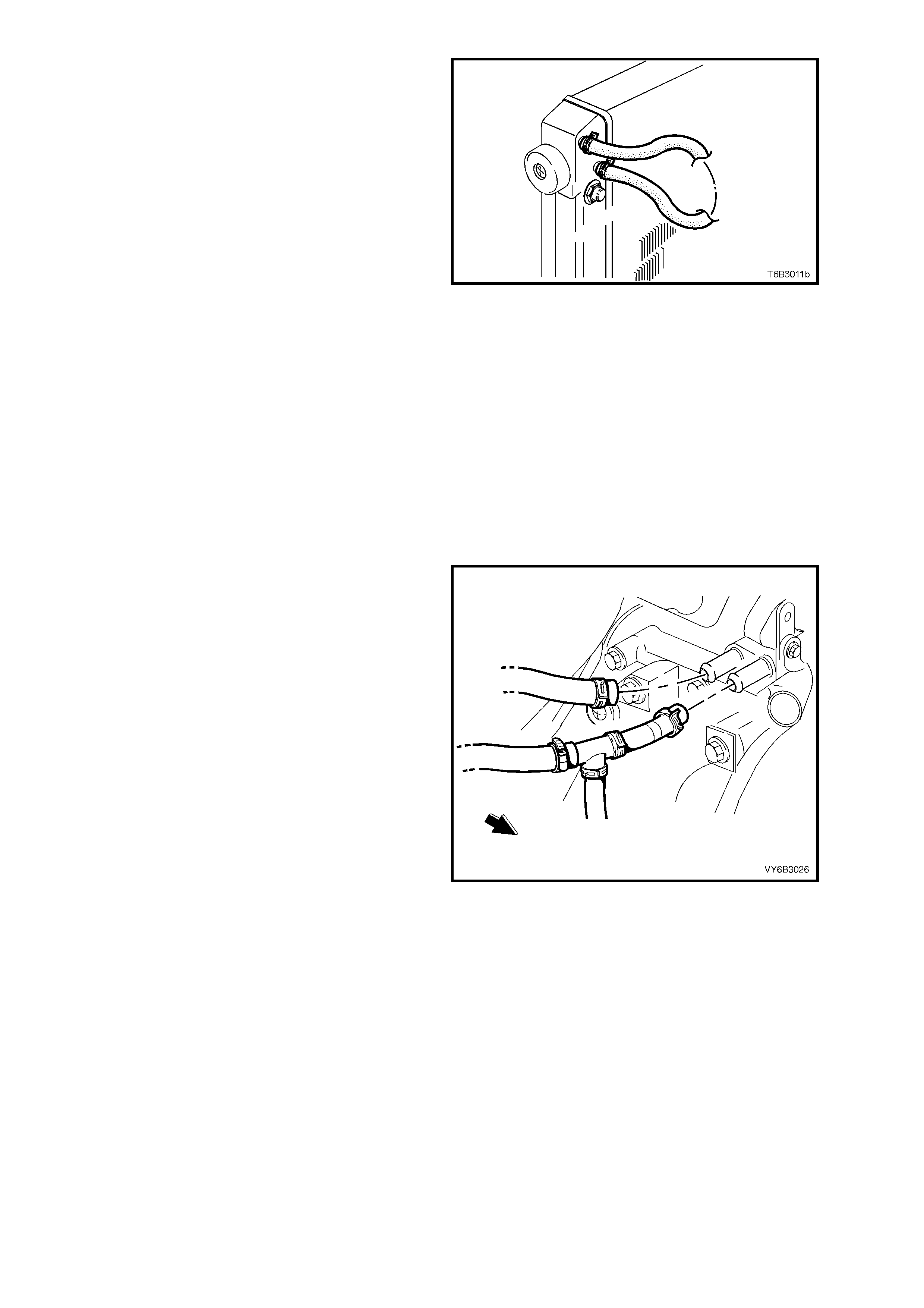
2. Remove both heater hose connections from
the coolant pump, then seal both pump
openings , using a piece of s crap hose and two
hose clamps.
3. Fit a lead-awa y hose t o the therm os tat housing
and a length of hose between the coolant
pump outlet fitting and the flushing equipment.
4. Connect and operate the flushing equipment
as recommended by the manufacturer.
5. Cont inue flushing unt il the water f rom the lead-
away hose runs clear.
6. Reinstall all disconnected hoses, ensuring that
hose clamps are positioned correctly and/or
tightened.
CAUTION: ALWAYS WEAR PROTECTIVE
SAFETY GLASSES WHEN WORKING WITH
SPRING TYPE HOSE CLAM PS. FAILURE T O DO
SO COULD RESULT IN EYE INJURY.
7. Fill the cooling system. Refer 2.3 DRAINING
AND FILLING COOLING SYSTEM, in this
Section.
8. Pressure test the cooling system to check for
leaks. Refer to 2.8 PRESSURE TESTING, in
this Section.
Figure 6B3-27
Heater Hoses and Core:
1. It is assumed that the following have already been carried out:
a. The engine is at room temperature.
b. The screw-on pressure cap has been removed.
c. The coolant has been drained.
2. Set the heater control to maximum.
3. Disconnect the heater hose (1) from the rear
coolant pump fitting (spring type clamp) and
the other Hose (2) from the T-piece (worm
drive hose clamp), leaving the T-piece and
coolant surge tank hose still connected, as
shown.
4. Direc t the hose disconnec ted from the T- piece,
into a suitable container and the other hose to
the flushing gun.
5. Connect and operate the flushing equipment
as recommended by the manufacturer.
6. Cont inue flushing unt il the water f rom the lead-
away hose runs clear.
7. Reinstall all disconnected hoses, ensuring that
hose clamps are positioned correctly and/or
tightened.
CAUTION: Always wear protective safety
glasses when working with spring type hose
clamps. failure to do so could result in eye
injury.
Figure 6B3-28
8. Fill the cooling system. Refer 2.3 DRAINING AND FILLING COOLING SYSTEM, in this Section.
9. Pressure test the cooling system to check for leaks. Refer to 2.8 PR ES SUR E TE STING, in this Section.
Coolant Surge Tank and Hose:
1. It is assumed that the following have already been carried out:
a. The engine is at room temperature.
b. The screw-on pressure cap has been removed.
c. The coolant has been drained.
2. Remove the coolant surge tank hose from the T-piece at the coolant pump and direct the open end into a
suitable container.
3. Connect the flushing equipment to the threaded surge tank opening, then operate the equipment as
recommended by the manufacturer.
4. Continue flushing until the water from the lead-away hose runs clear.
5. Reinstall all disconnected hoses, ensuring that spring hose clamps are positioned correctly and/or tightened.
CAUTION: ALWAYS WEAR PROTECTIVE SAFETY GLASSES WHEN WORKING WITH SPRING TYPE HOSE
CLAMPS. FAILURE TO DO SO COULD RESULT IN EYE INJURY.
6. Fill the cooling system. Refer 2.3 DRAINING AND FILLING COOLING SYSTEM, in this Section.
7. Pressure test cooling s ystem , refer to 2.8 PRESSU RE TEST ING in this Section a nd check for exter nal coolant
leaks.
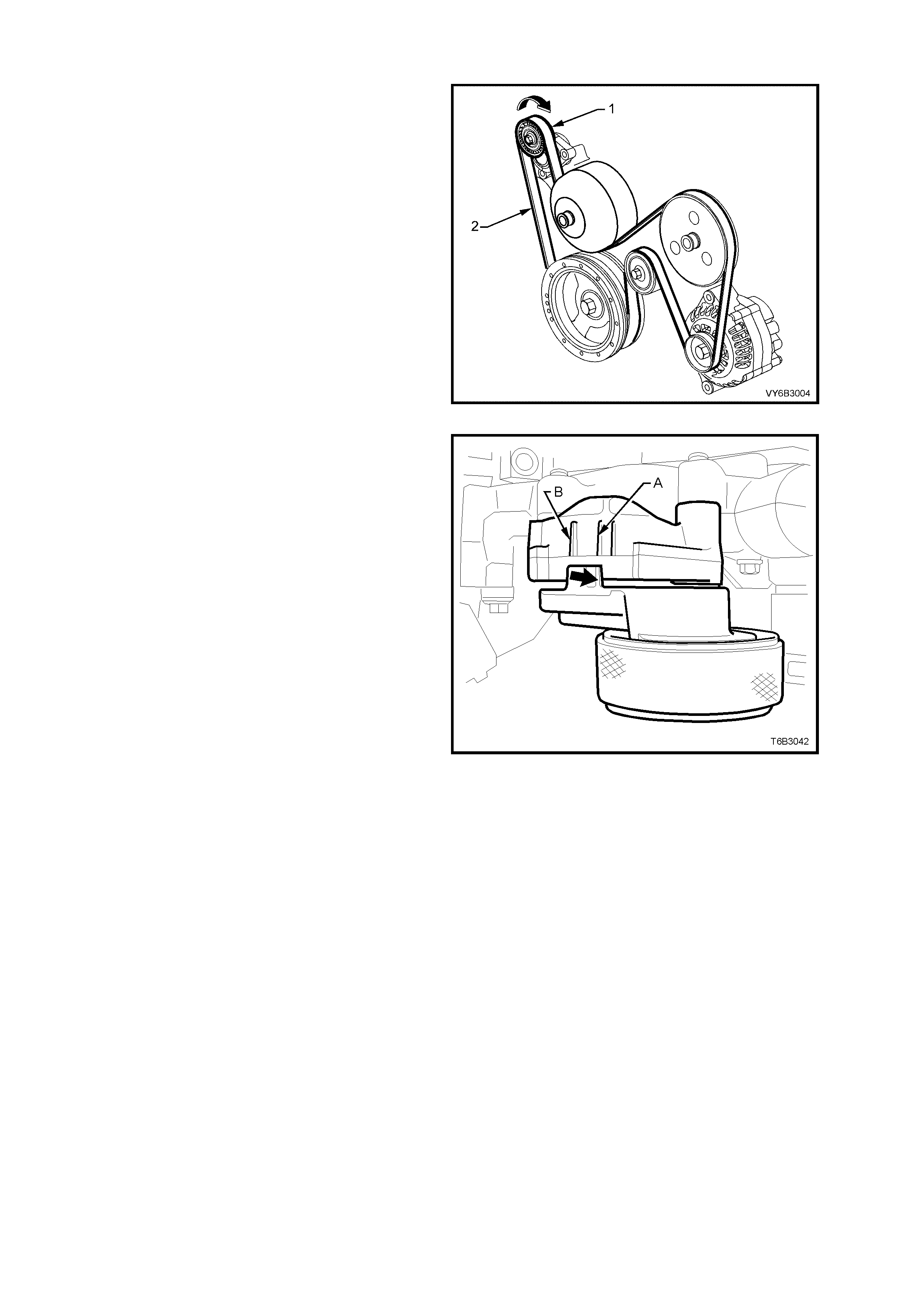
2.6 ENGINE ACCESSORY DRIVE BELT TENSION
Drive belt tension is provided by a tensioner
assembly (1). The tensioner is an idler pulley
mounted on a s pring- load ed arm that m aintains th e
drive belt (2) at the correct tension, without
imposing undue loads on the various components.
Figure 6B3-29
Drive belt tension is within the prescribed limits if
the indicator (bold arrow) on the tensioner is
between points ‘A’ and ‘B’ on t he tensi oner brac ket
.
If replacement is indicated, refer to 2.7 ENGINE
ACCESSORY DRIVE BELT, in this Section.
Figure 6B3-30
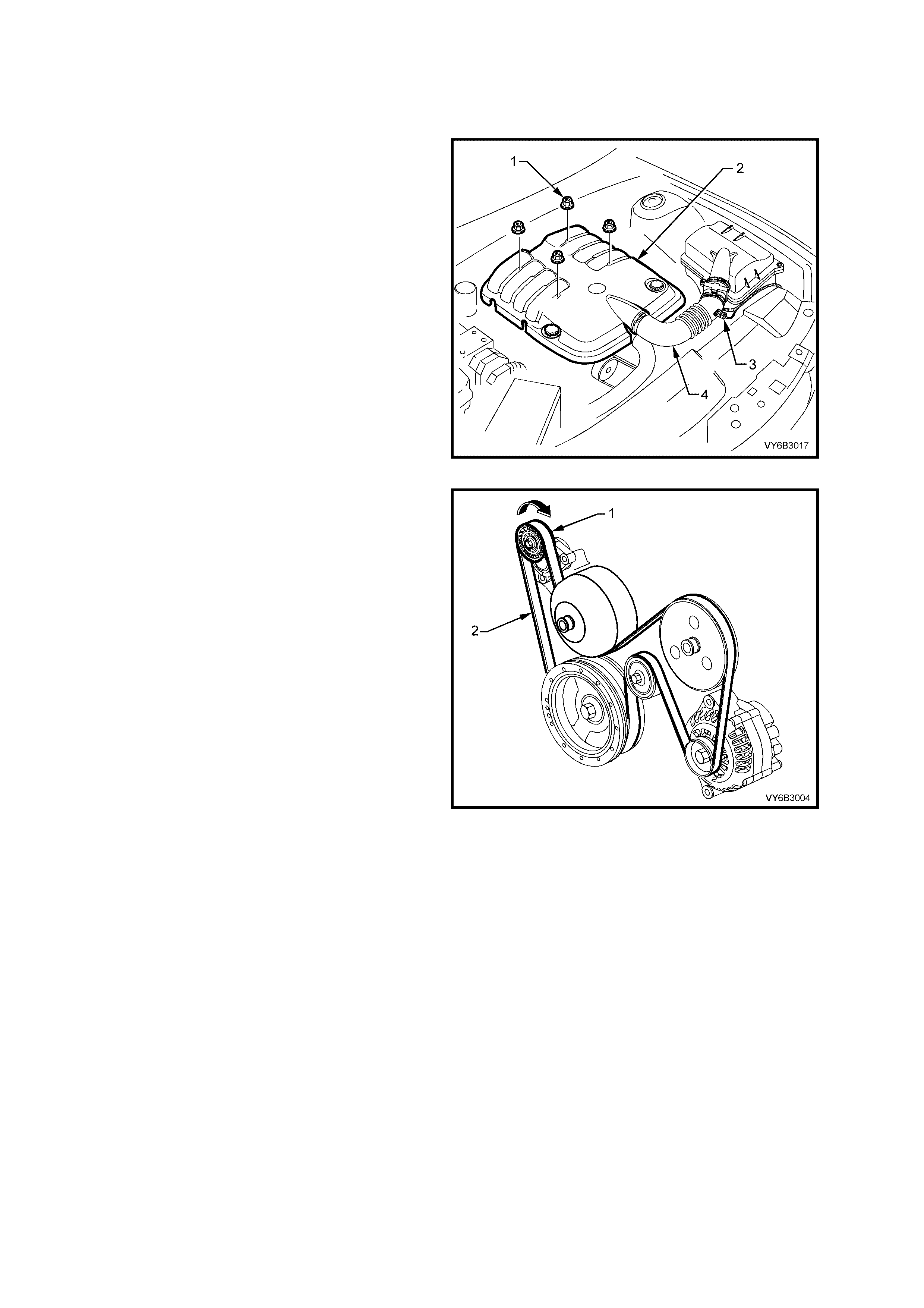
2.7 ENGINE ACCESSORY DRIVE BELT
LT SECTION NO. – 01-003
REMOVE
1. Remove engine dress cover decorative nuts
(1), then remove the cover (2).
Figure 6B3-31
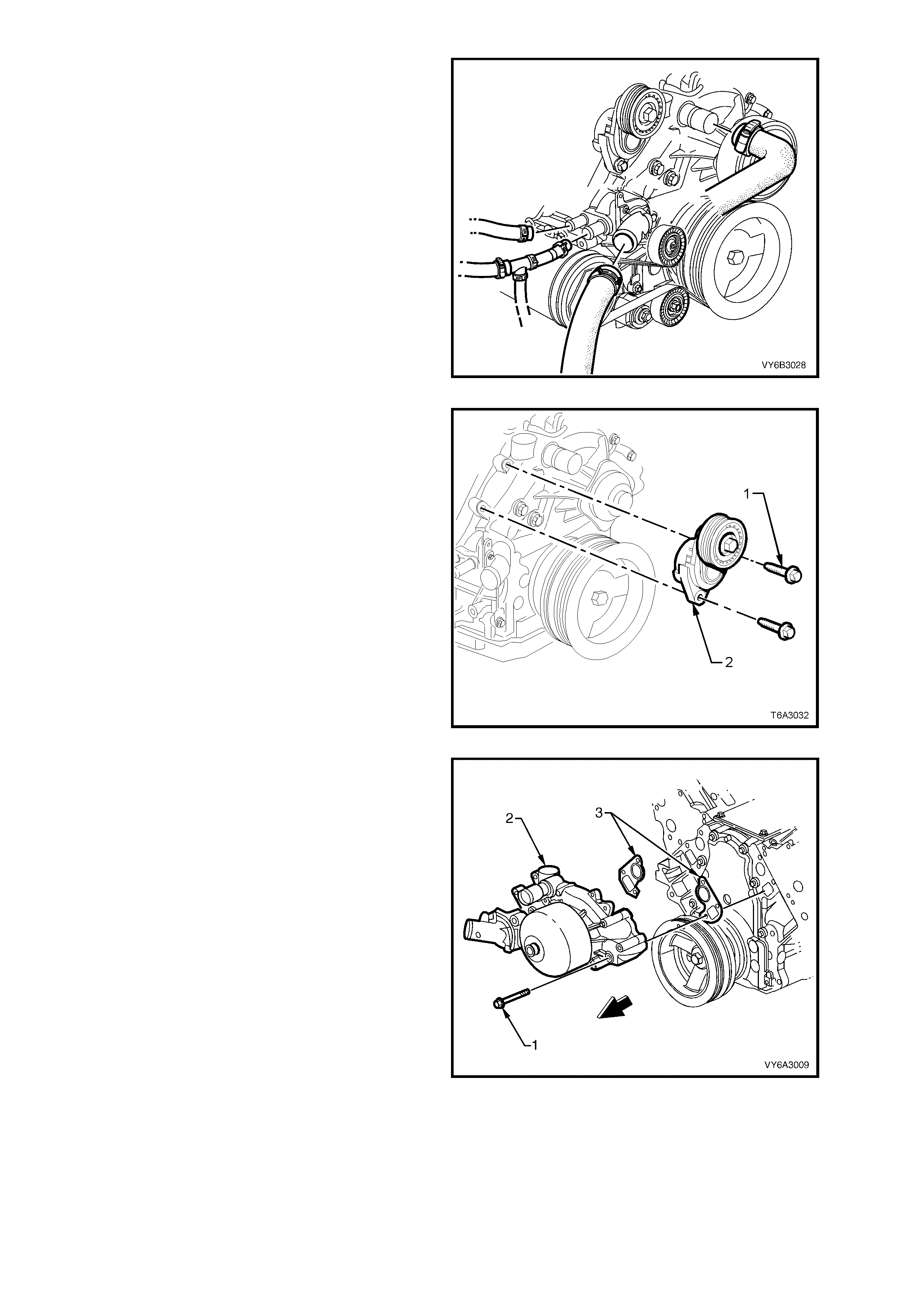
2. Using a 15 mm ring spann er, rotate the engi ne
accessory drive belt tensioner (1) in the
direction indicated, to reduce belt tension.
3. While holding the tensioner in the reduced
tension position, remove the accessory drive
belt from the engine, taking note of the belt
routing.
Figure 6B3-32
INSPECT
The four views in Figure 6B3-33 show the various
stages of drive belt wear, to assist in belt
replacement decisions.
NOTE: Condition of the belt ribs can be better
assessed if the belt is wrapped over the coolant
pump drive pulley.
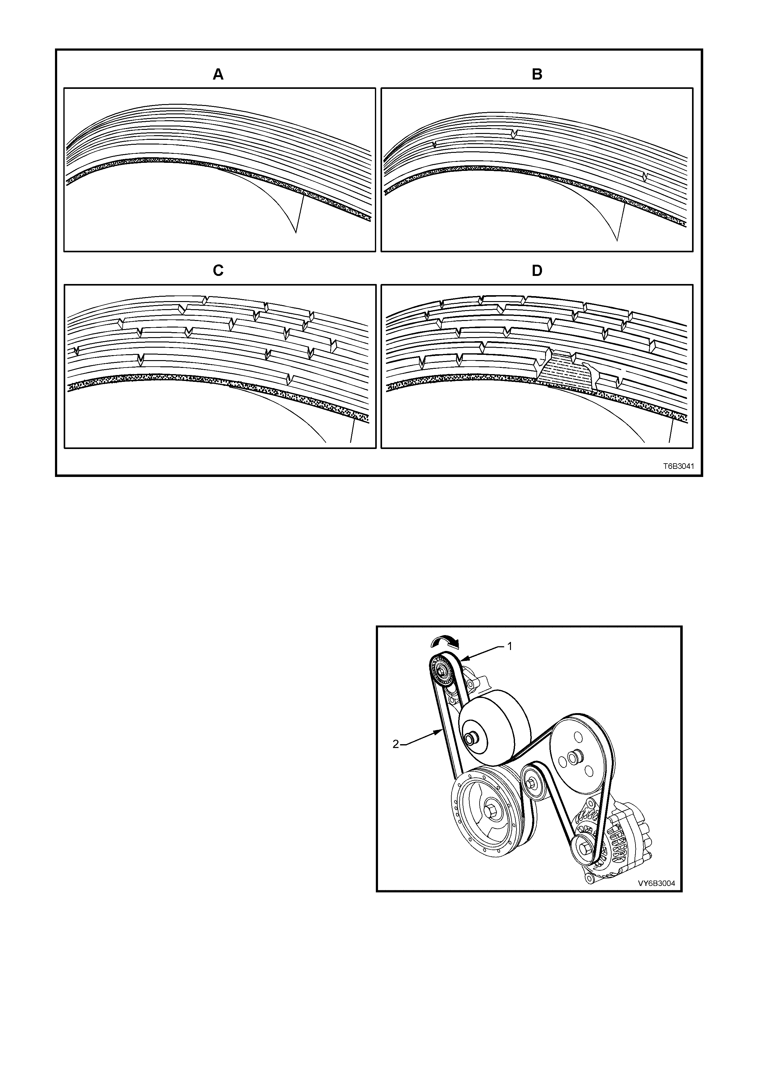
Figure 6B3-33
Legend:
A New Belt: No cracks or chunks.
B Moderately Used Belt: Few cracks, wi th some wear on the ribs and in the grooves. Belt replacement not required.
C Severely Used Belt: Several cracks per 30 mm. Should be replaced before chunking occurs
D Failed Belt: Separation of rib material from backing (chunking). Belt must be replaced immediately.
REINST ALL
1. W hile having an assistant hold the tens ioner in
the unloaded position (arrow) with a 15 mm
ring spanner, ins tall the engin e accessor y drive
belt, routing in the same manner as noted on
removal and as shown.
Figure 6B3-34
2.8 PRESSURE TESTING
SCREW-ON PRESSURE CAP TESTING
1. Allow engine to cool to ambient temperature
(less than 50°C), then remove radiator cap.
CAUTION: Do not remove screw-on pressure
cap while the engine coolant temperature is
above 50°
°°
° C, as personal injury will most likely
occur.
2. Thoroughly clean the threads and internal cap
parts, using clean cloth and water.
3. Install the Screw-on Cap Test Adaptor J
24460-92 onto a commercially available
cooling system pressure tester (2).
4. Install the pressure cap (1) onto the male
threaded half of the Test Adaptor J 24460-92,
then slowly pressurise the cap using the
pressure tester hand pump, noting the point at
which the cap unloads.
The cap is serviceable if it unloads slightly
above a pressure of 125 kPa and holds
pressure above 95 kPa. Should the cap fail to
reach or hold the specified pressures, install a
new pressure cap.
5. Prior to instal lin g s c r ew-on pres s ure c ap, c heck
that the coolant surge tank filler neck threads
and cap seating surface are clean and
undamaged.
Figure 6B3-35
COOLING SYSTEM PRESSURE TESTING
1. Allow engine to cool to ambient temperature
(less than 50° C), then check that the coolant
level is correct.
CAUTION: Do not remove screw-on pressure
cap while the engine coolant temperature is
above 50°
°°
° C, as personal injury will most likely
occur.
2. Carefully remove the screw-on pressure cap.
3. Connect the female half of Test Adaptor J
24460-92 to a commercially available cooling
system pressure tester, then install the
assembly to the coolant surge tank filler neck.
Dry any residual coolant around radiator filler
neck with compressed air. Pressurise cooling
system to no more than 110 kPa and check
for leaks at the following points:
a. All hoses and hose connections.
b. Radiator seams and core.
c. Corroded or faulty engine core plugs.
d. Coolant pump and gaskets and O-ring seals.
e. Vehicle heater system.
f. Check engine oil dipstick for evidence of
engine oil cont aminatio n wi th coolant .
4. If pressure will not hold, there is a leak in the
cooling system. Repair as required.
NOTE: If visible loss of coolant is not evident from
pressure testing, then the use of a dye and black
light, may be necessary. Refer to 3.4 BLACK
LIGHT AND DYE LEAK DIAGNOSIS M ETHOD, in
this Section.
Figure 6B3-36
2.9 THERMOSTAT
LT SECTION NO. – 00-350
REMOVE
1. Allow engine to cool to ambient temperature
(less than 50° C), then slowly remove the
screw-on pressure cap from the coolant surge
tank.
CAUTION: Do not remove screw-on pressure
cap while the engine coolant temperature is
above 50°
°°
° C, as personal injury will most likely
occur.
2. Drain the engine coolant into a suitable
container. Refer to 2.3 DRAINING AND
FILLING COOLING SYSTEM, in this Section.
3. Disconnect radiator hose from coolant inlet at
the thermostat housing.
CAUTION: Always wear protective safety
glasses when working with spring type hose
clamps. Failure to do so could result in eye
injury.
Figure 6B3-37
4. Remove thermostat housing bolts (1), then
remove the cover (2), thermostat and O-ring
seal from the coolant pump.
Figure 6B3-38
TEST
1. Suspend thermostat and a suitable thermometer in a container of 50/50 extended life anti-freeze coolant
(conforming to GM6277M) and water.
NOTE: Neither the thermostat nor thermometer should rest on the bottom of the container because of uneven
concentration of heat at this point when the container is heated.
2. Heat container until thermostat begins to open.
Agitate solution to ensure uniform temperature.
Note tem per atur e a nd ensu r e thermos tat op ens
within specified temperature range.
3. Continue heating the solution until the
thermostat is fully open. Again agitate the
solution and take note of the temperature
4. Install a new thermostat if it does not meet the
specified temperatures.
Thermostat Specifications
Opening Temperature 86° C
Fully Open Temperature 100° C
Figure 6B3-39
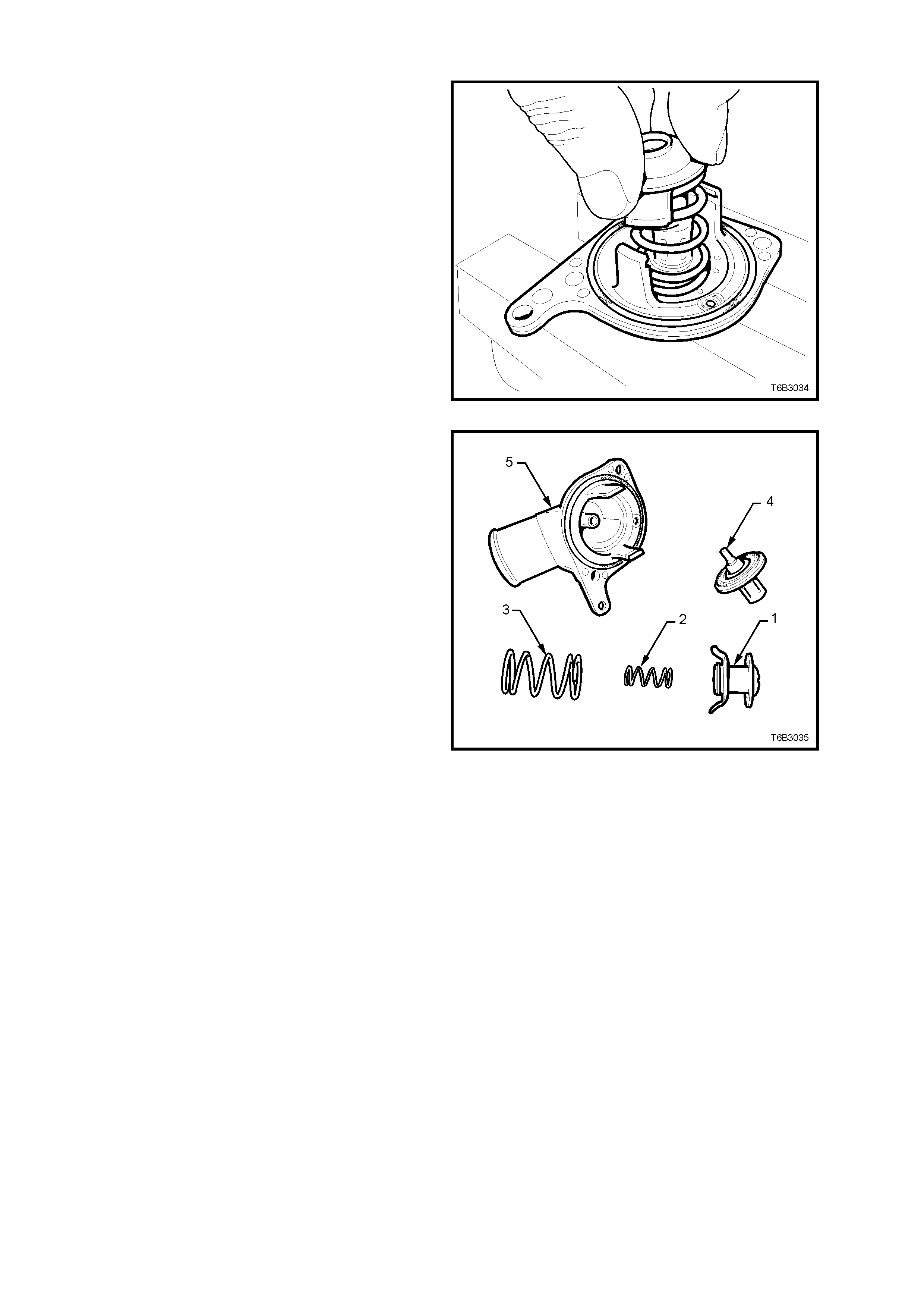
DISMANTLE
IMPORTANT: Only dismantle the thermostat if a
reverse flushing operation of the cylinder block is to
be carried out. If testing shows that r eplacement is
required, the thermostat and housing are only
serviced as a complete assembly.
1. Secur e the thermos tat housing by grip ping in a
vice fitted with soft jaws.
2. While compressing the springs with one hand,
rotate the retaining bar from the housing lugs
and release.
CAUTION: Wear safety glasses to avoid
potential eye injury.
Figure 6B3-40
3. Careful lay all parts out in order, for ease of
reassembly.
Legend:
1. Bypass Valve.
2. Bypass Valve Spring.
3. Thermostat Closing Spring.
4. Wax Pellet and Valve Assembly.
5. Thermostat Housing.
Figure 6B3-41
REASSEMBLE
Reassembly is the reverse of disassembly
procedures, except that the valve seat in the
therm ostat housing m ust be c hecked f or corros ion,
scratching or other damage and the valve seating
surface wiped with a clean rag.
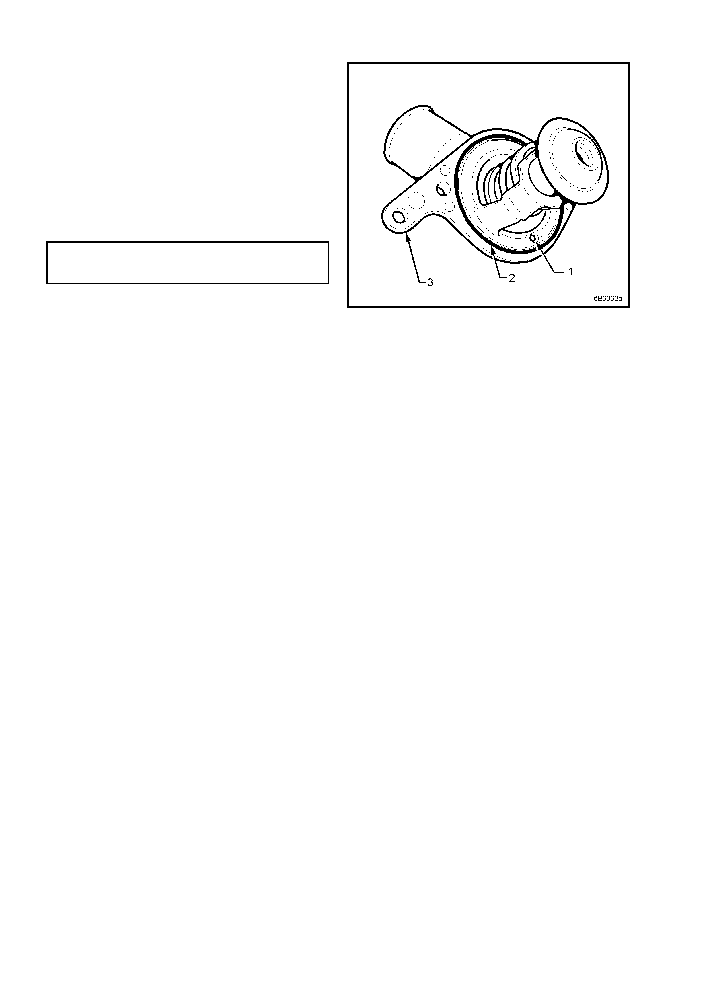
REINST ALL
1. Shake the thermostat assembly to ensure that
the air bleed check ball (1) in the housing is
free and not jammed.
2. Thoroughly clean the coolant pump to
thermostat housing sealing surfaces, taking
care not to scratch any machined alloy
surfaces.
3. Install thermostat assembly, with a new O-ring
(2), fitted to the coolant pump housing (3).
4. Install thermostat housing to coolant pump
housing attaching bolts and tighten to the
correct torque specification.
THERMOSTAT HOUSING TO
COOLANT PUMP BOLT
TORQUE SPECIFICATION 14 Nm
5. Install radiator hose and clamp to thermostat
housing.
CAUTION: Always wear protective safety
glasses when working with spring type hose
clamps. Failure to do so could result in eye
injury.
6. Refill cooling system, refer to 2.3 DRAINING
AND FILLING COOLING SYSTEM in this
Section.
7. Check for cooling system leaks, refer to
2.8 PRESSURE T EST ING in this Section.
Figure 6B3-42

2.10 COOLANT RECOVERY SURGE TANK
LT SECTION NO. – 01-140
REMOVE
1. Allow engine to cool to ambient temperature
(less than 50° C), then slowly remove the
screw-on pressure cap from the coolant surge
tank.
CAUTION: Do not remove screw-on pressure
cap while the engine coolant temperature is
above 50°
°°
° C, as personal injury will most likely
occur.
2. Drain the engine coolant into a suitable
container. Refer to 2.3 DRAINING AND
FILLING THE COOLING SYSTEM, in this
Section.
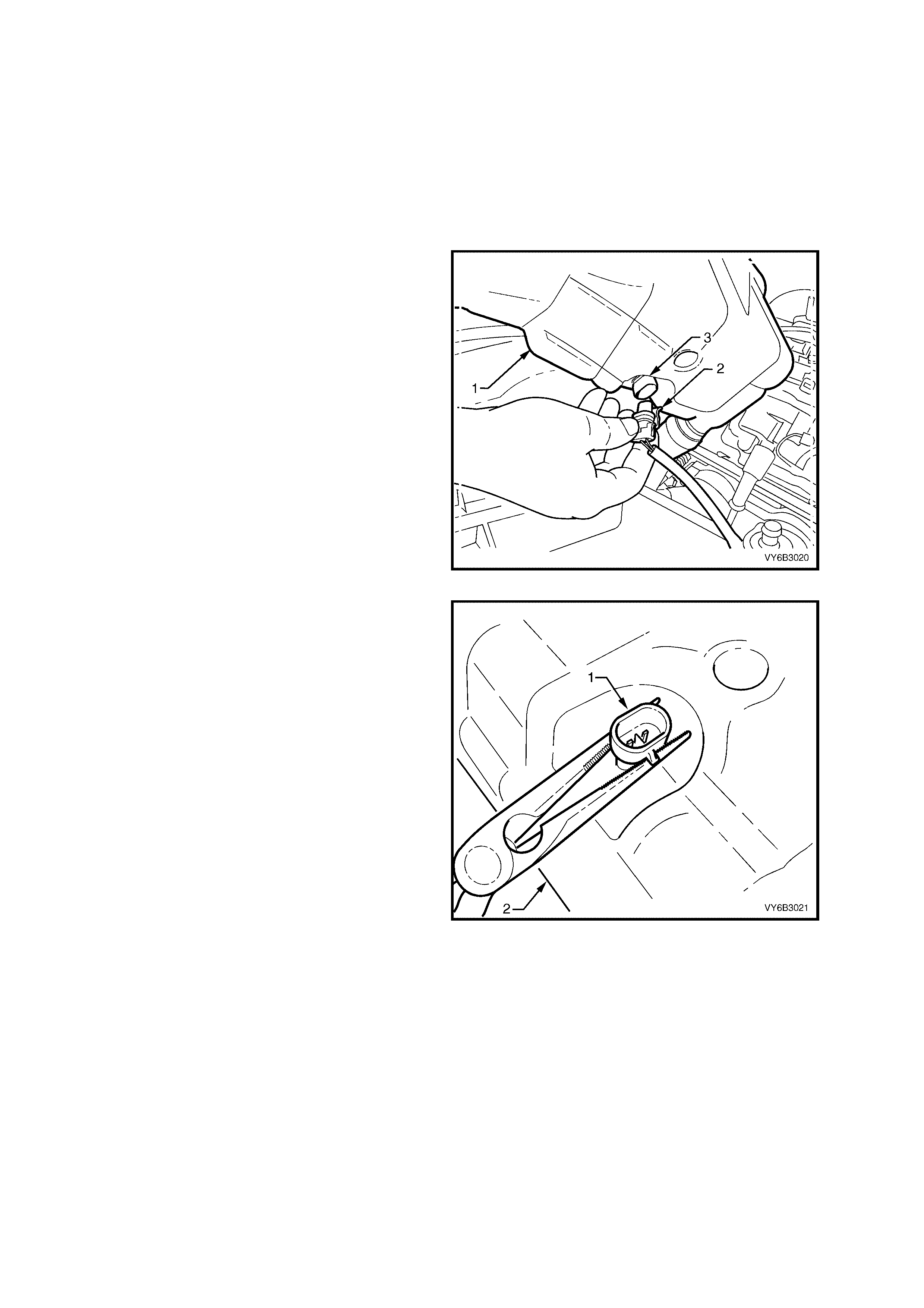
3. Disconnect radiator hose from surge tank inlet
fitting (1), vapour hose (2) and overflow hose
(3).
CAUTION: Always wear protective safety
glasses when working with spring type hose
clamps. Failure to do so could result in eye
injury.
Figure 6B3-43
4. Grasp the surge tank (1) firmly with both
hands, pivot as shown (arrow ‘A’) to dislodge
the surge tank (1) from the rear anchor point,
then pull inboard (arrow ‘B’) toward the engine
to remove from the anchor point attached to
the inner fender skirt.
Figure 6B3-44
INSPECT
1. Drain contents from surge tank assembly.
2. Clean surge tank assembly with water and dry, using compressed air.
CAUTION: Wear safety glasses to avoid eye injury.
3. Check surge tank and assembly for damage, e.g. abrasions, cracks or distortion. Install a new surge tank
assem bl y as required.
REINST ALL
Reinstallation of the surge tank assembly is the reverse of removal procedures, noting the following points:
1. Refill cooling system, refer to 2.3 DRAINING A ND FILLING COOLING SYSTEM in this Section.
2. Check for cooling system leaks, refer to 2.8 PRES SUR E TESTING in this Section.
2.11 ENGINE COOLANT LEVEL SWITCH
REMOVE
1. Remove the recovery surge tank; refer
2.10 COOLANT RECOVERY SURGE TANK,
but leave the screw-on cap and all hoses still
connected.
NOTE: The coolant level switch does not contact
the coolant, so there should be no coolant loss
during this service procedure.
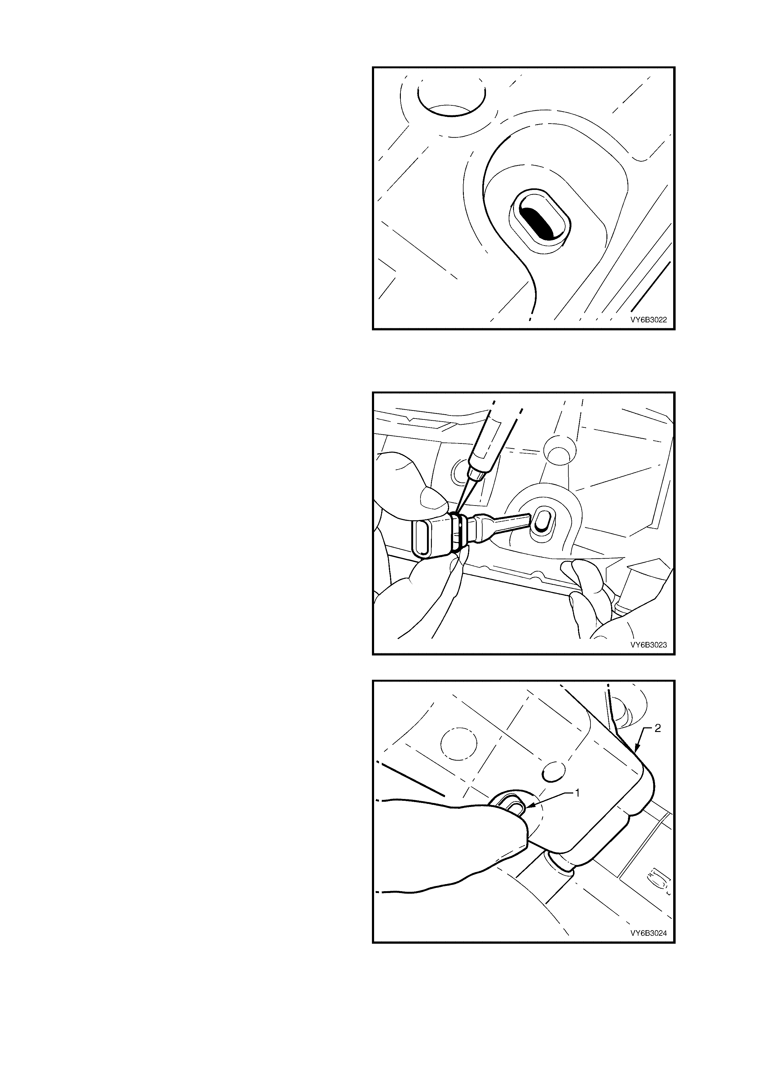
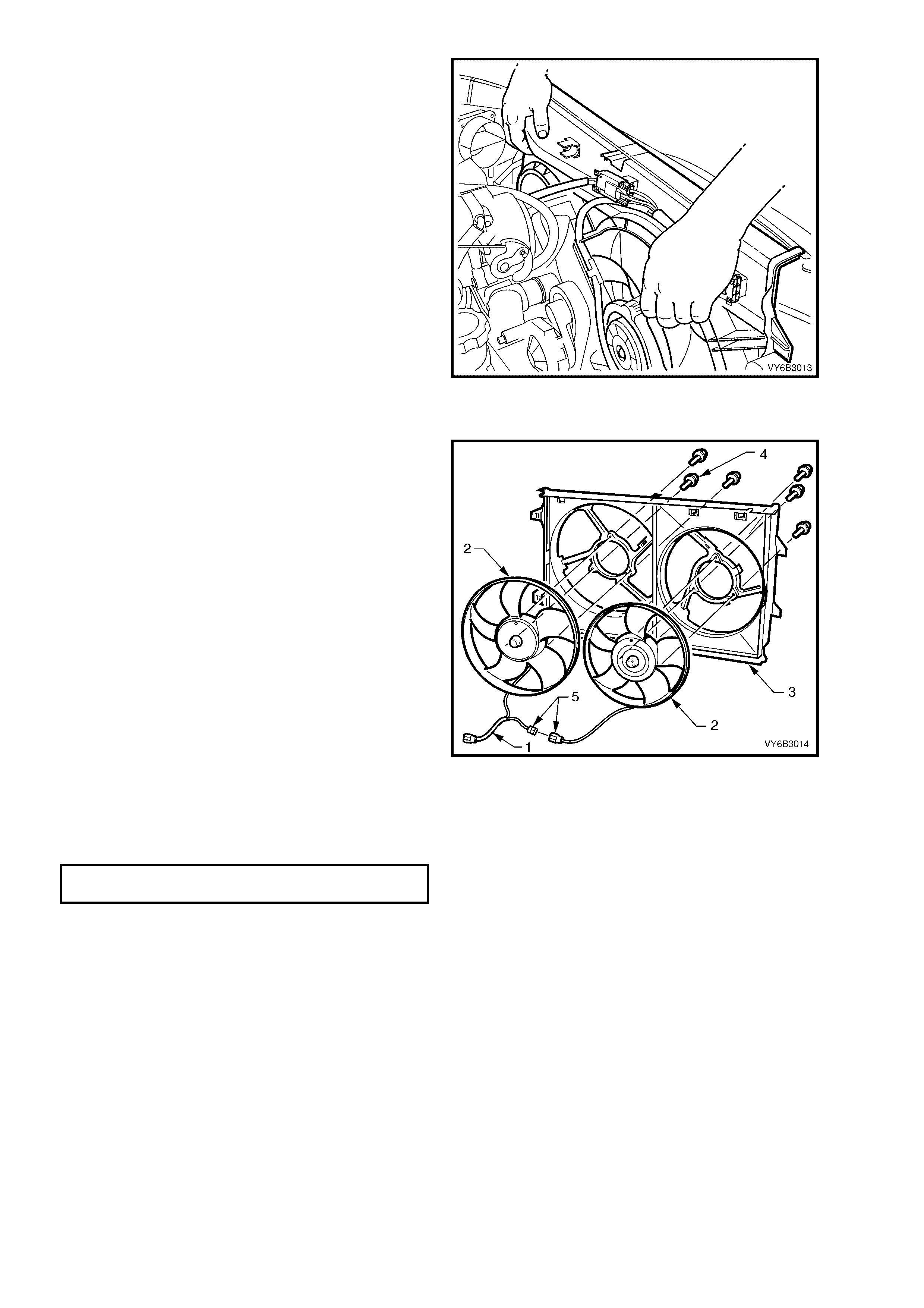
2. Position the recovery surge tank (1) to gain
access to the engine coolant level switch (3),
as shown.
3. Disconnect the coolant level switch harness
connector (2), after releasing the locking tang.
Figure 6B3-45
4. Using commercially available long nose pliers,
place the opened nose of pliers each side of
the coolant switch (1) between the recovery
surge tank (2) and the coolant level switch as
shown.
5. Using the reco ver y surge tank (2) as a pl ace of
purchase, dislodge the coolant switch (1) from
the recovery surge tank by wiggling the switch
gently side to side while levering the switch in
an upward direction away from the tank.
NOTE: The switch is a very firm fit and will requ ire
a little force to dislodge it from the recovery surge
tank.
Figure 6B3-46
INSPECT
1. Clean the coolant level switch and tank
aperture area if required using compressed air.
CAUTION: Wear safety glasses to avoid eye
injury.
2. Check for free movement of the coolant level
float located in the recovery surge tank, by
shaking the tank and listening/observing float
movement.
3. Check the recovery surge tank assembly for
damage, e.g. abrasions, cracks or distortion.
Install a new surge tank assembly as requir ed,
refer to 2.10 COOLANT RECOVERY SURGE
TANK, in this Section.
4. Check the operation of the coolant level
switch. For coolant level switch diagnostics
refer to COOLANT LEVEL SWITCH, in
Section 6C3-2C FUNCTION CHECKS – GEN
III V8 ENGINE.
Figure 6B3-47
REINST ALL
Reinstal lation of th e coolan t level switc h and surg e
tank assembly is the reverse of removal
procedures , not ing the fo llo wing points :
1. Apply a small amount of moisture to the
coolant level switch O-ring seal, prior to
reinstallation.
Figure 6B3-48
2. Using suitable hand protection (glove), install
the coolant level switch (1) by pushing it firmly
into the recovery surge tank (2), aperture.
CAUTION: As the force required to reinstall the
switch could cause injury from sharp edges on
the switch, hand protection is strongly
recommended.
3. Check the coolant level switch is completely
home in the surge tank aperture.
4. Reinstall the coolant recovery tank. Refer
2.10 COOLANT RECOVERY TANK, in this
Section.
5. Start the engine and check f or coolant leak age
from the recovery tank area.
Figure 6B3-49
2.12 OIL PAN UNDER-TR AY
REMOVE
1. Raise front of vehicle and support on safety
stands. Refer to Section 0A GENERAL
INFORMATION in the MY 2003 VY and V2
Series Service Information, for the location of
jacking and support points.
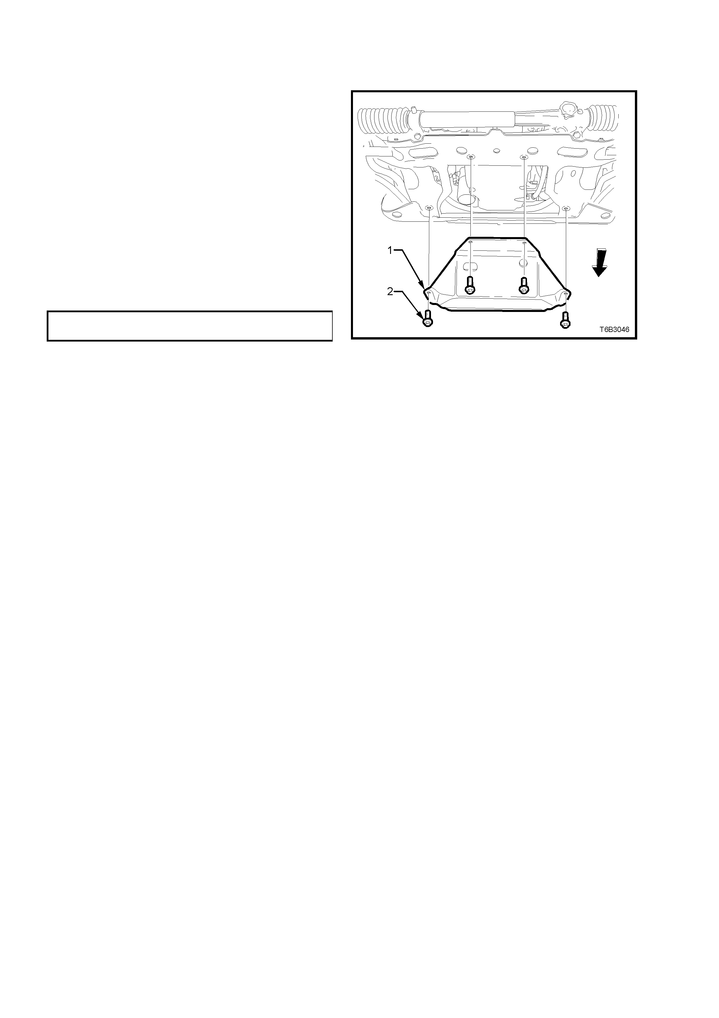
2. Remove the four bolts securing the under-tray
to the crossmember and remove tray from
vehicle.
REINST ALL
1. While holding the under-tray (1) up to the
crossmember with one hand, install all four
securing bolts (2).
2. Tighten all four bolts (2) to the correct torque
specification. DO NOT OVER TIGHTEN.
OIL PAN UNDER-TRAY BOLT
TORQUE SPECIFICATION 30 Nm
Figure 6B3-50
2.13 AIR BAFFLES
REPLACE
1. Raise front of ve hic l e a nd s uppor t on s af et y sta nds . R ef er to Section 0A GENERAL INFORMATION in the M Y
2003 VY and V2 Series Service Information, for the location of jacking and support points.
2. Remove the oil pan under-tray. Refer 2.12 OIL PAN UNDER-TRAY, in this Sec ti o n.
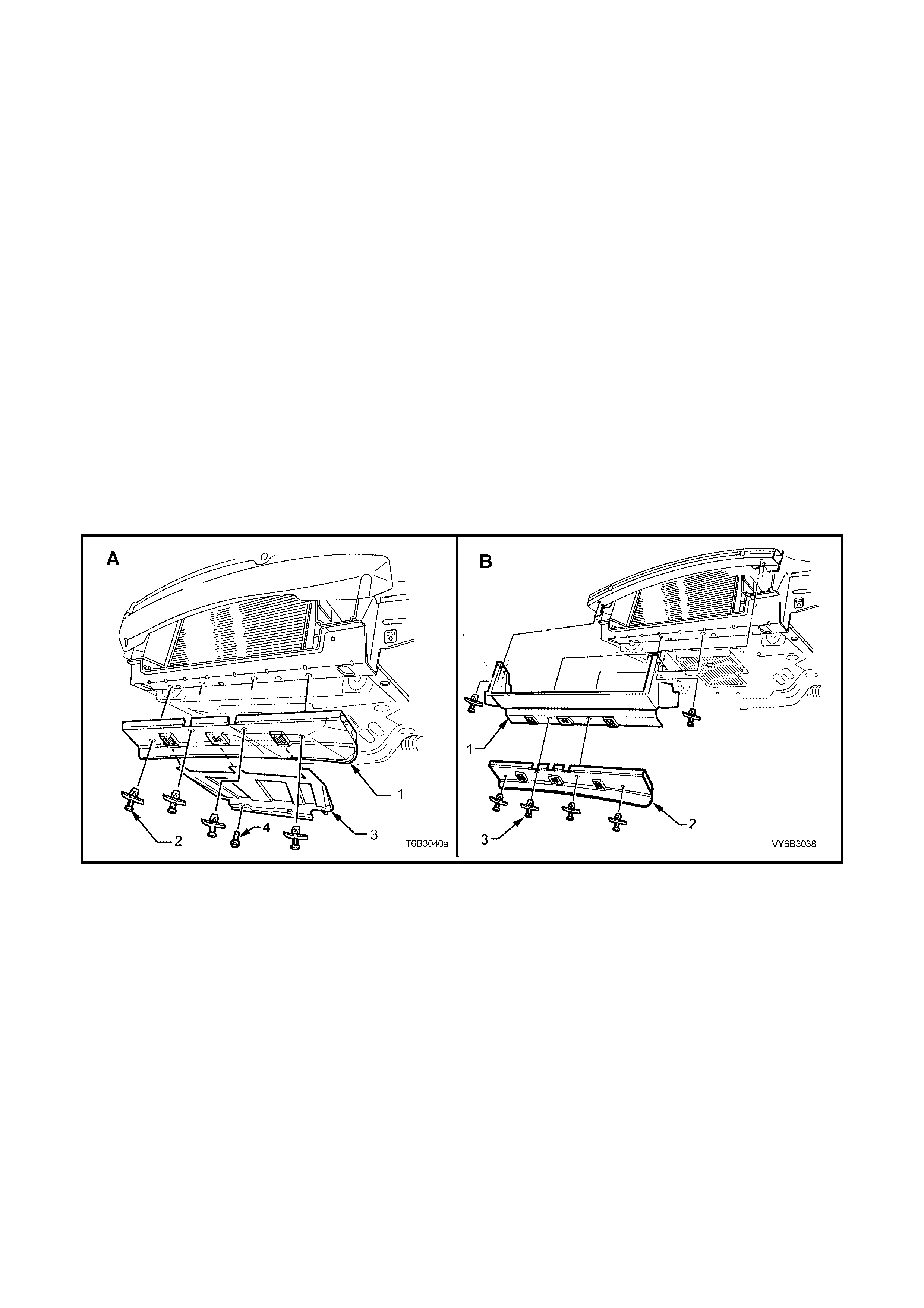
Standard GEN V8 Engine (View ‘A’)
3. Rem ove the lower air chute extension screws (4) (two places), lower the rear of the lower air chute extension
(3), slide the baffle rearward to disengage from the lower air chute (1), then remove from the vehicle.
4. Remove lo wer front baffle (1) to crossmember f asteners (2) (four places) and remove front air chute baffle (1)
from the vehicle.
SS Models, Including Utility (View ‘B’)
5. Remove the front bumper bar, refer to Section 1D BUMPER BARS.
NOTE: W hile the air duc t c an be rem oved without f irst rem oving t he bumper bar, ex cess ive distor tion of the duct is
required, both on removal and reinstallation. Also the reinstallation of the two upper scrivets is extremely difficult.
6. Remove the two scrivet fasteners (3) securing both the lower front baffle (2) and the duct (1) to the front
suspension crossmember, then remove the lower front baffle from the vehicle.
7. Rem ove the two scr ivet fas teners (4) securing t he air duct (1), t o the f ront upper panel as sembl y, the n remove
the duct from the vehicle.
8. Reinstallation is the reverse to removal procedures.
NOTE 1: Do not overtighten any of the fasteners.
NOTE 2: View ‘A’ in Figure 6B3-51 shows the standard GEN III lower baffle, while view ‘B’ shows the SS model
arrangement for all, including Utility.
Figure 6B3-51
2.14 COOLANT PUMP
LT SECTION NO. – 00-325
REMOVE
NOTE: Apart from the rear cover, O-ring and thermostat assembly, the coolant pump is not serviceable and if found
to be faulty must be replaced as an assembly.
1. Allow engine to c ool to am bie nt temperatur e ( les s th a n 50 ° C), then slowly remove screw-on pressure cap from
the coolant surge tank.
CAUTION: Do not remove screw-on pressu re cap w hile the engine coolant temperature is above 50 °
°°
° C, as
personal injury will most likely occur.
2. Disconnect battery ground lead.
IMPORTANT: Disconnection of the battery affects certain vehicle electronic systems. Refer to
Section 00 CAUTIONS, 5. BATTERY DISCONNECTION PROCEDURES befor e disc onn ec tin g the battery.
3. Remove engine dress cover decorative nuts
(1), then remove the cover (2).
4. Lift the locking lever on the Intake Air
Temperature (IAT) sensor wiring harness
connector (3), then remove the connector.
5. Loosen the two intake duct clamps, then
remove the duct (4).
Figure 6B3-52
6. Rem ove engine accessory drive belt (2), using
a 15 mm ring spanner to move the belt
tensioner (1) in th e direc tio n ind icated. Ref er t o
2.7 ENGINE ACCESSORY DRIVE BELT, in
this Section.
Figure 6B3-53
7. Drain engine coolant. Refer to 2.3 DRAINING
AND FILLING COOLING SYSTEM, in this
Section.
8. Disconnect both heater hoses, the outlet and
inlet hoses from the coolant pump.
CAUTION: Always wear protective safety
glasses when working with spring type hose
clamps. Failure to do so could result in eye
injury.
Figure 6B3-54
9. Remove the two bolts (1) securing the drive
belt tensioner (2) to the coolant pump housing
and set the tensioner to one side.
Figure 6B3-55
10. Loosen, then remove the six bolts (1) securing
the coolant pump (2) to the cylinder block.
11. If neces s ar y, use a sof t f ac ed ham mer to lig htly
tap coolant pump housing (2) to dislodge it
from the cylinder block.
12. Remove coolant pump gaskets (3) and discard.
Figure 6B3-56
DISMANTLE
NOTE: Apart f rom the s er vice oper ations des c ribe d
here, there are no other serviceable parts in the
coolant pump assembly and if required, then the
assembly must be replaced as a complete unit.
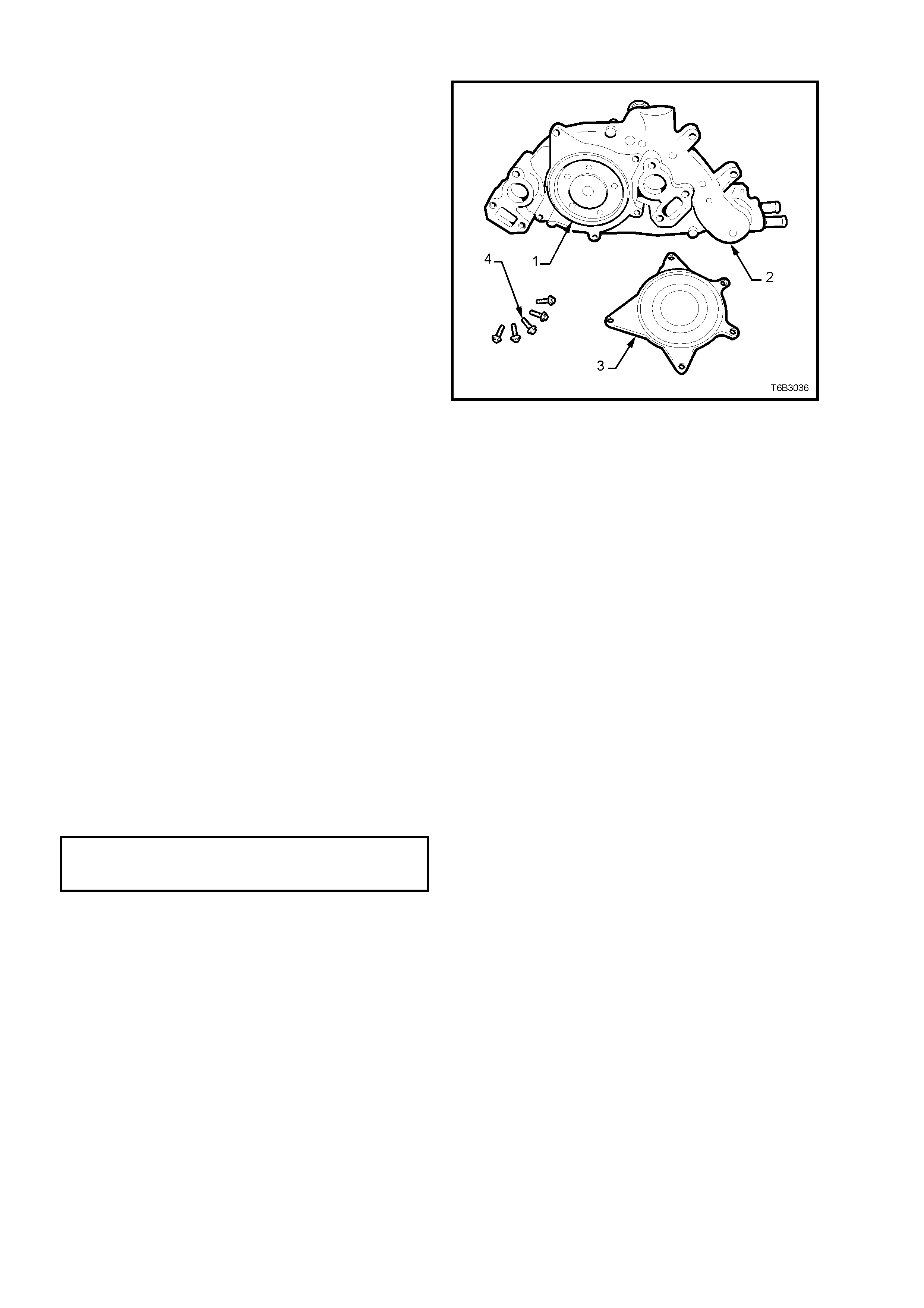
1. If required, remove the five bolts (4) securing
the rear cover (3) to the coolant pump (2). Tap
with a sof t faced h amm er to dislodge the cover
from the pump body.
2. Remove the seali ng O-ring (1) f rom the coolant
pump body (2).
3. For thermostat remove, test and reinstall
procedures, refer to 2.9 THERMOSTAT in this
Section.
Figure 6B3-57
CLEAN AND INSPECT
1. Remove the old gasket or gasket material from the coolant pump sealing surfaces and cylinder block, taking
care not to scratch the machined surfaces.
2. Clean all dirt and debris from the coolant pump housing.
3. Inspect the coolant pump for the following:
• Gasket surfaces for excessive scratches or gouging.
• Hose sealing surfaces for scratches, gouging or corrosion.
• Restrictions, corrosion or evidence of cavitation within the internal coolant passages or on the pump
impeller.
• Excessive side-to-side play in the pulley shaft.
• A loose belt pulley or a pulley with excessive wear or scoring on the belt tracking area.
• Evidenc e of c oolant leak age at th e cool ant out let hous ing or rear c over gas k et (if these p arts hav e not be en
removed).
• Leakage at the coolant pump vent hole. A stain around the vent hole is acceptable. If leakage occurs
(dripping) with the engine running and the cooling system pressurised, replace the coolant pump.
REASSEMBLE
1. Install a new O-ring seal to the cleaned groove in the pump housing, then install the cover and retaining bolts.
2. Gradually tighten every second bolt until the correct torque specification is reached.
COOLANT PUMP
REAR COVER BOLT
TORQUE SPECIFICATION 14 Nm

REINST ALL
Reinstallation is the reverse to removal except for the following items:
1. Ensure that the coolant pump and cylinder block surfaces are clean and dry.
2. Using two bolts on each side as guides, install NEW gaskets over them and reinstall the coolant pump to the
cylinder bl oc k.
3. Reinstall remaining bolts and tighten to the correct torque specification, in two stages.
COOLANT PUMP BOLT
TORQUE SPECIFICATION Stage 1: 15 Nm
Stage 2: 25 Nm
4. Reinstall the engine accessory drive belt tensioner and attaching bolts, tightening to the correct torque
specification.
ENGINE ACCESSORY DRIVE
BELT TENSIONER BOLT
TORQUE SPECIFICATION 50 Nm
5. Reinstall all removed radiator hoses and clamps.
CAUTION: Always wear protective safety glasses when working with spring type hose clamps. Failure to
do so could result in eye injury.
6. Reinstall the engine accessory drive belt. Refer 2.7 ENGINE ACCESSORY DRIVE BELT, in this Section.
7. Refill cooling system, refer to 2.3 DRAINING A ND FILLING COOLING SYSTEM in this Section.
8. Check for cooling system leaks, refer to 2.8 PRES SUR E TESTING in this Section.
2.15 COOLING FANS & SHROUD ASSEMBLY
LT SECTION NO. – 01-105
REMOVE
1. Allow engine to cool to ambient temperature (less than 50° C), slowly loosen screw-on pressure cap at the
coolant surge tank to relieve any residual coolant pressure, then remove.
CAUTION: Do not remove screw-on pressu re cap w hile the engine coolant temperature is above 50 °
°°
° C, as
personal injury will most likely occur.
2. Disconnect battery ground lead.
IMPORTANT: Disconnection of the battery affects certain vehicle electronic systems. Refer to
Section 00 CAUTIONS, 5. BATTERY DISCONNECTION PROCEDURES befor e disc onn ec tin g the battery.
3. Remove engine dress cover decorative nuts
(1), then remove the cover (2).
4. Lift the locking lever on the Intake Air
Temperature (IAT) sensor wiring harness
connector (3), then remove the connector.
5. Lift the locking lever on the Mass Air Flow
(MAF) sensor, then remove the connector.
6. Loosen the two intake duct clamps, one at the
throttle body and the other at the MAF to air
cleaner c onnect ion. Rem ove the duct a nd MAF
as an assembly and carefully set to one side.
7. Drain engine coolant into a suitable, clean
container. Refer to 2.3 DRAINING AND
FILLING COOLING SYSTEM, in this Section.
8. Release the vapour hose from the radiator fan
shroud clips, remove the clamp securing the
hose to the radiator, remove the hose and
route to one side.
9. Remove the clamp securing the vapour hose to
surge tank at the radiator end. Remove the
hose and route to one side.
Figure 6B3-58
10. Remove the 4 radiator upper shroud retainers
(2) by carefully lifting the inner stud with a
sm all screwdriver . Lift the upper shroud (1), on
the right side first, to allow release of the
locating tab on the lef t han d end.
Figure 6B3-59
11. Remove the upper rad iator hos e clam ps (worm
drive at coolant pump and spring type at
radiator), then remove the hose (1) and set to
one side.
CAUTION: Wear eye protection when working
with spring type hose clamps.
Figure 6B3-60
12. Press the retaining tang on wiring harness to
cooling f an m otor wirin g ha rness connector (1),
then separate the connector halves.
Figure 6B3-61
13. While holding the shroud locking tang in the
release position, lift the shroud and fan
assembly upwards. Repeat for the second
side.
NOTE: While the automatic transmission fluid
cooling pipe is shown removed, this is not a
mandatory requirement for shroud removal. Pipe
has been s ho wn rem oved t o m ore c learly sho w the
shroud release method.
Figure 6B3-62
14. Lift the shr oud and f an assem bl y clear from the
engine bay, grasping the motor mounting
brackets.
IMPORTANT: Do not lift the assembly clear by
lifting on the fan rings as this will bend the fan
motor shaft and create an unnecessary vibration.
Figure 6B3-63
DISASSEMBLE
IMPORTANT: E ither f an is are n ot to be s eparated
from its fan motor. The assembly is carefully
balanced during manufacture and duplication of
this balance is not possible, on reassembly.
1. Separate the intermediate wiring harness
connector (5) and remove motor assembly
wiring harness (1) from the integral clips that
form a part of the shroud (3).
2. Remove screws (4) attaching the motor and
fan assemblies (2) to the shroud (3), then
remove the motor, fan and wiring (2) from the
shroud.
3. Repeat for the second fan, motor and wiring
harness, as required.
Figure 6B3-64
REASSEMBLE
Reassembly is the reverse of disassembly procedures, noting the following points:
1. Tighten motor to shroud attaching screws to the correct torque specification. Do not over-tighten.
FAN MOTOR TO SHROUD SCREW
TORQUE SPECIFICATION 5.0 Nm
2. Ensure that all wiring is routed correctly and secured by the shroud clips.
REINST ALL
Reinstallation of the cooling fan and shroud assembly is the reverse of removal procedures, noting the following
points:
1. Ensure that fan and shroud assem bly to radiator attaching clips are all fully engaged and that the two locking
tangs on the upper clips secure the shroud correctly.
2. Refill cooling system and test concentration levels. Refer 2.3 DRAINING AND FILLING COOLING SYSTEM
and TESTING COOLANT CONCENTRATION, in 2.2 COOLANT MAINTENANCE, both in this Section.
3. Check cooling fan operation, refer to Section 6C3 POWERTRAIN MANAGEMENT - GEN III V8 ENGINE in
the MY 2003 VY and V2 Series Service Information. Also check for the correct cooling fan rotation direction.
2.16 RADIATOR
LT SECTION NO. – 01-105
REMOVE
1. Allow engine to cool to ambient temperature (less than 50° C), slowly loosen screw-on pressure cap at the
coolant surge tank to relieve any residual coolant pressure, then remove.
CAUTION: Do not remove screw-on pressu re cap w hile the engine coolant temperature is above 50 °
°°
° C, as
personal injury will most likely occur.
2. Disconnect battery ground lead.
IMPORTANT: Disconnection of the battery affects certain vehicle electronic systems. Refer to Section 00
CAUTIONS, 5. Battery Disconnection Procedures before disconnecting the battery.
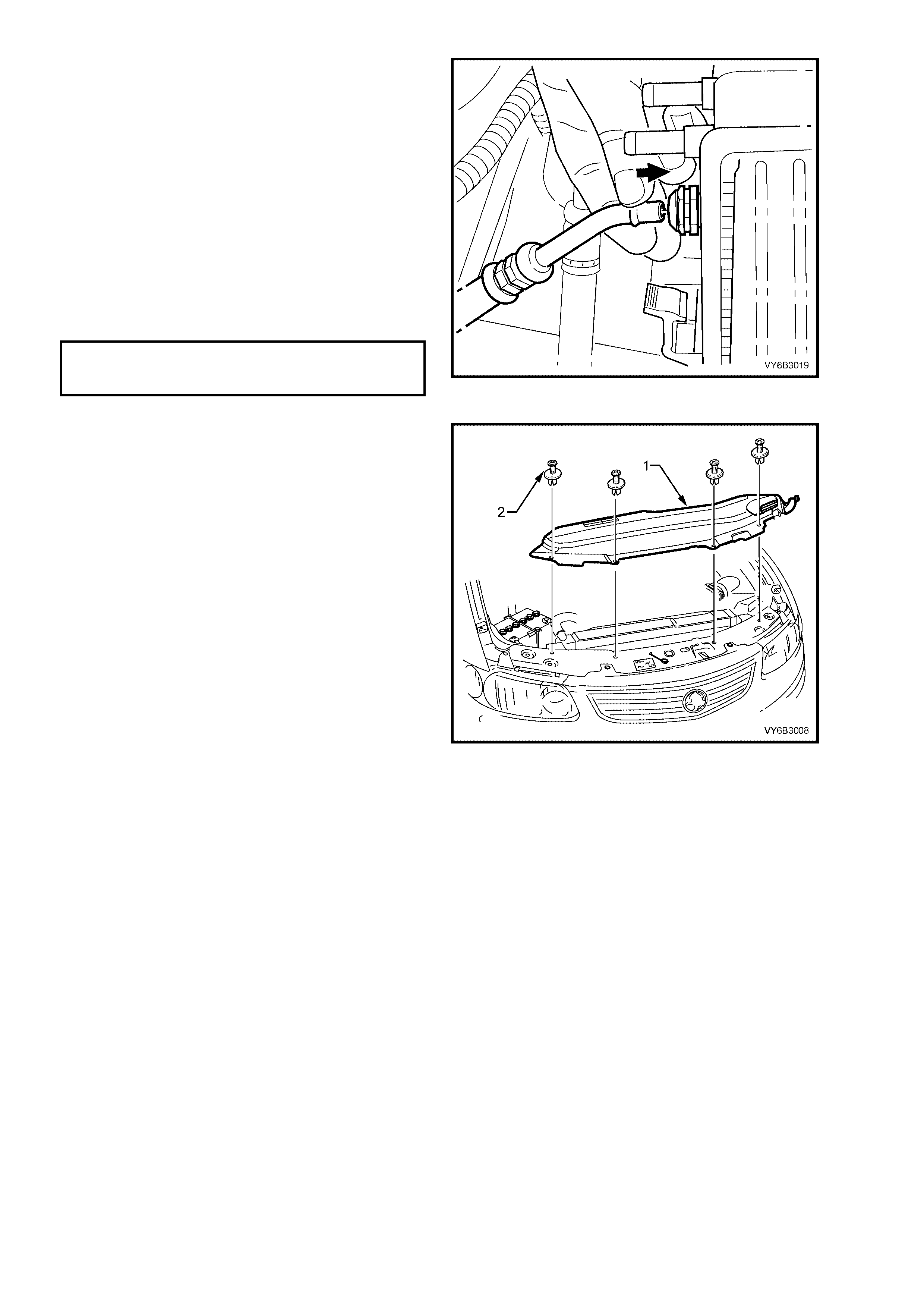
3. Remove engine dress cover decorative nuts
(1), then remove the cover (2).
4. Lift the locking lever on the Intake Air
Temperature (IAT) sensor wiring harness
connector (3), then remove the connector.
5. Lift the locking lever on the Mass Air Flow
(MAF) sensor, then remove the connector.
6. Loosen the two intake duct clamps, one at the
throttle body and the other at the MAF to air
cleaner c onnectio n. Rem ove the duct and MAF
as an assembly.
Figure 6B3-65
7. Loosen radiator lower hose worm drive clamp
from radiator connection (1).
8. Remove the h os e and dr a i n en gi ne co ol ant in to
a suitable, clean container. Refer to
2.3 DRAINING AND FILLING COOLING
SYSTEM, in this Section.
9. Remove radiator upper hose from radiator (2),
after releasing the spring type hose clamp,
using suitable pliers.
CAUTION: Always wear protective safety
glasses when working with spring type hose
clamps. Failure to do so could result in eye
injury.
10. Remove the fan and shroud assembly, refer
2.15 COOLING FAN AND SHROUD
ASSEMBLY, in this Section.
NOTE: The fan and shroud assembly must be
removed separately, to provide the required space.
Figure 6B3-66
Techline
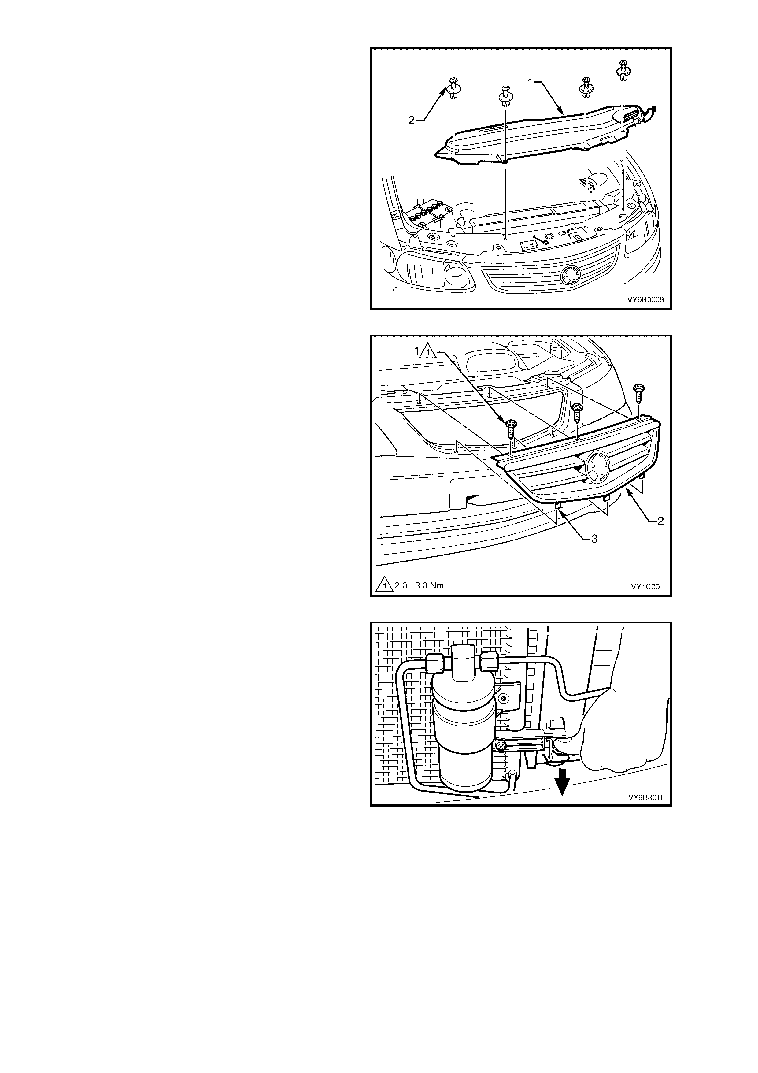
11. Remove the 4 radiator upper shroud retainers
(2) b y caref ul ly lifting the in ner s t ud with a small
screwdriver. Lift the upper shroud (1), on the
right side first, to allow release of the locating
tab on the left hand end.
12. Releas e t he c li p sec ur ing the ref riger a nt pi pe to
the receiver drier at the left side of the radiator.
Figure 6B3-67
NOTE: If fitted with air conditioning, the condenser
must be separated from the radiator assembly. This
action wil l allo w the radiat or r emoval with out hav ing
to open any refrigerant lines.
13. Remove the three grille securing screws (1).
Tilt the grille (2) forward at the top, then lift to
free the three locating pins (3). Carefully set to
one side.
NOTE: The grille on ‘S’ sedan and ‘SS’ model
vehicles is secured in a sim ilar m anner but has two
lugs on the lower edge rather than the three pins
(3) shown here.
Figure 6B3-68
14. Working thr ough t he gr ill e o pen ing, r e le as e on e
of the clips securing the condenser to the
radiator. Do this by pressing down on the lug
with the fingers of one hand, while lifting the
condenser assembly with the other. Repeat for
the other side.
NOTE: It is not necessary to remove the receiver
drier, nor disturb the air conditioning refrigerant
system (where fitted), for this operation. The
condenser can be lifted against the spring of the
attached refrigerant pipes.
15. Once released, pull the condenser assembly
forward to clear the radiator mounting lugs.
Figure 6B3-69
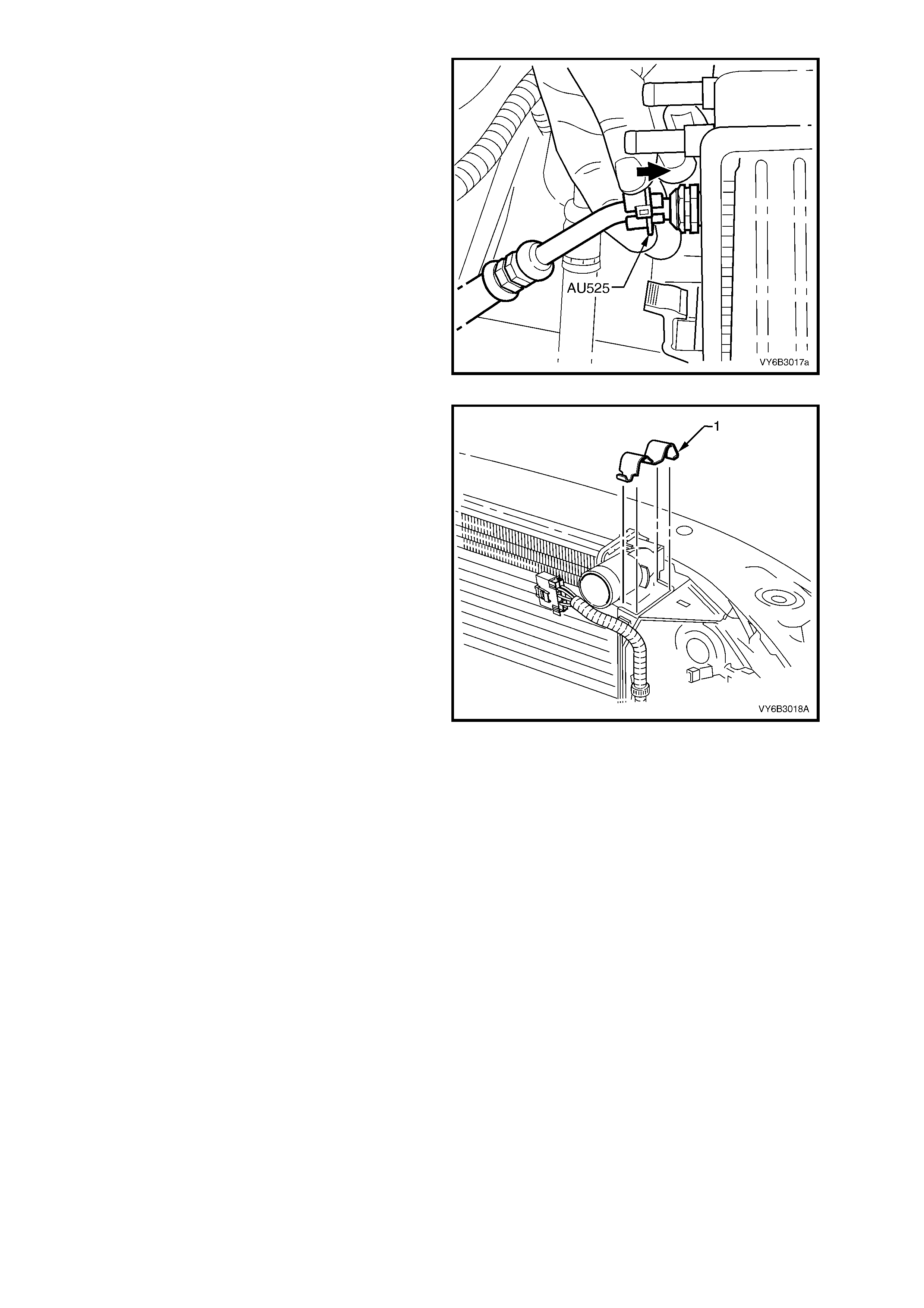
16. If the vehicle is fitted with an automatic
transmission, disconnect the transmission oil
cooler line quick connect fittings, using Tool
No. AU525, as described:
a. Open release tool AU525, then close and
clip around the pipe to be disconnected.
b. While holding the flexible hose with one
hand, push the tool into connection, to
release, then pull back on the pipe.
NOTE: If Tool No. AU525 is not available, the
cooler pipes can be disconnected from the cooler,
in the left side radiator tank, by removing the quick
connect fitting, using conventional tools. Do not
lose the sealing washer.
c. Plug al l openings to minim ise f luid loss and
prevent dirt entry.
Figure 6B3-70
17. Using a screwdriver, compress and lever out
radiator retaining clip (1) from radiator upper
mounting bracket, on each side.
18. Lift radiator upwards out of lower ins ulators. T o
rem ove the radiator as sembly fr om the vehicl e,
after clearing the top insulators, move the
radiator rearward on the left side, then across
to the left, to allow the right side to clear the
mounting brackets.
Remove upper insulators (2) from radiator
upper mounting pins.
Figure 6B3-71
REINST ALL
Reinstallation of the radiator is the reverse of
removal procedures, noting the following points:
1. Before installing radiator, inspect core to
ensure that there is no foreign matter such as
insects in the core fins. Clean out between
core fins with compressed air, working from
the engine side and blowing forwards.
2. Ensure that radiator lower mounting pins are
correctly located in lower insulators.
3. Ensure that upper insulators (2) are installed
on each of the upper mounting pins and
radiator retainers (1) are correctly installed on
each side of the radiator by checking that the
clips engage on both sides of the channel
support bracket.
4. Reins tall th e lower ra diator hose, secur ing with
the worm drive hose clamp.
5. If the vehicle is fitted with an automatic
transmission, remove plugs from the removed
cooling pipe ends and the two quick connect
fittings.
6. After wiping cooling pipe ends and smearing
clean automatic transmission fluid over each
flared pipe end, push into the quick connect
fitting to engage. As a security check, tug on
each pipe to ensure correct engagement.
NOTE: If the quick connect fittings were removed
from the left hand radiator tank , inspect t he sealin g
washer for serviceability before reinstallation.
Replace the sealing washer/s as required. Tighten
the quick connect fittings to the correct torque
specification.
QUICK CONNECT FITTINGS TO
TRANSMISSION FLUID COOLER
TORQUE SPECIFICATION 25 Nm
Figure 6B3-72
7. After reinstalling the condenser assembly to
the four retaining clips, ensure that the two
lower clips have fully engaged.
8. Reinstall the grille and the three retaining
screws. Do not over- tig hten .
9. Secure the air conditioning compressor
discharge pipe b y clos ing the plas tic clip at the
top left of the radiator, engaging the locking
tang.
10. Reinstall the upper radiator shroud (1), by first
engaging the lug on the left side, before
reinstalling the four retainers (2).
11. Reinstall the following hoses;
a. Vapour h ose to the r ad iat or f itting , s ec uri ng
with the spring clamp. Secure the vapour
hose with the integral clips on the radiator
fan shroud.
b. The surge tank hose to the radiator and
secure with the spring clamp.
c. Upper radiator hose, securing with the two
securing hose cl amps.
12. Refill cooling system, refer to 2.3 DRAINING
AND FILLING COOLING SYSTEM in this
Section.
13. Check for coolant leaks, refer to
2.8 PRESSURE T EST ING in this Section.
14. Check cooling fan operation, refer to
Section 6C3 POWERTRAIN MANAGEMENT
– GEN III V8 ENGINE in the MY 2003 VY and
V2 Series Service Information.
Figure 6B3-73
RADIATOR REPAIR PROCEDURE
Repairable Leaks
There are two types of leaks that can be repaired
on the aluminium-plastic radiator; core leaks and
automatic transmission oil cooler seal leaks. Leaks
in the plastic tanks or the seals between the side
tanks and the headers cannot be repaired,
requiring the radiator to be replaced.
Core leaks may occur in a tube or in the joints
between the tubes and the headers. Seal leaks
may occur in the joints between the plastic tanks
and the headers or in the joints between the oil
cooler fittings and the tank (vehicles with automatic
transmission).
While some leaks may be repaired while the
radiator remains installed, it is strongly
recommended that the radiator is removed from
the vehicle before attempting any repairs.
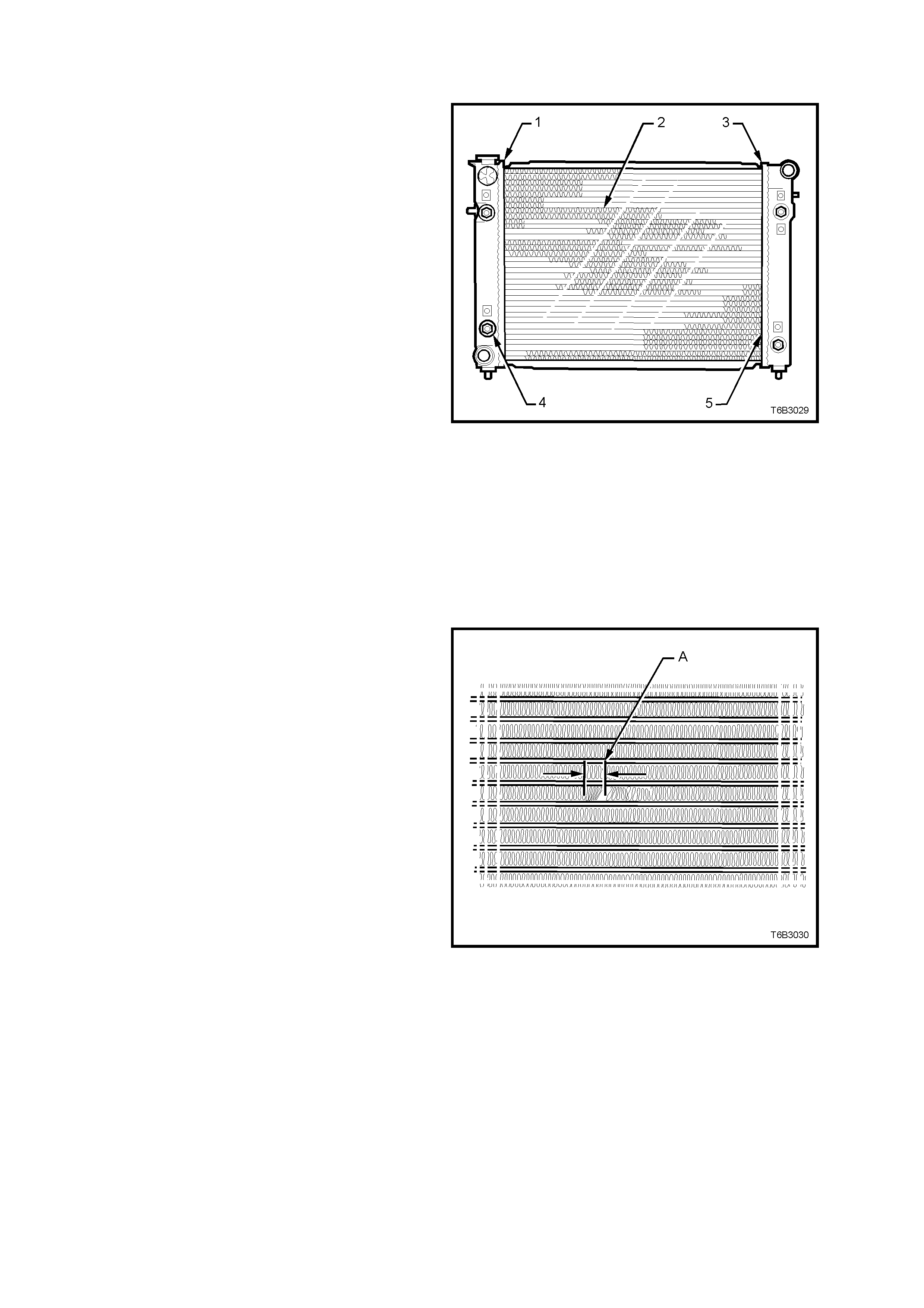
Legend:
1. Side Tank Seal
2. Core Tubes
3. Side Tank Seal
4. Oil Cooler Pipe Fittings
5. Joint Between Tube and Header
NOTE: Minor damage to tubes, or tube to header
joint (holes up to 1 mm diameter max.) can be
repaired. Core replacement is necessary if damage
is any greater.
Figure 6B3-74
Repair Method
Repairs to the aluminium radiator core should only
be made using the recommended 'Aluminised
Silicon' based liquid repair agent, in accordance
with the recommended procedure outlined in
GENERAL CORE REPAIR, later in this Section.
Refer to current release of PartFinder® for the
Aluminis e d Sil icon bas e li q uid par t number.
For damaged areas that are between the cooling
fins, it may be necessary to remove some of the
fins. Do not remove more fins than is necessary.
Usually 6 mm (distance ‘A’) beyond the leak or
damage area, up to a maximum of 25 mm of total
fin material, is enough to make an effective repair.
Figure 6B3-75
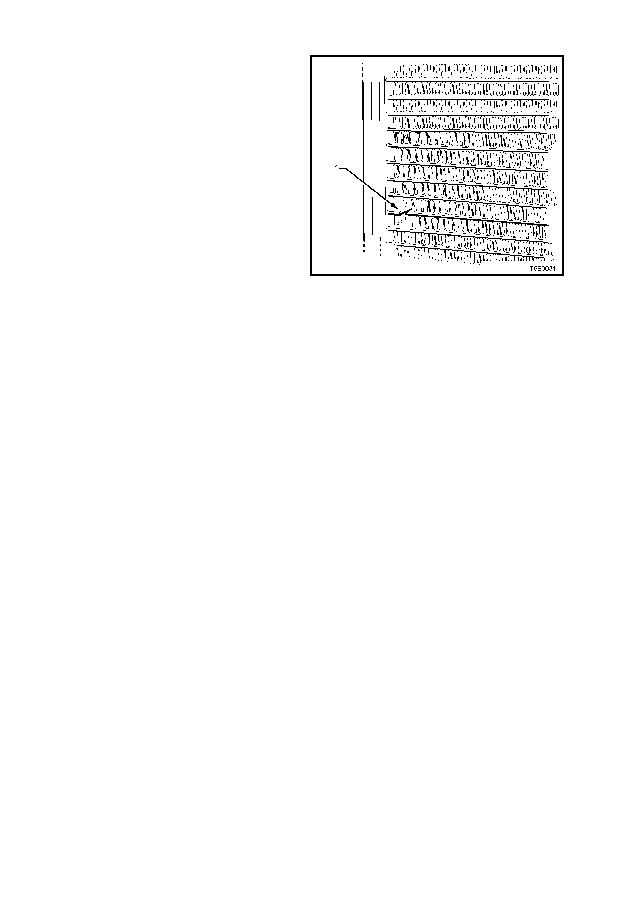
Tube Blocking
If a tube is severely damaged, it can be blocked
off.
NOTE: Do not block off more than two tubes in a
radiator. Blocking off more than two tubes will
reduce the cooling capacity of the system and
possibl y result in an overheated eng ine.
The tube should be cut off 6 mm from the header
(1) and pinched shut before it is cleaned and
sealed, refer to GENERAL CORE REPAIR, later in
this Section.
Figure 6B3-76
Header Repair
If the header or a tube near the header requires a repair, the side tank is not to be removed. If the repair requires
the removal of the header tank, then the radiator must be replaced.
General Core Repair
IMPORTANT: T he need f or caref ul preparati on of the surfac e in the repa ir area c annot be over-em phasised. If the
leak area surface is not clean, the repair material will not adhere to the surface.
1. Dr ain the c ooling s ystem . Refer to 2.3 D R AINING AND FILLING COOLING SYSTEM in this Section. Remove
the radiator, refer 2.16 RADIATOR, REMOVE, in this Section.
2. If necessary, carefully cut away fins to expose the damaged area.
NOTE: Do not cut away more than 25 mm total of fin material.
3. Clean away dirt etc. with water. Dry the affected area using hot air from a hair drier.
NOTE: Do not apply flame to dry damaged area.
4. Clean affected area with petrol to remove any traces of oil.
5. Thoroughly stir contents of repair agent. In cases of extended shelf life, the silicon in solution may separate
from the thinner carrier. Should this occur, mix contents well until agent is homogeneous again.
6. Apply repair agent sparingly to damaged area. Do not apply an excessive amount, as this will cause a
blockage of the radiator tube.
Use a clean, dry wooden applicator to 'drip' the repair agent onto damaged area of radiator.
7. Allow radiat or to s tand in a c lean, dry area for a m inim um of three hour s (at am bient temper ature of 20 – 30° C)
with adequate ventilat ion .
NOTE: Do not apply heat or flame to promote drying.
8. Install radiator, refer to 2.16 RADIATOR, REINSTALL in this Section.
Transmission Oil Cooler L eak Test
If the transmission oil cooler is suspected of leaking transmission fluid, test it before replacing the radiator, as
follows:
1. Disconnect oil cooler pipes from the flexible hose connections, using release tool AU525.
2. Using suitable connections, plug one of the flexible hoses and connect an air supply to the other.
3. Lay the radiator flat on a bench top and fill with clean water until both hose fittings are full and visible.
4. Apply air pressure GRADUALLY, increasing it up to a maximum of 103 kPa.
If bubbles appear in the water visible in the radiator hose fittings, then the radiator assembly must be replaced.
Transmission Oil Cooler Seal Replacem ent .
It is strongly recommended that the quick connect fittings at the left radiator header tank, not be disturbed. If
coolant is found to leak from ether of these two areas then the radiator should be replaced.

3. ENGINE COOLING SYSTEM DIAGNOSIS
3.1 ENGINE OVERHEATING
DEFINITION: En gine tem perature lamp com es O N and sta ys ON, or the tem peratur e gauge sh ows hot, or coolant
overflows from the surge tank onto the ground while the engine is running.
Step Action Value Yes No
1 1. Check for a loss of coolant.
2. Refer 2.2 COOLANT MAINTENANCE, Topping Up Cooling
System, in this Section.
Is there a loss of coolant?
—
Refer 3.2 LOSS
OF COOLANT,
in this Section.
Go to Step 2
2 1. Check for weak engine coolant solution.
2. Refer 2.2 COOLANT MAINTENANCE, Testing Coolant
Concentration, in this Section.
Does the engine still overheat ?
—
Go to Step 3
System OK
3 1. Check for obstruct ed radi ator air flow or bent radiator f i ns.
2. If necessary, remove or rel ocate added-on parts that block air
to the radiator. Clean away any ins ects, leaves, or other
debris.
Does the engine still overheat ?
—
Go to Step 4
System OK
4 1. Check for a loss of system pressure.
2. Conduct a test on the pressure c ap. Ref er 2.8 PRESSURE
TESTING, Screw-On Pressure Cap Testing, in this Section.
Does the engine still overheat ?
—
Go to Step 5
System OK
5 1. Check for a faulty Engine Coolant Temperature (E CT) sensor.
Refer 6C3 POWERTRAIN MANAGEMENT - GEN III V8
ENGINE.
2. Replace sensor as necessary.
Does the engine still overheat ?
—
Go to Step 6
System OK
6 1. Check for a damaged coolant surge tank.
2. Check for a leaking or kinked surge tank hos e.
3. If necessary, replace the surge tank hose and/or replace the
coolant surge tank. Refer 2.10 COOLANT SURGE TANK, in
this Section.
Does the engine still overheat ?
—
Go to Step 7
System OK
7 1. Check the tensi on of the engine accessory drive belt . Ref er to
2.6 ENGINE A CCESSORY DRIVE BELT TENSION, in this
Section.
2. Replace the engine accessory drive belt as necessary. Refer
to 2.7 ENGI NE ACCESSO RY DRIVE BELT, in this Section.
Does the engine still overheat ?
—
Go to Step 8
System OK
8 1. Check for blocked cooling system passages.
2. Reverse flush the cooling system. Refer to 2.5 CLEANING
THE COOLING SYSTEM, in this Section.
Does the engine still overheat ?
—
Go to Step 9
System OK
9 1. Check for incorrect or dam aged cooling f an blade(s ).
2. Check for the correct fan blade(s) part number.
3. Replace fan/s as nec essary. Refer 2.14 COOLING FANS
AND SHROUD ASSEMBLY, in this Section.
Does the engine still overheat ?
—
Go to Step 10
System OK
10 1. Check for correct operation of cooling fans. Refer 6C3
POWERT RAIN MANAGEMENT - GEN III V8 ENGINE.
2. Replace cooling fan/s and/or motor, as necessary. Refer 2.14
COOL IN G F AN S AND SH R O U D ASSEMBLY, in this Se ction.
Does the engine still overheat ?
—
Go to Step 11
System OK
11 1. Check for correct thermostat operation. Refer 2.9
THE RMOSTAT, Test, in this Section.
2. Replace thermostat assembly as necessary. Refer
2.9THERMOSTAT, in this Secti on.
Does the engine still overheat ?
—
Go to Step 12
System OK
12 1. Check for correct coolant pump operation.
2. Replace coolant pump assembly as necess ary. Refer 2.13
COOLANT PU M P, in this Se ct ion .
Does the engine still overheat ?
—
Go to Step 13
System OK
13 1. Check the radiator cooling capacity.
Is the radiator the correct part f or the GEN III V8 engine? —
System OK
Go to Step 14
14 1. Replace the radiator with the correct part.
Is the repair complete? —
System OK —

3.2 LOSS OF COOLANT
DEFINITION: The coolant level in the surge tank continually requires topping up or there is evidence of a sudden
coolant loss from the surge tank.
Step Action Value Yes No
1 1. Check for an incorrect or faulty screw-on pressure cap.
Conduct a test on the pressure c ap. Ref er 2.8 PRESSURE
TESTING, Screw-On Pressure Cap Testing, in this Section.
2. Replace the screw-on press ure cap as necessary.
Is a coolant loss still evident?
—
Go to Step 2
System OK
2 1. Check for a leaking or damaged coolant s urge tank
2. Replace the coolant surge tank. Refer 2.10 COOLANT
SURGE TANK, in this Section .
Is a coolant loss still evident?
—
Go to Step 3
System OK
3. 1. Conduct a pressure test of the cooling s yst em. Refer 2. 8
PRESSURE TESTING, Cooling System Pressure Testing, in
this Section.
Does test indicat e a pressure loss in the cooli ng system ?
—
Go to Step 4
System OK
4. Is there evidence of an external coolant leak? — Go to Step 5 Go to Step 12
5. 1. Check for loose or damaged surge tank, radiator and heater
hoses. Refe r 2.4 COOLANT HOSES, in this Section.
2. Replace hose/s as necessary.
Is a coolant loss still evident?
—
Go to Step 6
System OK
6. 1. Check for a coolant leak from the coolant pump gaskets.
2. Replace gaskets as necessary. Refer 2.13 COOLANT PUMP,
in this Section.
Is a coolant loss still evident?
—
Go to Step 7
System OK
7. 1. Check for a coolant leak from the coolant pump, rear O-ring
seal and thermostat housing O-ring seal.
2. Replace O-ring seals as nec essary. Ref er 2.9 THERMOSTAT
and 2.13 COOLANT PUMP, in this Section.
Is a coolant loss still evident?
—
Go to Step 8
System OK
8. 1. Check for a coolant leak from the coolant pump, shaft seal.
2. Replace coolant pump as necessary. Ref er 2. 13 COOLANT
PUMP, in this Section.
Is a coolant loss still evident?
—
Go to Step 9
System OK
9. 1. Inspect the radiator for coolant l eaks.
Are coolant leaks from the radiator evident? —
Go to Step 10
System OK
10. 1. If radiator leaks are mi nor, repai r as det ailed in 2.15
RADIATOR, Radi ator Repai r Procedure, in this Section.
2. If radiator coolant leaks are major, replace the radiator. Refer
2.15 RADIATOR, in this Secti on.
Is a coolant loss still evident?
—
Go to Step 11
System OK
11. 1. Check for coolant leaks from the heater core.
2. Replace heater core as necessary. Ref er 2B AIR
CONDITIO NING - REMOVAL & INSTALLATION.
Is a coolant loss still evident?
—
Go to Step 12
System OK
12. 1. Check for coolant leaks from the following;
• Engine block plugs.
• Vapour pipe and/or fitti ngs
• Cylinder head gask et/s .
2. Make the necessary repairs or replace aff ected components.
Refer 6A3 ENGINE MECHANICAL – GEN III V8 ENGINE.
Is/are the repair/ s complete?
—
System OK
—

3.3 ENGINE FAILS TO RE ACH NORMAL OPE RATING TEMPERATURE
Step Action Value Yes No
1 1. Check for correct coolant level in the coolant surge tank.
When checked cold, the level should be at the FULL COLD
mark.
Is the coolant level correc t?
—
Go to Step 3
Go to Step 2
2 1. Top up with correct mixture of extended life anti-freeze
coolant (conforming to GM6277M) and clean, good
quality water. Refer 2.2 COOLANT MAINTENANCE, in this
Section.
Does the engine reach normal operating t em perature now?
—
System OK
Go to Step 3
3 1. Check for a blockage in the cooling system passages.
2. Reverse flush the cooling system. Refer 2.5 CLEANING
COOLIN G SYSTEM, in this Sectio n .
Does the engine reach normal operating t em perature now?
—
System OK
Go to Step
4 1. Check that the correct thermostat is fitted.
2. Check that the thermostat is not stuck in the open position.
3. Replac e the thermostat as necessary. Refer 2.9
THERMOSTAT, in this Section.
Are repairs complete?
—
System OK
—

3.4 BLACK LIGHT AND DYE LEAK DIAGNOSIS METHOD
It is strongly recommended that the black light and dye method is used to diagnose and locate fluid leaks. This
method of leak detection is a proven, reliable method that identifies the specific leak source and/or location. The
black light kit is s uitable f or various t ypes of leak dete ction, when us ed with th e appropriat e tracer d ye and can be
used for detecting engine coolant, engine oil, transmission fluid, and air conditioning refrigerant leaks. The following
is a summary of the steps involved in detecting a cooling system fluid leak using black light and dye.
IMPORTANT: Adding dye to the GEN III V8 engine cooling system, may change the colour of the coolant
from an orange colour to a dark, muddy green. As the use of extended life anti-freeze coolant (conforming
to GM 6277M ) to this cooling system is mandat ory and is not t o be mixed with ot her composition coolant s,
the green colour could be misleading for future top-up operations.
Therefore, should the coolant change colour when the leak detection dye is added, then the cooling
system MUST be drained and new extended life anti-freeze coolant (conforming to GM6277M) coolant
added. Refer 2.3 DRAINING AND FILLING COOLING SYSTEM, in this Section.
1. Pour specified amount of dye into the coolant recovery surge tank. Refer 2.1 SAFETY NOTES in this Section.
2. Road test the vehicle under normal operating conditions.
3. Direc t the black light towar ds the suspec t area. An y fluid leak will appear as a brightl y coloured path leading to
the source.
4. Repair fluid leak and recheck to ensure that leak has been rectified.
5. Refer to the manufacturer’s directions when using this method.

4. SPECIFICATIONS
GENERAL
Radiator Cap Pressure Rating
Nominal.............................................................. 103 kPa
Range................................................................. 96.5 – 124 kPa
Cooling System Capacity........................................ 14.3 Litres
Coolant Corrosion Inhibitor ..................................... Extended life anti-freeze coolant, conforming to
GM6277M, approx. 7 litres required when changing
coolant.
THERMOSTA T
Type ........................................................................ Power element (wax pellet)
Starts to open at...................................................... 86° C
Fully open at............................................................ 100° C
COOLANT PUMP
Type ........................................................................ Centrifugal
Drive........................................................................ Multi-ribbed, Serpentine V-belt
Bear ing T ype........................................................... Double-ro w ball bear i ng
RADI ATOR
Core type................................................................. Aluminium crossflow core
Overall Width........................................................... 826 mm
Overall Height ......................................................... 495 mm
Core Width.............................................................. 674 mm
Core Height............................................................. 427 mm
Core Thickness....................................................... 35 mm
Plastic tanks............................................................ Nylon 6,6 (30% Glass Filled)
RADIATOR HOSES
Lower – Number and type....................................... Two, Moulded
Upper – Number and type....................................... One, Moulded
SMALL ENGINE COOLING FAN (Left)
Fan – Design.............................................................. Asy mmetrical spaced, curved blades with outer ring
Material.................................................................... Nylon 6,6 (30% Glass Filled), with zinc coated metal
hub insert
Number of Blades ................................................... 5
Diameter.................................................................. 293 mm
Fan Motor – Type ...................................................... Dual speed, 4 brush with 4 permanent magnets
Housing................................................................... Semi-sealed, zinc coated steel with drain hole
Direction of Rotation................................................ Counter-clockwise (as viewed from motor side)
Power...................................................................... 180 Watts (nominal)
Rotational Speed (with 12 volts applied, Radiator
and Condenser Installed – Stage 1................... 2,050 ± 150 rpm
– Stage 2................... 2,300 ± 150 rpm
LARGE ENGINE COOLING FAN – (Right)
Fan – Design.............................................................. Asy mmetrical spaced, curved blades with outer ring
Material.................................................................... Nylon 6,6 (30% Glass Filled), with zinc coated metal
hub insert
Number of Blades ................................................... 5
Diameter.................................................................. 342 mm
Fan Motor – Type ...................................................... Dual speed, 4 brush with 4 permanent magnets
Housing................................................................... Semi-sealed, zinc coated steel with drain hole
Direction of Rotation................................................ Counter-clockwise (as viewed from motor side)
Power...................................................................... 220 Watts (nominal)
Rotational Speed (with 12 volts applied, Radiator
and Condenser Installed – Stage 1................... 2,350 ± 150 rpm
– Stage 2................... 2,750 ± 150 rpm

5. TORQUE WRENCH SPECIFIC ATIONS
Nm
Coolant Pump to Cylinder Block Bolts Stage 1.................... 15
Stage 2.................... 25
Coolant Pump Rear Cover Bolts........................................... 14
Engine Accessory Drive Belt Tensioner Bolt........................ 50
Fan Motor to Shroud Screw.................................................. 5.0
Oil Cooler to Side Tank Nuts................................................ 25
Oil Pan Under-T ra y Bolts...................................................... 30
Quick Connect Fitting to Transmission Fluid Cooler ............ 25
Thermostat Housing to Coolant Pump Bolts ........................ 14
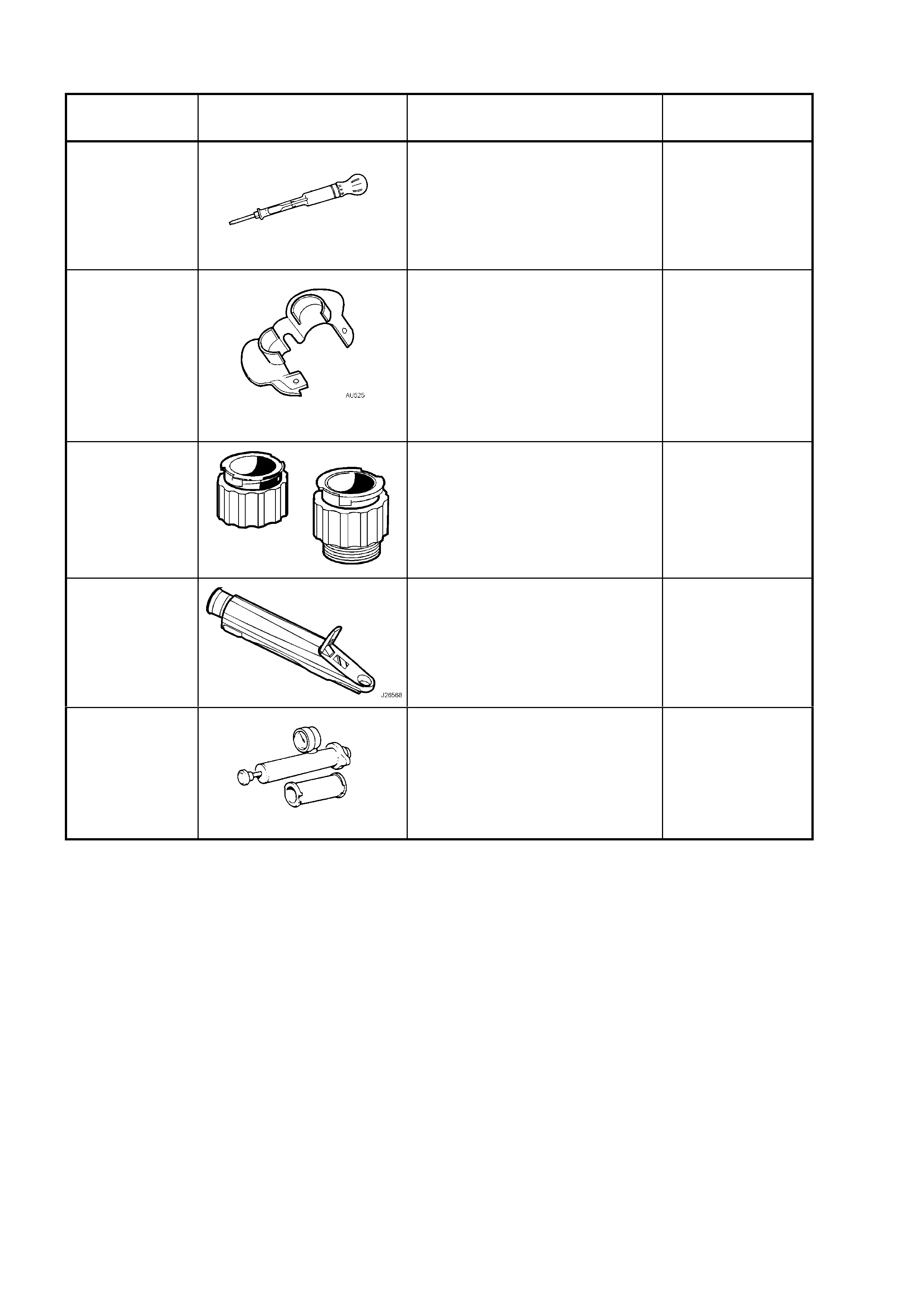
6. SPECIAL TOOLS
TOOL
NUMBER ILLUSTRATION DESCRIPTION CLASSIFICATION
AU505
COOLING SYSTEM
HYDROMETER
Also released as AU435
Also commercially available
Mandatory
AU525
QUICK CONNECT RELEASE
TOOL
Use to release the quick connect
fittings on the automatic
transmission fluid cooler lines at
the radiator end, when the veh ic le
is so equipped.
Previously released.
Mandatory
J 24460-92
COOLING SYSTEM TEST
ADAPTORS
Used to pressure test the screw-
on cooling system pressure cap
and the cooling system.
Previously released.
Mandatory
J 26568 REFRACTOMETER
Previously released, also under
the number, AU435.
Mandatory
N/A
COOLING SYSTEM PRESSURE
TESTER
Used in conjunction with adaptors
J 24460-92
Commercially available.
Available