
SECTION 6C1-1 - GENERAL INFORMATION -
V6 ENGINE
IMPORTANT
Before performing any Service Operation or other procedure described in this Section, refer to Section 00
CAUTIONS AND NOTES for correct workshop practices with regard to safety and/or property damage.
CONTENTS
1 GENERAL DESCRIPTION
1.1 POWERTRAIN CONTROL MODULE (PCM)
PCM PROGRAMMING
PCM TO BCM SECURITY LINK
SERIAL DATA
TECH 2 NORMAL MODE MESSAGE
1.2 INFORMATION SENSORS
CRANKSHAFT POSITION SENSOR
18X REFERENCE SIGNAL
CAMSHAFT POSITION SENSOR
MASS AIR FLOW (MAF) SENSOR
ENGINE COOLANT TEMPERATURE SENSOR
INTAKE AIR TEMPERATURE SENSOR
THROTTLE POSITION (TP) SENSOR
EXHAUST GAS OXYGEN SENSOR
KNOCK SENSORS
OIL PRESSURE SWITCH
FUEL MODE SWITCH
BATTERY VOLTAGE
AIR CONDITIONING REFRIGERANT
PRESSURE SENSOR
A/C REQUEST SIGNAL AND A/C CLUTCH
CONTROL WITH OCC
A/C REQUEST SIGNAL AND A/C CONTROL
WITHOUT OCC
THEFT DETERRENT INPUT SIGNAL
1.3 TRANSMISSION INFORMATION SENSORS
AND SIGNALS
VEHICLE SPEED SENSOR
TRANSMISSION POWER/ECONOMY SWITCH
AUTOMATIC TRANSMISSION FLUID
TEMPERATURE SENSOR
TRANSMISSION FLUID PRESSURE (TFP)
MANUAL VALVE POSITION SWITCH
PARK NEUTRAL POSITION AND BACKUP
LAMP SWITCH
BAROMETRIC PRESSURE SENSOR
1.4 DIRECT IGNITION SYSTEM (DIS)
OPERATION
IGNITION COILS
DIRECT IGNITION SYSTEM (DIS) MODULE
1.5 ELECTRONIC SPARK TIMING (EST)
OPERATION
1.6 FUEL SYSTEM
BASIC FUEL SYSTEM OPERATION
SYSTEM COMPONENTS
MODULAR RESERVOIR ASSEMBLY
FUEL PRESSURE REGULATOR
FUEL FILTER
FUEL PUMP ELECTRICAL CIRCUITS
FUEL INJECTORS
FUEL CONTROL SYSTEM
MASS AIR FLOW SYSTEM
MODES OF OPERATION
SHORT TERM FUEL TRIM
LONG TERM FUEL TRIM
LONG TERM FUEL TRIM CELLS
1.7 LPG OPERATION
LPG CONFIGURATION
LPG ENABLE
FUEL CONTROL VALVE
OPERATING MODES
1.8 ELECTRONIC TRACTION CONTROL
OPERATION
ENGINE TORQUE MANAGEM ENT
1.9 IDLE AIR CONTROL VALVE
1.10 ENGINE COOLING FANS
STANDARD ENGINE COOLING FAN
PACKAGE
HIGH POWER ENGINE COOLING FAN
PACKAGE
ENGINE COOLING FAN LOW SPEED
1.11 EVAPORATIVE EMISSION CONTROL SYSTEM
RESULTS OF INCORRECT OPERATION
1.12 EXHAUST GAS RECIRCULATION SYSTEM
RESULTS OF INCORRECT OPERATION
1.13 CHECK POWERTRAIN MALFUNCTION
INDICATOR LAMP (MIL)
1.14 AUTOMATIC TRANSMISSION SYSTEMS
1-2 SHIFT SOLENOID (A) AND 2-3 SHIFT
SOLENOID (B)
3-2 CONTROL SOLENOID
TRANSMISSION PRESSURE CONTROL
SOLENOID
TORQUE CONVERTER CLUT CH SOLENOID
VALVE
TORQUE CONVERTER CLUT CH PWM
SOLENOID VALVE
TRANSMISSION PASS-THRU CONNECTOR
1.15 ABBREVIATIONS AND GLOSSARY OF TERMS
Techline

1. 1 GENERAL DESCRIPTION
The V6 non supercharged engine uses a 6TDF Powertrain Control Module (PCM) to control exhaust emissions
while maintaining excellent driveability and fuel economy. This publication details the engine management
operation of the 6TDF PCM. The operation of the transmission management system is not covered in this
publication.
The PCM maintains a desired air/fuel ratio at precisely 14.7 to 1. To maintain a 14.7 to 1 air fuel ratio, the PCM
monitor s the outp ut signal f rom the oxygen sens ors. The PCM will either add or s ubtract fuel based on the o xygen
sensor output signal. This method of feedback fuel control is called closed loop.
In addition to fuel control, the PCM also controls the following systems.
• The ignition dwell.
• The ignition timing.
• The idle speed.
• The evaporative emission control system.
• The exhaust gas recirculation system.
• The engine cooling fans.
• The electric fuel pump.
• The instrument panel Check Powertrain Malfunction Indicator Lamp (MIL).
• The A/C compressor clutch.
• The automatic transmission functions.
• The fuel control valve (Vehicles equipped with LPG).
• The smart solenoid (Vehicles equipped with LPG).
The PCM also interfaces through the serial data line with other vehicle control modules, such as the Instrum ents,
Body Control Module (BCM), ABS/TCS Control Module, Occupant Climate Control (OCC) module, Audio System
and the Supplemental Inflatable Restraint (SIR) Sensing Diagnostic Module (SDM).
The PCM has a built-in diagnostic system that identifies operational problems and alerts the driver by illuminating
the Check Powertrain MIL on the instrument panel. If the lamp comes on while driving, it does not mean that the
engine should be stopped immediately, but the cause of the lamp coming on should be checked as soon as is
reasonably possible. The PCM has built in backup systems that in all but the most severe faults will allow the
vehicle to operate in a near normal manner until repairs can be made.
Below t he instrum ent panel to the left of the steerin g colum n is a Data L ink Conn ector (DLC), which is us ed b y the
assembly plant for a computer check-out of the system. This connector is used in service along with TECH 2 to
help diagnose the system. Refer to Section 6C1-2, DIAGNOSIS for further details.
The locations of the engine management components of the system are shown in the following Figures 6C1-1-2
through 6C1-1-6.
For the automatic transmission management system components and their locations, refer to Figure 6C1-1-7.
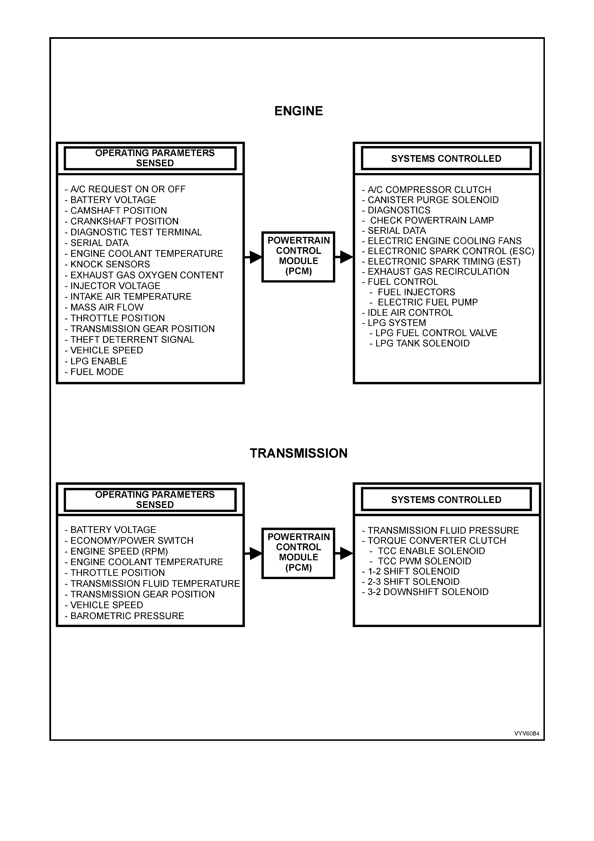
Figure 6C1-1-1 V6 Engine Powertrain Control Module Systems
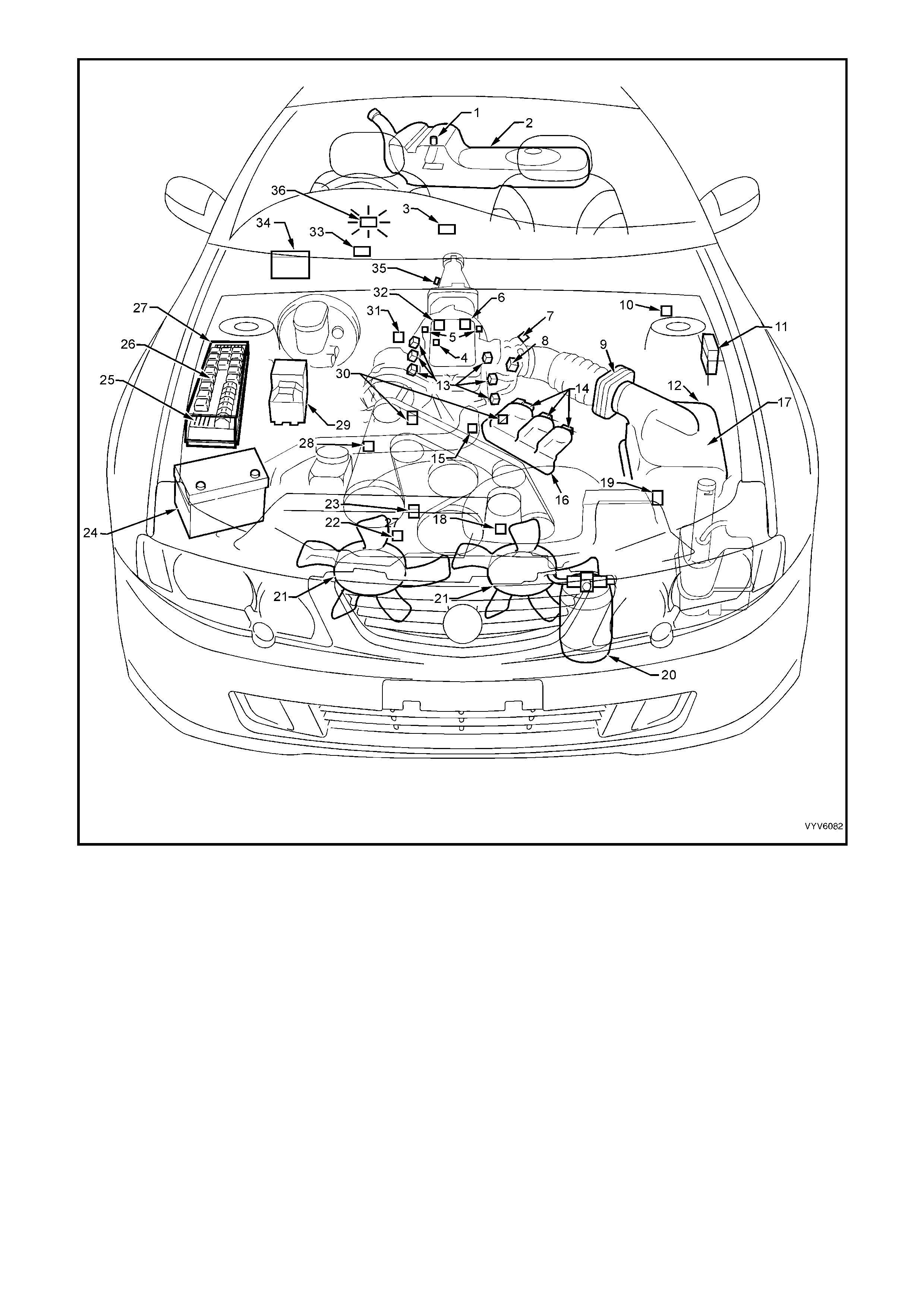
Figure 6C1-1-2 Component Locations
Legend
1. Fuel Pump (Inside Fuel Tank)
2. Fuel Tank
3. OCC In –Car Air Temperature Sensor
4. Fuel Pressure Regulator
5. Exhaust Gas Oxygen (O2S) Sensor (Two)
6. Engine Harness (PCM) Ground (Two
Terminals)
7. Idle Air Control (IAC) Valve
8. Throttle Position (TP) Sensor
9. Mass Air Flow (MAF) Sensor
10. Tachometer Lead
11. Powertrain Control Module (PCM) (Inside
Vehicle)
12. Intake Air Temperature (IAT) Sensor
13. Fuel Injectors
14. Ignition Coils
15. Engine Coolant Temperature (ECT) Sensor
16. DIS Module
17. Air Cleaner
18. Crankshaft Position (CKP) Sensor
19. A/C Refrigerant Pressure Sensor
20. A/C Accumulator
21. Engine Cooling Fans (Two)
22. Oil Pressure Switch
23. Camshaft Position (CMP) Sensor
24. Battery
25. Engine Compartment FusES
26. Engine Compartment Relays
27. Engine Compartment Fuse/Relay Centre
28. Engine Harness (PCM) Ground (Two Terminals)
29. ABS or ABS/TCS Hydraulic Modulator
30. Detonation Knock Sensors (KS) (Two)
31. Brake Hydraulic Failure Switch
32. EVAP Canister Purge Solenoid
33. Diagnostic Link Connector (DLC)
34. BCM
35. Vehicle Speed Sensor (VSS)
36. Check Powertrain MIL
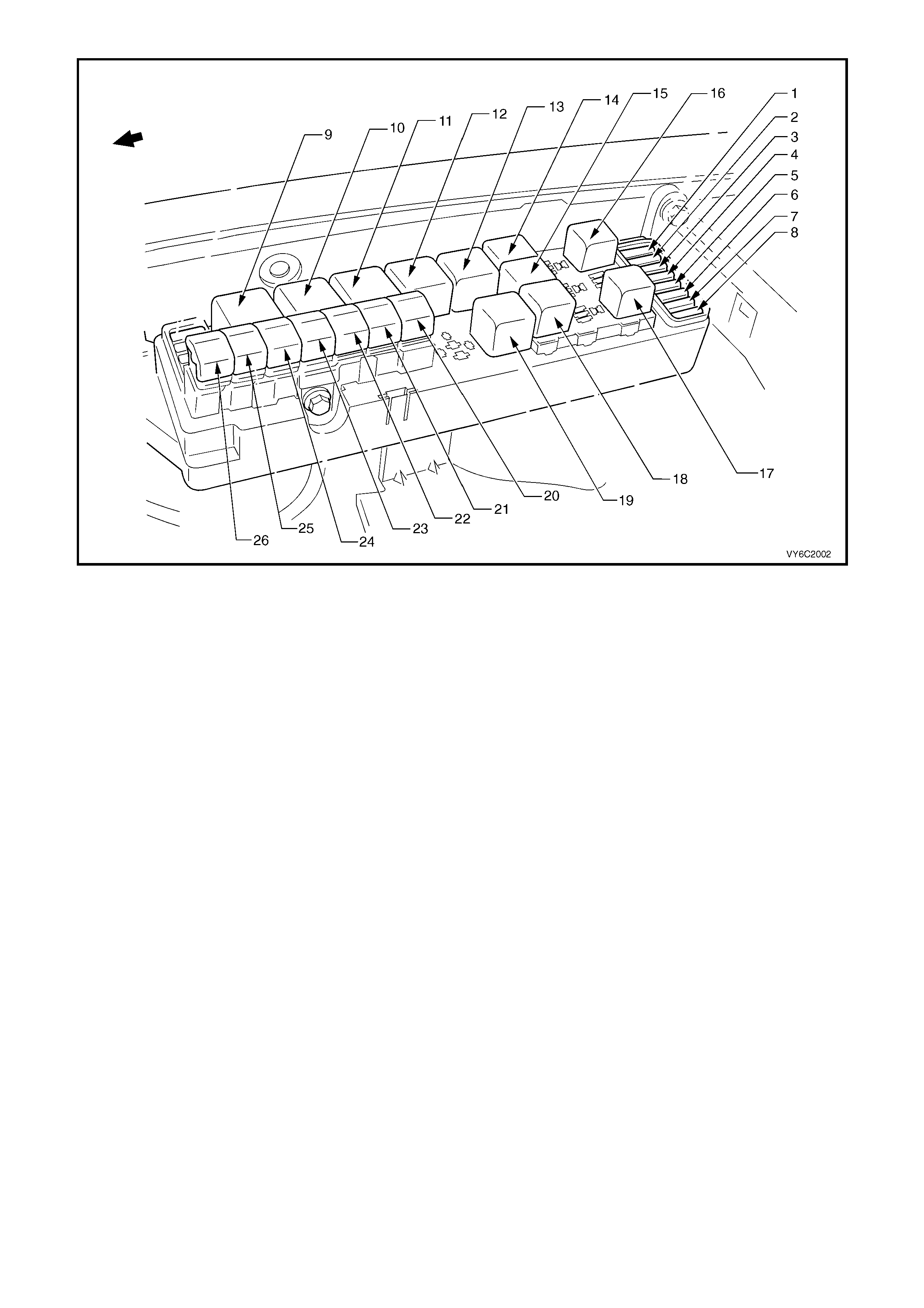
Figure 6C2-1-3 – Engine Compartment Fuse/Relay/Fusible Link Locations
Legend
Fuses
1. Fuel Pump Fuse – F28
2. Engine / BCM / Telematics– F29
3. RH Headlamps – F30
4. LH Headlamps – F31
5. Automatic Transmission – F32
6. Engine Sensors – F33
7. Injectors / Ignition – F34
8. Injectors / Ignition – F35
Relays
9. Start – R1
10. Blower Fan – R2
11. Headlamp (High Beam) – R3
12. Engine Control (EFI) – R4
13. Engine Cooling Fan Relay 2 – R5
14. Horn – R8
15. A/C Compressor – R11
16. Fog Lamp – R10
17. Fuel Pump – R16
18. Headlamp (Low Beam) – R14
19. Engine Cooling Fan Relay 1– R7
Fusible Links
20. Engine Cooling Small Fan F107 (30A)
21. Blower Fan – F106 (60A)
22. Main – F105 (60A)
23. Engine – F104 (60A)
24. A.B.S. – F103 (60A)
25. Lighting – F102 (60A)
26. Engine Cooling Large Fan F101 (30A)
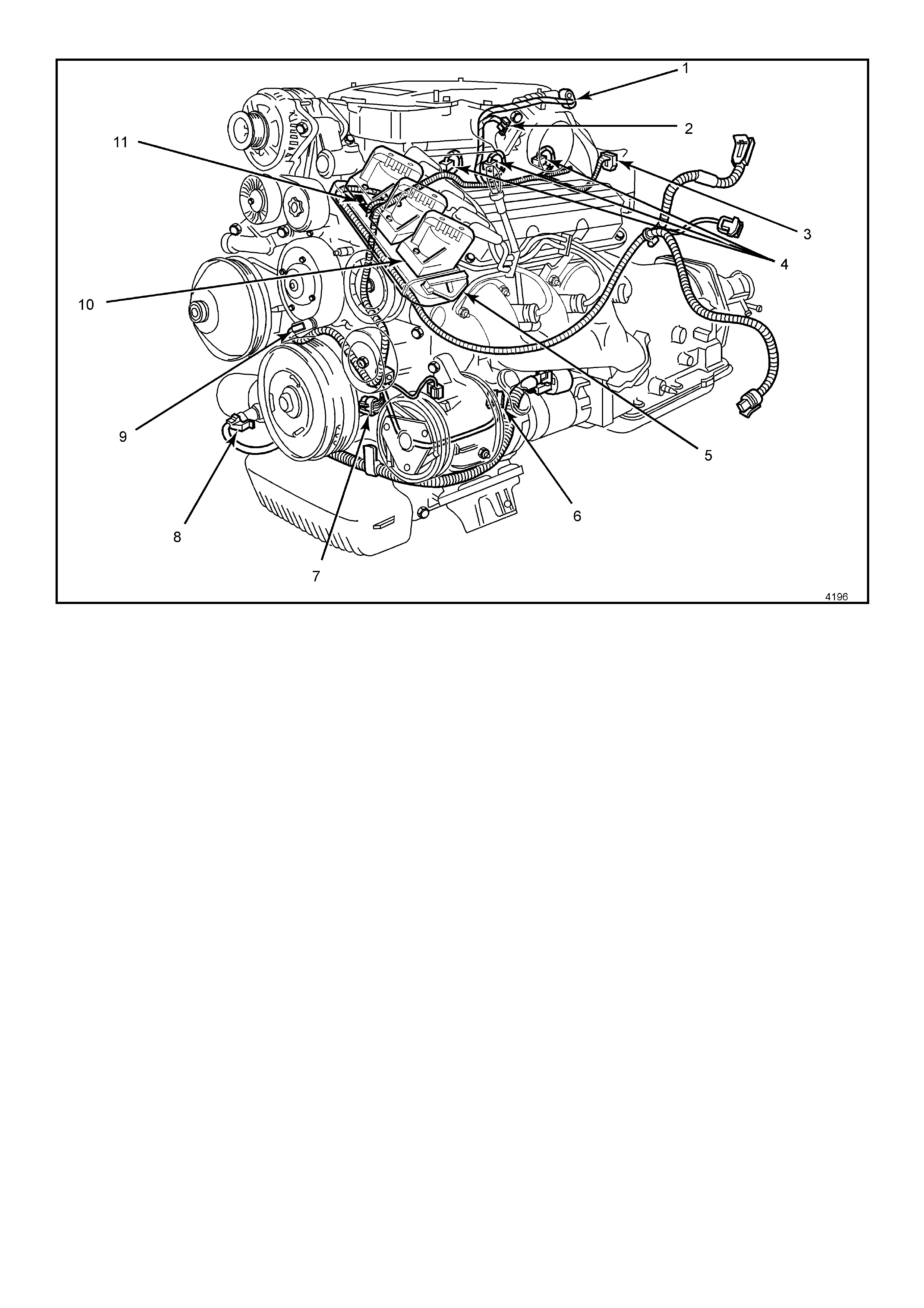
Figure 6C1-1-4 Engine Component Locations
Legend
1. Idle Air Control (IAC) Valve
2. Throttle Position (TP) Sensor
3. EGR Valve
4. Injectors
5. Direct Ignition System Module
6. L.H. Knock Sensor (KS)
7. Crankshaft Position (CKP) Sensor
8. Oil Pressure Switch
9. Camshaft Position (CMP) Sensor
10. Ignition Coils (Three Places)
11. Engine Coolant Temperature (ECT) Sensor
Figure 6C1-1-5 Engine Component Locations
Legend
1. Fuel Pressure Regulator.
2. Canister Purge Solenoid.
3. Injectors.
4. R.H. Exhaust Gas Oxygen (O2S) Sensor.
5. Transmission Pass-Through Connector.
6. Vehicle Speed Sensor (VSS) (Automatic Trans).
7. PCM Connectors.
8. Engine Harness Ground.
Figure 6C1-1-6 Engine Component Locations
Legend
1. Engine Harness Ground.
2. Ignition Coils (Three Places).
3. Direct Ignition System Module.
4. Camshaft Position (CMP) Sensor.
5. Oil Pressure Switch.
6. R.H. Knock Sensor (KS).
7. Vehicle Speed Sensor (VSS) Automatic Trans.
8. Injectors.
Figure 6C1-1-7 Automatic Transmission Internal Electronic Component Locations
Legend
1. Vehicle Speed Sensor.
2. 1-2 Shift Solenoid A and 2-3 Shift Solenoid B.
3. Automatic Transmission Fluid Pressure (TFP) Manual Valve Position Switch.
4. 3-2 Downshift Shift Control Solenoid.
5. Torque Converter Clutch Pulse Width Modulation (TCC PWM) Solenoid Valve.
6. Torque Converter Clutch (TCC) Solenoid Valve.
7. Pressure Control Solenoid (PCS) Valve.
1.1 POWERTRAIN CONTROL MODULE (PCM)
The 6TDF Powertrain Control Module (PCM),
located behind the front left hand cowl trim panel,
is the control c entr e of the eng ine and tr ansm iss ion
management systems. It constantly monitors
information from various sensors, and controls the
systems that affect exhaust emissions and vehicle
performance. The PCM performs the diagnostic
function of the s ystem . It can r eco gnise o perat ional
problems, alert the driver through the Check
Powertrain MIL and store a Diagnostic Trouble
Code(s) that will identify problem areas to aid
the technician in making repairs. Refer to
Section 6C1-2 Diagnosis in this Service
Information for more information on using the
diagnostic functions of the PCM.
The PCM s upplies either a buff ered 5 or 12 vo lts to
power various sensors or switches. This is done
through resistance's in the PCM which are so high
in value that a test light will not light when
connected to the circuit. In some cases, even an
ordinar y voltmeter will not give an accur ate readin g
because the meter's internal resistance is too low.
A 10 Meg Ohm input impedance Digital Multi
Meter (DMM) is required to assure accurate
readings.
Figure 6C1-1-8 Powertrain Control Module Location
The PCM controls output circuits such as the injectors, canister purge solenoid, a nd various rela ys,. by controlling
the ground circuit through transistors or a device called a quad-driver in the PCM. The four exceptions to this are
the fuel pump relay control circuit and the automatic transmission pressure control solenoid (PCS), the Exhaust
Gas Recir culatio n (EGR) Sole noid and th e Idle Air Control (I AC) valve. T he PCM controls th e +12 vo lts sent to th e
coil of the relay, the ground side of the fuel pump relay coil is connected to engine ground. The PCM supplies
current to the PCS and m onitors how much current returns to the PCM on a sep arate terminal. The PCM controls
the EGR solenoid by sending a positive Pulse Width Modulated signal to the EGR solenoid. To control the
operation of the Idle Air Control valve the PCM controls both the voltage and the ground circuits.
The PCM also receives and transmits serial data via the serial data bus.
The PCM d oes not co ntain a rem ovable PROM , it use s an E EPRO M (Flas h Mem ory) which is no n rem ovab le. T he
PCM is pr o gram med fr om the fac tory with the pr op er c ali br at ions for ve hicle oper a tion . In the ev ent that the P CM i s
replace d, or an update d cal ibrat ion is requir ed to corr ec t a vehic le's o perat ing c ondit ion, a new ca libr ation wi ll ha ve
to be d own load ed to the PCM EE PROM (F lash Mem ory). D own load ing is acco mplis hed through t he vehic le DLC
using the TECH 2 Service Programming System (SPS) and the Technical Information System (TIS) 2000.
A service r eplacem ent PCM wi ll not be pr ogramm ed and DTC P06 01 will be set in the PC M. DTC P0601 in dicates
the Flash Memory is not programmed or has malfunctioned.
Refer to Section 6C1-3 Service Operations for the SPS procedure.
DTC P0601 (PCM Memory) will set if:
• The ignition switch is in the crank position or the run position.
• The PCM is unable to correctly read data from the EEPROM (flash memory).
DEFAULT VALUE
If either DTC is set, the PCM activates the Malfunction Indicator Lamp (MIL) when the diagnostic runs and fails.
The PCM records the operating conditions at the time the diagnostic fails. The PCM stores this information in the
History Data.
DTC P0601 HISTORY DATA
PARAMETER PARAMETER
ENGINE SPEED IAT SENSOR
COOLANT TEMPERATURE INTAKE AIR TEMPERATURE
TIME FROM START BATTERY VOLTAGE
TIMES OCCURRED REFERENCE VOLTAGE
IGNITION CYCLES FUEL
ECT SENSOR
PCM TO BCM SECURITY LINK
Once the PCM and or BCM have been replaced, the new PCM and or BCM must be linked to each other. If this
procedure is not performed, the vehicle will not crank or start. Refer to Section 6C1-3 Service Operations for
further information.
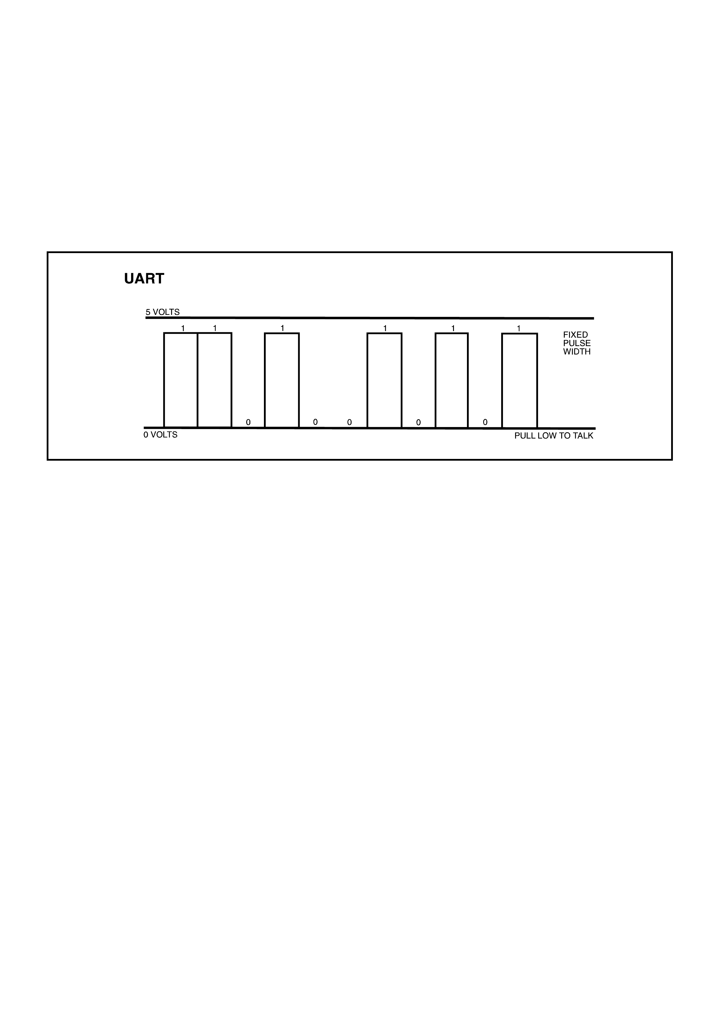
SERIAL DATA
Serial data is actually a series of rapidly changing voltage signals pulsed from high voltage to low voltage. These
voltage s ig na ls are typical l y 5 vo lts (h igh) t o 0 vo lts ( low) a nd are trans mitted thro ugh a wire of ten re f err ed to as th e
Serial D ata Li ne. T his ve hic le uses a Uni versal Async hronous Rec eive and T ransmit (U ART) serial dat a s ystem . In
the UART system, computers communicate on a single wire by pulling the voltage on the data line low when
communicating. Therefore, when no communication is occurring on the data line, the system voltage will go to a
high level, which is 5 volts. When measured with a Digital Multi Meter (DMM), the meter will display the average
voltage.
Figure 6C1-1-9 Serial Data Digital Wave Form
Each digit al signa l is called a "bit" and repres ents a nu mber , 8 bits make 1 “B yte”. The c omputer str ings together a
series of these "bytes" to make "words". Serial data means that each word is read in order, one at a time, in a
series. A typica l ser ial data s tr eam may have 64 words on it.
To help s implif y this, thi nk back to the last t ime you went sho pping. In m an y stor es these da ys your pur chas es are
registered automatically by "scanners". A bar code on the package interrupts a light beam creating a series of
digital sign als.
These signals are then translated by the microprocessor into a number which represents that product. Your
purchase is automatically registered and charged out on the cash register.
The TECH 2 r eads ser ial data in a s im ilar wa y. By interf acing with th e Serial D ata Line t hroug h the DLC, the T ECH
2 can read the serial data that is being sent between the various control modules.
BAUD RATE
A serial data stream contains bits, each bit holding a specific place in the data stream. Bits can represent a
message being sent or a separation between messages. These bits are being sent at precise time intervals. The
speed at whic h bits are tr ansm itted is k nown as "Baud Rate. " T he Baud Rate us ed in this UART s erial data is 8192
Bits Per Seco n d (BPS) .
SERIAL DATA COMMUNICATION
This vehicle uses a “Bus Master” communication system, where the BCM is the bus master. When the ignition is on
the BCM periodically polls (surveys) each control module on the bus (serial data circuit) and requests status data.
The control modules connected via the serial data circuit are:
Body Control Module (BCM), Powertrain Control Module (PCM), Occupant Climate Control (OCC), Instrument
Cluster, Anti-lock Brake / Electronic Traction Control Module, Audio System, Telematics Module and the
Supplemental Inflatable Restraint System (SIR) Sensing Diagnostic Module (SDM).
The data provided by each control module is called the “Normal Mode Message” and may be utilised by any
control m odule connect ed to the bus. Eac h control m odule has a uni que respons e Message Identif ier Wor d (MIW )
for eas e of identif ication of the inform ation that fol lows the MIW . The bus m aster (BCM) polls each control m odule
with a serial data message which includes that control module’s MIW. The control module responds by putting a
serial data message onto the bus which includes its MIW and data, which is retrieved and utilised by any control
module requiring it.

The BCM polls each control m odule for a status update, once every 300 milliseconds. The exception to this being
the PCM and the Audio System which is polled twice every 300 milliseconds.
The T ECH 2 diagnostic too l can be used to r ead the ser ial data on the da ta bus and r equest infor mation fr om any
control m odule o n the bus to analyse f aults in an y s ystem and its relat ed com ponents. The inf orm ation provi ded on
the serial data bus, which can be used by any control module is listed below.
ENGINE (PCM)
Engine Speed, Coolant Temperature, Intake Air Temperature, Vehicle Speed, A/C Clutch, A/C Pressure, Low
Speed Fan Request, Low Fan Run On, Theft Status, PCM DTC Status, Check Powertrain Lamp, MFD Message,
Fuel Used, L PG Used, Fu el Flow Rate ( Instant aneous) , Engine T ype, Transm ission Codin g, Fuel T ype, Engine O il
Change, Transmission Oil Change, Shift Pattern, Torque Multiplier, High Coolant Temperature, Oil Pressure
Switch, PRNDL S witch, C o m m anded Gear and PC M Chime.
ABS & ABS / TCS
Stop Lam p Switch, ABS Warning Lamp, ETC W arning Lamp, ETC Equipped, Low Traction, ABS Chim e and ABS
DTC Status.
BODY CONTROL MODULE
Ignition Switch, Ignition Off Time, Accessory Switch, Instrum ent Lam ps, Lights On, Sun Load, Rear Compartment,
Rear Lamp Fuse Fail, Rear Brake Bulb Fail, Rear Lamp Bulb Fail, Front Wiper Status, A/C Request (Air
Conditioning), BCM Low Fan Drive, Alarm, Alarm Trigger Source, Key Priority, BCM DTC Status and MFD
Message.
SUPPLEMENTAL INFLATABLE RESTRAINT SYSTEM (SENSING DIAGNOSTIC MODULE)
SRS Warning Lamp, SRS Deployed This Ignition Cycle, SRS DTC Status and SRS Module.
INSTRUMENTS
Engine Oil Life Reset, Transmission Fluid Life Reset, SRS Configuration, Cruise Control Engaged, Radio Status
Request Fuel Level (Litres), MFD Message Requested and MFD Message Received.
OCCUPANT CLIMATE CONTROL MODULE
MFD Message, A/C Request, Rear Window Heater Status and Ambient Temperature (Dampened).
AUDIO SYSTEM
Radio Status, Antenna Required, Antenna Direction Switch, Radio DTC Status, Mute, Pause and MFD Message.
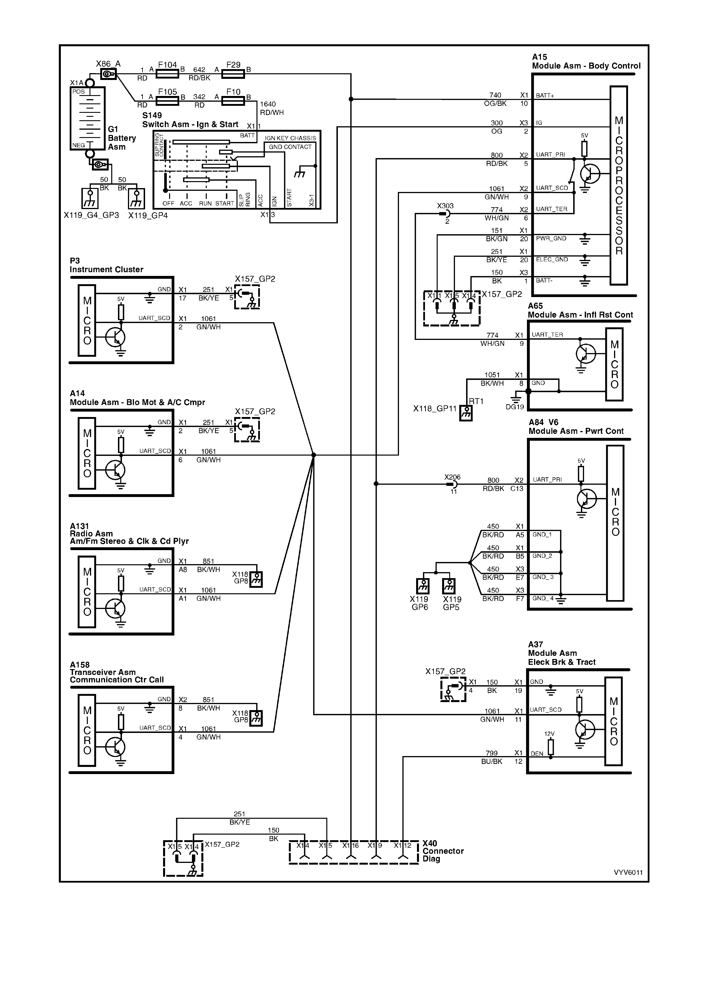
Figure 6C1-1-10 Serial Data Circuit
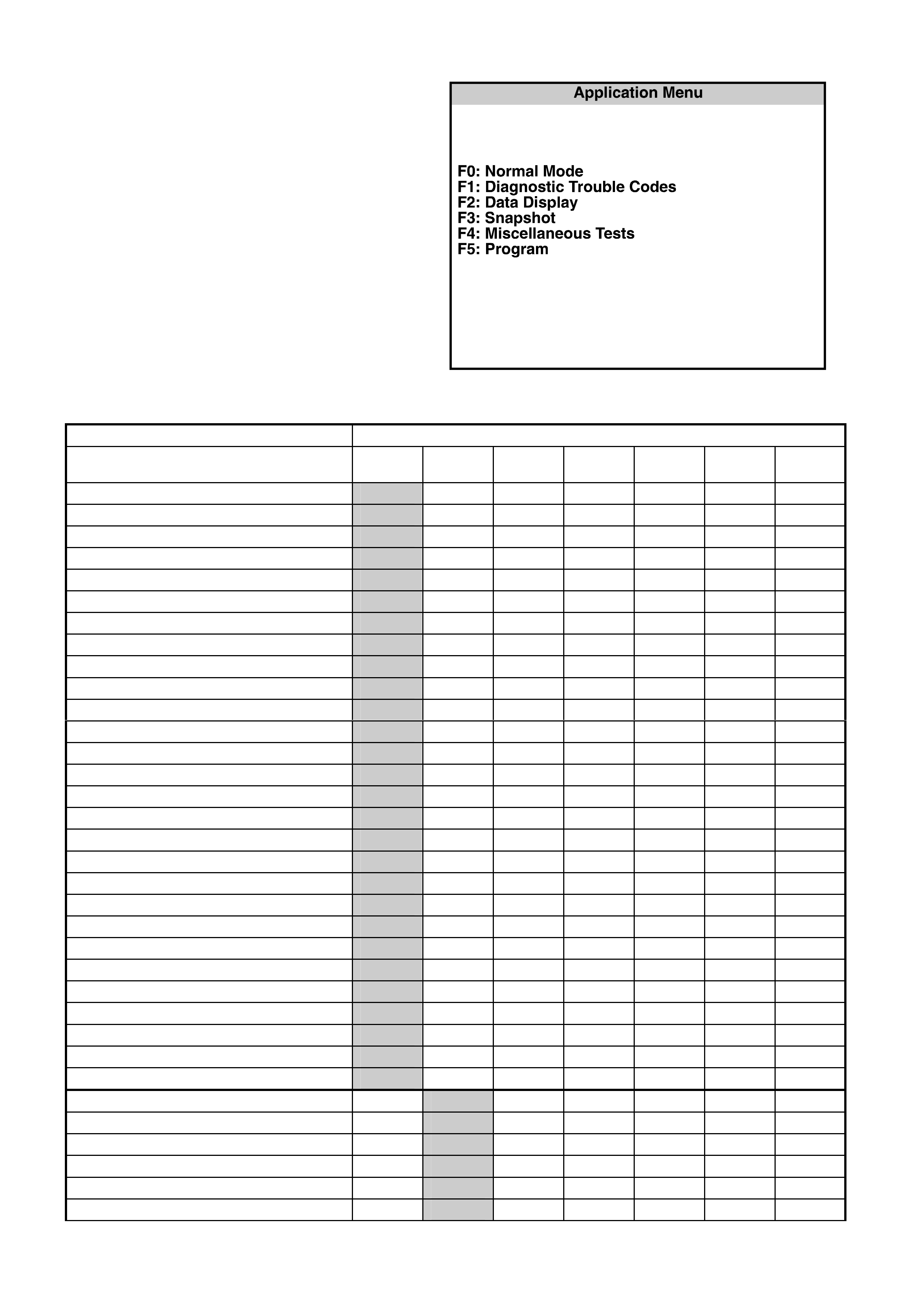
TECH 2 NORMAL MODE MESSAGE
The TECH 2 diagnostic tool can be used to read
the serial data on the data bus and request
information from any control module on the bus.
The serial data from a particular control module
can be monitored using TECH 2 by selecting F0:
Normal Mode from the Application Menu.
MODE F0: NORMAL MODE
In this mode, the TECH 2 monitors the constant
communication between control modules on the
serial data line. The information displayed on the
TECH 2 screen in this mode is what the control
module is communicating to the other modules via
the serial data line.
The norm al m ode m essage inf orm ation is sho wn in
the following table.
Typical Application Menu
INFORMATION TRANSMITTED INFORMATION RECEIVED
TECH 2 STRING PCM ABS
ETC BCM OCC INST SRS
AUDIO
SYSTEM
POWERTRAIN CONTROL MODULE
Engine Spee d X
Coolant Temperature X X
Vehicle Speed X X X
Intake Air Temperature
A/C Clutch (Air Conditioning)
A/C Pressure (Ai r Conditioning) X
Low Speed Fan Request X
Low Fan Run On X
Theft Status X
PCM DTC Status X
Check Powertrain Lamp X
MFD Message X
Fuel Used X
LPG Used X
Fuel Flow Rate (Instantaneous) X
Engine Type X
Transmission Coding
Fuel Type X X
Engine Oil Change
Transmission Oil Change
Shift Pattern X
Torque Mult iplier X
High Coolant Temperature
Oil Pressure Switch X
PRNDL Switch X
Commanded Gear X
PCM Chime (Powertrain Control Module) X
ABS/ETC
Stop Lamp Switch X
ABS Warning Lamp
TCS Warning Lamp X
ETC Equi pped X
Low Traction
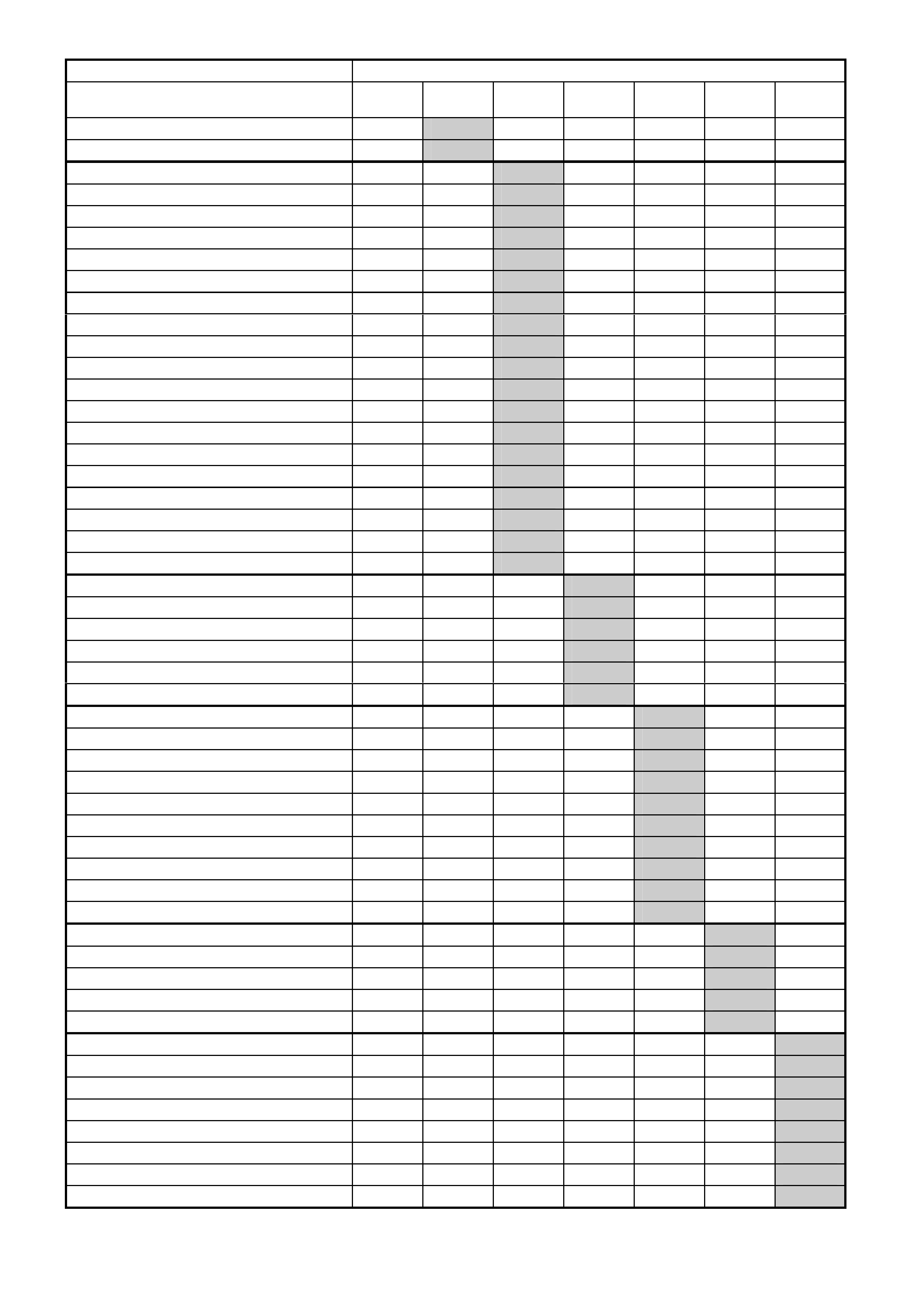
INFORMATION TRANSMITTED INFORMATION RECEIVED
TECH 2 STRING PCM ABS
ETC BCM OCC INST SRS
AUDIO
SYSTEM
ABS Chime X
DTC Status X
BODY CONTROL MODULE
Ignition Switch X
Ig nition O ff Ti me X
Accessories Switch X
Instrument Lam p s X X X
Lights On X
Sun Load X
Rear Compartment X
Rear Lamp Fuse Fail X
Rear Brake Bulb Fail X
Rear Lamp Bulb Fail X
Front Wiper Status
A/C Request (Air Conditioning) X
BCM Low Fan Drive X
Alarm X
Alarm Trigger Source X
Key Priorit y X X X X
BCM DTC Status X
MFD Message X
OCCUPANT CLIMATE CONTROL
MFD Message X
A/C Request (Air Conditioning) X
Rear Window Heater Status
DTC Set
Ambient Temperature
INSTRUMENTS
Engine Oil Life Reset
Transmission Fluid Life Reset
SRS Configuration X
Cruise Control Engaged X
Radio Status Request X
Fuel Level (Liters) X
MFD Message Requested X X X X X
MFD Message Received X X X X X
Language
SUPPLEMENTARY RESTRAINT SYSTEM
SRS Warning Lamp X
SRS Deployed Thi s Ignition Cycle X X
SRS DTC Status X
SRS Module X
AUDIO SYSTEM
Radio Status X
Antenna Required X
Antenna Direction Switch X
Radio DTC Status
Mute X
Pause X
MFD Message X
1. 2 INFORMATION S ENSORS
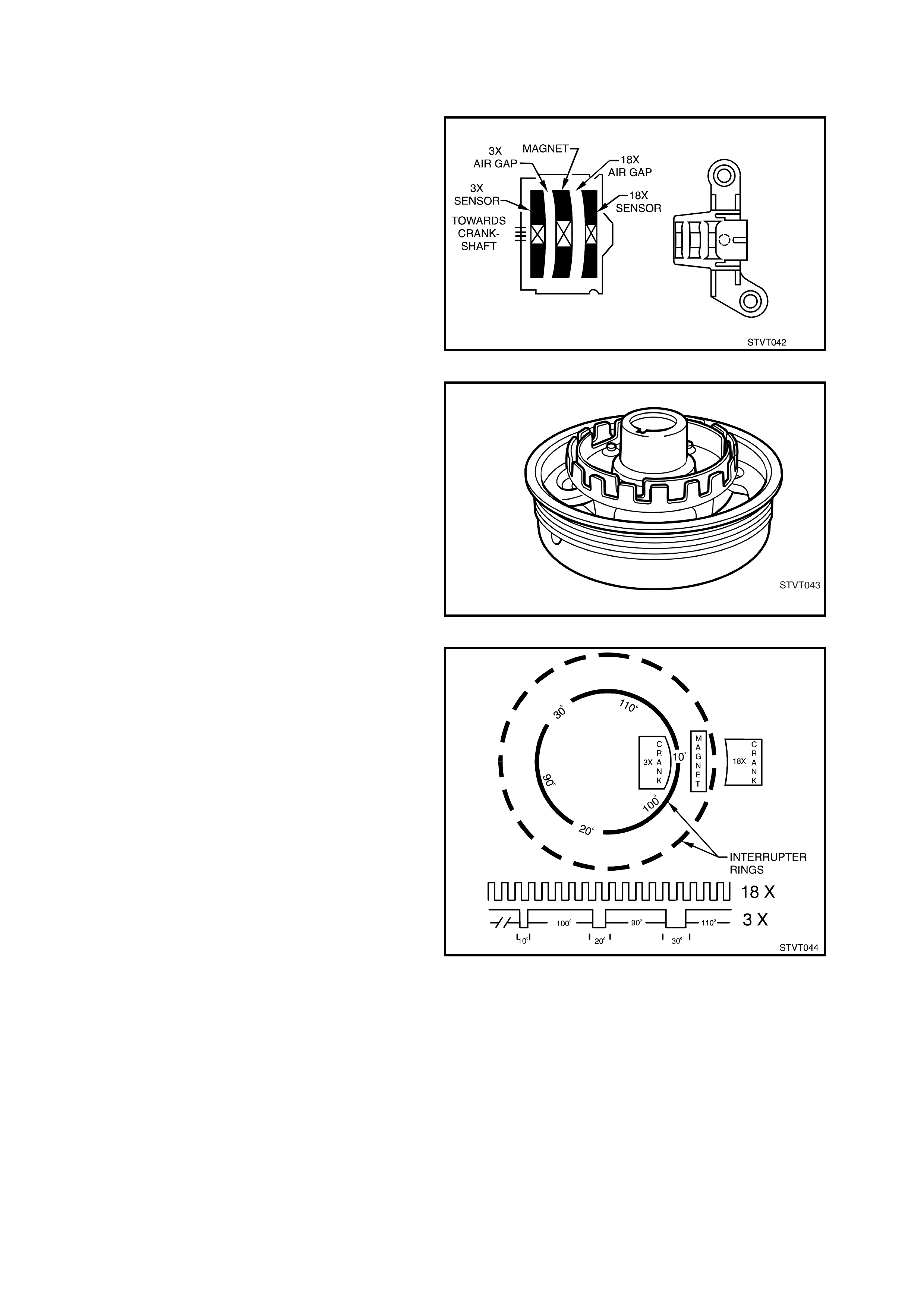
CRANKSHAFT POSITION SENSOR
The c rankshaf t referenc e signal is g enerated in the
Direct Ignition System (DIS) module from
information received from the Crankshaft Position
Sensor. The crank shaft positio n sensor, is secured
in a mounting bracket and bolted to the front left
side of the engine timing chain cover. A 4-wire
harness connector plugs into the sensor,
connecting it to the DIS module. The crankshaft
reference signal generated by the DIS module
provides the PCM with RPM and crankshaft
position inf o rmation.
NOTE: The engine will not run if the PCM does
not receive a crankshaft reference signal. With
no crankshaft reference signal, the PCM will
not issue any injector pulses.
The crankshaft position sensor contains two Hall-
effect switches with one shared magnet mounted
between th em . The magnet and eac h Hall s witch is
separate d by an air gap. A Hal l sw itch, r eacts l ik e a
solid-state switch, grounding a low-current signal
voltage when a magnetic field is present.
When the magnetic field is shielded from the switch
by a piece of steel placed in the air gap between
the magnet and the s witc h, the s ig na l vo lt age is not
grounded. If the piece of steel (called an
interrupter) is repeatedly moved in and out of the
air gap, the signal voltage will appear to go on-off-
on-off-on-off. Compared to a conventional
mechanical distributor, this on-off signal is similar
to the signal that a set of breaker points in the
distributor would generate as the distributor shaft
turned and t he poi nts open ed & cl osed. I n the case
of the DIS, the piece of steel is two concentric
interrupter rings mounted to the rear of the
crankshaft balancer. Each interrupter ring has
blades and windows that, with crankshaft rotation,
either block the magnetic field or allow it to reach
one of the Hall switches. The outer Hall switch is
called the 18X crankshaft sensor, because the
outer interrupter ring has 18 evenly-spaced same-
width blades and windows The 18X crankshaft
sensor produces 18 on-off ground pulses per
cranks haf t r evolut ion. The Hall switch c loses t to the
crankshaft, the 3X crankshaft sensor, is so called
because th e inside interru pter ring has 3 unevenl y-
spaced, different-width blades and windows. The
3X crankshaft sensor produces 3 different length
on-off ground pulses per crankshaft revolution.
When a 3X interrupter ring window is between the
magnet and inner switch, the magnetic field will
cause the 3X Hall switch to ground the 3X
crankshaft signal voltage supplied from the DIS
module. The 18X interrupter ring and Hall switch
react similarly.
Figure 6C1-1-11 Crankshaft Position Sensor
Figure 6C1-1-12 Cranksh aft B alancer with Inter rupter Rings
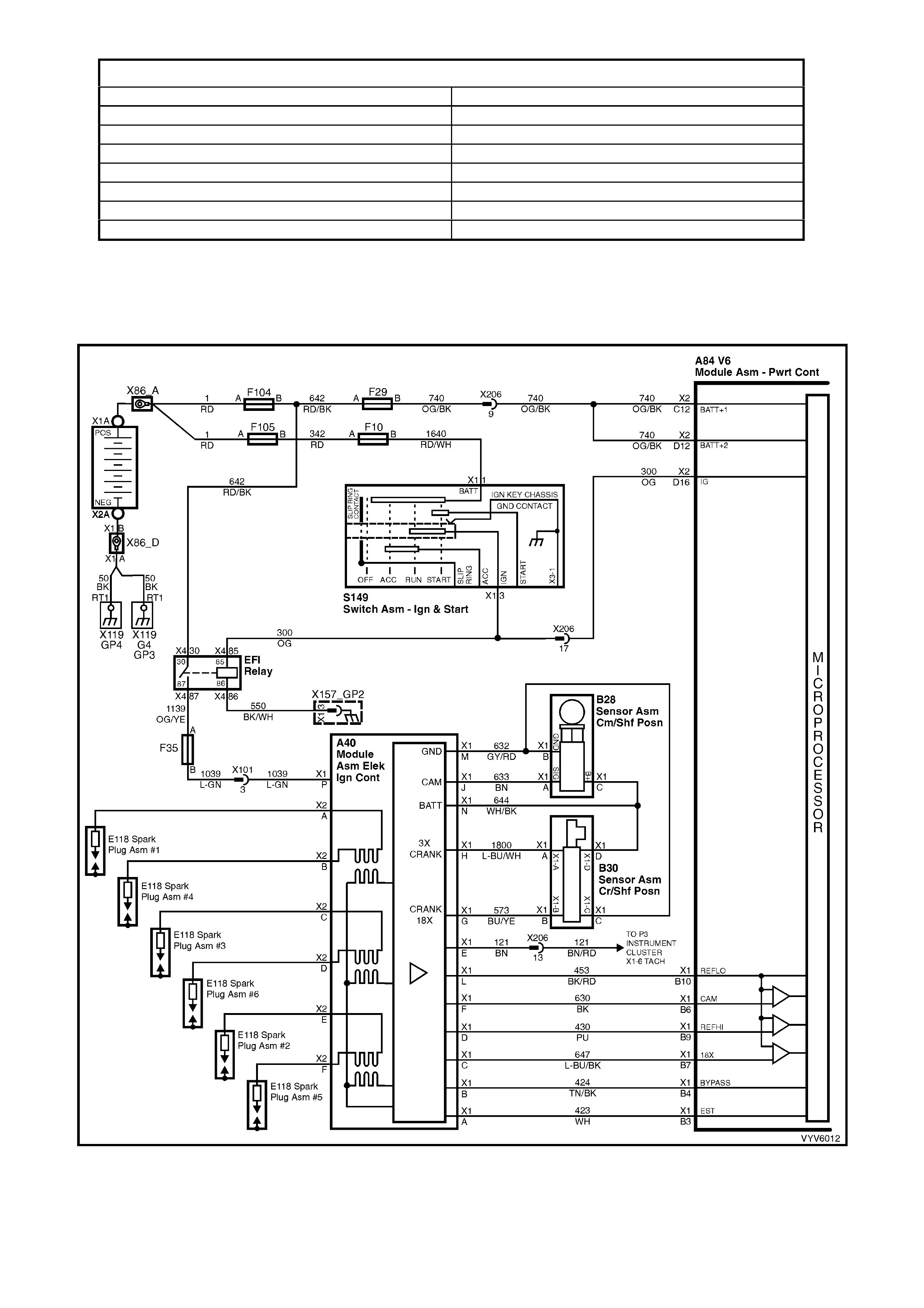
Figure 6C1-1-13 Hall Effect Sensor
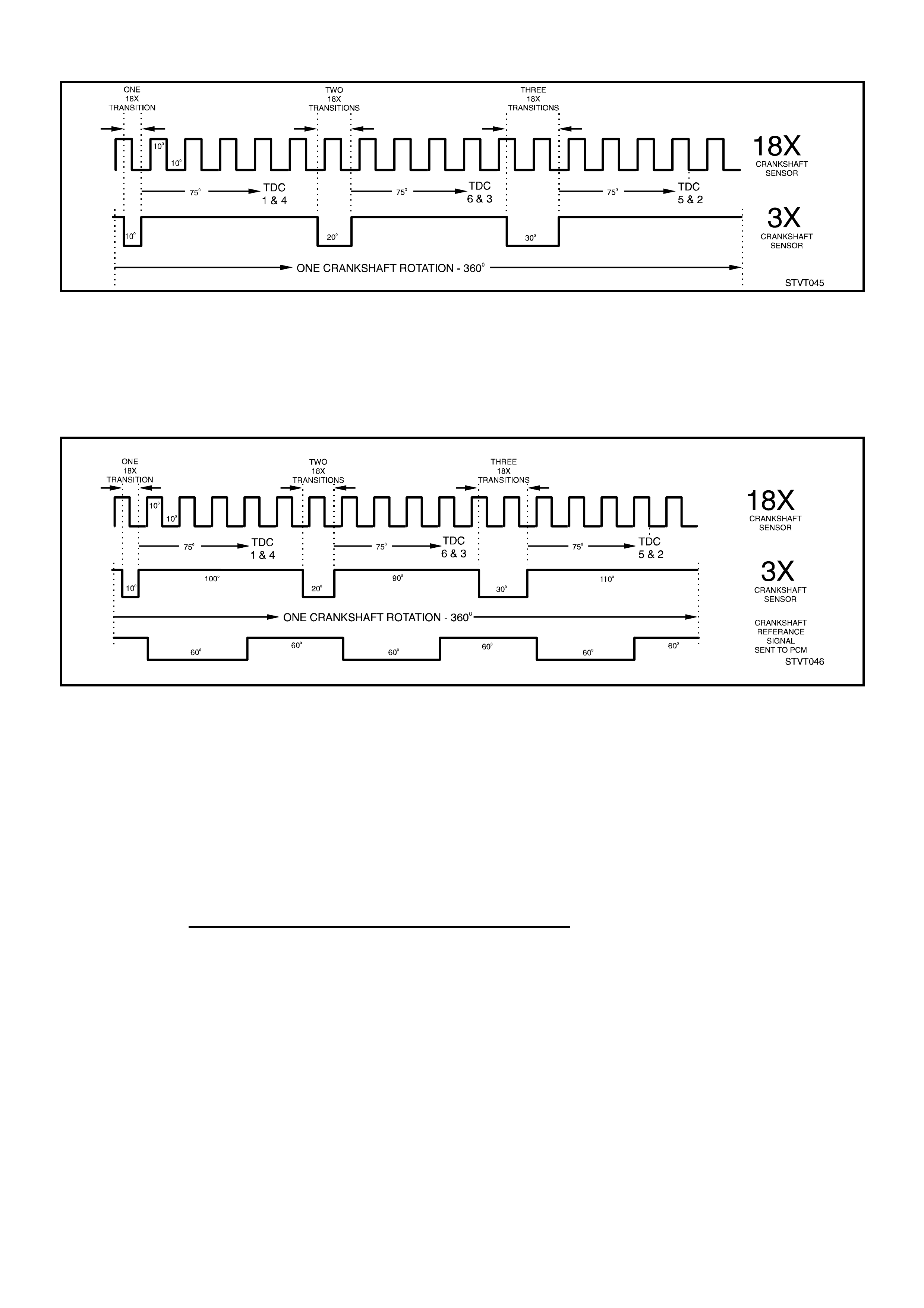
Figure 6C1-1-14 18X and 3X Crankshaft Sensor Pulses for One Crankshaft Revolution Sent To The DIS Module
CRANKSHAFT REFERENCE SIGNAL
The DIS m odule gener ates the c rank shaf t ref erence s ignal b y an inter nal divide- by-6 cir cuit. T his c ircuit div ides th e
18X crankshaft sensor pulses by 6. The divider circuit is enabled, or ready to begin dividing, only after it receives
3X crank shaf t sensor puls es. Af ter beginning, th e divi der circuit does not need the 3X puls es to continue o per ating.
However, if on initial start up either the 18X or 3X pulses are missing, the divider cannot generate any crankshaft
reference signal pulses (sent to the PCM), and no fuel injector pulses will occur.
Figure 6C1-1-15 Crankshaft Reference Signal Sent To The Powertrain Control Module
The PCM interprets engine RPM from this signal. It is also used by the PCM to determine crankshaft position for
EST s park adva nce calcu lations. (T he fal ling edge of the cr ankshaf t refer ence signal pulse occ urs 70 ° before TDC
of an y c ylinder) . The cr ankshaft ref erence signal sent to the PCM b y the DIS m odule is an on-of f pulse occ urring 3
times per crankshaft revolution. This is neither the 3X nor the 18X crankshaft sensor pulse, but both of these are
required by the DIS module to generate the crankshaft reference signal.
The crankshaf t reference signal init iates injector firing. The PCM uses this signal to determ ine engine RPM and is
one of the signals used to control:
• Fuel Delivery • Engine Timing (EST) • Idle (lAC)
• A/C Clutch (ON / OFF) • Canister Purge • Transmission
A failure in the crankshaft reference signal input sensor circuit w ill set a DTC P1372 No Reference Pulses
While Cranking: The engine will not start when this condition exists!
This DTC is intended to help in diagnosing a no-start condition. Anytime the crankshaft is turning, the DIS
(crankshaft sensor & DIS module) should generate the crankshaft reference pulses that the PCM should be
receiving. Fuel injection pulses are TIMED from the crankshaft pulses, and without them no injection pulses will
occur. The PCM can determine when these crankshaft pulses should be present, but aren't.
As with an y engi ne while b eing c rank ed, there is a sm all am ount of intak e air f low. Als o, wh ile cra nk ing, the battery
voltage will be something less than 11 volts. If the PCM's MAF sensor input detects sufficient air flow and the
ignition voltage input is less than 11 volts and there are no crankshaft reference input pulses, a DTC P1372 will set.
NOTE: It is possible for the ignition system to provide spark, yet there may not be any crankshaft
reference pulses at the PCM.
DTC P1372 No Reference Pulses While Cranking will set if DTC P0101 (MAF Air Flow Out Of Range) is not current
and…
• The voltage at the PCM ignition voltage input terminal D16 is less than 11 volts and...
• The MAF sensor input signal is greater than 2048 Hz, and...
• No cr ankshaf t ref erenc e in put pu ls es are r ecei ve d at t he PC M c r ankshaf t r eferenc e inpu t ter minal B9 f or at l east
2 seconds.
HISTORY DATA DTC 1372
PARAMETER PARAMETER
Engine Speed Reference Volts
Coolant Temperature Mass Air Flow
Time From Start Cam Signal
Times Occurred Fuelling Mode
Ignition Cycles Fuel Pump Relay
Fuel LPG Mode
Batter y Voltag e Thef t Status
Default Value
There is no def ault v alue f or the c rank shaf t ref erence s ignal as the PC M us es this s ignal to de term ine if the e ngine
is running an d initiate injec tion pulses. T he engine will not run if the PCM does not receive a crank shaft reference
signal. With no cranks haf t referenc e sign al the PC M will not is sue any injector pulses.
Figure 6C1-1-16 Direct Ignition System Circuit
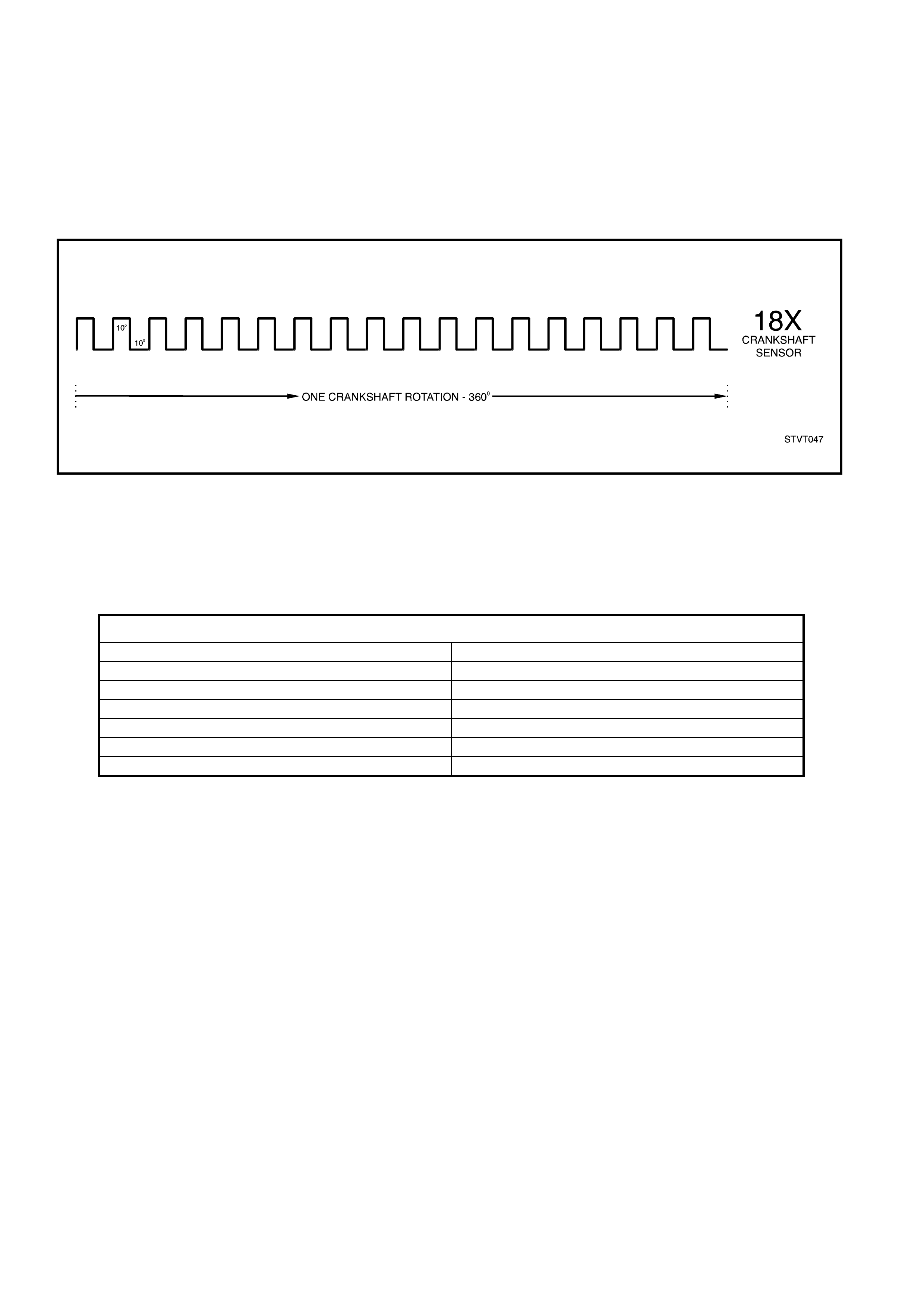
18X REFERENCE SIGN AL
The DIS module provides an interface between the crankshaft position sensor, and the PCM. The DIS module
process es the 18X ref er ence puls es f r om the cranks haf t positi on s e ns or, s e ndi ng t he s i gna l to t he PC M as th e 18X
refer ence s ign al. During no rmal oper ati on the PC M us es the 18X ref er enc e sig na l to det er mine cr ank s haf t pos itio n.
The PCM can calculate true crankshaft position in 1/6 the time that use of the crankshaft reference signal would
permit, this improves the ignition timing accuracy. The 18X reference signal also allows the use of EST mode below
400 RPM, eliminating the need to utilise bypass mode during startup.
The 18X reference signal is used to control:
• High Resolution EST.
Figure 6C1-1-17 18X Reference Signal Sent To The PCM
A failure in the 18X reference signal input sensor circuit will set a DTC P0374 18X Reference Signal
Missing:
DTC P0374 18X Reference Signal Missing will set if:
• The PCM detects 253 crankshaft reference pulses and no 18X signal pulses.
DTC P0374 does not activate the Check Powertrain MIL.
HISTORY DA TA DTC P0374
PARAMETER PARAMETER
Engine Speed Battery Voltage
Coolant Temperature Reference Volts
Time From Start Vehicle Speed
Times Occurred Injector Voltage
Ignition Cycles 18X Times Signal
Fuel 3X Times Signal
Default Value
When DTC P0374 is set and current, the PCM uses the crankshaft reference signal to determine engine speed.
This condition will cause the EST to be degraded; no high resolution spark.
Recovery
Recovery will occur when the PCM sees a valid condition.
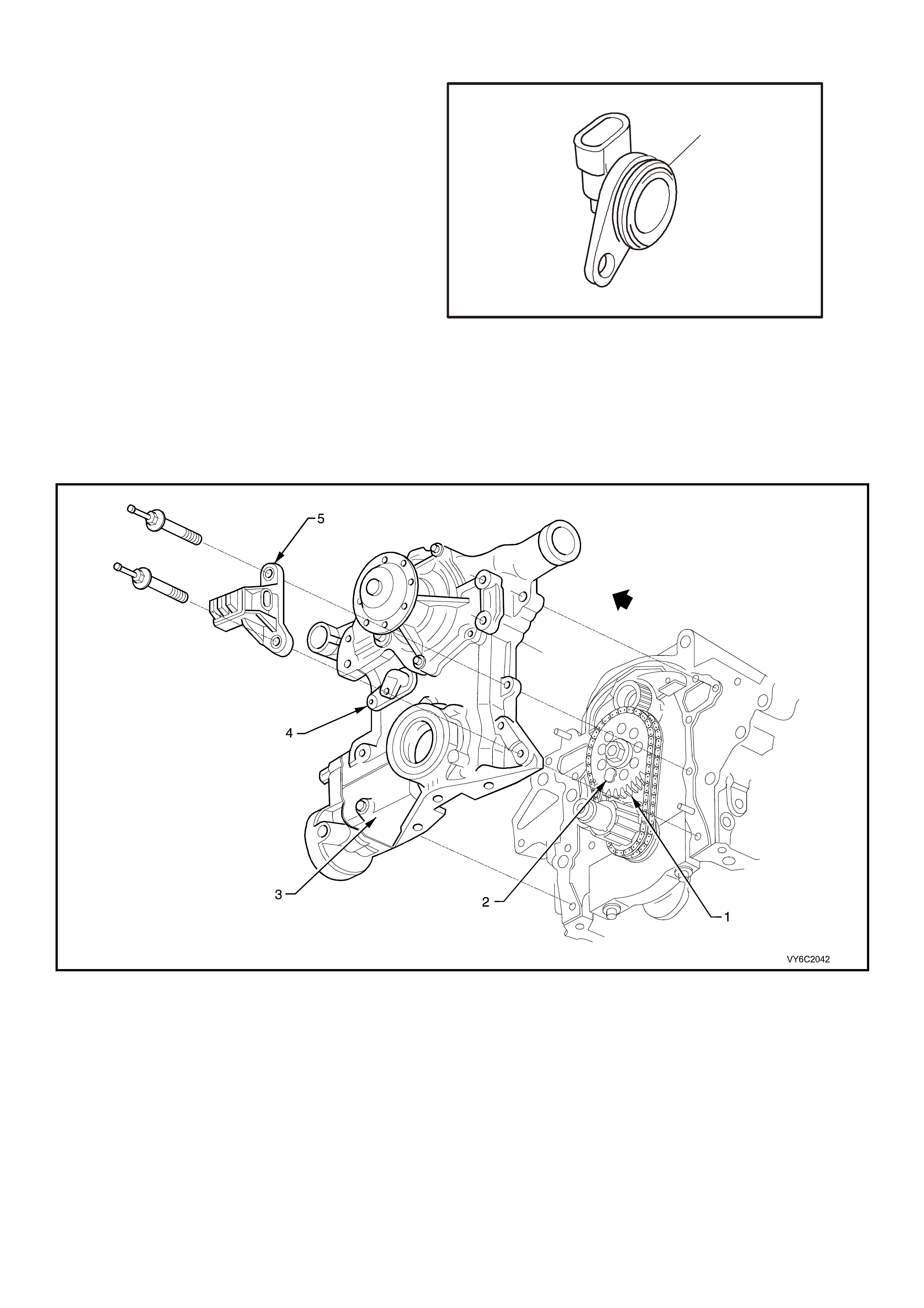
CAMSHAFT POSITION SENSOR
The camshaft position sensor is located in the
engine front cover, behind and below the water
pump, near the camshaft sprocket. As the
camshaft sprocket turns, a magnet mounted on it
activates the Hall Effect switch in the camshaft
position sensor. When the Hall Effect switch is
activated, it ground's the signal line to the DIS
module, pulling the camshaft position signal line's
applied voltage low. This is interpreted as a
camshaft position signal (Synchronisation Pulse).
Because of the way the signal is created by the
camshaft position sensor, the signal circuit is
always either at a high or low voltage (digital
signal).
While the camshaft sprocket continues to turn, the
Hall Effect switch turns off as the magnetic field
passes the camshaft position sensor, resulting in
one signal each time the camshaft makes one
revolution. This signal is sent to the Direct Ignition
System (DIS) module. T he DIS module th en sends
the signal, called a camshaft position signal to the
PCM.
1
4205
Figure 6C1-1-18 Camshaft Position Sensor
Figure 6C2-1-19 – Camshaft and Crankshaft Position Sensor Locations
Legend
1. Camshaft Sprocket
2. Magnetic Interrupter
3. Front Cover
4. Camshaft Position (CMP) Sensor
5. Crankshaft Position (CKP) Sensor
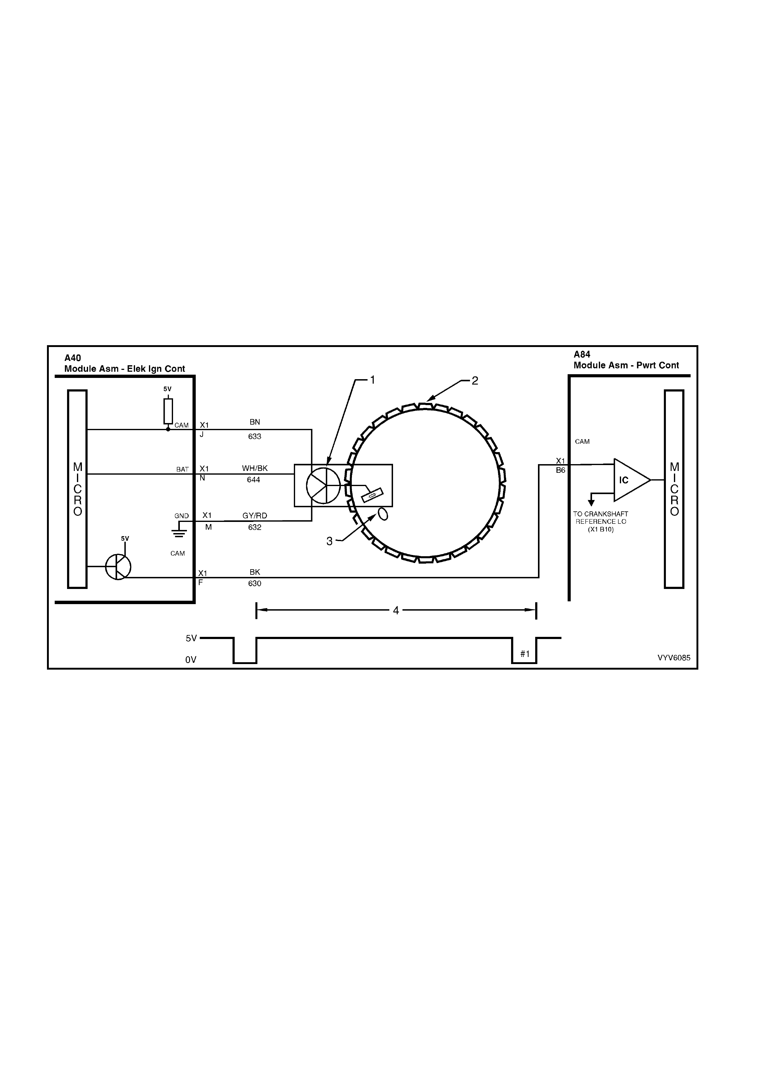
The Camshaft Position Signal
The PCM uses the camshaft position signal to determine the position of the No. 1 piston on its power strok e. This
signal is used by the PCM to calculate sequential fuel injection operation. If the camshaft position signal is lost
while the en gine is running, the f uel injection mode will be base d on t he last f uel injection pu lse, an d t he engine will
continue to r un. The engin e can be restarted and will run in the seque ntial mode with a o ne in six chance of being
correct.
During cr anking, the ignitio n m odule monitors the d ual crankshaf t position sensor 3X signal. The 3X signal is used
to determine the correct cylinder pair to spark first. After the 3X signal has been processed by the ignition module, it
sends a cr ankshaf t r ef er enc e signa l t o th e P C M. When the PCM receives this pul s e it wil l com mand all s ix in j ec tor s
to open for one priming shot of fuel in all cylinders. After the priming, all six of the injectors are left off for two
crankshaft revolutions (six crankshaft reference pulses from the ignition module). This allows each cylinder a
chance to use the f uel from the prim ing shot. During th is waiting period , a camshaf t signal will have been r eceived
by the PC M. Now the PC M begins to o perate the injectors in sequential fuelling m ode by energising each injector
based on true camshaft position. The camshaft signal is also use for Sequential Electronic Spark Control.
If the camshaft positi on s ig nal is not pres en t a t s tar tu p , a DT C P03 42 Cams haf t Pos ition Se ns or S ig na l M iss i ng wil l
set. With the engine running, the PCM monitors the camshaft position signal and crankshaft reference signal and
expects to see a specific number of crankshaft reference signal pulses for each cam pulse. If the sequence of
pulses is not cor rect f or 15 occurr ences, a DT C P03 41 Cam /Cr ank Sens or Sig nal Inter m ittent wil l set, ind icat ing an
intermittent problem with the camshaft or crankshaft reference signals.
Figure 6C2-1-20 – Camshaft Position Signal
Legend
1. Camshaft Position (CMP) Sensor
2. Camshaft Gear 3. Magnetic Interrupter
4. Camshaft Position Signal = One Camshaft Rotation
A failure in the Cam shaft Position Sensor w ill set a DT C P0342 Camshaft Po sit ion Senso r Signal Missing or
DTC P0341 Cam/Crank Sensor Signal Intermittent:
DTC P0342 Camshaft Position Sensor Signal Missing will set if:
• Engine is running and...
• The camshaft position signal has not been received by the PCM for the last five seconds.
DTC P0341 Cam/Crank Sensor Signal Intermittent will set if:
• Engine is running and...
• An incorrect number of crankshaft reference pulses have been received since the previous camshaft position
signal.
A DTC P0341 or P0342 does not activate the Check Powertrain MIL.
HISTORY DATA DTC P0341 AND P0342
PARAMETER PARAMETER
Engine Speed Battery Voltage
Coolant Temperature Reference Volts
Time From Start Vehicle Speed
Times Occurred Injector Voltage
Ignition Cycles 18X Signal
Fuel 3X Signal
Default Value
When a camshaft position signal circuit fault is detected, and current, the control module will operate the fuel
injection system based on the crankshaft reference pulses.
Recovery
Recovery will occur on the next ignition cycle.
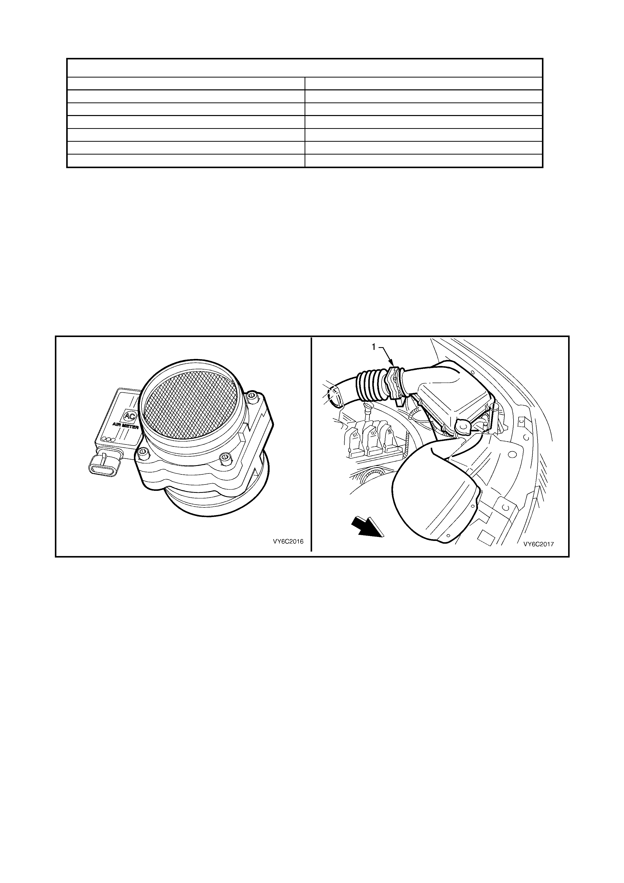
MASS AIR FLOW SENSOR
The Mass Air Flow (MAF) sensor utilises a heated element type of operation. A heated element in the MAF is
placed in the air flow stream of the engine intake system. The heating element is maintained at a constant
temper ature differentia l above the a ir temperature. T he amount of electrical po wer required to m aintain the heated
element at the proper temperature is a direct function of the mass flow rate of the air past the heated element.
Figure 6C2-1-21 – Mass Air Flow Sensor & Location
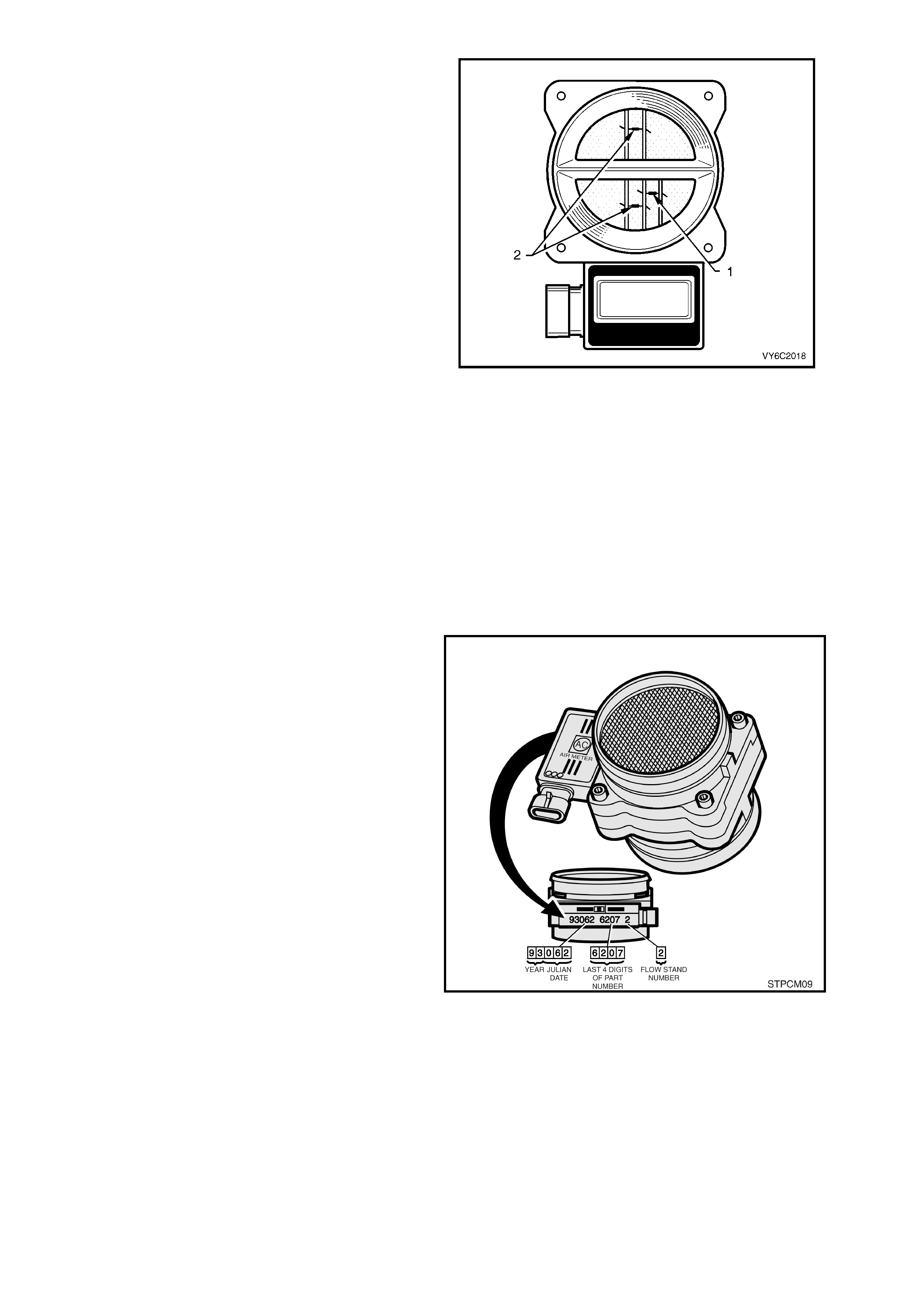
Three sensing elements are used in this system.
One senses ambient air tem perature and us es two
calibrated resistors to establish a voltage that is
always a function of ambient temperature. This
ambient sensor is mounted in the lower half of the
sensor housing. The other two sensing elements
are heated to a predetermined temperature that is
significantly above ambient air temperature. The
two heated elements are connected electrically in
parallel and m ounted directly in the air flow stream
of the sens or hous ing . O ne s ensor is in the top an d
the other sensor is in the bottom of the sensor
housing. This is done so that the air meter is less
sensitive to upstream ducting configurations that
could skew the flow of air through the housing.
As air passes over the heated elements during
engine operation they begin to cool. By measuring
the amount of electrica l power required to m aintain
the heated elements at the predetermined
temperature above ambient temperature the mass
air flow rate can be determined.
Once the mass air flow sensor has developed an
internal signal related to the mass air flow rate, it
must send this information to the PCM. In order to
preserve the accuracy and resolution of the small
voltage signal in the mass air flow sensor, it is
converted to a frequency signal by a voltage
oscillator and sent to the PCM.
Legend:
1. Ambient Temperature Sensor
2. Heater Sensing Elements
Figure 6C1-1-22 MAF Sensing Elements
The s ignal th at is s ent f rom the MAF sensor is s ent
in the form of a frequency output. A large quantity
of air passing through the sensor (such as when
accelerating) will be indicated as a high frequency
output. A small quantity of air passing through the
sensor will be indicated as a low frequency output
(such as when decelerating or at idle). Tech 2
displa ys MAF sens or infor mation in frequenc y, and
in grams per second and calculated in mg per
cylinder. At idle the readings should be low and
increase with engine RPM.
As the PCM receives this varying frequency signal
from the mass air flow sensor, it searches its
preprogrammed tables of information to determine
the pulse width of the fuel injectors required to
match the mass air flow signal.
If the PCM detects a problem in the MAF sensor
circuit, the PCM will store a DTC P0101 in its
memory. The PCM will turn on the Check
Powertrain MIL, indicating there is a problem. If this
occurs , the PCM wil l calc u l ate a subs titu te mas s air
flow signal based on engine speed and throttle
position sensor signal.
Figure 6C1-1-23 MAF Sensor Identification
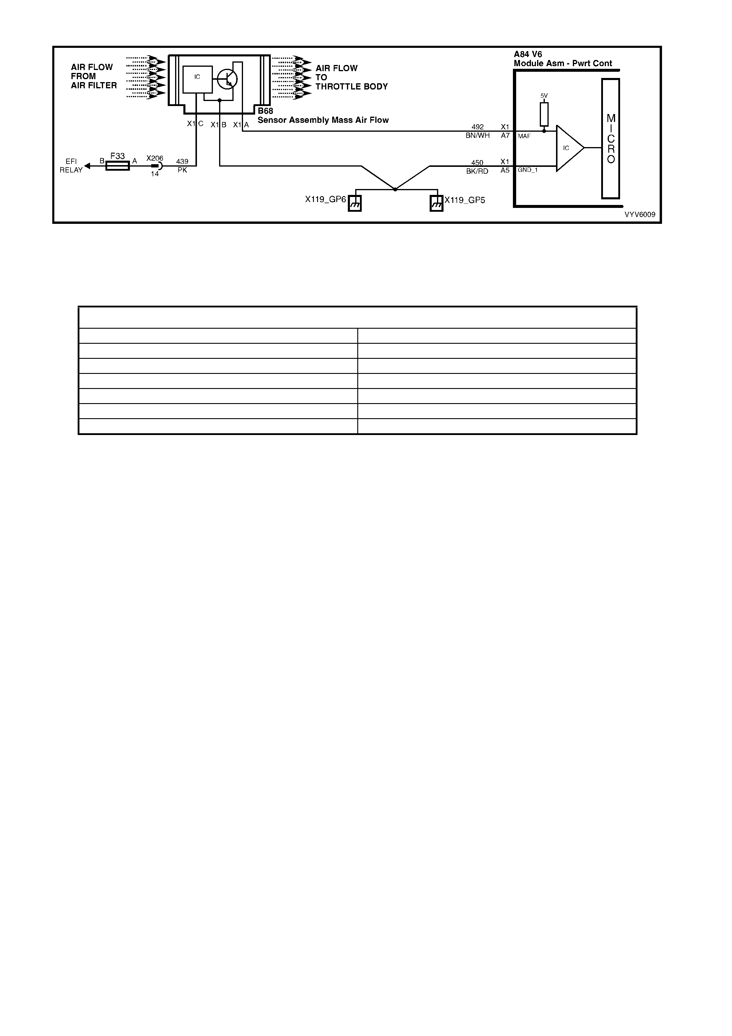
Figure 6C1-1-24 MAF Sensor Simplified Schematic and Sensor Circuit
A failure in the Mass Air Flow sensor or circuit will set a DTC P0101 Mass Air Flow Out of Range:
DTC P0101 Mass Air Flow Out of Range will set if the engine is running and...
• The PCM does not receive a Mass Air Flow sensor signal for more than 2 seconds.
HISTORY DA TA DTC P0101
PARAMETER PARAMETER
Engine Speed Right O2 Sensor
Coolant Temperature Mass Air Flow
Time From Start Right Short Term Fuel Trim
Times Occurred Right Long Term Fuel Trim
Ignition Cycles Throttle Angle
Fuel
Default Value
When a DTC P0101 is current, the PCM will substitute a MAF sensor value based on RPM, throttle position and
IAC position.
Recovery
Recovery will occur when the PCM sees a valid condition.
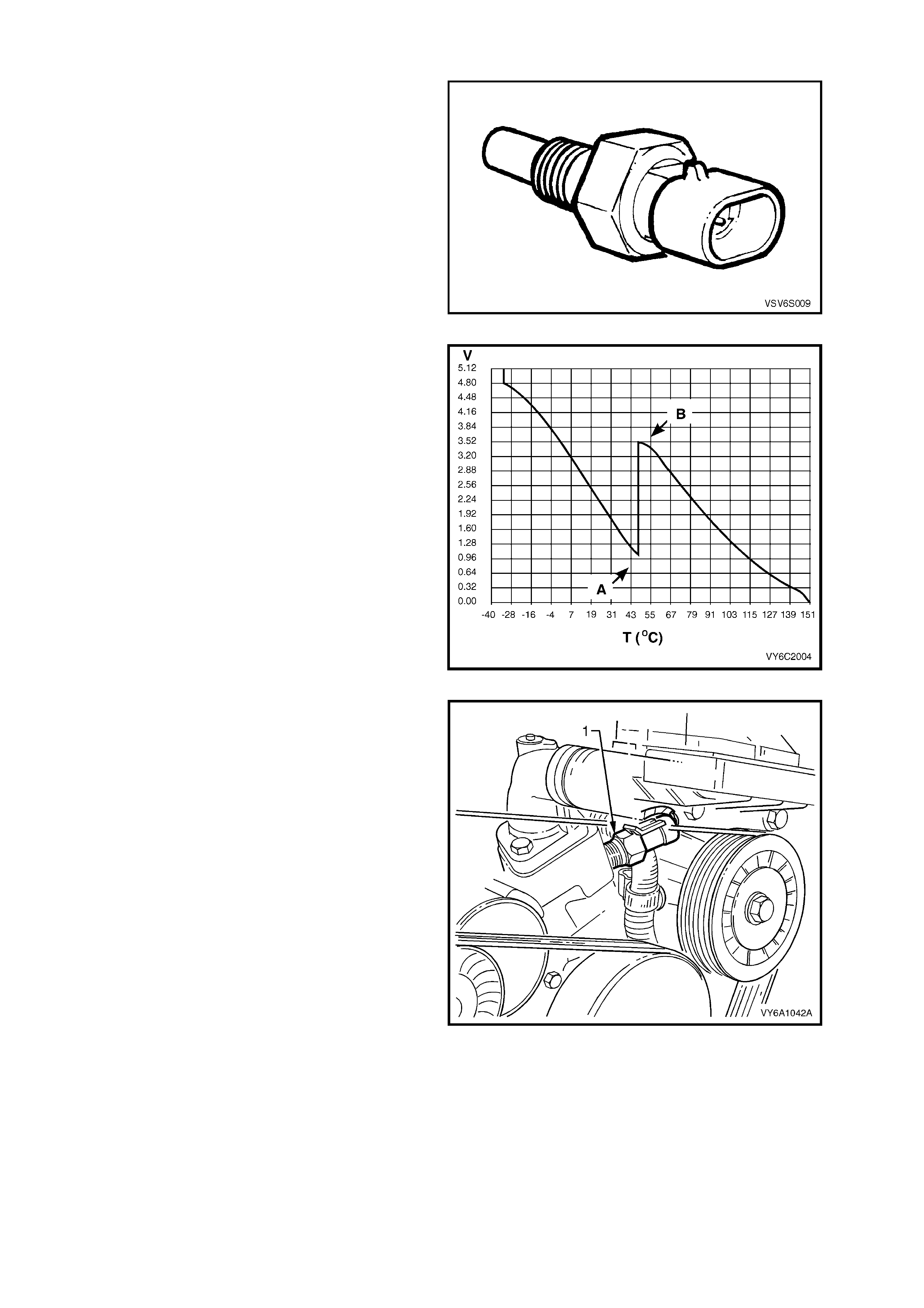
ENGINE COOLANT TEMPERATURE SENSOR
The Engine Coolant Temperature (ECT) sensor is
a thermistor, (a resistor that changes value based
on temperature) mounted in the engine coolant
stream. Low engine coolant temperature produces
a high sensor resistance (28,939 ohms at -20°C)
while high engine coolant temperature causes low
sensor resistance (180 ohms at 100°C).
The PCM supplies a 5 volt signal voltage to the
sensor through a resistor network in the PCM, and
monitors the circuit voltage, which will change
when connected to the sensor.
The circuit voltage will vary depending on the
resistance of the coolant temperature sensor. The
circuit vo ltage will be close to the 5 vo lt level when
the sensor is cold, and will decrease as the sensor
warms. Engine coolant temperature affects most
systems controlled b y the PCM.
The PCM uses a dual pull up resistor network to
increase t he res olut ion thro ugh the e ntir e oper ating
range of engine coolant temperature. When the
coolant temperature is less than 51°C both the 4K
and 348 ohm resistor s are used. When the coola nt
temperature reaches 51°C. The PCM switches a
short across the 4K resistor and only the 348 ohm
resistor is used.
As the engine warms, the sensor resistance
becomes less and the voltage at the PCM coolant
temperature sensor signal terminal should
decrease, from approximately 4.5 volts when cold
to 0.9 volts at 51°C (A). At this temperature the
PCM switc hes the short ac ross the 4K resis tor, the
voltage will then rise to 3.5 volts (B). The voltage
will again decrease as the coolant temperature
increases until at normal engine operating
temper ature (95°C) the vo ltage s hould b e less tha n
2.0 volts.
Legend:
1. Coolant Temperature Sensor
Figure 6C1-1-25 ECT Sensor
Figure 6C1-1-26 ECT Temperature vs Voltage
Figure 6C1-1-27 ECT Sensor Location
Engine Coolant Temperature is one of the inputs used to contr ol:
• Fuel Delivery • Idle Air Control Valve • Canister Purge
• Electronic Spark Timing • Electronic Spark Control • Electric Cooling Fans
• Transmission • Exhaust Gas Recirculation
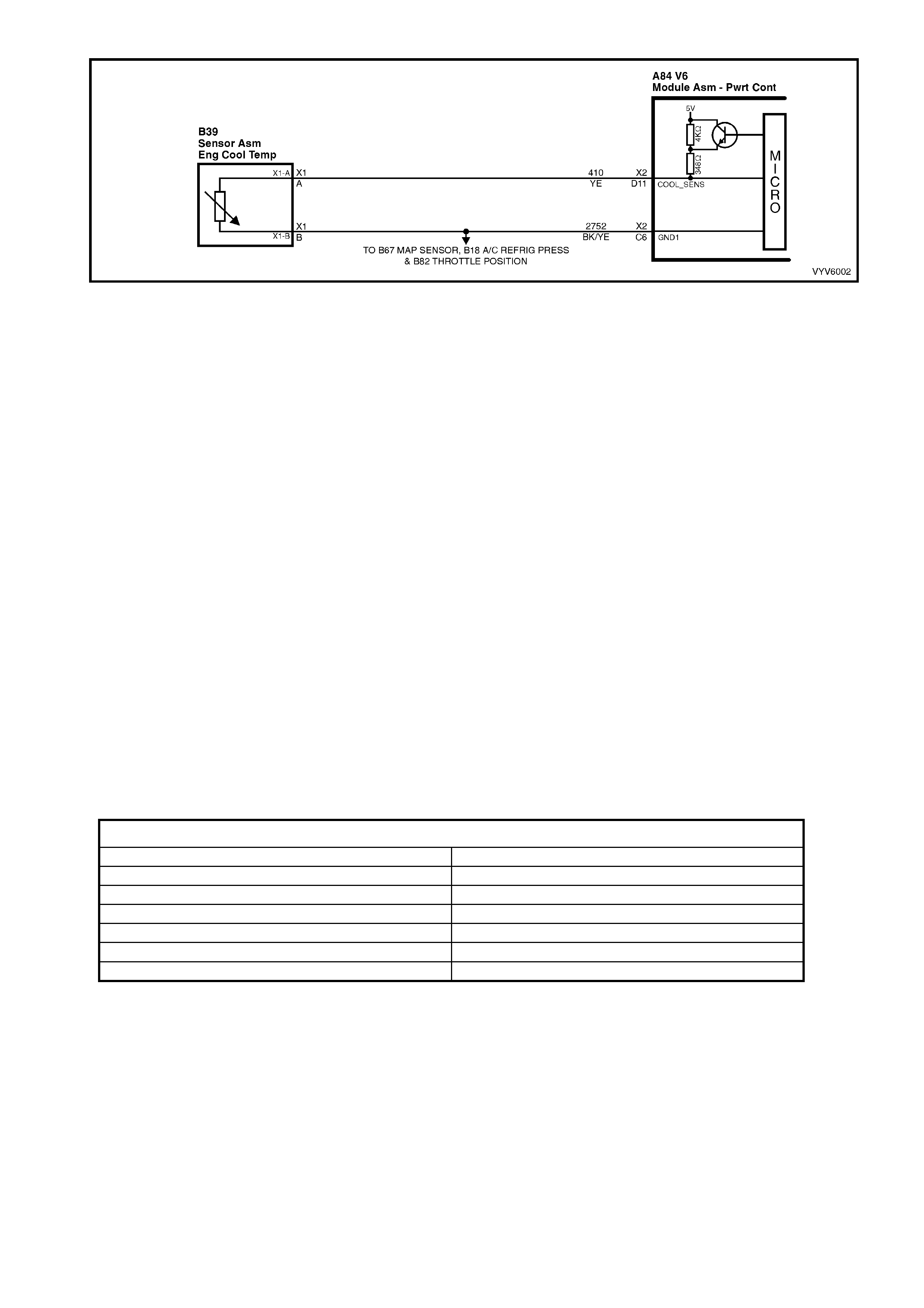
Figure 6C1-1-28 Engine Coolant Temp erature Sensor Circuit
A failure in the ECT sensor or circuit will set either of the following DTCs:
DTC P0117 Engine Coolant Temperature Signal Voltage Low.
DTC P0118 Engine Coolant Temperature Signal Voltage High.
DTC P1116 Engine Coolant Temperature Signal Voltage Unstable.
DTC P1628 PCM Error, Engine Coolant Temperature Circuit.
DTC P0117 Engine Coolant Temperature Signal Voltage Low will set if:
• Engine has been running for more than 20 seconds, and...
• The ECT input signal voltage between the PCM ECT sensor signal terminal X2-D11 and the ECT sensor
ground terminal X2-C6 is less than 0.3 volts for 1 second, indicating a coolant temperature above 140°C.
DTC P0118 Engine Coolant Temperature Signal Voltage High will set if:
• Engine has been running for more than 10 seconds, and...
• The ECT input signal voltage between the PCM ECT sensor signal terminal X2-D11 and the ECT sensor
ground terminal X2-C6 is more than 4.64 volts for 1 second, indicating a coolant temperature less than -30°C.
DTC P111 6 Engine Cool a nt T emperature Signal Volt age Unstabl e will set if DTC P0117, P01 18, or P1 628 ar e
not current and the following conditions exist:
• Engine has been running for more than 10 seconds, and...
• The ECT input signal voltage between the PCM ECT sensor signal terminal X2-D11 and the ECT sensor
ground terminal X2-C6 changes more than 400 mV in 200 milliseconds.
DTC P1116 does not activate the Check Powertrain MIL.
DTC P1628 PCM Error, Engine Coolant Temperature Circuit will set if:
• Engine has been running for more than 10 seconds, and...
• The PCM switches its pull-up resistor and there is less than 60 mV change in the ECT signal voltage.
DTC P1628 does not activate the Check Powertrain MIL.
HISTORY DATA DTC P0117, P0118, P1116 AND P1628
Parameter Parameter
Engine Speed Engine Coolant Temperature Sensor
Coolant Temperature Intake Air Temperature Sensor
Time From Start Intake Air Temperature
Times Occurred Battery Voltage
Ignition Cycles Reference Volts
Fuel
Default Value
When an ECT sensor circuit fault is detected, and current, the PCM will substitute a coolant temperature default
value based on the intake air temperature at engine startup and engine run time.
NOTE: When a DTC P0117, P0118, P1116 or P1628 is current, the PCM will turn on the electric engine
cooling fan/s. This is a “Fail-Safe” action by the PCM to prevent a possible engine overheat condition,
since these DTC's indicate an unknown actual coolant temperature.
If the ECT sensor circuit opens (or is open) with the ignition off, the PCM will interpret -40°C and deliver enough
fuel to start the engine at that temperature. If the actual temperature is above 0°C, the engine may flood and not
start unless “Clear Flood Mode” is used by fully depressing the accelerator while cranking. The Check Powertrain
MIL will not activate, and a DTC will not set until engin e has run f or 10 s econds . In the CLEAR F LOOD MOD E the
injector pulse width is set to zero milliseconds.
Recovery
Recovery will occur when the PCM sees a valid condition.
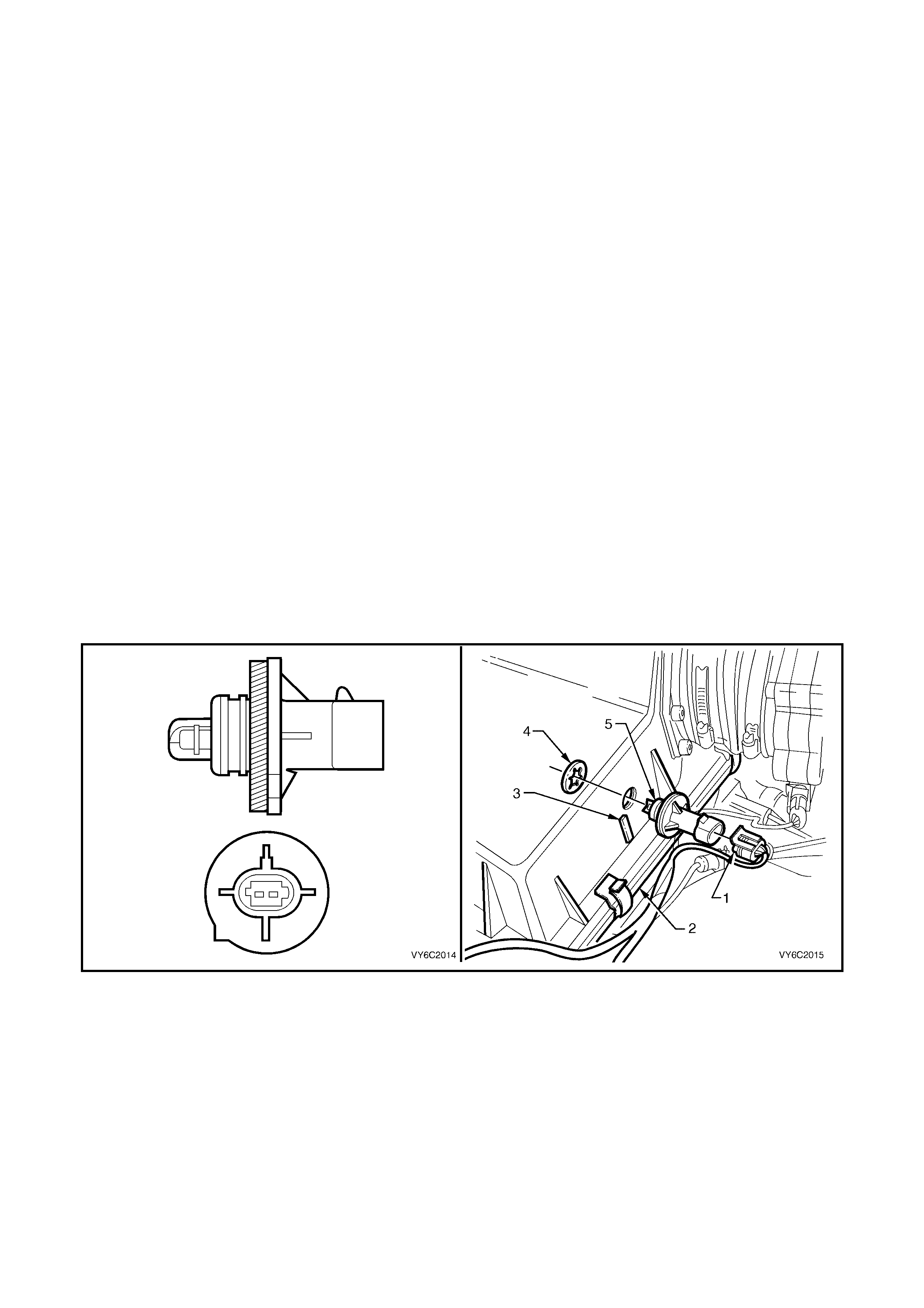
INT AKE AI R TEM PERATU RE SENSOR
The Intake Air Temperature (IAT) sensor is a thermistor, (a resistor that changes resistance with changes in
temperature) mounted in the air cleaner housing of the intake system. Low intake air temperature produces high
resistance in the sensor, approximately 100,866 ohms at -40°C, while high intake air temperature causes low
sensor resistance, approximately 78 ohms at 130°C.
The PCM:
1. Supplies a 5 volt signal voltage to the sensor through a resistor in the PCM, and
2. Monitors the intake air temperature circuit voltage, which will change when connected to the intake air
temperature sensor.
The circuit voltage will vary depending on the resistance of the IAT sensor. The voltage will be close to the 5 volt
level when the sensor is cold, and will decrease as the sensor warms.
The IAT sensor signal voltage is use d by the PCM to assist in calculating the fuel injector pulse width, idle speed,
canister purge and electronic spark timing.
INTAKE AIR TEMPERATURE IS ONE OF THE INPUTS USED TO CONTROL:
• Electr o nic Spark Tim ing
• Canister Purge
A failure in the IAT sensor circuit should set either a DTC P0112 or DTC P0113. An intermittent failure in the IAT
sensor circuit will set DTC P0111.
Figure 6C2-1-29 – IAT Sensor & Location
Legend
1. Wiring Harness Connector
2. Air Cleaner Upper Housing
3. Mating Tang
4. Retainer
5. IAT Sensor
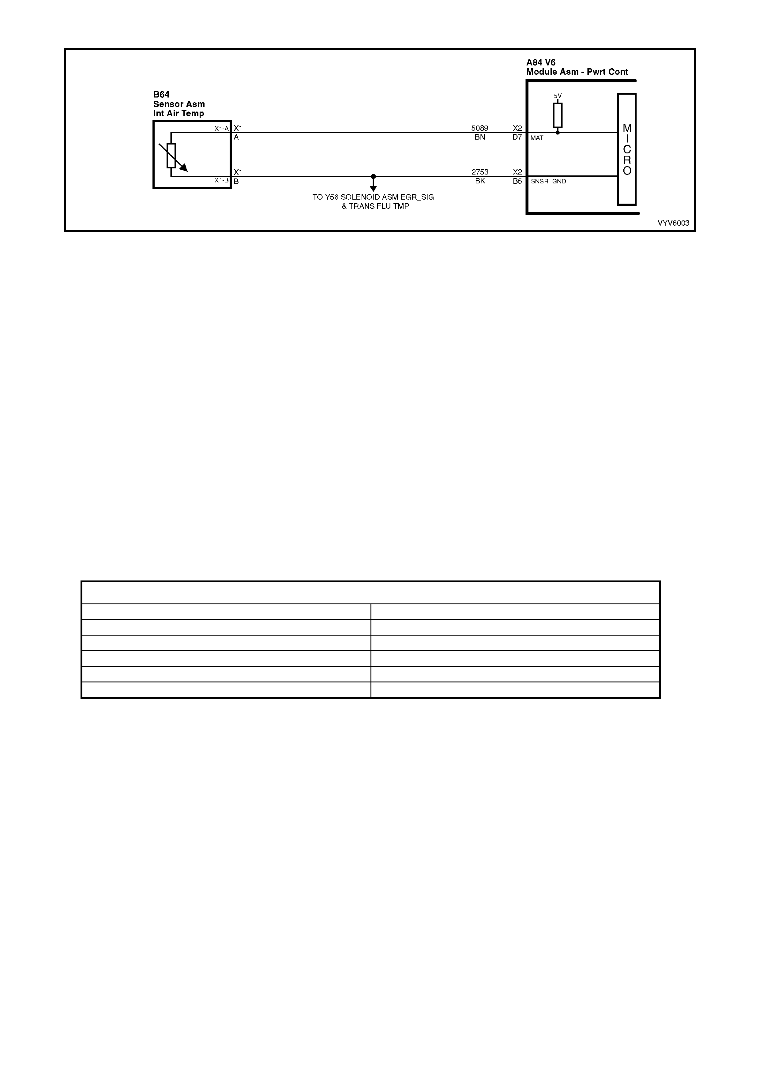
Figure 6C1-1-30 Intake Air Temperature Sensor Circuit
A failure in the IAT sensor or circuit will set either of the following DTCs:
DTC P0112 Intake Air Temperature Signal Voltage Low.
DTC P0113 Intake Air Temperature Signal Voltage High.
DTC P0111 Intake Air Temperature Signal Voltage Unstable.
DTC P0112 Intake Air Temperature Signal Voltage Low will be set if:
• The IAT sensor voltage between the PCM IAT sensor signal terminal X2-D7 and the IAT sensor ground
term inal X2-D 6 is l ess than 0.3 volts ind icat ing an inta ke air tem perature gr eater than 147 °C for m or e than one
second.
DTC P0113 Intake Air Temperature Signal Voltage High will be set if:
• The IAT sensor voltage between the PCM IAT sensor signal terminal X2-D7 and the IAT sensor ground
term inal X2-D6 is greater than 4.9 volts indicat ing an i ntake air tem perature les s than - 36°C f or mor e than one
second.
DTC P0111 Intake Air Temperature Signal Voltage Unstable will be set if:
• the engine has been operating for more than 10 seconds and....
• The IAT sensor voltage between the PCM IAT sensor signal terminal X2-D7 and the IAT sensor ground
terminal X2-D6 changes more than 140 mV in 100 milliseconds.
A DTC P0112, P0113 or P0111 does not activate the Check Powertrain MIL.
HISTORY DATA DTC P0112, P0113 AND P0111
PARAMETER PARAMETER
Engine Speed Fuel
Coolant Temperature Engine Coolant Temperature Sensor
Time From Start Intake Air Temperature Sensor
Times Occurred Battery Voltage
Ignition Cycles Reference Volts
Default Value
Once an IAT sensor DTC P0112, P0113 or P0111 is set, and current, the PCM will substitute an IAT value of 25°C.
Recovery
Recovery will occur when the PCM sees a valid condition.
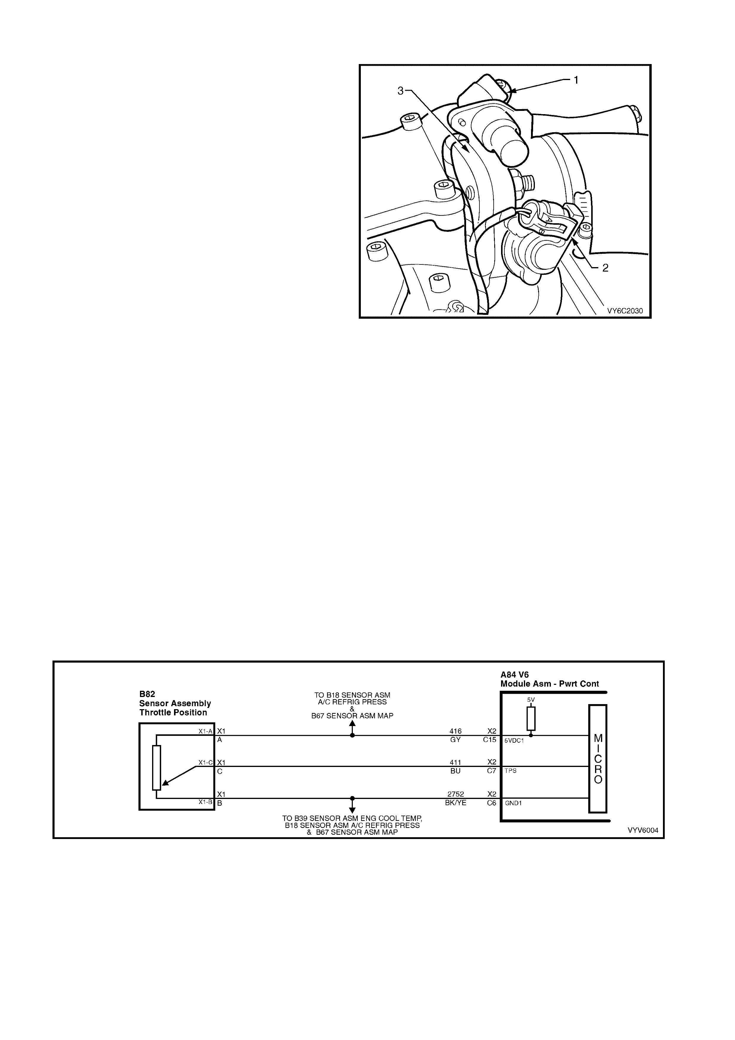
THROTTLE POSITION SENSOR
The Throttle Position (TP) sensor is connected to
the throttle shaft on the throttle body unit. It is a
potentiometer with one end connected to 5 volts
from the PCM an d the ot her end to PCM grou nd. A
third wir e connects f rom a sliding c ontact in t he TP
sensor to the PCM allowing the PCM to measure
the voltage from the TP sensor. As the throttle is
moved ( ac celer at or pe dal moved), the outp ut of th e
TP sensor changes. At a closed throttle position,
the output of the TP sensor is below 1.25V. As the
throttle valve opens, the output increases so that,
at wide-open throttle (WOT), the output voltage
should be about 4 volts.
By monitoring the output voltage from the TP
sensor, the PCM can det er mine f uel de livery based
on throttle valve angle (driver demand). A broken
or loos e TP s ensor c an ca use in term ittent b ursts of
fuel from the injectors, and an unstable idle,
because the PCM interprets the throttle is moving.
The TP s ensor is not adjust able and t here is no set
value for voltage at closed throttle because the
actual voltage at closed throttle can vary from
vehicle to vehicle due to tolerances. The PCM has
a specia l progr am built int o it that c an adj us t f or the
toleranc es in the T P sensor volt age readi ng at idle.
The PCM uses the reading at closed throttle idle
for the zero reading (0% throttle) so no adjustment
is necessary. Even if the TP sensor voltage
reading was to be changed by: tampering, throttle
body coking, sticking cable or any other reason,
the TP sensor will still be 0%. The PCM will learn
what the closed throttle value is every time the
throttle comes back to closed throttle.
A failure in the TP sensor circuit will set a DTC
P0122 or P0123. If the internal spring in the TP
sensor s houl d f ail, t he TP sens or will b e s tuck high.
A sticking TP sensor will set DTC P0121.
Figure 6C1-1-31 Throttle Position Sensor Location
Legend
1. Idle Air Control (IAC) Valve
2. Throttle Position (TP) Sensor
3. Throttle Body
THROTTLE POSITION IS ONE OF THE INPUTS USED TO CONTROL:
• Fuel Delivery • Electro nic Spark Control • Idle Air Control Valve
• Canister Purge • Transmission • Exhaust Gas Recirculation
Figure 6C1-1-32 Throttle Position Sens or Circuit
A failure in the throttle position sensor or circuit will set either of the following DTCs:
DTC P0121 Throttle Position Sensor Stuck.
DTC P0122 Throttle Position Sensor Voltage Low.
DTC P0123 Throttle Position Sensor Voltage High.

DTC P0121 Throttle Position Sensor Stuck will be set if:
• The throttl e posit ion sensor indicat ed percent age of opening is greater t han the R PM that c an be re ached wi th
a mass air flow of less than 301 mg/cyl.
DTC P0122 Throttle Position Sensor Voltage Low will be set if:
• The throttle position sensor vo ltage between the throttle position sensor signal terminal X2-C7 and the sensor
ground terminal X2-C6 is less than 0.2 volts for more than 2 seconds.
DTC P0123 Throttle Position Sensor Voltage High will be set if:
• The throttle position sensor vo ltage between the throttle position sensor signal terminal X2-C7 and the sensor
ground terminal X2-C6 is greater than 4.9 volts for more than 2 seconds.
HISTORY DATA DTC P0121, P0122 AND P0123
PARAMETER PARAMETER
Engine Speed Throttle Position Sensor Signal
Coolant Temperature Mass Air Flow
Time From Start Right Long Term Fuel Trim
Times Occurred Battery Voltage
Ignition Cycles Reference Volts
Fuel
Default Value
Once a throttle position sensor DTC is set and current, the PCM will substitute a throttle position sensor value
based on idle air control valve position, mass air flow and engine speed.
Recovery
Recovery will occur when the PCM sees a valid condition.
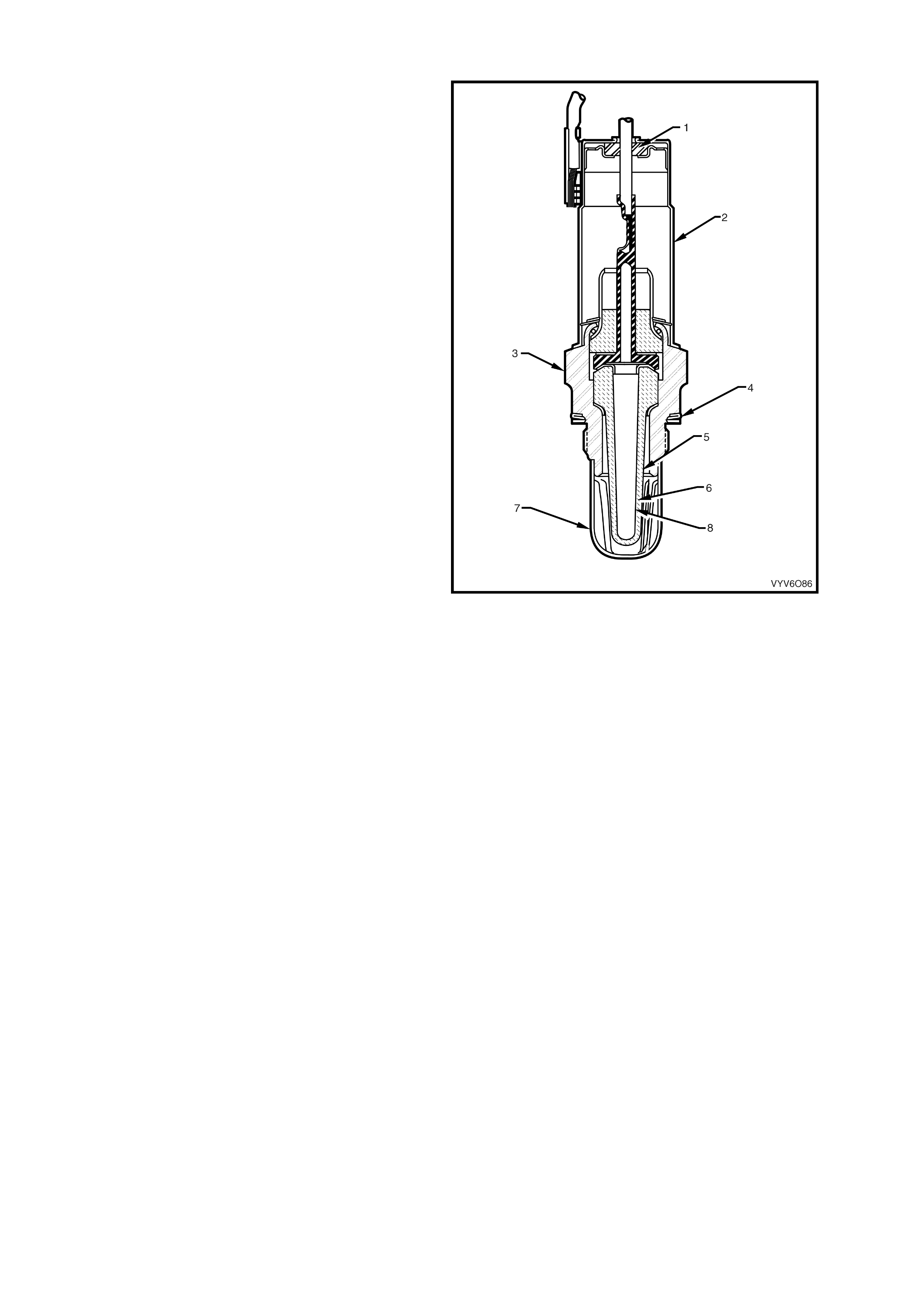
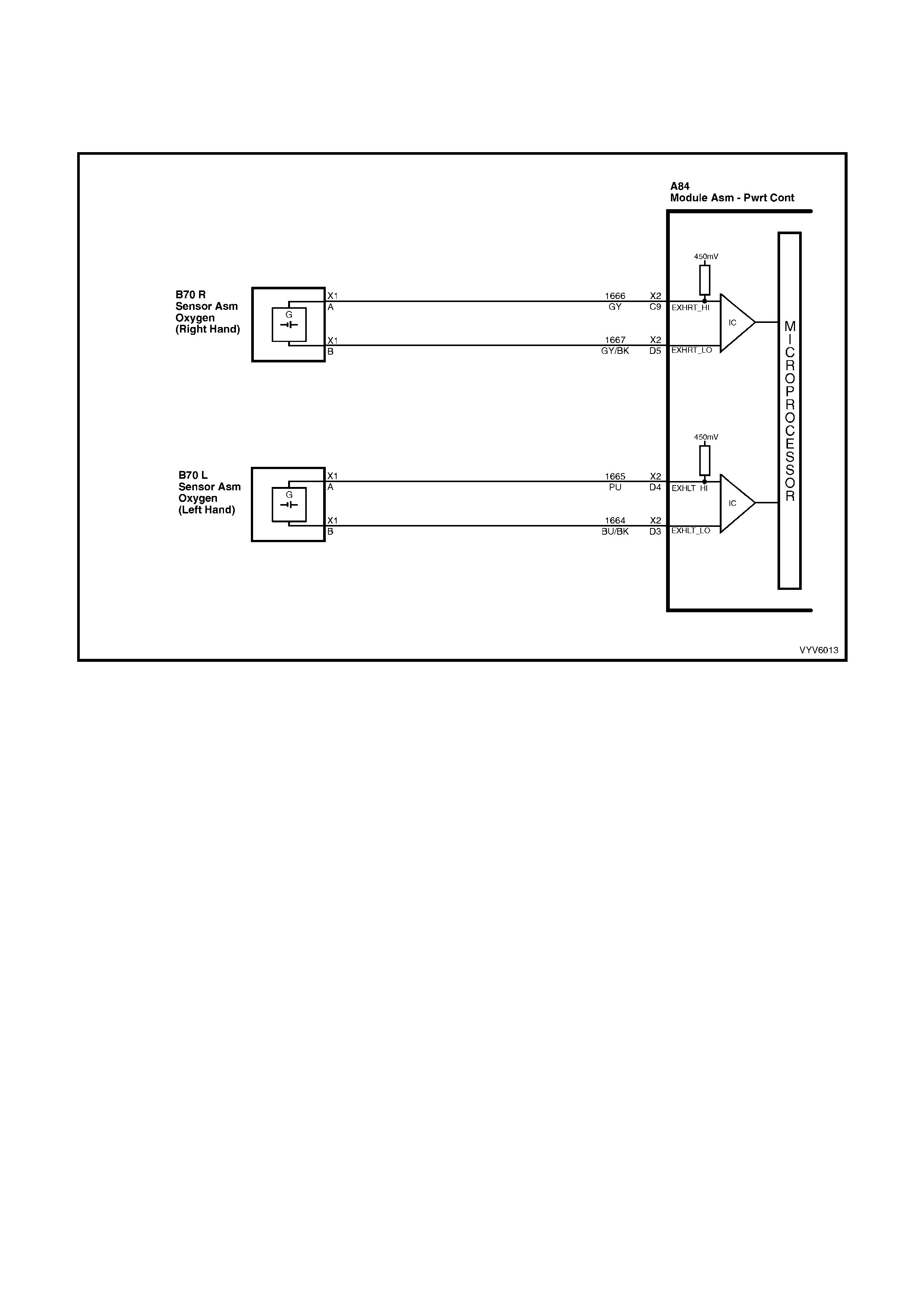
EXHAUST GAS OXYGEN SENSORS
The engine management system incorporates the
use of two exhaust gas oxygen sensors. The
oxygen sensors are the key to closed-loop fuel
control. The PCM uses information from the
oxygen sensors to precisely fine tune its fuel
injector pulse width calculations, based on the
unused, left-over oxygen content in the exhaust.
The V6 non supercharged engine uses two, two
wire unheated oxygen sensors. The oxygen
sensors have a zir coni a ele m ent that, whe n heat ed
to temperatures above 360°C, produce voltages
based on the amount of oxygen content
surrounding the tip, as compared to oxygen in the
atmosphere.
The s ensor is m ounted in the exha ust pi pe with t he
sensing portion exposed to the exhaust gas
stream. When the sensor has reached an
operating temperature of more than 360°C, it acts
as a voltage generator, producing a rapidly
changing voltage of between 10 - 1000 millivolts.
This voltage output is dependent upon the oxygen
content in the exhaust gas, as compared to the
sensor's atmospheric oxygen referenc e cavity. The
reference cavity of an un-heated oxygen sensor is
exposed t o the atmospher e throug h th e bo d y of the
oxygen sensor.
When the sensor is cold, it produces either no
voltage, or an unusable , slowl y c hanging one. A lso
when cold, its internal electrical resistance is
extremely high - many million ohms. The PCM
always supplies a steady 450 millivolt, very low
current bias voltage to the oxygen sensor circuit.
When the sensor is cold and not producing any
voltage, the PCM detects only this steady bias
voltage. As the sensor begins heating, its internal
resistance decreases and it begins producing a
rapidly changing voltage that will overshadow the
PCM's supplied steady bias voltage. When the
PCM detects the changing voltage, it knows the
oxygen sensor is hot and its output voltage can be
used for fine-tuning the fuel injector pulse width.
The PCM monitors the oxygen sensor's changing
voltage for going above and below a mid-range
voltage band (approximately 300 - 600 millivolts),
to help decide when to operate in the closed-loop
mode.
Legend:
1. Seal
2. Upper Shield
3. Body
4. Seat Gasket
5. Outer Electrode and Protective Coating
6. Zi rconia Element
7. Lower Shield
Figure 6C1-1-33 Two Wire unheated Oxygen Sensor
When the fuel system is correctly operating in the closed-loop mode, the oxygen sensor voltage output is rapidly
changing several times per second, going above and below a rich/lean band. The PCM monitors the changing
voltage, and decides the needed fuel mixture correction.
An open sensor signal circuit or ground circuit, or a defective, contaminated, or cold sensor could cause the voltage
to stay with in a 350- 550 milliv olt band f or too long, k eeping the f uel contr ol syste m in open- loop and s etting a DT C
P0134 No Right Hand Oxygen Sensor Signal or DTC P0154 No Left Hand Oxygen Sensor Signal.
If the PCM m onit ors a lo w voltag e f or too long indic ating a lea n exhaus t, a DT C P0131 R ight Han d Ox ygen Senso r
Signal Vo ltage Low or DTC P015 1 Left Hand Ox yge n Sensor Signal V oltage Low will st ore in mem ory. If the PCM
monitors a high oxygen sensor circuit voltage for too long indicating a rich exhaust, a DTC P0132 Right Hand
Oxygen Sensor Signal Voltage High or DTC P0152 Left Hand Oxygen Sensor Signal Voltage High will store in
memory.
Figure 6C1-1-34 Oxygen Sensor Circuits
RESPONSE TIME
Not only is it necessary for the oxygen sensors to produce voltage signals for rich or lean exhaust, it is also
important to respond quickly to changes. The PCM senses the response times and displa ys th is on Tech 2 as the
rich-lean status and as cross counts. If the oxygen sensors respond slowly, the customer may complain of poor fuel
economy, rough idle, surging or lack of performance. It may also set false PCM DTC’s because the PCM uses
oxygen sensor voltages for system checks.
OXYGEN SENSOR CONTAMINANTS
Carbon
Black carbon or soot deposits result from over-rich air-fuel mixtures. However, carbon does not harm an oxygen
sensor. Deposits can be burned off in the vehicle by running the engine at part throttle for at least two minutes.
Silica
Certain RT V silicone gasket m aterials give off vapour as they cure that may contaminate the ox yge n sensor. This
contamination is usually caused by the vapours being pulled from the PCV system, into the combustion chamber
and passed on to the exhaust system.
The s and like particles f rom the RT V silica em bed in the molec ules of the ox ygen sensor e lement and pl ug up the
surf ace. W ith the outside of the ox ygen se nsor el em ent not able t o sense a ll of the ox ygen in th e exhaus t s ystem it
results in lazy oxygen sensor response and eng ine control. T he oxygen sensor will have a whitish appearance on
the outside if it has been contaminated.
There is also a possibility of silica contamination caused by silicone in the fuel. Some oil companies have used
silico ne to rais e the oc tane r ating of their fuel. Careles s f uel handli ng practic es with tr ansport c ontainers can result
in unacceptable concentrations of silicone in the fuel at the pump.
Silica contamination can be caused by silicon in lubricants used to install vacuum hoses on fittings. Do not use
silicone sealers on gaskets or exhaust joints.
Lead
Lead glazing of the sensors can be introduced when regular, or leaded fuel is burned. It is difficult to detect lead
contam inati on b y visu al ins pec tio n.
Other Substances
Oil deposits will ultimately prevent oxygen sensor operation. The sensor will have a dark brown appearance.
Causes of high oil consumption should be checked.
The addit iv es in et hylene glyc ol can also af f ec t oxygen sensor per f orm anc e. T his pr oduc es a gr e enis h app ea r ance.
If antifreeze enters the exhaust s ystem, you will likely encounter other, more obvious s ym ptoms of cooling system
trouble. If for example the engine had a head gasket failure where coolant did enter the combustion chamber, it
would be a good idea to check the oxygen sensor operation after the head gasket was repaired.
Multiple Failures
If you encounter multiple or repeated oxygen sensor failures on the same vehicle, consider contamination.
Leaded fuel, silica contamination from uncured, low-grade (unapproved) RTV sealant, and high oil consumption are
possible causes.
A problem in the oxygen s ensor cir cuit or f uel s ys tem s hould set a DT C. Refer to appl icable d iagnostic chart if any
of these DTC’s are stored in memory.
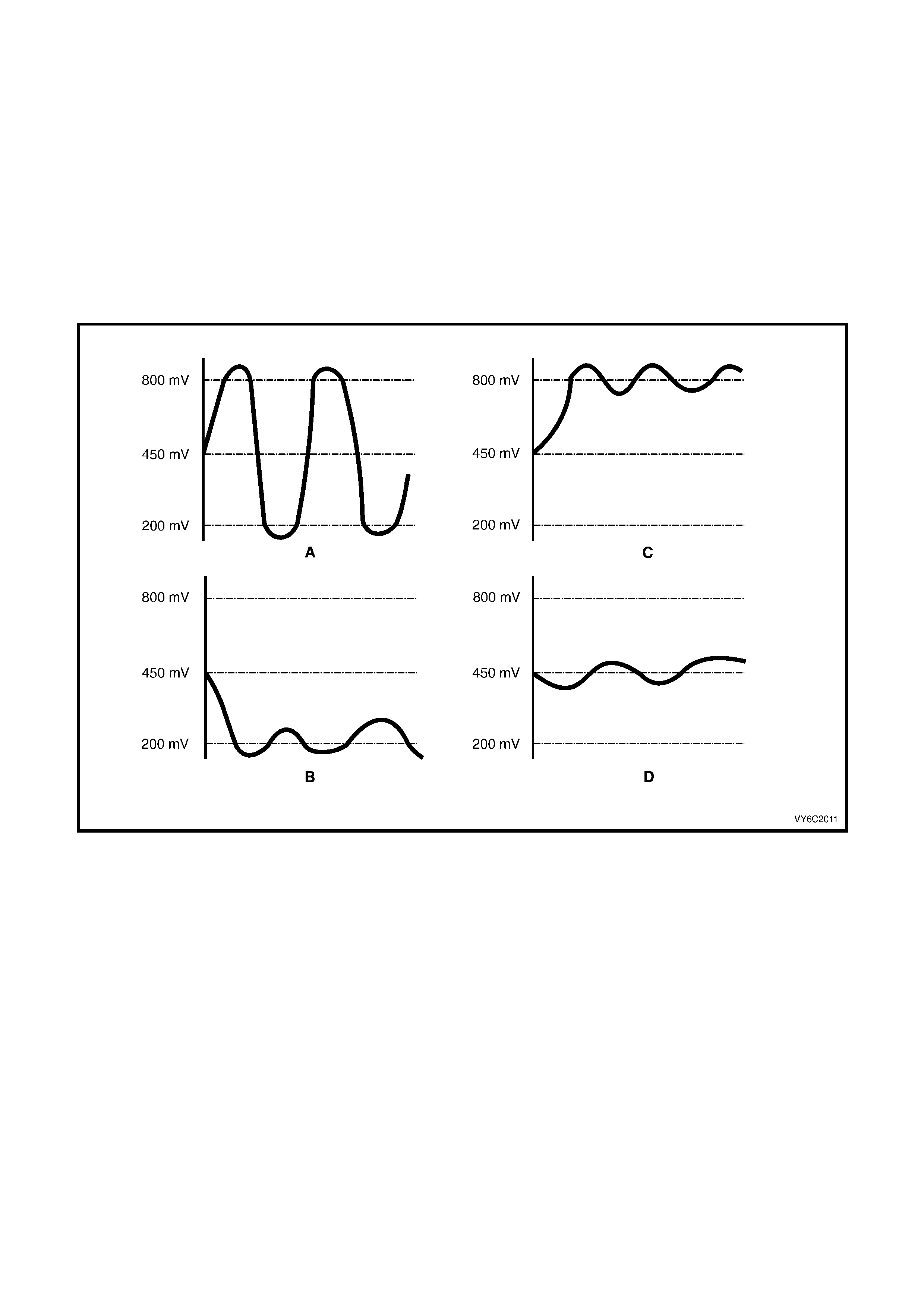
Figure 6C2-35 Typical Oxygen Sensor Voltage Curves
Legend
A. Normal, Closed Loop Operation
B. Lean – Below 200 mV for too long in Closed Loop (DTC P0131 or P0151 Will Set)
C. Rich – Above 780 mV for too long in Closed Loop (DTC P0132 or P0152 Will Set).
D. Between 410 – 477 mV for too long (DTC P0134 or P0154 Will Set).
800 mV – Rich
450 mV – PCM O2 Reference Signal
200 mV – Lean
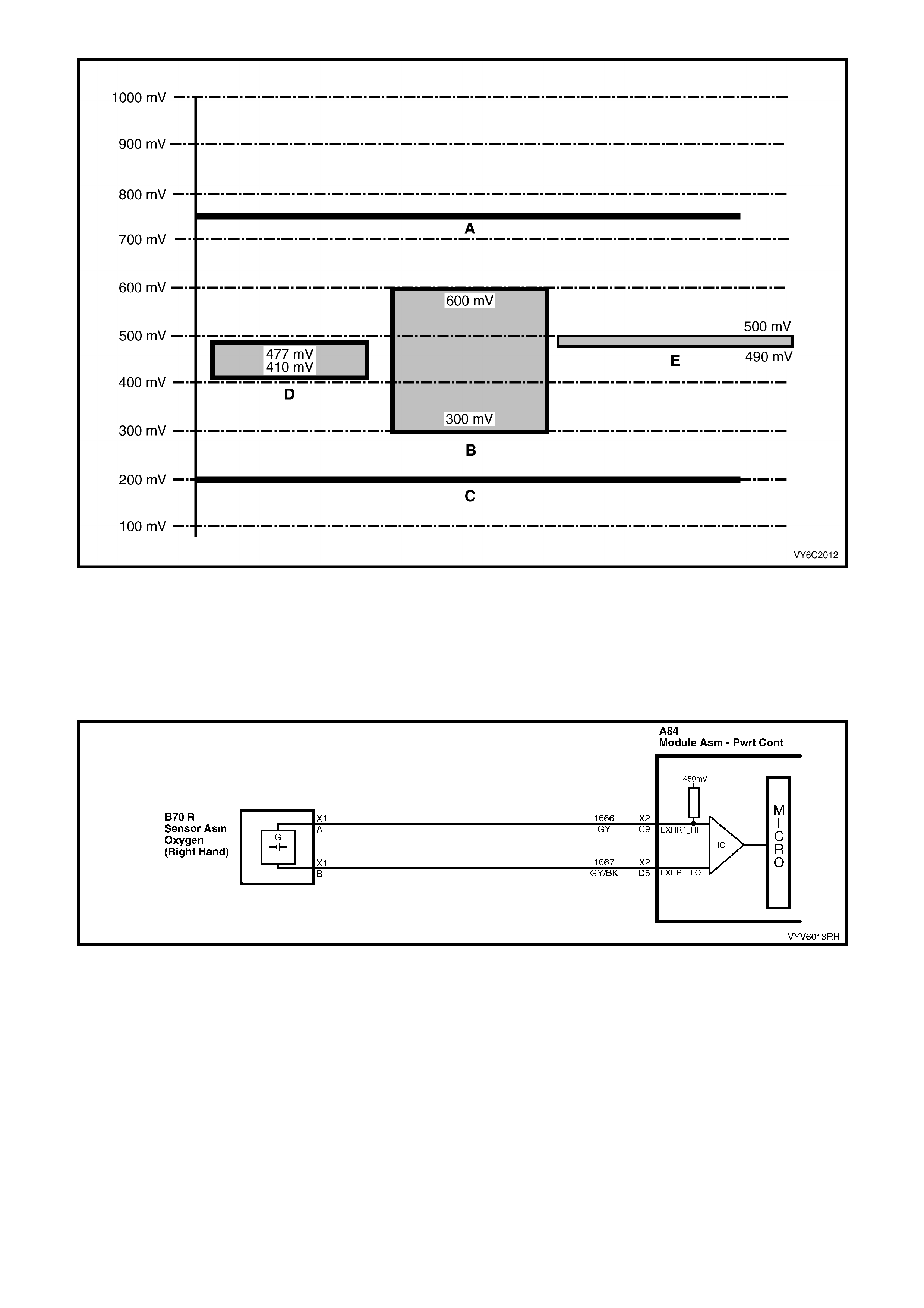
Figure 6C2-1-36 Typical Oxygen Sensor Voltages, and Abnormal Trends
Legend
A. More than 780 mV for Too Long (plus other parameters). (DTC P0132 or P0152 Will Set)
B. “Ready” Test
C. Less than 200 mV for Too Long (plus other parameters). (DTC P0131 or P0151 Will Set)
D. Between 410 and 477 mV (DTC P0134 or P0154 Will Set)
E. Rich-Lean Band at a Hot Idle (between 490 and 500 mV)
Figure 6C2-1-37 Right Hand Oxygen Sensor Circuit
A failure in the right hand oxygen sensor, circuits or a system malfunction that causes the system to run
too rich or too lean will set either of the following DTCs:
DTC P0131 Right Hand Oxygen Sensor Signal Voltage Low.
DTC P0132 Right Hand Oxygen Sensor Signal Voltage High.
DTC P0134 No Right Hand Oxygen Sensor Signal.
DTC P0131 Right Hand Oxygen Sen sor Signal Voltage Low w ill set if the fuel control system is operat ing in
the closed loop mode, DTC P0121, P0122 or P0123 are not current and...
• The Intake Air Temperature sensor signal is below 75°C and....
• The right hand oxygen sensor signal voltage between the PCM oxygen sensor signal terminal X2-C9 and the
oxygen sensor ground terminal X2-D5 has remained below 200 millivolts (0.200 volts) for more than 248
seconds.
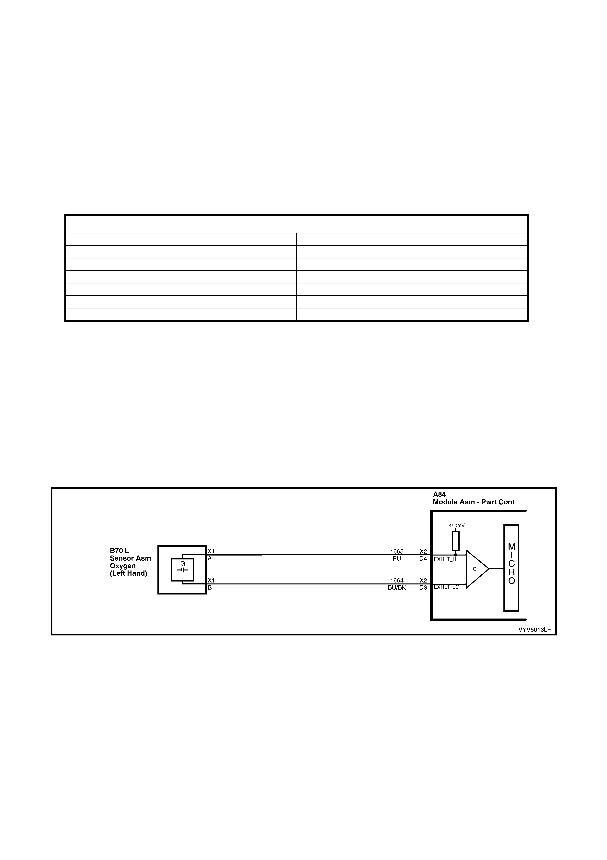
DTC P0132 Right Hand Oxygen Sensor Signal Voltage High will be set if the fuel control system is
operating in the closed loop mode, DTC P0121, P0122 or P0123 are not current and...
• The Throttle Position sensor voltage indicates the throttle is open between 9% and 30% and...
• The right hand oxygen sensor signal voltage between the PCM oxygen sensor signal terminal X2-C9 and the
oxygen sensor ground terminal X2-D5 is greater than 780 millivolts (0.780 volts) for more than 40 seconds.
DTC P0134 No Right Hand Oxygen Sensor Signal will set if the fuel control system is operating in the
closed loop mode, DTC P0121, P0122 or P0123 are not current and...
• The engine has been running for at least 250 seconds and...
• The engine coolant temperature is greater than 85°C, and...
• The Throttle Position sensor signal voltage indicates the throttle is open more than 15%, and...
• The right hand oxygen sensor signal voltage between the PCM oxygen sensor signal terminal X2-C9 and the
oxygen sensor ground terminal X2-D5 stays between 410 and 477 millivolts for more than 26 seconds.
HISTORY DATA DTC P0131, P0132, AND P0134
PARAMETER PARAMETER
Engine Speed Right Hand Oxygen Sensor
Coolant Temperature Mass Air Flow
Time From Start Right Short Term Fuel Trim
Times Occurred Right Long Term Fuel Trim
Ignition Cycles Throttle Angle
Fuel
Default Value
Once an ox ygen sensor DTC P0131, P0132 or P0134 is set and current, the PCM will operate the fuel system in
the open loop mode.
Recovery
Recovery will occur when the PCM sees a valid condition.
A failure in th e l eft han d oxygen senso r, circu it s or a s yst em ma lfu nct ion t hat cause s t he s yst em to r un too
rich or too lean will set either of the following DTCs:
DTC P0151 Left Hand Oxygen Sensor Signal Voltage Low.
DTC P0152 Left Hand Oxygen Sensor Signal Voltage High.
DTC P0154 No Left Hand Oxygen Sensor Signal.
Figure 6C1-1-38 Left Hand Oxygen Sensor Circuit
DTC P0151 Left Hand Oxygen Sensor Signal Voltage Low w ill set if the fuel control system is operating in
the closed loop mode, DTC P0121, P0122 or P0123 are not current and...
• The Intake Air Temperature sensor signal is below 75°C and....
• The left hand oxygen sensor signal voltage between the PCM oxygen sensor signal terminal X2-D4 and the
oxygen sensor ground terminal X2-D3 has remained below 200 millivolts (0.200 volts) for more than 248
seconds.
DTC P0152 Left Hand O xygen Sensor Signal Volta ge High will be set if the fuel control system is operating
in the closed loop mode, DTC P0121, P0122 or P0123 are not current and...
• The Throttle Position sensor voltage indicates the throttle is open between 9% and 30% and...
• The left hand oxygen sensor signal voltage between the PCM oxygen sensor signal terminal X2-D4 and the
oxygen sensor ground terminal X2-D3 is greater than 780 millivolts (0.780 volts) for more than 40 seconds.
DTC P0154 No L eft Hand O xygen Sen sor Sign al w ill set if the fu el contro l system is operatin g in th e closed
loop mode, and DTC P0121, P0122 or P0123 are not current and...
• The engine has been running for at least 250 seconds, and...
• The engine coolant temperature is greater than 85°C, and...
• The Throttle Position sensor voltage indicates the throttle is open more than 15%, and...
• The left hand oxygen sensor signal voltage between the PCM oxygen sensor signal terminal X2-D4 and the
oxygen sensor ground terminal X2-D3 stays between 410 and 477 millivolts for more than 26 seconds.
HISTORY DATA DTC P0151, P0152 AND P0154
PARAMETER PARAMETER
Engine Speed Left Hand Oxygen Sensor
Coolant Temperature Mass Air Flow
Time From Start Left Short Term Fuel Trim
Times Occurred Left Long Term Fuel Trim
Ignition Cycles Throttle Angle
Fuel
Default Value
Once an ox ygen sensor DTC P0151, P0152 or P0154 is set and current, the PCM will operate the fuel system in
the open loop mode.
Recovery
Recovery will occur when the PCM sees a valid condition.
KNOCK SENSORS
Varying octane levels in today's petrol may cause
detonation in some engines. Detonation is caused
by an uncontrolled pressure in the combustion
chamber. This uncontrolled pressure could
produce a f lame fr ont oppo s ite to that of the nor mal
flame front produced by the spark plug.
The rattling sound normally associated with
detonation is the result of two or more opposing
pressures (flame fronts) colliding within the
combustion chamber. Though light detonation is
sometimes considered normal, heavy detonation
could result in engine damage. Light detonation
occurs when the point of maximum pressure has
been exc eeded. To control spark knock , two knock
sensors are used. This system is designed to
individually retard spark timing for each cylinder to
reduce spark knock in the engine. This allows the
engine to use m aximum spark advance to improve
driveability and fuel economy.
Figure 6C1-1-39 Knock Sensor
The k nock sens ors produc e an AC output v oltage tha t increases with th e sever ity of the k nock . This s ignal voltag e
inputs to the PCM. This AC signal voltage to the PCM is processed by an analogue to Digital Signal Noise
Enhancement Fi lter (DSN E F) module. T his D SNEF m odu le is used to deter mine if the AC s ig nal c oming in i s nois e
or actua l detonation. This DSNEF modul e is part of the PCM an d c an not be r e placed. T he proc es sed k nock sensor
signal is then su pplied to the PC M. The PC M then adjusts the ignit ion contro l s ys tem to reduce t he spark advance
for each cylinder. How much the timing is retarded is based upon the amount of tim e knock is detected. After the
detonation stops, the timing will gradually return to it's calibrated value of spark advance. The Knock Sensor
system will only retard timing after the following conditions are met:
Engine running longer than 5 seconds, battery voltage higher than 9.3 volts, engine speed above 550 RPM and
ECT greater than 45°C.
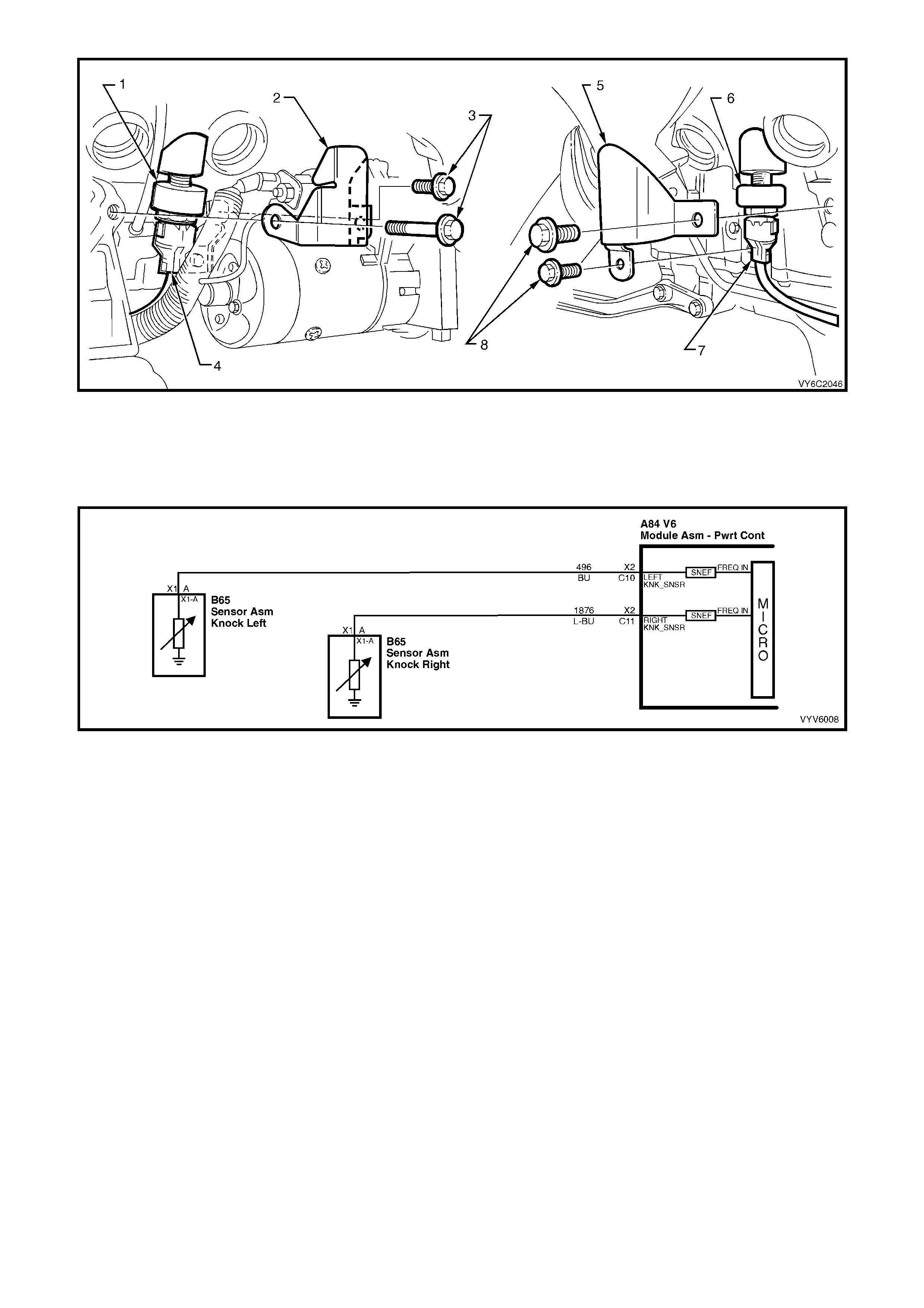
Figure 6C1-1-40 Knock Sensor Locations
Legend
1. LH Knock Sensor
2. LH Knock Sensor Shield
3. LH Knock Sensor Shield Attaching Bolts
4. RH Knock Sensor
5. RH Knock Sensor Shield
6. RH Knock Sensor Shield Attaching Bo lts
Figure 6C1-1-41 Knock Sensor Circuits
ELECTRONIC SPARK CONTROL
The PCM has six spark advance adapt tables, one for each cylinder, each table contains six adaptive cells. The
PCM has the abilit y to learn and adjust the spark advance adaptive cells proportionally to the amount of knock. If
knock is detected, the PCM will decrease the value in the applicable cell. If knock is not detected, the PCM will
increase the value in the applicable cell. This allows the PCM to adaptively adjust the spark advance for each
cylinder so that adaptive spark advance adjustment can be achieved, as determined by the amount of knock
detected.
A failure in either knock sensors, knock sensor circuits or a system malfunction will set either of the
following DTCs:
DTC P0325 DSNEF System Fault.
DTC P0327 Left Hand Knock Sensor Circuit Fault.
DTC P0332 Right Hand Knock Sensor Circuit Fault.
DTC P0325 (DSNEF System Fault) will set if:
• The engine has been running for more than 10 seconds.
• DTC P0327 or P0332 are not set.
• Engine RPM is greater than 1000.
• The PCM’s DSNEF circuit indicates knocking for more than 10 seconds.
DTC P0327 LH Knock Sensor Circuit Fault will set if:
• The engine has been running for more than 10 seconds.
• DTC P0325 is not set.
• The engine coolant temperature is greater than 35°C.
• The TP sensor signal is greater than 22%.
• The engine speed is greater than 1000 RPM.
• There is no left hand knock sensor signal or too high a knock sensor signal detected by the PCM for 3
seconds.
DTC P0332 (RH Knock Sensor Circuit Fault) will set if:
• The engine has been running for more than 10 seconds.
• DTC P0325 is not set.
• The engine coolant temperature is greater than 35°C.
• The TP sensor signal is greater than 22%.
• The engine speed is greater than 1000 RPM.
• There is no right hand knock sensor signal or too high a knock sensor signal detected by the PCM for 3
seconds
HISTORY DATA DTC P0325, P0327 AND P0332
PARAMETER PARAMETER
Engine Speed Mass Air Flow
Coolant Temperature Knock Signal
Time From Start Intake Air Temperature
Times Occurred Spark Advance
Ignition Cycles Throttle Angle
Fuel
Default Values
Once DTC P0325, P0327 or P0332 is set, and current, the PCM uses a default spark advance table.
Recovery
Recovery will occur when the PCM sees a valid condition.
OIL PRESSURE SWITCH
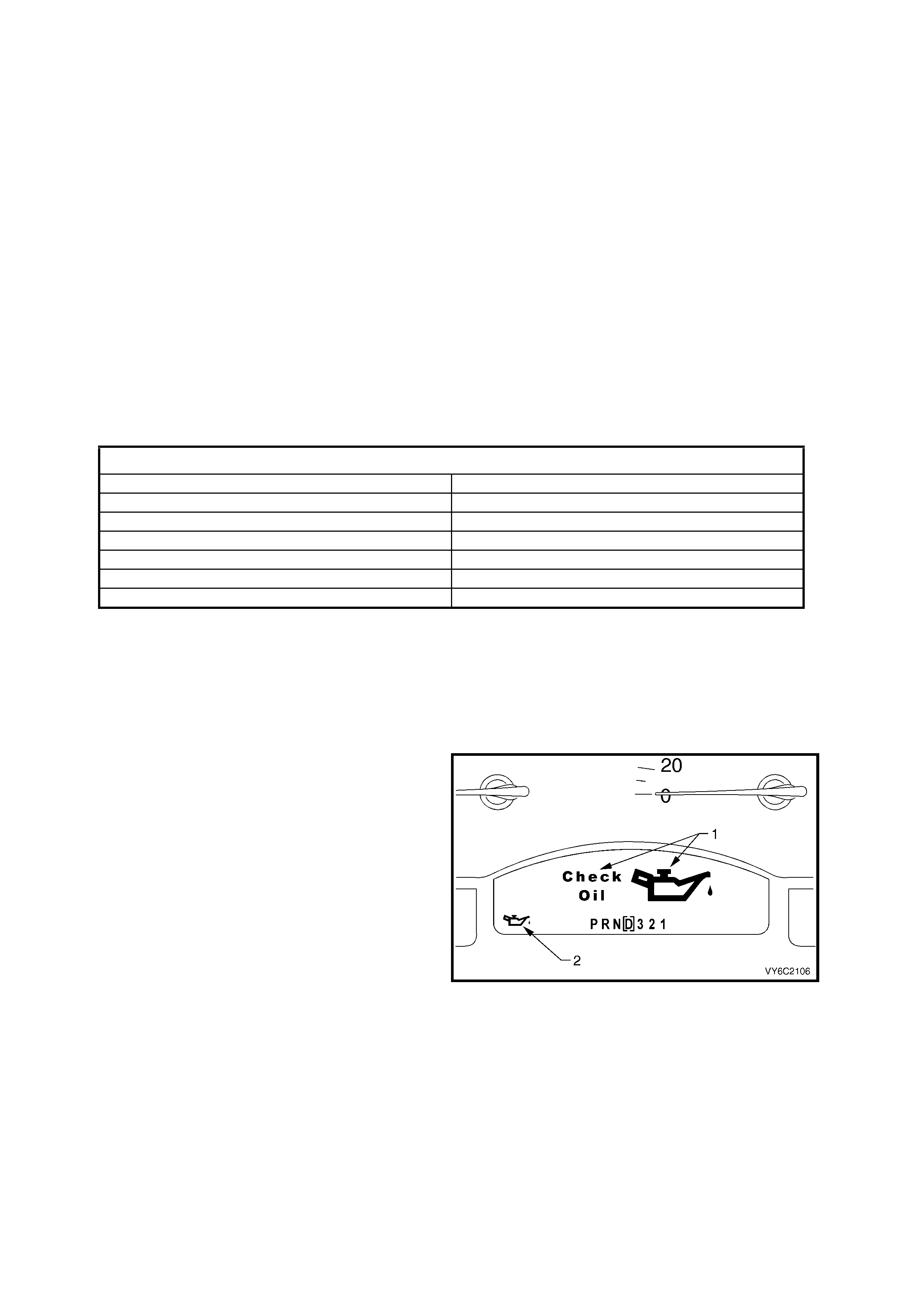
The instrument Multi Function Display (MFD)
receives o il pr ess ur e switch s tatus inf or mation f rom
the PCM via the serial data bus normal mode
message. The PCM monitors the voltage at
terminal X3-F15 to determine the status of the oil
pressure switch. When the engine is not running
the oil pressure switch is closed (low oil pressure)
and the voltage at F15 will be less than 0.2 volts,
when the engine is started the switch opens
(normal oil pressure) the voltage at terminal X3-
F15 will be pulled high, 12 volts via circuit 31
(Blue/Red wire) and the oil pressure switch.
The low voltage at terminal X3-F15 is seen by the
PCM as an oil pressure switch closed input signal.
When the PCM sees a low voltage at terminal X3-
F15 the PCM will command the instruments to
activate the oil pressure warning icon (1) in the
MFD. The large icon and message then revert to
the smaller icon (2). When the PCM sees a high
voltage at terminal X3-F15 the PCM will command
the instruments to deactivate the oil pressure
warning icon, via the serial data bus normal mode
message.
Figure 6C2-1-42 Oil Pressure Warning
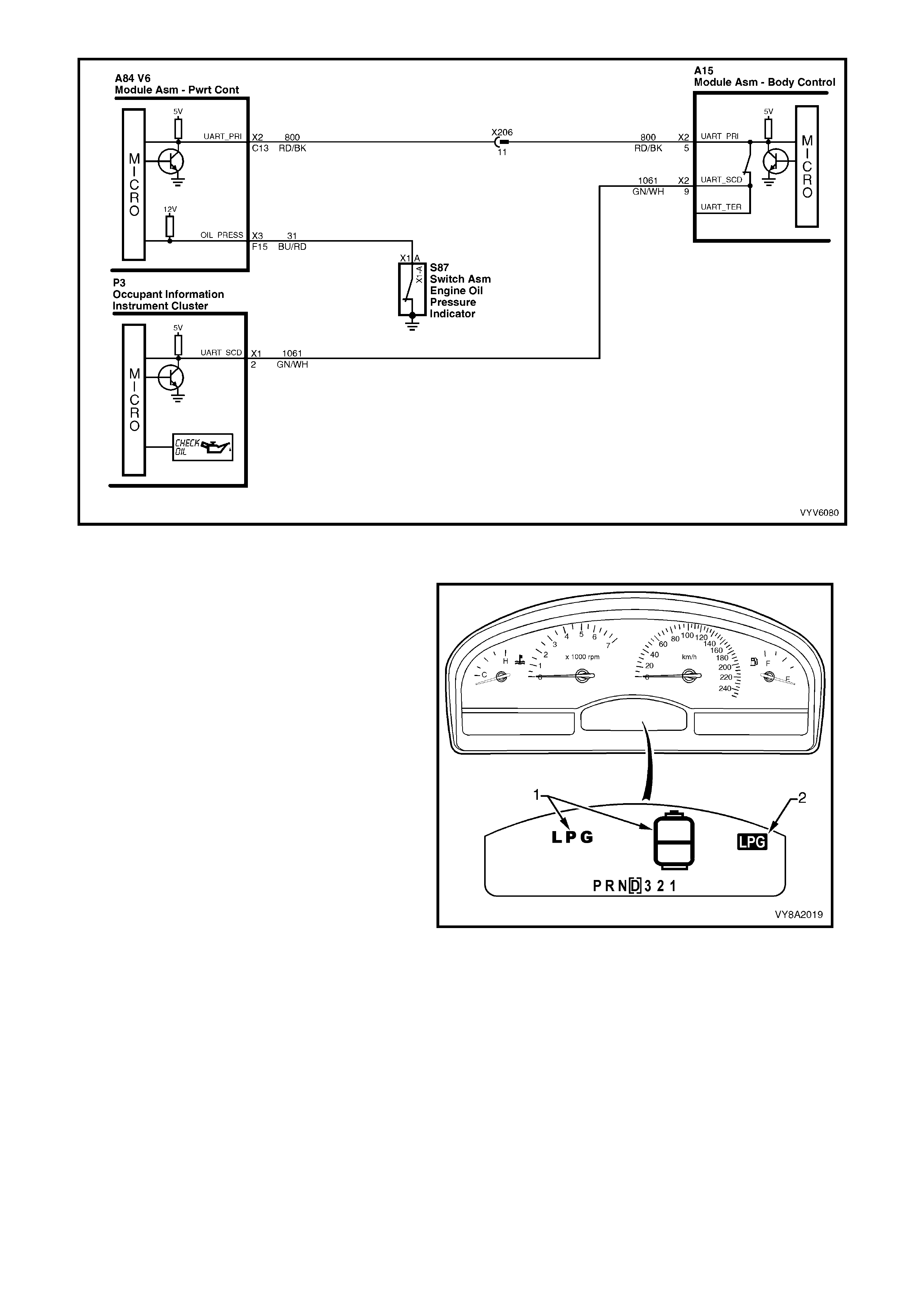
Figure 6C1-1-43 Oil Pressure Warning Circuit
FUEL MODE SWITCH
The PCM m onitor s t he vo ltage at ter m inal X3-F 4 to
determine the status of the fuel mode switch. When
the fuel mode switch is open, the voltage at X3-F4
will be 0 volts. When the switch closes, battery
voltage will be applied to terminal X3-F4 via the
ignition switch and circuit 300 (Orange wire), the
fuel mode switch and circuit 5606 (Blue/Orange
wire). This will cause the voltage at term inal X3-F4
to be pulled up to 1 2 volts whenev er the fuel m ode
switch is depressed.
This high voltage is seen by the PCM as a fuel
mode switch closed input signal. When the PCM
sees a high volt age at termina l X3-F4 the PCM wil l
toggle between the LPG and petrol operating
modes. The PCM will only toggle between the
petrol and LPG mode if the ignition is on and the
engine is not running, or if the engine speed is
greater that 1300 RPM.
When operating in the LPG mode the PCM will
comm and the ins truments to activate th e MF D LPG
Mode status Icon (1), via the serial data bus normal
mode message, after two seconds the large icon
and message will revert to the smaller icon (2).
The operational mode of the PCM is stored in the
PCM mem ory so that the engine s tarts in the sam e
mode on the next ignition cycle.
Figure 6C2-1-44
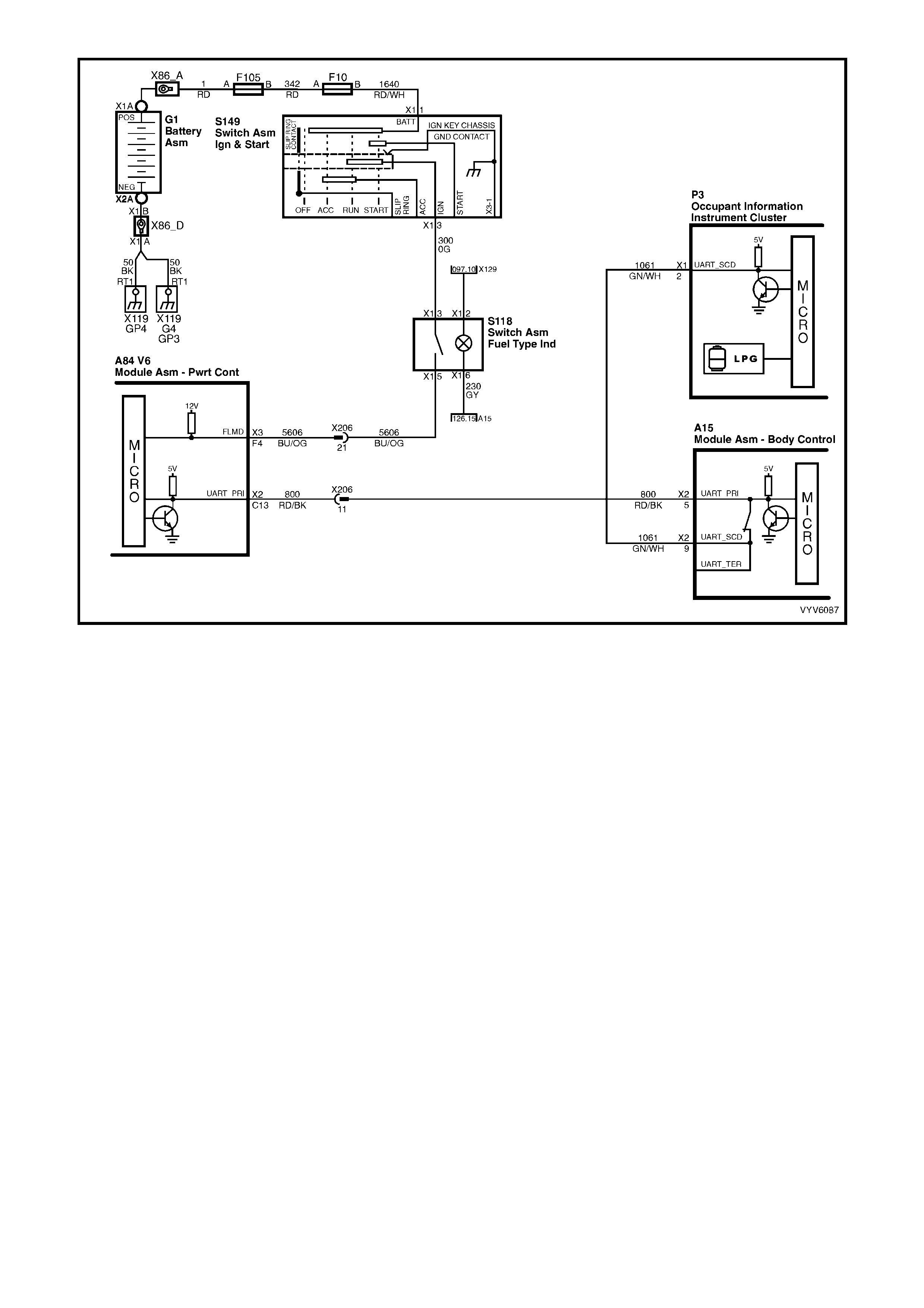
Figure 6C1-1-45 Fuel Mode Switch
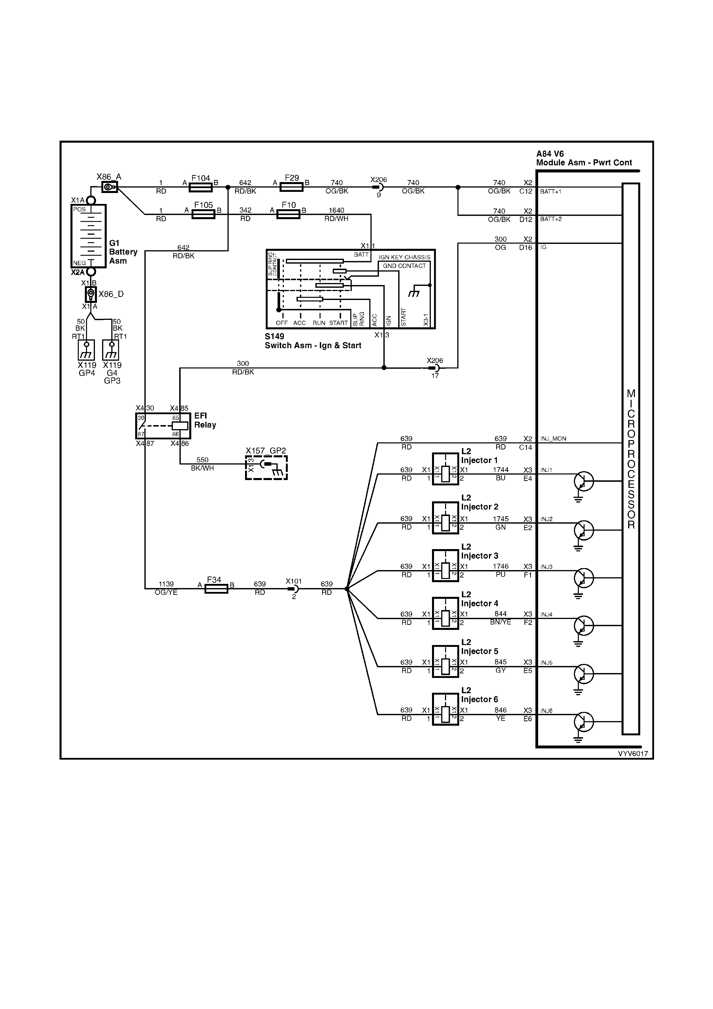
BATTERY VOLTAGE
The PCM continually monitors battery voltage. When the battery voltage is low, the ignition system may deliver a
weak spark and the injector mechanical movement takes longer to open the injector. The PCM will compensate by:
1. Increasing the ignition coil dwell time if the battery voltage is less than 12 volts.
2. Increasing the engine idle RPM if battery voltage drops below 10 volts.
3. Increasing the injector pulse width if the battery voltage drops below 10 volts.
Figure 6C1-1-46 PCM Battery and injector Circuits
On vehicles equipped with automatic transmissions, a high, unstable or low battery voltage will set either
of the following DTCs:
DTC P0560 System Voltage Too High Long Time.
DTC P0561 System Voltage Unstable.
DTC P0562 System Voltage Low.
DTC P0563 System Voltage Too High.
DTC P0560 System Voltage too High Long Time will be set if:
• Engine coolant temperature is at or above 85°C.
• The engine is running and the PCM ignition voltage is greater than 16 volts for more than 109 minutes.
DTC P0561 System Voltage Unstable will be set if:
• The ignition is on and the voltage at the PCM terminal X2-D16 has changed more than 2.5 volts in 100
milliseconds.
DTC P0562 System Voltage Low will set if:
• The ignition is on and the voltage at PCM terminal X2-D16 is less than 8.6 volts for about four seconds.
Minim um voltage allowed f or DTC P0562 to set is on a graduated sc ale and will change with t he temperatur e.
Minimum voltage at -40°C is 7.3 volts, m inimum voltag e at 90°C is 8.6 volt s, m inim um volta ge at 1 52°C is 11.4
volts.
DTC P0563 System Voltage too High will be set if:
• The ignition is on and the voltage at PCM terminal X2-D16 is greater than 19.5 volts for more than two
seconds.
HISTORY DATA DTC P0560, P0561, P0562 AND P0563
PARAMETER PARAMETER
Engine Speed Fuel
Coolant Temperature Engine Coolant Temperature Sensor
Time From Start Intake Air Temperature
Times Occurred Battery Voltage
Ignition Cycles Reference Volts
Default Values
There is no default value for DTC P0560, P0561, P0562 and P0563.
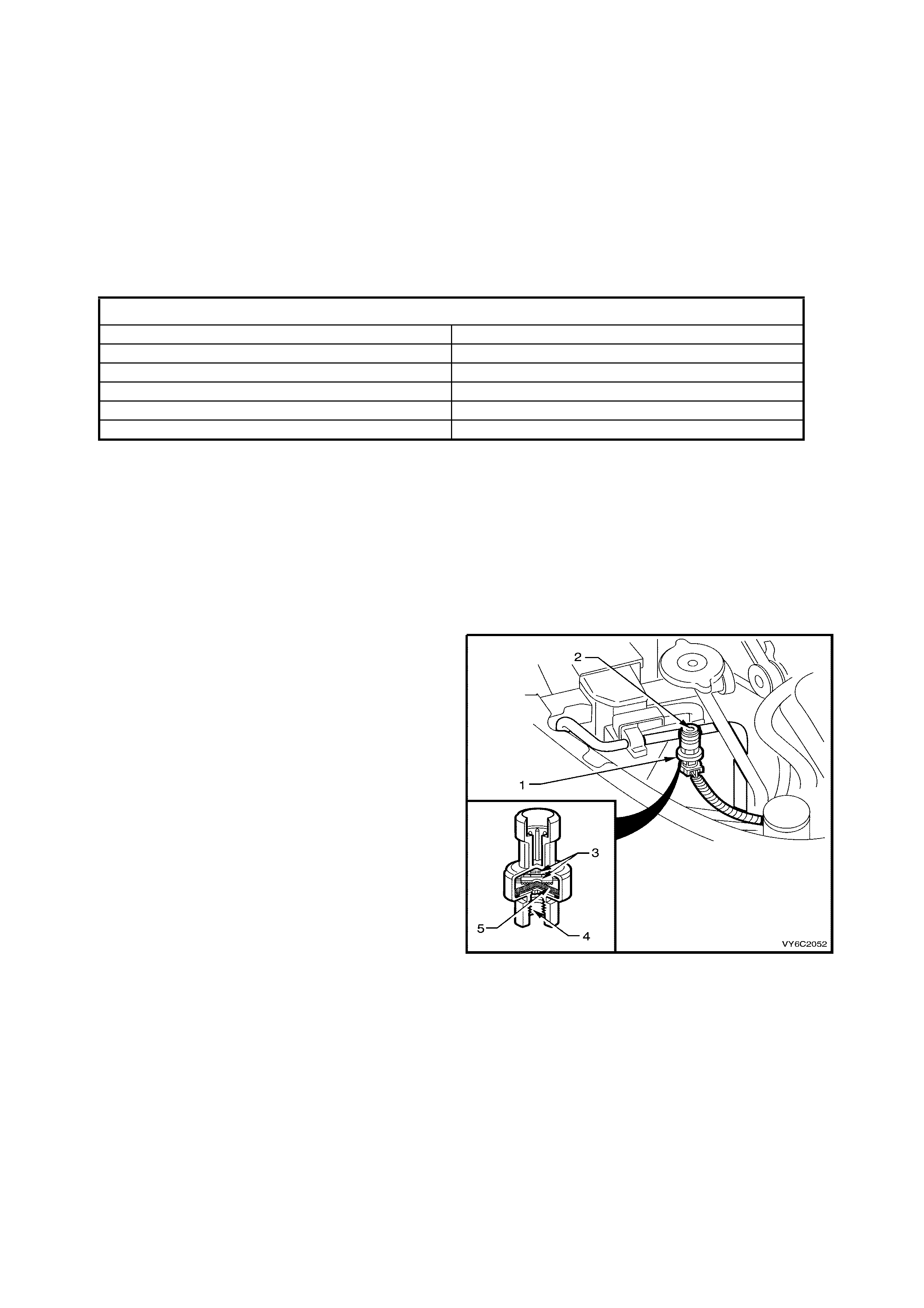
AIR CONDITIONING REFRIGERANT PRESSURE SENSOR
The air conditioning refrigerant pressure sensor is a sealed gauge reference capacitive pressure sensor with on
board signal conditioning. It provides a zero to five volt output and requires a five volt regulated power supply. In
operation the sensor senses applied pressure via the deflection of a two piece ceramic diaphragm with one half
being a parallel plate capacitor. Changes in capacitance influenced by the refrigerant pressure under the ceramic
diaphragm are converted to an analogue output by the sensors integral signal electronics.
The pressure sensor’s electronics are on a flexible
circuit board contained in the upper section of the
sensor. They provide linear calibration of the sending
signals to the PCM. The normal type pressure switch
only has an upper and lower cut out point. The PCM
will disengage the A/C compressor at low or high
refrigerant pressures and control the operation of the
engine cooling fans.
Low Pressure Compressor Cut OFF at 180 kPa
ON at 240 kPa
High Pressure Compressor Cut OFF at 2900 kPa
ON at 2400 kPa
Engine Cooling Fan Low Speed ON at 1500 kPa
OFF at 1250 kPa
Engine Cooling Fan High Speed ON at 2600 kPa
OFF at 2300 kPa
Figure 6C1-1-47 Pressure Sensor
Legend
1. A/C Pressure Transducer
1. High Side Charge Port
1. Signal Electronics
1. Pressure P ort
1. Ceramic Di aphragm
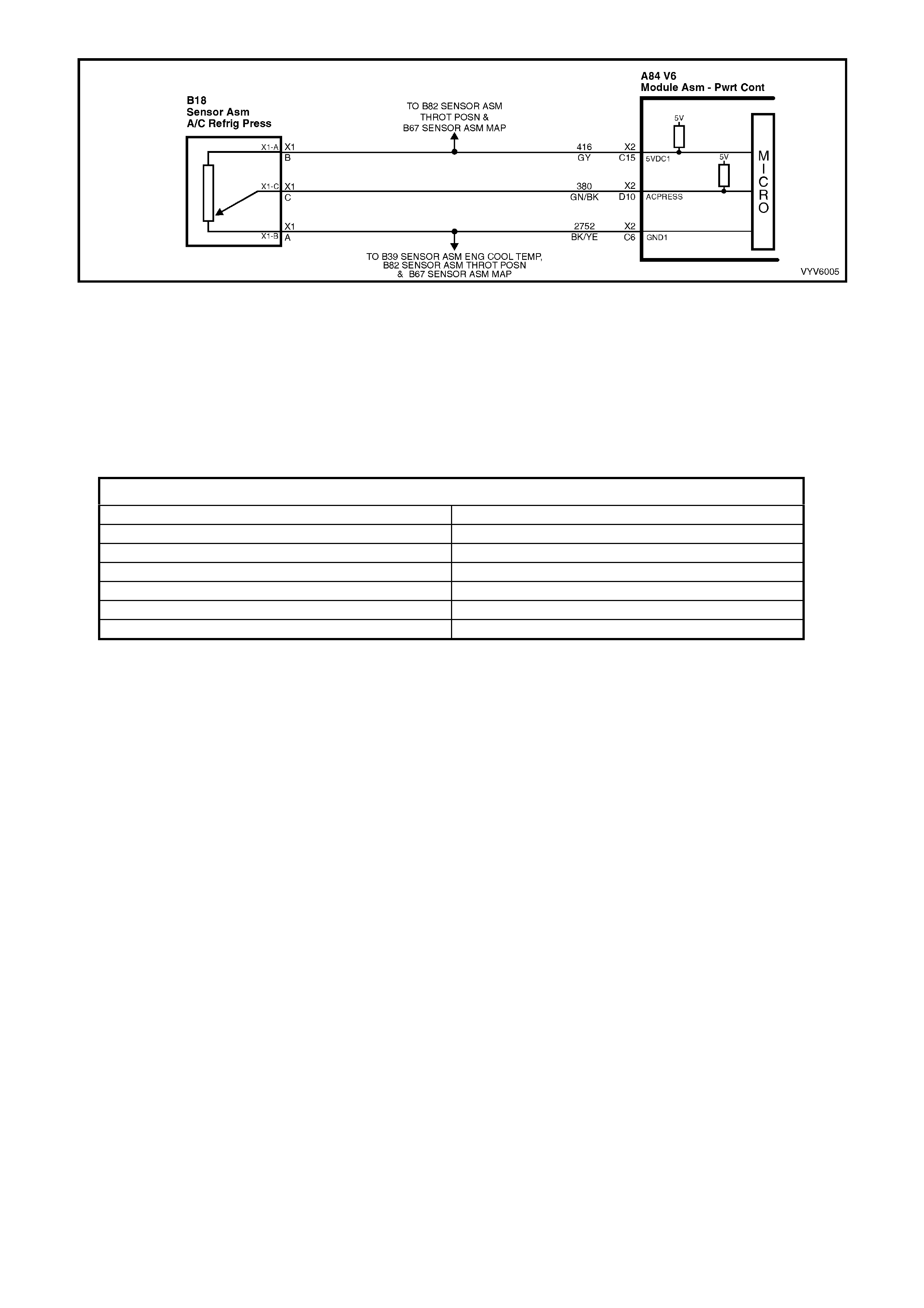
Figure 6C1-1-48 Air Conditioning Pressure Sens or Circuit
DTC P0530 A/C Refrigerant Pressure Sensor Circuit Fault will set if:
• Engine coolant temperature is below 120°C.
• Intake Air Temperature is below 90°C.
• Engine RPM is below 2000.
• Engine has been running for less than 10 minutes.
• A/C refrigerant pressure sensor signal voltage is greater than 4.9 volts.
• All of the above conditions are present for longer than 10 seconds.
HISTORY DA TA DTC P0530
PARAMETER PARAMETER
Engine Speed Engine Coolant Temperature Sensor
Coolant Temperature Intake Air Temperature Sensor
Time From Start Intake Air Temperature
Times Occurred Battery Voltage
Ignition Cycles Reference Volts
Fuel
Default Value
When DTC P0530 is set, the low speed cooling fan will operate for five seconds, then the hig h speed fan will turn
on and remain on until the fault is removed.
Recovery
Recovery will occur on the next ignition cycle.
A/C REQUEST SIGNAL AND A/C CLUTCH CONTROL WITH AUTOMATIC OCCUPANT CLIMATE CONTROL
The O cc upant C limate C on t rol ( OCC) module r e ques ts the PCM to turn t he A/C c ompres s or c lutc h on or off vi a th e
serial data bus norm al m ode message. The OCC module m onitors information from it’s sensors and switches and
determ ines if the A/C c ompr essor c lutch should be o n or off . The OCC c ontrol module wil l then request th e PC M to
turn the A/C compressor clutch on or off when required.
The PCM on receiving a request to turn on the A/C compressor will:
1. Adjust the Idle Air Control (IAC) valve position to compensate for the additional load placed on the engine by
the air conditioning compressor, and then…
2. Energise the A/C compressor relay, to operate the A/C com pressor if the pressure in the A/C s ystem is within
the correct operating range.
The PCM monitors the A/C pressure sensor to determine A/C system pressures.
Figure 6C1-1-49 Heater and Air Conditioning Controls With Automatic OCC
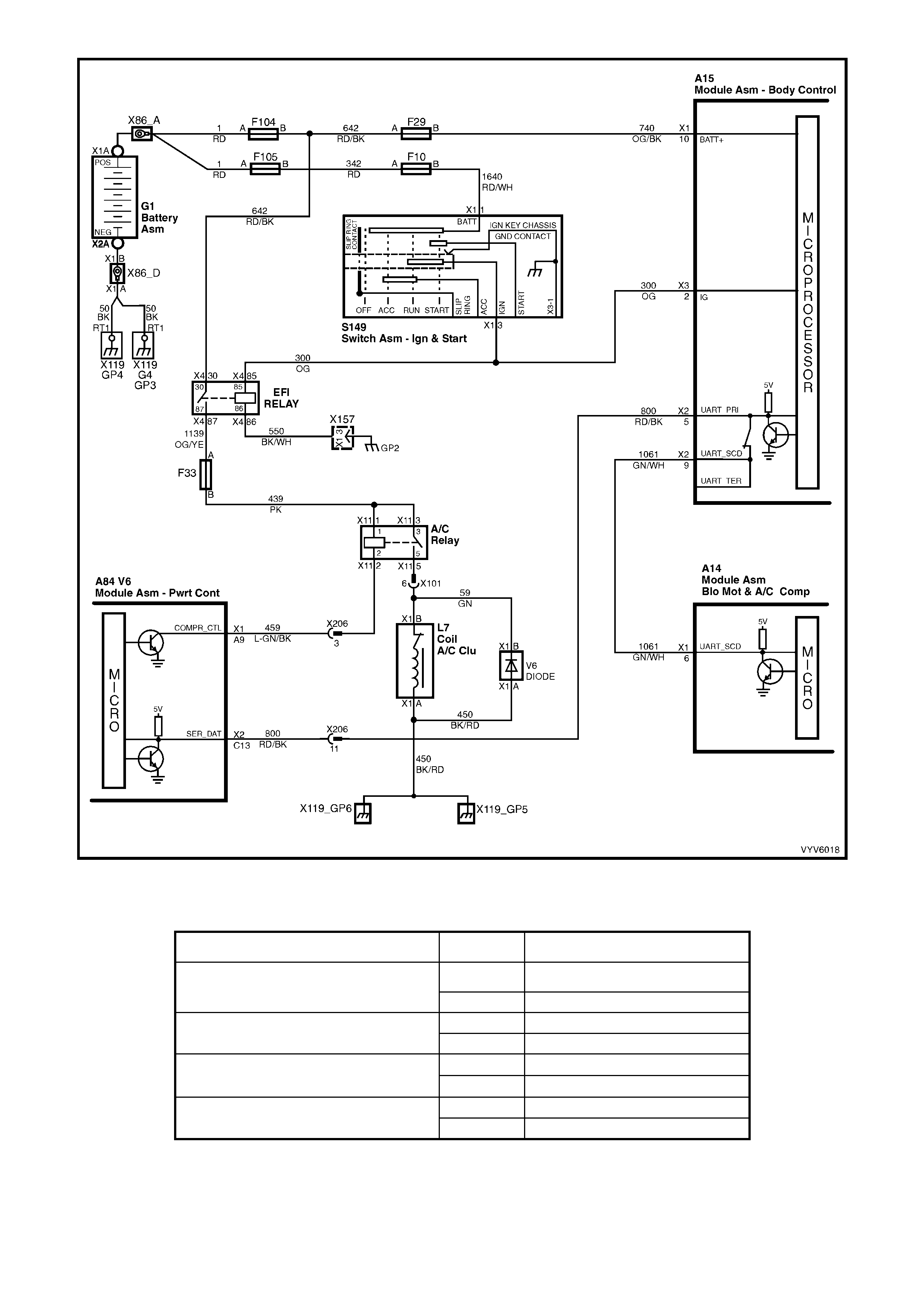
Figure 6C1-1-50 A/C Request Signal Circuit With OCC (Serial Data Bus Normal Mode Message)
The PCM on receiving a request to turn on the A/C compressor, monitors the A/C pressure, coolant temperature,
throttle position and RPM to determine A/C clutch operation.
A/C Clutch Operation ON / OFF Pressure / Temperature / %
Low Pressure Compressor Cut OFF @ 180 kPa
ON @ 240 kPa
High Pressure Compressor Cut OFF @ 2900 kPa
ON @ 2400 kPa
High Coolant Temperature Cut OFF @ 119 °C
ON
@ 116 °C
Wide Open Throttle Cut OFF @ 96 %
ON @ 92 %
A/C REQUEST SIGNAL AND A/C CONTROL WITH MANUAL OCCUPANT CLIMATE CONTROL
The BCM requests the PCM to turn the A/C compressor clutch on or off via the serial data bus normal mode
message. The BCM monitors the voltage at terminal X3-5 to determine the status of the momentary A/C master
switch. W hen the A/C m aster switch is pres sed, 12 volt s is applied to term inal X3- 5 via circuit 6 6 (Red/W hite wire)
causing the voltage at X3-5 to be pulled high, 12 volts. The BCM sees this high voltage as an A/C m aster switch
in put signal.
On receiving this A/C m aster switch input signal, the BCM will request th e PCM to energise the A/C clutch via the
serial data bus normal mode message, if the ignition is on and the blower motor is operating. If the A/C master
switch is pressed again the BCM will request the PCM to turn off the A/C compressor.
The operatin g status of the system will be rem ember ed by the BCM, when th e ignition is s witched f rom on to off or
when the blower is switched off. If the blower is off and the A/C master switch is pressed, then the next time the
blower is switched on the air conditioning will be turned on. Turning the ignition off will cancel this button press
function.
The system will reset to off when the battery is disconnected.
The PCM uses this signal to:
1. Adjust th e Idle Air Control (IAC) p osition to com pensate f or the addit ional load placed on the engine b y the air
conditioning compressor, and then…
2. Energise the A/C com pressor relay, to operate the A/C com pressor if the pressure in the A/C s ystem is within
the correct operating range.
The PCM monitors the A/C pressure sensor to determine A/C system pressures.
Figure 6C1-1-51 Heater and Air Conditioning Controls with Manual OCC
The PCM on receiving a request to turn on the A/C compressor, monitors the A/C pressure, coolant temperature,
throttle position and RPM to determine A/C clutch operation.
A/C Clutch Operation ON / OFF Pressure / Temperature / %
Low Pressure Compressor Cut OFF @ 180 kPa
ON @ 240 kPa
High Pressure Compressor Cut OFF @ 2900 kPa
ON @ 2400 kPa
High Coolant Temperature Cut OFF @ 119 °C
ON
@ 116 °C
Wide Open Throttle Cut OFF @ 96 %
ON @ 92 %
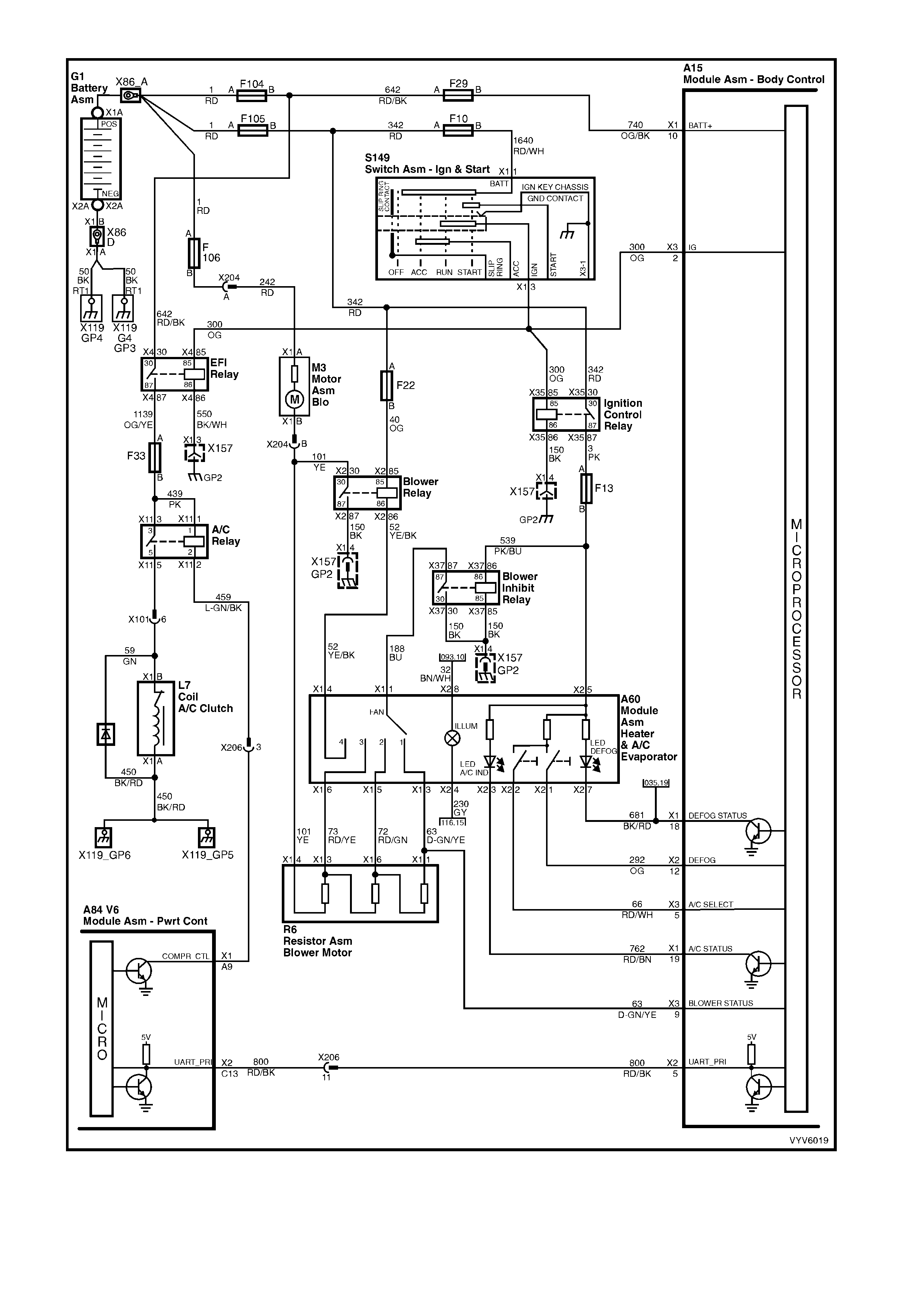
Figure 6C1-1-52 A/C Request Signal Circuit With Manual OCC
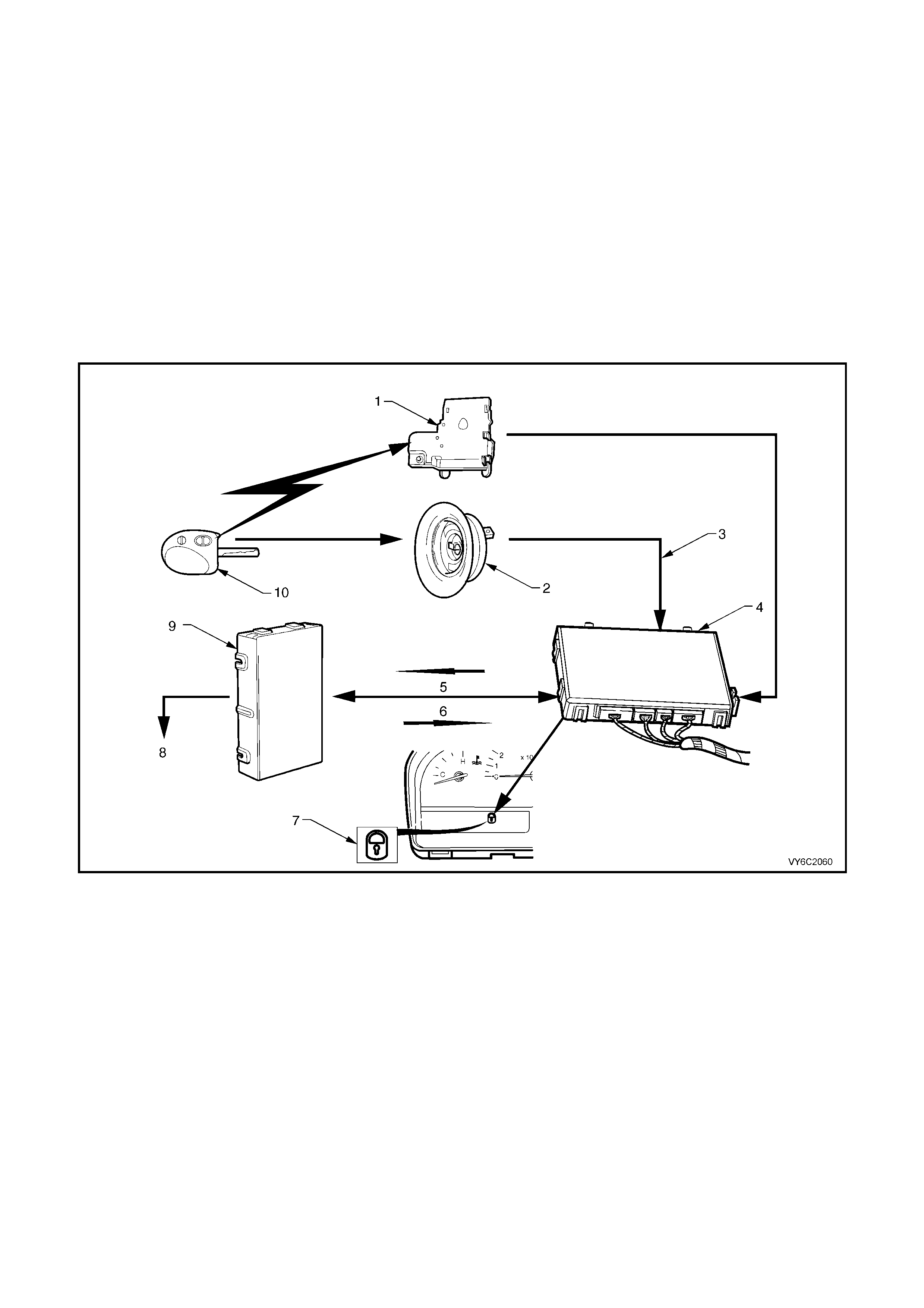
THEFT DETERRENT INPUT SIGNAL
When the ignition switch is turned from off to on, the BCM will transmit security information to the PCM via the
serial data bus, circuit 1221. The PCM compares the received security information with it’s stored security
inform ation and if m atched, the PCM will enable the starter relay, continue to enable the injectors and trans mit an
OK TO START message to the BCM via the serial data bus. The BCM will then poll each control module on the
serial data bus in turn. The BCM will only transmit the correct security information to the PCM if it has been
disarmed via the remote coded key.
If the BC M is unable to comm unicate with the PCM within 0.5 seconds of the i gnition bein g switched on , the BC M
will open the auxiliary serial data bus isolator, disconnecting all control modules connected to the auxiliary data
bus, circ uits 1061 AND 77 4. The isolati on of the auxi liary data bus d uring this pe riod elim inates the poss ibility of a
control m odule failur e, other than the BCM or PCM causing a problem on the bu s, that m ay be inhibit ing the BCM
from communicating with the PCM and preventing the vehicle from starting.
The BCM will continue to operate in this way until the PCM responds with an acknowledgment or a maximum of
five sec onds, af ter which th e BCM will c lose th e auxili ary bus is olator and s witch to the s tandard po lling s equence.
If no com m unication occ urs, a DT C1255 will s et, t he P CM wil l disab le the star ter r ela y and f uel inje ction puls es will
be cut off.
Figure 6C2-1-53 Theft Deterrent System
Legend
1. Remote Receiver Module
2. Remote Coded Key Reader Assembly
3. Code From Remote Coded Key
4. BCM
5. Security Code
6. OK To Start
7. Theft Deterrent Alert Indicator LED (LHS of Instrument)
8. Enable Or Disable Fuel System Control And Starter Motor
9. Powertrain Control Module (PCM)
10. Remote Coded Key
STARTER RELAY
The PCM controls the starter relay and will onl y allo w engine cranking for one second, if valid security information
is not rece ived fr om the BCM. If valid secur ity infor mation is receive d from the BC M the PCM will conti nue to all ow
engine cranking until the engine speed is greater than 500 RPM.
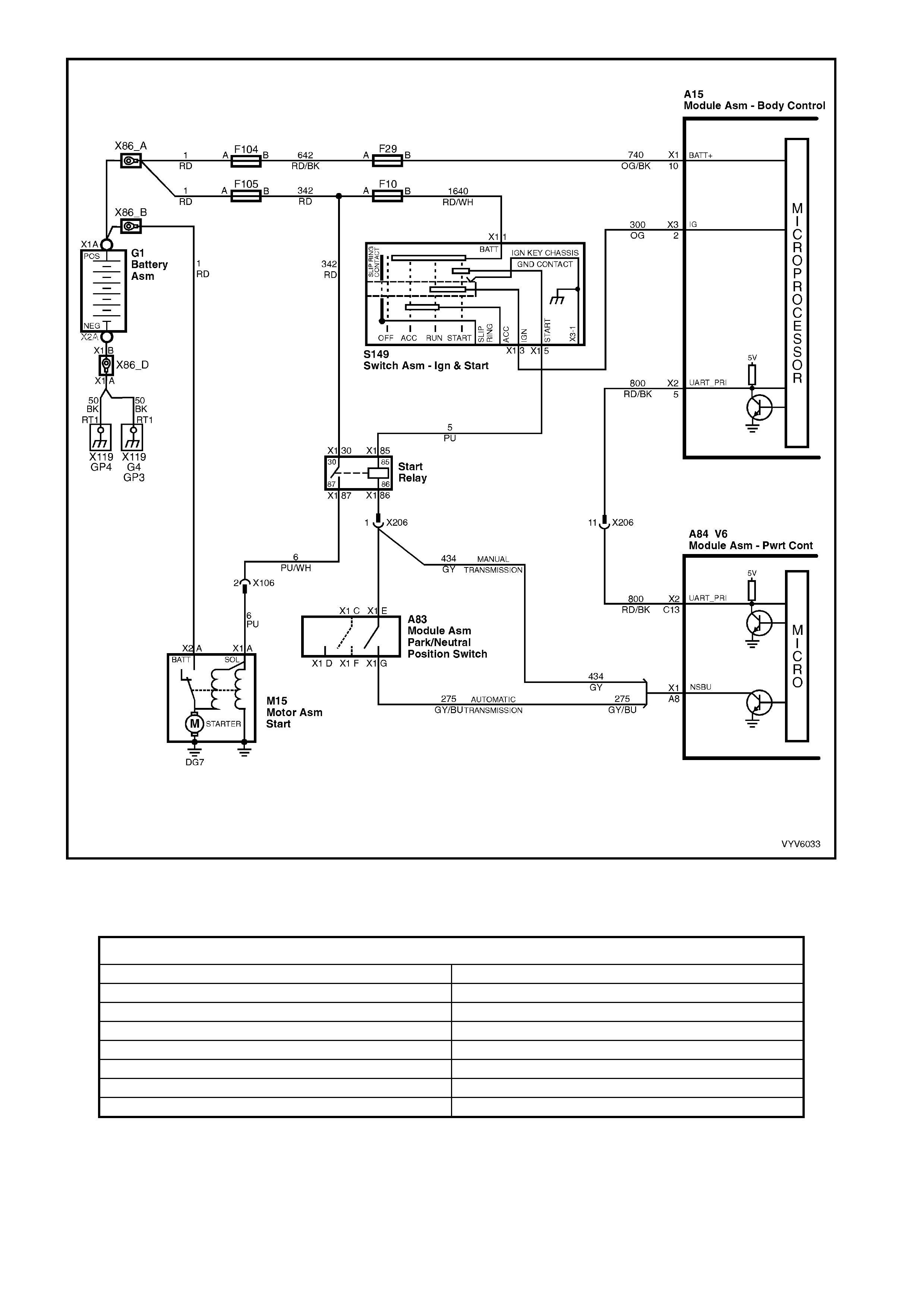
Figure 6C1-1-54 Theft Deterrent and Starter Circuit
DTC P1255 Theft Deterrent Signal Missing will be set if:
• The PCM does not receive serial data for greater than 10 seconds.
HISTORY DA TA DTC P1255
PARAMETER PARAMETER
Engine Speed Reference Volts
Coolant Temperature Mass Airflow
Time From Start Cam Signal
Times Occurred Fuelling Mode
Ignition Cycles Fuel Pump Relay
Fuel LPG Mode enabled
Batter y Voltag e Thef t Status
Default Value
There is no default value for DTC P1255 the engine will not start if DTC P1255 is current.
Recovery
Recovery will occur when the PCM sees a valid condition.
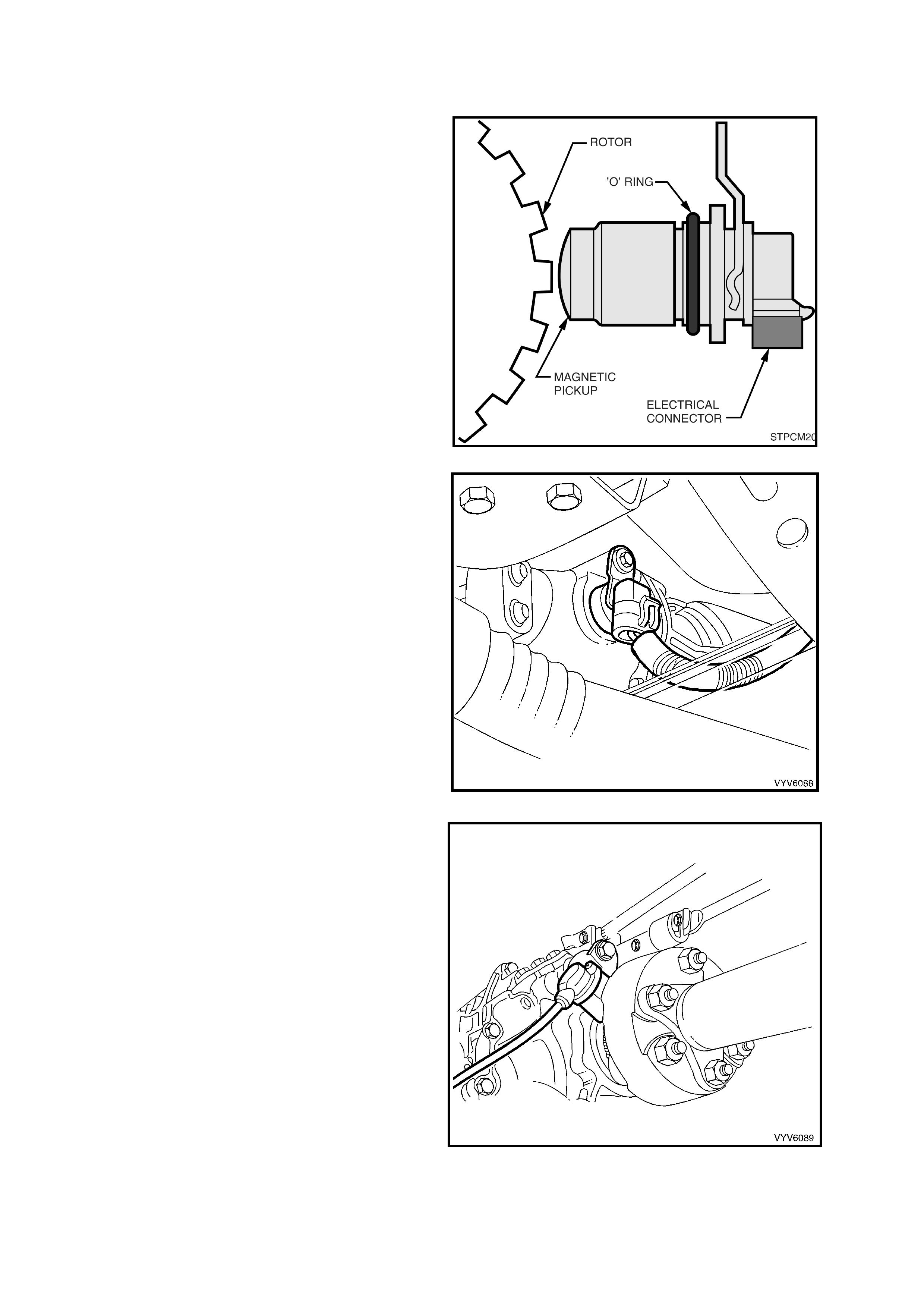
1.3 TRANSMISSION INFORMATION SENSORS AND SIGNALS
VEHICLE S PE ED SEN SO R
The PCM receives vehicle speed information from
the Vehicle Speed Sensor (VSS) located on the
rear of the transmission. The VSS basically
consists of a magnetic core and a coil. As the
output shaft turns, the teeth on the output shaft
concentrate the magnetic field causing the
magnetic flux to increas e and then decr ease as the
teeth move in and out of the magnetic field,
inducing a voltage into the coil, first, in a positive
and then in a negative direction.
This AC vo lta ge produce d i n the V SS s e ns or cir cuit
is fed into t he P C M, t he P C M f ilter s and s h apes th e
signal. T he PCM th en coun ts the num ber of puls es
received in a given time, to determine the vehicle
speed.
The PCM uses the information from this sensor to
determine vehicle speed, which is used to control
the following: Engine fuelling modes, IAC Valve
operation and Transmission operation.
Figure 6C1-1-55 Vehicle Speed Sensor
Once the PCM has calculated the vehicle speed it
then pulses circuit 123 (Violet/White wire) to
ground, th is will cause the 12 v olts a t term inal X 1-5
of the instruments to be pulled down to less than
0.2 volts. The instrument determines the vehicle
speed and the kilometres from the number of
pulses it receives. The PCM also transmits vehicle
speed information to other control modules via the
serial data bus normal mode message.
Figure 6C1-1-56 VSS Location - Automatic Transmission
Figure 6C1-1-57 VSS Location - Manual Transmission
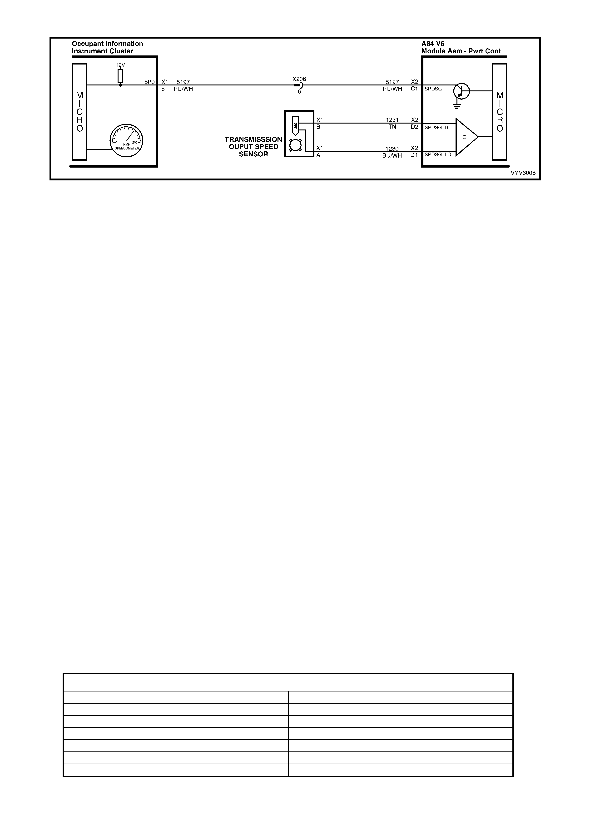
Figure 6C1-1-58 Vehicle Speed Sensor Circuit
A failure in the Vehicle Speed Sensor or circuit will set either a DTC P0502 No Vehicle Speed Signal or a
DTC P0503 Vehicle Speed Sensor Intermittent Signal.
DTC P0502 No Vehicle Speed Signal will be set if DTC’s P0122, P0123 or P1810 are not current and..
Automatic Transmission
• The transmission is not in Park or Neutral and…
• The engine speed is greater than 3000 RPM and…
• The Throttle Position angle is between 10% - 99% and…
• The VSS indicates an output shaft speed of less than 3 km/h for 3 seconds.
Manual Transmission
• The engine speed is between 1400 and 3000 RPM.
• The throttle is closed (throttle angle less than 1%).
• Engine load very low, MAF less than 95 mg/cyl.
• Vehicle in gear.
• The VSS indicates no output shaft speed for more than 4 seconds.
Default Value
Automatic Transmission Only.
W hen DT C P050 2 sets , t he PCM will com mand s econd ge ar on ly, max imum line press ur e, f ree ze s hif t ad apt s f rom
being updated and inhibit TCC engagement.
Recovery
Recovery will occur when the PCM sees a valid condition.
DTC P0503 Vehicle Speed Sensor Signal Intermittent will be set if..
• Two succ essive spee d readin gs have a dif ference of more than 1000 R PM in any dri ve range (dif ference m ust
be more than 2048 RPM in park or neutral).
Default Value
Automatic Transmission Only.
W hen DTC P0503 is set, the trans mission wi ll command m aximum line pr essure and 3rd gear onl y. If DTC P0503
is set while in 4th gear, the vehicle will stay in 4th gear. However, as the vehicle is coasting to stop the transmission
will downshift normally from 4 to 3. Once the downshift into 3rd gear has occurred, the vehicle will stay in 3rd gear.
Recovery
Recovery will occur when the PCM sees a valid condition.
HISTORY DATA DTC P0502 AND P0503
PARAMETER PARAMETER
Engine Speed Throttle Angle
Coolant Temperature Transmission Fluid Temperature
Time From Start Mass Air Flow
Times Occurred Commanded Gear
Ignition Cycles Vehicle Speed
Fuel
TR ANSM ISSION POW ER/ ECO NO MY SWIT CH
The Power/Economy switch (1) is used to modify
upshifts and shift times. The driver can select
either Econom y or Power mode with the s witch (1)
located in the centre console.
An animated icon in the instrument cluster Multi
Function Display (MFD) (2) is activated for 2
seconds and then changes to a highlighted “PWR”
icon (3), to remind the driver that the ‘Power Shift’
mode is enabled.
The PCM provides a voltage signal of about 12
volts, and monitors the status of this circuit. In the
Econom y position , the swit ch is open a nd the PCM
voltage status signal remains high, about 12 volts.
The PCM does not allow shif t point changes in the
economy mode. When the transmission switch is
pressed to the Power position the switch is
momentarily closed and the PCM voltage status
signal is mom entarily pulle d low, to ab out 0.5 vo lts.
The PCM s enses this momentar y voltag e drop an d
enables Po wer mode (alt ernate shift patter n tab les )
to be utilised.
In the Power m ode, the TCC can be applied in 3rd
and 4th gears. When the TCC is applied in 3rd
gear it will stay applied until the normal 4th gear
upshift c riteria is m et. W hen the 3- 4 ups hift occur s,
the TCC will be released momentarily. Also, in the
Power mode while in D gear select position, the
PCM will delay the 1-2 and 2-3 shift while under
light throttle. The shift patterns will be the same in
the Econom y and Po wer modes if the TP s ensor is
between 80% – 100%.
The power mode should be used when towing, as
applying the TCC in 3rd and 4th gear reduces
slippage in the TCC and thus reduces heat build
up.
In cruise m ode oper ation, when the dr iver act ivates
the cruise control, the power icon “PWR” and
power mode will be deactivated (if vehicle was in
power mode) and a CRUISE ACTIVE icon will be
displayed in the instrument cluster MFD. The
transmission shift pattern will then switch to cruise
shift pattern.
Figure 6C2-1-59 Transmission Power/Economy Switch
When in cruise mode the PCM will modify the transmission calibration so that transmission shift activity is reduced.
When the key is turned ON, the PCM shift mode is set to the last mode that was previously selected
(Power/Economy). The cruise control is set to OFF at every key ON cycle.
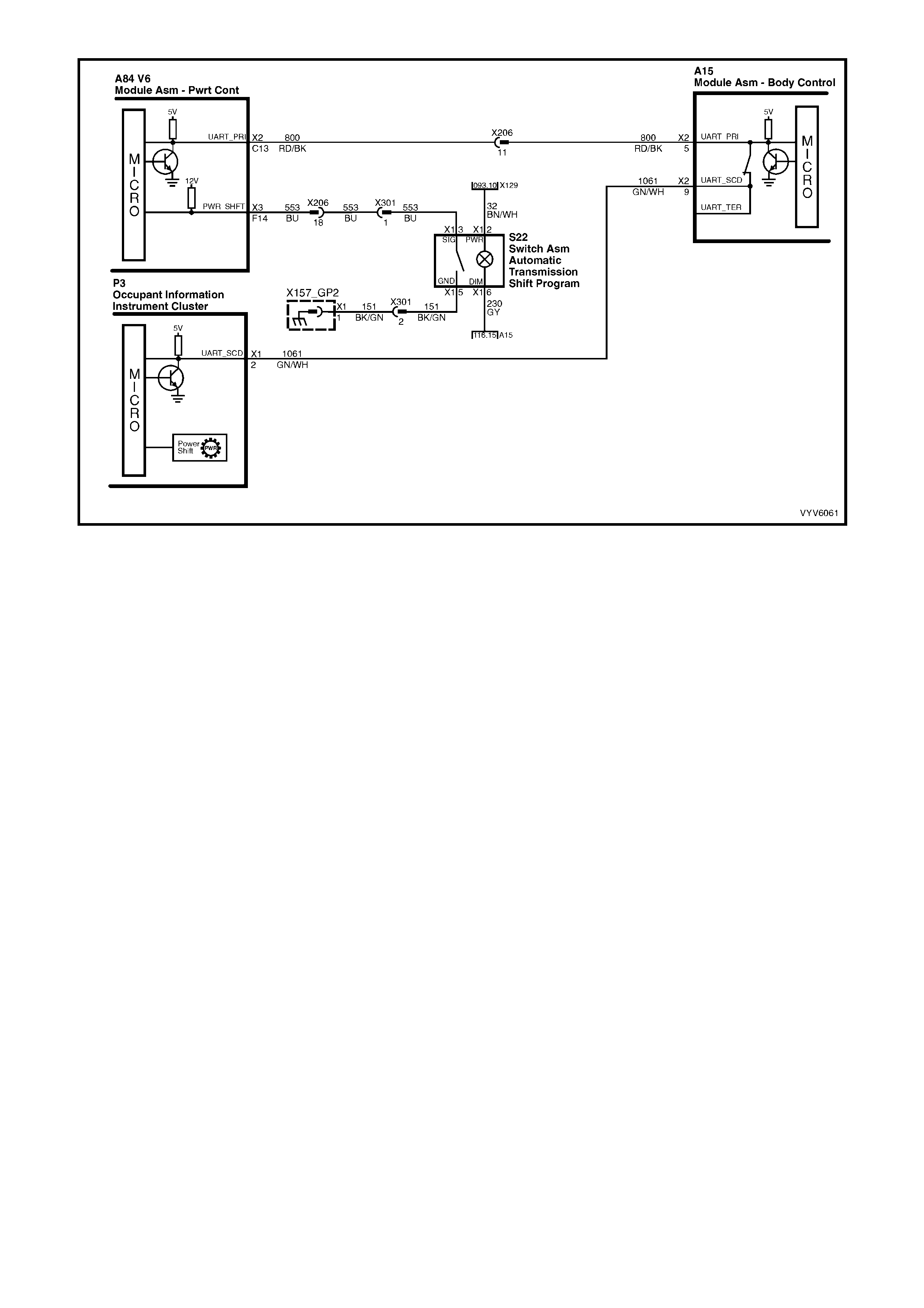
Figure 6C2-1-60 Transmission Power/Economy Switch Circuit
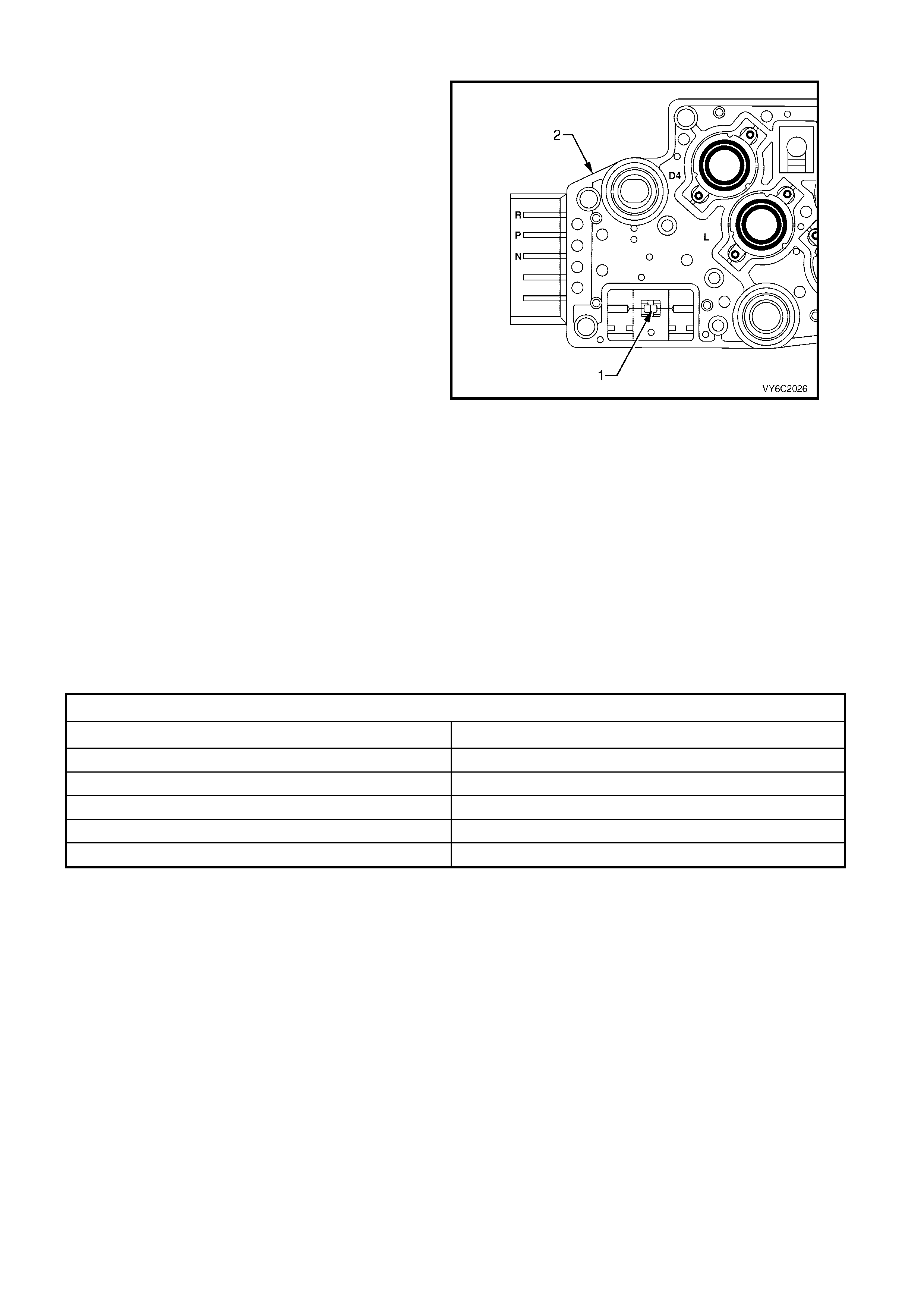
AUTOMATIC TRANSMISSION FLUID TEMPE RATURE SENSOR
The Transmission Fluid Temperature (TFT) (1)
sensor is part of the automatic transmission fluid
pressure (TFP) manual valve position switch
assembly (2). This sensor helps control torque
converter clutch apply and shift quality. The TFT
sensor is a resistor, or thermistor, which changes
value based on temperature. At low temperatures
the resistance is high, and at high temperatures the
resistanc e is low.
The PCM sends a 5 volt signal to the TFT sensor
and the PCM measures the voltage drop in the
circuit. You will measure a high voltage when the
transmission is cold and a low voltage when the
transmission is hot. Refer to the Temperature Vs
Resistance table in Section 6C1-2A Diagnostic
Tables.
If the TFT sensor circuit has a fault, DTC P0712 or
P0713 will set. A DTC P0712 indicates a short
circuit condition, while a DTC P0713 indicates an
open circuit condition. DTC P0218 is set if the
transmission is operating at a high temperature for
a period of time.
Figure 6C2-1 -61 Transmission Fluid Temperature Sensor
(TFT)
DTC P0218 (Transmission Fluid Overtemperature) will set if:
• DTC P0712 is not set.
• The TFT is greater than 137° C for 10 minutes (600 seconds).
The PCM will activate the Check Powertrain MIL.
Default Value
When this DTC sets, the PCM will freeze shift adapts from being updated.
Recovery
Recovery will occur when the PCM sees a valid condition.
DTC P0218 HISTORY DATA
PARAMETER PARAMETER
Engine Speed Fuel
Coolant Temperature TFT Sensor (Transmission Fluid Temperature)
Time From Start TFT (Transmission Fluid Temperature)
Times Occurred Throttle Angle
Ignition Cycles Commanded Gear
DTC P0712 (TFT Signal Voltage Low) will set if:
• Ignition is on.
• The TFT sensor indicates a signal voltage less than 0.2 volts for 10 seconds.
The PCM will not activate the Check Powertrain MIL.
Default Value
W hen this DT C sets , the P CM us es a tr ans mission f luid temperatur e def ault va lue bas ed on e ngi ne coo lan t, eng in e
run time and IAT at startup, the PCM will freeze shift adapts from being updated.
Recovery
Recovery will occur when the PCM sees a valid condition.
DTC P0713 (TFT Signal Voltage High) will set if:
• Ignition is on.
• The TFT sensor indicates a signal voltage greater than 4.92 volts for 6.8 minutes (409 seconds).
The PCM will not activate the Check Powertrain MIL.
Default Value
W hen this DT C sets , the P CM us es a tr ans mission f luid temperatur e def ault va lue bas ed on e ngi ne coo lan t, eng in e
run time and IAT at startup, the PCM will freeze shift adapts from being updated.
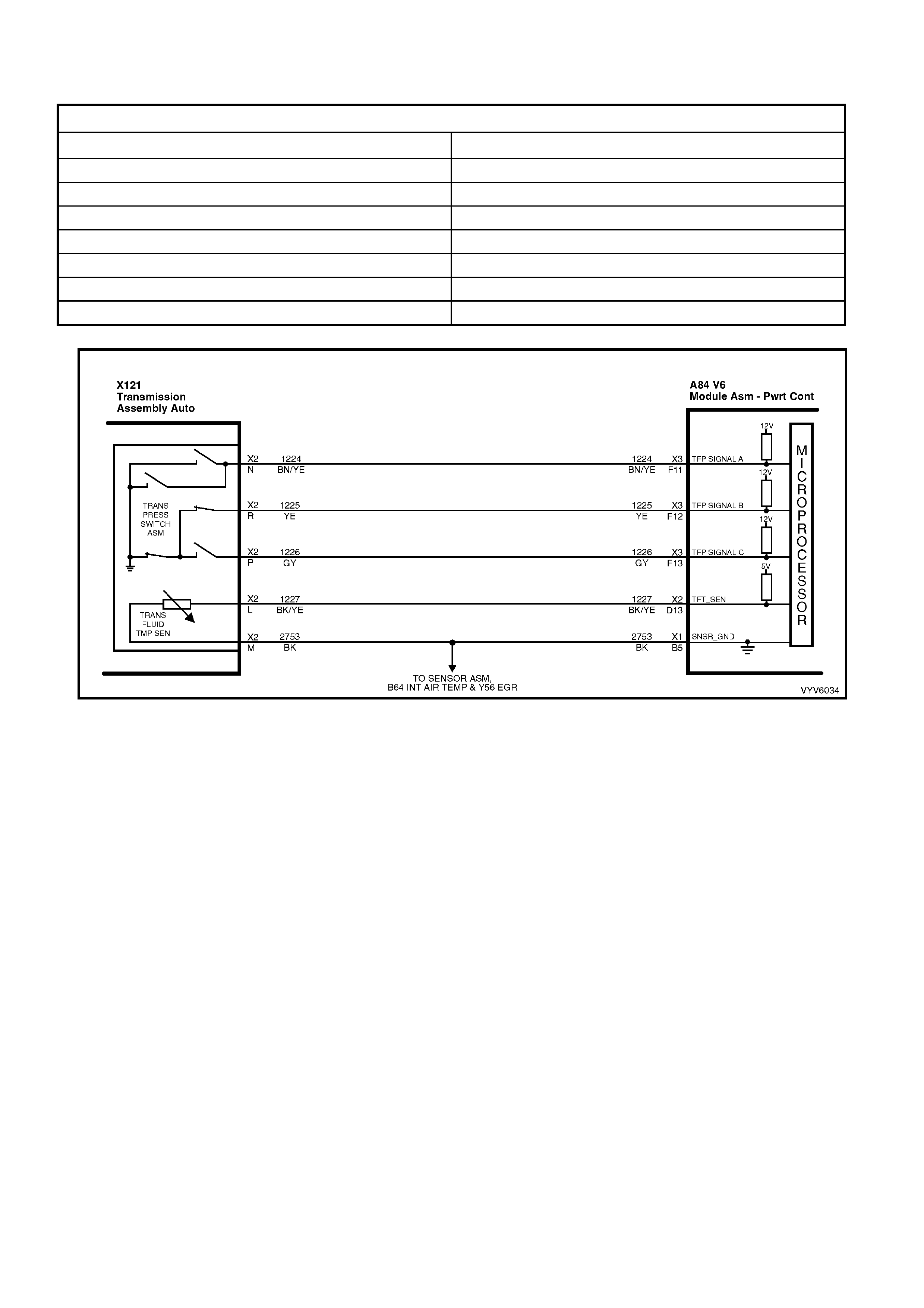
Recovery
Recovery will occur when the PCM sees a valid condition.
DTC P0712 AND P0713 HISTORY DATA
PARAMETER PARAMETER
Engine Speed Fuel
Coolant Temperature 3-2 Downshift Enabled
Time From Start TCC Solenoid (Torque Converter Clutch)
Times Occurred TFT (Transmission Fluid Temperature)
Ignition Cycles Throttle Angle
3-2 Downshift Enabled Vehicle Speed
Commanded Gear
Figure 6C1-1-62 TFT Sensor Circuit
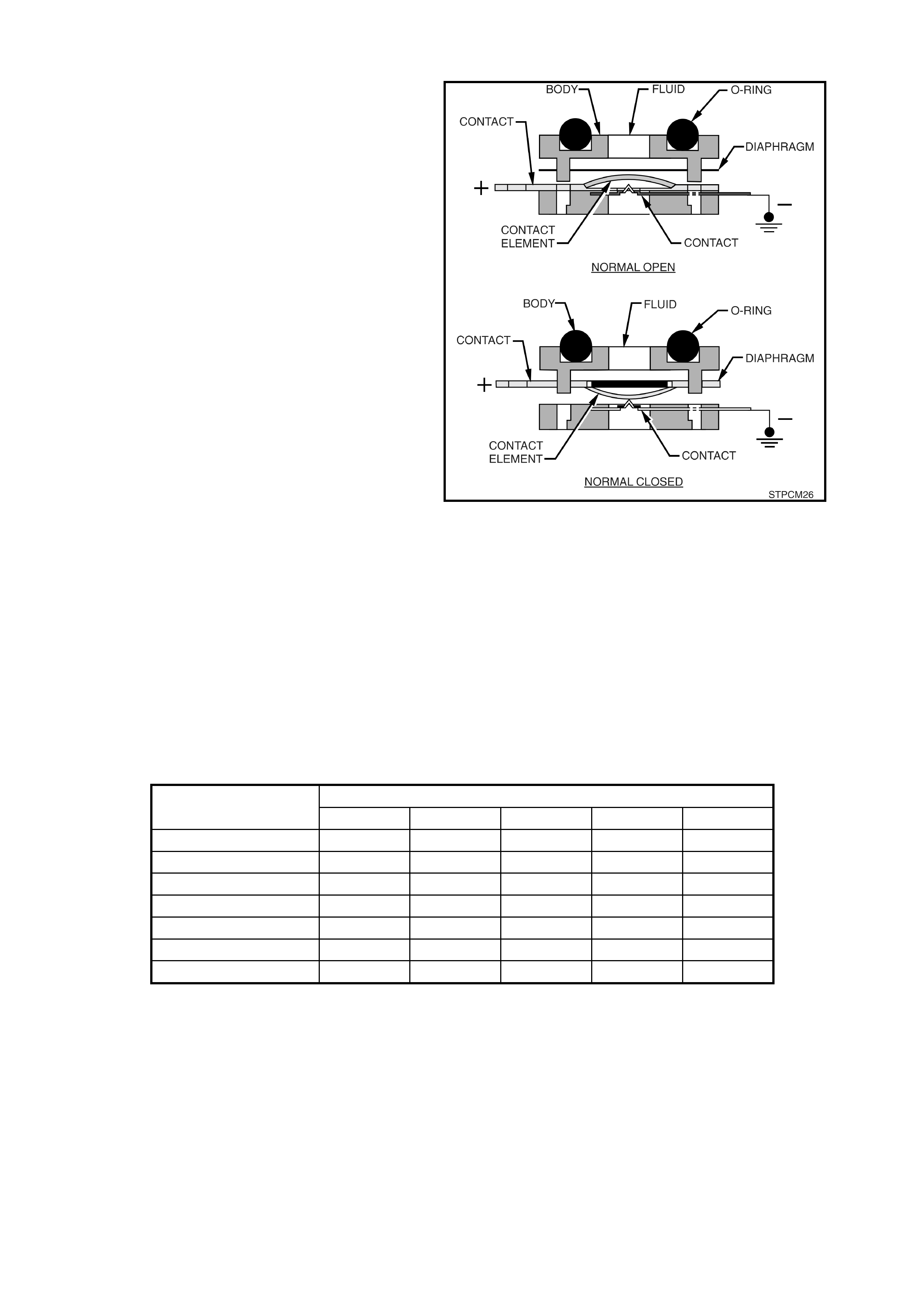
TRANSMISSION FLUID PRESSURE (TFP) MANUAL VALVE POSITION SWITCH ASSEMBLY
This gear range sensing device called a
Transmission Fluid Pressure (TFP) Manual Valve
Position Switch Assembly is used by the PCM to
sense which gear range has been selected by the
vehicle operator. The TFP is located on the valve
body and consists of five pressure switches, two
normally closed and three normally open,
combined into one unit.
The normally open fluid pressure switches are the
D4, LO and Reverse fluid pressure switches. They
are nor mally open and elec trical curre nt is sto pped
at these switches when no fluid pressure is
present. Fluid pressure moves the diaphragm and
contact element until the contact element touches
both the positive contact and the ground contact.
This creates a closed circuit and allows current to
flow from the positive contact, through the switch
and to ground. The normally closed fluid pressure
switches are the D2 and D3 fluid pressure
switches. They are normally closed and electrical
current is free to flow from the positive contact to
the ground contact when no fluid pressure is
present. Fluid pressure moves the diaphragm to
disconnect the positive and ground contacts. This
opens the switch and stops current from flowing
through the switch.
Figure 6C1-1-63 Transmission Fluid Pressure (TFP)
Switch Assembly
The PCM applies system voltage to the TFP on three separate wires. An open circuit measures 12 volts while a
grounded c ircuit m easures 0 vo lts. The s witches are opene d or closed b y fluid pres sure. The c ombination of which
switches are open and closed is used by the PCM to determine actual manual valve position. The TFP however
cannot distinguish between park and neutral because the monitored valve body pressures are identical in both
cases.
LO This switch will have hydraulic pressure applied to it in manual 1st gear only and will be closed.
REV This switch will ha ve hydra ulic pr es su re appl ied to it in revers e only and will be closed.
D2 This switch will have hydraulic pr es sur e appl ied to it in m anual 1st and 2nd gear a nd wil l be open.
D3 This switch will have hydraulic pressure applied to it in manual 1st, 2nd and 3rd gear and will be open.
D4 This switch will have hydraulic pressure applied to it in all drive gears except reverse and will be closed.
RANGE FLUID PRESSURE
INDICATOR REV D4 D3 D2 LO
PARK
REVERSE X
NEUTRAL
D X
3 X X
2 X X X
1 X X X X
Pressure Applied to TFP Switches
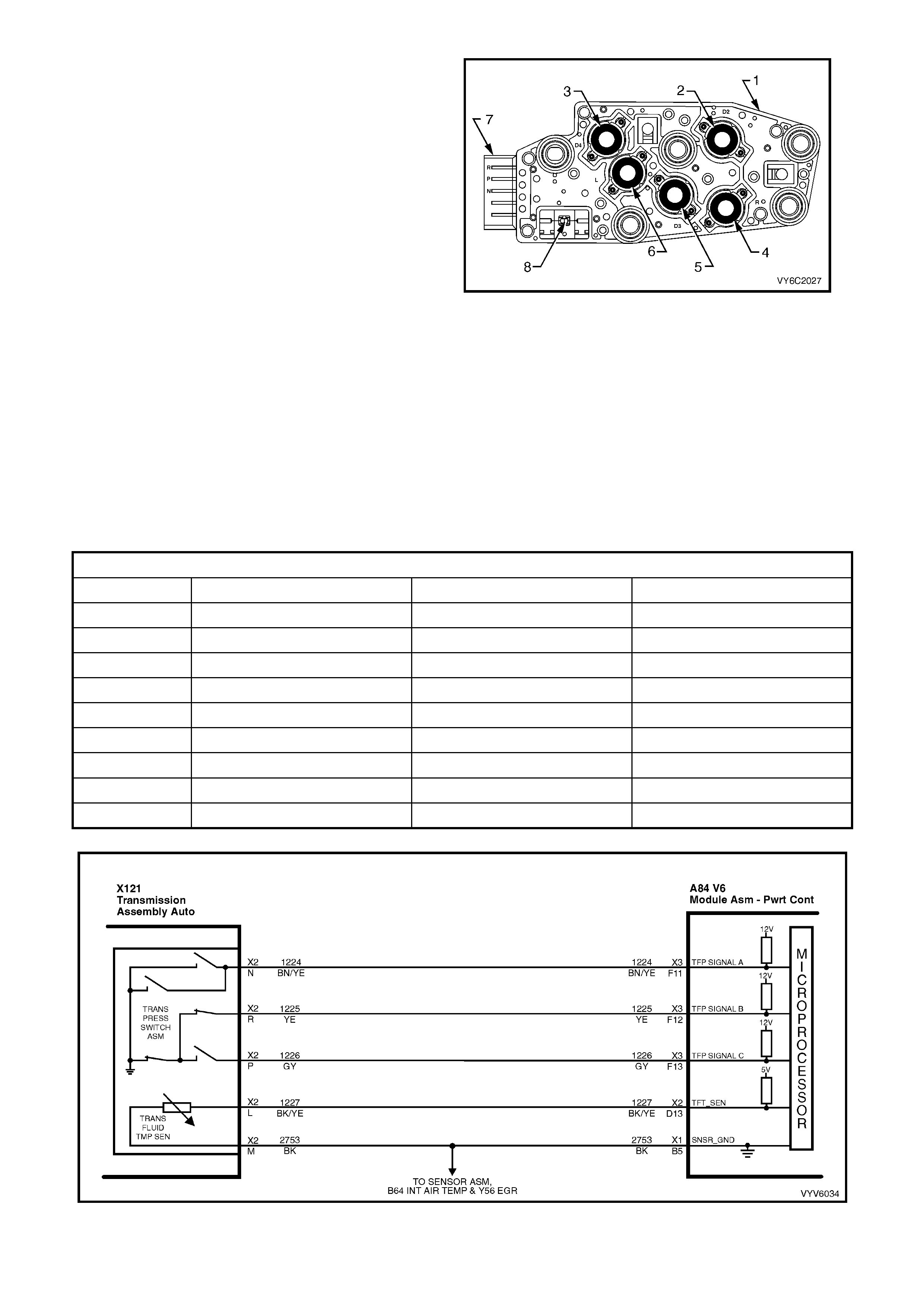
TFP assembly signal voltage can be measured with a
high impedance digital volt/ohmmeter by back probing
the PCM, taking measurements from each terminal to
ground, and comparing it to the combination chart. On
the transmission wiring harness connector, pin N is
Range Signal A, pin R is Range Signal B, and pin P is
Range Signal C. With the wiring harness connected and
engine operating, a voltage measurement of these three
lines will indicate a high reading (near 12 volts) when a
circuit is open, and a low (zero volts) reading when the
circuit is sw itched to ground.
These TFP inputs are used to help control IAC, line
pressure, torque converter clutch apply and shift
solenoid operation. To monitor TFP assembly operation,
the PCM compares the actual voltage combination of the
switches to a TFP combination chart stored in its
memory. If the PCM detects one of two illegal voltage
combinations a DTC P1810 will result.
There are two possible combinations of the switches
within the pressure switch assembly that do not
represent an actual gear range. If either of these
combinations are detected by the PCM for 5 seconds or
longer, DTC P1810 will set. DTC P1810 will also set if a
valid gear range combination appears at the wrong time.
Figure 6C1-1-64 TFP Switch Assembly
Legend
1. TFP Switch Assembly
2. D2 Indicator Switch
3. D4 Indicator Switch
4. Rev Indicator Switch
5. D3 Indicator Switch
6. LO Indicator Switch
7. Electrical Connector
8. TFT Sensor
VALID COMBINATION CHART
RANGE SIGNAL A RANGE SIGNAL B RANGE SIGNAL C
PARK 12V / OPEN 0V / GROUNDED 12V / OPEN
REVERSE 0V / GROUNDED 0V / GROUNDED 12V / OPEN
NEUTRAL 12V / OPEN 0V / GROUNDED 12V / OPEN
D 12V / OPEN 0V / GROUNDED 0V / GROUNDED
3 12V / OPEN 12V / OPEN 0V / GROUNDED
2 12V / OPEN 12V / OPEN 12V / OPEN
1 0V / GROUNDED 12V / OPEN 12V / OPEN
ILLEGAL 0V / GROUNDED 12V / OPEN 0V / GROUNDED
ILLEGAL 0V / GROUNDED 0V / GROUNDED 0V / GROUNDED
Figure 6C1-1-65 TFP Switch Assembly Circuit

DTC P1810 Transmission Fluid Pressure Manual Valve Position Switch Assembly Circuit Malfunction will
set if:
• The PCM detects an illegal switch combination for more than six seconds.
HISTORY DA TA DTC P1810
PARAMETER PARAMETER
Engine Speed Fuel
Coolant Temperature PRNDL Select
Time From Start Transmission Fluid Temperature
Times Occurred Vehicle Speed
Ignition Cycles Commanded Gear
Default Value
There is no default value for DTC P1810.
DTC P1810 (TFP Manual Valve Position Switch Assembly Circuit Malfunction) will set if:
Condition 1
• The PCM detects an illegal TFP manual valve position switch state for 60 seconds.
Condition 2
• The engin e s peed is les s th an 80 R PM f or 0.1 s econd; then th e engine s pee d is 8 0-550 RPM for 0.07 se con d s ;
then the engine spe ed is greater than 50 0 RPM.
• The vehicle speed is less than 3 km/h.
• The PCM detects a gear range of D2, D4, or Reverse during an engine start.
• All conditions are met for 5 seconds.
Condition 3
• The TP angle is 8-45%.
• The PCM commands 4th gear.
• The TCC is locked ON.
• The speed ratio is 0.65-0.8 (speed ratio is engine speed divided by transmission output speed).
• The PCM detects a gear range of Park or Neutral when operating in D4.
• All conditions are met for 10 seconds.
• The PCM will activate the Malfunction Indicator Lamp (MIL).
Default Values
W hen this DT C sets, the P CM will comm and D2 line pressure, a D4 shift pat tern, and wil l freeze sh ift adapts from
being updated.
Recovery
Recovery will occur when the PCM sees a valid condition.
PARK NEUTRAL POSITION AND BACKUP LAMP SWITCH
The park neutral position and backup lamp switch
(PRNDL Switch) is a multi-signal switch which sends
signals to the PCM to indicate ge ar lever position , Park,
Reverse, Neutral, Drive, 3, 2, or 1. The PCM will then
determine the signal from this switch and send a
command to the instruments MFD via the serial data
normal mode message commanding the instruments to
turn ON the correct gear indicator in the MFD for the
gear that has been selected.
The PRNDL s w itch uses f our disc rete c ircui ts to p ull f our
PCM voltages low in various combinations to indicate
each gear range. The voltage level of the circuits is
represente d as CLOSED = ground ed (0V), and O PEN =
open circuit (12V). The four states displayed represents
P, A, B, and C inputs.
This switch is also used to control the operation of the
neutral start relay and the backup lamps.
Figure 6C1-1-66 Park Neutral Position and Backup
Lamp Switch
GEAR POSITION
SELECTED TECH 2 PRNDL DISPLAY
(P, A, B, C)
P A B C
PARK (P) CLOSED (0V) CLOSED (0V) OPEN (12V) OPEN (12V)
REVERSE (R) OPEN (12V) CLOSED (0V) CLOSED (0V) OPEN (12V)
NEUTRAL (N) CLOSED (0V) OPEN (12V) CLOSED (0V) OPEN (12V)
DRIVE 4 (D) OPEN (12V) OPEN (12V) CLOSED (0V) CLOSED (0V)
DRIVE 3 (3) CLOSED (0V) CLOSED (0V) CLOSED (0V) CLOSED (0V)
DRIVE 2 (2) OPEN (12V) CLOSED (0V) OPEN (12V) CLOSED (0V)
DRIVE 1 (1) CLOSED (0V) OPEN (12V) OPEN (12V) CLOSED (0V)
Figure 6C1-1-67 PRNDL Switch Circuit
BAROMETRIC PRESSURE SENSOR
The barometric (Baro) pressure sensor is used as
an altitude (atmospheric pressure) sensor, and
provides information on barometric pressure to the
PCM. As elevation changes occur, air density
(pressure) changes, therefore, engine torque
output also varies. With the use of a barometric
pressur e s ensor , th e PCM c an calc u late a ltit ude f or
more precise control of transmission shift patterns
and line pressure. This allows for better overall
control of transmission operation at the higher
altitudes.
At sea level, the barometric pressure sensor
produces a voltage value between 4.7 and 4.9
volts. As elevation increases, the sensor output
voltage decreases. At 3048 meters (10,000 feet)
above sea level, the sensors output voltage value
is between 2.5 and 3.0 volts. The PCM compares
sensor signal voltage to a calibrated value to
determine actual altitude, and adjusts the
transmission line pressure accordingly.
Figure 6C1-1-68 Barometric Pressure Sensor
If a barometric pressure sensor circuit fault is
detected, the PCM will default to a sea level
calibration for transmission control.
Tech 2 displays barometric pressure sensor in
volts. Low altitude reads a high voltage while a
high altitude reads a lower voltage.
The PCM sends a 5-volt supply voltage to the
barometric pressure sensor. As the altitude (air
pressur e) chan ges t he out put voltag e of the sensor
also changes. By monitoring the sensor output
voltage, the PCM adjusts the transmission line
pressure according to altitude .
A failure in the barometric pressure sensor circuit
will set a Diagnos tic Tr ouble Code (DT C) P010 7 or
P0108.
Legend:
1. Mounting Bracket
2. Barometric Pressure Sensor
2. Connector Tang
3. Wiring Harness Connector
Figure 6C1-1-69 Barometric Pressure Sensor Location
Figure 6C1-1-70 Barometric Pressure Sensor Circuit

DTC P0107 (Barometric Pressure Sensor Signal Voltage Low) will set if:
• Engine has been running.
• No TP DTCs are set.
• TP sensor greater than 1%.
• Barometric Pressure sensor signal voltage is too low for greater than three seconds.
Default Value
Once a Barometric Pressure sensor circuit fault is detected, the PCM will default to a sea level calibration for
transmission control.
Recovery
Recovery will occur when the PCM sees a valid condition.
DTC P0108 (Barometric Pressure Sensor Signal Voltage High) will set if:
• Engine has been running.
• No TP DTCs are set.
• TP sensor less than about 3%.
• Barometric Pressure sensor signal voltage is too high for a time greater than three seconds.
HISTORY DATA DTC P0107 AND P0108
PARAMETER PARAMETER
Engine Speed Mass Air Flow
Coolant Temperature Knock Signal
Time From Start Intake Air Temperature
Times Occurred Spark Advance
Ignition Cycles Throttle Angle
Fuel
Default Value
Once a Barometric Pressure sensor circuit fault is detected, the PCM will default to a sea level calibration for
transmission control.
Recovery
Recovery will occur when the PCM sees a valid condition.
1.4 DIRECT IGNITION SYSTEM
The Direct Ignition System (DIS) controls fuel combustion by providing a spark to ignite the compressed air/fuel
mixture at the correct time. To provide optimum engine performance, fuel economy, and control of exhaust
emissions, the PCM controls spark advance in conjunction with the DIS system.
OPERATION
The DIS is an ignition system that does not use a
conventional distributor and ignition coil. The DIS
consists of: 3 ignition coils, a DIS module, a dual
Hall-effect crankshaft position sensor, an engine
crankshaft balancer with crankshaft sensor
interrupter rings attached to the rear, related
connecting wires, and the Electronic Spark Timing
(EST) portion of the PCM. The PCM controls only
the ignition timing and dwell. The DIS coils do the
actual firing of the spark plugs.
Conventional ignition coils have one end of the
secondary winding connected to ground. In the
DIS, neither end of the secondary winding is
grounded. Instead, each end of a coil's secondary
winding is attached to a spark plug. These two
plugs are on companion cylinders, ie, on top dead
centre at the same time.
When the coil discharges, both plugs fire at the
same time to complete the series circuit. The
cylinder on compression is said to be the event
cylinder and the one on exhaust is the waste
cylinder. The cylinder on the exhaust stroke
requires v er y l ittle of the av ail ab le ener g y to f ire th e
spark plug at idle. The remaining energy will be
used as required by the cylinder on the
compression stroke. This method of ignition is
called waste spark ignition.
Since the polarity of the ignition coil primary and
secondar y windi ngs is f ixed , one spar k plug a lwa ys
fires with a for ward current f low and it's c ompanion
plug fires with a reverse current flow. This is
different from a conventional ignition system that
fires all the plugs with th e same dir ection of c urrent
flow.
Figure 6C1-1-71 Waste Spark Ignition Companion Cylinders
Legend:
1. Ignition Coil (One Of Three)
2. Secondary Coil
3. Primary Coil
4. Compression Stroke, TDC
5. Exhaust Stroke TDC
Since it requires approximately 30% more voltage to fire a spark plug with reverse current flow, the ignition coil
design is improved, with saturation time and primary current flow increased. This redesign of the system allows
higher secondary voltage to be available from the ignition coils - greater than 40 kilovolts (40,000 volts) at any
engine R PM. The volta ge requ ired by each spar k plug is determ ined by the polar ity and the c ylinder pres sure. T he
cylinder on compression requires more voltage to fire the spark plug (approximately 8 kilovolts) than the one on
exhaust (approximately 3 kilovolts).
The reason it requires approximately 30% more voltage to fire a spark plug backwards, (from outer electrode to
centre electrode) than forwards (from centre electrode to outer electrode) is because electrons tend to leave a
hot/sharp surface more readily than a cold/dull surface. (The flow of current in a conventional ignition system
secondary circuit is from the centre electrode to the outer (side) electrode). The centre electrode is the sharp hot
surface, while the outer (side) electrode is cold because it readily sinks heat to the cylinder head.
In the past, technicians were warned not to reverse the polarity of the primary windings of an ignition coil, or a weak
spark and a misfire could result. This was partly due to ignition coil primary current limitations (3-5 amps), and
because of it, the ignition c oil cou ld not pr oduce m ore than ab out 20 - 35 k V. Actuall y this is no fault of the i gnition
coil; it will produce the same voltage regardless of primary winding polarity. It is the firing characteristics of the
spark plugs that made the “Weak Spark” problem with reverse polarity. On a vehicle using a conventional ignition
system, a misfire under high engine load could be experienced if the ignition coil primary windings were reversed.
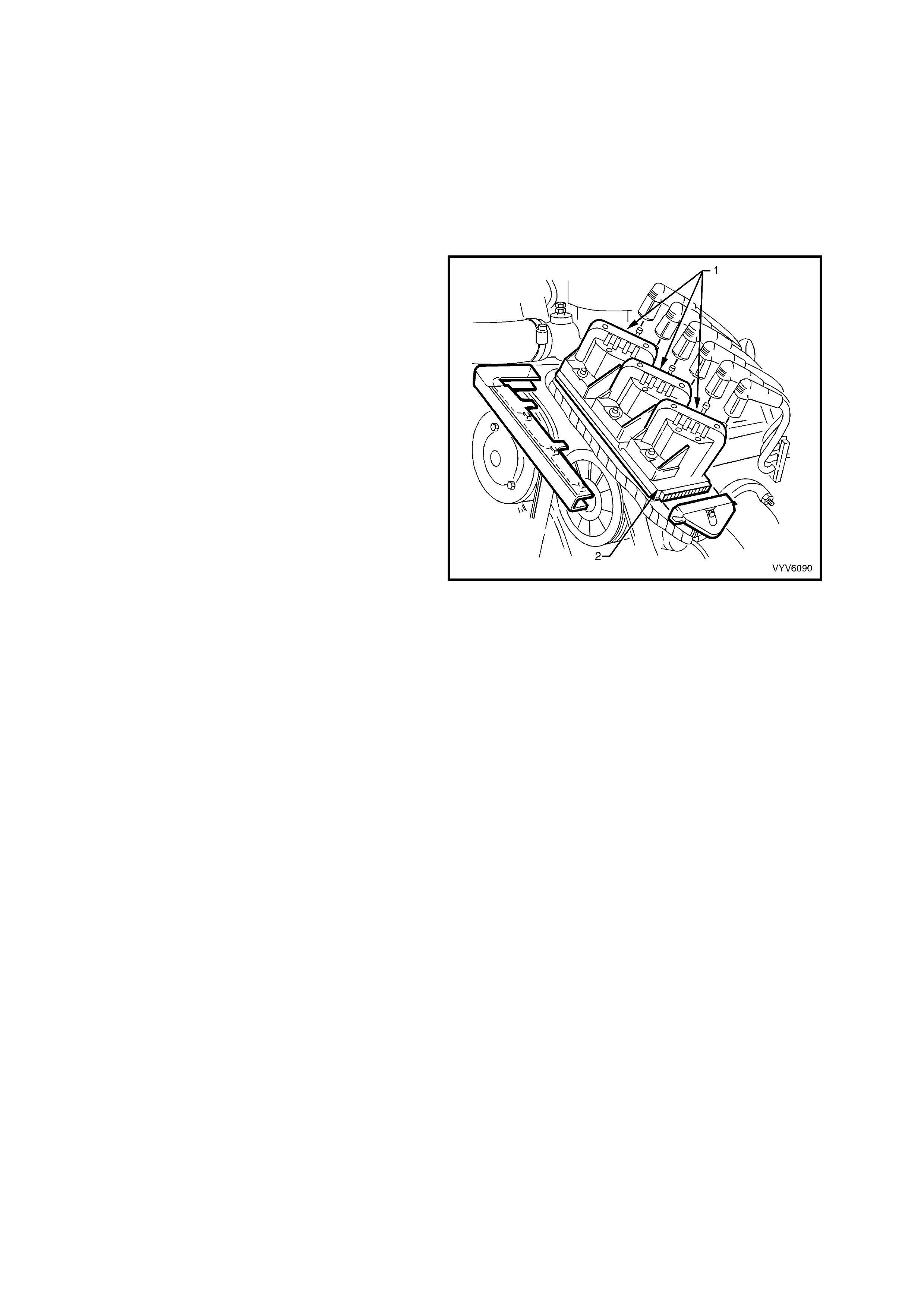
High engine load requir es m ore secondar y voltage to fire the plug than lo w engine loa d. At idle, no pr oblem would
be noticed, due to low se condary voltage r equirem ents. It is poss ible for one spa rk plug to fire e ven though a plu g
wire fed b y the sam e coil ma y be disconnect ed fr om it's c ompanion s park plug. The disc onnec ted plug wir e acts as
one plate of a capacit or, with the eng ine be ing the oth er plate. T hese two Capac itor Plates are char ged as a s park
jumps across the gap of the stil l-connec ted spark plug. T he plates are the n dischar ged as the sec ondar y en ergy is
dissipated in an oscillating current across the gap of the still connected spark plug. Secondary voltage
requirements are very high with an “Open” spark plug or wire. The ignition coil has enough reserve energy to fire
the still-connected plug at idle, but possibl y not under high engine load. A m ore noticeable m isfire may be evident
under load; both spark plugs may then be misfiring.
IGNITION COILS
The three twin-tower ignition coils (1) are mounted
to the DIS m odule ( 2). Ea ch coil pro vides the s par k
for two spark plugs simultaneously (waste spark
distribution). The module supplies +12 volts to the
positive terminal of each coil, while the negative
side of the ignition coil primary circuit is connected
to ground through the module. The module will
energise on ly one coil at a time in the c orrect order
by suppl ying & removi ng the prim ary circuit ground
path to each coil at the proper time.
Figure 6C1-1-72 Ignition Coils
DIRECT IGNITION SYSTEM (DIS) MODULE
The DIS module serves several functions:
• It powers the dual crankshaft sensor internal circuits.
• It supplies the 3X and 18X voltage that each respective Hall switch pulses to ground to generate the 3X and
18X crankshaft sensor pulses.
• It determines the correct ignition coil firing sequence, based on how many 18X transitions occur during a 3X
pulse. This coil sequencing occurs at start-up. After the engine is running, the module remembers the
sequence, and triggers the proper ignition coil.
• It sends a crankshaft ref erence signal to the PC M. The PCM interprets eng ine RPM from this signal. It is also
used by the PCM to determine crankshaft position for EST spark advance calculations. (The falling edge of
each crankshaft reference signal pulse occurs 70 degrees before TDC of any cylinder.) The crankshaft
reference signal sent to the PCM by the DIS module is an on-off pulse occurring 3 times per crankshaft
revolution. This is neither the 3X nor the 18X crankshaft sensor pulse, but both of these are required by the DIS
module to generate the crankshaft reference signal.
• The DIS m odule gener ates the crank shaft r eferenc e signal b y an inter nal divid e-b y-6 circ uit. T his cir cuit divid es
the 18X crankshaft sensor pulses by 6. The divider circuit is enabled, or ready to begin dividing, only after it
receives 3X crankshaft sensor pulses. If either the 18X or 3X pulses are missing, the divider cannot generate
any crankshaft reference signal pulses (sent to the PCM), and no fuel injector pulses will occur.
• When cranking the engine, or anytime the PCM does not apply 5 volts to the DIS m odule 'bypass' circuit, the
DIS module controls ignition by triggering each of the three coils in the proper sequence at a predetermined
dwell, with spark advance fixed at 10 degrees BTDC. This is called Bypass mode ignition. The DIS module
provides proper ignition coil sequencing during both the Bypass and EST modes.
• Once the engine is star ted, the PCM appli es 5 volts to the DIS module ' b ypass' c ircuit, sig nalli ng the m odule to
allow the PCM to control the dwell and spark timing. This is EST mode ignition. During EST mode, the PCM
adjusts spark dwell and timing advance for all driving conditions. Again, the DIS module is responsible for
proper ignition coil sequencing during both the Bypass and EST modes.
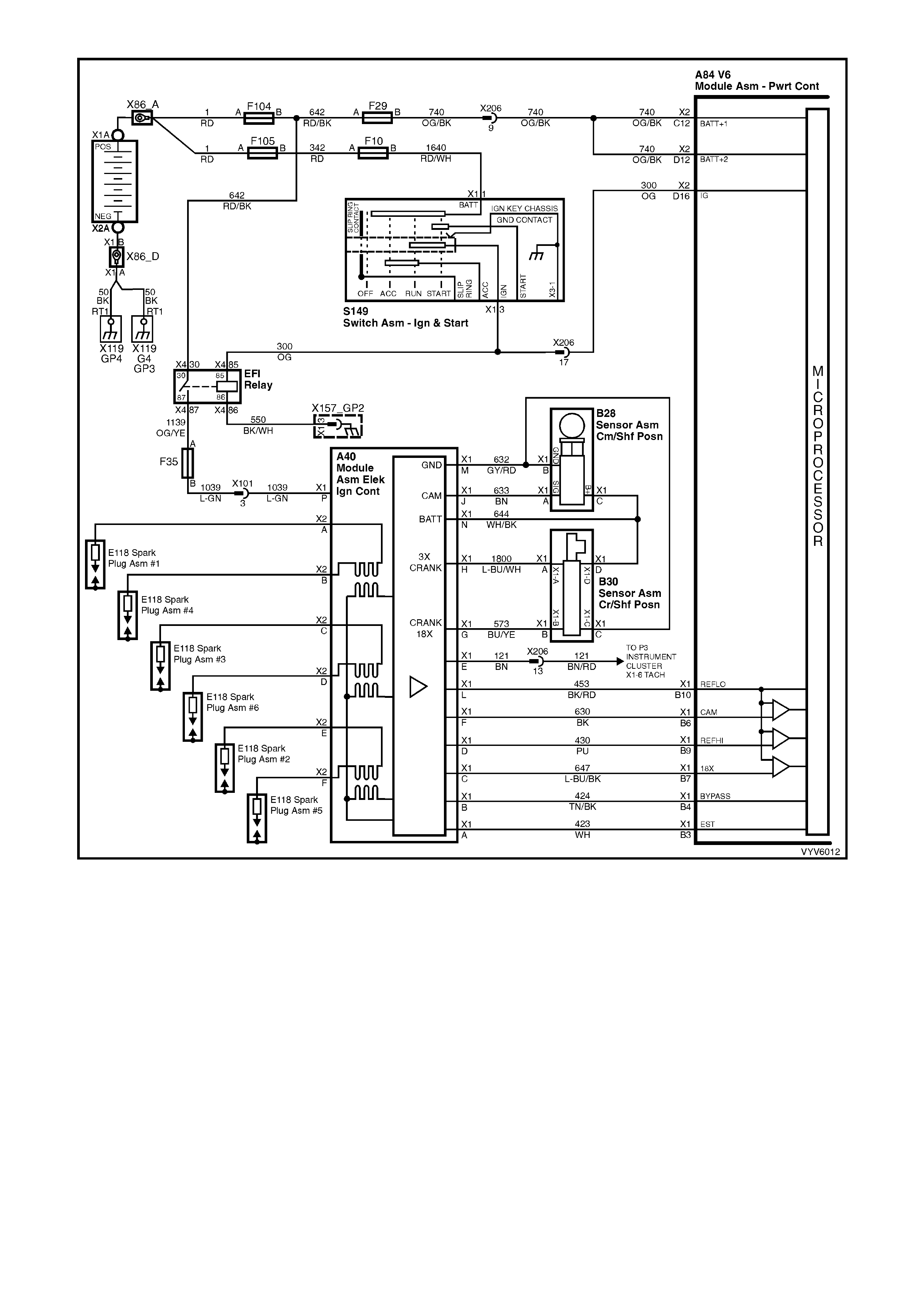
Figure 6C1-1-73 Direct Ignition System
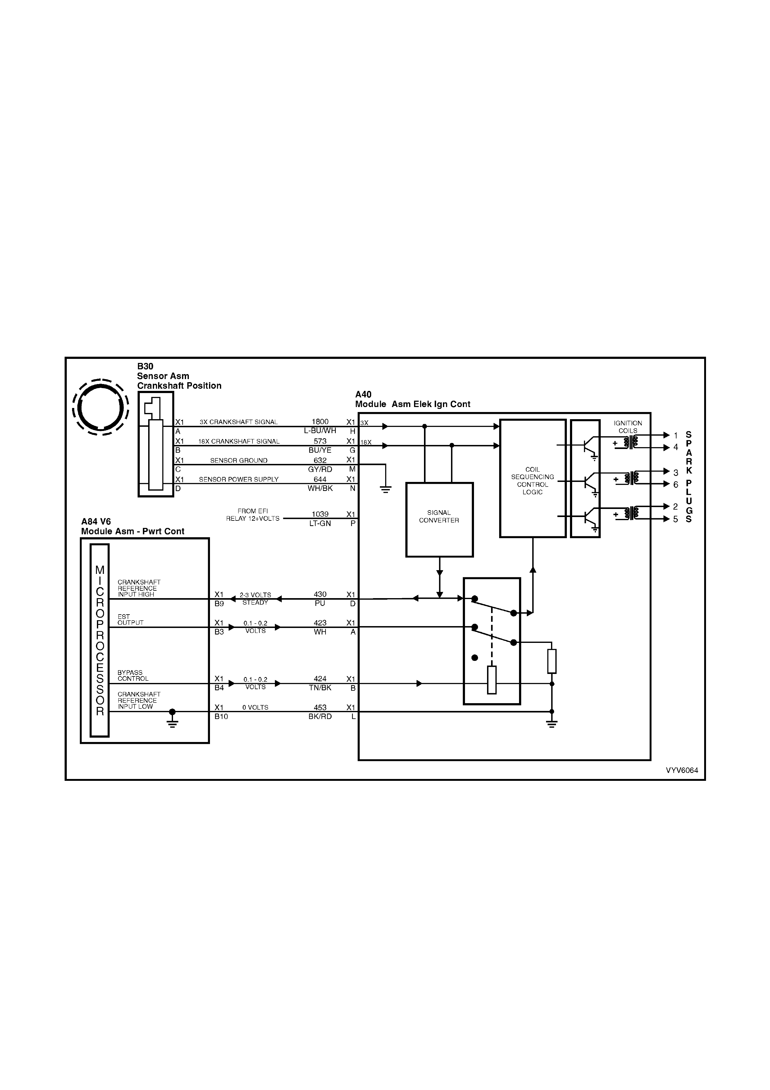
1.5 ELECTRONIC SPARK TIMING
OPERATION
Electronic Spark Timing (EST) is the PCM's method of controlling spark advance and ignition dwell, when the
ignition system is operating in the EST mode.
There are two modes of ignition system operation:
• Bypass mode
• EST mode
In the bypass mode, the ignition system operates independently of the PCM, with bypass mode spark advance
always at 10 degrees BTDC. The bypass m ode is in effect when crank ing the engine. The PCM has no control of
the ignition system when in this mode. In fact, the PC M could be disconnected and removed from the car and the
ignition system would still fire the spark plugs while cranking, as long as the other ignition system components were
functioning! (This would provide spark but no fuel injector pulses, and a no-start.)
After the engine has started, the PCM will cause the ignition system to change over to the EST mode. Once the
change is made to EST mode, it will stay in effect until either:
1. The ignition key is turned off. 2. The engine quits running, or. 3. An EST fault is detec ted.
If an EST f ault is d etec te d whi le th e e ngine is runn ing, the i gn iti on s yst em will s witc h bac k to the bypass mode. T he
engine may quit running, but will restart and stay in the bypass mode.
Figure 6C1-1-74 Direct Ignition System - Cranking
In the EST mode, the ignition spark timing and ignition dwell time is fully controlled by the PCM. EST spark
advance and ig nit io n dwel l is calculat ed b y the PCM us ing the fol lo win g inpu ts :
• Engine speed (crankshaft reference) • Crankshaft position (crankshaft reference)
• Engine load (MAF) • 18X Signal
• Intake Air Temperature (IAT) • Engine coolant temperature (ECT)
• Park/Neutral (TFP) • Throttle position (TP sensor)
• Vehicle speed (VSS) • Detonation (knock sensor)
• PCM supply voltage
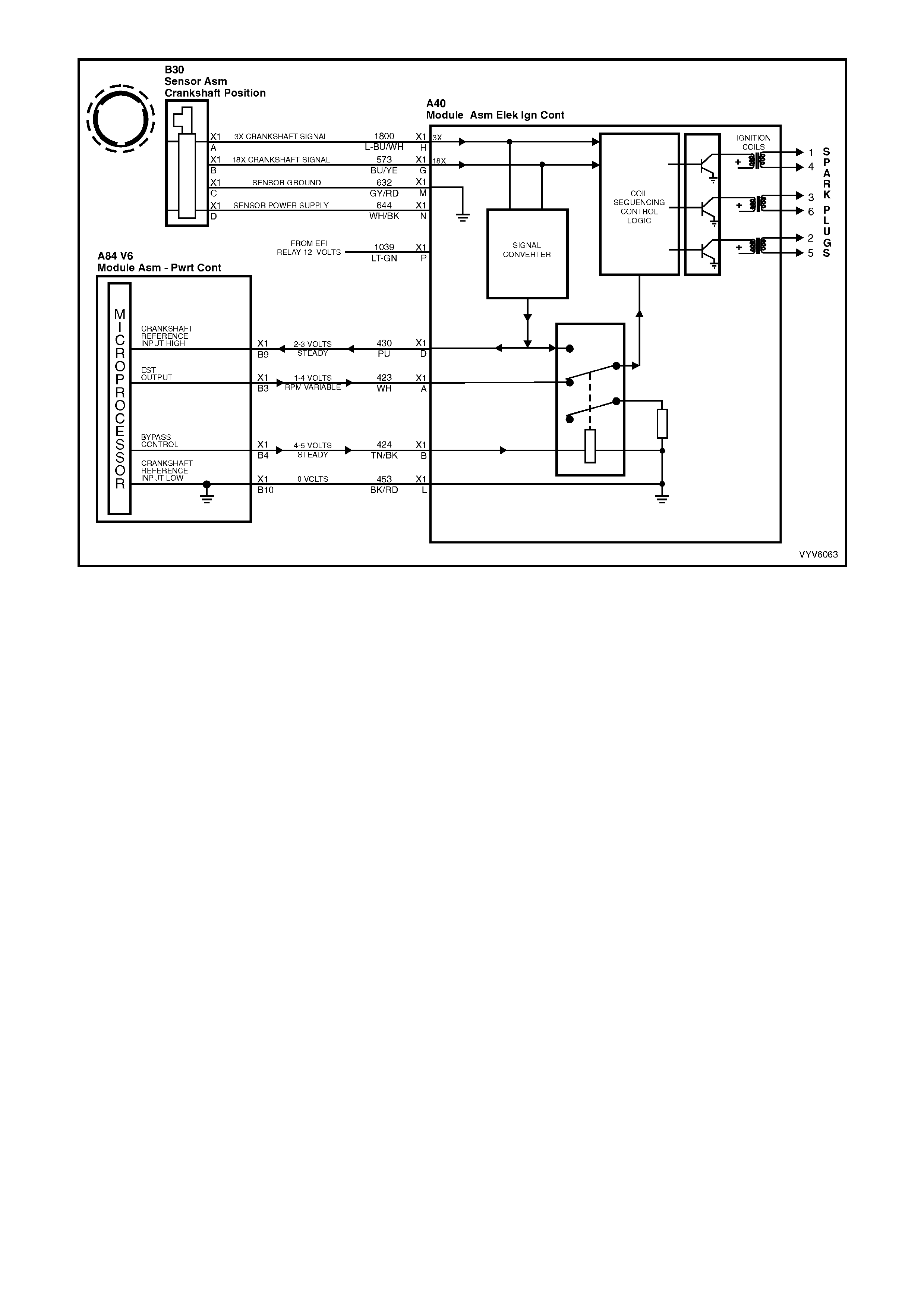
Figure 6C1-1-75 Direct Ignition System - Engine Running
Crankshaft Reference Input (X1-B9 Circuit 430)
The PCM uses this s ignal to calc ulate engi ne RPM and c rankshaf t position. If th e PCM rec eives no pu lses on this
circuit, no fuel injection pulses will occur, the engine will not ru n, and DTC P1372 will set when attempting to start
the engine.
Crankshaft Reference Ground (X1-B10 Circuit 453)
This is a gr ou nd circ uit f or the dig ita l RPM c ou nter ins i de t he PCM, but the wir e is conn ec ted to en gin e gr oun d o nly
through t he ig nitio n m odule. Althoug h t his circ uit is e lectr icall y connec ted to the PCM, it is not c onnect ed to groun d
at or through the PCM. The PCM compares voltage pulses on the reference input circuit 430 to any on this circuit. If
the circuit is open, or connected to ground at the PCM, it may cause poor engine performance and possibly
activate the Check Powertr ain MIL wit h no DTC.
Bypass Control (X1-B4 Circuit 424)
The PCM either allows the ignition module to keep the spark advance at bypass mode 10 degrees BTDC, or the
PCM signals the ignition module that the PCM is going to control the spark advance (EST mode). The PCM
provides 5 volts to the ignit ion m odule if the P CM is going t o contr ol s park tim ing (EST m ode). If the PCM do es not
turn on the 5 volts, or if the ignition module doesn't receive it, then the module will keep control of spark timing
(bypass m ode). An open or grounded b ypass control circuit 424 will set a DT C P1361 and the ignition s ystem will
stay in 'bypass mode'. If the bypass control circuit 424 is shorted to voltage then DTC P1351 will set.
EST Output (X1-B3 Circuit 423)
The EST output circuitry of the PCM sends out timing pulses to the ignition module on this circuit. When in the
bypass mode, the ignition module grounds these pulses. When in the EST mode, these pulses are the ignition
timing pulses used by the ignition module to energise the ignition coil. If circuit 423 is open when the engine is
started, a DTC P1351 wil l set and the ig nition s ys tem will sta y in the bypas s mode. If circ uit 423 becom es shorted
to voltage or grounded during EST mode operation above 1600 RPM, then DTC P1361 will set.
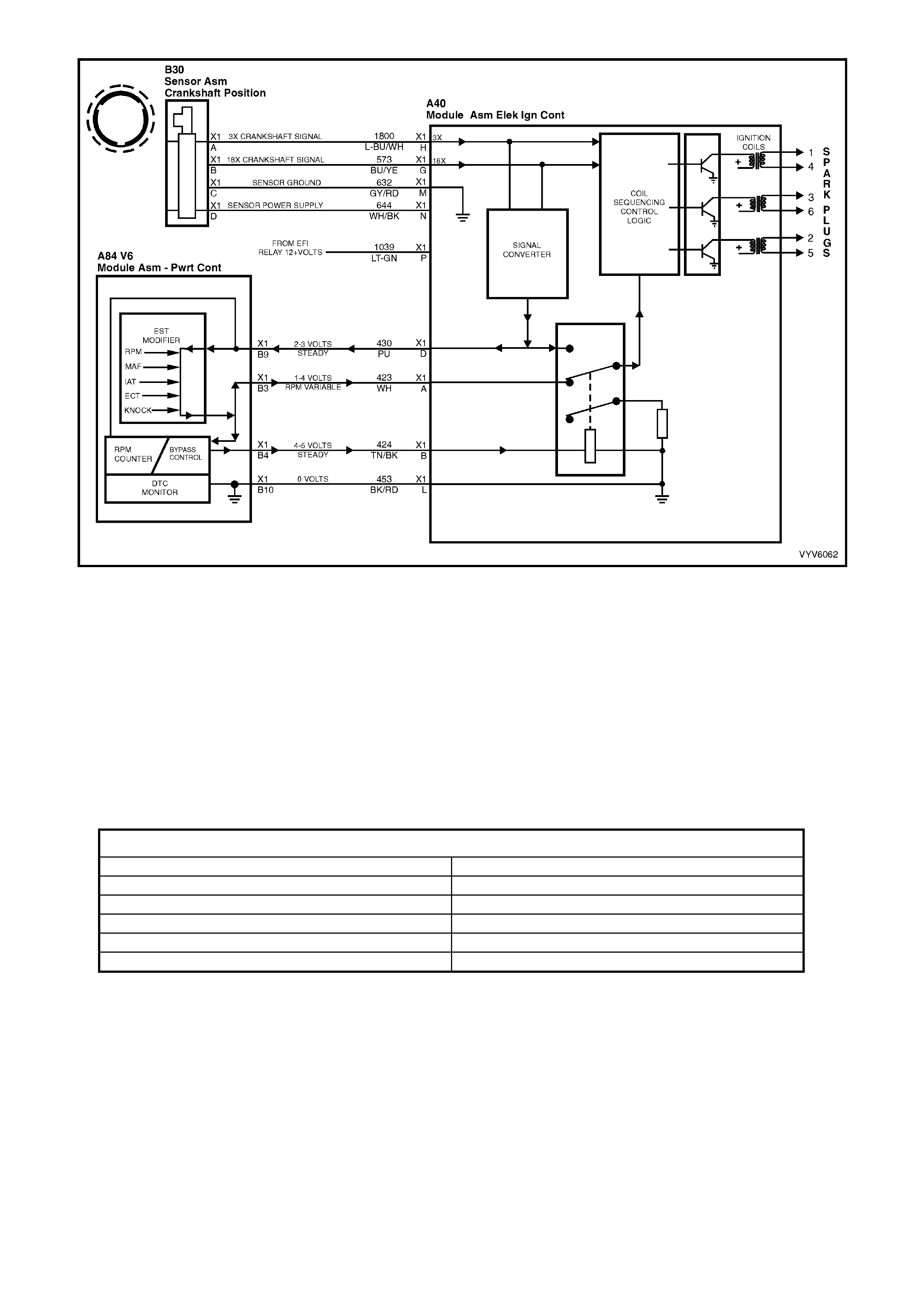
Figure 6C1-1-76 Engine Running with EST Inputs
An open or shorted EST or BYPASS circuit will set either a DTC P1351 or P1361.
DTC P1351 Ignition Electronic Spark Timing Output Circuit Fault will be set if:
• The ignition is on and...
• T he PCM has detec t ed at l east 2 E ST output p uls es d uring th e first 3 c rankshaf t r ef er ence pulses rec e iv ed f rom
the ignition m odul e.
DTC P1361 Ignition Bypass Circuit Fault will be set if:
• The PCM has commanded EST and...
• The PCM has detected no EST output pulses for 400 mS and...
• The engine RPM is greater than 1600 RPM.
DTC P1351 AND P1361 HISTORY DATA
PARAMETER PARAMETER
Engine Speed Fuel
Coolant Temperature Reference Volts
Time From Start Vehicle Speed
Times Occurred Spark Mode
Ignition Cycles
Default Value
Once a DTC P1351 or P1361 is set, the PCM will operate in the bypass spark mode.
Recovery
Recovery will occur on the next ignition cycle.
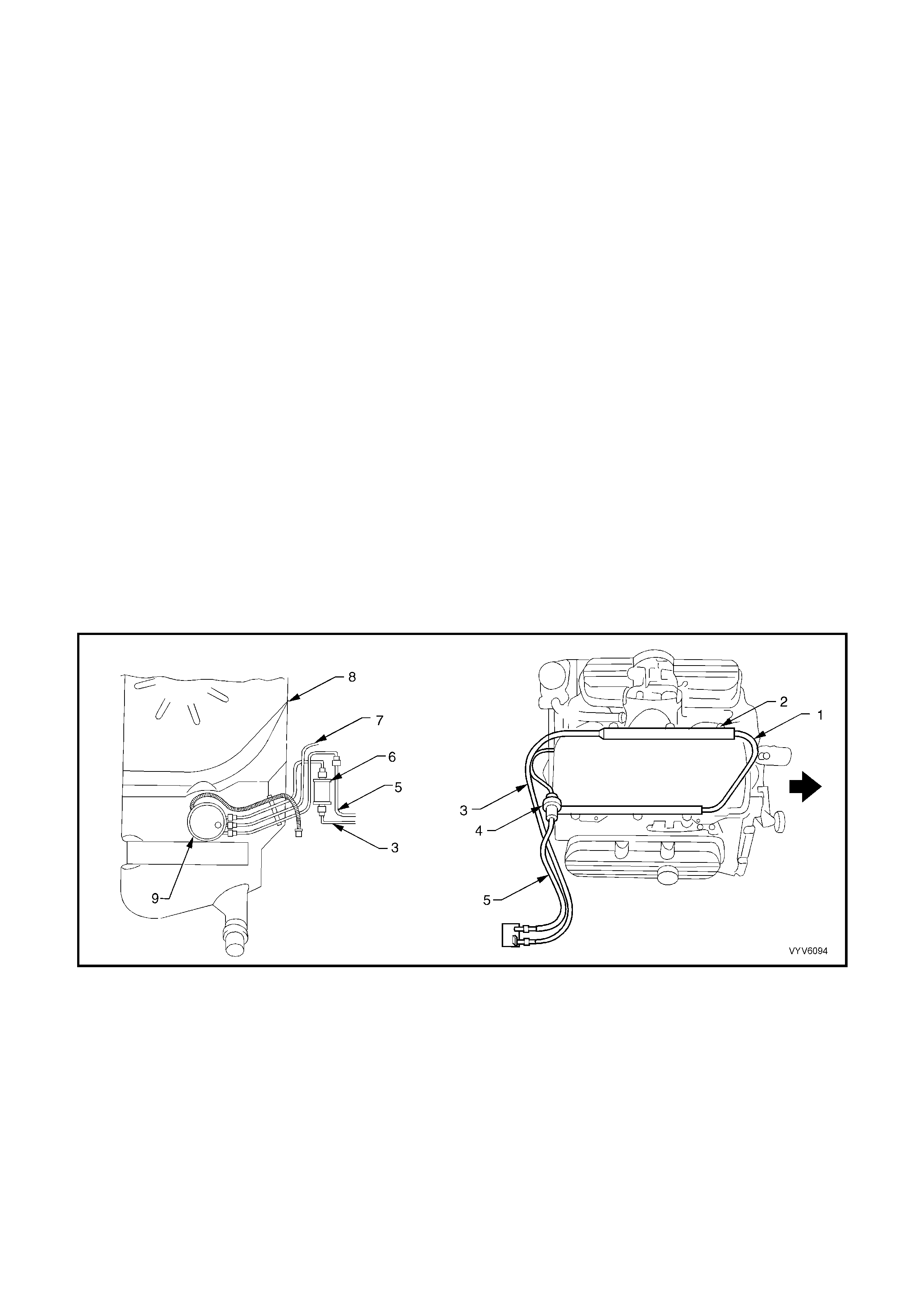
1.6 FUEL SYSTEM
BASIC FUEL SYSTEM OPERATION
The f uel control sys tem s tarts with the f uel in the f uel tank . A sing le in- tank high p ress ure fuel pump ( located ins id e
a modular sender unit) is used. F rom the high pr essure pum p, fuel f lows through a fuel filter, th en on to the engine
fuel rail through the fuel pressure supply line.
The high pressure in-tank single pump is capable of providing fuel at more than 414 kPa. A pressure regulator
connects between the fuel rail and the return fuel line, and keeps fuel available to the injectors at a regulated
pressure between 270 and 350 kPa.
The regulated pr essure will var y, depending on intak e manifold pressure. The pr essure regulat or senses m anifold
pressure through a small hose connecting it to the throttle body adaptor. When throttle body adaptor pressure is
low (closed-throttle), the regulated pressure is at its lowest. When the throttle is wide open, intake manifold
pressur e is high an d the fuel press ure also is at its hi ghest. Fuel in excess of injector nee ds is returned to the fue l
tank by the separate return line connected to the outlet of the pressure regulator.
The injectors, located in each runner of the intake manifold just ahead of the inlet ports to the cylinder head, are
controlled b y the PCM. T he y de liv er f uel i n o ne of s everal modes. The f uel pump is nor mally energis e d by the PCM
via the fuel pump relay.
SYSTEM COMPONENTS
The Fuel Control System is made up of the following components:
• PCM
• Fuel pressure supply line
• Fuel pum p relay
• Fuel rail
• Injectors
• Modular fuel sender assembly
• Fuel pum p assembly
• Fuel press ur e regulat or
• Fuel filter
• Fuel return line
Figure 6C1-1-77 V6 Fuel Delivery System
Legend
1. Fuel Rail
2. Fuel Injector (6 places)
3. Fuel Feed
4. Fuel Pressure Regulator
5. Fuel Return
6. Fuel Filter
7. Fuel Tank Vapour Line
8. Fuel tank
9. Modular Fuel Sender Assembly
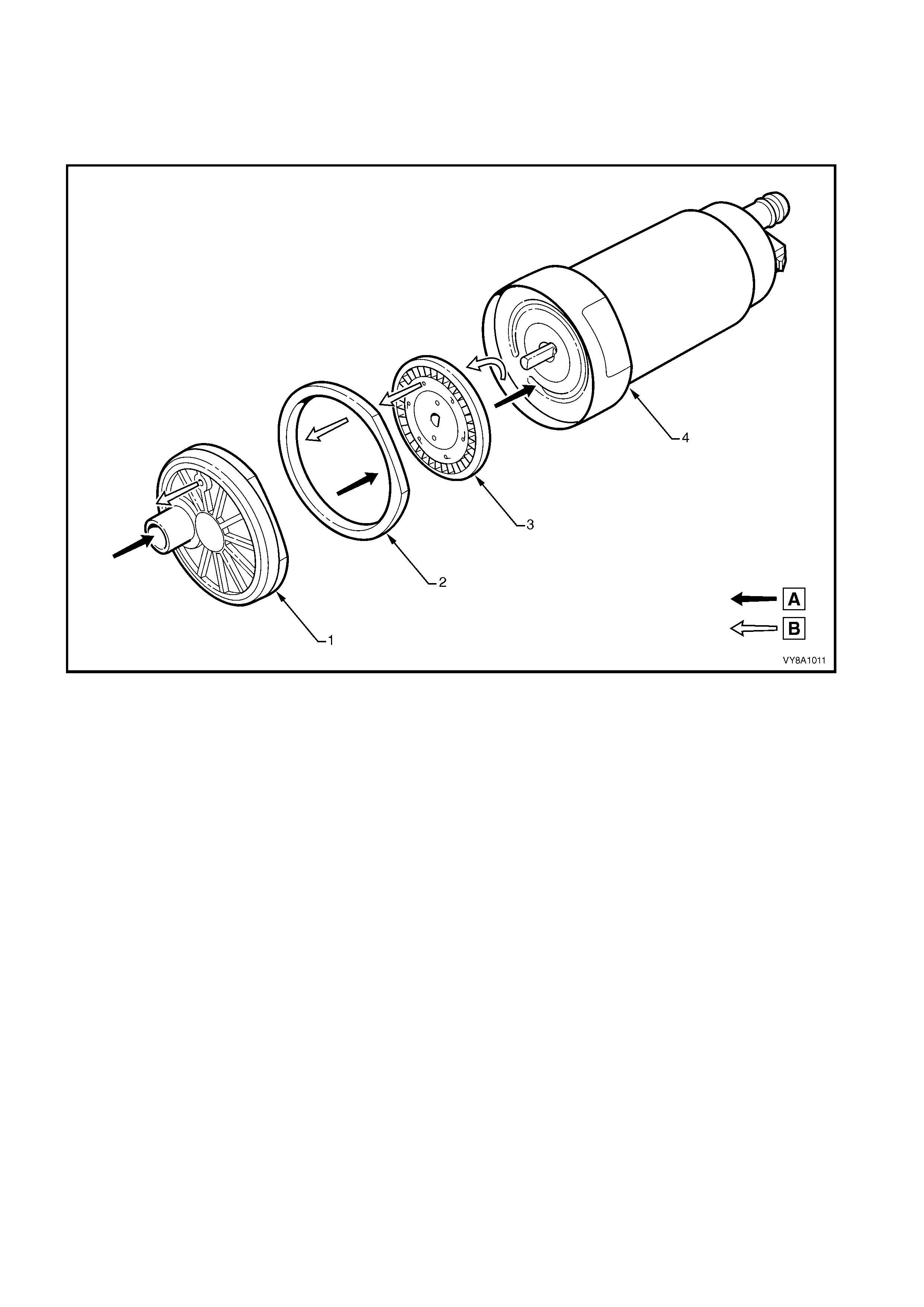
MODULAR RESERVOIR ASSEMBLY
The Modular Reservoir Assembly (MRA) is designed to maintain an optimum fuel level in the reservoir. This
ensures a cont inu ous f ue l f l o w u nder al l f uel le ve l c on d iti ons a nd ve hicle atti tud es . The V6 equippe d ve hic l es use a
single turbine type fuel pump, except Omega CD which uses a dual turbine TYPE .
SINGLE TURBINE FUEL PUMP
Figure 6C1-1-78 Single Turbine Fuel Pump
Legend
A. Fuel
B. Vapour out 1. Inlet Body
2. Impeller Housing
3. Impeller
4. Fuel pump housing
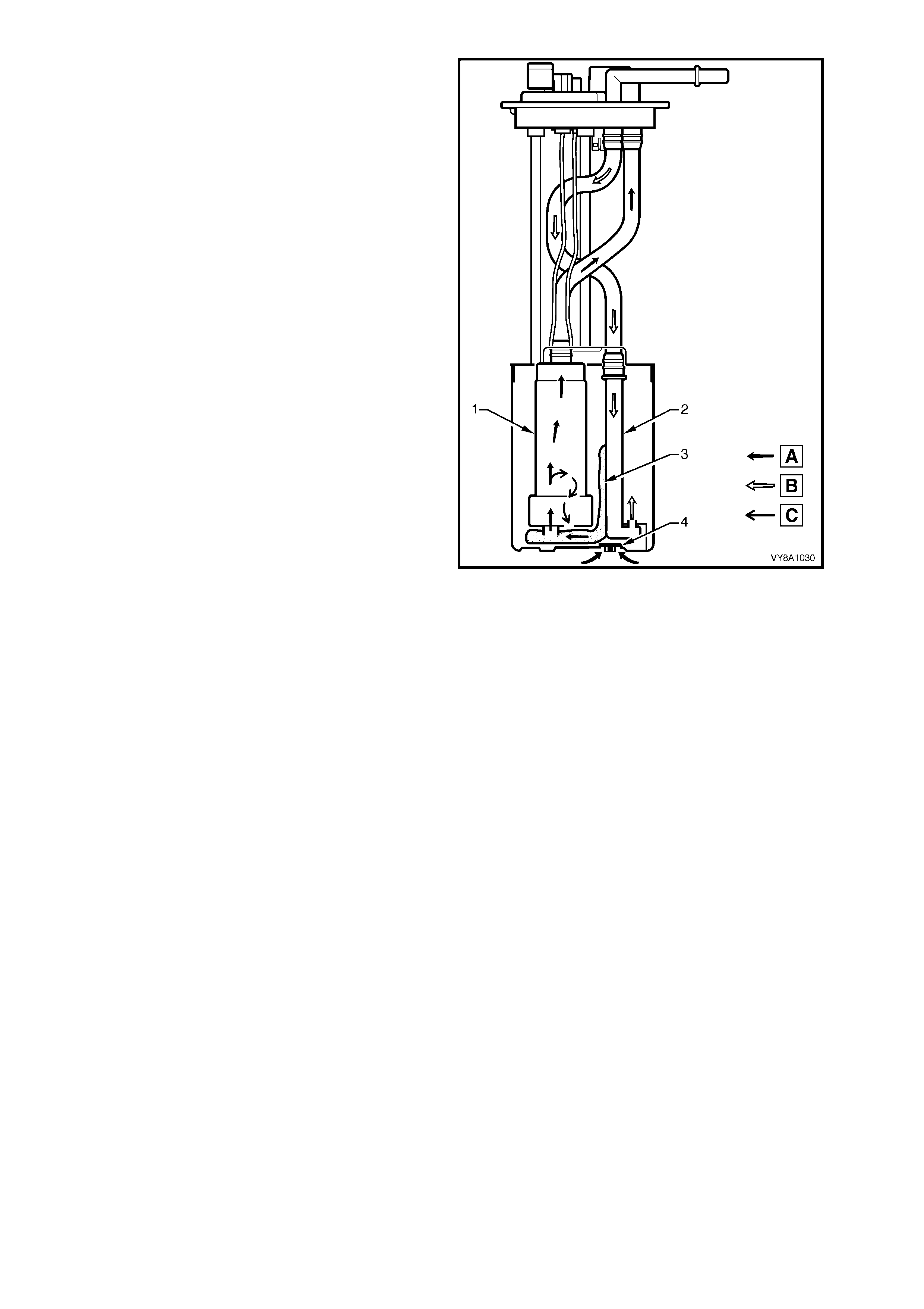
Fuel (A) is drawn into the reservoir of the modular
fuel sender assem bly from the fuel tank, through the
primary umbrella valve (4), and into the fuel pump’s
im peller, via the inter nal str ainer (3) at the f uel pump
inlet. At the impeller, vapour (C) is separated from
the fuel and the fuel is pressurised. The vapour is
ejected out of the fuel pump (1) and into the reservoir
via a port adjacent to the fuel pump’s inlet.
High-pressure fuel then flows through the end cap,
the lower connector and the fuel pump flex pipe.
From the flex pipe, fuel then exits the modular fuel
sender assembly through the fuel feed fitting and
flows on to the externally mounted fuel filter.
Return f uel (B) not used by the en gine is ret urned to
the fuel module via the fuel line harness and the
return port of the m odular fuel cover. The ret urn fuel
enters t he jet pum p stand pipe (2) of the res ervoir vi a
the return fuel tube.
When the power is switched off, the reservoir
remains full of fuel, due to of the action of the
prim ary umbrella valves. F uel from the tank overf low
enters the reservoir over the top of the assembly.
Fuel levels in the reservoir are also maintained by
returned engine fuel.
Electrical power to the fuel pump enters the unit via a
connector that is secured to the cover. An internal
harness assembly completes the connection to the
pump (not shown).
Figure 6C1-1-79 Modular Fuel Sender Assembly
DUAL TURBINE FUEL PUMP (OMEGA CD)
Figure 6C1-1-80 Dual Turbine Fuel Pump (Omega CD)
Legend
A. First Stage Fuel
B. Second and Third Stage Fuel
C. Vapour Out
1. Inlet Body
2. Inlet Housing
3. First Stage Impeller
4. Second Stage Impeller
5. Inlet Plate
6. Third Stage Impeller
Fuel (A) enters the dual stage turbine fuel pump
(6) via the external strainer (3) and of the modular
fuel sender assembly. In the first stage, the pump
separates the vapour (B) from the fuel. First stage
fuel is directed to the reservoir filling the reservoir
bucket.
Fuel levels in the reservoir are also maintained by
return fuel (B) via the return line. Reservoir fuel
flow proceeds through the fuel pump strainer (5),
bypassing the first stage impeller. Fuel then
proceeds to the second impeller and the high-
pressure third stage of the impeller pump.
High-pres sure f uel then f lows throug h the end cap.
Attached to the pump outlet is a diverter that
allows the prim ary fuel volume to flow into the flex
pipe and deliver a portion of the flow to the jet
pump via an aspirator (1) and the rest to an
externally mounted fuel filter.
The diverted fuel from the outlet of the fuel pump
passes thr ough the jet p ump filter (2) . This creates
a low pressure area at its base, causing the
umbrella valve (4) to unseat, drawing cooler fuel
into the reservoir area.
When the power is switched off, the reservoir
rem ains full of fuel, du e to t he action of the pr im ary
umbrella valves. Fuel tank overflow enters the
reservoir over the top of the assembly.
Should the external strainer become blocked or
restrict fuel entry, then the secondary umbrella
valve (4) will unseat, allowing fuel to enter the
reservoir ar ea.
Electrical power to the fuel pump enters the unit
via a connector that is secured to the cover. An
internal harness assembly completes the
connection to the pump (not shown).
Figure 6C1-1-81 Modular Fuel Sender Assembly

FUEL PRESSURE REGULATOR
The fuel pressure regulator is a diaphragm
operated relief valve with fuel pump pressure on
one side and intake manifold pressure (engine
vacuum) combined with mechanical spring
pressur e on the other . The f unction of the r egula tor
is to maintain a regulated pressure at the injectors
at all times by controlling the flow into the return
line.
Legend:
3. Fuel Inlet
4. Fuel Outlet Valve
4. Valve
5. Valve Holder
6. Diaphragm
7. Compression Spring
8. Vacuum Connection
Figure 6C1-1-82 Fuel Pressure Regulator
Legend:
1. Fuel Pressure Regulator
2. Vacuum Connection
Figure 6C1-1-83 Fuel Pressure Regulator Location
FUEL FILTER
The fuel filter is located under the vehicle by the
right hand rear side frame, forward of the fuel tank.
The fuel filter is mounted in place by a plastic
retainin g strap attac hed to t he rear f ram e. Both fuel
pressure hoses at the filter are quick connects to
the filter.
Legend:
1. Canister
2. Fuel Vapour Canister to Engine
3. Vent Line
4. Fuel Vapour Line
5. Fuel Feed Line
6. Fuel tank
7. Fuel Flow arrow
8. Fuel Filter
9. Fuel return Line
Figure 6C1-1-84 Fuel Filter Location
FUEL PUMP ELECTRICAL CIRCUITS
When the ignition switch is turned to on or crank
after having been off for at least 10 seconds, the
PCM will immediate ly energise the fuel pump relay
(1) to o perat e th e fuel p um p. This bu il ds up th e f uel
pressur e quick ly. If the engine is not crank ed withi n
two seco nds , t he PC M wil l s hut t he f ue l pump relay
off and wait un til th e engi ne is c rank ed. As soon as
the engine beg ins c ranking, the PCM wil l sens e the
engine turning from the crank shaft reference input,
and turn the relay on again to run the fuel pump.
On vehicles equipped with Telematics the fuel
pump relay control circuit is via the telematics
module. For more telematics information Refer
Section 12K-TELEMAT ICS.
Figure 6C1-1-85 Fuel Pump Relay Location
Figure 6C1-1-86 Fuel Pump Electrical Circuit
FUEL INJECTORS
The f uel injectors ar e electr ically operate d fuel flo w control va lves. The y are s upplied with batter y voltage f rom the
ignition s witch via t he EFI r ela y. The i njectors are cont rolled b y the PCM pro viding the ground c ircuit. T he injec tors
are never fully energised on, as that would flood the engine with too much fuel. The PCM supplies the ground
circuit in short pulses. T he longer the dura tion of the pulse (pulse width), the more fuel is injected into the engine.
Inside, the injectors have a coil of electrical wire that becomes an electromagnet when energised. The resistance of
these windings is important for the PCM to operate correctly. The PCM monitors the voltage at terminal X2-C14
and will compensate for low or high supply voltage to the injectors.
Figure 6C1-1-87 Fuel Injecto r Circuit
DTC P0200 Injector Voltage Monitor Fault will set if P0561 System Voltage Unstable is not current and…
• The engine is running and injector voltage monitor terminal X2-C14 is 2.2 volts less than ignition feed voltage for
more than three seconds.

DTC P0200 does not activate the Check Powertrain MIL.
DTC P0200 HISTORY DATA
PARAMETER PARAMETER
Engine Speed Battery Voltage
Coolant Temperature Reference Volts
Time From Start Vehicle Speed
Times Occurred Injector Voltage
Ignition Cycles 18X Signal
Fuel 3X Signal
Default Value
Once DTC P0200 is set the PCM will use battery voltage as a substitute for injector monitor voltage.
Recovery
Recovery will occur when the PCM sees a valid condition.
FUEL CONTROL SYSTEM
The purpose of closed loop fuel control is to control tailpipe emissions consisting of hydrocarbons (HC), Carbon
Monoxide (CO), and Oxides of Nitrogen (NOx). At the same time, the system must achieve good engine
performance and good fuel economy.
The closed loop system regulates exhaust emissions by controlling the air/fuel ratio at an optimum level during
various driving conditions. The most efficient air/fuel ratio to minimise exhaust emissions is 14.7 to 1. This allows
the 3-way catalytic converter to operate at maximum efficiency to control exhaust pollutants. Because of the
constant measuring of the exhaust gases by the oxygen sensors, and adjusting of the fuel injector pulse width by
the PCM, the fuel injection system is called a closed-loop control system.
FUNCTION
The fuel supply system delivers fuel at a regulated pressure to the fuel rail. The fuel injectors, located directly
ahead of each inlet port of the cylinder head, act as fuel flow control valves, spraying atomised fuel into the inlet
ports when the y are elec tric ally puls ed by the PC M. On the V6 e ngine, 6 inj ectors are wired ind ivi duall y so the y are
pulsed i nd iv idu all y. This t yp e of fuel i nj ec tio n is ref err ed to as sequentia l i nj ec tio n bec aus e pu ls ati on of the inj ec tor s
are individually controlled and in a specific order.
The PCM c ontrols the am ount of f uel injecte d into the engine b y controll ing th e le ngth of tim e the inj ectors ar e held
open. This length-of-time is called PULSE WIDTH. To increase the amount of fuel injected, the pulse width is
lengthened, and vice versa. The pulse width is calibrated and varies between 0 - 11 milliseconds with the engine
running at idle, each injector is normally pulsed once every two crankshaft revolutions.
MASS AIR FLOW SYSTEM
The Mass Air Flow system is based upon an Air Flow Meter that measures the mass of the air entering the engine.
Advantages of Mass Air Flow:
• Automatically compensates for engine ageing.
• No air measurement lag time.
• Excell ent id le stability.
Two specific data sensors provide the PCM with the basic information for the fuel management portion of its
operatio n. T hat is, t wo specif ic s ignals; cr anks haft r eference sig nal from the ignit ion s ystem , and the Mass Air Flo w
(MAF) s ensor signa l. Both of these signals to the PC M estab lish the engin e speed and m ass of air ingested b y the
engine.
Due to the additional temperature compensation sensor in the MAF sensor, this system does not require a manifold
absolute pres s ure sensor .
The engi ne speed sig nal com es from the ig nition m odule to th e PCM as th e crank shaft ref erence signal. T he PC M
uses RPM information to calculate the best fuel injector pulse width and spark timing for a given operating RPM
band.
W hen the engine is st arted, the PCM will imm ediate l y look at the Engin e Coolan t T emperatur e sensor to determ ine
how much fuel is required to start. After the engine is started, the PCM will constantly monitor the MAF sensor
values to determine both the spark advance and engine fuelling requirements. The MAF sensor measures the
mass of air ingested into the engine. The PCM then calculates the quantity of fuel to be injected to maintain an
air/fuel ratio of 14.7 to 1. An engine started in cold weather will require more fuel and spark advance than an
engine started hot, which requires less fuel and less spark advance.

One sensor is used to m easure the dens it y factor, the MAF se nsor . The MAF sen sor us ed on this e ngine util is es a
heated element type of operation. Three sensing elements are used in this system.
As air passes over the heated elements during engine operation they begin to cool. By measuring the amount of
electrical power required to maintain the heated elements at the predetermined temperature above ambient
temper ature m ass air f low rate c an b e determ ined. T he signal pro duced by the MAF s ensor is s ent in t he f orm of a
variable frequency output. A large quantity of air passing through the sensor (such as when accelerating) will be
indicated as a h igh frequenc y out put. A small quantit y of air passing t hrough the sensor will be indicat ed as a low
frequency output ( suc h as dec eler ati on or at idle). As t he P CM rec e i ves th is v arying f reque ncy signa l f r om the MAF
sensor, it searches its preprogrammed tables of information to determine the pulse width of the fuel injectors
required to match the mass air flow signal.
Tech 2 displays MAF sensor information in frequency, grams per second and mG/cylinder/second. A normal
reading is approximately 4 - 9 grams per second at idle and increases with engine RPM.
The remaining sensors and switches provide electrical inputs to the PCM which are used for modification of the
air/fuel mixture as well as for other PCM control functions, such as Idle Air Control (IAC).
MODES OF OPERATION
The PCM look s at voltage signals from several senso rs to determine how m uch fuel to give the e ngine, and when
to operate in the open- loop or closed-l oop modes . The fuel de liver y is contro lled in one of sever al possib le m odes,
these modes are described in the following paragraphs.
Starting Mod e
W hen the igniti on key is f irst turned on, the PCM wil l energise the f uel pum p relay, and the fuel pum p will build up
pressure to the f uel rail. The PC M then check s the engine coolant tem perature sensor a nd determines th e proper
injector pulse width for starting the engine.
W hen cranking begi ns, th e PCM wi ll o per at e i n th e S ta r ting Mod e un ti l en gine RPM is more than a bou t 40 0 -or- the
Clear Floo d mode is enab led. After the ignition is tur ned on and the f irst refer ence signal is rec eived, the P CM will
pulse al l of the f uel i nject ors. Af ter the f irst prim e puls e has been injec ted, th e PCM will wa it unti l it r eceive s a goo d
camshaft position signal. When a good camshaft position signal is received, the PCM then operates the fuel
injectors in sequential mode. Pulse width during the starting mode is between approximately 4 - 26 milliseconds,
depending upon engine coolant temperature.
Clear Flood Mode
If the engin e floods, it can be s tarted by pushing t he accelerator pe dal down all t he way to the floor wh ile crank ing
the engine. The PCM then pulses the injectors with zero millisecond pulse width, which should clear a flooded
engine. The PCM hol ds this puls e width as long as the thr ottle pos ition sensor input ind icates the thro ttle is abo ve
80% and RPM is below 400.
If the throttle is held wide-open while attempting to make a normal start with a non-flooded engine, the
engine will not start.
Normal Open L oop Mode
After the engine is running (RPM more than 400), the PCM will operate the fuel control system in the open loop
mode. In open loop, the PCM ignores the signal from the oxygen sensor, and calculates the air/fuel ratio injector
pulse widt h based on in puts fr om the cranks haft reference signal ( RPM input) and these se nsors: MAF, I AT, ECT,
and TP sensor.
The system will stay in the open loop mode until all the closed loop mode criteria have been met, or not at idle,
refer open loop idle mode description.
In open l oop, the ca lc ulate d pulse wid th ma y give an air /f uel rati o o ther tha n 1 4.7 to 1. A n ex ample of this woul d be
when the engine is cold, because a richer mixture is needed to ensure good driveability.
Open Loop Idle Mode
The reas on for the idle m ode is to allo w a slight l y ric her m ixtur e at idle f or better idle q ualit y. Idle m ode air /fuel r atio
is about 14.0 to 1. This is an open loop mode, meaning the oxygen sensor signals are ignored.
The open loop idle mode is in effect when the throttle is closed, and vehicle speed is below five km/h (VSS).
In the cas e where the vehi cle rolls to a stop while op erating in the cl osed lo op mode, idle m ode will be dela yed for
10 to 35 seconds. During this time, the PCM will learn a fuel correction factor for a 14.7 to 1 air/fuel ratio before
switching to the Idle Mode.
Closed Loop Mode
In closed loop mode, the PCM initially calculates injector pulse width based on the same sensors used in open
loop. The difference is that in closed loop, the PCM uses the oxygen sensor signals to modify and precisely fine
tune the fuel pulse width calculations in order to precisely maintain the 14.7 to 1 air/fuel ratio that allows the
catalytic converter to operate at its maximum conversion efficiency.
Delta TP Acceleration Mod e
The PCM lo oks at rapid c hanges in throttle p osition (TP s ensor) to increas e engine power , and provides extra fuel
by increas ing the inj ector pulse width. If the inc re ased f uel requir em ents are great enoug h, the PCM m a y add extra
fuel injection pulses between the injector pulses that normally occur once every intake stroke.

Lean Cruise Air/Fuel Mode
During steady state cruising, the air/fuel ratio is made higher in order to increase fuel economy.
The engine will operate in lean cruise when:
• ECT is greater than 80 °C.
• VSS is greater than 70 km/h.
• Engine has been running longer than two minutes and 30 seconds.
• Calculated A/F ratio is 14.8 to 1
• Engine is not in power enrichment mode.
If all the criteri a are m et, the PC M will le an out th e A/F ratio b y 0.1 ever y 0.2 se conds unti l it re aches its maxim um
total enleanment, approximately 17.4:1.
Deceler ation Mod e
When deceleration occurs, the fuel rem aining in the intake manifold can cause excessive emissions and possible
backf iring. A ga in, th e PCM looks at c hanges i n thrott le pos it ion a nd engine R PM a nd r educes th e amount of fuel by
decreasing the pulse width, but does not completely shut off the fuel.
Decel Fuel Cutoff Mode
Decel fuel cutoff disables fuel delivery during a deceleration to reduce emissions and to improve fuel economy.
When deceleration from road speed occurs, the PCM can cut off fuel pulses completely for short periods. The decel
fuel cutoff mode occurs when all these conditions are met:
1. Coolant temperature above 63 °C.
2. Engine RPM is greater than 1400 RPM.
3. Vehicle speed above 42 km/h.
4. Throttle is less than 2 %.
5. Mass Air Flow per cylinder is less than 109 mG/S.
6. Engine RPM has dropped more than 200 RPM.
When the decel fuel cutoff is in effect, any one of these can cause the injection pulses to restart.
1. Engine RPM is less than 1200 RPM.
2. Vehicle speed is less than 42 km/h.
3. Throttle is open greater than 2%.
4. Mass Air Flow per cylinder is greater than 133 mG/S.
Park/Neutral to Drive Acceleration Enrichment Mode
The PCM will deliver additional fuel to the engine to reduce the RPM droop associated with a transmission shift
from park/neutral to a drive shift. This mode will only add fuel based on the first 32 reference pulses after a shift has
been detected.
Power Enric hme nt (PE) Mo de
The Power Enrichment (PE) mode delivers a rich mixture to the cylinders during a large throttle position change
command from the driver. During PE mode, the PCM will not make fuelling changes based on the oxygen sensor
signals.
BATTERY VOLTAGE CORRECTION MODE
At low batt ery volta ges , t he ignit ion system m ay delive r a weak s park , and t he injector mec hanical movement takes
longer to open. The PCM will compensate by:
• Increasing ignition coil dwell time if the voltage is less than 12 volts.
• Increasing idle RPM if the voltage drops below 10 volts.
• Increasing injector pulse width if the voltage drops below 10 volts.
FUEL CUTOFF MODE
No fuel is delivered by the injectors when the ignition is off. This prevents dieseling. Also, fuel pulses are not
delivered if the PCM re ceives no cr ankshaf t referenc e pulses from the ignition m odule, which m eans the en gine is
not running.
The fuel cutoff mode is also enabled at:
• High engine RPM, as an overspeed protection for the engine. When cutoff is in effect due to high RPM,
injection pulses will resume after engine RPM drops slightly.
SEQUENTIAL FUEL INJECTION MODE
W hen the eng ine is first c ranked over, a ll six inj ectors will be energised onc e simulta neously. Af ter the engine ha s
been start ed and a goo d cam shaf t signal has bee n proc essed, the PC M will energ ise each i ndiv idual inj ector i n the
norm al firing order. T his mode of operation helps to stabilis e idle, reduce em issions and reduce fluctu ations in fuel
pressure.

ADAPTIVE LEARNING
Adaptive learning is the ability of the PCM to determine and remember its most recent operating experience. The
PCM uses this rem embered inform ation to learn from experience and to make adjustm ents with respect to what it
learnt. If the engine were to develop a restricted fuel f ilter, the PCM will chan ge the fuel injector pulse widt h richer
to com pensate for this con dition and will rem em ber to k eep this fuel inj ector p ulse in m em ory until the r estri ction is
corrected. After the restriction has been f ixed, the PCM will eventually go back to the original preprogrammed fuel
injector pulse. Adaptive learning is an on-going process that continues throughout the life of the engine.
SHORT TERM FUEL TRIM
Short Term Fuel Trim (ST FT) represents short term corrections to t he fuel inject or pulse width calculations, based
on the oxygen sensor input signals to the PCM.
When the engine is started cold, in open loop, the PCM will control the fuel injection pulse width based upon
various sensor inputs such as RPM, ECT, MAF and TP sensor until the oxygen sensors become hot enough to
operate properly. During this open loop period, both Short Term Fuel Trim (STFT) and Long Term Fuel Trim (LTFT)
are disabled and will read 0% on a TECH 2 scan tool.
When the oxygen sensors have reached normal operating temperature, they will produce a varying voltage to the
PCM and provide a good indication of what has happened in the combustion chambers.
At this time the PCM will switch from open loop to closed loop and the STFT will start to constantly monitor the
oxygen sensor signals, so that the PCM can modify fuel injector pulse width with greater accuracy than in open
loop.
STFT monitors the oxygen sensor signals so that it can adjust the fuel injector pulse width to maintain an air/fuel
ratio of 14.7 to 1 f or maximum catalytic convert er efficiency. An ST FT value of 0% is equiva lent to an air/fuel ratio
of 14.7 to 1 and an average oxygen sensor signal voltage of 450 mV.
The normal position for STFT is 0%, any change from this value indicates the STFT is changing the fuel injector
pulse width. The amount of pulse width change depends upon how far the STFT value is from 0%. If the STFT
value is above 0%, the fuel injector pulse width is being increased, thus adding more fuel. If the STFT value is
below 0%, the fuel injector pulse width is being decreased, thus removing fuel. The normal operating range of
STFT is considered to be between -22% and +25% ; any value out of this range is usually caused by a malfunction.
If an engine has a restricted fuel filter, the low fuel pressure will result in less fuel being injected and allows more air
into the air charge than is needed to ignite the amount of fuel the fuel injector has delivered, therefore, a lean
air/fuel ratio exists in the combustion chamber. After combustion has taken place, the exhaust gases still contain
mor e ox ygen content th an nor mal and the oxygen sen sor s read this as lo w volta g e, s a y 200 mV. The ST FT detects
that the oxygen sensor signals are low and will increase the value to richen up the air/fuel m ixture. On a TECH 2
scan tool it will display STFT as a value above 0%. This STFT change will increase the injector pulse width allowing
the fuel injectors to stay open longer and inject more fuel.
If the additional fuel was injected and the oxygen sensor signal voltages are still low, the STFT will continue to
increase its value until the oxygen sensor signal voltages go above 450 mV. If the STFT continues to detect low
oxygen s ensor signal vo ltages it will c ontinue to tr y an d compensate f or the lean exhaus t condition u ntil it runs out
of its authority in the particular Long Term Fuel Trim (LTFT) cell it's operating in. At this point, the PCM will reset
STFT to 0% and go through this procedure again until it can control the system.
If af ter a specif ied amount of r esets have been tr ied and fa iled, the PC M knows t hat it cannot co ntrol for the failure
and the STFT will remain at its maximum value.
STFT values are based on the oxygen sensor signal voltage readings, therefore, STFT is used by the PCM to
make quick changes to the fuel injector pulse width over a short period of time.
LONG TERM FUEL TRIM
LTFT is used to adjus t for eng ine to engin e varia tion and t o adj ust f or engin e agein g. LT FT is a port ion of the PCM
memory used to a dj us t f uel del ivery acros s all operat in g c ond itions of th e engine. T he PCM monitor s the STFT and
will adj ust th e long ter m trend of the f uel inje ctor puls e widt h if the ST FT has bee n at a va lue f or a cer tain period of
time. LTFT is used to change the long term fuel injector pulse width and is only operational when the fuel control
system is in Closed Loop. A normal LTFT value is 0% and should follow the STFT value.
If an eng ine has a r estricte d fuel filt er, the lo w fuel pr essur e will resul t in less f uel being injected an d will c ause the
STFT value to go higher than 0%, say 2%. If this STFT value change does not compensate for the restricted fuel
filter, the PCM will continue to increase the STFT value. The STFT may climb as high as its maximum calibrated
value if there is a severe restriction. The PCM will continue to monitor STFT as it climbs, but it will not make any
changes to the LTFT for a specific period of time. After a specific period of time has elapsed and the STFT value
has rem ained ab ove sa y +8%, the LTFT wil l move up to sa y 4% and wait ag ain to de tect if the STF T has dr opped
back down to 0%. If not, the STFT will gradually move toward its maximum calibrated value limit until it gains
control of the fuel injection system. If STFT and LTFT are both set at their maximum value limit, the fuel control
system is out of the limits of control and will set either a Diagnostic Trouble Code (DTC) P0131, or DTC P0151
(lean exha ust) or DT C P0132, or DTC P01 52 (rich exhaust) and go into open loop operat ion. Under the co nditions
of power enrichment, (W ide Open Throttle, WOT), the PCM sets the STFT to 0% and freezes it there until power
enrichment is no longer in effect. This is done so that LTFT will not try to correct for the commanded richness of
power enrichment.
The PCM will k eep the lates t LTFT values store d in its LT FT m emor y cells. MAF sens or read ings and e ngin e R PM
are used b y the LTFT to determ ine what cell to read. LT FT values are store d in the PCM's long term memor y, for
use each time the engine's RPM and load matches one of the LTFT cells. All LTFT values are reset to 0% when
the PCM's lon g term memor y power sup ply is disco nnected, as when diag nostic tr ouble codes are c leared. T ech 2
also has the ability to reset LTFT to 0% with a special command.
Figure 6C2-1-88 – Long Term Fuel Trim Values
Legend
A. Throttle Position (%)
B. Air Flow (mg/Cyl)
C. Vehicle Speed (km/h)
D. Engine Speed (RPM)
E. Light Percentage Canister Purge
F. Heavy Percentage Canister Purge
G. Engine Speed (RPM)
H. Air Flow (mg/Cyl)
J. Idle (Manual Transmission Only)
1. Hysteresis

LONG TERM FUEL TRIM CELLS
The LT FT function of the PCM is di vided up into cells arrange d by Mass Air Flow (MAF ) signal an d Engine Speed
(RPM). Each cell corresponds to a region on a MAF vs RPM table. Each region is calibrated to a LTFT value of 0%.
A value of 0% in a given block indicates no fuel adjustment is needed for that engine load condition. A higher
number, say + 4%, indicates that the PCM has detected a lean exhaust indication under those conditions, and is
adding fuel (increasing fuel injector pulse width) to compensate. Conversely, a lower number, say -6%, indicates
that the PCM has detected a rich exhaust indication under those load conditions, and is subtracting fuel
(decreasing fuel injector pulse width) to compensate.
As the vehicle is driven from a standing start and accelerated or decelerated from various engine speeds, the
engine's LTFT calibration will change from one cell to another cell. As the LTFT changes cell so does STFT,
however, STFT will only make short term corrections in whatever LTFT cell the engine is operating in. When the
engine is idling, it can be in one of two cells. On a vehicle with automatic transmission, depending upon canister
purge, the en gine will idl e in cell 0 or 17. If the en gine was runni ng at idle and th e c anister pur ge was on, we would
be in cell number 0 on an automatic transmission equipped vehicle.
Cells 16 and 33 are used f or idle on vehic les with m anua l transm ission o nly. W hatever cell t he engin e is op eratin g
in, the PCM will read that c ell's particu lar LTFT value and electro nicall y adj ust the f uel injector base p ulse width to
compens ate for a rich or le an condition in the engine. If an engine has a r estricted f uel filter and th e customer has
driven the vehicle like this for quite some time, the LTFT value would be high, and the PCM would be
compensating for this condition by adding more fuel. Because the STFT value is above 0%, LTFT will also be
greater than 0% in most of the cells to compensate for the lean exhaust. If you suspect a driveability problem
associated with an o ver r ich or over lean c ondit ion, t h en use t he ST FT value to d etect what th e fuel contr ol s ystem
is doing at the pr esent t ime. Use t he LT FT to ident ify what the s ystem has lear ned over a greater period of tim e to
compensate for the condition.
Use the LTFT cells to determine if the fuel control system is commanding rich or lean throughout the operating
range. If it is only rich or lean at idle or part throttle, look for components that would cause problems in these areas.
All LT FT cell va lues ar e reset to 0% when long ter m memor y power to the PCM is rem oved, suc h as when c learin g
DTC's.
Tech 2 has the ability to reset all LTFT cells to 0%.
A system malfunction that causes too great a difference between right and left Short Term Fuel Trim values
or too great a difference between right and left Long Term Fuel Trim values will set either a DTC P0170
Long Term Fuel Trim Delta High or DTC P0173 Short Term Fuel Trim Delta High.
DTC P0170 Long Term Fuel Trim Delta High will be set if:
• The left hand long term fuel trim value varies from the right hand long term fuel trim value by more than 59% for
more than 32 seconds.
DTC P0173 Short Term Fuel Trim Delta High will be set if:
• The lef t hand sh ort term fuel tr im valu e vari es from the right hand short term fuel trim value by more t han 63%
for more than 32 seconds.
DTC P0170 or P0173 does not activate the Check Powertrain MIL.
HISTORY DATA DTC P0170 AND P0173
PARAMETER PARAMETER
Engine Speed Right Short Term Fuel Trim
Coolant Temperature Left Short Term Fuel Trim
Time From Start Right Long Term Fuel Trim
Times Occurred Left Long Term Fuel Trim
Ignition Cycles Right O2 Status
Fuel Left O2 Status
Default Value
Once a DTC P0170 or P0173 is set, and current, the PCM will operate the fuel system in the open loop mode.
Recovery
Recovery will occur when the PCM sees a valid condition.
Figure 6C2-1-89 Long Term Fuel Trim Cell Matrix
Legend
A. Throttle Position (%)
B. Air Flow (mg/Cyl)
C. Vehicle Speed (km/h)
D. Engine Speed (RPM)
E. Light Canister Purge
F. Heavy Canister Purge
G. Engine Speed (RPM)
H. Air Flow (mg/Cyl)
J. Idle (Manual Transmission Only)
1. Hysteresis
1.7 LPG OPERATION
LPG CONFIGURATION
For the vehicle to operate in the LPG mode, the PCM must be programmed with the correct LPG calibration and
battery voltage must be applied to terminal X3-F16 via the ignition switch and circuit 300 (Orange wire). If batter y
voltage is not applied to terminal X3-F16 the engine will not operate in the LPG Mode.
LPG ENABLE
The PCM monitors the voltage at terminal X3-F4 to determine the status of the fuel mode switch. When the fuel
mode s witch is ope n, the volta ge at PCM ter m inal X 3-F4 will be 0 v olts. When the LPG f uel m ode sw itch is c losed ,
battery voltage will be applied to PCM terminal X3-F4 via the ignition switch circuit 300 (Orange wire), the fuel
mode switch and circuit 5606 (Blue/Orange wire). This will cause the voltage at terminal X3-F4 to be pulled up to
12 volts whenever th e fuel m ode switch is depress ed. This high voltage is seen b y the PCM as a f uel mode s witch
input sig na l. When the PCM sees a h ig h voltage at t e rminal X 3-F 4 t he PCM wil l t ogg le b et ween the LPG a n d petrol
operatin g modes . T he PCM wil l o nly toggle b et ween th e Petrol a nd LPG mode if the i gni tio n is o n a nd th e en gin e i s
not running or the engine is running above 1300 RPM.
When operating in the LPG Mode, the PCM supplies an LPG enable signal to the LPG smart unit from PCM
terminal X1-A3. T he smart unit is attach ed to the solenoid and m anual service valve located on the LPG tank and
controls the operation of the solenoid valve and the LPG lockoff. When the smart unit receives a signal from the
PCM, it will energis e the so lenoid val ve an d LPG l ock off. W hen oper ating in the LPG Mode the PC M wil l signal th e
smar t unit to energise t he solenoid valve and LPG lock off for three s econds when the i gnition s witch is first turne d
on and a val id theft deterre nt signal has bee n received, or whe n the engine is be ing cranked and while the eng ine
is runn ing . If the eng in e s to ps r unn ing, the PC M wil l s t op s en ding the si gna l t o th e s mart unit, th e s mart unit wil l d e-
energise the solenoid valve and the LPG lockoff and the flow of LPG will stop. If there is a fault with the LPG
Enable circuit 2531 (White/Green wire), DTC P1642 will set.
Figure 6C1-1-90 LPG Configuration and Enable Circuits

A failure in the LPG Enable circuit will set a DTC P1642:
DTC P1642 LPG Enable Signal Out of Range will set if:
• The engine is operating in the LPG mode and the voltage at PCM terminal X1-A3 is either too high or too low for
greater that one second.
DTC P01642 does not activate the Check Powertrain MIL.
HISTORY DA TA DTC P1642
PARAMETER PARAMETER
Engine Speed Reference Volts
Coolant Temperature Mass Air Flow
Time From Start Cam Signal
Times Occurred Fuelling Mode
Ignition Cycles Fuel Pump Relay
Fuel LPG Mode Enabled
Batter y Voltag e Thef t Status
Default Value
The PCM will default to the petrol fuel mode.
Recovery
Recovery will occur on the next ignition cycle.
FUEL CONTROL VALVE
The Fuel Contr o l Va l ve (F CV) is us ed to c ontro l fuel deli very. Beca us e the d iap hra gm of the c onver ter is very large,
little movement is required to control the amount of LPG delivered. The fuel control valve is connected into the
balance line between the atmospheric vent of the converter secondary diaphragm and the air valve venturi of the
mixer. This applies a very low vacuum to the atmospheric side of the converter secondary diaphragm. Any
pressure less than atmospheric results in a reduction in LPG delivery. This assures extremely accurate LPG
deliver y and rapi d response tim e. The PCM controls the air fuel ratio b y s ending a Pulse W idth Modulation (PW M)
signal to the FCV at a frequency of 10Hz to control the vacuum supply to the converter for precise air/fuel ratio
control.
When operating in the LPG mode the PCM controls the air fuel ratio by sending a PWM signal to the FCV to control
the vacuum s uppl y to the c onver ter f or precis e air /fue l r atio contr ol, b ased on the f ollo wing in puts: R PM, M AF , IAT ,
ECT and TP. This mode of operation is LPG open loop mode.
Once the oxygen sensors are active and the PCM is operating in the Closed Loop mode, the PCM will send a PWM
signal to the FC V based on the right hand oxygen se nsor voltage. This mode of operation is the LPG closed loop
mode. If there is a fault with the FCV circuit, DTC P1643 will set.
Figure 6C1-1-91 Fuel Control Valve Circuit
A failure in the fuel control valve circuit will set a DTC P1643:
DTC P1643 LPG Fuel Control Valve Pulse Width Modulation signal out of range will set if:
• T he engine is operat ing in the L PG mode and t he voltage a t PCM term inal X3-E 16 is either too high or too low
for greater that one second.
DTC P01643 does not activate the Check Powertrain MIL.
HISTORY DA TA DTC P1643
PARAMETER PARAMETER
Engine Speed Right Short Term Fuel Trim
Coolant Temperature Left Short Term Fuel Trim
Time From Start Right Long Term Fuel Trim
Times Occurred Left Long Term Fuel Trim
Ignition Cycles Right O2 Status
Fuel Left O2 Status
Default Value
The PCM will default to the petrol fuel mode.

Recovery
Recovery will occur on the next ignition cycle.
OPERATING MODES
The PCM when programmed with the correct LPG calibration is capable of operating in either of two operating
modes, PETROL or LPG.
PETROL MODE
When operating in petrol mode, the LPG system is turned off and the vehicle operates on petrol with full engine
managem ent control in the same manner as a vehicle not fitted with LPG . In this mode, the ins trument c luster fuel
gauge will show the amount of petrol in the petrol fuel tank.
LPG MODE
W hen operating in the L PG mode, the eng ine managem ent system is s witc hed to LPG mode and the L PG system
is turned on, enabling the vehicle to operate on LPG. In this mode the LPG lamp will be turned on and the
instrument cluster fuel gauge will show the amount of LPG in the LPG cylinder.
The PCM c ontrols the f low of LPG , by sending a s ignal to th e smart unit v ia circui t 2531 W H/GN. On rec eiving this
signal the sm art unit energises the so lenoid valve. The smart unit also energises the LPG lock-off via c ircuit 5620
(Blue/Yellow wire).
NOTE: In the LPG mode, the following changes have been made so the engine can operate on LPG. These
changes only affect the operation of the PCM when operating in LPG mode.
Injector Pulse Width
The injector pulse width is set to zero in a ll LPG operating m odes, except during engine cranking or, on when the
vehicle runs in “engine valve seat recession protection mode”.
During engine cranking the amount of petrol delivered is determined by the engine coolant temperature and the
engine crank time. The injection of petrol during engine cranking is to aid engine starting. If the engine stalls no
petrol will be injected during cranking, unless the ignition is cycled off and on.
When operating in LPG mode under conditions of prolonged high speed / high load, a small amount of petrol is
injected into the engine to cool the valves and catalytic converter.
Fuel Pump
To provi de petrol whe n st ar ting i n t he LPG mode, th e f uel pump will r un f or t wo s e c onds wh en the i gn ition is t ur ne d
to the ON position and continue to run when the engine is being cranked, but will be turned off five seconds after
the engine starts.
The fuel pump will also operate under high load conditions. This allows for petrol to be injected into the engine
when the vehicle goes into the engine valve seat recession protection mode.
As a protection device to the fuel pump, the PCM will switch off the fuel pump and disable the engine valve seat
recess ion protect ion m ode, if there is less than s ix litre s of fuel in the petr ol tank . The PCM m onitor s the ser ial dat a
normal mode message to determine the amount of fuel in the petrol tank.
Electron ic Sp ark T imin g
A specif ic E lectron ic Spar k Tim ing (EST ) map is used when in the LPG m ode and the PCM has b een progr am med
to provide optimum EST for LPG operation. If the engine speed drops below 300 RPM, the PCM prevents the spark
plugs from firing by setting the ignition dwell to zero.
Fuel Usage Signal Output
The PCM f uel us ag e out put s igna l is used by the trip c omputer to det er mine the f uel co ns umption d ispl a y an d is re-
calibrated to suit LPG.
Engine Cranking
If the throttle opening is greater than 7% when operating in LPG mode, the PCM will prevent the engine from
cranking by not energising the starter relay.
LPG & Traction Control (TCS) Operation
W henever the vehicle is o peratin g in th e LPG m ode, the trac tion co ntrol s ystem (if f itted) is d isabl ed and the T RAC
OFF warning lamp in the instrument cluster is activated, warning the driver that the traction control system (TCS)
has been disabled.
The traction control system is disabled by the PCM, which sends a message to the ABS/TCS control module via
the serial data circuit, requesting the traction control system be switched off.
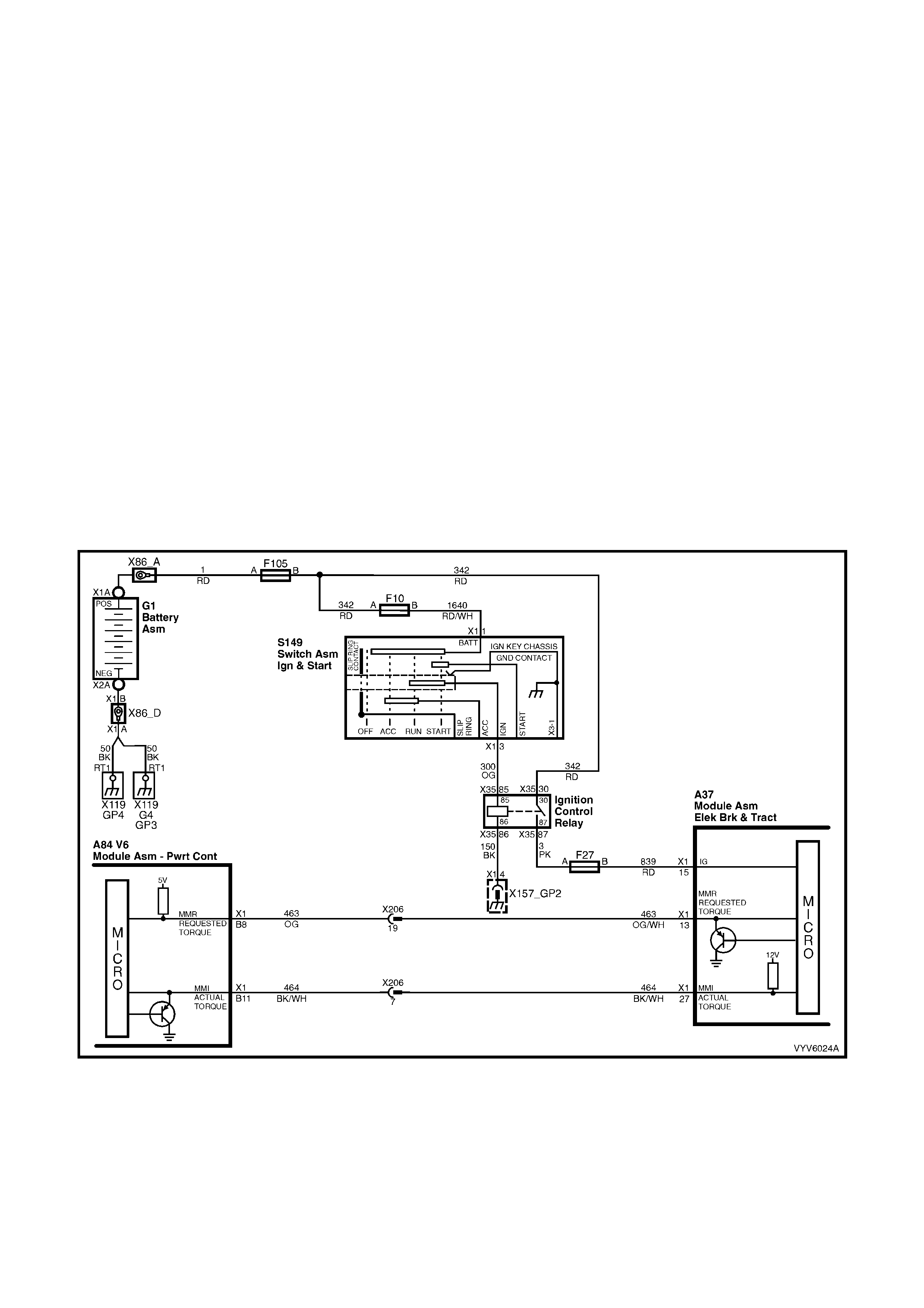
1.8 ELECTRONIC TRACTION CONTROL
OPERATION
W hen the ABS/T CS control module s enses spin from the drive wheels du e to too much engine tor que for the road
conditions, it enters the traction control mode.
The AB S/TCS module m onitors bo th front and rear wheel s peeds throu gh the wh eel speed sens ors. If at an y time
during acceleration the ABS/TCS module detects drive wheel slip, it will request on the Torque Request (MMR)
circuit to the Powertrain Control Module (PCM) to bring excess engine torque into a specific range. This is
accomplished via two high speed Pulse Width Modulated (PWM) circuits between the ABS/TCS module and the
PCM. The PCM will then adjust spark firing and air/fuel ratio, altering boost duty cycle (Supercharged only), and
shutting "OFF" up to five injectors (if necessary), and report the modified torque value on the Torque Achieved
(MMI) circuit back to the ABS/TCS module. Simultaneous with engine torque m anagement, the ABS/TCS module
will activat e the ABS is olati on valves, turn on the ABS pum p motor and supply br ake pres sure to the over s pinning
wheel(s).
The isolation valves isolate the front brake hydraulic circuits from the master cylinder and rear brake hydraulic
circuits. Once the rear brake hydraulic circuits are isolated, pressure can be applied to the rear wheels without
aff ecting an y oth er brak e h ydraul ic circ uits. T he ABS/ T CS control m odule op ens the pr im ing va lve, allo wing fluid to
be drawn from the master cylinder to the pump motor, turns on the pump motor to apply pressure and begins
cycling the inlet a nd outlet valves, and closes the switching valve, ensuring fluid is directed to the wheel, not back
into the master cylinder.
The inl et and out let valve cycling aids in o btaining m axim um road surf ace tractio n in the sam e m anner as t he anti-
lock brake m ode. T he differenc e b et ween Trac tion Co n tr ol a nd Ant i- Lock Brake mode is th at br ake f luid pr essure is
increased to lessen wheel spin (Traction Control m ode), rather than reduced to allow greater wheel spin (anti-lock
brake mode).
If at an y tim e dur ing tr actio n contro l m ode, the brak es are m anual ly app lie d, the brak e s witch sig nals the A BS/T CS
module to inhibit brake intervention and allow manual braking. Engine intervention can still occur if necessary.
Figure 6C1-1-92 Requested Torque (MMR) and Actual Torque (MMI) Circuits

ENGINE TORQUE MANAGEMENT
Simultaneously to brake intervention, the system also has engine torque management, the ABS/TCS control
module communicates with the PCM, requesting the PCM to bring the engine torque into a specific range, by
sending a requested torqu e signal to the PCM. The PCM achieves the requested torque by adjusting spark tim ing
and air fuel ratio, altering boost duty cycle (supercharged engine only) and shutting off up to five injectors (if
necessar y). The PCM then reports back to the ABS/TCS control m odule by sending an act ual torque signal to the
ABS/TCS control module.
W ith the ignition o n and the engine n ot running, th e ABS/TCS contr ol module c onstantly sen ds a PWM signal with
a dut y c ycle of 93% to th e PCM. T he PCM res ponds with a PW M signal with a dut y cycle of 5%. When the engine
is started t he dut y c ycle of the actu al torque sig nal will incr ease to approx imatel y 30% at idle. W hen the ABS/T CS
control module determines that a reduction in engine torque is required the requested torque signal will decrease
from 93% (no torque reduction) to 30% (maximum torque reduction), the PCM will then reduce the engine torque
the required am ount. The dut y c ycle of the actual tor que signal will v ary with engine torqu e. During traction c ontrol
the duty cycle of the actual torque signal should be similar to and follow the duty cycle of the requested torque
signal.
REQUESTED TORQUE
The requested torque signal sent to the PCM from the ABS/TCS control module is a Pulse Width Modulated (PWM)
signal with a frequenc y of approximatel y 100 Hz. The ABS/TCS control m odule varies the dut y c ycle of this signal
dependent on the torque reduction required.
ACTUAL TORQUE
On receiving the requested torque signal, the PCM will modify the output of the engine and then send an actual
torque signal to th e ABS/TCS control m odule. This signal is a lso a PW M signal with a f requency of approx imately
100 Hz. The duty cycle of the actual torque signal will vary depending on the torque reduction achieved, ie. the
actual torque of the engine.
ENGINE SPEED
To determine the requested torque and prevent engine stalling the ABS/TCS control module monitors the engine
speed. An engine RPM signal is sent to terminal X1-30 of the ABS/TCS control module from the Direct Ignition
System (DIS) Module. This signal has a fixed duty cycle and a frequency that will vary with changing engine RPM.
TYPICAL REQUESTED TORQUE AND ACTUAL TORQUE VALUES
CIRCUIT IGNITION ON IDLE LOW TRACTION
REQUESTED TORQUE 93 % 93 % 93 - 30 %
ACTUAL TORQUE 5 % 30 % 93 - 30 %
REQUESTED TORQUE 614 Nm 614 Nm 614 - 0 Nm
ACTUAL TORQUE 0 Nm 25 Nm 614 - 0 Nm
A failure in the requested torque circuit will set a DTC P1571.
DTC P1571 Requested Torque Out Of Range will be set if:
• The PCM detects the incorrect voltage on the Requested Torque circuit.
HISTORY DA TA DTC P1571
PARAMETER PARAMETER
Engine Speed 3-2 Downshift Enabled
Coolant Temperature TCC Solenoid
Time From Start Transmission Fluid Temperature
Times Occurred Throttle Angle
Ignition Cycles Vehicle Speed
Fuel Commanded Gear
Default Value
When DTC P1571 is set, traction control will be disabled and a corresponding DTC will be set in the ABS/TCS.
Recovery
Recovery will occur when the DTC has been cleared and the ignition cycled off and on.
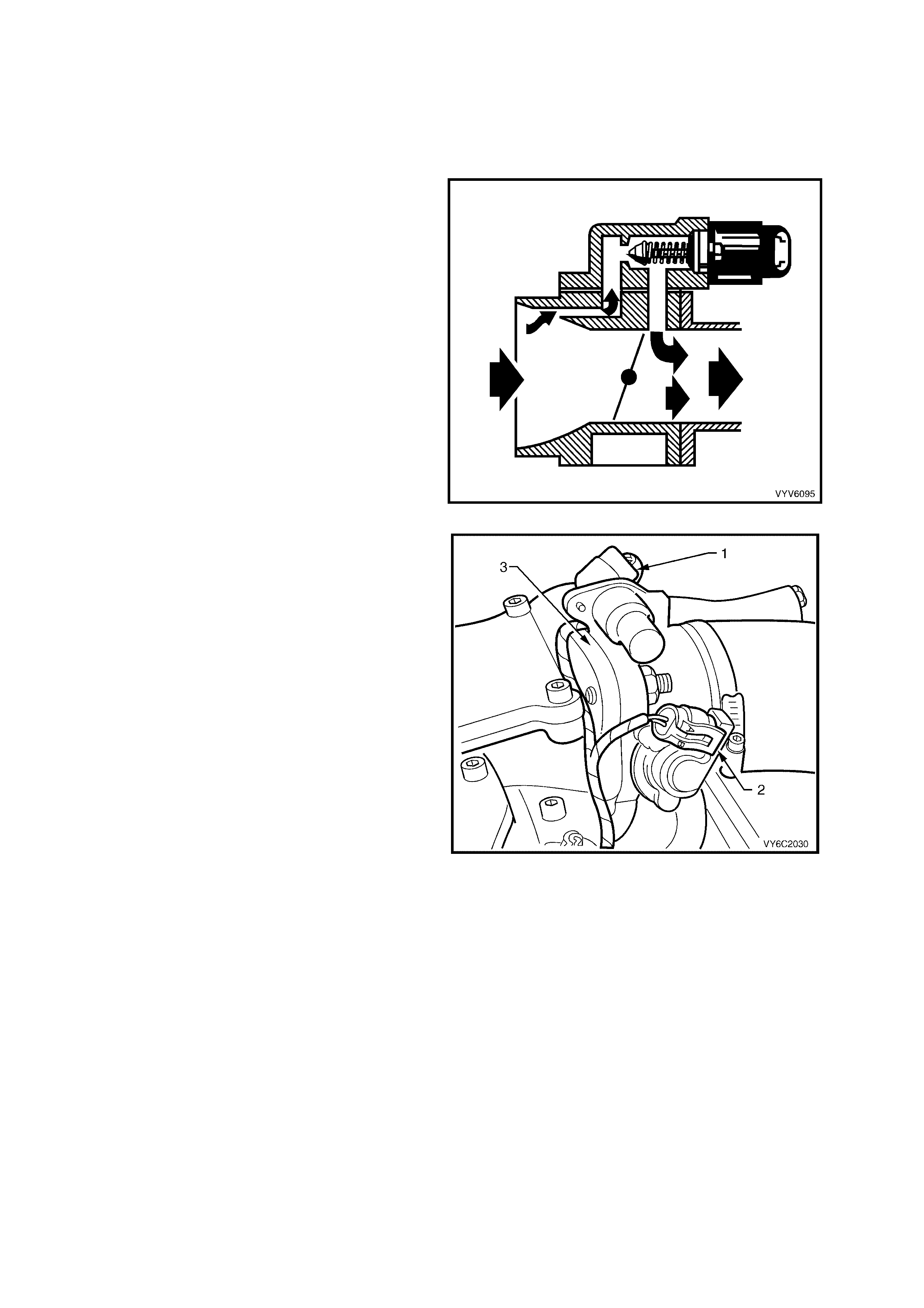
1.9 IDLE AIR CONTROL VALVE
The purpose of the Idle Air Control (IAC) valve, is to control engine idle speed, and prevent engine stalling due to
changes in engi ne load a t idle. T he IAC val ve, m ounted in the t hrottle b ody, contr ols b ypass air around th e throttle
valve. By extending the pintle (to decrease air flow) or retracting the pintle (to increase air flow), a controlled
amount of air can m ove ar ound the thr ottle va lve. If RPM is too lo w, more air is bypas sed arou nd the thro ttle va lve
to increase RPM. If RPM is too high, less air is bypassed around the throttle valve to decrease RPM.
The IAC valve moves in small steps numbered
from 0 (extended pintle, bypass air passage fully
shut) to 255 (retracted pintle, maximum bypass
airflow) as commanded by the PCM. At idle, the
desired position of the IAC valve is calculated by
the PCM based on coolant temperature, actual
engine RPM, MAF, IAT and battery voltage.
If the IAC valve is disconnected or reconnected
with the e ngine running , the PCM can lose track of
the actual position of the IAC. This also happens
when the PCM's keep alive memory voltage, ie.
PCM connectors, ENGINE fuse, or battery
term inals are disc onnected. The PCM will reset the
IAC whenever the ignition is turned off, the reset
procedure goes like this:
The PCM c om mands the IAC va lve to shut the idle
air passageway in the throttle body. It does so by
issuing enough extend pulses to move the IAC
valve pintle fully shut in the bore, regardless of
where the actual position was. Then, the PCM
calculates the IAC valve is at a fully shut position,
and calls that position 0 steps. Next, the PCM
issues retract steps to properly position the pintle.
The IAC valve can also be reset with TECH 2.
The IAC valve affects only the idle RPM of the
engine. If it is open fully, too much air will be
allowe d into the m anif old a nd id le sp eed will b e to o
high. If it is stuc k closed, to o lit tle air will be a llo wed
into the intake manifold, and idle speed will be too
low.
Figure 6C1-1-93 IAC Valve
Figure 6C1-1-94 Throttle Position Sensor Location
Legend
1. Idle Air Control (IAC) Valve
2. Throttle Position (TP) Sensor
3. Throttle Body
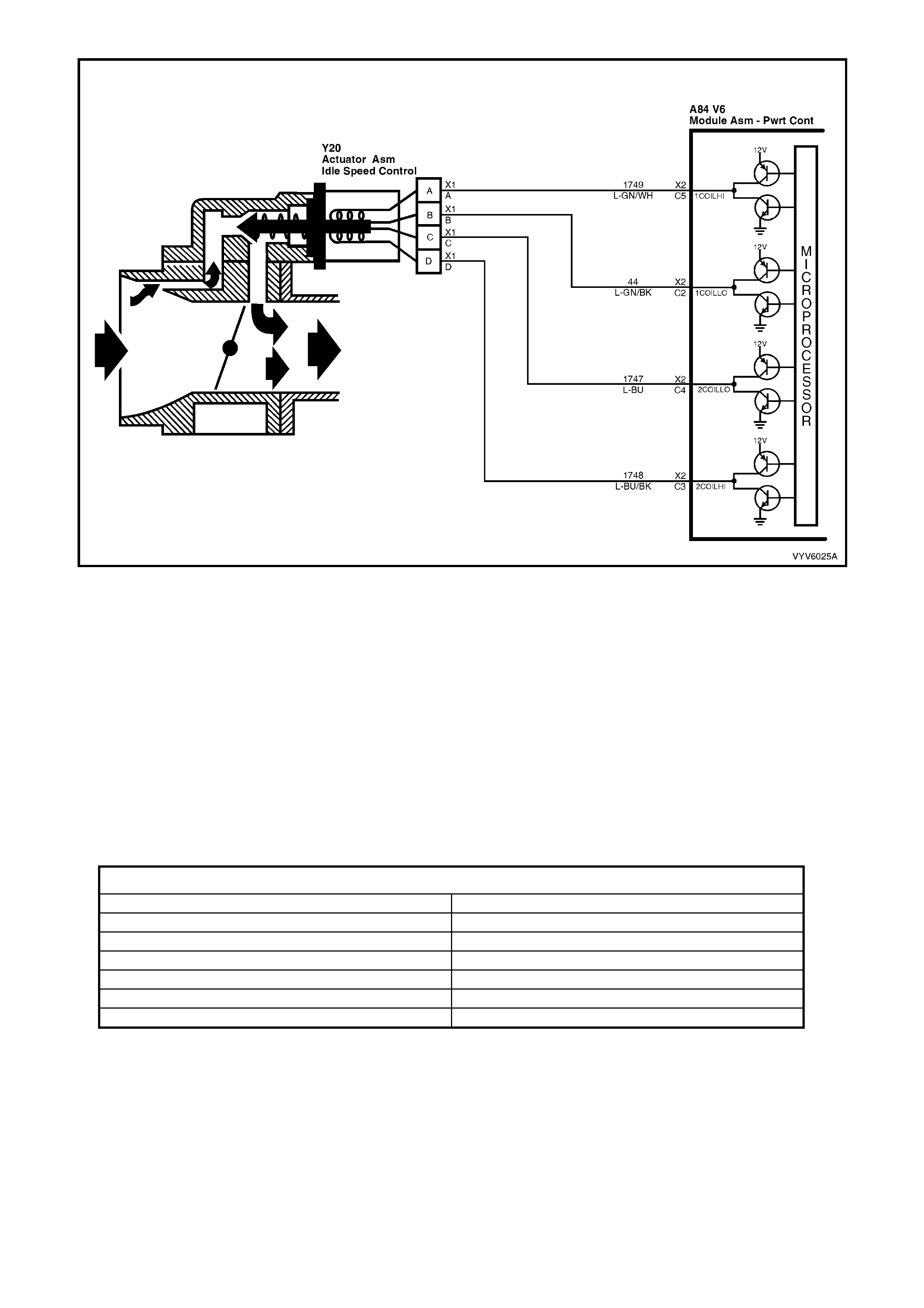
Figure 6C1-1-95 IAC Valve Circuit
A system malfunction that causes too great a difference between desired idle and the actual idle speed will set
either a DTC P0506 Idle Speed Error or P0507 Vacuum Leak.
DTC P0506 Idle Speed Error or DTC P0507 Vacuum Leak will be set if DTC’s P0111, P0112, P0113, P0121,
P0122, P0123 or P0502 are not current and:
• Engine has been idling for at least 15 seconds and...
• The intake air temperature is less than 73°C and...
• The engine speed is 200 RPM be low the desired idle speed for five seconds and the IAC has been opened to
it’s maximum position (255 steps), then a DTC P0506 will be set. If the PCM detects a condition where a high
idle spee d is present and t he IAC has been clos ed (0 steps), the PC M will comm and the IAC m otor to open 50
steps. If the RPM increases more than 50 RPM it is accepted that the IAC motor is moving and therefore the
fault is a v acuum leak , and DT C P0507 will s et. If the RPM does not chang e whe n the PCM com m ands the IAC
to open, the PCM will set a DTC P0506.
DTC P0506 or P0507 does not activate the Check Powertrain MIL.
HISTORY DATA DTC P0506 AND P0507
PARAMETER PARAMETER
Engine Speed Desired Idle
Coolant Temperature Idle Air Control
Time From Start Mass Air Flow
Times Occurred Battery Voltage
Ignition Cycles Throttle Position Sensor
Fuel
Default Value
There is no default value for DTC P0506 or P0507.

STALL DATA
If an engine stall occurs the PCM will capture eleven data values. The PCM will store the first stall condition data
values, then count the number of times the engine stalls after the first.
STALL DATA
PARAMETER PARAMETER
Engine Speed Vehicle Speed
Time from start Battery Voltage
Times occurred Throttle Position Sensor
Ignition Cycles A/C Request
Coolant Temperature Fuel
Idle Air Control
NOTE: Stall data will be erased from the PCM memory whenever DTC History Data is cleared.
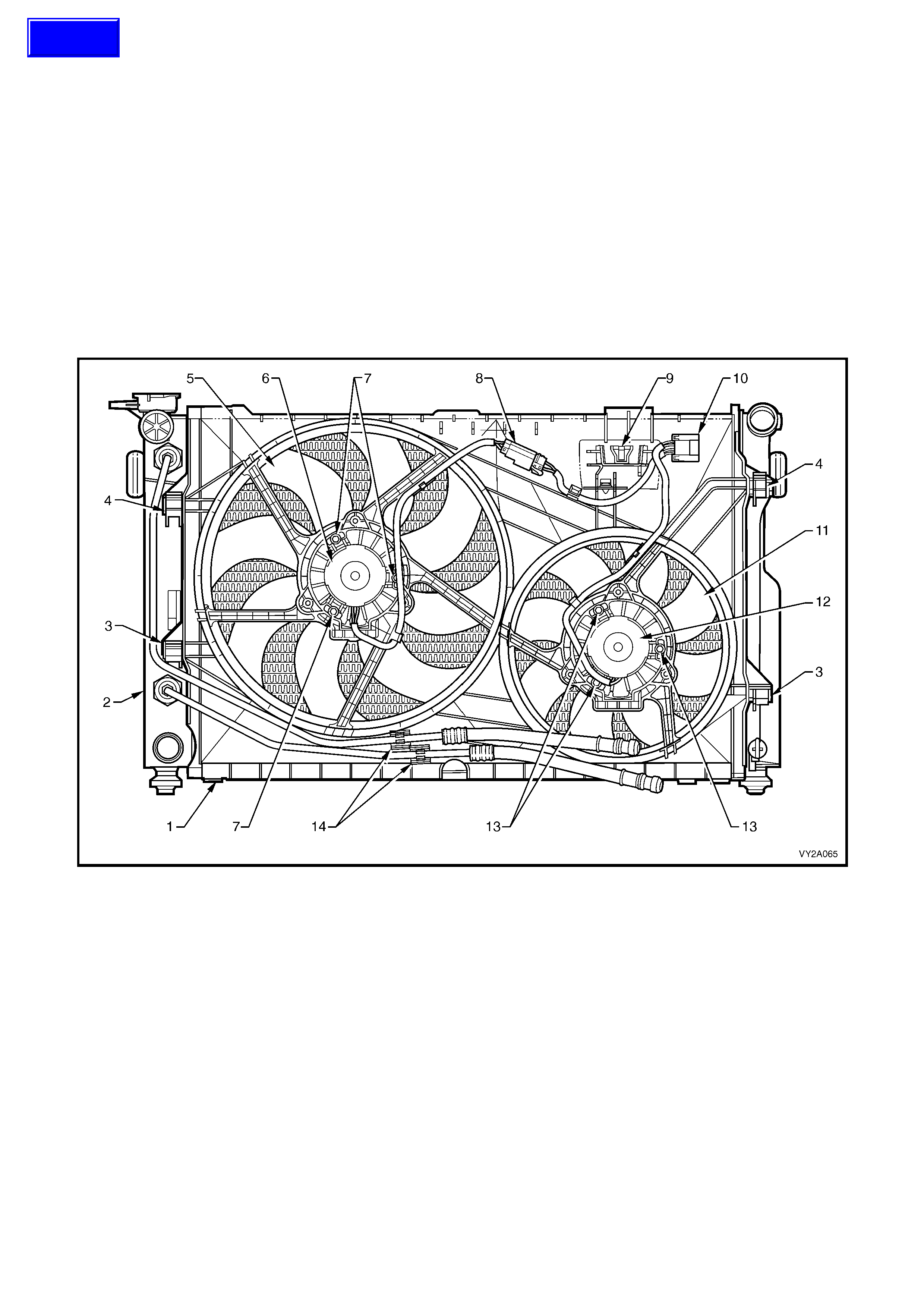
1.10 ENGINE COOLING FANS
Vehicles equipped with the V6 engines either have a Standard Fan package or a High Power Fan Package. The
engine cooling fan assemblies provide the primary means of moving air through the engine radiator. These fans are
placed b etween the ra diator and the engine and have their own shrouds. T hese fan conf igurations ar e used on a ll
vehicles e ven if no t e qu ipp ed with a ir c on dit ion in g. T he e lec tric eng ine c oo li ng f a ns are us ed to c o ol en gine coola n t
flowing through the radiator, and if fitted, refrigerant flowing through the A/C condenser.
STANDARD ENGINE COOLING FAN PACKAGE
The s tandard f an pack age uses two, s ingle sp eed, en gin e coolin g fan m otor s. The sm all high s peed f an is 2 68 mm
in diameter with a motor rated at 120 Watts, while the large low speed fan is 370 mm in diameter with a motor
power ra ting of 160 W atts. T he engine coolin g fan motor s have two ter minals; on e positive an d one negati ve. The
positiv e term inals are perm anently conn ected to batter y voltage, via fusible l inks F101 to th e large and F 107 to the
small fan. When low speed engine cooling fan relay 1 (R7) is energised, the negative terminal of the large low
speed co olin g fan is conn ec ted to grou nd through the rela y and the lar ge lo w spe ed coo ling fan will oper ate. W hen
the high speed cooling fan relay 2 (R5) is energised, the negative t erminals of both cooling fans are connect ed to
ground via the relay and both cooling fans will operate.
Figure 6B1-96 – Cooling Fans, V6 Engine Standard Fan Package
Legend
1. Fan Shroud
2. Radiator
3. Fan Shroud Lower Support
4. Fan Shroud Upper Support/Locking Retainer
5. Left Fan – 8 Blade, 370 mm Diameter
6. Left Fan Motor – 160 W att, Single Speed
7. Left Fan Motor Securing Screws (3 places)
8. Left Fan Motor Harness Connector (2 terminal)
9. Power Steering Reservoir Mount
10. Left and Right Fan Motor Harness Connector (6 terminal)
11. Right Fan – 8 Blade, 268 mm Diameter
12. Right Fan Motor – 120 Watt, Single Speed
13. Right Fan Motor Securing Screws (3 places)
14. Automatic Transmission Cooling Line Retaining Clips
Techline
Figure 6C1-1-97 Standard Engine Cooling Fan Package Circuit
HIGH POWER ENGINE COOLING FAN PACKAGE
The high power fan package uses two, dual speed, engine cooling fan motors. The small fan is 268 mm in diameter
and has a m otor rated at 180 W atts , while the lef t large fan is 370 mm in diam eter with a motor power rating of 220
Watts.
While both the standard a nd high power assemblies have the sam e diameter fans, the power rating of the electric
motors, changes and can be seen visually by the larger diameter motor for the high power assemblies.
The engine cooling fan motors have three terminals; one positive and two negative. The positive terminals are
permanently connected to battery voltage, via fusible links F101 to the large fan motor and F107 to the small fan
motor . W hen the lo w speed en gine co oling f an relay 1 (R7) is energise d, one ne gative term inal of both coo ling f an
motors is connected to ground through the relay and the fans will operate at low speed. When the high speed
cooling f an re la y 2 (R5) is energ ised, t he other negati ve ter m inal of both coolin g fan m otors is connecte d to gr ound
via the relay and both cooling fans will operate at high speed.
Figure 6B1-98 – Cooling Fans, V6 Engine High Power Specification
Legend
1. Fan Shroud
2. Radiator
3. Fan Shroud Lower Support
4. Fan Shroud Upper Support/Locking Retainer
5. Left Fan – 8 Blade, 370 mm Diameter
6. Left Fan Motor – 220 Watt, Dual Speed
7. Left Fan Motor Securing Screws (3 places)
8. Left Fan Motor Harness Connector (2 terminal)
9. Power Steering Reservoir Mount
10. Left and Right Fan Motor Harness Connector (6 terminal)
11. Right Fan – 8 Blade, 268 mm Diameter
12. Right Fan Motor – 180 Watt, Dual Speed
13. Right Fan Motor Securing Screws (3 places)
14. Automatic Transmission Cooling Line Retaining Clips
Figure 6C1-1-99 High Power Engine Cooling Fan Package Circuit

ENGINE COOLING FAN LOW SPEED
The PCM determines when to enable the low speed fan based on A/C Request, A/C pressure, Engine Coolant
Temperature and vehicle speed.
Note: The cooling fan operating pa rameters listed below may vary with different PCM calibrations.
The cooling fan low speed relay will be turned "ON'' when:
• The A/C request indicated (YES) and either
• the vehicle speed is less than 54 km/h.
or
• A/C pressure is greater than 1500 kPa
or
• The coolant temperature is greater than 104°C.
• or
• If the coolant temperature is greater than 117°C, when the ignition is switched off, the relay is energised for
approximately four minutes. This is known as “Low Fan Run On”.
• or
• If an engine coolant temperature sensor fault is detected, such as DTC P1116, P0117, P0118, or P1628.
The cooling fan low speed relay will be turned "OFF'' when any of the following conditions have been met:
• The coolant temperature is less than 99 °C.
• The A/C request is not indicated (NO)
• The A/C request is indicated (YES) and the vehicle speed is greater than 50 km/h and A/C pressure is less
than 1170 kPa.
ENGINE COOLING FAN HIGH SPEED
• The engine coo ling f an hi gh s peed re la y 2 (R5) is c on troll ed b y the PCM b ased on en gine c oolant tem peratu re
and A/C pressure. The PCM will only turn "ON'' the engine cooling fan high speed relay 2 (R5) if the engine
cooling fan low speed relay 1 (R7) has been "ON" for two seconds and the following conditions are satisfied.
• There is a BCM message response fault which has caused a DTC P1064.
• An engine coolant temperature sensor fault is detected such as DTC P1116, P0117, P0118, or P1628.
• Coolant temperature greater than 108°C.
• The A/C refrigerant pressure is greater than 2000 kPa Standard Fan Package / 2400 kPa High Power Fan
Package.
If the lo w speed fan was "OFF " when the crit eria was met to turn t he high speed fan "ON", t he high spe ed fan wil l
come "ON" 5 seconds after the low speed fan is turned "ON". If both the engine cooling fan relays are "ON", the
PCM will turn "OFF" the high speed relay when:
• The engine coolant temperature is less than 108°C.
• A/C request not indic ate d (NO ) .
• A/C request indicated (YES) and A/C pressure is less than 1500 kPa Standard Fan Pack age / 2000 kPa High
Power Fan Package.
LOW SPEED RESPONSE
The engine cooling low speed fan is enabled when the low speed relay is energised by the BCM. The PCM will
request the BCM to turn the low speed engine cooling fan relay on or off, via the serial data bus normal mode
message. After the PCM requests a change in the engine cooling fan low speed relay, the BCM will send a
response message back to the PCM via the serial data bus normal mode message confirming it received the
request. A failure in this response communication will set a DTC P1064.

DTC P1064 Low Speed Fan No BCM Response will be set if:
• En gine is idling
• The PCM sends a request to the BCM to turn ON the engine cooling fan low speed relay via the serial data
normal mode message and the BCM does not send a message back to the PCM.
• The PCM will not illuminate the Check Powertrain MIL.
HISTORY DA TA DTC P1064
PARAMETER PARAMETER
Engine Speed Reference Volts
Coolant Temperature Mass Airflow
Time From Start Cam Signal
Times Occurred Fuelling Mode
Ignition Cycles Fuel Pump Relay
Fuel LPG Mode Enabled
Batter y Voltag e Thef t Status
Default Value
Once a DTC P1064 is set, the PCM will energise the high speed engine cooling fan relay 2 (R5).
Recovery
Recovery will occur on the next ignition cycle.
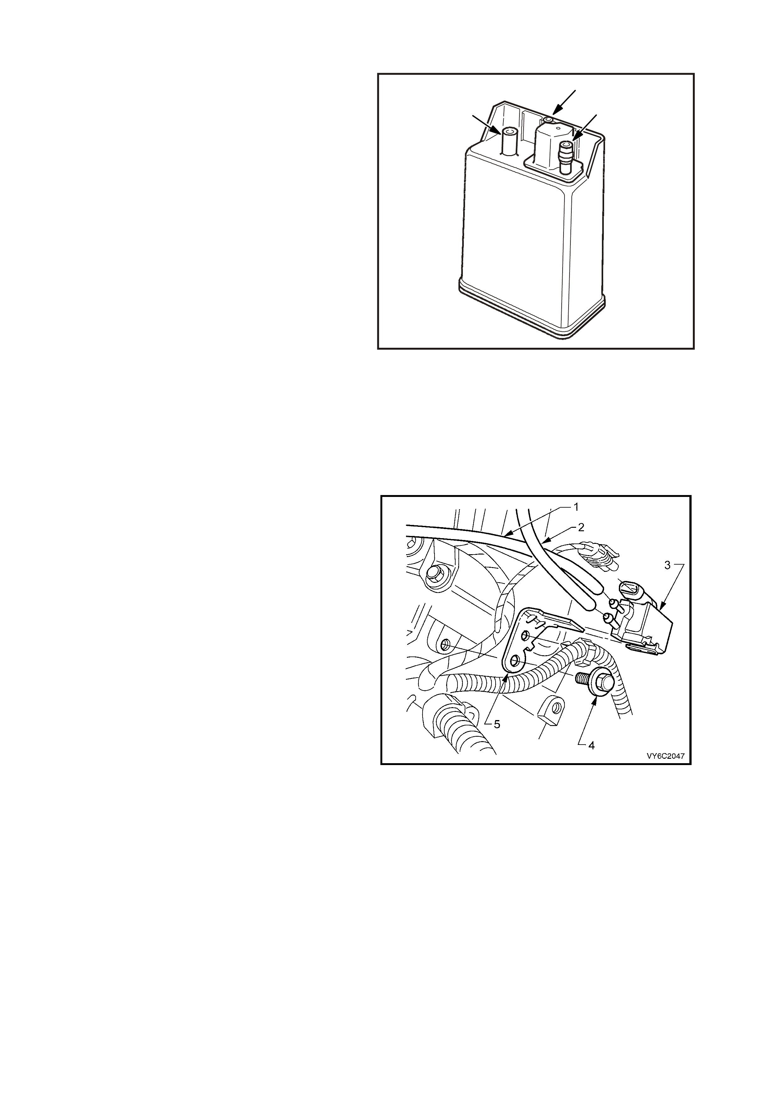
1.11 EVAPORATIVE EMISSION CONTROL SYSTEM
The Evaporative Emission Control System (EECS)
used on this vehicle is the charcoal canister
storage method. T his method trans f er s fuel vap our
from the fuel tank, via piping and port (2) to an
activated carbon (charcoal) storage device
(canister located under the rear of the vehicle) to
hold the vap ours when t he vehicle is not operat ing.
When the engine is running, the fuel vapour is
purged fr om the car bon ele ment through por t (1) b y
intake air flow through port (3) and consumed in
the normal combustion process.
The EECS purge solenoid valve allows manifold
vacuum to purge the canister, via port (1). The
Powertrain Control Module (PCM) supplies a
ground signal to energis e t he EE CS pur g e solenoid
valve (purge “ON”). The EECS purge solenoid
control is Pulse Width Modulated (PWM) or turned
“ON” and “ OFF” sever al tim es a s econd. The PCM
controlled PWM output is commanded when the
appropriate conditions have been met:
• Engine coolant temperature above 80°C.
• Engine has been running longer than 3
minutes.
• Engine is not in Decel Fuel Cutoff Mode.
• Throttle opening is less than 92%.
• Engine is in Closed Loop mode.
3
1
2
4255
Figure 6C1-1-100 – Fuel Vapour Canister
EECS purge PWM duty cycle varies according to
operating conditions determined by mass air flow,
fuel trim and intake air temperature. The EECS
purge wi ll be re-e nabled when TP angl e decreas es
below 92%.
The c anister (located un der the rear of the vehicle)
cannot be repaired, and is serviced only as an
assembly. Periodically check the canister at the
time or distance intervals specified in the vehicle
Owners Handbook. If there is a fault with the
Canister Purge Solenoid electrical circuits, DTC
P0446 will set.
Legend:
1. To Throttle Body
2. To Canister
3. Solenoid Valve
4. Solenoid Mounting Bracket Screw
5. Solenoid Mounting Bracket
Figure 6C1-1-101 – Canister Purge Solenoid Location
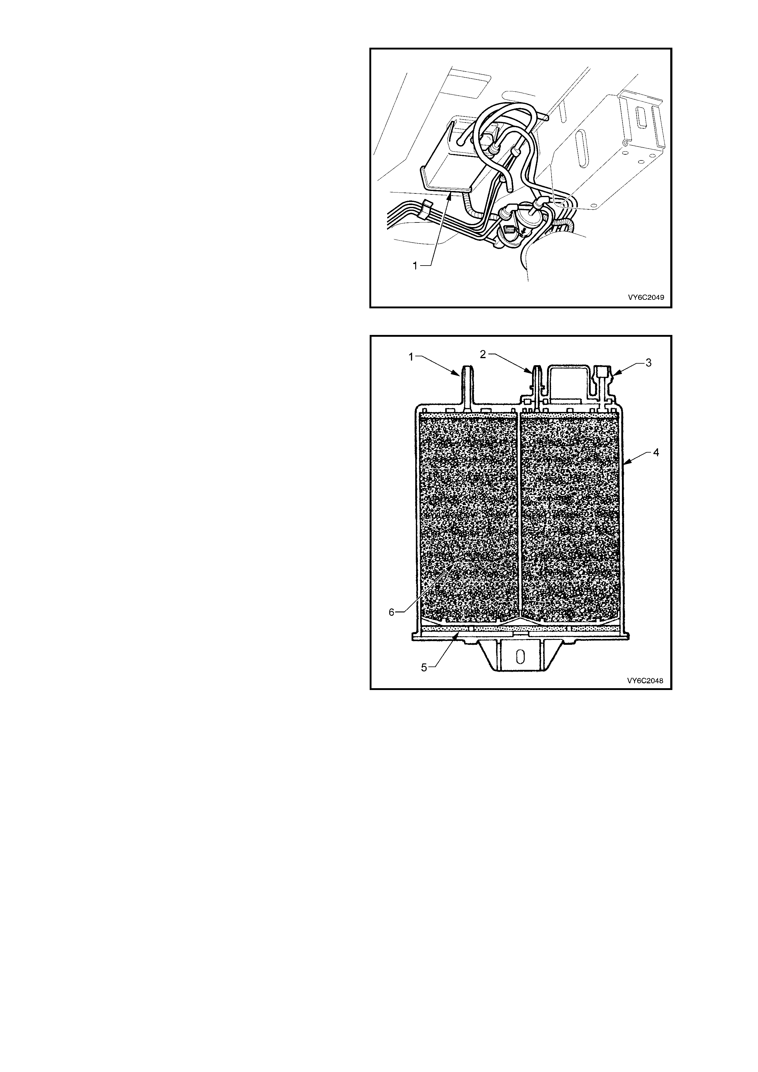
The fuel vapour canister (1) is mounted in a
bracket underneath the vehicle, near the fuel filter.
This canister is a three port design. The fuel
vapour is absorbed by the charcoal within the
canister. When the engine is running at idle speed
and above idle, air is drawn into the canister
through the atmospheric port at the top of the
canister assembly. The air mixes with the fuel
vapour and the mixture is drawn into the intake
manifold via the canister purge line.
The upperm ost por t on the canister is controll ed by
a PCM controlled canister purge solenoid. The
canister purge solenoid controls the manifold
vacuum signal from the throttle body. The port
below the canister purge port is the vapour inlet
from the fuel tank. The single off centre port is
open to the atmosphere.
Figure 6C1-1-102 – Canister Location
The evaporative canister consists of an air vent
port (1), a canister purge port (2), a port to receive
vapour from the fuel tank (3), the canister housing
(4), a dust filter (5) and the charcoal bed (6).
Figure 6C1-1-103 – Sectioned View of Canister

Figure 6C1-1-104 Evaporative Emission Control System Circuit
RESULTS OF INCORRECT OPERATION
Poor idle, stalling and poor driveability can be caused by:
• Inoperative canister purge solenoid.
• Damaged canister.
• Hoses split, cracked and/or not connected to the proper tubes.
Evidence of fuel loss or fuel vapour odour can be caused by:
• Liquid fuel leaking from fuel lines.
• Cracked or damaged canister.
• Disconnected, misrouted, kinked, deteriorated or damaged vapour hoses, or control hoses.
If the solenoid is stuck open, or the control circuit is shorted to ground the canister will purge to the inlet manifold
continuous ly. This can allo w extra fuel at idle or during warm -up, which can cause rough or unstable id le or a rich
fuel operation.
If the canister purge solenoid is always closed, the canister can become over loaded with fuel, resulting in fuel
odour.
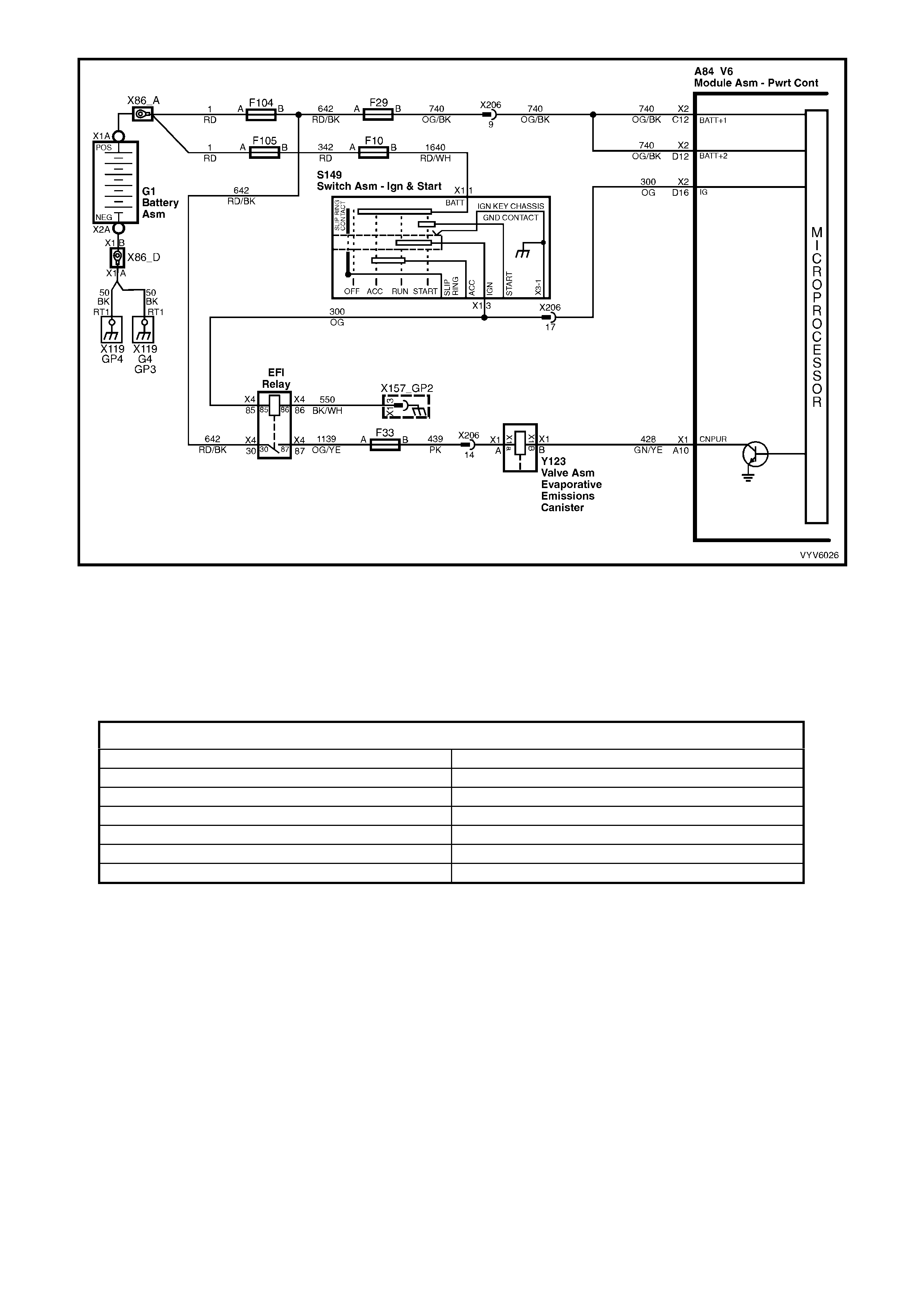
Figure 6C1-1-105 Evaporative Emission Control System Circuit
A failure in the canister purge solenoid or circuit will set a DTC P0446 Canister Purge Circuit Fault.
DTC P0446 Canister Purge Circuit Fault will be set if:
• The ignition is on and...
• The PCM detects the incorrect voltage on the canister purge solenoid driver terminal X1-A10.
DTC P0446 does not activate the Check Powertrain MIL.
HISTORY DA TA DTC P0446
PARAMETER PARAMETER
Engine Speed EGR Position Commanded
Coolant Temperature EGR Position Feedback
Time From Start EGR Position Sensor
Times Occurred Purge PWM
Ignition Cycles Mass Air Flow
Fuel
Default Value
There is no default value for DTC P0446.
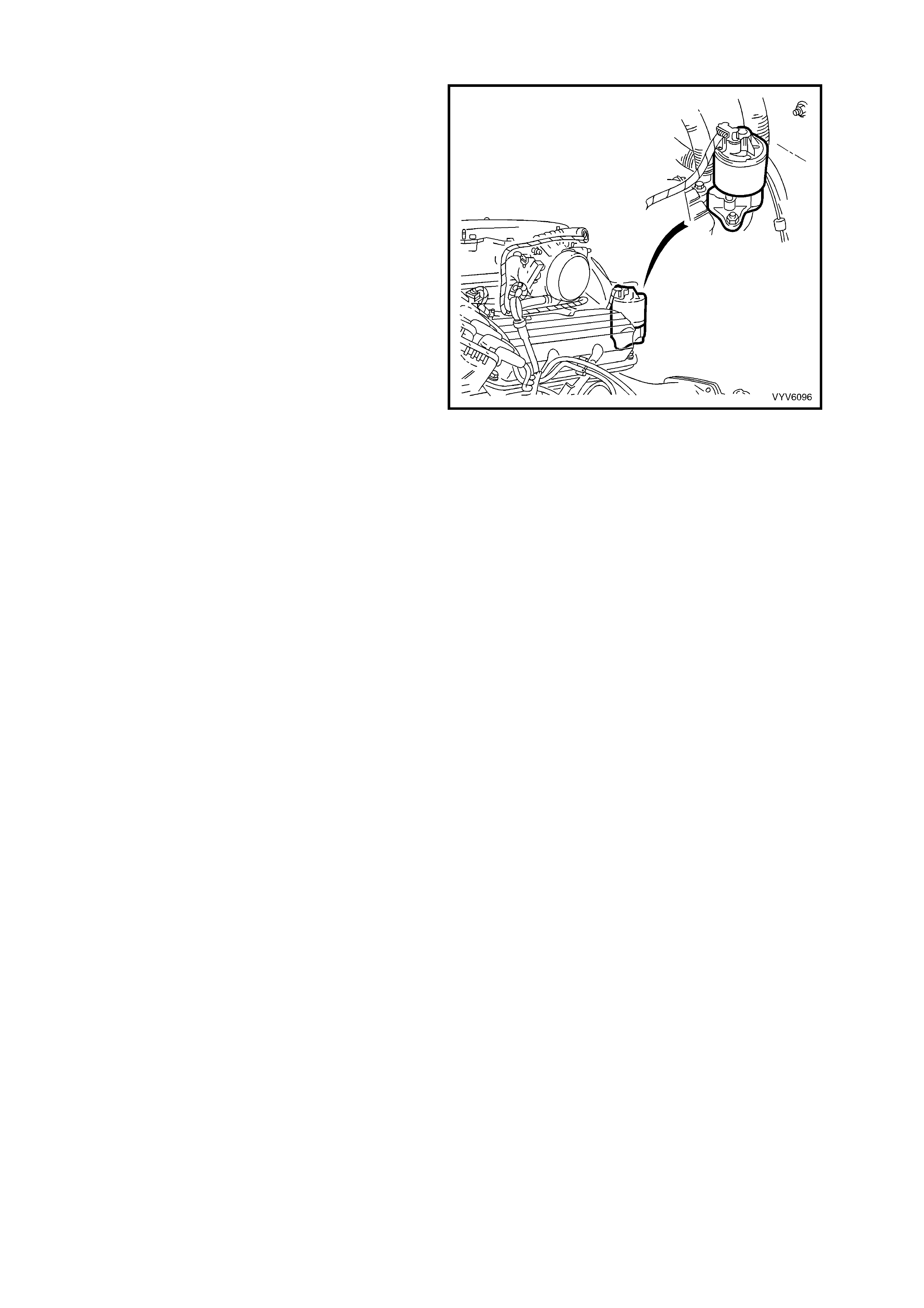
1.12 EXHAUST GAS RECIRCULATION SYSTEM
The Exhaust Gas Recirculation (EGR) system is
used to lower Oxides of Nitrogen (NOx) emission
levels caused by high combustion temperatures. It
does this by decreasing combustion temperature.
The main element of the system is the linear EGR
valve. The EGR valve feeds small amounts of
exhaust gas back into the combustion chamber.
With the air/fuel mixture thus diluted, combustion
temperatures are reduced.
The linear EGR valve is designed to accurately
supply EGR to an engine independent of intake
manifold vacuum. The valve controls EGR flow
from the exhaust to the intake m anifold through an
orifice with a PCM controlled pintle. During
operation, the PCM controls pintle position by
monitoring the pintle position feedback signal.
If the PCM det ects a proble m with the EGR s ystem
a DTC P0405 will be set.
The line ar EGR valv e is usuall y acti vat ed under t he
following conditions:
• Engine coolant temperature greater than 75°C.
• The throttle is between 2% and 50%.
• T he vehicle not in par k or neutral.
• The fuel control is in closed loop mode.
Figure 6C1-1-106 Linear EGR Valve Location
LINEAR EGR CONTROL
The PCM m onitors EG R fe edback posit ion and a djust s pintle posi tion accor dingl y. The PCM us es infor m ation fr om
the following sensors to control the pintle position:
• Engine Coolant Temperature sensor.
• Mass Air Flow.
• Engine RPM.
RESULTS OF INCORRECT EGR SYSTEM OPERATION
Too much EGR flow at idle, cruise, or cold operation may cause any of the following conditions to occur:
• Engine stalls after cold start.
• Engine stalls at idle after deceleration.
• Vehicle surge during cruise.
• Rough idle.
• Misfire.
Too little or no EGR flow may allow combustion temperatures to get too high. This could cause:
• Spark knock (detonation).
• Engine overheating.
• High emissions.
• Poor fuel economy.
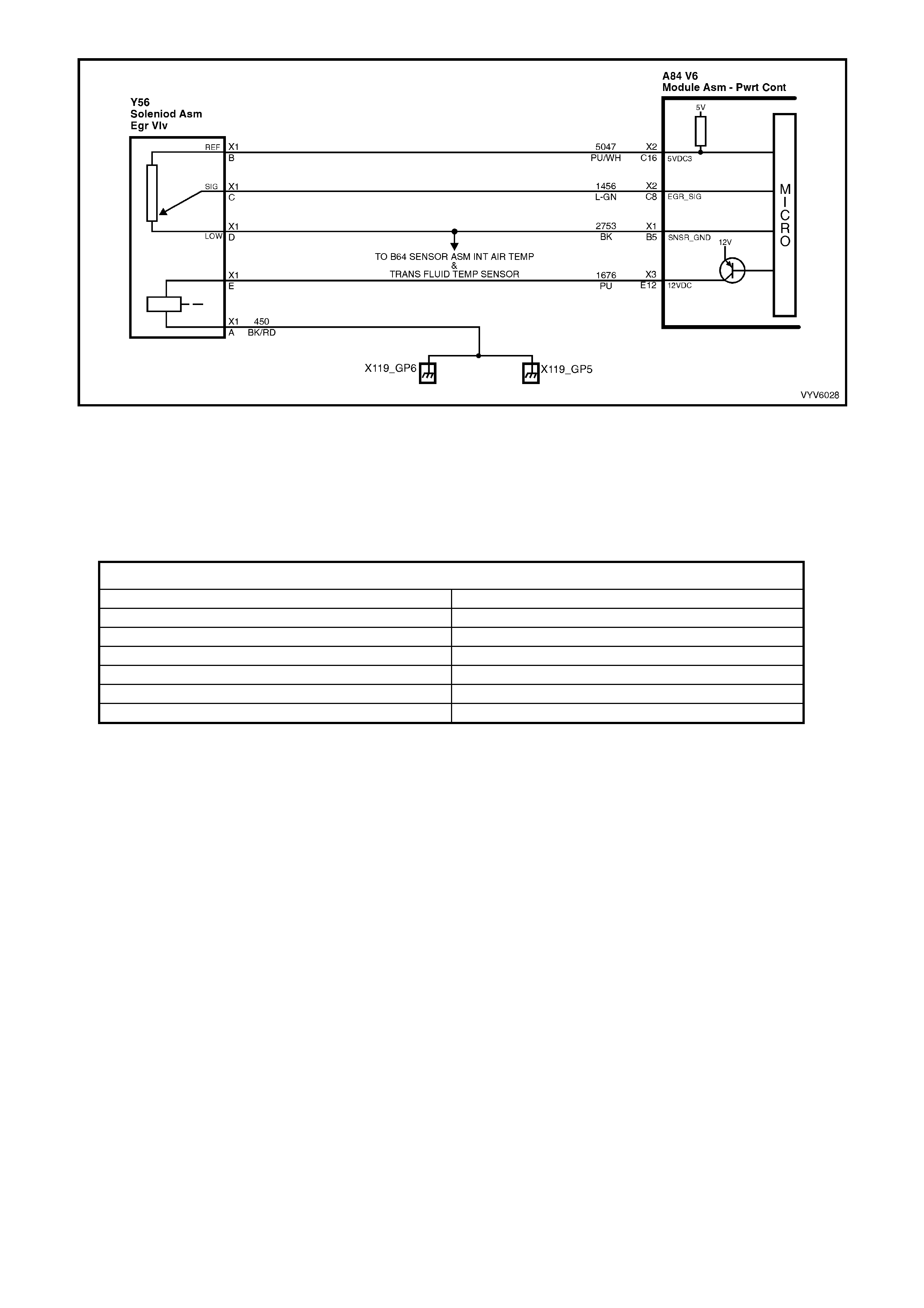
Figure 6C1-1-107 EGR Circuit
DTC P0405 EGR Position Fault will set if:
• The EGR position feedback is less than 0.32 volts for greater than one second.
or
• The EGR commanded position is 10% greater or less than EGR position feedback for more than five seconds.
DTC P0405 does not activate the Check Powertrain MIL.
HISTORY DA TA DTC P0405
PARAMETER PARAMETER
Engine Speed EGR Position Commanded
Coolant Temperature EGR Position Feedback
Time From Start EGR Position Sensor
Times Occurred Purge PWM
Ignition Cycles Mass Air Flow
Fuel
Default Value
There is no default value for DTC P0405.
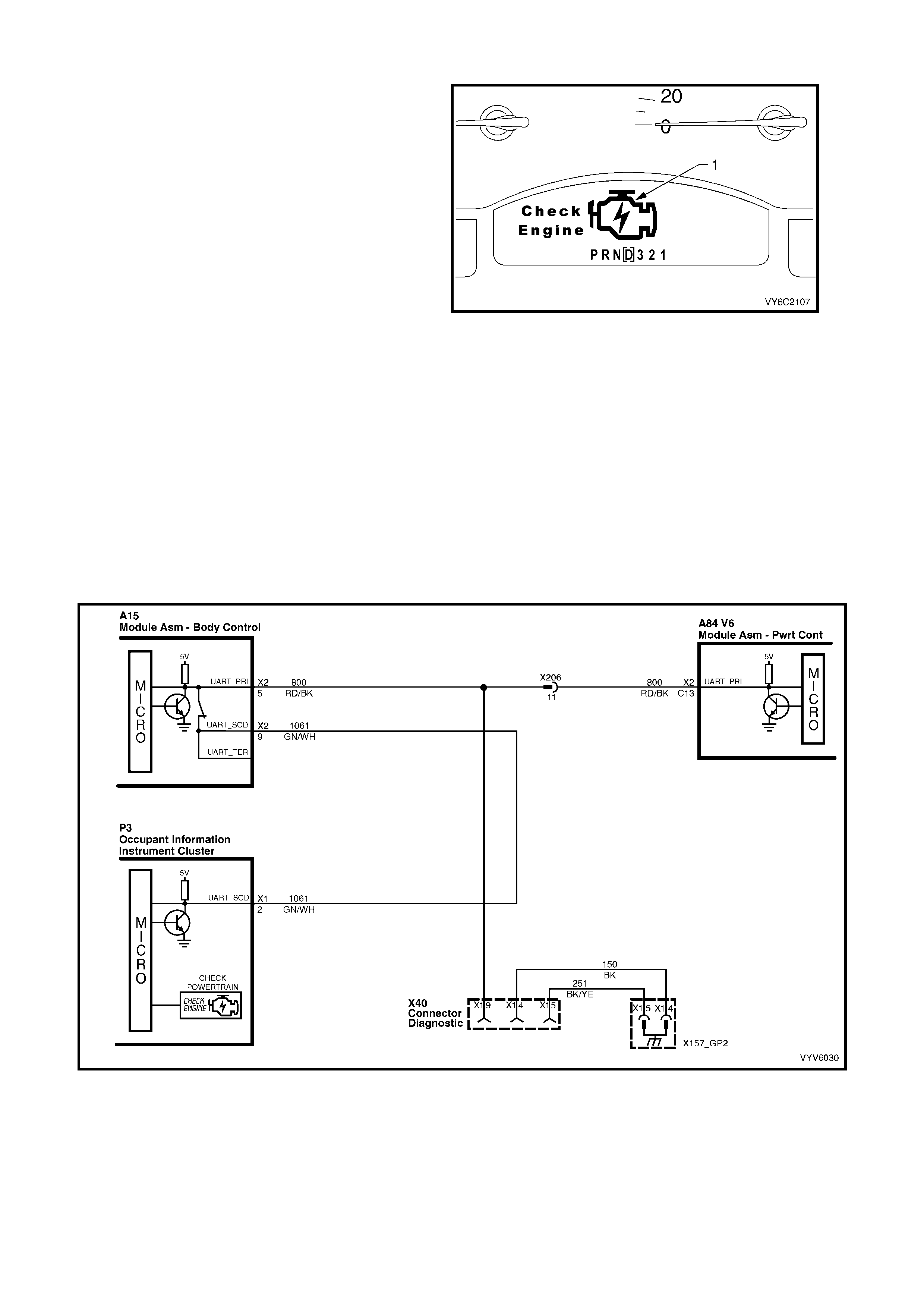
1.13 CHECK POWERTR AIN MALFUNCTION INDICATOR LAMP (MIL)
The instrument receives Check Powertrain MIL
information from the PCM via the serial data bus
norm al m ode m essage. O n receiving this message
the instrument will activate the Check Powertrain
MIL (1). The Check Powertrain MIL is a symbol of
an engine with the words “Check Engine” next to
engine symbol.
If the PCM detects a problem that requires that the
lamp be ac ti vat ed it wil l co mmand the i ns trument to
activate the Check Powertrain MIL. Not all DTCs
require the Check Powertrain MIL to be activated.
If the Check Powertrain MIL is activated, the self-
diagnostic system has detected a problem. If the
problem goes away, the Check Powertrain MIL will
deactivated after 10 seconds or once the ignition
has been cycled, but a Diagnostic Trouble Code
(DTC) will remain stored in the PCM.
If the instrument does not receive a normal mode
mess age from the PCM, th e instrument wil l display
“Service Error Contact Retailer”.
When the Check Powertrain MIL remains
activated, or when a fault is suspected due to a
driveabilit y or em issions problem , perform the “On-
Board Diagnostic System Check". Refer to
OBD System Check in Section 6C1-2 Diagnostic
Tables . These c hecks will help ident ify faul ts which
may not be detected if other diagnostics are
performed.
Figure 6C1-1-108 Check Powertrain MIL
Figure 6C1-1-109 Check Powertrain MIL Circuit
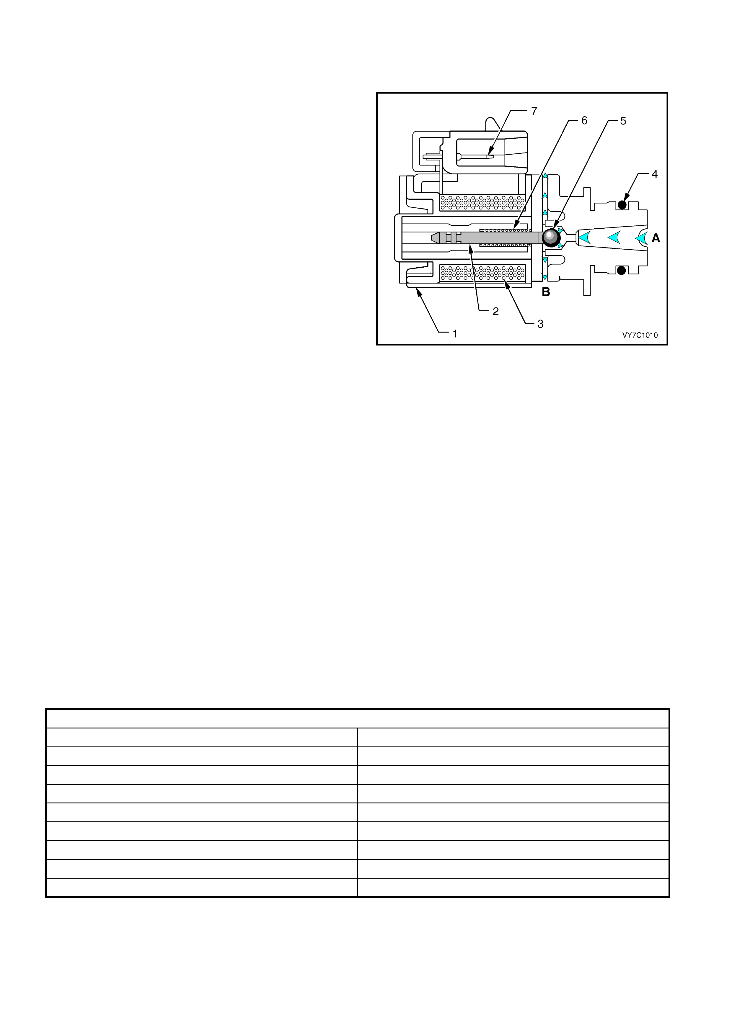
1.14 AUTOMATIC TRANSMISSION SYSTEMS
1-2 SHIFT SOLENOID (A) AND 2-3 SHIFT SOLENOID (B)
The 1-2 and 2-3 Shift Solenoids (also called A and B
solenoids) are identical devices that control the
mo vement of the 1-2 and 2 -3 shift va lves (the 3-4 sh ift
valve is not dir ectl y controlled b y a shif t solenoid). The
solenoids are normally open exhaust valves that work
in four combinations to shift the transmission into
different gears.
The PCM energises each solenoid by grounding the
solenoid through an internal quad driver. This sends
current through the coil winding in the solenoid and
moves the internal p lunger out of the exhaus t position .
When ON, the solenoid redirects fluid to move a shift
valve.
NOTE: The shift solenoid valve resistance should
measure 19-24 ohms minimum when measured at
20°C. The shift solenoid current flow should not
exceed 0.75 amps . The shif t solenoid shou ld energis e
at a voltage of 7.5 volts or m ore (measured ac ross the
term inals ). T he s hif t s olenoi d should d e -en er gis e when
the voltage is one volt or less. If both solenoids lose
power, third gear only results.
The manual valve hydraulically can override the shift
solenoids. Only in D4 do the shift solenoid states
totally determine what gear the transmission is in. In
the other manual valve positions, the transmission
shifts hydraulically and the shift solenoid states
CATCH UP when the throttle position and the vehicle
speed fall into the correct ranges. Diagnostic trouble
codes P0730, P0753, P0756 and P0757 indicate shift
solenoid circuit voltage faults.
Figure 6C1-1-110 Shift Solenoid
Legend
A Signal Fluid 4 O-Ring
B Exhaust 5 Metering Ball
1 Frame 6 Spring
2 Plunger 7 Connector Terminal
3 Coil Assembly
DTC P0730 (2-3 Shift Solenoid B Circuit Voltage High) will set if:
• The engine is running.
• The PCM commands the solenoid ON and the voltage input remains high (B+).
• The PCM will activate the Check Powertrain MIL.
Default Values
W hen this DTC sets, the PCM wil l comm and D2 line press ure. The PCM inhi bits 3-2 do wnshift if the vehicle speed
is greater than 48 km/h, and will freeze shift adapts from being updated.
Recovery
Recovery will occur when the PCM sees a valid condition.
DTC P0730 HISTORY DATA
PARAMETER PARAMETER
Engine Speed 1-2 Shift Solenoid A
Coolant Temperature 2-3 Shift Solenoid B
Time From Start 1-2 Shift Solenoid A Feedback
Times Occurred 2-3 Shift Solenoid B Feedback
Ignition Cycles Throttle Angle
Fuel Vehicle Speed
TCC Solenoid (Torque Converter Clutch) Commanded Gear
TCC Feedback (Torque Converter Clutch)
DTC P0753 (1-2 Shift Solenoid A Circuit Voltage High) will set if:
• The engine is running.
• The PCM commands the solenoid ON and the voltage input remains high (B+).
• The PCM will activate the Check Powertrain MIL.

Default Values
When this DTC sets, the PCM will command 3rd gear only, maximum line pressure, inhibit TCC engagement, and
freeze shift adapts from being updated.
Recovery
Recovery will occur when the PCM sees a valid condition.
DTC P0753 HISTORY DATA
PARAMETER PARAMETER
Engine Speed 2-3 Shift Solenoid B
Coolant Temperature 1-2 Shift Solenoid A Feedback
Time From Start 2-3 Shift Solenoid B Feedback
Times Occurred Throttle Angle
Ignition Cycles Vehicle Speed
Fuel Commanded Gear
1-2 Shift Solenoid A
DTC P0756 (1-2 Shift Solenoid B Circuit Voltage Low) will set if:
• The engine is running.
• The PCM commands the solenoid OFF and the voltage input remains low (0 volts)
• The PCM will activate the Check Powertrain MIL.
Default Values
When this DTC sets, the PCM will command 3rd gear only, maximum line pressure, inhibit TCC engagement, and
freeze shift adapts from being updated.
Recovery
Recovery will occur when the PCM sees a valid condition.
DTC P0756 HISTORY DATA
PARAMETER Parameter
Engine Speed 1-2 Shift Solenoid A
Coolant Temperature 2-3 Shift Solenoid B
Time From Start 1-2 Shift Solenoid A Feedback
Times Occurred 2-3 Shift Solenoid B Feedback
Ignition Cycles Throttle Angle
Fuel Vehicle Speed
TCC Solenoid (Torque Converter Clutch) Commanded Gear
TCC Feedback (Torque Converter Clutch)
DTC P0757 (2-3 Shift Solenoid B Circuit Voltage Low) will set if:
• The engine is running.
• The PCM commands the solenoid OFF and the voltage input remains low (0volts).
• The PCM will activate the Check Powertrain MIL.
Default Values
W hen this DTC sets, the PCM will comm and D2 line pressure, inhibit 3-2 downshift if the vehicle speed is greater
than 48 km/h, and freeze shift adapts from being updated.
Recovery
Recovery will occur when the PCM sees a valid condition.
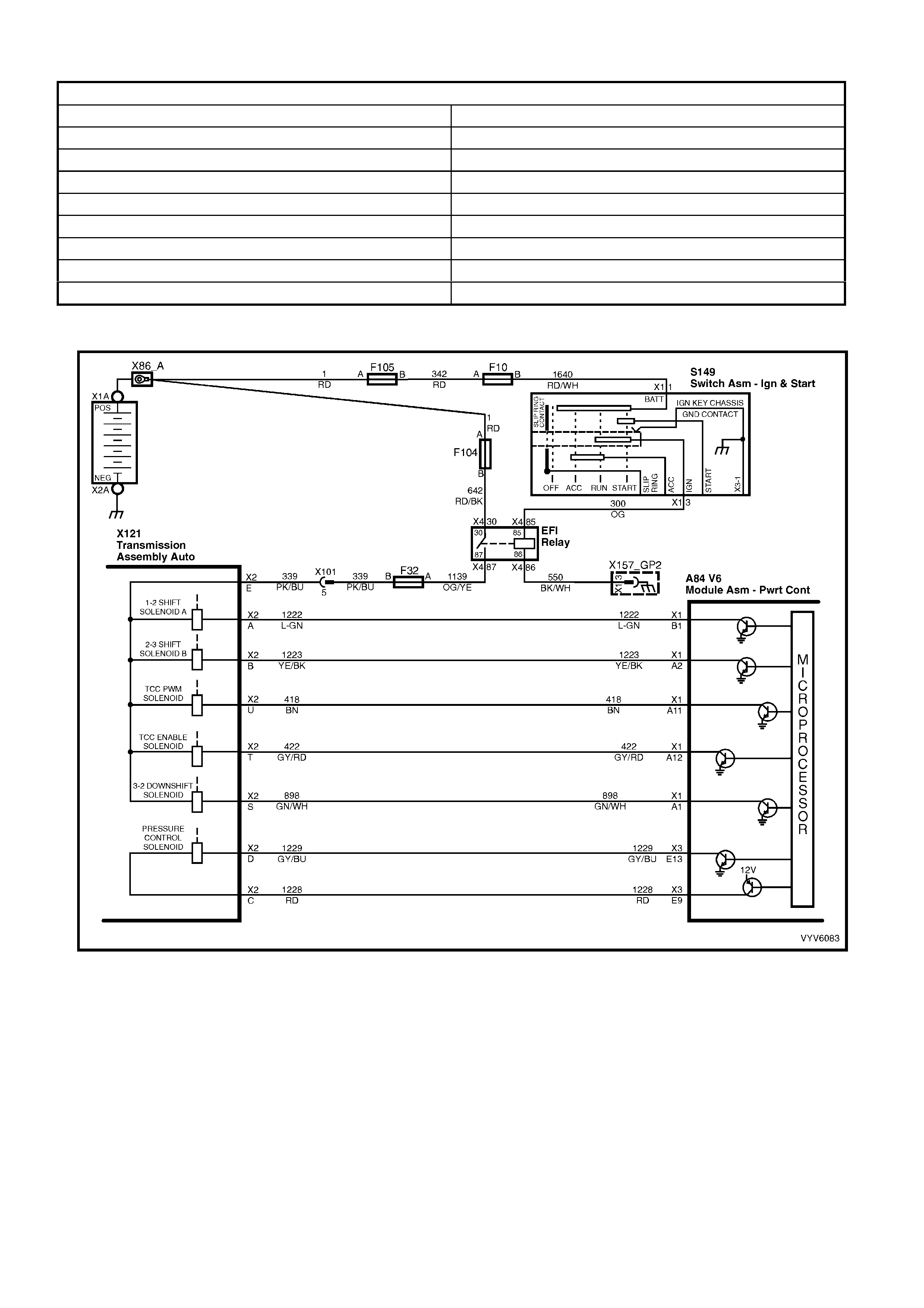
DTC P0757 HISTORY DATA
PARAMETER PARAMETER
Engine Speed 1-2 Shift Solenoid A
Coolant Temperature 2-3 Shift Solenoid B
Time From Start 1-2 Shift Solenoid A Feedback
Times Occurred 2-3 Shift Solenoid B Feedback
Ignition Cycles Throttle Angle
Fuel Vehicle Speed
TCC Solenoid (Torque Converter Clutch) Commanded Gear
TCC Feedback (Torque Converter Clutch)
Figure 6C1-1-111 Transmission Solenoid Circuits

3-2 CONTROL SOLENOID
The 3-2 Control solenoid is an ON/OFF solenoid that
is used in order to improve the 3-2 downshift. The
solenoid regulates the release of the 3-4 clutch and
the 2-4 band apply.
If a voltage fault is detected in the 3-2 shift solenoid
circuit, diagnostic trouble code P0785 will set.
NOTE: The 3-2 shift solenoid valve assembly
resistance should be a minimum of 20-24 ohms at
20°C.
Figure 6C1-1-112 – 3-2 Control Solenoid
Legend
A Press ure Supply (AFL) 4. Filter Screen
B Exhaust 5 Plunger
C Pressure Control (3-2 Signal ) 6 Coil Assembly
1 Housing 7 Connector Terminal
2 Metering Ball 8 Spring
3 O-Ring
DTC P0785 (3-2 Downshift Control Solenoid Circuit Fault) will set if:
• The PCM commands the solenoid ON and the voltage input remains high (B+).
or
• The PCM commands the solenoid OFF and the voltage input remains low (0 volts).
• The PCM will activate the Check Powertrain MIL.
Default Values
When this DTC sets, the PCM will command a soft landing to 3rd gear, maximum line pressure, inhibit TCC
engagement. The PCM inhibits 4th gear if the transmission is in hot mode, and will freeze shift adapts from being
updated.
Recovery
Recovery will occur when the PCM sees a valid condition.
P0785 HISTORY DATA
PARAMETER PARAMETER
Engine Speed 3-2 Downshift Enabled
Coolant Temperature TCC Solenoid (Torque Converter Clutch)
Time From Start TFT (Transmission Fluid Temperature)
Times Occurred Throttle Angle
Ignition Cycles Vehicle Speed
Fuel Commanded Gear
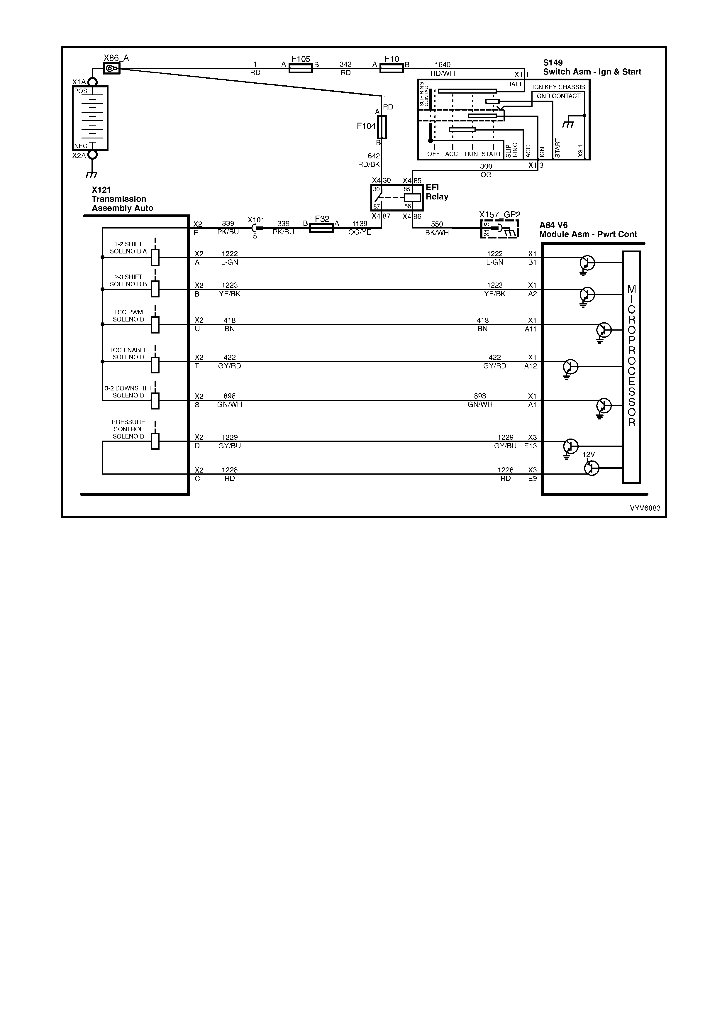
Figure 6C1-1-113 Transmission Solenoid Circuits
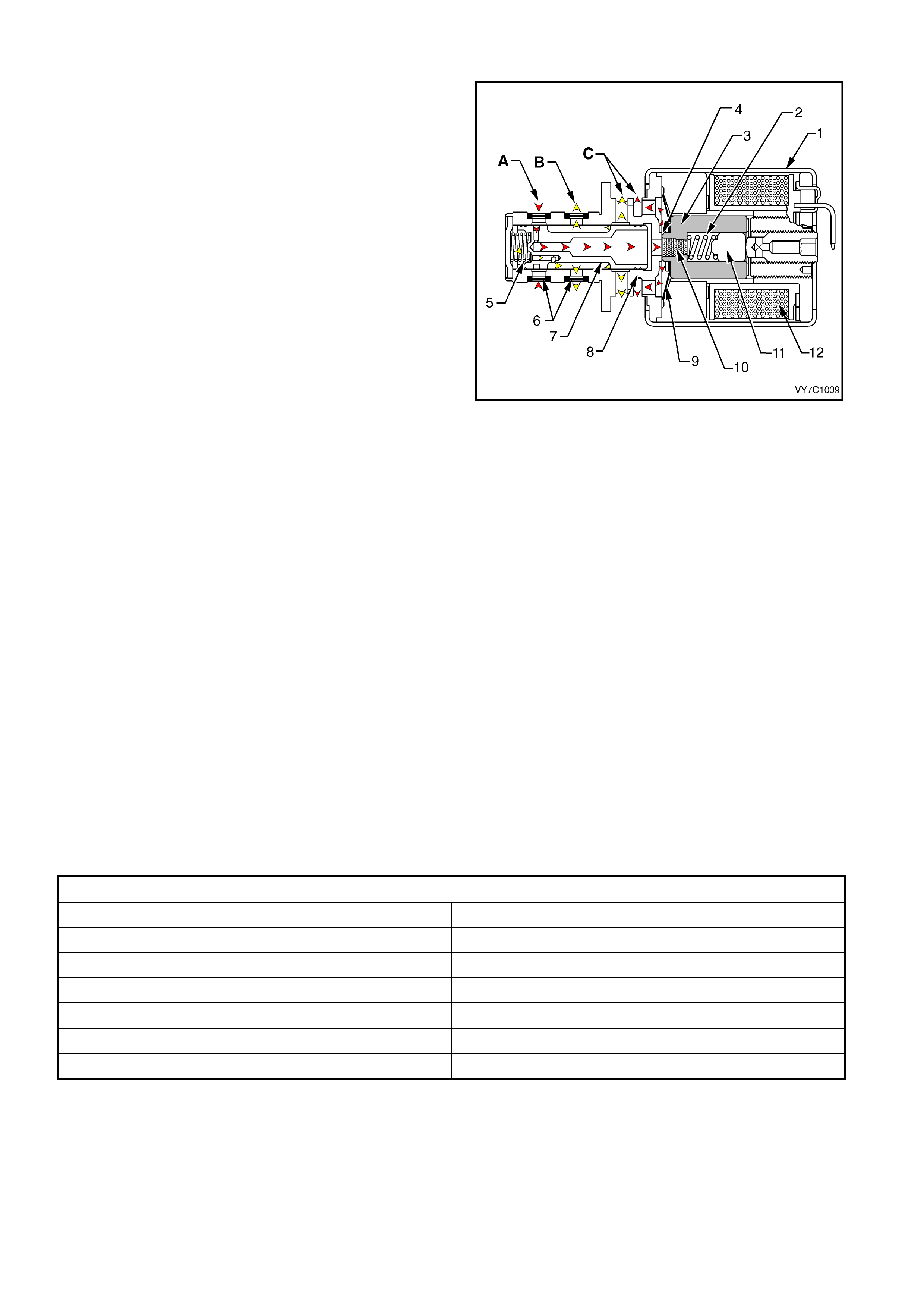
TRANSMISSION PRESSURE CONTROL SOLENOID
The transmission pressure control solenoid is an
electronic pressure regulator that controls pressure
based on the c urrent flow throug h its coil winding. T he
magnetic field produced by the coil moves the
solenoid's internal valve, which varies pressure to the
pressure regulator valve.
The PCM controls the pressure control solenoid by
commanding current between 100 and 1100
milliamps . This changes the dut y cycle of the sole noid ,
which can range between 5 percent and 95 percent
(typically less than 60 percent). 1100 milliamps
corresponds to minimum line pressure, and 100
milliamps corresponds to maximum line pressure (if
the solenoid loses power, the transmission defaults to
maximum line pressure).
The PCM commands the line pressure values, using
inputs such as the throttle position sensor. The
pressure control solenoid takes the place of the
throttle valve or the vacuum modulator that was used
on the past model transmissions.
If the duty c ycle drops below 5 percent or rises above
95 percent, DTC P0748 will set.
IMPORTANT: Transmission pressure control solenoid
resistance should measure 3-5 ohms when measured
at 20°C.
Figure 6C2-1-114 – Pressure Control Solenoid Valve
Legend
A Actuator Feed Limit Fluid 6 Filter Screens
B Torque Signal Fluid 7 Spool Valve
C Exhaust 8 Spool Valve Sleeve
1 Frame 9 Damper Spring
2 Spring 10 Restrictor
3 Armature 11 Push Rod
4 Variable Bleed Ori fice 12 Coil As sembly
5 Spool Valve Spring
DTC P0748 (PC Solenoid Current Error) will set if:
• No DTC P0562 is set.
• The system voltage is between 10 and 16 volts.
• The engine is running.
• The PC s olenoi d valve dut y c ycle reach es its h igh lim it ( approxim atel y 95%) or low limit ( approxim atel y 0%) f or
200 milliseconds.
• The PCM will not activate the Check Powertrain MIL.
Default Values
When this DTC sets, the PCM will command the PC solenoid valve OFF, and will freeze shift adapts from being
updated.
Recovery
Recovery will occur when the PCM sees a valid condition.
DTC P0748 HISTORY DATA
PARAMETER Parameter
Engine Speed Commanded PCS (Pressure Control Solenoid)
Coolant Temperature Actual PCS (Pressure Control Solenoid)
Time From Start Throttle Angle
Times Occurred Vehicle Speed
Ignition Cycles Commanded Gear
Fuel
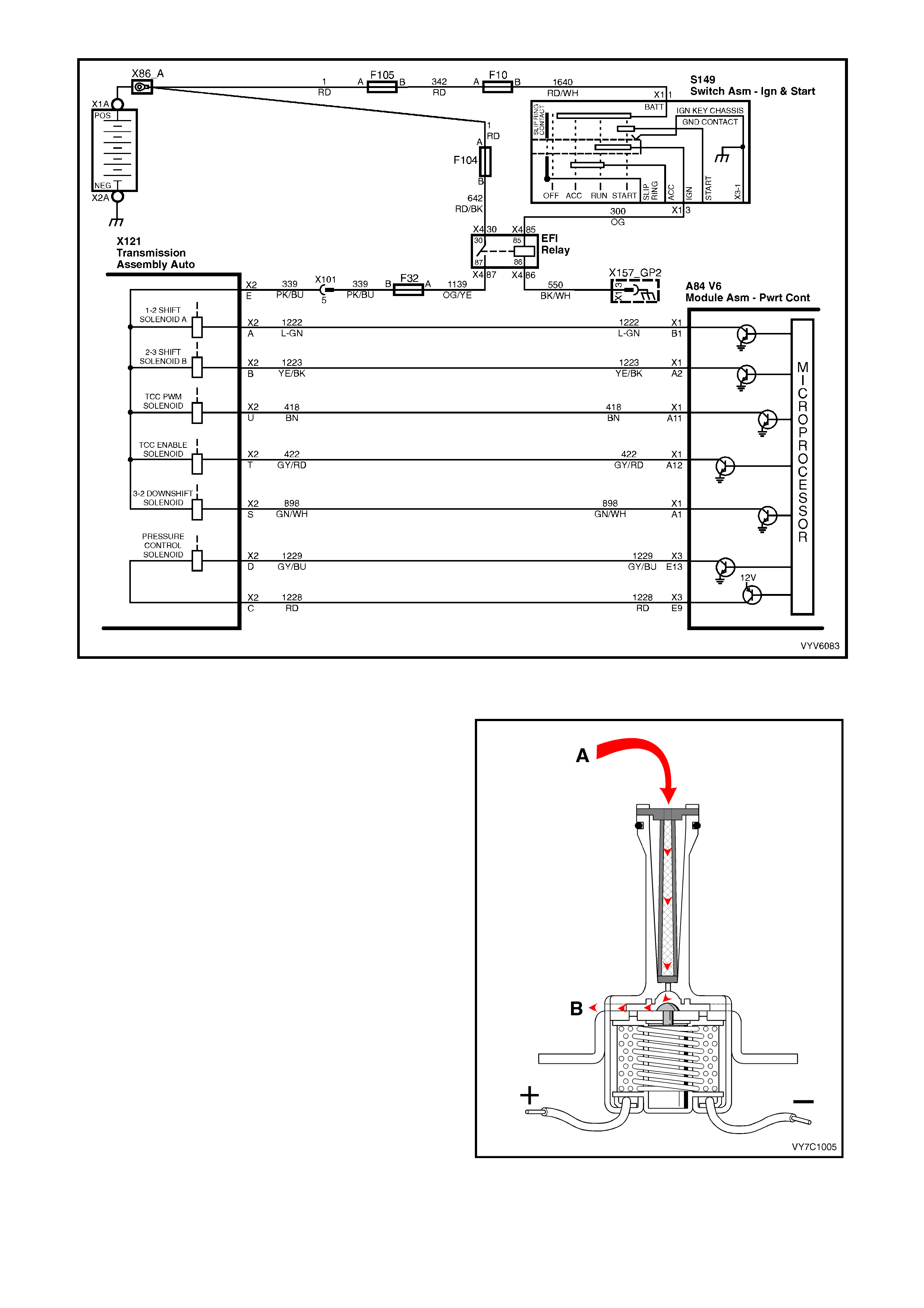
Figure 6C1-1-115 Transmission Solenoid Circuits
TORQUE CONVERTER CLUTCH SOLENOID VALVE
The Torque Converter Clutch (TCC) solenoid valve is
a normally open exhaust valve that is used to control
torque converter clutch apply and release. When
grounded (energised) by the PCM, the TCC solenoid
valve stops converter signal oil from exhausting. This
causes converter signal oil pressure to increase and
shifts the TCC solenoid valve into the apply position.
There are two DTCs associated with the TCC
solenoid. The first DTC is P0740, TCC enable
solenoid. DTC P0740 is designed to detect a fault in
the TCC enable solenoid electrical circuit. While DTC
P0740 is set, the PCM will inhibit 4th gear if the
transmission is in hot mode, and no TCC operation.
The second DTC associated with the TCC enable
solenoid is DTC P0741, TCC stuck on. DTC P0741 is
designed to detect a TCC enable solenoid that does
not disengage. It does this by monitoring engine RPM
when the TCC is commanded off. If the engine speed
does not rise when the TCC solenoid is disengaged
DTC P0741 will set. W hile DTC P0741 is set, the T CC
will be on in all gears or 2nd, 3rd, and 4th depending
upon the failure, and the transmission will have an
early shift pattern.
NOTE: The TCC solenoid resistance should be 21-26
ohms minimum when measured at 20°C.
Legend
A Converter Feed Fluid
B Exhaust
Figure 6C1-1-116
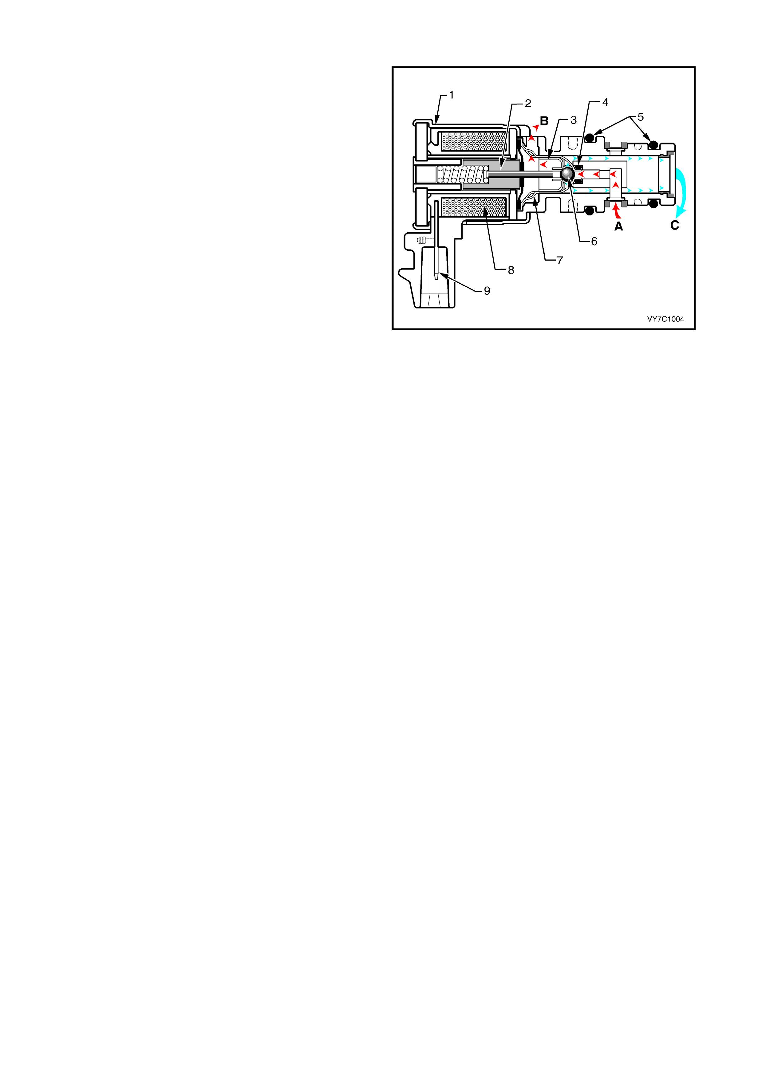
TORQUE CONVERTER CLUTCH PWM SOLENOID VALVE
The Torque Converter Clutch (TCC) PWM solenoid
valve controls the fluid acting on the converter clutch
valve, which then contro ls the T CC apply and releas e.
This solenoid is attached to the control valve body
assem bly within the tr ansm is sion.
The TCC PWM solenoid valve provides smooth
engagement of the torque converter clutch by
operating on a negative duty cycle with a variable
percent of ON time.
If a fault is detected in the TCC PWM circuit, DTC
P1860 will set.
NOTE: TCC PW M solenoid val ve res istance shoul d be
10-11 ohm s when meas ured at 2 0°C, and 13-1 5 ohm s
when measured at 100°C.
Legend:
A Actuator Feed Li mit Fluid
B Exhaust
C Converter Clutch Signal Fluid
1. Frame
2. Armature
3. Exhaust Seat
4. Internal O-Ring
5. O-Rings
6. Metering Ball
7. Inlet Seat
8. Coil Assembly
9. Connector Terminal
Figure 6C1-1-117
DTC P0740 (TCC Enable Solenoid Circuit Fault) will set if:
• The engine is running.
• Batter y volta ge is between 10 and 16 vol ts .
• The PCM commands the solenoid ON and the voltage input remains high (B+).
or
• The PCM commands the solenoid OFF and the voltage input remains low (0 volts).
• Conditions are met for 5 seconds.
The PCM will activate the Check Powertrain MIL.
Default Values
When this DTC sets, the PCM will inhibit T CC engagement, inhib it 4th gear if the transmission is in hot mode, and
will freeze shift adapts from being updated.
Recovery
Recovery will occur when the PCM sees a valid condition.
DTC P0741 (TCC Stuck ON) will set if:
• No TP DTCs set.
• No VSS DTCs set.
• No TFP Valve Position Switch DTC P1810 is set.
• No TCC Solenoid Valve DTC P0740 is set.
• No TCC PWM Solenoid Valve DTC P1860 is set.
• The TP angle is greater than 25%.
• The engine RPM is greater than 450 for 8 seconds.
• The commanded gear is not 1st.
• The gear range is D4 or D3.
• The PCM commands TCC OFF.
• The trans slip speed is –20 to +20 RPM.
• All conditions are met for 4 seconds.
The PCM will not activate the Check Powertrain MIL.

Default Values
When this DTC sets, the PCM will freeze shift adapts from being updated.
Recovery
Recovery will occur when the PCM sees a valid condition.
DTC P1860 (TCC PWM Solenoid Fault ) will set if:
• The system voltage is 8-18 volts.
• The engine speed is greater than 300 RPM for 5 seconds.
• The engine is not in fuel cutoff.
• The PCM commands first gear.
• The TCC duty cycle is less than 10% or greater than 90%.
• The PCM commands the solenoid ON and the voltage input remains high (B+).
or
• The PCM commands the solenoid OFF and the voltage input remains low (0 volts).
The PCM will not activate the Check Powertrain MIL.
Default Values
When this DTC sets, the PCM will inhibit T CC engagement, inhib it 4th gear if the transmission is in hot mode, and
will freeze shift adapts from being updated.
Recovery
Recovery will occur when the PCM sees a valid condition.
DTC P0740 , P0741 AND P1860 HISTORY DATA
PARAMETER PARAMETER
Engine Speed 1-2 Shift Solenoid A
Coolant Temperature 2-3 Shift Solenoid B
Time From Start 1-2 Shift Solenoid A Feedback
Times Occurred 2-3 Shift Solenoid B Feedback
Ignition Cycles Throttle Angle
Fuel Vehicle Speed
TCC Solenoid (Torque Converter Clutch) Commanded Gear
TCC Feedback (Torque Converter Clutch)
DTC P1870 (Transmission Slipping) will set if:
• No Throttle Position DTCs P0122 or P0123.
• No VSS assembly DTCs P0502 or P0503.
• No TCC solenoid valve DTC P0740.
• No 1-2 SS valve DTC P0753.
• No 2-3 SS valve DTC P0730.
• No 3-2 SS valve assembly DTC P0785.
• No TCC PWM solenoid valve DTC P1860.
• The engine speed is greater than 300 RPM for 5 seconds.
• The engine is not in fuel cutoff.
• The vehicle speed is 56-105 km/h.
• The speed ratio is 0.67-0.90 (the speed ratio is the engine speed divided by the transmission output speed).
• The engine speed is 1200-3500 RPM.
• The engine torque is 54-542 N.m.
• The gear range is D4.
• The commanded gear is not 1st gear.
• The Throttle Position angle is 10-50%.
• The TFT is between 20-130°C.
• DTC P1870 sets if the following conditions occur for three TCC cy cles.
- The TCC is commanded ON for 5 seconds.
- The TCC is at maximum duty cycle for 1 second.
- The TCC slip speed is 80-800 RPM for 7 seconds.

IMPORTANT: The following actions may occur before the DTC sets:
• If the TCC is commanded ON and at maximum duty cycles for 5 seconds, the TP angle is 10-40%, and the
transm ission slip c ounter h as increm ented to e ither 1 or 2 (o ut of 3 to increm ent the fai l counter f or the cur rent
ignition cycle), then the following slip conditions and actions may increment the fail counter for the current
ignition cycle:
- Condition 1: If the TCC slip speed is 80-800 RPM for 7 seconds, then the PCM will command maximum
line pressure and freeze shift adapts from being updated.
- Condition 2: If c ondition 1 is m et and the T CC slip sp eed is 80-80 0 RPM f or 7 sec onds, then t he PCM wil l
command the TCC OFF for 1.5 seconds.
- Condition 3: If condition 2 is met and the TCC slip speed is 80-800 RPM for 7 seconds, then the fail
counter on the current ignition cycle is incremented.
The abov e sli p c on dit io ns a nd ac tions ma y be disr egar ded if the TCC is c om manded OFF at a n y time as a result of
a driving manoeuvre (sudden acceleration or deceleration).
• The PCM will not activate the Check Powertrain MIL.
Default Value
W hen this DTC sets , the PCM inhibits TCC engagem ent, c omm ands maximum line press ure, inhib its 4th gear if the
transmission is in hot mode and will freeze shift adapts from being updated.
Recovery
Recovery will occur when the PCM sees a valid condition.
DTC P1870 HISTORY DATA
PARAMETER PARAMETER
Engine Speed Transmission Slip Speed
Coolant Temperature TFT (Transmission Fluid Temperature)
Time From Start Throttle Angle
Times Occurred Vehicle Speed
Ignition Cycles Commanded Gear
Fuel

Figure 6C1-1-118 Transmission Solenoid Circuits
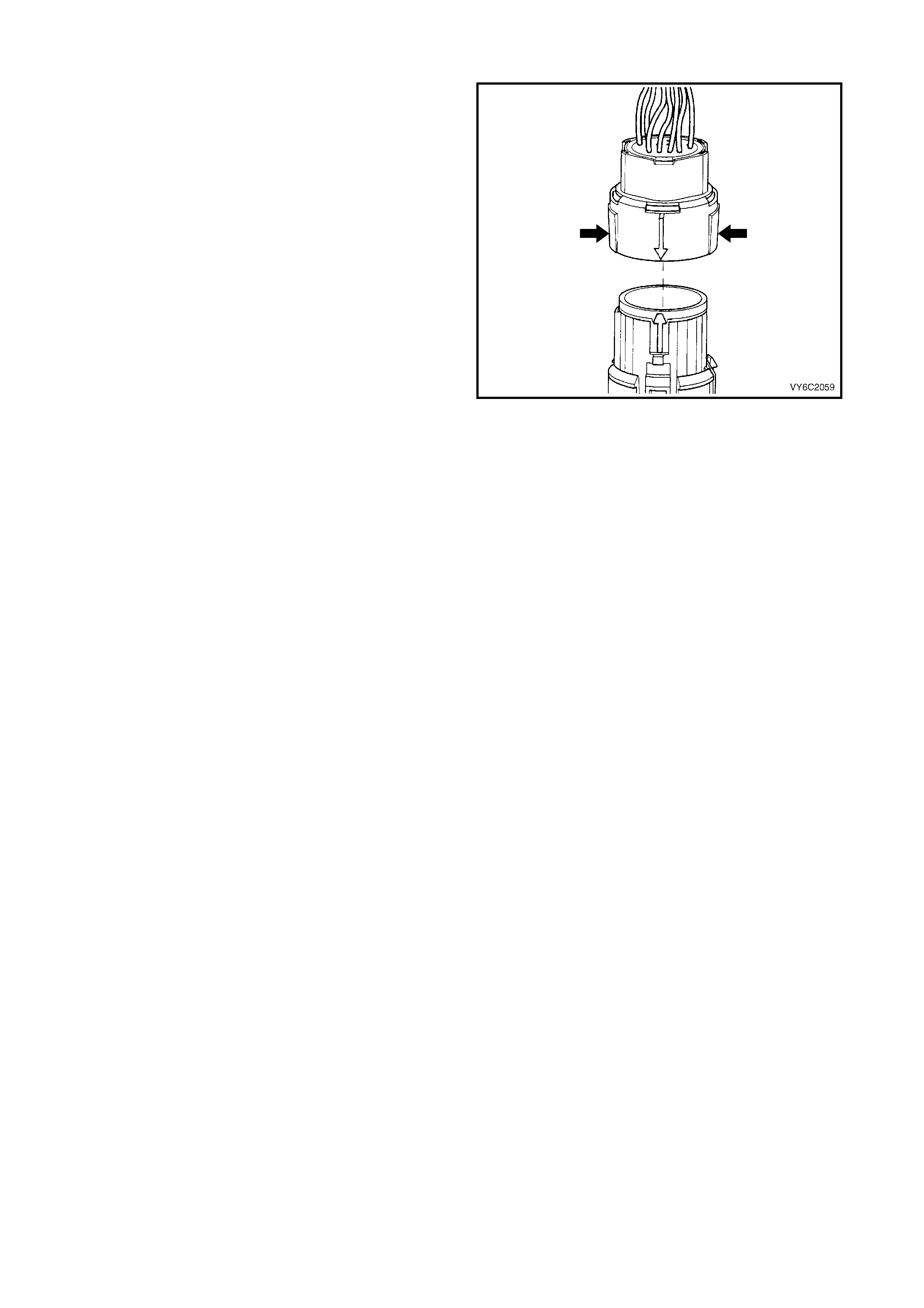
TR ANSMISSION P ASS-THRU CONNECT O R
The transmission electrical connector is an important
part of the transmission operating system. Any
interference with the electrical connection can cause
the transmission to set Diagnostic Trouble Codes
(DTCs) or affect proper operation.
The following items can affect the electrical
connection:
• Bent pins in the connector from rough handling
during connection and disconnection
• Wires backing away from the pins or coming
uncrimped (in either the internal or the external
wir ing harness)
• Dirt contamination entering the connector when
disconnected
• Pins in th e intern al wiring c onnector back ing out of
the connector or pushed out of the connector
during reconnection
• Excessive transmission fluid leaking into the
connector, wicking up into the external wiring
harness and degrading the wire insulation
• Moisture intrusion in the connector
• Low pin retention in the external connector from
excessive connection and disconnection of the
wiring conn ector assembly
• Pin corrosion from contamination
• Damaged connector assembly
Figure 6C1-1 -119
Remember the following points:
• In order to remove t he c o n nec tor, s q uee ze th e two
tabs towar d each other a nd pu ll s tra ight up with out
pulling by the wires.
• Limit twisting or wiggling the connector during
removal. Bent pins can occur.
• Do not pry the connector off with a screwdriver or
other tool.
• Visually inspect the seals to ensure that they are
not damaged during handling.
• In order to reinstall the external wiring connector,
first align t he pins by lining up the arrows on each
half of the connector. Push the connector straight
down into the transmission without twisting or
angling the mating parts.
• The connector should click into place with a
positive feel and/or noise.
IMPORTANT: Whenever the transmission external
wiring connector is disconnected from the internal
harness and the engine is operating, DTCs will set.
Clear these DTCs after reconnecting the external
connector.

1.15 ABBREVI ATIONS AND GLOSSARY OF TERMS
Abbreviations used in this Service Information are listed below in alphabetical order with an explanation of the
abbreviation.
AC - ALTERNATING CURRENT
A /C - AIR CONDITIONING
A/F - AIR/FUEL (A/F RATIO)
ANALOG SI GNAL - An ele c tric al signal that varies in v olta ge with in a given par ameter.
BAROMETRIC PRESSURE- Atmospheric pressure. May be called BARO, or barometric absolute pressure.
BATTERY - Stores chemical energy and converts it into electrical energy. Provides DC current for the vehicle
electrical systems.
CAMSHAFT POSITION SENSOR - The PCM uses this signal to determine the position of the No.1 piston in its
power stroke. This signal is used by the PCM to calculate sequential fuel injection mode of operation.
CAT. CONV. - CATALYTIC CONVERTER - A muffler-shaped device fitted in the exhaust system, between the
engine an d the muffler. It is the primary "work horse" of the emission control s ys tem, and the PCM's control of the
air/fuel ratio allows it to operate efficiently. It contains platinum, palladium and rhodium . It receives pollutants (HC,
CO, and NOx) emitted by the engine, and through a chemical reaction, converts these harmful pollutants into
harmless water vapour, carbon dioxide, and nitrogen. Maximum conversion efficiency of exhaust emissions is
achieved with precise control of the air/fuel ratio at 14.7 to 1.
CHECK POWERTRAIN MIL - Warning indicator with t he outline of an engine an d the words “Check Engine”. The
Check Po wertr ain M IL is dis played on the ins trument pane l, and is c ontrolled by the PC M. Check Po wertr a in MIL is
activated by the PCM when it detects a malfunction in the engine or transmission management system.
CKT - CIRCUIT
CLOSED LOOP - A fuel c ontr ol s ystem mode of oper ation that us es the sig nal f rom the exhaus t ox ygen se nsor, in
order to control the air/fuel ratio precisely at a 14.7 to 1 ratio, allowing maximum efficiency of the catalytic
converter.
CO - CARBON MONOXIDE - One of the pollutants found in engine exhaust.
DC - DIRECT CURRENT
DTC - DIAGNOSTIC TROUBLE CODE - The PCM can detect malfunctions in the engine or transmission
management system. If a malfunction occurs, the PCM may turn on the Check Powertrain MIL, and a four-digit
code num ber will set i n the PCM's m emory. A diagn ostic tr ouble code c an be obta ined b y using Tec h 2. A DTC will
indicate the area of the malfunction , and properly following the diagnostic procedures for the engine managem ent
system will locate the source of the problem.
DIGITAL SIGNAL - An electrical signal that is either one of two states, "ON" or "OFF" with no in between.
DLC - DATA LINK CONNECTOR - The 16 pin connector used at the assembly plant to evaluate the control
module system and in service is used by Tech 2 to communicate with the vehicles control modules.
DLC DATA STRE AM - An outp ut of the PCM, initia ted b y Tech 2 send ing a command to the PCM. T his out put is a
digital computer language signal, used by assem bly p lant test equipment and Tech 2. This signal is transmitted to
the data link connector.
DRIVER - An electronic device, usually a power transistor, that operates like a switch; that is, it turns something
"ON" or "OF F."
DUTY CYCLE - The measurement of the length of time, in percentage, that a circuit is "ON" versus "OFF" when
compared with a 100% full ON/OFF time factor.
DVM (10 Meg.) - Digital voltmeter with 10 million ohms per volt impedance - used for voltage and resistance
measurement in electrical/electronic systems.
EECS - EVAPORAT IVE EMISSIONS CONTROL SYSTEM - Used to prevent petrol vapours in the fuel tank from
entering the atmosphere. Stores the vapours in a storage canister, located in the engine compartment. Canister
contains activated charcoal, and the vapours are "purged" by engine vacuum during certain operating conditions.
EEPROM - ELECTRICALLY ERASABLE PROGRAMMABLE READ ONLY MEMORY - Type of read only
memory (ROM) that can be electrically programmed, erased and reprogrammed.
EMI (ELECT ROMAGN ETIC INDUCTION) OR ELECT RICAL NOISE - An unwanted s ignal interf ering with anot her
needed si gna l; l ik e an el ec t r ic r a zor upse ts a tel ev isi on pic ture, or dr ivin g under h i gh voltage po wer li nes upsets the
AM radio in a vehicle.
EGR - EXHAUST GAS RECIRCULATION VALVE - A device that is used to lower Oxides of Nitrogen (NOx)
emission levels by recirculating exhaust gases back into the combustion chamber.
ENGINE COOLANT TEMPERATURE (ECT) SENSOR - Device that senses the engine coolant temperature, and
passes that information to the PCM.
EPROM - ERASABLE PROGRAMMABLE READ ONLY MEMORY - Type of read only memory (ROM) that can
be erased with ultra vi olet li ght and re progr am med.

ESD - ELECTROSTATIC DISCHARGE - The discharge of static electricity, which has built up on an insulative
material.
FUSE - A thi n m etal strip that m elts through whe n exces sive curr ent flo ws through it, th ereb y stoppin g cur rent flo w
and protecting a circuit from damage.
HC - HYDROCARBONS - One of the pollutants found in engine exhaust.
HIGH - A voltage more than a specific threshold such as ground or 0. In digital signals, high is "ON" and low is
"OFF".
HYSTERESIS - Movement that does not follow the same path as it entered an area as it exits.
IAC - IDLE AIR CONTROL - Installed in the throttle bod y unit and controlled b y the PCM to regulate idle a ir flow,
and thus idle RPM.
IAT - INTAKE AIR TEMPERATURE SENSOR - Se ns es in take manif old inc oming a ir temperatur e, a nd passes that
information to the PCM.
IDEAL MIXT URE - T he air/f uel ratio tha t pro vides th e bes t perfo rm ance, whil e maint ainin g m axim um conver sion of
exhaust emissions, typically 14.7 to 1 on petrol engines.
IGN - IGNITION
INPUTS - Information from sensors (MAF, TPS, etc.) and switches (A/C request, etc.) used by the PCM to
determine how to control it's outputs.
INTERMITTENT - Oc curs now and then; not continuo usly. In electrical circuits , refers to occasional open, s hort, or
ground.
I.C. - INSTRUMENT CLUSTER
LOW - A voltage less than a specific threshold. Operates the same as a ground and may, or may not, be
connected to chassis ground.
MAF - MASS AIR FLOW SENSOR - A device that monitors the amount of air flow coming in the engine intake. The
MAF sensor sends a signal to the PCM.
MODE - A particular state of operation.
N.C. - NORMALLY CLOSED - Switch contacts that are connected, or together, when no outside forces
(temperature, pressure, position) are applied.
N.O. - NORMALLY OPEN - Switch contacts that are not connected, or not together, when no outside forces
(temperature, pressure, position) are applied.
NOx - NITROGEN OXIDES - One of the pollutants found in engine exhaust.
O2 - OXYGEN
OXYGEN SENSOR - Exhaust gas oxygen sensor, fitt ed in the exhaust m anifold. Senses leftover oxygen after the
combustion process, and produces a very small electrical signal based on the amount of oxygen in the exhaust
gas, as compared to oxygen in the atmosphere.
OPEN LOOP - Describes PCM control of the fuel control system without use of oxygen sensor information.
OUTPUT - Functions, typically solenoids and relays that are controlled by the PCM.
PCM - POWERTRAIN CONTROL MODULE. A metal cased box (located in passenger compartment) containing
electronic circuitry that electrically monitors and controls the transmission system and emission systems of the
engine management system. It also commands ON the Check Powertrain MIL when a malfunction occurs in the
system .
PCV - POSIT IVE CRANKC AS E VENTIL AT ION - Method of r eburning crank case fumes, r ather than passing them
directly into the atmosphere.
PFI - PORT FUEL INJECT ION - Meth od of injec ting f uel into th e engine. Places a f uel inject or at each i nlet port of
a cylinder head, directly in front of the intake valve, mounted in the intake manifold.
PULSE WIDTH MODULATED (PWM)- a digital signal turned "ON" and "OFF'" for a percentage of available on-
plus-off cycle time, such as 30% "on" and 70% "off" would be called a 30% "ON" PWM signal.
QUAD DRIVER - A "chip" device in the PCM, capable of operating four separate outputs. Outputs can be either
"ON-OFF" or pulse width modulated.
RAM - RANDOM ACCESS MEMORY - Is the micropr oces s ors "s cr atc h pad ". T he pr oc ess or c an wri te into , or read
from this mem ory as needed. This mem ory is volatile and needs a constant s upply of volta ge to be retained. If the
voltage is lost or removed, this memory is lost.
SERI AL DAT A - Serial dat a is a series of rapidl y changi ng voltage s ignals pu lsed from high to low volt age. T hese
voltage signals are typically 5 volts (high) and 0 volts (low) and are transmitted through a wire often referred to as
the serial data line.
SEQUENTIAL FUEL INJECTION - A mode of injecting fuel into the engine on the intake stroke of each cylinder.
SOLENOID - An electromagnetic coil that creates a magnetic field when current flows through it and causes a
plunger or ball to move.

SUPPRESSION CAPACITORS - These capacitors are connected between the power and ground circuits of the
cooling fan motors. These capacitors are for controlling fan motor noise in the radio.
SWITCH - Opens and closes circuits, thereby stopping or allowing current flow.
TCC - TORQUE CONVERTER CLUTCH - PCM controlled solenoid in automatic transmission that positively
couples the transmission input shaft to the engine.
TECH 2 SC AN TOOL - A hand- held dia gnostic tool, containing a micropr ocessor to int erpret the PC M's DLC data
stream. A display panel displays the PCM input signals and output commands.
TP SENSOR - THROTTLE POSITION SENSOR - Device that tells the PCM the current throttle position, and, when
it is moving, the rate of throttle opening / closing.
VACUUM, MANIFOLD - Vacuum source in the engine.
VACUUM, PORT ED - Vac uum sour c ed from a small " por t" in the thrott le bo dy. With the thr ott le cl os ed, th er e woul d
be no vacuum m easured, bec ause the p ort is on the a ir c leaner side of the throttl e blad e, and is exposed to e ngine
vacuum only after the throttle is open.
VSS - VEHICL E SPEED SENSOR - A perm anent m agnet type s ens or wh ich pro duces AC v oltage whic h is sent t o
the PCM to determine vehicle speed.
UART - UNIVERSAL ASYNCHRONOUS RECEIVE AND TRANSMIT - A method of communicating between two
electronic devices (Serial Data).
WOT - WIDE OPEN THROTTLE