
SECTION 6C1-2 - DIAGNOSIS – V6 ENGINE
IMPORTANT
Before performing any Service Operation or other procedure described in this Section, refer to Section 00
CAUTIONS AND NOTES for correct workshop practices with regard to safety and/or property damage.
CONTENTS
1. GENERAL DESCRIPTION
1.1 DIAGNOSTIC PRECAUTIONS
1.2 BLOCKING DRIVE WHEELS
1.3 VISUAL/PHYSICAL INSPECTION
1.4 BASIC KNOWLEDGE AND TOOLS
REQUIRED
1.5 ELECTROSTATIC DISCHARGE DAMAGE
1.6 DIAGNOSTIC INFORMATION
SELF DIAGNOSTICS
CHECK POWERTRAIN MALFUNCTION
INDICATOR LAMP (MIL)
INTERMITTENT CHECK POWERTRAIN
(MIL)
DATA LINK CONNECTOR (DLC)
2. STRATEGY BASED DIAGNOSTICS
3. DIAGNOSTIC TROUBLE CO DES
CURRENT DIAGNOSTIC TROUBLE
CODES
HISTORY DIAGNOSTIC TROUBLE CODE
HOW DTC HISTORY WORKS
HOW TO USE DTC HISTORY CODE
INFORMATION
READING DTCS
CLEARING DTCS
CLEARING DTC HISTORY
IGNITION CYCLE DEFAULT
PCM SLEEP TEST
PCM LEARNING ABILITY
TRANSMISSION ADAPT FUNCTION
4. TABLE A – V6 ENGINE PCM
ON-BOARD DIAGNOSTIC (OBD)
SYSTEM CHECK
5. POWERTRAIN OBD SYSTEM CHECK
DLC TECH 2
TECH 2 EXPLANATION
5.1 TECH 2 USES - POWERTRAIN CONTROL
MODULE (PCM)
MODE F0: NORMAL MODE
MODE F1: DIAGNOSTIC TROUBLE CODES
MODE F2: DATA DISPLAY
MODE F3: SNAPSHOT
MODE F4: MISC. TESTS
MODE F5: FUNCTION TESTS
MODE F6: STALL DATA
MODE F7: SPECIAL FUNCTIONS
TECH 2: USE WITH INTERMITTENT FAULTS
TECH 2: LIMITATIONS
5.2 TECH 2: PCM NORMAL MODE
TECH 2: PCM NORMAL MODE DESCRIPTIONS
5.3 TECH 2: ENGINE DATA
TECH 2: ENGINE DATA DESCRIPTIONS
5.4 TECH 2: AUTOMATIC TRANSMISSION DATA
TECH 2: AUTOMATIC TRANSMISSION
DATA DESCRIPTIONS
6. DIAGNOSTIC TABLES
6.1 INTRODUCTION
6.2 WRITING THE REPAIR ORDER
6.3 QUESTIONS
"WHO"? QUESTIONS
"WHAT"? QUESTIONS
"WHEN"? QUESTIONS
"WHERE"? QUESTIONS
"HOW"? QUESTIONS
SUMMARY
VERIFYING THE COMPLAINT
CALIBRATIONS
1. GENERAL DESCRIPTION
This is where to start all driveability and emissions diagnosis, once you read and understand Section 6C1-1
GENERAL INFORMATION in this Section. The beginning of Section 6C1-2A contains reference material such as
wiring di agrams, c ontrol modu le terminal e nd views, and engi ne component locations. Rem ember, this inform ation
is for ref erenc e only and is not intended to be us e d as a s tart to di agn os is . A lways start diag nos is on the pag e titl e d
“Powertra in OBD System Check”. This c heck verif ies that the diag nos tic c irc uits a re oper ati ng pro per ly, then directs
you to the correct Service Information location for specific diagnosis.
If the init ia l s teps in the Po wer tr ain O BD System Chec k reveal a prob lem, or if the engi ne d oes not s tart, you wil l be
using one or more tables in Sect ion 6C1-2A in this Se ction for diagnos is. The Powertr ain OBD System Check will
send you to the correct table. These tables follow the Powertrain OBD System Check and problems that prevent
the engine from starting.
If the Powertrain OBD System Check shows that diagnostic trouble codes have been stored, proceed to the
appropriate Diagnostic Trouble Code (DTC) diagnosis pages. If more than one diagnostic trouble code has been
stored, always start diagnostic trouble code diagnosis with the lowest diagnostic trouble code number and work
upward. Diagnostic trouble code diagnosis pages start immediately after the diagnosis tables in Section 6C1-2A.
1. 1 DIAGNOSTIC PRECAUTIONS
THE FOLLOWING REQUIREMENTS MUST BE OBSERVED WHEN WORKING ON VEHICLES.
1. Before removing any PCM system component, disconnect the battery ground lead.
2. Never start the engine without the battery being solidly connected.
3. Never separate the battery from the on board electrical system while the engine is running.
4. When charging the battery, disconnect the battery from the vehicle's electrical system.
5. Never subject the PCM to temperatures above 80° C i.e. paint oven. Always remove control unit first if this
temperature is to be exceeded.
6. Ensure that all cable harness plugs are connected solidly and that battery terminals are thoroughly clean.
7. The powertrain management system harness connectors are designed to fit in only one way; there are indexing
tabs and slots on both halves of the connector. Forcing the co nnector into place is not necessar y if it is being
installed with the proper orientation. Failure to take care to match the indexing tabs and slots to ensure the
connector is being installed correctly can cause damage to the connector, the module, or other vehicle
components or s ystem s .
8. Never connect or disconnect a PCM wiring harness connector when the ignition is switched ON.
9. Before attempting any electric Arc welding on the vehicle, disconnect the battery leads and the PCM
connectors.
10. When steam cleaning engines, do not direct the steam cleaning nozzle at PCM system components. If this
happens, corrosion of the terminals can take place.
11. Use only the test equipment specified in the diagnostic tables, since other test equipment may either give
incorrect results or damage good components.
12. For all voltage measurements using a voltmeter, a digital multimeter with an internal impedance rating of at
least 10 million ohms per volt (10 megohms) such as the DMM J 39200, must be used .
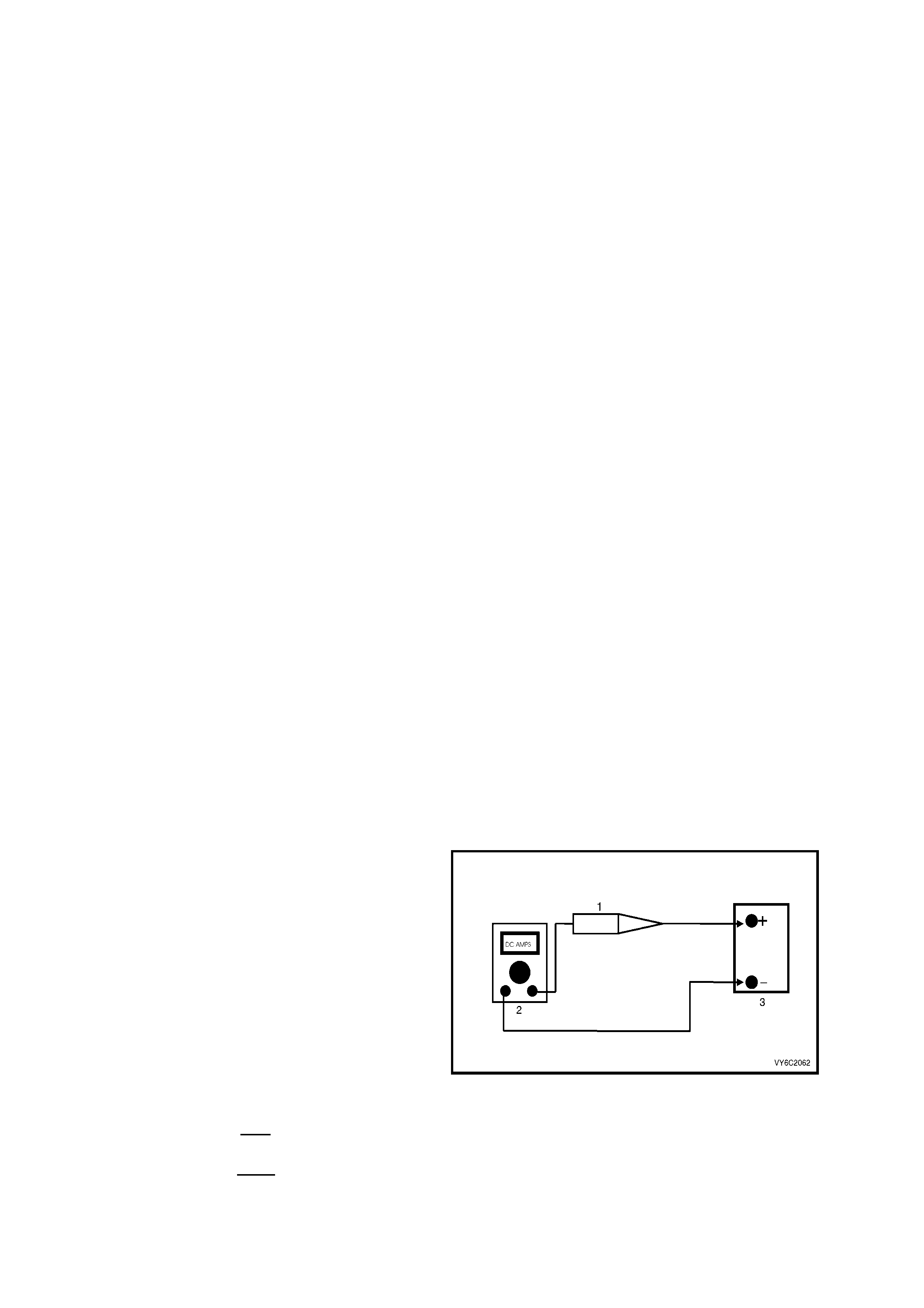
13. When a test light is specified, a "low-power"
test light must be used. Do not use a high -
wattage test light. While a particular brand of
test ligh t is no t sug geste d, a sim ple t est o n an y
test light will ensure it to be OK for PCM c ircuit
testing. Connect an accurate ammeter (such
as the high-impedance digital multimeter) in
series with the test light being tested, and
power the test light-ammeter circuit with the
vehicle battery.
Legend:
1. Test Lamp
2. Digital Multimeter, Set to DC Amps
3. 12 Volt Battery
If the ammeter indicates less than 0.3 A (300 mA)
current flow, the test light is OK to use.
If the am meter in dic at es more than 0.3 A (300 mA)
current flow, the test light is NOT OK to use.
Figure 6C1-2-1

1.2 BLOCKING DRIVE WHEELS
The vehicle drive wheels should always be chocked and the parking brake firmly applied while checking any
system.

1.3 VISUAL/PHYSICAL INSPECTION
A careful visual and physical inspection must be performed as part of any diagnostic procedure. This can often lead
to fixing a problem without further steps. Inspect all the wires in the engine compartment for bad connections,
burned or chafed spots, pinched wires, or contact with sharp edges or hot exhaust manifolds. Check beneath the
air cleaner, the compressor, the generator, etc. This visual/physical inspection is very important. The inspection
must be done carefully and thoroughly.

1.4 BASIC KNOWLEDGE AND TOOLS REQUIRED
To use this service manual most effectively, a general understanding of basic electrical circuits and circuit testing
tools is required. You should be familiar with wiring diagrams, the meaning of voltage, ohms, amps, the basic
theories of electricity, and understand what happens in an open or shorted circuit.
To perform system diagnosis, the following tools are required.
• A Tech 2
• A test light
• A digital multimeter with 10 megohms impedance
• A vacuum gauge
• A fuel pressure gauge and suitable fittings
• Fuel injec tor co il/ ba lanc e te s ter
• IAC motor analyser
Familiarise yourself with the tools and their uses before attempting diagnosis. Special tools that are required for
system service and the ones described above are illustrated in Section 6 SPECIAL TOOLS, at the end of this
Section.

1.5 ELECTROSTATIC DISCHARGE DAMAGE
Electronic components used to control the systems are often designed to carry very low voltage. They are very
susceptib le to dam age caus ed by electr ostatic dis charge. It is possib le for less than 100 vo lts of s tatic electr icit y to
cause damage to some electronic components.
By comparison, it takes as much as 4,000 volts for a person to even feel the zap of a static discharge.
There ar e several wa ys for a person to bec ome staticall y charged. T he mos t common methods of charging are by
fric tion and b y induction. An ex am ple of c harging by fr iction is a pers on slidi ng ac ross a car seat, in which a charge
of as much as 25,000 volts can build.
Charging by induction occurs when a person with well-insulated shoes stands near a highly charged object and
mom entarily touches ground. Charges of the sam e polarity are drained of f, leaving the person high ly char ged with
the opposite polarity. Static charges of either type can cause damage, therefore, use care when handling and
testing the electronic components.
NOTE: To prevent possible Electrostatic Discharge damage:
Do Not touch the PCM connector pins or soldered components on the PCM circuit board.
1.6 DIAGNOSTIC INFORMATION
The diagnostic tables and functional checks in this manual are designed to locate a faulty circuit or component
through logic based on the process of elimination. The tables are prepared with the understanding that the vehicle:
Functioned correctly at the time of assembly.
There are no multiple faults.
The problem currently exists.
The PCM per f orms a c ontin ual self- diagn os is on ce rta i n c ontr ol f unc tions . This dia gnos tic c ap abi lity is suppor t ed by
the diagnostic procedures. The PCM indicates the source of a fault through the use of Diagnostic Trouble Codes
(DT Cs). The DT Cs are two dig it codes. When a fault is detec ted b y the PCM, a d iagnost ic troub le code will set and
the Check Powertrain Malfunction Indicator Lamp (MIL) indicator may be activated.
SELF-DIAGNOSTICS
The PCM performs system self diagnostics. The PCM can detect and often isolate system faults. When a fault is
detected, th e PCM sets a DTC that repr esents the area of the f ault. The PC M may or m ay not turn ON the "Check
Powertrain" Malfunction Indicator Lam p (MIL).
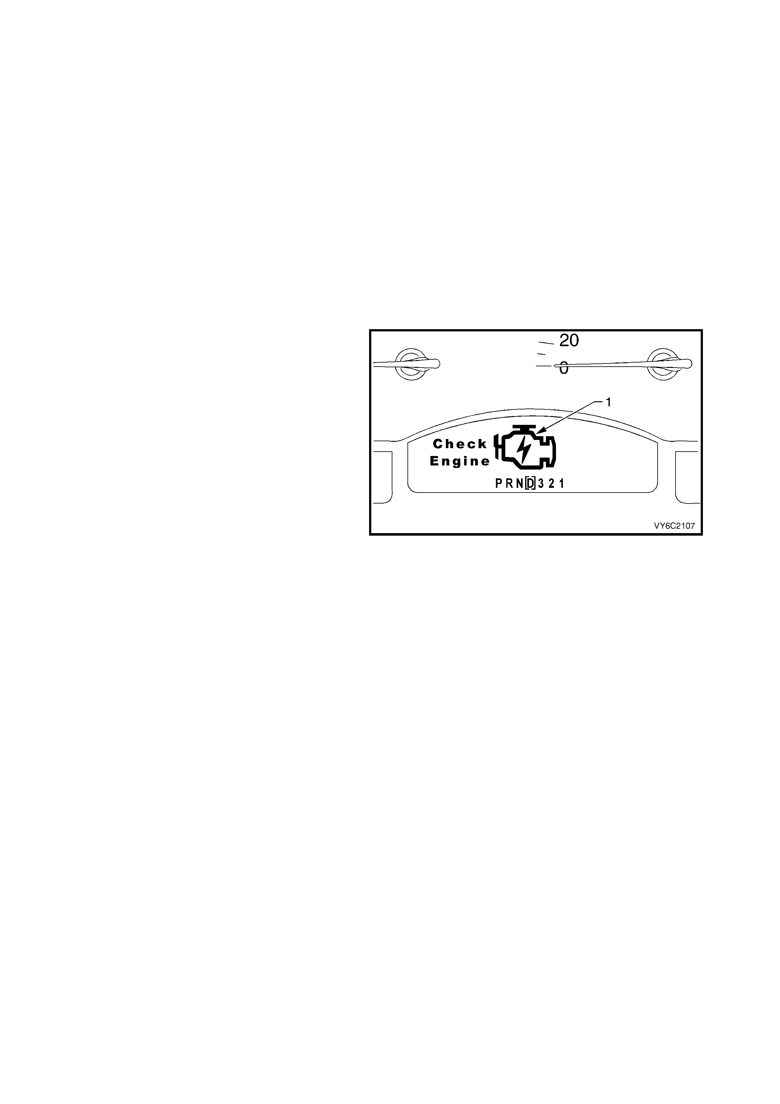
CHECK POWERTRAIN MALFUNCTION INDICATOR LAMP (MIL)
The instruments receive Check Powertrain MIL
information from the PCM via the serial data bus
normal mode message.
The PCM will command the MIL ON, when a DTC
has been set and the DTC requires the icon to be
activated in the instrument Multi Function Display
(MFD).
If the instruments do not receive a normal mode
message from the PCM, the MIL will be activated
continuously. When the MIL remains activated
when the engine is running, or when a fault is
suspected due to a driveability or emissions
problem, perform the “On-Board Diagnostic
System Check". Refer to POWERTRAIN OBD
SYSTEM CHECK in this Section. These checks
will help ide ntif y faults whic h ma y not be detected if
other diagnostics are performed.
Figure 6C1-2-2 – Malfunction Indicator Lamp (MIL) Symbol
INTERMITTENT CHECK POWERTRAIN MALFUNCTION INDICATOR LAMP (MIL)
In the case of an "intermittent" problem, the Check Powertrain MIL may be activated for ten seconds and then
disappear . The corr esponding D iagnostic Trouble Co de will be store d. The DT C will rem ain stored unt il the batter y
voltage to t he PCM has b een disconnec ted or unti l it is erased us ing Tech 2. W hen unexpecte d diagnostic t rouble
codes appear, chances are that these diagnostic trouble codes were set by an intermittent fault.
An intermittent DTC may not re-set. If an intermittent fault occurs, do not use a Diagnostic Trouble Code Table.
Consult the "Diagnostic Aids" on the facing page. The diagnostic table corresponds to the intermittent diagnostic
trouble code.
Section 6C1-2B , SYMPTOM S also covers the topic of "In termittents." A physic al inspect ion of the ap plicable sub-
system most often will resolve the problem. Tech 2 also has several features which can help in diagnosing
interm ittent pr ob lems.
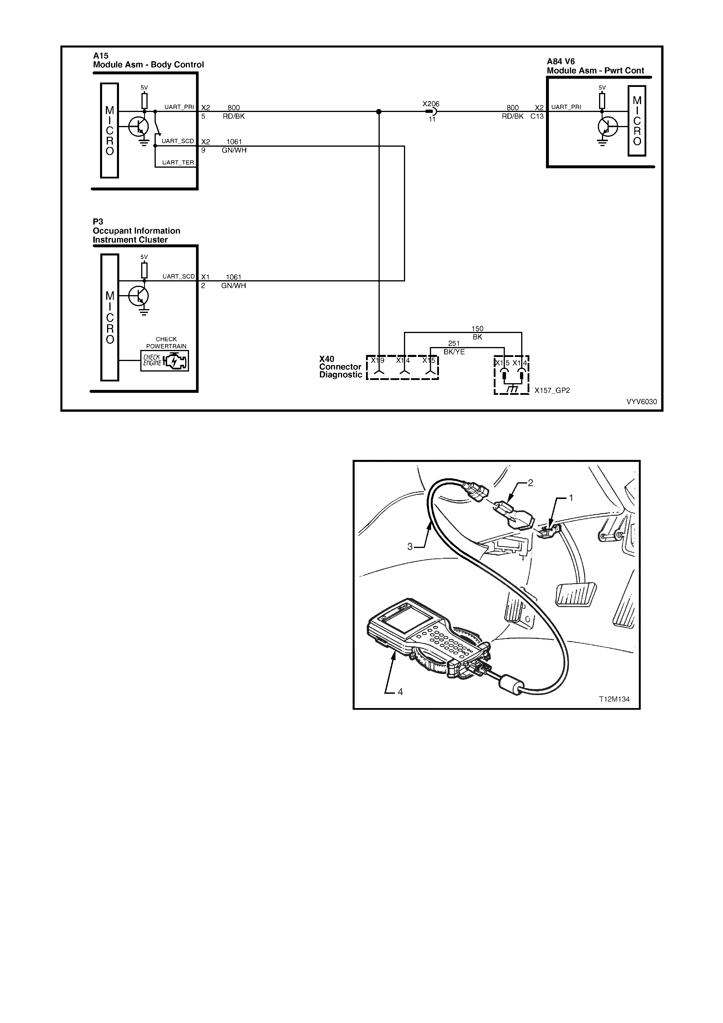
Figure 6C1-2-3 – Check Powertrain MIL Circuit
DA TA LINK CONNECTOR (DLC)
The DLC is a standardised 16 way connector
located below the instrument panel and close to
the steering column.
Legend:
1. Data Link Connector (DLC)
2. DLC Adaptor
3. DLC Cable
4. Tech 2
Figure 6C1-2-4 – Data Link Connector (DLC) Location

• Pin 2 is the Class II serial data circuit that is
only used in GEN III V8 engine applications.
This circuit is used to comm unicate only to the
GEN III V8, PCM.
• Pin 4 is the ground circuit for Tech 2, while Pin
5 is an auxil iary groun d, that should be used to
ground the Diagnostic Test Enable Circuits,
where used.
• The DLC p in 9 is the prim ary UART serial dat a
circuit. Tech 2 uses this circuit to read serial
data information from the PCM, BCM,
Instruments, Occupant Climate Control,
Supplemental Inflatable Restraint System and
the ABS/TCS Control Modules.
• The DLC pin 12 is the ABS/TCS Diagnostic
Tes t Enable circuit. T his circuit when jum pered
to DLC pin 5 will cause the ABS/TCS Control
Module to enter the Diagnos tic Mode and flash
out ABS/TCS diagnostic trouble codes.
• The DLC is designe d to provi de batter y voltage
to pin 16 from fuse F29. This circuit is used to
power Tech 2.
Figure 6C1-2-5 Data Link Connector (DLC)
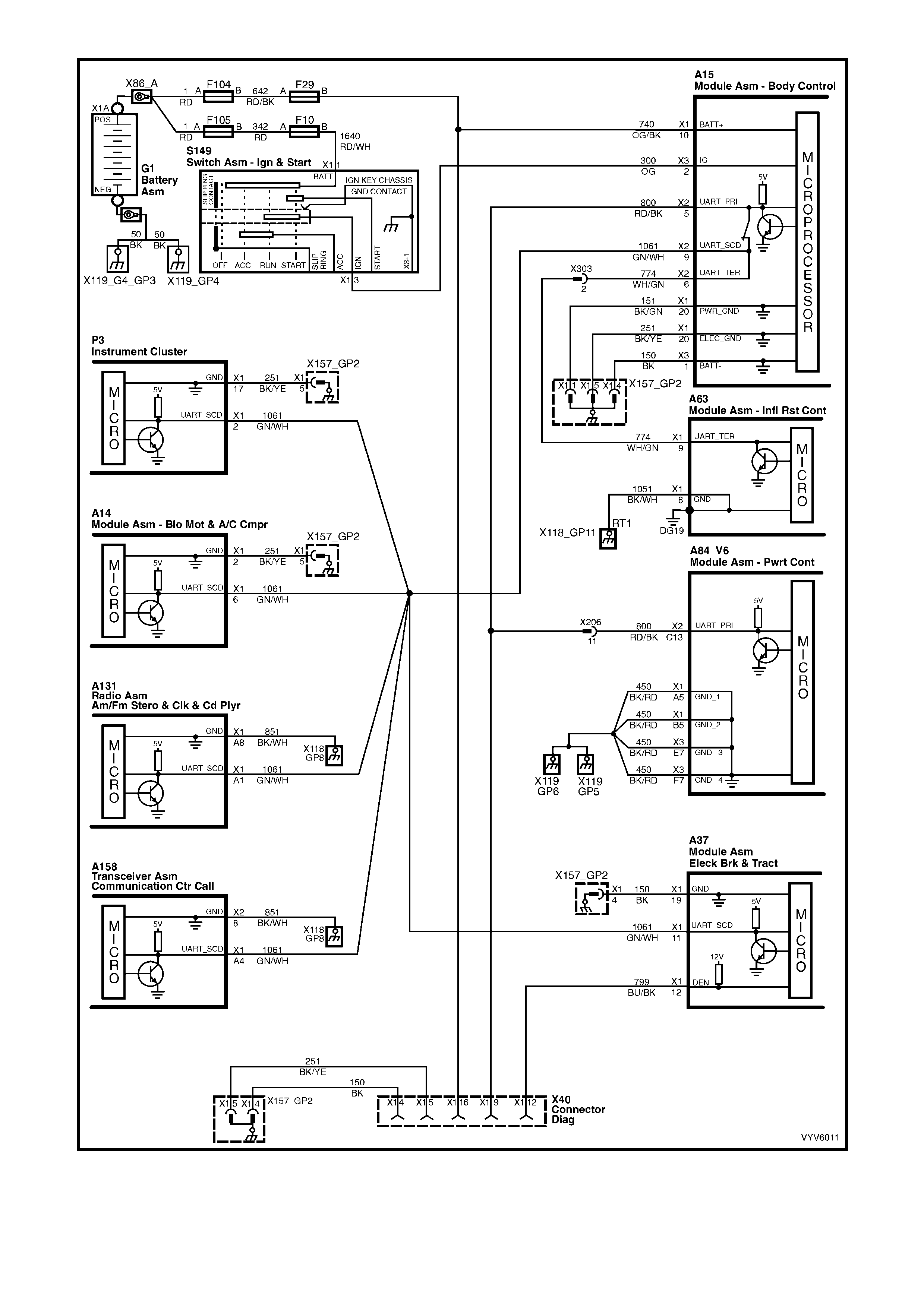
Figure 6C1-2-6 – Data Link Connector Circuits

2. STRATEGY BASED DIAGNOSTICS
The strategy based diagnostic is a uniform approach to repair all Electrical/Electronic systems. The diagnostic flow
can always be used to resolve an Electrical/Electronic system problem and is a starting point when repairs are
necessary. The steps below are defined to instruct the technician how to proceed with a diagnostic. Steps below
also refer to step numbers found on the Strategy Based Diagnostic table.
1. Verify the Customer Concern: To verify the customer concern, the technician should know the normal
operation of the system.
2. Preliminary Check: Conduct a thorough visual and operational inspection, review the service history, detect
unusual sounds or odours, and gather diagnostic trouble code information to achieve effective repair.
3. Service Information (Manual) System Check(s): System checks verify proper operation of the system. This
will lead the technician in an organised approach to diagnostics.
4. Check Bulletins and Other Service Information: This should include Dealer letters, Service Techlines and
Service Training publications.
5. Service Diagnostics (Paper/Electronic)
5a DTC Stored: Follow the designed DTC table exactly to make an effective repair.
5b Symptom, No DTC: Select the symptom from the symptom tables and follow the diagnostic
paths or suggestions to complete the repair, or refer to the applicable component/system checks in
Section 6C1-2C FUNCTION AL CHECKS, in this Section.
5c No Published Diagnostics: Analyse the complaint and develop a plan for diagnostics. Utilise the wiring
diagrams and theory of operation.
Call Technical Assistance for similar cases where repair history may be available. Combine Technician
knowledge with efficient use of the available service information.
5d Intermittent: Conditions that are not always present are intermittent. T o resolve intermittents, perform the
following steps:
5d.1 Observe history DTCs, DTC modes.
5d.2 Evaluate the symptoms and conditions described by the customer.
5d.3 Use a check sheet or other method to identify the circuit or electrical system component.
5d.4 Follow the suggestions for intermittent diagnosis found in the service documentation.
The Tech 2 and DMM have data capturing capabilities that can assist in detection of intermittents.
5e Vehicle Operates As Designed/No T rouble Found: This condition exists when the vehicle is found to be
operatin g nor mally. T he co ndition des c ribe d by the cu stomer m a y be norm al. Verif y agains t an oth er veh icl e
that is operating normally. The condition may be interm ittent. Contact Technical Assistance if the concern
is common. Verify the complaint under the conditions described by the customer before releasing the
vehicle.
6. Re-examine the Concern: When the complaint cannot be successfully found or isolated, a re-evaluation is
necessary. The complaint should be re-verified and could be intermittent or normal as per step 5c or 5d.
7. Repair and Verification Tests: After isolatin g the caus e, the repair s hould be m ade. Then val idate for proper
operatio n and verif y that the s ymptom has bee n corrected. T his m ay involve roa d testing or other m ethods to
verify the complaint has been resolved under the following conditions:
• Conditions noted by the customer.
• If a DTC was diagnosed, verify a repair by duplicating conditions for setting the DTC.
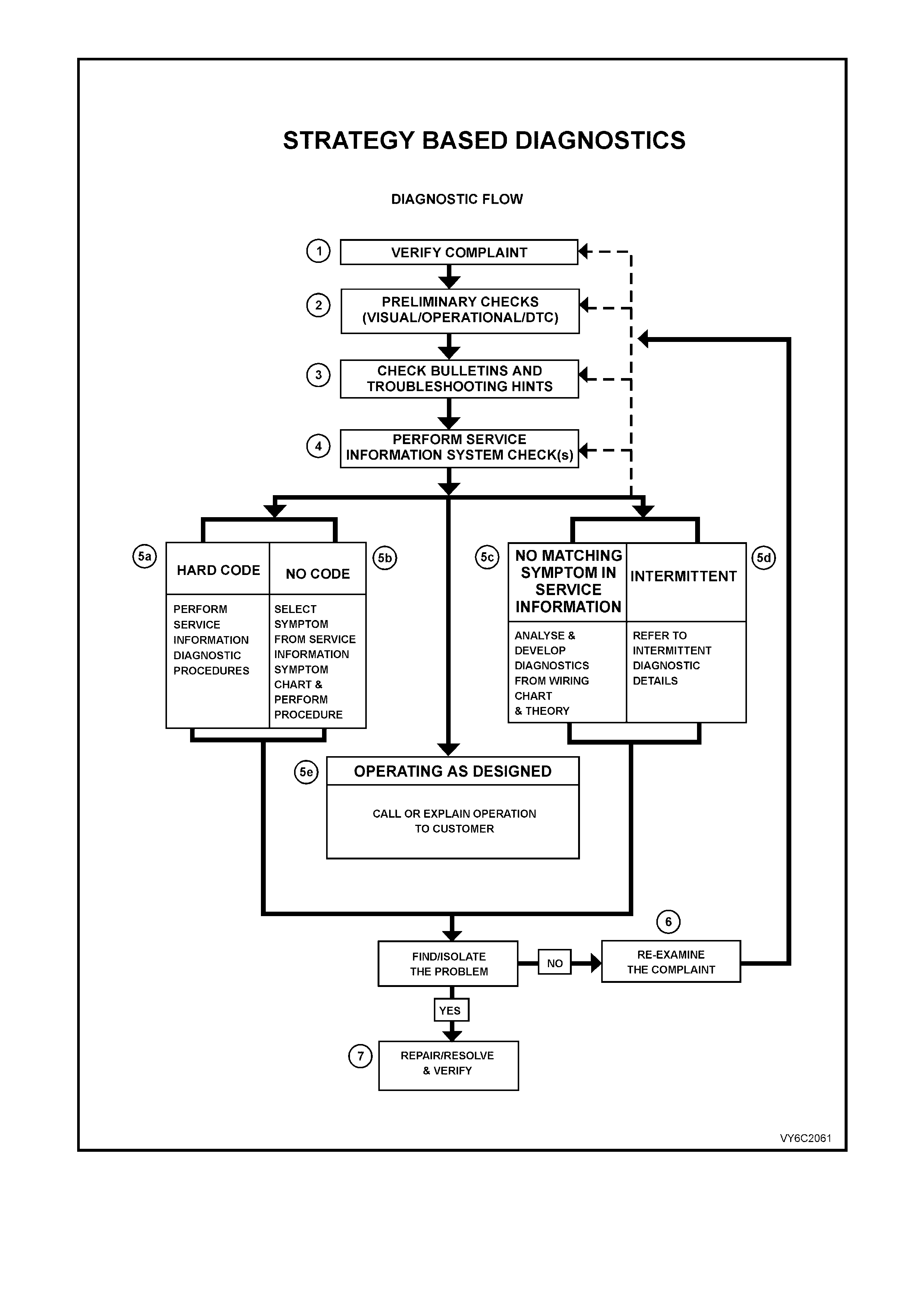
Figure 6C1-2-7 – Strategy Based Diagnostic Table

3. DIAGNOSTIC TROUBLE CODES
CURRENT DIAGNOSTIC TROUBLE CODES
A current diagnostic trouble code is one that is set in the vehicle at this time. The diagnostic trouble code can be
displa yed on T ech 2 b y pressing the a ppropr iate butt on at the a ppro priate m enu. When the diagnostic tr oubl e code
is disp la yed, a code desc riptor will a lso b e liste d on T ec h 2 scr een. Use of the proper diagnos tic trouble cod e table
will find the cause of the problem.
HISTORY DIAGNOSTIC TROUBLE CODE
A history Diagn ostic Trouble Cod e ( DTC) is on e th at was a cur r ent troub le c ode at s ome point prev io us l y, however ,
the fault that caused the diagnostic trouble code to be logged is no longer present. The way to identify whether a
DTC is current or history is to look at the DTC history information parameter "IGN CYCLES". If the number is ‘0’,
the DTC is current, any other num ber means it's a hist ory DT C. . The diagn ostic trouble code c an be displayed on
Tech 2 b y press ing th e proper button at the appropr iat e m enu. Use of th e diag nos tic troub le co de tab les to f ind the
cause of the problem for the history diagnostic trouble code may lead to replacement of good components.
W henever a h istor y code is s et Refer to Sect ion 6 C1- 2B SYM PT OM S and also look at the "D ia gnost ic Aids " lis ted
on the dia gnost ic trou ble codes fac ing page f or c riteri a to set th e DT C. Histor y diagnos tic tr ouble codes are usuall y
caused by intermittent conditions.
HOW DTC HISTORY WORKS
When a DTC is set, up to eleven (11) parameters will always be stored with it. The first four (4) parameters are:
1. "Engine speed" - RPM when DTC set .
2. "Time from start" - how long the engine had been running when the DTC set.
3. Times occurred, - number (#) of DTC occurrences.
4. "Ignition cy cles" - since DTC last appeared.
Depending upon the DTC, up to 7 additional param eters that are related t o this specific DT Cs are also stored, for
example, if DTC P0123 TP sensor circuit high voltage was set, the variable parameters would be: TPS signal, ECT,
Fuel, MAF, Battery Voltage, Reference Voltage and RH LTFT.
HOW TO USE DTC HISTORY CODE INFORMATION
Based upon this information stored in DTC history, the Technician can obtain the DTC criteria when the DTC set
and should be able to get the DTC to become current again by repeating the criteria.
READING DTC'S
The provision for communicating with the PCM is the Data Link Connector (DLC). It is attached to the instrument
panel lower trim, directly beneath the steering column. It is used in the assembly plant to receive information in
checking that the engine and transmission are operating properly before they leave the plant. The diagnostic
trouble code(s) stored in the PCM's memory can only be read by using Tech 2, (a handheld diagnostic scanner
plugged into the DLC).
NOTE: For MY2003 vehicles, there is no flash code capability for powertrain DTCs. Grounding the Diagnostic
Enable circuit (DLC pin #6) will not cause the Check Powertrain MIL to flash diagnostic information.
CLEARING DTCS
To c lear th e c urr ent d iag no s tic trouble c ode f r om the memor y of the PC M, eit her to det er mine if the malf unc tion wil l
occur again or because repair has been completed, the PCM power feed must be disconnected for at least thirty
(30) seconds. The PCM power feed can be disconnected by turning the ignition "OFF" and disconnecting the
negative battery terminal or by removing fuse F29. Tech 2 has a special mode that must be used to clear both
history and current diagnostic trouble codes.
NOTE: To prevent PCM damage, the ignition must be "OFF" when disconnecting or reconnecting PCM power.
CLEARING DTC HISTORY
Tec h 2 is the on l y tool cap able of clear ing the DT C hi stor y. Disconnec ting th e b atter y or rem ovin g fus e F29 wil l not
erase DTC history. Tech 2 sends a special message into the PCM to erase this memory.
PCM SLEEP TEST
After the ignition switch is turned "OFF," the PCM will continue to operate for several seconds. During this shut
down, the PC M will return the IAC back to a position to be used on th e next startup, de-e nergise all the s olenoids
and relays, then the PCM will "go to sleep". The PCM can be checked for this sleep test by monitoring how long
Tech 2 will display updated data before the sleep m ode is activated. Once activated, the PCM will no longer send
out serial data and Tech 2 will display ‘DLC DATA LOST’.

PCM LEARNING ABILITY
The PCM has a "learning" ability which allows it to make corrections for minor variations in the engine or
transmission system to improve driveability.
TR ANSM ISSION ADAPT FUNCTION
The HYDRA-MATIC 4L60-E uses a feedback line pressure control system which has the ability to adapt the
system's line pressure to compensate for normal wear of clutch fibre plates, seals, springs, etc. This "learning"
feature is similar to what is used for engine fuel control, short term fuel correction, long term fuel trim.
The HYDRA-MATIC 4L60-E transmission only uses the adapt function for the 1-2 upshift. The PCM monitors
engine speed to determine if the shift is occurring too fast (harsh) or too slow (soft) and adjusts the pressure control
solenoid to maintain t he corr ect shift feel. T he line pres sure can adapt t o values rang ing from 35 kPa below, to 70
kPa above normal line pressure.
If the batt er y is disc onn ec te d, to cl ear d iag nostic tr o uble c odes or for other r e pair, the " le ar ning " pr oces s res et s and
begins aga in. A c hange m ay be n oted in t he veh icle's perform anc e. To "teac h" the ve hicle, r eset th e IAC va lve and
ensure that the engine is at operating temperature. The vehicle should be driven at part throttle, with moderate
acceleration and idle conditions until normal performance returns.

4. TABLE A V6 ENGINE PCM
ON-BOARD DIAGNOSTIC (OBD) SYSTEM CHECK
STEP ACTION VALUE YES NO
1. 1. Install Tech 2 to Data Link Connector.
2. Select V6 Engine.
Does Tech 2 display Identification Data?
Go to Step 2 Go to Table A-2
in this Section
2. 1. Ignition "ON".
2. Using Tech 2, check for DTC P1255.
Is DTC 31 set?
Go to DTC
P1255 Table Go to Step 3
3. Does engine crank?
Go to Step 4 Go to
Table A-4.0
4. 1. Using Tech 2, select Current DTC(s).
Are any Diagnostic Trouble Codes displayed?
Refer to
Applicable DTC
Table.
Start with lowest
DTC
Go to Step 5
5. Does engine start and continue to run?
Go to Step 6 Go to
Table A-3.1
6. 1. Ignition "ON", engine "STOPPED".
2. Compare Tech 2 data with typical values shown on
Scan Data page.
Are values normal or within typical ranges?
Go to Step 7 Refer to
indicated
"Component(s) –
System" ch ec ks
in this Section.
7. 1. Run engine until normal operating temperature is
reached.
2. Run engine at 1500 revolutions per minute for 2
minutes, then idle engine.
3. Compare Tech 2 data with typical values shown on
Scan Data page in this Section.
Are values normal or within typical ranges?
Refer to
Section 6C1-2B
SYMPTOMS.
Refer to
indicated
"Component(s) –
System "checks
in this Section.
Figure 6C1-2-8 – Example of On-Board Diagnostic System Check

5. POWERTRAIN OBD SYSTEM CHECK
After the visual and physical underhood inspection, the Powertrain OBD System Check is the starting point for all
diagnostic procedures or finding the cause of an emissions test failure.
All diagnostic procedures must always begin with the Powertrain OBD System Check.
Diagnostic procedures must begin with the Powertrain OBD System Check, which represents an organised
approach for identifying system problems.
The POW ERTRAIN OBD SYSTEM CHECK m akes an initial check of the system , then will direct th e technician to
other tabl es in this Vol ume. It m ust be used as a star ting point for all procedures . The entire Volume is set up in a
specif ic order , that is, the P OW ERTRAIN O BD S YSTEM CH ECK wi ll lea d the tec hnic ian t o other ta bles , and those
tables may lead to still other tables. THE SEQUENCE MUST BE FOLLOWED. The engine/transmission control
system uses many input signals and controls many output functions. If the correct diagnostic sequence is not
followed, incorrect diagnosis and replacement of serviceable parts may happen.
Diagnostic tables incor porat e diagnosis pr ocedures using T ech 2 where possib le. This Tech 2 is a sm all hand-held
computer in itself. Its job is to give information to a technician about what is happening in the powertrain
management system.
The Data Link Connector (DLC) is used by the as sembl y plant to perf orm end of line tests. T his c onnector c an also
be used by the Technician to monitor certain inputs and output as seen by the electronic control module. Tech 2
reads and displays the information (serial data) supplied to the data link connector from the Powertrain Control
Module (PCM).
The correct procedure to diagnose a problem is to follow three basic steps:
1. Are the On-Board Diagnostics working?: This is determined by performing the Powertrain OBD System
Check. Since this is the starting point for the diagnostic procedures or finding the cause of a failure, always
begin here.
If the On-Board Diagn os tics ar en't working, t he Po wertrain OBD S ystem Chec k will l ea d to a d iag nostic t ab le in
this Volume to correct the problem. If the On-Board Diagnostics are working correctly, the next step is:
2. Is there a Diagnostic Trouble Code stored?: If a diagnostic trouble code is stored, go directly to the
numbered diagnostic trouble code table in Section 6C1-2A DIAGNOSTIC TABLES. This will determ ine if the
fault is still present. If no diagnostic trouble code is stored, then:
3. Observe Serial Data transmitted by the PCM: This involves reading the information available on the Serial
Data Stream with Tech 2. Inf ormation on this tool and the m eaning of the var ious displa ys can be found i n the
succeeding paragraphs. Typical data readings under a particular operating condition can be found on the "Tech
2 Scan Tool Data" page.
DLC TECH 2
The PCM can communicate a variety of information through DLC connector. This data is transmitted at a high
frequency which requires Tech 2 for interpretation.
TECH 2 EXPLANATION
To ex plain how Tec h 2 works , think for a minute abo ut how a tel evision work s. A televis ion is an el ectronic d evice
that rec eives and proc es ses inf ormation, a nd s ends o ut i nf ormation i n a f or m that can be un der stood b y the pers on
watching it. The television receives a signal (from a transmitting station) that is not useable to the person.
The television processes it, then sends the signal to a screen. The person can then see the information that the
televis ion transm itting station s ent out. Tech 2 is like the televis ion because it a lso proces ses inform ation, sent to it
by the PCM.
The information is sent out of the PCM to the Data Link Connector (DLC) serial data line. Tech 2 plugs into the
Data Link Connector (DLC) , and the inform ation is sent to the tool on its cable. Tech 2 processes the inform ation,
and "sends" the signal to the Tech 2 display screen.
Just like a television, you can select which "station" that you want to see. The difference is instead of seeing the
picture on a television, you "see" the display screen, and the "stations" that you can select on Tech 2 are the
different input and output signals that are being processed by the PCM.
Tec h 2 has the ability to se nd messages back to the PCM to do dif ferent things s uch as switch outp uts "OFF" and
"ON." This allows the Technician to control the PCM but this control only lasts as long as Tech 2 is connected to
the DLC.

5.1 TECH 2 US ES - POWERTRAIN CONTRO L MODULE (PCM)
Tech 2 is a useful and quick way of com paring operating parameters of a poorly operating engine or transmission
with a known good one. For example, a sensor may shift its value but not set a DTC. Comparison with a known
good vehicle may uncover this problem.
Tec h 2 allows a q uick c heck of s ensors and s witches whic h are i nputs to th e PCM. The PC M in the vehicle, sends
out information to Tech 2 at a very fast rate, and the display on Tech 2 can update quicker than a digital multimeter.
Tec h 2 allows the Tec hnician to manipula te wiring har nesses or components under the vehic le while obser ving the
Tech 2 readout. This can help in locating intermittent connections.
After you enter the c orrect vehicle inf ormation, the f irst display on Tech 2 will as k for what type of s ystem to select
from.
The following is a list of systems the Tech 2 will display:
F0: Engine
F1: Tr ansmission
F2: Chassis
F3: Body
F4: Vehicle DTC Check
After selecting “F0: Engine”, Tech 2 will display:
V6
V8 GEN III
Once the correct engine has been selected, Tech 2 will now have seven test modes for diagnosis and service of
the PCM system. The seven test modes are as follows:

MODE F0: NORMAL MODE
In this mode, Tech 2 will display various engine and transmission data and vehicle information.
The following PCM Normal Mode controller usage table, indicates specific Control Modules using the PCM supplied
report status information:
PCM Normal Mode Controller Usage Table
PCM Normal Mode Parameters Used by:
Tech 2 String BCM INST ECC ABS/ETC SRS Audio
Engine Speed √
√√
√
Coolant Temperature √
√√
√ √
√√
√
Intake Air Temperature
Vehicl e Speed √
√√
√ √
√√
√
√
√√
√
A/C Clutch
A/C Pre s su r e √
√√
√
Low Speed Fan Request √
√√
√
Low Fan Run ON √
√√
√
Theft Status √
√√
√
PCM DTC Status √
√√
√
Check Powertrain MIL √
√√
√
MFD Message √
√√
√
Fuel Used √
√√
√
Fuel Flow Rate (Instantaneous) √
√√
√
Engine Type √
√√
√
Transmission Coding
Fuel Type √
√√
√ √
√√
√
Engine Oil Change
Transmission Oil Change
Shift Patte r n √
√√
√
Torque Multiplier
√
√√
√
High Coolant Temperature
Oil Pressur e Sw itch √
√√
√
PRNDL Switch √
√√
√
Commanded Gear √
√√
√
PCM Chime √
√√
√
Table 6C1-2-1
MODE F1: DIAGNOSTIC TROUBLE CODES
In this test mode, DTCs stored by the PCM may be displayed or cleared. When entering this mode there are four
modes: F0. Read Current DTC
F1. Read History DTC
F2: Clear Current DTC
F3: Clear History DTC
MODE F2: DATA DISPLAY
In this test mode, Tech 2 continuously monitors system data, such as: engine speed data, engine coolant
temperature, etc. When entering this mode, there are three modes;
F0: All Data – Displays all engine input and output data.
F1: Inputs – Displays all input data to the PCM.
F2: Outputs – Displays all output data from the PCM.

MODE F3: SNAPSHOT
In this test mode, Tech 2 captures data before and after a snapshot triggering condition which may or may not set a
DTC.
MODE F4: MISCELLANEOUS TESTS
In this test mode, Tech 2 performs PCM software override commands, to help in problem isolation during
diagnostics.
F0: OUTPUT TESTS
F0: Fuel Pump
F1: A/C Clutch
F2: Check Powertrain Lamp
F3: High Fan
F4: Canister Purge
F5: Starter Relay
F1: IAC SYSTEM
F0: RPM Control: used to control engine RPM from 600 RPM to 1675 RPM.
F1: IAC Control: Used to control IAC steps from 0 to 255 in 25 step increments.
F2: IAC Reset: used to reset IAC if the IAC is lost or if IAC has been replaced.
F3: Base Idle: used to set the engine to base idle.
F2: EGR CONTROL
This test will allo w for control of the EGR by increments of 10% to decrease or in crease EGR flow up to 100% on
time.
F3: RESET CELLS
Resets all LT Fuel Trim values to 0%
F4: BYPA SS SPARK
With the engine running, this command turns the bypass control circuit, ON and OFF.
F5: A/F RATIO
With the engine running, forces air fuel ratio from 11.7 to 17.7.
F6: LPG FCV TEST
This test will allow for control of the FCV by increments of 7% to decrease or increase FCV flow up to 100% on
time.
F7: LPG ENABLE TEST
Used to command the LPG enable circuit on and off.
MODE F5: FUNCTION TESTS
This mode performs functional tests on the PCM system which help verify proper operation. In this mode, fault
conditions are automatically logged by Tech 2.
Tech 2 also has the ability to send commands to the PCM, instructing the PCM to perform various functions or
tasks. This provides a quick way to determine if a device is operational or not.
In the F5 mode, the following tests can be performed:
F0: IAC Circuit
Designed to conf irm that the IAC motor functions O K and is not losi ng track of position. Moni tor the engine
speed. Repeatedly cycles the IAC motor in and out and then monitors the engine speed. If OK, then
ignition "OFF" and start repeatedly, then stabilise. If the value of final RPM – initial RPM is greater than a
calibrated threshold, then the IAC circuit has failed.
F1: O2 Sensor
Designed t o confirm ox ygen sensor is funct ioning OK and not bi ased or s low respond ing. Mon itors ox ygen
sensor voltages and cross counts when in "Closed Loop" and forces rich/lean "Open Loop" operation.
F2: Power Balance
Designed to identify low power output from individual cylinders. Automatically cycles each injector "OFF"
then "ON" while monitoring and recording the RPM drop for each cylinder.
F3: Wiring Harness
Designed to confirm no intermittent open or short circuits exist in selected circuits. Engine is at idle in "N".
The Technician should wriggle powertrain harness. Tech 2 monitors inputs that should remain relatively
static at idle such as: ECT, IAT, TP Sensor, VSS, CAM signal present, 18X signal present, EST lines,
injector vo lta ge monitor, ba ttery and ignit io n. If disc ontinuity occur s , T ec h 2 logs the f ailur e an d prompts the
Technician to check the appropriate circuit.

F4: Low Fan
Designed to confirm that the PCM will send a command to the BCM to turn "ON" the low speed fan.
F5: LPG Setup
This is used to lock the vehicle in a fixed state in order for the LPG fuel system mixture adjustment screw to
be adjus ted. The PC M will s et the f oll o wing to a pr e d etermined s ett ing i n or der f or the adj ustment s cr ew t o
be adjusted:
Fixed Spark
IAC Fixed to 800 RPM
Fixed FCV to 40%
MODE F6: STALL DA TA
Designed to capture nine (9) particular data values, when the engine is in a stall condition. This is very similar to
DTC History mode. The PCM will store the first stall condition values, then count the number of stalls after the first.
NOTE: Stall data will be erased from the PCM memory whenever DTC HISTORY DATA is cleared.
TECH 2: Stall Data
SCAN POSITION UNITS DISPLAYED
Engine Speed RPM
Time Fro m Start Time
Times Occurred Number
Igniti on Cycles Number
Coolant Temperature Degrees
Idle Air Contr o l STEPS
Vehicl e Speed km/h
Battery Voltage Volts
Throttle Position Sensor 0-100%
A/C Request No/Yes
Fuel Petrol / L PG
TECH 2: USE WITH INTERMITTENT FAULTS
Tec h 2 allows m anipu lat io n of wiring harness es or c o mponents und er th e bonnet with the engi ne not runnin g, wh il e
observing the Tech 2 readout.
Tec h 2 can be plugge d in and obs erve d while dri ving the v ehicle und er the cond ition when the "C heck Powe rtrain"
MIL turns ON mom entarily or when the eng ine driveab ility is m omentaril y poor. If the problem seems to be relat ed
to certain parameters that can be checked on Tech 2, they should be checked while driving the vehicle. If there
does not s eem to be an y connection bet ween the problem and an y specif ic circuit, T ech 2 can be use d to m onitor
each parameter, watching for a period of time to see if there is any change in the readings that indicates an
intermittent condition.
Tec h 2 can capture and s to r e data when the pr o blem occ urs , s o it can be played back at a s lower rate to d ete rmine
what happened to the system. This is called the "SNAPSHOT" mode.
Tech 2 is an easy way to compare the operating parameters of a poorly operating engine with those of a known
good one. F or ex ample, a sensor ma y shift in value but not s e t a DTC. Com par ing the s ensor 's r e adi ngs with t hos e
of a known good vehicle may uncover the problem.
Tec h 2 saves tim e in diag no sis and h elps to prevent t he replac em ent of s ervicea ble par ts. T he ke y to using Tec h 2
successfully is the Technician's ability to understand the system being diagnosed, as well as understanding the
Tech 2 operation and limitations. The Technician should read the Tech 2 Operator’s Manual to become familiar
with the Tech 2 operation.
With an understanding of the data which the tool displays, and knowledge of the circuits involved, Tech 2 can be
very useful in obta in ing info rmation which wou ld be m or e diff icult or imposs ible to obta in with other equi pment.
Tec h 2 does not m ake the use of diagnos tic tables unnec essar y, nor can it in dica te exactl y where a pr oblem is in a
particular circuit. Diagnostic Tables incorporate diagnosis procedures that require the use of Tech 2.

TECH 2: LIMITATIONS
Tech 2 must receive a signal from the PCM in order to display any useable information. If the PCM sends no
signals to the DLC, or the c onnection to Tech 2 is defectiv e, Tech 2 will onl y dis play, "W AITING FOR DATA - NO
DATA RECEIVED FROM PCM." The Powertrain OBD System Check instructs the Technician what to do if this
happens.
Tec h 2 has a few limitatio n s. If Tech 2 is dis p laying a PCM "o utpu t" funct ion, it di s plays onl y the com mand g iven by
the PCM. That does not mean that the desired action took place. This is similar to the automatic transmission
dashboar d gearshif t indicat or. Just bec ause the gearshif t P R N D L poin ter indic ates the trans mis sion is in DRIV E
does not mean that the transmission is actually in that gear. To be sure, you must check the linkage and
adjustment at the transmission.
When using Tech 2 to observe one of the PCM "output" functions, such as an idle air control motor, or a TCC
solenoid, the Technician must not assume that the ‘indicated’ is the same as the ‘actual’. If Tech 2 is displaying
TCC s olenoid as be ing "O N," but the wire to power it is discon nected or defecti ve, the PCM in s ome ca ses has no
way of knowing it. The display may indicate the command is "ON," but the device may not be operating!
Tec h 2 saves tim e in diag no sis and h elps to prevent t he replac em ent of s ervicea ble par ts. T he ke y to using Tec h 2
successfully for diagnosis is the Technician's ability to understand the system being diagnosed, as well as an
understanding of Tech 2's limitations.
W ith an understan ding of the data that T ech 2 displa ys, and knowledge of the circuits in volved, Tec h 2 is useful in
obtaining inf or mation whic h is diff ic ult or im pos s ible to re trie ve with oth er m ethods .
Remember, Tech 2 does NOT make using diagnostic tables unnecessary, nor can it tell you exactly where a
problem is in a circuit. Most diagnostic tables incorporate diagnosis procedures that require the use of Tech 2.

5.2 TECH 2: PCM NORMAL MODE
The Tech 2 ‘Normal Mode’ in the table may be used for comparison if a status report is being sent from the PCM:
1. After completing the Powertrain OBD System Check.
2. Finding the on-board diagnostics are functioning properly and
3. No diagnostic DTCs are displayed.
IMPORTANT: A Tech 2 that displays faulty data should not be used and the problem should be reported to
the manufacturer. The use of a faulty Tech 2 can result in misdiagnosis and unnecessary parts
replacement.
Only the parameters listed are used in this Section for diagnosis. For more description on the values and use of
Tec h 2 to di agn ose P C M in puts, ref er to th e ap pl ic ab le dia gnosis tab le in Section 6C1-2A DI AGNOST IC TABLES.
If all values are within the range illustrated, refer to Section 6C1-2B SYMPTOMS.
Test Description: The number(s) below refer to the number(s) on the Tech 2., ‘PCM Normal Mode’ table header.
1. DATA PARAMETER:– Tech 2 can display nine (9) data parameters at any one time. The down arrow button
will scroll down through all of the data parameters one at a time. After the last data parameter is displayed,
pressing the down arrow button again, will display the fist data parameter, once again.
2. UNITS DISPLAYED are th e ways/units that each par ameter will be displayed, w hich is the value that is being
sensed or being is sued b y the PCM.
3. TYPICAL DATA VALUE is separated into two parts. These displayed values are typical of a normally operating
vehicle . T he ‘IGNITION O N ’ c omparis on should be performed f irs t as this may lea d to a quick identificati on of a
failure. T he ‘ENGIN E RUN NING’ data s hould be com pared to th e ‘IGNIT ION ON ’ data as a diagn ostic c heck to
make sure the component or system is operating properly.
4. IGNITION ON values are the typical values that should be seen on Tech 2 with the ignition ON and engine
stopped. T emperature sensors should be com pared to the actual tem peratures (e.g. coolant, air, transmission
fluid) b y allowing the sens or to coo l overnig ht and the n com paring their valu es. A diff erence of 3-5° C f rom the
actual temperature may indicate a problem with the sensor. Use the diagnostic aids table for that sensor to
compare the resistance to temperature values.
5. ENGINE RUNNING typical data values are an average of display values recorded from a normally operating
vehicles at normal operating temperature. They are intended to represent what a normally functioning system
would typically display.

TECH 2: PCM NORMAL MODE
TYPICAL DATA V ALUE S
DATA POSITION Q UNITS DISPLAYED R IGNITION ON T ENGINE RUNNING U
Engine Speed RPM 0 RPM 600 – 650 RPM (± 50 RPM In Drive)
Coolant Temperature ° C Varies Varies
Intake Air Temperature ° C Varies Varies
Vehicl e Speed km/h 0 0
A/C Clutch On /Off Off Off
A/C Pressure kPa 896 kPa 400 – 1000 kPa A/C Off
500 – 1900 kPa A/C On
Low Speed Fan Request On / Off OFF OFF
Low Fan Run on Yes / No NO NO
Theft Status No Start / Start START START
PCM DTC Stat us No DTC / DTC Set No DTC(s) No DTC(s )
Check Powertrain Lamp Off/On On Off
MFD Message Yes/No No No
Fuel Used L 00.00 Varies
LPG Used L Varies
Fuel Flow Rate L/Hour 00.00 Varies
Engine Type V6, V8,
V6 Supercharged,
GEN III V8 V6 V6
Transmissi on Codi ng Manual Trans.
Automatic Trans. Manual Trans.
Automatic Trans. Manual Trans.
Automatic Trans.
Fuel Type Petrol / LPG Petrol Petrol
Engine Oil Change Okay /
Service Requi red Okay Okay
Transmission Oil Change Okay /
Service Requi red Okay Okay
Shift Pattern Power/Economy Economy Economy
Torque Multiplier Ratio 0 13
High Coolant Temperature Yes/No No No
Oil Pressure Switch Off/On Off Off
PRNDL Switc h Invalid / P,R,N,D,3,2,1 Invalid or Gear
Selected Invalid or Gear Selected
Commanded Gear 1, 2, 3, 4 1 Gear 1 Gear
PCM Chime Yes/No Yes Yes
Table 2

TECH 2: PCM NORMAL MODE DESCRIPTIONS
A list of explanations for each data message displayed on Tech 2 is listed below. This information will assist in
diagnosi ng emiss ion or dr i v eab ility problems . The dis pl a ys can be vi e wed whi le th e veh icl e is bei ng dri ve n. R efer to
“Powert rain OBD S ystem Check” for additional information.
ENGINE SPEED: Tech 2 Displays a range of 0 to 9999 RPM
The engine speed is computed by the PCM from the crankshaft reference input. It should remain close to desired
idle speed under various engine loads with engine idling.
COOLANT TEMPERATURE: Tech 2 Displays a range of -39° C to 140° C
The Engine Coolant T emperature (ECT) sensor is mounted in the c ylinder head of the left bank . The PCM apples
5.0 volts to the ECT sensor circuit. The sensor is a thermistor which changes internal resistance as temperature
changes. W hen the s ensor is co ld (in terna l res istanc e hig h), th e PCM m onitors a high s igna l vo ltage and in ter prets
the voltage as a cold engine. As the sensor warms (internal resistance decreases), the voltage signal decreases
and the PCM interpr ets the lo wer vo lta ge as a warm engin e.
INTAKE AIR TEMPERATURE: Tech 2 Displays a range of -40° C to 148° C
The Intake Air Temperature (IAT) sensor is mounted in the rear of the upper air cleaner housing and senses the
temperature of the incoming air. The PCM apples 5.0 volts to the IAT sensor circuit. The sensor is a thermistor
which ch anges inter nal res istance as tem perature cha nges. W hen the se nsor is c old (int ernal res istance h igh), the
PCM monitors a high signal voltage and interprets the voltage as cold intake air. As the sensor warms (internal
resistance decreases), the voltage signal decreases and the PCM interprets the lower voltage as warm intake air.
VEHICLE SPEED: Tech 2 Displays a range of 0 to 255 km/h
The vehicle speed sensor signal is converted into km/h for display.
A/C CLUTCH: Tech 2 Displays "ON" or "OFF"
Represents the commanded state of the A/C clutch control relay. Clutch should be engaged when ON is displayed.
A/C PRESSURE: Tech 2 Displays a range of 0 to 3195 kPa
The kPa displayed indicates that the PCM is monitoring an A/C Refrigerant Pressure signal voltage which is too
high or too low to allow the A/C compressor clutch to engage.
LOW SPEED FAN REQUEST: Tech 2 Displays "ON" or "OFF
Indicates if the engine cooling fan low speed relay has been commanded ON or OFF.
LOW FAN RUN ON: Tech 2 Displays "NO" or "YES"
This indicates if the PCM is requesting the BCM to turn the Low Speed Fan ON at key OFF.
THEFT STATUS: Tech 2 Displays "NO START" or "START"
Indicates the status of the Theft Deterrent System.
PCM DTC STATUS: Tech 2 Displays "NO DTC(s)" or “DTC SET”
Indicates if a DTC is set. This does not indicate what DTC is set, just informs that DTCs are or are not set.
CHECK POWERTRA IN MALFUNCTION INDICATOR LAMP (MIL): Tech 2 Displays "OFF" or "ON"
Indicated if the instrument panel Malfunction Indicator Lamp is ON or OFF.
MULTI-FUNCTION DISPLAY MESSAGE: Tech 2 displays either Yes or No
The PCM can send extra messages to the Instrument, Multi-Function Display (MFD).
FUEL USED: Tech 2 Displays a range of 0 to 1000 Litres
When the key is turned ON, and the engine is running, the PCM will calculate ‘Fuel Used’ during each ignition
cycle.
LPG USED: Tech 2 Displays a range of 0 to 1000 Litres
When the vehicle is equipped with this fuel type, and the engine is running, the PCM will calculate ‘Fuel Used’
during each ignition cycle.
FUEL FLOW RATE: Tech 2 Displays a range of 0 to 100 litres
Indicates fuel consumption per litres per hour.
ENGINE TYPE: Tech 2 Displays Engine Type
The Tech 2 uses this information for proper Tech 2 software.
TRANSMISSION CODING: Tech 2 Displays “MANUAL” or “AUTOMATIC”
The Tech 2 uses this information for proper Tech 2 software.
FUEL TYPE: Tech 2 Displays “PETROL” or “LPG”
The scan tool will display what fuel type the PCM software is set up for.
ENGINE OIL CHANGE: The Tech 2 Displays “OKAY” or “SERVICE REQUESTED”
The scan tool will display the status of the engine oil change condition. This display is currently not in use.

TRANSMISSION OIL CHANGE: The Tech 2 Displays “OKAY” or “SERVICE REQUESTED”
The scan tool will display the status of the transmission oil change condition. This display is currently not in use.
SHIFT PATTERN: Tech 2 Displays “ECONOMY” or “POWER”
This display shows the state of the POWER/ECONOMY switch.
TORQUE MULTIPLIER: Tech 2 Displays a range of 0 to 13
The display shows a calculated value derived from the Transmission Slip and Commanded Gear values. The
calcula ted va lue is used b y the ABS/ ET C m odule.
HIGH COOLANT TEMPERATURE: Tech 2 Displays "NO" or "YES"
This is an indication to the PCM that the engine is running hot.
LOW COOLANT LEVEL: Tech 2 Displays "NO" or "YES"
This is an indicat ion to the PCM th at the coo lant le vel i s low, and th e PCM wil l turn on the Lo w Coo lant lam p. (O nly
with GEN III V8 Engine).
OIL PRESSURE SWITCH: Tech 2 Displays "OFF" or "ON"
This is an indica tion to t he PCM if the oil pres sure is high or low. If the o il pressur e is lo w, the PCM will activ ate a
“Check Oil” icon in the Instrument Multi-Function Display (MFD).
PRNDL SWITCH: Tech 2 Displays “INVALID” or “P, R, N, D, 3, 2, 1”
This displa ys if th e veh icle i s not e quippe d with a PRN DL s witch (IN VALID) , or if equ ipped, indicat es what g ear the
driver has selected.
COMMANDED GEAR: Tech 2 Displays “1, 2, 3, 4”
The gear that the PCM is commanding the transmission to be in. In PARK, the Tech 2 will display "1", the
commanded state of the shift.
PCM CHIME: Tech 2 Displays "NO" or "YES"
This is a indication to the instrument panel allowing the instrument panel to chime if a problem or fault is detected.

5.3 TECH 2: ENGINE DATA DISPLAY – ALL DATA
The Tech 2 Engine Data listed in the following table may only be used for comparison:
1. After completing the Powertrain OBD System Check.
2. Finding the on-boar d dia gn os tic s are func tio ning properly and
3. No diagnostic DTCs are displayed.
A TECH 2 THAT DISPLAYS FAULTY DATA SHOULD NOT BE USED, AND THE PROBLEM SHOULD BE
REPORTED TO THE MANUFACTURER. THE USE OF A FAULTY TECH 2 CAN RESULT IN MISDIAGNOSIS
AND UNNECESSARY PARTS REPLACEMENT.
Only the parameter s lis ted ar e used in this Vo lume f or diagnosis . F or mor e desc r iption on th e va lues and use of the
Tech 2 to diagnosis PCM inputs, refer to the applicable diagnosis table in S ectio n 6C1-2A DIAGNOST IC T ABLES.
If all values are within the range illustrated, refer to Section 6C1-2B SYMPTOMS.
Test Description: The number(s) below refer to the number(s) on the ‘Tech 2 Engine Data Display’ table.
1. DATA PARAMETER:– Tech 2 can display nine (9) data parameters at any one time. The down arrow button
will scroll down through all of the data parameters one at a time. After the last data parameter is displayed,
pressing the down arrow button again, will display the fist data parameter, once again.
2. UNITS DISPLAYED are th e ways/units that each par ameter will be displayed, w hich is the value that is being
sensed or being is sued b y the PCM.
3. TYPICAL DATA VALUE is separated into two parts. These displayed values are typical of a normally operating
vehicle . T he ‘IGNITION O N ’ c omparis on should be performed f irs t as this may lea d to a quick identificati on of a
failure. T he ‘ENGIN E RUN NING’ data s hould be com pared to th e ‘IGNIT ION ON ’ data as a diagn ostic c heck to
make sure the component or system is operating properly.
4. IGNITION ON values are the typical values that should be seen on Tech 2 with the ignition ON and engine
stopped. T emperature sensors should be com pared to the actual tem peratures (e.g. coolant, air, transmission
fluid) b y allowing the sens or to coo l overnig ht and the n com paring their valu es. A diff erence of 3-5° C f rom the
actual temperature may indicate a problem with the sensor. Use the diagnostic aids table for that sensor to
compare the resistance to temperature values.
5. ENGINE RUNNING typical data values are an average of display values recorded from a normally operating
vehicles at normal operating temperature. They are intended to represent what a normally functioning system
would typically display.

TECH 2: ENGINE DATA DISPLAY
TYPICAL DATA V ALUE S
DATA PARAMETER Q UNITS DISPLAYED R IGNITION ON T ENGINE RUNNING U
Engine Speed RPM 0 RPM 735
Desired Idl e Speed RPM 0 RPM 725
ECT Sensor Volts Varies 1.92 volts
Coolant Temperat ure degrees C Varies 92° C
IAT Sensor Volts Varies 2.29 – Varies
Intake Air Temperature degrees C Varies 31° C – Varies
MAF Sensor Hz 0 Hz 2200 – 2500 Hz
Mass Air Flow gram/sec 0 g/s 4 – 9 g/s
Mass Air Flow Per Cylinder milligram/sec 0.0 mg/s 135 to 150 mg/s
TPS Signal Volts 0.57 V 0.57 V
Throttle Angle 0-100 % 0 % 0 %
Right O2 Sensor Ready Yes/No No Yes
Left O2 Sensor Ready Yes/No No Yes
Right 02 Sensor mV 447 mV 100 – 1000 mV and Varying
Left O2 Sensor mV 447 mV 100 – 1000 mV and Varying
Right Short Term Fuel Trim + 100% to –100% +0% + 0% +10% to –10%
Left Short Term Fuel Trim + 100% to –100% +0% + 0% +10% to –10%
Right Long Term Fuel Trim + 100% to – 100 % + 0 % + 0 % + 10% to – 10%
Left Long Term Fuel Trim + 100% to – 100 % + 0 % + 0 % + 10% to – 10%
LTFT Enabled Yes / No No Yes
Fuelling Mode Open/ Closed Loop Open Loop Closed Loop
LTFT Cell Cell # 0 0
Right O2 Status Rich / Lean Lean Rich/Lean and Varying
Left O2 Status Rich / Lean Lean Rich/Lean and Varying
Right O2 Cross Counts Counts 0 0 -– 10
Left O2 Cross Counts Counts 0 0 -– 10
STFT Delta 0 – 100 % 0 % Varies
LTFT Delta 0 – 100 % 0 % Varies
Decelerati on Fuel Cutoff No/Yes No No
Injector Puls Width ms 27.5 ms 3.25 ms
Injector V olt age Volts 11.4 V 14.0 V
Air / Fuel Ratio % 0. 0 : 1 14.7 : 1
Canister Purge PWM % 0 % 0% – 10 %
EGR Position Commanded % 0% 0%
EGR Position Feedback % 0% 0%
EGR Pintle Sensor Volts 0.6 V 0.6 V
Battery Voltage Volts 11.3 V 14.0 V
Reference Volts Volts 4. 99 V 5.0 volts
3X SIGNAL Missing / Present Missing Present
18X Signal Missing / Present Missing Present
Cam Signal Missing / Present Missing Present
Idle Air Control Steps 169 Steps 22 Steps
Litres Per Hour Litres/ Hour 00.00 1 - 2 L/Hour
Idle RPM Variat i on RPM 0 RP M 100 RPM
Spark Mode Bypass/EST Bypass EST
Spark Advance Degrees BTDC 14 ° BTDC + 20° CA
Knock Signal Cyl i nder 1 None/Knock Detect ed None None
Knock Signal Cyl i nder 2 None/Knock Detect ed None None
Knock Signal Cyl i nder 3 None/Knock Detect ed None None
Knock Signal Cyl i nder 4 None/Knock Detect ed None None
Knock Signal Cyl i nder 5 None/Knock Detect ed None None

TYPICAL DATA V ALUE S
DATA PARAMETER Q UNITS DISPLAYED R IGNITION ON T ENGINE RUNNING U
Knock Signal Cyl i nder 6 None/Knock Detect ed None None
Knock Signal Any Cylinder None/Knock Detected None None
Knock Ret ard Yes/No No No
Knock Ret ard Cylinder 1 # of Degrees 0 ° 0 °
Knock Ret ard Cylinder 2 # of Degrees 0 ° 0 °
Knock Ret ard Cylinder 3 # of Degrees 0 ° 0 °
Knock Ret ard Cylinder 4 # of Degrees 0 ° 0 °
Knock Ret ard Cylinder 5 # of Degrees 0 ° 0 °
Knock Ret ard Cylinder 6 # of Degrees 0 ° 0 °
TCC Solenoid On / Off Off Off
Vehicl e Speed km/h 0 km/h 0 km/ h
A/C Request On /Off Off On/Off
A/C Clutch On /Off Off On/Off
A/C Pressure Sensor Volts 1 – 2 V 1 – 2 V
A/C Pressure kPa 352 kPa 600 – 700 kPa A/C Off
800 – 1000 kPa A/C On
High Speed Fan On / Off Off Off
Low Speed Fan Request On / Off Off On/Off
Theft Status No Start/Start Start Start
Starter Relay Off/On On Off
Fuel Pump Relay On / Off Off On
Crank Time Seconds 0.0 sec 0.3 s ec
DTC Status No DTC / DT C Set No DTC(s) No DTC(s)
Time From Start Time 0:00:00 Varies
Check Powertrain Lamp Off/0n Off Off
Requested Torque Nm 214 Nm 476 Nm
(will decrease with engine load)
Actual Torque Nm 0 Nm 15 – 30 Nm
(will closely follow requested torque once
engine load is detected)
Low Oil Pressure No/Yes Yes No
-
--
- LPG Swi tch Off/On Off Off
-
--
- LPG Fuel Enabled No/Yes No No
-
--
- Fuel Petrol / L PG Petrol Petrol
-
--
- LPG Fuel Control Valve 0 – 100 % 0% 0%
-
--
- LPG Mode Enabled No/Yes No No
-
--
- LPG Low Petrol Cutout No/Yes No No
-
--
- LPG Smart Solenoid Enabled No/Yes No No
-
--
- These data displays only apply to those vehicles equipped with Liquefied Petroleum Gas (LPG) fuel.

TECH 2: ENGINE DATA DESCRIPTIONS
A list of explanations for each data m essage displayed on T ech 2 begins as f ollows. This inform ation will assist in
track ing down em iss ion or driv eabil it y problem s, s ince the disp la ys can be viewe d while th e vehic le is be ing driven.
Refer to the "On-Board Diagnostic System Check" for additional information.
ENGINE SPEED - Range 0-9999 RPM - Engine speed is computed by the PCM from the fuel control reference
input. It should remain close to desired idle under various engine loads with engine idling.
DESIRED IDL E - Range 0- 3175 R PM - The idle s peed that is c omm anded b y the PCM. The PC M will c om pensate
for various engine loads to keep the engine at the desired idle speed.
ECT SENSOR VOLTS/ENG COOLANT TEMP - Range –40°
°°
° to 151°
°°
° C/ 0 – 5 VOLTS - The Engine Coolant
Tem perature (ECT) sens or is mounted in the in let manifold a nd sends engi ne temperatur e information to the PCM
applies 5 volts to the coolant temperature sensor circuit. The sensor is a thermistor which changes internal
resistance as temperature changes. When the sensor is cold (internal resistance high), the PCM monitors a high
signal vol tag e whic h it inter p rets as a cold engin e. As the sens or war ms (internal r esis tanc e decr eas es) , the v olta ge
signal will increase, the voltage signal will decrease and the PCM will interpret the lower voltage as a warm engine.
IAT SENSOR VOLTS/IAT - Range -40°
°°
° to 151 °
°°
° C – The PCM converts the res istanc e of the intake air temperatur e
sensor to d egrees. Intak e Air Te mp (IAT) is used by the PC M to adjust fuel deliver y and spark tim ing accordin g to
incoming air density.
M AF SENSOR FREQUENCY - Range 0-10,192 Hz - The s ignal that is sent fr om the Mas s Air Flo w (MAF) s ensor
to the PC M is in the f orm of a f requenc y outp ut. This freque nc y output c hanges a s the d em and of engi ne air intak e
changes.
MASS AIR FLOW - Range 0-246 grams/sec. - The Mass Air Flow (MAF) sensor measures the change in the
intake air flow which results from engine load and speed changes. As intake air flow increases, the air in the inlet
manifold also increases and addition fuel is required.
MASS AIR FLOW/CYL - Range 0-1000 mg/S. - Calculated air flow per each cylinder.
TPS SIGNAL - Range 0 to 5.10 Volts - Used by the PCM to determine the amount of throttle demanded by the
driver. Should read 0.25 - 1.25 volt at idle to above 4 volts at wide open throttle.
TPS ANGL E - Range 0-100% - Com puted b y the PCM f rom TP s ensor voltag e (T hrottle Position) should r ead 0%
at idle, 100% at Wide Open Throttle (WOT).
RH/LH OXYGEN SENSOR RE ADY - Tech 2 Displays "YES" or "NO". Indica tes if the 02 sensors have reached
operating temperature.
RH/LH OXYGEN SENSOR - Range 0-1192 - Represents the exhaust sensor output voltage. Should fluctuate
constant ly withi n a r ange b etween 1 00 m V (Lea n exh aust) an d 1000 m V (R ich e xhaus t) whe n operat ing i n " Closed
Loop".
ST FUEL TRIM R/L - Range -100% -0% -+ 100% - Short Term F uel Trim repr esents a s hort-term correc tion to fuel
deliver y b y the PCM in res ponse to the amount of time the oxygen sensor voltage spends above or belo w the 450
mV thr es hold. If the oxygen s ens or v olt age has mainly been be lo w 45 0 mV, ind ica ting a lea n a ir /f uel mixtur e, STFT
will increase to tell the PCM to reduce fuel delivery to compensate for the indicated rich condition. Under certain
conditions such as extended idle and high ambient temperatures, canister purge may cause STFT to read less than
–10%.
LT F UEL TRIM R/L -100% - 0% - +100 % – LT FT is derive d b y the PCM from the ST FT value and is used f or long-
term correction of fuel delivery. A value of 0% indicates that fuel delivery requires no compensation to maintain a
14.7:1 air/fuel rat io. A valu e be low 0 % m eans th at the fuel syst em has been ric h and fuel deli ver y is be ing r educed
(decreas ed injector pulse width) to m aintain a 1 4.7 to 1 A/F rati o. A value abov e 0% indicates that a lean c onditio n
exists and the PCM has been compensating by adding fuel (increased injector pulse width). LTFT tends to follow
STFT, a value of less than -10% due to canister purge at idle should not be considered unusual.
LTFT EN ABLE - T ech 2 D ispla ys "Y ES" o r "NO ". - The Long T erm Fuel T rim is enable b y the PCM when a lon g
term fuel correction is required. A YES indicates that the LTFT is enabled, a NO indicates that is not.
FUELLING MO DE - Tech 2 Displays "O PEN" o r "CLOSED " - "Close d Loop" d ispla yed indicat es that the PCM is
controlling fuel delivery according to oxygen sensor voltage. In "Open Loop", the PCM ignores the oxygen sensor
voltage and bases the amount of fuel to be delivered on TP Sensor, coolant and IAT sensor inputs only. "Closed
Loop" operation should begin when the 02 sensor be comes active, engine coolant tem perature exceeds 50° C for
more than 30 seconds and the PCM has seen a RPM of 1200 or greater for 10 seconds. At extremely high
temperature or when towing a trailer, it is possible for the system to remain in "Open Loop" operation to control
catalytic converter temperatures.
LONG TERM FUEL TRIM CELL (LTFT CELL) - Range 0-34 - LTFT cell is dependent upon engine speed and
m ass air f low readi ngs and canis ter pur ge. A plot of RPM vs MAF is brok en int o 34 cel ls. LT FT cell indic ate s wh ich
cell is curr ently active.
RH/LH 02 ST ATUS - Tech 2 Displays "RICH" or "LEAN" - Indicates whether exhaust ox ygen sensor voltage is
above (r ich) or be low ( lean) the 45 0 m V ox ygen sensor threshol d volt age. Sh ould change c onstant l y indicat ing tha t
the PCM is controlling the air/fuel mixture properly.

RH/LH O2 CROSS CNTS - Range 0-255 - The number of times the oxygen sensor voltage crosses over the
rich/lean threshold during a two second interval.
STFT /LTFT DELT A - Range 0-100 %. - T he diff erence ( Delta) in % of the ST FT/LT FT counts f rom eac h bank . This
value is used by the PCM to determine bank to bank fuel trim balance.
DECEL FUEL CUTOFF - Tech 2 Displays "YES" or "NO" - Yes displayed indicates that the PCM has detected
conditions appropr iate to operate in deceleration fuel m ode. The PCM will command deceleration fuel mode when
a sudden dec reas e in t hr ott le pos i tio n has be en det ec t ed while th e ve hicle is trav e ll ing o ver a c erta in k m/h. While in
decelerati on fuel mode, t he PCM will d ecrease the am ount of fuel del ivered by en tering open loop and decreas ing
the injector pulse width.
INJ. PULSE WIDTH TIME - Range 0.0 - 999.9 ms. - The "ON" time of the injector as determined by the PCM.
INJECTOR VOLTAGE - Range 0 - 14.0 Volts. System voltage monitoring
AIR/FUEL RATIO - Range 0.00 : 99.99 - The reading reflects the commanded value. This should be at or near
14.7. A lower number indicates a richer commanded air fuel mixture while a higher number indicates a leaner
mixture.
PURGE PW M - Ran ge 0 - 100% - A proport ional sign al used to contr ol EV AP Canister Purge func tion. 0% implies
the valve is commanded fully closed, while 100% implies that the value is fully open.
EGR POSITION COMMANDED - Range 0 - 100% - Represents the EGR pintle position that the PCM is
commanding. Desired EGR position should stay close to EGR Pintle Position.
EGR POSITION FEEDBACK - Range 0% - 100% - Represents the actual position of the EGR pintle in percent.
0% displayed indicates a fully extended pintle (EGR valve closed).
EGR PINTLE SENSOR - Range 0.0 - 5.0 Volts - Repr esents the v oltage that th e PCM uses to de termine weathe r
or not the EGR valve is fully closed (0% pintle position).
BATTERY VOLTAGE - Range 0-25.5 volts - This represents the system voltage measured by the PCM at its
ignition No. 1 feed.
REFERENCE VOLTS - Range 0-5.10 Volts - Indicates the voltage that is supplied to various sensors from the
PCM.
3X SIGNAL - Range Missing or Present - Signal indicates crankshaft position for correct ignition coil sequencing.
18X SIGNAL - Range Missing or Present – Signal indicates the position of the crankshaft within the 3X cycle.
CAM SIGNAL - Range Missing or Present - Signal sent to the PCM by the Cam Sensor. This indicates
movement of the camshaft. This signal is used by the PCM to indicate if the engine is running.
IAC POSITION - Range 0-255 Counts - Displays the commanded position of the idle air control pintle in counts.
The higher the number of counts, the greater the commanded idle speed. Idle air control should respond fairly
quickly to changes in engine load to maintain desired idle RPM.
LITRES Per Hour - Range 0-100 - Indicates fuel consumption per litres per hour.
IDLE RPM VARIANT - Range 0-9999 RPM - Indicates the variation in RPM between sampling's of the engine
speed.
SPARK MODE - Tech 2 displays "BYPASS" or "EST" - Indicates what mode of ignition timing the vehicle is
operating under.
SPARK ADVANCE - Range –90°
°°
° to +90°
°°
° – This is a display of the spark advance (EST) calculation which the
PCM is programming into the ignition system. It computes the desired spark advance using data such as engine
temperature, rpm, load, vehicle speed, and operating mode.
KNOCK SIGNAL CYLINDER (1 THROUGH 6) - Tech 2 Displays NONE or knock detected – This signal
indicates what cylinder is knocking.
KNOCK SIGNAL - Tech 2 Displays "KNOCK" or "NONE" – Indicates whether or not a knock signal is being
detected by the PCM. Should read "NONE" at idle.
KNOCK RETARD - Range 0°
°°
° - 90°
°°
° – Indicates the amount of spark advance the PCM is removing from EST in
response to the Knock sensor (ESC) signal. Should read 0 degrees at idle.
KNOCK RETARD CYLINDER (1 THROUGH 6) - Range 0°
°°
° – 90°
°°
° – Indicates the amount of spark advance the
PCM is removing from each cylinder in response to the Knock sensor (ESC) signal. Should read 0° at idle.
TCC SOLENOID - Tech 2 Displays "ON" or "OFF". - Indicates if the transmission TCC Solenoid is comm anded
the TCC ON or OFF.
VEHICLE SPEED - Range 0-255 km/h - The vehicle speed sensor signal is converted into kph and mph for
display.
A/C REQU EST - Tech 2 Disp lays "Y ES" o r "NO" - Repres ents the s tate of the A/C r equest s erial data in put f rom
the BCM.
A/C CLUTCH - Tech 2 Displays "ON" or "OFF" - Represents the commanded state of the A/C clutch control
relay. Clutch should be engaged when "ON" is displayed.

A/C PR ESSUR E - T ech 2 Disp lays 0. 0 – 5.10 Volts - Repres ents the A /C ref rig erant press ure Sensor signal. T he
amount of pressure indicates the amount of load that the A/C compressor is placing on the engine.
The PCM uses this information to adjust idle speed and to control the cooling fan.
A/C PRESSURE - Range 0 - 3195 kPa - The kPa displayed indicates that the PCM is monitoring an A/C
Refrigerant Pressure signal voltage which is too high or too low to allow the A/C compressor clutch to engage.
HIGH SPEED FAN - Tech 2 Displays "ON" or "OFF - Indicates if the engine cooling fan high speed relay has
been commanded ON or OFF.
LOW SPEED FAN REQUEST - Tech 2 Displays "ON" or "OFF - Indicates if the engine cooling fan low speed
relay has been commanded ON or OFF.
THEFT STATUS - Tech 2 Displays "NO START" or "START". - Indicates the status of the Theft Deterrent
System.
ST ARTER REL AY - Tech 2 Displays "OF F" or "ON" - If Tec h 2 indicates ON, then the veh icle will start. As long
as the Theft Deterrent System is working properly, Tech 2 should indicate "ON"
FUEL PUMP RELAY - Tech 2 Displays "ON" or "OFF. - Indicates if the Fuel Pump is ON or OFF.
CRANK TIME - Range 0 - 99.9 Seconds. - Indicates the duration of the engine crank time.
DTC STATUS - Tech 2 Displays "NO DTC(s)" or DTC SET - Indicates if a DTC is set. This does not indicate what
DTC is set, just informs that DTC are or are not set.
TIM E FROM START - T ech 2 Displa ys 0:00:00. - Indicates the ho urs, m inutes and sec onds t he engine has been
running.
CHECK POWERT RAIN MALFUNCT ION INDICATOR L AMP (M IL) - Tech 2 Displays "OFF" or "ON" - Indicated
if the instrument panel Malfunction Indicator Lamp is "ON", or "OFF".
REQUESTED T ORQUE - T ech 2 Displays 0 - 2 15 N m of T orque - In dic at es what Nm torqu e s i gna l t he A BS/T C S
module is sending to the PCM.
ACTUAL TO RQUE - T ech 2 Displa ys 0 - 2 15 Nm of T o rqu e - Indic ates the PC M Nm torque r espons e back to the
ABS/ETC module.
LOW OIL PRESSURE - Tech 2 Displays "NO" or "YES" - Indicated if the PCM is detecting a low oil pressure
signal.
LPG SWITCH - Tech 2 Displays "OFF" or "ON" - Indicates which mode the driver has selected, Petrol or LPG
mode.
LPG FUEL ENABLE - Tech 2 Displays "NO" or "YES" Indicates if the PCM is capable of operating in LPG
mode..
FUEL - Tech 2 Displays Petrol or LPG - Indicates what type of fuelling mode the Vehicle is currently operating
under.
LPG FUEL CONTROL VALVE – Range 0% - 100% Represents the actual position of the FCV in percent. 0%
displayed indicates the FCV is OFF. 100% indicated the FCV is fully ON.
LPG MODE ENABLE – Tech 2 Displays "NO" or "YES" This indicates if the LPG mode has been selected.

5.4 TECH 2: AUTOMATIC TRANSMISSION DATA
The Tech 2 scan data listed in the following table may be used for comparison:
1. After completing the Powertrain OBD System Check.
2. Finding the on-boar d dia gn os tic s are func tio ning properly and
3. No diagnostic DTCs are displayed.
A TECH 2 THAT DISPLAYS FAULTY DATA SHOULD NOT BE USED, AND THE PROBLEM SHOULD BE
REPORTED TO THE MANUFACTURER. THE USE OF A FAULTY TECH 2 CAN RESULT IN MISDIAGNOSIS
AND UNNECESSARY PARTS REPLACEMENT.
Only the parameter s lis ted ar e used in this Vo lume f or diagnosis . F or mor e desc r iption on th e va lues and use of the
Tech 2 to diagnosis PCM inputs, refer to the applicable diagnosis table in S ectio n 6C1-2A DIAGNOST IC T ABLES.
If all values are within the range illustrated, refer to Section 6C1-2B SYMPTOMS.
Test Description: The number(s) below refer to the number(s) on the ‘Tech 2 Transmission Data Display’ table.
1. DATA PARAMETER:– Tech 2 can display nine (9) data parameters at any one time. The down arrow button
will scroll down through all of the data parameters one at a time. After the last data parameter is displayed,
pressing the down arrow button again, will display the fist data parameter, once again.
2. UNITS DISPLAYED are th e ways/units that each par ameter will be displayed, w hich is the value that is being
sensed or being is sued b y the PCM.
3. TYPICAL DATA VALUE is separated into two parts. These displayed values are typical of a normally operating
vehicle . T he ‘IGNITION O N ’ c omparis on should be performed f irs t as this may lea d to a quick identificati on of a
failure. T he ‘ENGIN E RUN NING’ data s hould be com pared to th e ‘IGNIT ION ON ’ data as a diagn ostic c heck to
make sure the component or system is operating properly.
4. IGNITION ON values are the typical values that should be seen on Tech 2 with the ignition ON and engine
stopped. T emperature sensors should be com pared to the actual tem peratures (e.g. coolant, air, transmission
fluid) b y allowing the sens or to coo l overnig ht and the n com paring their valu es. A diff erence of 3-5° C f rom the
actual temperature may indicate a problem with the sensor. Use the diagnostic aids table for that sensor to
compare the resistance to temperature values.
5. ENGINE RUNNING typical data values are an average of display values recorded from a normally operating
vehicles at normal operating temperature. They are intended to represent what a normally functioning system
would typically display.
TECH 2 TRANSMISSION DATA DISPLAY – ALL DATA
TYPICAL DATA VALUE S
SS
S
DATA PARAMETER Q
QQ
Q UNITS DISPLAYED
R
RR
R IGNITION "ON"
T
TT
T ENGINE RUNNING U
UU
U
Engine Speed RPM 0 RPM ± 100 RPM FROM DESIRED RPM
(± 50 RPM IN DRIVE)
Vehicl e Speed km/h 0 0
TPS Signal Volts 0.25V – 1.25V 0. 25V – 1.25V
Throttle Angle % 0% 0%
ECT Sensor Volts 1.9 V
(Varies) 1.9 V
(Varies)
Coolant Temperature ° C +96° C
(Varies) +96° C
(Varies)
TFT Sensor Volts 2.8 V
(Varies) 2.8 V
(Varies)
Transmission Fluid Temperat ure ° C 96° C
(Varies) 96° C
(Varies)
TFP Switch A 0V - 12V 12 V 12 V
TFP Switch B 0V -12 V 0 V 0 V
TFP Switch C 0V - 12V 12 V 12 V
TFP Gear P/ N R, D, 3, 2, 1 P/N P/N
PRNDL Switc h Invalid / P,R,N,D,3,2,1 Invalid or Gear
Selected P/N
Transmission Range (TR) Park/Neutral
Reverse, Drive 4, O/D,
Drive 3, Drive 2, Drive 1 Park/Neutral -P-
TR Switch P Open 12 V/Closed 0V Closed 0V Closed 0V
TR Switch A Open 12 V/Closed 0V Closed 0V Closed 0V
TR Switch B Open 12 V/Closed 0V Closed 0V Open 12V

TYPICAL DATA VALUE S
SS
S
DATA PARAMETER Q
QQ
Q UNITS DISPLAYED
R
RR
R IGNITION "ON"
T
TT
T ENGINE RUNNING U
UU
U
TR Switch C Open 12 V/Closed 0V Closed 0V Open 12V
1 - 2 Shift Solenoid A On/Off Off On
2 - 3 Shift Solenoid B On/Off On On
1 - 2 Shift Solenoid A Feedback On/Off Off On
2 - 3 Shift Solenoid B Feedback On/Off On On
1 - 2 Shift Time Sec 0. 00 0.00
2 - 3 Shift Time Sec 0. 00 0.00
Commanded. PCS Millia mps 0 mA 957 mA
Actual PCS Milliamps 0 mA 957 mA
PCS Duty Cycle % 0 % 55 to 75 %
TCC Solenoid On/Off Off Off
TCC PWM Solenoid % 0% 0%
TCC Solenoid Feedback On/Off Off Off
Transmission Slip Speed RPM 0 +700 to 800 RPM
Shift Pattern Economy, Power, Cruise Economy Economy
3 - 2 Downshift Enabled Yes/No No No
3 - 2 Downshift Solenoid Feedback Off/On On Off
Long Term 1-2 Shift Adapt kPa 0 kPa 0 kP a
Long Term 2-3 Shift Adapt kPa 0 kPa 0 kP a
Short Term Shift Adapt kPa –32 kPa –32 kPa
Adapt Shift Status Disabled/Enabled Enabled Enabled
Shift Adapt Cell 0 0 0
Gear Ratio Ratio % 3.06:1 3.06:1
Commanded Gear 1, 2, 3, 4 1 Gear -P/N-
Battery Voltage Volts 12. 6 V 13.5 - 14.5V
Time From Start Time 0:00:00 Varies
Check Powertrain Lamp Off/0n Off Off
TECH 2: TRANSMISSION DATA DISPLAY DESCRIPTIONS
A list of expl anatio ns f or eac h data m e ssage dis pla yed on th e Tec h 2 begi ns as f ollo ws. T his inf orm ation will as sist
in tracking down emission or driveability problems, since the displays can be viewed while the vehicle is being
driven. Refer to the "On-Board Diagnostic System Check" for additional informational.
ENGINE SPEED - Range 0-9999 RPM - Displays the PCM's interpretation of actual engine speed, as received
from the reference input signal. Displays in increments of 1 RPM. Often useful to detect if extra reference pulses
are suspec ted. A s udden high R PM indic ation while at a s teady thrott le wou ld indic ate electrica l interf erence in t he
reference input signal circuit. This interference is usually caused by PCM wires too close to ignition secondary
wires or an open reference earth circuit.
VEHICLE SPEED - Range 0-255 KM /H - Displays the PCM's int erpretation of vehicle speed as received from the
PCM. If this position indicates no vehicle speed (zero), but the speedometer shows otherwise, then a Diagnostic
Trouble Code 24 will eventually set. Also useful for checking speedometer accuracy.
TPS VO LT AGE - Rang e 0-5.10 VOL TS - This pos ition shows th e Thr ottle Pos ition s ensor s ignal in put to the PCM.
Values re ad wil l be in vo ltage a nd wil l int erpret t he thr ottl e open ing to the PC M. T he vol tage s hould bet ween 0.25 -
1.25 volts with the throttle closed and go up to approximately 4.5 volts at Wide Open Throttle (WOT).
TPS ANGLE - R ange 0-1 00% - This dis pla y is the PC M's interpr etation of the per centage of throttle opening. T PS
angle should display zero (0%) with the throttle closed and 100% at Wide Open Throttle (WOT).
ECT SENSOR VOLTS/ENG COOLANT TEMP - Range -40 degrees to 151 degrees C/ 0 - 5.10 Volts - The
Engine Coolant Temperature (ECT) sensor is mounted in the inlet manifold and sends engine temperature
information to t he PCM ap p lies 5 v olts to the c oo la nt te mperatur e sens or cir cuit. The sens or circ u it. The sensor is a
therm istor which c hang es inter nal res istanc e as tem peratur e cha nges. W hen the s ensor is cold (int erna l resi stance
high), the PCM monitors a high signal voltage which it interprets as a cold engine. As the sensor warms (internal
resistance decreases), the voltage signal will increase, the voltage signal will decrease and the PCM will interpret
the lower volta ge as a warm engine.

TFT SENSOR VOLTS/TRANS FLUID TEMP - Range -40 degrees C to 151 degrees C/ 0 - 5.10 VOLTS - This
position will display the PCM's interpretation of temperature in the transmission. The Transmission Fluid
Tem per ature ( T FT) s ensor is mounted in the valv e bo d y an d is wired to t he PCM. The PCM monitors the d if f erenc e
in voltage b etween t wo ter minals, and the TECH 1 sc an too l will d ispl a y TF T in volta ge and a tem per ature s ho wn in
degrees Celsius. The T FT sensor reading should read close to the air temperature when th e transmission is cold,
and increases as the transmission fluid temperature increases. After the engine is started the temperature should
rise steadily to about 82 degrees C- 94 degrees C then stabilise.
TFP SWITCH A/B/C VOLTS - Range 0 Volts or 12 VOLTS - These values represent the three fluid pressure
switch as sembl y signals . Thes e li nes are nor mall y hig h and ar e t aken low as the f luid pr es sur e s witc h in terprets the
manual valve position. The sequence of these signals is decoded by the PCM to determine the appropriate gear
range. O volts indicates closed, and 12 volts indicates open.
TFP GEAR - Tech 2 Displays P/N-R,D,3,2,1 - This value represents the decoded sequence of the Transmission
Fluid Pressure Manual Valve Position Switch Assembly (TFP). The TFP is used to determine the manual valve
position. The manual valve position is an input to the PCM used to control line pressure, TCC, and shift solenoid
operation.
PRNDL SWITCH - T ech 2 Displays Invalid or P, R, N, D, 3, 2, 1 - T his displays if the veh icle is n ot eq uipp ed with
a PRNDL switch ( Invaded), or if equipped, indicates what gear the driver has selected.
TRANSMISSION RANGE (TR) - Tech 2 Displays PARK / NEUTRAL, REVERSE, PARK/NEUTRAL, DRIVE 4
O/D, DRIVE 3/D , DR IVE 2, DRIVE 1. T he sc an to ol dis pla ys the dec oded p osit ion of the trans m ission Park /Neutra l
range switch (PRNDL). This information is then sent to the instrument panel and is displayed to the operator.
TR SWITCH A (TRANSMISSION RANGE) - Tech 2 Displays OPEN 12 V/CLOSED 0 V. This parameter is the
input from the automatic transmission Park/Neutral range switch. OPEN represents a B+ voltage signal and
CLOSED represents a 0 voltage signal.
TR SWITCH B (TRANSMISSION RANGE) - Tech 2 Displays OPEN 12 V/CLOSED 0 V. This parameter is the
input from the automatic transmission PARK/NEUTRAL range switch. OPEN represents a B+ voltage signal and
CLOSED represents a 0 voltage signal.
TR SWITCH C (TRANSMISSION RANGE) - Tech 2 Displays OPEN 12 V/CLOSED 0 V. This parameter is the
input from the automatic transmission Park/Neutral range switch. OPEN represents a B+ voltage signal and
CLOSED represents a 0 voltage signal.
TR SWITCH P (TRANSMISSION RANGE) - Tech 2 Displays OPEN 12 V/CLOSED 0 V. This parameter is the
input from the automatic transmission PARK/NEUTRAL range switch. OPEN represents a B+ voltage signal and
CLOSED represents a 0 voltage signal.
1-2 SHIFT SOL ENOID, 2-3 SHIF T SO LENO ID - The 2 Displays "O N " or "O FF " - This dis p lays the "ON" or " OF F "
state of the two shift solenoids. The shift solenoids are turned "OFF" or "ON" to change gears.
1-2 AND 2-3 SHIFT SO L ENO ID FEE DBACK - The 2 Disp la ys O N/OF F - T h e 2 Displa ys "O N " or "O FF " - These
values represent the true electrical state of the solenoids. The PCM uses this information to set malfunction DTC's.
1-2 SHIFT TIME -Tech 2 Displays Time - This value represents the time taken to shift from first gear to second
gear. This information is only accurate if the shift was adaptable.
2-3 SHIFT TIME - T ech 2 Displays T ime - This value repres ents the t ime taken to shift fr om sec ond gear to third
gear. This information is only accurate if the shift was adaptable.
COMMANDED PCS - Tech 2 Range 0 to 1000 Milliamps - This value represents the commanded pressure
control so lenoid current. T he commanded current is determined from the manual valve position, transmission fluid
temperature, transmission output speed, shift solenoid state, TCC, A/C status, engine speed, TCC slip and the
throttle posit ion sens or. The c ommanded pr essure contr ol solenoid c urrent is th en used to c ontrol the tra nsm ission
line pressure.
ACTUAL PCS - Tech 2 Range 0 to 1000 Milliamps - This value represents the actual pressure control solenoid
current. This value should always be very similar to the desired pressure control solenoid current. If the actual
deviates from the desired by 0.16 amps, a DTC will set.
PCS DUTY CYCLE - The 2 Range 0 to 100 % - This value represents the pressure control solenoid duty cycle.
This value is determined by the desired pressure control solenoid current.
TCC SOLENOID - The 2 Displays "ON" or "OFF" - The Torque Converter Clutch (TCC) solenoid is an
electronically controlled exhaust valve. When energised (provided an earth) by the PCM, the TCC solenoid stops
converter signal fluid from exhausting. The closing of the solenoid valve causes converter signal fluid pressure to
increase and shift the converter clutch apply valve into the apply position.
This value represents the status of the Torque Converter Clutch (TCC) solenoid. This status is determined by
throttle position, transmission output speed, transmission range, engine coolant temperature, transmission fluid
temperature, and TCC slip.
TCC PWM SOLENOID - Tech 2 Displays 0 to 100 % - A proportional signal used to control TCC function 0%
implies that the TCC solenoid is commanded fully closed, while 100% implies that the TCC solenoid is fully open.

TRANS SLIP SPEED - Tech 2 Displays RPM - This displays the calculated difference between the engine RPM
and the transmission input shaft RPM. This TCC slip RPM should be +/- 30 to the actual engine RPM if TCC is
applied.
SHIFT PATTERN - Tech 2 Displays ECONOMY, POWER OR CRUISE – This display shows the state of the
Economy/ Power switch or the Cruise Switch.
3-2 DOWNSHIFT ENABLE - Tech 2 Displays "YES" or "NO" - This value represents the state of the 3-2
downshift contro l sol en oid . This devic e r e gulates th e r ele as e of the 3- 4 clu tc h an d the a pp l y of the 2-4 band. The 3-
2 solenoid is normally "NO", except during a 3-2 downshift when it switches to "YES". The solenoid will be NO in
first gear. The solenoid YES state is determined by throttle position, vehicle speed, and the commanded gear.
3-2 DOWN SHIFT SOL FDBK - Tech 2 Displays "OF F" or "ON" - T hese values represent the true e lectric al state
of the solenoid and circuit. The PCM uses this information to set a DTC.
LONG TERM 1 - 2 SHIFT ADAPT -
LONG TERM 2 - 3 SHIFT ADAPT -
SHORT TERM 1 - 2 SHIFT ADAPT
ADAPT SH IFT STATUS - T his val ue in dic at es if th e curr ent s h if t wi ll upd ate th e 1- 2 a dapt ta bles wh ic h are us ed t o
modify line pressure. The following are used to determine if the shift should be adapted.
Braking pressures (manual gear ranges).
Long shift delay is the time the solenoid changes state until the shift starts.
Long shift time.
Throttle range.
Changes of throttle.
Hot mode
Transmission fluid temperature range.
Manual gear ranges (1, 2).
If shift starts too soon after the solenoid state changes.
Diagnostic failure.
SH IF T AD APT C EL L - This value displa ys the c ell that the PCM is operating in. These are thr ee cells avail able to
adapt the s hift, thes e cells are: Lig ht thrott le, Medium throttle and Ful l throttle. These thr ee ce lls are very si milar to
LTFT cell used by the engi ne.
GEAR RATIO - This display represents the gear ratio of the comm anded gear. 1st 3.06:1 , 2nd 1.63:1, 3rd 1.00:1,
4th 0.69:1, Rev 2.29 :1.
COMMANDED GE AR - T ech 2 Disp la ys 1 , 2,, 3, 4 - T he gear that t he P CM is c omm anding the tr a ns miss ion to be
in. In Park, the Tech 2 will display "1", the commanded state of the shift.
BATTERY VOLTAGE - Range 0-25.5 VOLTS - This represents the system voltage measured by the PCM at its
ignition No. 1 feed.
TIME FROM ST ART - Tech 2 Displays 0:00:00 - Indicates the hours, minutes and seconds the engine has been
running.
CHECK POWERT RAIN MALFUNCT ION INDICATOR L AMP (M IL) - Tech 2 Displays "OFF" or "ON" - Indicated
if the instrument panel Malfunction Indicator Lamp is "ON", or "OFF".
TIME FROM ST ART - Tech 2 Displays 0:00:00 - Indicates the hours, minutes and seconds the engine has been
running.
CHECK POWERT RAIN MALFUNCT ION INDICATOR L AMP (M IL) - Tech 2 Displays "OFF" or "ON" - Indicated
if the instrument panel Malfunction Indicator Lamp is "ON", or "OFF".
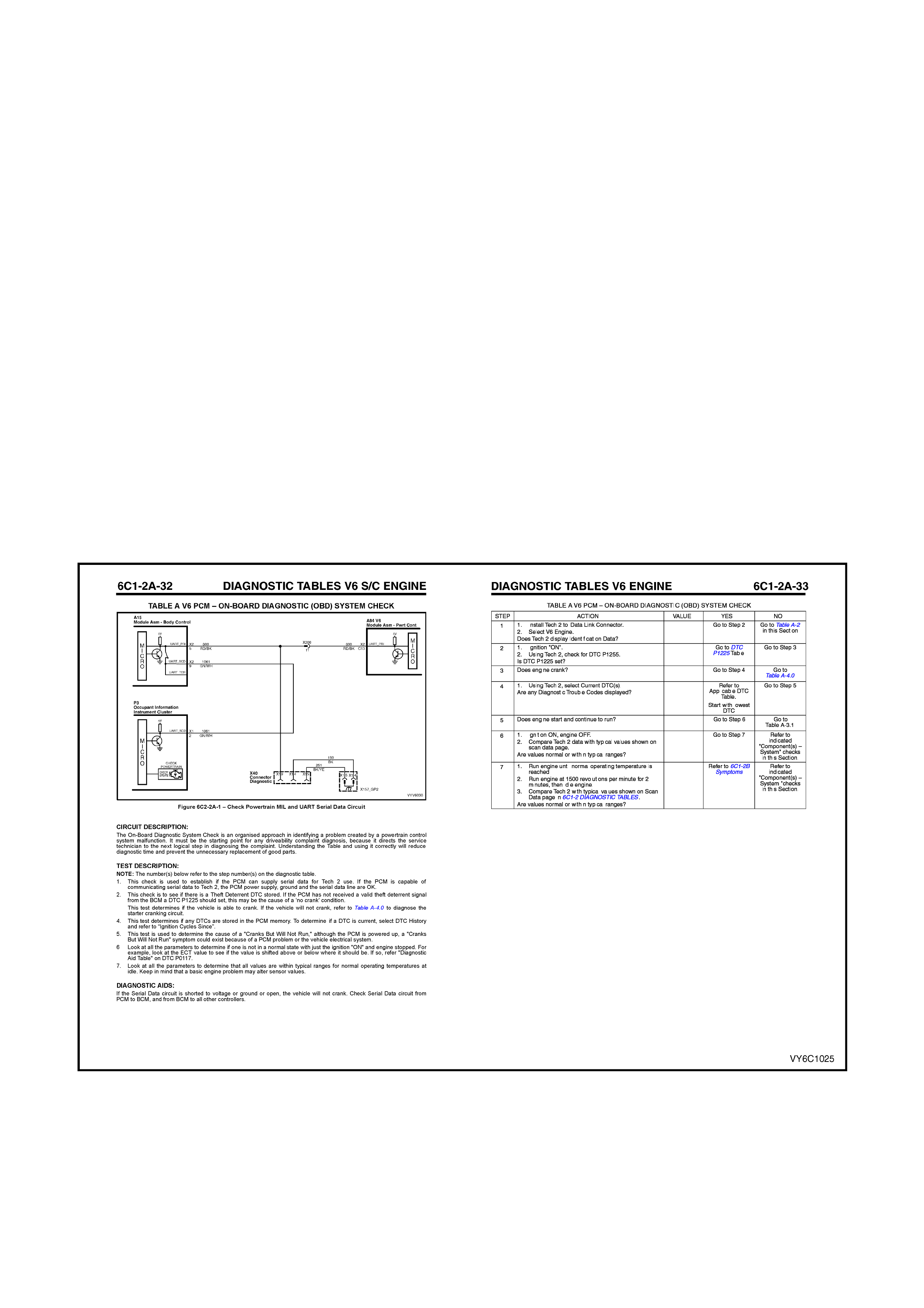
6. DIAGNOSTIC TABLES
6.1 INTRODUCTION
The diagnostic tables are designed to provide fast and efficient means of fault location for all engine and
transmission functions associated with the PCM. Each diagnostic table uses 2 pages; a table on the right side
page, and a facing page on the left side page. The le ft side "facing page" contains pertinent information, in cluding
diagnostic trouble code setting parameters and circuit diagrams. The table steps are explained by the
corresponding numbered paragraph on the left side facing page.
W hen diagnosin g an y problem, alwa ys begin with the ON- BOARD DIAG NOST IC SYST EM CHECK. T he On-Board
Diagnostic System Check will lead you to the other tables. DO NOT GO DIRECTLY TO A SPECIFIC TABLE or
false dia gn os is an d rep lac e ment of s ervic eable p ar ts c ould r es ul t. Af ter a fault is correc ted a nd al l DTCs hav e bee n
cleared, repeat the On-Board Diagnostic System Check to assure that the proper repairs have been made.
The "A" Table pages and the diagnostic trouble code diagnostics pages are constructed in a similar fashion. The
box at the top of the left page contains a wiring diagram showing the components involved in each circuit.
Immediately below the box is a brief circuit description. On the facing right-hand page a troubleshooting table for
diagnosing conditions. Step numbers on the right-hand page next to the action boxes in the table relate to the items
in the Test Description on the left-hand page. These items provide an explanation of each test in the table.
The appropriate step in any of the trouble shooting tables will instruct you either to make a specific repair or to
continue diagnosis. If further diagnosis is needed, the step will specify where to continue.
The Yes or No column in any diagnostic table will instruct you either to make a specific repair or to continue
diagnosis. If further diagnosis is needed, the Yes or No column will specify where to continue.
If the condition is intermittent, the trouble shooting table will direct you to the diagnostic aids on the facing page.
This section gives suggestions for diagnosing intermittent conditions and explains how some faults can occur.
Remember, tables are for solving active conditions or diagnostic trouble codes, not intermittent conditions. Use
symptom diagnosis for solving intermittent conditions.
Figure 6C1-2-9 Typical Diagnostic Flow Table
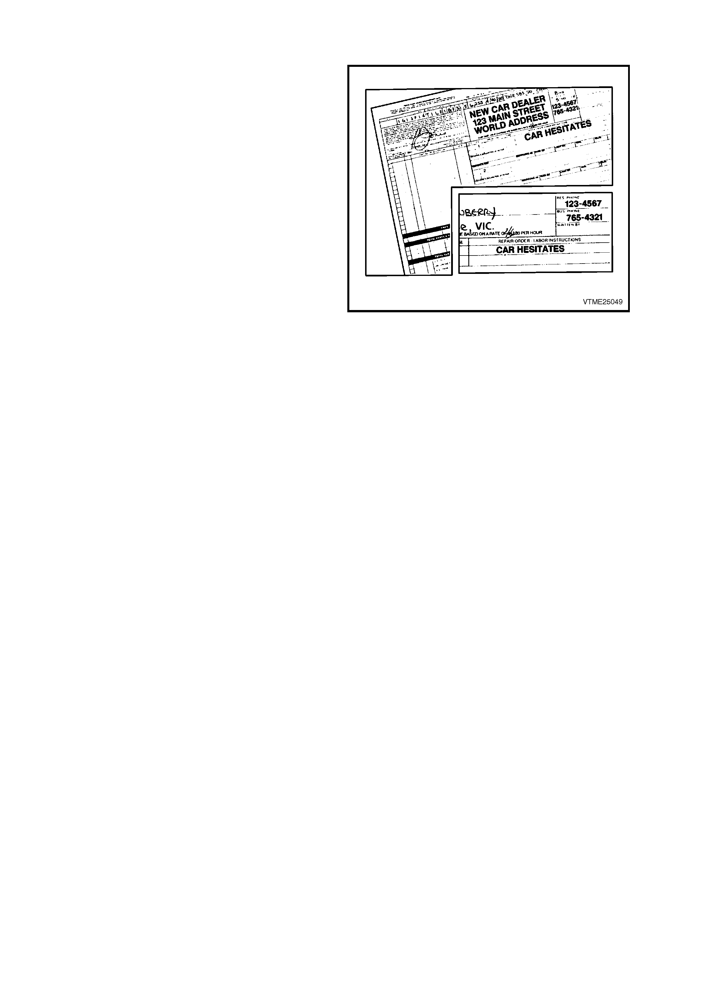
6.2 WRITING THE REPAIR ORDER
The repair order is one of the most important tools
a Technician can have. Like his other tools, the
repair order must be highly accurate to give him
the greatest help.
It's up to the Service Adviser to supply the
Technician with this highly accurate tool. Problems
begin for the Technician when the repair order is
incomplete or is incorrect.
An incomplete repair order doesn't provide the
Technician with a good starting point for the
diagnosis. Consequently, the Technician may
waste tim e, using a “shotgun” appr oach attem pting
to find the problem.
An incorrectly written repair order can lead the
Technician down the wrong diagnostic path,
preventing him from finding the problem.
Consequently, a Service Adviser needs to write an
accurate and complete repair order.
This is accomp lished by ask ing the custom er these
important questions: WHO? WHAT? WHEN?
WHERE? and HOW?
Figure 6C1-2-10 An Incomplete Repair Order

6.3 QUESTIONS
"WHO"? QUESTIONS
WHO"? is the first question you need to ask. As
you begin to fill out the repair order, you need to
find out who was driving the vehicle when the
problem occurred and talk directly to that person if
at all possible.
This allows you to give first-hand information on
the problem to the Technician, which is critical to
diagnosing the problem. If you can't talk directly to
this person, get their name and phone number so
the Technician can call the customer if needed.
"WHAT"? QUESTIONS
The next step is to find out "WHAT"? the problem
is. If it's a driveability problem, and it seems to be
complex, bring the Technician who's going to work
on the vehicle into the picture if at all possible.
Allow the Technician to question the customer
directly, so he can get the information he needs to
help him diag nose the pr o b lem. Aga in, this is so h e
can get first-hand knowledge of the problem.
If you don't involve the Technician with the
custom er, you need to ask if the Check Powertrain
MIL is O N all the time, c oming ON and OFF during
the same key cycle, or is never ON.
Figure 6C1-2-11 Typical ‘Symptoms’ Table
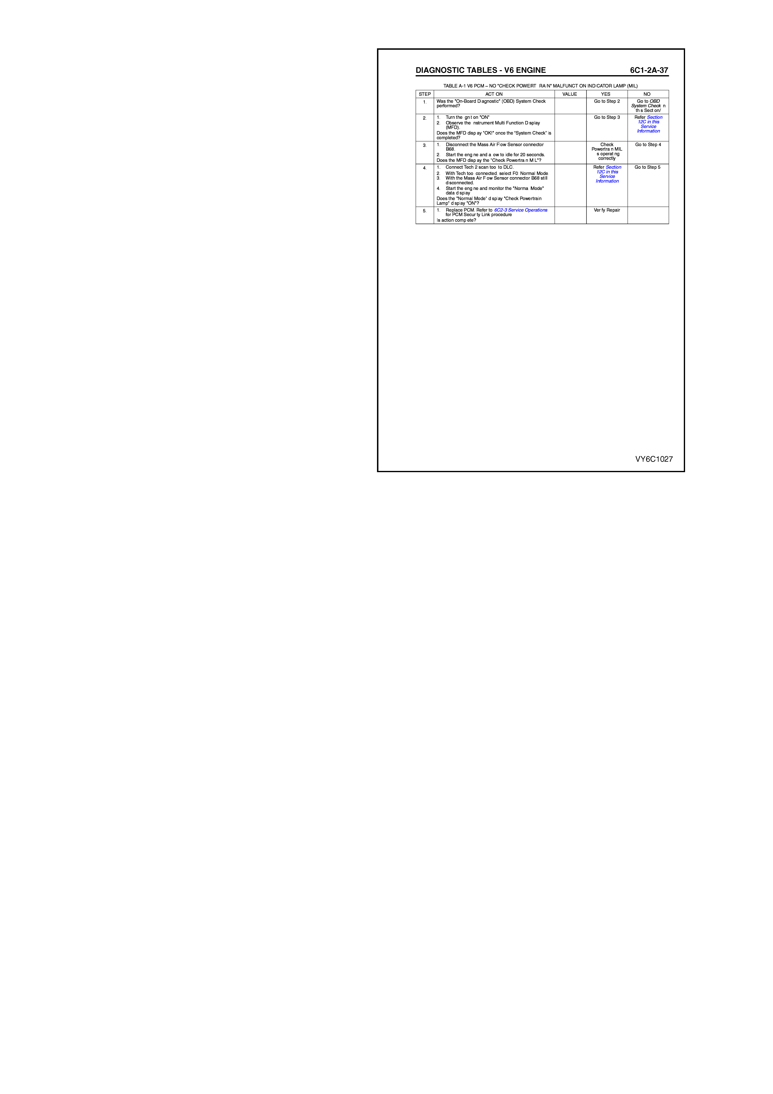
This is important to the Technician because this
informs him/her which diagnostic direction to take.
These tables are different from one another. If a
Technician is following the wrong table, a lot of
time is wasted. So, ask the customer questions
about the "Check Powertrain" lamp.
Other good "WHAT"? questions are; “Under what
conditions did the problem occur?”
Were they accelerating, decelerating, or coasting?
Were they driving in the city or on the freeway?
What were the environmental conditions? Was it
raining? snowing? Hot? cold? The technician may
need to duplicate these conditions as closely as
possible if he is to find the cause of the problem.
"WHEN"? QUESTIONS
WHEN"? questions are the next step. If the
customer says the "Check Powertrain" MIL was
ON, you need to ask when the Check Powertrain
MIL came ON and how long it has been "ON." Is
the Check Powertrain MIL ON before or during
starting, or when the engine is running?
More im por tant, you need to as k when the pr oblem
first oc curr ed. Ma ybe it beg an after th e veh icle was
serviced f or a re lated pro bl em or for something that
appears to be totally unrelated.
The Technician also needs to know if the problem
has become worse. This information may give the
Technician some clues as to what the problem may
be.
"WHERE"? QUESTIONS
W HERE"? is the nex t question . The locat ion where
the problem occurs may give the technician an
idea as to what ma y be con tribut ing to th e pr ob lem,
such as electromagnetic interference from
overhead power lines.
Figure 6C1-2-12 Typical Diagnostic Table
"HOW"? QUESTIONS
To round ou t your q uestioning, you need to ask the custom er "HOW "? often the p roblem occurs . This can gi ve the
Technician direction as to what type of system may be causing the problem; electrical, mechanical, vacuum, etc.
SUMMARY
In summary, you need to obtain the following information from the customer:
• Who the principal driver is.
• What the problem is.
• When the problem began.
• Where the problem occurs.
• How often the prob lem occurs.
Complete answers to these questions will aid the technician in diagnosing the problem.

VERIFYING THE COMPLAINT
Engine Compartment Inspection
The most important step in diagnosing a driveability complaint is to verify the complaint. This means you have to
duplicate the problem if possible.
Start by performing an engine compartment inspection. Check the integrity of all the electrical connections and
vacuum hoses, etc. Also, check the wire routing for the possibility of Electromagnetic Interference (EMI).
Checking For Stored Diagnostic Trouble Codes
As you check for diagnostic trouble codes, keep in mind that intermittent faults may not store a diagnostic trouble
code. So proceed with verifying the complaint, even if no diagnostic trouble codes are stored.
If a diagnostic trouble code is stored, check the service bulletins for the particular vehicle you're working on.
Road Testing The Vehicle
This step is optional if the repair order states.
• The driveability problem is intermittent.
• You did not find any problems under the bonnet .
• No diagnostic trouble codes are stored.
Then you need to road test the vehicle in order to recreate the problem.
This is an important step because the problem has to be present in order to repair the problem.
Most intermittent driveability problems are repeatable. That is what road testing is all about.
Before you go o n your r oad tes t, r evie w th e ve hic le's s er vice h is tory. This inf ormation can gi ve you clues as to what
may be causing the driveability problem and what you need to watch.
Read the repair order and think about what system s could possibly cause the problem . This is essential to finding
the problem. Think about how the system or systems in question works, what inputs are needed and what could
cause the problem.
Check all the inputs r equired for a c ircuit, whether t he circuit actually has trouble or if you only suspec t trouble. A ll
inputs are needed and must be within a "normal" range. You will want to pay attention to these systems and circuits
during and after the road test.
As you're road testing, put Tech 2 in the Snapshot Mode so you can capture the system data when the problem
occurs.
Do not discount the other information the Tech 2 snapshot mode can supply you with.
Don't Forget The Basics
Whether or not you find anything wrong during the road test, don't forget the basics.
Electrical connections such as power feeds and grounds are vital to the operation of almost all of the vehicle
systems.
No matter how good the system is, it is still working in combination with the engine. If the engine is not in good
condition, the computer system can't make up for the condition.
Compare performance problems, such as lack of power, with a comparable vehicle. This will let you know if the
customer complaint really is a problem or something that is normal.
If you can't repeat the problem , and you need m ore inform ation for diagnosing, call the custom er who was driving
the vehicle when the problem occurred. This type of professionalism will probably help you diagnose the problem.
CALIBRATIONS
If a vehicle is just starting to have an intermittent driveability problem and it has accumulated more than 30,000
kilometres, chances are that the PCM calibration is not at fault.
If the vehicl e was runni ng pr operl y for such a long t im e, the origina l PCM cali brations are not the pro blem since the
PCM calibrations don't change, the chances of the calibrations going bad are rare. There may however be an
updated calibration for a particular condition, so check service bulletins for calibrations updates.