
SECTION 6C1-2C - FUNCTIONAL CHECKS –
V6 ENGINE
IMPORTANT
Before performing any Service Operation or other procedure described in this Section, refer to Section 00
CAUTIONS AND NOTES for correct workshop practices with regard to safety and/or property damage.
The following pages are to be used when there is a customer com plaint but there are no diagnostic trouble codes
set, but on e or m ore of the Tec h 2 data val ues are no t within t ypical values. Befor e using t hese Tabl es you s hould
refer to Section 6C1-2 B SYMPTOM S that may lead you to using this Section.
The purpose of these Tables is to diagnose Powertrain Control Module (PCM) controlled components or sub-
systems that do not have diagnostic trouble codes assigned to them. Another purpose of these Tables is for
Technicians who feel confident that a particular part of the sub-system is not operating properly and want to only
check that particular item for proper operation without going through lengthy diagnostic procedures.
CONTENTS
1. 4L60-E COMPONENT RESISTANCE TABLE
2. FUNCTIONAL CHECK TABLES
2.1 V6 PCM – AUTOMATIC TRANSMISSION WIRING HARNESS ASSEMBLY CHECK
2.2 V6 PCM – TRANSMISSION FLUID PRESSURE MANUAL VALVE POSITION SWITCH CHECK
2.3 V6 PCM – 1-2 SHIFT SOLENOID ‘A’ PERFORMANCE CHECK
2.4 V6 PCM – 2-3 SHIFT SOLENOID ‘B’ PERFORMANCE CHECK
2.5 V6 PCM – TRANSMISSION POWER/ECONOMY SWITCH
2.6 V6 PCM – INSTRUMENT PANEL GEAR INDICATOR CHECK
2.7 V6 PCM – FUEL INJECTOR BALANCE TEST
2.8 V6 PCM – FUEL INJECTOR COIL TEST – ECT BETWEEN 10 – 35°
°°
° C
2.9 V6 PCM – FUEL INJECTOR COIL TEST – ECT OUTSIDE 10 – 35°
°°
°C
2.10 V6 PCM – FUEL INJECTOR CIRCUIT DIAGNOSIS
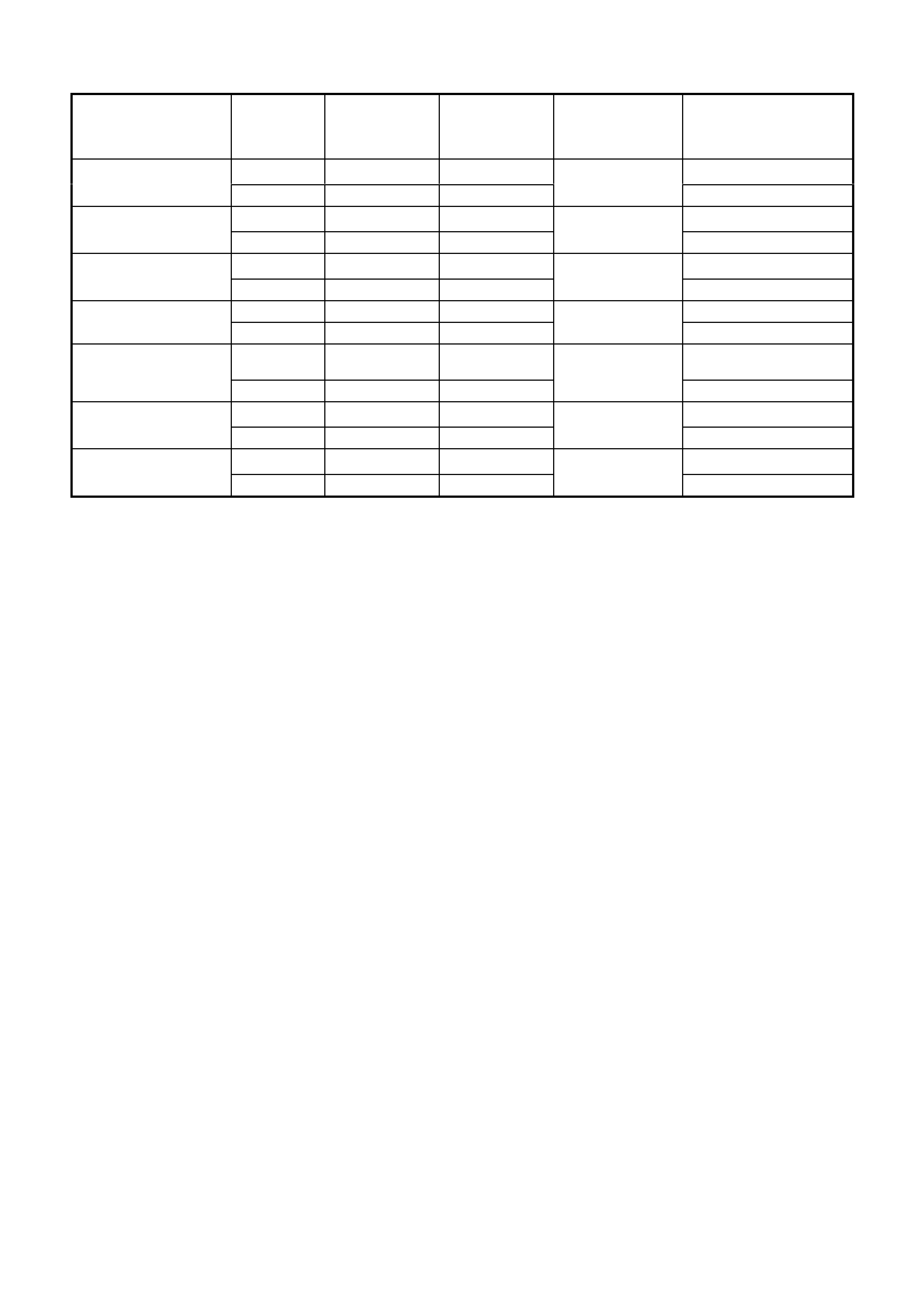
1. 4L60-E COMPONENT RESISTANCE TABLE
COMPONENT TERMINAL WIRE COLOUR
PASS-THRU
CONNECTOR
X121-X2
TERMINAL ID
RESISTANCE AT
20°
°°
° C CIRCUIT NO.
1-2 SHIFT B RD E- 19-24 Ohms 339
SOLENOID VALVE A L-GN A 1222
2-3 SHIFT A RD E- 19-24 Ohms 339
SOLENOID VALVE B YE B 1223
3-2 CONTROL A RD E- 20-24 Ohms 339
SOLENOID VALVE B WH S 898
PRESSURE CONTROL A PU C 3-5 Ohms 1228
SOLENOID VALVE B L-BU D 1229
TRANSMISSION FLUID
TEMPERATURE A BN L 3088 - 3942 Ohms 1227
SENSOR (TFT) B BK M 2753
TCC "PWM" A RD E- 9 - 14 Ohms 339
SOLENOID VALVE B BN U 418
TCC ENABLE A RD E- 21-26 Ohms 339
SOLENOID VALVE B BN T 422
- Spliced internally to pin E
2. FUNCTIONAL CHECK TABLES
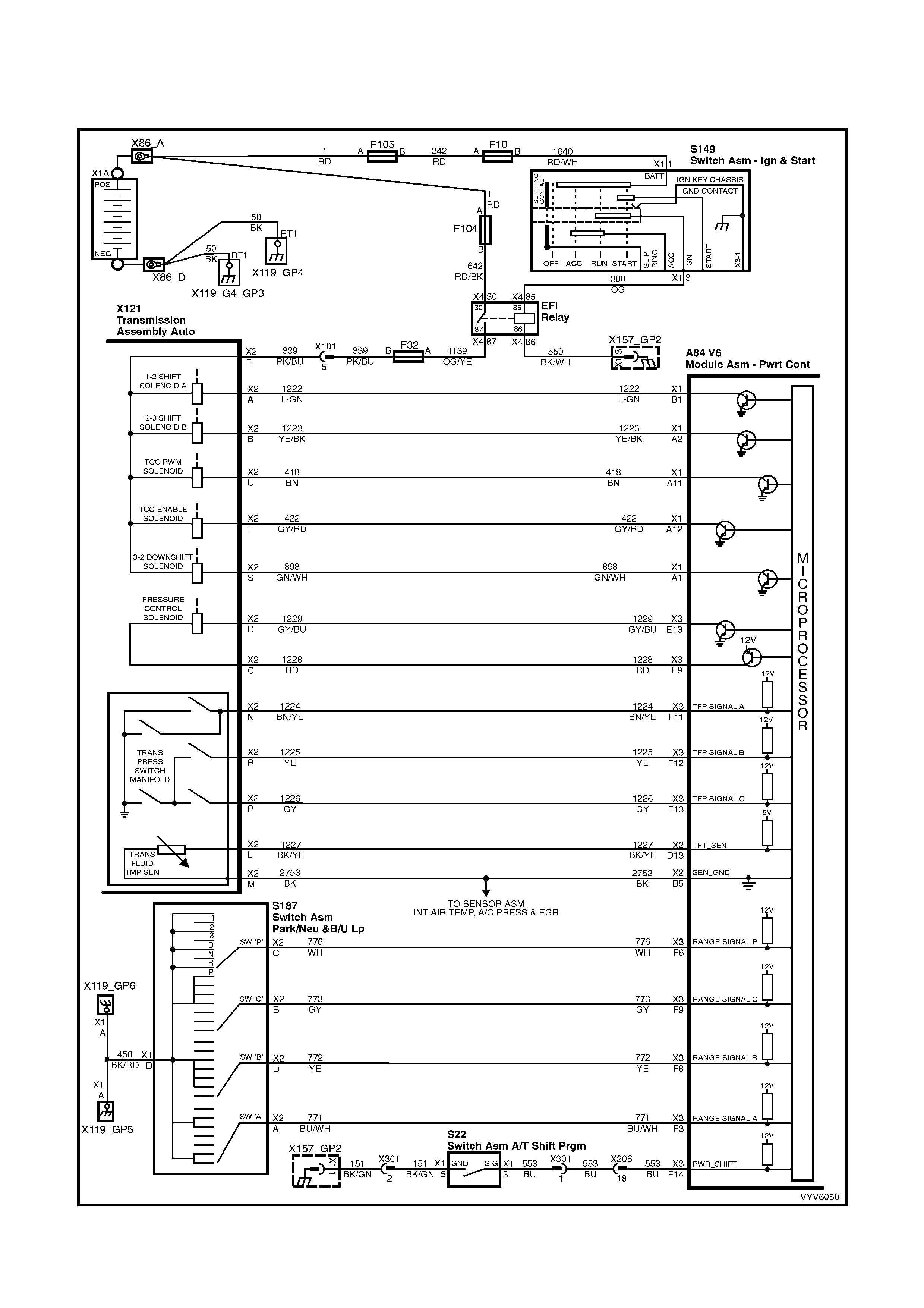
2.1 V6 PCM – AUTOMATIC TRANSMISSION WIRING HARNESS CHECK
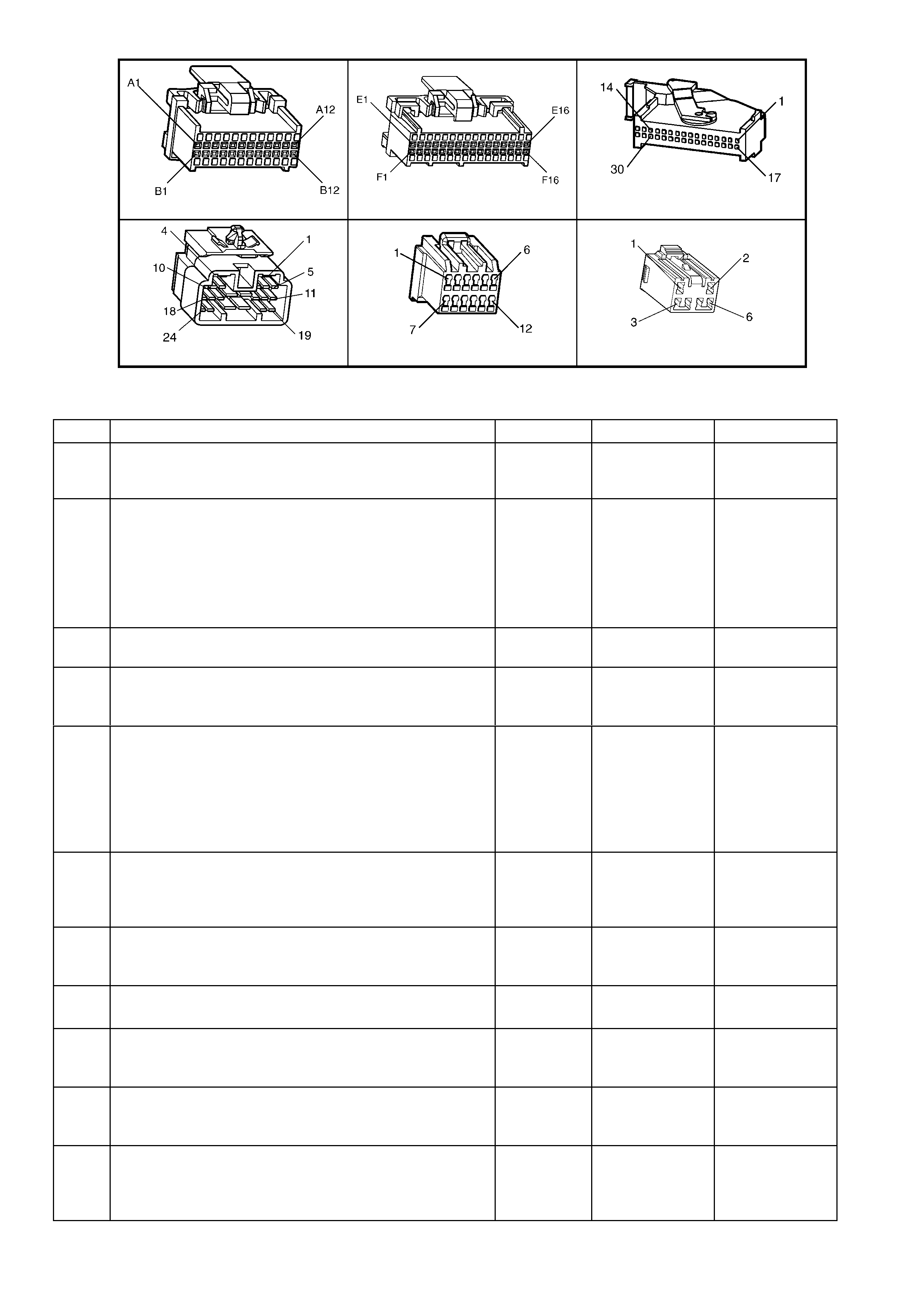
Figure 6C1-2C-1 – Automatic Transmission Circuits
TOOLS REQUIRED:
J 39775 4L60-E Jumper Harness
J 35616-A Connector Test Adaptor Kit
Digital Multimeter (DMM)
IMPORTANT: This procedure cannot be used for checking the Automatic Transmission Fluid Pressure Manual
Valve P os it ion S witc h ( T F P Man . V al. P os ition Sw.) c ir c uit, or the Au tomatic T r ansmission F l uid T em per atur e (TFT)
Sensor circuit. Refer to TFP Manual Valve Position Switch Assembly, Resistance Check, for those circuits.
Powertrain Harness Terminal Identification
CAVITY FUNCTION
A 1-2 SHIFT SOLENOID ‘A’ (LOW)
B 2-3 SHIFT SOLENOID ‘B’ (LOW)
C PRESSURE CONTROL SOLENOID (HIGH)
D PRESSURE CONTROL SOLENOID (LOW)
E BOTH SHIFT SOLENOIDS , TCC SOLENOID, TCC PWM SOLENOID & 3-2 CONTROL
SOLENOID (HIGH)
L TRANSMISSION FLUID TEMPERATURE HIGH
M TRANSMISSION FLUID TEMPERATURE (LOW)
N RANGE SIGNAL "A"
P RANGE SIGNAL "C"
R RANGE SIGNAL "B"
S 3-2 CONTROL SOLENOID (LOW)
T TCC SOLENOID (LOW)
U TCC PWM SOLENOID
A84 V6 – X1 A84 V6 – X2 A84 V6 – X3
X206 X121 – X2
Figure 6C1-2C-2

2.1 1 V6 PCM – AUTOMATIC TRANSMISSION WIRING HARNESS ASSEMBLY CHECK
STEP ACTION VALUE YES NO
1. 1. Install the J 39775 Jumper Harness on the
transmission pass-thru connector.
2. Using a DMM and a J 35616-A Connector Test
Adaptor Kit, measure the resistance between terminals
‘A’ and ‘E’ (1-2 Shift Solenoid Valve).
Is the resistance within the specified range?
19 – 24 Ω @
20° C
24 – 31Ω @
100° C
Go to Step 3 Go to Step 2
2. 1. Disconnect the 1-2 Shift Solenoid Valve (1-2 SS Valve)
from the Automatic Transmission Wiring Harness
Assembly.
2. Using the DMM, measure the resistance of the 1-2
Shift Solenoid Valve.
Is the resistance within the specified range?
19-24 Ω @
20° C
24-31Ω @
100° C
Go to Step 14 Go to Step 16
3. 1. Measure the resistance between terminals B and E
(2-3 Shift Solenoid Valve).
Is the resistance within the specified range?
19 – 24 Ω @
20° C
24 – 31Ω @
100° C
Go to Step 5 Go to Step 4
4. 1. Disconnect the 2-3 Shift Solenoid Valve (2-3 SS Valve)
from the Automatic Transmission Wiring Harness
Assembly.
2. Using the DMM, measure the resistance of the 2-3 SS
Valve.
Is the resistance within the specified range?
19 – 24 Ω @
20° C
24 – 31Ω @
100° C
Go to Step 14 Go to Step 16
5. 1. Measure the resistance between terminals T and E
(Torque Converter Clutch Solenoid Valve).
Is the resistance within the specified range?
21 – 26 Ω @
20° C
26 – 33 Ω
100° C
Go to Step 6 Go to Step 14
6. 1. Measure the resistance between terminals U and E
(Torque Converter Clutch Pulse Width Modulation
Solenoid Valve).
Is the resistance within the specified range?
9 – 14 Ω @
20° C
13 – 15 Ω @
100° C
Go to Step 8 Go to Step 7
7. 1. Disconnect the TCC PWM Solenoid Valve from the
Automatic Transmission Wiring Harness Assembly.
2. Using the DMM, measure the resistance of the TCC
PWM Solenoid Valve.
Is the resistance within the specified range?
9 – 14 Ω @
20° C
13 – 15 Ω @
100° C
Go to Step 14 Go to Step 16
8. 1. Measure the resistance between terminals S and E
(3-2 Shift Solenoid Valve assembly).
Is the resistance within the specified range?
20 – 24 Ω @
20° C
29 – 32 Ω @
100° C
Go to Step 10 Go to Step 9
9. 1. Disconnect the 3–2 Shift Solenoid Valve Assembly
from the Automatic Transmission Wiring Harness
Assembly.
2. Using the DMM, measure the resistance of the 3-2
Shift Solenoid Valve Assy.
Is the resistance within the specified range?
20 – 24 Ω @
20° C
29 – 32 Ω @
100° C
Go to Step 14 Go to Step 16
10. 1. Measure the resistance between terminals C and D
(Pressure Control Solenoid Valve).
Is the resistance within the specified range?
3 – 5 Ω @
20° C
4 – 7 Ω @
100° C
Go to Step 12 Go to Step 11
11. 1. Disconnect the Pressure Control Solenoid Valve from
the Automatic Transmission Wiring Harness Assembly.
2. Using a DMM, measure the resistance of the Pressure
Control Solenoid Valve.
Is the resistance within the specified range?
3 – 5 Ω @
20° C
4 – 7 Ω @
100° C
Go to Step 14 Go to Step 16

STEP ACTION VALUE YES NO
12. 1. Using a DMM and the J 35616-A Connector Test
Adaptor Kit, measure the resistance from each of the
terminals A, B, C, D, E, S, T and U of the A/T Wiring
Harness Assembly at the transmission pass-thru
connector to the transmission case.
Is the resistance more than the specified value?
250 kΩ System OK. Go to Step 13
13. 1. Disconnect the A/T Wiring Harness Assembly from all
the components.
2. Measure the resistance from each of the component
terminals to the transmi ss ion case.
Is the resistance more than the specified value?
250 kΩ Go to Step 14 Go to Step 16
14. 1. Inspect for high resistance or a short.
2. Inspect the A/T Wiring Harness Assembly at the
transmission pass-thru connector, and the component
connectors for the following conditions:
• Poor electrical connections
• Bent, backed-out, or damaged terminals
• Weak terminal tension
• A chafed wire that could short to bare metal or
other wiring
• A broken wire inside the insulation
• Moisture intrusion
• Corrosion
If diagnosing for a possible intermittent condition,
move or wriggle the A/T Wiring Harness Assembly
while observing the test equipment for a change.
Did you find and correct the high resistance or a short?
Verify the repair. Go to Step 15
15. 1. Replace the Automatic Transmission Wiring Harness
Assembly. Refe r to 7C4 AUTOMATIC
TRANSMISSION – ON-VEHICLE SERVICING.
Is the action complete?
Verify the repair. –
16. 1. Replace the faulty component. Refer 6C3-3 SERVICE
OPERATIONS.
Is the action complete?
Verify the repair. –
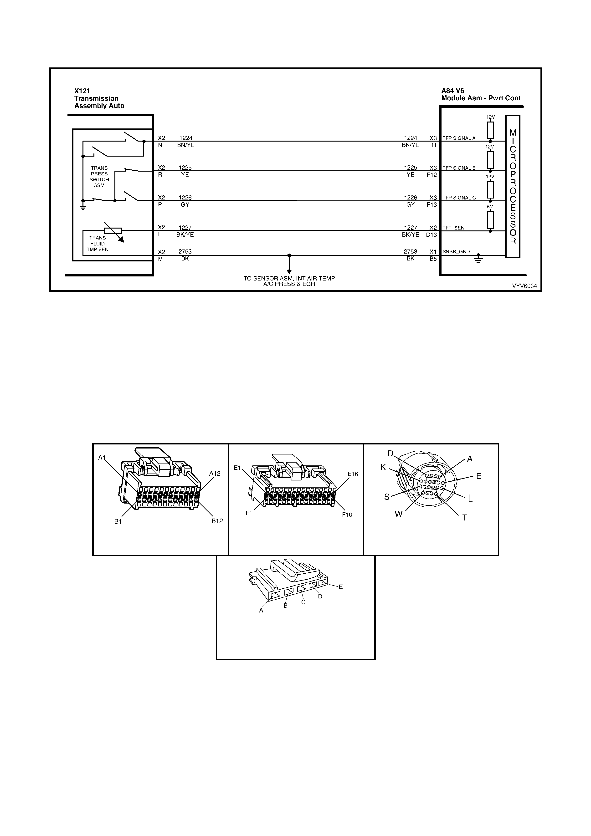
2.2 V6 PCM – TRANSMISSION FLUID PRESSURE MANUAL VALVE
POSITION SWITCH CH ECK
Figure 6C1-2C-3 – Automatic Transmission Fluid Pressure Manual Valve Position Switch
TOOLS REQUIRED:
J 39775 4L60-E Jumper Harness
J 35616-A Connector Test Adaptor Kit
Digital Multimeter (DMM)
IMPORTANT: W henever the transm ission pass-thr u connector is d isconnected and the engine is r unning, m ultiple
DTCs will set. Be sure to clear these codes when you are finished with this procedure.
NOTE: This procedure tests the Transmission Fluid Pressure Manual Valve Position Switch (TFP Man. Val.
Position Sw.) circuits and the Transmission Fluid Temperature (TFT) Sensor circuit. Do not use this procedure to
test other Automatic Transmission circuits, refer to Table 2.1 V6 PCM – Automatic Transmission Internal Wiring
Harness check.
A84 V6 – X1 A84 V6 – X3 X121 – X2
TFP MANUAL VALVE POSITION
SWITCH
(PART OF A/T INTERNAL
HARNESS)
Figure 6C1-2C-4

2.2 V6 PCM – TRANSM ISSION FLU ID PR ES SUR E MANU AL VALVE POSITION SWITCH CHECK
STEP ACTION VALUE YES NO
1. 1. Install the J 39775 Jumper Harness on the
transmissi on sid e of the pass-t hru conne ctor.
2. Using a DMM and the J 35616-A Connector Test
Adaptor Kit, measure the resistance from terminal N to
the transmission case.
Is the resistance greater than the specified value?
250 kΩ Go to Step 3 Go to Step 2
2. 1. Disconnect the TFP Manual Valve Position Switch
from the A/T Wiring Harness Assembly.
2. Measure the resistance from terminal C of the TFP
Manual Valve Position Switch to the switch housing.
Is the resistance greater than the specified value?
250 kΩ Go to Step 16 Go to Step 19
3. 1. Measure the resistance from terminal R to the
transmissi on cas e.
Is the resistance less than the specified value?
200 Ω Go to Step 5 Go to Step 4
4. 1. Disconnect the TFP Manual Valve Position Switch
from the A/T Wiring Harness Assembly.
2. Measure the resistance from terminal E of the TFP
Manual Valve Position Switch to the switch housing.
Is the resistance less than the specified value?
200 Ω Go to Step 16 Go to Step 19
5. 1. Measure the resistance from terminal P to the
transmissi on cas e.
Is the resistance greater than the specified value?
250 kΩ Go to Step 7 Go to Step 6
6. 1. Disconnect the TFP Manual Valve Position Switch
from the A/T Wiring Harness Assembly.
2. Measure the resistance from terminal D of the TFP
Manual Valve Position Switch to the switch housing.
Is the resistance greater than the specified value?
250 kΩ Go to Step 16 Go to Step 19
7. 1. Start the engine.
2. Allow the engine to idle.
3. Apply the park brake and firmly apply the foot brake.
4. Place the gear selector in Reverse.
5. Measure the resistance from terminal N to the
transmissi on cas e.
Is the resistance less than the specified value?
200 Ω Go to Step 8 Go to Step 16
8. 1. Place the gear selector in Low (D1).
2. Measure the resistance from terminal N to the
transmissi on cas e.
Is the resistance less than the specified value?
200 Ω Go to Step 9 Go to Step 16
9. 1. Place the gear selector in Manual Third (D3).
2. Measure the resistance from terminal R to the
transmissi on cas e.
Is the resistance greater than the specified value?
250 kΩ Go to Step 10 Go to Step 16
10. 1. Place the gear selector in Drive (D4).
2. Measure the resistance from terminal P to the
transmissi on cas e.
Is the resistance less than the specified value?
200 Ω Go to Step 11 Go to Step 16
11. 1. Place the gear selector in Manual Second (D2).
2. Measure the resistance from terminal P to the
transmissi on cas e.
Is the resistance greater than the specified value?
250 kΩ Go to Step 12 Go to Step 16
12. 1. Turn the ignition OFF.
IMPORTANT: The resistance of the TFT Sensor is
temperature dependent, and therefore varies far more
than any other device.
2. Measure the resistance from terminal L to terminal M
(TFT Sensor) of the Jumper Harness.
Is the resistance within the specified range?
3,088 – 3,942 Ω
@ 20° C
159 – 198 Ω @
100° C
Go to Step 13 Go to Step 14

STEP ACTION VALUE YES NO
13. 1. Measure the resistance from terminal L to the
transmissi on cas e.
2. Measure the resistance from terminal M to the
transmissi on cas e.
Are both resistance values greater than the specified
value?
250 kΩ System OK Go to Step 16
14. 1. Disconnect the TFP Manual Valve Position Switch
from the A/T Wiring Harness Assembly.
IMPORTANT: The resistance of the TFT Sensor is
temperature dependent, and therefore varies far more
than any other device. Refer to Transmission Fluid
Temperature Sensor in 6C1-1 GENERAL
INFORMATION.
2. Using a DMM, measure the resistance between
terminal A and terminal B of the TFP Manual Valve
Position Switch (TFT Sensor).
Is the resistance within the specified range?
3,088 – 3,942 Ω
@ 20° C
159 – 198 Ω @
100° C
Go to Step 15 Go to Step 19
15. 1. Measure the resistance from TFP Manual Valve
Position Switch terminal A to the transmission case.
2. Measure the resistance from TFP Manual Valve
Position Switch terminal B to the transmission case.
Are both resistance values greater than the specified
value?
250 kΩ Go to Step 16 Go to Step 19
16. 1. Inspect for high resistance or a short.
2. Inspect the A/T Wiring Harness Assembly for poor
electrical connections at the A/T pass-thru connector,
and at the TFP Manual Valve Position Switch. Look for
the following problems:
• A bent terminal
• A backed out terminal
• A damaged terminal
• Poor terminal tension
3. If diagnosing for an intermittent problem, wriggle the
wiring harness while watching the test equipment for a
change.
Did you find and correct the high resistance or a short?
Verify the
repair.
Go to Step 17
17. 1. Disconnect the TFP Manual Valve Position Switch
from the A/T Wiring Harness Assembly.
2. Inspect the following circuits for an open or short:
• Circuit 1224
• Circuit 1225
• Circuit 1226
• Circuit 1227 (TFT Hi)
• Circuit 2753 (TFT Lo)
Did you find a problem?
Go to Step 18 Go to Step 19
18. 1. Replace the A/T Wiring Harness Assembly.
2. Refer to Automatic Transmission Wiring Harness
Assembly Replacement, in 7C4 AUTOMATIC
TRANSMISSION ON-VEHICLE SERVICING.
Is the action complete?
Verify the
repair.
19. 1. Replace the TFP Manual Valve Position Switch.
2. Refer to Transmission Fluid Pressure Manual Valve
Position Switch Replacement. Refer to 6C1-3
SERVICE OPERATIONS, in this Section.
Is the action complete?
Verify the
repair.

2.3 V6 PCM 1-2 SHIFT SOLENOID ‘ A’ PERFORMANCE CHECK
Figure 6C1-2C-5 – Automatic Transmission Shift Solenoids
CIRCUIT DESCRIPTION:
The 1-2 Shift Solenoid Valve ‘A’ (1-2 SS Valve) controls the fluid flow acting on the 1-2 and 3-4 shift valves. The
1-2 SS Valv e is a norm ally-open exha ust valve that is used with the 2-3 Shift Soleno id Valve ‘B’ (2-3 S S Valve), in
order to allow four different shifting combinations.
This functional check is useful for diagnosing unusual shift patterns that result from a mechanical fault of the 1-2
shift solenoid or the shift valve. A 1-1-4-4 shift pattern indicates that the shift solenoid or the shift valve is stuck
ON. The stuck ON condition could be caused by the solenoid not exhausting fluid or the shift valve remaining in
the applied position. Similarly, a 2-2-3-3 shift pattern indicates that the shift solenoid or the shift valve is stuck OFF.
The stuck OFF condition could be caused b y the solenoid exhausting fluid or the shift valve rem aining in the non-
applied position.
DIAGNOSTIC AIDS:
• Verify that the transmission shift speeds are within specifications.
• Other internal transmission faults may cause more than one shift to occur.
• Refer to the following Table for the correct On and Off states of the shift solenoids.
Gear 1-2 Shift
Solenoid ‘A’ 2-3 Shift
Solenoid ‘B’
1 ON ON
2 OFF ON
3 OFF OFF
4 ON OFF
TEST DESCRIPTION:
NOTE: The number(s) below refer to the step number(s) on the diagnostic table.
2. This step tests that Tech 2 commanded all shifts and all shift solenoid valves responded correctly, but all the
shifts did not occur. Refer to the table below.
A84 V6 – X2 A84 V6 – X3 X206 X121 – X2
Figure 6C1-2C-6
2 3 V6 PCM – 1-2 SHIFT SOLENOID ‘A’ PERFORMANCE CHECK
STEP ACTION VALUE YES NO
1. Was the "On-Board Diagnostic" (OBD) System Check
performed? Go to Step 2. Go to
OBD System
Check.
2. 1. Install Tech 2.
2. With the engine OFF, turn the ignition switch to the
RUN position.
3. While the engine is oper atin g, raise the drive wheel s.
4. With the transmission in D4 range, use Tech 2 to
command 1st, 2nd, 3rd and 4th gears while
accelerating the vehicle. Road testing the vehicle may
be necessary.
Did you detect a 1-1-4-4 or a 2-2-3-3 only shift pattern?
— Go to Step 3 Go to
“Diagnostic
Aids”, above.
3. 1. Check the shift solenoid/hydraulic circuit for:
• An internal malfunction.
• Damaged seals on the shift solenoid valves.
Refer to 6C1-2B SYMPTOMS.
Did you find and correct a problem?
— Go to Step 4 Go to
“Diagnostic
Aids”, above.
4. In order to verify your repair, perform the following
procedure:
1. Select DTC.
2. Select Clear Info.
3. Operate the vehicle under the following conditions
(only if traffic and road conditions pe rmit):
• With the transmission in D4 range, use Tech 2 to
command 1st, 2nd, 3rd and 4th gears while
accelerating the vehicle.
Did you detect a 1-1-4-4 or a 2-2-3-3 only shift pattern?
— Begin the
diagnosis agai n.
Go to Step 2
Repair Verified,
exit table.
2.4 V6 PCM – 2-3 SHIFT SOLENOID ‘B’ PERFORMANCE CHECK
Figure 6C1-2C-7 – Automatic Transmission Shift Solenoids
CIRCUIT DESCRIPTION:
The 2-3 Shift Solenoid Valve ‘B’ (2-3 SS Valve) controls the fluid flow acting on the 2-3 shift valves. The 2-3 SS
Valve is a normall y-open e xhaust val ve that is use d with the 1- 2 Shift S olenoid V alve ‘A’ (1- 2 SS Va lve) in o rder to
allow four different shifting combinations.
This f unctional chec k is useful f or diagnosing unusual shif t patterns that r esult from a m ec hanical failure of the 2-3
shift solenoid or the shift valve. A 1-2-2-1 shift pattern indicates that the shift solenoid or the shift valve is stuck
ON. The stuck ON condition could be caused by the solenoid not exhausting fluid or the shift valve remaining in
the applied position. Similarly, a 4-3-3-4 shift pattern indicates that the shift solenoid or the shift valve is stuck OFF.
The stuck OFF condition could be caused b y the solenoid exhausting fluid or the shift valve rem aining in the non-
applied position.
DIAGNOSTIC AIDS:
Verify that the transmission shift speeds are within specifications.
Other internal transmission faults may cause more than one shift to occur.
• Refer to the following Table for the correct On and Off states of the shift solenoids.
Gear 1-2 Shift
Solenoid ‘A’ 2-3 Shift
Solenoid ‘B’
1 ON ON
2 OFF ON
3 OFF OFF
4 ON OFF
TEST DESCRIPTION:
NOTE: The number(s) below refer to the step number(s) on the diagnostic table.
2. This verifies that Tech 2 commanded all the shifts, and all the shift solenoids responded correctly, but all the
shifts did not occur. Refer to the table below.
A84 V6 S/C – X2 A84 V6 S/C – X3 X206 X121 – X2
Figure 6C1-2C-8
2.4 V6 PCM – 2-3 SHIFT SOLENOID ‘B’ PERFORMANCE CHECK
STEP ACTION VALUE YES NO
1. Was the "On-Board Diagnostic" (OBD) System Check
performed? Go to Step 2. Go to
OBD System
Check.
2. 1. Install Tech 2.
2. With the engine OFF, turn the ignition switch to the
RUN position.
3. While the engine is oper atin g, raise the drive wheel s.
4. With the transmission in D4 range, use Tech 2 to
command 1st, 2nd, 3rd and 4th gears while
accelerating the vehicle. Road testing the vehicle may
be necessary.
Did you detect a 1-2-2-1 or a 4-3-3-4 only shift pattern?
— Go to Step 3 Go to
“Diagnostic
Aids”, above.
3. 1. Check the shift solenoid/hydraulic circuit for:
• An internal malfunction.
• Damaged seals on the shift solenoid valves.
Refer to 6C1-2B SYMPTOMS.
Did you find and correct a problem?
— Go to Step 4 Go to
“Diagnostic
Aids”, above.
4. In order to verify your repair, perform the following
procedure:
1. Select DTC.
2. Select Clear Info.
3. Operate the vehicle under the following conditions
(only if traffic and road conditions pe rmit):
• With the transmission in D4 range, use Tech 2 to
command 1st, 2nd, 3rd and 4th gears while
accelerating the vehicle.
Did you detect a 1-2-2-1 or a 4-3-3-4 only shift pattern?
— Begin the
diagnosis agai n.
Go to Step 1
Repair Verified,
exit table.
2.5 V6 PCM – TRANSMISSION POWER/ECONOMY SWITCH
Figure 6C1-2C-9 – Power/Economy Switch
CIRCUIT DESCRIPTION:
The driver can select three transmission shift modes, ECONOMY, POWER or CRUISE using centre console
mounted switch for Economy/Power, and a cruise switch located on the steering column. The Economy/Power
switch is wired to the PCM and allows the driver to choose the Economy mode, for the best fuel economy in all
driving conditions throug h the increased use of T CC. Po wer mode provides later upshifts and higher line pressure
in the transmission.
The PCM sends out a buffered voltage signal, about 12 volts, and monitors the status of this circuit. Once the driver
selects Power, the switch momentarily pulls low the buffered 12 volts, and the PCM will interpret this as a Power
selection and adjust the transmission shift pattern accordingly, and instructs the instrument panel to turn ON the
Power lamp. If while driving, the driver selects the Economy position, again the buffered 12 volts is momentarily
pulled lo w, and the PCM will adjust th e transm ission shif t pattern a nd instruc t the ins trum ent panel to t urn OF F the
Power lamp.
When the key is turned ON, the PCM shift mode is set to the last mode that was previously selected
(Economy/Power). The cruise control is set to OFF at every key ON cycle.
In cruise mode operation, when the driver activates the cruise control, the Power Shift (PWR) icon in the Multi
Function Display (MFD) of the Instrument will be deactivated (if vehicle was in power m ode) and the transm ission
shift pattern will switch to cruise shift pattern. When in cruise mode, the PCM will modify the transmission
calibration so that earlier downshift and later upshift points are provided.
For replacement of the Economy/Power switch, refer to Section 7C4 AUTOMATIC TRANSMISSION – ON-
VEHICLE SERVI CING in the MY 2003 VY and V2 Series Service Information.
TEST DESCRIPTION:
NOTE: The number(s) below refer to the step number(s) on the diagnostic table.
2. This step tests for proper operation of the transmission POWER switch, the wiring and the PCM.
3. This step tests for proper POWER lamp illumination.
5. This step determines if the switch is faulty.
8. Some interior parts must be removed to disconnect and replace the transmission switch, Refer to
Section 1A3, INSTRUM ENT PANEL AND CONSOLE in the MY 2003 VY and V2 Series Service Information.
A84 V6 S/C – X3 A84 V6 S/C – X3 P3
X206 A15 X2 S22
Figure 6C1-2C-10
2.5 TRANSMISSION POWER/ECONOMY SWITCH
STEP ACTION VALUE YES NO
1. Was the "On-Board Diagnostic" (OBD) System Check
performed? Go to Step 2 Go to
OBD System
Check.
2. 1. Install Tech 2.
2. With the engine OFF, turn the ignition switch to the
RUN position.
3. Depress the Transmission POWER switch S22 and
observe the Tech 2 display.
Does the Tech 2 display change between the Power or
Economy mode?
Go to Step Go to Step 5
3. Is the POWER lamp ON, when the Tech 2 displays
POWER? Go to Step 4 Go to 12C
Instruments.
4. Does the POWER icon deactivate when Tech 2 displays
ECONOMY?
No Problem
found with
switch operation.
Go to 12C
Instruments.
5. 1. Disconnect the POWER switch from the wiring
harness connec tor S22.
2. Using a fused jumper wire, connect the two terminals
S22 X1 3 and 5 of the POWER switch wiring harness
connector together.
Does Tech 2 display a change between the Power and
Economy mode?
Go to Step 7 Go to Step 6
6. 1. Using a fused jumper wire, connect circuit 553 to
ground.
Does Tech 2 display a change between the Power and
Economy mode?
Go to Step 10 Go to Step 9
7. 1. Check the POWER switch connector S22 for a poor
terminal connection.
Was a problem found?
Verify Repair Go to Step 8
8. 1. Replace the faulty POWER/ECONOMY switch.
Is the action complete? Verify Repair –
9. 1. Check for an open or short to Ground in circuit 553, or
a faulty PCM connection for circ uit 553.
Was a problem found?
Verify Repair Go to Step 11
10. 1. Repair open in ground circuit 151at Power/Economy
switch.
Is action complete?
Verify Repair –
11. 1. Replace PCM. Refer to 6C1-3 SERVICE
OPERATIONS, for PCM Programming and Security
Link procedure.
Is action complete?
Verify Repair –
2.6 V6 PCM – INSTRUMENT PANEL GEAR INDICATOR CHECK
Figure 6C1-2C-11 – PRNDL Instrument Display
CIRCUIT DESCRIPTION:
The transm ission PR NDL module is a m ulti-sig nal switch as sembly that s ends signa ls to the PCM t o indicat e gear
selection. The PCM will then determine the signal from the PRNDL module and send a command via serial data
comm unication t o the ins trument panel c lus ter to turn "ON" the pr oper gear indic ator lam p f or the gear that i s being
selected.
The PRNDL module uses four (4) discrete circuits to pull four (4) PCM voltages low in various combinations to
indicate each gear range. The voltage level of the circuits is represented as LOW = grounded, and HIGH = open
circuit. The four (4) states displayed represents decoder P, A, B, and C inputs.
The T ech 2 will d ispla y all four c ircuits ( P, A, B, C ) and the ap propriate HIG H's and LOW 's to repres ent the g ear
selected . If the gear selec te d does not matc h the HIGH/LOW Table as dis played b elo w on T ec h 2 or the ins trument
panel clus ter gear lam p does not l ight up for the ge ar selected , there is a fault in the PR NDL select c ircuit or in the
instrument panel (IP) cluster.
DIAGNOSTIC AIDS:
• Monitor T ech 2 while m oving relate d connectors a nd wiring har ness. If a f ailure is ind icated, the sc an data will
change stat es from either LOW to HIGH, or from HIGH to LOW . Moving the gear selector slowl y thr ough each
gear while monitoring Tech 2 may also help to isolate the problem.
• Any circ uitry that is suspected as c ausing the intermittent c omplaint, s hould be th oroughly check ed for back ed
out term inals, improper mating, brok en locks , im properly form ed or damaged ter minals , poor terminal to wiring
connection or physical damage to the wiring harness.
TRANSMISSION RANGE / PRNDL SWITCH
VALID INPUT COMBINATIONS
GEAR POSITION
SELECTED TECH 2 PRNDL DIS PLAY
(P, A, B, C)
P A B C
PARK (P) LOW (0) LOW (0) HIGH (12) HIGH (12)
REVERSE (R) HIGH (12) LOW (0) LOW (0) HI GH (12)
NEUTRAL (N) LOW (0) HIGH (12) LOW (0) HIGH (12)
DRIVE 4 (D) HIGH (12) HIGH (12) LOW (0) LOW (0)
DRIVE 3 (3) LOW (0) LOW (0) LOW (0) LOW (0)
DRIVE 2 (2) HIGH (12) LOW (0) HIGH (12) LOW (0)
DRIVE 1 (1) LOW (0) HIGH (12) HIGH (12) LOW (0)
TEST DESCRIPTION:
NOTE: Number(s) below refer to the step number(s) on the diagnostic table.
4. Any circuitr y that is suspected as causing the interm ittent complai nt, should be th oroughly check ed for bac ked
out term inals, improper mating, brok en locks , im properly form ed or damaged ter minals, poor ter minal to wirin g
connection or physical damage to the wiring harness.
5. An invalid circuit will cause the PRNDL display to go out. Jumpering each circuit to ground simulates the
PRNDL modul e switch operation and ch eck s the circuitr y and PCM. W hile the PR NDL module is d isconn ected
and the c ircuits are not jumper ed to grou nd, th e Tec h 2 s hould ind icate a HIGH valu e. A value that is i ndicat ed
as LOW with no jumper to ground indicates a grounded circuit or faulty PCM.
A84 V6 S/C X1 A84 V6 S/C X3 A15 X2
P3 S187 X206
Figure 6C1-2C-12

2.6 V6 PCM – INSTRUMENT PANEL GEAR INDICATOR CHECK
STEP ACTION VALUE YES NO
1. Was the "On-Board Diagnostic" (OBD) System Check
performed? Go to Step 2 Go to
OBD System
Check.
2. 1. Install Tech 2.
2. Ignition "ON", engine "OFF".
3. Move the gear selector through all it's ranges.
Does Tech 2 indicate an INVALID in any of the ranges?
Go to Step 3 Go to Step 10
3. 1. Compare Tech 2 values with the Transmission Range
Switch Valid Input Combinations table, above.
Are all the circuits indicated as HIGH?
Go to Step 4 Go to Step 5
4. 1. Check the transm ission PRNDL module switch ground
circuit for an open or poor connection and repair if
necessary.
Was a problem found?
Verify Repair Go to Step 5
5. 1. Move the gear selector through all it's ranges and note
which circuit did not correspond with the Transmission
Range Switch Valid Input Combination table.
2. Disconnect the PRNDL module electrical connector.
3. Jumper the circuit with the incorrect value to ground.
Does the jumpered circuit go from a HIGH value to a LOW
value?
Go to Step 8 Go to Step 6
6. 1. Check the affected circuit for an open or short to
ground and repair as necessary.
Was a problem found?
Verify Repair Go to Step 7
7. 1. Check for a poor connection at the PCM connector
and repair as necessary .
Was a problem found?
Verify Repair Go to Step 9
8. 1. Replace the PRNDL module.
Is action complete? Verify Repair –
9. 1. Replace PCM. Refer to 6C1-3 SERVICE
OPERATIONS, for PCM Programming and Security
Link procedure.
Is action complete?
Verify Repair –
10. Does Tech 2 indicate the same gear as the Instrument?
System OK,
refer to
Diagnostic Aids,
above.
Go to step 11
11. 1. Replace Instrument.
Is action complete? Verify Repair –
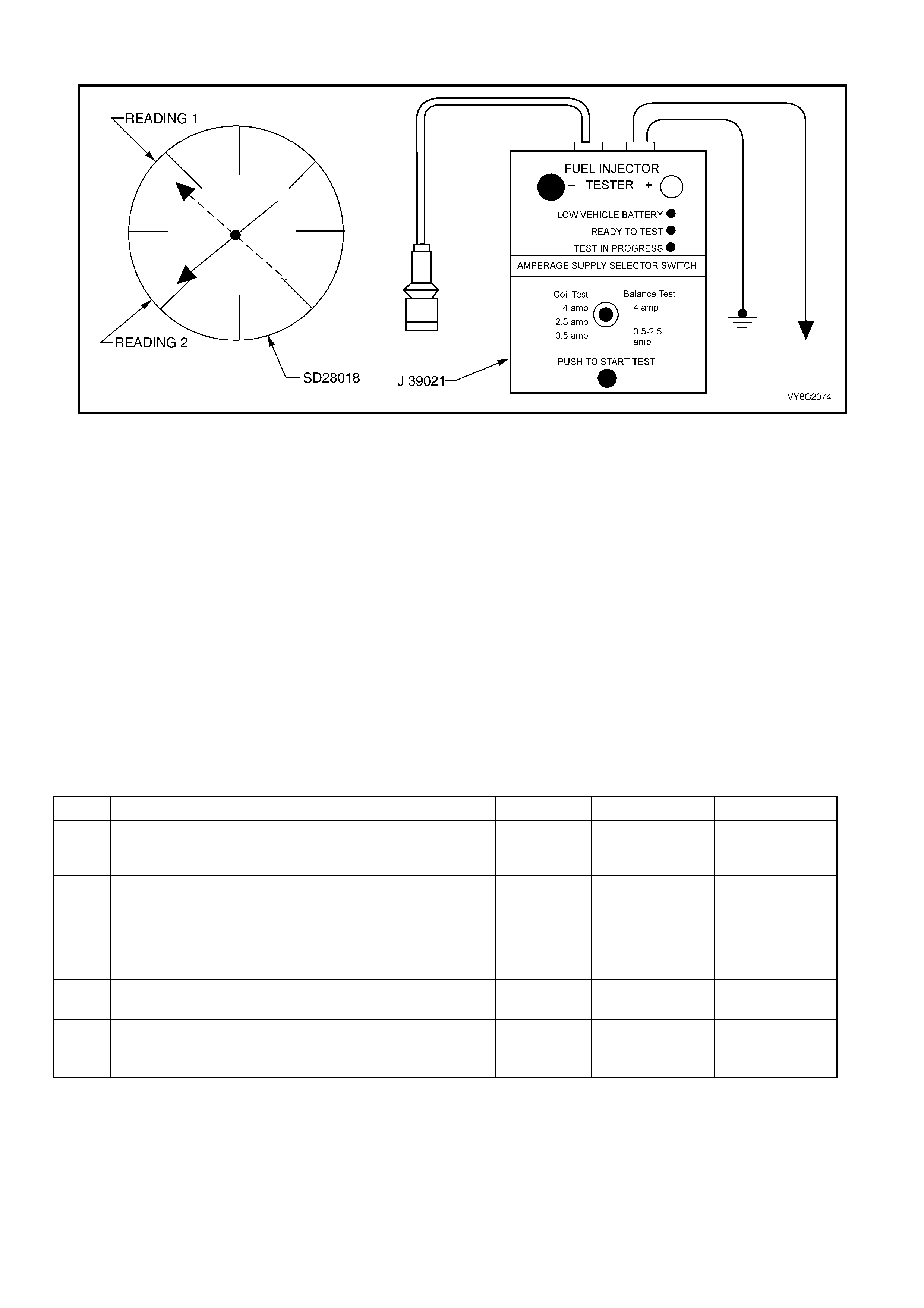
2.7 V6 PCM – FUEL INJECTOR BALANCE TEST
Figure 6C1-2C-13 – Fuel Injector Balance Test Equipment
TEST DESCRIPTION:
NOTE: The number(s) below refer to the step number(s) on the diagnostic table.
CAUTION: Wrap a shop towel around the fuel pressure connection in order to reduce the risk of fire and
personal injury. The towel will absorb any fuel leakage that occurs during the connection of the fuel
pressure gauge. Place th e towel in an approved container when the connection of the fuel pressure gauge
is complete.
4. The engine coolant temperature must be below the operating temperature in order to avoid irregular fuel
pressure readings due to Hot Soak fuel boiling.
5. The fuel pr essure shoul d be within the spec ified rang e. If the fuel pressure is not within the spec ified rang e, go
to Fuel System Diagnosis in Section 6C1-2A.
6. The fuel pressure should reach a steady value. If the fuel pressure d oes not reach a steady value, go to Fuel
System Diagnosis.
7. If the pressure drop value for each fuel injector is within 10 kPa of the average pressure drop value, the fuel
injectors are flowing properly. Calculate the pressure drop value for each fuel injector by subtracting the second
pressure reading from the first pressure reading. Refer to the illustration above.
Running the engine after each injector test will prevent the engine from flooding.
2.7 V6 PCM – FUEL INJECTOR BALANCE TEST
STEP ACTION VALUE YES NO
1. Was the "On-Board Diagnostic" (OBD) System Check
performed? Go to Step 2 Go to
OBD System
Check.
2. Was the Fuel Injector Coil Test Procedure performed?
Go to Step 3 Go to Table 2.8
Fuel Injector Coil
Test – ECT
Between
10 – 35° C in
this Section.
3. Is the engine coolant temperature above the specified
value? 94 °C Go to Step 4 Go to Step 5
4. 1. Allow the engine to cool below the specified value.
Is the engine coolant temperature below the specified
value?
94 °C Go to Step 5 –

STEP ACTION VALUE YES NO
5. CAUTION: Wrap a shop towel around the fuel pressure
connection in order to reduce the risk of fire and
personal injury. The towel will absorb any fuel leakage
that occurs during the connection of the fuel pressure
gauge. Place the towel in an approved container when
the connection of the fuel pressure gauge is complete.
1. Relieve fuel pressure. Refer to 6C1-3 SERVICE
OPERATIONS, for the procedure.
2. Connect the Fuel Gauge Schrader Fitting Adaptor
AU453 to the fuel rail, then connect SD28018 fuel
pressure gauge to the Schrader Fitting Adaptor.
3. Place the bleed hose of the fuel pressure gauge into
an approved petrol container.
4. Connect Tech 2 and use it to energise the fuel pump.
5. Bleed the air out of the fuel pressure gauge.
6. Observe the reading on the fuel pressure gauge.
Is the fuel pressure within the specified limits?
270 –350
kPa Go to Step 6 Go to
Fuel System
Diagnosis in
6C1-2A
DIAGNOSTIC
TABLES
6. 1. Turn the fuel pump OFF.
Does the fuel pressure remain constant? Go to Step 7 Go to
Fuel System
Diagnosis in
6C1-2A
DIAGNOSTIC
TABLES
7. 1. Connect the J 39021 fuel injector tester to a fuel
injector.
2. Set the amperage supply selector switch on the fuel
injector tester to the Balance Test 0.5-2.5 amp
position.
3. Turn the fuel pump ON then OFF in order to pressurise
the fuel system.
4. Record the fuel pressure indicated by the fuel pressure
gauge after the fuel pressure stabilises. This is the 1st
pressure reading (refer to (1) in the illustration).
5. Energise the fuel injector by depressing the Push to
Start Test button on the fuel injector tester.
6. Record the fuel pressure indicated by the fuel pressure
gauge after the fuel pressure gauge needle has
stopped moving. This is the 2nd pressure reading
(refer to (2) in the illustration).
7. Subtract the 2nd pressure reading from the 1st
pressure reading for the fuel injector. The result is the
pressure drop value.
8. Run the engine after each test to clear the residual fuel
from the cylinder.
Was test completed?
Go to Step 8 –
8. 1. Repeat Step 7 for each fuel injector.
2. Obtain a pressure drop value for each fuel injector.
3. Add all of the individual pressure drop values. This is
the total pressure drop.
4. Divide the total pressure drop by the number of fuel
injector s. This is the av erage p ress ure drop.
Does any fuel injector have a pressure drop value that is
either higher than the average pressure drop or lower than
the average pressure drop by the specified value?
10 kPa Go to Step 9 –
9. NOTE: Do not repeat any portion of this test before running
the engine in order to prevent the engine from flooding.
1. Re-test any fuel injector that does not meet the
specification. Refer to procedure in Step 7.
Does any fuel injector still have a pressure drop value that
is either higher than the average pressure drop or lower
than the average pressure drop by the specified value?
10 kPa Go to Step 10 Go to 6C1-2B
SYMPTOMS.
10. 1. Replace the faulty fuel injector(s). Refer to Fuel
Injector Replacement in 6C1-3 SERVICE
OPERATIONS.
Is the replacement complete?
System OK –
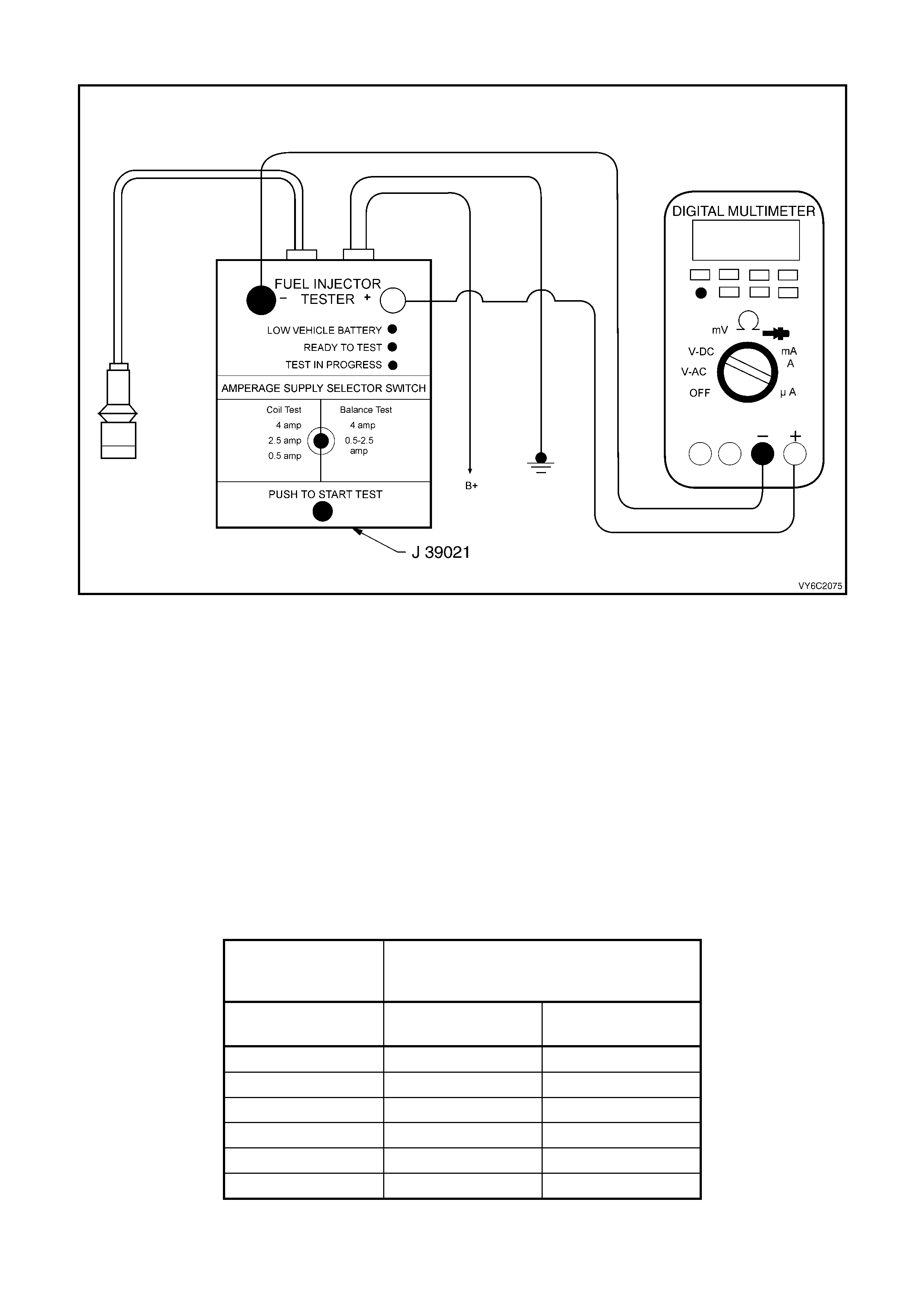
2.8 V6 PCM – FUEL INJECTOR COIL TEST – ECT BETWEEN 10 – 35° C
Figure 6C1-2C-14 – Fuel Injector Coil Test
TEST DESCRIPTION:
NOTE: The number(s) below refer to the step number(s) on the diagnostic table.
CAUTION: Wrap a shop towel around the fuel pressure connection in order to reduce the risk of fire and
personal injury. The towel will absorb any fuel leakage that occurs during the connection of the fuel
pressure gauge. Place th e towel in an approved container when the connection of the fuel pressure gauge
is complete.
2. The engine coo lant tem perature aff ects the abilit y of the fuel i njector tes ter to det ect a fault y fuel inject or. If the
engine coo lant tem per ature is NOT betwe en 10° C an d 35° C, go to T able 2.10 – Fuel Inj ector Coi l Tes t – ECT
Outside 10 – 35° C.
3. The first second of the voltage displayed by the DMM may be inaccurate due to the initial current surge.
Therefore, record the lowest voltage displayed by the DMM after the first second of the test. The voltage
displayed by the DMM should be within the specified range (refer to the example). The voltage displayed by the
DMM may increase thro ug hout th e tes t as the f uel inj e c tor wind ings warm and the res is tance of the f uel injec t or
windings changes. An erratic voltage reading (large fluctuations in voltage that do not stabilise) indicates an
intermittent connection within the fuel injector.
Example:
Resistance
(11.4 – 12.6 Ohms)
Voltage Specification Between 10° C –
35° C
(5.7 – 6.6 Volts)
Fuel Injector
Number Voltage Reading Pass/Fail
1 6.3 P
2 5.9 P
3 6.2 P
4 6.1 P
5 4.8 F
6 6.0 P

2.8 V6 PCM – FUEL INJECTOR COIL TEST – ECT BETWEEN 10 – 35° C
STEP ACTION VALUE YES NO
1. Was the "On-Board Diagnostic" (OBD) System Check
performed? Go to Step 2 Go to
OBD System
Check.
2. 1. Connect Tech 2.
2. Check the engine coo lan t temperature.
Is the engine coolant temperature within the specified
value?
10 – 35° C Go to Step 3 Go to Table 2.9,
Fuel Injector Coil
Test – ECT
Outside 10– 35°
C.
3. 1. Turn the ignition ON.
NOTE: In order to prevent flooding of a single cylinder and
possible engine damage, relieve the fuel pressure before
performing the fuel injector coil test procedure.
2. Relieve the fuel pressure. Refer to the Fuel Pressure
Relief Procedure, in 6C1-3 SERVICE OPERATIONS.
3. Access the fuel injector electrical connectors, as
required.
4. Connect the J 39021 Fuel Injector Tester to B+ and
ground.
5. Set the amperage supply selector switch on the fuel
injector tester to the ‘Coil Test 0.5 Amp’ position.
6. Connect the leads from a Digital Multimeter (DMM) to
the fuel injector tester. Refer to the illustration
associated with the test description.
7. Set the DMM to the tenths scale (0.0).
8. Connect the fuel injector tester to a fuel injector.
IMPORTANT: Check the engine coolant temperature
again in order to ensure that the correct Table is being
used.
9. Press the ‘Push to Start Test’ button on the fuel
injector test er.
10. Observe the voltage reading on the DMM.
IMPORTANT: The voltage reading may rise during the
test.
11. Record the lowest voltage observed after the first
second of the test.
12. Repeat Steps 8 through 11 for each fuel injector.
Did any fuel injector have an erratic voltage reading (large
fluctuations in voltage that do not stabilise) or voltage
readings out sid e of the specif i ed value ?
5.7 – 6.6 V Go to Step 4 Go to Table 2.7,
Fuel Injector
Balance Test in
this Section.
4. 1. Replace the faulty fuel injector(s). Refer to Fuel
Injector Replacement in Section 6C1-3 SERVICE
OPERATIONS.
Is the replacement complete?
Go to Table 2.8,
Fuel Injector
Balance Test in
this Section.
–
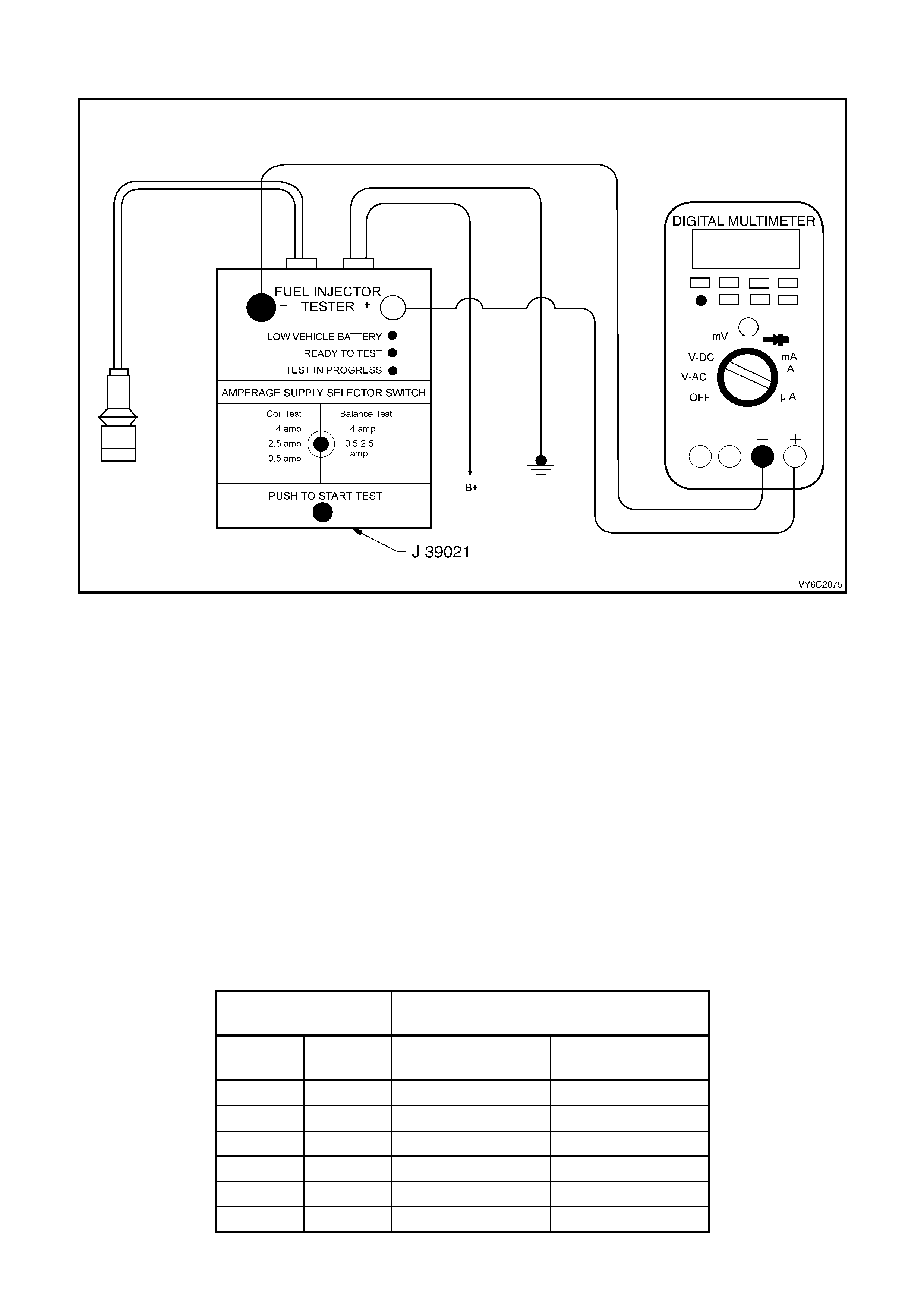
2.9 V6 PCM – FUEL INJECTOR COIL TEST – ECT OUTSIDE 10 – 35° C
Figure 6C1-2C-15 – Fuel Injector Coil Test
TEST DESCRIPTION:
NOTE: The number(s) below refer to the step number(s) on the diagnostic table.
CAUTION: Wrap a shop towel around the fuel pressure connection in order to reduce the risk of fire and
personal injury. The towel will absorb any fuel leakage that occurs during the connection of the fuel
pressure gauge. Place th e towel in an approved container when the connection of the fuel pressure gauge
is complete.
2. The engine coo lant tem perature aff ects the abilit y of the fuel i njector tes ter to det ect a fault y fuel inject or. If the
engine c ool ant temperatur e is NOT outsid e 1 0° C a nd 35° C, r ef er to T able 2.8, Fuel In je cto r Coil T est – E CT
Between 10 – 35° C.
3. The first second of the voltage displayed by the DMM may be inaccurate due to the initial current surge.
Therefore, record the lowest voltage displayed by the DMM after the first second of the test. The voltage
displa ye d by the DMM m ay increase thr oughout the te st as the fuel inj ector windings warm and the res istance
of the fuel injector windings changes. An erratic voltage reading (large fluctuations in voltage that do not
stabilise) indicates an intermittent connection within the fuel injector.
From the voltages record ed, ident if y the highest voltag e, excludi ng an y voltages above 9.5 vo lts. Su btrac t eac h
voltage that is not above 9.5 volts from the highest voltage. Record each subtracted value (refer to the
Example). Any fuel injector with a subtracted value that is greater than 0.6 volts is faulty. Replace the fuel
injector. Any fuel injector with a recorded voltage above 9.5 volts is also faulty. Replace the fuel injector.
Example:
Highest Voltage
Reading (7.1 Volts) Voltage Specification Outside 10° C –
35° C (0.6 Volts)
Injector
Number Voltage Subtracted Value Pass/Fail
1 9.8 – F
2 6.6 0.5 P
3 6.9 0.2 P
4 5.8 1.3 F
5 7.0 0.1 P
6 7.1 0.0 P

2.9 V6 PCM – FUEL INJECTOR COIL TEST – ECT OUTSIDE 10 – 35° C
STEP ACTION VALUE YES NO
1. Was the "On-Board Diagnostic" (OBD) System Check
performed? Go to Step 2 Go to
OBD System
Check.
2. 1. Connect Tech 2
2. Check the engine coo lan t temperature.
Is the engine coolant temperature outside the specified
value?
10 – 35° C Go to Step 3 Go to Table 2.8
Fuel Injector Coil
Test - ECT
Between 10 –
35° C.
3. 1. Turn the ignition OFF.
NOTE: In order to prevent flooding of a single cylinder
and possible engine damage, relieve the fuel pressure
before performing the fuel injector coil test procedure.
2. Relieve the fuel pressure. Refer to the Fuel Pressure
Relief Procedure in 6C1-3 SERVICE OPERATIONS.
3. Access the fuel injector electrical connectors as
required.
4. Connect the J 39021 Fuel Injector Tester to B+ and
ground.
5. Set the amperage supply selector switch on the fuel
injector tester to the ‘Coil Test 0.5 Amp’ position.
6. Connect the leads from a Digital Multimeter (DMM) to
the fuel injector tester. Refer to the illustration
associated with the test description.
7. Set the DMM to the tenths scale (0.0).
8. Connect the fuel injector tester to a fuel injector.
IMPORTANT: Check the engine coolant temperature
again in order to ensure that the correct Table is being
used.
9. Press the ‘Push to Start Test’ button on the fuel
injector test er.
10. Observe the voltage reading on the DMM.
IMPORTANT: The voltage reading may rise during the
test.
11. Record the lowest voltage observed after the first
second of the test.
12. Repeat Steps 8 through 11 for each fuel injector.
13. Identify the highest voltage reading recorded from the
recorded readings.
14. Subtract any other voltage reading recorded from the
voltage readings recorded.
15. Repeat Step 14 for all the remaining fuel injectors.
Is any value that resulted from subtracting greater than the
specified value?
0.6 Volts Go to Step 4 Go to Table 2.7
Fuel Injector
Balance Test in
this Section.
4. 1. Replace any fuel injector that had any of the following:
• A subtracted value exceeding 0.6 volts.
• An initial reading above 9.5 volts.
• An erratic reading.
Refer to Fuel Injector Replacement in 6C1-3 SERVICE
OPERATIONS.
Is the replacement complete?
Go to Table 2.7
Fuel Injector
Balance Test in
this Section.
–
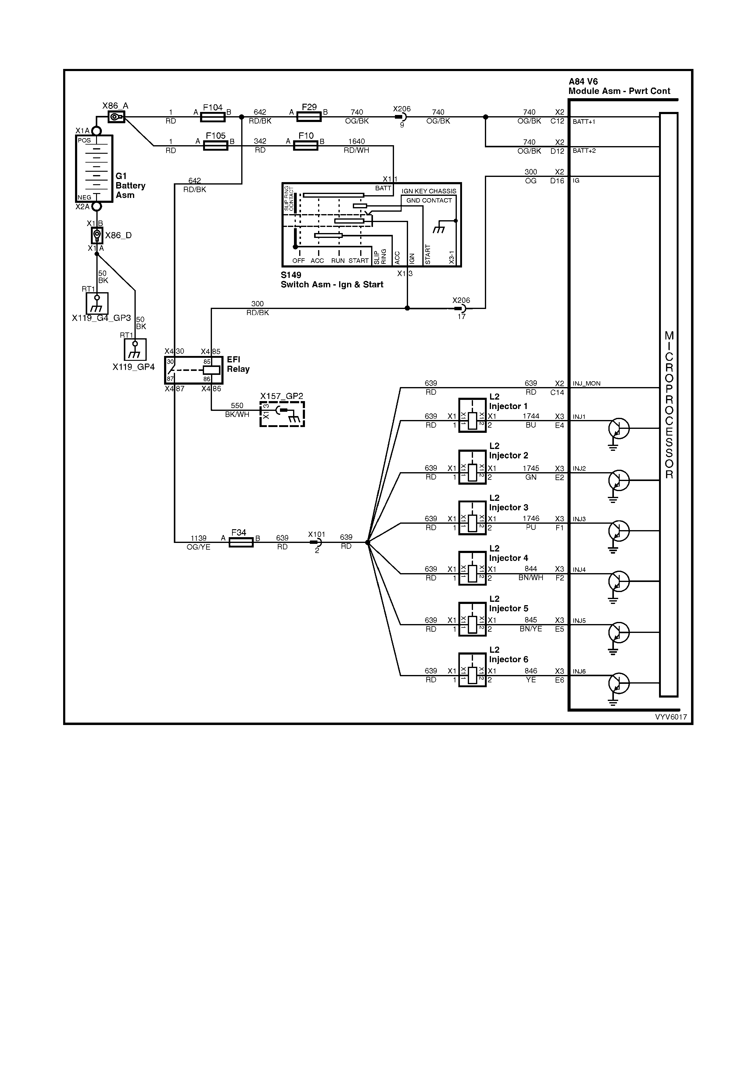
2.10 V6 PCM – FUEL INJECTOR CIRCUIT DIAGNOSIS
Figure 6C1-2C-16 – Fuel Injector Circuit
CIRCUIT DESCRIPTION:
The PCM will enab le an injector on the intak e stroke of each cylinder. Individual cylinder fuel control is referred to
as Sequential Fuel Injection (SFI).
Battery voltage is supplied directly to the fuel injectors. The PCM controls each injector by grounding the control
circuit via an internal switch called a driver. The primary function of the driver is to supply the ground for the
component be ing contr o lled.
DIAGNOSTIC AIDS:
• For an intermittent condition, refer to Section 6C1-2B SYMPTOMS in this Section.
TEST DESCRIPTION:
NOTE: The number(s) below refer to the step number(s) on the diagnostic table.
4. This step checks to see if each injector is functioning properly, electrically.
6. This step checks to see if there is a short to ground in the injector ignition feed circuits.
9. This step checks for an open or short to ground in the injector driver circuit.
A84 V6 X1 A84 V6 X3 L2 X206
Figure 6C1-2C-17
2.10 V6 PCM – FUEL INJECTOR CIRCUIT DIAGNOSIS
STEP ACTION VALUE YES NO
1. Was the "On-Board Diagnostic" (OBD) System Check
performed? Go to Step 2 Go to
OBD System
Check.
2. 1. Check injector fuse F34. If faulty, replace fuse.
Was a problem found? Go to Step 3 Go to Step 6
3. 1. Turn ignition OFF.
2. Disconnect all the injector harness connectors.
3. Turn ON the ignition leaving the engine OFF.
4. Using a test lamp connected to ground, probe each
injector harness ignition feed circuit.
Does the test lamp illuminate for all injectors?
Go to Step 4 Go to Step 8
4. 1. Turn ignition OFF.
2. Connect the injector test lamp (ST 8329) to isolate the
injector harness to each of the injectors one at a time.
3. Start the engine and idle.
Does the test lamp flash for all injectors?
Go to Step 5 Go to Step 9
5. 1. Inspect the injector harness terminals for correct
terminal tension, on the connector/s that did not flash
the test lamp.
2. Replace termi nal as nec es sar y .
Was a repair necessary?
System OK Go to Step 13
6. 1. Turn ignition OFF.
2. Disconnect the injector harness connectors.
3. Using a test lamp connected to B+, probe the injector
harness ignitio n feed circ uit at each inject or.
Does the test lamp illuminate?
Go to Step 11 Go to Step 7
7. 1. Measure the resistance of each injector that is
powered by the fuse that is open, us ing a DMM.
Does any injector measure less than the specified value?
11.4 Ω Go to Step 13 Go to Step 12
8. 1. Repair the injector ignition feed circuit that did not
illuminate the test light.
Is the action complete?
Verify Repair –
9. 1. Turn ignition OFF.
2. Disconnect the PCM connector A84-X3.
3. Check the injector driver circuit that did not flash the
test light, for an open, short to ground or short to
voltage.
Is the injector driver circuit open, shorted to ground or
voltage?
Go to Step 10 Go to Step 15
10. 1. Repair injector driver circuit for an open, short to
ground or short to voltage.
Is the action complete?
Verify Repair –
11. 1. Repair the grounded ignition feed circuit to the
injectors.
Is the action complete?
Verify Repair –
12. 1. Repair short to voltage in the injector ignition feed
circuit.
Is the action complete?
Verify Repair –

STEP ACTION VALUE YES NO
13. 1. Replace the faulty injector(s) that was isolated. Refer
to Fuel Injector Replacement, in 6C1-3 SERVICE
OPERATIONS.
Is the action complete?
Verify Repair –
14. 1. Replace PCM. Refer to 6C1-3 SERVICE
OPERATIONS, for PCM Programming and Security
Link procedure.
Is action complete?
Verify Repair –
15. 1. Inspect the appropriate injector circuit for the following:
• Poor connections at the injector and the PCM
terminal.
• Intermittent short to ground.
• Intermittent opens.
If a problem is found, repair the circuit as necessary.
Did you find and correct the condition?
Verify Repair Go to Step 14