
SECTION 6C1-3 - SERVICE OPERATIONS - V6 ENGINE
IMPORTANT
Before performing any Service Operation or other procedure described in this Section, refer to Section 00
CAUTIONS AND NOTES for correct workshop practices with regard to safety and/or property damage.
1. GENERAL DESCRIPTION
1.1 SERVICE PRECAUTIONS
2. ELECTRONIC CONTROL
2.1 POWERTRAIN CONTROL MODULE
PCM REPLACEMENT/PROGRAMMING
REMOVE
REINSTALL
SERVICE PROGRAMMING
PCM SECURITY LINK
FUNCTIONAL CHECK
2.2 CAMSHAFT POSITION SENSOR
REMOVE
REINSTALL
2.3 ENGINE COOLANT TEMPERATURE (ECT)
SENSOR
REMOVE
REINSTALL
2.4 INTAKE AIR TEMPERATURE (IAT) SENSOR
REMOVE
REINSTALL
2.5 MASS AIR FLOW (MAF) SENSOR
REMOVE
REINSTALL
2.6 OXYGEN SENSOR
REMOVE
REINSTALL
2.7 THROTTLE POSITION (TP) SENSOR
REMOVE
REINSTALL
2.8 VEHICLE SPEED SENSOR
REMOVE
REINSTALL
3. FUEL CONTROL SYSTEM
3.1 FUEL PUMP RELAY
FUEL PRESSURE RELIEF PROCEDURE
3.2 THROTTLE STOP SCREW- RESET
PROCEDURE
CHECK OR RESET
3.3 MODULAR FUEL SENDER ASSEMBLY
REMOVE
REINSTALL
FUEL STRAINER AND FUEL LEVEL SENSOR)
FUEL PUMP ASSEMBLY
3.4 FUEL SYSTEM PRESSURE TEST
MEASURE
3.5 FUEL FILTER
REMOVE
REINSTALL
3.6 LEAK TESTING
3.7 FUEL PRESSURE REGULATOR
REMOVE
REINSTALL
3.8 FUEL RAIL AND INJECTORS
REMOVE
DISASSEMBLE
REASSEMBLE
REINSTALL
3.9 AIR CLEANER ASSEMBLY
REMOVE
REINSTALL
3.10 THROTTLE CABLE
REMOVE
REINSTALL
ADJUST
3.11 THROTTLE BODY
REMOVE
CLEAN
THROTTLE BODY CLEANING PROCEDURE
REINSTALL
THROTTLE BODY IAC VALVE COUNT
CHECKING PROCEDURE
3.12 FUEL RAIL AND INJECTORS
3.13 IDLE AIR CONTROL VALVE
REMOVE
CLEAN
REINSTALL
3.14 THROTTLE PEDAL ASSEMBLY
REMOVE
DISASSEMBLE
REASSEMBLE
REINSTALL
4. DIRECT IGNITION SYSTEM (DIS)
4.1 GENERAL SERVICE INFORMATION
TIMING ADJUSTMENT
CHECK EST SPARK TIMING OPERATION
4.2 IGNITION COIL/S
REMOVE
RESISTANCE TESTS
REINSTALL
4.3 DIS MODULE
REMOVE
REINSTALL
4.4 CRANKSHAFT (CKP) SENSOR
REMOVE
REINSTALL
4.5 KNOCK SENSORS
CHECKING KNOCK SENSOR OPERATION
REMOVE
REINSTALL
4.6 SPARK PLUG LEADS
REMOVE
SPARK PLUG LEAD BENCH TESTS
REINSTALL
4.7 SPARK PLUGS
REMOVE
CLEANING AND INSPECTION
REINSTALL
SPARK PLUG DIAGNOSIS
ANALYSIS OF SPARK PLUG CONDITION
5. AUTOMATIC TRANSMISSION
SERVICE OPERATIONS AND COMPONENTS
6. MISCELLANEOUS SYSTEMS
6.1 EVAPORATIVE EMISSION CONTROL CANISTER
6.2 CANISTER PURGE SOLENOID
REPLACE
6.3 EXHAUST GAS RECIRCULATION (EGR) VALVE
REMOVE
REINSTALL
6.4 A/C REFRIGERANT PRESSURE SENSOR
REPLACE
Techline
Techline
1. GENERAL DESCRIPTION
This Section describes the proper service procedures to repair components of the Powertrain Management
System , used with th e V6 engine. Emphasis is placed on the proper pr ocedures and repair of components related
to this specific system.
1.1 SERVICE PRECAUTIONS
The following requirements must be observed when working on vehicles:
1. Before removing any PCM system component, disconnect the battery ground lead.
2. Never start the engine without the battery being solidly connected.
3. Never disconnect the battery from the on board electrical system while the engine is running.
4. When charging the battery, disconnect it from the vehicle's electrical system.
5. Never subject the PCM to temperatures above 80° C; i.e. paint oven. Always remove PCM first if this
temperature is to be exceeded.
6. Ensure that all cable harness plugs are connected solidly and that battery terminals are thoroughly clean.
7. The engine management system harness connectors are designed to fit in only one way; there are indexing
tabs and slots on both halves of the connector. Forcing the co nnector into place is not necessar y if it is be ing
installed with the proper orientation. Failure to take care to match the indexing tabs and slots to ensure the
connector is being installed correctly can cause damage to the connector, the module, or other vehicle
components or s ystem s .
8. Never connect or disconnect a cable harness plugs at the PCM when the ignition is switched "ON."
9. Before attempting any electric arc welding on the vehicle, disconnect the battery leads and the PCM
connectors.
10. When steam cleaning engines, do not direct the steam cleaning nozzle at PCM system components. If this
happens, corrosion of the terminals can take place.
11. Use only the test equipment specified in the diagnostic Tables, since other test equipment may either give
incorrect results or damage good components.
12. All vol tag e meas urements using a vo ltmeter mus t us e a dig ital voltmeter with an inter na l impedance r at in g of at
least 10 million ohms per volt (10 megohm/volt).
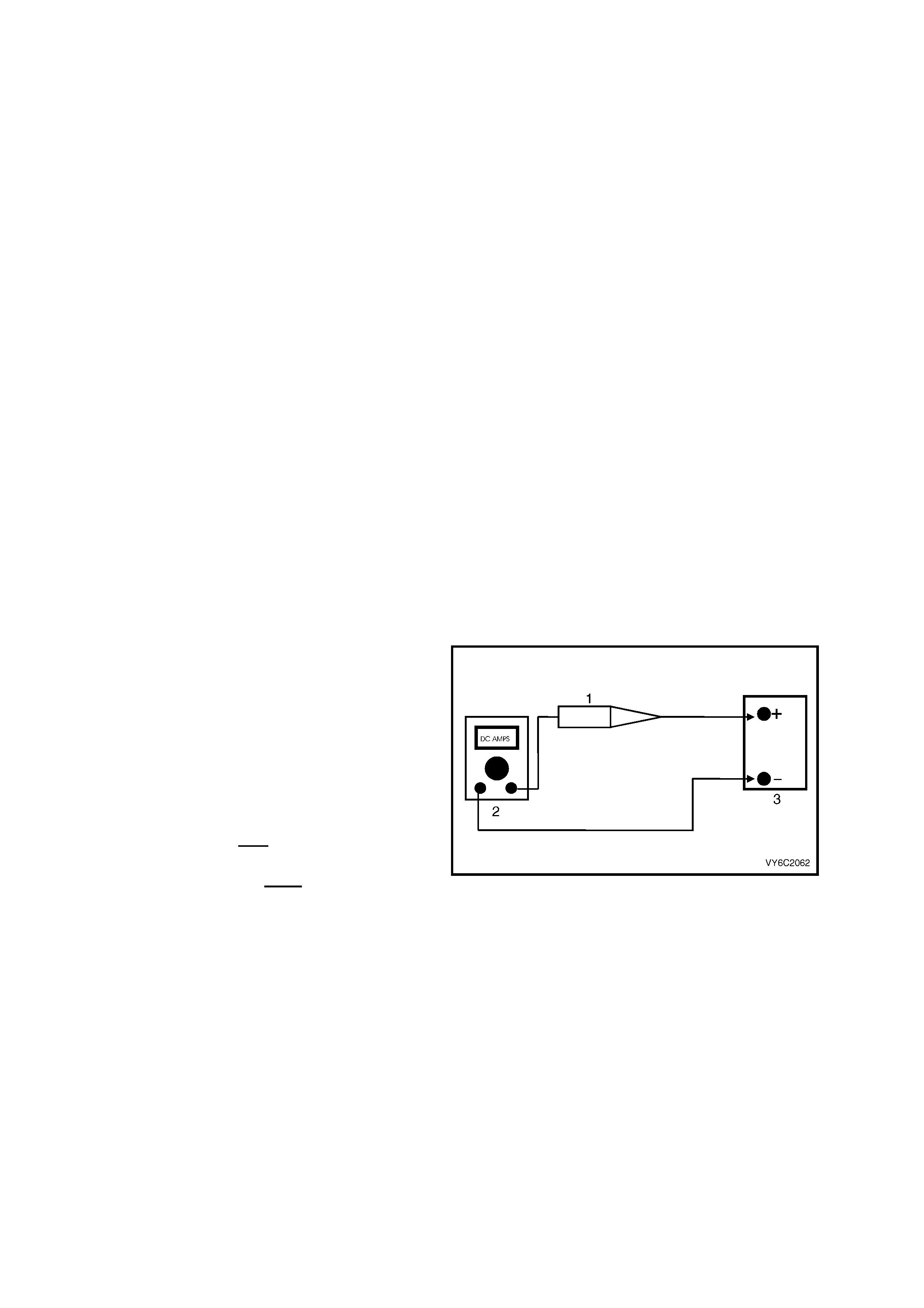
13. When a test light ( 1) is s pec ified, a " low-p ower"
test light must be used. Do not use a high –
wattage test light. While a particular brand of
test ligh t is no t sug geste d, a sim ple t est o n an y
test light will ensure it to be OK for PCM c ircuit
testing. Connect an accurate (2) Ammeter
(such as a high-impedance digital multimeter)
in series with the test light being tested, and
power the test light-ammeter circuit with the
ve hicle battery (3).
If the am meter indicat es less tha n 0.3 Am p current
flow (300 mA), the test light is OK to use.
If the ammeter indicates more than 0.3 Amp
current flow (or 300 mA), the test light is NOT OK
to use.
Figure 6C2-3-1
14. When fasteners are removed, always reinstall them at the same location from which they were removed. If a
fastener needs to be replaced, use the correct part number fastener for that application. If the correct part
number fastener is not available, a fastener of equal size and strength (or stronger) may be used. Fasteners
that are not to be re-used, or those requiring thread locking compound will be identified. The correct torque
value must be used when installing fasteners that require it. If the above conditions are not followed, parts or
system damage could result.
2. ELECTRONIC CONTROL
2.1 POWERTRAIN CONTROL MODULE
LT Section No. – 02-245
PCM REPLACEMENT/ PROGRAMMING
Service of the PCM (1) should normally consist of
either replacement of the PCM or EEPROM (flash
memory) programming. If the diagnostic
procedures call for the PCM to be replaced, the
PCM should be first checked to ensure it is the
correct part. If it is, remove the faulty PCM and
insta ll the ne w PCM .
NOTE 1: The replacement PCM EEPROM will not
be programmed.
NOTE 2: DT C P0601 indic ates the E EPRO M is not
programmed or has malfunctioned. Refer to
Service Programming in this Section for
programming procedures.
IMPORTANT: The following operations must be
carried out whenever the PCM is replaced:
• The EEPROM must be programmed.
• The Functional Check must be performed
(described later in this Section).
IMPORTANT: W henever the PCM is disconnected
or loses power:
• The Functional Check must be performed
(also described later in this Section).
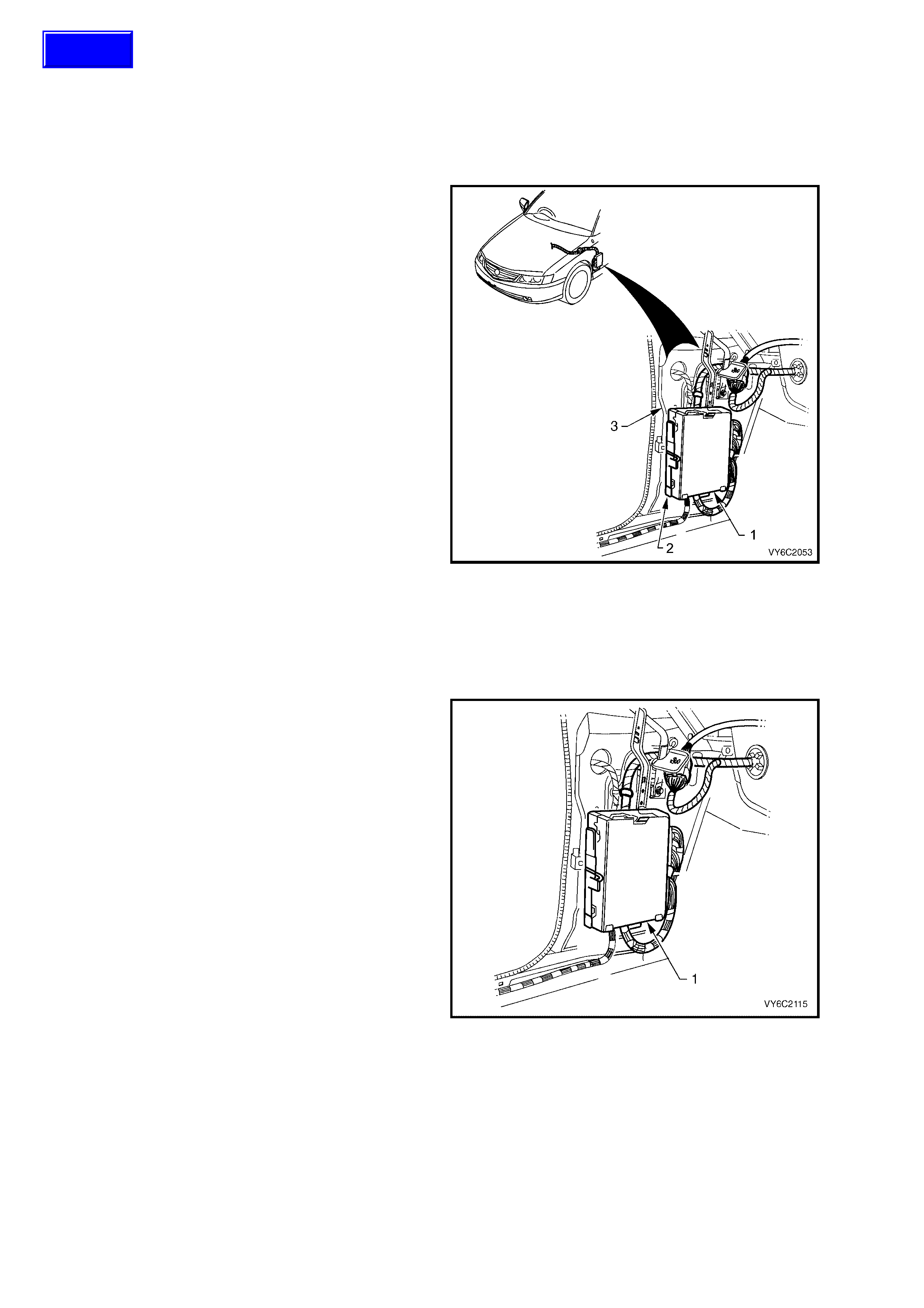
Legend:
1. Powertrain Control Module (PCM)
2. PCM Mounting Bracket
3. Left Hand Front Shroud Panel
Figure 6C1-3-2 – PCM Location
NOTE 1: To prevent internal PCM damage, the
ignition must be OFF when disconnecting or
reconnecting power to the PCM.
NOTE 2: The PCM (1) and mounting bracket are
located un der the left ha nd front shr oud panel trim ,
as shown.
Figure 6C1-3-3 – PCM Mounting
Techline
REMOVE
IMPORTANT: Remove any debris from the PCM connector surfaces before servicing the PCM.
NOTE: Do not touch the connector pins or soldered components on the circuit board. Otherwise possible
electrostatic discharge damage to the PCM could occur.
1. Disconnect battery ground lead.
IMPORTANT: Disconnection of the battery affects certain vehicle electronic systems. Refer to Section 00 CAUTIONS, 5.
Battery Disconnection Procedures before disconnecting the battery.
2. Remove left hand front shroud panel lower trim assembly (cowl panel trim), refer to
Section 1A3, INSTRUMENT PANEL and CONSOLE in the MY 2003 VY and V2 Series Service Information.
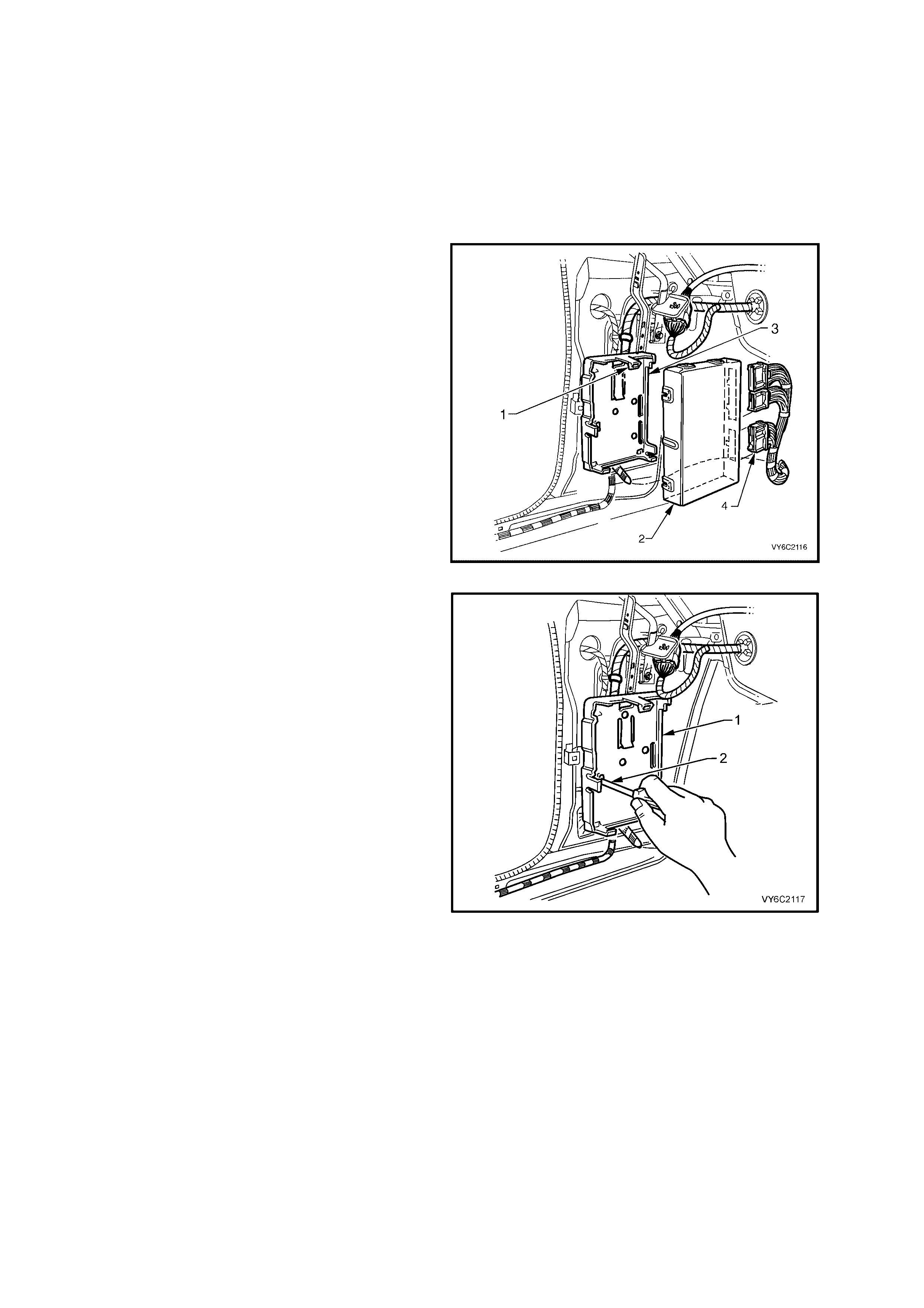
3. Lift up mounting bracket to PCM upper
retaining tang (1), pull PCM (2) out at the top
then up, to remove it from the mounting
bracket (3).
4. Remove wiring harness connectors (4) from
PCM, then remove the PCM (2) from the
vehicle.
IMPORTANT: The replacement PCM EEPROM
will not be programmed.
Figure 6C1-3-4 – PCM Removal
5. If required, remove PCM mounting bracket (1)
by inserting a screwdriver (2) into the retaining
tang slot, lever screwdriver to release tang.
Pull bracket out then down to release from the
cowl panel.
Figure 6C1-3-5 – PCM Mounting Bracket Removal
REINST ALL
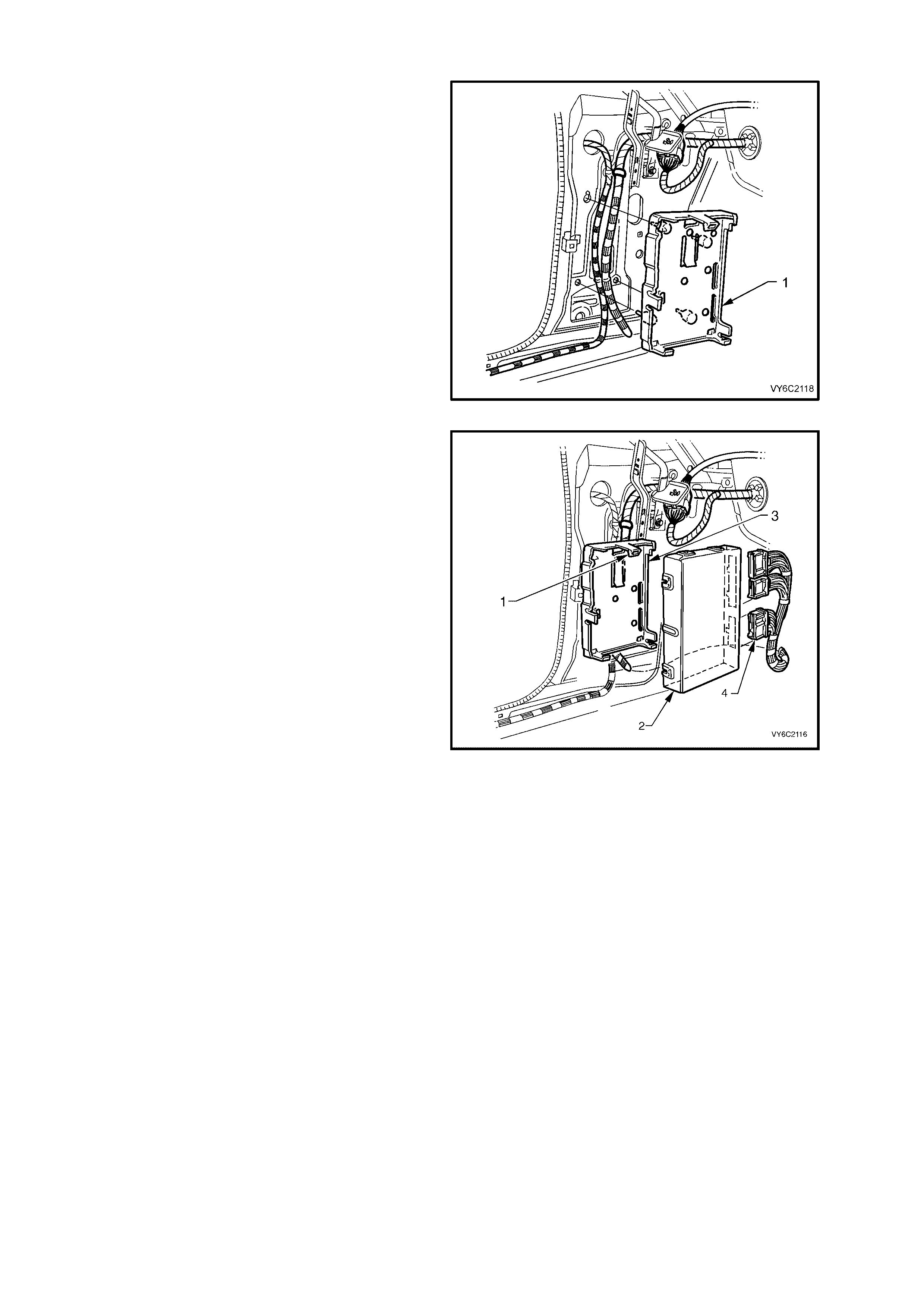
1. If removed, r eins tal l PC M mounting brac ket (1) ,
engaging bracket leg into slotted hole in cowl
panel. Lift up bracket and engage bracket
lower retainers and retaining tang into cowl
panel.
Figure 6C1-3-6 – PCM Mounting Bracket Reinstallation
2. Reconnect wiring harness connectors (4) to
PCM.
3. Assemble PCM (2) into mounting bracket (3),
ensurin g wiring harness is r outed in f ront of the
mounting bracket.
4. Reinstall cowl panel trim, Refer to
Section 1A3, INSTRUMENT PANEL AND
CONSOLE.
5. Reconnect batter y ground l ead.
6. Perform Service Programming if the PCM
was replaced with a new unit, refer to
Service Programming in this Section.
Otherwise start the vehicle and allow to idle.
Check vehicle for correct operation.
Figure 6C1-3-7 – PCM Mounting Bracket Reinstallation
SERVIC E PRO GRAMMING
NOTE: Follow th e program ming instru ctions c omplete ly an d do n ot ke y OFF dur ing progr am ming unles s ins tr uc ted.
If the key is turned OFF during programming, possible PCM damage may occur.
IMPORTANT: Do not disconnect Tech 2 during each programming step.
1. Ensure that the following conditions have been met, before starting this process:
a. The battery is fully charged, but not charging during programming.
b. The ignition is ON.
c. Ensure that all PCM connections are OK.
2. Connect Tech 2 to the vehicle and select Service Programming System (SPS) / Request Info and follow
instructions.
3. Connect Tech 2 to a PC with the Technical Information System (TIS) installed and download latest software
matching the vehicle. Refer to TIS terminal/equipment user instructions.
4. Connect Tech 2 to the vehicle again and select Service Programming System (SPS) / Program ECU.
5. If the PCM fails to program, proceed as follows:
a. Ensure that all PCM connections are OK.
b. Attempt to re-program the PCM. If the PCM still cannot be programmed correctly, replace the PCM and
program it according to this procedure.
IMPORTANT: O nce the ne w PCM has been pr ogram m ed, it m ust be Securit y Linked. Ref er to PCM Security Link
for linking procedure. If updating calibrations to the vehicle’s existing PCM hardware, no linking procedure is
necessary.

PCM SECURITY LINK
Once the PCM an d or BCM h ave been replace d, the ne w PCM and /or BCM must be securit y linked t o each ot her.
If this procedure is not performed, the vehicle will not crank.
PCM to BCM Link ing Proce dur e
Connect Tech 2 to DL C an d s elect “D iag nos tic / (3) 20 03 V Y C om modore / Body / Body Contro l M odu le / Securit y /
BCM Link to PCM” and follow Tech 2 instructions.
For additional information regarding Tech 2 and Tech 2 test modes (including this linking procedure), refer to
Tech 2 Diagnosis for BCM, in Section 12J BCM.
NOTE: If this vehicle is als o fitted with LPG, ref er to Section 8A2 LPG SY STEM , after the PCM is r eplaced and/or
reprogrammed for the LPG setup procedure. This must be performed whenever the PCM is replaced or
reprogrammed.
FUNCTIONAL CHECK
1. Clear the Diagnostic Trouble Codes (DTCs).
2. Perform the Powertrain OBD System Check.
3. Start the engine and idle for one minute.
4. Use Tech 2 to check for DTCs.
2.2 CAMSHAFT POSITION SENSOR
LT Section No. – 02-200
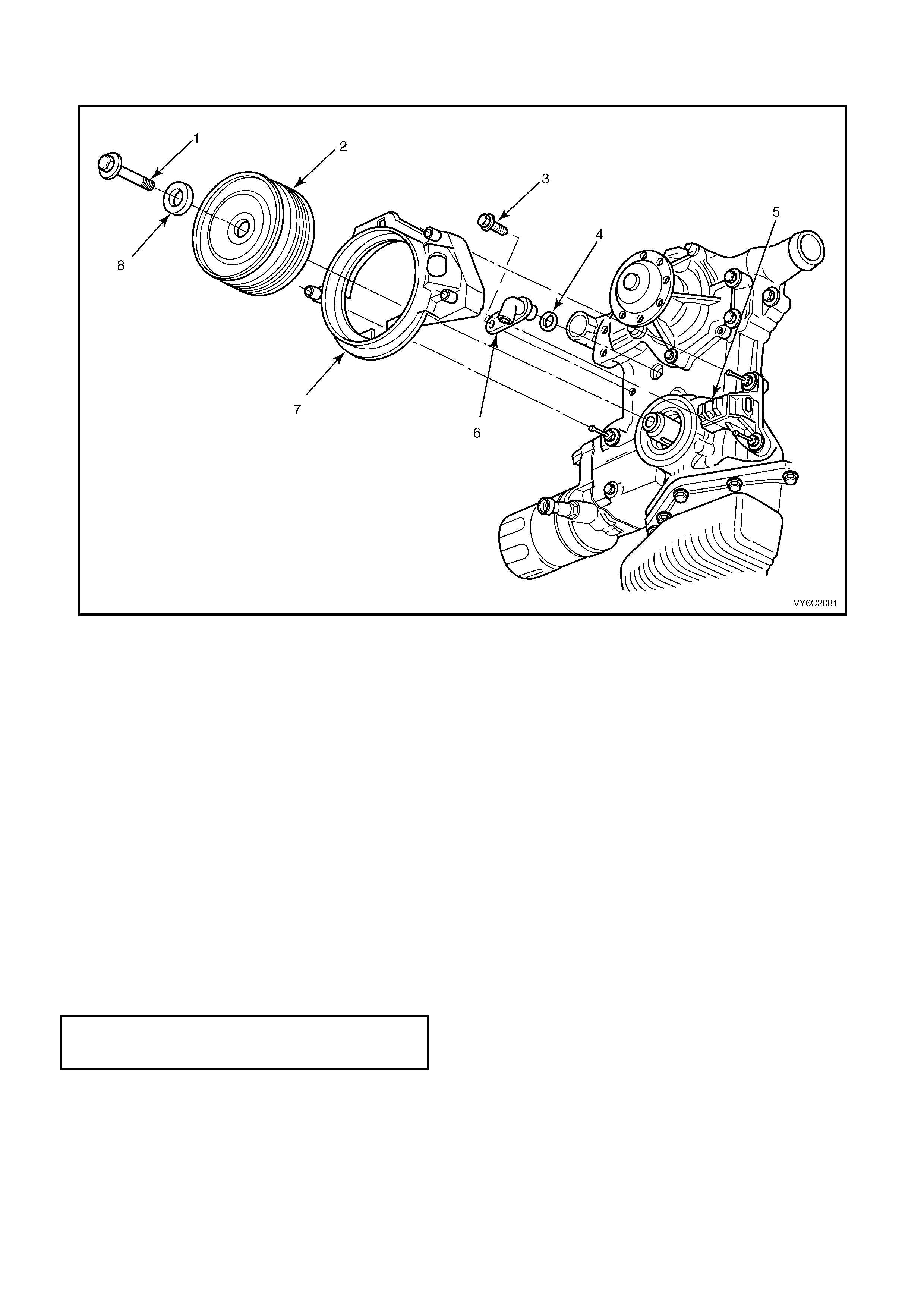
Figure 6C1-3-8 – Camshaft/Crankshaft Position Sensors
Legend
1. Bolt
2. Balancer - Crankshaft
3. Screw – Camshaft Sensor Retaining
4. O-Ring
5. Sensor – Crankshaft Position
6. Sensor – Camshaft
7. Shield – Crankshaft Position Sensor
8. Bolt
REMOVE
1. Disconnect battery ground lead.
IMPORTANT: Disconnection of the battery affects certain vehicle electronic systems. Refer to Section 00 CAUTIONS, 5.
Battery Disconnection Procedures before disconnecting the battery.
2. Lift up retaining tang and disconnect wiring harness connector from camshaft position sensor (6).
3. Remove camshaft position sensor to front cover retaining screw (3).
4. Remove camshaft position sensor and O-ring (4) from front cover.
REINST ALL
1. Apply light engine oil to O-ring (4) on new camshaft position sensor (6).
2. Assemble camshaft position sensor (6) into front cover hole.
3. Install camshaft position sensor (6) to front cover retaining bolt (3) and tighten to the correct torque
specification.
CAMSHAFT POSITION SENSOR
RETAINING SCREW
TORQUE SPECIFICATION 11 Nm
4. Reconnect wiring harness connector to camshaft position sensor (6).
5. Reconnect batter y ground l ead.
2.3 ENGINE COOLANT TEMPERATURE (ECT) SENSOR
LT Section No. – 02-000
IMPORTANT: Care must be taken when handling the PCM engine coolant sensor. Damage to the sensor will affect
the operation of the engine management system. Ensure that the correct sensor is located before service is
attempted. The ECT sensor is located in the front of the intake manifold below the engine thermostat housing
(Refer to Figure 6C1-3- 1 0).
NOTE: The Engine C oolant Temperature (ECT ) sensor (2) is installed in to a "wet" engine coolant passage (in the
intake m anifold, b elow t he ther m ostat housing) . Drain t he engin e coola nt befor e removing the E CT sensor from the
engine. Position a coolant drain pan appropriately, then loosen lower radiator hose at the radiator to drain the
coolant.
REMOVE
1. Disconnect battery ground lead.
IMPORTANT: Disconnection of the battery affects certain vehicle electronic systems. Refer to Section 00
CAUTIONS, 5. Battery Disconnection Procedures before disconnecting the battery.
2. De-pressurise engine cooling system by removing the radiator cap in two stages.
CAUTION: Do not remove radiator cap while the engine coolant temperature is above 50°
°°
° C.
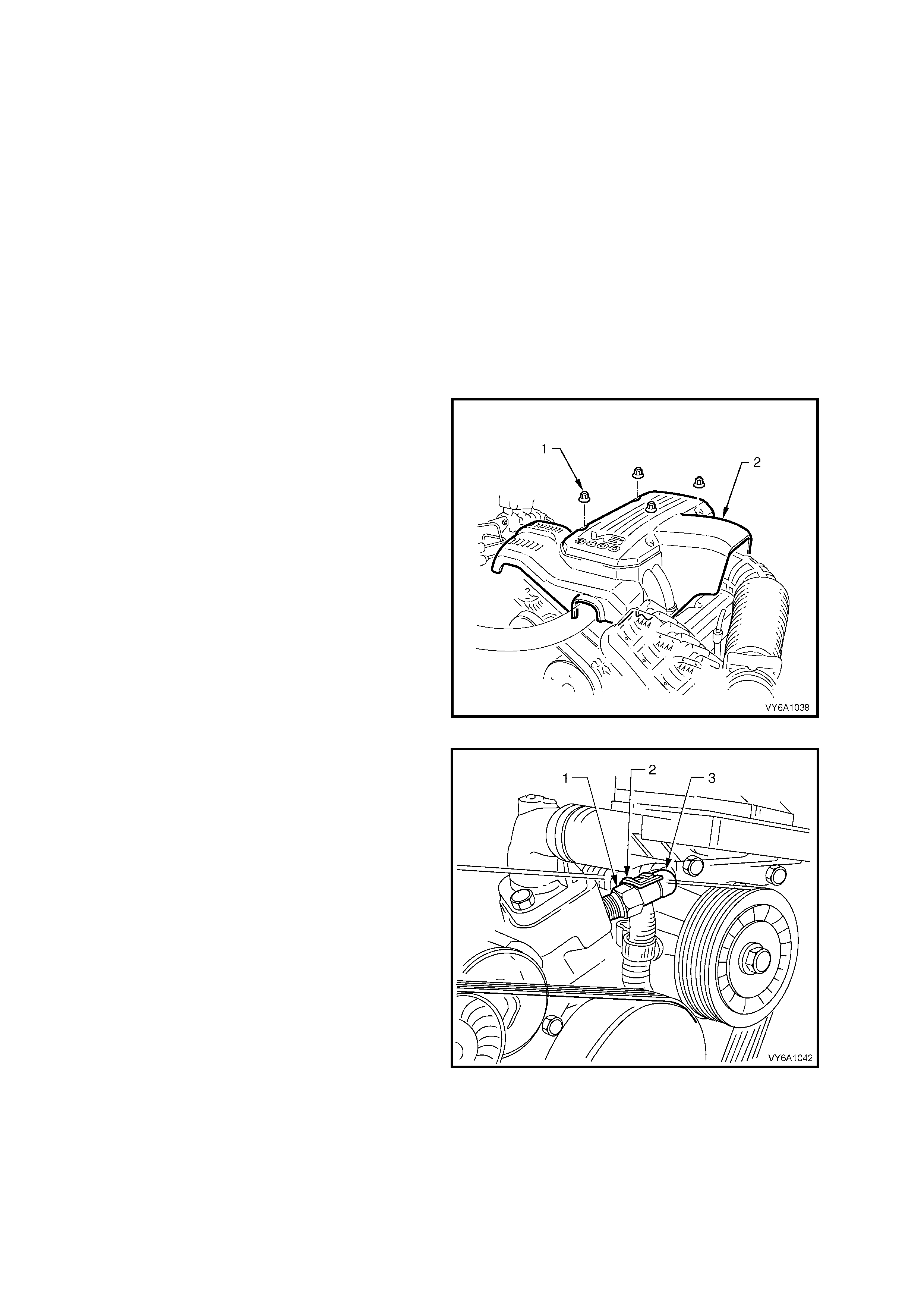
3. Remove four dome nuts (1) securing the
engine dress cover assembly (2) to the intake
manifold studs, then remove the cover
assembly.
Figure 6C1-3-9 – Engine Dress Cover - V6 Engine
4. Place a suitable coolant drain pan under the
vehicle, then loosen lower radiator hose at the
radiator to drain the engine coolant.
5. Lift up retaining tang (2) and disconnect wiring
harness connector (3) from ECT sensor (1). Lift
connector up away from sensor.
6. Carefully move powertrain wiring harness
down und er the ECT sens or to allow acc ess to
the sensor.
7. Using a 19 mm ring spanner, carefully loosen
and remove PCM, ECT sensor.
Figure 6C1-3-10 – ECT Sensor Location

REINST ALL
1. Apply Loctite 242 (GM Specification 998 5283) sealant to the cleaned sensor threads.
2. Install ECT sensor into intake manifold and tighten to the correct torque specification.
ECT SENSOR TO INTAKE MANIFOLD
TORQUE SPECIFICATION 18 Nm
3. Reconnect wiring harness connector onto ECT sensor.
NOTE: Recheck that wiring harness connector and harness are correctly positioned. The accessory drive belt
passes ver y close to the tem perature sensor conn ector. Futur e damage to the harness could occur if not cor rectly
positioned now.
4. Reconnect batter y ground l ead.
5. Refill the engine coolant system, Refer to Section 6B1, ENGINE COOLING - V6 ENGINE .
6. Reinstall engine dress cover to the intake manifold, ensuring that stud grommets in dress cover remain in
place. Tighten securing dome nuts to the correct torque specification.
ENGINE DRESS COVER TO INTAKE
MANIFOLD DOME NUT
TORQUE SPECIFICATION 5 Nm
2.4 INTAKE AIR TEMP ERATURE (IAT) SENSOR
LT Section No. – 03-250
IMPORTANT: Care must be taken when handling the IAT Sensor. Damage to the IAT Sensor will affect proper
operation of the fuel control system.
REMOVE
1. Disconnect battery ground lead.
IMPORTANT: Disconnection of the battery affects certain vehicle electronic systems. Refer to
Section 00 CAUTIONS, 5. Battery Disconnection Procedures before disconnecting the battery.
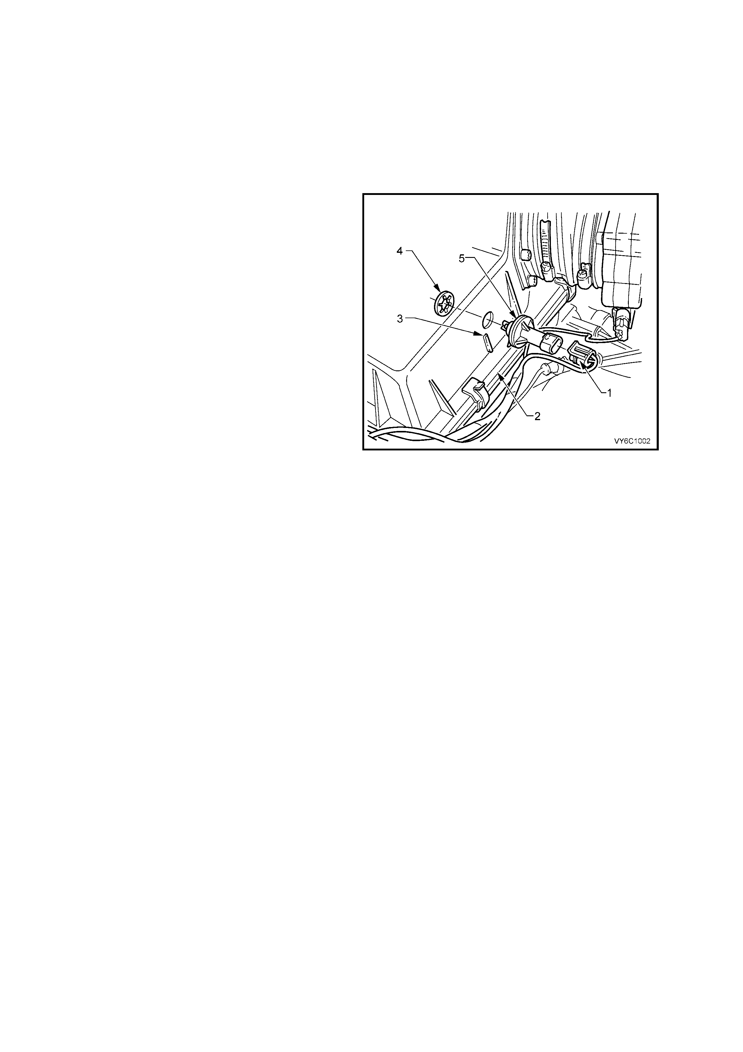
2. Lift up tang on IAT sensor wiring harness
connector (1) and pull connector from
sensor (5).
3. Loosen intake air duct adaptor clamp that is
located closest to air cleaner assembly.
4. Disconnect air duct, with mass air flow sensor
attached, from air cleaner upper housing.
5. Unclip 5 retaining clips holding the air cleaner
upper housing (2) in place.
6. Separate the upper and lower air cleaner
housings.
IMPORTANT: Air filter should remain in the lower
housing.
7. Remove air cleaner upper housing and place
on bench.
8. Using a pair of side cutters, cut across the IAT
sensor retainer (4) to remove it. Once
removed, discard retainer.
9. Pull out IAT sensor (5) from air cleaner upper
housing.
Figure 6C1-3-11 – IAT Sensor Removal
REINST ALL
1. Push new IAT s ensor (5) into air clea ner up per housin g (2) , with triangular ta ng o n the mounting f lan ge loc ati ng
on the mating rib (3) of the air cleaner upper housing.
2. Position the upper air cleaner housing assembly, with the IAT sensor on the work bench, pushing up into the
air cleaner upper housing.
3. Position new retainer (4) onto IAT sensor and then using a 20 m m socket, push the retainer full y onto the IAT
sensor.
4. Assemble the air filter element into the air cleaner upper housing and place the upper housing onto the air
cleaner lower air cleaner housing, ensuring that air filter element remains in position.
5. Snap 5 retainer clips up into place over the top of the air cleaner upper housing.
6. Reconnect wiring harness connector (1) to IAT sensor (5).
7. Carefully assemble intake air duct and mass air flow sensor onto air cleaner upper housing.
NOTE: Align notch on air cleaner housing adaptor with notch in air duct adaptor and notch in clamp.
8. Tighten air duct clamp securely.
9. Check that mass air flow sensor wiring harness connector has remained firmly in place.
2.5 MASS AIR FLOW (MAF) SENSOR
LT Section No. – 02-000
NOTE: Care must be taken when handling MAF sensor. Damage to MAF sensor will affect proper operation of
PCM control.
REMOVE
1. Disconnect battery ground lead.
IMPORTANT: Disconnection of the battery affects certain vehicle electronic systems. Refer to
Section 00 CAUTIONS, 5. Battery Disconnection Procedures before disconnecting the battery.
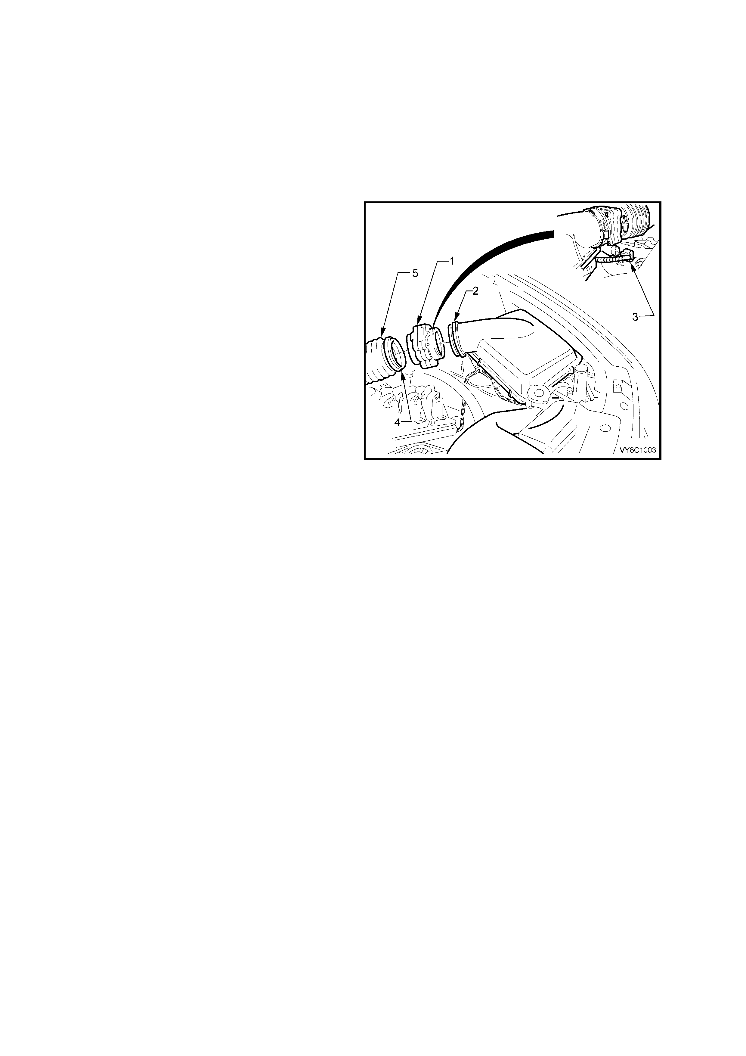
2. Lift up tang on MAF sensor wiring harness
connector (3) and pull connector from
sensor (1).
3. Loosen clamp on air duct adaptor (2), closest
to MAF sensor (1).
4. Loosen clamp (4) on air duct (5) at MAF sensor
(1) and pull back air duct (5) from sensor.
IMPORTANT: Air duct adaptor (between the air
cleaner and MAF sensor), both clamps, air duct
and MAF sensor itself, all have locating notches.
5. Remove MAF sensor (1) from air duct
adaptor (5).
REINST ALL
1. Reinstall MAF sensor (1) into air duct adaptor
(5) and air duct, aligning all notches.
2. Reinstall clamps, aligning notches, tighten
clamps securely.
3. Reconnect MAF sensor wiring harness
connector (3). Reconnect battery ground lead.
4. Start vehicle and check for air leaks.
Figure 6C1-3-12 – MAF Sensor Removal
2.6 OXYGEN SENSOR
LT Section No. – 00-450
NOTE 1: The oxygen sensor uses a permanently attached pigtail and connector. This pigtail should not be
rem oved from the ox ygen sens or. Damage or r emova l of the pigta il or connector will affec t proper operation of the
oxygen sensor.
NOTE 2:Take care when handling the oxygen sensor. The in-line electrical connector and louvred end must be
kept free of grease, dirt or other contaminants. Avoid using any cleaning solvents. Do not drop or roughly handle
the oxygen sensor.
NOTE 3: The ox ygen sens or m ay be diff icult to remove when e ngine temper ature is below 60 ° Celsius. Excessive
force may damage threads in the exhaust pipe or sensor.
NOTE 4: Under no c ircumstances ar e the wiring harnes s connectors as sociated with the ox ygen sens or circuits to
be sealed in any way, by using grease or other substance. To do so, would result in an inadequate supply of
refer ence air to be able t o reach the atm ospheric reference c avity of eac h sensor, res ulting in a DTC to be s et. If a
flexible sealant is used (i.e. grease), then this would be drawn into the sensor cavity, poisoning the sensor,
resulting in a premature failure. Also, should connector damage be evident, then the sensor and lead must be
replace d, as soldering of the wiri ng wou ld also neg ate the ‘br eat hi ng ’ capa bility of the sensor wiri ng.
REMOVE
1. Disconnect battery ground lead.
IMPORTANT: Disconnection of the battery affects
certain vehicle electronic systems. Refer to
Section 00 CAUTIONS, 5. Battery
Disconnection Procedures before disconnecting
the battery.
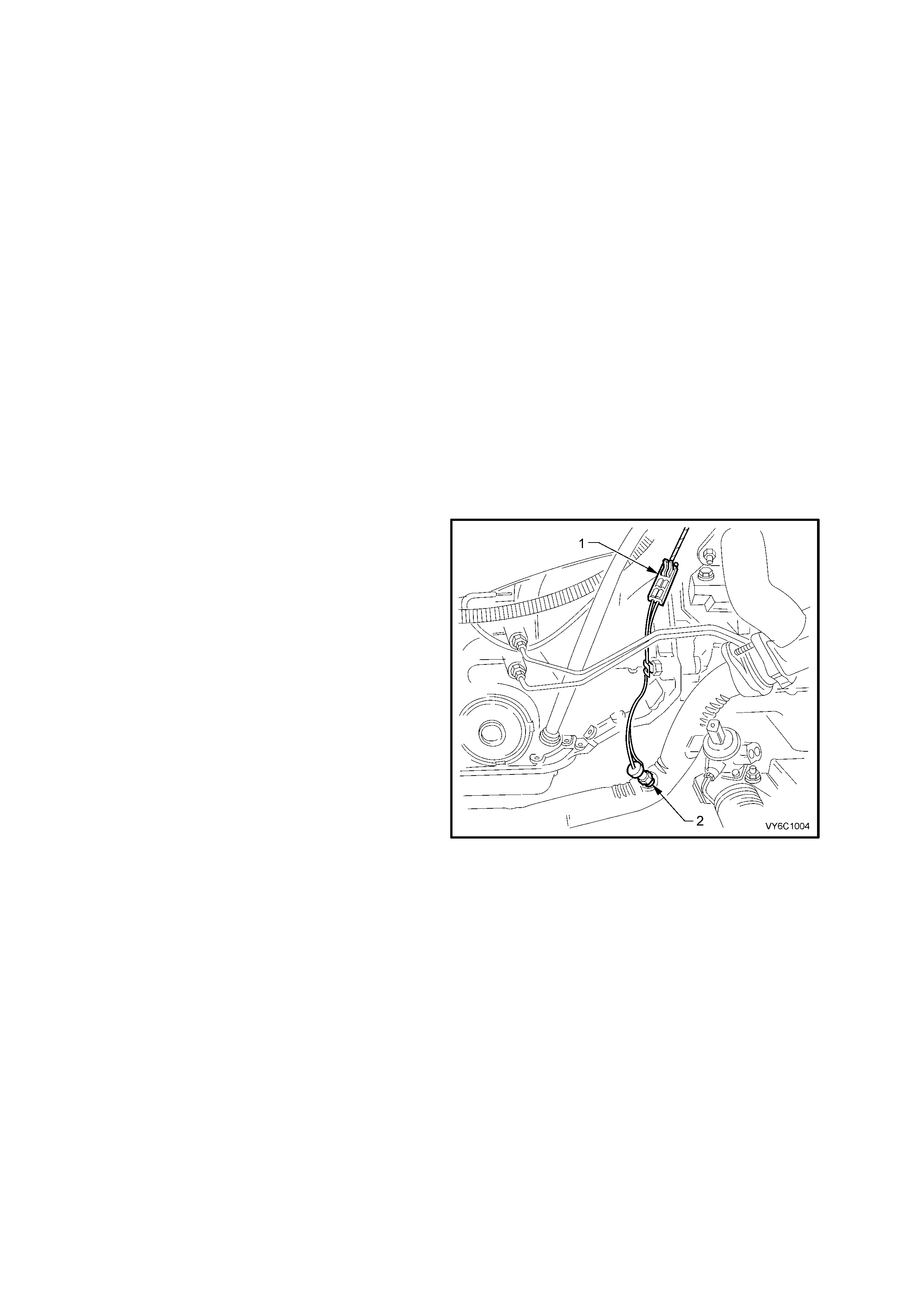
2. Lift up retaining tang on oxygen sensor wiring
harness connector (1) and pull connector from
sensor pigtail connector.
For RH sensor, the connector (1) is located at
the rear of the RH cylinder head and is
accessed from the rear of the engine
compartment. The sensor pigtail leads are
further retained by a c lip attac hed to the torque
converter housing (automatic transmission).
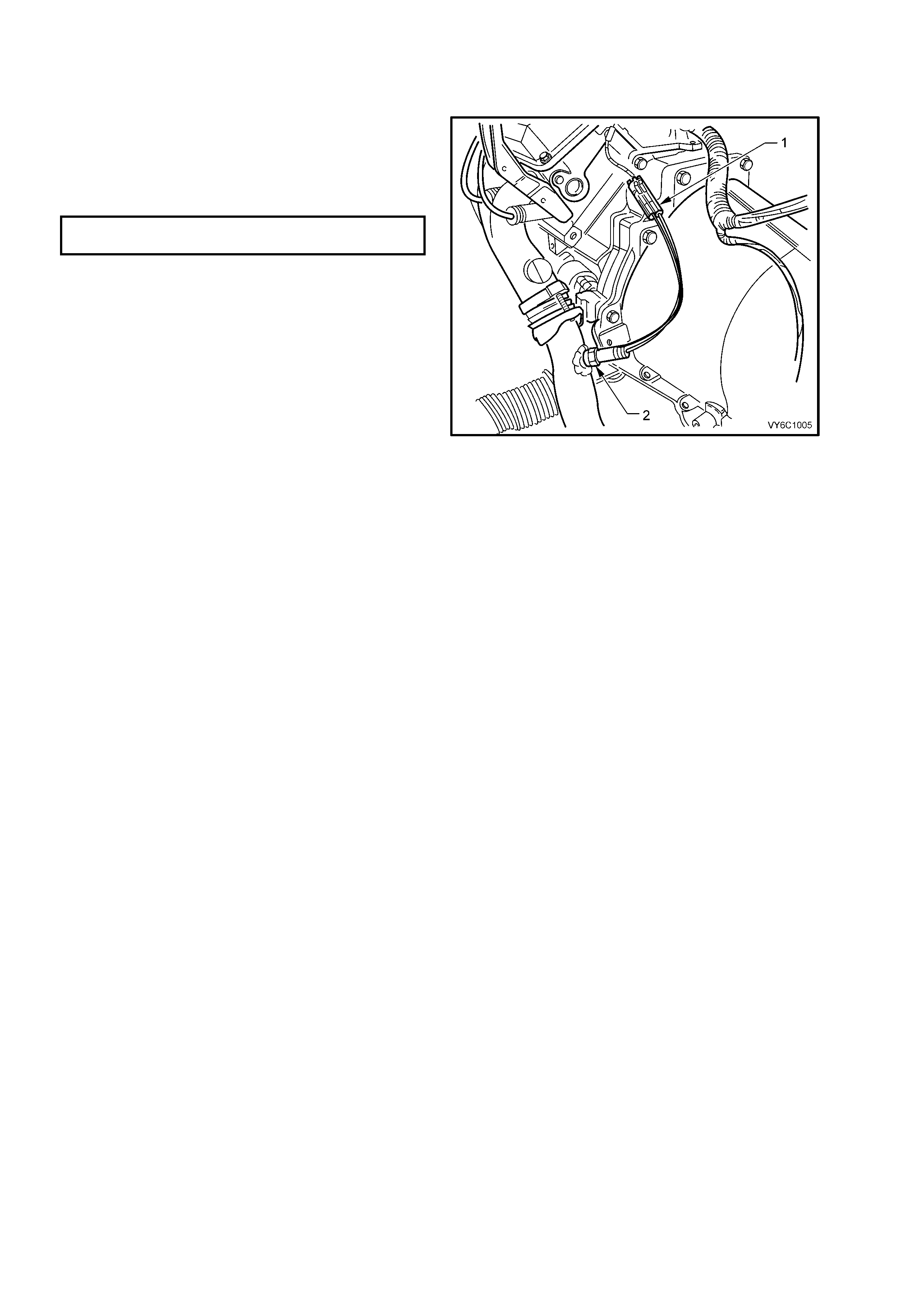
For LH sensor (refer Figure 6C3-1-14), the
connector is located at the rear of the LH
cylinder head and is accessed from the rear of
the engine compartment.
3. Raise vehicle and support on safety stands.
Refer to Section 0A GENERAL
INFORMATION in the MY 2003 VY and V2
Series Service Information, for the location of
jacking and support points.
4. Carefully unscrew oxygen sensor (2) from
exhaust pipe referring to the ‘NOTES’ above.
NOTE: While the RHD vehicle arrangement is
shown, the LHD is similar.
Figure 6C1-3-13 – RH Sensor Location
REINST ALL
NOTE 1: A special anti-s eize c ompound is us ed o n
the oxygen sensor threads. The compound
consists of a liquid graphite and very small glass
beads. The graphite will burn away, but the glass
beads will remain, making the sensor easier to
remove.
NOTE 2: Genuine replacement sensors will
already have the compound applied to the threads.
If a sensor is removed from an engine, and, if for
any reason it is to be reinstalled, the threads
MUST have the specified anti-seize compound
applied before reinstallation.
NOTE: Specified anti-seize compound is available
from authorised Parts Outlets as part number
5613695.
1. If necessary, coat the cleaned oxygen sensor
threads with the specified anti-seize
compound.
2. Install oxygen sensor (2) into exhaust pipe and
tighten to the correct torque specification.
EXHAUST GAS OXYGEN SENSOR
TORQUE SPECIFICATION 45 Nm
3. Remove safety stands and lower the vehicle.
4. Reconnect oxygen sensor wiring harness
connector (1).
IMPORTANT: Ensure that the RH sensor pigtail
leads are retained by a clip attached to the torque
converter housing (refer Figure 6C1-3-13).
5. Reconnect batter y ground l ead.
Figure 6C1-3-14 – LH Sensor Location
2.7 THROTTLE POSITION (TP) SENSOR
LT Section No.– 03-300
REMOVE
1. Disconnect battery ground lead.
IMPORTANT: Disconnection of the battery affects certain vehicle electronic systems. Refer to Section 00
CAUTIONS, 5. Battery Disconnection Procedures before disconnecting the battery.
2. Remove four dome nuts securing the engine dress cover assembly to the intake manifold studs, then remove
the cover assembly . Refer to Figu re 6C1-3-9.
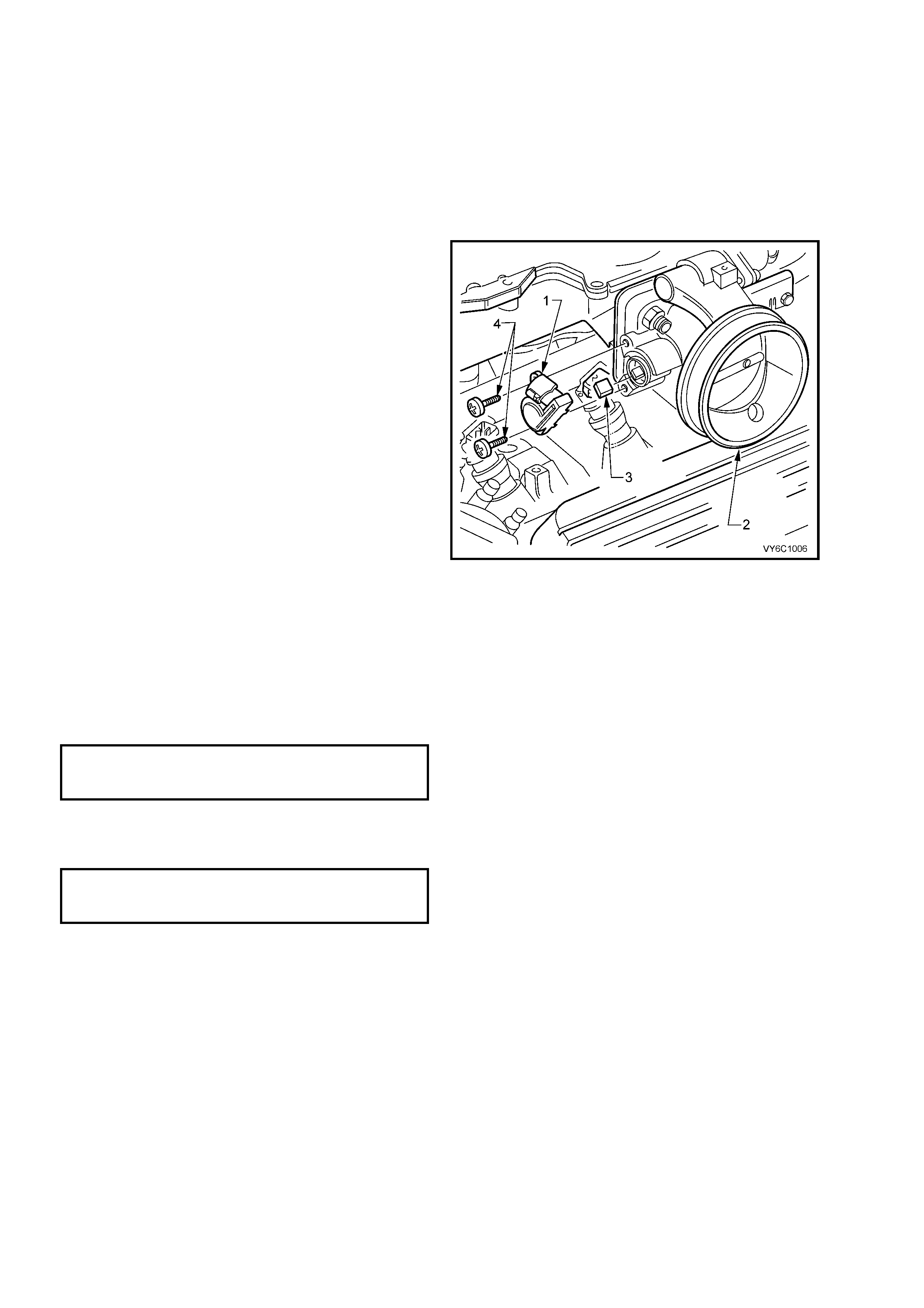
3. Lift up retaining tang on TP sensor wiring
harness connector and pull connector from
sensor (1).
4. Remove the two TP sensor to throttle body
attaching screws (4).
5. Remove sensor (1) from throttle body (2)
taking care not to lose the drive adaptor (3).
IMPORTANT: The "drive adaptor" (3) is a plastic
cover th at loose ly slid es ov er the end of the thr ottle
shaft, on the TP sensor side of the throttle body. It
is captured when the TP sensor is in position on
the throttle body. The drive adaptor could fall from
the throttle shaft after the TP sensor is removed.
Ensure that the drive adaptor is not lost.
Figure 6c1-3-15 – TP Sensor Removal
REINST ALL
1. Check that the drive adaptor (3) is in place on the throttle valve shaft, refer to the previous ‘IMPORTANT’
statement relating to the drive adaptor.
2. With throttle va lve i n the no rmall y closed i dl e pos i tio n, i nst all TP sens or ( 1) on to t hrottl e v al ve shaf t an d thr ot tle
body at a position 30° clockwise past throttle body attaching screw holes.
3. Rotate TP sensor anti-clockwise on throttle body, and install TP sensor attaching screws and tighten to the
correct torque specification.
TP SENS O R TO TH R OTTL E B ODY
ATTACHING SCREW
TORQUE SPECIFICATION 1.2 Nm
4. Reconnect TP sensor wiring harness connector.
5. Reinstall engine dress cover to the intake manifold, ensuring that stud grommets in the dress cover remain in
place . Tighten securing dome nuts to the correct torque specification.
ENGINE DRESS COVER TO INTAKE
MANIFOLD DOME NUT
TORQUE SPECIFICATION 5 Nm
6. Reconnect batter y ground l ead.
2.8 VEHICLE SPEED SENSOR
LT Section No.– 04-075
REMOVE
Automatic Transmission
1. Raise rear of vehic le an d suppor t on saf ety st ands. R ef er to Section 0 A GENERAL INFORM ATION in t he M Y
2003 VY and V2 Series Service Information, for the location of jacking and support points.
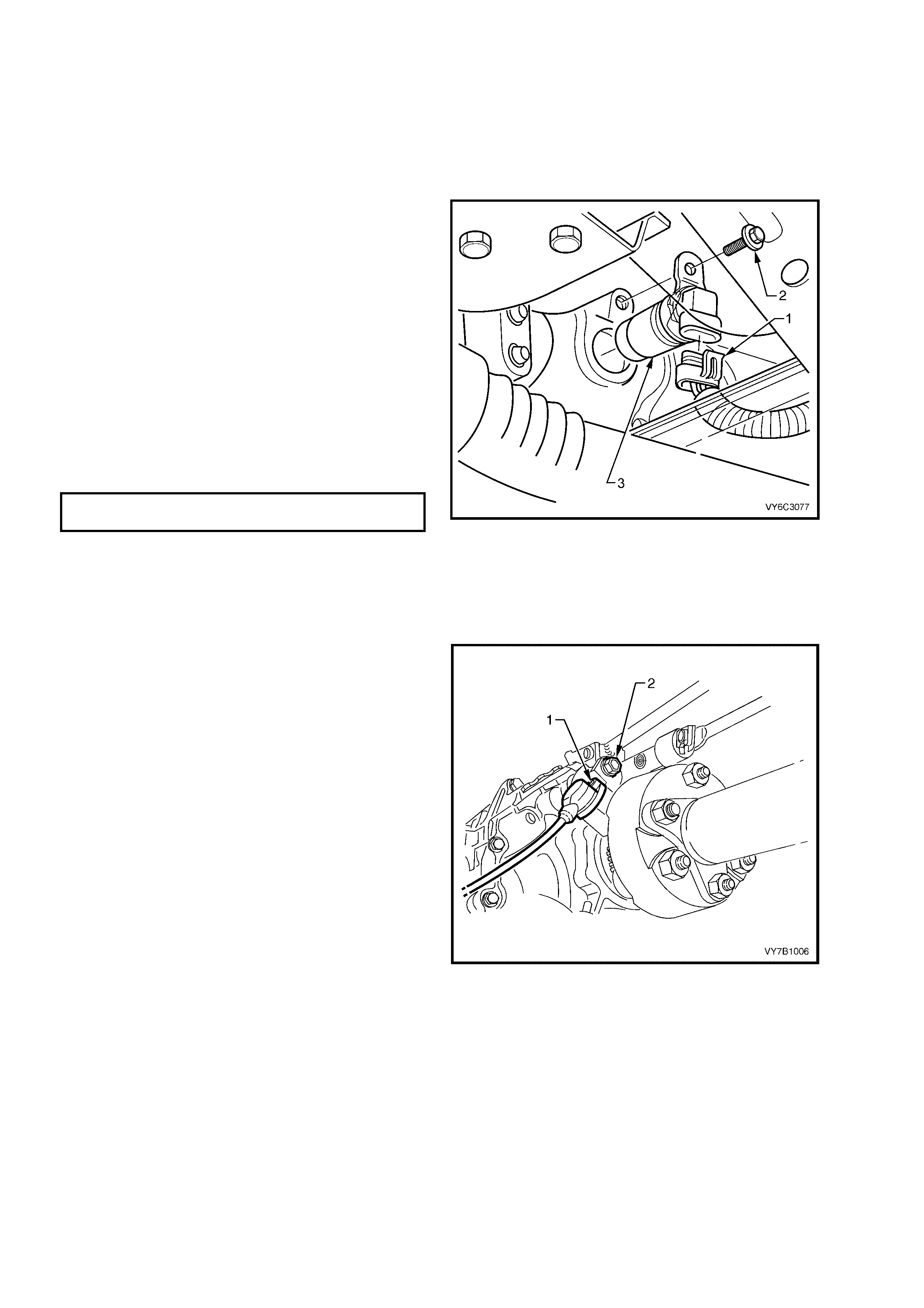
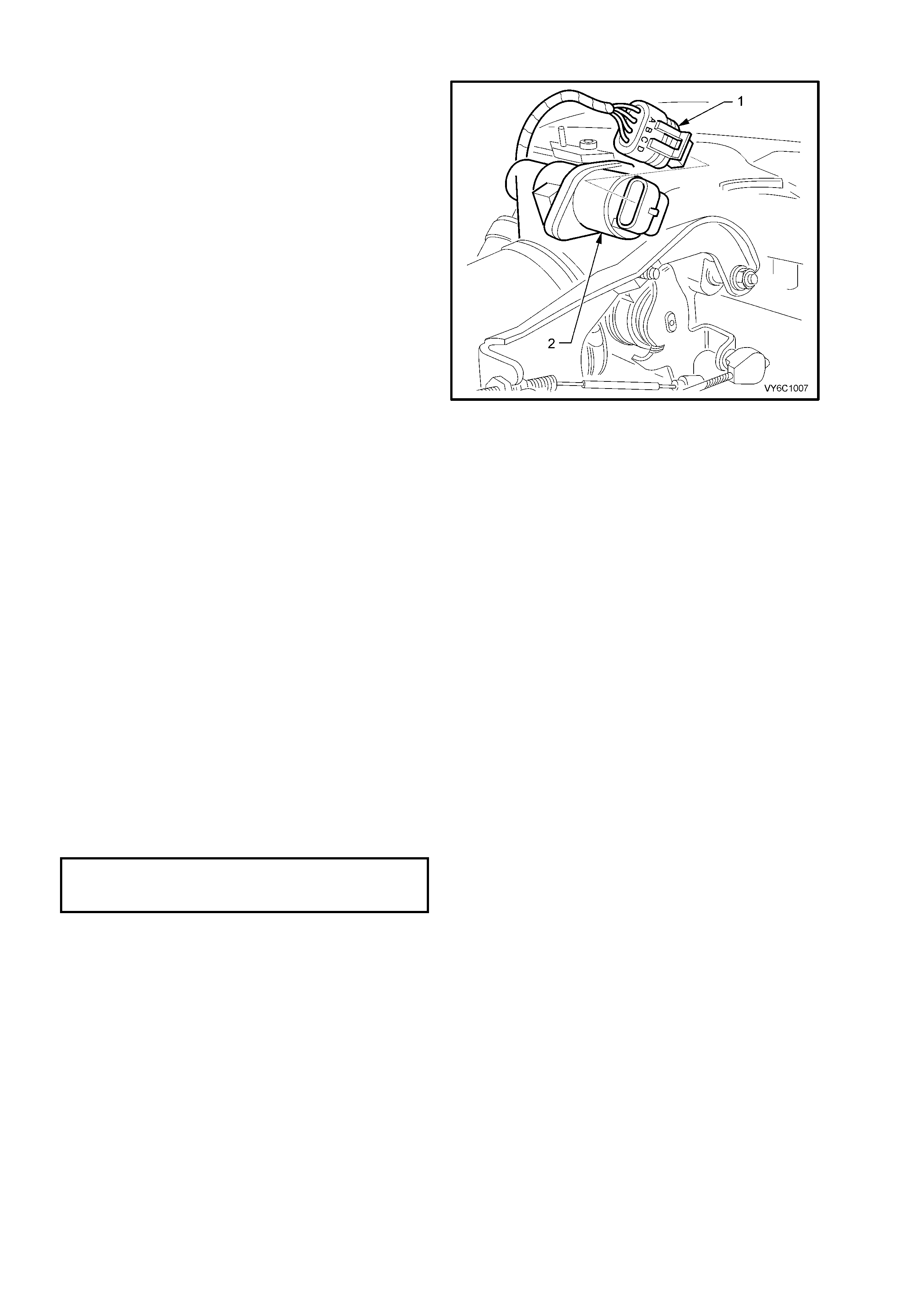
2. Lift up tang on VSS wiring harness connector
(1) and pull connector from VSS (3).
3. Remove VSS to transmission extension
housing screw (2).
4. Remove VSS and O-ring seal from extension
housing by slowly prying out sensor with a flat
screwdriver.
REINST ALL
1. Coat the VSS O-ring seal with a thin film of
transmission fluid.
2. Install new VSS and O-ring into transmission
extension housing.
3. Reinstall retaining screw (2) and tighten to the
correct torque specification.
VSS RETAINING BOLT
TORQUE SPECIFICATION 11 Nm
4. Reconnect wiring harness connector (2) to
VSS (3).
5. Remove safety stands and lower vehicle.
Figure 6C1-3-16 – VSS Location Automatic Transmission
Manual Transmission
For vehicle speed sensor removal and
reinstallation, Refer to 3.2 Speed Sensor and/or
Bracket, in Section 7B1 MANUAL
TRANSMI SSIO N – V6 EN GI NE.
Figure 7C1-3-17 VSS Location Manual Transmission
3. FUEL CONTROL SYSTEM
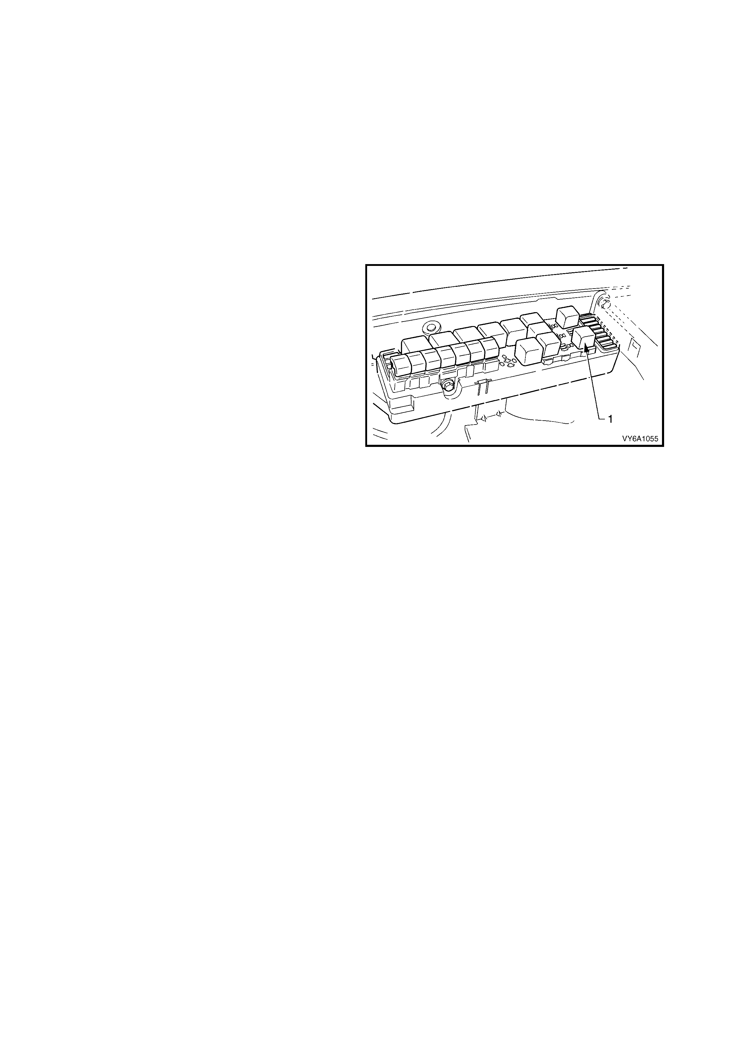
3.1 FUEL PUMP RELAY
LT Section No.– 02-250
The fuel pump relay (1) is located in the underhood fuse and relay centre, in the engine compartment. The relay
centre is posit ioned for ward of the righ t sid e strut t ower . Other t han c heck ing for loose c onnec tors, the onl y s ervice
possible is replacement.
FUEL PRESSURE RELIEF PROCEDURE
CAUTION: Unless this procedure is carried out
before servicing fuel lines or connections, fuel
spray into the engine compartment could
occur!
1. Remove Fuel Pump Relay (1) from the
underhood fuse and relay centre.
2. With throttle closed, crank engine – engine
ma y start and idle u ntil f uel suppl y rem aining in
fuel line is exhausted. When engine stops,
engage starter again for 10 seconds to ensure
dissipation of any remaining pressure.
3. Reinstall fuel pump relay (1).
Figure 6C1-3-18 – Fuel Pump Relay Location
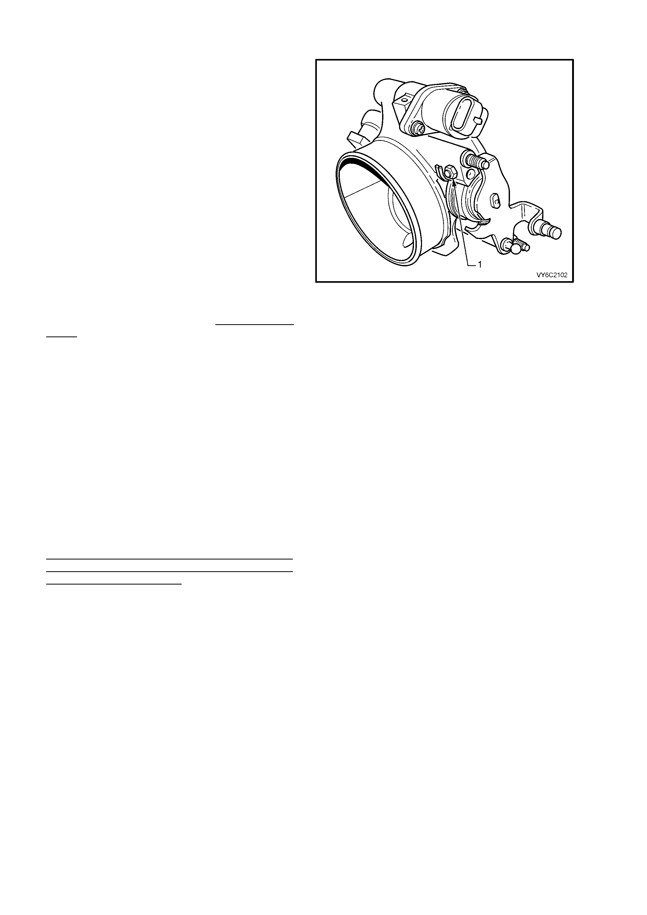
3.2 THROTTLE STOP SCREW – RESET PROCEDURE
IMPORTANT: Engine idle for the V6 engine must
be checked every 80,000 km. If the IAC
valve counts are greater than 25 at idle, the
throttle body must be removed and cleaned. Refer
to ‘Throttle Body Cleaning Procedure’ in
3.11 THROTTLE BODY, in this Section for the
procedure.
The throttle stop screw (1) controls the minimum
throttle opening (nominal "Closed Throttle"
position). It i s preset at th e factor y and must no t
be reset unless:
a. The screw position is known to have been
tampered with, or;
b. Clearly instructed to do so by a diagnostic
table.
NOTE 1: Engine idle speed, which will vary with
engine temperature, is PCM controlled and is not
adjustable.
NOTE 2: T he PCM con troll ed idle sp eed (IAC) and
throttle stop screw setting (rpm) ARE NOT THE
SAME!
The throttle stop screw setting (RPM) m ust always
be less than the PCM controlled idle speed, and is
check ed only after tem porarily disabling the PCM's
method of controlling idle speed (i.e. the Idle Air
Control system). The throttle stop screw setting is
the least lik ely cause of an abnorm al idle conditi on,
therefore resetting the screw should only be
considered as a last resort. An incorrect setting is
likely to cause a deterioration in idle stability.
Figure 6C1-3-19 Throttle Stop Screw Location
IMPORTANT: Before any adjustments are made,
ensure that no vacuum leaks exist. Check all
vacuum hoses, MAF air ducts, intake manifold
gasket, throttle body-to-manifold attachment, and
any vacuum-operated devices. The engine must
be at normal operating temperature before any
checking or resetting is attempted.
WITH THIS ENGINE CONTROL SYSTEM, ANY
VACUUM LEAK WILL RESULT IN A
LOW/ROUGH IDLE SPEED.
CHECK OR RESET
IMPORTANT: Before performing this procedure,
carry out the On-Board Diagnostic System Check.
Refer to Section 6C1-2A DIAGNOSTIC TABLES,
in this Section.
1. Before performing steps 3 to 10 of this
procedure, ensure that the IAC system is
functioning properly. Refer diagnostic
TABLE A-7.1 (IAC system check) in Section
6C1-2A, DIAGNOSTIC TABLES - V6 ENGINE
in this Section, and work through to the "NO
TROUBLE FOUND - IAC OK", step before
proceeding.
2. Engine must be at normal operating
temperature (above 90° C), preferable
achieved by driving for at least 15 minutes,
before continuing.
3. Set parking brake and block drive wheels.
Ensure transmission is in ‘Park' (automatic
transmission) or Neutral (manual
transmission).
4. Remove four dome nuts securing the engine
dress cover assembly to the intake manifold
studs, l ift off and s et the c o ver assembl y to on e
side.
5. Verify that t he t hr ott le c ab le and t hrottle linkage
are not binding. The throttle lever attached to
the throttl e butterfly shaft m ust be able to open
fully, and shut fully and freely every time the
accelerator pedal is full y depressed and slowly
released.
Figure 6C1-3-20 – IAC Valve Harness Removed
NOTE: Refer to THROTTLE CABLE – Adjust in this Section if throttle cable adjustment is required.
6. Install Tech 2 and select Miscellaneous tests, IAC System, Base Idle.
7. Ignition “ON”, engine running.
NOTE: If the engine has completed less than 3,000 km, do not reset the throttle stop screw unless the RPM is
above 600 rpm. Otherwise, RPM should be 500 – 600 rpm. If a reset is necessary, adjust throttle stop screw to
obtain an engine speed of 450 - 550 rpm.
8. Using Tech 2, activate the Base Idle test and follow the Tech 2 instructions.
9. Adjust the base idle screw to obtain engine idle speed of 450-550 rpm.
10. Reinstall engine dress cover to the intake manifold, ensuring that stud grommets in the dress cover remain in
place. Tighten securing dome nuts to the correct torque specification.
ENGINE DRESS COVER TO INTAKE
MANIFOLD DOME NUT
TORQUE SPECIFICATION 5 Nm
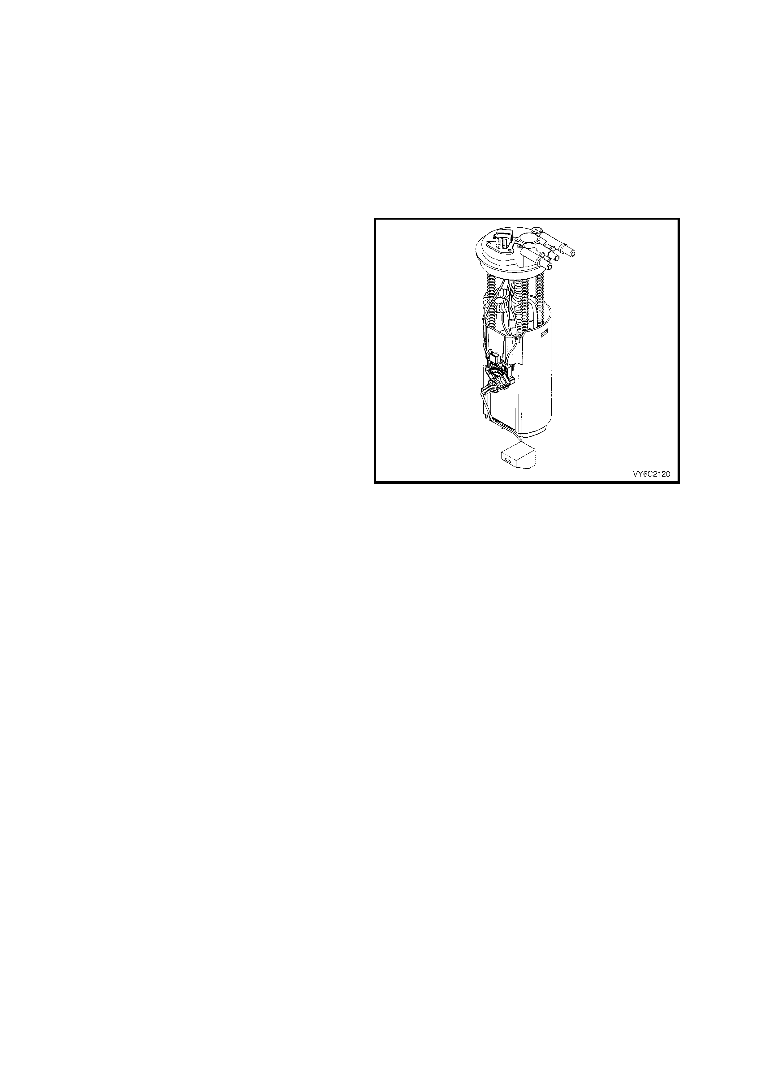
3.3 MODULAR FUEL SENDER ASSEMBLY
LT Section No.– 03-074
REMOVE
NOTE: Do not handle the modular fuel sender assembly by the fuel pipes.
1. Relieve the f uel system pressur e. Refer to the ‘Fuel Pressur e Relief Proc edure’ in 3.1 FUEL PUM P REL AY, in
this Section.
2. Dis c onnect batter y ground l ead.
IMPORTANT: Disconnection of the battery affects certain vehicle electronic systems. Refer to
Section 00 CAUTIONS, 5. Battery Disconnection Procedures before disc onn e c ting the batt ery.
3. Remove fuel tank, Refer to Section 8A, FUEL
TANK.
4. Remove the modular fuel sender retaining ring
using the J 39765 Fuel Sender Locknut
Wrench.
CAUTION: When removing the modular fuel
sender assembly from the fuel tank, the
reservo ir buck et on the fuel send er as sembl y is
full of fuel. The modular fuel sender assembly
must be tipped slightly during removal in order
to avoid damage to the float. Place any
remaining fuel into an approved container once
the modular fuel sender assembly is removed
from the fuel tank.
IMPORTANT: The modular fuel sender assembly
will spring-up when the locking ring is removed.
5. Pull the modular fuel sender straight up while
draining the fuel from the reservoir.
6. Clean the fuel sender assembly O-ring sealing
surface.
7. Inspect the fuel sender assembly O-ring
sealing surface.
Figure 6C1-3-21 – Modular Sender Assembly
REINST ALL
IMPORTANT: Always replace the fuel sender O-ring when reinstalling the fuel sender assembly.
1. Position the new fuel sender assembly O-ring on the fuel tank, after lubricating with some commercially
available, rubber grease.
IMPORTANT: Car e should be taken not to fold over or twist the f uel pum p strainer when install ing the fuel sender
assem bly, as th is will res trict fuel f low. Also, as sure that the f uel pum p strainer does not interfer e with full travel of
float arm.
2. Reins tall the f uel sender as sembly and the fuel se nder assem bly retainer r ing using the J 39765 Fuel Sender
Locknut Wrench.
3. Reinstall fuel tank, Refer to Section 8A FUEL TANK.
4. Rec onn ec t batter y ground l ead.
5. Inspect system for leaks.
FUEL STRAINER AND FUEL LEVEL SENSOR
NOTE: T he fuel s trainer is not s er viced s eparat ely. Sh ould th e strai ner b ecom e clogge d or dam aged, the c om plete
modular fuel sender assembly must be replaced.
FUEL PUMP ASSEMBLY
NOTE: The f uel pump is not s erviced separa tely. If the f uel pump is f ound to be fault y, then the c omplete m odular
fuel sender assembly must be replaced.
3.4 FUEL SYSTEM PRESSURE TEST
A Fuel S ystem Pr ess ur e Test is par t of s everal of the Diagnostic T ables an d S ymp tom check s . To perf orm this tes t,
follow this procedure:
CAUTION: To reduce the risk of fire or personal injury, it is necessary to relieve fuel system pressure
before performing this test. See Fuel Pressure Relief Procedure in 3.1 FUEL PUMP RELAY, " in this
Section.
IMPORTANT: At no time must the fuel intake hose or return line hose be clamped or kinked, as this will cause a
permanent deformation of the inner hose section and will result in restricted fuel flow.
1. Relieve fuel pressure as described in Fuel Pressure Relief Procedure in 3.1 FUEL PUMP RELAY, in this
Section. Turn ignition OFF.
2. Remove f our dome nuts s e c uring the en gi ne dres s c over as sembl y to the intake manif old, lif t off and s et t o on e
side.
3. Open Tool No. 7370 and install over fuel inlet line.
4. Close 7370 and pull into fuel line quick connect to release it from the fuel inlet line, pull back on quick connect.
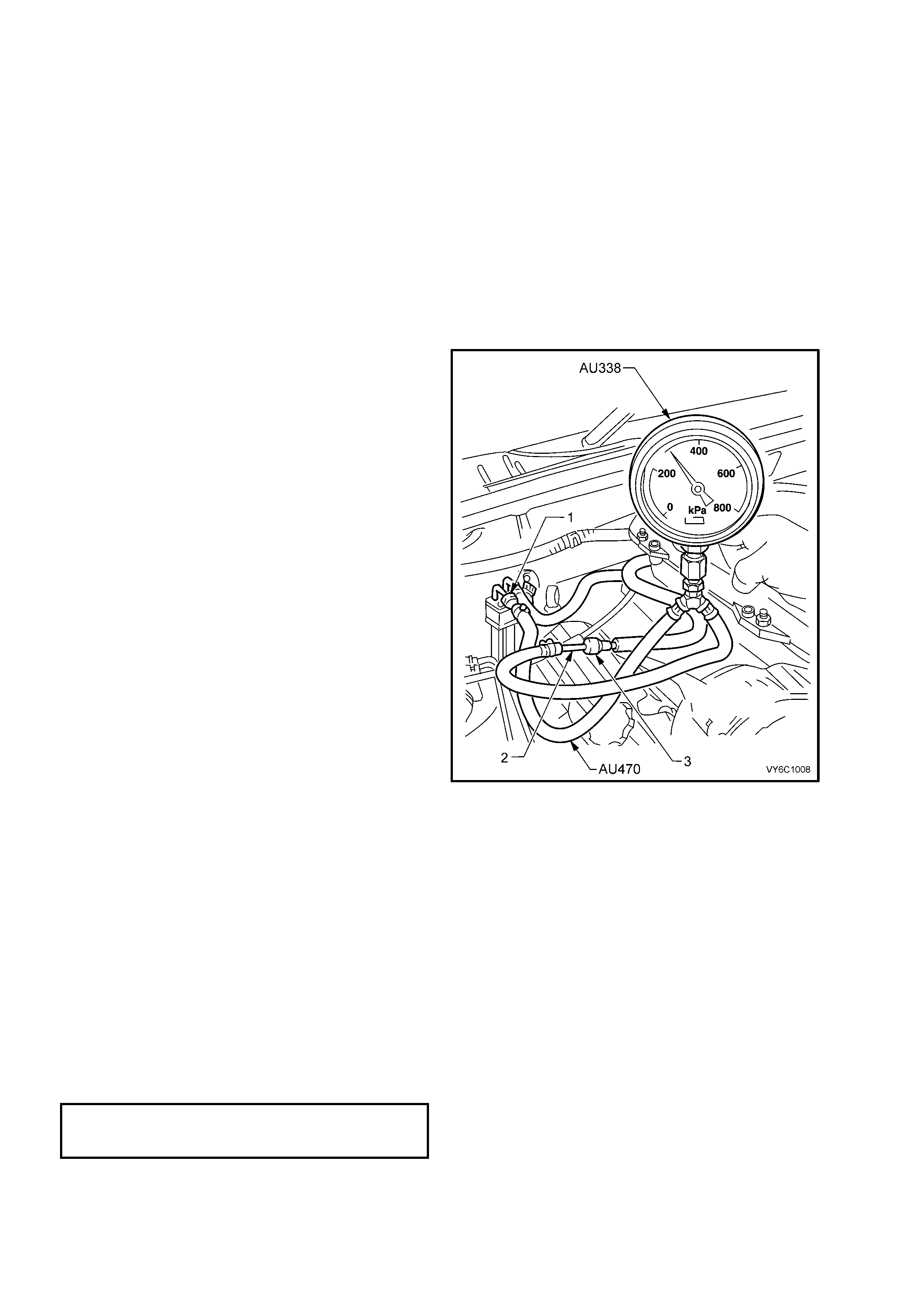
IMPORTANT: Before conducting step 5, inspect
adaptor tube (2) on fuel pressure gauge hose
(AU470) to ensure that it is free from any damage
or burrs. This is necessary to ensure that the tube
does not damage the sealing ring in the quick
connect fitting (3). If the sealing ring becomes
damaged, f uel le akage will occ ur.
5. Install fuel pressure gauge AU338 (also
released as SD28018) & hose AU4570 (also
released as SD28057) fitted with Coupler
212157 (1) and tube 216812 (2) in the
pressure line, between the fuel inlet line and
the fuel inlet hose quick connect (3).
NOTE: The fuel pressure gauge hose assembly
AU470 is comprised of the following:
212157 Coupler (1)
216812 Adaptor Tube (2)
SD28057 Hose Assembly
MEASURE
1. Using Tech 2, enable fuel pump so that the fuel
pump can pressurise the system.
2. Fuel gauge reading should be 270 – 350 kPa.
If not, refer to Diagnostic TABLE A-4.1 in
Section 6C1-2A, DIAGNOSTIC TABLES, in
this Section.
3. Relieve fuel pressure as described in
3.1, FUEL PUMP RELAY - FUEL
PRESSURE RELIEF PROCEDURE, in this
Section.
4. Remove fuel pressure gauge and adaptor.
5. Reinstall fuel line.
6. Check for fuel leaks as described in
3.0, FUEL CONTROL SYSTEM, 3.6 LEAK
TESTING, in this Section.
Figure 6C1-3-22 – Fuel Pressure Gauge Set-Up
7. Reinst all engine dress cover, ensuring that t he
four stud grommets in the cover, remain in
place. Secure with the four decorative nuts,
tightened to the correct torque specification.
ENGINE DRESS COVER
DECORATIVE NOT
TORQUE SPECIFICATION 5 Nm
3.5 FUEL FILTER
LT Section No.– 03-075
REMOVE
1. Relieve fuel pressure as described in 3.1, FUEL PUMP RELAY, Fuel Pressure Relief Procedure in this
Section.
2. Dis c onnect batter y ground l ead.
IMPORTANT: Disconnection of the battery affects certain vehicle electronic systems. Refer to
Section 00 CAUTIONS, 5. Battery Disconnection Procedures before disconnecting the battery.
3. Raise rear of vehic le and support on safet y stands, ref er to Section 0 A, GENERAL INFORM AT ION in the MY
2003 VY and V2 Series Service Information.
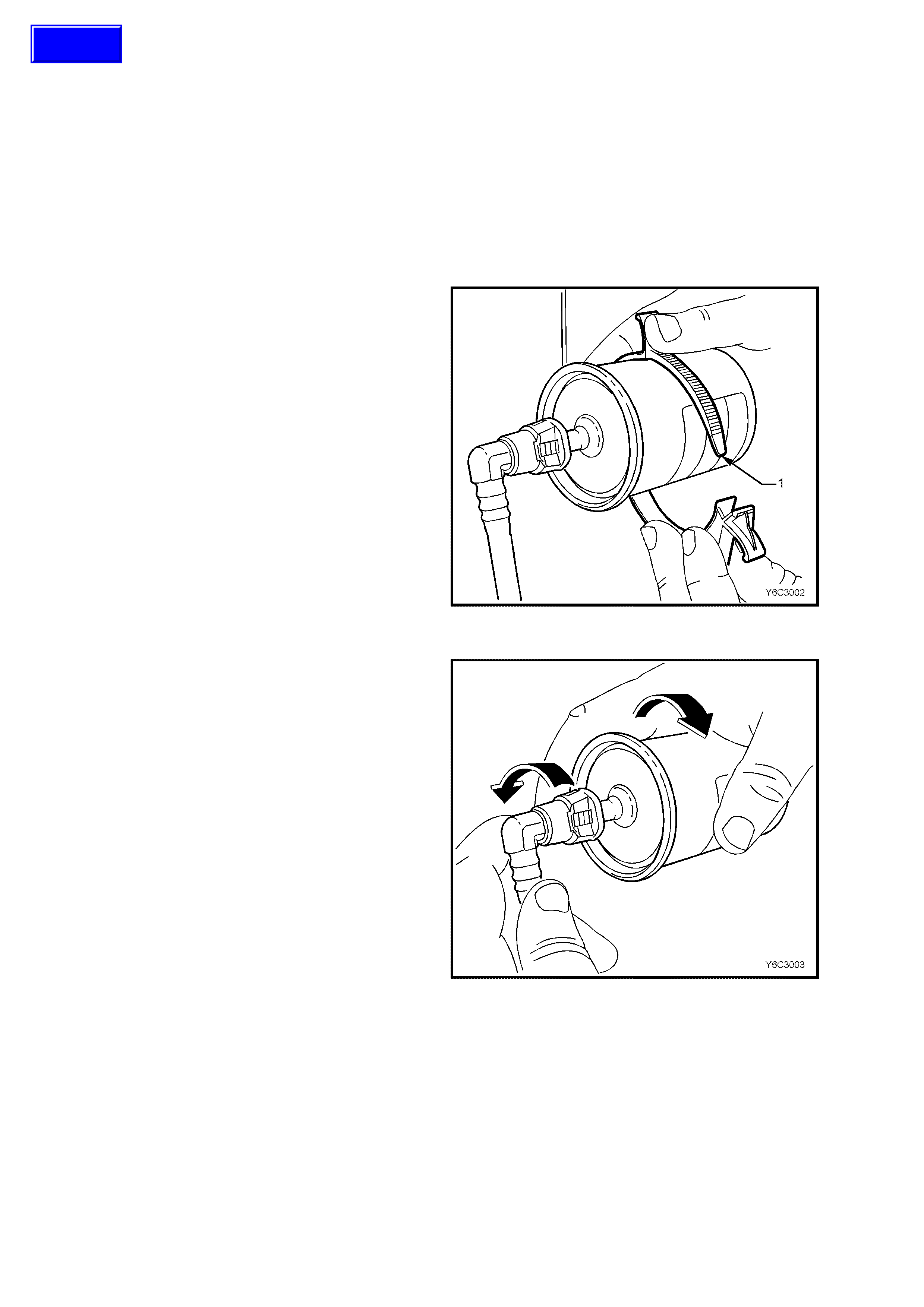
4. Place a drain tray beneath fuel filter.
5. Remove the fuel filter from the retaining
bracket (1) with the fuel lines still connected to
the fuel filter to allow easier access.
Figure 6C1-3-23 – Releasing Filter From Retaining Strap
Quick Connect Fittings (Plastic Collar)
6. Grasp the quick-connect fittings on each side
of the fuel filter. Twist the female connectors
1/4 turn in each directio n in order to loos e n any
dirt within the quic k-connec t fittin g.
Figure 6C1-3-24 – Rotating Quick Connect Fitting
Techline
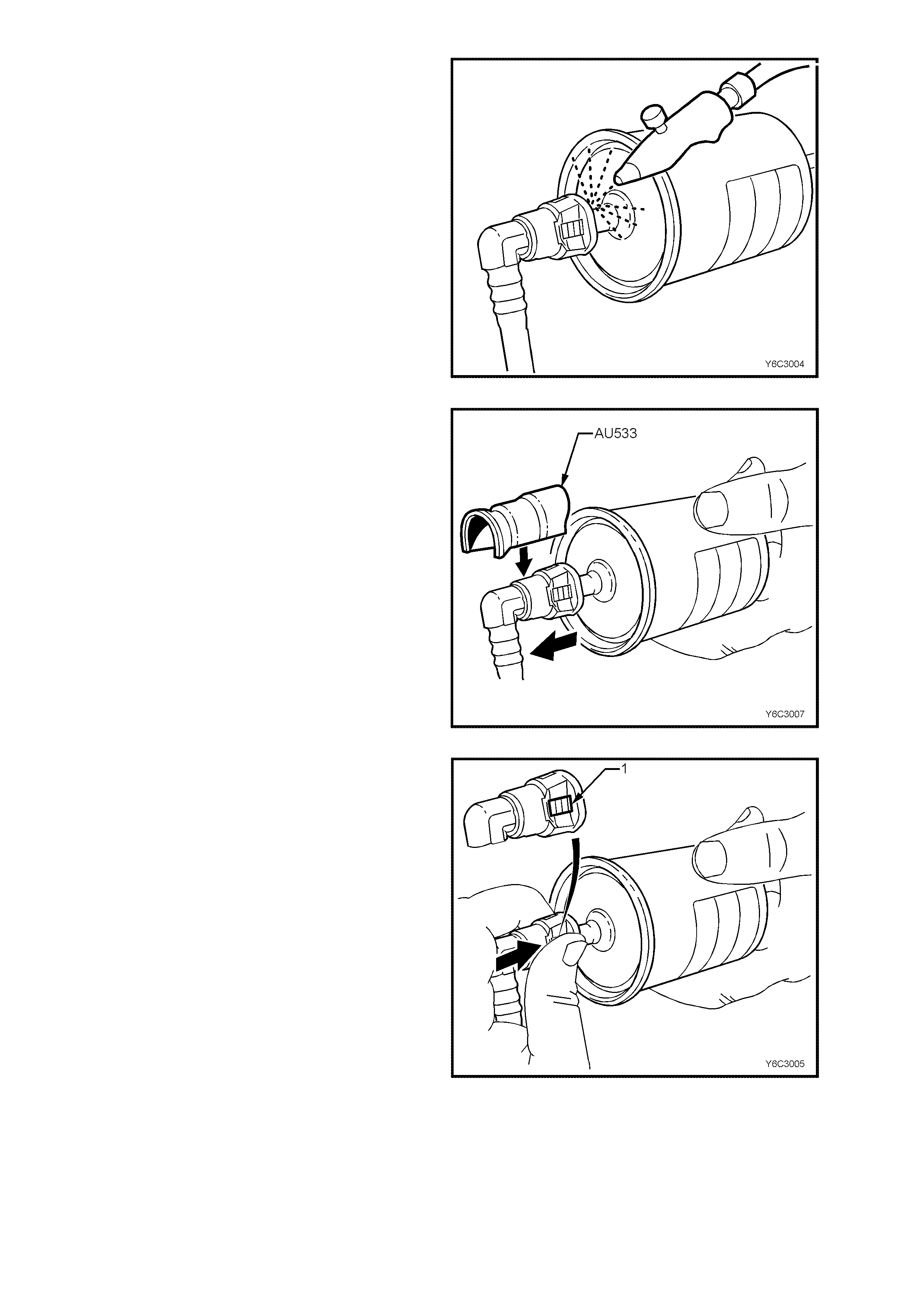
7. Using compressed air, blow any dirt out of the
quick-connect fitting to aid the release of any
tension or binding on the release tabs .
CAUTION: Wear safety glasses when using
compressed air, in order to prevent eye injury.
Figure 6C1-3-25 – Clearing Debris
8. Use Tool No. AU533 to squeeze the release
tabs, by pushing down on the quick connect
fitting. This action compresses both release
tabs. With AU533 in place, push the
connection together to release tension on the
locking tabs and then pull to separate the two
components. Repeat this operation for the
second connection, to release the fuel filter.
NOTE: Tool No AU533 is available in two pipe
sizes; Red for 5/16” and Blue for 3/8”. Only the
blue (3/8”) tool is required for this operation.
9. Remove fuel filter from vehicle and discard
safely, remembering that some fuel will still
remain in the filter.
Figure 6C1-3-26 – Releasing Quick Connect Fitting
If Tool No. AU533 is not available, an alternative
method of removing the filter, is as follows:
10. Hold the f uel filter f irm ly in one h and to sup port
the filter.
11. Using your o ther hand, grasp one of the quick -
connect fittings and squeeze the plastic
retainer release tabs (1) on each side of the
fitting whi le pushing the fitti ng firmly toward the
fuel filter to release any tension on the release
tabs.
Figure 6C1-3-27 – Releasing Quick Connect Fitting

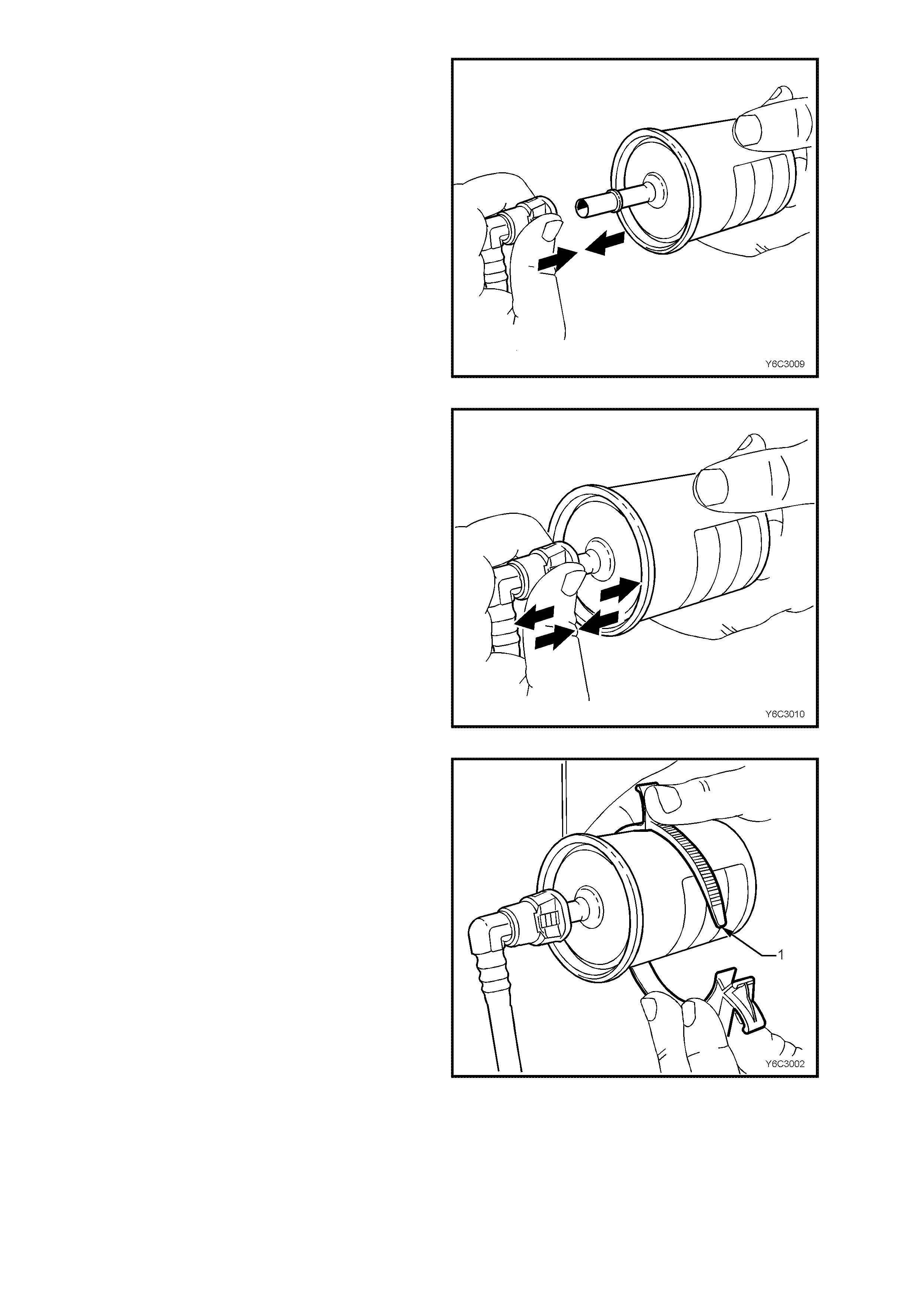
12. With the tension release tabs still held in the
squeezed position, move the complete quick-
connect fitting away from the fuel filter to
separate the connector fitting from the fuel
filter.
13. App ly the sam e m ethod from steps 10 to 12 for
the remaining quick-connect fitting.
Figure 6C1-3-28 – Separating Quick Connect Fitting
REINST ALL
IMPORTANT: The fuel filter must be installed with
the flow arrow (6) on its body pointing in the same
direction as the fuel flow to the front of the vehicle.
Legend:
1 Evaporative Emission Charcoal Canister
2 Fuel Tank Vapour Purge Line
3 Atmospheric Line
4 Fuel Vapour Inlet Line
5 Fuel Feed from Modular Fuel Sender
6 Filter Fuel Flow Arrow
7 Fuel Filter.
8 Fuel Return Line to Fuel Tank.
Figure 6C1-3-29 – Fuel Filter Installation
IMPORTANT: In or der t o r educ e t he ris k of fir e and
personal injury, before connecting fuel filter quick-
connect fittings, always apply a few drops of clean
engine oil to the male ends of the fuel filter. This
will ensure proper reconnection and prevent a
possible fuel leak.
During normal operation, the O-ring located in the
fem ale connec tor will s wel l and ma y prevent proper
reconnection if not lubr icated.
1. Apply a few drops of clean engine oil to each
male fuel filter end.
Figure 6C2-3-30 – Lubricating Fittings
2. Push both th e quic k -conne ct f itting a nd the fuel
filter together, causing the retaining tabs to
snap into place. Apply this method to both
ends of the fuel filter and the respective quick-
connect fittings.
Figure 6C1-3-31 – Installing Quick Connect
3. Once installed, pull and push on both the
quick-connect fitting and the fuel filter in order
to make sure the connection is secure. Apply
this method to each end of the fuel filter and
the respective quick-connect fittings.
Figure 6C1-3-32 – Testing Quick Connect Security
4. Re-install the fuel filter to the retaining bracket
(1).
5. Conn ec t battery ground lead.
6. Check for fuel leaks, refer to 3.6 LEAK
TESTING in this Section.
7. Remove safety stands and lower vehicle.
Figure 6C1-3-33 – Installing Filter Retainer
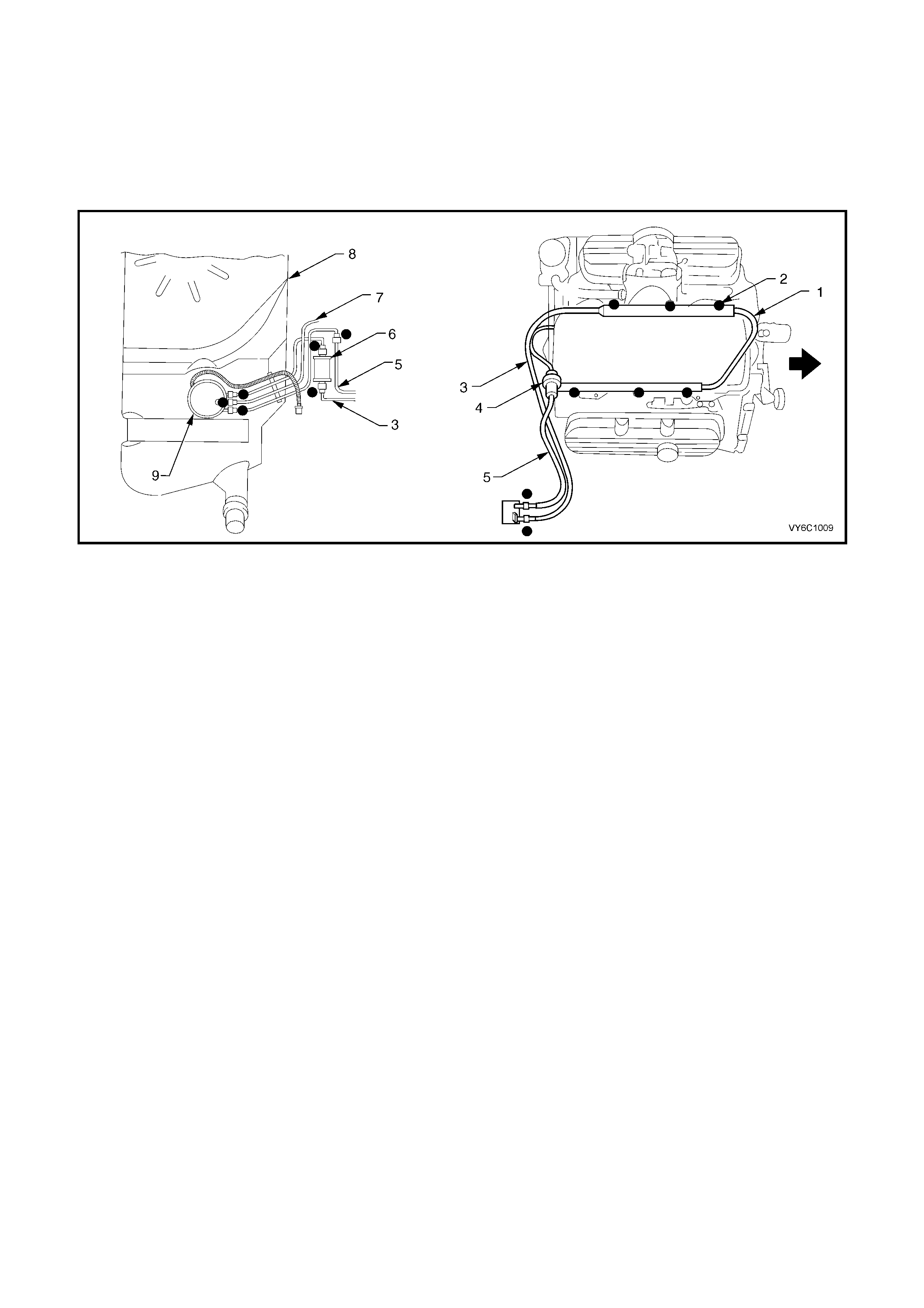
3.6 LEAK TESTING
IMPORTANT: Following the installation of any fuel system component, and prior to starting the engine, the fuel
system must be checked for leaks, using the following procedure:
1. Check to ensure that there is a sufficient level of fuel in the fuel tank.
2. Install T ech 2 to the vehic le and sel ect "Ou tput T est" f or "Fuel Pum p." Ena bling t he output tes t will activate the
fuel pump to pressurise the fuel system.
3. Check fuel system for leaks, particularly at points marked (l) in Figure 6C1-3-34.
Figure 6C1-3-34 – Leak Testing V6 Engine
Legend
1. Fuel Rail
2. Fuel Injector (6 places)
3. Fuel Feed
4. Fuel Pressure Regulator
5. Fuel Return
6. Fuel Filter
7. Fuel Tank Vapour Line
8. Fuel tank
9. Modular Fuel Sender Assembly
3.7 FUEL PRESSURE REGULATOR
LT Section No.– 03-375
NOTE 1: Compressed air must never be used to test or clean a fuel pressure regulator, as damage to the
regulator may result.
NOTE 2: To prevent damage to the fuel pressure regulator, do not immerse in solvent.
REMOVE
1. Relieve fuel pressure as described in Fuel Pressure Relief Procedure, in 3.1 FUEL PUMP RELAY, in this
Section.
2. Dis c onnect batter y ground l ead.
IMPORTANT: Disconnection of the battery affects certain vehicle electronic systems. Refer to
Section 00 CAUTIONS, 5. Battery Disconnection Procedures before disconnecting the battery.
3. Remove four dome nuts securing the engine dress cover assembly to the intake manifold studs, then remove
the cover assembly. Refer Figure 6C1-3-9 in this Sec t ion.
4. Remove fuel rail assembly, refer to 3.8, FUEL RAIL, in this Section.
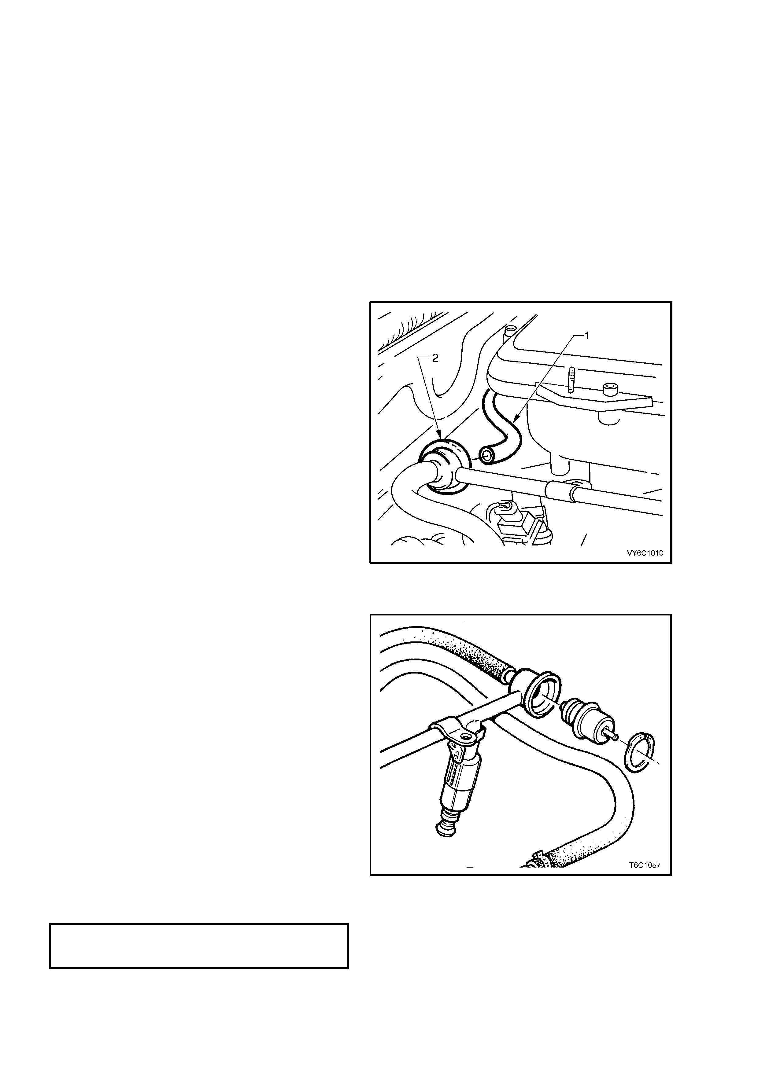
5. Disconnect vacuum hose (1) from fuel
pressure regulator (2).
6. Clean any dirt from the fuel pressure regulator
retaining ring.
7. Using suitable snap ring pliers, remove snap
ring from fuel pressure regulator.
8. Using a sh op towel to c atch an y spilled f uel, lift
and twist the fue l pressure regulator in order to
remove the fuel pressure regulator from the
fuel pressure regulator housing.
9. Cover the fuel pressure regulator housing to
prevent contamination from entering the fuel
system.
Figure 6C1-3-35 – Fuel Pressure Regulator Location
REINST ALL
1. If a new fuel pressure regulator is not being
installed, fit new O-rings to the fuel pressure
regulator and lightly lubricate the O-rings with
clean engin e oil.
2. Reinstall the fuel pressure regulator in the fuel
pressure regulator housing.
3. Reinstall the retaining circlip to the fuel
pressure regulator using suitable pliers.
4. Reinstall the fuel rail. refer to 3.8 FUEL RAIL,
in this Section.
5. Reinstall the vacuum hose to the fuel pressure
regulator.
6. Rec onn ec t batter y ground l ead.
7. Check for fuel leaks as described in
3.6 LEAK TESTING in this Section.
8. Reinstall engine dress cover to the intake
manif old, ensurin g that stu d gromm ets in dres s
cover remain in place. Tighten securing dome
nuts to the correct torque specification.
ENGINE DRESS COVER TO INTAKE
MANIFOLD DOME NUT
TORQUE SPECIFICATION 5 Nm
Figure 6C1-3-36 Fuel Pressure Regulator
3.8 FUEL RAIL AND INJECTORS
LT Section No.– 03-375
NOTE: The fuel inlet hose, return hose and the fuel rail are a complete assembly. No components are serviced
separately.
REMOVE
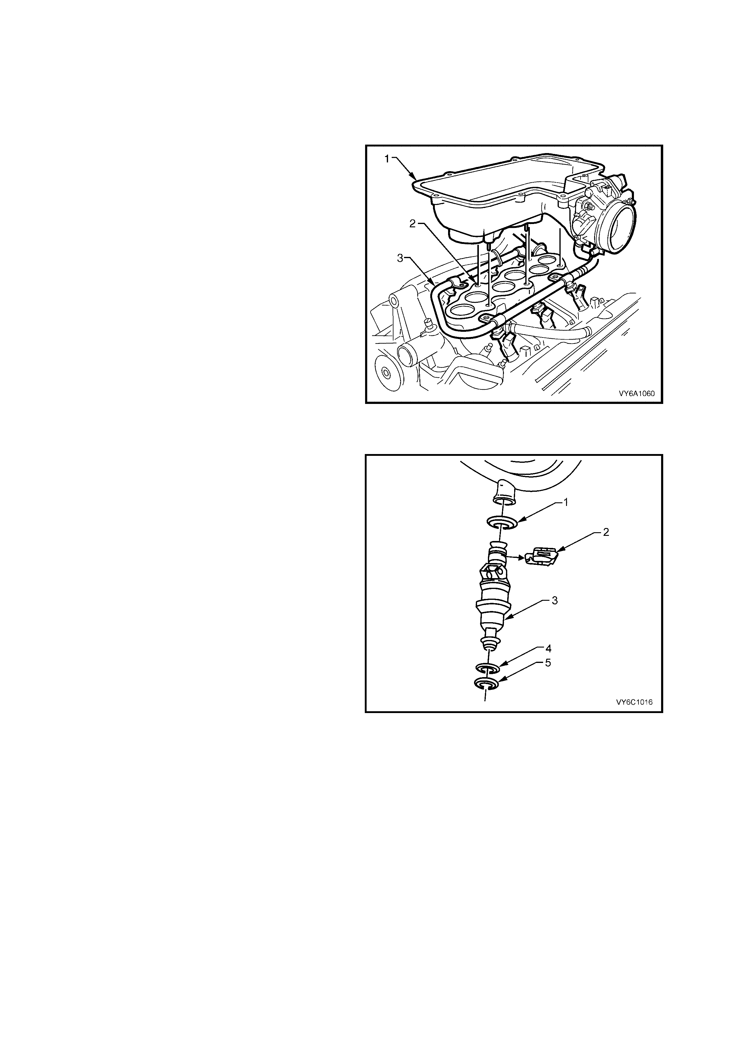
IMPORTANT: The fuel rail and injectors (3) are
attached to the bottom of the two-piece air inlet
plenum (1). T he top of the air inlet plen um m ust be
rem oved to ga in ac c ess to the bo lts th at s ecur e th e
inlet plenum (1) to the lower intake manifold (2).
For the procedure to remove both the upper inlet
plenum and the f uel rail/i njector ass embl y (3), refer
to 2.10 UPPER INTAKE MANIFOLD, in Section
6A1, ENGINE MECHANICAL – V6 ENGINE.
IMPORTANT: Following the removal of the upper
inlet plenum (1) and the fuel rail/injector assembly
(3), place a clean piece of cardboard over the
intake manifold (or plug all open ports with clean
workshop rag), to prevent foreign objects from
entering the exposed intake manifold ports.
Figure 6C1-3-37
DISASSEMBLE
1. Remove injector retaining clip/s (2). Withdraw
injector/s (3) from fuel rail.
NOTE 1: When servicing the fuel rail assembly,
precautions m ust be taken to pr event d irt and other
contaminants from entering the fuel passages. It is
recommended that fittings be capped, and holes
plugged, during servicing.
NOTE 2: Any time the fuel system is opened for
service, the O-ring seals used with related
component(s) should be replaced, including those
used between the air inlet plenum and intake
manifold, and between the plenum and it's cover.
REASSEMBLE
1. Coat NEW O-rings (1 & 5) with clean engine
oil, then install to each removed injector.
2. Reinstall removed injector/s to the fuel rail,
securing with injector retaining clip/s (2).
3. If removed, reinstall the pressure regulator to
fuel rail.
REINSTALL
Reinstal l the fuel rail/i njector assem bly to the l ower
intake manifold, then reinstall the upper air inlet
plenum and cover. Refer to 2.10 UPPER INTAKE
MANIFOLD, in Section 6A1, ENGINE
MECHANIC AL – V6 ENGI NE.
Figure 6C1-3-38 – Fuel Injector Removal
3.9 AIR CLEANER ASSEMBLY
LT Section No.– 03-250
REMOVE
1. Dis c onnect batter y ground l ead.
IMPORTANT: Disconnection of the battery affects certain vehicle electronic systems. Refer to
Section 00 CAUTIONS, 5. Battery Disconnection Procedures before disconnecting the battery.
2. Remove four dome nuts securing the engine dress cover assembly to the intake manifold studs, then remove
the cover assembly. Refer Figure 6C1-3-9 in this Sec t ion.
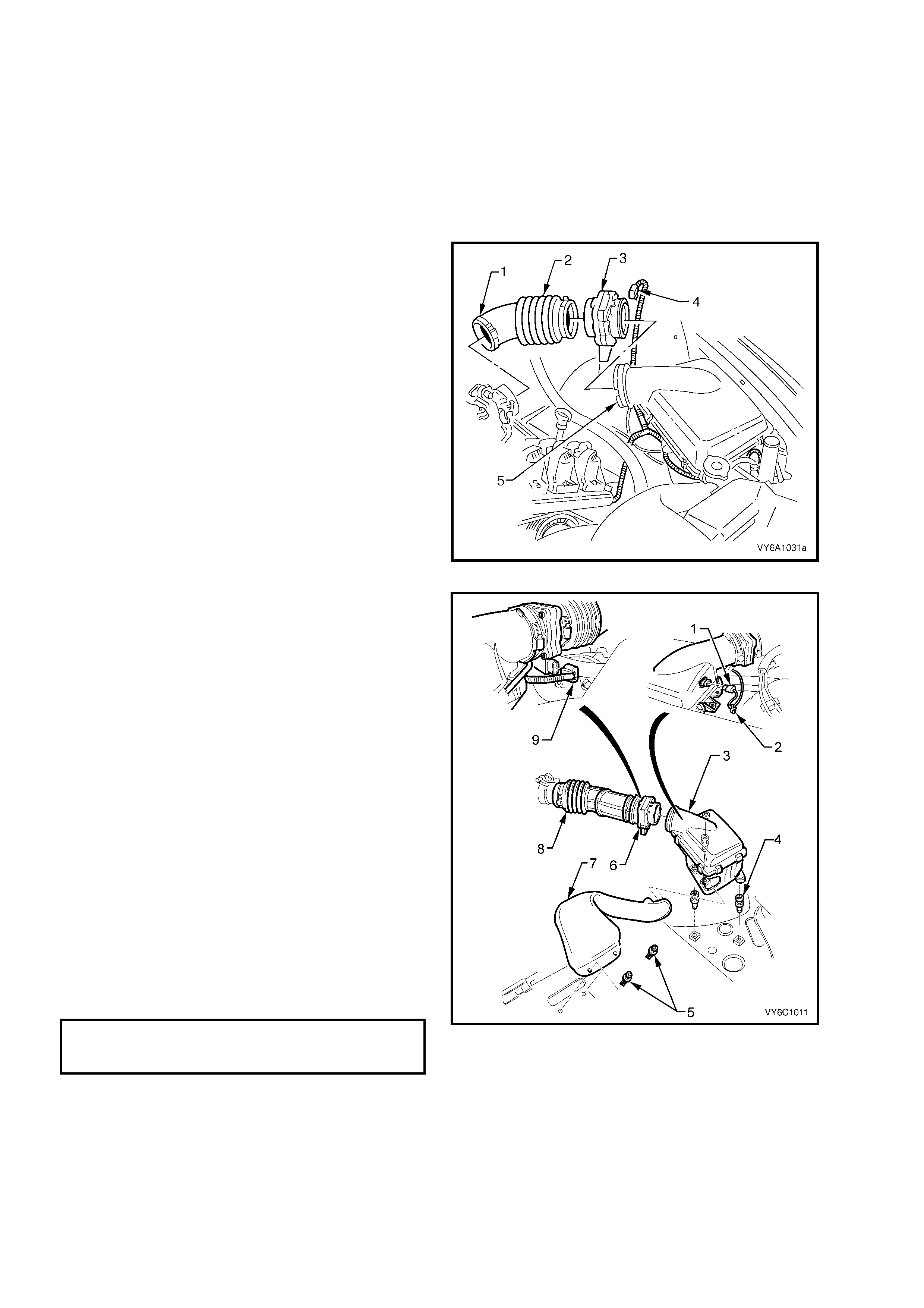
3. Disconnect the mass air flow sensor wiring
harness connector (4) from the sensor.
4. Loosen the air f low duct rubber boot clam ps at
the throttle body (1) and air cleaner housing
(5).
5. Rem ove the air f low duct (2) and m ass air f low
sensor assembly (3) and carefully set to one
side.
Figure 6C3-3-39
6. Pull up retaining tang on IAT sensor wiring
harness connector and pull connector from
sensor (1).
7. Unclip five clips holding the air cleaner upper
housing (3) in place.
8. Remove air cleaner upper housing (3) and air
cleaner element assembly.
9. Remove three studs (4) securing air cleaner
lower housing to fender inner panel insulators.
10. Disengage air cleaner cold air intake duct
assembly (7) from lower housing, after
removing the two scrivets (5).
11. Remove the lower air cleaner housing
grommets from the retaining screw heads (4),
then remove from the vehicle.
REINST ALL
1. Reassemble air cleaner lower housing on to
mounting insulators, engaging with the intake
duct assembly (7).
2. Reinstall securing studs (4) (if removed) and
tighten to the correct torque specification.
AIR CLEANER LOWER
HOUSING SECURING STUD
TORQUE SPECIFICATION 10 Nm
3. Secure the cold air intake duct assembly ( 7) by
reinstalling the two scrivets.
Figure 6C1-3-40 – Air Cleaner Housing Removal
4. Reas s emble the a ir c leaner element int o th e air c lean er upp er ho us in g ( 3) and pl a c e the up per h ousi ng ont o
the air cleaner lower housing, ensuring that air filter element remains in position.
5. Snap 5 retainer clips up into place to secure the air cleaner upper housing (3).
6. Reconnect wiring harness connector to IAT sensor (1).

7. Carefully reinstall the air flow duct (8) and mass air flow sensor assembly (6) to the throttle body and air cleaner
upper hous ing (3).
IMPORTANT: Align notch on air cleaner housing adaptor with notch in air duct adaptor and notch in clamp.
8. Tighten air duct clamp securely.
9. Reinstall the mass air flow sensor wiring harness connector (9) to the sensor.
10. Reinstall engine dress cover to the intake manifold, ensuring that stud grommets in dress cover remain in
place. Tighten securing dome nuts to the correct torque specification.
ENGINE DRESS COVER TO INTAKE
MANIFOLD DOME NUT
TORQUE SPECIFICATION 5 Nm
11. Reconnec t batter y ground l ead.
3.10 THROTTLE CABLE
LT Section No.– 03-325
REMOVE
1. Remove four dome nuts securing the engine dress cover assembly to the intake manifold studs, lift off and
remove the cover assembly. Refer to Figure 6C1-3-9.
2. Loosen outer cable lock nuts at throttle body mounting bracket.
NOTE: Do not detach adjusting nuts from cable.
3. Remove inner cable from throttle body linkage.
4. Disconnect outer cable from mounting bracket.
5. Remove instrument panel lower right side trim assembly retainers and lower trim, Refer to
Section 1A3, INSTRUM ENT PANEL.
6. Disconnect inner cable plastic spacer from throttle pedal lever.
7. Withdraw cable assembly from engine compartment.
REINST ALL
1. Reassemble outer cable into dash panel.
2. Attach inner cable to throttle pedal lever.
3. Reinstall outer cable to mounting bracket.
4. Attach inner cable to throttle body linkage.
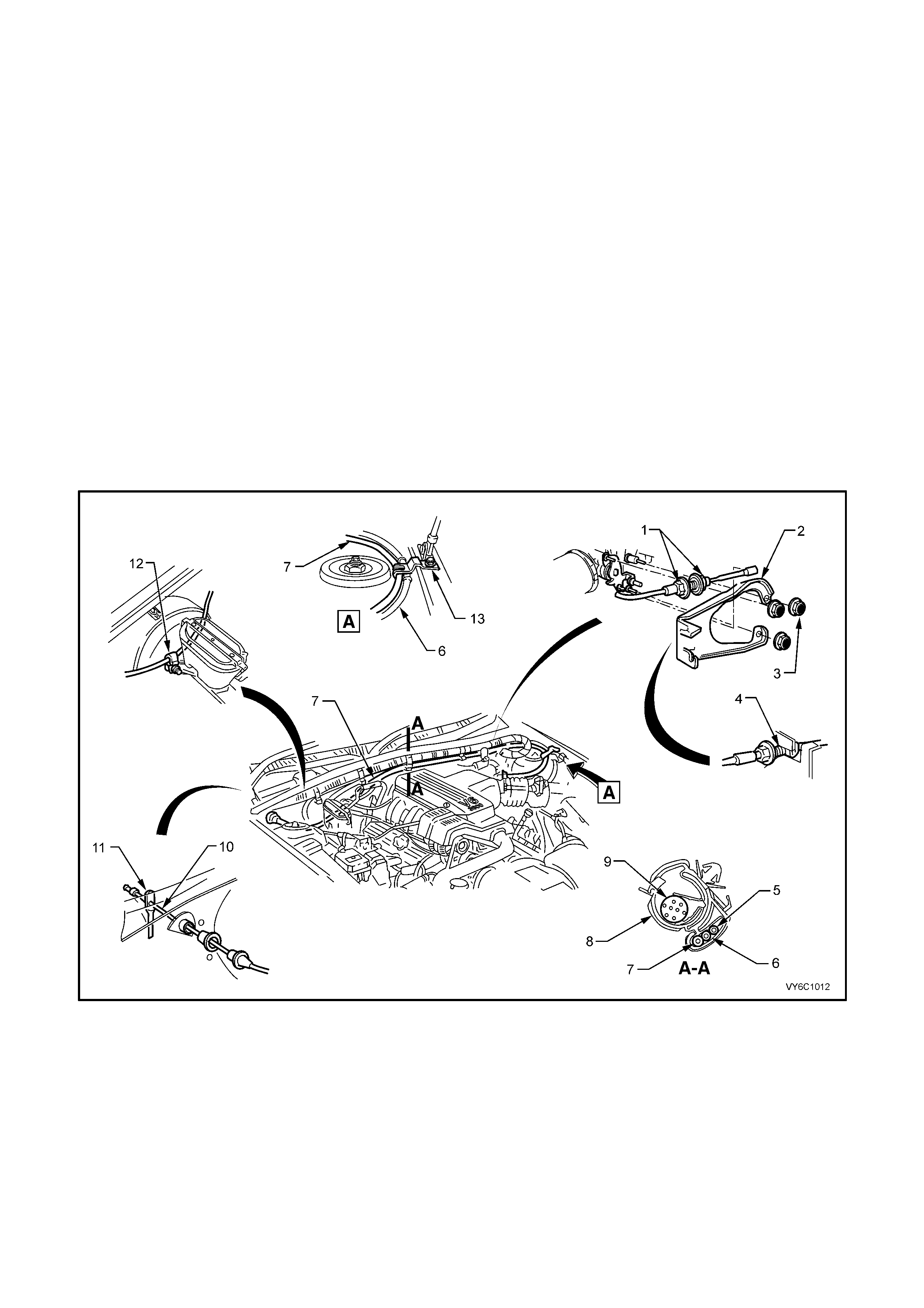
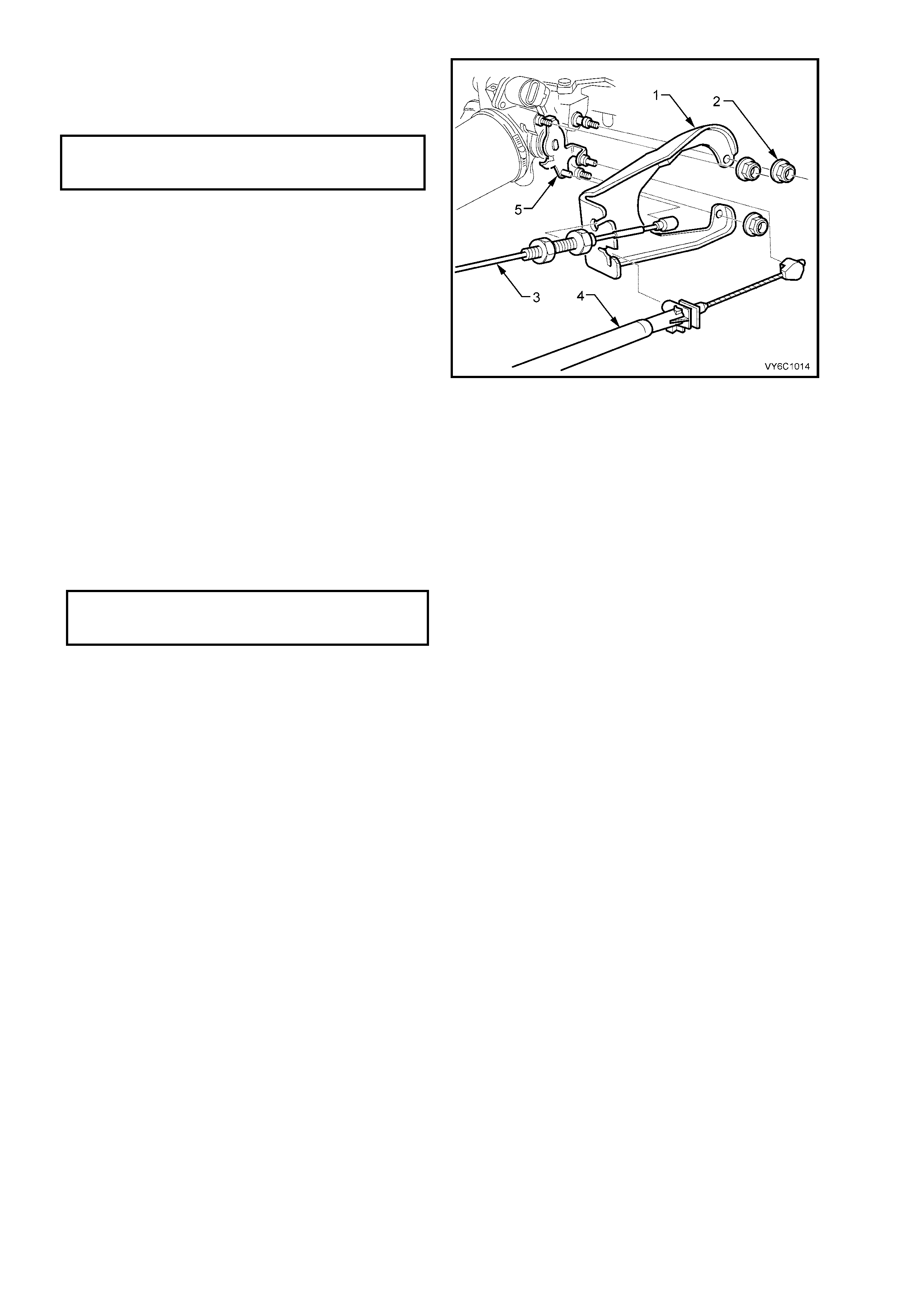
Figure 6C1-3-41 – Throttle Cable V6 Engine – RHD
Legend
1. Nuts – Outer Cable Adjusting
2. Bracket – Throttle Cable
3. Nut – Mounting Bracket (3 places)
4. Circular Hole – Outer Cable Locating
5. Hose – Rear Washer Hose (Wagon)
6. Cable – Cruise Control
7. Cable – Throttle
8. Clip – Wiring Harness Retaining
9. Harness – Powertrain Wiring
10. Cable – Inner Throttle
11. Lever – Throttle Pedal
12. Clip – Throttle Cable Routing
13. Clip – Cable securing
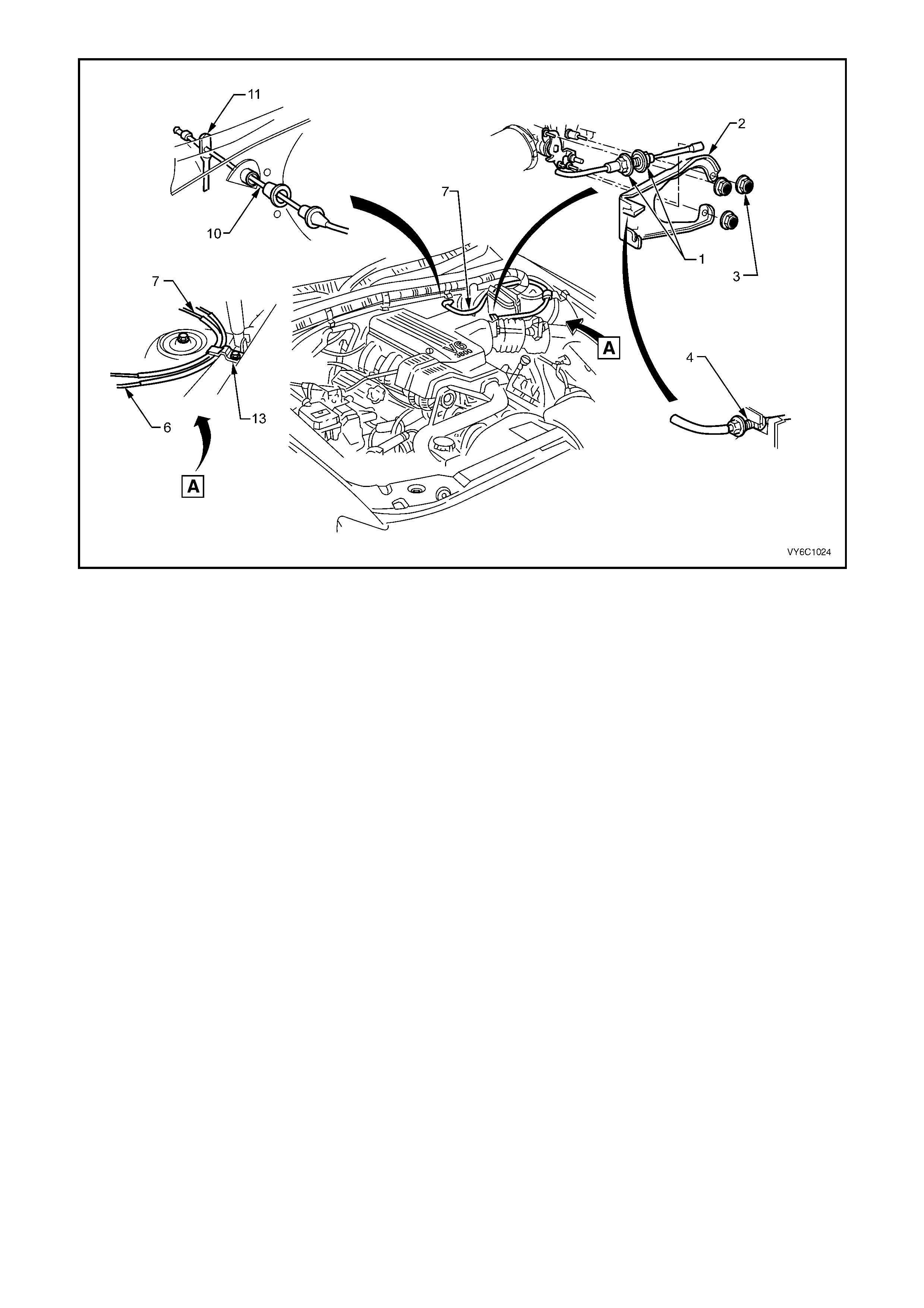
Figure 6C1-3-42 – Throttle Cable V6 Engine – LHD
Legend
1. Nuts – Outer Cable Adjusting
2. Bracket – Throttle Cable
3. Nut – Mounting Bracket (3 places)
4. Circular Hole – Outer Cable Locating
5. Cable – Cruise Control
6. Cable – Throttle
7. Cable – Inner Throttle
8. Lever – Throttle Pedal
9. Clip – Cable securing
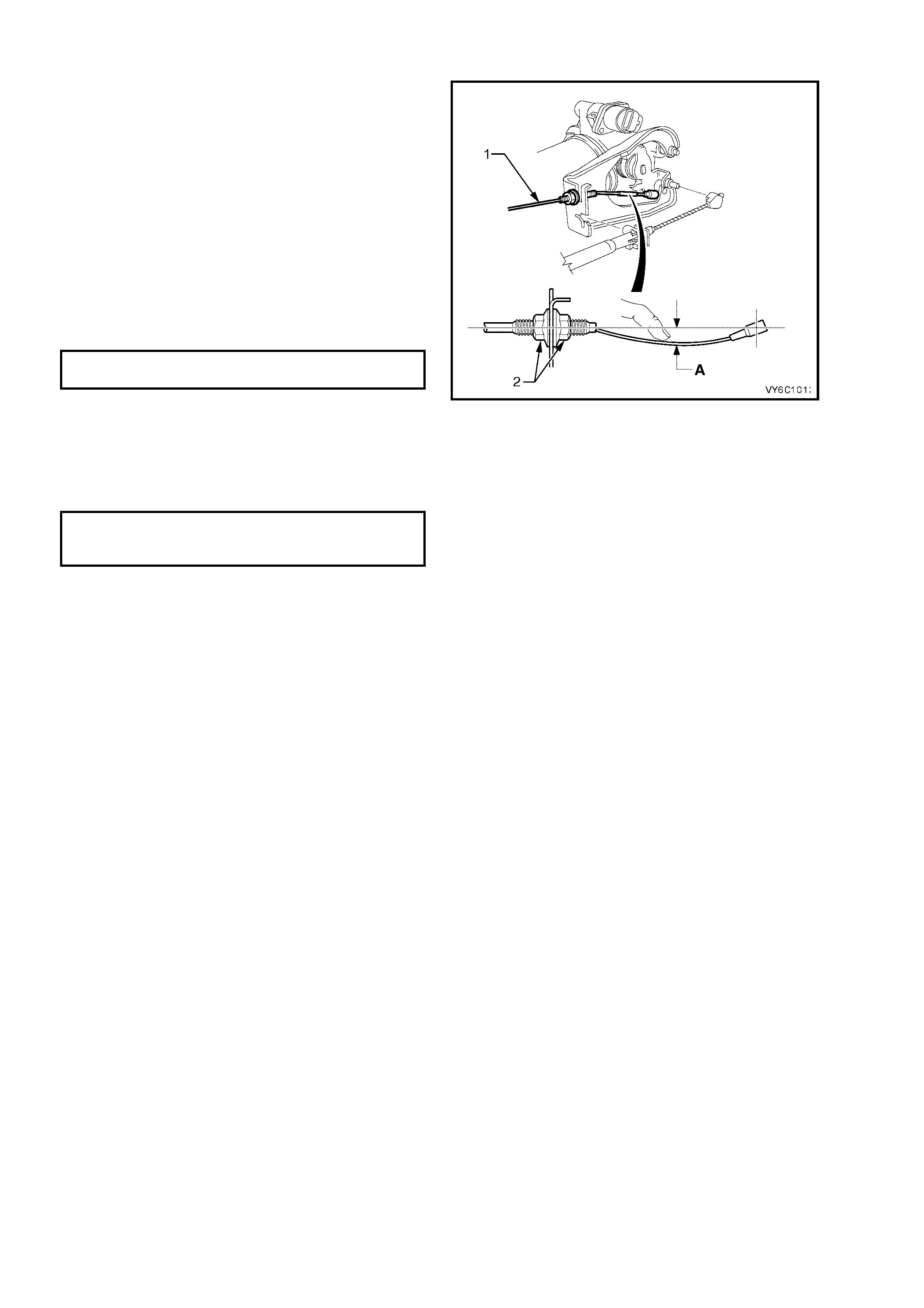
ADJUST
1. Remove instrument panel lower right side
trim (if not already removed, Refer to
Section 1A3, INSTRUMENT PANEL AND
CONSOLE.
2. Ensure throttle pedal is free to move from
closed to fully open position. Check that throttle
pedal comes to rest at the correct closed
throttle position (against pedal stop).
3. Adjust outer cable lock nuts (2) so that inner
cable length has a deflection of 10 – 15 mm
(‘A’), without moving throttle linkage from idle
stop.
4. Tighten cable lock nuts (2) to the correct torque
specification.
THROTTLE CABLE OUTER CABLE
LOCK NUT TORQUE SPECIFICATION 5 Nm
5. Check for Wide Open Throttle (WOT) and
smooth operation of throttle pedal.
6. Reinstall engine dress cover to the intake
manif old, ensurin g that stu d gromm ets in dres s
cover remain in place. Tighten securing dome
nuts to the correct torque specification.
ENGINE DRESS COVER TO INTAKE
MANIFOLD DOME NUT
TORQUE SPECIFICATION 5 Nm
7. Refit instrument panel lower right side trim,
Refer to Section 1A3, INSTRUMENT PANEL
& CONSOLE.
Figure 6C1-3-43 – Throttle Cable Adjustment

3.11 THROTTLE BODY
LT Section No.– 03-300
REMOVE
1. Dis c onnect batter y ground l ead.
IMPORTANT: Disconnection of the battery affects certain vehicle electronic systems. Refer to
Section 00 CAUTIONS, 5. Battery Disconnection Procedures before disconnecting the battery.
2. Remove four dome nuts securing the engine dress cover assembly to the intake manifold studs, lift off and
remove the cover assembly. Refer to Figure 6C1-3-9.
3. Disconnect wiring harness connectors from IAC valve and TP sensor.
4. Loosen air duct clamp at throttle body and mass air flow sensor.
5. Remove air flow duct from the vehicle.
6. Disconnect throttle cable (3) from the throttle
body linkage (5).
7. If vehicle is fitted with cruise control, remove
cruise control cable (4) from throttle body
linkage.
8. Remove throttle cable mounting bracket
attaching nuts (2).
Figure 6C1-3-44 – Throttle Cable Mounting Bracket
9. Loosen the hose clamps (1) and remove
engine positive crankcase ventilation hose (2)
from throttle body union.
10. Remove canister purge hose from throttle
body.
11. Remove throttle body to intake manifold
attaching nuts (3).
12. Remove throttle body (4) and gasket (5) from
the intake m anif old.
Figure 6C1-3-45 – Throttle Body Removal
CLEAN
Gasket surfaces on throttle body and manifold.
IMPORTANT: If reusing the old throttle body, the
Throttle Body Cleaning Procedure must be
completed before reinstalling.
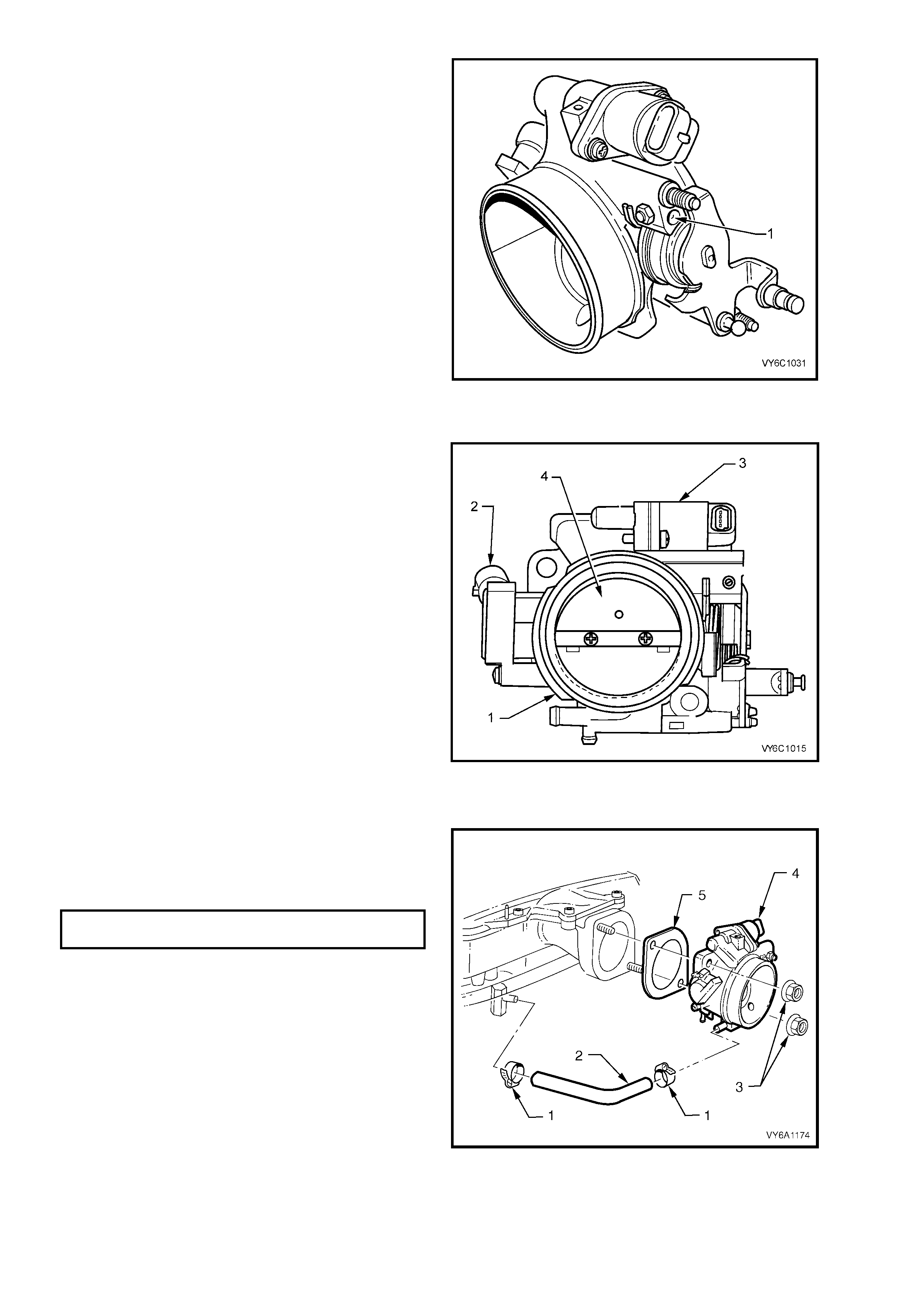
NOTE: There are specific t hrottle body assemblies
for vehicles with automatic and manual
transmissions. If replacing a throttle body, ensure
that the correct type is fitted.
For example f or ve hic les wi th manual tr ansmis sion,
identification is by a drill point marking (1) on the
throttle body.
Figure 6C1-3-46
THROTTLE BODY CLEANING PROCEDURE
1. Remove throttle body (1) from vehicle.
2. Remove the TP sensor (2) and IAC valve (3)
from the throttle body.
3. Using an approved injector cleaner, clean the
carbon build up around the pintle of the IAC
valve (3).
4. On the throttle body, clean the carbo n build up
around the IAC air port, throttle body bore and
throttle blade (4).
5. Reinstall TP sensor (2) to throttle body.
6. Reinstall IAC valve (3) to throttle body.
7. Continue with the reinstallation of the throttle
body (1) to the engine.
Figure 6C1-3-47 – Throttle Body Cleaning
REINST ALL
1. Instal l thrott le bod y gask et (5) and thrott le b od y
(4) to intake manifold.
2. Install throttle body attaching nuts (3) and
tighten to the correct torque specification.
THROTTLE BODY ATTACHING
NUTS TORQUE SPECIFICATION 15 – 20 Nm
3. Reinst all canister purge control hose to throttle
body.
4. Reinstall engine positive crankcase ventilation
(PCV) hose (2) to throttle body and intake
manifold. Tighten both PCV hose clamps (1)
securely.
5. Reinstall wiring harness connectors to IAC
valve and TP Sensor.
6. Reinstall throttle cable mounting bracket
attaching nut.
Figure 6C1-3-48 – Throttle Body Installation
7. Reinstall cable mounting bracket (1) to the
throttle body, reinstall the three mounting
nuts (2), tightening to the correct torque
specification.
THROTTLE CABLE MOUNTING
BRACKET ATTACHING NUT
TORQUE SPECIFICATION 10 Nm
8. Reinstall throttle cable (3) to throttle body
linkage (5), then reinstall t he outer ca ble to the
bracket (1).
9. Reinstall cruise control cable (4) (if fitted) to
throttle body linkage.
10. Reinstall air duct onto throttle body and mass
air flow sensor, align clamp and air duct
locating notches. Tighten air duct clamp at
throttle body securely.
11. Reconnec t batter y ground l ead.
12. Start engine then listen for air leaks.
13. Check throttle cable adjustment, refer Throttle
Cable Adjust, in 3.10, THROTTLE CABLE, in
this Section.
14. Check cruise control cable adjustment, Refer
to Section 12E, CRUISE C ONTROL.
15. Reinstall engine dress cover to the intake
manifold, ensuring that stud grommets in the
dress cover remain in place. Tighten securing
dome nuts to the correct torque specification.
Figure 6C1-3-49
ENGINE DRESS COVER SECURING
DOME NUT TO INTAKE MANIFOLD
TORQUE SPECIFICATION 5 Nm
THROTTLE BODY IAC VALVE COUNT CHECKING PROCEDURE
1. Start engine and run to normal operating temperature (85° C).
2. Transmission in Park or Neutral.
3. Turn off all accessories (A/C, radio etc.).
4. Install Tech 2 and display Engine Data.
5. Confirm the IAC valve counts are at 25 counts or less at idle.
6. If the counts are not at 15 or less, refer to 3.2 THROTT LE STOP SCREW RESET PROCEDURE if the screw
has been tampered with. If the Throttle Stop Screw has not been tampered with, replace the throttle body.

3.13 IDLE AIR CONTROL VALVE
LT Section No.– 03-300
REMOVE
1. Disconnect battery ground lead.
IMPORTANT: Disconnection of the battery affects certain vehicle electronic systems. Refer to
Section 00 CAUTIONS, 5. Battery Disconnection Procedures before disconnecting the battery.
2. Remove four dome nuts securing the engine dress cover assembly to the intake manifold studs, lift off and
remove the cover assembly.
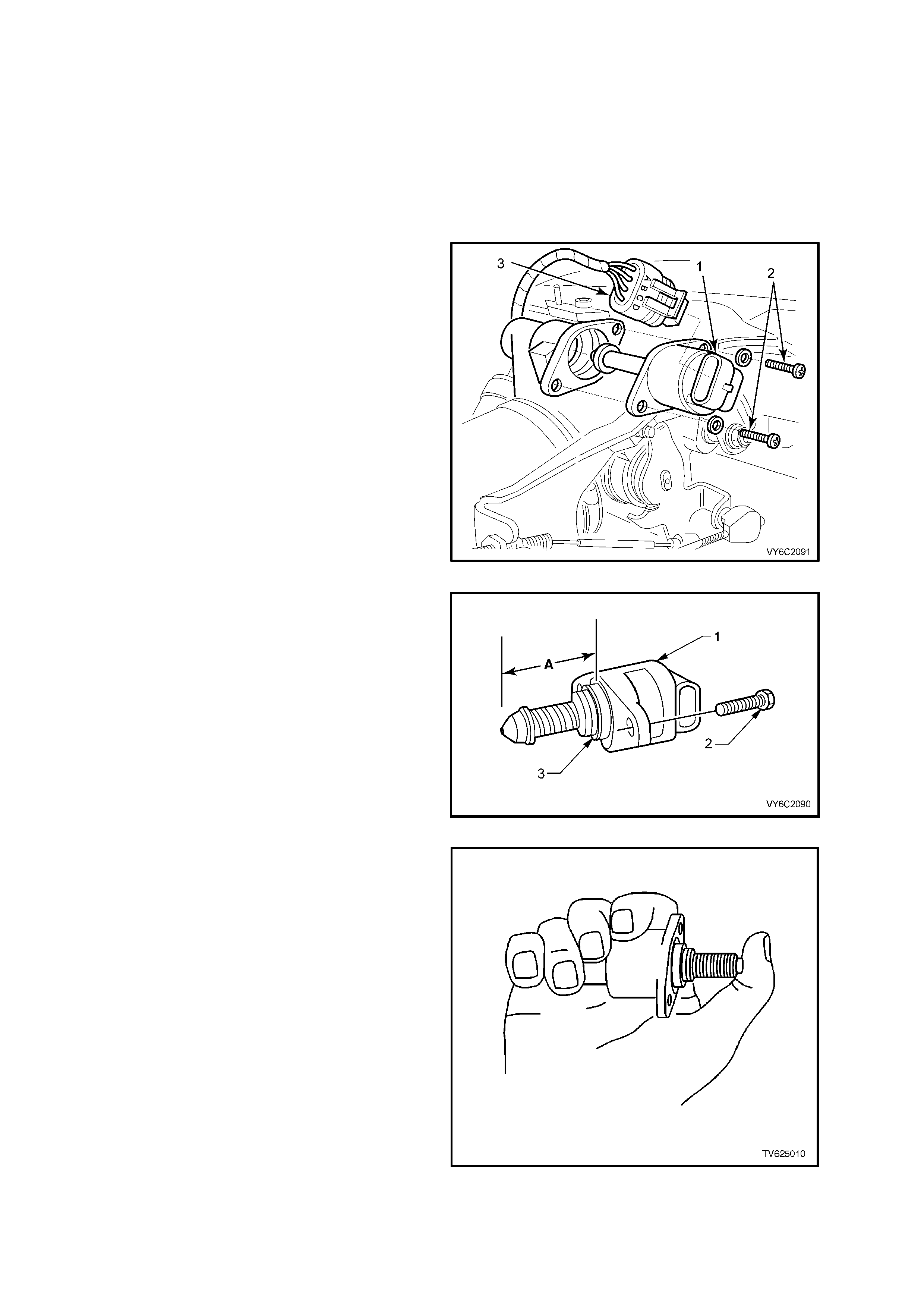
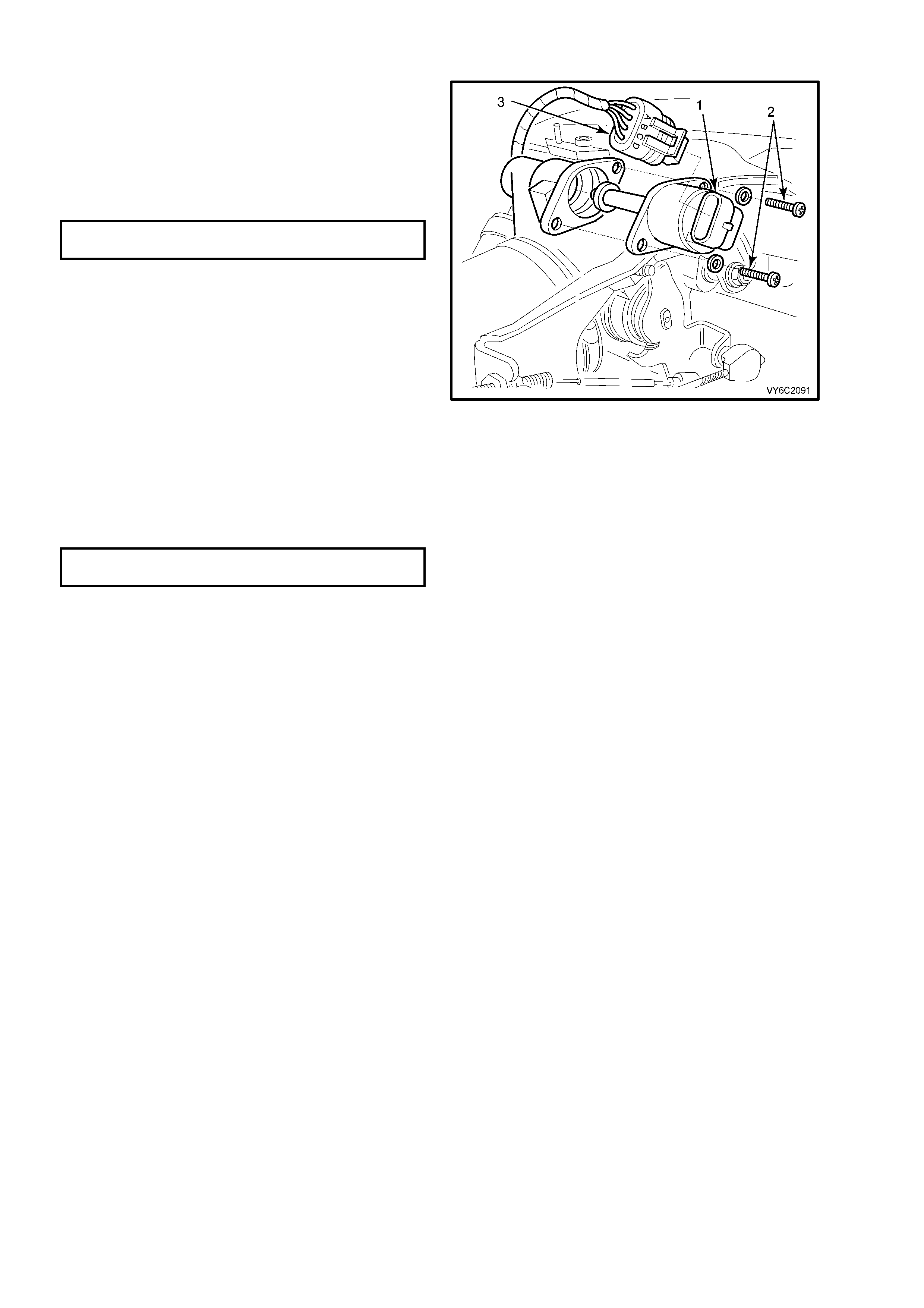
3. Lift up retaining tang on IAC valve wiring
harness connector (3) and pull connector from
valve.
4. Remove IAC valve to throttle body attaching
screws (2).
5. Remove IAC valve (1) from throttle body.
CLEAN
IAC valve sealing surfaces on throttle body, to
assure proper seal of O-ring and contact of IAC
valve flange.
IMPORTANT: When installing a new IAC valve, be
sure it has the correct part number. Check the
current release of the PartFinder® CD ROM.
Figure 6C1-3-50 – IAC Valve Removal
IMPORTANT: Before installing a new IAC valve,
measure distance "A" between tip of valve pintle
and the flange mounting surface (3). If it is greater
than 28 mm, it m us t be reduc ed to prevent d amage
to the valve when it is installed.
Figure 6C1-3-51 – IAC Measured Distance
6. To reduce the length of the pintle, exert firm
pressure on valve pintle to retract it. (A slight
side-to-side movement may be helpful).
Figure 6C1-3-52 – IAC Retraction Method
REINST ALL
1. Lubr icate IAC valv e O-ring with li ght engine oil.
If necessary, install on to valve assembly.
2. Reinstall IAC valve (1) into throttle body with
wiring harness connector (3) facing up, as
shown.
3. Reinstall IAC valve attaching screws (2) and
tighten to the correct torque specification.
IAC VALVE TO THROTTLE BODY
SCREW TORQUE SPECIFICATION 1.5 Nm
4. Rec onnect IAC val ve wiring harn ess connect or
(3).
5. Rec onn ec t batter y ground l ead.
6. If required, clear any DTCs using Tech 2.
7. Start engine, and allow engine to run for 5
seconds then turn engine "OFF" to "reset" the
IAC valve.
OR
Using Tech 2, select “IAC RESET” to reset the
IAC valve.
8. Reinstall engine dress cover to the intake
manifold, ensuring that stud grommets in the
dress cover remain in place. Tighten securing
dome nuts to the correct torque specification.
ENGINE DRESS COVER NUT
TORQUE SPECIFICATION 5 Nm
Figure 6C1-3-53– Idle Air Control Valve Reinstallation

3.14. THROTTLE PEDAL ASSEMBLY
GENERAL DESCRIPTION
This Section describes the servicing procedures for the throttle pedal assemblies fitted with the moulded plastic pad
or the alloy pad.
Althou gh there are obvi ous dif f erences between the t wo st yles of p edal pads, the ser vice pr ocedur es are the sam e
for both options. For the purposes of service information, only the alloy pedal pad is shown.
NOTE: There are differences in the throttle cable adjustment procedures for the various engines available. The
procedure described in this Section for servicing the throttle pedal assembly does not require the throttle cable
adjustment to be altered. However, if throttle cable adjustment is required, refer to the correct Section for the
appropriate engine option.
REMOVE
1. Remove the instrument panel lower right
side trim, refer Section 1A3, INSTRUMENT
PANEL in the MY2003 VY and V2 Series
Service Information.
2. Pull the throttle cable and the plastic retainer
free of the pedal ar m and then s lide the c able
through the slot in the pedal arm.
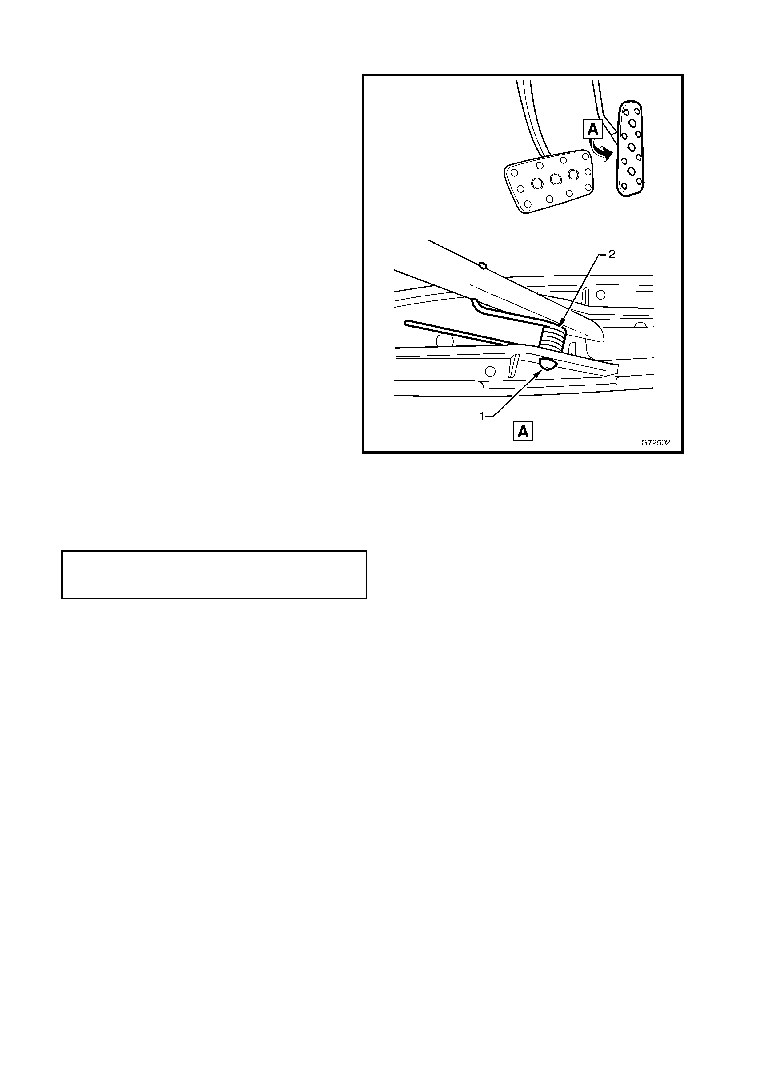
3. Remove the four nuts (1) securing the pedal
assembly to the dash panel bracket and
remove from the mounting studs.
Figure 6C1-3-54
DISASSEMBLE
1. Using a vice, lay the pedal assembly over on
its side to gain access to the roll pin (1)
securing the ped al pad to the shaf t.
2. Us ing a suit able si ze pin p unc h tap the rol l pin
(1) out of the pedal pad and the assembly,
remove the roll pin and return spring, taking
note of the position of the return spring. (2).
Figure 6C1-3-55
REASSEMBLE
1. Position the throttle pedal pad and return
spring into the correct position as shown.
2. Using a s uitable p in punch, tap the roll pin (1)
in until it is even with the pedal pad housing
on both sides.
3. Ensur e the pedal pad is f ree to swivel and th e
return spr ing has been s eated into the correct
position shown.
Figure 6C1-3-56
REINST ALL
Installation throttle pedal assembly is in the reverse of the removal process noting the following:
1. Tighten the four nuts to the specified torque.
2. Before starting the engine ensure the throttle pedal assembly is free from any restrictions and check throttle
operatio n. If required, adj ust the throttle c able, for V6 engine ref er to 3.10 THROT TLE CABLE – ADJUST , for
V6 S/C eng ine refer to Section 6C2-3, 3.10 THROTTLE CABLE – ADJUST, or for GEN III V8 engin e refer to
Section 6C3-3, 3.4 THROTTLE CABLE ADJUSTMENT – ALL.
3. Reinstall the instrument panel lower right side trim, refer Section 1A3, INSTRUMENT PANEL in the MY2003
VY and V2 Series Service Information.
THROTTLE PEDAL ASSEMBLY
ATTACHING NUT
TORQUE SPECIFICATION 20.0 – 25.0 Nm

4. DIRECT IGNITION SYSTEM
4.1 GENERAL SERVICE INFORMATION
TIMING ADJUSTMENT
The Direc t Ignition S ystem ( DIS) system fully contro ls the spark tim ing. No adjust ment for s park timing is pr ovided.
There are no timing marks on the crankshaft balancer or engine.
CHECKING EST SPARK TIMING OPERATION
The PCM will force the Electronic Spark Timing (EST) spark advance to 10 degrees BTDC when Tech 2 is used,
and By-Pass mode is selected. To check for EST operation, run the engine with the throttle fixed at a steady
1,600 – 1,800 rpm, then enter the "By-Pass" mode of operation, using Tech 2. If the engine speed changes
(drops), EST spark timing is operating. An EST system fault will set a DTC. Use proper DTC Table in
Section 6C1-2A DIAGNOST IC TABLES, to correctly diagnosis the system.
4.2 IGNITION COIL/S
LT Section No.– 02-235
REMOVE
1. Dis c onnect batter y ground l ead.
IMPORTANT: Disconnection of the battery affects certain vehicle electronic systems. Refer to
Section 00 CAUTIONS, 5. Battery Disconnection Procedures before disconnecting the battery.
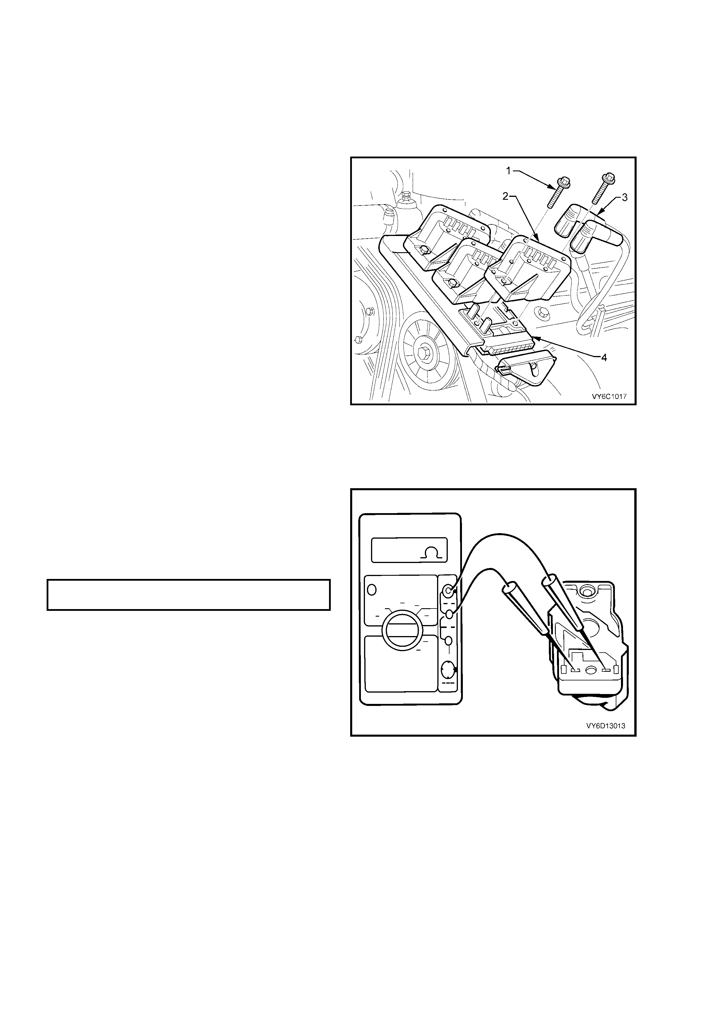
2. Remove spark plug leads (3) from coil towers,
noting lead numbering with reference to coil
tower numbers.
IMPORTANT: Sli ght l y twis t s park plug leads bef or e
removing from coil towers
IMPORTANT: All spark plug leads and coil
terminals are numbered to correspond to the
cylinder numbering. On service replacement coils
the cylinder numbering does not appear on top of
any coil assembly, refer to cylinder numbering on
the module.
3. Remove screws (1) securing coil(s) to module
and mounting plate (4).
4. Pull coil/s (2) from module (4), taking care not
to bend module terminals.
5. Repeat ste ps 2 to 4 inclusi ve for an y addition al
coils that are to be removed.
Figure 6C1-3-57 – Ignition Coils To Module
RESISTANCE TEST
1. Visually inspect each coil for any signs of
damage or spark tracking.
2. Using a Digital Multimeter (DMM) set to
resistance, measure the coil primary winding
resistance by probing into terminals from the
underside of the coil assembly.
3. Compare the resistance reading to the
specification.
IGNITION COIL PRIMARY WINDING
RESISTANCE SPECIFICATION 0.3 – 1.5 Ω
4. Replace a ny coil that is da maged, s hows signs
of spark tracking or is outside the specified
resistance range.
NOTE: Som e DMM lead pr obes m y be too lar ge to
contact the primary winding connections inside the
coil housing. If this is the case, then use a suit able
size test terminal from J35616-A Connector Test
Adaptor Kit.
Figure 6C1-3-58 – Testing Coil Primary Windings

5. To check the secondary winding resistance of
the coil, turn the coil over and measure the
resistance between the two high tension
terminals, as shown.
6. Compare the reading to the specification.
IGNITION COIL SECONDARY WINDING
RESISTANCE SPECIFICATION 5,000 – 7,000 Ω
7. Replace any coil assembly that is not within
specification.
Figure 6C1-3-59 – Testing Coil Secondary Windings
REINST ALL
1. Reinstall coil/s (2) onto module (4), aligning
module terminals with mating slots on
underside of coil.
2. Reins t al l c oi l sec uri ng s c rews ( 1) a nd t ig hten to
the correct torque specification.
DIS COIL TO MOUNTING PL ATE
SCREW TORQUE SPECIFICATION 5 Nm
3. Reconnect spark plug leads (3) to coil
term inals, ensuring correct lead to coi l term inal
relationship.
4. Reconnect battery ground lead, start engine
and ensure eng ine operate s corr ectl y.
Figure 6C1-3-60 – Ignition Coils To Module
4.3 DIS MODULE
LT Section No.– 02-235
REMOVE
1. Dis c onnect batter y ground l ead.
IMPORTANT: Disconnection of the battery affects certain vehicle electronic systems. Refer to
Section 00 CAUTIONS, 5. Battery Disconnection Procedures before disconnecting the battery.
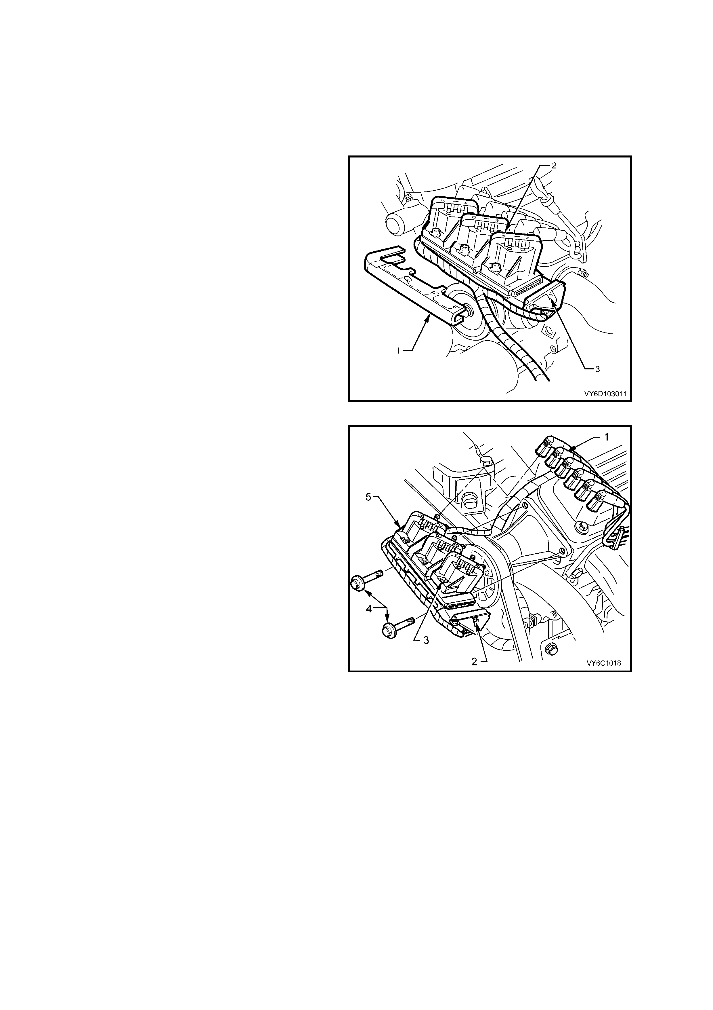
2. From beneath powertrain harness retainer (1)
at front of gently pull down on the retainer
lower locating tangs and pull retainer (1) from
coil and module assembly (2).
3. Loosen screw (3) attaching 14-pin wiring
harness connector to coil and module
assem bly (2), until the c onnector can be p ulled
from module.
4.
Figure 6C1-3-61 Removing Module Electrical Connector
5. Remove all spark plug leads (1) from the coil
towers, taking particular note of the lead
numbering with reference to the coil tower
markings.
NOTE 1: Slightly twist spark plug leads to break
the seal, before removing from coil towers
NOTE 2: All spark plug leads and ignition coil
terminals are numbered to correspond to the
cylinder numbering. On service replacement
ignition coils, the cylinder numbering does not
appear on top of any coil assembly, so refer to
cylinder numbering on t he module.
6. Rem ove two bolts ( 4) securing the DIS m odule
and coil assembly, to the left hand cylinder
head. Carefully place the DIS module and coil
assembly to one side.
7. Remove the two screws (3) securing the three
ignition coils (5) from the DIS module. Refer to
4.2 IGNITION COIL/S, in this Section.
8. Rem ove the co ils from the m odule, taking car e
not to bend the module terminals.
9. Remove the ignition module assembly from he
module mounting plate.
Figure 6C1-3-62 – Ignition Module Removed

REINST ALL
1. When replacing module assembly, remove module to coil terminal and 14 pin wiring harness connector
terminal seals from original module. Install seals onto new module, taking care not to damage seals. If any
seal(s) is damaged in any way, install new seal(s).
2. Place coils onto module, aligning module terminals with mating slots on underside of coil. Refer to
4.2 IGNITION COIL/S, Reinstall, in this Section.
3. Reinstall the ignition module assembly to the mounting plate, locating raised lugs on both coil and module
together.
NOTE: The lugs on the underside of the module will only mate with the mounting plate holes in one way only to
ensure correct assembly relationship.
4. Reinstall screws (3) securing coils and module to the mounting plate and tighten to the correct torque
specification.
DIS COIL TO MOUNTING PL ATE
SCREW TORQUE SPECIFICATION 5 Nm
5. Reins t al l DI S module and c oil as sembl y to the lef t h an d cylinder h ead, s ecur in g with t he t w o retainin g b olts a nd
tightening to the correct torque specification.
DIS MODULE AND COIL ASSEMBLY
BOLT TORQUE SPECIFICATION 45 Nm
6. Reconnect spark plug leads (1) to coil terminals, ensuring correct lead to coil terminal relationship.
7. Reconnect 14-pin wiring harness connector to module assembly and tighten attaching bolt (2) to the correct
torque specification.
WIRING HARNESS CONNECTOR
TO DIS MODULE SCREW
TORQUE SPECIFICATION 1.0 Nm
8. Snap powertrain wiring harness retainer onto coil and module assembly and it's mounting plate.
9. Rec onn ec t batter y ground l ead.
10. Start engine and ensure engine operates correctly.
4.4 CRANKSHAFT (CKP) SENSOR
LT Section No.– 02-000
REMOVE
1. Dis c onnect batter y ground l ead.
IMPORTANT: Disconnection of the battery affects certain vehicle electronic systems. Refer to
Section 00 CAUTIONS, 5. Battery Disconnection Procedures before disconnecting the battery.
2. Remove crankshaft balancer. Refer to 2.19 CRANKSHAFT BALANCER, in Section 6A1, ENGINE
MECHANICAL - V6 ENGINE.
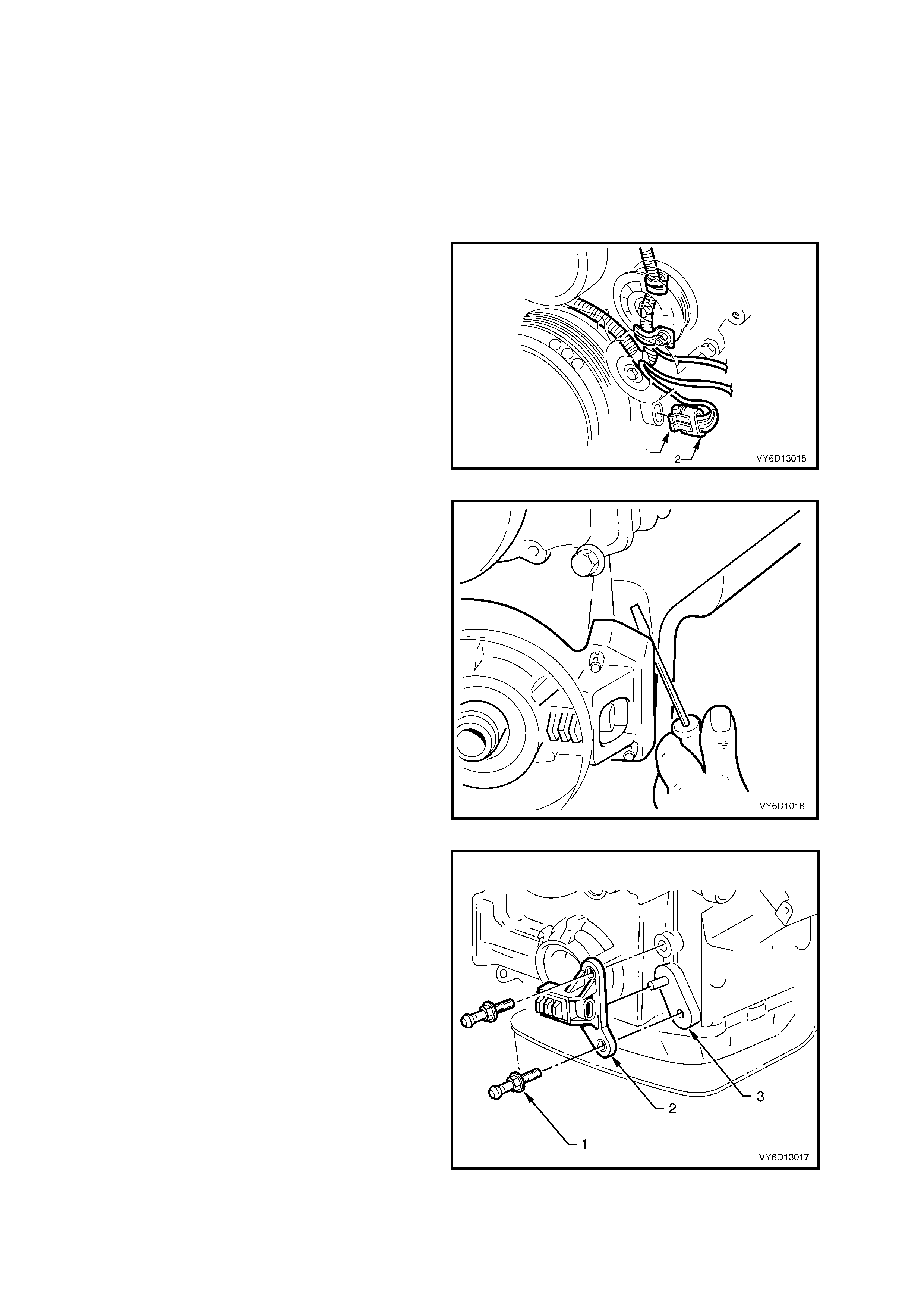
3. Lift up retaining tang on crankshaft sensor
engine wiring harness connector and pull
connector from sensor assembly.
Figure 6C1-3-63 – CKP Sensor Connector Removal
4. Rem ove the s ensor shie ld by car efull y leveri ng
each corner from the front cover using a
screwdriver or s imilar lever . Move the sh ield to
and fro until it comes clear. Set the shield to
one side.
Figure 6C1-3-64 – CKP Sensor Shield Removal
5. Remove the studs (1) attaching the sensor (2)
to the front cover (3).
6. Remove the sensor (2) from the front plate.
Figure 6C1-3-65 – Removing the CKP Sensor
REINST ALL
1. Clea n the threads of the studs and , using a suita ble tap, clean s ealer from the sensor m ounting threa ds in the
cylinder bl oc k.
2. Reinstall the crankshaft sensor onto the front cover dowel pin.
3. Apply Loctite 242 or equivalent to the cleaned CKP sensor retaining studs, reinstall to the front cover and
tighten to the correct torque specification.
CKP SENSOR TO FRONT COVER
STUD TORQUE SPECIFICATION 25 Nm
4. Reins tall the se nsor shield onto the front co ver studs, ens uring that the sh ield retain ers are full y engaged ov er
the stud ends. Gently tap fully home, using a plastic faced hammer.
5. Reinstall the wiring harness connector to the sensor, ensuring that the locking tang is engaged and that the
harness is routed correctly.
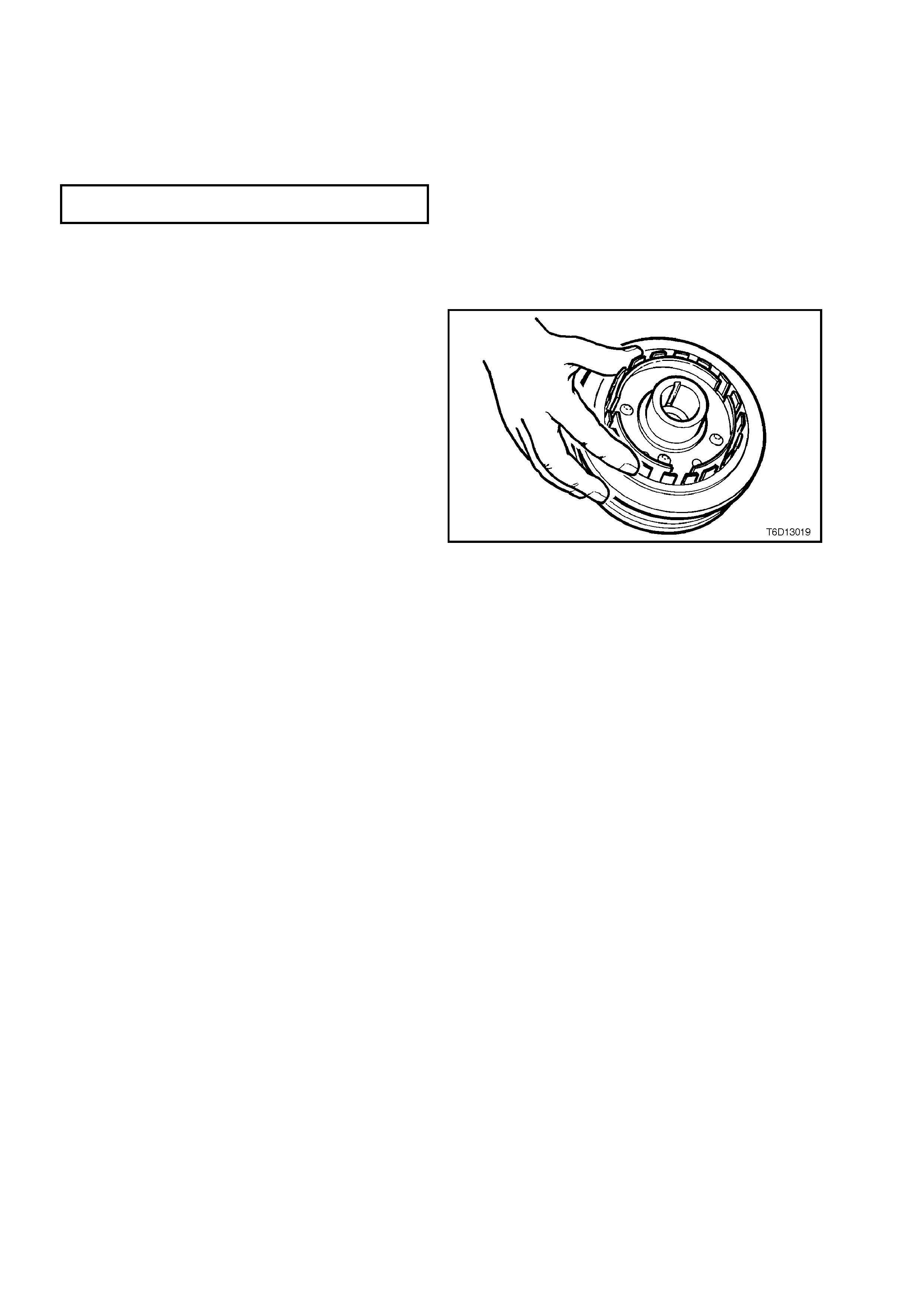
6. Visually inspect the interrupter rings for any
damage or distortion.
NOTE: Replace the crankshaft pulley if any
damage or distortion is noticed. Do not attempt to
repair any damage.
Figure 6C1-3-66 – Inspect Crankshaft Pulley Rings
7. Reinstall the crankshaft pulley. Refer to
2.19 CRANKSHAFT BALANCER, in Section
6A1, ENGINE MECHAN IC AL - V6 ENGINE.
NOTE: Do not install the drive belt at this stage.
8. Rotate the crankshaft to check that the
interrupter rings do not contact the sensor.
9. Replace the balancer assembly if the
interrupter rings contact the sensor at any
point. This indicates that the interrupter rings
have excessive runou t.
10. Reinstall the engine drive belt. Refer to
2.7 ENGINE DRIVE BELT, in Section 6A1
ENGINE MECH ANIC AL – V6 ENG IN E.
11. Refit the battery ground lead.
12. Start the engine and check for correct engine
operation.
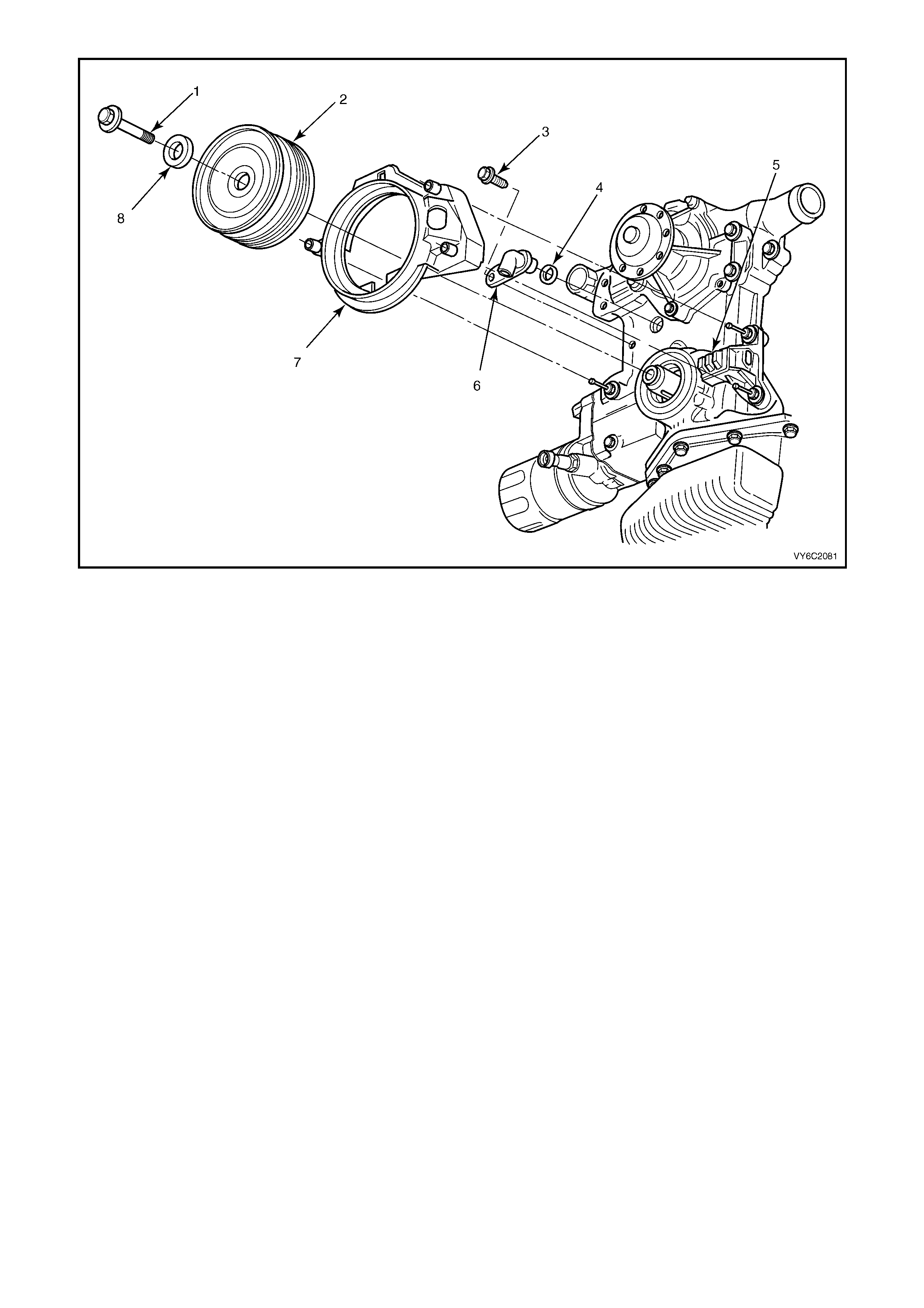
Figure 6C1-3-67 – Camshaft/Crankshaft Position Sensors
Legend
1. Crankshaft Balancer Retaining Bolt
2. Crankshaft Balancer
3. Screw _ Camshaft Sensor Retaining
4. O-Ring – Camshaft Sensor Sealing
5. Sensor – Crankshaft Position
6. Sensor – Camshaft Position
7. Shield – Crankshaft Sensor
8. Washer – Crankshaft Balancer Bolt
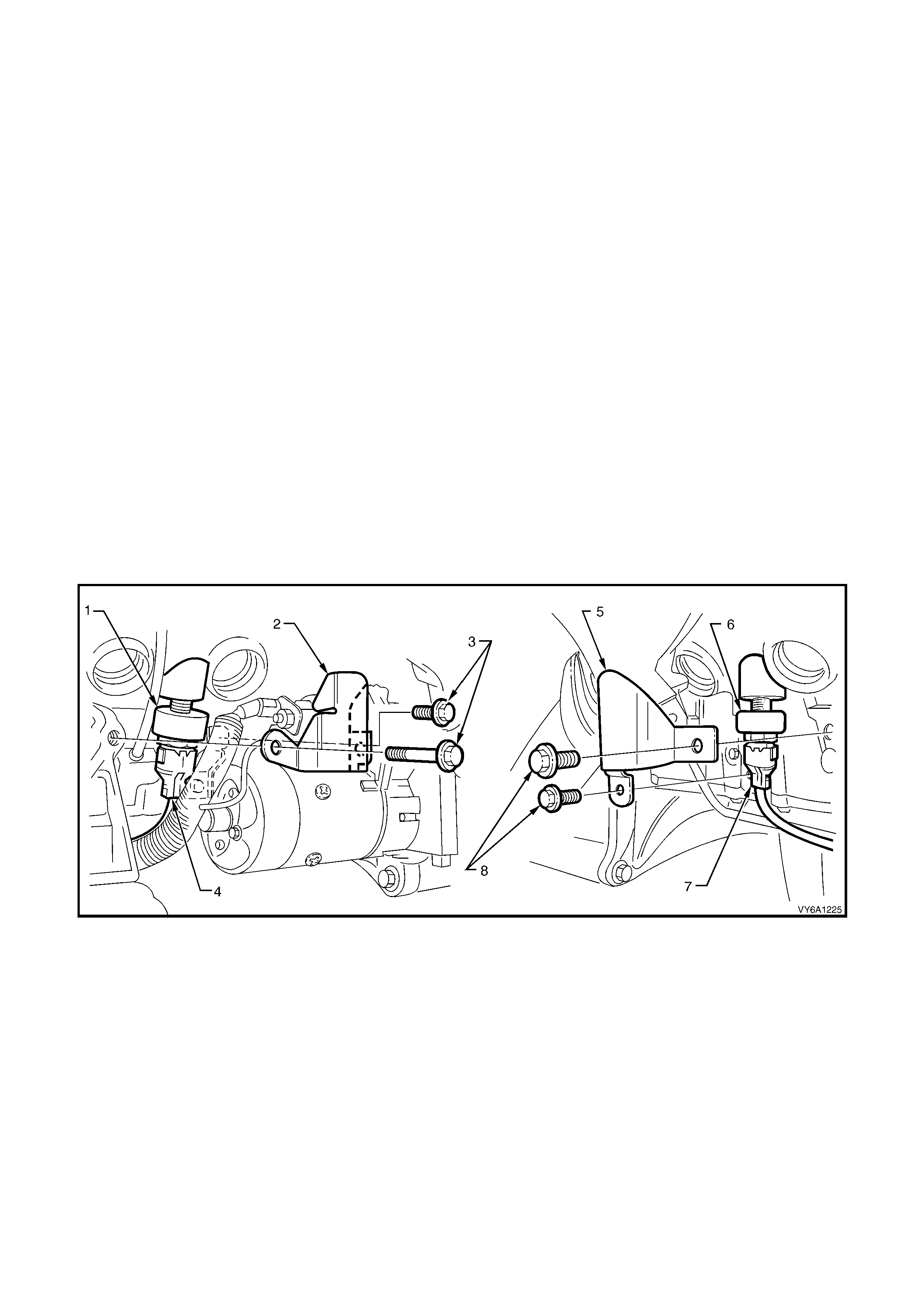
4.5 KNOCK SENSORS
LT Section No.– 02-000
CHECKING KNOCK SENSOR OPERATION
The PCM's knock sensor input will reduce t he EST spark advance wh en detonati on is present. T his sensor signals
the PCM of engine noise, and the PCM determines if the noise is detonation, or normal mechanical noise. The
PCM can be "tricked" into thinking that detonation is present by lightly ‘tapping' on the engine with a small hammer.
To check the "knock retard" function of the ignition system, run the engine with throttle fixed at a steady 1,600 –
1,800 rpm , quick ly and rep eatedl y ‘tap' on the eng ine bloc k, cylinder hea d, or inta ke manif old with a sm all ha mm er.
The RPM s hould dr op, due to th e tim ing advanc e being reduc ed. W hen you stop ‘tapping' o n the eng ine, the RPM
should come back to the original starting point.
REMOVE
CAUTION: Both knock sensors are threaded into the engine block cylinder cooling jackets, which is a
"wet" area of the engine coolant system. When either knock sensor is removed from the engine block
engine coolant will drain out. Allow the engine to fully cool down to ambient temperature before servicing
either of the knock sensors. Make that a drain pan is available to catch spilled engine coolant.
1. Allow engine to cool to ambient temperature (less than 50° C), then remove radiator cap.
2. Dis c onnect batter y ground l ead.
IMPORTANT: Disconnection of the battery affects certain vehicle electronic systems. Refer to Section 00
CAUTIONS, 5. Battery Disconnection Procedures before disconnecting the battery.
3. Raise r ear of veh icle and s upport on s afet y stands. R efer to Section 0A GENERAL INFORM ATION in t he M Y
2003 VY and V2 Series Service Information, for the location of jacking and support points.
4. Squ e e ze ' wide ends ' o n s e ns or wir in g h arnes s connector toge ther ( ‘4’ & ‘7’) ( c onn ec tor is ov al sh aped) an d p ull
connector from sensor (3 and 10).
NOTE: To achieve this s tep it m ay be necess ary to rem ove the k nock sensor heat shie ld attachin g bolts (‘ 3’ & ‘8’)
and heat shields (2 and 5).
Figure 6C1-3-68
Legend
1. Left Hand Knock Sens or.
2. Knock Sensor Shield. LHS
3. Attaching Bolts
4. Wiring Harness Connector
5. Knock Sensor Shield RHS
6. Right Hand Knock Sensor
7. Wiring Harness Connector
8. Attaching Bolts
9. Place a suitable drain tray beneath the knock sensor location.
10. Using a 22 mm socket, univers al joint and suita ble length s ocket bars , loosen then rem ove knock sens or/s (‘1’
& ‘6’) from the cylinder block, taking extreme care to avoid scalding from any hot coolant that may be draining!

REINST ALL
1. Ensure that the threads in the sensor mounting hole in cylinder block are clean.
2. If reinstalling original sensor, inspect sealant on sensor threads. If deteriorated, appl y a light coating of Loctite
242 or equivalent to the cleaned sensor threads.
NOTE: The threads on a new sensor are c oated with seala nt during manuf acture. Do not appl y additio nal sealant,
as this will reduce the effectiveness of the sensor.
3. Install sensor/s (‘1’ & ‘6’) and tighten to the correct torque specification.
KNOCK SENSOR
TORQUE SPECIFICATION 20 Nm
IMPORTANT: Ensure that knock sensor is never over tightened, as damage to the sensor can occur.
4. Rec onnect wiring har ness connector /s (‘4’ & ‘7’) to s ensor. Ensure th at each connector is securel y f itted to the
sensor.
5. Reins tall k nock sensor heat shield/s (‘2’ & ‘ 5’) and atta ching bolts (‘ 3’ & ‘8’). T ighten bolts to th e correct torq ue
specification.
KNOCK SENSOR HEAT SHIELD
BOLT TORQUE SPECIFICATION 30 Nm
6. Refill cooling system and pressure test for leaks, refer Section 6B1, ENGINE COOLING - V6 ENGINE
7. Rec onn ec t batter y ground l ead.
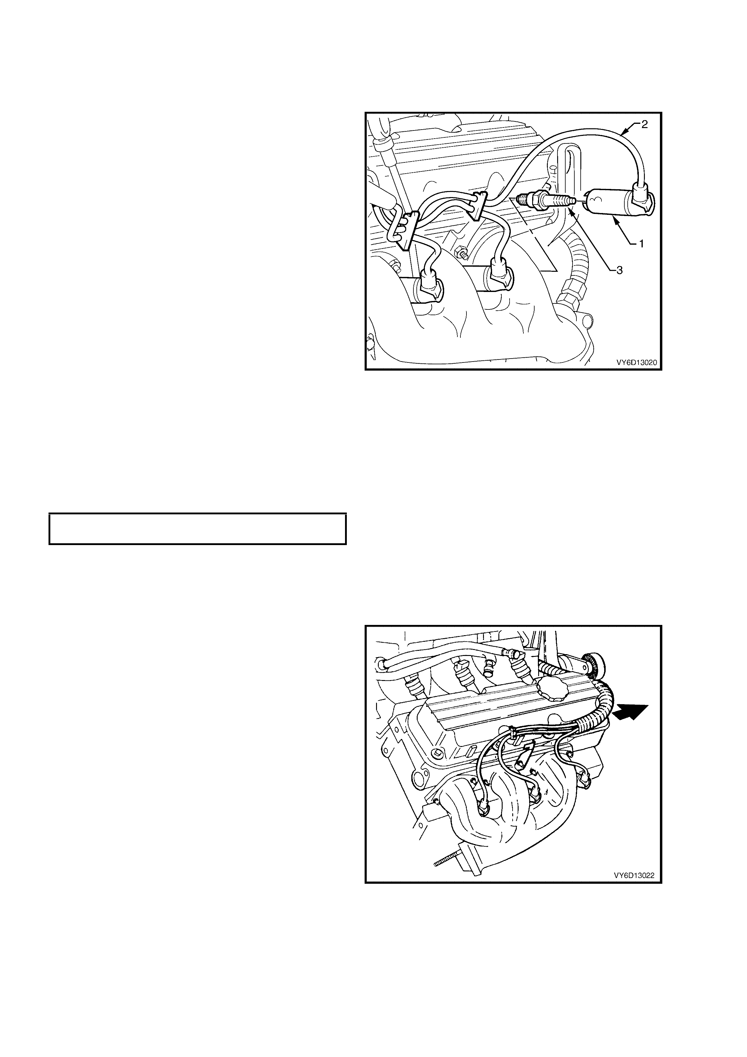
4.6 SPARK PLUG LEADS
LT Section No.– 02-030
REMOVE
NOTE 1: Pulling or bending spark plug leads can
cause hidden damage. Follow the removal steps
carefully to avoid damage.
1. Firmly grasp the boot (1) at the end of the
spark plug lead (2).
IMPORTANT: Grasp the boot (1), not the cable (2).
2. Twist the boot (1) in both directions to relieve
any suction and to break the seal.
3. Pull the boot straight off the spark plug (3).
4. Remove all spark plug leads from the DIS
ignition coil towers, working in the same way
as the spark plug ends.
5. Carefully set the spark plug leads to one side.
Figure 6C1-3-69
SPARK PLUG LEAD BENCH TESTS
1. Connect an ohmmeter capable of reading to 50 kilohms (kΩ) to each end of the lead.
2. Record the reading of each lead.
3. Measure and record the length of each lead.
4. For each lead, calculate the resistance over 30 cm.
5. Compare the resistance reading of each lead to the specification.
‘ELECTRICFIL’ SPARK PLUG LEAD
RESISTANCE per 30 cm 1,700 ohms
6. Replace any lead/s with resistance values that are significantly different from the stated specification.
REINST ALL
IMPORTANT: Ensure that the spark plug leads are routed correctly and fit each to its corresponding spark plug.
The next three diagrams show the correct routing.
•
••
•
Right Bank
Figure 6C1-3-70
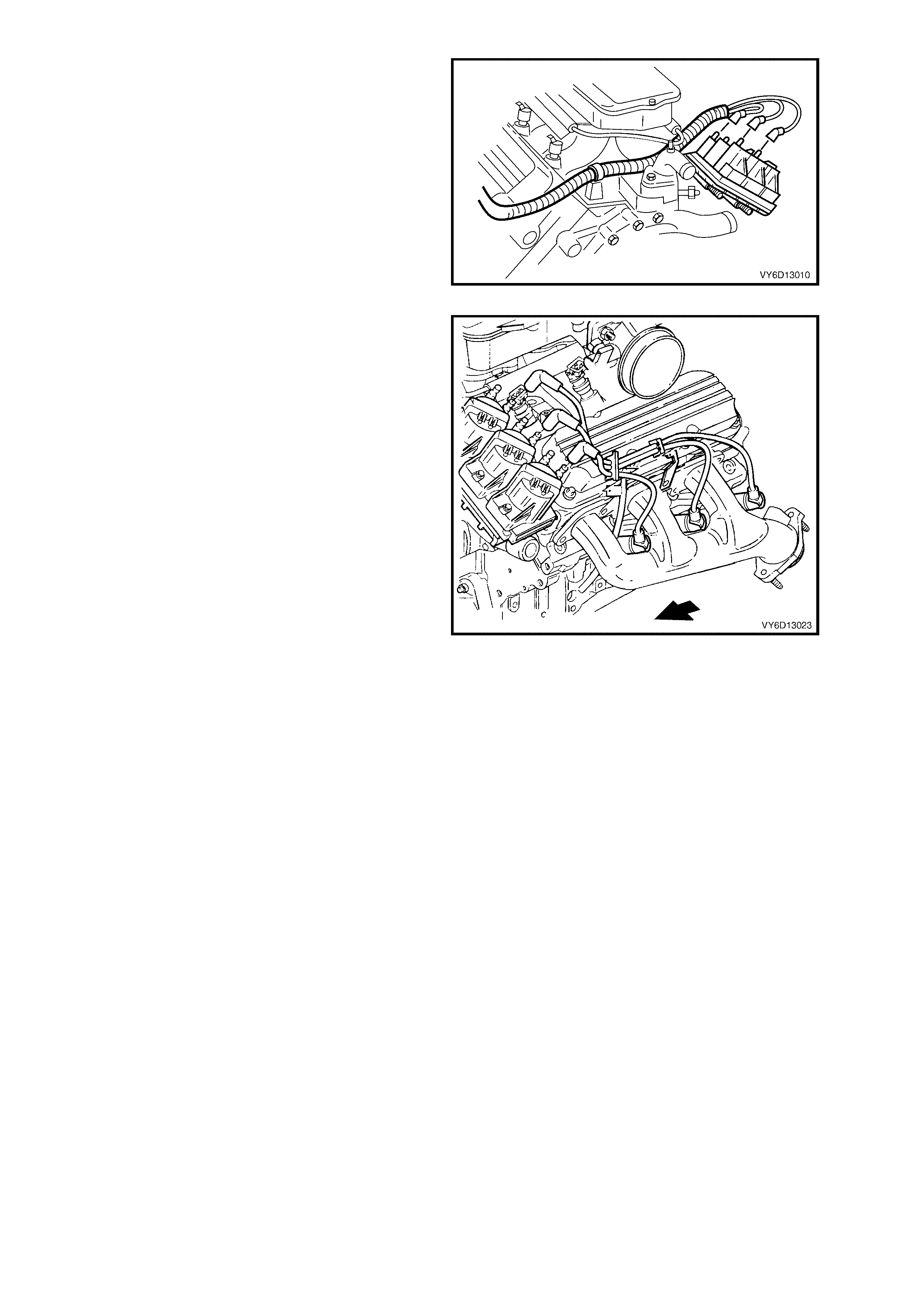
•
••
•
Front View
Figure 6C1-3-71
•
••
•
Left Bank.
Figure 6C1-3-72
NOTE: Handle only the boot of each lead.
1. Grasp the boot at the end of the spark plug lead.
2. Position the boot over the correct spark plug. Refer to Figure 6D1-3-70 for the number of each cylinder; right
bank (1) and left bank (2).
3. ‘Feel’ for the centering of the lead connection onto the spark plug terminal (or coil post).
4. Push the boot until the lead connection is fully engaged with the spark plug terminal (or coil post). This
installation approach is required to avoid potential misfiring.
NOTE: A higher than expected effort is required to fully seat the new boots to the spark plug or coil post.
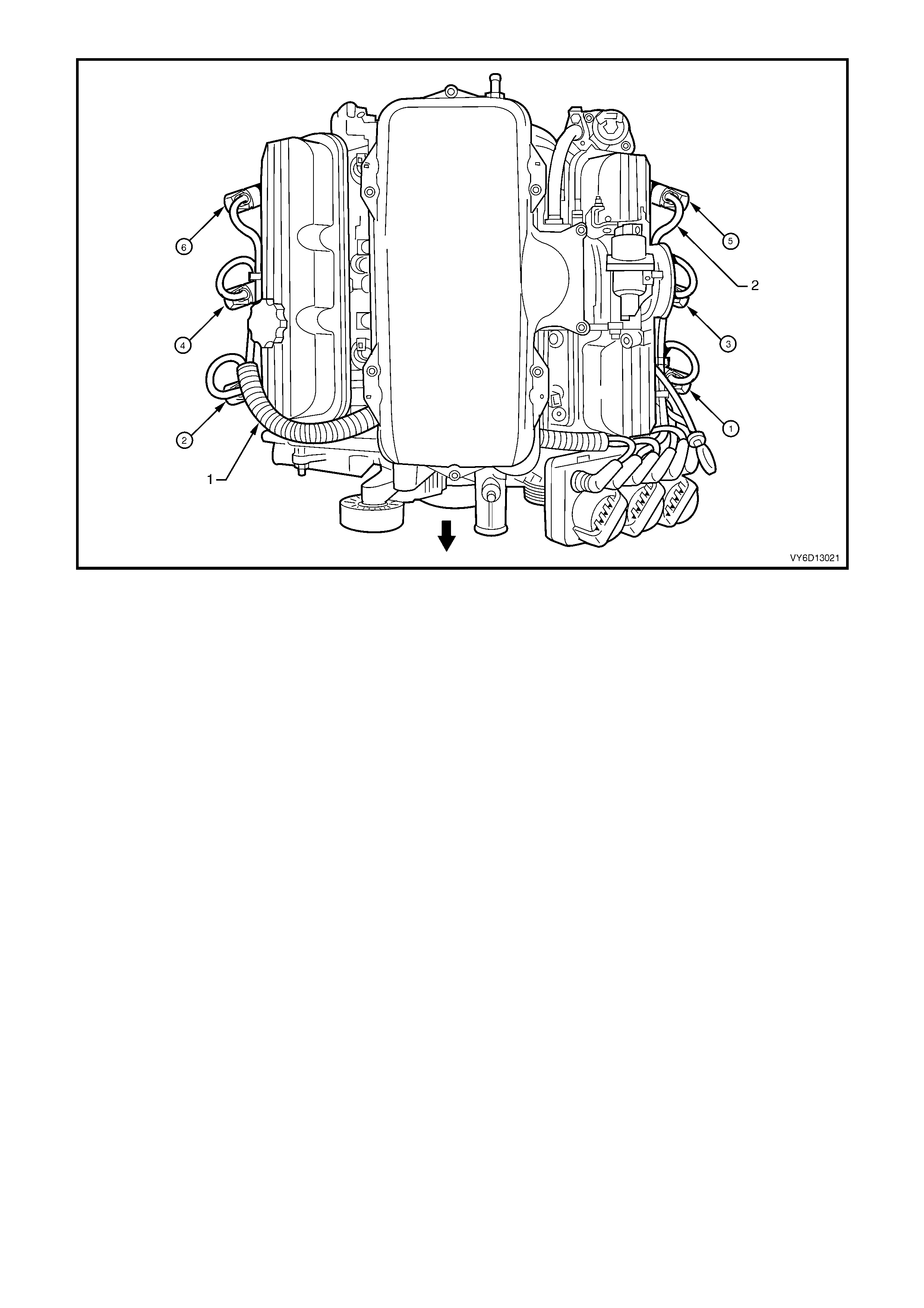
Figure 6C1-3-73 – Cylinder Numbering – V6 Engine
Legend
1. Right Bank 2. Left Bank
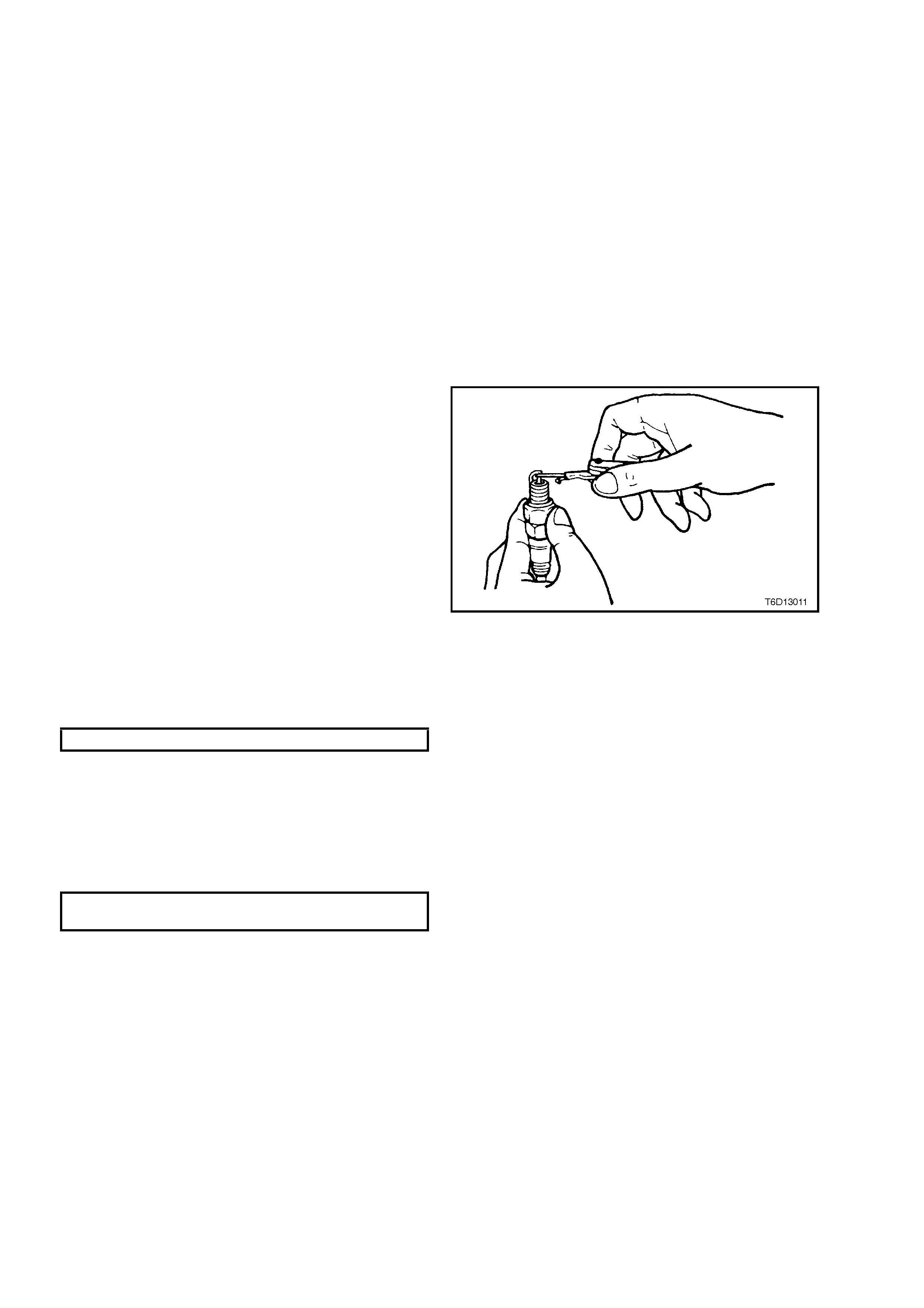
4.7 SPAR K PLUGS
LT Section No.– 02-030
REMOVE
1. Remove spark plug leads from each spark plug, remembering to only grasp the lead boot and twist in both
directions to relieve any suction and to break the seal.
2. Pull the boot straight off the spark plug.
3. Repeat this procedure for each spark lead.
4. Using a jet of compressed air remove any foreign material from around each spark plug cavity.
CAUTION: Use eye protection during this operation to prevent eye damage
5. Using a 16 mm spark plug socket and suitable equipment, loosen the remove each spark plug.
IMPORTANT: Af ter spark plug removal, place each in order of removal. This will enable an y abnorm al spark plug
condition to be identified with the correct cylinder.
6. Plug all spark plug holes in each cylinder head to prevent foreign material ingress.
CLEANING AND INSPECTION
1. Replace any plug that has cracked insulation,
broken insulation or loose electrodes.
2. Clean any oil from the plugs using a
degreasing agent.
3. Dry the plugs using compressed air.
4. Clean the spark plugs as per the
manufacturer's instructions using a purpose-
built machine (sand blasting type).
5. Inspect the spark plugs for defects. Refer to
Spark Plug Diagnosis in this Section for
identification of the condition of spark plugs.
6. Ensure that the threads are clean and in good
order.
7. Use a round wire feeler gauge to check the
spark plug gap.
8. Adjust the gap to the correct specification by
gently bendi ng the out er elec trode.
Figure 6C1-3-74
SPARK PLUG GAP – V6 Engine 1.5 mm
REINST ALL
1. Remove the rag/s from the spark plug holes.
2. Fit each spark plug carefully to avoid
damaging the thread.
3. Tighten the plugs to the correct torque
specification using a 16 mm spark plug socket.
SPARK PLUG
TORQUE SPECIFICATION 20 Nm
4. Reinstall spark plug leads to all spark plugs
after installation.

SPARK PLUG DIAGNOSIS
Poor Spark Pl ug Per formanc e
A spark plug can perform poorly due to wear, dirt, ca rbon fouling, excessive electrode wear, a broken insulator or
excessive gap.
NOTE 1: When re-gapping a spark plug, always make the gap adjustment by bending the ground (side) electrode.
NOTE 2: When replacing spark plugs, use genuine spark plugs or recommended of the correct heat range.
Worn or Dirty Plugs
Worn or dirty plugs can give satisfactory operation while the vehicle is idling, but break down under load.
This can cause:
•
••
•
poor fuel economy
•
••
•
power loss
•
••
•
acceleration loss
•
••
•
difficult starti ng
•
••
•
gener al l y poor engin e perf o rmance.
Carbon Fouling
Carbon fouling is indicated by black carbon deposits. The black deposits are usually the result of slow-speed
driving and short runs. In these circumstances, the optimum engine operating temperature is seldom reached.
Fouling can also be caused by:
•
••
•
worn piston rings
•
••
•
f ault y ignit ion
•
••
•
rich fuel mixture
•
••
•
spark plugs that are rated too cold.
Excessive Electrode Wear
This often indicates:
•
••
•
the engine is operating at high speeds
•
••
•
the engine is operating at levels that are consistently greater than normal
•
••
•
a plug that is rated too hot
•
••
•
excessively lean fuel mixture
•
••
•
plug/s overheating due to insufficient tightening (caused by combustion gases leaking past the threads).
Broken Insulator
IMPORTANT: Do not use a spark plug with a broken insulator.
Broken insulators are usually the result of improper installation or carelessness.
Breaks in the upper insulator can result from a poor fitting spark plug socket or an outside blow. The cracked
insulator m a y not show up until oil or mois ture penetra tes the crac k. T he crack is often jus t below the c rimpe d part
of the shell and may not be visible.
Break s in the lo wer insu lator often r esult f rom c areles s re- gapping and ar e usua lly vis ible. T his can als o res ult f rom
the plug operating too hot. For example, in periods of high speed operation or under heavy loads.
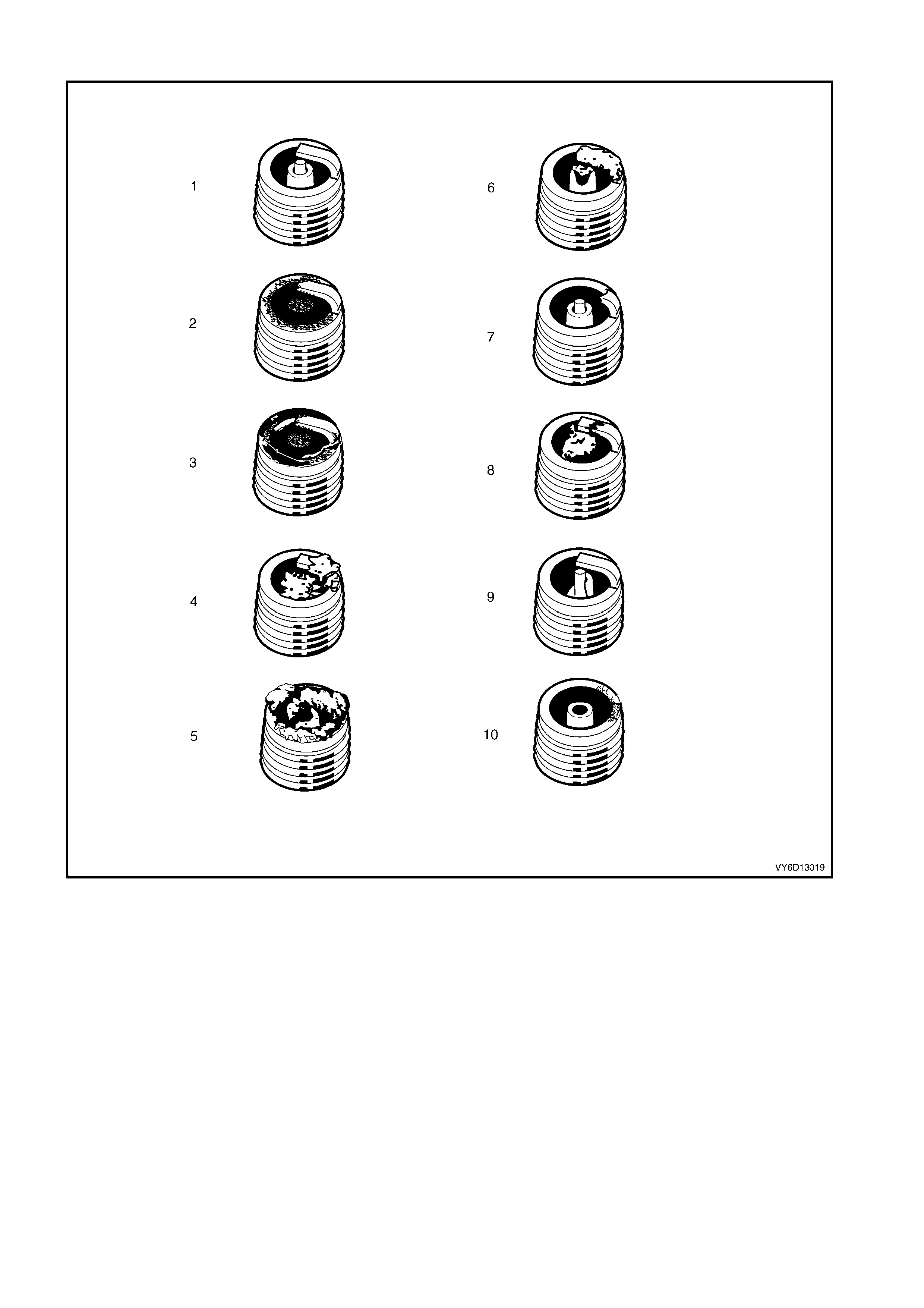
ANALYSIS OF SPARK PLUG CONDITION
Figure 6D1-3-75
Legend
1. Normal 5. Deposit fouling B 8. Pre-ignition
2. Carbon fouled 6. Deposit fouling C 9. Heated shock failure
3. Oil fouled 7. Detonation 10. Insufficient installation torque
4. Deposit fouling A
Normal Operation (1)
Brown or greyish-tan deposits and slight e lectrode wear ind icate correct spark plug heat ra nge and mixed periods
of high and low speed driving.
Carbon Fouled (2)
Dry, fluffy black carbon deposits possibl y due to poor ignition output, weak coil, faulty spark plug leads, excessive
idling, s low sp eeds under light load. If spar k plu g temperatures rem ain t oo lo w for norm al com bus tion, the depos its
are not burned off.
Oil Foul ed (3)
Wet, oily deposits with minor electrode wear possibly due to oil leaking past worn piston rings.
Breaking in a new or recently overhauled engine before the rings are fully seated may also result in this condition.

Deposit Fouling A (4)
Red brown, yellow and white coloured coatings on the insulator tip which are by-products of combustion. They
come from the fuel and the lubricating oil which generally contain additives. Most powdery deposits have no
adverse effect on spark plug operation; however, they may cause intermittent missing under severe operating
conditions.
Deposit Fouling B (5)
Deposits sim ilar to t hose identif ied in Depos it f oulin g A ( 4). T hese are a lso by-pro ducts of com bus tion fr om the f uel
and lubric ating o il. Exc essive val ve stem clearanc es and/or def ective int ake valve seals allow too m uch oil t o enter
the combustion chamber. The deposits will accumulate on the portion of the spark plug that projects into the
cham ber and will be hea vie st on th e side f acing the int ak e valve. W hen you detec t this c ondi tion i n onl y one or two
cylinders, check the seals.
Deposit Fouling C (6)
Most powd ery deposits identified in Deposit f ouling A (4) have no advers e effec t on the operation of the spark plug
as long as they remain powdery.
Under cert ain cond it ions of oper at io n ho we ver , t hes e d epos its melt a nd f orm a s hin y gl a ze coat in g o n th e ins ulat o r.
W hen hot, this acts as a g o od e lec tric a l conduct or a llo wing th e c urr ent to f lo w al o ng t he dep os it ins t ead of s par k ing
across the gap.
Detonation (7)
Commonly referred to as engine knock or ‘pinging’, detonation causes severe shocks inside the combustion
chamber causing damage to parts.
Pre-ignition (8)
Burnt or blistered insulator tip and badly eroded electrodes probably due to the excessive heat.
This is often caused by a cooling system blockage, sticking valves, improperly installed spark plugs or plugs that
are the wrong heat rating (too hot).
Sustained high speed with a heavy load can produce temperatures high enough to cause pre-ignition.
Heat Shock Failure (9)
A rapid increase in spark plug tip temperature under severe operating conditions can cause heat shock and result
in fractured insulators. This is a common cause of broken and cracked insulator tips.
Insufficient Installation Torque (10)
Poor contact between the spark plug and the cylinder head seat.
The lac k of proper he at transf er that results f rom poor s eat contact ca uses overheati ng of the sp ark plug. In many
cases, severe damage occurs, as shown.
Dirty threads in the cylinder head can cause the plug to seize before it is seated.
IMPORTANT: The recommended installation torque may be obtained before the taper seat engages with the
cylinder hea d.
Ensure that the cylinder head and spark plug threads are free of deposits, burrs and scale before installation.

5. AUTOMATIC TRANSMI SSI ON
For an y or all of the f ollowing servic e operatio ns relating to aut omatic transm ission elec tronic com ponents, ref er to
the service operations noted in Section 6C2-3 SERVICE OPERATIONS – V6 S/C ENGINE.
SERVICE OPERATIONS AND COMPONENTS
5.1 1-2 Shift Solenoid ‘A’
5.2 2-3 Shift Solenoid ‘B’
5.3 3-2 Control Solenoid
5.4 Pressure Control Solenoid
5.5 Transmission Fluid Pressure (TFP) Manual Valve Switch
Assembly & Transmission Fluid Temperature (TFT) Sensor
5.6 TCC Enable Solenoid

6. MISCELLA NEOUS SYSTEMS
LT Section No.– 03-165
6.1 EVAPORATIVE EMISSION CONTROL CANISTER
1. The Evaporative Emission Control Canister (1)
is located underneath the vehicle adjacent
to the fuel filter. For canister removal
and reinstallation procedures, Refer to
Section 6E1 EMISSION CONTROL - V6
ENGINE.
Figure 6C1-3-76
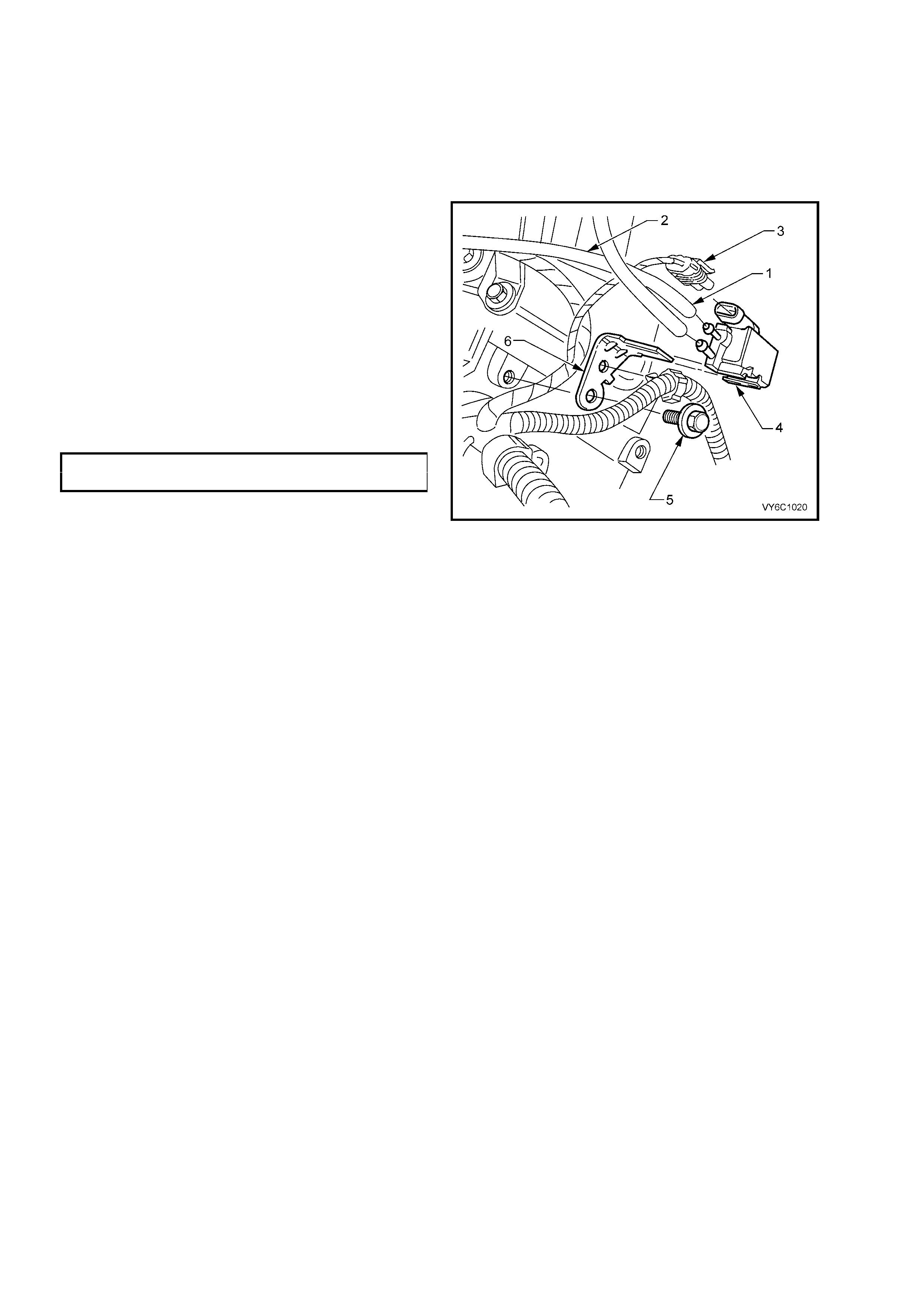
6.2 CANISTER PURGE SOLENOID
LT Section No.– 03-165
REPLACE
1. Disconnect batt ery ground lead.
IMPORTANT: Disconnection of the battery affects certain vehicle electronic systems. Refer to
Section 00 CAUTIONS, 5. Battery Disconnection Procedures before disconnecting the battery.
2. Mark hoses on canister purge solenoid (top
– ‘1’, bottom – ‘2’), then pull hoses from
solenoid (4).
3. Release the licking tan g on the solenoid wiring
harness connector (3), then pull to remove
from solenoid (4).
4. Remove bo lt ( 5) f rom solen oid br acket (6 ). This
bolt attaches to the rear of the right hand
cylinder head, remove solenoid.
5. Reinstall canister purge solenoid and bracket
(4 and 6) to rear of cylinder head and install
bracket bolt (5). Tighten bolt to the correct
torque specification.
PURGE CONTROL SOL E NOID
BOLT TORQUE SPECIFICATION 35 Nm
6. Rec onnect hoses (1 and 2) and wiring har ness
connector (3) to canister purge solenoid (4),
ensuring connections are correct and secure.
7. reconnect battery ground lead.
Figure 6C1-3-77
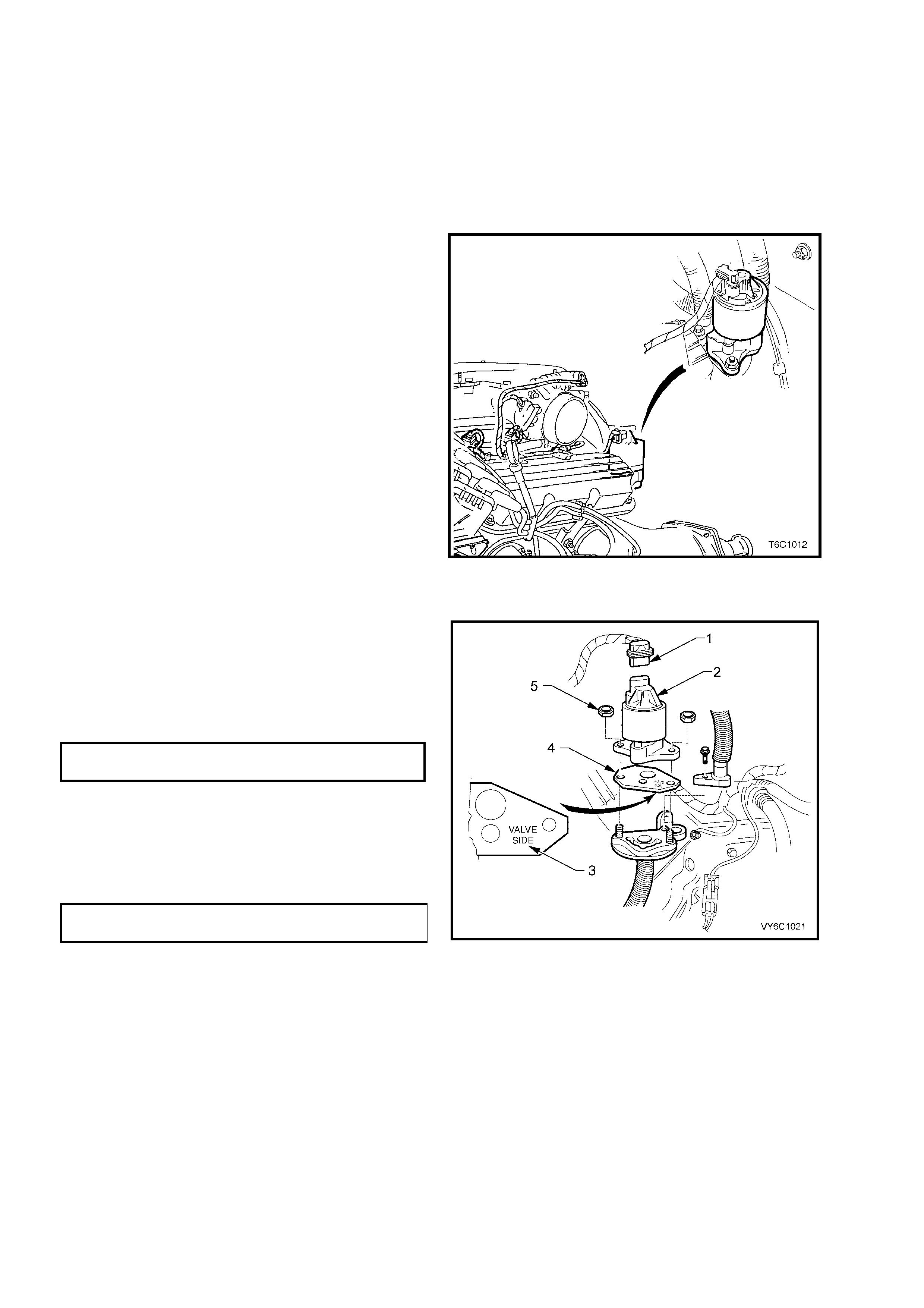
6.3 EXHAUST GAS RECIRCULATION (EGR) VALVE
LT Section No.– 03-300A
REMOVE
1. Remove four dome nuts securing the
engine dress cover assembly to the intake
manifold studs, lift off and remove the cover
assembly. Refer to Figure 6C1-3-9, in this
Section.
2. Release the wiring harness connector at EGR
valve.
3. Remove the two EGR va lv e reta ining nuts .
4. Remove the EGR valve assembly from the
engine.
5. Remove and discard the gasket.
IMPORTANT: Ensure that all old gasket material
has been removed from the EGR valve and the
EGR valve mounting sealing surface.
Figure 6C1-3-78 – EGR Valve Location
REINST ALL
1. Fit a NEW gasket (4).
NOTE: The gasket is stamped (3) to indicate the
correct fitment orientation.
2. Reinstall EGR valve assembly (2) and the two
retaining nuts (5), tightening to the correct
torque specification.
EGR RETAINING NUT
TORQUE SPECIFICATION 30 Nm
3. Reinstall the wiring harness connector (1).
Check that the retaining tang is correctly
engaged.
4. Reinstall the engine dr ess cover, securing with
the decorative nuts tightened to the correct
torque specification.
ENGINE DRESS COVER NUT
TORQUE SPECIFICATION 5 Nm
Figure 6C1-3-79
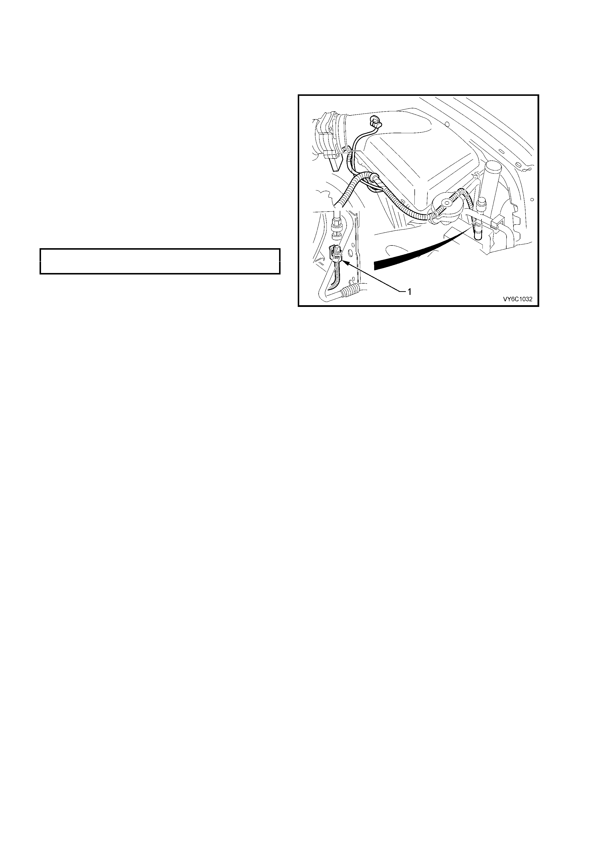
6.4 A/C REFRIGERANT PRESSURE SENSOR
LT Section No.– 08-200
REPLACE
1. Disconnect the electrical connector (1) at the
pressure sensor.
CAUTION: While there is a Schrader valve
under the pressure sensor, slight refrigerant
loss may occur, when the sensor is initially
loosened. F or t his re aso n , wear prot ectiv e h and
and eye wear, during this operation.
2. Using suitable socket equipment, remove the
sensor from the high pressure line.
3. Reinstall pressure sensor to the high pressure
line, tightening to the correct torque
specification.
A/C REFRIGERANT PRESSURE
SENSOR TORQUE SPECIFICATION 6 Nm
4. Reinstall electrical connector (1) to the
pressure sensor.
Figure 6C1-3-80 – A/C Refrigerant Pressure Sensor