
SECTION 6C1-2A - DIAGNOSTIC TABLES –
V6 ENGINE
IMPORTANT
Before performing any Service Operation or other procedure described in this Section, refer to Section 00
CAUTIONS AND NOTES for correct workshop practices with regard to safety and/or property damage.
CONTENTS
SYSTEM COMPONENT LOCATIONS
PCM WIRING DIAGRAMS
POWERTRAIN CONTROL MODULE CONNECTOR
IDENTIFICATION
PCM CONNECTOR TERMINAL VOLTAGES WITH
EXPLANATIONS
PCM ENGINE AND TRANSMISSION DIAGNOSTIC
TROUBLE CODES (DTC)
4L60-E TRANSMISSION FLUID CHECKING
PROCEDURE
TABLE A V6 PCM - ON BOARD DIAGNOSTIC (OBD)
SYSTEM CHECK
TABLE A-1 V6 PCM - NO CHECK POWERTRAIN
MALFUNCTION INDICATOR LAMP (MIL)
TABLE A-2 V6 PCM - NO SERIAL DATA
TABLE A-3.1 V6 PCM - ENGINE CRANKS BUT WILL
NOT RUN
TABLE A-3.2 V6 PCM - ENGINE CRANKS BUT WILL
NOT RUN
TABLE A-3.3 V6 PCM - ENGINE CRANKS BUT WILL
NOT RUN
TABLE A-4.0 V6 PCM - STARTER CRANKING
CIRCUIT
TABLE A-4.1 V6 PCM - FUEL PUMP ELECTRICAL
CIRCUIT
TABLE A-4.2 V6 PCM - FUEL PUMP ELECTRICAL
CIRCUIT
TABLE A-4.3 V6 PCM - FUEL DELIVERY SYSTEM
TABLE A-4.4 V6 PCM - FUEL DELIVERY SYSTEM
TABLE A-4.5 V6 PCM - FUEL DELIVERY SYSTEM
TABLE A-6.0 V6 PCM - BAROMETRIC PRESSURE
SENSOR OUTPUT CHECK
TABLE A-6.1 V6 PCM - MAF SENSOR OUTPUT
CHECK
TABLE A-6.2 V6 PCM - TP SENSOR OUTPUT CHECK
TABLE A-6.3 V6 PCM - OXYGEN SENSOR CHECK
TABLE A-6.4 V6 PCM - CANISTER PURGE SOLENOID
CHECK
TABLE A-6.5 V6 PCM - ENGINE CONTROL EFI RELAY
DIAGNOSIS
TABLE A-7.1 V6 PCM - IDLE AIR CONTROL (IAC)
SYSTEM
TABLE A-7.2 V6 PCM - IDLE AIR CONTROL (IAC)
SYSTEM
TABLE A-8.1 V6 PCM - DIRECT IGNITION SYSTEM
(DIS) CHECK
TABLE A-8.2 V6 PCM - DIRECT IGNITION SYSTEM
(DIS) CHECK
TABLE A-11.1 V6 PCM - A/C CLUTCH CONTROL
(NON-OCC SYSTEM)
TABLE A-11.2 V6 PCM - A/C CLUTCH CONTROL
WITH OCCUPANT CLIMATE CONTROL (OCC)
TABLE A-12.1 V6 PCM - ELECTRIC FAN CONTROL -
STANDARD FAN PACKAGE
TABLE A-12.2 V6 PCM - ELECTRIC FAN CONTROL -
STANDARD FAN PACKAGE
TABLE A-12.3 V6 PCM - ELECTRIC FAN CONTROL -
HIGH PERFORMANCE FAN PACKAGE
TABLE A-12.4 V6 PCM - ELECTRIC FAN CONTROL -
HIGH PERFORMANCE FAN PACKAGE
TABLE A-12.5 V6 PCM - ELECTRIC FAN CONTROL -
HIGH PERFORMANCE FAN PACKAGE
TABLE A-13 V6 PCM - RESTRICTED EXHAUST
CHECK
DTC P0101 - V6 PCM MASS AIR FLOW SENSOR OUT
OF RANGE
DTC P0107 - V6 PCM BAROMETRIC PRESSURE
SENSOR SIGNAL VOLTAGE LOW
DTC P0108 - V6 PCM BAROMETRIC PRESSURE
SENSOR SIGNAL VOLTAGE HIGH
DTC P0111 - V6 PCM INTAKE AIR TEMPERATURE
SIGNAL VOLTAGE UNSTABLE
DTC P0112 - V6 PCM INTAKE AIR TEMPERATURE
SIGNAL VOLTAGE LOW
DTC P0113 - V6 PCM INTAKE AIR TEMPERATURE
SIGNAL VOLTAGE HIGH
DTC P0117 - V6 PCM ENGINE COOLANT
TEMPERATURE SIGNAL VOLTAGE LOW
DTC P0118 - V6 PCM ENGINE COOLANT
TEMPERATURE SIGNAL VOLTAGE HIGH
DTC P0121 - V6 PCM THROTTLE POSITION SENSOR
STUCK
DTC P0122 - V6 PCM THROTTLE POSITION SENSOR
VOLTAGE LOW
DTC P0123 - V6 PCM THROTTLE POSITION SENSOR
VOLTAGE HIGH
DTC P0131 - V6 PCM RIGHT HAND OXYGEN SENSOR
VOLTAGE LOW
DTC P0132 - V6 PCM RIGHT HAND OXYGEN SENSOR
VOLTAGE HIGH
DTC P0134 - V6 PCM NO RIGHT HAND OXYGEN
SENSOR SIGNAL
DTC P0151 - V6 PCM LEFT HAND OXYGEN SENSOR
SIGNAL VOLTAGE LOW
DTC P0152 - V6 PCM LEFT HAND OXYGEN SENSOR
SIGNAL VOLTAGE HIGH
DTC P0154 - V6 PCM NO LEFT HAND OXYGEN
SENSOR SIGNAL
DTC P0170 - V6 PCM LONG TERM FUEL TRIM (LTFT)
DELTA HIGH
DTC P0173 - V6 PCM SHORT TERM FUEL TRIM (STFT)
DELTA HIGH
DTC P0200 - V6 PCM INJECTOR VOLTAGE MONITOR
FAULT
DTC P0218 - V6 PCM TRANSMISSION FLUID
OVERTEMPERATURE
DTC P0325 - V6 PCM DSNEF SYSTEM FAULT
DTC P0327 - V6 PCM LEFT HAND KNOCK SENSOR
CIRCUIT FAULT
DTC P0332 - V6 PCM RIGHT HAND KNOCK SENSOR
CIRCUIT FAULT
DTC P0341 - V6 PCM CAM/CRANK SENSOR SIGNAL
INTERMITTENT
DTC P0342 - V6 PCM CAMSHAFT POSITION SENSOR
SIGNAL MISSING

DTC P0374 - V6 PCM 18X REFERENCE SIGNAL
MISSING
DTC P0400 - V6 PCM EGR FLOW FAULT INDICATED
DTC P0405 - V6 PCM EGR POSITION FAULT
DTC P0446 - V6 PCM CANISTER PURGE CIRCUIT
FAULT
DTC P0502 - V6 PCM NO VEHICLE SPEED SIGNAL
DTC P0503 - V6 PCM VEHICLE SPEED SENSOR
INTERMITTENT SIGNAL
DTC P0506 - V6 PCM IDLE SPEED ERROR
DTC P0507 - V6 PCM VACUUM LEAK
DTC P0530 - V6 PCM A/C PRESSURE SENSOR
CIRCUIT FAULT
DTC P0560 - V6 PCM SYSTEM VOLTAGE TOO HIGH
(LONG TIME)
DTC P0561 - V6 PCM SYSTEM VOLTAGE UNSTABLE
DTC P0562 - V6 PCM SYSTEM VOLTAGE LOW
DTC P0563 - V6 PCM SYSTEM VOLTAGE TOO HIGH
DTC P0601 - V6 PCM POWERTRAIN CONTROL
MODULE MEMORY
DTC P0712 - V6 PCM TFT SIGNAL VOLTAGE LOW
DTC P0713 - V6 PCM TFT SIGNAL VOLTAGE HIGH
DTC P0730 - V6 PCM 2-3 SHIFT SOLENOID B CIRCUIT
VOLTAGE HIGH
DTC P0740 - V6 PCM TCC ENABLE SOLENOID
CIRCUIT FAULT
DTC P0741 - V6 PCM TCC SYSTEM STUCK ON
DTC P0748 - V6 PCM PC SOLENOID CURRENT
ERROR
DTC P0753 - V6 PCM 1-2 SHIFT SOLENOID A CIRCUIT
VOLTAGE HIGH
DTC P0756 - V6 PCM 1-2 SHIFT SOLENOID A CIRCUIT
VOLTAGE LOW
DTC P0757 - V6 PCM 2-3 SHIFT SOLENOID B CIRCUIT
VOLTAGE LOW
DTC P0785 - V6 PCM 3-2 DOWNSHIFT CONTROL
SOLENOID CIRCUIT FAULT
DTC P1064 - V6 PCM LOW SPEED FAN - NO BCM
RESPONSE
DTC P1116 - V6 PCM ENGINE COOLANT
TEMPERATURE SIGNAL VOLTAGE UNSTABLE
DTC P1255 - V6 PCM THEFT DETERRENT SIGNAL
MISSING
DTC P1351 - V6 PCM IGNITION ELECTRONIC SPARK
TIMING (EST) CIRCUIT FAULT
DTC P1361 - V6 PCM IGNITION BYPASS CIRCUIT
FAULT
DTC P1372 - V6 PCM NO REFERENCE PULSES
WHILE CRANKING
DTC P1571 - V6 PCM REQUESTED TORQUE OUT OF
RANGE
DTC P1627 - V6 PCM PCM – ANALOG TO DIGITAL
(A/D) CONVERSION ERROR
DTC P1628 - V6 PCM PCM ERROR – ENGINE
COOLANT TEMPERATURE
DTC P1642 - V6 PCM LPG ENABLE SIGNAL OUT OF
RANGE
DTC P1643 - V6 PCM LPG FCV PWM OUT OF RANGE
DTC P1810 - V6 PCM TFP MANUAL VALVE POSITION
SWITCH ASSEMBLY CIRCUIT MALFUNCTION.
DTC P1860 - V6 PCM TCC PWM SOLENOID FAULT
DTC P1870 - V6 PCM TRANSMISSION SLIPPING
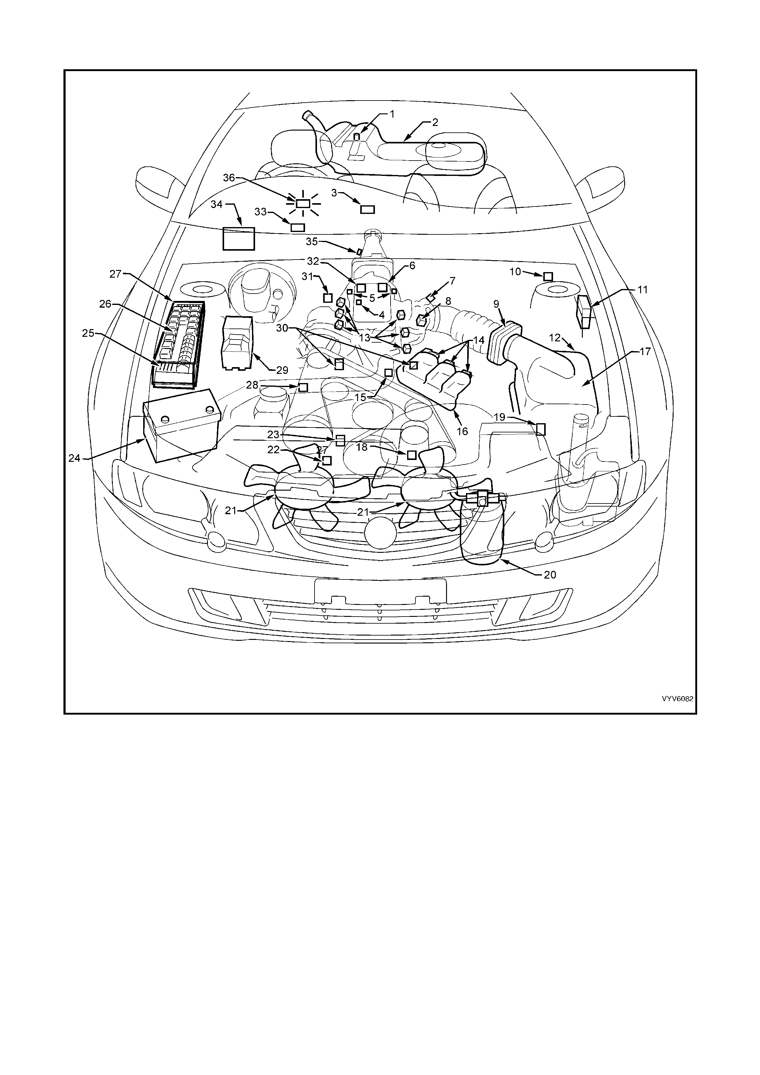
SYSTEM COMPONENT LOCATIONS
Figure 6C1-2A-1 Component Locations
Legend
1. Fuel Pump (Inside Fuel Tank)
2. Fuel Tank
3. OCC In –Car Air Temperature Sensor
4. Fuel Pressure Regulator
5. Exhaust Gas Oxygen (O2S) Sensor (Two)
6. Engine Harness (PCM) Ground (Two Terminals)
7. Idle Air Control (IAC) Valve
8. Throttle Position (TP) Sensor
9. Mass Air Flow (MAF) Sensor
10. Tachometer Lead
11. Powertrain Control Module (PCM) (Inside Vehicle)
12. Intake Air Temperature (IAT) Sensor
13. Fuel Injectors
14. Ignition Coils
15. Engine Coolant Temperature (ECT) Sensor
16. DIS Module
17. Air Cleaner
18. Crankshaft Position (CKP) Sensor
19. A/C Refrigerant Pressure Sensor
20. A/C Accumulator
21. Engine Cooling Fans (Two)
22. Oil Pressure Switch
23. Camshaft Position (CMP) Sensor
24. Battery
25. Engine Compartment Fuses
26. Engine Compartment Relays
27. Engine Compartment Fuse/Relay Centre
28. Engine Harness (PCM) Ground (Two Terminals)
29. ABS or ABS/TCS Hydraulic Modulator
30. Detonation Knock Sensors (KS) (Two)
31. Brake Hydraulic Failure Switch
32. EVAP Canister Purge Solenoid
33. Diagnostic Link Connector (DLC)
34. BCM
35. Vehicle Speed Sensor (VSS)
36. Check Powertrain MIL
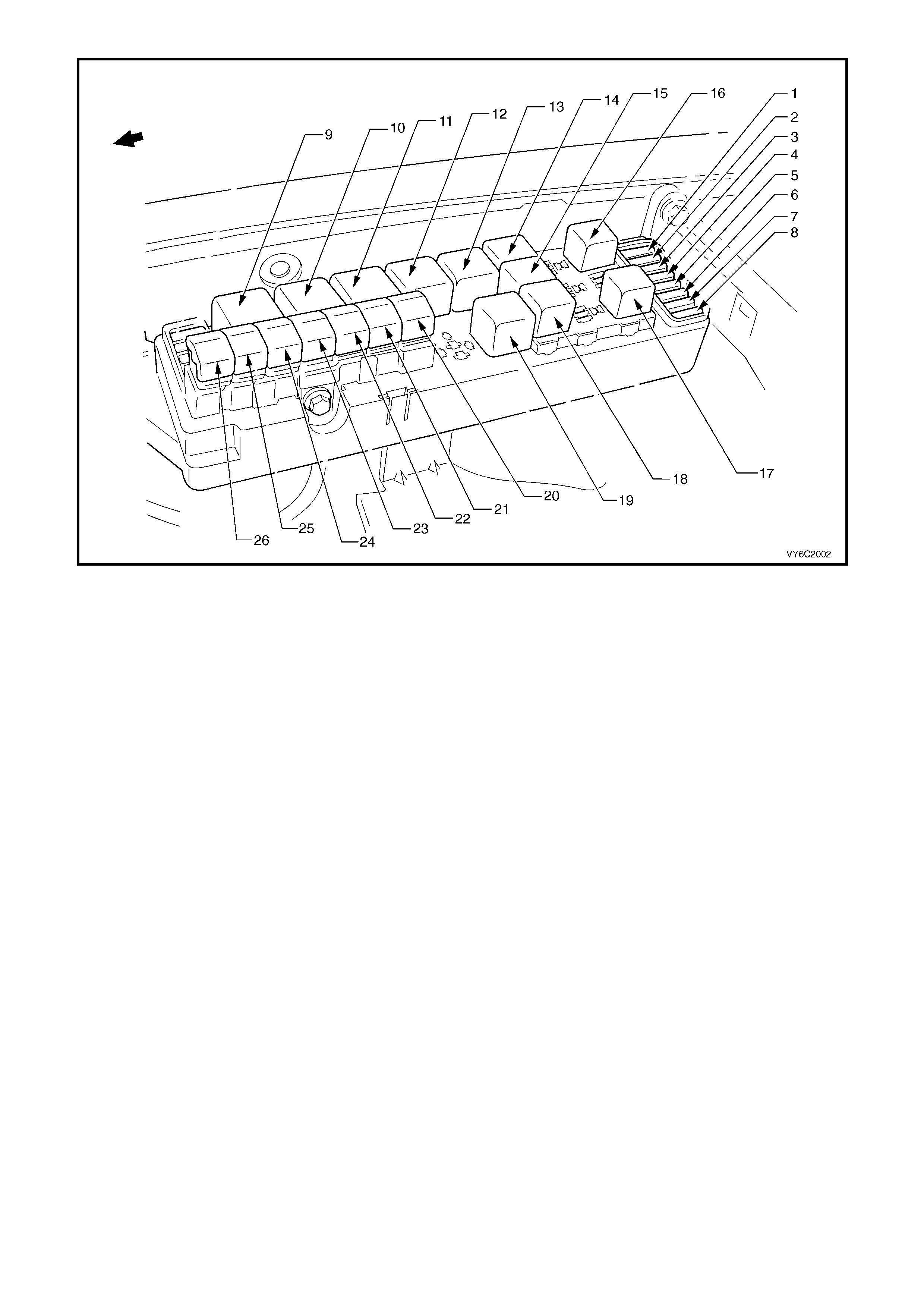
Figure 6C1-2A-2 – Engine Compartment Fuse/Relay/Fusible Link Locations
Legend
Fuses
1. Fuel Pump Fuse – F28
2. Engine / BCM / Telematics– F29
3. RH Headlamps – F30
4. LH Headlamps – F31
5. Automatic Transmissi on – F32
6. Engine Sensors – F33
7. Injectors / Ignition – F34
8. Injectors / Ignition – F35
Relays
9. Start – R1
10. Blower Fan – R2
11. Headlamp (High Beam) – R3
12. Engine Control (EFI) – R4
13. Engine Cooling Fan Relay 2 – R5
14. Horn – R8
15. A/C Compressor – R11
16. Fog Lamp – R10
17. Fuel Pump – R16
18. Headlamp (Low Beam) – R14
19. Engine Cooling Fan Relay 1– R7
Fusible Links
20. Engine Cooling Small Fan F107 (30A)
21. Blower Fan – F106 (60A)
22. Main – F105 (60A)
23. Engine – F104 (60A)
24. A.B.S. – F103 (60A)
25. Lighting – F102 (60A)
26. Engine Cooling Large Fan F101 (30A)

Figure 6C1-2A-3 Engine Component Locations
Legend
1. Idle Air Control (IAC) Valve
2. Throttle Position (TP) Sensor
3. EGR Valve
4. Injectors
5. Direct Ignition System Module
6. L.H. Knock Sensor (KS)
7. Crankshaft Position (CKP) Sensor
8. Oil Pressure Switch
9. Camshaft Position (CMP) Sensor
10. Ignition Coils (Three Places)
11. Engine Coolant Temperature (ECT) Sensor
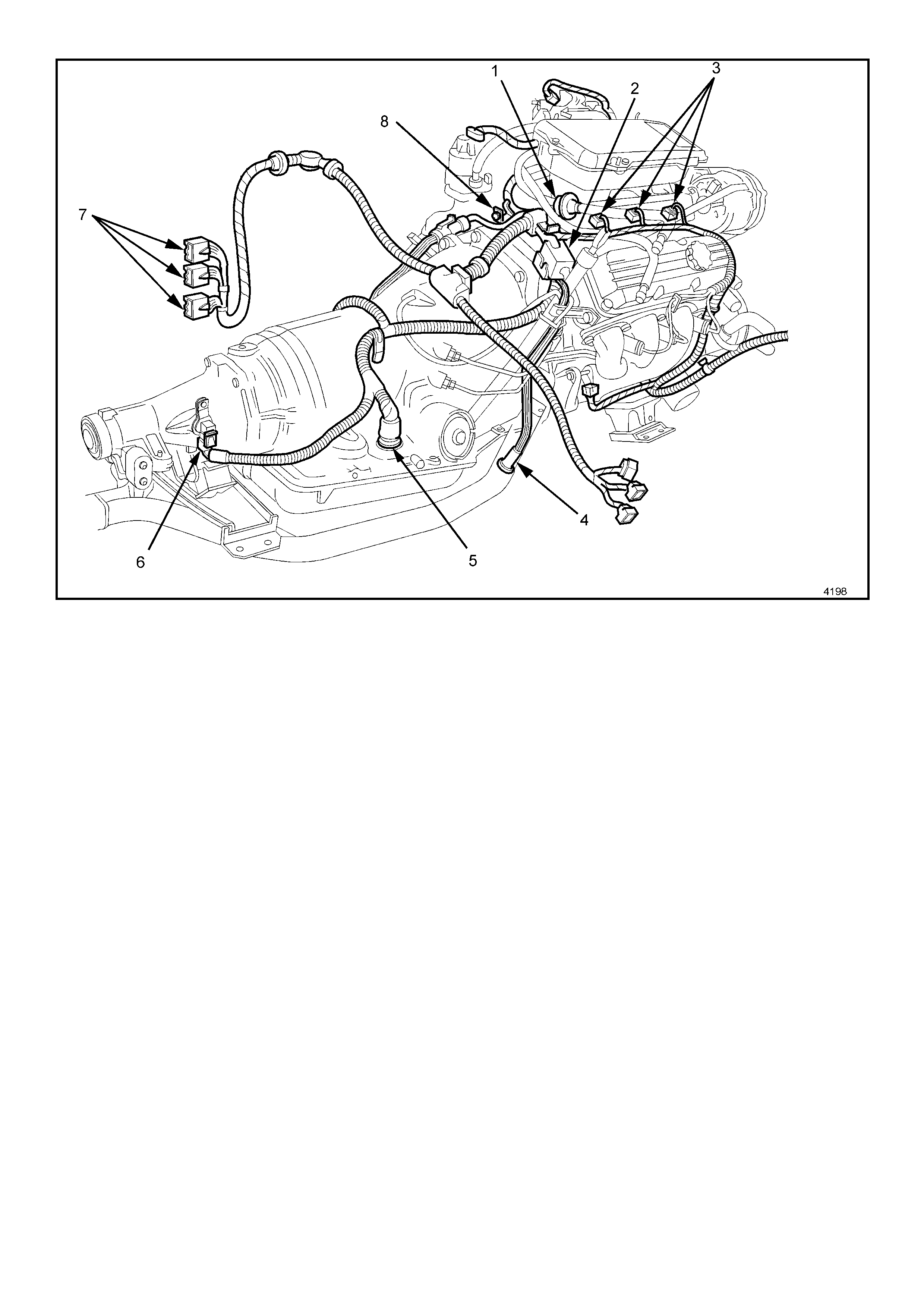
Figure 6C1-2A-4 Engine Component Locations
Legend
1. Fuel Pressure Regulator.
2. Canister Purge Solenoid.
3. Injectors.
4. R.H. Exhaust Gas Oxygen (O2S) Sensor.
5. Transmission Pass-Through Connector.
6. Vehicle Speed Sensor (VSS) (Automatic Trans).
7. PCM Connectors.
8. Engine Harness Ground.
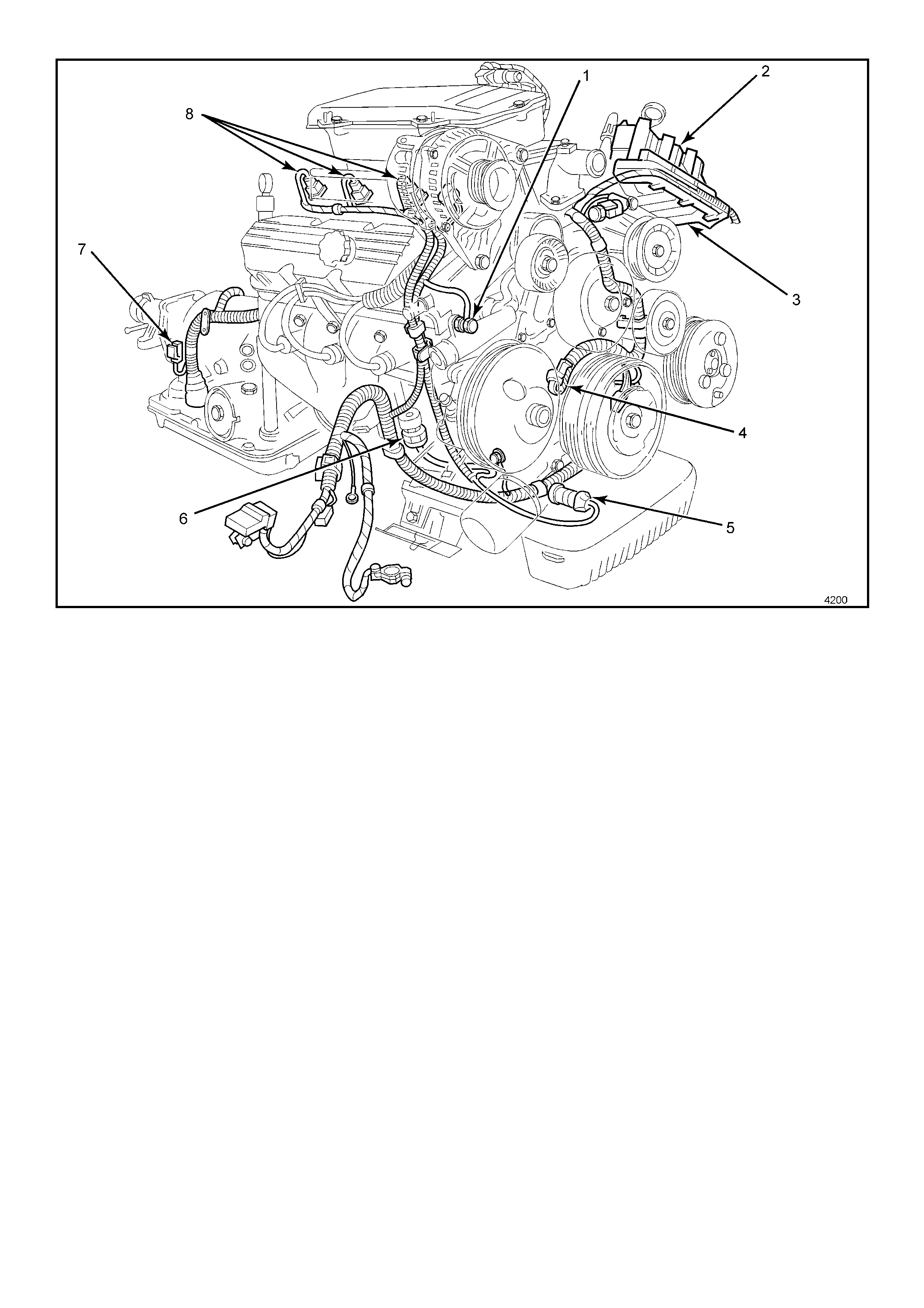
Figure 6C1-2A-5 Engine Component Locations
Legend
1. Engine Harness Ground.
2. Ignition Coils (Three Places).
3. Direct Ignition System Module.
4. Camshaft Position (CMP) Sensor.
5. Oil Pressure Switch.
6. R.H. Knock Sensor (KS).
7. Vehicle Speed Sensor (VSS) Automatic Trans.
8. Injectors.
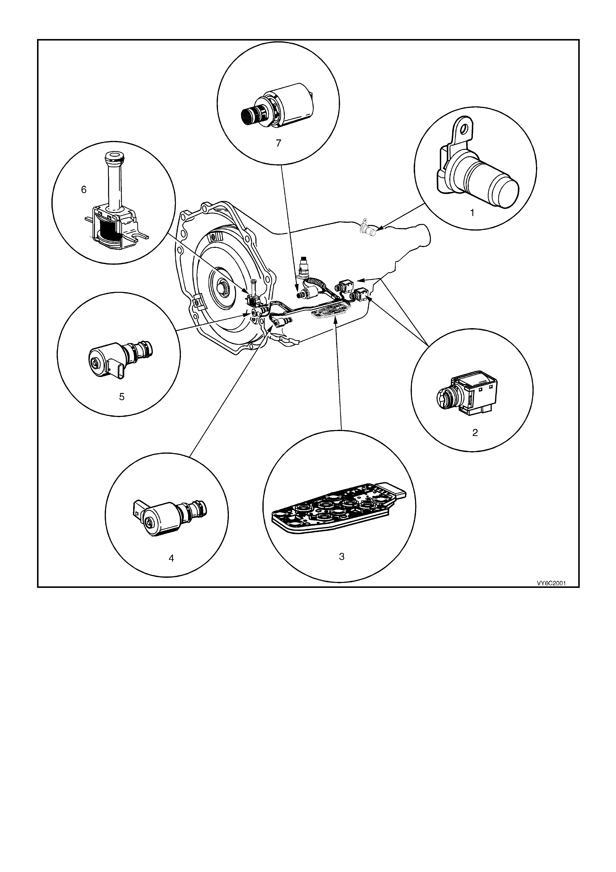
Figure 6C1-2A-6 Automatic Transmission Internal Electronic Component Locations
Legend
1. Vehicle Speed Sensor.
2. 1-2 Shift Solenoid A and 2-3 Shift Solenoid B.
3. Automatic Transmission Fluid Pressure (TFP) Manual Valve Position Switch.
4. 3-2 Downshift Shift Control Solenoid.
5. Torque Converter Clutch Pulse Width Modulation (TCC PWM) Solenoid Valve.
6. Torque Converter Clutch (TCC) Solenoid Valve.
7. Pressure Control Solenoid (PCS) Valve.
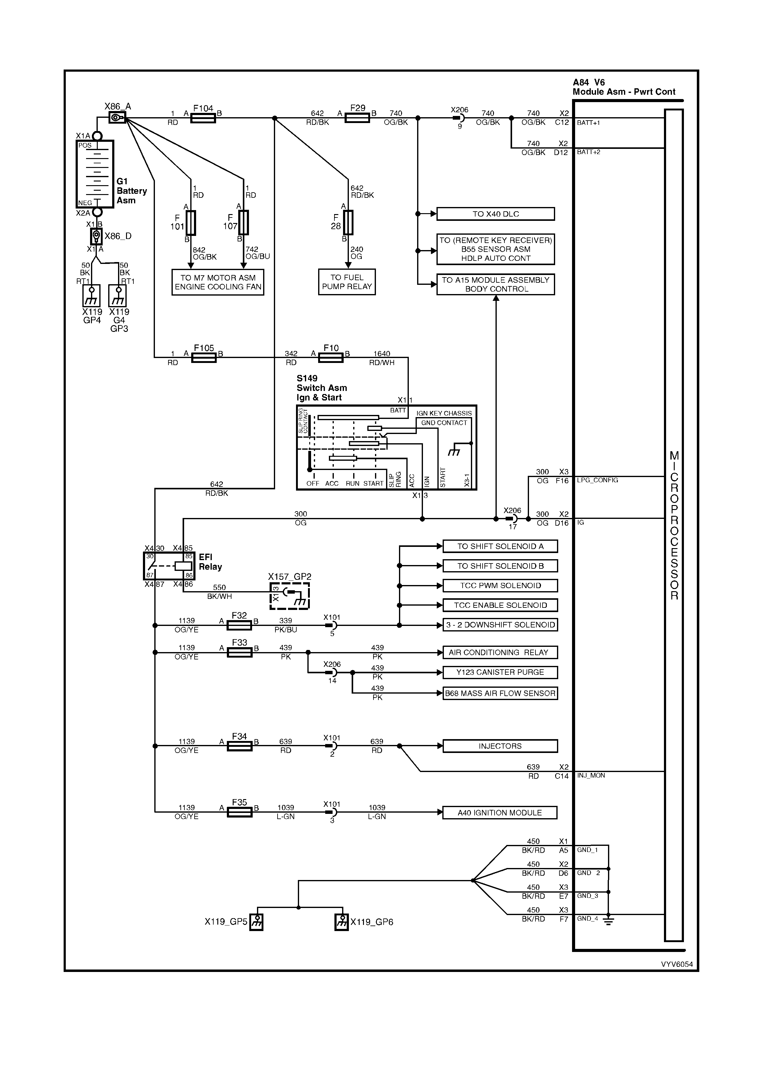
PCM WIRING DIAGRAMS
Figure 6C1-2A-7 PCM Wiring Diagram (1 of 10)
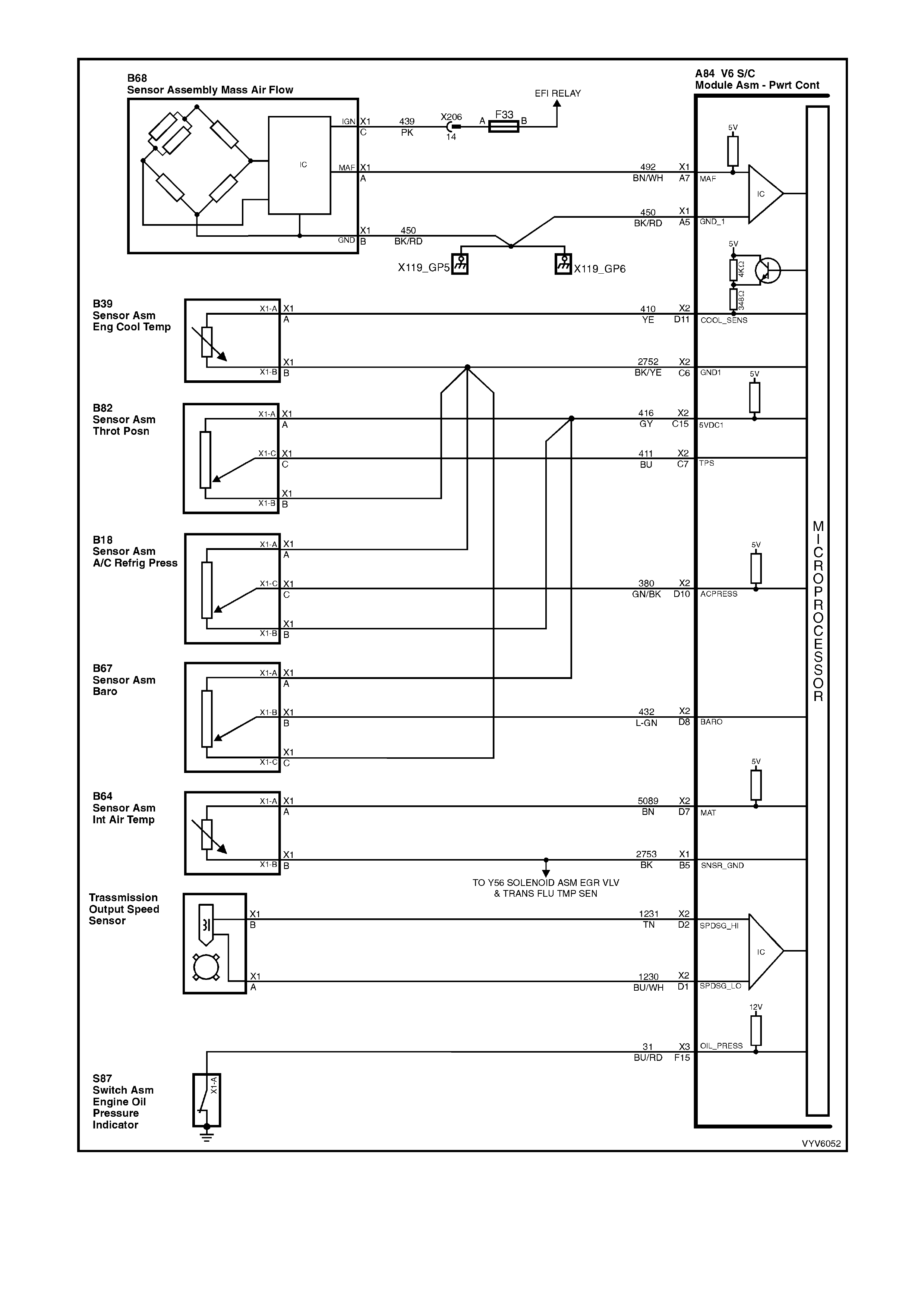
Figure 6C1-2A-8 PCM Wiring Diagram (2 of 10)
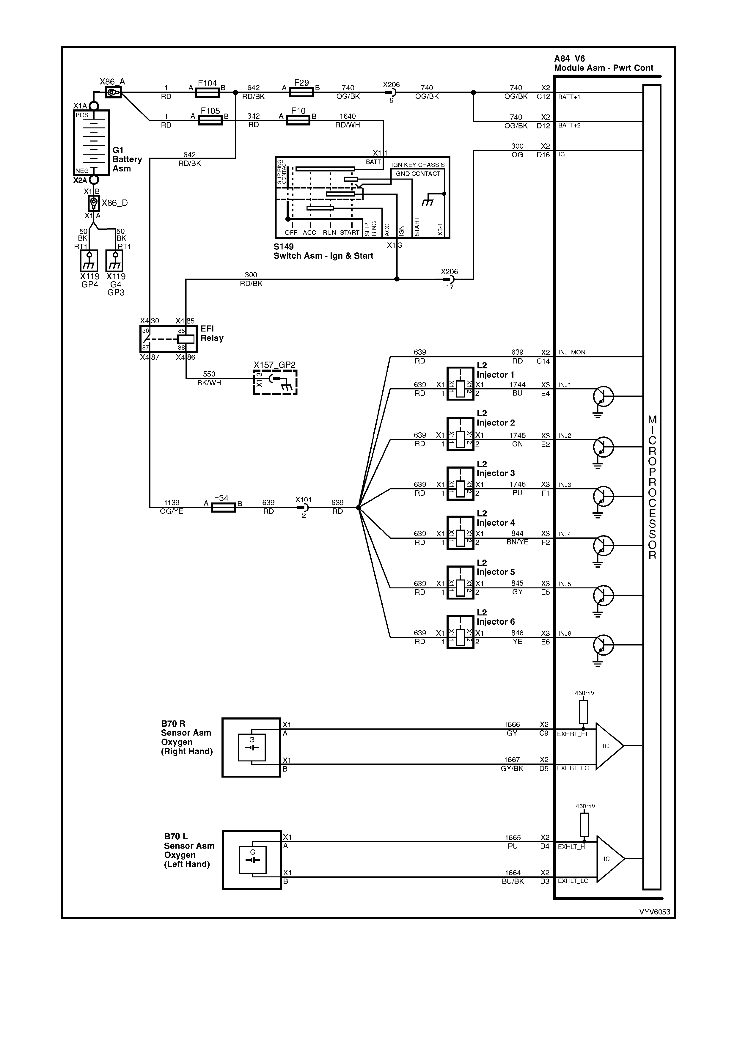
Figure 6C1-2A-9 PCM Wiring Diagram (3 of 10)
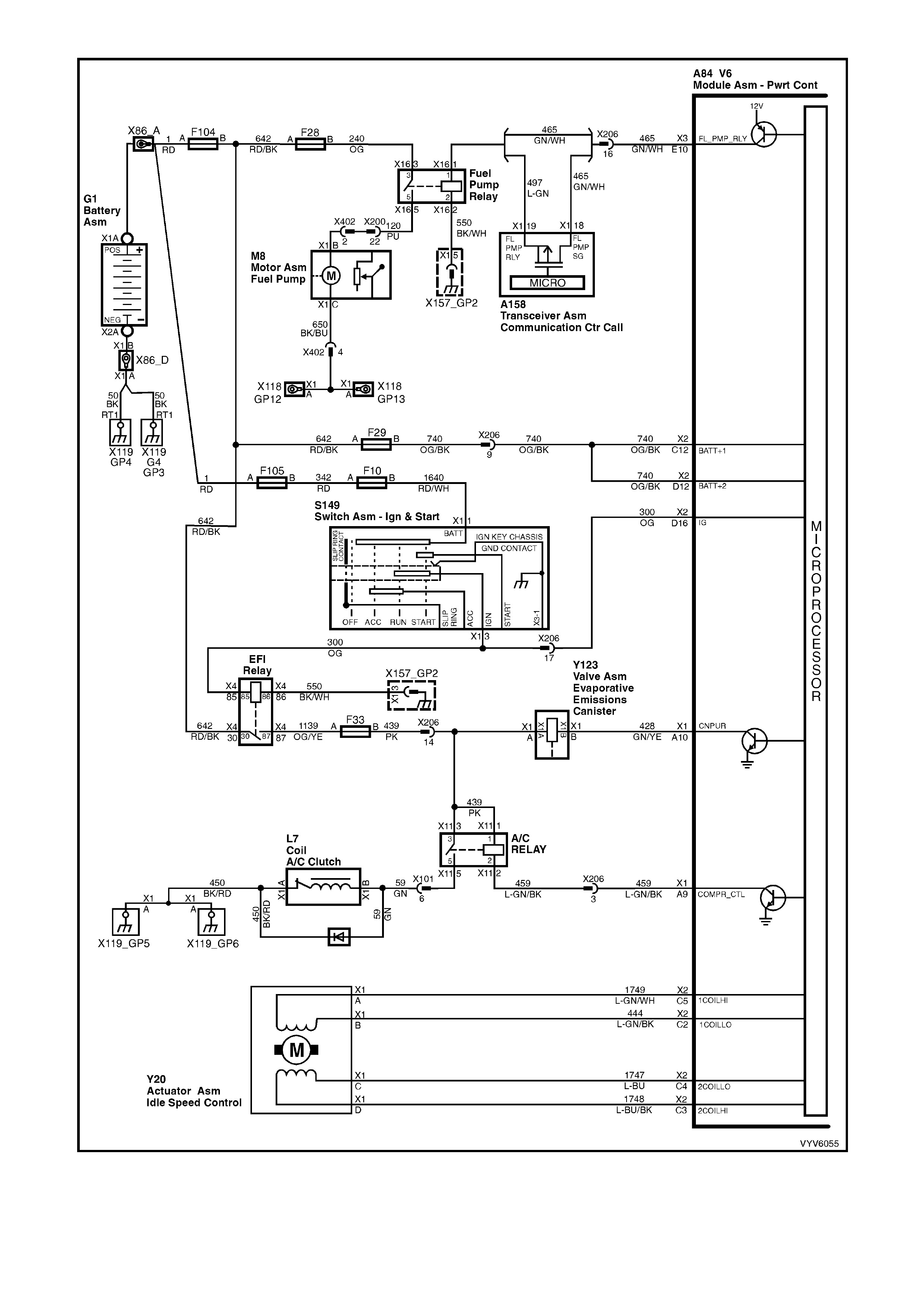
Figure 6C1-2A-10 PCM Wiring Diagram (4 of 10)
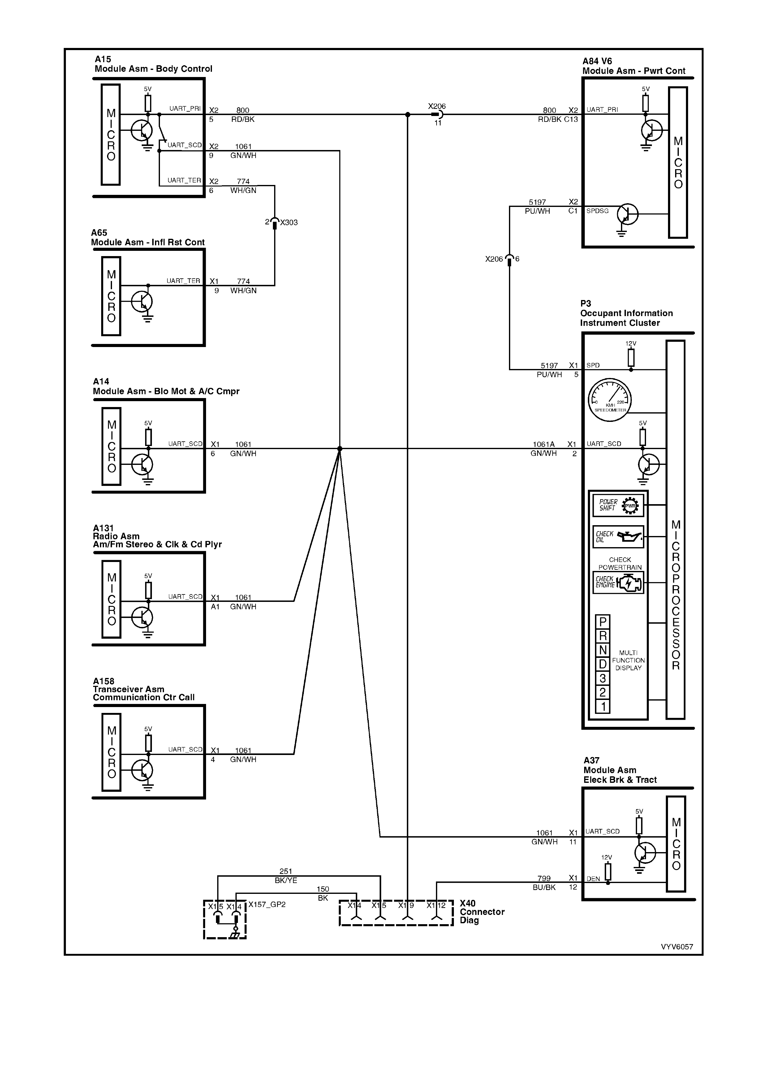
Figure 6C1-2A-11 PCM Wiring Diagram (5 of 10)
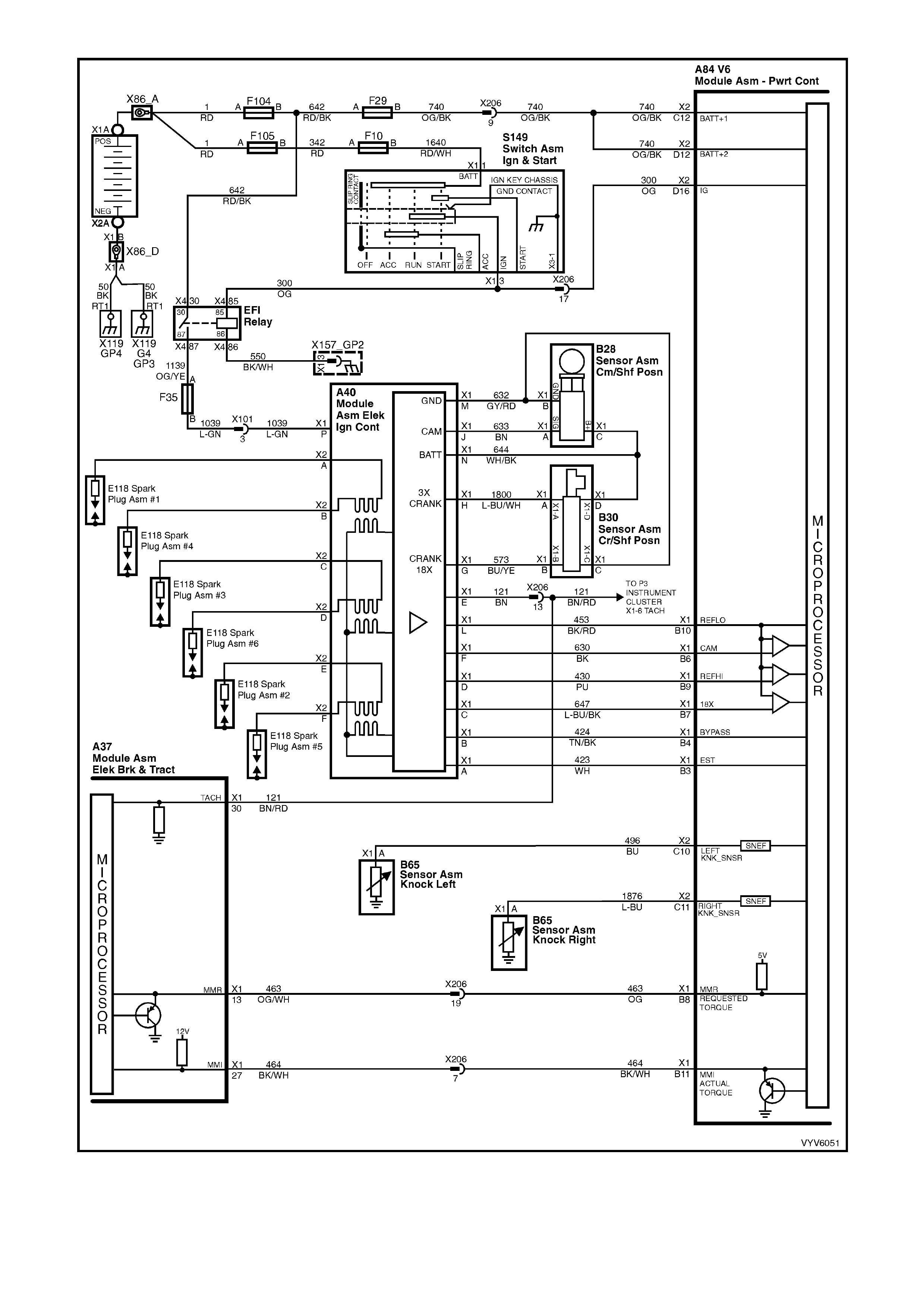
Figure 6C1-2A-12 PCM Wiring Diagram (6 of 10)
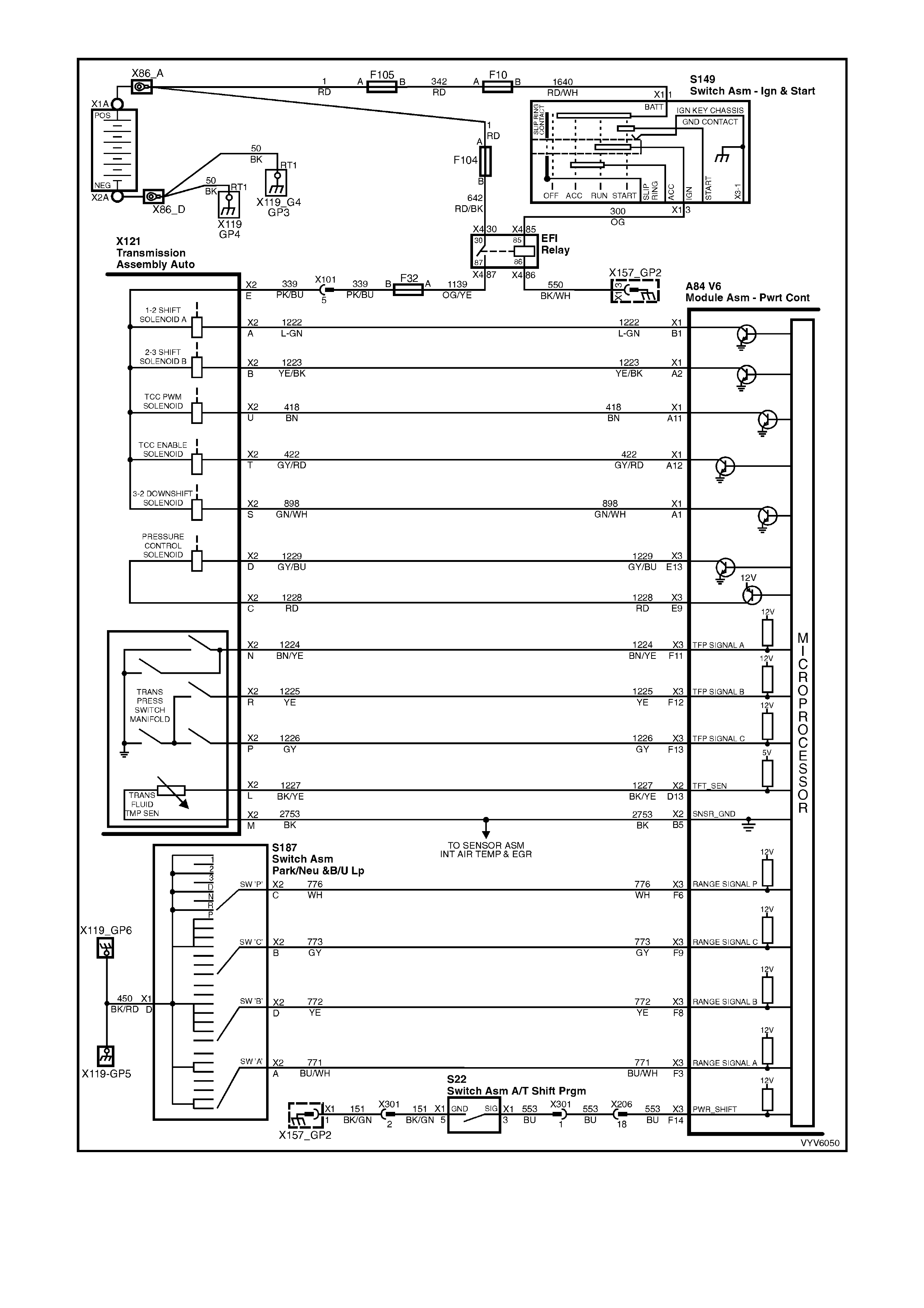
Figure 6C1-2A-13 PCM Wiring Diagram (7 of 10)
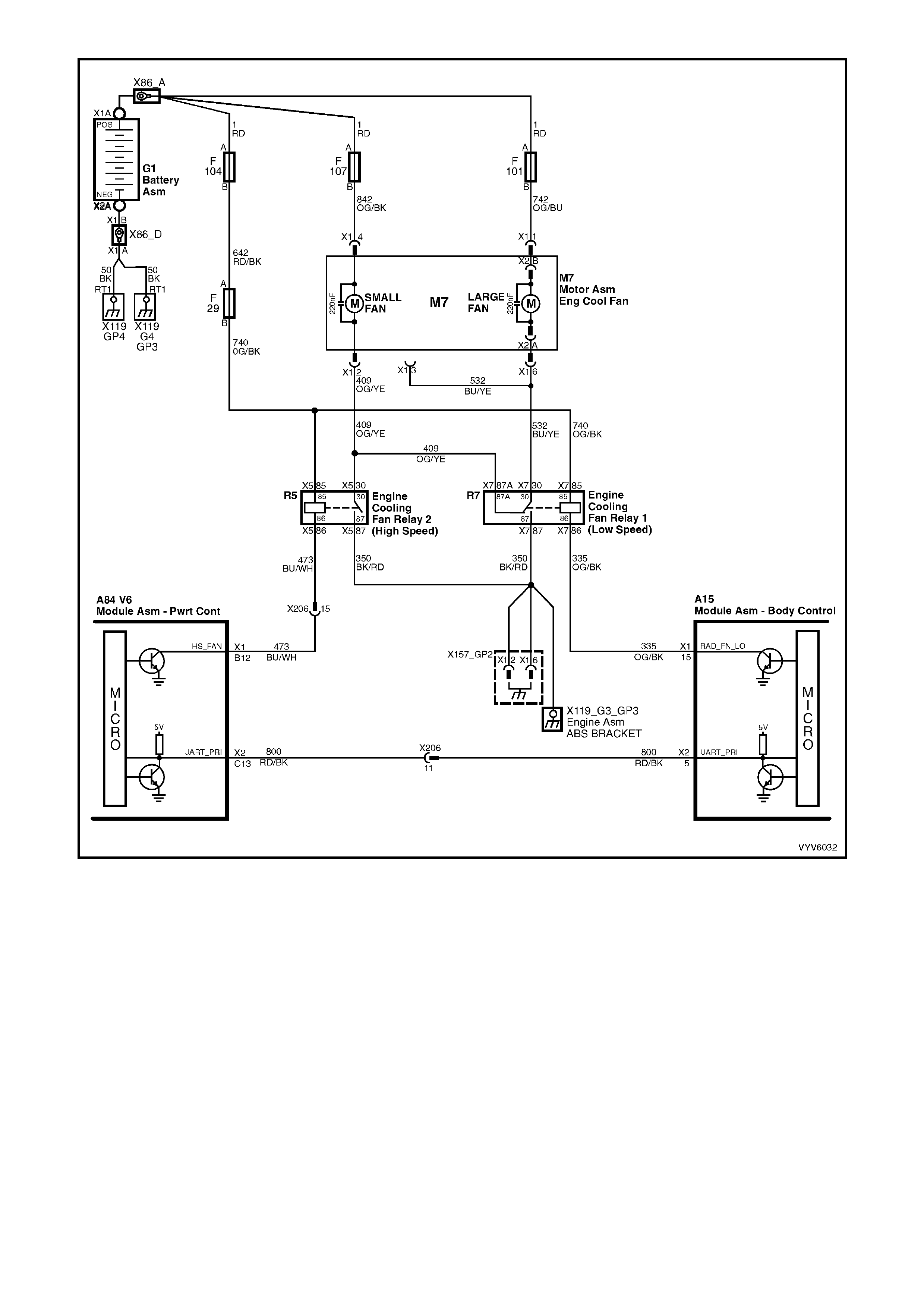
Figure 6C1-2A-14 PCM Wiring Diagram (8 of 10)

Figure 6C1-2A-15 PCM Wiring Diagram (9 of 10)
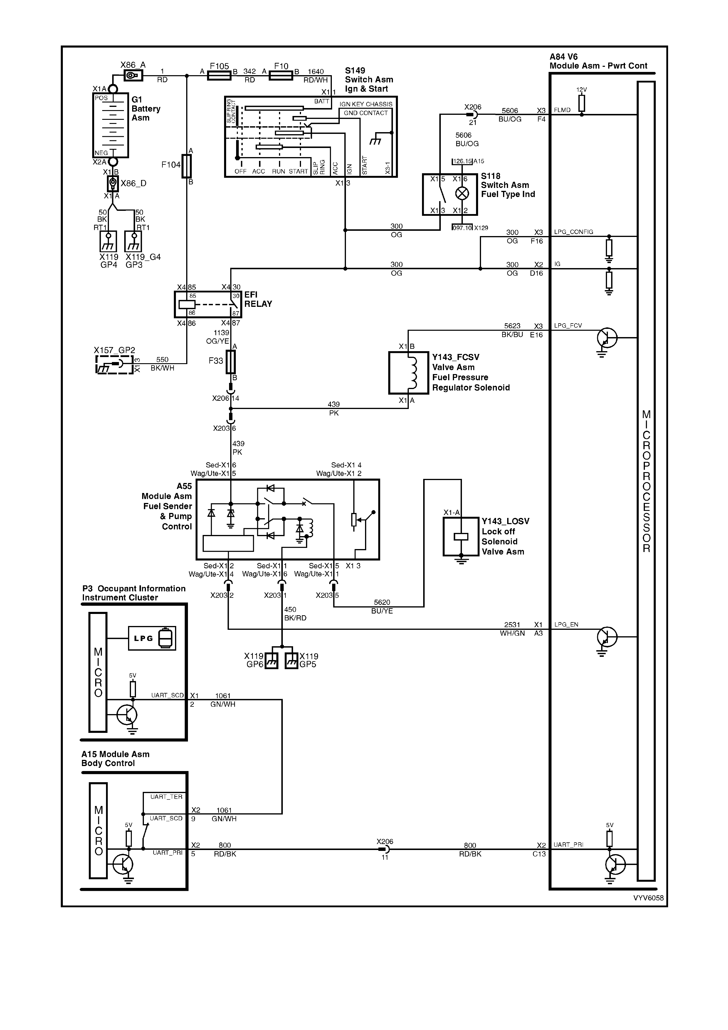
Figure 6C1-2A-16 PCM Wiring Diagram (10 of 10)

POWERTRAIN CONTROL MODULE CONNECTOR IDENTIFICATION
This powertrain control module voltage table is for use with a Digital Multimeter (DMM) to further aid in
diagnosis . Conn ect the B lack (-) probe to a goo d chass is ground, a nd back probe the powert rain c ontrol m odule
term inal with the Re d (+) probe. These v olt ages were der i ved f rom a k nown g ood ve hicle. T he vo lt ages you get
may vary due to low battery charge or other reasons, but they should be very close.
THE FOLLOWING CONDITIONS MUST BE MET BEFORE TESTING:
• Engine and Transmission at operating temperature
• Closed Loop
• Engine idling ( for “Engine Run” column)
• TECH 2 not installed
• Accessories “OFF”
BACKPROBING VIEW OF BROWN PCM CONNECTOR X1
Figure 6C1-2A-17 PCM Connector Terminal End View (1 of 3)
Pin
Pin Function
CKT
#
Wire
Colour
Ign
"ON"
Eng
Run
Pin
Pin Function
CKT
#
Wire
Colour
Ign
"ON"
Eng
Run
A1 3-2 CONTROL
SOLENOID 898 GN/WH 12 * B1 1-2 SHIFT
SOLENOID A
CONTROL
1222 L-GN 12 *
A2 2-3 SHIFT
SOLENOID B
CONTROL
1223 YE/BK 12 * B2 NOT USED - - - -
A3 LPG ENABLE
OUTPUT (LPG ONLY) 2531 WH/GN (1) (1) B3 EST OUTPUT 423 WH 0 2.0
A4 NOT USED - - - -
B4 BYPASS
CONTROL 424 TN/BK 0 4.7
A5 SYSTE M GROUND 450 BK/RD * * B5 SYSTE M GROUND 2753 BK * *
A6 NOT USED - - - -
B6 CAMSHAFT
POSITION
SENSOR SIGNAL
630 BK 4.8 4.4
A7 MAF SENSOR
INPUT 492 BN/WH 4.8 4.2 B7 CRANKSHAFT 18X
SIGNAL 647 L-BU/BK 5
OR
0
2.7
TO
3.0
A8 START RELAY
CONTROL 434 GY * *
B8 TORQUE
REQUEST 463 OG 0.2 0.2
A9 AIR
CONDITIONING
RELAY CONTROL
459 L-GN/BK 12 (2) B9 CRANKSHAFT
REFERENCE HIGH 430 PU 4.8 2-3
A10 CANISTER PURGE
SOLENOID 428 GN/YE 12 13 B10 CRANKSHAFT
REFERENCE LOW 453 BK/RD * *
A11 TCC SOLENOID
PWM CONTROL 418 BN 12 13
B11 TORQUE
ACHIEVED 464 BK/WH .9 3-6
A12 TCC ENABLE
SOLENOID
CONTROL
422 GY/RD 12 13 B12 ENGINE COOLING
FAN RELAY HIGH
SPEED CONTROL
473 BU/WH 12 (7)
Normal
Volta
g
es Normal
Volta
g
es

This powertrain control module voltage table is for use with a Digital Multimeter (DMM) to further aid in diagnosis. Connect
the Black (-) probe to a good chassis ground, and backprobe the powertrain control module terminal with the Red (+) probe.
These voltages were derived from a known good vehicle. The voltages you get may vary due to low battery charge or other
reasons, but they should be very close.
THE FOLLOWING CONDITIONS MUST BE MET BEFORE TESTING:
• Engine and Transmission at operating temperature
• Closed Loop
• Engine idling ( for “Engine Run” column)
• TECH 2 not installed
• Accessories “OFF” BACKPROBING VIEW OF BROWN PCM CONNECTOR X2
Figure 6C1-2A-18 PCM Connector Terminal End View (2 of 3)
Pin
Pin Function
CKT
#
Wire
Colour
Ign
"ON"
Eng
Run
Pin
Pin Function
CKT
#
Wire
Colour
Ign
"ON"
Eng
Run
C1 VEHICLE SPEED
OUTPUT TO
SPEEDOMETER
5197 PU/WH 0.1
OR
12
0.1
OR
13
D1 VEHICLE SPEED
SENSOR SIGNAL
LO
1230 BU/WH * *
C2 IAC COIL “B” LOW 444 L-GN/BK NOT USE-
ABLE D2 VEHICLE SPEED
SENSOR SIGNAL
HI
1231 TN * *
C3 IAC COIL “A” LOW 1748 L-BU/BK NOT USE-
ABLE D3 LH OXYGEN
SENSOR GROUND 1664 BU/BK * *
C4 IAC COIL “A” HIGH 1747 L-BU NOT USE -
ABLE D4 LH OXYGEN
SENSOR SIGNAL 1665 PU 450
Mv (4)
C5 IAC COIL “B” HIGH 1749 L-GN/WH NOT USE-
ABLE D5 RH OXYGEN
SENSOR GROUND 1667 GY/BK * *
C6 ECT/TP A/C
PRESSURE
SENSOR GROUND
2752 BK/YE * * D6 PCM GROUND 450 BK/RD * *
C7 TP SENSOR
SIGNAL 411 BU (5) (5) D7 INTAKE AIR
TEMPERATURE
SENSOR SIGNAL
5089 BN 1.0
(3) 1.0
(3)
C8 EGR PINTLE
POSITION 1456 L-GN .7 .7 D8 BARO SENSOR
SIGNAL 432 L-GN 4-5 4-5
C9 RH OXYGEN
SENSOR SIGNAL 1666 GY 450
Mv (4) D9 NOT USED
C10 LEFT HAND
KNOCK SENSOR
SIGNAL
496 BU 1.3
Mv
A/C
1.9
Mv
A/C
D10 A/C PRESSURE
SENSOR SIGNAL 380 GN/BK 1-2 1-2
C11 RIGHT HAND
KNOCK SENSOR
SIGNAL
1876 L-BU 1.3
Mv
A/C
1.9
Mv
A/C
D11 ENGINE COOLANT
TEMPERATURE
SENSOR SIGNAL
410 YE 1.9
(3) 1.9
(3)
C12 BATTERY
VOLTAGE FEED 740 OG/BK 12 13 D12 BATTERY
VOLTAGE FEED 740 OG/BK 12 12
C13 UART PRIMARY
SERIAL DATA 800 RD/BK 3-5 3-5 D13 TRANS FLUID
TEMP (TFT)
SENSOR SIGNAL
1227 BK/YE 1.8
(3) 1.8
(3)
C14 INJECTOR
VOLTAGE
MONITOR LINE
639 RD 12 13 D14 NOT USED - - - -
C15 TP & A/C & BARO
PRESSURE
SENSOR
REFERENCE
VOLTAGE
416 GY 5 5 D15 NOT USED - - - -
C16 EGR, REFERENCE
VOLTAGE 5047 PU/WH 5 5 D16 IGNITION FEED 300 OG 12 13
(3) Varies with temperature.
(4) The voltage should vary between 100 mV - 1000 mV.
(5) 0.l25 - 1.25 volts measured between terminals "X2-C7" and "X2-B1" or about 4.0 volts at wide open throttle.
* Less than 0.50 volts
Normal
Volta
g
es Normal
Volta
g
es
This powertrain control module voltage Table is for use with a Digital Multimeter (DMM) to further aid in
diagnosis . Conn ect the B lack (-) probe to a goo d chass is ground, a nd back probe the powert rain c ontrol m odule
term inal with the Re d (+) probe. These v olt ages were der i ved f rom a k nown g ood ve hicle. T he vo lt ages you get
may vary due to low battery charge or other reasons, but they should be very close.
THE FOLLOWING CONDITIONS MUST BE MET BEFORE TESTING:
• Engine and Transmission at operating temperature
• Closed Loop
• Engine idling (for “Engine Run” column)
• TECH 2 not installed
• Accessories “OFF”
BACKPROBING VI EW OF TAN PCM CONNECTOR X3
Figure 6C1-2A-19 PCM Connector Terminal End View (3 of 3)
Pin
Pin Function
CKT
#
Wire
Colour
Ign
"ON"
Eng
Run
Pin
Pin Function
CKT
#
Wire
Colour
Ign
"ON"
Eng
Run
E1 NOT USED - - - - F1 FUEL INJECTOR
# 3 CONTROL 1746 PU 12 13
E2 FUEL INJECTOR
#2 CONTROL 1745 GN 12 13 F2 FUEL INJECTOR
#4 844 BN/YE 12 13
E3 NOT USED - - - - F3 PRNDL “A” 771 BLU/W * *
E4 FUEL INJECTOR
#1 CONTROL 1744 BU 12 13 F4 FUEL MODE
SWITCH (LPG ONLY) 5606 BU/OG * *
E5 FUEL INJECTOR
# 4 CONTROL 845 GY 12 13 F5 NOT USED - - - -
E6 FUEL INJECTOR
# 6 CONTROL 846 YE 12 13 F6 PRNDL “P” 776 WH * *
E7 SYSTEM GROUND 450 BK/RD * * F7 SYSTEM GROUND 450 BK/RD * *
E8 NOT USED - - - - F8 PRNDL “B” 772 YE 12 13
E9 PRESSURE
CONTROL
SOLENOID HIGH
1228 RD * 1.3 F9 PRNDL “C” 773 GY 12 13
E10 FUEL PUMP
RELAY CONTROL 465 GN/WH (1) 13 F10 NOT USED - - - -
E11 NOT USED - - - - F11 RANGE SIGNAL
"A" 1224 BN/YE 12 13
E12 EGR CONTROL
(PWM) 1676 PU 0.0 0.0 F12 RANGE SIGNAL
"B" 1225 YE 0 0
E13 PRESSURE
CONTROL
SOLENOID LOW
1229 GY/BU * 6.8 F13 RANGE SIGNAL
"C" 1226 GY 12 13
E14 NOT USED - - - - F14
POWER/ECONOMY
SWITCH INPUT 553 BU (6) (6)
E15 NOT USED - - - - F15 OIL PRESSURE
INPUT SI GN AL 31 BU/RD * 13
E16 LPG FCV
(LPG ONLY ) 5623 BK/BU (1) (1) F16
LPG
CONFIGURATION
(LPG ONLY )
300 OG 12 13
(1) Battery voltage first 2 seconds
(2) With air conditioning "ON" 0 volts, with air conditioning "OFF" 13 volts.
(6) W hen Power/Economy switch is depressed, voltage will momentarily change from 12 volts to 0 volts then back
to 12V.
(7) W ith engine cooling fan "ON" 0 volts, with engine cooling fan "OFF" 13 volts.
* Less than 0.50 volts.
Normal
Volta
g
es
Normal
Volta
g
es Normal
Volta
g
es

PCM CONNECTOR TERMINAL VOLTAGES WITH EXPLANATIONS
CONNECTOR X1
A1: 3-2 Downshift Control Solenoid Control
Automatic Transmission Only
The 3-2 control solenoid is a normally closed, ON – OFF solenoid used to control the 3-2 downshift. The solenoid is
constant l y fed 12 volts and PCM co ntro ls pat h to groun d.
A2: 2-3 Shift Solenoid “B” Control
Automatic Transmission Only
The PCM is used to either open or provide a path to ground for the 2-3 shift solenoid. W hen the PCM provides a
path to ground, the 2-3 shift solenoid is considered “ON” and the voltage should read 0 volts.
A3: LPG Enable (LPG Only)
When operating in the LPG Mode, the PCM supplies an LPG enable signal to the LPG smart unit from this
terminal.
A4: Not Used
A5: System Ground
This terminal is connected directly to the engine ground, the voltage on this terminal should be zero volts.
A6: Not Used
A7: Mass Air-Flow (MAF) Input Signal
The PCM supplies a 5-volt signal voltage to the mass air flow sensor on this circuit. The mass air flow sensor
pulses the 5-volt signal to ground. These ground pulses occur at a very fast rate, from less than 500 per second
(500 Hz) with no airflow through the sensor, to upwards of many thousands of pulses per second at high air flow
rates such as during acceleration. If measured, the voltage seen will be between 0.5 and 4.5 volts, depending on
air flow through the sensor.
A8: Start Relay Control
W hen the PCM receives th e proper T hef t Deterrent s ignal, the PCM will s upply a ground s igna l to Start Rel ay. This
will allo w t he ve hic le to start. If an impr oper Theft Deter r ent sig nal is sens e d by th e PC M, t he PCM wil l no t su pply a
ground signal to the Start Relay. This will prevent the starter motor from operating.
A9: Air Conditioning Relay Control
W hen the A/C is req uested , the BC M or OCC will com m unica te to the PCM via the s erial data line, r equesti ng A/C.
The PCM supplies the ground path on this terminal to energise the A/C control relay. The voltage will be less than 1
volt when the PCM energises the relay. When the PCM does energise the A/C control relay, the voltage will be
more than 0.1, but less than 1 volt.
A10: Canister Purge Solenoid Control
The PCM operates a normally closed solenoid valve, which controls vacuum to purge the evaporative emissions
storage canister of stored fuel vapours. The PCM turns “ON” the pulse width modulated control of the purge
solenoid, to control purging of the stored vapours. If the PCM is not energising the purge solenoid, the voltage
measured at this terminal should equal battery voltage. If the PCM is controlling the solenoid, the measured voltage
will be between battery voltage and 0.50 volts.
A11: Torque Converter Clutch, Pulse Width Modulated Apply Solenoid Control
Automatic Transmission Only
The PCM uses the pulse width modulated TCC apply solenoid to smoothly engage the torque converter clutch,
after the TCC “ON-OFF” solenoid is energised. By varying the duty cycle pulse width modulation, the PCM can
slowly engage the torque converter clutch, allowing very smooth TCC engagement.
A12: Torque Converter Clutch Enable Solenoid Control
Automatic Transmission Only
The PCM is used to either open or provide a path to ground for the torque converter solenoid. When the PCM
provides a path to ground, the T CC solen oid is co nsidered O N and volta ge shoul d be near 0 vol ts. The P CM uses
both the TCC enable solenoid and the TCC “PWM” solenoid to control the torque converter clutch.
B1: 1-2 Shift Solenoid “A” Control
Automatic Transmission Only
The PCM is used to either open or provide a path to ground for the 1-2 shift solenoid. W hen the PCM provides a
path to ground, the 1-2 shift solenoid is considered “ON” and the voltage should read 0 volts.
B2: Not Used
B3: Electronic Spark Timing (EST) Output
This terminal will have very low voltage with the ignition “ON” but engine not running. With the engine running at
idle, the voltage should be slightly more than 1 volt. As the engine RPM goes up, this voltage will increase.

B4: Ignition Module Bypass Control
Ignition System Mode Control
With ignition “ON” and engine not running this terminal will have very low voltage. As soon as the PCM sees engine
RPM of more than 450 RPM (Electronic Spark Timing “run” threshold) the PCM turns on 5 volts to the Ignition
Module Bypass Control circuit, causing the ignition module to allow the PCM to operate the ignition system.
B5: System Ground
This terminal is connected directly to the engine ground, the voltage on this terminal should be zero volts.
B6: Camshaft Position Input Signal
This signal is used by the PCM to “sequence” the energising of the fuel injectors, similar to the firing order of an
engine. This allows the PCM to operate the fuel injectors in a “sequential fuel injection” mode. The camshaft
position sensor is actually wired to the ignition module. The ignition module sends one pulse per every two
crankshaft revolutions to the PCM to determine actual camshaft position, and thus, engine cycle sequence.
B7: Crankshaft 18X Input Signal
The 18X cr ank s haf t ref erenc e input s i gna l is us ed to v ery accurate l y contr ol E ST s par k tim ing at lo w engine speeds
– below 1200 RP M. Below 1200 R PM, the PCM m onitors the 18X signal t o control spark timing. At eng ine speeds
above 1200 RPM, the PCM uses the 3X crankshaft reference input signal to control spark timing. (See 3X
crankshaft reference terminal X2-D12)
B8: Traction Control Torque Requested (MMR)
The ABS/TCS module will send a torque requested PWM signal to the PCM when torque reduction is requested
from the ABS/TCS module for traction control. This PW M signal should closel y match the Torque Achieved (MMI)
signal, when traction control is being requested.
B9: 3X Crankshaft Reference Input Signal High
This terminal could be called the “tacho” input. It provides the PCM with RPM and crankshaft position information.
With ignition “ON” but engine not running, t he voltage will be either hig h or low, depending on crank shaft position.
As the crank shaf t turns, the volta ge will be a n averag e of the two rea dings. T he PCM uses th e 3X signal to control
fuel injection, and spark timing with engine speeds above 1200 RPM.
B10: Cranks haft Reference Input Signal Low
This terminal should always be zero volts. It is connected through the ignition module to engine ground.
B11: Traction Control Torque Achieved (MMI)
The PCM sends a Torque Achieved PWM signal to the ABS/TCS module informing the ABS/TCS module of the
achieve d eng ine tor que. This PWM signal s hould match c losely the Requeste d Torque (MMR) s ignal, wh en trac tion
control is occur in g.
B12: Engine Cooling Fan High Speed Relay Control
This terminal will have battery voltage until the PCM energises the high speed cooling fan relay by supplying the
ground; then it will be close to zero. The inputs that cause the PCM to energise the high speed fan relay are the
engine coolant temperature and A/C pressure.
CONNECTOR X2
C1: Vehicle Speed Output To Speedometer
The PCM a lternatel y grounds this signa l, in puls es, when it r eceives a vehicle s peed signa l from the vehicle speed
sensor in the transmission. This pulsing action takes place about 6250 times per kilometre. The speedometer
calculates vehicle speed based on the time between pulses.
C2: Idle Air Control (IAC)
C3: Idle Air Control (IAC)
C4: Idle Air Control (IAC)
C5: Idle Air Control (IAC)
Thes e term inals connect th e Idle Air Control valve, located o n the throttle b ody, to the PCM. I t is diffic ult to predict
what the voltage will be, and the measurement is unusable for any service procedures.
C6: Engine Coolant Temperature and Throttle Position Sensor Ground
This terminal should be zero volts. It is connected through the PCM circuitry to engine ground.
C7: Throttle Position (TP) Sensor Signal
The TP sensor input voltage, which follows actual throttle changes, is variable from 0 to 5 volts. Typically the
voltage is less than 1 volt at idle, and 4 to 5 volts at wide-open throttle.
C8: Linear EGR Valve Pintle Position
This voltage is an indication to the PCM of the position of the EGR valve pintle. A low voltage indicates a fully
extended pintle (closed valve). A voltage near 5 volts indicates a retracted pintle (open valve).
C9: Right Hand Oxygen Sensor Input Signal
W ith ignit ion on a nd en gine not r un ni ng, the vol tag e s h oul d b e 350 – 450 mill ivolts (0.350 – 0 . 45 0 vo lts ). This is th e
PCM-sup plied c ircuit “bi as” vo ltage. W ith the e ngine runn ing an d after the ox ygen sens or is hot, t he vo lta ge shou ld
be rapidly changing, somewhere between 10 – 1000 millivolts.

C10: Left Hand Electronic Spark Control (ESC) Knock Input Signal
The Electronic Spark Control “knock” sensor detects when detonation is occurring in the combustion chambers.
W hen detected, the PCM will reduce t he amount of spark advance bein g deliver ed on the EST output circ uit to the
ignition module.
C11: Right Hand Electronic Spark Control (ESC) Knock Input Signal
The Electronic Spark Control “knock” sensor detects when detonation is occurring in the combustion chambers.
W hen detected, the PCM will reduce t he amount of spark advance bein g deliver ed on the EST output circ uit to the
ignition module.
C12: Battery Voltage Feed
Hot At All Times
This supplies the PCM with full-time +12 volts. It stays hot even when the ignition is turned off. It receives its
voltage through the “ENGINE” fuse. This PCM terminal could be called the power supply and “MEMORY” terminal.
C13: UART Primary Serial Data
The c ircuit conn ects the PCM to the B CM t he ABS, I nstrum ents , SRS, OC C an d Audio System are a lso c onnect ed
to this c irc uit v ia the BCM and th e s ec on dary and t er tia r y seria l d ata c irc uits. The Tech 2 c an “ ta lk ” to each of thes e
modules by sending a message to a controller and asking only it to respond. The communication rate is at 8192
baud. T he c ontro l modul es also “t a lk ” to each other vi a these s er ia l data c irc uits . T he voltag e o n this cir cuit wi th th e
ignition on will vary from zero to five volts, if read with a DVM will be approximatley 3-4 volts.
C14: Injector Circuit Voltage Monitor Input Signal
The inj ect or volt age monito r line is us ed s o th at the P C M wil l know the exac t vo lta ge the f uel i nj ec tors ar e op erating
at. This voltage signal is used to modify the fuel injector pulse width calculation.
C15: Throttle Position (TP) Sensor Reference voltage and A/C Refrigerant Pressure Sensor
This voltage should always be 5 volts anytime the ignition is “ON.” It is a regulated voltage output from the PCM,
and supplies 5 volts to the TP sensor and A/C Refrigerant Pressure Sensor.
C16: EGR Sensor Reference Voltage
This voltage should always be 5 volts anytime the ignition is “ON.” It is a regulated voltage output from the PCM,
and supplies 5 volts to the EGR valve.
D1: Vehicle Speed Sensor Output Shaft Speed Input Signal Low
The transmission has an output shaft speed sensor used by the PCM to calculate vehicle speed, and to help
determ ine vario us aut om atic transm is sion shif ting f unctions . It is a m agnetic induc tive s ensor th at gener ates an A C
voltage signal sent to the PCM. If measured with the digital AC voltmeter, no voltage will appear until the output
shaft begins turning.
D2: Vehicle Speed Sensor Output S haft Speed Input Signal High
The transmission has an output shaft speed sensor used by the PCM to calculate vehicle speed, and to help
determ ine vario us aut om atic transm is sion shif ting f unctions . It is a m agnetic induc tive s ensor th at gener ates an A C
voltage signal sent to the PCM. If measured with the digital AC voltmeter, no voltage will appear until the output
shaft begins turning.
D3: Left Hand Oxygen Sensor Ground
This terminal shoul d have zero volts. It is connected dir ectly to the engine gro und. This ter minal grou nds the PCM
circuitry for the oxygen sensor voltage monitor inside the PCM.
D4: Left Hand Oxygen Sensor Input Signal
W ith ignit ion on a nd en gine not r un ni ng, the vol tag e s h oul d b e 350 – 450 mill ivolts (0.350 – 0 . 45 0 vo lts ). This is th e
PCM supp lie d c irc u it “b ias ” vo lta ge. With the engine running a nd af ter the oxygen s ensor is hot , th e v olt ag e should
be rapidly changing, somewhere between 10 – 1000 millivolts.
D5: Right Hand Oxygen Sensor Ground
This terminal shoul d have zero volts. It is connected dir ectly to the engine gro und. This ter minal grou nds the PCM
circuitry for the oxygen sensor voltage monitor inside the PCM.
D6: Intake Air Temperature / Transmission Fluid Temperature / EGR Valve / A/C Pressure Sensor Ground
Circuit
This terminal should be zero volts. It is connected through the PCM circuitry to engine ground.
D7: Intake Air Temperature (IAT) Input Signal
The PCM sends a 5 volt signal voltage to the IAT sensor, which is a temperature variable resistor called a
thermistor. The sensor is also connected to ground, and will alter the signal voltage according to incoming air
temper atur e. As the air t em per ature i nc r eases , th e v olt age s e en on t his t er minal d ecr eas es. At zer o °C, the voltage
will be above 4 volts. At normal operating temperature (10 °C to 80 °C) the voltage will be less than 4 volts.
D8: Not Used
D9: Not Used
D10: A/C Refrigerant Pressure Sensor Input Signal
The signal that is sent from the pressure Sensor to the PCM indicates to the PCM what the A/C pressure is at.
Depending on the A/C pressure, this signal will indicate to the PCM if A/C pressure is too low or too high.

D11: Engine Coolant Temperature (ECT) Input Signal
The PCM sends a 5 volt signal voltage out to the engine coolant temperature sensor, which is a temperature
variable resistor called thermistor. The sensor, being also connected to ground, will alter the voltage according to
engine coolant temperature. As the engine coolant temperature increases, the voltage seen on terminal X2-D11
decreases. At zero °C engine coolant temperature the voltage will be above 4 volts. At normal operating
temperature (85 °C to 100 °C) the voltage will be less than 2 volts.
D12: Battery Voltage Feed
“HOT” At All Times
This supplies the PCM with full-time +12 volts. It stays “hot” even when the ignition is turned off. It receives its
voltage through the ENGINE fuse. This PCM terminal could be called the power supply and “MEMORY” terminal.
D13: Transmission Fluid Temperature (TFT) Input Signal
Automatic Transmission Only
The PCM sends a 5 volt signal voltage out to the transmission fluid temperature sensor, which is a temperature-
variab le-resis tor cal led a th erm istor . The sensor , being also c onnected t o gro und, wil l alter th e volt age acc ording t o
transmission fluid temperature. As the fluid temperature increases, the voltage seen on the PCM terminal will
decrease.
D14: Not Used
D15: Not Used
D16: Ignition Switch Input Signal
This is the “ tur n on” s igna l t o the P CM f r om the ign ition s witch c irc u it. It is no t the “po wer supp ly” to the PCM, it on l y
tells the PC M t hat the igniti on switch is “ ON.” The vo lt age s h ou ld equal the batter y vol tag e when the k e y is i n e ither
the “run“ or “crank“ position.
CONNECTOR X3
E1: Not Used
E2: Fuel Injector #2 Control
The voltage seen a t these terminals actually com es through the injectors, which are connect ed to +12 volts. With
the engine not running, the voltage seen would be battery voltage. With the engine running at idle, the charging
system increases the voltage slightly, so this voltage will increase. With higher engine RPM or more engine load,
the resulting increase in injector pulse frequency or injector pulse width will cause this voltage to appear slightly
less.
E3: Not Used
E4: Fuel Injector #1 Control
The voltage seen at these terminals actually comes through the injectors, which are connected to +12 volts. W ith
the engine not running, the voltage seen would be battery voltage. With the engine running at idle, the charging
system increases the voltage slightly, so this voltage will increase. With higher engine RPM or more engine load,
the resulting increase in injector pulse frequency or injector pulse width will cause this voltage to appear slightly
less.
E5: Fuel Injector #4 Control
The voltage seen at these terminals actually comes through the injectors, which are connected to +12 volts. W ith
the engine not running, the voltage seen would be battery voltage. With the engine running at idle, the charging
system increases the voltage slightly, so this voltage will increase. With higher engine RPM or more engine load,
the resulting increase in injector pulse frequency or injector pulse width will cause this voltage to appear slightly
less.
E6: Fuel Injector #6 Control
The voltage seen at these terminals actually comes through the injectors, which are connected to +12 volts. W ith
the engine not running, the voltage seen would be battery voltage. With the engine running at idle, the charging
system increases the voltage slightly, so this voltage will increase. With higher engine RPM or more engine load,
the resulting increase in injector pulse frequency or injector pulse width will cause this voltage to appear slightly
less.
E7: System Ground
This terminal is connected directly to the engine ground, the voltage on this terminal should be zero volts.
E8: Not Used
E9: Transmission Pressure Control Solenoid (PCS) High
Automatic Transmission Only
The dut y cycle, an d am ount of c urrent f low to the PCS , are contr olle d by the PC M. T his c ircuit is the B+ su pply lin e
from the PCM to th e PCS. The duty c ycle and amperage ar e c ontro lle d b y the PCM. A high c urr ent ou tput in dic ates
low transmission fluid pressure, while a low current output would indicate high fluid pressure.
E10: Fuel Pump Relay Control
Turning the ignition “O N” causes the PCM t o energise (+12V) the fuel pump relay. If no cranks haft reference inp ut
pulses are received, the PCM turns off the relay. As soon as the PCM receives crankshaf t reference input pulses,
the PCM will turn the fuel pump relay on again.

E11: Not Used
E12: EGR Control
The PCM monitors EGR actual position and adjust a pintle position accordingly. The PCM uses information from
several sensors to control the pintle position. The PCM provides a PWM 12 volt control signal (% Duty) for EGR
operation.
E13: Transmission Pressure Control (PCS) Solenoid Low
Automatic Transmission Only
The 4L60-E automatic transmission uses an electrical solenoid to control hydraulic pressure inside the
transmission. This electrical solenoid allows the PCM to control “line pressure”, similar to other automatic
transm issions that use a “thr ottle valve” cabl e or vacuum modulator. The dut y cycle, and am ount of current f low to
the PCS, are both controlled by the PCM. By monitoring this line, the PCM can determine if the commanded
amperage has gone to the PCS and returned to the PCM.
E14: Not Used
E15: Not Used
E16: LPG Fuel Control Valve (LPG Only)
This is the PCM output PWM signal to the Fuel Control Valve for LPG air/fuel ratio adjustment.
F1: Fuel Injector #3 Control
The voltage seen at these terminals actually comes through the injectors, which are connected to +12 volts. W ith
the engine not running, the voltage seen would be battery voltage. With the engine running at idle, the charging
system increases the voltage slightly, so this voltage will increase. With higher engine RPM or more engine load,
the resulting increase in injector pulse frequency or injector pulse width will cause this voltage to appear slightly
less.
F2: Fuel Injector #4 Control
The voltage seen at these terminals actually comes through the injectors, which are connected to +12 volts. W ith
the engine not running, the voltage seen would be battery voltage. With the engine running at idle, the charging
system increases the voltage slightly, so this voltage will increase. With higher engine RPM or more engine load,
the resulting increase in injector pulse frequency or injector pulse width will cause this voltage to appear slightly
less.
F3: PRNDL “A”
Automatic Transmission Only
These circuits alo ng with PCM circuit F6 indicate to the PCM what transm ission gear the driver has selected. The
PCM will then send a com mand via the seria l data li ne to the instrum ent panel c luster ( smart c luster) to ind icate to
the driver what gear has been selected.
F4: Fuel Mode Switch (LPG Only)
This is the input s ignal from the f uel mode switch indicating to the PCM that the driver has requested a ch ange in
the fuelling mode, either LPG or Petrol.
F5: Not Used
F6: PRNDL “P”
Automatic Transmission Only
This circuit a long with P CM c ircuits F3, F 8, F9 indic ate to the PC M what transm is sion gear the driver has s elec ted.
The PCM will then send a command via the serial data line to the instrument panel cluster (smart cluster) to
indicate to the driver what gear has been selected.
F7: System Ground
This terminal is connected directly to the engine ground, the voltage on this terminal should be zero volts.
F8: PRNDL “B”
Automatic Transmission Only
These circuits alo ng with PCM circuit F6 indicate to the PCM what transm ission gear the driver has selected. The
PCM will then send a com mand via the seria l data li ne to the instrum ent panel c luster ( smart c luster) to ind icate to
the driver what gear has been selected.
F9: PRNDL “C”
Automatic Transmission Only
These circuits alo ng with PCM circuit F6 indicate to the PCM what transm ission gear the driver has selected. The
PCM will then send a com mand via the seria l data li ne to the instrum ent panel c luster ( smart c luster) to ind icate to
the driver what gear has been selected.
F10: Not Used
F11: TFP Manual Valve Position Switch Range Signal “A” Input Signal
Automatic Transmission Only
Range signal “A”, “B” and “C”. The PCM sends out a buffered 12 volt signal to the pressure switch assembly,
located in the automatic transmission valve body. The 12 volt signal must pass through either a normally open or
norm all y clos ed s w itch to r eac h gro und . When the switches are c l os ed, t he s igna l s houl d b e ne ar 0 volts . The PCM
monitors the status of these signals to determine which gear servo is actually receiving hydraulic apply pressure.

F12: TFP Manual Valve Position Switch Range Signal “B” Input Signal
Automatic Transmission Only
Range signal “A”, “B” and “C”. The PCM sends out a buffered 12 volt signal to the pressure switch assembly,
located in the automatic transmission valve body. The 12 volt signal must pass through either a normally open or
norm all y clos ed s w itch to r eac h gro und . When the switches are c l os ed, t he s igna l s houl d b e ne ar 0 volts . The PCM
monitors the status of these signals to determine which gear servo is actually receiving hydraulic apply pressure.
F13: TFP Manual Valve Position Switch Range Signal “C” Input Signal
Automatic Transmission Only
Range signal “A”, “B” and “C”. The PCM sends out a buffered 12 volt signal to the pressure switch assembly,
located in the automatic transmission valve body. The 12 volt signal must pass through either a normally open or
norm all y clos ed s w itch to r eac h gro und . When the switches are c l os ed, t he s igna l s houl d b e ne ar 0 volts . The PCM
monitors the status of these signals to determine which gear servo is actually receiving hydraulic apply pressure.
F14: Power/Economy Switch Input Signal
Automatic Transmission Only
The PCM sends a signal of about 12 volts, and monitors the status of this circuit. In the economy position the
switch is open, the PCM vo ltage status s ignal rem ains high, abo ut 12 volts, an d the PCM does not all ow shift point
changes. W hen the transmission switch is pressed to the power position the switch is momentarily closed and the
PCM voltage status signal is momentarily pulled low. The PCM senses the momentary voltage signal drop and
enables power mode shifting only if other criteria are met. These criteria include throttle position and engine speed.
F15: Oil Pressure Switch
This input to the PCM from the Oil Pressure Switch indicates oil pressure when the engine is running. If oil pressure
is lost while the engine is running, the oil switch will close its contacts and the 12 volt signal to the PCM will be
removed. When the PCM sees this loss of signal, the PCM will command the instruments to activate the oil
pressure lamp, via the normal mode message.
F16: LPG Wiring Configuration (LPG Only)
This is the LPG configuration signal to the PCM from the ignition switch circuit. It is not the “power supply” to the
PCM, it only tells the PCM that the vehicle is equipped with LPG and enables the PCM to operate in either the
petrol and LPG modes.

V6 PCM ENGINE AND TRANSMISSION DIAGNOSTIC TROUBLE CODES (DTC)
DTC
DESCRIPTION CHECK
POWERTRAIN
MIL ACTIVATED
P0012 No revolutions per minute signal – normal when engine is not running No
P0101 Mass Air Flow (MAF) Sensor Out of Range Yes
P0107 Barometric (Baro) Pressure Sensor Signal Voltage Low No
P0108 Barometric (Baro) Pressure Sensor Signal Voltage High No
P0111 Intake Air Temperature Signal Voltage Unstable No
P0112 Intake Air Temperature Signal Voltage Low No
P0113 Intake Air Temperature Signal Voltage High No
P0117 Engine Coolant Temperature Signal Voltage Low Yes
P0118 Engine Coolant Temperature Signal Voltage High Yes
P0121 Throttle Position Sensor Stuck Yes
P0122 Throttle Position Sensor Voltage Low Yes
P0123 Throttle Position Sensor Voltage High Yes
P0131 Right Hand Oxygen Sensor Signal Voltage Low Yes
P0132 Right Hand Oxygen Sensor Signal Voltage High Yes
P0134 No Right Hand Oxygen Sensor Signal Yes
P0151 Left Hand Oxygen Sensor Signal Voltage Low Yes
P0152 Left Hand Oxygen Sensor Signal Voltage High Yes
P0154 No Left Hand Oxygen Sensor Signal Yes
P0170 Long Term Fuel Trim (LTFT) Delta High No
P0173 Short Term Fuel Trim (STFT) Delta High No
P0200 Injector Voltage Monitor Fault No
P0218 Transmission Fluid Overtemperature Yes
P0325 DSNEF System Fault Yes
P0327 Left Hand Knock Sensor Circuit Fault Yes
P0332 Right Hand Knock Sensor Circuit Fault Yes
P0341 Cam/Crank Sensor Signal Intermittent No
P0342 Camshaft Posit ion Sens or Sig na l Miss ing No
P0374 18X Reference Signal Missing No
P0 400 EGR Flow Fault Indicated No
P0405 EGR Position Fault No
P0446 Canister Purge Circuit Fault No
P0502 No Vehic le Spe ed Si gna l Yes
P0503 Vehicle Speed Sensor Intermittent Signal No
P0506 Idle Speed Error No
P0507 Vacuum Leak No
P0530 A/C Refrigerant Pressure Sensor Circuit Fault No
P0560 System Voltage Too High (Long Time) Yes
P0561 System Voltage Unstable Yes
P0562 System Voltage Low Yes
P0563 System Voltage Too High Yes
P0601 Powertrain Control Module Memory Yes
P0712 Transmission Fluid Temperature Signal Voltage Low No
P0713 Transmission Fluid Temperature Signal Voltage High No

DTC
DESCRIPTION CHECK
POWERTRAIN
MIL ACTIVATED
P0730 2-3 Shift Solenoid B Circuit Voltage High Yes
P0740 Torque Converter Clutch Enable Solenoid Circuit Fault Yes
P0741 Torque Converter Clutch System Stuck On No
P0748 Pres sur e Contr ol So le noi d Curr ent Er ror No
P0753 1-2 Shift Solenoid A Circuit Voltage High Yes
P0756 1-2 Shift Solenoid A Circuit Voltage Low Yes
P0757 2-3 Shift Solenoid B Circuit Voltage Low Yes
P0785 3-2 Down-Shift Control Solenoid Circuit Fault Yes
P1064 Low Spe ed Fan – No BCM Response No
P1116 Engine Coolant Temperature Signal Voltage Unstable No
P1255 Theft Deterrent Signal Missing Yes
P1351 Ignition Electronic Spark Timing (EST) Circuit Fault Yes
P1361 Ignition Bypass Circuit Fault Yes
P1372 No Reference Pulses While Cranking Yes
P1571 Requested Torque Out Of Range Yes
P1627 PCM - Analog to Digital (A/D) Conversion Error Yes
P1628 PCM Error – Engine Coolant Temperature Circuit No
P1642 LPG Enable Signal Out Of Range No
P1643 LPG FCV PWM Signal Out Of Range No
P1810 Transmission Fluid Pressure Manual Valve Position Switch Assembly
Circuit Ma lf unc tion Yes
P1860 Torque Converter Clutch Pulse Width Modulation Solenoid Fault No
P1870 Transmission Slipping No

4L60-E TR ANSMISSION FLUID CHECKING PROCEDURE
GENERAL INFORMATION
W hen adding or chan ging t he transm is sion fluid, use onl y Dexron® III. Ref er to th e MY200 3 Owner's Han dbook for
the recommended servicing intervals.
Because this transmission fluid changes colour and smell very easily in its life, these indicators should not
necessarily be relied upon to diagnose either transmission internal condition or fluid deterioration.
The Fluid Chec king Proc edure shows th at a dark br own fluid colour, cou pled with a dela yed shift patter n, may onl y
indicate that the fluid requires replacement and alone, is not a definite indication of a potential transmission failure.
NOTE: Do not o verfill th e trans miss ion. Overfillin g will cause f oaming of the fluid, loss of fluid, s hift com plaints and
possible damage to the transmission.
TRANSMISSION FLUID COLOUR
Transmission fluid colour when new and unused, is red. A red dye is added so that it can be distinguished from
other oils and lubricants. The red dye is not an indicator of fluid quality and is not permanent. As the vehicle is
driven, the transmission fluid will quickly begin to look darker in colour. The colour will then appear light brown. A
DARK brown colour with a distinctively burnt odour MAY indicate fluid deterioration and a need for the fluid to be
changed.
TRANSMISSION FLUID CHECKING PROCEDURE
1. Start the engine and drive vehicle for a maximum of 24 km, or until the transmission normal operating
temperature is reached.
NOTE: As temperature greatly affects transmission fluid levels, this operation must only be carried out when the
transm ission is at norm al operating tem perature (82 – 94° C). If the vehicle is not at normal oper ating tem perature,
and the proper checking procedures are not followed, the result could be a false reading of the fluid level on the
dipstick.
2. Park vehicle on level ground.
3. Move gear selector to 'PARK' position.
4.. Apply park brake.
5. Let engine idle for 3 minutes with accessories turned off.
6. Locate red coloured dipstick in the engine compartment, lift the locking lever, remove the dipstick and check
fluid colour, condition and level.
7. If the fluid level is low, add only enough DEXRONâ III to bring the level into the "HOT" area.
NOTE: Inaccurate fluid level readings will result if checked immediatel y after the vehicle has been op erated under
any or all of the following conditions:
a. In high ambient temperatures above 32° C.
b. At sustained high speeds.
c. In heavy city traffic during hot weather.
d. Towing
e. In commercial use (e.g. taxi).
If the vehicle has been operated under these conditions, switch the engine off and allow the vehicle to 'cool' for
approximately thirty minutes. After cool-down period, re-start the vehicle and continue from step 2.
4L60-E AUTOMATIC TRANSMISSION FLUID CHECKING PROCEDURE
STEP ACTION VALUE YES NO
1. Check the fluid colour.
Is the fluid colour red? Go to Step 2 Go to Step 11
2. Is the fluid level satisfactory? Go to Step 20 Go to Step 3
3. Check the fluid.
Is the fluid foamy? Go to Step 8 Go to Step 4
4. Check the fluid level. The proper fluid level should be in
the middle of the X-hatch.
Is the level high?
Go to Step 9 Go to Step 5
5. Fluid will be low.
Add fluid to the proper fluid level.
Is the fluid level satisfactory?
Go to Step 6 Go to Step 1
6. Check for external leaks.
Were any leaks present? Go to Step 7 Go to Step 20

STEP ACTION VALUE YES NO
7. Correct the fluid leak condition.
Is action complete? Go to Step 20
8. Is the fluid level too high? Go to Step 9 Go to Step 10
9. Remove excess fluid to adjust to the proper fluid level.
Is action complete? Go to Step 20
10. 1. Check for contaminants in the fluid.
2. Drain the fluid to determine the source of the
contamination.
Is action complete?
Go to Step 15
11. Is the fluid colour non-transparent pi nk? Go to Step 12 Go to Step 13
12. Replace the cooler.
Is action complete? Go to Step 15
13. The fluid colour should be light brown. Transmission fluid
may turn dark with normal use. This does not always
indicate oxidation or contamination.
Is the fluid colour light brown?
Go to Step 14 Go to Step 1
14. Drain the fluid to determine if the fluid is contaminated.
A very small amount of material in the bottom of the pan
is a normal condition, but large pieces of metal or other
material in the bottom of the pan requires a transmission
overhaul.
Was the fluid contaminated?
Go to Step 15 Go to Step 18
15. Overhaul the transmission. Refer 7C5, UNIT REPAIR.
Is action complete? Go to Step 16
16. Flush the cooler.
Is action complete? Go to Step 17
17. Add new fluid.
Is action complete? Go to Step 19
18. Change the fluid and filter.
Is action complete? Go to Step 19
19. Is the fluid level satisfactory, If not, correct as necessary.
Is action complete? Go to Step 20
20. Refer 4L60-E Transmission Functional Test Procedure, in
7C3, DIAGNOSIS.
Is action complete?
Fluid Checking
Procedure
Completed
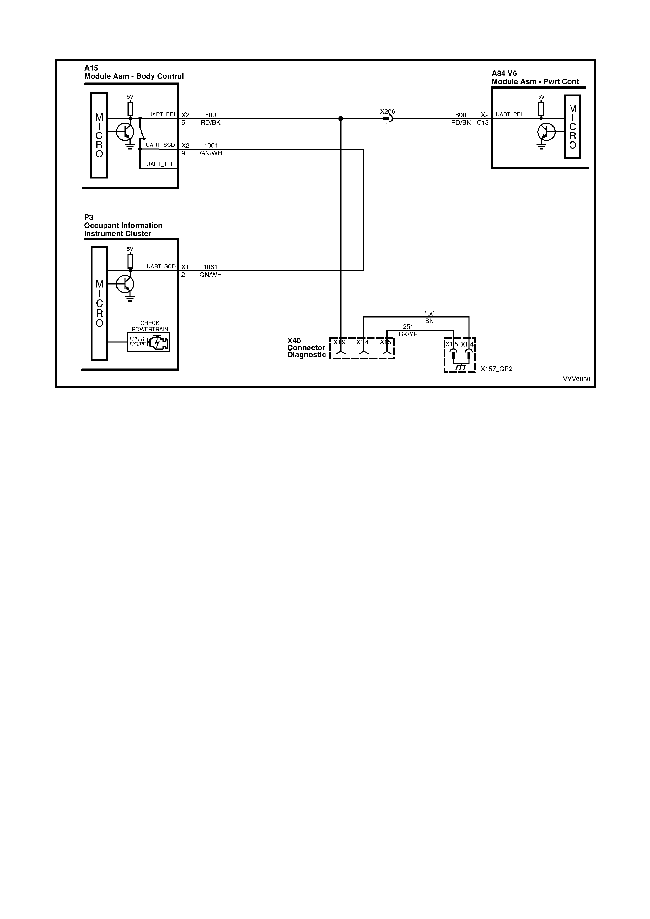
TABLE A V6 PCM - ON-BOARD DIAGNOSTIC (OBD) SYSTEM CHECK
Figure 6C1-2A-20 – Check Powertrain MIL and UART Serial Data Circuit
CIRCUIT DESCRIPTION
The On-Board Diagnostic System Check is an organised approach in identifying a problem created by a powertrain
control system malfunction. It must be the starting point for any driveability complaint diagnosis, because it directs
the service technician to the next logical step in diagnosing the complaint. Understanding the Table and using it
correctly will reduce diagnostic time and prevent the unnecessary replacement of good parts.
TEST DESCRIPTION
Number(s) below refer to step number(s) on the diagnostic Table.
1. Confirms TECH 2 operation and that TECH 2 is being powered up.
2. This check is used to establish if the PCM can supply serial data for TECH 2 use. If the PCM is capable of
communicating serial data to TECH 2, the PCM power supply, ground and the serial data line are OK. If TECH
2 displays “Incorrect Selection or Unknown Software” check that you have selected the correct Model Year,
Vehicle Type and Engine, if these selections were correct, check the PCM has the correct software loaded from
TIS 2000 Service Programming System.
3. This check is to see if there is a Theft Deterrent DTC stored. If the PCM has not received a valid theft deterrent
signal from the BCM a DTC P1225 should set, this may be the cause of a ‘no crank’ condition.
4. This test determines if the vehicle is able to crank. If the vehicle will not crank, refer to Table A-4.0 to diagnose
the starter cranking circuit.
5. This test determines if any DTCs are stored in the PCM memory. To determine if a DTC is current, select DTC
History and refer to “Ignition Cycles Since”.
6. This test is used to determine the cause of a "Cranks But Will Not Run," although the PCM is powered up, a
"Cranks But Will Not Run" symptom could exist because of a PCM problem or the vehicle electrical system.
7. Look at all the parameters to determine if one is not in a normal state with just the ignition "ON" and engine
stopped. For example, look at the ECT value to see if the value is shifted above or below where it should be. If
so, refer "Diagnostic Aid Table" on DTC P0117.
8. Look at all the parameters to determine that all values are within typical ranges for normal operating
temperatures at idle. Keep in mind that a basic engine problem may alter sensor values.
DIAGNOSTIC AIDS
If the Serial Data circuit is shorted to voltage or ground or open, the vehicle will not crank. Check Serial Data circuit
from PCM to BCM, and from BCM to all other controllers.

TABLE A V6 PCM – ON-BOARD DIAGNOSTIC (OBD) SYSTEM CHECK
STEP ACTION VALUE YES NO
1. 1. Turn ignition off, install TECH 2 to DLC, turn ignition
on and turn on TECH 2.
Does TECH 2 power up and display the title display
screen?
Go to Step 2 Refer TECH 2
Diagnosis,
Section 0C
TECH 2 in this
Service
Information.
2. 1. From the TECH 2 engine application menu select
V6 Engine.
Does TECH 2 display Identification Data?
Go to Step 3 Go to Table A-2
in this Section
3. 1. Ignition "ON".
2. Using TECH 2, check for DTC P1255.
3. Is DTC P1225 set?
Go to DTC
P1225 Table
Go to Step 4
4. Does engine crank?
Go to Step 5 Go to
Table A-4.0
5. 1. Using TECH 2, select Current DTC(s).
Are any Diagnostic Trouble Codes displayed?
Refer to
Applicable DTC
Table.
Start with lowest
DTC
Go to Step 6
6. Does engine start and continue to run?
Go to Step 7 Go to
Table A-3.1
7. 1. Ignition "ON", engine "STOPPED".
2. Compare TECH 2 data with “Typical Data Values”.
Are values normal or within typical ranges?
Go to Step 8 Refer to
indicated
"Component(s) –
System" checks
in this Section.
8. 1. Run engine until normal operating temperature is
reached.
2. Run engine at 1500 revolutions per minute for 2
minutes, then idle engine.
3. Compare TECH 2 scan data with “Typical Data
Values”.
Are values normal or within typical ranges?
Refer to
"Symptom"
Diagnosis
Tables" in
Section 6C1-2B
in this Section.
Refer to
indicated
"Component(s) –
System "checks
in this Section.
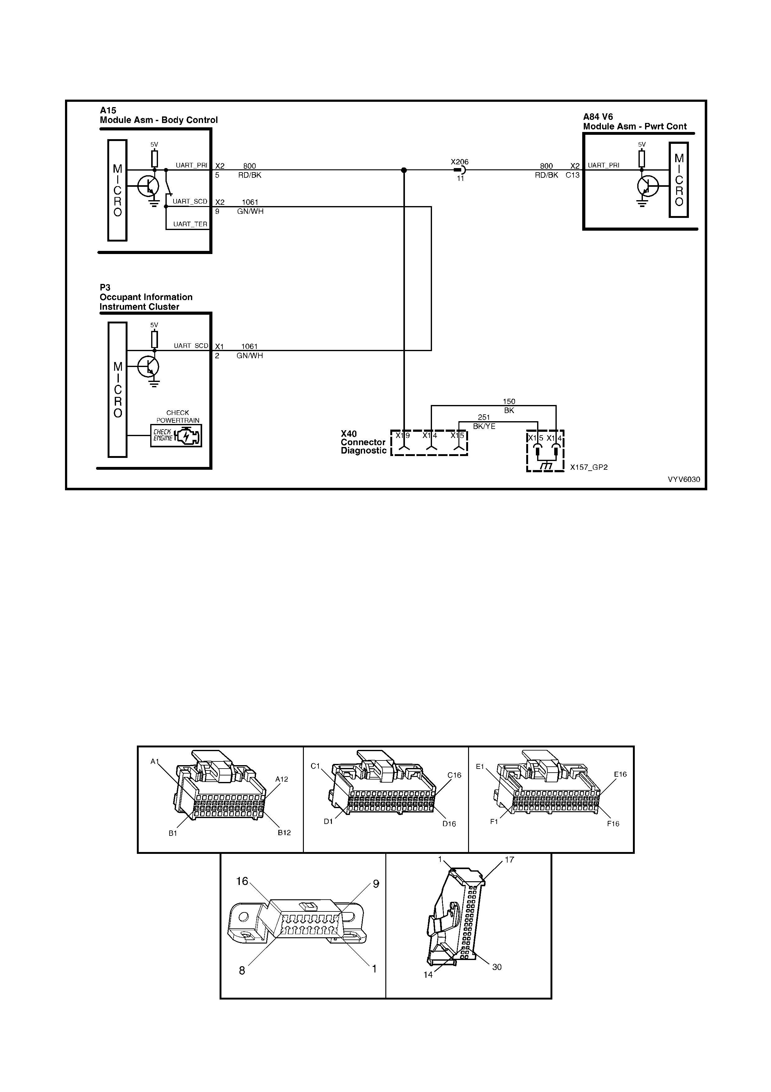
TABLE A-1 V6 PCM -
NO CHECK POWE RTRAIN MALFUNCTION INDICATOR LAMP (MIL)
Figure 6C1-2A-21 – Check Powertrain Malfunction Indicator Lamp (MIL) Circuit
CIRCUIT DESCRIPTION
The Powertrain Control Module (PCM) controls the lamp via serial data communication to the Instrument on the
serial dat a circu it. W hen the PCM determ ines that the Check Po wertrain MIL sh ould be "ON", the PCM will s end a
mess age to the instrum ent s via the s erial d ata circ uit nor m al mode m essage, r equestin g the Check Powertr ain MI L
"ON”. The Instrument will then activate the Check Powertrain MIL.
TEST DESCRIPTION
Number(s) below refer to step number(s) on the diagnostic Table.
2. This test confirms that the Instrument MFD has passed its system check.
3. Disc onnect ing the Mas s Air Flo w Se nsor s hou ld caus e DTC P0101 to s e t an d th e PCM to c om mand the C he ck
Powertrain Lamp “ON” via the serial data normal mode message. If the DTC does not set then the internal
diagnostics of the PCM are not functioning correctly.
4. This test checks that the serial data normal mode message displays "ON" when the DTC sets.
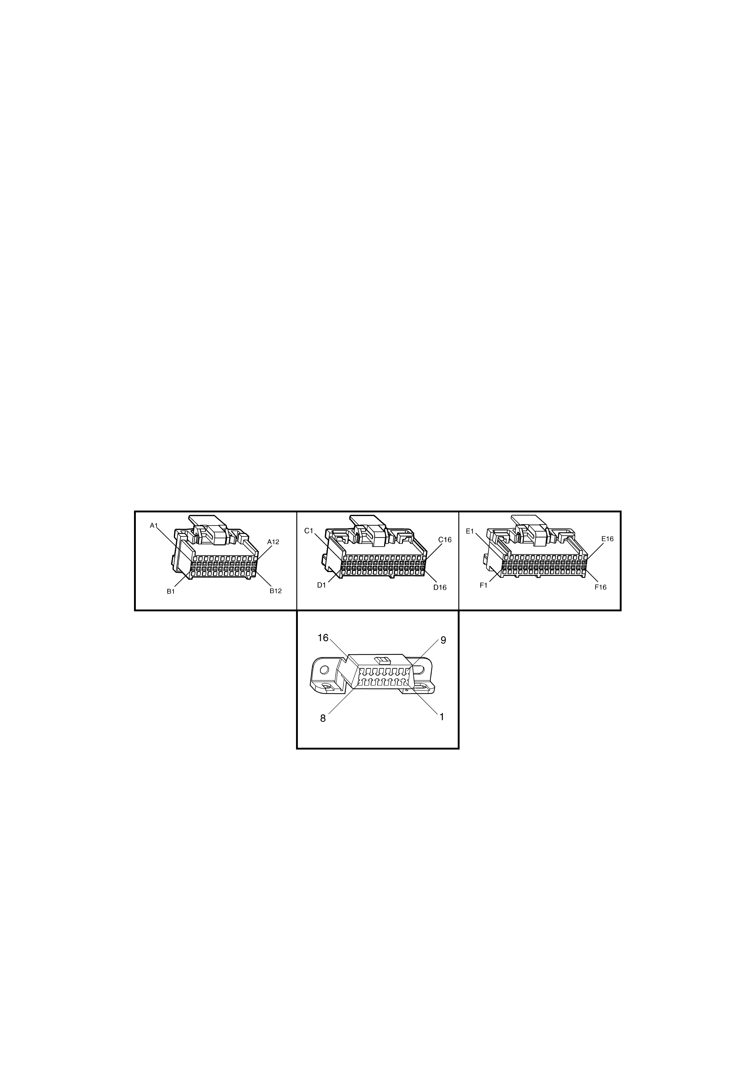
A84 V6 – X1 A84 V6 – X2 A84 V6 – X3
X40 P3
Figure 6C1-2A-22

TABLE A-1 V6 PCM – NO "CHECK POWERTRAIN" MALFUNCTION INDICATOR LAMP (MIL)
STEP ACTION VALUE YES NO
1. Was the "On-Board Diagnostic" (OBD) System Check
performed? Go to Step 2 Go to
OBD System
Check
2. 1. Turn the ignition "ON".
2. Observe the Instrument Multi Function Display
(MFD).
Does the MFD display "OK!" once the “System Check” is
completed?
Go to Step 3 Refer 12C in this
Service
Information
3. 1. Disconnect the Mass Air Flow Sensor connector
B68.
2. Start the engine and allow to idle for 20 seconds.
Does the MFD display the "Check Powertrain MIL"?
Check
Powertrain MIL
is operating
correctly
Go to Step 4
4. 1. Connect TECH 2 to DLC.
2. With TECH 2 connected, select F0: Norm al Mode.
3. With the Mass Air Flow Sensor connector B68 still
disconnected.
4. Start the engine and monitor the "Normal Mode"
data display.
Does the "Normal Mode" display "Check Powertrain
Lamp" display "ON"?
Refer 12C in this
Service
Information
Go to Step 5
5. 1. Replace PCM. Refer to 6C1-3 Service Operations,
for PCM Security Link procedure
Is action complete?
Verify Repair
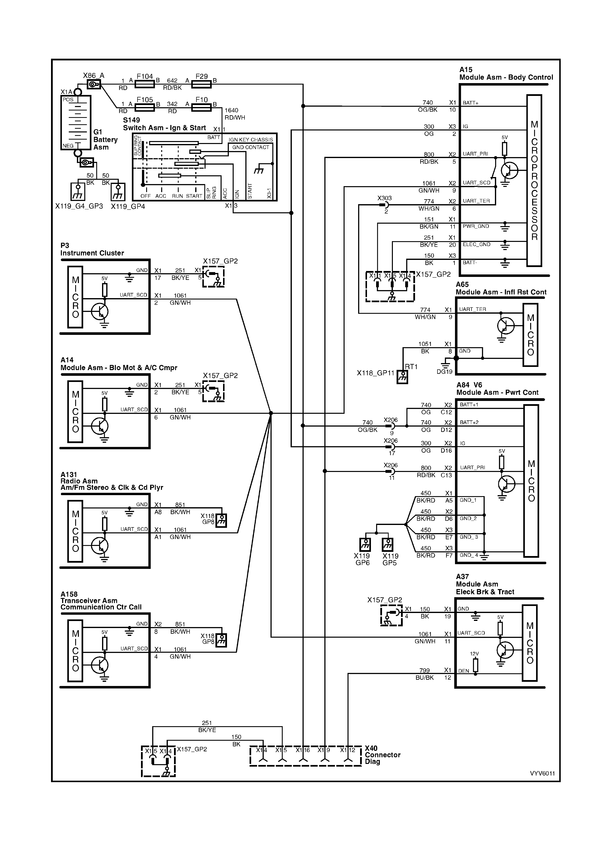
TABLE A-2 V6 PCM – NO SERIAL DATA
Figure 6C1-2A-23 – Serial Data Circuit
CIRCUIT DESCRIPTION
The VY and V2 series of vehicles use a “Bus Master” communication system, where the BCM is the bus master.
The BCM periodically polls (surveys) each control module on the bus (serial data circuit) and requests status data.
The control modules connected via the serial data circuit are the (PCM, BCM, ABS/TCS module, OCC module,
SDM, Instrument, Audio System and Telematics Module, TECH 2 communicates with these modules via the serial
data circuit and DLC terminal 9. Any one of these modules could cause a fault on the serial data line. This fault
could result in TECH 2 not being able to display serial data.
TEST DESCRIPTION
Number(s) below refer to step number(s) on the diagnostic Table.
2. This step checks to see if TECH 2 will communicate with the PCM.
3. This step checks to see if TECH 2 will communicate with the BCM.
4. Using a Digital Multi Meter (DMM), there should be 3 to 4.5 volts at the DLC terminal 9. If the voltage is higher
or lower, serial communication will be affected. This serial data circuit is also connected to several other
modules. A problem with any one of these other modules, may cause a serial data communication malfunction.
5. If the voltage at DLC terminal 9 is at or above 5 volts the serial data circuit is shorted to voltage. If the voltage is
0 volts the serial data circuit may be open or shorted to ground.
6. This step checks the PCM power supply circuit 740. There should be battery voltage at these terminal at all
times.
7. This step checks the PCM ignition circuit 300. There should be battery voltage at this terminal when the ignition
is on.
8. This step checks the continuity of the four PCM ground circuits. All four ground circuits should be checked for
continuity.
9. If the voltage at DLC terminal 9 is at or above 5 volts the serial data circuit is shorted to voltage. If the voltage is
0 volts the serial data circuit may be open or shorted to ground.
DIAGNOSTIC AIDS
If there is a fault with the serial data circuit, it could be caused by one or more of the several modules connected to
this serial data circuit. Isolate the fault by disconnecting each controller (one at a time), until the serial data
communication is restored.
A84 V6 – X1 A84 V6 – X2 A84 V6 – X3
X40
Figure 6C1-2A-24

TABLE A-2 V6 PCM – NO SERIAL DATA
STEP ACTION VALUE YES NO
1. Was the "On-Board Diagnostic" (OBD) System Check
performed?
Go to Step 2 Go to
OBD System
Check
2. 1. Connect Tech 2 to DLC.
2. Ignition "ON", engine stopped.
Does Tech 2 display PCM serial data?
No trouble found Go to Step 3
3. 1. Connect Tech 2 to DLC.
2. Ignition "ON", engine stopped.
Does Tech 2 display BCM serial data?
Go to step 6 Go to Step 4
4. 1. Ignition "ON", engine stopped.
2. Using DMM, probe DLC terminal 9 with DMM
connected to ground.
Does DMM display voltage varying between the
specified value?
3 – 4.5 volts Go to Step 15 Go to Step 5
5. Is voltage steady at or above the specified value? 5 volts Go to Step 10 Go to Step 11
6. 1. Ignition "ON", engine stopped.
2. Using DMM, check for voltage at PCM power
supply circuit 740 terminals X2-C12 and X2-D12.
Does DMM display the specified value at both
terminals?
B+ Go to Step 7 Go to Step 12
7. 1. Ignition "ON", engine stopped.
2. Using DMM, check for voltage at PCM ignition
supply circuit 300 terminal X2-D16.
Does DMM display the specified value?
B+ Go to Step 8 Go to Step 13
8. 1. Using DMM, check continuity of the four PCM
ground circuits 450, between PCM terminals
X1-A5, X2-D6, X3-E7 & X3-F7 and a known good
ground.
Do all four ground circuits have continuity?
Go to Step 9 Go to Step 14
9. Check for open in the serial data circuit 800 between the
PCM and the DLC.
Is the circuit open?
Verify Repair Go to step 16
10. Repair short to voltage on the serial data circuit.
NOTE: Ensure that none of the other modules on the
serial data circuit are causing this voltage problem.
Unplug each module one at a time to isolate short to
voltage.
Is action complete?
Verify Repair
11. Repair short to ground or open in the serial data line.
NOTE: Ensure that none of the other modules on the
serial data circuit are causing this voltage problem.
Unplug each module one at a time to isolate short to
ground.
Was a problem found?
Verify Repair Go to Step 16
12. Repair open in PCM power suppy circuit 740.
Was a problem found?
Verify Repair
13. Repair open in PCM ignition circuit 300.
Was a problem found?
Verify Repair
14. Repair open in PCM ground circuit 450.
Was a problem found?
Verify Repair
15. 1. Refer to BCM No Serial Data diagnostics in Section
12J BCM in this Service Information.
Is action complete?
Verify Repair
16. 1. Replace PCM. Refer to 6C1-3 Service Operations,
for PCM Security Link procedure
Is action complete?
Verify Repair
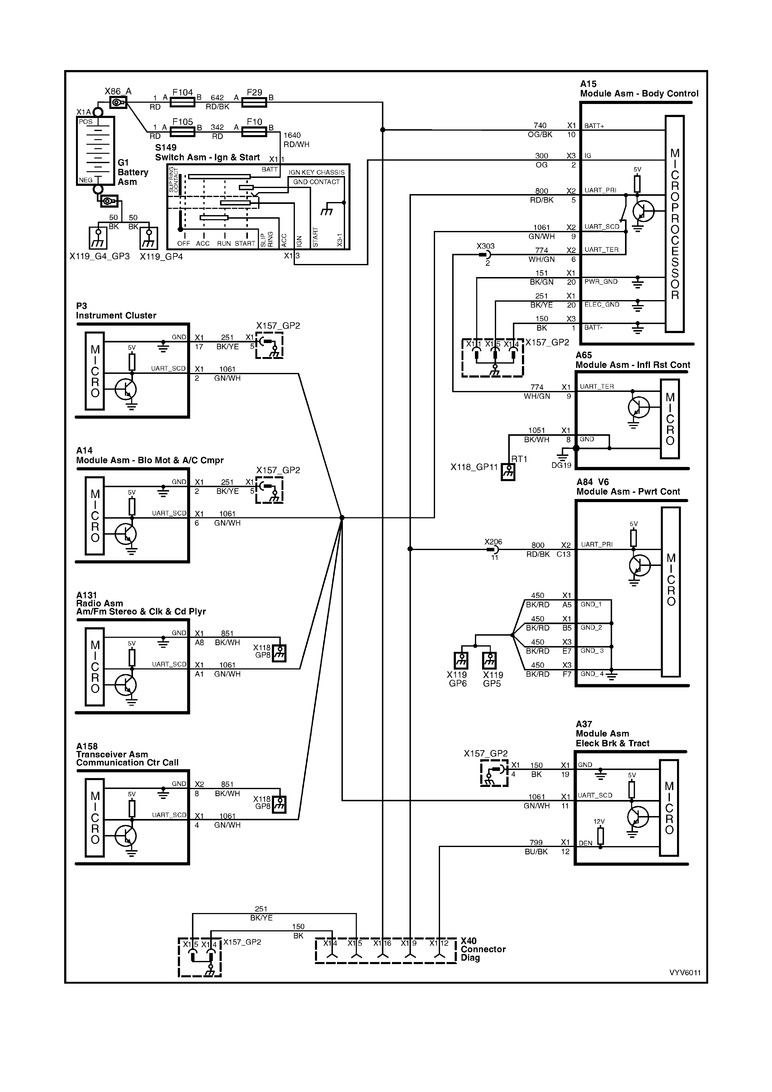
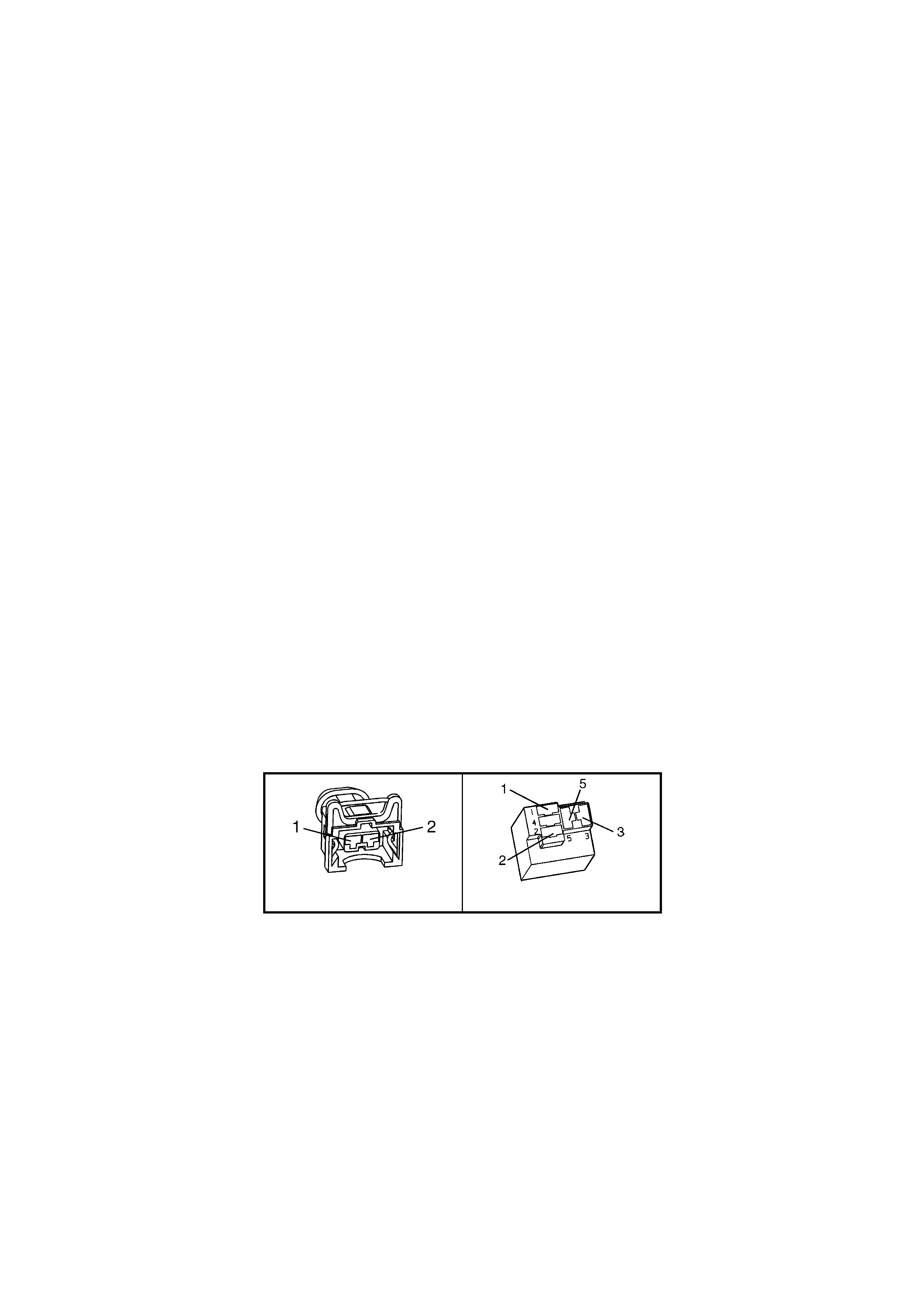
TABLE A-3.1 V6 PCM - ENGINE CRANKS BUT WILL NOT RUN
Figure 6C1-2A-25 – Injector Circuit
CIRCUIT DESCRIPTION
This is the f irst of sever al diagnos tic Tables that m us t be fol lowed in an orderl y, p rogres sive f ashion in or der to find
the cause of a no-start. These Tables assume an a dequate suppl y of goo d quality fue l is in the fuel tank, that the
cranking motor circuit is in good working order, and that the engine will crank with adequate RPM. These Tables
also assu m e that no Diagn ostic T rouble Cod e (DT C) P1255 or P1372 is s et in the PCM m em or y, as det erm ined by
the On-Boar d Diagn ostic S ystem Check . The On- Board Diagnos tic S ystem Check is always the be ginni ng point f or
all diagnostic procedures.
TEST DESCRIPTION
Number(s) below refer to step number(s) on the diagnostic Table.
1. The PCM must be operable. The On-Board Diagnostic System Check will prove that. There are few chances
that the PCM itself would cause a no-start, but the On-Board Diagnostic System Check will uncover any
problems in the PCM power and ground circuitry.
4. NOTE: If the vehicle is fitted with LPG, and if the vehicle will not start in the LPG mode only, and no DTC
P1642 is s et, PC M ter minal X 1- A3 cir cuit 253 1 ma y be shorted to v olt age. R efer Sect ion 8A2 LPG SYSTEM in
this Service Information for further diagnosis of the LPG system.
This checks for a short to ground on the injector control circuit. If this were to occur, the engine would be
extrem ely flooded, since the injectors would be "ON " contin uously, and would inj ect fuel an y time there is fuel
pressure.
5. Any time the PCM has been "OFF" for at least 10 seconds, it should energise the Fuel Pump Relay for 2
seconds after the ignition is turned "ON." If the engine is not cranked, the PCM should turn the relay "OFF"
after 2 s econds. Pr oper oper ation of the Fuel Pum p elec trical c ircuit would be not ed here b y the test lig ht being
"ON" f or 2 sec onds after the i gnitio n sw itch is turn ed to th e "O N" pos itio n. Af ter 2 seconds , the test light s ho uld
go "OFF."
6. Note that this check is for sufficient voltage at the spark plug wire. If, for some reason, the spark plug
electrodes were wet with fuel (engine flooded), this could cause a no-start. However, a "flooded" engine is a
symptom of some other problem. There is no normal condition that should ever be able to "flood" the engine.
7. T his is a quick check of the f uel s ystem. T he easiest plac e to ins tall th e press ure gaug e is where th e fuel p ipes
come up into the engine compartment. There are 2 hoses, and the gauge must be connected to the hose or
pipe lea ding direc tly to the f uel rail. This connection is on the lef t (passenger ) side of the fuel rail (r efer Servic e
Operation 3.4 FUEL CONTROL SYSTEM; Fuel System Pressure Test in this Service Information). The
other hos e or pipe lea ds to the pres sure reg ulator, an d no pressur e testin g is done ther e. If the press ure is not
as specif ied, or continues to drop after the pum p stops running, the Fuel System Diagnostic Table A-4.3 m ust
be used.
NOTE: Us e ST 125 spark check er or equival ent. An ST 125 requires a bout 25, 000 volts (25 k ilovolts , or 25 k V) to
"spark". Do not use a spark plug in open air grounded to the engine as an indication of sufficient "spark". Only a
few kilovolts are required to jump the gap of a spark plu g outside of the engine, and that would be an inadequate
test of the ignition coil output ability.
L2
X 16 (PART OF X100)
Figure 6C1-2A-26

TABLE A-3.1 V6 PCM - ENGINE CRANKS BUT WILL NOT RUN
STEP ACTION VALUE YES NO
1. Was the "On-Board Diagnostic" (OBD) System Check
performed? Go to Step 2 Go to
OBD System
Check
2. Is DTC P1255 present? Go to DTC
P1255 Table Go to Step 3
3. Is DTC P1372 present? Go to DTC
P1372 Table Go to Step 4
4. NOTE: If this vehicle is fitted with LPG and the engine will
not start in the LPG mode only, and DTC P1642 is not
set, check the LPG Enable circuit 2531 at PCM terminal
X1-A3 for a short to voltage.
1. Check fuel tank quantity.
2. Disconnect ALL injector electrical connectors.
3. Connect test light between the terminals of each
injector harnes s conne ctor.
Be very careful to NOT short across the terminals, or to
engine ground.
4. Ignition "ON", note test light.
Is light "OFF" on all six injector connectors?
Go to Step 5 Go to Step 8
5. 1. Probe Fuel Pump Relay X16 5 circuit with a test light
connected to ground.
2. Ignition "ON".
3. Using TECH 2, Select Fuel Pump.
4. Activate Fuel Pump.
Is test light "ON"?
Go to Step 6 Go to
Table A-4.1
6. 1. Ignition "O FF".
2. Remove the spark plug leads from 2 spark plugs.
3. Connect ST 125 spark checker (refer Test
Description) to each individually, and check for spark
while cranking the engine.
4. Check both wires. A few sparks and then nothing is
consider ed no spar k.
Was there spark on both wires?
Go to Step 7 Go to
Table A-8.1
7. 1. Ignition "O FF".
2. Reconnect both spark plug leads to spark plugs.
3. Reconnect all injector electrical connectors.
4. Remove Fuel Pump Relay from engine compartment
"FUSE AND RELAY CENTRE," and crank engine for
15 seconds to relieve any residual fuel pressure.
5. Ignition "OFF," connect Fuel Pr ess ure Gauge
(Gauge to be installed in the pressure line, between
the fuel feed hose and the fuel inlet line to the fuel
rail, at left rear of fuel rail.)
6. Reinstall Fuel Pump Relay
7. Observe fuel pressure when ignition is turned "ON."
8. Pressure should be within the specified value, and
not continue to drop after pump stops running.
Is fuel pressure at or between the specified value?
270 to 350
kPa Go to
Table A-3.2 Go to
Table A-4.3
8. Check for short to ground on Injector Circuit.
Was Injector Circuit shorted to ground? Verify Repair Go to Step 9
9. Replace PCM.
Refer to 6C1-3 SERVICE OPERATIONS, for PCM
Programming and Security Link procedure.
Is action complete?
Verify Repair
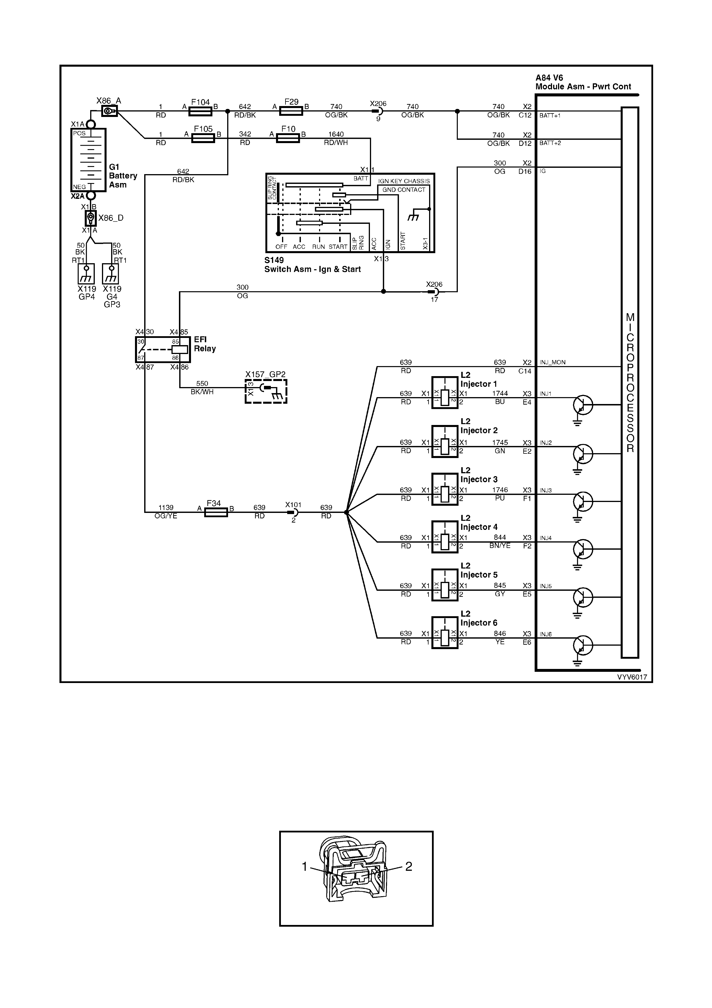
TABLE A-3.2 V6 PCM - ENGINE CRANKS BUT WILL NOT RUN
Figure 6C1-2A-27 – Injector Circuit
TEST DESCRIPTION
Number(s) below refer to step number(s) on the diagnostic Table.
3. "STEAD Y LIG HT" indic at es the PC M is c o nti nuo us l y supp l ying th e gr o und pat h on the i nj ec tor c irc uit. It is no t a
harness pr oblem at this point. T hat would have b een identif ied in T able A-3.1. T his ma y destr oy an injector , as
they are designed to be energised in short pulses and may not withstand 100% "ON" time. If any injector
checks less than 11.4 ohms, it could be the cause of the defective PCM. The PCM can be damaged when it
attempts to energise the injector circuit with a very-low-resistance load. Normal injector resistance is
approximately 12.2 ohms at 20°C per individual injector.
L2
Figure 6C1-2A-28 – Injector Circuit

TABLE A-3.2 V6 PCM - ENGINE CRANKS BUT WILL NOT RUN
STEP ACTION VALUE YES NO
1. Was the "On-Board Diagnostic" (OBD) System Check
performed? Go to Step 2 Go to
OBD System
Check
2. • From Table A-3.1.
1. Ignition "OFF".
2. With all injectors disconnected, connect test light
across both harness terminals of one injector
connector.
Be very careful to not short across the terminals, or
to engine ground.
3. Have a helper crank the engine while you closely
observe the test light.
4. Test light should blink while cranking, indicating
electrical injector pulses are present, do this test for
all injectors.
Did test light blink on all injector circuits while cranking?
Go to Step 3 If there was no
blinking light, Go
to Table A3.3
----------------------
If the test light
was on steady
(no blinking light)
Go to Step 4
3. At this point, the fuel control system, fuel delivery system,
and ignition system are OK.
Check For:
• Fouled spark plugs.
• Proper MAF sensor operation. If engine will start with
MAF sensor electrical connector disconnected, refer
Table A-6.1 in this Service Information.
• Proper TP sensor circuit operation. Use TECH 2 to
monitor TP sensor signal. If voltage is over 1.25 volts
with throttle closed, refer Table A-6.2 .
• Restricted exhaust system. Loosen front pipe from
exhaust manifold(s). If the engine will start, refer
Table A-13 .
• Improper engine coolant temperature (ECT) sensor
resistance. Refer DTC P0118 Diagnostic Aids to
check resistance of ECT sensor.
• Water or foreign material in fuel, or incorrect fuel.
• Spark plug wires crossed.
• Camshaft timing chain.
• Inadequate engine compression.
Is action complete?
Verify Repair
4. Check for a short to ground in injector circuit that caused
test light to stay "ON" steady.
Was a problem found?
Verify Repair Go to Step 5
5. Check resistance across each injector. Each injector
should be between the specified value.
Is each injector between the specified value?
11.4 - 12.6
ohms Go to step 6 Go to step 7
6. Replace PCM.
Refer to 6C1-3 Service Operations in this Service
Information, for PCM Programming and Security Link
procedure.
Is action complete?
Verify Repair
7. 1. Replace any injector that did not measure within the
specified value.
2. Retest beginning at Step 2.
Is action complete?
11.4 - 12.6
ohms Verify Repair

TABLE A-3.3 V6 PCM - ENGINE CRANKS BUT WILL NOT RUN
Figure 6C1-2A-29 – Injector Circuit
TEST DESCRIPTION
Number(s) below refer to step number(s) on the diagnostic Table.
2. "NO LIGHT " indicates no PCM contro l of the inj ector. Fus e F34 supplies +12 vol ts to the inj ectors. Prob e both
terminals of one injector connector with a test light to ground. There should be a light on only one terminal,
confirming ignition voltage to one terminal, but not both.
3. The PCM injector control c irc uit ma y be open. Reco nnect the injector s. Using a tes t light conn ected to groun d,
check for a lig ht at the PC M connec tor term inals. A l ight at th is point indicat es that injector c ontrol cir cuit is not
"open." The voltage to light that test light comes from circuit 639, through t he injector windings, and cont inues
through the injector control circuit to PCM connector terminals.
5. During this test step TECH 2 should displa y the crank ing RPM. If RPM disp lay remains at zero (0) there is no
crankshaft reference pulses.
8. There is no terminal identification on the relay connector socket, but the relay itself has terminal numbers.
Make certain the correct relay connector socket terminal (NOT the relay) is being probed.
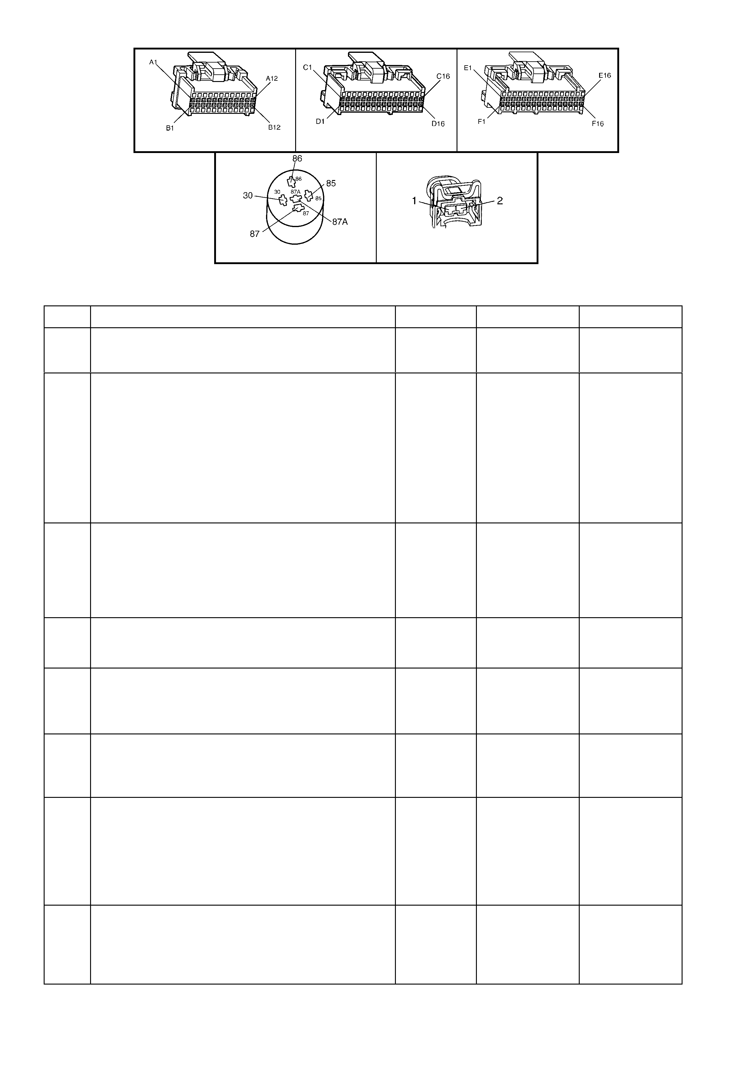
A84 V6 – X1 A84 V6 – X2 A84 V6 – X3
X4 (Part of X100) L2
Figure 6C1-2A-30
TABLE A-3.3 V6 PCM - ENGINE CRANKS BUT WILL NOT RUN
STEP ACTION VALUE YES NO
1. Was the "On-Board Diagnostic" (OBD) System Check
performed? Go to Step 2 Go to
OBD System
Check
2. • From Table A-3.2
1. Ignition "OFF"
2. Disconnect injector connectors.
3. Ignition "ON," engine stopped.
4. Probe each terminal of each injector harness
connector with a test light to ground.
Is the test light "ON" at one terminal of each injector
connector?
Go to Step 3 If
the test light was
"ON" at both
terminals, repair
short to voltage
on injector circuit.
----------------------
If
there was no
light "ON", Go to
Step 7
3. 1. Ignition "OFF".
2. Reconnect injectors.
3. Ignition "ON".
4. Backprobe PCM injector control terminals with a test
light connected to ground.
Is test light "ON" at each terminal?
Go to Step 4 Go to Step 12
4. 1. Ignition "ON".
2. With TECH 2, monitor TP sensor signal voltage.
Is voltage less than the specified value?
1.25 volts Go to Step 5 Go to
Table A-6.2
5. 1. Ignition "ON".
2. W ith TECH 2, monitor the RPM signal while cranking
the engine.
Is there an RPM signal?
Go to Step 6 Go to DTC
P1372 Table.
6. Replace PCM.
Refer to 6C1-3 SERVICE OPERATIONS, for PCM
Programming and Security Link procedure.
Is action complete?
Verify Repair
7. 1. Ignition "OFF".
2. Disconnect EFI relay, R4.
3. Ignition "ON".
4. Probe EFI relay harness connector terminal X4 30
and terminal X4 85 with a test light connected to
ground.
Is the test light "ON" at both circuits?
Go to Step 8 Go to Step 13
8. 1. Ignition "OFF".
2. Disconnect EFI relay, R4.
3. With test light connected to 12 volts, probe relay
harness terminal ground circuit X4-86 of EFI relay.
Is test light "ON"?
Go to Step 9 Go to Step 14

STEP ACTION VALUE YES NO
9. Check injector fuse F34 for an open.
Was a problem found? Go to step 15 Go to Step 10
10. Check for an open in injector power circuit from fuse F34
to each injector connector term inal X1-1.
Was a problem found?
Verify Repair Go to Step 11
11. Replace EFI relay.
Is action complete? Verify Repair
12. Repair open injector control circuit that did not light test
light.
Is action complete?
Verify Repair
13. Check fuses and repair circuit that did not turn
"ON" test light.
Is action complete?
Verify Repair
14. Repair ground circuit to EFI relay.
Is action complete? Verify Repair
15. Repair short to ground in fuse circuit.
Replace fuse.
Is action complete?
Verify Repair
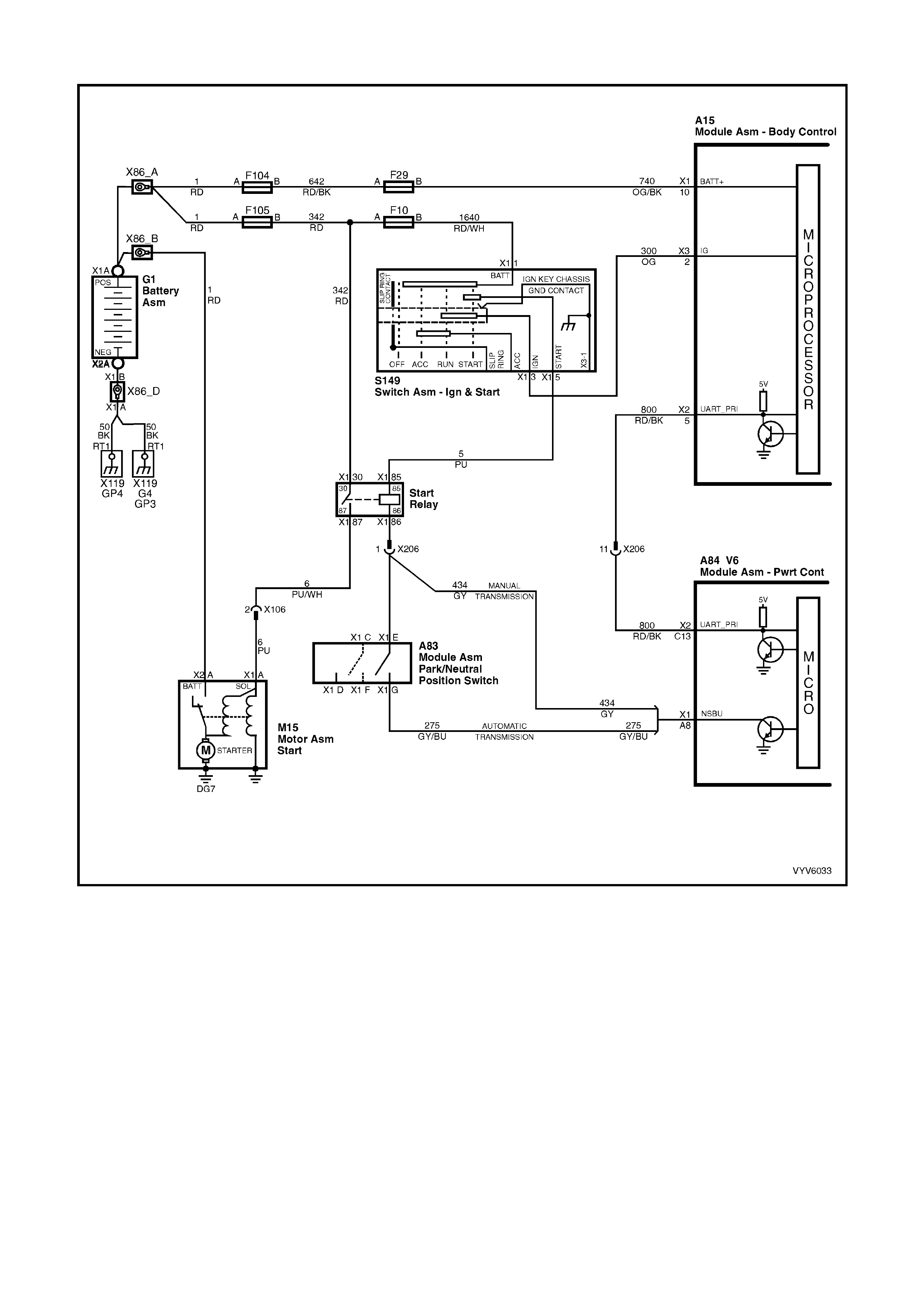
TABLE A- 4.0 V6 PCM - STARTER CRANKING CIRCUIT
Figure 6C1-2A-31 – Starter Cranking Circuit
CIRCUIT DESCRIPTION
When the ignition is turned to the "ON" position, battery power is supplied from a fusible link to the Start Relay
term inal X1- 30. As the igni tion s witch is turned to t he ST ART position, p ower is s upplie d to the Star t Rela y ter m inal
X1-85. The PCM supplies the ground signal needed to energise the Start Relay which allows power to the starter
motor.
W hen the ignition is tur ned “ON”, the PCM will the n loo k f or the proper T heft Deterr ent signal s ent from the BCM. If
the PCM has determined that the proper Theft Deterrent signal is present, the PCM will allow the vehicle to crank. If
the PCM determines that an improper Theft Deterrent signal was sent from the BCM, or no Theft Deterrent signal
was sent, the PCM will n ot suppl y a ground s ignal f rom the PCM term inal to the Start Rela y terminal X 1-86. W hen
the Start Re lay receives th is ground signa l from the PCM, the re lay will be ener gised, allowing th e starter motor to
operate. This removed ground signal to the Start Relay will cause the vehicle not to crank.
If there is a problem with the Theft Deterrent signal from the BCM to the PCM, DTC P1255 will set.
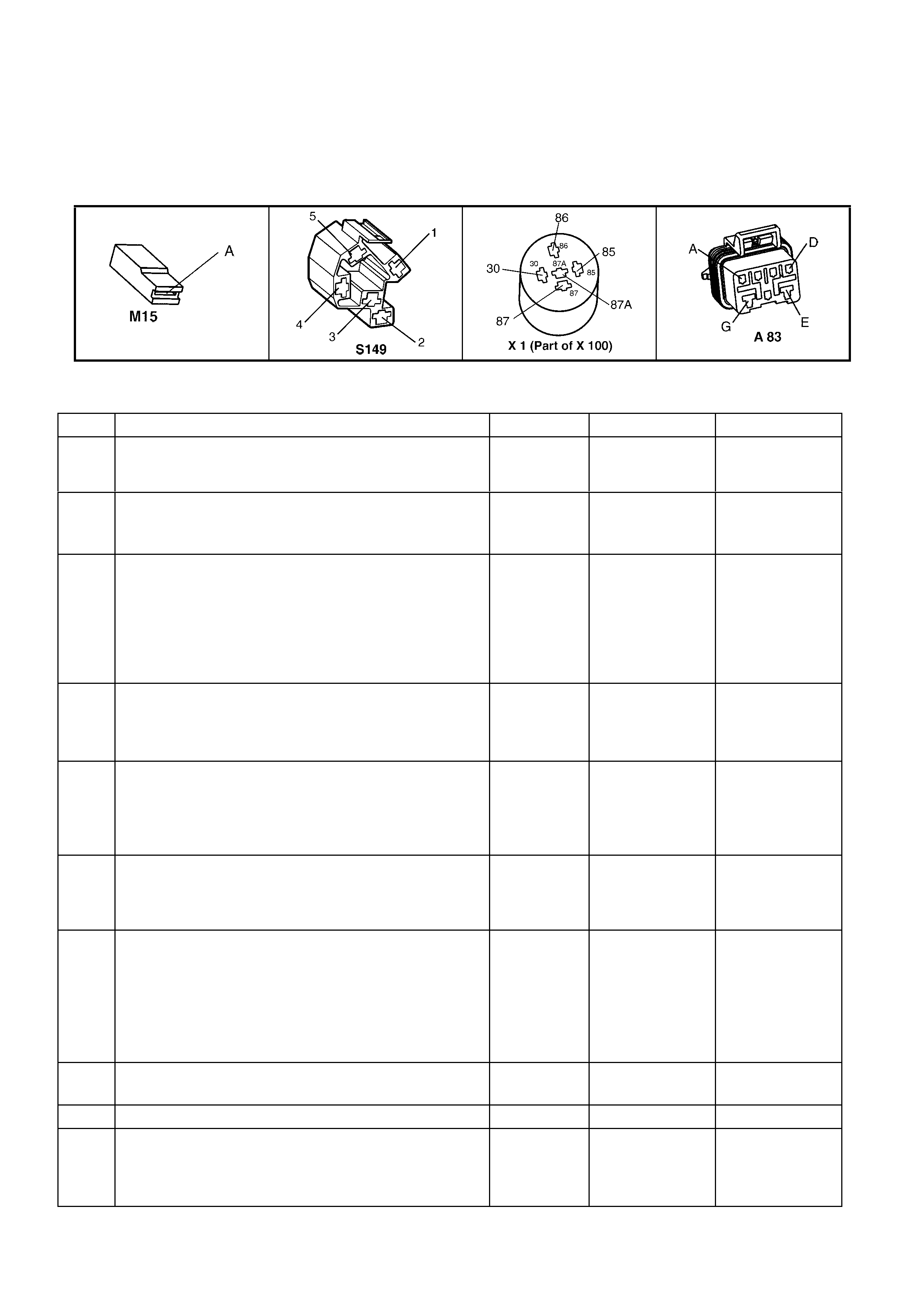
TEST DESCRIPTION
Number(s) below refer to step number(s) on the diagnostic Table.
2. This step check s to see if DTC P1255 is set. T his DTC c ould preve nt the veh icle fr om crank ing. This s tep als o
verifies that if a PCM was replaced, that the Security Link procedure was performed.
3. This step checks to see if power is being applied to the starter motor. If test light illuminates, the problem is with
the starter motor.
11. This step checks the adjustment of the Neutral start switch.
Figure 6C1-2A-32
TABLE A-4.0 V6 PCM - STARTER CRANKING CIRCUIT
STEP ACTION VALUE YES NO
1. Was the "On-Board Diagnostic" (OBD) System Check
performed? Go to Step 2 Go to
OBD System
Check
2. 1. Install TECH 2.
2. Ignition “ON” engine “OFF”.
Does TECH 2 display “Theft Status” as “Start”?
Go to Step 3 Refer to 12J
BCM
DIAGNOSIS
3. 1. Ignition OFF.
2. Using a test light, probe the starter solenoid terminal
X1-A with test light connect ed to ground.
3. Have a helper turn the ignition switch to the START
position, note the test light.
Does the test light illuminate when the ignition switch is
turned to the START position?
Refer to 6D1-2
Starting System -
V6
Go to Step 4
4. 1. Remove the start relay, R1.
2. W ith a test light connected to ground probe the start
relay harness terminal X1-30.
Does the test light illuminate?
Go to Step 5 Go to Step 15
5. 1. With the start relay still removed and the test light
connected to ground, probe the start relay harness
terminal X1-85.
2. Turn the ignition to the START position.
Did the test light illuminate?
Go to Step 7 Go to Step 14
6. Check for an open circuit between the starter solenoid
connector terminal X1-A and the Start Relay connector
terminal X1-87.
Was a problem found?
Verify Repair Go to Step 8
7. 1. Ignition OFF.
2. Remove the Start Relay.
3. Connect a test light between the relay harness
terminal X1-85 and termina l X1-86.
4. Turn the ignition switch to the START position.
Does the test light illuminate when the ignition switch is
turned to the START position?
Go to Step 6 Go to Step 9
8. Replace the Start Relay.
Is the action complete? Verify Repair
9. Is the vehicle equipped with an automatic transmission? Go to Step 10 Go to Step 16
10. 1. Ignition ON engine OFF.
2. With a test light connected to B+, probe terminal
X1-G at the neutral start switch.
Did the test light illuminate?
Go to Step 11 Go to Step 12

STEP ACTION VALUE YES NO
11. 1. Disconnect the neutral start switch connector A83.
2. Connect a fused jumper wire between A83 terminals
X1-E and X1-G.
3. Connect a test light between start relay harness
connector terminals X1-85 and X1-86.
4. Turn the ignition to the START position.
Did the test light illuminate when the ignition was turned
to the START position?
Go to Step 17 Go to Step 18
12. Check for open in circuit 275 from the neutral start switch
connector term inal X1-G to the PCM terminal X1-A8.
Was a problem found?
Verify Repair Go to Step 19
13. Repair the open or short to ground in the faulty circuit.
Replace the fusi ble lin k or the fuse as necessary .
Is the action complete?
Verify Repair
14. Repair the open in the cranking circuit from the ignition
switch or faulty ignition switch.
Is the action complete?
Verify Repair
15. Check for an open circuit 342 including the fusible link
F105.
Was an open circuit found?
Go to step 13
16. Repair the open in circuit 434, including PCM for correct
terminal retention.
Was an open circuit found?
Verify Repair Go to step 19
17. Check adjustment of neutral start switch. If adjustment is
OK replace switch. Verify Repair
18. Check for open in circuit 434 between neutral start switch
connector term inal X1-E and start relay connector X1-86.
Was an open circuit found?
Verify Repair
19. Replace PCM.
Refer 6C1-3 SERVICE OPERATIONS for PCM
Programming and Security Link procedure.
Is action complete?
Verify Repair

TABLE A-4.1 V6 PCM - FUEL PUMP ELECTRICAL CIRCUIT
Figure 6C1-2A-33 - Fuel Pump Electrical Circuit
CIRCUIT DESCRIPTION
When the ignition switch is turned "ON," the Powertrain Control Module (PCM) energises its Fuel Pump Relay
control output. It will provide +12 volts to the Fuel Pump Relay, as long as the engine is cranking or running, and
the PCM is receiving crankshaft reference input signal pulses.
If there are no crankshaft reference pulses (ignition "ON," engine stopped - or - engine stalled), the PCM will shut
"OFF" the Fuel Pump Relay within 2 seconds.
• Improper electrical control of the pump will result in one or more of the following symptoms:
• Cranks, but won't run.
• Hard start.
• Cuts out, may feel like ignition problem.
• Excessive cranking time.
TEST DESCRIPTION
Number(s) below refer to step number(s) on the diagnostic Table.
3. If the fuse is blown, this test will check for short to ground on Fuel Pump power feed circuit. To prevent mis-
diagnosis, be sure Fuel Pump is disconnected and ignition is "OFF" before performing this test.
4. This checks to see if the cause of the blown fuse is a short to ground in the Fuel Pump Relay power feed
circuit.
8. Determines if the PCM and Fuel Pump Relay circuit are operating correctly. The PCM should turn "ON" the
Fuel Pump Relay.
- If test light stays "OFF," go to Table A-4.2
- If test light stays "ON," disconnect the Fuel Pump Relay. If the test light now stays "ON," repair short to voltage
on Fuel Pump power feed circuit, but if the light goes out, check for short to voltage on Fuel Pump Relay
control circuit. If no voltage on Fuel Pump Relay control circuit, replace relay.
10. This should turn "ON" the Fuel Pump if Fuel Pump power feed circuit wiring is OK. If the Fuel Pump runs
(Pump Runs? YES), the Fuel Pump electrical circuit is OK. Continue to Table A-4.3 to complete the testing of
the fuel delivery system.
14. The fuel pump is serviceable separate from the Modular Sender Assembly. Refer to Section 6C1-3 Service
Operations for replacement procedures.
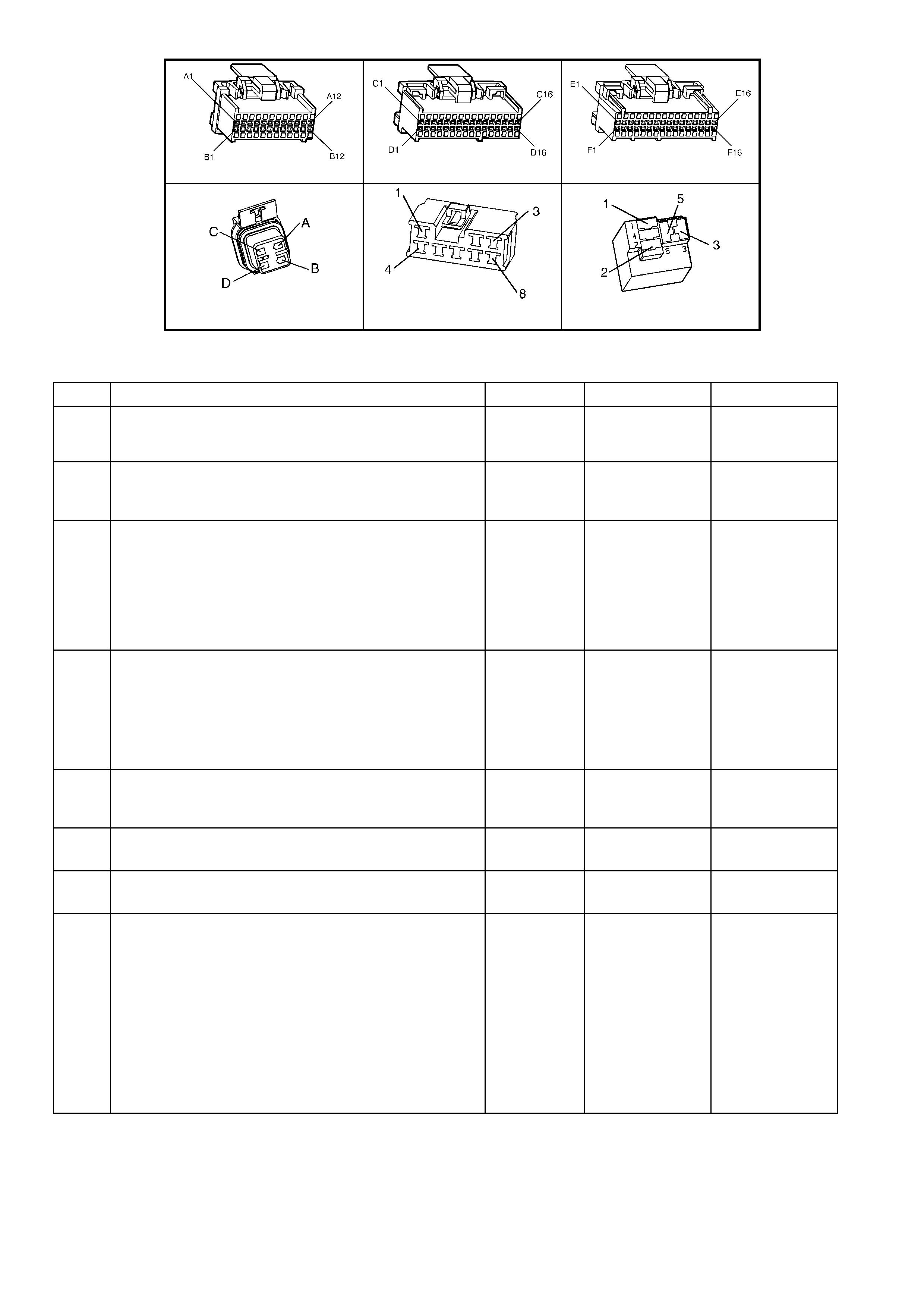
A84 V6 – X1 A84 V6 – X2 A84 V6 – X3
M8 A47 X16 (Part of X100)
Figure 6C1-2A-34
TABLE A-4.1 V6 PCM - FUEL PUMP ELECTRICAL CIRCUIT
STEP ACTION VALUE YES NO
1. Was the "On-Board Diagnostic" (OBD) System Check
performed? Go to Step 2 Go to
OBD System
Check
2. Check Fuel Pump fuse F28 in engine compartment fuse
and relay centre.
Is the Fuel Pump fuse blown?
Go to step 3 Go to step 8
3. 1. Ignition "OFF".
2. Disconnect Fuel Pump electrical connector M8 from
the fuel pump.
3. Remove the Fuel Pump Relay and probe the fuel
pump power feed circuit connector X16-3 with a test
light connected to B+.
Is the test light "ON"?
Go to Step 15 Go to step 4
4. 1. Ignition "OFF".
2. Reconnect Fuel Pump electrical connector.
3. Replace Fuel Pump fuse F28.
4. Ignition "ON".
5. Recheck fuse.
Is Fuel Pump fu se OK?
Problem is
intermittent.
Refer
Intermittents in
this Section
Go to step 5
5. Check for short to ground in fuel pump power feed circuit
120 at fuel pump relay connector terminal X16-5.
Was a problem found?
Verify Repair Go to step 6
6. Check Fuel Pump for internal short.
Was fuel pump shorted internally? Go to Step 14
7. Replace Fuel Pump Relay.
Is action complete? Verify Repair
8. 1. Ignition "OFF".
2. Disconnect Fuel Pump Relay, R16 from relay
housing.
3. With Fuel Pump Relay disconnected, probe relay
connector terminal X16-1 with test light connected to
ground.
4. Ignition "ON".
5. Using TECH 2, Command Fuel Pump "ON" and
"OFF".
Is test light "ON" and "OFF" when Fuel Pump is
commanded "ON" and "OFF"?
Go to Step 9 If Test
Light stays
"OFF", Go to
Table A-4.2 in
this Section
-----------------------
If Test Light stays
"ON",
Go to Step 16

STEP ACTION VALUE YES NO
9. 1. Ignition "OFF".
2. Fuel pump relay still disconnected.
3. Connect a test light between X16-1 and X16-2.
4. Ignition "ON".
5. Using TECH 2, Command Fuel Pump "ON" and
"OFF"
Is test light "ON" and "OFF" when Fuel Pump is
commanded "ON" and "OFF"?
Go to Step 10 Go to
Table A-4.2 in
this Section
10. 1. Ignition "OFF".
2. Fuel pump relay still disconnected.
3. Connect a fused jumper wire between X16-3 and
X16-5.
Is fuel pump running?
Go to Step 7 Go to Step 11
11. Check for faulty connect ion at Fuel Pump and relay .
Is connection faulty? Verify Repair Go to Step 12
12. Check for open in Fuel Pump power feed circuit 120.
Was a problem found? Verify Repair Go to Step 13
13. Check for open in Fuel Pump.
Is Fuel Pump open? Go to Step 14 Go to Step 17
14. Replace Fuel Pump.
Is action complete? Verify Repair
15. Repair short to ground in Fuel Pump power feed circuit
240.
Is repair complete?
Verify Repair
16. Repair short to voltage in circuit 465.
For vehicles equipped with Telematics check for short to
voltage in circuits 465 and 497.
Is action complete?
Verify Repair
17. Repair open in fuel pump ground circuit 650.
Is action complete? Verify Repair
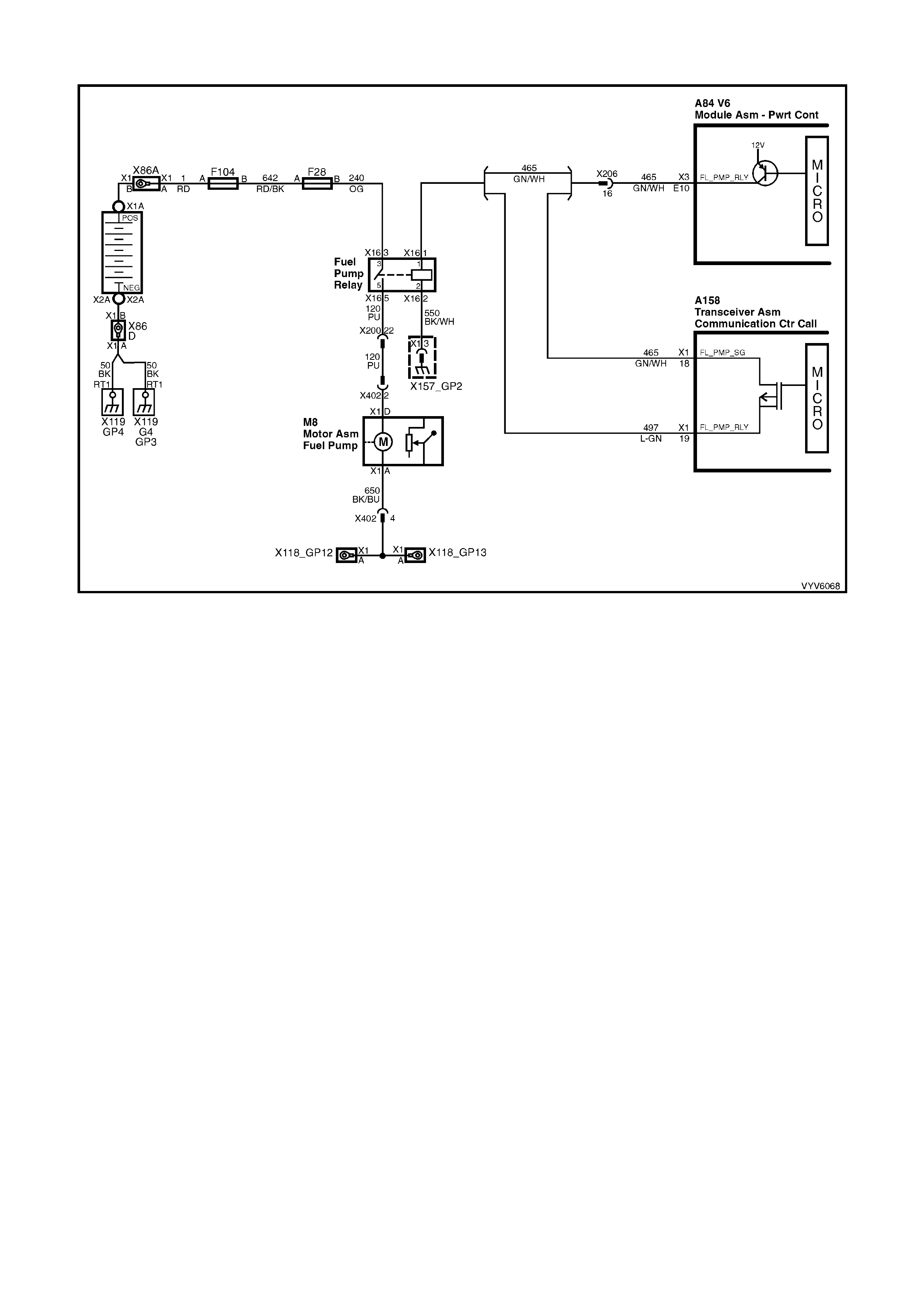
TABLE A-4.2 V6 PCM - FUEL PUMP ELECTRICAL CIRCUIT
Figure 6C1-2A-35 - Fuel Pump Electrical Circuit
CIRCUIT DESCRIPTION
Relay connector has no terminal identification. See diagram below for terminal identification.
There are 3 basic circuits to any relay. They are:
LOAD - This is the device controlled by the relay. In this case, it is the fuel pump’s power feed circuit.
LINE - This is the voltage supply that will power the load whenever the relay switch contacts are closed. In this
case, it is the fused power circuit.
CONTROL - This is the circuitry that energises the small electromagnet windings in the relay, which causes the
switching contacts to change position. In this case, one side of the relay windings is simply grounded. The other
control circuit is the +12 volts supplied by the PCM whenever it wants the relay to be energised.
TEST DESCRIPTION
Number(s) below refer to step number(s) on the diagnostic Table.
2. This checks the ground circuit 550 to the relay windings, part of the relay's control circuitry (CONTROL).
3. This checks the fuel pump power supply circuit 240 to the relay switching contacts (LINE).
4. This checks for the relay control voltage supplied by the PCM to the relay (CONTROL).
5. At this poi nt, the 3 oth er circ uits to the re lay are OK. This chec k is to det ermine if the contac ts in the re lay will
close, a llo win g th e c urr ent t o pas s throu gh the s witch in g c ontac ts to the "lo ad " terminal of the r elay, which go es
to the fuel pump motor.
7. Note: Before performing this Test Step ensure that the Telematics Service Mode is enabled. Refer
Section 12K TELEMATICS. If the telematics module is not in service mode a battery disconnect alert will be
sent to Holden Assist when this connector is disconnected.

A84 V6 – X1 A84 V6 – X2 A84 V6 – X3
X16 (Part of X100)
Figure 6C1-2A-36
TABLE A-4.2 V6 PCM - FUEL PUMP ELECTRICAL CIRCUIT
STEP ACTION VALUE YES NO
1. Was the "On-Board Diagnostic" (OBD) System Check
performed? Go to Step 2 Go to
OBD System
Check
2. • From Table A-4.1.
1. Ignition "ON", engine not running.
2. Disconnect fuel pump relay from relay housing.
3. With fuel pump relay disconnected, probe relay
connector X16-2 ground circuit 550 with a test light
connected to B+.
Is test light "ON"?
Go to Step 3 Go to step 12
3. Probe relay connector power feed circuit 240 at fuel
pump relay connector terminal X16-3 with test light
connected to ground.
Is test light "ON"?
Go to Step 4 Go to step 13
4. 1. Probe relay control circuit 465 at fuel pump relay
connector terminal X16-1 with test light to ground.
2. Ignition "ON".
3. Using TECH 2, Select Fuel Pump.
4. Command Fuel Pump "ON" and "OFF".
Is test light "ON" and "OFF", when Fuel Pump is
commanded "ON" and "OFF"?
Go to Step 5 For vehicles
equipped with
Telematics
Go to Step 7
For other
vehicles go to
Step 8
5. 1. Reconnect fuel pump relay.
2. Ignition "ON".
3. Using TECH 2, Select Fuel Pump.
4. Probe fuel pump relay connector X16-5 power feed
circuit 120 with test light to ground.
5. Command fuel pump "ON" and "OFF".
Is test light "ON" and "OFF", when Fuel Pump is
commanded "ON" and "OFF"?
Go to Step 6 Go to Step 9
6. Fuel Pump Relay is operating correctly.
Repair open in power feed circuit 120 from fuel pump
relay to fuel pump.
Is action complete?
Verify Repair

STEP ACTION VALUE YES NO
7. Note: Before performing this Test Step ensure that the
Telematics Service Mode is enabled. Refer Section 12K
TELEMATICS.
1. Disconnect the Telematics Module Connector A158.
2. Connect a fused jumper wire between connector
A158 terminals X1-18 and X1-19.
3. Probe relay control circuit 465 at fuel pump relay
connector terminal X16-1 with test light to ground.
4. Ignition "ON".
5. Using TECH 2, Select FUEL PUMP.
6. Command Fuel Pump "ON" and "OFF".
Is test light "ON" and "OFF", when Fuel Pump is
commanded "ON" and "OFF"?
Replace
Telematics
Module. Refer
12K Telematics.
Go to step 8
8. 1. Ignition "O FF".
2. Disconnect Fuel Pump Relay and PCM connectors.
3. Check for open in Fuel Pump Relay control circuits
465 and 497.
Was a problem found?
Verify Repair Go to Step 10
9. 1. Ignition "OFF"
2. Replace Fuel Pump Relay.
Will engine start?
Verify Repair Go to OBD
System Check
10. Check for short to ground in Fuel Pump Relay control
circuit.
Was a problem found?
Verify Repair Go to step 11
11. Replace PCM.
Refer to 6C1-3 SERVICE OPERATIONS, for PCM
Programming and Security Link procedure.
Is action complete?
Verify Repair
12. Repair open in relay ground circuit 550.
Is action complete? Verify Repair
13. Repair open in Fuel Pump power feed circuit 240.
Is action complete? Verify Repair

TABLE A-4.3 V6 PCM - FUEL DELIVERY SYSTEM
Figure 6C1-2A-37 V6 Fuel Delivery System
1. Fuel Rail
2. Fuel Injector (6 places)
3. Fuel Feed
4. Fuel Pressure Regulator
5. Fuel Return
6. Fuel Filter
7. Fuel Tank Vapour Line
8. Fuel tank
9. Modular Fuel Sender Assembly
Fuel Pressure Too LOW or Too HIGH or Pressure That Continues to Drop After The Ignition is Turned OFF Can
Cause The Following Driveability Complaints:
• Poor Idle Quality
• Exces sive Ex ha us t Odour
• Poor Fuel Economy
• Excessive Cranking Time
• Detonation
• Loss of Power
• DTC P0132 or P0152
• DTC P0131 or P0151
CIRCUIT DESCRIPTION
Fuel is drawn from the tank by the electric fuel p ump and is fed under pressure through a fuel filter and continues
on into the fuel rail and then is injected into the ports through the fuel injectors.
Fuel pressure in the system is governed by the fuel pressure regulator, in such a manner that a certain pressure
difference between fuel pressure and inlet manifold pressure is maintained. Excess fuel above the regulated
pressure is returned to the fuel tank by the pressure regulator and the fuel return line.
The fuel pump has a check valve to maintain pressure at the fuel rail after the pump stops running. The check valve
plays an im portant part in the f uel del iver y s ystem: to k eep the f uel ra il "char ged" with fue l after the pum p shuts off .
When the engine begins cranking to start, there is no delay before fuel injection begins, and quick starting is
ensured. The check valve is inside the fuel pump, and is not serviceable.
TEST DESCRIPTION
Number(s) below refer to step number(s) on the diagnostic Table.
2. T hese are elec trical s ystem check s , which m ust both be O K before an y further fuel deliv er y system check s can
be made. If either do not "pass," refer Table A-4.1, Fuel Pump Electrical Circuit .
3. This has eleven sequenced segments to follow in order. "1" and "2" is to reduce the residual pressure in the
lines bef ore opening the lin es. "6" is to purge any air f rom the lines after installing the g auge. It also serves to
cool the fuel rail for more accurate pressure testing if the engine is hot. "9" is to allow the PCM to "power
down," so the next time the ignition is turned "ON," the PCM will energise its Fuel Pump Relay control for 2
seconds. "10" and "11" indicate what the pressure should do when the ignition is turned "ON". There are two
things to note: (A) - pressure reading, and (B) - that the pressure does not continue to drop after the pump
stops running.

4. At this point, the regulated pressure should be within specification, and the pressure does not drop when the
pump stops running. This check is to see if the pressure regulator will modulate the regulated fuel pressure
when the vacuum signal to it changes. During normal engine operation, the regulated pressure can change,
based on inlet m anifo ld pres sure. W hen the m anifold pressure is at its lowest (engi ne idli ng), fue l pressur e will
be at its lowest regulated pressure. When inlet manifold pressure is at its highest (wide open throttle), regulated
fuel pressure will be at its highest regulated pressure.
TABLE A-4.3 V6 PCM FUEL DELIVERY SYSTEM
STEP ACTION VALUE YES NO
1. Was the "On-Board Diagnostic" (OBD) System Check
performed? Go to Step 2 Go to
OBD System
Check
2. 1. Ignition "O N".
2. Using TECH 2, Select FUEL PUMP .
3. Turn Fuel Pump "On" and "OFF".
4. Listen for Fuel Pump in fuel tank.
Does the fuel pump run when turned "ON" with TECH 2?
Go to Step 3 Go to
Table A-4.1
3. 1. Disable output test for Fuel Pump .
2. Turn ignition "OFF".
3. Remove Fuel Pump Relay from engine compartment
fuse and relay centre, then crank engine for 15
seconds to relieve any residual fuel pressure.
4. Connect Fuel Pressure Gauge, then reinstall fuel pump
relay.
5. Remove vacuum hose from fuel pressure regulator.
6. Ignition "ON",
7. Enable output test with TECH 2 for Fuel Pump and
allow pump to run for 15 seconds. This is to purge the
lines of any air before pressure testing.
8. Disable output test for Fuel Pump.
9. Ignition "OFF" for 10 seconds.
10. Observe fuel pressure when ignition is turned "ON".
11. Pressure should be within specified value and not
continue to drop (after a small amount) after pump
stops running.
Is fuel pressure at or between the specified value and
holding?
270 to 350
kPa
Go to Step 4 Go to
Table A-4.4
4. 1. Ignition "ON".
2. Enable output test with TECH 2 for fuel pump and note
fuel pressure.
3. Connect a hand vacuum pump to the fuel pressure
regulator vacuum fitting, and apply 38 cm Hg of
vacuum to the fuel pressure regulator.
4. Note fuel pressure with vacuum applied to regulator.
W hen vacuum is appl ied, is fue l press ure at l east spe cified
value difference than when no vacuum applied?
15 kPa Fuel supply
system OK.
Refit regulator
vacuum hose.
Go to Step 5
5. Replace fuel pressure regulator.
Is repair complete? Verify Repair
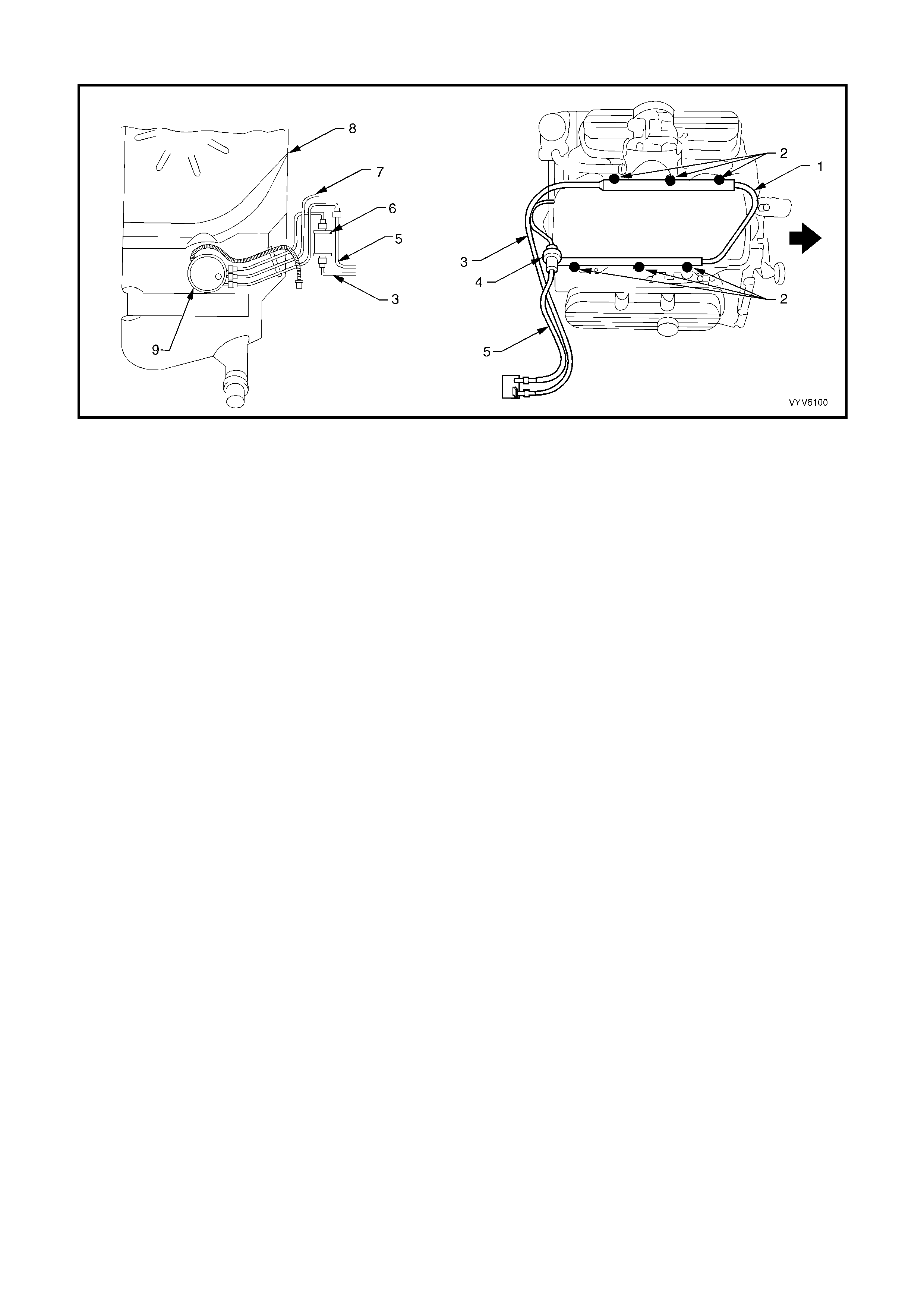
TABLE A-4.4 V6 PCM - FUEL DELIVERY SYSTEM
Figure 6C1-2A-38 V6 Fuel Delivery System
1. Fuel Rail
2. Fuel Injector (6 places)
3. Fuel Feed
4. Fuel Pressure Regulator
5. Fuel Return
6. Fuel Filter
7. Fuel Tank Vapour Line
8. Fuel tank
9. Modular Fuel Sender Assembly
Fuel Pressure Too LOW or Too HIGH or Pressure That Continues to Drop After The Ignition is Turned OFF Can
Cause The Following Driveability Complaints:
• Poor Idle Quality
• Exces sive Ex ha us t Odour
• Poor Fuel Economy
• Excessive Cranking Time
• Detonation
• Loss of Power
• DTC P0132 or P0152
• DTC P0131 or P0151
CIRCUIT DESCRIPTION
Fuel is drawn from the tank by the electric fuel p ump and is fed under pressure through a fuel filter and continues
on into the fuel rail and then is injected into the ports through the fuel injectors.
Fuel pressure in the system is governed by the fuel pressure regulator, in such a manner that a certain pressure
difference between fuel pressure and inlet manifold pressure is maintained. Excess fuel above the regulated
pressure is returned to the fuel tank by the pressure regulator and the fuel return line.
The fuel pump has a check valve to maintain pressure at the fuel rail after the pump stops running. The check valve
plays an im portant part in the f uel del iver y s ystem: to k eep the f uel ra il "char ged" with fue l after the pum p shuts off .
When the engine begins cranking to start, there is no delay before fuel injection begins, and quick starting is
ensured. The check valve is inside the fuel pump, and is not serviceable.
TEST DESCRIPTION
Number(s) below refer to step number(s) on the diagnostic Table.
2. If the pressure continues to drop after the pump stops running, there is a leak somewhere. Either the Fuel
Pump chec k valve is le aking f uel bac k into the tank , th e r egu lat or h as an in ter na l leak allo win g f uel to le ak f r om
the pressure to the return side, or an injector is leaking (dripping).

TABLE A-4.4 V6 PCM - FUEL DELIVERY SYSTEM
STEP ACTION VALUE YES NO
1. Was the "On-Board Diagnostic" (OBD) System Check
performed? Go to Step 2 Go to
OBD System
Check
2. From Table A-4.3
Fuel pressure not OK.
Does fuel pressure continue to drop after pump stops?
Go to Step 3 Go to Step 10
3. 1. Ignition "OFF" for 10 seconds.
2. While you observe the pressure gauge, have an
assistant turn the ignition "ON".
3. W hen the pump stops running, pinch shut the rubber
section of the pressure gauge supply hose.
Fuel pressure should now hold, does it?
Go to Step 4 Go to step 7
4. Check for leaks in the "pressure-side" of the fuel
System.
Were any leaks found?
Verify Repair Go to step 5
5. Replace fuel pump.
Is action complete? Verify Repair
6. Check For:
• Fuel pressure line restricted between pump and fuel
rail.
• Fuel supply line between tank and pump either
restrict ed or leakin g.
• Restricted fuel filter.
• Restricted in-tank fuel strainer.
• Defective Fuel Pump .
Was a problem found?
Verify Repair Go to Service
Operation
3.10 FUEL
CONTROL
SYSTEM
for Fuel Pump
pressure test
procedures
7. 1. Ignition "OFF" for 10 seconds.
2. Release pinched off pressure ( supp ly ) hose.
3. While you observe the pressure gauge, have an
assistant turn the ignition "ON".
4. When the pump stops running, pinch shut the rubber
section of the fuel return hose.
DO NOT PINCH OFF THE FUEL RETURN HOSE AT
THE FUEL PRESSURE REGULATOR.
Fuel pressure should now hold, does it?
Go to Step 8 Go to Step 9
8. Replace fuel pressure regulator.
Is action complete? Verify Repair
9. Locate and replace leaking injectors.
Is action complete? Go to Step 11
10. Is there fuel pressure? Go to Step 11 Go to Step 6
11. Is Pressure between specified values? 270 to 350
kPa
Fuel Delivery
System OK Go to
Table
A-4.5

TABLE A-4.5 V6 PCM - FUEL DELIVERY SYSTEM
Figure 6C1-2A-39 V6 Fuel Delivery System
1. Fuel Rail
2. Fuel Injector (6 places)
3. Fuel Feed
4. Fuel Pressure Regulator
5. Fuel Return
6. Fuel Filter
7. Fuel Tank Vapour Line
8. Fuel tank
9. Modular Fuel Sender Assembly
Fuel Pressure Too LOW or Too HIGH or Pressure That Continues to Drop After The Ignition is Turned OFF Can
Cause The Following Driveability Complaints:
• Poor Idle Quality
• Exces sive Ex ha us t Odour
• Poor Fuel Economy
• Excessive Cranking Time
• Detonation
• Loss of Power
• DTC P0132 or P0152
• DTC P0131 or P0151
CIRCUIT DESCRIPTION
Fuel is drawn from the tank by the electric fuel p ump and is fed under pressure through a fuel filter and continues
on into the fuel rail and then is injected into the ports through the fuel injectors.
Fuel pressure in the system is governed by the fuel pressure regulator, in such a manner that a certain pressure
difference between fuel pressure and inlet manifold pressure is maintained. Excess fuel above the regulated
pressure is returned to the fuel tank by the pressure regulator and the fuel return line.
The fuel pump has a check valve to maintain pressure at the fuel rail after the pump stops running. The check valve
plays an im portant part in the f uel del iver y s ystem: to k eep the f uel ra il "char ged" with fue l after the pum p shuts off .
When the engine begins cranking to start, there is no delay before fuel injection begins, and quick starting is
ensured. The check valve is inside the fuel pump , and is not serviceable.
TEST DESCRIPTION
Number(s) below refer to step number(s) on the diagnostic Table.
3. If any fuel lines, fittings, filter, or components are restricted, correct pressure cannot be attained.
6. When the fuel return hose is pinched shut, there is no pressure regulator control to limit the pressure. The
pressure reading will be whatever the Fuel Pump is capable of producing. This is the same as attaching a
pressur e gauge direct ly to the output of the Fuel Pum p . The pres sure reading wo uld be a "m aximum pressure
- no flow" reading, and should be well over 320 kPa. Do not allow the pressure to exceed 414 kPa.
10. At this point, the pressure checks are OK, but a complete test has not been performed. Return to Table A-4.1
to complete the testing.
11. This is to determine if the cause of the high pressure is a restricted fuel return line, or a defective pressure
regulator. If the pressure is normal when the regulator outlet (hose or fuel pipe attached to regulator) is
connected only to an open hose, then the problem is a restricted return line between the regulator and the tank.
12. The fuel pressure regulator is serviceable separate from the fuel rail. Refer to Section 6C-3 for fuel pressure
regulator replacement service procedures.

TABLE A-4.5 V6 PCM - FUEL DELIVERY SYSTEM
STEP ACTION VALUE YES NO
1. Was the "On-Board Diagnostic" (OBD) System Check
performed? Go to Step 2 Go to
OBD System
Check
2. Is fuel pressure less than specified value? 270 kPa Go to Step 3 Go to Step 11
3. There is low fuel pressure
1. Make close inspection of all fuel lines between fuel
tank and fuel rail for restrictions.
This includes these lines:
Tank to filter.
Filter to fuel rail.
Were any restrictions found?
Go to Step 4 Go to Step 5
4. Repair any restrictions, then recheck pressure.
Is action complete? Verify Repair
5. Replace fuel filter, then recheck fuel pressure.
Is fuel pressure still less than specified value? Less than
270 kPa Go to Step 6 Go to Step 10
6. 1. Ignition "O FF".
2. Pinch shut the fuel gauge hose on the fuel rail side.
DO NOT PINCH OFF THE FUEL RETURN HOSE AT
THE FUEL PRESSURE REGULATOR.
3. Ignition "ON"
4. Enable output test with TECH 2 for fuel pump.
Is fuel pressure at or above the specified value?
350 kPa Go to Step 7 Go to Step 9
7. Replace pressure regulator and recheck pressure.
Is pressure now between value? 270 to 350
kPa Verify Repair Go to Step 8
8. Replace in-tank fuel strainer.
Is action complete? Verify Repair
9. Pressure less than 320 kPa.
Replace fuel pump.
Is action complete?
Verify Repair
10. Is pressure between value, and does not continue
dropping when pump stops? 270 to 350
kPa Verify Repair Go to Table
A-4.1
11. 1. Disconnect fuel return line flexible hose from fuel
pipe that lead s to the pressure regulator.
2. Attach a long length of hose to the fuel pipe leading
to the pressure regulator.
3. Insert other end of hose into an approved fuel
container.
4. Enable output test with TECH 2 for fuel pump.
Is fuel pressure still more than specified value?
350 kPa Go to Step 12 Go to Step 13
12. Replace pressure regulator
Is action complete? Verify Repair
13. Locate and correct restricted fuel return line to tank, or
blocked return line screen filter in fuel tank return
connector, or scr een in fuel pr ess ure regul ator.
Is action complete?
Verify Repair
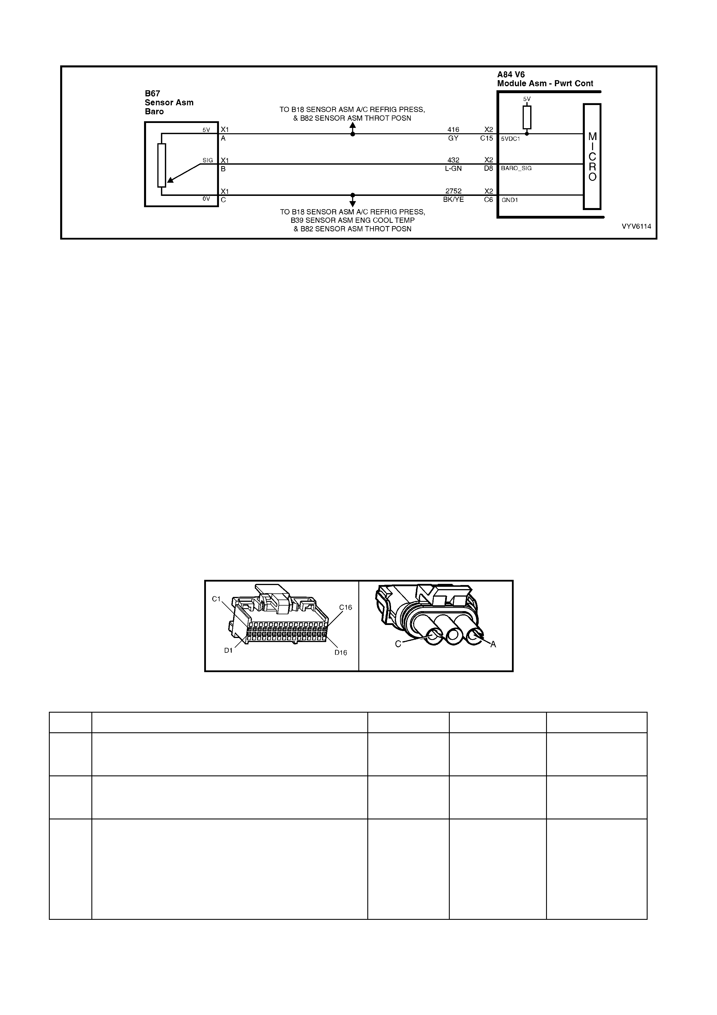
TABLE A-6.0 V6 PCM - BAROMETRIC PRESSURE S ENSOR OUTPUT CHECK
Figure 6C1-2A-40 Barometric Pressure Sensor Circuit
CIRCUIT DESCRIPTION
The Barometric (Baro) Pressure sensor responds to changes in altitude (air pressure). The PCM receives this
information as a voltage signal that will vary from about 4.7 to 4.9 volts at sea level to about 2.5 to 3.0 volts at 3048
meters (10,000 feet). TECH 2 displays altitude air pressure in volts. High altitude (low pressure) reads a low
voltage while a low altitude (high pressure) reads a high voltage. If a Barometric Pressure sensor circuit fault is
detected, the PCM will default to a sea level calibration for transmission control.
DIAGNOSTIC AIDS
W ith the ignition "ON", t he Barom etric Pres sure is equal t o atmos pheric pres sure and the s ignal vo ltage out put will
be high, close to 5 volts at sea level. This voltage is used by the PCM as an indication of vehicle altitude and is
refer red to as Baro . Com parison of this Baro r eading with one f rom a known g ood veh icle at the s am e locatio n with
the sam e part number s ensor is a good wa y to c heck the acc uracy of a "sus pect" sensor. Re adings sho uld be the
same +/- 0.4 vol ts.
TEST DESCRIPTION
Number(s) below refer to step number(s) on the diagnostic Table.
3. Compare Tech 2 readings to a known good vehicle.
4. Apply 25 cm Hg vacuum to the Barometric Pressure sensor should cause the voltage to change. Subtract
second reading from the first. Voltage should be greater than 1.5 volts. Upon applying vacuum to the sensor,
the change in voltage should be instantaneous. A slow voltage change indicates a faulty sensor.
7. Disconnect sensor from brack et and twist sensor by hand (onl y), to check for interm ittent connection. If output
changes greater than .10 volts, this indicates a bad sensor connection. If voltage is OK, replace sensor.
A84 V6 – X2 B67
Figure 6C1-2A-41
TABLE A-6.0 V6 PCM – BAROMETRIC PRESSURE SENSOR (BARO) OUTPUT CHECK
STEP ACTION VALUE YES NO
1. Was the "On-Board Diagnostic" (OBD) System Check
performed? Go to Step 2. Go to
OBD System
Check
2 Are DTC P0107 or DTC P0108 present? Go to DTC
P0107 or DTC
P0108
Go to Step 3
3. 1. Ignition "ON", engine "OFF".
2. TECH 2 should indicate a Barometric Pressure
sensor voltage.
3. Compare this reading with the reading of a known
good vehicle.
Are the voltage readings within the +/- value of the
know good sensor?
+/- 0.4 volts Go to Step 4 Go to Step 6

STEP ACTION VALUE YES NO
4. 1. Disconnect Barometric Pressure sensor from
mounting bracket.
2. Connect a hand vacuum pump to Barometric
Pressure sensor.
3. Ignition "ON", engine "OFF".
4. Note Barometric Pressure sensor voltage on
TECH 2.
5. Apply 25 cm HG of vacuum and note voltage
change.
6. Subtract second voltage reading from the first.
Is voltage change greater than specified value?
1.5 volts Go to Step 5 Go to Step 7
5. There is no problem found with Barometric Pressure
sensor. Check sensor pressure source for restrictions.
Is action complete?
Verify Repair
6. Replace Barometric Pressure sensor.
Is action complete ? Verify Repair
7. 1. Check Barometric Pressure sensor connections.
2. If OK, replace Barometric Pressure sensor.
Is action complete ?
Verify Repair Go to
OBD System
Check
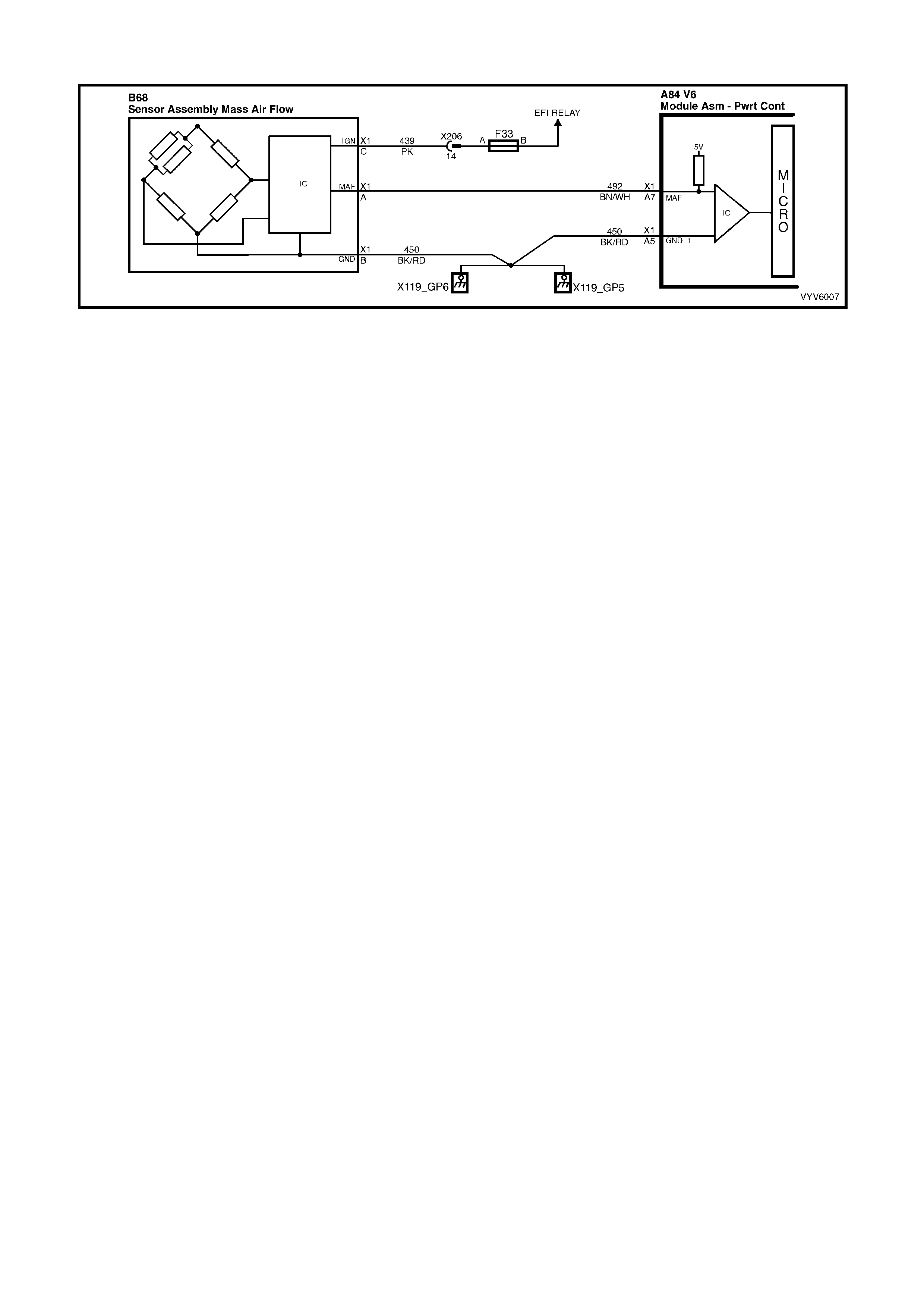
TABLE A-6.1 V6 PCM - MAF SENSOR OUTPUT CHECK
Figure 6C1-2A-42
CIRCUIT DESCRIPTION
The signal that is sent from the Mass Air Flow (MAF) sensor is sent in the form of a frequency output. A large
quantity of air passing through the MAF sensor will be indicated as a high frequency output (such as when under
accelerat ion). A sm all quantity of air passing through the sensor will be indicated as a low f requency output (such
as when decelerating or at id le). TECH 2 displa ys this information as air flow in grams per second, milligrams per
cylinder and frequency. A "normal" reading is approximately 4-9 grams per second at idle and increases with RPM.
TEST DESCRIPTION
Number(s) below refer to step number(s) on the diagnostic Table.
3. This step checks for the proper Mass Air Flow grams per second at idle.
4. This step checks for the proper Mass Air Flow grams per second at 2500 RPM.
5. This step checks the Mass Air Flow sensor for a steady decrease in grams per second as the RPM changes
from 2500 to idle.
DIAGNOSTIC AIDS
Check air filter for being plugged.
Check air intake ducts for restrictions.
Check air intake ducts for leaks after the MAF sensor.
Check for partly restricted exhaust system.
Check for any other source that would allow air into the engine after the MAF sensor.
Thi s would include:
• inlet manifold gasket.
• inlet manifold.
• throttle body and or gasket.
• PCV system, this includes the oil dipstick for proper seating.
• injector o-rings.

TABLE A-6.1 V6 PCM - MAF SENSOR OUTPUT CHECK
STEP ACTION VALUE YES NO
1. Was the "On-Board Diagnostic" (OBD) System Check
performed? Go to Step 2 Go to
OBD System
Check
2. Is DTC P0101 present? Go to
DTC P0101 Go to Step 3
3. 1. Ignition "ON", engine running at normal operating
temperature.
2. Using TECH 2; select Data List, then select "Mass
Air Flow".
3. With engine at idle, TECH 2 should indicate a MAF
sensor reading between the specified value.
Is the reading between the specified value?
4-9 Grams
Per Second
(G/S)
at
Idle
Go to Step 4 Go to Step 6
4. Increase engine RPM to 2500 and hold steady. TECH 2
should now indicate a MAF sensor reading at the
specified value.
Is the reading at the specified value?
15-20 Grams
Per Second
(G/S)
at
2500 RPM
Go to Step 5 Go to Step 6
5. Release the throttle, and watch the MAF sensor readings
on TECH 2. The Mass Air Flow G/S should decrease at a
steady rate down to the reading
determined at idle, did it?
No trouble found
with Mass Air
Flow sensor
Go to Step 6
6. Check for restrictions in the Mass Air Flow induction
system. Also check for air leaks after the MAF sensor or
a possible restricted exhaust system.
Refer to Diagnostic Aids.
If all checks OK, replace the Mass Air Flow sensor.
Is action complete?
Verify Repair
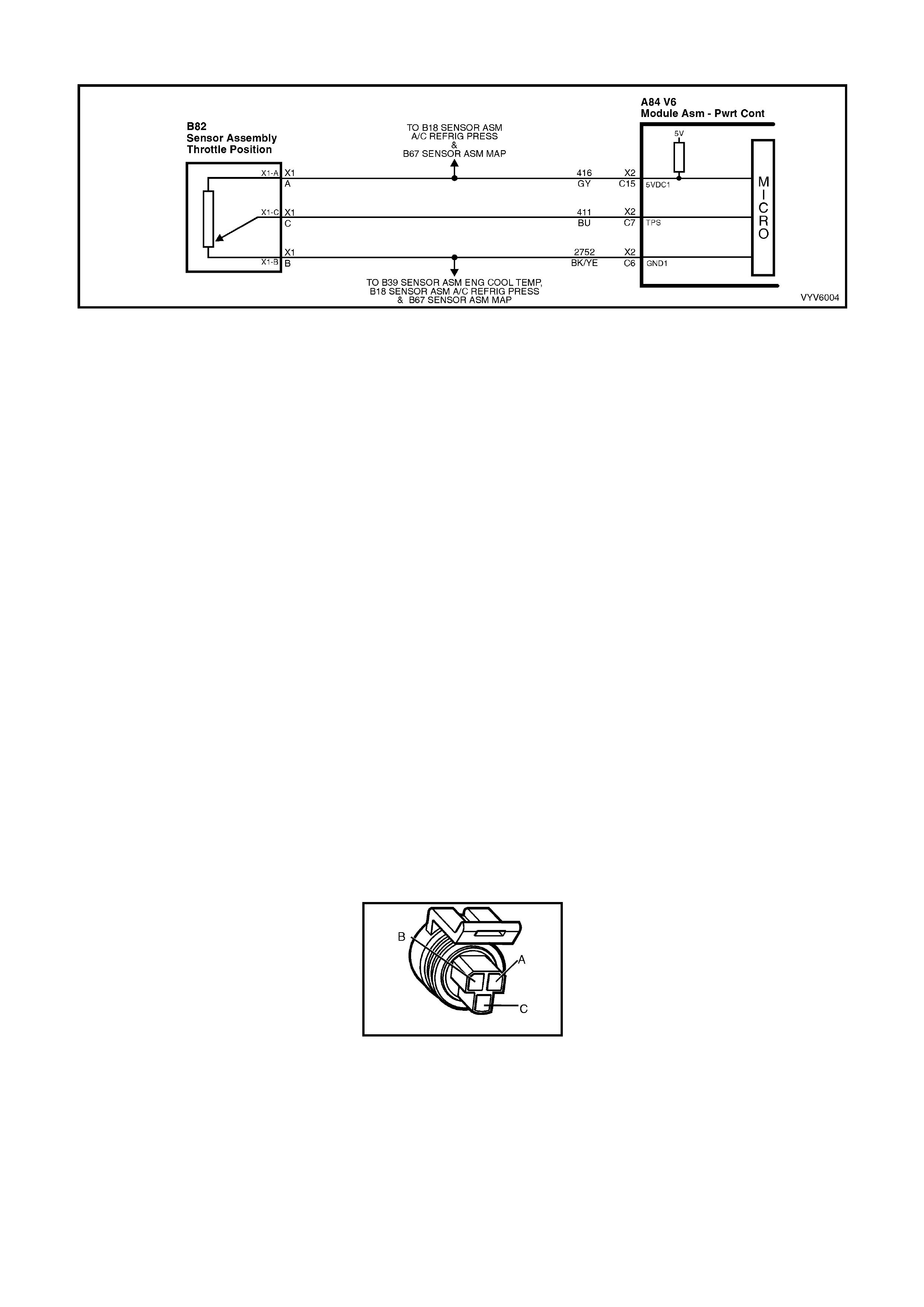
TABLE A-6.2 V6 PCM - TP SENSOR OUTPUT CHECK
Figure 6C1-2A-43
CIRCUIT DESCRIPTION
The T hr ottle Position (TP) s ensor is at tache d to the throttle bo d y, an d is int erna lly rotated by the thro ttle body s haf t.
It is a potentiom eter with one end c onnected to 5 volt s from the PCM and the ot her to PCM ground. A thir d wire is
connected to the PCM, allowing it to measure the variable output voltage from the TP sensor.
As the throttle valve angle is changed (accelerator pedal moved), the TP Sensor output voltage also changes in
proport ion. At a cl osed thr ottle p osit ion, the outp ut volt age is us uall y belo w 1.0 vol t. As the thr ottle val ve ope ns , the
output increases so that, at wide-open throttle, the output should be above 4.0 volts. By monitoring the output
voltage from the TP sensor, the PCM can determine fuel needs based on throttle opening (driver demand).
A brok en or loose T P Sens or, or one th at has an unst able output, c an ca use int erm ittent burst s of f uel beca use the
PCM thinks the throttle is moving. Results could include engine surge or poor idle quality. If the PCM interprets a
high vo ltage when eng ine RPM is less than 400, hard s tarting could be the result ( clear-flood m ode). A problem in
any of the TP sensor circuits will set either a DTC P0122 or DTC P0123 after the engine is started. Once a
Diagnostic Trouble Code is set, the PCM will us e an artificial de fault value for TP sens or based on engine R PM to
enable the vehicle to be driven, although performance could be less than normal.
The TP sensor is not adjustable. The PCM uses the reading at idle as "0% throttle," so no adjustment is necessary.
TEST DESCRIPTION
Number(s) below refer to step number(s) on the diagnostic Table.
If a DTC P0122 or DTC P0123 is present, follow that Table first.
2. This is a check of the voltage at the idle position. It is usually less than 1.0 volt.
3. The voltage should increase at the same steady rate at which the throttle is opened with the throttle valve.
6. With the throttle valve wide open, the TP sensor output needs to be above 4 volts, allowing the PCM to
interpret a wide open throttle position.
7. If the throttle stop screw has been inadvertently reset, the TP sensor output at idle could be out of allowable
limits.
9. If the closed-throttle voltage is over 2.5 volts, hard starting may be encountered (worse cold) due to "clear-
flood" m ode. This m ode occ ur s when en gine RP M is l ess than 400, an d TP sensor input i nd ic ates the thr o ttl e is
mor e than 80% open. Poss ible causes: shor t to voltage on input signa l circuit, open gr ound circuit , or a faulty
sensor.
B82
Figure 6C1-2A-44

TABLE A-6.2 V6 PCM - TP SENSOR OUTPUT CHECK
STEP ACTION VALUE YES NO
1. Was the "On-Board Diagnostic" (OBD) System Check
performed? Go to Step 2 Go to
OBD System
Check
2. 1. Ignition "ON", engine stopped, throttle plate closed.
2. TECH 2 set to TP sensor voltage.
Is voltage on TECH 2 within value shown?
0.25 to 1.25
volts Go to Step 3 Go to Step 4
3. 1. Ignition "O N".
2. With TECH 2 still connected, monitor the voltage as
the throttle is slowly and steadily opened to a wide-
open-position.
3. Voltage should increase at a steady rate, with no
sudden changes.
Did voltage increase at a steady rate with throttle
movement?
Go to Step 6 Go to Step 8
4. 1. Ignition "O N ", engin e stopp ed.
2. TECH 2 set to TP sensor voltage.
Is voltage on TECH 2 within value shown?
1.26 to 2.5
volts Go to Step 7 Go to Step 5
5. 1. Ignition "O N ", engin e stopp ed.
2. TECH 2 set to TP sensor voltage.
Is voltage on TECH 2 over value shown?
2.5 volts Go to Step 9 Go to Step 12
6. 1. Ignition "O N".
2. With TECH 2 still connected, monitor the voltage as
the throttle valve is opened to the wide open position.
Have a helper ensure that the throttle valve is fully open
when accelerator pedal is fully depressed.
If throttle valve does not fully open when pedal is
depressed, check for extra floor mats or carpet under
accelerator pedal.
Then refer to SERVICE OPERATIONS, 3.10 FUEL
CONTROL SYSTEM - Throttle Cable - "Adjust" .
Is the TPS voltage above the specified value?
4 volts TP sensor is
working properly
Go to
OBD System
Check
Go to Step 8
7. 1. Check throttle stop screw.
Refer to SERVICE OPERATIONS, 3.10 FUEL
CONTROL SYSTEM - Throttle Stop Screw - "Reset
Procedure".
Reset only if incorre ct.
2. Ignition "ON".
3. TECH 2 connected.
4. Recheck TPS voltage.
Is voltage now within the specified value?
0.25 to 1.25
volts Go to Step 6 Go to Step 8
8. Replace TP sensor.
Is action complete? Verify Repair
9. 1. Ignition "OFF".
2. Disconnect TPS.
3. Connect TECH 2 and set to TPS voltage.
4. Ignition "ON"
Is voltage on TECH 2 at or below specified value?
1.25 volt Go to Step 10 Go to Step 11
10. Check for open in TP sensor ground circuit.
Was a problem found? Verify Repair Go to Step 8
11. Repair short to voltage on TP sensor signal circuit.
Is action complete? Verify Repair
12. Repair short to ground on TP sensor signal circuit.
Is repair complete? Verify Repair
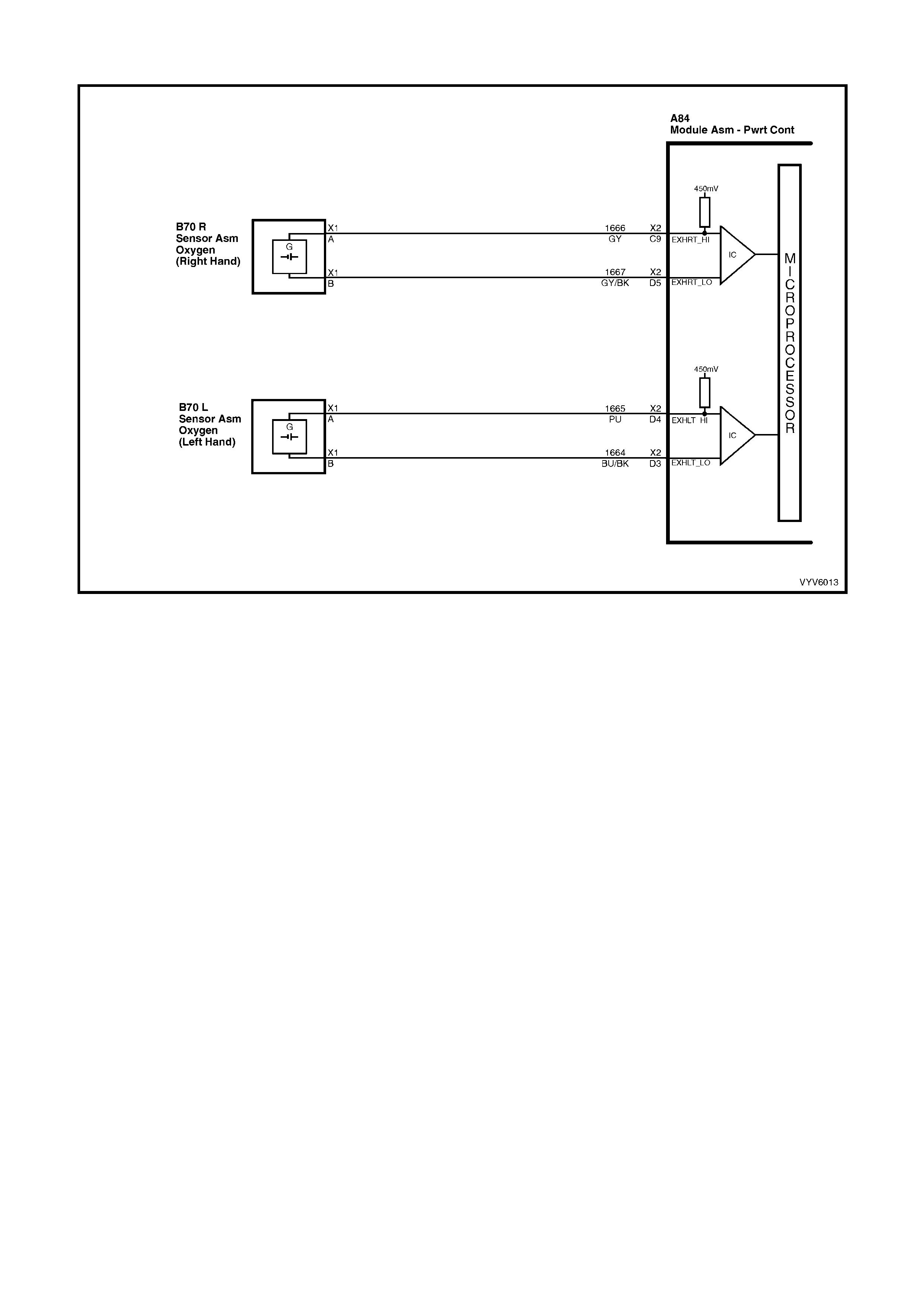
TABLE A-6.3 V6 PCM - OXYGEN SENSOR CHECK
Figure 6C1-2A-45 – Left Hand Oxygen Sensor Circuit
CIRCUIT DESCRIPTION
The oxygen sensors are mounted in the exhaust pipes near the cylinders. At operating temperature, the oxygen
sensors are required to respond quickly to changes to oxygen content in the exhaust. If the oxygen sensors
become contaminated or faulty, a sluggish driveability or a complaint of poor idle condition may exist. A proper
oxygen sensor response should be almost instantaneous to the fuelling mode command.
TEST DESCRIPTION
Number(s) below refer to step number(s) on the diagnostic Table.
2. Never perform this test on a cold engine. The oxygen sensor must be near normal operating temperature for
this Table to work. It is important to see a low voltage and a high voltage response very quickly because this
means the oxygen sensor is not contaminated or faulty.

TABLE A-6.3 V6 PCM - OXYGEN SENSOR CHECK
STEP ACTION VALUE YES NO
1. Was the "On-Board Diagnostic" (OBD) System Check
performed? Go to Step 2 Go to
OBD System
Check
2. 1. Ignition "ON", engine Running.
2. Run engine at 1600 to 1800 RPM for 2 minutes, or
until engine temperature is above 85°C, then let
engine idle.
3. Using TECH 2, select Miscellaneous Test / A/F
Ratio, then display RH O2 Sensor and LH O2
Sensor.
4. With engine idling, Press the Decrease Soft Key on
TECH 2 until 11.7 A/F Ratio is displayed, at the
same time note the response of both O2 Sens ors.
5. Both O2 Sensors should display above specified
value.
6. Then press the Increase Soft Key on TECH 2 until
17.7 A/F Ratio is displayed, at the same time note
the response of both O2 Sensors.
7. Both O2 Sensors should display below specified
value.
Did both O2 Sensors display above and below the
specified value?
Above 700
mV
or
Below 100
mV
No trouble
found Go to Step 3
3. Replace the O2 Sensor that did not perform as specified
in Step 2.
Is action complete?
Verify Repair
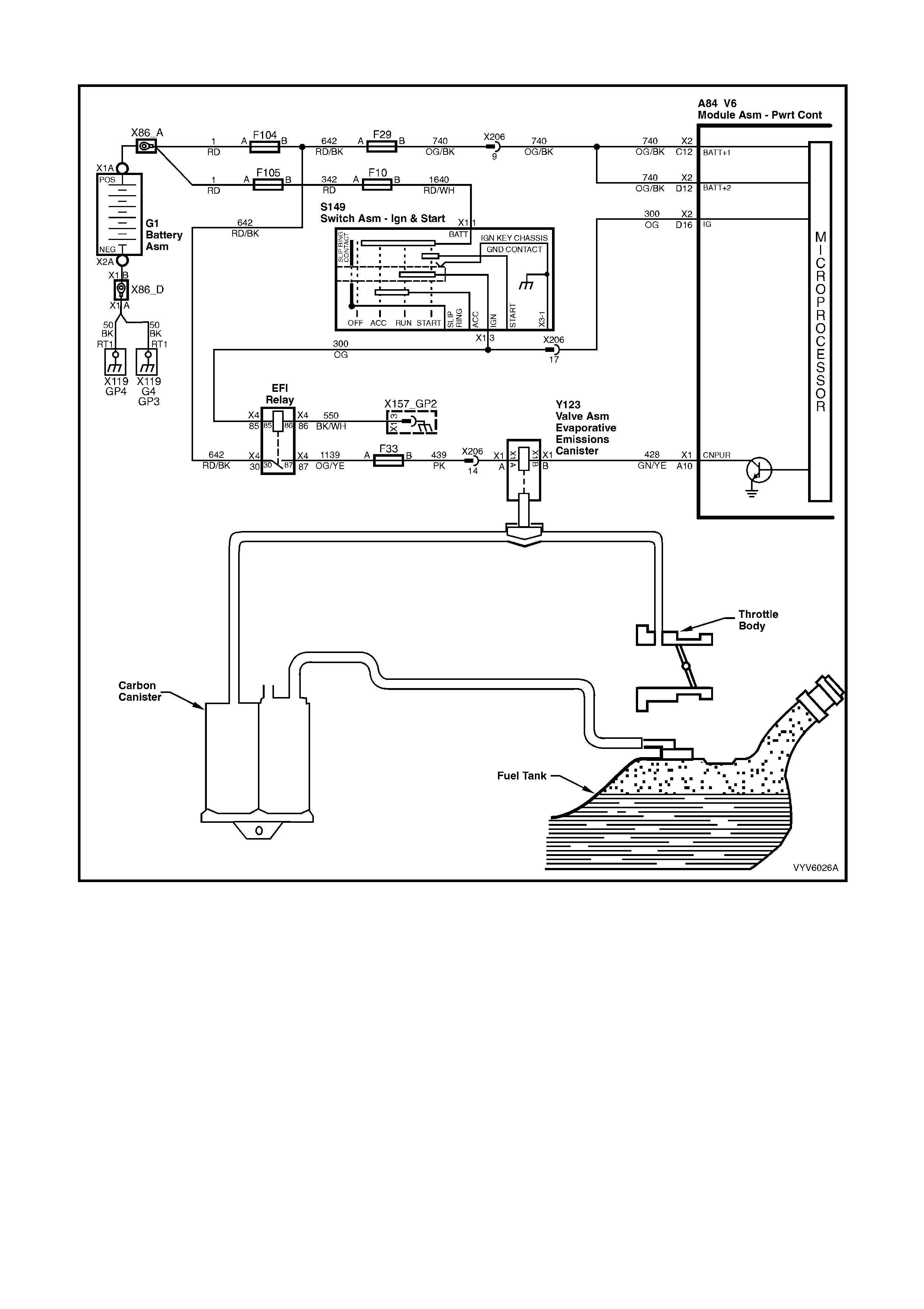
TABLE A-6.4 V6 PCM - CANISTER PURGE SOLENOID CHECK
Figure 6C1-2A-46 Canister Purge Solenoid and Circuit
CIRCUIT DESCRIPTION
The c anister purge is contr olled by a sol enoid that allo ws manifold vac uum to purge the f uel vapour can ister when
energised. The PCM supplies a pulse width modulated ground signal to energise the solenoid (purge "ON").
If the following conditions are met with the engine running, the canister purge solenoid is energised.
• Engine run time after start more than 3 minutes and 15 seconds if coolant is less than 80°C or,
• Engine run time after start is more than 15 seconds if coolant is above 80°C.
• Coolant temperature above 60°C.
• Engine not in Decel fuel cutoff mode.
• Throttle is less than 92%.
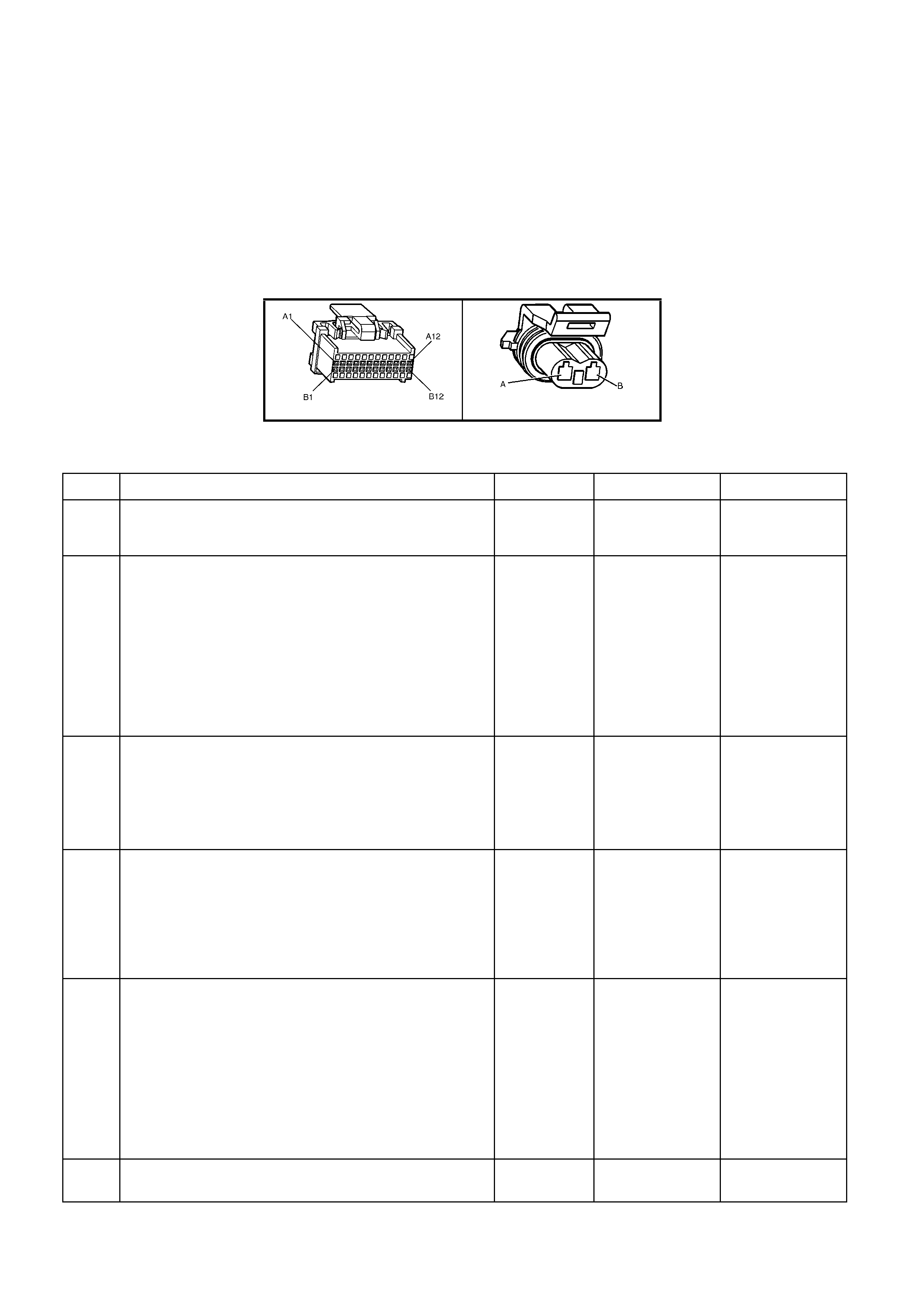
TEST DESCRIPTION
Number(s) below refer to step number(s) on the diagnostic Table.
2. Checks to see if the s olenoid is opened or c losed. The s olenoid is norm ally energised in t his step, so it shou ld
be open.
3. This checks to see if the Canister Purge Solenoid mechanical function is operating properly by grounding the
Canister Purge Solenoid several times with TECH 2.
4. This checks to see if +B volts is supplied to the Canister Purge Solenoid.
5. This checks to see if the PCM is supplying the ground signal for the Canister Purge Solenoid.
DIAGNOSTIC AIDS
Normal operation of the Canister Purge Solenoid is described as follows:
With the ignition "ON", engine "OFF", the Canister Purge Solenoid will be de-energised.
A84 V6 – X1 Y123
Figure 6C1-2A-47
TABLE A-6.4 V6 PCM - CANISTER PURGE SOLENOID CHECK
STEP ACTION VALUE YES NO
1. Was the "On-Board Diagnostic" (OBD) System Check
performed? Go to Step 2 Go to
OBD System
Check
2. Note: This Table only covers the solenoid portion of the
Canister Purge system.
1. Ignition OFF.
2. Disconnect purge vacuum hose from top of canister,
and place a vacuum gauge in hose.
3. Ignition "ON", engine Running.
4. With TECH 2 command Canister Purge Solenoid
"ON".
Does vacuum gauge read manifold vacuum with canister
purge solenoid display "ON"?
No trouble found.
Canister Purge
Solenoid is OK.
Go to Step 3
3. 1. Ignition "ON", engine "OFF".
2. Place index finger on top of Canister Purge Solenoid.
3. With TECH 2, command the Canister Purge Solenoid
"ON" and "OFF" several times with TECH 2.
Does the solenoid click while the solenoid is being
commanded "ON" and "OFF"?
Canister Purge
Solenoid
electrical is OK.
Go to Step 10 for
vacuum check
Go to Step 4
4. 1. Ignition "ON", engine "OFF".
2. Disconnect Canister Purge Solenoid electrical
connector.
3. W ith a test light connected to ground, probe Canister
Purge Solenoid electrical connector power feed
circuit.
Is test light "ON"?
Go to Step 5 Go to Step 6
5. 1. Ignition "ON", engine "OFF".
2. Disconnect Canister Purge Solenoid electrical
connector.
3. With a test light connected to +B volts, probe
Canister Purge Solenoid electrical connector Purge
Solenoid contr ol cir cuit .
4. With TECH 2, command the Canister Purge Solenoid
"ON".
Is test light "ON" when Canister Purge Solenoid is
commanded "O N"?
Go to Step 7 Go to Step 8
6. Check for open in power feed circuit.
Is action complete? Verify Repair

STEP ACTION VALUE YES NO
7. Replace Canister Purge Solenoid.
Is action complete? Verify Repair
8. Check for open in Purge Solenoid control circuit from
PCM to Canister Purge Solenoid.
Was an open found?
Verify Repair Go to Step 9
9. Check for poor connection at PCM. If connection is OK,
replace PCM. Refer to 6C1-3 Service Operations, for the
Programming and Security Link procedure.
Is the action complete?
Verify Repair
10. Check manifold vacuum hose from manifold to Canister
Purge Solenoid for kinks, pinched, cracked, or plugged.
Repair as necessary.
Is action complete?
Verify Repair
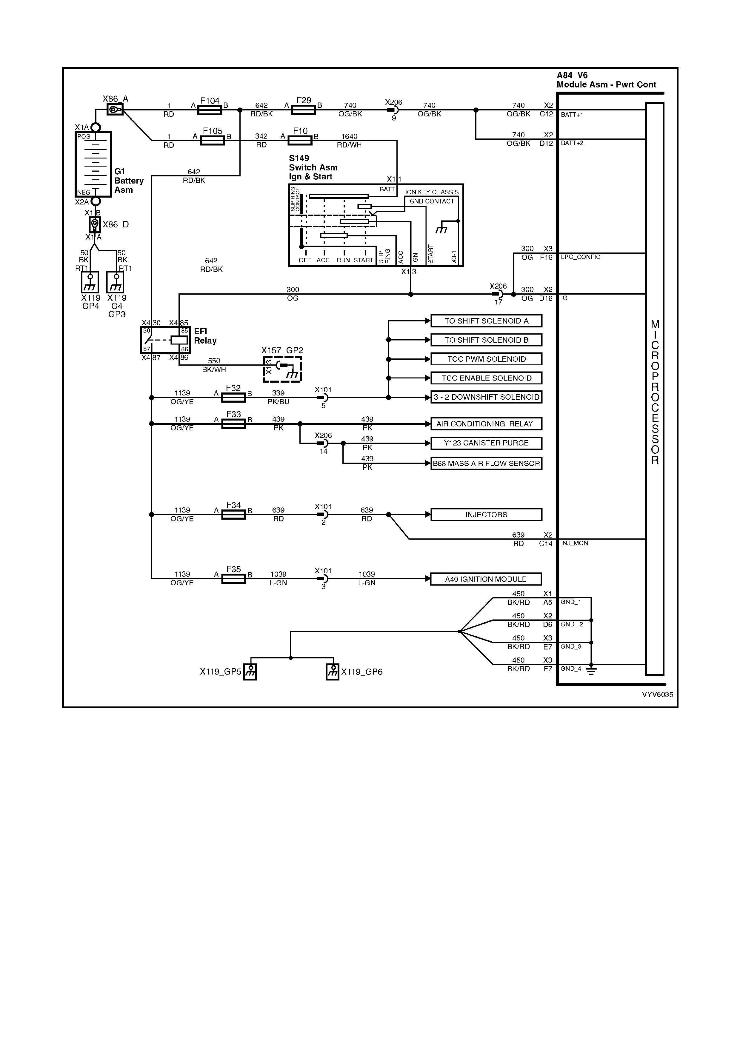
TABLE A-6.5 V6 PCM – ENGINE CONTROL EFI RELAY DIAGNOSIS
Figure 6C1-2A-48 - Engine Control EFI Relay Circuit
CIRCUIT DESCRIPTION
The EFI relay protects the battery from a parasitic draw. The following components are powered by the EFI relay:
• Injectors
• DIS Module
• Transmission
• A/C System
• EVAP Solenoid
• MAF Sensor

DIAGNOSTIC AIDS
• The following may cause an intermittent:
• Poor connections. Check for adequate terminal tension.
• Corrosion.
• Incorrectly routed harness.
• Rubbed through wire insulation.
• Broken wire inside the insulation.
TEST DESCRIPTION
Number(s) below refer to step number(s) on the diagnostic Table.
NOTE: For any test that requires probing the PCM or a component harness connector, use the Connector Test
Adapter Kit J35616-A. Using this kit prevents damage to the harness connector terminals.
2. This test checks the fusible link F104 power feed to the EFI relay.
3. This test checks the fused power feed ignition circuit.
4. This test is checking the ground circuit of the EFI relay.
5. This step isolates the circuit from the EFI relay. All of the circuits at the relay are good if the test lamp
illuminates.
Figure 6C1-2A -49
TABLE A-6.5 V6 PCM - ENGINE CONTROL EFI RELAY DIAGNOSIS
Step Action Value(s) Yes No
1. Did you perform the Powertrain On-Board Diagnostic
(OBD) System Check? Go to Step 2 Go to
OBD System
Check
2. Turn OFF the ignition.
Remove the engine compartment Fuse/Relay panel
cover.
Remove the Engine Control EFI relay, R4.
Probe the fusible link F104 power feed circuit to the EFI
relay harness terminal X4-30 with a test lamp connected
to ground.
Does the test lamp illuminate?
Go to Step 3 Go to Step 8
3. Turn ON the ignition leaving the engine OFF.
Probe the fused ignition feed circuit to the EFI relay
harness terminal X4-85 with the test lamp connected to
ground.
Does the test lamp illuminate?
Go to Step 4 Go to Step 9
4. Turn OFF the ignition.
Probe the ground circuit to the Engine Control EFI relay
connector terminal X4-86 with the test lamp connected to
B+.
Does the test lamp illuminate?
Go to Step 5 Go to Step 10
5. Turn OFF the ignition
Jump the Engine Control EFI relay B+ feed circuit
terminal X4-30 and the EFI relay load circ uit terminal X4-
87 together using a fused jumper wire.
Probe the following fuses with a test lamp connected to
ground:
- F32
- F33
- F34
- F35
Does the test lamp illuminate for all fuses?
Go to Step 6 Go to Step 11

Step Action Value(s) Yes No
6. Check for poor terminal contact at the EFI relay harness
connector.
Did you find and correct the condition?
Verify Repair Go to Step 7
7. Replace the EFI relay.
Is the action complete? Verify Repair
8. Repair the open in fusible link F104 circuit to the EFI
relay.
Is the action complete?
Verify Repair
9. Repair the fused ignition feed circuit to the EFI relay.
Replace fuse if open.
Is the action complete?
Verify Repair
10. Repair the open in the ground circuit for the EFI relay.
Is the action complete? Verify Repair
11. Repair open in the EFI relay load circuit, or open in
fuse(s) circuit that did not ill um inate the test light.
Is the action complete?
Verify Repair
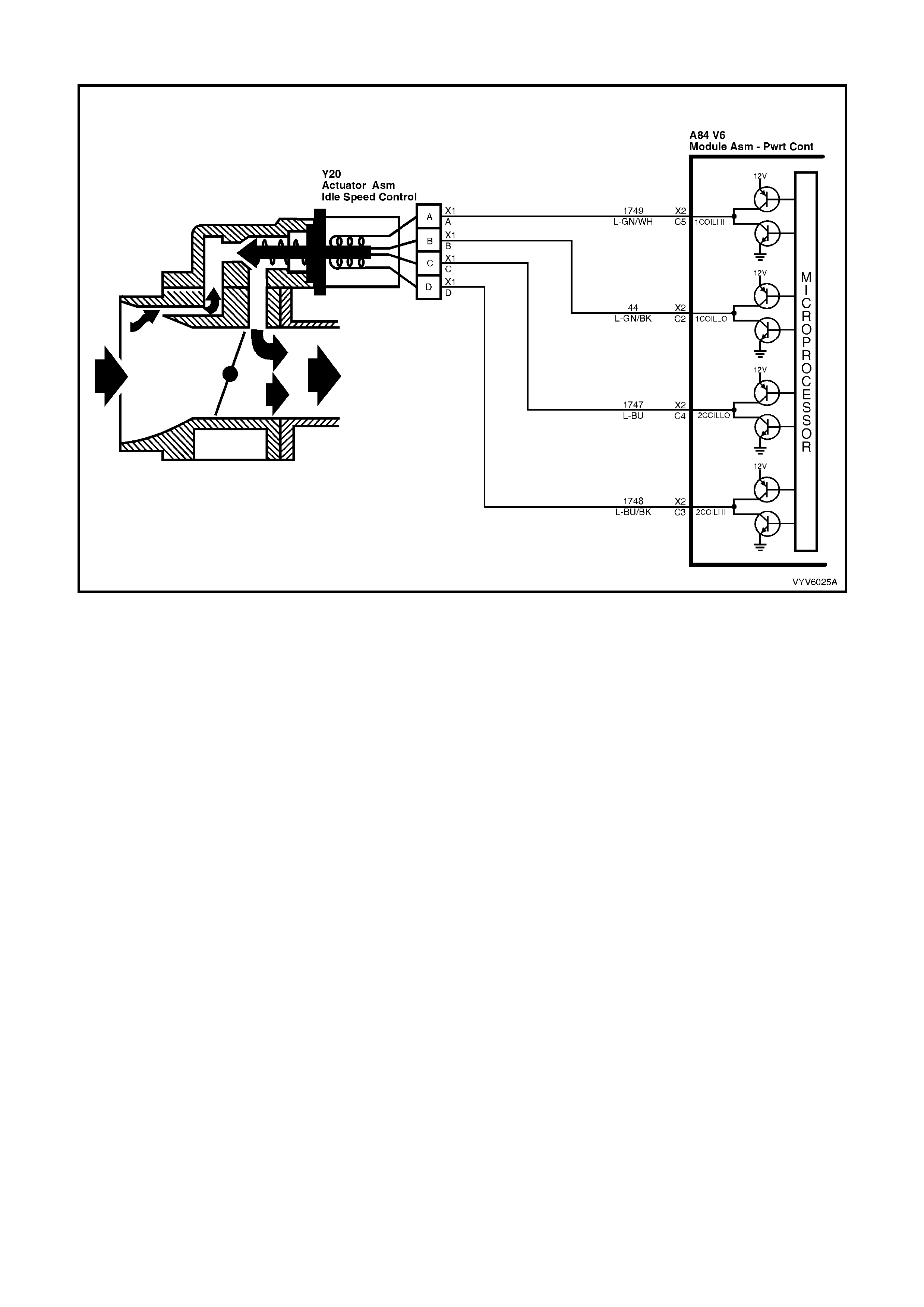
TABLE A-7.1 V6 PCM - IDLE AIR CONTROL (IAC) SYSTEM
Figure 6C1-2A-50 – IAC Circuit
CIRCUIT DESCRIPTION
The PCM controls e ngine idle speed by moving the IAC valve to control closed-throttle air flow around the throttle
plate. It do es this b y send ing vo ltage pu lses ( calle d "co unts" or "st eps") to the IAC m otor windings . The m otor shaft
and conical valve move a given distance for each pulse received.
• TO INCREASE IDLE SPEED: The PCM sends enough pulses to retract the IAC valve and allow more air to
bypass the throttle plate through the idle air passage, until idle speed reaches the PCM-desired idle RPM.
• TO DECREA SE IDLE SPEED: T he PCM sen ds enou gh pulses t o extend the IA C valve an d reduce t he airf low
bypassing the throttle plate through the idle air passage, until idle speed reaches the PCM-desired RPM.
The PCM desired idle RPM, and the commanded IAC position, is based on:
• Engine Coolant Temperature
• Actual engine RPM (crankshaft reference input)
• Engine load (A/C request input, engine fan command), Selected Gear
• Batter y volta ge
• Vehicle speed (VSS)
• Throttle position (TP)
TEST DESCRIPTION
Number(s) below refer to step number(s) on the diagnostic Table.
2. This tests the PCM's ability to control IAC valve.
DIAGNOSTIC AIDS
Remove IAC and check for frozen or sticking IAC. Check that TP sensor is within acceptable range.

TABLE A-7.1 V6 PCM - IDLE AI R CONTROL (IAC) SYSTEM
STEP ACTION VALUE YES NO
1. Was the "On-Board Diagnostic" (OBD) System Check
performed? Go to Step 2 Go to
OBD System
Check
2. 1. Using TECH 2, Select RPM CONTROL.
2. With the up/down arrows, vary RPM from 600 to 1675
RPMs.
Does engine speed rise and fall?
Go to Step 3 Go to
Table A-7.2
3. No trouble found with IAC system.
Check For:
• Vacuum leaks.
• Sticking or binding throttle shaft, cables, or linkages.
• Engine Coolant Temperature sensor resistance.
• Refer DTC P0118 in this Section.
• TP Sensor Operation. Refer Table A-6.2 in this Section.
• Dirty or loose battery cables or ground connections.
• System ground circuit terminals at the engine for being
clean and tight.
• Inspect all accessory drive pulleys. They should all spin
freely.
• Spark plugs that are excessively worn, mis-gapped or
cracked.
• For high or low fuel pressure, or leaking injectors - refer
Table A-4.3
• A/C Clutch Control circuit failure.
• Refer Table A 11.1 or Table A 11.2 in this Section.
• Generator Output - if under 9 vo lts or over 16 volts.
• PCM will not command the IAC to move.
• Throttle Body - remove IAC and inspect bore for foreign
material or evidence of IAC valve "Dragging" in the bore.
• Throttle Stop Screw, refer SERVICE OPERATIONS,
3.10 FUEL CONTROL SYSTEM – Throttle Stop Screw -
Reset Procedure.
Refer To "Rough, Unstable, Or Incorrect Idle" In Section
6C1-2B SYMPTOMS.
Verify Repair

TABLE A-7.2 V6 PCM - IDLE AIR CONTROL (IAC) SYSTEM
Figure 6C1-2A-51 – IAC Circuit
CIRCUIT DESCRIPTION
The PCM controls e ngine idle speed by moving the IAC valve to control closed-throttle air flow around the throttle
plate. It do es this b y send ing vo ltage pu lses ( calle d "co unts" or "st eps") to the IAC m otor windings . The m otor shaft
and conical valve move a given distance for each pulse received.
• TO INCREASE IDLE SPEED: The PCM sends enough pulses to retract the IAC valve and allow more air to
bypass the throttle plate through the idle air passage, until idle speed reaches the PCM - desired idle RPM.
• TO DECREASE ID LE SP EED: T he PCM s ends enoug h pulses to ex tend the IAC va lve an d reduce t he air f low
bypassing the throttle plate through the idle air passage, until idle speed reaches the PCM-desired RPM.
The PCM desired idle RPM, and the commanded IAC position, is based on:
• Engine Coolant Temperature (ECT)
• Actual engine RPM (crankshaft reference input)
• Engine load (A/C request input, engine cooling fan command, selected gear)
• Batter y volta ge
• Vehicle Sp eed (V SS)
• Throttle Position (TPS)
TEST DESCRIPTION
Number(s) below refer to step number(s) on the diagnostic Table.
2. With the ignition "ON," engine stopped, and TECH 2: IAC reset, the PCM should issue electrical
"extend/retract" pulses to the IAC valve. With the IAC disconnected, each connector terminal should have a
"pulsing" voltage, noted by a flashing or flickering test light. The rate of flashing or flickering is not important.
8. T here are 2 s eparate windi ngs in the IAC m otor. Each windin g (A - t o - B, and C - to - D) s hould have b etween
40 and 80 ohms resistance. Also, there should be no continuity between the two windings.
NOTE: When performing this test, ensure that a standard low power test light is used.
Do not use a "High-Wattage" test light, as the PCM could be damaged. A high wattage test light will either give
inaccurate test results, or damage the PCM, or both.
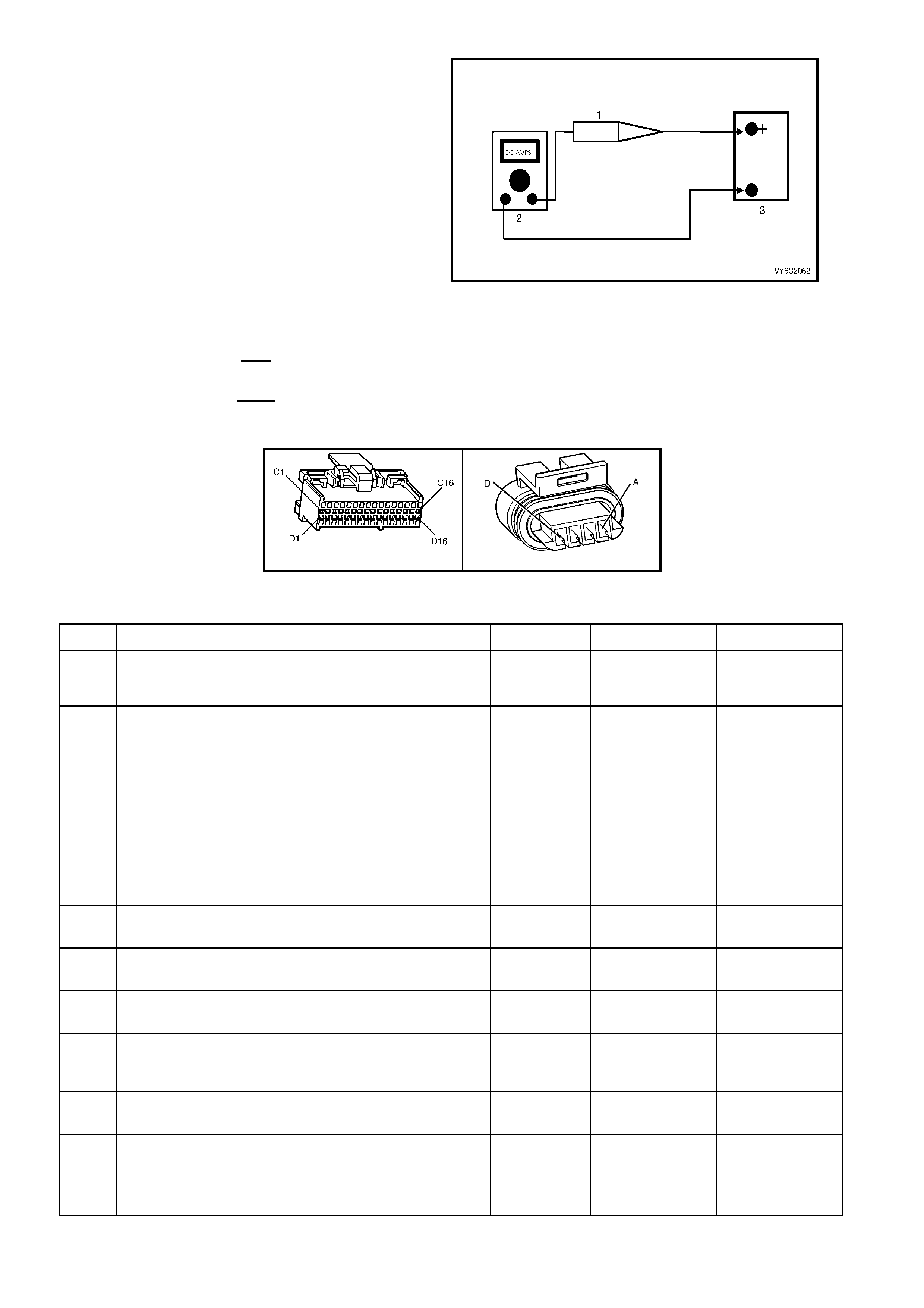
A low-power test light must be used for any circuit
testing. While a particular brand of test light is not
suggested, a simple test on any test light will
ensure it to be OK f or PCM circuit tes ting. Connect
an accurate ammeter (such as the digital
multimeter) in series with the test light being tested,
and power the test light-ammeter circuit with the
vehicle battery (as shown). If the ammeter
indicates less than 3/10 a mp current flow (0.3 A or
300 mA), the test light is OK to use. If more than
0.3A (300 mA), do not use!
Legend:
1. Test Lamp
2. Digital Multimeter, Set to DC Amps
3. 12 Volt Battery
If the ammeter indicates less than 0.3 A (300 mA)
current flow, the test light is OK to use.
If the amm eter indicates more than 0.3 A (300 m A)
current flow, the test light is NOT OK to use.
Figure 6C1-2A-52
A84 V6 – X2 Y20
Figure 6C1-2A-53
TABLE A-7.2 V6 PCM - IDLE AI R CONTROL (IAC) SYSTEM
STEP ACTION VALUE YES NO
1. Was the "On-Board Diagnostic" (OBD) System Check
performed? Go to Step 2. Go to
OBD System
Check
2. • From Table A-7.1
1. Disconnect IAC valve electrical connector.
2. Ignition "ON", engine stopped. Using TECH 2, select
RE SET IAC.
3. Probe each IAC harness connector terminal for 5
seconds with test light connected to ground, while
using TECH 2.
Refer Test Description for proper test light usage.
Does test light flash at all terminals while IAC is being
reset?
Go to Step 3 If
No light one or
more terminals,
Go to Step 6
----------------------
If
steady light one
or more
terminals,
Go to Step 13
3. Check for faulty IAC terminals.
Were any faulty terminals found? Go to Step 4 Go to Step 5
4. Repair faulty terminals
Is action complete? Verify Repair
5. Replace IAC valve.
Is action complete? Verify Repair
6. Check for open or short to ground in circuit(s) that did not
light the test light.
Were any opens or short's found?
Go to Step 7 Go to Step 8
7. Repair any opens or short found.
Is action complete? Verify Repair
8. 1. Check resistance across IAC coils.
2. Check all IAC terminals opposite harness connectors
terminals "A " to "B" and "C" to "D".
Are the IAC coils within specified value?
40 to 80
ohms Go to Step 9 Go to Step 5

STEP ACTION VALUE YES NO
9. Check for short between windings by measuring for
continuity between IAC terminals "A" to "D".
Ohmmeter should indicate an open circuit, does it?
Go to Step 10 Go to Step 5
10. Check for faulty PCM terminals .
Were any faulty terminals found? Go to Step 17 Go to Step 11
11. Check for faulty IAC terminals.
Were any faulty terminals found? Go to Step 14 Go to Step 12
12. Replace PCM.
Refer 6C1-3 Service Operations, for PCM Programming
and Security Link procedure.
Is action complete?
Verify Repair
13. 1. Ignition "OFF".
2. Disconnect PCM.
3. Ignition "ON".
4. Check for short to voltage on circuits that steady light
was "ON".
Was a short to voltage found?
Go to Step 15 Go to Step 14
14. Check for faulty IAC connections.
Were faulty connections found? Go to Step 16 Go to Step 5
15. Repair short to voltage.
Is action complete? Verify Repair
16. Repair faulty IAC connections.
Is action complete? Verify Repair
17. Repair faulty PCM terminals.
Is action complete? Verify Repair

TABLE A-8.1 V6 PCM - DIRECT IGNITION SYSTEM (DIS) CHECK
Figure 6C1-2A-54 – DIS Ignition System Circuit
CIRCUIT DESCRIPTION
The DIS ign ition system uses a waste spar k m ethod of spark dist ribution. In this type of ign ition system the ignitio n
module triggers the correct ignition coil, based on signals from the crankshaft sensor. Each ignition coil provides
the high secondary voltage required to fire two spark plugs at the same time on "companion" cylinders, i.e.
cylinders with pistons at th e top of their s trok e (TDC) at the sam e tim e. O ne of th ese pis tons would be at the top of
its compression stroke, the other piston would be at the top of its exhaust stroke.
For additional information about the DIS system, refer to Section 6C1-1 GENERAL DESCRIPTION.
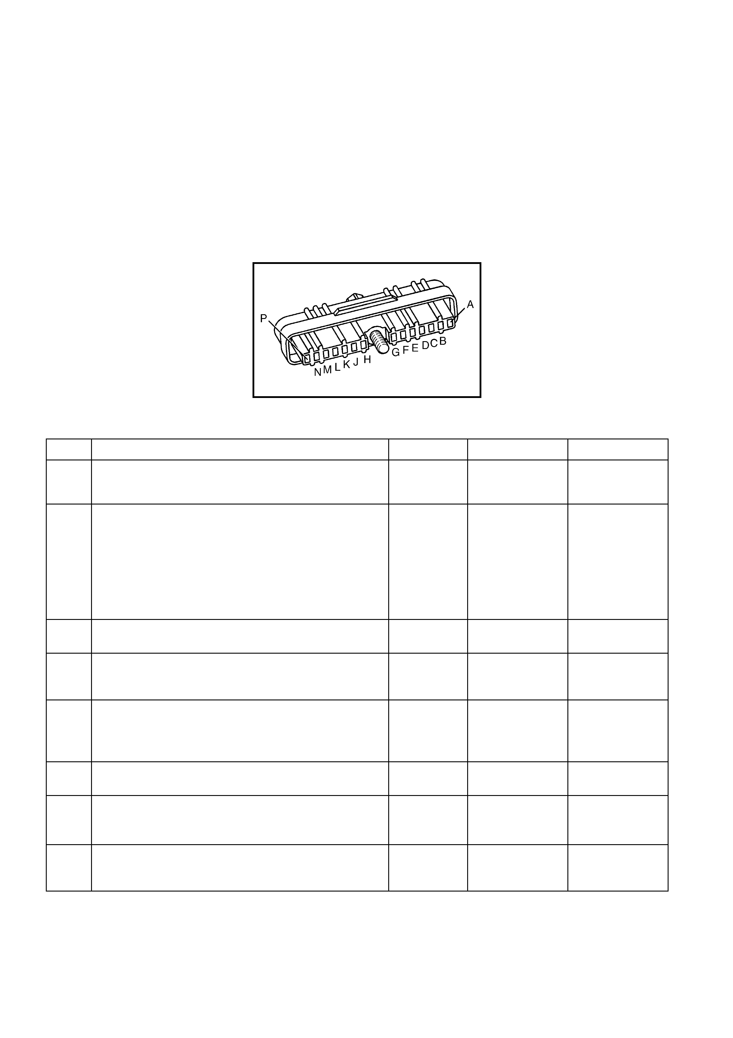
TEST DESCRIPTION
Number(s) below refer to step number(s) on the diagnostic Table.
5. Terminal "P" to the DIS module is the +12 volt supply to the DIS system.
9. This procedure will check the crankshaft sensor output, through the harness to the DIS module harness
connector. D IS m odule har ness c onnector t erm inals "N" an d "P" ar e jum pered to gethe r to pro vide po wer to the
sensor Hall circuits. Terminal "M" is grounded to provide a ground path for the Hall circuits. As the crankshaft
balancer interrupter rings a re r otated , the tes t lig ht s ho uld b li nk "ON" and "O FF " as the bla des pas s thr ou gh t he
crankshaft sensor air gap. The test light should be "ON" when the window is in the crankshaft sensor air gap,
indicati ng the Hall circuits are providing t he ground path f or the test light c onnected to +12 volts . Terminal " H",
the 3X signal terminal, should blink "ON" and "OFF" three times per crankshaft revolution.
NOTE: Use ST-125 spark checker or equivalent to check for adequate spark. An ST-125 requires about 25,000
volts (25 kilovolts, or 25 kV) to "Spark". Do not use a spark plug in open air connected to the engine as an
indication of sufficient "Spark". Only a few kilovolts are required to jump the gap of a spark plug outside of the
engine, and that would be an inadequate test of the ignition system.
A40
Figure 6C1-2A-55
TABLE A-8.1 V6 PCM - DIRECT IGNITION SYSTEM (DIS) CHECK
STEP ACTION VALUE YES NO
1. Was the "On-Board Diagnostic" (OBD) System Check
performed? Go to Step 2 Go to
OBD System
Check
2. 1. Remove one spark plug lead.
2. Connect ST-125 spark checker (Refer note in Test
Description) to lead and check for spark while
cranking the engine.
3. Check 3 wires on the same side of the engine this
way. A few sparks and then nothing is considered No
Spark.
Is spark present on all spark plug leads?
Go to Step 3 If
Spark on only
1 or 2 leads,
Go to Step 4
_____________
If
No Spark,
Go to Step 5
3. No trouble found with ignition system.
Is action complete? Verify Repair
4. Refer to DIS module and coil checking procedure, Table
A-8.2 Step 5.
Is action complete?
Verify Repair
5. 1. Disconnect 14-pin connector A40 from DIS module.
2. Ignition "ON", probe harness connector terminal
A40-P with a test light connected to ground.
Is test light "ON"?
Go to Step 9 Go to Step 6
6. Check ignition module fuse F35.
Is fuse open? Go to Step 7 Go to Step 8
7. Repair short to ground in fuse circuit.
Replace fuse.
Is action complete?
Verify Repair
8. Check for open in power circuit to DIS ignition module
harness connector terminal A40-P.
Was a problem found?
Verify Repair Go to
Table A-6.5

STEP ACTION VALUE YES NO
9. 1. Ignition "OFF".
2. Get three paper clips, and re-form until straight.
3. Bend one of the straightened paper clips into a very
narrow "U", and use it to jumper DIS module harness
connector term inals A40-N and A40-P.
4. Insert a straightened paper clip into terminal A40-M.
Connect a jumper lead from this paper clip to ground.
• Ensure that the Two paper clips and/or jumper
leads Do Not Touch.
5. Insert a straightened paper clip into harness
connector terminal A40-H, and connect a test light
between this terminal and +12 volts.
6. Ignition "ON".
7. Using a 24 mm socket and hand tools, slowly rotate
the crankshaft balancer one revolution, while
observing the test light.
The test light should go "ON" and "OFF" as the 3X
interrupter blades pass through the sensor air gap, does
it?
Go to
Table 8.2,
Step 2
Go to Step 10
10. Check for good continuity, and for no Shorts or Opens on
the 4 circuits between the crank sensor and DIS module.
If all are OK, replace crank sensor. Refer DIS SERVICE
OPERATIONS in Section 6C1-3 for proper procedure.
It must be followed.
Is action complete?
Verify Repair

TABLE A-8.2 V6 PCM - DIRECT IGNITION SYSTEM (DIS) CHECK
Figure 6C1-2A-56 – DIS Ignition System Circuit
CIRCUIT DESCRIPTION
The DIS ign ition system uses a waste spar k m ethod of spark dist ribution. In this type of ign ition system the ignitio n
module triggers the correct ignition coil, based on signals from the crankshaft sensor. Each ignition coil provides
the high secondary voltage required to fire two spark plugs at the same time on "companion" cylinders, i.e.
cylinders with pistons at th e top of their s trok e (TDC) at the sam e tim e. O ne of th ese pis tons would be at the top of
its compression stroke, the other piston would be at the top of its exhaust stroke.
For additional information about the DIS system refer Section 6C1-1 GENERAL DESCRIPTION.
TEST DESCRIPTION
Number(s) below refer to step number(s) on the diagnostic Table.
2. Terminal "G", the 18x signal terminal, should blink "ON" and "OFF" eighteen times per crankshaft revolution.
5. This procedure will check the modules ability to control the ignition coil primary system.
6. These check s are f or the prim ary and s econdar y wind ings of eac h of the three igni tion coils. T he resist ance
of each of the six checks (3 primary and 3 secondary windings) must be within the specified ranges.

A40
Figure 6C1-2A-57
TABLE A-8.2 V6 PCM - DIRECT IGNITION SYSTEM (DIS) CHECK
STEP ACTION VALUE YES NO
1. Was the "On-Board Diagnostic" (OBD) System Check
performed? Go to Step 2 Go to
OBD System
Check
2. 1. Ignition "OFF".
2. Remove the paper clip from terminal A40-H and
insert it into terminal A40-G.
3. Ignition "ON".
Slowly rotate the crankshaft balancer one revolution and
note test light. It should go "ON" and "OFF" as the 18X
interrupter blades pass through the sensor air gap, does
it?
Go to Step 4 Go to Step 3
3. Check for good continuity, and for no Shorts or Opens on
the 4 circuits between the crank sensor and DIS module.
If all are OK, replace crank sensor. See DIS Service
Operations in Section 6C1-3 for proper procedure. It must
be followed.
Is action complete?
Verify Repair
4. 1. Remove test light and all leads from harness
connector terminals. Reconnect 14-pin connector to
DIS module. Torque retaining bolt to specification
value.
2. Disconnect all spark plug leads from the DIS coils.
3. Remove 6 screws that retain the coils to the module.
4. Remove all three coils.
5. Connect the test light clip lead to one of the two coil
terminals on the module.
6. Connect the test light probe to the other coil terminal
on the module.
7. While the engine is cranki ng, o bserv e test light.
The test light should blink.
8. This test should be performed for each pair of
module terminals that connect to the three (3)
ignition co ils .
Is the test light blinking for all three coil pairs?
0.6 to 1.2
N.m Go to Step 6 Go to Step 5
5. If no blink, or blinks on less than all 3 pairs, replace DIS
module.
Is action complete?
Verify Repair
6. 1. Ignition "OFF".
2. Using a digital ohmmeter, check resistance across
the ignition coil primary winding (underside)
terminals.
3. Correct resistance of the ignition coil primary winding
must be within the specified value.
Are all three coils (6-3, 2-5, 4-1) wi thin this range?
0.3 ohms
to
1.5 ohms
Go to Step 8 Go to Step 7
7. Replace coil(s) that had the incorrect ohms reading.
Is action complete? Verify Repair

STEP ACTION VALUE YES NO
8. 1. Check resistance across the ignition coil secondary
tower terminals. Each tower is marked.
2. Correct resistance of the ignition coil secondary
windings must be within the specified value.
Are all three coils (6-3, 2-5, 4-1) wi thin this range?
5000
(5K ohms)
to
7000
(7K ohms)
Go to Step 10 Go to Step 9
9. Replace coil(s) that had the incorrect ohms reading.
Is action complete? Verify Repair
10. At this point, all DIS component tests indicate the DIS
system should produce spark. If a No Spark condition still
exists, very closely check the metal terminals in the
plastic connectors at the DIS module and crank sensor.
Also check the resistance of the spark plug leads,
ensuring that non e are "Open".
Is action complete?.
Verify Repair
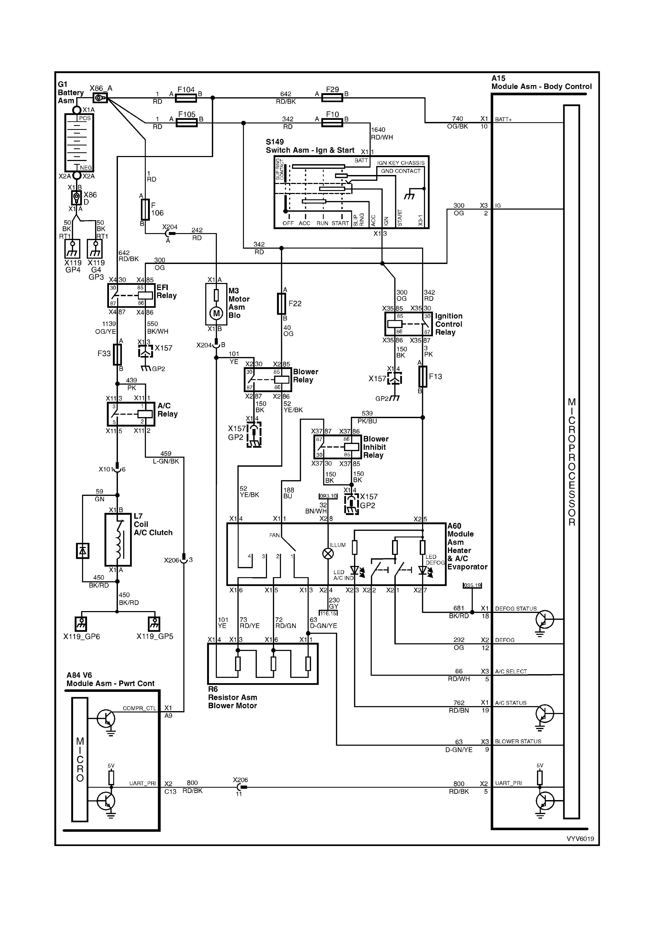
TABLE A-11.1 V6 PCM -
A/C CLUTCH CONTROL HVAC MANUAL OCCUPANT CLIMATE CONTROL
Figure 6C1-2A-58 A/C Clutch Control HVAC Manual OCC System
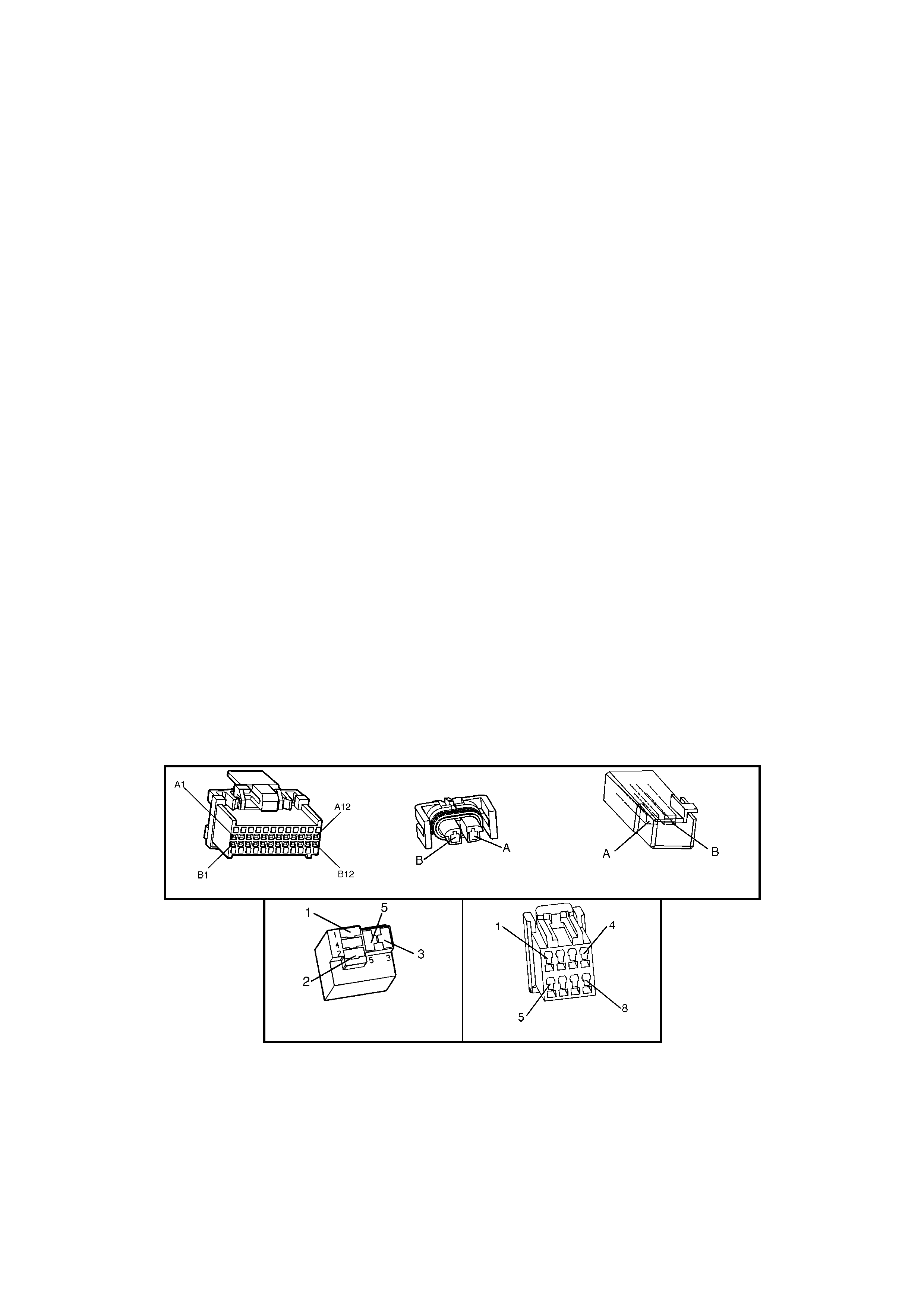
CIRCUIT DESCRIPTION
With the blower fan switched "ON", and the air conditioning switched "ON," switched ignition voltage is supplied
from fuse F 13 through the A/C master s witch, a nd then to t he BCM. The BC M will then supply a ser ial data signal
to the PCM requesting A/C . If the BCM does not receive a ground signal from the blower switch, the BCM will not
supply the serial data request for A/C to the PCM. Once the PCM receives this serial data signal, the PCM will
energise the A/C compressor relay by supplying a ground signal (A/C Relay Control ). The BCM also supplies a
ground signal from BCM terminal X1-15 to the number one (1) cooling fan relay.
This serial data signal to the PCM is also used to adjust the idle speed before turning "ON" the A/C compressor
relay. If this signal is not available to the PCM, the A/C compressor will be inoperative.
This system also incorporates an A/C Refrigerant Pressure Sensor. The A/C Refrigerant Pressure Sensor signal
indicates Low / High pressure on the A/C high side refrigerant pressure line to the PCM. The PCM uses this
information to adjust the idle air control valve to compensate for the higher engine loads present with high A/C
refrigerant pressures. A fault in the A/C Refrigerant Pressure Sensor signal will cause DTC P0530 to set.
The purpose of this A/C Refrigerant Pressure Sensor is to protect the system from danger because of either
refr igerant press ure too lo w (which co uld dam age the c om press or due to insuff icient lubr icati on), or too h igh (whic h
could result in a leak in the sealed refrigerant R134a system).
The PCM will NOT energise the A/C control relay if any of the following conditions are present:
DTC P0530 is set.
• RPM more than 4,800. If de-energised because of RPM, it can be re-energised when RPM falls below 4,000
for at least 10 seconds.
• Throttle is more than 90% open.
• A/C Refrigerant Pressure Sensor voltage is too Low or too High.
TEST DESCRIPTION
Number(s) below refer to step number(s) on the diagnostic Table.
1. The PCM's diagnostic circuits must be proven before any further testing is performed.
2. The PCM does not normally energise the A/C control relay unless the engine is running.
4. This checks for operation of the cooling fan.
20, 21, 22, 23, 24, 26, 28.
There are no terminal identification numbers on the relay connector (although the relay itself has terminal
numbers). Make certain the correct relay connector terminal (not the relay) is being probed.
39. The most likely cause of an automotive air conditioner not working is a discharged refrigerant R134a system,
due to a refrigerant leak.
Check For: If fuse F13 is blown, check for short to ground on all circuits associated with this fuse.
A84 V6 - X1 L7 V6
X11 (Part of X100) A60 – X2
Figure 6C1-2A-59

TABLE A-11.1 V6 PCM - A/C CLUTCH CONTROL HVAC MANUAL OCC SYSTEM
STEP ACTION VALUE YES NO
1. Was the "On-Board Diagnostic" (OBD) System Check
performed? Go to Step 2 Go to
OBD System
Check
2. 1. Ignition "O N ", engin e stopp ed.
2. Disconnect the A/C compressor clutch electrical
connector L7 and reconnect, and note compressor
clutch.
Did compressor clutch cycle "OFF" then "ON" with
electrical connector disconnected and reconnected?
If
A/C clutch cycled
"OFF" then "ON"
or will not
disengage
Go to Step 6
Go to Step 3
3. 1. Ignition "O N", engine idling.
2. Blower Switch turned "ON".
3. Cycle the A/C switch "ON" and "OFF", waiting a few
seconds between positions.
Listen for A/C compressor clutch. Does it cycle "ON" and
"OFF”?
Go to Step 4 Go to Step 14
4. 1. Ignition "O N", engine idling.
2. A/C switch in the "ON" position.
Does the cooling fan operate when the A/C Switch is
turned "ON"?
Go to Step 5 Go to
Table A-12
5. 1. A/C clutch control circuits OK.
2. If complaint is insufficient cooling, review symptoms.
Is action complete?
Verify Repair
6. 1. Ignition "O FF".
2. Disconnect A/C compressor electrical connector.
3. Observe A/C clutch.
Is A/C clutch staying engaged to compressor?
Go to Step 7 Go to Step 8
7. Replace A/C compressor clutch. Refer to section 2B in
Section 1 of this Service Manual for details.
Is action complete?
Verify Repair
8. 1. Ignition "ON", engine "OFF".
2. Remove A/C Relay R11 from relay housing.
3. Using test light connected to B+, probe PCM terminal
for A/C Relay Control, X11-2.
Does test light illuminate?
Go to Step 9 Go to Step 11
9. Check for a short to ground in circuit for A/C Relay
Control from the PCM to A/C Compressor Relay.
Was a problem found?
Verify Repair Go to Step 10
10. Replace PCM.
Refer to Section 6C1-3 Service Operations, for PCM
Programming and Security Link procedure.
Is action complete?
Verify Repair
11. 1. Ignition "ON".
2. Disconnect A/C compressor electrical connector.
3. Using test light connected to ground, probe A/C
compressor electrical connector power circuit, 59.
4. With test light "ON", remove A/C Compressor Relay
and note test light.
Did test light turn "OFF"?
Go to Step 12 Go to Step 13
12. Replace A/C Compressor Relay.
Is action complete? Verify Repair
13. Repair short to voltage on A/C compressor power feed
circuit from A/C Compressor Relay to A/C compressor.
Is action complete?
Verify Repair

STEP ACTION VALUE YES NO
14. 1. Ignit ion "ON ", engin e idlin g.
2. Install TECH 2.
3. Observe A/C Refrigerant Pressure Sensor voltage
display on TECH 2.
Is indicated A/C Refrigerant Pressure Sensor voltage at
or between the specified value?
0.35V - 4.2V Go to Step 15 Go to Step 39
15. Check power supply fuse F13 to A/C master switch.
Is fuse open? Go to Step 16 Go to Step 17
16. Repair short to ground in fuse circuit, and replace fuse.
Is action complete? Verify Repair
17. 1. Ignit ion "ON ", engin e "OFF ".
2. Turn A/C Master Switch to "ON" position.
3. Using test light connected to ground, backprobe
BCM terminal for A/C Select Input circuit, X3-5.
Does test light illuminate?
Go to Step 20 Go to Step 18
18. Check for open or poor connection in circuit from A/C
Master Switch to BCM A/C Select Input, or open in power
feed circuit to A/C Master Switch.
Was a problem found?
Verify Repair Go to Step 19
19. Replace A/C Master Switch.
Is action complete? Verify Repair
20. 1. Ignit ion "ON ", engin e idlin g.
2. Remove Blower Inhibit Relay R37 Relay center,
leave harness connector connected to relay.
3. Using test light connected to B+, backprobe relay
harness connector terminal X37-87.
Does test light illuminate?
Go to Step 21 Go to Step 26
21. 1. Ignit ion "ON ", engin e idlin g.
2. Using test light connected to B+, backprobe BCM
terminal for Blower Switch Input Signal, X3-9.
3. Turn Blower Switch to "ON" position.
Does test light illuminate?
Go to Step 22 Go to Step 33
22. 1. Ignit ion "OFF".
2. Remove A/C Compressor Relay R1 from Relay
center.
3. Ignition "ON", engine idlin g.
4. Turn A/C Master Switch to "ON" position.
5. Turn Blower Switch to "ON" position.
6. Using test light connected to B+, probe terminal
X11-2 of A/C Compressor Relay harness connector.
Does test light illuminate?
Go to Step 23 Go to Step 35
23. 1. Ignit ion "ON ", engin e "OFF ".
2. Using test light connected to ground, probe A/C
Compressor Relay harness terminals X11-1 and
X11-3.
Does test light illuminate on both circuits?
Go to Step 24 Go to Step 36
24. 1. Ignit ion "OFF".
2. Reinstall Blower Inhibit Relay and A/C Compressor
Relay.
3. Disconnect electrical connector at A/C compressor.
4. Ignition "ON", engine idlin g.
5. Turn A/C Master Switch to the "ON" position.
6. Turn Blower Switch to the "ON" position.
7. Using test light connected to ground, probe A/C
compressor harness power feed circuit 59 from A/C
Compressor Relay to compressor.
Does test light illuminate?
Go to Step 25 Go to Step 37

STEP ACTION VALUE YES NO
25. Check A/C compressor ground circuit for an open, if open
repair. If ground circuit is OK, Replace A/C compressor.
Refer to Section 2C for details.
Is action complete?
Verify Repair
26. 1. Ignit ion "ON ", engin e idlin g.
2. Using test light connected to B+, backprobe Blower
Inhibit Relay terminal X37-85.
Does test light illuminate?
Go to Step 28 Go to Step 27
27. Check for open in circuit from Blower Inhibit Relay
X37-85 to ground.
Is action complete?
Verify Repair
28. 1. Ignit ion "ON ", engin e "OFF ".
2. Disconnect Blower Inhibit Relay from connector.
3. Using test light connected to ground, probe relay
harness terminal X37-86.
Does test light illuminate?
Go to Step 30 Go to Step 29
29. Repair open in circuit from Blower Inhibit Relay terminal
X37-86 to Ignition Switch.
Is action complete?
Verify Repair
30. 1. Ignit ion "ON ", engin e "OFF ".
2. With Blower Inhibit Relay still disconnected, probe
relay harness terminal X37-30 with a test light
connected to B+.
Does test light illuminate?
Go to Step 31 Go to Step 32
31. Replace Blower Inhibit Relay.
Is action complete? Verify Repair
32. Repair open in ground circuit to Blower Inhibit Relay.
Is action complete? Verify Repair
33. Check for open circuit from Blower S witch to BCM Blower
Switch Input terminal.
Was a problem found?
Verify Repair Go to Step 34
34. Check for open in circuit from Blower Inhibit Relay
terminal X37-87 to Blower Switch.``
Was a problem found?
Verify Repair Go to Step 38
35. Check for open in circuit from A/C Compressor Relay to
PCM terminal X1-A9 for A/C Relay Control.
Was a problem found?
Verify Repair Go to Step 10
36. Repair open in circuit that did not illuminate test light.
Is action complete? Verify Repair
37. Check for open in circuit from A/C Compressor to A/C
Compressor Rel ay.
Was a problem found?
Verify Repair Go to Step 12
38. Replace Blower Switch.
Is action complete? Verify Repair
39. Check A/C Pressure Sensor signal circuit for short to
ground.
Was a problem found?
Verify Repair Go to Step 40
40. Check A/C refrigerant (R-134a) system for being
underchar ged, or overc harg ed .
Is action complete?
Verify Repair
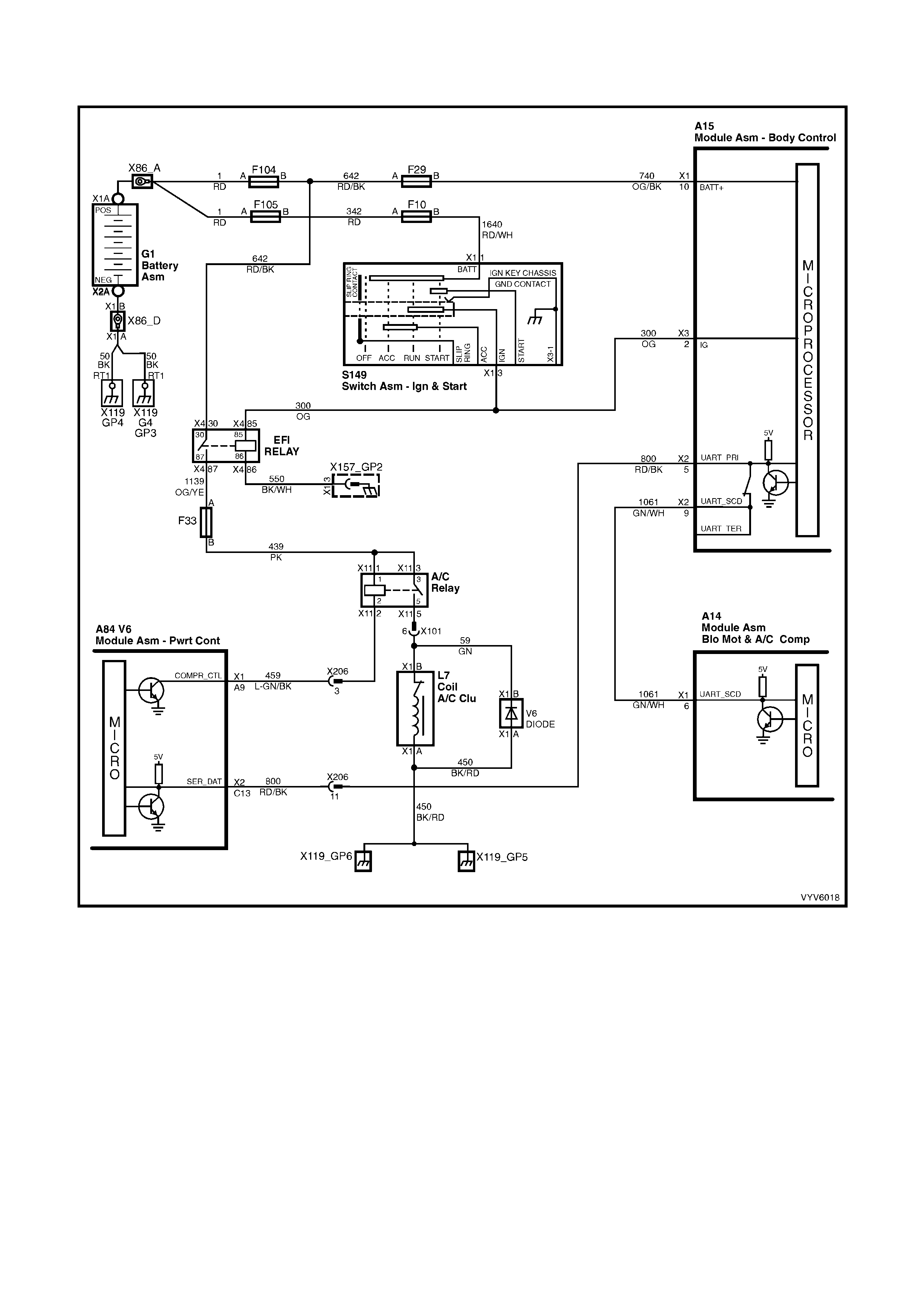
TABLE A-11.2 V6 PCM -
A/C CLUTCH CONTROL W ITH AUTOMATIC OCCUPANT CLIMATE CONTROL
Figure 6C1-2A-60 A/C Clutch Control HVAC Automatic OCC System
CIRCUIT DESCRIPTION
When the A/C is requested, the Occupant Climate Control Module will send an A/C request to the PCM via the
serial data normal mode message. When the PCM receives the serial data request on PCM serial data circuit, it
indicates that air conditioning has been requested and approximately 1/2 second after the PCM receives this
signal, it will energis e the A/C contr ol rela y. This serial data s ignal to the PC M is also used to adj ust the idle s peed
before turning "ON" the A/C compressor relay. If this signal is not available to the PCM, the A/C compressor will not
operate.
This A/C system also incorporates an A/C Refrigerant Pressure Sensor. The A/C Refrigerant Pressure Sensor
signal indicates low and high side refrigerant pressures to the PCM. The PCM uses this information to adjust the
idle air control valve to compensate for the higher engine loads present with high A/C refrigerant pressures, and not
allow A/C operation if pressure is too low or too high. A fault in the A/C Refrigerant Pressure Sensor signal will
cause DTC P0530 to set.
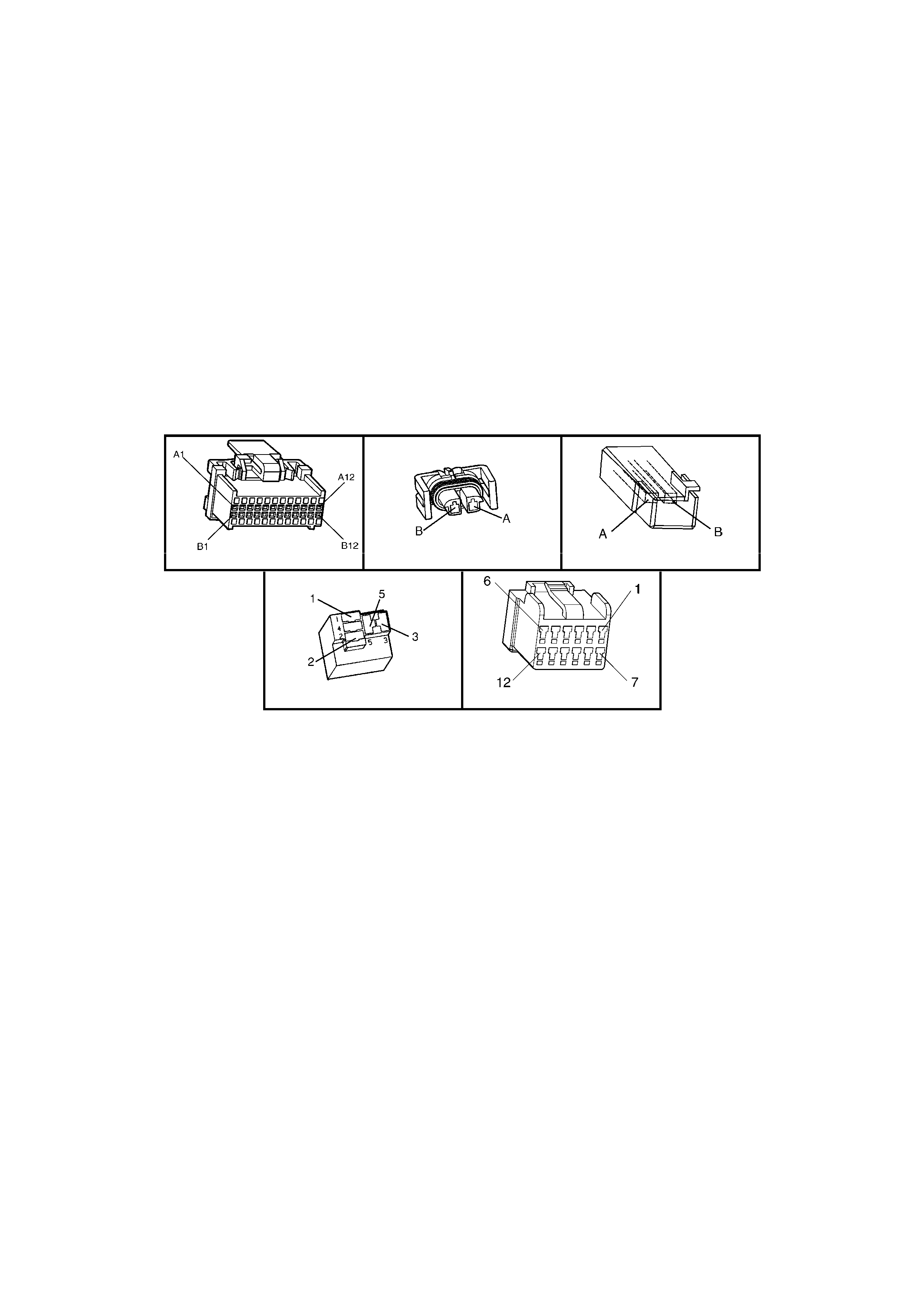
The PCM will not energise the A/C control relay if any of the following conditions are present:
• DTC P0530 is set.
• RPM more than 4,800. If de-energised because of RPM, it can be re-energised when RPM falls below 4,000
for at least 10 seconds.
• Throttle is more than 90% open.
• A/C Refrigerant Pressure Sensor voltage is too Low or too High.
TEST DESCRIPTION
Number(s) below refer to step number(s) on the diagnostic Table.
1. The PCM's diagnostic circuits must be proven before any further testing is performed.
3. The PCM does not normally energise the A/C control relay unless the engine is running.
4. When TECH 2 is installed, and the A/C switch is turned "ON", TECH 2 should display "A/C Requested".
6. This checks for operation of the cooling fan.
7. The most likely cause of an automotive air conditioner not cooling properly is a discharged or overcharged
refrigerant R134a system.
18, 19, 20. There are no terminal identification numbers on the relay connector (although the relay itself has
terminal numbers). Make certain the correct relay connector terminal (not the relay) is being probed.
Check For: If fuse F13 is blown, check for short to ground on all circuits associated with this fuse.
A84 V6 - X1 L7 V6
X11 (Part of X100) A14
Figure 6C1-2A-61

TABLE A-11.2 V6 PCM - A/C CLUTCH CONTROL WITH AUTOMATIC OCCUPANT CLIMATE CONTROL
STEP ACTION VALUE YES NO
1. Was the "On-Board Diagnostic" (OBD) System Check
performed? Go to Step 2 Go to
OBD System
Check
2. Does OCC power up when the Auto button is pressed? Go to Step 3 Go to 2F OCC
Diagnostics
3. 1. Ignition "ON", engine stopped.
2. Cycle A/C master switch "ON" and "OFF", waiting a
few seconds between positions.
3. Observe the A/C compressor clutch.
Did the compressor clutch cycle "ON" and "OFF"?
If either engages
or will not
disengage Go to
Step 10
Go to Step 4
4. 1. Ignition "ON".
2. Install TECH 2.
3. Does TECH 2 display OCC System Identification
information?
Go to Step 5 Go to Step 8
5. 1. Ignition "ON", engine idling.
2. Cycle the A/C switch "ON" and "OFF", waiting a few
seconds between positions.
3. Listen for A/C compressor clutch.
Does A/C compressor clutch cycle "ON" and "OFF"?
Go to Step 6 Go to Step 13
6. Ignition "ON", engine idling.
Does the cooling fan operate when the A/C is turned
"ON"?
Go to Step 7 Go to
Table A-12
7. A/C clutch control circuits OK. If complaint is insufficient
A/C cooling, review symptoms.
Is action complete?
Verify Repair
8. Check for poor connection or an open circuit between
BCM terminal A15 X2-9 and Occupant Climate Control
Module, terminal A14 X1-6.
Was a problem found?
Verify Repair Go to Step 9
9. Check for poor connection at Occupant Climate Control
module, if connection OK, replace faulty Occupant
Climate Control Module.
Is action complete?
Verify Repair
10. Check for short to ground from PCM circuit A84 X1-A9
A/C Relay Con trol to A/C Compressor Relay.
Was a problem found?
Verify Repair Go to Step 11
11. Check for short to voltage on power feed circuit 59 to A/C
compressor.
Was a problem found?
Verify Repair Go to Step 12
12. Replace defective A/C compressor relay.
NOTE: If compressor clutch still will not disengage,
replace A/C compressor clutch. Refer Section 2B.
Is action complete?
Verify Repair
13. 1. Ignit ion "ON ", engin e idlin g.
2. Install TECH 2.
3. Observe A/C Refrigerant Pressure Sensor voltage
display on TECH 2.
Is indicated A/C Refrigerant Pressure Sensor voltage at
or between the specified value?
0.35V - 4.2V Go to Step 14 Go to Step 25
14. 1. Ignition "ON", engine idling.
2. Disconnect A/C compressor relay.
3. Probe both A/C compressor relay terminals X11-3
and X11-1 of harness connector, with a test light
connected to ground.
Is test light "ON" at both terminals?
Go to Step 15 Go to Step 21

STEP ACTION VALUE YES NO
15. 1. Ignition "ON", engine idling.
2. Probe A/C compressor relay connector circuit X11-2
for A/C Relay Control with a test light connected to
B+.
3. Turn A/C switch "ON".
Is test light "ON" when the A/C switch is "ON"?
Go to Step 16 Go to Step 19
16. 1. Ignition "ON", engine idling.
2. Reconnect A/C compressor relay.
3. Backprobe A/C compressor relay harness terminal
X11-5 with a test light connected to ground.
4. Turn A/C switch "ON".
Is test light "ON" when A/C switch is turned "ON"?
Go to Step 17 Go to Step 12
17. 1. Ignition "OFF".
2. Disconnect A/C compressor electrical connector.
3. Ignition "ON", engine idling.
4. Probe compressor harness connector terminal X1-B
power feed circuit 59 with a test light connected to
ground.
5. Turn A/C switch "ON".
Is test light "ON" when the A/C switch is turned "ON"?
Go to Step 18 Go to Step 24
18. Check for a poor ground circuit to A/C compressor.
Was a problem found? Verify Repair Go to Step 23
19. Check for a faulty connection at the A/C compressor relay
connector terminal X11-2.
Was a problem found?
Verify Repair Go to Step 20
20. Check for an open in the PCM A/C Relay Control circuit
459, from the PCM to the A/C compressor relay.
Was a problem found?
Verify Repair Go to Step 22
21. Repair open in circuit that did not light test light.
Is action complete? Verify Repair
22. Replace PCM.
Refer to 6C1-3 Service Operations, for PCM
Programming and Security Link procedure.
Is action complete?
Verify Repair
23. Replace A/C compressor.
Is repair complete? Verify Repair
24. Repair open in circuit 59 to A/C compressor clutch.
Is repair complete? Verify Repair
25. Check A/C Pressure Sensor signal circuit for short to
ground.
Was a problem found?
Verify Repair Go to Step 26
26. Check A/C refrigerant (R-134a) system for being
underchar ged, or overc harg ed .
Is action complete.
Verify Repair
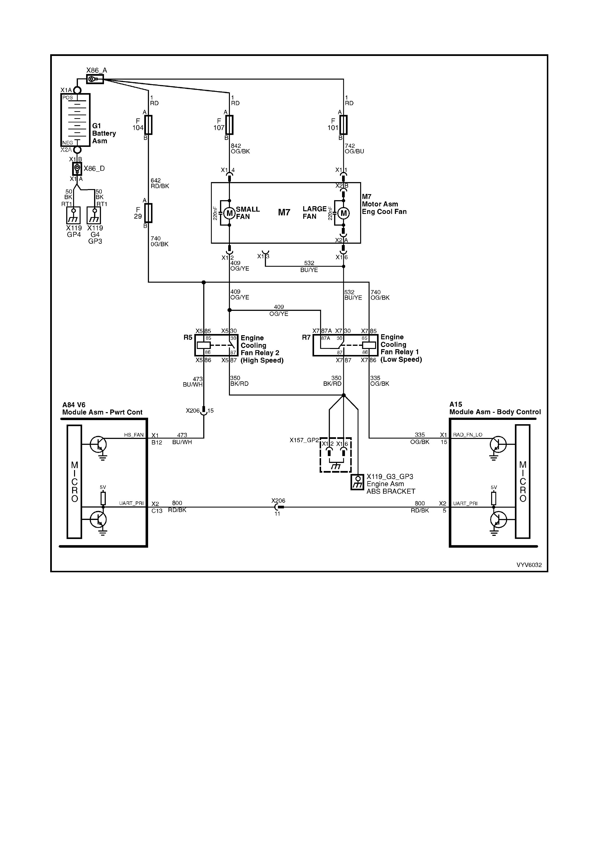
TABLE A-12.1 V6 PCM - ELECTRIC FAN CONTROL
Figure 6C1-2A-62 V6 Standard Cooling Fan Package Circuit
CIRCUIT DESCRIPTION
The V6 Standard Cooling Fan Package uses two single speed electric engine cooling fan motor assemblies. The
large fan motor provides low speed cooling operation and the small fan provides high speed cooling operation.
Both of these fan motors provide the primary means of moving air through the engine radiator. These electric
cooling fan m otors are used to cool engine coolant flowing through the radiator. These electric cooling fan m otors
are also used to cool the refrigerant flowing through the A/C condenser (if fitted).
The large lo w speed coo ling f an is enabled b y the engine coo ling fan rela y 1 (R7) which is energ ised by the b y the
BCM, when the BCM receives a Low Speed Cooling Fan ON request from the PCM, via the serial data normal
mode message. The BCM controls the ground path for the relay.
The small high speed cooling fan is enabled by cooling fan relay 2 (R5). Cooling fan relay 2 is energised by the
PCM by controlling the ground path for the Relay.
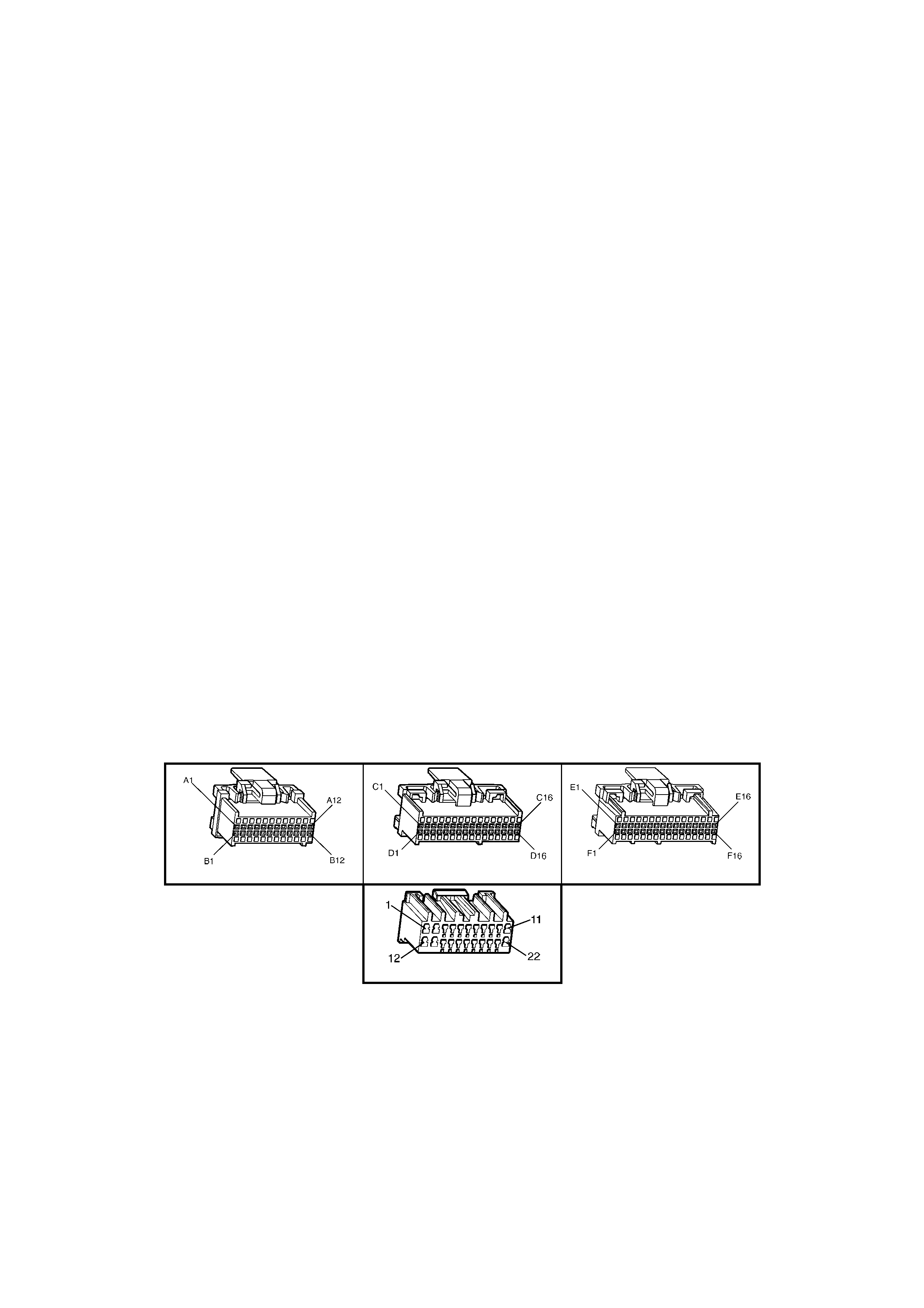
ENGINE COOLING FAN LOW SPEED
The large low speed engine cooling fan relay 1 (R7) is energised by the BCM. The PCM determines when to
enable the large low speed engine cooling fan based on inputs from the A/C request signal, vehicle speed and
engine coolant temperature. The large low speed engine cooling fan will be turned "ON" when:
• A/C request indicated (YES)
• Vehicle speed less than 54 Km/h
or
• Coolant temperature is greater than 104°C and will remain on until coolant temperature goes down below 99°C
or
• A/C pressure >1500kPa
or
• DTC Set
ENGINE COOLIN G FAN HIGH SPEED
The small high speed engine cooling fan is controlled by the PCM based on input from the Engine Coolant
Temperature Sensor (ECT) or A/C Refrigent Pressure Sensor. The PCM will only turn "ON" the small high speed
engine cooling fan if the small low speed engine cooling fan has been "ON" for 2 seconds and the following
conditions are satisfied.
• There is a BCM message response fault which will cause a DTC P1064.
• An engine coolant temperature sensor failure is detected, such as DTC P0116, P0117, P0118 or P1628.
• Coolant temperature greater than 107°C.
• If the lar ge lo w s pee d c oo ling fan was "O FF " when t he c riter ia was met to tur n the small h ig h s pe ed c oo l ing fan
"ON", the small high speed cooling fan will come "ON" 5 seconds after the large low speed cooling fan is turned
"ON".
• The sm all high s peed eng ine cooli ng fan re lay 2 can also be e nabled b y the A/C Refriger ant Press ure Se nsor.
The A/C Refrigerant Pressure Sensor will provide a signal to the PCM when A/C pressure becomes too high,
approximately 2000 kPa.
TEST DESCRIPTION:
Number(s) below refer to step number(s) on the diagnostic Table.
2. T his entire diagnostic procedure must begin with a "cold" engine - at ambient air tem perature. If the coolant is
hot when diagnosis is performed, replacement of good parts will result. Fan should not be running if engine
coolant temperature is less than 99°C and air conditioning is not "ON".
7. Using T ECH 2 wil l allo w oper ation of the sm all high s peed c ooling f an rela y 2. If the f an oper ates with TECH 2,
the small high speed cooling fan is operating properly.
A84 V6 – X1 A84 V6 – X2 A84 V6 – X3
A15 – X1
Figure 6C1-2A-63

TABLE A-12.1 V6 PCM - ENGINE COOLING FAN CONTROL
STEP ACTION VALUE YES NO
1. Was the "On-Board Diagnostic" (OBD) System Check
performed? Go to Step 2 Go to
OBD System
Check
2. 1. Ignition "ON", engine stopped.
2. Engine coolant temperature below 99°C.
Is the Small High Speed Cooling Fan running?
Go to Step 3 Go to Step 6
3. 1. Ignition “ON”, engine stopped.
2. Remove the High Speed Engine Cooling Fan Relay
(R5).
Does the Small High Speed Cooling Fan stop running?
Go to Step 4 Go to Step 9
4. 1. Ignition "OFF".
2. Disconnect all PCM connectors.
3. Using a test light connected to B+, probe PCM
harness connector terminal X1-B12 for High Speed
Cooling Fan Relay (R5) control circ uit 473.
Does test light illuminate?
Go to Step 5 Go to Step 10
5. Check for open or short to ground in Small High Speed
Cooling Fan Relay (R5) control circ uit 473.
Was a problem found?
Verify Repair Go to Step 21
6. Is Large Low Speed Cooling Fan Running? Go to
Table A-12.2 Go to Step 7
7. 1. Ignition “ON”, engine stopped.
2. Using Tech 2: Select High Fan Relay Control.
3. Turn “ON” High Fan with TECH 2.
Does the Small High Speed Cooling Fan operate?
Go to Step 8 Go to Step 12
8. The Small High Speed Cooling Fan is OK.
Verify the Large Low Speed Fan operation. Refer to
Table A-12.2.
Is action complete?
System OK
9. Repair short to ground in the Small High Speed Cooling
Fan ground circuit 409 between fan motor and High
Speed Cooling Relay 2 (R5).
Is action complete?
Verify Repair
10. 1. Ignition “OFF”.
2. Reconnect the PCM connectors.
3. Ignition “ON”.
4. Using test light connected to B+, probe Small High
Speed Cooling Fan Relay 2 (R5) control circuit 473
at relay harness connector terminal X5-86.
Does test light illuminate?
Go to Step 11 Go to Step 16
11. Replace PCM.
Refer 6C1-3 Service Operations, for PCM Programming
and Security Link procedure.
Is action complete?
Verify Repair
12. Check for open or short to ground in power supply fuses
(F29 & F104) and circuit 740 to the Small High Speed
Cooling Fan Relay (R5). Replace fuse if open.
Was a problem found?
Verify Repair Go to Step 13
13. 1. Ignition “ON”, engine stopped.
2. Remove Small High Speed Cooling Fan Relay (R5).
3. Using test light connected to B+, probe relay harness
connector terminal X5-86.
4. Using Tech 2, command “ON” and “OFF” High
Speed Cooling Fan.
Does test light turn “ON” and “OFF” with TECH 2
commands?
Go to Step 14 Go to Step 5

STEP ACTION VALUE YES NO
14. 1. Ignition “OFF”.
2. Disconnect Small High Speed Cooling Fan motor
electrical con nect or.
3. Using test light connected to ground, probe power
feed circuit 842 to fan motor.
Does test light illuminate?
Go to Step 17 Go to Step 15
15. Repair open or short to ground in power feed circuit to
Small High Speed Cooling Fan motor. Repair fusible link
if open.
Is action complete?
Verify Repair
16. Replace Small High Speed Cooling Fan Relay (R5).
Is action complete? Verify Repair
17. 1. Ignition “ON”, engine stopped.
2. Remove Small High Speed Cooling Fan Relay 2
(R5).
3. Using fused jumper lead connected to ground, probe
Small High Speed Cooling Fan Relay (R5) harness
connector terminal X5-30.
Does Small High Speed Cooling Fan motor operate?
Go to Step 18 Go to Step 20
18. Using test light connected to B+, probe the Small High
Speed Cooling Fan Relay (R5) harness connector
terminal X5-87.
Does test light illuminate?
Go to Step 16 Go to Step 19
19. Repair open in ground circuit to the Small High Speed
Cooling Fan Relay (R5) terminal X5-87.
Is action complete?
Verify Repair
20. Check for open in ground circuit from the Small High
Speed Cooling Fan Relay (R5) to Small High Speed
Cooling Fan motor.
Was a problem found?
Verify Repair Go to Step 22
21. Check for poor connection at PCM.
Was a problem found? Verify Repair Go to Step 11
22. Replace Small High Speed Cooling Fan motor.
Is action complete? Verify Repair

TABLE A-12.2 V6 PCM - ELECTRIC FAN CONTROL - STAN DARD FAN PACAKAGE
Figure 6C1-2A-64 V6 Standard Cooling Fan Package Circuit
CIRCUIT DESCRIPTION
The V6 Standard Cooling Fan Package uses two single speed electric engine cooling fan motor assemblies. The
large fan motor provides low speed cooling operation and the small fan provides high speed cooling operation.
Both of these fan motors provide the primary means of moving air through the engine radiator. These electric
cooling fan m otors are used to cool engine coolant flowing through the radiator. These electric cooling fan m otors
are also used to cool the refrigerant flowing through the A/C condenser (if fitted).
The large low speed cooling fan is enabled by the engine cooling fan relay (R7) which is energised by the by the
BCM, when the BCM receives a Low Speed Cooling Fan ON request from the PCM, via the serial data normal
mode message. The BCM controls the ground path for the relay.
The small high speed cooling fan is enabled by cooling fan relay (R5), which is energised by the PCM by controlling
the ground path for the Relay.
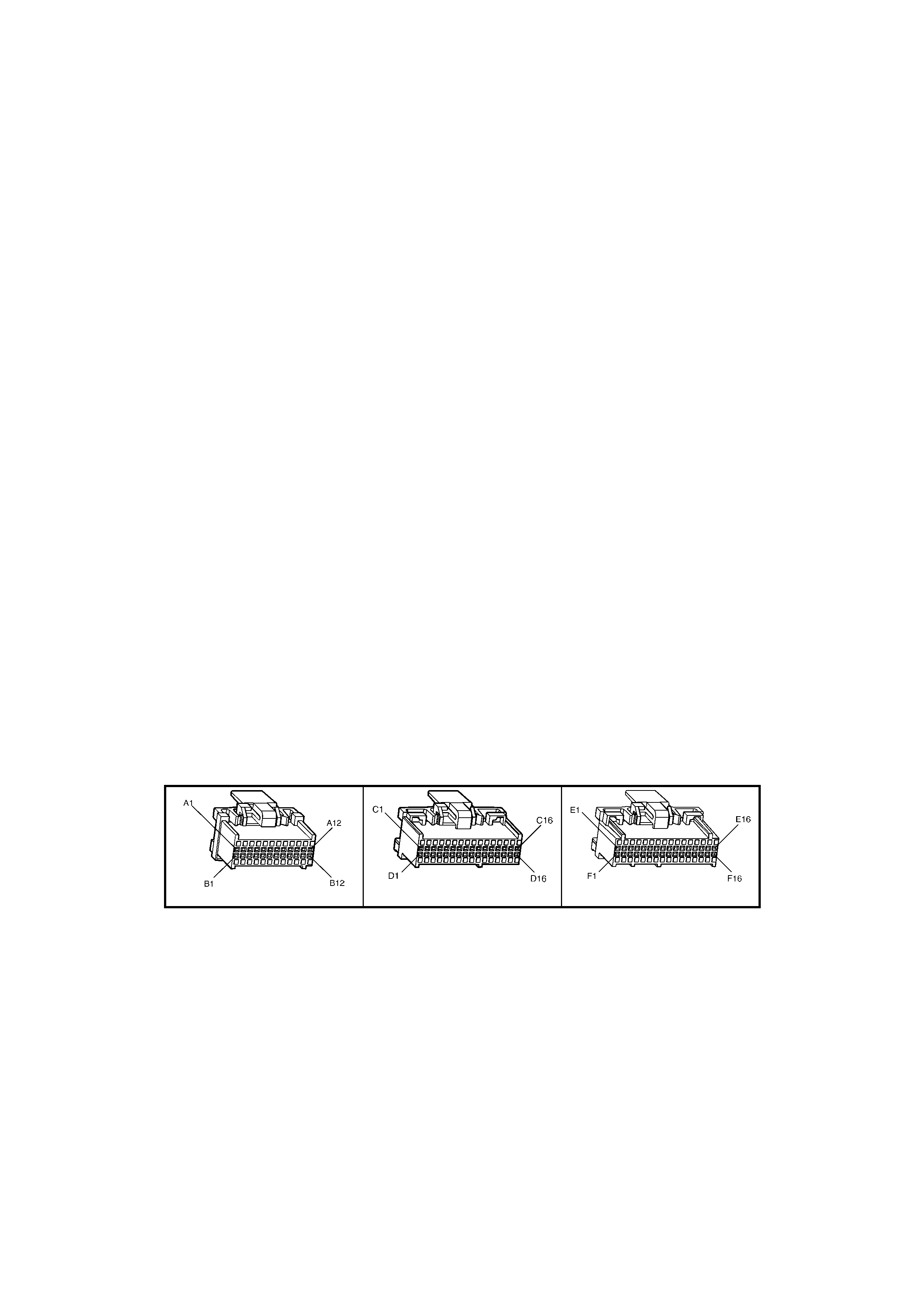
ENGINE COOLING FAN LOW SPEED
The large low speed engine cooling fan relay 1 (R7) is energised by the BCM. The PCM determines when to
enable the large low speed engine cooling fan based on inputs from the A/C request signal, vehicle speed and
engine coolant temperature. The large low speed engine cooling fan will be turned "ON" when:
• A/C request indicated (YES)
• Vehicle speed less than 54 Km/h
or
• Coolant temperature is greater than 104°C and will remain on until coolant temperature goes down below 99°C
or
• A/C pressure >1500kPa
or
• DTC Set
ENGINE COOLIN G FAN HIGH SPEED
The small high speed engine cooling fan is controlled by the PCM based on input from the Engine Coolant
Temperature Sensor (ECT) or A/C Refrigent Pressure Sensor. The PCM will only turn "ON" the small high speed
engine cooling fan if the small low speed engine cooling fan has been "ON" for 2 seconds and the following
conditions are satisfied.
• There is a BCM message response fault which will cause a DTC P1064.
• An engine coolant temperature sensor failure is detected, such as DTC P0116, P0117, P0118 or P1628.
• Coolant temperature greater than 107°C.
• If the lar ge lo w s pee d c oo ling fan was "O FF " when t he c riter ia was met to tur n the small h ig h s pe ed c oo l ing fan
"ON", the small high speed cooling fan will come "ON" 5 seconds after the large low speed cooling fan is turned
"ON".
• The sm all high s peed eng ine cooli ng fan re lay 2 can also be e nabled b y the A/C Refriger ant Press ure Se nsor.
The A/C Refrigerant Pressure Sensor will provide a signal to the PCM when A/C pressure becomes too high,
approximately 2000 kPa.
TEST DESCRIPTION
Number(s) below refer to step number(s) on the diagnostic Table.
2. This entire diagnostic pr ocedure m ust begin wit h a “COLD” eng ine – at am bient air tem perature. If the coolant
is hot when di agnosis is perf ormed, replac ement of good parts m ay result. Fan sh ould not be r unning if engine
coolant temperature is less than 99°C and air conditioning is not “ON”.
6. Using Tech 2 will allow operation of the Low Speed Cooling Fan Relay. If the fan operates with TECH 2, the
Low Speed Cooling Fan is operating properly.
7. This test verifies that the Low Speed Cooling Fan will operate when the A/C system is turned “ON”.
A84 V6 – X1 A84 V6 – X2 A84 V6 – X3
Figure 6C1-2A-65

TABLE A-12.2 V6 PCM - ELECTRIC FAN CONTROL - STANDARD FAN PACAKAGE
STEP ACTION VALUE YES NO
1. Was the "On-Board Diagnostic" (OBD) System Check
performed? Go to Step 2. Go to
OBD System
Check
2. 1. Ignition “ON”, engine stopped.
2. Engine coolant temperature below 99°C.
3. Turn “OFF” A/C (if fitted).
Is Large Low Speed Cooling Fan running?
Go to Step 3 Go to Step 6
3. 1. Ignition “ON”, engine stopped.
2. Remove the Large Low Speed Cooling Fan Relay
(R7).
Does the Large Low Speed Cooling Fan stop running?
Go to Step 4 Go to Step 10
4. 1. Ignition “OFF”.
2. Disconnect the BCM connectors.
3. Using test light connected to B+, probe BCM harness
connector terminal for the Large Low Speed Cooling
Fan Relay 1 (R7) control circuit 335 terminal X1-15.
Does test light illuminate?
Go to Step 5 Go to Step 11
5. Check for open or short to ground in Large Low Speed
Cooling Fan Relay (R7) control circ uit 335.
Was a problem found?
Verify Repair
Go to Step 22
6. 1. Ignition “ON”, engine stopped.
2. Using Tech 2: Select Low Fan Relay Control.
3. Turn “ON” Low Fan with TECH 2.
Does the Large Low Speed Cooling Fan operate?
Go to Step 7 Go to Step 13
7. Notice: If vehicle is not equipped with A/C, proceed to
Step 8.
1. Ignition “ON”, engine idling.
2. Turn “ON” A/C system and blower motor switch.
Does the Large Low Speed Cooling Fan Operate?
Go to Step 8 Go to Step 9
8. The Large Low Speed Cooling Fan circuit is OK.
Is action complete? Verify Repair
9. Refer to Table A-11.1 A/C Clutch Control, for Non OCC
system, or Table A-11.2 A/C Clutch Control with OCC.
Is action complete?
Verify Repair
10. Repair short to ground in the Large Low Speed Cooling
Fan ground circuit 532 between fan motor and Large Low
Speed Relay 1 (R7).
Is action complete?
Verify Repair
11. 1. Ignition “OFF”.
2. Reconnect BCM connectors.
3. Ignition “ON”, engine stopped.
4. Using test light connected to B+, probe the Large
Low Speed Cooling Fan Relay (R7) control circuit
335 at relay harness connector X7-86.
Does test light illuminate?
Go to Step 12 Go to Step 17
12. Verify the A/C system (if fitted) is working properly. If OK,
replace BCM.
Is action complete?
Verify Repair
13. Check for open or short to ground in power supply fuses
(F29 & F104) and curcuit 740 to the Large Low Speed
Cooling Fan Relay (R7). Replace fuse if open.
Was a problem found?
Verify Repair Go to Step 14

STEP ACTION VALUE YES NO
14. 1. Ignition “ON”, engine stopped.
2. Remove Large Low Speed Cooling Fan Relay 1
(R7).
3. Using test light connected to B+, probe relay harness
connector terminal X7-86.
4. Using Tech 2, command “ON” and “OFF” Low Speed
Cooling Fan.
5. Does test light turn “ON” and “OFF” with TECH 2
commands?
Go to Step 15 Go to Step 5
15. 1. Ignition “OFF”.
2. Disconnect the Large Low Speed Cooling Fan motor
electrical con nect or.
3. Using test light connected to ground, probe power
feed circuit 742 to fan motor.
Does test light illuminate?
Go to Step 18 Go to Step 16
16. Repair open or short to ground in power feed circuit to the
Large Low Speed Cooling Fan motor. Repair fusible link if
open.
Is action complete?
Verify Repair
17. Replace Large Low Speed Cooling Fan Relay (R7).
Is action complete? Verify Repair
18. 1. Ignition “ON”, engine stopped.
2. Remove the Large Low Speed Cooling Fan Relay 1
(R7).
3. Using a fused jumper lead connected to ground,
probe the Large Low Speed Cooling Fan Relay 1
(R7) harness connector terminal X7-30.
Does Low Speed Cooling Fan motor operate?
Go to Step 19 Go to Step 21
19. Using test light connected to B+, probe the Large Low
Speed Cooling Fan Relay (R7) harness connector
terminal X7-87.
Does test light illuminate?
Go to Step 17 Go to Step 20
20. Repair open in ground circuit to the Large Low Speed
Cooling Fan Relay 1 (R7) terminal X7-87.
Is action complete?
Verify Repair
21. Check for open in ground circuit from the Large Low
Speed Cooling Fan Relay (R7) to the Large Low Speed
Cooling Fan motor.
Was a problem found?
Verify Repair Go to Step 23
22. Check for poor connection at BCM.
Was a problem found? Verify Repair Go to Step 12
23. Replace Low Speed Cooling Fan motor.
Is action complete? Verify Repair

TABLE A-12.3 V6 PCM - ELECTRIC FAN CONTROL
HIGH PERFORMANCE FAN PACKAGE
Figure 6C1-2A-66 V6 High Performance Cooling Fan Package Circuit
HIGH PERFORMANCE COOLING FAN PACKAGE
The high power fan package uses two, dual speed, engine cooling fan motors. The small fan is 268 mm in diameter
and has a m otor rated at 180 W atts , while the lef t large fan is 370 mm in diam eter with a motor power rating of 220
Watts.
While both the standard a nd high power assemblies have the sam e diameter fans, the power rating of the electric
motors, changes and can be seen visually by the larger diameter motor for the high power assemblies.
The engine cooling fan motors have three terminals; one positive and two negative. The positive terminals are
permanently connected to battery voltage, via fusible links F101 to the large fan motor and F107 to the small fan
motor . W hen the lo w speed en gine co oling f an rela y 1 (R7) is energis ed, one negative terminal of bot h cooling fan
motors is connected to ground through the relay and the fans will operate at low speed. When the high speed
cooling f an re la y 2 (R5) is energ ised, t he oth er negati ve ter m inal of bot h coo ling fan m otors is connec ted to ground
via the relay and both cooling fans will operate at high speed.

ENGINE COOLING FAN LOW SPEED
The PCM determines when to enable the low speed fan based on A/C Request, A/C pressure, Engine Coolant
Temperature and vehicle speed.
Note: The cooling fan operating pa rameters listed below may vary with different PCM calibrations.
The cooling fan low speed relay will be turned "ON'' when:
• The A/C request indicated (YES) and either
• the vehicle speed is less than 54 km/h.
or
• A/C pressure is greater than 1500 kPa
or
• The coolant temperature is greater than 104°C.
• or
• If the coolant temperature is greater than 117°C, when the ignition is switched off, the relay is energised for
approximately four minutes. This is known as “Low Fan Run On”.
• or
• If an engine coolant temperature sensor fault is detected, such as DTC P1116, P0117, P0118, or P1628.
The cooling fan low speed relay will be turned "OFF'' when any of the following conditions have been met:
• The coolant temperature is less than 99 °C.
• The A/C request is not indicated (NO)
• The A/C request is indicated (YES) and the vehicle speed is greater than 50 km/h and A/C pressure is less
than 1170 kPa.
ENGINE COOLING FAN HIGH SPEED
• T he eng ine co oling f an h igh s peed re la y 2 (R 5) is c on troll ed b y the PCM b ased o n engi ne c oolant tem peratu re
and A/C pressure. The PCM will only turn "ON'' the engine cooling fan high speed relay 2 (R5) if the engine
cooling fan low speed relay 1 (R7) has been "ON" for two seconds and the following conditions are satisfied.
• There is a BCM message response fault which has caused a DTC P1064.
• An engine coolant temperature sensor fault is detected such as DTC P1116, P0117, P0118, or P1628.
• Coolant temperature greater than 108°C.
• The A/C refrigerant pressure is greater than 2400 kPa.
If the lo w speed fan was "OFF " when the crit eria was met to turn t he high speed fan "ON", t he high spe ed fan wil l
come "ON" 5 seconds after the low speed fan is turned "ON". If both the engine cooling fan relays are "ON", the
PCM will turn "OFF" the high speed relay when:
• The engine coolant temperature is less than 108°C.
• A/C request not indic ate d (NO ) .
• A/C request indicated (YES) and A/C pressure is less than 2000 kPa.
LOW SPEED RESPONSE
The engine cooling low speed fan is enabled when the low speed relay is energised by the BCM. The PCM will
request the BCM to turn the low speed engine cooling fan relay on or off, via the serial data bus normal mode
message. After the PCM requests a change in the engine cooling fan low speed relay, the BCM will send a
response message back to the PCM via the serial data bus normal mode message confirming it received the
request. A failure in this response communication will set a DTC P1064.
DTC P1064 Low Speed Fan No BCM Response will be set if:
• En gine is idling
• The PCM sends a request to the BCM to turn ON the engine cooling fan low speed relay via the serial data
normal mode message and the BCM does not send a message back to the PCM.
• The PCM will not illuminate the Check Powertrain MIL.
TEST DESCRIPTION
Number(s) below refer to step number(s) on the diagnostic Table.
2. T his entire diagnostic procedure must begin with a "cold" engine - at ambient air tem perature. If the coolant is
hot when diagnosis is performed, replacement of good parts will result. Fan should not be running if engine
coolant temperature is less than 99°C and air conditioning is not "ON".
7. Using T ECH 2 wil l allo w oper ation of the sm all high s peed c ooling f an rela y 2. If the f an oper ates with TECH 2,
the small high speed cooling fan is operating properly.
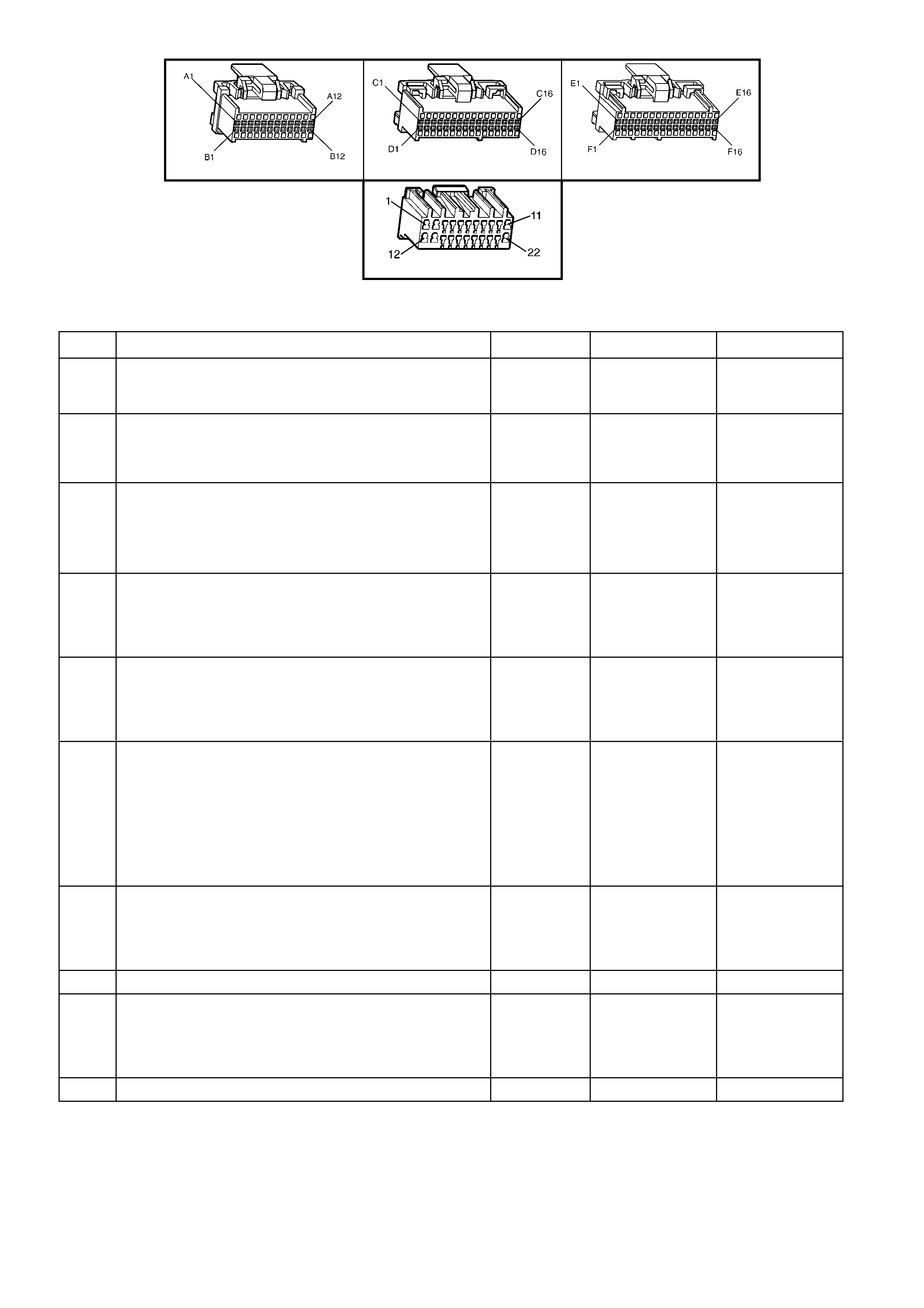
A84 V6 – X1 A84 V6 – X2 A84 V6 – X3
A15 – X1
Figure 6C1-2A-67
TABLE A-12.3 V6 PCM –ELECTRIC COOLING FAN CONTROLHIGH PERFORMANCE FAN PACKAGE
STEP ACTION VALUE YES NO
1. Was the "On-Board Diagnostic" (OBD) System Check
performed? Go to Step 2 Go to
OBD System
Check
2. 1. Ignition "ON", engine stopped.
2. Engine coolant temperature below 99°C.
Are both electric fan motor's running?
Go to Step 3 Go to Step 9
3. 1. Ignition OFF.
2. Remove the High Speed Fan Relay (R5).
3. Ignition ON.
Do both fans continue to run?
Go to Step 4 Go to Step 5
4. 1. Ignition ON.
2. Remove the Low Speed Relay (R7) from relay
housing.
Do both fans continue to run?
Go to Step 13 Go to Step 16
5. 1. Ignition ON.
2. Probe the High Speed Relay (R5) harness connector
circuit 473 with a test light to +12 volts.
Is the test light ON?
Go to Step 6 Go to Step 8
6. 1. Ignition OFF.
2. Disconnect PCM connectors.
3. Ignition "ON".
4. Using test light, probe Radiator Fan High Speed
Relay harness connector circuit 473 with a test light
connected to +12 volts.
Is the test light ON ?
Go to Step 14 Go to Step 7
7. Replace PCM.
Refer 6C1-3 Service Operations, for PCM Programming
and Security Link procedure.
Is action complete?
Verify Repair
8. Replace the Engine Cooling Fan High Speed Relay (R5). Verify Repair
9. 1. Ignition ON.
2. Using TECH 2, Select F3: High Fan and command
the High Fan ON.
Do both cooling fans operate in high speed mode?
Go to Step 19 Go to
Table A-12.4
10. Is the vehicle equipped with A/C? Go to Step 11 Go to Step 12

STEP ACTION VALUE YES NO
11. 1. Start engine, allow to idle.
2. Turn A/C ON.
3. The engine cooling fans should run when the A/C
clutch enga ges .
NOTE: If A/C clutch will not engage,
Do the engine cooling fans run when A/C clutch is
engaged?
Go to Step 12 Go to
Table A-11.1 A/C
Clutch Control,
for Manual OCC
or
Table A-11.2 A/C
Clutch Control for
Automatic OCC.
12. The electric cooling fan circuits are OK. Verify Operation
13. 1. Connect a test light to +12 volts.
2. Probe circuits 532 and 409 of engine cooling Fan
Low Speed Relay (R7).
Is the test light ON?
Go to Step 15 Go to Step 21
14. Repair short to ground in circuit 473. Verify Repair
15. Repair short to ground in circuit 532 and/or circuit 409. Verify Repair
16. 1. Ignition ON.
2. Probe the Engine Cooling Fan Low Speed Relay
(R7) harness connector circuit 335 with a test light
connected to +12 volts.
Is the test light ON?
Go to Step 17 Go to Step 20
17. 1. Ignition OFF.
2. Check for short to ground on circuit 335.
Was a short to ground found?
Verify Repair Go to Step 18
18. Replace the BCM.
Refer 12C BODY CONTROL MODULE. Verify Repair
19. 1. Ignition ON.
2. Using TECH 2, Select LOW FAN and command the
Low Fan ON.
Do the engine cooling fans run?
Go to Step 10 Go to
Table A-12.5
20. Check for short to ground in circuit 409.
Was a problem found? Verify Repair Go to Step 21
21. Replace the Engine Cooling Fan Low Speed Relay (R7).
Is action complete? Verify Repair
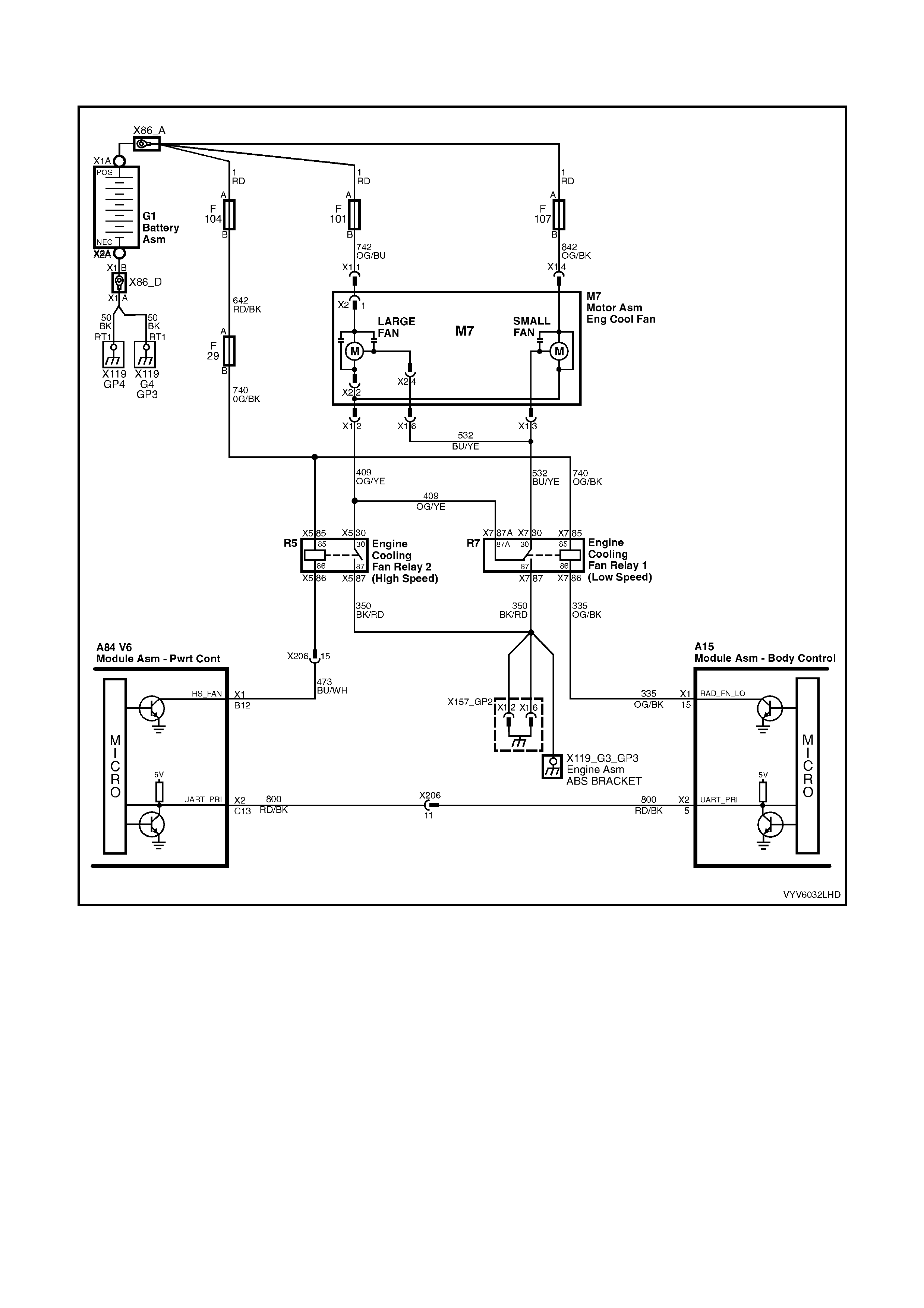
TABLE A-12.4 V6 PCM - ELECTRIC FAN CONTROL
HIGH PERFORMANCE FAN PACKAGE
Figure 6C1-2A-68 V6 High Performance Cooling Fan Package Circuit
HIGH PERFORMANCE ELECTRIC COOLING FAN PACKAGE
The high power fan package uses two, dual speed, engine cooling fan motors. The small fan is 268 mm in diameter
and has a m otor rated at 180 W atts , while the lef t large fan is 370 mm in diam eter with a motor power rating of 220
Watts.
While both the standard a nd high power assemblies have the sam e diameter fans, the power rating of the electric
motors, changes and can be seen visually by the larger diameter motor for the high power assemblies.
The engine cooling fan motors have three terminals; one positive and two negative. The positive terminals are
permanently connected to battery voltage, via fusible links F101 to the large fan motor and F107 to the small fan
motor . W hen the lo w speed en gine co oling f an rela y 1 (R7) is energis ed, one negative terminal of bot h cooling fan
motors is connected to ground through the relay and the fans will operate at low speed. When the high speed
cooling f an re la y 2 (R5) is energ ised, t he oth er negati ve ter m inal of bot h coo ling fan m otors is connec ted to ground
via the relay and both cooling fans will operate at high speed.

ENGINE COOLING FAN LOW SPEED
The PCM determines when to enable the low speed fan based on A/C Request, A/C pressure, Engine Coolant
Temperature and vehicle speed.
Note: The cooling fan operating pa rameters listed below may vary with different PCM calibrations.
The cooling fan low speed relay will be turned "ON'' when:
• The A/C request indicated (YES) and either
• the vehicle speed is less than 54 km/h.
or
• A/C pressure is greater than 1500 kPa
or
• The coolant temperature is greater than 104°C.
• or
• If the coolant temperature is greater than 117°C, when the ignition is switched off, the relay is energised for
approximately four minutes. This is known as “Low Fan Run On”.
• or
• If an engine coolant temperature sensor fault is detected, such as DTC P1116, P0117, P0118, or P1628.
The cooling fan low speed relay will be turned "OFF'' when any of the following conditions have been met:
• The coolant temperature is less than 99 °C.
• The A/C request is not indicated (NO)
• The A/C request is indicated (YES) and the vehicle speed is greater than 50 km/h and A/C pressure is less
than 1170 kPa.
ENGINE COOLING FAN HIGH SPEED
• T he eng ine co oling f an h igh s peed re la y 2 (R 5) is c on troll ed b y the PCM b ased o n engi ne c oolant tem peratu re
and A/C pressure. The PCM will only turn "ON'' the engine cooling fan high speed relay 2 (R5) if the engine
cooling fan low speed relay 1 (R7) has been "ON" for two seconds and the following conditions are satisfied.
• There is a BCM message response fault which has caused a DTC P1064.
• An engine coolant temperature sensor fault is detected such as DTC P1116, P0117, P0118, or P1628.
• Coolant temperature greater than 108°C.
• The A/C refrigerant pressure is greater than 2400 kPa.
If the lo w speed fan was "OFF " when the crit eria was met to turn t he high speed fan "ON", t he high spe ed fan wil l
come "ON" 5 seconds after the low speed fan is turned "ON". If both the engine cooling fan relays are "ON", the
PCM will turn "OFF" the high speed relay when:
• The engine coolant temperature is less than 108°C.
• A/C request not indic ate d (NO ) .
• A/C request indicated (YES) and A/C pressure is less than 2000 kPa.
LOW SPEED RESPONSE
The engine cooling low speed fan is enabled when the low speed relay is energised by the BCM. The PCM will
request the BCM to turn the low speed engine cooling fan relay on or off, via the serial data bus normal mode
message. After the PCM requests a change in the engine cooling fan low speed relay, the BCM will send a
response message back to the PCM via the serial data bus normal mode message confirming it received the
request. A failure in this response communication will set a DTC P1064.
DTC P1064 Low Speed Fan No BCM Response will be set if:
• En gine is idling
• The PCM sends a request to the BCM to turn ON the engine cooling fan low speed relay via the serial data
normal mode message and the BCM does not send a message back to the PCM.
• The PCM will not illuminate the Check Powertrain MIL.
TEST DESCRIPTION
Number(s) below refer to step number(s) on the diagnostic Table.
2. This entire diagnostic pr ocedure m ust begin wit h a “COLD” eng ine – at am bient air tem perature. If the coolant
is hot when di agnosis is perf ormed, replac ement of good parts m ay result. Fan sh ould not be r unning if engine
coolant temperature is less than 99°C and air conditioning is not “ON”.
6. Using Tech 2 will a llow operation of the High Speed C ooling Fan Rela y. If the test illum inates, the High Spe ed
Cooling Fan Relay is operating properly.
7. This test verifies that the Low Speed Cooling Fan will operate when the A/C system is turned “ON”.

A84 V6 – X1 A84 V6 – X2 A84 V6 – X3
Figure 6C1-2A-69
TABLE A-12.4 V6 PCM – HIGH PERFORMANCE ELECTRIC COOLING FAN CONTROL
STEP ACTION VALUE YES NO
1. Was the "On-Board Diagnostic" (OBD) System Check
performed? Go to Step 2. Go to
OBD System
Check
2. • From Table A-12.3
1. Check fusible links F101, F104, and F107 for an
open.
Was a problem found?
Go to Step 8 Go to Step 3
3. 1. Ignition OFF.
2. Remove the Engine Cooling Fan High Speed Relay
(R5).
3. Ignition ON.
4. Probe relay connector X5-85, circuit 740 with test
light connected to ground.
Is test light ON?
Go to Step 4 Go to Step 10
4. 1. Ignition ON.
2. Probe the Engine Cooling Fan High Speed Relay
(R5) connector X5-86, circuit 473 with a test light
connected to +12 volts.
3. Using TECH 2, select HIGH FAN, and command the
fan ON.
Is test light ON?
Go to Step 5 Go to Step 9
5. 1. Ignition OFF.
2. Reinstall the Engine Cooling Fan High Speed Relay
(R5).
1. Ignition ON.
3. Back probe the Engine Cooling Fan High Speed
Relay (R5) harness connector circuit 409 with test
light connected to +12 volts.
4. Using TECH 2, select HIGH FAN and command the
fan ON.
Is test light ON?
Go to Step 6 Go to Step 11
6. 1. Ignition ON.
2. Disconnect both electric cooling fan wiring harness
connectors.
3. Probe both fan harness connectors, circuits 532 and
409 with a test light to +12 volts.
4. Using TECH 2, select HIGH FAN and command fan
ON.
Is test light ON for both circuits ?
Go to Step 7 Go to Step 13
7. Probe both fan harness connector power feed circuits
742 and 842 with a test light connected to ground.
Is test light ON for all circuits?
Go to Step 12 Go to Step 15
8. 1. Check for a short to ground that caused fusible link
to blow.
2. Check that the engine cooling fan motor is not
drawing too much curre nt.
Is action complete ?
Verify Repair

STEP ACTION VALUE YES NO
9. 1. Ignition ON.
2. Using TECH 2, select HIGH FAN and command the
High Speed cooling fan ON.
3. Back probe PCM terminal X1-B12 with a test light
connected to +12 volts.
Is test light ON?
Go to Step 14 Go to Step 16
10. Repair open or short to ground in circuit 740.
Replace fuse F29 if blow n. Verify Repair
11. With test light connected to +12 volts, back probe the
Cooling Fan High Speed Relay (R5) harness connector
X5-87 circuit 350.
Does test light illuminate?
Go to Step 17 Go to Step 18
12. Check for a poor connection at both fan motors. If OK,
replace the electric cooling fan motor that did not operate. Verify Repair
13. Check for open in circuits 532 or 409.
Was a problem found? Verify Repair Go to Step 18
14. Repair open in circuit 473. Verify Repair
15. Repair open circuit in fan motor power circuit that did not
light test li ght. Verify Repair
16. Check for short to voltage in circuit 473, or faulty
connection at PCM, if OK replace PCM. Verify Repair
17. Replace Engine Cooling Fan High Speed Relay (R5). Verify Repair
18. Check for open in ground circuit 350.
Was a problem found? Verify Repair Go to Step 17

TABLE A-12.5 V6 PCM - ELECTRIC FAN CONTROL
HIGH PERFORMANCE FAN PACKAGE
Figure 6C1-2A-70 V6 High Performance Cooling Fan Package Circuit
HIGH PERFORMANCE ELECTRIC COOLING FAN PACKAGE
The high power fan package uses two, dual speed, engine cooling fan motors. The small fan is 268 mm in diameter
and has a m otor rated at 180 W atts , while the lef t large fan is 370 mm in diam eter with a motor power rating of 220
Watts.
While both the standard a nd high power assemblies have the sam e diameter fans, the power rating of the electric
motors, changes and can be seen visually by the larger diameter motor for the high power assemblies.
The engine cooling fan motors have three terminals; one positive and two negative. The positive terminals are
permanently connected to battery voltage, via fusible links F101 to the large fan motor and F107 to the small fan
motor . W hen the lo w speed en gine co oling f an rela y 1 (R7) is energis ed, one negative terminal of bot h cooling fan
motors is connected to ground through the relay and the fans will operate at low speed. When the high speed
cooling f an re la y 2 (R5) is energ ised, t he oth er negati ve ter m inal of bot h coo ling fan m otors is connec ted to ground
via the relay and both cooling fans will operate at high speed.

ENGINE COOLING FAN LOW SPEED
The PCM determines when to enable the low speed fan based on A/C Request, A/C pressure, Engine Coolant
Temperature and vehicle speed.
Note: The cooling fan operating pa rameters listed below may vary with different PCM calibrations.
The cooling fan low speed relay will be turned "ON'' when:
• The A/C request indicated (YES) and either
• the vehicle speed is less than 54 km/h.
or
• A/C pressure is greater than 1500 kPa
or
• The coolant temperature is greater than 104°C.
• or
• If the coolant temperature is greater than 117°C, when the ignition is switched off, the relay is energised for
approximately four minutes. This is known as “Low Fan Run On”.
• or
• If an engine coolant temperature sensor fault is detected, such as DTC P1116, P0117, P0118, or P1628.
The cooling fan low speed relay will be turned "OFF'' when any of the following conditions have been met:
• The coolant temperature is less than 99 °C.
• The A/C request is not indicated (NO)
• The A/C request is indicated (YES) and the vehicle speed is greater than 50 km/h and A/C pressure is less
than 1170 kPa.
ENGINE COOLING FAN HIGH SPEED
• T he eng ine co oling f an h igh s peed re la y 2 (R 5) is c on troll ed b y the PCM b ased o n engi ne c oolant tem peratu re
and A/C pressure. The PCM will only turn "ON'' the engine cooling fan high speed relay 2 (R5) if the engine
cooling fan low speed relay 1 (R7) has been "ON" for two seconds and the following conditions are satisfied.
• There is a BCM message response fault which has caused a DTC P1064.
• An engine coolant temperature sensor fault is detected such as DTC P1116, P0117, P0118, or P1628.
• Coolant temperature greater than 108°C.
• The A/C refrigerant pressure is greater than 2400 kPa.
If the lo w speed fan was "OFF " when the crit eria was met to turn t he high speed fan "ON", t he high spe ed fan wil l
come "ON" 5 seconds after the low speed fan is turned "ON". If both the engine cooling fan relays are "ON", the
PCM will turn "OFF" the high speed relay when:
• The engine coolant temperature is less than 108°C.
• A/C request not indic ate d (NO ) .
• A/C request indicated (YES) and A/C pressure is less than 2000 kPa.
LOW SPEED RESPONSE
The engine cooling low speed fan is enabled when the low speed relay is energised by the BCM. The PCM will
request the BCM to turn the low speed engine cooling fan relay on or off, via the serial data bus normal mode
message. After the PCM requests a change in the engine cooling fan low speed relay, the BCM will send a
response message back to the PCM via the serial data bus normal mode message confirming it received the
request. A failure in this response communication will set a DTC P1064.
DTC P1064 Low Speed Fan No BCM Response will be set if:
• En gine is idling
• The PCM sends a request to the BCM to turn ON the engine cooling fan low speed relay via the serial data
normal mode message and the BCM does not send a message back to the PCM.
• The PCM will not illuminate the Check Powertrain MIL.
TEST DESCRIPTION
Note: This entire diagnos tic proc edure mu st begin with a "cold" e ngine - at am bient air t emperature. If the cool ant
is hot when diagnosis is performed, replacement of good parts will result. Fan should not be running if engine
coolant temperature is less than 99°C and air conditioning is not "ON".
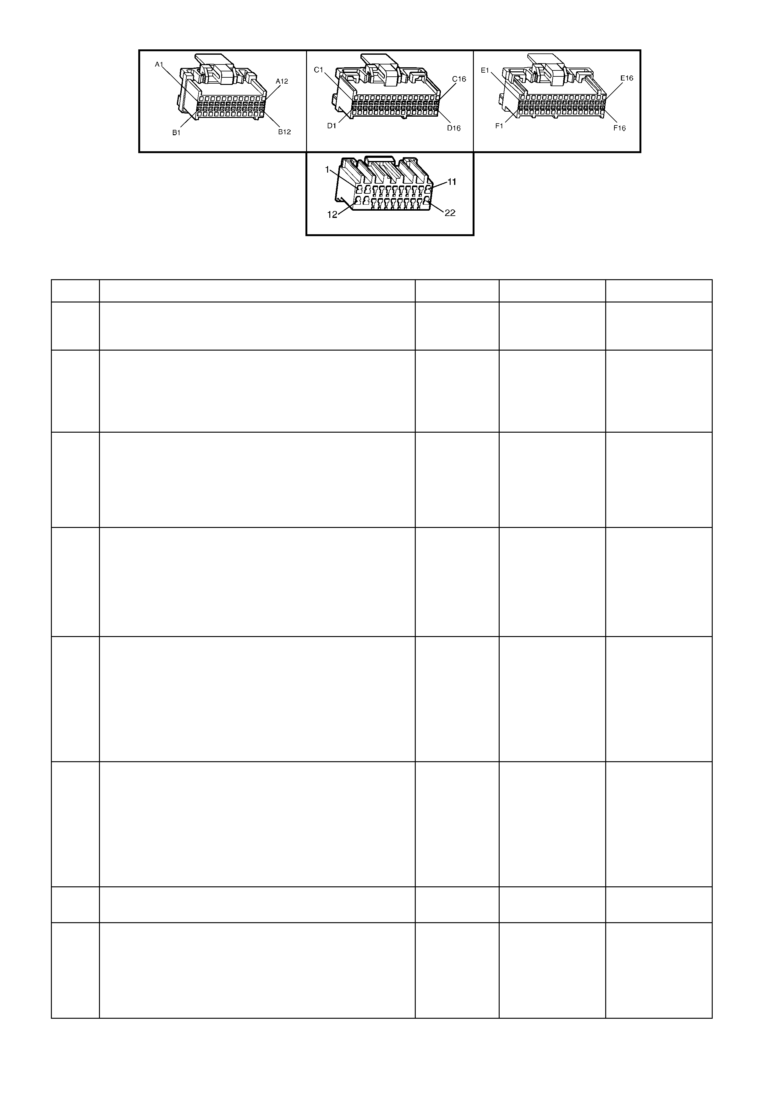
A84 V6 – X1 A84 V6 – X2 A84 V6 – X3
A15 – X1
Figure 6C1-2A-71
TABLE A-12.5 V6 PCM – HIGH POWER ELECTRIC COOLING FAN CONTROL
STEP ACTION VALUE YES NO
1. Was the "On-Board Diagnostic" (OBD) System Check
performed? Go to Step 2 Go to
OBD System
Check
2. 1. Ignition OFF.
2. Remove Engine Cooling Fan Low Speed Relay (R7).
3. Probe relay socket, circuit 740 with a test light
connected to +12 volts.
Is test light ON?
Go to Step 7 Go to Step 3
3. 1. W ith the Engine Cooling Fan Low Speed Relay (R7)
still removed.
2. Ignition ON.
3. Probe relay connector X7-85, circuit 740 with test
light connected to ground.
Is test light ON?
Go to Step 4 Go to Step 9
4. 1. Ignition ON.
2. Probe the Engine Cooling Fan Low Speed Relay
(R7) connector X7-86, circuit 335 with a test light
connected to +12 volts.
2. Using TECH 2, select LOW FAN and command the
Low Fan ON.
Is test light ON?
Go to Step 5 Go to Step 8
5. 1. Ignition ON.
2. Reinstall Engine Cooling Fan Low Speed Relay (R7).
3. Back probe the Engine Cooling Low Speed Relay
(R7) wiring harness connector X7-30, circuit 532 with
test light connected to +12 volts.
4. Using TECH 2, select LOW FAN and command the
Low Speed Fan ON.
Is test light ON?
Go to Step 6 Go to Step 10
6. 1. Ignition OFF.
2. Disconnect both Engine Cooling Fan wiring harness
connectors.
3. Probe both wiring harness connector circuits 532 X1-
3 and X1-6 with test light connected to +12 volts.
4. Using TECH 2, select LOW FAN and command the
Low Speed Fan ON.
Is test light ON?
Go to Step 14 Go to Step 12
7. Repair short to ground in circ uit 740.
Is action complete? Verify Repair
8. 1. Ignition ON.
2. Using TECH 2, select LOW FAN and command the
Low Fan ON.
3. Back probe BCM terminal X1-15 with a test light
connected to +12 volts.
Is test light ON?
Go to Step 13 Go to Step 15

STEP ACTION VALUE YES NO
9. Repair open in circuit which causes test light not to come
ON.
Is action complete?
Verify Repair
10. Replace Engine Cooling Fan Low Speed Relay (R7).
Is action complete? Verify Repair
11. Repair short to ground. Verify Repair
12. Repair open in circuits 532 or 409.
Is action complete? Verify Repair
13. Repair open in circuit 335 between BCM and the Engine
Cooling Fan Low Speed Relay (R7).
Is action complete?
Verify Repair
14. Replace the Engine Cooling Fan motor that did not
operate.
Is action complete?
Verify Repair
15. Check for faulty connection at BCM, if OK replace BCM.
Is action complete? Verify Repair
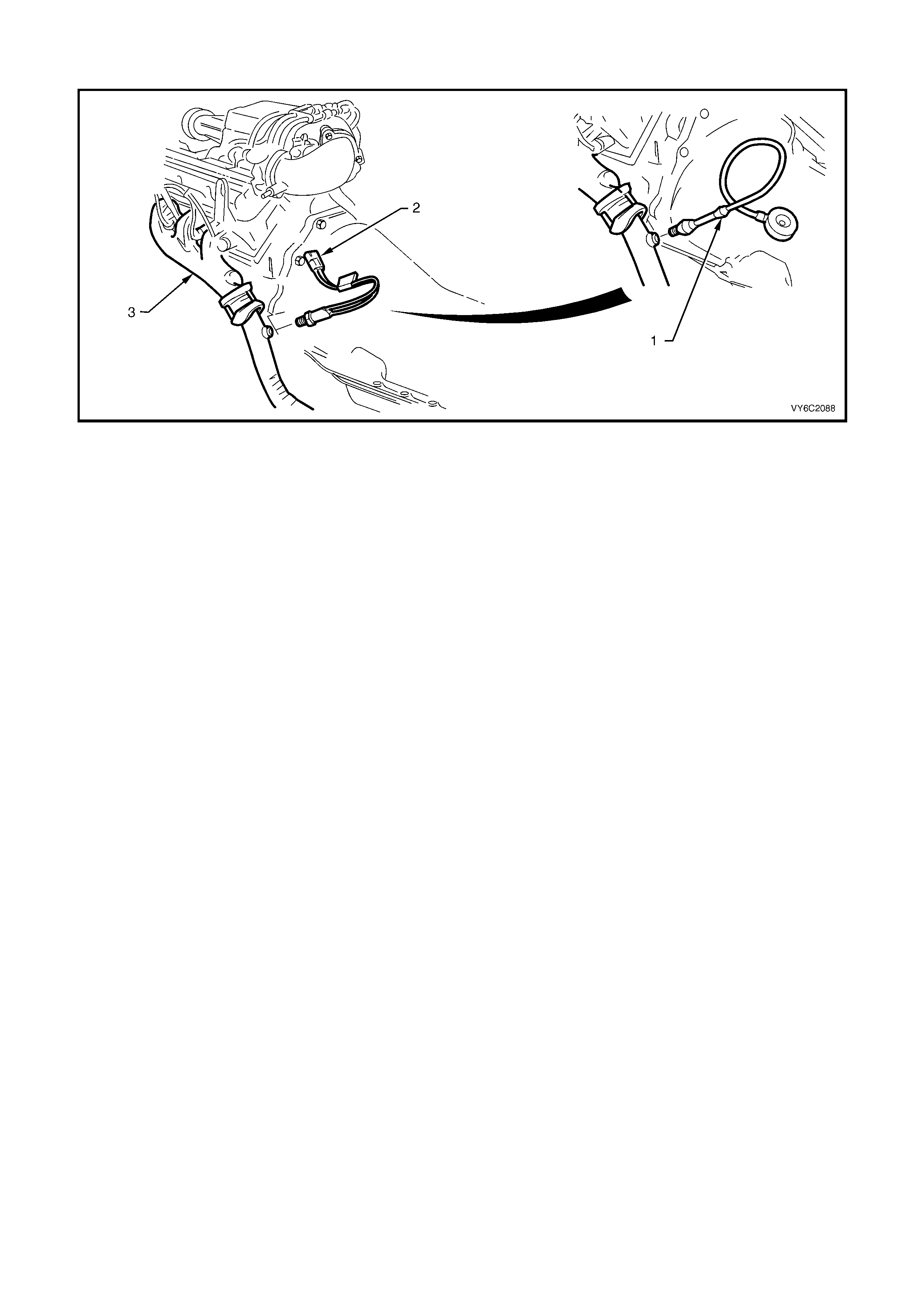
TABLE A-13 V6 PCM - RESTRICTED EXHAUST CHECK
Figure 6C1-2A-72 – Restricted Exhaust Check
Legend
1. Back Pressure Gauge Assembly. 2. Exhaust Gas Oxygen (O2S) Sensor 3. LH Engine Exhaust Pipe.
There are times when a restricted exhaust can cause a variety of owner complaints. Below is a list of some of these
owner complaints.
• No power, sluggish
• Hesitation on acceleration
• Surges while dr i ving
• Poor fuel economy
• Stalling
• Hard starting
Things that could cause a restricted exhaust:
A. Collapsed exhaust pipe.
B. Muffler. Loose baffles may cause internal restriction.
C. Catalytic converter. Things that can cause a catalytic converter to become restricted:
(1) The use of LEADED FUEL.
(2) A very rich-running engine. This rich-running condition could be caused by fuel pressure too high, a
malfunc tion in the eng in e contro l s ystem.
(3) Eng ine in a bad st ate of tune. W orn parts in the ignit ion system can cause an e ngine misf ire, which sends
unburned f uel and a ir into t he exhaust s ystem. T he catalytic con verter "s ees" th is unburned f uel and a ir as
a lean running condition.
(4) Push-starting the engine. This can send a tremendous amount of unburned fuel and air into the exhaust
system.

TABLE A-13 V6 PCM - RESTRICTED EXHAUST CHECK
STEP ACTION VALUE YES NO
1. Was the "On-Board Diagnostic" (OBD) System Check
performed? Go to Step 2 Go to
OBD System
Check
2. Carefully remove O2 sensor.
Did O2 sensor remove from exhaust system? Go to Step 3 Go to Step 6
3. 1. Install exhaust back pressure gauge in place of
removed O2 sensor.
2. Ignition "ON", engine idling.
3. Observe the exhaust system back pressure reading
on the gauge.
Is the reading below the specified value?
8.6 kPa Go to Step 4 Go to Step 7
4. Accelerate engine to 2000 RPM and observe reading on
gauge.
Is reading on gauge below the specified value?
20.7 kPa Go to Step 5 Go to Step 7
5. No problem with exhaust system.
NOTE: Make sure to coat threads of O2 sensor with a
specified anti-seize compound prior to
installation.
Is action complete?
Go to OBD
System Check
6. If the O2 sensor will not remove from the exhaust
System, make sure that the exhaust system is above
60°C. Excessive force may damage threads.
If the O2 sensor cannot be removed , the exhaust pipe
and O2 sensor may need to be replaced.
Was removal of O2 sensor successful?
Go to Step 3 Verify Repair
7. NOTE: If there are no obvious reasons for the excessive
back pressure, a restricted catalytic converter
should be suspected and replaced using current
recommended procedures. Refer to Things that
could cause a restricted exhaust: above for
possible causes.
NOTE: Make sure to coat threads of oxygen sensor with
a specified anti-seize compound prior to
installation.
Is action complete?
Verify Repair and
Go to OBD
System Check
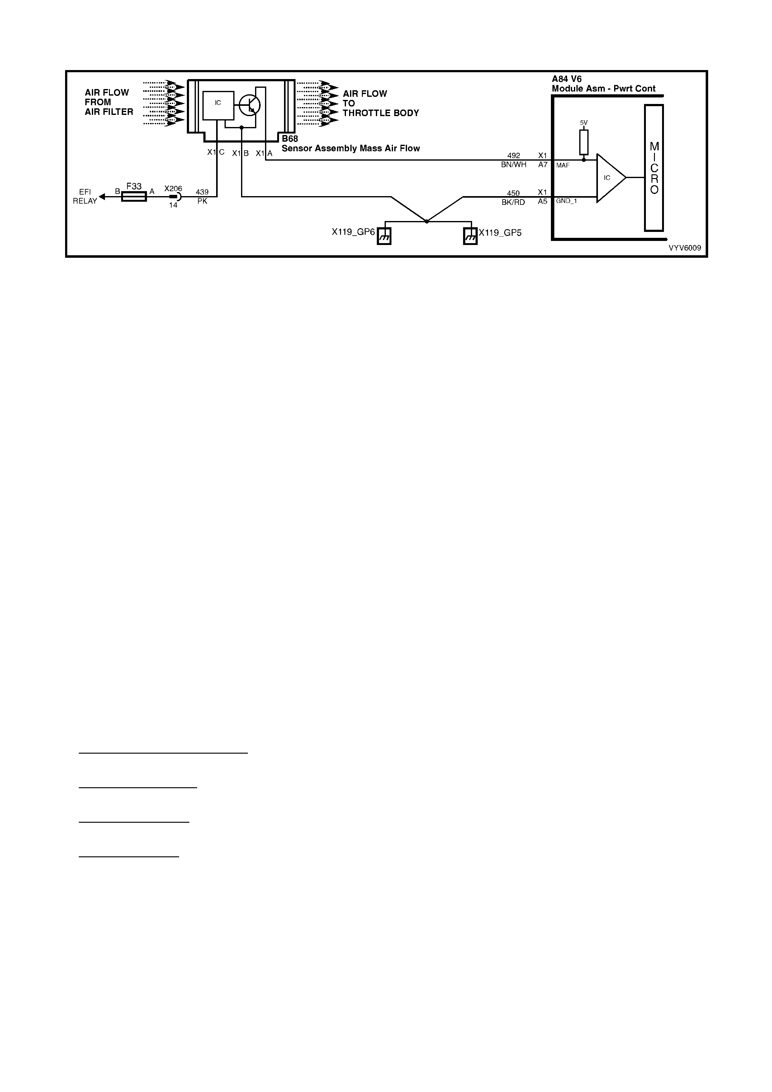
DTC P0101 V6 PCM - MASS AIR FLOW (MAF) SENSOR OUT OF RANGE
Figure 6C1-2A-73 Mass Air Flow Sensor Circuit
CIRCUIT DESCRIPTION
The Mas s Air Flo w ( M AF) s ens or meas ures the mass of air whic h pas s es thr o ugh it in a given time. T he PCM uses
this inf orm ation to m onitor t he opera tin g condi tion of the e ngine f or f uel del iver y c alculati ons. A larg e qua ntit y of air
movement indicates acceleration, while a small quantity indicates deceleration or idle.
The MAF sensor produces a frequency signal which cannot be easily measured.
The MAF sensor can be diagnosed using the procedures on this Table.
W ith DTC P0101 set, the PCM wil l use a def ault value for air flow based on thrott le pos ition, engi ne spee d and IAC
position, and some vehicle performance will return. When DTC P0101 is set the Check Powertrain MIL will be
activated.
Conditions for Running the DTC
• The engine is running.
Conditions for Setting the DTC
• No MAF signal for over 2 seconds.
Action Taken When the DTC Sets
• The PCM activates the Check Powertrain MIL when the diagnostic runs and fails.
• The PCM records the operating conditions at the time the diagnostic fails. The PCM stores this information in
the History Data.
• The PCM will substitute a MAF sensor value based on RPM, throttle angle and IAC position.
Conditions for Clearing the DTC
• The PCM turns the Check Powertrain MIL OFF when it sees a valid condition.
• Use a TECH 2 in order to clear the MIL/DTC.
DIAGNOSTIC AIDS
An interm ittent m ay be caused by a poor c onnection, mis-r outed harness, rubb ed throug h wire insula tion, or a wire
broken inside the insulation.
Check for:
• Poor Connection at PCM Pin - Inspect harness connectors for backed out terminals, improper mating, broken
locks, improperly formed or damaged terminals, and poor terminal to wire connection.
• Mis-Rout ed Harnes s - Ins pect MAF sensor harness to ens ure that it is not to o clos e to high volt age wires , suc h
as spark plug leads.
• Damaged Harness - Inspect harness for damage. If harness appears OK, observe TECH 2 while moving
related connectors and wiring harness. A change in display would indicate the intermittent fault location.
• Plugg ed Air Filter - A wide open thrott le acc eleratio n from a stop shoul d cause th e MAF read ing on T ECH 2 to
range from about 4-7 g/s at idle to 100 or greater at the time of the 1-2 shift on an automatic transmission. If
not, check for restriction.
TEST DESCRIPTION
Number(s) below refer to step number(s) on the diagnostic Table.
5. Verifies that both ignition feed voltage and a good ground circuit are available.
6. This step checks to see if the PCM recognises a problem.
7. A voltage reading at sensor harness connector terminal X1-A of less than 4 or over 6 vo lts indicates a fault in
circuit 492 or poor connection.

A84 V6 – X1 B68
Figure 6C1-2A-74
DTC P0101 V6 PCM - MASS AIR FLOW (MAF) SENSOR OUT OF RANGE
STEP ACTION VALUE YES NO
1. Was the "On-Board Diagnostic" (OBD) System Check
performed? Go to Step 2 Go to
OBD System
Check
2. 1. Ignition "ON".
2. Using TECH 2, select MAF frequency.
Is "MAF frequency" reading at the specified value?
0 Hz Go to Step 4 Go to Step 3
3. Replace MAF sensor.
Is action complete? Verify Repair
4. 1. Ignition "OFF".
2. Disconnect MAF sensor.
3. Ignition "ON".
4. Connect a test light to ground, and probe MAF
sensor ha rness c onnector terminal X1-C.
Is test light "ON"?
Go to Step 5 Go to Step 11
5. 1. Ignition "OFF".
2. Disconnect MAF sensor.
3. Ignition "ON".
4. Measure voltage between MAF sensor harness
connector term inals X1-B and X1-C.
Is voltage greater than specified value?
10 volts Go to Step 7 Go to Step 10
6. 1. Ignition "O FF".
2. Reconnect MAF sensor.
3. Ignition "ON" engine idling .
Is MAF sensor "MASS AIR FLOW" reading between the
Specified value?
4 - 9
grams/sec DTC P0101 is
intermittent. If no
additional DTC's
were stored, refer
to "Diagnostic
Aids"
Go to Step 3
7. 1. Ignition "OFF".
2. Disconnect wiring harness connector from MAF
sensor.
3. Ignition "ON".
4. Measure voltage at MAF sensor harness connector
terminal X1-A with a voltmeter to ground.
Is the measured voltage between the specified values?
4 - 6 volts Go to Step 6 Go to Step 8
8. Is voltage on MAF sensor harness connector terminal X1-
A less than specified value? 4 volts Go to Step 9 Go to Step 12
9. Check for an open or short to ground on circuit 492.
Is a fault found? Verify Repair Go to Step 13
10. Repair open in circuit 450.
Is action complete? Verify Repair
11. Repair open or short to ground in circuit 439.
Replace fuse F33 if blow n.
Is action complete?
Verify Repair
12. Repair short to voltage on circuit 492.
Is action complete? Verify Repair
13. Replace PCM.
Refer 6C1-3 Service Operations, for PCM Programming
and Security Link procedure.
Is action complete?
Verify Repair
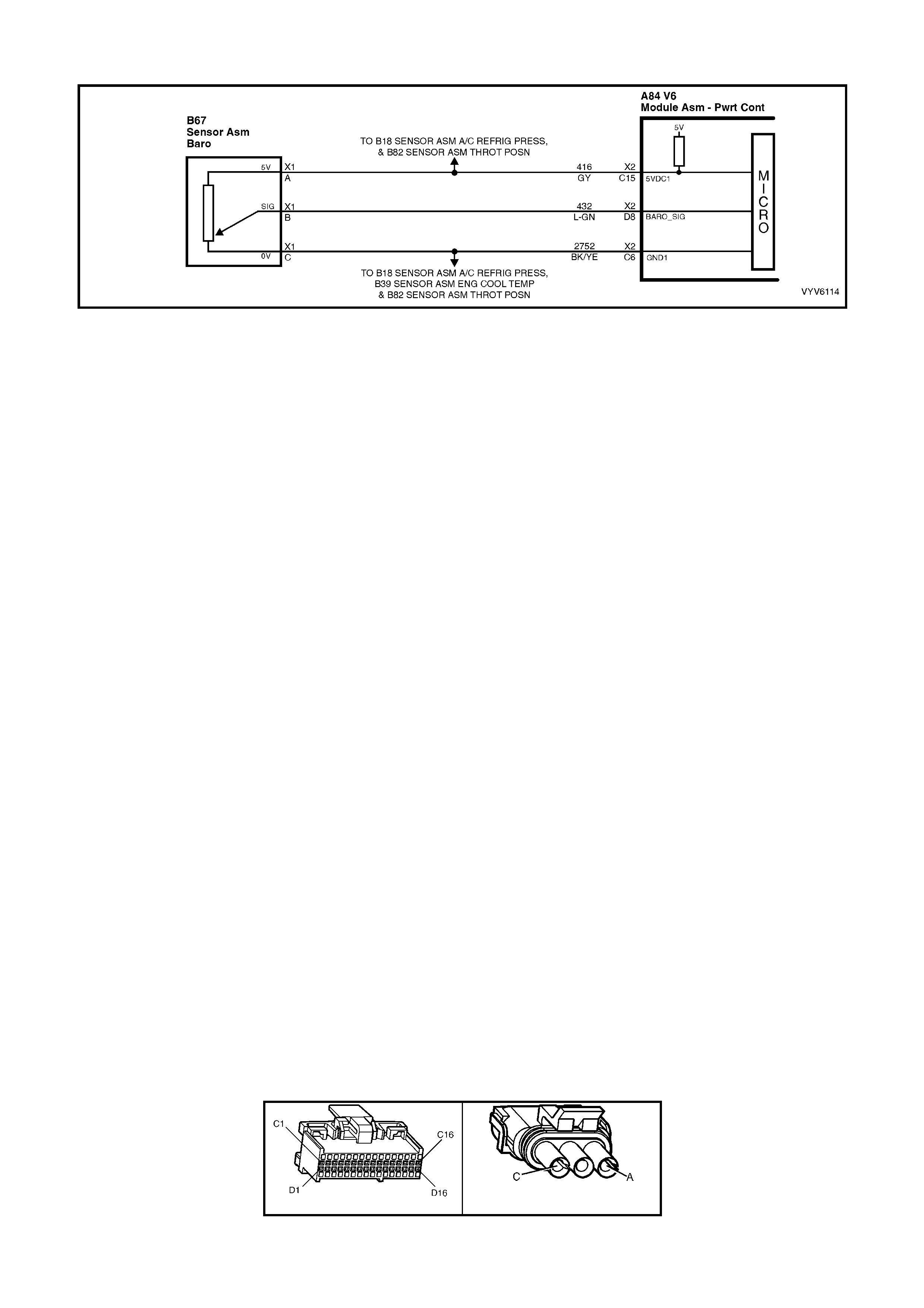
DTC P0107 V6 PCM - BAROMETRIC PRESSURE SENSOR SIGNAL VOLTAGE LOW
Figure 6C1-2A-75 Barometric Pressure Sensor Circuit
CIRCUIT DESCRIPTION
The Baro metric Pressur e sensor responds to changes in altitu de (air press ure). T he PCM rece ives this inf orm ation
as a voltage signal that will var y from about 4.7 to 4.9 volts at sea level to about 2.5 to 3.0 volts at 3048 meters
(10,000 feet).
Tech 2 displays altitude air pressure in volts. High altitude (low pressure) reads a low voltage while a low altitude
(high pressure) reads a high voltage.
If a Barometric Pressure sensor circuit fault is detected, the PCM will default to a sea level calibration for
transmission control.
CONDITIONS FOR RUNNING THE DTC
• Engine running.
• No TP DTCs are set.
• TP sensor greater than 1%.
CONDITIONS FOR SETTING THE DTC
• Barometric Pressure sensor signal voltage is too low for greater than three seconds.
ACTION TAKEN WHEN THE DTC SETS
• The PCM stores the DTC information into memory when the diagnostic runs and fails.
• The Check Powertrain MIL will not be activated.
• The PCM records the operating conditions at the time the diagnostic fails. The PCM stores this information in
the History Data.
• Once a Barometric Pressure sensor circuit fault is detected, the PCM will default to a sea level calibration for
transmission control.
CONDITIONS FOR CLEARING THE MIL/DTC
• Use a Tech 2 scan tool in order to clear the MIL/DTC.
DIAGNOSTIC AIDS:
An intermittent open in the sensor signal circuit or the 5 volt reference circuit will result in a DTC P0107.
W ith the ignition "ON", t he Barom etric Pres sure is equal t o atmos pheric pres sure and the s ignal vo ltage out put will
be high - close to 5 volts at sea level. This voltage is used by the PCM as an indication of vehicle altitude and is
refer red to as BARO. C omparison of this BARO r eading with one from a known good v ehicle at the same locatio n
with the s am e part num ber sens or is a good wa y to ch eck the accur ac y of a "sus pect" s ens or. R eadings s ho uld be
the sam e +/- 0.4 volts . Also, TABLE A-6.0 in this Service I nformation c an be used to t est the Barom etric pres sure
sensor.
Refer to INTERMITTENTS in Section 6C1-2B SYMPTOMS.
TEST DESCRIPTION
Number(s) below refer to step number(s) on the diagnostic Table.
3. If the PCM recognises the high Barometric Pressure sensor signal, the PCM and wiring are OK.
4. T ech 2 may not displa y 12 volts, h owever the important thing is that the PCM recognises the vo ltage as more
than 4 volts, indicating that the PCM and the sensor signal circuit are OK.
A84 V6 – X2 B67
Figure 6C1-2A-76

DTC P0107 V6 PCM - BAROMETRIC PRESSURE SENSOR SIGNAL VOLTAGE LOW
STEP ACTION VALUE YES NO
1. Was the "On-Board Diagnostic" (OBD) System Check
performed? Go to Step 2 Go to
OBD System
Check
2. 1. Ignition "ON", engine "OFF".
2. Connect Tech 2 to DLC.
Does Tech 2 display a Barometric Pressure Sensor
voltage equal to or less than specified value?
2.0 Volts Go to Step 3 DTC P0107 is
intermittent.
If no additional
DTCs were
stored, refer to
"Intermitt ent s" in
Section 6C1-2B
SYMPTOMS.
3. 1. Ignition "OFF".
2. Disconnect Barometric Pressure sensor electrical
connector.
3. Jumper harness terminal A to B.
4. Ignition "ON".
Does Tech 2 display Barometric Pressure sensor signal
voltage above spe cifi ed val ue ?
4.7 Volts Go to Step 6 Go to Step 4
4. 1. Ignition "OFF".
2. Remove jumper wire.
4. Probe circuit 432 (terminal B) connector with a test
light connected to 12 Volts.
5. Ignition "ON".
Does Tech 2 display Barometric Pressure sensor signal
voltage above spe cifi ed val ue ?
4.0 Volts Go to Step 5 Go to Step 8
5. Check for open or short to ground in the Barometric
Pressure sensor 5 volt reference circuit.
Was a problem found?
Verify Repair Go to Step 9
6. Check for a faulty connection.
Was a problem found? Verify Repair Go to Step 7
7. Replace Barometric Pressure sensor.
Is action complete? Verify Repair
8. Check for open, short to ground, in the Barometric
Pressure sensor sign al circuit.
Was a problem found?
Verify Repair Go to Step 9
9. Replace PCM.
Refer 6C1-3 Service Operations, for PCM Programming
and Security Link procedure.
Is action complete?
Verify Repair
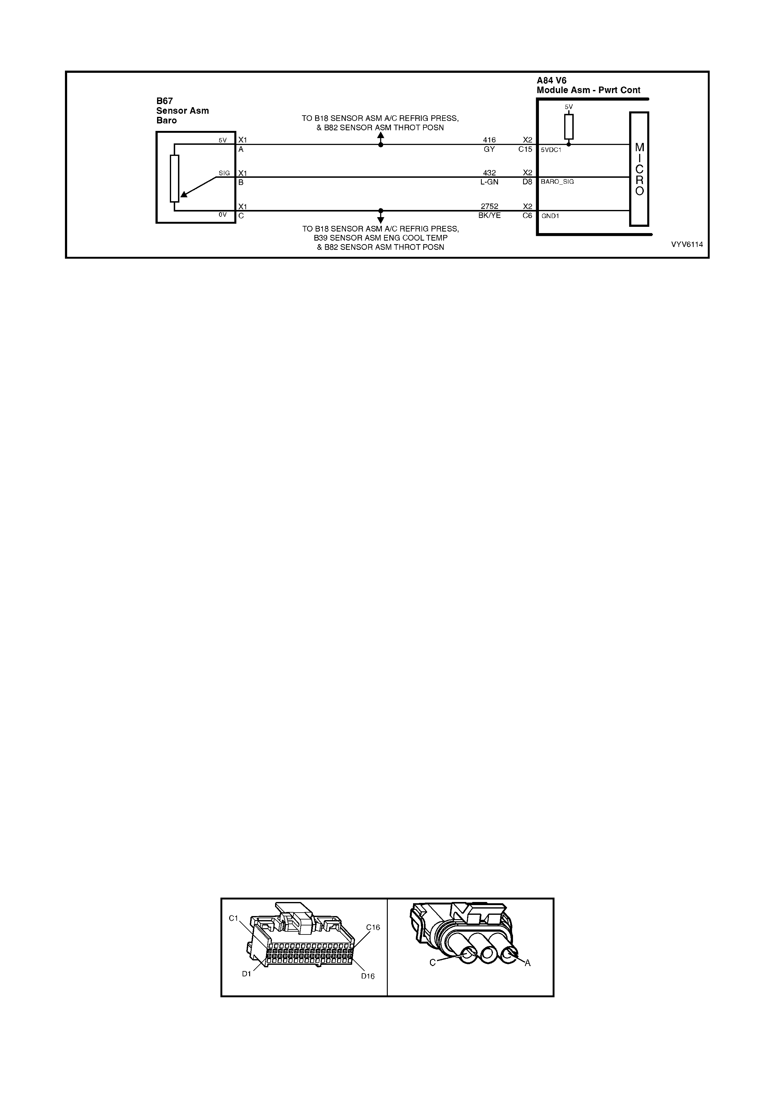
DTC P0108 V6 PCM - BARO METRIC PRESSURE SENSOR SIGNAL VOLTAGE HIGH
Figure 6C1-2A-77 Barometric Pressure Sensor Circuit
CIRCUIT DESCRIPTION
The Baro metric Pressur e sensor responds to changes in altitu de (air press ure). T he PCM rece ives this inf orm ation
as a voltage signal that will var y from about 4.7 to 4.9 volts at sea level to about 2.5 to 3.0 volts at 3048 meters
(10,000 feet).
Tech 2 displays altitude air pressure in volts. High altitude (low pressure) reads a low voltage while a low altitude
(high pressure) reads a high voltage.
CONDITIONS FOR RUNNING THE DTC
• Engine running.
• No TP DTCs are set.
• TP sensor less than about 3%.
CONDITIONS FOR SETTING THE DTC
• Barometric Pressure sensor signal voltage is too high for a time greater than three seconds.
ACTION TAKEN WHEN THE DTC SETS
• The PCM stores the DTC information into memory when the diagnostic runs and fails.
• The Check Powertrain MIL will not be illuminated.
• The PCM records the operating conditions at the time the diagnostic fails. The PCM stores this information in
the History Data.
• Once a Barometric Pressure sensor circuit fault is detected, the PCM will default to a sea level calibration for
transmission control.
CONDITIONS FOR CLEARING THE MIL/DTC
• Use a Tech 2 scan tool in order to clear the MIL/DTC.
DIAGNOSTIC AIDS
An open sensor ground circuit will set DTC P0123 and DTC P0118.
W ith the ignition "ON", t he Barom etric Pres sure is equal t o atmos pheric pres sure and the s ignal vo ltage out put will
be high - close to 5 volts at sea level. This voltage is used by the PCM as an indication of vehicle altitude and is
refer red to as BARO. C omparison of this BARO r eading with one from a known good v ehicle at the same locatio n
with the s am e part num ber sens or is a good wa y to ch eck the accur ac y of a "sus pect" s ens or. R eadings s ho uld be
the same +/- 0.4 volts. Also, TABLE A-6.0 in this Section can be used to test the Barometric pressure sensor.
Refer to INTERMITTENTS in Section 6C1-2B SYMPTOMS.
TEST DESCRIPTION
Number(s) below refer to step number(s) on the diagnostic Table.
2. This step checks to see if the Barometric Pressure sensor is working properly.
4. If the PCM recognises the low Barometric Pressure sensor signal, the PCM and wiring are OK.
A84 V6 – X2 B67
Figure 6C1-2A-78

DTC P0108 V6 PCM – BAROMETRIC PRESSURE SENSOR SIGNAL VOLTAGE HIGH
STEP ACTION VALUE YES NO
1. Was the "On-Board Diagnostic" (OBD) System Check
performed? Go to Step 2 Go to
OBD System
Check.
2. 1. Ignition "ON", engine "OFF".
2. Connect Tech 2 to DLC.
Does Tech 2 display a Barometric Pressure Sensor
voltage equal to or greater than specified value?
4.0 volts Go to Step 3 If no additional
DTCs were
stored, refer to
"Intermitt ent s" in
Section
6C1-2B
SYMPTOMS.
3. 1. Ignition "OFF".
2. Disconnect Barometric Pressure sensor electrical
connector.
3. Ignition "ON".
Does Tech 2 display a Barometric Pressure Sensor
voltage less than spe cif ied val ue?
1.0 volt Go to Step 4 Go to Step 7
4. 1. Ignition "ON", engin e "OFF ".
2. Using a test light connected to B+, probe the
Barometric Pressure Sensor connector ground circuit.
Does the test light illuminate ?
Go to Step 5 Go to Step 9
5. Check the Barometric Pressure Sensor 5 volt reference
circuit for short to B+.
Was problem found?
Verify Repair Go to Step 6
6. Replace the Barometric Pressure Sensor.
Is action complete? Verify Repair
7. Check for short to voltage in the Barometric Pressure
Sensor signal circuit.
Was a problem found?
Verify Repair Go to Step 8
8. Replace PCM.
Refer 6C1-3 Service Operations, for PCM Programming
and Security Link procedure.
Is action complete?
Verify Repair
9. Check for and repair open in Barometric Pressure Sensor
ground circuit.
Is repair completed?
Verify Repair
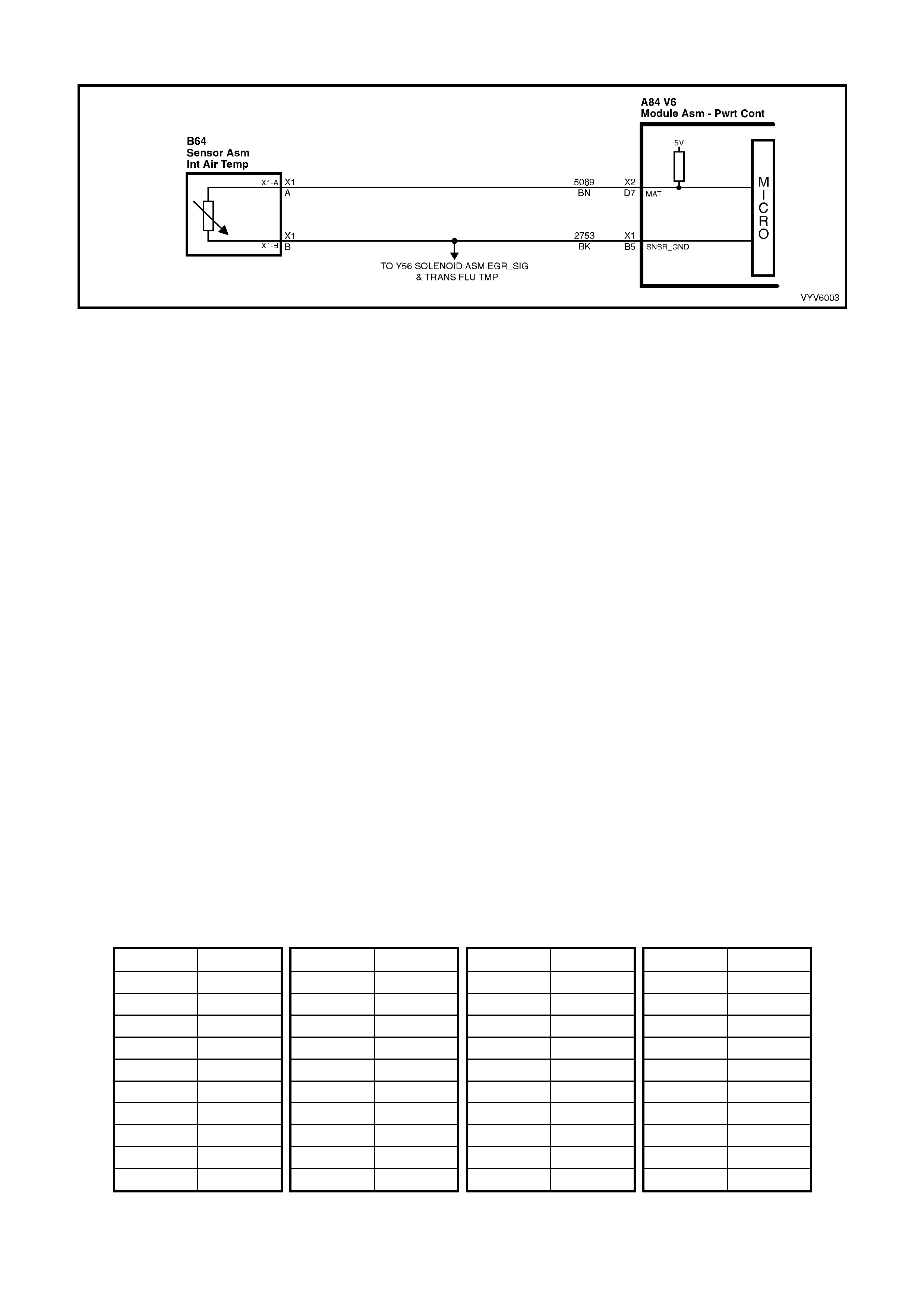
DTC P0111 V6 PCM - INTAKE AIR TEMPERATURE (IAT) SIGNAL VOLTAGE UNSTABLE
Figure 6C1-2A-79 Intake Air Temperature Sensor Circuit
CIRCUIT DESCRIPTION
The Intake Air Temperature (IAT) sensor uses a thermistor to control the signal voltage to the PCM. The PCM
applies a voltage ( about 5 vo lts) on circu it 5089 to the sensor. W hen manifold in take air is cold (s uch as when the
engine is first started on a cold day), the sensor (thermistor) resistance is high, therefore, the PCM will sense a high
signal voltage. If the m anifold intake air is warm, the sensor (therm istor) resistance is low, therefore, the PCM will
sense a low signal voltage.
CONDITIONS FOR RUNNING THE DTC
• The engine has been operating for more than 10 seconds.
CONDITIONS FOR SETTING THE DTC
• IAT sensor reading changes more than 7°C (140 millivolts) in 100 milliseconds.
ACTION TAKEN WHEN THE DTC SETS
• The PCM stores the DTC information into memory when the diagnostic runs and fails.
• The Check Powertrain MIL will not be activated.
• The PCM records the operating conditions at the time the diagnostic fails. The PCM stores this information in
the History Data.
• When DTC P0111 is set, the PCM will default to a 25°C IAT for engine operation.
CONDITIONS FOR CLEARING THE MIL/DTC
• Use a TECH 2 in order to clear the MIL/DTC.
DIAGNOSTIC AIDS
When attempting to diagnose an intermittent problem, use the snapshot mode of TECH 2 to review diagnostic
information.
TEST DESCRIPTION
Number(s) below refer to step number(s) on the diagnostic table.
8. When checking terminal retention use a suitably sized test terminal as found in Connector Test Adapter Kit
J35616-A.
10. When checking terminal retention at PCM connectors use a 0.95 mm drill shank.
IAT SENSOR T ABLE RES ISTANCE-TEMPERATURE CH AR ACTER ISTICS
Temp (C) Ω
ΩΩ
Ω Temp (C) Ω
ΩΩ
Ω Temp (C) Ω
ΩΩ
Ω Temp (C) Ω
ΩΩ
Ω
-40 102,129 15 4,497 60 679 110 135
-35 73,345 20 3,555 65 566 115 117
-30 53,253 25 2,830 70 475 120 102
-25 39,066 30 2,268 75 400 125 89
-20 28,940 35 1,829 80 338 130 79
-15 21,638 40 1,483 85 287 135 69
-10 16,321 45 1,210 90 245 140 61
-5 12,414 50 993 95 210 145 54
0 9,517 55 819 100 180 150 48
5 7,355 10 5,729 105 156
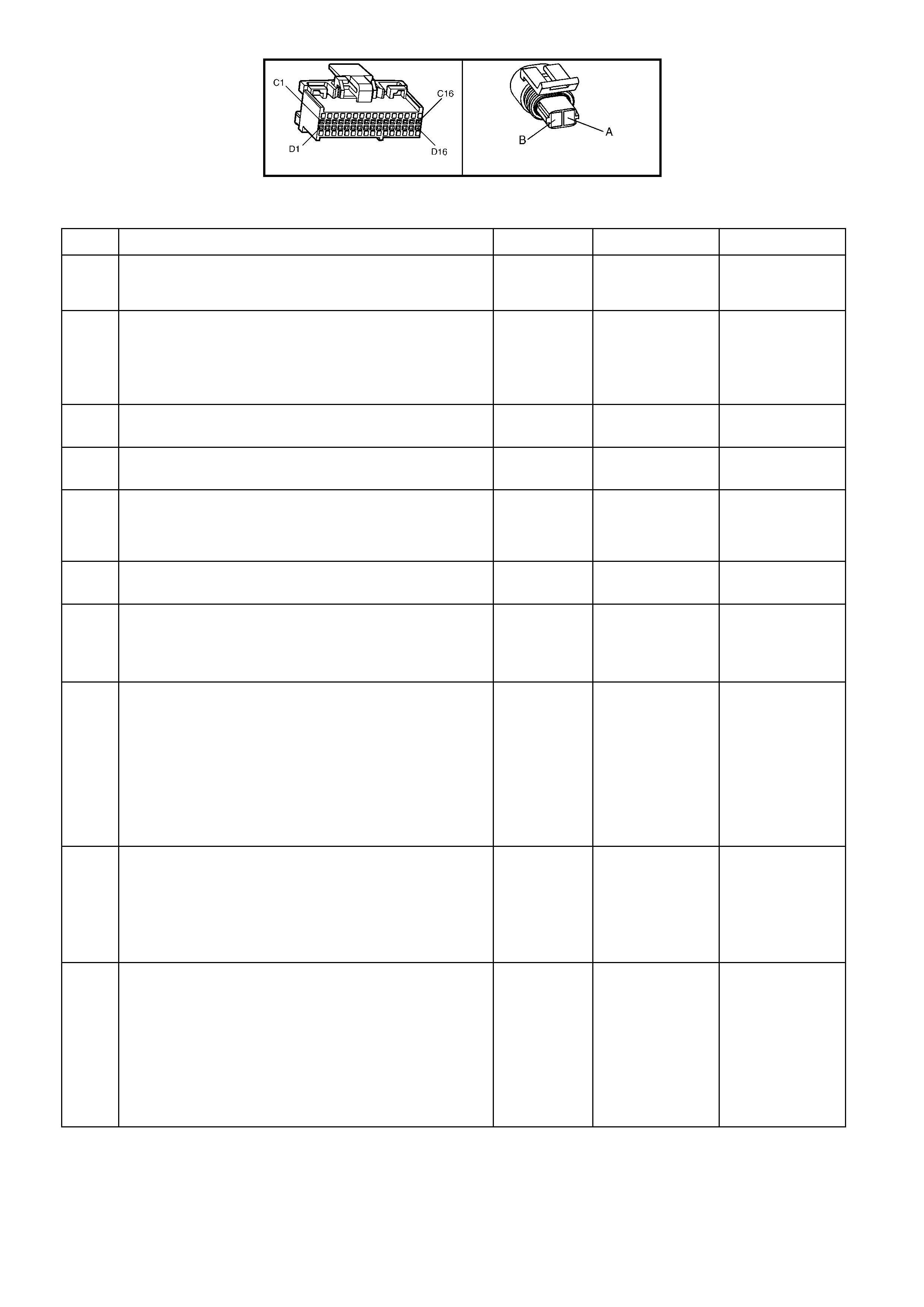
A84 V6 – X2 B64
Figure 6C1-2A-80
DTC P0111 V6 PCM - INTAKE AIR TEMPERATURE (IAT) SIGNAL VOLTAGE UNSTABLE
STEP ACTION VALUE YES NO
1. Was the "On-Board Diagnostic" (OBD) System Check
performed? Go to Step 2 Go to
OBD System
Check
2. 1. Install TECH 2 and set up snapshot mode to trigger
on DTC P0111.
2. Watch TECH 2 while wiggling the IAT sensor
connector.
Does the "IAT" reading change sharply?
Go to Step 8 Go to Step 3
3. Wiggle and tug the IAT sensor harness.
Does the "IAT" reading change sharply? Go to Step 9 Go to Step 4
4. Wiggle and tug the harness at the PCM.
Does the "IAT" reading change sharply? Go to Step 10 Go to Step 5
5. Lightly tap on the PCM.
Does the "IAT" reading change sharply? Go to Step 6 DTC P0111 is
intermittent, refer
to Diagnostic
Aids
6. Make sure PCM is mounted securely to vehicle.
Was a problem found? Verify Repair Go to Step 7
7. Replace PCM.
Refer 6C1-3 Service Operations, for PCM Programming
and Security Link procedure.
Is action complete?
Verify Repair
8. 1. Check IAT sens or connector.
2. Check the tightness of the female terminal retention
with a suitable sized test terminal.
3. Inspect connectors for corrosion. If connectors are
corroded, try cleaning with electronic part cleaner
and retest.
4. If these repairs do not resolve the problem, replace
terminals.
Is action complete?
Verify Repair
9. 1. Check for an open or short in the IAT harness.
2. Check for broken strands of wire in IAT sensor
harness.
3. Check for cuts or pinches in IAT sensor harness.
4. Make repairs as necessary.
Is action complete?
Verify Repair
10. 1. Check the IAT sensor connection at the PCM.
2. Check tightness of the female terminal retention with
a suitable test terminal.
3. Inspect connectors for corrosion. If connectors are
corroded, try cleaning with electronic parts cleaner
and retest.
4. Remove connector strain relief and remove terminal
from connector to check for broken locking tang.
Is action complete?
Verify Repair
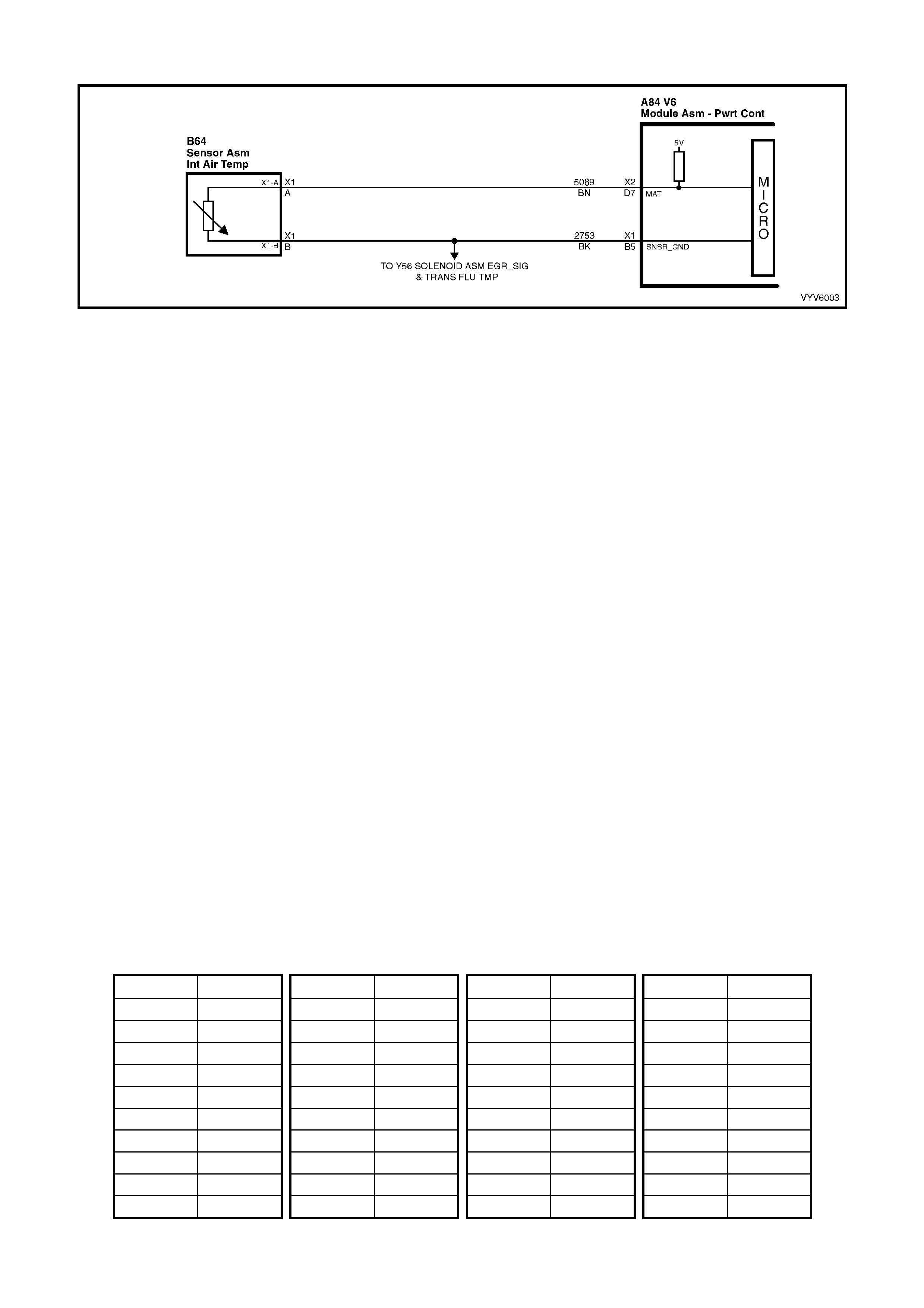
DTC P0112 V6 PCM - INTAKE AIR TEMPERAT URE (IAT) SIGNAL VOLTAGE LOW
Figure 6C1-2A-81 Intake Air Temperature Sensor Circuit
CIRCUIT DESCRIPTION
The Intake Air Temperature (IAT) sensor uses a thermistor to control the signal voltage to the PCM. The PCM
applies a voltage (about 5 volts) on circuit 5089 to the sensor. W hen the intake air is cold, the sensor (ther mistor)
resistance is high, therefore, the PCM will sense a high signal voltage. If the intake air is warm, the sensor
(thermistor) resistance is low, therefore, the PCM will sense a low signal voltage.
Conditions for Running the DTC
• The engine has been operating for more than 10 seconds.
Conditions for Setting the DTC
• IAT Sens or s ign al v olt ag e i s at or les s t han 0. 3 volts, i ndic at in g a n int ake air temper atur e at or abo ve 1 35°C for
more than one second.
Action Taken When the DTC Sets
• The PCM stores the DTC information into memory when the diagnostic runs and fails.
• The Check Powertrain MIL will not be activated.
• The PCM records the operating conditions at the time the diagnostic fails. The PCM stores this information in
the History Data.
• When DTC P0112 is set, the PCM will default to a 25°C IAT for engine operation.
Conditions for Clearing the MIL/DTC
• Use a TECH 2 in order to clear the MIL/DTC.
DIAGNOSTIC AIDS
Intake Air Temperature ( IAT) on a TECH 2 indic ates the temper ature of the air in the air cleaner. If the en gine has
been allowed to sit overnight, the IAT sensor and engine coolant temperature values should be within a few
degrees of each other. After the engine is started, the IAT will increase due to engine compartment tem peratures,
however, IAT will rarely exceed 80°C.
When the PCM detects a fault in the IAT circuit, a default value of 25°C will be used.
Check harness routing for a possible short to ground in circuit 5089.
Refer to "Intermittents" in Section 6C1- 2 B SYM PT O MS.
TEST DESCRIPTION
Number(s) below refer to step number(s) on the diagnostic Table.
IAT SENSOR T ABLE RES ISTANCE-TEMPERATURE CH AR ACTER ISTICS
Temp (C) Ω
ΩΩ
Ω Temp (C) Ω
ΩΩ
Ω Temp (C) Ω
ΩΩ
Ω Temp (C) Ω
ΩΩ
Ω
-40 102,129 15 4,497 60 679 110 135
-35 73,345 20 3,555 65 566 115 117
-30 53,253 25 2,830 70 475 120 102
-25 39,066 30 2,268 75 400 125 89
-20 28,940 35 1,829 80 338 130 79
-15 21,638 40 1,483 85 287 135 69
-10 16,321 45 1,210 90 245 140 61
-5 12,414 50 993 95 210 145 54
0 9,517 55 819 100 180 150 48
5 7,355 10 5,729 105 156
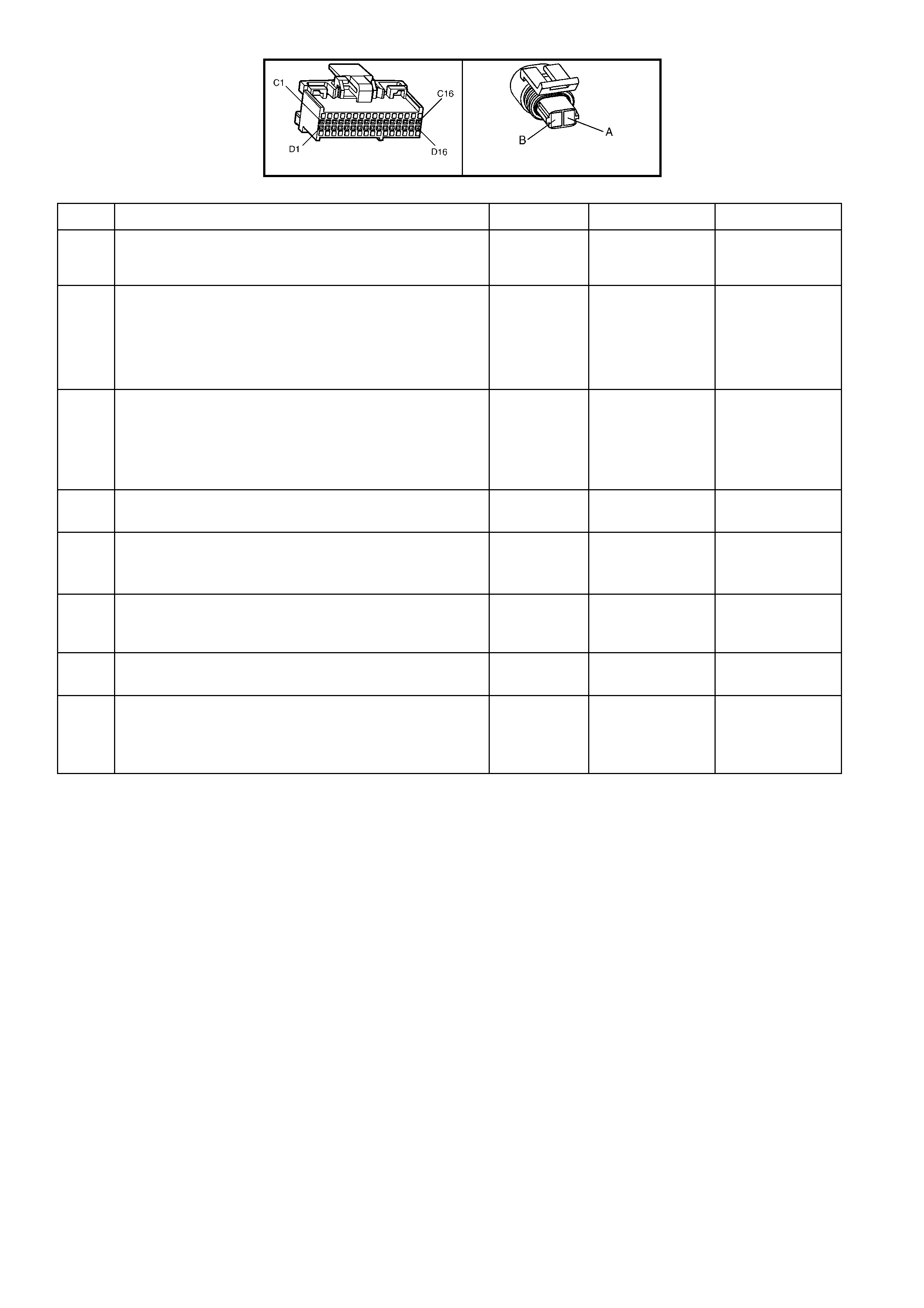
A84 V6 – X2 B64
DTC P0112 V6 PCM - INTAKE AIR TEMPERATURE (IAT) SIGNAL VOLTAGE LOW
STEP ACTION VALUE YES NO
1. Was the "On-Board Diagnostic" (OBD) System Check
performed? Go to Step 2 Go to
OBD System
Check
2. 1. Ignition OFF.
2. Install TECH 2.
3. Ignition ON.
Does TECH 2 momentarily display "IAT" equal or greater
than specified val ue?
135 °C Go to Step 3 DTC P0112 is
intermittent, if no
additional DTCs
were stored, refer
to "Diagnostic
Aids"
3. 1. Disconnect IAT sensor wiring harness.
2. Ignition off.
3. Install TECH 2.
4. Ignition ON.
Does TECH 2 display "IAT" below specified value?
-30 °C Go to Step 4 Go to Step 6
4. Measure resistance across IAT sensor.
Does value correspond to specified value? Refer to IAT
table. Go to Step 5 Go to Step 7
5. Check for intermittent or loose terminals in harness
connector, or termina ls shorted together.
Was a problem found?
Verify Repair Go to Step 8
6. Check for a short in circuit 5089 to ground or to IAT
sensor ground.
Was a problem found?
Verify Repair Go to Step 8
7. Replace IAT sensor.
Is action complete? Verify Repair
8. Replace PCM.
Refer 6C1-3 Service Operations, for PCM Programming
and Security Link procedure.
Is action complete?
Verify Repair
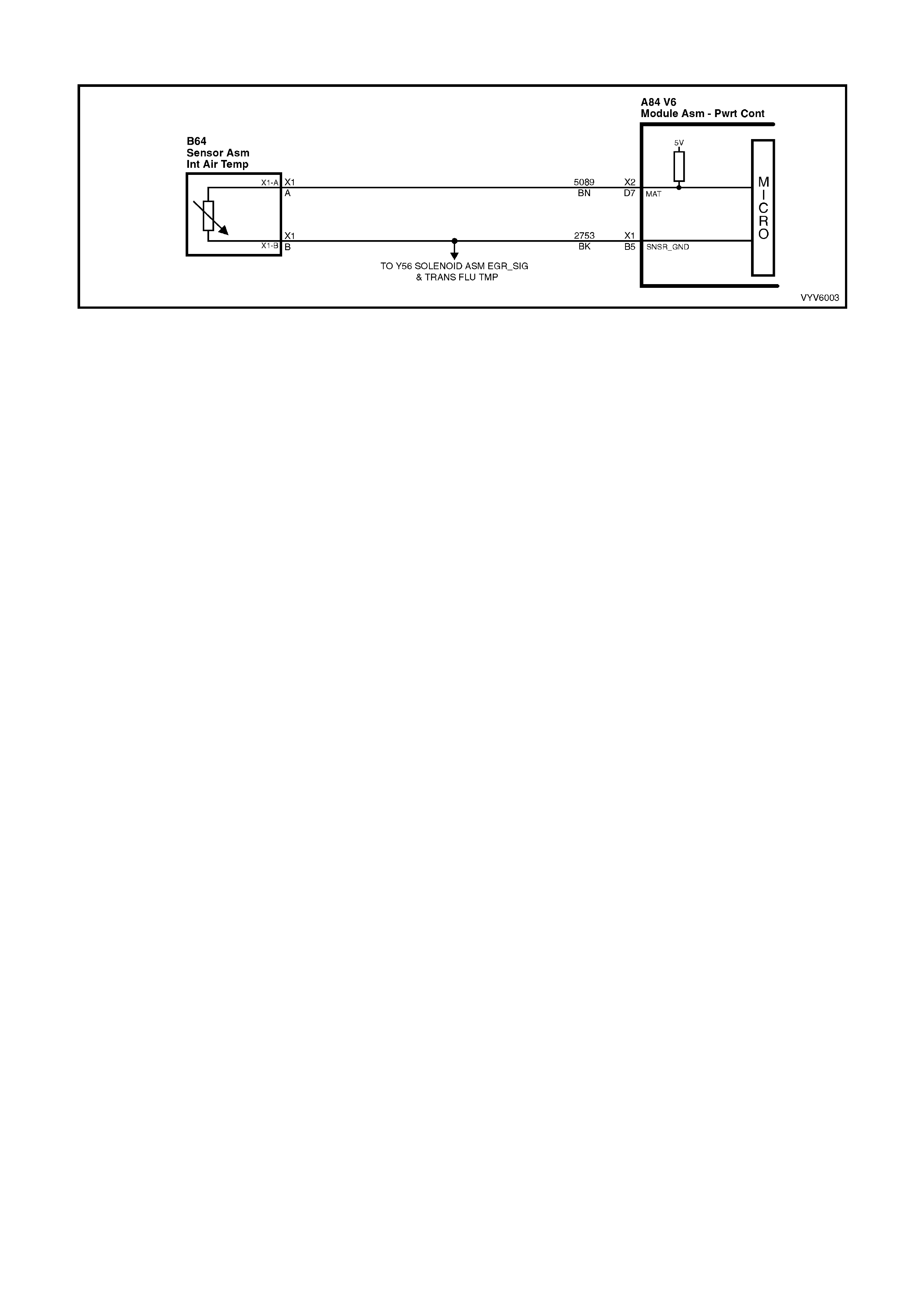
DTC P0113 V6 PCM - INTAKE AIR TEMPERATURE (IAT) SIGNAL VOLTAGE HIGH
Figure 6C1-2A-82 Intake Air Temperature Sensor Circuit
CIRCUIT DESCRIPTION
The Intake Air Temperature (IAT) sensor uses a thermistor to control the signal voltage to the PCM. The PCM
applies a voltage (about 5 volts) on circuit 5089 to the sensor. W hen the intake air is cold, the sensor (ther mistor)
resistance is high, therefore, the PCM will sense a high signal voltage. If the intake air is warm, the sensor
(thermistor) resistance is low, therefore, the PCM will sense a low signal voltage.
CONDITIONS FOR RUNNING THE DTC
• The engine has been operating for more than 10 seconds.
Conditions for Setting the DTC
• IAT s ensor signal vo ltage is mor e than 4.9 volts, indicatin g an intak e air tem perature at or belo w -30°C for one
second.
Action Taken When the DTC Sets
• The PCM stores the DTC information into memory when the diagnostic runs and fails.
• The Check Powertrain MIL will not be activated.
• The PCM records the operating conditions at the time the diagnostic fails. The PCM stores this information in
the History Data.
• When DTC P0113 is set, the PCM will default to a 25°C IAT for engine operation.
Conditions for Clearing the MIL/DTC
• Use a TECH 2 to clear the MIL/DTC.
DIAGNOSTIC AIDS
When the PCM detects a fault in the IAT sensor circuit, a default value of 25°C will be used by the PCM.
Carefully check harness and connections for possible open circuit 5089 or circuit 2753.
An open circuit 2753 will s et DTC P0113, P0405 and P0713. If the engine has been allowed to sit overnight, th en
the intake air temperature and engine coolant temperature values should be within a few degrees of each other.
After the engine is started, the IAT sensor will increase due to engine compartment temperatures.
Refer to "Intermittents" in Section 6C1-2B SYMPTOMS .
TEST DESCRIPTION
Number(s) below refer to step number(s) on the diagnostic Table.
4. A Diagnos tic Trouble Co de P01 13 wil l s et, du e to a n o pen sens or , wire or c on nection. This tes t wil l deter mine if
the wiring and PCM are OK.
5. This will determine if the IAT sensor ground circuit 2753 is open.
Note: If this c ircuit is open at the PCM DT C P0530, P0405 and P0 713 wil l also b e set. If these ad ditional DT Cs
are not set the open circuit is between the IAT sensor and the splice joint in circuit 2753.
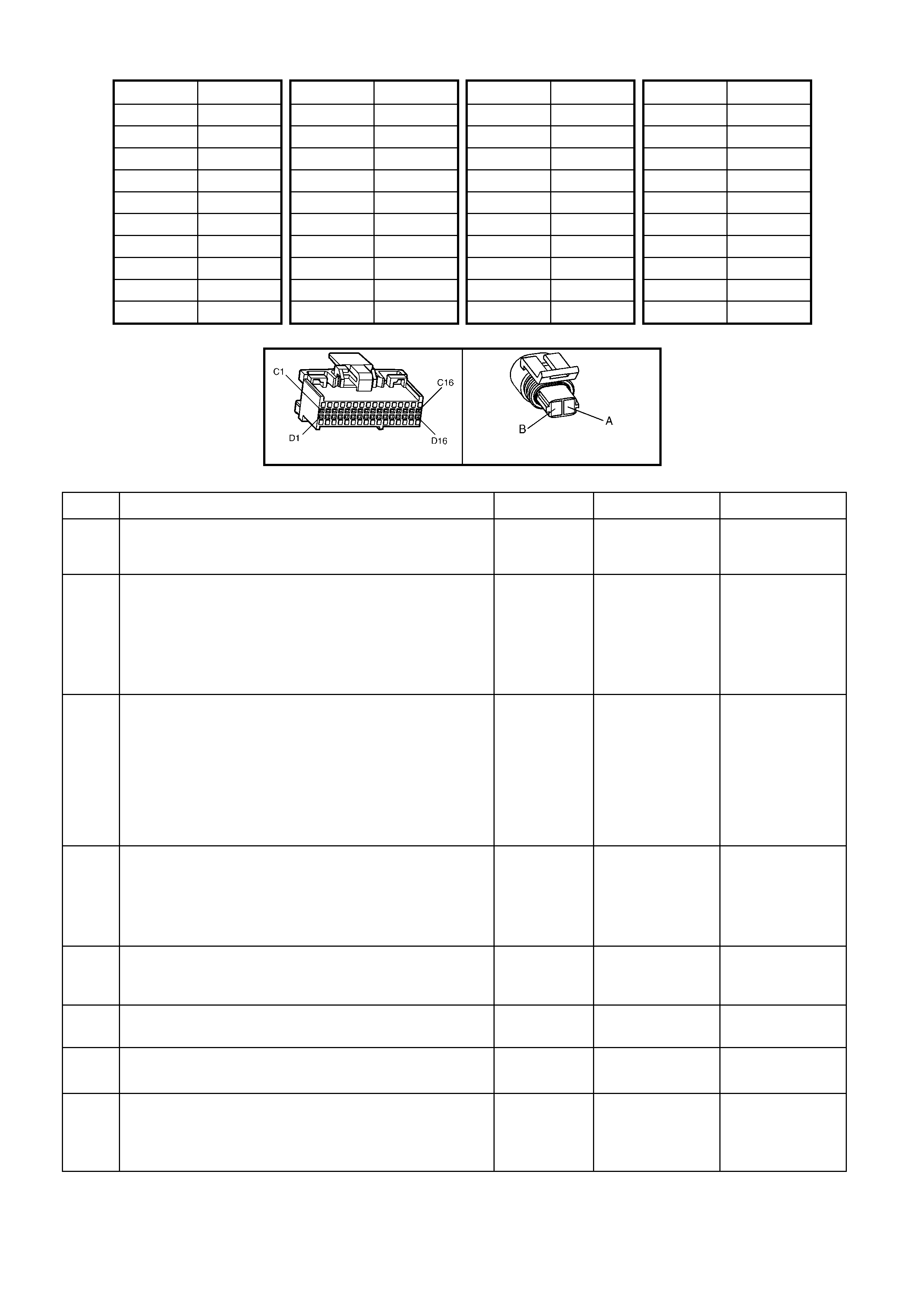
IAT SENSOR T ABLE RES ISTANCE-TEMPERATURE CH AR ACTER ISTICS
Temp (C) Ω
ΩΩ
Ω Temp (C) Ω
ΩΩ
Ω Temp (C) Ω
ΩΩ
Ω Temp (C) Ω
ΩΩ
Ω
-40 102,129 15 4,497 60 679 110 135
-35 73,345 20 3,555 65 566 115 117
-30 53,253 25 2,830 70 475 120 102
-25 39,066 30 2,268 75 400 125 89
-20 28,940 35 1,829 80 338 130 79
-15 21,638 40 1,483 85 287 135 69
-10 16,321 45 1,210 90 245 140 61
-5 12,414 50 993 95 210 145 54
0 9,517 55 819 100 180 150 48
5 7,355 10 5,729 105 156
A84 V6 – X2 B64
DTC P0113 V6 PCM - INTAKE AIR TEMPERATURE (IAT) SIGNAL VOLTAGE HIGH
STEP ACTION VALUE YES NO
1. Was the "On-Board Diagnostic" (OBD) System Check
performed? Go to Step 2 Go to
OBD System
Check
2. 1. Ignition "OFF".
2. Install TECH 2.
3. Ignition ON.
Does TECH 2 display "IAT" at or between the specified
value?
-30 to -40 °C Go to Step 3 DTC P0113
intermittent. If no
additional DTCs
were stored, refer
to "Intermittents"
in Section 6C1-
2B SYMPTOMS .
3. 1. Ignition "OFF".
2. Install TECH 2.
3. Disconnect the IAT sensor connector B64-X1.
4. Connect a fused jumper wire between connector
terminal X1-A and ground.
5. Ignition "ON".
Does TECH 2 display "IAT" at the specified value or
higher?
130 °C Go to Step 4 Go to Step 6
4. 1. Ignition "OFF".
2. Install TECH 2.
3. Jumper circuit 5089 to 2753.
4. Ignition ON.
Does TECH 2 display "IAT" at specified value or higher?
130°C Go to Step 7 Go to Step 5
5. Check for an open sensor ground circuit or faulty
connection.
Was an open or faulty connection found?
Verify Repair See Diagnostic
Aids
6. Check for an open circuit 5089 or faulty connection.
Was an open or faulty connection found? Verify Repair Go to Step 9
7. Replace intake air temperature sensor.
Is action complete. Verify Repair
8. Replace PCM.
Refer 6C1-3 Service Operations, for PCM Programming
and Security Link procedure.
Is action complete?
Verify Repair

STEP ACTION VALUE YES NO
9. 1. Ignition "OFF"
2. Disconnect PCM connectors.
3. Remove jumper from IAT sensor harness.
4. Ignition "ON".
5. Check for short to voltage in circuit 5089.
Was a short to voltage found?
Verify Repair Go to Step 8

DTC P0117 V6 PCM -
ENGINE COOLANT TEMPERATURE (ECT) SIGNAL VOLTAGE LOW
Figure 6C1-2A-83 Engine Coolant Temperature Sensor Circuit
CIRCUIT DESCRIPTION
The Engine Coolant Temperature (ECT) sensor uses a thermistor to control the signal voltage to the PCM. The
PCM applies about 5 volts on circuit 410 to the sensor. When the engine coolant is cold, the sensor (thermistor)
resistance is high, therefore the PCM will see high signal voltage about 4.0 - 4.5 volts. As the engine coolant
warms , the sensor resist an ce becom es less, and t he PCM s ees a lo wer signa l v oltage. At norm al eng ine o perati ng
temperature (85°C to 95°C), the voltage should measure about 2.2 to 1.8 volts.
CONDITIONS FOR RUNNING THE DTC
• Time since engine started is greater than 20 seconds.
CONDITIONS FOR SETTING THE DTC
• ECT sensor signal voltage is less than 0.3 volts, indicating an engine coolant temperature at or above 140°C
for one second.
ACTION TAKEN WHEN THE DTC SETS
• The PCM activates the Check Powertrain MIL when the diagnostic runs and fails.
• The PCM records the operating conditions at the time the diagnostic fails. The PCM stores this information in
the History Data.
• The PCM will substitute a coolant temperature default value based on intake air temperature at start-up and
engine run time.
• W hen DTC P0117 is set, the T CC will be appli ed with a c old engine and the eng ine coolin g fans wil l be turned
"ON".
• A DTC P0117 may enable TCC operation when cold.
CONDITIONS FOR CLEARING THE MIL/DTC
• The PCM turns the Check Powertrain MIL OFF when it sees a valid condition.
• Use a TECH 2 in order to clear the MIL/DTC.
DIAGNOSTIC AIDS
Check harness routing for a potential short to ground in circuit 410.
Check terminals at ECT sensor for a good connection.
TECH 2 reads engine coo lant temperatur e in degrees Celsius. After engine is star ted, the temper ature should ris e
steadily to about 90°C then stabilise when thermostat opens.
The "Temperature to Resistance Value" scale may be used to test the engine coolant temperature sensor at
various temperature levels to evaluate the possibility of a "shifted" (mis-scaled) sensor. A "shifted" sensor could
result in poor driveability complaints.
Refer to "Intermittents" in Section 6C1-2B SYMPTOMS.
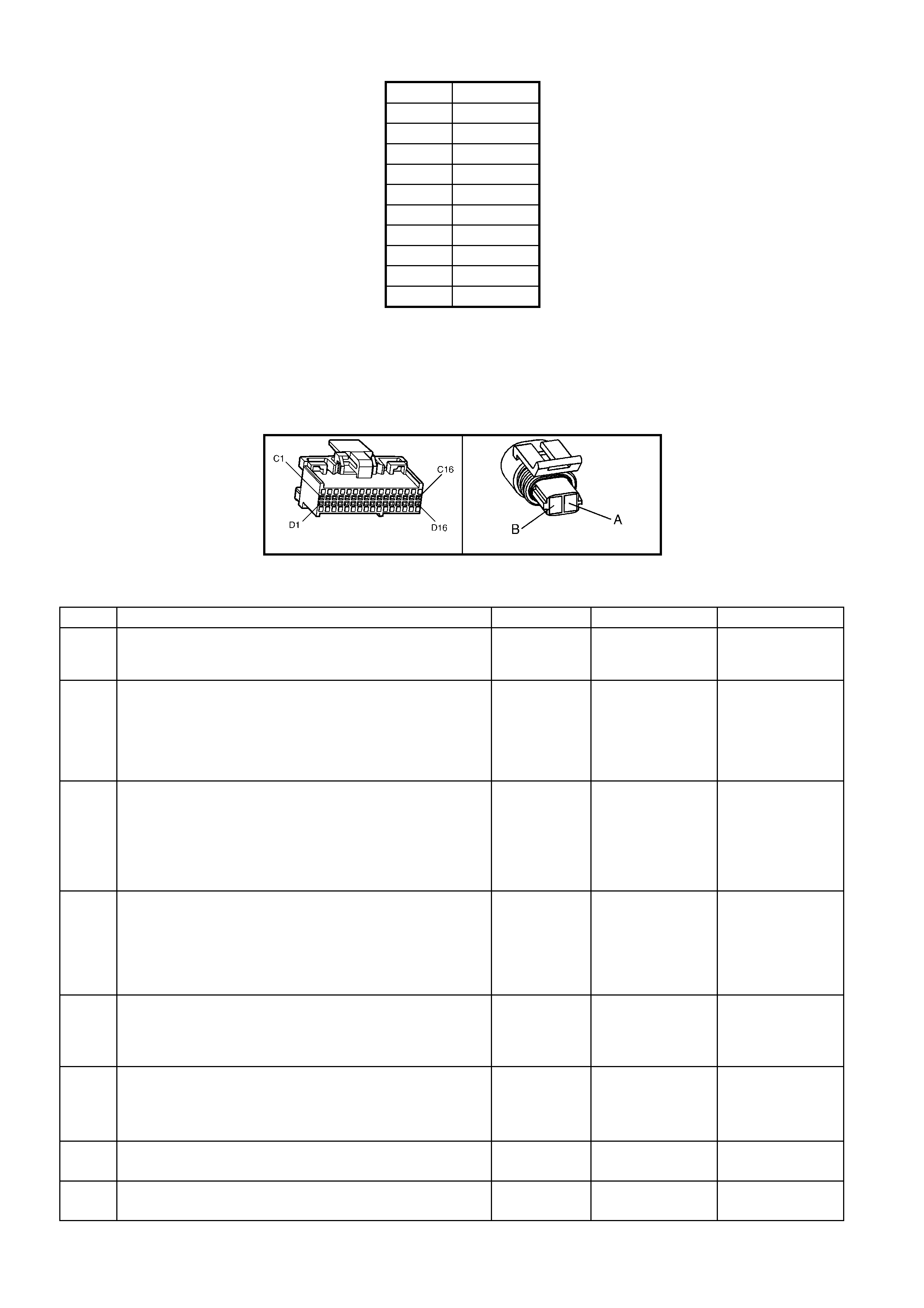
ECT SENSOR TABLE TEMP. TO RESISTANCE VALUES (APPROXIMATE)
C OHMS
110 134
100 180
90 244
70 474
40 1,483
30 2,268
20 3,555
0 9,517
-10 16,320
-20 28,939
TEST DESCRIPTION
Number(s) below refer to step number(s) on the diagnostic table.
3. This test will determine if circuit 410 is shorted to ground which will cause the conditions for DTC P0117.
4. If checking resistance at the engine coolant temperature sensor is difficult because of sensor location,
disconnect the PCM con nectors and check resistance betwee n engine coolant temperature signal and sensor
ground terminals.
A84 V6 – X2 B39
Figure 6C1-2A-84
DTC P0117 V6 PCM - ENGINE COOLANT TEMPERATURE (ECT) SIGNAL VOLTAGE LOW
STEP ACTION VALUE YES NO
1. Was the "On-Board Diagnostic" (OBD) System Check
performed? Go to Step 2 Go to
OBD System
Check
2. 1. Ignition “ON”
2. Using TECH 2, select "Engine Coolant Temperature"
on the data display.
Is the "Engine Coolant Temperature" display value at or
above the specified value?
140°C Go to Step 3 If no additional
DTCs were
stored, refer to
"Intermitt ent s" in
6C1-2B
SYMPTOMS.
3. 1. Ignition "OFF".
2. Disconnect engine coolant temperature sensor wiring
harness.
3. Ignition "ON".
Does TECH 2 display "Eng. Coolant Temp" below
specified value?
-30°C Go to Step 4 Go to Step 7
4. Check resistance across engine coolant temperature
sensor terminals.
Does DMM ohms reading match the specified values for
temperature to sensor resistanc e?
Refer
Resistance
Table
in Diagnostic
Aids
Go to Step 5 Go to Step 8
5. Check for intermittent or loose terminals in sensor
harness connector, or for the 2 terminals shorting
together when connected to the sensor.
Was a faulty connection found?
Verify Repair Go to Step 6
6. Replace PCM.
Refer 6C1-3 Service Operations, for PCM Programming
and Security Link procedure.
Is action complete?
Verify Repair
7. Check circuit 410 for short to ground or to sensor ground.
Was a short found? Verify Repair Go to Step 6
8. Replace ECT sensor.
Is replacement complete? Verify Repair
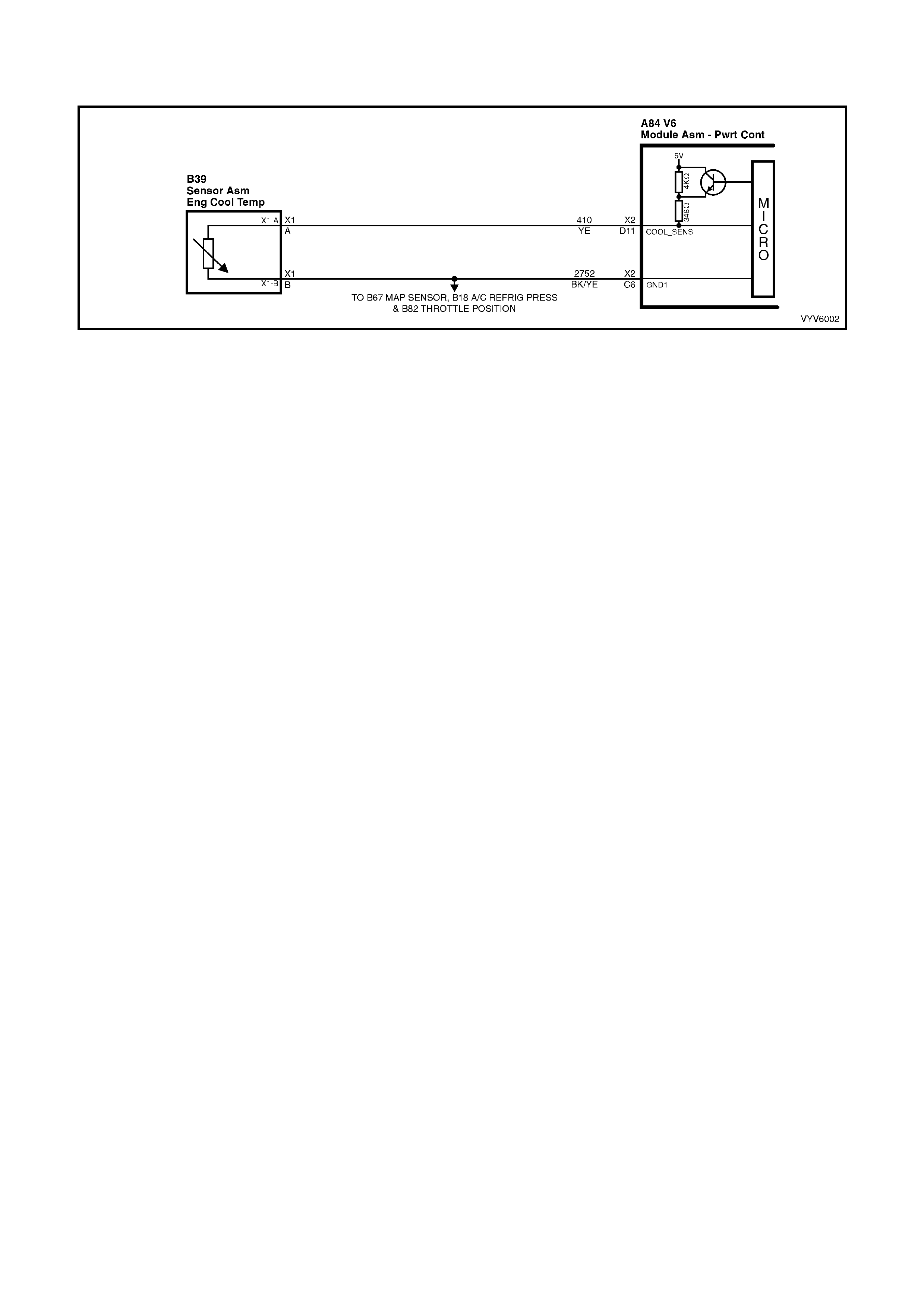
DTC P0118 V6 PCM -
ENGINE COOLANT TEMPERATURE (ECT) SIGNAL VOLTAGE HIGH
Figure 6C1-2A-85 Engine Coolant Temperature Sensor Circuit
CIRCUIT DESCRIPTION
The Engine Coolant Temperature (ECT) sensor uses a thermistor to control the signal voltage to the PCM. The
PCM applies about 5 volts on circuit 410 to the sensor. When the engine coolant is cold, the sensor (thermistor)
resistanc e is h igh, th eref or e th e P CM wi ll s ee hig h si g nal v olt age, a bout 4 - 4.5 v olts . As th e e ng ine cool ant war m s ,
the sensor (thermistor) resistance becomes less, and the PCM sees a lower signal voltage. At normal engine
operating temperature (85°C to 95°C), the voltage will measure about 2.2 to 1.8 volts.
A Diagnostic Trouble Code P0118 may enable TCC operation when cold.
CONDITIONS FOR RUNNING THE DTC
• Time since engine started is greater than 10 seconds.
CONDITIONS FOR SETTING THE DTC
• ECT input s ignal volta ge is greater tha n 4.64 volts, in dicating an eng ine coolant temperature at or lower than -
30°C for one second.
• Above conditions present for at least 1 second.
ACTION TAKEN WHEN THE DTC SETS
• The PCM activates the Check Powertrain MIL when the diagnostic runs and fails.
• The PCM records the operating conditions at the time the diagnostic fails. The PCM stores this information in
the History Data.
• The PCM will substitute a coolant temperature default value based on the intake air temperature at start-up and
the engine run time.
• When the Diagnostic Trouble Code P0117 is set, the TCC will be applied with a cold engine and the engine
cooling fans will be forced "ON".
CONDITIONS FOR CLEARING THE MIL/DTC
• The PCM turns the Check Powertrain MIL OFF when it sees a valid condition.
• Use a TECH 2 in order to clear the MIL/DTC.
DIAGNOSTIC AIDS
A TECH 2 reads engine coolant temperature in degrees Celsius. After engine is started, the temperature should
rise steadily to about 90°C then stabilise when thermostat opens.
A faulty connection, or an open in circuit 410 or circuit 2752 will result in a Diagnostic Trouble Code (DTC) P0118.
If DT C P0123 is also set, check circuit 275 2 for fault y wiring or c onnections. Ch eck term inals at sensor for a good
connection. The "Temperature to Resistance Value" scale may be used to test the engine coolant temperature
sensor at v ar ious t emperatur e le ve ls to e va lua te th e p os s ibility of a "s h if ted" ( mis-s c aled) s ens or. A "shif ted " s ens or
could result in poor dr i veabi lity com plaints .
Refer to "Intermittents" in Section 6C1-2B SYMPTOMS.
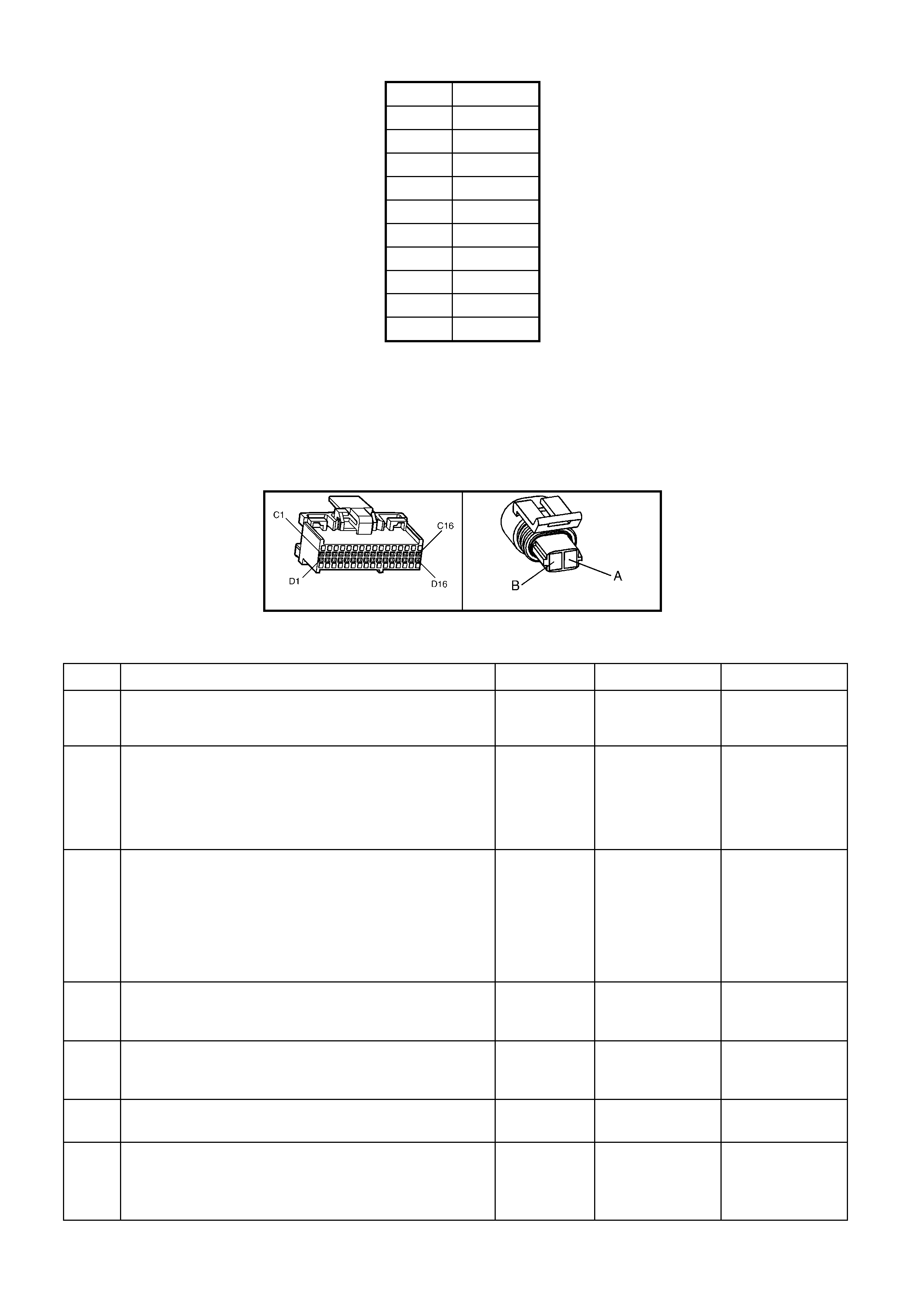
ECT SENSOR TABLE TEMP. TO RESISTANCE VALUES (APPROXIMATE)
C OHMS
110 134
100 180
90 244
70 474
40 1,483
30 2,268
20 3,555
0 9,517
-10 16,320
-20 28,939
TEST DESCRIPTION
Number(s) below refer to step number(s) on the diagnostic table.
3. This test simulates a Diagnostic Trouble Code P0117. If the PCM recognises the low signal voltage, (high
temperature) and TECH 2 reads 130°C or above, the PCM and wir ing are OK.
4. This test will determine if circuit 410 is open. There should be an open circuit voltage of 5 volts present at
Engine Coolant Temperature (ECT) sensor harness connector if measured with a DMM. By jumpering this 5
volt signal to ground, the PCM should recognise this change.
A84 V6 – X2 B39
Figure 6C1-2A-86
DTC P0118 V6 PCM - ENGINE COOLANT TEMPERATURE (ECT) SIGNAL VOLTAGE HIGH
STEP ACTION VALUE YES NO
1. Was the "On-Board Diagnostic" (OBD) System Check
performed? Go to Step 2. Go to
OBD System
Check
2. 1. Using Tech, select "Engine Coolant Temperature" on
the data display.
2. Ignition ON, engine OFF.
Is the "Engine Coolant Temperature" display value at or
between the specified value?
-30 to -40°C Go to Step 3 If no additional
DTCs were
stored, refer to
"Intermitt ent s" in
Section 6C1-2B
SYMPTOMS.
3. 1. Ignition "OFF".
2. Disconnect engine coolant temperature sensor
connector.
3. Jumper harness terminals X1-A and X1-B together.
4. Ignition "ON".
Does TECH 2 display "Engine Coolant Temperature" at
or above specified value?
130°C Go to Step 10 Go to Step 4
4. Jumper circuit 410 to ground.
Does TECH 2 display "Engine Coolant Temperature" at
or above specified value?
130°C Go to Step 5 Go to Step 8
5. Check circuit 2752 for an open or poor connection at
PCM or ECT Sensor.
Was a problem found?
Verify Repair Go to Step 6
6. Check circuit 410 for a short to voltage.
Was a problem found? Verify Repair Go to Step 7
7. Replace PCM.
Refer to Section 6C1-3 SERVICE OPERATIONS, for
PCM Programming and Security Link procedure.
Is action complete?
Verify Repair

STEP ACTION VALUE YES NO
8. Check circuit 410 for an open circuit or faulty connection
at PCM.
Was a problem found?
Verify Repair Go to Step 7
9. Replace ECT sensor.
Is action complete? Verify Repair
10. Check for faulty connection.
Was a problem found? Verify Repair Go to Step 9
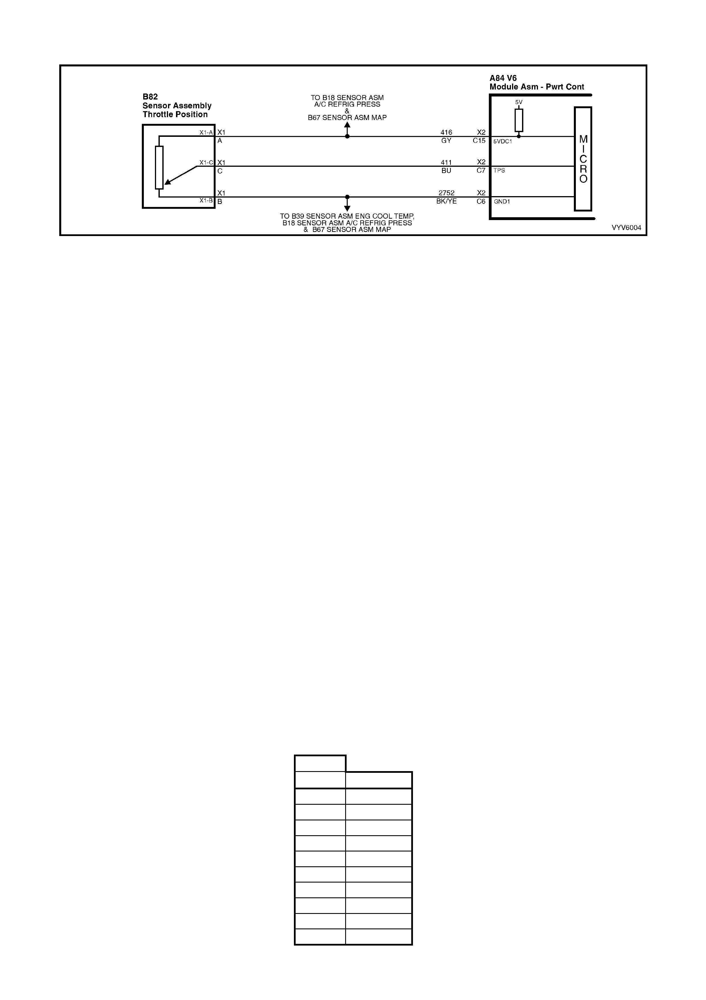
DTC P0121 V6 PCM - THROTTLE POSITION (TP) SENSOR STUCK
Figure 6C1-2A-87 Throttle Position Sensor Circuit
CIRCUIT DESCRIPTION
The T hrottle Pos ition (TP) sensor prov ides a voltage signal th at change s relati ve to the thr ottle blad e angle. Signal
voltage will vary from about 0.25 to 1.25 volts at idle to about 4 volts at Wide Open Throttle (WOT).
The TP sensor signal is one of the most important inputs used by the PCM for transient fuelling, transmission
control and for most of the PCM control outputs.
Diagnostic Trouble Code (D TC) P0121 is used to det ect a stuck open or binding T P sensor. DT C P0121 detects if
the TP sensor does not return with the throttle blade when decelerating.
Conditions for Running the DTC
Time since engine started is greater than 20 seconds.
Conditions for Setting the DTC
The Throttle Position (TP) sensor percentage of opening angle indicated is greater than the RPM that can be
reached with a Mass Air Flow reading of less than 301 mg/cyl for 20 seconds.
Action Taken When the DTC Sets
The PCM activates the Check Powertrain MIL when the diagnostic runs and fails.
The PCM records the operating conditions at the time the diagnostic fails. The PCM stores this information in the
History Data.
When DTC P0121 is set, the PCM will calculate throttle position based on RPM, IACV and MAF for engine and
transmission operation.
Conditions for Clearing the MIL/DTC
• The PCM turns the Check Powertrain MIL OFF when it sees a valid condition.
• Use a TECH 2 in order to clear the MIL/DTC.
DIAGNOSTIC AIDS
A TECH 2 reads throttle po sition in volts . With ignition "ON'' or at idle, T P sensor signa l voltage sh ould read about
0.25 to 1.25 volts with the throttle closed and increase at a steady rate as throttle is moved toward Wide Open
Throttle (WOT).
TECH 2 will read throttle angle. 0%=closed throttle; 100%=WOT.
If voltage is steady above DTC P0122 voltage criteria and below DTC P0123 voltage criteria, check for a short to
voltage on the TP Sensor signal circuit.
Refer to "Intermittents" in Section 6C1-2B SYMPTOMS.
DTC P0121 CRITERIA TABLE MAF LESS THAN 301 MG/CYL. (APPROXIMATE)
TPS%
V6 RPM
20 800
22 1,200
27 1,600
29 2,000
33 2,400
37 2,800
39 3,200
40 3,600
41 4,000
44 4,400
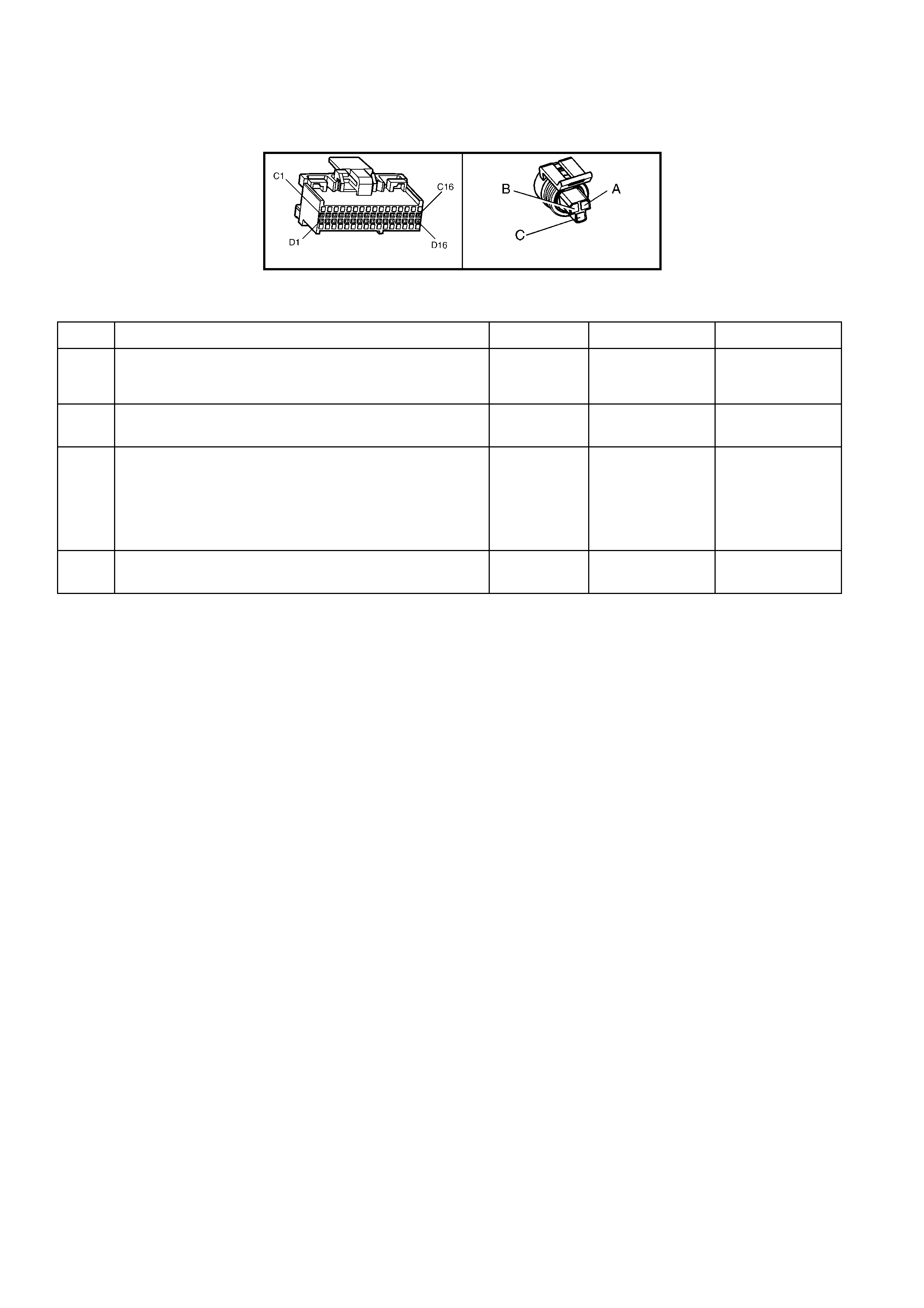
TEST DESCRIPTION
Number(s) below refer to step number(s) on the diagnostic Table.
2. This step checks to verify the throttle linkage is moving freely.
A84 V6 – X2 B82
Figure 6C1-2A-88
DTC P0121 V6 PCM - THROTTLE POSITION (TP) SENSOR STUCK
STEP ACTION VALUE YES NO
1. Was the "On-Board Diagnostic" (OBD) System Check
performed? Go to Step 2 Go to
OBD System
Check
2. Inspect throttle cab le, lin kag e, and blade move ment .
Are components binding or sticking? Verify Repair Go to Step 3
3 Using TECH 2 to monitor TP sensor voltage, inspect TP
sensor for binding or sticking during its movement from
closed throttle to wide open throttle and back to closed
throttle positi on.
Was fault found?
Go to Step 4 DTC P0121
intermittent. If no
additional DTC's
were stored, refer
to Diagnostic
Aids
4. Replace binding Throttle Position (TP) sensor.
Is action complete? Verify Repair
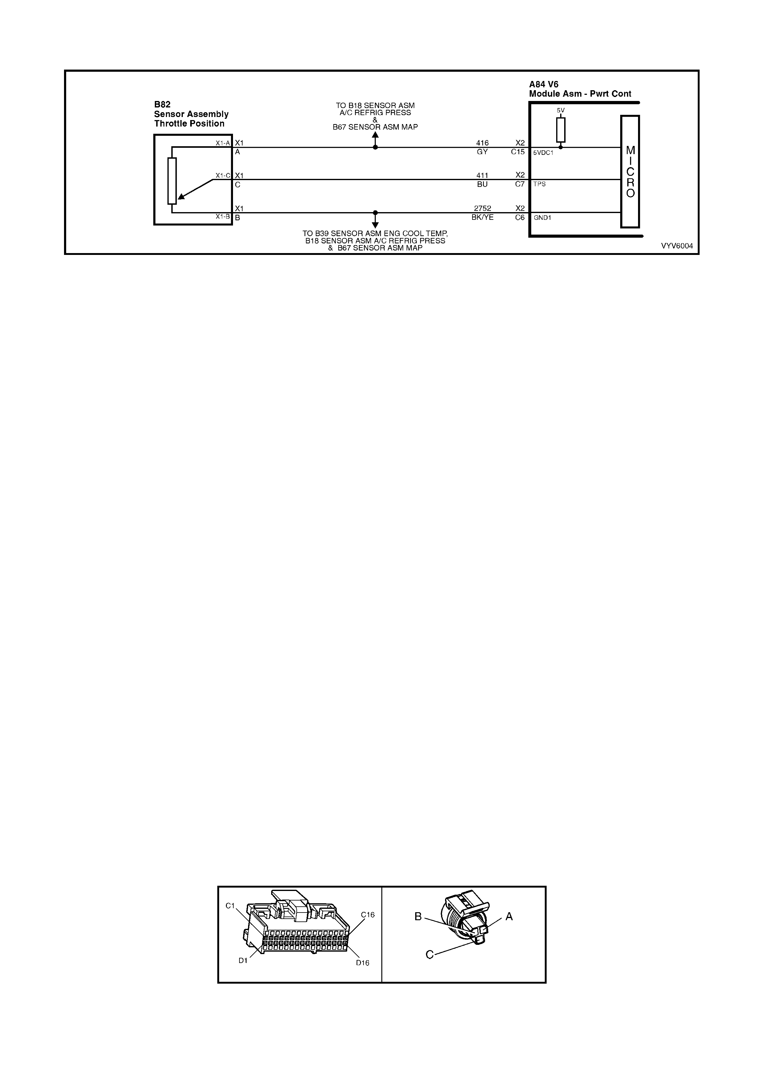
DTC P0122 V6 PCM - THROTTLE POSITION (TP) SENSOR VOLTAGE LOW
Figure 6C1-2A-89 Throttle Position Sensor Circuit
CIRCUIT DESCRIPTION
The Throttle Position (TP) sensor provides a voltage signal that changes relative to the throttle blade. Signal
voltage will vary from about 0.25 to 1.25 volts at idle to about 4 volts at Wide Open Throttle (WOT).
The TP sensor signal is one of the most important inputs used by the PCM for transient fuelling, transmission
control and for most of the PCM control. outputs.
Conditions for Running the DTC
• Ignition on.
Conditions for Setting the DTC
• The TP Sens or voltage bet ween the PCM TP Sens or signa l ter minal a nd th e T P Sens or gro und terminal is l es s
than 0.2 volts for more than two seconds.
Action Taken When the DTC Sets
• The PCM activates the Check Powertrain MIL when the diagnostic runs and fails.
• The PCM records the operating conditions at the time the diagnostic fails. The PCM stores this information in
the History Data.
• When a DTC P0122 is set, the PCM does not receive the proper signal from the TP sensor, but it can still
determ ine the T P s ens or valu e with a default v alu e ba s ed on RPM , Idl e Air Co ntro l Va lve pos i tio n and M as s Air
Flow.
• If DTC P0122 is set, the transmission will have no TCC.
Conditions for Clearing the MIL/DTC
• The PCM turns the Check Powertrain MIL OFF when it sees a valid condition.
• Use a TECH 2 in order to clear the MIL/DTC.
DIAGNOSTIC AIDS
TECH 2 reads throttle position in volts. With ignition "ON'' or at idle, TP sensor signal voltage should read about
0.25 to 1.25 volts with the throttle closed and increase at a steady rate as throttle is moved toward Wide Open
Throttle (WOT).
TECH 2 can also read throttle angle. 0%=closed throttle; 100%=WOT.
An open or short to ground in circuit 416 or circuit 411 will result in a DTC P0122.
Refer to "Intermittents" in Section 6C1-2B SYMPTOMS.
TEST DESCRIPTION
Number(s) below refer to step number(s) on the diagnostic Table.
3. This test simulates a Diagnostic Trouble Code P0123 (high voltage). If the PCM recognises the high signal
voltage and TECH 2 reads over 4 volts, the PCM and wiring are OK.
4. This s im ulates a h igh sig na l vol tag e t o c hec k for an op en in c irc u it 411. T ECH 2 will n ot re ad up to 12 vo lts , b ut
what is important is that the PCM recognises the signal on circuit 411.
A84 V6 – X2 B82
Figure 6C1-2A-90

DTC P0122 V6 PCM - THROTTLE POSITION (TP) SENSOR VOLTAGE LOW
STEP ACTION VALUE YES NO
1. Was the "On-Board Diagnostic" (OBD) System Check
performed? Go to Step 2 Go to
OBD System
Check
2. 1. Ignition “ON” engine “OFF”.
2. Throttle closed
Does TECH 2 display "TPS Voltage" at or below specified
value?
0.2 Volt
(200 mV) Go to Step 3 DTC P0122 is
intermittent, if no
additional DTCs
were stored, refer
to "Intermittents"
in Section 6C1-
2B SYMPTOMS.
3. 1. Disconnect TPS wiring harness, connector B82.
2. Jumper circuits 416 & 411 together.
Does TECH 2 display "TPS Voltage" above
specified value?
4.0 Volts Go to Step 6 Go to Step 4
4. Probe circuit 411 with test light connected to 12 volts.
Does TECH 2 display "TPS Voltage" above
specified value?
4.0 Volts Go to Step 5 Go to Step 7
5. Check for open or short on cir cuit 416 or faulty
connection.
Was a short, open or faulty connection found?
Verify Repair Go to Step 8
6. Replace Throttle Position (TP) Sensor.
Is action complete? Verify Repair
7. Check for open or short on cir cuit 411 or faulty
connection.
Was a short, open or faulty connection found?
Verify Repair Go to Step 8
8. Replace PCM.
Refer to Section 6C1-3 Service Operations, for PCM
Programming and Security Link procedure.
Is action complete?
Verify Repair
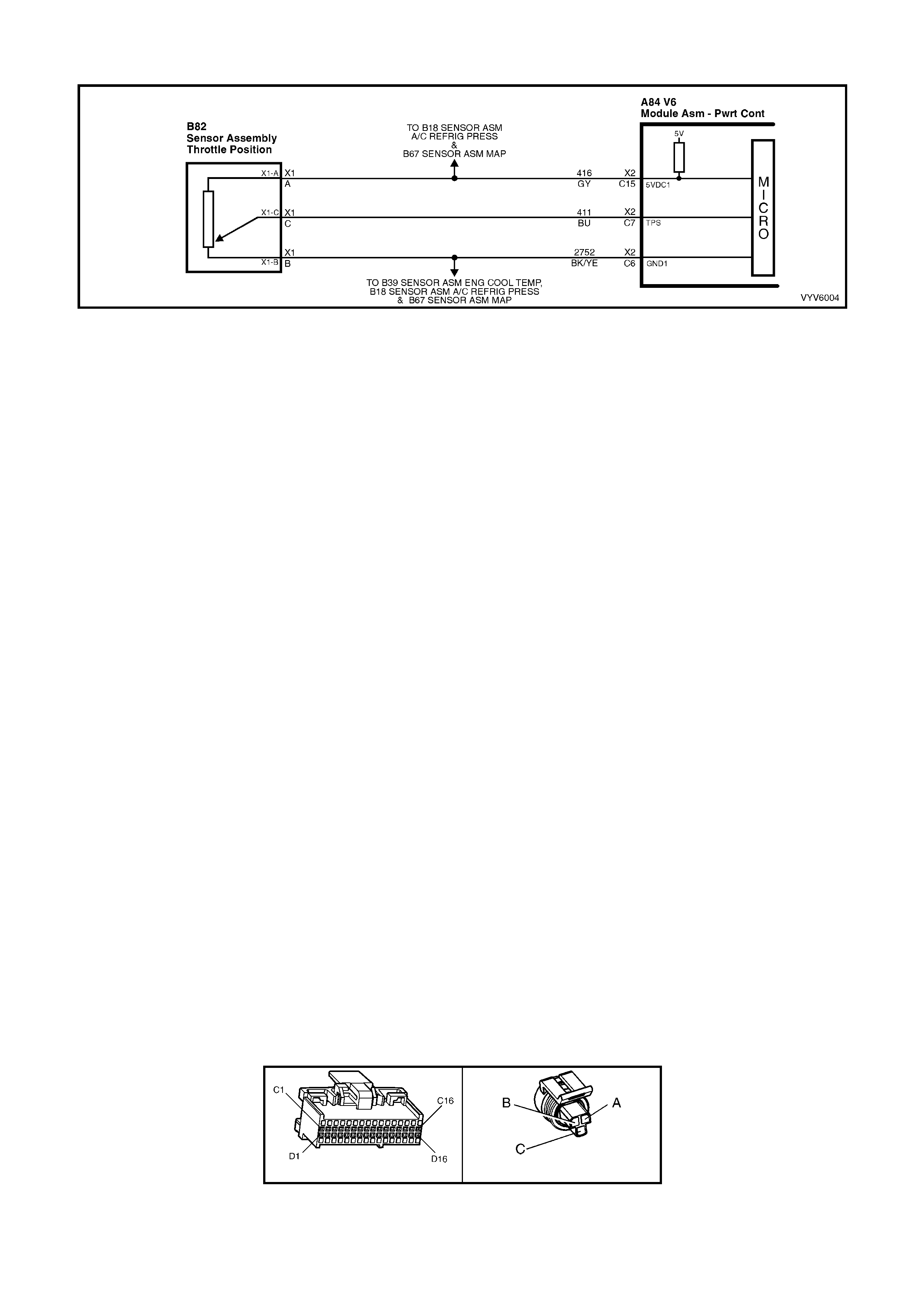
DTC P0123 V6 PCM - THROTTLE POSITION (TP) SENSOR VOLTAGE HIGH
Figure 6C1-2A-91 Throttle Position Sensor Circuit
CIRCUIT DESCRIPTION
The Throttle Position (TP) sensor provides a voltage signal that changes relative to the throttle blade. Signal
voltage will vary from about 0.25 to 1.25 volts at idle to about 4 volts at Wide Open Throttle (WOT).
The TP sensor signal is one of the most important inputs used by the PCM for transient fuelling, transmission
control and for most of the PCM control. outputs.
CONDITIONS FOR RUNNING THE DTC
• Ignition On.
CONDITIONS FOR SETTING THE DTC
• The TP Sensor voltage between the PCM TP Sensor signal terminal and the TP Sensor ground terminal is
greater than 4.9 volts (97%) for more than two seconds.
ACTION TAKEN WHEN THE DTC SETS
• The PCM activates the Check Powertrain MIL when the diagnostic runs and fails.
• The PCM records the operating conditions at the time the diagnostic fails. The PCM stores this information in
the History Data.
• When a DTC P0123 is set, the PCM does not receive the proper signal from the TP sensor, but it can still
determ ine the T P s ens or valu e with a default v alu e ba s ed on RPM , Idl e Air Co ntro l Va lve pos i tio n and M as s Air
Flow.
• If DTC P0123 is set, the transmission will have no TCC.
CONDITIONS FOR CLEARING THE MIL/DTC
• The PCM turns the Check Powertrain MIL OFF when it sees a valid condition.
• Use a TECH 2 in order to clear the MIL/DTC.
DIAGNOSTIC AIDS
TECH 2 reads throttle position in volts. With ignition "ON'' or at idle, TP sensor signal voltage should read about
0.25 to 1.25 volts with the throttle closed and increase at a steady rate as throttle is moved toward Wide Open
Throttle (WOT).
TECH 2 can also rea d throttle angle. 0%=c losed thrott le; 100%=W OT. An open in circuit 2752 will r esult in a DTC
P0123.
Refer to "Intermittents" in Section 6C1-2B SYMPTOMS.
TEST DESCRIPTION
Number(s) below refer to step number(s) on the diagnostic table.
3. With the TP sensor disconnected, the TP sensor signal voltage should go low if the PCM and wiring are OK.
4. Probing circuit 452 with a test light connected to 12 volts checks the sensor ground circuit. A faulty sensor
ground will cause a DTC P0123.
A84 V6 – X2 B82
Figure 6C1-2A-92

DTC P0123 V6 PCM - THROTTLE POSITION (TP) SENSOR VOLTAGE HIGH
STEP ACTION VALUE YES NO
1. Was the "On-Board Diagnostic" (OBD) System Check
performed? Go to Step 2 Go to
OBD System
Check
2. 1. Ignition ON , engine stopped.
2. Throttle closed.
Does TECH 2 display "TPS Voltage" over specified
value?
2.5 volts Go to Step 3 If no additional
DTCs were
stored, refer to
"Intermitt ent s" in
Section 6C1-2B
SYMPTOMS.
3. Disconnect TPS wiring harness.
Does TECH 2 display "TPS Voltage" below
specified value?
0.2 volts
(200 mV) Go to Step 4 Go to Step 7
4. Probe TP sensor ground circuit 2752 with test light
connected to battery voltage.
Is test light "ON"?
Go to Step 5 Go to Step 8
5. Check for a faulty connection.
Was faulty connection found? Verify Repair Go to Step 6
6. Replace Throttle Position Sensor (TPS). Verify Repair
7. Check TP sensor circuit 411 for short to voltage, or short
to circuit 416.
Was a problem found?
Verify Repair Go to Step 9
8. Check TP sensor ground circuit 2752 for open or poor
terminal retention.
Was a problem found?
Verify Repair Go to Step 9
9. Replace PCM.
Refer 6C1-3 Service Operations, for PCM Programming
and Security Link procedure.
Is action complete?
Verify Repair

DTC P0131 V6 PCM - RIGHT HAND OXYGEN SENSOR (O2S) SIGNAL VOLTAGE LOW
Figure 6C1-2A-93 Right Hand Oxygen Sensor Circuit
CIRCUIT DESCRIPTION
The PCM s upplies a volta ge of about 4 50 m illivo lts bet ween terminal X 2-C9 and X2- D5. The O x ygen (O2S) s ensor
varies the voltage within a range of about 1 volt if the ex haust is rich, do wn throu gh about 10 0 mill ivolts, if exhaus t
is lean.
The s ensor is like an ope n circ uit and pr oduc es no vol tage when it is belo w abo ut 360°C. A n open sens or circ uit or
cold sensor causes "Open Loop" operation.
CONDITIONS FOR RUNNING THE DTC
• No IAT Sensor DTC’s are set.
• IAT Sensor is below 75°C.
• The system is in "Closed Loop”.
• Throttle angle is between 9% and 30%.
CONDITIONS FOR SETTING THE DTC
• The RH 02S signal voltage remains below 200 millivolts for 46 seconds.
ACTION TAKEN WHEN THE DTC SETS
• The PCM activates the Check Powertrain MIL when the diagnostic runs and fails.
• The PCM records the operating conditions at the time the diagnostic fails. The PCM stores this information in
the History Data.
• Once an 02S DTC is set, and current, the PCM will operate the fuel system in the “Open Loop” mode.
CONDITIONS FOR CLEARING THE MIL/DTC
• The PCM turns the Check Powertrain MIL OFF when it sees a valid condition.
• Use a TECH 2 in order to clear the MIL/DTC.
DIAGNOSTIC AIDS
Using TECH 2, observe the Long Term Fuel Trim values at different RPMs and air flow conditions. TECH 2 also
displa ys the Lo ng Term Fuel Tr im ce lls, so the L ong T erm Fuel Trim values c an be check ed in e ach of th e cells t o
determine when the DTC P0131 may have been set. If the conditions for DTC P0131 exist, the Long Term Fuel
Trim values will be around +25%.
TEST DESCRIPTION
Number(s) below refer to step number(s) on the diagnostic Table.
4. The DTC P0131 or lean exhaust is most likely caused by one of the following:
• O2 Sensor Wire - Sensor pigtail may be mispositioned and contacting the exhaust manifold.
• Check for intermittent ground in wire between connector and sensor.
• MAF Sensor - A shifted MAF sensor could cause the fuel system to go lean. Refer to TABLEA-6.1.
• Lean Injector(s) - Perform injector balance test. Refer Section 6C1-2C .
• Fuel Contamination - Water, even in small amounts, near the in-tank Fuel Pump inlet can be delivered to the
injectors. The water causes a lean exhaust and can set a DTC P0131 and/or DTC P0151.
• Fuel Pressure - System will go lean if pressure is too low. It may be necessary to monitor fuel pressure while
driving the vehicle at various road speeds and/or loads to confirm. Refer TABLEA-4.1.
• Exhaust L eaks - If there is an exha ust leak , the engin e can cause o utside air t o be pull ed into the ex haust and
past the sensor. Vacuum or crankcase leaks can also cause a lean condition.

A84 V6 – X2 B70
Figure 6C1-2A-94
DTC P0131 V6 PCM - RIGHT HAND OXYGEN SENSOR (02S) SIGNAL VOLTAGE LOW
STEP ACTION VALUE YES NO
1. Was the "On-Board Diagnostic" (OBD) System Check
performed? Go to Step 2 Go to
OBD System
Check
2. 1. Start engine.
2. Run engine until it reaches normal operating
temperature (Above 80°C).
3. Continue to run at 1600 to 1800 RPM for two
minutes.
Does TECH 2 indicate O2 sensor voltage fixed below
specified value?
200 mV Go to Step 3
DTC P0131 is
intermittent, If no
additional DTCs
were stored, refer
to "Intermittents"
in Section 6C1-
2B SYMPTOMS .
3. Disconnect O2 sen sor con nec tor.
With engine idling, does TECH 2 display O2 sensor
voltage between the specified values?
Between
350 mV and
550 mV
Go to Step 4 Go to Step 6
4. 1. Refer to step 4 Test Description first.
2. Perform the checks on the i tems as note d.
MAF sensor operation
Low fuel pressure
Contaminated fuel
Exhaust manifold leaks ahead of O2 sensor
Lean injector (possibly restricted)
Are all items checked found to be OK?
Go to Step 5 Verify Repair
5. Replace Oxygen sensor.
Is action complete?
Verify repair
6. 1. Ignition "OFF".
2. Disconnect PCM connectors.
3. With O2 sensor still disconnected, check O2 signal
circuit 1666 for a short to ground.
Is a short to ground detected?
Go to Step 7 Go to Step 8
7. Repair circuit 1666.
Is action complete? Verify Repair
8. Replace PCM.
Refer 6C1-3 Service Operations, for PCM Programming
and Security Link procedure.
Is action complete?
Verify Repair
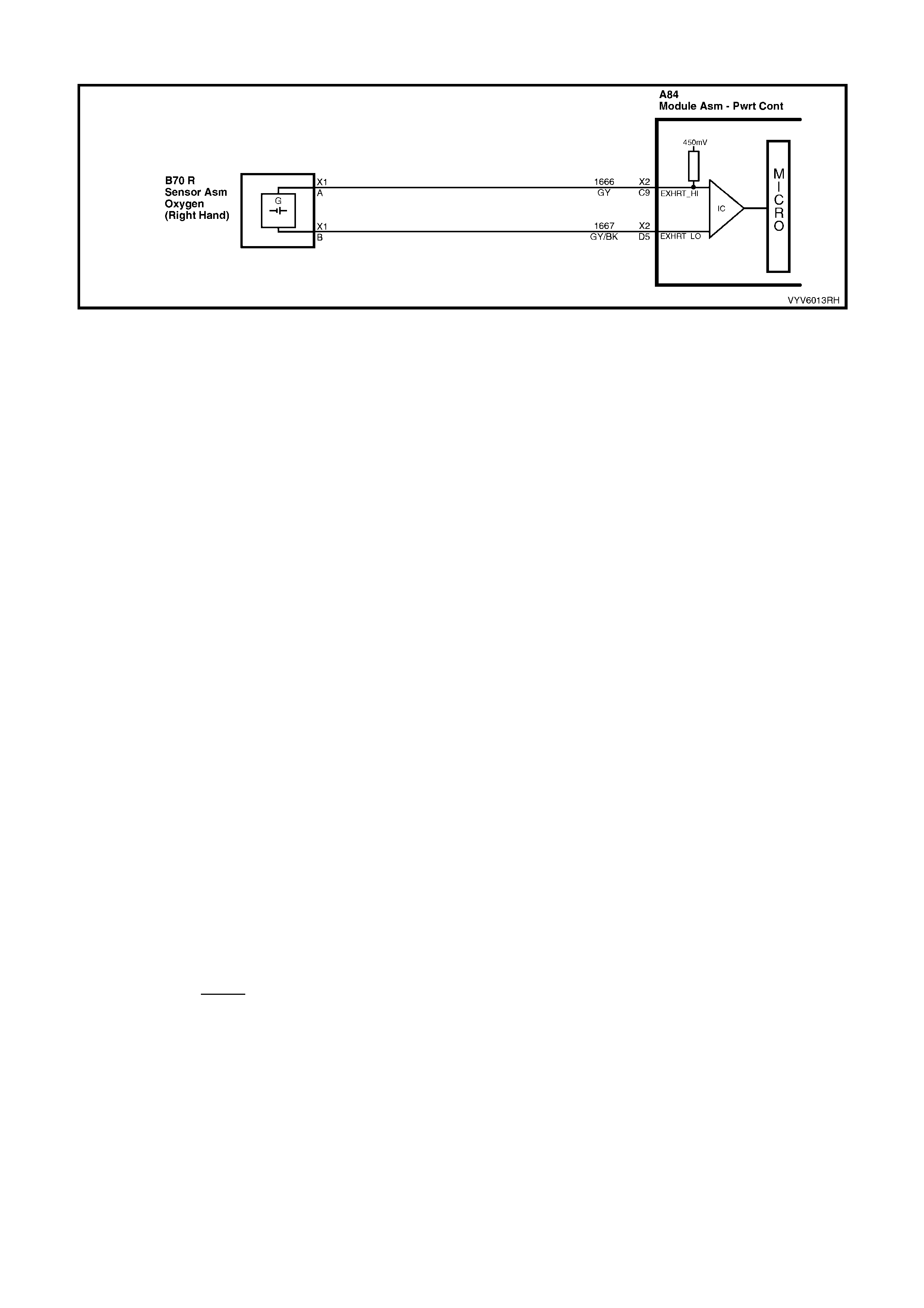
DTC P0132 V6 PCM - RIGHT HAND OXYGEN SENSOR (O2S) SIGNAL VOLTAGE HIGH
Figure 6C1-2A-95 Right Hand Oxygen Sensor Circuit
CIRCUIT DESCRIPTION
The PCM supplies a volta ge of about 450 millivolts between term inal X2-C9 and X2-D5. The Oxygen (O2) sensor
varies the voltage within a range of about 1 volt, if the exhaust is rich and down through about 100 millivolts if
exhaust is lean. The sensor produces no voltage when it is below about 360°C. An open sensor circuit or cold
sensor causes "Open Loop" operation.
CONDITIONS FOR RUNNING THE DTC
• No TP Sensor DTC’s are set.
• The system is in "Closed Loop”.
• Throttle angle is between 9% and 30%.
CONDITIONS FOR SETTING THE DTC
• The RH 02S signal voltage remains above 780 millivolts for 40 seconds.
ACTION TAKEN WHEN THE DTC SETS
• The PCM activates the Check Powertrain MIL when the diagnostic runs and fails.
• Once an O2S DTC is set, and current, the PCM will operate the fuel system in the “Open Loop” mode.
CONDITIONS FOR CLEARING THE MIL/DTC
• The PCM turns the Check Powertrain MIL OFF when it sees a valid condition.
• Use a TECH 2 in order to clear the MIL/DTC.
DIAGNOSTIC AIDS
Using TECH 2, observe the Long Term Fuel Trim values at different RPM and air flow conditions. TECH 2 also
displa ys the Lo ng Term Fuel Tr im ce lls, so the L ong T erm Fuel Trim values c an be check ed in e ach of th e cells t o
determine when the DTC P0132 may have been set. If the conditions for DTC P0132 exist, the Long Term Fuel
Trim values will be around - 22%.
NOTE: Oxygen Sensor Contamination - If fuel containing lead or silicone is used, or engine repairs using
unappro ved RTV gas k et sealer are perf orm ed, the sens or m ay be contam inated. It ma y send a "false" ric h ex haust
indicati on to the PCM, a nd the PCM will attem pt to drive the f uel system lean to c ompensate. Poor driveab ility or a
Diagnostic T r ouble C ode P 0131 c ou ld res u lt. If this ha ppens, the sensor wi ll ne ed to be repl ac ed, b ut ev er y attempt
to locate the source of contamination should be pursued.
TEST DESCRIPTION
Number(s) below refer to step number(s) on the diagnostic Table.
2. The O2 sensor MUST be at operating temperature before checking operation.
3. This step checks for a short to voltage on the O2S signal line.
7. Grounding circuit 1666 causes a low O2S signal voltage. If the PCM and wiring are OK, the PCM should
recognise the low voltage and confirm the lean signal.
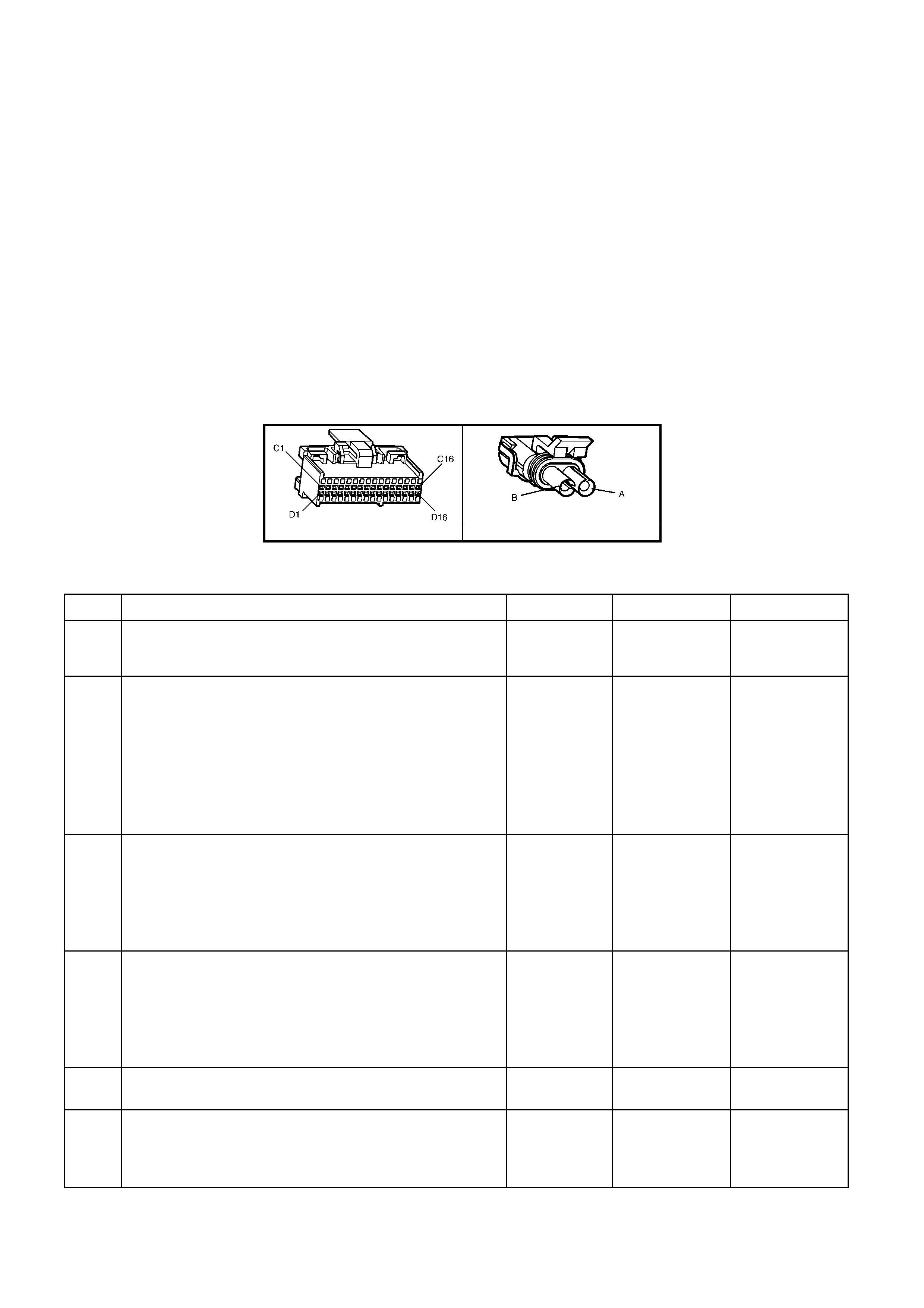
8. A DTC P013 2 will mos t likel y NO T be caus ed by a fa ulty O2 sensor . DTC P0132 i ndicates a r ich exhaust and
diagnosis should begin with the items listed:
• Fuel pressure. System will go rich, if pressure is too high. The PCM can compensate for some increase.
However, if it gets too high, a DTC P0132 may be set. Refer to fuel system diagnosis TABLE A-4.3.
• Rich injector.
• Leaking injector. Refer to TABLE A-4.3.
• Check for fuel contaminated oil.
• Short to voltage on circuit 1666.
• HEI shiel di ng. An o pen gro und c irc u it 45 3 ( ig nit io n system) ma y result i n E MI, or induc ed el ec tric al "n ois e. " The
PCM looks at this "noise" as reference pulses. The additional pulses result in a higher than actual engine
speed signa l. T he PCM the n deli vers too m uch f uel, caus ing the s ystem to go rich. Engine t achom eter wil l also
show higher than actual engine speed, which can help in diagnosing this problem.
• Canister purge. Check for fuel saturation. If full of fuel, check canister control and hoses.
• MAF sensor. A shifted MAF sensor could cause the fuel system to go rich.
• Check for leaking fuel pressure regulator diaphragm by checking vacuum line to regulator for fuel.
• TP Sensor. An intermittent TP sensor output will cause the system to go rich, due to a false indication of the
engine acc eler a tin g.
A84 V6 – X2 B70
Figure 6C1-2A-96
DTC P0132 V6 PCM - RIGHT HAND OXYGEN SENSOR (O2S) SIGNAL VOLTAGE HIGH
STEP ACTION VALUE YES NO
1. Was the "On-Board Diagnostic" (OBD) System Check
performed? Go to Step 2 Go to
OBD System
Check
2. 1. Engine at normal operating temperature (above 80°C).
2. Run engine at approximately 1600 RPM to 1800 RPM
for two minutes.
Is TECH 2 voltage above specified value?
750 mV Go to Step 3 DTC P0132 is
intermittent,
If no additional
DTC(s) were
stored, refer to
"Intermittents"
in Section
6C1-2B
SYMPTOMS.
3. 1. Ignition "OFF".
2. Disconnect O2 sensor wiring harness connector.
3. With a DMM connected to ground, probe circuit 1666
at O2 sensor wiring harness connector.
4. Ignition "ON".
Is voltmeter indicating less than specified value?
500 mV Go to Step 7 Go to Step 4
4. 1. Ignition "O FF".
2. Disconnect PCM connectors.
3. Probe circuit 1666 at O2 sensor wiring harness
connector.
5. Ignition "ON".
Is voltmeter indicating voltage below specified value?
350 mV Go to Step 6 Go to Step 5
5. Repair circuit 1666, shorted to voltage.
Is action complete? Verify Repair
6. Replace PCM.
Refer to Section 6C1-3 Service Operations, for PCM
Programming and Security Link procedure.
Is action complete?
Verify Repair

STEP ACTION VALUE YES NO
7. 1. Disconnect O2 sensor wiring harness connector.
2. Jumper harness connector circuit 1666 to ground.
With engine running, does TECH 2 display O2 voltage
below specified value?
350 mV Go to Step 8 Go to Step 9
8. Refer Test Descriptions to perform additional checks for:
• High Fuel Pressure
• MAF Sensor Operation
• Leaking Inje ctor s
• Ignition Ground Circuit
• Canister Purge
• Engine Coolant Temperature Sensor Circuit
• Intake Air Temperature Sensor Circuit
• Throttle Position Sensor Operation
Do all additional checks test OK?
Go to Step 11 Verify Repair
9. 1. Ignition "O FF"
2. Connect PCM connectors.
3. Check O2 sensor ground circuit 1667 for continuity
between PCM connector terminal X2-D5 and engine
ground.
Is an "OPEN" circuit indicated?
Verify Repair Go to Step 10
10. Check PCM ground wire connection at engine.
Must be a clean and tight connection to the engine.
Is connection good?
Go to Step 6 Verify Repair
11. Replace Oxygen Sensor
Is action complete? Verify Repair
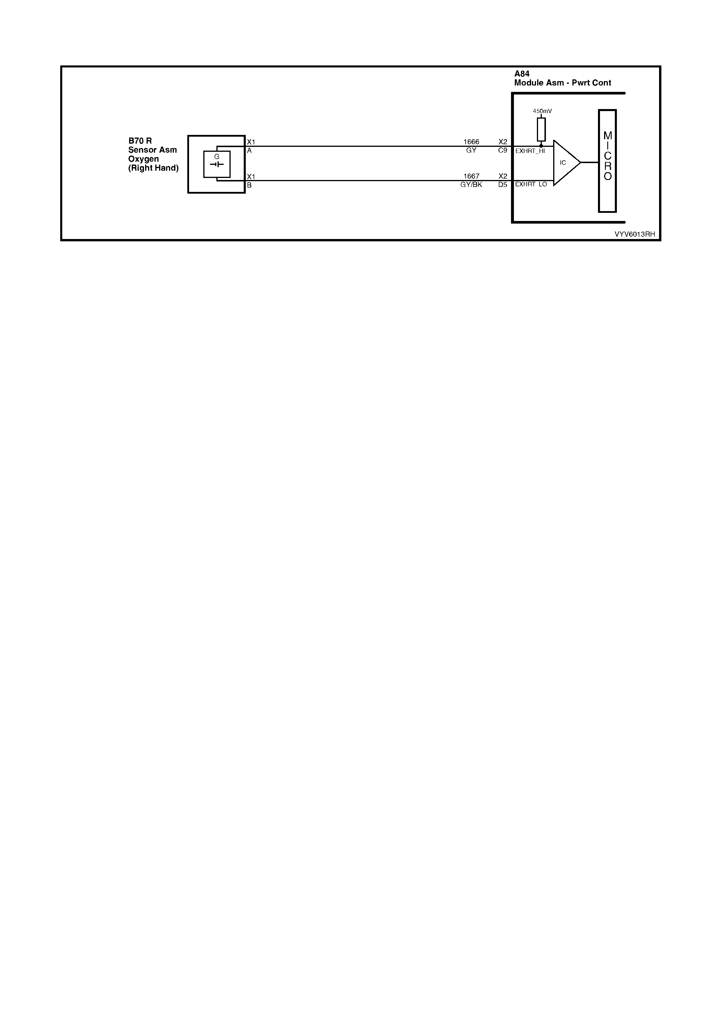
DTC P0134 V6 PCM - NO RIGHT HAND OXYGEN SENSOR (O2S) SIGNAL
Figure 6C1-2A-97 Right Hand Oxygen Sensor Circuit
CIRCUIT DESCRIPTION
The exhaust gas oxygen sensor is mounted in the exhaust pipe with the sensing portion exposed to exhaust gases.
After the sensor is hot (360°C), it becomes a voltage generator, producing a "changing" voltage. This voltage
ranges from approximately 100 millivolts with a "lean" exhaust, to 900 millivolts with a "rich" exhaust. When the
sensor is cold (be low 360°C) it acts lik e an open circ uit and prod uces alm ost no vo ltage. The PC M suppli es a ver y
small "bias" voltage between terminals X2-C9 and X2-D5, normally about 450 millivolts. If measured with the 10
megaohm digital voltmeter, it may measure as low as 350 millivolts. When the sensor is hot, it's output
overshadows this PCM supplied voltage.
When the fuel system is correctly operating in the closed-loop mode, the sensor output is changing several times
per second, going above and below a mid-point range of 490-500 millivolts at a hot idle. The PCM compares the
voltage between the sensor signal and sensor ground terminals and decides the needed fuel mixture correction.
The PCM also monitors the changing voltage, watching for transitions above and below the mid-point range, to
decide when to operate in the closed-loop mode. An open circuit, defective, or contaminated sensor could cause
the voltag e to sta y within a 410-4 77 m illivolt band f or too l ong, keep ing the s ystem in open-loop a nd setting a DTC
P0134.
CONDITIONS FOR RUNNING THE DTC
• Engine run time is longer than 4 minutes.
• No TP Sensor DTC’s are set.
• The ECT sensor is more than 85°C.
• Throttle angle is more than 15%.
CONDITIONS FOR SETTING THE DTC
• The RH 02S voltage stays between 410-477 millivolts.
ACTION TAKEN WHEN THE DTC SETS
• The PCM activates the Check Powertrain MIL when the diagnostic runs and fails.
• The PCM records the operating conditions at the time the diagnostic fails. The PCM stores this information in
the History Data.
• Once an 02S DTC is set, and current, the PCM will operate the fuel system in the “Open Loop” mode.
CONDITIONS FOR CLEARING THE MIL/DTC
• The PCM turns the Check Powertrain MIL OFF when it sees a valid condition.
• Use a TECH 2 in order to clear the MIL/DTC.
DIAGNOSTIC AIDS
Normal TECH 2 voltage varies between 100 mV to 999 mV while in "Closed Loop". DTC P0134 sets if voltage
remains between 410 and 477 millivolts, but the system will go "Open Loop" before the Check Powertrain MIL is
turned "ON ".
Refer to "Intermittents" in Section 6C1-2B SYMPTOMS . To diagnose the oxygen sensor, refer TABLE A-6.3.
NOTE: Oxygen Sensor Contamination - If fuel containing lead or silicone is used, or engine repairs using
unapproved RTV gasket sealer are performed, the sensor may be contaminated. It may send a "False" rich
exhaust indication to the PCM, and the PCM will attempt to drive the fuel system lean to compensate. Poor
driveability or a Diagnostic T rouble Code P0134 could result. If this happens, the sensor will need to be replaced,
but every attempt to locate the source of contamination should be pursued.

TEST DESCRIPTION
Number(s) below refer to step number(s) on the diagnostic Table.
2. TECH 2 allows you to read the same oxygen sensor voltage the PCM is using for its calculations.
3. This step s imulates a lean exhaust indic ation to the P CM. If the PCM and wir ing are OK, the PCM will see the
lean indication and TECH 2 should display O2S voltage below 200 mV.
A84 V6 – X2 B70
Figure 6C1-2A-98
DTC P0134 V6 PCM - NO RIGHT HAND OXYGEN SENSOR (O2S) SIGNAL
STEP ACTION VALUE YES NO
1. Was the "On-Board Diagnostic" (OBD) System Check
performed? Go to Step 2 Go to
OBD System
Check
2. 1. Engine at normal operating temperature (above
85°C).
2. Run engine at approximately 1600 to 1800 RPM for
two minutes.
Is TECH 2 oxygen sensor voltage between specified
values?
410-477 mV
Go to Step 3 If no additional
DTCs were
stored, refer to
“Intermittents” in
Section 6C1-2B
SYMPTOMS .
3. 1. Ignition ON, engine stopped.
2. Disconnect O2S and jumper the O2S signal and low
circuits (PCM side) together.
3. Using TECH 2, monitor O2S voltage.
Is the O2S voltage less than the specified value?
0.2 Volt
(200 mV) Go to Step 7 Go to Step 4
4. 1. Remove the jumper wire from the O2S signal circuit
1666.
2. Using a DMM, measure voltage between the O2S
signal circuit (PCM side) and ground.
Does the O2S signal voltage measure near the specified
value?
410-477 mV
Go to Step 5 Go to Step 6
5. 1. Ignition OFF.
2. Disconnect all PCM connectors.
3. Check continuity of the O2S low circuit 1667
between the PCM harness connector and the O2S
harness connec tor.
4. If the O2S low circuit measures over 5 ohms, repair
open or poor connection as necessary.
Was a problem found?
Verify Repair Go to Step 8
6. 1. Ignition OFF.
2. Disconnect all PCM connectors.
3. Check continuity of the following circuit:
• The O2S signal circuit between the PCM harness
connector and the O2S harness connector.
4. If circuit measures over 5 ohms, repair open or poor
connect ion as neces sary .
Was a problem found?
Verify Repair Go to Step 9
7. 1. Check the following circuits for a poor terminal
connection at the O2S harness connector.
• O2S signal circuit.
• O2S low circuit.
2. If a problem is found, repair as necessary.
Was a problem found?
Verify Repair Go to Step 10
8. 1. Check for poor O2S low circuit terminal connection at
PCM.
2. If a problem is found, repair as necessary.
Was a problem found?
Verify Repair Go to Step 11

STEP ACTION VALUE YES NO
9. 1. Check the O2S signal circuit for a poor terminal
connection at the PCM.
2. If a problem is found, repair as necessary.
Was a problem found?
Verify Repair Go to Step 11
10. Replace the O2 sensor.
Is action complete? Verify Repair
11. Replace PCM.
Refer to Section 6C1-3 Service Operations, for PCM
Programming and Security Link procedure.
Is action complete?
Verify Repair
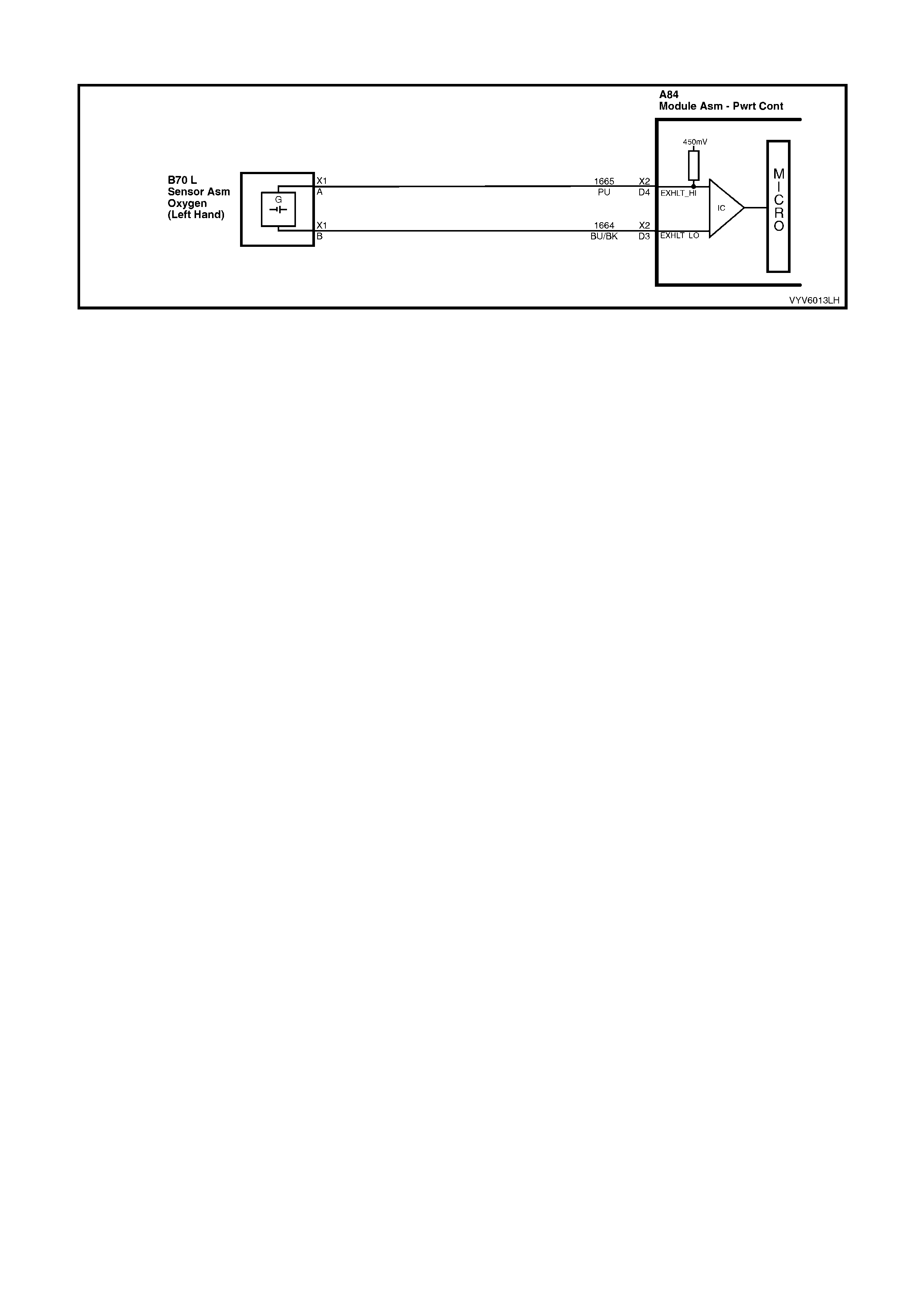
DTC P0151 V6 PCM - LEFT HAND OXYGEN SENSOR (O2S) SIGNAL VOLTAGE LOW
Figure 6C1-2A-99 Left Hand Ox ygen Sensor Circuit
CIRCUIT DESCRIPTION
The PCM supplies a volta ge of about 450 millivolts between term inal X2-D4 and X2-D3. The Oxygen (O2) sensor
varies the voltage within a range of about 1 volt if the ex haust is rich, do wn throu gh about 10 0 mill ivolts, if exhaus t
is lean.
The s ensor is like an ope n circ uit and pr oduc es no vol tage when it is belo w abo ut 360°C. A n open sens or circ uit or
cold sensor causes "Open Loop" operation.
CONDITIONS FOR RUNNING THE DTC
• No IAT Sensor DTC’s are set.
• IAT Sensor is below 75°C.
• The system is in "Closed Loop”.
• Throttle angle is between 9% and 30%.
CONDITIONS FOR SETTING THE DTC
• The LH 02S signal voltage remains below 200 millivolts for 46 seconds.
ACTION TAKEN WHEN THE DTC SETS
• The PCM activates the Check Powertrain MIL when the diagnostic runs and fails.
• The PCM records the operating conditions at the time the diagnostic fails. The PCM stores this information in
the History Data.
• Once an 02S DTC is set, and current, the PCM will operate the fuel system in the “Open Loop” mode.
CONDITIONS FOR CLEARING THE MIL/DTC
• The PCM turns the Check Powertrain MIL OFF when it sees a valid condition.
• Use a TECH 2 in order to clear the MIL/DTC.
DIAGNOSTIC AIDS
Using TECH 2, observe the Long Term Fuel Trim values at different RPMs and air flow conditions. TECH 2 also
displa ys the Lo ng Term Fuel Tr im ce lls, so the L ong T erm Fuel Trim values c an be check ed in e ach of th e cells t o
determine when the DTC P0151 may have been set. If the conditions for DTC P0151 exist, the Long Term Fuel
Trim values will be around +25%.
TEST DESCRIPTION
Number(s) below refer to step number(s) on the diagnostic Table.
4. The DTC P0151 or lean exhaust is most likely caused by one of the following:
• O2 Sensor Wire - Sensor pigtail may be mispositioned and contacting the exhaust manifold.
• Check for intermittent ground in wire between connector and sensor.
• MAF Sensor - A shifted MAF sensor could cause the fuel system to go lean. Refer to TABLE A-6.1.
• Lean Injector(s) - Perform injector balance. Refer Section 6C1-2C, Table 2.7.
• Fuel Contamination - Water, even in small amounts, near the in-tank Fuel Pump inlet can be delivered to the
injectors. The water causes a lean exhaust and can set a DTC P0151 and/or DTC P0131.
• Fuel Pressure - System will go lean if pressure is too low. It may be necessary to monitor fuel pressure while
driving the vehicle at various road speeds and/or loads to confirm. Refer to TABLE A-4.1.
• Exhaust L eaks - If there is an exha ust leak , the engin e can cause o utside air t o be pull ed into the ex haust and
past the sensor. Vacuum or crankcase leaks can also cause a lean condition.

A84 V6 – X2 B70
Figure 6C1-2A-100
DTC P0151 V6 PCM - LEFT HAND OXYGEN SENSOR (02S) SIGNAL VOLTAGE LOW
STEP ACTION VALUE YES NO
1. Was the "On-Board Diagnostic" (OBD) System Check
performed? Go to Step 2 Go to
OBD System
Check
2. 1. Start engine.
2. Run engine until it reaches normal operating
temperature (Above 80°C).
3. Continue to run at 1600 to 1800 RPM for two
minutes.
Does TECH 2 indicate O2 sensor voltage fixed below
specified value?
200 mV Go to Step 3
DTC P0151 is
intermittent, If no
additional DTCs
were stored, refer
to "Intermittents"
in Section 6C1-
2B SYMPTOMS.
3. Disconnect O2 sen sor con nec tor.
With engine idling, does TECH 2 display O2 sensor
voltage between the specified values?
Between
350 mV
and
550 mV
Go to Step 4 Go to Step 6
4. 1. Refer to step 4 Test Description first.
2. Perform the checks on the i tems as note d.
• MAF sensor operation
• Low fuel pressure
• Contaminated fuel
• Exhaust manifold leaks ahead of O2 sensor
• Lean injector (possibly restricted)
Are all items checked found to be OK?
Go to Step 5 Verify Repair
5. Replace Oxygen sensor.
Is action complete?
Verify repair
6. 1. Ignition "O FF".
2. Disconnect PCM connectors.
3. With O2 sensor still disconnected, check O2 signal
circuit 1665 for a short to ground.
Is a short to ground detected?
Go to Step 7 Go to Step 8
7. Repair circuit 1665.
Is action complete? Verify Repair
8. Replace PCM.
Refer to Section 6C1-3 Service Operations, for PCM
Programming and Security Link procedure.
Is action complete?
Verify Repair

DTC P0152 V6 PCM - LEFT HAND OXYGEN SENSOR (O2S) SIGNAL VOLT AGE HIGH
Figure 6C1-2A-101 Left Hand Oxygen Sensor Circuit
CIRCUIT DESCRIPTION
The PCM supplies a volta ge of about 450 millivolts between term inal X2-D4 and X2-D3. The Oxygen (O2) sensor
varies the voltage within a range of about 1 volt, if the exhaust is rich and down through about 100 millivolts if
exhaust is lean.
The sensor produces no voltage when it is below about 360°C. An open sensor circuit or cold sensor causes "Open
Loop" operation.
CONDITIONS FOR RUNNING THE DTC
• No TP Sensor DTC’s are set.
• The system is in "Closed Loop”.
• Throttle angle is between 9% and 30%.
CONDITIONS FOR SETTING THE DTC
• The LH 02S signal voltage remains above 780 millivolts for 40 seconds.
ACTION TAKEN WHEN THE DTC SETS
• The PCM activates the Check Powertrain MIL when the diagnostic runs and fails.
• The PCM records the operating conditions at the time the diagnostic fails. The PCM stores this information in
the History Data.
• Once an 02S DTC is set, and current, the PCM will operate the fuel system in the “Open Loop” mode.
CONDITIONS FOR CLEARING THE MIL/DTC
• The PCM turns the Check Powertrain MIL OFF when it sees a valid condition.
• Use a TECH 2 in order to clear the MIL/DTC.
DIAGNOSTIC AIDS
Using TECH 2, observe the Long Term Fuel Trim values at different RPM and air flow conditions. TECH 2 also
displa ys the Lo ng Term Fuel Tr im ce lls, so the L ong T erm Fuel Trim values c an be check ed in e ach of th e cells t o
determine when the DTC P0152 may have been set. If the conditions for DTC P0152 exist, the Long Term Fuel
Trim values will be around -22%.
NOTE: Oxygen Sensor Contamination - If fuel containing lead or silicone is used, or engine repairs using
unappro ved RTV gas k et sealer are perf orm ed, the sens or m ay be contam inated. It ma y send a "false" ric h ex haust
indicati on to the PCM, a nd the PCM will attem pt to drive the f uel system lean to c ompensate. Poor driveab ility or a
Diagnostic T r ouble C ode P 0151 c ou ld res u lt. If this ha ppens, the sensor wi ll ne ed to be repl ac ed, b ut ev er y attempt
to locate the source of contamination should be pursued.
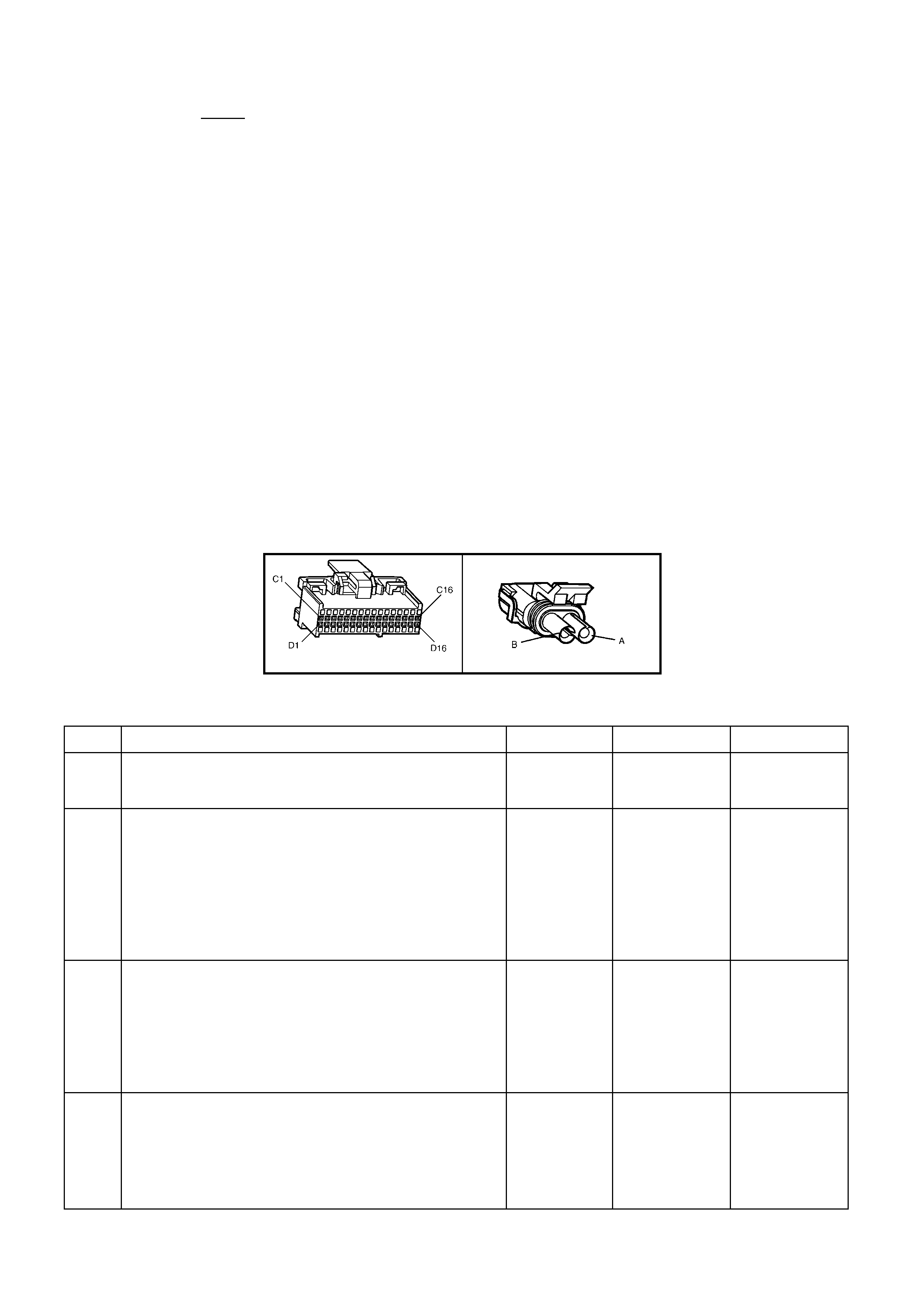
TEST DESCRIPTION
Number(s) below refer to step number(s) on the diagnostic Table.
2. The O2 sensor MUST be at operating temperature before checking operation.
3. This step checks for a short to voltage on the O2S signal line.
7. Grounding circuit 1665 causes a low O2S signal voltage. If the PCM and wiring are OK, the PCM should
recognise the low voltage and confirm the lean signal.
8. A DTC P015 2 will mos t likel y NO T be caus ed by a fa ulty O2 sensor . DTC P0152 i ndicates a r ich exhaust and
diagnosis should begin with the items listed:
• Fuel pressure. System will go rich, if pressure is too high. The PCM can compensate for some increase.
However, if it gets too high, a DTC P0152 may be set. Refer to fuel system diagnosis TABLE A-4.3.
• Rich injector.
• Leaking injector. Refer to TABLE A-4.3.
• Check for fuel contaminated oil.
• Short to voltage on circuit 1665.
• HEI shiel di ng. An o pen gro und c irc u it 45 3 ( ig nit io n system) ma y result i n E MI, or induc ed el ec tric al "n ois e. " The
PCM looks at this "noise" as reference pulses. The additional pulses result in a higher than actual engine
speed signa l. T he PCM the n deli vers too m uch f uel, caus ing the s ystem to go rich. Engine t achom eter wil l also
show higher than actual engine speed, which can help in diagnosing this problem.
• Canister purge. Check for fuel saturation. If full of fuel, check canister control and hoses.
• MAF sensor. A shifted MAF sensor could cause the fuel system to go rich.
• Check for leaking fuel pressure regulator diaphragm by checking vacuum line to regulator for fuel.
• TP Sensor. An intermittent TP sensor output will cause the system to go rich, due to a false indication of the
engine acc eler a tin g.
A84 V6 – X2 B70
Figure 6C1-2A-102
DTC P0152 V6 PCM - LEFT HAND OXYGEN SENSOR (O2S) SIGNAL VOLTAGE HIGH
STEP ACTION VALUE YES NO
1. Was the "On-Board Diagnostic" (OBD) System Check
performed? Go to Step 2 Go to
OBD System
Check
2. 1. Engine at normal operating temperature (above 80°C).
2. Run engine at approximately 1600 RPM to 1800 RPM
for two minutes.
Is TECH 2 voltage above specified value?
750 mV Go to Step 3 DTC P0152 is
intermittent,
If no additional
DTC(s) were
stored, refer to
"Intermittents"
in Section
6C1-2B
SYMPTOMS.
3. 1. Ignition "OFF".
2. Disconnect O2 sensor wiring harness connector.
3. With Digital Multimeter (DMM) connected to ground,
probe circuit 1665 at O2 sensor wiring harness
connector.
4. Ignition "ON".
Is voltmeter indicating less than specified value?
500 mV Got to Step 7 Go to Step 4
4. 1. Ignition "OFF".
2. Disconnect PCM connectors.
3. Probe circuit 1665 at O2 sensor wiring harness
connector.
4. Ignition "ON".
Is voltmeter indicating voltage below specified value?
350 mV Go to Step 6 Go to Step 5

STEP ACTION VALUE YES NO
5. Repair circuit 1665, shorted to voltage.
Is action complete? Verify Repair
6. Replace PCM.
Refer 6C1-3 Service Operations, for PCM Programming
and Security Link procedure.
Is action complete?
Verify Repair
7. 1. Disconnect O2 sensor wiring harness connector.
2. Jumper harness con ne ctor cir cuit 166 5 to ground.
With engine running, does TECH 2 display O2 voltage
below specified value?
350 mV Go to Step 8 Go to Step 9
8. See step 8 in Test Description to perform additional checks
for:
• High Fuel Pressure
• MAF Sensor Operation
• Leaking Inje ctor s
• Ignition Ground Circuit
• Canister Purge
• Engine Coolant Temperature Sensor Circuit
• Intake Air Temperature Sensor Circuit
• Throttle Position Sensor Operation
Are all items checked found to be OK?
Go to Step 11 Verify Repair
9. 1. Ignition "OFF"
2. Connect PCM connectors.
3. Check O2 sensor ground circuit 1664 for good
continuity between PCM connector terminal X2-D3 and
engine ground.
Is an "OPEN" circuit indicated?
Verify Repair Go to Step 10
10. Check PCM ground wire connections at engine. Must be a
clean and tight connection to the engine.
Are connections good?
Go to Step 6 Verify Repair
11. Replace oxygen sensor.
Is action complete Verify Repair

DTC P0154 V6 PCM - NO LEFT HAND OXYGEN SENSOR (O2S) SIGNAL
Figure 6C1-2A-103 Left Hand Oxygen Sensor Circuit
CIRCUIT DESCRIPTION
The exhaust gas oxygen sensor is mounted in the exhaust pipe with the sensing portion exposed to exhaust gases.
After the sensor is hot (360°C), it becomes a voltage generator, producing a "changing" voltage. This voltage
ranges from approximately 100 millivolts with a "lean" exhaust, to 900 millivolts with a "rich" exhaust. When the
sensor is cold (be low 360°C) it acts lik e an open circ uit and prod uces alm ost no vo ltage. The PC M suppli es a ver y
small "bias" voltage between terminals X2-D4 and X2-D3, normally about 450 millivolts. If measured with the 10
megaohm digital voltmeter, it may measure as low as 350 millivolts. When the sensor is hot, it's output
overshadows this PCM supplied voltage.
When the fuel system is correctly operating in the closed-loop mode, the sensor output is changing several times
per second, going above and below a mid-point range of 490-500 millivolts at a hot idle. The PCM compares the
voltage between the sensor signal and sensor ground terminals and decides the needed fuel mixture correction.
The PCM also monitors the changing voltage, watching for transitions above and below the mid-point range, to
decide when to operate in the closed-loop mode. An open circuit, defective, or contaminated sensor could cause
the voltag e to sta y within a 410-4 77 m illivolt band f or too l ong, keep ing the s ystem in open-loop a nd setting a DTC
P0154.
CONDITIONS FOR RUNNING THE DTC
• Engine run time is longer than 4 minutes.
• No TP Sensor DTC’s are set.
• The ECT sensor is more than 85°C.
• Throttle angle is more than 15%.
CONDITIONS FOR SETTING THE DTC
• The LH 02S voltage stays between 410-477 millivolts.
ACTION TAKEN WHEN THE DTC SETS
• The PCM activates the Check Powertrain MIL when the diagnostic runs and fails.
• The PCM records the operating conditions at the time the diagnostic fails. The PCM stores this information in
the History Data.
• Once an O2S DTC is set, and current, the PCM will operate the fuel system in the “Open Loop” mode.
CONDITIONS FOR CLEARING THE MIL/DTC
• The PCM turns the Check Powertrain MIL OFF when it sees a valid condition.
• Use a TECH 2 in order to clear the MIL/DTC.
DIAGNOSTIC AIDS
Normal TECH 2 voltage varies between 100 mV to 999 mV while in "Closed Loop". DTC P0154 sets if voltage
remains between 410 and 477 millivolts, but the system will go "Open Loop" before the Check Powertrain MIL is
turned "ON ".
Refer to "Intermittents" in Section 6C1-2B SYMPTOMS. To diagnose the oxygen sensor, refer TABLEA-6.3.
NOTE: Oxygen Sensor Contamination - If fuel containing lead or silicone is used, or engine repairs using
unapproved RTV gasket sealer are performed, the sensor may be contaminated. It may send a "False" rich
exhaust indication to the PCM, and the PCM will attempt to drive the fuel system lean to compensate. Poor
driveability or a Diagnostic T rouble Code P0154 could result. If this happens, the sensor will need to be replaced,
but every attempt to locate the source of contamination should be pursued.
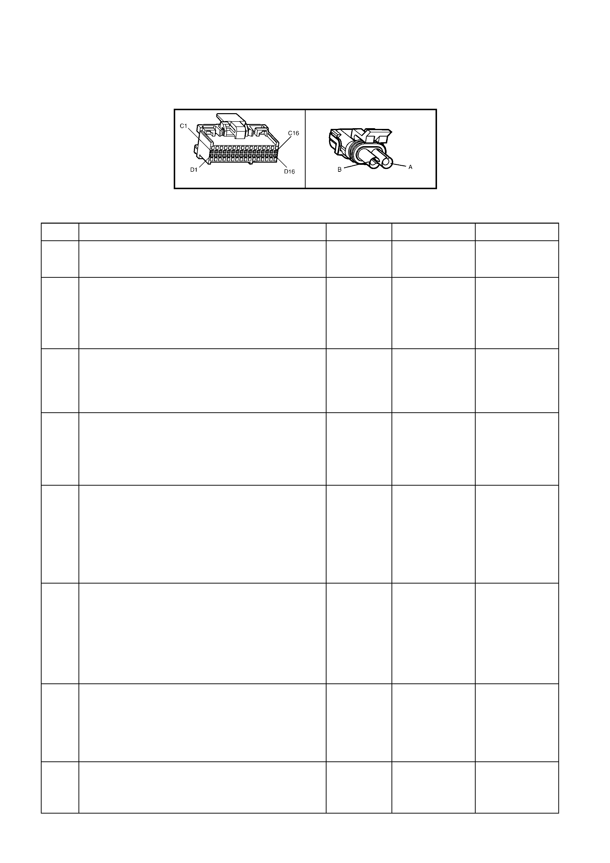
TEST DESCRIPTION
Number(s) below refer to step number(s) on the diagnostic Table.
2. TECH 2 allows you to read the same oxygen sensor voltage the PCM is using for its calculations.
3. This step s imulates a lean exhaust indic ation to the P CM. If the PCM and wir ing are OK, the PCM will see the
lean indication and TECH 2 should display O2 voltage below 200 mV.
A84 V6 – X2 B70
Figure 6C1-2A-104
DTC P0154 V6 PCM - NO LEFT HAND OXYGEN SENSOR (O2S) SIGNAL
STEP ACTION VALUE YES NO
1. Was the "On-Board Diagnostic" (OBD) System Check
performed? Go to Step 2 Go to
OBD System
Check
2. 1. Engine at normal operating temperature (above
85°C).
2. Run engine at approximately 1600 to 1800 RPM for
two minutes.
Is TECH 2 oxygen sensor voltage between specified
values?
410-477 mV
Go to Step 3 If no additional
DTCs were
stored, refer to
“Intermittents” in
Section 6C1-2B
SYMPTOMS.
3. 1. Ignition ON, engine stopped.
2. Disconnect O2S and jumper the O2S signal and low
circuits (PCM side) together.
3. Using TECH 2, monitor O2S voltage.
Is the O2S voltage less than the specified value?
0.2 Volt
(200 mV) Go to Step 7 Go to Step 4
4. 1. Remove the jumper wire from the O2S signal circuit
1665.
2. Using a DMM, measure voltage between the O2S
signal circuit (PCM side) and ground.
Does the O2S signal voltage measure near the specified
value?
410-477 mV
Go to Step 5 Go to Step 6
5. 1. Ignition OFF.
2. Disconnect the PCM.
3. Check continuity of the O2S low circuit 1665
between the PCM harness connector and the O2S
harness connec tor.
4. If the O2S low circuit measures over 5 ohms, repair
open or poor connection as necessary.
Was a problem found?
Verify Repair Go to Step 8
6. 1. Ignition OFF.
2. Disconnect the PCM.
3. Check continuity of the following circuit:
• The O2S signal circuit between the PCM harness
connector and the O2S harness connector.
4. If circuit measures over 5 ohms, repair open or poor
connect ion as neces sary .
Was a problem found?
Verify Repair Go to Step 9
7. 1. Check the following circuits for a poor terminal
connection at the O2S harness connector.
• O2S signal circuit, 1665.
• O2S low circuit, 1664.
2. If a problem is found, repair as necessary.
Was a problem found?
Verify Repair Go to Step 10
8. 1. Check for poor O2S low circuit terminal connection at
PCM.
2. If a problem is found, repair as necessary.
Was a problem found?
Verify Repair Go to Step 11

STEP ACTION VALUE YES NO
9. 1. Check the O2S signal circuit for a poor terminal
connection at the PCM.
2. If a problem is found, repair as necessary.
Was a problem found?
Verify Repair Go to Step 11
10. Replace the O2 sensor.
Is action complete? Verify Repair
11. Replace PCM.
Refer 6C1-3 Service Operations, for PCM Programming
and Security Link procedure.
Is action complete?
Verify Repair

DTC P0170 V6 PCM - LONG TERM FUEL TRIM (LTFT) DELT A HIGH
Figure 6C1-2A-105 Ox ygen Sensor Circuits
CIRCUIT DESCRIPTION
The PCM controls left to right cylinder bank fuel delivery separately based on their respective oxygen sensor
signals. If the PCM detects too great a difference between the left to right cylinder bank Long Term Fuel Trim
values, it will set DTC P0170.
CONDITIONS FOR RUNNING THE DTC
• En gine is idling.
CONDITIONS FOR SETTING THE DTC
• The left hand Long T erm Fuel Trim value var ies from the right ha nd Long Term Fuel Trim value by more than
59% for more than 32 seconds.
ACTION TAKEN WHEN THE DTC SETS
• The PCM stores the DTC information into memory when the diagnostic runs and fails.
• The Check Powertrain MIL will not be activated.
• The PCM records the operating conditions at the time the diagnostic fails. The PCM stores this information in
the History Data.
• DTC P0170 will clear when the fault no longer exists and the ignition switch is cycled "OFF" and "ON".
CONDITIONS FOR CLEARING THE MIL/DTC
• Use a TECH 2 in order to clear the MIL/DTC.
DIAGNOSTIC AIDS
• Lean or faulty injector(s) on one side of the engine.
• Cracked or fouled spark plug(s).
• Exhaust or inlet manifold leak, on one side of the engine.
• Make sure oxygen sensor leads are not swapped.
TEST DESCRIPTION
Number(s) below refer to step number(s) on the diagnostic Table.
2. Check and repair other DTC(s) first.
3. Check for other mechanical problems causing DTC to set.
4. The bank that is the farthest from the neutral value of 0% is the bank which is out of fuel control.

DTC P0170 V6 PCM - LONG TERM FUEL TRIM (LTFT) DELTA HIGH
STEP ACTION VALUE YES NO
1. Was the "On-Board Diagnostic" (OBD) System Check
performed? Go to Step 2 Go to
OBD System
Check
2. Are any other PCM DTC(s) set? Diagnose other
DTC(s) first Go to Step 3
3. Is there a Driveability complaint associated with this DTC
such as an Engine Miss, Lack of Power, or Poor Fuel
Economy?
Go to Step 7 Go to Step 4
4. 1. Start Engine and allow to warm up (Coolant
Temperature above 85°C).
2. Install TECH 2 and note left and right bank Long
Term Fuel Trim values.
Is the left bank Long Term Fuel Trim value further from
0% than the right bank?
Go to Step 5 Go to Step 6
5. Perform Oxygen Sensor (O2S) Diagnosis, refer
Table A-6.3.
Is action complete?
Verify Repair
6. 1. Start Engine and allow to warm up (Coolant
Temperature above 85°C).
2. Install TECH 2 and note left and right bank Long
Term Fuel Trim values.
Is the right bank Long Term Fuel Trim value further
from 0% than the left bank?
Go to Step 5 DTC P0170 is
intermittent.
Refer "Diagnostic
Aids"
7. Perform the following tests in the order given until the
problem is correcte d :
• Fuel System check, refer Table A-4.3.
• Oscilloscope engine, note and repair any Ignition
System problem found.
• Compression test each cylinder.
Is action complete?
Verify Repair
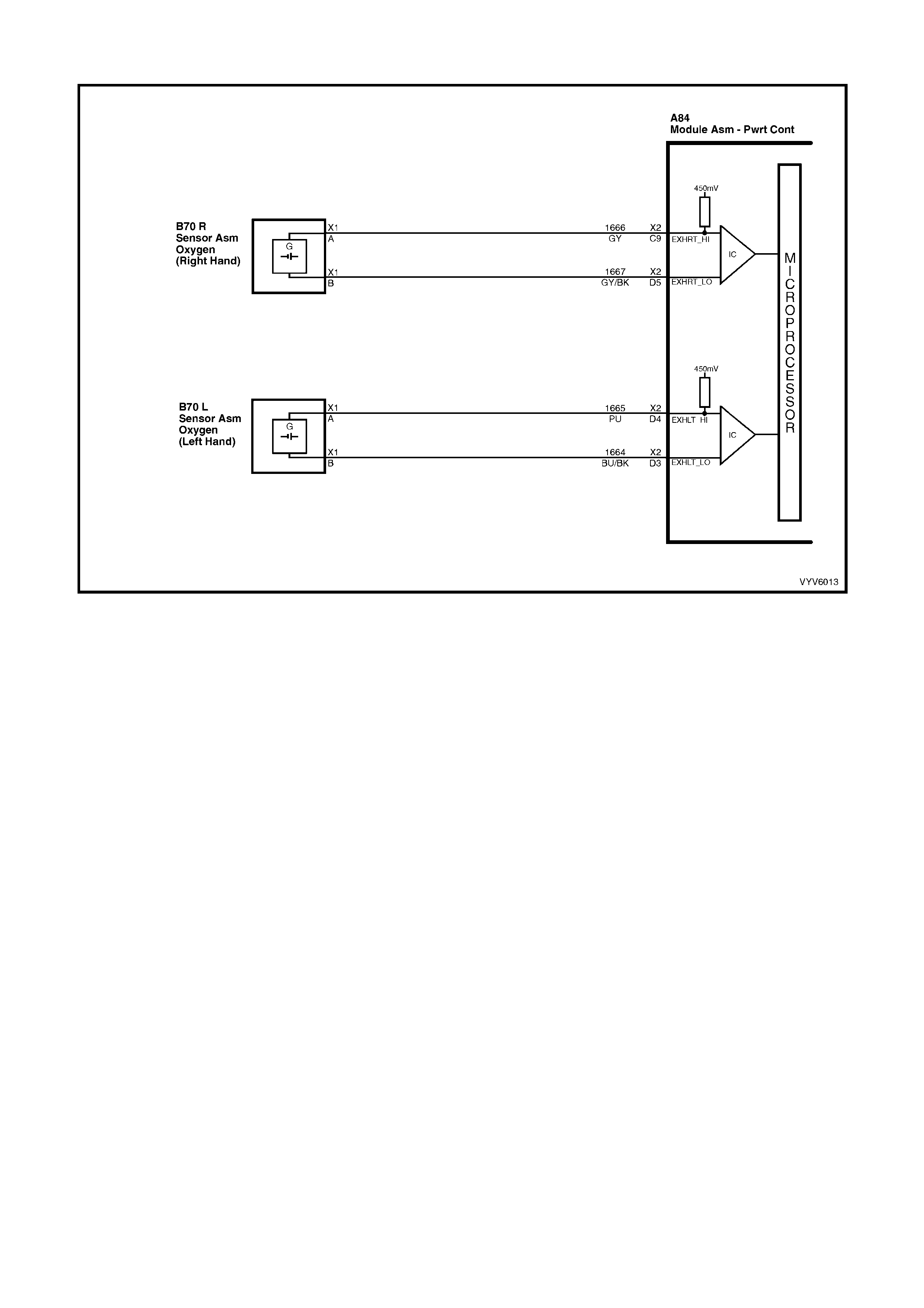
DTC P0173 V6 PCM - SHORT TERM FUEL TRIM (STFT) DELT A HIGH
Figure 6C1-2A-106 Ox ygen Sensor Circuits
CIRCUIT DESCRIPTION
The PCM controls left to right cylinder bank fuel delivery separately based on their respective oxygen sensor
signals. If the PCM detects too great a diff erence between the l eft to right c ylinder bank Short T erm (ST) Fuel T rim
values, it will set DTC P0173.
CONDITIONS FOR RUNNING THE DTC
• En gine is idling.
CONDITIONS FOR SETTING THE DTC
• The lef t hand Sh ort T erm Fuel Trim value vari es from the right hand Sh ort Te rm Fuel T rim valu e b y more tha n
63% for more than 32 seconds.
ACTION TAKEN WHEN THE DTC SETS
• The PCM stores the DTC information into memory when the diagnostic runs and fails.
• The Check Powertrain MIL will not be activated.
• The PCM records the operating conditions at the time the diagnostic fails. The PCM stores this information in
the History Data.
• DTC P0173 will clear when the fault no longer exists and the ignition switch is cycled "OFF" and "ON".
CONDITIONS FOR CLEARING THE MIL/DTC
• Use a TECH 2 in order to clear the MIL/DTC.
DIAGNOSTIC AIDS
• Lean or faulty injector(s) on one side of the engine.
• Cracked or fouled spark plug(s).
• Exhaust or inlet manifold leak on one side of the engine.
• Make sure oxygen sensor leads are not swapped.
TEST DESCRIPTION
Number(s) below refer to step number(s) on the diagnostic Table.
2. Check and repair other DTC(s) first.
3. Check for other mechanical problems causing DTC to set.
4. The bank that is the farthest from the neutral value of 0% is the bank which is out of fuel control.

DTC P0173 V6 PCM - SHORT TERM FUEL TRIM (STFT) DELTA HIGH
STEP ACTION VALUE YES NO
1. Was the "On-Board Diagnostic" (OBD) System Check
performed? Go to Step 2 Go to
OBD System
Check
2. Are any other PCM DTC(s) set? Diagnose other
DTC(s) first Go to Step 3
3. Is there a Driveability complaint associated with this
DTC such as an Engine Miss, Lack of Power, or
Poor Fuel Economy?
Go to Step 7 Go to Step 4
4. 1. Start Engine and allow to warm up (Coolant
Temperature above 85°C).
2. Install TECH 2 and note left and right bank Short
Term Fuel Trim values.
Is the left bank Short Term Fuel Trim value further from
0% than the right bank?
Go to Step 5 Go to Step 6
5. Perform Oxygen Sensor (O2S) Diagnosis, Table A-6.3.
Is action complete? Verify Repair
6. 1. Start Engine and allow to warm up (Coolant
Temperature above 85°C).
2. Install TECH 2 and note left and right bank Short
Term Fuel Trim values.
Is the right bank Short Term Fuel Trim value further from
0% than the left bank?
Go to Step 5 DTC P0173 is
intermittent.
Refer "Diagnostic
Aids"
7. Perform the following tests in the order given until the
problem is correcte d :
• Fuel system check, refer to Table A-4.3.
• Oscilloscope Engine, note and repair any Ignition
System problem found.
• Compression test each cylinder.
Is action complete?
Verify Repair

DTC P0200 V6 PCM - INJECTOR VOLTAGE MONITOR FAULT
Figure 6C1-2A-107 Injector Circuits
CIRCUIT DESCRIPTION
The inj ect or volt age monito r line is us ed s o th at the P C M wil l know the exac t vo lta ge the f uel i nj ec tors ar e op erating
at. This voltage is used to c ontr ol the p ulse width m odulat ion of the fuel inj ectors . If the injec tor vo ltage m onit or lin e
drops more than 2.2 volts for more than 3 seconds, Diagnostic Trouble Code (DTC) P0200 will set. This DTC will
not turn "ON" the Check Powertrain MIL, but will have a DTC set in the PCM memory that can be read with
TECH 2.
CONDITIONS FOR RUNNING THE DTC
• The engine is running.
• DTC P0561 is not set.
CONDITIONS FOR SETTING THE DTC
• Injector voltage monitor line voltage is 2.2 volts different than system voltage for 3 seconds.
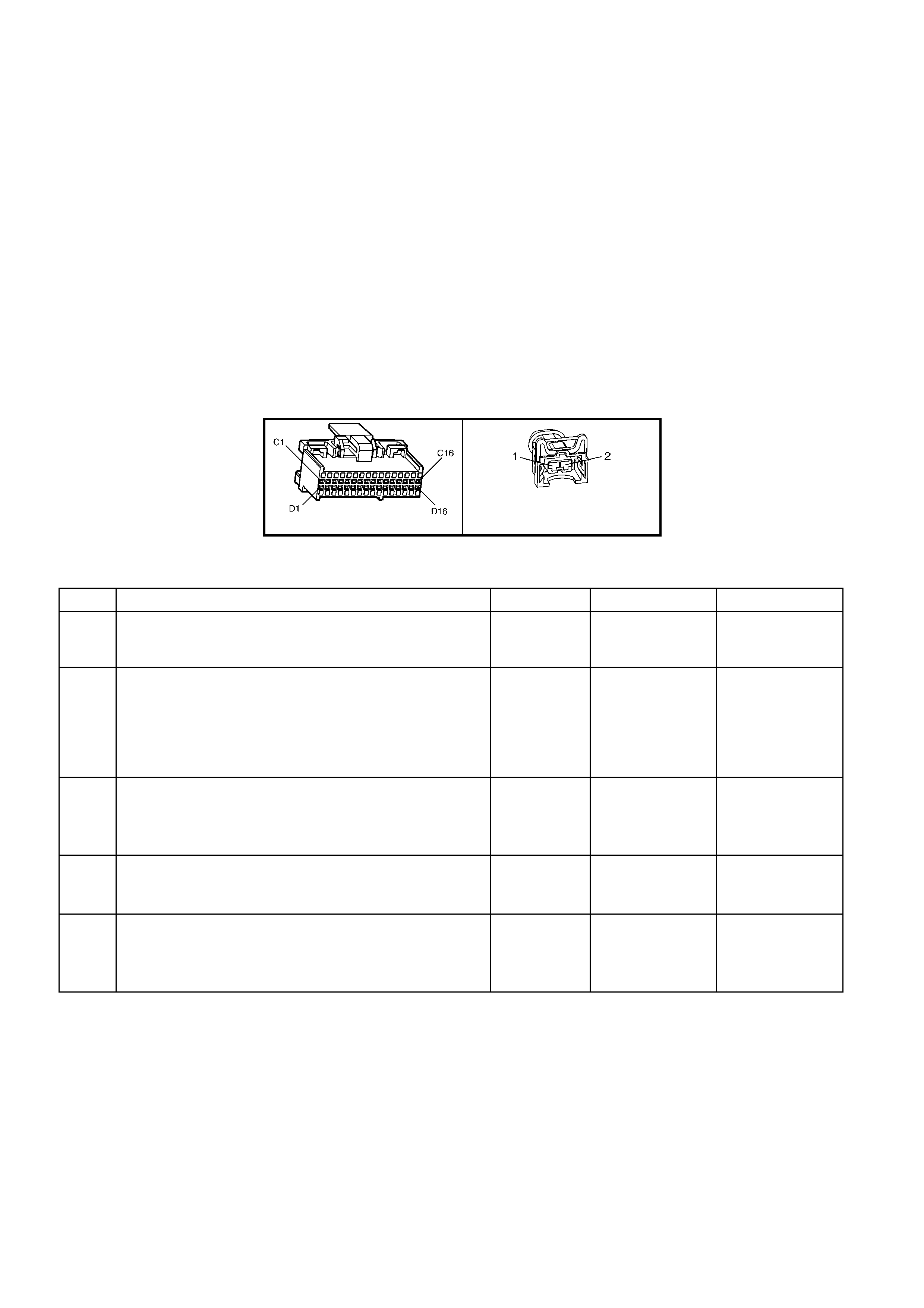
ACTION TAKEN WHEN THE DTC SETS
• The PCM stores the DTC information into memory when the diagnostic runs and fails.
• The Check Powertrain MIL will not be activated.
• The PCM records the operating conditions at the time the diagnostic fails. The PCM stores this information in
the History Data.
• The PCM will use the battery feed input signal as the voltage value to control the fuel injectors base pulse
width.
CONDITIONS FOR CLEARING THE MIL/DTC
• Use a TECH 2 in order to clear the MIL/DTC.
DIAGNOSTIC AIDS
When the injector voltage monitor line voltage drops more than 2.2 volts, the PCM will operate on an incorrect
value for 3 seconds until the DTC P0200 is set. Check PCM terminal connections for proper mating.
TEST DESCRIPTION
Number(s) below refer to step number(s) on the diagnostic Table.
2. If the charging voltage is too high, this could set DTC P0200. If DTC P0563 is set, refer to that DTC first.
4. If voltage is low on circuit 689 also check for voltage drop from EFI relay to X2-C14.
A84 V6 – X2 L2
Figure 6C1-2A-108
DTC P0200 V6 PCM - INJECTOR VOLTAGE MONITOR FAULT
STEP ACTION VALUE YES NO
1. Was the "On-Board Diagnostic" (OBD) System Check
performed? Go to Step 2. Go to
OBD System
Check
2. 1. This table assumes that no DTC P0561 is set and
the battery and charging systems are operating
properly.
2. Using TECH 2, display "Injector Voltage" and
"Battery Voltage".
Are they within the specified value of each other?
2.4 volts DTC P0200 is
intermittent, if no
additional DTCs
were stored, refer
to "Diagnostic
Aids".
Go to Step 3
3. Using DMM, backprobe PCM terminal X2-C14 with
red lead and connect black lead to PCM terminal X1-A5.
Is voltage measured within specified value of "Battery
Voltage" reading on TECH 2?
2.4 volts Go to Step 5
Go to Step 4
4. Repair open in circuit 639 between splice and PCM
terminal X1-A5.
Is action complete?
Verify Repair
5. Replace PCM.
Refer 6C1-3 Service Operations, for PCM Programming
and Security Link procedure.
Is action complete?
Verify Repair
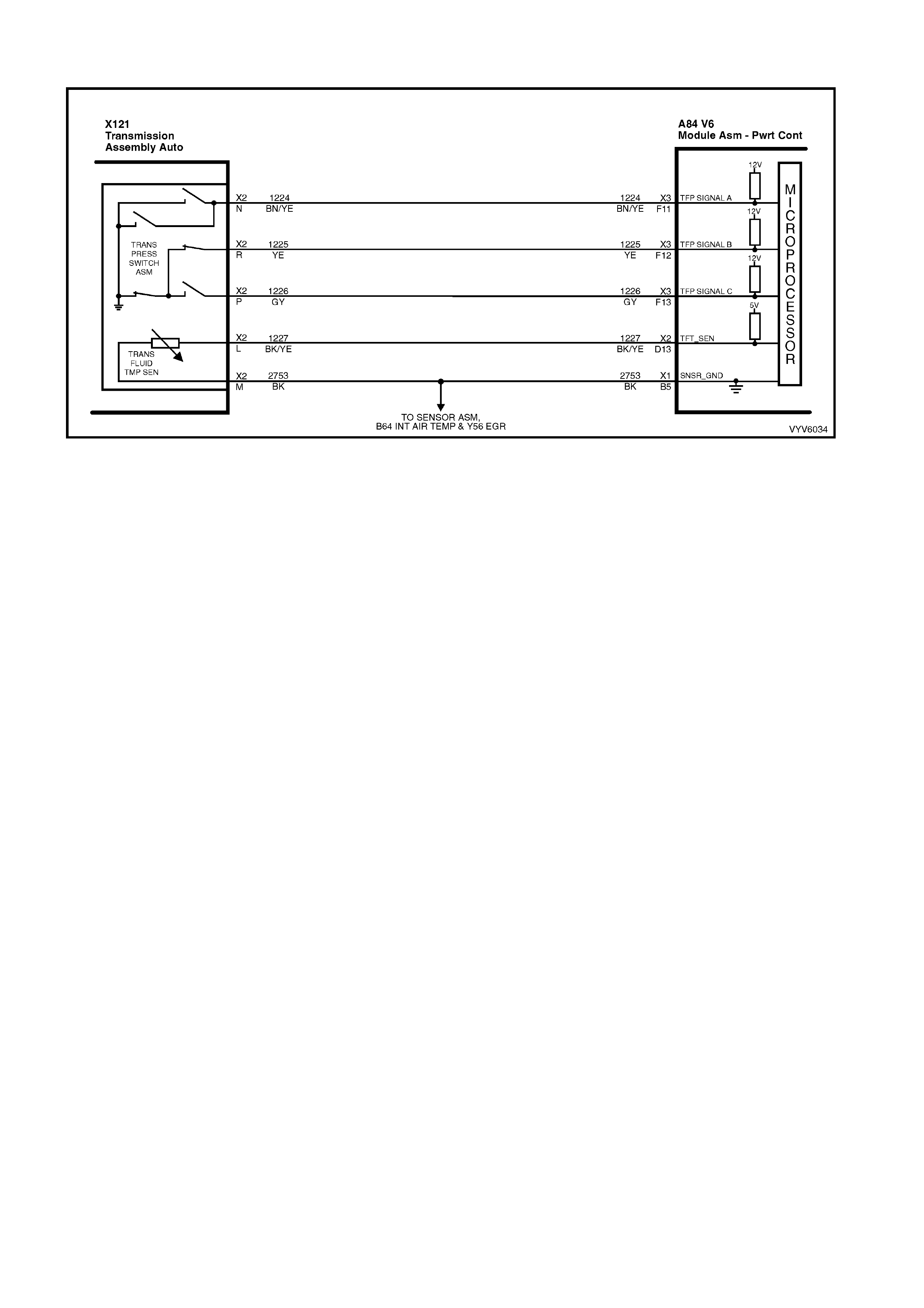
DTC P0218 V6 PCM - TRANSMISSION FLUID OVERTEMPERATURE
Figure 6C1-2A-109 Automatic Transmission Fluid Temperature Sensor
CIRCUIT DESCRIPTION
The f low of transm ission fluid s tarts in the bottom of the pan and is drawn throu gh the f ilter, transm iss ion case and
into the oil pump assembly. The oil pump assembly pressurises the fluid and directs it to the pressure regulator
valve where it becomes the main supply of fluid to the various components and hydraulic circuits in the
transmission. Hot fluid exiting the torque converter flows through the converter clutch apply valve and into the
transm ission cooler lines to the oi l cooler loc ated in th e radiator ( and auxiliar y cooler if equipped) . From the cooler,
fluid returns to cool and lubricate the front of the transmission. In forward drive ranges, D4 fluid from the manual
valve is routed through an orifice cup plug in the rear of the transmission case to feed the rear lube fluid circuit.
W hen the PCM det ec ts a hi gh trans miss ion f luid tem pe r atur e via th e Transmission F luid T emperatur e (TFT) sensor
for a long period of time, DTC P0218 sets.
As the transm ission f luid tem perature warm s (normal trans miss ion operating tem perature 82°C - 94°C), the s ensor
(thermistor) resistance becomes less and the voltage will measure about 1.5 to 2.0 volts. If the fluid temperature
becomes greater than 146°C and does not drop below 137°C for 30 minutes, a DTC P0218 will set.
When DTC P0218 sets the transmission fluid may be severely degraded.
CONDITIONS FOR RUNNING THE DTC
• DTC P0712 is not set.
CONDITIONS FOR SETTING THE DTC
• The TFT is at or greater than 137° C for 10 minutes (600 seconds).
ACTION TAKEN WHEN THE DTC SETS
• The PCM activates the Check Powertrain MIL when the diagnostic runs and fails.
• The PCM records the operating conditions at the time the diagnostic fails. The PCM stores this information in
the History Data.
• When a DTC P0218 sets, the PCM freezes shift adapts from being updated.
CONDITIONS FOR CLEARING THE MIL/DTC
• The PCM turns the MIL OFF after the first ignition cycle that the diagnostic runs and does not fail.
• Use a TECH 2 in order to clear the MIL/DTC.
DIAGNOSTIC AIDS
• Inspect the cooling system fluid level and condition.
• DTC P0218 may set approximately 30 minutes after DTC P0712 has set. Follow the diagnostic table for DTC
P0712 before proceeding to the diagnostic table for DTC P0218. Repairing the condition that set DTC P0712
will likely eliminate DTC P0218.
• The TFT temperature displayed on TECH 2 should rise steadily to a normal operating temperature, then
stabilise.
• Inspect the torque converter stator for a possible problem.
• Ask about the customer's driving habits, trailer towing, etc.

TEST DESCRIPTION
Number(s) below refer to step number(s) on the diagnostic Table.
3. DTC P0712 may also set a DTC P0218. Go to the DTC P0712 table for diagnosis.
3. This step inspects for air restrictions and loss of transmission fluid flow, causing an extremely high TFT.
DTC P0218 V6 PCM - TRANSMISSION FLUID OVERTEMPERATURE
STEP ACTION VALUE YES NO
1. W as the On-Board Diagnostic (OBD) System Check
performed? Go to Step 2 Go to
OBD System
Check
2. 1. Install TECH 2.
2. Ignition “ON” engine “OFF”.
3. Record the DTC History Data.
IMPORTANT: Before clearing the DTCs, use TECH 2 in
order to record the DTC History Data for reference.
The Clear DTC History function will erase the data.
4. Perform the transmission fluid checking procedure.
Refer to Transmission Fluid Checking Procedure.
Was the fluid checking procedure performed?
Go to Step 3 Go to
Transmission
Fluid Checking
Procedure
3. Is DTC P0712 also set? Go to “Diagnostic
Aids” Go to Step 4
4. 1. Inspect the cooling system for the following
conditions:
• Air flow restrictions
• Air flow blockage
• Debris
2. Inspect the transmission cooling system for the
following con diti on s:
• Air flow restrictions
• Air flow blockage
• Debris
• Damaged cooler lines
3. Repair restrictions if necessary.
Was a problem found?
Go to Step 7 Go to Step 5
5. Drive the vehicle in D4 with the TCC commanded On.
Observer the TCC slip speed on TECH 2.
Is the TCC slip speed within the specified value?
-20 to +20
RPM Go to Step 6 Refer to Torque
Converter Clutch
Diagnosis
Symptoms
6. Perform the Line Pressure Check Procedure. Refer 7C-3.
Was a problem found? Go to Step 7 Go to “Diagnostic
Aids”
7. In order to verify your repair, perform the following
procedure:
1. Drive the vehicle to normal operating engine and
transmission temperature.
2. Observe the TFT during the entire drive.
Is the TFT less than the specified value during the entire
drive?
137°C System OK Begin the
diagnosis agai n.
Go to Step 1
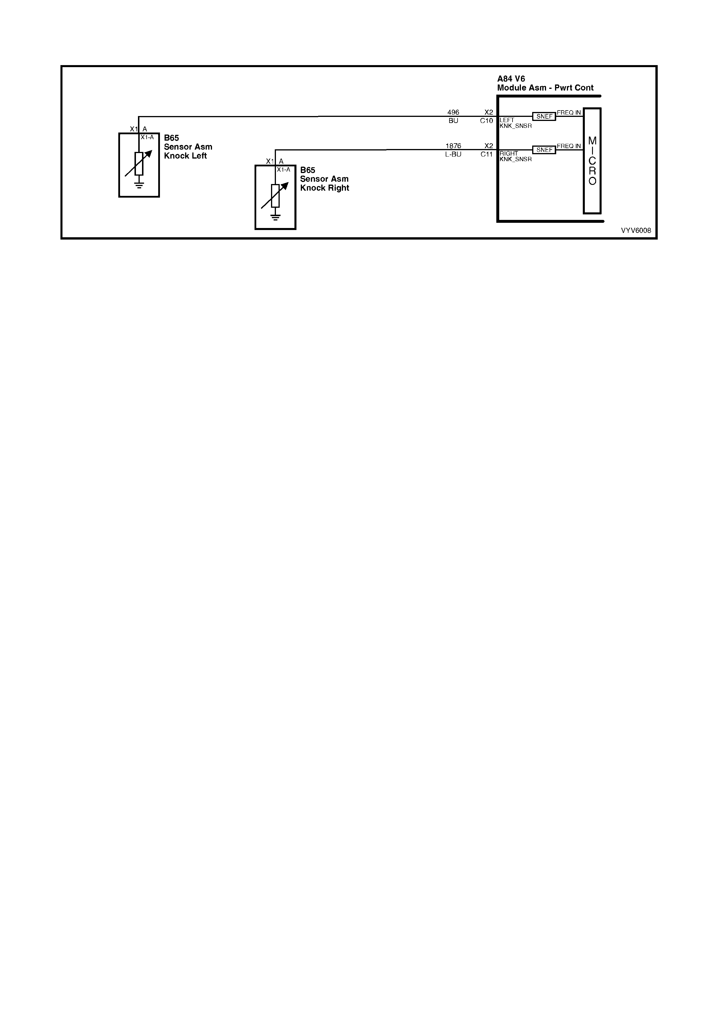
DTC P0325 V6 PCM - DSNEF SYSTEM FAULT
Figure 6C1-2A-110 Knock Sensor Circuits
CIRCUIT DESCRIPTION
The Knoc k sensor is used to detect en gine detonat ion, and the PCM will retard t he Electronic Spark T im ing (EST )
based on the s igna l being r eceived. T he Kn ock sensor pr oduces an AC s ignal whi ch varies i n signal amplitu de and
frequency depending upon the amount of Knock being experienced.
The PCM monitors the output of the DSNEF (Digital Signal To Noise Enhancement Filter) circuit. The PCM
determines whether Knock is occurring by comparing the Knock sensor signal level with the voltage level on the
DSNEF circuit. The DSNEF circuit allows the PCM to reject only false Knock signals by indicating the amount of
normal engine mechanical noise present. Normal engine noise varies depending on engine speed and load. A
normal Knock condition could result in a Knock sensor signal from a few milliseconds to possibly as high as 100
m illisec onds in len gth.
W hen the DSNEF circ uit output is signific antly longer than the long est expected "Normal" o utput it is assumed t he
DSNEF circuitry has failed and DTC P0325 will set.
CONDITIONS FOR RUNNING THE DTC
• The engine has been running for more than 10 seconds.
• DTC P0327 or P0332 are not set.
• Engine RPM is greater than 1000.
CONDITIONS FOR SETTING THE DTC
• The PCM’s DSNEF circuit indicates knocking for more than 10 seconds.
ACTION TAKEN WHEN THE DTC SETS
• The PCM activates the Check Powertrain MIL when the diagnostic runs and fails.
• The PCM records the operating conditions at the time the diagnostic fails. The PCM stores this information in
the History Data.
• When DTC P0325 is set, and current, the PCM uses a default spark advance table.
CONDITIONS FOR CLEARING THE MIL/DTC
• The PCM turns the Check Powertrain MIL OFF when it sees a valid condition.
• Use a TECH 2 in order to clear the MIL/DTC.
DIAGNOSTIC AIDS
Refer to "Intermittents" in Section 6C1-2B SYMPTOMS.
TEST DESCRIPTION
Number(s) below refer to step number(s) on the diagnostic Table.
2. This step checks to see if TECH 2 is displaying Knock signal at all times.
3. This step checks to see if an audible Knock is being caused by the engine or transmission.

DTC P0325 V6 PCM - DSNEF SYSTEM FAULT
STEP ACTION VALUE YES NO
1. Was the "On-Board Diagnostic" (OBD) System Check
performed? Go to Step 2 Go to
OBD System
Check
2. 1. Install TECH 2.
2. Ignition "ON", engine Idling.
3. Using TECH 2, select "Knock Signal" and "Knock
Retard".
Is "Knock Signal" indication "Knock"?
Go to Step 3 Go to Step 4
3. With engine running, is an audible "Knock" condition
heard? Refer to Engine
Mechanical or
Transmi ssi on in
this Service
Information to
repair audible
Knock
Go to Step 4
4. Replace PCM.
Refer 6C1-3 Service Operations, for PCM Programming
and Security Link procedure.
Is action complete?
Verify Repair
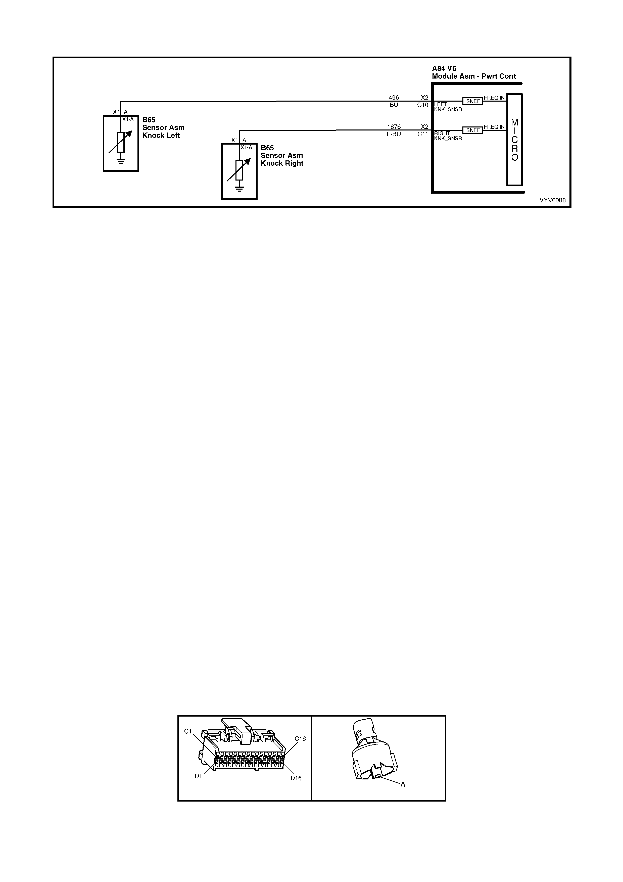
DTC P0327 V6 PCM - LEFT HAND KNOCK S E NSOR CIRCUIT FAULT
Figure 6C1-2A-111 Knock Sensor Circuits
CIRCUIT DESCRIPTION
The Knoc k Sens or (K S) s ystem detects engine d etonatio n. T he PCM r etards the s park timing based on the signa ls
from the k nock sensor s. T he knock sens ors pr oduce an A C vol tage. T he k nock sensor vol tages ar e an input to th e
PCM. The amount of AC voltage produced is proportional to the amount of knock.
An operating engine produces a normal amount of engine mechanical vibration (noise). The knock sensors
produce an AC voltage signal from this noise. When an engine operates, the PCM learns the minimum and
maximum frequenc y of the noise the engine produces. When the PCM determines that this frequency is le ss than
or greater than the expected amount, a knock sensor DTC will set.
CONDITIONS FOR RUNNING THE DTC
• The engine has been running for more than 10 seconds.
• DTC P0325 is not set.
• The engine coolant temperature is greater than 35°C.
• The TP sensor signal is greater than 22%.
• The engine speed is greater than 1000 RPM.
CONDITIONS FOR SETTING THE DTC
• There is no LH knock sensor signal or too high a knock sensor signal detected by the PCM for 3 seconds.
ACTION TAKEN WHEN THE DTC SETS
• The PCM activates the Check Powertrain MIL when the diagnostic runs and fails.
• The PCM records the operating conditions at the time the diagnostic fails. The PCM stores this information in
the History Data.
• When DTC P0327 is set, and current, the PCM uses a default spark advance table.
CONDITIONS FOR CLEARING THE MIL/DTC
• The PCM turns the Check Powertrain MIL OFF when it sees a valid condition.
• Use a TECH 2 in order to clear the MIL/DTC.
DIAGNOSTIC AIDS
If circ uit 49 6 is not op en or s horted to gr oun d, t he mos t likely cause is an ope n c ircuit in t he PC M. It is pos sib le t hat
a faulty PCM could be the cause of the DTC P0327, and it should be replaced.
Refer to "Intermittents" in Section 6C1-2B SYMPTOMS.
TEST DESCRIPTION
Number(s) below refer to step number(s) on the diagnostic Table.
2. This Step determines if conditions for DTC P0327 still exist.
6. This Step determines if the knock sensor resistance is between 93,000 ohms and 107,000 ohms.
A84 V6 – X2 B65
Figure 6C1-2A-112

DTC P0327 V6 PCM - LEFT HAND KNOCK SENSOR CIRCUIT FAULT
Step Action Value(s) Yes No
1. Did you perform the Powertrain On-Board
Diagnostic (OBD) System Check? Go to Step 2 Go to
OBD Syste m
Check
2. 1. Install TECH 2.
2. Record then clear DTC(s).
3. Start the engine.
4. Operate the vehicle, within the conditions
required for setting the DTC.
5. Select the Diagnostic Trouble Code (DTC)
option, using TECH 2.
Does TECH 2 indicate that this DTC reset?
Go to Step 3 Refer to
Diagnostic Ai ds
3. 1. Disconnect the LH Knock Sensor electrical
connector.
2. Measure t he resist ance of t he Knock Sensor b y
connecti ng a Dig ital Multim eter (DM M) bet ween
the Knock Sensor signal circuit, on the sensor
side and the engine block.
3. Set the DMM to the appropriate Ohm scale.
Is the resistance of the Knock Sensor within the
specified range?
93-107KΩ Go to Step 4 Go to Step 6
4. 1. Connect the DMM between the Knock Sensor
signal circuit, on the sensor side, and the
engine bloc k.
2. Set the DMM to the AC voltage scale.
3. Tap on the front of the engine while observing
the signal indicated on the DMM.
Is any signal indicated on the DMM while tapping
on the engine near the Knock Sensor?
Go to Step 5 Go to Step 6
5. 1. Disconnect al l PCM co nnectors.
2. Check the KS signal circuit between the PCM
and the Knock Sensor connector for the
following:
• An open
• A short to voltage
• A short to ground
Was a problem found?
Verify Repair Go to Step 7
6. Replace the Knock Sensor. Refer 6C1-3 Knock
Sensor Replacement.
Is the action complete?
Verify Repair
7. Check the KS signal circuit for a poor terminal
connection at the PCM.
Was a problem found and corrected?
Verify Repair Go to Step 8
8. Replace PCM.
Refer 6C1-3 Service Operations, for PCM
Programming and Security Link procedure.
Is action complete?
Verify Repair

DTC P0332 V6 PCM - RIGHT HAND KNOCK SENSO R CIRCUIT FAULT
Figure 6C1-2A-113 Knock Sensor Circuits
CIRCUIT DESCRIPTION
The Knoc k Sens or (K S) s ystem detects engine d etonatio n. T he PCM r etards the s park timing based on the signa ls
from the k nock sensor s. T he knock sens ors pr oduce an A C vol tage. T he k nock sensor vol tages ar e an input to th e
PCM. The amount of AC voltage produced is proportional to the amount of knock.
An operating engine produces a normal amount of engine mechanical vibration (noise). The knock sensors
produce an AC voltage signal from this noise. When an engine operates, the PCM learns the minimum and
maximum frequenc y of the noise the engine produces. When the PCM determines that this frequency is le ss than
or greater than the expected amount, a knock sensor DTC will set.
CONDITIONS FOR RUNNING THE DTC
• The engine has been running for more than 10 seconds.
• DTC P0325 is not set.
• The engine coolant temperature is greater than 35°C.
• The TP sensor signal is greater than 22%.
• The engine speed is greater than 1000 RPM.
CONDITIONS FOR SETTING THE DTC
• There is no RH knock sensor signal or too high a knock sensor signal detected by the PCM for 3 seconds.
ACTION TAKEN WHEN THE DTC SETS
• The PCM activates the Check Powertrain MIL when the diagnostic runs and fails.
• The PCM records the operating conditions at the time the diagnostic fails. The PCM stores this information in
the History Data.
• When DTC P0332 is set, and current, the PCM uses a default spark advance table.
CONDITIONS FOR CLEARING THE MIL/DTC
• The PCM turns the Check Powertrain MIL OFF when it sees a valid condition.
• Use a TECH 2 in order to clear the MIL/DTC.
DIAGNOSTIC AIDS
If circuit 1876 is not open or shorted to ground, the most likely cause is an open circuit in the PCM. It is possible
that a faulty PCM could be the cause of the DTC P0332, and it should be replaced.
Refer to "Intermittents" in Section 6C1-2B SYMPTOMS.
TEST DESCRIPTION
Number(s) below refer to step number(s) on the diagnostic Table.
2. This Step determines if conditions for DTC P0332 still exist.
6. This Step determines if the knock sensor resistance is between 93,000 and 107,000 ohms.
A84 V6 – X2 B65
Figure 6C1-2A-114

DTC P0332 V6 PCM - RIGHT HAND KNOCK SENSOR CIRCUIT FAULT
Step Action Value(s) Yes No
1. Did you perform the Powertrain On-Board
Diagnostic (OBD) System Check? Go to Step 2 Go to
OBD Syste m
Check
2. 1. Install TECH 2.
2. Record then clear DTC(s).
3. Start the engine.
4. Operate the vehicle, within the conditions
required for setting the DTC.
5. Select the Diagnostic Trouble Code (DTC)
option, using TECH 2.
Does TECH 2 indicate that this DTC reset?
Go to Step 3 Refer to
Diagnostic Ai ds
3. 1. Disconnect the RH Knock Sensor electrical
connector.
2. Measure t he resist ance of t he Knock Sensor b y
connecting a Digital Multi Meter (DMM)
between the K nock Sensor sign al circ uit, on the
sensor side, and the engine block.
3. Set the DMM to the appropriate scale.
Is the resistance of the Knock Sensor within the
specified range?
93-107KΩ Go to Step 4 Go to Step 6
4. 1. Connect the DMM between the Knock Sensor
signal circuit, on the sensor side, and the
engine bloc k.
2. Set the DMM to the AC voltage scale.
3. Tap on the front of the engine while observing
the signal indicated on the DMM.
Is any signal indicated on the DMM while tapping
on the engine near the Knock Sensor?
Go to Step 5 Go to Step 6
5. 1. Disconnect al l the PCM co nnector s .
2. Check the KS signal circuit between the PCM
and the Knock Sensor connector for the
following:
• An open
• A short to voltage
• A short to ground
Was a problem found?
Verify Repair Go to Step 7
6. Replace the Knock Sensor. Refer 6C1-3 Knock
Sensor Replacement.
Is the action complete?
Verify Repair
7. Check the KS signal circuit for a poor terminal
connection at the PCM.
Was a problem found and corrected?
Verify Repair Go to Step 8
8. Replace PCM.
Refer 6C1-3 Service Operations, for PCM
Programming and Security Link procedure.
Is action complete?
Verify Repair

DTC P0341 V6 PCM - CAM/CR ANK SENSOR SIGN AL INTERMITTENT
Figure 6C1-2A-115 Ignition System
CIRCUIT DESCRIPTION
During cr anking, the igniti on module m onitors the dual crank sensor 3X signal. The 3X s ignal is used to det ermine
the correct cylinder pair to spark first. After the 3X signal has been processed by the ignition module, it sends a
cranks haft ref erence pulse to the PCM. W hen the PCM rec eives this pulse it will comm and all six inj ectors to ope n
for one pr im ing shot of fuel in all c ylinders. Af ter the prim ing, the inj ectors are lef t "OFF" for the nex t six cran kshaf t
reference pulses from the ignition module (two crankshaft revolutions). This allows each cylinder a chance to use
the fuel from the priming shot. During this waiting period, a cam signal will have been received by the PCM. Now
the PCM begins to operate the injectors by energising each injector based on true camshaft position. With the
engine running, the PCM monitors the cam and crankshaft reference pulses it receives and expects to see six
camshaft reference pulses for each cam pulse.
CONDITIONS FOR RUNNING THE DTC
• The engine is cranking.
CONDITIONS FOR SETTING THE DTC
• An incorrect number of crankshaft reference pulses have been received since the previous camshaft position
signal.
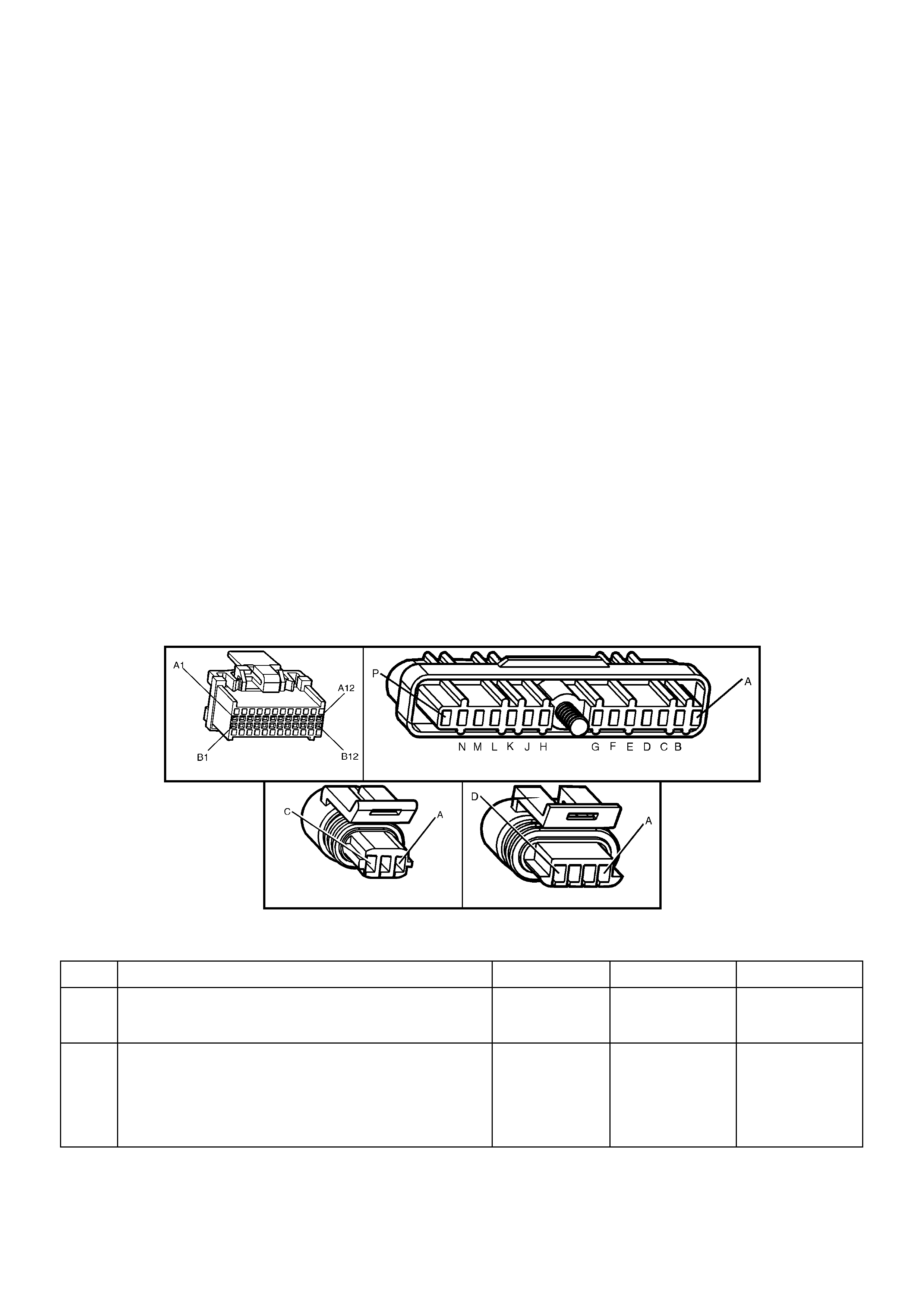
ACTION TAKEN WHEN THE DTC SETS
• The PCM stores the DTC information into memory when the diagnostic runs and fails.
• The Check Powertrain MIL will not be activated.
• The PCM records the operating conditions at the time the diagnostic fails. The PCM stores this information in
the History Data.
• Once DTC P0341 is set, the PCM will determine the fuel injection sequence based on the last fuel injection
pulse received. In the calculated SFI mode, the engine continues to start and run. However, with the fault
present, only a 1 in 6 chance of the correct injection sequence exists.
CONDITIONS FOR CLEARING THE MIL/DTC
• Use a TECH 2 in order to clear the MIL/DTC.
DIAGNOSTIC AIDS
DTC P0341 indicates an intermittent fault and may not set immediately or under all conditions. Customer
comm ents of s ym ptoms exper ienced ma y help is olate the c ause of the condition. A poor co nnection or f ault in the
cam sensor circuits 630, 633, 644, or 632 or a faulty cam sensor may cause the PCM to re-initialise injector
sequence when the fault occurs, causing a possible stumble or miss. A poor connection or fault in the 18X signal
circuit 6 47, c rank sensor circuits 573, 644, or 632 , the 18X port ion of the c rank sens or or b ent or m is sing van es o n
the harmonic balancer interrupter rings will cause the PCM to stop pulsing the injectors when the fault occurs,
causing an intermittent stumble or stall.
TEST DESCRIPTION
Number(s) below refer to step number(s) on the diagnostic Table.
2. Determines if conditions necessary to set DTC P0341 exist on this ignition cycle. Ignition cycle display will be
zero (0) if the DTC is current on this ignition cycle.
3. If 5 volts are not present at PCM harness connector terminal X1-B6, the cam sensor may be interfacing with
the magnet in the camshaft sprocket. Bumping the starter should correct this condition.
6. If a failur e is induc ed in the 18X s ignal c ir cuit, th e 5 vo lts on th e cir cuit s hou ld ch ange when t he fault y wiri ng or
connecti on is m anipul ate d.
NOTE: If DTC P0342 is set along with DTC P0341, use DTC P0342 table for diagnosis.
A84 V6 - X1 A40
B28 B30
Figure 6C1-2A-116
DTC P0341 V6 PCM - CAM/CRANK SENSOR SIGNAL INTERMITTENT
STEP ACTION VALUE YES NO
1. Was the "On-Board Diagnostic" (OBD) System Check
performed? Go to Step 2 Go to
OBD System
Check
2. 1. Install TECH 2.
2. Start and idle engine.
3. Using TECH 2, look at "IGN Cycles" in DTC history.
Is DTC P0341 current (Ignition Cycles 0)?
Go to Step 3 DTC P0341 is
intermittent. If no
additional DTC's
were set, refer to
"Diagnostic
Aids".

STEP ACTION VALUE YES NO
3. 1. Ignition "OFF".
2. Disconnect PCM connectors.
3. Connect a DMM between PCM harness connector
terminal X1-B6 and ground.
4. Ignition "ON".
Is voltage at X1-B6 at specified value?
Approximately
5 volts Go to Step 5 Go to Step 4
4. Bump engine with starter.
Is voltage at X1-B6 at specified value? Approximately
5 volts Go to Step 5 Go to
DTC P0342
5. Monitor voltage at X1-B6 while manipulating powertrain
wiring harness to PCM connector.
Does voltage remain steady as wiring is manipulated?
Go to Step 6 Go to Step 10
6. 1. Connect DMM between PCM harness connector
terminal X1-B7 and ground.
2. Monitor voltage at X1-B7 while manipulating ignition
harness, engine harness, and body harness to PCM
connector.
Does voltage remain steady as wiring is manipulated?
Go to Step 7 Go to Step 8
7. Check for:
• Poor connections at PCM.
• Harmonic balancer interrupter ring vanes bent or
missing.
• Faulty crank sensor (malfunctioning hot/cold).
Are all above OK?
Refer to
"Diagnostic
Aids".
Verify Repair
8. Check for poor connection at crankshaft position sensor
or ignition module.
Was a fault found?
Verify Repair Go to Step 9
9. Repair intermittent open/short to ground in circuit 573,
632, 644 or 647.
Is action complete?
Verify Repair
10. Check for poor connection at camshaft position sensor or
ignition mo dule .
Was a fault found?
Verify Repair Go to Step 11
11. Repair intermittent open/short to ground in circuit 630,
632, 633 or 644.
Is action complete?
Verify Repair

DTC P0342 V6 PCM - CAMSHAFT POSITION (CMP) SENSOR SIGNAL MISSING
Figure 6C1-2A-117 Ignition System
CIRCUIT DESCRIPTION
During cr anking, the igniti on module m onitors the dual crank sensor 3X signal. The 3X s ignal is used to det ermine
the correct cylinder pair to spark first. After the 3X signal has been processed by the ignition module, it sends a
cranks haft ref erence pulse to the PCM. W hen the PCM rec eives this pulse it will comm and all six inj ectors to ope n
for one pr im ing shot of fuel in all c ylinders. Af ter the prim ing, the inj ectors are lef t "OFF" for the nex t six cran kshaf t
reference pulses from the ignition module (two crankshaft revolutions). This allows each cylinder a chance to use
the fuel from the priming shot. During this waiting period, a cam signal will have been received by the PCM. Now
the PCM begins to operate the injectors by energising each injector based on true camshaft position. With the
engine running, the PCM monitors the cam and crankshaft reference pulses it receives and expects to see six
camshaft reference pulses for each cam pulse.
CONDITIONS FOR RUNNING THE DTC
• The engine is cranking or running.
CONDITIONS FOR SETTING THE DTC
• The PCM detects the Camshaft Position sensor signal is low when the signal should be high for five (5)
seconds.

ACTION TAKEN WHEN THE DTC SETS
• The PCM stores the DTC information into memory when the diagnostic runs and fails.
• The Check Powertrain MIL will not be activated.
• The PCM records the operating conditions at the time the diagnostic fails. The PCM stores this information in
the History Data.
• Once DTC P0342 is set, the PCM will determine the fuel injection sequence based on the last fuel injection
pulse received. In the calculated SFI mode, the engine continues to start and run. However, with the fault
present, only a one in six chance of the correct injection sequence exists.
CONDITIONS FOR CLEARING THE MIL/DTC
• Use a TECH 2 in order to clear the MIL/DTC.
DIAGNOSTIC AIDS
An intermittent may be caused by a poor connection, rubbed through wire insulation, or a wire broken inside the
insulation.
Check for:
• Poor Connection or Damaged Harness - Inspect PCM harness connectors for backed out terminal X1-B6,
improper mating, broken locks, improperly formed or damaged terminal, poor terminal to wire connection and
damaged harness.
• Intermittent Test - If connections and harness check OK, monitor a digital voltmeter connected from PCM
terminal
X1-B6 to ground while moving related connectors and wiring harness. If the failure is induced, the voltage
reading will change. This may help to isolate the location of the malfunction.
TEST DESCRIPTION
Number(s) below refer to step number(s) on the diagnostic Table.
3. This step verifies proper operation of circuits 632, 633 and 644.
4. This step verifies the integr ity of c ircuit 630 fr om ignitio n module to P CM. If the vol tage reading of X1-B6 dro ps
slightly from 4.7 vo lts to a p pr ox imately 4.1 vol ts , the cams haf t s ens or is pull in g th e s ign al lin e l o w, ther ef or e the
connection to t he PCM is not good or the PCM is f ault y. If the volt ag e r emains at approximately 4.4 vo lts and is
stead y, contin ue with di agn os is.
A84 V6 - X1 A40
B28 B30
Figure 6C1-2A-118

DTC P0342 V6 PCM - CAMSHAFT POSITION (CMP) SENSOR SIGNAL MISSSING
STEP ACTION VALUE YES NO
1. Was the "On-Board Diagnostic" (OBD) System Check
performed? Go to Step 2 Go to
OBD System
Check
2. 1. Install TECH 2.
2. Ignition "ON", engine "OFF".
3. Re cord, then clear DTCs.
4. Start engine, idle for 1 minute.
5. Select DATA LIST.
Does TECH 2 display "Cam Signal" as "Missing"?
Go to Step 3 DTC P0342 is
intermittent. If
no additional
DTCs were
stored, refer to
"Diagnostic
Aids"
3. 1. Ignition "O FF".
2. Disconnect camshaft position sensor harness
connector from camshaft position sensor.
3. Ignition "ON", engine "OFF".
Using DMM, does voltage between harness connector
pins X1-A & X1-B and X1-B & X1-C measure between
specified values?
"A-B"
6-8 volts
"B-C"
10-12 volts
Go to Step 4 Go to Step 11
4. 1. Ignition "O FF".
2. Reconnect camshaft position sensor harness to
camshaft position sensor.
3. Install DMM to backprobe PCM terminals X1-B6 &
X1-A5 to measure voltage at PCM terminal X1-B6.
4. Ignition "ON", engine "OFF".
Is voltage fixed at specified value?
Approximately
4.7 volts Go to Step 5 Go to Step 10
5. Start engine, idle 1 minute to stabilise system.
Is voltage reading of X1-B6 constantly varying around a
mid-point of specified value?
Approximately
4.0 volts Go to Step 9 Go to Step 6
6. 1. Ignition "OFF".
2. Disconnect camshaft position sensor harness
connector from camshaft position sensor.
3. Ignition "ON", engine "OFF".
4. Touch terminal B28 X1-A circuit 633 of camshaft
position sensor harness connector with a test light
connected to ground while observing voltmeter.
Does voltage reading at PCM terminal X1-B6 drop to
specified value?
0 volts Go to Step 7 Go to Step 8
7. Check the following:
• Poor connection at camshaft position sensor.
• Faulty camshaft position sensor.
• Missing camshaft magnet.
Is action complete?
Verify Repair
8. Replace faulty ignition module.
Is action complete? Verify Repair
9. Check for poor connection at PCM terminal X1-B6.
Was a problem found? Verify Repair Go to Step 19
10. Bump engine with starter.
Retest voltage at terminal X1-B6.
Is voltage fixed at specified value?
Approximately
4.7 volts Go to Step 5 Go to Step 17
11. Was one voltage reading low? Go to Step 12 Go to Step 16
12. Was the reading between harness connector B28 pin
X1-A & X1- B l ow? Go to Step 13 Go to Step 15
13. Check for open or short to ground in circuit 633.
Was a fault found? Verify Repair Go to Step 14
14. Check for poor ignition module connection.
Was a fault found? Verify Repair Go to Step 8
15. Repair circuit 644 between splice and camshaft position
sensor connect or.
Is action complete?
Verify Repair

STEP ACTION VALUE YES NO
16. Repair circuit 632 between splice and camshaft position
sensor connect or.
Is action complete?
Verify Repair
17. Check circuit 630 for open or short to ground.
Was a fault found? Verify Repair Go to Step 18
18. Replace the camshaft position sensor.
Is action complete? Verify Repair
19. Replace PCM.
Refer 6C1-3 Service Operations, for PCM Programming
and Security Link procedure.
Is action complete?
Verify Repair

DTC P0374 V6 PCM - 18X REFERENCE SIGNAL MISSING
Figure 6C1-2A-119 Ignition System
CIRCUIT DESCRIPTION
The 18X signal (circuit 647) is used by the PCM to improve ignition timing accuracy during crank and at engine
speeds of up to 2000 RPM. The 18X signal circuit allows the use of EST mode below 400 RPM, eliminating the
need to utilis e b ypass m ode durin g star tup, and also a llows th e PC M to calcul ate tr ue crank shaf t positio n in 1/6 the
time that use of the crankshaft reference signal would permit.
During normal operation, the PCM uses the 18X signal to control ignition timing until the engine speed exceeds
2000 RPM, at which time the crankshaft reference signal (circuit 430) is used. When conditions for setting DTC
P0374 exist, the crankshaft reference signal is used by the PCM to control EST. This condition will cause bypass
mode to be used for ignition timing below 400 RPM and EST ignition timing to be degraded below 2000 RPM.
CONDITIONS FOR RUNNING THE DTC
• The engine is running.
• The MAF sensor input signal is greater than 2048 Hz.
CONDITIONS FOR SETTING THE DTC
• The PCM detects 253 crankshaft reference pulses and no 18X pulses.
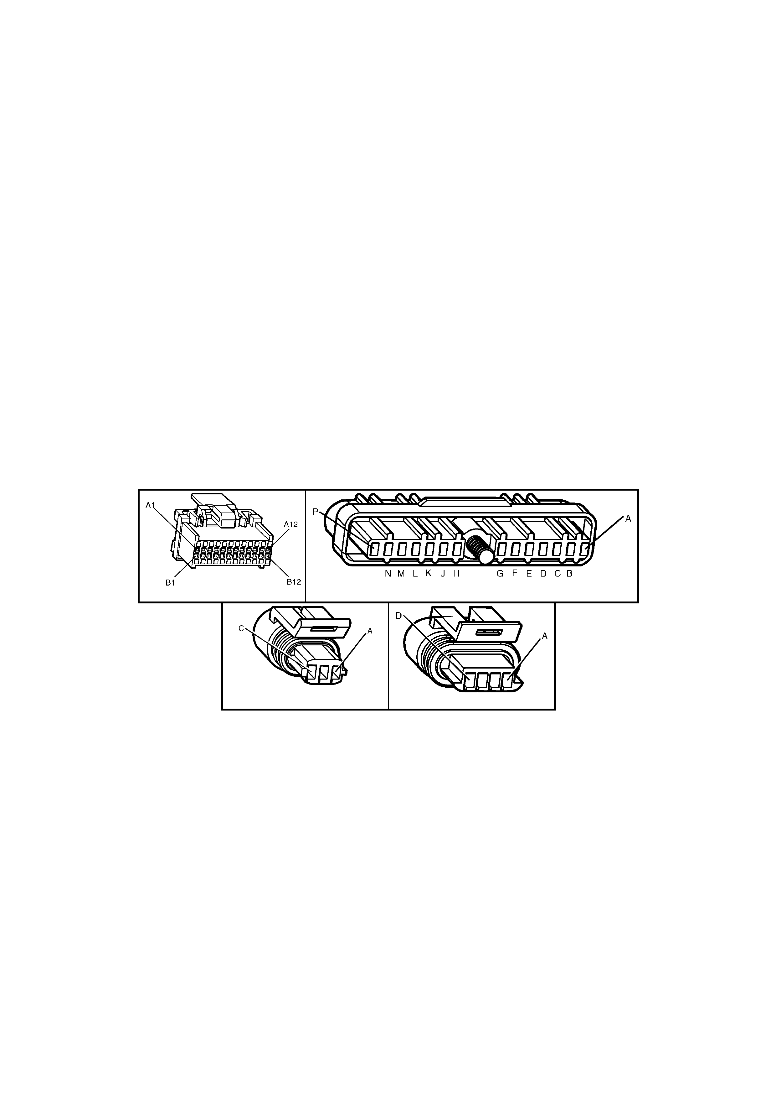
ACTION TAKEN WHEN THE DTC SETS
• The PCM stores the DTC information into memory when the diagnostic runs and fails.
• The Check Powertrain MIL will not be activated.
• The PCM records the operating conditions at the time the diagnostic fails. The PCM stores this information in
the History Data.
• W hen DTC P03 74 is set and current (no 18X ref erence sign al), the P CM uses the c rankshaf t reference sig nal
to determine engine speed. This condition will cause the EST to be degraded; no high resolution spark.
CONDITIONS FOR CLEARING THE MIL/DTC
• Use a TECH 2 in order to clear the MIL/DTC.
DIAGNOSTIC AIDS
An intermittent may be caused by a poor connection, rubbed through wire insulation, or a wire broken inside the
insulation.
Check for:
• Backed out connector terminals or broken down insulation in circuit 647.
• If connec tions and harn ess chec k OK, tr y m onitor ing voltage o n circuit 6 47 with DMM while m oving the rel ated
wiring harness and connectors with the engine idling. This may help to isolate the location of the malfunction.
The TECH 2 wiring harness test can also be used for this purpose.
TEST DESCRIPTION
Number(s) below refer to step number(s) on the diagnostic Table.
4. If a window on the harmonic balancer is interfering with the 18X Hall-Effect sensor, the ignition module will
ground the 18X signal. Starter may have to be bumped several times to obtain a voltage reading.
5. Voltage reading should be lower than that obtained with engine not running, indicating a pulsed reference
signal.
8. Verifies that circuit 647 is not shorted to ground or open in the harness.
A84 V6 - X1 A40
B28 B30
Figure 6C1-2A-120

DTC P0374 V6 PCM - 18X REFERENCE SIGNAL MISSING
STEP ACTION VALUE YES NO
1. Was the "On-Board Diagnostic" (OBD) System Check
performed? Go to Step 2 Go to
OBD System
Check
2. 1. Ignition "OFF".
2. Install TECH 2 and clear DTCs.
3. Ignition "ON".
4. Start engine, idle for 1 minute or until Diagnostic
Trouble Code P0374 sets.
Did Diagnostic Trouble Code P0374 set?
Go to Step 3 DTC P0374 is
intermittent.
If no additional
DTC's were
stored, refer
"Diagnostic Aids"
above.
3 1. Backprobe PCM terminal X1-B7 with a DMM
connected to ground.
2. Ignition "ON", engine "OFF", observe voltage on
PCM terminal X1-B7.
Does voltage measure specified value?
Approximately
5 volts Go to Step 5 Go to Step 4
4. 1. Bump engine w ith starter .
2. Retest voltage at PCM terminal X1-B7.
Does voltage measure specified value?
Approximately
5 volts Go to Step 5 Go to Step 8
5. 1. Start engine, idle 1 minute to stabilise system.
2. Observe voltage on PCM terminal X1-B7.
Does voltage measure specified value?
Approximately
3 volts Go to Step 7 Go to Step 6
6. Check for poor ignition module connections.
Was a fault found? Verify Repair Go to Step 10
7. Check for poor connection at PCM terminal X1-B7.
Was a fault found? Verify Repair Go to Step 11
8. 1. Ignition "OFF".
2. Disconnect PCM connectors.
3. Ignition "ON".
4. Measure voltage at PCM harness connector terminal
X1-B7.
Does voltage measure specified value?
Approximately
5 volts Go to Step 11 Go to Step 9
9. Check circuit 647 open or shorted to ground.
Was a fault found? Verify Repair Go to Step 10
10. Replace faulty ignition module.
Is action complete? Verify Repair
11. Replace PCM.
Refer 6C1-3 Service Operations, for PCM Programming
and Security Link procedure.
Is action complete?
Verify Repair

DTC P0400 V6 PCM - EGR FLOW FAULT INDICATED
Figure 6C1-2A-121 Exhaust Gas Recirculation Circuit
CIRCUIT DESCRIPTION
An Exhaus t Gas Rec irculati on (EGR) s ystem is used to lo wer Oxides of Nitrogen (NOx ) emiss ion levels caus ed by
high combustion temperatures. It accomplishes this by feeding small amounts of exhaust gases back into the
combustion chamber. When the air/fuel mixture is diluted with the exhaust gases, combustion temperatures are
reduced.
The linear EGR valve is designed to accurately supply exhaust gases to the engine without the use of intake
manifold vacu um. T he val v e c ontro ls ex h aus t f lo w go i ng into th e i ntake m anifold from the ex haust manif old throug h
an orifice with a PCM controlled pintle. The PCM controls the pintle position using inputs such as engine RPM,
Engine Co olant T em peratur e (ECT ) and Mas s Air Fl ow ( MAF) s ensor. T he PCM then com m ands the EGR val ve to
operate when necessary by controlling the 12 volt signal through the PCM. This can be m onitored on TECH 2 as
the EGR Position Com manded.
The PCM monitors the results of its command through a feedback potentiometer. By sending a 5 volt reference and
suppl ying a gr o und to t he E G R pote nti ometer, a v olt ag e s ign al r epr esen tin g the E G R va lv e p int le position is s ent to
the PCM. T his feedbac k signal c an also be m onitored on T ECH 2 and is the ac tual pos ition of the EGR pintle. T he
EGR Position Feedback should always be near the commanded or EGR Position Commanded .
CONDITIONS FOR RUNNING THE DTC
• Engine speed is between 700 and 1100 RPM.
• The ECT sensor is greater than 80°C.
• Vehicle speed is above 37 KM/H.
• IAC Valve has not changed more than 5 counts.
• Throttle angle is less than 1%.
CONDITIONS FOR SETTING THE DTC
• Expected RPM drop during PCM EGR test is less than 50 RPMs.
ACTION TAKEN WHEN THE DTC SETS
• The PCM stores the DTC information into memory when the diagnostic runs and fails.
• The Check Powertrain MIL will not be activated.
• The PCM records the operating conditions at the time the diagnostic fails. The PCM stores this information in
the History Data.
CONDITIONS FOR CLEARING THE MIL/DTC
• Use a TECH 2 in order to clear the MIL/DTC.
DIAGNOSTIC AIDS
Check for the following conditions:
A poor connection or damaged harness. Inspect the wiring harness for damage. If the harness appears to be OK,
observe t he EGR Pos ition Feedbac k display on the T ECH 2 whil e m oving conne ctor s and wirin g harness es relate d
to the EGR valve. A change in the display will indicate the location of the fault.

NOTE: If the EGR valve shows signs of excessive heat, check the exhaust system for blockage (possibly a
plugged converter).
TEST DESCRIPTION
Number(s) below refer to step number(s) on the diagnostic Table.
2. This step verifies if the exhaust system has been modified.
3. Visually and physically inspect the EGR passages and valve for excessive carbon deposits or damage.
4. This step checks to see if the EGR ports are blocked.
5. This step verifies if the fault is present and also verifies if a repair corrected the problem.
Y56
Figure 6C1-2A-122
DTC P0400 V6 PCM - EGR FLOW FAULT INDICATED
STEP ACTION VALUE(s) YES NO
1. Was the "On-Board Diagnostic" (OBD) System Check
performed? Go to Step 2 Go to
OBD System
Check
2. 1. Inspect the exhaust system for modification of
original instal led parts or leaks.
2. If a problem was found, repair exhaust system as
necessary.
Was a condition present that required repair?
Go to Step 5 Go to Step 3
3. 1. Remove the EGR valve.
2. Visually and physically inspect the pintle, valve
passages and the adapter for excessive deposits or
any kind of restriction.
3. If a problem is found, clean or replace EGR system
components as necessary.
Was a condition present that required repair?
Go to Step 5 Go to Step 4
4. 1. Remove the EGR feed pipe from the intake manifold.
2. Inspect the manifold EGR ports for a blockage
caused by excessive deposits or other damage.
3. If a problem is found, correct the condition as
necessary.
Was a condition present that required repair?
Go to Step 5 Refer to
Diagnostic Aids
5. 1. Using TECH 2, clear the DTCs.
2. Start the engine and allow the engine to idle until the
specified engine coolant temperature is reached.
3. Operate the vehicle within the conditions for setting
this DTC as specified in the supporting text.
Does TECH 2 indicate DTC P0400 set?
80°C Go to Step 2 System OK
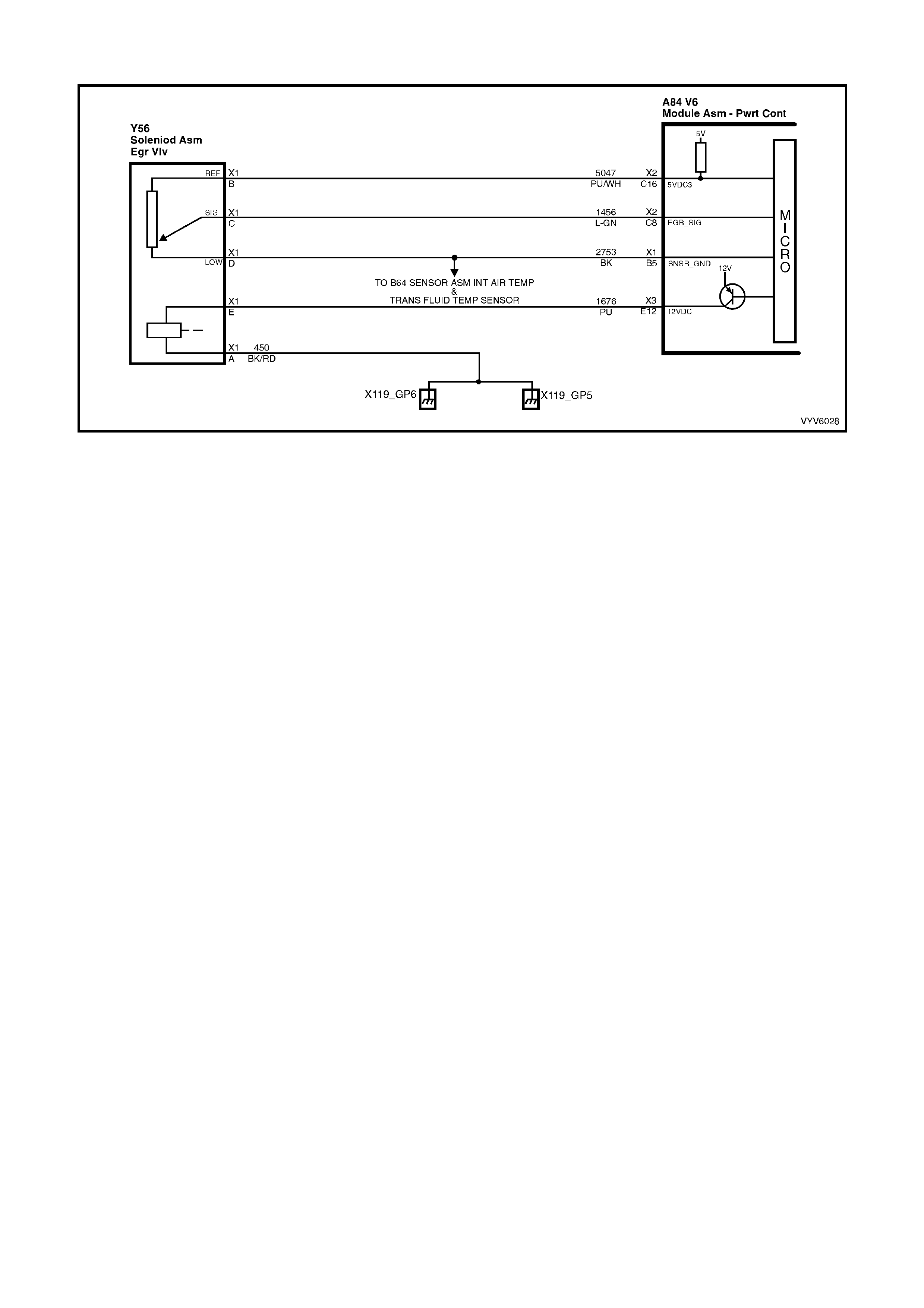
DTC P0405 V6 PCM - EGR POSITION FAULT
Figure 6C1-2A-123 Exhaust Gas Recirculation Circuit
CIRCUIT DESCRIPTION
The PCM monitors the EGR valve pintle position input to ensure that the valve responds properly to commands
from the PCM and to d etect a f ault if the pintle positio n sensor an d control c ircuit s are open or shorted. If the PCM
detects a pintle position signal voltage outside the normal range of the pintle position sensor, or a signal voltage
that is not within a tolerance considered acceptable for proper EGR system operation, the PCM will set a DTC
P0405.
CONDITIONS FOR RUNNING THE DTC
• The engine is running.
• Battery voltage is greater than 11.2 volts
CONDITIONS FOR SETTING THE DTC
• The EGR position feedback is less than 0.32 volts for greater than one second.
or
• The EGR commanded position is 10% greater or less than EGR position feedback for more than five seconds.
ACTION TAKEN WHEN THE DTC SETS
• The PCM stores the DTC information into memory when the diagnostic runs and fails.
• The Check Powertrain MIL will not be activated.
• The PCM records the operating conditions at the time the diagnostic fails. The PCM stores this information in
the History Data.
CONDITIONS FOR CLEARING THE MIL/DTC
• Use a TECH 2 in order to clear the MIL/DTC.
DIAGNOSTIC AIDS
Check for the following conditions:
Excessive deposits on the EGR valve pintle or seat. Check for deposits that may interfere with the EGR valve pintle
extending completely or cause the pintle to stick.
Poor connection or damaged harness. Inspect the wiring harness for damage. If the harness appears to be OK,
observe the EGR Position Feedback display on TECH 2 while moving connect ors and wiring harnesses related to
the EGR valve. A change in the display will indicate the location of the fault.
If P0405 and P0530 are set, check for an open ground circuit 2753.
NOTE: If the EGR valve shows signs of excessive heat, check the exhaust system for blockage (possibly a
plugged converter).
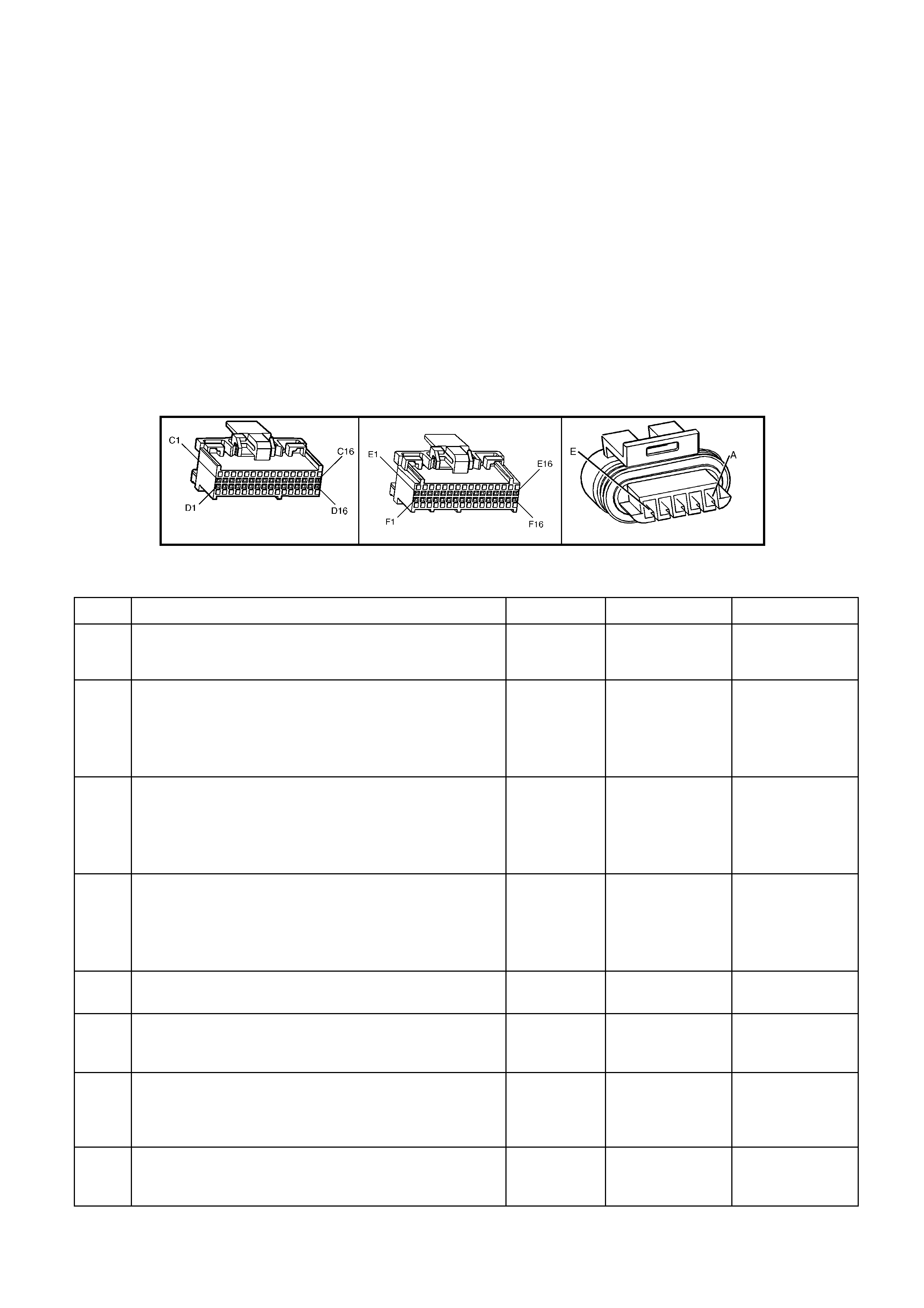
TEST DESCRIPTION
Number(s) below refer to step number(s) on the diagnostic Table.
2. Commanding the EGR valve open determines whether the PCM can control the EGR valve accurately.
4. W hen the EGR valv e electric al connector is disc onnected, T ECH 2 shoul d displa y the EGR Pos ition Feedbac k
as 0%. If it does not, go direc tly to step 11 , as the f ault lies eith er in the EG R signal c ircuit or the PC M. A tes t
light, when connected to ground, will glow dimly when the EGR valve is commanded to 25%, and brighter as
the EGR valve is commanded to 100%.
6. If the EGR valve 5 volt reference is shorted to voltage, the DMM will read battery voltage and an additional
DTC will be set and engine performance will be poor. When this circuit is open, an additional DTC may also
be set if the entire circuit is open.
7. The test li ght will have g lowed bright ly in step 4 if the EGR contr ol circuit was shorted t o voltage an d the EGR
Position Feedback on TECH 2 will display 100%. A test light that did not illuminate, indicates that the circuit
may be open or shorted to ground.
10. The EGR Position Feedback should read 0% before jum ping the 5 volt reference circuit to th e signal circuit. If
any other reading is present, then either the signal circuit or the PCM is at fault.
11. An open or short in the EG R valve sensor ground c ircuit will also cause additional DT Cs to be set. If no ot her
DTC's are set, and the circ uit is found to be open or shorted, the fault is on the EGR valve side of the splic ed
circuit.
A84 V6 – X2 A84 V6 – X3 Y20
Figure 6C1-2A-124
DTC P0405 V6 PCM - EGR POSITION FAULT
STEP ACTION VALUE(s) YES NO
1. Was the “On-Board Diagnostic (OBD) System Check”
performed? Go to Step 2 Go to
OBD System
Check
2. 1. Ignition "ON, engine "OFF".
2. Install TECH 2.
3. Command the EGR valve to the specified values.
Does the EGR Position Commanded follow the EGR
Position Feed back?
0% to 98% Refer to
"Diagnostic Aids" Go to Step 3
3. 1. Ignition "ON", engine "OFF".
2. Disconnect the EGR valve electrical connector Y56.
3. With a test light connected to B+, probe the EGR
valve ground, circuit 450.
Does the test light illuminate?
Go to Step 4 Go to Step 5
4. 1. Connect the test light to ground.
2. Probe the EGR control circuit 1676 to the EGR valve.
3. Command the EGR valve to the specified values.
Does the test light glow dimly and then glow brighter or
flash as the commanded percentage is raised?
0% to 98% Go to Step 6 Go to Step 7
5. Repair open in the EGR valve ground circuit 450.
Is action complete? Verify Repair
6. Using a Digital Multimeter (DMM) connected to ground,
probe the 5 volt reference circuit 5047 to the EGR valve.
Does the DMM read the specified value?
5.0V Go to Step 8 Go to Step 9
7. Check for an open or short in the EGR control circuit or
poor PCM terminal (X3-E12) retention and repair as
necessary.
Was a repair necessary?
Verify Repair Go to Step 14
8. Using a DMM connected to B+, probe the EGR valve
sensor ground circuit, 2753.
Does the DMM read the specified value?
B+ Go to Step 10 Go to Step 11

STEP ACTION VALUE(s) YES NO
9. Check for an open or short in the EGR valve 5 volt
reference circuit 5047 and repair as necessary.
Was a repair necessary?
Verify Repair Go to Step 14
10. Jumper the EGR valve 5 volt reference circuit 5047 to the
signal cir cuit 145 6.
Does the EGR Position Feedback display the specified
value?
100% Go to Step 12 Go to Step 13
11. Check for an open in the EGR valve sensor ground circuit
2753 or poor PCM terminal (X1-B5) retention and repair
as necessary.
Was a repair necessary?
Verify Repair Go to Step 14
12. Replace the EGR valve.
Is the action complete? Verify Repair
13. Check for an open or short in the EGR valve signal circuit
or poor PCM terminal (X2-C8) retention and repair as
necessary.
Was a repair necessary?
Verify Repair Go to Step 14
14. Replace PCM.
Refer 6C1-3 Service Operations, for PCM Programming
and Security Link procedure.
Is action complete?
Verify Repair
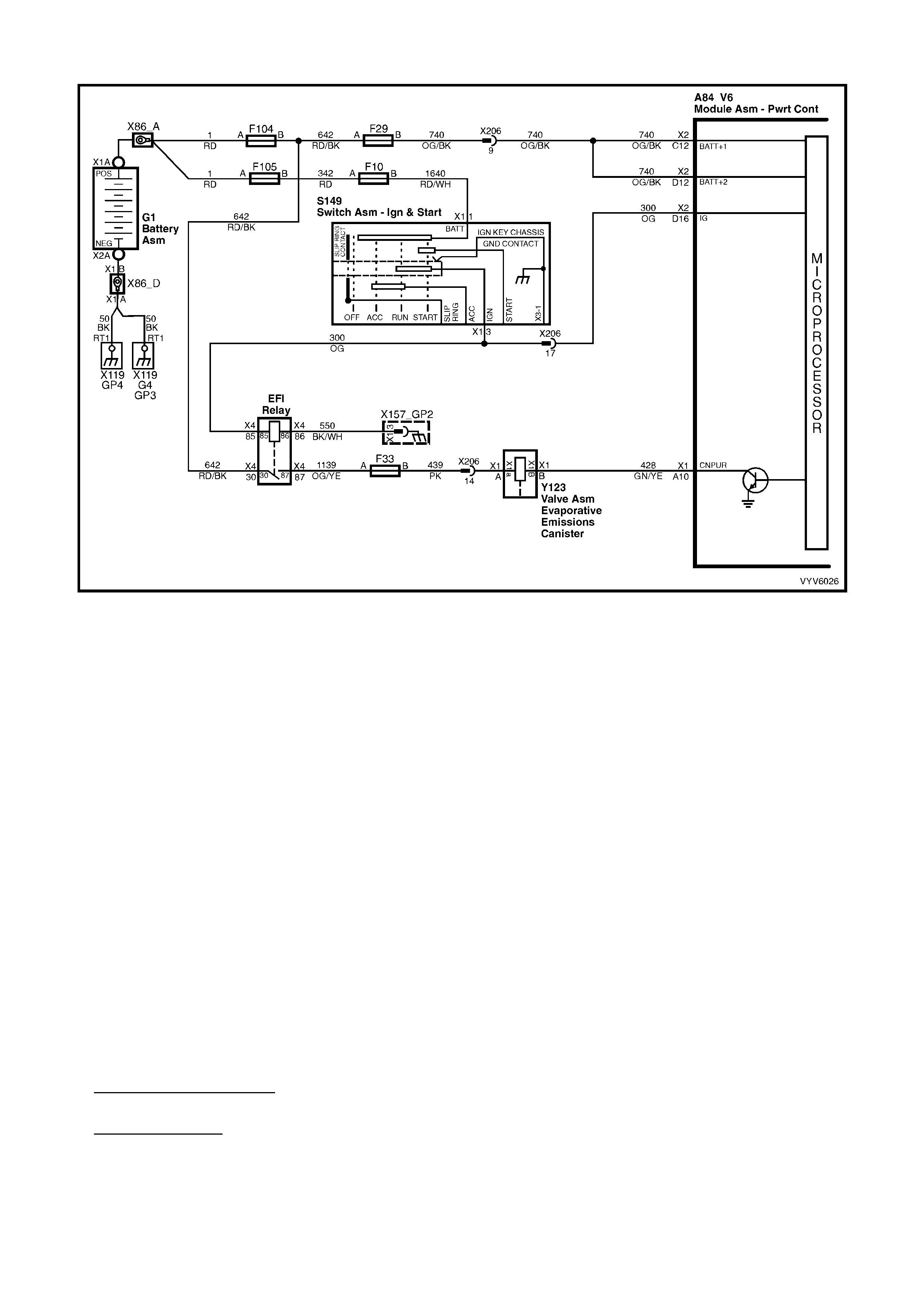
DTC P0446 V6 PCM - CANISTER PURGE CIRCUIT FAULT
Figure 6C1-2A-125 Evaporative Canister Purge Circuit
CIRCUIT DESCRIPTION
Quad Driver Modules (QDMs) are used by the PCM to turn "ON" many of the current-driven devices that are
needed to con trol various engine and trans mission f unctions. Each Q DM is capable of c ontrolling up to 4 sep arate
outputs by applying ground to the device which the PCM is commanding "ON".
The Quad Driver Modules (QDMs) used have the capability of diagnosing each output circuit individually. If DTC
P0446 is set, this indicates an improper voltage level has been detected on the QDM fault line which controls the
Canister Purge Solenoid.
CONDITIONS FOR RUNNING THE DTC
• The ignition is on.
CONDITIONS FOR SETTING THE DTC
• The PCM detects an incorrect voltage on the EVAP purge solenoid driver circuit for 5 seconds.
ACTION TAKEN WHEN THE DTC SETS
• The PCM activates the Check Powertrain MIL when the diagnostic runs and fails.
• The PCM records the operating conditions at the time the diagnostic fails. The PCM stores this information in
the History Data.
CONDITIONS FOR CLEARING THE MIL/DTC
• The PCM turns the Check Powertrain MIL OFF when it sees a valid condition.
• Use a TECH 2 in order to clear the MIL/DTC.
DIAGNOSTIC AIDS
Check for the following conditions:
• Poor connection at PCM. Inspect harness connections for backed out terminals, improper mating , broken
locks, improperly formed or damaged terminals, and poor terminal to wire connection.
• Damaged harness. Inspect the wiring harness for damage. If the harness appears to be OK, disconnect the
PCM, turn th e ignitio n "ON" and observe a voltm eter connect ed to the Canis ter P urge Soleno id driver c ircuit at
the PCM harness connector while moving connectors and wiring harness related to the Canister Purge
Solenoid. A change in voltage will indicate the location of the fault.
If DTC P0446 cannot be duplicated, the inform ation included in the DTC History can be useful in determ ining how
many ignition cycles have passed since the DTC was last set.
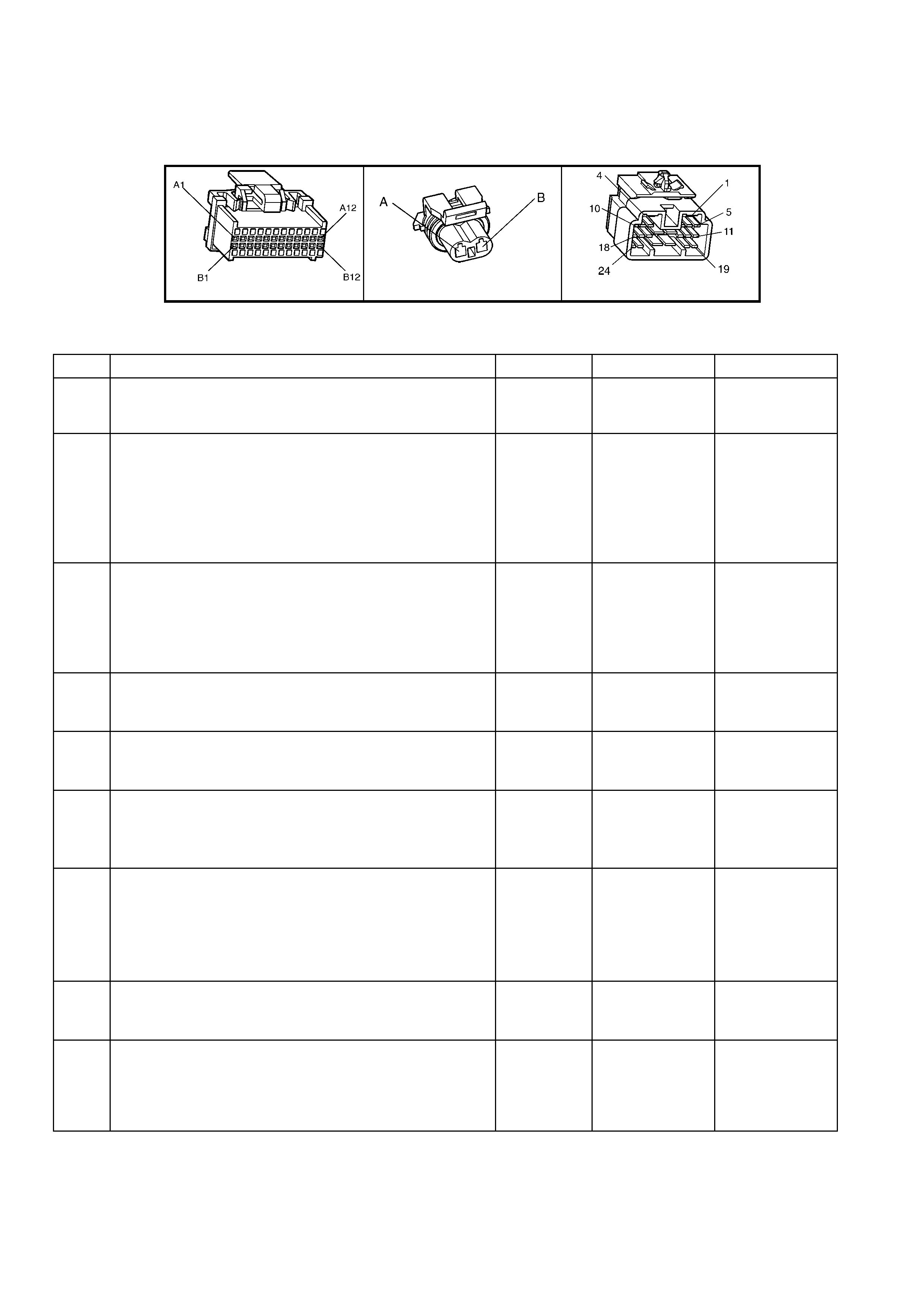
TEST DESCRIPTION
Number(s) below refer to step number(s) on the diagnostic Table.
2. Normally, ignition feed voltage should be present on the output driver circuit with the PCM disconnected and
the ignition "ON" .
9. If the solenoid connectors are OK then the solenoid should be replaced.
A84 V6 – X1 Y123 X206
Figure 6C1-2A-126
DTC P0446 V6 PCM - CANISTER PURGE CIRCUIT FAULT
STEP ACTION VALUE YES NO
1. Was the "On-Board Diagnostic" (OBD) System Check
performed? Go to Step 2 Go to
OBD System
Check
2. 1. Ignition "OFF", disconnect the PCM wiring harness
connectors.
2. Ignition "ON".
3. Using a Digital Multimeter (DMM), measure voltage
between the Canister Purge Solenoid driver circuit at
the PCM harness connector A84 X1-A10 and ground.
Is voltage near the specified value?
B+ Go to Step 3 Go to Step 5
3. 1. Disconnect the Canister Purge Solenoid harness
connector Y123.
2. Using DMM set to DC volts, measure voltage between
the Canister Purge Solenoid driver circuit Y123 X1-B
and ground.
Is voltage at specified value?
0 volts Go to Step 10 Go to Step 4
4. 1. Locate and repair short to voltage in the Canister
Purge Solenoid driver circuit Y123 X1-B.
Is action complete?
Verify Repair
5. 1. Check the ignition feed fuse F33 for the Canister
Purge Solenoid Y123.
Is the fuse bl own?
Go to Step 6 Go to Step 7
6. 1. Locate and repair short to ground in ignition feed
circuit for the Canister Purge Solenoid, fuse F33.
2. Replace fuse.
Is action complete?
Verify Repair
7. 1. Disconnect the Canister Purge Solenoid harness
connector Y123.
2. Ignition "ON".
3. Measure voltage between the ignition feed circuit at
harness connector Y123, terminal X1-A and ground.
Is voltage near the specified value?
B+ Go to Step 8 Go to Step 12
8. 1. Check the Canister Purge Solenoid driver circuit 428
for an open or a short to ground.
Was a problem found?
Verify Repair Go to Step 9
9. 1. Check the Canister Purge Solenoid driver circuit and
the ignition feed circuit for a poor connection at the
Canister Purge Solenoid, connector Y123 and the
PCM A84 X1-A10.
Was a problem found?
Verify Repair Go to Step 14

STEP ACTION VALUE YES NO
10. 1. Ignition "OFF", reconnect the PC M and disconnect the
Canister Purge Solenoid harness connector Y123.
2. Ignition "ON, connect a test light between the Canister
Purge Solenoid driver circuit and the ignition feed
circuit at the Canister Purge Solenoid connector Y123.
3. With TECH 2 installed, select, “Canister Purge”.
4. Cycle the Purge Solenoid "ON" and "OFF".
Does the test light flash "ON" and "OFF"?
Go to Step 9 Go to Step 11
11. 1. Check the Canister Purge Solenoid driver for a poor
connection at the PCM, connector A84 X1-A10.
Was a problem found?
Verify Repair Go to Step 13
12. 1. Locate and repair open ignition feed circuit to the
Canister Purge Solenoid.
Is action complete?
Verify Repair
13. 1. Replace PCM. Refer 6C1-3 SERVICE OPERATIONS,
for PCM Programming and Security Link procedure.
Is action complete?
Verify Repair
14. 1. Replace Canister Purge Solenoid. Refer 6C1-3
SERVICE OPERATIONS.
Is action complete?
Verify Repair

DTC P0502 V6 PCM - NO VEHICLE SPEED SIGNAL
Figure 6C1-2A-127 Vehicle Speed Sensor Circuit
CIRCUIT DESCRIPTION
The PCM receives vehicle speed information from the Vehicle Speed Sensor (VSS) located on the rear of the
transm ission. The VSS b asically consis ts of a magneti c core and a coil. As t he output shaf t turns, the teeth on the
output shaft concentrate the magnetic field causing the magnetic flux to increase and then decrease as the teeth
move in and out of the magnetic field, inducing a voltage into the coil, first, in a positive and then in a negative
direction.
This AC vo lta ge pr oduce d in the V SS s e ns or cir cuit is f ed into the PCM, the PCM f ilter s and shapes t he s i gna l. T he
PCM then counts the number of pulses received in a given time, to determine the vehicle speed.
The PCM us es the inform ation from this sensor to de term ine vehicle speed , which is us ed to control t he follo wing:
Engine fuelling modes, IAC Valve operation and Transmission operation.
Once the PCM has calculated t he vehicle speed it then pulses circuit 5197 (Purple/W hite wire) to ground, this will
cause the 12 volts at terminal X1-5 of the instruments to be pulled down to less than 0.2 volts. The instrument
determines the vehicle speed and the kilometres from the num bers of pulses it receives. The PCM also transmits
vehicle speed information to other control modules via the serial data bus normal mode message.
CONDITIONS FOR RUNNING THE DTC
Automatic Transmission
• The transmission is not in Park or Neutral.
• The engine speed is greater than 3000 RPM.
• The TP Sensor angle is between 10% and 99%.
Manual Transmission
• The engine speed is between 1400 and 3000 RPM.
• The throttle is closed (throttle angle less than 1%).
• Engine load very low, MAF less than 95 mg/cyl.
• Vehicle in gear.
• Vehicle is decelerating from road speed.
CONDITIONS FOR SETTING THE DTC
Automatic Transmission
• The VSS indicates an output shaft speed of less than 3 km/h for 3 seconds.
Manual Transmission
• The VSS indicates no output shaft speed for more than 4 seconds.
ACTION TAKEN WHEN THE DTC SETS
• The PCM activates the Check Powertrain MIL when the diagnostic runs and fails.
• The PCM records the operating conditions at the time the diagnostic fails. The PCM stores this information in
the History Data.
• For the automatic transmission, when this DTC sets, the PCM will command a 1-2 upshift then second gear
only. The PCM will also command maximum line pressure, freeze shift adapts from being updated and will
inhibit TCC engagement.
CONDITIONS FOR CLEARING THE MIL/DTC
• The PCM turns the Check Powertrain MIL OFF after the first ignition cycle that the diagnostic runs and does
not fail.
• Use a TECH 2 in order to clear the MIL/DTC.
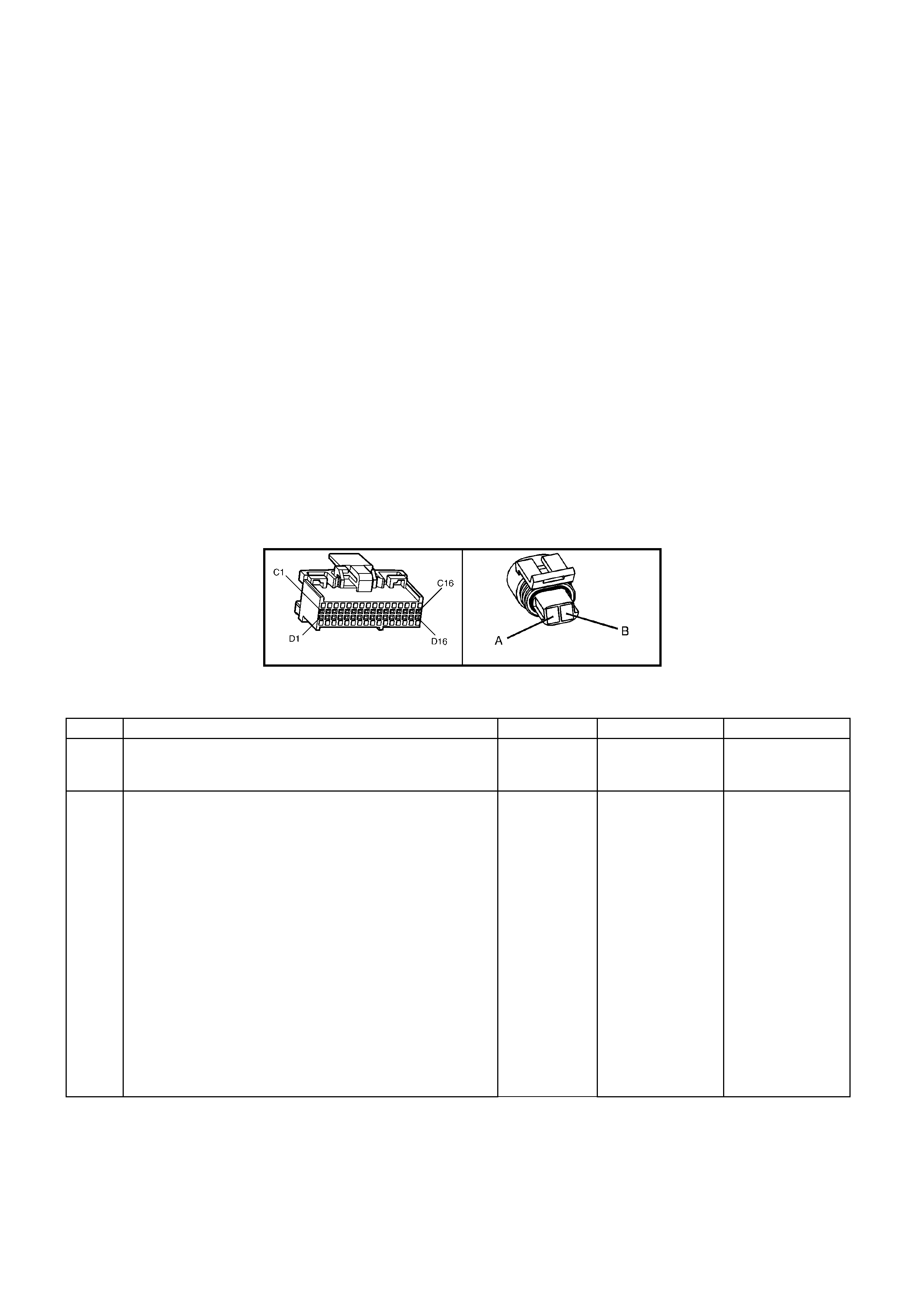
DIAGNOSTIC AIDS
• Inspect the wiring for poor electrical connections at the PCM. Look for the following conditions:
- A bent terminal
- A backed out terminal
- A damaged terminal
- Poor terminal tension
- A chafed wire
- A broken wire inside the insulation
- Moisture intrusion
- Corrosion
• When diagnosing for an intermittent short or open condition, massage the wiring harness while watching the
test equipment for a change.
• Check cir cuits 12 30 and 1 2 31 for th e proper conn ec tio ns to be s ure t hey are c l ea n a nd t ig ht and th e harnes s is
routed correctly.
• TECH 2 should indicate a vehicle speed whenever the drive wheels are turning greater than 3 km/h.
• The vehicle speed sensor resistance should be between 1470-2140 Ω at 20°C, and 2270-2820 Ω at 100° C.
• Refer to "Intermittents" in Section 6C1-2B Symptoms.
TEST DESCRIPTION
Number(s) below refer to step number(s) on the diagnostic Table.
3. This step tests the integrity of the VSS.
4. T his step tests the VSS circuit to the PCM, while performing this test step, check for proper term inal retention
on terminals X2-D1 & X2-D2.
A84 V6 – X2 X121-X1
Figure 6C1-2A-128
DTC P0502 V6 PCM - NO VEHICLE SPEED SIGNAL
STEP ACTION VALUE YES NO
1. Was the On-Board Diagnostic (OBD) System Check
performed? Go to Step 2 Go to
OBD System
Check
2. 1. Install TECH 2.
2. With the engine OFF, turn the ignition switch to the
RUN position.
3. Record the DTC history.
IMPORTANT: Before clearing the DTCs, use TECH 2 in
order to record the DTC history for reference. The Clear
DTC History function will erase the data.
4. Clear the DTC.
5. Raise the drive wheels .
Note: Do not perform this test without supporting the rear
axle assembly or the lower control arms on vehicles with
independent rear suspension so that the drive shafts are
in a normal horizontal position.
6. Start the engine.
7. Place the transmis sion in any driv e gear.
With the rear wheels rotating, does TECH 2 Vehicle
Speed increase with the drive wheel speed?
Go to “Diagnostic
Aids” Go to Step 3

STEP ACTION VALUE YES NO
3. 1. Turn the ignition switch to the OFF position.
2. Disconnect the VSS connector from the VSS
assembly.
3. Using the J 35616-A Connector Test Adapter Kit,
connect a Digital Multimeter (DMM) to the VSS
terminals.
4. Select AC volts.
5. Place the transmission selector in the neutral
position.
6. Rotate the drive wheels by hand, ensuring that the
driveshaft is turning.
With rear wheels rotating, is the DMM voltage greater
than the specified value?
0.5 volts AC Go to Step 4 Go to Step 11
4. 1. Turn the ignition switch to the OFF position.
2. Reconnect the VSS connector to the VSS Assy.
3. Disconnect the PCM connectors from the PCM.
4. Connect the DMM test leads to the connector
terminals X2-D1 and X2-D2.
5. Place the transmission selector in the neutral
position.
6. Rotate the drive wheels by hand, ensuring that the
driveshaft is turning.
With rear wheels rotating, is the DMM voltage greater
than the specified value?
0.5 volts AC Go to Step 13 Go to Step 5
5. 1. Select Ω (Ohms), on the DMM.
2. Measure the resistance between the connector
terminals X2-D1 and X2-D2.
Is the circuit resistance within the specified range?
1470-2820 Ω Go to Step 6 Go to Step 8
6. Connect the DMM between the connector terminal X2-D1
and ground.
Is the circuit resistance less than the specified value?
250k Ω Go to Step 7 Go to Diagnostic
Aids
7. Check circuit 1230 and circuit 1231 for a short to ground.
Repair the circuit if nece ss ary.
Was a short to ground condition found and corrected?
Go to Step 14 Go to “Diagnostic
Aids”
8. Is the resistance reading in step 6 greater than the
specified value? 2820 Ω Go to Step 10 Go to Step 9
9. Check circuit 1230 and circuit 1231 for a shorted together
condition.
Repair the circuit if nece ss ary.
Was a shorted together condition found and corrected?
Go to Step 14 Go to “Diagnostic
Aids”
10. Check circuit 1230 and circuit 1231 for an open condition.
Repair the circuit if nece ss ary.
Was an open circuit found and corrected?
Go to Step 14 Go to “Diagnostic
Aids”
11. Remove the VSS Assembly.
Inspect the VSS Output Sensor Rotor for damage or
misalignment.
Did you find a problem?
Refer to
7B-1 Manual
Transmission -
or
7C-4 Automatic
Transmission
Go to Step 12
12. Replace the VSS Assy. Refer to Service Operations.
Is the action complete? Go to Step 14
13. Replace PCM.
Refer 6C1-3 Service Operations, for PCM Programming
and Security Link procedure.
Is action complete?
Go to Step 14
14. In order to verify your repair, perform the following
procedure:
1. Clear Histo r y DTCs.
2. Operate the vehicle ensuring that the vehicle speed
is greater than 10 km/h and observe TECH 2 Vehicle
Speed.
Does TECH 2 display the specified Vehicle Speed?
10 km/h System OK Go to Step 2
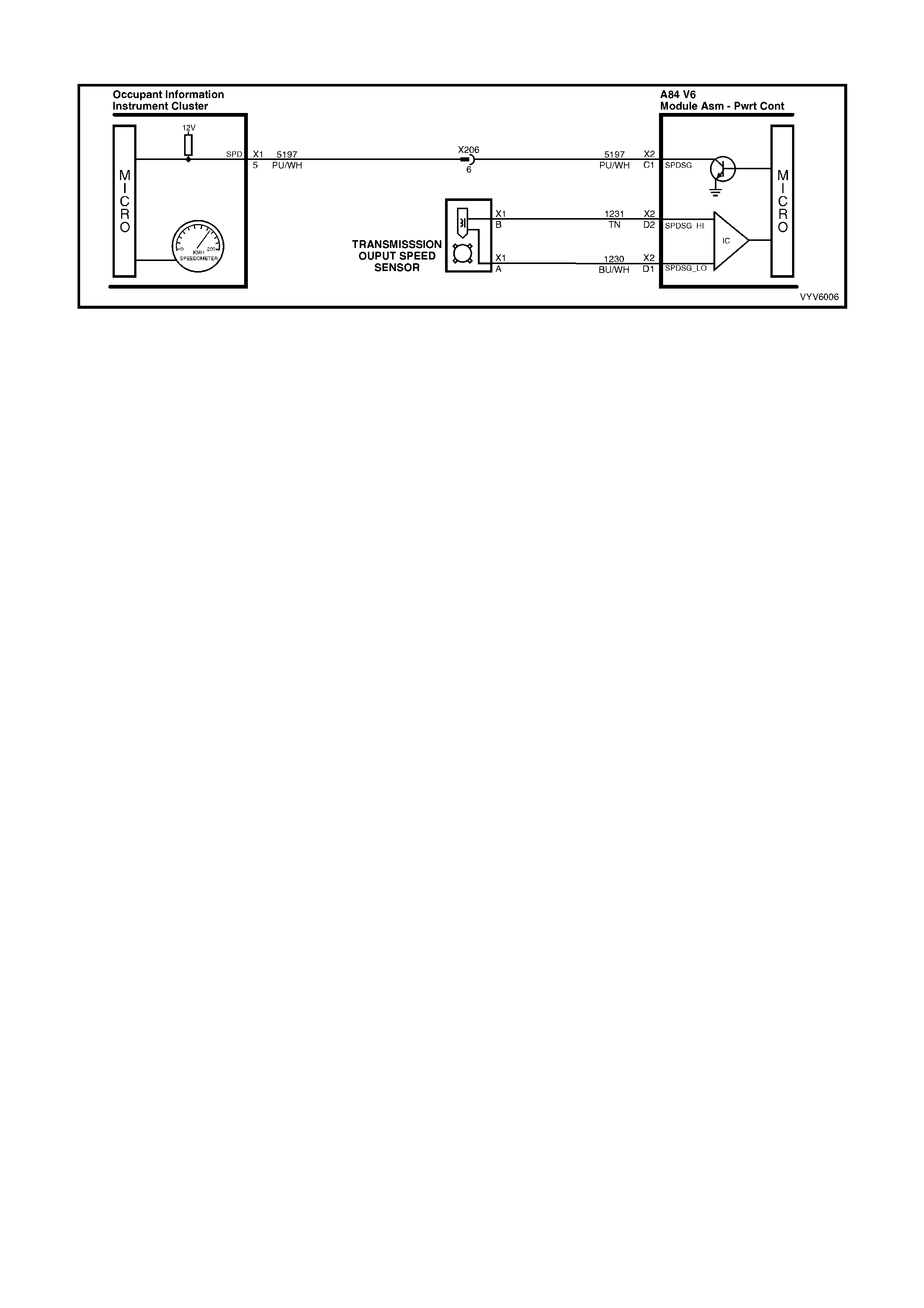
DTC P0503 V6 PCM - VEHICLE SPEED SENSOR INTERMITTENT SIGNAL
Figure 6C1-2A-129 Vehicle Speed Sensor Circuit
CIRCUIT DESCRIPTION
The PCM receives vehicle speed information from the Vehicle Speed Sensor (VSS) located on the rear of the
transm ission. The VSS b asically consis ts of a magneti c core and a coil. As t he output shaf t turns, the teeth on the
output shaft concentrate the magnetic field causing the magnetic flux to increase and then decrease as the teeth
move in and out of the magnetic field, inducing a voltage into the coil, first, in a positive and then in a negative
direction.
This AC vo lta ge pr oduce d in the V SS s e ns or cir cuit is f ed into the PCM, the PCM f ilter s and shapes t he s i gna l. T he
PCM then counts the number of pulses received in a given time, to determine the vehicle speed.
The PCM us es the inform ation from this sensor to de term ine vehicle speed , which is us ed to control t he follo wing:
Engine fuelling modes, IAC Valve operation and Transmission operation.
Once the PCM has calculated t he vehicle speed it then pulses circuit 5197 (Purple/W hite wire) to ground, this will
cause the 12 volts at terminal X1-5 of the instruments to be pulled down to less than 0.2 volts. The instrument
determines the vehicle speed and the kilometres from the num bers of pulses it receives. The PCM also transmits
vehicle speed information to other controls modules via the serial data bus normal mode message.
CONDITIONS FOR RUNNING THE DTC
• The engine is running.
CONDITIONS FOR SETTING THE DTC
• Two decis ive s peed r eadin gs ha ve a dif f erence of m ore than 1 000 RP M in an y dri ve range ( dif ferenc e m ust be
more than 2048 RPM in park or neutral). This test checks the vehicle speed sensor signal to the PCM.
ACTION TAKEN WHEN THE DTC SETS
• The PCM stores the DTC information into memory when the diagnostic runs and fails.
• The Check Powertrain MIL will not be activated.
• The PCM records the operating conditions at the time the diagnostic fails. The PCM stores this information in
the History Data.
• W hen Diagnostic Tr ouble Code P0 503 is set , the tr an sm ission will ha ve m axim um line press ure and c om mand
3rd gear o nly. If DTC P0503 is s et whil e i n 4 th gear , th e v eh icle wi ll s t a y in 4t h g e ar . Ho wev er, as the ve hic l e is
coasting to a stop the transmission will downshift normally from 4 to 3. Once the downshift into 3rd gear has
occurred, the vehicle will stay in 3rd gear.
CONDITIONS FOR CLEARING THE MIL/DTC
• Use a TECH 2 in order to clear the MIL/DTC.
DIAGNOSTIC AIDS
DTC P0503 is used to detect an intermittent failure. If a hard VSS fault exists, it will set DTC P0502.
DTC P0503 will set if the vehicle is operating at a road speed and something happens to the VSS signal.
Check all connections for proper retention. Check that the wiring harness for VSS is not routed near high voltage
sources such as spark plug cables which could induce a false signal onto the VSS circuit.
DTC P0503 could possibly be set by rapidly accelerating the vehicle in a loose material (such as sand or gravel)
where the wheels can be spinning faster than actual vehicle speed then having the spinning wheel rapidly decrease
when it contacts a hard surface. Review DTC history to identify when DTC P0503 was set.

TEST DESCRIPTION
Number(s) below refer to step number(s) on the diagnostic Table.
3. This test checks the vehicle speed sensor signal to the powertrain control module.
A84 V6 – X2 X121-X1
Figure 6C1-2A-130
DTC P0503 V6 PCM - VEHICLE SPEED SENSOR INTERMITTENT SIGNAL
STEP ACTION VALUE YES NO
1. Was the "On-Board Diagnostic" (OBD) System Check
performed? Go to Step 2 Go to
OBD System
Check
2. 1. Clear DTC History, set TECH 2 to display "Vehicle
Speed" in the snapshot mode and set to trigger on
DTC P0503.
2. Drive vehicle at different speeds and road conditions.
Is DTC P0503 set again?
Go to Step 3 DTC P0503 is
intermittent. If
no additional
DTC's were
stored, refer to
"Diagnostic
Aids"
3. 1. Raise drive wheels.
NOTE: Do not perform this test without supporting the
lower control arms so that the drive shafts are in a normal
horizontal position. On vehicles with IRS, running the
vehicle in gear with the wheels hanging down at full travel
may damage the drive shaft.
2. Engine idling in gear.
Does TECH 2 display "Vehicle Speed" above specified
value?
0 km/h Go to Step 4 Go to
DTC P0502
4. W iggle and tug on connector at vehicle speed sensor.
Does TECH 2 display "Vehicle Speed" drop to specified
value?
0 km/h Go to step 5 Refer to
"Diagnostic
Aids"
6. Repair connector ter minal s.
Is action complete? Verify Repair

DTC P0506 V6 PCM - IDLE SPEED ERROR
Figure 6C1-2A-131 Idle Speed Control Valve Circuit
CIRCUIT DESCRIPTION
The IAC valve is a stepper motor. Stepper motors have coils that the PCM turns ON and OFF several times per
second. T his allo ws for an increm ental c lock wise and count er cloc k wise rotation of the motor drive shaf t. T he pintle
valve has a threaded shaft that either extends or retracts with each pulse of the PCM. The controlled pulses are
called s teps or c ounts. T he PCM c ontro ls the air enteri ng into th e engin e at idle t hr ough the IA C val ve. To inc rease
the idle s peed, the PCM wi ll comm and the pi ntle valve awa y from the throttl e body. T his allo ws mor e air to bypas s
the throttl e blade and t hus inc rease engi ne RPM. To d ecrease the engine R PM at idl e, the PCM will com mand the
pintle valve toward the throttle body seat to restrict air from entering into the engine and thus reduce engine RPM.
CONDITIONS FOR RUNNING THE DTC
• Engine is Idling.
• No TP Sensor or IAT Sensor DTCs are set.
• DTC P0507 is not set.
• The IAT is less than 73°C.
• No vehicle speed indicated.
• Conditions present for 5 seconds.
CONDITIONS FOR SETTING THE DTC
• Engine speed is 200 RPM below the desired idle speed for 5 seconds and the IAC has been opened to its
maximum position (255 steps).
ACTION TAKEN WHEN THE DTC SETS
• The PCM stores the DTC information into memory when the diagnostic runs and fails.
• The Check Powertrain MIL will not be activated.
• The PCM records the operating conditions at the time the diagnostic fails. The PCM stores this information in
the History Data.
CONDITIONS FOR CLEARING THE MIL/DTC
• Use a TECH 2 in order to clear the MIL/DTC.
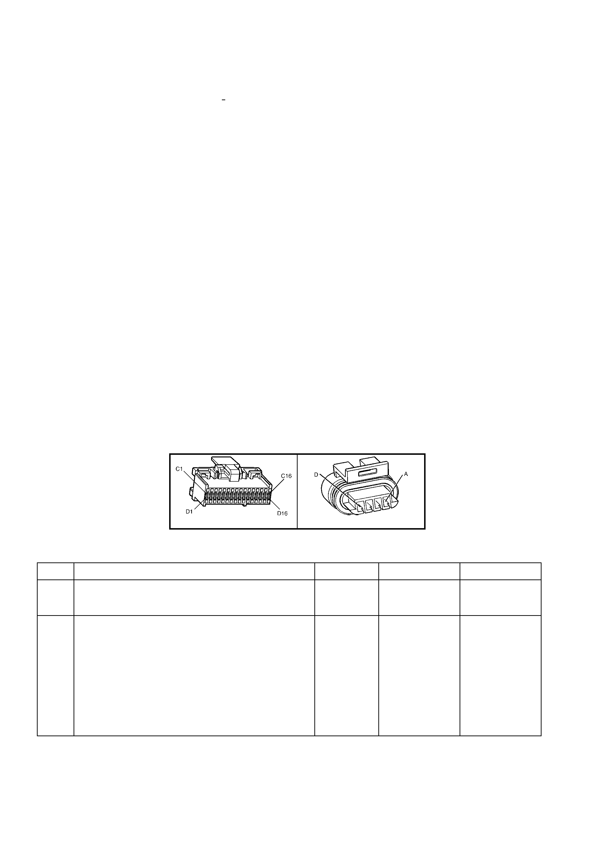
DIAGNOSTIC AIDS
A slow, u nstable, or fast id le m ay be caused b y a non -IAC system problem that cannot be com pensated for by the
IAC valv e. Out of c ontrol range IAC T ECH 2 counts will be abo ve 60 if idle is too lo w and zero co unts if idl e is too
high. The following checks should be made to repair a non-IAC system problem:
• System too lean (High Air /Fuel Ratio).
The idle speed m ay be too hig h or too low. En gine speed m ay be too high or too low. Eng ine speed m ay va ry
up and down and disconnecting the IAC valve does not help. DTC P0132 or P0152 may be set. TECH 2 O2
voltage will be less than 300 mV. Check for low regulated fuel pressure, water in the fuel or a restricted injector.
• System too rich (Low Air/Fuel Ratio).
The idle sp eed will be too lo w. TECH 2 IAC cou nts wil l usuall y be above 8 0. Syst em is obvio usly ric h and ma y
exhibit black sm oke in exhaus t. TECH 2 O2 voltage will b e fixed abo ve 800 m V. Check fo r high fuel pr essure,
leaking or sticking injector. Silicon contaminated O2 sensor TECH 2 voltage will be slow to respond.
• Throttle Body.
Remove the IAC valve and inspect bore for foreign material.
• IAC valve Electrical Connections.
The IAC valve connections should be carefully checked for proper contact tension.
• PCV Valve.
An incor re ct or fault y PCV valve m a y result in an incorrec t idle spe ed.
• Refer to "Rough, Unstable, Incorrect Idle or Stalling" in Section 6C1-2B SYMPTOMS.
• If intermittent poor driveability or idle symptoms are resolved by disconnecting the IAC, carefully recheck
connections, valve terminal resistance, or replace IAC.
TEST DESCRIPTION
Number(s) below refer to step number(s) on the diagnostic Table.
2. TECH 2 RPM control mode is used to extend and retract the IAC valve. The valve should move smoothly within
the specif ied range. If the idle speed is comm anded (IAC exten ded) too lo w (below 6 00 RPM), the eng ine ma y
stall. This may be normal and would not indicate a problem. Retracting the IAC beyond its controlled range
(above 1675 RPM) will cause a delay before the RPM starts dropping, this too is normal.
3. This test uses TECH 2 to command the IAC controlled idle speed. The PCM issues commands to obtain
commanded idle speed. The test lights each should flash indicating a good circuit as the PCM issues
commands. While the sequence is not important, if either light is OFF or does not flash, check the circuits for
faults, beginning with poor terminal contacts.
A84 V6 – X2 Y20
Figure 6C1-2A-132
DTC P0506 V6 PCM - IDLE SPEED ERROR
STEP ACTION VALUE YES NO
1. Was the "On-Board Diagnostic" (OBD) System Check
performed? Go to Step 2 Go to
OBD System
Check
2. 1. Install TECH 2.
2. Start the engine and allow the engine to idle until the
specified temperature is reached.
3. Transmi ssi on in park or neutra l.
4. Set the park brake.
5. Turn the A/C OFF.
6. Using TECH 2 cycle the IAC valve from 600 RPM to
1675 RPM.
Does the engine speed change smoothly when
commanded?
80°C Go to Step 3 Go to Step 5

STEP ACTION VALUE YES NO
3. 1. Ignition OFF.
2. Disconnect the IAC valve electrical connector, Y20.
3. Measure the resistance across the IAC valve
terminals A and B.
4. Measure the resistance across the IAC valve
terminals C and D.
Are the resistance readings across terminals A and B,
and terminals C and D within the specified values?
40-80 ohms Go to Step 4 Go to Step 13
4. 1. Measure the resistance across the IAC valve
terminals B and C.
2. Measure the resistance across the IAC valve
terminals A and D.
Are the resistance readings across terminals B and C,
and terminals A and D within the specified values?
Infinite IAC valve control
circuits are OK.
Refer to
Diagnostic Aids.
Go to Step 13
5. 1. Disconnect the IAC valve electrical connector, Y20.
2. Ignition ON engine OFF.
3. W ith a test light connected to ground, probe the IAC
valve electrical connectors.
Does the test light illuminate on two terminals?
Go to Step 6 Go to Step 7
6. With a test light connected to B+, probe the IAC valve
electrical con nect or ter mi nal s.
Does the test light illuminate on two terminals?
Go to Step 8 Go to Step 7
7. Check for an open or a short in the IAC valve HI and LO
circuits.
Was a problem found?
Go to Step 12 Go to Step 11
8. 1. Start the engine and allow to idle.
2. W ith a test light connected to ground, probe the IAC
valve electrical terminals?
Does the test light flash ON and OFF on all the
terminals?
Go to Step 10 Go to Step 9
9. Did the test light remain ON steady for the terminals
that did not flash? Go to Step 7 Go to Step 11
10. Check the IAC passages for a restriction.
Was a fault found? Go to Step 15 Go to Step 13
11. Check the PCM electrical connector for proper terminal
retention.
Was a problem found?
Go to Step 12 Go to Step 14
12. Repair the circuit or the connector as necessary.
Is the action complete? Verify Repair
13. Replace the IAC valve.
Is the action complete? Verify Repair
14. Replace PCM.
Refer 6C1-3 Service Operations, for PCM Programming
and Security Link procedure.
Is action complete?
Verify Repair
15. Clean the passages as necessary.
Is the action complete? Verify Repair

DTC P0507 V6 PCM - VACUUM LEAK
Figure 6C1-2A-133 Idle Speed Control Valve Circuit
CIRCUIT DESCRIPTION
The PCM controls engine idle speed by adjusting the position of the Idle Air Control (IAC) motor pintle. The IAC is a
bi-direc tio nal motor dr i ven by two coils . The PCM sen ds pulses (s teps ) to th e IA C to ex ten d or retr act th e IAC pint le
into a passage in the throttle body to decrease or increase air flow. The commanded IAC position (displayed in
counts) can be monitored on TECH 2 a lower number of counts indicates less commanded airflow (pintle
extended) . This method a llo ws highl y accurate c ontr ol of idle speed an d qu ick response to c hanges in engin e loa d.
If the PCM detects a condition where too high of an idle speed is presen t, the PCM will send 50 cou nts (steps) to
the IAC motor. If the RPM increases more than 50 RPM it is accepted that the IAC motor is moving and ther efore
the fault is a vac u um leak , and DT C P05 07 will s et. If the RP M do es not c han ge when t he P CM c om mands the IAC
to respond to a commanded count (steps), the PCM will set a DTC P0506.
CONDITIONS FOR RUNNING THE DTC
• Engine is Idling.
• No TP Sensor or IAT Sensor DTCs are set.
• DTC P0506 is not set.
• The IAT is less than 73°C.
• No vehicle speed indicated.
• Conditions present for 5 seconds.
CONDITIONS FOR SETTING THE DTC
• If the PCM detects a condition where a high idle speed is present and the I AC has been closed (0 steps); the
PCM will command the IAC motor to open 50 steps. If the RPM increases more than 50 RPM it is accepted
that the IAC motor is moving and therefore the fault is a vacuum leak.
ACTION TAKEN WHEN THE DTC SETS
• The PCM stores the DTC information into memory when the diagnostic runs and fails.
• The Check Powertrain MIL will not be activated.
• The PCM records the operating conditions at the time the diagnostic fails. The PCM stores this information in
the History Data.
CONDITIONS FOR CLEARING THE MIL/DTC
• Use a TECH 2 in order to clear the MIL/DTC.

DIAGNOSTIC AIDS
Check the IAC air passage for possible foreign material.
Code P0507 may also be set by other system faults. Refer to “Symptom Tables” for diagnosis by symptoms.
TEST DESCRIPTION
Number(s) below refer to step number(s) on the diagnostic Table.
2. The importanc e of this step cannot be s tressed too strong ly. It can lead to correc ting a problem without f urther
checks and save valuable time.
4. By restricting vacuum supply hoses, you are isolating which vacuum circuit may have a vacuum leak. When the
leak is stopped, the engine should respond immediately.
A84 V6 – X2 Y20
Figure 6C1-2A-134
DTC P0507 V6 PCM - VACUUM LEAK
STEP ACTION VALUE YES NO
1. Was the "On-Board Diagnostic" (OBD) System Check
performed? Go to Step 2 Go to
OBD System
Check
2. 1. Ignition Off.
2. Perform a visual/physical check of all the vacuum
hoses and air duct between the Mass Air Flow
Sensor and the throttle body for: Cracks, Splits,
Kinks, Connections and in their proper location.
Was a problem found?
Verify Repair Go to Step 3
3. 1. Ignition "O N", engin e runnin g.
2. Listen for a hissing sound as evidence of a vacuum
leak.
Was a problem found?
Verify Repair Go to Step 4
4. 1. Ignition "O N", engin e runnin g.
2. Using pliers, restrict each vacuum hose near the
intake manifold and listen for the engine RPM to
change when hoses are restricted.
Did RPM change with vacuum hoses restricted?
Repair vacuum
leak in hose or
vacuum circuit.
Verify Repair
Go to Step 5
5. Inspect suspect areas of the intake system such as:
• The intake manifold gaskets
• PCV system
• Throttle body vacuum hose connections
• Throttle body gasket
• Oil dipstick seal and oil fill cap for sources of
unmetered air
• IACV O-ring
Was a problem found?
Verify Repair Go to Step 6
6. Clear DTC and drive vehicle.
Does DTC reset? Go to Step 7 Repair Complete
7. Replace PCM.
Refer 6C1-3 Service Operations, for PCM Programming
and Security Link procedure.
Is action complete?
Verify Repair
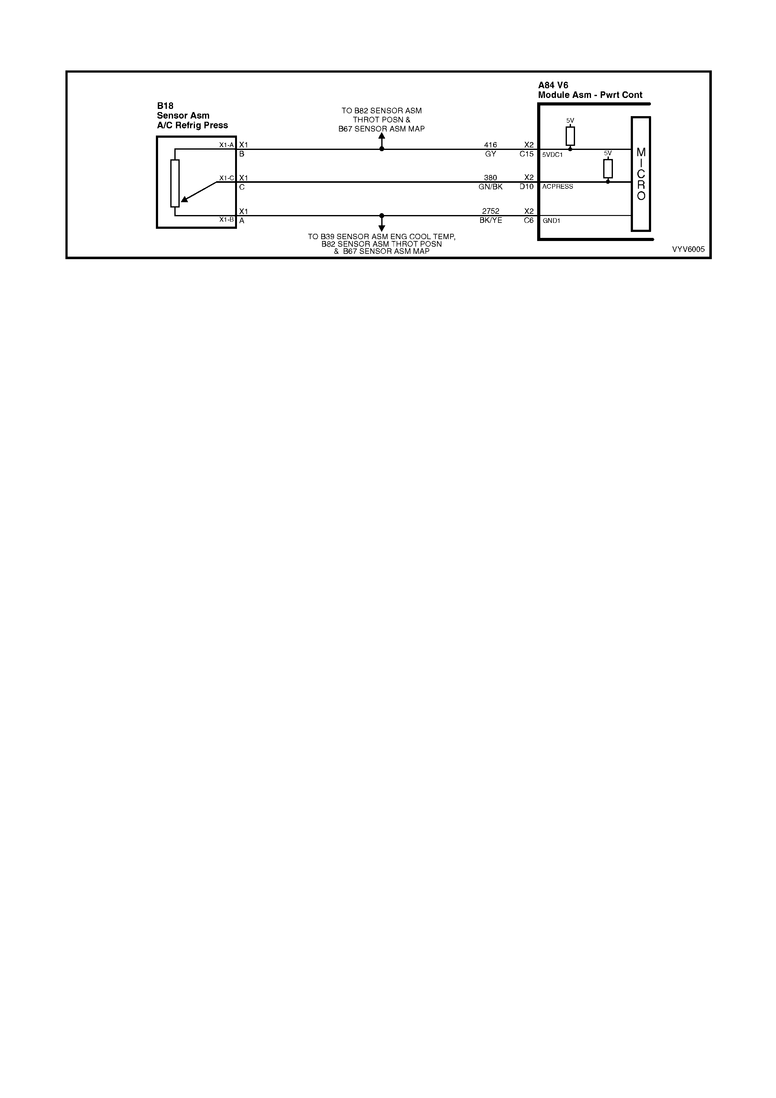
DTC P0530 V6 PCM - A/C REFRIGERANT PRESSURE SENSOR CIRCUIT FAULT
Figure 6C1-2A-135 - A/C Refrigerant Pressure Sensor Circ uit
CIRCUIT DESCRIPTION
The A/C refrigerant pressure Sensor responds to changes in the A/C refrigerant high side pressure. This input to
the PCM indicates how much load the A/C compressor is putting on the engine and is one of the factors used by
the PCM to determine the Idle Air Control (IAC) valve position for idle speed. The circuits consist of a 5 volt
reference and a ground circuit, both provided by the PCM, and a signal circuit from the Sensor to the PCM. The
signal is a voltag e which is pr oportional t o A/C pres sure. T he Sensors oper ating r ange is between 0 and 316 0 kPa
(0-468 psi). At 0 kpa, the signal voltage will be about 0.1 volts, varying to about 4.9 volts at 3160 kPa.
CONDITIONS FOR RUNNING THE DTC
• Engine Coolant Temperature is below 119°C.
• Intake Air Temperature is below 90°C.
• Engine RPM is below 20 00.
• Engine has been running for less than 10 minutes.
CONDITIONS FOR SETTING THE DTC
• A/C Refrigerant Pressure Sensor signal voltage is greater than 4.9 volts.
ACTION TAKEN WHEN THE DTC SETS
• The PCM stores the DTC information into memory when the diagnostic runs and fails.
• The Check Powertrain MIL will not be activated.
• The PCM records the operating conditions at the time the diagnostic fails. The PCM stores this information in
the History Data.
• W hen DTC P0530 is set, th e low spee d cool ing fan will operate f or 5 s econds, the n the high spee d f an will turn
"ON, and remain "ON" until the fault is removed.
CONDITIONS FOR CLEARING THE MIL/DTC
• Use a TECH 2 in order to clear the MIL/DTC.
DIAGNOSTIC AIDS
• DTC P0530 will only set with a short to voltage or an open circuit. A short to ground will not set the DTC, but
the A/C system will be inoperative.
• DTC P0530 sets when th e signa l vol tage f alls o utside the nor m al possibl e range of the sensor. R epa ir an y A/C
pressure problems before using this table.
• Any circuitry, that is suspected as causing the intermittent complaint, should be thoroughly check for backed
out term inals, improper mating, brok en locks, im properly form ed or damaged ter minals, poor ter minal to wiring
connections or physical damage to the wiring harness.
• If P0113, P0405, P0530 and P0713 are set, check for an open ground circuit 2752.

TEST DESCRIPTION
Number(s) below refer to step number(s) on the diagnostic Table.
3. This step checks if the A/C pressure sensor signal circuit 380 is shorted to voltage.
4. Jumping the sensor signal circuit to ground checks if the signal circuit is OK. If the signal circuit is OK the
voltage displayed on TECH 2 will be less than 0.2 volts.
5. Jumping the sensor signal circuit to the sensor ground circuit checks if the signal ground circuit is OK. If the
signal ground circuit is OK the voltage displayed on TECH 2 will be less than 0.2 volts.
6. This test step checks the 5 volt reference circuit 416. An open in a shared 5 volt reference circuit can cause
other DTC's to be set. If no other DTC's were set, the circuit must have an open between the sensor and the
circuits wiring harnes s splic e.
7. This test step check if circuits 416 and 380 are shorted together.
A84 V6 – X2 B18
Figure 6C1-2A-136
DTC P0530 V6 PCM - A/C REFRIGERANT PRESSURE SENSOR CIRCUIT FAULT
STEP ACTION VALUE YES NO
1. Was the "On-Board Diagnostic" (OBD) System Check
performed? Go to Step 2 Go to
OBD System
Check
2. 1. Ignition ON, engine OFF.
2. Install TECH 2, and display A/C pressure sensor
voltage.
Is the A/C pressure sensor voltage at or above the
specified value?
4.0 V Go to Step 3 Go to Step 9
3. 1. Disconnect A/C pressure sensor electrical
connector B18.
3. Using a Digital Multimeter (DMM) check the voltage
at terminal X1-C circuit 380 of harness connector
B18.
Is voltage greater than specified value?
5.0 V Go to Step 12 Go to Step 4
4. 1. With A/C pressure sensor electrical connector B18
disconnected.
2. Using fused jumper wire, jumper the A/C pressure
sensor signal circuit 380 of harness connector B18
terminal X1-C to a known good ground.
Does TECH 2 indicate A/C pressure sensor voltage at
or below the specified value?
0.2 V Go to Step 5 Go to Step 11
5. 1. With A/C pressure sensor electrical connector
disconnected.
2. Using fused jumper wire, jumper circuit 380, A/C
pressure sensor signal terminal X1-C to circuit 2752
sensor ground terminal X1-A of harness connector
B18.
Does TECH 2 indicate A/C pressure sensor voltage at
or below the specified value?
0.2 V Go to Step 6 Go to Step 13
6. 1. With A/C pressure sensor electrical connector
disconnected.
2. Using a DMM measure voltage on circuit 416 at
terminal X1-B of harness connector B18.
Is the voltage at specified value?
5.0 V Go to Step 7 Go to Step 14
7. 1. With A/C pressure sensor electrical connector B18
disconnected.
2. Disconnect all PCM connectors.
3. Using a DMM check for continuity between circuit
416 and 380.
Is there continuity?
Go to Step 15 Go to Step 8

STEP ACTION VALUE YES NO
8. Replace A/C pressure sensor.
Is action complete? Verify Repair
9. Is the A/C pressure sensor voltage at or below the
specified value? 0.2 V Go to Step 10 Go to Step 6
10. Check for short to ground in A/C pressure sensor signal
circuit 380.
Was a problem found?
Verify Repair Go to Step 16
11. Check for open or poor terminal retention in A/C
pressure sensor sig nal circu it 380.
Was a problem found?
Verify Repair Go to Step 16
12. Check A/C pressure sensor signal circuit 380 for short to
voltage.
Was a problem found?
Verify Repair Go to Step 16
13. Check for open or poor terminal retention in ground
circuit 2752 to A/C pressure sensor.
Was a problem found?
Verify Repair Go to Step 16
14. Check for open, poor terminal retention, short to ground
or short to voltage in 5 volt reference circuit 416.
Is action complete?
Verify Repair Go to Step 16
15. Repair short between cir cuit s 380 and 416.
Is action complete? Verify Repair
16. Replace PCM.
Refer 6C1-3 Service Operations, for PCM Programming
and Security Link procedure.
Is action complete?
Verify Repair

DTC P0560 V6 PCM - SYSTEM VOLTAGE TOO HIGH (LONG TIME)
Figure 6C1-2A-137 – PCM Power Supply Circuits
CIRCUIT DESCRIPTION
Circuit 300 is the igni tio n v olta ge f eed c irc uit t o ter minal X2- D1 6 f o r the PCM. Circuit 7 40 is t he batter y vo lta ge f eed
circuit to terminals X2-C12 and X2-D12 for the PCM. When the PCM detects a high voltage for a long time, then
DTC P0560 sets.
CONDITIONS FOR RUNNING THE DTC
• The ignition is on.
• ECT is at or above 85°C.
CONDITIONS FOR SETTING THE DTC
• The engine is running and the PCM ignition voltage is greater than 16 volts for more than 109 minutes.

ACTION TAKEN WHEN THE DTC SETS
• The PCM activates the Check Powertrain MIL when the diagnostic runs and fails.
• The PCM records the operating conditions at the time the diagnostic fails. The PCM stores this information in
the History Data.
• During the time fault is present, the pressure control solenoid is turned "OFF", the transmission shifts
immediately to 3rd gear and TCC operation is inhibited.
CONDITIONS FOR CLEARING THE MIL/DTC
• The PCM turns the Check Powertrain MIL OFF after the first ignition cycle that the diagnostic runs and does
not fail.
• Use TECH 2 in order to clear the MIL/DTC.
DIAGNOSTIC AIDS
• Inspect the wiring for poor electrical connections at the PCM. Look for the following conditions:
A bent terminal
A backed out terminal
A damaged terminal
Poor terminal tension
A chafed wire
A broken wire inside the insulation
Moisture intrusion
• When diagnosing for an intermittent short or open condition, massage the wiring harness while watching the
test equipment for a change.
• Charging the battery with a battery charger may set DTCs. Jump starting an engine may set DTCs.
• If DTCs set when you operate an accessory, inspect the applicable wiring for faulty connections. Inspect the
wiring for excessive current draw.
• Inspect the following items for faulty connections:
The starter solenoid
The fusible link
The generator terminals
Battery cables
• Inspect the belts for excessive wear. Inspect the belts for proper tension.
TEST DESCRIPTION:
Number(s) below refer to step number(s) on the diagnostic Table.
4. This step tests the charging system voltage.
5. This step tests the voltage at the PCM.
A84 V6 – X2
Figure 6C1-2A-138

DTC P0560 V6 PCM - SYSTEM VOLTAGE TOO HIGH (LONG TIME)
STEP ACTION VALUE YES NO
1. Was the On Board Diagnostic (OBD) System Check
performed? Go to Step 2 Go to
OBD System
Check
2. 1. Install TECH 2.
2. Ignition ON, engine OFF.
IMPORTANT: Before clearing the DTCs, use TECH 2 in
order to record the DTC history. The Clear History DTCs
function will erase the data.
3. Record the DTC history.
4. Using a Digital Multimeter (DMM), measure the
battery voltage across the battery terminals. Record
the measurement for future reference.
Is the voltage higher than the specified value?
10 volts Go to Step 3 Go to Battery
Diagnosis
3. 1. Start the engine.
2. Warm the engine to the operating temperature.
Is the “Check Alternator” warning displayed in the
Instrument MFD?
85°C Go to Charging
System
Diagnosis
Go to Step 4
4. 1. Increase the engine speed to 2000 RPM for 15
seconds.
2. Observe the DMM battery voltage.
Is the DMM battery voltage greater than the specified
value?
15 volts Refer 6D1-1
Charging System
Diagnosis.
Go to Step 5
5. 1. Increase the engine speed to 2000 RPM.
2. Observe TECH 2 “Battery Voltage” display.
Is TECH 2 Battery Voltage greater than the specified
value?
15.5 volts Go to Step 6 System Checks
OK, Go to
“Diagnostic Aids”
6. Replace PCM.
Refer 6C1-3 Service Operations, for PCM Programming
and Security Link procedure.
Is action complete?
Go to Step 7
7. In order to verify your repair, perform the following
procedure:
1. Clear Histo r y DTCs.
2. Operate the vehicle under the following conditions:
• Start the vehicle.
• Warm the engine to normal operating temperature.
Is TECH 2 Battery Voltage within the specified range?
13-15.5 volts System OK Go to Step 2

DTC P0561 V6 PCM - SYSTEM VOLTAGE UNSTABLE
Figure 6C1-2A-139 – PCM Power Supply Circuits
CIRCUIT DESCRIPTION
Diagnostic Trouble Code (DTC) P0561 will set when the ignition is "ON" and PCM terminal X2-D16 voltage
changed more than 2.5 volts in 100 milliseconds.
CONDITIONS FOR RUNNING THE DTC
• The ignition is ON.
• Conditions present for at least 10 seconds.
CONDITIONS FOR SETTING THE DTC
• System voltage changes more than 2.5 volts in 100 millivolts.
ACTION TAKEN WHEN THE DTC SETS
• The PCM activates the Check Powertrain MIL and stores the DTC information into memory when the
diagnostic runs and fails.
• W hen DTC P0561 sets, the PCM tur ns off all transm ission ou tput devic es, and f reezes sh ift adapts from being
updated.
CONDITIONS FOR CLEARING THE MIL/DTC
• The PCM turns the Check Powertrain MIL OFF after the first ignition cycle that the diagnostic runs and does
not fail.
• Use TECH 2 in order to clear the MIL/DTC.
DIAGNOSTIC AIDS
• Inspect the wiring for poor electrical connections at the PCM. Look for the following conditions:
A bent terminal
A backed out terminal
A damaged terminal
Poor terminal tension
A chafed wire
A broken wire inside the insulation
Moisture intrusion
• When attempting to diagnose an intermittent problem, use the snapshot mode of the TECH 2, to review
diagnostic information.
• Charging the battery with a battery charger may set DTCs. Jump starting an engine may set DTCs.
• If DTCs set when you operate an accessory, inspect the applicable wiring for faulty connections. Inspect the
wiring for excessive current draw.
• Inspect the following items for faulty connections:
The starter solenoid
The fusible link
The generator terminals
Battery cables
• Inspect the belts for excessive wear. Inspect the belts for proper tension.

TEST DESCRIPTION
Number(s) below refer to step number(s) on the diagnostic Table.
2. Diag nostic T rouble Co de P0561 will set if : T he last 25% of the samples f or igniti on feed vo ltage c hanges more
than 2.5 volts in 100 milliseconds.
A84 V6 – X2
Figure 6C1-2A-140
DTC P0561 V6 PCM - SYSTEM VOLTAGE UNSTABLE
STEP ACTION VALUE YES NO
1. Was the "On-Board Diagnostic" (OBD) System Check
performed? Go to Step 2 Go to
OBD System
Check
2. 1. Install TECH 2 and set up snapshot mode to trigger
on DTC P0561.
2. Ignition "ON".
3. Wiggle the PCM connector.
Does "System Voltage" reading change sharply as
connector is wiggled?
Go to Step 7
Go to Step 3
3. Wiggle and tug the harness at the PCM.
Does "System Voltage" reading change sharply as
harness is wiggl ed?
Go to Step 7 Go to Step 4
4. Lightly tap on the PCM.
Does "System Voltage" reading change sharply as PCM
is tapped?
Go to Step 5 DTC P0561 is
intermittent. If no
additional DTC's
were stored, refer
to "Diagnostic
Aids".
5. Verify that PCM is securely mounted to vehicle
Is PCM securely mounted? Go to Step 6
Verify Repair
6. Replace PCM.
Refer 6C1-3 SERVICE OPERATIONS, for PCM
Programming and Security Link procedure.
Is action complete?
Verify Repair
7. Check PCM connector for corrosion.
Is corrosion present? Go to Step 8 Go to Step 9
8. Clean corroded terminals with electronic part cleaner.
Is action complete? Verify Repair
9. Check PCM terminal tension.
Are terminals tight? Go to Step 10 Verify Repair
10. Remove PCM connector strain relief and remove
terminal from connector to check for broken or bent
locking tang.
Is locking tang OK?
Find intermittent
open in
powertrain wiring
harness.
Replace terminal

DTC P0562 V6 PCM - SYSTEM VOLTAGE LOW
Figure 6C1-2A-141 – PCM Power Supply Circuits
CIRCUIT DESCRIPTION
Circuit 300 is the igni tio n v olta ge f eed c irc uit t o ter minal X2- D1 6 f o r the PCM. Circuit 7 40 is t he batter y vo lta ge f eed
circuit to terminals X2-C12 and X2-D12 for the PCM. When the PCM detects a low voltage for a short period of
time, DTC P0562 sets.
CONDITIONS FOR RUNNING THE DTC
• The ignition is ON.
• Conditions present for at least 4 seconds.
CONDITIONS FOR SETTING THE DTC
• The system voltage is less than 7.3 volts with the transmission fluid temperature at or above -40°C.
or
• The system voltage is less than 10 volts with the transmission fluid temperature at or below 151°C.

ACTION TAKEN WHEN THE DTC SETS
• The PCM activates the Check Powertrain MIL and stores the DTC information into memory when the
diagnostic runs and fails.
• W hen DTC P0562 sets, the PCM tur ns off all transm ission ou tput devic es, and f reezes sh ift adapts from being
updated.
CONDITIONS FOR CLEARING THE MIL/DTC
• The PCM turns the Check Powertrain MIL OFF after the first ignition cycle that the diagnostic runs and does
not fail.
• Use TECH 2 in order to clear the MIL/DTC.
DIAGNOSTIC AIDS
• Inspect the wiring for poor electrical connections at the PCM. Look for the following conditions:
A bent terminal
A backed out terminal
A damaged terminal
Poor terminal tension
A chafed wire
A broken wire inside the insulation
Moisture intrusion
• When attempting to diagnose an intermittent problem, use the snapshot mode of the TECH 2, to review
diagnostic information.
• Inspect the belts for excessive wear. Inspect the belts for proper tension.
• Minimum voltage allowed for Diagnostic Trouble Code P0562 to set is on a graduated scale and will change
with temperature. Minimum voltage at - 40°C is 7.3 volts, minimum voltage at 151°C is 10.0 volts, 8.6 volts is
the minimum voltage at 90°C.
TEST DESCRIPTION
Number(s) below refer to step number(s) on the diagnostic Table.
4. This step tests the charging system voltage.
6. This step tests for proper voltage to the PCM on circuits 300 and 740.
A84 V6 – X2
Figure 6C1-2A-142
DTC P0562 V6 PCM - SYSTEM VOLTAGE LOW
STEP ACTION VALUE YES NO
1. Was the On Board Diagnostic (OBD) System Check
performed? Go to Step 2 Go to
OBD System
Check
2. 1. Install TECH 2.
2. Ignition ON, engine OFF.
IMPORTANT: Before clearing the DTCs, use TECH 2 in
order to record the DTC history for reference. The Clear
History DTC function will erase the data.
3. Record the DTC history.
4. Using a Digital Multimeter (DMM), measure the
battery voltage across the battery terminals.
Is the voltage higher than the specified value?
10 volts Go to Step 3 Go to Battery
Diagnosis,
3. 1. Start the engine.
2. Warm the engine to normal operating temperature.
Is the “Check Alternator” warning displayed in the
Instrument MFD?
Refer 6D1-1
Charging System
Diagnosis.
Go to Step 4

STEP ACTION VALUE YES NO
4. 1. Turn on the headlights and the heater blower motor.
2. Increase the engine spe ed t o 1500 RPM .
3. Observe the DMM battery voltage and record your
reading for reference.
Is the DMM voltage within the spec ified range?
13-15 volts Go to Step 5 Refer 6D1-1
Charging System
Diagnosis.
5. 1. Increase the engine speed to 1500 RPM.
2. Observe TECH 2 “Battery Voltage” display.
Is TECH 2 Battery Voltage within the specified range?
13-15 volts System Checks
OK, Go to
“Diagnostic Aids”
Go to Step 6
6. 1. Turn the igniti on switch to OFF position.
2. Locate terminals X2-D16, X2-C12 and X2-D12 in the
PCM connector (24 pin). Do not disconnect the PCM
connector.
3. Connect the DMM black lead to ground.
4. Start the engine.
5. Run the engine at 1500 RPM with the headlights and
the blower motor on.
6. Using a DMM and J 35616-A Connector Test
Adapter Kit, backprobe terminals X2-D16, X2-C12
and X2-D12 to measure the battery voltage input at
the PCM connector.
Is there a voltage variance between the voltage
measured at the battery (taken in Step 4) and at terminals
X2-D16, X2-C12 and X2-D12 that is greater than the
specified value?
0.5 volts Go to Step 7 Go to Step 10
7. Does terminal X2-D16 (circuit 300) have the voltage
variance? Go to Step 8 Go to Step 9
8. Repair the high resistance condition in circuit 300.
Is the action complete? Verify Repair
9. Repair the high resistance condition in circuit 740.
Is the action complete? Verify Repair
10. Replace PCM.
Refer 6C1-3 Service Operations, for PCM Programming
and Security Link procedure.
Is action complete?
Verify Repair
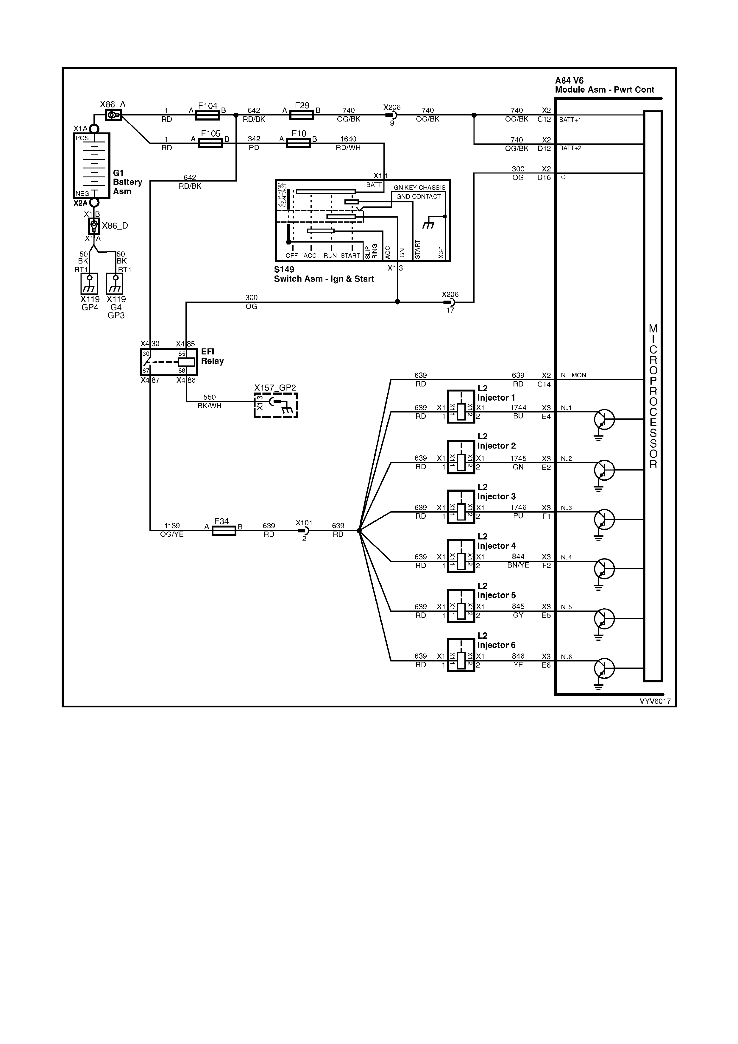
DTC P0563 V6 PCM - SYSTEM VOLTAGE TOO HIGH
Figure 6C1-2A-143 – PCM Power Supply Circuits
CIRCUIT DESCRIPTION
Circuit 300 is the igni tio n v olta ge f eed c irc uit t o ter minal X2- D1 6 f o r the PCM. Circuit 7 40 is t he batter y vo lta ge f eed
circuit to term inals X2-C12 and X2-D12 for the PCM. When the PCM detects a HIGH volta ge for a short period of
time, DTC P0563 sets.
CONDITIONS FOR RUNNING THE DTC
• The ignition is ON.
• ECT is at or above 85°C.
• Conditions present for at least 4 seconds.
CONDITIONS FOR SETTING THE DTC
• Voltage at PCM ignition feed terminal is more than 19.5 volts for more than 2 seconds.

ACTION TAKEN WHEN THE DTC SETS
• The PCM activates the Check Powertrain MIL and stores the DTC information into memory when the
diagnostic runs and fails.
• W hen DTC P0563 sets, the PCM tur ns off all transm ission ou tput devic es, and f reezes sh ift adapts from being
updated.
CONDITIONS FOR CLEARING THE MIL/DTC
• The PCM turns the Check Powertrain MIL OFF after the first ignition cycle that the diagnostic runs and does
not fail.
• Use TECH 2 in order to clear the MIL/DTC.
DIAGNOSTIC AIDS
• Inspect the wiring for poor electrical connections at the PCM. Look for the following conditions:
A bent terminal
A backed out terminal
A damaged terminal
Poor terminal tension
A chafed wire
A broken wire inside the insulation
Moisture intrusion
• When diagnosing for an intermittent short or open condition, massage the wiring harness while watching the
test equipment for a change.
• Charging the battery with a battery charger may set DTCs. Jump starting an engine may set DTCs.
• If DTCs set when you operate an accessory, inspect the applicable wiring for faulty connections. Inspect the
wiring for excessive current draw.
• Inspect the following items for faulty connections:
The starter solenoid
The fusible link
The generator terminals
Battery cables
• Inspect the belts for excessive wear. Inspect the belts for proper tension.
TEST DESCRIPTION
Number(s) below refer to step number(s) on the diagnostic Table.
4. This step tests the charging system voltage.
5. This step checks battery voltage of the PCM, using TECH 2.
A84 V6 – X2
Figure 6C1-2A-144

DTC P0563 V6 PCM - SYSTEM VOLTAGE TOO HIGH
STEP ACTION VALUE YES NO
1 Was the On-Board Diagnostic (OBD) System Check
performed? Go to Step 2 Go to
OBD System
Check
2 1. Install TECH 2.
2. Ignition ON, engine OFF.
IMPORTANT: Before clearing the DTCs, use TECH 2 in
order to record the DTC history for reference. The Clear
History DTC function will erase the data.
3. Record the DTC history.
4. Using a Digital Multimeter (DMM), measure the
battery voltage across the battery terminals.
Is the voltage higher than the specified value?
10 volts Go to Step 3 Go to Battery
Diagnosis
3 1. Start the engine.
2. Warm the engine to the operating temperature.
Is the “Check Alternator” warning displayed in the
Instrument MFD?
85°C Refer 6D1-1
Charging System
Diagnosis.
Go to Step 4
4. 1. Increase the engine speed to 2000 RPM for 15
seconds.
2. Observe the DMM battery voltage and record your
reading.
Did the DMM battery voltage exceed the specified value?
16.0 volts Refer 6D1-1
Charging System
Diagnosis.
Go to Step 5
5. 1. Increase the engine spe ed to 2000 RPM.
2. Observe TECH 2 Battery Voltage.
Is TECH 2 Battery Voltage within 0.5 volts of your
recorded voltage in Step 4?
System Checks
OK, Go to
“Diagnostic Aids”
Go to Step 6
6. Replace PCM.
Refer 6C1-3 Service Operations, for PCM Programming
and Security Link procedure.
Is action complete?
Verify Repair
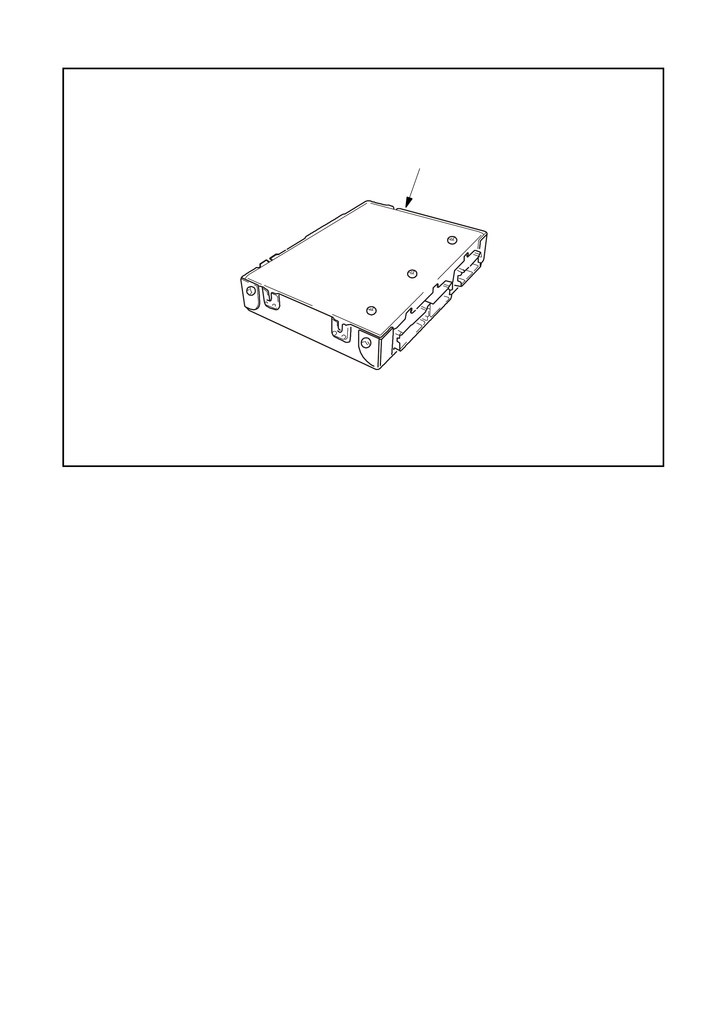
DTC P0601 V6 PCM -POWERTR AIN CONTROL MODULE (PCM) MEMORY
4226
1
Figure 6C1-2A-145 – Powertrain Control Module
CIRCUIT DESCRIPTION
The PCM EEPROM contains data which is essential to running the engine and transmission. The PCM
continuously checks the integrity of this data.
CONDITIONS FOR RUNNING THE DTC
• The ignition switch is in the CRANK position or the RUN position.
CONDITIONS FOR SETTING THE DTC
• The PCM is unable to correctly read data from the EEPROM (flash memory).
ACTION TAKEN WHEN THE DTC SETS
• The PCM activates the Check Powertrain MIL and stores the DTC information into memory when the
diagnostic runs and fails.
• The PCM records the operating conditions at the time the diagnostic fails. The PCM stores this information in
the History Data.
CONDITIONS FOR CLEARING THE MIL/DTC
• The PCM turns the Check Powertrain MIL OFF after the first ignition cycle that the diagnostic runs and does
not fail.
• Use TECH 2 in order to clear the MIL/DTC.
DIAGNOSTIC AIDS
• Replace the PCM even if this DTC exists only in history.
• For an intermittent, Refer to Section 6C1- 2B Sympt oms.
TEST DESCRIPTION
Number(s) below refer to step number(s) on the diagnostic Table.
3. This DTC indicates an internal PCM problem.

DTC P0601 V6 PCM - POWERTRAIN CONTROL MODULE (PCM) MEMORY
STEP ACTION VALUE YES NO
1. Was the "On-Board Diagnostic" (OBD) System Check
performed? Go to Step 2 Go to
OBD System
Check
2. Replace PCM.
Refer 6C1-3 Service Operations, for PCM Programming
and Security Link procedure.
Is action complete?
Go to Step 3
3. 1. Install TECH 2.
2. Operate the vehicle within the conditions for running
the DTC.
Does TECH 2 indicate that this DTC reset?
Go to Step 2 Go to Step 4
4. Using TECH 2, check for any other DTCs.
Does TECH 2 display and DTCs that you have not
diagnosed?
Go to applicable
DTC table System OK

DTC P0712 V6 PCM -
TRANSMISSION FLUID TEMPERATURE (TFT) SIGNAL VOLTAGE LOW
Figure 6C1-2A-146 – Transmission Fluid Temperature Sensor Circuit
CIRCUIT DESCRIPTION
The Automatic Transmission Fluid Temperature (TFT) sensor is a thermistor within the Automatic Transmission
Fluid Pressure Manual Valve Position Switch. The TFT sensor controls the signal voltage to the PCM. The PCM
supplies a 5-volt reference signal to the sensor on circuit 1227. When the transmission fluid is cold, the sensor
resistance will be high. The PCM will then detect a high signal voltage. As the transmission fluid temperature
increases to the normal operating temperature, the sensor resistance becomes less and the voltage decreases.
When the PCM detects a c ontinuous short to groun d in the T FT signal circuit or in the T FT sensor, a DTC P0712
will set.
CONDITIONS FOR RUNNING THE DTC
• The ignition switch is ON.
CONDITIONS FOR SETTING THE DTC
• The TFT sensor indicates a signal voltage less than 0.2 volts for 10 seconds.
ACTION TAKEN WHEN THE DTC SETS
• The PCM stores the DTC information into memory when the diagnostic runs and fails.
• The Check Powertrain MIL will not be activated.
• When this DTC sets, the PCM uses a transmission fluid temperature default value based on engine coolant,
engine run time and IAT at startup, the PCM will freeze shift adapts from being updated.
CONDITIONS FOR CLEARING THE MIL/DTC
• The PCM turns the Check Powertrain MIL OFF after the first ignition cycle that the diagnostic runs and does
not fail.
• Use TECH 2 in order to clear the MIL/DTC.
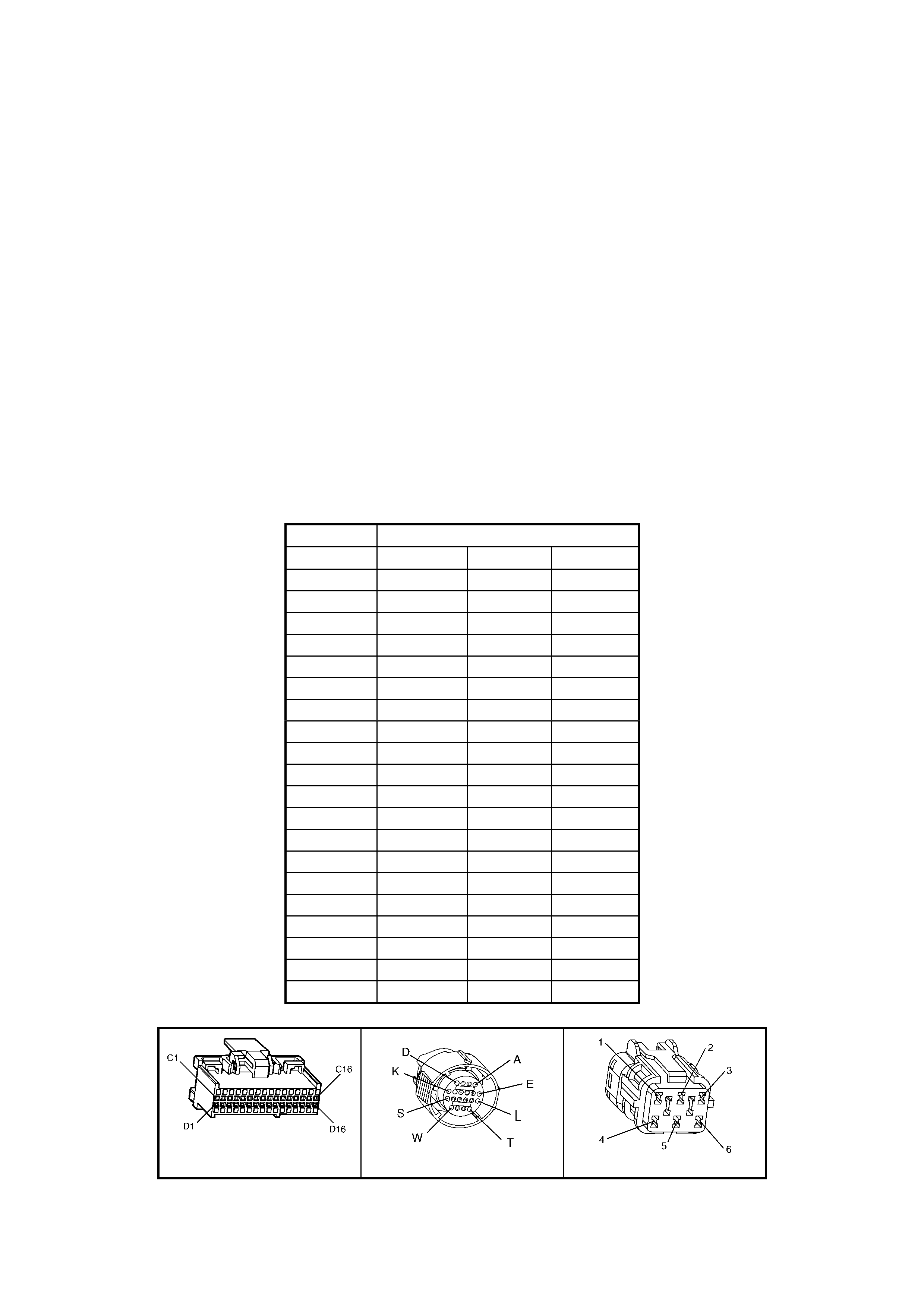
DIAGNOSTIC AIDS
• Inspect the wiring for poor electrical conn ections at th e PCM. Inspect the wiring for poor el ectrical connec tions
at the transmission pass-through connector. Look for the following conditions:
A backed out terminal
A damaged terminal
Poor terminal tension
A chafed wire
A broken wire inside the insulation
Corrosion
• When diagnosing for an intermittent short or open condition, massage the wiring harness while watching the
test equipment for a change.
• Use the Tem peratur e vs Res istance tab le when tes ting the TFT sensor at var ious tem peratur e levels. T est t he
TFT s ensor in order to ev aluate the poss ibilit y of a sk ewed (m is-scaled) s ensor. A sk ewed sensor can r esult in
delayed garage shifts or TCC complaints.
• TECH 2 displays the transmission fluid temperature in degrees. After the transmission is operating, the fluid
temperature should rise steadily to a normal operating temperature, then stabilise.
TEST DESCRIPTION
Number(s) below refer to step number(s) on the diagnostic Table.
3. This step tests for a short to ground or a skewed sensor.
4. This step creates an open within the transmission in order to test for an internal fault.
Transmission Fluid Temperature (TFT) Sensor Temperature To Resistance Table
Temperature TFT Resistance
Degrees °C Minimum Ω
ΩΩ
Ω Normal Ω
ΩΩ
Ω Maximum Ω
ΩΩ
Ω
-40 90636 100707 110778
-30 47416 52684 57952
-20 25809 28677 31545
-10 14558 16176 17784
0 8481 9423 10365
10 5104 5671 6238
20 3164 3515 3867
30 2013 2237 2461
40 1313 1459 1605
50 876 973 1070
60 600 667 734
70 420 467 514
80 299 332 365
90 217 241 265
100 159 177 195
110 119 132 145
120 89.9 99.9 109.9
130 69.1 76.8 84.5
140 53.8 59.8 65.8
150 42.5 47.2 51.9
A84 V6 – X2 X121 – X2 X101
Figure 6C1-2A-147

DTC P0712 V6 PCM - TRANSMISSION FLUID TEMPERATURE (TFT) SIGNAL VOLTAGE LOW
STEP ACTION VALUE YES NO
1. Was the On-Board Diagnostic (OBD) System Check
performed? Go to Step 2 Go to
OBD System
Check
2. Perform the transmi ss ion flu id che cki ng pr oc edure .
Have you perform ed the fluid checking procedure?
Go to Step 3 Go to
Transmission
Fluid Checking
Procedure
3. 1. Install TECH 2.
2. Ignition ON, engine OFF.
IMPORTANT: Before clearing the DTCs use TECH 2 in
order to record the DTC history. The Clear History DTC
function will erase the data.
3. Record the DTC history.
Does TECH 2 display a TFT voltage less than the
specified value?
0.33 volts Go to Step 4 Go to
“Diagnostic Aids”
4. 1. Turn the ignition OFF.
2. Disconnect the transmission pass-through connector.
3. With the engine OFF, turn the ignition switch to the
RUN position.
Does TECH 2 display a TFT voltage greater than the
specified value?
4.92 volts Go to Step 5 Go to Step 9
5. 1. Install the J 39775 Jumper Harness on the
transmissi on sid e of the pass-through connector.
2. Using a Digital Multimeter (DMM) and J 35616-A
Connector Test Adapter Kit, measure the resistance
between terminal L and terminal M.
Is the resistance within specifications?
3088-3942Ω
@ 20° C
159-198Ω
@100° C
Go to
“Diagnostic Aids”
on facing page
Go to Step 6
6. 1. Check the internal Automatic Transmission Wiring
Harness Assembly for a short to ground.
2. Replace the harness if necessary.
Did you find and correct the problem?
Verify Repair Go to Step 7
7. 1. Disconnect the internal Automatic Transmission
Wiring Harness Assembly at the TFT sensor.
2. Measure the resistance of the TFT sensor.
Is the resistance within specifications?
3088-3942Ω
@ 20° C
159-198 Ω
@ 100° C
Go to
“Diagnostic Aids” Go to Step 8
8. Replace the TFT Sensor (this is part of the TFP Valve
Position Switch). Refer to 6C1-3 Service Operations.
Is the action complete?
Verify Repair
9. Check circuit 1227 for a short to ground. Repair the circuit
if necessary.
Did you find a problem?
Verify Repair Go to Step 10
10. Replace PCM.
Refer 6C1-3 Service Operations, for PCM Programming
and Security Link procedure.
Is action complete?
Verify Repair

DTC P0713 V6 PCM -
TRANSMISSION FLUID TEMPERATURE (TFT) SIGNAL VOLTAGE HIGH
Figure 6C1-2A-148 – Transmission Fluid Temperature Sensor Circuit
CIRCUIT DESCRIPTION
The Automatic Transmission Fluid Temperature (TFT) sensor is a thermistor within the Automatic Transmission
Fluid Pressure Manual Valve Position Switch. The TFT sensor controls the signal voltage to the PCM. The PCM
supplies a 5 volt reference signal to the sensor on circuit 1227. When the transmission fluid is cold, the sensor
resistance will be high. The PCM will then detect a high signal voltage. As the transmission fluid temperature
increases to the normal operating temperature, the sensor resistance becomes less and the voltage decreases.
W hen the PCM detects a conti nuous ope n or short to vo ltage in the T FT signal ci rcuit or in the T FT sens or, a DTC
P0713 will set.
CONDITIONS FOR RUNNING THE DTC
• The ignition switch is ON.
CONDITIONS FOR SETTING THE DTC
• The TFT sensor indicates a signal voltage greater than 4.92 volts for 6.8 minutes (409 seconds).
ACTION TAKEN WHEN THE DTC SETS
• The PCM stores the DTC information into memory when the diagnostic runs and fails.
• The Check Powertrain MIL will not be activated.
• When this DTC sets, the PCM uses a transmission fluid temperature default value based on engine coolant,
engine run time and IAT at startup, the PCM will freeze shift adapts from being updated.
CONDITIONS FOR CLEARING THE MIL/DTC
• Use TECH 2 in order to clear the MIL/DTC.
DIAGNOSTIC AIDS
• Inspect the wiring for poor electrical conn ections at th e PCM. Inspect the wiring for poor el ectrical connec tions
at the transmission pass-through connector. Look for the following conditions:
A backed out terminal
A damaged terminal
Poor terminal tension
A chafed wire
A broken wire inside the insulation
Corrosion
• When diagnosing for an intermittent short or open condition, massage the wiring harness while watching the
test equipment for a change.
• Use the Tem peratur e vs Res istance tab le when tes ting the TFT sensor at var ious tem peratur e levels. T est t he
TFT s ensor in order to ev aluate the poss ibilit y of a sk ewed (m is-scaled) s ensor. A sk ewed sensor can r esult in
delayed garage shifts or TCC complaints.
• TECH 2 displays the transmission fluid temperature in degrees. After the transmission is operating, the fluid
temperature should rise steadily to a normal operating temperature, then stabilise.
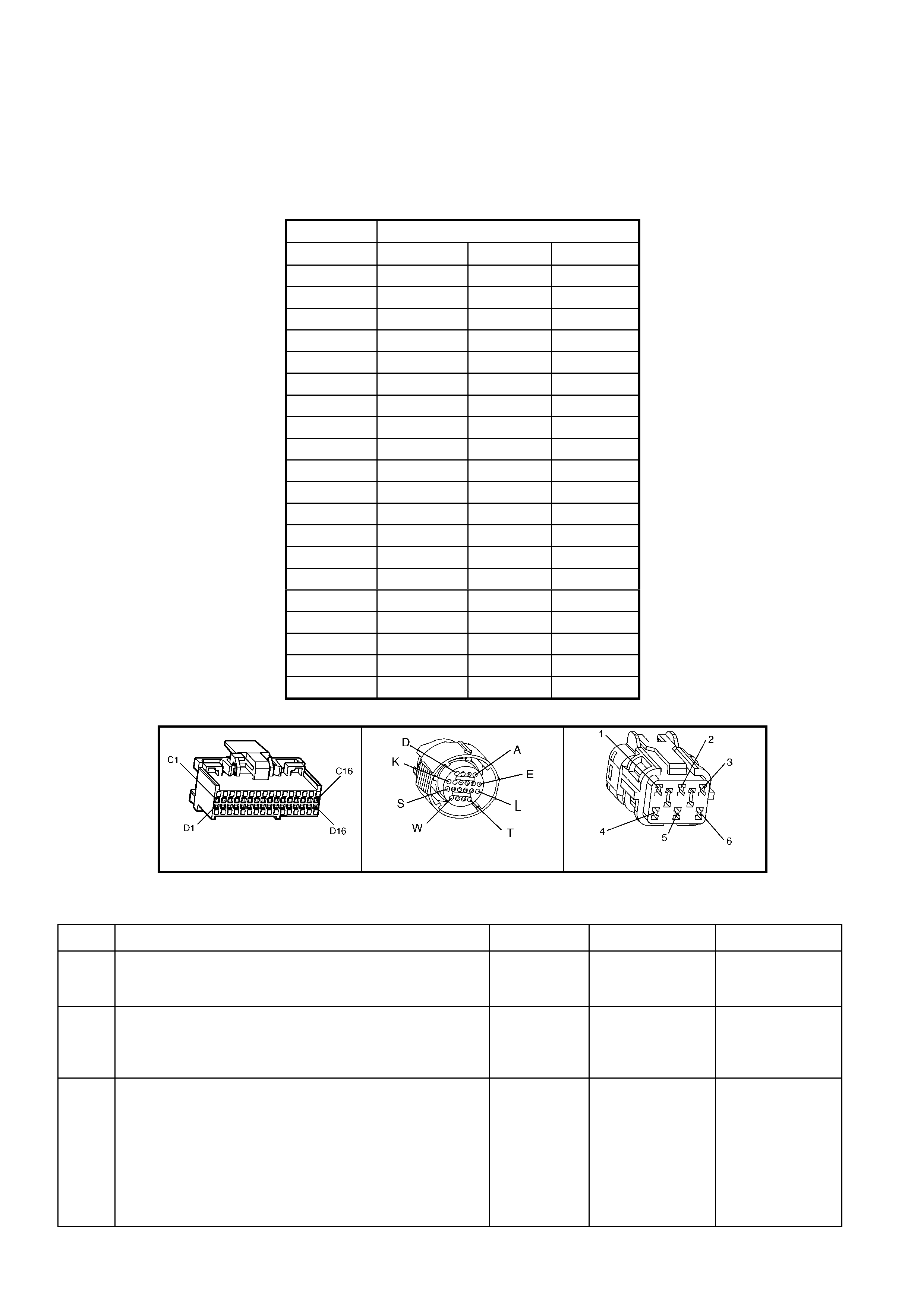
TEST DESCRIPTION
Number(s) below refer to step number(s) on the diagnostic Table.
3. This step verifies that a problem exists in the TFT sensor circuit.
4. This step simulates a TFT sensor DTC P0712. If the PCM recognises high temperature, the PCM and wiring
are functioning normally.
5. This step tests the TFT sensor and Automatic Transmission Wiring Harness Assembly.
Transmission Fluid Temperature (TFT) Sensor Temperature To Resistance Table
Temperature TFT Resistance
Degrees °C Minimum Ω
ΩΩ
Ω Normal Ω
ΩΩ
Ω Maximum Ω
ΩΩ
Ω
-40 90636 100707 110778
-30 47416 52684 57952
-20 25809 28677 31545
-10 14558 16176 17784
0 8481 9423 10365
10 5104 5671 6238
20 3164 3515 3867
30 2013 2237 2461
40 1313 1459 1605
50 876 973 1070
60 600 667 734
70 420 467 514
80 299 332 365
90 217 241 265
100 159 177 195
110 119 132 145
120 89.9 99.9 109.9
130 69.1 76.8 84.5
140 53.8 59.8 65.8
150 42.5 47.2 51.9
A84 V6 – X2 X121 – X2 X101
Figure 6C1-2A-149
DTC P0713 V6 PCM - TRANSMISSION FLUID TEMPERA TURE (TFT) SIGNAL VOLTAGE HIGH
STEP ACTION VALUE YES NO
1. Was the On-Board Diagnostic (OBD) System Check
performed? Go to Step 2 Go to
OBD System
Check
2. Perform the tran smi ss ion flu id che cki ng pr oc edure .
Have you perform ed the fluid checking procedure?
Go to Step 3 Go to
Transmission
Fluid Checking
Procedure
3. 1. Install TECH 2.
2. Ignition ON, engine OFF.
IMPORTANT: Before clearing the DTCs, use TECH 2 in
order to record the DTC history for reference. The Clear
History DTC function will erase the data.
3. Record the DTC history.
Does TECH 2 display a TFT Sensor voltage greater than
the specified value?
4.92 volts Go to Step 4 Go to “Diagnostic
Aids”

STEP ACTION VALUE YES NO
4. 1. Turn the ignition OFF.
2. Disconnect the transmission pass-through connector.
3. Install the J 39775 Jumper Harness on the engine
side of the pass-through connector.
4. Install a fused jumper wire from terminal L to terminal
M on the connector.
5. Ignition ON engine OFF.
Does the TFT Sensor voltage drop to less than the
specified value?
0.2 volts Go to Step 5 Go to Step 9
5. 1. Turn the ignition OFF.
2. Install the J 39775 Jumper Harness on the
transmissi on sid e of the pass-through connector.
3. Using a Digital Multimeter (DMM) and J 35616-A
Connector Test Adapter Kit, measure the resistance
between terminal L and terminal M.
Is the resistance within specification?
3088-3942 Ω
at 20° C
159-198 Ω
at 100° C
Go to “Diagnostic
Aids” on facing
page
Go to Step 6
6. 1. Check the internal Automatic Transmission Wiring
Harness Assembly for an open condition.
2. Replace the harness if necessary.
Did you find and correct the problem?
Verify Repair Go to Step 7
7. 1. Disconnect the internal Automatic Transmission
Wiring Harness Assembly at the TFT sensor.
2. Measure the resistance of the TFT sensor.
Is the resistance within specifications?
3088-3942 Ω
at 20° C
159-198 Ω at
100° C
Go to “Diagnostic
Aids” on facing
page
Go to Step 8
8. Replace the TFT Sensor (this is part of the TFP Valve
Position Switch) Refer to 6C1-3 Service Operations.
Is the replacement complete?
Verify Repair
9. Check circuit 1227 for an open or short to B+. Repair the
circuit if nece ss ary .
Did you find a problem?
Verify Repair Go to Step 10
10. Check circuit 2753 for an open. Repair the circuit if
necessary.
Did you find a problem?
Verify Repair Go to Step 11
11. Replace PCM.
Refer 6C1-3 Service Operations, for PCM Programming
and Security Link procedure.
Is action complete?
Verify Repair

DTC P0730 V6 PCM - 2-3 SHIFT SOLENOID B CIRCUIT VOLTAGE HIGH
Figure 6C1-2A-150 – Transmission Solenoid Circuits
CIRCUIT DESCRIPTION
The 2- 3 Shif t Soleno id Valv e (2-3 SS V alve) contr ols t he f luid f low act ing on th e 12-3 s hift va lve. T he 2-3 SS Valve
is a normally open exhaust valve that is used with the 1-2 Shift Solenoid Valve in order to allow four different
shifting combinations. The solenoid attaches to the control valve body within the transmission. The 2-3 SS Valve
receives voltage through circuit 339. The PCM controls the solenoid by providing the ground path on circuit 1223.
When the PCM detects a short to voltage in the 2-3 SS Valve circuit or the 2-3 SS Valve, DTC P0730 sets.
CONDITIONS FOR RUNNING THE DTC
• The engine is running.
CONDITIONS FOR SETTING THE DTC
• The PCM commands the solenoid ON and the voltage input remains high (B+).
ACTION TAKEN WHEN THE DTC SETS
• The PCM activates the Check Powertrain MIL when the diagnostic runs and fails.
• The PCM records the operating conditions at the time the diagnostic fails. The PCM stores this information in
the History Data.
• When this DTC sets, the PCM will command D2 line pressure, inhibit a 3-2 downshift if the vehicle speed is
greater than 48 km/h, and freeze shift adapts from being updated.
CONDITIONS FOR CLEARING THE MIL/DTC
• The PCM turns the Check Powertrain MIL OFF after the first ignition cycle that the diagnostic runs and does
not fail.
• Use TECH 2 in order to clear the MIL/DTC.
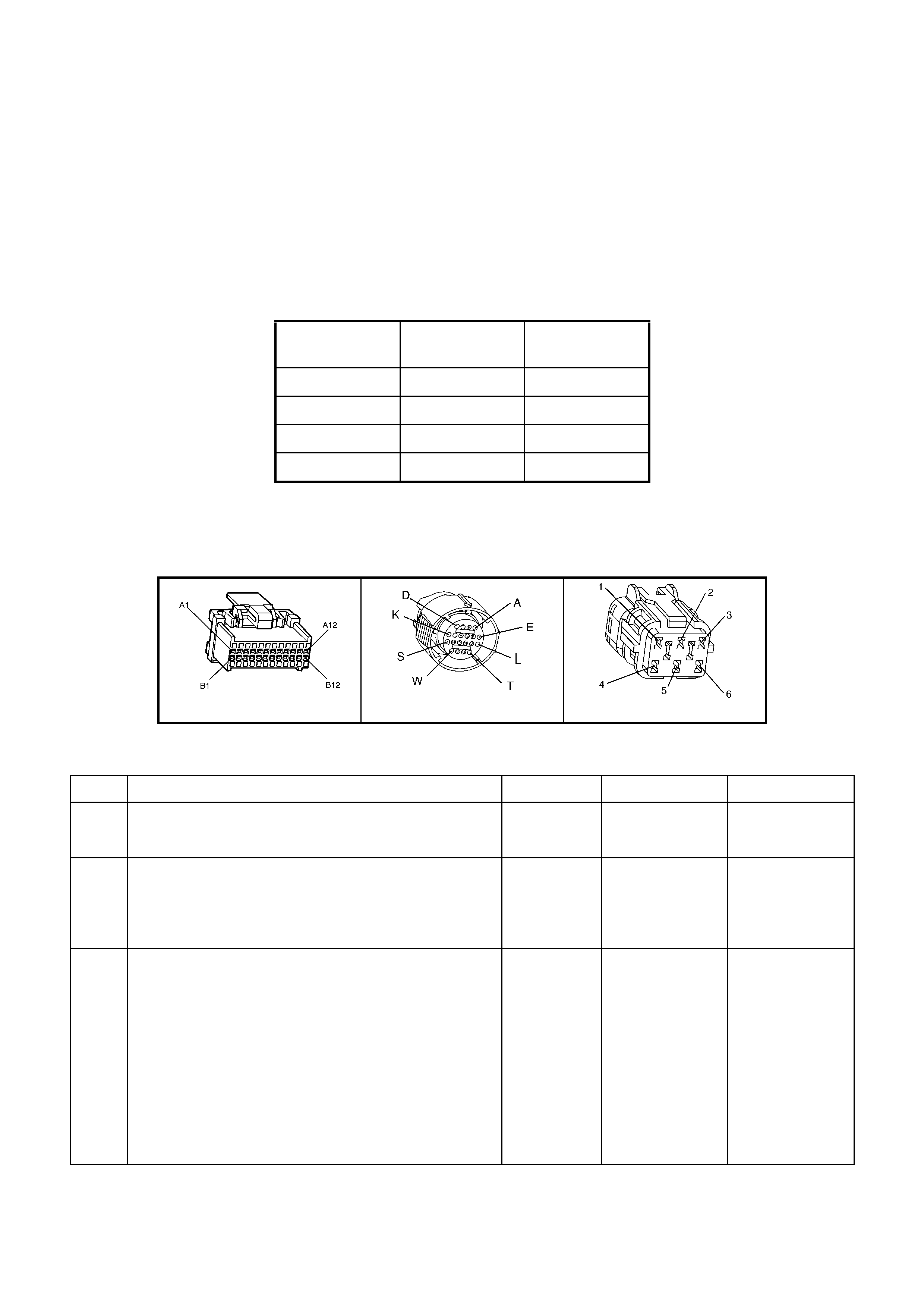
DIAGNOSTIC AIDS
• Inspect the wiring for poor electrical conn ections at th e PCM. Inspect the wiring for poor el ectrical connec tions
at the transmission pass-through connector. Look for the following conditions:
A bent terminal
A backed out terminal
A damaged terminal
Poor terminal tension
A chafed wire
A broken wire inside the insulation
• Moisture intrusion when diagnosing for an intermittent short or open condition, massage the wiring harness
while watching the test equipment for a change.
Refer to the following Table for the correct On and Off states of the shift solenoids.
GEAR 1-2-SHIFT
SOLENOID A 2-3 SHIFT
SOLENOID B
1 ON ON
2 OFF ON
3 OFF OFF
4 ON OFF
TEST DESCRIPTION
Number(s) below refer to step number(s) on the diagnostic Table.
2. This step tests the function of the 2-3 SS valve and the automatic transmission wiring harness assembly.
3. This step tests the ability of the PCM and the wiring to control the ground circuit.
A84 V6 – X1 X121 – X2 X101
Figure 6C1-2A-151
DTC P0730 V6 PCM - 2-3 SHIFT SOLENOID B CIRCUIT VOLTAGE HIGH
Step Action Value(s) Yes No
1. Was the Powertrain On-Board Diagnostic (OBD) System
Check performed? Go to Step 2 Go to
OBD System
Check
2. 1. Using the transmission Miscellaneous Tests function
on TECH 2, command the 2-3 SS valve ON and OFF
three times while listening to the bottom of the
transmission pan (a stethoscope may be necessary).
Did the solenoid click when commanded?
Go to Diagnostic
Aids Go to Step 3
3. 1. Turn the ignition OFF.
2. Disconnect the transmission pass-through connector
(additional DTCs may set).
3. Install the J 39775 jumper harness on the engine
side of the pass-through connector.
4. Install a test lamp from J 39775 jumper harness
cavity E to cavity B.
5. Using the transmission Miscellaneous Tests function
on TECH 2, command the 2-3 SS valve ON and OFF
three times.
Is the test lamp ON when the 2-3 SS valve is
commanded ON, and OFF when commanded OFF?
Go to Step 6 Go to Step 4

Step Action Value(s) Yes No
4 1. Inspect circuit 1223 of the powertrain wiring harness
for a short to voltage condition .
2. Repair the circuit if nece ssary .
Did you find a short to voltage condition?
Go to Step 12 Go to Step 5
5. Replace PCM.
Refer 6C1-3 Service Operations, for PCM Programming
and Security Link procedure.
Is action complete?
Go to Step12
6. 1. Install the J 39775 jumper harness on the
transmissi on sid e of the pass-through connector.
2. With the a digital multimeter (DMM) and the
J35616-A Connector Test Adapter Kit, measure the
resistance between terminals B and E.
Is the resistance within the range indicated?
19-31 Ω Go to Step 8 Go to Step 7
7. 1. Disconnect the A/T wiring harness assembly from the
2-3 SS valve.
2. Measure the resistance of the 2-3 SS valve.
Is the resistance within the range indicated?
19-31 Ω Go to Step 10 Go to Step 11
8. Using a DMM, measure the resistance between terminal
B and ground, and between terminal E and ground.
Are both readings greater than the specified value?
250 K Ω Go to Diagnostic
Aids Go to Step 9
9. 1. Disconnect the A/T wiring harness assembly from the
2-3 SS valve.
2. Using a DMM, measure the resistance from the
component's terminals to ground.
Are both readings greater than the specified value?
250 K Ω Go to Step 10 Go to Step 11
10. Replace the automatic transmission wiring harness
assembly. Refer 7C4 A/T On-Vehicle Servicing.
Is the replacement complete?
Go to Step 12
11. Replace the 2-3 SS valve.
Refer 7C4 A/T On-Vehicle Servicing.
Is the replacement complete?
Go to Step 12
12. Perform the following procedure in order to verify the
repair:
Drive the vehicle in D and ensure the following conditions
are met:
• The PCM commands the 2-3 SS valve ON and the
voltage input drops to zero.
• The PCM commands the 2-3 SS valve OFF and the
voltage input increases to B+.
• All conditions are met for 5 seconds.
Were the above conditions verified?
System OK Go to Step 1
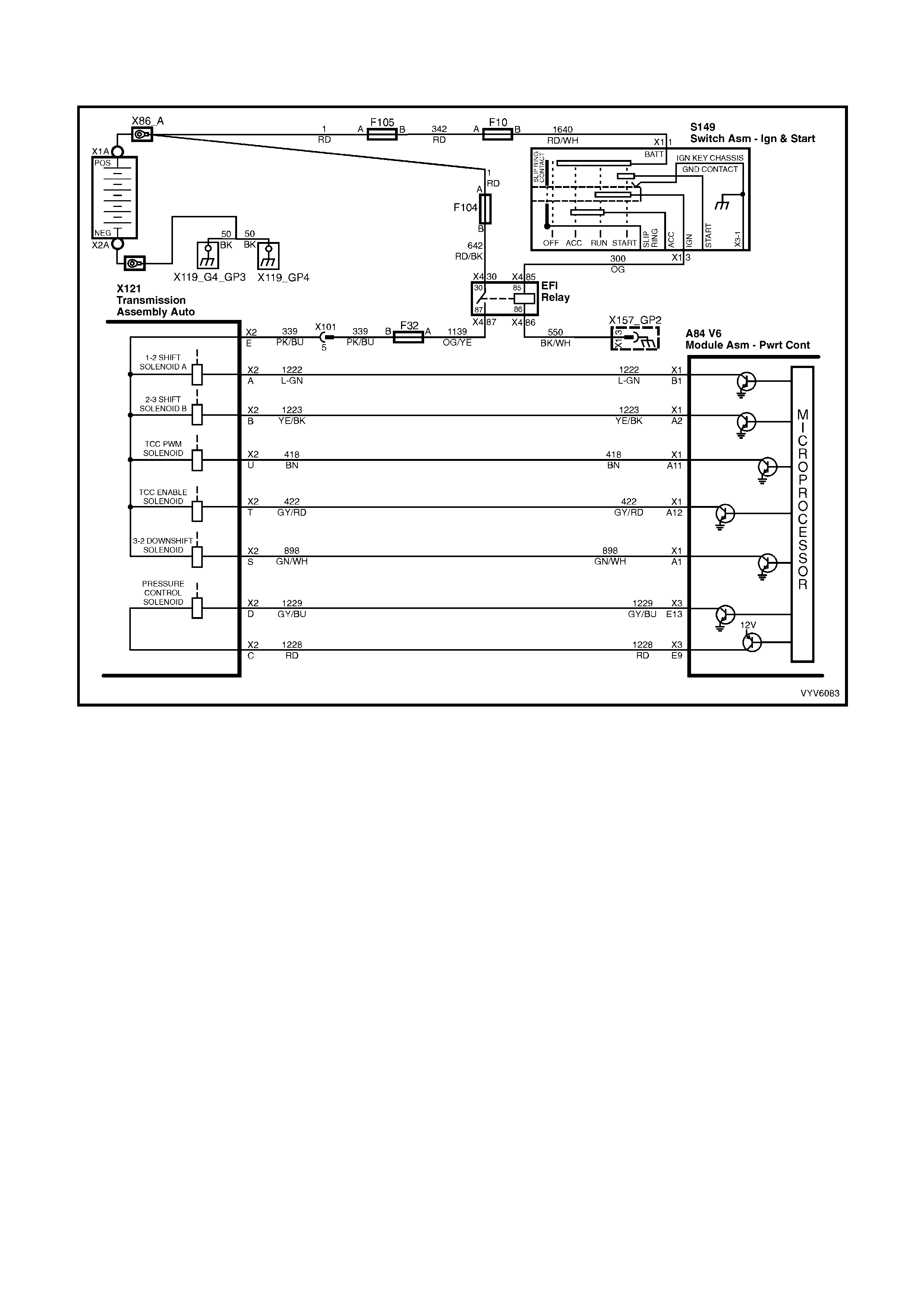
DTC P0740 V6 PCM -
TORQUE CONVERTER CLUTCH (TCC) E NABLE SOLENOID CIRCUIT FAULT
Figure 6C1-2A-152 – Transmission Solenoid Circuits
CIRCUIT DESCRIPTION
The torque converter clutch (TCC) solenoid valve is an electrical device that is used with the torque converter
clutch pulse width modulation (TCC PWM) solenoid valve in order to control TCC apply and release. The TCC
solenoid v al ve a ttach es to t he tr ans mission c as e ass e mbl y extending in to the pu mp c over. The TCC s oleno i d va l ve
receives ignition voltage through circuit 339. The powertrain control module (PCM) controls the solenoid by
providing the ground path on circuit 422. The PCM monitors the throttle position (TP) voltage, the vehicle speed
and other inputs in order to determine when to energise the TCC solenoid valve.
When the PCM detects a continuous open or a short to ground in the TCC solenoid valve circuit or in the TCC
solenoid valve, DTC P0740 sets.
CONDITIONS FOR RUNNING THE DTC
• The system voltage is 8-18 volts.
• The engine speed is greater than 300 RPM for 5 seconds.
• The engine is not in fuel cutoff.
CONDITIONS FOR SETTING THE DTC
• DTC P0740 sets if either of the following conditions occurs for 5 seconds:
• The PCM commands the solenoid ON and the voltage input remains high (B+).
• The PCM commands the solenoid OFF and the voltage input remains low (0 volt).
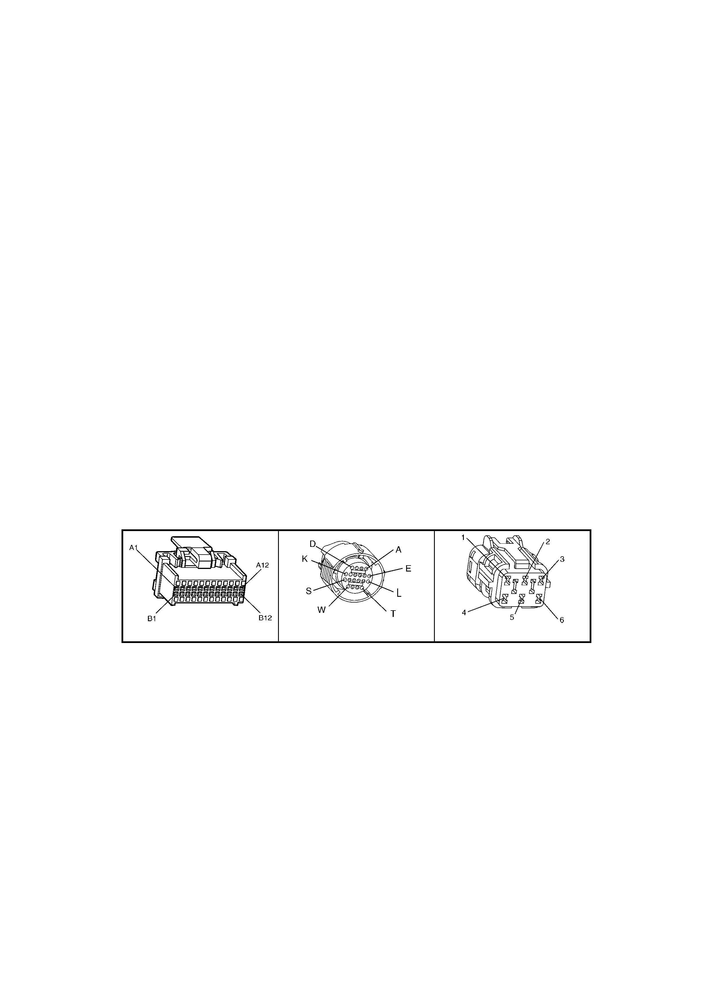
ACTION TAKEN WHEN THE DTC SETS
• The PCM does not activate the Check Powertrain MIL.
• The PCM inhibits TCC engagement.
• The PCM records the operating conditions at the time the diagnostic fails. The PCM stores this information in
the History Data.
• The PCM inhibits 4th gear if the transmission is in hot mode.
• The PCM freezes shift adapts from being updated.
CONDITIONS FOR CLEARING THE DTC
• Use TECH 2 in order to clear the MIL/DTC.
DIAGNOSTIC AIDS
• Inspect the wiring at the PCM, the transmission connector and all other circuit connecting points for the
following conditions:
A backed out terminal
A damaged terminal
Reduced terminal tension
A chafed wire
A broken wire inside the insulation
Moisture intrusion
Corrosion
• When diagnosing for an intermittent short or open condition, massage the wiring harness while watching the
test equipment for a change.
• With the TCC engaged, the TCC slip speed should be -20 to +40 RPM.
TEST DESCRIPTION
Number(s) below refer to step number(s) on the diagnostic Table.
4. This step tests for voltage to the solenoid.
6. This step tests the ability of the PCM and wiring to control the ground circuit.
8. This step tests the resistance of the TCC solenoid valve and the automatic transmission (A/T) wiring harness
assembly.
A84 V6 – X1 X121 – X2 X101
Figure 6C1-2A-153

DTC P0740 V6 PCM - TORQUE CONVERTER CLUTCH (TCC) ENABLE SOLENOID CIRCUIT FAULT
Step Action Value(s) Yes No
1. Was the Powertrain On-Board Diagnostic (OBD) System
Check performed? Go to Step 2 Go
OBD System
Check.
2. 1. install the TECH 2.
2. Ignition ON engine OFF.
IMPORTANT: Before clearing the DTC, use TECH 2 in
order to record the History Data.
3. Record the DTC History Data.
4. Clear Histo r y DTCs.
Are any of the following DTCs also set?
• P0753
• P0730
• P0785
• P1860
Go to Step 3
Go to Step 4
3. 1. Inspect fuse F32.
2. If the fuse is open, inspect the following components
for a short to ground condition:
• Circuit 339.
• The solenoids.
• The A/T wiring harness assembly.
3. Repair the circuit, the solenoids, and the harness if
necessary.
Did you find a short to ground condition?
Go to Step 12
Go to Step 4
4. 1. Turn the ignition switch OFF.
2. Disconnect the transmission pass-through connector,
(additional DTCs may set).
3. Install the J 39775 jumper harness on the engine
side of the pass-through connector.
4. Ignition ON engine OFF.
5. Connect a test lamp from cavity E of the J 39775
jumper harness to ground.
Is the test la mp ON?
Go to Step 6
Go to Step 5
5. IMPORTANT: The condition that affects this circuit may
exist in other connecting branches of the circuit. Refer
12P Wiring Diagrams for complete power distribution
circuit distrib utio n.
1. Repair the open or short to ground in ignition feed
circuit 339 to the TCC solenoid valve.
Is the repair complete?
Go to Step 12
6. 1. Install the test lamp from cavities E to T of the
J 39775 jumper harness.
2. Using the TECH 2 TCC Soleniod Miscellaneous
Test, command the TCC solenoid valve ON and OFF
three times.
Does the test lamp turn ON when the TCC solenoid valve
is commanded ON, and OFF when commanded OFF?
Go to Step 8
Go to Step 7
7. 1. Inspect circuit 422 of the engine wiring harness for
an open, short to ground or short to power condition.
2. Repair the circuit if nece ssary .
Did you find an open, short to ground or short to power
condition?
Go to Step 12
Go to Step 9
8. 1. Install the J 39775 jumper harness on the
transmissi on sid e of the pass-through connector.
2. Using Digital Multimeter (DMM) and the
J 35616-A Connector Test Adapter Kit, measure the
resistance between terminals T and E.
Is the resistance wi thin the specified range?
21-33 Ω
Go to Step 10
Go to Step 11

Step Action Value(s) Yes No
9. Replace PCM.
Refer 6C1-3 Service Operations, for PCM Programming
and Security Link procedure.
Is action complete?
Go to Step 12
10. Measure the resistance between terminal E and ground,
and between terminal T and ground.
Are both readings greater than the specified value?
250 K Ω
Go to
Diagnostic Aids
Go to Step 11
11. Replace the automatic transmission wiring harness
assembly (this includes the TCC solenoid valve).
Refer 7C4 A/T On-Vehicle Servicing.
Is the replacement complete?
Go to Step 12
12. Perform the following procedure in order to verify the
repair:
1. Clear Histo r y DTCs.
2. Drive the vehicle in D with the TCC ON and OFF.
Ensure the foll owing conditions are met:
• The PCM commands the TCC solenoid valve
ON, and the voltage input drops to zero.
• The PCM commands the TCC solenoid valve
OFF, and the voltage input increases to B+.
• All conditions are met for 5 seconds.
Were the above conditions verified?
System OK
Go to Step 1

DTC P0741 V6 PCM - TORQUE CONVERTER CLUTCH (TCC) STUCK ON
Figure 6C1-2A-154 – Transmission Solenoid Circuits
CIRCUIT DESCRIPTION
The PCM energises th e Torque Con verter Clutch S olenoid Valve (TCC Soleno id Valve) b y c reating a ground pat h
on circuit 422. When circuit 422 is grounded (energised) by the PCM, the TCC Solenoid Valve stops converter
signal oil from exhausting. This causes converter signal oil pressure to increase and move the TCC valve. The TCC
Solenoid Valve de-energises when the PCM no longer provides a path to ground. When the TCC Solenoid Valve
de-energises, the valve exhausts fluid and releases the TCC.
Diagnostic T r oub le Cod e P 0741 is f or d eter mining a mec han ic al f au lt whic h wil l c aus e t he Torque Co nv erter Clu tc h
to be stuck "ON." An electrical fault in the torque converter clutch solenoid circuit which could cause the torque
converter clutch to be "Stuck ON" is diagnosed in DTC P0740.
When the PCM detects low torque converter slip when the PCM commands the TCC OFF, DTC P0741 sets.
CONDITIONS FOR RUNNING THE DTC
• No TP DTCs set.
• No VSS DTCs set.
• No TFP Manual Valve Position Switch DTC P1810 is set.
• No TCC Solenoid Valve DTC P0740 is set.
• No TCC PWM Solenoid Valve DTC P1860 is set.
• The TP angle is greater than 25%.
• The engine RPM is greater than 450 for 8 seconds.
• The commanded gear is not 1st.
• The gear range is D4 or D3.
• The PCM commands TCC OFF.
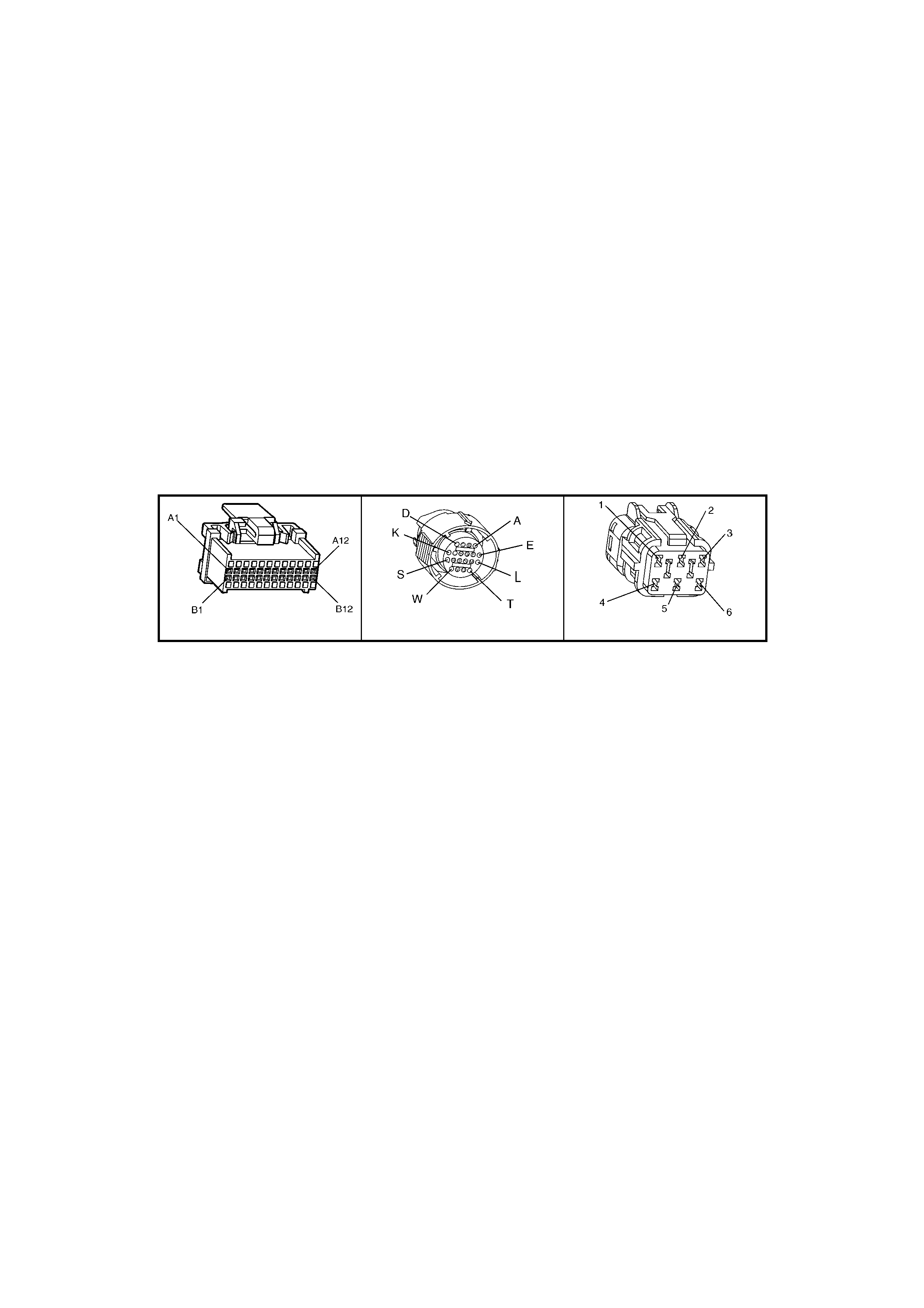
CONDITIONS FOR SETTING THE DTC
• DTC P0741 sets if the TCC slip speed is –20 to +30 RPM for 4 seconds.
ACTION TAKEN WHEN THE DTC SETS
• The Check Powertrain MIL will not be activated.
• The PCM records the operating conditions at the time the diagnostic fails. The PCM stores this information in
the History Data.
• When this DTC sets, the PCM will freeze shift adapts from being updated.
CONDITIONS FOR CLEARING THE MIL/DTC
• Use TECH 2 in order to clear the MIL/DTC.
DIAGNOSTIC AIDS
• The TCC fluid will mechanically apply the TCC, possibly causing an engine stall, under the following conditions:
The TCC is mechanically stuck ON.
The parking brake is applied.
Any gear range is selected.
A stuck TP sensor may set DTC P0741.
TEST DESCRIPTION
Number(s) below refer to step number(s) on the diagnostic Table.
3. This step inspec ts the m echanic al state of the T CC. W hen the PC M comm ands the T CC Sole noid Va lve OF F,
the slip speed should increase to greater than +50 RPM.
A84 V6 – X1 X121 – X2 X101
Figure 6C1-2A-155

DTC P0741 V6 PCM - TORQUE CONVERTER CLUTCH (TCC) STUCK ON
STEP ACTION VALUE YES NO
1. Was the On-Board Diagnostic (OBD) System Check
performed? Go to Step 2 Go to
OBD System
Check
2. 1. Install TECH 2.
2. With the engine OFF, turn the ignition switch to the
RUN position.
IMPORTANT: Before clearing the DTCs, use TECH 2 in
order to record the DTC history for reference. The Clear
History DTC function will erase the data.
3. Record the DTC history.
4. Using TECH 2, verify the TP Sensor operation.
Are the TP Sensor values within the normal range (shown
in the value column)?
0.6–5.0 volts Go to Step 3 Go to “Diagnostic
Aids”
3. Drive the vehicle in the D4 drive range in fourth gear
under steady acceleration, with a TP angle greater than
25%.
While the displayed TCC Solenoid status is No, does
TECH 2 display a Trans Slip Speed within the specified
range?
-20 to +30
RPM Go to Step 4 Go to “Diagnostic
Aids”
4. The TCC is mechanically stuck ON. Inspect for the
following con diti on s:
• A clogged exhaust orifice in the TCC Solenoid Valve.
• The converter clutch apply valve is stuck in the apply
position.
• A misaligned or damaged valve body gasket.
• A restricted release passage.
• A restr icted transmission cooler line.
Did you find and correct a problem?
Go to Step 5 Go to
Symptoms-
No TCC Release
5. In order to verify your repair, perform the following
procedure:
Operate the vehicle under the following conditions:
• Hold the throttle at 25% and acce lerat e to 88 km/h.
• Ensure that the Trans Slip Speed is -50 to +2500
RPM for 4 seconds, with the TCC commanded OFF.
Was the slip speed greater than 50 RPM in 2nd, 3rd and
4th gears when the TCC was commanded OFF?
System OK Go to Step 1

DTC P0748 V6 PCM - PRESS URE CONTROL (PC) SOLENOID CURRENT ERROR
Figure 6C1-2A-156 – Transmission Solenoid Circuits
CIRCUIT DESCRIPTION
The Pressure Control Solenoid Valve (PC Solenoid Valve) is a PCM controlled device which regulates the
transmission line pressure. The PCM compares the TP voltage, the engine speed and other inputs in order to
determ ine the appr opriate line pres sure f or a give n loa d. The PCM a pplies a var ying am per age to th e PC Sol enoid
Valve in ord er to regulate the pressure. The applied am perage can vary from 0.1 to 1.1 am ps. The PCM monitors
the amperage.
When the PCM detects a c ontinuous open or short to ground in th e PC Solenoid Valve circuit or t he PC Soleno id
Valve, a DTC P0748 sets.
Once a DTC P0748 is set, the pressure control solenoid is disabled and full line pressure will be applied until the
next tim e the ignition k e y is cycled. If upon res tart, the c urrent err or does not ex ist, a DT C P0748 will rem ain store d
but the pressure control solenoid will resume normal function.
CONDITIONS FOR RUNNING THE DTC
• No DTC P0562 is set.
• The system voltage is between 10 and 16 volts.
• The engine is running.
CONDITIONS FOR SETTING THE DTC
• The PC s oleno id val ve dut y c ycle reach es its high lim it ( approxim atel y 95%) or low lim it (approx im atel y 0%) for
200 milliseconds.
ACTION TAKEN WHEN THE DTC SETS
• The Check Powertrain MIL will not be activated.
• The PCM records the operating conditions at the time the diagnostic fails. The PCM stores this information in
the History Data.
• W hen this DTC sets , t he P CM wil l comm and the PC sole noi d va lv e OF F a nd will fr eeze s h if t ada pts f r om being
updated.
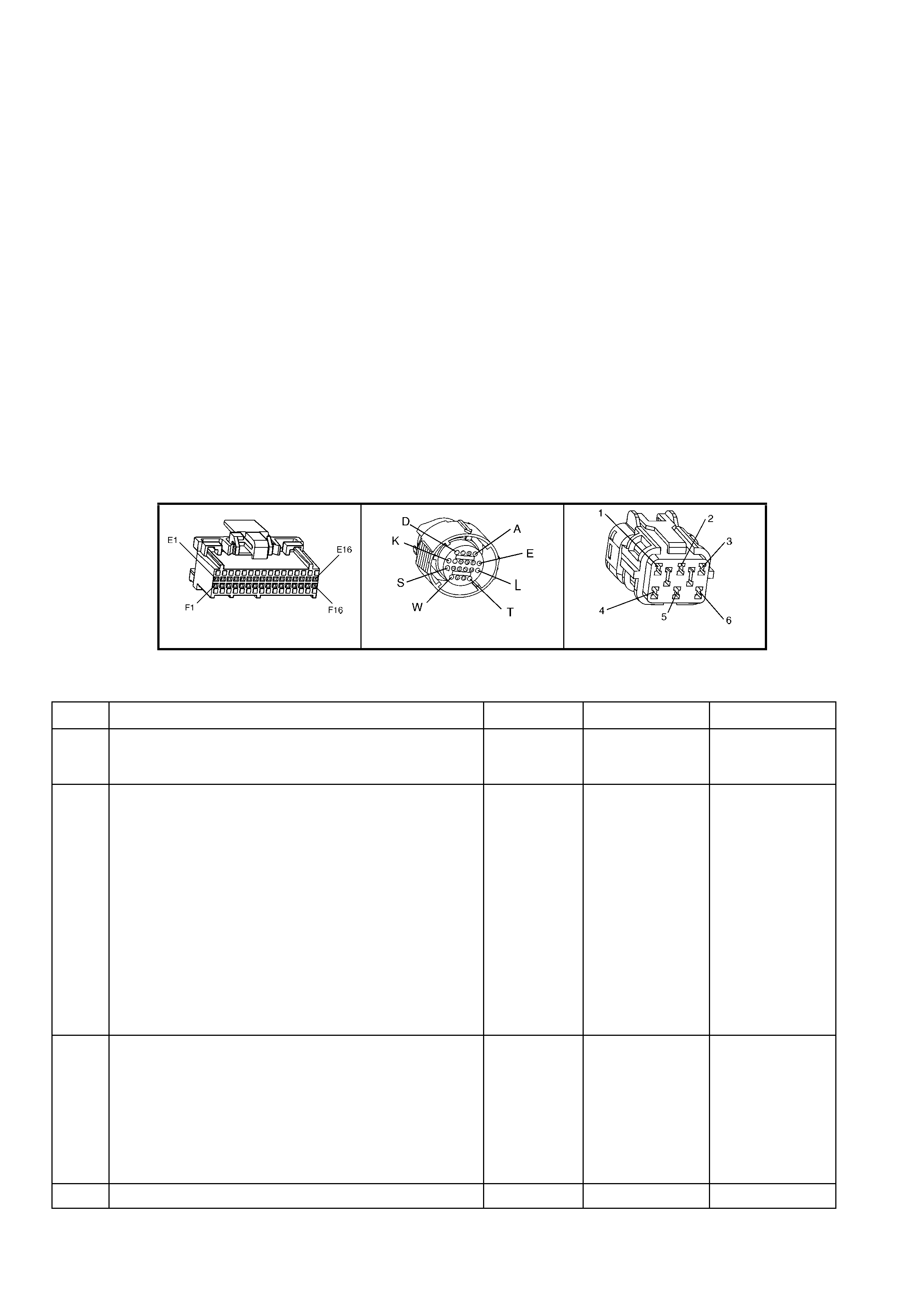
CONDITIONS FOR CLEARING THE MIL/DTC
• Use TECH 2 in order to clear the MIL/DTC.
DIAGNOSTIC AIDS
• Inspect the wiring for poor electrical conn ections at th e PCM. Inspect the wiring for poor el ectrical connec tions
at the transmission pass-through connector. Look for the following conditions:
A bent terminal
A backed out terminal
A damaged terminal
Poor terminal tension
A chafed wire
A broken wire inside the insulation
Moisture intrusion
Corrosion
• When diagnosing for an intermittent short or open condition, massage the wiring harness while watching the
test equipment for a change.
TEST DESCRIPTION
Number(s) below refer to step number(s) on the diagnostic Table.
2. This step tests the ability of the PCM to command the PC Solenoid Valve.
3. This step tests the PC Solenoid Valve and Automatic Transmission Wiring Harness Assembly for correct
resistance.
A84 V6 – X3 X121 – X2 X101
Figure 6C1-2A-157
DTC P0748 V6 PCM - PRESSURE CONTROL (PC) SOLENOID CURRENT ERROR
STEP ACTION VALUE YES NO
1. Was the On-Board Diagnostic (OBD) System Check
performed? Go to Step 2 Go to
OBD System
Check
2. 1. Install TECH 2.
2. Ignition ON engine OFF.
IMPORTANT: Before clearing the DTCs, use TECH 2 in
order to record the DTC history for reference. The Clear
History DTC function will erase the data.
3. Record the DTC history.
4. W hile the engine is operating, put the transmission in
Park position.
5. Using the transmission output control function on
TECH 2, apply 0.1 amp through 1.0 amp while
observing Commanded PCS and Actual PCS
amperage.
Is the Actual PCS amperage always within the specified
value of the Commanded PCS amperage?
0.16 amp Go to
“Diagnostic Aids” Go to Step 3
3. 1. Turn the ignition OFF.
2. Disconnect the transmission pass-through connector.
3. Install the J 39775 Jumper Harness on the
transmissi on sid e of the pass-through connector.
4. Using a Digital Multimeter DMM and J 35616-A
Connector Test Adapter Kit, measure the resistance
between terminal C and terminal D.
Is the resistance wi thin the specified range?
3-7 Ω Go to Step 8 Go to Step 4
4. Is the resistance greater than the specified value? 7 Ω Go to Step 5 Go to Step 6

STEP ACTION VALUE YES NO
5. 1. Check the Automatic Transmission Wiring Harness
Assembly for an open.
2. Replace the harness if necessary. Refer Refer to
7C4 A/T On-Vehicle Servicing.
Did you find and correct the problem?
Go to Step 15 Go to Step 10
6. Is the resistance less than the spec ified value? 3 Ω Go to Step 7
7. 1. Check the Automatic Transmission Wiring Harness
Assembly for a shorted together condition.
2. Replace the harness if necessary.
Refer to 7C4 A/T On-Vehicle Servicing.
Did you find and correct the problem?
Go to Step 15 Go to Step 10
8. Using a DMM and J 35616-A Connector Test Adapter Kit,
measure the resistance from terminal C to the
transmissi on cas e.
Is the resistance less than the specified value?
9 Ω Go to Step 9 Go to Step 11
9. 1. Check the Automatic Transmission Wiring Harness
Assembly for a short to ground.
2. Replace the harness if necessary. 7C4 A/T On-
Vehicle Servicing..
Did you find and correct the problem?
Go to Step 15 Go to Step 10
10. 1. Replace the PC Solenoid Valve.
Refer to 7C4 A/T On-Vehicle Servicing.
Is the action complete?
Go to Step 15
11. 1. Disconnect the J 39775 Jumper Harness from the
transmissi on sid e of the pass-through connector.
2. Reconnect the transmission pass-through connector.
3. Disconnect the PCM connector X3.
4. Using a DMM and J 35616-A Connector Test
Adapter Kit, measure the resistance from terminal
X3-E9 to ground.
Is the resistance greater than the specified value?
9 Ω Go to Step 12 Go to Step 13
12. 1. Check circuit 1228 and circuit 1229 for an open.
2. Repair the circuits if necessary.
Did you find and correct the problem?
Go to Step 15 Go to Step 14
13. Check circuit 1228 and circuit 1229 for a short to ground.
Repair the circuits if necessary.
Did you find and correct the problem?
Go to Step 15
14. Replace PCM.
Refer 6C1-3 Service Operations, for PCM Programming
and Security Link procedure.
Is action complete?
Go to Step 15
15. In order to verify your repair, perform the following
procedure:
Operate the vehicle under the following conditions:
• The engine is running.
• Observe the Actual PCS amperage and the
Commanded PCS amperage.
Is the difference between the Actual PCS amperage and
the Commanded PCS amperage less than the specified
value?
0.16 amp System OK Go to Step 1

DTC P0753 V6 PCM - 1-2 SHIFT SOLENOID A CIRCUIT VOLTAGE HIGH
Figure 6C1-2A-158 – Transmission Solenoid Circuits
CIRCUIT DESCRIPTION
The 1- 2 Shif t Sole no id V al v e (1- 2 SS Va l ve) c ontr o ls the f luid f lo w actin g on the 1-2 shif t val ve. T he 1- 2 SS V al ve is
a norm ally-open ex haust valve that is us ed with th e 2-3 Sh ift Sole noid Va lve in order to allow f our dif ferent shif ting
combinat ions. The solenoid attaches to the control valve body within the transm ission. The 1-2 SS Valve receives
ignition voltage through circuit 339. The PCM controls the solenoid by providing a path to ground on circuit 1222.
When the PCM detects a short to voltage in the 1-2 SS Valve circuit or the 1-2 SS Valve, DTC P0753 sets.
CONDITIONS FOR RUNNING THE DTC
• The engine is running.
CONDITIONS FOR SETTING THE DTC
• The PCM commands the solenoid ON and the voltage input remains high (B+).
ACTION TAKEN WHEN THE DTC SETS
• The PCM activates the Check Powertrain MIL when the diagnostic runs and fails.
• The PCM records the operating conditions at the time the diagnostic fails. The PCM stores this information in
the History Data.
• When this DTC sets, the PCM will command D2 line pressure, inhibit a 3-2 downshift if the vehicle speed is
greater than 48 km/h and will freeze shift adapts from being updated.
CONDITIONS FOR CLEARING THE MIL/DTC
• The PCM turns the Check Powertrain MIL OFF after the first ignition cycle that the diagnostic runs and does
not fail.
• Use TECH 2 in order to clear the MIL/DTC.
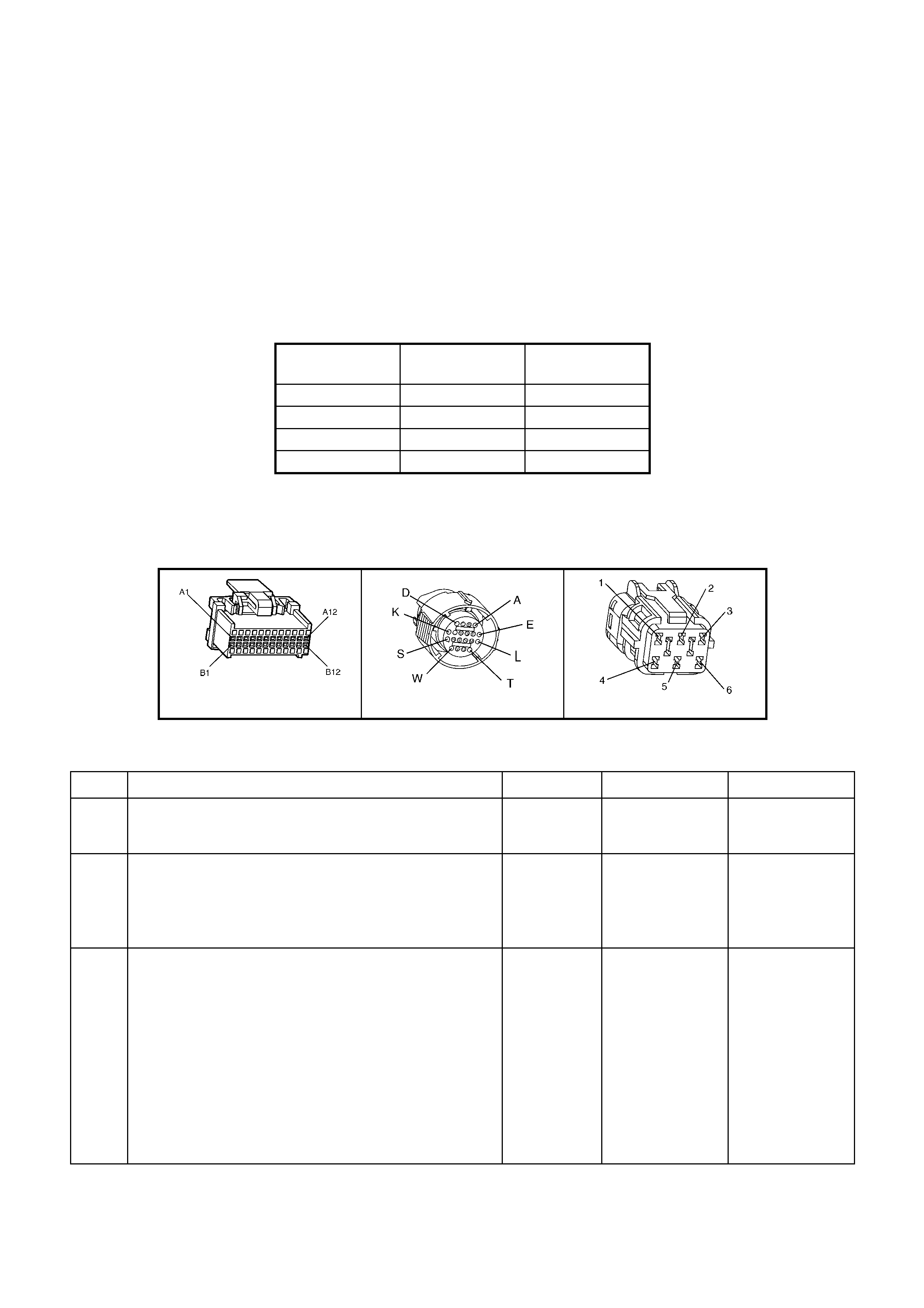
DIAGNOSTIC AIDS
Inspect the wiring for poor electrical connections at the PCM. Inspect the wiring for poor electrical connections at
the transmission pass-through connector. Look for the following conditions:
A bent terminal
A backed out terminal
A damaged terminal
Poor terminal tension
A chafed wire
A broken wire inside the insulation
Moisture intrusion
• When diagnosing for an intermittent short or open condition, massage the wiring harness while watching the
test equipment for a change.
• Refer to the following Table for the correct On and Off states of the shift solenoids.
GEAR 1-2-SHIFT
SOLENOID A 2-3 SHIFT
SOLENOID B
1 ON ON
2 OFF ON
3 OFF OFF
4 ON OFF
TEST DESCRIPTION
Number(s) below refer to step number(s) on the diagnostic Table.
2. This step tests the function of the 1-2 SS valve and the automatic transmission wiring harness assembly.
3. This step tests the ability of the PCM and the wiring to control the ground circuit.
A84 V6 – X2 X121 – X2 X101
Figure 6C1-2A-159
DTC P0753 V6 PCM - 1-2 SHIFT SOLENOID A CIRCUIT VOLTAGE HIGH
Step ACTION Value(s) Yes No
1. Was the Powertrain On-Board Diagnostic (OBD) System
Check performed? Go to Step 2 Go to
OBD System
Check
2. Using the TECH 2 1-2 Shift Solenoid Miscellaneous Test,
command the 1-2 SS valve ON and OFF three times
while listening to the bottom of the transmission pan (a
stethoscope may be necessary).
Did the solenoid click when commanded?
Go to “Diagnostic
Aids” Go to Step 3
3. 1. Turn the ignition OFF.
2. Disconnect the transmission pass-through connector
(additional DTCs may set).
3. Install the J 39775 jumper harness on the engine
side of the pass-through connector.
4. Install a test lamp from J 39775 jumper harness
cavity E to cavity A.
5. Using the TECH 2 1-2 Shift Solenoid Miscellaneous
Test, command the 1-2 SS valve ON and OFF three
times.
Is the test lamp ON when the 1-2 SS valve is
commanded ON, and OFF when commanded OFF?
Go to Step 6 Go to Step 4

Step ACTION Value(s) Yes No
4. 1. Inspect circuit 1222 of the powertrain wiring harness
for a short to voltage condition .
2. Repair the circuit if nece ssary .
Did you find a short to voltage condition?
Go to Step 12 Go to Step 5
5. Replace PCM.
Refer 6C1-3 Service Operations, for PCM Programming
and Security Link procedure.
Is action complete?
Go to Step12
6. 1. Install the J 39775 jumper harness on the
transmissi on sid e of the pass-through connector.
2. With a Digital Multimeter (DMM) and the J 35616-A
Connector Test Adapter Kit, measure the resistance
between terminals A and E.
Is the resistance within the range indicated?
19-31 Ω Go to Step 8 Go to Step 7
7. 1. Disconnect the A/T wiring harness assembly from the
1-2 SS valve.
2. Measure the resistance of the 1-2 SS valve.
Is the resistance within the range indicated?
19-31 Ω Go to Step 10 Go to Step 11
8. 1. Using a DMM, measure the resistance between
terminal A and ground, and between terminal E and
ground.
Are both readings greater than the specified value?
250 K Ω Go to “Diagnostic
Aids” Go to Step 9
9. 1. Disconnect the A/T wiring harness assembly from the
1-2 SS valve.
2. Using a DMM, measure the resistance from the
component's terminals to ground.
Are both readings greater than the specified value?
250 K Ω Go to Step 10 Go to Step 11
10. 1. Replace the automatic transmission wiring harness
assembly.
Refer 7C4 A/T On-Vehicle Servicing.
Is the replacement complete?
Go to Step 12
11. Replace the 1-2 SS valve.
Refer 7C4 A/T On-Vehicle Servicing.
Is the replacement complete?
Go to Step 12
12. Perform the following procedure in order to verify the
repair:
• Drive the vehicle in D and ensure the following
conditions are met:
• The PCM commands the 1-2 SS valve ON and the
voltage input drops to zero.
• The PCM commands the 1-2 SS valve OFF and the
voltage input increases to B+.
• All conditions are met for 5 seconds.
Were the above conditions verified?
System OK Go to Step 1

DTC P0756 V6 PCM - 1-2 SHIFT SOLENOID A CIRCUIT VOLTAGE LOW
Figure 6C1-2A-160 – Transmission Solenoid Circuits
CIRCUIT DESCRIPTION
The 1- 2 Shif t Sole no id V al v e (1- 2 SS Va l ve) c ontr o ls the f luid f lo w actin g on the 1-2 shif t val ve. T he 1- 2 SS V al ve is
a norm ally-open ex haust valve that is us ed with th e 2-3 Sh ift Sole noid Va lve in order to allow f our dif ferent shif ting
combinat ions. The solenoid attaches to the control valve body within the transm ission. The 1-2 SS Valve receives
ignition voltage through circuit 339. The PCM controls the solenoid by providing a path to ground on circuit 1222.
W hen the PCM detec ts a conti nuous op en or shor t to groun d in the 1-2 SS Valve cir cuit or th e 1-2 SS Valve , DTC
P0756 sets.
CONDITIONS FOR RUNNING THE DTC
• The engine is running.
CONDITIONS FOR SETTING THE DTC
• The PCM commands the solenoid OFF and the voltage input remains low (0 volts).
ACTION TAKEN WHEN THE DTC SETS
• The PCM activates the Check Powertrain MIL when the diagnostic runs and fails.
• The PCM records the operating conditions at the time the diagnostic fails. The PCM stores this information in
the History Data.
• When this DTC sets, the PCM will command D2 line pressure, inhibit a 3-2 downshift if the vehicle speed is
greater than 48 km/h and will freeze shift adapts from being updated.
CONDITIONS FOR CLEARING THE MIL/DTC
• The PCM turns the Check Powertrain MIL OFF after the first ignition cycle that the diagnostic runs and does
not fail.
• Use TECH 2 in order to clear the MIL/DTC.
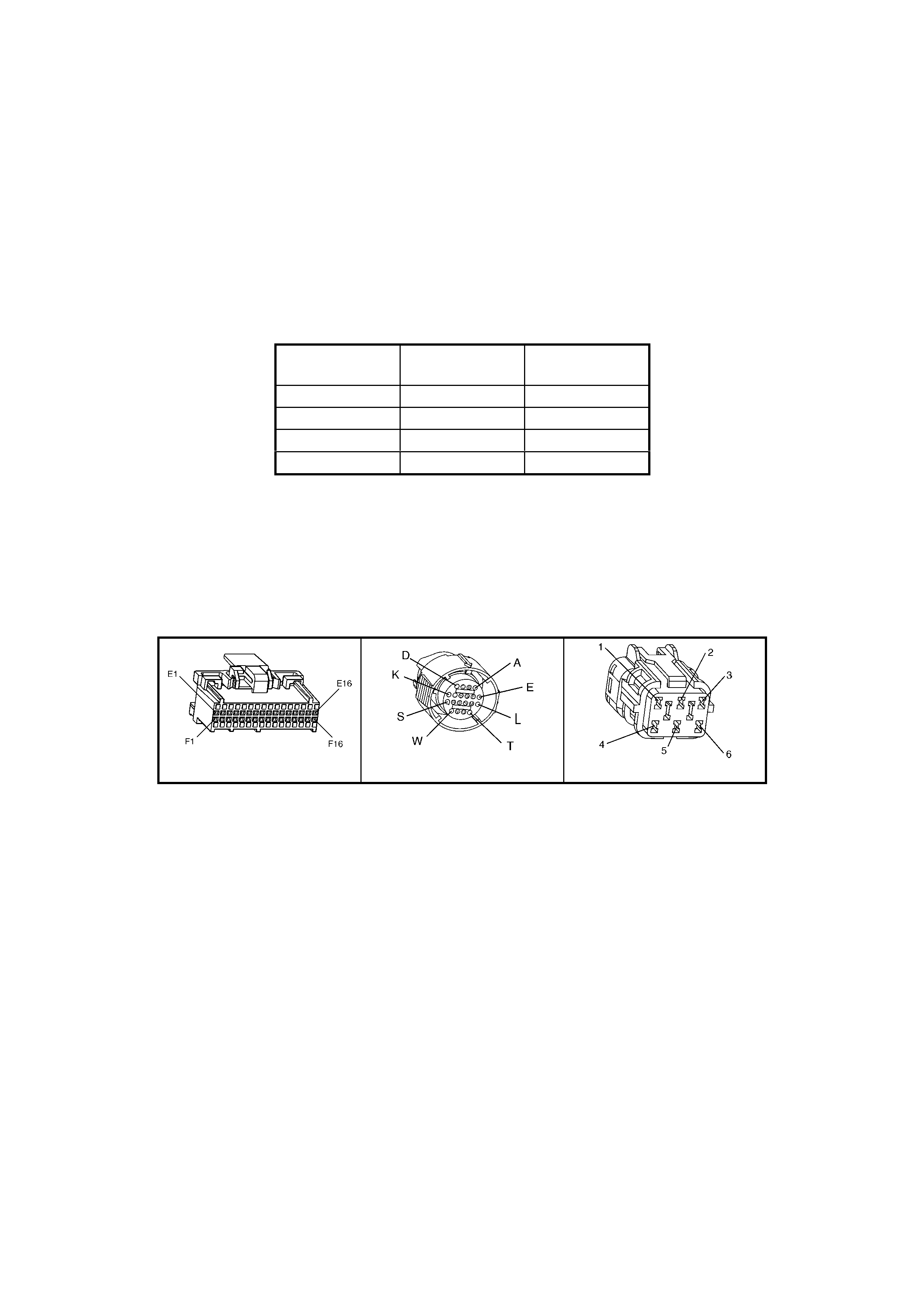
DIAGNOSTIC AIDS
• Inspect the wiring for poor electrical conn ections at th e PCM. Inspect the wiring for poor el ectrical connec tions
at the transmission pass-through connector. Look for the following conditions:
A bent terminal
A backed out terminal
A damaged terminal
Poor terminal tension
A chafed wire
A broken wire inside the insulation
Moisture intrusion
• When diagnosing for an intermittent short or open condition, massage the wiring harness while watching the
test equipment for a change.
• Refer to the following Table for the correct On and Off states of the shift solenoids.
GEAR 1-2-SHIFT
SOLENOID A 2-3 SHIFT
SOLENOID B
1 ON ON
2 OFF ON
3 OFF OFF
4 ON OFF
TEST DESCRIPTION
Number(s) below refer to step number(s) on the diagnostic Table.
4. This step tests the function of the 1-2 SS valve and the automatic transmission wiring harness assembly.
5. This step tests for power to the 1-2 SS valve from the ignition through the fuse.
7. This step tests the ability of the PCM and the wiring to control the ground circuit.
10. This step measures the resistance of the A/T wiring harness assembly and the 1-2 SS valve.
A84 V6 – X2 X121 – X2 X101
Figure 6C1-2A-161

DTC P0756 V6 PCM - 1-2 SHIFT SOLENOID A CIRCUIT VOLTAGE LOW
Step Action Value(s) Yes No
1. Was the Powertrain On-Board Diagnostic (OBD) System
Check performed? Go to Step 2 Go to
OBD System
Check
2. 1. Install the TECH 2.
2. Ignition ON engine OFF.
IMPORTANT: Before clearing the DTCs, use TECH 2 in
order to record the DTC history for reference. The Clear
History DTC function will erase the data.
3. Record the DTC history.
Are any of the following DTCs also set?
P0740
P0730
P0753
P0757
P0785
P1860
Go to Step 3 Go to Step 4
3. 1. Inspect fuse F32.
2. If the fuse is open, inspect the following components
for a short to ground condition:
• Circuit 339.
• The solenoids.
• The A/T wiring harness assembly.
3. Repair the circuit, the solenoids, and the harness if
necessary.
Did you find a short to ground condition?
Go to Step 16 Go to Step 5
4. 1. Using the TECH 2 1-2 Shift Solenoid A
Miscellaneous Test, command the 1-2 SS valve ON
and OFF three times while listening to the bottom of
the transmission pan (a stethoscope may be
necessary).
Did the solenoid click when commanded?
Go to
“Diagnostic Aids” Go to Step 5
5. 1. Turn the ignition OFF.
2. Disconnect the transmission pass-through connector
(additional DTCs may set).
3. Install the J 39775 jumper harness on the engine
side of the pass-through connector.
4. Ignition ON engine OFF.
5. Connect a test lamp from J 39775 jumper harness
cavity E to ground.
Is the test la mp ON?
Go to Step 7 Go to Step 6
6. Repair the open or short to ground in ignition feed circuit
339 to the 1-2 SS valve.
Is the repair complete?
Go to Step 16
7. 1. Install a test lamp from J 39775 jumper harness
cavity E to cavity A.
2. Using the TECH 2 1-2 Shift Solenoid A
Miscellaneous Test, command the 1-2 SS valve ON
and OFF three times.
Is the test lamp ON when the 1-2 SS valve is
commanded ON, and OFF when commanded OFF?
Go to Step 10 Go to Step 8
8. 1. Inspect circuit 1222 of the powertrain wiring harness
for an open or short to ground condition.
2. Repair the circuit if nece ssary .
Did you find an open or short to ground condition?
Go to Step 16 Go to Step 9
9. Replace PCM.
Refer 6C1-3 Service Operations, for PCM Programming
and Security Link procedure.
Is action complete?
Go to Step16

Step Action Value(s) Yes No
10. 1. Install the J 39775 jumper harness on the
transmissi on sid e of the pass-through connector.
2. With a Digital Multimeter (DMM) and the J 35616-A
Connector Test Adapter Kit, measure the resistance
between terminals A and E.
Is the resistance within the range indicated?
19-31 Ω Go to Step 12 Go to Step 11
11. 1. Disconnect the A/T wiring harness assembly from the
1-2 SS valve.
2. Measure the resistance of the 1-2 SS valve.
Is the resistance within the range indicated?
19-31 Ω Go to Step 14 Go to Step 15
12. 1. Using a DMM, measure the resistance between
terminal A and ground, and between terminal E and
ground.
Are both readings greater than the specified value?
250 K Ω Go to Diagnostic
Aids Go to Step 13
13. 1. Disconnect the A/T wiring harness assembly from the
1-2 SS valve.
2. Using a DMM, measure the resistance from the
component's terminals to ground.
Are both readings greater than the specified value?
250 K Ω Go to Step 14 Go to Step 15
14. Replace the automatic transmission wiring harness
assembly.
Refer 7C4 A/T On-Vehicle Servicing.
Is the replacement complete?
Go to Step 16
15. Replace the 1-2 SS valve.
Refer 7C4 A/T On-Vehicle Servicing.
Is the replacement complete?
Go to Step 16
16. Perform the following procedure in order to verify the
repair:
Drive the vehicle in D and ensure the following conditions
are met:
• The PCM commands the 1-2 SS valve ON and the
voltage input drops to zero.
• The PCM commands the 1-2 SS valve OFF and the
voltage input increases to B+.
• All conditions are met for 5 seconds.
Were the above conditions verified?
System OK Go to Step 1

DTC P0757 V6 PCM - 2-3 SHIFT SOLENOID B CIRCUIT VOLTAGE LOW
Figure 6C1-2A-162 – Transmission Solenoid Circuits
CIRCUIT DESCRIPTION
The 2- 3 Shif t Sole no id V al v e (2- 3 SS Va l ve) c ontr o ls the f luid f lo w actin g on the 2-3 shif t val ve. T he 2- 3 SS V al ve is
a norm ally-open ex haust valve that is us ed with th e 1-2 Sh ift Sole noid Va lve in order to allow f our dif ferent shif ting
combinat ions. The solenoid attaches to the control valve body within the transm ission. The 2-3 SS Valve receives
voltage through circuit 339. The PCM controls the solenoid by providing the ground path on circuit 1223.
W hen the PCM detec ts a conti nuous op en or shor t to groun d in the 2-3 SS Valve cir cuit or th e 2-3 SS Valve , DTC
P0757 sets.
CONDITIONS FOR RUNNING THE DTC
• The engine is running.
CONDITIONS FOR SETTING THE DTC
• The PCM commands the solenoid OFF and the voltage input remains low (0 volts)
ACTION TAKEN WHEN THE DTC SETS
• The PCM activates the Check Powertrain MIL when the diagnostic runs and fails.
• The PCM records the operating conditions at the time the diagnostic fails. The PCM stores this information in
the History Data.
• When this DTC sets, the PCM will command D2 line pressure, inhibit a 3-2 downshift if the vehicle speed is
greater than 48 km/h and will freeze shift adapts from being updated.
CONDITIONS FOR CLEARING THE MIL/DTC
• The PCM turns the Check Powertrain MIL OFF after the first ignition cycle that the diagnostic runs and does
not fail.
• Use TECH 2 in order to clear the MIL/DTC.
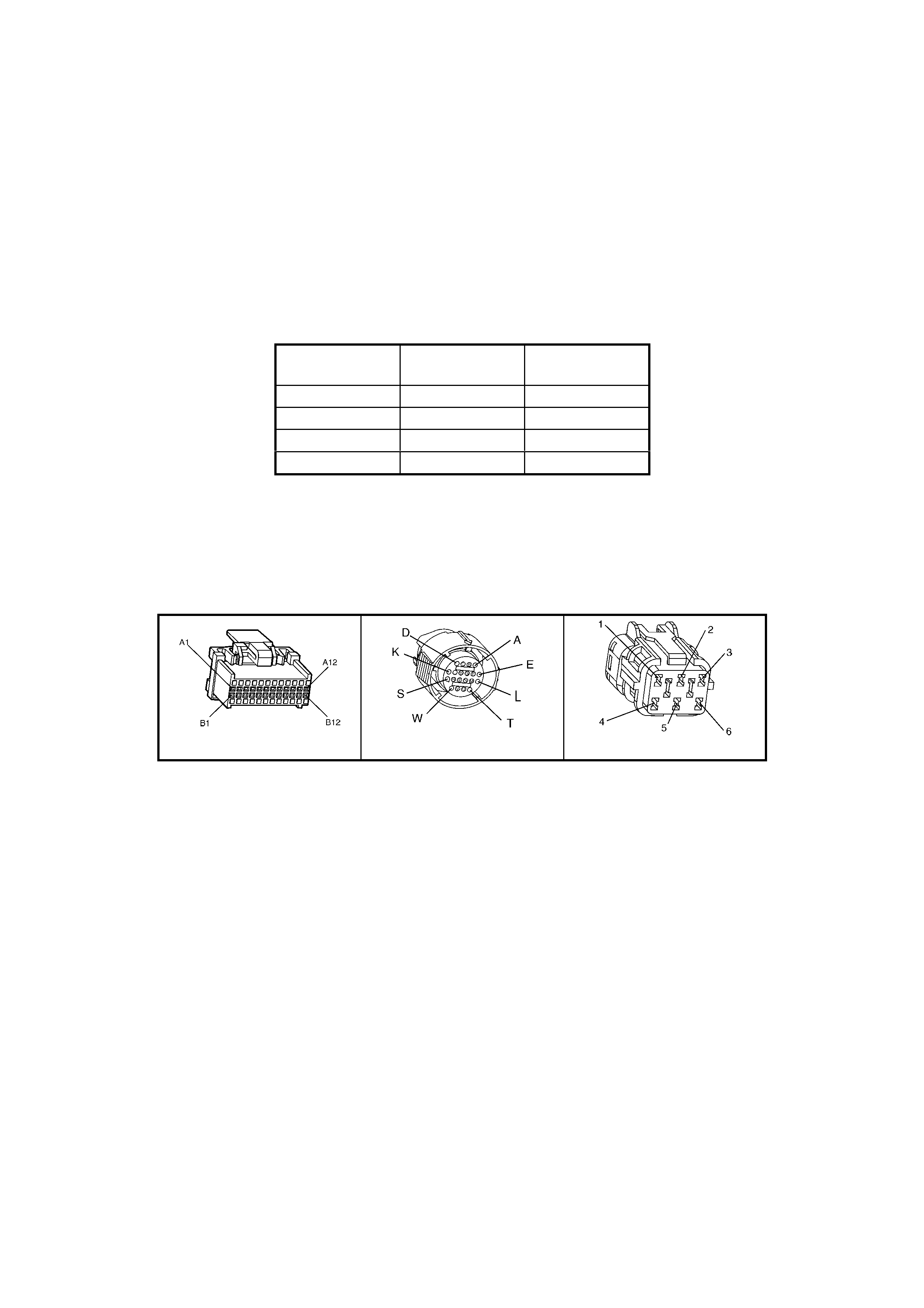
DIAGNOSTIC AIDS
• Inspect the wiring for poor electrical conn ections at th e PCM. Inspect the wiring for poor el ectrical connec tions
at the transmission pass-through connector. Look for the following conditions:
A bent terminal
A backed out terminal
A damaged terminal
Poor terminal tension
A chafed wire
A broken wire inside the insulation
Moisture intrusion
• When diagnosing for an intermittent short or open condition, massage the wiring harness while watching the
test equipment for a change.
• Refer to the following Table for the correct On and Off states of the shift solenoids.
GEAR 1-2-SHIFT
SOLENOID A 2-3 SHIFT
SOLENOID B
1 ON ON
2 OFF ON
3 OFF OFF
4 ON OFF
TEST DESCRIPTION
Number(s) below refer to step number(s) on the diagnostic Table.
4. This step tests the function of the 2-3 SS valve and the automatic transmission wiring harness assembly.
5. This step tests for power to the 2-3 SS valve from the ignition through the fuse.
7. This step tests the ability of the PCM and the wiring to control the ground circuit.
10. This step measures the resistance of the A/T wiring harness assembly and the 2-3 SS valve.
A84 V6 – X1 X121 – X2 X101
Figure 6C1-2A-163

DTC P0757 V6 PCM - 2-3 SHIFT SOLENOID B CIRCUIT VOLTAGE LOW
STEP ACTION VALUE(S) YES NO
1. Was the Powertrain On-Board Diagnostic (OBD) System
Check performed? Go to Step 2 Go to
OBD System
Check
2. 1. Install the TECH 2.
2. Ignition ON engine OFF.
IMPORTANT: Before clearing the DTCs, use TECH 2 in
order to record the DTC history for reference. The Clear
History DTC function will erase the data.
3. Record the DTC history.
Are any of the following DTCs also set?
P0730
P0740
P0753
P0756
P0785
P1860
Go to Step 3 Go to Step 4
3. 1. Inspect fuse F32.
2. If the fuse is open, inspect the following components
for a short to ground condition:
• Circuit 339.
• The solenoids.
• The A/T wiring harness assembly.
3. Repair the circuit, the solenoids, and the harness if
necessary.
Did you find a short to ground condition?
Go to Step 16 Go to Step 5
4. 1. Using the TECH 2, 2-3 Shift Solenoid B
Miscellaneous Test, command the 2-3 SS valve ON
and OFF three times while listening to the bottom of
the transmission pan (a stethoscope may be
necessary).
Did the solenoid click when commanded?
Go to
“Diagnostic Aids” Go to Step 5
5. 1. Turn the ignition OFF.
2. Disconnect the transmission pass-through connector
(additional DTCs may set).
3. Install the J 39775 jumper harness on the engine
side of the pass-through connector.
4. With the engine OFF, turn the ignition switch to the
RUN position.
5. Connect a test lamp from J 39775 jumper harness
cavity E to ground.
Is the test la mp ON?
Go to Step 7 Go to Step 6
6. Repair the open or short to ground in ignition feed circuit
339 to the 2-3 SS valve.
Is the repair complete?
Go to Step 16
7. 1. Install a test lamp from J 39775 jumper harness
cavity E to cavity B.
2. Using the TECH 2, 2-3 Shift Solenoid B
Miscellaneous Test, command the 2-3 SS valve ON
and OFF three times.
Is the test lamp ON when the 2-3 SS valve is
commanded ON, and OFF when commanded OFF?
Go to Step 10 Go to Step 8
8. 1. Inspect circuit 1223 of the powertrain wiring harness
for an open or short to ground condition.
2. Repair the circuit if nece ssary .
Did you find an open or short to ground condition?
Go to Step 16 Go to Step 9
9. Replace PCM.
Refer 6C1-3 Service Operations, for PCM Programming
and Security Link procedure.
Is action complete?
Go to Step16

STEP ACTION VALUE(S) YES NO
10. 1. Install the J 39775 jumper harness on the
transmissi on sid e of the pass-through connector.
2. With a Digital Multimeter (DMM) and the J 35616-A
Connector Test Adapter Kit, measure the resistance
between terminals B and E.
Is the resistance within the range indicated?
19-31 Ω Go to Step 12 Go to Step 11
11. 1. Disconnect the A/T wiring harness assembly from the
2-3 SS valve.
2. Measure the resistance of the 2-3 SS valve.
Is the resistance within the range indicated?
19-31 Ω Go to Step 14 Go to Step 15
12. Using a DMM, measure the resistance between terminal
B and ground, and between terminal E and ground.
Are both readings greater than the specified value?
250 K Ω Go to
“Diagnostic Aids” Go to Step 13
13. 1. Disconnect the A/T wiring harness assembly from the
2-3 SS valve.
2. Using a DMM, measure the resistance from the
component's terminals to ground.
Are both readings greater than the specified value?
250 K Ω Go to Step 14 Go to Step 15
14. Replace the automatic transmission wiring harness
assembly.
Refer 7C4 A/T On-Vehicle Servicing.
Is the replacement complete?
Go to Step 16
15. Replace the 2-3 SS valve.
Refer 7C4 A/T On-Vehicle Servicing.
Is the replacement complete?
Go to Step 16
16. Perform the following procedure in order to verify the
repair:
• Drive the vehicle in D and ensure the following
conditions are met:
• The PCM commands the 2-3 SS valve ON and the
voltage input drops to zero.
• The PCM commands the 2-3 SS valve OFF and the
voltage input increases to B+.
• All conditions are met for 5 seconds.
Were the above conditions verified?
System OK Go to Step 1
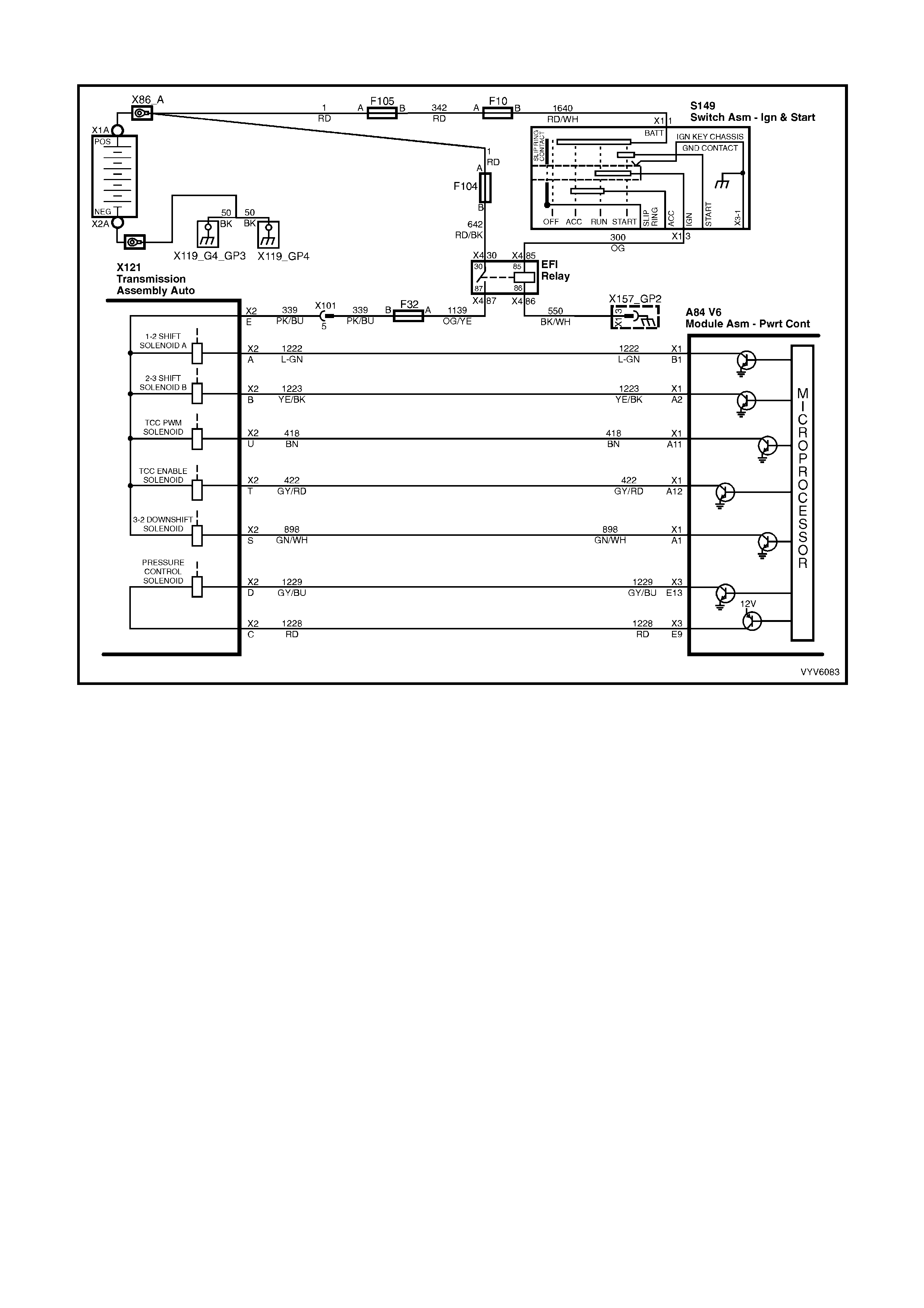
DTC P0785 V6 PCM - 3-2 DOWNS HIFT CONTROL SOLENOID CIRCUIT FAULT
Figure 6C1-2A-164 – Transmission Solenoid Circuits
CIRCUIT DESCRIPTION
The 3-2 Shift Solenoid (SS) valve is a normally-closed, 3-port, on/off device that controls the 3-2 downshift. The
solenoid attaches to the control valve body within the transm ission. The solenoid receives ignition voltage through
circuit 3 39. The Po wertrain Contro l Module ( PCM) contr ols the solen oid by prov iding a grou nd path on c ircuit 898.
During a 3-2 do wnshif t, the 2-4 b and ap plies as t he 3- 4 clutch releas es. T he PC M var ies the tim ing bet ween the 3-
4 clutch release and the 2-4 band apply depending on the vehicle speed and the throttle position.
When the PCM detects a continuous open or short to ground in the 3-2 SS valve assembly circuit or the 3-2 SS
valve assembly, DTC P0785 sets.
CONDITIONS FOR RUNNING THE DTC
• The engine is running.
CONDITIONS FOR SETTING THE DTC
DTC P0785 sets if either of the following conditions occur for 5 seconds:
• The PCM commands the solenoid ON and the voltage input remains high (B+).
or
• The PCM commands the solenoid OFF and the voltage input remains low (0 volts).
ACTION TAKEN WHEN THE DTC SETS
• The PCM activates the Check Powertrain MIL when the diagnostic runs and fails.
• The PCM records the operating conditions at the time the diagnostic fails. The PCM stores this information in
the History Data.
• When this DTC sets, the PCM will command maximum line pressure, and inhibit TCC engagement.
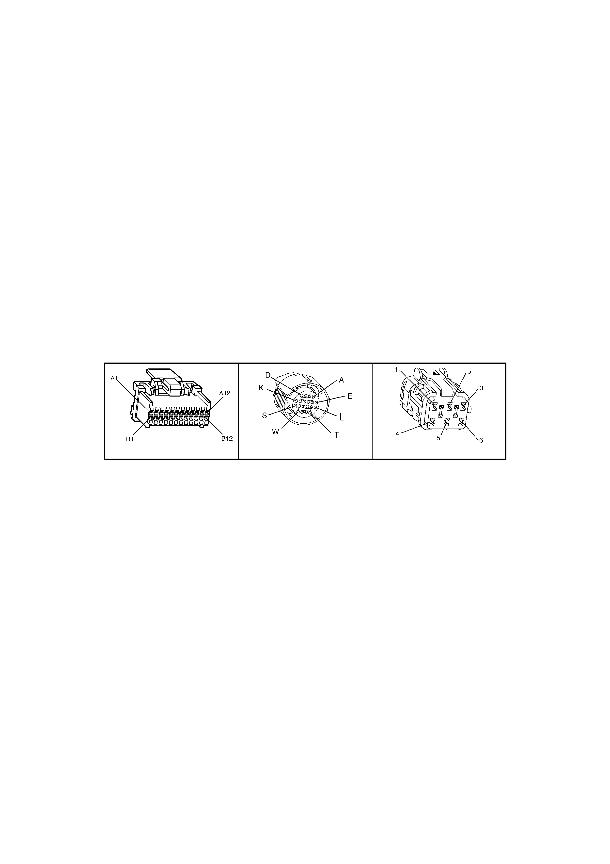
CONDITIONS FOR CLEARING THE MIL/DTC
• The PCM turns the Check Powertrain MIL OFF after the first ignition cycle that the diagnostic runs and does
not fail.
• Use TECH 2 in order to clear the MIL/DTC.
DIAGNOSTIC AIDS
• Inspect the wiring at the PCM, the transmission connector and all other circuit connecting points for the
following conditions:
A backed out terminal
A damaged terminal
Reduced terminal tension
A chafed wire
A broken wire inside the insulation
Moisture intrusion
Corrosion
• When diagnosing for an intermittent short or open condition, massage the wiring harness while watching the
test equipment for a change.
TEST DESCRIPTION
Number(s) below refer to step number(s) on the diagnostic Table.
4. This step tests the ability of the PCM to control the solenoid.
5. This step tests for power to the 3-2 SS valve assembly.
7. This step tests the ability of the PCM and the wiring to control the ground circuit.
10. This step measures the resistance of the A/T wiring harness assembly and the 3-2 SS valve assembly.
A84 V6 – X1 X121 – X2 X101
Figure 6C1-2A-165

DTC P0785 V6 PCM - 3-2 DOWNSHIFT CONTROL SOLENOID CIRCUIT FAULT
STEP ACTION VALUE(S) YES NO
1. Was the Powertrain On-Board Diagnostic (OBD) System
Check performed? Go to Step 2 Go to
OBD System
Check
2. 1. Install the TECH 2.
2. Ignition ON engine OFF.
IMPORTANT: Before clearing the DTCs, use TECH 2 in
order to record the DTC history for reference. The Clear
History DTC function will erase the data.
3. Record the DTC history.
Are any of the following DTCs also set?
P0740
P0753
P0756
P1860
Go to Step 3 Go to Step 4
3. 1. Inspect fuse F32.
2. If the fuse is open, inspect the following components
for a short to ground condition:
• Circuit 339.
• The solenoids.
• The A/T wiring harness assembly.
3. Repair the circuit, the solenoids, and the harness if
necessary.
Did you find a short to ground condition?
Go to Step 16 Go to Step 5
4. 1. Using the TECH 2, 3-2 Downshift Solenoid
Miscellaneous Test, command the 2-3 SS valve ON
and OFF three times while listening to the bottom of
the transmission pan (a stethoscope may be
necessary).
Did the solenoid click when commanded?
Go to
“Diagnostic Aids” Go to Step 5
5. 1. Turn the ignition OFF.
2. Disconnect the transmission pass-through connector
(additional DTCs may set).
3. Install the J 39775 jumper harness on the engine
side of the pass-through connector.
4. Ignition ON engine OFF.
5. Connect a test lamp from J 39775 jumper harness
cavity E to ground.
Is the test la mp ON?
Go to Step 7 Go to Step 6
6. Repair the open or short to ground in ignition feed circuit
339 to the 3-2 SS valve assembly.
Is the repair complete?
Go to Step 16
7. 1. Install a test lamp from J 39775 jumper harness
cavity E to cavity S.
2. Using the TECH 2, 3-2 Downshift Solenoid
Miscellaneous Test, command the 2-3 SS valve ON
and OFF three times.
Is the test lamp ON when the solenoid is commanded ON
and OFF, when the solenoid is commanded OFF?
Go to Step 10 Go to Step 8
8. 1. Inspect circuit 898 of the powertrain wiring harness
for an open, short to ground or short to power
condition.
2. Repair the circuit if nece ssary .
Did you find an open, short to ground or short to power
condition?
Go to Step 16 Go to Step 9
9. Replace PCM.
Refer 6C1-3 Service Operations, for PCM Programming
and Security Link procedure.
Is action complete?
Go to Step16

STEP ACTION VALUE(S) YES NO
10. 1. Install the J 39775 jumper harness on the
transmissi on sid e of the pass-through connector.
2. With a DMM and the J 35616-A Connector Test
Adapter Kit, measure the resistance between
terminals S and E.
Is the resistance within the range indicated?
20-32 Ω Go to Step 12 Go to Step 11
11. 1. Disconnect the A/T wiring harness assembly from the
3-2 SS valve assembly.
2. Measure the resistance of the 3-2 SS valve
assembly.
Is the resistance within the range indicated?
20-32 Ω Go to Step 14 Go to Step 15
12. 1. Measure the resistance between terminal S and
ground, and between terminal E and ground.
Are both readings greater than the specified value?
250 K Ω Go to “Diagnostic
Aids” Go to Step 13
13. 1. Disconnect the A/T wiring harness assembly from the
3-2 SS valve assembly.
2. Measure the resistance from the component’s
terminals to ground.
Are both measurements greater than the specified value?
250 K Ω Go to Step 14 Go to Step 15
14. Replace the automatic transmission wiring harness
assembly.
Refer 7C4 A/T On-Vehicle Servicing.
Is the replacement complete?
Go to Step 16
15. Replace the 3-2 SS valve.
Refer 7C4 A/T On-Vehicle Servicing.
Is the replacement complete?
Go to Step 16
16. Perform the following procedure in order to verify the
repair:
• Drive the vehicle in 3 or D and perform a 3-2
downshift. Ensure the following conditions are met:
• The PCM commands the 3-2 SS valve ON and the
voltage input drops to zero.
• The PCM commands the 3-2 SS valve OFF and the
voltage input increases to B+.
• All conditions are met for 5 seconds.
Were the above conditions verified?
System OK Go to Step 1

DTC P1064 V6 PCM - LOW SPEED FAN – NO BCM RESPONSE
Figure 6C1-2A-166 – V6 Standard Fan Package Circuit
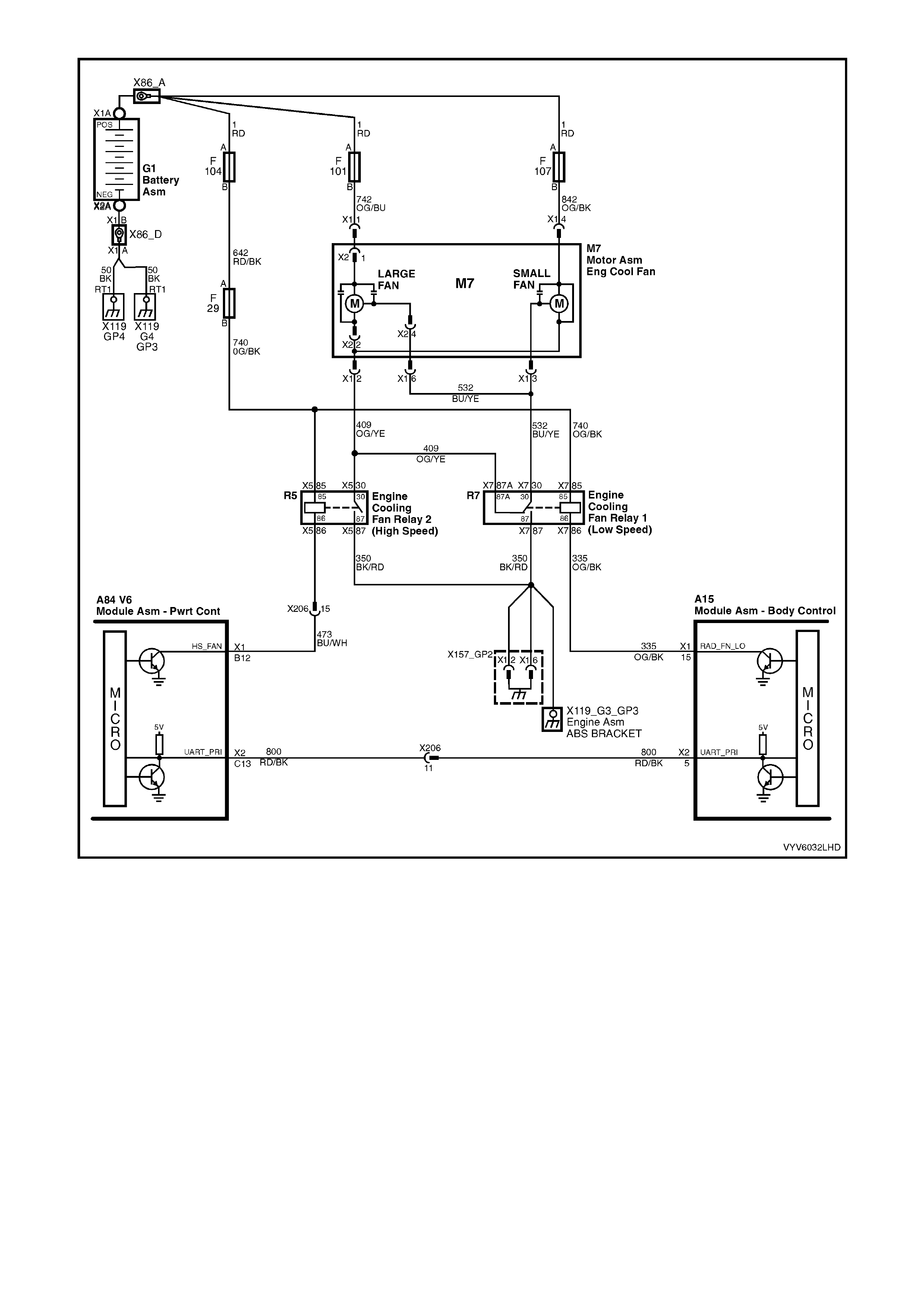
Figure 6C1-2A-167 – V6 High Power Fan Package Circuit
CIRCUIT DESCRIPTION
The PCM determines operation of the two engine cooling fans based on A/C request signal input, engine coolant
temperature and vehicle speed.
The large low sp eed engi ne coo ling fan r elay 1 (R 7) is ener gised b y the BC M. W hen the PC M determ ines that th e
large low speed engine cooling fan relay 1 (R7) should be turned "ON", the PCM will send a message on circuit
800 to the BCM. This message will ask the BCM to ground circuit 335 and energise the engine cooling fan low
speed relay. After the BCM provides the ground for circuit 335, the BCM will send a message back to the PCM
saying that the ground circuit was commanded.
CONDITIONS FOR RUNNING THE DTC
• En gine is idling.
• PCM supplies a signal to the BCM.
CONDITIONS FOR SETTING THE DTC
• This DTC will set if the PCM sends a request to the BCM to turn on the large low speed engine cooling fan
relay 1 (R7) via the serial data normal mode message and the BCM does not send a message back to the
PCM.

ACTION TAKEN WHEN THE DTC SETS
• The Check Powertrain MIL will not be activated.
• The PCM records the operating conditions at the time the diagnostic fails. The PCM stores this information in
the History Data.
CONDITIONS FOR CLEARING THE MIL/DTC
• Use Tech 2 in order to clear the MIL/DTC.
DIAGNOSTIC AIDS
If this DTC is set, it generally indicates that there has been a momentary loss of serial data comm unication. If this
DTC is current, TECH 2 will not be able to communicate with the PCM.
• Dirty, Damaged, or Loose Connections or Damaged Harness - Check for any damage to the harness which
could cause an intermittent open or short to ground or backed out terminals at the PCM connectors, broken
locks, improperly formed or damaged terminals.
TEST DESCRIPTION
Number(s) below refer to step number(s) on the diagnostic Table.
2. If the engine cranks for one second and then disables cranking it means that the PCM did not see an “OK to
Start” message from the BCM when the ignition was turned "ON".
3. An open or short to ground on circuit 800 will disable any communication of serial data.
DTC P1064 V6 PCM - LOW SPEED FAN – NO BCM RESPONSE
STEP ACTION VALUE YES NO
1. Was the "On-Board Diagnostic" (OBD) System Check
performed? Go to Step 2 Go to
OBD System
Check
2. Is DTC P1255 set? Go to
DTC P1255
Diagnostic Table
Go to Step 3
3. 1. Engine at idle speed.
2. Using Tech 2, select "LOW FAN".
Does Tech 2 "BCM Response" display change from "FAN
OFF" to "FAN ON" when test is enabled?
Go to Step 4
Go to
Table A-12.1
4. Does Tech 2 "BCM Response" display
change from "FAN OFF" to "FAN ON" when test is
enabled?
DTC P1064 is
intermittent.
Refer to
"Diagnostic
Aids".
Refer to
12J-1 BCM
for additional
diagnosis.
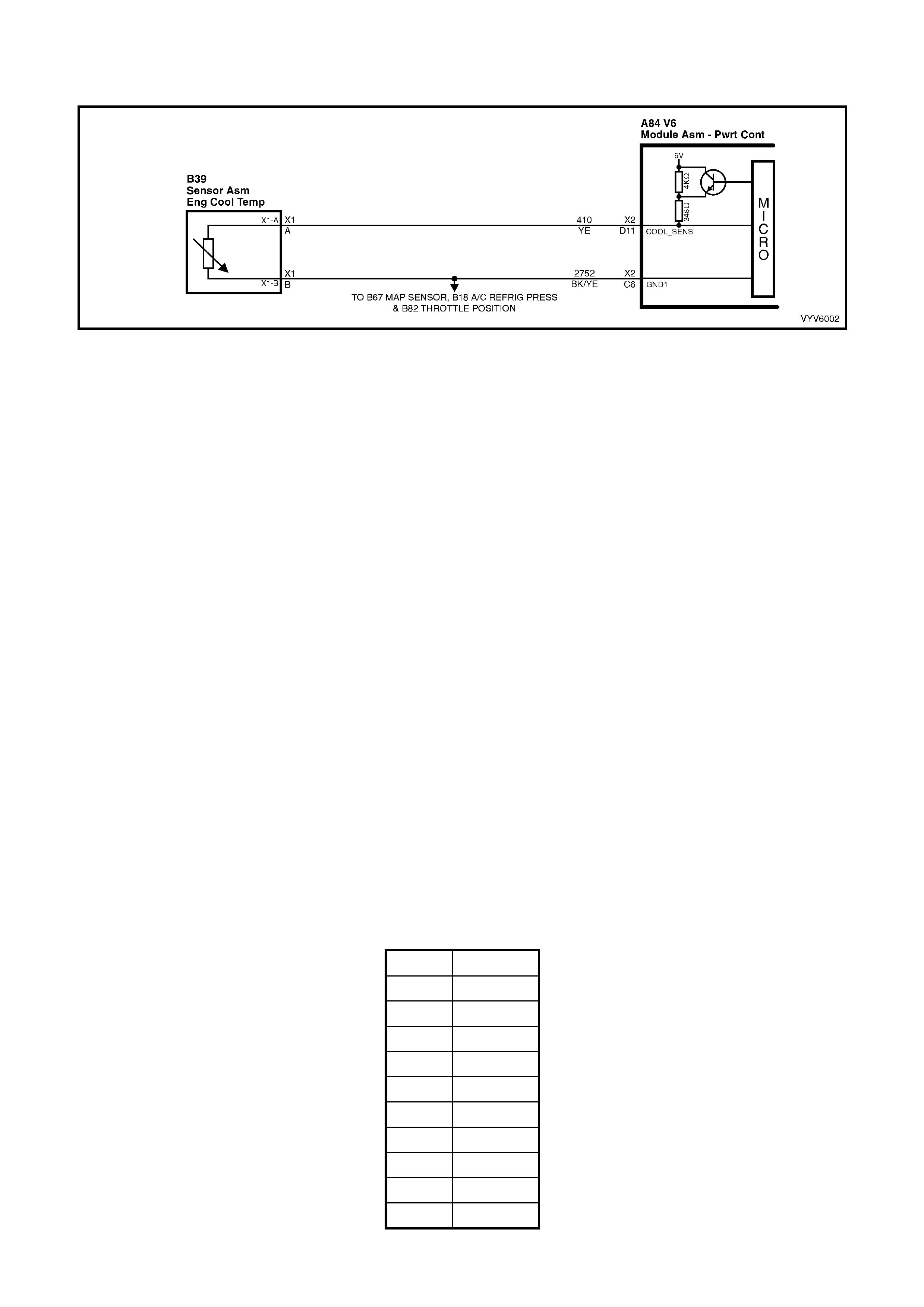
DTC P1116 V6 PCM -
ENGINE COOLANT TEMPERATURE (ECT) SIGNAL VOLTAGE UNST ABLE
Figure 6C1-2A-168 – Engine Coolant Temperature Circuit
CIRCUIT DESCRIPTION
The Engine Coolant T emperature (ECT) sensor is a thermistor located in a coolant passage on the engine . W hen
engine coolant temperature is cold, the sensor has a high resistance. As temperature increases, the resist ance of
the sensor d ec r eases . The PCM pr ov ides a f i ve vol t s i gna l to th e en gi ne coolant s ensor , whic h is als o c onnected to
PCM ground. The PCM reads the voltage drop on the signal line to determine engine coolant temperature.
CONDITIONS FOR RUNNING THE DTC
• Time since engine started is greater than 10 seconds.
• DTC P0117, P0118 or P1628 are not set.
CONDITIONS FOR SETTING THE DTC
• ECT reading changes more than 400 mV in 200 milliseconds.
ACTION TAKEN WHEN THE DTC SETS
• The Check Powertrain MIL will not be activated.
• The PCM records the operating conditions at the time the diagnostic fails. The PCM stores this information in
the History Data.
• The PCM will substitute a coolant temperature default value based on intake air temperature and engine run
time.
• When DTC P1116 is set, the PCM will turn "ON" the engine cooling fans.
CONDITIONS FOR CLEARING THE MIL/DTC
• Use TECH 2 in order to clear the MIL/DTC.
DIAGNOSTIC AIDS
W hen attempting to d iagnos e an interm ittent prob lem, us e the snapsh ot mode of the T ECH 2, to rev iew diag nostic
information.
This DTC is more likely to set on a cold engine than on a hot engine because of the pull up resistors in the PCM.
When checking the PCM terminals for correct terminal tension use the shank of a 0.95mm drill bit. When the drill bit
is inserted into the female PCM terminals it should have slight drag indicating the terminals are correctly sized.
ECT SENSOR TABLE TEMPERATURE TO RESISTANCE VALUES (APPROXIMATE)
C OHMS
110 134
100 180
90 244
70 474
40 1,483
30 2,268
20 3,555
0 9,517
-10 16,320
-20 28,939
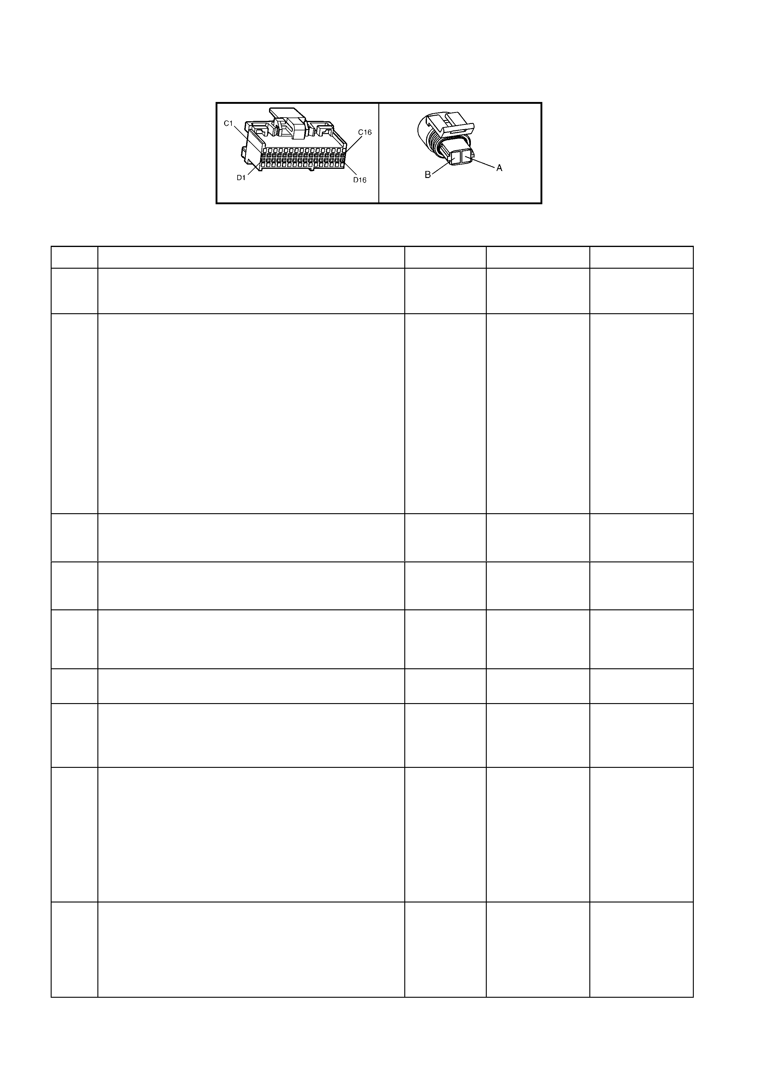
TEST DESCRIPTION
Number(s) below refer to step number(s) on the diagnostic Table.
2. This step checks the wiring of the sensor for an intermittent fault.
A84 V6 – X2 B39
Figure 6C1-2A-169
DTC P1116 V6 PCM - ENGINE COOLANT TEMPERATURE (ECT) SIGNAL VOLTAGE UNSTABLE
STEP ACTION VALUE YES NO
1. Was the "On-Board Diagnostic" (OBD) System Check
performed? Go to Step 2 Go to
OBD System
Check
2. 1. Install the TECH 2.
2. Ignition ON engine OFF.
IMPORTANT: Before clearing the DTCs, use TECH 2 in
order to record the DTC history for reference. The Clear
History DTC function will erase the data.
3. Record the DTC history.
4. Clear DTC History.
5. Set up TECH 2 in snapshot mode to trigger on DTC
P1116.
2. Watch the TECH 2 while wiggling the ECT sensor
connector.
Does the "Engine Coolant Temperature" reading change
sharply?
Go to Step 8 Go to Step 3
3. Wiggle and tug the ECT sensor harness.
Does the " Engine Coolant Temperature " reading change
sharply?
Go to Step 9 Go to Step 4
4. Wiggle and tug the harness at the PCM.
Does the "Engine Coolant Temperature" reading change
sharply?
Go to Step 10 Go to Step 5
5. Lightly tap on the PCM.
Does the "Engine Coolant Temperature" reading change
sharply?
Go to Step 6 DTC P1116 is
intermittent.
Refer "Diagnostic
Aids"
6. Make sure PCM is mounted securely to vehicle.
Was a problem found? Verify Repair Go to Step 7
7. Replace PCM.
Refer 6C1-3 Service Operations, for PCM Programming
and Security Link procedure.
Is action complete?
Verify Repair
8. 1. Check ECT sensor connector.
2. Check the tightness of the female terminal grip with a
suitable sized test terminal.
3. Inspect connectors for corrosion. If connectors are
corroded, try cleaning with electronic part cleaner
and retest.
4. If these repairs do not resolve the problem, replace
terminals.
Is action complete?
Verify Repairs
9. 1. Check for an open in the ECT harness.
2. Check for broken strands of wire in ECT sensor
harness.
3. Check for cuts or pinches in ECT sensor harness.
4. Make repairs as necessary.
Is action complete?
Verify Repairs

STEP ACTION VALUE YES NO
10. 1. Check the ECT sensor connection at the PCM.
2. Check the tightness of the female terminal grip with a
suitable sized (0.95mm) test terminal.
3. Inspect connec tors for corrosi on.
If connectors are corroded, try cleaning with
electronic parts cleaner and retest.
4. Remove connector strain relief and remove terminal
from connector to check for broken locking tang.
Is action complete?
Verify Repairs

DTC P1255 V6 PCM - THEFT DETERRENT SIGNAL MISSING
Figure 6C1-2A-170 – Theft Deterrent Starter Circuit
CIRCUIT DESCRIPTION
W hen the igniti on is turn ed "O N", t he BC M will s en d a thef t deter r ent mess age on cir cuit 800 to the PCM. When the
PCM receives this message, it instantly sends a message back to the BCM. The message says that the proper
ignition k ey h as been used to turn the ig nition on and that it is OK for the PCM to enable the fuel injectors to start
the engine. If the PCM does not receive communications from the BCM when the ignition is switched "ON", then
the starter motor will be disabled after one second and the fuel injectors with be turned off.
CONDITIONS FOR RUNNING THE DTC
• The ignition is ON.
CONDITIONS FOR SETTING THE DTC
• The PCM does not receive serial data for greater than ten seconds.
ACTION TAKEN WHEN THE DTC SETS
• The PCM activates the Check Powertrain MIL when the diagnostic runs and fails.
• The PCM records the operating conditions at the time the diagnostic fails. The PCM stores this information in
the History Data.
• When DTC P1255 is set and current, the engine will not start.

CONDITIONS FOR CLEARING THE CHECK POWERTRAIN MIL/DTC
• Use Tech 2 in order to clear the Check Powertrain MIL/DTC.
DIAGNOSTIC AIDS
If the engine starts and runs without a crank delay DTC P1255 is intermittent.
TEST DESCRIPTION
NOTE: The number(s) below refer to the step number(s) on the diagnostic table.
2. If the Theft Deter rent LED is flashing, the BC M has not seen a val id ke y s ignal and will be is suing a “No Star t”
command to the PCM.
3. If the engine starts and runs, DTC P1255 is intermittent. If the engine cranks with a one second delay then DTC
P1255 is curr ent.
4. An open or short to ground on circuit 800 will disable any communication via serial data.
DTC P1255 V6 PCM – THEFT DETERRENT SIGNAL MISSING
STEP ACTION VALUE YES NO
1. Was the "On-Board Diagnostic" (OBD) System Check
performed? Go to Step 2 Go to
OBD System
Check.
2. 1. Turn the ignition “ON”.
Is the Theft Deterrent LED Flashing? Refer to 12J
Body Control
Module
Go to Step 3
3. 1. Turn the ignition from “OFF“ to “START“.
Does the engine start and continue to run? DTC P1255 is
intermittent, refer
to "Diagnostic
Aids"
Go to Step 4
4. 1. Check for poor connection at PCM terminal and/or
open or shorted circuit 800.
Was a problem found?
Verify Repair Go to Step 5
5. Replace PCM. Refer 6C1-3 Service Operations, for PCM
Programming and Security Link procedure.
Is action complete?
Verify Repair
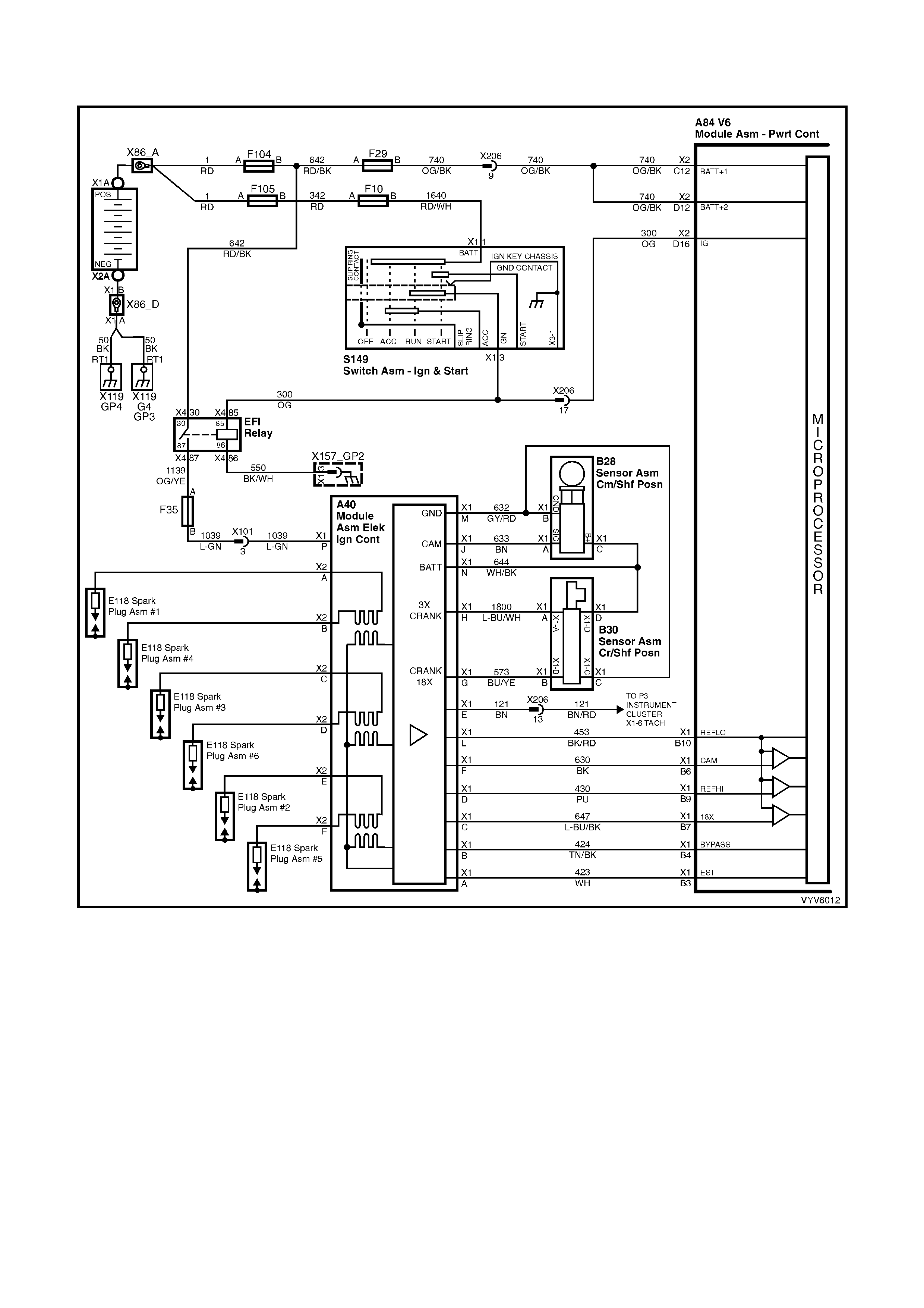
DTC P1351 V6 PCM -
IGNITION ELECTRONIC SPARK TIMING (EST) CIRCUIT FAULT
Figure 6C1-2A-171 – Ignition System Circuit
CIRCUIT DESCRIPTION
There ar e two m odes of ignit ion s ystem operati on: B YPASS m ode, a nd EL ECT RONIC S PARK T IMING m ode. T he
Bypass mode is norm ally used while starting the engine, while the Electronic Spark Timing mode is used to allow
the PCM to control the ignition system after the engine is running. The PCM controls a "Bypass control circuit",
used to control the ignition module between the two different ignition system modes.
The PCM's Electronic Spark Timing (EST) output circuitry generates EST output pulses anytime crankshaft
reference input pulses are received. The PCM also monitors it's EST output terminal, to monitor if and when EST
pulses are present.
When the ignition system is operating in the Bypass mode (such as when the engine is cranking), the ignition
module grounds the EST pulses coming from the PCM. Because the EST pulses should be grounded thro ugh the
ignition module during Bypass mode operation, the PCM should not detect EST pulses on it's EST output terminal.
If the EST outp ut circu it wir e be tween t he PCM an d th e ignitio n m odule has an "open c irc uit" f ault, th en the ignit ion
module can not ground the PCM's EST output pulses. If the PCM detects two EST pulses during the first 3
crankshaft reference input pulses, indicating the EST circuit is open, the PCM will set a DTC P1351.
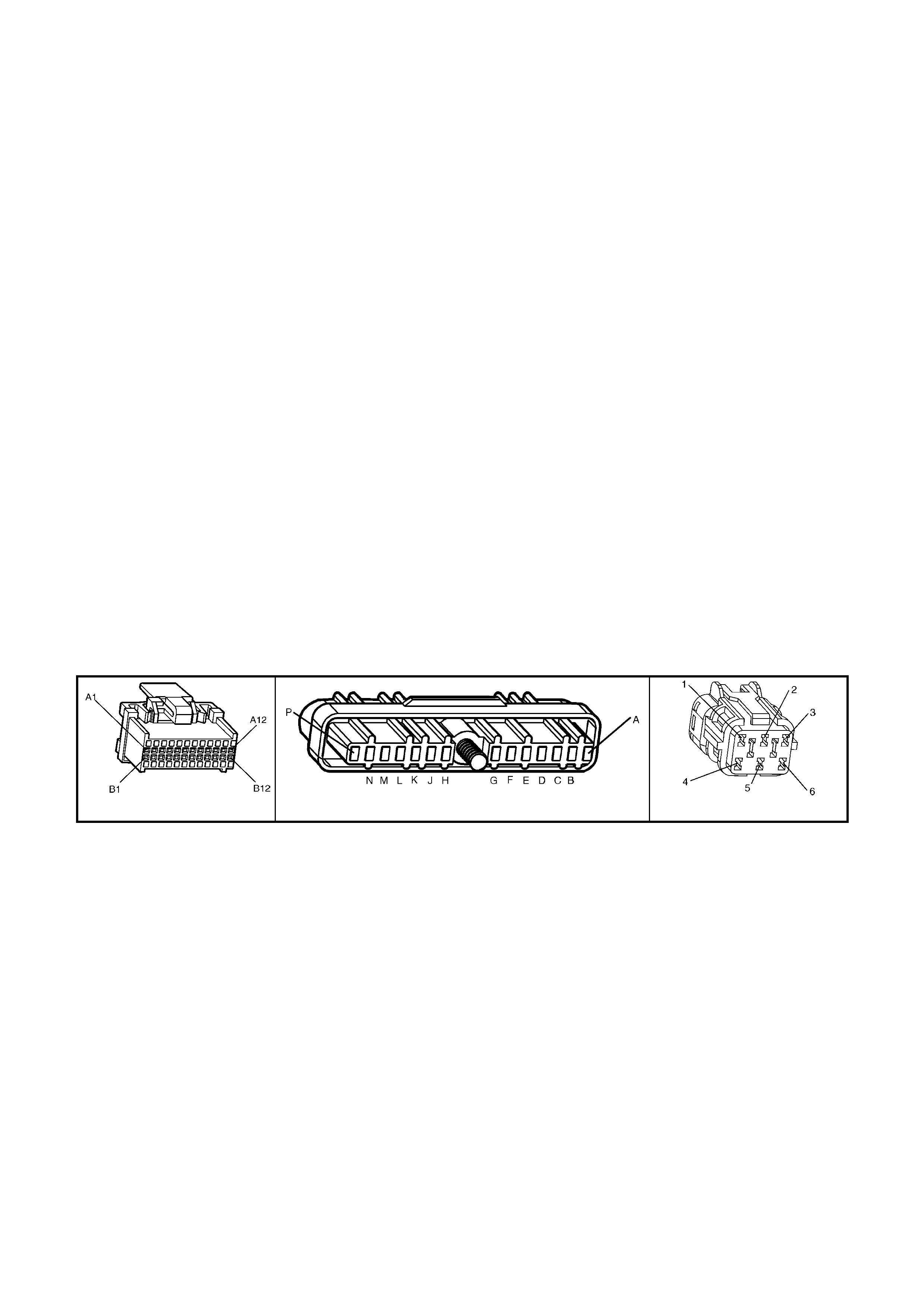
DTC P1351 can also be set if the Bypass control circuit is shorted to voltage. If this were to happen, the PCM's
EST monitor would not sense the EST signal being grounded in the ignition module while cranking , and DTC
P1351 would be set.
CONDITIONS FOR RUNNING THE DTC
• The ignition is ON.
CONDITIONS FOR SETTING THE DTC
• PCM has detected at leas t 2 EST output pu lses, d uring the first 3 c ranks haft referenc e signal pulses received
from the ignition module.
ACTION TAKEN WHEN THE DTC SETS
• The PCM illuminates the Check Powertrain MIL when the diagnostic runs and fails.
• The PCM records the operating conditions at the time the diagnostic fails. The PCM stores this information in
the History Data.
• When DTC P1351 is set and current, the PCM will operate in the Bypass spark mode.
CONDITIONS FOR CLEARING THE MIL/DTC
• The PCM turns the Check Powertrain MIL OFF after the first ignition cycle that the diagnostic runs and does
not fail.
• Use TECH 2 in order to clear the MIL/DTC.
DIAGNOSTIC AIDS
• Poor connection at PCM. Inspect harness conn ectors for backed out term inals, improper mating, broken locks,
improperly formed or damaged terminals, and poor terminal to wire connection.
• Damaged Harness. Inspect the wiring harness for damage. If the harness appears to be OK, disconnect the
ignition module, turn the ignition "ON". Connect and observe a voltmeter connected between the Bypass
control cir cuit and +B, whi le moving conn ectors and wir ing harness related to the ignit ion module. A c hange in
voltage will indicate the location of the fault.
TEST DESCRIPTION
Number(s) below refer to step number(s) on the diagnostic Table.
4. This Step checks to see if circuit 424 is shorted to voltage.
8. This Step checks to see if circuit 423 is open.
A84 V6 – X1 A40 X101
Figure 6C1-2A-172

DTC P1351 V6 PCM - IGNITION ELECTRONIC SPARK TIMING (EST) CIRCUIT FAULT
STEP VALUE YES NO
1. Was the "On-Board Diagnostic" (OBD) System Check
performed? Go to Step 2 Go to
OBD System
Check
2. 1. Clear DTC P1351.
2. Start engine and run above 1600 RPM.
3. Observe DTC(s).
Did DTC P1351 set?
Go to Step 3 DTC P1351 is
intermittent. If no
additional DTC's
were stored, refer
to "Diagnostic
Aids".
3. 1. Ignition "OFF".
2. Disconnect ignition module 14 pin connector A40.
3. Probe ignition module harness connector A40
terminal X1-B with a voltmeter connected to ground.
4. Ignition "ON".
Is voltage greater than the specified value?
0.5 V Go to Step 4 Go to Step 7
4. 1. Ignition "OFF".
2. Disconnect PCM connectors.
3. Ignition "ON".
Is voltage still present at ignition module harness
Connector A40 term inal X1-B?
Go to Step 5 Go to Step 10
5. Repair short to voltage in Bypass circ uit 424.
Is action complete? Verify Repair
6. Replace ignition module.
Refer 6C1-3 Service Operations.
Is action complete?
Verify Repair
7. 1. Ignition "OFF".
2. Reconnect 14 pin connector A40 to ignition module.
3. Backprobe PCM connector X1-B3 with voltmeter
connected to ground.
4. Ignition "ON", crank engine.
Is voltage approximately at specified value while
cranking or with engine running?
2 volts Go to Step 8 Go to Step 9
8. Check for faulty connection, or an open in the EST circuit
423 between the PCM terminal X1-B3 and the ignition
module harness connector A40 terminal X1-A.
Was a fault found?
Verify Repair Go to Step 6
9. Check PCM for faulty connection.
Was a faulty connection found ? Verify Repair Go to Step 10
10. Replace PCM.
Refer 6C1-3 Service Operations, for PCM Programming
and Security Link procedure.
Is action complete?
Verify Repair

DTC P1361 V6 PCM - IGNITION BYPASS CIRCUIT FAULT
Figure 6C1-2A-173 – Ignition System Circuit
CIRCUIT DESCRIPTION
There ar e two m odes of ignit ion s ystem operati on: B YPASS m ode, a nd EL ECT RONIC S PARK T IMING m ode. T he
Bypass mode is norm ally used while starting the engine, while the Electronic Spark Timing mode is used to allow
the PCM to control the ignition system after the engine is running. The PCM controls a "Bypass control circuit",
used to control the ignition module between the two different ignition system modes.
The PCM's Electronic Spark Timing (EST) output circuitry generates EST output pulses anytime crankshaft
reference input pulses are received. The PCM also monitors it's EST output terminal, to monitor if and when EST
pulses are present.
When the ignition system is operating in the Bypass mode (such as when the engine is cranking), the ignition
module grounds the EST pulses coming from the PCM. Because the EST pulses should be grounded thro ugh the
ignition module during Bypass mode operation, the PCM should not detect EST pulses on it's EST output terminal.
When the engine is started, the PCM applies 5 volts to the Bypass control circuit. When received by the ignition
module, this 5 volts c ontrol caus es the ignition m odule to r elease the grou nd from the EST pulses coming fr om the
PCM. The ignition m odule wil l then us e the EST pulses to oper ate the ignition s ystem . When this oc curs, th e PCM
will correctly detect EST pulses at it's EST output terminal.
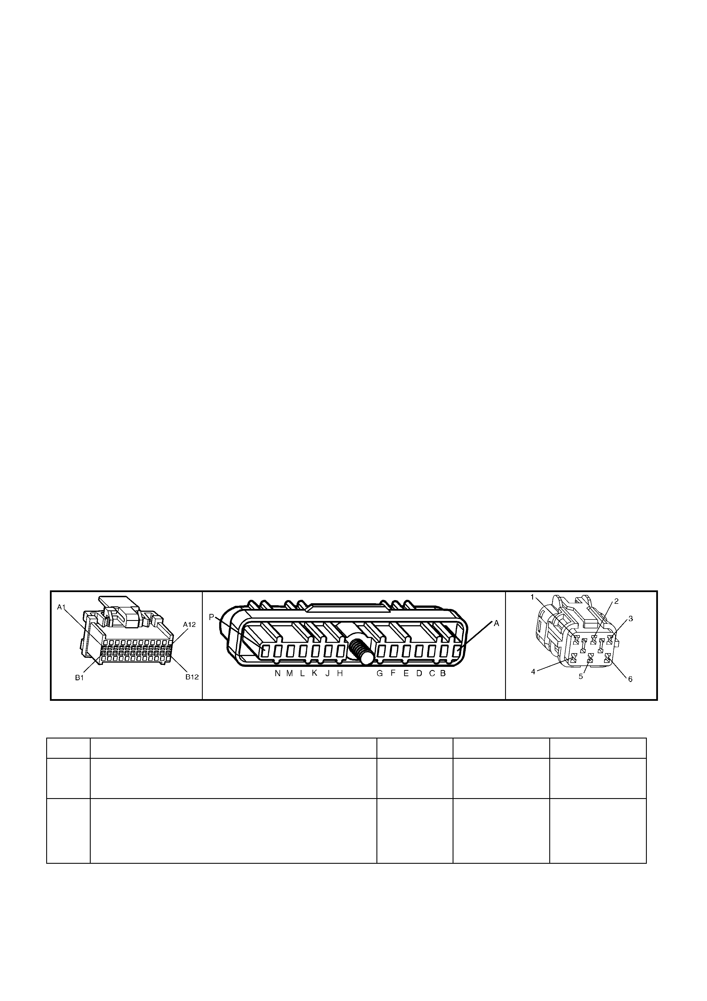
If the B ypass contr ol cir cuit has an open f ault or short to ground, or if the E ST c ircuit h as a shor t to gr ound or s hort
to voltage, the PCM cannot control the ignition module to release the EST pulses from being grounded. Because
the PCM also monitors it's EST outp ut terminal for EST pulses, if it detects no EST pulses after it has "turned on"
the 5 volts to the Bypass control circuit, and the engine speed goes above 1600 RPM, a DTC P1361 will be set.
CONDITIONS FOR RUNNING THE DTC
• The engine is running.
CONDITIONS FOR SETTING THE DTC
• The PCM has commanded EST.
• The PCM has detected no EST output pulses for 400 ms
• The engine speed is greater than 1600 RPM.
ACTION TAKEN WHEN THE DTC SETS
• The PCM activates the Check Powertrain MIL when the diagnostic runs and fails.
• The PCM records the operating conditions at the time the diagnostic fails. The PCM stores this information in
the History Data.
• When DTC P1361 is set and current, the PCM will operate in the Bypass spark mode.
CONDITIONS FOR CLEARING THE MIL/DTC
• The PCM turns the Check Powertrain MIL OFF after the first ignition cycle that the diagnostic runs and does
not fail.
• Use TECH 2 in order to clear the MIL/DTC.
DIAGNOSTIC AIDS
• Poor conn ection at PCM. I nspect harness connectors for backed out term inals, improper mating, brok en locks,
improperly formed or damaged terminals, and poor terminal to wire connection.
• Damaged Harness. Inspect the wiring harness for damage. If the harness appears to be OK, disconnect the
ignition module, turn the ignition "ON". Connect and observe a voltmeter connected between the Bypass
control cir cuit and B+, whi le moving conn ectors and wir ing harness r elated to the ignit ion module. A chan ge in
voltage will indicate the location of the fault.
TEST DESCRIPTION
Number(s) below refer to step number(s) on the diagnostic Table.
3. This step checks to see if circuit 423 is shorted to voltage.
7. This step checks to see if circuit 423 is shorted to ground.
10. This step checks to see if circuit 424 is shorted to ground.
12. This step checks to see if circuit 424 is open.
13. This step checks to see if the ignition module is capable of switching from Bypass to EST mode.
A84 V6 – X1 A40 X101
Figure 6C1-2A-174
DTC P1361 V6 PCM - IGNITION BYPASS CIRCUIT FAULT
STEP ACTION VALUE YES NO
1. Was the "On-Board Diagnostic" (OBD) System Check
performed? Go to Step 2 Go to
OBD System
Check
2. 1. Clear DTC P1361.
2. Start engine, and run above 1600 RPM.
3. Observe DTC(s).
Did DTC P1361 set ?
Go to Step 3 DTC P1361
is intermittent.
Refer
"Diagnostic
Aids".

STEP ACTION VALUE YES NO
3. 1. Ignition "OFF".
2. Disconnect ignition module 14 pin connector A40.
3. Probe ignition module harness connector A40
terminal X1-A with a voltmeter to ground.
4. Ignition "ON".
Is voltage greater than the specified value?
0.5 V Go to Step 4 Go to Step 6
4. 1. Ignition "OFF".
2. Disconnect PCM connectors.
3. Ignition "ON".
Is voltage still present at ignition module harness
Connector A40 term inal X1-A?
Go to Step 5 Go to Step 14
5. Repair short to voltage on circuit 423.
Is action complete ? Verify Repair
6. 1. Ignition "O N".
2. Probe ignition module harness connector A40 circuit
423 with a test light connected to battery voltage.
Is test light "ON" ?
Go to Step 7 Go to Step 9
7. 1. Ignition "O FF
2. Disconnect PCM connectors.
3. Probe ignition module connector A40 circuit 423 with
a test light connected to battery voltage.
Is test light "ON" ?
Go to Step 8 Go to Step 14
8. Repair short to ground in circ uit 423.
Is action complete Verify Repair
9. 1. Ignition "ON".
2. Disconnect ignition module 14 pin connector A40.
3. With test light connected to battery voltage, probe
ignition module harness connector A40 circuit 424.
Is test light "ON" ?
Go to Step 10 Go to Step 12
10. 1. Ignition "OFF".
2. Disconnect PCM connectors.
3. Ignition "ON".
4. With test light connected to battery voltage, probe
ignition module harness connector A40 circuit 424.
Is test light "ON" ?
Go to Step 11 Go to Step 14
11. Repair short to ground on circuit 424.
Is action complete ? Verify Repair
12.
1. Ignition "OFF".
2. Disconnect PCM connectors.
3. Check for faulty conn ection or open circuit 424.
Is fault found ?
Verify Repair Go to Step 13
13. 1. Ignition "OFF".
2. Reconnect igniti on modu le 14 pin conn ector A40.
3. Disconnect PCM connectors.
3. Ignition "ON".
4. Probe PCM harness connector circuit 423 with an
ohmmeter connected to ground.
5. Probe PCM harness connector circuit 424 with a test
light connected to battery voltage.
As the test light contacts circuit 424, does resistance
switch from under the specified value to over the
specified value?
300 ohms
to
6000 ohms
Go to Step 14 Go to Step 15
14. Replace PCM.
Refer 6C1-3 Service Operations, for PCM Programming
and Security Link procedure.
Is action complete?
Verify Repair
15. Replace ignition module.
Refer 6C1-3 Service Operations.
Is action complete?
Verify Repair
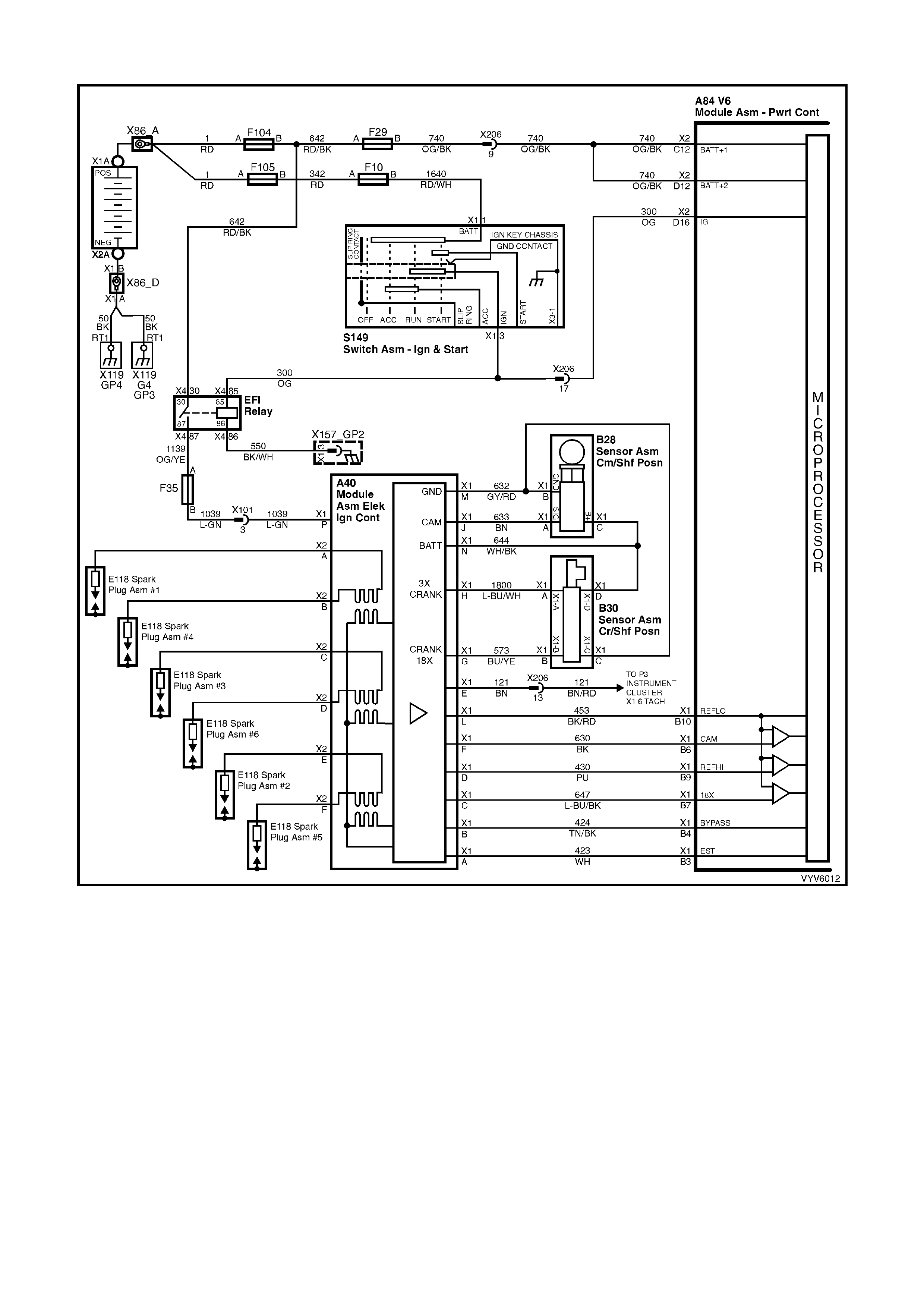
DTC P1372 V6 PCM - NO REFERENCE PULSES WHILE CRANKING
Figure 6C1-2A-175 – Ignition System Circuit
CIRCUIT DESCRIPTION
This DTC is intended to help in diagnos ing a no-start c ondition. Any tim e the engine is turni ng, the ignition modu le
should generate the crankshaft reference pulses that the PCM should be receiving. Fuel injection pulses are
"timed" f rom the cr ankshaft pulses, an d without them no injection p ulses will occ ur. The PCM can de termine when
these crankshaft pulses should be present, but aren't.
As with an y engine wh ile b eing cr ank ed, there is a sm all am ount of inl et m anifo ld vacu um . Also while crank ing, t he
battery voltage will be less than 11 volts. If the PCM's MAF sensor input detects air flow and the ignition voltage
input detects less than 11 volts and there are no reference input pulses, a DTC P1372 will set.
NOTE: It is possible for the ignition system to provide spark, yet there may not be any reference pulses at the
PCM.
CONDITIONS FOR RUNNING THE DTC
• No MAF sensor DTC is set.
• Batter y volta ge is at or belo w 11 volts .
• The MAF sensor input signal is greater than 2048 Hz.

CONDITIONS FOR SETTING THE DTC
• No crank shaf t ref erence in put puls es are rec eived at t he PCM cr ank shaf t refer ence in put term inal f or at leas t 2
seconds.
ACTION TAKEN WHEN THE DTC SETS
• The PCM activates the Check Powertrain MIL when the diagnostic runs and fails.
• The PCM records the operating conditions at the time the diagnostic fails. The PCM stores this information in
the History Data.
CONDITIONS FOR CLEARING THE MIL/DTC
• The PCM turns the Check Powertrain MIL OFF after the first ignition cycle that the diagnostic runs and does
not fail.
• Use TECH 2 in order to clear the MIL/DTC.
DIAGNOSTIC AIDS
• Poor conn ection at PCM. I nspect harness connectors for backed out term inals, improper mating, brok en locks,
improperly formed or damaged terminals, and poor terminal to wire connection.
• Damaged Harness. Inspect the wiring harness for damage. If the harness appears to be OK, disconnect the
ignition module, turn the ignition "ON".
NOTE: Use ST-125 spark checker or equivalent to check for adequate spark. An ST-125 requires about 25,000
volts ( 25 Ki lo vo lts or 25 kV) to "spark". Do not use a s park plug in o pen a ir connected to the e ng ine as an i nd i c ation
of sufficient "spark". Only a few kilovolts are required to jump the gap of a spark plug outside of the engine, and that
would be an inadequate test of the ignition system.
TEST DESCRIPTION
Number(s) below refer to step number(s) on the diagnostic Table.
2. If engine starts, the problem is not present now. While the PCM monitors 3 inputs to determine DTC P1372,
only a lack of reference input signal pulses can set the DTC. If a problem occurred on the MAF or ignition
voltage inputs, other problems would be apparent.
NOTE: Even one crankshaft reference pulse while cranking will cause DTC P1372 not to set.
3. Spark on all three wires on the same side of the engine proves the DIS coil pack to be OK. No spark on any
lead means the DIS ignition system is suspect of causing the DTC P1372. If the DIS ignition system cannot
generate any spark, it cannot generate the crankshaft reference signal either.
Refer to TABLE A-8.1 in th is Sect ion to de term ine the cause. If there is spark on onl y 1 or 2 spar k plu g lead s,
the crank sensor is prob ably OK , but there could be a pr oblem with the co il pack or DIS m odule. T ABLE A- 8.1
should determine the problem.
4. The voltage should be either "OFF" (less than 1 volt) or "ON" (more than 3 volts). This is the square-wave,
digital "ON-OFF" reference signal generated by the ignition module. The voltage could be either reading,
depending on wher e the r eluc tor wheel st opp ed tur nin g.
5. T his is again the reference signal. W hen the reluctor wheel is t urning, the signal changes from under 1 volt to
over 3 vol ts , bac k and forth, three times per re volu tio n. Sinc e i t changes quic k l y, the vo ltmeter can ind ic ate o nly
an average voltage. (expected reading - approximately 2-3 volts.)
6. A loose connection at PCM terminal X1-B9 could cause an intermittent voltage measurement to be seen.
A84 V6 – X1 A40 X101
Figure 6C1-2A-176

DTC P1372 V6 PCM - NO REFERENCE PULSES WHILE CRANKING
STEP ACTION VALUE YES NO
1. Was the "On-Board Diagnostic" (OBD) System check
performed? Go to Step 2 Go to
OBD System
Check
2. Attempt to start engine.
Did engine start and continue to run? DTC P1372 is
intermittent. If no
additional DTC's
were stored, refer
to "Intermittents"
in Section 6C1-
2B SYMPTOMS.
Go to Step 3
3. 1. Remove the spark plug leads from three spark plugs.
2. Connect ST-125 spark checker (See Test
Description) to each lead individually, and check for
spark while cranking the engine.
Was spark evident on all leads?
(A few sparks and then nothing is considered no spark.)
Go to Step 4 Go to
Table A-8.1
in this Section
4. 1. Ignition "OFF".
2. Disconnect PCM.
3. Backprobe PCM harness connector terminal X1-B9
to ground with a digital multimeter (DMM) set to read
"DC volts".
4. Ignition "ON".
Is the voltage at the specified value?
4.5 – 5.0
volts Go to Step 5 Go to Step 10
5. 1. Ignition "OFF".
2. Disconnect PCM.
3. Backprobe PCM harness connector terminal X1-B9
to ground with a DMM set to read "DC Volts".
4. Ignition "ON" .
5. While observing DMM, crank the engine.
Is voltage measured approximately the specified value?
2.0 – 3.0
volts Go to Step 6 Go to Step 8
6. Check PCM terminal X1-B9 for a loose connection.
Was a fault found? Verify Repair
Go to Step 7
7. Replace PCM.
Refer 6C1-3 Service Operations, for PCM Programming
and Security Link procedure.
Is action complete?
Verify Repair
8. Check circuit 430 for a faulty connection or an open or
short to ground.
Was a fault found?
Verify Repair Go to Step 9
9. Replace Ignition Module.
Refer 6C1-3 Service Operations.
Is action complete?
Verify Repair
10. 1. Disconnect M odule con nec tor A40.
2. With the DMM still connected to PCM terminal X1-
B9.
Is voltage above the specified value?
5.0 Volts Go to Step 11 Go to Step 9
11. Check circuit 430 for a short to voltage.
Was a fault found? Verify Repair
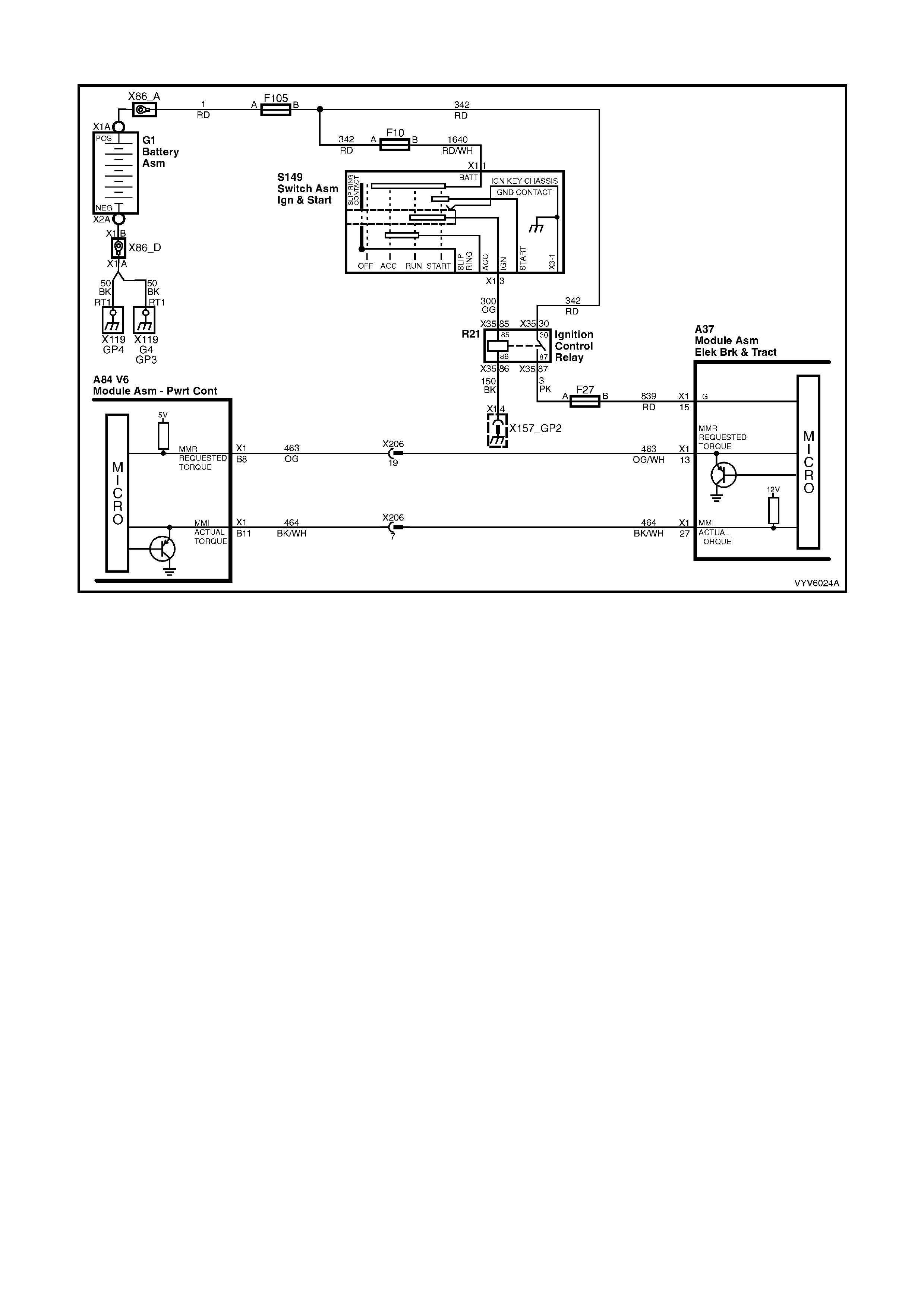
DTC P1571 V6 PCM - REQUESTED TORQUE OUT OF RANGE
Figure 6C1-2A-177 – Requested Torque Circuit
CIRCUIT DESCRIPTION
The Anti-Lock Brake System/Electronic Traction Control (ABS/TCS) Module (Traction Control) controls the PWM
signal on the torque request circuit while monitoring the wheel speed sensors to detect slippage. The PCM
monitors the PWM signal and reduces engine torque as needed by retarding ignition timing, or in severe cases,
shutting off up to five ( 5) injec tors. T he PCM se nds a PW M s ignal to the ABS/TC S m odule on th e torqu e achie ved
circuit informing the ABS/TCS module of response made to the torque request signal. A problem with the torque
request circuit should cause DTC P1571 and an ABS/TCS DTC to set and traction control to be disabled. Refer
Section 5B ABS & ABS/TCS for information on ABS/TCS operation and DTC diagnosis.
CONDITIONS FOR RUNNING THE DTC
• The engine is running.
CONDITIONS FOR SETTING THE DTC
• The PCM detects the incorrect voltage on the Requested Torque circuit.
ACTION TAKEN WHEN THE DTC SETS
• The PCM activates the Check Powertrain MIL when the diagnostic runs and fails.
• The PCM records the operating conditions at the time the diagnostic fails. The PCM stores this information in
the History Data.
• W hen DTC P1571 is s et, traction c ontro l will be d isabled an d a correspo nding DTC wil l be set in th e ABS/T CS
module.
CONDITIONS FOR CLEARING THE MIL/DTC
• The PCM turns the Check Powertrain MIL OFF after the first ignition cycle that the diagnostic runs and does
not fail.
• Use TECH 2 in order to clear the MIL/DTC.
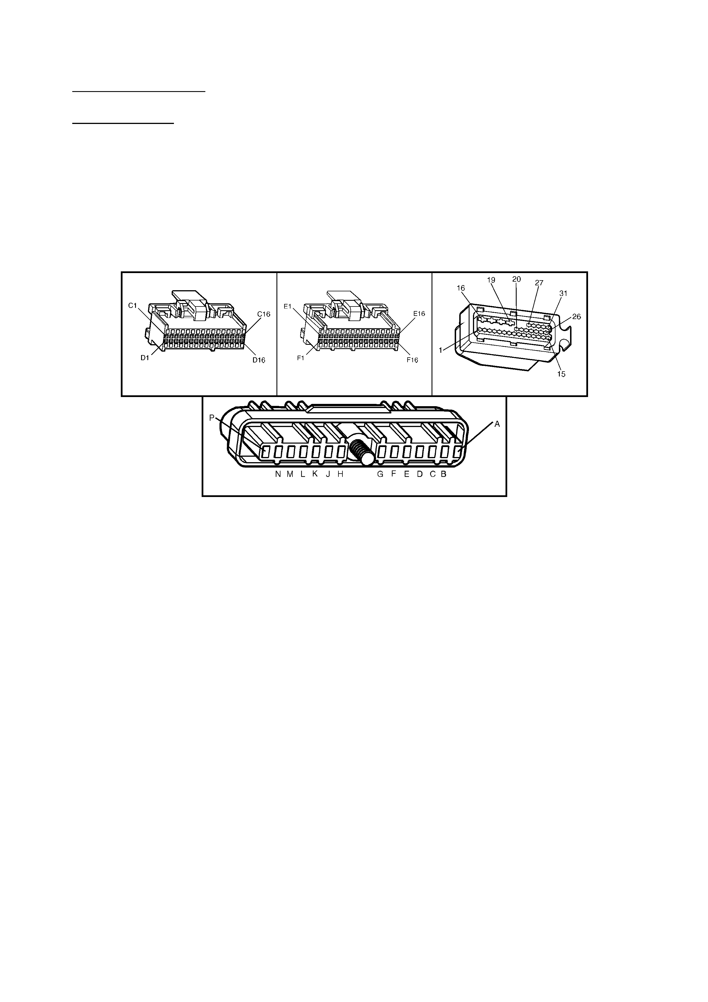
DIAGNOSTIC AIDS
Check for the following conditions:
• Poor conn ection at PCM. I nspect harness connectors for backed out term inals, improper mating, brok en locks,
improperly formed or damaged terminals, and poor terminal to wire connection.
• Damaged harness. Inspect the wiring harness for damage. If the harness appears to be OK, disconnect the
PCM, turn the ignition ON and observe a voltmeter connected to the Torque Request circuit at the PCM
harness c onnec tor whi le m oving co nnec tors and wir ing harn ess es relat ed to t he AB S/T CS m odule. If a volt age
is indicated the fault is in the harness.
TEST DESCRIPTION
Number(s) below refer to step number(s) on the diagnostic Table.
2. The PCM supp lies 4 to 5 volts on t he Torque Request circuit. W ith the PCM disconnec ted, there shou ld be no
voltage on the circuit.
6. This step checks to see if the Torque Request circuit is shorted to voltage.
11. This step checks to see if the ABS/TCS system is functioning properly.
A84 V6 - X2 A84 V6 – X3 A37
A40 – X1
Figure 6C1-2A-178

DTC P1571 V6 PCM - REQUESTED TORQUE OUT OF RANGE
STEP ACTION VALUE YES NO
1. Was the "On-Board Diagnostic" (OBD) System Check
performed? Go to Step 2 Go to
OBD System
Check
2. 1. Ignition "OFF".
2. Disconnect the PCM connectors.
3. Ignition "ON".
4. Using a Digital Multimeter (DMM), measure voltage
between the Torque Request circuit at the PCM
harness connector and ground.
Is voltage at the specified value?
0 V Go to Step 3 Go to Step 6
3. 1. Ignition "OFF".
2. Reconnect the PCM connectors.
3. Disconnect the ABS/TCS connector.
4. Ignition "ON".
5. Using A DMM, measure voltage between the
Torque Request circuit at the ABS/TCS harness
connector and ground.
Is voltage at the specified value?
4-5 V Go to Step 4 Go to Step 8
4. Check for poor connection at ABS/TCS module.
Was a problem found? Verify Repair Go to Step 5
5. Replace ABS/TCS module.
Is action complete? Verify Repair
6. 1. Ignition "OFF".
2. Disconnect the ABS/TCS module connector.
3. Ignition "ON".
4. Using a DMM, measure voltage between the
Torque Request circuit at the PCM harness
connector and ground.
Is voltage at the specified value?
0 V Go to Step 5 Go to Step 7
7. Locate and repair short to voltage in Torque Request
circuit.
Is action complete?
Verify Repair
8. Check for an open or short to ground in the Torque
Request circuit between the PCM and the ABS/TCS
module.
Was a problem found?
Verify Repair Go to Step 9
9. Check for poor connection at PCM harness connectors.
Was a problem found? Verify Repair Go to Step 10
10. Replace PCM.
Refer 6C1-3 Service Operations, for PCM Programming
and Security Link procedure.
Is action complete?
Verify Repair
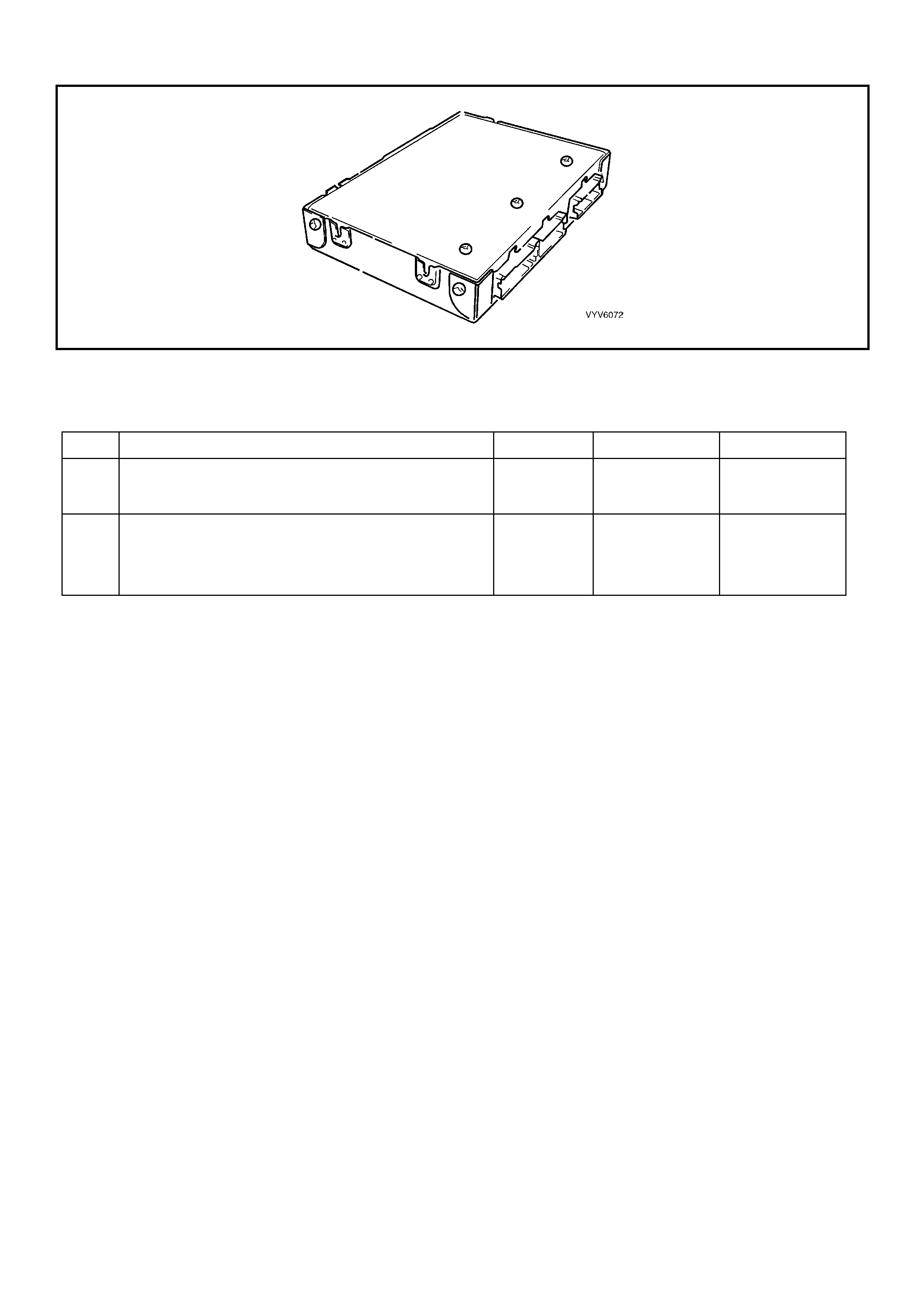
DTC P1627 V6 PCM - PCM - ANALOGUE TO DIGITAL (A/D) CONVERSION ERROR
Figure 6C1-2A-179 – Powertrain Control Module (PCM)
DTC P1627 V6 PCM - PCM - ANALOGUE TO DIGITAL (A/D) CONVERSION ERROR
STEP ACTION VALUE YES NO
1. Was the "On-Board Diagnostic" (OBD) System Check
performed? Go to Step 2 Go to
OBD System
Check
2. Replace PCM.
Refer 6C1-3 Service Operations, for PCM Programming
and Security Link procedure.
Is action complete?
Verify repair
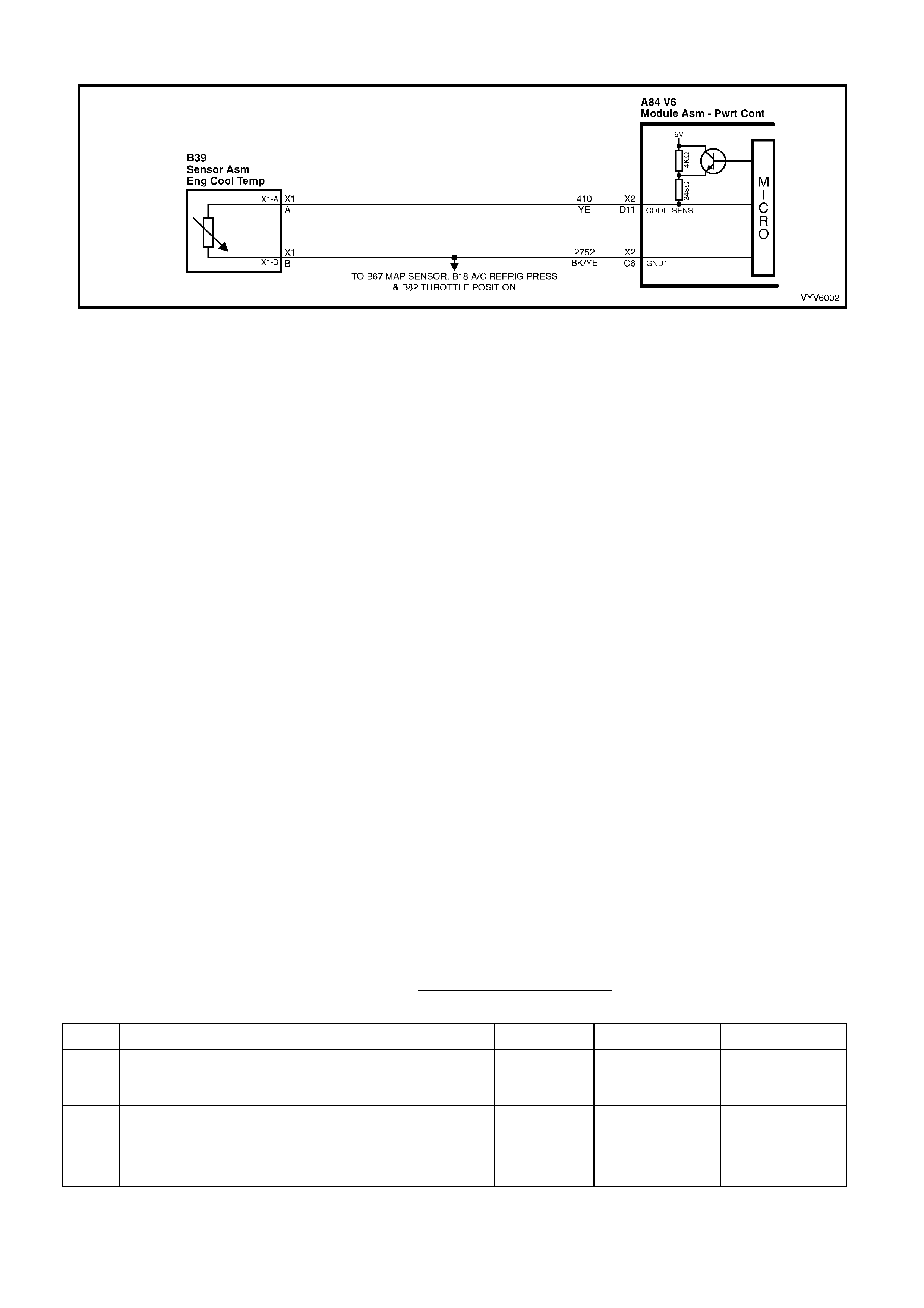
DTC P1628 V6 PCM - PCM ERROR - ENGINE COOLANT TEMPERAT URE
Figure 6C1-2A-180 Engine Coolant Temperature Sensor Circuit
CIRCUIT DESCRIPTION
The PCM uses two different internal pull-up resistors to increase resolution throughout the entire range of engine
operating temperatures. When the engine coolant temperature is less than 50°C, the 4K and 348 Ohm resistors are
used. W hen temperature is above 50°C, the PCM switches a short across the 4K Ohm resistor and only uses the
348 ohm resistor. If the pull-up resistor does not switch, DTC P1628 will set.
CONDITIONS FOR RUNNING THE DTC
• The engine run time is longer than 10 seconds.
CONDITIONS FOR SETTING THE DTC
• The pull-up resistor inside the PCM switches and there is less than a 60mV change in the engine coolant
temperature signal.
ACTION TAKEN WHEN THE DTC SETS
• The Check Powertrain MIL will not be activated.
• The PCM records the operating conditions at the time the diagnostic fails. The PCM stores this information in
the History Data.
• When an ECT sensor circuit fault is detected, and current, the PCM will substitute a coolant temperature
default value based on intake air temperature at start up and engine run time.
• When DTC P1628 is set, the PCM will turn "ON" the engine cooling fans.
CONDITIONS FOR CLEARING THE MIL/DTC
• Use TECH 2 in order to clear the MIL/DTC.
DIAGNOSTIC AIDS
When a DTC P0117, P0118, P1116 or P1628 is current, the PCM will turn on the electric engine cooling fan(s).
This is a FAIL-SAFE action by the PCM to prevent a possible engine overheat condition, since these DTC’s
indicate an unknown actual engine coolant temperature.
If the ECT s ensor c irc uit op ens with the ig nit io n of f, the PCM wil l interpret -40 °C a nd de li ver enough fue l to s t art th e
engine at that temperature. If the actual ambient temperature is above 0°C, the engine may flood and not start
unless CLEAR FLOOD MODE is used by fully depressing the accelerator while cranking. In the CLEAR FLOOD
MODE the injectors pulse width is set to zero milliseconds.
TEST DESCRIPTION
Number(s) below refer to step number(s) on the diagnostic Table.
2. DTC P1628 is an internal fault within the PCM. The PCM must be replaced!
DTC P1628 V6 PCM - PCM ERROR - ENGINE COOLANT TEMPERATURE
STEP ACTION VALUE YES NO
1. Was the "On-Board Diagnostic" (OBD) System Check
performed? Go to Step 2 Go to
OBD System
Check
2. Replace PCM.
Refer 6C1-3 Service Operations, for PCM Programming
and Security Link procedure.
Is action complete?
Verify Repair
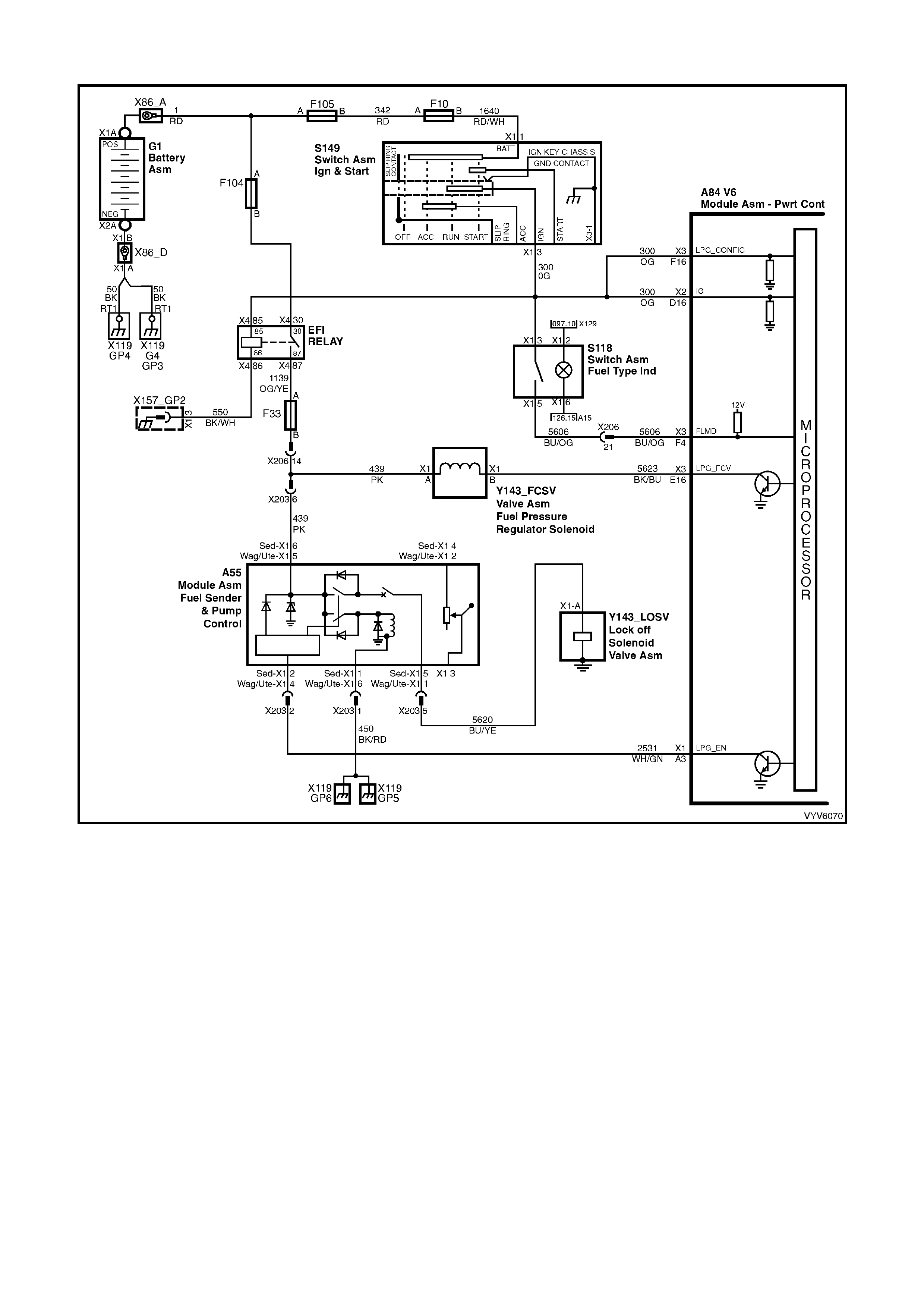
DTC P1642 V6 PCM - LPG ENABLE SIGNAL OUT OF RANGE
Figure 6C1-2A-181 LPG Enable Circuit
CIRCUIT DESCRIPTION
The PCM monitors the voltage at terminal X3-F4 to determine the status of the fuel mode switch. When the fuel
mode s witch is ope n, the volta ge at PCM t erm inal X 3- F4 will be 0 volts . When the LPG fuel m ode switc h is clos ed,
battery voltage will be applied to PCM term inal X3-F4 via fuse F10, the ignition switch, circuit, 300, the fuel mode
switch a nd cir cu it 5 60 6. This wil l caus e th e v oltag e at PCM ter minal X3- F4 to be pul led up to 12 v olts when e ver t he
fuel m ode sw itch is depres sed. T his hi gh vo ltage is se en b y the PCM as a f uel m ode s witch inp ut sig nal. When the
PCM sees a high v oltage at terminal X 3-F4 the PCM wil l toggle bet wee n the LPG and petr ol operat ing modes . The
PCM will only toggle between the Petrol and LPG mode if the ignition is on and the engine is not running or the
engine is running above 1300 RPM.
When operating in the LPG Mode, the PCM will supply a ground signal from PCM terminal X1-A3 to the the Fuel
Sender a nd Pump Contr o l Modu le As se mbly A55. This s igna l e nab les L PG syste m oper ation. If ther e is a f a ult with
the LPG Enable circuit 2531, DTC P1642 will set.
CONDITIONS FOR RUNNING THE DTC
• The engine is operating in the LPG mode.
CONDITIONS FOR SETTING THE DTC
• The voltage at PCM terminal X1-A3 is too high for greater that one second.
or
• The voltage at PCM terminal X1-A3 is too low for greater that one second.
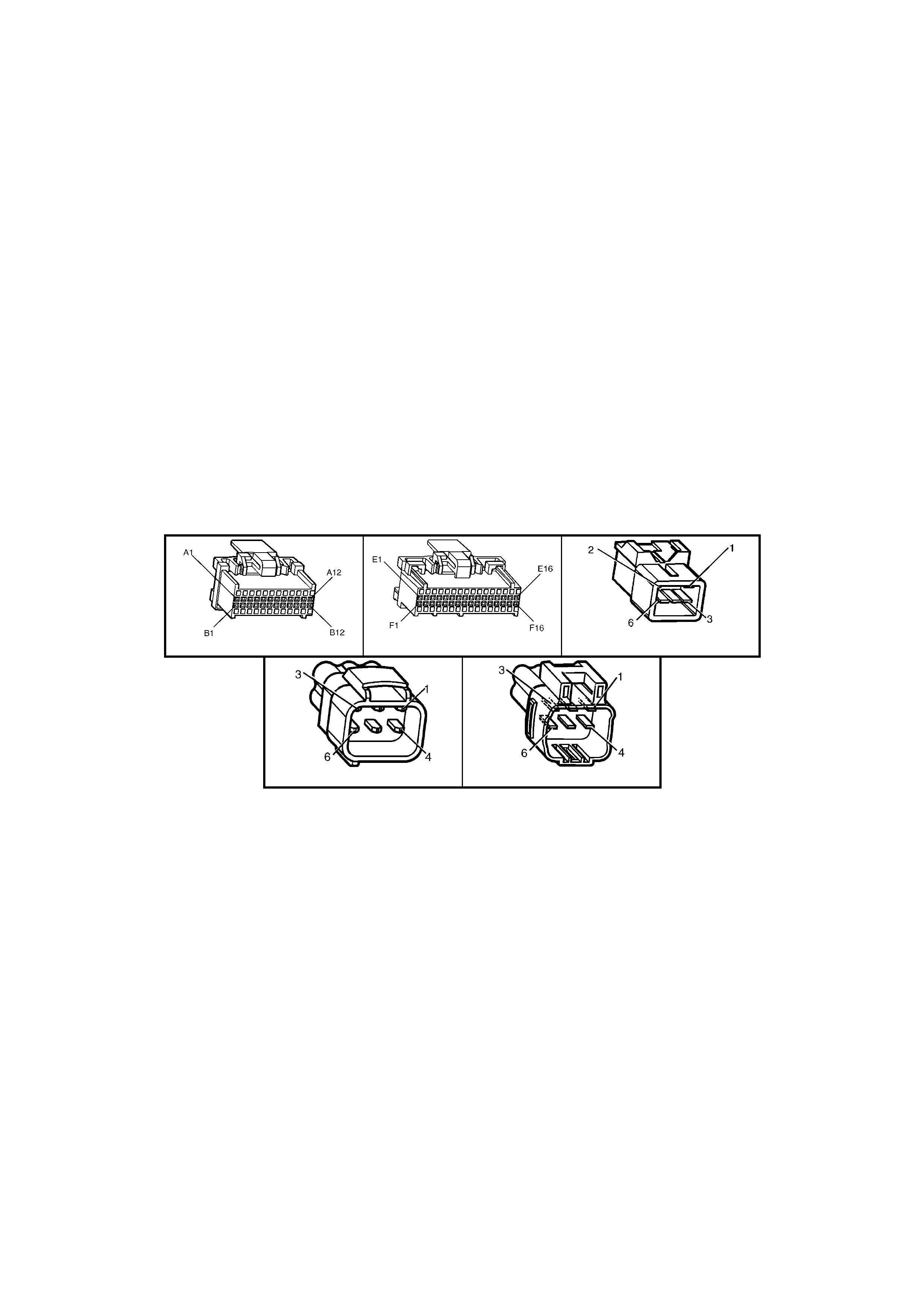
ACTION TAKEN WHEN THE DTC SETS
• The PCM records the operating conditions at the time the diagnostic fails. The PCM stores this information in
the History Data.
• The PCM will default to the Petrol fuel mode for vehicle operation.
CONDITIONS FOR CLEARING THE MIL/DTC
• Use TECH 2 in order to clear the MIL/DTC.
DIAGNOSTIC AIDS
Check for the following conditions:
• Poor connection at PCM. Inspect harness conn ectors for backed out term inals, improper mating, broken locks,
improperly formed or damaged terminals, and poor terminal to wire connection.
• Dirty, Damaged, or Loose Connections or Damaged Harness - Check for any damage to the harness which
could cause an intermittent open or short to ground or backed out terminals at the PCM connectors, broken
locks, improperly formed or damaged terminals.
TEST DESCRIPTION
Number(s) below refer to step number(s) on the diagnostic Table.
2. This step verifies that B+ is supplied from the Fuel Sender and Pump Control Module Assembly A55 to the
PCM terminal X1-A3. If there is no B+ on circuit 2531 and the circuit is not open or grounded or shorted to
voltage, the Fuel Sender and Pump Control Module Assembly A55 is faulty.
3. This step is checking circuit 2531 for a short to voltage or a faulty PCM.
6. This step is checking the power supply to the Fuel Sender and Pump Control Module Assembly A55. If fuse
F33 is open, there will be other DTC’s set. Verify all DTC’s are checked and corrected.
9. This step verifies a good ground circuit at the Fuel Sender and Pump Control Module Assembly A55.
A84 V6 – X1 A84 V6 – X3 A55 Sedan
A55 Wagon A55 Utility
Figure 6C1-2A-182

DTC P1642 V6 PCM - LPG ENABLE SIGNAL OUT OF RANGE
STEP ACTION VALUE YES NO
1. Was the "On-Board Diagnostic" (OBD) System Check
performed? Go to Step 2 Go to
OBD System
Check
2. 1. Ignition "OFF", disco nne ct all PCM connectors.
2. Ignition "ON".
3. Using Digital Multimeter (DMM), measure circuit
2531 voltage at PCM terminal X1 -A3 and ground.
Is voltage near the specified value?
B+ Go to Step 3 Go to Step 5
3. 1. Ignition "OFF", disconnect the the Fuel Sender and
Pump Control Module Assembly connector A55.
2. Ignition "ON".
3. Using a DMM, measure circuit 2531 voltage at PCM
terminal X1-A3 and ground.
Is voltage near the specified value?
0 Volts Go to Step 11 Go to Step 4
4. Repair short to voltage in LPG Enable circuit 2531 from
the Fuel Sender and Pump Control Module Assembly
A55 to PCM terminal X1-A3.
Is action complete?
Verify Repair
5. Check for an open or short to ground in circuit 2531
between the Fuel Sender and Pump Control Module
Assembly A55 and PCM terminal X1-A3.
Was a problem found?
Verify Repair Go to Step 6
6. Check the fused power feed circuit 439 and fuse F33 for
the Fuel Sender and Pump Control Module Assembly
A55.
Is the fuse faulty?
Go to Step 8 Go to Step 7
7. Check for an open in circuit 439 power feed circuit to the
Fuel Sender and Pump Control Module Assembly A55.
Was a problem found?
Verify Repair Go to Step 9
8. 1. Locate and repair short to ground in fuse power feed
circuit 439 for the Fuel Sender and Pump Control
Module Assembly A55.
2. Replace fuse.
Is action complete?
Verify Repair
9. Check for an open in the Fuel Sender and Pump Control
Module Assembly A55 ground circuit 450.
Was a problem found?
Verify Repair Go to Step 10
10. Replace the Fuel Sender and Pump Control Module
Assembly A55. Refer 8A2, LP GAS.
Is action complete?
Verify Repair
11. Check for poor connection at PCM terminal X1-A3.
Was a problem found? Verify Repair Go to Step 12
12. Replace PCM.
Refer 6C1-3 Service Operations, for PCM Programming
and Security Link procedure.
Is action complete?
Verify Repair
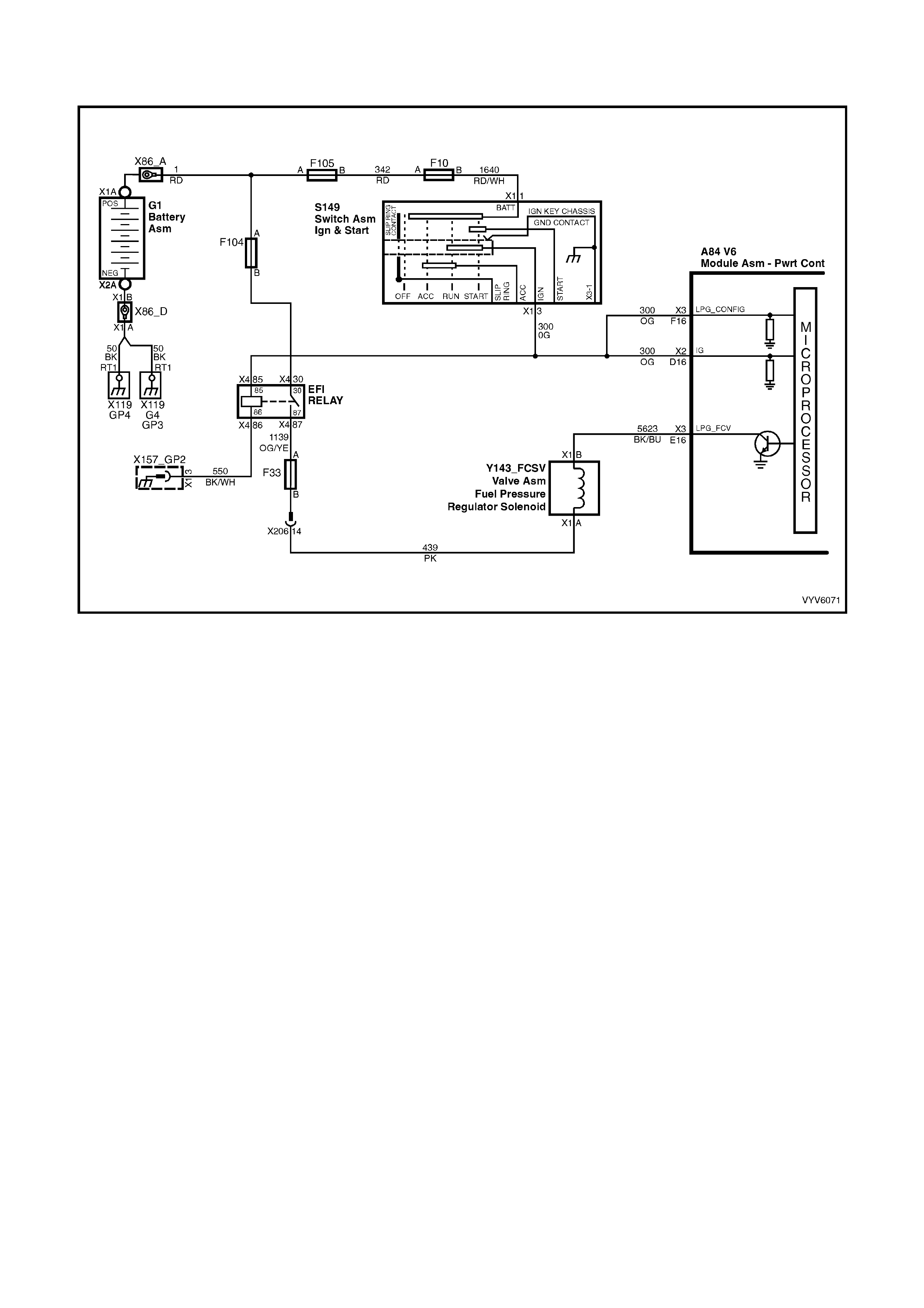
DTC P1643 V6 PCM - LPG FUEL CONTROL VALVE (FCV) PULSE WIDTH MODULATION
(PWM) SIGNAL CIRCUIT OUT OF RANGE
Figure 6C1-2A-183 Fuel Control Valve Circuit
DESCRIPTION:
The PCM monitors the voltage at terminal X3-F4 to determine the status of the fuel mode switch. When the fuel
mode s witch is ope n, the volta ge at PCM t erm inal X 3- F4 will be 0 volts . When the LPG fuel m ode switc h is clos ed,
battery voltage will be applied to PCM terminal X3-F4 via fuse F10, the ignition switch circuit 300, the fuel mode
switch a nd cir cu it 5 60 6. This wil l caus e th e v oltag e at PCM ter minal X3- F4 to be pul led up to 12 v olts when e ver t he
fuel m ode sw itch is depres sed. T his hi gh vo ltage is se en b y the PCM as a f uel m ode s witch inp ut sig nal. When the
PCM sees a high v oltage at terminal X 3-F4 the PCM wil l toggle bet wee n the LPG and petr ol operat ing modes . The
PCM will only toggle between the Petrol and LPG mode if the ignition is on and the engine is not running or the
engine is running above 1300 RPM.
W hen operating in the LPG mode the PCM controls the air fuel rat io by sending a Pulse W idth Modulated (PW M)
signal to the Fuel Control Valve (FCV) Assembly to control the vacuum supply to the converter for precise air/fuel
ratio control, based on the following inputs: RPM, MAF, IAT, ECT and TP. This mode of operation is LPG open loop
mode.
Once the ox ygen s ens ors a re ac tive a nd th e PCM is oper ati ng in the Closed L oop f uellin g mode, the PCM wil l send
a Pulse W idth Modulated ( PW M) s ignal to the Fuel Control Val ve (FCV) Assem bly base d on the right hand ox ygen
sensor voltage. This mode of operation is the LPG closed loop mode. If there is a fault with the FCV Assembly
circuit, DTC P1643 will set.
CONDITIONS FOR RUNNING THE DTC
• The engine is operating in the LPG mode.
CONDITIONS FOR SETTING THE DTC
• The voltage at PCM terminal X3-E16 is too high for greater than one second.
or
• The voltage at PCM terminal X3-E16 is too low for greater than one second.
ACTION TAKEN WHEN THE DTC SETS
• The Check Powertrain MIL will not be activated.
• The PCM records the operating conditions at the time the diagnostic fails. The PCM stores this information in
the History Data.
• The PCM will default to the Petrol fuel mode for vehicle operation regardless of the LPG switch position.
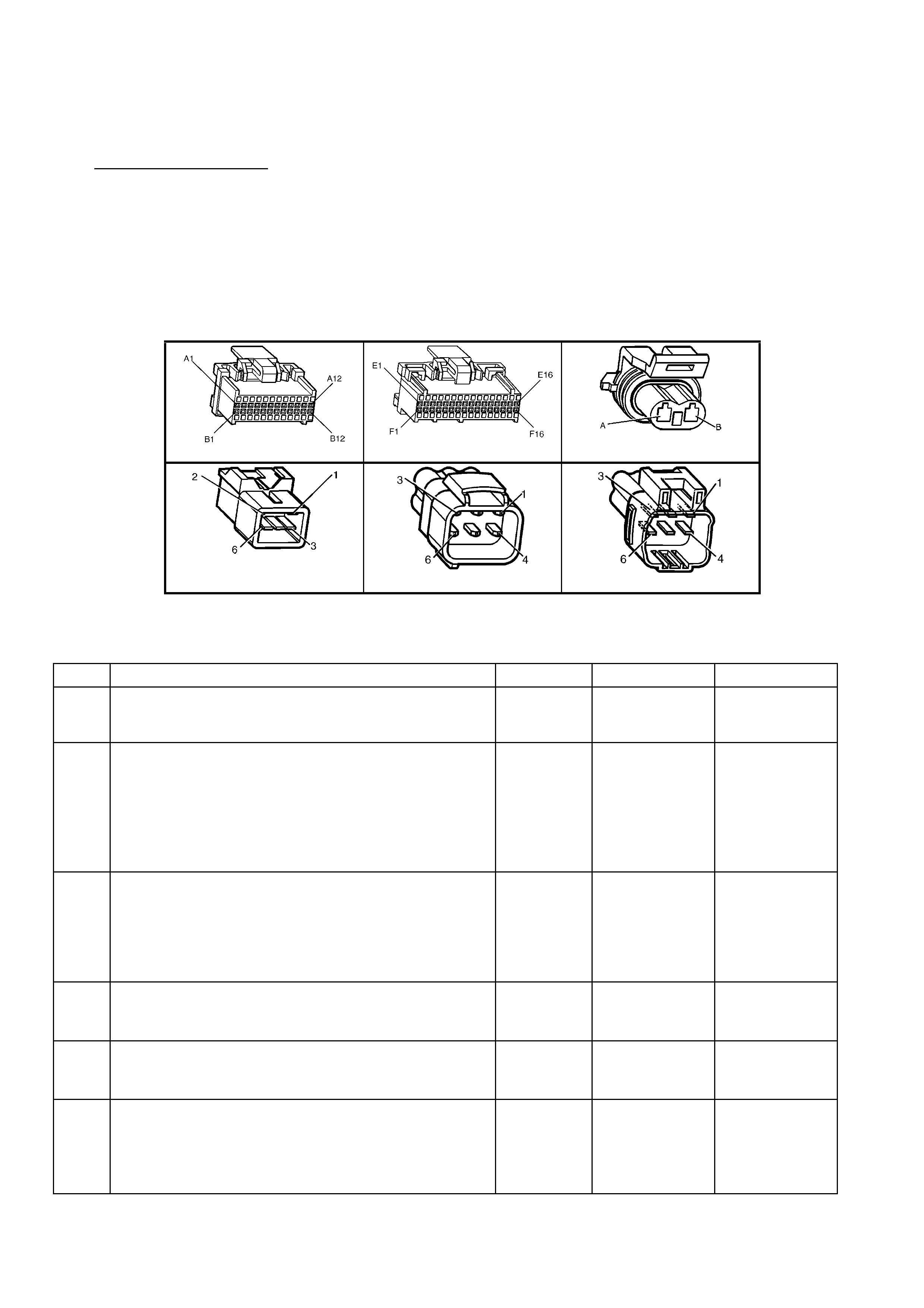
CONDITIONS FOR CLEARING THE MIL/DTC
• Use TECH 2 in order to clear the MIL/DTC.
DIAGNOSTIC AIDS
Check for the following conditions:
• Poor conn ection at PCM. I nspect harness connectors for backed out term inals, improper mating, brok en locks,
improperly formed or damaged terminals, and poor terminal to wire connection.
• Dirty, Damaged, or Loose Connections or Damaged Harness - Check for any damage to the harness which
could cause an intermittent open or short to ground or backed out terminals at the PCM connectors, broken
locks, improperly formed or damaged terminals.
TEST DESCRIPTION
Number(s) below refer to step number(s) on the diagnostic Table.
2. Norm ally, there should be power feed vo ltage prese nt on the out put circuit with t he PCM disc onnected and the
ignition on.
A84 V6 – X1 A84 V6 – X3 Y143
A55 Sedan A55 Wagon A55 Utility
Figure 6C1-2A-184
DTC P1643
LPG FUEL CONTROL VALVE (FCV) PULSE WIDTH MODULATION (PWM) SIGNAL OUT OF RANGE
STEP ACTION VALUE YES NO
1. Was the "On-Board Diagnostic" (OBD) System Check
performed? Go to Step 2 Go to
OBD System
Check
2. 1. Ignition "OFF", disconnect all PCM wiring harness
connectors.
2. Ignition "ON".
3. Using a DMM, measure voltage between the Fuel
Control Valve Solenoid driver circuit 5623 at the PCM
harness connector A84 X3-E16 and ground.
Is voltage near the specified value?
B+ Go to Step 3 Go to Step 5
3. 1. Disconnect the Fuel Control Valve Assembly harness
connector Y143.
2. Using a DMM set to DC volts, measure circuit 5623
voltage between the Fuel Control Valve Assembly
driver connector Y143 X1-B and ground.
Is voltage at specified value?
0 volts Go to Step 10 Go to Step 4
4. 1. Locate and repair short to voltage in the Fuel Control
Valve Assembly circuit 5623.
Is action complete?
Verify Repair
5. 1. Check the ignition feed fuse F33 for the Fuel Control
Valve Assembly Y143.
Is the fuse bl own?
Go to Step 6 Go to Step 7
6. 1. Locate and repair short to ground in ignition feed
circuit 439 for the Fuel Control Valve Assembly, fuse
F33.
2. Replace fuse.
Is action complete?
Verify Repair

STEP ACTION VALUE YES NO
7. 1. Disconnect the Fuel Control Valve Assembly harness
connector Y143.
2. Ignition "ON".
3. Measure voltage between the ignition feed circuit 439
at harness connector Y143, terminal X1-A and ground.
Is voltage near the specified value?
B+ Go to Step 8 Go to Step 12
8. 1. Check the Fuel Control Valve Solenoid driver circuit
5623 for an open or a short to ground.
Was a problem found?
Verify Repair Go to Step 9
9. 1. Check the Fuel Control Valve Solenoid Assembly
circuit and the ignition feed circuit for a poor
connection at the Fuel Control Valve, connector Y143
and the PCM A84 X3-E16.
Was a problem found?
Verify Repair Go to Step 14
10. 1. Ignition "OFF", reconnect the PCM connectors and
disconnect the Fuel Control Valve Solenoid Assembly
connector Y143.
2. Ignition "ON, connect a test light between the Fuel
Control Valve Solenoid Assembly circuit 5623 and the
ignition feed circuit 439 at the Fuel Control Valve
Solenoid Assembly connector Y143.
3. With Tech 2 installed, select, “LPG Fuel Control
Valve”.
4. Cycle the Solenoid from minimum to maximum %.
Does the test light increase in brightness as the %
increases?
Go to Step 9 Go to Step 11
11. 1. Check the Fuel Control Valve Solenoid Assembly for a
poor connection at the PCM, connector A84 X3-E16.
Was a problem found?
Verify Repair Go to Step 13
12. 1. Locate and repair open ignition feed circuit 439 to the
Fuel Control Valve Solenoid Assembly.
Is action complete?
Verify Repair
13. 1. Replace PCM. Refer 6C1-3 SERVICE OPERATIONS,
for PCM Programming and Security Link procedure.
Is action complete?
Verify Repair
14. 1. Replace Fuel Control Valve Solenoid.
Refer 8A2 LP GAS.
Is action complete?
Verify Repair
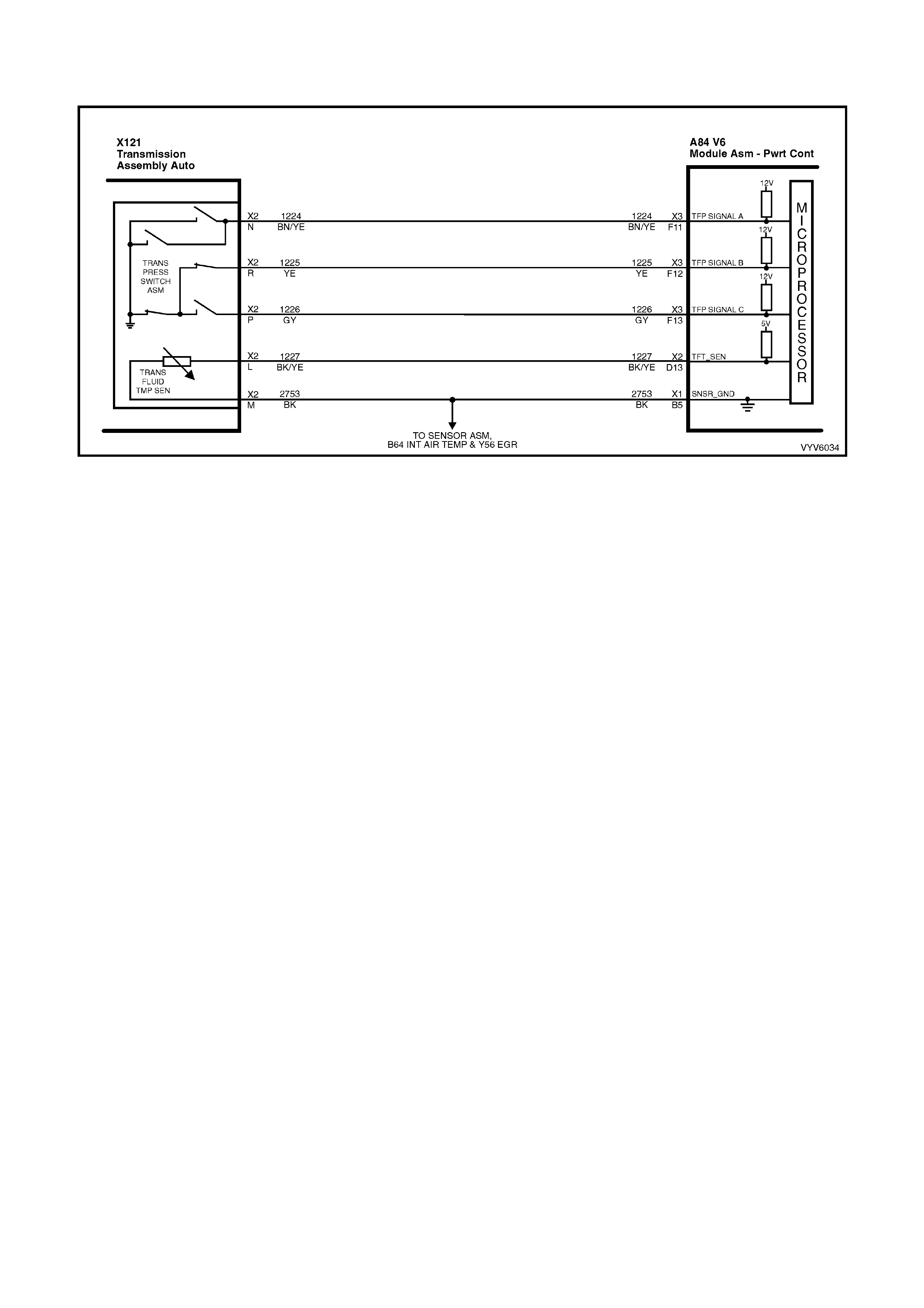
DTC P1810 V6 PCM - TRANSMISSION FLUID PRESSURE MANUAL VALVE POSITION
SWITCH ASSEMBLY MALFUNCTION
Figure 6C1-2A-185 - Transmission TFP Switch and TFT Circuits
CIRCUIT DESCRIPTION
The Autom atic Tr ansm ission Flu id Press ure (T FP) Manua l Val ve Posit ion S witch cons ists of f ive pressur e switc hes
(two norm ally-close d and three nor mall y-ope n) and a T ransm ission Fluid T emperature ( TFT ) sensor com bined into
one unit. The combined unit mounts on the valve body. The PCM supplies the battery voltage for each range
signal. By grounding one or more of the circuits through various combinations of the pressure switches, the PCM
detects whic h manual va l ve pos it ion you sel ec t. The PCM c ompares the ac tua l vo ltag e c ombination of the switc hes
to a TFP Switch combination table stored in memory. The TFP Switch cannot distinguish between Park and Neutral
because t he m onitored val ve bod y pressures are iden tical. With the engine OFF and t he igniti on switc h in th e RUN
position, the TFP Switch indicates Park/Neutral. Disconnecting the transmission pass-through connector removes
the grounding potential for the three range signals to the PCM. In this case, with the engine OFF, and the ignition
switch in the RUN position, D2 will be indicated.
W hen the PCM detect s an inval id state of the TFP S witch or th e TFP Switch c ircuit b y decip hering the T FP Switch
inputs, DTC P1810 sets.
CONDITIONS FOR RUNNING THE DTC
• The engine is running.
• The vehicle automatic transmission is in gear.
CONDITIONS FOR SETTING THE DTC
Condition 1
• The PCM detects an illegal TFP manual valve position switch state for 60 seconds.
Condition 2
• The engin e s peed is les s th an 80 R PM f or 0.1 sec ond; then th e en gi ne s pee d is 8 0-550 RPM for 0.07 sec on d s ;
then the engine spe ed is greater than 50 0 RPM.
• The PCM detects a gear range of D2, D4, or Reverse during an engine start.
• All conditions are met for 5 seconds.
Condition 3
• The TP angle is 8-45%.
• The PCM commands 4th gear.
• The TCC is locked ON.
• The speed ratio is 0.65-0.8 (speed ratio is engine speed divided by transmission output speed).
• The PCM detects a gear range of Park or Neutral when operating in D4.
• All conditions are met for 10 seconds.
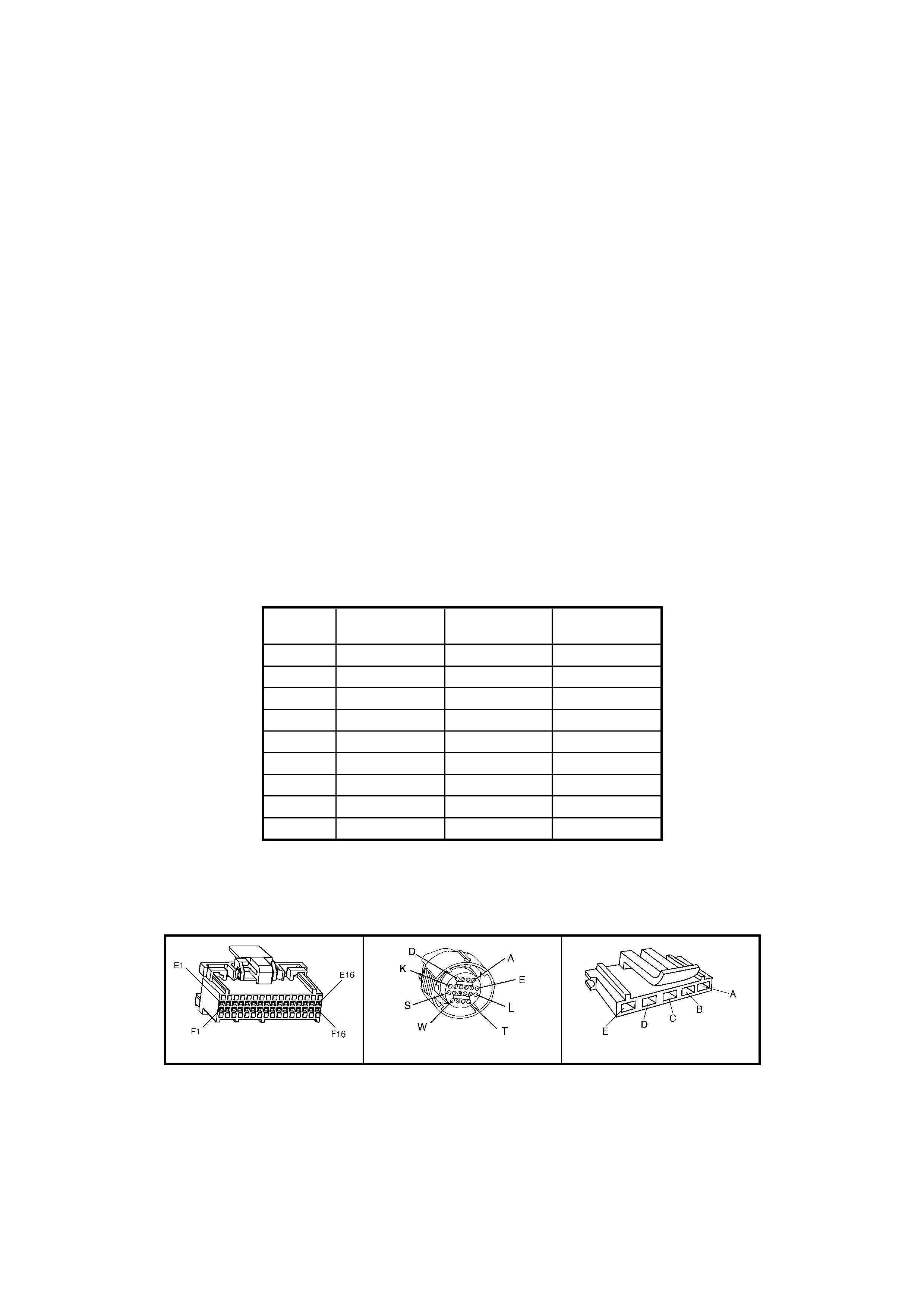
ACTION TAKEN WHEN THE DTC SETS
• The PCM activates the Check Powertrain MIL when the diagnostic runs and fails.
• The PCM records the operating conditions at the time the diagnostic fails. The PCM stores this information in
the History Data.
• When DTC P1810 is set, the PCM will inhibit TCC engagement, command D2 line pressure, and freeze shift
adapts from being updated.
CONDITIONS FOR CLEARING THE MIL/DTC
• The PCM turns the Check Powertrain MIL OFF after the first ignition cycle that the diagnostic runs and does
not fail.
• Use TECH 2 in order to clear the MIL/DTC.
DIAGNOSTIC AIDS
• Refer to the TFP Val. Position Sw. Logic Table for the normal range signals and the illegal combinations.
• Inspect the wiring for poor electrical conn ections at th e PCM. Inspect the wiring for poor el ectrical connec tions
at the transmission pass-through connector. Look for the following conditions:
A bent terminal
A backed out terminal
A damaged terminal
Poor terminal tension
A chafed wire
A broken wire inside the insulation
Moisture intrusion
• When diagnosing for an intermittent short or open condition, massage the wiring harness while watching the
test equipment for a change. Refer to Automatic Transmission Fluid Pressure Manual Valve Position Switch
Resistance Check or Functional Test Procedure for further information.
TFP Switch Logic
Gear
Position Range Signal
Swi tch A Range Signal
Switch B Range Signal
Switch C
P Open 12V Closed 0V Open 12V
R Closed 0V Closed 0V Open 12V
N Open 12V Closed 0V Open 12V
D Open 12V Closed 0V Closed 0V
3 Open 12V Open 12V Closed 0V
2 Open 12V Open 12V Open 12V
1 Closed 0V Open 12V Open 12V
Illegal Closed 0V Open 12V Closed 0V
Illegal Closed 0V Closed 0V Cl osed 0V
TEST DESCRIPTION
Number(s) below refer to step number(s) on the diagnostic Table.
3. This step compares the indicated range signal to the manual valve position that is actually selected.
4. This step tests for correct voltage from the PCM to the transmission pass-through connector terminals.
A84 V6 – X3 X121 – X2 TFP Connector
Figure 6C1-2A-186

DTC P1810 V6 PCM
TRANSMISSION FLUID PRESSURE MANUAL VALVE POSITION SWITCH ASSEMBLY MALFUNCTION
STEP ACTION VALUE YES NO
1. Was the On-Board Diagnostic (OBD) System Check
performed? Go to Step 2 Go to
OBD System
Check
2. Perform the following inspections:
1. Ensure that the transmission linkage from the select
lever to the manual valve is adjusted properly.
2. Perform the fluid checking procedure/inspection.
Did you perform the inspections?
Go to Step 3 Perform the
Inspections
3. 1. Install TECH 2.
2. With the engine OFF, turn the ignition switch to the
RUN position.
IMPORTANT: Before clearing the DTCs, use TECH
2 in order to record the DTC history for reference.
3. Record the DTC history.
4. While the engine is idling at normal operating
temperature, apply the parking brake.
5. Select e ach transmission range: P, R, N, D4, D3, D2,
and D1.
Does each selected transmission range match TECH 2
TFP Switch A/B/C display?
Refer to the TFP Switch Logic Table.
Go to “Diagnostic
Aids”
Go to Step 4
4. 1. Turn the ignition OFF.
2. Disconnect the transmission pass-through connector
(additional DTCs may set).
3. Install the J 39775 Jumper Harness on the engine
side of the transmission pass-through connector.
4. With the engine OFF, turn the ignition switch to the
RUN position.
5. Using a Digital Multimeter DMM and J 35616-A
Connector Test Adapter Kit, check for voltage at
connector terminals N, R, and P.
Is B+ displayed on all three circuits?
Go to Step 6 Go to Step 5
5. 1. Check the circuits that did not indicate B+ for an
open or a short to ground.
2. Check PCM terminal for proper tension on circuits
that did not have B+.
Repair the circuits if necessary.
Did you find and correct the problem?
Go to Step 13 Go to Step 7
6. In order to verify that circuit 1224, circuit 1225, and circuit
1226 are not shorted together, use a fused jumper to
ground, on each circuit while monitoring TECH 2 TFP
Switch A/B/C display.
When a range signal circuit is grounded, are any other
range signal cir cui ts affe cted ?
Go to Step 8 Go to Step 9
7. Replace PCM.
Refer 6C1-3 Service Operations, for PCM Programming
and Security Link procedure.
Is action complete?
Go to Step 13
8. Repair the affected wiring as necessary.
Is the action complete? Go to Step 13
9. 1. Turn the ignition switch to the OFF position.
2. Reconnect the pass-through connector.
3. Select the PARK position.
4. Start the engine.
5. Apply the brakes.
6. Move the shift selector through all gear ranges, while
observing the A and C range signals on TECH 2.
Does either range signal always indicate 0 volts/ON?
Go to Step 10 Intermittent
Problem Go to
“Diagnostic Aids”

STEP ACTION VALUE YES NO
10. 1. Turn the ignition switch to the OFF position.
2. Disconnect the transmission pass-through connector.
3. Remove the transmission pan.
4. Remove the internal wiring harness connector from
the TFP Valve Position Switch.
5. Check the internal wiring harness circuits 1224 and
1226 for a short to ground.
Did you find a short to ground condition on either circuit?
Go to Step 12 Go to Step 11
11. Replace the TFP Valve Position Switch.
Refer 7C4 A/T On-Vehicle Servicing.
Is the action complete?
Go to Step 13
12. Replace the internal A/T Wiring Harness Assembly.
Refer 7C4 A/T On-Vehicle Servicing.
Is the replacement complete?
Go to Step 13
13. In order to verify your repair, perform the following
procedure:
Operate the vehicle under the following conditions:
• With the engine OFF, turn the ignition switch to the
RUN position for at least 2 seconds.
• Start the vehicle and idl e for 5 seconds.
• Select each transmission range: P, R, N, D4, D3, D2
and D1.
• Compare TECH 2 TFP Switch A/B/C/ display, to the
TFP Valve Position Switch Logic Table.
Does each shifter position range signal match TECH 2
TFP Switch A/B/C display?
System OK Go to Step 1

DTC P1860 V6 PCM - TORQUE CONVERTER CLUTCH (TCC) PULSE WIDTH
MODULATION (PWM) SOLENOID FAULT
Figure 6C1-2A-187 – Transmission Solenoid Circuits
CIRCUIT DESCRIPTION
The Torque Converter Clutch Pulse Width Modulation (TCC PW M) Solenoid Valve controls the fluid acting on the
convert er clutch va lve. The conver ter clutch valve cont rols the T CC applicati on and release . The soleno id attaches
to the control valve body within the transmission. The solenoid receives ignition voltage through circuit 339. The
PCM controls the solenoid by providing a ground path on circuit 418. Current flows through the solenoid coil
according to the dut y cycle (percentage of ON and OFF time). The TCC PWM Solenoid Valve provides a smooth
engagement of the torque converter clutch by operating during a duty cycle percent of ON time.
The "TCC PWM" solenoid is used in combination with the TCC Enable solenoid to regulate fluid to the torque
converter, and is attached to the control valve body within the transmission. The use of the Torque Converter
Clutch Pu ls e Width Mo du la ted ( TCC PWM) s olenoi d p rovi des th e a bi lity of be ing abl e to c ontro l mor e prec isel y, the
rate of Torque Converter Clutch (TCC) apply and release.
When the PCM detects a continuous open or short to ground in the TCC PWM Solenoid Valve circuit or the TCC
PWM Solenoid Valve, then DTC P1860 sets.
CONDITIONS FOR RUNNING THE DTC
• The system voltage is 8 - 18 volts.
• The engine speed is greater than 300 RPM for 5 seconds.
• The engine is not in fuel cutoff.
• The PCM commands first gear.
• The TCC duty cycle is less than 10% or greater than 90%.
CONDITIONS FOR SETTING THE DTC
• The PCM commands the solenoid ON and the voltage input remains high (B+).
or
• The PCM commands the solenoid OFF and the voltage input remains low (0volts).
• Either condition for 5 seconds.
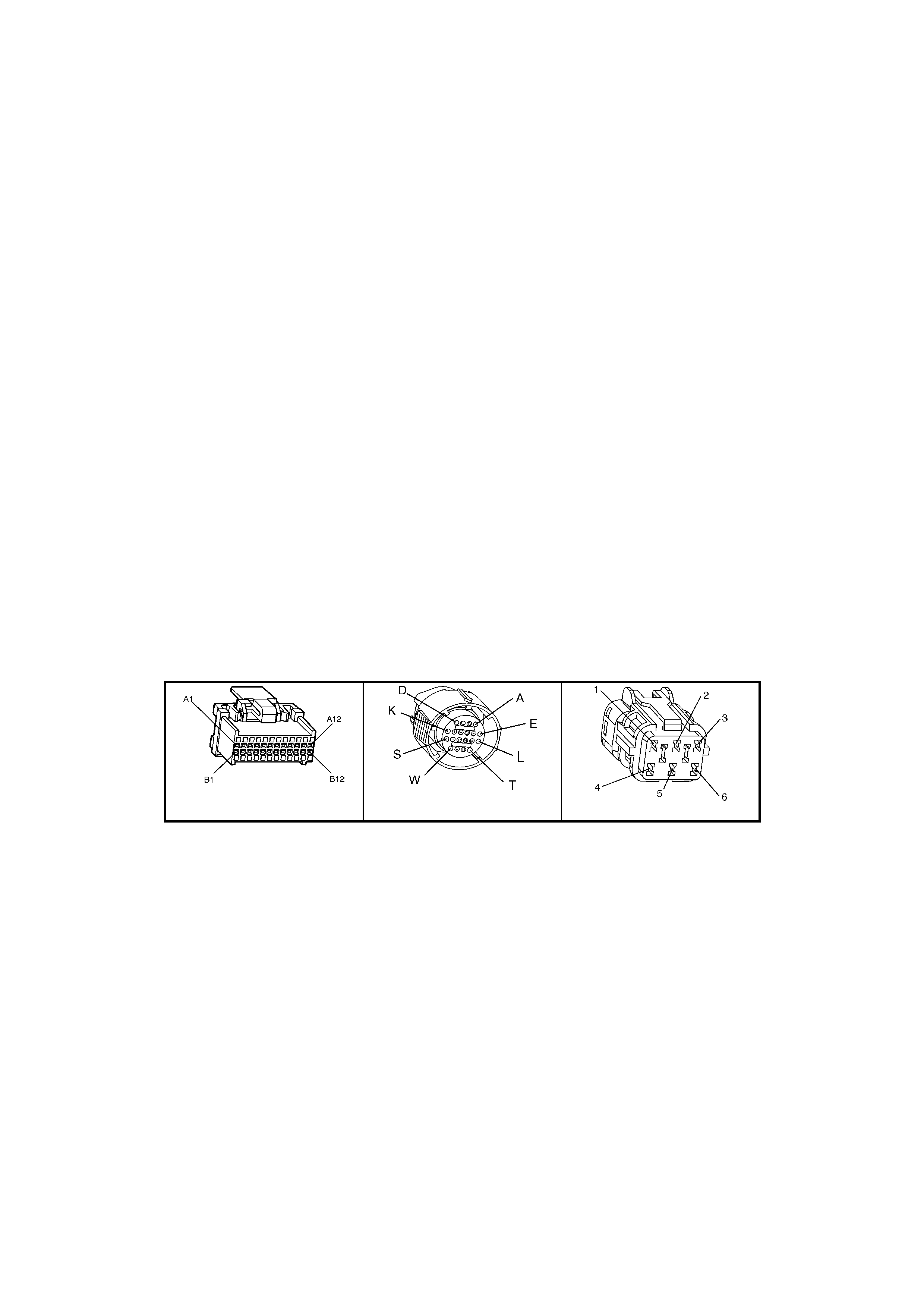
ACTION TAKEN WHEN THE DTC SETS
• The PCM stores the DTC information into memory when the diagnostic runs and fails.
• The Check Powertrain MIL will not be activated.
• The PCM records the operating conditions at the time the diagnostic fails. The PCM stores this information in
the History Data.
• When this DTC sets, the PCM will freeze shift adapts from being updated.
CONDITIONS FOR CLEARING THE MIL/DTC
• Use TECH 2 in order to clear the MIL/DTC.
DIAGNOSTIC AIDS
• Inspect the wiring for poor electrical conn ections at th e PCM. Inspect the wiring for poor el ectrical connec tions
at the transmission pass-through connector. Look for the following conditions:
A bent terminal
A backed out terminal
A damaged terminal
Poor terminal tension
A chafed wire
A broken wire inside the insulation
Moisture intrusion
• When diagnosing for an intermittent short or open condition, massage the wiring harness while watching the
test equipment for a change.
TEST DESCRIPTION
Number(s) below refer to step number(s) on the diagnostic Table.
3. An op en fuse indicates a s hort circuit in circuit 339. A short in an y of the five soleno ids fed by circuit 339 m ay
cause an open fuse.
4. This step tests for voltage to the solenoid.
6. This step tests the ability of the PCM and wiring to control the ground circuit.
7. This step tests the resistance of the TCC PWM Solenoid Valve and the Automatic Transmission Wiring
Harness Assembly.
A84 V6 – X1 X121 – X2 X101
Figure 6C1-2A-188

DTC P1860 V6 PCM
TORQUE CONVERTER CLUTCH (TCC) PULSE WIDTH MODULATION (PWM) SOLENOID FAULT
STEP ACTION VALUE YES NO
1. Was the On-Board Diagnostic (OBD) System Check
performed? Go to Step 2 Go to
OBD System
Check
2. 1. Install TECH 2.
2. Ignition ON engine OFF.
IMPORTANT: Before clearing the DTCs, use TECH 2 in
order to record the DTC history for reference. The Clear
History DTC function will erase the data.
3. Record the DTC history.
4. If DTCs P0740, P0753, P0756 or P0785, are also
set, inspect the F32 fuse for an open.
Is the fuse open?
Go to Step 3 Go to Step 4
3. 1. Check circuit 339 for a short to ground.
2. Check each of the five solenoids for being internally
shorted or shorted to ground .
3. Check the A/T Wiring Harness Assembly for a short
to ground on each of the five solenoid circuits.
4. Make the repair/replacement if necessary.
Did you find and correct a problem?
Go to Step 15 Go to
“Diagnostic Aids”
4. 1. Turn the ignition OFF.
2. Disconnect the transmission pass-through connector
(additional DTCs may set).
3. Install J 39775 Jumper Harness on the engine
harness connec tor.
4. With the engine OFF, turn the ignition switch to the
RUN position.
5. Connect a lest lamp from J 39775 Jumper Harness
cavity E to ground.
Is the test la mp on?
Go to Step 6 Go to Step 5
5. Repair the open in the ignition feed circuit 339 to the TCC
PWM Solenoid Valve.
Is the repair complete?
Go to Step 15
6. 1. Install the test lamp from cavity E to cavity U of the J
39775 Jumper Harness.
2. Using the TECH 2, TCC PWM Solenoid
Miscellaneous Test, command the TCC PWM
Solenoid ON and OFF three times.
Does the test lamp turn ON when the TCC PWM
Solenoid Valve is commanded ON, and OFF when
commanded OFF?
Go to Step 8 Go to Step 7
7. Check circuit 418 for an open, short to B+, or a short to
ground. Repair the circuit if necessary.
Did you find and correct the problem?
Go to Step 15 Go to Step 9
8. 1. Install J 39775 Jumper Harness on the transmission
pass-through con nec tor.
2. Using Digital Multimeter (DMM) and the J 35616-A
Connector Test Adapter Kit, measure the resistance
between terminals E and U.
Is the resistance wi thin the specified range?
10-15 Ω Go to Step 11 Go to Step 10
9. Replace PCM.
Refer 6C1-3 Service Operations, for PCM Programming
and Security Link procedure.
Is action complete?
Go to Step 15
10. 1. Disconnect the Automatic Transmission Wiring
harness Assembly at the TCC PWM Solenoid Valve.
2. Measure the resistance of the TCC PWM Solenoid
Valve.
Is the resistance wi thin the specified range?
10-15 Ω Go to Step 13 Go to Step 14

STEP ACTION VALUE YES NO
11. Measure the resistance between terminal E and ground,
and between terminal U and ground.
Are both readings greater than the specified value?
250 K Ω Go to
“Diagnostic Aids” Go to Step 12
12. 1. Disconnect the Automatic Transmission Wiring
Harness Assembly at the TCC PWM Solenoid Valve.
2. Measure the resistance between each of the
component terminals and a known good ground.
Are both readings greater than the specified value?
250 K Ω Go to Step 13 Go to Step 14
13 Replace the Automatic Transmission Wiring Harness
Assembly.
Refer 7C4 A/T On-Vehicle Servicing.
Is the action complete?
Go to Step 15
14 Replace the TCC PWM Solenoid Valve.
Refer 7C4 A/T On-Vehicle Servicing.
Is the action complete?
Go to Step 15
15 In order to verify your repair, perform the following
procedure:
Operate the vehicle under the following conditions while
observing the TCC PWM Solenoid and TCC Slip Speed:
• The PCM commands the TCC PW M Solenoid Valve
ON, and the TCC Slip Speed is -20 to +20 RPM.
• The PCM commands the TCC PW M Solenoid Valve
OFF, and the TCC Slip Speed is greater than 50
RPM.
Are both of the TCC Slip conditions met for at least
4 seconds?
System OK Go to Step 1
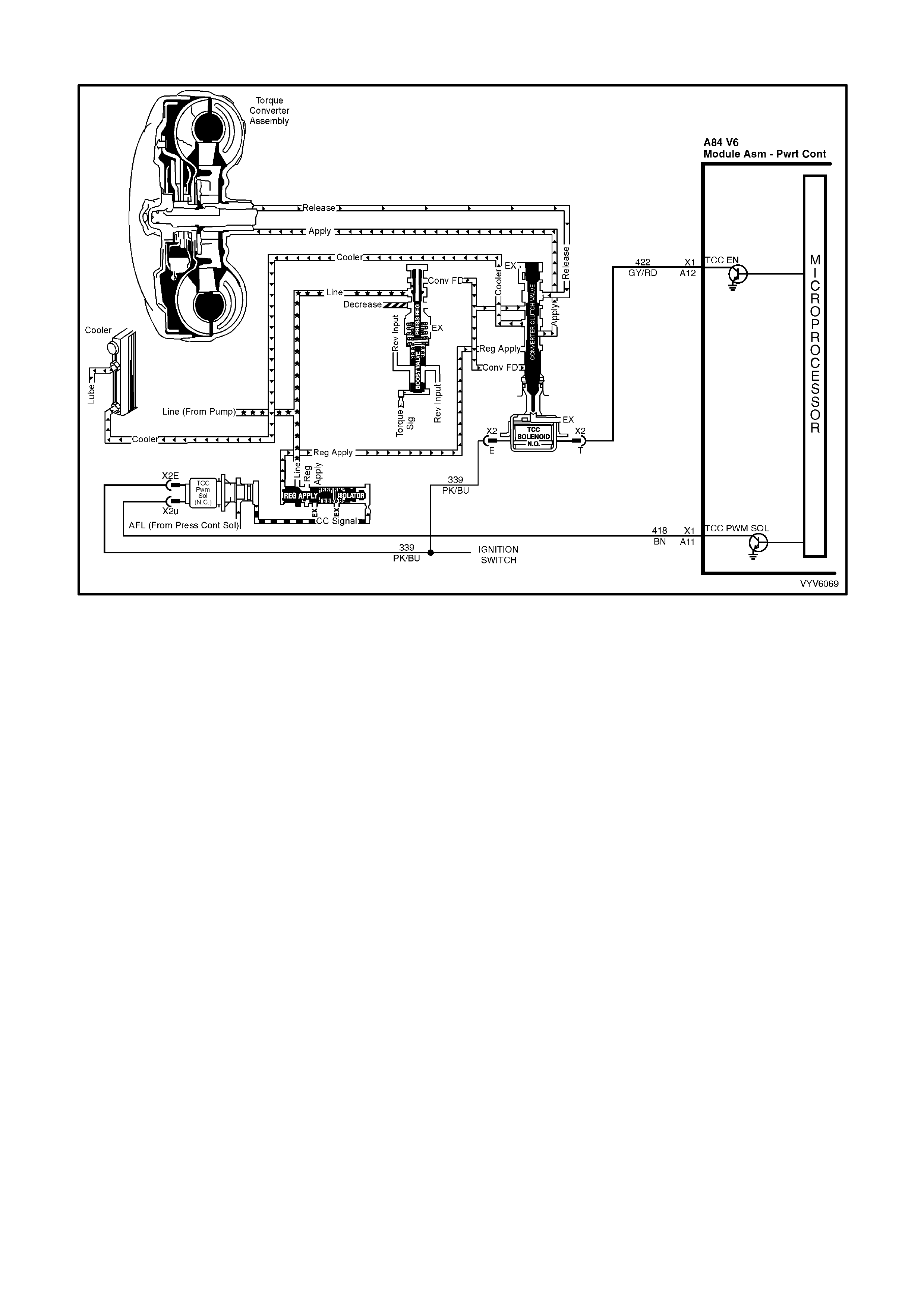
DTC P1870 V6 PCM - TRANSMISSION SLIPPING
Figure 6C1-2A-189 - Torque Converter Clutch Circuits
CIRCUIT DESCRIPTION
The PCM m onitors the d ifference be tween the en gine s peed and the tr ansmis sion output spe ed. In D3 drive r ange
with the TCC engaged, the engine speed should closely match the transm ission output speed. In D4 drive range,
with the TCC engaged, the Trans Slip Speed should be -20 to +20 RPM.
W hen the PCM detects an exces sive transm ission slip speed when t he TCC should b e engaged, t hen DT C P1870
will set.
CONDITIONS FOR RUNNING THE DTC
• No Throttle Position DTCs P0122 or P0123.
• No VSS assembly DTCs P0502 or P0503.
• No TCC solenoid valve DTC P0740.
• No 1-2 SS valve DTC P0753.
• No 2-3 SS valve DTC P0730.
• No 3-2 SS valve assembly DTC P0785.
• No TCC PWM solenoid valve DTC P1860.
• The engine speed is greater than 300 RPM for 5 seconds.
• The engine is not in fuel cutoff.
• The vehicle speed is 56-105 km/h.
• The speed ratio is 0.67-0.90 (the speed ratio is the engine speed divided by the transmission output speed).
• The engine speed is 1200-3500 RPM.
• The engine torque is 54-542 N.m
• The gear range is D4.
• The commanded gear is not 1st gear.
• The Throttle Position angle is 10-50%.
• The TFT is between 20-130°C.

CONDITIONS FOR SETTING THE DTC
• DTC P1870 sets if the TCC is commanded ON for 5 seconds.
• The TCC is at maximum duty cycle for 1 second.
• The TCC slip speed is 80-800 RPM for 7 seconds.
IMPORTANT: The following actions may occur before the DTC sets.
• If the T CC is com manded O N and at maxim um dut y c ycle f or 5 s ec on ds, th e T hr ottle P os it ion an gl e is 10-40%,
and the tr ansm iss ion slip c ounter has increm ented t o eith er 1 or 2 ( out of 3 to i ncrem ent the f ail coun ter f or t he
current ignition cycle), then the following slip conditions and actions may increment the fail counter for the
current ignition cycle:
• These conditions must occur sequentially.
Condition 1: If the TCC slip speed is 80-800 RPM for 7 seconds, then the PCM will comm and maximum line
pressure and freeze shift adapts from being updated.
Condition 2: If Condition 1 is met and the TCC slip speed is 80-800 RPM for 7 seconds, then the PCM will
command the TCC OFF for 1.5 seconds.
Condition 3: If Condit ion 2 is m et and the T CC slip speed is 80-80 0 RPM for 7 seconds, then the fail c ounter
on the current ignition cycle is incremented.
• The above slip conditions and actions may be disregarded if the TCC is commanded OFF at any time as a
result of a driving manoeuvre (sudden acceleration or deceleration).
ACTION TAKEN WHEN THE DTC SETS
• The PCM stores the DTC information into memory when the diagnostic runs and fails.
• The Check Powertrain MIL will not be activated.
• The PCM records the operating conditions at the time the diagnostic fails. The PCM stores this information in
the History Data.
• W hen this DTC sets , the PC M will f ree ze sh if t ada pts f r om being u pdat ed, in hi bit s 4th ge ar if the transmiss ion is
in hot mode, and command maximum line pressure.
CONDITIONS FOR CLEARING THE MIL/DTC
• Use TECH 2 in order to clear the MIL/DTC.
DIAGNOSTIC AIDS
• Int ernal transmissi on failures may set DTC P1870.
TEST DESCRIPTION
Number(s) below refer to step number(s) on the diagnostic Table.
3. This step tests the torque converter for slippage while in a commanded lock-up state.
DTC P1870 V6 PCM - TRANSMISSION SLIPPING
STEP ACTION VALUE YES NO
1. Was the On-Board Diagnostic (OBD) System Check
performed? Go to Step 2 Go to
OBD
System Check
2. Perform the tran smi ss ion flu id che cki ng pr oc edure .
Have you performed the transmission fluid checking
procedure?
Go to Step 3 Go to
Transmission
Fluid Checking
Procedure
3. 1. Install TECH 2.
2. Drive the vehicle in 4th gear and command the TCC
ON with TECH 2.
Is the TCC Slip Speed between the specified values for
7 seconds?
300-1000
RPM Go to Step 4 Go to “Diagnostic
Aids”

STEP ACTION VALUE YES NO
4. Inspect the Torque Converter Clutch Solenoid Valve
(TCC Solenoid Valve) for the following conditions:
• Internal malf unc tion (such as s edim ent or damag e)
• Damaged seals
Inspect the Torque Converter Clutch Pulse Width
Modulation Solenoid Valve (TCC PWM Solenoid Valve)
for the following conditions:
• Internal malf unc tion (such as s edim ent or damag e)
• Damaged seals
Did you find and correct the problem?
Go to Step 13 Go to Step 5
5. Inspect the 1-2 Shift Solenoid Valve (1-2 SS Valve) for
the following conditions:
• Internal malf unc tion (such as s edim ent or damag e)
• Damaged seals
Inspect the 2-3 Shift Solenoid Valve (2-3 SS Valve) for
the following conditions:
• Internal malf unc tion (such as s edim ent or damag e)
• Damaged seals
Did you find and correct the problem?
Go to Step 13 Go to Step 6
6. Inspect the valve body assembly for a stuck TCC signal
valve.
Refer 7C4 A/T On-Vehicle Servicing.
Did you find and correct the problem?
Go to Step 13 Go to Step 7
7. Inspect the torque converter assembly for the following
conditions:
• Stator roller clutch not holding
• Internal damage
Did you find and correct the problem?
Go to Step 13 Go to Step 8
8. Inspect the oil pump assembly for the following
conditions:
• Stuck converter clutch valve
• Converter clutch valve assembled backward
• Mispositioned converter clutch valve retaining ring
• Mispositioned pump to case gasket
• Restricted orifice cup plugs
• Damage d orifi ce cup plug s
• Over-tightened, or unevenly tightened pump body to
cover bolts
Did you find and correct the problem?
Go to Step 13 Go to Step 9
9. Inspect the input housing and shaft assembly for the
following con diti on s:
• Cut turbine shaft O-ring seal
• Damaged turbine shaft O-ring seal
• Restricted turbine shaft retainer and ball assembly
• Damaged turbine shaft retainer and ball assembly
Did you find and correct the problem?
Go to Step 13 Go to Step 10

STEP ACTION VALUE YES NO
10. Inspect the 2-4 band assembly for the following
conditions:
• Worn 2-4 band
• Damaged 2-4 band
• Mispositioned 2-4 band
• Misassembled 2-4 band
• The band anchor pin is not engaged
• Restricted apply passages in the 2-4 servo assembly
• Blocked apply passages in the 2-4 servo assembly
• Nicks or burrs on the servo pin
• Nicks or burrs on the pin bore in the case
• Damaged fourth servo piston
• Misassembled fourth servo piston
• Damaged band apply pin
• Incorrect band apply pin
• Damaged servo bore in the case
• Missing piston seals
• Cut piston seals
• Damaged piston seals
• Porosity in the pistons
• Porosity in the cover
• Porosity in the case
• Damaged piston seal grooves
• Plugged orifice cup plug
• Missing orifice cup plug
Did you find and correct the problem?
Go to Step 13 Go to Step 11
11. Inspect the forward clutch assembly for the following
conditions:
• Worn clutch plates
• Porosity in the forward clutch piston
• Damaged forward clutch piston
• Missing forward clutch piston inner and outer seals
• Cut forward clutch piston inner and outer seals
• Damaged forward clutch piston inner and outer seals
• Missing input housing to forward clutch housing
O-ring seal
• Cut input housing to forward clutch housing O-ring
seal
• Damaged input housing to forward clutch housing
O-ring seal
• Damaged forward clutch housing
• Damaged forward clutch housing retainer and ball
assembly
• Forward clutch housing retainer and ball assembly is
not sealing
Did you find and correct problem?
Go to Step 13 Go to Step 12

STEP ACTION VALUE YES NO
12. Inspect the 3-4 clutch assembly for the following
conditions:
• Worn clutch plates
• Porosity in the 3-4 clutch piston
• Damaged 3-4 clutch piston
• Missing 3-4 clutch inner and outer seals
• Cut 3-4 clutch inner and outer seals
• Damaged 3-4 clutch inner and outer seals
• Damaged 3-4 clutch spring assembly
• Damaged 3-4 clutch apply ring
• Damaged piston seal grooves
• Plugged orifice cup plug
• Missing orifice cup plug
Did you find and correct the problem?
Go to Step 13 Go to
“Diagnostic Aids”
13. In order to verify your repair, operate the vehicle under
the following conditions:
• Drive the vehicle in D4 with the TCC ON and a
throttle position of 16-50%.
Did the vehicle obtain a Trans Slip Speed of -20 to +40
RPM?
System OK Go to Step 1