
SECTION 6C1-2B - SYMPTOMS – V6 ENGINE
IMPORTANT
Before p erf orming any Service O p eratio n o r ot her p roced ure describ ed in t his Sect ion , refer t o Sect ion 00
CAUTIONS AND NOTES for correct workshop practices with regard to safety and/or property damage.
W hen no diagnostic trouble codes have been set and the Tec h 2 data values are within typical ranges, you should
diagnose the condition based on the symptoms of the complaint.
This Symptom Section starts with preliminary checks that must be performed in order to diagnose by symptom.
Then, intermittent conditions are discussed. These preliminary pages provide important information to assist you
with symptom diagnosis. Next, the contents of this Section presents the various symptoms and lists a series of
checks for each.
Many of the s ymptom diagnostic s st art with a very important pr ocedur e, a vis ual/physical inspection. Always look for
the obvious first. Some situations may warrant observing the driver. Is the driver using the correct shift lever position
or riding the brake pedal? Visually check the engine, transmission and PCM connectors. Are there any
disconnected wires or incorrectly installed components? Finally, are there obvious signs that someone may have
performed incorrect repairs? These check s take very little time; they can eliminate the time spent on a broad-base
systematic diagnos is by direct ing you to the problem . If they do not reveal the problem , proceed to chec k the other
suspect systems, as shown.
The last pages of this Sec tion contain PCM connector symptom Tables. If you are diagnosing a problem , scan the
right-most column for the symptom(s) and check for the correct wire and voltage at the designated connector cavity.
CONTENTS
PCM
IMPORTANT PRELIMINARY CHECKS
BEFORE USING THIS SECTION
SYMPTOM
VISUAL/PHYSICAL CHECK
INTERMITTENTS
HARD START
PRELIMINARY CHECKS
SENSORS
IGNITION SYSTEM
FUEL SYSTEM
ADDITIONAL CHECKS
SURGES AND/OR CHUGGLES
PRELIMINARY CHECKS
SENSOR CHECKS
IGNITION SYSTEM CHECKS
FUEL SYSTEM CHECKS
ADDITIONAL CHECKS
LACK OF POWER, SLUGGISH OR SPONGY
PRELIMINARY CHECKS
SENSOR CHECKS
ENGINE MECHANICAL CHECKS
IGNITION SYSTEM CHECKS
FUEL SYSTEM CHECKS
ADDITIONAL CHECKS
DETONATION/SPARK KNOCK
PRELIMINARY CHECKS
IGNITION SYSTEM CHECKS
ENGINE MECHANICAL CHECKS
COOLING SYSTEM CHECKS
FUEL SYSTEM CHECKS
ADDITIONAL CHECKS
HESITATION, SAG, STUMBLE
PRELIMINARY CHECKS
SENSOR CHECKS
IGNITION SYSTEM CHECKS
FUEL SYSTEM CHECKS
ADDITIONAL CHECKS
CUTS OUT, MISSES
PRELIMINARY CHECKS
IGNITION SYSTEM CHECKS
ENGINE MECHANICAL CHECKS
FUEL SYSTEM CHECKS
ADDITIONAL CHECKS
ROUGH, UNSTABLE, OR INCORRECT IDLE,
STALLING
PRELIMINARY CHECKS
ENGINE MECHANICAL CHECKS
FUEL SYSTEM CHECKS
ADDITIONAL CHECKS
POOR FUEL ECONOMY
PRELIMINARY CHECKS
IGNITION SYSTEM CHECKS
COOLING SYSTEM CHECKS
ENGINE MECHANICAL CHECKS
ADDITIONAL CHECKS
FUEL SYSTEM CHECKS
BACKFIRE
PRELIMINARY CHECKS
IGNITION SYSTEM CHECKS
ENGINE MECHANICAL CHECKS
FUEL SYSTEM CHECKS
EXCESSIVE EXHAUST EMISSIONS OR ODOURS
PRELIMINARY CHECKS
IGNITION SYSTEM CHECKS
COOLING SYSTEM CHECKS
FUEL SYSTEM CHECKS
ADDITIONAL CHECKS
DIESELING, RUN-ON
PRELIMINARY CHECKS
FUEL SYSTEM CHECKS
IGNITION SYSTEM CHECKS
RICH/LEAN SYMPTOM CHART
CIRCUIT DESCRIPTION
TEST DESCRIPTION
DIAGNOSTIC AIDS
RICH/LEAN SYMPTOM CHART

AUTOMATIC TRANSMISSION SYMPTOM TABLES
OIL PRESSURE HIGH OR LOW
HARSH SHIFTS / INACCURATE SHIFT
POINTS
1ST GEAR RANGE ONLY – NO UPSHIFTS
SLIPS IN 1ST GEAR
SLIPPING OR ROUGH 1–2 SHIFT
NO 2-3 SHIFT OR 2-3 SHIFT SLIPS, ROUGH
OR HUNTING
2ND/3RD GEARS ONLY OR 1ST/4TH GEARS
ONLY
THIRD GEAR ONLY
3-2 FLARE OR TIE-UP
NO 3-4 SHIFT, SLIPS OR ROUGH 3-4 SHIFT
NO REVERSE OR SLIPS IN REVERSE
NO PART THROTTLE OR DELAYED
DOWNSHIFTS
HARSH GARAGE SHIFT
NO OVERRUN BRAKING - MANUAL 3-2 - 1
NO TCC APPLY
TORQUE CONVERTER CLUTCH SHUDDER
NO TCC RELEASE
DRIVES IN NEUTRAL
2ND GEAR START (DRIVE RANGE)
NO PARK
RATCHETING NOISE
FLUID OUT THE VENT
VIBRATION IN REVERSE AND WHINING
NOISE IN PARK
NO DRIVE IN ALL RANGES
NO DRIVE IN DRIVE RANGE
FRONT OIL LEAK
DELAY IN DRIVE AND REVERSE
PCM CONNECTOR SYMPTOM TABLES
TESTING GROUNDS
BASICS
GROUND CIRCUITS
PARALLEL GROUNDS
CHECKING GROUNDS
SOLID STATE CIRCUIT VOLTAGE DROP
SPECIFICATIONS
GROUND CREDIBILITY CHECK
CIRCUIT DESCRIPTION
TEST DESCRIPTION
DIAGNOSTIC AIDS
CORRECTING PROBLEMS IN GROUND
CIRCUITS
PCM
Since the PCM can have a failure which may affect only one circuit, following the Diagnostic Procedures in this
section will determine which circuit has a problem and where it is.
If a diagnostic T able indicates that the PCM connections or PCM is the cause of a problem, and the PCM is
replaced, but does not correct the problem, one of the following may be the reason:
• There is a problem with the PCM terminal connections. The diagnostic Table will say "PCM connections or
PCM." The terminals may have to be removed from the connector in order to check them properly.
• The PCM is not correct for the application. The incorrect PCM may cause a malfunction and may or may not set
a code.
• The problem is intermittent. This means that the problem is not present at the time the system is being
checked. In this c as e, ref er to the "Symptoms" Tables and m ake a carefu l phys ical inspec tion of all com ponents
of the system involved.
• Shorted solenoid, relay coil, or harness. Solenoids and relays are turned "ON" and "OFF" by the PCM, using
internal electronic switches called "Drivers." Each "driver" is part of a group of four (called "Quad drivers").
Failure of one driver may cause other drivers in the set to m alfunction. Solenoid and relay coil resis tance must
measure more than 20 ohms, in most cases. Less resistance may cause early failure of the PCM "driver."
Before r eplacing a PCM, be sure to c heck the c oil resistance of all solenoids and re lays controlled by the PCM.
See PCM wiring diagram for the solenoid(s) and relay(s) and the coil terminal identification.
• The replacement PCM may be faulty. After the PCM is replaced, the system should be rechecked for proper
operation. If the diagnostic Table again indicates the PCM is the problem, substitute a known good PCM.
Although this is an extremely rare condition, it could happen.
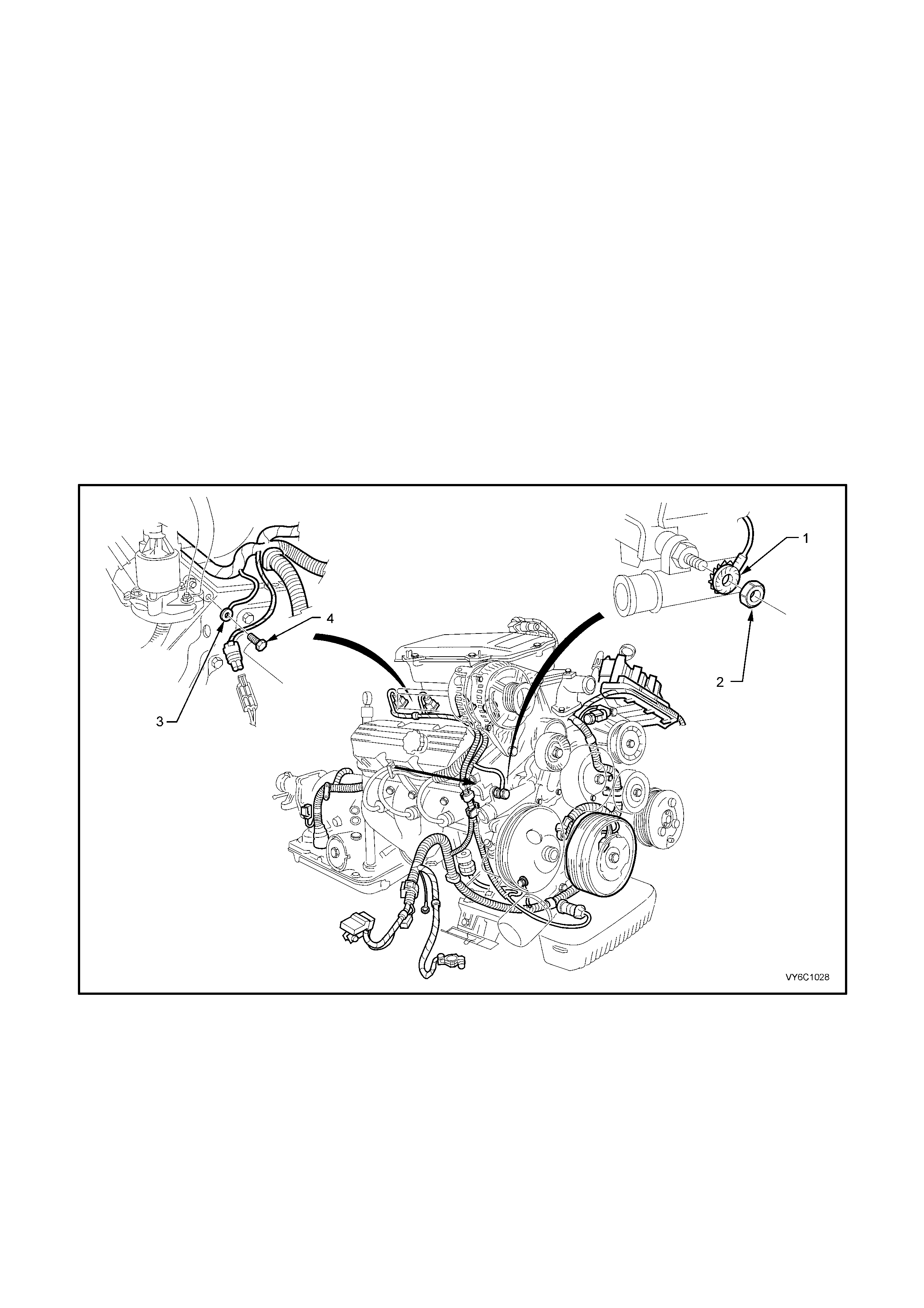
Figure 6C1-2B-1 – V6 Engine – Powertrain Wiring Harness to Engine Assembly Ground Locations.
Legend
1. Engine Ground Terminal.
2. Nut. 3. Engine Ground Terminal.
4. Bolt.

IMPORTANT P RELIMINARY CHECKS
BEFORE USING THIS SECTION:
Before using this Symptoms Section you should have performed the "On Board Diagnostic System Check" as
detailed in Section 6C1-2A DIAGNOSTIC TABLES and determined that:
1. The "Check Powertrain" Malfunction Indicator Lamp (MIL) is operating correctly.
2. There are no diagnostic trouble codes stored.
3. There is a diagnostic trouble code stored in the PCM memory and the "Check Powertrain” MIL is not activated.
4. The diagnostic table for the diagnostic trouble code indicates that the trouble is intermittent.
5. You are familiar with the Powertrain wiring harness to engine assembly ground locations, illustrated in Figure
6C1-2B-1 and as described in the various "SYMPTOM TABLES" in this Section.
SYMPTOM:
Verify the customer complaint, and locate the correct symptom in the table of contents. Check all the items
indicated under that symptom.
If the “ENGINE CRANKS BUT W ILL NOT RUN”, refer to Table A 3.1 in Sect ion 6C1-2A DIAGNOSTIC T ABLES –
V6 ENGINE.
VISUAL/PHYSICAL CHECK:
Several of the symptom procedures call for a “Careful Visual/Physical Check”. The importance of this step cannot
be stressed too strongly, as it can lead to the correction of a problem without further check s, saving valuable time.
This check should include the checking of:
• Service records for any recent repairs that may indicate a related problem, or the current need for scheduled
maintenance.
• PCM sensors for being in their proper location.
• PCM ground circuits ter minate at 2 separ ate eyelet terminals . On a V6 engine, thes e attac h to the engine at two
separate locations : the rear of the lef t cylinder head, and on the by-pass tube and drive belt tensioner attaching
stud, below the generator (refer Figure 6C1-2B-1). They must be clean and tight. Check for ground terminals
that m ay be loose under the retaining nuts/bolts, or for term inals that m ay have been left off after engine repair.
Any repair of the wire to terminal connection must include soldering with resin core solder. (NEVER use acid
core solder for any wiring repairs.)
• Vacuum hoses for splits, kinks, and proper connections. Check thoroughly for any type of leak or restriction.
• Air leaks at throttle body mounting area and intake manifold sealing surfaces.
• Ignition wires for cracking, hardness, proper routing and carbon tracking.
• Wiring for proper connections, pinches and cuts.
• Check for any non genuine Holden's options or accessories that may have been fitted to the vehicle that may
cause or exaggerate the problem.

INTERMITTENTS
DEFINITION: Problem may or may not activate the Check Powertrain Malfunction Indicator Lam p (MIL) or store a
DTC. DO NOT use the Diagnostic Trouble Code (DTC) Tables for intermittent problems. When using the DTC
Tables, the fault must be present to locate the problem. If a fault is intermittent, use of diagnostic trouble code
tables may result in replacement of good parts.
• Most inter mittent problem s are caused by faulty electrical connections or wiring. Perform car eful visual/physical
check as described at the start of this Section - "IMPORTANT PRELIMINARY CHECKS".
CHECK FOR:
• Poor mating of the connector halves or terminals not fully seated in the connector body (backed out).
• Improperly formed or damaged terminals. All connector terminals in the problem circuit should be carefully
reformed or replaced to ensure proper contact tension.
• Poor terminal to wire connection. This requires removing the terminal from the connector body to check as
outlined in service operations.
• PCM ground circuit terminals being loose at the engine. On a V6 engine these attach to the engine at two
separate locations : the rear of the lef t cylinder head, and on the by-pass tube and drive belt tensioner attaching
stud, below the generator, refer Figure 6C1-2B-1.
• If a visual/physical check does not find the cause of the problem, the car can be driven with a voltmeter
connected to a suspected circuit. Tech 2 can also be used to help detect intermittent conditions. An abnormal
voltage, or Tech 2 reading, when the problem occurs, indicates the problem may be in that circuit. If the wiring
and connectors check OK, and a diagnostic trouble code was stored for a circuit having a sensor, except for
DTCs P0132 or P0152 and P0131 or P0151, substitute a known good sensor and recheck.
• Loss of diagnostic code memory. To check, disconnect TP sensor and idle engine until the Check Powertrain
Malfunction MIL activates. DT C P0122 should be stored, and k ept in memory when ignition is turned "OFF." If
not, the PCM is faulty.
• With the V6 engine management system, an intermittent Check Powertrain MIL with no stored diagnostic
trouble code may be caused by:
– Ignition coil shorted to ground and arcing at spark plug wires or plugs.
– Intermittent short to + 12 volts on 0 – 5 volt input, circuits 410 (ECT sensor), 492 (MAF sensor), 411 (TP
sensor), and 5089 (IAT sensor).
• Check for an electrical system interference caused by a defective relay, PCM driven solenoid, or switch. They
can cause a sharp electrical surge. Normally, the problem will occur when the faulty component is operated.
• Check for improper installation of non-factory installed electrical options such as lights, 2 way radios, etc.
• EST wires should be routed away from spark plug wires, ignition wires, ignition module assembly and
generator. The wire from PCM to ignition should have a good connection.
• Check f or an open diode, acr os s A/C c ompres s or c lutch and for other open diodes ( ref er to the wiring diagrams
with TABLE A-11.1 or TABLE A-11.2 in Section 6C1-2A DIAGNOSTIC TABLES.
• If problem has not been found, refer to the proper symptom and perform all checks listed there.

HARD START
DEFINITION: Engine cranks OK, but does not start for a long time. Does eventually run, or may start but
immediately dies.
PRELIMINARY CHECKS:
• Perform the careful visual/physical checks as described at the start of this Section;
"IMPORTANT PRELIMINARY CHECKS".
• Make sure the driver is using the correct starting procedure. Do not depress accelerator pedal during cranking.
• Work through TABLE A-3.1 ENGINE CRANKS BUT WILL NOT RUN in Section 6C1-2A DIAGNOSTIC
TABLES. Although this table may not exactly describe the problem, most all of the causes of a "no start" can
also cause a "hard start".
• Time or distance travelled since a normal engine tune-up has been performed, refer to time/distance intervals
specified in the MY 2003 VY and V2 Series Owner’s Handbook.
• PCM ground circuit terminals being loose at the engine. On a V6 engine these attach to the engine at two
separate locations : the rear of the lef t cylinder head, and on the by-pass tube and drive belt tensioner attaching
stud, below the generator, refer Figure 6C1-2B-1.
SENSORS:
CHECK:
• Engine Coolant Temperature (ECT) sensor using Tech 2, compare coolant temperature with ambient
temperature on cold engine.
If the coolant temperature reading is 5° C greater than or less than ambient air temperature on a cold engine,
check resistance in coolant sensor circuit or sensor itself. Compare ECT resistance value to the "Diagnostic
Aids" table on DTC P0117 table in Section 6C1-2A DIAGNOSTIC TABLES, in this Section.
• MAF sensor for a shifted sensor calibration, refer TABLE A-6.1 MAF SENSOR OUTPUT CHECK in Section
6C1-2A DIAGNOSTIC TABLES.
• TP Sensor for binding or a high TP sensor voltage with the throttle closed.
IGNITION SYSTEM:
CHECK:
• Spark plug leads being misrouted at the coils or at the spark plugs.
• For proper ignition voltage output with spark tester, Tool No. 7230 (also released as ST-125).
• Spark plugs. Remove spark plugs, check for wet plugs, cracks, wear, incorrect gap, burned electrodes, or
heavy deposits. Repair or replace as necessary.
• Bare or shorted wires.
FUEL SYSTEM:
CHECK:
• Fuel pump relay operation; pump should turn "ON" for 2 seconds when ignition is turned "ON." Use
TABLE A-4.1 for Engine.
• Fuel pressure, refer to TABLE A-4.3 in Section 6C1-2A DIAGNOSTIC TABLES.
• Contaminated fuel or incorrect fuel.
• If the problem occurs worse with hotter temperatures, check for leaking injectors, refer
Table A-4.3 FUEL DELIVERY SYSTEM in Section 6C1-2A DIAGNOSTIC TABLES.
NOTE: A faulty in-tank f uel pum p check valve will allow the fuel in the lines to drain back to the tank after engine is
stopped. To check for this condition, perf orm fuel system diagnosis, refer Tab le A-4.3 FUEL DEL IVERY SYSTEM
in Section 6C1-2A DIAGNOSTIC TABLES.
ADDITIONAL CHECKS:
CHECK:
• Exhaust back pressure, refer Table A-13 RESTRICTED EXHAUST CHECK in Section 6C1-2A DIAGNOSTIC
TABLES, in this Section.
• IAC Operation, refer to Table A-7.1 IDLE AIR CONTROL (IAC) SYSTEM in Section 6C1-2A DIAGNOSTIC
TABLES.
• Basic engine problem. Camshaft timing chain for being stripped or slipped, causing valve timing to be retarded.
• Compression. Remove relays ‘X4’ (engine control – EFI) and ‘X16’ (fuel pump) from the underhood electrical
centre, before performing test.
• Service Techlines for update information.

SURGES AND/OR CHUGGLES
DEFINITION: Engine power variation under steady throttle or cruise, feels like the vehicle speeds up and slows
down with no change in the accelerator pedal.
PRELIMINARY CHECKS:
• Perform the careful visual checks as described at the start of this Section - "IMPORTANT PRELIMINARY
CHECKS".
• Make sure driver understands transmission torque converter clutch as explained in the Owner’s Handbook.
• Time or distance travelled since normal engine tune-up has been performed. Refer to time/distance intervals
specified in the MY 2003 VY and V2 Series Owner’s Handbook.
SENSOR CHECKS:
• Oxygen Sensor (HO2S). The Oxygen Sensor (HO2S) should respond quickly to different throttle positions. If
either one does not, chec k eac h Ox ygen Sensor (HO2S) f or silic on or other c ontam ination fr om fuel, or the us e
of improper RTV sealant.
The sensor may have a white, powdery coating and result in a high but false signal voltage (rich exhaust
indication). The PCM will then reduce the amount of fuel delivered to the engine, causing a severe driveability
problem. Also, look for coolant additive contamination or cracking. Also check the LTFT values with Tech 2.
• MAF sensor for proper operation, refer Table A-6.1 MAF SENSOR OUTPUT CHECK in Section 6C1-2A
DIAGNOSTIC TABLES.
IGNITION SYSTEM CHECKS:
• For proper ignition voltage output using spark tester, Tool No. 7230 (also released as ST-125).
• Spark plugs. Remove spark plugs, check for wet plugs, cracks, wear, improper gap, burned electrodes, or
heavy deposits. Repair or replace as necessary. Also, check spark plug wires.
• Ignition secondary coil or wiring shorting to ground.
FUEL SYSTEM CHECKS:
• Contaminated or incorrect fuel.
NOTE: To determine if the condition is caused by a rich or lean system, the vehicle should be driven at the
speed of the c omplaint. Monitoring Long T erm Fuel Trim (LT FT ) and Short Ter m F uel Trim (ST FT) values with
Tech 2 will help to identify a problem.
Lean – Long Term F uel T r im near +25%. Refer to "Diagnos tic Aids " with DTCs P0131 or P0151 in Section 6C1-
2A DIAGNOSTIC TABLES.
Rich – Long T erm Fuel T rim near –22%. Ref er to "Diagnos tic Aids" with DT Cs P0132 or P0152 in Sec tion 6C1-
2A DIAGNOSTIC TABLES.
• Fuel pressure while condition exists, refer Table A-4.3 FUEL DELIVERY SYSTEM in Section 6C1-2A
DIAGNOSTIC TABLES.
• In line fuel filter. Replace if dirty or plugged.
• Restricted fuel injectors. Perform an Injector Balance Test, using Tech 2 to check flow rate. Refer to
2.7 FUEL INJECTOR BALANCE TEST, in Section 6C1-2C FUNCTIONAL CHECKS – V6 ENGINE.
ADDITIONAL CHECKS:
• PCM ground circuits for being clean, tight and in their proper location.
• Vacuum lines for splits, kinks, leaks and proper connections.
• Generator output voltage. Repair if less than 9 or more than 16 volts.
• Speedometer reading with the speed on Tech 2 are equal.
• Service Bulletins for updates.
• Excessive exhaust back pressure, refer Table A-13 RESTRICTED EXHAUST CHECK in Section 6C1-2A
DIAGNOSTIC TABLES.
• TCC operation for proper operation.

LACK OF POWER, SLUGGISH, OR SPONGY
DEFINITION: Engine delivers less than expected power. Little or no increase in speed when accelerator pedal is
pushed down part way.
PRELIMINARY CHECKS:
• Perform the careful visual/physical checks as described at the start of this Section;
"IMPORTANT PRELIMINARY CHECKS".
• Compare customer's car to similar unit. Make sure the customer has an actual problem.
• Remove air filter and check air filter for dirt, or for being plugged. Replace as necessary.
• Tim e or distanc e travelled since norm al engine tune-up has been perform ed. Refer to time/distance intervals in
MY 2003 VY and V2 Series Owner’s Handbook.
SENSOR CHECKS:
• MAF sensor for proper operation, refer Table A-6.1 MAF SENSOR OUTPUT CHECK in Section 6C1-2A
DIAGNOSTIC TABLES.
ENGINE MECHANICAL CHECKS:
• Engine valve timing.
• Engine for correct or worn camshaft.
• Compression. Remove relays ‘X4’ (engine control – EFI) and ‘X16’ (fuel pump) from the underhood electrical
centre, before performing test.
IGNITION SYSTEM CHECKS:
• Secondary voltage using a shop oscilloscope or a spark tester ST-125 or 7230.
• For ignition misfire under heavy engine load. Check each spark plug lead for excessive resistance (or open
circuit), or for faulty or cracked spark plugs.
FUEL SYSTEM CHECKS:
• Restricted fuel filter, refer Table A-4.3 FUEL DELIVERY SYSTEM in Section 6C1-2A DIAGNOSTIC TABLES.
• Fuel pressure, refer Table A -4.3 FUEL DELIVERY SYSTEM in Section 6C1-2A DIAGNOSTIC TABLES.
• Contaminated fuel, refer Table A-4.3 FUEL DELIVERY SYSTEM in Section 6C1-2A DIAGNOSTIC TABLES.
• Fuel Pump. Refer to Table A-4.1 FUEL PUMP ELECTRICAL CIRCUIT in Section 6C1-2A DIAGNOSTIC
TABLES.
ADDITIONAL CHECKS:
• PCM ground circuits for being clean, tight and in their proper locations.
• Generator output voltage. Repair if less than 9 or more than 16 volts.
• Exhaust system for possible re striction, refer Table A-13 REST RICTED EXHAUST CHECK in Section 6C1-2A
DIAGNOSTIC TABLES.
– Inspect exhaust system for damaged or collapsed pipes.
– Inspect muffler for heat distress or possible internal failure.
• Torque Converter Clutch (TCC) for proper operation (if the automatic transmission is fitted).

DETONATION/SPARK KNOCK
DEFINITION: A mild to severe ‘ping’, usually worse under acceleration. The engine makes sharp metallic knocks
that change with throttle opening.
PRELIMINARY CHECKS:
• Perform the careful visual/physical checks as described at the start of this Section;
"IMPORTANT PRELIMINARY CHECKS".
NOTE: If Tech 2 readings are normal (refer information with "On-Board Diagnostic System Check" in
Section 6C1-2A DIAGNOSTIC TABLES) and there are no engine mechanical faults, fill the fuel tank with a
premium unleaded fuel and re-evaluate vehicle performance.
IGNITION SYSTEM CHECKS:
• Spark plugs for proper heat range.
ENGINE MECHANICAL CHECKS:
• Combustion chambers for excessive carbon build up. Remove carbon with top engine cleaner and follow
instructions on can. If the problem re-occurs and top engine cleaner corrects it again, look for possible causes
of high oil consumption.
• For excessive oil in the combustion chamber – Valve stem oil seals leaking.
• Combustion chamber pressure by performing a compression test. Remove relays ‘X4’ (engine control – EFI)
and ‘X16’ (fuel pump) from the underhood electrical centre, before performing test.
• For incorrect basic engine parts such as camshaft, heads, pistons, etc.
COOLING SYSTEM CHECKS:
• Check for obvious overheating problems:
– Low engine coolant.
– Defective engine thermostat.
– Loose water pump drive belt.
– Restricted air flow to radiator, or restricted coolant flow through radiator.
– Inoperative electric cooling fan circuit, refer to Table A-12.1 ELECTRIC FAN CONTROL, in Section 6C1-
2A DIAGNOSTIC TABLES.
– Correct coolant solution should be a 50/50 mix of antifreeze coolant and water.
FUEL SYSTEM CHECKS:
• Fuel quality and proper octane rating.
NOTE: To determine if the condition is caused by a rich or lean system, the car should be driven at the speed of
the complaint. Monitoring Long Term Fuel Trim values with Tech 2 will help identify the problem.
Lean – Long Term F uel T r im near +25%. Refer to "Diagnos tic Aids " with DTCs P0131 or P0151 in Section 6C1-
2A DIAGNOSTIC TABLES.
Rich – Long T erm Fuel T rim near –22%. Ref er to "Diagnos tic Aids" with DT Cs P0132 or P0152 in Sec tion 6C1-
2A DIAGNOSTIC TABLES.
• Fuel pressure, refer to Table A-4.3 FUEL DELIVERY SYSTEM in Section 6C1-2A DIAGNOSTIC TABLES.
ADDITIONAL CHECKS:
• Vacuum leaks.
• TCC operation (TCC applying too soon).
• Service Techlines for update information.

HESITATION, SAG, STUMBLE
DEFINITION: A momentary lack of response as the accelerator is pushed down. Can occur at all vehicle speeds.
Usually most sever e when fir st tr ying to mak e the c ar move, as f r om a s top sign. May cause engine to s tall if severe
enough.
PRELIMINARY CHECKS:
• Perform the careful visual/physical checks as described at the start of this Section;
"IMPORTANT PRELIMINARY CHECKS".
• Time or distance interval since normal engine tune-up has been performed. Refer to time/distance intervals
specified in Owner’s Handbook.
• Vacuum hoses for splits, kinks, and proper connections.
• For vacuum leaks at throttle body mounting and intake manifold.
SENSOR CHECKS:
• TP Sensor - Check TP Sensor for binding or sticking. Voltage should increase at a steady rate as throttle is
moved toward Wide Open Throttle (WOT), refer Table A-6.2 in Section 6C1-2A DIAGNOSTIC TABLES.
• MAF sensor, refer to Table A-6.1 MAF SENSOR OUTPUT CHECK in Section 6C1-2A DIAGNOSTIC TABLES.
• Engine coolant temperatur e s ensor res is tance. Ref er to DT C P0117 in Sec tion 6C1- 2A DIAG NOSTIC T ABLES,
for engine coolant temperature sensor temperature versus resistance table.
IGNITION SYSTEM CHECKS:
• Spark plugs for being fouled, or for there being faulty secondary wiring.
• Ignition system ground, circuit 453.
FUEL SYSTEM CHECKS:
• Fuel pressure, refer to Table A-4.3 FUEL DELIVERY SYSTEM in Section 6C1-2A DIAGNOSTIC TABLES.
• Contaminated or incorrect fuel.
• Canister purge sy stem for proper operation.
• Fuel injectors. Perform injector balance test. Refer to 2.7 FUEL INJECT OR BALANCE T EST, in Section 6C1-
2C FUNCTIONAL CHECKS – V6 ENGINE.
ADDITIONAL CHECKS:
• Service Techlines for update information.
• Exhaust system back press ure, refer T able A-13 RESTRICT ED EXHAUST SYST EM T EST in Sec tion 6C1-2A
DIAGNOSTIC TABLES.
• Engine thermostat functioning correctly and proper heat range.
• Generator output voltage. Repair if less than 9 or more than 16 volts.

CUTS OUT, MISSES
DEFINITION: Steady pulsation or jerking that follows engine speed, usually more pronounced as engine load
increases. The exhaust has a steady spitting sound at idle or under load.
PRELIMINARY CHECKS:
• Perform the careful visual/physical checks as described at start of this Section;
"IMPORTANT PRELIMINARY CHECKS".
IGNITION SYSTEM CHECKS:
• If ignition system is suspected of causing a miss at idle or cutting out under load.
• If the previous checks did not find the problem, visually inspect ignition system for moisture, dust, cracks, burns,
etc. Spray plug wires with fine water mist to check for shorts.
• Check for a misfiring cylinder at idle by:
1. Start engine and perform a cylinder balance test, using Tech 2.
2. If there is an engine speed drop on all cylinders (equal to within 50 rpm), go to the
ROUGH, UNSTABLE, OR INCORRECT IDLE, STA LLING symptom, in this Section.
3. If there is no engine speed drop on one or more cylinders, or excessive variation in drop, check for spark on
the suspected c ylinder(s) with Spark Chec k ing Tool No. 7230 ( also released as ST -125). If no spark , check
plug lead for excessive resistance (or possibly ‘open'). If there is spark, remove spark plug(s) in those
cylinders and check for:
– Cracks – Wear.
– Improper Gap – Burned Electrodes.
– Heavy Deposits.
ENGINE MECHANICAL CHECKS:
• Compression. Perform compression check on questionable cylinder(s) found above. If compression is low,
repair as necessary. Remove relays ‘X4’ (engine control – EFI) and ‘X16’ (fuel pump) from the underhood
electrical centre, before performing test.
• Base engine. Remove rocker covers. Check for bent pushrods, worn rocker arms, broken valve springs, worn
camshaft lobes and valve timing, repair as necessary.
FUEL SYSTEM CHECKS:
• Fuel system – Blocked fuel filter, low pressure, refer Table A-4.3 FUEL DELIVERY SYSTEM in Section 6C1-
2A DIAGNOSTIC TABLES.
• Contaminated or incorrect fuel.
• Performance of injector. If there is good spark and compression on all cylinders, check for restricted or non-
operating fuel injectors. To check for a non-operating injector, perform an Injector Balance test, using Tech 2,
or:
W ith the engine idling, check for c licking sound at each inj ector with a stethoscope or long screwdriver held on
the body of each injector. If any injector fails to make the clicking sound, disconnect the electrical connector,
and connect an injector node light tester such as Tool No. J34730-2C (also released as BT-8329), across the
harness connector terminals. If the test light blinks with the engine idling, replace the injector. If there is no
blinking light, check f or an "open" wire leading to that injector. Ref er to 3.1 ENGINE CRANKS BUT W ILL NOT
RUN, in Section 6C1-2A DIAGNOSTIC TABLES.
ADDITIONAL CHECKS:
• For EMI interference. A missing condition can be caused by Electromagnetic Interference (EMI) on the
reference circuit. EMI can usually be detected by monitoring engine RPM with Tech 2. A sudden increase in
engine speed with little change in actual engine RPM, is indicative that EMI is present. If the problem exists,
check routing of secondary wires and also check ground circuit.
• Intake and exhaust manifold passages for a casting flash.

ROUGH, UNSTABLE, OR INCORRECT IDLE , S TALLING
DEFINITION: Engine runs unevenly at idle. If bad enough, the vehicle may shake. Also, the idle may vary in RPM
(called "hunting"). Either condition may be bad enough to cause stalling. Engine idles at incorrect speed.
PRELIMINARY CHECKS:
• Perform the careful visual/physical checks as described at the start of this Section;
"IMPORTANT PRELIMINARY CHECKS".
• For vacuum leaks, they will cause an erratic idle.
• PCM grounds are clean, tight and in there correct location(s). Refer to PCM wiring diagrams.
• Idle Air Control (IAC) system for proper operation, refer Table A-7.1 IDLE AIR CONTROL (IAC) SYSTEM, in
Section 6C1-2A DIAGNOSTIC TABLES.
• For proper ignition voltage output using spark tester, Tool No. 7230 (also released as ST-125).
• Spark plugs. Remove spark plugs, check for wet plugs, cracks, wear, improper gap, burned electrodes, or
heavy deposits.
ENGINE MECHANICAL CHECKS:
• Perform a cylinder compression check. Remove relays ‘X4’ (engine control – EFI) and ‘X16’ (fuel pump) from
the underhood electrical centre, before performing test.
• For correct camshaft valve lift and timing or weak valve springs.
FUEL SYSTEM CHECKS:
• For contaminated or incorrect fuel.
• For injectors that are restricted or not operating. Perform an Injector Balance Test, using Tech 2. Refer to
2.7 FUEL INJECTOR BALANCE TEST, in Section 6C1-2C FUNCTIONAL CHECKS – V6 ENGINE.
• For injectors leak ing, or incorrect fuel pressure, refer Table A-4.3 FUEL DELIVERY SYST EM in Section 6C1-
2A DIAGNOSTIC TABLES.
• Monitoring Long Term Fuel trim will help identify the cause of the problem . If the system is running lean (Long
Term Fuel Trim near +25%), refer to "Diagnostic Aids" with DTC P0131 or P0151 in Section 6C1-2A
DIAGNOST IC T ABLES in this Section. If the system is running rich (Long T erm Fuel Tr im near –22%) , refer to
"Diagnostic Aids" with DTC P0132 or P0152, in Section 6C1-2A DIAGNOSTIC TABLES.
• For fuel in pressure regulator hose. If fuel is present, replace regulator assembly.
• The Oxygen Sensors (HO2S) should respond quickly to different throttle positions, if they do not, check the
Oxygen Sensors (HO2S) for silicon contamination from fuel, or use of improper RTV sealant. The sensor will
have a white, powdery coating, and will result in a high but false signal voltage (rich exhaust indication). The
PCM will then reduce the amount of fuel delivered to the engine, causing a severe driveability problem.
ADDITIONAL CHECKS:
• MAF sensor, refer to Table A-6.1 MAF SENSOR OUTPUT CHECK in Section 6C1-2A DIAGNOSTIC TABLES.
• Throttle linkage for sticking or binding.
• IAC operation, refer Table A-7.1 IDLE AIR CONTROL (IAC) SYSTEM in Section 6C1-2A DIAGNOSTIC
TABLES.
• A/C signal to PCM. Tech 2 should indicate A/C is being requested whenever A/C is selected and the blower
switch is "ON." If problem exists with A/C "ON," check A/C system operation Table A-11.1 A/C CONTROL
(Non OCC SYSTEM) or Table A-11.2 A/C CONTROL (With OCC SYSTEM) in Section 6C1-2A DIAGNOSTIC
TABLES.
• PCV valve for proper operation. Refer 2.1 POSITIVE CRANKCASE VENTILATION VALVE, in Section 6E1
EMISSION CONTROL V6 ENGINE, in the MY 2003 VY and V2 Series Service Information.
• Service Techlines for update information.
• For broken engine support mounts.
• Generator output voltage. Repair if less than 9 or more than 16 volts.
• Battery cables and ground straps should be clean and secure. Erratic voltage will cause IAC to change its
position resulting in poor idle quality.

POOR FUEL ECONOMY
DEFINITION: Fuel ec onomy, as m easur ed by an actual road test, is notic eably lower than expected. Also, economy
is noticeably lower than it was on this vehicle at one time, as previously shown by an actual road test.
IMPORTANT: A m isfiring engine will have excessive unburned oxygen in the exhaust, and the "Closed-Loop" fuel
control system oxygen sensor will interpret a lean exhaust. The PCM will cause an increase in fuel injector pulse
width in attempts to overcome the lean exhaust indication.
PRELIMINARY CHECKS:
• Perform the careful visual checks as described at the start of this Section;
"IMPORTANT PRELIMINARY CHECKS".
• Visually/physically check: Vacuum hoses for splits, kinks, and proper connections.
• Check owner's driving habits.
– Is A/C "ON" full time (Defroster mode "ON")?
– Are tyres at correct pressure?
– Are excessively heavy loads being carried?
– Is acceleration too much, too often?
• Check air cleaner element (filter) for dirty or being blocked.
• Check for correct size tyres. Oversize tyres will cause speedometer/odometer to be "slow," and indicated fuel
usage may increase.
IGNITION SYSTEM CHECKS:
• Spark plugs. Remove spark plugs, check for wet plugs, cracks, wear, improper gap, burned electrodes, or
heavy deposits. Repair or replace as necessary.
COOLING SYSTEM CHECKS:
• Engine coolant level.
• Engine thermostat for faulty part (always open) or for wrong heat range.
ENGINE MECHANICAL CHECKS:
• Compression. Remove relays ‘X4’ (engine control – EFI) and ‘X16’ (fuel pump) from the underhood electrical
centre, before performing test.
ADDITIONAL CHECKS:
• TCC operation. Tech 2 should indicate an rpm drop, when the TCC is commanded "ON."
• For dragging brakes.
• For exhaust system restriction, refer to Table A-13 RESTRICTED EXHAUST CHECK in Section 6C1-2A
DIAGNOSTIC TABLES.
• For proper calibration of speedometer.
• Induction system and crankcase for air leaks.
• Exhaust system for air leaks before the oxygen sensor(s).
FUEL SYSTEM CHECKS:
• For leaking injectors or high fuel pressure or an external fuel leak.
• Long Term Fuel Trim values using Tech 2, for an abnormally high reading; i.e. greater than 10% (possibly
caused by engine misfiring).

BACKFIRE
DEFINITION: Fuel ignites in intake manifold, or in exhaust system, making loud popping noise.
PRELIMINARY CHECKS:
• Perform the careful visual/physical checks as described at the start of this Section;
"IMPORTANT PRELIMINARY CHECKS".
IGNITION SYSTEM CHECKS:
• Proper ignition coil output voltage with spark tester, Tool No. 7230 (also released as ST-125).
• Spark plugs. Remove spark plugs, check for wet plugs, cracks, wear, improper gap, burned electrodes, or
heavy deposits. Repair or replace as necessary.
• Spark plug wires for proper routing to avoid cross-fire and correct resistance.
ENGINE MECHANICAL CHECKS:
• Compression - Look for sticking or leaking valves. Remove relays ‘X4’ (engine control – EFI) and ‘X16’ (fuel
pump) from the underhood electrical centre, before performing test.
• Valve timing.
• Intake and exhaust manifold passages for a casting flash.
FUEL SYSTEM CHECKS:
• Perform "Fuel System Diagnosis Check", refer Table A-4.3 FUEL DELIVERY SYSTEM in Section 6C1-2A
DIAGNOSTIC TABLES.

EXCESSIVE EXHAUST EMISSIONS OR ODOURS
DEFINITION: Vehicle fails an emission test. Vehicle has excessive "rotten egg" smell. Excessive odours do not
necessarily indicate exce ssive emissions.
PRELIMINARY CHECKS
• Perform "On-Board Diagnostic System Check" in Section 6C1-2A DIAGNOSTIC TABLES.
IGNITION SYSTEM CHECKS:
• Spark plugs. Remove spark plugs, check for wet plugs, cracks, wear, improper gap, burned electrodes, or
heavy deposits. Repair or replace as necessary.
COOLING SYSTEM CHECKS:
• If Tech 2 indicates a very high engine coolant temperature and the system is running lean, check:
– Engine coolant level.
– Engine thermostat for faulty part (always open) or for wrong heat range.
– Cooling fan operation.
FUEL SYSTEM CHECKS:
• For contaminated or incorrect fuel.
NOTE: If the system is running RICH (Long T erm F uel Tr im near –22%) - Refer to "Diagnostic Aids" with DT Cs
P0132 or P0152 in Section 6C1-2A DIAGNOSTIC TABLES. If the system is running LEAN (Long Term Fuel
Trim near +25%) - Refer to "Diagnostic Aids" with DTCs P0131 or P0151 in Section 6C1-2A DIAGNOSTIC
TABLES.
• For properly installed fuel tank cap.
• Fuel pressure, refer to Table A-4.3 FUEL DELIVERY SYSTEM in Section 6C1-2A DIAGNOSTIC TABLES.
• Canister for fuel loading.
ADDITIONAL CHECKS:
• For vacuum leaks.
• Burnt valves.
• For lead contamination of catalytic converter (look for the removal of the fuel filler neck restriction).
• Carbon build-up. Remove carbon with top engine cleaner. Follow instructions on can.
• For exhaust system restriction, refer to Table A-13 RESTRICTED EXHAUST CHECK in Section 6C1-2A
DIAGNOSTIC TABLES.
• PCV valve for being plugged or stuck, or fuel in the crankcase.
• Service Bulletins for updates.

DIESELING, RUN-ON
DEFINITION: Engine continues to run after ignition is turned "OFF," but runs very roughly.
PRELIMINARY CHECKS:
• Perform the careful visual/physical checks as described at the start of this Section;
"IMPORTANT PRELIMINARY CHECKS".
FUEL SYSTEM CHECKS:
• Injector s f or leak ing. Per form "F uel System Diagnosis Check ", ref er to T abl e A-4.3 F UEL DELI VERY SYST EM
in Section 6C1-2A DIAGNOSTIC TABLES.
IGNITION SYSTEM CHECKS:
• If engine runs smoothly, check ignition switch and adjustment.

RICH/LEAN SYMPTOM CHART
CIRCUIT DESCRIPTION:
The Rich/Lean Symptom Chart is an organised appr oach to identifying a driveability com plaint that may be caused
by an over rich or over lean operating condition. Under standing the Chart and us ing it corr ectly will reduce diagnostic
time and improve customer satisfaction. Start at the left side of the Chart and work to the right.
TEST DESCRIPTION:
NOTE: The number(s) below refer to the step number(s) on the diagnostic table.
1. This is a partial list of possible customer complaints and what the air/fuel mixture must be to cause such a
condition.
2. A lean exhaust m eans that there is a lot of ox ygen in the ex haust str eam . Lots of oxygen in the exhaust stream
means a low oxygen sensor signal voltage. Lean = lots of oxygen = low oxygen sensor signal voltage. A rich
exhaust means that there is some fuel and very little oxygen in the exhaust stream.
3. The oxygen sensor signal to the PCM determines what the PCM should do to compensate for the present
condition. Depending upon the severity of the problem , the PCM will compensate f or the condition by changing
the Short Term Fuel Trim and Long T erm Fuel Trim values either higher or lower. A short term fuel trim value
above 0% m eans the PCM will add m or e f uel to the engine, by increasing the injector pulsewidth, thus making a
lean engine run richer. A s hort term f uel trim value below 0% m eans the PCM will decr ease the am ount of fuel
to the engine, by decreasing the injector pulse width, thus making a rich engine run leaner.
4. This list represents areas where you should look to find the root cause of the customer complaint. Not every
cause of the symptom is listed here, however, the items listed provide a good general description of areas to
look at.
DIAGNOSTIC AIDS:
Driveability complaints may be caused by the PCM, system components or electrical faults, however, a basic engine
problem may also present a symptom sim ilar to an electr ical failure. Rem em ber to check the air cleaner and all the
basic engine components, there could be worn rings, worn camshaft lobes, collapsed lifters, misaligned timing
chain, vacuum leaks etc.
RICH/LEAN SYMPTOM CHART
VEHICLE OPERATION OXYGEN SENSOR
OPERA TION SHORT AND LONG TERM
FUEL TRIM OPERATION POSSIBLE CAUSES
CUSTOMER
DRIVEABILITY
COMPLAINT/SYMPTOM
EXHAUST
STREAM
STATUS
OXYGEN
SENSOR
VOLTAGE
LEAN Air/Fuel Mixture
High NOx Emis sions
Stumbles/Stalls
Surges
Poor Performance
High
Oxygen
Content
LEAN
EXHAUST
0 mV
+ 25 %
RICH COM MAND
ADD FUEL
LEAN Air/Fuel Mi xture
Short Term Fuel Trim and Long Term
Fuel Trim are numeric al ly i ncreasing
High (above 0%) possible DTC
P0131 or DTC P0151.
Oxygen Sensor voltage between 450
mV and 0 mV.
Cause: Fuel s ys t em not i n control.
Check For:
Poor PCM grounds.
Intak e manif ol d vacuum l eak.
Restricted fuel f i l ter.
Low fuel pressure.
Water c ontami nation in fuel .
Lean (restricted fl ow), fuel
injector(s).
16 to 1 Air/Fuel Mixture
Increas e I nj ector Pul se
Width
Oxygen Sensor being “Trick ed” Lean.
Cause: Too m uch air in exhaust
stream above oxygen sensor.
Cylinders not firing (misfire),
sending unburned air/ f uel mixture
into exhaust.
Cracked or leaking exhaust
manifold.
Oxygen sensor mount i ng i s loose,
dirty or has no sealing washer.
14.7:1 Air/Fuel Mixture 450 mV 0 % NO
CHANGE
RICH Air/Fuel Mixture
Short Term Fuel Trim and Long Term
Fuel Trim are numeric al ly decreasing
low (below 0%) possible DTC P 0132
or DTC P0152.
Oxygen Sensor voltage between 450
mV and 1,000 mV.
13 to 1 Air/Fuel Mixture
RICH Air/Fuel Mixture
High HC, CO Emis sions
Black Sm oke
Catalytic Converter Odour
Decrease I nj ector Pul se
Width
REMOVE FUEL
LEAN COMMAND
Cause: Fuel s ys t em not i n control.
Check For:
Restricted (dirt y) ai r f i l ter.
Leaking injector(s ).
High fuel pres sure.
Restricted fuel return line.
ECT tem perature value low.
Oxygen Sensor contaminated
(covered with foreign substance).
Engine oil contam i nated with fuel.
Canister purge continuous l y
purging.
– Fouled Spark Plugs RICH
EXHAUST 1, 000 mV –22% Oxygen Sensor being “Trick ed” Ri ch.
Cause: Not enough air i n exhaust .
Low
Oxygen
Content
Restricted exhaust s ys tem.
Oxygen Sensor ground, wire
open, or has a poor c onnection.
Oxygen Sensor poisoned
(impregnated with foreign
substance).
When using Tech 2 to observe S hort Term Fuel Tri m and Long Term Fuel Trim values, remem ber that, i f the syst em is i n control,
no action is required unless there is a driveabilit y symptom present.
AUTOMATIC TRANSMISSION SYMPTOM TABLES
OIL PRESSURE HIGH OR LOW
Checks Causes
Oil Pump Assembly • Pressure regulator valve stuck
• Pressure regulator valve spring
• Rotor guide omitted or disassembled
• Rotor cracked or broken
• Reverse boost valve or sleeve stuck, damaged or incorrectly assembled
• Orifice hole in pressure regulator valve plugged
• Sticking slide
• Pressure relief ball not seated or damaged
• Porosity in pump cover or body
• Wrong pump cover
• Pump faces not flat
• Excessive rotor clearance
Oil Filter • Intake pipe restricted by casting flash
• Cracks in filter body or intake pipe
• O-ring seal missing, cut or damaged
• Wrong grease used on rebuild
Valve Body • Manual valve scored or damaged
• Spacer plate or gaskets incorrect, misassembled or damaged
• Face not flat
• 2-3 Shift valve stuck
• Checkballs omitted or misassembled
Pressure Control Solenoid
Valve • Damage to pins
TFP Manual Valve Position
Switch • Contamination
• Damaged seals
Case • Case to valve body face not flat
HARSH SHIFTS/INACCURATE SHIFT POINTS
Checks Causes
Throttle Position Sensor • Open or shorted circuit
Vehicle Speed Sensor • Open or shorted circuit
TFP Manual Valve Position
Switch • Contamination
• Damaged seals
Trans Fluid Temperature
Sensor • Open or shorted circuit
Engine Coolant
Temperature Sensor • Open or shorted circuit
Pressure Control Solenoid
Valve • Damage to pins
• Contamination
Oil Pump Assembly • Stuck pressure regulator valve
• Sticking pump slide
Valve Body Assembly • Spacer plate or gaskets misassembled, damaged or incorrect
Case • Porous or damaged valve body pad
• 2-4 Servo Assembly:
– 2-4 accumulator porosity
– Damaged servo piston seals
– Apply pin damaged or improper length
• 2-4 Band Assembly:
– Burned
– Anchor pin not engaged
TP Sensor • Disconnected
• Damaged
Vehicle Speed Sensor • Disconnected
• Damaged
• Bolt not tightened

1ST GEAR RANGE ONLY - NO UPSHIFT
Checks Causes
Valve Body • The 1-2 Shift valve is sticking
• The spacer plate or gaskets are mispositioned or damaged
Case • The case to valve body face is damaged or is not flat
Shift Solenoid Valves • Stuck or damaged
• Faulty electrical connection
2-4 Servo Assembly • The apply passage in the case is restricted or blocked
• Nicks or burrs on the servo pin or on the pin bore in the case
• Fourth servo pistons installed backwards
2-4 Band Assembly • The 2-4 band is worn or damaged
• The band anchor pin is not engaged
Vehicle Speed Sensor • No signal.
SLIPS IN 1ST GEAR
Checks Causes
Forward Clutch Assembly • Clutch plates worn
• Porosity or damage in forward clutch piston
• Forward clutch piston inner and outer seals missing, cut or damaged
• Damaged forward clutch housing
• Forward clutch housing retainer and ball assembly not sealing or damaged
Forward Clutch
Accumulator • Piston seal missing, cut or damaged
• Piston out of its bore
• Porosity in the piston or valve body
• Stuck abuse valve
Forward Sprag Assembly • Forward sprag assembly not holding
Input Housing and Shaft
Assembly • Turbine shaft seals missing, cut or damaged
Valve Body • 1-2 Accumulator valve stuck
• Face not flat, damaged lands or interconnected passages
• Spacer plate or gaskets incorrect, mispositioned or damaged
Low Roller Clutch • Damage to lugs to inner ramps
• Rollers not free moving
• Inadequate spring tension
• Damage to inner splines
• Lube passage plugged
Torque Converter • Stator roller clutch not holding
1-2 Accumulator Assembly • Porosity in piston or 1-2 Accumulator cover and pin assembly
• Damaged ring grooves on piston
• Piston seal missing, cut or damaged
• Valve body to spacer plate gasket at 1-2 Accumulator cover, missing or damaged
• Leak between piston and pin
• Broken 1-2 Accumulator spring
Line Pressure • Refer to Oil Pressure High or Low
2-4 Servo Assembly • 4th Servo piston in backward
SLIPPING OR ROUGH 1-2 SHIFT
Checks Causes
Valve Body Assembly • 1-2 Shift valve train stuck
• Gaskets or spacer plate incorrect, mispositioned or damaged
• 1-2 Accumulator valve stuck
• Face not flat
2-4 Servo Assembly • Apply pin too long or too short
• 2nd servo apply piston seal missing, cut or damaged
• Restricted or missing oil passages
• Servo bore in case damaged
1-2 Accumulator • Porosity in 1-2 accumulator housing or piston
• Piston seal or groove damaged
• Nicks or burrs in 1-2 accumulator housing
• Missing or restricted oil passage
2-4 Band • Worn or mispositioned
Oil Pump Assembly or Case • Faces not flat
NO 2-3 SHIFT OR 2-3 SHIFT SLIPS, ROUGH OR HUNTING
Checks Causes
Torque Converter • Internal damage.
Valve Body Assembly • 2-3 Shift valve train stuck.
• Accumulator valve stuck.
• Gaskets or spacer plate incorrect, mispositioned or damaged.
2-4 Servo Assembly • 2nd apply servo piston seals missing, cut or damaged.
Input Housing Assembly • Clutch plates worn (3-4 or forward).
• Excessive clutch plate travel.
• Cut or damaged 3-4 or forward clutch seals.
• Porosity in input clutch housing or piston.
• 3-4 Piston checkball stuck, damaged or not seating.
• Restricted apply passages.
• Forward clutch piston retainer and ball assembly not seating.
• Sealing balls loose or missing.
Oil Pump Assembly • Stator shaft sleeve scored or off location.
Transmission Case • 3rd accumulator retainer and ball assembly not sealing.
2ND/3RD GEARS ONLY OR 1ST/4TH GEARS ONLY
Checks Causes
Shift Solenoid Valves • Sediment is in the valves.
• The electrical connection is faulty.
• Damaged seal.
THIRD GEAR ONLY
Checks Causes
DTC 81 • The electrical connection is faulty.
• Shorted or damaged.
3-2 FLARE OR TIE-UP
Checks Causes
3-2 Shift Solenoid • Shorted or damaged.
• Contamination.
• Damaged Seal.

NO 3-4 SHIFT, SLIPS OR ROUGH 3-4 SHIFT
Checks Causes
Oil Pump Assembly • Pump cover retainer and ball assembly omitted or damaged.
• Faces not flat.
Valve Body Assembly • Valves stuck:
– 2-3 Shift valve train.
– Accumulator valve.
– 1-2 Shift valve train.
– 3-2 Shift valve.
• Spacer plate or gasket incorrect, mispositioned or damaged.
2-4 Servo Assembly • Incorrect band apply pin.
• Missing or damaged servo seals.
• Porosity in piston, cover or case.
• Damaged piston seal grooves.
• Plugged or missing orifice cup plug.
Case • 3rd Accumulator retainer and ball assembly leaking.
• Porosity in 3-4 accumulator piston or bore.
• 3-4 Accumulator piston seal or seal grooves damaged.
• Plugged or missing orifice cup plug.
• Restricted oil passage.
Input Housing Assembly • Refer to Slipping 2-3 Shift
2-4 Band Assembly • Worn or Disassembled
NO REVERSE OR SLIPS IN REVERSE
Checks Causes
Input Housing Assembly • 3-4 Apply ring stuck in applied position.
• Forward clutch not releasing.
• Turbine shaft seals missing, cut or damaged.
Manual Valve Link • Disconnected.
Valve Body Assembly • 2-3 Shift valve stuck.
• Manual linkage not adjusted.
• Spacer plate and gaskets incorrect, mispositioned or damaged.
• Lo overrun valve stuck.
• Orificed cup plug restricted, missing or damaged.
Reverse Input Clutch
Assembly • Clutch plate worn.
• Reverse input housing and drum assembly cracked at weld.
• Clutch plate retaining ring out of groove.
• Return spring assembly retaining ring out of groove.
• Seals cut or damaged.
• Restricted apply passage.
• Porosity in piston.
• Belleville plate installed incorrectly.
• Excessive clutch plate travel.
• Oversized housing.
Lo and Reverse Clutch • Clutch plates worn.
• Porosity in piston.
• Seals damaged.
• Return spring assembly retaining ring mispositioned.
• Restricted apply passage.
NO PART THROTTLE OR DELAYED DOWNSHIFTS
Checks Causes
2-4 Servo Assembly • Servo cover retaining ring omitted or misassembled.
• 4th Apply piston damaged or misassembled.
• Servo inner housing damaged or misassembled.
Valve Body Assembly • 3-2 Downshift valve stuck.
• 4-3 Sequence valve body channel blocked.
HARSH GA RAGE SHIFT
Checks Causes
Valve Body Assembly • Orifice cup plug missing.
• Checkball missing.
NO OVERRUN BRAKING - MANUAL 3-2-1
Checks Causes
External Linkage • Not adjusted properly.
Valve Body Assembly • 4-3 Sequence valve stuck.
• Checkball mispositioned.
• Spacer plate and gaskets incorrect, damaged or mispositioned.
Input Clutch Assembly • Turbine shaft oil passages plugged or not drilled.
• Turbine shaft seal rings damaged.
• Turbine shaft sealing balls loose or missing.
• Porosity in forward or overrun clutch piston.
• Overrun piston seals cut or damaged.
• Overrun piston checkball not sealing.
NO TCC APPLY
Checks Causes
Electrical • 12 Volts not supplied to transmission.
• Outside electrical connector damaged.
• Inside electrical connector, wiring harness or solenoid damaged.
• Electrical short (pinched solenoid wire).
• Solenoid not grounded.
Converter • Internal damage.
Oil Pump Assembly • Converter clutch valve stuck or assembled backwards.
• Converter clutch valve retaining ring mispositioned.
• Pump to case gasket mispositioned.
• Orifice cup plug restricted or damaged.
• Solenoid O-ring seal cut or damaged.
• High or uneven bolt torque (pump body to cover).
Input Housing and Shaft • Turbine shaft O-ring seal cut or damaged.
• Turbine shaft retainer and ball assembly restricted or damaged.
TFP Manual Valve
Position Switch • Contamination.
• Damaged seals.
Valve Body Assembly • TCC signal valve stuck.
• Solenoid O-ring leaking.
Solenoid Screen • Blocked.
TCC Solenoid Valve • Valve stuck.
Engine Speed Sensor • Incorrect or no signal.
Engine Coolant
Temperature Sensor • Temperature reading too low or too high.
DTCs P0121, P0122,
P0123, P0740, P0753,
P1810, P1860
–
Transmission Fluid
Temperature Sensor • Temperature reading incorrect
TORQUE CONVERTER CLUTCH SHUDDER
Checks Causes
Electrical • 12 Volts not supplied to transmission.
• Powertrain harness connector to pass-thru connector damaged.
• Internal connector, wiring harness or solenoid damaged.
• Electrical short (pinched solenoid wire).
• Solenoid not grounded.
Converter • Internal damage.
Oil Pump Assembly • Converter clutch valve stuck or assembled backwards.
• Restricted oil passage.
Input Housing and Shaft • Turbine shaft O-ring seal cut or damaged.
• Turbine shaft retainer and ball assembly restricted or damaged.
Fluid Filter • Crack in filter body.
• Casting flash restricting filter neck.
• O-ring seal cut or damaged.
Miscellaneous • Low fluid pressure.
• Engine not tuned correctly.
Input Housing and Shaft
Assembly • Turbine shaft O-ring cut or damaged.
• Turbine shaft retainer and ball assembly restricted or damaged.
NO TCC RELEASE
Checks Causes
TCC Solenoid Valve • Internal ground.
• Clogged exhaust orifice.
Converter • Internal damage.
Valve Body Assembly • The converter clutch apply valve is stuck in the apply position.
Oil Pump Assembly • The converter clutch valve is stuck.
PCM • External ground.
DRIVES IN NEUTRAL
Checks Causes
Forward Clutch • The clutch does not release
Manual Valve Link • Disconnected
Case • The face is not flat
• Internal leakage exists
2ND GEAR START (DRIVE RANGE)
Checks Causes
Forward Clutch Sprag
Assembly • The sprag assembly is installed backwards.
NO PARK
Checks Causes
Parking Linkage • Actuator rod assembly bent or damaged.
• Actuator rod spring binding or improperly crimped.
• Actuator rod not attached to inside detent lever.
• Parking lock bracket damaged or not torqued properly.
• Inside detent lever not torqued properly.
• Parking pawl binding or damaged.
RATCHETING NOISE
Checks Causes
Parking Pawl • The parking pawl return spring is weak, damaged, or misassembled
FLUID OUT THE VENT
Checks Causes
Oil Pump • Chamber in pump body rotor pocket.
Miscellaneous • Fluid level – overfilled.
VIBRATION IN REVERSE AND WHINING NOISE IN PARK
Checks Causes
Oil Pump • Chamber in pump body rotor pocket.
Miscellaneous • Fluid level – overfilled.
NO DRIVE IN ALL RANGES
Checks Causes
Torque Converter • The converter to flex plate bolts are missing.
NO DRIVE IN DRIVE RANGE
Checks Causes
Torque Converter • The stator roller clutch is not holding.
• The converter to flex plate bolts are missing.
FRONT OIL LEAK
Checks Causes
Torque Converter • The welded seam is leaking.
• The converter hub is damaged.
Torque Converter Seal • The seal assembly is damaged.
• The garter spring is missing.
DELAY IN DRIVE AND REVERSE
Checks Causes
Torque Converter • Converter drainback

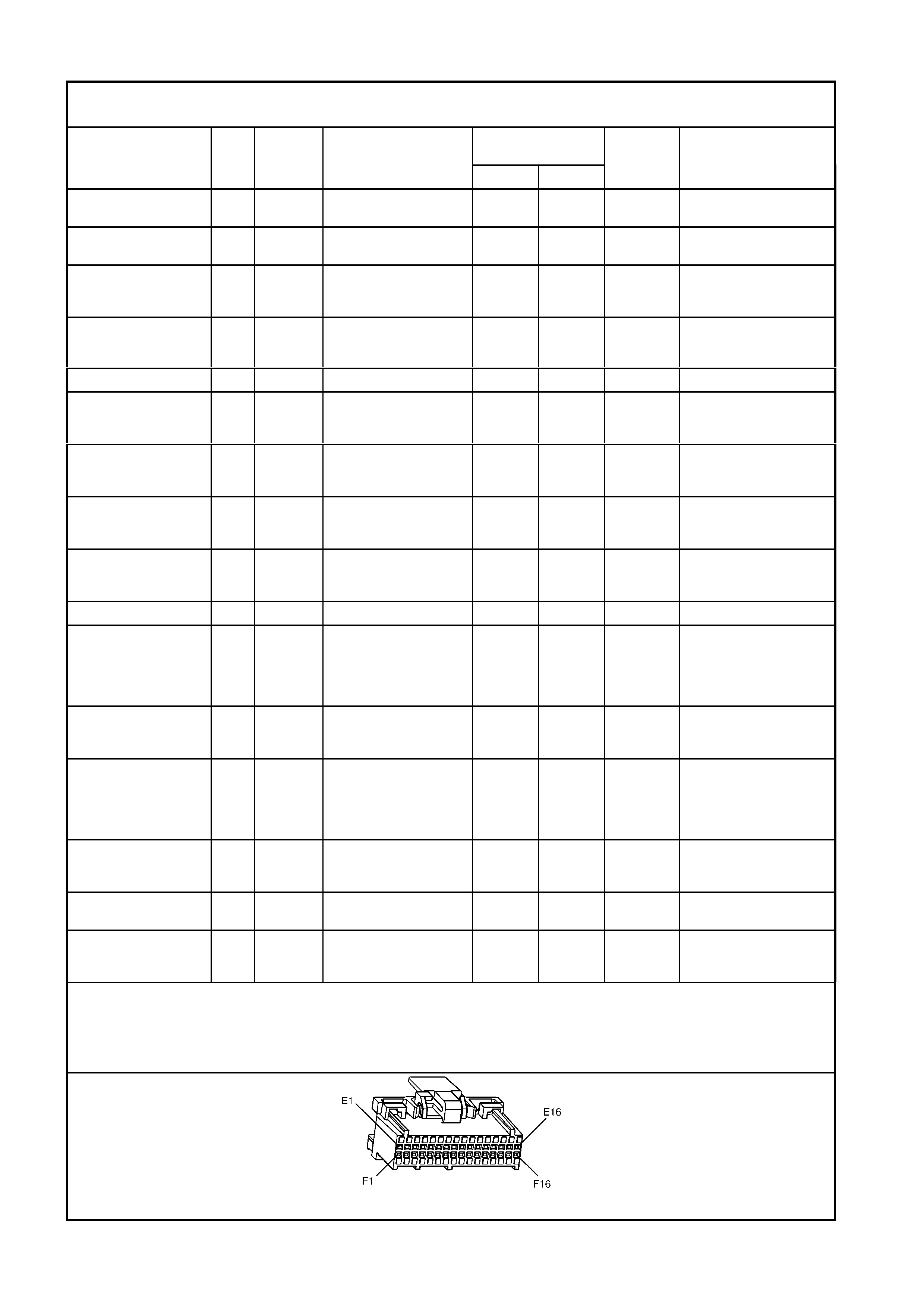
PCM CONNECTOR SYMPTOM TABLES
The following Powertrain Control Module (PCM) connector Symptoms Tables identifies the function of each pin of
the PCM connector, the c irc uit number, the wire colour , and the c avity of the com ponent to which the wire connects.
The left column in these table lists the PCM connector pins in ascending order. The tables may also be entered
from the r ight-m ost colum n, which lis ts poss ible symptom s that m ay be caused by a fault in each of the cir cuits. If a
problem in any of these circuits will cause a Diagnostic Trouble Code to be set, the DTC's are identified in the
second column from the right edge of the Table. (However, if a DTC has been s et, you should attem pt to diagnose
the condition using Section 6C1-2A DIAGNOSTIC TABLES - V6 ENGINE, before diagnosing by symptom.) The
expected normal voltage for each circuit is shown for two conditions. Check the voltage with the ignition "ON" but
the engine not running, and with the engine running. Both checks are required for accurate diagnosis. Reference
notes are made for some circuits. These notes state conditions that cause varying voltages or mention unique
characteristics of the circuit. To m easure the voltages, backprobe the PCM connector. W henever backprobing, be
careful not to damage the connector. Careless backprobing may damage the connector seal and/or terminal.
Damaged pins will provide incorrect readings and cause additional system problems.
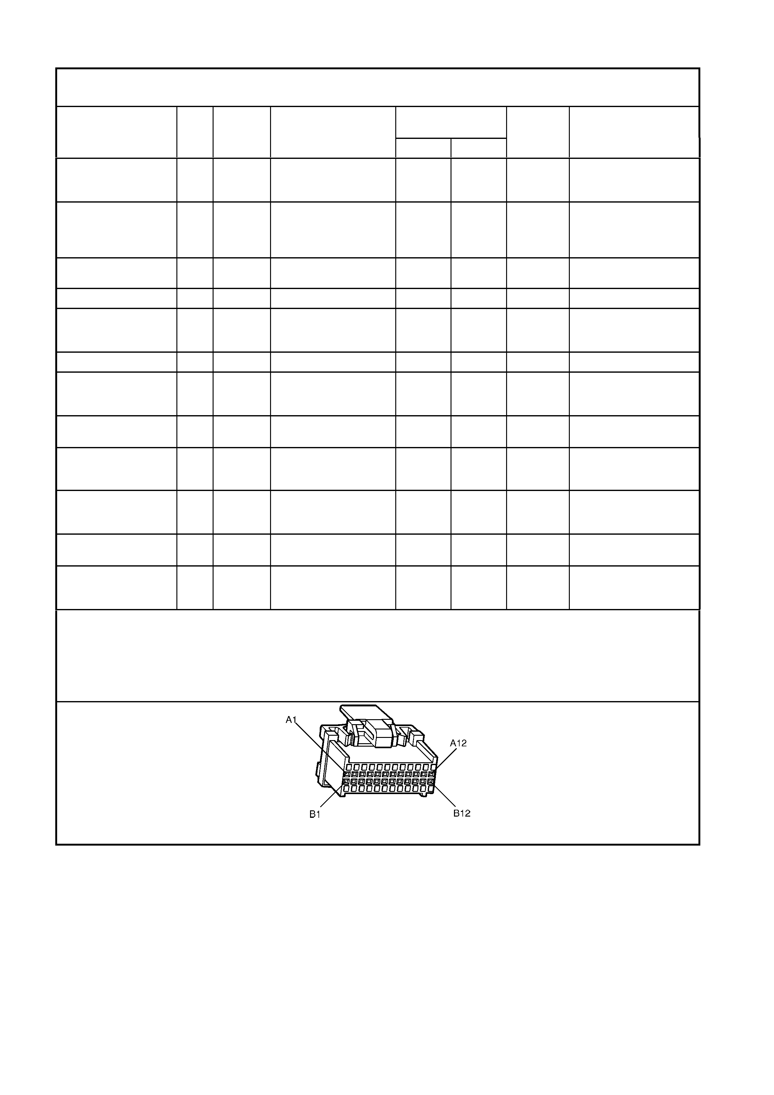
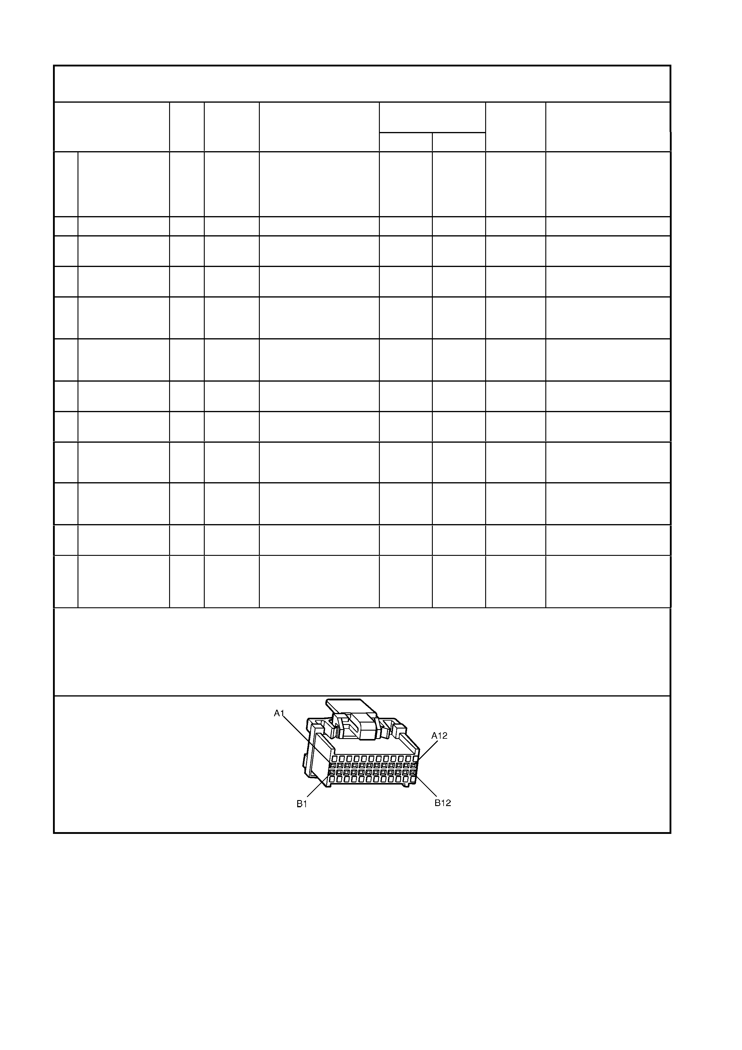
PCM CONNECTOR A84 – X1
POWERTRAIN CONTROL MODULE CONNECTOR “A84 X1” SYMPTOMS TABLE
BROWN 24 PIN – ROW ‘A’
NORMAL VOLTAGES POSSIBLE SYMPTOMS
FROM FAULTY CIRCUIT
PIN
FUNCTION CKT
No. WIRE
COLOUR COMPONENT/
CONNECTOR CAVITY
IGN “ON” ENG RUN
DTCs
AFFECTED
A1 3-2 CONTROL
SOLENOID 898 GN/WH 3-2 CONTROL
SOLENOID,
TERMINAL X121-X2 ‘S’
12 * P0785 SOFT LANDING INTO
THIRD GEAR
STAY IN THIRD GEAR.
A2 2-3 SHIFT
SOLENOID ‘B’
CONTROL
1223 YE/BK 2-3 S HI FT SOLENOID ‘B ’
TERMINAL X121-X2 ‘B’ 12 * P0730
P0757
(9)
POSSIBLY THIRD GEAR
ONLY, NO TCC
OPERA TION, MAXIMUM
LINE PRESSURE.
A3 LPG ENABLE
(LPG Only) 2531 WH/ G N LPG TANK S MART UNIT 12 * P1642 LPG SYSTEM INOP
A4 NOT USED – – – – – – –
A5 SYSTEM
GROUND 450 BK/RD ENGINE GROUND * * NONE NO START IF A LL
GROUND CIRCUITS ARE
OPEN.
A6 NOT USED – – – – – – –
A7 MAF SENSOR
INPUT 492 BN/WH MASS AI R FLOW
SENSOR B 68
TERMINAL X1-A
4.8 4.2 P0101 RICH EXHAUST
A8 START RELAY
CONTROL 434 GY START RELAY R1
TERMINAL ‘86’ * * NONE NO START
A9 AIR
CONDITIONING
RELAY CONT ROL
459 L-GN/BK A/C RELAY R11
TERMINAL ‘2’ 12 (3) NONE ROUGH IDLE, NO AIR
CONDITIONING
A10 AIR
CONDITIONING
RELAY CONT ROL
428 GN/YE CANISTER PURGE
SOLENOID Y 123
TERMINAL X1-B
12 13 P0446 RICH EXHAUST
A11 TCC SOLENOID
PWM CONTROL 418 BN TCC SOLENOID
TERMINAL X121-X2 ‘U’ 12 13 P1860 NO TCC
A12 TCC ENABLE
SOLENOID
CONTROL
422 GY/RD TCC SOLENOID
TERMINAL X121-X2
‘T’12
12 13 P-740
(9) NO TCC AND NO
FOURTH GEAR IF IN
HOT MODE
(3) Less than 0.50 volt when A/C is commanded ON, 13 volts if commanded OFF
(9) Open/Grounded Circuit.
* Less than 0.50 Volts.
** Refer to Wiring Diagrams.
A84 V6 – X1
PCM CONNECTOR A84 – X1
POWERTRAIN CONTROL MODULE CONNECTOR “A84 X1” SYMPTOMS TABLE
BROWN 24 PIN – ROW ‘B’
NORMAL VOLTAGES POSSIBLE SYMPTOMS
FROM FAULTY CIRCUIT
PIN
FUNCTION CKT
No. WIRE
COLOUR COMPONENT/
CONNECTOR CAVITY
IGN “ON” ENG RUN
DTCs
AFFECTED
B1 1-2 SHIFT
SOLENOID ‘A’
CONTROL
1222 L-GN 1-2 SHIFT SOLE NOI D ‘ A ’
TERMINAL X121-X2 ‘A’ 12 * P0753
P0756
(9)
2ND and 3RD GEAR
ONLY or 1ST and 4TH
GEAR ONLY and
MAXIMUM L INE
PRESSURE.
B2 NOT USED – – – – – – –
B3 EST OUTPUT 423 WH IGNITION MODULE A 40
TERMINAL ‘X1-A’ 0 2.0 P1351
P1361 HARD T O START,
STALL.
B4 BYPASS
CONTROL 424 TN/BK IGNITION MODULE A40
TERMINAL ‘X1-B’ 0 4.7 P1351
P1361 POOR PERFORMANCE
B5 SYSTEM
GROUND 2753 BK ENGINE SENSOR
GROUND * * NONE NO START IF A LL
GROUND CIRCUITS ARE
OPEN.
B6 CAMSHAFT
POSITION
SENSOR S IGNAL
630 BK IGNITION MODULE N40
TERMINAL ‘X1-F’ 7.0 6.1 P0341
P0342 SEQUENTIAL FUEL
INJECTION MAY BE OUT
OF SEQUENCE
B7 CRANKSHAFT
18X SIGNAL 647 L-BU/BK IGNITION MODULE N40
TERMINAL ‘X1-C’ 5 2.7 or 3.0 P0374
(9) NO HIGH RESOLUTI ON
EST
B8 TORQUE
REQUEST 463 OG ABS/TCS MODULE A37
TERMINAL ‘X1-13’ 10 – 12 10 – 12 – –
B9 CRANKSHAFT
REFERENCE
HIGH
430 PU IGNI TI ON MODULE N40
TERMINAL ‘X1-D’ 4.8 2.3 P1372 NO START
B10 CRANKSHAFT
REFERENCE
LOW
453 BK/RD IGNITION MODULE N40
TERMINAL ‘X1-L’ * * NONE POOR PERFORMANCE,
INTERMITTENT MIL,
NO DTC
B11 TORQUE
ACHIEVED 464 BK/WH ABS/TCS MODULE A37
TERMINAL ‘X1-27’ 0.9 3.6 – –
B12 ENGINE
COOLING FAN
HIGH SPEED
CONTROL
335 BU/WH ENGINE COOLI NG FA N
2 RELAY ‘ R5’ ,
TERMINAL ‘86’
12 (7) NONE HIGH ENGINE
TEMPERATURE,
OVERHEATING
(7) Less than 0.50 volt when A/C is commanded ON, 13 volts if commanded OFF.
(9) Open or grounded circuit.
* Less than 0.50 Volts.
** Refer to Wiring Diagrams.
A84 V6 – X1
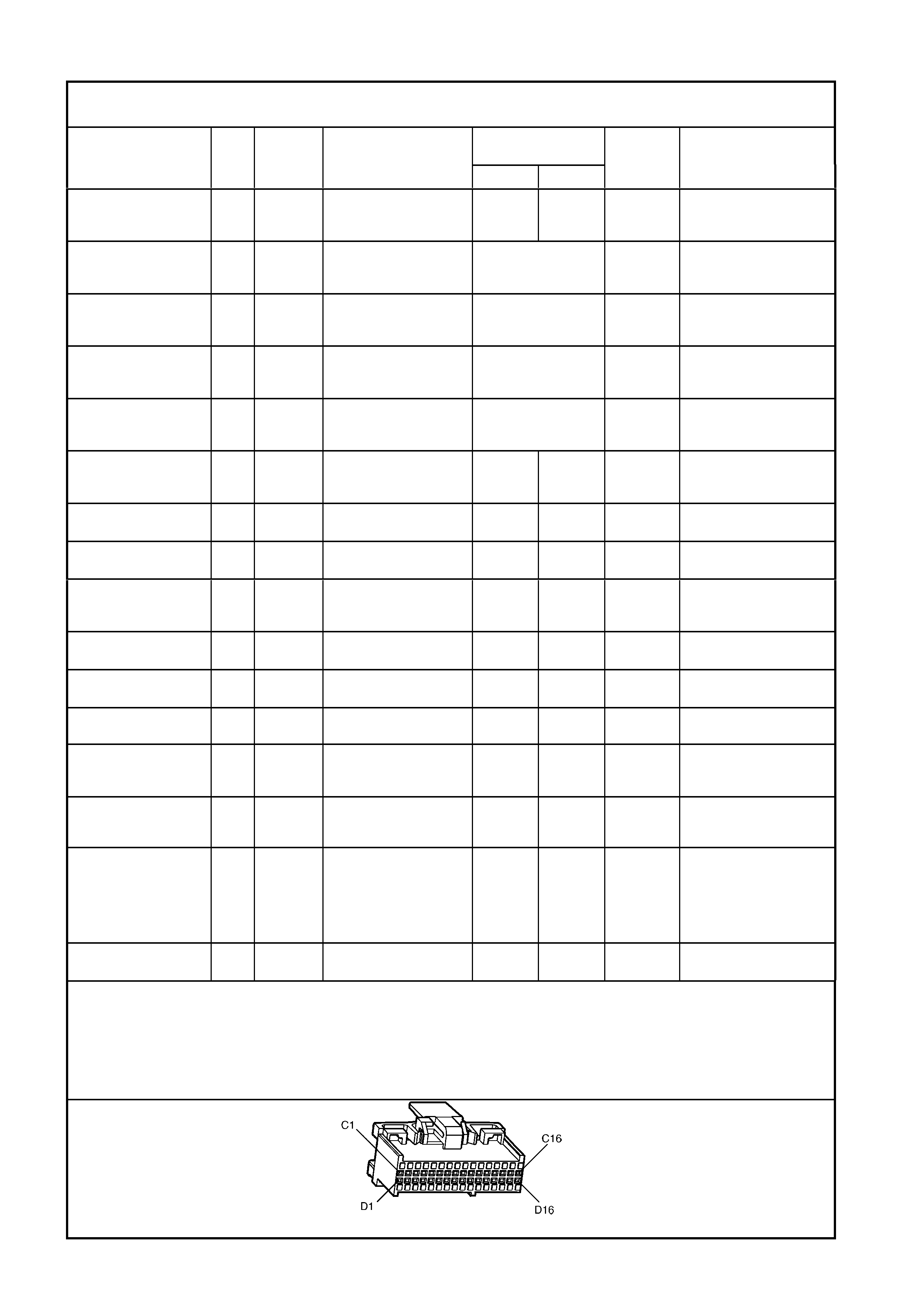
PCM CONNECTOR A84 – X2
POWERTRAIN CONTROL MODULE CONNECTOR “A84 X2” SYMPTOMS TABLE
BROWN 24 PIN – ROW ‘C’
NORMAL VOLTAGES POSSIBLE SYMPTOMS
FROM FAULTY CIRCUIT
PIN
FUNCTION CKT
No. WIRE
COLOUR COMPONENT/
CONNECTOR CAVITY
IGN “ON” ENG RUN
DTCs
AFFECTED
C1 VEHICLE SPEED
OUTPUT TO
SPEEDOMETER
5197 PU/WH INSTRUMENT
CONNECTOR ‘P 3’
TERMINAL ‘X1-5’
(1) (1) NONE INOPERATIVE
SPEEDOMETER
C2 IAC
‘1’ COIL: LOW 1748 L-BU/BK IDLE AIR CONTROL
VALVE ‘Y20’ TERMINAL
‘X1-B’
NOT USEAB LE P0506 S T ALLING, ROUGH,
UNSTABLE OR
INCORRECT I DLE
C3 IAC
‘2’ COIL: HIGH 1749 L-BU I DLE AIR CONTROL
VALVE ‘Y20’ TERMINAL
‘X1-D’
NOT USEAB LE P0506 S T ALLING, ROUGH,
UNSTABLE OR
INCORRECT I DLE
C4 IAC
‘2’ COIL: LOW 444 L-GN/BK IDLE A IR CONTROL
VALVE ‘Y20’ TERMINAL
‘X1-C’
NOT USEA B LE STA LLI NG, ROUGH,
UNSTABLE OR
INCORRECT I DLE
C5 IAC
‘1’ COIL: HIGH 1747 L-GN/WH I DLE AIR CONTROL
VALVE ‘Y20’ TERMINAL
‘X1-A’
NOT USEA B LE STA LLI NG, ROUGH,
UNSTABLE OR
INCORRECT I DLE
C6 ECT/TP SENSOR
GROUND 2752 BK/ Y E ECT ‘B39’ TERMINAL
‘X1-B’, TP SENSOR
‘B82’ TERMINA L ‘X1-B’
* * P0117
P0118
P0123
POOR PERFORMANCE,
HARD START,
HESITATION
C7 TP SENSOR
SIGNAL 411 BU TP SENSOR ‘B82’
TERMINAL ‘X1-C’ (5) (5) P0122
P0123 POOR PERFORMANCE,
HIGH IDLE
C8 EGR PINTLE
POSITION 1456 L-GN EGR VALVE Y56
TERMINAL ‘X1-C’ 0.7 0.7 P0405 ROUGH IDLE , STA LLI NG
C9 RH OXYGEN
SENSOR S IGNAL 1666 GY RH OXYGEN SENS OR
‘B70 R’
TERMINAL ‘X1-A’
450 mV (4) P0131
P0132
P0134 (9)
NO “CLOSED LOOP”
OPERATION
C10 LH KNOCK
SENSOR S IGNAL 496 BU LH KNOCK SENSOR
‘B65’ TERMINAL X1-A’ 1. 3 mV
A/C 25.6 mV
A/C P0327 ENGINE KNOCK
C11 RH KNOCK
SENSOR 1876 L-BU RH KNOCK SENSOR
‘B65’ TERMINAL X1-A’ 1. 3 mV
A/C 25.6 mV
A/C P0332 ENGINE KNOCK
C12 BATTERY
VOLTAGE 740 OG/BK FUSE F29 12 13 NONE NO START
C13 PRIMARY SERIAL
DATA 800 RD/BK DLC ‘ X40’TERMINA L ‘ 9’
BCM ‘A15’ TERMINAL
‘X2-5’
3 – 5 3 – 5 P1255 NO SERIA L DATA, NO
CRANK
C14 INJECTOR
VOLTAGE
MONITOR LINE
639 RD FUSE F34 12 13 P0200
C15 TP SENSOR
REFERENCE
VOLTAGE
416 GY TP SENSOR B82
TERM. ‘X1-A’, MAP
SENSOR B67 TERM.
‘X1-A’, A/C PRESSURE
SENSOR ‘B18’
TERMINAL ‘X1-B’
5 5 P0122
P0123 ROUGH IDLE
C16 EGR REFERENCE
VOLTAGE 5047 PU/WH EGR ’Y56’ TERMINAL
‘X1-B’ 5 5 P0405 ENGINE DETONATION
ROUGH IDLE.
(1) Varies f rom 0.10 V ol ts to about 13 Volt s, depending on pos i tion of drive wheels when vehicle i s m ovi ng.
(4) Voltage s houl d vary between 100 mV and 1000 mV.
(1) 0.25 – 1.25 Volts at i dl e to above 4.0 Volts at Wide Open Throttl e.
(9) Open/Grounded Circuit.
* Less than 0.50 Volts.
** Refer to Wi ri ng Di agrams.
A84 V6 – X2
PCM CONNECTOR A84 – X2
POWERTRAIN CONTROL MODULE CONNECTOR “A84 X2” SYMPTOMS TABLE
BROWN 24 PIN – ROW ‘D’
NORMAL VOLTAGES POSSIBLE SYMPTOMS
FROM FAULTY CIRCUIT
PIN
FUNCTION CKT
No. WIRE
COLOUR COMPONENT/
CONNECTOR CAVITY IGN “ON” ENG RUN
DTCs
AFFECTED
D1 VEHICLE SPEED
SENSOR S IGNAL
LOW
1230 BU/WH
(AUTO.
and
MANUAL)
VEHICLE SPEED
SENSOR,
TERMINAL X121-X1 A
* * P0502
P0503 SPEEDOMETER
INOPERATIVE –
MAXIMUM L INE
PRESSURE.
D2 VEHICLE SPEED
SENSOR S IGNAL
HIGH
1231 TN
(AUTO.
and
MANUAL)
VEHICLE SPEED
SENSOR,
TERMINAL X121-X1 B
* * P0502
P0503 SPEEDOMETER
INOPERATIVE –
MAXIMUM L INE
PRESSURE, SECOND
GEAR ONLY.
D3 LH OXYGEN
SENSOR
GROUND
1664 BU/BK LH OXYGEN SENSOR
‘B70 L’,
TERMINAL ‘X1-B’
* * P0151
P0152 NO ‘CLOSED LOOP’
OPERATION (8).
D4 LH OXYGEN
SENSOR S IGNAL 1665 PU LH OXYGEN SENSOR
‘B70 L’,
TERMINAL ‘X1-A’
450 mV (4) P0151
P0152
P0154
NO “CLOSED LOOP”
OPERATION (9).
D5 RH OXYGEN
SENSOR
GROUND
1667 GY/ B K RH OXYGEN SENSOR
‘B70 R’,
TERMINAL ‘X1-B’
* * P0131
P0132 NO ‘CLOSED LOOP’
OPERATION (8).
D6 TFT, EGR,
GROUND TO
ENGINE GROUND
‘GP5 – X119’
450 BK/RD TFT SENSOR ‘X121-X2
M’, EGR VALVE ‘Y56’
TERMINAL ‘X1-A’
* * P0112
P0405
P0530
P0713
SLIGHT HIGH IDLE,
TCC APPLY EARLY
D7 INTAKE AIR
TEMPERATURE
SENSOR S IGNAL
5089 BN IAT SENSO R ‘ B 64’
TERMINAL ‘X1-A’ 1.0 (6) 1.0 (6) P0111
P0112
P0113
NONE
D8 MAP SENSOR 432 L-GN MAP SENSOR ‘B 67’
TERMINAL ‘X1-B’ 5 5 P0107
P0108 ABNORMAL AUTO
TRANS SHIFTS AT HIGH
ALTITUDES
D9 NOT USED – – – – – – –
D10 A/C PRESSURE
SENSOR S IGNAL 380 GN/BK A/C PRESSURE
SENSOR ‘B18’
TERMINAL ‘X1-C’
1 – 2 1 – 2 P0530 A/C INOPERAT IVE
D11 ENGINE
COOLANT
TEMPERATURE
SENSOR S IGNAL
410 YE ECT SENSOR ‘B18’,
TERMINAL ‘X1-A’ 1.9
(6) 1.9
(6) P0117
P0118
P1116
HARD STA RT , LONG
CRANK TIME
D12 BATTERY
VOLTAGE FEED 740 OG/BK FUSE F29 12 13 NONE NO START I F ‘ C12’ IS
ALSO OPEN.
D13 TRANS FLUID
TEMPERATURE
SENSOR S IGNAL
1227 BK/YE TRANSMISSION PASS-
THROUGH
CONNECTOR X121-X2,
TFT TERMINAL ‘A’
1.8
(6) 1.8
(6) P0712
P0713 MAXIMU M L INE
PRESSURE, TCC IN
SECOND, T HIRD, AND
FOURTH GEA RS
D14 NOT USED – – – – – – –
D15 NOT USED – – – – – – –
D16 IGNI TION FEED 300 OG FUSE F10 12 13 NONE NO ‘CHECK
POWE RT RAIN MIL’, NO
START.
(4) Voltage should vary between 100 mV to 1,000 mV.
(6) Varies with Temperature.
(8) Open
(6) Open/Grounded Circuit.
(7) Grounded Circuit
* Less than 0.50 Volts.
** Refer to Wiring Diagrams.
A84 V6 – X2
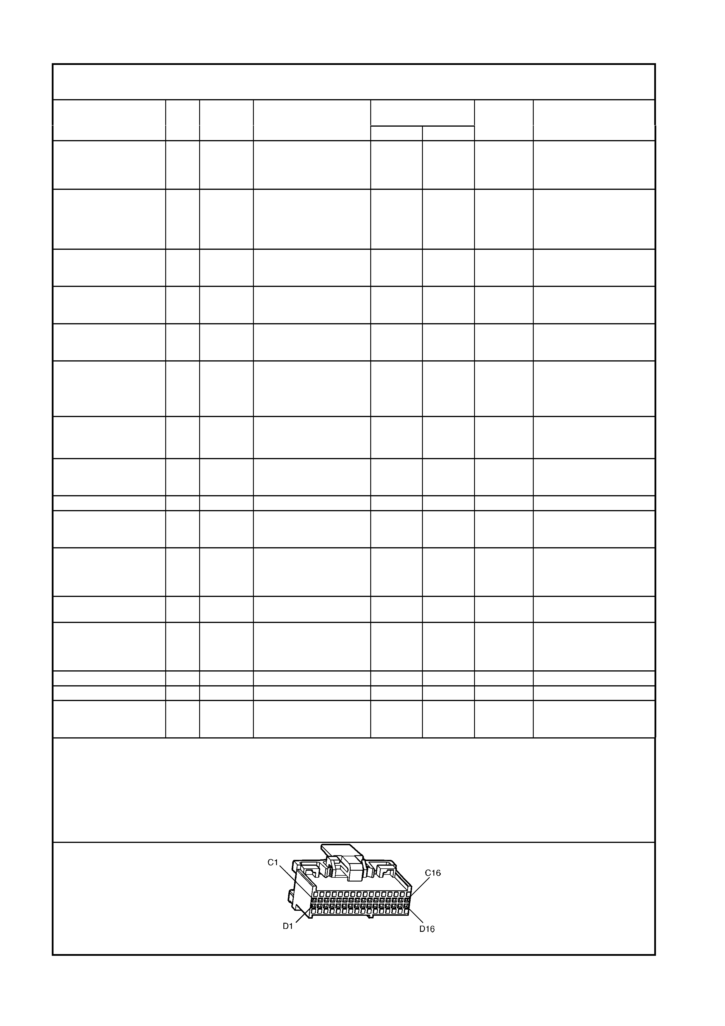
PCM CONNECTOR A84 – X3
POWERTRAIN CONTROL MODULE CONNECTOR “A84 X3” SYMPTOMS TABLE
TAN 24 PIN – ROW ‘E’
NORMAL VOLTAGES POSSIBLE SYMPTOMS
FROM FAULTY CIRCUIT
PIN
FUNCTION CKT
No. WIRE
COLOUR COMPONENT/
CONNECTOR CAVITY
IGN “ON” ENG RUN
DTCs
AFFECTED
E1 NOT USED – – – – – – –
E2 FUEL INJECTOR
#2 CONTROL 1745 GN FUEL INJECTOR #2 12 13 NONE ROUGH IDLE, HARD
START
E3 NOT USED – – – – – – –
E4 FUEL INJECTOR
#1 CONTROL 1744 BU FUE L I NJECTOR #1 12 13 NONE ROUGH IDLE, HA RD
START
E5 FUEL INJECTOR
#5 CONTROL 845 B N/ YE FUE L INJECTOR #5 12 13 NONE ROUGH IDLE, HARD
START
E6 FUEL INJECTOR
#6 CONTROL 846 YE FUEL INJECTOR # 12 13 NONE ROUGH IDLE , HARD
START
E7 SYSTEM
GROUND 450 BK/RD ENGINE GROUND AT
GP5-X119 * * NONE NO START IF ALL
GROUND CIRCUITS ARE
OPEN
E8 NOT USED – – – – – – –
E9 PRESSURE
CONTROL
SOLENOID HIGH
1228 RD TRANSMISSION PASS-
THRU CONNECTOR
X121-X2 TERMINAL ‘C’
* 1.3 P0748 MAXIMUM LINE
PRESSURE, HARD
SHIFT (8)
E10 FUEL PUMP
RELAY CONT ROL 465 GN/WH FUEL PUMP RELA Y R16
TERMINAL ‘2’ (4) (2) 13 NONE HARD TO START , LONG
CRANK TIME
E11 NOT USED – – – – – – –
E12 EGR CONTROL
(PWM) 1676 PU EGR VALVE Y56
TERMINAL ‘X1-E’ 0.0% 0.0% P0400
P0405 ROUGH IDLE, SPARK
KNOCK. (9)
E13 PRESSURE
CONTROL
SOLENOID LOW
1229 GY/BU TRANSMISSION PASS-
THRU CONNECTOR
X121-X2 TERMINAL ‘D’
* 6.8 P0748 (9) MAXI MUM LINE
PRESSURE - HARD
SHIFT
E14 NOT USED – – – – – – –
E15 NOT USED – – – – – – –
E16 FUEL CONTROL
VALVE (LPG Only) 5623 B K /BU FUEL CONTROL VALVE
SOLENOID, ‘ Y143’ 12 5 – 7
(1) P1643 LPG SYSTEM INOP
(1) Only when operating in the LPG Mode.
(2) 12 Volts for the First Two Seconds after Ignition is Turned ON without Cranking.
(4) 12 Volts when Fuel Pump is Running.
(6) Varies with Temperature.
(8) Open
(9) Open/Grounded Circuit.
* Less than 0.50 Volts.
** Refer to Wiring Diagrams.
A84 V6 – X3
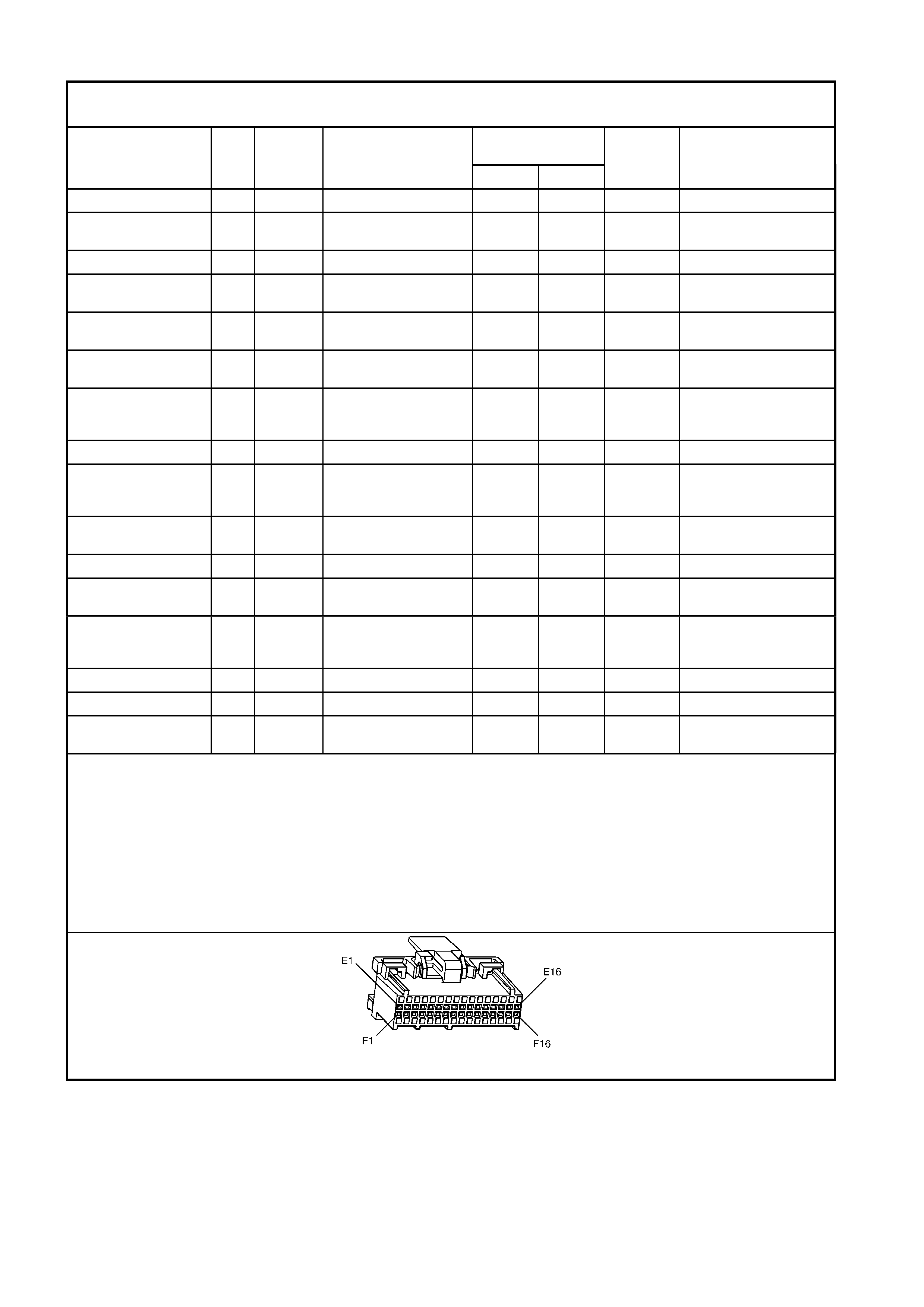
PCM CONNECTOR A84 – X3
POWERTRAIN CONTROL MODULE CONNECTOR “A84 X3” SYMPTOMS TABLE
TAN 24 PIN – ROW ‘F’
NORMAL VOLTAGES POSSIBLE SYMPTOMS
FROM FAULTY CIRCUIT
PIN
FUNCTION CKT
No. WIRE
COLOUR COMPONENT/
CONNECTOR CAVITY
IGN “ON” ENG RUN
DTCs
AFFECTED
F1 FUEL INJECTOR
#3 CONTROL 1746 PU FUE L I NJECTOR #3 12 13 NONE ROUGH IDLE, HA RD
START
F2 FUEL INJECTOR
#4 CONTROL 844 BN/WH FUEL INJECTOR #4 12 13 NONE ROUGH IDLE, HARD
START
F3 PRNDL “A ” 771 BU/WH PRNDL SWITCH S187
TERMINAL ‘X2-A’ * * NONE IMPROPER GEAR
INDICA T E D ON
INSTRUMENT PANEL (9)
F4 FUEL MODE
SW ITCH (LPG
Only)
5606 L-GN FUE L MODE SWIT CH
S118 * * NONE LPG SYS T E M INOP
F5 NOT USED – – – – – – –
F6 PRNDL “P ” 776 WH PRNDL SWITCH S187
TERMINAL ‘X2-P’ * * NONE IMPROPER GEAR
INDICA T E D ON
INSTRUMENT PANEL (9)
F7 SYSTEM
GROUND 450 BK/RD ENGINE GROUND AT
GP5-X119 * * NONE NO START IF ALL
GROUND CIRCUITS ARE
OPEN.
F8 PRNDL “B ” 772 Y E PRNDL SWITCH S187
TERMINAL ‘X2-P’ * * NONE IMPROPER GEAR
INDICA T E D ON
INSTRUMENT PANEL (9)
F9 PRNDL “C” 773 GY PRNDL SWIT CH S 187
TERMINAL ‘X2-P’ * * NONE IMPROPER GEAR
INDICA T E D ON
INSTRUMENT PANEL (9)
F10 NOT USED – – – – – – –
F11 RANGE SIGNAL
“A” 1224 BN/YE TRANSMISSION PASS-
THRU CONNECTOR
X121-X2 TERMINAL ‘N’
12 13 P1810 MAXIMUM LINE
PRESSURE, NO
FOURTH GEAR IF IN
HOT MODE, NO TCC
OPERATION (8)
F12 RANGE SIGNAL
“B” 1225 YE TRANSMISSION PASS-
THRU CONNECTOR
X121-X2 TERMINAL ‘R’
0 0 P1810
(8) NONE
F13 RANGE SIGNAL
“C” 1226 GY TRANSMISSION PASS-
THRU CONNECTOR
X121-X2 TERMINAL ‘P’
12 13 P1810 MAXIMUM LINE
PRESSURE, NO
FOURTH GEAR IF IN
HOT MODE, NO TCC
OPERATION (8)
F14 POWER/
ECONOMY
SWITCH
553 BU POWER/ECONOMY
SWI T CH S22
TERMINAL ‘X1-3’
12 13 NO POWER S HI FT
PATTERN
F15 OIL PRESSURE
SWITCH INPUT 231 BU/RD OIL PRESSURE
SW ITCH, S87 * 13 NONE OIL LIGHT ON
F16 IGNITION FEED
(LPG Only) 300 OG FUSE F10 12 13 NONE NO CHECK
POWERTRAIN MIL,
NO START
(8) Open Circuit.
(9) Open/Grounded Circuit.
* Less than 0.50 Volts.
** Refer to Wiring Diagrams.
A84 V6 – X3
TESTING GROUNDS
Unusual displays in the instrument, lamps that are dim or flash unexpectedly, stop lamps that come on when the
indicators are used, are all classic symptoms of ground problems.
This section discusses the importance of good ground circuits and starts by explaining some basic theory. Then, the
diagnosis of a solid-state circuit ground condition is detailed, to help show how to correct a problem, should it occur.
BASICS
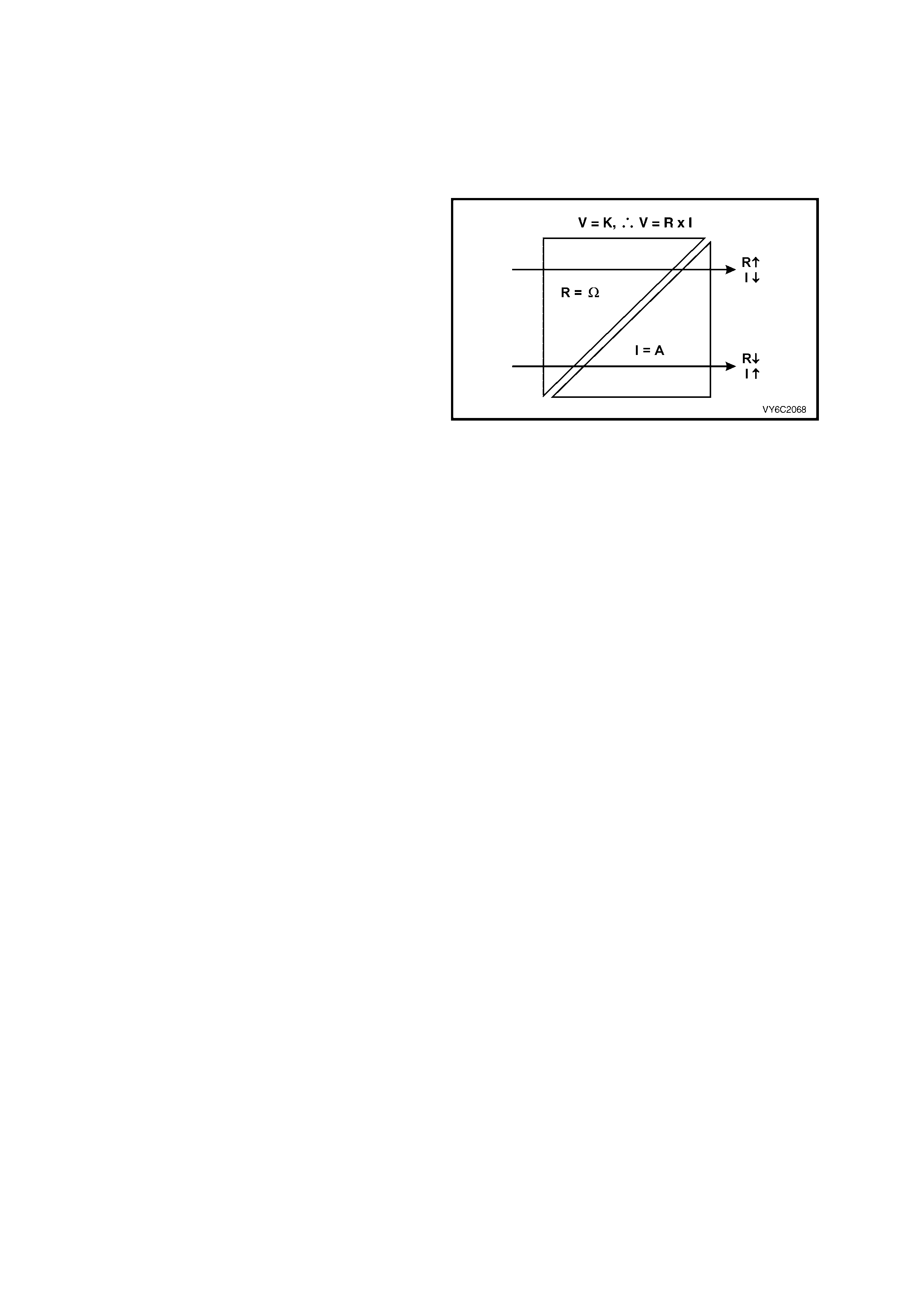
For a circuit to operate properly, three things are
needed:
a. A good power supply to components;
b. Good components and,
c. Sound ground circuits.
Circuits are complete systems; current must flow
from beginning to end as designed, not hinder ed by
unexpected resistance anywhere in the circuit.
While some Technicians realise that the power
supply to a circuit must be free of unwanted
resistance, they can have difficulty in visualising
why a ground cir cuit mus t also be fr ee of unwanted
resistance.
For current to flow, the circuit must be complete; it
must pass through and out of a component like
water flowing thr ough a bathtub. With a f ree f lowing
tub (no plug inserted), the water can flow out as
freely as it flows in. In electrical term s , current m ust
also enter and leave components freely, if they are
to perform as they are designed.
Figure 6C1-2B-2
Sensitive, solid-s tate systems have their own ground points; high c urrent devic es (e.g. m otor s) do not ground at the
same location. High current devices can cause voltage spikes (sudden changes in voltage) when turned “ON” or
“OFF.” To prevent these spikes from affecting sensitive solid-state circuits, two different types of different ground
location s ystem s are used. An exam ple is the use of a dedic ated wir e to connect an isolated ground junc tion block
to the battery negative terminal. This wire reduces the effect of spikes on sensitive circuits at the ground junction
block.
Solid-state circuits are particularly sensitive to poor circuit continuity because, in most cases, they use low current
flow. T his Sec tion on ground c ir cuits , c oncer ns itse lf with one solid-s tate device; the PCM. However, the information
included here can also be applied to all solid-state ground circuits.
Severe restrictions (i.e. resistance) in the ground circuit can cause resets and intermittent codes to set, in solid-state
systems. The PCM operates devic es such as fuel injec tors, idle air control (IAC) , etc., and rec eives inputs from low
voltage sensors, such as the mass air flow sensor (MAF), manifold absolute pressure (MAP) (where fitted),
crankshaft speed/position (CKP). These input and output devices need good circuitry for correct operation.
Remember that, when maladjusted or defective sensors cause values to shift, they are usually accompanied by
driveability problems. If there is excessive resistance in the ground circuit, then the result will be the sam e; shifted
sensor outputs with corresponding driveability conditions. These conditions may not be severe enough to set
diagnostic trouble codes, but they will reduce vehicle efficiency and performance and may be noticed by the
customer.
Sensor circuit ground sensitivity – an example. Looking at the Throttle Position (TP) sensor circuit will provide an
example of how a little resistance in the ground circuit can cause problems. Figure 6C1-2B-3 shows a throttle
position sensor (1) first with a good ground circuit (‘A’) and then with a poor connection (‘B’) in the ground circuit.
Refer to this illustration, as you proceed through the text that follows:
First, the throttle position sensor consists of a resistor and a wiper and, one terminal of the resistor is connected to a
supply voltage (5 V) , while the other is connec ted to ground. As the wiper m oves across the resistor, the voltage of
the wiper terminal progressively changes, with a change in the throttle position. If the wiper is near the supply
voltage end of the resistor, the wiper output will approach the supply voltage (over 4.5 volts at wide open throttle).
As the wiper m oves toward the grounded end of the resistor , the voltage of the wiper output decreases to near zero
(about 0.5 volts for the closed throttle in this example). Note though, that the actual closed and wide open throttle
voltage specifications may vary for different engines. Also, the sensor output should never be greater than reference
supply voltage or less than 0.20 volts. (The PCM would set a DTC, should this situation occur.)
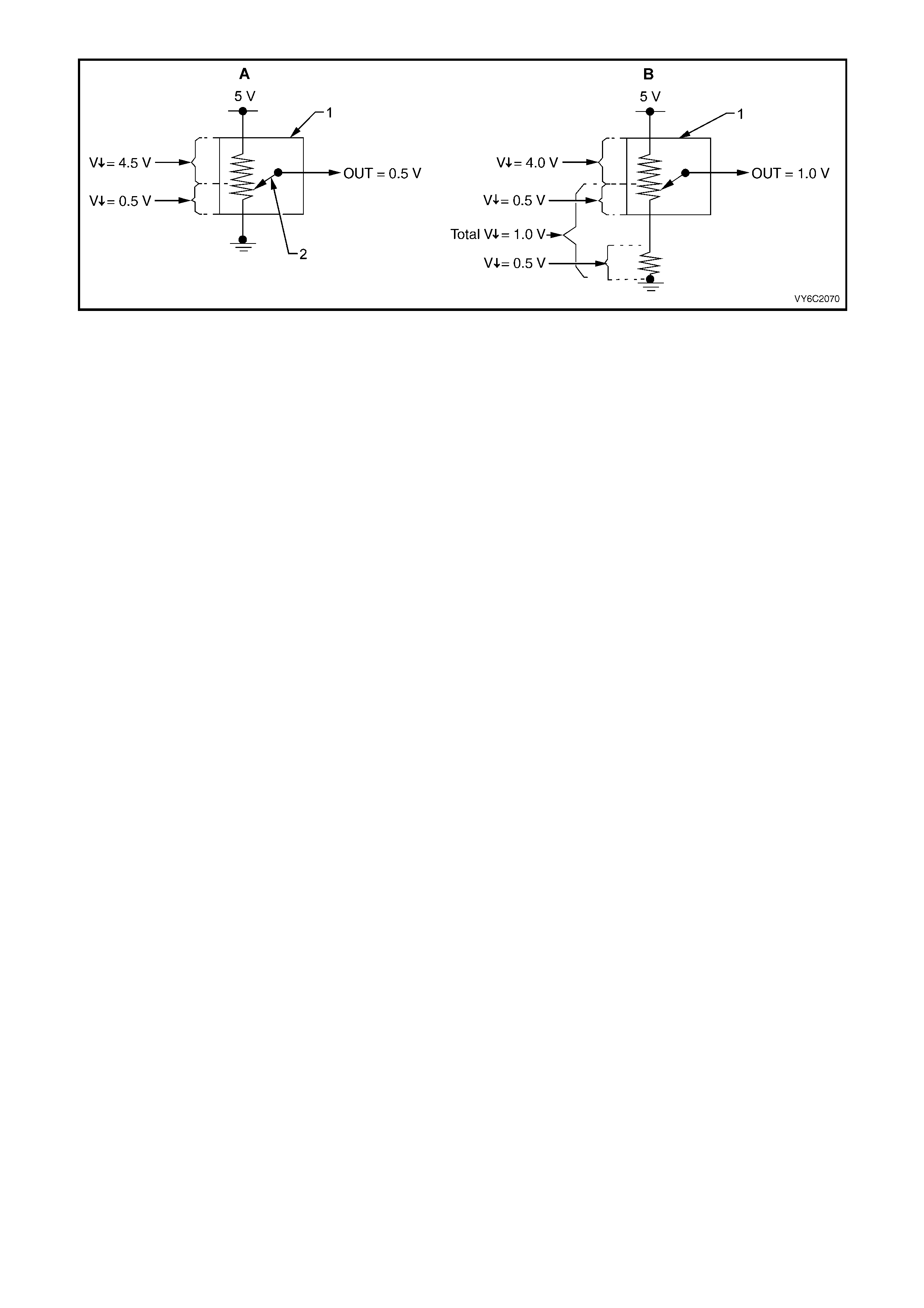
Figure 6C1-2B-3
In the f irst exam ple with a good gr ound circuit (‘A’), the T P sensor (1) is s hown with the wiper in the closed throttle
position. T he total voltage acros s the r esistor in the TP s ensor is 5 volts . The voltage drop f rom the resistor s ource
voltage terminal to the wiper is 4.5 volts. The voltage drop from the wiper to the resistor ground side is 0.5 volts. The
wiper output is 0.5 volts – a good value for this example of a closed throttle.
Now, look at the sensor with the bad signal caused by resistance in the ground circuit. The throttle position stays the
sam e but the sens or output voltage changes . In this exam ple the increas ed resistanc e causes an additional voltage
drop of 0.5 volts. The voltage drop from the wiper to ground is now 1.0 volt (0.5 + 0.5 = 1.0). Because the source
voltage is a constant 5 volts, the voltage drop from the source voltage input to the wiper can now be only 4 volts (5.0
– 1.0 = 4.0). The PCM now receives 1.0 Volt from the TP sensor. This is not a good value (in this example) of a
closed throttle.
Now you can see why good grounds are needed and how sensitive some circuits can be.
GROUND CIRCUITS
How do you know which wires are ground wires, which connectors they go through, and whether they are connected
to a ground junction or the body?
Refer to Section 12P, WIRING DIAGRAMS for reference whenever you are diagnosing any electrical condition,
including grounds. The individual circuits show the power and ground circuits for components in specific systems.
If you suspec t s everal c ircuits are being af f ected by a poor or a back -f eed to ground, look at the circ uits to s ee how
the systems might interact. If they have any common ground wires, that is where you should start diagnosis.
Back -feeding is when current, s eeking ground, f eeds back through inac tive circuits (the r everse direction of normal
current flow) to find a path to ground. This can only happen when the active circuit (needing a ground) shares a
disconnected or poor ground with an inactive circuit and the voltage supply side of the inactive circuit feeds other
components with good grounds.
PARALLEL GROUNDS
Some solid-state components use redundant ground circuits. That is, they have more than one wire connecting to
ground. The PCM has more than one ground circuit wire. There are several reasons for redundant grounds.
The PCM has many low-current circuits, but the current from all these circuits (when they are active) adds up to a
larger current. Higher current loads are managed more easily with several regular size wires, rather than with one
large diameter wire.
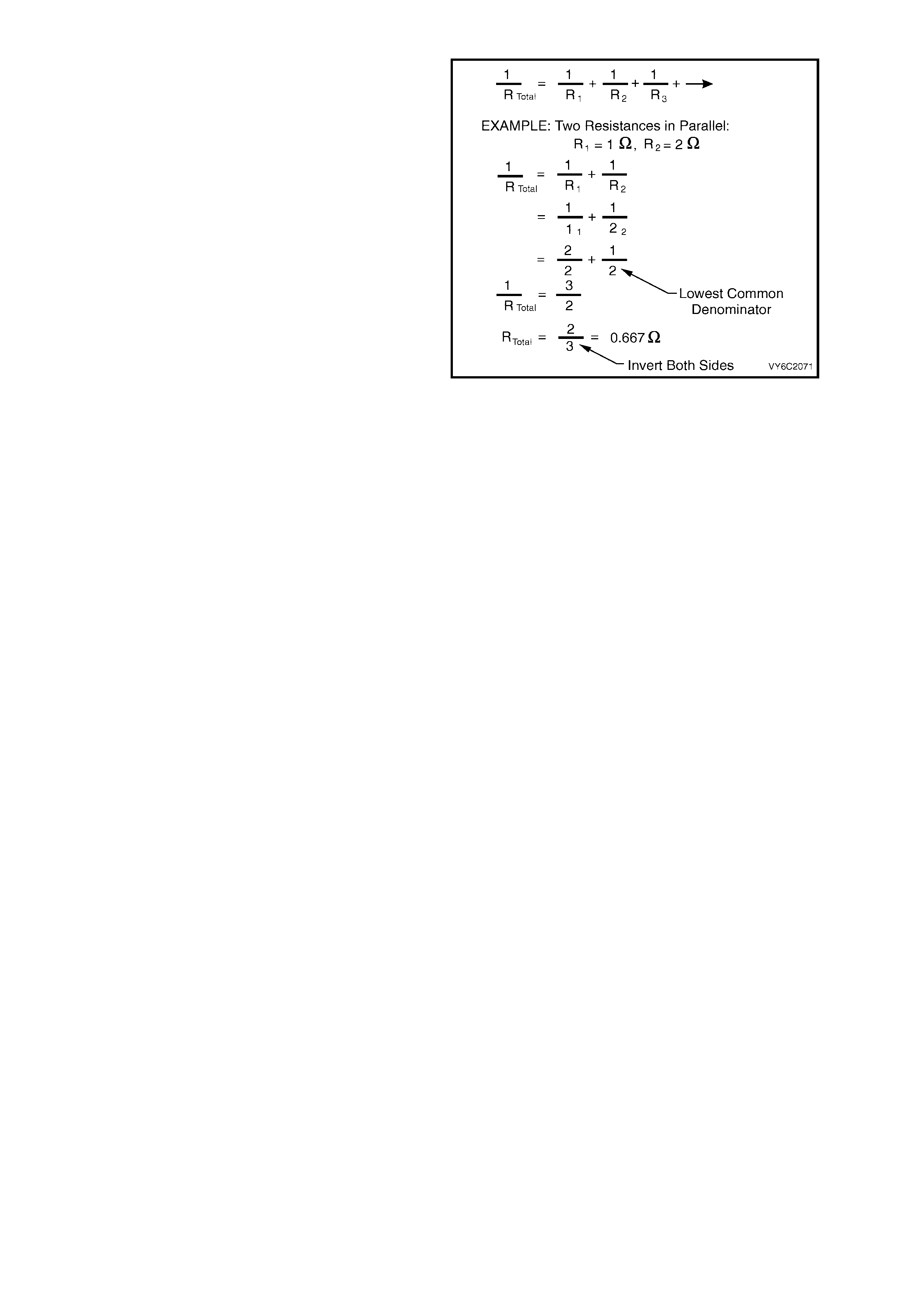
Basic circuit theory shows that the effective
resistance of parallel resistors is less than any of
the individual resistors. The simple example shown,
proves this to be true and holds for even the small
resistance’s in wires.
It follows that parallel wires provide the lowest
resistance. Because of them, in many solid-state
systems a problem with one of the ground wires
would not affect the circuit; the redundant wires
could handle the current load. For other solid-state
systems the loss of even one redundant ground
may affect operation, but the remaining ground
wire(s) may allow the vehicle to be driven.
Figure 6C1-2B-4
An example that can be difficult to locate, follows:
Symptom: A vehicle has driveability problems. However, whenever Tech 2 is hooked up and the vehicle tested,
none of the complaint sy mptoms are displayed.
Cause: T he PCM grounds ar e not providing a good ground, henc e the resulting driveability c ondition. When T ech 2
is connected to the vehicle, a good ground path is provided for the PCM through the Data Link Connector (DLC).
The DLC uses a diff erent gr ound than the PCM. Always test for driveability sym ptom s befor e hooking up T ech 2. If
they disappear when Tech 2 is hooked up, check the ground circuit for continuity.
The severity of the sym ptom (s) is propor tional to the s everity of the problem in the gr ound circuit. A com plete open
in the circuit has the most severe effect. Use the severity of the symptom(s) as an indication of the extent of the
open in the ground circuit.
CHECKING GROUNDS
Once you determine that the cause of the vehicle symptom(s) m ay be caused by a bad ground, it is time to check
for poor ground with one more tool: a high-impedance multimeter set to DC Volts.
The best way to check for poor ground connections in low-current solid-state circuits is to check the voltage drop.
To do this you need a high-impedance digital m ultimeter ( DMM) rated at a minim um of 10 megaohm s (10,000,000
ohms ) per volt. Any DMM with less impedanc e than this c an aff ec t the circuit being tested and also give an incorrec t
reading.
Start by checking the entire suspect ground circuit. With the DMM set on the 2 Volt DC scale, connect the black
negative lead to the battery negative (ground) term inal. (If you are using an auto-ranging m eter, sim ply set it to the
DC volts setting.)
Connect the red positive lead of the DMM to the ground terminal of the component to be tested. With the circuit
activated, check the voltage drop in the circuit. If the voltage reading is within specific ations, look f or a c ause other
than a poor ground at this component.
If the voltage drop reading is too high, proceed by isolating the cause of the high voltage drop. Move the positive
lead to the next connection in the ground circuit, working closer to the source voltage. (Keep the negative lead
connected to the battery negative terminal.) Be sure to check both sides of each in-line connector and both the
eyelet and the stud or screw at ground points. Repeat this process through the ground path until the voltmeter
reading is within specifications. The high resistance causing the ground problem is located between where you
obtained a good reading and the last high reading.
When a circuit uses redundant grounds be sure to check all the ground circuits for excessive voltage drop.
SOLID-STATE CIRCUIT VOLTAGE DROP SPECIFICATIONS
There ar e two ac c eptable maximum voltage dr ops for s olid-s tate c irc uits. If you are measur ing the voltage drop of a
circuit that will pass through a solid-state component before going to ground (such as the ECT sensor circuit
between the ECT sensor and the PCM), measured voltage cannot be higher than 0.060 volts (60 millivolts).
If you are measuring the voltage drop of a solid-state ground circuit anywhere in the ground path at or after the
solid-state component (such as the PCM ground circuit from the PCM to the battery), the maximum allowable
measured voltage is 0.020 volts (20 millivolts). If you measure a voltage above specifications, repair the ground
circuit.
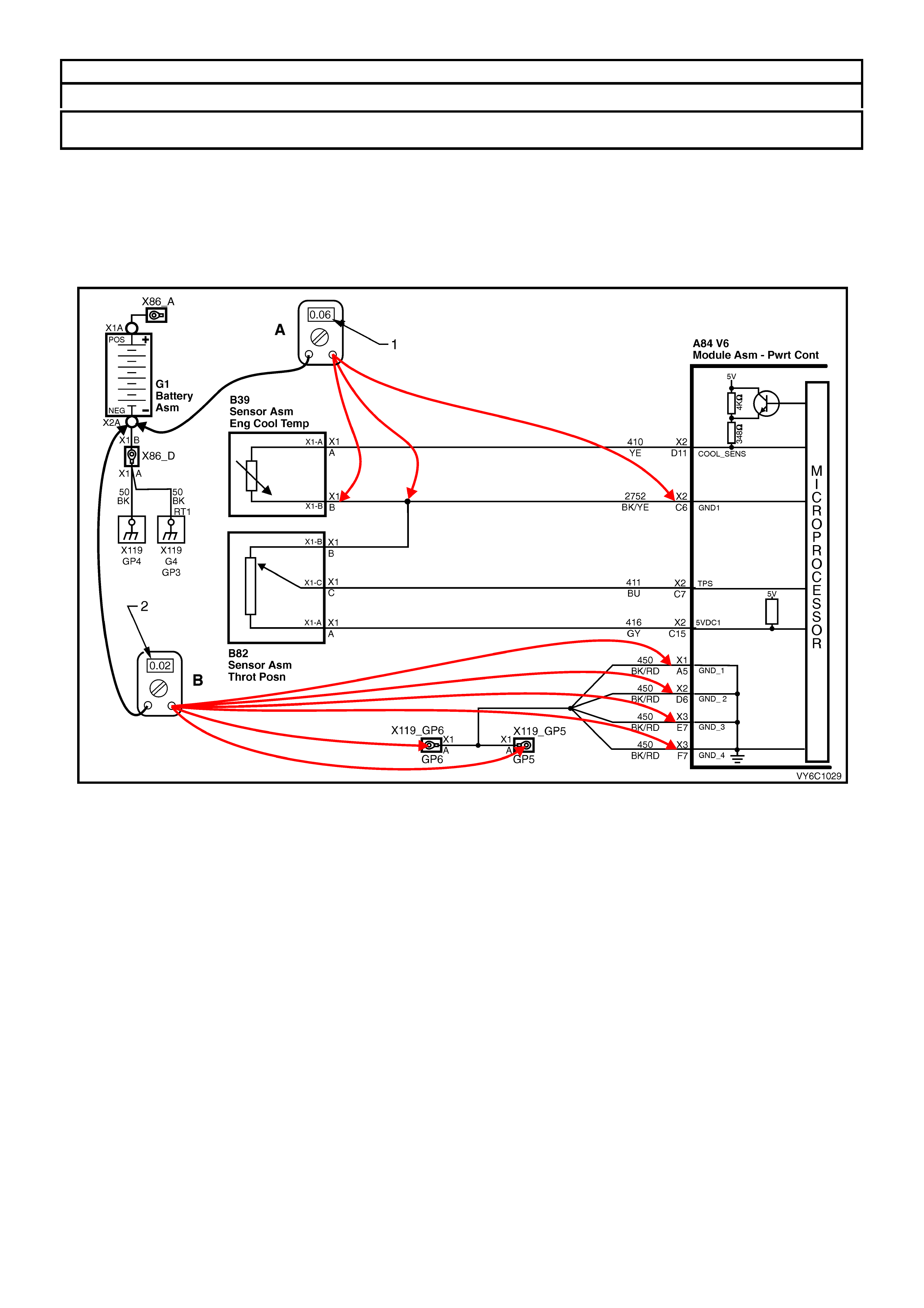
ACCEPTABLE VOLTAGE DROP READINGS
BETWEEN SE NS OR AND PCM 0.060 V (60 mV)
BETWEEN PCM AND BATTERY
NEGATIV E TERMINAL 0.020 V (20 mV)
Checking the voltage drop in a solid-state sensor circuit.
Example ’A’: Look again at the Engine Coolant T emper ature ( ECT ) s ensor c irc uit. With the voltmeter negative lead
connected to the negative battery terminal and the ignition ON, check the voltages at various points between the
ECT sensor B39, term inal “X 1-B” and PCM A84, term inal “X2-C6”. A voltage reading of 0.060 volts or les s with the
meter positive lead at the ECT sens or, terminal “X 1-B” indicates that the entire ground circuit fr om the ECT sensor
to the battery is continuous and sufficiently low in resistance. A voltage reading of 0.060 volts at the “splice” or the
PCM connector “X2-C6” pin would also be within specifications.
Figure 6C1-2B-5 Testing Voltage Drop Before and After the PCM
Legend
A Voltage Drop Testing Before the PCM
1. Voltage Reading to be 0.060 Volt, Maximum B Voltage Drop Testing After the PCM
2. Voltage Reading to be 0.020 Volt, Maximum
Exam ple ‘B’: When voltage m easur em ents are m ade in the gr ound circuit af ter the PCM, the s pecific ation changes.
A voltage reading of 0.020 volts (20 millivolts) or less is within specification. If voltage is not within specifications
check the different c onnector s to f ind where the exc ess voltage is . Be s ure to c hec k both s ides of in-line c onnec tors
and both the eyelet and the stud at ground points.
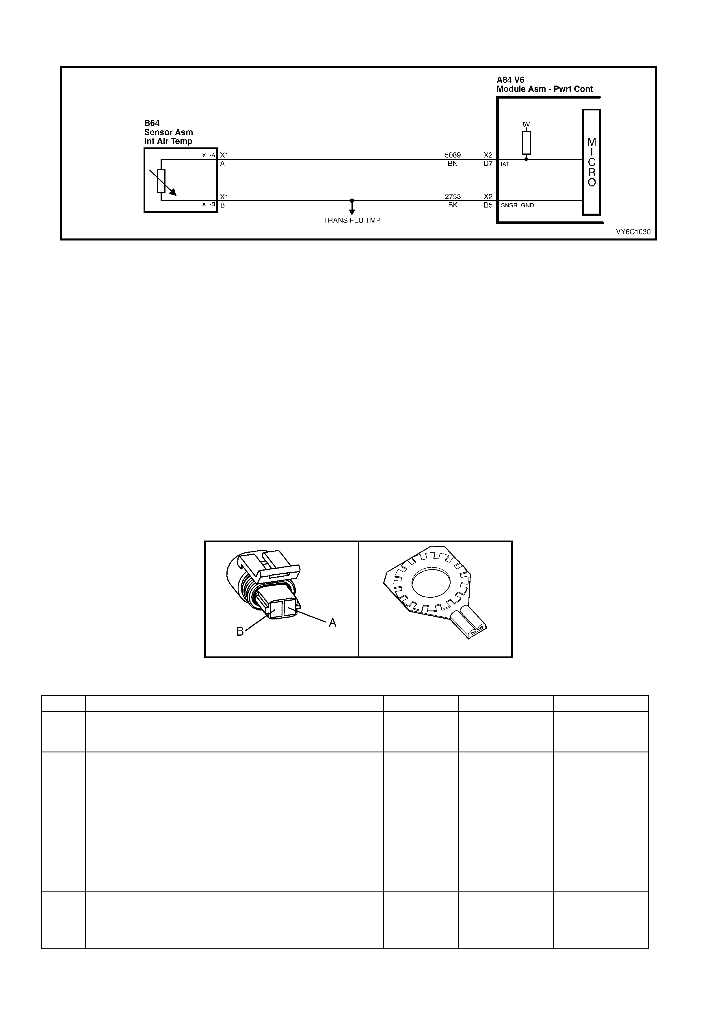
GROUND CREDIBILITY CHECK
Figure 6C1-2B-6 – Intake Air Temperature Sensor
CIRCUIT DESCRIPTION:
The ground c r edibility check can be either us ed at the beginning of all diagnos tic pr oc edures or it can be used when
no diagnostic trouble codes are set, but a symptom still exists.
TEST DESCRIPTION:
NOTE: Number(s) below refer to step number(s) on the diagnostic table.
2. To properly test the voltage drop of the Powertrain Control Module (PCM) system ground, a load must be
present on the circuit.
Using Tech 2, select CANISTER PURGE. By turning “ON” the Purge solenoid, this will cause a sufficient
current draw on the system for testing.
2. Check connectors in ground circuit to find where the excessive voltage is. Make sure to check both sides of in-
line connectors.
DIAGNOSTIC AIDS:
Because the PCM operates on such small current even a minor corrosion problem will cause problems with the
system. Make sure the grounds are clean and tight. Remember a good ground is about 25% of the total system
circuit. Normally you will check the wiring for; power, continuity, the load, but rarely check the ground. Powertrain
control module system grounds are very important to proper operation.
B64 X119_GP5 AND GP6
Figure 6C1-2B-7
GROUND CREDIBILITY CHECK
STEP ACTION VALUE YES NO
1. Was the "On-Board Diagnostic" (OBD) System Check
performed? Go to Step 2. Go to
OBD System
Check.
2. 1. Ignition "OFF"
2. Disconnect IAT sensor connector.
3. Using Digital Multimeter (DMM) set to DC voltage
scale, connect negative lead to negative battery cable
at battery and connect positive lead to the black wire
at the IAT sensor connector.
4. Ignition "ON"
5. Using Tec h 2, sele ct CANISTER PURGE.
6. Turn "ON'" Canister Purge.
Is voltage measured less than value shown.
0.060 volts
(60
Millivolts)
No problem
found, continue
with symptom
diagnosis.
Go to Step 3
3. 1. Remove and thoroughly clean the PCM ground
terminals and connection.
2. Reassemble the PCM Ground terminals.
Is action complete?
Verify Repair –

CORRECTING PROBLEMS IN GROUND CIRCUITS
Once a high resistance condition in a ground circuit has been located, you must determine the actual cause.
If the problem is at a connector, check for bent, corroded, or loose connector terminals. Terminals m ust have a
slight drag when disassembled/assembled. If they slide apart/together without resistance, they will not provide a
good connection.
If the prob lem is at a st ud , bolt, or sheet metal screw, check for corrosion, paint, or loose connections. Paint can
be a very good insulator; good conductors, not insulators are needed for electrical connections.
Corrosion, paint, and other contaminants should be removed using a wire brush and/or emery cloth.
When assem bling ground wire eyelet's to ground points, be sur e an external type star w asher is placed below the
wire eyelet(s). If the system is marginal, you can also place a s tar washer between the nut or the sheet- metal s cr ew
and the top wire eyelet. Tighten the fastener to specification, making sure the star washer digs through any paint
into the mounting surface. Star washers also lock the fastener in place, preventing it from loosening.
All fasteners should be tightened so that the fastener head presses the ground wire eyelet or star washer to the
mounting surface and stops. Repair any stripped ground fasteners.
IMPORTANT: Do not over-tighten sheet-metal screws. Over-tightening can enlarge the hole and create a bad
ground. If the sheet-metal is enlarged, the screw will continue to turn: drill a new correctly sized hole for the screw.