
SECTION 6C2-2A - DIAGNOSTIC TABLES -
V6 SUPERCHARGED ENGINE
IMPORTANT
Before p erf orming any Service O p eratio n o r ot her p rocedu re describ ed in th is Sect ion , refer t o Sect ion 00
CAUTIONS AND NOTES for correct workshop practices with regard to safety and/or property damage.
CONTENTS
SYSTEM COMPONENT LOCATIONS
PCM WIRING DIAGRAMS
POWERTRAIN CONTROL MODULE CONNECTOR IDENTIFICATION
PCM CONNECTOR TERMINAL VOLTAGES WITH EXPLANATIONS
PCM ENGINE AND TRANSMISSION DIAGNOSTIC TROUBLE CODES
4L60-E TRANSMISSION FLUID CHECKING PROCEDURE
TABLE A- V6 S/C PCM - ON BOARD DIAGNOSTIC (OBD) SYSTEM CHECK
TABLE A-1 V6 S/C PCM - NO "CHECK POWERTRAIN" MALFUNCTION INDICATOR LAMP (MIL)
TABLE A-2 V6 S/C PCM - NO SERIAL DATA
TABLE A-3. 1 V6 S/C PCM - ENGINE CRANKS BUT WILL NOT RUN
TABLE A-3. 2 V6 S/C PCM - ENGINE CRANKS BUT WILL NOT RUN
TABLE A-3. 3 V6 S/C PCM - ENGINE CRANKS BUT WILL NOT RUN
TABLE A-4. 0 V6 S/C PCM - STARTER CRANKING CIRCUIT
TABLE A-4.1 V6 S/C PCM - FUEL PUMP ELECTRICAL CIRCUIT
TABLE A-4.2 V6 S/C PCM - FUEL DELIVERY SYSTEM
TABLE A-4.3 V6 S/C PCM - FUEL DELIVERY SYSTEM
TABLE A-4.4 V6 S/C PCM - FUEL DELIVERY SYSTEM
TABLE A-6. 1 V6 S/C PCM - MAF SENSOR OUTPUT CHECK
TABLE A-6. 2 V6 S/C PCM - TP SENSOR OUTPUT CHECK
TABLE A-6.3 V6 S/C PCM - OXYGEN SENSOR CHECK
TABLE A-6.3-A V6 S/C PCM - ENGINE OXYGEN SENSOR HEATER CHECK
TABLE A-6. 4 V6 S/C PCM - CANISTER PURGE SOLENOID CHECK
TABLE A-6.5 V6 S/C PCM - EFI RELAY DIAGNOSIS
TABLE A-7.1 V6 S/C PCM - IDLE AIR CONTROL (IAC) SYSTEM
TABLE A-7.2 V6 S/C PCM - IDLE AIR CONTROL (IAC) SYSTEM
TABLE A-8.1 V6 S/C PCM - DIRECT IGNITION SYSTEM (DIS) CHECK
TABLE A-8.2 V6 S/C PCM - DIRECT IGNITION SYSTEM (DIS) CHECK
TABLE A-11.1 V6 S/C PCM - A/C CLUTCH CONTROL (HVAC CLIMATE CONTROL)
TABLE A-11.3 V6 S/C PCM - A/C CLUTCH CONTROL WITH OCCUPANT CLIMATE CONTROL (OCC)
TABLE A-12.1 V6 S/C PCM - ELECTRIC FAN CONTROL
TABLE A-12.2 V6 S/C PCM - ELECTRIC FAN CONTROL
TABLE A-13 V6 S/C PCM - RESTRICTED EXHAUST CHECK
DTC 13 V6 S/C PCM - RIGHT HAND OXYGEN SENSOR (HO2S) INSUFFICIENT ACTIVITY
DTC 14 V6 S/C PCM - ENGINE COOLANT TEMPERATURE (ECT) SENSOR LOW VOLTAGE
DTC 15 V6 S/C PCM - ENGINE COOLANT TEMPERATURE (ECT) SENSOR HIGH VOLTAGE
DTC 16 V6 S/C PCM - ENGINE COOLANT TEMPERATURE (ECT) SENSOR UNSTABLE)
DTC 17 V6 S/C PCM - PCM ERROR - ECT CIRCUIT
DTC 19 V6 S/C PCM - THROTTLE POSITION (TP) SENSOR CIRCUIT INSUFFICIENT ACTIVITY
DTC 21 V6 S/C PCM - THROTTLE POSITION (TP) SENSOR CIRCUIT HIGH VOLTAGE
DTC 22 V6 S/C PCM - THROTTLE POSITION (TP) SENSOR CIRCUIT LOW VOLTAGE
DTC 23 V6 S/C PCM - INTAKE AIR TEMPERATURE (IAT) SENSOR CIRCUIT HIGH VOLTAGE
DTC 24 V6 S/C PCM - VEHICLE SPEED SENSOR (VSS) CIRCUIT LOW VOLTAGE
DTC 25 V6 S/C PCM - INTAKE AIR TEMPERATURE (IAT) SENSOR CIRCUIT LOW VOLTAGE
DTC 26 V6 S/C PCM - INTAKE AIR TEMPERATURE (IAT) SENSOR UNSTABLE)
DTC 28 V6 S/C PCM - TRANSMISSION FLUID PRESSURE (TFP) MANUAL VALVE POSITION
SWITCH CIRCUIT
DTC 31 V6 S/C PCM - THEFT DETERRENT SIGNAL MISSING
DTC 32 V6 S/C PCM - MASS AIR FLOW (MAF) OUT OF RANGE

DTC 35 V6 S/C PCM - IDLE SPEED LOW
DTC 36 V6 S/C PCM – VACUUM LEAK
DTC 41 V6 S/C PCM - ELECTRONIC SPARK TIMING (EST) – OUTPUT CIRCUIT FAULT
DTC 42 V6 S/C PCM - IGNITION BYPASS CIRCUIT FAULT
DTC 43 V6 S/C PCM - KNOCK SENSOR CIRCUIT FAULT
DTC 44 V6 S/C PCM - RIGHT HAND HEATED OXYGEN SENSOR (HO2S) LOW VOLTAGE
DTC 45 V6 S/C PCM - RIGHT HAND HEATED OXYGEN SENSOR (HO2S) HIGH VOLTAGE
DTC 46 V6 S/C PCM - NO REFERENCE PULSES WHILE CRANKING
DTC 47 V6 S/C PCM - 18 X REFERENCE SIGNAL MISSING
DTC 48 V6 S/C PCM - CAMSHAFT POSITION SENSOR CIRCUIT LOW VOLTAGE
DTC 49 V6 S/C PCM - CAMSHAFT POSITION SENSOR PERFORMANCE
DTC 51 V6 S/C PCM – POWERTRAIN CONTROL MODULE (PCM) M EMORY
DTC 52 V6 S/C PCM - SYSTEM VOLTAGE TOO HIGH (LONG TIME)
DTC 53 V6 S/C PCM - SYSTEM VOLTAGE TOO HIGH
DTC 54 V6 S/C PCM - SYSTEM VOLTAGE UNSTABLE
DTC 55 V6 S/C PCM - PCM - ANALOGUE – DIGITAL (A/D) CONVERSION ERROR
DTC 56 V6 S/C PCM - LEAN CONDITION UNDER LOAD
DTC 57 V6 S/C PCM - INJECTOR VOLTAGE MONITOR FAULT
DTC 58 V6 S/C PCM - TRANSMISSION FLUID TEMPERATURE (TFT) SENSOR – LOW INPUT
DTC 59 V6 S/C PCM - TRANSMISSION FLUID TEMPERATURE (TFT) SENSOR HIGH INPUT
DTC 63 V6 S/C PCM - LEFT HAND OXYGEN SENSOR (HO2S) INSUFFICIENT ACTIVITY
DTC 64 V6 S/C PCM - LEFT HAND HEATED OXYGEN SENSOR (HO2S) LOW VOLTAGE
DTC 65 V6 S/C PCM - LEFT HAND HEATED OXYGEN SENSOR (HO2S) HIGH VOLTAGE
DTC 66 V6 S/C PCM - 3-2 SHIFT SOLENOID CIRCUIT ELECTRICAL
DTC 67 V6 S/C PCM - TORQUE CONVERTER CLUTCH (TCC) ENABLE SOLENOID CIRCUIT ELECTRICAL
DTC 69 V6 S/C PCM - TORQUE CONVERTER CLUTCH (TCC) SYSTEM STUCK ON
DTC 72 V6 S/C PCM - TRANSMISSION OUTPUT SPEED LOSS
DTC 73 V6 S/C PCM - PRESSURE CONTROL (PC) SOLENOID CIRCUIT ELECTRICAL
DTC 75 V6 S/C PCM - SYSTEM VOLTAGE LOW
DTC 76 V6 S/C PCM - SHORT TERM FUEL TRIM (STFT) DELTA HIGH
DTC 78 V6 S/C PCM - LONG TERM FUEL TRIM (LTFT) DELTA HIGH
DTC 79 V6 S/C PCM - TRANSMISSION FLUID OVER-TEMPERATURE
DTC 81 V6 S/C PCM - 2-3 SHIFT SOLENOID ‘B’ ELECTRICAL CIRCUIT ELECTRICAL FAULT
DTC 82 V6 S/C PCM - 1-2 SHIFT SOLENOID ‘A’ ELECTRICAL CIRCUIT FAULT
DTC 83 V6 S/C PCM - TORQUE CONVERTER CLUTCH (TCC) PULSE WIDTH M ODULATION (PWM)
SOLENOID CIRCUIT FAULT
DTC 85 V6 S/C PCM - TRANSMISSION SLIPPING
DTC 91 V6 S/C PCM - QDSM (QUAD DRIVER SURFACE MODULE) CIRCUIT
DTC 92 V6 S/C PCM - LOW SPEED FAN – NO BCM RESPONSE
DTC 93 V6 S/C PCM - KNOCK SENSOR SYSTEM
DTC 95 V6 S/C PCM - REQUESTED TORQUE OUT-OF-RANGE
DTC 96 V6 S/C PCM - A/C REFRIGERANT PRESSURE SENSOR CIRCUIT FAULT
DTC 97 V6 S/C PCM - EVAP PURGE SOLENOID CONTROL CIRCUIT FAULT
SYSTEM COMPONENT LOCATIONS
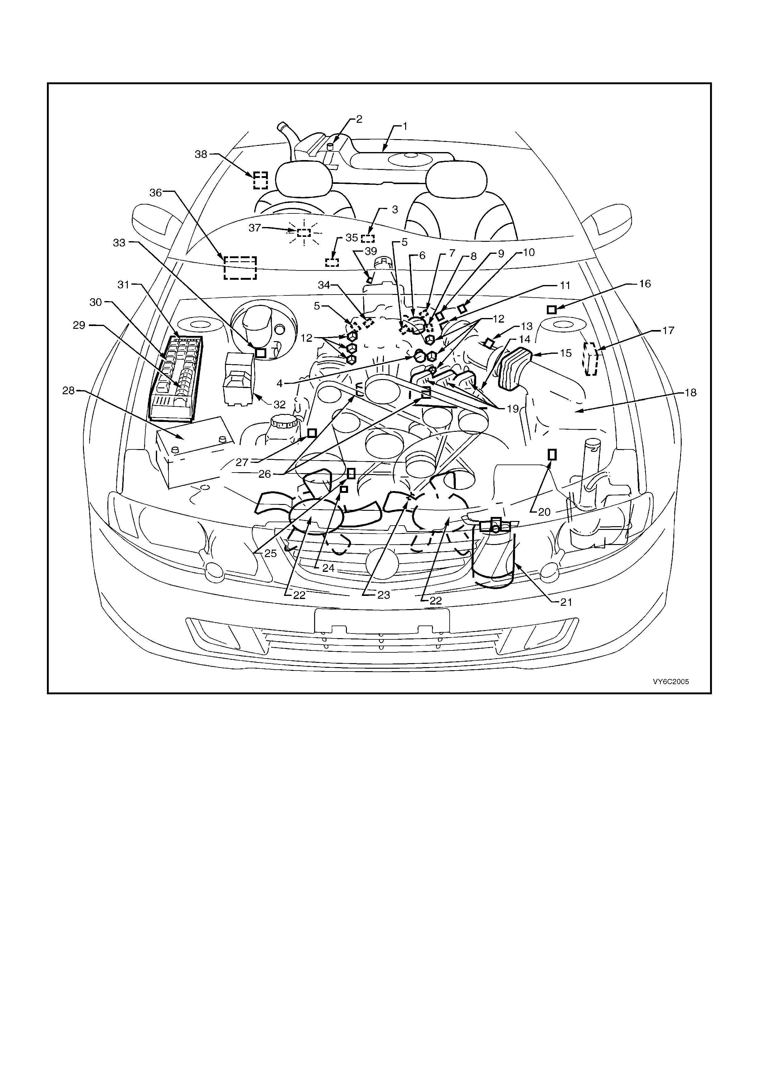
Figure 6C2-2A-1 – V6 Supercharged Engine Compartment Component Locations
Legend
1. Fuel Tank
2. Fuel Pump (Inside Fuel Tank)
3. OCC In-Car Air Temperature Sensor
4. Fuel Pressure Regulator
5. Heated Exhaust Gas Oxygen (HO2S) Sensor (Two)
6. Bypass Valve Actuator
7. Engine Coolant Temperature (ECT) Sensor
8. Boost Control Solenoid
9. Throttle Position (TP) Sensor
10. Idle Air Control (IAC) Valve
11. Engine Harness (PCM) Ground (Two Terminals)
12. Fuel Injectors
13. Intake Air Temperature (IAT) Sensor
14. DIS Module
15. Mass Air Flow (MAF) Sensor
16. Tachometer Lead
17. Powertrain Control Module (PCM) (Inside Vehicle)
18. Air Cleaner
19. Ignition Coils
20. A/C Refrigerant Pressure Sensor
21. A/C Accumulator
22. Engine Cooling Fans (Two)
23. Crankshaft Position (CKP) Sensor
24. Oil Pressure Switch
25. Camshaft Position (CMP) Sensor
26. Detonation Knock Sensors (KS) (Two)
27. Engine Harness (PCM) Ground (Two Terminals)
28. Battery
29. Engine Compartment Fusible Links
30. Engine Compartment Relays
31. Engine Compartment Fuses
32. Anti-Lock Braking System (ABS)
33. Brake Hydraulic Failure Switch
34. EVAP Canister Purge Solenoid
35. Diagnostic Link Connector (DLC)
36. Body Control Module (BCM)
37. Check Powertrain Malfunction Indicator Lamp (MIL)
38. Fuel Pump Control Module (Rear Compartment)
39. Vehicle Speed Sensor (VSS)
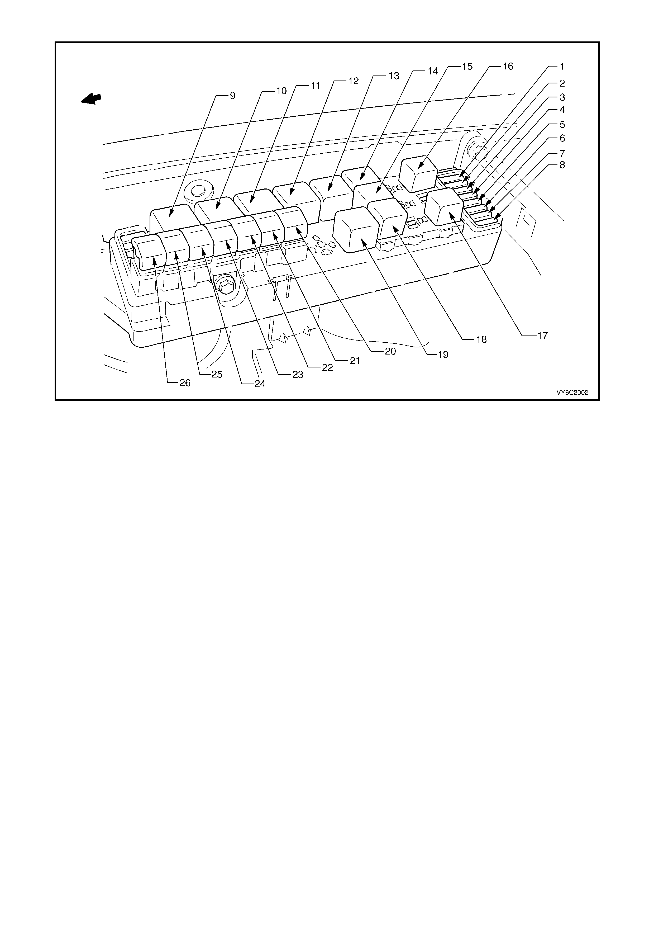
Figure 6C2-2A-2 – Engine Compartment Fuse/Relay/Fusible Link Locations
Legend
Fuses
1. Fuel Pump Fuse – F28
2. Engine Control / BCM – F29
3. RH Headlamps – F30
4. LH Headlamps – F31
5. Automatic Transmission – F32
6. Engine Sensors – F33
7. Injectors / Ignition – F34
8. Injectors / Ignition – F35
Relays
9. Start – X1
10. Blower Fan – X2
11. Headlamp (High Beam) – X3
12. Engine Control (EFI) – X4
13. Engine Cooling Fan (High Speed) – X5
14. Horn – X8
15. A/C Compressor – X11
16. Fog Lamp – X10
17. Fuel Pump – X16
18. Headlamp (Low Beam) – X14
19. Engine Cooling Fan (Low Speed) – X7
Fusible Links
20. Engine Cooling Fan LT – F101 (30A)
21. Blower Fan – F106 (60A)
22. Main – F105 (60A)
23. Engine – F104 (60A)
24. A.B.S. – F103 (60A)
25. Lighting – F102 (60A)
26. Engine Cooling Fan RT – F107 (30A)
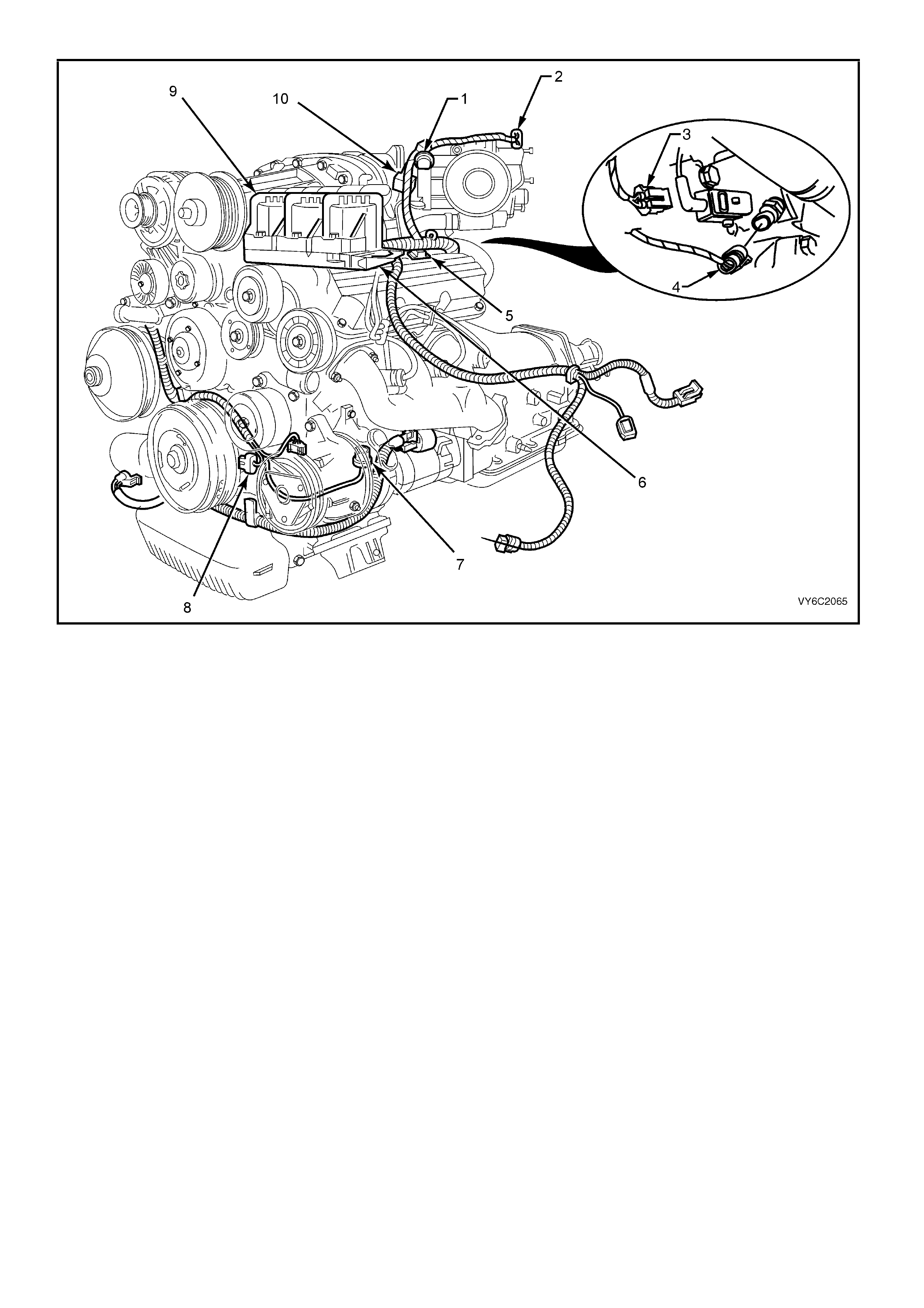
Figure 6C2-2A-3 – V6 Supercharged Engine Component Locations
Legend
1. Throttle Position (TP) Sensor
2. Idle Air Control Valve (IAC)
3. Boost Control Solenoid Valve
4. Engine Coolant Temperature (ECT) Sensor
5. Injectors
6. Direct Ignition System Module
7. L.H. Knock Sensor (KS)
8. Crankshaft Position (CKP) Sensor
9. Ignition Coils (3 places)
10. Bypass Valve Actuator
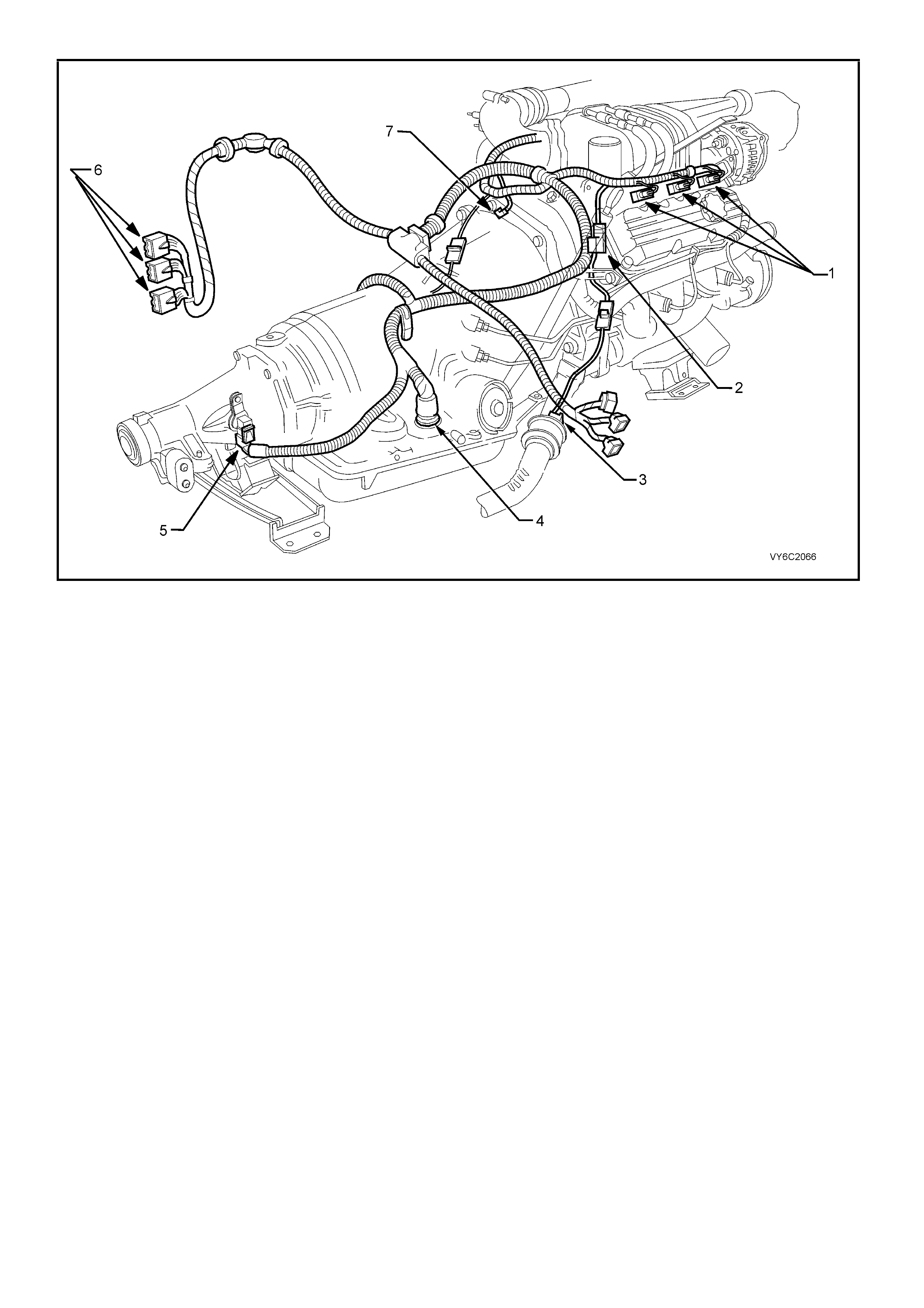
Figure 6C2-2A-4 – V6 Supercharged Engine Component Locations
Legend
1. Injectors
2. Canister Purge Solenoid
3. R.H. Heated Oxygen (HO2S) Sensor
4. Transmission Pass-Through Connector
5. Vehicle Speed Sensor (VSS) (Automatic Trans)
6. PCM Connectors
7. Engine Harness Ground
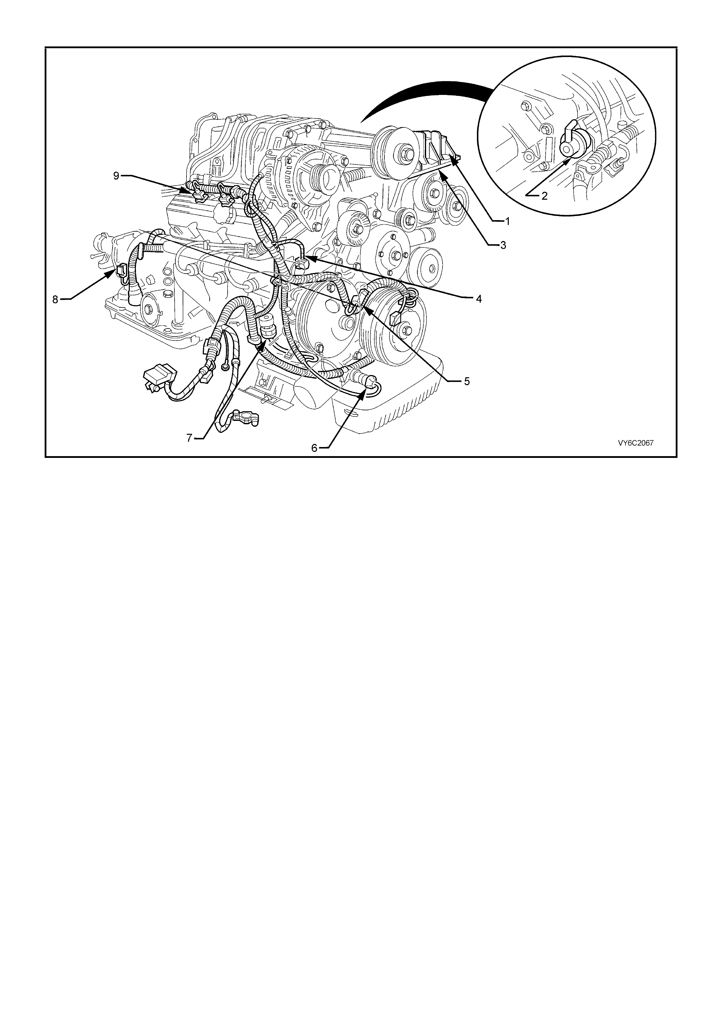
Figure 6C2-2A-5 – V6 Supercharged Engine Component Locations
Legend
1. Ignition Coils (3 places)
2. Fuel Pressure Regulator
3. Direct Ignition System Module
4. Engine Harness Ground
5. Camshaft Position (CMP) Sensor
6. Oil Pressure Switch
7. R.H. Knock Sensor (KS)
8. Vehicle Speed Sensor (VSS) – Automatic Transmission
9. Injectors (3 places)
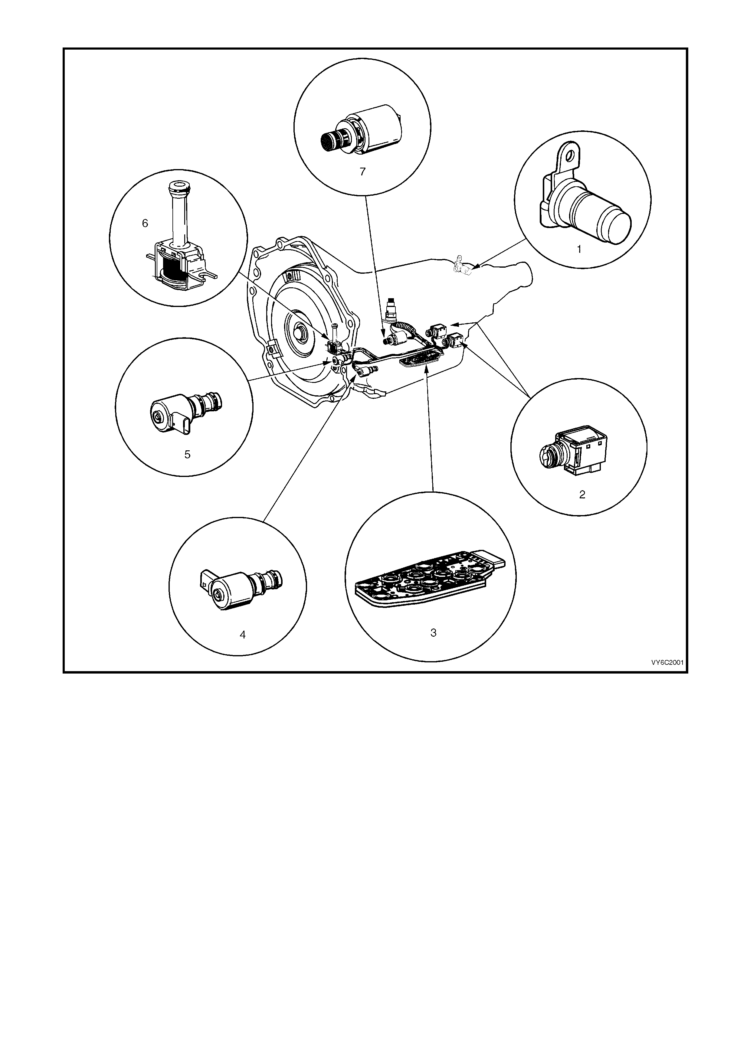
Figure 6C2-2A-6 – V6 Supercharged Engine, Automatic Transmission,
Internal Electronic Component Locations
Legend
1. Vehicle Speed Sensor
2. 1-2 Shift Solenoid A and 2-3 Shift Solenoid B
3. Automatic Transmission Fluid Pressure (TFP) Manual
Valve Position Switch
4. 3-2 Downshift Control Solenoid
5. Torque Converter Clutch Pulse Width Modulation
(TCC PWM) Solenoid Valve
6. Torque Converter Clutch (TCC) Solenoid Valve
7. Pressure Control Solenoid (PCS) Valve
PCM WIRING DIAGRAMS
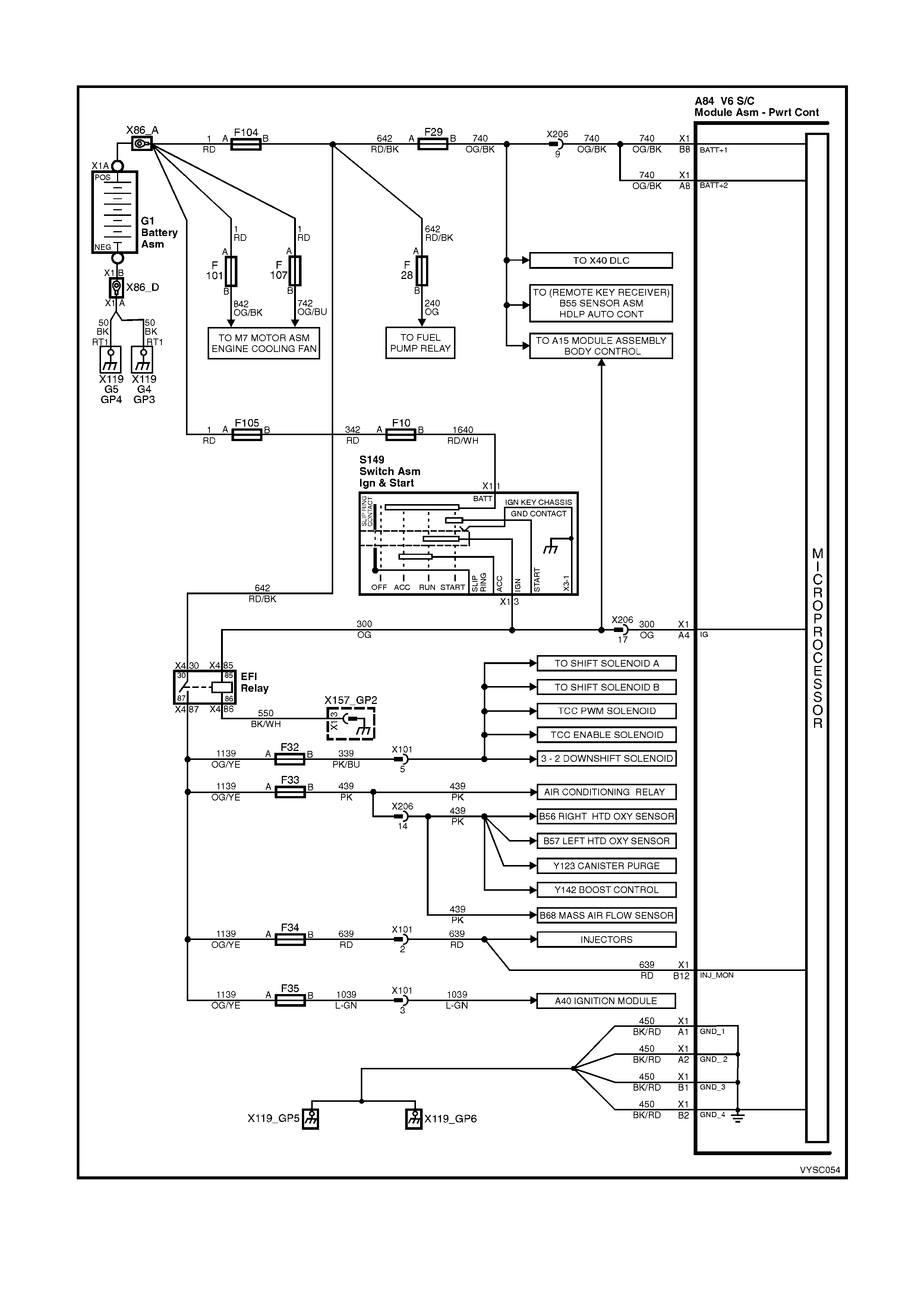
Figure 6C1-2A-7 – PCM Wiring Diagram (1 of 8) V6 Supercharged Engine – Fuse & Power Circuits
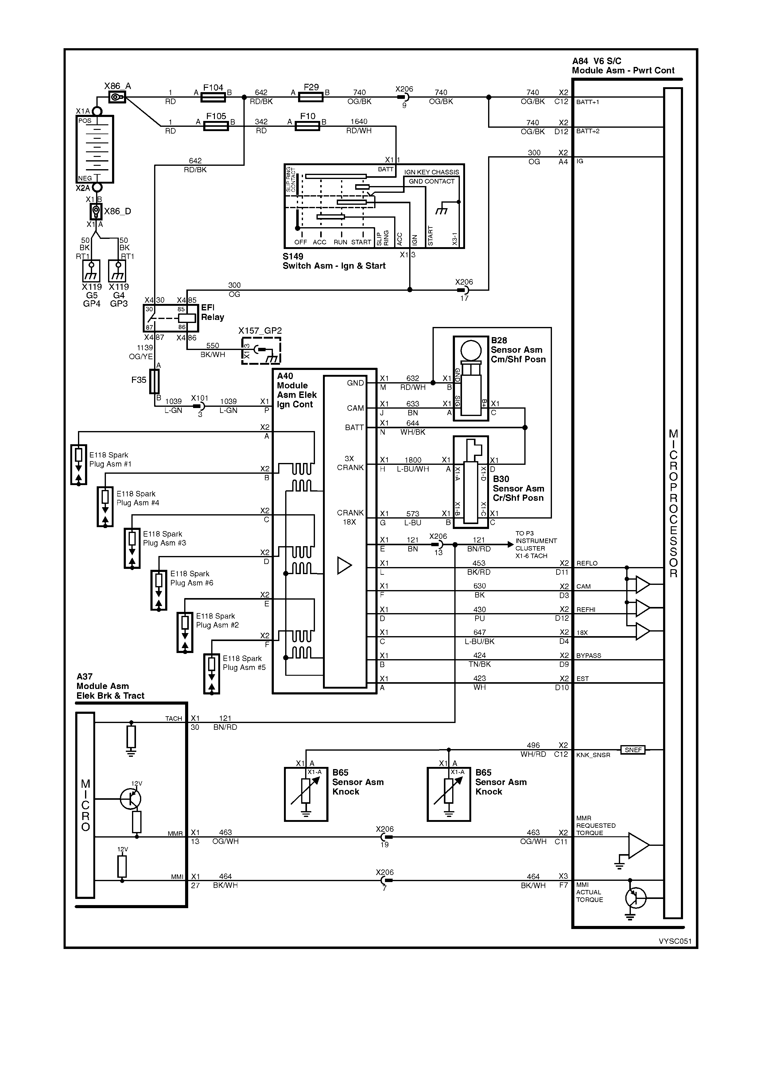
Figure 6C1-2A-8 – PCM Wiring Diagram (2 of 8) V6 Supercharged Engine Application – DIS Ignition System
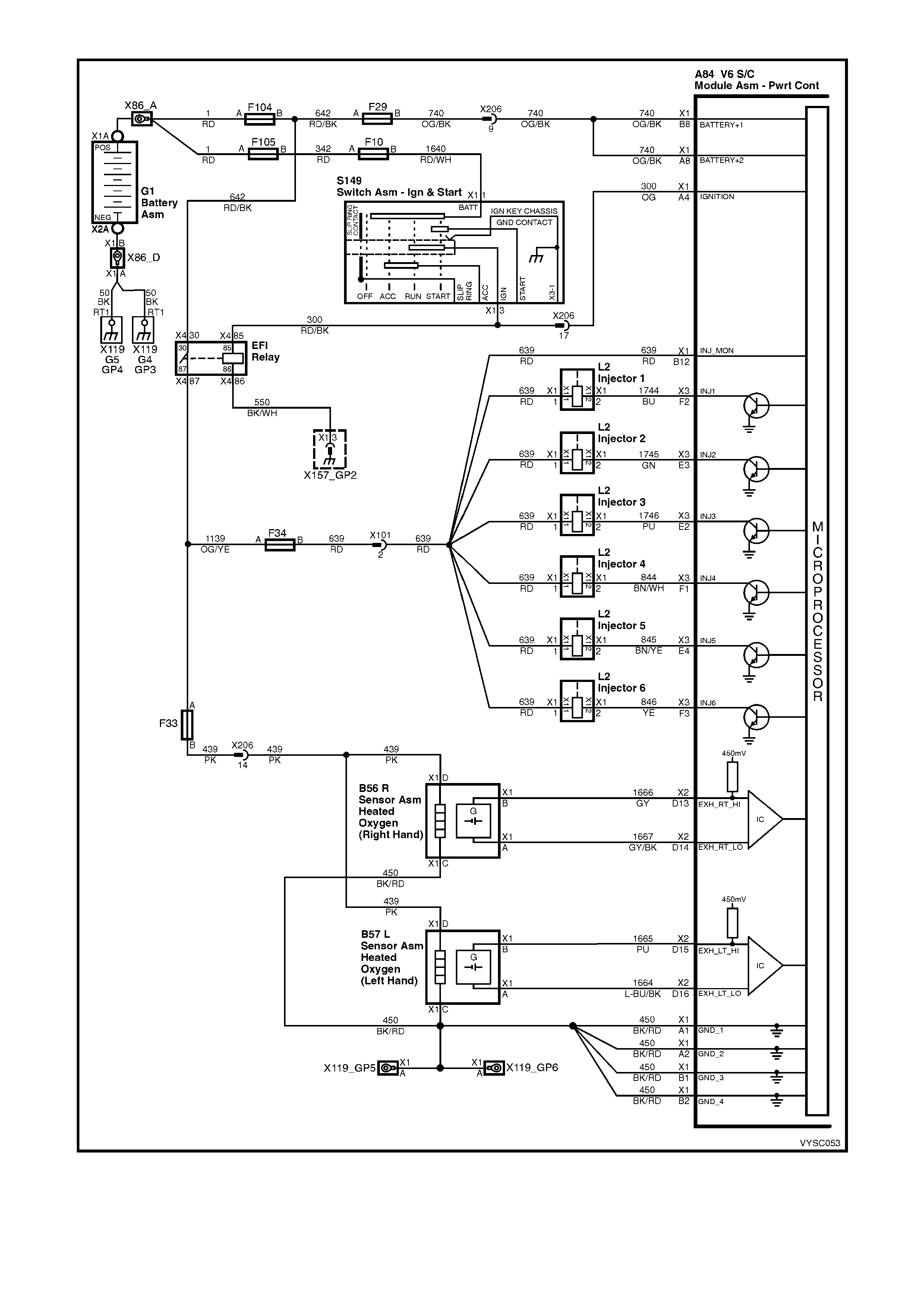
Figure 6C1-2A-9 – PCM Wiring Diagram (3 of 8 ) V6 Supercharged Engine Application – Fuel System Circuits
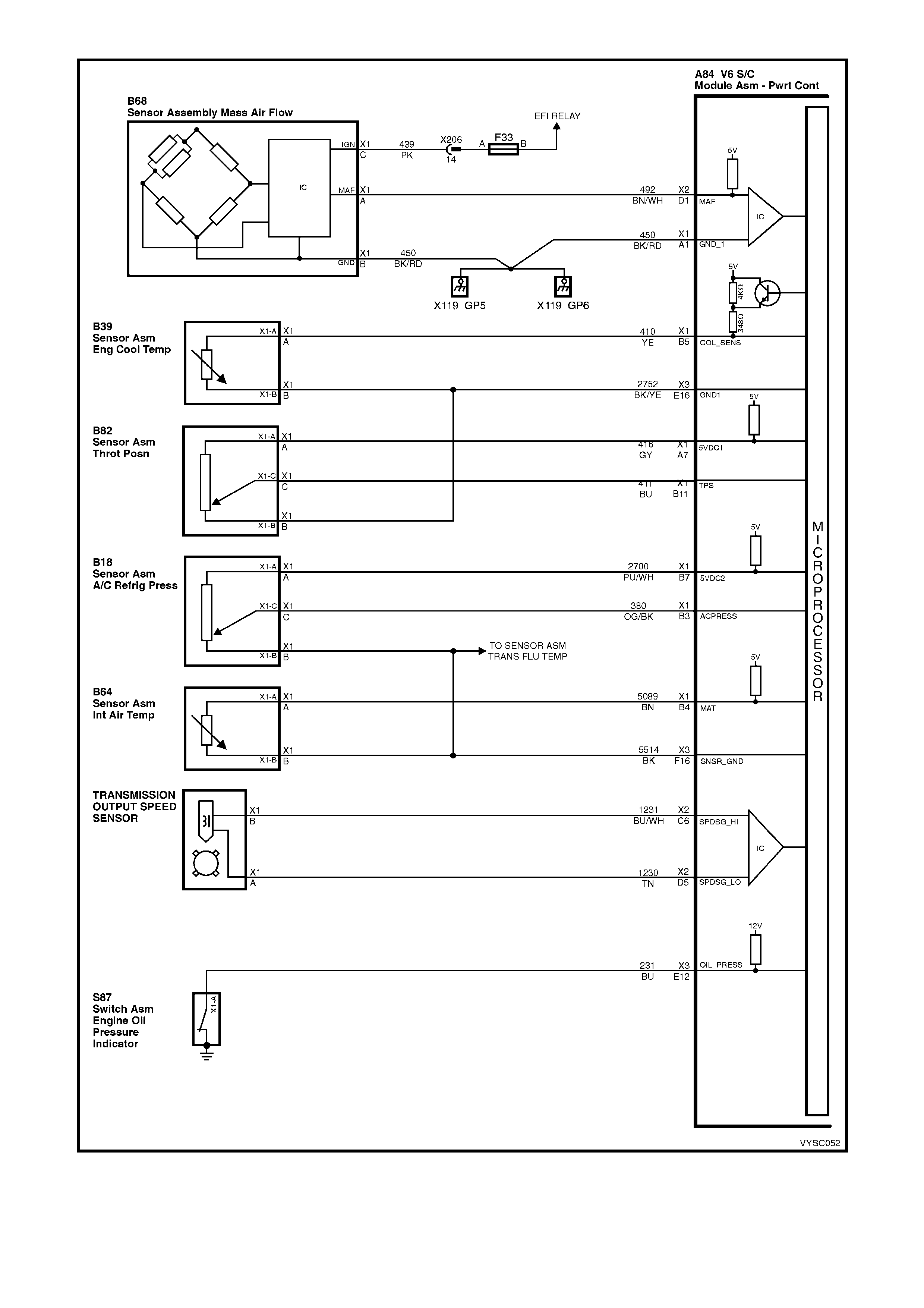
Figure 6C1-2A-10 – PCM Wiring Diagram (4 of 8) V6 Supercharged Engine Application – Sensor Input Circuits
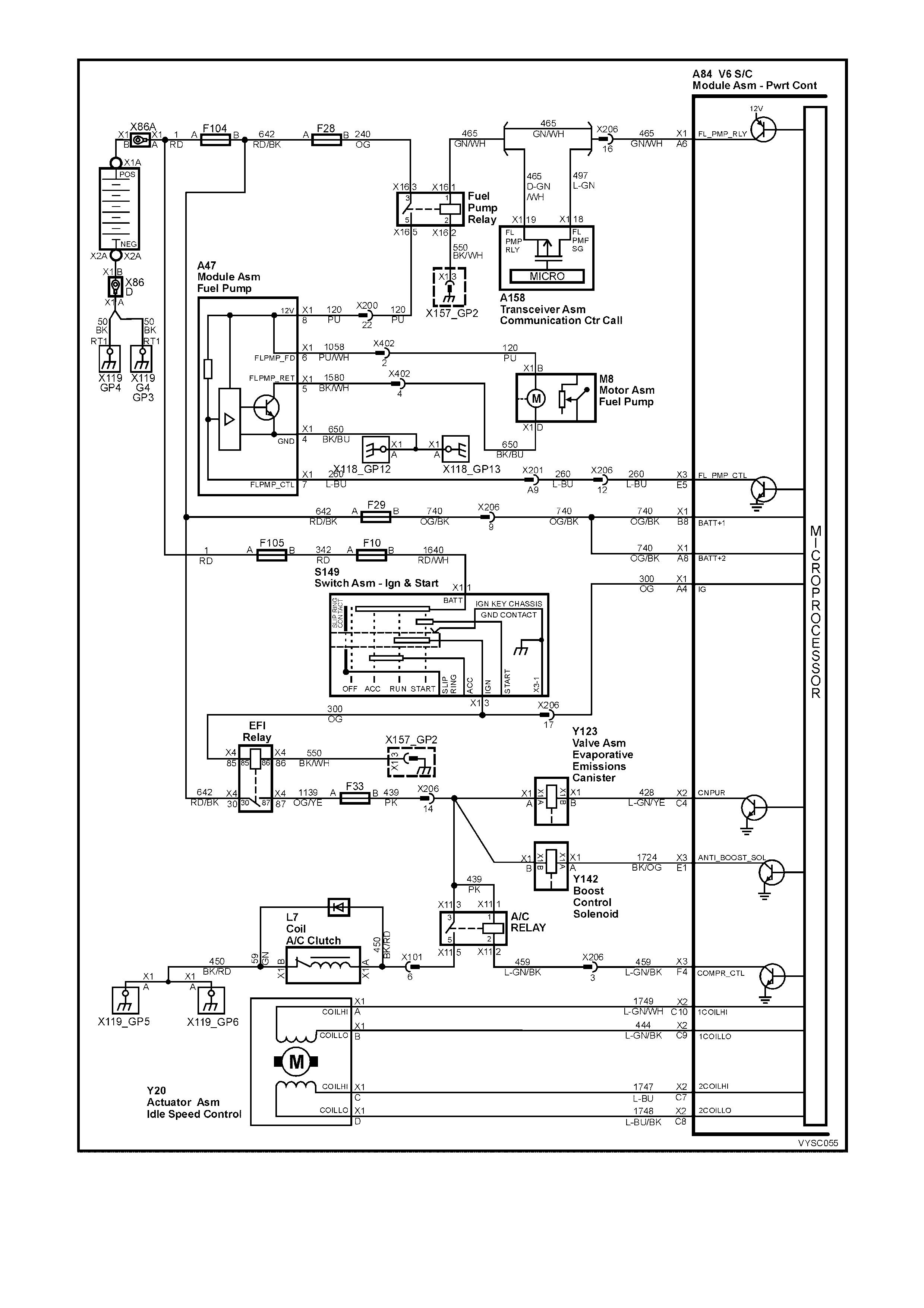
Figure 6C1-2A-11 PCM Wiring Diagram (5 of 8) V6 Supercharged Engine Application – Control Circuits
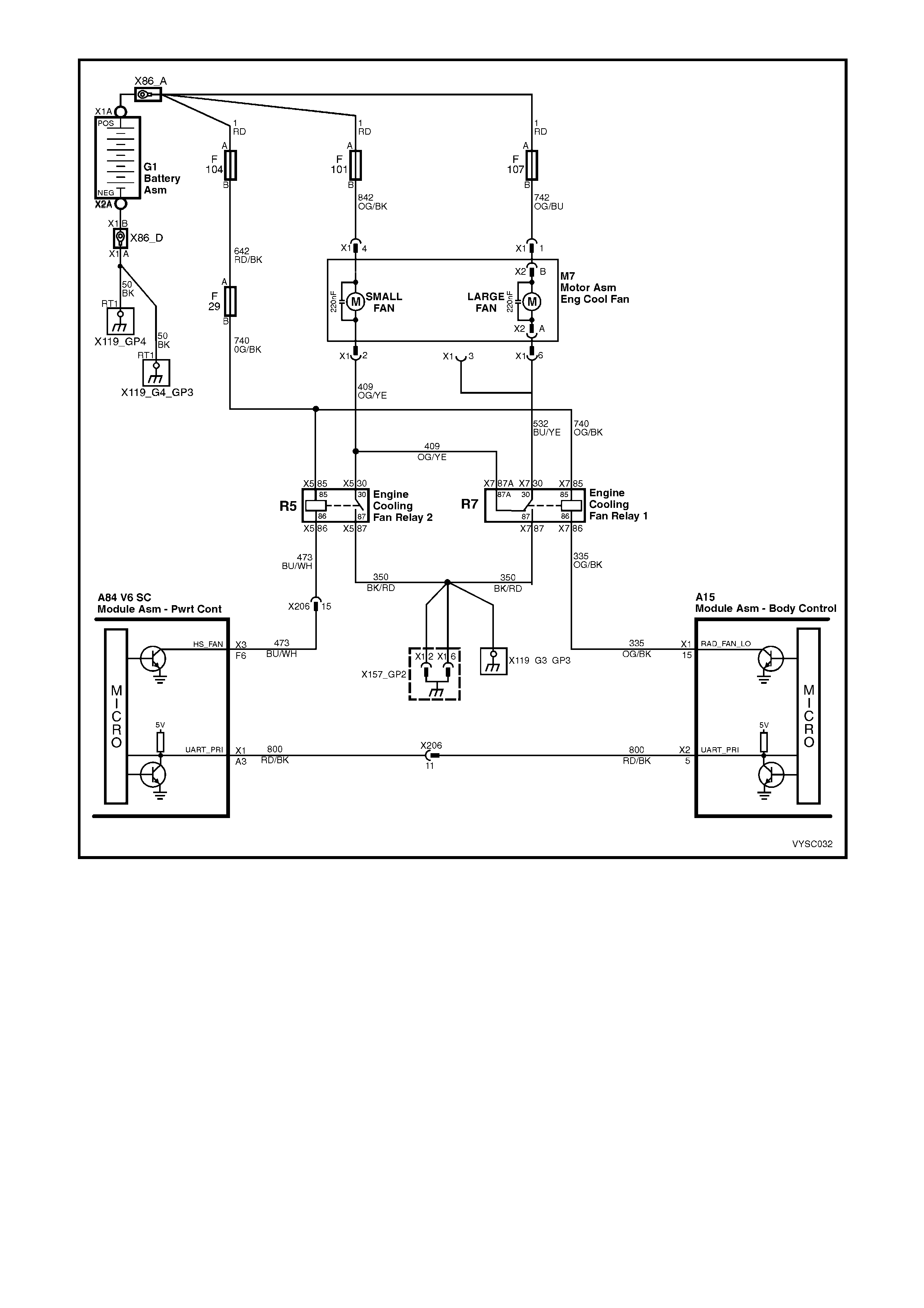
Figure 6C1-2A-12 PCM Wiring Diagram (6 of 8) V6 Supercharged Engine Application – Cooling System Control
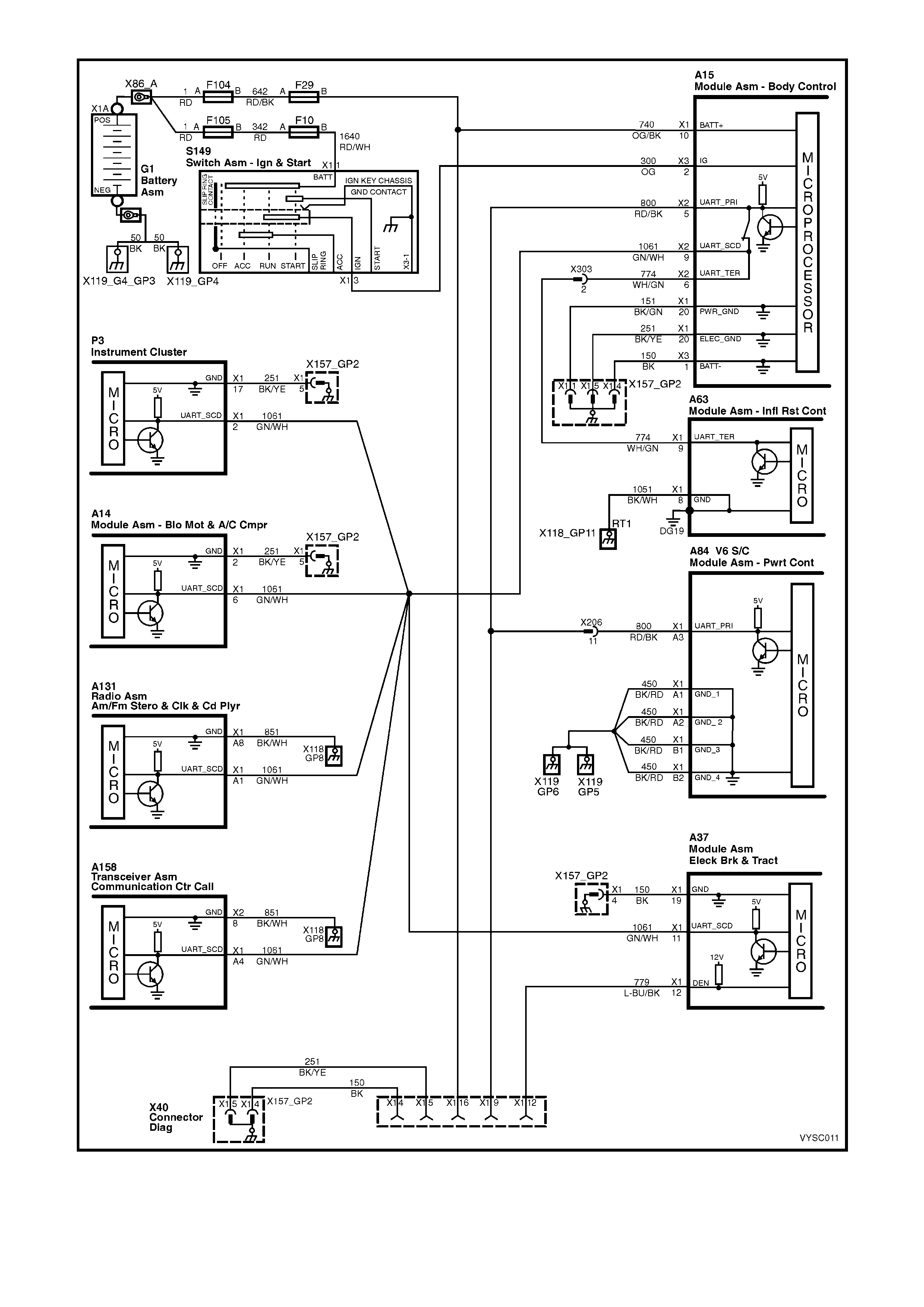
Figure 6C1-2A-13 PCM Wiring Diagram (7 of 8) V6 Supercharged Engine Application – Serial Data Circuits
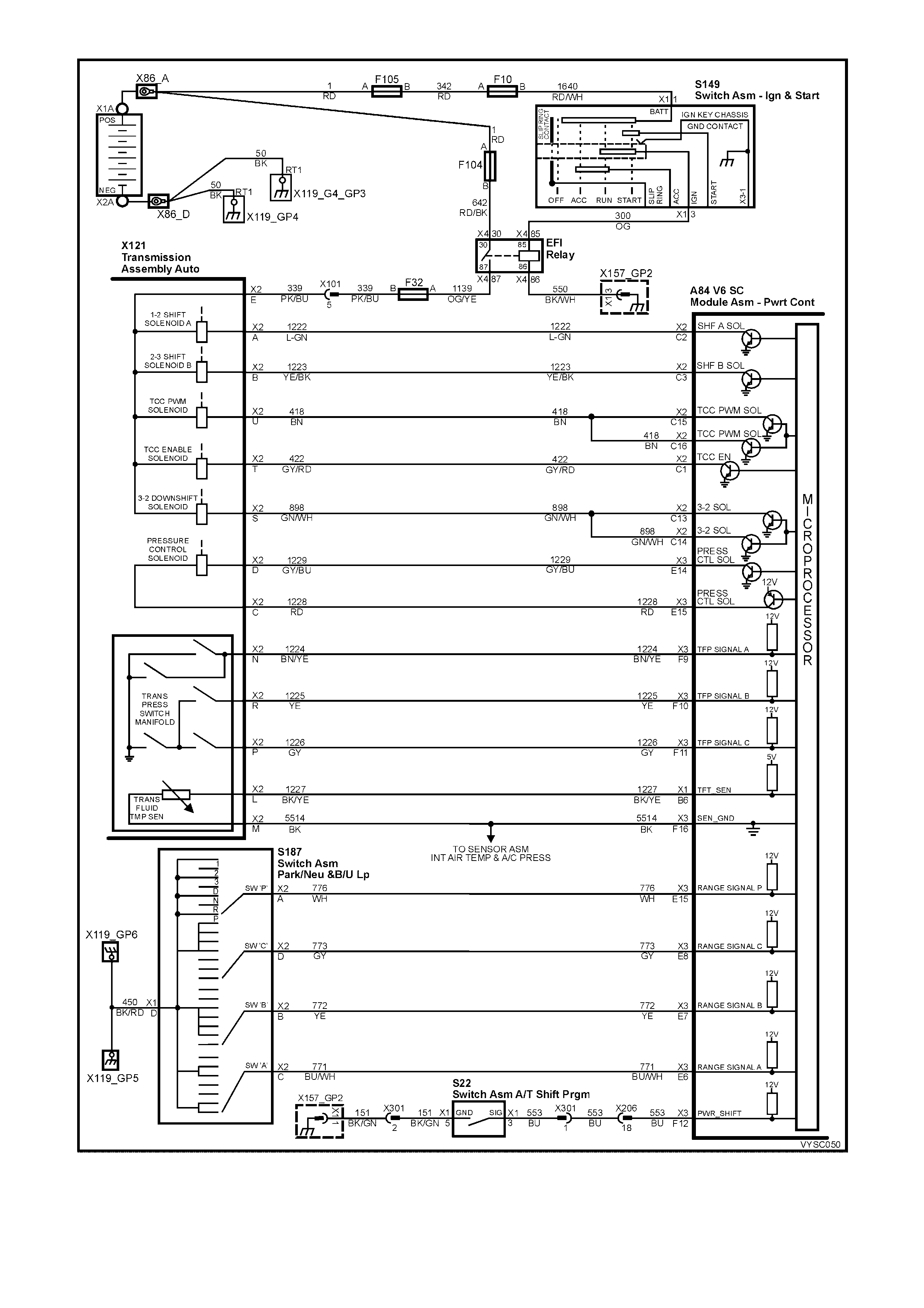
Figure 6C1-2A-14 PCM Wiring Diagram (8 of 8) V6 Supercharged Engine Application –
Automatic Transmission Circuits
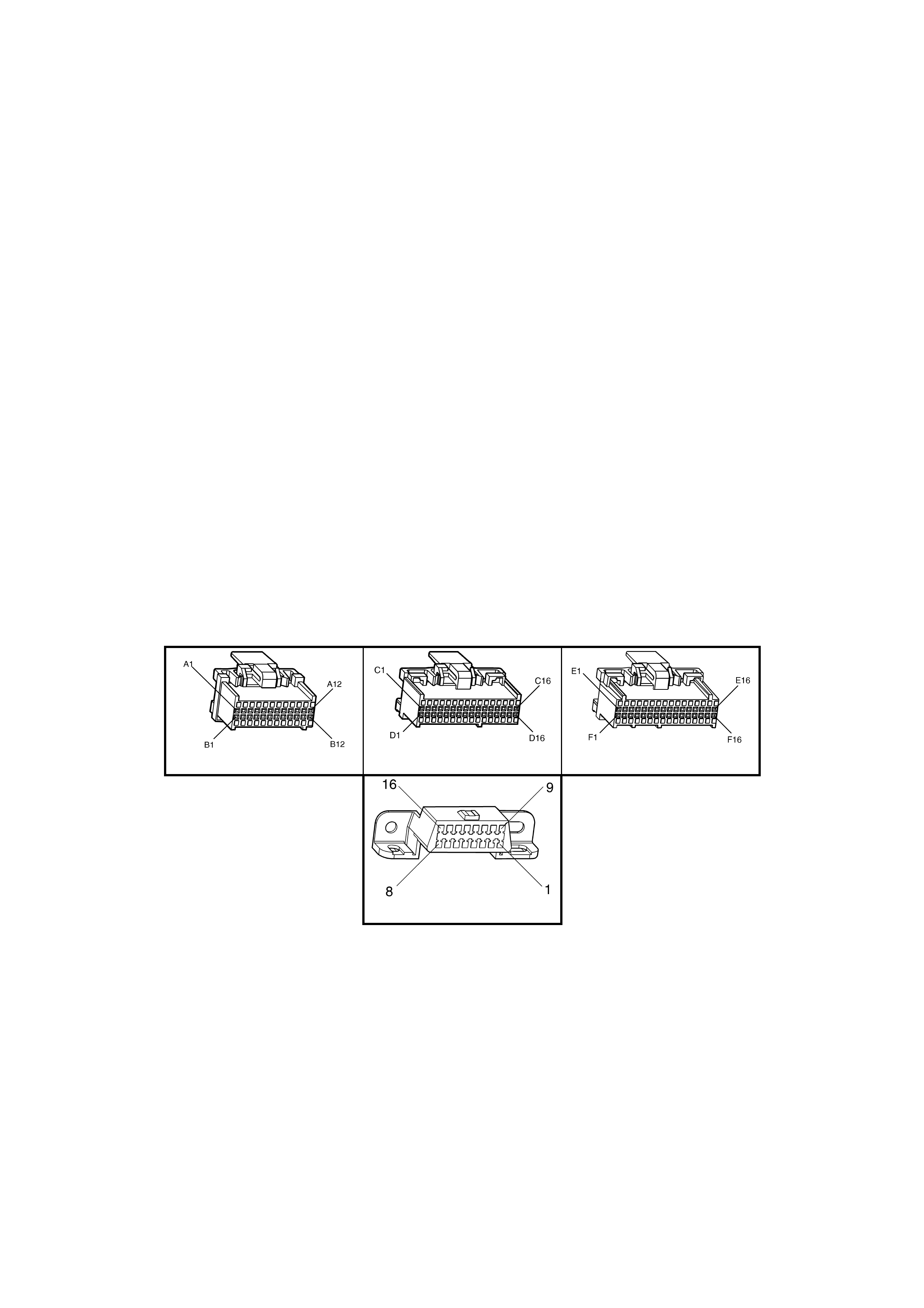
POWERTRAIN CONTROL MODULE CONNECTOR IDENTIFICATION
This Powertrain Control Module Voltage Table is for use with a digital voltmeter to further aid in diagnosis.
Connect the Black (–) probe to a good chassis ground, and backprobe the powertrain control module terminal
with the Red ( +) pr obe. T hese voltages were derived fr om a k nown good vehicle. The voltages you get m ay vary
due to low battery charge or other reasons, but they should be very close.
THE FOLLOWING CONDITIONS MUST BE MET BEFORE TESTING:
• Engine and Transmission at operating
temperature
• Closed Loop
• Engine idling (for "Engine Run" column)
• Diagnostic "Test" terminal not grounded
• Tech 2 scan tool not installed
• Accessories "OFF"
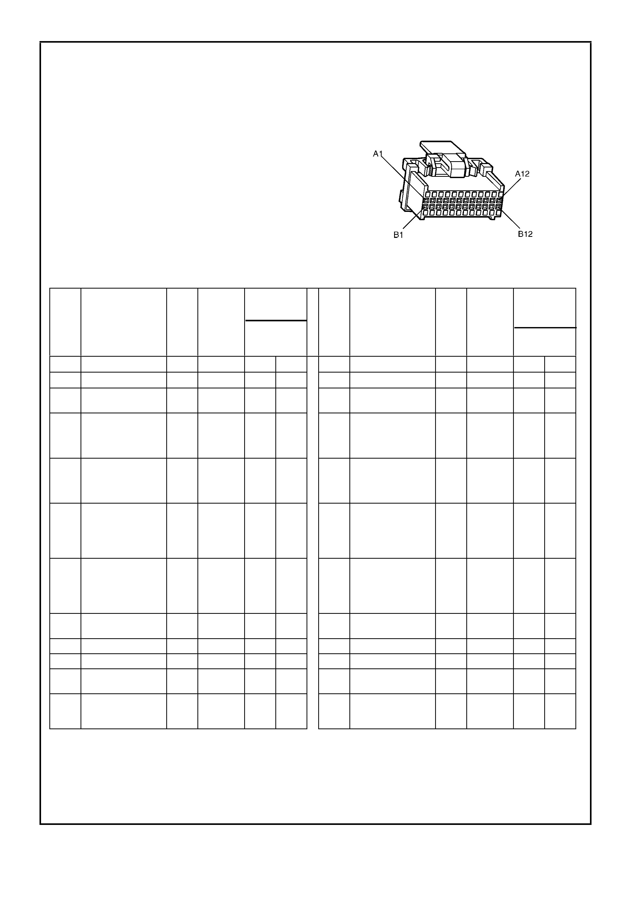
A84 S/C V6 – X1
BACKPROBING VIE W OF PINK PCM CONNECTOR – A84 S/C V6 – X1
Figure 6C1-2A 15 – PCM Connector Terminal End View (1 of 3)
Pin
Pin Funct i on
CKT
#
Wire
Colour
Ign
"ON"
Eng
Run
Pin
Pin Funct i on
CKT
#
Wire
Colour
Ign
"ON"
Eng
Run
A1 SYSTEM GROUND 450 BK/RD -
--
- -
--
- B1 SYSTEM GROUND 450 BK/RD -
--
- -
--
-
A2 SYSTEM GROUND 450 BK/RD -
--
- -
--
- B2 SYSTEM GROUND 450 BK/RD -
--
- -
--
-
A3 PRIMARY SERIAL
DATA 800 RD/BK 2.5 to
3.5 2.5 t o
3.5 B3 A/C PRESSURE
SENSOR SIGNAL 380 OG/BK 1 to 2 1 to 2
A4 FUSED IGNITION
FEED 300 OG 12 13 B4 INTAKE AIR
TEMPERATURE
(IAT) SENSOR
SIGNAL
5089 BN (3) (3)
A5 NOT USED – – – – B5 ENGINE COOLANT
TEMPERATURE
(ECT) SENSOR
SIGNAL
410 YE (3) (3)
A6 FUEL PUMP
RELAY CONT ROL 465 GN/WH (1) 13 B6 TRANSMISSION
FLUID
TEMPERATURE
(TFT) SENSOR
SIGNAL
1227 BK/YE (3) (3)
A7 TP SENSOR
5 VOLT
REFERENCE
416 GY 5 5 B7 A/C
REFRIGERANT
PRESSURE
SENSOR 5 VOLT
REFERENCE
2700 PU/WH 5 5
A8 BATTERY
VOLTAGE FEED 740 OG/BK 12 13 B8 BATTERY
VOLTAGE FEED 740 OG/BK 12 12
A9 NOT USED – – – – B9 NOT USED – – – –
A10 NOT USED – – – – B10 NOT USED – – – –
A11 NOT USED – – – – B11 TP SENSOR
SIGNAL 411 BU (5) (5)
A12 NOT USED – – – – B12 INJECTOR
VOLTAGE
MONITOR LINE
639 RD 12 13
(1) Battery voltage first 2 seconds.
(3) Varies with temperature.
(5) 0.25 – 1.25 volts measured between terminals "B11" and "B1" or about 4.0 volts at wide open throttle.
(6) Varies with altitude.
-
--
- Less than 0.50 volts
Normal
Voltages Normal
Voltages
POWERTRAIN CONTROL MODULE CONNECTOR IDENTIFICATION
This Powertrain Control Module Voltage Table is for use with a digital voltmeter to further aid in diagnosis.
Connect the Black (–) probe to a good chassis ground, and backprobe the powertrain control module terminal
with the Red ( +) pr obe. These voltages were derived from a known good vehicle. The voltages you get may vary
due to low battery charge or other reasons, but they should be very close.
THE FOLLOWING CONDITIONS MUST BE MET BEFORE TESTING:
• Engine and Transmission at operating
temperature
• Closed Loop
• Engine idling (for "Engine Run" column)
• Diagnostic "Test" terminal not grounded
• Tech 2 scan tool not installed
• Accessories "OFF"
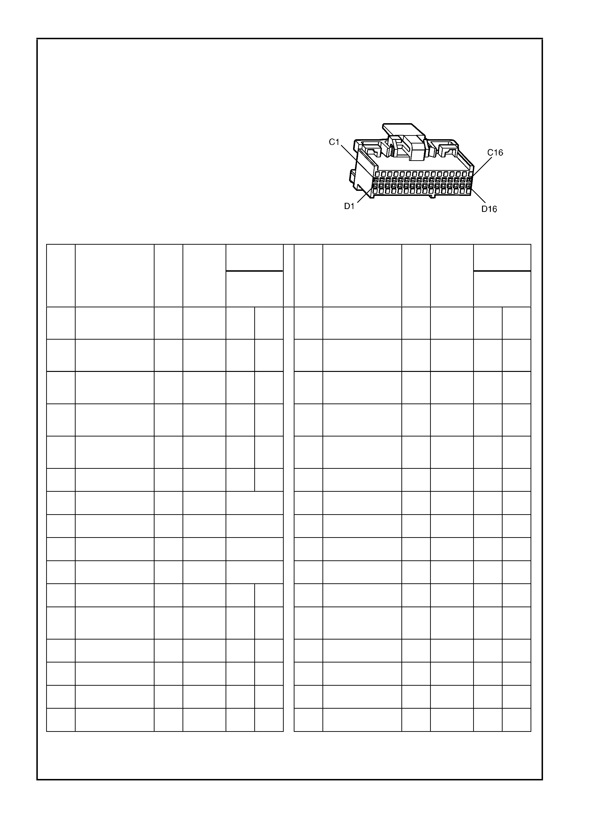
A84 S/C V6 – X2
BACKPROBING VIE W OF PINK PCM CONNECTOR – A84 S/C V6 – X2
Figure 6C1-2A-16 – PCM Connector Terminal End View (2 of 3)
Pin
Pin Funct i on
CKT
#
Wire
Colour
Ign
"ON"
Eng
Run
Pin
Pin Funct i on
CKT
#
Wire
Colour
Ign
"ON"
Eng
Run
C1 TCC "ON-OFF"
SOLENOID
CONTROL
422 GY/ RD 12 13 D1 MASS AI R FLOW
(MAF) SENS OR
INPUT SIGNAL
492 BN/WH 4.8 4.2
C2 1-2 SHIFT
SOLENOID
CONTROL
1222 L-GN 12 -
--
- D2 NOT USED – – – –
C3 2-3 SHIFT
SOLENOID
CONTROL
1223 YE/BK 12 -
--
- D3 CAMSHAFT
POSITION (CMP)
SENSOR INPUT
630 BK 4.8 4.0
C4 CANISTER PURGE
SOLENOID 428 L-GN/YE 12 13 D4 CRANKSHAFT 18X
SIGNAL 647 L-BU/BK 5
or
0
2.0
to
3.0
C5 VEHICLE SPEED
OUTPUT TO
SPEEDOMETER
5197 PU/WH 0.1
OR
12
0.1
OR
13
D5 VEHICLE SPEED
SENSOR SIGNAL
LOW
1230 TN -
--
- -
--
-
C6 VEHICLE SPEED
SIGNAL HIGH 1231 BU/WH -
--
- -
--
- D6 NOT USED – – – –
C7 IAC 2 COIL ‘ HI ’ 1747 L-BU/WH NOT
USEABLE D7 NOT USED – – – –
C8 IAC 2 COIL ‘ LO’ 1748 L-B U/BK NOT
USEABLE D8 NOT USED – – – –
C9 IAC 1 COIL ‘ LO’ 444 L-GN/BK NOT
USEABLE D9 BYPASS
CONTROL 424 TN/BK 0 4.7
C10 IAC 1 COIL ‘ HI ’ 1749 L-GN/WH NOT
USEABLE D10 EST OUTPUT 423 WH 0 2.0
C11 TORQUE
REQUEST 463 OG/WH 4-5 4-5 D11 CRANKSHAFT
REFERE NCE LOW 453 BK/RD -
--
- -
--
-
C12 KNOCK SENSOR
(ESC) SIGNAL
INPUT
496 WH/RD 1.3
mV
AC
19
mV
AC
D12 CRANKSHAFT
REFERE NCE HIGH 430 PU 4.8 2.3
C13 3-2 CONTROL
SOLENOID 898 GN/WH 12 -
--
- D13 RH OXYGEN
SENSOR SIGNAL 1666 GY 450
mV (4)
C14 3-2 CONTROL
FEEDBACK 898 GN/WH 12 -
--
- D14 RH OXYGEN
SENSOR GROUND 1667 GY/BK -
--
- -
--
-
C15 TCC PWM
FEEDBACK 418 BN 12 13 D15 LH OXYGEN
SENSOR SIGNAL 1665 PU 450
mV (4)
C16 TCC SOLENOID
PWM CONTROL 418 BN 12 13 D16 LH OXYGEN
SENSOR GROUND 1664 L-BU/BK -
--
- -
--
-
(4) The voltage should vary between 100 mV - 1000 mV.
-
--
- Less than 0.50 volts
Normal
Voltages Normal
Voltages
POWERTRAIN CONTROL MODULE CONNECTOR IDENTIFICATION
This Powertrain Control Module Voltage Table is for use with a digital voltmeter to further aid in diagnosis.
Connect the Black (–) probe to a good chassis ground, and backprobe the powertrain control module terminal
with the Red ( +) pr obe. These voltages were derived from a known good vehicle. The voltages you get may vary
due to low battery charge or other reasons, but they should be very close.
THE FOLLOWING CONDITIONS MUST BE MET BEFORE TESTING:
• Engine and Transmission at operating
temperature
• Closed Loop
• Engine idling (for "Engine Run" column)
• Diagnostic "Test" terminal not grounded
• Tech 2 scan tool not installed
• Accessories "OFF"
A84 S/C V6 – X3
BACKPROBING VIE W OF BLUE PCM CONNECTOR – A84 S/C V6 – X3
Figure 6C1-2A 17 – PCM Connector Terminal End View (3 of 3)
Pin
Pin Funct i on
CKT
#
Wire
Colour
Ign
"ON"
Eng
Run
Pin
Pin Funct i on
CKT
#
Wire
Colour
Ign
"ON"
Eng
Run
E1 BOOST CONTROL
SOLENOID 1724 BK/OG 12 -
--
- F1 FUEL INJECTOR
#4 CONTROL 844 BN/WH 12 13
E2 FUEL INJECTOR
#3 CONTROL 1746 PU 12 13 F2 FUE L INJECTOR
#1 CONTROL 1744 BU 12 12
E3 FUEL INJECTOR
#2 CONTROL 1745 GN 12 13 F3 FUEL INJE CTOR
#6 CONTROL 846 YE 12 13
E4 FUEL INJECTOR
#5 CONTROL 845 BN/YE 12 13 F4 AIR
CONDITIONING
RELAY CONT ROL
459 L-GN/BK 12 (2)
E5 FUEL PUMP
CONTROL
MODULE (PWM)
DRIVER
260 L-BU -
--
--
--
- 3.0
to
3.4 V
F5 START RELAY
CONTROL 434
or
275
GY
or
GY/BU
-
--
- -
--
-
E6 PRNDL "A" 771 BU/WH -
--
- -
--
- F6 ENGINE COOLING
FAN RELA Y HIGH
SPEED CONTROL
473 BU/WH 12 (7)
E7 PRNDL "B" 772 YE 12 13 F7 TORQUE
ACHIEVED (MMI) 464 BK/WH 0.9 3-6
E8 PRNDL "C" 773 GY 12 13 F8 NOT-USED – – – –
E9 NOT USED – – – – F9 RANGE SIGNAL
"A" 1224 BN/YE 12 13
E10 NOT-USED – – – – F10 RANGE SIGNAL
"B" 1225 YE 0 0
E11 NOT USED – – – – F11 RANGE SIGNAL
"C" 1226 GY 12 13
E12 OIL PRESSURE
INPUT SIGNAL 231 BU * 13 F12 POWER/ECONOM
Y SWITCH INPUT 553 BU (6) (6)
E13 NOT USED – – – – F13 NOT USED – – – –
E14 PRESSURE
CONTROL
SOLENOID LOW
1229 GY/BU -
--
- 6.8
to
7.8
F14 NOT USED – – – –
E15 PRESSURE
CONTROL
SOLENOID HIGH
1228 RD -
--
- 1.3
to
1.5
F15 PRNDL "P" 776 WH -
--
- -
--
-
E16 ECT/TP SENSOR
SENSOR GROUND 2752 BK/YE -
--
- -
--
- F16 IAT, TFT, A/C
REFRIGERANT
PRESSURE
SENSOR GROUND
5514 BK -
--
- -
--
-
(2) With air conditioning "ON" 0 volts, with air conditioning "OFF" 13 volts.
(3) 12 volts while engine is cranking.
(6) W hen Power/Economy switch is depressed, voltage will quickly change from 12 to 0 volts then back
to 12 volts.
(7) With engine cooling fan "ON" 0 volts, with engine cooling fan "OFF" 13 volts.
-
--
- Less than 0.50 volts.
-
--
--
--
- 9 – 10 volts for 2 seconds
Normal
Voltages Normal
Voltages

PCM CONNECTOR TERMINAL VOLTAGES WITH EXPLANATIONS
A1 - SYSTEM GROUND
A2 - SYSTEM GROUND
These terminals should have zero volts. They are connected directly to the engine ground.
A3 - PRIMARY SERIAL DATA
This is a serial bus that connects the PCM, BCM, A.B.S./T.C.S., OCC, INSTRUMENT S and SIR. T he T ech 2 sc an
tool can "talk" to each of these modules by sending a message to a controller and asking only it to respond. The
communication rate is at 8192 baud. The normal voltage on this circuit is about 5 volts, but with serial data
communication occurring, the voltage will vary and if read with a DMM may read about 2.5 volts
A4 - IGNITION SWITCH INPUT SIGNAL
This is the "turn on" s ignal to the PCM from the ignition s witch circ uit. It is not the "power supply" to the PCM, it only
tells the PCM that the ignition switch is "ON." The voltage should equal the battery voltage when the key is in either
the `run' or ‘crank' position.
A5 - NOT USED
A6 - FUEL PUMP (FP) RELAY CONTROL
Turning the ignition "O N" c aus es the PCM to ener gis e (+12V) the F uel Pump Relay. If no crank s haf t refer enc e input
pulses are received, the PCM turns "OFF" the relay. As soon as the PCM receives crankshaft reference input
pulses, the PCM will turn the Fuel Pump Relay on again.
A7 - THROTTLE POSITION (TP) SENSOR REFERENCE VOLTAGE
This voltage should always be 5 volts anytime the ignition is "ON." It is a regulated voltage output from the PCM,
and supplies 5 volts to the TP sensor.
A8 - BATTERY VOLTAGE FEED – HOT AT ALL TIMES
This supplies the PCM with full- time +12 volts . It s tays hot even when the ignition is turned off . It receives its voltage
through the "ENGINE" fuse F29. This PCM terminal could be called the power supply and "MEMORY" terminal.
A9 - NOT USED
A10 - NOT USED
A11 - NOT USED
A12 - NOT USED
B1 - SYSTEM GROUND
B2 - SYSTEM GROUND
These terminals should have zero volts. They are connected directly to the engine ground.
B3 - A/C REFRIGERANT PRESSURE SENSOR INPUT SIGNAL
The signal that is sent from the pressure Sensor to the PCM indicates to the PCM what the A/C pressure is at.
Depending on the A/C pressure, this signal will indicate to the PCM if A/C pressure is too low or too high.
B4 - INTAKE AIR TEMPERATURE (IAT) INPUT SIGNAL
The PCM sends a 5 volt signal voltage to the IAT sensor, which is a temperature - variable-resistor called a
thermistor. The sensor is also connected to ground, and will alter the signal voltage according to incoming air
temperature. As the air temperature increases, the voltage seen on this terminal decreases. At 0 degrees C, the
voltage will be above 4 volts. At normal operating temperature (10 degrees C to 80 degrees C) the voltage will be
less than 4 volts.
B5 - ENGINE COOLANT TEMPERATURE (ECT) INPUT SIGNAL
The PCM sends a 5 volt signal voltage out to the engine coolant temperature sensor, which is a temperature-
variable-resistor called thermistor. The sensor, being also connected to ground, will alter the voltage according to
engine coolant temperature. As the engine coolant temperature increases, the voltage seen on terminal B5
decreases. At 0 degrees C engine coolant temperature the voltage will be above 4 volts. At normal operating
temperature (85 degrees C to 100 degrees C) the voltage will be less than 2 volts.
B6 - TRANSMISSION FLUID TEMPERATURE (TFT) INPUT SIGNAL (AUTO TRANS ONLY)
The PCM sends a 5 volt signal voltage out to the transmission fluid temperature sensor, which is a temperature-
variable-resistor called thermistor. The sensor, being also connected to ground, will alter the voltage according to
transmission fluid temperature. As the fluid temperature increases, the voltage seen on terminal B6 will decrease.

B7 - A/C PRESSURE SENSOR REFERENCE VOLTAGE
This voltage should always be 5 volts anytime the ignition is "ON." It is a regulated voltage output from the PCM,
and supplies 5 volts to the A/C Pressure Sensor.
B8 - BATTERY VOLTAGE FEED – HOT AT ALL TIMES
This supplies the PCM with full- time +12 volts . It s tays hot even when the ignition is turned off . It receives its voltage
through the "ENGINE" fuse F29. This PCM terminal could be called the power supply and "MEMORY" terminal.
B9 - NOT USED
B10 - NOT USED
B11 - THROTTLE POSITION (TP) SENSOR SIGNAL
The TP sensor input voltage, which follows actual throttle changes, is variable from 0 to 5 volts. Typically the voltage
is less than 1 volt at idle, and 4 to 5 volts at wide-open throttle.
B12 - INJECTOR CIRCUIT VOLTAGE MONITOR INPUT SIGNAL
The inj ector voltage m onitor line is used s o that the PCM will know the exact voltage the fuel injectors are operating
at. This voltage signal is used to modify the fuel injector pulse width calculation.
C1 - TORQUE CONVERTER CLUTCH ENABLE SOLENOID CONTROL (AUTO TRANS ONLY)
The PCM is used to either open or provide a path to ground for the torque converter solenoid. When the PCM
provides a path to ground, the TCC solenoid is cons idered ON and voltage should be near 0 volts. T he PCM uses
both the TCC enable s olenoid and the TCC "PWM" solenoid to c ontrol the torque converter clutch. (See TCC PW M
solenoid, terminal C16)
C2 - 1-2 SHIFT SOLENOID ‘A’ CONTROL (AUTO TRANS ONLY)
The PCM is used to either open or provide a path to ground for the 1-2 shift solenoid. When the PCM provides a
path to ground, the 1-2 shift solenoid is considered "ON" and the voltage should read 0 volts.
C3 - 2-3 SHIFT SOLENOID ‘B’ CONTROL (AUTO TRANS ONLY)
The PCM is used to either open or provide a path to ground for the 2-3 shift solenoid. When the PCM provides a
path to ground, the 2-3 shift solenoid is considered "ON" and the voltage should read 0 volts.
C4 - CANISTER PURGE SOLENOID CONTROL
The PCM operates a normally closed solenoid valve, which controls vacuum to purge the evaporative emissions
storage canister of stored fuel vapours. The PCM turns "ON" the pulse width modulated control of the purge
solenoid, to control purging of the stored vapours. If the PCM is not energising the purge solenoid, the voltage
meas ured at this ter m inal should equal battery voltage. If the PCM is c ontrolling the solenoid, the measured voltage
will be between battery voltage and 0.50 volts.
C5 - VEHICLE SPEED OUTPUT
The PCM alternately grounds this signal, in pulses, when it rec eives a vehicle speed signal fr om the vehicle speed
sensor in the transmission. This pulsing action takes place about 6,250 times per kilometre. The control modules
calculate vehicle speed based on the time between pulses (frequency).
C6 - VEHICLE SPEED SENSOR - OUTPUT SHAFT SPEED INPUT SIGNAL HIGH
The transmission has an output shaft speed sensor used by the PCM to calculate vehicle speed, and to help
determ ine various autom atic transm ission shif ting functions . It is a m agnetic inductive sens or that generates an AC
voltage signal sent to the PCM. If measured with the digital AC voltmeter, no voltage will appear until the output
shaft begins turning.
C7 - IDLE AIR CONTROL (IAC)
C8 - IDLE AIR CONTROL (IAC)
C9 - IDLE AIR CONTROL (IAC)
C10 - IDLE AIR CONTROL (IAC)
These terminals connect the Idle Air Control valve, located on the throttle body, to the PCM. It is difficult to predict
what the voltage will be, and the measurement is unusable for any service procedures.
C11 - TRACTION CONTROL (TORQUE REQUESTED)
The A.B.S./T.C.S. module will send a Nm signal to the PCM when torque reduction is requested from the
A.B.S./T.C.S. module for traction control. This Nm signal should match closely with Torque Achieved Nm signal,
when traction control is being requested.
C12 – ELECTRONIC SPARK CONTROL (ESC) "KNOCK" INPUT SIGNAL
The Electronic Spark Control "knock" sensors detect when detonation is occurring in the combustion chambers.
W hen detected, the PCM will reduce the am ount of spar k advance being delivered on the EST output circuit to the
ignition module.

C13 - 3-2 DOWNSHIFT CONTROL SOLENOID CONTROL (AUTO TRANS ONLY)
The 3-2 control solenoid is a norm ally closed, solenoid us ed to control the 3- 2 downshift. T he solenoid is constantly
fed 12 volts and PCM controls the length of time the path to ground for the electrical circuit is closed.
C14 - 3-2 SHIFT SOLENOID FEEDBACK (AUTO TRANS ONLY)
The 3-2 Shift solenoid is a normally closed solenoid used to control the 3-2 downshift. The solenoid is constantly fed
12 volts and PCM controls the length of time the path to ground for the electrical circuit is closed. The PCM does
this to pr ovide a s mooth 3-2 downshif t. If the PCM s ens es an inc or rec t voltage on this c irc uit when controlling the 3-
2 downshift solenoid (i.e. – zero volts with the solenoid OFF, or 12 volts with the solenoid ON) a DT C code 66 will
set.
C15 - T ORQUE CONVERTER CLUT CH - PULSE WIDTH M ODULATED APPLY SOLENOID FEEDBACK (AUTO
TRANS ONLY)
The PCM us es the puls e width m odulated TCC apply solenoid to smoothly engage the torque converter clutch, after
the TCC "ON-OFF" solenoid is energised. By varying the duty cycle pulse width modulation, the PCM can slowly
engage the torque converter clutch, allowing very smooth TCC engagement. If the PCM senses an incorrect voltage
on this circuit when controlling the TCC PWM solenoid (i.e. zero volts with the solenoid OFF, or 12 volts with the
solenoid ON ) a DTC code 83 will set.
C16 - TORQUE CONVERTER CLUTCH - PULSE WIDTH MODULATED APPLY SOLENOID CONTROL (AUTO
TRANS ONLY)
The PCM us es the puls e width m odulated TCC apply solenoid to smoothly engage the torque converter clutch, after
the TCC "ON-OFF" solenoid is energised. By varying the duty cycle pulse width modulation, the PCM can slowly
engage the torque converter clutch, allowing very smooth TCC engagement.
D1 - MASS AIR FLOW (MAF) INPUT SIGNAL
The PCM supplies a 5-volt signal voltage to the mass air flow sensor on this circuit. The mass air flow sensor
pulses the 5-volt signal to ground. These ground pulses occur at a very fast rate - from less than 500 per second
(500 Hz) with no airflow through the sensor, to upwards of many thousands of pulses per second at high air flow
rates suc h as during ac c eleration. If measur ed, the voltage seen will be between 0.5 and 4.5 volts, depending on air
flow through the sensor.
D2 - NOT USED
D3 - CAMSHAFT POSITION INPUT SIGNAL
This signal is used by the PCM to "sequence" the energising of the fuel injectors, similar to the firing order of an
engine. This allows the PCM to operate the fuel injectors in a "sequential fuel injection" mode. The camshaft
position sensor is actually wired to the ignition module. The ignition module sends one pulse per every two
crankshaft revolutions to the PCM to determine actual camshaft position, and thus, engine cycle sequence.
D4 - CRANKSHAFT 18X INPUT SIGNAL
The 18X crank s haft ref erenc e input signal is us ed to very accurately control EST spark timing at low engine speeds
- below 1200 RPM. Below 1,200 RPM, the PCM monitors the 18X signal to control spark timing. At engine s peeds
above 1,200 RPM, the PCM uses the crankshaft reference input signal to control spark timing. (See crankshaft
reference terminal D12).
D5 - VEHICLE SPEED SENSOR - OUTPUT SHAFT SPEED INPUT SIGNAL LOW
The transmission has an output shaft speed sensor used by the PCM to calculate vehicle speed, and to help
determ ine various autom atic transm ission shif ting functions . It is a m agnetic inductive sens or that generates an AC
voltage signal sent to the PCM. If measured with the digital AC voltmeter, no voltage will appear until the output
shaft begins turning.
D6 - NOT USED
D7 - NOT USED
D8 - NOT USED
D9 - IGNITION MODULE BYPASS CONTROL (IGNITION SYSTEM MODE CONTROL)
With ignition "ON" and engine not running this term inal will have very low voltage. As soon as the PCM sees engine
RPM of more than 450 RPM (Electronic Spark Timing "run" threshold) the PCM turns on 5 volts to the Ignition
Module Bypass Control circuit, causing the ignition module to allow the PCM to control the ignition system.
D10 - ELECTRONIC SPARK TIMING (EST) OUTPUT
This terminal will have very low voltage with the ignition "ON" but engine not running. With the engine running at
idle, the voltage should be slightly more than 1 volt. As the engine RPM goes up, this voltage will increase.
D11 - CRANKSHAFT REFERENCE INPUT SIGNAL LOW
This terminal should always be zero volts. It is connected through the ignition module to engine ground.

D12 - CRANKSHAFT REFERENCE INPUT SIGNAL HIGH
This term inal could be called the "tacho" input. It provides the PCM with RPM and crank shaft position information.
W ith ignition "ON" but engine not running, the voltage will be either high or low, depending on crankshaft position.
As the crank s haft tur ns, the voltage will be an average of the two readings. The PCM uses this signal to contr ol fuel
injection, and spark timing with engine speeds above 1,200 RPM. (See 18X crankshaft reference terminal D4).
D13 - OXYGEN SENSOR INPUT SIGNAL (RIGHT BANK)
W ith ignition "ON" and engine not running, the voltage should be 350 - 450 millivolts (0.350 - 0.450 volts). This is
the PCM-supplied 02 circuit "bias" voltage. With the engine running and after the 02 sensor is hot, the voltage
should be rapidly changing, som ewher e between 10 - 1000 m illivolts (0.010 - 1.000 volt, with the PCM operating in
closed loop).
D14 - OXYGEN SENSOR GROUND (RIGHT BANK)
This term inal should have zero volts. It is connected directly to the engine ground. This term inal grounds the PCM
circuitry for the O2 voltage monitor inside the PCM.
D15 - OXYGEN SENSOR INPUT SIGNAL (LEFT BANK
W ith ignition "ON" and engine not running, the voltage should be 350 - 450 millivolts (0.350 - 0.450 volts). This is
the PCM-supplied 02 circuit "bias" voltage. With the engine running and after the 02 sensor is hot, the voltage
should be rapidly changing, som ewher e between 10 - 1000 m illivolts (0.010 - 1.000 volt, with the PCM operating in
closed loop).
D16 - OXYGEN SENSOR GROUND (LEFT BANK)
This term inal should have zero volts. It is connected directly to the engine ground. This term inal grounds the PCM
circuitry for the O2 voltage monitor inside the PCM.
E1 - BOOST CONTROL SOLENOID
The PCM operates a normally closed solenoid valve, which controls vacuum to the By-Pass Valve Actuator. The
PCM turns "ON" the s olenoid , to allow vacuum to the By-Pass Valve Actuator , to c lose the By-Pass valve and allow
full boost. If the PCM is not energising the boost solenoid, the voltage measured at this terminal should equal
battery voltage. If the PCM is controlling the solenoid, the measured voltage will be between battery voltage and
0.50 volts.
E2 - FUEL INJECTOR 3 - CONTROL
E3 - FUEL INJECTOR 2 - CONTROL
E4 - FUEL INJECTOR 5 - CONTROL
The voltage seen at these terminals actually comes through the injectors, which are connected to +12 volts. W ith
the engine not running, the voltage seen would be battery voltage. With the engine running at idle, the charging
system increases the voltage slightly, so this voltage will increase. With higher engine RPM or more engine load,
the resulting increase in injector pulse frequency or injector pulse width will cause this voltage to appear slightly
less.
E5 - FUEL PUMP CONTROL MODULE
A duty c ycle ground signal on this cir cuit var ies depending on engine load. Under nor mal driving c onditions , the duty
cycle ground signal supplied f rom the PCM to the Fuel Pum p Control Module (term inal 7 of the Fuel Pum p Control
Module) is at 67% duty cycle. This 67% duty cycle runs the Fuel Pump at a lower f uel f low rate. When the vehicle is
in a heavy engine load condition, the PCM will switch from 67% duty cycle to 100% duty cycle. This will cause the
Fuel Pump to operate at a high fuel flow rate to compensate for the higher engine load condition. This change in
duty cycles does not change the fuel system operating fuel pressure, but changes the fuel flow rate.
E6 - PRNDL A
E7 - PRNDL B
E8 - PRNDL C
Thes e circuits along with PCM circuit F15 indic ate to the PCM what transmiss ion gear the driver has selected. The
PCM will then send a com mand via the ser ial data line to the ins trument panel clus ter (sm art cluster) to indicate to
the driver what gear has been selected.
E9 – NOT USED
E10 - NOT USED
E11 - NOT USED
E12 - OIL PRESSURE SWITCH
This is a ground input to the PCM from the Oil Pressure Switch indicating proper oil pressure when the engine is
running. If oil pr essure is lost while the engine is r unning, the switch will close its contacts and the ground signal to
the PCM will be seen. W hen the PCM sees this ground signal, the PCM will command the oil pressure icon in the
Instrument MFD to be activated, via a serial data normal mode message.

E13 - NOT USED
E14 - TRANSMISSION PRESSURE CONTROL
SOLENOID (PCS) – LOW (AUTO TRANS ONLY)
The 4L60-E automatic transmission uses an electrical solenoid to control hydraulic pressure inside the
transmission. This electrical solenoid allows the PCM to control "line pressure", similar to other automatic
transm issions that use a "throttle valve" cable or vacuum modulator. The duty cycle, and amount of current flow to
the PCS, are both controlled by the PCM. By monitoring this line, the PCM can determine if the commanded
amperage has gone to the PCS and returned to the PCM.
E15 - TRANSMISSION FLUID PRESSURE CONTROL SOLENOID (PCS) – HIGH (AUTO TRANS ONLY)
The duty cycle, and am ount of c urrent flow to the PCS, are c ontrolled by the PCM. T his circ uit is the B+ supply line
from the PCM to the PCS. The duty cycle and amperage are controlled by the PCM.
E16 - ENGINE COOLANT TEMPERATURE and THROTTLE POSITION SENSOR GROUND
This terminal should be zero volts. It is connected through the PCM circuitry to engine ground.
F1 - FUEL INJECTOR 4 - CONTROL
F2 - FUEL INJECTOR 1 - CONTROL
F3 - FUEL INJECTOR 6 - CONTROL
The voltage seen at these terminals actually comes through the injectors, which are connected to +12 volts. W ith
the engine not running, the voltage seen would be battery voltage. With the engine running at idle, the charging
system increases the voltage slightly, so this voltage will increase. With higher engine RPM or more engine load,
the resulting increase in injector pulse frequency or injector pulse width will cause this voltage to appear slightly
less.
F4 -AIR CONDITIONING RELAY CONTROL
When the A/C is requested, the BCM or the OCC module, will communicate to the PCM via the serial data line,
requesting A/C. The PCM supplies the ground path on this terminal to energise the A/C control relay. The voltage
will be less than 1 volt when the PCM energises the relay and battery voltage, when the relay is commanded OFF.
F5 - START RELAY CONTROL
W hen the PCM receives the proper T heft Deterrent signal, the PCM will supply a ground signal to the Start Relay.
This will allow the vehicle to start. If an impr oper Thef t Deterr ent s ignal is s ens ed by the PCM, then the PCM will not
supply a ground signal to the Start Relay. This will prevent the starter motor from operating.
F6 - ENGINE COOLING FAN - HIGH SPEED RELAY CONTROL
This terminal will have battery voltage until the PCM energises the high speed cooling fan relay by supplying the
ground; then it will be close to zero. The input that causes the PCM to energise the high speed fan relay is the
engine coolant temperature sensor or the A/C pressure sensor. The PCM will also energise the high speed fan relay
in the Diagnostic Mode - i.e., ignition "ON," engine stopped, and DLC diagnostic "test" enable terminal grounded.
Refer engine fan TABLE A-12 in this Section for further explanation. (The Body Control Module operates the cooling
fan low speed relay).
F7 - TRACTION CONTROL (TORQUE ACHIEVED)
The PCM sends a Nm signal to the A.B.S./T.C.S. module on the actual torque circuit informing the A.B.S./T.C.S.
module of response made to the desired torque Nm signal. This Nm signal should match closely with the
Requested Torque Nm signal during a traction control event. A problem with the delivered torque circuit should
cause an A.B.S./T.C.S. DTC to set, and traction control to be disabled.
F8 – NOT USED
F9 - RANGE SIGNAL A INPUT SIGNAL (AUTO TRANS ONLY)
F10 - RANGE SIGNAL B INPUT SIGNA L (AUTO TRANS ONLY)
F11 - RANGE SIGNAL C INPUT SIGNA L (AUTO TRANS ONLY)
Range signal "A", "B" and "C". The PCM sends out a buffered 12 volt signal to the transmission fluid pressure
manual valve position s witc h assem bly ( TFP), loc ated in the automatic transm ission valve body. T he 12 volt signal
must pass through either a normally open or normally closed switch to reach ground. When the switches are closed,
the signal should be near 0 volts. The PCM monitors the status of these signals to determine which position the
manual valve has actually been moved to.
F12 -POWER / ECONOMY INPUT SIGNAL (AUTO TRANS ONLY)
The PCM sends a signal of about 12 volts, and monitors the status of this circuit. In the ECONOMY position the
switch is open, the PCM voltage s tatus s ignal remains high – about 12 volts, and the PCM does not allow shif t point
changes. When the transmission switch is pressed to the POWER position the switch is momentarily closed and
the PCM voltage status s ignal is mom entarily pulled low. The PCM s enses the m omentary voltage signal drop and
enables power mode s hifting. T he PCM rem embers this status and will only enable Economy Mode if the switch is
depressed again.

F13 - NOT USED
F14 - NOT USED
F15 - PRNDL
This circuit, along with PCM circuits E6, E7 and E8, indicate to the PCM what transmission gear the driver has
selected. T he PCM will then send a com mand via the s erial data line to the instr ument panel cluster (sm art cluster)
to indicate to the driver what gear has been selected.
F16 - INTAKE AIR TEMPERATURE / TRANSMISSION FLUID TEMPERATURE / A/C PRESSURE SENSOR
GROUND CIRCUIT
This terminal should be zero volts. It is connected through the PCM circuitry to engine ground.

PCM V6 SUPERCHARGED ENGINE AND TRANSMISSION DIAG NOSTIC
TROUBLE CODES (DTC)
DTC DESCRIPTION
ILLUMINATE
"CHECK
POWERTRAIN"
LAMP
12 No revolutions per minute signal - normal when engine is not running No
13 Right Hand Heated Oxygen Sensor (HO2S) Insufficient Activity Yes
14 Engine Coolant Temperature ECT - Signal Voltage Low Yes
15 Engine Coolant Temperature ECT - Signal Voltage High Yes
16 Engine Coolant Temperature ECT – Sensor Unstable No
17 PCM Error - ECT Circuit No
19 Throttle Position (TP) Sensor Circuit Insufficient Activity Yes
21 Throttle Position (TP) Sensor Circuit High Voltage Yes
22 Throttle Position (TP) Sensor Circuit Low Voltage Yes
23 Intake Air Temperature (IAT) Sensor Circuit High Voltage No
24 Vehicle Speed Sensor (VSS) Circuit Low Voltage Yes
25 Intake Air Temperature (IAT) Sensor Circuit Low Voltage No
26 Intake Air Temperature (IAT) Sensor Unstable No
28 Transmission Fluid Pressure (TFP) Manual Valve Position Switch Circuit Yes
31 Theft Deterrent Signal Missing Yes
32 Mass Air Flow (MAF) Out Of Range Yes
35 Idle Speed Low No
36 Idle Speed High No
41 Ignition Electronic Spark Timing (EST) Output Circuit Fault Yes
42 Ignition Bypass Circuit Fault Yes
43 Knock Sensor Circuit Fault No
44 Right Hand Heated Oxygen Sensor (HO2S) Low Voltage Yes
45 Right Hand Heated Oxygen Sensor (HO2S) High Voltage Yes
46 No Crankshaft Reference Pulses W hile Cranking Yes
47 18X Reference Signal Missing No
48 Camshaft Position Sensor Circuit Low Voltage No
49 Camshaft Position Sensor Circuit Performance No
51 PROM Error Yes
52 System Voltage Too High (Long Time) Yes
53 System Voltage Too High Yes
54 System Voltage Unstable Yes
55 PCM – Analogue/Digital (A/D) Conversion Error Yes
56 Lean Condition Under Load (Supercharged Engine Only) Yes
57 Injector Voltage Monitor Fault No
58 Transmission Fluid Temperature (TFT) Sensor Circuit - Low Input No
59 Transmission Fluid Temperature (TFT) Sensor Circuit - High Input No
63 Left Hand Heated Oxygen Sensor (HO2S) Insufficient Activity Yes
64 Left Hand Heated Oxygen Sensor (HO2S) Low Voltage Yes
65 Left Hand Heated Oxygen Sensor (HO2S) High Voltage Yes
66 3-2 Shift Solenoid Circuit Electrical Yes
67 Torque Converter Clutch (TCC) Enable Solenoid Circuit Electrical Yes
69 Torque Converter Clutch (TCC) System Stuck On No
72 Transmission Output Speed Loss No

PCM V6 SUPERCHARGED ENGINE AND TRANSMISSION DIAGNOSTIC TROUBLE CODES (DTC) (Cont)
DTC DESCRIPTION
ILLUMINATE
"CHECK
POWERTRAIN"
LAMP
73 Pressure Control (PC) Solenoid Circuit Electrical No
75 System Voltage Low Yes
76 Short Term Fuel Trim (STFT) Delta High No
78 Long Term Fuel Trim (LTFT) Delta High No
79 Transmission Fluid Over-temperature Yes
81 2-3 Shift Solenoid ‘B’ Circuit - Fault Yes
82 1-2 Shift Solenoid ‘A’ Circuit - Fault Yes
83 Torque Converter Clutch Pulse Width Modulation Solenoid Circuit - Fault No
85 Transmission Slipping No
91 QDSM (Quad Driver Surface Module) Circuit No
92 Low Speed Fan No BCM Response No
93 SNEF Circuit Fault No
94 Not Used with the V6 Supercharged Engine –
95 Requested Torque Out Of Range Yes
96 A/C Pressure Sensor Fault No
97 Canister Purge Circuit Fault No

4L60-E TRANSMISSION FLUID CHECKING PROCEDURE
GENERAL INFORMATION
W hen adding or changing the transm ission fluid, us e only Dexron® III. Ref er to the MY2003 Owner's Handbook for
the recommended servicing intervals.
Because this transmission fluid changes colour and smell very easily in its life, these indicators should not
necessarily be relied upon to diagnose either transmission internal condition or fluid deterioration.
The Fluid Chec king Procedure s hows that a dar k brown fluid colour , coupled with a delayed shift pattern, m ay only
indicate that the fluid requires replacement and alone, is not a definite indication of a potential transmission failure.
NOTE: Do not overf ill the transmis sion. Overfilling will cause f oaming of the f luid, loss of f luid, shift com plaints and
possible damage to the transmission.
TRANSMISSION FLUID COLOUR
Transmission fluid colour when new and unused, is red. A red dye is added so that it can be distinguished from
other oils and lubricants. The red dye is not an indicator of fluid quality and is not permanent. As the vehicle is
driven, the transmission fluid will quickly begin to look darker in colour. The colour will then appear light brown. A
DARK brown colour with a distinctively burnt odour MAY indicate fluid deterioration and a need for the fluid to be
changed.
TRANSMISSION FLUID CHECKING PROCEDURE
1. Start the engine and drive vehicle for a maximum of 24 km, or until the transmission normal operating
temperature is reached.
NOTE: As temperature greatly affects transmission fluid levels, this operation must only be carried out when the
transm ission is at norm al operating tem perature (82 – 94° C) . If the vehicle is not at nor mal operating tem perature,
and the proper checking procedures are not followed, the result could be a false reading of the fluid level on the
dipstick.
2. Park vehicle on level ground.
3. Move gear selector to 'PARK' position.
4. Apply park brake.
5. Let engine idle for 3 minutes with accessories turned off.
6. Locate red coloured dipstick in the engine compartment, lift the locking lever, remove the dipstick and check
fluid colour, condition and level.
7. If the fluid level is low, add only enough DEXRONâ III to bring the level into the "HOT" area.
NOTE: Inaccurate fluid level readings will result if checked immediately after the vehicle has been operated under
any or all of the following conditions:
a. In high ambient temperatures above 32° C.
b. At sustained high speeds.
c. In heavy city traffic during hot weather.
d. Towing
e. In commercial use (e.g. taxi).
If the vehicle has been operated under these conditions , switch the engine off and allow the vehicle to 'cool' for
approximately thirty minutes. After cool-down period, re-start the vehicle and continue from step 2.

4L60-E AUTOMATIC TRANSMISSION FLUID CHECKING PROCEDURE
STEP ACTION VALUE YES NO
1. Check the fluid colour.
Is the fluid colour red? Go to Step 2 Go to Step 11
2. Is the fluid level satisfactory? Go to Step 20 Go to Step 3
3. Check the fluid.
Is the fluid foamy? Go to Step 8 Go to Step 4
4. Check the fluid level. The proper fluid level should be in
the middle of the X-hatch.
Is the level high?
Go to Step 9 Go to Step 5
5. Fluid will be low.
Add fluid to the proper fluid level.
Is the fluid level satisfactory?
Go to Step 6 Go to Step 1
6. Check for external leaks.
Were any leaks present? Go to Step 7 Go to Step 20
7. Correct the fluid leak condition.
Is action complete? Go to Step 20
8. Is the fluid level too high? Go to Step 9 Go to Step 10
9. Remove excess fluid to adjust to the proper fluid level.
Is action complete? Go to Step 20
10. 1. Check for contaminants in the fluid.
2. Drain the fluid to determine the source of the
contamination.
Is action complete?
Go to Step 15
11. Is the fluid colour non-transparent pink? Go to Step 12 Go to Step 13
12. Replace the cooler.
Is action complete? Go to Step 15
13. The fluid colour should be light brown. Transmission fluid
may turn dark with normal use. This does not always
indicate oxidation or contamination.
Is the fluid colour light brown?
Go to Step 14 Go to Step 1
14. Drain the fluid to determine if the fluid is contaminated.
A very small amount of material in the bottom of the pan
is a normal condition, but large pieces of metal or other
material in the bottom of the pan requires a transmission
overhaul.
Was the fluid contaminated?
Go to Step 15 Go to Step 18
15. Overhaul the transmission. Refer to Section 7C5, UNIT
REPAIR in the MY 2003 VY and V2 Series Service
Information.
Is action complete?
Go to Step 16
16. Flush the cooler.
Is action complete? Go to Step 17
17. Add new fluid.
Is action complete? Go to Step 19
18. Change the fluid and filter.
Is action complete? Go to Step 19
19. Is the fluid level satisfactory, If not, correct as necessary.
Is action complete? Go to Step 20
20. Refer to 4L60-E Transmission Functional Test
Procedure, in Section 7C3, HYDRAULIC/MECHANICAL
DIAGNOSIS, in the MY 2003 VY and V2 Series Service
Information.
Is action complete?
Fluid Checking
Procedure
Completed
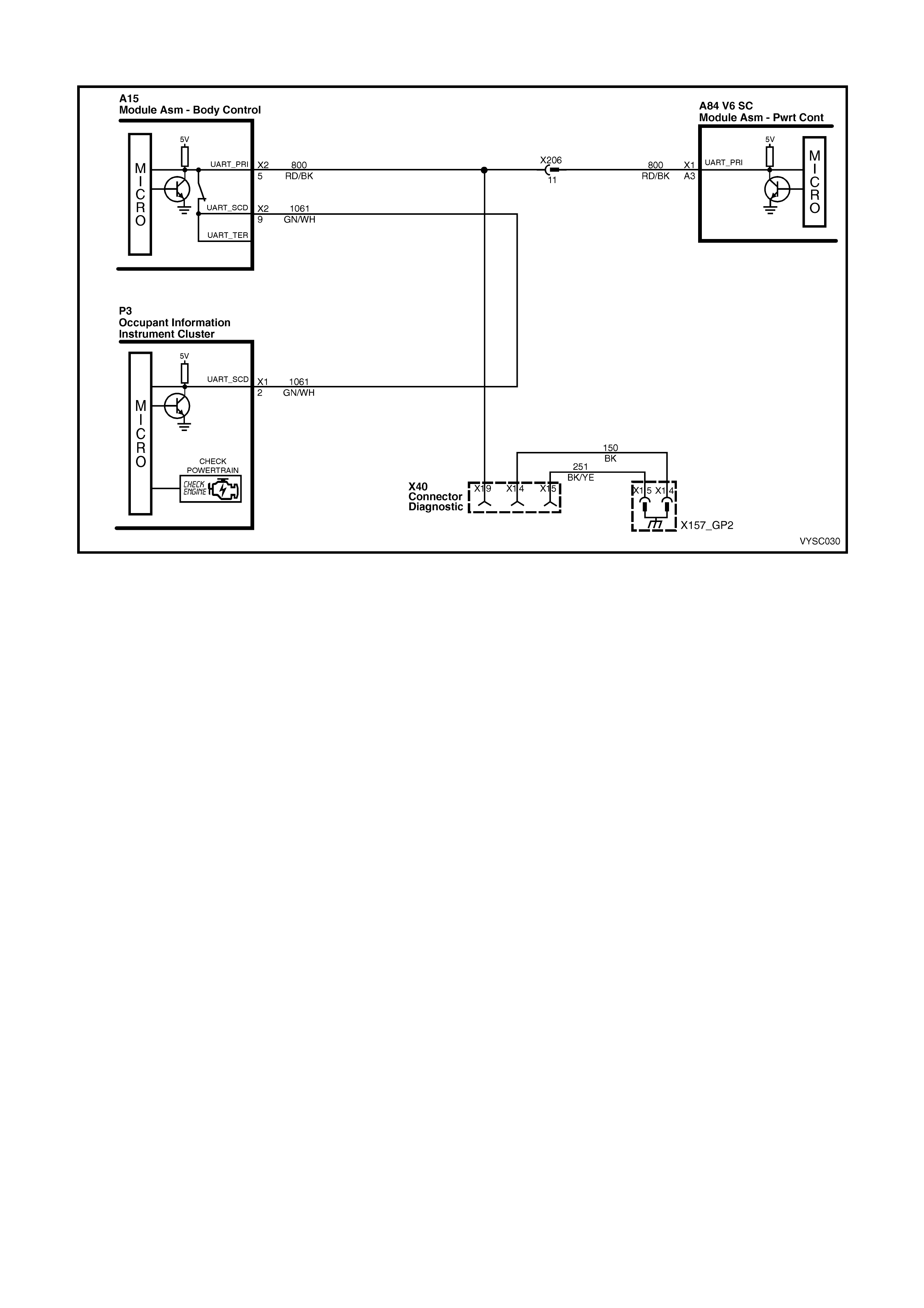
TABLE A V6 S/C PCM – ON-BOARD DIAGNOSTIC (OBD) SYSTEM CHECK
Figure 6C2-2A-18 – Check Powertrain Malfunction Indicator Lamp Circuit
CIRCUIT DESCRIPTION:
The On-Board Diagnostic System Check is an organised approach in identifying a problem created by a powertrain
control system malfunction. It must be the starting point for any driveability complaint diagnosis, because it directs
the service technician to the next logical step in diagnosing the complaint. Understanding the Table and using it
correctly will reduce diagnostic time and prevent the unnecessary replacement of good parts.
TEST DESCRIPTION:
NOTE: Number(s) below refer to the step number(s) on the diagnostic table.
1. Confirms TECH 2 operation and that Tech 2 is being powered up.
2. This check is used to establish if the PCM can supply serial data for Tech 2 use. If the PCM is capable of
communicating serial data to Tech 2, the PCM power supply, ground and the serial data line are OK. If Tech 2
displays “Incorrect Selection or Unknown Software” check that you have selected the correct Model Year,
Vehicle Type and Engine. If these selections where correct, check that the PCM has the correct software
loaded from TIS 2000 Service Programming System.
3. This check is to see if there is a Theft Deterrent DTC stored. If the PCM has not received a valid theft deterrent
signal from the BCM a DTC 31 should set, this may be the cause of a ‘no crank’ condition.
4. This test determines if the vehicle is able to crank. If the vehicle will not crank, refer to Table A-4.0 to diagnose
the starter cranking circuit.
5. This test determines if any DTC’s are stored in the PCM memory. To determine if a DTC is current, select DTC
History and refer to “Ignition Cycles Since”.
6. This test is used to determine the cause of a "Cranks But Will Not Run," although the PCM is powered up, a
"Cranks But Will Not Run" symptom could exist because of a PCM problem or the vehicle electrical system.
7. Look at all the parameters to determine if one is not in a normal state with just the ignition "ON" and engine
stopped. For example, look at the ECT value to see if the value is shifted above or below where it should be. If
so, refer "Diagnostic Aid Table" on DTC 14.
8. Look at all the parameters to determine that all values are within typical ranges for normal operating
temperatures at idle. Keep in mind that a basic engine problem may alter sensor value.
DIAGNOSTIC AIDS:
If the Serial Data circuit is shorted to voltage or ground or open, the vehicle will not crank. Check Serial Data circuit
from PCM to BCM, and from BCM to all other controllers.

X40 P3
Figure 6C2-2A-19
TABLE A V6 S/C PCM – ON-BOARD DIAGNOSTIC (OBD) SYSTEM CHECK
STEP ACTION VALUE YES NO
1. 1. Turn ignition off, install Tech 2 to DLC, turn ignition
on and turn on TECH 2.
Does Tech 2 power up and display the title display
screen?
Go to Step 2 Refer TECH 2
Diagnosis,
Section 0C
TECH 2 in this
Service
Information.
2. 1. Install Tech 2 to Data Link Connector (DLC).
2. Select V6 Engine.
Does Tech 2 display Identification Data?
Go to Step 3 Go to Table A-2
in this Section
3. 1. Ignition "ON".
2. Using Tech 2, check for DTC 31.
Is DTC 31 set?
Go to DTC 31
Table
Go to Step 4
4. Does engine crank?
Go to Step 5 Go to
Table A-4.0
5. 1. Using Tech 2, select Current DTC(s).
Are any Diagnostic Trouble Codes displayed?
Refer to
Applicable DTC
Table.
Start with lowest
DTC
Go to Step 6
6. Does engine start and continue to run?
Go to Step 7 Go to
Table A-3.1
7. 1. Ignition "ON", engine "STOPPED".
2. Compare Tech 2 data with typical values shown on
scan data page.
Are values normal or within typical ranges?
Go to Step 8 Refer to
indicated
"Component(s) –
System" checks
in this Section.
8. 1. Run engine until normal operating temperature is
reached.
2. Run engine at 1500 revolutions per minute for 2
minutes, then idle engine.
3. Compare Tech 2 with typical values shown on Scan
Data page in this Section.
Are values normal or within typical ranges?
Refer to 6C2-2B
SYMPTOMS
Refer to
indicated
"Component(s) –
System "checks
in this Section.
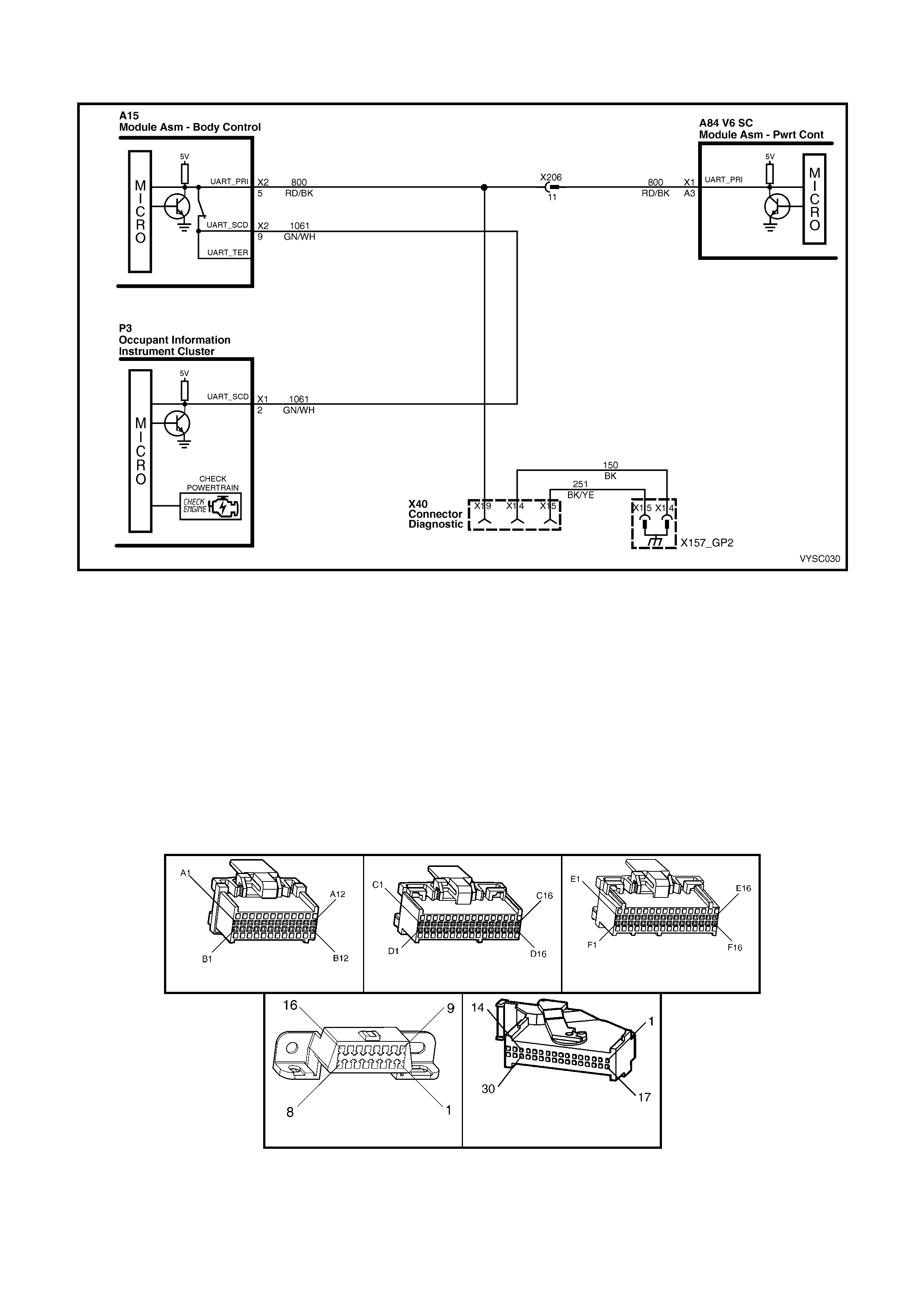
TABLE A-1 V6 S/C PCM –
NO CHECK POWE RTRAIN MALFUNCTION INDICATOR LAMP (MIL)
Figure 6C2-2A-20 – Check Powertrain Malfunction Indicator Lamp Circuit
CIRCUIT DESCRIPTION:
The Powertrain Control Module (PCM) controls the lamp via serial data communication to the Instrument on the
serial data circuit. When the PCM determ ines that the Check Powertrain MIL s hould be "ON", the PCM will send a
mes sage to the instrum ents via the serial data c ircuit norm al mode m es sage, reques ting the Check Powertrain MIL
"ON”. The Instrument will then activate the Check Powertrain MIL.
TEST DESCRIPTION:
NOTE: Number(s) below refer to step number(s) on the diagnostic table.
2. This test confirms that the Instrument MFD has passed its system check.
3. Disconnecting the Mass Air Flow Sensor should cause DTC 32 to set and the PCM to command the Check
Powertrain Lamp “ON” via the serial data normal mode message. If the DTC does not set then the internal
diagnostics of the PCM are not functioning correctly.
4. This test checks that the serial data normal mode message displays "ON" when the DTC sets.
A84 V6 S/C – X1 A84 V6 S/C – X2 A84 V6 S/C – X3
X40 P3
Figure 6C2-2A-21

TABLE A-1 V6 S/C PCM – NO "CHECK POWERTRAIN" MALFUNCTION INDICATOR LAMP (MIL)
STEP ACTION VALUE YES NO
1. Was the "On-Board Diagnostic" (OBD) System Check
performed? Go to Step 2 Go to
OBD System
Check
in this Section/
2. 1. Turn the ignition "ON".
2. Observe the Instrument Multi Function Display
(MFD).
Does the MFD display "OK!" once the “System Check”
is completed?
Go to Step 3 Refer
Section 12C
in this Service
Information
3. 1. Disconnect the Mass Air Flow Sensor connector
B68.
2. Start the engine and allow to idle for 20 seconds.
Does the MFD display the "Check Powertrain MIL"?
Check
Powertrain MIL
is operating
correctly
Go to Step 4
4. 1. Connect Tech 2 to the DLC.
2. With Tech 2 connected, select F0: Normal Mode.
3. With the Mass Air Flow Sensor connector B68 still
disconnected.
4. Start the engine and monitor the "Normal Mode"
data display.
Does the "Normal Mode" display "Check Powertrain
Lamp" display "ON"?
Refer
Section 12C
in this Service
Information
Go to Step 5.
5. 1. Replace PCM. Refer to Section 6C2-3 Service
Operations, for PCM Security Link procedure
Is action complete?
Verify Repair
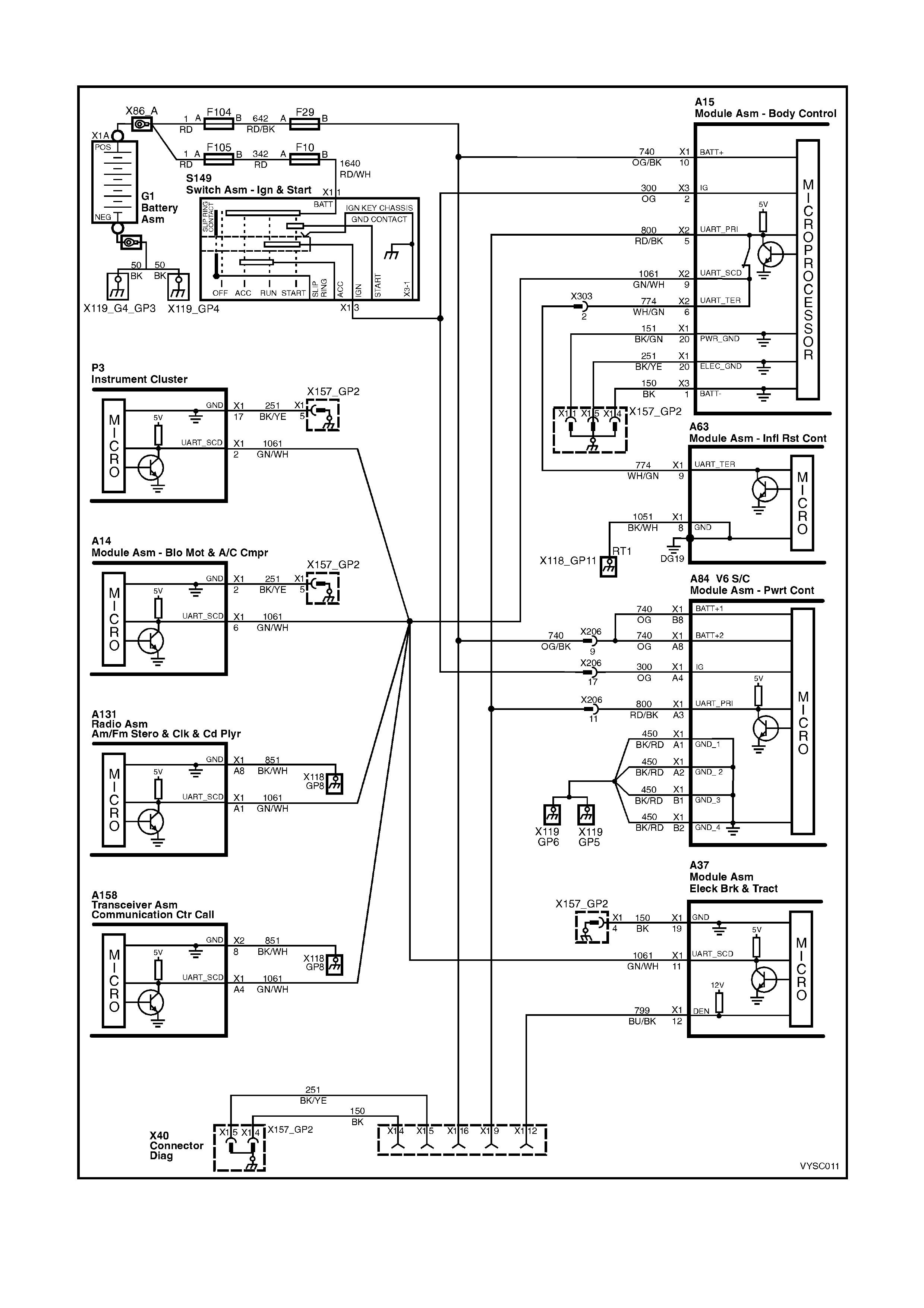
TABLE A-2 V6 S/C PCM – NO SERIAL DATA
Figure 6C2-2A-22 – Serial Data Circuit
CIRCUIT DESCRIPTION:
The VY and V2 series of vehicles use a “Bus Master” communication system, where the BCM is the bus master.
The BCM periodically polls (surveys) each control module on the bus (serial data circuit) and requests status data.
The control modules connected via the serial data circuit are the (PCM, BCM, A.B.S./T.C.S. module, OCC module,
SDM, instrument and Telematics Module, Tech 2 communicates with these modules via the serial data circuit and
DLC terminal 9. Any one of these modules could cause a fault on the serial data line. This fault could result in the
scan tool not being able to display serial data. If there is no serial data the instrument will display “Service Error
Contact Dealer” and Tech 2 will not be able to communicate with any of the control modules.
TEST DESCRIPTION:
NOTE: The number(s) below refer to the step number(s) on the diagnostic table.
2. This step checks to see if Tech 2 will communicate with the PCM.
3. This step checks to see if Tech 2 will communicate with the BCM.
4. Using a Digital Multi Meter (DMM), there should be 3 to 4.5 volts at the DLC terminal 9. If the voltage is higher
or lower, serial communication will be affected. This serial data circuit is also connected to several other
modules. A problem with any one of these other modules, may cause a serial data communication malfunction.
5. If the voltage at DLC terminal 9 is at or above 5 volts the serial data circuit is shorted to voltage. If the voltage is
0 volts the serial data circuit may be open or shorted to ground.
6. This step checks the PCM power supply circuit 740. There should be battery voltage at these terminal at all
times.
7. This step checks the PCM ignition circuit 300. There should be battery voltage at this terminal when the ignition
is on.
8. This step checks the continuity of the four PCM ground circuits. All four ground circuits should be checked for
continuity.
9. If the voltage at DLC terminal 9 is at or above 5 volts the serial data circuit is shorted to voltage. If the voltage is
0 volts the serial data circuit may be open or shorted to ground.
DIAGNOSTIC AIDS:
If there is a fault with the serial data circuit, it could be caused by one or more of the several modules connected to
this serial data circuit. Isolate the fault by disconnecting each controller (one at a time), until the serial data
communication is restored.
A84 V6 S/C – X1 A84 V6 S/C – X2 A84 V6 S/C – X3
X40
Figure 6C2-2A-23

TABLE A-2 V6 S/C PCM – NO SERIAL DATA
STEP ACTION VALUE YES NO
1. Was the "On-Board Diagnostic" (OBD) System Check
performed?
Go to Step 2 Go to
OBD System
Check
2. 1. Connect Tech 2 to DLC.
2. Ignition "ON", engine stopped.
Does Tech 2 display PCM serial data?
No trouble found Go to Step 3
3. 1. Connect Tech 2 to DLC.
2. Ignition "ON", engine stopped.
Does Tech 2 display BCM serial data?
Go to step 6 Go to Step 4
4. 1. Ignition "ON", engine stopped.
2. Using DMM, probe DLC terminal 9 with DMM
connected to ground.
Does DMM display voltage varying between the
specified value?
3 – 4.5 volts Go to Step 15 Go to Step 5
5. Is voltage steady at or above the specified value? 5 volts Go to Step 10 Go to Step 11
6. 1. Ignition "ON", engine stopped.
2. Using DMM, check for voltage at PCM power
supply circuit 740 terminals X1-A8 and X1-B8.
Does DMM display the specified value at both
terminals?
B+ Go to Step 7 Go to Step 12
7. 1. Ignition "ON", engine stopped.
2. Using DMM, check for voltage at PCM ignition
supply circuit 300 terminal X1-A4.
Does DMM display the specified value?
B+ Go to Step 8 Go to Step 13
8. 1. Using DMM, check continuity of the four PCM
ground circuits 450, between PCM terminals
X1-A1, X1-A2, X1-B1 & X1-B2 and a known good
ground.
Do all four ground circuits have continuity?
Go to Step 9 Go to Step 14
9. Check for open in the serial data circuit 800 between
the PCM and the DLC.
Is the circuit open?
Verify Repair Go to step 16
10. Repair short to voltage on the serial data circuit.
NOTE: Ensure that none of the other modules on the
serial data circuit are causing this voltage problem.
Unplug each module one at a time to isolate short to
voltage.
Is action complete?
Verify Repair
11. Repair short to ground or open in the serial data line.
NOTE: Ensure that none of the other modules on the
serial data circuit are causing this voltage problem.
Unplug each module one at a time to isolate short to
ground.
Was a problem found?
Verify Repair Go to Step 16
12. Repair open in PCM power suppy circuit 740.
Was a problem found?
Verify Repair
13. Repair open in PCM ignition circuit 300.
Was a problem found?
Verify Repair
14. Repair open in PCM ground circuit 450.
Was a problem found?
Verify Repair
15. 1. Refer to BCM No Serial Data diagnostics in Section
12J BCM in this Service Information.
Is action complete?
Verify Repair
16. 1. Replace PCM. Refer to 6C1-3 Service Operations,
for PCM Security Link procedure
Is action complete?
Verify Repair

TABLE A-3 .1 V6 S/ C PCM – ENGINE CRANKS BUT WILL NOT RUN
Figure 6C2A-2-24 – Fuel Injector Circuit
CIRCUIT DESCRIPTION:
This is the first of several diagnostic tables that m ust be followed in an orderly, progressive fashion in order to find
the cause of a no-start. These tables assume an adequate supply of good quality fuel is in the fuel tank, that the
cranking motor circuit is in good working order, and that the engine will crank with adequate RPM. These tables
also assume that no Diagnos tic T rouble Code (DT C) 31 or 46 is s et in the PCM m em ory, as determined by the On-
Board Diagnostic System Check. The On-Board Diagnostic System Check is always the beginning point for all
diagnostic procedures.
TEST DESCRIPTION:
NOTE: Number(s) below refer to step number(s) on the diagnostic table.
1. The PCM must be operable. The On-Board Diagnostic System Check will prove that. There are few chances
that the PCM itself would cause a no-start, but the On-Board Diagnostic System Check will uncover any
problems in the PCM power and ground circuitry.
4. This checks for a short to ground on the injector control circuit. If this were to occur, the engine would be
extremely flooded, since the injectors would be "ON" continuously, and would inject fuel any time there is fuel
pressure.
5. Any time the PCM has been "OFF" for at least 10 seconds, it should energise the Fuel Pump Relay for 2
seconds af ter the ignition is tur ned "ON." If the engine is not c r ank ed, the PCM should turn the relay "OFF" after
2 seconds . Proper operation of the Fuel Pum p elec trical c ircuit would be noted here by the test light being "ON"
for 2 seconds after the ignition switch is turned to the "ON" position. After 2 seconds, the test light should go
"OFF."
6. Note that this check is for sufficient voltage at the spark plug wire. If, for some reason, the spark plug electrodes
were wet with fuel (engine flooded), this could cause a no-start. However, a "flooded" engine is a symptom of
some other problem. There is no normal condition that should ever be able to "flood" the engine.
NOTE: Use Tool ST 125 spark checker or equivalent. An ST 125 requires about 25,000 volts (25 kilovolts, or 25
kV) to "s park ". Do not use a s park plug in open air grounded to the engine as an indication of suff icient "spar k ".
Only a few kilovolts are required to jump the gap of a spark plug outside of the engine, and that would be an
inadequate test of the ignition coil output ability.
7. This is a quick c heck of the fuel s yst em. The appropriate plac e to install the press ure gauge is at the Schr ader
valve test point on the left hand side, fuel rail, using fuel pressure adaptor, Tool AU 453 with fuel pressure
gauge Tool AU 338.
L2 X 16 (PART OF X100)
Figure 6C2-2A-25
TABLE A-3.1 V6 S/C PCM ENGINE CRANKS BUT WILL NOT RUN
STEP ACTION VALUE YES NO
1. Was the "On-Board Diagnostic" (OBD) System Check
performed? Go to Step 2. Go to OBD
System Check
in this Section.
2. Is DTC 31 present ?
Go to DTC 31
Table in this
Section.
Go to Step 3
3. Is DTC 46 present ?
Go to DTC 46
Table in this
Section.
Go to Step 4
4. 1. Check fuel tank quantity.
2. Disconnect ALL injector electrical connectors.
3. Connect test light between the terminals of each
injector harness connector.
• Be very careful not to short across the
terminals, or to engine ground.
4. Switch ignition "ON", while noting the test light.
Is light "OFF" ?
Go to Step 5 Go to Step 8
5. 1. Ignition "OFF".
2. Backprobe Fuel Pump Control Module A47
connector, terminal X1-6 with a test light connected
to ground.
3. Ignition "ON".
4. Using TECH 2 scan tool, select “Fuel Pump”.
5. Activate Fuel Pump.
Is test light "ON"?
Go to Step 6 Go to
Table A-4.1-1 in
this Section.
6. 1. Ignition "OFF".
2. Remove the spark plug leads from two spark plugs.
3. Connect ST 125 spark checker (refer NOTE #6
above) to each spark plug lead and check for spark
activity, while cranking the engine.
4. Check both wires. A few sparks and then nothing is
considered no spark.
Was there spark on both wires?
Go to Step 7 Go to
Table A-8.1 in
this Section.

STEP ACTION VALUE YES NO
7. 1. Ignition "OFF".
2. Reconnect both spark plug leads to spark plugs.
3. Reconnect all injector electrical connectors.
4. Remove Fuel Pump Relay R16 from underhood
electrical centre in the engine compartment and
crank engine for 15 seconds to relieve any residual
fuel pressure.
5. Ignition "OFF," connect Fuel Pressure Gauge.
6. Reinstall Fuel Pump Relay.
7. Turn the ignition “ON” and observe fuel pressure.
8. Pressure should be within the value, and not
continue to drop after pump stops running.
Is fuel pressure at or between the specified value and
holding steady?
290 to 410
kPa Go to
Table A-3.2 in
this Section.
Go to
Table A-4.3 in
this Section.
8. 1. Check for short to ground on Injector Circuit.
Was Injector Circuit shorted to ground ? Verify Repair Go to Step 9
9. 1. Replace PCM. Refer to Section 6C2–3 SERVICE
OPERATIONS, for the PCM Security Link
procedure.
Is action complete?
Verify Repair –

TABLE A-3 .2 V6 S/ C PCM – ENGINE CRANKS BUT WILL NOT RUN
Figure 6C2-2A-26 – Fuel Injector Circuit
TEST DESCRIPTION:
NOTE: Number(s) below refer to step number(s) on the diagnostic table.
6. "ST EADY LIGHT" indicates the PCM is continuously supplying the ground path on the injector circuit. It is not a
harness problem at this point; that would have been in Table A-3.1. This may destroy an injector, as they are
designed to be energised in short pulses and may not withstand 100% "ON" time. If any injector checks less
than 11.4 ohms, it could be the cause of the defective PCM. The PCM can be damaged when it attempts to
energise the injector circuit with a very-low-resistance load. Normal injector resistance is approximately 12.2
ohms at 20 degrees C per individual injector.
L2
Figure 6C2-2A-27

TABLE A-3.2 V6 S/C PCM – ENGINE CRANKS BUT WILL NOT RUN
STEP ACTION VALUE YES NO
1. Was the "On-Board Diagnostic" (OBD) System Check
performed? Go to Step 2. Go to
OBD
System Check
in this Section.
2. From Table A-3.1.
1. Ignition "OFF".
2. With all injectors disconnected, connect test light
across both harness terminals of one injector
connector.
Be very careful to not short across the terminals, or
to engine ground.
3. Have a helper crank the engine while you closely
observe the test light.
4. Test light should blink while cranking, indicating
electrical injector pulses are present. Repeat this
test for all injectors.
Did test light blink while cranking ?
Go to Step 3 If there was no
blinking light, Go
to Table 3.3 in
this Section.
----------------------
If the test light
was on steady
(no blinking light)
Go to Step 6.
3. 1. Check the remaining 5 injector connectors for
blinking test light, as described in step 2.
Did all the remaining injector connectors blink the test
light?
Go to Step 4 Go to Step 5
4. At this stage, the fuel control system, fuel delivery
system, and ignition system are OK.
Check For:
• Fouled spark plugs.
• Proper MAF sensor operation. If engine will start with
MAF sensor electrical connector disconnected, refer
Table A-6.1 in this Section.
• Proper TP sensor circuit operation. Use Tech 2 scan
tool to monitor TP sensor signal. If voltage is over
1.25 volts with throttle closed, refer Table A-6.2 in
this Section.
• Restricted exhaust system. Loosen front pipe from
exhaust manifold(s). If the engine will start, refer
Table A-13 in this Section.
• Improper engine coolant temperature (ECT) sensor
resistance. Refer DTC 14 Diagnostic Aids in this
Section to check resistance of ECT sensor.
• Water or foreign material in fuel, or incorrect fuel.
• Spark plug wires crossed.
• Camshaft timing chain.
• Inadequate engine compression.
Is action complete?
Verify Repair
5. 1. Repair open in injector power circuit or injector
circuit to connector that did not blink the test light.
Is action complete ?
Verify Repair
6. 1. Check for a short to ground in injector circuit that
caused test light to stay "ON" steady.
Was a problem found?
Verify Repair Go to Step 7
7. 1. Check resistance across each injector. Each injector
should be between the specified value.
Is each injector at the value ?
11.4 - 12.6
ohms Go to step 8 Go to step 9
8. 1. Replace PCM. Refer to Section 6C1-3 SERVICE
OPERATIONS in this Section, for PCM Security Link
procedure.
Is action complete?
Verify Repair
9. 1. Replace any injector that did not measure within the
specified value.
2. Retest beginning at Step 2.
Is action complete?
11.4 – 12.6
ohms Verify Repair
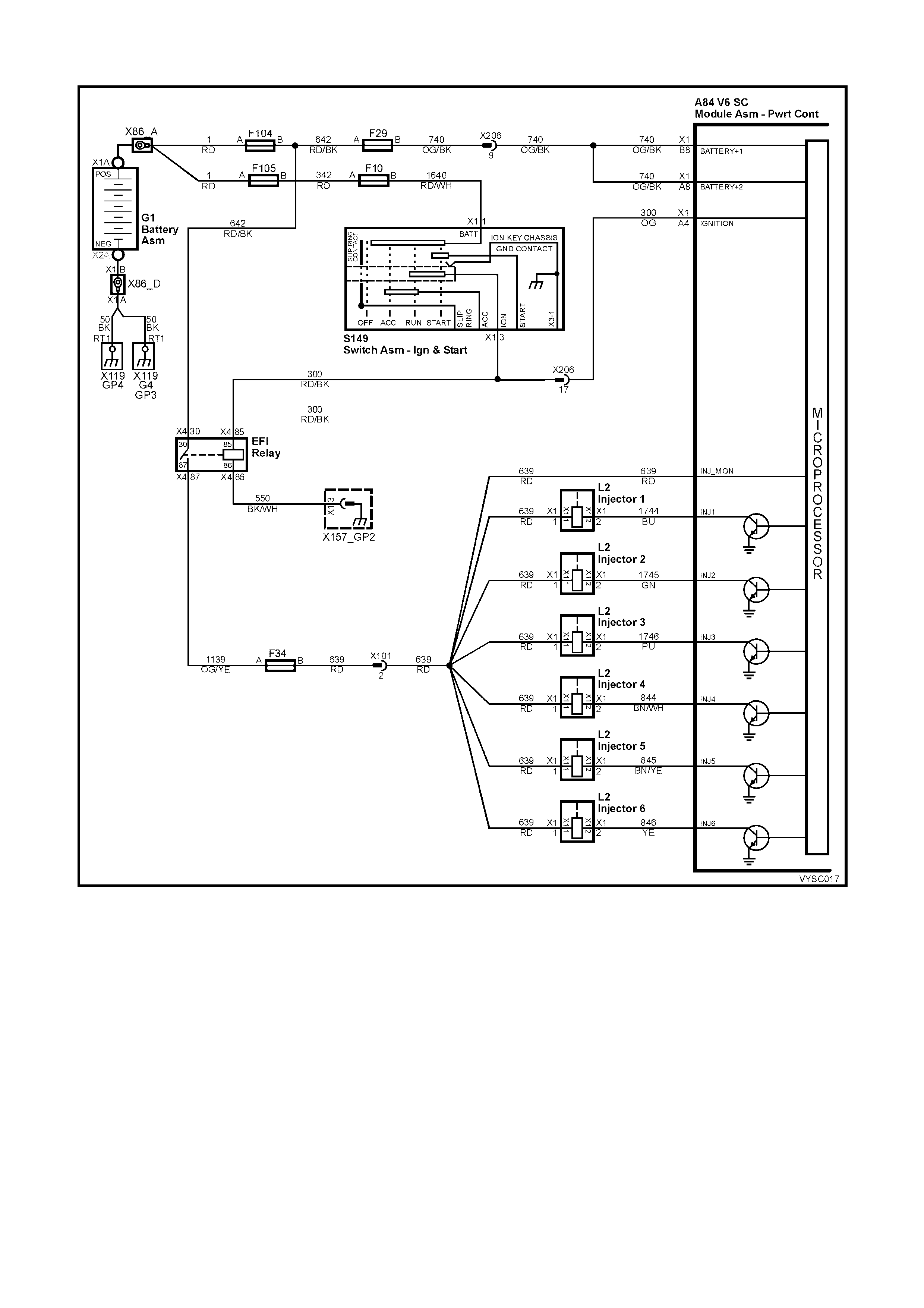
TABLE A-3 .3 V6 S/ C PCM – ENGINE CRANKS BUT WILL NOT RUN
Figure 6C2-2A-28 – Fuel Injector Circuit
TEST DESCRIPTION:
NOTE: Number(s) below refer to step number(s) on the diagnostic table.
2. “NO LIGHT” indicates no PCM control of the injector. Fuse F34 supplies +12 volts to the injectors. Probe both
terminals of one injector connector with a test light to ground. There should be a light on only one terminal,
confirming ignition voltage to one terminal, but not both.
3. T he PCM inject or control c ircuit m ay be open. Reconnec t the injectors. Using a tes t light connected to ground,
check for a light at the PCM connec tor terminals . A light at this point indicates that inject or control circuit is not
“open.” T he voltage to light that test light com es fr om circ uit 639 (Red wire), through the injector windings, and
continues through the injector control circuit to PCM connector terminals.
7. There is no ter minal identif ic ation on the relay connector s ocket, but the relay itself has terminal num ber s . Mak e
certain the correct relay connector socket terminal (NOT the relay) is being probed.
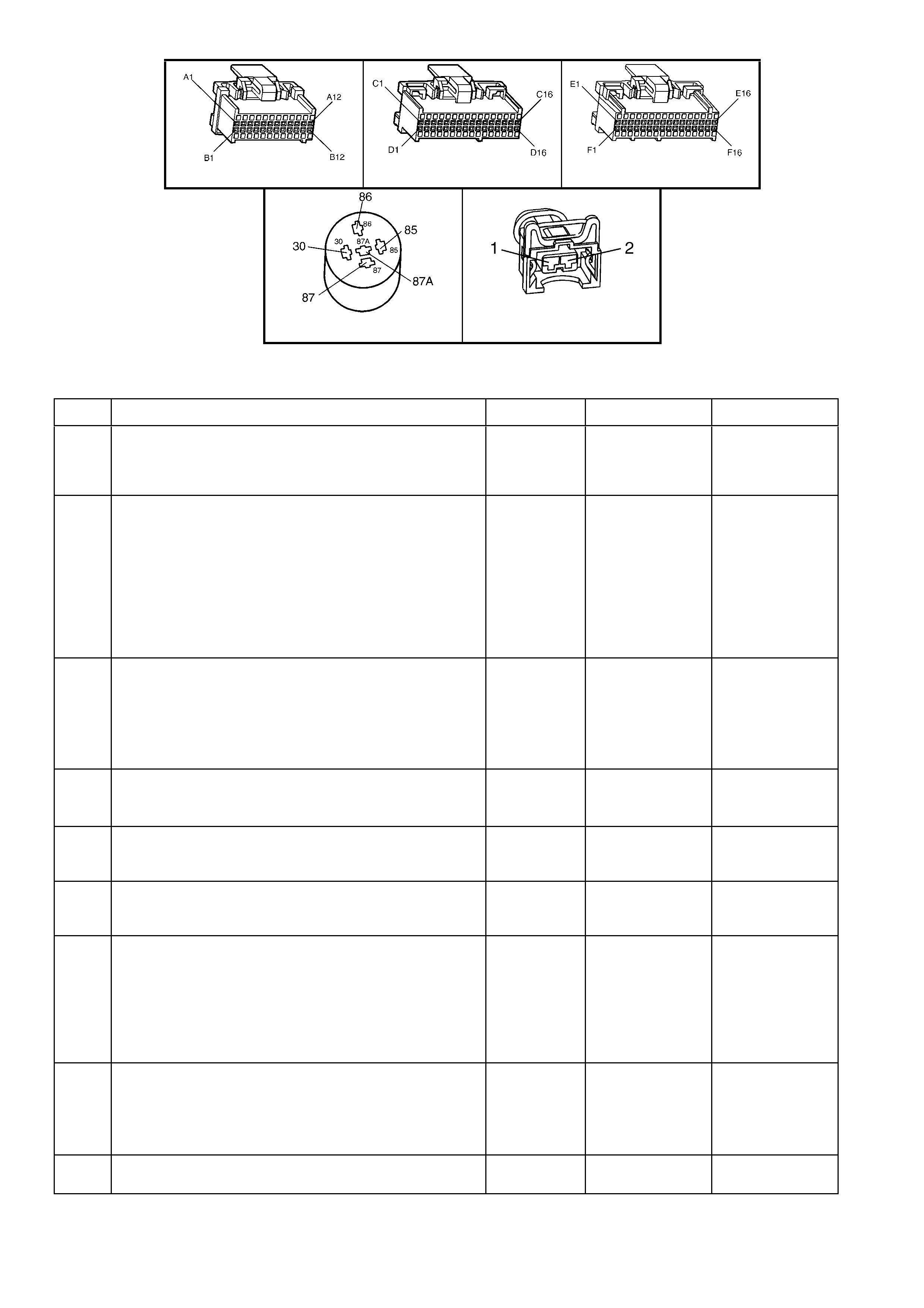
A84 V6 S/C – X1 A84 V6 S/C – X2 A84 V6 S/C – X3
X4 (Part of X100) L2
Figure 6C2-2A-29
TABLE A-3.3 V6 S/C PCM – ENGINE CRANKS BUT WILL NOT RUN
STEP ACTION VALUE YES NO
1. Was the "On-Board Diagnostic" (OBD) System Check”
performed? Go to Step 2. Go to
OBD
System Check
in this Section.
2. 1. Ignition "OFF"
2. Disconnect injector connectors. From Table A-3.2 –
No Light
3. Ignition "ON," engine stopped.
4. Probe each terminal of each injector harness
connector with a test light to ground.
Is the test light "ON" at only one terminal for each
injector?
Go to Step 3 If the test light
was" ON" at both
terminals, repair
short to voltage
on injector
circuit.
----------------------
If there was no
light "ON", Go to
Step 7
3. 1. Ignition "OFF".
2. Reconnect injectors.
3. Ignition "ON".
4. Backprobe PCM injector control terminals with a test
light connected to ground.
Is test light "ON" at each terminal?
Go to Step 4 Go to Step 12
4. 1. Ignition "ON".
2. Using Tech 2, monitor TP sensor signal voltage.
Is voltage less than value?
1.25 volts Go to Step 5 Go to
Table A-6.2 in
this Section.
5. 1. Check for faulty crankshaft reference High signal
input to PCM connector terminal.
Was a problem found?
Verify Repair Go to Step 6
6. 1. Replace PCM. Refer to 6C1-3 SERVICE
OPERATIONS, for PCM Security Link procedure.
Is action complete?
Verify Repair –
7. 1. Ignition "OFF".
2. Disconnect EFI relay.
3. Ignition "ON".
4. Probe EFI relay harness connector terminal X4-30
and terminal X4-85 with a test light connected to
ground.
Is the test light "ON" at both circuits?
Go to Step 8 Go to Step 13
8. 1. Ignition "OFF".
2. Disconnect EFI relay.
3. With test light connected to 12 volts, probe relay
harness terminal ground circuit X4-86 of EFI relay.
Is test light "ON"?
Go to Step 9 Go to Step 14
9. 1. Check injector fuse F34 for an open.
Was a problem found? Go to step 15 Go to Step 10

STEP ACTION VALUE YES NO
10. 1. Check for an open in injector power circuit from fuse
F34 to injector splice.
Was a problem found?
Verify Repair Go to Step 11
11. 1. Replace EFI relay.
Is action complete? Verify Repair –
12. 1. Repair open injector control circuit that did not light
test light.
Is action complete?
Verify Repair –
13. 1. Check fuses and repair circuit that did not turn "ON"
the test light.
Is action complete?
Verify Repair –
14. 1. Repair ground circuit to EFI relay.
Is action complete? Verify Repair –
15. 1. Repair short to ground in fuse circuit.
2. Replace fuse.
Is action complete?
Verify Repair –

TABLE A- 4 . 0 V6 S/C P CM – STARTER CRANKING CIRCUIT
Figure 6C2-2A-30 – Starter/Theft Deterrent Circuit
CIRCUIT DESCRIPTION:
Battery power is supplied from fusible link F105 to the Start Relay terminal ‘X1 30’. As the ignition switch is turned to
the START position, power is supplied to the Start Relay terminal ‘X1 85’. The PCM supplies the ground signal
needed to energise the Start Relay and allows power to the starter motor.
W hen the ignition is tur ned “ON”, the PCM will look f or the proper Thef t Deterrent signal sent f rom the BCM. If the
PCM has deter mined that the pr oper Thef t Deterr ent s ignal is pr esent, the PCM will allow the vehicle to crank. If the
PCM determ ines that an improper T heft Deterrent s ignal was s ent from the BCM, or no Theft Deterr ent signal was
sent, the PCM will not supply a ground signal from the PCM term inal to the Start Relay term inal ‘X1 86’. W hen the
Start Relay receives this ground signal from the PCM, the relay will be energised, allowing the starter motor to
operate. A removed ground signal to the Start Relay will cause the vehicle not to crank.
If there is a problem with the Theft Deterrent signal from the BCM to the PCM, DTC 31 will set.
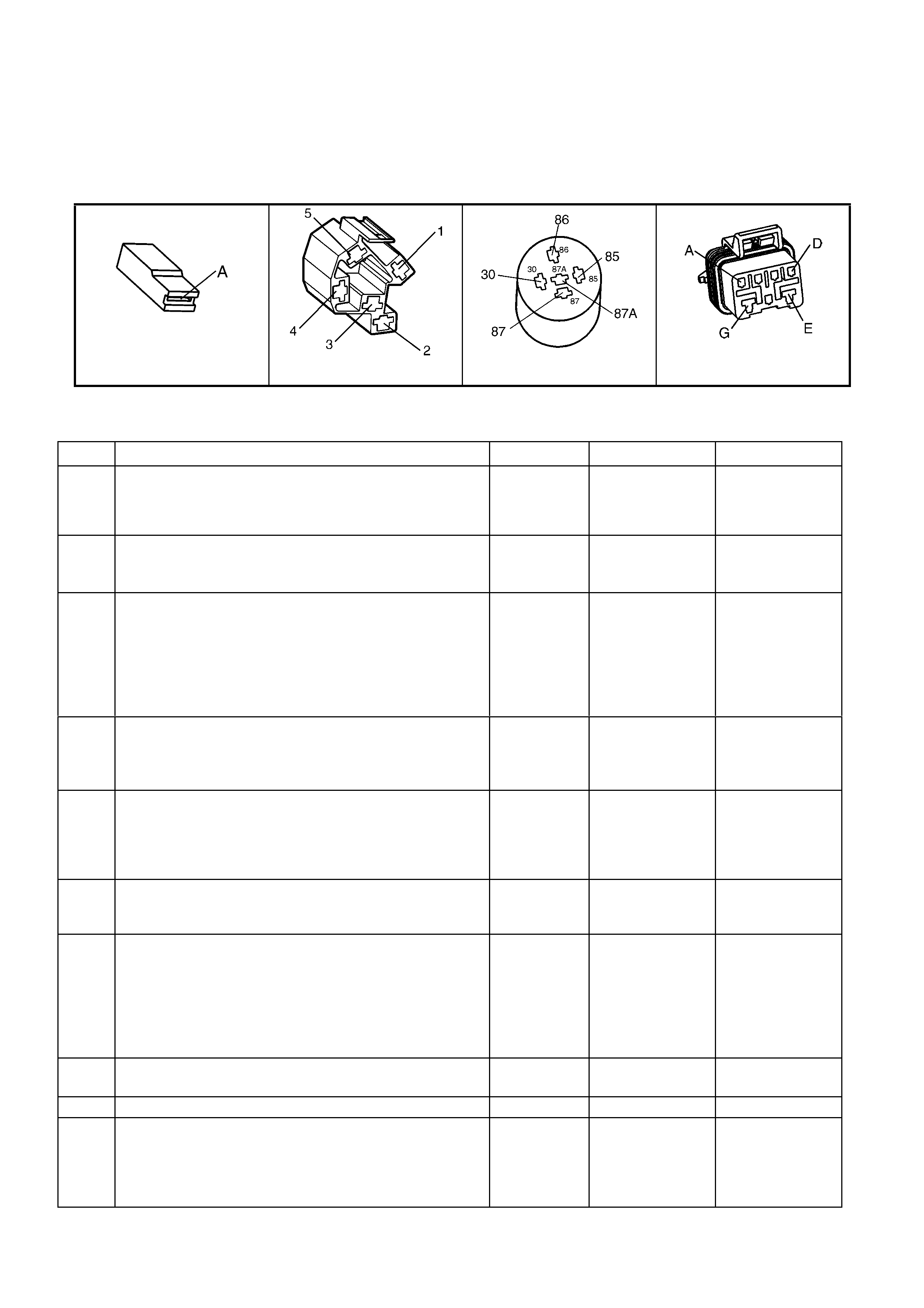
TEST DESCRIPTION:
NOTE: Number(s) below refer to step number(s) on the diagnostic table.
2. This step checks to see if DTC 31 is set. This DTC could prevent the vehicle from cranking. This step also
verifies that if a PCM was replaced, that the Security Link procedure was performed.
3. This step checks to see if power is being applied to the starter motor. If test light illuminates, the problem is with
the starter motor.
10. This step verifies correct operation of the neutral start switch.
M15 S149 X1 (Part of X100) A83
Figure 6C2-2A-31
TABLE A-4.0 V6 S/C PCM – STARTER CRANKING CIRCUIT
STEP ACTION VALUE YES NO
1. Was the "On-Board Diagnostic" (OBD) System Check
performed? Go to Step 2 Go to
OBD
System Check
in this Section.
2. 1. Install Tech 2.
2. Check for a DTC 31.
Is DTC 31 set?
Go to the
appropriate DTC
Table
Go to Step 3
3. 1. Ignition OFF.
2. Using a test light, probe the starter solenoid terminal
M15 X1–A with test light connected to ground.
3. Have a helper turn the ignition switch to the START
position, note the test light.
Does the test light illuminate when the ignition switch is
turned to the START position?
Refer to
6D2-2 Starting
System - V6 S/C.
Go to Step 4
4. 1. Remove the start relay.
2. W ith a test light connected to ground probe the start
relay harness terminal X1–30.
Does the test light illuminate?
Go to Step 5 Go to Step 17
5. 1. With the start relay still removed and the test light
connected to ground, probe the start relay harness
terminal X1 85.
2. Turn the ignition to the START position.
Did the test light illuminate?
Go to Step 7 Go to Step 16
6. 1. Check for an open circuit between the starter
solenoid and the Start Relay.
Was a problem found?
Verify Repair Go to Step 8
7. 1. Ignition OFF.
2. With the start relay removed, connect a test light
between the relay harness terminal X1 85 and
terminal X1-86.
3. Turn the ignition switch to the START position.
Does the test light illuminate when the ignition switch is
turned to the START position?
Go to Step 6 Go to Step 9
8. 1. Replace the start relay.
Is the action complete? Verify Repair –
9. Is the vehicle equipped with an automatic transmission? Go to Step 10 Go to Step 12
10. 1. Ignition ON, transmission selector in the Park
position.
2. With a test light connected to B+, probe terminal
X1-E at the neutral start switch A83.
Does the test light illuminate?
Go to Step 19 Go to Step 11

STEP ACTION VALUE YES NO
11. 1. Ignition ON, transmission selector in the Park
position.
2. With a test light connected to B+, probe the circuit
from the neutral start switch A83 terminal X1-G to
the PCM terminal X3-F5.
Does the test light illuminate?
Go to Step 14 Go to Step 18
12. 1. Check for open in circuit 434 from the start relay to
the PCM, terminal X3-F5.
Was a problem found?
Verify Repair Go to Step 20
13. 1. Repair the short to ground in the faulty circuit.
2. Replace the fusible link or the fuse as necessary.
Is the action complete?
Verify Repair –
14. 1. Check adjustment of the neutral start switch. Refer
to Section 7C4 AUTOMATIC TRANSMISSION On –
Vehicle Servicing.
Is adjustment OK?
Go to Step 15 Verify Repair
15. 1. Replace neutral start switch. Verify Repair –
16. 1. Repair the open in ignition to start relay, circuit 5.
Is the action complete? Verify Repair –
17. 1. Check for an open in circuit 342 including the fusible
link F105.
Is the action complete?
Verify Repair –
18. 1. Repair the open in circuit 275 from neutral start
switch to PCM terminal X3-F5.
Is the action complete?
Verify Repair Go to Step 20
19. 1. Repair the open in start relay to neutral start switch,
circuit 434.
Is the action complete?
Verify Repair –
20. 1. Check PCM connector terminals for correct
retention.
Is the terminal retention OK?
Go to Step 21 Repair Terminals
Verify Repair
21. 1. Replace PCM. Refer to Section 6C2-3 SERVICE
OPERATIONS for PCM Security Link procedure.
Is action complete?
Verify Repair –

TABLE A-4.1 V6 S/C PCM – FUEL PUMP ELECTRICAL CIRCUIT
Figure 6C2-2A-32 – Fuel Pump Electrical Circuit
CIRCUIT DESCRIPTION:
When the ignition switch is first turned "ON", the PCM energises the Fuel Pump Relay which applies power to the
Fuel Pump Control Module. The Fuel Pump Relay will remain "ON" as long as the engine is cranking or running and
the PCM is receiving reference pulses. If no reference pulses are present, the PCM de-energises the Fuel Pump
Relay within 2 seconds after the ignition is turned "ON" or the engine is stopped. The Fuel Pump delivers fuel to the
fuel rail and injectors, then to the fuel pressure regulator. The pressure regulator controls fuel pressure by allowing
excess fuel to be returned to the fuel tank. With the engine stopped, the Fuel Pump can be turned "ON" by using
the Tech 2 scan tool output controls function.
The PCM alters Fuel Pump speed by applying or removing a 67% duty cycle on the Fuel Pump PWM driver circuit
260 to the Fuel Pump Control Module. Under normal driving conditions, the PCM will apply a 67% PWM ground
signal to the Fuel Pump Control Module circuit 260. This 67% duty cycle will command the Fuel Pump Control
Module to run the fuel pump at a lower speed, (lower fuel volume, low voltage supplied to fuel pump, between 7 to 9
volts). When higher fuel volume is required due to increased engine load, the PCM will remove the supplied 67%
PWM ground signal from circuit 260. This will cause the Fuel Pump Control Module to switch internally and allow
the Fuel Pump to run at a higher speed (higher fuel volume, system voltage applied to fuel pump). The PCM also
compensates for low system voltage by commanding the Fuel Pump Control Module to switch to high speed Fuel
Pump , when system voltage is low.
TEST DESCRIPTION:
NOTE: Number(s) below refer to step number(s) on the diagnostic table.
3. Checks that fuel pressure is sufficient for the vehicle to start.
4. Ensures that the Fuel Pump PWM driver circuit and the PCM are capable of controlling fuel pump speed.
5. Verifies that the Fuel Pump feed and ground circuits are OK between the Fuel Pump Control Module and the
Fuel Pump , and that the Fuel Pump can deliver adequate pressure to the fuel rail.
6. Checks the feed circuit to the Fuel Pump Control Module.
8. Ensures that the Fuel Pump PWM driver circuit is not shorted to ground.
13. Checks the feed circuit to the Fuel Pump Relay contacts.
14. Checks the ground circuit for the Fuel Pump Relay coil.
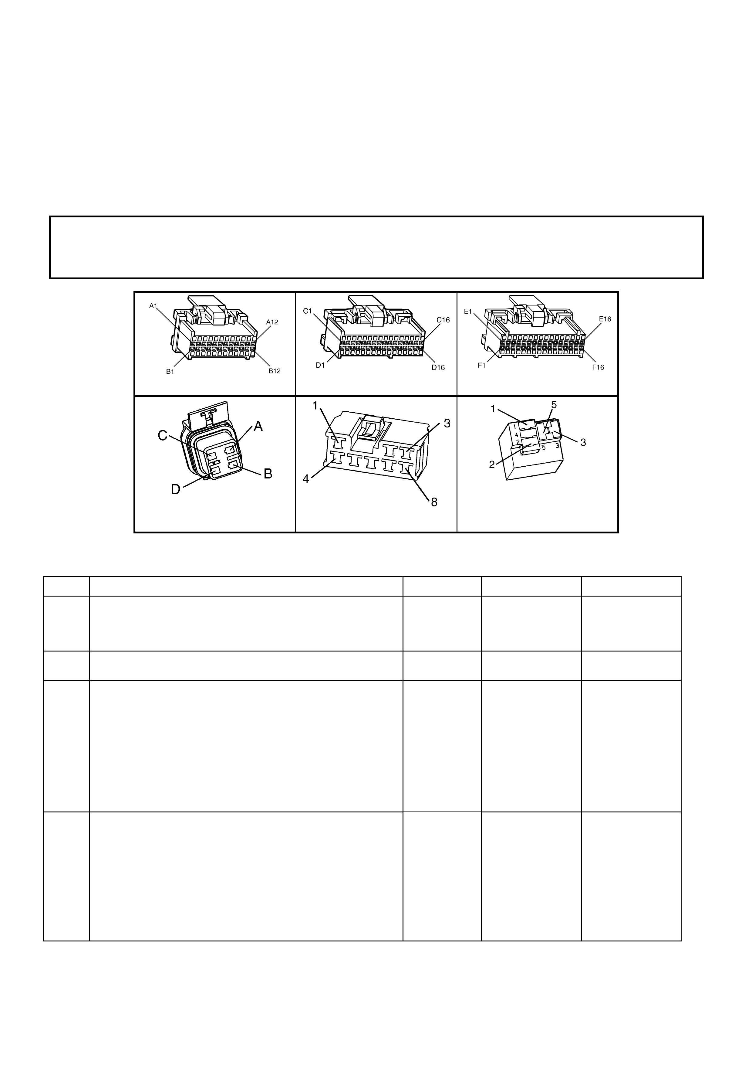
15. Ensures that the Fuel Pump Relay driver circuit is OK and that the PCM is capable of controlling the Fuel Pump
Relay. Using the Tech 2 scan tool to command the Fuel Pump Relay allows only a 2 second "ON" time.
21. Checks the Fuel Pump Relay driver circuit for a short to ground.
26. If the Fuel Pump is operating but incorrect pressure is noted, the Fuel Pump wiring is OK. Go to Table A-4.3.
28. Determines whether the problem is being caused by an open in the Fuel Pump feed circuit or the Fuel Pump
ground circuit.
31. Ensures that the Fuel Pump speed control PWM circuit is OK and that the PCM can control the Fuel Pump
speed control PWM driver.
37. The fuel pump is not serviced separately from the Modular Sender Assembly. If the pump is confirmed as being
faulty, then the complete Modular Sender Assembly must be replaced.
NOTICE:
When performing this diagnostic Table, make certain that the drive wheels are blocked and the parking
brake is firmly applied.
A84 V6 S/C – X1 A84 V6 S/C – X2 A84 V6 S/C – X3
M8 A47 X16 (Part of X100)
Figure 6C2-2A-33
TABLE A-4.1 V6 S/C PCM – FUEL PUMP ELECTRICAL CIRCUIT
STEP ACTION VALUE YES NO
1. Was the "On-Board Diagnostic" (OBD) System Check
performed?
Go to Step 2. Go to
OBD
System Check
in this Section.
2. Are any DTC’s set? Go to DTC Table
first
Go to step 3
3. 1. Connect Fuel Pressure Gauge and adaptor to the fuel
pressure tap fitting.
2. Turn the ignition switch to the "ON" position.
3. Select “Fuel Pump Relay Output Control” with the
Tech 2 scan tool.
3. Observe the pressure gauge while activating the fuel
pump "ON" with Tech 2.
5. Note fuel pressure on Fuel Pressure Gauge.
Is proper fuel pressure indicated?
290 to 410
kPa
Go to Step 4 Go to Step 5
4. 1. Engine idling.
2. Remove vacuum hose from fuel pressure regulator,
and plug open hose end.
3. Observe the Fuel Pressure Gauge at idle.
4. Using Tech 2, select Fuel Pump Speed , and select
High Speed.
Does the fuel pressure increase slightly from the idle
position when the fuel pump ‘High Speed’ is turned "ON",
then turned "OFF"?
No problem
found
Go to Step 31

STEP ACTION VALUE YES NO
5. 1. Ignition "OFF".
2. Disconnect Fuel Pump Control Module.
3. Connect a fused jumper wire between Fuel Pump
Control Module harness connector terminal X1-6 (Fuel
Pump power feed circuit) and Battery +12 volts.
4. Connect a second jumper between the Fuel Pump
Control Module harness connector terminal X1-5 (Fuel
Pump ground circuit) and chassis ground.
4. Note the fuel pressure on the Fuel Pressure Gauge.
Is proper fuel pressure indicated?
290 to 410
kPa
Go to Step 6 Go to Step 26
6. 1. Ignition "OFF".
2. Disconnect the jumpers from the Fuel Pump Control
Module connector.
3. Connect a test light between the Fuel Pump Control
Module harness connector terminal X1-8 (Fuel Pump
Control Module relay feed circuit) and ground.
4. Ignition "ON".
5. Using the Tech 2 output control functions, command
the Fuel Pump Relay "ON".
6. Observe the test light.
Did the test light turn "ON"?
Go to Step 7 Go to Step 13
7. Probe terminal X1-4 (Fuel Pump Control Module ground
circuit) with a test light to +12 volts.
Is the test light "ON"?
Go to Step 8 Go to Step 25
8. 1. Ignition "OFF".
2. Disconnect the PCM connectors.
3. Probe the Fuel Pump Control Module PWM driver
circuit X3-E5 at the PCM connector with a test light
connected to +12 volts.
Is the test light "ON"?
Go to Step 9 Go to Step 10
9. Locate and repair short to ground in the Fuel Pump Control
Module PWM driver circuit .
Is action complete?
Go to Step 39 –
10. 1. Ignition "OFF".
2. Reconnect PCM and Fuel Pump Control Module
connectors.
3. Ignition "ON".
4. Install a Digital Multimeter (DMM) to measure voltage
between the Fuel Pump Control Module connector
terminal X1-7 (Fuel Pump Control Module PWM driver
circuit) and terminal X1-4 (ground circuit ).
5. Using the Tech 2 relay output test function, command
the Fuel Pump Relay "ON" and "OFF".
Does the voltage measure at or above the specified value
while the Fuel Pump Relay is commanded "ON"?
2 – 4 volts Go to Step 11 Go to Step 38
11. 1. Ignition "OFF".
2. Reconnect the Fuel Pump Control Module electrical
connector.
3. Ignition "ON".
4. Using a test light, back-probe between the Fuel Pump
Module connector terminal X1-6 (Fuel Pump power
feed circuit) and terminal X1-5 (Fuel Pump ground
circuit).
5. Using the Tech 2 relay output test functions, command
the Fuel Pump Relay "ON" and "OFF".
6. Observe the test light.
Is the test light "ON" while the Fuel Pump Relay is
commanded "ON"?
Go to Step 12 Go to Step 34
12. 1. Check for a poor connection at the Fuel Pump Control
Module.
2. If a problem is found, replace faulty terminals as
necessary.
Was a problem found?
Go to Step 39 Refer to
Diagnostic Aids
in this
diagnostic.

STEP ACTION VALUE YES NO
13. 1. Ignition "OFF".
2. Disconnect the Fuel Pump Relay.
3. Ignition "ON".
4. Probe the Fuel Pump Relay fused power feed circuit
240 with a test light to ground.
Is the test light "ON"?
Go to Step 14 Go to Step 19
14. 1. With the Fuel Pump Relay still removed, connect test
light between the Fuel Pump Relay power feed circuit
240 and the Fuel Pump Relay ground circuit 550 (X16-
2).
Is the test light "ON"?
Go to Step 15 Go to Step 20
15. 1. Connect the test light between the Fuel Pump Relay
control circuit 465 and ground.
2. Using the Tech 2 output control function, command
the Fuel Pump Relay "ON".
Is the test light "ON" when the Fuel Pump Relay is
commanded "ON"?
Go to Step 16 Go to Step 21
16. Is the vehicle fitted with Telematics? – Go to Step 17 Go to Step 26
17. 1. Ignition "OFF".
2. Disconnect the connector A158 X-1 from the
Telematics Module A158.
3. Connect a fused jumper wire between terminals X1-18
and X1-19 of connector A158.
4. Connect the test light between the Fuel Pump Relay
control circuit 465 and ground.
5. Using the Tech 2 output control functions, command
the Fuel Pump Relay "ON".
6. Observe the test light.
Did the test light turn "ON"?
– Go to Step 20 Go to Step 18
18. 1. Check for an open, short or poor connection on circuit
465 from the PCM to the Telematics Module A158 and
repair as necessary.
Was a problem found?
– Go to Step 44 Go to Step 19
19. 1. Check for an open, short or poor connection on circuit
497 from the Fuel Pump relay to the Telematics
Module A158 and repair as necessary.
Was a problem found?
– Go to Step 44 Go to Step 20
20. 1. Replace the Telematics Module.
Is action complete?
– Go to Step 44 -
21. 1. Connect a fused jumper wire between Fuel Pump
Relay connector power feed circuit 240 (terminal X16
3) and output power feed circuit 120 (terminal X16 5).
2. Probe the Fuel Pump power feed circuit at the Fuel
Pump Control Module harness connector (terminal X1-
6) with a test light to ground.
Is the test light "ON"?
– Go to Step 22 Go to Step 29
22. 1. Check for a faulty terminal connection at the Fuel
Pump Relay R16.
2. If a problem is found, repair terminals as necessary.
Was a problem found?
– Go to Step 44 Go to Step 23
23. 1. Replace the Fuel Pump Relay.
Is action complete?
– Go to Step 44 –
24. 1. Locate and repair open in Fuel Pump Relay fused
power feed circuit .
Is action complete?
– Go to Step 44 –
25. 1. Locate and repair open in Fuel Pump Relay ground
circuit 550.
Is action complete?
– Go to Step 44 –
26. 1. Ignition "OFF".
2. Disconnect the PCM connectors.
3. Probe the Fuel Pump Relay control circuit 465 at the
PCM connector X1-A6 with a test light to + 12 volts.
Is test light "ON"?
– Go to Step 27 Go to Step 28
27. 1. Locate and repair short to ground in the Fuel Pump
Relay control circuit 465.
Is action complete?
– Go to Step 44 –

STEP ACTION VALUE YES NO
28. 1. Check for the following conditions:
• Fuel Pump Relay control circuit 465 for an open
between the Fuel Pump Relay and the PCM.
• Fuel Pump Relay control circuit 465 for a poor
terminal connection at the PCM terminal X1-A6.
2. If a problem is found, repair as necessary.
Was a problem found?
– Go to Step 44 Go to Step 43
29. 1. Check for an open or poor connection in the Fuel
Pump Control Module Fuel Pump power feed circuit
1058.
Was a problem found?
– Go to Step 44 Go to Step 40
30. 1. Locate and repair open in Fuel Pump Control Module
ground circuit 650.
Is action complete?
– Go to Step 44 –
31. Remove the fuel tank filler cap and listen for the Fuel
Pump running.
Is the Fuel Pump running?
– Go to
Table A-4.2
Go to Step 32
32. 1. Using fused jumper wires, jumper Fuel Pump Control
Module terminal X1-6 circuit 1058 to +12 volts, and
jumper terminal X1-5 circuit 1580 to ground.
2. Raise the vehicle.
3. Disconnect the Fuel Pump electrical connector at the
fuel tank.
4. Connect a test light between the Fuel Pump electrical
connector power feed circuit , and fuel pump ground
circuit at PCM side of connector.
Is the test light "ON"?
– Go to Step 41 Go to Step 33
33. 1. Probe the Fuel Pump power feed circuit at the Fuel
Pump electrical connector with a test light connected
to chassis ground.
Is the test light "ON"?
– Go to Step 35 Go to Step 34
34. 1. Locate and repair open in the Fuel Pump power feed
circuit 1058.
Is action complete?
– Go to Step 44 –
35. 1. Locate and repair open in the Fuel Pump ground
circuit 1580.
Is action complete?
– Go to Step 44 –
36. 1. Ignition "OFF"
2. Reconnect fuel pressure regulator vacuum hose.
3. Using a test light, backprobe between the Fuel Pump
Control Module terminal X1-7 (Fuel Pump Control
Module PWM circuit ) and terminal X1-8 (Fuel Pump
Control Module Fuel Pump Relay circuit).
4. Ignition "ON", engine idling.
5. Observe the test light while the engine is idling.
6. Using Tech 2, select Fuel Pump Speed and select
High Speed.
Is the test light "ON" but dull when the engine is idling, and
brighter when the fuel pump high speed is turned "ON"?
– Go to Step 37 Go to Step 38
37. 1. Using a DMM, backprobe between Fuel Pump control
module terminal X1-5 (Fuel Pump ground circuit ) and
terminal X1-6 (Fuel Pump power supply circuit ).
2. Engine idling for longer than 15 seconds.
3. Observe the voltage on the DMM while the engine is
idling.
4. Using Tech 2, select Fuel Pump Speed , and select
High Speed.
• Idle speed voltage is the first value shown.
• Fuel Pump High Speed voltage is the second
value shown.
Does the voltage measure near the specified values?
8 – 9 volts
at idle.
12 + volts
with fuel
pump at
high speed
Go to Step 41 Go to Step 39
38. 1. Check for the following conditions:
• Fuel Pump PWM driver circuit 260 for an open or
short to voltage between the Fuel Pump Control
Module and the PCM.
• Fuel Pump PWM driver circuit 260 for a poor
terminal connection at the PCM.
2. If a problem is found, repair as necessary.
Was a problem found?
– Go to Step 44 Go to Step 43

STEP ACTION VALUE YES NO
39. 1. Ignition "ON", select Fuel Pump Relay output control
with Tech 2.
2. Observe the Fuel Pressure Gauge while turning the
fuel pump "ON" with Tech 2.
3. Note the fuel pressure on the Fuel Pressure Gauge.
Is proper fuel pressure indicated?
290 to 410
kPa
Go to Step 40 Go to Step 5
40. 1. Ignition "OFF".
2. Fuel Pressure Gauge still installed.
3. Remove vacuum hose from fuel pressure regulator,
and plug hose.
4. Ignition "ON", engine idling.
5. Observe the Fuel Pressure Gauge at idle.
6. Using scan tool, select Fuel Pump Speed , and select
High Speed.
Does the fuel pressure increase slightly from the idle
Position when the fuel pump High Speed is turned "ON"?
Repair
complete.
If a driveability
symptom exists,
Refer to 6C2-2B
SYMPTOMS in
this Section.
–

TABLE A-4.2 V6 S/C PCM – FUEL DELIVERY SYSTEM
Figure 6C2-2A-34 – Fuel Delivery System
Legend
1. Fuel Tank
2. Fuel Filter
3. Quick Connect
Connectors
4. Fuel Pressure Gauge Connection
Point
5. Fuel Rail
6. Fuel Injectors
7. Fuel Pressure Regulator Vacuum Hose
Fitting
8. Fuel Pressure Regulator
9. Modular Fuel Sender Assembly
NOTE: Fuel pressure too LOW or too HIGH or pressure that continues to drop after the ignition is turned OFF can cause the
following driveability problems:
• Poor Idle Quality
• Excessive Exhaust Odour
• Poor Fuel Economy
• Excessive Cran king Time
• Detonation
• Loss of Power
• DTC 44 or 64
• DTC 45 or 65
CIRCUIT DESCRIPTION:
Fuel is drawn from the tank by the electric fuel pump and is fed under pressure through a fuel filter and continues on
into the fuel rail and then is injected into the intake ports through the fuel injectors.
Fuel pressure in the system is governed by the fuel pressure regulator, in such a manner that a certain pressure
difference between fuel pressure and inlet manifold pressure is maintained. Excess fuel above the regulated
pressure is returned to the fuel tank by the pressure regulator and the fuel return line.
The f uel pump has a chec k valve to maintain pres s ure at the fuel rail after the pump stops running. The chec k valve
plays an important par t in the fuel delivery system : to k eep the fuel rail "c harged" with fuel after the pum p shuts off.
When the engine begins cranking to start, there is no delay before fuel injection begins, and quick starting is
ensured. The check valve is inside the fuel pump, and is not serviceable.
TEST DESCRIPTION:
NOTE: Number(s) below refer to step number(s) on the diagnostic table:
2. These are electric al s ystem c heck s, which m ust both be O K befor e any f urther fuel delivery system chec ks can
be made. If either do not "pass," refer Table A-4.1, Fuel Pump Electrical Circuit in this Section.
3. This has eleven sequenced segments to follow in order. "1" and "2" is to reduce the residual pressure in the
lines before opening the lines. "6" is to purge any air from the lines after installing the gauge. It also serves to
cool the fuel r ail f or more ac c ur ate pres s ur e test ing if the engine is hot. "8" is to allow the PCM to "power down,"
so the next time the ignition is turned "ON," the PCM will energise its Fuel Pump Relay control for 2 seconds.
"9" and "10" indicate what the pressure should do when the ignition is turned "ON". There are two things to note:
(A) - pressure reading, and (B) - that the pressure does not continue to drop after the pump stops running.
4. At this point, the regulated pressure should be within specification, and the pressure does not drop when the
pump stops running. This check is to see if the pressure regulator will modulate the regulated fuel pressure
when the vacuum signal to it changes. During normal engine operation, the regulated pressure can change,
based on inlet manif old pressure. When the m anifold press ure is at its lowest (engine idling) , fuel pressure will
be at its lowest r egulated pr ess ur e. When inlet m anifold pres sur e is at its highes t ( wide open throttle), r egulated
fuel pressure will be at its highest regulated pressure.

X16 (Part of X100
Figure 6C2-2A-35
TABLE A-4.2 V6 S/C PCM – FUEL DELIVERY SYSTEM
STEP ACTION VALUE YES NO
1. Was the "On-Board Diagnostic" (OBD) System Check
performed? Go to Step 2. Go to
OBD
System Check
in this Section.
2. 1. Ignition "ON".
2. Using Tech 2, Select FUEL PUMP.
3. Turn Fuel Pump "ON” and "OFF".
4. Listen for Fuel Pump in fuel tank.
Does fuel pump run when turned "ON" with Tech 2?
Go to Step 3 Go to Table
A-4.1 in this
Section.
3. 1. Disable output test for Fuel Pump.
2. Turn ignition "OFF".
3. Remove Fuel Pump Relay from engine compartment
fuse and relay centre, then crank engine for 15
seconds to relieve any residual fuel pressure.
4. Connect fuel pressure gauge, then reinstall fuel pump
relay.
5. Remove vacuum hose from fuel pressure regulator.
6. Ignition "ON".
7. Enable output test with Tech 2 scan tool for Fuel
Pump and allow pump to run for 15 seconds. This is to
purge the lines of any air before pressure testing.
8. Disable output test for Fuel Pump.
9. Ignition "OFF" for 10 seconds.
10. Observe fuel pressure when ignition is turned “ON”.
11. Pressure should be within specified value and not
continue to drop (after a small amount) after pump
stops running.
Is fuel pressure at or between the specified value and
holding?
290 to 410
kPa Go to Step 4 Go to Table
A-4.3 in this
Section.
4. 1. Ignition "ON".
2. Enable output test with Tech 2 scan tool for fuel pump
and note fuel pressure.
3. Connect a hand vacuum pump to the fuel pressure
regulator vacuum fitting, and apply 38 cm Hg of
vacuum to the fuel pressure regulator.
4. Note fuel pressure with vacuum applied to regulator.
When vacuum is applied, is fuel pressure at least specified
value difference than when no vacuum applied?
15 kPa Fuel supply
system OK.
Refit regulator
vacuum hose.
Go to Step 5
5. 1. Replace fuel pressure regulator.
Is repair complete? Verify Repair
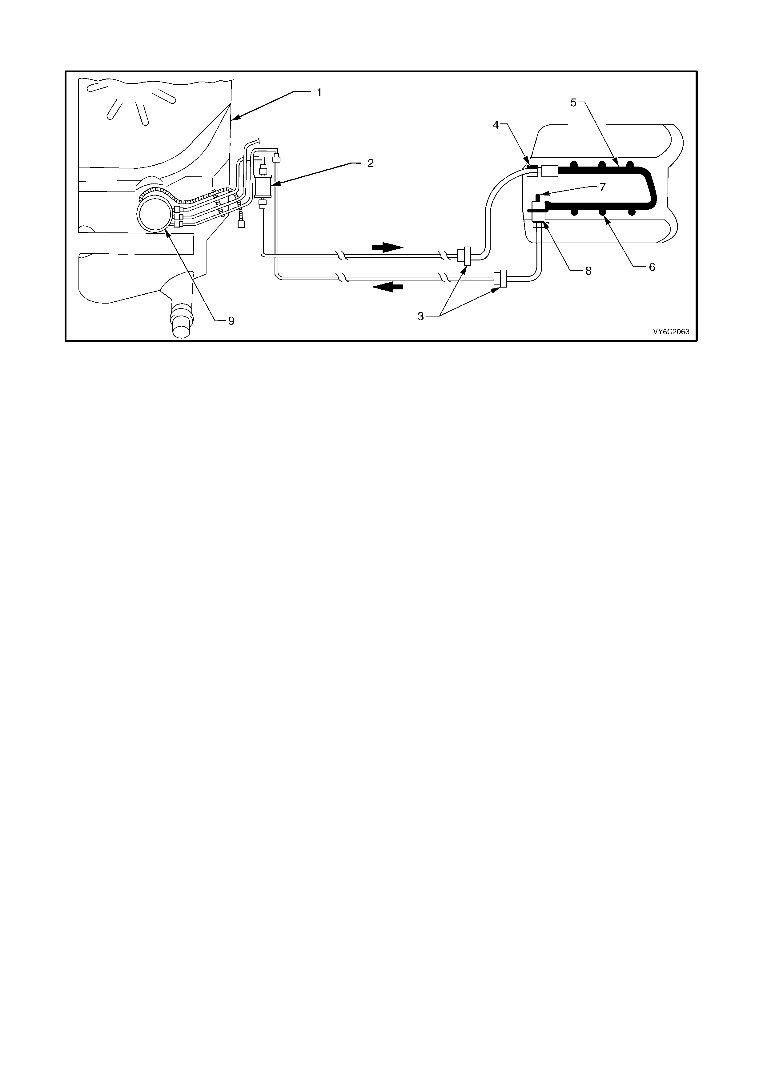
TABLE A-4.3 V6 S/C PCM – FUEL DELIVERY SYSTEM
Figure 6C2-2A-36 – Fuel Delivery System
Legend
1. Fuel Tank
2. Fuel Filter
3. Quick Connect
Connectors
4. Fuel Pressure Gauge Connection
Point
5. Fuel Rail
6. Fuel Injectors
7. Fuel Pressure Regulator Vacuum Hose
Fitting
8. Fuel Pressure Regulator
9. Modular Fuel Sender Assembly
NOTE: Fuel pressure too LOW or too HIGH or pressure that continues to drop after the ignition is turned OFF can cause the
following driveability problems:
• Poor Idle Quality
• Excessive Exhaust Odour
• Poor Fuel Economy
• Excessive Cran king Time
• Detonation
• Loss of Power
• DTC 44 or 64
• DTC 45 or 65
CIRCUIT DESCRIPTION:
Fuel is drawn from the tank by the electric fuel pump and is fed under pressure through a fuel filter and continues on
into the fuel rail and then is injected into the intake ports through the fuel injectors.
Fuel pressure in the system is governed by the fuel pressure regulator, in such a manner that a certain pressure
difference between fuel pressure and inlet manifold pressure is maintained. Excess fuel above the regulated
pressure is returned to the fuel tank by the pressure regulator and the fuel return line.
The f uel pump has a chec k valve to maintain pres s ure at the fuel rail after the pump stops running. The chec k valve
plays an important par t in the fuel delivery system : to k eep the fuel rail "c harged" with fuel after the pum p shuts off.
When the engine begins cranking to start, there is no delay before fuel injection begins, and quick starting is
ensured. The check valve is inside the fuel pump, and is not serviceable.
TEST DESCRIPTION:
NOTE: Number(s) below refer to step number(s) on the diagnostic table.
2. If the pressure continues to drop after the pump stops running, there is a leak somewhere. Either the Fuel
Pump check valve is leak ing f uel back into the tank , the regulator has an internal leak allowing fuel to leak from
the pressure to the return side, or an injector is leaking (dripping).

TABLE A-4.3 V6 S/C PCM – FUEL DELIVERY SYSTEM
STEP ACTION VALUE YES NO
1. Was the "On-Board Diagnostic" (OBD) System Check
performed? Go to Step 2. Go to
OBD
System Check
in this Section.
2. 1. From Table A-4.2, fuel pressure is not to specification.
Does fuel pressure continue to drop after pump stops? Go to Step 3 Go to Step 10
3. 1. Ignition "OFF" for 10 seconds.
2. While observing the pressure gauge, have an
assistant turn the ignition "ON".
3. When the pump stops running, pinch the rubber
section of the pressure (supply) hose connection shut.
Fuel pressure should now hold. Does it?
Go to Step 4 Go to step 7
4. 1. Check for leaks in the "pressure-side" of the fuel
system.
Were any leaks found ?
Go to Step 11 Go to step 5
5. 1. Replace fuel pump.
Is action complete? Go to Step 11
6. 1. Check for the following:
• Fuel pressure line restricted between pump and
fuel rail.
• Fuel supply line between tank and pump either
restricted or leaking.
• Restricted fuel filter.
• Restricted in-tank fuel strainer.
• Defective Fuel Pump.
Was a problem found?
Go to Step 11 Go to
6C2-3.11 FUEL
CONTROL
SYSTEM for
Fuel Pump
pressure test
procedures
7. 1. Ignition "OFF" for 10 seconds.
2. Release pinched off pressure (supply) hose.
3. While observing the pressure gauge, have an
assistant turn the ignition "ON".
4. When the pump stops running, pinch shut the rubber
section of the fuel return hose.
DO NOT PINCH OFF THE FUEL RETURN HOSE AT THE
FUEL PRESSURE REGULATOR.
Fuel pressure should now hold. Does it?
Go to Step 8 Go to Step 9
8. 1. Replace fuel pressure regulator.
Is action complete? Go to Step 11
9. 1. Locate and replace leaking injectors.
Is action complete? Go to Step 11
10. Is there fuel pressure? Go to Step 11 Go to Step 6
11. 1. Retest fuel pressure system.
Is pressure between specified values? 290 to 410
kPa Fuel Delivery
System OK Go to Table
A-4.4 in this
Section.
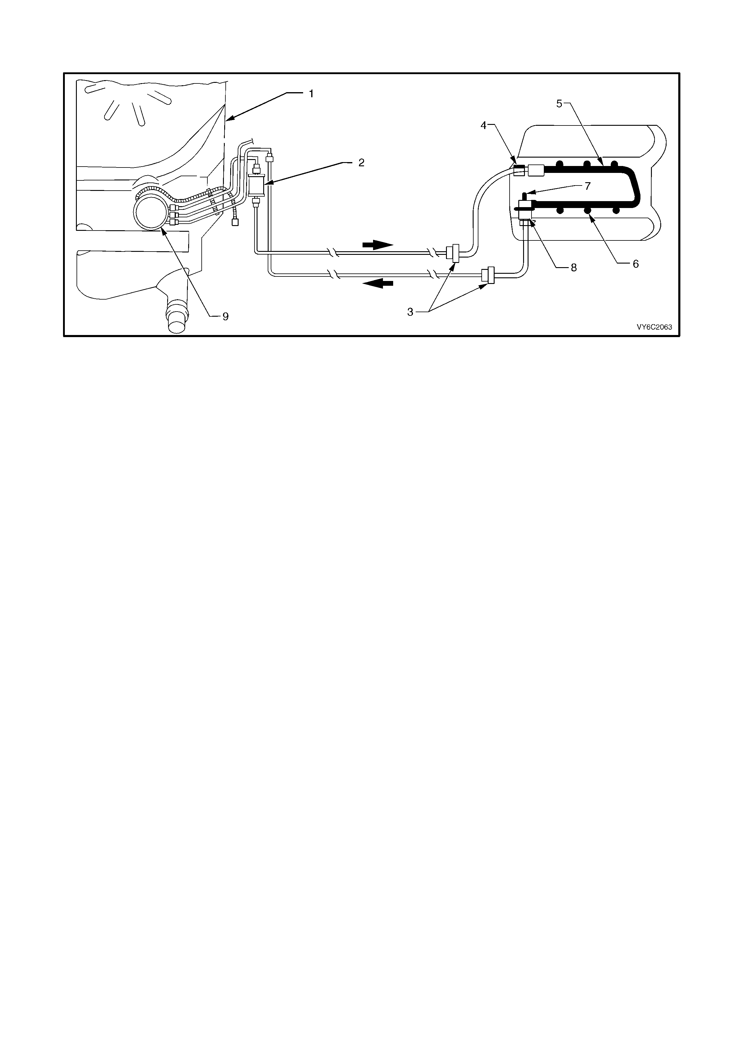
TABLE A-4.4 V6 S/C PCM – FUEL DELIVERY SYSTEM
Figure 6C2-2A – 37 –Fuel Delivery System
Legend
1. Fuel Tank
2. Fuel Filter
3. Quick Connect
Connectors
4. Fuel Pressure Gauge Connection
Point
5. Fuel Rail
6. Fuel Injectors
7. Fuel Pressure Regulator Vacuum Hose
Fitting
8. Fuel Pressure Regulator
9. Modular Fuel Sender Assembly
NOTE: Fuel pressure too LOW or too HIGH or pressure that continues to drop after the ignition is turned OFF can cause the
following driveability problems:
• Poor Idle Quality
• Excessive Exhaust Odour
• Poor Fuel Economy
• Excessive Cran king Time
• Detonation
• Loss of Power
• DTC 44 or 64
• DTC 45 or 65
CIRCUIT DESCRIPTION:
Fuel is drawn from the tank by the electric fuel pump and is fed under pressure through a fuel filter and continues on
into the fuel rail and then is injected into the intake ports through the fuel injectors.
Fuel pressure in the system is governed by the fuel pressure regulator, in such a manner that a certain pressure
difference between fuel pressure and inlet manifold pressure is maintained. Excess fuel above the regulated
pressure is returned to the fuel tank by the pressure regulator and the fuel return line.
The f uel pump has a chec k valve to maintain pres s ure at the fuel rail after the pump stops running. The chec k valve
plays an important par t in the fuel delivery system : to k eep the fuel rail "c harged" with fuel after the pum p shuts off.
When the engine begins cranking to start, there is no delay before fuel injection begins, and quick starting is
ensured. The check valve is inside the fuel pump , and is not serviceable.
TEST DESCRIPTION:
NOTE: Number(s) below refer to step number(s) on the diagnostic table.
3. If any fuel lines, fittings, filter, or components are restricted, correct pressure cannot be attained.
6. When the fuel return hose is pinched shut, there is no pressure regulator control to limit the pressure. The
pressure reading will be whatever the Fuel Pump is capable of producing. This is the same as attaching a
pressure gauge directly to the output of the Fuel Pump . The pressure reading would be a "maximum pressure -
no flow" reading, and should be well over 320 kPa. Do not allow the pressure to exceed 414 kPa.
10. At this point, the pressure checks are OK, but a complete test has not been performed. Return to Table A-4.3 in
this Section to complete the testing.
11. This is to determine if the cause of the high pressure is a restricted fuel return line, or a defective pressure
regulator. If the pressure is normal when the regulator outlet (hose or fuel pipe attached to regulator) is
connected only to an open hose, then the problem is a restricted return line between the regulator and the tank.
12. The pr ess ur e regulator on the Super c harged Engine applic ation is part of the fuel rail, and the c omplete f uel r ail
must be replaced. Refer to 3. FUEL CONTROL SYSTEM in Section 6C2-3 SERVICE OPERATIONS for fuel
pressure regulator replacement service procedures.

TABLE A-4.4 V6 S/C PCM – FUEL DELIVERY SYSTEM
STEP ACTION VALUE YES NO
1. Was the "On-Board Diagnostic" (OBD) System Check
performed? Go to Step 2. Go to
OBD
System Check
in this Section.
2. Is fuel pressure less than stated values? 290 – 410
kPa Go to Step 3 Go to Step 11
3. When there is low fuel pressure:
1. Make close inspection of all fuel lines between fuel
tank and fuel rail for restrictions. This includes:
• Tank to filter.
• Filter to fuel rail.
Were any restrictions found ?
Go to Step 4 Go to Step 5
4. 1. Repair any restrictions, then recheck fuel pressure.
Is action complete ? Verify Repair
5. 1. Replace fuel filter, then recheck fuel pressure.
Is fuel pressure still less than stated value ? Less then
290 kPa Go to Step 6 Go to Step 10
6. 1. Ignition "OFF".
2. Pinch shut the fuel return hose at the fuel gauge
sender unit (this fuel return hose is the lower hose).
DO NOT PINCH OFF THE FUEL RETURN HOSE AT
THE FUEL PRESSURE REGULATOR.
3. Ignition "ON".
4. Enable output test with Tech 2 scan tool for fuel pump.
Is fuel pressure at or above the specified value?
410 kPa Go to Step 7 Go to Step 9
7. Replace pressure regulator and recheck pressure.
Is pressure now between value ? 290 – 410
kPa Verify Repair Go to Step 8
8. Replace in-tank fuel strainer.
Is action complete ? Verify Repair
9. If the fuel pressure is less than 320 kPa:
1. Replace the fuel pump module assembly.
Is action complete?
Verify Repair
10. Is pressure between value, and does not continue
dropping when pump stops? 290 – 410
kPa Verify Repair Go to
Table A-4.1
11. 1. Disconnect fuel return line flexible hose from fuel pipe
that leads to the pressure regulator.
2. Attach a long length of hose to the fuel pipe leading to
the pressure regulator.
3. Insert other end of hose into an approved fuel
container.
4. Enable output test with Tech 2 scan tool for fuel pump.
Is fuel pressure still more than value?
410 kPa Go to Step 12 Go to Step 13
12. 1. Replace pressure regulator.
Is action complete ? Verify Repair
13. 1. Locate and correct restricted fuel return line to tank, or
blocked return line screen filter in fuel tank return
connector, or screen in fuel pressure regulator.
Is action complete ?
Verify Repair
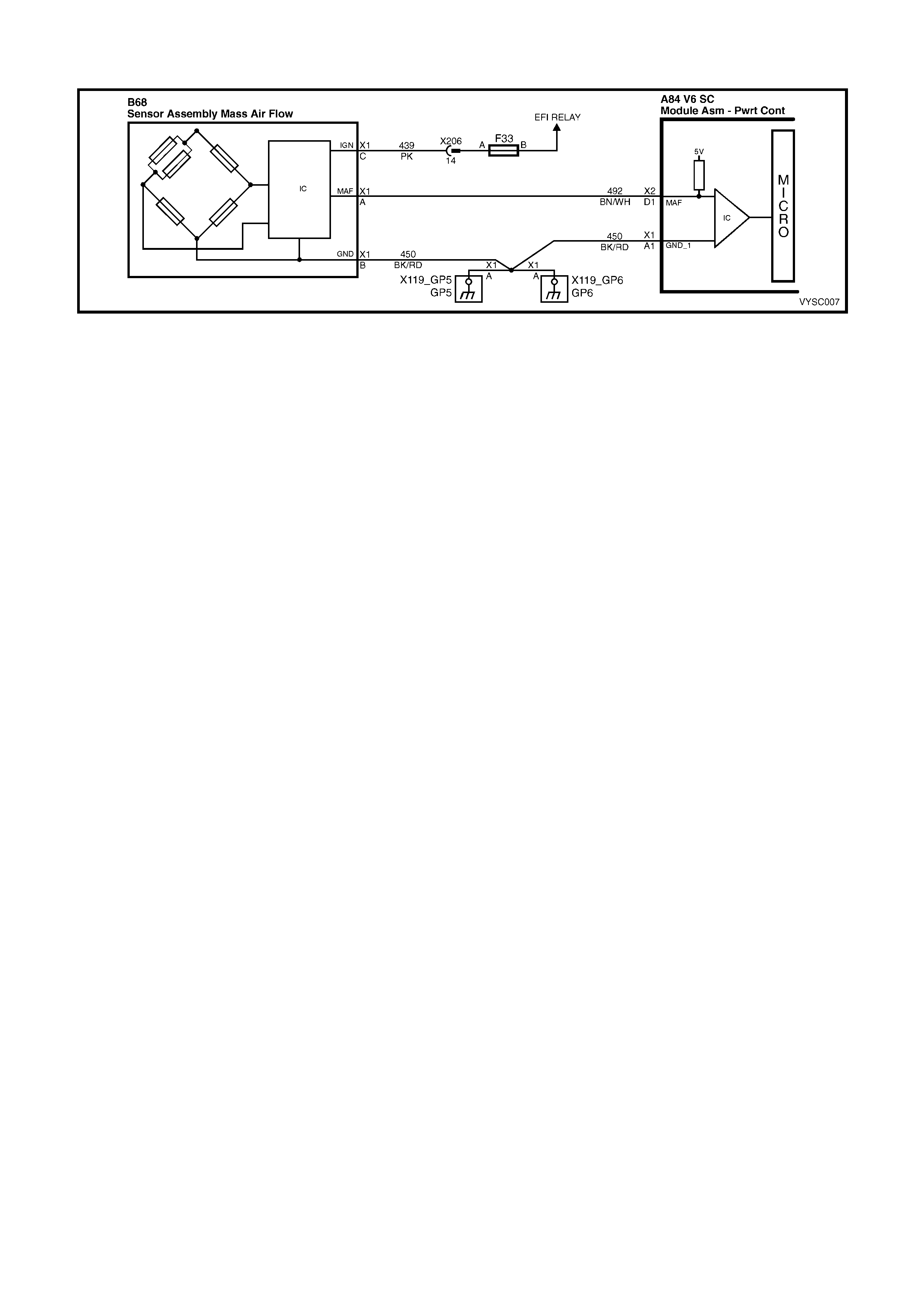
TABLE A-6.1 V6 S/C PCM – MAF SENSOR OUTPUT CHECK
Figure 6C2-2A-38 – Mass Air Flow Sensor
CIRCUIT DESCRIPTION:
The signal that is sent from the Mass Air Flow (MAF) sensor is sent in the form of a frequency output. A large
quantity of air passing through the MAF sensor will be indicated as a high frequency output (such as when under
acceleration). A small quantity of air passing through the sensor will be indicated as a low frequency output (such as
when decelerating or at idle). The Tech 2 scan tool displays this inform ation both as air flow in grams per second,
gram s per cylinder and frequenc y. A "norm al" reading is approxim ately 4-9 gr ams per second at idle and incr eases
with RPM.
TEST DESCRIPTION:
NOTE: Number(s) below refer to step number(s) on the diagnostic table.
3. This step checks for the proper Mass Air Flow grams per second at idle.
4. This step checks for the proper Mass Air Flow grams per second at 2500 RPM.
5. This step checks the Mass Air Flow sensor for a steady decrease in grams per second as the RPM changes
from 2500 to idle.
DIAGNOSTIC AIDS:
• Check air filter for being plugged.
• Check air intake ducts for restrictions.
• Check air intake ducts for leaks after the MAF sensor.
• Check for partly restricted exhaust system.
• Check for any other source that would allow air into the engine after the MAF sensor.
• This would include:
a. Intake manifold gasket.
b. Intake manifold.
c. Throttle body and or gasket.
d. PCV system, this includes the oil dipstick for proper sealing.
e. Injector O-rings.

TABLE A-6.1 V6 S/C PCM – MAF SENSOR OUTPUT CHECK
STEP ACTION VALUE YES NO
1. Was the "On-Board Diagnostic" (OBD) System Check
performed? Go to Step 2. Go to
OBD
System Check
in this Section.
2. Is DTC 32 present? Go to DTC 32 Go to Step 3
3. 1. Ignition "ON", engine running at normal operating
temperature.
2. Using Tech 2 scan tool; select Data List, then select
"Mass Air Flow G/S".
3. With engine at idle, the Tech 2 scan tool should
indicate a MAF sensor reading between the specified
value.
Is the reading between the specified value?
4-9 grams/
second (g/s)
at idle
Go to Step 4 Go to Step 6
4. 1. Increase engine speed to 2,500 rpm and hold steady.
The Tech 2 should now indicate a MAF sensor reading
at the specified value.
Is the reading at the specified value ?
17 – 20
grams /
second (g/s)
at 2,500 rpm
Go to Step 5 Go to Step 6
5. 1. Release the throttle, and watch the MAF sensor
readings on the Tech 2. The Mass Air Flow G/S
should decrease at a steady rate down to the reading
determined at idle.
Does it decrease at a steady rate?
No trouble found
with Mass Air
Flow sensor
Go to Step 6
6. 1. Check for restrictions in the Mass Air Flow induction
system. Also check for air leaks after the MAF sensor
or a possible restricted exhaust system.
2. Refer to Diagnostic Aids on the facing page.
4. If all checks OK, replace the Mass Air Flow sensor.
Is action complete ?
Verify Repair
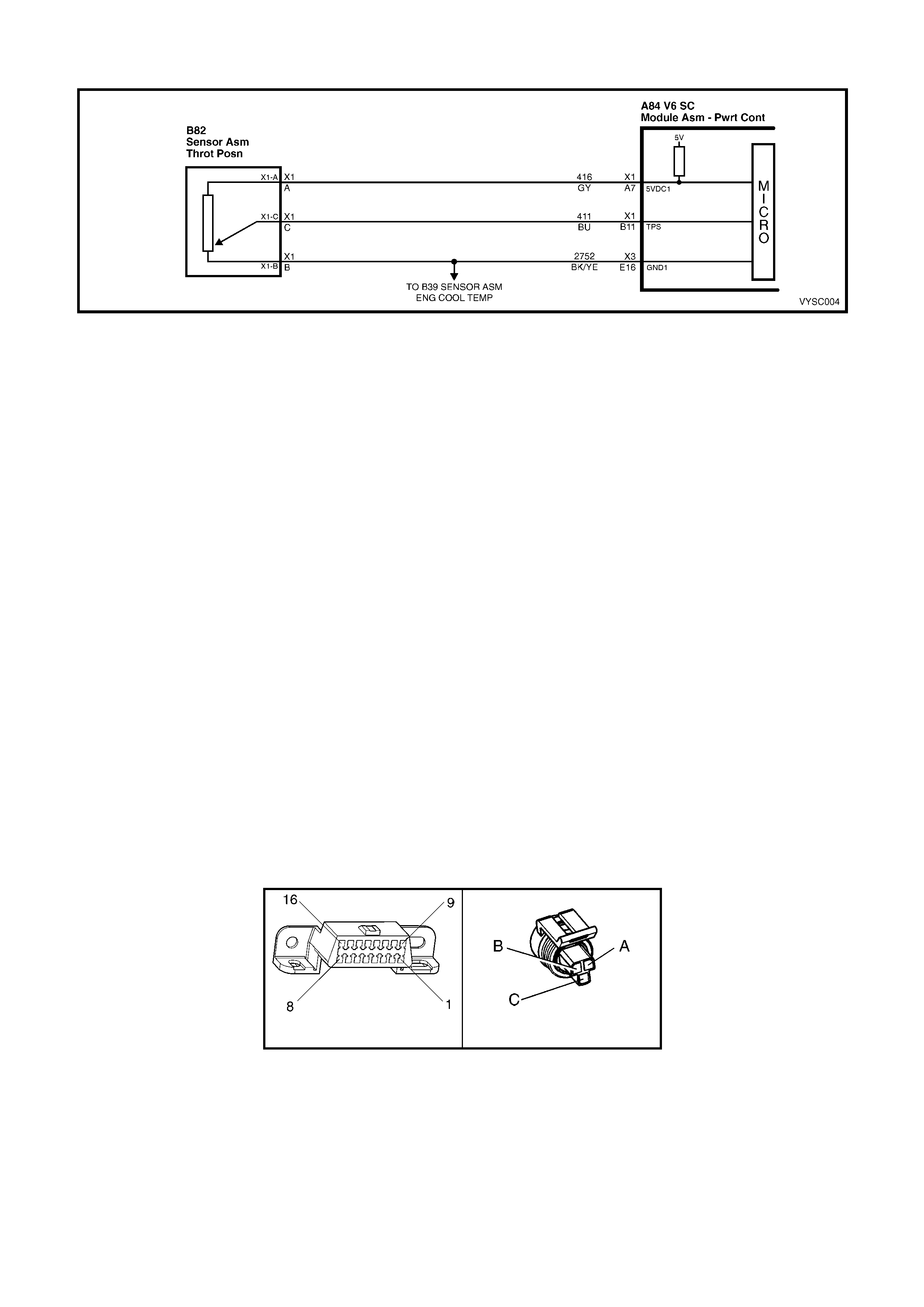
TABLE A-6 .2 V6 S/C PCM – TP SENSOR OUTPUT CHECK
Figure 6C2-2A-39 – Throttle Position Sensor
CIRCUIT DESCRIPTION:
The T hrottle Position (T P) sensor is attached to the throttle body, and is internally rotated by the throttle body shaft.
It is a potentiometer with one end connec ted to 5 volts from the PCM and the other to PCM ground. A third wire is
connected to the PCM, allowing it to measure the variable output voltage from the TP sensor.
As the throttle valve angle is changed (accelerator pedal moved), the TP Sensor output voltage also changes in
proportion. At a clos ed throttle position, the output voltage is usually below 1.0 volt. As the throttle valve opens, the
output increases so that, at wide-open throttle, the output should be above 4.0 volts. By monitoring the output
voltage from the TP sensor, the PCM can determine fuel needs based on throttle opening (driver demand).
A brok en or loos e T P Sens or, or one that has an unstable output, can c ause interm ittent bur sts of fuel bec ause the
PCM thinks the throttle is moving. Results could include engine surge or poor idle quality. If the PCM interprets a
high voltage when engine RPM is less than 400, hard starting could be the result (clear-flood mode). A problem in
any of the TP sensor circuits will set either a DTC 21 or DTC 22 after the engine is started. Once a Diagnostic
Trouble Code is set, the PCM will use an artificial default value for TP sensor based on engine RPM and MAF to
enable the vehicle to be driven, although performance could be compromised.
The TP sensor is not adjustable. The PCM uses the reading at idle as "0% throttle," so no adjustment is necessary.
TEST DESCRIPTION:
NOTE: Number(s) below refer to step num ber(s) on the diagnostic table. If a DTC 21 or DTC 22 is present, follow
that Table first.
2. This is a check of the voltage at the idle position. It is usually less than 1.0 volt.
3. The voltage should increase at the same steady rate at which the throttle is opened with the throttle valve.
6. With the throttle valve wide open, the T P sens or output needs to be above 4 volts , allowing the PCM to interpret
a wide open throttle position.
7. If the throttle stop screw has been inadvertently reset, the TP sensor output at idle could be out of allowable
limits.
9. If the closed-throttle voltage is over 2.5 volts, hard starting may be encountered (worse cold) due to "clear-flood"
mode. T his m ode oc curs when engine RPM is less than 400, and T P sens or input indicates the throttle is m or e
than 80% open. Possible causes: short to voltage on input signal circuit, open ground circuit , or a faulty sensor.
X40 B82
Figure 6C2-2A-40

TABLE A-6.2 V6 S/C PCM – TP SENSOR OUTPUT CHECK
STEP ACTION VALUE YES NO
1. Was the "On-Board Diagnostic" (OBD) System Check
performed? Go to Step 2. Go to
OBD
System Check
in this Section.
2. 1. Ignition "ON", engine stopped, throttle plate closed.
2. Install Tech 2 and set to TP sensor voltage.
Is voltage on Tech 2 within value shown?
0.25 – 1.25
volts Go to Step 3 Go to Step 4
3. 1. Ignition "ON".
2. With Tech 2 still connected, monitor the voltage as the
throttle is slowly and steadily opened to a wide-open-
position.
3. Voltage should increase at a steady rate, with no
sudden changes.
Did voltage increase at a steady rate with throttle
movement ?
Go to Step 6 Go to Step 4
4. 1. Ignition "ON", engine stopped.
2. Tech 2 set to TP sensor voltage.
Is voltage on Tech 2 within value shown?
1.26 – 2.5
volts Go to Step 7 Go to Step 5
5. 1. Ignition "ON", engine stopped.
2. Tech 2 set to TP sensor voltage.
Is voltage on Tech 2 scan tool over value shown?
2.5 volts Go to Step 9 Go to Step 12
6. 1. Ignition "ON".
2. W ith the Tech 2 still connected, monitor the voltage as
the throttle valve is opened to the wide open position.
• Have an assistant ensure that the throttle valve is
fully open when accelerator pedal is fully
depressed.
• If throttle valve does not fully open when pedal is
depressed, check for extra floor mats or carpet
under accelerator pedal. Then refer to 3.11 FUEL
CONTROL SYSTEM – Throttle Cable - "Adjust",
in 6C2-3 SERVICE OPERATIONS, .
Is the TPS voltage above the specified value?
4 volts TP sensor is
working
properly.
Go to
OBD
System Check
in this Section.
Go to Step 8
7. 1. Check throttle stop screw. refer to 3.11 FUEL
CONTROL SYSTEM – Throttle Stop Screw - "Reset
Procedure" in 6C2-3 SERVICE OPERATIONS. Only
reset if incorrect.
2. Ignition "ON".
3. Tech 2 connected to data link connector X40.
4. Recheck TPS voltage.
Is voltage now within the specified value ?
0.25 – 1.25
volts Go to Step 6 Go to Step 8
8. 1. Replace TP sensor.
Is action complete ? Verify Repair –
9. 1. Ignition "OFF".
2. Disconnect TPS.
3. Connect Tech 2 to DLC, set to TPS voltage.
4. Ignition "ON"
Is voltage on Tech 2 at or below specified value?
1.25 volts Go to Step 10 Go to Step 11
10. 1. Check for open in TP sensor ground circuit.
Was a problem found? Verify Repair Go to Step 8
11. 1. Repair short to voltage on TP sensor signal circuit.
Is repair complete ? Verify Repair –
12. 1. Repair open or short to ground on TP sensor signal
circuit or 5 volt reference circuit.
Is repair complete ?
Verify Repair –
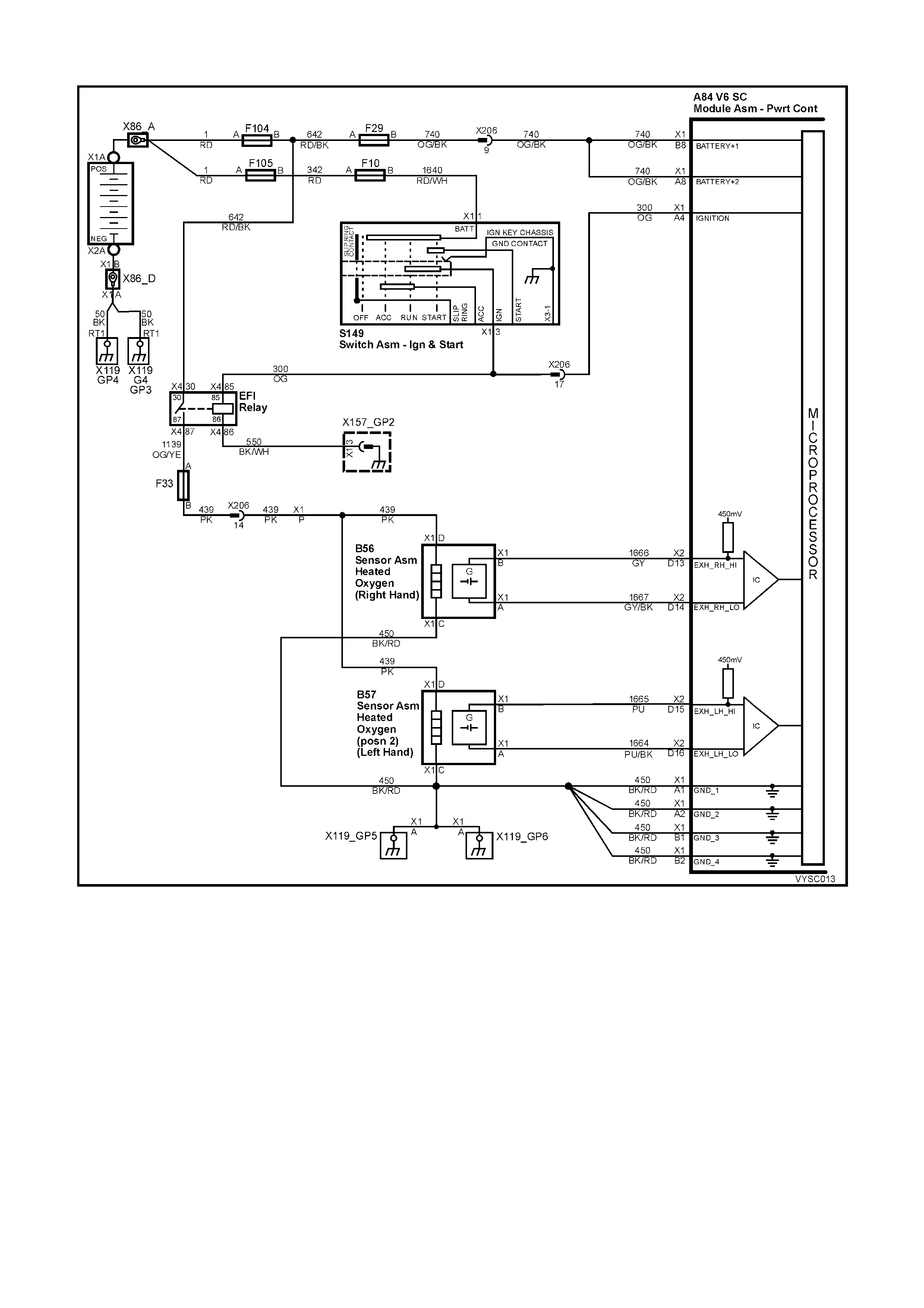
TABLE A-6.3 V6 S/C PCM – OXYGEN SENSOR CHECK
Figure 6C2-2A-41 – Heated Oxygen Sensors
CIRCUIT DESCRIPTION:
The oxygen sensors are mounted in the exhaust pipes near the cylinders. At operating temperature, the oxygen
sensors are required to respond quickly to changes to oxygen content in the exhaust. If the oxygen sensors become
contaminated or faulty, a sluggish driveability or a complaint of poor idle condition may exist. A proper oxygen
sensor response should be almost instantaneous to the fuelling mode command.
TEST DESCRIPTION:
NOTE: Number(s) below refer to step number(s) on the diagnostic table.
2. Never perform this test on a cold engine. The oxygen sensor must be near normal operating temperature for
this Table to work. It is important to see a low voltage and a high voltage response very quickly because this
means the oxygen sensor is not contaminated or faulty.

TABLE A-6.3 V6 S/C PCM – OXYGEN SENSOR CHECK
STEP ACTION VALUE YES NO
1. Was the "On-Board Diagnostic" (OBD) System Check
performed? Go to Step 2. Go to
OBD
System Check
in this Section.
2. 1. Ignition "ON", engine Running.
2. Run engine at 1600 to 1800 RPM for 2 minutes, or
until engine temperature is above 85 degrees C, then
let engine idle.
3. Using Tech 2, select Misc. Test, then A/F Ratio, then
display "RH O2 Sensor and LH O2 Sensor.
4. With engine idling, press the Down select button on
Tech 2 until 11.7 A/F Ratio is displayed, at the same
time note the response of both O2 Sensors.
5. Both O2 Sensors should display above specified
value.
6. Then press the Up select button on Tech 2 until 17.7
A/F Ratio is displayed, at the same time note the
response of both O2 Sensors.
7. Both O2 Sensors should display below specified
value.
Did both O2 Sensors display above and below the
specified value?
Above
700 mV
or
Below
100 mV
No trouble
found Go to Step 3
3. 1. Replace the O2 Sensor that did not perform as
specified in Step 2.
Is action complete?
Verify Repair –

TABLE A-6.3A V6 S/C PCM ENGINE – OXYGEN SENSOR HEATER CHECK
Figure 6C2-2A-42 – Heated Oxygen Sensors
CIRCUIT DESCRIPTION:
On the Supercharged V6 engine, two heated ox ygen sens ors are used to m inim ise the amount of tim e required for
closed loop fuel control operation and to allow accurate exhaust converter operation. The oxygen sensor heater
greatly decreases the am ount of time r equired for the oxygen sensor signal to becom e active, and the PCM to use
this signal for efficient emissions control.
Because the sensor must be at least 360°C to operate effectively, it is equipped with an internal electric heating
element to quickly heat the sensor after key "ON", or start up. This heating element is powered from the vehicles
electrical system, any time the ignition is "ON".
The heater is used to maintain the oxygen sensor at a sufficiently high temperature. This allows accurate exhaust
oxygen content readings further from the engine, and maintains the sensors temperature at long engine idle
intervals.

TEST DESCRIPTION:
NOTE: Number(s) below refer to step number(s) on the diagnostic table.
2. Never perform this test on a cold engine. The oxygen sensor must be near normal operating temperature for
this T able to work. You m ay not see the voltage at 450 m V when the ignition is cycled "ON", because the T ech
2 scan tool menus take some time, however, it is important to see a low voltage because this means the
oxygen sensor is only monitoring oxygen in the exhaust pipe.
B56 Right/B57 Left
Figure 6C2-2A-43
TABLE A-6.3A V6 S/C PCM ENGINE – OXYGEN SENSOR HEATER CHECK
STEP ACTION VALUE YES NO
1. Was the "On-Board Diagnostic" (OBD) System Check
performed? Go to Step 2. Go to
OBD
System Check,
in this Section.
2. 1. Ignition "ON".
2. Using Tech 2, display LH and RH O2 Sensors.
3. Ignition "ON", engine "OFF".
Did LH and RH O2 Sensor voltages drop to specified value
within 60 seconds?
450 mV to
less than
100 mV
No problem
found.
Oxygen Sensor
Heater is OK
If both did not
drop to specified
value,
Go to Step 8
----------------------
If only one
dropped to
specified value,
Go to Step 3.
3. 1. Ignition "OFF".
2. Disconnect the oxygen sensor harness connector from
the sensor that did not drop.
3. Connect test light between oxygen sensor connector
on powertrain harness, circuit 439 (Pink) and ground,
circuit 450 (Black/Red wire).
4. Ignition "ON".
Is the test light "ON"?
Go to Step 4 Go to Step 7
4. 1. Ignition "OFF".
2. Measure resistance of oxygen sensor heater with
ohmmeter between circuits 439 (Pink) and circuit 450
(Black/Red wire).
Is measured resistance within the specified value?
3.5 - 13.2
ohms Go to Step 6 Go to Step 5
5. 1. Replace heated oxygen sensor.
Is action complete? Verify Repair
6. 1. Repair poor connection at oxygen sensor.
Is action complete? Verify Repair –
7. 1. Ignition "OFF".
3. Connect test light to battery positive.
3. Probe oxygen sensor connector on powertrain
harness connector, circuit 450 (Black/Red wire).
Is test light "ON"?
Go to Step 8 Go to Step 9
8. 1. Repair open or short to ground in circuit 439 (Pink)
between fuse F33 and oxygen sensor. Replace fuse if
blown.
Is action complete?
Verify Repair –
9. 1. Repair open in circuit 450 (Black/Red wire).
Is action complete ? Verify Repair –
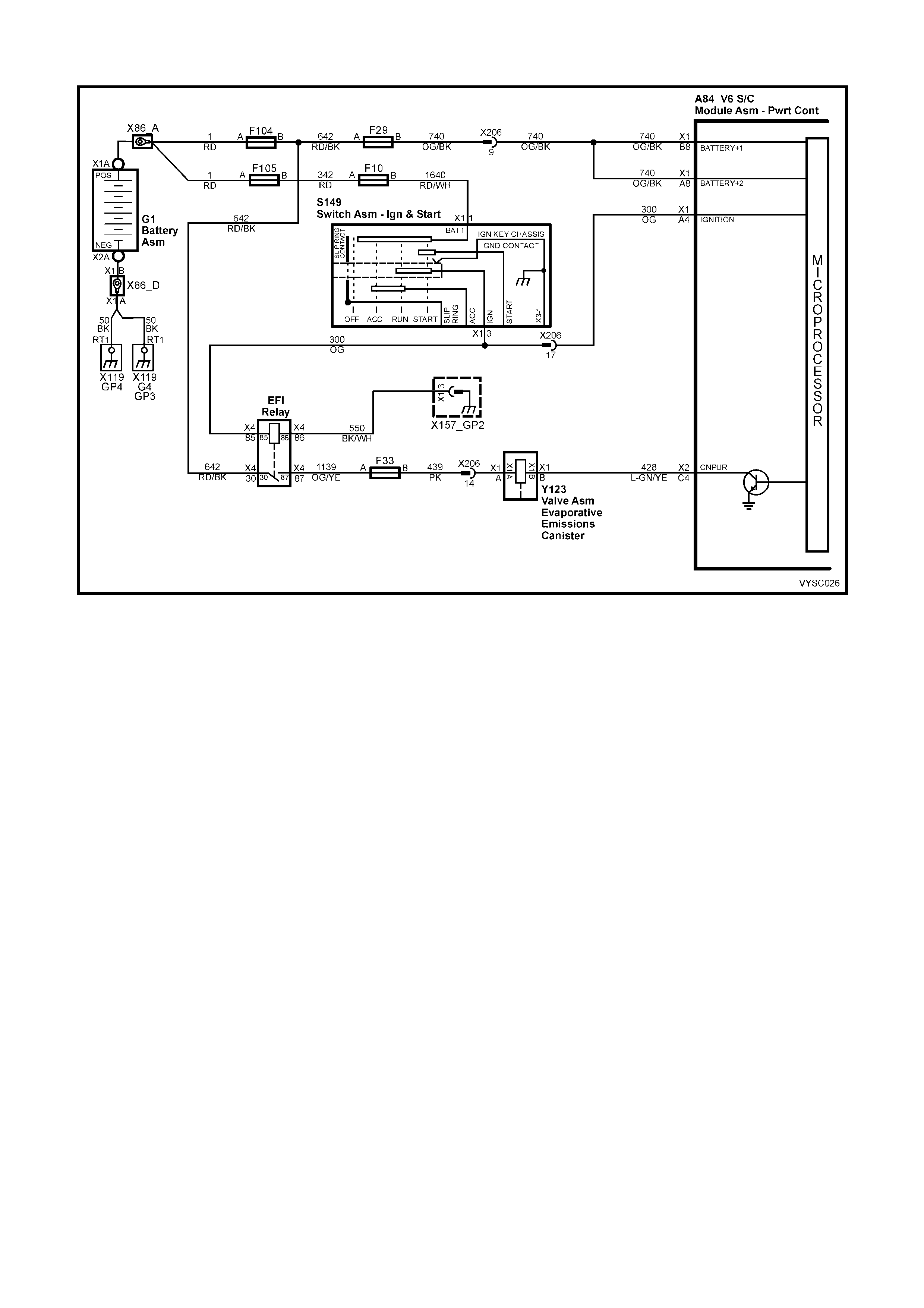
TABLE A-6 . 4 V6 S/C PCM – CANISTE R P URGE SOLENOID CHECK
Figure 6C2-2A-44 – Evaporative Purge Canister Solenoid
CIRCUIT DESCRIPTION:
The canister purge is controlled by a solenoid that allows manifold vacuum to purge the fuel vapour canister when
energised. The PCM supplies a ground to energise the solenoid (purge "ON").
If the following conditions are met with the engine running, the canister purge solenoid is energised.
• Engine run time after start more than 3 minutes and 15 seconds if coolant is less than 80° C or
• Engine run time after start is more than 15 seconds if coolant is above 80° C.
• Coolant temperature above 60° C
• Engine not in Decel fuel cutoff mode.
• Throttle is less than 92%.
TEST DESCRIPTION:
NOTE: Number(s) below refer to step number(s) on the diagnostic table.
2. Checks to see if the solenoid is opened or closed. T he solenoid is norm ally energised in this step, so it should
be open.
3. This checks to see if the Canister Purge Solenoid mechanical function is functioning properly by grounding
Canister Purge Solenoid several times with Tech 2 .
4. This checks to see if +B volts is supplied to the Canister Purge Solenoid.
5. This checks to see if the PCM is supplying the ground signal for the Canister Purge Solenoid.
DIAGNOSTIC AIDS:
Normal operation of the Canister Purge Solenoid is described as follows:
With the ignition "ON", engine "OFF", diagnostic "Test" terminal ungrounded, the Canister Purge Solenoid will be
de-energised.
NOTE: This Table only covers the solenoid portion of the Canister Purge system.

A84 Y123
Figure 6C2-2A-45
TABLE A-6.4 V6 S/C PCM – CANISTER PURGE SOLENOID CHECK
STEP ACTION VALUE YES NO
1. Was the "On-Board Diagnostic" (OBD) System Check
performed? Go to Step 2. Go to
OBD
System Check
in this Section.
2. 1. Ignition OFF.
2. Disconnect purge vacuum hose from top of canister,
and place a vacuum gauge in hose.
3. Ignition "ON", engine Running.
4. With Tech 2, enable Canister Purge Solenoid "ON".
Does vacuum gauge read manifold vacuum with canister
purge solenoid display "ON"?
No trouble
found. Canister
Purge Solenoid
is OK.
Go to Step 3
3. 1. Ignition "ON", engine "OFF".
2. Place index finger on top of Canister Purge Solenoid.
3. Enable Canister Purge Solenoid "ON" and "OFF"
several times with Tech 2.
Does the solenoid click while enabling and disabling?
Canister Purge
Solenoid
electrical is OK.
Go to Step 10
for vacuum
check
Go to Step 4
4. 1. Ignition "ON", engine "OFF".
2. Disconnect Canister Purge Solenoid electrical
connector.
3. With a test light connected to ground, probe Canister
Purge Solenoid electrical connector power feed circuit.
Is test light "ON" ?
Go to Step 5 Go to Step 6
5. 1. Ignition "ON", engine "OFF".
2. Disconnect Canister Purge Solenoid electrical
connector.
3. W ith a test light connected to +B volts, probe canister
purge solenoid electrical connector purge solenoid
control circuit.
4. With Tech 2, enable Canister Purge Solenoid "ON”.
Is test light "ON" when Canister Purge Solenoid is
commanded "ON"?
Go to Step 7 Go to Step 8
6. 1. Check for open in power feed circuit.
Is action complete ? Verify Repair
7. 1. Replace Canister Purge Solenoid.
Is action complete ? Verify Repair
8. 1. Check for open in Purge Solenoid control circuit from
PCM to Canister Purge Solenoid.
Was an open found?
Verify Repair Go to Step 9
9. 1. Check for poor connection at PCM. If connection is
OK, replace PCM. Refer to 6C2-3 SERVICE
OPERATIONS, for the Security Link procedure.
Is the action complete?
Verify Repair
10. 1. Check manifold vacuum hose from manifold to
Canister Purge Solenoid for kinks, pinched, cracked,
or plugged.
2. Repair as necessary.
Is action complete?
Verify Repair
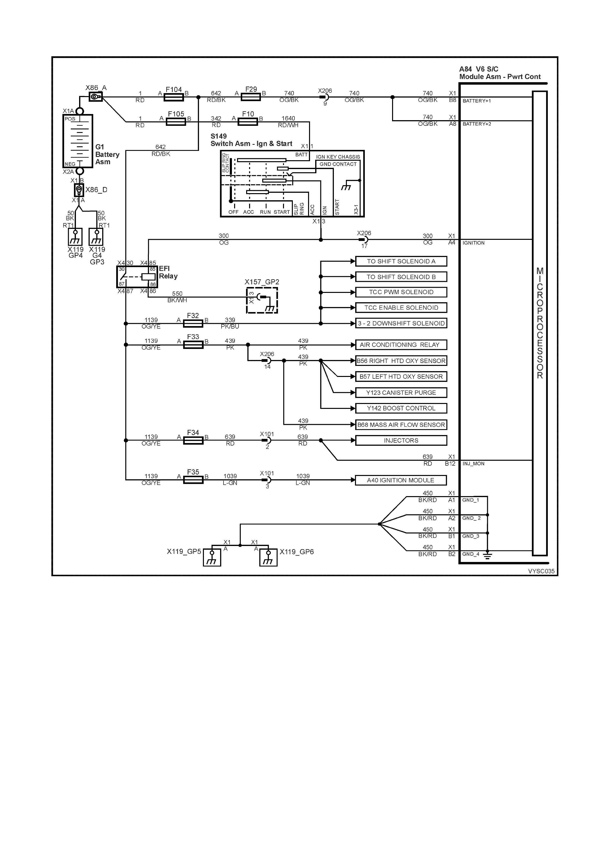
TABLE A-6.5 V6 S/C PCM – EFI RELAY DIAGNOSIS
Figure 6C2-2A-46
CIRCUIT DESCRIPTION:
The EFI relay protects the battery from a parasitic draw. The following components are powered by the EFI relay:
Legend
1. Injectors
2. DIS Module
3. Transmission
4. A/C System
5. EVAP Solenoid
6. MAF Sensor
7. Oxygen Sensors
8. Boost Control Solenoid
DIAGNOSTIC AIDS:
The following may cause an intermittent:
• Poor connections. Check for adequate terminal tension.
• Corrosion.
• Incorrectly routed harness.
• Rubbed through wire insulation.
• Broken wire inside the insulation.

TEST DESCRIPTION:
NOTE 1: Number(s) below refer to the step number(s) on the diagnostic table.
NOTE 2: For any test that requires probing the PCM or a component harness connector, use the Connector Test
Adaptor Kit J35616-A. Using this kit prevents damage to the harness connector terminals.
2. This test checks the fusible link F104 power feed to the EFI relay.
3. This test checks the fused power feed ignition circuit.
4. This test is checking the ground circuit of the EFI relay.
5. This step isolates the circuit from the EFI relay. All of the circuits at the relay are good if the test lamp
illuminates.
X4 (Part of X100)
Figure 6C2-2A -47
TABLE A-6.5 V6 S/C PCM – EFI RELAY DIAGNOSIS
STEP ACTION VALUE YES NO
1. Did you perform the Powertrain On-Board Diagnostic
(OBD) System Check? Go to Step 2 Go to
Powertrain OBD
System Check
Table
2. 1. Turn OFF the ignition.
2. Remove the engine compartment Fuse/Relay panel
cover.
3. Remove the EFI relay.
4. Probe the fusible link F104 power feed circuit to the
EFI relay harness terminal X4-87 with a test lamp
connected to ground.
Does the test lamp illuminate?
Go to Step 3 Go to Step 8
3. 1. Turn ON the ignition leaving the engine OFF.
2. Probe the fused ignition feed circuit to the EFI relay
harness terminal X4-85 with a test lamp connected to
ground.
Does the test lamp illuminate?
Go to Step 4 Go to Step 9
4. 1. Turn OFF the ignition.
2. Probe the ground circuit to the EFI relay harness
terminal X4-86 with a test lamp connected to + 12 V.
Does the test lamp illuminate?
Go to Step 5 Go to Step 10
5. 1. Turn OFF the ignition.
2. Jump the EFI relay B+ feed circuit terminal X4 30 and
the EFI relay load circuit terminal X4-87 together using
a fused jumper wire.
3. Probe the following fuses with a test lamp connected
to ground:
– F32
– F33
– F34
– F35
Does the test lamp illuminate for all fuses?
Go to Step 6 Go to Step 11
6. 1. Check for poor terminal contact at the EFI relay
harness connector.
Did you find and correct the condition?
System OK Go to Step 7
7. 1. Replace the EFI relay.
Is the action complete? System OK –
8. 1. Repair the open in fusible link F104 circuit to the EFI
relay.
Is the action complete?
System OK –

STEP ACTION VALUE YES NO
9. 1. Repair the fused ignition feed circuit to the EFI relay.
Replace fuse if open.
Is the action complete?
System OK –
10. 1. Repair the open in the ground circuit for the EFI relay.
Is the action complete? System OK –
11. 1. Repair open in the EFI relay load circuit, or open in
fuse(s) circuit that did not illuminate the test light.
Is the action complete?
Verify Repair –
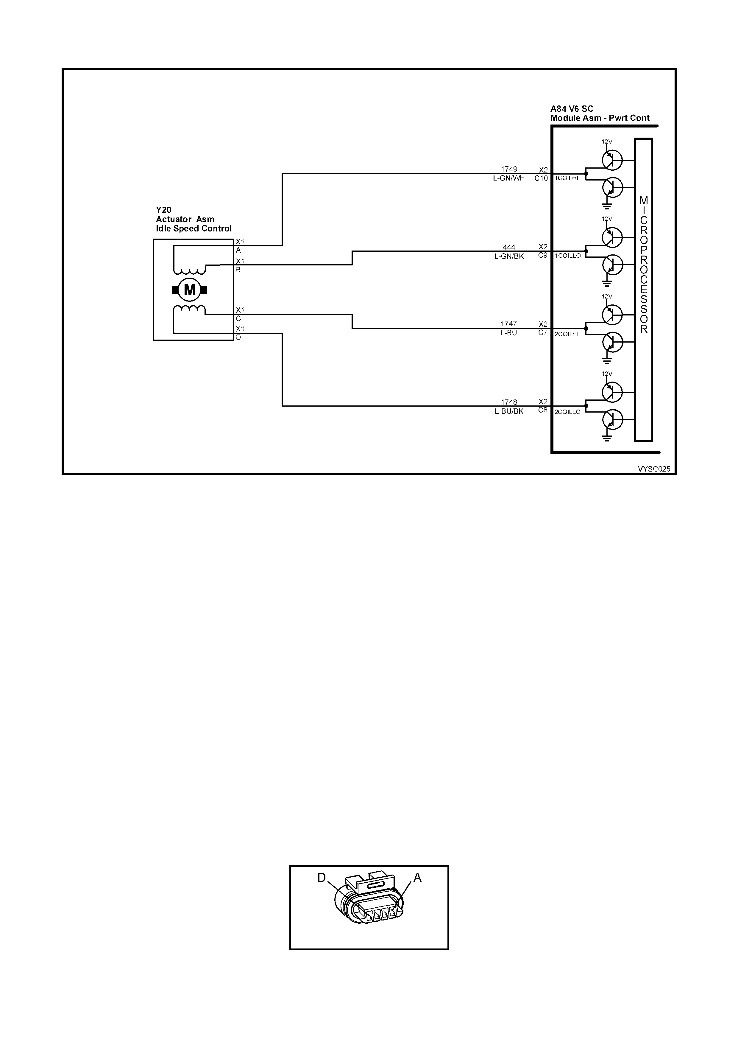
TABLE A-7.1 V6 S/C PCM – IDLE AIR CONTROL (IAC) SYSTEM
Figure 6C2-2A-48 – Idle Air Control
CIRCUIT DESCRIPTION:
The PCM controls engine idle speed by moving the IAC valve to control closed-throttle air flow around the throttle
plate. It does this by sending voltage pulses (c alled "counts" or "steps ") to the IAC m otor windings . The motor shaf t
and conical valve move a given distance for each pulse received.
TO INCREASE IDLE SPEED: The PCM s ends enough pulses to retrac t the IAC valve and allow more air to bypass
the throttle plate through the idle air passage, until idle speed reaches the ‘PCM-desired idle RPM’.
TO DECREASE IDLE SPEED: The PCM sends enough pulses to extend the IAC valve and reduce the airflow
bypassing the throttle plate through the idle air passage, until engine speed reaches the ‘PCM-desired idle RPM’.
The ‘PCM desired idle RPM’, and the commanded IAC position, is based on:
• Engine Coolant Temperature (ECT).
• Actual engine RPM (crankshaft reference input).
• Engine load (A/C request input, engine fan command).
• Battery voltage.
• Vehicle speed (VSS).
• Throttle position (TPS).
TEST DESCRIPTION:
NOTE: Number(s) below refer to step number(s) on the diagnostic table.
2. This tests the PCM's ability to control IAC valve.
DIAGNOSTIC AIDS:
Remove IAC and check for frozen or sticking IAC. Check that TP sensor is within acceptable range.
Y20
Figure 6C2-2A -49

TABLE A-7.1 V6 S/C PCM – IDLE AIR CONTROL (IAC) SYSTEM
STEP ACTION VALUE YES NO
1. Was the "On-Board Diagnostic" (OBD) System Check
performed? Go to Step 2. Go to
OBD
System Check
in this Section.
2. 1. Usin g Tech 2, s elect RPM CONTROL.
2. W ith the arrows, vary engine speed from 600 to 1,675
rpm.
Does engine speed rise and fall?
Go to Step 3 Go to
Table A-7.2 in
this Section.
3. No trouble found with IAC system. Check For:
• Vacuum leaks.
• Sticking or binding throttle shaft, cables, or linkages.
• Engine Coolant Temperature sensor resistance. Refer
DTC 14 in this Section.
• TP Sensor Operation. Refer Table A-6.2 in this
Section.
• Dirty or loose battery cables or ground straps.
• System ground circuit terminals at the engine for being
clean and tight.
• Inspect all accessory drive pulleys. They should all
spin freely.
• Spark plugs that are excessively worn, mis-gapped or
cracked.
• For high or low fuel pressure, or leaking injectors -
refer Table A-4.3 in this Section.
• A/C Clutch Control circuit failure. Refer Table A 11.1
or Table A 11.3 in this Section.
• Generator Output - if under 9 volts or over 16 volts,
PCM will not command the IAC to move.
• Throttle Body - remove IAC and inspect bore for
foreign material or evidence of IAC valve "dragging" in
the bore.
• Throttle Stop Screw, refer 3.11 FUEL CONTROL
SYSTEM – Throttle Stop Screw – Reset Procedure,
6C2-3 SERVICE OPERATIONS, in this Section.
• Refer to "Rough, Unstable, Or Incorrect Idle" in 6C2-
2B SYMPTOMS, in this Section.
Verify Repair –

TABLE A-7.2 V6 S/C PCM – IDLE AIR CONTROL (IAC) SYSTEM
Figure 6C2-2A-50 – Idle Air Control
CIRCUIT DESCRIPTION:
The PCM controls engine idle speed by moving the IAC valve to control closed-throttle air flow around the throttle
plate. It does this by sending voltage pulses (c alled "counts" or "steps ") to the IAC m otor windings . The motor shaf t
and conical valve move a given distance for each pulse received.
TO INCREASE IDLE SPEED: The PCM s ends enough pulses to retrac t the IAC valve and allow more air to bypass
the throttle plate through the idle air passage, until idle speed reaches the ‘PCM-desired idle RPM’.
TO DECREASE IDLE SPEED: The PCM sends enough pulses to extend the IAC valve and reduce the airflow
bypassing the throttle plate through the idle air passage, until engine speed reaches the ‘PCM-desired idle RPM’.
The ‘PCM desired idle RPM’, and the commanded IAC position, is based on:
• Engine Coolant Temperature (ECT).
• Actual engine RPM (crankshaft reference input).
• Engine load (A/C request input, engine fan command).
• Battery voltage.
• Vehicle speed (VSS).
• Throttle position (TPS).
TEST DESCRIPTION:
NOTE: Number(s) below refer to step number(s) on the diagnostic table.
2. With the ignition "ON," engine s topped, and Tec h 2: IAC reset, the PCM should iss ue electrical "ex tend/retract"
pulses to the IAC valve. W ith the IAC disconnected, each connector terminal should have a "pulsing" voltage,
noted by a flashing or flickering test light. The rate of flashing or flickering is not important.
8. There are 2 s eparate windings in the IAC m otor. Each winding (A – B, and C – D) should have between 40 and
80 ohms resistance. Also, there should be no continuity between the two windings.
NOTE: When performing this test, ensure that a standard low power test light is used.
Do not use a "high wattage" test light, as the PCM could be damaged. A high wattage test light will either give
inaccurate test results, or damage the PCM, or both.
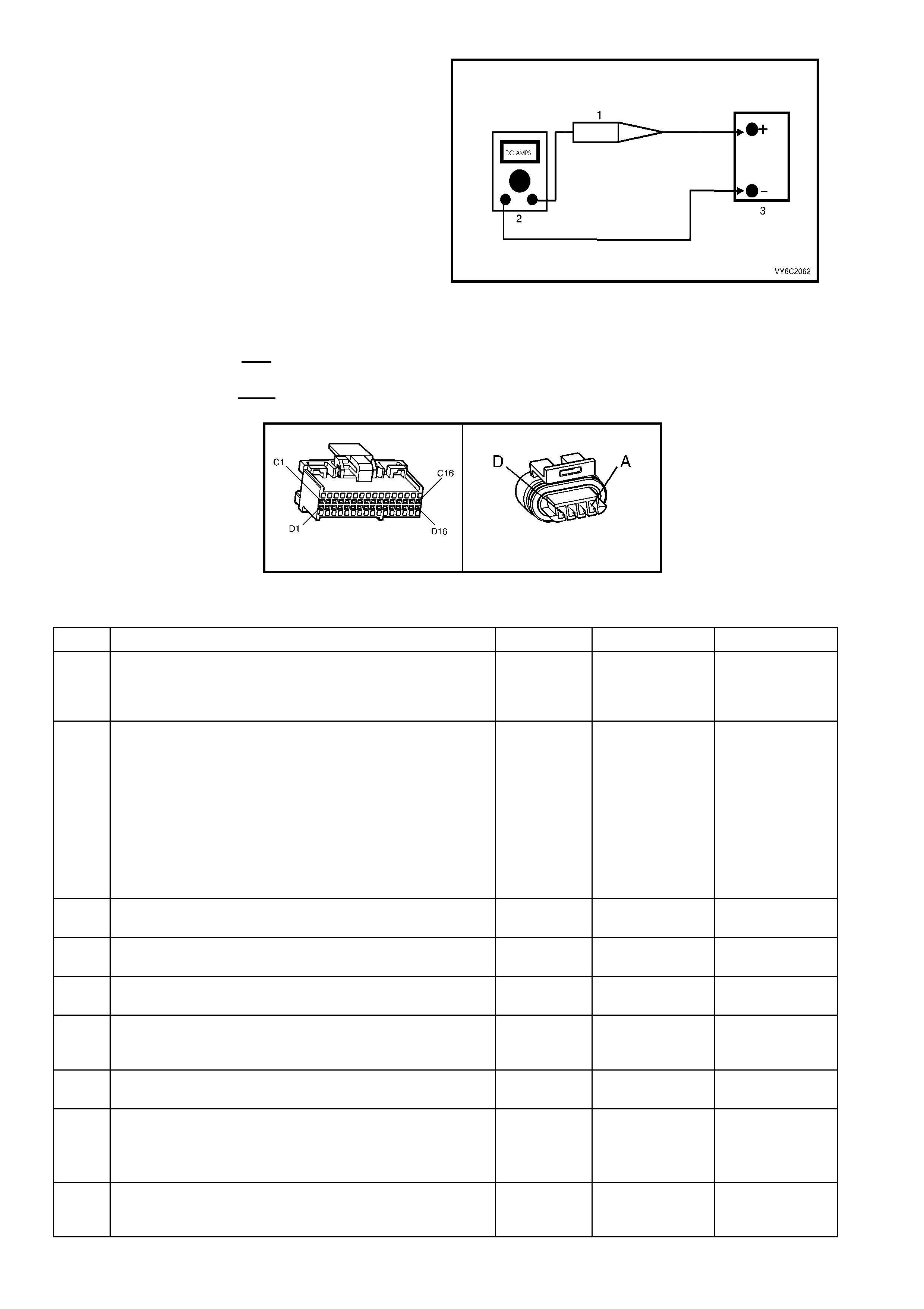
A low-power test light must be used for any circuit
testing. While a particular brand of test light is not
suggested, a simple test on any test light will
ensure it to be OK for PCM circuit testing. Connect
an accurate ammeter (such as the digital
multimeter ) in ser ies with the test light being tested,
and power the test light-ammeter circuit with the
vehicle battery (as shown). If the ammeter indicates
less than 3/10 amp curr ent flow (0.3 A or 300 mA),
the test light is OK to use. If more than 0.3A (300
mA), do not use!
Legend:
1. Test Lamp
2. Digital Multimeter, Set to DC Amps
3. 12 Volt Battery
If the ammeter indicates less than 0.3 A (300 mA)
current flow, the test light is OK to use.
If the am m eter indic ates more than 0.3 A (300 mA)
current flow, the test light is NOT OK to use.
Figure 6C2-2A-51
A84 V6 S/C – X2 Y20
Figure 6C2-2A-52
TABLE A-7.2 V6 S/C PCM – IDLE AIR CONTROL (IAC) SYSTEM
STEP ACTION VALUE YES NO
1. Was the "On-Board Diagnostic" (OBD) System Check
performed? Go to Step 2. Go to
OBD
System Check
in this Section.
2. From Table A-7.1:
1. Disconnect IAC valve electrical connector.
2. Ignition "ON", engine stopped. Using Tech 2, select
RESET IAC.
3. Probe each IAC harness connector terminal for 5
seconds with test light connected to ground, while
using Tech 2.
See note on facing page for proper test light usage.
Does test light flash at all terminals while IAC is being
reset?
Go to Step 3 If no light at one
or more
terminals,
Go to Step 6.
----------------------
If a steady light
one or more
terminals,
Go to Step 13.
3. 1. Check for faulty IAC terminals.
Were any faulty terminals found? Go to Step 4 Go to Step 5
4. 1. Repair faulty terminals.
Is action complete? Verify Repair –
5. 1. Replace IAC valve.
Is action complete ? Verify Repair –
6. 1. Check for open or short to ground in circuit(s) that did
not light the test light.
Were any open or short circuits found ?
Go to Step 7 Go to Step 8
7. 1. Repair any opens or short found.
Is action complete? Verify Repair –
8. 1. Check resistance across IAC coils.
2. Check IAC terminals with Ohmmeter across terminals
"A" to "B" and "C" to "D".
Are the IAC coils within specified value ?
40 to 80
ohms Go to Step 9 Go to Step 5
9. 1. Check for short between windings by measuring for
continuity between IAC terminals "A" to "D".
Ohmmeter should indicate an open circuit, does it?
Go to Step 10 Go to Step 5

STEP ACTION VALUE YES NO
10. 1. Check for faulty PCM terminals.
Were any faulty terminals found? Go to Step 17 Go to Step 11
11. 1. Check for faulty IAC terminals.
Were any faulty terminals found? Go to Step 14 Go to Step 12
12. 1. Replace PCM. Refer to 6C2-3 SERVICE
OPERATIONS, for PCM Security Link procedure.
Is action complete?
Verify Repair –
13. 1. Ignition "OFF".
2. Disconnect PCM.
3. Ignition "ON".
4. Check for short to voltage on circuits that steady light
was "ON ".
Was a short to voltage found ?
Go to Step 15 Go to Step 14
14. 1. Check for faulty IAC connections.
Were faulty connections found? Go to Step 16 Go to Step 5
15. 1. Repair short to voltage.
Is action complete? Verify Repair –
16. 1. Repair faulty IAC connections.
Is action complete? Verify Repair –
17. 1. Repair faulty PCM terminals.
Is action complete? Verify Repair –

TABLE A-8. 1 V6 S/C P CM – DIRECT IGNITION SYSTEM (DIS) CHECK
Figure 6C2-2A-53 – DIS Ignition System
CIRCUIT DESCRIPTION:
The DIS ignition s ys tem uses a was te spark m ethod of spark distribution. In this type of ignition system the ignition
module tr igger s the c or rec t ignition c oil, bas ed on signals f r om the cr ankshaf t s ens or. Eac h ignition coil provides the
high secondary voltage required to fire two spark plugs at the same time on "companion" cylinders, i.e. cylinders
with pistons at the top of the their stroke (TDC) at the same time. One of these pistons would be at the top of its
compression stroke, the other piston would be at the top of its exhaust stroke.
For additional information about the DIS system, Refer to 6C2-1 GENERAL DESCRIPTION in this Section.
TEST DESCRIPTION:
NOTE: Number(s) below refer to step number(s) on the diagnostic table.
5. Terminal "P" to the DIS module is the +12 volt supply to the DIS system.
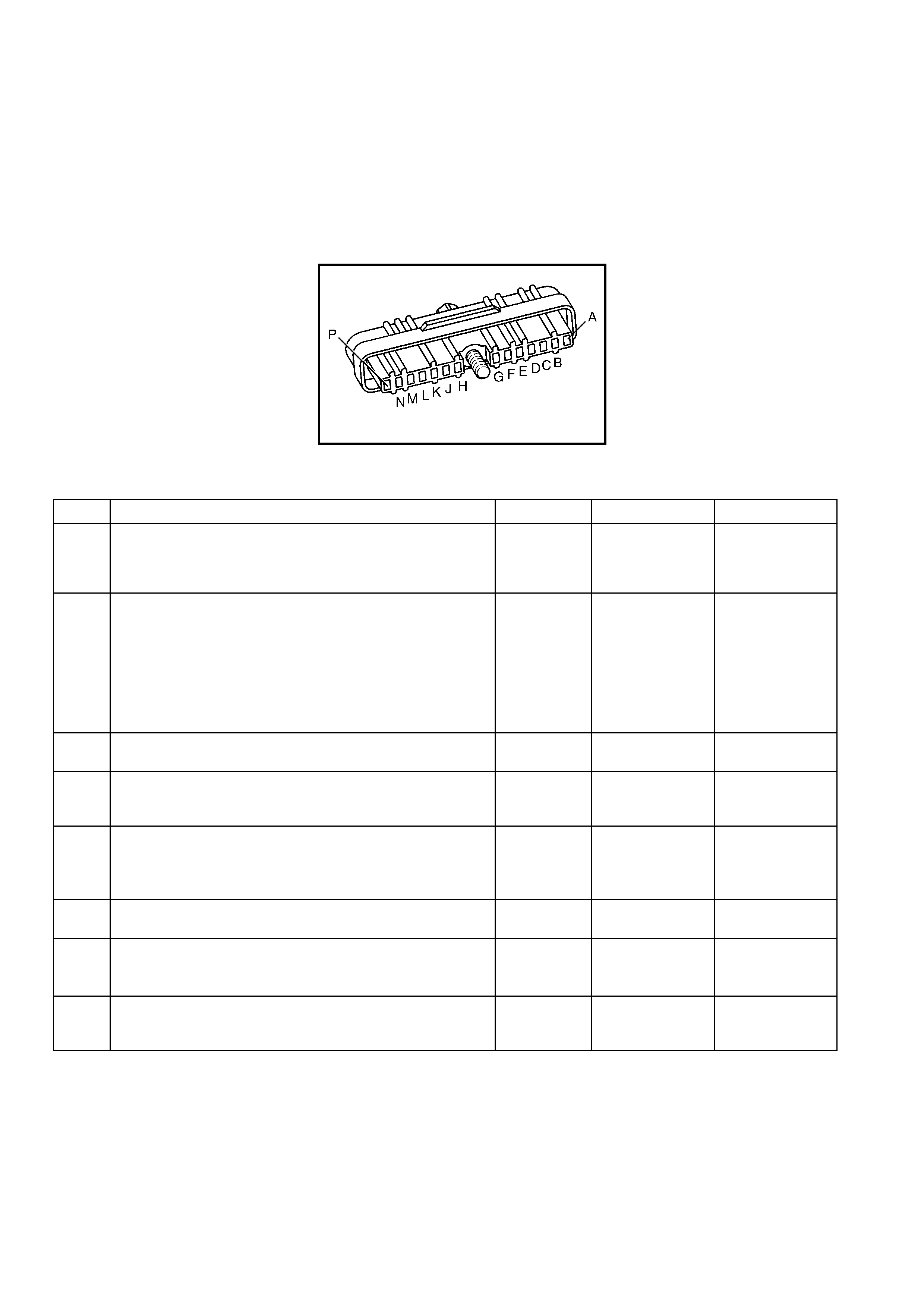
7. This procedure will check the crankshaft sensor output, through the harness to the DIS module harness
connector. DIS m odule harnes s connector ter minals "N" and "P" are jum pered together to provide power to the
Hall sensor circuits. Terminal "M" is grounded to provide a ground path for the Hall sensor circuits. As the
crank shaft balancer inter rupter rings are rotated, the tes t light should blink "ON" and "O FF" as the blades pass
the crank shaft sensor air gap. The test light should be "ON" when the blade is not in the crankshaft sensor air
gap, indicating the Hall sensor circuits are providing the ground path for the test light connected to +12 volts.
Terminal "H", the 3X signal terminals, should blink "ON" and "OFF" three times per crankshaft revolution.
NOTE: Use ST-125 spark checker or equivalent to check for adequate spark. An ST-125 requires about 25,000
volts (25 k ilovolts, or 25 k V) to "Spark ". Do not use a spar k plug in open air grounded to the engine as an indication
of sufficient "Spark". Only a few kilovolts are required to jump the gap of a spark plug outside of the engine, and that
would be an inadequate test of the ignition system.
A40 V6 S/C
Figure 6C2-2A-54
TABLE A-8.1 V6 S/C PCM – DIRECT IGNITION SYSTEM (DIS) CHECK
STEP ACTION VALUE YES NO
1. Was the "On-Board Diagnostic" (OBD) System Check
performed? Go to Step 2. Go to
OBD
System Check
in this Section.
2. 1. Remove one spark plug lead.
2. Connect ST-125 spark checker (see note of facing
page) to lead and check for spark while cranking the
engine.
3. Check 3 wires on the same side of the engine this
way. A few sparks and then nothing is considered ‘no
spark’.
Is spark present on all spark plug leads?
Go to Step 3 If spark on only
1 or 2 leads,
Go to Step 4
_____________
If no spark at all,
Go to Step 5
3. 1. No trouble found with ignition system.
Is action complete? Verify Repair –
4. 1. Refer to DIS module and coil checking procedure,
Table A-8.2 Step 5 in this Section.
Is action complete?
Verify Repair –
5. 1. Disconnect 14-pin connector from DIS module.
2. Ignition "ON", probe harness connector terminal "P"
with a test light connected to ground.
Is test light "ON"?
Go to Step 9 Go to Step 6
6. 1. Check ignition module fuse F35.
Is fuse open? Go to Step 7 Go to Step 8
7. 1. Repair short to ground in fuse circuit.
2. Replace fuse.
Is action complete?
Verify Repair –
8. 1. Check for open in power circuit to DIS ignition module
harness connector terminal "P".
Was a problem found?
Verify Repair Go To
Table A-6.5

STEP ACTION VALUE YES NO
9. 1. Ignition "OFF".
2. Get three paper clips, and re-form until straight.
3. Bend one of the straightened paper clips into a very
narrow "U", and use it to jumper DIS module harness
connector terminals "N" and "P".
4. Insert a straightened paper clip into terminal "M".
Connect a jumper lead from this paper clip to ground.
• Ensure that the Two paper clips and/or jumper
leads Do Not Touch.
5. Insert a straightened paper clip into harness connector
terminal "H", and connect a test light between this
terminal and +12 volts.
6. Ignition "ON".
7. Using a 28 mm socket and hand tools, slowly rotate
the crankshaft balancer one revolution, while
observing the test light.
The test light should go "ON" and "OFF" as the 3X
interrupter blades pass through the sensor air gap. Does
it?
Go to Table 8.2,
Step 8 in this
Section.
Go to Step 10
10. 1. Check for good continuity, and for no Shorts or Opens
on the 4 circuits between the crank sensor and DIS
module. If all are OK, replace crank sensor. Refer 3.13
DIS SERVICE OPERATIONS in 6C2-3 SERVICE
OPERATIONS, for the correct procedure, that MUST
be followed.
Is action complete?
Verify Repair –

TABLE A-8. 2 V6 S/C P CM – DIRECT IGNITION SYSTEM (DIS) CHECK
Figure 6C2-2A-55 – DIS Ignition System
CIRCUIT DESCRIPTION:
The DIS ignition s ys tem uses a was te spark m ethod of spark distribution. In this type of ignition system the ignition
module tr igger s the c or rec t ignition c oil, bas ed on signals f r om the cr ankshaf t s ens or. Eac h ignition coil provides the
high secondary voltage required to fire two spark plugs at the same time on "companion" cylinders, i.e. cylinders
with pistons at the top of the their stroke (TDC) at the same time. One of these pistons would be at the top of its
compression stroke, the other piston would be at the top of its exhaust stroke.
For additional information about the DIS system, Refer to 6C2-1 GENERAL DESCRIPTION in this Section.
TEST DESCRIPTION:
NOTE: Number(s) below refer to step number(s) on the diagnostic table.
3. Terminal "G", the 18x signal terminal, should blink "ON" and "OFF" eighteen times per crankshaft
revolution.
5. This procedure will check the modules ability to control the ignition coil primary system.
7. T hese checks are for the prim ary and secondary windings of each of the three ignition coils. The resistance of
each of the six checks (3 primary and 3 secondary windings) must be within the specified ranges.

A40 V6 S/C
Figure 6C2-2A-56
TABLE A-8.2 V6 S/C PCM DIRECT IGNITION SYSTEM (DIS) CHECK
STEP ACTION VALUE YES NO
1. Was the "On-Board Diagnostic" (OBD) System Check
performed? Go to Step 2. Go to
OBD
System Check
in this Section.
2. 1. Ignition "OFF".
2. Remove the paper clip from terminal "H" and insert it
into terminal "G".
3. Ignition "ON".
4. Slowly rotate the crankshaft balancer one revolution
and note test light.
The test light should go "ON" and "OFF" as the 18X
interrupter blades pass through the sensor air gap. Does
it?
Go to Step 4 Go to Step 3
3. 1. Check for good continuity, and for no Shorts or Opens
on the 4 circuits between the crank sensor and DIS
module. If all are OK, replace crank sensor. Refer 3.13
DIS SERVICE OPERATIONS in Section 6C2-3
SERVICE OPERATIONS, for the correct procedure,
that MUST be followed.
Is action complete ?
Verify Repair –
4. 1. Remove test light and all leads from harness
connector terminals. Reconnect 14-pin connector to
DIS module. Tighten the retaining bolt to the correct
torque specification.
2. Disconnect all spark plug leads from the DIS coils.
3. Remove 6 screws that retain the coils to the module.
4. Remove all three coils.
5. Connect the test light clip lead to one of the two coil
terminals on the module.
6. Connect the test light probe to the other coil terminal
on the module.
7. While the engine is cranking, observe test light. The
test light should blink.
8. This test should be performed for each pair of module
terminals that connect to the three (3) ignition coils.
Is the test light blinking for all three coil pairs?
0.6 – 1.2
Nm Go to Step 6 Go to Step 5
5. 1. If no blink, or blinks on less than all 3 pairs, replace
DIS module.
Is action complete?
Verify Repair –
6. 1. Ignition "OFF".
2. Using a digital ohmmeter, check resistance across the
ignition coil primary winding (underside) terminals.
3. Correct resistance of the ignition coils primary winding
must be within the specified value.
Are all three coils (6-3, 2-5, 4-1) within this range?
0.3 – 1.5
ohms Go to Step 8 Go to Step 7
7. 1. Replace coil(s) that had the incorrect ohms reading.
Is action complete? Verify Repair –
8. 1. Check resistance across the ignition coil secondary
tower terminals. Each tower is marked.
2. Correct resistance of the ignition coil secondary
windings must be within the specified value.
Are all three coils (6-3, 2-5, 4-1) within this range?
5,000
(5K ohms)
to
7,000
(7K ohms)
Go to Step 10 Go to Step 9

STEP ACTION VALUE YES NO
9. 1. Replace coil(s) that had the incorrect ohms reading.
Is action complete? Verify Repair –
10. At this point, all DIS component tests indicate the DIS
system should produce spark. If a ‘no spark’ condition still
exists, check the metal terminals in the plastic connectors
at the DIS module and crank sensor very closely.
Also check the resistance of the spark plug leads, ensuring
that none are "Open".
Is action complete?
Verify Repair –
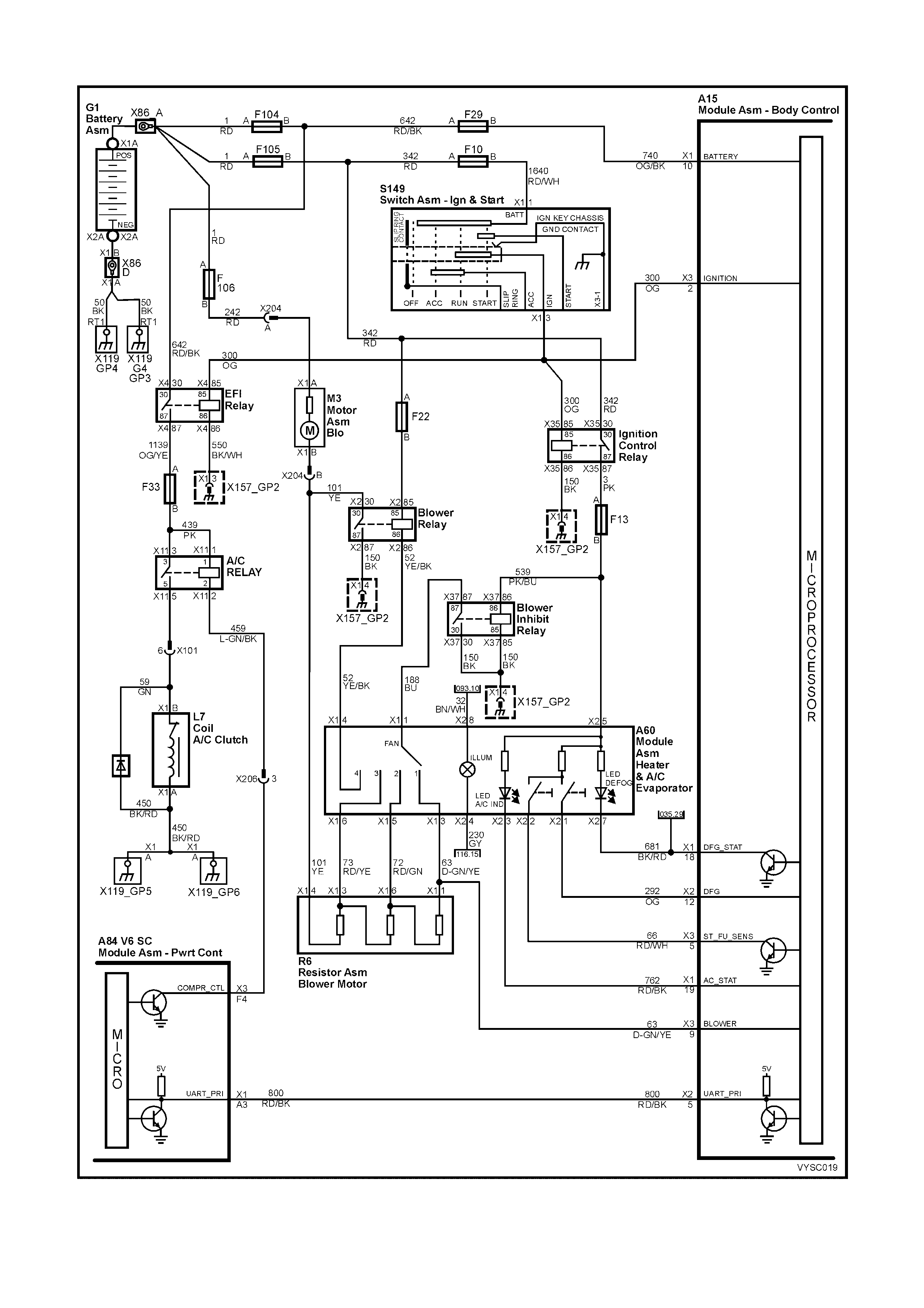
TABLE A-11.1 V6 S/C PCM – A/C CLUTCH CONTROL (HVAC CLIMATE CONTROL)
Figure 6C2-2A-57 – A/C Request – HVAC Climate Control
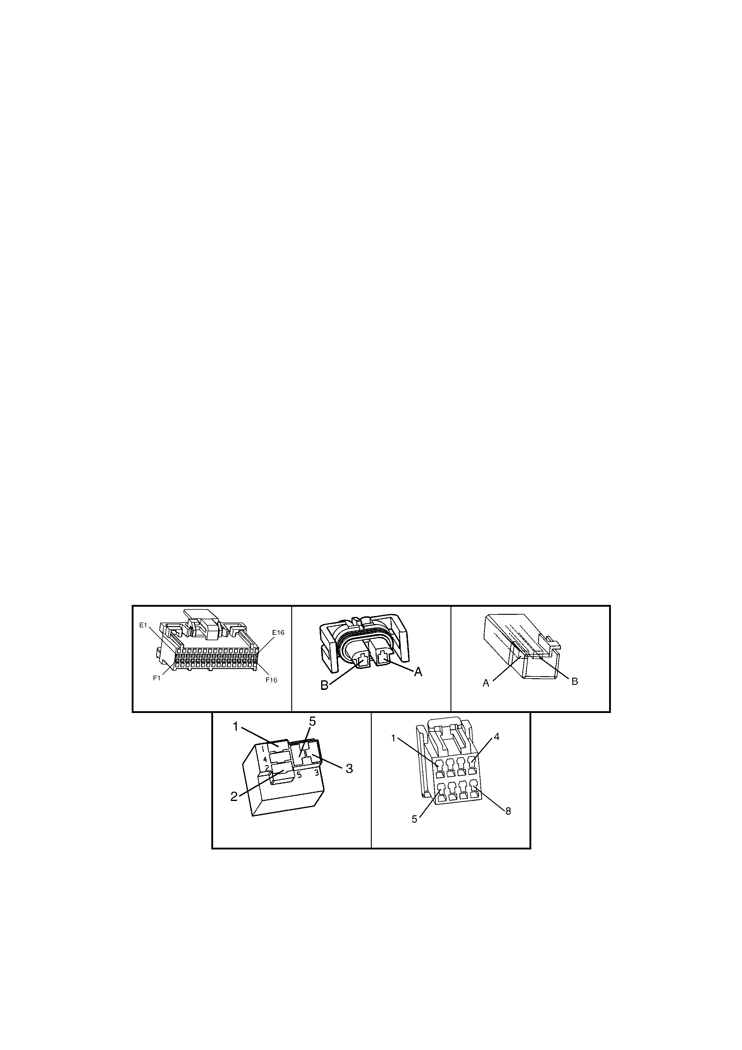
CIRCUIT DESCRIPTION:
With the blower fan switched "ON", and the air conditioning switched "ON," switched ignition voltage is supplied
from f us e F13 thr ough the A/C mast er s witch, and then to the BCM. T he BCM will then supply a serial data signal to
the PCM requesting A/C. If the BCM does not receive a ground signal from the blower switch, the BCM will not
supply the serial data request for A/C to the PCM. Once the PCM receives this serial data signal, the PCM will
energise the A/C compressor relay by supplying a ground signal (A/C Relay Control). The BCM also supplies a
ground signal from BCM terminal A15 X1-15 to the low speed cooling fan relay.
This serial data signal to the PCM is also used to adjust the idle speed before turning "ON" the A/C compressor
relay. If this signal is not available to the PCM, the A/C compressor will be inoperative.
This system also incorporates an A/C Refrigerant Pressure Sensor. The A/C Refrigerant Pressure Sensor signal
indicates Low / High pressure on the A/C high side refrigerant pressure line to the PCM. The PCM uses this
information to adjust the idle air control valve to compensate for the higher engine loads present with high A/C
refrigerant pressures. A fault in the A/C Refrigerant Pressure Sensor signal will cause DTC 96 to set.
The purpose of this A/C Refrigerant Pressure Sensor is to protect the system from danger because of either
refr igerant pressur e too low (which could damage the c ompr essor due to insuf ficient lubrication), or too high (whic h
could result in a leak in the sealed refrigerant R134a system).
The PCM will NOT energise the A/C control relay if any of the following conditions are present:
• DTC 96 is set.
• Engine speed is more than 4,800 rpm. If de-energised because of excessive engine speed, it can be re-
energised when the speed falls below 4,000 rpm for at least 10 seconds.
• Throttle is more than 90% open.
• A/C Refrigerant Pressure Sensor voltage is too Low or too High.
TEST DESCRIPTION:
NOTE: Number(s) below refer to step number(s) on the diagnostic table.
1. The PCM's diagnostic circuits must be proven before any further testing is performed.
2. The PCM does not normally energise the A/C control relay unless the engine is running.
4. This checks for operation of the condenser fan.
20, 21, 22, 23, 24, 26, 28. No terminals are identified on the relay connector (although the relay itself has terminal
numbers). Ensure that the correct relay connector terminal (not the relay) is being probed.
39. T he m ost lik ely cause of an autom otive air c onditioner not work ing is that the r efriger ant (R134a) is disc harged,
because of a leak.
CHECK:
If fuse F13 is blown, check for short to ground on all circuits associated with this fuse.
A84 V6 S/C - X3 L7 V6
X11 (Part of X100) A60
Figure 6C2-2A-58

TABLE A-11.1 V6 S/C PCM – A/C CLUTCH CONTROL (NON-OCC SYSTEM)
STEP ACTION VALUE YES NO
1. Was the "On-Board Diagnostic" (OBD) System Check
performed? Go to Step 2 Go to
OBD
System Check
in this Section
2. 1. Ignition "ON", engine stopped.
2. Disconnect the A/C compressor clutch electrical
connector and reconnect, and note compressor clutch.
Did compressor clutch cycle "OFF" then "ON" with
electrical connector disconnected and reconnected?
If A/C clutch
cycled "OFF"
then "ON" or will
not disengage,
Go to Step 6
Go to Step 3
3. 1. Ignition "ON", engine idling.
2. Blower Switch turned "ON".
3. Cycle the A/C switch "ON" and "OFF", waiting a few
seconds between positions.
4. Listen for A/C compressor clutch.
Does the A/C compressor clutch cycle "ON" and "OFF?
Go to Step 4 Go to Step 14
4. 1. Ignition "ON", engine idling
2. A/C switch in the "ON" position.
Does the A/C condenser fan operate when the A/C Switch
is turned "ON"?
Go to Step 5 Go to
Table A-12 in
this Section.
5. 1. A/C clutch control circuits are OK.
2. If complaint is insufficient cooling, review symptoms
Is action complete ?
Verify Repair –
6. 1. Ignition "OFF".
2. Disconnect A/C compressor electrical connector.
3. Observe A/C clutch.
Is A/C clutch staying engaged to compressor?
Go to Step 7 Go to Step 8
7. 1. Replace A/C compressor clutch. Refer to Section 2B
in the MY 2003 VY and V2 Series Service Information.
Is action complete?
Verify Repair –
8. 1. Ignition "ON", engine "OFF".
2. Using test light connected to B+, backprobe PCM
terminal for A/C relay control.
Does test light illuminate?
Go to Step 9 Go to Step 11
9. 1. Check for a short to ground in circuit for A/C relay
control from the PCM to A/C compressor relay.
Was a problem found?
Verify Repair Go to Step 10
10. 1. Replace PCM. Refer to 6C2-3 SERVICE
OPERATIONS, for PCM Security Link procedure.
Is action complete?
Verify Repair –
11. 1. Ignition "ON".
2. Disconnect A/C compressor electrical connector.
3. Using test light connected to ground, probe A/C
compressor electrical connector power circuit.
4. With test light "ON", remove A/C compressor relay
and note test light.
Did test light turn "OFF"?
Go to Step 12 Go to Step 13
12. 1. Replace A/C compressor relay.
Is action complete? Verify Repair –
13. 1. Repair short to voltage on A/C compressor power feed
circuit from A/C compressor relay to A/C compressor.
Is action complete?
Verify Repair –
14. 1. Ignition "ON", engine idling.
2. Install Tech 2.
3. Observe A/C refrigerant pressure sensor voltage
displayed on Tech 2.
Is indicated A/C refrigerant pressure sensor voltage at or
between the specified value?
0.35 – 4.2
volts Go to Step 15 Go to Step 39
15. 1. Check power supply fuse to A/C master switch.
Is fuse open? Go to Step 16 Go to Step 17

STEP ACTION VALUE YES NO
16. 1. Repair short to ground in fuse circuit, and replace
fuse.
Is action complete?
Verify Repair –
17. 1. Ignition "ON", engine "OFF".
2. Turn A/C master switch to "ON" position.
3. Using test light connected to ground, backprobe BCM
terminal for A/C select input circuit.
Does test light illuminate?
Go to Step 20 Go to Step 18
18. 1. Check for open or poor connection in circuit from A/C
master switch to BCM A/C select input, or open in
power feed circuit to A/C master switch.
Was a problem found?
Verify Repair Go to Step 19
19. 1. Replace A/C master switch.
Is action complete? Verify Repair –
20. 1. Ignition "ON", engine idling.
2. Remove blower inhibit relay (X37) from interior relay
centre (X129); leave harness connector connected to
relay.
3. Using test light connected to B+, backprobe relay
harness connector terminal X37-30.
4. Turn A/C master switch to "ON" position.
Does test light illuminate?
Go to Step 21 Go to Step 26
21. 1. Ignition "ON", engine idling.
2. Using test light connected to B+, backprobe BCM
terminal for blower switch Input Signal.
3. Turn A/C master switch to "ON" position.
4. Turn blower switch to "ON" position.
Does test light illuminate?
Go to Step 22 Go to Step 33
22. 1. Ignition "OFF".
2. Remove A/C compressor relay (X11) from underhood
relay centre (X100).
3. Ignition "ON", engine idling.
4. Turn A/C master switch to "ON" position.
5. Turn blower switch to "ON" position.
6. Using test light connected to B+, probe terminal X11-2
of A/C compressor relay harness connector.
Does test light illuminate?
Go to Step 23 Go to Step 35
23. 1. Ignition "ON", engine "OFF".
2. Using test light connected to ground, probe A/C
compressor relay harness terminals X11-1 and X11-3?
Does test light illuminate on both circuits?
Go to Step 24 Go to Step 36
24. 1. Ignition "OFF".
2. Reinstall blower inhibit relay (X37) and A/C
compressor relay (X11).
3. Disconnect electrical connector at A/C compressor.
4. Ignition "ON", engine idling.
5. Turn A/C master switch to the "ON" position.
6. Turn blower switch to the "ON" position.
7. Using test light connected to ground, probe A/C
compressor harness power feed circuit from A/C
compressor relay to compressor.
Does test light illuminate?
Go to Step 25 Go to Step 37
25. 1. Check A/C compressor ground circuit for an open
circuit. Repair as required.
2. If ground circuit is OK, replace A/C compressor. Refer
to Section 2C in the MY 2003 VY and V2 Series
Service Information.
Is action complete?
Verify Repair –

STEP ACTION VALUE YES NO
26. 1. Ignition "ON", engine idling.
2. Using test light connected to B+, backprobe blower
inhibit relay (X37) terminal X37-85 for blower relay
ground circuit.
3. Turn A/C master switch "ON".
Does test light illuminate?
Go to Step 28 Go to Step 27
27. 1. Check for open in circuit from the blower inhibit relay
(X37), terminal X37-85 to ground.
Is action complete?
Verify Repair –
28. 1. Ignition "ON", engine "OFF".
2. Disconnect blower inhibit relay (X37) from interior
relay centre (X129).
3. Using test light connected to ground, probe relay
harness terminal X37-86.
Does test light illuminate?
Go to Step 30 Go to Step 29
29. 1. Repair open in circuit from blower inhibit relay (X37)
terminal X37-86 to ignition control relay (X35).
Is action complete?
Verify Repair –
30. 1. Ignition "ON", engine "OFF".
2. With blower inhibit relay (X37) still disconnected,
probe relay harness terminal X37-30 with a test light
connected to B+.
Does test light illuminate?
Go to Step 31 Go to Step 32
31. 1. Replace blower inhibit relay (X37).
Is action complete? Verify Repair –
32. 1. Repair open in ground circuit to blower inhibit relay
(X37).
Is action complete?
Verify Repair –
33. 1. Check for open circuit from blower switch to BCM
blower switch input terminal.
Was a problem found?
Verify Repair Go to Step 34
34. 1. Check for open in circuit from blower inhibit relay
(X37) terminal X37-87 to the blower switch.
Was a problem found?
Verify Repair Go to Step 38
35. 1. Check for open in circuit from A/C compressor relay to
PCM terminal for A/C relay control.
Was a problem found?
Verify Repair Go to Step 10
36. 1. Repair open in circuit that did not illuminate the test
light.
Is action complete?
Verify Repair –
37. 1. Check for open in circuit from A/C compressor to A/C
compressor relay.
Was a problem found?
Verify Repair Go to Step 12
38. 1. Replace blower switch.
Is action complete? Verify Repair –
39. 1. Check A/C pressure sensor signal circuit for short to
ground (Check for DTC 96).
Was a problem found?
Verify Repair Go to Step 40
40. 1. Check A/C refrigerant (R-134a) system for being
under or over-charged.
Is action complete.
Verify Repair –
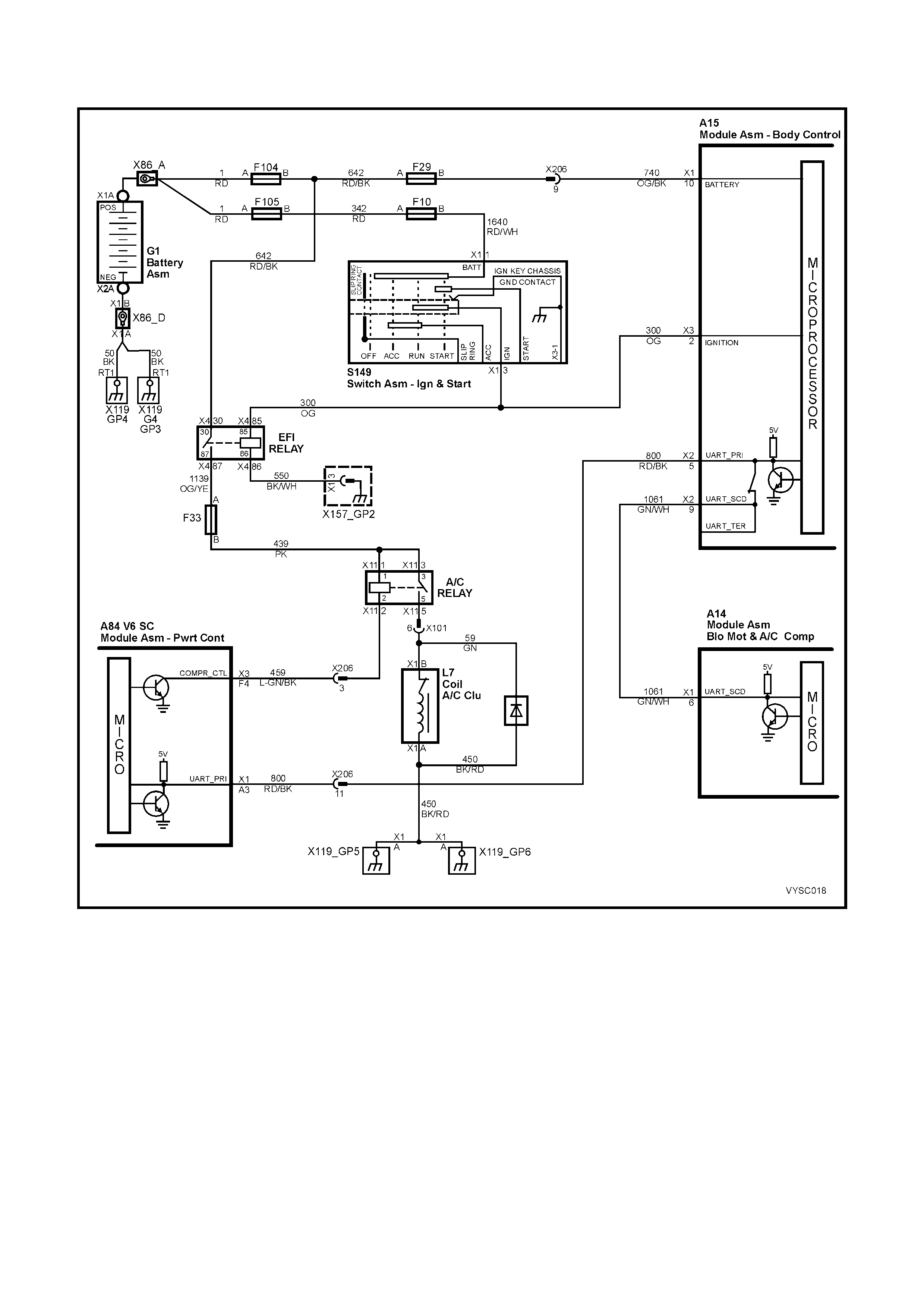
TABLE A-11.3 V6 S/C PCM
A/C CLUTCH CONTROL WI TH OCCUPANT CLIMATE CONTROL (OCC)
Figure 6C2-2A-59 – A/C Request Occupant Climate Control
CIRCUIT DESCRIPTION:
When the A/C is requested, the Occupant Climate Control Module will supply a signal to the PCM, via the serial
data reques t. W hen the PCM receives the serial data reques t, it indicates that air conditioning has been r equested
and approxim ately 0.5 seconds after the PCM receives this signal, it will energise the A/C control relay. T his serial
data signal to the PCM is also used to adjust the idle speed before turning "ON" the A/C com pressor relay. If this
signal is not available to the PCM, the A/C compressor will not operate.
The BCM also supplies the ground signal to the low speed cooling fan relay.
This A/C system also incorporates an A/C refrigerant pressure sensor. The A/C refrigerant pressure sensor signal
indicates high side refrigerant pressures to the PCM. The PCM uses this information to adjust the idle air control
valve to compensate for the higher engine loads present with high A/C refrigerant pressures and not allow A/C
operation if pressure is too low. A fault in the A/C refrigerant pressure sensor signal will cause DTC 96 to set.

The PCM will NOT energise the A/C control relay if any of the following conditions are present:
• DTC 96 is set.
• Engine speed is more than 4,800 rpm. If de-energised because of engine over-speeding, it can be re-
energised when the engine speed falls below 4,000 rpm for at least 10 seconds.
• Throttle is more than 90% open.
• A/C refrigerant pressure sensor voltage is too low or too high.
TEST DESCRIPTION:
NOTE: Number(s) below refer to step number(s) on the diagnostic table.
1. The PCM's diagnostic circuits must be proven before any further testing is performed.
3. The PCM does not normally energise the A/C control relay unless the engine is running.
4. W hen the Tech 2 scan tool is installed, and the A/C switch is turned "ON", the scan tool should display "A/C
Requested".
6. This checks for operation of the low speed cooling fan.
7. The most likely cause of an automotive air conditioner not cooling properly is a discharged or overcharged
refrigerant R134a system.
14, 15, 16. No terminals are identified on the relay connector (although the relay itself has terminal numbers).
Ensure that the correct relay connector terminal (not the relay) is being probed.
CHECK:
If fuse F13 is blown, check for short to ground on all circuits associated with this fuse.
A15-X1 A15-X2 A15-X3
A60-X1 A60-X2 A84 V6 S/C – X1
A84 V6 S/C – X2 L7 V6
X11 (Part of X100) S125
Figure 6C2-2A-60

TABLE A-11.3 V6 S/C PCM – A/C CLUTCH CONTROL WITH OCCUPANT CLIMATE CONTROL (OCC)
STEP ACTION VALUE YES NO
1. Was the "On-Board Diagnostic" (OBD) System Check
performed? Go to Step 2 Go to
OBD
System Check
in this Section
2. 1. Turn on the Occupant Climate Control.
Does Occupant Climate Control power up? Go to Step 3 Go to OCC
Diagnostics
Refer Section 2F
3. 1. Ignition "ON", engine stopped.
2. Cycle A/C master switch "ON" and "OFF", waiting a
few seconds between positions.
3. Observe the A/C compressor clutch.
4. It should not cycle "ON" and "OFF".
Did the compressor clutch not cycle "ON" and "OFF"?
Go to Step 4 If either engages
or will not
disengage.
Go to Step 10
4. 1. Install Tech 2.
2. Ignition "ON".
3. Turn A/C switch "ON".
Does Tech 2 display "A/C Requested - ON"?
Go to Step 5 Go to Step 8
5. 1. Ignition "ON", engine idling.
2. Cycle the A/C switch "ON" and "OFF", waiting a few
seconds between positions.
3. Listen for A/C compressor clutch.
Does A/C compressor clutch cycle "ON" and "OFF"?
Go to Step 6 Go to Step 13
6. 1. Ignition "ON", engine idling.
Does the low speed cooling fan operate when the A/C is
turned "ON"?
Go to Step 7 Go to
Table A-12 in
this Section.
7. A/C clutch control circuits are OK. If complaint is
insufficient A/C cooling, refer 2C in the MY 2003 VY and
V2 Series Service Information.
Is action complete?
Verify Repair
8. 1. Install Tech 2.
2. Ignition "ON".
3. Select Electronic Climate Control (ECC).
Does Tech 2 display ECC identification data?
Go to Step 9 Go to OCC
Diagnostics
Refer Section 2F
9. 1. With Tech 2 still connected.
2. Select ECC Normal Mode.
3. Turn A/C switch "ON".
Does Tech 2 display "A/C Requested – ON”?
Go to Step 22 Go to OCC
Diagnostics
Refer Section 2F
10. 1. Check for short to ground from PCM circuit A/C Relay
Control to A/C Co mpress or Relay.
Was a problem found?
Verify Repair Go to Step 11
11. 1. Check for short to voltage on power feed circuit to A/C
compressor.
Was a problem found?
Verify Repair Go to Step 12
12. 1. Replace defective A/C compressor relay.
NOTE: If compressor clutch still will not disengage, replace
A/C compressor clutch. Refer to 2B in the MY 2003 VY and
V2 Series Service Information.
Is action complete?
Verify Repair –
13. 1. Ignition "ON", engine idling.
2. Install Tech 2.
3. Observe A/C refrigerant pressure sensor voltage
display on Tech 2.
Is the indicated A/C refrigerant pressure sensor voltage at
or between the specified value?
0.35 – 4.2
volts Go to Step 14 Go to Step 25
14. 1. Ignition "ON", engine idling.
2. Disconnect A/C compressor relay (X11).
3. Probe both relay terminals X11-3 and X11-1 of
harness connector, with a test light connected to
ground.
Is test light "ON" at both terminals?
Go to Step 15 Go to Step 21

STEP ACTION VALUE YES NO
15. 1. Ignition "ON", engine idling.
2. Probe A/C compressor relay connector X11-2 circuit
459 with a test light connected to B+.
3. Turn A/C switch "ON".
Is test light "ON" when the A/C switch is "ON"?
Go to Step 16 Go to Step 19
16. 1. Ignition "ON", engine idling.
2. Reconnect A/C compressor relay.
3. Backprobe relay harness terminal X11-5 with a test
light connected to ground.
4. Turn A/C switch "ON".
Is test light "ON" when A/C switch is turned "ON"?
Go to Step 17 Go to Step 12
17. 1. Ignition "OFF".
2. Disconnect A/C compressor electrical connector.
3. Ignition "ON", engine idling.
4. Probe compressor harness connector terminal power
feed circuit with a test light connected to ground.
5. Turn A/C switch "ON".
Is test light "ON" when the A/C switch is turned "ON"?
Go to Step 18 Go to Step 24
18. 1. Check for an open in the A/C compressor ground
circuit 450.
Was a problem found?
Verify Repair Go to Step 23
19. 1. Check for a faulty connection for A/C compressor
relay (X11).
Was a problem found?
Verify Repair Go to Step 20
20. 1. Check for an open in the PCM A/C Relay Control
circuit, from the PCM to the A/C compressor relay.
Was a problem found?
Verify Repair Go to Step 22
21. 1. Repair open in circuit that did not light test light.
Is action complete? Verify Repair –
22. 1. Replace PCM. Refer to 6C2-3 SERVICE
OPERATIONS, for PCM Security Link procedure.
Is action complete?
Verify Repair –
23. 1. Replace A/C compressor.
Is repair complete? Verify Repair –
24. 1. Repair open in circuit 59 to A/C compressor clutch.
Is repair complete? Verify Repair –
25. 1. Check A/C pressure sensor signal circuit for short to
ground, short to voltage or open ground circuit.
Was a problem found?
Verify Repair Go to Step 26
26. 1. Check A/C refrigerant (R-134a) system for being
undercharged, or overcharged.
Is action complete.
Verify Repair –

TABLE A-12.1 V6 S/C PCM – ELECTRIC FAN CONTROL
Figure 6C2-2A-61 – Electric Cooling Fan Control
CIRCUIT DESCRIPTION:
The V6 Supercharged engine has two single speed electric engine cooling fan assemblies. One fan motor provides
high speed cooling operation and the other fan motor provides low speed cooling operation. Both of these fan
motors provide the primary means of moving air through the engine radiator. These electric cooling fan motors are
used to cool engine coolant flowing through the radiator and also to cool the refrigerant flowing through the A/C
condenser (if fitted).
The engine cooling fan high speed relay is controlled by the PCM. The PCM controls the ground path for the engine
cooling fan high speed relay.
The engine cooling fan, low speed relay is controlled by the PCM through Serial Data Communication to the BCM.
The BCM controls the ground path for the engine cooling fan low speed relay.
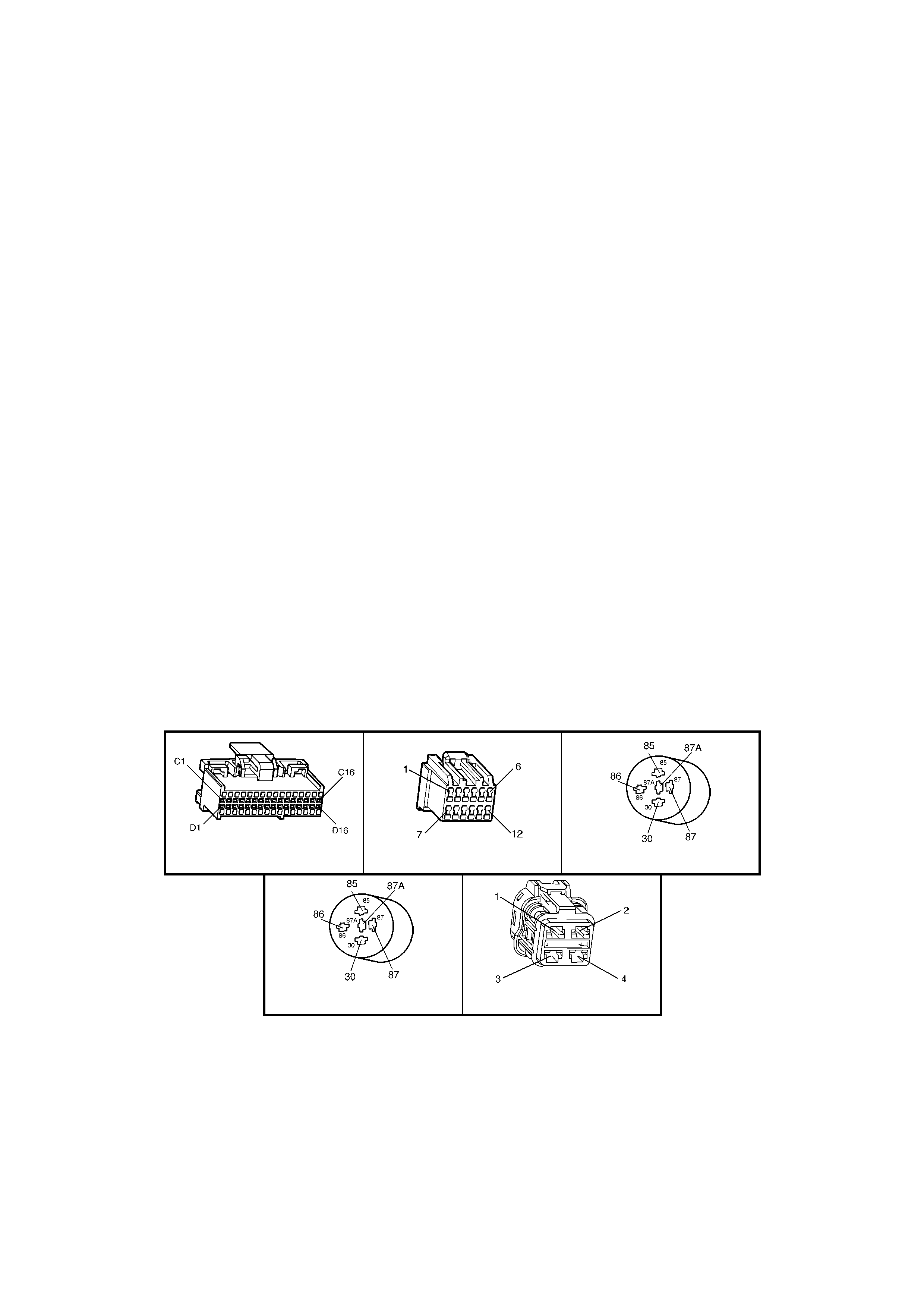
ENGINE COOLING FAN LOW SPEED:
The engine c ooling fan low speed relay is ener gised by the BCM. T he PCM determines when to enable the engine
cooling fan low speed bas ed on inputs from the A/C request s ignal, vehicle speed and engine coolant tem perature.
The engine cooling low speed fan will be turned "ON" when:
• A/C request indicated (YES),
• Vehicle speed is less than 54 km/h,
OR
• Coolant temperature is greater than 104 ° C and will remain on until coolant temperature falls below 99° C,
OR
• A/C refrigerant pressure is >1,500 kPa,
OR
• A DTC is set.
ENGINE COOLING FAN HIGH SPEED:
The engine c ooling f an high speed is c ontrolled by the PCM based on inputs from the Engine Coolant T em per ature
(ECT) sensor and the A/C Refrigerant Pressure sensor. The PCM will only turn "ON" the engine cooling fan high
speed if the engine cooling low speed fan has been "ON" for 2 seconds and the following conditions are satisfied:
• There is a BCM message response fault which will cause a DTC 92 to be logged.
• An engine coolant temperature sensor failure is detected, such as DTC 14,15,16, 17 or 91.
• Coolant temperature greater than 107° C.
• If the fan low speed was "OFF" when the criteria was met to turn the fan high speed "ON", the fan high speed
will come "ON", 5 seconds after the fan low speed is turned "ON".
• The engine c ooling fan high speed relay can also be enabled by the A/C Refrigerant Press ure sensor. The A/C
Refriger ant Pressure s ensor will provide a signal to the PCM when A/C pressure bec omes too high (appr oximately
1,770 kPa).
TEST DESCRIPTION:
NOTE: Number(s) below refer to step number(s) on the diagnostic table.
2. This entire diagnostic procedure must begin with a "cold" engine – at am bient air temper ature. If the coolant is
hot when diagnosis is perf orm ed, unneces sary replacem ent of good par ts will result. Fan s hould not be running
if engine coolant temperature is less than 99° C and air conditioning is not "ON".
7. Using Tech 2 will allow operation of the engine cooling fan High Speed Relay. If the fan operates with Tech 2,
the High Speed Cooling Fan is operating properly.
A84 V6 S/C–X2 A15–X2 X5 (Part of X100)
X7 (Part of X100) M7
Figure 6C2-2A-62

TABLE A-12.1 V6 S/C PCM – ELECTRIC FAN CONTROL
STEP ACTION VALUE YES NO
1. Was the "On-Board Diagnostic" (OBD) System Check
performed? Go to Step 2. Go to
OBD
System Check
in this Section.
2. 1. Ignition "ON", engine stopped.
2. Engine coolant temperature below 99° C.
Is the High Speed Cooling Fan running?
Go to Step 3 Go to Step 6
3. 1. Ignition "ON", engine stopped.
2. Remove the Radiator Fan High Speed Relay.
Does the High Speed Cooling Fan stop running?
Go to Step 4 Go to Step 9
4. 1. Ignition "OFF”.
2. Disconnect the PCM connectors.
3. Using the test light connected to B+, probe PCM
harness connector X3 terminal F6.
Does the test lamp illuminate?
Go to Step 5 Go to Step 10
5. 1. Check for short to ground in High Speed Cooling Fan
relay control circuit.
Was a problem found?
Verify Repair
6. 1. Ignition “ON”, engine stopped.
2. Engine coolant temperature below 99° C.
Is Low Speed Cooling Fan running?
Go to
Table A-12.2 in
this Section.
Go to Step 7.
7. 1. Ignition “ON”, engine stopped.
2. Using the Tech 2, select High Fan Relay Control.
3. Turn High Fan “ON” using Tech 2.
Does the High Speed Cooling Fan operate?
Go to Step 8.
Go to Step 12.
8. The High Speed Cooling Fan is OK.
1. Verify Low Speed Fan operation. Refer to Table
A-12.2.
Is action complete?
System OK –
9. 1. Repair short to ground in High Speed Cooling Fan
ground circuit between fan motor and High Speed
Relay.
Is action complete?
Verify Repair –
10. 1. Ignition “OFF”.
2. Reconnect the PCM connectors.
3. Ignition “ON”.
4. Using a test light connected to B+, probe High Speed
Cooling Fan Relay control circuit at the relay harness
connector.
Does the test light illuminate?
Go to Step 11 Go to Step 16
11. 1. Replace PCM. Refer to 6C2-3 SERVICE
OPERATIONS, in this Section for PCM Programming
and Security Linking procedure.
Is action complete?
Go to Step 12. Go to Step 9
12. 1. Check for open or short to ground in power supply
fuse and circuit to High Speed Cooling Fan Relay.
Replace fuse if open.
Was a problem found?
Verify Repair Go to Step 13
13. 1. Ignition “ON”, engine stopped.
2. Remove High Speed Cooling Fan Relay (X5).
3. Using test light connected to B+, probe relay harness
connector, terminal X5-86.
4. Using Tech 2, command the High Speed Cooling Fan
“ON” and “OFF”.
Does the test light turn “ON and “OFF” with the Tech 2
scan tool commands?
Go to Step 14 Go to Step 5
14. 1. Ignition “OFF”.
2. Disconnect the High Speed Cooling Fan motor
electrical connector (M7).
3. Using test light connected to ground, probe the power
feed circuit to fan motor (X1-3).
Does the test light illuminate?
Go to Step 17 Go to Step 15

STEP ACTION VALUE YES NO
15. 1. Repair open or short to ground in power feed circuit to
High Speed Cooling Fan motor. Replace fusible link
F101 if open.
Is action complete?
Verify Repair –
16. 1. Replace High Speed Cooling Fan relay.
Is action complete? Verify Repair Go to Step 21
17. 1. Ignition “ON”, engine stopped.
2. Remove High Speed Cooling Fan Relay (X5).
3. Using fused jumper lead connected to ground, probe
High Speed Cooling fan relay connector (in X100),
terminal X5-87.
Does High Speed Cooling Fan motor operate?
Go to Step 18 Go to Step 20
18. 1. Using test light connected to B+, probe High Speed
Cooling Fan relay harness connector (in X100),
terminal X5-87.
Does the test light illuminate?
Go to Step 16 Go to Step 19
19. 1. Repair open in ground circuit to High Speed Cooling
Fan relay, terminal X5-30.
Is action complete?
Verify Repair –
20. 1. Check for open in ground circuit to High Speed
Cooling Fan relay, to High Speed Cooling Fan motor.
Was a problem found?
Verify Repair Go to Step 22
21. 1. Check for poor connection to PCM.
Was a problem found? Verify Repair Go to Step 11
22. Replace High Speed Cooling Fan motor.
Is action complete? Verify Repair –
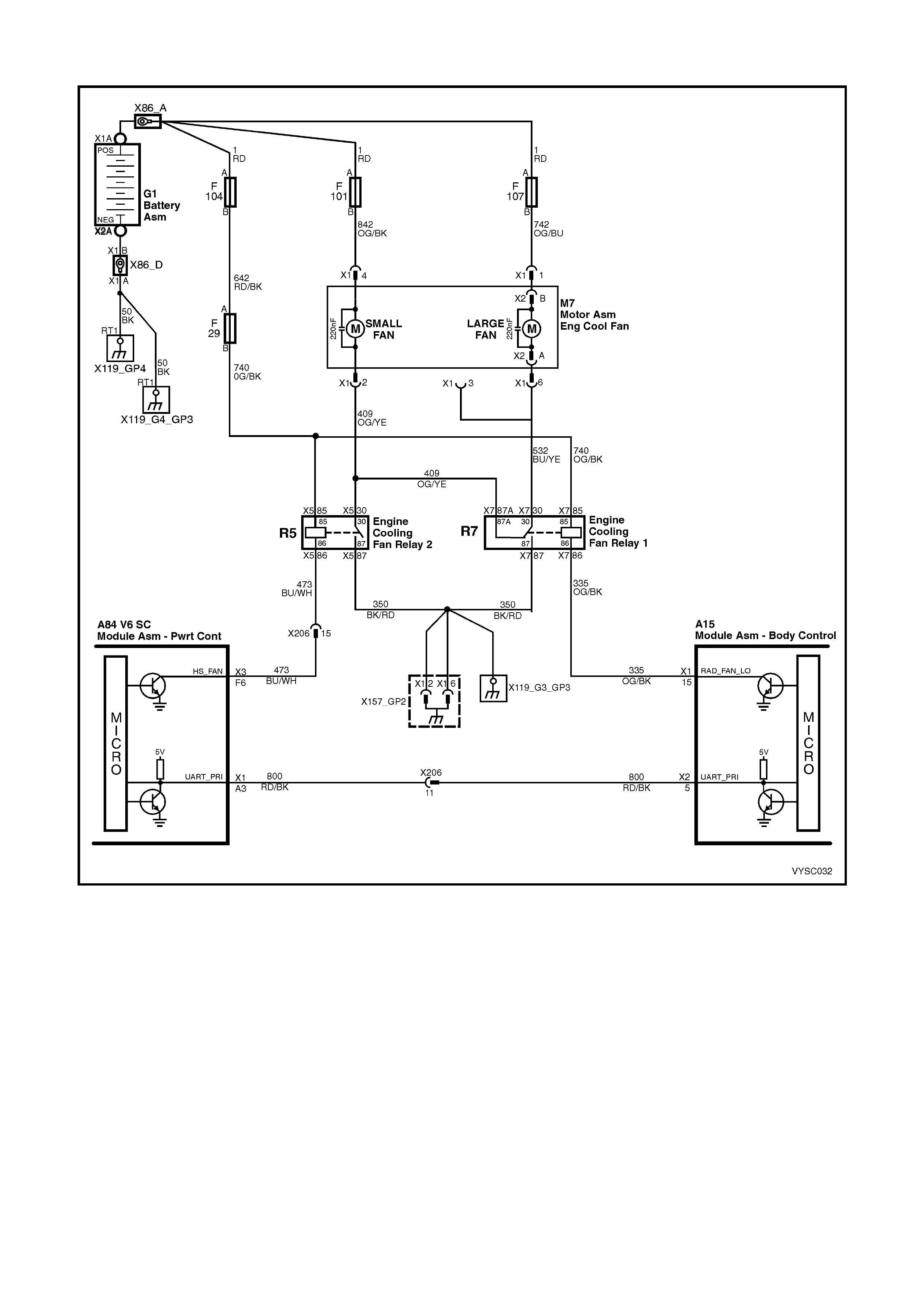
TABLE A-12.2 V6 S/C PCM – ELECTRIC FAN CONTROL
Figure 6C2-2A-63 – Electric Cooling Fan Control
CIRCUIT DESCRIPTION:
The V6 Supercharged engine has two single speed electric engine cooling fan assemblies. One fan motor provides
high speed cooling operation and the other fan motor provides low speed cooling operation. Both of these fan
motors provide the primary means of moving air through the engine radiator. These electric cooling fan motors are
used to cool engine coolant flowing through the radiator and also to cool the refrigerant flowing through the A/C
condenser (if fitted).
The engine cooling fan high speed relay is controlled by the PCM. The PCM controls the ground path for the engine
cooling fan high speed relay.
The engine cooling fan, low speed relay is controlled by the PCM through Serial Data Communication to the BCM.
The BCM controls the ground path for the engine cooling fan low speed relay.

ENGINE COOLING FAN LOW SPEED:
The engine c ooling fan low speed relay is ener gised by the BCM. T he PCM determines when to enable the engine
cooling fan low speed bas ed on inputs from the A/C request s ignal, vehicle speed and engine coolant tem perature.
The engine cooling low speed fan will be turned "ON" when:
• A/C request indicated (YES),
• Vehicle speed is less than 54 km/h,
OR
• Coolant temperature is greater than 104 °C and will remain on until coolant temperature falls below 99 °C,
OR
• A/C refrigerant pressure is >1,500 kPa,
OR
• A DTC is set.
ENGINE COOLING FAN HIGH SPEED:
The engine c ooling f an high speed is c ontrolled by the PCM based on inputs from the Engine Coolant T em per ature
(ECT) sensor and the A/C Refrigerant Pressure Sensor. The PCM will only turn "ON" the engine cooling fan high
speed if the engine cooling low speed fan has been "ON" for 2 seconds and the following conditions are satisfied:
• There is a BCM message response fault which will cause a DTC 92 to be logged.
• An engine coolant temperature sensor failure is detected, such as DTC 14,15,16, 17 or 91.
• Coolant temperature greater than 107 °C.
• If the fan low speed was "OFF" when the criteria was met to turn the fan high speed "ON", the fan high speed
will come "ON", 5 seconds after the fan low speed is turned "ON".
• The engine cooling f an High speed relay can also be enabled by the A/C Refrigerant Press ure sens or. T he A/C
Refrigerant Pressure sensor will provide a signal to the PCM when A/C pressure becomes too high
(approximately 2,000 kPa).
TEST DESCRIPTION:
NOTE: Number(s) below refer to step number(s) on the diagnostic table.
2. This entire diagnostic procedure m ust begin with a “COLD” engine – i.e. at am bient temper ature. If the coolant
is hot when diagnosis is per form ed, replacement of good parts m ay r esult. Fan s hould not be running if engine
coolant is less than 99 °C and the air conditioning is not “ON”.
6. Using the T ech 2 sc an tool will allow operation of the Low Speed Cooling Fan relay. If the fan operates with the
scan tool, the Low Speed Cooling Fan is operating properly.
7. This test verifies that the Low Speed Cooling Fan will operate when the A/C system is turned “ON”.

TABLE A-12.2 V6 S/C PCM – ELECTRIC FAN CONTROL
STEP ACTION VALUE YES NO
1. Was the "On-Board Diagnostic" (OBD) System Check
performed? Go to Step 2. Go to
OBD
System Check
in this Section.
2. 1. Ignition “ON”, engine stopped.
2. Engine coolant temperature below 99° C.
3. Turn “OFF” A/C (if fitted).
Is Low Speed Cooling Fan running?
Go to Step 3 Go to Step 6
3. 1. Ignition “ON”, engine stopped.
2. Remove Low Speed Cooling Fan relay.
Does the Low Speed Cooling Fan stop running?
Go to Step 4 Go to Step 10
4. 1. Ignition “OFF”.
2. Disconnect the BCM connectors.
3. Using test light connected to B+, probe BCM harness
connector terminal for Low Speed Cooling Fan relay
control circuit.
Does the test light illuminate?
Go to Step 5 Go to Step 11
5. 1. Check for open or short to ground in Low Speed
Cooling Fan relay control circuit.
Was a problem found?
Verify Repair Go to Step 22
6. 1. Ignition “ON”, engine stopped.
2. Using Tech 2, select ‘Low Fan Relay Control’.
3. Turn “ON” Low Fan with Tech 2.
Does Low Speed Cooling Fan operate?
Go to Step 7 Go to Step 13
7. NOTE: If vehicle is not fitted with A/C, proceed to step 8.
1. Ignition “ON”, engine running.
2. Turn A/C system and blower switch “ON”.
Does Low Speed Cooling Fan operate?
Go to Step 8 Go to Step 9
8. The Low Speed Cooling Fan circuit is OK.
Is action complete? Verify Repair –
9. Refer to Table A-11.1 A/C Clutch Control, for no OCC
system or Table A-11.3 A/C Clutch Control with OCC.
Is action complete?
Verify Repair –
10. 1. Repair short to ground in Low Speed Cooling Fan
ground circuit between fan motor and Low Speed
relay.
Is action complete?
Verify Repair –
11. 1. Ignition “OFF”.
2. Reconnect BCM connectors.
3. Ignition “ON”, engine stopped.
4. Using test light connected to B+, probe Low Speed
Cooling Fan relay, BCM control circuit.
Does test light illuminate?
Go to Step 12 Go to Step 17
12. 1. Verify the A/C system (if fitted) is working properly. If
OK, replace BCM.
Is action complete?
Verify Repair –
13. 1. Check for open or short to ground in fusible link power
supply to Low Speed Cooling Fan relay. Repair fusible
link if open.
Was a problem found?
Verify Repair Go to Step 14
14. 1. Ignition “ON”, engine stopped.
2. Remove Low Speed Cooling Fan relay (X7).
3. Using test light connected to B+, probe relay harness
connector terminal X7-86.
4. Using Tech 2, command the Low Speed Cooling fan
“ON” and “OFF”.
Does the test light turn “ON” and “OFF” with Tech 2
commands?
Go to Step 15 Go to Step 5

STEP ACTION VALUE YES NO
15. 1. Ignition “OFF”.
2. Disconnect Low Speed Cooling Fan motor electrical
connector.
3. Using test light connected to ground, probe power
feed circuit to fan motor.
Does test light illuminate?
Go to Step 18 Go to Step 16
16. 1. Repair open or short to ground in power feed circuit to
Low Speed Cooling Fan motor. Repair fusible link if
open.
Is action complete?
Verify Repair –
17. 1. Replace Low Speed Cooling Fan relay.
Is action complete? Verify Repair –
18. 1. Ignition “ON”, engine stopped.
2. Remove Low Speed Cooling Fan relay.
3. Using a fused jumper lead connected to ground, probe
Low Speed Cooling Fan relay harness connector
terminal X7-30.
Does Low Speed Cooling Fan operate?
Go to Step 19 Go to Step 21
19. 1. Using test light connected to B+, probe Low Speed
Cooling Fan relay harness connector terminal X7-87.
Does test light illuminate?
Go to Step 17 Go to Step 20
20. 1. Repair open in ground circuit to Low Speed Cooling
Fan relay, terminal X7-87.
Is action complete?
Verify Repair –
21. 1. Check for open in ground circuit from Low Speed
Cooling Fan relay to Low Speed Cooling Fan motor.
Was a problem found?
Verify Repair Go to Step 23
22. 1. Check for poor connection at BCM.
Was a problem found? Verify Repair Go to Step 12
23. Replace Low Speed Cooling Fan motor.
Is action complete? Verify Repair –
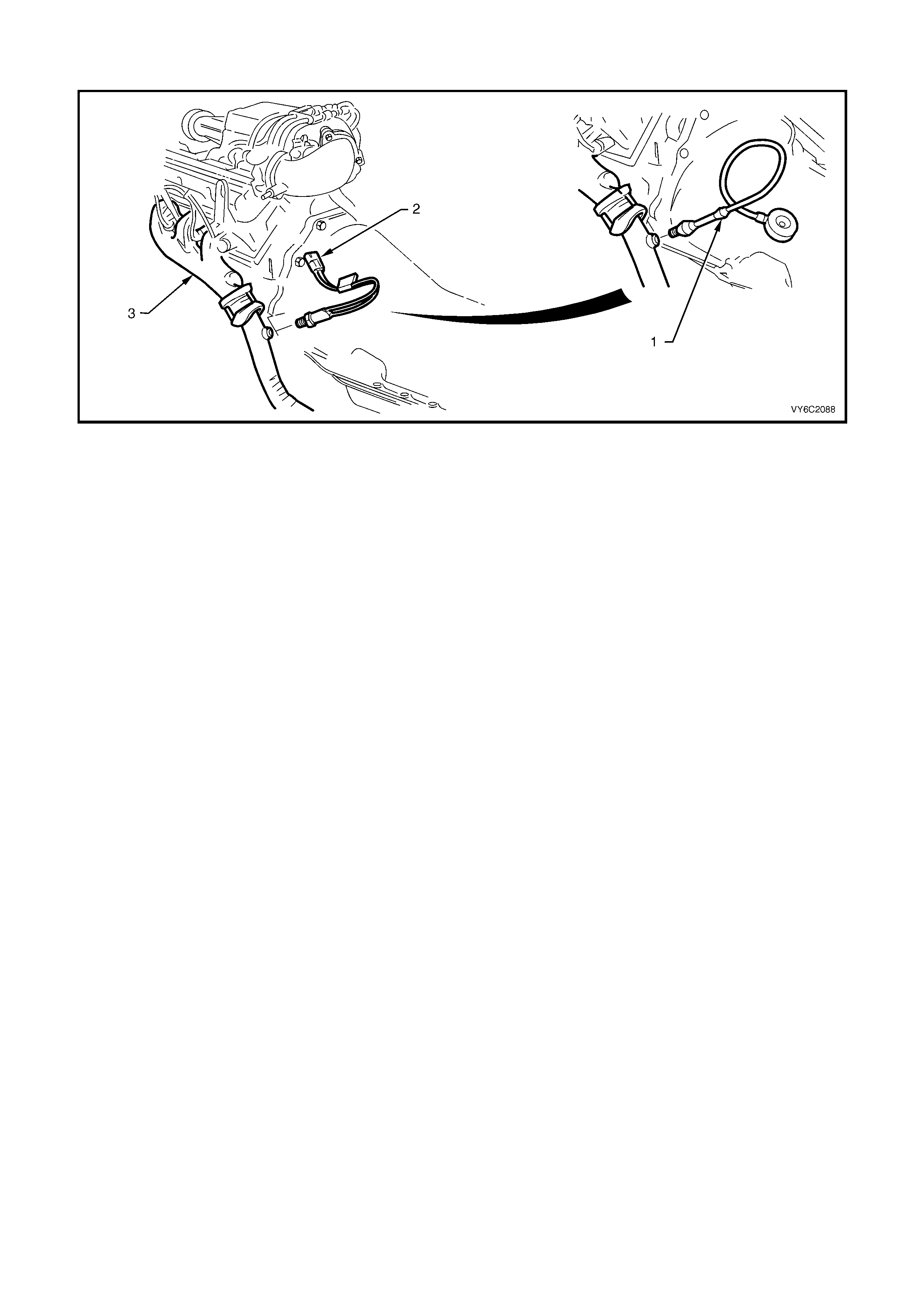
TABLE A-13 V6 S/C PCM – RESTRICTED EXHAUST CHECK
Figure 6C2-2A-64 – Restricted Exhaust Check
Legend
1. Back Pressure Gauge Assembly. 2. Exhaust Gas Heated Oxygen
(HO2S) Sensor 3. LH Engine Exhaust Pipe.
There are times when a restricted exhaust can cause a variety of owner complaints, some of which are:
• No power, sluggish.
• Hesitation on acceleration.
• Surges while driving.
• Poor fuel economy.
• Stalling.
• Hard starting.
THINGS THA T COULD CAUSE A RESTRICTED EXHAUST:
1. Collapsed exhaust pipe.
2. Muffler. Loose baffles may cause internal restriction.
3. Catalytic converter. Things that can cause a catalytic converter to become restricted are:
a. The use of leaded fuel.
b. A very rich-running engine. This rich-running condition could be caused by fuel pressure too high or by a
malfunction in the engine control system.
c. Engine in a bad state of tune. W orn parts in the ignition system can cause an engine misfire, which sends
unburned fuel into the exhaust system. The catalytic converter "sees" this unburned fuel as a rich-running
condition.
d. Push-starting the engine. This can send a tremendous amount of unburned fuel into the exhaust system.

TABLE A-13 V6 S/C PCM – RESTRICTED EXHAUST CHECK
STEP ACTION VALUE YES NO
1. Was the "On-Board Diagnostic" (OBD) System Check
performed? Go to Step 2. Go to
OBD
System Check
in this Section.
2. 1. Carefully remove O2 sensor from the left hand
exhaust pipe.
Can sensor be removed from exhaust system ?
Go to Step 3 Go to Step 6
3. 1. Install exhaust back pressure gauge in place of
removed O2 sensor.
2. Ignition "ON", engine started.
3. Observe the exhaust system back pressure reading on
the gauge.
Is the reading below the specified value?
8.6 kPa Go to Step 4 Go to Step 7
4. 1. Raise engine speed to 2,000 rpm and observe reading
on gauge.
Is reading on gauge below the specified value?
20.7 kPa Go to Step 5 Go to Step 7
5. No problem with exhaust system.
NOTE: Make sure to coat threads of O2 sensor with a
specified anti-seize compound prior to installation.
Is action complete?
Go to
OBD
System Check
in this Section.
6. 1. If the O2 sensor will not remove from the exhaust
System, make sure that the exhaust system is above
60° C. Excessive force may damage threads. If the O2
sensor cannot be removed , the exhaust pipe and O2
sensor may need to be replaced.
Was removal of O2 sensor successful?
Go to Step 3 Verify Repair
7. NOTE 1: If there are no obvious reasons for the excessive
back pressure, a restricted catalytic converter should be
suspected and replaced using current recommended
procedures. Refer to facing page Things that could
cause a restricted exhaust: for possible causes.
NOTE 2: Ensure that the O2 sensor threads are coated
with the specified anti-seize compound prior to installation.
Is action complete ?
Verify Repair
and Go to
OBD
System Check
in this Section.

DTC 13 V6 S/C PCM –
RIGHT HAND OXYGEN SENSOR (O2S) INSUFFICIENT ACTIVITY
Figure 6C2-2A-65 – Heated Oxygen Sensors
CIRCUIT DESCRIPTION:
The exhaust oxygen sensor is mounted in the exhaust pipe with the sensing portion exposed to exhaust gases.
After the sensor is hot (360 °C), it becomes a voltage generator, producing a "changing" voltage. This voltage
ranges from approximately 100 millivolts with a "lean" exhaust, to 900 millivolts with a "rich" exhaust. When the
sensor is cold (below 360° C) it ac ts like an open c ircuit and produces almos t no voltage. The PCM supplies a very
sm all "bias" voltage between term inals A84 X 2 D13 and X2 D14, nor m ally about 450 millivolts . If meas ured with the
10 megohm digital voltmeter, it may measure as low as 350 millivolts. When the sensor is hot, it's output
overshadows this PCM supplied voltage.
W hen the fuel system is correctly operating in the closed-loop mode, the sensor output is changing several times
per second, going above and below a mid-point range of 490-500 millivolts at a hot idle. The PCM compares the
voltage between the sensor signal and sensor ground terminals and decides the needed fuel mixture correction.
The PCM also monitors the changing voltage, watching for transitions above and below the mid-point range, to
decide when to operate in the closed-loop mode. An open circuit, defective, or contaminated sensor could cause
the voltage to stay within a 410-477 millivolt band too long, keeping the system in open-loop and setting a DTC 13.
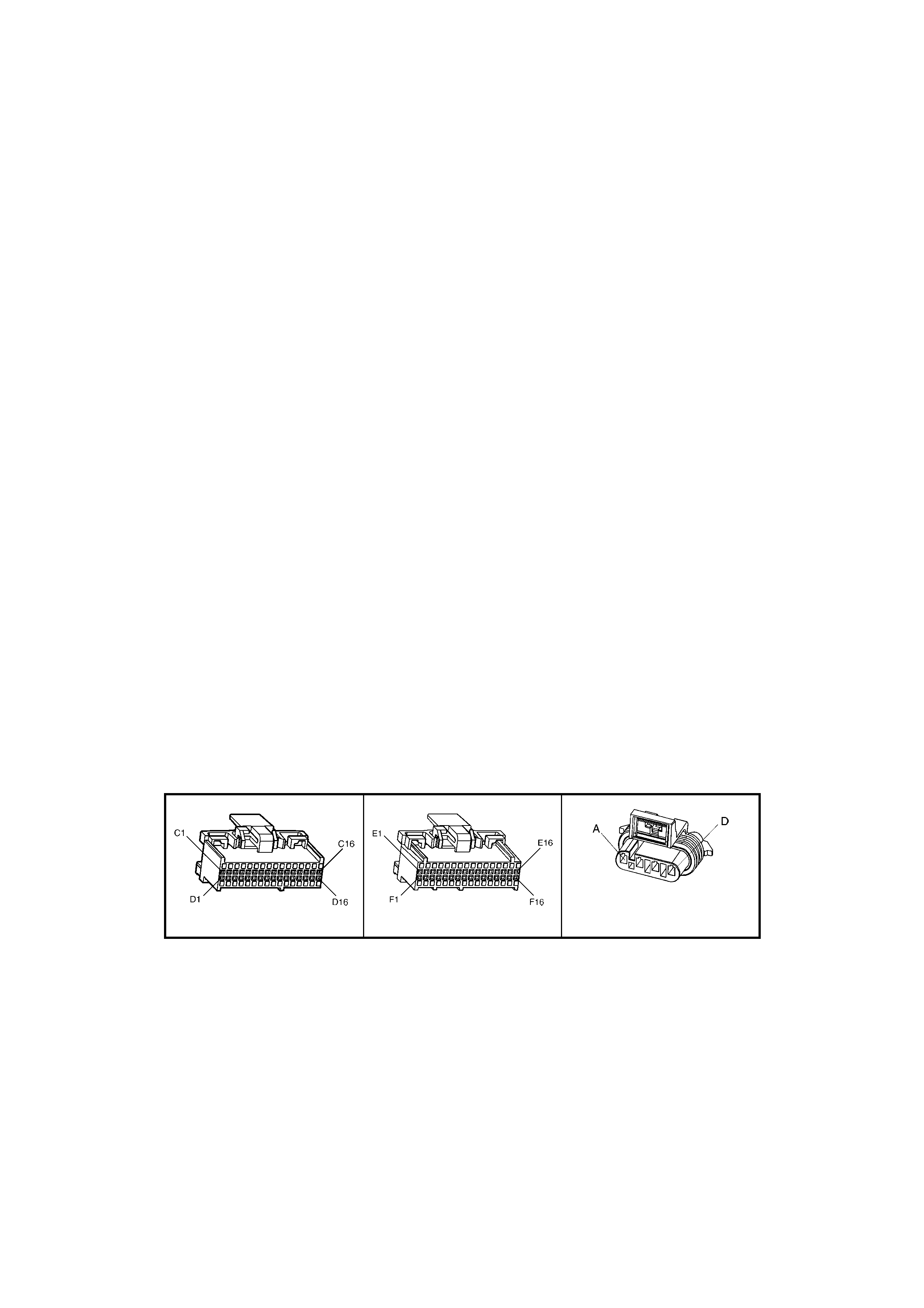
CONDITIONS FOR RUNNING THE DTC:
• The fuel control system is operating in closed loop mode.
• Engine run time is longer than 4 minutes.
• No TP Sensor DTC’s are set.
• The ECT sensor is more than 85°C.
• Throttle angle is more than 15%.
CONDITIONS FOR SETTING THE DTC:
• The RH 02S voltage stays between 410-477 millivolts for greater than 40 seconds.
ACTION TAKEN WHEN THE DTC SETS:
• The PCM activates the Check Powertrain Malfunction Indicator Lamp (MIL) when the diagnostic runs and fails.
• The PCM records the operating conditions at the time the diagnostic fails. The PCM stores this information in
the History Data.
• Once an H02S DTC is set, and current, the PCM will operate the fuel system in the “Open Loop” mode.
CONDITIONS FOR CLEARING THE CHECK POWERTRAIN MIL/DTC:
• The PCM deactivates the Check Powertrain MIL when a valid signal has been received for greater than ten
seconds.
• Use Tech 2 to clear the Check Powertrain MIL/DTC.
DIAGNOSTIC AIDS:
Norm al Tech 2 voltage, varies between 100 m V to 999 mV while in "Closed Loop". DT C 13 sets if voltage remains
between 410 and 477 millivolts, but the system will go "Open Loop" before the "Check Powertrain Malfunction
Indicator Lamp (MIL)" is activated.
Refer to "Intermittents" in Section 6C1-2B SYMPTOMS. To diagnose the oxygen sensor, refer TABLE A-6.3. in
this Section.
NOTE: Oxygen Sensor Contamination - If fuel containing lead or silicone is used, or engine repairs using
unapproved RTV gas ket sealer are per f or med, the sens or may be contaminated. It may send a "F alse" rich exhaus t
indication to the PCM, and the PCM will attem pt to drive the fuel system lean to c ompensate. Poor driveability or a
Diagnostic Trouble Code 13 or 63 could result. If this happens, the sensor will need to be replaced, but every
attempt to locate the source of contamination should be pursued.
TEST DESCRIPTION:
NOTE: Number(s) below refer to step number(s) on the diagnostic table.
2. Tech 2 allows you to read the same oxygen sensor voltage the PCM is using for its calculations.
3. T his step simulates a lean exhaust indication to the PCM. If the PCM and wiring are OK, the PCM will see the
lean indication and Tech 2 should display O2 voltage below 200 mV.
A84 V6 S/C – X3 A84 V6 S/C – X3 B56 -Right/B57 -Left
Figure 6C2-2A-66

DTC 13 V6 S/C PCM – RIGHT HAND OXYGEN SENSOR (O2S) INSUFFICIENT ACTIVITY
STEP ACTION VALUE YES NO
1. Was the "On-Board Diagnostic" (OBD) System Check
performed? Go to Step 2. Go to
OBD
System Check
in this Section.
2. 1. Engine at normal operating temperature (above
85° C).
2. Run engine at approximately 600 to 1,800 RPM for
two minutes.1.
Is Tech 2 oxygen sensor voltage between specified
values?
410-477 mV Go to Step 3 If no additional
DTC’s were
stored, refer to
Intermittents in
6C2-2B
SYMPTOMS.
3. 1. Ignition ON, engine stopped.
2. Disconnect O2 sensor and jumper the O2 signal and
low circuits (PCM side).
3. Using Tech 2, monitor O2 voltage.
Is the O2 voltage less than the specified value?
0.2 Volt
(200 mV) Go to Step 7 Go to Step 4
4. 1. Remove the jumper wire from the O2 signal circuit.
2. Using a DMM, measure voltage between the O2 signal
circuit (PCM side) and ground.
Does the O2 signal voltage measure near the specified
value?
350-477 mV Go to Step 5 Go to Step 6
5. 1. Ignition OFF.
2. Disconnect all PCM harness connectors.
3. Check continuity of the O2 low circuit between the
PCM harness connector and the O2 harness
connector.
4. If there is no continuity, repair open or poor connection
as necessary.
Was a problem found?
Verify Repair Go to Step 8
6. 1. Ignition OFF.
2. Disconnect all PCM harness connectors.
3. Check continuity of the O2 signal circuit between the
PCM harness connector and the O2 harness
connector.
4. If there is no continuity, repair open or poor connection
as necessary.
Was a problem found?
Verify Repair Go to Step 9
7. 1. Check the following circuits for a poor terminal
connection at the O2 harness connector.
• O2 signal circuit.
• O2 low circuit.
2. If a problem is found, repair as necessary.
Was a problem found?
Verify Repair Go to Step 11
8. 1. Check for poor O2 low circuit terminal connection at
PCM.
2. If a problem is found, repair as necessary.
Was a problem found?
Verify Repair Go to Step 11
9. 1. Check the O2 signal circuit and the O2 low circuit for a
poor terminal connection at the PCM.
2. If a problem is found, repair as necessary.
Was a problem found?
Verify Repair Go to Step 11
10. 1. Replace the O2 sensor.
Is action complete? Verify Repair –
11. 1. Replace PCM. Refer to Section 6C2-3 SERVICE
OPERATIONS in this Section for PCM Programming
and Security Link procedures.
Is action complete?
Verify Repair –
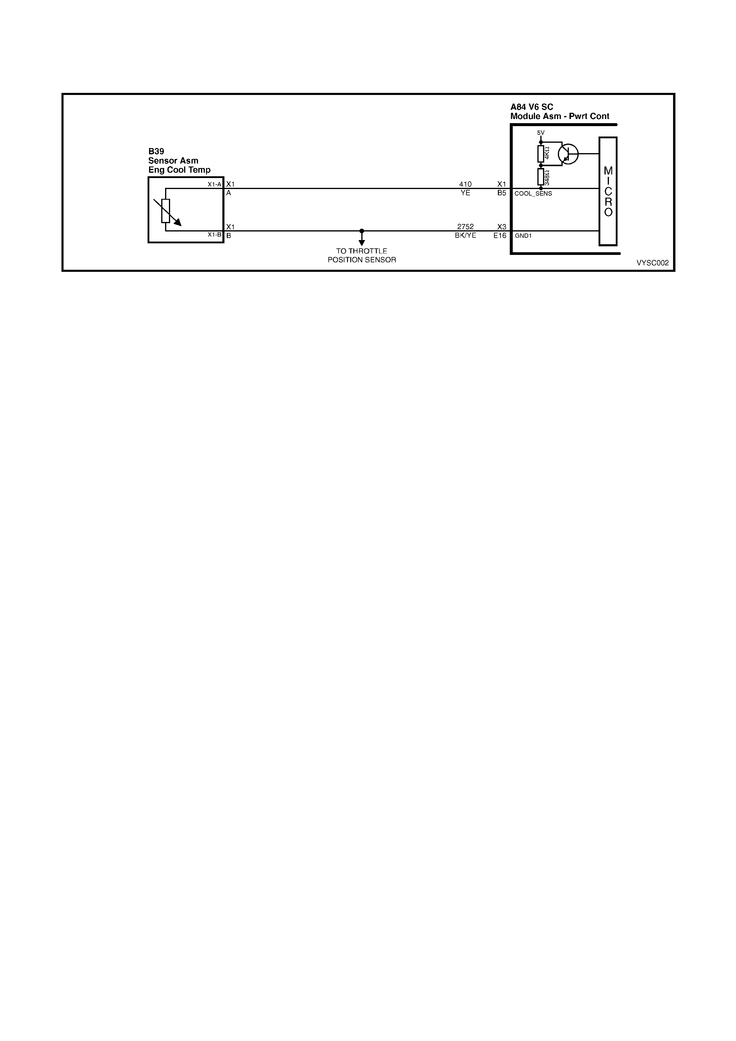
DTC 14 V6 S/C PCM –
ENGINE COOLANT TEMPERATURE (ECT) SENSOR LOW VOLTAGE
Figure 6C2-2A-67 – Coolant Temperature Sensor
CIRCUIT DESCRIPTION:
The Engine Coolant Temperature (ECT) sensor uses a thermistor to control the signal voltage to the PCM. The
PCM applies about 5 volts on circuit 410 to the sensor. When the engine coolant is cold, the sensor (thermistor)
resistance is high, therefore the PCM will see high signal voltage about 4.0 – 4.5 volts.
As the engine coolant warms, the sensor resistance becomes less, and the PCM sees a lower signal voltage. At
normal engine operating temperature (85° C to 95° C), the voltage should measure about 2.2 to 1.8 volts.
CONDITIONS FOR RUNNING THE DTC:
• Time since engine started is greater than 20 seconds
CONDITIONS FOR SETTING THE DTC:
• ECT sensor signal voltage is less than 0.3 volts, indicating an engine coolant temperature at or above 140° C
for one second.
ACTION TAKEN WHEN THE DTC SETS:
• The PCM illuminates the Check Powertrain Malfunction Indicator Lamp (MIL) when the diagnostic runs and
fails.
• The PCM records the operating conditions at the time the diagnostic fails. The PCM stores this information in
the History Data.
• The PCM will substitute a coolant temperature default value. The PCM arrives at this default, or substitute
value, by switching to a starting point, then counting upwards to 95°C at a rate of 11 degrees per minute.
• When Diagnostic Trouble Code 14 is set, the TCC will be applied with a cold engine and the engine cooling
fans will be turned "ON".
CONDITIONS FOR CLEARING THE CHECK POWERTRAIN MIL/DTC
• The PCM turns the MIL OFF after the first ignition cycle that the diagnostic runs and does not fail.
• Use Tech 2 to clear the Check Powertrain MIL/DTC.
DIAGNOSTIC AIDS:
Check harness routing for a potential short to ground in circuit 410.
Check terminals at ECT sensor for a good connection.
The Tech 2 s c an tool reads engine c oolant temperatur e in degrees Cels ius. Af ter engine is s tar ted, the temperatur e
should rise steadily to about 90 ° C then stabilise when thermostat opens.
The "Temperature to Resistance Value" scale may be used to test the engine coolant temperature sensor at various
temperature levels to evaluate the possibility of a "shifted" (mis-scaled) sensor. A "shifted" sensor could result in
poor driveability complaints.
Refer to Intermittents in Section 6C2-2B SYMPTOMS.
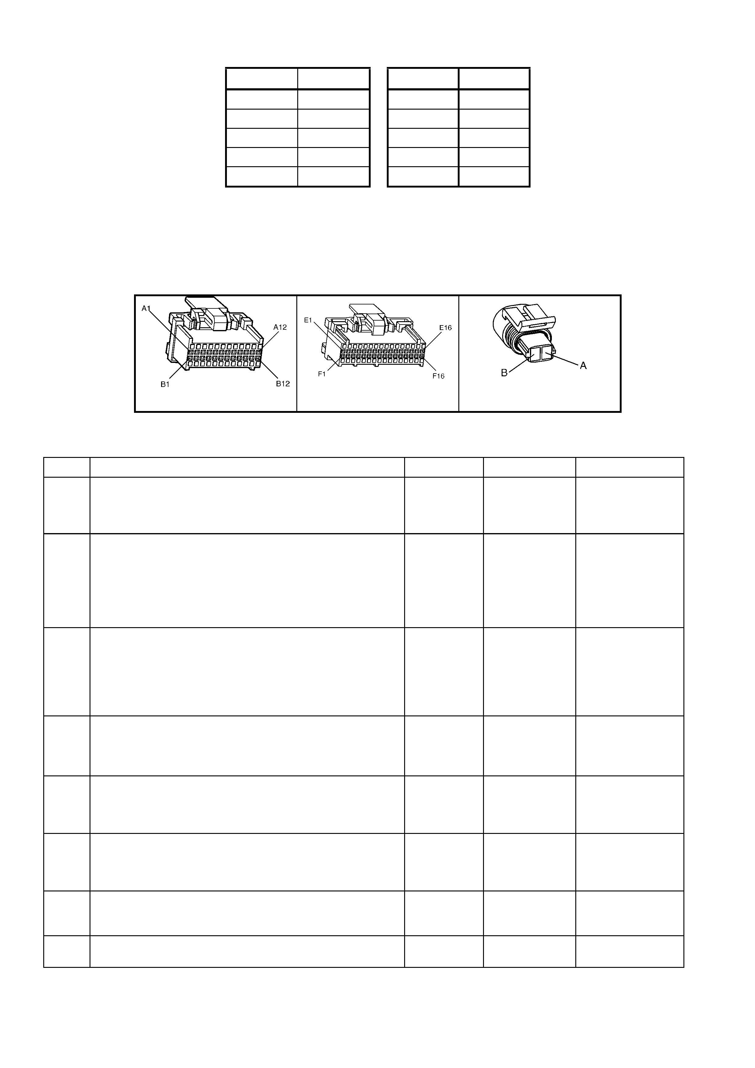
APPROXIMATE ECT SENSOR TABLE – TEMPERA TURE TO RESISTANCE VALUES
°
°°
°C OHMS °
°°
°C OHMS
110 134 30 2,268
100 180 20 3,555
90 244 0 9,517
70 474 -10 16,320
40 1,483 -20 28,939
TEST DESCRIPTION:
NOTE: Number(s) below refer to step number(s) on the diagnostic table.
3. This test will determine if circuit 410 is shorted to ground which will cause the conditions for DTC 14.
4. If checking resistance at the engine coolant temperature sensor is difficult because of sensor location,
disconnect the PCM connectors and check resistance between engine coolant temperature signal and sensor
ground terminals.
A84 V6 S/C-X1 A84 V6 S/C-X3 B39
Figure 6C2-2A-68
DTC 14 V6 S/C PCM – ENGINE COOLANT TEMPERATURE (ECT) SENSOR LOW VOLTAGE
STEP ACTION VALUE YES NO
1. Was the "On-Board Diagnostic" (OBD) System Check
performed? Go to Step 2. Go to
OBD
System Check
in this Section.
2. 1. Using Tech 2, select "Coolant Temp" on the data
display.
Is the "Coolant Temp" display value at or above the
specified value?
140 °C Go to Step 3 If no additional
DTCs were
stored, refer
INTERMITTENTS
in 6C2-2B
SYMPTOMS in
this Section.
3. 1. Ignition "OFF".
2. Disconnect engine coolant temperature sensor wiring
harness connector.
3. Ignition "ON".
Does Tech 2 display "Eng. Coolant Temp" below specified
value?
–30 °C Go to Step 4 Go to Step 7
4. 1. Check resistance across engine coolant temperature
sensor terminals.
Does DMM ohms reading match the specified values for
temperature to sensor resistance?
See above
table Go to Step 5 Go to Step 8
5. 1. Check for intermittent or loose terminals in sensor
harness connector, or for the 2 terminals shorting
together when connected to the sensor.
Was a faulty connection found?
Verify Repair Go to Step 6
6. 1. Replace PCM. Refer 6C2-3 SERVICE OPERATIONS
in this Section, for PCM Programming and Security
Link procedures.
Is action complete?
Verify Repair –
7. 1. Check circuit 410 for short to ground or to sensor
ground.
Was a short found?
Verify Repair Go to Step 6
8. 1. Replace ECT sensor.
Is replacement complete? Verify Repair –
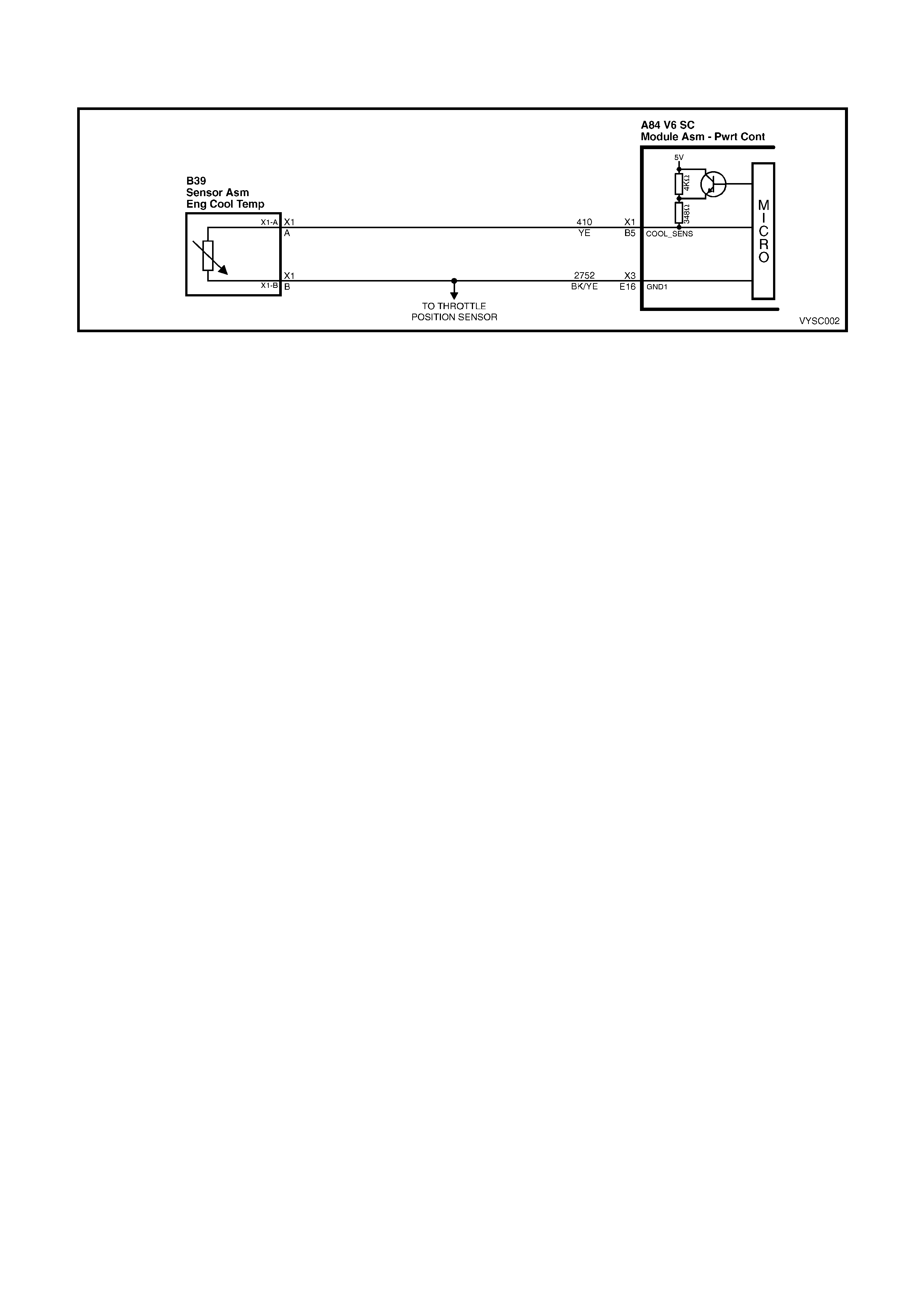
DTC 15 V6 S/C PCM –
ENGINE COOLANT TEMPERATURE (ECT) SENSOR HIGH VOLTAGE
Figure 6C2-2A-69 – Coolant Temperature Sensor
CIRCUIT DESCRIPTION:
The Engine Coolant Temperature (ECT) sensor uses a thermistor to control the signal voltage to the PCM. The
PCM applies about 5 volts on circuit 410 to the sensor. When the engine coolant is cold, the sensor (thermistor)
resistance is high, therefore the PCM will see high signal voltage, about 4 – 4.5 volts.
As the engine coolant warms, the sensor (thermistor) resistance becomes less, and the PCM sees a lower signal
voltage. At normal engine operating temperature (85° C to 95° C), the voltage will measure about 2.2 to 1.8 volts.
CONDITIONS FOR RUNNING THE DTC:
• Time since engine started is greater than 10 seconds.
CONDITIONS FOR SETTING THE DTC:
• ECT input signal voltage is greater than 4.64 volts, indic ating an engine coolant temper ature at or lower than –
30° C for one second.
• Above conditions present for at least 1 second.
ACTION TAKEN WHEN THE DTC SETS:
• The PCM illuminates the Check Powertrain Malfunction Indicator Lamp (MIL) when the diagnostic runs and
fails.
• The PCM records the operating conditions at the time the diagnostic fails. The PCM stores this information in
the History Data.
• The PCM will substitute a coolant temperature default value. The PCM arrives at this default, or substitute
value, by switching to a starting point, then counting upwards to 95° C at a rate of 11° C per minute.
• When the Diagnostic T rouble Code 15 is set, the T CC will be applied with a cold engine and the engine cooling
fans will be turned "ON".
CONDITIONS FOR CLEARING THE CHECK POWERTRAIN MIL/DTC:
• The PCM turns the Chec k Powertrain MIL OF F af ter the f irs t ignition c ycle that the diagnostic runs and does not
fail.
• Use Tech 2 to clear the Check Powertrain MIL/DTC.
DIAGNOSTIC AIDS:
Tech 2 reads engine coolant temperature in degrees Celsius. After engine is started, the temperature should rise
steadily to about 90° C then stabilise when thermostat opens.
A faulty connection, or an open in circuit 410 or circuit 2752 will result in a Diagnostic Trouble Code
(DTC) 15.
If DTC 21 is also set, check circuit 2752 for faulty wiring or connections. Check terminals at sensor for a good
connection. The "Temperature to Resistance Value" scale may be used to test the engine coolant temperature
sensor at var ious tem peratur e levels to evaluate the poss ibility of a "shifted" (mis -sc aled) s ensor. A "s hifted" s ensor
could result in poor driveability complaints.
Refer to Intermittents in Section 6C2-2B SYMPTOMS.
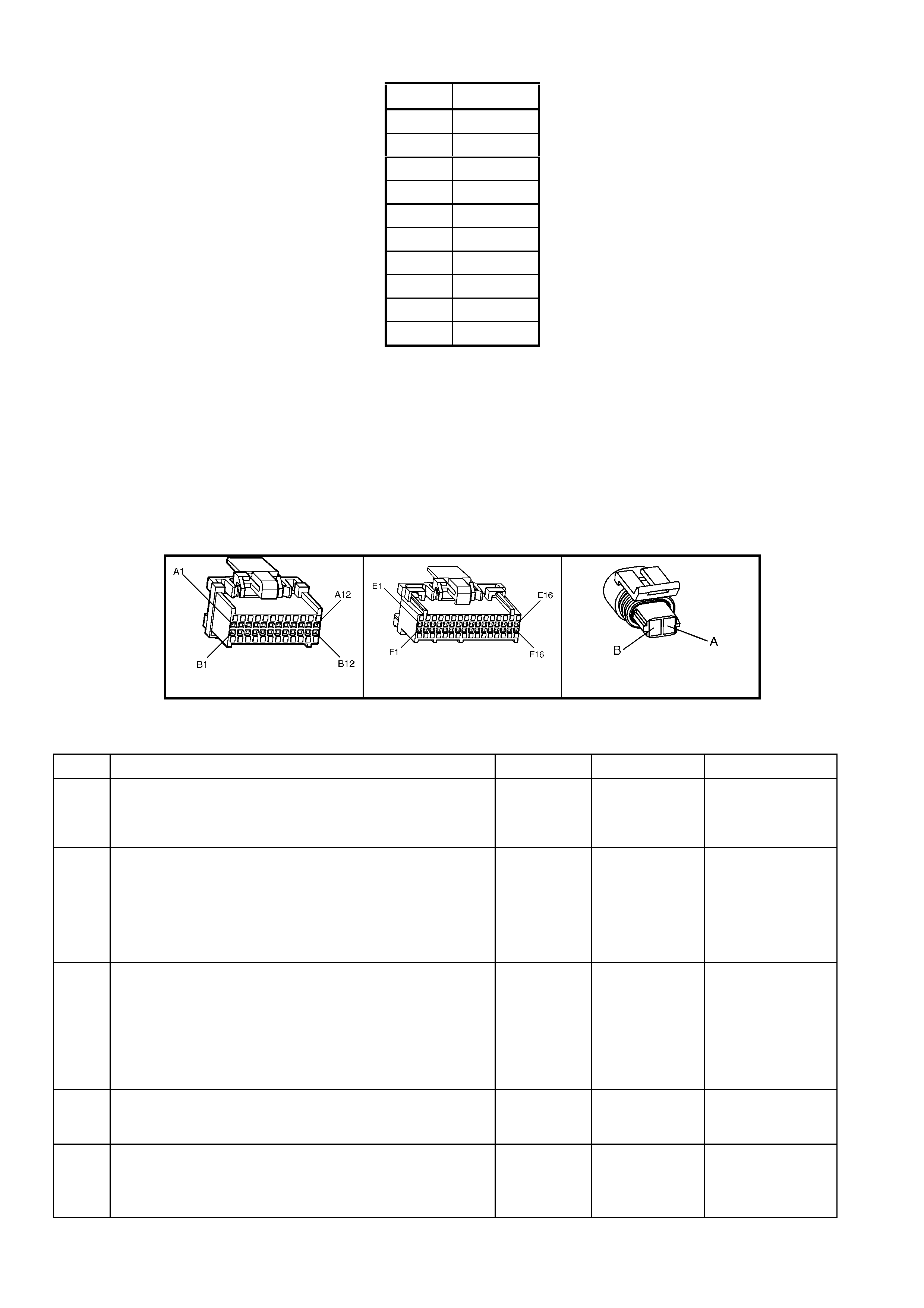
APPROXIMATE ECT SENSOR TABLE – TEMPERA TURE TO RESISTANCE VALUES
°
°°
°C OHMS
110 134
100 180
90 244
70 474
40 1,483
30 2,268
20 3,555
0 9,517
-10 16,320
-20 28,939
TEST DESCRIPTION:
NOTE: Number(s) below refer to step number(s) on the diagnostic Table.
3. This test simulates a Diagnostic Trouble Code 15. If the PCM recognises the low signal voltage, (high
temperature) and the Tech 2 reads 130° C or above, the PCM and wiring are OK.
4. This test will determine if circuit 410 is open. There should be an open circuit voltage of 5 volts present at
Engine Coolant Temperature (ECT) sensor harness connector if measured with a DMM. By jumpering this 5
volt signal to ground, the PCM should recognise this change.
11. This test will determine if circuit 2752 is open. If this circuit is open, a DTC 21 should also be present if the
problem is the PCM terminal connection. If DTC 21 is not set, the problem will not be the PCM end of this
circuit.
A84 V6 S/C-X1 A84 V6 S/C-X3 B39
Figure 6C2-2A-70
DTC 15 V6 S/C PCM – ENGINE COOLANT TEMPERATURE (ECT) SENSOR HIGH VOLTAGE
STEP ACTION VALUE YES NO
1. Was the "On-Board Diagnostic" (OBD) System Check
performed? Go to Step 2. Go to
OBD
System Check
in this Section.
2. 1. Using Tech 2, select "Coolant Temp" on the data
display.
Is the "Coolant Temp" display value at or between the
specified value?
–30 to –40
°C Go to Step 3 If no additional
DTC’s were
stored, refer to
INTERMITTENTS
in 6C2-2B
SYMPTOMS in
this Section.
3. 1. Ignition "OFF".
2. Disconnect engine coolant temperature sensor wiring
harness connector.
3. Jumper harness terminals together.
4. Ignition "ON".
Does Tech 2 display "Coolant Temp" at or above specified
value?
130° C Go to Step 10 Go to Step 4
4. 1. Jumper circuit 410 to ground.
Does Tech 2 display "Coolant Temp" at or above specified
value?
130° C Go to Step 11 Go to Step 8
5. 1. Check resistance across engine coolant temperature
sensor terminals.
Does DMM reading match the specified values for
temperatures to sensor resistance?
See above
table. Go to Step 6 Go to Step 9

STEP ACTION VALUE YES NO
6. 1. Check for intermittent or loose terminals in sensor
harness connector. Terminals may not be contacting
the sensor when connected.
Was a problem found?
Verify Repair Go to Step 7
7. 1. Replace PCM. Refer to 6C2-3 SERVICE
OPERATIONS in this Section, for PCM Programming
and Security Link procedure.
Is action complete?
Verify Repair –
8. 1. Check circuit 410 for an open, short to voltage or
faulty connection at PCM.
Was a problem found?
Verify Repair Go to Step 7
9. 1. Replace ECT sensor.
Is action complete? Verify Repair –
10. 1. Check for faulty connection.
Was a problem found? Go to Step 9
11. 1. Check continuity between sensor connector ground
circuit 2752 and PCM connector.
Does DMM display continuity?
Go to Step 5 Verify Repair

DTC 16 V6 S/C PCM –
ENGINE COOLANT TEMPERATURE (ECT) SENSOR UNSTABLE
Figure 6C2-2A-71 – Coolant Temperature Sensor
CIRCUIT DESCRIPTION:
The Engine Coolant Tem perature (ECT) sensor is a therm istor located in a coolant passage on the engine. W hen
engine coolant temperature is cold, the sensor has a high resistance. As temperature increases, the resistance of
the sensor dec reases . T he PCM provides a f ive volt signal to the engine coolant s ensor, which is also connec ted to
PCM ground. The PCM reads the voltage drop on the signal line to determine engine coolant temperature.
CONDITIONS FOR RUNNING THE DTC:
• Time since engine started is greater than 10 seconds.
• DTC 14, 15 or 17 are not set.
CONDITIONS FOR SETTING THE DTC:
• ECT reading changes more than 400 mV in 200 milliseconds.
• Above conditions present for at least 10 seconds.
ACTION TAKEN WHEN THE DTC SETS
• The PCM stores the DTC information into memory when the diagnostic runs and fails.
• The Check Powertrain Malfunction Indicator Lamp (MIL) will not be illuminated.
• The PCM records the operating conditions at the time the diagnostic fails. The PCM stores this information in
the History Data.
• The PCM will substitute a coolant temperature default value. The PCM arrives at this default, or substitute
value, by switching to a starting point, then counting upwards to 95° C at a rate of 11° C per minute.
• When DTC 16 is set, the PCM will turn "ON" the engine cooling fans.
CONDITIONS FOR CLEARING THE CHECK POWERTRAIN MIL/DTC:
• Use Tech 2 to clear the Check Powertrain MIL/DTC.
DIAGNOSTIC AIDS:
When attempting to diagnose an intermittent problem, use the snapshot mode of Tech 2, to review diagnostic
information.
This DTC is more likely to set on a cold engine than on a hot engine because of the pull up resistors in the PCM.
If DTC 16, 53 and 57 are set, check for short to voltage on "Diagnostic Test" line circuit 448.
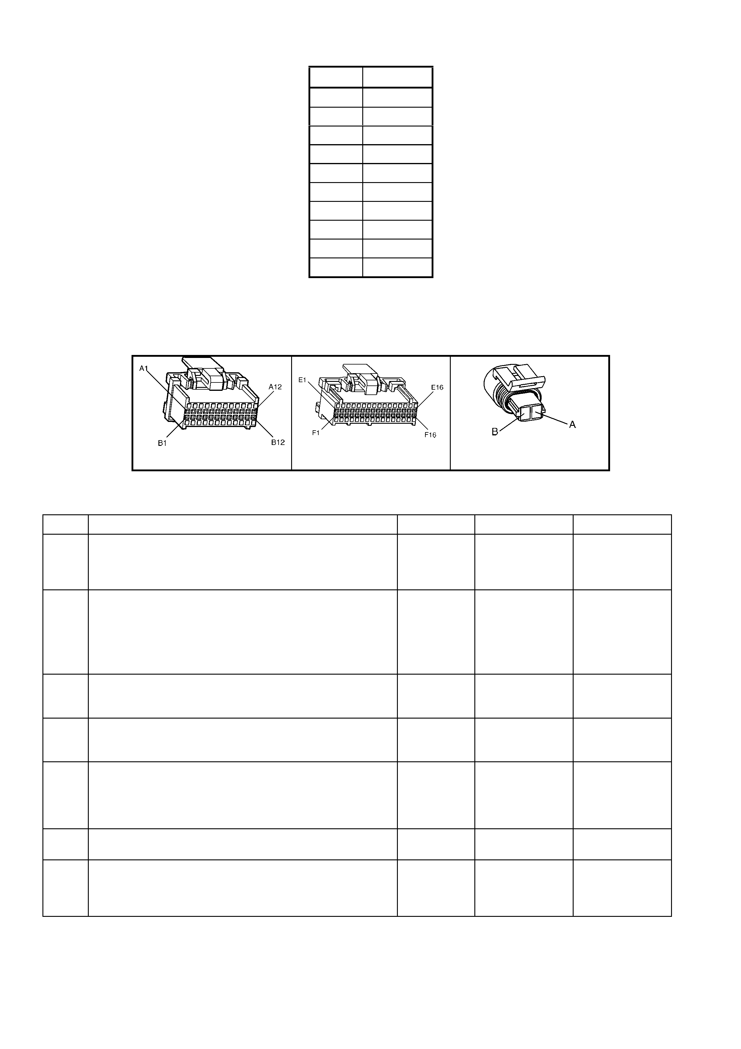
APPROXIMATE ECT SENSOR TABLE – TEMPERA TURE TO RESISTANCE VALUES
°
°°
°C OHMS
110 134
100 180
90 244
70 474
40 1,483
30 2,268
20 3,555
0 9,517
-10 16,320
-20 28,939
TEST DESCRIPTION:
NOTE: Number(s) below refer to step number(s) on the diagnostic table.
2. This step checks the wiring of the sensor for an intermittent fault.
10. The shank of a 0.95 mm twist drill is ideal for this PCM terminal tension test.
A84 V6 S/C-X1 A84 V6 S/C-X3 B39
Figure 6C2-2A-72
DTC 16 V6 S/C PCM – ENGINE COOLANT TEMPERATURE (ECT) SENSOR UNSTABLE
STEP ACTION VALUE YES NO
1. Was the "On-Board Diagnostic" (OBD) System Check
performed? Go to Step 2. Go to
OBD
System Check
in this Section.
2. 1. Install Tech 2 and set up snapshot mode to trigger on
DTC 16.
2. Watch Tech 2 while wiggling the ECT sensor
connector.
Does the Snapshot trigger or "Coolant Temp" reading
change sharply?
Go to Step 8 Go to Step 3
3. 1. Wriggle and tug the ECT sensor harness.
Does the Snapshot trigger or "Coolant Temp" reading
change sharply?
Go to Step 9 Go to Step 4
4. 1. Wriggle and tug the harness at the PCM.
Does the Snapshot trigger or "Coolant Temp" reading
change sharply?
Go to Step 10 Go to Step 5
5. 1. Lightly tap on the PCM.
Does the Snapshot trigger or "Coolant Temp" reading
change sharply?
Go to Step 6 DTC 16 is
intermittent.
Refer
"Diagnostic
Aids" above.
6. 1. Ensure the PCM is mounted securely to vehicle.
Was a problem found? Verify Repair Go to Step 7
7. 1. Replace PCM. Refer to 6C23 SERVICE
OPERATIONS in this Section for PCM Security Link
procedures
Is action complete?
Verify Repair –

STEP ACTION VALUE YES NO
8. 1. Check ECT sensor connector.
2. Check the tightness of the female terminal grip with a
suitable test terminal.
3. Inspect connectors for corrosion. If connectors are
corroded, try cleaning with electronic part cleaner and
retest.
4. If these repairs do not resolve the problem, replace
terminals.
Is action complete?
Verify Repairs –
9. 1. Check for an open in the ECT harness.
2. Check for broken strands of wire in ECT sensor
harness.
3. Check for cuts or pinches in ECT sensor harness.
4. Make repairs as necessary.
Is action complete?
Verify Repairs –
10. 1. Check the ECT sensor connection at the PCM.
2. Check tightness of the female terminal grip with a
suitable test terminal.
3. Inspect connectors for corrosion. If connectors are
corroded, try cleaning with electronic parts cleaner
and retest.
4. Remove connector strain relief and remove terminal
from connector to check for broken locking tang.
Is action complete?
Verify Repairs –
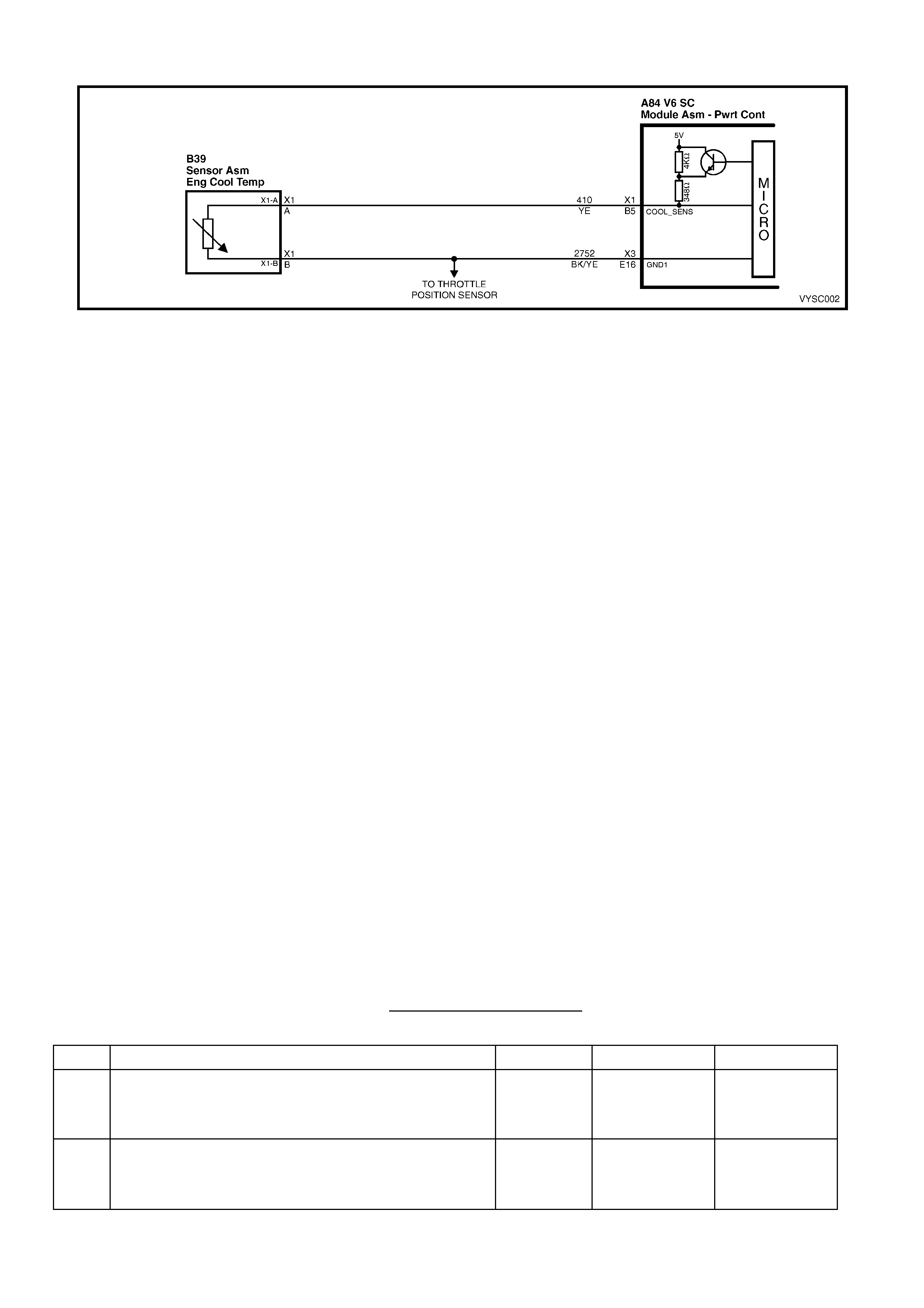
DTC 17 V6 S/C PCM – PCM ERROR – ECT CIRCUIT
Figure 6C2-2A-73 – Coolant Temperature Sensor
CIRCUIT DESCRIPTION:
The PCM uses two different internal pull-up resistors to increase resolution throughout the entire range of engine
operating temperatures. When the engine coolant temperature is less than 50 °C, the 4 kΩ and
348 Ω res istors are us ed. W hen tem perature is above 50 ° C, the PCM switches to the 348 Ω resistor. If the pull-up
resistor does not switch, DTC 17 will set.
CONDITIONS FOR RUNNING THE DTC:
• The engine run time is longer than 10 seconds.
CONDITIONS FOR SETTING THE DTC:
• The pull-up resistor inside the PCM switches and there is less than a 60mV change in the engine coolant
temperature signal.
ACTION TAKEN WHEN THE DTC SETS:
• The PCM stores the DTC information into memory when the diagnostic runs and fails.
• The Check Powertrain Malfunction Indicator Lamp (MIL) will not be illuminated.
• The PCM records the operating conditions at the time the diagnostic fails. The PCM stores this information in
the History Data.
• When an ECT sens or c irc uit f ault is detec ted, and cur rent, the PCM will subs titute a coolant temperatur e default
value. The PCM arrives at this default, or substitute value, by switching to a starting point, then counting
upwards to 95°C at a rate of 11° C per minute.
• When DTC 17 is set, the PCM will turn "ON" the engine cooling fans.
CONDITIONS FOR CLEARING THE CHECK POWERTRAIN MIL/DTC:
• Use Tech 2 to clear the Check Powertrain MIL/DTC.
DIAGNOSTIC AIDS:
When a DTC 14, 15, 16 or 17 is current, the PCM will turn on the electric engine cooling fan(s). This is a FAIL-SAFE
action by the PCM to prevent a possible engine overheat condition, since these DTC’s indicate an unknown actual
engine coolant temperature.
If the ECT sensor circuit opens with the ignition off, the PCM will interpret –30° C and deliver enough fuel to start the
engine at this temperature. If the actual ambient temperature is above 0° C, the engine may flood and not start
unless CLEAR FLOOD MODE is used by fully depressing the accelerator while cranking. In the CLEAR FLOOD
MODE the injectors pulse width is set to zero milliseconds.
TEST DESCRIPTION:
NOTE: Number(s) below refer to the step number(s) on the diagnostic table.
2. DTC 17 is an internal fault within the PCM. The PCM must be replaced!
DTC 17 V6 S/C PCM – PCM ERROR - ECT CIRCUIT
STEP ACTION VALUE YES NO
1. Was the "On-Board Diagnostic" (OBD) System Check
performed? Go to Step 2. Go to
OBD
System Check
in this Section.
2 1. Replace PCM. Refer to 6C2-3 SERVICE
OPERATIONS, in this Section for PCM Security Link
procedure.
Is action complete?
Verify Repair –
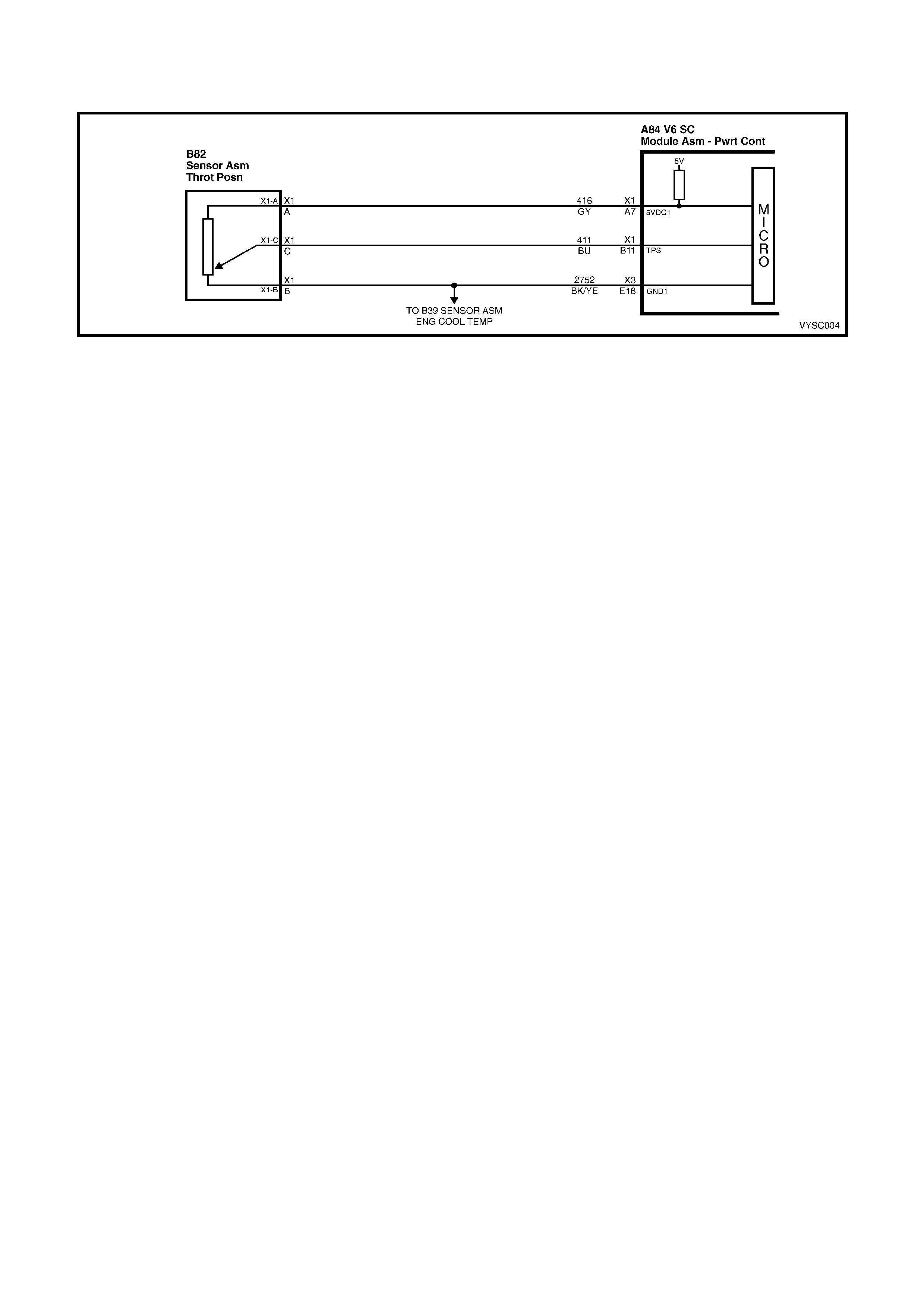
DTC 19 V6 S/C PCM –
THROTTLE POSITION (TP) SENSOR CIRCUIT INSUFFICIENT ACTIVITY
Figure 6C2-2A-74 – Throttle Position Sensor
CIRCUIT DESCRIPTION:
The T hrottle Position (TP) sensor provides a voltage signal that changes relative to the throttle blade angle. Signal
voltage will vary from about 0.25 to 1.25 volts at idle to about 4 volts at Wide Open Throttle (WOT).
The TP sensor signal is one of the most important inputs used by the PCM for transient fuelling and transmission
control and for most of the PCM controlled outputs.
Diagnostic T r ouble Code (D T C) 19 is used to detec t a s tuck open T P s ens or. DTC 19 detects if the TP sensor does
not return with the throttle blade when decelerating.
CONDITIONS FOR RUNNING THE DTC:
• Time since engine started is greater than 20 seconds
CONDITIONS FOR SETTING THE DTC:
• The Throttle Position (TP) sensor percentage of opening angle indicated is greater than the RPM that can be
reached with a Mass Air Flow reading of less than 301 mg/cyl for 20 seconds.
ACTION TAKEN WHEN THE DTC SETS:
• The PCM illuminates the Check Powertrain Malfunction Indicator Lamp (MIL) when the diagnostic runs and
fails.
• The PCM records the operating conditions at the time the diagnostic fails. The PCM stores this information in
the History Data.
• When DTC 19 is set, the PCM will calculate throttle position based off of IACV and MAF for engine and
transmission operation.
CONDITIONS FOR CLEARING THE CHECK POWERTRAIN MIL/DTC:
• The PCM turns the Chec k Powertrain MIL OF F af ter the f irs t ignition c ycle that the diagnostic runs and does not
fail.
• Use Tech 2 to clear the Check Powertrain MIL/DTC.
DIAGNOSTIC AIDS:
Tec h 2 reads throttle pos ition in volts. With ignition "ON'' or at idle, TP sensor signal voltage should read about 0.25
to 1.25 volts with the throttle closed and increase at a steady rate as throttle is moved toward W ide Open Throttle
(WOT).
Tech 2 will read throttle angle. 0%=closed throttle; 100%=WOT.
If voltage is s teady above DTC 22 voltage criter ia and below DT C 19 voltage cr iter ia, chec k f or a s hor t to voltage on
the TP Sensor signal circuit.
Refer to Intermittents in Section 6C2-2B SYMPTOMS.
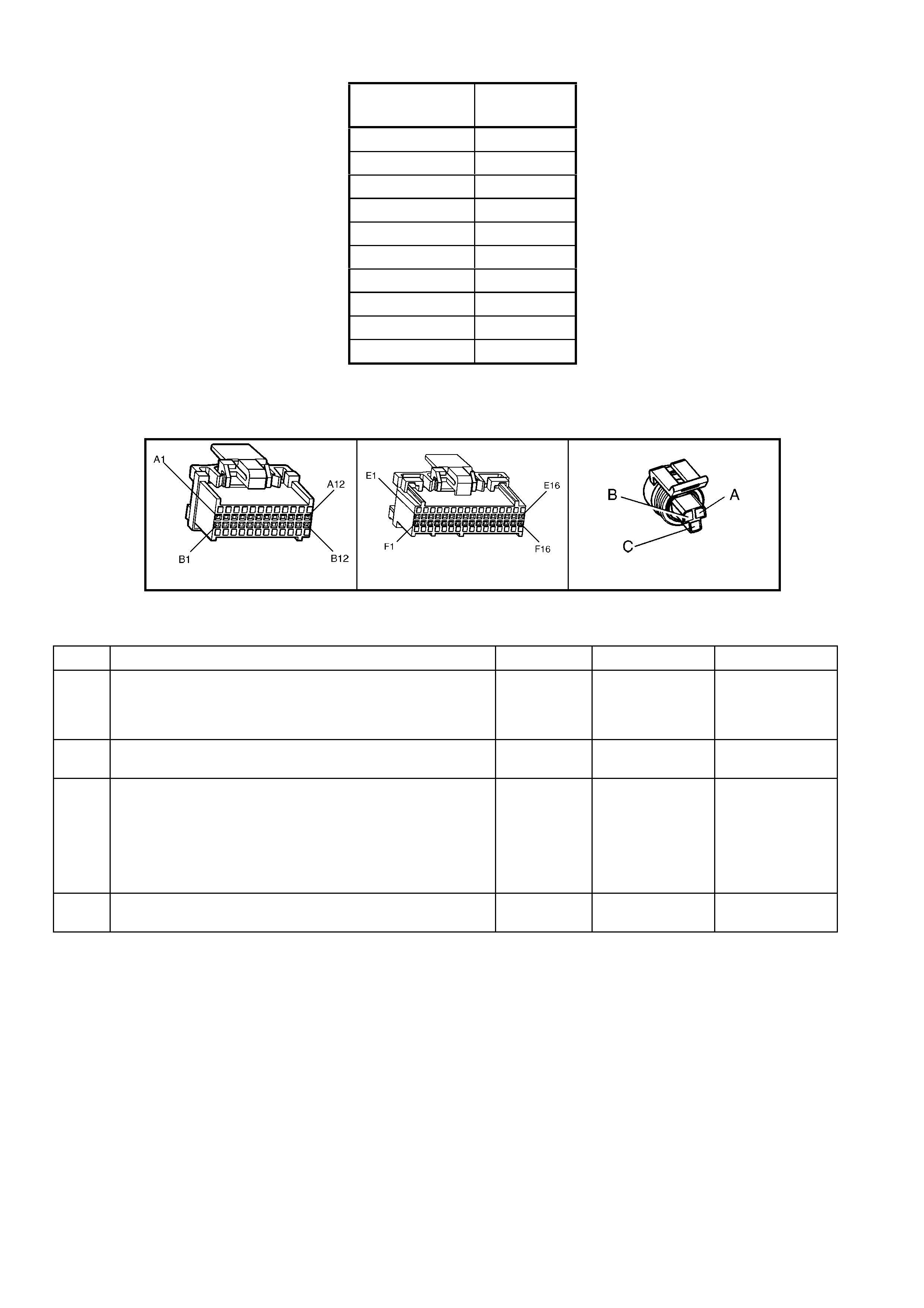
DTC 19 CRITERIA TABLE MAF LESS THAN 301 mg/Cyl. (APPROXIMATE)
TPS % – V6
S/C RPM
20 800
22 1,200
27 1,600
29 2,000
33 2,400
37 2,800
39 3,200
40 3,600
41 4,000
44 4,400
TEST DESCRIPTION:
NOTE: Number(s) below refer to step number(s) on the diagnostic table.
3. This step checks to verify the throttle linkage is moving freely.
A84 V6 S/C – X1 A84 V6 S/C – X3 B82
Figure 6C2-2A-75
DTC 19 V6 S/C PCM – THROTTLE POSITION (TP) SENSOR CIRCUIT INSUFFICIENT ACTIVITY
STEP ACTION VALUE YES NO
1. Was the "On-Board Diagnostic" (OBD) System Check
performed? Go to Step 2. Go to
OBD
System Check
in this Section.
2. 1. Inspect throttle cable, linkage, and blade movement.
Are components binding or sticking? Verify Repair Go to Step 3
3. 1. Using Tech 2,monitor TP sensor voltage, inspect TP
sensor for binding or sticking during its movement
from closed throttle to wide open throttle and back to
closed throttle position.
Was a fault found ?
Go to Step 4 DTC 19 is
intermittent. If no
additional DTC’s
were stored,
refer to
Diagnostic Aids,
above.
4. 1. Replace binding Throttle Position (TP) sensor.
Is action complete? Verify Repair –
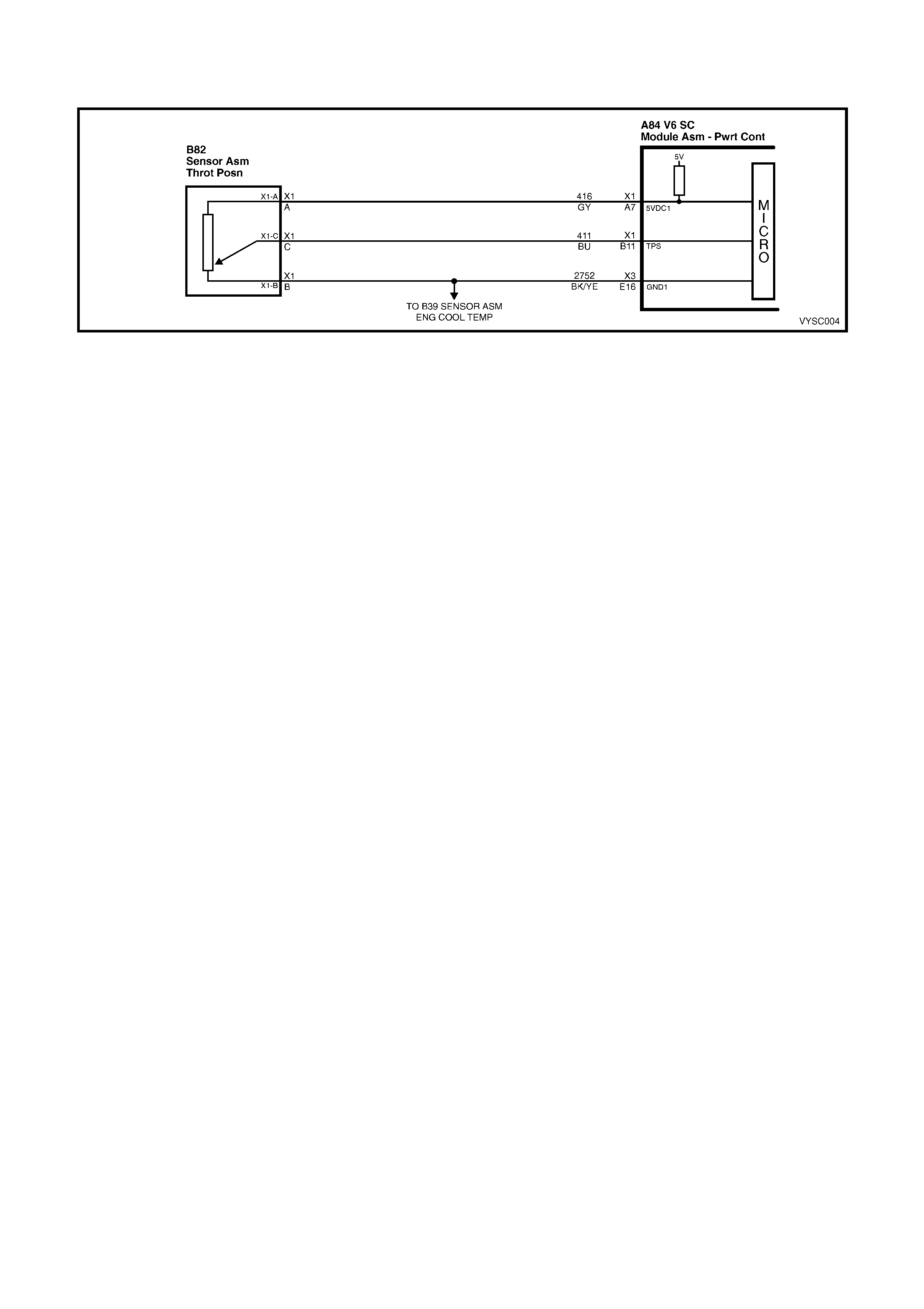
DTC 21 V6 S/C PCM –
THROTTLE POSITION (TP) SENSOR CIRCUIT HIGH VOLTAGE
Figure 6C2-2A-76 – Throttle Position Sensor
CIRCUIT DESCRIPTION:
The T h rottle Pos ition (TP) s ens or pr ovides a voltage signal that c hanges relative to the throttle blade. Signal voltage
will vary from about 0.25 to 1.25 volts at idle to about 4 volts at Wide Open Throttle (WOT).
The TP sensor signal is one of the most important inputs used by the PCM for transient fuelling and transmission
control and for most of the PCM controlled outputs.
CONDITIONS FOR RUNNING THE DTC:
• Time since engine started is greater than 20 seconds
CONDITIONS FOR SETTING THE DTC:
• The TP Sensor voltage between the PCM TP Sensor signal terminal and the TP Sensor ground terminal is
greater than 4.9 volts (97%) for more than two seconds.
ACTION TAKEN WHEN THE DTC SETS:
• The PCM illuminates the Check Powertrain Malfunction Indicator Lamp (MIL) when the diagnostic runs and
fails.
• The PCM records the operating conditions at the time the diagnostic fails. The PCM stores this information in
the History Data.
• When a DTC 21 is set, the PCM does not receive the proper signal from the TP sensor, but it can still
determ ine the TP s ensor value with a default value bas ed on RPM, Idle Air Control Valve position and Mass Air
Flow.
• If DTC 21 is set, the transmission will have no TCC.
CONDITIONS FOR CLEARING THE CHECK POWERTRAIN MIL/DTC:
• The PCM de-activates the Check Powertrain MIL after the first ignition cycle that the diagnostic runs and does
not fail.
• Use a Tech 2 scan tool in order to clear the Check Powertrain MIL/DTC.
DIAGNOSTIC AIDS:
Tec h 2 reads throttle pos ition in volts. With ignition "ON'' or at idle, TP sensor signal voltage should read about 0.25
to 1.25 volts with the throttle closed and increase at a steady rate as throttle is moved toward W ide Open Throttle
(WOT).
Tech 2 will read throttle angle. 0% = closed throttle; 100% = WOT. An open in circuit 2752 will result in a DTC 21.
Refer to Intermittents in Section 6C2-2B SYMPTOMS.
TEST DESCRIPTION:
NOTE: Number(s) below refer to step number(s) on the diagnostic table.
3. With the TP sensor disconnected, the TP sensor signal voltage should go low if the PCM and wiring are OK.
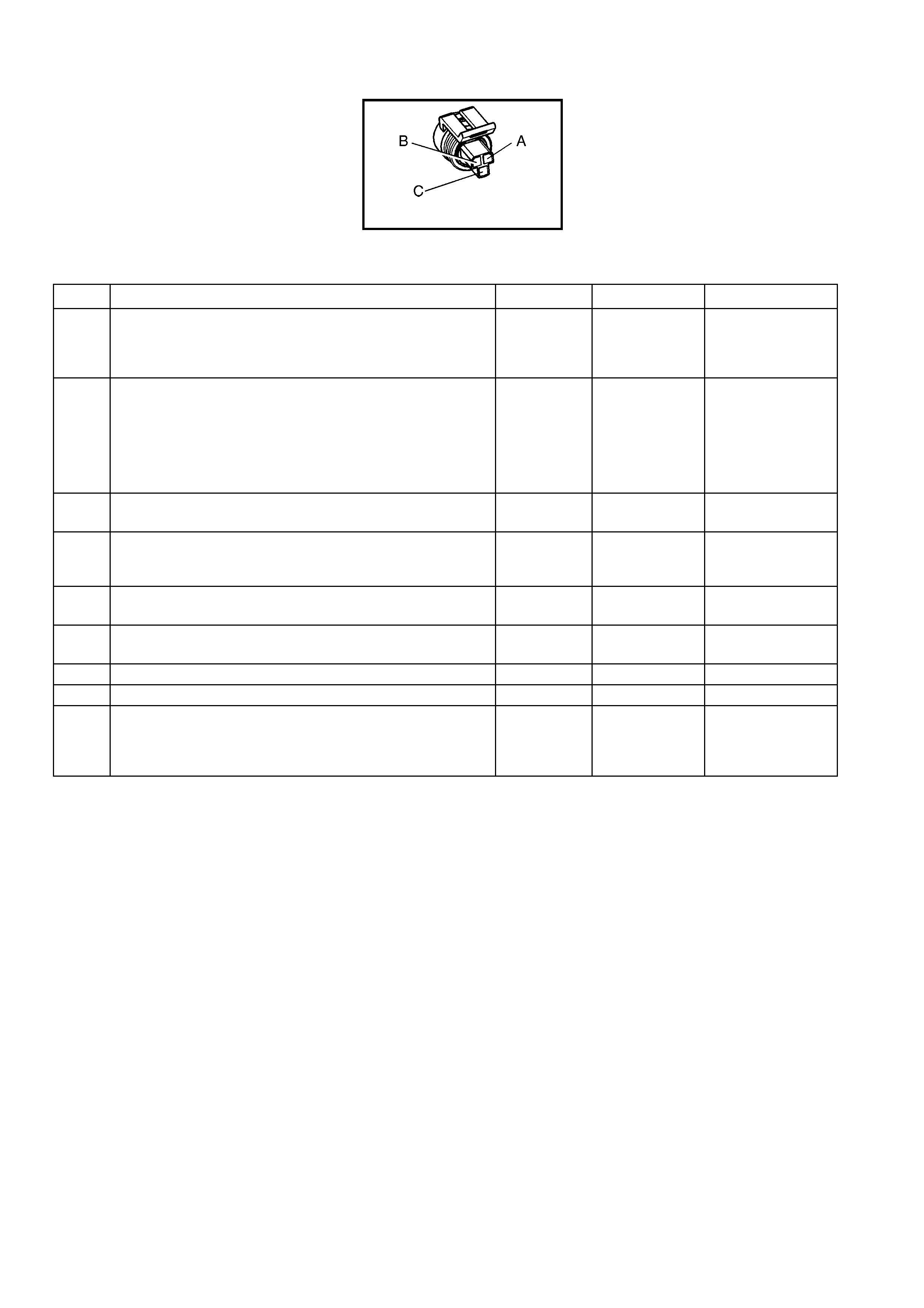
4. Probing circuit 2752 with a test light connected to 12 volts checks the sensor ground circuit. A faulty sensor
ground will cause a DTC 21.
B82
Figure 6C2-2A-77
DTC 21 V6 S/C PCM – THROTTLE POSITION (TP) SENSOR CIRCUIT HIGH VOLTAGE
STEP ACTION VALUE YES NO
1. Was the "On-Board Diagnostic" (OBD) System Check
performed? Go to Step 2. Go to
OBD
System Check
in this Section.
2. 1. Throttle closed.
Does Tech 2 display "TPS Signal" above the specified
value?
2.5 volts Go to Step 3 If no additional
DTC’s were
stored, refer to
INTERMITTENTS
in 6C2-2B
SYMPTOMS in
this Section.
3. 1. Disconnect TPS wiring harness.
Does Tech 2 display "TPS Signal" below specified value? 0.2 volts
(200 mV) Go to Step 4 Go to Step 7
4. 1. Probe TP sensor ground circuit with test light
connected to B+.
Is test light "ON"?
Go to Step 5 Go to Step 8
5. 1. Check for a faulty connection.
Was faulty connection found? Verify Repair Go to Step 6
6. 1. Replace Throttle Position Sensor (TPS).
Is action complete? Verify Repair –
7. Is the TP sensor signal circuit shorted to voltage? Verify Repair Go to Step 9
8. Is the TP sensor ground circuit open? Verify Repair Go to Step 9
9. 1. Replace PCM. Refer to section 6C2-3 SERVICE
OPERATIONS in this Section for PCM Security Link
procedure.
Is action complete?
Verify Repair –

DTC 22 V6 S/C PCM –
THROTTLE POSITION (TP) SENSOR CIRCUIT LOW VOLTAGE
Figure 6C2-2A-78 – Throttle Position Sensor
CIRCUIT DESCRIPTION:
The T h rottle Pos ition (TP) s ens or pr ovides a voltage signal that c hanges relative to the throttle blade. Signal voltage
will vary from about 0.25 to 1.25 volts at idle to about 4 volts at Wide Open Throttle (WOT).
The TP sensor signal is one of the most important inputs used by the PCM for transient fuelling and transmission
control and for most of the PCM controlled outputs.
CONDITIONS FOR RUNNING THE DTC:
• Time since engine started is greater than 20 seconds
CONDITIONS FOR SETTING THE DTC:
• The T P Sensor voltage between the PCM TP Sensor s ignal term inal and the T P Sensor ground terminal is less
than 0.2 volts for more than two seconds.
ACTION TAKEN WHEN THE DTC SETS:
• The PCM activates the Check Powertrain Malfunction Indicator Lamp (MIL) when the diagnostic runs and fails.
• The PCM records the operating conditions at the time the diagnostic fails. The PCM stores this information in
the History Data.
• When a DTC 22 is set, the PCM does not receive the proper signal from the TP sensor, but it can still
determ ine the TP s ensor value with a default value bas ed on RPM, Idle Air Control Valve position and Mass Air
Flow.
• If DTC 22 is set, the transmission will have no TCC.
CONDITIONS FOR CLEARING THE CHECK POWERTRAIN MIL/DTC:
• The PCM deactivates the Check Powertrain MIL after the first ignition cycle that the diagnostic runs and does
not fail.
• Use a Tech 2 to clear the Check Powertrain MIL/DTC.
DIAGNOSTIC AIDS:
A Tech 2 reads throttle position in volts. W ith ignition "ON'' or at idle, TP sensor signal voltage should read about
0.25 to 1.25 volts with the throttle closed and increase at a steady rate as throttle is moved toward Wide Open
Throttle (WOT).
The Tech 2 scan tool will read throttle angle. 0% = closed throttle; 100% = WOT.
An open or short to ground in circuit 416 or circuit 411 will result in a DTC 22.
Refer to Intermittents in Section 6C2-2B SYMPTOMS.
TEST DESCRIPTION:
NOTE: Number(s) below refer to step number(s) on the diagnostic table.
3. This test simulates a Diagnostic Trouble Code 21 ( high voltage). If the PCM recognises the high s ignal voltage
and Tech 2 reads over 4 volts or above, the PCM and wiring are OK.
4. T his simulates a high signal voltage to check for an open in circuit 411. T ech 2 will not read up to 12 volts, but
what is important is that the PCM recognises the signal on circuit 411.

B82
Figure 6C2-2A-79
DTC 22 V6 S/C PCM – THROTTLE POSITION (TP) SENSOR CIRCUIT LOW VOLTAGE
STEP ACTION VALUE YES NO
1. Was the "On-Board Diagnostic" (OBD) System Check
performed? Go to Step 2. Go to
OBD
System Check
in this Section.
2. 1. Throttle closed.
Does Tech 2 display "TPS Signal" at or below the specified
value?
0.2 Volt
(200 mV) Go to Step 3 DTC 22 is
intermittent, if no
additional DTC’s
were stored, refer
to
INTERMITTENTS
in Section 6C2-2B
SYMPTOMS in
this Section.
3. 1. Disconnect TPS wiring harness.
2. Jumper circuits 416 & 411 together.
Does Tech 2 display "TPS Signal" above the specified
value?
4.0 Volts Go to Step 6 Go to Step 4
4. 1. Probe circuit 411 with test light connected to 12 volts.
Does Tech 2 scan tool display "TPS Signal" above the
specified value?
4.0 Volts Go to Step 5 Go to Step 7
5. 1. Check for open or short on circuit 416 or faulty
connection.
Was a short, open or faulty connection found?
Verify Repair Go to Step 8
6. 1. Replace Throttle Position (TP) Sensor.
Is action complete? Verify Repair –
7. 1. Check for open or short on circuit 411 or faulty
connection.
Was a short, open or faulty connection found?
Verify Repair Go to Step 8
8. 1. Replace PCM. Refer to 6C2-3 SERVICE
OPERATIONS in this Section for PCM Security Link
procedure.
Is action complete?
Verify Repair –
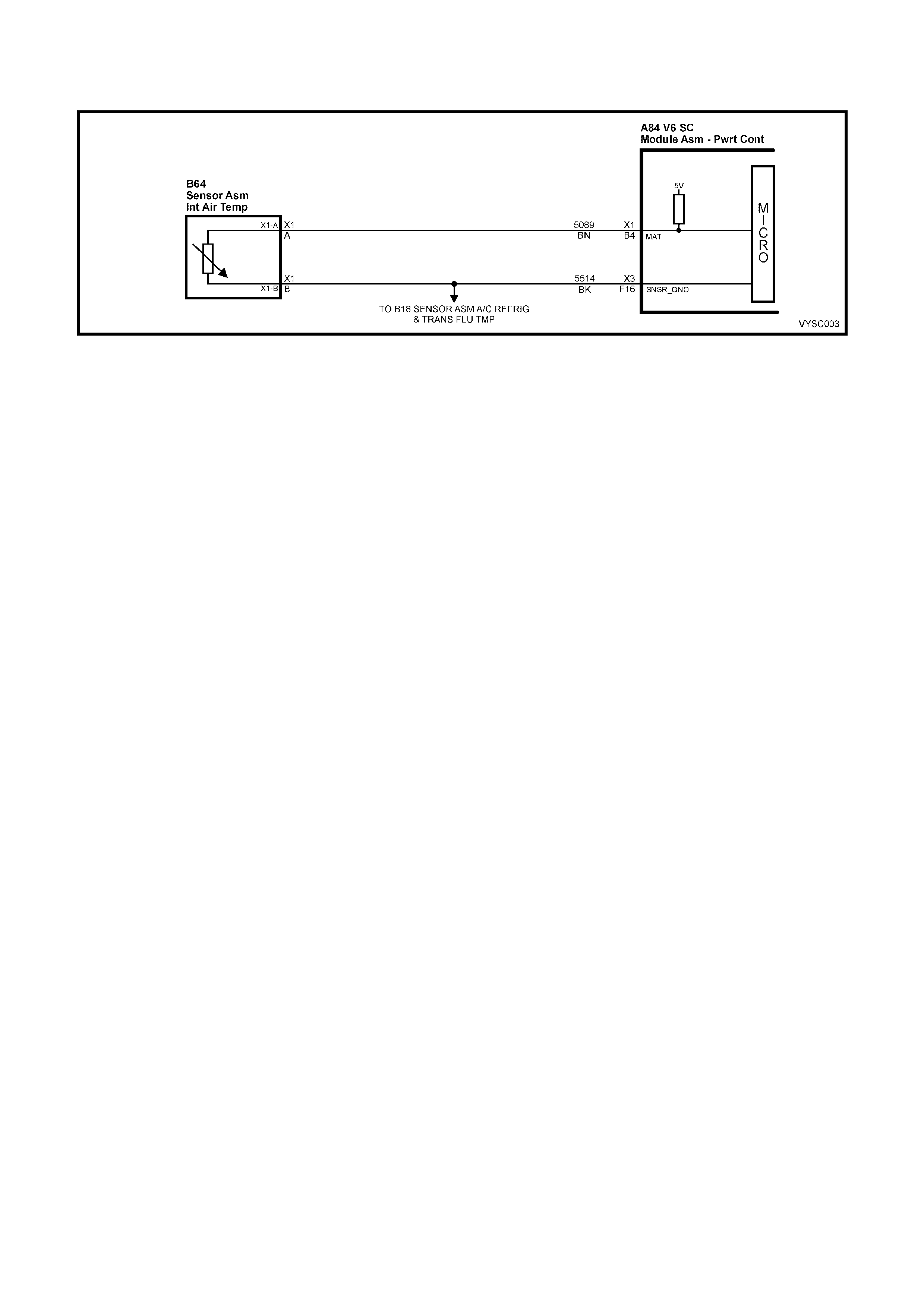
DTC 23 V6 S/C PCM –
INTAKE AIR TEMPERATURE (IAT) SENSO R CIRCUIT HIGH VOLTAGE
Figure 6C2-2A-80 – Intake Air temperature Sensor
CIRCUIT DESCRIPTION:
The Intake Air Temperature (IAT) sensor uses a thermistor to control the signal voltage to the PCM. The PCM
applies a voltage (about 5 volts) on circuit 5089 to the sensor. W hen the intake air is cold, the sensor (thermistor)
resistance is high, therefore, the PCM will sense a high signal voltage. If the intake air is warm, the sensor
(thermistor) resistance is low, therefore, the PCM will sense a low signal voltage.
CONDITIONS FOR RUNNING THE DTC:
• The engine has been running for more than 10 seconds.
CONDITIONS FOR SETTING THE DTC:
• IAT sensor signal voltage is more than 4.9 volts, indicating an intake air temperature is at or below –30 °C for
one second.
ACTION TAKEN WHEN THE DTC SETS:
• The PCM stores the DTC information into memory when the diagnostic runs and fails.
• The Check Powertrain Malfunction Indicator Lamp (MIL) will not be illuminated.
• The PCM records the operating conditions at the time the diagnostic fails. The PCM stores this information in
the History Data.
• When DTC 23 is set, the PCM will default to a 25° C IAT for engine operation.
CONDITIONS FOR CLEARING THE POWERTRAIN CHECK POWERTRAIN MIL/DTC:
• Use a Tech 2 scan tool in order to clear the Check Powertrain MIL/DTC.
DIAGNOSTIC AIDS:
A Tech 2 scan tool indicates the temperature of the air in the intake. When the PCM detects a fault in the IAT
sensor circuit, a default value of 25° C will be used by the PCM.
Carefully check harness and connections for possible open circuit 5089 or circuit 2573.
An open circuit 2573 will set DT C 23 and DTC 59. If the engine has been allowed to sit overnight, then the intak e air
temper ature and engine coolant tem perature values s hould be within a few degrees of each other . After the engine
is started, the IAT sensor will increase due to engine compartment temperatures.
Refer to Intermittents in Section 6C2-2B SYMPTOMS.
Test Description:
NOTE: Number(s) below refer to step number(s) on the diagnostic table.
3. A Diagnostic T rouble Code 23 will set, due to an open s ensor, wire or c onnection. T his test will determine if the
wiring and PCM are OK.
6. This will determine if the IAT sensor signal, circuit 5089 or the IAT sensor ground circuit 2573 is open.
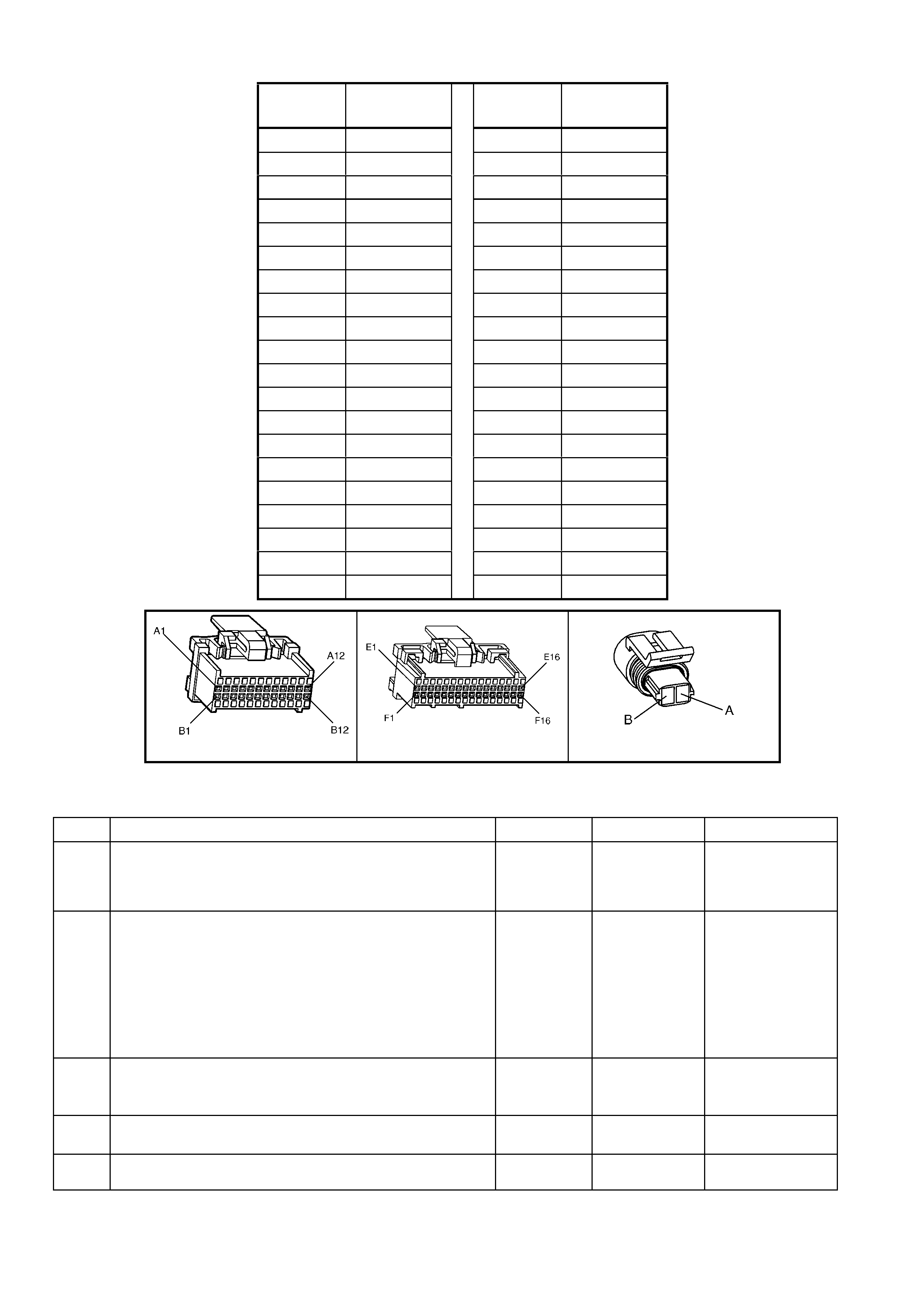
IAT SENSOR TABLE RESISTANCE-TEMPERATURE CHARACTERISTICS
Temp
(°
°°
°C) No Load (Ω
ΩΩ
Ω) Temp
(°
°°
°C) No Load (Ω
ΩΩ
Ω)
-40 102,129 60 679
-35 73,345 65 566
-30 53,253 70 475
-25 39,066 75 400
-20 28,940 80 338
-15 21,638 85 287
-10 16,321 90 245
-5 12,414 95 210
0 9,517 100 180
5 7,355 105 156
10 5,729 110 135
15 4,497 115 117
20 3,555 120 102
25 2,830 125 89
30 2,268 130 79
35 1,829 135 69
40 1,483 140 61
45 1,210 145 54
50 993 150 48
55 819
A84 V6 S/C – X1 A84 V6 S/C – X3 B64
Figure 6C2-2A-81
DTC 23 V6 S/C PCM – INTAKE AIR TEMPERATURE (IAT) SENSOR CIRCUIT HIGH VOLTAGE
STEP ACTION VALUE YES NO
1. Was the "On-Board Diagnostic" (OBD) System Check
performed? Go to Step 2. Go to
OBD
System Check
in this Section.
2. Does Tech 2 "IAT" at or between the specified value?
–30 to –40
°C Go to Step 3 DTC 23
intermittent. If no
additional DTC’s
were stored,
refer to
INTERMITTENTS
in 6C2-2B
SYMPTOMS in
this Section.
3. 1. Disconnect IAT sensor wiring harness.
2. Jumper harness terminals together.
Does Tech 2 display "IAT" at specified value or higher?
130 °C Go to Step 4 Go to Step 6
4. 1. Check resistance across "IAT" sensor terminals.
Is value OK? See IAT
table above. Go to Step 5 Go to Step 12
5. Is there an intermittent or loose terminal in sensor harness
connector? Verify Repair Go to Step 11

STEP ACTION VALUE YES NO
6. 1. Jumper circuit 5089 to ground.
Does Tech 2 scan tool display "IAT" at specified value or
higher?
130 °C Go to Step 7 Go to Step 8
7. 1. Check for an open sensor ground circuit or faulty
connection.
Was an open or faulty connection found?
Verify Repair Go to Step 10
8. 1. Check for an open circuit 5089 or faulty connection.
Was an open or faulty connection found? Verify Repair Go to Step 10
9. 1. Replace intake air temperature sensor.
Is action complete? Verify Repair –
10. 1. Replace PCM. Refer to 6C2-3 SERVICE
OPERATIONS in this Section for PCM Security Link
procedure.
Is action complete?
Verify Repair –
11. 1. Ignition "OFF"
2. Disconnect PCM connectors.
3. Remove jumper from IAT sensor harness.
4. Ignition "ON".
5. Check for short to voltage in circuit 5089.
Was a short to voltage found?
Verify Repair Go to Step 10
12. 1. Replace IAT sensor.
Is action complete? Verify Repair –
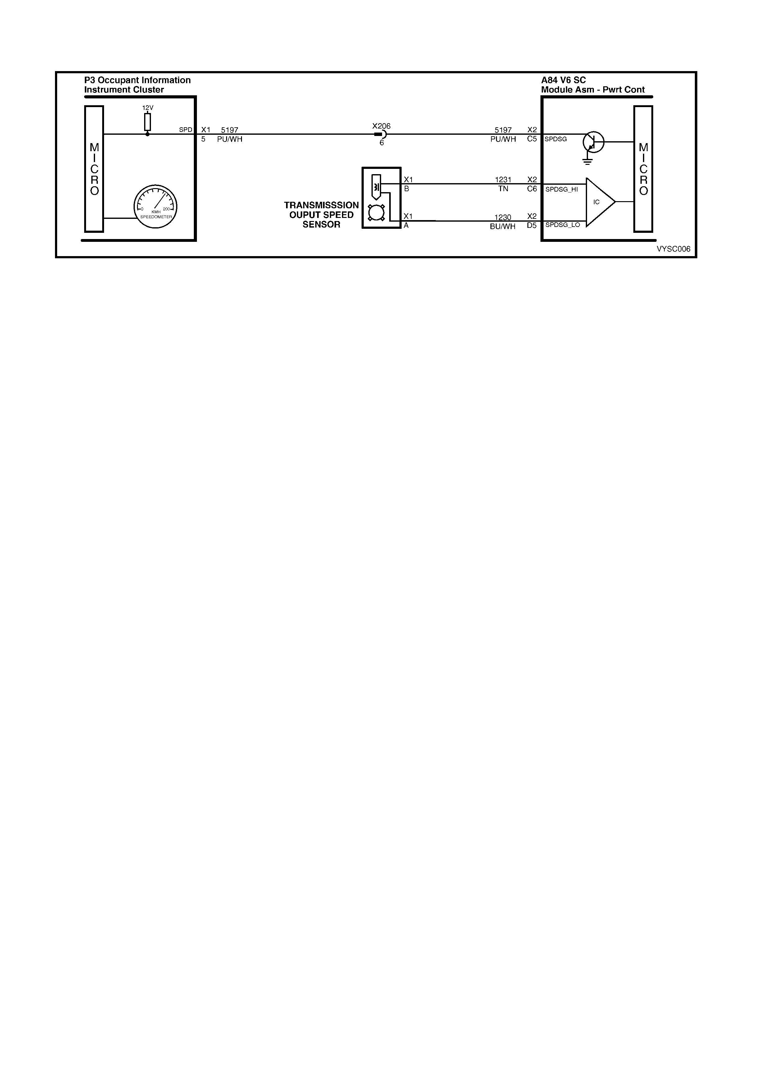
DTC 24 V6 S/C PCM – VEHICLE SPEED SENSOR (VSS) CIRCUIT LOW VOLTAGE
Figure 6C2-2A-82 – Vehicle Speed Sensor
CIRCUIT DESCRIPTION:
The Vehic le Speed Sensor (VSS) provides vehic le speed inf orm ation to the PCM. T he VSS is a perm anent m agnet
generator. T he perm anent magnet generator produces a pulsing AC voltage. T he AC voltage level and the num ber
of pulses increase with the speed of the vehicle. T he PCM then converts the pulsing voltage to vehic le speed. T he
PCM uses this information for calculations. A scan tool can display the vehicle speed.
W hen the PCM detects a low or no vehicle speed, when there is high engine speed in a drive r ange, then DTC 24
sets.
CONDITIONS FOR RUNNING THE DTC:
• The transmission is not in Park or Neutral.
• The engine speed is greater than 3000 RPM.
• The TP Sensor angle is between 10% and 99%.
CONDITIONS FOR SETTING THE DTC:
• The VSS indicates an output shaft speed of less than 3 km/h for 3 seconds.
ACTION TAKEN WHEN THE DTC SETS:
• The PCM illuminates the Check Powertrain Malfunction Indicator Lamp (MIL) when the diagnostic runs and
fails.
• The PCM records the operating conditions at the time the diagnostic fails. The PCM stores this information in
the History Data.
• For the automatic transmission, when this DTC sets, the PCM will command first gear only. The PCM will
command maximum line pressure, freeze shift adapts from being updated and will inhibit TCC engagement.
CONDITIONS FOR CLEARING THE CHECK POWERTRAIN MIL/DTC:
• The PCM turns the Chec k Powertrain MIL OF F af ter the f irs t ignition c ycle that the diagnostic runs and does not
fail.
• Use Tech 2 to clear the Check Powertrain MIL/DTC.
DIAGNOSTIC AIDS:
• Inspect the wiring for poor electrical connections at the PCM. Look for the following conditions:
- A bent terminal.
- A backed out terminal.
- A damaged terminal.
- Poor terminal tension.
- A chafed wire.
- A broken wire inside the insulation.
- Moisture intrusion.
- Corrosion.
• When diagnosing for an intermittent short or open condition, massage the wiring harness while watching the
test equipment for a change.
• Check cir cuits 1231 and 1230 f or the proper connections to be sure they are clean and tight and the harness is
routed correctly.
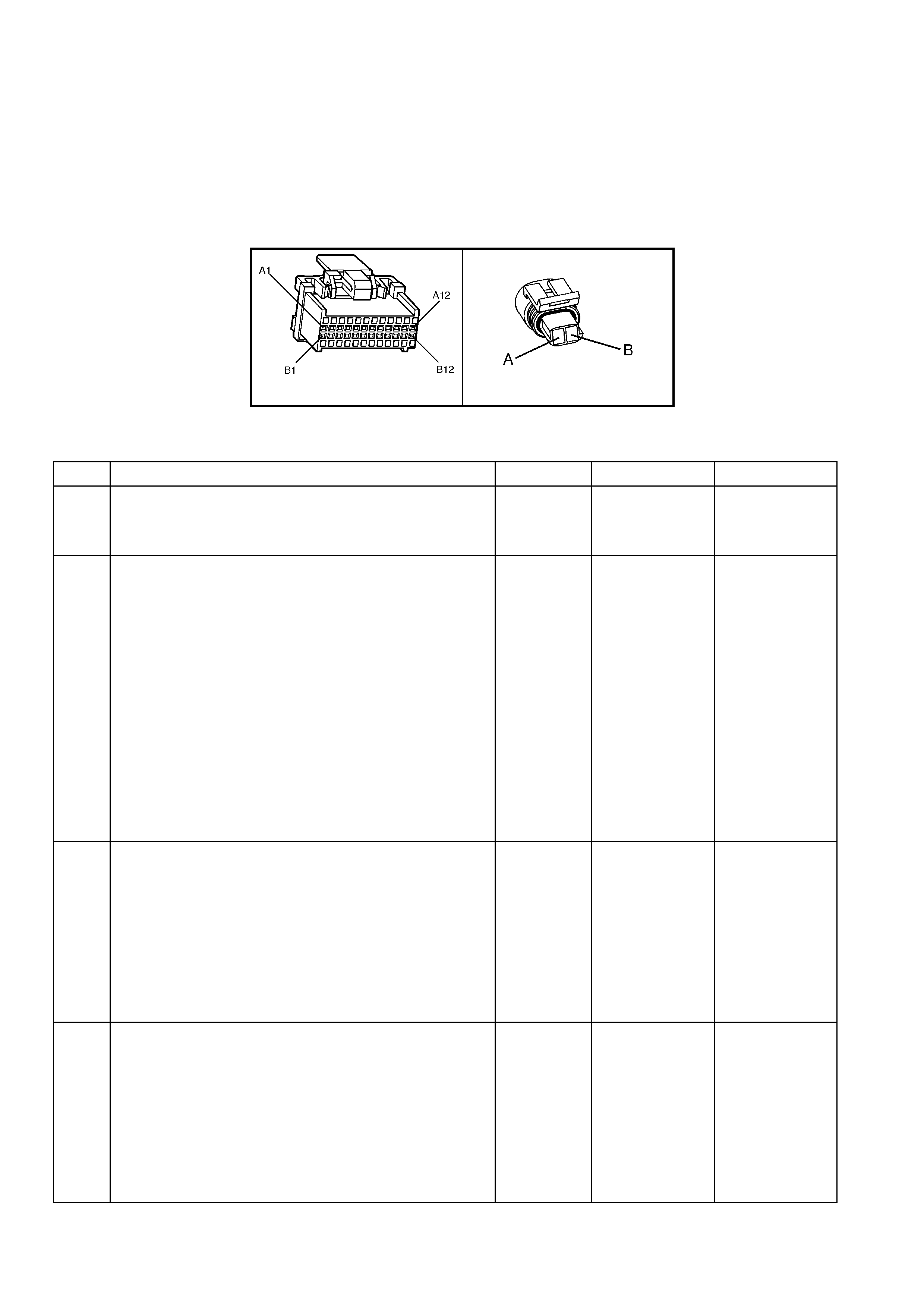
• The scan tool should indicate a vehicle speed whenever the drive wheels are turning greater than 3 km/h.
• The vehicle speed sensor resistance should be between 1,470–2,140 Ω at 20° C, and 2,270–2,820 Ω at 100° C.
• Refer to Intermittents in Section 6C2-2B SYMPTOMS.
TEST DESCRIPTION:
NOTE: Number(s) below refer to step number(s) on the diagnostic table.
3. This step tests the integrity of the VSS.
4. This step tests the VSS circuit.
13. The shank of a 0.95 mm twist drill is ideal for this PCM terminal tension test.
A84 V6 S/C – X1 X121 – X1
Figure 6C2-2A-83
DTC 24 V6 S/C PCM – VEHICLE SPEED SENSOR (VSS) CIRCUIT LOW VOLTAGE
STEP ACTION VALUE YES NO
1. Was the "On-Board Diagnostic" (OBD) System Check
performed? Go to Step 2. Go to
OBD
System Check
in this Section.
2. 1. Install Tech 2.
2. With the engine OFF, turn the ignition switch to the
“ON” position.
IMPORTANT: Before clearing the DTC’s, use Tech 2 to
record the DTC history for reference. The “Clear Info”
function will erase the data.
3. Record the DTC history.
4. Clear the DTC.
5. Raise the rear wheels.
NOTE: Do not perform this test without supporting the
lower control arms so that the drive shafts are in a normal
horizontal position.
6. Start the engine.
7. Place the transmission in any drive gear.
With the rear wheels rotating, does the Tech 2 scan tool
“Vehicle Speed” display, increase with drive wheel speed?
Go to
“Diagnostic
Aids” above.
Go to Step 3
3. 1. Turn the ignition switch to the “OFF” position.
2. Disconnect the VSS connector from the VSS.
3. Using the J 35616-A Connector Test Adaptor Kit,
connect a DMM to the VSS terminals.
4. Select AC volts.
5. Place the transmission selector in the neutral position.
6. Rotate the drive wheels by hand, ensuring that the
driveshaft is turning.
W ith rear wheels rotating, is the DMM voltage greater than
the specified value?
0.5 volts AC Go to Step 4 Go to Step 11
4. 1. Turn the ignition switch to the “OFF” position.
2. Reconnect the wiring harness connector to the VSS.
3. Disconnect the PCM connector from the PCM.
4. Connect the DMM test leads to the connector
terminals A84-X2 D5 (TN) and A84-X2 C6 (BLU/WH).
5. Place the transmission selector in the neutral position.
6. Rotate the drive wheels by hand, ensuring that the
propeller shaft is turning.
W ith rear wheels rotating, is the DMM voltage greater than
the specified value?
0.5 volts AC Go to Step 14 Go to Step 5

STEP ACTION VALUE YES NO
5. 1. Select Ω (Ohms), on the DMM.
2. Measure the resistance between the connector
terminals A84-X2 D5 and A84-X2 C6.
Is the circuit resistance within the specified range?
1,470-2,820
Ω Go to Step 6 Go to Step 8
6. 1. Connect the DMM between the connector terminal
A84-X2 C6 and ground.
Is the circuit resistance less than the specified value?
250k Ω Go to Step 7 Go to
“Diagnostic
Aids”, above.
7. 1. Check circuit 1231 and circuit 1230 for a short to
ground.
2. Repair the circuit if necessary.
Was the short to ground condition found and corrected?
Go to Step 15 Go to
“Diagnostic
Aids” above.
8. Is the resistance reading in step 6 greater than the
specified value? 2,820 Ω Go to Step 10 Go to Step 9
9. 1. Check circuit 1231 and circuit 1230 for a shorted
together condition.
2. Repair the circuit if necessary.
Was a shorted together condition found and corrected?
Go to Step 15 Go to
“Diagnostic
Aids” above.
10. 1. Check circuit 1231 and circuit 1230 for an open
condition.
2. Repair the circuit if necessary.
Was an open condition found and corrected?
Go to Step 15 Go to
“Diagnostic
Aids” above.
11. 1. Remove the VSS from the transmi ssion.
2. Inspect the VSS output sensor rotor in the
transmission, for damage or misalignment.
Did you find a non-standard condition?
Refer to 7C-5
Automatic
Transmission –
Unit Repair in
the MY 2003 VY
and V2 Series
Service
Information.
Go to Step 12
12. 1. Replace the VSS. Refer to Refer to 7C-4 Automatic
Transmission – ON-VEHICLE SERVICING in the MY
2003 VY and V2 Series Service Information.
Is the action complete?
Go to Step 15 –
13. 1. Replace PCM. Refer to 6C2-3 SERVICE
OPERATIONS in this Section for PCM Security Link
procedure.
Is action complete?
Refer to
“Diagnostic
Aids” above.
Go to Step 15 –
14. 1. Check PCM terminals A84-X2 D5 and A84-X2 C6 for
correct terminal tension.
Was a problem found?
Go to Step 15 Go to Step 13
15. In order to verify your repair, connect Tech 2 to the vehicle
and perform the following procedure:
1. Select DTC.
2. Select Clear Info.
3. Operate the vehicle ensuring that the vehicle
speed is greater than 10 km/h and observe the
scan tool “Vehicle Speed”.
Is the Tech 2 “Vehicle Speed” value greater than the
specified value?
10 km/h System OK Go to Step 2

DTC 25 V6 S/C PCM –
INTAKE AIR TEMPERATURE (IAT) SENSOR CIRCUIT LOW VOLTAGE
Figure 6C2-2A-84 – Intake Air Temperature
CIRCUIT DESCRIPTION:
The Intake Air Temperature (IAT) sensor uses a thermistor to control the signal voltage to the PCM. The PCM
applies a voltage (about 5 volts) on circuit 5089 to the sensor. W hen the intake air is cold, the sensor (thermistor)
resistance is high, therefore, the PCM will sense a high signal voltage. If the intake air is warm, the sensor
(thermistor) resistance is low, therefore, the PCM will sense a low signal voltage.
CONDITIONS FOR RUNNING THE DTC:
• The engine has been running for more than 10 seconds.
CONDITIONS FOR SETTING THE DTC:
• IAT Sensor signal voltage is less than 0.3 volts, indicating an intake air temperature at or above 135° C for
more than one second.
ACTION TAKEN WHEN THE DTC SETS:
• The PCM stores the DTC information into memory when the diagnostic runs and fails.
• The Check Powertrain Malfunction Indicator Lamp (MIL) will not be illuminated.
• The PCM records the operating conditions at the time the diagnostic fails. The PCM stores this information in
the History Data.
• When DTC 25 is set, the PCM will default to a 25° C IAT for engine operation.
CONDITIONS FOR CLEARING THE CHECK POWERTRAIN MIL/DTC:
• Use Tech 2 clear the Check Powertrain MIL/DTC.
DIAGNOSTIC AIDS:
Intake Air Temperature (IAT) on a Tech 2 scan tool indicates the temperature of the air in the air cleaner. If the
engine has been allowed to sit overnight, the IAT sensor and engine coolant tem peratur e values should be within a
few degrees of each other. After the engine is started, the IAT will increase, due to the engine compartment
temperature increase. IAT however, will rarely exceed 80° C.
When the PCM detects a fault in the IAT circuit, a default value of 25° C will be used.
Check harness routing for possible short to ground in circuit 5089.
Refer to Intermittents in Section 6C2-2B SYMPTOMS.
TEST DESCRIPTION:
NOTE: Number(s) below refer to step number(s) on the diagnostic table.
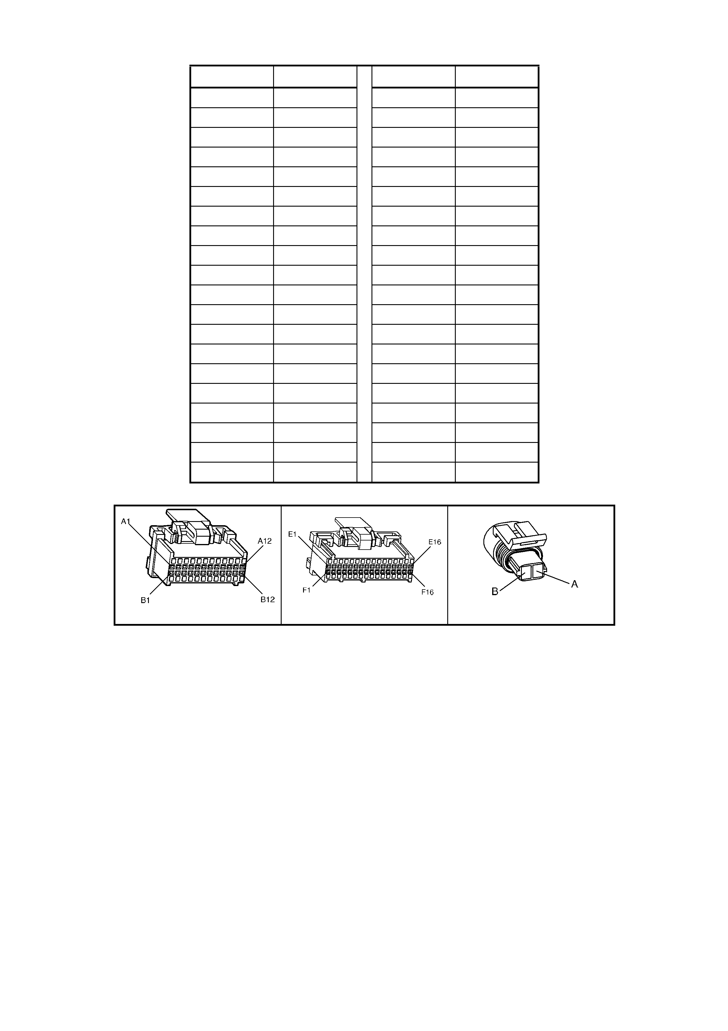
IAT SENSOR TABLE RESISTANCE-TEMPERATURE CHARACTERISTICS
Temp (°
°°
°C) No Load (Ω
ΩΩ
Ω) Temp (°
°°
°C) No Load (Ω
ΩΩ
Ω)
-40 102,129 60 679
-35 73,345 65 566
-30 53,253 70 475
-25 39,066 75 400
-20 28,940 80 338
-15 21,638 85 287
-10 16,321 90 245
-5 12,414 95 210
0 9,517 100 180
5 7,355 105 156
10 5,729 110 135
15 4,497 115 117
20 3,555 120 102
25 2,830 125 89
30 2,268 130 79
35 1,829 135 69
40 1,483 140 61
45 1,210 145 54
50 993 150 48
55 819
A84 V6 S/C – X1 A84 V6 S/C – X3 B64
Figure 6C2-2A-85

DTC 25 V6 S/C PCM – INTAKE AIR TEMPERATURE (IAT) SENSOR CIRCUIT LOW VOLTA GE
STEP ACTION VALUE YES NO
1. Was the "On-Board Diagnostic" (OBD) System Check
performed? Go to Step 2. Go to
OBD
System Check
in this Section.
2. 1. Connect Tech 2 to the DLC.
Does Tech 2 display "IAT" equal or greater than specified
value?
135 °C Go to Step 3 DTC 25 is
intermittent, if no
additional DTC’s
were stored,
refer to
"Diagnostic
Aids" above.
3. 1. Disconnect IAT sensor wiring harness connector B64.
Does Tech 2 display "IAT" below specified value? –30 °C Go to Step 4 Go to Step 6
4. 1. Measure resistance across IAT sensor.
Does value correspond to specified value? Refer to IAT
table above. Go to Step 5 Go to Step 7
5. 1. Check for intermittent or loose terminals in wiring
harness connector B64, or terminals shorted together.
Was a problem found?
Verify Repair. Go to Step 8
6. 1. Check for a short in circuit 5089 to ground or to IAT
sensor ground.
Was a problem found?
Verify Repair. Go to Step 8
7. 1. Replace IAT sensor.
Is action complete? Verify Repair.
8. 1. Replace PCM. Refer to 6C2-3 SERVICE
OPERATIONS, in this Section, for Security Link
procedure.
Is action complete?
Verify Repair. –
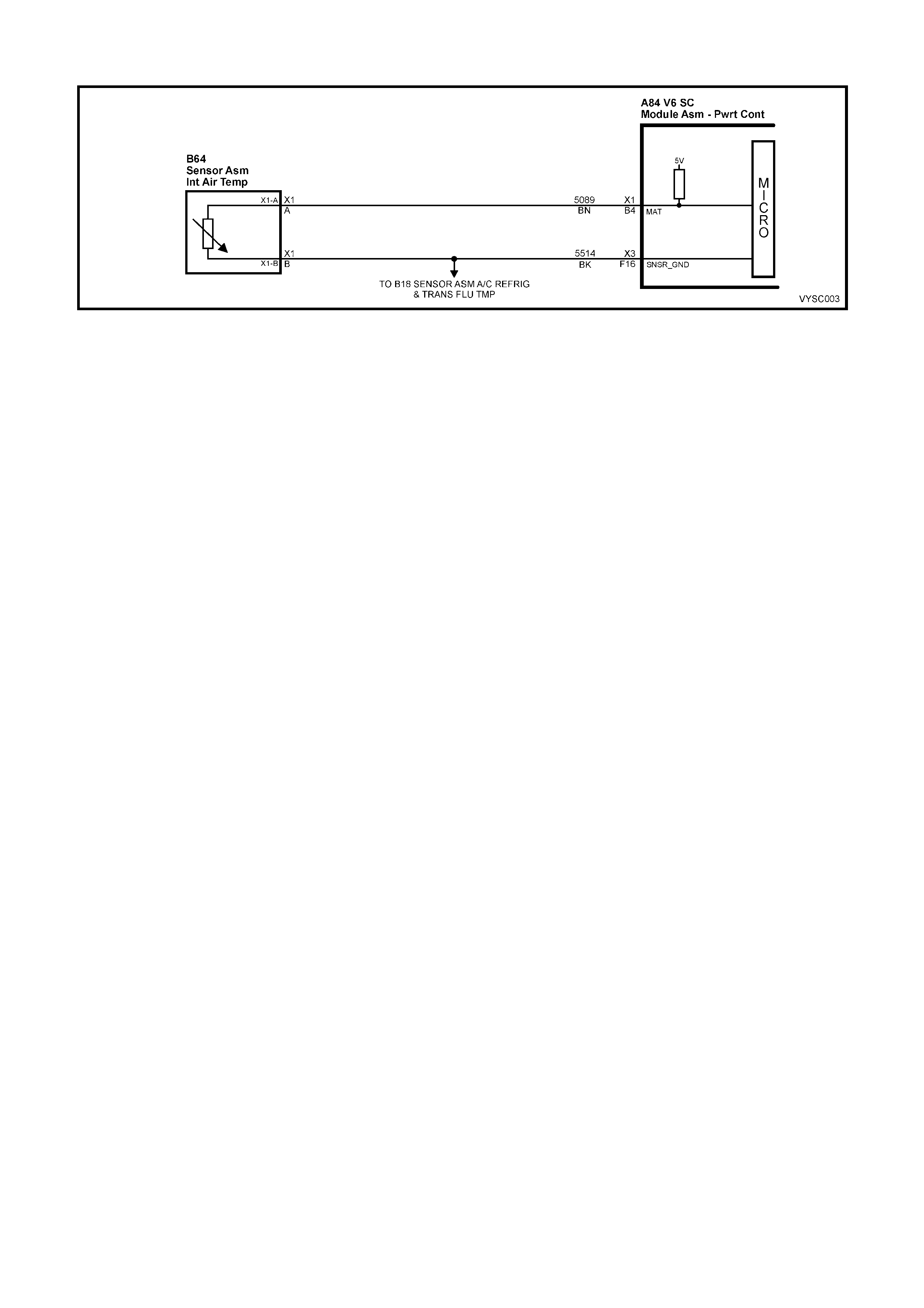
DTC 26 V6 S/C PCM – INTAKE AI R TEMPERATURE (IAT) S ENSOR UNSTABLE
Figure 6C2-2A-86 – Intake Air Temperature
CIRCUIT DESCRIPTION:
The Intake Air Temperature (IAT) sensor uses a thermistor to control the signal voltage to the PCM. The PCM
applies a voltage (about 5 volts) on circuit 5089 to the sensor. W hen m anifold intake air is cold (such as when the
engine is f ir st s tar ted on a c old day), the sensor ( thermis tor) r esis tanc e is high, ther ef or e, the PCM will sense a high
signal voltage. If the manifold intake air is warm, the sensor (thermistor) resistance is low, therefore, the PCM will
sense a low signal voltage.
CONDITIONS FOR RUNNING THE DTC:
• The engine has been running for more than 10 seconds.
CONDITIONS FOR SETTING THE DTC:
• IAT sensor reading changes more than 7° C (140 millivolts) in 100 milliseconds.
ACTION TAKEN WHEN THE DTC SETS:
• The PCM stores the DTC information into memory when the diagnostic runs and fails.
• The Check Powertrain Malfunction Indicator Lamp (MIL) will not be activated.
• The PCM records the operating conditions at the time the diagnostic fails. The PCM stores this information in
the History Data.
• When DTC 26 is set, the PCM will default to a 25° C IAT for engine operation.
CONDITIONS FOR CLEARING THE CHECK POWERTRAIN MIL/DTC:
• Use Tech 2 to clear the Check Powertrain MIL/DTC.
DIAGNOSTIC AIDS:
When attempting to diagnose an intermittent problem, use the snapshot mode of Tech 2 to review diagnostic
information.
TEST DESCRIPTION:
NOTE: Number(s) below refer to step number(s) on the diagnostic table.
8 &10. To perform these terminal tests, use a terminal of appropriate size, from the Test Connector Adaptor Kit
35616-A.
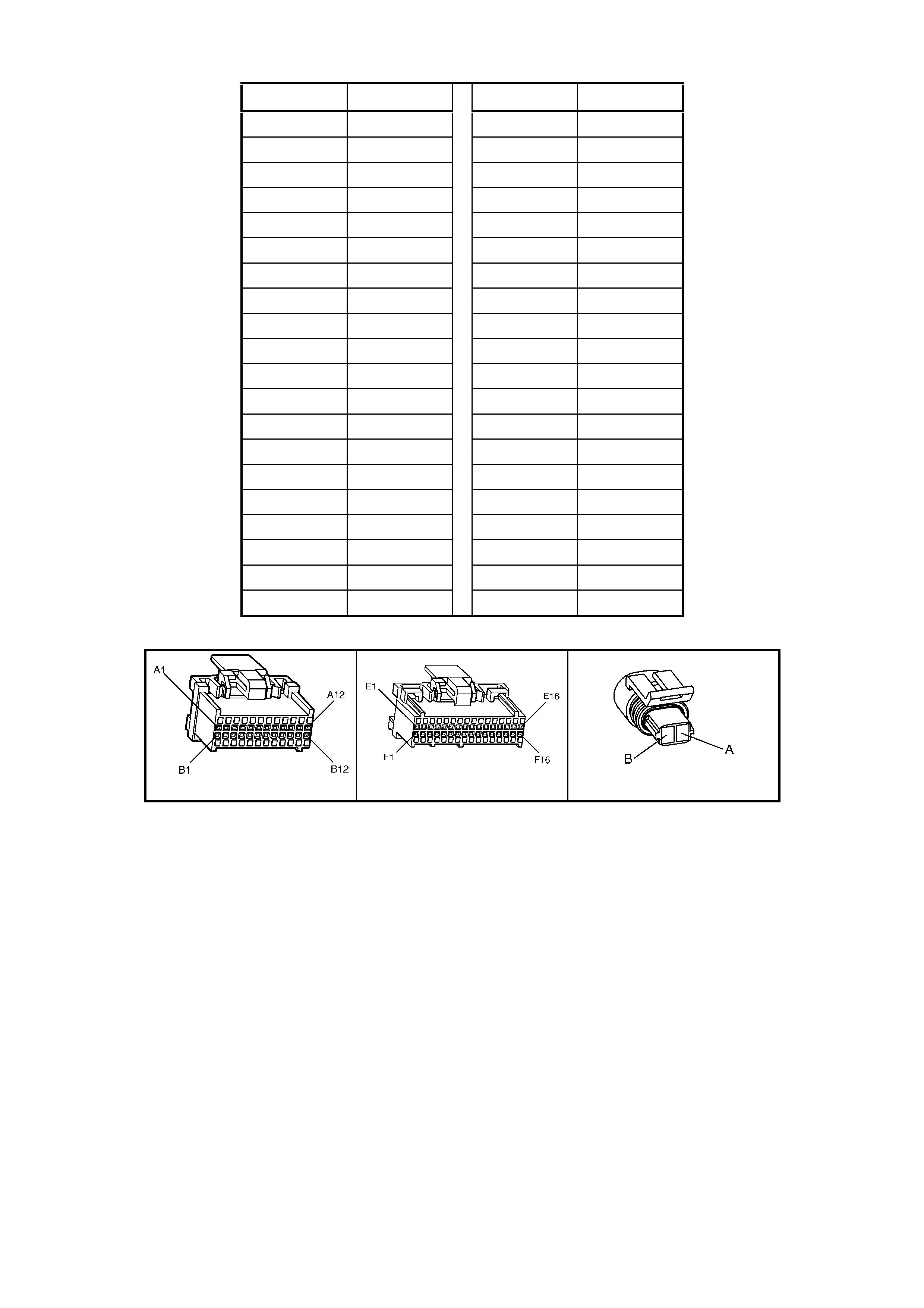
IAT SENSOR TABLE RESISTANCE-TEMPERATURE CHARACTERISTICS
Temp (°
°°
°C) No Load (Ω
ΩΩ
Ω) Temp (°
°°
°C) No Load (Ω
ΩΩ
Ω)
-40 102,129 60 679
-35 73,345 65 566
-30 53,253 70 475
-25 39,066 75 400
-20 28,940 80 338
-15 21,638 85 287
-10 16,321 90 245
-5 12,414 95 210
0 9,517 100 180
5 7,355 105 156
10 5,729 110 135
15 4,497 115 117
20 3,555 120 102
25 2,830 125 89
30 2,268 130 79
35 1,829 135 69
40 1,483 140 61
45 1,210 145 54
50 993 150 48
55 819
A84 V6 S/C – X1 A84 V6 S/C – X3 B64
Figure 6C2-2A-87

DTC 26 V6 S/C PCM – INTAKE AIR TEMPERATURE (IAT) SENSOR UNSTABLE
STEP ACTION VALUE YES NO
1. Was the "On-Board Diagnostic" (OBD) System Check
performed? Go to Step 2. Go to
OBD
System Check
in this Section.
2. 1. Install Tech 2 and set up snapshot mode to trigger on
DTC 26.
2. Watch the Tech 2 screen while wriggling the IAT
sensor connector.
Does the snapshot trigger or the "IAT" reading change
sharply?
Go to Step 8 Go to Step 3
3. 1. Wriggle and tug the IAT sensor harness.
Does the snapshot trigger or the "IAT" reading change
sharply?
Go to Step 9 Go to Step 4
4. 1. Wriggle and tug the harness at the PCM.
Does the snapshot trigger or the "IAT" reading change
sharply?
Go to Step 10 Go to Step 5
5. 1. Lightly tap on the PCM.
Does the snapshot trigger or the "IAT" reading change
sharply?
Go to Step 6 DTC 26 is
intermittent,
refer to
“Diagnostic
Aids” above.
6. Make sure PCM is mounted securely to vehicle.
Was a problem found? Verify Repair Go to Step 7
7. 1. Replace PCM. Refer to 6C2-3 SERVICE
OPERATIONS in this Section for PCM Security Link
procedure.
Is action complete?
Verify Repair –
8. 1. Check IAT sensor connector.
2. Check the tightness of the female terminal grip with a
suitable test terminal.
3. Inspect connectors for corrosion. If connectors are
corroded, try cleaning with electronic part cleaner and
retest.
4. If these repairs do not resolve the problem, replace
terminals.
Is action complete?
Verify Repair –
9. 1. Check for an open in the IAT harness.
2. Check for broken strands of wire in IAT sensor
harness.
3. Check for cuts or pinches in IAT sensor harness.
4. Make repairs as necessary.
Is action complete?
Verify Repair –
10. 1. Check the IAT sensor connection at the PCM,
terminals A84-X1 B4 and A84-X3 F16.
2. Check tightness of the female terminal grip with a
suitable test terminal.
3. Inspect connectors for corrosion. If connectors are
corroded, try cleaning with electronic parts cleaner
and retest.
4. Remove connector strain relief and remove terminal
from connector to check for broken locking tang.
Is action complete?
Verify Repair –

DTC 28 V6 S/C PCM –
TRANSMISSION FLUID PRESSURE (TFP) MANUAL VALVE POSITION SWITCH CIRCUIT
Figure 6C2-2A-88 Transmission Fluid Pressure (TFP) Valve Position Switch Circuit
CIRCUIT DESCRIPTION:
The Autom atic T ransm ission Fluid Pr essure (T FP) Manual Valve Pos ition Switch consists of five pressure switches
(two norm ally-clos ed and three normally-open) and a Tr ansmiss ion Fluid Tem perature (TF T) sensor com bined into
one unit. The c ombined unit mounts on the valve body. The PCM supplies the battery voltage for each r ange signal.
By grounding one or more of the circuits through various com binations of the pressure switches, the PCM detects
which manual valve position is selected. The PCM compares the actual voltage combination of the switches to a
TFP combination table stored in memory. The TFP cannot distinguish between Park and Neutral because the
monitored valve body pressures are identical. With the engine OFF and the ignition switch in the RUN position, the
TFP indicates Park/Neutral. Disconnecting the transmission pass-through connector removes the grounding
potential for the three range signals to the PCM. In this case, with the engine OFF, and the ignition switch in the
RUN position, D2 will be indicated.
W hen the PCM detects an invalid state of the TFP or the T FP circuit by deciphering the TFP inputs, then DTC 28
will set.
CONDITIONS FOR RUNNING THE DTC:
• The engine is running.
• The vehicle automatic transmission is in gear.
CONDITIONS FOR SETTING THE DTC:
Condition 1
• The PCM detects an illegal TFP manual valve position switch state for 60 seconds.
Condition 2
• The engine s peed is less than 80 RPM for 0.1 s econd; then the engine speed is 80-550 RPM f or 0.07 seconds;
then the engine speed is greater than 500 RPM.
• The PCM detects a gear range of D2, D4, or Reverse during an engine start.
• All conditions are met for 5 seconds.
Condition 3
• The TP angle is 8-45%.
• The PCM commands 4th gear.
• The TCC is locked ON.
• The speed ratio is 0.65-0.8 (speed ratio is engine speed divided by transmission output speed).
• The PCM detects a gear range of Park or Neutral when operating in D4.
• All conditions are met for 10 seconds.

ACTION TAKEN WHEN THE DTC SETS:
• The PCM illuminates the Check Powertrain Malfunction Indicator Lamp (MIL) when the diagnostic runs and
fails.
• The PCM records the operating conditions at the time the diagnostic fails. The PCM stores this information in
the History Data.
• When DTC 28 is set, the PCM will inhibit TCC engagement, command D2 line pressure, and freeze shift adapts
from being updated.
CONDITIONS FOR CLEARING THE CHECK POWERTRAIN MIL/DTC:
• The PCM turns the Chec k Powertrain MIL OF F af ter the f irs t ignition c ycle that the diagnostic runs and does not
fail.
• Use Tech 2 to clear the Check Powertrain MIL/DTC.
DIAGNOSTIC AIDS:
• Refer to the TFP logic table for the normal range signals and the illegal combinations.
• Inspect the wiring for poor electrical connections at the PCM. Inspect the wiring for poor electrical connections
at the transmission pass-through connector. Look for the following conditions:
- A bent terminal
- A backed out terminal
- A damaged terminal
- Poor terminal tension
- A chafed wire
- A broken wire inside the insulation
- Moisture intrusion
• When diagnosing for an intermittent short or open condition, massage the wiring harness while watching the
test equipm ent for a change. Refer to “Table 2.2 V6 PCM Transm ission Fluid Pressure Manual Valve Position
Switch Check” in Section 6C2-2C FUNCTIONAL CHECKS, for further information.
TFP VALVE POSITION SWITCH LOGIC
Gear
Position Range Signal
Switch A Range Signal
Switch B Range Signal
Switch C
P Open 12V Closed 0V Open 12V
R Closed 0V Closed 0V Open 12V
N Open 12V Closed 0V Open 12V
D Open 12V Closed 0V Cl osed 0V
3 Open 12V Open 12V Cl osed 0V
2 Open 12V Open 12V Open 12V
1 Cl osed 0V Open 12V Open 12V
Illegal Closed 0V Open 12V Closed 0V
Illegal Closed 0V Closed 0V Closed 0V
TEST DESCRIPTION:
NOTE: Number(s) below refer to the step number(s) on the diagnostic table.
3. This step compares the indicated range signal to the manual valve position that is actually selected.
4. This step tests for correct voltage from the PCM to the transmission pass-through connector terminals.
X121-X2
Figure 6C2-2A-89

DTC 28 V6 S/C PCM – TRANSMISSION FLUID PRESSURE (TFP) VALVE POSITION SWITCH CIRCUIT
STEP ACTION VALUE YES NO
1. Was the "On-Board Diagnostic" (OBD) System Check
performed? Go to Step 2. Go to |
OBD
System Check
in this Section.
2. Perform the following inspections:
1. Ensure that the transmission linkage from the select
lever to the manual valve is adjusted properly.
2. Perform the fluid checking procedure/inspection.
Did you perform the inspections?
Go to Step 3 Perform the
Inspections
3. 1. Install Tech 2.
2. With the engine OFF, turn the ignition switch to the
RUN position.
IMPORTANT: Before clearing the DTCs, use Tech 2 to
record the DTC history for reference. The “Clear Info”
function will erase the data.
3. Record the DTC history.
4. While the engine is idling at normal operating
temperature, apply the parking brake.
5. Select each transmission range: P, R, N, D4, D3, D2,
and D1.
Does each selected transmission range match the scan
tool TFP Switch A/B/C display?
• Refer to the TFP logic table, above.
Go to
“Diagnostic
Aids” above.
Go to Step 4
4. 1. Turn the ignition OFF.
2. Disconnect the transmission pass-through connector
(additional DTC’s may set).
3. Install the J 39775 Jumper Harness on the engine side
of the transmission pass-through connector.
4. With the engine OFF, turn the ignition switch to the
RUN position.
5. Using a DMM and J 35616-A Connector Test Adaptor
Kit, check for voltage at connector terminals N, R, and
P.
Is B+ displayed on all three circuits?
Go to Step 6 Go to Step 5
5. 1. Check the circuits that did not indicate B+ for an open
or a short to ground, including PCM terminals for
proper terminal tension.
2. Repair the circuits if necessary.
Did you find and correct the problem?
Go to Step 13 Go to Step 7
6. 1. In order to verify that circuits 1224, 1225 and 1226 are
not shorted together, use a fused jumper to ground, on
each circuit while monitoring the scan tool TFP Switch
A/B/C display.
When a range signal circuit is grounded, are any other
range signal circuits affected?
Go to Step 8 Go to Step 9
7. 1. Replace PCM. Refer to 6C2-3 SERVICE
OPERATIONS in this Section, for PCM Security Link
procedure.
Is action complete?
Go to Step 13 –
8. 1. Repair the affected wiring as necessary.
Is the action complete? Go to Step 13 –
9. 1. Turn the ignition switch to the “OFF” position.
2. Reconnect the pass-through connector.
3. Select the PARK position.
4. Start the engine.
5. Apply the brakes.
6. Move the shift selector through all gear ranges, while
observing the ‘A’ and ‘C’ range signals on the Tech 2
scan tool.
Does either range signal always indicate 0 volts/ON?
Go to Step 10 Intermittent
Problem.
Go to
“Diagnostic
Aids” above.

STEP ACTION VALUE YES NO
10. 1. Turn the ignition switch to the OFF position.
2. Disconnect the transmission pass-through connector.
3. Remove the transmission pan.
4. Remove the internal wiring harness connector from
the TFP Manual Valve Position Switch.
5. Check the internal wiring harness circuits 1224 and
1226 for a short to ground.
Did you find a short to ground condition on either circuit?
Go to Step 12 Go to Step 11
11. 1. Replace the TFP Manual Valve Position Switch. Refer
to 6C2-3 SERVICE OPERATIONS, in this Section.
Is the action complete?
Go to Step 13 –
12. 1. Replace the internal A/T Wiring Harness Assembly.
Refer to 7C-4 AUTOMATIC TRANSMISSION – ON-
VEHICLE SERVICING in the MY 2003 VY and V2
Series Service Information.
Is the replacement complete?
Go to Step 13 –
13. In order to verify your repair, perform the following
procedure:
1. Select DTC on Tech 2.
2. Select Clear Info.
3. Operate the vehicle under the following conditions:
• With the engine OFF, turn the ignition switch to
the “ON” position for at least 2 seconds.
• Start the vehicle and idle for 5 seconds.
• Select each transmission range: P, R, N, D4, D3,
D2 and D1.
• Compare the Tech 2 TFP Sw. A/B/C/ display, to
the TFP Manual Valve Position Sw. Logic Table.
Does each shifter position range signal match the Tech 2
TFP Sw. A/B/C display?
System OK Begin the
diagnosis again.
Go to Step 2
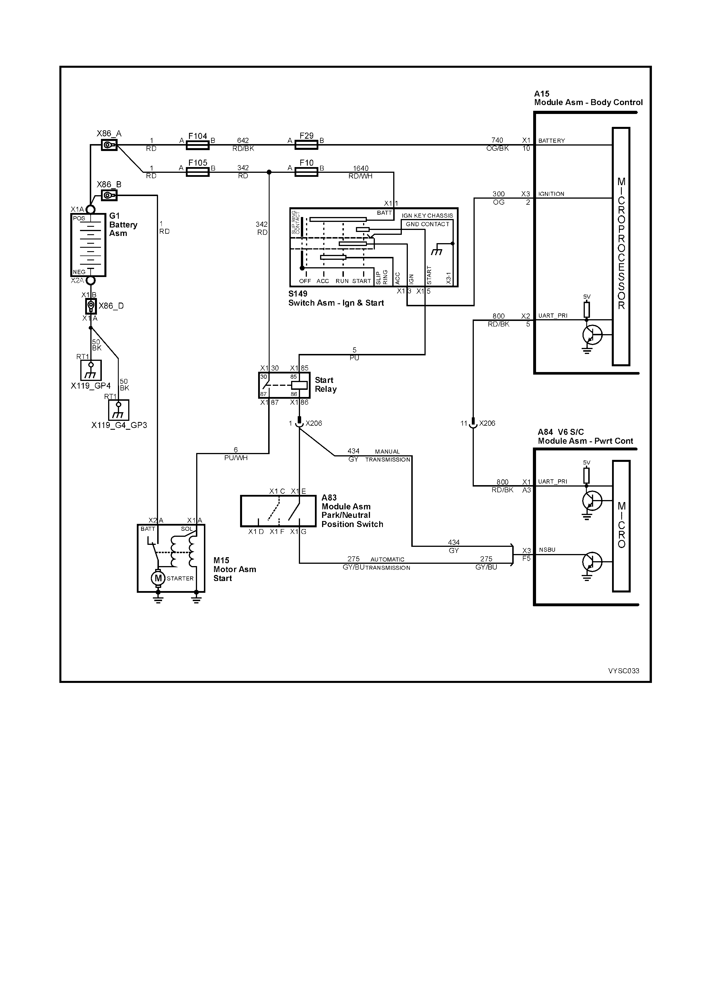
DTC 31 V6 S /C PCM – THEFT DETE RRENT SIGNAL MISS I NG
Figure 6C2-2A-90 – Theft Deterrent Starter Circuit
CIRCUIT DESCRIPTION:
When the ignition is turned "O N", the BCM will send a thef t deter rent mes s age on cir cuit 800 to the PCM. When the
PCM receives this message, it instantly sends a message back to the BCM. The message says that the proper
ignition key has been used to turn the ignition on and that it is OK for the PCM to enable the fuel injectors to start
the engine. If the PCM does not r ec eive communic ations f rom the BCM when the ignition is switched "ON", then the
starter motor will be disabled after one second and the fuel injector with be turned off.
CONDITIONS FOR RUNNING THE DTC:
• The ignition is on.
CONDITIONS FOR SETTING THE DTC:
• The PCM does not receive serial data for greater than ten seconds.
ACTION TAKEN WHEN THE DTC SETS:
• The PCM records the operating conditions at the time the diagnostic fails. The PCM stores this information in
the History Data.
• When DTC 31 is set and current, the engine will not start.

CONDITIONS FOR CLEARING THE CHECK POWERTRAIN MIL/DTC:
• Use Tech 2 to clear the Check Powertrain MIL/DTC.
DIAGNOSTIC AIDS:
If the instrument does not receive PCM serial data information for more than ten seconds, “Service Error Contact
Dealer” will be displayed in the instrument Multi Function Display.
If the engine starts and runs without a crank delay DTC 31 is intermittent.
TEST DESCRIPTION:
NOTE: The number(s) below refer to the step number(s) on the diagnostic table.
2. If the Theft Deterrent LED is flashing, the BCM has not s een a valid key signal and will be is suing a “No Start”
command to the PCM.
3. If the engine s tarts and r uns, DTC 31 is interm ittent. If the engine cr anks with a one second delay then DTC 31
is current.
4. An open or short to ground on circuit 800 will disable any communication via serial data.
DTC 31 V6 S/C PCM – THEFT DETERRENT SIGNAL MISSING
STEP ACTION VALUE YES NO
1. Was the "On-Board Diagnostic" (OBD) System Check
performed? Go to Step 2 Go to
OBD
System Check
in this Section.
2. 1. Turn the ignition “ON”.
Is the Theft Deterrent LED Flashing? Refer to 12J
Body Control
Module
Go to Step 3
3. 1. Turn the ignition from “OFF“ to “START“.
Does the engine start and continue to run? DTC 31 is
intermittent,
refer to
"Diagnostic
Aids" above.
Go to Step 4
4. 1. Check for poor connection at PCM terminal and/or
open or shorted circuit 800.
Was a problem found?
Verify Repair Go to Step 5
5. Replace PCM. Refer to 6C2-3 SERVICE OPERATIONS,
for PCM Security Link procedure.
Is action complete?
Verify Repair
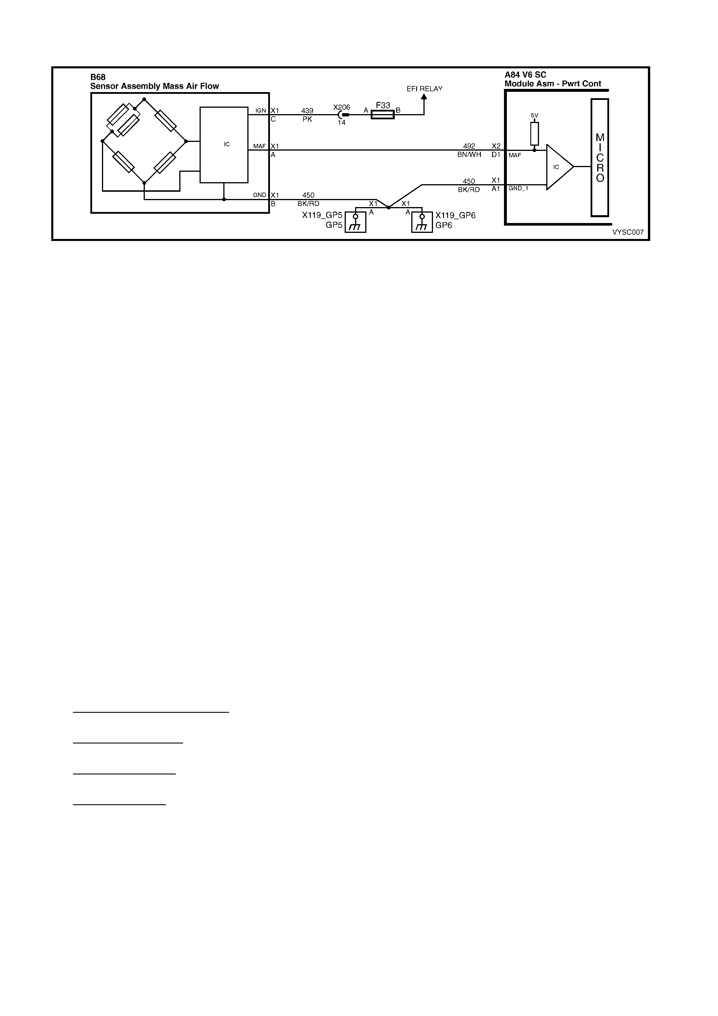
DTC 32 V6 S/C PCM – MASS AIR FLOW (MAF) OUT OF RANGE
Figure 6C2-2A-91 – Mass Air Flow Sensor
CIRCUIT DESCRIPTION:
The Mass Air Flow (MAF) sensor meas ures the flow of air which passes thr ough it in a given time. T he PCM uses
this infor mation to m onitor the operating condition of the engine f or fuel delivery calculations. A large quantity of air
movement indicates acceleration, while a small quantity indicates deceleration or idle.
The MAF sensor produces a frequency signal which cannot be easily measured.
The MAF sensor can be diagnosed using the procedures in this Table.
When DTC 32 is set, the PCM will use a default value for air flow based on throttle position and engine speed.
CONDITIONS FOR RUNNING THE DTC:
• The engine is running.
CONDITIONS FOR SETTING THE DTC:
• No MAF signal for over 2 seconds.
• Above conditions present for at least 10 seconds.
ACTION TAKEN WHEN THE DTC SETS:
• The PCM illuminates the Check Powertrain Malfunction Indicator Lamp (MIL) when the diagnostic runs and
fails.
• The PCM records the operating conditions at the time the diagnostic fails. The PCM stores this information in
the History Data.
• The PCM will substitute a MAF sensor value based on RPM, throttle angle and IAC position.
CONDITIONS FOR CLEARING THE CHECK POWERTRAIN MIL/DTC:
• The PCM turns the Chec k Powertrain MIL OF F af ter the f irs t ignition c ycle that the diagnostic runs and does not
fail.
• Use a Tech 2 scan tool in order to clear the Check Powertrain MIL/DTC.
DIAGNOSTIC AIDS:
An interm ittent may be caused by a poor c onnection, mis-r outed harness, rubbed through wire insulation, or a wire
broken inside the insulation.
Check for:
• Poor Connection at PCM Pin - Inspect harnes s connectors f or backed out ter minals, im proper m ating, broken
locks, improperly formed or damaged terminals, and poor terminal to wire connection.
• Mis-Routed Harnes s - Inspect MAF sensor har ness to ens ure that it is not too c lose to high voltage wires, suc h
as spark plug leads.
• Damaged Harness - Inspect harness for damage. If harness appears OK, observe Tech 2 scan tool while
moving related connectors and wiring harness. A change in display would indicate the intermittent fault location.
• Plugged Air Filter - A wide open throttle ac celeration from a stop should caus e the MAF reading on the Tec h 2
scan tool to range from about 4-7 g/s at idle to 100 or greater at the time of the 1-2 shift on an automatic
transmission. If not, check for restriction.
TEST DESCRIPTION:
NOTE: Number(s) below refer to step(s) on the diagnostic table.
5. Verifies that both ignition feed voltage and a good ground circuit are available.
6. This step checks to see if PCM recognises a problem.
7. A voltage reading at sensor harness connector terminal "A" of less than 4 or over 6 volts indicates a fault in
circuit 492 or poor connection.

A84 V6 S/C – X1 A84 V6 S/C – X2 B68
Figure 6C2-2A-92
DTC 32 V6 S/C PCM – MASS AIR FLOW (MAF) OUT OF RANGE
STEP ACTION VALUE YES NO
1. Was the "On-Board Diagnostic" (OBD) System Check
performed? Go to Step 2. Go to
OBD
System Check
in this Section.
2. 1. Ignition "ON".
2. Using Tech 2, select MAF Sensor.
Is "MAF Sensor" reading at the specified value?
0 Hz Go to Step 4 Go to Step 3
3. 1. Replace MAF sensor.
Is action complete? Verify Repair
4. 1. Ignition "OFF".
2. Disconnect MAF sensor.
3. Ignition "ON".
4. Connect a test light to ground, and probe MAF sensor
harness connector terminal "C".
Is test light "ON"?
Go to Step 5 Go to Step 11
5. 1. Ignition "OFF".
2. Disconnect MAF sensor.
3. Ignition "ON".
4. Measure voltage between MAF sensor harness
connector terminals "B" and "C" .
Is voltage greater than specified value?
10 volts Go to Step 7 Go to Step 10
6. 1. Ignition "OFF".
2. Reconnect MAF sensor.
3. Ignition "ON" engine idling.
Is MAF sensor "MASS AIR FLOW" reading on the Tech 2
scan tool between the specified values?
4 – 9
grams/sec DTC 32 is
intermittent. If no
additional DTC's
were stored,
refer to
"Diagnostic
Aids" above.
Go to Step 3
7. 1. Ignition "OFF".
2. Disconnect wiring harness connector from MAF
sensor.
3. Ignition "ON".
4. Measure voltage at MAF sensor harness connector
terminal "A" with a voltmeter to ground.
Is the measured voltage between the specified values?
4 – 6 volts Go to Step 6 Go to Step 8
8. Is voltage on MAF sensor harness connector terminal "A"
less than specified value ? 4 volts Go to Step 9 Go to Step 12
9. 1. Check for an open or short to ground on circuit 492 or
a poor connection at the PCM.
Is a fault found?
Verify Repair Go to Step 13
10. 1. Repair open in circuit 450.
Is action complete? Verify Repair
11. 1. Repair open or short to ground in circuit 439.
2. Replace fuse F33, if blown.
Is action complete?
Verify Repair
12. 1. Repair short to voltage on circuit 492.
Is action complete? Verify Repair
13. 1. Replace PCM. Refer to 6C2-3 SERVICE
OPERATIONS in this Section for PCM Security
Link procedure.
Is action complete?
Verify Repair

DTC 35 V6 S/C PCM – IDLE SPEED ERROR
Figure 6C2-2A-93 – Idle Air Control
CIRCUIT DESCRIPTION:
The IAC valve is a stepper motor. Stepper motors have coils that the PCM turns ON and OFF several times per
second. T h is allows for an inc remental c loc k wise and c ounter c lockwise rotation of the motor s haf t. T he pintle valve
has a threaded shaft that either extends or retracts with each pulse of the PCM. The controlled pulses are called
steps or counts. The PCM controls the air entering into the engine at idle through the IAC valve. To increase the
idle speed, the PCM will command the pintle valve away from the throttle body. This allows more air to bypass the
throttle blade and thus increase engine RPM. To decrease the engine RPM at idle, the PCM will command the
pintle valve toward the throttle body seat to restrict air from entering into the engine and thus reduce engine RPM.
CONDITIONS FOR RUNNING THE DTC:
• Engine is Idling.
• No TP Sensor or IAT Sensor DTCs are set.
• DTC 36 is not set.
• The IAT is less than 73°C.
• No vehicle speed indicated.
• Conditions present for 5 seconds.
CONDITIONS FOR SETTING THE DTC:
• Engine speed is 200 RPM above or below the desir ed idle speed for 5 sec onds and the IAC has been opened
or closed to its maximum position (255 steps) or minimum position (0 steps).
ACTION TAKEN WHEN THE DTC SETS:
• The PCM stores the DTC information into memory when the diagnostic runs and fails.
• The Check Powertrain Malfunction Indicator Lamp (MIL) will not be activated.
• The PCM records the operating conditions at the time the diagnostic fails. The PCM stores this information in
the History Data.
CONDITIONS FOR CLEARING THE CHECK POWERTRAIN MIL/DTC:
• Use Tech 2 to clear the Check Powertrain MIL/DTC.
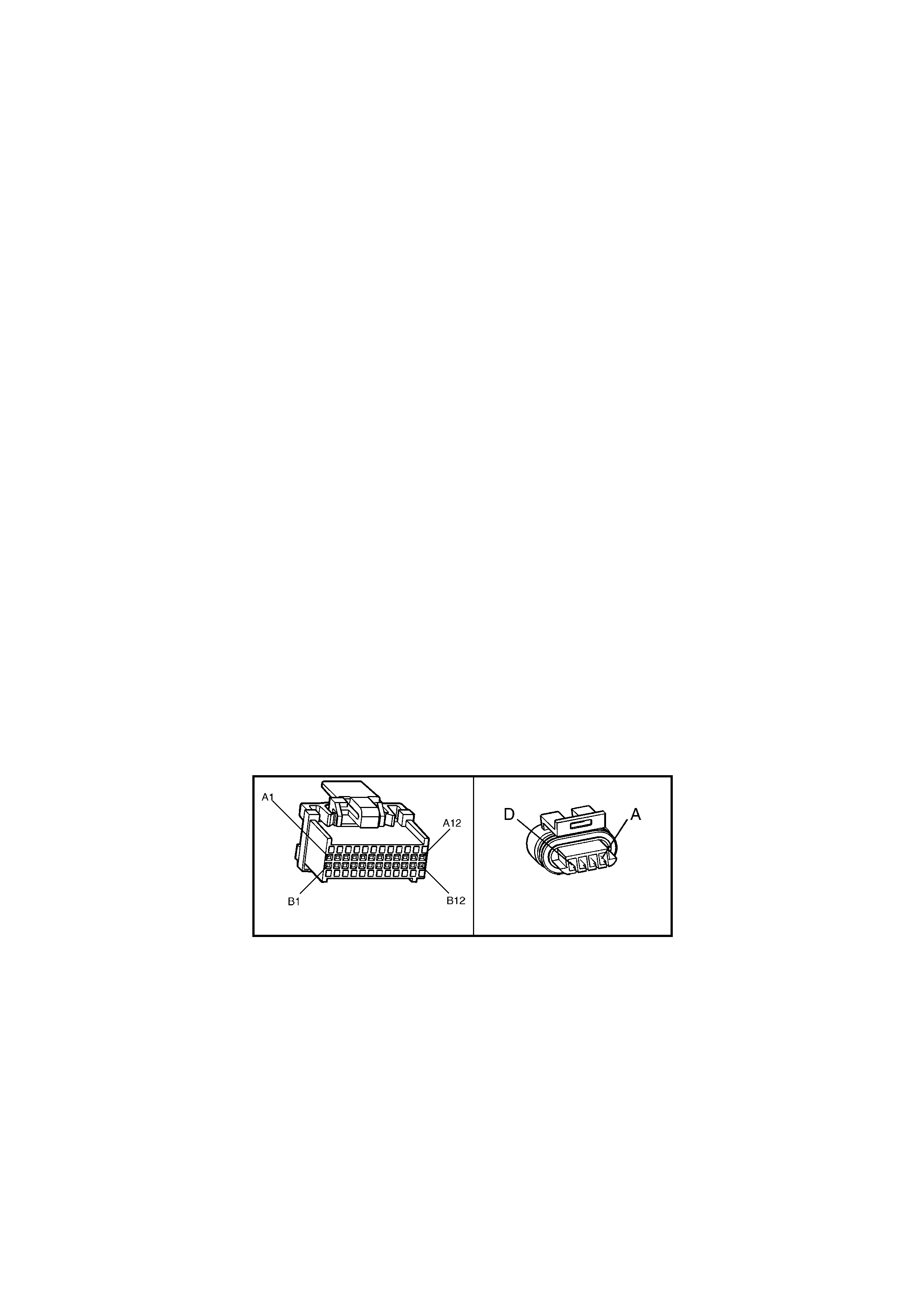
DIAGNOSTIC AIDS:
A slow, uns table, or fas t idle m ay be caused by a non-IAC system pr oblem that cannot be com pens ated by the IAC
valve. Out of control range IAC Tech 2 counts will be above 60 if idle is too low and zero counts if idle is too high.
The following checks should be made to repair a non-IAC system problem:
• High idle.
If idle is too high, stop the engine. Fully extend (low) IAC with Tech 2. Start engine.
If idle speed is above 800 RPM, check for binding of thr ottle blade or linkage or an incor rectly adj usted throttle
stop screw or throttle cable.
• System too lean (High Air/Fuel Ratio).
The idle speed may be too high or too low. Engine speed may vary up and down and disconnecting the IAC
valve does not help. DT C 44 or 64 may be set. Tec h 2 sc an tool O 2 voltage will be less than 300 mV. Check for
low regulated fuel pressure, water in the fuel, a restricted injector or an air leak into the intake manifold, after the
MAF sensor.
• System too rich (Low Air/Fuel Ratio).
The idle speed will be too low. Tech 2 IAC counts will usually be above 80. System is obviously rich and may
exhibit black smoke in exhaust. Tech 2 O2 voltage will be fixed above 800 mV. Check for high fuel pressure,
leaking or sticking injector. Silicon contaminated O2 sensor, Tech 2 voltage will be slow to respond.
• Throttle Body.
Remove the IAC valve and inspect bore for foreign material.
• IAC valve Electrical Connections.
The IAC valve connections should be carefully checked for proper contact tension.
• PCV Valve.
An incorrect or faulty PCV valve may result in an incorrect idle speed.
• Refer to "Rough, Unstable, Incorrect Idle or Stalling" in 6C2-2B SYMPTOMS, in this Section.
• If intermittent poor driveability or idle symptoms are resolved by disconnecting the IAC, carefully recheck
connections, valve terminal resistance, or replace IAC Valve.
TEST DESCRIPTION:
NOTE: Number(s) below refer to step number(s) in the diagnostic table.
2. The Tech 2 IAC Circuit Functions Test is used to extend and retract the IAC valve automatically. The valve
should move smoothly within the specified range. Tech 2 will inform you if the test passes or fails.
3. This test uses the Tech 2 to command the IACV to a controlled idle speed. The PCM issues commands to
obtain the commanded idle speed. The test lights each should flash, indicating a good circuit as the PCM
issues commands. While the sequence is not important, if either light is “OFF” or does not flash, check the
circuits for faults, beginning with poor terminal contacts.
A84 V6 S/C – X1 Y20
Figure 6C2-2A-94

DTC 35 V6 S/C PCM – IDLE SPEED ERROR
STEP ACTION VALUE YES NO
1. Was the "On-Board Diagnostic" (OBD) System Check
performed? Go to Step 2 Go to
OBD
System Check
in this Section.
2. 1. Install Tech 2.
2. Start the engine and allow the engine to idle until the
specified temperature is reached.
3. Transmission in park or neutral.
4. Set the park brake.
5. Turn the A/C OFF.
6. Using Tech 2, perform an IAC Circuit Functions Test.
Was the IAC Circuit Functions Test successful?
80° C IAC valve
control circuits
are OK.
Refer to
Diagnostic Aids
above
Go to Step 3
3. 1. Ignition OFF.
2. Disconnect the IAC valve electrical connector.
3. Measure the resistance across the IAC valve terminals
A and B.
4. Measure the resistance across the IAC valve terminals
C and D.
Are the resistance readings across terminals A and B, and
terminals C and D within the specified values?
40 – 80 Ω Go to Step 4 Go to Step 13
4. 1. Measure the resistance across the IAC valve terminals
B and C.
2. Measure the resistance across the IAC valve terminals
A and D.
Are the resistance readings across terminals B and C, and
terminals A and D within the specified values?
Infinite Go to step 5 Go to Step 13
5. 1. Disconnect the IAC valve electrical connector.
2. Ignition ON engine OFF.
3. With a test light connected to ground, probe the IAC
valve electrical connectors.
Does the test light illuminate on two terminals?
Go to Step 6 Go to Step 7
6. 1. W ith a test light connected to B+, probe the IAC valve
electrical connector terminals.
Does the test light illuminate on two terminals?
Go to Step 8 Go to Step 7
7. 1. Check for an open or a short in the IAC valve Hi and
Lo circuits.
Was a problem found?
Go to Step 12 Go to Step 14
8. 1. Start the engine and allow to idle.
2. With a test light connected to ground, probe the IAC
valve electrical terminals?
Does the test light flash ON and OFF on all the terminals?
Go to Step 10 Go to Step 9
9. Did the test light remain ON steady for the terminals that
did not flash? Go to Step 7 Go to Step 11
10. 1. Check the IAC passages for a restriction.
Was a fault found? Go to Step 15 Go to Step 13
11. 1. Check the PCM electrical connector for proper tension
at the terminals.
Was a problem found?
Go to Step 12 Go to Step 14
12. 1. Repair the circuit or the connector as necessary.
Is the action complete? Verify Repair
13. 1. Replace the IAC valve.
Is the action complete? Verify Repair
14. 1. Replace PCM. Refer to 6C2-3 SERVICE
OPERATIONS in this Section for PCM Security Link
procedure.
Is action complete?
Verify Repair
15. 1. Clean the passages as necessary.
Is the action complete? Verify Repair
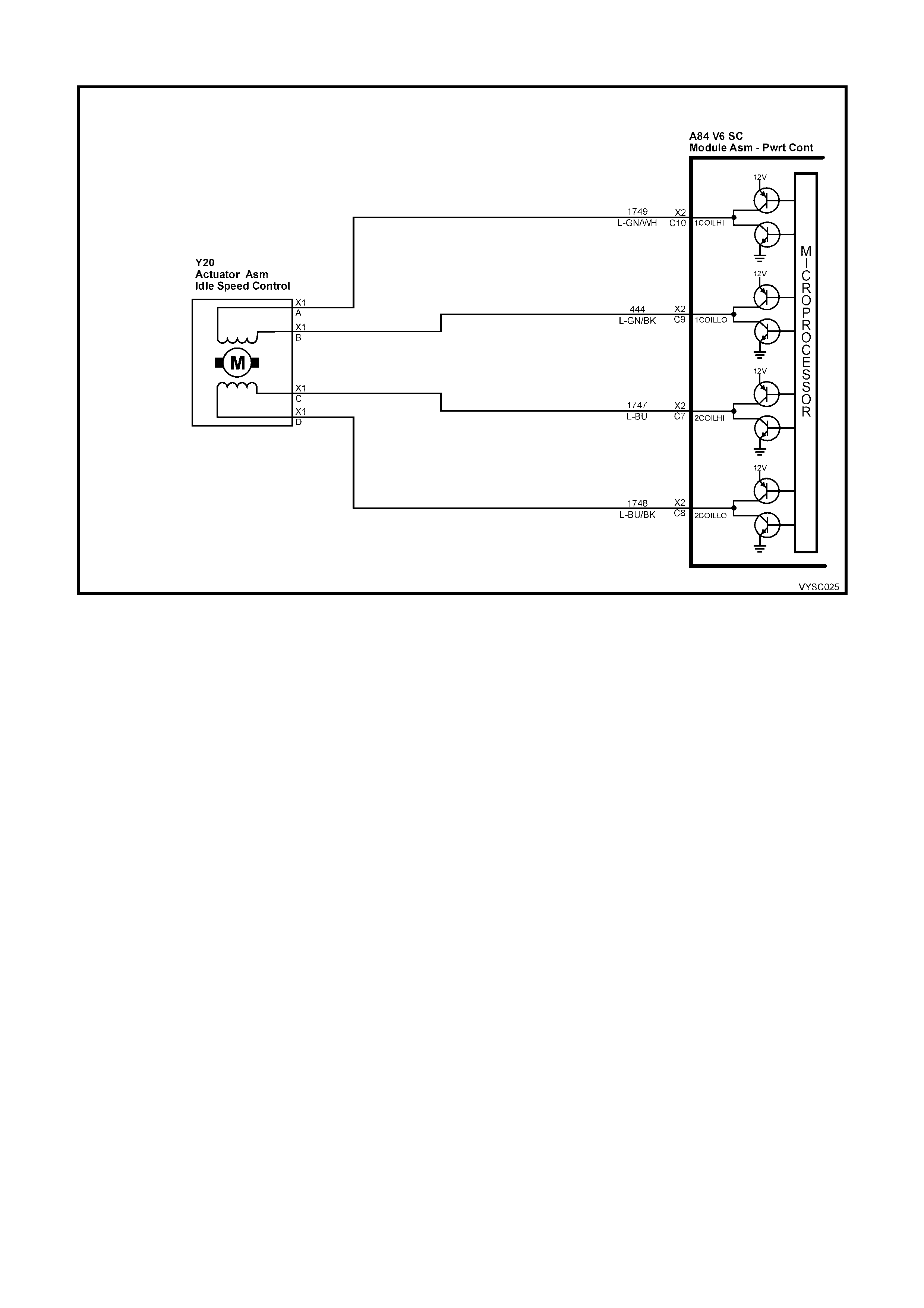
DTC 36 V6 S/C PCM – VACUUM LEAK
Figure 6C2-2A-95 – Idle Air Control
CIRCUIT DESCRIPTION:
The PCM c ontrols engine idle s peed by adjusting the pos ition of the Idle Air Contr ol (IAC) motor pintle. The IAC is a
bi-directional m otor driven by two c oils. T he PCM sends puls es (s teps) to the IAC to ex tend or retr act the IAC pintle
into a passage in the throttle body to decrease or increase air flow. The commanded IAC position (displayed in
counts) c an be monitored on Tec h 2; a lower number of c ounts indic ates les s c ommanded airf low (pintle extended).
This method allows highly accurate contr ol of idle speed and quick respons e to changes in engine load. If the PCM
detects a condition where too high an idle speed is present, the PCM will send 50 counts (steps) to the IAC motor. If
the RPM increases more than 50 RPM it is accepted that the IAC motor is moving and therefore the fault is a
vacuum leak , and DT C 36 will set. If the RPM does not change when the PCM com m ands the IAC to respond to a
commanded count (steps), the PCM will set a DTC 35.
CONDITIONS FOR RUNNING THE DTC:
• Engine is idling for at least 15 seconds.
• No TP Sensor or IAT Sensor DTCs are set.
• DTC 35 is not set.
• The IAT is less than 73° C.
• No vehicle speed indicated.
• Conditions present for 5 seconds.
CONDITIONS FOR SETTING THE DTC:
• If the PCM detects a condition where a high idle speed is present and the IAC has been closed (0 steps); the
PCM will command the IAC motor to open 50 steps . If the RPM inc reas es more than 50 RPM it is accepted that
the IAC motor is moving and therefore the fault is a vacuum leak.
ACTION TAKEN WHEN THE DTC SETS:
• The PCM stores the DTC information into memory when the diagnostic runs and fails.
• The Check Powertrain Malfunction Indicator Lamp (MIL) will not be activated.
• The PCM records the operating conditions at the time the diagnostic fails. The PCM stores this information in
the History Data.
CONDITIONS FOR CLEARING THE CHECK POWERTRAIN MIL/DTC:
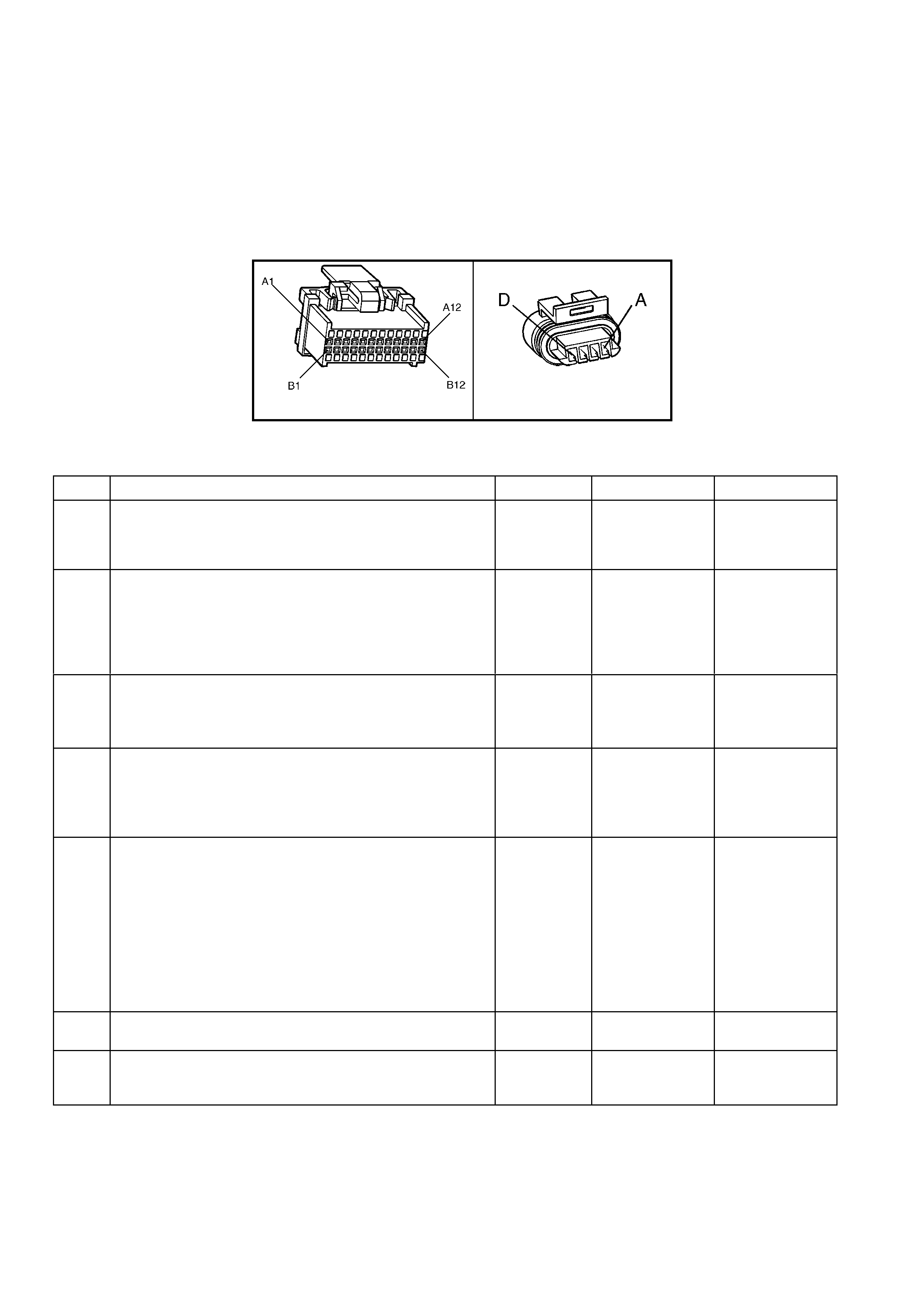
DIAGNOSTIC AIDS:
Check the IAC air passage for possible foreign material.
Code 36 may also be set by other system faults. Refer to 'Symptom Tables" when diagnosing by symptoms.
TEST DESCRIPTION:
NOTE: Number(s) below refer to step number(s) on the diagnostic table.
2. The importance of this step cannot be str essed too strongly. It can lead to correc ting a problem without further
checks and save valuable time.
4. By r estric ting vacuum supply hoses, you are isolating which vacuum circuit m ay have a vacuum leak. When the
leak is stopped, the engine should respond immediately.
A84 V6 S/C – X1 Y20
Figure 6C2-2A-96
DTC 36 V6 S/C PCM – IDLE SPEED HIGH
STEP ACTION VALUE YES NO
1. Was the "On-Board Diagnostic" (OBD) System Check
performed? Go to Step 2. Go to
OBD
System Check
in this Section.
2. 1. Ignition “OFF.”
2. Perform a visual/physical check of all the vacuum
hoses and air duct between the Mass Air Flow Sensor
and the throttle body for: Cracks, Splits, Kinks,
connections and in their proper location.
Was a problem found?
Verify Repair Go to Step 3
3. 1. Ignition "ON", engine running.
2. Listen for a hissing sound as evidence of a vacuum
leak.
Was a problem found?
Verify Repair Go to Step 4
4. 1. Ignition "ON", engine running.
2. Using pliers, restrict each vacuum hose near the
intake manifold and listen for the engine RPM to
change when hoses are restricted.
Did RPM change with vacuum hoses restricted?
Repair vacuum
leak in hose or
vacuum circuit.
Verify Repair
Go to Step 5
5. 1. Inspect suspect areas of the intake system such as:
• The intake manifold gaskets,
• PCV system,
• Throttle body vacuum hose connections,
• Throttle body gasket,
• Oil dipstick seal and oil fill cap for sources of un-
metered air,
• IAC Valve O-ring.
Was a problem found?
Verify Repair Go to Step 6
6. 1. Clear DTC and drive vehicle.
Does DTC reset? Go to Step 7 Repair Complete
7. 1. Replace PCM. Refer to Section 6C2-3 SERVICE
OPERATIONS, for PCM Security Link procedure.
Is action complete?
Verify Repair
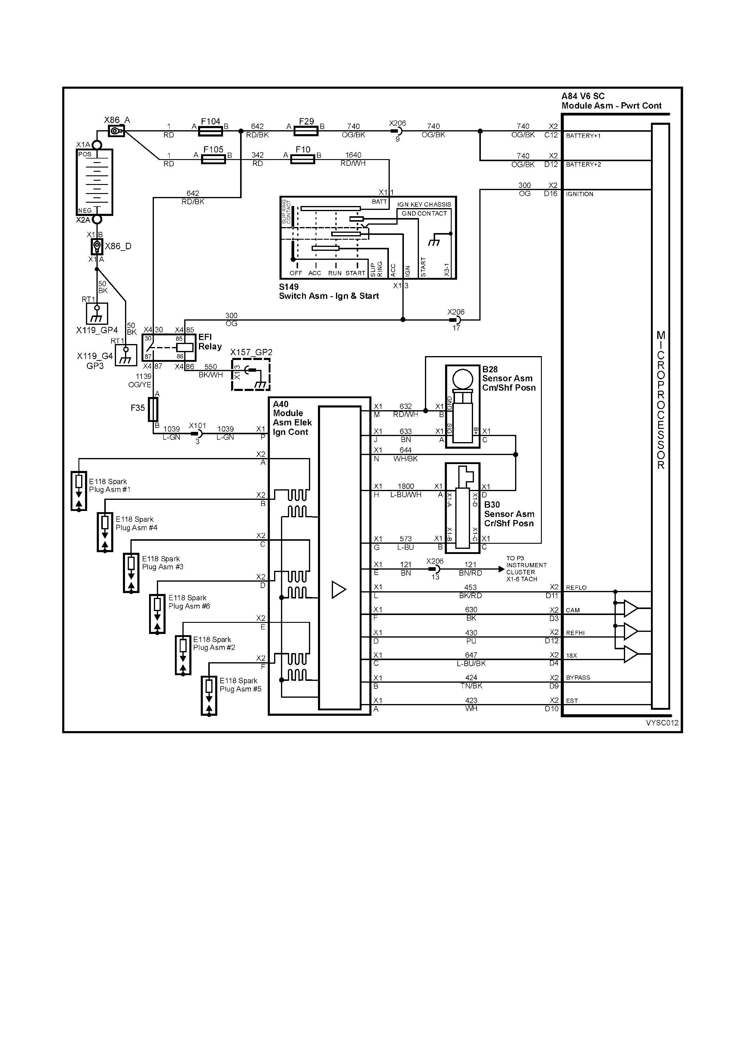
DTC 41 V6 S/C PCM –
ELECTRONIC SPARK TIMING (EST) OUTPUT CIRCUIT FAULT
Figure 6C2-2A-97 – Direct Ignition System
CIRCUIT DESCRIPTION:
There are two modes of ignition system oper ation: BYPASS mode, and ELECTR ONIC SPARK TIMING mode. T he
Bypass mode is normally used while starting the engine, while the Electronic Spark Timing mode is used to allow
the PCM to control the ignition system after the engine is running. The PCM controls a "Bypass Control Circuit",
used to control the ignition module between the two different ignition system modes.
The PCM's Electronic Spark Timing (EST) output circuitry generates EST output pulses anytime crankshaft
reference input pulses are received. The PCM also monitors it's EST output terminal, to monitor if and when EST
pulses are present.
When the ignition system is operating in the Bypass mode (such as when the engine is cranking), the ignition
module grounds the EST pulses coming from the PCM. Because the EST pulses should be grounded through the
ignition module during Bypass mode operation, the PCM should not detect EST pulses on it's EST output terminal.
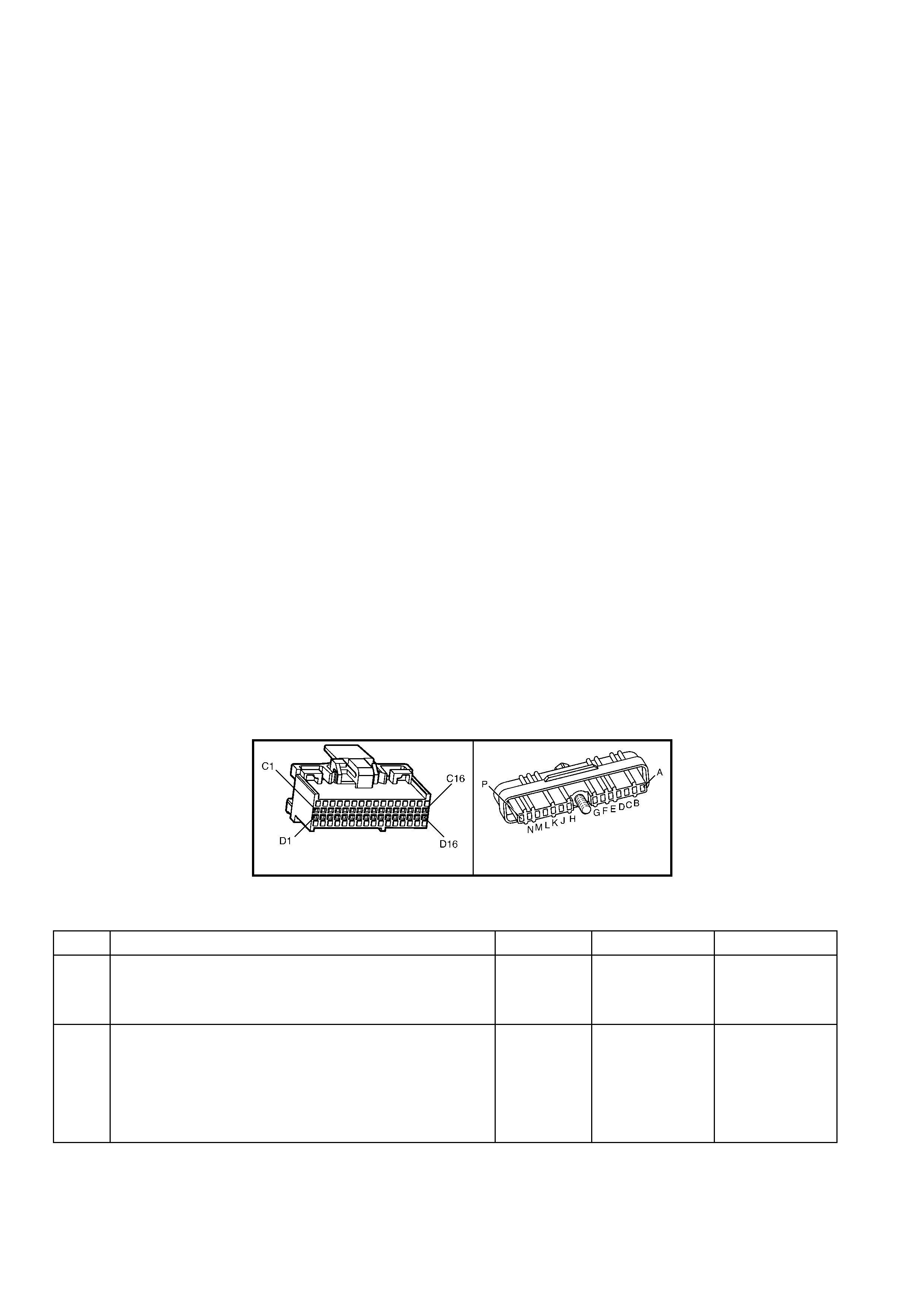
If the EST output circuit wire between the PCM and the ignition module has an "open circ uit" f ault, then the ignition
module can not ground the PCM's EST output pulses. If the PCM detects two EST pulses during the first 3
crankshaft reference input pulses, indicating the EST circuit is open, the PCM will set a DTC 41.
DTC 41 can also be set if the Bypass control circuit is shorted to voltage. If this were to happen, the PCM's EST
monitor would not sense the EST signal being grounded in the ignition module while cranking , and DTC 41 would
be set.
CONDITIONS FOR RUNNING THE DTC:
• The ignition is on.
CONDITIONS FOR SETTING THE DTC:
• PCM had detected at least 2 EST output pulses, during the first 3 crankshaft reference signal pulses received
from the ignition module, while cranking to start the engine.
ACTION TAKEN WHEN THE DTC SETS:
• The PCM activates the Check Powertrain Malfunction Indicator Lamp (MIL) when the diagnostic runs and fails.
• The PCM records the operating conditions at the time the diagnostic fails. The PCM stores this information in
the History Data.
• When DTC 41 is set and current, the PCM will operate in the Bypass spark mode.
CONDITIONS FOR CLEARING THE CHECK POWERTRAIN MIL/DTC:
• The PCM deactivates the Check Powertrain MIL after the first ignition cycle that the diagnostic runs and does
not fail.
• Use Tech 2 to clear the Check Powertrain MIL/DTC.
DIAGNOSTIC AIDS:
• Poor c onnection at PCM. Inspec t harness connec tors for backed out ter minals , improper mating, br oken lock s,
improperly formed or damaged terminals, and poor terminal to wire connection.
• Damaged Harness. Inspect the wiring harness for damage. If the harness appears to be OK, disconnect the
ignition module, tur n the ignition "O N". Connect and obs er ve a voltmeter c onnec ted between the Bypass control
circuit and +B, while moving connec tors and wiring harness related to the ignition m odule. A change in voltage
will indicate the location of the fault.
TEST DESCRIPTION:
NOTE: Number(s) below refer to the step number(s) on the diagnostic table.
4. This Step checks to see if circuit 424 is shorted to voltage.
8. This Step checks to see if circuit 423 is open.
A84 V6 S/C – X2 A40 V6 S/C
Figure 6C2-2A-98
DTC 41 V6 S/C PCM – ELECTRONIC SPARK TIMING (EST) OUTPUT CIRCUIT FAULT
STEP ACTION VALUE YES NO
1. Was the "On-Board Diagnostic" (OBD) System Check
performed? Go to Step 2. Go to
OBD
System Check
in this Section.
2. 1. Clear DTC 41.
2. Start engine and run above 1600 RPM.
3. Observe DTC(s).
Did DTC 41 set?
Go to Step 3 DTC 41 is
intermittent.
If no additional
DTC's were
stored, refer to
"Diagnostic
Aids" above.

STEP ACTION VALUE YES NO
3. 1. Ignition "OFF".
2. Disconnect ignition module 14 pin connector.
3. Probe ignition module harness connector terminal A40
X1-B with a voltmeter connected to ground.
4. Ignition "ON".
Is voltage greater than the specified value?
0.5 volts Go to Step 4 Go to Step 7
4. 1. Ignition "OFF".
2. Disconnect PCM connectors.
3. Ignition "ON".
Is voltage still present at ignition module harness
connector terminal A40 X1-B?
Go to Step 5 Go to Step 10
5. 1. Repair short to voltage in Bypass circuit 424.
Is action complete? Verify Repair –
6. 1. Replace DIS ignition module.
Is action complete? Verify Repair –
7. 1. Ignition "OFF".
2. Reconnect 14 pin connector A40 to ignition module.
3. Backprobe PCM connector A84 X2-10 with voltmeter
connected to ground.
4. Ignition "ON", crank engine.
Is voltage approximately at specified value while cranking
or with engine running?
2 volts Go to Step 8 Go to Step 9
8. 1. Check for faulty connection, or an open in the EST
circuit 423 between the PCM terminal and the ignition
module harness connector A40, terminal X1-A.
Was a fault found?
Verify Repair Go to Step 6
9. 1. Check PCM for faulty connection.
Was a faulty connection found? Verify Repair Go to Step 10
10. 1. Replace PCM. Refer to 6C1-3 SERVICE
OPERATIONS, for PCM Security Link procedure.
Is action complete?
Verify Repair –
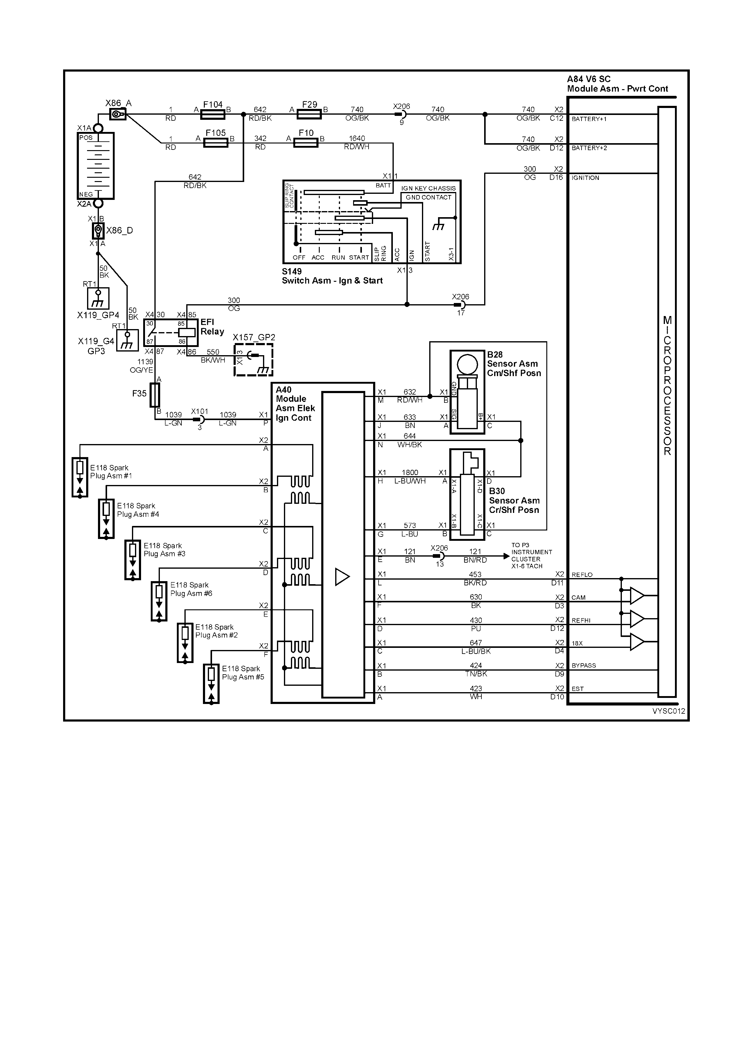
DTC 42 V6 S / C PCM IGNITION BYPASS CIRCUIT FAULT
Figure 6C2-2A-99 – Direct Ignition System
CIRCUIT DESCRIPTION:
There are two modes of ignition system oper ation: BYPASS mode, and ELECTR ONIC SPARK TIMING mode. T he
Bypass mode is normally used while starting the engine, while the Electronic Spark Timing mode is used to allow
the PCM to control the ignition system after the engine is running. The PCM controls a "Bypass Control Circuit",
used to control the ignition module between the two different ignition system modes.
The PCM's Electronic Spark Timing (EST) output circuitry generates EST output pulses anytime crankshaft
reference input pulses are received. The PCM also monitors it's EST output terminal, to monitor if and when EST
pulses are present.
When the ignition system is operating in the Bypass mode (such as when the engine is cranking), the ignition
module grounds the EST pulses coming from the PCM. Because the EST pulses should be grounded through the
ignition module during Bypass mode operation, the PCM should not detect EST pulses on it's EST output terminal.
When the engine is started, the PCM applies 5 volts to the Bypass control circuit. When received by the ignition
module, this 5 volts control c auses the ignition m odule to release the ground f rom the EST pulse s com ing from the
PCM. The ignition m odule will then use the EST pulses to operate the ignition syst em. W hen this oc curs, the PCM
will correctly detect EST pulses at it's EST output terminal.
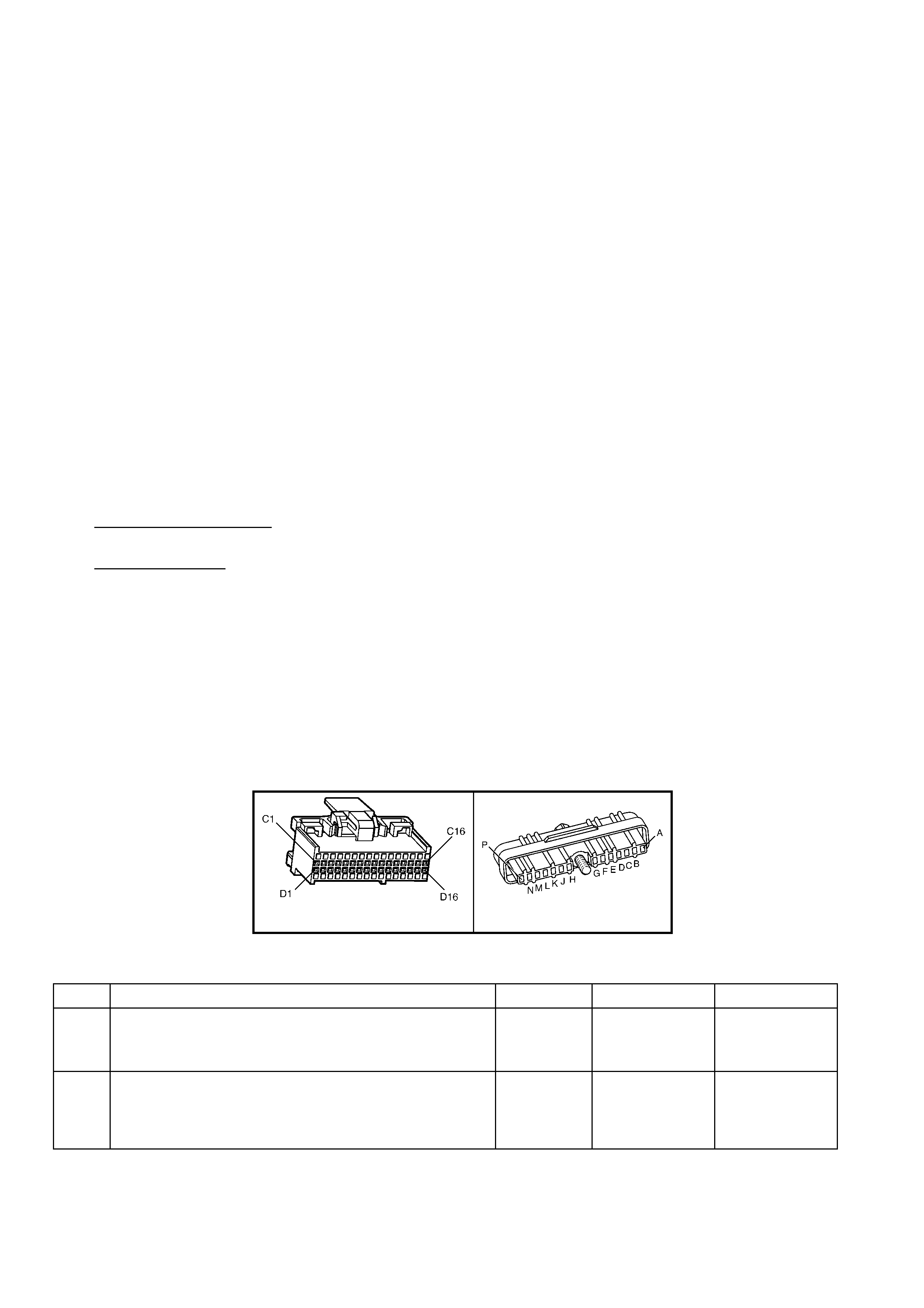
If the Bypass control cir cuit has an open fault or short to ground, or if the EST circ uit has a short to ground or short
to voltage, the PCM cannot control the ignition module to release the EST pulses from being grounded. Because
the PCM also monitors it's EST output terminal for EST pulses, if it detects no EST pulses after it has "turned on"
the 5 volts to the Bypass control circuit, and the engine speed goes above 1600 RPM, a DTC 42 will be set.
CONDITIONS FOR RUNNING THE DTC:
• The engine is running.
CONDITIONS FOR SETTING THE DTC:
• The PCM has commanded EST.
• The PCM has detected no EST output pulses for 1000 ms with the engine RPM below 200, or no EST pulses
received for 200 ms with engine RPM greater than 200.
ACTION TAKEN WHEN THE DTC SETS:
• The PCM activates the Check Powertrain Malfunction Indicator Lamp (MIL) when the diagnostic runs and fails.
• The PCM records the operating conditions at the time the diagnostic fails. The PCM stores this information in
the History Data.
• When DTC 42 is set and current, the PCM will operate in the Bypass spark mode.
CONDITIONS FOR CLEARING THE CHECK POWERTRAIN MIL/DTC:
• The PCM deactivates the Check Powertrain MIL after the first ignition cycle that the diagnostic runs and does
not fail.
• Use Tech 2 to clear the Check Powertrain MIL/DTC.
DIAGNOSTIC AIDS:
• Poor connection at PCM.– Inspect harness connectors for backed out terminals, improper mating, broken
locks, improperly formed or damaged terminals, and poor terminal to wire connection.
• Damaged Harness. Inspect the wiring harness for damage. If the harness appears to be OK, disconnect the
ignition module, tur n the ignition "O N". Connect and obs er ve a voltmeter c onnec ted between the Bypass control
circuit and B+, while moving connec tors and wiring harness related to the ignition m odule. A change in voltage
will indicate the location of the fault.
TEST DESCRIPTION:
NOTE: Number(s) below refer to the step number(s) on the diagnostic table.
4. This step checks to see if circuit 423 is shorted to voltage.
7. This step checks to see if circuit 423 is shorted to ground.
10. This step checks to see if circuit 424 is shorted to ground.
12. This step checks to see if circuit 424 is open.
13. This step checks to see if the ignition module is capable of switching from Bypass to EST mode.
A84 V6 S/C – X2 A40 V6 S/C
Figure 6C2-2A-100
DTC 42 V6 S/C PCM – IGNITION BYPASS CIRCUIT FAULT
STEP ACTION VALUE YES NO
1. Was the "On-Board Diagnostic" (OBD) System Check
performed? Go to Step 2. Go to
OBD
System Check
in this Section.
2. 1. Clear DTC 42, using Tech 2.
2. Start engine, and run above 1,600 RPM.
3. Observe DTC(s).
Did DTC 42 set?
Go to Step 3 DTC 42 is
intermittent.
Refer to
"Diagnostic
Aids" above.

STEP ACTION VALUE YES NO
3. 1. Ignition "OFF".
2. Disconnect ignition module 14 pin connector, A40.
3. Probe ignition module harness connector terminal X1-
A with a DMM to ground.
4. Ignition "ON".
Is voltage greater than the specified value?
0.5 V Go to Step 4 Go to Step 6
4. 1. Ignition "OFF".
2. Disconnect PCM connectors.
3. Ignition "ON".
Is voltage still present at ignition module harness
connector terminal A40 X1-A?
Go to Step 5 Go to Step 14
5. 1. Repair short to voltage on circuit 423.
Is action complete? Verify Repair –
6. 1. Ignition "ON".
2. Probe ignition module harness connector circuit 423
with a test light connected to battery voltage.
Is test light "ON"?
Go to Step 7 Go to Step 9
7. 1. Reconnect ignition module harness connector A40.
2. Ignition "OFF
3. Disconnect PCM connectors.
4. Probe ignition module connector circuit 423 with a test
light connected to battery voltage.
Is test light "ON"?
Go to Step 8 Go to Step 14
8. 1. Repair short to ground in circuit 423.
Is action complete? Verify Repair
9. 1. Ignition "ON".
2. Disconnect ignition module 14 pin connector, A40.
3. With test light connected to battery voltage, probe
ignition module harness connector circuit 424,
terminal X1-B.
Is test light "ON"?
Go to Step 10 Go to Step 12
10. 1. Ignition "OFF".
2. Disconnect PCM connectors.
3. Ignition "ON".
4. Disconnect ignition module 14 pin connector.
5. With test light connected to battery voltage, probe
ignition module harness connector circuit 424.
Is test light "ON"?
Go to Step 11 Go to Step 14
11. 1. Repair short to ground on circuit 424.
Is action complete? Verify Repair –
12. 1. Ignition "OFF".
2. Disconnect PCM connector A84 X2.
3. Check for faulty connection or open circuit 424.
Is fault found ?
Verify Repair Go to Step 13
13. 1. Ignition "OFF".
2. Reconnect ignition module 14 pin connector, A40.
3. Disconnect PCM connector A84 X2.
4. Ignition "ON".
5. Probe PCM harness connector circuit 423 with an
ohmmeter connected to ground.
6. Probe PCM harness connector circuit 424 with a test
light connected to battery voltage.
As the test light contacts circuit 424, does resistance
switch from under the specified value to over the specified
value?
300 to
6,000 ohms Go to Step 14 Go to Step 15
14. 1. Replace PCM. Refer to 6C2-3 SERVICE
OPERATIONS, for PCM Security Link procedure.
Is action complete?
Verify Repair –
15. 1. Replace ignition module.
Is action complete? Verify Repair –
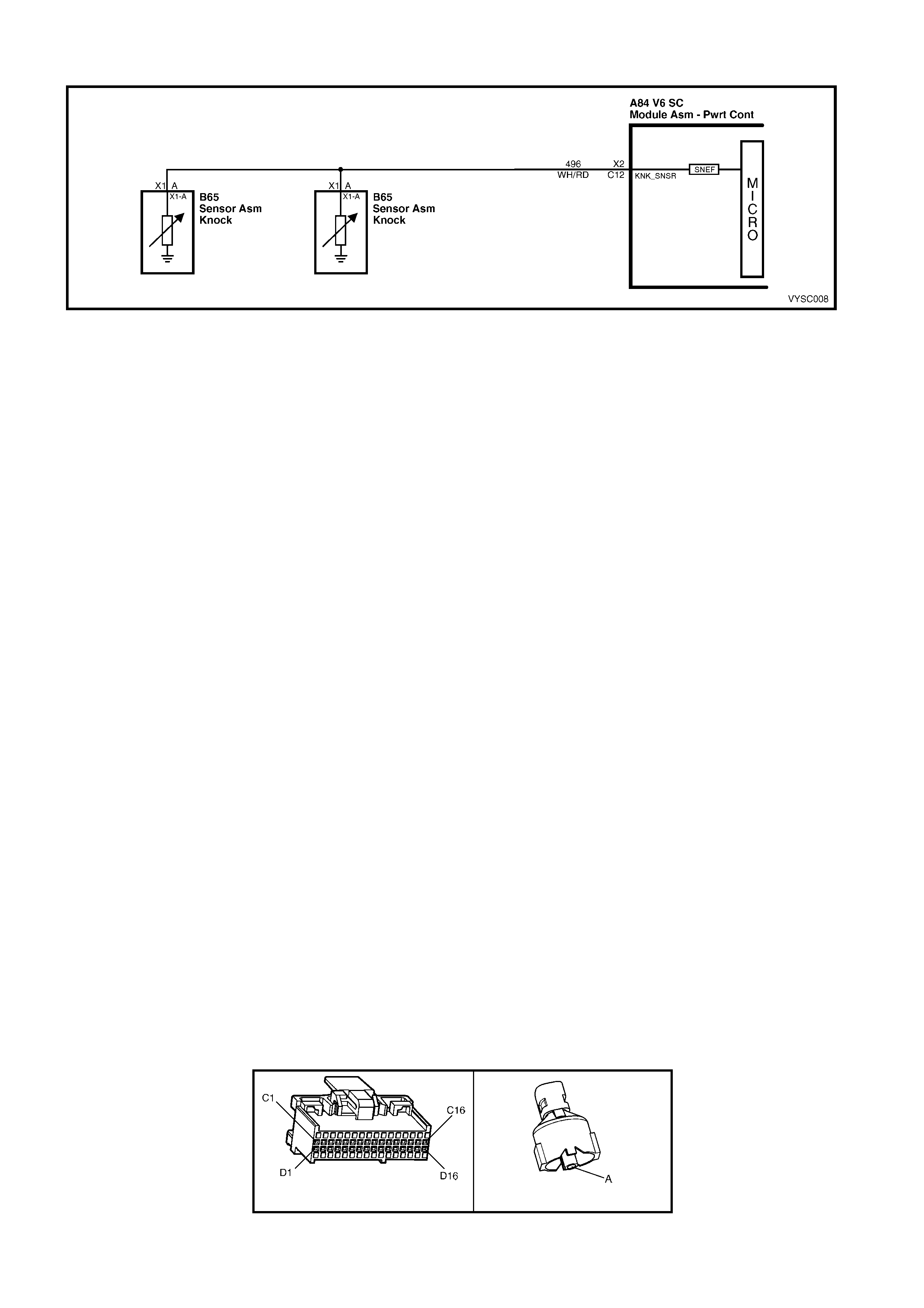
DTC 43 V6 S/C PCM – KNOCK SE NSOR CIRCUIT FAULT
Figure 6C2-2A-101 – Knock Sensors
CIRCUIT DESCRIPTION:
The knock sensor is used to detect engine detonation, and the PCM will retard the Electronic Spark Timing (EST)
based on the signal being received. The Knock sensor produces an AC signal which the PCM receives, so that
under a no k nock c ondition cir cuit 496 would measur e about 29 m illivolts AC when the engine is running at idle. The
amplitude and signal frequency is dependent upon the Knock level.
CONDITIONS FOR RUNNING THE DTC:
• No DTC 14,15,16,17,19 ,21, 22, or 93 are set.
• Engine has been running longer than 10 seconds.
• Engine Coolant Temperature is greater than 65° C.
• TP sensor signal is greater than 22%.
• Engine RPM is between 2000 and 6375 RPM.
CONDITIONS FOR SETTING THE DTC:
• There is no knock sensor signal or too high a knock sensor signal detected by the PCM for 3 seconds.
ACTION TAKEN WHEN THE DTC SETS:
• The PCM stores the DTC information into memory when the diagnostic runs and fails.
• The Check Powertrain Malfunction Indicator Lamp (MIL) will not be activated.
• Once DTC 43 is set and current, the PCM uses a default spark advance table.
CONDITIONS FOR CLEARING THE POWERTRAIN MALFUNCTION MIL/DTC:
• Use Tech 2 to clear the Check Powertrain MIL/DTC.
DIAGNOSTIC AIDS:
If circuit 496 is not open or shor ted to ground, the m ost lik ely cause is an open cir cuit in the PCM. It is pos sible that
a faulty PCM could be the cause of the DTC 43, and it should be replaced.
Refer to "Intermittents" in Section 6C2-2B SYMPTOMS.
TEST DESCRIPTION:
NOTE: Number(s) below refer to step number(s) on the diagnostic table.
2. This Step determines if conditions for DTC 43 still exist.
6. This Step determines the resistance of the knock sensors and circuit 496.
NOTE: If the resistance is at 50,00 ohms, this means that both knock sensor shunt resistors are OK. If the
resistanc e is at 100,000 ohms, this means that one of the k nock s ensors is open, but the knock sensor sys tem will
still work properly with only one knock sensor functioning.
13. Check eac h “knock ” sensor f or an open circuit 496 between splice and s ensor. If wiring is OK, replace “knock ”
sensor.
A84 V6 S/C – X2 B65
Figure 6C2-2A-102

DTC 43 V6 S/C PCM – KNOCK SENSOR CIRCUIT FAULT
STEP ACTION VALUE YES NO
1. Was the "On-Board Diagnostic" (OBD) System Check
performed? Go to Step 2. Go to
OBD
System Check
in this Section.
2. 1. Ignition "ON", engine Idling.
2. Lightly tap on alternator bracket with hammer.
Is Tech 2 indicating "Knock Retard" above the specified
value?
0 ° DTC 43 is
intermittent.
If no additional
DTC's were
stored, refer to
"Diagnostic
Aids" above.
Go to Step 3
3. 1. Ignition "ON", engine stopped.
2. Backprobe PCM connector A84 X2 C12 circuit 496,
with DMM connected to ground.
4. Set DMM to read DC voltage.
Is voltage reading on DMM above the specified value?
0.2 volts Go to Step 4 Go to Step 6
4. 1. Ignition "ON", engine stopped.
2. Disconnect PCM connector A84 X2.
3. Backprobe PCM connector X2 C12 circuit 496, with
DMM connected to ground.
4. Set DMM to read DC voltage.
Is voltage reading on DMM above the specified value?
0.2 volts Go to Step 5 Go to Step 11
5. 1. Repair short to voltage on circuit 496.
Is action complete? Verify Repair –
6. 1. Ignition "OFF".
2. Disconnect PCM connector A84 X2.
3. Backprobe PCM connector terminal X2 C12 circuit
496, with DMM connected to ground.
4. Set DMM to read resistance.
Is resistance on DMM at the specified value?
45 to 55 k
ohms Go to Step 8
Go to Step 7
7. Was the resistance measured in step 6 less than the
specified value? Go to Step 12 Go to Step 13
8. 1. Ignition "OFF".
2. Reconnect PCM connectors.
3. Disconnect the right hand knock sensor connector
B65.
3. Backprobe PCM connector terminal X2 C12 circuit
496, with DMM connected to ground.
4. Set DMM to read AC voltage.
5. Tap on alternator bracket with hammer.
Is DMM indicating voltage above specified value?
50 mV AC Go to Step 9 Go to Step 14
9. 1. Ignition "OFF".
2. Reconnect reconnect right hand knock sensor.
3. Disconnect the left hand knock sensor connector B65.
4. Backprobe PCM connector terminal X2 C12 circuit
496, with DMM connected to ground.
5. Set DMM to read AC voltage.
6. Tap on alternator bracket with hammer.
Is DMM indicating voltage above specified value?
50 mV AC Go to Step 10 Go to Step 14
10. 1. Check for poor connection at PCM.
Was a poor connection found? Verify Repair Go to Step 11
11. 1. Replace PCM. Refer to 6C2-3 SERVICE
OPERATIONS in this Section for PCM Security Link
procedure.
Is action complete?
Verify Repair –
12. 1. Check for short to ground in circuit 496.
Was a fault found? Verify Repair Go to Step 14
13. 1. Check for open in circuit 496.
Was a fault found? Verify Repair Go to Step 14
14. 1. Replace knock sensor(s).
Is action complete? Verify Repair –
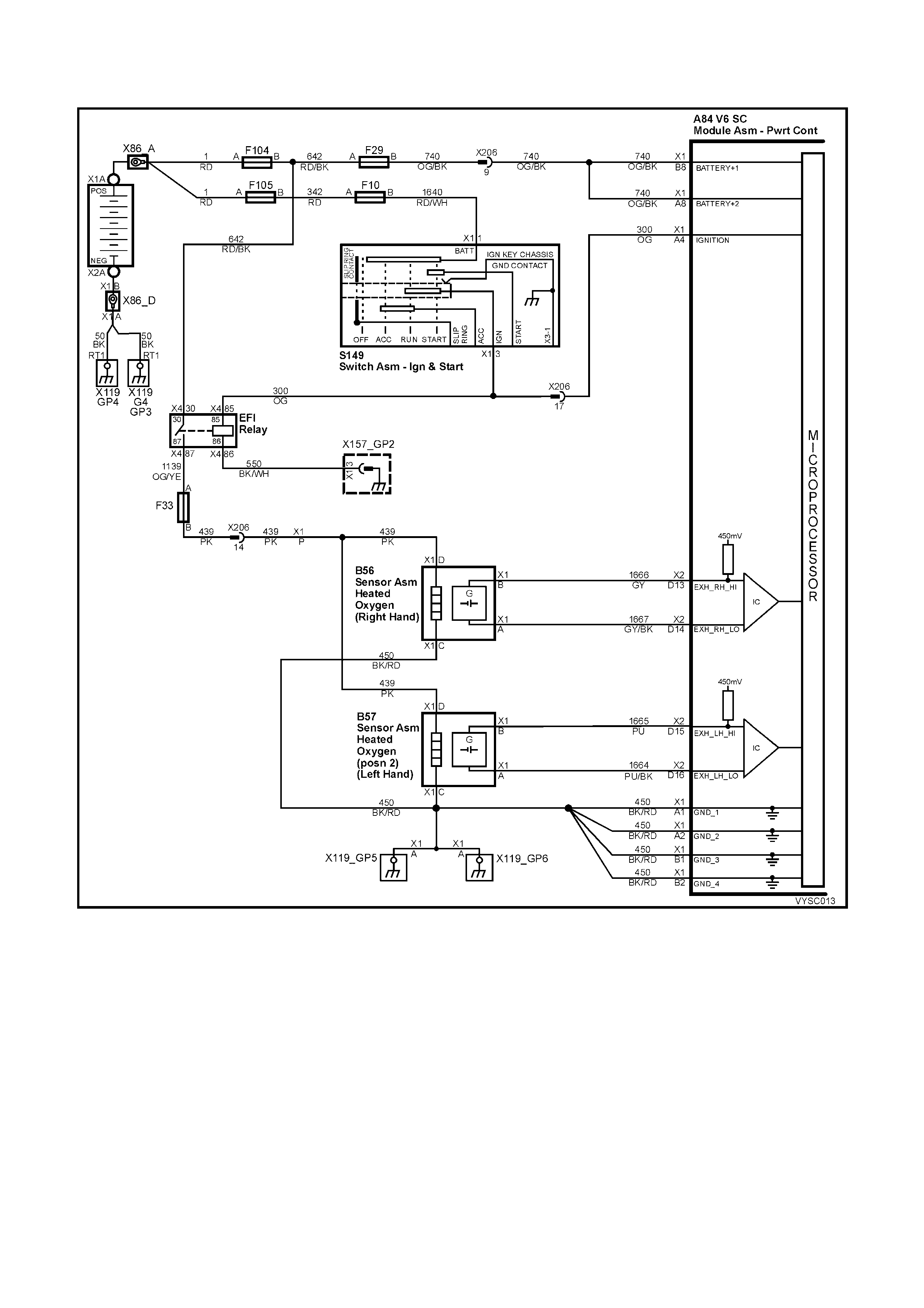
DTC 44 V6 S/C PCM –
RIGHT HAND HEATED OXYGEN SENSOR (HO2S) LOW VOLTAGE
Figure 6C2-2A-103 – Heated Oxygen Sensors
CIRCUIT DESCRIPTION:
The PCM supplies a voltage of about 450 millivolts between terminal A84 X2-D14 and A84 X2-D13. The Oxygen
(O2) sensor varies the voltage within a range of about 1 volt if the exhaust is rich, down through about 100 millivolts,
if exhaust is lean.
The s ensor is like an open c ircuit and pr oduces no voltage when it is below about 360° C. An open sensor c irc uit or
cold sensor causes "Open Loop" operation.
CONDITIONS FOR RUNNING THE DTC:
• No IAT Sensor DTC’s are set.
• IAT Sensor is below 75° C.
• The system is in "Closed Loop”.
• Throttle angle is between 9% and 30%.
CONDITIONS FOR SETTING THE DTC:
• The RH H02S signal voltage remains below 200 millivolts for 46 seconds.
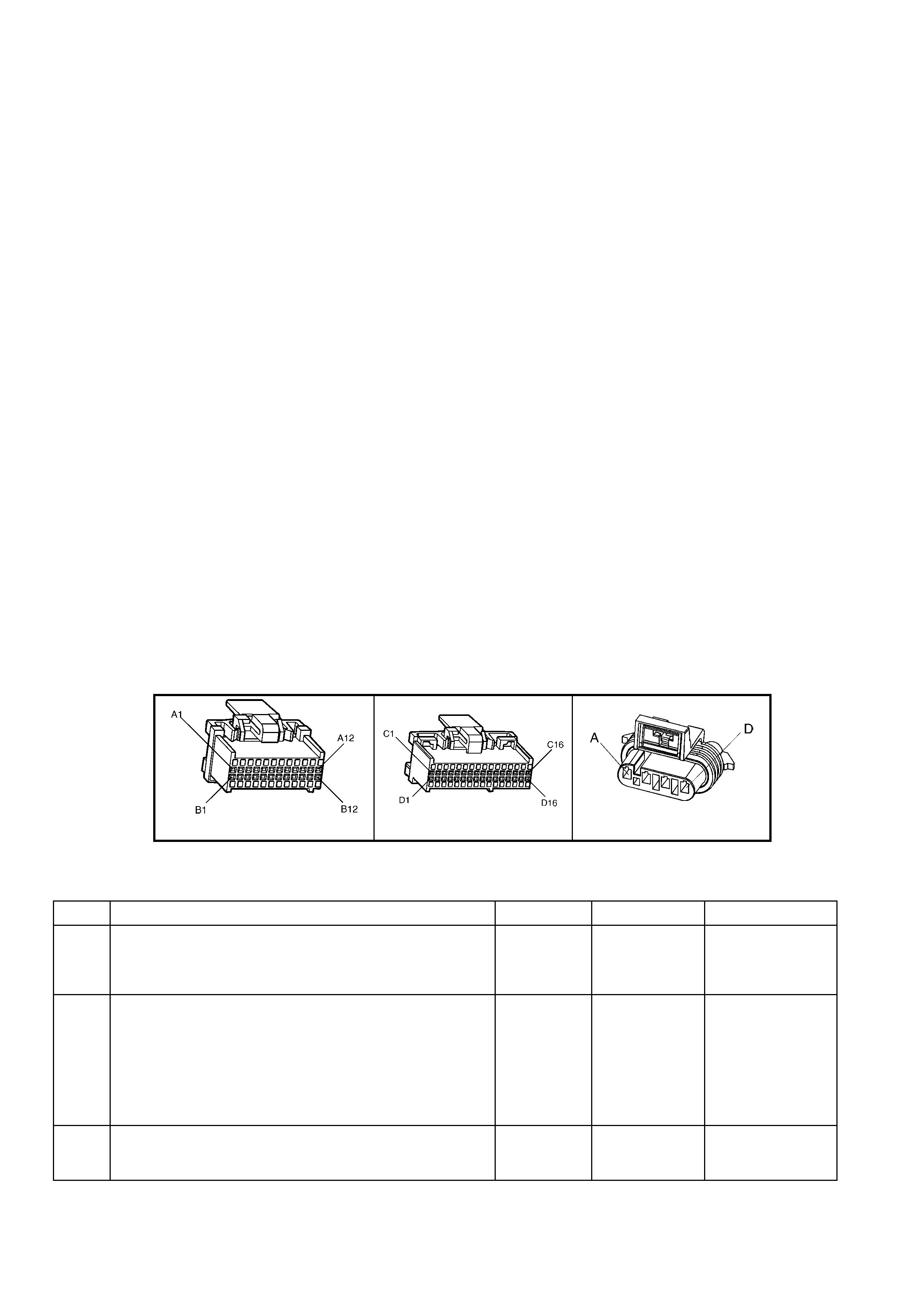
ACTION TAKEN WHEN THE DTC SETS:
• The PCM activates the Check Powertrain Malfunction Indicator Lamp (MIL) when the diagnostic runs and fails.
• The PCM records the operating conditions at the time the diagnostic fails. The PCM stores this information in
the History Data.
• Once an H02S DTC is set, and current, the PCM will operate the fuel system in the “Open Loop” mode.
CONDITIONS FOR CLEARING THE CHECK POWERTRAIN MIL/DTC:
• The PCM deactivates the Check Powertrain MIL after the first ignition cycle that the diagnostic runs and does
not fail.
• Use Tech 2 to clear the Check Powertrain MIL/DTC.
DIAGNOSTIC AIDS:
Using T ech 2, observe the Long Term Fuel Trim values at diff erent engine speeds and air flow conditions. Tech 2
also displays the Long Term Fuel Trim cells, so the Long Term Fuel Trim values can be checked in each of the
cells to determine when the DTC 44 may have been set. If the conditions for DTC 44 exist, the Long Term Fuel
Trim values will be around +25%.
TEST DESCRIPTION:
NOTE: Number(s) below refer to step number(s) on the diagnostic table.
4. The DTC 44 or lean exhaust is most likely caused by one of the following:
• O2 Sensor Wire – Sensor pigtail may be mispositioned and contacting the exhaust manifold.
• Check for intermittent ground in wire between connector and sensor.
• MAF Sensor – A shifted MAF sensor or an intake manifold leak could cause the fuel system to go lean.
Refer to TABLE A-6.1 in this Section.
• Lean Injector(s) – Perform power balance test using Tech 2.
• Fuel Contamination – W ater, even in sm all amounts, near the in- tank Fuel Pum p inlet can be delivered to
the injectors. The water causes a lean exhaust and can set a DTC 44 and/or DTC 64.
• Fuel Pressure – System will go lean if pressure is too low. It may be necessary to monitor fuel pressure
while driving the vehicle at various road speeds and/or loads to confirm. Refer to
TABLE A-4.1 in this Section.
• Ex haust Leaks – If there is an exhaust leak , the engine can cause outside air to be pulled into the exhaust
and past the sensor. Vacuum or crankcase leaks can cause a lean condition.
A84 V6 S/C – X1 A84 V6 S/C – X2 B56
Figure 6C2-2A-104
DTC 44 V6 S/C PCM – RIGHT HAND HEATED OXYGEN SENSOR (HO2S) LOW VOLTAGE
STEP ACTION VALUE YES NO
1. Was the "On-Board Diagnostic" (OBD) System Check
performed? Go to Step 2. Go to
OBD
System Check
in this Section.
2. 1. Connect Tech 2.
2. Start engine.
3. Run engine until it reaches normal operating
temperature (above 80° C).
4. Continue to run at 1600 to 1800 RPM for two minutes.
Does Tech 2 indicate O2 sensor voltage fixed below
specified value?
200 mV Go to Step 3 DTC 44 is
intermittent. If no
additional DTC’s
were stored, refer
to
INTERMITTENTS
in 6C2-2B
SYMPTOMS.
3. 1. Disconnect O2 sensor connector.
W ith engine idling, does Tech 2 display O2 sensor voltage
between the specified values?
Between
350 mV and
550 mV
Go to Step 4 Go to Step 6

STEP ACTION VALUE YES NO
4. 1. Refer to step 4 Test Description notes, first.
2. Perform the checks on the items as noted.
• MAF sensor operation.
• Low fuel pressure.
• Contaminated fuel, exhaust manifold leaks ahead of
O2 sensor.
• Lean injector (possibly restricted).
• O2 sensor ground circuit.
Are all items checked found to be OK?
Go to Step 5 Verify Repair
5. 1. Replace Oxygen sensor.
Is action complete? Verify repair –
6. 1. Ignition "OFF".
2. Disconnect PCM connector A84-X2.
3. With O2 sensor still disconnected, check O2 signal
circuit 1666 for a short to ground.
Is a short to ground detected?
Go to Step 7 Go to Step 8
7. 1. Repair circuit 1666.
Is action complete? Verify Repair –
8. 1. Replace PCM. Refer to 6C2-3 SERVICE
OPERATIONS in this Section, for PCM Security Link
procedure.
Is action complete?
Verify Repair –

DTC 45 V6 S/C PCM –
RIGHT HAND HEATED OXYGEN SENSOR (HO2S) HIGH VOLTAGE
Figure 6C2-2A-105 – Heated Oxygen Sensors
CIRCUIT DESCRIPTION:
The PCM supplies a voltage of about 450 millivolts between terminal A84 X2-D13 and A84 X2-D14. The Oxygen
(O2) sensor varies the voltage within a range of about 1 volt, if the exhaust is rich and down through about 100
millivolts if exhaust is lean.
The sensor produces no voltage when it is below about 360° C. An open sensor circuit or cold sensor causes "Open
Loop" operation.
CONDITIONS FOR RUNNING THE DTC:
• No TP Sensor DTC’s are set.
• The system is in "Closed Loop”.
• Throttle angle is between 9% and 30%.
CONDITIONS FOR SETTING THE DTC:
• The RH H02S signal voltage remains above 780 millivolts for 40 seconds.
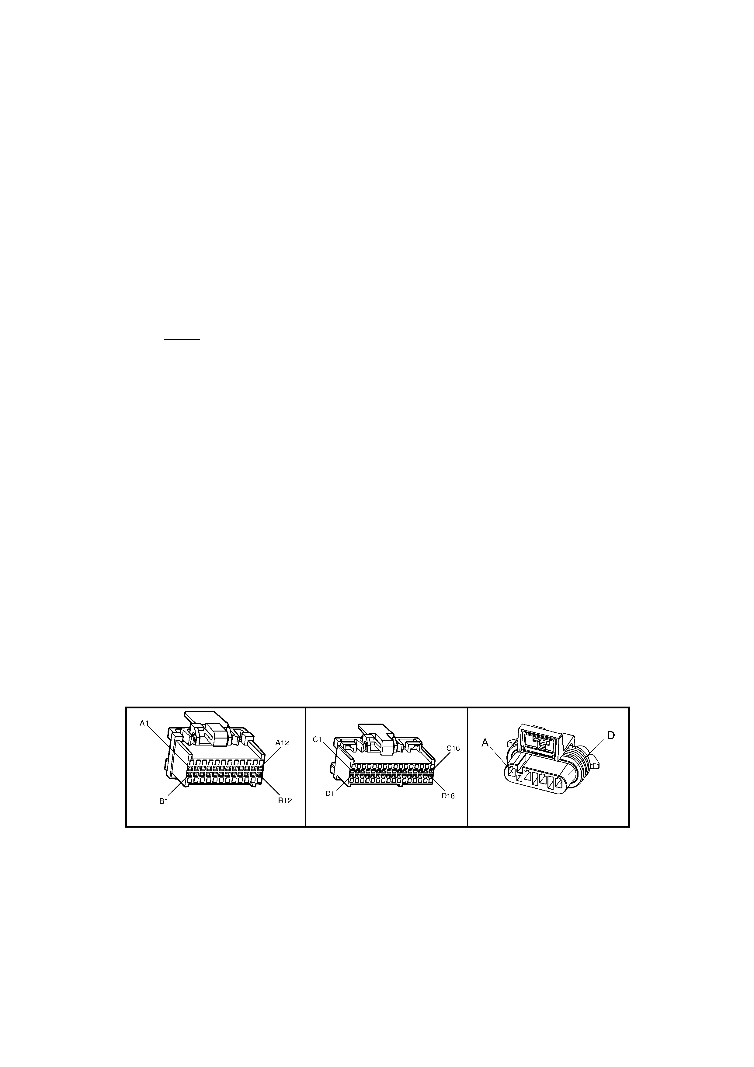
ACTION TAKEN WHEN THE DTC SETS:
• The PCM activates the Check Powertrain Malfunction Indicator Lamp (MIL) when the diagnostic runs and fails.
• The PCM records the operating conditions at the time the diagnostic fails. The PCM stores this information in
the History Data.
• Once an HO2S DTC is set, and current, the PCM will operate the fuel system in the “Open Loop” mode.
CONDITIONS FOR CLEARING THE CHECK POWERTRAIN MIL/DTC:
• The PCM deactivates the Check Powertrain MIL after 10 seconds when it sees a valid condition.
• Use Tech 2 to clear the Check Powertrain MIL/DTC.
DIAGNOSTIC AIDS:
Using Tech 2, observe the Long Term Fuel Trim values at different RPM and air flow conditions. Tech 2 also
displays the Long Term Fuel Tr im cells, s o the Long Term Fuel Trim values can be check ed in each of the cells to
determ ine when the DTC 45 may have been set. If the conditions f or DT C 45 ex is t, the Long Term Fuel Trim values
will be around – 22%.
TEST DESCRIPTION:
NOTE: Number(s) below refer to step number(s) in the diagnostic table.
2. The O2 sensor MUST be at operating temperature before checking operation.
3. This step checks for a short to voltage on the O2 signal line.
7. Grounding circuit 1666 causes a low O2 signal voltage. If the PCM and wiring are OK, the PCM should
recognise the low voltage and confirm the lean signal.
8. A DT C 45 will mos t likely NOT be caus ed by a faulty O 2 sens or . DT C 45 indic ates a ric h ex haust and diagnos is
should begin with the items listed:
• Fuel pressure. System will go rich if pressure is too high. The PCM can compensate for some increase.
However, if it gets too high, a DTC 45 or DTC 65 may be set. Refer to fuel system diagnosis TABLE A-4.3
in this Section.
• Rich injector.
• Leaking injector. Refer to TABLE A-4.3 in this Section.
• Check for fuel contaminated oil.
• Short to voltage on circuit 1666.
• HEI shielding. An open ground cir cuit 453 (ignition sys tem) m ay res ult in EMI, or induced electrical "noise."
The PCM looks at this "noise" as reference pulses. The additional pulses result in a higher than actual
engine speed signal. The PCM then delivers too m uch fuel, causing system to go rich. Engine tachom eter
will also show higher than actual engine speed, which can help in diagnosing this problem.
• Canister purge. Check for fuel saturation. If full of fuel, check canister control and hoses.
• MAF sensor. A shifted MAF sensor could cause the fuel system to go rich.
• Check for leaking fuel pressure regulator diaphragm by checking vacuum line to regulator for fuel.
• TP Sensor. An intermittent TP sensor output will cause the system to go rich, due to a false indication of the
engine accelerating.
A84 V6 S/C – X1 A84 V6 S/C – X2 B56
Figure 6C2-2A-106

DTC 45 V6 S/C PCM – RIGHT HAND HEATED OXYGEN SENSOR (HO2S) HIGH VOLTAGE
NOTE: Oxygen Sensor Contamination – If fuel containing lead or silicone is used, or engine repairs using
unapproved RT V gas k et s ealer ar e perf orm ed, the sens or m ay be contaminated. It m ay send a "false" ric h exhaust
indication to the PCM, and the PCM will attem pt to drive the fuel system lean to c ompensate. Poor driveability or a
Diagnostic Trouble Code 45 could result. If this happens, the sensor will need to be replaced, but every attempt to
locate the source of contamination should be pursued.
STEP ACTION VALUE YES NO
1. Was the "On-Board Diagnostic" (OBD) System Check
performed? Go to Step 2. Go to
OBD
System Check
in this Section.
2. 1. Engine at normal operating temperature (above
80° C).
2. Run engine at approximately 1600 RPM to 1800 RPM
for two minutes.
Is Tech 2 voltage display above specified value?
750 mV Go to Step 3 DTC 45 is
intermittent. If no
additional DTC(s)
were stored,
refer to
INTERMITTENTS
in 6C2-2B
SYMPTOMS.
3. 1. Ignition "OFF".
2. Disconnect O2 sensor wiring harness.
3. With voltmeter connected to ground, probe circuit
1666 at O2 sensor wiring harness connector.
4. Ignition "ON".
Is voltmeter indicating less than specified value?
500 mV Got to Step 7 Go to Step 4
4. 1. Ignition "OFF".
2. Disconnect PCM connectors.
3. Probe circuit 1666 at O2 sensor wiring harness
connector.
4. Ignition "ON".
Is voltmeter indicating voltage below specified value?
350 mV Go to Step 6 Go to Step 5
5. 1. Repair circuit 1666 shorted to voltage.
Is action complete? Verify Repair –
6. 1. Replace PCM. Refer to 6C23 SERVICE
OPERATIONS in this Section for PCM Security Link
procedure.
Is action complete?
Verify Repair –
7. 1. Disconnect O2 sensor wiring harness connector.
2. Jumper harness connector circuit 1666 to 1667.
With engine running, does Tech 2 display O2 voltage
below specified value?
350 mV Go to Step 8 Go to Step 9
8. 1. Refer to step 8 Test Description notes, for:
• High Fuel Pressure.
• Leaking Injectors.
• Ignition Ground Circuit.
• Canister Purge.
• Engine Coolant Temperature Sensor Circuit.
• Intake Air Temperature Sensor Circuit.
• Throttle Position Sensor Operation.
Do all additional checks in Step 8 above, test OK?
Go to Test
Description,
Step 8, above
Verify Repair
9. 1. Ignition "OFF"
2. Disconnect PCM connectors.
3. Check O2 sensor ground circuit 450 for good
continuity between PCM connector terminal A84 X1-
A2 and engine ground.
Is an "OPEN" circuit indicated?
Verify Repair Go to Step 10
10. 1. Check PCM ground wire connection at engine. Must
be a clean and tight connection to the engine.
Is connection good?
Go to Step 6 Verify Repair

DTC 46 V6 S/C PCM – NO REFERENCE PULSES WHILE CRANKING
Figure 6C2-2A-107 – Ignition System
CIRCUIT DESCRIPTION:
This DTC is intended to help in diagnosing a no-start condition. Any time the engine is turning, the ignition m odule
should generate the crankshaft reference pulses that the PCM should be receiving. Fuel injection pulses are "timed"
from the crankshaft pulses, and without them no injection pulses will occur. The PCM can determine when these
crankshaft pulses should be present, but aren't.
As with any engine while being crank ed, there is a sm all am ount of inlet m anifold vacuum . Also while crank ing, the
battery voltage will be less than 11 volts. If the PCM's MAF sensor input detects air flow and the ignition voltage
input detects less than 11 volts and there are no reference input pulses, a DTC 46 will set.
NOTE: It is possible for the ignition system to provide spark, yet there may not be any reference pulses at the
PCM.
CONDITIONS FOR RUNNING THE DTC:
• No MAF sensor DTC is set.
• Battery voltage is at or below 11 volts.
• The MAF sensor input signal is greater than 2,048 Hz.
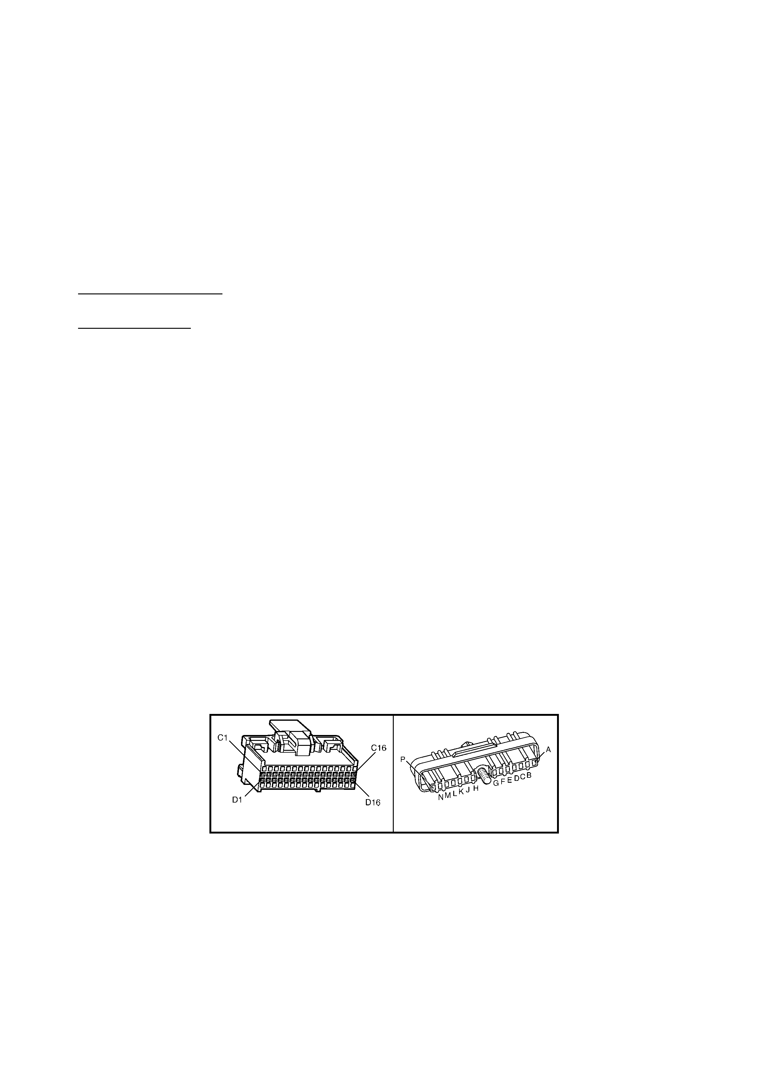
CONDITIONS FOR SETTING THE DTC:
• No crank shaft r eference input puls es are received at the PCM c ranks haft refe rence input term inal for at least 2
seconds.
ACTION TAKEN WHEN THE DTC SETS:
• The PCM activates the Check Powertrain Malfunction Indicator Lamp (MIL) when the diagnostic runs and fails.
• The PCM records the operating conditions at the time the diagnostic fails. The PCM stores this information in
the History Data.
CONDITIONS FOR CLEARING THE CHECK POWERTRAIN MIL/DTC:
• The PCM deactivates the Check Powertrain MIL after the first ignition cycle that the diagnostic runs and does
not fail.
• Use Tech 2 to clear the Check Powertrain MIL/DTC.
DIAGNOSTIC AIDS:
• Poor connection at PCM. Inspec t harness connec tors for backed out ter minals , improper mating, brok en lock s,
improperly formed or damaged terminals, and poor terminal to wire connection.
• Damaged Harness. Inspect the wiring harness for damage. If the harness appears to be OK, disconnect the
ignition module, tur n the ignition "O N". Connect and obs er ve a voltmeter c onnec ted between the Bypass control
circuit and B+, while moving connector s and wir ing harness related to the ignition m odule. A change in voltage
will indicate the location of the fault.
NOTE: Use ST-125 spark checker or equivalent to check for adequate spark. An ST-125 requires about 25,000
volts (25 Kilovolts or 25 kV) to "s park". Do not use a s park plug in open air, grounded to the engine, as an indication
of suf ficient "spar k". Only a few kilovolts ar e requir ed to j ump the gap of a spar k plug outside of the engine, and that
would be an inadequate test of the ignition system.
TEST DESCRIPTION:
NOTE: The number(s) below refer to the step number(s) on the diagnostic table.
2. If engine starts, the problem is not present now. While the PCM monitors 3 inputs to determine
DTC 46, only a lack of reference input signal pulses can set the DTC. If a problem occurred on the MAF or
ignition voltage inputs, other problems would be apparent.
NOTE: Even one crankshaft reference pulse while cranking will cause DTC 46 to NOT set.
3. Spark on all three wires on the same side of the engine proves the DIS coil pack to be OK. No spark on any
lead means the DIS ignition system is suspect of causing the DTC 46. If the DIS ignition system cannot
generate any spark, it cannot generate the crankshaft reference signal either.
Refer to TABLE A-8.1 in this Section to determine the cause. If there is spark on only 1 or 2 spark plug leads,
the crank sensor is probably OK, but there could be a problem with the coil pack or DIS module. TABLE A-8.1
in this Section should determine the problem.
5. This is again the reference signal. When the reluctor wheel is turning, the signal changes from under
1 volt to over 3 volts, back and forth, three times per revolution. Since it changes quickly, the voltmeter can
indicate only an average voltage. (expected reading - approximately 2 volts.)
6. A loose connection at PCM terminal A84 X2-D12 could cause an intermittent voltage measurement to be seen.
A84 V6 S/C – X2 A40 V6 S/C
Figure 6C2-2A-108

DTC 46 V6 S/C PCM – NO REFERENCE PULSES WHILE CRANKING
STEP ACTION VALUE YES NO
1. Was the "On-Board Diagnostic" (OBD) System Check
performed? Go to Step 2 Go to
OBD
System Check
in this Section.
2. 1. Attempt to start engine.
Did engine start and continue to run? DTC 46 is
intermittent. If no
additional DTC's
were stored,
refer to
INTERMITTENT
S in 6C2-2B
SYMPTOMS.
Go to Step 3
3. 1. Remove the spark plug leads from three spark plugs
on the same side of the engine.
2. Connect ST-125 spark checker (See Test Description,
Note 3 above) to each lead individually, and check for
spark while cranking the engine.
W as spark evident on both leads? (A few sparks and then
nothing is considered ‘no spark’).
Go to Step 4 Go to Table
A-8.1 in this
Section.
4. 1. Ignition "OFF".
2. Disconnect PCM connectors.
3. Backprobe PCM harness connector terminal A84 X2-
D12 to ground with a digital voltmeter set to read "DC
Volts".
4. Ignition "ON".
Is the voltage at the specified value? (See Test
Description, Note 4 above)
4.7 – 5.2
volts Go to Step 5 Go to Step 8
5. 1. Ignition "OFF".
2. Disconnect wiring harness connectors from PCM.
3. Backprobe PCM harness connector terminal A84 X2-
D12 to ground with a digital voltmeter set to read "DC
Volts".
4. Ignition "ON".
5. While observing digital voltmeter, crank the engine.
Is voltage measured approximately the specified value?
2 – 3 volts Go to Step 6 Go to Step 8
6. 1. Check PCM terminal A84 X2-D12 for a loose
connection.
Was a fault found?
Verify Repair Go to Step 7
7. 1. Replace PCM. Refer to 6C2-3 SERVICE
OPERATIONS in this Section for PCM Security Link
procedure.
Is action complete?
Verify Repair
8. 1. Check circuit 430 for a faulty connection or an open,
short to ground or short to voltage.
Was a fault found?
Verify Repair Go to Step 9
9. 1. Replace DIS Ignition Module A40.
Is action complete? Verify Repair

DTC 47 V6 S / C PCM – 18X REFERENCE SIGNAL MISSING
Figure 6C2-2A-109 – Ignition System
CIRCUIT DESCRIPTION:
The 18X signal (circuit 647) is used by the PCM to improve ignition timing accuracy during crank and at engine
speeds of up to 2000 RPM. The 18X signal circuit allows the use of EST mode below 400 RPM, eliminating the
need to utilis e bypass mode dur ing s tart- up, and als o allows the PCM to calc ulate tr ue cr ankshaf t pos ition in 1/6 the
time that use of the crankshaft reference signal would permit.
During normal operation, the PCM uses the 18X signal to control ignition timing until the engine speed exceeds
2000 RPM, at which time the c rankshaf t reference s ignal (circuit 430) is us ed. W hen conditions for setting DTC 47
exist, the crank shaf t ref erence s ignal is us ed by the PCM to contr ol EST. T his condition will cause bypass m ode to
be used for ignition timing below 400 RPM and EST ignition timing to be degraded below 2000 RPM, (no high
resolution spark timing).
CONDITIONS FOR RUNNING THE DTC:
• The engine is running.
• The MAF sensor input signal is greater than 2048 Hz.
CONDITIONS FOR SETTING THE DTC:
• The PCM detects 253 crankshaft reference pulses and no 18X pulses.
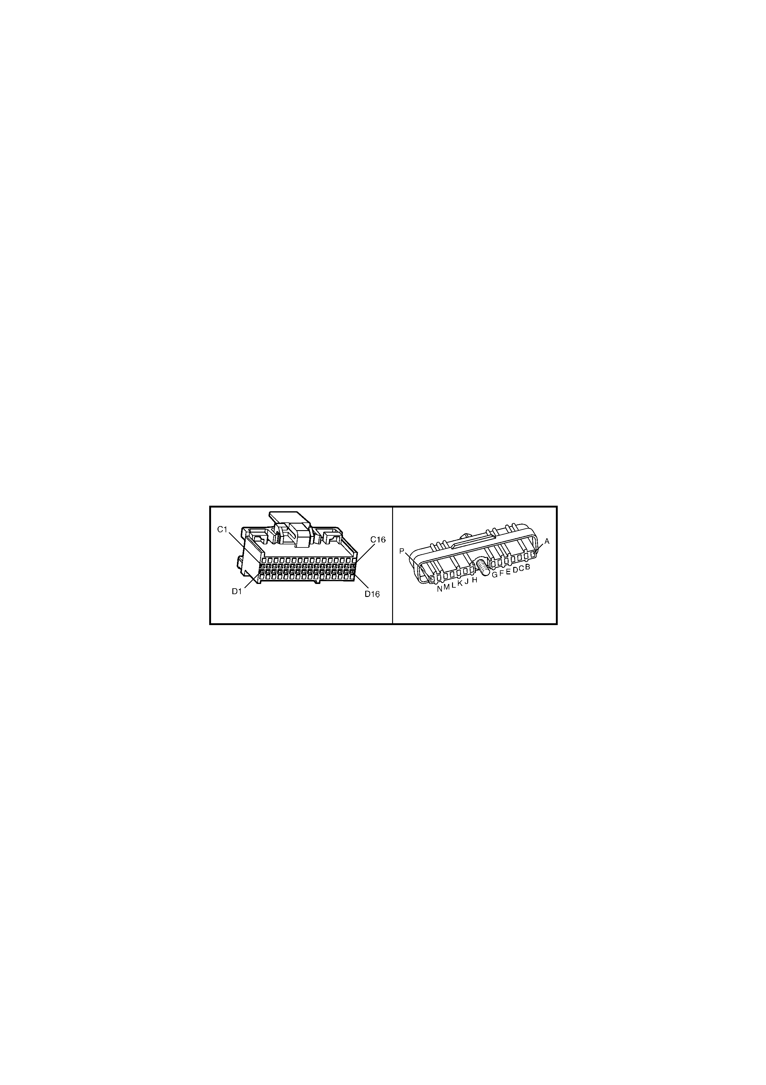
ACTION TAKEN WHEN THE DTC SETS:
• The PCM stores the DTC information into memory when the diagnostic runs and fails.
• The Check Powertrain Malfunction Indicator Lamp (MIL) will not be activated.
• The PCM records the operating conditions at the time the diagnostic fails. The PCM stores this information in
the History Data.
• When DTC 47 is set and current (no 18X reference signal), the PCM uses the crankshaft reference signal to
determine engine speed. This condition will cause the EST to be degraded; i.e. no high resolution spark timing.
CONDITIONS FOR CLEARING THE CHECK POWERTRAIN MIL/DTC:
• Use Tech 2 to clear the Check Powertrain MIL/DTC.
DIAGNOSTIC AIDS:
An intermittent may be caused by a poor connection, rubbed through wire insulation, or a wire broken inside the
insulation.
Check for:
• Backed out connector terminals or broken down insulation in circuit 647.
• If connections and harness check OK, try monitoring voltage on circuit 647 with DMM while moving the
related wiring harness and connectors with the engine idling. This may help to isolate the location of the
malfunction.
TEST DESCRIPTION:
NOTE: Number(s) below refer to step number(s) on the diagnostic table.
4. If a window on the harmonic balancer is interfering with the 18X Hall-Effect switch, the ignition module will
ground the 18X signal. Starter may have to be bumped several times to obtain a voltage reading.
5. Voltage reading should be lower than that obtained with engine not running, indicating a pulsed reference
signal.
8. Verifies that circuit 647 is not shorted to ground or open in the harness.
A84 V6 S/C – X2 A40 V6 S/C
Figure 6C2-2A-110

DTC 47 V6 S/C PCM – 18X REFERENCE SIGNAL MISSING
STEP ACTION VALUE YES NO
1. Was the "On-Board Diagnostic" (OBD) System Check
performed? Go to Step 2. Go to
OBD
System Check
in this Section.
2. 1. Ignition "OFF".
2. Install Tech 2 and clear DTCs.
3. Ignition "ON".
4. Start engine and idle for 1 minute or until Diagnostic
Trouble Code 47 sets.
Did Diagnostic Trouble Code 47 set?
Go to Step 3 DTC 47 is
intermittent. If no
additional DTC’s
were stored,
refer "Diagnostic
Aids" above.
3. 1. Backprobe PCM terminal A84 X2-D4 with a DMM
connected to ground.
2. Ignition "ON", engine "OFF", observe voltage on
PCM terminal A84 X2-D4.
Does voltage measure specified value?
Approximately
5 volts Go to Step 5 Go to Step 4
4. 1. ‘Bump’ engine with starter.
2. Retest voltage at PCM terminal A84 X2-D4.
Does voltage measure specified value?
Approximately
5 volts Go to Step 5 Go to Step 8
5. 1. Start engine and idle for 1 minute to stabilise
system.
2. Observe voltage on PCM terminal A84 X2-D4.
Does voltage measure specified value?
Approximately
2 – 3 volts Go to Step 7 Go to Step 6
6. 1. Check for poor ignition module connections.
Was a fault found? Verify Repair Go to Step 10
7. 1. Check for poor connection at PCM A84 X2-D4.
Was a fault found? Verify Repair Go to Step 11
8. 1. Ignition "OFF".
2. Disconnect PCM connectors.
3. Ignition "ON".
4. Measure voltage at PCM harness connector terminal
A84 X2-D4.
Does voltage measure specified value?
Approximately
5 volts Go to Step 11 Go to Step 9
9. 1. Check circuit 647 open or shorted to ground.
Was a fault found? Verify Repair Go to Step 10
10. 1. Replace faulty ignition control module.
Is action complete? Verify Repair –
11. 1. Replace PCM. Refer to 6C2-3 SERVICE
OPERATIONS in this Section for PCM Security Link
procedure.
Is action complete?
Verify Repair –

DTC 48 V6 S/C PCM –
CAMSHAFT POSITION (CMP) SENSOR CIRCUIT LOW VOLTAGE
Figure 6C2-2A-111 – Ignition System
CIRCUIT DESCRIPTION:
During cr anking, the ignition module monitors the dual crank sensor 3X signal. The 3X signal is used to determine
the correct cylinder pair to spark first. After the 3X signal has been processed by the ignition module, it sends a
crank shaft refer ence pulse to the PCM. W hen the PCM receives this pulse it will com mand all s ix injectors to open
for one priming shot of fuel in all cylinders. After the prim ing, all six of the injectors are left "OFF" until the next six
crankshaft reference pulses from the ignition module (two crankshaft revolutions). This allows each cylinder a
chance to us e the f uel f r om the priming s hot. During this waiting period, a cam s ignal will have been received by the
PCM. Now the PCM begins to operate the injectors in sequential fuelling mode by energising each injector based on
true camshaft position. If DTC 48 is set while the engine is running the PCM will continue to operate in Sequential
Fuel Injection (SFI) mode. If the camshaft position signal is not received at start up the PCM will operate in
Sequential Fuel Injection (SFI) mode, however, there is only a 1 in 6 chance of the correct injection sequence
exists.
CONDITIONS FOR RUNNING THE DTC:
• The engine is cranking.
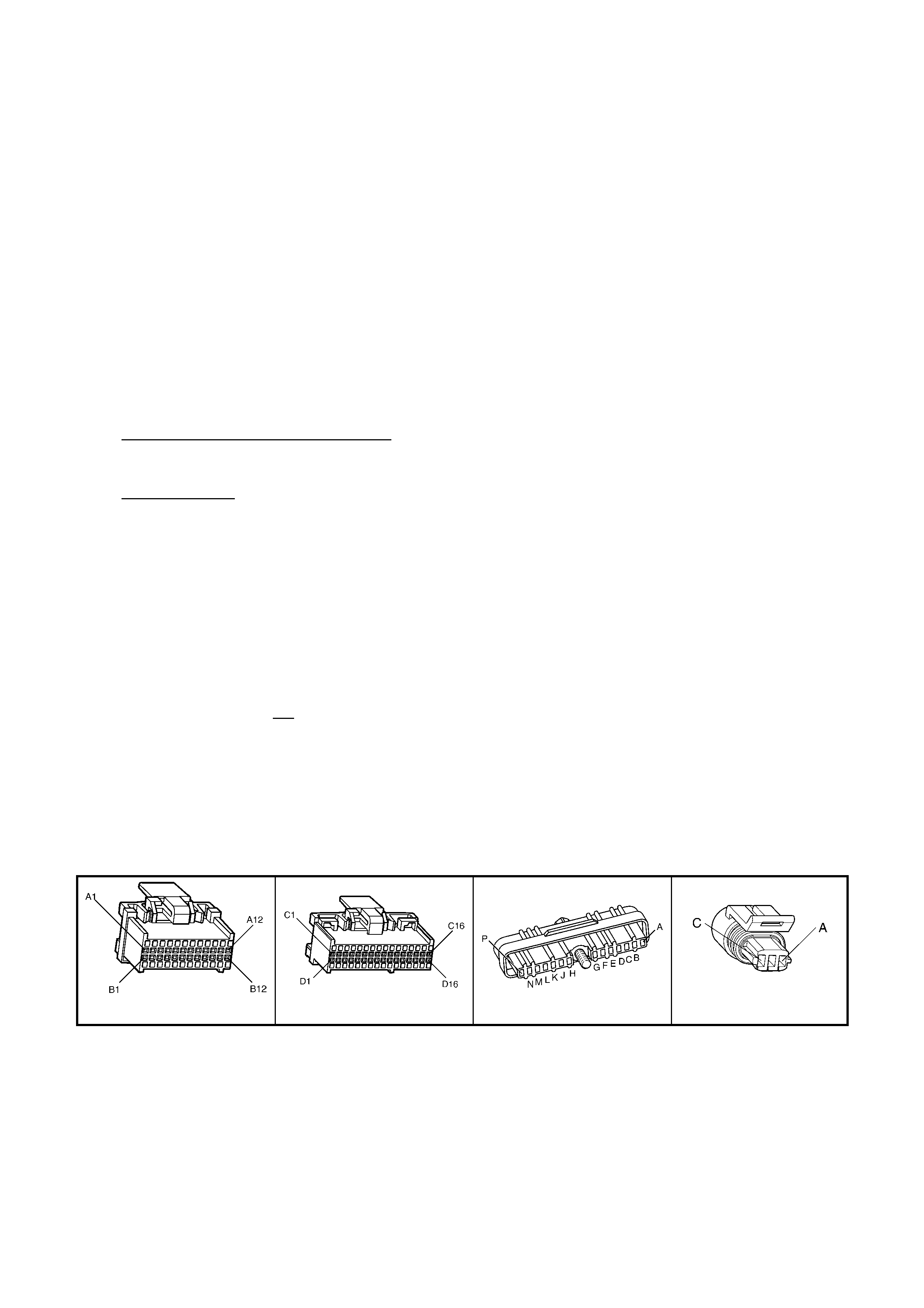
CONDITIONS FOR SETTING THE DTC:
• The PCM detects the Camshaft Position sensor signal is low when the signal should be high for 5.0 seconds.
ACTION TAKEN WHEN THE DTC SETS:
• The PCM stores the DTC information into memory when the diagnostic runs and fails.
• The Check Powertrain Malfunction Indicator Lamp (MIL) will not be activated.
• The PCM records the operating conditions at the time the diagnostic fails. The PCM stores this information in
the History Data.
• Once DTC 48 is set while the engine is running the PCM will continue to operate in Sequential Fuel Injection
(SFI) mode. If the camshaft position signal is not received at start up the PCM will operate in Sequential Fuel
Injection (SFI) mode, however, there is only a 1 in 6 chance of the correct injection sequence exists.
CONDITIONS FOR CLEARING THE CHECK POWERTRAIN MIL/DTC:
• Use Tech 2 to clear the Check Powertrain MIL/DTC.
DIAGNOSTIC AIDS:
An intermittent may be caused by a poor connection, rubbed through wire insulation, or a wire broken inside the
insulation.
Check for:
• Poor Connec tion or Damaged Harness – Inspect PCM harness c onnectors for bac ked out term inal X2 D3,
improper mating, broken locks, improperly formed or damaged terminal, poor terminal to wire connection
and damaged harness.
• Intermittent Test – If connections and harness check OK, monitor a digital voltm eter connected from PCM
term inal X2 D3 to ground while m oving related connectors and wir ing harness. If the f ailure is induced, the
voltage reading will change. This may help to isolate the location of the malfunction.
TEST DESCRIPTION:
NOTE: Number(s) below refer to step number(s) on the diagnostic table.
3. T his step verifies proper operation of c ircuits 632, 633, and 644. If the voltage is c orrect for both “A-B” and “B-
C” then all circuits from the ignition module to the camshaft position sensor are OK. If no voltage is m easured
for both “A-B” and “B-C” then the problem is in the c amshaf t position ground circuit 632 between the cam shaft
position sensor and the splice. If the voltage is low for only “A-B” or “B-C” then the problem is in that circuit.
6. This step verifies the integrity of circuit 630 from ignition m odule to PCM. If the voltage r eading of X2 D3 dr ops
slightly from 4.7 volts to appr oxim ately 4.1 volts, the cam shaf t sens or is pulling the s ignal line low, therefore the
connection to the PCM is not good or the PCM is f aulty. If the voltage rem ains at approx im ately 4.4 volts and is
steady, continue with diagnosis.
7. During this step the voltage at PCM term inal X2 D3 should be at approximately 4.9 volts with the test light not
connected, the voltage should dr op to les s than 0.5 volts when the test light is c onnected. If the voltage drops to
0.2 volts the DIS Module and circuits are OK, this means that the camshaft position sensor has poor
connections or is faulty.
11. T he voltage will only be pulled low to 0.5 volts or less when the m agnet in the cam shaft sp rock et is adjacent to
the camshaft position sensor. By bumping the engine the magnet should move away from the sensor and the
voltage rise to approximately 4.9 volts.
A84 V6 S/C – X1 A84 V6 S/C – X2 A40 B28
Figure 6C2-2A-112

DTC 48 V6 S/C PCM – CAMSHAFT POSITION (CMP) SENSOR CIRCUIT LOW VOLTAGE
STEP ACTION VALUE YES NO
1. Was the "On-Board Diagnostic" (OBD) System Check
performed? Go to Step 2 Go to
OBD
System Check
in this Section.
2. 1. Install Tech 2.
2. Ignition "ON", engine "OFF".
3. Record, then clear DTCs.
4. Start engine and idle for 1 minute.
5. Select DATA LIST.
Does Tech 2 display "Cam Signal" as "Missing"?
Go to Step 3 DTC 48 is
intermittent. If no
additional DTC’s
were stored,
refer to
"Diagnostic
Aids" above.
3. 1. Ignition "OFF".
2. Disconnect camshaft position sensor harness
connector from camshaft position sensor.
3. Ignition "ON", engine "OFF".
Using DMM, does voltage between harness connector pins
B28 X1-A/B and B28 X1-B/C measure between specified
values?
"A-B"
5-7 volts
"B-C"
8-11 volts
Go to Step 5 Go to Step 4
4. In test step 3 was the voltage at "A-B" greater than the
specified value? Go to step 13 Go to Step 12
5. 1. Ignition "OFF".
2. Reconnect camshaft position sensor connector B28
X1 to camshaft position sensor.
3. Install DMM to backprobe PCM terminals A84 X2-D3
and A84 X1-A1 to measure voltage at PCM terminal
A84 X2-D3.
4. Ignition "ON", engine "OFF".
Is voltage fixed at specified value?
Approximately
4.9 volts Go to Step 6 Go to Step 11
6. 1. Start engine and idle for 1 minute to stabilise system.
Is voltage reading of A84 X2-D3 constantly varying around
a mid-point of specified value?
Approximately
4.1 volts Go to Step 10 Go to Step 7
7. 1. Ignition "OFF".
2. Disconnect camshaft position sensor harness
connector B28 from camshaft position sensor.
3. Ignition "ON", engine "OFF".
4. Touch terminal B28 X1-A of camshaft position sensor
harness connector with a test light connected to
ground while observing voltmeter.
Does voltage reading at PCM terminal A84 X2-D3 drop to
specified value?
0.5 volts Go to Step 8 Go to Step 16
8. 1. Check the following:
• Poor connection at camshaft position sensor or
ignition module.
• Faulty camshaft position sensor.
• Missing camshaft magnet.
Is action complete?
Verify Repair –
9. 1. Replace faulty DIS ignition control module A40.
Is action complete? Verify Repair –
10. 1. Check for poor connection at PCM terminal A84 X2-
D3.
Was a fault found?
Verify Repair Go to Step 20
11. 1. ‘Bump’ engine with starter.
2. Re-test voltage at terminal A84 X2-D3.
Is voltage at specified value?
Approximately
4.7 volts Go to Step 6 Go to Step 19
12. Was one voltage reading low? Go to Step 14 Go to Step 18
13. 1. Repair short to voltage in circuit 633.
Is action complete? Verify Repair
14. Was the reading between harness connector pin B28 X1-A
to B low? Go to Step 15 Go to Step 17
15. 1. Check for open or short to ground in circuit 633.
Was a fault found? Verify Repair Go to Step 16

STEP ACTION VALUE YES NO
16. 1. Check for poor ignition control module connection.
Was a fault found? Verify Repair Go to Step 9
17. 1. Repair circuit 644 between splice and camshaft
position sensor connector, B28, terminal X1-C.
Is action complete?
Verify Repair –
18. 1. Repair open in circuit 632 between splice and
camshaft position sensor connector, B28, terminal
X1 B.
Is action complete?
Verify Repair –
19. 1. Check circuit 630 for open or short to ground.
Was a fault found? Verify Repair Go to Step 16
20. 1. Replace PCM. Refer to 6C2-3 SERVICE
OPERATIONS in this Section for PCM Security Link
procedure.
Is action complete?
Verify Repair –

DTC 49 V6 S/C PCM – CAMSHAFT POSITION (CMP) SENSOR PERFORMANCE
Figure 6C2-2A-113 – Ignition System
CIRCUIT DESCRIPTION:
During cr anking, the ignition module monitors the dual crank sensor 3X signal. The 3X signal is used to determine
the correct cylinder pair to spark first. After the 3X signal has been processed by the ignition module, it sends a
crank shaft refer ence pulse to the PCM. W hen the PCM receives this pulse it will com mand all s ix injectors to open
for one pr iming shot of fuel in all cylinder s. After the prim ing, the injectors are left "OFF " for the nex t six cr ankshaf t
reference pulses from the ignition module (two crankshaft revolutions). This allows each cylinder a chance to use
the fuel from the priming shot. During this waiting period, a cam signal will have been received by the PCM. Now the
PCM begins to operate the injectors by energising each injector based on true camshaft position. W ith the engine
running, the PCM monitors the cam and crank shaft reference signal pulses it receives and expects to see 6 crank
reference signal pulses for each cam pulse.
CONDITIONS FOR RUNNING THE DTC:
• The engine is cranking.
CONDITIONS FOR SETTING THE DTC:
• An incorrect number of crankshaft reference pulses have been received since the previous camshaft position
signal.

ACTION TAKEN WHEN THE DTC SETS:
• The PCM stores the DTC information into memory when the diagnostic runs and fails.
• The Check Powertrain Malfunction Indicator Lamp (MIL) will not be activated.
• The PCM records the operating conditions at the time the diagnostic fails. The PCM stores this information in
the History Data.
• Once DTC 49 is set, the PCM will determine the fuel injection sequence based on the last fuel injection pulse
received.
CONDITIONS FOR CLEARING THE CHECK POWERTRAIN MIL/DTC:
• Use Tech 2 to clear the Check Powertrain MIL/DTC.
DIAGNOSTIC AIDS:
DTC 49 indic ates an interm ittent fault and m ay not set im m ediately or under all conditions. Custom er c om m ents of
symptoms experienced may help isolate the cause of the condition. A poor connection or fault in the cam sensor
circuits 630, 632, 633, or 644 or a f aulty cam sens or m ay cause the PCM to re-initialis e injector sequence when the
fault occurs, causing a possible stumble or miss. A poor connection or fault in the 18X signal circuit 647, crank
sensor circuits 573, 632, or 644, the 18X portion of the crank sensor or bent or missing vanes on the harmonic
balancer interrupter rings will cause the PCM to stop pulsing the injectors when the fault occurs, causing an
intermittent stumble or stall.
TEST DESCRIPTION:
NOTE: Number(s) below refer to step number(s) on the diagnostic table.
2. Determines if conditions necessary to set DTC 49 exist on this ignition cycle.
3. If 5 volts are not present at PCM harness connector terminal A84 X2-D3, the cam sensor may be interfacing
with the magnet in the camshaft sprocket. Bumping the starter should correct this condition.
6. If a f ailure is induced in the 18X signal c ircuit, the 5 volts on the circ uit s hould change when the faulty wiring or
connection is manipulated.
NOTE: If DTC 48 is set along with DTC 49, use DTC 48 table for diagnosis.
A84 V6 S/C – X2 A40 B28
Figure 6C2-2A-114
DTC 49 V6 S/C PCM – CAMSHAFT POSITION (CKP) SENSOR PERFORMANCE
STEP ACTION VALUE YES NO
1. Was the "On-Board Diagnostic" (OBD) System Check
performed? Go to Step 2. Go to
OBD
System Check
in this Section.
2. 1. Install Tech 2.
2. Start and idle engine.
3. Using Tech 2, look at "IGN Cycles" in DTC history.
Is DTC 49 current (ignition cycles at 0)?
Go to Step 3 DTC 49 is
intermittent. If no
additional DTC's
were set, refer to
"Diagnostic
Aids" above.
3. 1. Ignition "OFF".
2. Disconnect PCM connectors.
3. Connect a DMM between PCM harness connector
terminal A84 X2-D3 and ground.
4. Ignition "ON".
Is voltage at "D3” at specified value?
Approximately
5 volts Go to Step 5 Go to Step 4
4. 1. ‘Bump’ engine with starter.
Is voltage at A84 X2-D3 at specified value? Approximately
5 volts Go to Step 5 Go to DTC 48 in
this Section.
5. 1. Monitor voltage at A84 X2-D3 while manipulating
powertrain wiring harness to PCM connector.
Does voltage remain steady as wiring is manipulated?
Go to Step 6 Go to Step 10

STEP ACTION VALUE YES NO
6. 1. Connect DMM between PCM harness connector
terminal A84 X2-D3 and ground.
2. Monitor voltage at A84 X2-D3 while manipulating
ignition harness, engine harness, and dash harness to
PCM connector.
Does voltage remain steady as wiring is manipulated?
Go to Step 7 Go to Step 8
7. Check for:
• Poor connections at PCM;
• Harmonic balancer interrupter ring vanes bent or
missing;
• Faulty crank sensor (malfunctioning hot/cold).
Are all above OK?
Refer to
"Diagnostic
Aids" above
Verify Repair
8. 1. Check for poor connection at crankshaft position
sensor or ignition control module.
Was a fault found?
Verify Repair Go to Step 9
9. 1. Repair intermittent open/short to ground in circuit 632,
633, 644 or 647.
Is action complete?
Verify Repair –
10. 1. Check for poor connection at camshaft position sensor
or ignition control module.
Was a fault found?
Verify Repair Go to Step 11
11. 1. Repair intermittent open/short to ground in circuit 630,
632, 633 or 644.
Is action complete?
Verify Repair –
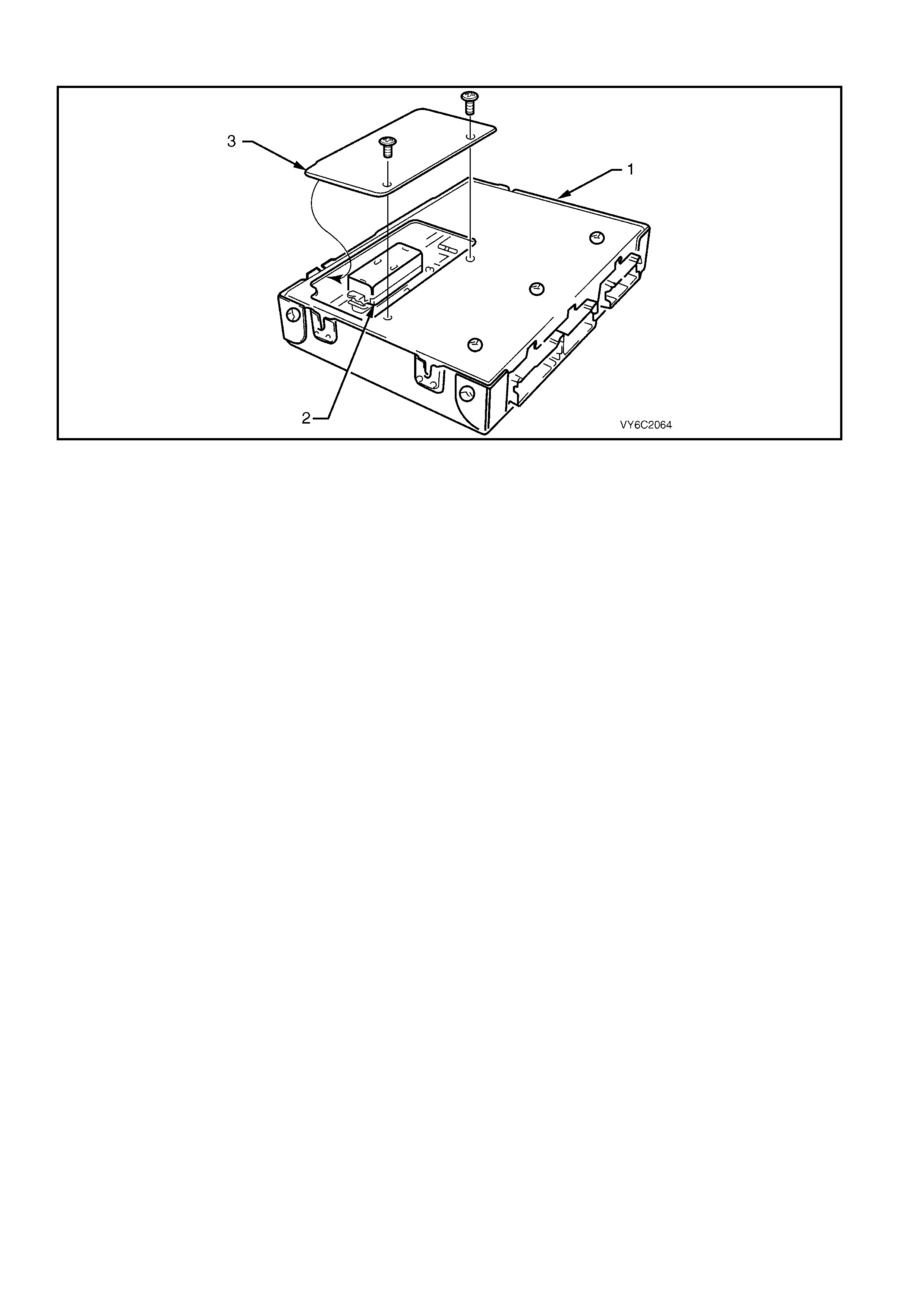
DTC 51 V6 S/C PCM – P OWERTRAIN CONTROL MODULE (PCM) MEMORY
Figure 6C2-2A 115 – Powertrain Control Module PROM
Legend
1. Powertrain Control Module (PCM) 2. Programmable Read Only Memory (PROM) 3. PROM Access Cover
CIRCUIT DESCRIPTION:
The PCM Programmable Read Only Memory (PROM) contains data which is essential to running the engine and
transmission. The PCM continuously checks the integrity of this data.
CONDITIONS FOR RUNNING THE DTC:
• The ignition switch is in the crank position or the run position.
CONDITIONS FOR SETTING THE DTC:
• The PCM is unable to correctly read data from the PROM.
ACTION TAKEN WHEN THE DTC SETS:
• The PCM activates the Check Powertrain Malfunction Indicator Lamp (MIL) when the diagnostic runs and fails.
• The PCM records the operating conditions at the time the diagnostic fails. The PCM stores this information in
the History Data.
CONDITIONS FOR CLEARING THE CHECK POWERTRAIN MIL/DTC:
• The PCM turns the Chec k Powertrain MIL OF F af ter the f irs t ignition c ycle that the diagnostic runs and does not
fail.
• Use Tech 2 to clear the Check Powertrain MIL/DTC.
DIAGNOSTIC AIDS
• Replace the PCM Prom even if this DTC exists only in history.
• For an Intermittent, refer to Section 6C2-2B SYMPTOMS.
TEST DESCRIPTION
NOTE: Number(s) below refer to the step number(s) on the diagnostic table.
2. This step verifies that the Prom is inserted properly into the PCM.

DTC 51 V6 S/C PCM – POWERTRAIN CONTROL MODULE (PCM) MEMORY
STEP ACTION VALUE YES NO
1. Was the "On-Board Diagnostic" (OBD) System Check
performed? Go to Step 2. Go to
OBD
System Check
in this Section.
2. 1. Check that PROM is fully inserted into the PCM.
Is PROM fully inserted? Go to Step 3 Go to Step 5
3. 1. Replace PROM. Refer to 6C2-3 SERVICE
OPERATIONS in this Section
2. Clear DTC’s and recheck for DTC 51.
Does DTC 51 reset?
Go to Step 4 Go to Step 6
4. 1. Replace PCM. Refer to 6C2-3 SERVICE
OPERATIONS in this Section for PCM Security Link
procedure.
Is action complete?
Verify Repair –
5. 1. Fully insert PROM.
2. Clear DTC’s and recheck for DTC 51.
Does DTC 51 reset?
Go to Step 3 Go to Step 6
6. 1. Clear DTC’s and confirm no "Check Powertrain MIL”.
Is action complete? Verify Repair –

DTC 52 V6 S/C PCM – SYSTEM VOLTAGE TOO HIGH (LONG TIME)
Figure 6C2-2A-116 – Power Feed
CIRCUIT DESCRIPTION:
Circuit 300 is the ignition voltage feed circuit to terminal A84 X1 A4 for the PCM. Circuit 740 is the battery voltage
feed circ uit to terminals A84 X 1 A8 and X1 B8 for the PCM. When the PCM detects a high voltage for a long time,
then DTC 52 sets.
CONDITIONS FOR RUNNING THE DTC:
• The ignition is on.
• ECT is at or above 85° C.
CONDITIONS FOR SETTING THE DTC:
• The engine is running and the PCM ignition voltage is greater than 16 volts for more than 109 minutes.

ACTION TAKEN WHEN THE DTC SETS:
• The PCM activates the Check Powertrain Malfunction Indicator Lamp (MIL) when the diagnostic runs and fails.
• The PCM records the operating conditions at the time the diagnostic fails. The PCM stores this information in
the History Data.
• During the time fault is present, the pressure control solenoid is turned "OFF", the transmission shifts
immediately to 3rd gear and TCC operation is inhibited.
CONDITIONS FOR CLEARING THE CHECK POWERTRAIN MIL/DTC:
• The PCM deactivates the Check Powertrain MIL after the first ignition cycle that the diagnostic runs and does
not fail.
• Use Tech 2 to clear the Check Powertrain MIL/DTC.
DIAGNOSTIC AIDS:
• Inspect the wiring for poor electrical connections at the PCM. Look for the following conditions:
– A bent terminal.
– A backed out terminal.
– A damaged terminal.
– Poor terminal tension.
– A chafed wire.
– A broken wire inside the insulation.
– Moisture intrusion.
• When diagnosing for an intermittent short or open condition, massage the wiring harness while watching the
test equipment for a change.
• Charging the battery with a battery charger may set DTC’s. Jump starting an engine may set DTC’s.
• If DTC’s set when you operate an accessory, inspect the applicable wiring for faulty connections. Inspect the
wiring for excessive current draw.
• Inspect the following items for faulty connections:
– The starter solenoid.
– The fusible link.
– The generator terminals.
– Battery cables.
• Inspect the belts for excessive wear. Inspect the belts for proper tension.
TEST DESCRIPTION:
NOTE: Number(s) below refer to the step number(s) on the diagnostic table.
4. This step tests the charging system voltage.
5. This step tests PCM battery voltage.
DTC 52 V6 S/C PCM – SYSTEM VOLTAGE TOO HIGH (LONG TIME)
STEP ACTION VALUE YES NO
1. Was the "On-Board Diagnostic" (OBD) System Check
performed? Go to Step 2. Go to
OBD
System Check
in this Section.
2. 1. Install Tech 2.
2. With the engine OFF, turn the ignition switch to the
“ON” position.
IMPORTANT: Before clearing the DTC’s, use the scan tool
in order to record the DTC history. The ‘Clear Info’
function will erase the data.
3. Record the DTC history.
4. Using a DMM, measure the battery voltage across the
battery terminals. Record the measurement for future
reference.
Is the voltage higher than the specified value?
10 volts Go to Step 3 Go to Battery
Diagnosis, refer
12A BATTERY
AND CABLES.

STEP ACTION VALUE YES NO
3. 1. Start the engine.
2. Warm the engine to the operating temperature.
Is the Generator/Check Powertrain MIL activated?
Go to Charging
System
Diagnosis,
refer 6D2-1
CHARGING
SYSTEM – V6
S/C ENGINE.
Go to Step 4
4. 1. Increase the engine speed to 2000 RPM for 15
seconds.
2. Observe the DMM battery voltage.
Is the DMM battery voltage greater than the specified
value?
15 volts Go to Charging
System
Diagnosis,
refer 6D2-1
CHARGING
SYSTEM – V6
S/C ENGINE.
Go to Step 5
5. 1. Increase the engine speed to 2000 RPM.
2. Observe Battery Voltage on Tech 2.
Is the Tech 2 Battery Voltage greater than the specified
value?
15.5 volts Go to Step 6 System Checks
OK, Go to
“Diagnostic
Aids” above.
6. 1. Replace PCM. Refer to 6C2-3 SERVICE
OPERATIONS in this Section, for PCM Security Link
procedure.
Is action complete?
Go to Step 7 –
7. In order to verify your repair, perform the following
procedure:
1. Select DTC.
2. Select Clear Info.
3. Operate the vehicle under the following conditions:
• Start the vehicle.
• Warm the engine to normal operating
temperature.
Is the scan tool Battery Voltage within the specified range?
13 – 15.5
volts System OK Go to Step 2

DTC 53 V6 S/C PCM – SYSTEM VOLTAGE TOO HIGH
Figure 6C2-2A-117 – Power Feed
CIRCUIT DESCRIPTION:
Circuit 300 is the ignition voltage feed circuit to terminal A84 X1-4 for the PCM. Circuit 740 is the battery voltage
feed circuit to terminals A84 X1-A8 and A84 X1-B8 for the PCM. When the PCM detects a HIGH voltage for a short
period of time, then DTC 53 sets.
CONDITIONS FOR RUNNING THE DTC:
• The ignition is on.
• ECT is at or above 85° C.
• Conditions present for at least 4 seconds.
CONDITIONS FOR SETTING THE DTC:
• Voltage at PCM ignition feed terminal is more than 19.5 volts for more than 2 seconds.

ACTION TAKEN WHEN THE DTC SETS:
• The PCM activates the Check Powertrain Malfunction Indicator Lamp (MIL) when the diagnostic runs and fails.
• The PCM records the operating conditions at the time the diagnostic fails. The PCM stores this information in
the History Data.
• When DTC 53 sets, the PCM turns off all transmission output devices, and freezes shift adapts from being
updated.
CONDITIONS FOR CLEARING THE CHECK POWERTRAIN MIL/DTC:
• The PCM deactivates the Check Powertrain MIL after the first ignition cycle that the diagnostic runs and does
not fail.
• Use Tech 2 to clear the Check Powertrain MIL/DTC.
DIAGNOSTIC AIDS:
• Inspect the wiring for poor electrical connections at the PCM. Look for the following conditions:
– A bent terminal.
– A backed out terminal.
– A damaged terminal.
– Poor terminal tension.
– A chafed wire.
– A broken wire inside the insulation.
– Moisture intrusion.
• W hen diagnos ing for an intermittent shor t or open condition, wriggle the wiring harness while watching the test
equipment for a change.
• Charging the battery with a battery charger may set DTC’s. Jump starting an engine may also set DTC’s.
• If DTC’s set when you operate an accessory, inspect the applicable wiring for faulty connections. Inspect the
wiring for excessive current draw.
• Inspect the following items for faulty connections:
– The starter solenoid.
– The fusible link.
– The generator terminals.
– Battery cables.
• Inspect the drive belts for excessive wear. Inspect the belts for proper tension.
TEST DESCRIPTION:
NOTE: Number(s) below refer to the step number(s) on the diagnostic table.
4. This step tests the charging system voltage.
6. This step checks battery voltage of the PCM, using Tech 2.
DTC 53 V6 S/C PCM – SYSTEM VOLTAGE TOO HIGH
STEP ACTION VALUE YES NO
1. Was the "On-Board Diagnostic" (OBD) System Check
performed? Go to Step 2. Go to
OBD
System Check
in this Section.
2. 1. Install the Tech 2.
2. With the engine OFF, turn the ignition switch to the
RUN position.
IMPORTANT: Before clearing the DTC’s, use Tech 2 to
record the DTC history. The ‘Clear Info’ function will erase
the data.
3. Record the DTC history.
4. Using a DMM, measure the battery voltage across the
battery terminals. Record the measurement for future
reference.
Is the voltage higher than the specified value?
10 volts Go to Step 3 Go to Battery
Diagnosis, refer
12A BATTERY
AND CABLES.

STEP ACTION VALUE YES NO
3. 1. Start the engine.
2. Warm the engine to the operating temperature.
Is the Generator/Check Powertrain MIL activated?
Go to Charging
System
Diagnosis,
refer 6D2-1
CHARGING
SYSTEM – V6
S/C ENGINE.
Go to Step 4
4. 1. Increase the engine speed to 2000 RPM for 15
seconds.
2. Observe the DMM battery voltage and record your
reading.
Did the DMM battery voltage exceed the specified value?
16.0 volts Go to Charging
System
Diagnosis, refer
6D1-1
CHARGING
SYSTEM – V6
S/C ENGINE.
Go to Step 5
5. 1. Increase the engine speed to 2000 RPM.
2. Observe Battery Voltage displayed by Tech 2.
Is the Tech 2 Battery Voltage within 0.5 volts of your
recorded voltage in step 4?
System Checks
OK, Go to
“Diagnostic
Aids” above.
Go to Step 6
6. 1. Replace PCM. Refer to 6C2-3 SERVICE
OPERATIONS, in this Section for PCM Security Link
procedure.
Is action complete?
Go to Step 7 –
7. In order to verify your repair, perform the following
procedure:
1. Select DTC.
2. Select Clear Info.
1. Operate the vehicle under the following conditions:
• Start the vehicle.
• Warm the engine to normal operating
temperature.
Is the Tech 2 Battery Voltage within the specified range?
13 –15.5
volts System OK Begin the
diagnosis again.
Go to Step 2

DTC 54 V6 S/C PCM – SYSTEM VOLTAGE UNSTABLE
Figure 6C2-2A-118 – Power Feed
CIRCUIT DESCRIPTION:
Diagnostic Trouble Code (DTC) 54 will set when the ignition is “ON” and PCM terminal “X1 A4” voltage changed
more than 2.5 volts in 100 milliseconds.
CONDITIONS FOR RUNNING THE DTC:
• The ignition is “ON”.
• Conditions present for at least 10 seconds.
CONDITIONS FOR SETTING THE DTC:
• System voltage changes more than 2.5 volts in 100 milliseconds.
ACTION TAKEN WHEN THE DTC SETS:
• The PCM activates the Check Powertrain Malfunction Indicator Lamp (MIL) when the diagnostic runs and fails.
• The PCM records the operating conditions at the time the diagnostic fails. The PCM stores this information in
the History Data.
• When DTC 54 sets, the PCM turns off all transmission output devices, and freezes shift adapts from being
updated.
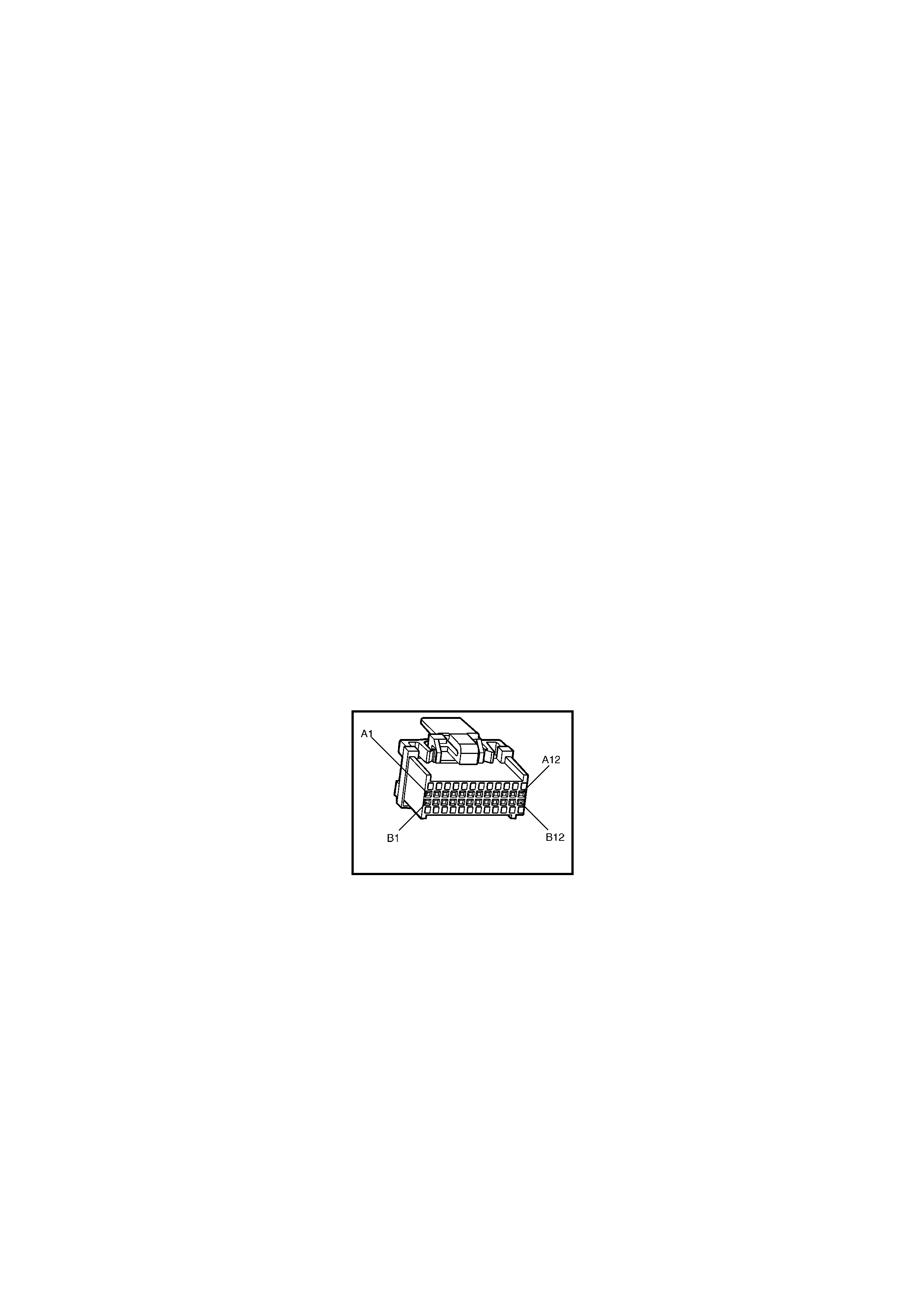
CONDITIONS FOR CLEARING THE CHECK POWERTRAIN MIL/DTC:
• The PCM deactivates the Check Powertrain MIL after the first ignition cycle that the diagnostic runs and does
not fail.
• Use Tech 2 to clear the Check Powertrain MIL/DTC.
DIAGNOSTIC AIDS:
• Inspect the wiring for poor electrical connections at the PCM. Look for the following conditions:
– A bent terminal.
– A backed out terminal.
– A damaged terminal.
– Poor terminal tension.
– A chafed wire.
– A broken wire inside the insulation.
– Moisture intrusion.
• When attempting to diagnose an intermittent problem, use the snapshot mode of the Tech 2, to review
diagnostic information.
• Charging the battery with a battery charger may set DTC’s. Jump starting an engine may also set DTC’s.
• If DTC’s set when you operate an accessory, inspect the applicable wiring for faulty connections. Inspect the
wiring for excessive current draw.
• Inspect the following items for faulty connections:
– The starter solenoid.
– The fusible link.
– The generator terminals.
– Battery cables.
• Inspect the drive belts for excessive wear. Inspect the drive belts for proper tension.
TEST DESCRIPTION:
NOTE: Number(s) below refer to the step number(s) on the diagnostic table.
2. Diagnostic Tr ouble Code 54 will set if: T he last 25% of the sam ples for ignition feed voltage changes more than
2.5 volts in 100 milliseconds.
A84 V6 S/C – X1
Figure 6C2-2A-119

DTC 54 V6 S/C PCM – SYSTEM VOLTAGE UNSTABLE
STEP ACTION VALUE YES NO
1. Was the "On-Board Diagnostic" (OBD) System Check
performed? Go to Step 2. Go to
OBD
System Check
in this Section.
2. 1. Install Tech 2 and set up snapshot mode to trigger on
DTC 54.
2. Ignition "ON".
3. Wriggle the PCM connector, A84 X1.
Does "System Voltage" reading change sharply as
connector is wriggled?
Go to Step 7 Go to Step 3
3. 1. Wriggle and tug the harness at the PCM.
Does "System Voltage" reading change sharply as
harness is wriggled?
Go to Step 7 Go to Step 4
4. 1. Lightly tap on the PCM.
Does "System Voltage" reading change sharply as PCM is
tapped?
Go to Step 5 DTC 54 is
intermittent. If no
additional DTC's
were stored,
refer to
"Diagnostic
Aids" above
5. 1. Verify that PCM is securely mounted to vehicle.
Is PCM securely mounted? Go to Step 6 Verify Repair
6. 1. Replace PCM. Refer to 6C2-3 SERVICE
OPERATIONS in this Section, for PCM Security Link
procedure.
Is action complete?
Verify Repair –
7. 1. Check PCM connector for corrosion.
Is corrosion present? Go to Step 8 Go to Step 9
8. 1. Clean corroded terminals with electronic part cleaner.
Is action complete? Verify Repair –
9. 1. Check tightness of the female terminal grip with the
shank of a 0.95 mm twist drill.
Are terminals tight?
Go to Step 10 Verify Repair
10. 1. Remove PCM connector strain relief and remove
terminal from connector to check for broken or bent
locking tang.
Is locking tang OK?
Locate and
repair
intermittent open
in powertrain
wiring harness.
Replace
terminal.
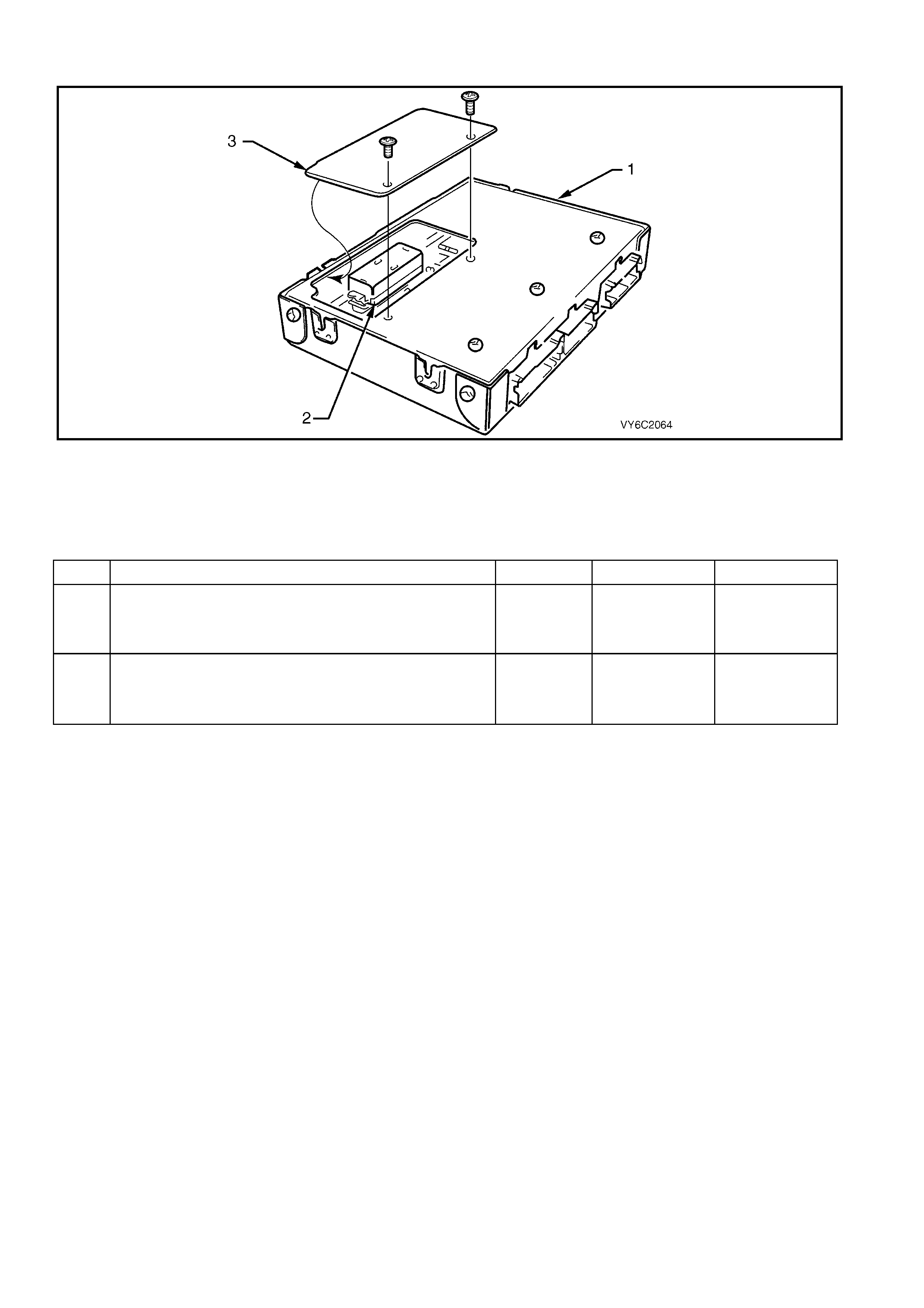
DTC 55 V6 S/C PCM – ANALOGUE TO DIGITAL (A/D) CONVERSION ERROR
Figure 6C2-2A 120 – Powertrain Control Module PROM
Legend
1. Powertrain Control Module (PCM) 2. Programmable Read Only Memory (PROM) 3. PROM Access Cover
DTC 55 V6 S/C PCM – ANALOGUE TO DIGITAL (A/D) CONVERSION ERROR
STEP ACTION VALUE YES NO
1. Was the "On-Board Diagnostic" (OBD) System Check
performed? Go to Step 2. Go to
OBD
System Check
in this Section.
1. Replace PCM. Refer to 6C2-3 SERVICE
OPERATIONS in this Section, for PCM Security Link
procedure.
Is action complete?
Verify repair –
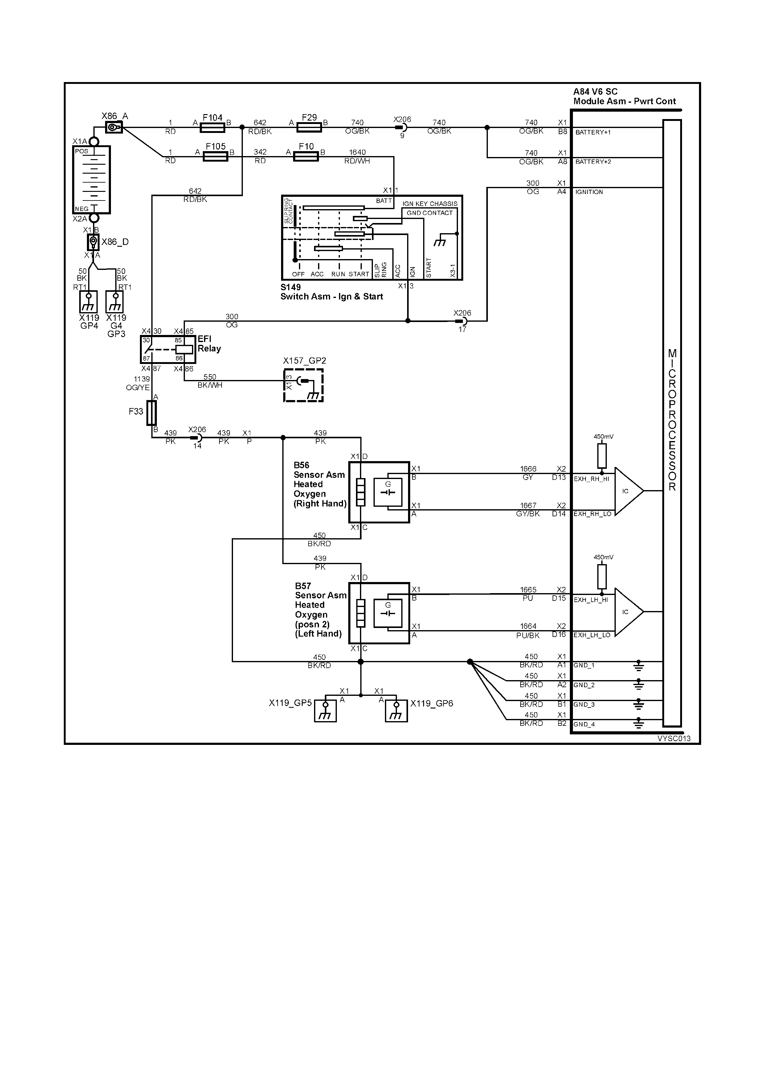
DTC 56 V6 S / C PCM – LEAN CONDITION UNDER LOAD
Figure 6C2-2A-121 – Oxygen Sensor Circuits
CIRCUIT DESCRIPTION:
The PCM's internal circuitry can identify if the vehicle's fuel system is capable of supplying adequate amounts of
fuel during heavy acceler ation (power enrichment) by monitor ing the voltage of the oxygen s ensor. W hen a "power
enrichment" mode of operation is requested during "Closed Loop" (remember the PCM will go "Open Loop" not
ma ke f uelling changes based on oxygen sensor s ignal under heavy acc eleration), the PCM will provide m ore fuel to
the engine. Under these conditions, the PCM should detect a "rich" condition, high oxygen sensor voltage. If this
"rich" exhaust is NOT detected at this time, a DTC 56 will set. A plugged fuel filter or restricted fuel line or a fuel
pump that is not switching to high speed can prevent adequate amounts of fuel from being supplied during the
power enrichment mode but may be fine at idle or light throttle acceleration.
This supercharged engine application has a two speed fuel pump that switches from low speed (low fuel flow) to
high speed (high fuel flow) when heavy boost is required, and will switch back to low speed (low fuel flow) for normal
vehicle driving conditions.
CONDITIONS FOR RUNNING THE DTC:
• The engine has been running for longer than two minutes.
• DTC 13, 44, 45, 63, 64 and 65 are not current.

CONDITIONS FOR SETTING THE DTC:
• The PCM detects a low oxygen sensor voltage for 10 seconds during “Power Enrichment” mode of operation.
ACTION TAKEN WHEN THE DTC SETS:
• The PCM stores the DTC information into memory when the diagnostic runs and fails.
• The Check Powertrain Malfunction Indicator Lamp (MIL) will not be activated.
• The PCM records the operating conditions at the time the diagnostic fails. The PCM stores this information in
the History Data.
CONDITIONS FOR CLEARING THE CHECK POWERTRAIN MIL/DTC:
• Use Tech 2 to clear the Check Powertrain MIL/DTC.
DIAGNOSTIC AIDS:
A restricted filter can supply adequate amounts of fuel at idle but may not be able to supply enough fuel during
heavy acceleration. A vapour lock condition can cause a DTC 56.
Be certain that the proper fuel pump is installed in the vehicle. If the improper fuel pump is installed, this could
cause DTC 56 to set.
Refer to Table A-4.1 for checking the operation of the two speed fuel pump.
TEST DESCRIPTION:
NOTE: Number(s) below refer to the step number(s) on the diagnostic table.
3. Wrap a shop towel around the fuel pressure connector to absorb any small amount of fuel leakage that may
occur when installing the gauge. Ignition "ON," pump pressure should be 290-410 kPa. This pressure is
controlled by s pring pres sure within the fuel press ure regular as sembly. Pressur e below 290 kPa. m ay caus e a
lean condition and may set a DTC 44. It could also cause hard starting cold and poor driveability. Low enough
pressure will cause the engine not to run at all. Restricted flow may allow the engine to run at idle, or low
speeds, but may cause a surge and stall when more fuel is required, as when accelerating or driving at high
speeds. Low fuel pressure under heavy acceleration conditions may set a DTC 56.
5. Restricting the fuel return line allows the fuel pressure to build above regulated pressure. W ith Tech 2, enable
the fuel pump and pressure should rise above 410 kPa as the return line is partially closed.
12. A vehicle driven in extremely hot temperatures and a near empty fuel tank can cause the temperature of the
fuel in the tank to become heated. Couple this with the f act fuel is being sent to an even hotter engine and the
fuel becomes even hotter. Not all fuel sent to the engine is injected and this hot fuel is sent back to the fuel
tank, increasing the temperature of the fuel in the tank even more. If temperature becomes great enough, a
possible vapour lock could exist causing a DTC 56. Check that the engine cooling system and ignition timing
are working properly. Adding fuel to the fuel tank could lower fuel tank temperature.
DTC 56 V6 S/C PCM – LEAN CONDITION UNDER LOAD
STEP ACTION VALUE YES NO
1. Was the "On-Board Diagnostic" (OBD) System Check
performed? Go to Step 2. Go to
OBD
System Check
in this Section.
2. 1. Connect Tech 2 to the DLC and check for multiple
DTC’s.
Is any other DTC set?
Go to that DTC
first. Go to Step 3
3. 1. Disconnect Fuel Pump Relay and crank engine to
relieve fuel pressure.
2. Install fuel pressure gauge.
3. Start and idle engine at normal operating temperature.
4. Disconnect vacuum line going to fuel pressure
regulator.
5. Note fuel pressure with engine running.
Is fuel pressure within specified value?
290 – 410
kPa No trouble
found.
If no additional
DTC’s were
stored, refer to
"Diagnostic
Aids" above.
Go to Step 4
4. 1. Check for restrictions in the fuel lines or the in-line fuel
filter.
Are any restrictions found?
Verify Repair Go to Step 5
5. 1. Ignition "OFF".
2. Ignition "ON".
3. Using Tech 2, select and enable the fuel pump.
4. Use pliers, slowly close the fuel return line at the fuel
gauge sender unit while fuel pump is operating.
Does pressure rise above value shown?
410 kPa +
NOTE: Do
not exceed
450 kPa
DTC 56 is
intermittent.
Refer to
"Diagnostic
Aids" above.
Go to Step 6

STEP ACTION VALUE YES NO
6. 1. Check for faulty fuel pump.
Is faulty fuel pump found? Verify Repair Go to Step 7
7. 1. Verify that fuel pulse dampener (Pulsator) is properly
connected.
Is the fuel pulse dampener connected correctly?
Go to Step 8 Verify Repair
8. 1. Check for restriction in fuel pump strainer.
Is a restriction found? Verify Repair Go to Step 9
9. 1. Check that the fuel pump being used is the correct
part number for the vehicle.
Is incorrect fuel pump installed in vehicle?
Go to Step 10 Go to Step 11
10. 1. Install the correct fuel pump.
Is action complete?
Verify Repair
Refer to
"Diagnostic
Aids" above.
–
11. 1. Check that the fuel pump strainer on the modular fuel
pump and sender assembly is not collapsed.
Is the sock collapsed?
Verify Repair
NOTE: Strainer
is not serviced
separately.
Go to Step 12
12. 1. Check vehicle fuel for being overheated?
Was a problem found?
Repair
overheating
problem
Go to Step 13
13. 1. Clear DTC and drive vehicle under the condition for
setting the DTC on the facing page.
Does DTC 56 reset?
Go to Step 2 Repair complete

DTC 57 V6 S/C PCM – INJECTOR VO LTAGE MONITOR FAULT
Figure 6C2-2A-122 – Fuel Injectors
CIRCUIT DESCRIPTION:
The inj ector voltage m onitor line is used s o that the PCM will know the exact voltage the fuel injectors are operating
at. This voltage is used to control the puls e width modulation of the f uel injector s. If the injector voltage monitor line
drops more than 2.2 volts for more than 3 seconds, Diagnostic Trouble Code (DTC) 57 will set. This DTC will not
activate the "Check Powertrain" Malfunc tion Indicator :Lam p (MIL) but will have a DT C set in the PC M m em ory that
can be read with Tech 2.
CONDITIONS FOR RUNNING THE DTC:
• The engine is running.
• DTC 54 is not set.
CONDITIONS FOR SETTING THE DTC:
• Injector voltage monitor line voltage is 2.2 volts different than system voltage for 3 seconds.
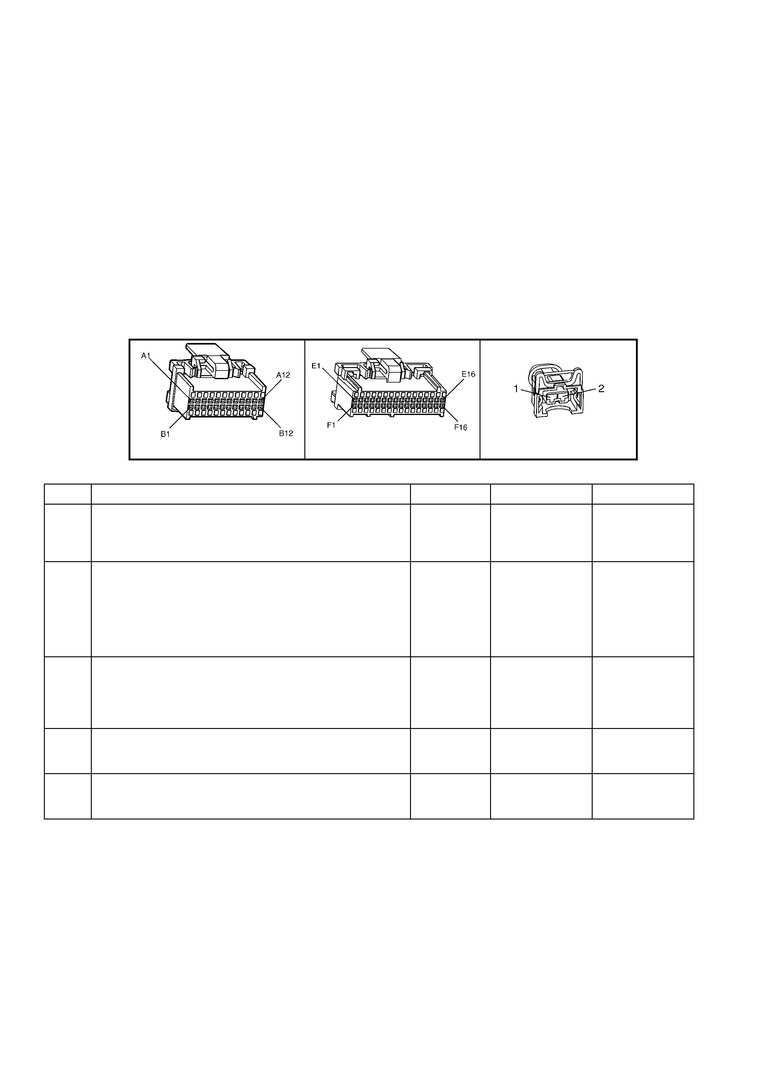
ACTION TAKEN WHEN THE DTC SETS:
• The PCM stores the DTC information into memory when the diagnostic runs and fails.
• The Check Powertrain Malfunction Indicator Lamp (MIL) will not be activated.
• The PCM records the operating conditions at the time the diagnostic fails. The PCM stores this information in
the History Data.
• The PCM will use the battery feed input signal as the voltage value to control the fuel injectors base pulse width.
CONDITIONS FOR CLEARING THE CHECK POWERTRAIN MIL/DTC:
• Use Tech 2 to clear the Check Powertrain MIL/DTC.
DIAGNOSTIC AIDS:
When the injector voltage monitor line voltage drops more than 2.2 volts, the PCM will operate on an incorr ec t value
for 3 seconds until the DTC 57 is set. Check PCM terminal connections for proper mating.
If DTC 16, 53 and 57 are set, check for short to voltage on "Diagnostic Test" line, circuit 448.
TEST DESCRIPTION:
NOTE: Number(s) below refer to step number(s) on the diagnostic table.
2. If the charging voltage is too high, this could set DTC 57. If DTC 53 or 54 is set, refer to that DTC first.
A84 V6 S/C – X1 A84 V6 S/C – X2 L2
DTC 57 V6 S/C PCM – INJECTOR VOLTAGE MONITOR FAULT
STEP ACTION VALUE YES NO
1. Was the "On-Board Diagnostic" (OBD) System Check
performed? Go to Step 2. Go to
OBD
System Check
in this Section.
2. 1. This table assumes that no DTC 53 or 54 is set and
the battery and charging systems are operating
properly.
2. Using Tech 2, display "Injector Voltage" and "Battery
Voltage".
Are they within the specified value of each other?
2.4 volts DTC 57 is
intermittent.
If no additional
DTC’s were
stored, refer to
"Diagnostic
Aids" above.
Go to Step 3
3. 1. Using DMM set to DC volts, backprobe PCM terminal
A84 X1-B12 with red lead and connect black lead to
PCM terminal A84 X1-A1.
Is voltage measured within specified value of "Battery
Voltage" reading on Tech 2?
2.4 volts Go to Step 5 Go to Step 4
4. 1. Repair open in circuit 639 between splice and PCM
terminal A84 X1-A1.
Is action complete?
Verify Repair –
5. 1. Replace PCM. Refer 6C2-3 SERVICE OPERATIONS
in this Section for PCM Security Link procedure.
Is action complete?
Verify Repair –

DTC 58 V6 S/C PCM –
TRANSMISSION FLUID TEMPERATURE (TFT) SENSOR LOW INPUT
Figure 6C2-2A-123 – Automatic Transmission Fluid Temperature Sensor
CIRCUIT DESCRIPTION:
The Automatic Transmission Fluid Temperature (TFT) sensor is a thermistor within the Transmission Fluid
Pressure Manual Valve Position Switch (TFP). The TFT sensor controls the signal voltage to the PCM. The PCM
supplies a 5-volt reference signal to the sensor on circuit 1227. When the transmission fluid is cold, the sensor
resistance will be high. The PCM will then detect a high signal voltage. As the transmission fluid temperature
increases to the normal operating temperature, the sensor resistance becomes less and the voltage decreases.
W hen the PCM detects a continuous short to ground in the T FT signal circ uit or in the T FT sensor, then a DTC 58
will set.
CONDITIONS FOR RUNNING THE DTC:
• The ignition switch is on.
CONDITIONS FOR SETTING THE DTC:
• The TFT sensor indicates a signal voltage less than 0.2 volts for 10 seconds.
ACTION TAKEN WHEN THE DTC SETS:
• The PCM stores the DTC information into memory when the diagnostic runs and fails.
• The Check Powertrain Malfunction Indicator Lamp (MIL) will not be activated.
• The PCM records the operating conditions at the time the diagnostic fails. The PCM stores this information in
the History Data.
• When this DTC sets, the PCM uses a transmission fluid temperature default value based on engine coolant,
engine run time and IAT at start up, the PCM will freeze shift adapts from being updated.
CONDITIONS FOR CLEARING THE CHECK POWERTRAIN MIL/DTC:
• Use Tech 2 to clear the Check Powertrain MIL/DTC.
DIAGNOSTIC AIDS:
• Inspect the wiring for poor electrical connections at the PCM. Inspect the wiring for poor electrical connections
at the transmission pass-through connector. Look for the following conditions:
- A backed out terminal
- A damaged terminal
- Poor terminal tension
- A chafed wire
- A broken wire inside the insulation
- Corrosion
• When diagnosing for an intermittent short or open condition, massage the wiring harness while watching the
test equipment for a change.
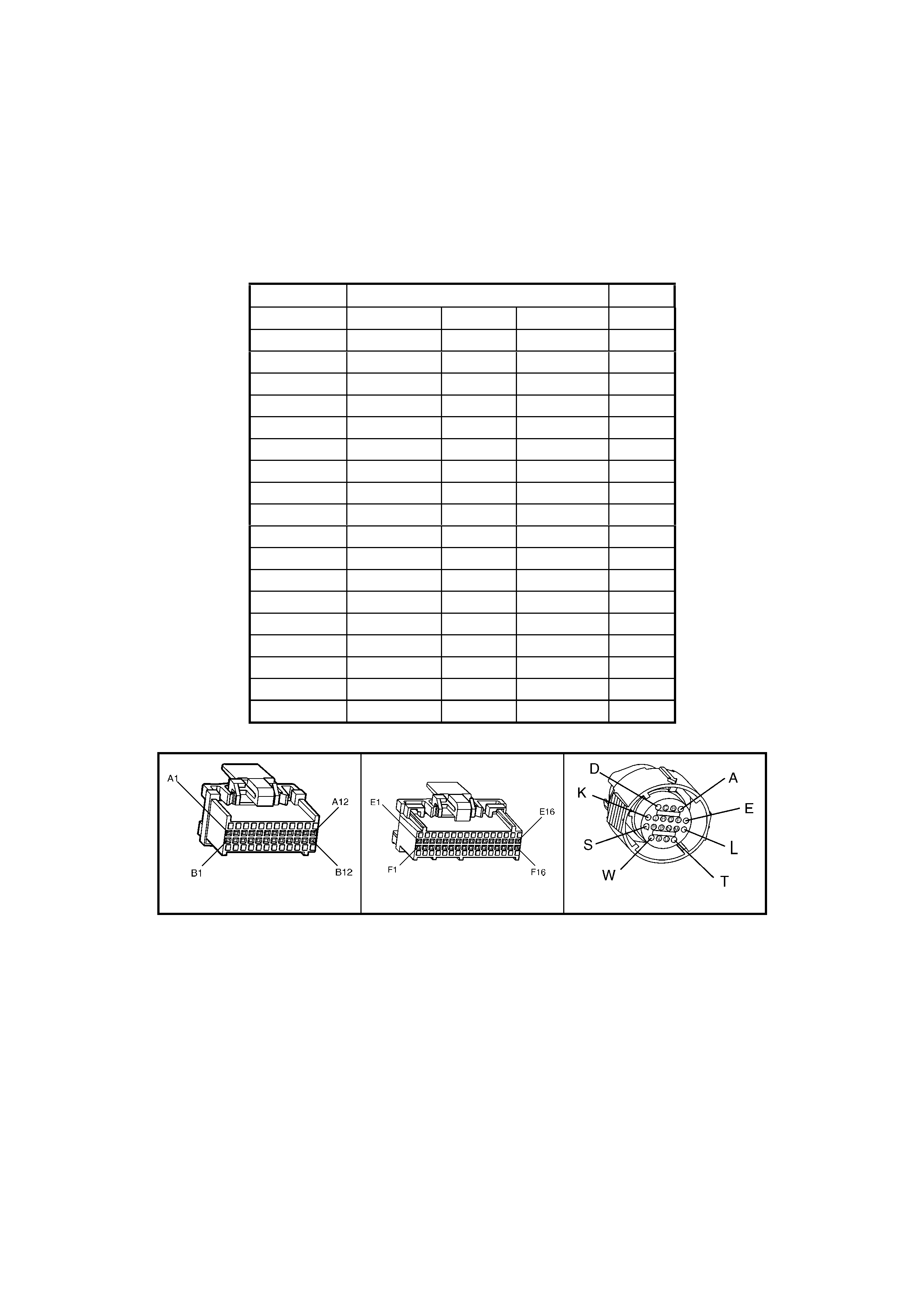
• Use the Temperature vs Resistance table when testing the TF T sensor at var ious temperature levels . Test the
TFT s ensor in order to evaluate the poss ibility of a s kewed (m is-s caled) sensor . A skewed sens or can res ult in
delayed garage shifts or TCC complaints.
• The Tech 2 can display the transmission fluid temperature in degrees. After the transmission is operating, the
fluid temperature should rise steadily to a normal operating temperature, then stabilise.
TEST DESCRIPTION:
NOTE: Number(s) below refer to the step number(s) on the diagnostic table.
3. This step tests for a short to ground or a skewed sensor.
4. This step creates an open within the transmission in order to test for an internal fault.
TRANSMISSION FLUID TEMPERATURE (TFT) SENSOR TEMPERATURE TO RESISTANCE TABLE
Temperature TFT Resistance (Ohm) Signal
Degrees C Minim u m Normal Maximum Volts
-20 25809 28677 31545 4.90
-10 14558 16176 17784 4.80
0 8481 9423 10365 4.80
10 5104 5671 6238 4.70
20 3164 3515 3867 4.50
30 2013 2237 2461 4.30
40 1313 1459 1605 4.00
50 876 973 1070 3.70
60 600 667 734 3.20
70 420 467 514 2.80
80 299 332 365 2.40
90 217 241 265 2.00
100 159 177 195 1.70
110 119 132 145 1.40
120 89.9 99.9 109.9 1.10
130 69.1 76.8 84.5 0.9
140 53.8 59.8 65.8 0.7
150 42.5 47.2 51.9 0.4
A84 V6 S/C – X1 A84 V6 S/C – X2 X121 – X2
Figure 6C2-2A-124

DTC 58 V6 S/C PCM – TRA NSMISSION FLUID TEMPERATURE (TFT) SENSOR LOW INPUT
STEP ACTION VALUE YES NO
1. Was the "On-Board Diagnostic" (OBD) System Check
performed? Go to Step 2. Go to
OBD
System Check
in this Section.
2. 1. Perform the transmission fluid checking procedure, in
this Section.
Has the fluid checking procedure been completed?
Go to Step 3 Go to
Transmission
Fluid Checking
Procedure, in
this Section.
3. 1. Install Tech 2.
2. With the engine OFF, turn the ignition switch to the
ON position.
Does Tech 2 display a TFT voltage less than the specified
value?
0.33 volts Go to Step 4 Go to
“Diagnostic
Aids” above.
4. 1. Turn the ignition OFF.
2. Disconnect the transmission pass-through connector.
3. With the engine OFF, turn the ignition switch to the
RUN position.
Does Tech 2 display a TFT voltage greater than the
specified value?
4.92 volts Go to Step 5 Go to Step 9
5. 1. Install the J 39775 Jumper Harness on the
transmission side of the pass-through connector.
2. Using a DMM and J 35616-A Connector Test Adaptor
Kit, measure the resistance between terminal L and
terminal M.
Is the resistance within specifications?
3,164 – 3,867
Ohm @ 20° C
159 – 195
Ohm @100° C
Go to
“Diagnostic
Aids” above
Go to Step 6
6. 1. Check the internal Automatic Transmission Wiring
Harness Assembly for a short to ground.
2. Replace the harness if necessary.
Did you find and correct the problem?
Go to Step 11 Go to Step 7
7. 1. Disconnect the internal Automatic Transmission
Wiring Harness Assembly at the TFT sensor.
2. Measure the resistance of the TFT sensor.
Is the resistance within specifications?
3,164 – 3,867
Ohm @ 20° C
159–195 Ohm
@ 100° C
Go to
“Diagnostic
Aids” above
Go to Step 8
8. 1. Replace the TFT Sensor (this is part of the TFP
Manual Valve Position Switch). Refer to 6C2-3
SERVICE OPERATIONS.
Is the action complete?
Go to Step 11 –
9. 1. Check circuit 1227 for a short to ground. Repair the
circuit if necessary.
Was a problem found?
Go to Step 11 Go to Step 10
10. 1. Replace PCM. Refer to 6C2-3 SERVICE
OPERATIONS, for PCM Security Link procedure.
Is action complete?
Go to Step 11 –
11. In order to verify the repair, perform the following
procedure:
1. Select DTC on Tech 2.
2. Select ‘Clear Info’.
3. With the engine OFF, turn the ignition switch to the
ON position.
Does Tech 2 indicate a TFT voltage greater than the
specified value?
0.33 volts System OK Begin the
diagnosis again.
Go to Step 1
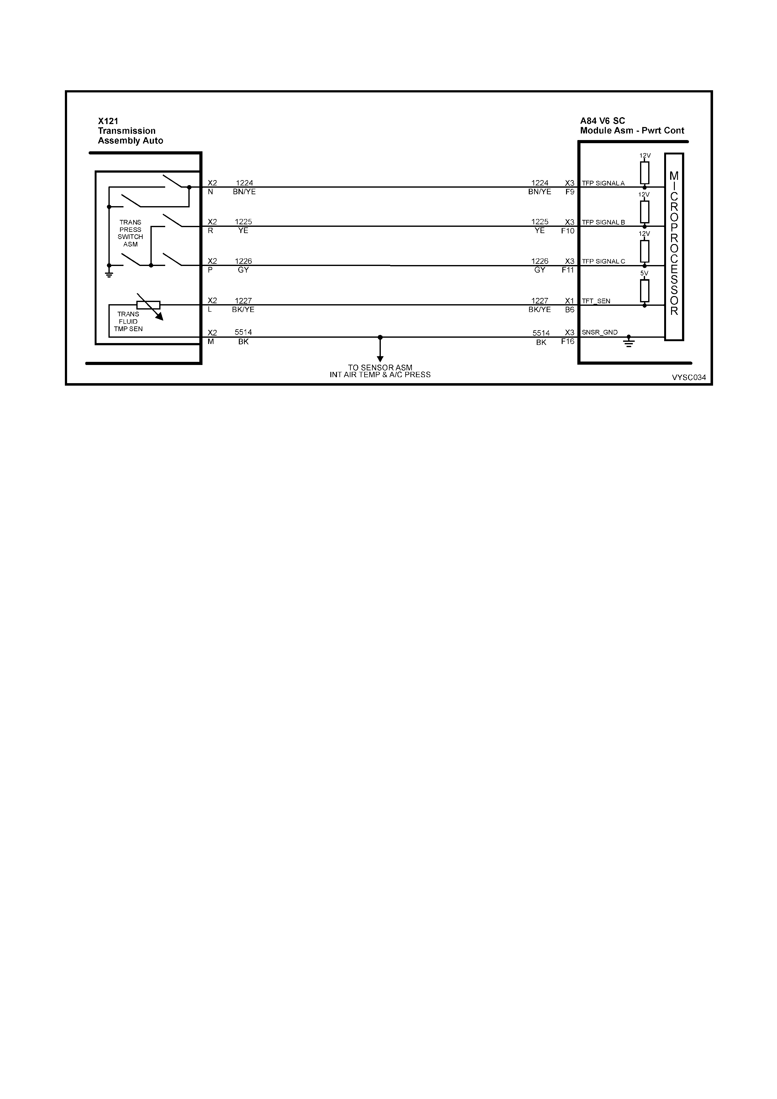
DTC 59 V6 S/C PCM –
TRANSMISSION FLUID TEMPERATURE (TFT) SENSOR HIGH INPUT
Figure 6C2-2A-125 – Automatic Transmission Fluid Temperature Sensor
CIRCUIT DESCRIPTION:
The Transmission Fluid Temperature (TFT) sensor is a thermistor within the Transmission Fluid Pressure Manual
Valve Position Switch (TFP). The TFT sensor controls the signal voltage to the PCM. The PCM supplies a 5-volt
reference signal to the sensor on circuit 1227. When the transmission fluid is cold, the sensor resistance will be
high. The PCM will then detect a high s ignal voltage. As the transm ission fluid tem perature increases to the norm al
operating temperature, the sensor resistance becomes less and the voltage decreases.
W hen the PCM detects a continuous open or short to voltage in the T FT signal circuit or in the T FT sensor, then a
DTC 59 will set.
CONDITIONS FOR RUNNING THE DTC:
• The ignition switch is on.
CONDITIONS FOR SETTING THE DTC:
• The TFT sensor indicates a signal voltage greater than 4.92 volts for 10 seconds.
ACTION TAKEN WHEN THE DTC SETS:
• The PCM stores the DTC information into memory when the diagnostic runs and fails.
• The Check Powertrain Malfunction Indicator Lamp (MIL) will not be activated.
• The PCM records the operating conditions at the time the diagnostic fails. The PCM stores this information in
the History Data.
• When this DTC sets, the PCM uses a transmission fluid temperature default value based on engine coolant,
engine run time and IAT at startup, the PCM will freeze shift adapts from being updated.
CONDITIONS FOR CLEARING THE CHECK POWERTRAIN MIL/DTC:
• Use Tech 2 to clear the Check Powertrain MIL/DTC.
DIAGNOSTIC AIDS:
• Inspect the wiring for poor electrical connections at the PCM. Inspect the wiring for poor electrical connections
at the transmission pass-through connector. Look for the following conditions:
– A backed out terminal
– A damaged terminal
– Poor terminal tension
– A chafed wire
– A broken wire inside the insulation
– Corrosion
• Corrosion when diagnosing for an intermittent short or open condition, massage the wiring harness while
watching the test equipment for a change.
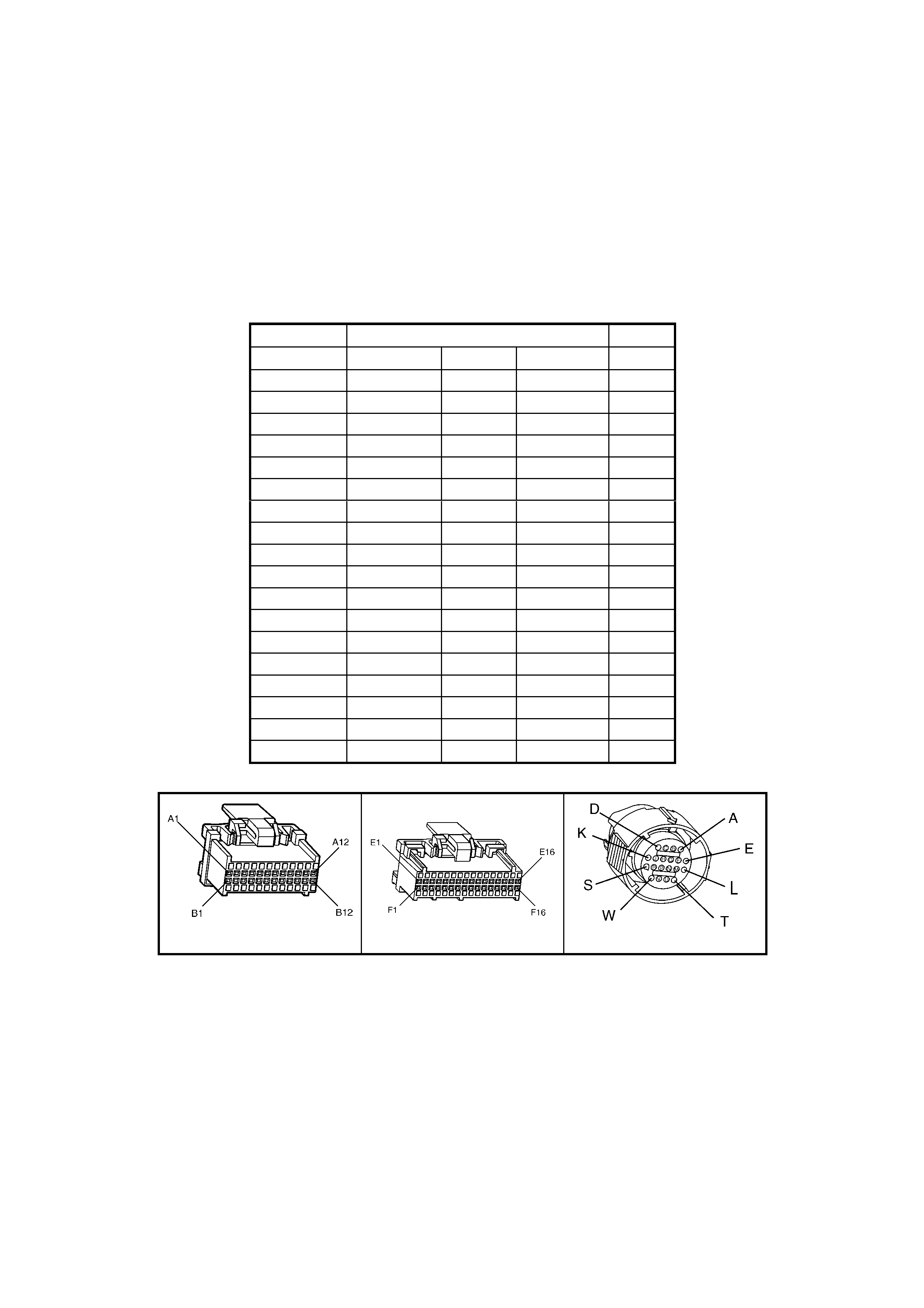
• Use the Temperature vs Resistance table when testing the TF T sensor at var ious temperature levels . Test the
TFT s ensor in order to evaluate the poss ibility of a s kewed (m is-s caled) sensor . A skewed sens or can res ult in
delayed garage shifts or TCC complaints.
• Tech 2 can display the transmission fluid temperature in degrees. After the transmission is operating, the fluid
temperature should rise steadily to a normal operating temperature, then stabilise.
TEST DESCRIPTION:
NOTE: Number(s) below refer to the step number(s) on the diagnostic table.
3. This step verifies that a problem exists in the TFT sensor circuit.
4. This step simulates a TFT sensor DTC 58. If the PCM recognises high temperature, the PCM and wiring are
functioning normally.
5. This step tests the TFT sensor and Automatic Transmission Wiring Harness Assembly.
TRANSMISSION FLUID TEMPERATURE (TFT) SENSOR TEMPERATURE TO RESISTANCE TABLE
Temperature TFT Resistance (Ohm) Signal
Degrees C Minim u m Normal Maximum Volts
-20 25809 28677 31545 4.90
-10 14558 16176 17784 4.80
0 8481 9423 10365 4.80
10 5104 5671 6238 4.70
20 3164 3515 3867 4.50
30 2013 2237 2461 4.30
40 1313 1459 1605 4.00
50 876 973 1070 3.70
60 600 667 734 3.20
70 420 467 514 2.80
80 299 332 365 2.40
90 217 241 265 2.00
100 159 177 195 1.70
110 119 132 145 1.40
120 89.9 99.9 109.9 1.10
130 69.1 76.8 84.5 0.9
140 53.8 59.8 65.8 0.7
150 42.5 47.2 51.9 0.4
A84 V6 S/C – X1 A84 V6 S/C – X2 X121 – X2
Figure 6C2-2A-126

DTC 59 V6 S/C PCM – TRA NSMISSION FLUID TEMPERATURE (TFT) SENSOR HIGH INPUT
STEP ACTION VALUE YES NO
1. Was the "On-Board Diagnostic" (OBD) System Check
performed? Go to Step 2. Go to
OBD
System Check
in this Section.
2. 1. Perform the transmission fluid checking procedure,
in this Section.
Has the fluid checking procedure been completed?
Go to Step 3 Go to
Transmission
Fluid Checking
Procedure, in
this Section.
3. 1. Install Tech 2.
2. With the engine OFF, turn the ignition switch to the
ON position.
Does Tech 2 display a TFT voltage greater than the
specified value?
4.92 volts Go to Step 4 Go to
“Diagnostic
Aids” above.
4. 1. Turn the ignition OFF.
2. Install the J 39775 Jumper Harness on the PCM side
of the pass through connector.
3. Jumper terminals L and M, then turn the ignition
switch to the ON position.
Is the TFT Sensor voltage on Tech 2 at or below the
specified value?
0.2 volts Go to Step 5 Go to Step 9
5. 1. Turn the ignition OFF.
2. Install the J 39775 Jumper Harness on the
transmission side of the pass-through connector.
3. Using a DMM and J 35616-A Connector Test
Adaptor Kit, measure the resistance between
terminal L and terminal M.
Is the resistance within specification?
3,164 – 3,867
Ohm @ 20° C.
159-195
Ohm @ 100° C
Go to
“Diagnostic
Aids” above.
Go to Step 6
6. 1. Check the internal Automatic Transmission Wiring
Harness Assembly for a open condition.
2. Replace the harness if necessary.
Was a problem found and corrected?
Go to Step 12 Go to Step 7
7. 1. Disconnect the internal Automatic Transmission
Wiring Harness Assembly at the TFT sensor.
2. Measure the resistance of the TFT sensor.
Is the resistance within specifications?
3,088 – 3,942
Ohm at 20° C.
159-195
Ohm at 100° C
Go to
“Diagnostic
Aids” above.
Go to Step 8
8. 1. Replace the TFT Sensor (this is part of the TFP
Manual Valve Position Switch). Refer 6C2-3
SERVICE OPERATIONS in this Section.
Is the replacement complete?
Go to Step 12 –
9. 1. Check circuit 1227 for an open, poor terminal
contact at PCM or short to B+. Repair the circuit if
necessary.
Was a problem found?
Go to Step 12 Go to Step 10
10. 1. Check circuit 2573 for an open, poor terminal
contact at PCM . Repair the circuit as necessary.
Was a problem found?
Go to Step 12 Go to Step 11
11. 1. Replace PCM. Refer to 6C1-3 SERVICE
OPERATIONS in this Section, for PCM
Programming and Security Link procedure.
Is action complete?
Go to Step 12 –
12. In order to verify the repair, perform the following
procedure:
1. Select DTC on Tech 2.
2. Select ‘Clear Info’.
3. With the engine OFF, turn the ignition switch to the
ON position.
Does Tech 2 indicate a TFT voltage less than the
specified value?
4.92 volts System OK Begin the
diagnosis again.
Go to Step 1

DTC 63 V6 PCM
LEFT HAND HEATED OXYGEN SENSOR (HO2S) INSUFFICIENT ACTIVITY
Figure 6C2-2A-127 – Oxygen Sensors
CIRCUIT DESCRIPTION:
The exhaust oxygen sensor is mounted in the exhaust pipe with the sensing portion exposed to exhaust gases.
After the sensor is hot (360 °C), it becomes a voltage generator, producing a "changing" voltage. This voltage
ranges from approximately 100 millivolts with a "lean" exhaust, to 900 millivolts with a "rich" exhaust. When the
sensor is cold (below 360 °C) it acts like an open circ uit and produces alm ost no voltage. T he PCM supplies a very
small "bias" voltage between terminals A84 X2-D15 and A84 X2-D16, normally about 450 millivolts. If measured
with the 10 Megohm digital voltmeter, it may measure as low as 350 millivolts. W hen the sensor is hot, it's output
overshadows this PCM supplied voltage.
W hen the fuel system is correctly operating in the closed-loop mode, the sensor output is changing several times
per second, going above and below a mid-point range of 490-510 millivolts. The PCM compares the voltage
between the sens or signal and sensor ground term inals and decides the needed f uel mixture c orrection. The PCM
also monitors the changing voltage, watching for transitions above and below the mid-point range, to decide when
to operate in the closed-loop m ode. An open circuit, defective, or contaminated sensor could cause the voltage to
stay within a 410-477 millivolt band too long, keeping the system in open-loop and setting a DTC 63.

CONDITIONS FOR RUNNING THE DTC:
• Engine run time is longer than 4 minutes.
• No TP Sensor DTC’s are set.
• The ECT sensor is more than 85°C.
• Throttle angle is more than 15%.
CONDITIONS FOR SETTING THE DTC:
• The LH H02S voltage stays between 410 – 477 millivolts.
ACTION TAKEN WHEN THE DTC SETS:
• The PCM activates the Check Powertrain Malfunction Indicator Lamp (MIL) when the diagnostic runs and fails.
• Once a H02S DTC is set, and current, the PCM will operate the fuel system in the “Open Loop” mode.
CONDITIONS FOR CLEARING THE CHECK POWERTRAIN MIL/DTC:
• The PCM deactivates the Check Powertrain MIL when it sees a valid condition for more than ten seconds.
• Use Tech 2 to clear the "Check Powertrain" MIL/DTC.
DIAGNOSTIC AIDS:
Normal Tech 2 voltage varies between 100 mV to 999 mV while in "Closed Loop". DTC 63 sets if voltage remains
between 410 and 477 millivolts, but the system will go "Open Loop" before the "Check Powertrain" MIL is activated.
Refer to Intermittents in Section 6C2-2B SYMPTOMS. To diagnose the oxygen sensor, refer TABLE A-6.3. in this
Section.
NOTE: Oxygen Sensor Contamination - If fuel containing lead or silicone is used, or engine repairs using
unapproved RTV gas ket sealer are per f or med, the sens or may be contaminated. It may send a "F alse" rich exhaus t
indication to the PCM, and the PCM will attem pt to drive the fuel system lean to c ompensate. Poor driveability or a
Diagnostic Trouble Code 13 or 63 could result. If this happens, the sensor will need to be replaced, but every
attempt to locate the source of contamination should be pursued.
TEST DESCRIPTION:
NOTE: Number(s) below refer to step number(s) on the diagnostic table.
2. Tech 2 allows you to read the same oxygen sensor voltage the PCM is using for its calculations.
3. This step sim ulates a lean exhaust indication to the PCM. If the PCM and wiring are OK, the PCM will see the
lean indication and Tech 2 should display O2 voltage below 200 mV.
A84 V6 S/C – X1 A84 V6 S/C – X2 B57 – LEFT
Figure 6C2-2A-128

DTC 63 V6 S/C PCM – LEFT HAND HEATED OXYGEN SENSOR (HO2S) INSUFFICIENT ACTIVITY
STEP ACTION VALUE YES NO
1. Was the "On-Board Diagnostic" (OBD) System Check
performed? Go to Step 2. Go to
OBD
System Check
in this Section.
2. 1. Engine at normal operating temperature (above 85° C)
2. Run engine at approximately 600 to 1800 RPM for two
minutes.
Is Tech 2 oxygen sensor voltage between specified
values?
410 – 477
mV Go to Step 3 If no additional
DTC’s were
stored, refer to
“Intermittents” in
6C2-2B
SYMPTOMS.
3. 1. Ignition ON, engine stopped.
2. Disconnect O2 and jumper circuit 1665 (PCM side) to
circuit 1664.
3. Using Tech 2, monitor O2 voltage.
Is the O2 voltage less than the specified value?
0.2 Volt
(200 mV) Go to Step 7 Go to Step 4
4. 1. Remove the jumper wire from circuit 1664 and jumper
circuit 1665 to ground.
2. Using a Tech 2, monitor O2 voltages.
Does the O2 signal voltage measure below the specified
value?
0.2 Volt
(200 mV) Go to Step 5 Go to Step 6
5. 1. Ignition OFF.
2. Disconnect the PCM.
3. Check continuity of the O2 low circuit 1664 between
the PCM harness connector and the O2 harness
connector.
4. If the resistance of circuit 1664 measures over 5
ohms, repair open or poor connection as necessary.
Was a problem found?
Verify Repair Go to Step 8
6. 1. Ignition OFF.
2. Disconnect the PCM.
3. Check continuity of the O2 signal circuit 1665 between
the PCM harness connector and the O2 harness
connector.
4. If the circuit resistance measures over 5 ohms, repair
open or poor connection as necessary.
Was a problem found?
Verify Repair Go to Step 9
7. 1. Check the following circuits for a poor terminal
connection at the O2 harness connector.
• O2 signal circuit.
• O2 low circuit.
2. If a problem is found, repair as necessary.
Was a problem found?
Verify Repair Go to Step 10
8. 1. Check for a poor O2 low circuit 1664 terminal
connection at PCM.
2. If a problem is found, repair as necessary.
Was a problem found?
Verify Repair Go to Step 11
9. 1. Check the O2 signal circuit 1665 for a poor terminal
connection at the PCM.
2. If a problem is found, repair as necessary.
Was a problem found?
Verify Repair Go to Step 11
10. 1. Replace the LH HO2 sensor.
Is action complete? Verify Repair –
11. 1. Replace PCM. Refer to 6C2-3 SERVICE
OPERATIONS in this Section, for PCM Security Link
procedure.
Is action complete?
Verify Repair –

DTC 64 V6 S/C PCM –
LEFT HAND HEATED OXYGEN SENSOR (HO2S) LOW VOLTAGE
Figure 6C2-2A-129
CIRCUIT DESCRIPTION:
The PCM supplies a voltage of about 450 millivolts between terminal A84 X2-D15 and A84 X2-D16. The Oxygen
(O2) s ens or var ies the voltage within a range of about 1Volt if the ex haust is r ich, down through about 100 millivolts,
if exhaust is lean.
The s ensor is like an open c ircuit and pr oduces no voltage when it is below about 360 °C. An open sensor c irc uit or
cold sensor causes "Open Loop" operation.
CONDITIONS FOR RUNNING THE DTC:
• No IAT Sensor DTC’s are set.
• IAT Sensor is below 75° C.
• The system is in "Closed Loop”.
• Throttle angle is between 9% and 30%.
CONDITIONS FOR SETTING THE DTC:
• The LH H02S signal voltage remains below 200 millivolts for 46 seconds.
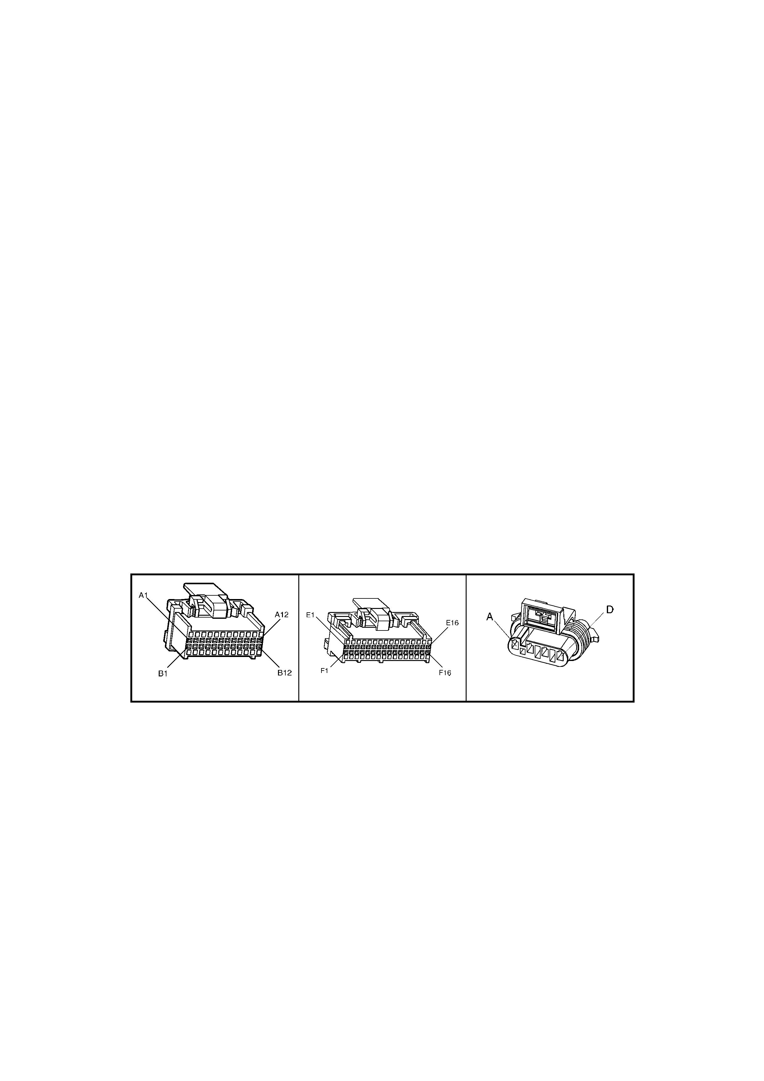
ACTION TAKEN WHEN THE DTC SETS:
• The PCM activates the Check Powertrain Malfunction Indicator Lamp (MIL) when the diagnostic runs and fails.
• The PCM records the operating conditions at the time the diagnostic fails. The PCM stores this information in
the History Data.
• Once an H02S DTC is set, and current, the PCM will operate the fuel system in the “Open Loop” mode.
CONDITIONS FOR CLEARING THE CHECK POWERTRAIN MIL/DTC:
• The PCM deactivates the Check Powertrain MIL when a valid signal has been received for greater than ten
seconds.
• Use Tech 2 to clear the “Check Powertrain” MIL/DTC.
DIAGNOSTIC AIDS:
Using T ech 2, observe the Long Term Fuel Trim values at diff erent engine speeds and air flow conditions. Tech 2
also displays the Long Term Fuel Trim cells, so the Long Term Fuel Trim values can be checked in each of the
cells to determine when DTC 64 may have been set. If the conditions for DTC 64 exist, the Long Term Fuel Trim
values will be around +25%.
TEST DESCRIPTION:
NOTE: Number(s) below refer to step number(s) on the diagnostic table.
4. The DTC 64 or lean exhaust is most likely caused by one of the following:
• O2 Sensor Wire – Sensor pigtail may be mispositioned and contacting the exhaust manifold.
• Check for intermittent ground in wire between connector and sensor.
• MAF Sensor – A shifted MAF sensor or an intake manifold leak, could cause the fuel system to go lean.
Refer to TABLE A-6.1 in this Section.
• Lean Injector(s) – Perform power balance test using Tech 2.
• Fuel Contam ination – Water, even in small amounts, near the in-tank Fuel Pum p inlet can be delivered to
the injectors. The water causes a lean exhaust and can set a DTC 44 and/or DTC 64.
• Fuel Pressure – System will go lean if pressure is too low. It may be necessary to monitor fuel pressure
while driving the vehicle at various road speeds and/or loads to confirm. Refer to TABLE A-4.1 in this
Section.
• Ex haust Leaks – If there is an exhaust leak , the engine can cause outside air to be pulled into the exhaust
and past the sensor. Vacuum or crankcase leaks can cause a lean condition.
A84 V6 S/C – X1 A84 V6 S/C – X2 B57 – LEFT
Figure 6C2-2A-130

DTC 64 V6 S/C PCM – LEFT HAND HEATED OXYGEN SENSOR (H02S) LOW VOLTAGE
STEP ACTION VALUE YES NO
1. Was the "On-Board Diagnostic" (OBD) System Check
performed? Go to Step 2 Go to
OBD
System Check
in this Section.
2. 1. Start engine.
2. Run engine until it reaches normal operating
temperature (above 80 °C).
3. Continue to run at 1600 to 1800 rpm for two minutes.
Does Tech 2 indicate O2 sensor voltage fixed below
specified value?
200 mV Go to Step 3 DTC 64 is
intermittent. If no
additional DTC’s
were stored,
refer to
INTERMITTENTS
in 6C2-2B
SYMPTOMS in
this Section.
3. 1. Disconnect O2 sensor connector.
W ith engine idling, does Tech 2 display O2 sensor voltage
between the specified values?
Between
350 mV and
550 mV.
Go to Step 4 Go to Step 6
4. 1. Refer to Test Description, Step 4 above.
2. Perform the checks on the items as noted:
• MAF sensor operation.
• Intake manifold leaks.
• Low fuel pressure.
• Contaminated fuel or exhaust manifold leaks
ahead of O2 sensor.
• Lean injector (possibly restricted).
Are all items checked found to be OK?
Go to Step 5 Verify Repair
5. 1. Replace Oxygen sensor.
Is action complete? Verify Repair
6. 1. Ignition "OFF".
2. Disconnect PCM connectors.
3. With O2 sensor still disconnected, check O2 signal
circuit 1665 for a short to ground.
Is a short to ground detected?
Go to Step 7 Go to Step 8
7. 1. Repair circuit 1665.
Is action complete? Verify Repair
8. 1. Replace PCM. Refer to Section 6C2-3 SERVICE
OPERATIONS in this Section, for PCM Security Link
procedure.
Is action complete?
Verify Repair

DTC 65 V6 S/C PCM – LEFT HAND HEATED SENSOR (HO2S) HIGH VOLTAGE
Figure 6C2-2A-131
CIRCUIT DESCRIPTION:
The PCM supplies a voltage of about 450 millivolts between terminal A84 X2-15 and A84 X2-D16. The Oxygen (O2)
sensor varies the voltage within a range of about 1 Volt, if the exhaus t is rich and down through about 100 m illivolts
if exhaust is lean.
The sensor produces no voltage when it is below about 360° C. An open sensor circuit or cold sensor causes "Open
Loop" operation.
CONDITIONS FOR RUNNING THE DTC:
• No TP Sensor DTC’s are set.
• The system is in "Closed Loop”.
• Throttle angle is between 9% and 30%.
CONDITIONS FOR SETTING THE DTC:
• The LH H02S signal voltage remains above 780 millivolts for 40 seconds.
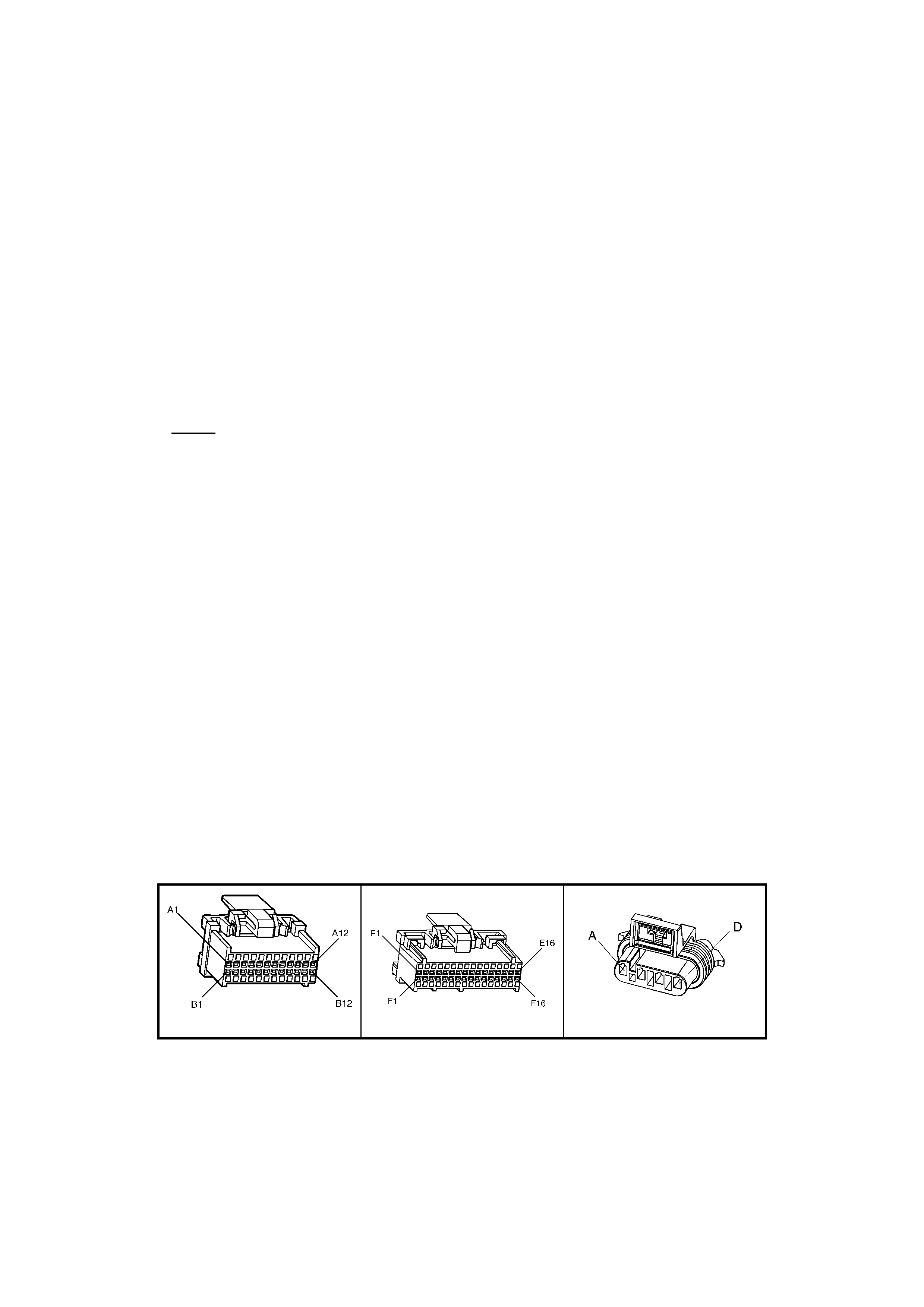
ACTION TAKEN WHEN THE DTC SETS:
• The PCM activates the Check Powertrain Malfunction Indicator Lamp (MIL) when the diagnostic runs and fails.
• The PCM records the operating conditions at the time the diagnostic fails. The PCM stores this information in
the History Data.
• Once an H02S DTC is set, and current, the PCM will operate the fuel system in the “Open Loop” mode.
CONDITIONS FOR CLEARING THE CHECK POWERTRAIN MIL/DTC:
• The PCM deactivates the Check Powertrain MIL when a valid signal has been received for more than ten
seconds.
• Use Tech 2 in order to clear the Check Powertrain MIL/DTC.
DIAGNOSTIC AIDS:
Using Tech 2, observe the Long Term Fuel Trim values at different RPM and air flow conditions. Tech 2 also
displays the Long Term Fuel Tr im cells, s o the Long Term Fuel Trim values can be check ed in each of the cells to
determ ine when the DTC 65 may have been set. If the conditions f or DT C 65 ex is t, the Long Term Fuel Trim values
will be around – 22%.
TEST DESCRIPTION:
NOTE: Number(s) below refer to step number(s) on the diagnostic table.
2. The HO2S MUST be at operating temperature before checking operation.
3. This step checks for a short to voltage on the HO2S signal line.
7. Grounding circuit 1665 causes a low HO2S signal voltage. If the PCM and wiring are OK, the PCM should
recognise the low voltage and confirm the lean signal.
8. A DT C 65 will mos t likely NOT be caus ed by a faulty O 2 sens or . DT C 65 indic ates a ric h ex haust and diagnos is
should begin with the items listed:
• Fuel pressure. System will go rich, if pressure is too high. The PCM can compensate for some increase.
However, if it gets too high, a DTC 45 or DTC 65 may be set. Refer to fuel system diagnosis, TABLE A-4.3
in this Section.
• Rich injector.
• Leaking injector. Refer to TABLE A-4.3 in this Section.
• Check for fuel contaminated oil.
• Short to voltage on circuit 1665.
• HEI shielding. An open ground cir cuit 453 (ignition sys tem) m ay res ult in EMI, or induced electrical "noise."
The PCM looks at this "noise" as reference pulses. The additional pulses result in a higher than actual
engine speed signal. The PCM then delivers too m uch fuel, causing system to go rich. Engine tachom eter
will also show higher than actual engine speed, which can help in diagnosing this problem.
• Canister purge. Check for fuel saturation. If full of fuel, check canister control and hoses.
• MAF sensor. A shifted MAF sensor could cause the fuel system to go rich.
• Check for leaking fuel pressure regulator diaphragm by checking vacuum line to regulator for fuel.
• TP Sensor. An intermittent TP sensor output will cause the system to go rich, due to a false indication of the
engine accelerating.
A84 V6 S/C – X1 A84 V6 S/C – X2 B57 – LEFT
Figure 6C2-2A-132

DTC 65 V6 S/C PCM – LEFT HAND HEATED OXYGEN SENSOR (HO2S) HIGH VOLTAGE
NOTE: O xygen Sensor Contam ination – If f uel containing lead or silicone is used, or engine repairs using unapproved
RTV gas k et s ealer are per f or med, the sens or may be contam inated. It may send a "false" ric h exhaust indication to the
PCM, and the PCM will attem pt to drive the fuel system lean to c ompensate. Poor driveability or a Diagnostic T rouble
Code 45 or 65 could res ult. If this happens, the s ensor will need to be replaced, but every attem pt to locate the source
of contamination should be pursued.
STEP ACTION VALUE YES NO
1. Was the "On-Board Diagnostic" (OBD) System Check
performed? Go to Step 2 Go to
OBD
System Check
in this Section.
2. 1. Engine at normal operating temperature (above
80° C).
2. Run engine at approximately 1600 to 1800 RPM for
two minutes.
Is Tech 2 voltage above specified value?
750 mV Go to Step 3 DTC 65 is
intermittent.
If no additional
DTC(s) were
stored, refer to
Intermittents in
6C2-2B
SYMPTOMS.
3. 1. Ignition "OFF".
2. Disconnect O2 sensor wiring harness.
3. With voltmeter connected to ground, probe circuit
1665 at O2 sensor wiring harness connector.
4. Ignition "ON".
Is voltmeter indicating less than specified value?
550 mV Got to Step 7 Go to Step 4
4. 1. Ignition "OFF".
2. Disconnect PCM connectors.
3. Probe circuit 1665 at O2 sensor wiring harness
connector.
4. Ignition "ON".
Is voltmeter indicating voltage below specified value ?
550 mV Go to Step 6 Go to Step 5
5. 1. Repair circuit 1665, shorted to voltage.
Is action complete? Verify Repair –
6. 1. Replace PCM. Refer to 6C2-3 SERVICE
OPERATIONS, for PCM Programming and Security
Link procedure.
Is action complete?
Verify Repair –
7. 1. Disconnect O2 sensor wiring harness connector.
2. Jumper harness connector circuit 1665 to 1664.
With engine running, does Tech 2 display O2 voltage
below specified value?
350 mV Go to Step 8 Go to Step 9
8. See Test Description, Step 8 above, to perform additional
checks for:
• High Fuel Pressure.
• Map Sensor Operation.
• Leaking Injectors.
• Ignition Ground Circuit.
• Canister Purge.
• Engine Coolant Temperature Sensor Circuit.
• Intake Air Temperature Sensor Circuit.
• Throttle Position Sensor Operation.
Do all of these additional checks test OK.?
Go to “Test
Description”,
Step 8, above.
Verify Repair
9. 1. Ignition "OFF"
2. Disconnect PCM connectors.
3. Check O2 sensor ground circuit 450 for good
continuity between PCM connector terminal A84 X1-A2
and engine ground.
Is an "OPEN" circuit indicated?
Verify Repair Go to Step 10
10. 1. Check that the PCM ground wire connection at the
engine is clean and tight.
Is connection good?
Go to Step 6 Verify Repair

DTC 66 V6 S / C PCM – 3-2 SHIFT SO LENOID CIRCUIT ELECTRICAL
Figure 6C2-2A-133 – Automatic Transmission Shift Solenoids
CIRCUIT DESCRIPTION:
The 3-2 Shif t Solenoid valve is a nor m ally-closed, 3-port, on/of f devic e that controls the 3-2 downshif t. The solenoid
is f itted to the control valve body within the transm iss ion. The solenoid rec eives ignition voltage through circ uit 339.
The Powertrain Contr ol Module (PCM) controls the solenoid by providing a ground path on circuit 898. Dur ing a 3-2
downshift, the 2-4 band applies as the 3-4 clutch releases. The PCM varies the timing between the 3-4 clutch
release and the 2-4 band apply depending on the vehicle speed and the throttle position.
W hen the PCM detec ts a continuous open or short to ground in the 3-2 Shif t Solenoid valve assem bly c ircuit or the
3-2 Shift Solenoid valve assembly, then DTC 66 sets.
CONDITIONS FOR RUNNING THE DTC:
• The engine is running.

CONDITIONS FOR SETTING THE DTC:
DTC 66 sets if either of the following conditions occur for 5 seconds:
• The PCM commands the solenoid ON and the voltage input remains high (B+).
or
• The PCM commands the solenoid OFF and the voltage input remains low (0 volts)
ACTION TAKEN WHEN THE DTC SETS:
• The PCM activates the Check Powertrain Malfunction Indicator Lamp (MIL) when the diagnostic runs and fails.
• The PCM records the operating conditions at the time the diagnostic fails. The PCM stores this information in
the History Data.
• When this DTC sets, the PCM will command maximum line pressure, and inhibits TCC engagement.
CONDITIONS FOR CLEARING THE CHECK POWERTRAIN MIL/DTC:
• The PCM deactivates the Check Powertrain MIL after the first ignition cycle that the diagnostic runs and does
not fail.
• Use Tech 2 to clear the Check Powertrain MIL/DTC.
DIAGNOSTIC AIDS:
• Inspect the wiring at the PCM, the transmission pass-through connector and all other circuit connecting points
for the following conditions:
– A backed out terminal.
– A damaged terminal.
– Reduced terminal tension.
– A chafed wire.
– A broken wire inside the insulation.
– Moisture intrusion.
– Corrosion.
• When diagnosing for an intermittent short or open condition, wriggle the wiring harness while watching the test
equipment for a change.
TEST DESCRIPTION:
NOTE: Number(s) below refer to the step number(s) on the diagnostic table.
4. This step tests the ability of the PCM to control the solenoid.
5. This step tests for power to the 3-2 SS valve assembly.
7. This step tests the ability of the PCM and the wiring to control the ground circuit.
10. This step measures the resistance of the A/T wiring harness assembly and the 3-2 SS valve assembly .
A84 V6 S/C – X2 X121 – X2 X101
Figure 6C2-2A-134

DTC 66 V6 S/C PCM – 3-2 SHIFT SOLENOID CIRCUIT ELECTRICAL
STEP ACTION VALUE YES NO
1. Was the "On-Board Diagnostic" (OBD) System Check
performed? Go to Step 2. Go to
OBD
System Check
in this Section.
2. 1. Install Tech 2.
2. With the engine OFF, turn the ignition switch to the
ON position.
Are any of the following DTC’s also set? 67, 81, 82, 83.
Go to Step 3 Go to Step 4
3. 1. Inspect fuse F32.
2. If the fuse is open, inspect the following components
for a short to ground condition:
– Circuit 339.
– The solenoids.
– The A/T wiring harness assembly.
3. Repair the circuit, the solenoids, and the harness if
necessary.
Did you find a short to ground condition?
Go to Step 16 Go to Step 5
4. IMPORTANT: The 3-2 shift solenoid valve will rapidly apply
when commanded ON by Tech 2.
1. Using the transmission Miscellaneous Tests function
on Tech 2, command the 3-2 Shift Solenoid valve ON
and OFF three times while listening to the bottom of
the transmission pan (a stethoscope may be
necessary).
Did the solenoid click when commanded?
Go to Diagnostic
Aids, above. Go to Step 5
5. 1. Turn the ignition OFF.
2. Disconnect the transmission pass-through connector
(additional DTCs may set).
3. Install the J 39775 jumper harness on the PCM side of
the pass-through connector.
4. With the engine OFF, turn the ignition switch to the
ON position.
5. Connect a test lamp from J 39775 jumper harness
cavity E to ground.
Is the test lamp ON?
Go to Step 7 Go to Step 6
6. 1. Repair the open or short to ground in ignition feed
circuit 339 to the 3-2 Shift Solenoid valve assembly.
Is the repair complete?
Go to Step 16
7. 1. Install a test lamp from J 39775 jumper harness cavity
E to cavity S.
IMPORTANT: The 3-2 shift solenoid will rapidly apply
when commanded ON by Tech 2.
2. Using the transmission Miscellaneous Tests function
on Tech 2, command the 3-2 Shift Solenoid valve ON
and OFF three times.
Is the test lamp ON when the solenoid is commanded ON
and OFF, when the solenoid is commanded OFF?
Go to Step 10 Go to Step 8
8. 1. Inspect circuit 898 of the powertrain wiring harness for
an open, short to ground or short to power condition.
2. Repair the circuit if necessary.
Did you find an open, short to ground or short to power
condition?
Go to Step 16 Go to Step 9
9. 1. Replace PCM. Refer to 6C2-3 SERVICE
OPERATIONS, for PCM Security Link procedure.
Is action complete?
Go to Step16 –
10. 1. Install the J 39775 jumper harness on the
transmission side of the pass-through connector.
2. With a digital multimeter (DMM) and the J 35616-A
Connector Test Adaptor Kit, measure the resistance
between terminals S and E.
Is the resistance within the range indicated?
20 – 32
Ohm Go to Step 12 Go to Step 11

STEP ACTION VALUE YES NO
11. 1. Disconnect the A/T wiring harness assembly from the
3-2 Shift Solenoid valve assembly.
2. Measure the resistance of the 3-2 Shift Solenoid valve
assembly.
Is the resistance within the range indicated?
20 – 32
Ohm Go to Step 14 Go to Step 15
12. 1. Measure the resistance between terminal S and
ground, and between terminal E and ground.
Are both readings greater than the specified value?
250 kOhm Go to Diagnostic
Aids above. Go to Step 13
13. 1. Disconnect the A/T wiring harness assembly from the
3-2 Shift Solenoid valve assembly.
2. Measure the resistance from the component’s
terminals to ground.
Are both measurements greater than the specified value?
250 kOhm Go to Step 14 Go to Step 15
14. 1. Replace the automatic transmission wiring harness
assembly. Refer to 3.9 Control Valve Body and W iring
Harness replacement in 7C4 AUTOMATIC
TRANSMISSION – ON-VEHICLE SERVICING.
Is the replacement complete?
Go to Step 16 –
15. 1. Replace the 3-2 Shift Solenoid valve. Refer to 6C2-3
SERVICE OPERATIONS.
Is the replacement complete?
Go to Step 16 –
16. Perform the following procedure in order to verify the
repair:
• Drive the vehicle in ‘3’ or ‘D’ and perform a 3-2
downshift. Ensure the following conditions are met:
– The PCM commands the 3-2 Shift Solenoid valve
ON and the voltage input drops to zero.
– The PCM commands the 3-2 Shift Solenoid valve
OFF and the voltage input increases to B+.
– All conditions are met for 5 seconds.
Were the above conditions verified?
System OK Go to Step 1

DTC 67 V6 S/C PCM -
TORQUE CONVERTER CLUTCH (TCC) ENABLE SOLENOID CIRCUIT ELECTRICAL
Figure 6C2-2A-135 – Automatic Transmission Solenoids
CIRCUIT DESCRIPTION:
The Torque Converter Clutch (TCC) solenoid valve is an electrical device that is used with the torque converter
clutch pulse width modulation (TCC PWM) solenoid valve in order to control TCC apply and release. The TCC
solenoid valve attaches to the trans m ission c ase ass em bly extending into the pump cover . The T CC s olenoid valve
receives ignition voltage through circuit 339. The powertrain control module (PCM) controls the solenoid by
providing the ground path on circ uit 422. The PCM monitors the throttle position (T P) voltage, the vehicle s peed and
other inputs in order to determine when to energise the TCC solenoid valve.
When the PCM detects a continuous open or a short to ground in the TCC solenoid valve circuit or in the TCC
solenoid valve, then DTC 67 sets.
CONDITIONS FOR RUNNING THE DTC:
• The system voltage is 8-18 volts.
• The engine speed is greater than 300 RPM for 5 seconds.
• The engine is not in fuel cutoff.
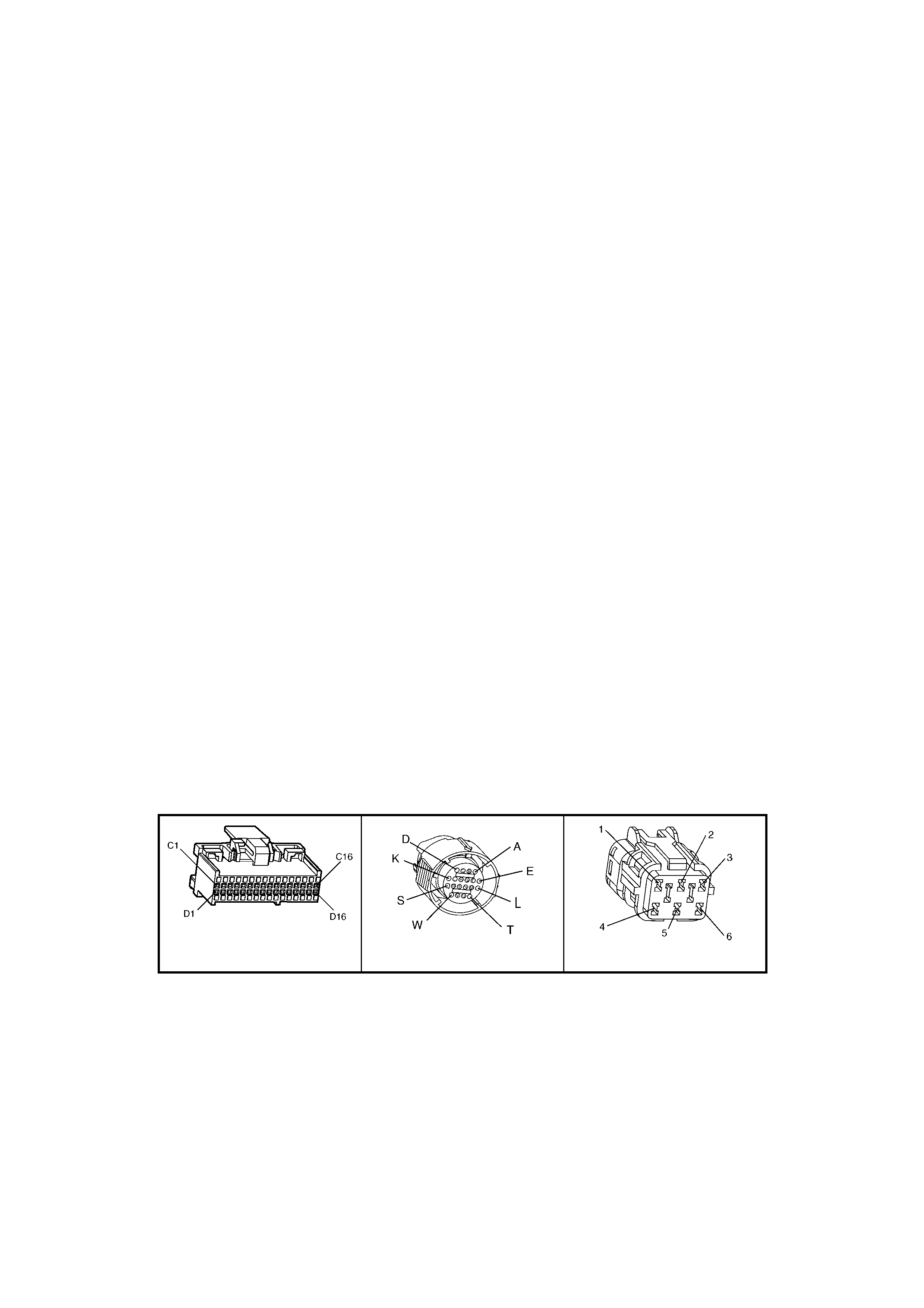
CONDITIONS FOR SETTING THE DTC:
• DTC 67 sets if either of the following conditions occurs for 5 seconds:
– The PCM commands the solenoid ON and the voltage input remains high (B+).
– The PCM commands the solenoid OFF and the voltage input remains low (0 volt).
ACTION TAKEN WHEN THE DTC SETS:
• The PCM stores the DTC information into memory when the diagnostic runs and fails.
• The PCM does not activate the Check Powertrain Malfunction Indicator Lamp (MIL) icon.
• The PCM records the operating conditions at the time the diagnostic fails. The PCM stores this information in
the History Data.
• The PCM inhibits TCC engagement.
• The PCM inhibits 4th gear if the transmission is in hot mode.
• The PCM freezes shift adapts from being updated.
CONDITIONS FOR CLEARING THE CHECK POWERTRAIN MIL/DTC:
• Use Tech 2 to clear the Check Powertrain MIL/DTC.
DIAGNOSTIC AIDS;
• Inspect the wiring at the PCM, the transmission connector and all other circuit connecting points for the
following conditions:
– A backed out terminal.
– A damaged terminal.
– Reduced terminal tension.
– A chafed wire.
– A broken wire inside the insulation.
– Moisture intrusion.
– Corrosion.
• When diagnosing for an intermittent short or open condition, massage the wiring harness while watching the
test equipment for a change.
• With the TCC engaged, the TCC slip speed should be -20 to +40 RPM.
TEST DESCRIPTION:
NOTE: Number(s) below refer to the step number(s) on the diagnostic table.
2. This step tests for voltage to the solenoid.
4. This step tests the ability of the PCM and wiring to control the ground circuit.
6. This step tests the resistance of the TCC solenoid valve and the automatic transmission (A/T) wiring harness
assembly.
A84 V6 S/C – X2 X121 – X2 X101
Figure 6C2-2A-136

DTC 67 V6 S/C PCM –
TORQUE CONVERTER CLUTCH (TCC) ENABLE SOLENOID CIRCUIT ELECTRICAL
STEP ACTION VALUE YES NO
1. Was the "On-Board Diagnostic" (OBD) System Check
performed? Go to Step 2. Go to
OBD
System Check
in this Section.
2. 1. Install Tech 2.
2. Ignition ON, engine OFF.
Are any of the following DTC’s also set? 66, 81, 82, 83.
Go to Step 3 Go to Step 4
3. 1. Inspect fuse F32.
2. If the fuse is open, inspect the following components
for a short to ground condition:
– Circuit 339.
– The solenoids.
– The A/T wiring harness assembly.
3. Repair the circuit, the solenoids, and the harness if
necessary.
Did you find a short to ground condition?
Go to Step 12 Go to Step 4
4. 1. Turn the ignition switch OFF.
2. Disconnect the transmission pass-through connector
(additional DTC’s may set).
3. Install the J 39775 jumper harness on the PCM side of
the pass-through connector.
4. With the engine OFF, turn the ignition switch to the
ON position.
5. Connect a test lamp from cavity E of the J 39775
jumper harness to ground.
6. Refer to AT In-line Harness Connector (X121-X2) End
View in this diagnostic table.
Is the test lamp ON?
Go to Step 6 Go to Step 5
5. IMPORTANT: The condition that affects this circuit may
exist in other connecting branches of the circuit. Refer to
12P Power Distribution, in 12P WIRING DIAGRAMS for
complete circuit distribution.
1. Repair the open in ignition feed circuit 339 to the TCC
solenoid valve.
Is the repair complete?
Go to Step 12 –
6. 1. Install the test lamp from cavities E to T of the J 39775
jumper harness.
2. Using the transmission Miscellaneous Tests function
on Tech 2, command the TCC solenoid valve ON and
OFF three times.
Does the test lamp turn ON when the TCC solenoid valve
is commanded ON and OFF when commanded OFF?
Go to Step 8 Go to Step 7
7. 1. Inspect circuit 422 of the engine wiring harness for an
open, proper terminal tension at connections, an open
or short to power condition.
2. Repair the circuit if necessary.
Did you find an open, short to ground or short to power
condition?
Go to Step 12 Go to Step 9
8. 1. Install the J 39775 jumper harness on the
transmission side of the pass-through connector.
2. Using a digital multimeter (DMM) and the J35616-A
Connector Test Adaptor Kit, measure the resistance
between terminals T and E.
Is the resistance within the specified range?
21 – 33
Ohm Go to Step 10 Go to Step 11
9. 1. Replace PCM. Refer to 6C2-3 SERVICE
OPERATIONS in this Section, for PCM Programming
and Security Link procedure.
Is action complete?
Go to Step 12 –
10. 1. Measure the resistance between terminal E and
ground and between terminal T and ground.
Are both readings greater than the specified value?
250 kOhm Go to Diagnostic
Aids, above. –

STEP ACTION VALUE YES NO
11. 1. Replace the automatic transmission wiring harness
assembly (this includes the TCC solenoid valve).
Refer to 3.9 Control Valve Body and Wiring Harness
replacement in 7C4 AUTOMATIC TRANSMISSION –
ON-VEHICLE SERVICING.
Is the replacement complete?
Go to Step 12 –
12. Perform the following procedure in order to verify the
repair:
1. Select DTC.
2. Select Clear Info.
3. Drive the vehicle in D with the TCC ON and OFF.
Ensure the following conditions are met:
– The PCM commands the TCC solenoid valve ON,
and the voltage input drops to zero.
– The PCM commands the TCC solenoid valve
OFF, and the voltage input increases to B+.
– All conditions are met for 5 seconds.
Were the above conditions verified?
System OK Go to Step 1

DTC 69 V6 S/C PCM – TORQUE CONV ERTER CLUTCH (TCC) SYSTEM STUCK ON
Figure 6C2-2A-137 – Automatic Transmission Solenoids
CIRCUIT DESCRIPTION:
The PCM energises the Torque Converter Clutch Solenoid Valve (TCC Solenoid Valve) by creating a ground path
on circuit 422. When circuit 422 is grounded (energised) by the PCM, the TCC Solenoid Valve stops converter
signal oil fr om exhaus ting. This c aus es c onver ter s ignal oil pres s ure to inc r eas e and move the T CC valve. The TCC
Solenoid Valve de-energises when the PCM no longer provides a path to ground. W hen the TCC Solenoid Valve
de-energises, the valve exhausts fluid and releases the TCC.
Diagnostic Trouble Code 69 is for determining a mechanical fault which will cause the Torque Converter Clutch to
be stuck "ON." An electrical fault in the torque converter clutch solenoid circuit which could cause the torque
converter clutch to be "Stuck ON" is diagnosed in DTC 67.
When the PCM detects low torque converter slip when the PCM commands the TCC OFF, then DTC 69 sets.
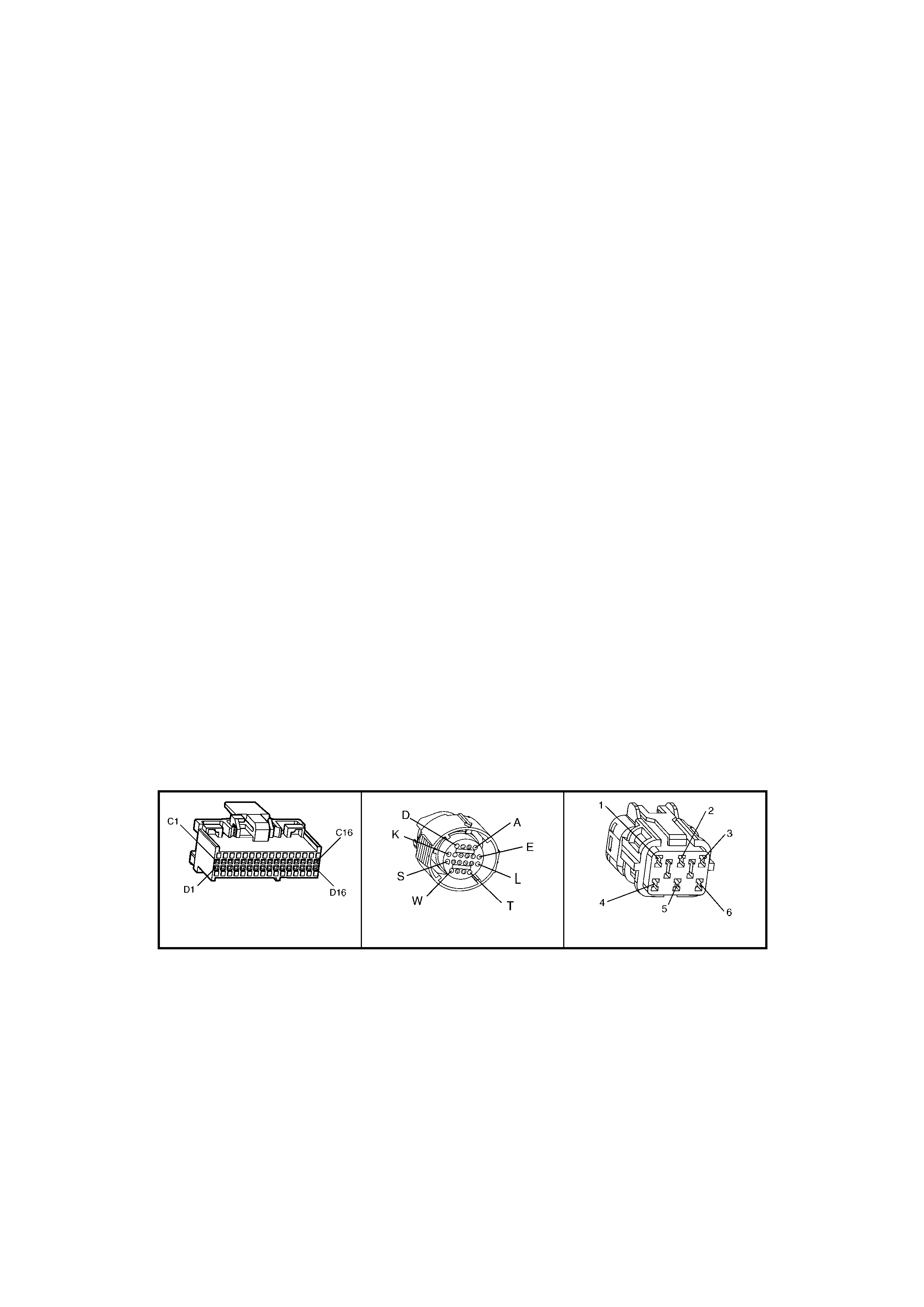
CONDITIONS FOR RUNNING THE DTC:
• No TP DTCs set.
• No VSS DTCs set.
• No TFP Manual Valve Position Switch DTC 28 is set.
• No TCC Solenoid Valve DTC 67 is set.
• No TCC PWM Solenoid Valve DTC 83 is set.
• The TP angle is greater than 25%.
• The engine RPM is greater than 450 for 8 seconds.
• The commanded gear is not 1st.
• The gear range is D4 or D3.
• The PCM commands TCC OFF.
CONDITIONS FOR SETTING THE DTC:
• DTC 69 sets if the following condition occurs three times:
– The TCC slip speed is –20 to +30 RPM for 4 seconds.
ACTION TAKEN WHEN THE DTC SETS:
• The PCM stores the DTC information into memory when the diagnostic runs and fails.
• The Check Powertrain Malfunction Indicator Lamp (MIL) will not be activated.
• The PCM records the operating conditions at the time the diagnostic fails. The PCM stores this information in
the History Data.
• When this DTC sets, the PCM will freeze shift adapts from being updated.
CONDITIONS FOR CLEARING THE CHECK POWERTRAIN MIL/DTC:
• Use Tech 2 to clear the Check Powertrain MIL/DTC.
DIAGNOSTIC AIDS:
• The TCC fluid will mechanically apply the TCC, possibly causing an engine stall, under the following conditions:
– The TCC is mechanically stuck ON
– The parking brake is applied
– Any gear range is selected
TEST DESCRIPTION:
NOTE: Number(s) below refer to the step number(s) on the diagnostic table.
4. This step inspects the mechanical state of the TCC. W hen the PCM commands the TCC Solenoid Valve OFF,
the slip speed should increase to greater than 50 RPM.
A84 V6 S/C – X2 X121 – X2 X101
Figure 6C2-2A-138

DTC 69 V6 S/C PCM – TORQUE CONVERTER CLUTCH (TCC) SYSTEM STUCK ON
STEP ACTION VALUE YES NO
1. Was the "On-Board Diagnostic" (OBD) System Check
performed? Go to Step 2. Go to
OBD
System Check
in this Section.
2. 1. Install Tech 2.
2. With the engine OFF, turn the ignition switch to the
ON position.
3. Using Tech 2, verify the TP Sensor operation.
Are the TP Sensor values within the normal range (shown
in the value column)?
0.4 – 4.7
volts Go to Step 3 Go to
“Diagnostic
Aids”, above.
3. 1. Drive the vehicle in D4 drive range in fourth gear
under steady acceleration, with a TP angle greater
than 25%.
While the displayed TCC Solenoid status is ‘NO’, does
Tech 2 display a Trans Slip Speed within the specified
range?
–20 to +40
RPM Go to Step 4 Go to
“Diagnostic
Aids”, above.
4. The TCC is mechanically stuck ON. Inspect for the
following conditions:
• A clogged exhaust orifice in the TCC Solenoid
Valve.
• The converter clutch apply valve is stuck in the
apply position.
• A misaligned or damaged valve body gasket.
• A restricted release passage.
• A restricted transmission cooler line.
Did you find and correct a problem?
Go to Step 5 Go to 6C2-2B
SYMPTOMS
‘No TCC
Release”, in this
Section.
5. In order to verify your repair, perform the following
procedure:
Operate the vehicle under the following conditions:
• Hold the throttle at 25% and accelerate to 88
km/h.
• Ensure that the Trans Slip Speed is -50 to +2500
RPM for 4 seconds, with the TCC commanded
OFF.
Was the slip speed greater than 50 RPM in 2nd, 3rd and
4th gears when the TCC was commanded OFF?
System OK Begin the
diagnosis again.
Go to Step 1
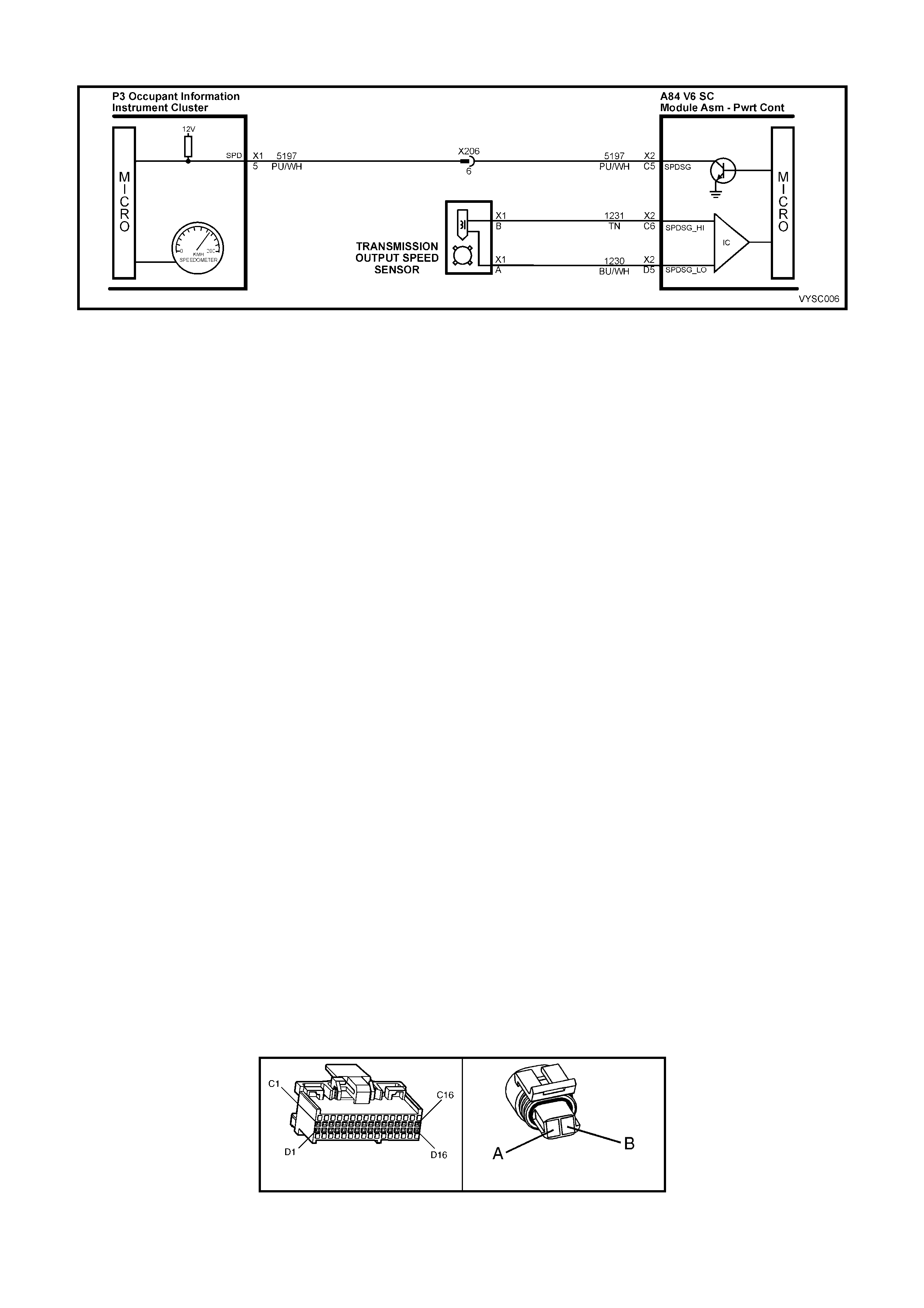
DTC 72 V6 S/C PCM – TRANSMISSION OUTPUT SPEED LOSS
Figure 6C2-2A-139 – Vehicle Speed Sensor
CIRCUIT DESCRIPTION:
The Vehicle Speed Sensor (VSS) circuit consists of a magnetic induction type sensor and vehicle speed sensor
wiring. Gear teeth pres s ed on the output s haf t of the trans miss ion induce an alter nating c urr ent in the vehicle s peed
sensor. This alternating current is transmitted to the PCM.
CONDITIONS FOR RUNNING THE DTC:
• The engine is running.
CONDITIONS FOR SETTING THE DTC:
• T wo successive s peed readings have a differ ence of m ore than 1000 RPM in any drive range (dif ference mus t
be more than 2048 RPM in park or neutral). This test checks the vehicle speed sensor signal to the PCM.
ACTION TAKEN WHEN THE DTC SETS:
• The PCM stores the DTC information into memory when the diagnostic runs and fails.
• The Check Powertrain Malfunction Indicator Lamp (MIL) will not be activated.
• The PCM records the operating conditions at the time the diagnostic fails. The PCM stores this information in
the History Data.
• W hen Diagnos tic Tr ouble Code 72 is set, the trans miss ion will have maxim um line pres sure and comm and 3rd
gear only. If DTC 72 is s et while in 4th gear, the vehicle will stay in 4th gear. However, as the vehic le is coasting
to stop the transm iss ion will downshif t norm ally f rom 4 to 3. Once the downshift into 3rd gear has oc curred, the
vehicle will stay in 3rd gear.
CONDITIONS FOR CLEARING THE CHECK POWERTRAIN MIL/DTC:
• Use Tech 2 to clear the Check Powertrain MIL/DTC.
DIAGNOSTIC AIDS:
DTC 72 is used to detect an intermittent failure. If a hard VSS fault exists, it will set DTC 24.
DTC 72 will set if the vehicle is operating at a road speed and something happens to the VSS signal.
Check all connections for proper retention. Check that the wiring harness for VSS is not routed near high voltage
sources such as spark plug cables which could induce a false signal onto the VSS signal.
DTC 72 c ould possibly be set by rapidly accelerating the vehicle in a loose m aterial (s uch as sand or gravel) where
the wheels can be spinning f aster than actual vehicle speed then having the s pinning wheel rapidly decreas e when
it contacts a hard surface. Review DTC history to identify when DTC 72 was set.
TEST DESCRIPTION:
NOTE: Number(s) below refer to the step number(s) on the diagnostic table.
3. This test checks the vehicle speed sensor signal to the powertrain control module.
A84 V6 S/C – X2 X121 – X1
Figure 6C2-2A-140

DTC 72 V6 S/C PCM – TRANSMISSION OUTPUT SPEED LOSS
STEP ACTION VALUE YES NO
1. Was the "On-Board Diagnostic" (OBD) System Check
performed? Go to Step 2 Go to
OBD
System Check
in this Section.
2. 1. Clear DTC, set Tech 2 to display "Vehicle Speed" in
the snapshot mode and set to trigger on DTC 72.
2. Drive vehicle at different speeds and road conditions.
Is DTC 72 set again?
Go to Step 3 DTC 72 is
intermittent. If no
additional DTC's
were stored,
refer to
"Diagnostic
Aids" above.
3. 1. Raise drive wheels.
NOTE: Do not perform this test without supporting the
rear trailing arms, to ensure that the drive shafts are in
a normal horizontal position. If the drive wheels are
allowed to hang down at full travel, the driveshafts
and/or boots may be damaged.
2. Engine idling in gear.
Does Tech 2 display "Vehicle Speed" above specified
value?
0 km/h Go to Step 4 Go to DTC 24 in
this Section.
4. 1. Wriggle and tug on connector at vehicle speed sensor.
Does Tech 2 display "Vehicle Speed" drop to specified
value?
0 km/h Go to step 6 Go to step 5
5. 1. Wriggle and tug on connectors at Powertrain Control
Module.
Does Tech 2 display "Vehicle Speed" above specified
value?
0 km/h Go to step 6 Refer to
"Diagnostic
Aids" above.
6. 1. Repair connector terminals.
Is action complete? Verify Repair –

DTC 73 V6 S/C PCM –
PRESSURE CONTROL (PC) SOLENOID CIRCUIT ELECTRICAL
Figure 6C2-2A-141 – Automatic Transmission Solenoids
CIRCUIT DESCRIPTION:
The Pressure Control Solenoid Valve (PC Solenoid Valve) is a PCM controlled device which regulates the
transmission line pressure. The PCM compares the TP voltage, the engine speed and other inputs in order to
determ ine the appropriate line pressure f or a given load. The PCM applies a var ying am perage to the PC Solenoid
Valve in order to regulate the pressure. The applied amperage can vary from 0.1 to 1.1 amps. The PCM monitors
the amperage.
W hen the PCM detects a continuous open or short to ground in the PC Solenoid Valve circuit or the PC Solenoid
Valve, then a DTC 73 sets.
Once a DTC 73 is set, the pressure control solenoid is disabled and full line pressure will be applied until the next
time the ignition k ey is cycled. If upon restart, the current error does not exist, a DTC 73 will remain stored but the
pressure control solenoid will resume normal function.
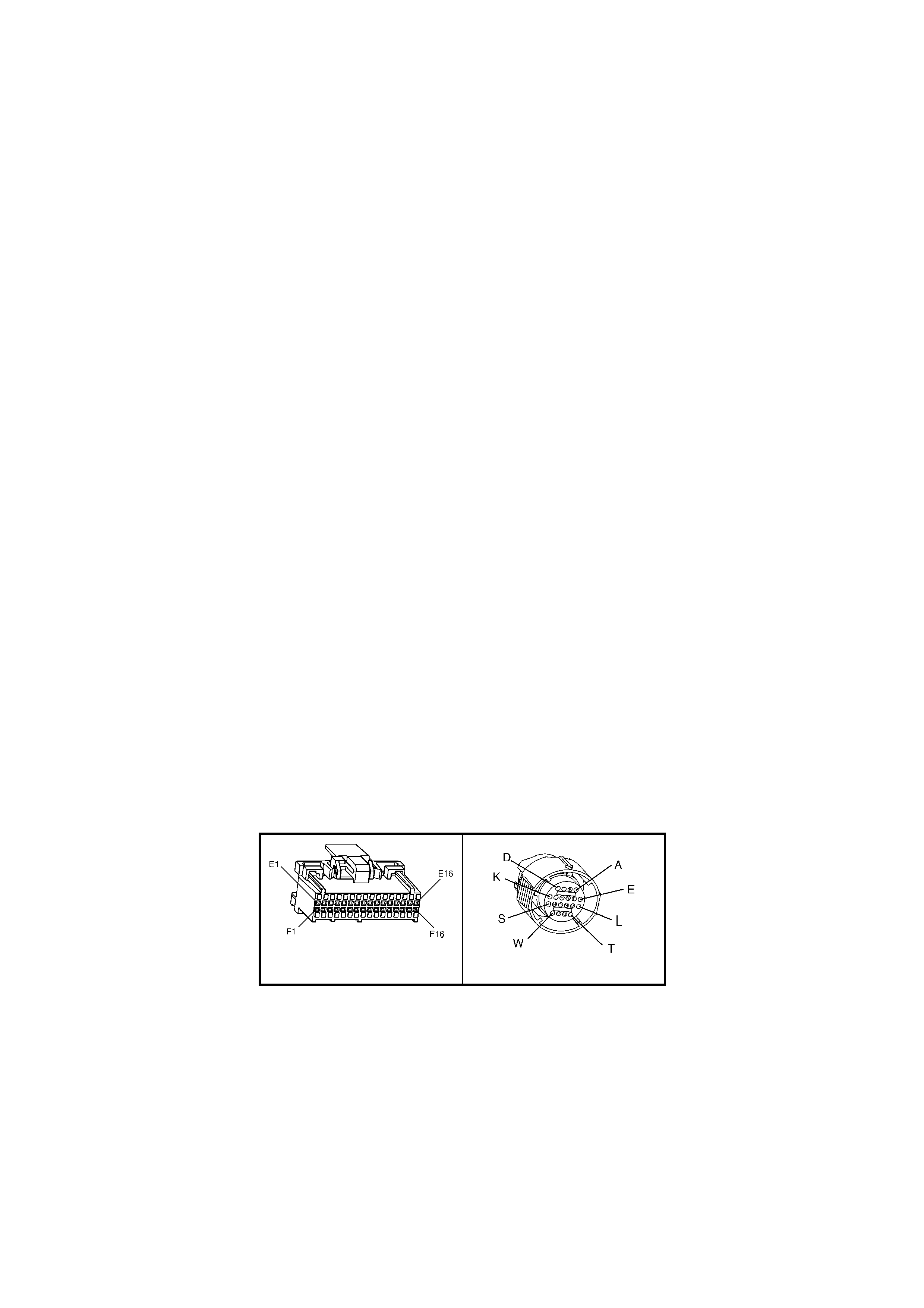
CONDITIONS FOR RUNNING THE DTC:
• No DTC 75 is set.
• The system voltage is between 10 and 16 volts.
• The engine is running.
CONDITIONS FOR SETTING THE DTC:
• The PC solenoid valve duty cyc le reaches its high lim it (approxim ately 95%) or low limit (appr oxim ately 0%) f or
200 milliseconds.
ACTION TAKEN WHEN THE DTC SETS:
• The PCM stores the DTC information into memory when the diagnostic runs and fails.
• The Check Powertrain Malfunction Indicator Lamp (MIL) will not be activated.
• The PCM records the operating conditions at the time the diagnostic fails. The PCM stores this information in
the History Data.
• When this DT C s ets , the PCM will c ommand the PC s olenoid valve OF F. T he PCM will f reeze shif t adapts f rom
being updated.
CONDITIONS FOR CLEARING THE CHECK POWERTRAIN MIL/DTC:
• Use Tech 2 to clear the Check Powertrain MIL/DTC.
DIAGNOSTIC AIDS:
• Inspect the wiring for poor electrical connections at the PCM. Inspect the wiring for poor electrical connections
at the transmission pass-through connector. Look for the following conditions:
– A bent terminal.
– A backed out terminal.
– A damaged terminal.
– Poor terminal tension.
– A chafed wire.
– A broken wire inside the insulation.
– Moisture intrusion.
– Corrosion.
• When diagnosing for an intermittent short or open condition, massage the wiring harness while watching the
test equipment for a change.
TEST DESCRIPTION:
NOTE: Number(s) below refer to the step number(s) on the diagnostic table.
2. This step tests the ability of the PCM to command the PC Solenoid Valve.
3. This step tests the PC Solenoid Valve and Automatic Transmission Wiring Harness Assembly for correct
resistance.
A84 V6 S/C – X3 X121 – X2
Figure 6C2-2A-142

DTC 73 V6 S/C PCM – PRESSURE CONTROL SOLENOID (PCS) CIRCUIT ELECTRICAL
STEP ACTION VALUE YES NO
1. Was the "On-Board Diagnostic" (OBD) System Check
performed? Go to Step 2 Go to
OBD
System Check
in this Section.
2. 1. Install Tech 2.
2. With the engine OFF, turn the ignition switch to the
ON position.
3. W hile the engine is operating, put the transmission in
the Park position.
4. Using the transmission output control function on Tech
2, apply 0.1 Amp through 1.0 Amp while observing
Commanded PCS and Actual PCS amperage.
Is the Actual PCS amperage always within the specified
value of the Commanded PCS amperage?
0.16 amp Go to
“Diagnostic
Aids” above.
Go to Step 3
3. 1. Turn the ignition OFF.
2. Disconnect the transmission pass-through connector.
3. Install the J 39775 Jumper Harness on the
transmission side of the pass-through connector.
4. Using a DMM and J 35616-A Connector Test Adaptor
Kit, measure the resistance between terminals ‘C’ and
‘D’.
Is the resistance within the specified range?
3 - 7 Ohm Go to Step 8 Go to Step 4
4. Is the resistance greater than the specified value? 7 Ohm Go to Step 5 Go to Step 6
5. 1. Check the Automatic Transmission Wiring Harness
Assembly for an open.
2. Replace the harness if necessary. Refer to Service
Operations.
Did you find and correct the problem?
Go to Step 15 Go to Step 10
6. Is the resistance less than the specified value? 3 Ohm Go to Step 7 Go to Step 10
7. 1. Check the Automatic Transmission Wiring Harness
Assembly for a shorted together condition.
2. Replace the automatic transmission wiring harness
assembly (this includes the TCC solenoid valve).
Refer to 3.9 Control Valve Body and Wiring Harness
replacement in 7C4 AUTOMATIC TRANSMISSION –
ON-VEHICLE SERVICING.
Did you find and correct the problem?
Go to Step 15 Go to Step 10
8. 1. Using a DMM and J 35616-A Connector Test Adaptor
Kit, measure the resistance from terminal ‘C’ to the
transmission case.
Is the resistance less than the specified value?
9 Ohm Go to Step 9 Go to Step 11
9. 1. Check the Automatic Transmission Wiring Harness
Assembly for a short to ground.
2. Replace the automatic transmission wiring harness
assembly (this includes the TCC solenoid valve).
Refer to 3.9 Control Valve Body and Wiring Harness
replacement in 7C4 AUTOMATIC TRANSMISSION –
ON-VEHICLE SERVICING.
Did you find and correct the problem?
Go to Step 15 Go to Step 10
10. 1. Replace the PC Solenoid Valve. Refer to Service
Operations in this 6C2-3 SERVICE OPERATIONS in
this Section.
Is the action complete?
Go to Step 15 –
11. 1. Disconnect the J 39775 Jumper Harness from the
transmission side of the pass-through connector.
2. Reconnect the transmission pass-through connector.
3. Disconnect the PCM connector A84 X3 (BLUE 32 pin).
4. Using a DMM and the J 35616-A Connector Test
Adaptor Kit, measure the resistance from terminal A84
X3-E15 to ground.
Is the resistance greater than the specified value?
9 Ohm Go to Step 12 Go to Step 13
12. 1. Check circuit 1228 and circuit 1229 for an open.
2. Repair the circuits if necessary.
Did you find and correct the problem?
Go to Step 15 Go to Step 14

STEP ACTION VALUE YES NO
13. 1. Check circuit 1228 and circuit 1229 for a short to
ground.
2. Repair the circuits if necessary.
Did you find and correct the problem?
Go to Step 15 –
14. 1. Replace PCM. Refer to 6C2-3 SERVICE
OPERATIONS in this Section, for PCM Security Link
procedure.
Is action complete?
–
15. In order to verify your repair, perform the following
procedure:
1. Operate the vehicle under the following conditions:
• The engine is running.
• Observe the Actual PCS amperage and the
Commanded PCS amperage.
Is the difference between the Actual PCS and the
Commanded PCS amperage less than the specified
value?
0.16 Amp System OK Begin the
diagnosis again.

DTC 75 V6 S/C PCM – SYSTEM VOLTAGE LOW
Figure 6C2-2A-143 – PCM Power Supplies
CIRCUIT DESCRIPTION:
Circuit 300 is the ignition voltage f eed circuit to terminal X1A4 for the PCM. Circuit 740 is the battery voltage feed
circuit to term inals X 1 A8 and X1 B8 for the PCM. When the PCM detects a low voltage for a short period of tim e,
then DTC 75 sets.
CONDITIONS FOR RUNNING THE DTC:
• The ignition is ON.
• Conditions present for at least 4 seconds.
CONDITIONS FOR SETTING THE DTC:
• The system voltage is less than 7.3 volts with the TFT at or above -40° C.
Or
• The system voltage is less than 10 volts with the TFT at or below 151° C.

ACTION TAKEN WHEN THE DTC SETS:
• The PCM activates the Check Powertrain Malfunction Indicator Lamp (MIL) when the diagnostic runs and fails.
• The PCM records the operating conditions at the time the diagnostic fails. The PCM stores this information in
the History Data.
• When DTC 75 sets, the PCM turns off all transmission output devices, and freezes shift adapts from being
updated.
CONDITIONS FOR CLEARING THE CHECK POWERTRAIN MIL/DTC:
• The PCM deactivates the Check Powertrain MIL after the first ignition cycle that the diagnostic runs and does
not fail.
• Use Tech 2 to clear the Check Powertrain MIL/DTC.
DIAGNOSTIC AIDS:
• Inspect the wiring for poor electrical connections at the PCM. Look for the following conditions:
– A bent terminal.
– A backed out terminal.
– A damaged terminal.
– Poor terminal tension.
– A chafed wire.
– A broken wire inside the insulation.
– Moisture intrusion.
• W hen attempting to diagnose an intermittent problem, use the snapshot mode of Tech 2, to review diagnostic
information.
• Inspect the belts for excessive wear and for proper tension.
• Minimum voltage allowed f or DTC 75 to set is on a gr aduated s cale and will change with tem per atur e. Minimum
voltage at – 40° C is 7.3 volts, m inim um voltage at 151° C is 10.0 volts, 8.6 volts is the m inim um voltage at 90°
C.
TEST DESCRIPTION:
NOTE: Number(s) below refer to the step number(s) on the diagnostic table.
4. This step tests the charging system voltage.
6. This step tests for proper voltage to the PCM on circuits 300 and 740.
A84 V6 S/C - X1 P3
Figure 6C2-2A-144

DTC 75 V6 S/C PCM – SYSTEM VOLTAGE LOW
STEP ACTION VALUE YES NO
1. Was the "On-Board Diagnostic" (OBD) System Check
performed? Go to Step 2 Go to
OBD
System Check
in this Section.
2. 1. Install Tech 2.
2. With the engine OFF, turn the ignition switch to the
ON position.
3. Using a DMM, measure the battery voltage across the
battery terminals.
Is the voltage higher than the specified value?
10 volts Go to Step 3 Refer Battery
Diagnosis, in
12A BATTERY
AND CABLES.
3. 1. Start the engine.
2. Warm the engine to normal operating temperature.
Is the generator/charge MIL activated?
Refer Charging
System
Diagnosis in
6D1-1
CHARGING
SYSTEM
Go to Step 4
4. 1. Turn on the headlights and the heater blower motor.
2. Increase the engine speed to 1500 RPM.
3. Observe the DMM battery voltage and record your
reading for reference.
Is the DMM voltage within the specified range?
13 – 15 volts Go to Step 5 Refer Charging
System
Diagnosis in
6D1-1
CHARGING
SYSTEM
5. 1. Increase the engine speed to 1500 RPM.
2. Observe battery voltage on Tech 2, in PCM Data.
Is the Tech 2 Battery Voltage within the specified range?
13 – 15
volts System Checks
OK, Go to
“Diagnostic
Aids” above.
Go to Step 6
6. 1. Turn the ignition switch to OFF position.
2. Locate terminals A84 X1-A4, A84 X1-A8 and A84 X1-
B8 in the PCM connector. Do not disconnect the PCM
connector.
3. Connect the DMM black lead to ground.
4. Start the engine.
5. Run the engine at 1500 RPM with the headlights and
the blower motor on.
6. Using a DMM and J 35616-A Connector Test Adaptor
Kit, backprobe terminals A84 X1-A4, A84 X1-A8 and
A84 X1-B8 to measure the battery voltage input at the
PCM connector.
Is there a voltage variance between the voltage measured
at the battery (taken in Step 4) and at terminals A84 X1-
A4, A84 X1-A8 and A84 X1-B8 that is greater than the
specified value?
0.5 volts Go to Step 7 Go to Step 10
7. Does terminal A84 X1-A4 have the voltage variance? Go to Step 8 Go to Step 9
8. 1. Repair the high resistance condition in circuit 300.
Is the action complete? Go to Step 11 –
9. 1. Repair the high resistance condition in circuit 740.
Is the action complete? Go to Step 11 –
10. 1. Replace PCM. Refer to 6C2-3 SERVICE
OPERATIONS, for PCM Security Link procedure.
Is action complete?
Go to Step 11 –
11. In order to verify your repair, perform the following
procedure:
1. Operate the vehicle under the following conditions:
• Start the vehicle.
• Warm the engine to normal operating
temperature.
Is the Tech 2 Battery Voltage within the specified range?
13 – 15.5
volts System OK Begin the
diagnosis again.
Go to Step 1

DTC 76 V6 S/C PCM – SHORT TERM FUEL TRIM (STFT) DELTA HIGH
Figure 6C2-2A-145 – Heated Oxygen Sensors
CIRCUIT DESCRIPTION:
The PCM controls left to right cylinder bank fuel delivery separately based on their respective oxygen sensor
signals. If the PCM detects too great a diff erence between the left to right c ylinder bank Short T erm ( ST) Fuel T rim
values, it will set DTC 76.
CONDITIONS FOR RUNNING THE DTC:
• Engine is operating in Closed Loop.
CONDITIONS FOR SETTING THE DTC:
• The lef t hand short term fuel trim value varies from the right hand short term fuel trim value by m ore than 63%
for more than 32 seconds.
ACTION TAKEN WHEN THE DTC SETS:
• The PCM stores the DTC information into memory when the diagnostic runs and fails.
• The Check Powertrain Malfunction Indicator Lamp (MIL) will not be activated.

CONDITIONS FOR CLEARING THE CHECK POWERTRAIN MIL/DTC:
• Use Tech 2 to clear the Check Powertrain MIL/DTC.
DIAGNOSTIC AIDS:
• Lean or faulty injector(s) on one side of the engine.
• Cracked or fouled spark plug(s).
• Exhaust or inlet manifold leak.
• Make sure oxygen sensor leads are not swapped.
TEST DESCRIPTION:
NOTE: Number(s) below refer to step number(s) on the diagnostic table.
2. Check and repair other DTC(s) first.
3. Check for other mechanical problems causing DTC to set.
4. The bank that is the farthest from the neutral value of 0% is the bank which is out of fuel control.
DTC 76 V6 S/C PCM – SHORT TERM FUEL TRIM (STFT) DELTA HIGH
STEP ACTION VALUE YES NO
1. Was the "On-Board Diagnostic" (OBD) System Check
performed? Go to Step 2 Go to
OBD
System Check
in this Section.
2. Are any other PCM DTC(s) set?
Diagnose other
DTC(s) first Go to Step 3
3. Is there a Driveability complaint associated with this DTC
such as an Engine Miss, Lack of Power, or Poor Fuel
Economy?
Go to Step 7 Go to Step 4
4. 1. Start Engine and allow to warm up (Coolant
Temperature above 85° C).
2. Install Tech 2, run engine between 1500 – 1800 RPM
and note left and right bank Short Term Fuel Trim
values.
Is the left bank Short Term Fuel Trim value further from 0%
than the right bank?
Go to Step 5 Go to Step 6
5. 1. Perform Oxygen Sensor (O2S) Diagnosis, Table A-6.3
in this Section.
Is action complete?
Verify Repair
6. 1. Start Engine and allow to warm up (Coolant
Temperature above 85° C).
2. Install Tech 2, run engine between 1500 – 1800 RPM
and note left and right bank Short Term Fuel Trim
values.
Is the right bank Short Term Fuel Trim value further from
0% than the left bank?
Go to Step 5 DTC 76 is
intermittent.
Refer
"Diagnostic
Aids" above.
7. Perform the following tests in the order given until the
problem is corrected:
• Fuel system check, (refer to Table A-4.3 in this
Section).
• Oscilloscope Engine, note and repair any Ignition
System problem found.
• Compression test each cylinder.
Is action complete ?
Verify Repair
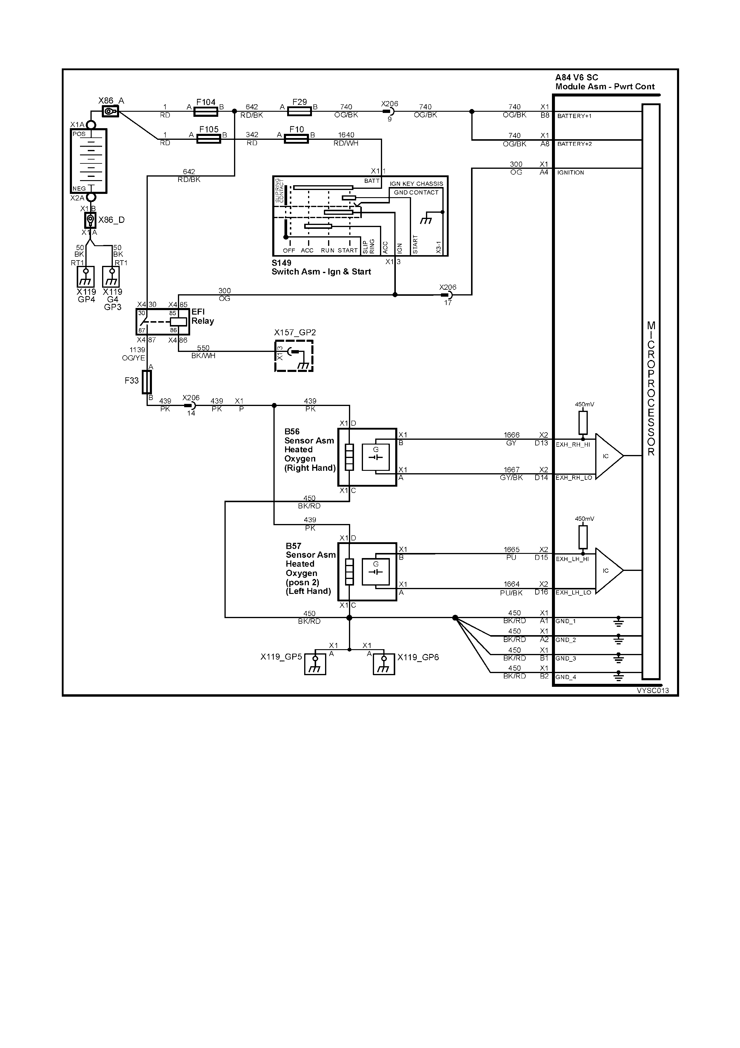
DTC 78 V6 S/C PCM – LONG TERM FUEL TRIM (LTFT) DELTA HIGH
Figure 6C2-2A-146 – Heated Oxygen Sensors
CIRCUIT DESCRIPTION:
The PCM controls left to right cylinder bank fuel delivery separately based on their respective oxygen sensor
signals. If the PCM detects too great a difference between the left to right cylinder bank Long Term Fuel Trim
values, it will set DTC 78.
CONDITIONS FOR RUNNING THE DTC:
• Engine is operating in Closed Loop.
CONDITIONS FOR SETTING THE DTC:
• The lef t hand long ter m f uel trim value var ies from the right hand long ter m f uel trim value by more than 59% for
more than 32 seconds.
ACTION TAKEN WHEN THE DTC SETS:
• The PCM stores the DTC information into memory when the diagnostic runs and fails.
• The Check Powertrain Malfunction Indicator Lamp (MIL) will not be activated.
• The PCM records the operating conditions at the time the diagnostic fails. The PCM stores this information in
the History Data.
• DTC 78 will clear when the fault no longer exists and the ignition switch is cycled "OFF" and "ON".

CONDITIONS FOR CLEARING THE CHECK POWERTRAIN MIL/DTC:
• The PCM deactivates the Check Powertrain MIL after the first ignition cycle that the diagnostic runs and does
not fail.
• Use Tech 2 to clear the Check Powertrain MIL/DTC.
DIAGNOSTIC AIDS:
• Lean or faulty injector(s) on one side of the engine.
• Cracked or fouled spark plug(s).
• Exhaust or inlet manifold leak.
• Make sure oxygen sensor leads are not swapped.
TEST DESCRIPTION:
NOTE: Number(s) below refer to step number(s) on the diagnostic table.
2. Check and repair other DTC(s) first.
3. Check for other mechanical problems causing DTC to set.
4. The bank that is the farthest from the neutral value of 0% is the bank which is out of fuel control.
DTC 78 V6 S/C PCM – LONG TERM FUEL TRIM (LTFT) DELTA HIGH
STEP ACTION VALUE YES NO
1. Was the "On-Board Diagnostic" (OBD) System Check
performed? Go to Step 2 Go to
OBD
System Check
in this Section.
2. Are any other PCM DTC(s) set?
Diagnose other
DTC(s) first Go to Step 3
3. Is there a Driveability complaint associated with this DTC
such as an Engine Miss, Lack of Power, or Poor Fuel
Economy?
Go to Step 7 Go to Step 4
4. 1. Start Engine and allow to warm up (Coolant
Temperature above 85° C).
2. Install Tech 2, run engine between 1500 –1800 RPM
and note left and right bank Long Term Fuel Trim
values.
Is the left bank Long Term Fuel Trim value further from 0%
than the right bank?
Go to Step 5 Go to Step 6
5. 1. Perform Oxygen Sensor (O2S) Diagnosis, Table A-6.3
in this Section.
Is action complete?
Verify Repair –
6. 1. Start Engine and allow to warm up (Coolant
Temperature above 85° C).
2. Install Tech 2, run engine between 1500 –1800 RPM
and note left and right bank Long Term Fuel Trim
values.
Is the right bank Long Term Fuel Trim value further from
0% than the left bank?
Go to Step 5 DTC 78 is
intermittent.
Refer
"Diagnostic
Aids" above.
7. Perform the following tests in the order given until the
problem is corrected:
• Fuel System check, (refer Table A-4.3 in this Section).
• Oscilloscope Engine, note and repair any Ignition
System problem found.
• Compression test each cylinder.
Is action complete?
Verify Repair –
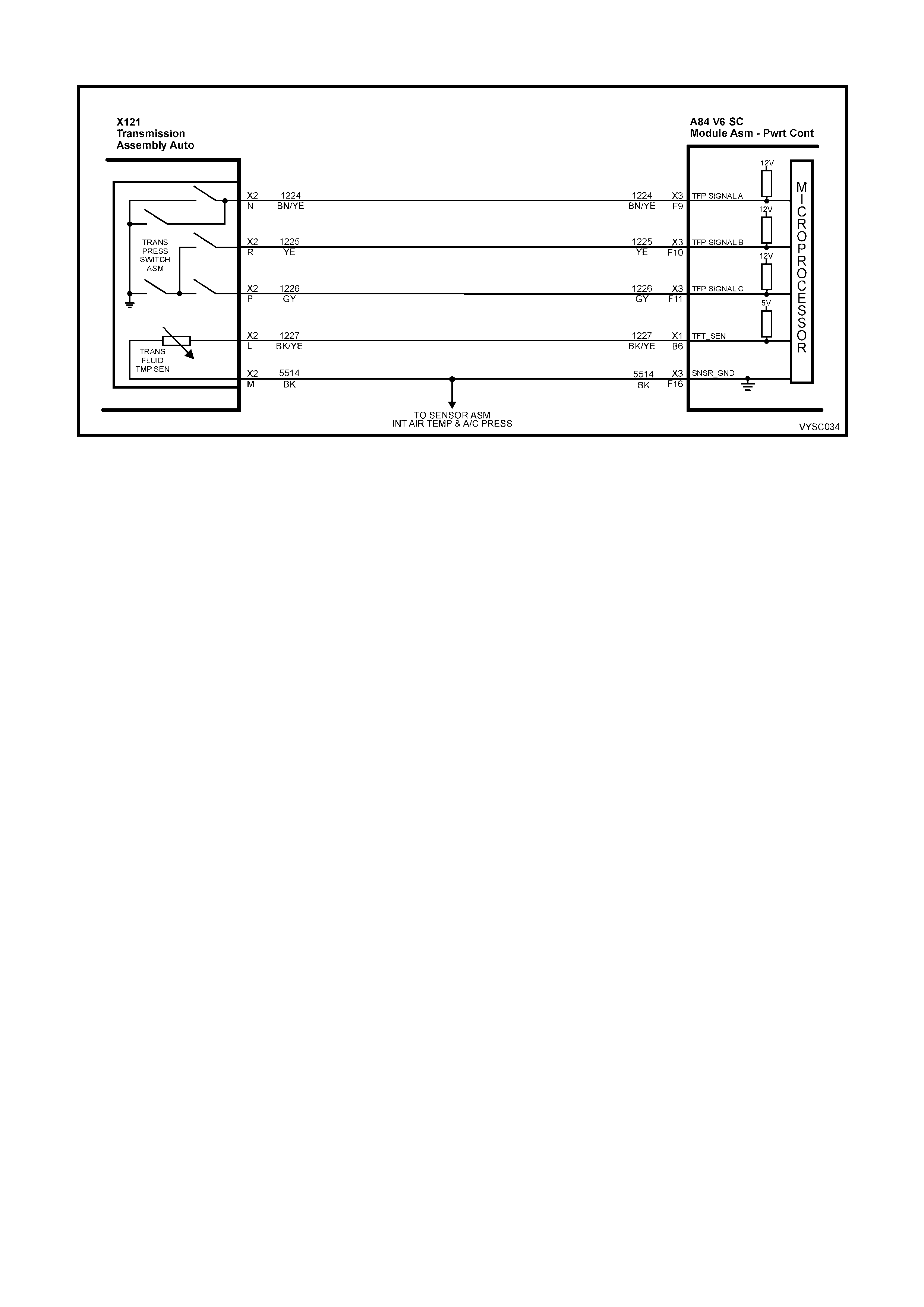
DTC 79 V6 S/C PCM – TRANSMISSION FLUID OVER-TEMPERATURE
Figure 6C2-2A-147 – Pressure Switch and Trans Fluid Temperature Sensor Assembly
CIRCUIT DESCRIPTION:
The flow of transmission fluid starts in the bottom of the pan and is drawn through the filter, control valve body
assembly, transmission case and into the oil pump assembly. The oil pump assembly pressurises the fluid and
directs it to the pressure regulator valve where it becom es the main supply of fluid to the various com ponents and
hydraulic circuits in the transm ission. Hot fluid exiting the tor que converter flows through the converter clutch apply
valve and into the transmission cooler lines to the oil cooler(s) located in the radiator (and auxiliary cooler if
equipped). From the cooler, fluid returns to cool and lubricate the front of the transmission. In forward drive
ranges, D4 f luid from the m anual valve is routed through an or ifice cup plug in the rear of the transmiss ion cas e to
feed the rear lube fluid circuit.
When the PCM detects a high transmission fluid temperature (TFT) for a long period of time, then DTC 79 sets.
As the transmission fluid temperature warms (normal transmission operating temperature 82° C – 94° C), the
sensor (thermistor) resistance becomes less and the voltage will measure about 1.5 to 2.0 volts. If the fluid
temperature becomes greater than 146° C and does not drop below 137° C for 10 minutes, a DTC 79 will set.
When DTC 79 sets the transmission fluid may be severely degraded.
CONDITIONS FOR RUNNING THE DTC:
• DTC 58 is not set.
CONDITIONS FOR SETTING THE DTC:
• The TFT is at or greater than 137° C for 10 minutes (600 seconds).
ACTION TAKEN WHEN THE DTC SETS:
• The PCM activates the Check Powertrain Malfunction Indicator Lamp (MIL) when the diagnostic runs and fails.
• The PCM records the operating conditions at the time the diagnostic fails. The PCM stores this information in
the History Data.
• When a DTC 79 sets, the PCM freezes shift adapts from being updated.
CONDITIONS FOR CLEARING THE CHECK POWERTRAIN MIL/DTC:
• The PCM deactivates the Check Powertrain MIL after the first ignition cycle that the diagnostic runs and does
not fail.
• Use Tech 2 to clear the Check Powertrain MIL/DTC.

DIAGNOSTIC AIDS:
• Inspect the cooling system fluid level and condition.
• DTC 79 may set approximately 30 minutes after DTC 58 has set. Follow the diagnostic table for DTC 58
before proceeding to the diagnostic table for DTC 79. Repairing the condition that set DTC 58 will likely
eliminate DTC 79.
• The TFT displayed on Tech 2 should rise steadily to a normal operating temperature, then stabilise.
• Inspect the torque converter stator for a possible problem.
• Ask about the customer's driving habits, trailer towing, etc.
• Transmission fluid should be changed if this DTC has set.
TEST DESCRIPTION:
NOTE: Number(s) below refer to step number(s) on the diagnostic table.
3. DTC 58 may also set a DTC 79. Go to the DTC 58 table for diagnosis.
4. This step inspects for air restrictions and loss of transmission fluid flow, causing an extremely high TFT.
DTC 79 V6 S/C PCM – TRANSMISSION FLUID OVER-TEMPERATURE
STEP ACTION VALUE YES NO
1. Was the "On-Board Diagnostic" (OBD) System Check
performed? Go to Step 2 Go to
OBD
System Check
in this Section.
2. 1. Install Tech 2.
2. With the engine OFF, turn the ignition switch to the
ON position.
IMPORTANT: Before clearing the DTC’s, use Tech 2
to record the DTC history for reference. The Clear Info
function will erase the data.
3. Record the DTC history.
4. Perform the transmission fluid checking procedure.
Refer to Transmission Fluid Checking Procedure in
this Section.
Was the fluid checking procedure performed?
Go to Step 3 Go to
Transmission
Fluid Checking
Procedure in this
Section.
3. Is DTC 58 also set?
Go to
“Diagnostic
Aids” above.
Go to Step 4
4. 1. Inspect the cooling system for the following conditions:
• Air flow restrictions
• Air flow blockage
• Debris
2. Inspect the transmission cooling system for the
following conditions:
• Air flow restrictions
• Air flow blockage
• Debris
• Damaged cooler lines
3. Repair restrictions if necessary.
Was a problem found?
Go to Step 7 Go to Step 5
5. 1. Drive the vehicle in D4 with the TCC commanded ON.
2. Observe the TCC slip speed on Tech 2.
Is the TCC slip speed within the specified value?
–20 to +20
rpm Go to Step 6 Refer to Torque
Converter Clutch
Diagnosis in
6C2-2B
SYMPTOMS.
6. 1. Perform the Line Pressure Check Procedure. Refer to
7C-3 AUTOMATIC TRANSMISSION – HYDRAULIC/
MECHANICAL DIAGNOSIS.
Was a problem found?
Go to Step 7 Go to
“Diagnostic
Aids” above.
7. In order to verify your repair, perform the following
procedure:
1. Drive the vehicle to normal operating engine and
transmission temperature.
2. Observe the TFT during the entire drive.
Is the TFT less than the specified value during the entire
drive?
137 °C System OK Begin the
diagnosis again.
Go to Step 1

DTC 81 V6 S/C PCM – 2-3 SHIFT SO LENOID ‘B’ CIRCUIT ELECTRICAL FAULT
Figure 6C2-2A-148 – Automatic Transmission Solenoids
CIRCUIT DESCRIPTION:
The 2- 3 Shift Solenoid Valve (2-3 SS Valve) contr ols the fluid flow acting on the 2-3 shif t valves . T he 2- 3 SS Valve
is a normally-open exhaust valve that is used with the 1-2 Shift Solenoid Valve in order to allow four different shifting
combinations. The solenoid attaches to the control valve body within the transmission. The 2-3 SS Valve receives
ignition voltage through circuit 339. The PCM controls the solenoid by providing a path to ground on circuit 1223.
W hen the PCM detects a continuous open or short to ground in the 2-3 SS Valve circuit or the 2-3 SS Valve, then
DTC 81 sets.
CONDITIONS FOR RUNNING THE DTC:
• The engine is running.
CONDITIONS FOR SETTING THE DTC:
• The PCM commands the solenoid ON and the voltage input remains high (B+).
Or
• The PCM commands the solenoid OFF and the voltage input remains low (0 volts).
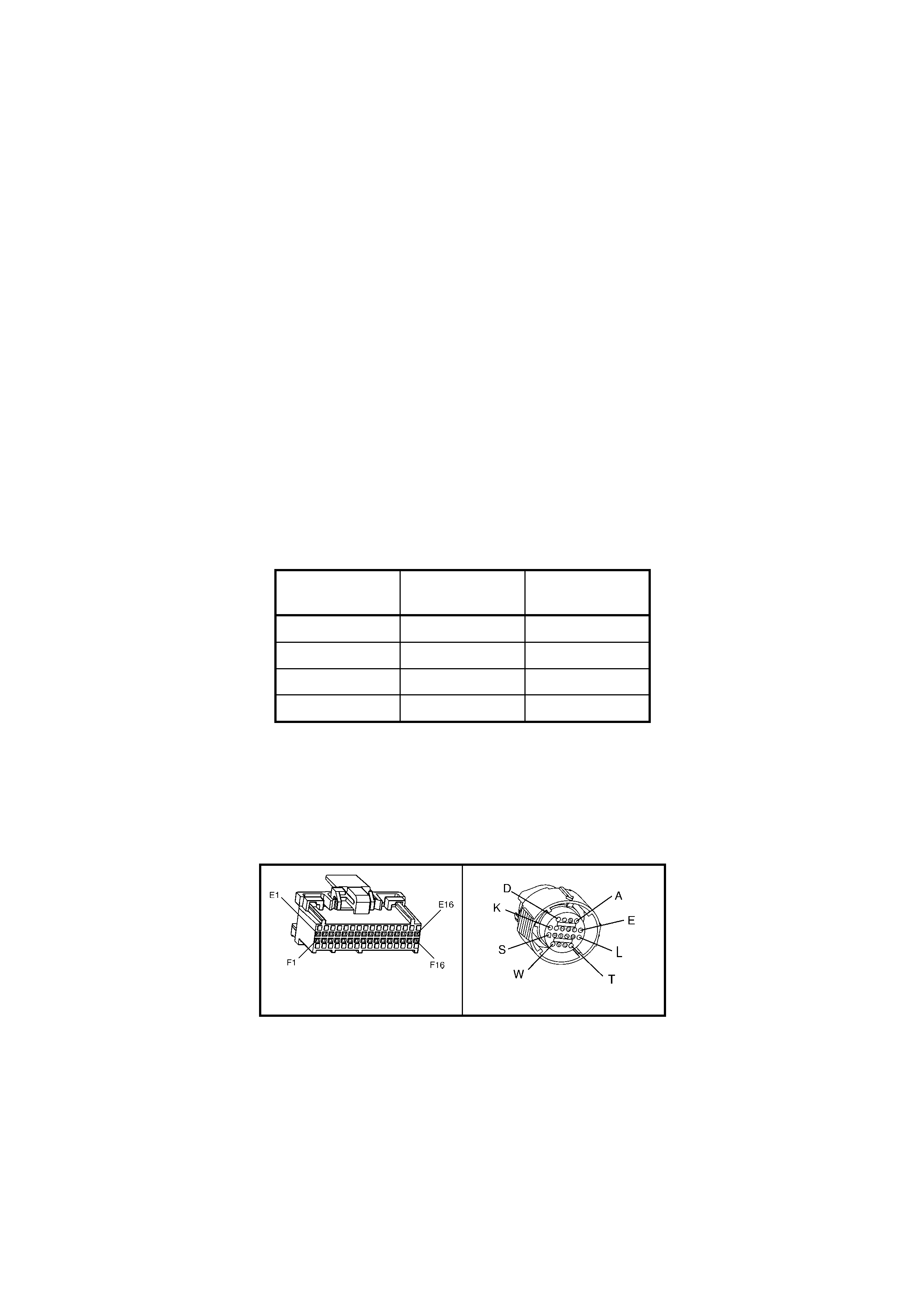
ACTION TAKEN WHEN THE DTC SETS:
• The PCM activates the Check Powertrain Malfunction Indicator Lamp (MIL) when the diagnostic runs and fails.
• The PCM records the operating conditions at the time the diagnostic fails. The PCM stores this information in
the History Data.
• When this DTC sets , the PCM will c om m and D2 line press ure (thir d gear only). The PCM inhibits 3-2 downshif t
if the vehicle speed is greater than 48 km/h and shift adapt updates will be frozen.
CONDITIONS FOR CLEARING THE CHECK POWERTRAIN MIL/DTC:
• The PCM turns the Chec k Powertrain MIL OF F af ter the f irs t ignition c ycle that the diagnostic runs and does not
fail.
• Use Tech 2 to clear the Check Powertrain MIL/DTC.
DIAGNOSTIC AIDS:
Inspect the wiring for poor electrical connections at the PCM. Inspect the wiring for poor electrical connections at the
transmission pass-through connector. Look for the following conditions:
– A bent terminal.
– A backed out terminal.
– A damaged terminal.
– Poor terminal tension.
– A chafed wire.
– A broken wire inside the insulation.
– Moisture intrusion.
• When diagnosing for an intermittent short or open condition, massage the wiring harness while watching the
test equipment for a change.
• Refer to the following table for the correct ON and OFF states of the shift solenoids.
GEAR 1-2 SHIFT
SOLENOID ‘A’ 2-3 SHIFT
SOLENOID ‘B’
1 ON ON
2 OFF ON
3 OFF OFF
4 ON OFF
TEST DESCRIPTION:
NOTE: Number(s) below refer to the step number(s) on the diagnostic table.
4. This step tests the function of the 2-3 SS valve and the automatic transmission wiring harness assembly.
5. This step tests for power to the 2-3 SS valve from the ignition through the fuse.
7. This step tests the ability of the PCM and the wiring to control the ground circuit.
10. This step measures the resistance of the A/T wiring harness assembly and the 2-3 SS valve.
A84 V6 S/C – X3 X121 – X2
Figure 6C2-2A-149

DTC 81 V6 S/C PCM – 2-3 SHIFT SOLENOID ‘B’ CIRCUIT ELECTRICAL FAULT
STEP ACTION VALUE YES NO
1. Was the "On-Board Diagnostic" (OBD) System Check
performed? Go to Step 2 Go to
OBD
System Check
in this Section.
2. 1. Install Tech 2.
2. With the engine OFF, turn the ignition switch to the
ON position.
Are any of the following DTC’s also set? 66, 67, 82, 83
Go to Step 3 Go to Step 4
3. 1. Inspect fuse F32.
2. If the fuse is open, inspect the following components
for a short to ground condition:
– Circuit 339
– The solenoids
– The A/T wiring harness assembly
3. Repair the circuit, the solenoids, and the harness if
necessary.
Did you find a short to ground condition?
Go to Step 16 Go to Step 5
4. 1. Using the transmission Miscellaneous Tests function
on Tech 2, command the 2-3 SS valve ON and OFF
three times while listening to the bottom of the
transmission pan (a stethoscope may be necessary).
Did the solenoid click when commanded?
Go to
“Diagnostic
Aids”, above.
Go to Step 5
5. 1. Turn the ignition OFF.
2. Disconnect the transmission pass-through connector
X121 – X2 (additional DTC’s may set).
3. Install the J 39775 jumper harness on the PCM side of
the pass-through connector.
4. With the engine OFF, turn the ignition switch to the
ON position.
5. Connect a test lamp from J 39775 jumper harness
cavity E to ground.
Is the test lamp ON?
Go to Step 7 Go to Step 6
6. 1. Repair the open in ignition feed circuit 339 to the 2-3
SS valve.
Is the repair complete?
Go to Step 16 –
7. 1. Install a test lamp from J 39775 jumper harness cavity
E to cavity B.
2. Using the transmission Miscellaneous Tests function
on Tech 2, command the 2-3 SS valve ON and OFF
three times.
Is the test lamp ON when the 2-3 SS valve is commanded
ON, and OFF when commanded OFF?
Go to Step 10 Go to Step 8
8. 1. Inspect circuit 1223 of the powertrain wiring harness
for proper terminal tension, an open, short to ground
or short to power condition.
2. Repair the circuit if necessary.
Did you find an open, short to ground or short to power
condition?
Go to Step 16 Go to Step 9
9. 1. Replace PCM. Refer to 6C1-3 SERVICE
OPERATIONS, for PCM Security Link procedure.
Is action complete?
Go to Step16 –
10. 1. Install the J 39775 jumper harness on the
transmission side of the pass-through connector.
2. With a DMM set to Ohms, and the J 35616-A
Connector Test Adaptor Kit, measure the resistance
between terminals B and E.
Is the resistance within the range indicated?
19 – 31
Ohms Go to Step 12 Go to Step 11
11. 1. Disconnect the A/T wiring harness assembly from the
2-3 SS valve.
2. Measure the resistance of the 2-3 SS valve.
Is the resistance within the range indicated?
19 – 31
Ohms Go to Step 14 Go to Step 15

STEP ACTION VALUE YES NO
12. 1. Using a DMM set to Ohms, measure the resistance
between terminal B and ground and between terminal
E and ground.
Are both readings greater than the specified value?
250 kOhm Go to Diagnostic
Aids, above. Go to Step 13
13. 1. Disconnect the A/T wiring harness assembly from the
2-3 SS valve.
2. Using a DMM set to Ohms, measure the resistance
from the component's terminals to ground.
Are both readings greater than the specified value?
250 kOhm Go to Step 14 Go to Step 15
14. 1. Replace the automatic transmission wiring harness
assembly. Refer to Control Valve Body and Wiring
Harness replacement in 7C4 AUTOMATIC
TRANSMISSION – ON-VEHICLE SERVICING.
Is the replacement complete?
Go to Step 16 –
15. 1. Replace the 2-3 SS valve. Refer to 6C2-3 SERVICE
OPERATIONS.
Is the replacement complete?
Go to Step 16 –
16. Perform the following procedure in order to verify the
repair:
1. Drive the vehicle in ‘D’ range and ensure the following
conditions are met:
– The PCM commands the 2-3 SS valve ON and
the voltage input drops to zero.
– The PCM commands the 2-3 SS valve OFF and
the voltage input increases to B+.
– All conditions are met for 5 seconds.
Were the above conditions verified?
Begin the
diagnosis again.
Go to Step 1.
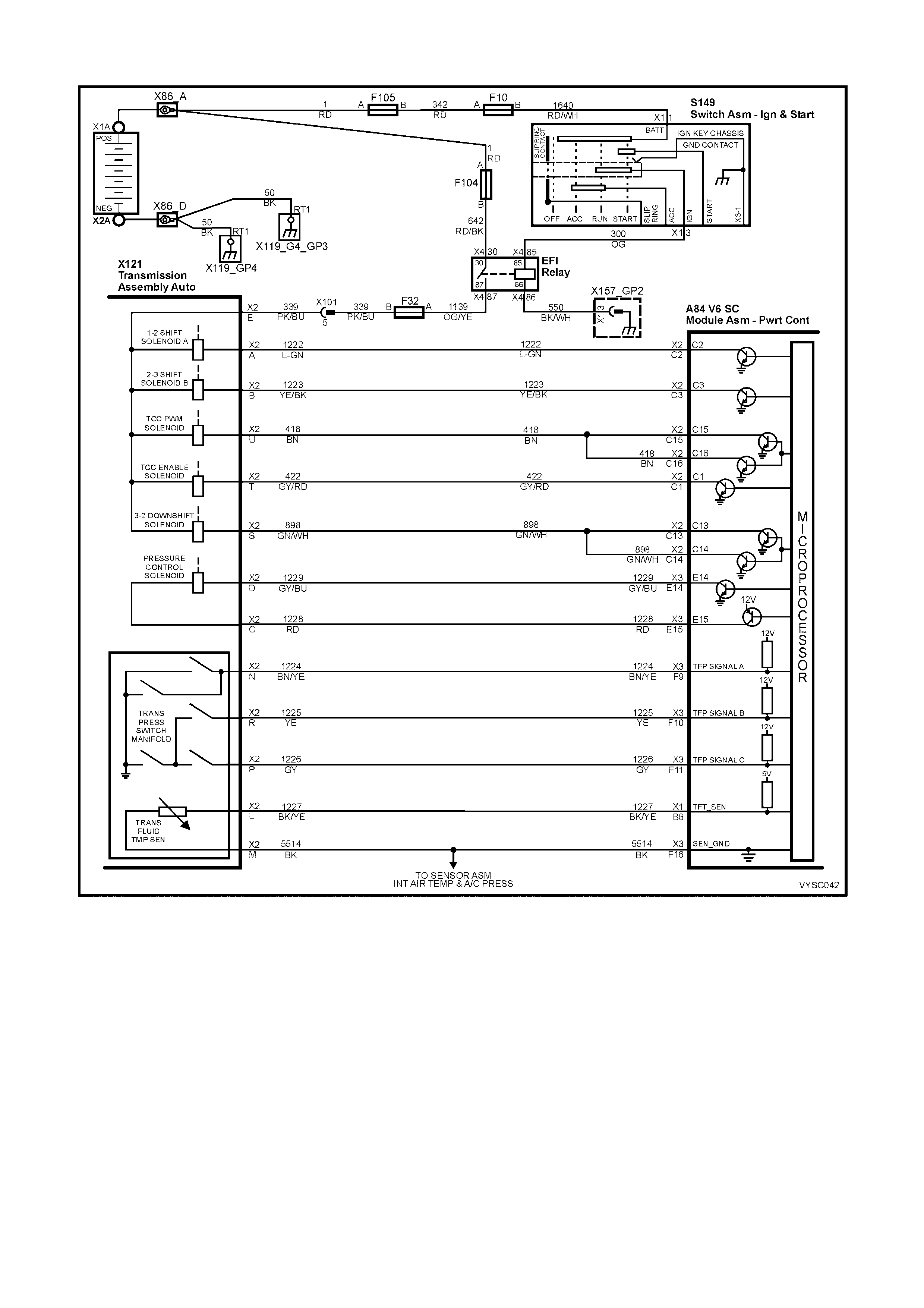
DTC 82 V6 S/ C PCM – 1-2 SHIFT SOLE NOID ‘A’ CIRCUIT ELECTRICAL FAULT
Figure 6C2-2A-150 – Automatic Transmission Solenoids
CIRCUIT DESCRIPTION:
The 1-2 Shift Solenoid Valve (1-2 SS Valve) controls the fluid flow acting on the 1-2 and 3-4 shift valves. The 1-2 SS
Valve is a norm ally-open exhaust valve that is used with the 2-3 Shif t Solenoid Valve in order to allow four dif ferent
shifting combinations. The solenoid attaches to the control valve body within the transmission. The 1-2 SS Valve
receives voltage through circuit 339. The PCM controls the solenoid by providing the ground path on circuit 1222.
W hen the PCM detects a continuous open or short to ground in the 1-2 SS Valve circuit or the 1-2 SS Valve, then
DTC 82 sets.
CONDITIONS FOR RUNNING THE DTC:
• The engine is running.
CONDITIONS FOR SETTING THE DTC:
• The PCM commands the solenoid ON and the voltage input remains high (B+).
Or
• The PCM commands the solenoid OFF and the voltage input remains low (0 volts).
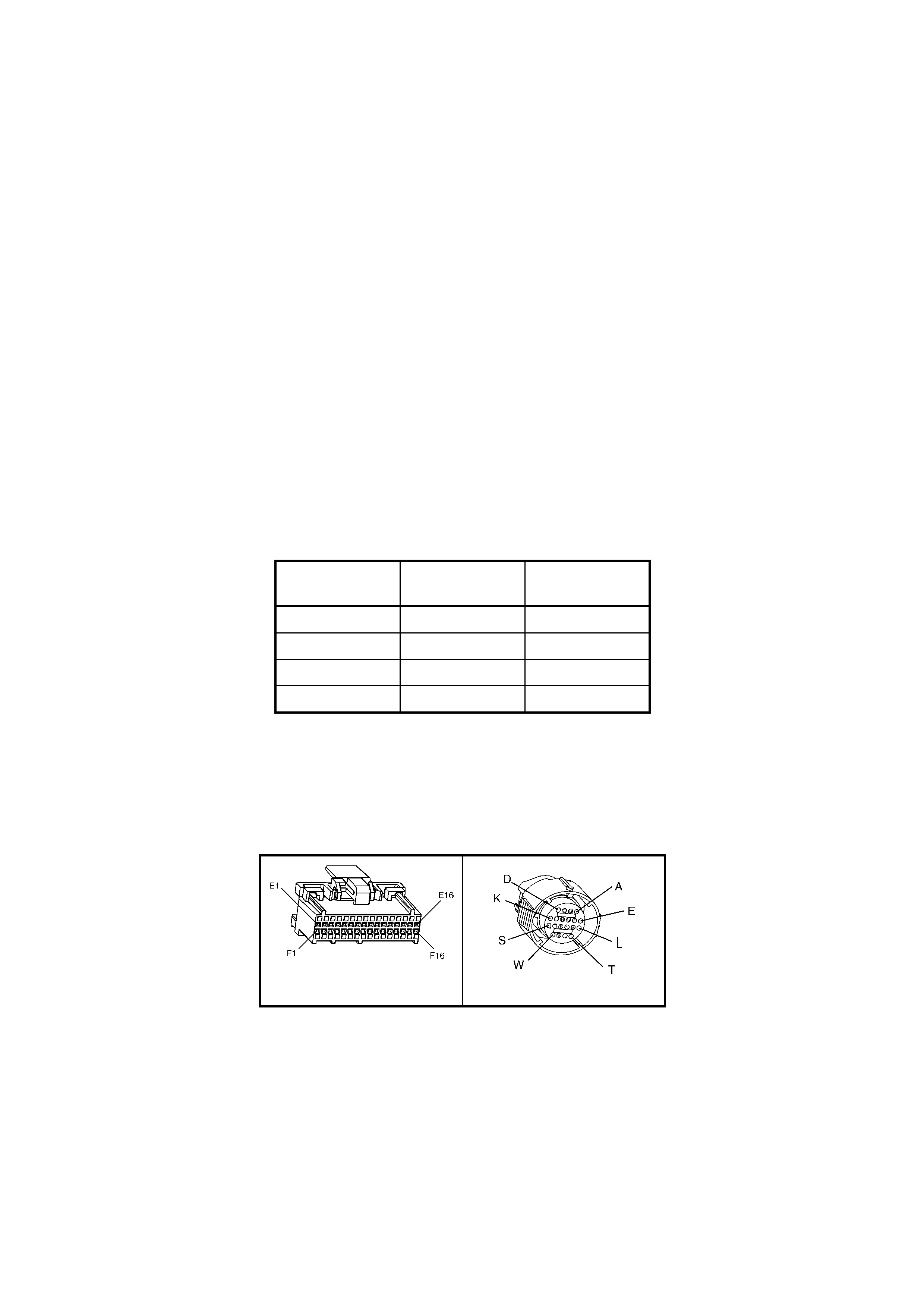
ACTION TAKEN WHEN THE DTC SETS:
• The PCM activates the Check Powertrain Malfunction Indicator Lamp (MIL) when the diagnostic runs and fails.
• The PCM records the operating conditions at the time the diagnostic fails. The PCM stores this information in
the History Data.
• When this DTC sets, the PCM will command D2 line pressure (third gear only), inhibit a 3-2 downshift if the
vehicle speed is greater than 48 km/h and freeze shift adapts from being updated.
CONDITIONS FOR CLEARING THE CHECK POWERTRAIN MIL/DTC:
• The PCM deactivates the Check Powertrain MIL after the first ignition cycle that the diagnostic runs and does
not fail.
• Use Tech 2 to clear the Check Powertrain MIL/DTC.
DIAGNOSTIC AIDS:
Inspect the wiring for poor electrical connections at the PCM. Inspect the wiring for poor electrical connections at the
transmission pass-through connector. Look for the following conditions:
– A bent terminal.
– A backed out terminal.
– A damaged terminal.
– Poor terminal tension.
– A chafed wire.
– A broken wire inside the insulation.
– Moisture intrusion.
• When diagnosing for an intermittent, short or open condition, massage the wiring harness while watching the
test equipment for a change.
• Refer to the following Table for the correct On and Off states of the shift solenoids.
GEAR 1-2-SHIFT
SOLENOID ‘A’ 2-3 SHIFT
SOLENOID ‘B’
1 ON ON
2 OFF ON
3 OFF OFF
4 ON OFF
TEST DESCRIPTION:
NOTE: Number(s) below refer to the step number(s) on the diagnostic table.
4. This step tests the function of the 1-2 SS valve and the automatic transmission wiring harness assembly.
5. This step tests for power to the 1-2 SS valve from the ignition through the fuse.
7. This step tests the ability of the PCM and the wiring to control the ground circuit.
10. This step measures the resistance of the A/T wiring harness assembly and the 1-2 SS valve.
A84 V6 S/C – X3 X121 – X2
Figure 6C2-2A-151

DTC 82 V6 S/C PCM – 1-2 SHIFT SOLENOID ‘A’ CIRCUIT ELECTRICAL FAULT
STEP ACTION VALUE YES NO
1. Was the "On-Board Diagnostic" (OBD) System Check
performed? Go to Step 2 Go to
OBD
System Check
in this Section.
2. 1. Install Tech 2.
2. With the engine OFF, turn the ignition switch to the
ON position.
Are any of the following DTCs also set? 66, 67, 81, 83
Go to Step 3 Go to Step 4
3. 1. Inspect fuse F32.
2. If the fuse is open, inspect the following components
for a short to ground condition:
– Circuit 339.
– The solenoids.
– The A/T wiring harness assembly.
3. Repair the circuit, the solenoids, and the harness if
necessary.
Did you find a short to ground condition?
Go to Step 16 Go to Step 5
4. 1. Using the transmission Miscellaneous Tests function
on Tech 2, command the 1-2 SS valve ON and OFF
three times while listening to the bottom of the
transmission pan (a stethoscope may be necessary).
Did the solenoid click when commanded?
Go to
“Diagnostic
Aids”, above.
Go to Step 5
5. 1. Turn the ignition OFF.
2. Disconnect the transmission pass-through connector
(additional DTCs may set).
3. Install the J 39775 jumper harness on the PCM side of
the pass-through connector.
4. With the engine OFF, turn the ignition switch to the
ON position.
5. Connect a test lamp from J 39775 jumper harness
cavity E to ground.
Is the test lamp ON?
Go to Step 7 Go to Step 6
6. 1. Repair the open or short to ground in ignition feed
circuit 339 to the 1-2 SS valve.
Is the repair complete?
Go to Step 16 –
7. 1. Install a test lamp from J 39775 jumper harness cavity
E to cavity A.
2. Using the transmission Miscellaneous Tests function
on Tech 2, command the 1-2 SS valve ON and OFF
three times.
Is the test lamp ON when the 1-2 SS valve is commanded
ON, and OFF when commanded OFF?
Go to Step 10 Go to Step 8
8. 1. Inspect circuit 1222 of the powertrain wiring harness
for proper terminal tension, an open, short to ground
or short to power condition.
2. Repair the circuit if necessary.
Did you find an open, short to ground or short to power
condition?
Go to Step 16 Go to Step 9
9. 1. Replace PCM. Refer to 6C2-3 SERVICE
OPERATIONS, for PCM Security Link procedure.
Is action complete?
Go to Step16 –
10. 1. Install the J 39775 jumper harness on the
transmission side of the pass-through connector.
2. With a DMM set to Ohms and the J 35616-A
Connector Test Adaptor Kit, measure the resistance
between terminals B and E.
Is the resistance within the range indicated?
19 – 31
Ohm Go to Step 12 Go to Step 11
11. 1. Disconnect the A/T wiring harness assembly from the
1-2 SS valve.
2. Measure the resistance of the 1-2 SS valve.
Is the resistance within the range indicated?
19 – 31
Ohm Go to Step 14 Go to Step 15

STEP ACTION VALUE YES NO
12. 1. Using a DMM set to Ohms, measure the resistance
between terminal B and ground, and between terminal
E and ground.
Are both readings greater than the specified value?
250 kOhm Go to
“Diagnostic
Aids”, above.
Go to Step 13
13. 1. Disconnect the A/T wiring harness assembly from the
1-2 SS valve.
2. Using a DMM set to Ohms, measure the resistance
from the component's terminals to ground.
Are both readings greater than the specified value?
250 kOhm Go to Step 14 Go to Step 15
14. 1. Replace the automatic transmission wiring harness
assembly. Refer to Control Valve Body and Wiring
Harness replacement in 7C4 AUTOMATIC
TRANSMISSION – ON-VEHICLE SERVICING.
Is the replacement complete?
Go to Step 16 –
15. 1. Replace the 1-2 SS valve. Refer to 6C2-3 SERVICE
OPERATIONS in this Section.
Is the replacement complete?
Go to Step 16 –
16. Perform the following procedure in order to verify the
repair:
1. Drive the vehicle in ‘D’ range and ensure the following
conditions are met:
– The PCM commands the 1-2 SS valve ON and
the voltage input drops to zero.
– The PCM commands the 1-2 SS valve OFF and
the voltage input increases to B+.
– All conditions are met for 5 seconds.
Were the above conditions verified?
System OK Begin the
diagnosis again.
Go to Step 1
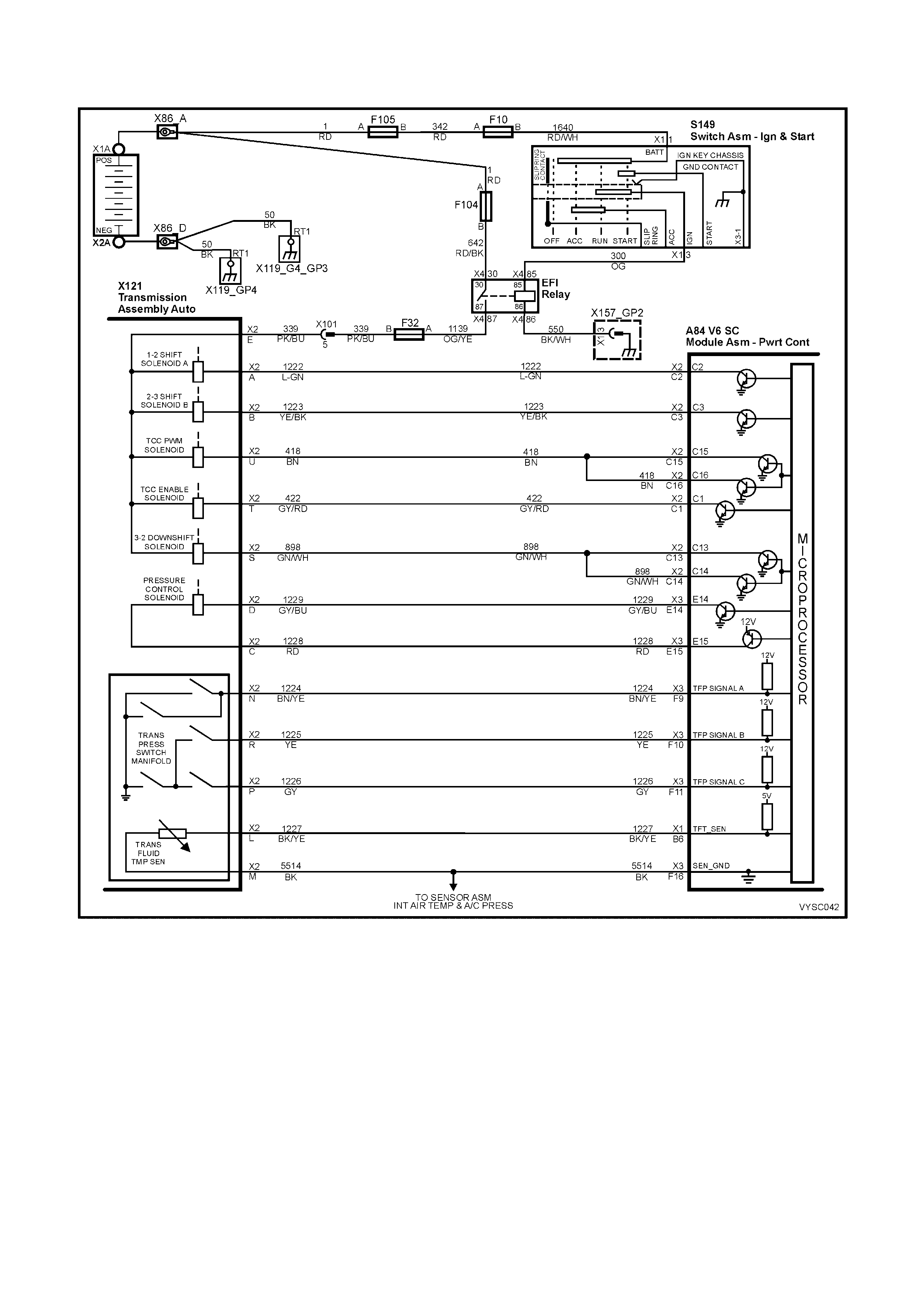
DTC 83 V6 S/C PCM – TORQUE CONV ERTER CLUTCH (TCC) PULSE WIDTH
MODULATION (PWM) S O LENOID CIRCUIT
Figure 6C2-2A-152 – Automatic Transmission Solenoids
CIRCUIT DESCRIPTION:
The T orque Conver ter Clutch Puls e Width Modulation Solenoid Valve (TCC PWM Solenoid Valve) contr ols the fluid
acting on the converter clutch valve. The converter clutch valve controls the TCC application and release. The
solenoid attaches to the control valve body within the transmission. The solenoid receives ignition voltage through
circuit 339. The PCM controls the solenoid by providing a ground path on circuit 418. Current flows through the
solenoid coil according to the duty cycle (percentage of ON and OFF time). The TCC PWM Solenoid Valve provides
a smooth engagement of the torque converter clutch by operating during a duty cycle percent of ON time.
The TCC PWM solenoid is used in combination with the TCC Enable solenoid to regulate fluid to the torque
converter, and is attac hed to the contr ol valve body within the trans miss ion. The use of the Torque Converter Clutch
Pulse Width Modulated ( T CC PWM) solenoid provides the ability of being able to control m ore prec isely, the rate of
Torque Converter Clutch (TCC) apply and release.
W hen the PCM detects a continuous open or short to ground in the TCC PW M Solenoid Valve circuit or the TCC
PWM Solenoid Valve, then DTC 83 sets.

CONDITIONS FOR RUNNING THE DTC:
• The system voltage is 8-18 volts.
• The engine speed is greater than 300 RPM for 5 seconds.
• The engine is not in fuel cutoff.
• The PCM commands first gear.
• The TCC duty cycle is less than 10% or greater than 90%.
CONDITIONS FOR SETTING THE DTC:
• The PCM commands the solenoid ON and the voltage input remains high (B+).
Or
• The PCM commands the solenoid OFF and the voltage input remains low (0 volts).
• Either condition for 5 seconds.
ACTION TAKEN WHEN THE DTC SETS:
• The PCM stores the DTC information into memory when the diagnostic runs and fails.
• The Check Powertrain Malfunction Indicator Lamp (MIL) will not be activated.
• The PCM records the operating conditions at the time the diagnostic fails. The PCM stores this information in
the History Data.
• When this DTC sets, the PCM will freeze shift adapts from being updated.
CONDITIONS FOR CLEARING THE CHECK POWERTRAIN MIL/DTC:
• Use Tech 2 to clear the Check Powertrain MIL/DTC.
DIAGNOSTIC AIDS:
• Inspect the wiring for poor electrical connections at the PCM. Inspect the wiring for poor electrical connections
at the transmission pass-through connector. Look for the following conditions:
– A bent terminal.
– A backed out terminal.
– A damaged terminal.
– Poor terminal tension.
– A chafed wire.
– A broken wire inside the insulation.
– Moisture intrusion.
• W hen diagnos ing for an intermittent shor t or open condition, wriggle the wiring harness while watching the test
equipment for a change.
TEST DESCRIPTION:
NOTE: Number(s) below refer to the step number(s) on the diagnostic table.
3. An open fuse indicates a short circuit in circuit 339. A short in any of the five solenoids fed by circuit 339
may cause an open fuse.
4. This step tests for voltage to the solenoid.
6. This step tests the ability of the PCM and wiring to control the ground circuit.
7. This step tests the resistance of the TCC PWM Solenoid Valve and the Automatic Transmission Wiring
Harness Assembly.

DTC 83 V6 S/C PCM –
TORQUE CONVERTER CLUTCH (TCC) PULSE WIDTH MODULATION (PWM) SOLENOID CIRCUIT
STEP ACTION VALUE YES NO
1. Was the "On-Board Diagnostic" (OBD) System Check
performed? Go to Step 2 Go to
OBD
System Check
in this Section.
2. 1. Install Tech 2.
2. With the engine OFF, turn the ignition switch to the
ON position.
Are any of the following DTCs also set? 66, 67, 81, 83.
Go to Step 3 Go to Step 4
3. 1. Inspect fuse F32.
2. If the fuse is open, inspect the following components
for a short to ground condition:
– Circuit 339.
– The solenoids.
– The A/T wiring harness assembly.
3. Repair the circuit, the solenoids, and the harness if
necessary.
Did you find a short to ground condition?
Go to Step 15 Go to
“Diagnostic
Aids” above.
4. 1. Turn the ignition OFF.
2. Disconnect the transmission pass-through connector
(additional DTC’s may set).
3. Install J 39775 Jumper Harness on the PCM side of
the harness connector.
4. With the engine OFF, turn the ignition switch to the
ON position.
5. Connect a lest lamp from J 39775 Jumper Harness
cavity E to ground.
Is the test lamp on?
Go to Step 6 Go to Step 5
5. 1. Repair the open in the ignition feed circuit 339 to the
TCC PW M Solenoid Valve.
Is the repair complete?
Go to Step 15 –
6. 1. Install the test lamp from cavity E to cavity U of the J
39775 Jumper Harness.
2. Command the TCC PWM Solenoid Valve ON and
OFF three times.
Does the test lamp turn ON when the TCC PW M Solenoid
Valve is commanded ON, and OFF when commanded
OFF?
Go to Step 8 Go to Step 7
7. 1. Check circuit 418 for proper terminal tension, an open,
short to B+, or a short to ground. Repair the circuit if
necessary.
Did you find and correct the problem?
Go to Step 15 Go to Step 9
8. 1. Install J 39775 Jumper Harness on the transmission
pass-through connector.
2. Using a DMM set to Ohms and the J 35616-A
Connector Test Adaptor Kit, measure the resistance
between terminals E and U.
Is the resistance within the specified range?
9 – 15 Ohm Go to Step 11 Go to Step 10
9. 1. Replace PCM. Refer to 6C2-3 SERVICE
OPERATIONS, for PCM Security Link procedure.
Is action complete?
Go to Step 15 –
10. 1. Disconnect the Automatic Transmission Wiring
harness Assembly at the TCC PWM Solenoid Valve.
2. Measure the resistance of the TCC PWM Solenoid
Valve.
Is the resistance within the specified range?
9 – 15 Ohm Go to Step 13 Go to Step 14
11. 1. Measure the resistance between terminal E and
ground, and between terminal U and ground.
Are both readings greater than the specified value?
250 kOhm Go to
“Diagnostic
Aids” above.
Go to Step 12

STEP ACTION VALUE YES NO
12. 1. Disconnect the Automatic Transmission Wiring
Harness Assembly at the TCC PWM Solenoid Valve.
2. Measure the resistance between each of the
component terminals and a known good ground.
Are both readings greater than the specified value?
250 kOhm Go to Step 13 Go to Step 14
13. 1. Replace the automatic transmission wiring harness
assembly. Refer to Control Valve Body and Wiring
Harness replacement in 7C4 AUTOMATIC
TRANSMISSION – ON-VEHICLE SERVICING.
Is the replacement complete?
Go to Step 15 –
14. 1. Replace the TCC solenoid valve. Refer to 6C2-3
SERVICE OPERATIONS in this Section.
Is the replacement complete?
Go to Step 15 –
15. In order to verify the repair, perform the following
procedure:
Operate the vehicle under the following conditions while
observing the TCC PWM Solenoid and TCC Slip Speed:
• The PCM commands the TCC PWM Solenoid
Valve ON, and the TCC Slip Speed is -20 to +20
rpm.
• The PCM commands the TCC PWM Solenoid
Valve OFF, and the TCC Slip Speed is greater
than rpm 50.
Are both of the TCC Slip conditions met for at least
4 seconds?
System OK Begin the
diagnosis again.
Go to Step 1
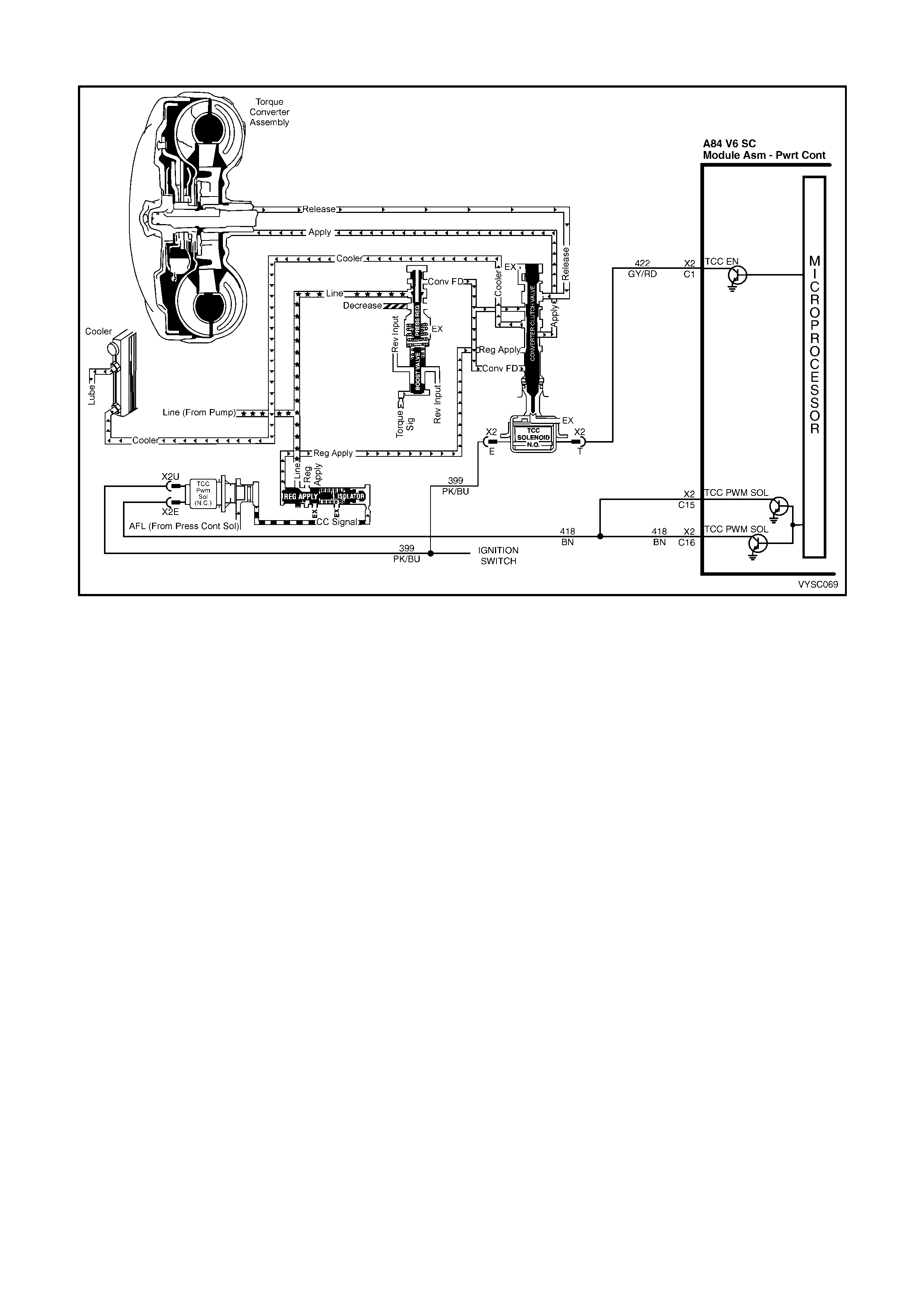
DTC 85 V6 S/C PCM – TRANSMISSION SLIPPING
Figure 6C2-2A-153 – Torque Converter Clutch
CIRCUIT DESCRIPTION:
The PCM m onitors the diff erence between the engine speed and the transm ission output speed. In D3 drive range
with the TCC engaged, the engine speed should closely match the transmission output speed. In D4 drive range,
with the TCC engaged, the Trans Slip Speed should be -20 to +20 RPM.
W hen the PCM detec ts an excessive tr ansmission s lip speed when the TCC should be engaged, then DTC 85 will
set.
CONDITIONS FOR RUNNING THE DTC:
• No Throttle Position DTCs 21 or 22.
• No VSS assembly DTCs 24 or 72.
• No TCC solenoid valve DTC 67.
• No 1-2 SS valve DTC 82.
• No 2-3 SS valve DTC 81.
• No 3-2 SS valve assembly DTC 66.
• No TCC PWM solenoid valve DTC 83.
• The engine speed is greater than 300 RPM for 5 seconds.
• The engine is not in fuel cutoff.
• The vehicle speed is greater than 56 km/h.
• The speed ratio is 0.67 – 0.90 (the speed ratio is the engine speed divided by the transmission output speed).
• The engine speed is 1200-3500 RPM.
• The engine torque is 54-542 Nm.
• The gear range is D4.
• The commanded gear is not 1st gear.
• The Throttle Position angle is 10-50%.
• The TFT is between 20-130° C.

CONDITIONS FOR SETTING THE DTC:
• DTC 85 sets if the following conditions occur for three TCC cycles.
– The TCC is commanded ON for 5 seconds.
– The TCC is at maximum duty cycle for 1 second.
– The TCC slip speed is 80 – 800 RPM for 7 seconds.
IMPORTANT: The following actions may occur before the DTC sets.
• If the TCC is comm anded ON and at m axim um duty cycle for 5 seconds, the Thr ottle Position Sensor angle is
10 – 40%, and the transmission slip counter has incremented to either 1 or 2 (out of 3 to increment the fail
counter for the current ignition cycle), then the following slip conditions and actions may increment the fail
counter for the current ignition cycle:
These conditions must occur sequentially.
- Condition 1: If the TCC slip speed is 80-800 RPM for 7 seconds, then the PCM will command maximum line
pressure and freeze shift adapts from being updated.
- Condition 2: If Condition 1 is m et and the TCC slip s peed is 80-800 RPM for 7 sec onds, then the PCM will
command the TCC OFF for 1.5 seconds.
- Condition 3: If Condition 2 is met and the TCC slip speed is 80-800 RPM for 7 seconds, then the fail
counter on the current ignition cycle is incremented.
• The above slip conditions and actions may be disregarded if the TCC is commanded OFF at any time as a
result of a driving manoeuvre (sudden acceleration or deceleration).
ACTION TAKEN WHEN THE DTC SETS:
• The PCM stores the DTC information into memory when the diagnostic runs and fails.
• The Check Powertrain Malfunction Indicator Lamp (MIL) will not be activated.
• The PCM records the operating conditions at the time the diagnostic fails. The PCM stores this information in
the History Data.
• When this DTC sets, the PCM will freeze shift adapts from being updated, inhibits 4th gear if the transmission is
in hot mode, and command maximum line pressure.
CONDITIONS FOR CLEARING THE CHECK POWERTRAIN MIL/DTC:
• Use Tech 2 to clear the Check Powertrain MIL/DTC.
DIAGNOSTIC AIDS:
• Internal transmission failures may set DTC 85.
TEST DESCRIPTION:
NOTE: Number(s) below refer to the step number(s) on the diagnostic table.
2. This step tests the torque converter for slippage while in a commanded lock-up state.
DTC 85 V6 S/C PCM – TRANSMISSION SLIPPING
STEP ACTION VALUE YES NO
1. Was the "On-Board Diagnostic" (OBD) System Check
performed? Go to Step 2 Go to
OBD
System Check
in this Section.
2. 1. Perform the transmission fluid checking procedure.
Have you performed the transmission fluid checking
procedure?
Go to Step 3 Go to
Transmission
Fluid Checking
Procedure, in
this Section.
3. 1. Install Tech 2.
2. With the engine OFF, turn the ignition switch to the
ON position.
3. Drive the vehicle in 4th gear with the TCC engaged.
Is the TCC Slip Speed between the specified values for 7
seconds?
80 – 800
RPM Go to Step 4 Go to
“Diagnostic
Aids”, above.

STEP ACTION VALUE YES NO
4. 1. Inspect the Torque Converter Clutch Solenoid Valve
(TCC Solenoid Valve) for the following conditions:
• Internal malfunction (such as sediment or
damage).
• Damaged seals.
2. Inspect the Torque Converter Clutch Pulse Width
Modulation Solenoid Valve (TCC PWM Solenoid
Valve) for the following conditions:
• Internal malfunction (such as sediment or
damage).
• Damaged seals.
Did you find and correct the problem?
Go to Step 13 Go to Step 5
5. 1. Inspect the 1-2 Shift Solenoid Valve (1-2 SS Valve) for
the following conditions:
• Internal malfunction (such as sediment or
damage).
• Damaged seals.
2. Inspect the 2-3 Shift Solenoid Valve (2-3 SS Valve) for
the following conditions:
• Internal malfunction (such as sediment or
damage).
• Damaged seals.
Did you find and correct the problem?
Go to Step 13 Go to Step 6
6. 1. Inspect the valve body assembly for a stuck TCC
signal valve. Refer to 7C4 AUTOMATIC
TRANSMISSION – ON-VEHICLE SERVICING.
Did you find and correct the problem?
Go to Step 13 Go to Step 7
7. 1. Inspect the torque converter assembly for the
following conditions:
• Stator roller clutch not holding.
• Internal damage.
Did you find and correct the problem?
Go to Step 13 Go to Step 8
8. 1. Inspect the oil pump assembly for the following
conditions:
• Stuck converter clutch valve.
• Converter clutch valve assembled backward.
• Mispositioned converter clutch valve retaining
ring.
• Mispositioned pump to case gasket.
• Restricted orifice cup plugs.
• Damaged orifice cup plugs.
• Over-tightened, or unevenly tightened pump body
to cover bolts.
Did you find and correct the problem?
Go to Step 13 Go to Step 9
9. 1. Inspect the input housing and shaft assembly for the
following conditions:
• Cut turbine shaft o-ring seal.
• Damaged turbine shaft o-ring seal.
• Restricted turbine shaft retainer and ball
assembly.
• Damaged turbine shaft retainer and ball
assembly.
Did you find and correct the problem?
Go to Step 13 Go to Step 10

STEP ACTION VALUE YES NO
10. 1. Inspect the 2-4 band assembly for the following
conditions:
• Worn 2-4 band.
• Damaged 2-4 band.
• Mispositioned 2-4 band.
• Misassembled 2-4 band.
• The band anchor pin is not engaged.
• Restricted apply passages in the 2-4 servo
assembly.
• Blocked apply passages in the 2-4 servo
assembly.
• Nicks or burrs on the servo pin.
• Nicks or burrs on the pin bore in the case.
• Damaged fourth servo piston.
• Misassembled fourth servo piston.
• Damaged band apply pin.
• Incorrect band apply pin.
• Damaged servo bore in the case.
• Missing piston seals.
• Cut piston seals.
• Damaged piston seals.
• Porosity in the pistons.
• Porosity in the cover.
• Porosity in the case.
• Damaged piston seal grooves.
• Plugged orifice cup plug.
• Missing orifice cup plug.
Did you find and correct the problem?
Go to Step 13 Go to Step 11
11. 1. Inspect the forward clutch assembly for the following
conditions:
• Worn clutch plates.
• Porosity in the forward clutch piston.
• Damaged forward clutch piston.
• Missing forward clutch piston inner and outer
seals.
• Cut forward clutch piston inner and outer seals.
• Damaged forward clutch piston inner and outer
seals.
• Missing input housing to forward clutch housing
O-ring seal.
• Cut input housing to forward clutch housing O-ring
seal.
• Damaged input housing to forward clutch housing
O-ring seal.
• Damaged forward clutch housing.
• Damaged forward clutch housing retainer and ball
assembly.
• Forward clutch housing retainer and ball
assembly is not sealing.
Did you find and correct problem?
Go to Step 13 Go to Step 12

STEP ACTION VALUE YES NO
12. 1. Inspect the 3-4 clutch assembly for the following
conditions:
• Worn clutch plates.
• Porosity in the 3-4 clutch piston.
• Damaged 3-4 clutch piston.
• Missing 3-4 clutch inner and outer seals.
• Cut 3-4 clutch inner and outer seals.
• Damaged 3-4 clutch inner and outer seals.
• Damaged 3-4 clutch spring assembly.
• Damaged 3-4 clutch apply ring.
• Damaged piston seal grooves.
• Plugged orifice cup plug.
• Missing orifice cup plug.
Did you find and correct the problem?
Go to Step 13 Go to
“Diagnostic
Aids”, above.
13. 1. In order to verify your repair, operate the vehicle under
the following conditions:
• Drive the vehicle in D4 with the TCC ON and a
throttle position of 16 – 50%.
Did the vehicle obtain a Trans Slip Speed of -20 to +40
RPM?
System OK Begin the
diagnosis again.
Go to Step 2
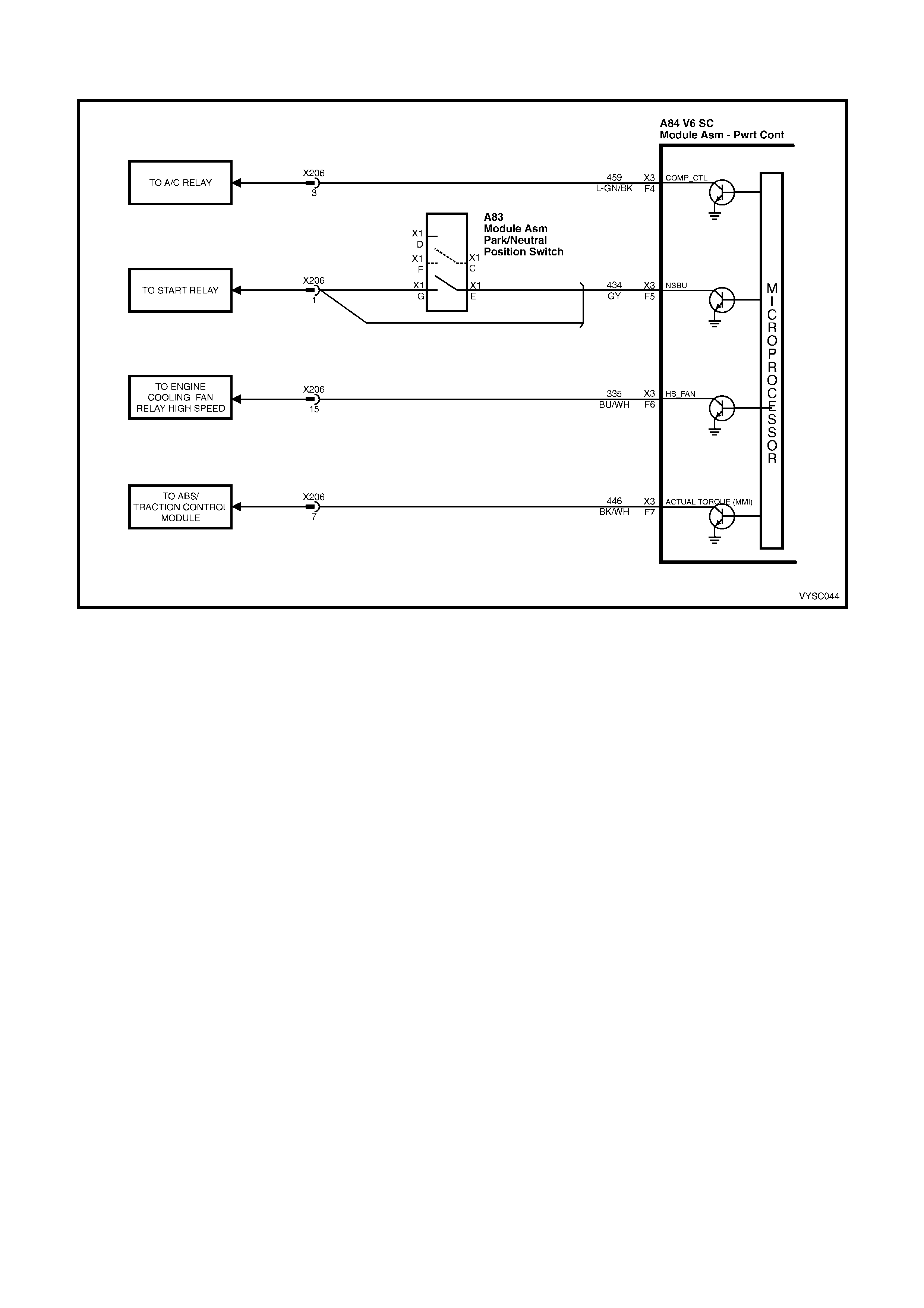
DTC 91 V6 S /C PCM – QDSM (QUAD DRIVER SURFACE MODULE) CIRCUIT
Figure 6C2-2A-154 – Quad Driver Surface Module (QDSM)
CIRCUIT DESCRIPTION:
The Q uad Driver Surfac e Module (QDSM) is us ed by the PCM to turn "ON" many of the cur rent-driven devices that
are needed to control various engine functions. A QDSM is capable of controlling up to 4 separate outputs by
applying ground or voltage to the device which the PCM is commanding "ON."
QDSM do not have the capability of diagnosing each output circuit individually. A DTC 91 that is set indicates an
improper voltage level has been detected on one of the QDSM circuits. The QDSM controls the A/C compressor
relay, the Start Relay, High Speed fan relay, and the Torque Achieved circuit to the ABS/TCS module.
CONDITIONS FOR RUNNING THE DTC:
• The engine has been running for longer than 5 seconds.
CONDITIONS FOR SETTING THE DTC:
• An improper voltage level has been detected on a QDSM circuit.
ACTION TAKEN WHEN THE DTC SETS:
• The PCM stores the DTC information into memory when the diagnostic runs and fails.
• The Check Powertrain Malfunction Indicator Lamp (MIL) will not be activated.
• The PCM records the operating conditions at the time the diagnostic fails. The PCM stores this information in
the History Data.
• When DTC 91 is set, the low speed fan will be turned "ON" and will remain "ON" until DTC 91 has been
cleared.
CONDITIONS FOR CLEARING THE CHECK POWERTRAIN MIL/DTC:
• The PCM turns the Chec k Powertrain MIL OF F af ter the f irs t ignition c ycle that the diagnostic runs and does not
fail.
• Use Tech 2 to clear the Check Powertrain MIL/DTC.
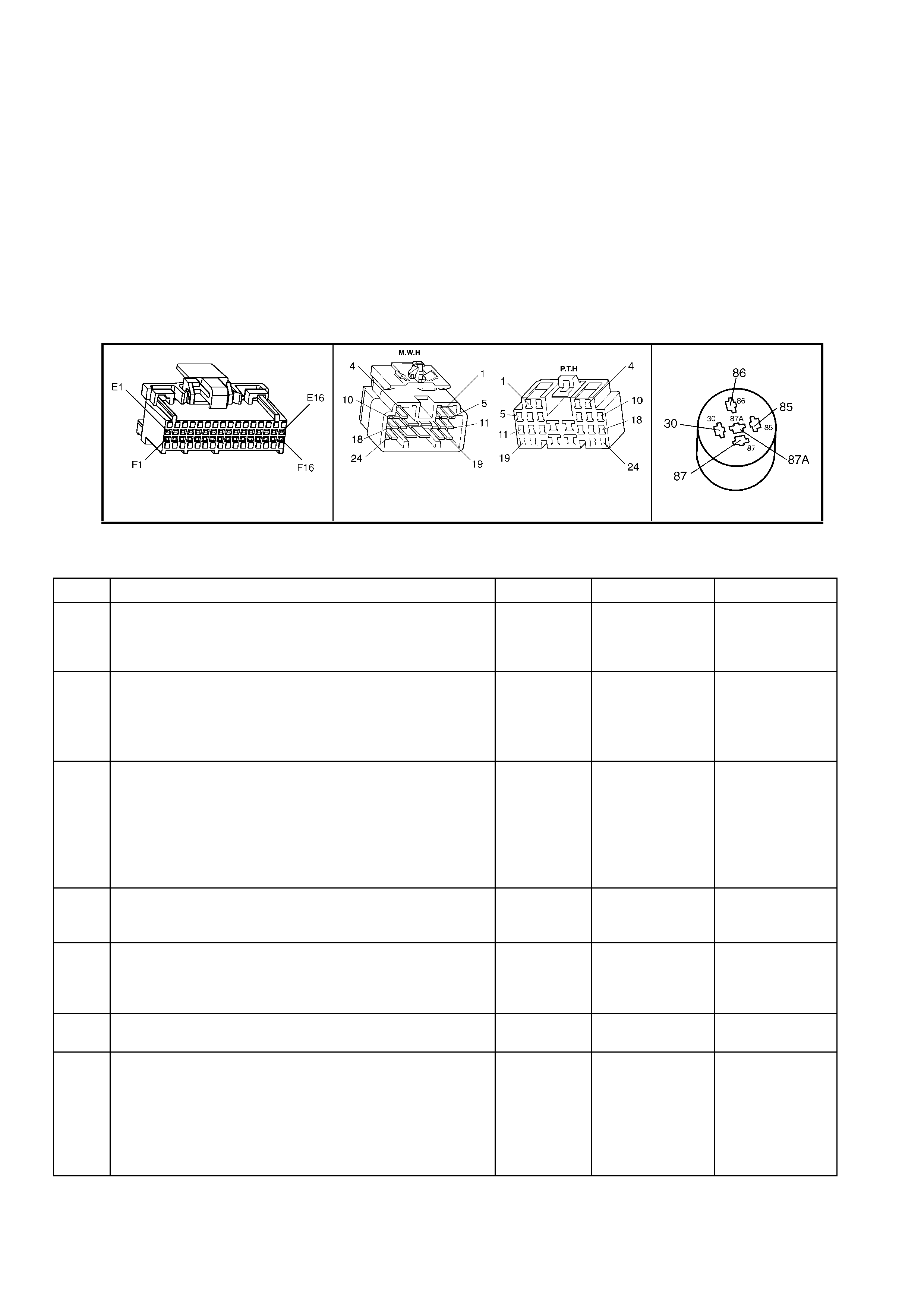
DIAGNOSTIC AIDS:
An ABS/TCS DTC may also be set, if the Torque Achieved Circuit is causing the fault.
Check the connector harnesses for:
• Dirty, Damaged, or Loose Connections or Damaged Harness – Check for any damage to the harness which
could c ause an interm ittent open or short to ground or backed out ter minals at the PCM and BCM connec tors,
broken locks, improperly formed or damaged terminals.
TEST DESCRIPTION:
NOTE: Number(s) below refer to step number(s) on the diagnostic table.
2. This step checks to see if the A/C compressor relay can be controlled using Tech 2. If Tech 2 can control the
A/C relay, the A/C circuit is not causing DTC 91 to set.
7. This step checks to see if the Start Relay can be controlled using Tech 2. If the test light illuminates then Tech 2
can control the Start relay, the Start relay circuit is not causing DTC 91 to set.
12. T his step chec ks to see if the High Speed Fan Relay can be contr olled using Tech 2. If Tech 2 can control the
High Speed Fan relay, the High Speed Relay circuit is not causing DTC 91 to set.
A84 V6 S/C X3 X206 X1 (Part of X100)
Figure 6C2-2A-155
DTC 91 V6 S/C PCM – QDSM (QUA D DRIVER SURFACE MODULE) CIRCUIT
STEP ACTION VALUE YES NO
1. Was the "On-Board Diagnostic" (OBD) System Check
performed? Go to Step 2 Go to
OBD
System Check
in this Section.
2. 1. Ignition "ON", engine "OFF".
2. Using Tech 2, command A/C compressor relay "ON"
and "OFF" while listening to relay.
Did the A/C compressor relay click "ON" and "OFF" when
commanded?
Go to Step 7 Go to Step 3
3. 1. Ignition "OFF".
2. Disconnect all PCM harness connectors.
3. Ignition "ON".
4. Using DMM set to DC volts, probe PCM harness
connector A84 X3-F4 with negative lead connected to
ground.
Is the voltage at the specified value?
B+ Go to Step 4 Go to Step 5
4. 1. Check for a short to B+ or a poor connection at PCM
harness connector A84 X3-F4.
Was a problem found?
Verify Repair Go to step 17
5. 1. Check for an open, or a short to ground between the
PCM harness connector terminal A84 X3-F4, and the
A/C compressor relay terminal X112.
Was a problem found?
Verify Repair Go to Step 6
6. 1. Replace A/C Compressor Relay.
Is action complete? Verify Repair –
7. 1. Remove start relay with a test light connected to B+
2. With a test light connected to B+, probe terminal X1
86 of the start relay connector.
3. Using Tech 2, command Start relay "ON", and "OFF"
while observing test light.
Does test lamp illuminate when the start relay is
commanded "ON", and go out when commanded "OFF"?
Go to Step 12 Go to Step 8

STEP ACTION VALUE YES NO
8. 1. Ignition "OFF".
2. Reinstall start relay.
3. Disconnect all PCM harness connectors.
3. Using DMM set to DC volts, probe PCM harness
connector A84 X3-F5 with negative lead connected to
ground.
4. Turn ignition to “Start”.
Is the voltage at the specified value?
B+ Go to Step 9 Go to Step 10
9. 1. Check for a short to B+ or a poor connection at PCM
harness connector A84 X3-F5.
Was a problem found?
Verify Repair Go to Step 17
10. 1. Check for an open or short to ground between the
PCM harness connector A84 X3-F5, and the Start
relay terminal X1-86.
Was a problem found?
Verify Repair Go to Step 11
11. 1. Replace Start Relay.
Is action complete? Verify Repair
12. 1. Ignition "ON", engine "OFF".
2. Using Tech 2, command High Speed fan relay "ON",
and "OFF" while listening to relay.
Did the High Speed relay click "ON" and "OFF" when
commanded?
Go to Step 16 Go to Step 13
13. 1. Ignition "OFF".
2. Disconnect all PCM harness connectors.
3. Ignition "ON".
4. Using DMM set to DC volts probe PCM harness
connector terminal A84 X3-F6, with negative lead
connected to ground.
Is the voltage at the specified value?
B+ Go to Step 14 Go to Step 15
14. 1. Check for a short to B+ or a poor connection at PCM
harness connector A84 X3-F6.
Was a problem found?
Verify Repair Go to Step 17
15. 1. Check for an open or a short to ground between the
PCM harness connector A84 X3-F6, and the High
Speed fan relay terminal X5-86.
Was a problem found?
Verify Repair Refer to Table
A-12.2 in this
Section for
testing of the
High Speed Fan
Relay
16. 1. Check for open or short to ground in Torque Achieved
circuit between the PCM and ABS/TCS Module. If OK,
check for poor connection at PCM, and ABS/TCS
Module.
Was a problem found?
Verify Repair Go to Step 17
17. 1. Replace PCM. Refer to 6C2-3 SERVICE
OPERATIONS for PCM Security Link procedure.
Is action complete?
Verify Repair

DTC 92 V6 S/C PCM – LOW SPEED FAN – NO BCM RESPONSE
Figure 6C2-2A-156 – Engine Cooling Fans
CIRCUIT DESCRIPTION:
The PCM determines operation of the low speed engine cooling fan based on A/C request signal input, engine
coolant temperature and vehicle speed.
The engine cooling fan low speed relay is energised by the BCM. When the PCM determines that the engine
cooling fan low speed relay should be turned "ON", the PCM will send a message on circuit 800 to the BCM. This
message will ask the BCM to ground circuit 473 and energise the engine cooling fan low speed relay. After the BCM
provides the ground for circuit 473, the BCM will send a message back to the PCM saying that the ground circuit
was commanded.
When the PCM does not receive communications from the BCM when the ignition is switched "ON", then DTC 92
may set.
CONDITIONS FOR RUNNING THE DTC:
• Engine is idling.
• PCM supplies a signal to the BCM.

CONDITIONS FOR SETTING THE DTC:
• The PCM sends a request to the BCM to turn on the engine cooling fan low speed relay via the serial data
normal mode message and the BCM does not send a message back to the PCM.
ACTION TAKEN WHEN THE DTC SETS:
• The PCM stores the DTC information into memory when the diagnostic runs and fails.
• The Check Powertrain Malfunction Indicator Lamp (MIL) will not be activated.
• The PCM records the operating conditions at the time the diagnostic fails. The PCM stores this information in
the History Data.
CONDITIONS FOR CLEARING THE CHECK POWERTRAIN MIL/DTC:
• Use Tech 2 to clear the Check Powertrain MIL/DTC.
DIAGNOSTIC AIDS:
• Dirty, Damaged, or Loose Connections or Damaged Harness - Check for any damage to the harness which
could cause an intermittent open or short to ground or backed out terminals at the PCM connectors, broken
locks, improperly formed or damaged terminals.
TEST DESCRIPTION:
NOTE: Number(s) below refer to the step number(s) on the diagnostic table.
3. An open or short to ground on circuit 800 will disable any communication of serial data.
DTC 92 V6 S/C PCM – LOW SPEED FAN – NO BCM RESPONSE
STEP ACTION VALUE YES NO
1. Was the "On-Board Diagnostic" (OBD) System Check
performed? Go to Step 2 Go to
OBD
System Check
in this Section.
2. 1. Is DTC 31 set?
Go to DTC 31
Diagnostic Table
in this Section.
Go to Step 3
3. 1. Engine at idle speed.
2. Using Tech 2, select "LOW FAN".
Does the Tech 2 "BCM Response" display change from
"FAN OFF" to "FAN ON" when test is enabled?
Go to Step 4 Go to
Table A-12.1 in
this Section.
4. Does the Tech 2 "BCM Response" display change from
"FAN OFF" to "FAN ON" when test is enabled?
DTC 92 is
intermittent.
Refer to
"Diagnostic
Aids" above.
Refer 12J BCM,
for additional
diagnosis.
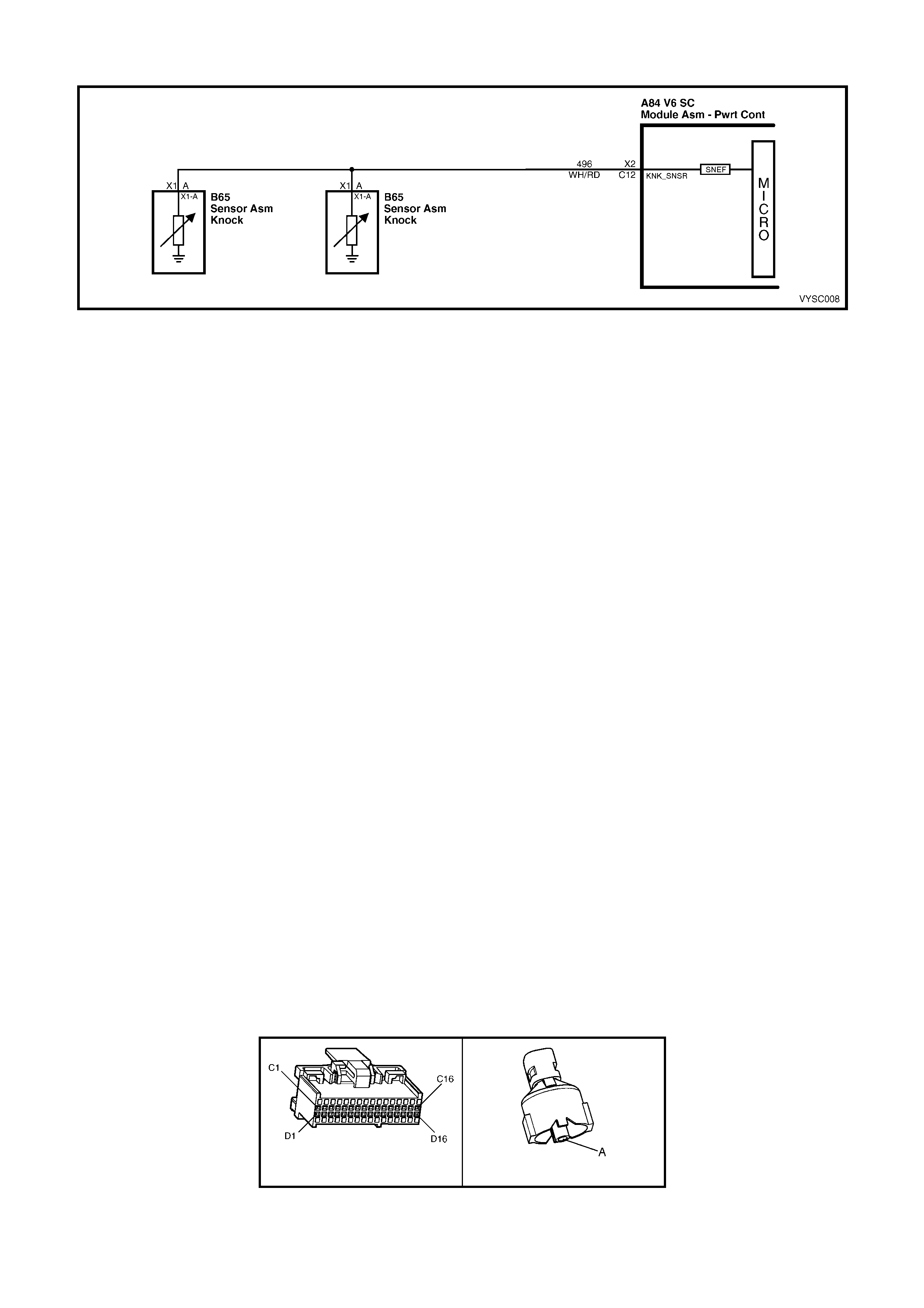
DTC 93 V6 S/C PCM – KNOCK SENSOR SYSTEM
Figure 6C2-2A-157 – Knock Sensors
CIRCUIT DESCRIPTION:
The Knock sensors are used to detect engine detonation, and the PCM will retard the Electronic Spark Timing
(EST) based on the signal being received. The Knock sensors produce an AC signal which varies in signal
amplitude and frequency depending upon the amount of Knock being experienced.
The PCM monitors the output of the SNEF (Signal To Noise Enhancement Filter) circuit. The PCM determines
weather Knock is occurring by comparing the Knock sensor signal level with the voltage level on the SNEF circuit.
The SNEF circuit allows the PCM to reject only false Knock signals by indicating the amount of normal engine
mechanical noise present. Normal engine noise varies depending on engine speed and load. A normal Knock
condition could result in a Knock sensor signal from a few milliseconds to possibly as high as 100 milliseconds in
length.
When the SNEF circuit output is significantly longer than the longest expected "Normal" output it is assumed the
SNEF circuitry has failed and DTC 93 will set.
CONDITIONS FOR RUNNING THE DTC:
• The engine has been running for more than 10 seconds.
• DTC 43 is not set.
• Engine speed is greater than 1000 RPM.
CONDITIONS FOR SETTING THE DTC:
• The PCM’s SNEF circuit indicates knocking for more than 10 seconds.
ACTION TAKEN WHEN THE DTC SETS:
• The PCM activates the Check Powertrain Malfunction Indicator Lamp (MIL) when the diagnostic runs and fails.
• When DTC 93 is set, and current, the PCM uses a default spark advance table.
CONDITIONS FOR CLEARING THE CHECK POWERTRAIN MIL/DTC:
• The PCM deactivates the Check Powertrain MIL after the first ignition cycle that the diagnostic runs and does
not fail.
• Use Tech 2 to clear the Check Powertrain MIL/DTC.
DIAGNOSTIC AIDS:
Refer to Intermittents in Section 6C2-2B SYMPTOMS.
TEST DESCRIPTION:
NOTE: Number(s) below refer to step number(s) on the diagnostic table.
2. This step checks to see if Tech 2 is displaying Knock signal at all times.
3. This step checks to see if an audible Knock is being caused by the engine or transmission.
A84 V6 S/C – X2 B65
Figure 6C2-2A-158

DTC 93 V6 S/C PCM – KNOCK SENSOR SYSTEM
STEP ACTION VALUE YES NO
1. Was the "On-Board Diagnostic" (OBD) System Check
performed? Go to Step 2. Go to
OBD
System Check
in this Section.
2. 1. Install Tech 2.
2. Ignition "ON", engine running between 1500 – 1800
RPM.
3. Using Tech 2, select "Knock Signal" and "Knock
Retard".
Is "Knock Signal" indication "Knock"?
Go to Step 3 Go to Step 4
3. With engine running, is an audible "Knock" condition
heard?
Refer to 6A1
Engine
Mechanical or
7C3 Automatic
Transmission to
repair audible
knock.
Go to Step 4
4. 1. Replace PCM. Refer to 6C2-3 SERVICE
OPERATIONS, for PCM Security Link procedure.
Is action complete?
Verify Repair –
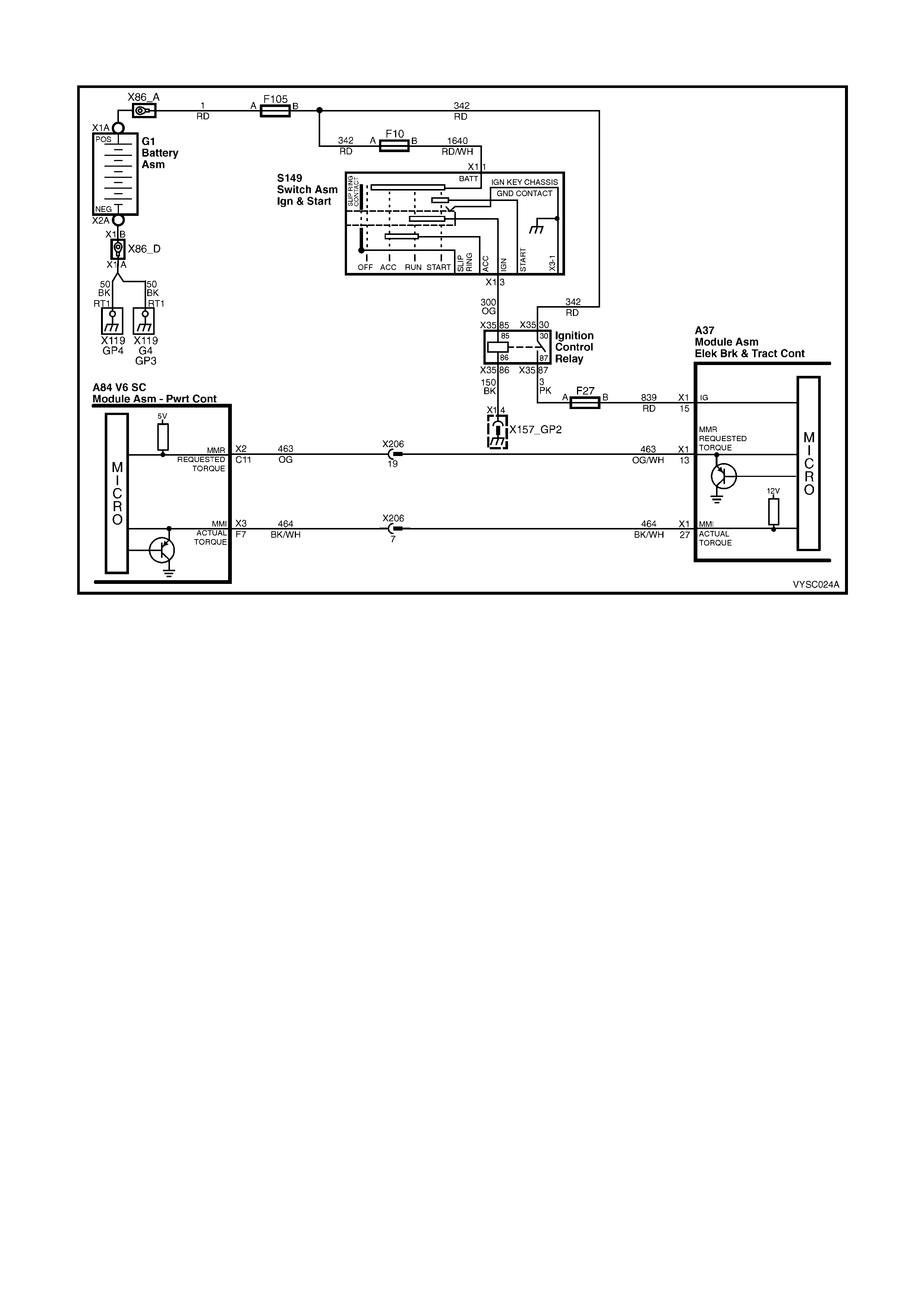
DTC 95 V6 S / C PCM - REQUESTED TORQUE OUT OF RANGE
Figure 6C2-2A-159 – Requested Torque Circuit
CIRCUIT DESCRIPTION:
The Anti-Lock Brake System/Traction Control System (ABS/TCS) Module controls the PWM signal on the torque
request circuit while monitoring the wheel speed sensors to detect slippage. The PCM monitors the PWM signal
and reduces engine torque as needed by retarding ignition timing, or in severe cases, shutting off up to five (5)
injectors. The PCM sends a PWM signal to the ABS/TCS module on the torque achieved circuit informing the
ABS/TCS module of the response made to the torque request signal. A problem with the torque request circuit
should cause DTC 95 and an ABS/TCS DTC to set and traction control to be disabled. Refer Section 5B ABS &
ABS/TCS for information on ABS/TCS operation and DTC diagnosis.
CONDITIONS FOR RUNNING THE DTC
• The engine is running.
CONDITIONS FOR SETTING THE DTC
• The PCM detects the incorrect voltage on the Requested Torque circuit.
ACTION TAKEN WHEN THE DTC SETS
• The PCM illuminates the Check Powertrain MIL when the diagnostic runs and fails.
• The PCM records the operating conditions at the time the diagnostic fails. The PCM stores this information in
the History Data.
• When DTC 95 is set, traction control will be disabled and a corresponding DTC will be set in the ABS/TCS
module.
CONDITIONS FOR CLEARING THE MIL/DTC
• The PCM turns the Chec k Powertrain MIL OF F af ter the f irs t ignition c ycle that the diagnostic runs and does not
fail.
• Use Tech 2 to clear the MIL/DTC.
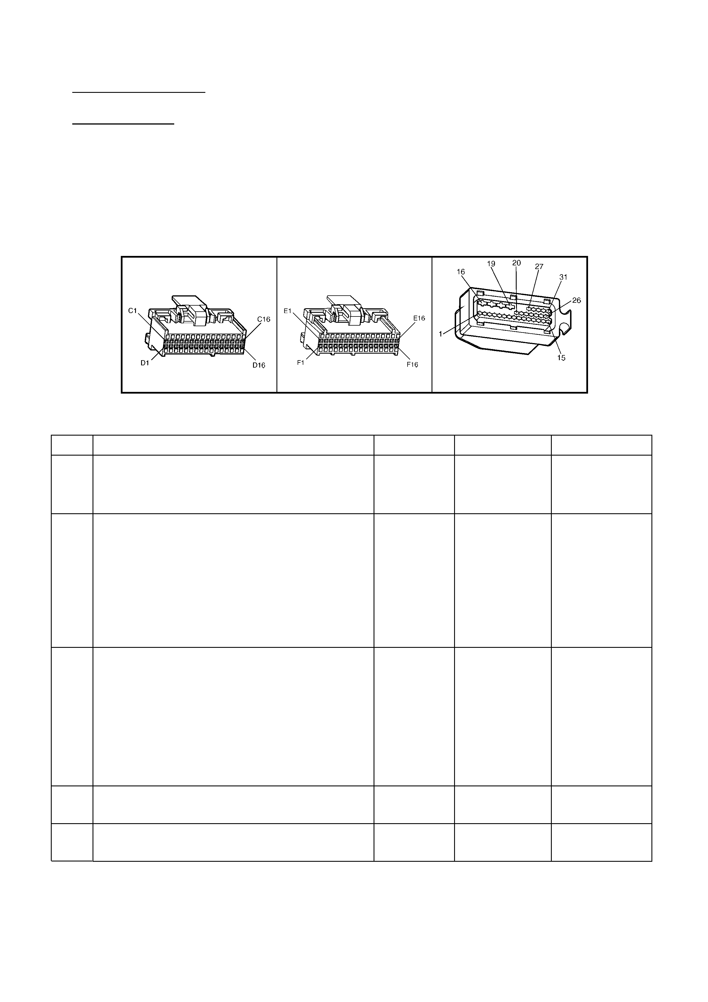
DIAGNOSTIC AIDS
Check for the following conditions:
• Poor connection at PCM. Inspec t harness connec tors for backed out ter minals , improper mating, brok en lock s,
improper formed or damaged terminals, and poor terminal to wire connection.
• Damaged harness. Inspect the wiring harness for damage. If the harness appears to be OK, disconnect the
PCM, turn the ignition ON and observe a voltmeter connected to the Torque Request circuit at the PCM
harness connector while m oving connector s and wiring harnesses related to the ABS/TCS m odule. If a voltage
is indicated the fault is in the harness.
TEST DESCRIPTION:
NOTE: Number(s) below refer to the step number(s) on the diagnostic table.
2. T he PCM supplies 4 to 5 volts on the Torque Request circuit. W ith the PCM disconnected, there should be no
voltage on the circuit.
6. This step checks to see if the Torque Request circuit is shorted to voltage.
A84 V6 S/C - X2 A84 V6 S/C - X3 A37
Figure 6C1-2A-160
DTC 95 V6 S/C PCM - REQUESTED TORQUE OUT OF RANGE
STEP ACTION VALUE YES NO
1. Was the "On-Board Diagnostic" (OBD) System
Check performed? Go to Step 2 Go to
OBD
System Check
in this Section
2. 1. Ignition "OFF".
2. Disconnect the PCM connectors.
3. Ignition "ON".
4. Using a Digital Multimeter (DMM), measure
voltage between the Torque Request circuit
463 at the PCM harness connector terminal
X2-C11 and ground.
Is voltage at the specified value?
0 V Go to Step 3 Go to Step 6
3. 1. Ignition "OFF".
2. Reconnect the PCM connectors.
3. Disconnect the ABS/TCS connector.
4. Ignition "ON".
5. Using a DMM, measure voltage between the
Torque Request circuit 463 at the ABS/TCS
harness connector terminal X1-13 and ground.
Is voltage at the specified value?
4-5 V Go to Step 4 Go to Step 8
4. Check for poor connection at ABS/TCS module.
Was a problem found? Verify Repair Go to Step 5
5. Replace ABS/TCS module.
Is action complete? Verify Repair

STEP ACTION VALUE YES NO
6. 1. Ignition "OFF".
2. Disconnect the ABS/TCS module connector.
3. Ignition "ON".
4. Using a DMM, measure voltage between the
Torque Request circuit at the PCM harness
connector and ground.
Is voltage at the specified value?
0 V Go to Step 5 Go to Step 7
7. Locate and repair short to voltage in Torque
Request circuit.
Is action complete?
Verify Repair
8. Check f or an open or s hort to gr ound in the Torque
Request circuit between the PCM and the
ABS/TCS module.
Was a problem found?
Verify Repair Go to Step 9
9. Check for poor connection at PCM harness
connectors.
Was a problem found?
Verify Repair Go to Step 10
10. Replace PCM.
Refer 6C1-3 Service Operations, for PCM
Programming and Security Link procedure.
Is action complete?
Verify Repair
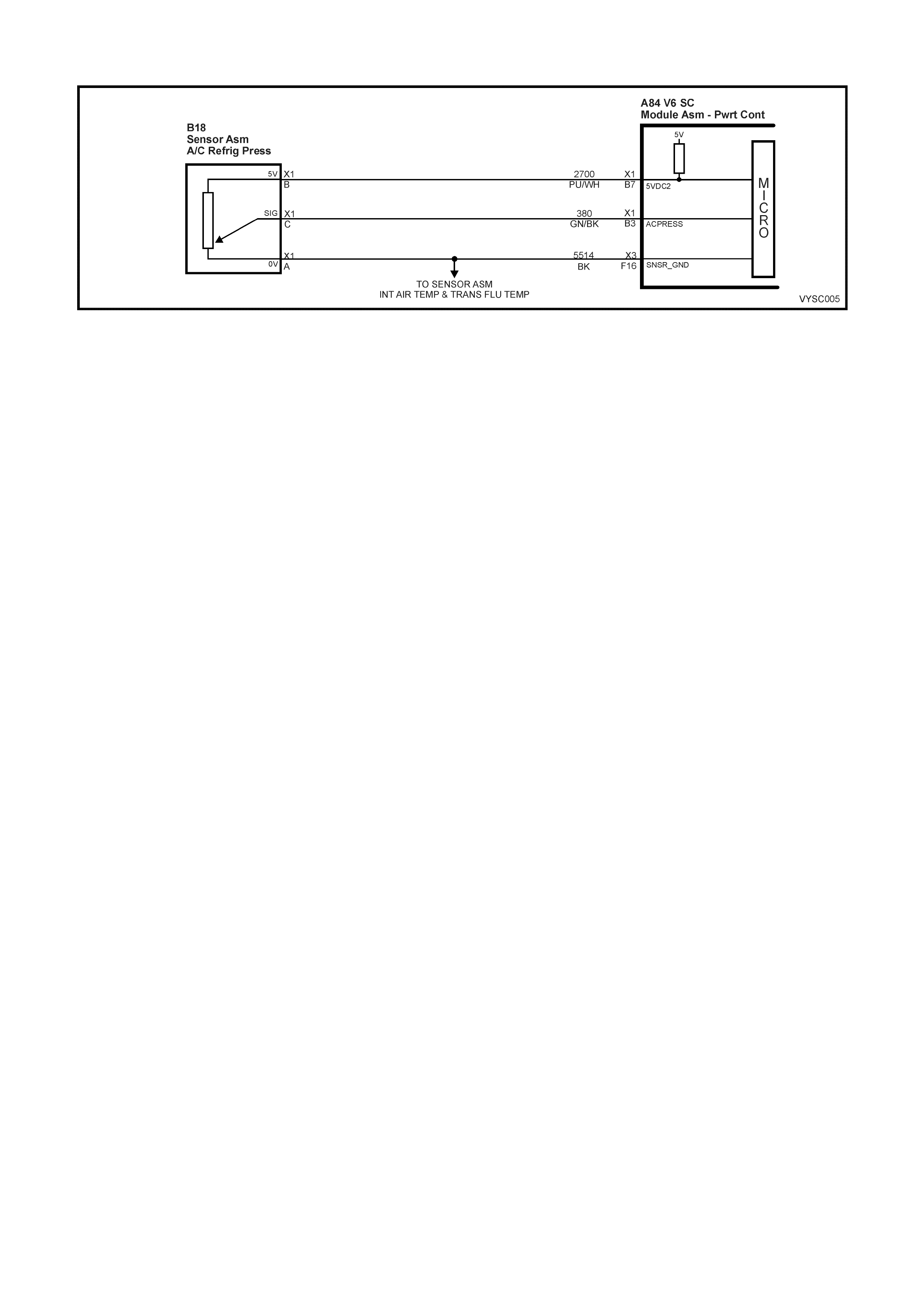
DTC 96 V6 S/C PCM – A/C REFRIGERANT PRESSURE SENSOR CIRCUIT FAULT
Figure 6C2-2A-161 – A/C Pressure Sensor
CIRCUIT DESCRIPTION:
The A/C Refrigerant Pressure Sensor responds to changes in the A/C refrigerant high side pressure. This input to
the PCM indicates how much load the A/C compressor is putting on the engine and is one of the factors used by the
PCM to determine the Idle Air Control (IAC) valve position for idle speed. The circuits consist of a 5 Volt reference
and a ground circuit, both provided by the PCM, and a signal circuit from the Sensor to the PCM. The signal is a
voltage which is proportional to A/C pressure. The sensor’s operating range is between 0 and 3,160 kPa. At 0 kPa,
the signal voltage will be about 0.1 volts, varying to about 4.9 volts at 3,160 kPa.
CONDITIONS FOR RUNNING THE DTC:
• Engine Coolant Temperature is below 119° C.
• Intake Air Temperature is below 90° C.
• Engine RPM is below 2000.
• Engine has been running for more than 10 seconds.
CONDITIONS FOR SETTING THE DTC:
• A/C Refrigerant Pressure Sensor signal voltage is greater than 4.9 volts, or less than 0.2 volts.
ACTION TAKEN WHEN THE DTC SETS:
• The PCM stores the DTC information into memory when the diagnostic runs and fails.
• The Check Powertrain Malfunction Indicator Lamp (MIL) icon will not be activated.
• The PCM records the operating conditions at the time the diagnostic fails. The PCM stores this information in
the History Data.
• When DTC 96 is set, the low speed cooling fan will operate for 5 seconds, then the high speed fan will turn
“ON” and remain "ON" until the fault is removed.
CONDITIONS FOR CLEARING THE CHECK POWERTRAIN MIL/DTC:
• Use Tech 2 to clear the Check Powertrain MIL/DTC.
DIAGNOSTIC AIDS:
• DTC 96 will only set with a short to voltage or an open circuit. A short to ground will not set the DTC, but the A/C
system will be inoperative.
• DTC 96 sets when the signal voltage falls outside the normal possible range of the sensor. Repair any A/C
pressure problems before using this table.
• Any circuitry, that is suspected as causing the intermittent complaint, should be thoroughly check for backed out
terminals, improper mating, broken locks, improperly formed or damaged terminals, poor terminal to wiring
connections or physical damage to the wiring harness.
TEST DESCRIPTION:
NOTE: Number(s) below refer to step number(s) on the diagnostic table.
3. This step checks if the A/C pressure sensor signal circuit 380 is shorted to voltage.
4. Jumping the sensor signal circuit to ground checks if the signal circuit is OK. If the signal circuit is OK the
voltage displayed on Tech 2 will be less than 0.2 volts.
5. Jumping the sensor signal circuit to the sensor ground circuit checks if the signal ground circuit is OK. If the
signal ground circuit is OK the voltage displayed on Tech 2 will be less than 0.2 volts.
6. This test step checks the 5 volt reference circuit 2700. An open in a shared 5 volt reference circuit can cause
other DTC's to be set. If no other DTC's were set, the circuit must have an open between the sensor and the
circuits wiring harness splice.
7. This test step check if circuits 2700 and 380 are shorted together.

A84 V6 S/C – X1 A84 V6 S/C – X3 B18
Figure 6C2–2A-162
DTC 96 V6 S/C PCM - A/C REFRIGERANT PRESSURE SENSOR CIRCUIT FAULT
STEP ACTION VALUE YES NO
1. 1. Was the "On-Board Diagnostic" (OBD) System
Check performed? Go to Step 2 Go to
OBD
System Check
2. 1. Ignition ON, engine OFF.
2. Install Tech 2, and display A/C pressure sensor
voltage.
Is the A/C pressure sensor voltage at or above the
specified value?
4.0 V Go to Step 3 Go to Step 9
3. 1. Disconnect A/C pressure sensor electrical
connector.
2. Using a Digital Multimeter (DMM) check the voltage
at terminal X1-C circuit 380 of harness connector
B18.
Is voltage greater than specified value?
5.0 V Go to Step 12 Go to Step 4
4. 1. With A/C pressure sensor electrical connector B18
disconnected.
2. Using fused jumper wire, jumper the A/C pressure
sensor signal circuit 380 of harness connector B18
terminal X1-C to a known good ground.
Does Tech 2 indicate A/C pressure sensor voltage at or
below the specified value?
0.2 V Go to Step 5 Go to Step 11
5. 1. With A/C pressure sensor electrical connector
disconnected.
2. Using fused jumper wire, jumper circuit 380, A/C
pressure sensor signal terminal X1-C to circuit
2753 sensor ground terminal X1-A of harness
connector B18.
Does Tech 2 indicate A/C pressure sensor voltage at or
below the specified value?
0.2 V Go to Step 6 Go to Step 13
6. 1. With A/C pressure sensor electrical connector
disconnected.
2. Using a DMM measure voltage on circuit 2700 at
terminal X1-B of harness connector B18.
Is the voltage at specified value?
5.0 V Go to Step 7 Go to Step 14
7. 1. With A/C pressure sensor electrical connector
disconnected.
2. Disconnect all PCM connectors.
3. Using a DMM check for continuity between circuit
2700 and 380.
Is there continuity?
Go to Step 15 Go to Step 8
8. 1. Replace A/C pressure sensor.
Is action complete? Verify Repair –
9. Is the A/C pressure sensor voltage at or below the
specified value? 0.2 V Go to Step 10 Go to Step 6
10. 1. Check for short to ground in A/C pressure sensor
signal circuit 380.
Was a problem found?
Verify Repair Go to Step 16
11. 1. Check for open or poor terminal retention in A/C
pressure sensor signal circuit 380.
Was a problem found?
Verify Repair Go to Step 16
12. 1. Check A/C pressure sensor signal circuit 380 for
short to voltage.
Was a problem found?
Verify Repair Go to Step 16

STEP ACTION VALUE YES NO
13. 1. Check for open or poor terminal retention in ground
circuit 2753 to A/C pressure sensor.
Was a problem found?
Verify Repair Go to Step 16
14. 1. Check for open, poor terminal retention, short to
ground or short to voltage in 5 volt reference circuit
2700.
Is action complete?
Verify Repair Go to Step 16
15. 1. Repair short between circuits 380 and 2700.
Is action complete? Verify Repair –
16. 1. Replace PCM. Refer 6C2-3 Service Operations, for
PCM Programming and Security Link procedure.
Is action complete?
Verify Repair –

DTC 97 V6 S / C PCM – CANISTER P URGE SOLENOID CONTROL CIRCUIT
Figure 6C2-2A-163 – Evaporative Canister Purge
CIRCUIT DESCRIPTION:
Quad Driver Sur face Modules (QDSMs ) are used by the PCM to turn "ON" many of the current- driven devices that
are needed to control various engine and transmission functions. Each QDSM is capable of controlling up to 4
separate outputs by applying ground to the device which the PCM is commanding "ON".
The Q uad Driver Surface Modules (QDSMs) used have the c apability of diagnosing each output circuit individually.
If DTC 97 is set, this indicates an im proper voltage level has been detected on the QDSM fault line which controls
the Canister Purge Solenoid.
CONDITIONS FOR RUNNING THE DTC:
• The ignition is “ON”.
CONDITIONS FOR SETTING THE DTC:
• The PCM detects an incorrect voltage on the EVAP canister purge solenoid driver circuit for 5 seconds.
ACTION TAKEN WHEN THE DTC SETS:
• The PCM activates the Check Powertrain Malfunction Indicator Lamp (MIL) when the diagnostic runs and fails.
• The PCM records the operating conditions at the time the diagnostic fails. The PCM stores this information in
the History Data.
CONDITIONS FOR CLEARING THE CHECK POWERTRAIN MIL/DTC:
• The PCM deactivates the Check Powertrain MIL after the first ignition cycle that the diagnostic runs and does
not fail.
• Use Tech 2 to clear the Check Powertrain MIL/DTC.
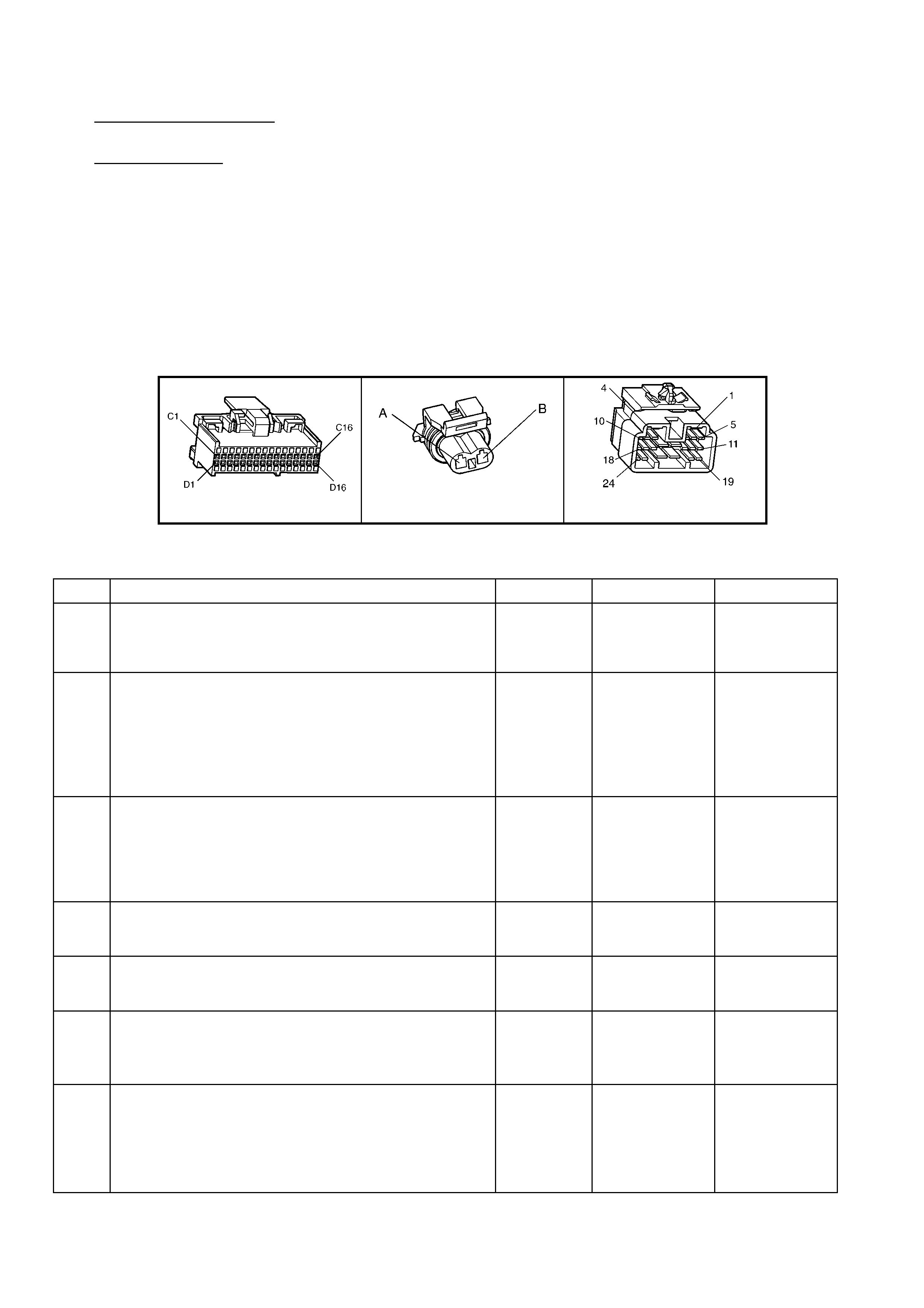
DIAGNOSTIC AIDS:
Check for the following conditions:
• Poor connection at PCM. Inspect harness connections for backed out terminals, improper mating , broken
locks, improperly formed or damaged terminals, and poor terminal to wire connection.
• Damaged harness. Inspect the wiring harness for damage. If the harness appears to be OK, disconnect the
PCM, turn the ignition "ON" and observe a voltm eter connected to the Canis ter Purge Solenoid driver circ uit at
the PCM harness connector while moving connectors and wiring harness related to the Canister Purge
Solenoid. A change in voltage will indicate the location of the fault.
If DT C 97 c annot be duplic ated, the inf ormation inc luded in the DT C His tor y can be useful in determining how m any
ignition cycles have passed since the DTC was last set.
TEST DESCRIPTION:
NOTE: Number(s) below refer to step number(s) on the diagnostic table.
2. Normally, ignition feed voltage should be pres ent on the output driver cir cuit with the PCM disconnected and the
ignition "ON".
9. If the solenoid connectors are OK then the solenoid should be replaced.
A84 V6 S/C – X2 Y123 X206
Figure 6C2-2A-164
DTC 97 V6 S/C PCM – CANISTER PURGE SOLENOID CONTROL CIRCUIT FAULT
STEP ACTION VALUE YES NO
1. Was the "On-Board Diagnostic" (OBD) System Check
performed? Go to Step 2 Go to
OBD
System Check
in this Section.
2. 1. Ignition "OFF", disconnect the PCM wiring harness
connectors.
2. Ignition "ON".
3. Using a Digital Multi-Meter (DMM), measure voltage
between the Canister Purge Solenoid driver circuit at
the PCM harness connector A84 X2-C4 and ground.
Is voltage near the specified value?
B+ Go to Step 3 Go to Step 5
3. 1. Disconnect the Canister Purge Solenoid harness
connector Y123.
2. Using DMM set to DC volts, measure voltage between
the Canister Purge Solenoid driver circuit Y123 X1-B
and ground.
Is voltage at specified value?
0 volts Go to Step 10 Go to Step 4
4. 1. Locate and repair short to voltage in the Canister
Purge Solenoid driver circuit Y123 X1-B.
Is action complete?
Verify Repair –
5. 1. Check the ignition feed fuse F33 for the Canister
Purge Solenoid Y123.
Is the fuse blown?
Go to Step 6 Go to Step 7
6. 1. Locate and repair short to ground in ignition feed
circuit for the Canister Purge Solenoid, fuse F33.
2. Replace fuse.
Is action complete?
Verify Repair –
7. 1. Disconnect the Canister Purge Solenoid harness
connector Y123.
2. Ignition "ON".
3. Measure voltage between the ignition feed circuit at
harness connector Y123, terminal X1-A and ground.
Is voltage near the specified value?
B+ Go to Step 8 Go to Step 12

STEP ACTION VALUE YES NO
8. 1. Check the Canister Purge Solenoid driver circuit 428
for an open or a short to ground.
Was a problem found?
Verify Repair Go to Step 9
9. 1. Check the Canister Purge Solenoid driver circuit and
the ignition feed circuit for a poor connection at the
Canister Purge Solenoid, connector Y123 and the
PCM A84 X2-C4.
Was a problem found?
Verify Repair Go to Step 14
10. 1. Ignition "OFF", reconnect the PCM and disconnect the
Canister Purge Solenoid harness connector Y123.
2. Ignition "ON, connect a test light between the Canister
Purge Solenoid driver circuit and the ignition feed
circuit at the Canister Purge Solenoid connector
Y123.
3. With Tech 2 installed, select, “Canister Purge”.
4. Cycle the Purge Solenoid "ON" and "OFF".
Does the test light flash "ON" and "OFF"?
Go to Step 9 Go to Step 11
11. 1. Check the Canister Purge Solenoid driver for a poor
connection at the PCM, connector A84 X2-C4.
Was a problem found?
Verify Repair Go to Step 13
12. 1. Locate and repair open ignition feed circuit to the
Canister Purge Solenoid.
Is action complete?
Verify Repair –
13. 1. Replace PCM. Refer to 6C2-3 SERVICE
OPERATIONS, for PCM Security Link procedure.
Is action complete?
Verify Repair –
14. 1. Replace Canister Purge Solenoid. Refer to 6C2-3
SERVICE OPERATIONS.
Is action complete?
Verify Repair –