
SECTION 6C2-2C - FUNCTIONAL CHECKS –
V6 SUPERCHARGED ENGINE
IMPORTANT
Before p erf orming any Service O p eratio n o r ot her p roced ure describ ed in t his Sect ion , refer t o Sect ion 00
CAUTIONS AND NOTES for correct workshop practices with regard to safety and/or property damage.
The following pages are to be used when there is a customer complaint but there are no diagnostic trouble codes
set, but one or more of the T ech 2 data values are not within typical ranges. Before using these tables you should
refer to Section 6C2-2B SYMPTOMS.
The purpose of these tables is to diagnose Powertrain Control Module (PCM) controlled components or sub-
systems that do not have diagnostic trouble codes assigned to them. Another purpose of these Tables is for
technicians who feel confident that a particular part of the sub-system is not operating properly and want to only
check that particular item for proper operation without going through lengthy diagnostic procedures.
CONTENTS
1. 4L60-E COMPONENT RESISTANCE TABLE
2. FUNCTIONAL CHECK TABLES
2.1 V6 PCM – AUTOMATIC TRANSMISSION WIRING HARNESS CHECK
2.2 V6 PCM – TRANSMISSION FLUID PRESSURE MANUAL VALVE POSITION SWITCH CHECK
2.3 V6 PCM – 1-2 SHIFT SOLENOID ‘A’ PERFORMANCE CHECK
2.4 V6 PCM – 2-3 SHIFT SOLENOID ‘B’ PERFORMANCE CHECK
2.5 V6 PCM – TRANSMISSION POWER/ECONOMY SWITCH
2.6 V6 PCM – S/C ENGINE BOOST CONTROL SYSTEM FUNCTIONAL CHECK
2.7 V6 PCM – INSTRUMENT PANEL GEAR INDICATOR CHECK
2.8 V6 PCM – FUEL INJECTOR BALANCE TEST
2.9 V6 PCM – FUEL INJECTOR COIL TEST – ECT BETWEEN 10 – 35°
°°
° C
2.10 V6 PCM – FUEL INJECTOR COIL TEST – ECT OUTSIDE 10 – 35°
°°
° C
2.11 V6 PCM – FUEL INJECTOR CIRCUIT DIAGNOSIS
1. 4L60 E COMPONENT RESISTANCE TABLE
COMPONENT TERMINAL WIRE COLOUR
PASS-THRU
CONNECTOR
TERMINAL
RESISTANCE AT
20 DEGREES C CIRCUIT
NO.
B PK/BU E, 339
1-2 SHIFT SOLENOI D
VALVE ‘A’ A L-GN A
19 – 24 OHMS 1222
A PK/BU E, 339
2-3 SHIFT SOLENOI D
VALVE ‘B’ B YE/BK B
19 – 24 OHMS 1223
A PK/BU E, 339
3-2 CONTROL
SOLENOID VALVE B GN/WH S 20 – 24 OHMS 898
A RD C 1228
PRESS URE CONTROL
SOLENOID VALVE B GY/BU D 3 – 5 OHMS 1229
A BK/YE L 1227
TRANSMISSION FLUID
TEMPERATURE SENSOR (TFT) B BK M
3088 – 3942 OHMS 2753
A PK/BU E, 339
TCC "PWM" SOLENOID
VALVE B BN U
9 – 11 OHMS 418
A PK/BU E, 339
TCC ENABLE
SOLENOID VALVE B GY/RD T
21 – 26 OHMS 422
,
,,
,
Spliced internally to pin E
2. FUNCTIO NAL CHECK TABLES
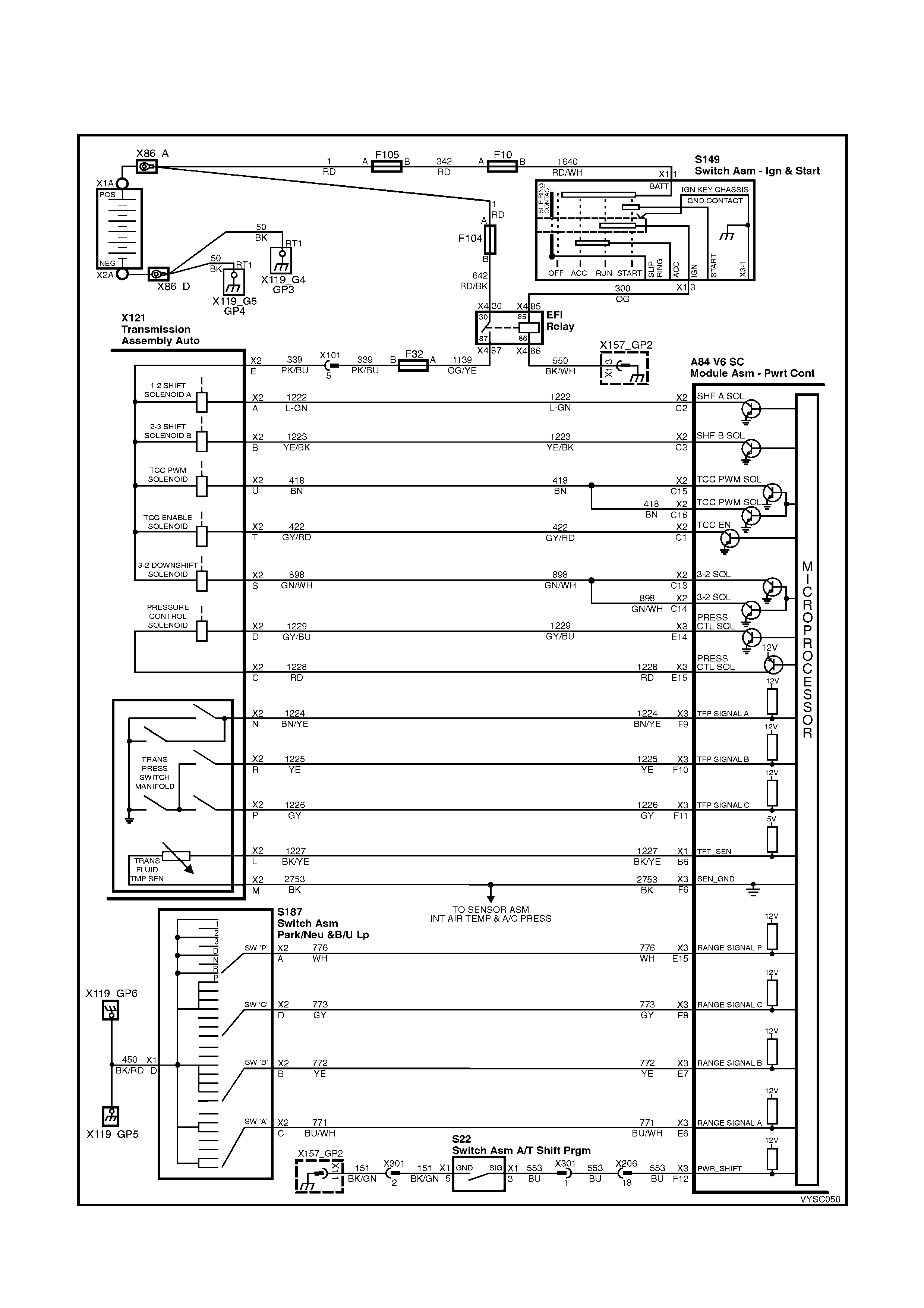
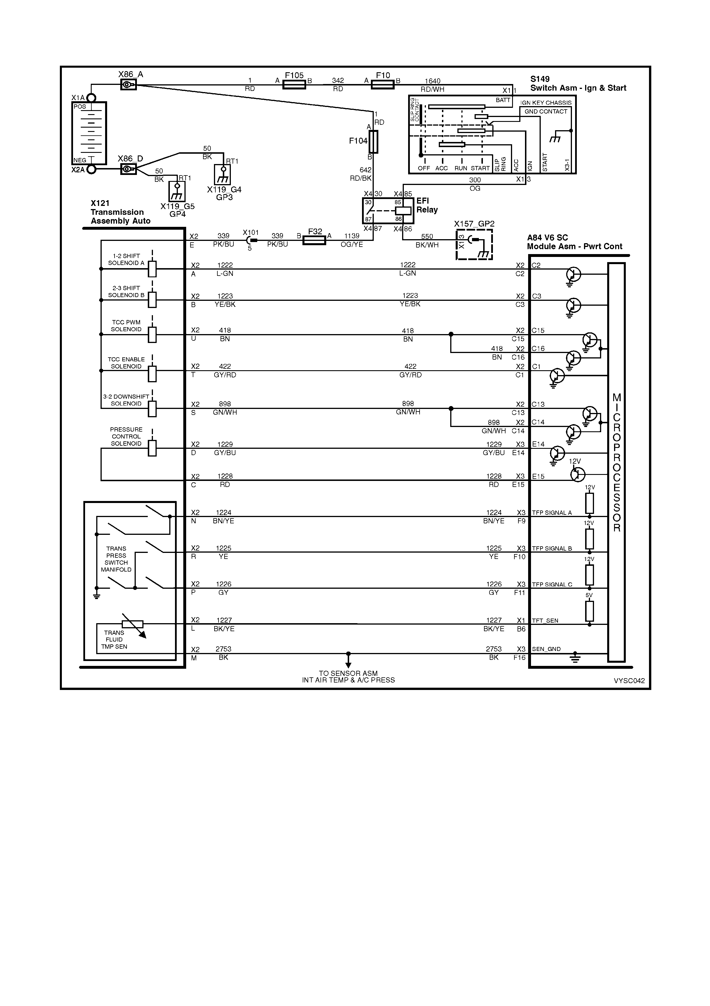
2.1 V6 PCM – AUTOMATIC TRANSMISSION WIRING HARNESS CHECK
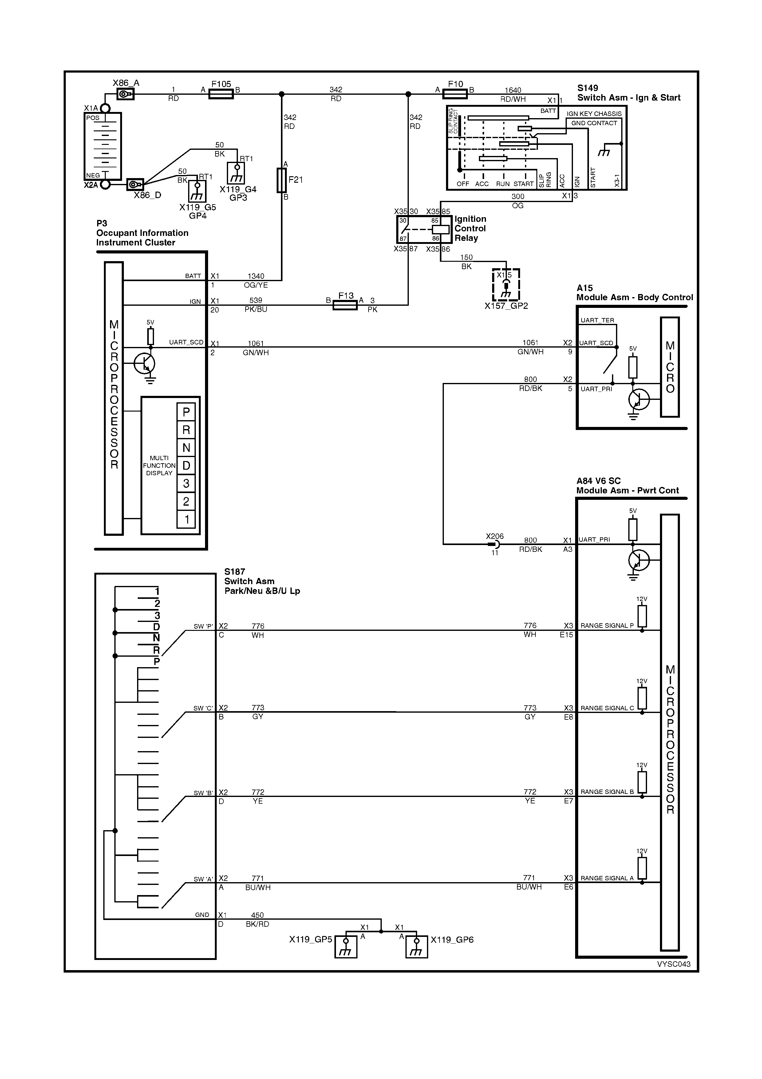
Figure 6C2-2C-1 – Automatic Transmission Circuits
TOOLS REQUIRED:
J 39775 4L60-E Jumper Harness
J 35616-A Connector Test Adapter Kit
Digital Multimeter (DMM)
IMPORTANT: This procedure cannot be used for checking the Automatic Transmission Fluid Pressure Manual
Valve Position Switch (T FP Man. Val. Pos ition Sw.) circuit, or the Autom atic T rans m ission Fluid T em peratur e (T FT )
Sensor circuit. Refer to TFP Manual Valve Position Switch Assembly Resistance Check, for those circuits.
POWERTRAIN HARNESS TERMINAL IDENTIFICATION
CAVITY FUNCTION
A 1-2 SHIFT SOLENOID ‘A’ (LOW)
B 2-3 SHIFT SOLENOID ‘B’ (LOW)
C PRESSURE CONTROL SOLENOID (HIGH)
D PRESSURE CONTROL S OLENOID (LOW)
E BOTH SHIFT SOLENOIDS , TCC SOLENOID, TCC PWM SOLENOID & 3-2 CONTROL SOLENOID (HIGH)
L TRANSMISSION FLUID TEMPERATURE HIGH
M TRANSMISSION FLUID TEMPERATURE (LOW)
N RANGE SIGNAL " A"
P RANGE SIGNAL "C"
R RANGE SIGNAL " B"
S 3-2 CONTROL SOLENOID (LOW)
T TCC SOLENOID (LOW)
U TCC PWM SOLENOID
Table 1
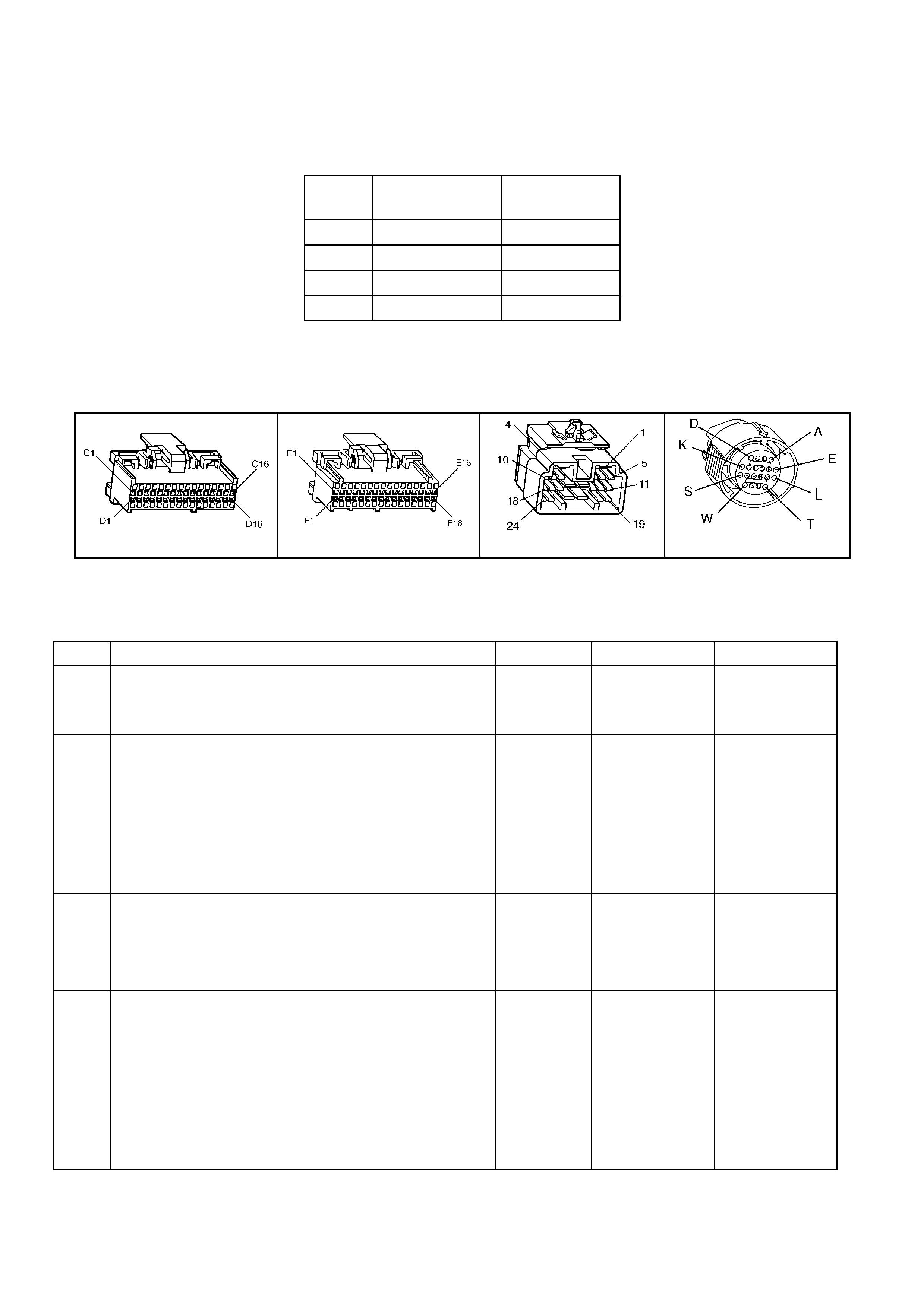
a84 V6 S/C – x1 a84 V6 S/C – x2 a84 V6 S/C – x3
x206 x121 – x2
Figure 6C2-2C-2

V6 PCM – AUTOMATIC TRANSMISSION WIRING HARNESS ASSEMBLY CHECK
STEP ACTION VALUE YES NO
1. 1. Install the J 39775 Jumper Harness on the
transmission pass-thru connector.
2. Using a DMM and a J 35616-A Connector Test
Adapter Kit, measure the resistance between
terminals ‘A’ and ‘E’ (1-2 Shift Solenoid Valve).
Is the resistance within the specified range?
19 – 24 Ω
@ 20° C
24 – 31Ω @
100° C
Go to Step 3 Go to Step 2
2. 1. Disconnect the 1-2 Shift Solenoid Valve (1-2 SS
Valve) from the Automatic Transmission Wiring
Harness Assembly.
2. Using the DMM, measure the resistance of the 1-2
Shift Solenoid Valve.
Is the resistance within the specified range?
19-24 Ω @
20° C
24-31Ω @
100° C
Go to Step 14 Go to Step 16
3. 1. Measure the resistance between terminals B and E
(2-3 Shift Solenoid Valve).
Is the resistance within the specified range?
19 – 24 Ω
@ 20° C
24 – 31Ω @
100° C
Go to Step 5 Go to Step 4
4. 1. Disconnect the 2-3 Shift Solenoid Valve (2-3 SS
Valve) from the Automatic Transmission Wiring
Harness Assembly.
2. Using the DMM, measure the resistance of the 2-3 SS
Valve.
Is the resistance within the specified range?
19 – 24 Ω
@ 20° C
24 – 31Ω @
100° C
Go to Step 14 Go to Step 16
5. 1. Measure the resistance between terminals T and E
(Torque Converter Clutch Solenoid Valve).
Is the resistance within the specified range?
21 – 26 Ω
@ 20° C
26 – 33 Ω
100° C
Go to Step 6 Go to Step 14
6. 1. Measure the resistance between terminals U and E
(Torque Converter Clutch Pulse Width Modulation
Solenoid Valve).
Is the resistance within the specified range?
9 – 14 Ω @
20° C
13 – 15 Ω
@ 100° C
Go to Step 8 Go to Step 7
7. 1. Disconnect the TCC PWM Solenoid Valve from the
Automatic Transmission Wiring Harness Assembly.
2. Using the DMM, measure the resistance of the TCC
PWM Solenoid Valve.
Is the resistance within the specified range?
9 – 14 Ω @
20° C
13 – 15 Ω
@ 100° C
Go to Step 14 Go to Step 16
8. 1. Measure the resistance between terminals S and E
(3-2 Shift Solenoid Valve assembly).
Is the resistance within the specified range?
20 – 24 Ω
@ 20° C
29 – 32 Ω
@ 100° C
Go to Step 10 Go to Step 9
9. 1. Disconnect the 3–2 Shift Solenoid Valve Assembly
from the Automatic Transmission Wiring Harness
Assembly.
2. Using the DMM, measure the resistance of the 3-2
Shift Solenoid Valve Assy.
Is the resistance within the specified range?
20 – 24 Ω
@ 20° C
29 – 32 Ω
@ 100° C
Go to Step 14 Go to Step 16
10. 1. Measure the resistance between terminals C and D
(Pressure Control Solenoid Valve).
Is the resistance within the specified range?
3 – 5 Ω @
20° C
4 – 7 Ω @
100° C
Go to Step 12 Go to Step 11
11. 1. Disconnect the Pressure Control Solenoid Valve from
the Automatic Transmission Wiring Harness
Assembly.
2. Using a DMM, measure the resistance of the Pressure
Control Solenoid Valve.
Is the resistance within the specified range?
3 – 5 Ω @
20° C
4 – 7 Ω @
100° C
Go to Step 14 Go to Step 16
12. 1. Using a DMM and the J 35616-A Connector Test
Adapter Kit, measure the resistance from each of the
terminals A, B, C, D, E, S, T and U of the A/T Wiring
Harness Assembly at the transmission pass-thru
connector to the transmission case.
Is the resistance more than the specified value?
250 kΩ System OK. Go to Step 13

STEP ACTION VALUE YES NO
13. 1. Disconnect the A/T Wiring Harness Assembly from all
the components.
2. Measure the resistance from each of the component
terminals to the transmission case.
Is the resistance more than the specified value?
250 kΩ Go to Step 14 Go to Step 16
14. 1. Inspect for high resistance or a short.
2. Inspect the A/T Wiring Harness Assembly at the
transmission pass-thru connector, and the component
connectors for the following conditions:
• Poor electrical connections
• Bent, backed-out, or damaged terminals
• Weak terminal tension
• A chafed wire that could short to bare metal or
other wiring
• A broken wire inside the insulation
• Moisture intrusion
• Corrosion
If diagnosing for a possible intermittent condition,
move or wriggle the A/T Wi ring Harness Assembly
while observing the test equipment for a change.
Did you find and correct the high resistance or a short?
Verify the repair. Go to Step 15
15. 1. Replace the Automatic Transmission Wiring Harness
Assembly. Refer to 7C4 AUTOMATIC
TRANSMISSION – ON-VEHICLE SERVICING.
Is the action complete?
Verify the repair. –
16. 1. Replace the faulty component. Refer 6C3-3 SERVICE
OPERATIONS.
Is the action complete?
Verify the repair. –
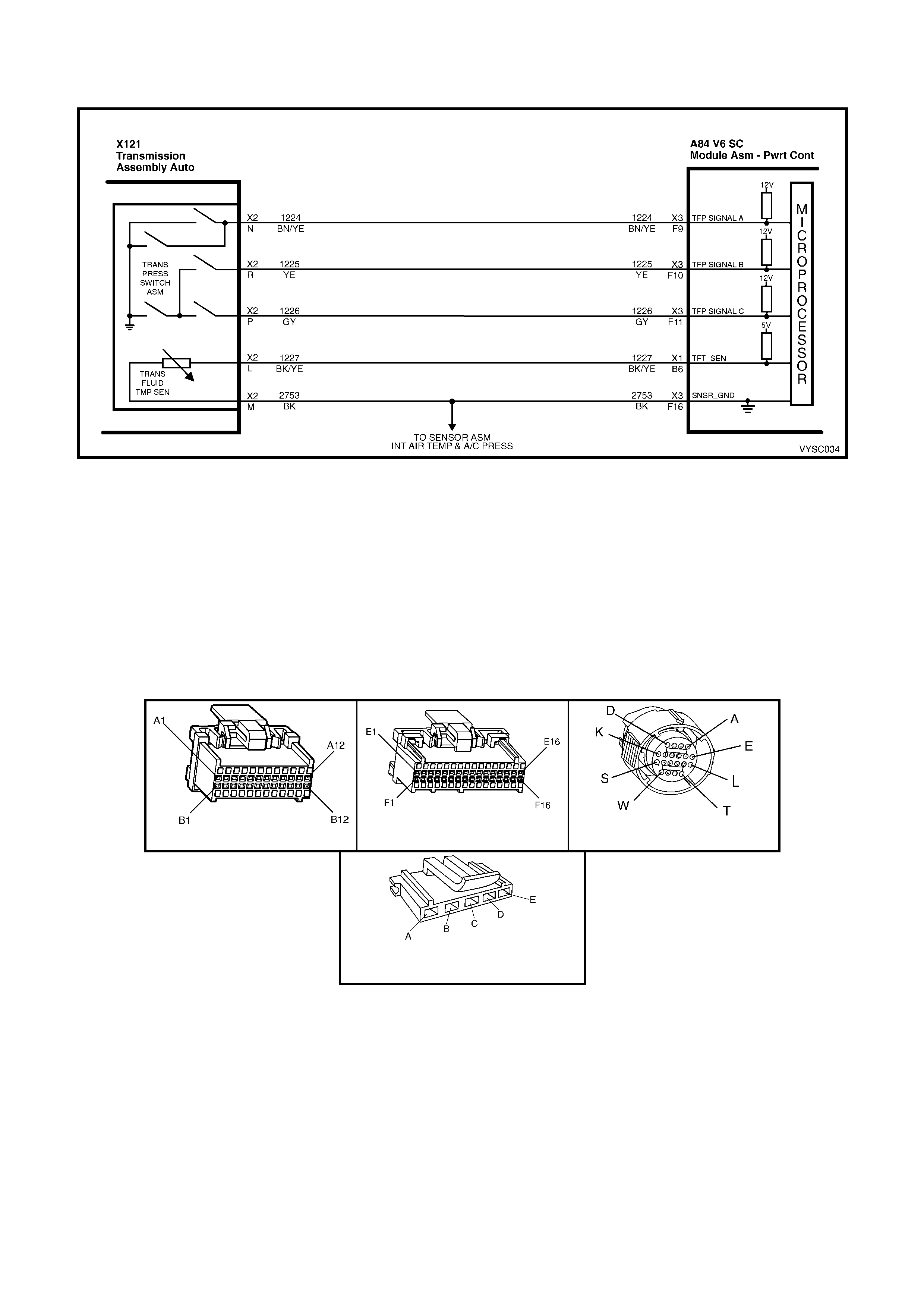
2.2 V6 PCM – TRANSMISSION FLUID PRESSURE MANUAL VALVE
POSITION SWITCH CHECK
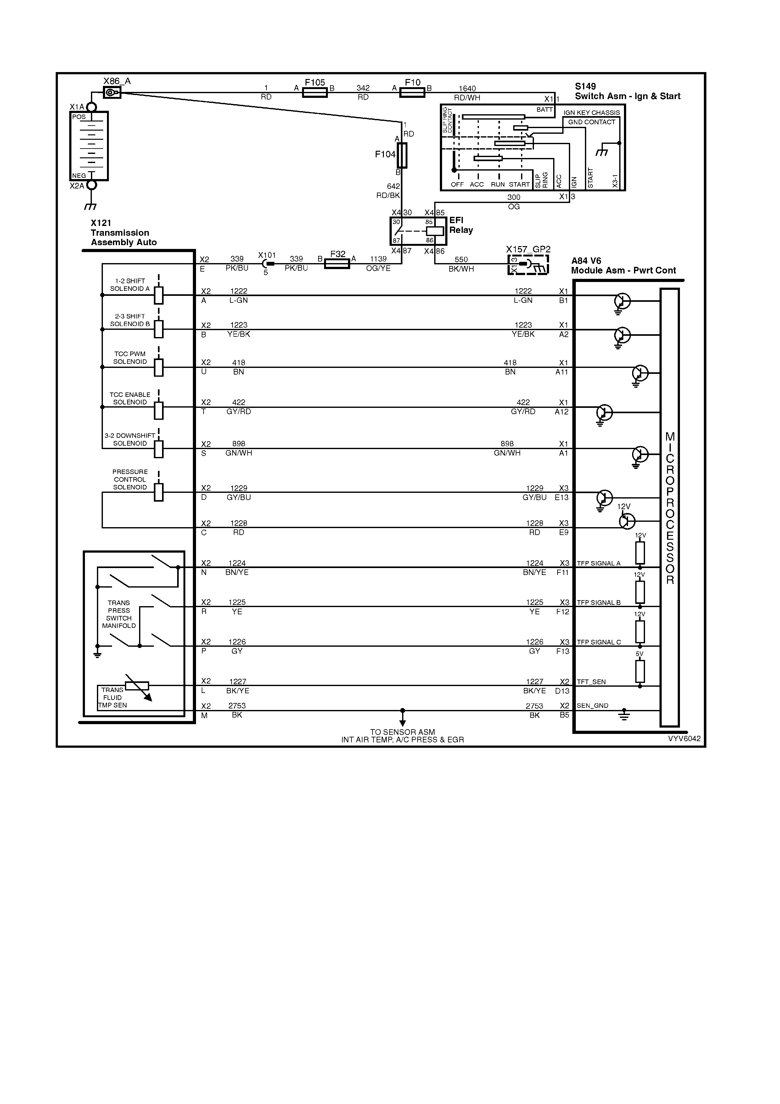
Figure 6C2-2C-3 – Automatic Transmission Fluid Pressure Manual Valve Position Switch
TOOLS REQUIRED:
J 39775 4L60-E Jumper Harness
J 35616-A Connector Test Adapter Kit
Digital Multimeter (DMM)
IMPORTANT: W henever the transmission pass-thru connector is disconnected and the engine is running, multiple
DTCs will set. Be sure to clear these codes when you are finished with this procedure.
NOTE: This procedure tests the Transmission Fluid Pressure Manual Valve Position Switch (TFP Man. Val.
Position Sw.) circuits and the Transmission Fluid Temperature (TFT) Sensor circuit. Do not use this procedure to
test other Automatic Transmission circuits, refer to Table 2.1 V6 PCM – Automatic Transmission Internal Wiring
Harness check.
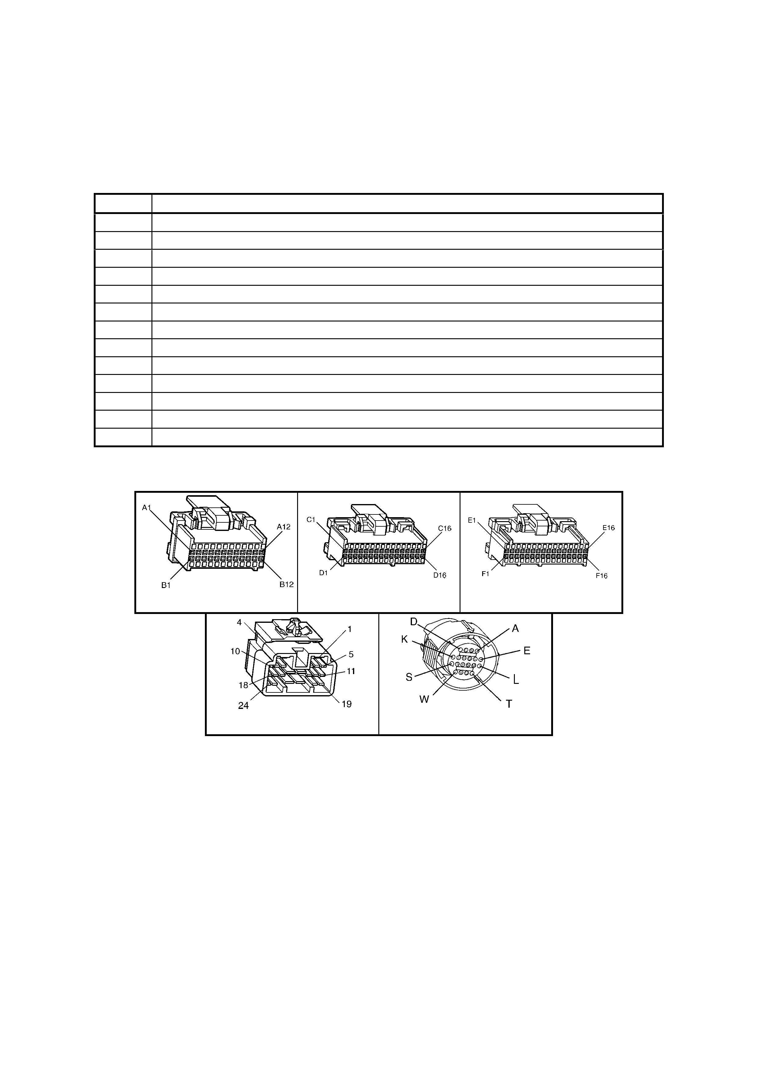
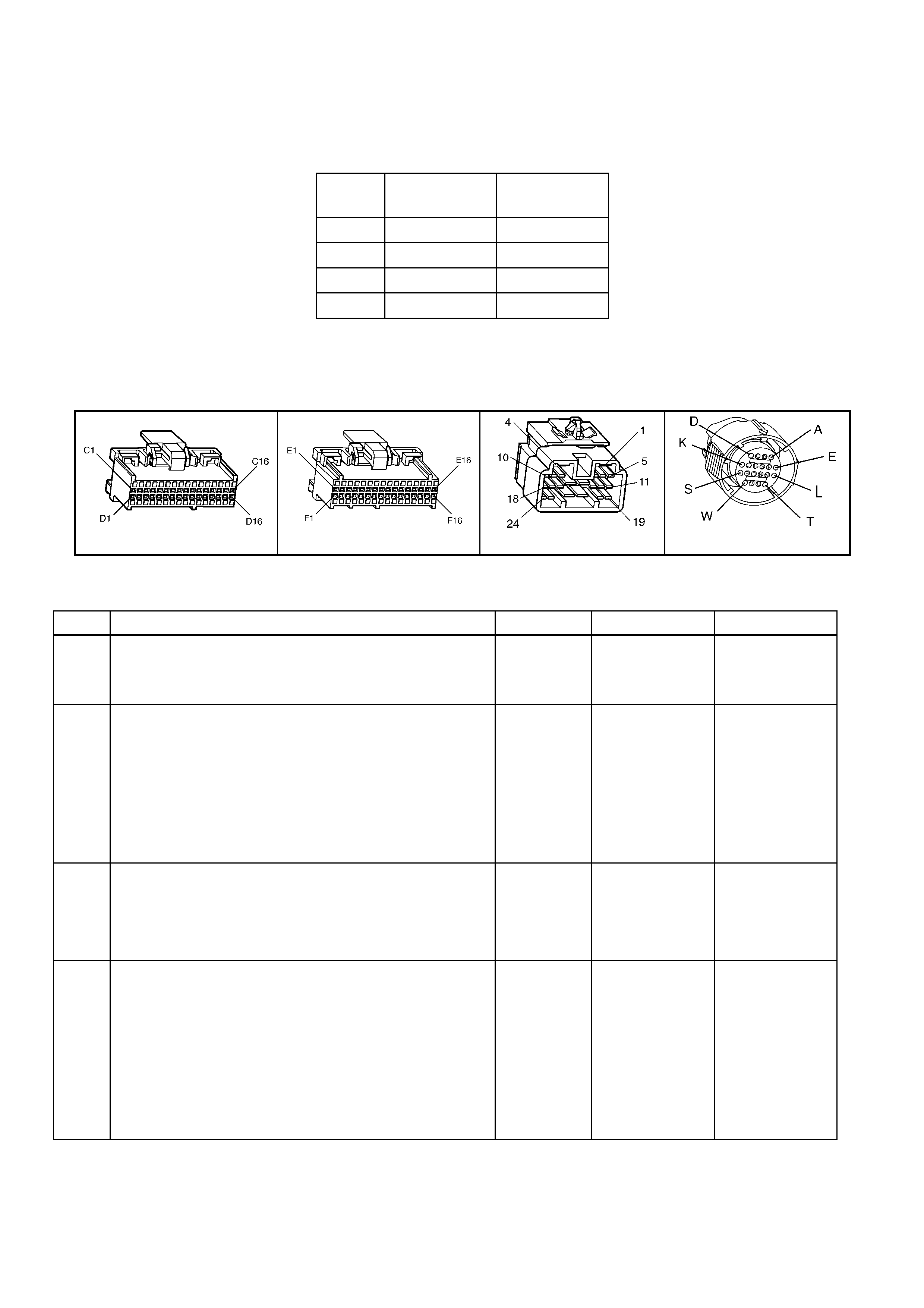
A84 V6 S/C – x1 A84 V6 S/C – x3 X121 – X2
TFP Manual Valve Position Switch
(Part of A/T Internal Harness)
Figure 6C2-2C-4

V6 PCM – TRANSMISSION FLUID PRESSURE MANUAL VALVE POSITION SWITCH CHECK
STEP ACTION VALUE YES NO
1. 1. Install the J 39775 Jumper Harness on the
transmission side of the pass-thru connector.
2. Using a DMM and the J 35616-A Connector Test
Adapter Kit, measure the resistance from terminal N to
the transmission case.
Is the resistance greater than the specified value?
250 kΩ Go to Step 3 Go to Step 2
2. 1. Disconnect the TFP Manual Valve Position Switch
from the A/T Wiring Harness Assembly.
2. Measure the resistance from terminal C of the TFP
Manual Valve Position Switch to the switch housing.
Is the resistance greater than the specified value?
250 kΩ Go to Step 16 Go to Step 19
3. 1. Measure the resistance from terminal R to the
transmission case.
Is the resistance less than the specified value?
200 Ω Go to Step 5 Go to Step 4
4. 1. Disconnect the TFP Manual Valve Position Switch
from the A/T Wiring Harness Assembly.
2. Measure the resistance from terminal E of the TFP
Manual Valve Position Switch to the switch housing.
Is the resistance less than the specified value?
200 Ω Go to Step 16 Go to Step 19
5. 1. Measure the resistance from terminal P to the
transmission case.
Is the resistance greater than the specified value?
250 kΩ Go to Step 7 Go to Step 6
6. 1. Disconnect the TFP Manual Valve Position Switch
from the A/T Wiring Harness Assembly.
2. Measure the resistance from terminal D of the TFP
Manual Valve Position Switch to the switch housing.
Is the resistance greater than the specified value?
250 kΩ Go to Step 16 Go to Step 19
7. 1. Start the engine.
2. Allow the engine to idle.
3. Apply the park brake and firmly apply the foot brake.
4. Place the gear selector in Reverse.
5. Measure the resistance from terminal N to the
transmission case.
Is the resistance less than the specified value?
200 Ω Go to Step 8 Go to Step 16
8. 1. Place the gear selector in Low (D1).
2. Measure the resistance from terminal N to the
transmission case.
Is the resistance less than the specified value?
200 Ω Go to Step 9 Go to Step 16
9. 1. Place the gear selector in Manual Third (D3).
2. Measure the resistance from terminal R to the
transmission case.
Is the resistance greater than the specified value?
250 kΩ Go to Step 10 Go to Step 16
10. 1. Place the gear selector in Drive (D4).
2. Measure the resistance from terminal P to the
transmission case.
Is the resistance less than the specified value?
200 Ω Go to Step 11 Go to Step 16
11. 1. Place the gear selector in Manual Second (D2).
2. Measure the resistance from terminal P to the
transmission case.
Is the resistance greater than the specified value?
250 kΩ Go to Step 12 Go to Step 16
12. 1. Turn the ignition OFF.
IMPORTANT: The resistance of the TFT Sensor is
temperature dependent, and therefore varies far more
than any other device.
2. Measure the resistance from terminal L to terminal M
(TFT Sensor) of the Jumper Harness.
Is the resistance within the specified range?
3,088 – 3,942 Ω
@ 20° C
159 – 198 Ω @
100° C
Go to Step 13 Go to Step 14

STEP ACTION VALUE YES NO
13. 1. Measure the resistance from terminal L to the
transmission case.
2. Measure the resistance from terminal M to the
transmission case.
Are both resistance values greater than the specified
value?
250 kΩ System OK Go to Step 16
14. 1. Disconnect the TFP Manual Valve Position Switch
from the A/T Wiring Harness Assembly.
IMPORTANT: The resistance of the TFT Sensor is
temperature dependent, and therefore varies far more
than any other device. Refer to Transmission Fluid
Temperature Sensor in 6C2-1 GENERAL
INFORMATION.
2. Using a DMM, measure the resistance between
terminal A and terminal B of the TFP Manual Valve
Position Switch (TFT Sensor).
Is the resistance within the specified range?
3,088 – 3,942 Ω
@ 20° C
159 – 198 Ω @
100° C
Go to Step 15 Go to Step 19
15. 1. Measure the resistance from TFP Manual Valve
Position Switch terminal A to the transmission case.
2. Measure the resistance from TFP Manual Valve
Position Switch terminal B to the transmission case.
Are both resistance values greater than the specified
value?
250 kΩ Go to Step 16 Go to Step 19
16. 1. Inspect for high resistance or a short.
2. Inspect the A/T Wiring Harness Assembly for poor
electrical connections at the A/T pass-thru connector,
and at the TFP Manual Valve Position Switch.
Look for the following problems:
• A bent terminal
• A backed out terminal
• A damaged terminal
• Poor terminal tension
3. If diagnosing for an intermittent problem, wriggle the
wiring harness while watching the test equipment for a
change.
Did you find and correct the high resistance or a short?
Verify the
repair. Go to Step 17
17. 1. Disconnect the TFP Manual Valve Position Switch
from the A/T Wiring Harness Assembly.
2. Inspect the following circuits for an open or short:
• Circuit 1224
• Circuit 1225
• Circuit 1226
• Circuit 1227 (TFT Hi)
• Circuit 2753 (TFT Lo)
Did you find a problem?
Go to Step 18 Go to Step 19
18. 1. Replace the A/T Wiring Harness Assembly.
2. Refer to Automatic Transmission Wiring Harness
Assembly Replacement, in 7C4 AUTOMATIC
TRANSMISSION ON-VEHICLE SERVICING.
Is the action complete?
Verify the
repair.
Go to Step 1.
19. 1. Replace the TFP Manual Valve Position Switch.
2. Refer to Transmission Fluid Pressure Manual Valve
Position Switch Replacement. Refer to 6C2-3
SERVICE OPERATIONS, in this Section.
Is the action complete?
Verify the
repair.
Go to Step 1.
2.3 V6 PCM 1-2 SHIFT SOLENOID ‘A’ PERFORMANCE CHECK
Figure 6C2-2C-5 – Automatic Transmission Shift Solenoids
CIRCUIT DESCRIPTION:
The 1-2 Shift Solenoid Valve ‘A’ (1-2 SS Valve) controls the fluid flow acting on the 1-2 and 3-4 shift valves. The 1-2
SS Valve is a nor mally-open exhaus t valve that is used with the 2-3 Shif t Solenoid Valve ‘B’ ( 2- 3 SS Valve), in or der
to allow four different shifting combinations.
This functional check is useful for diagnosing unusual shift patterns that result from a mechanical fault of the 1-2
shift s olenoid or the s hif t valve. A 1-1- 4- 4 shift pattern indic ates that the shift solenoid or the shif t valve is stuck ON.
The stuck ON condition could be caused by the solenoid not exhausting fluid or the shift valve remaining in the
applied position. Similarly, a 2-2-3-3 shift pattern indicates that the shift solenoid or the shift valve is stuck OFF.
The stuck OFF condition could be caused by the solenoid exhausting fluid or the shift valve rem aining in the non-
applied position.
DIAGNOSTIC AIDS:
• Verify that the transmission shift speeds are within specifications.
• Other internal transmission faults may cause more than one shift to occur.
• Refer to the following Table for the correct ON and OFF states of the shift solenoids.
Gear 1-2 Shift
Solenoid ‘A’ 2-3 Shift
Solenoid ‘B’
1 ON ON
2 OFF ON
3 OFF OFF
4 ON OFF
TEST DESCRIPTION:
NOTE: The number(s) below refer to the step number(s) on the diagnostic table.
2. This step tests that Tech 2 commanded all shifts and all shift solenoid valves responded correctly, but all the
shifts did not occur. Refer to the table below.
A84 V6 S/C – X2 A84 V6 S/C – X3 X206 X121 – X2
Figure 6C2-2C-6
V6 PCM – 1-2 SHIFT SOLENOID ‘A’ PERFORMANCE CHECK
STEP ACTION VALUE YES NO
1. Was the "On-Board Diagnostic" (OBD) System Check
performed? Go to Step 2. Go to
OBD
System Check
in this Section.
2. 1. Install Tech 2.
2. With the engine OFF, turn the ignition switch to the
RUN position.
3. While the engine is operating, raise the drive wheels.
4. With the transmission in D4 range, use Tech 2 to
command 1st, 2nd, 3rd and 4th gears while
accelerating the vehicle. Road testing the vehicle may
be necessary.
Did you detect a 1-1-4-4 or a 2-2-3-3 only shift pattern?
— Go to Step 3 Go to
“Diagnostic
Aids”, above.
3. 1. Check the shift solenoid/hydraulic circuit for:
• An internal malfunction.
• Damaged seals on the shift solenoid valves.
Refer to 6C2-2B SYMPTOMS.
Did you find and correct a problem?
— Go to Step 4 Go to
“Diagnostic
Aids”, above.
4. In order to verify your repair, perform the following
procedure:
1. Select DTC.
2. Select Clear Info.
3. Operate the vehicle under the following conditions
(only if traffic and road conditions permit):
• With the transmission in D4 range, use Tech 2 to
command 1st, 2nd, 3rd and 4th gears while
accelerating the vehicle.
Did you detect a 1-1-4-4 or a 2-2-3-3 only shift pattern?
— Begin the
diagnosis again.
Repair Verified,
exit table.
2. 4 V6 PCM – 2-3 SHIFT SOLENOID ‘B’ PERFORMANCE CHECK
Figure 6C2-2C-7 – Automatic Transmission Shift Solenoids
CIRCUIT DESCRIPTION:
The 2-3 Shift Solenoid Valve ‘B’ (2-3 SS Valve) controls the fluid flow acting on the 2-3 shift valves. The 2-3 SS
Valve is a norm ally-open ex haust valve that is used with the 1-2 Shift Solenoid Valve ‘A’ (1-2 SS Valve) in or der to
allow four different shifting combinations.
This functional check is useful for diagnosing unus ual shift patterns that res ult from a mechanic al failure of the 2-3
shift s olenoid or the s hif t valve. A 1-2- 2- 1 shift pattern indic ates that the shift solenoid or the shif t valve is stuck ON.
The stuck ON condition could be caused by the solenoid not exhausting fluid or the shift valve remaining in the
applied position. Similarly, a 4-3-3-4 shift pattern indicates that the shift solenoid or the shift valve is stuck OFF.
The stuck OFF condition could be caused by the solenoid exhausting fluid or the shift valve rem aining in the non-
applied position.
DIAGNOSTIC AIDS:
Verify that the transmission shift speeds are within specifications.
Other internal transmission faults may cause more than one shift to occur.
• Refer to the following Table for the correct ON and OFF states of the shift solenoids.
Gear 1-2 Shift
Solenoid ‘A’ 2-3 Shift
Solenoid ‘B’
1 ON ON
2 OFF ON
3 OFF OFF
4 ON OFF
TEST DESCRIPTION:
NOTE: The number(s) below refer to the step number(s) on the diagnostic table.
2. This verifies that Tech 2 commanded all the shifts, and all the shift solenoids responded correctly, but all the
shifts did not occur. Refer to the table below.
A84 V6 S/C – X2 A84 V6 S/C – X3 X206 X121 – X2
Figure 6C2-2C-8
V6 PCM – 1-2 SHIFT SOLENOID ‘B’ PERFORMA NCE CHECK
STEP ACTION VALUE YES NO
1. Was the "On-Board Diagnostic" (OBD) System Check
performed? Go to Step 2. Go to
OBD
System Check
in this Section.
2. 1. Install Tech 2.
2. With the engine OFF, turn the ignition switch to the
RUN position.
3. While the engine is operating, raise the drive wheels.
4. With the transmission in D4 range, use Tech 2 to
command 1st, 2nd, 3rd and 4th gears while
accelerating the vehicle. Road testing the vehicle may
be necessary.
Did you detect a 1-2-2-1 or a 4-3-3-4 only shift pattern?
— Go to Step 3 Go to
“Diagnostic
Aids”, above.
3. 1. Check the shift solenoid/hydraulic circuit for:
• An internal malfunction.
• Damaged seals on the shift solenoid valves.
Refer to 6C2-2B SYMPTOMS.
Did you find and correct a problem?
— Go to Step 4 Go to
“Diagnostic
Aids”, above.
4. In order to verify your repair, perform the following
procedure:
1. Select DTC.
2. Select Clear Info.
3. Operate the vehicle under the following conditions
(only if traffic and road conditions permit):
• With the transmission in D4 range, use Tech 2 to
command 1st, 2nd, 3rd and 4th gears while
accelerating the vehicle.
Did you detect a 1-2-2-1 or a 4-3-3-4 only shift pattern?
— Begin the
diagnosis again.
Repair Verified,
exit table.
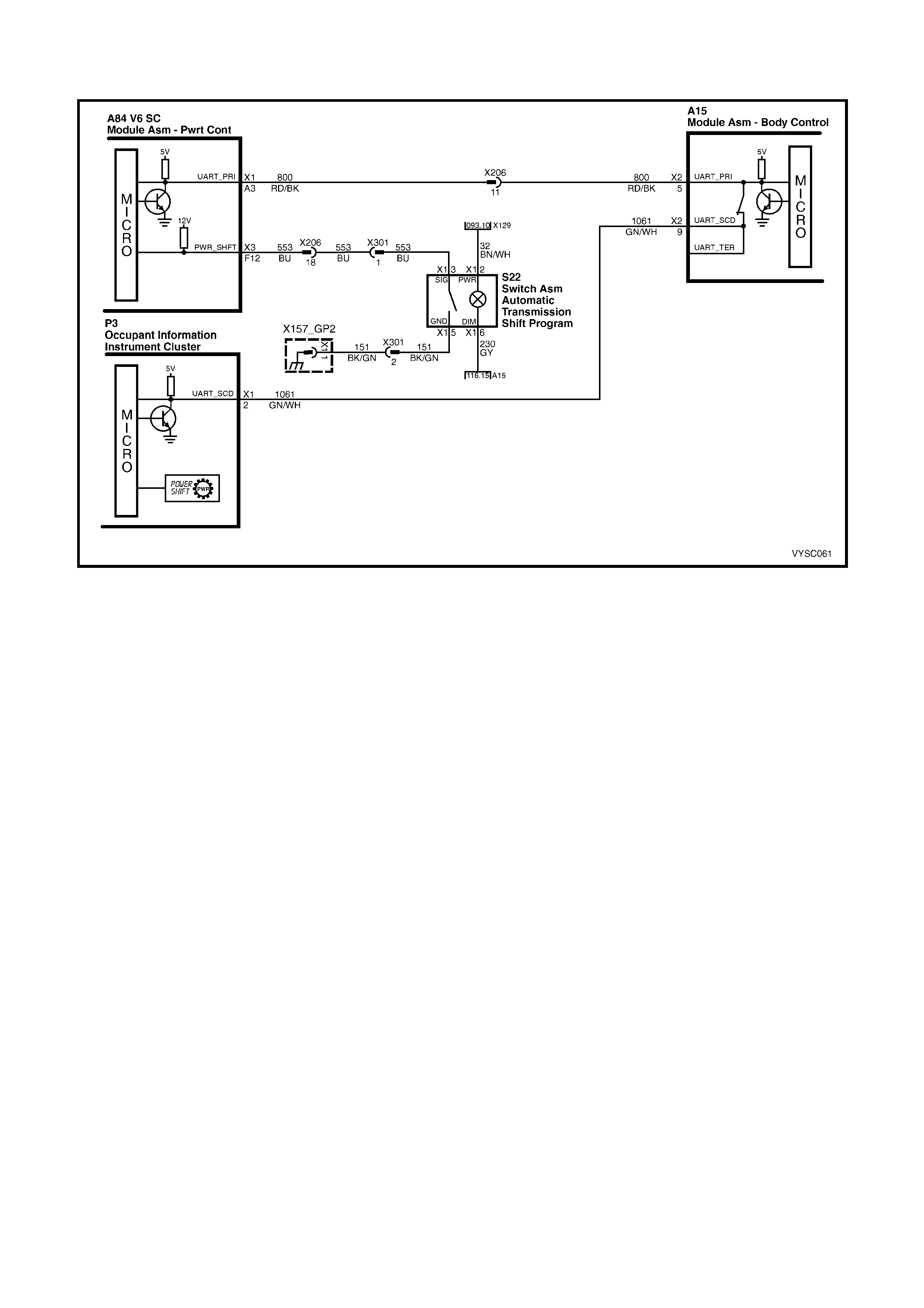
2.5 V6 PCM – TRANSMISSION POWER/ECONOMY SWITCH
Figure 6C2-2C-9 – Power/Economy Switch
CIRCUIT DESCRIPTION:
The driver can select three transmission shift modes, ECONOMY, POWER or CRUISE using centre console
mounted switch for Economy/Power, and a cruise switch located on the steering column. The Economy/Power
switch is wired to the PCM and allows the driver to choose the Economy mode, for the best fuel economy in all
driving conditions through the increased use of TCC. Power mode provides later upshifts and higher line pressure in
the transmission.
The PCM s ends out a buffer ed voltage s ignal, about 12 volts, and monitor s the status of this c irc uit. Onc e the dr iver
selects Power, the switch momentarily pulls low the buffered 12 volts. The PCM will interpret this as a Power
selection, adjusting the transmission shift pattern accordingly, and instructs the instrument panel to turn ON the
Power lamp. If while driving, the driver selects the Economy position, again the buffered 12 volts is momentarily
pulled low, and the PCM will adj ust the transm ission shift pattern and ins truct the instrum ent panel to turn OFF the
Power lamp.
When the key is turned ON, the PCM shift mode is set to the last mode that was previously selected
(Economy/Power). The cruise control is set to OFF at every key ON cycle.
In cruise mode operation, when the driver activates the cruise control, the Power Shift (PWR) icon in the Multi
Function Display (MFD) of the Instrument will be deactivated (if vehicle was in power mode) and the transmission
shift pattern will switch to cruise shift pattern. When in cruise mode, the PCM will modify the transmission calibration
so that earlier downshift and later upshift points are provided.
For replacement of the Economy/Power switch, refer to Section 7C4 AUTOMATIC TRANSMISSION – ON-
VEHICLE SERVICING in the MY 2003 VY and V2 Series Service Information.
TEST DESCRIPTION:
NOTE: The number(s) below refer to the step number(s) on the diagnostic table.
2. This step tests for proper operation of the transmission POWER switch, the wiring and the PCM.
3. This step tests for proper POWER lamp illumination.
5. This step determines if the switch is faulty.
8. Some interior parts must be removed to disconnect and replace the transmission switch, Refer to
Section 1A3, INSTRUMENT PANEL AND CONSOLE in the MY 2003 VY and V2 Series Service Information.
A84 V6 S/C – X1 A84 V6 S/C – X3 P3
X206 A15 X2 S22
Figure 6C2-2C-10
TRANSMISSION POWER/ECONOMY SWITCH
STEP ACTION VALUE YES NO
1. Was the "On-Board Diagnostic" (OBD) System Check
performed? Go to Step 2 Go to
OBD
System Check
in this Section.
2. 1. Install Tech 2.
2. With the engine OFF, turn the ignition switch to the
RUN position.
3. Depress the Transmission POWER switch S22 and
observe the Tech 2 display.
Does the Tech 2 display change between the Power or
Economy mode?
Go to Step Go to Step 5
3. Is the POWER lamp ON, when the Tech 2 displays
POWER? Go to Step 4 Go to 12C
Instruments.
4. Does the POWER icon deactivate when Tech 2 displays
ECONOMY?
No Problem
found with
switch operation.
Go to 12C
Instruments.
5. 1. Disconnect the POWER switch from the wiring
harness connector S22.
2. Using a fused jumper wire, connect the two terminals
S22 X1 3 and 5 of the POW ER switch wiring harness
connector together.
Does Tech 2 display a change between the Power and
Economy mode?
Go to Step 7 Go to Step 6
6. 1. Using a fused jumper wire, connect circuit 553 to
ground.
Does Tech 2 display change between the Power and
Economy mode?
Go to Step 10 Go to Step 9
7. 1. Check the POWER switch connector S22 for a poor
terminal connection.
Was a problem found?
Verify Repair Go to Step 8
8. 1. Replace the faulty POW ER/ECONOMY switch.
Is the action complete? Verify Repair –
9. 1. Check for an open or short to Ground in circuit 553, or
a faulty PCM connection for circuit 553.
Was a problem found?
Verify the Repair Go to Step 11
10. 1. Repair open in Ground circuit 151at Power/Economy
switch.
Is action complete?
Verify Repair –
11. 1. Replace PCM. Refer to 6C2-3 SERVICE
OPERATIONS, for PCM Programming and Security
Link procedure.
Is action complete?
Verify Repair –
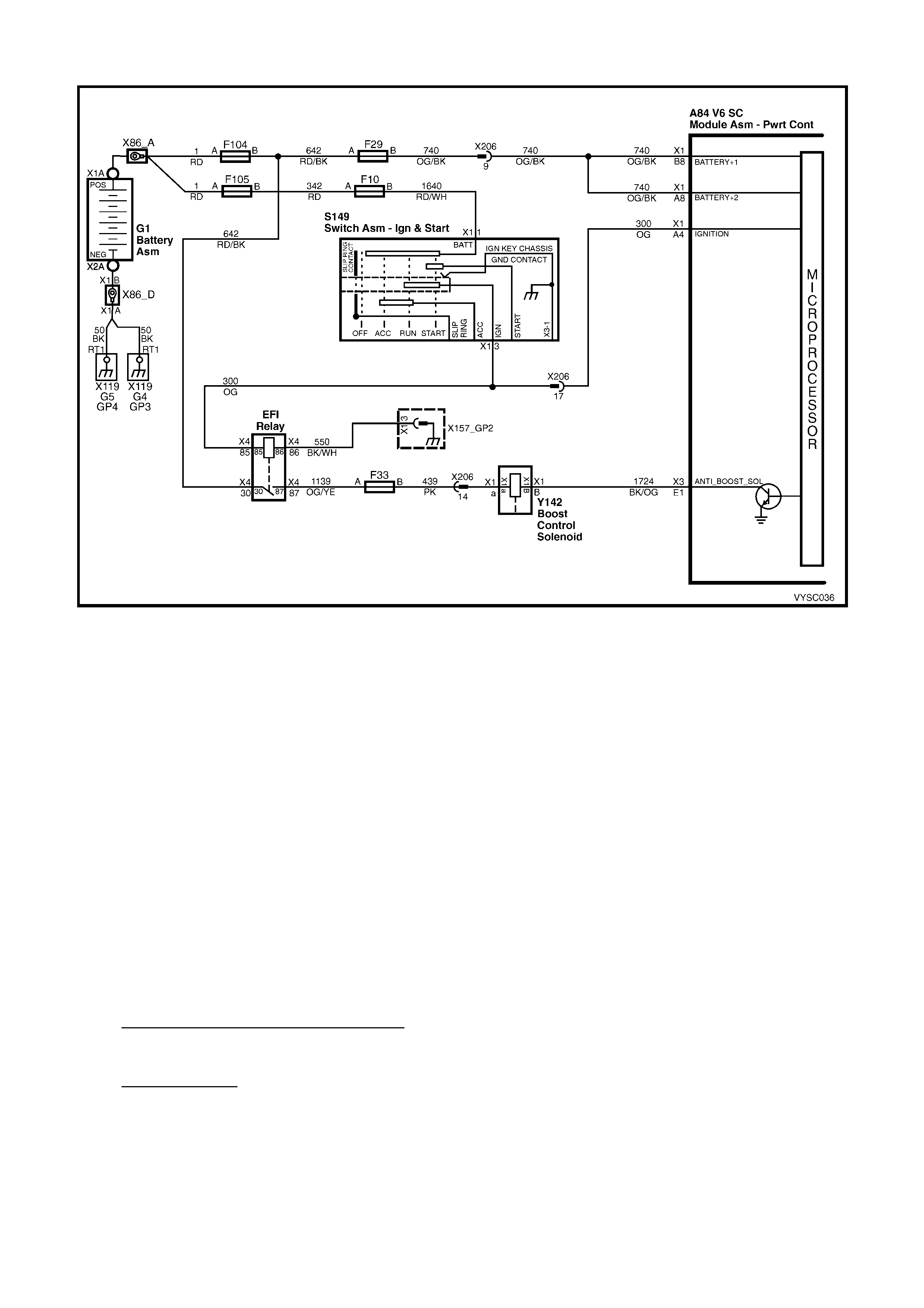
2.6 V6 P CM – S/C ENGINE BOOST CONTROL SYSTEM FUNCTIONAL CHECK
Figure 6C2-2C-11 – Boost Control Solenoid
CIRCUIT DESCRIPTION:
Under most conditions, the PCM commands the Boost Control Solenoid to operate at 100% duty cycle ("ON") to
allow full boost pres sure upon demand. However, if reverse gear is selected or the PCM detects rapid dec eleration
or engine load is ex tremely high, reduc ed boos t pres s ur e is des ir ed. Under thes e 3 c onditions, the PCM c ommands
the Boost Control Solenoid to operate at a 0% duty cycle ("OFF"), which opens the bypass valve. W ith the bypass
valve open, boost pressure is reduced by recirculating intake air back through the supercharger inlet.
CAUTION: When performing this diagnostic, ensure that the drive wheels are chocked and the park brake is
firmly applied.
DIAGNOSTIC AIDS:
1. If this diagnostic has been perform ed and no electrical or vacuum related f ault is noted, chec k for the following
conditions:
• Misadjusted or sticking Bypass Valve Actuator.
• Binding Bypass Valve or Bypass Valve linkage.
2. Refer to 6C2-3 SERVICE OPERATIONS in this Section for bypass valve actuator service and adjustment
procedure. If no problem is found and a driveability symptom still exists, refer to 6C2-2B Symptoms in this
Section.
3. An intermittent may be c aused by a poor connection, rubbed thr ough wire insulation, or a wire broken inside the
insulation. Check for the following conditions:
• Poor connection or Damaged Harness – Inspect PCM harness connector for backed out terminals,
impr oper m ating, improper ly f ormed or damaged terminals, poor terminal to wire connec tion and damaged
harness.
• Intermittent Test – Disconnect PCM and install a DMM to monitor voltage between the Boost Control
Solenoid driver circuit at the PCM connector and ground. With the key "ON", observe voltage while
manipulating related connectors and wiring harness. If the failure is induced, the voltage display will change.
This may indicate the location of the fault.
TEST DESCRIPTION:
NOTE: Number(s) below refer to step number(s) on the diagnostic table.
2. Verifies ignition feed to the Boost Control Solenoid.
3. The Boost Control Solenoid should be commanded "OFF" (0% duty cycles) with the ignition "ON", engine not
running. If the sy stem is functioning properly, the test light should be "OFF".
4. Ensures that the PCM can control the QDM output for the Boost Control Solenoid and Boost Control Solenoid
driver circuit is not open.
5. Checks for a faulty Boost Control Solenoid (sticking open or leaking).
A84 V6 S/C X3 Y142 X206
Figure 6C2-2C-12
V6 PCM – S/C ENGINE BOOST CONTROL SYSTEM FUNCTIONAL CHECK
STEP ACTION VALUE YES NO
1. Was the "On-Board Diagnostic" (OBD) System Check
performed? Go to Step 2 Go to
OBD
System Check
in this Section.
2. 1. Unbolt Boost Control Solenoid from engine, to gain
access to solenoid.
2. Disconnect the Boost Control Solenoid electrical
connector.
3. Ignition "ON".
4. Install a test light between the ignition feed circuit at
the Boost Control Solenoid harness connector and
engine ground.
Is the test light "ON"?
Go to Step 3 Go to Step 11
3. 1. Connect the test light between the Boost Control
Solenoid harness connector Y142, terminals X1 A and
X1 B.
Is the test light "ON"?
Go to Step 14 Go to Step 4
4. 1. Ignition "ON", engine idling.
2. Set vehicle parking brake firmly.
3. With the test light still connected to the Boost Control
Solenoid, observe the test light.
Is the test light "ON" while the engine is running?
Go to Step 5 Go to Step 16
5. 1. Reconnect the Boost Control Solenoid electrical
connector Y142.
2. Disconnect the boost signal hose between the Boost
Control Solenoid and the Bypass Valve Actuator.
3. Connect a vacuum gauge to read the boost signal
from the Boost Control Solenoid.
4. Start the engine and idle in park.
5. Observe the vacuum gauge reading.
Does the vacuum gauge indicate near the specified value?
0 cm (0 in.)
Hg Go to Step 6 Go to Step 17
6. 1. With engine still idling, shift vehicle into Reverse gear.
2. Observe the vacuum gauge.
Does the vacuum gauge indicate greater than the specified
value with the Boost Control Solenoid turned "OFF when
vehicle is shifted into Reverse gear"?
38 cm
(15 in.) Hg Go to Step 7 Go to Step 10
7. 1. Check for a restriction in the boost signal hose
between the Boost Control Solenoid and the Bypass
Valve Actuator.
2. If a problem is found, repair as necessary.
Was a problem found?
Go to Step 21 Go to Step 8

STEP ACTION VALUE YES NO
8. 1. Reconnect the boost signal hose between the Boost
Control Solenoid and the Bypass Valve Actuator.
2. Connect the vacuum gauge to read the inlet vacuum
signal to the Bypass Valve Actuator.
3. Start the engine and idle in park.
4. Observe the vacuum gauge reading.
Does the vacuum gauge indicate greater than the specified
value?
38 cm
(15 in.) Hg Refer to
Diagnostic Aids,
above.
Go to Step 9
9. 1. Repair the restriction in the inlet vacuum signal hose
to the Bypass Valve Actuator or blocked inlet vacuum
source.
Is action complete?
Go to Step 21 –
10. 1. Check for a restriction in the boost source hose to the
Boost Control Solenoid.
2. If a problem is found, repair as necessary.
Was a problem found?
Go to Step 21 Go to Step 18
11. 1. Check the fuse for the Boost Control Solenoid ignition
feed circuit.
Is the fuse blown?
Go to Step 12 Go to Step 13
12. 1. Locate and repair short to ground in the ignition feed
circuit.
Is action complete?
Go to Step 21 –
13. 1. Locate and repair open in the ignition feed circuit to
the Boost Control Solenoid.
Is action complete?
Go to Step 21 –
14. 1. Ignition "OFF", disconnect the PCM.
2. Ignition "ON", observe the test light.
Is the test light "ON"?
Go to Step 15 Go to Step 20
15. 1. Locate and repair short to ground in Boost Control
Solenoid driver circuit.
Is action complete?
Go to Step 21 –
16. 1. Ignition "OFF", disconnect the PCM.
2. Ignition "ON".
3. Check the Boost Control Solenoid driver circuit for an
open, a short to voltage or poor terminal contact.
4. If a problem is found, repair as necessary.
Was a problem found?
Go to Step 21 Go to Step 20
17. 1. Check for poor terminal connections at the Boost
Control Solenoid.
2. If a problem is found, repair as necessary.
Was a problem found?
Go to Step 21 Go to Step 18
18. 1. Replace the Boost Control Solenoid.
Is action complete? Go to Step 21 –
19. 1. Check the Boost Control Solenoid driver circuit for a
poor terminal connection at the PCM.
2. If a problem is found, repair as necessary.
Was a problem found?
Go to Step 21 Go to Step 20
20. 1. Replace PCM. Refer to 6C2-3 SERVICE
OPERATIONS, for PCM Security Link procedure.
Is action complete?
Go to Step 21 –
21. 1. Ignition "ON", engine idling in Park.
2. Disconnect inlet vacuum signal hose to Bypass Valve
Actuator.
The Bypass valve Actuator linkage should move when the
signal hose is removed. Does it?
Go to Step 22 Go to
Diagnostic Aids,
above.
22. 1. Ignition "OFF".
2. Connect a vacuum gauge to the Boost Control
Solenoid.
3. Ignition "ON, engine idling in Park.
Does the vacuum gauge indicate near the specified value?
0 cm
(0 in.) Hg Go to Step 23 Go to Step 17

STEP ACTION VALUE YES NO
23. 1. Set vehicle parking brake firmly.
2. Ignition "ON", engine idling in Park.
3. With vacuum gauge still connected to Boost Control
Solenoid, shift transmission into reverse gear.
Does the vacuum gauge now read at or above the
specified value when the transmission is shifted into
reverse gear?
38 cm
(15 in.) Hg Go to Step 24 Go to Step 10
24. 1. Reconnect vacuum hose to Boost Control Solenoid.
2. Reinstall Boost Control Solenoid to engine.
Is action complete?
System is
working
properly. Refer
to Diagnostic
Aids, above.
–
2.7 V6 P CM – INSTRUMENT PANEL GEAR INDICATOR CHECK
Figure 6C2-2C-13 – PRNDL Instrument Disp la y
CIRCUIT DESCRIPTION:
The transmission PRNDL module is a m ulti-signal switch assembly that sends signals to the PCM to indicate gear
selection. The PCM will then determine the signal from the PRNDL module and send a command via serial data
com m unication to the instr um ent panel cluster to turn "O N" the proper gear indicator lam p for the gear that is being
selected.
The PRNDL module uses four (4) discrete circuits to pull four (4) PCM voltages low in various combinations to
indicate each gear range. The voltage level of the circuits is represented as LOW = grounded, and HIGH = open
circuit. The four (4) states displayed represents decoder P, A, B, and C inputs.
The Tech 2 will display all four circuits ( P, A, B, C ) and the appropriate HIGH's and LOW 's to represent the gear
selected. If the gear selected does not match the HIGH/LOW Table as displayed below on Tech 2, or the instrument
panel cluster gear lam p does not light up for the gear selected, there is a f ault in the PRNDL select circuit or in the
instrument panel (IP) cluster.
DIAGNOSTIC AIDS:
• Monitor T ech 2 while m oving related connectors and wiring harness. If a failure is indicated, the scan data will
change states from either LOW to HIGH, or f rom HIGH to LO W . Moving the gear selector slowly through each
gear while monitoring Tech 2 may also help to isolate the problem.
• Any circuitry that is suspected as causing the interm ittent complaint, should be thoroughly checked for back ed
out term inals, im proper m ating, brok en lock s, impr operly form ed or dam aged terminals , poor terminal to wiring
connection or physical damage to the wiring harness.
TRANSMISSION RANGE / PRNDL SWITCH
VALID INPUT COMBINATIONS
GEAR POSITION
SELECTED TECH 2 PRNDL DI SPLAY
(P, A, B, C)
P A B C
PARK (P ) LOW (0) LOW (0) HIGH (12) HI GH (12)
REVERS E (R) HIGH (12) LOW (0) LOW (0) HIGH (12)
NEUTRAL (N) LOW (0) HIGH (12) LOW (0) HIGH (12)
DRIVE 4 (D) HIGH (12) HIGH (12) LOW (0) LOW (0)
DRIVE 3 (3) LOW (0) LOW (0) LOW (0) LOW (0)
DRIVE 2 (2) HIGH (12) LOW (0) HIGH (12) LOW (0)
DRIVE 1 (1) LOW (0) HIGH (12) HIGH (12) LOW (0)
TEST DESCRIPTION:
NOTE: Number(s) below refer to the step number(s) on the diagnostic table.
4. Any circuitry that is suspected as causing the interm ittent complaint, should be thoroughly checked for backed
out term inals, im proper m ating, brok en locks , improperly form ed or damaged ter minals, poor ter minal to wiring
connection or physical damage to the wiring harness.
5. An invalid circuit will cause the PRNDL display to go out. Jumpering each circuit to ground simulates the
PRNDL module s witch operation and checks the circuitry and PCM. W hile the PRNDL m odule is disconnected
and the c ircuits are not j umper ed to ground, the Tec h 2 should indicate a HIGH value. A value that is indicated
as LOW with no jumper to ground indicates a ground circuit or faulty PCM.
A84 V6 S/C X1 A84 V6 S/C X3 A15 X2
P3 S187 X206
Figure 6C2-2C-14

V6 PCM – INSTRUMENT PANEL GEAR INDICATOR CHECK
STEP ACTION VALUE YES NO
1. Was the "On-Board Diagnostic" (OBD) System Check
performed? Go to Step 2 Go to
OBD
System Check
in this Section.
2. 1. Install Tech 2.
2. Ignition "ON", engine "OFF".
3. Move the gear selector through all it's ranges.
Does Tech 2 indicate an INVALID in any of the ranges?
Go to Step 3 Go to Step 10
3. 1. Compare Tech 2 values with the Transmission Range
Switch Valid Input Combinations table, above.
Are all the circuits indicated as HIGH?
Go to Step 4 Go to Step 5
4. 1. Check the transmission PRNDL module switch ground
circuit for an open or poor connection and repair if
necessary.
Was a problem found?
Verify Repair Go to Step 5
5. 1. Move the gear selector through all it's ranges and note
which circuit did not correspond with the Transmission
Range Switch Valid Input Combination table.
2. Disconnect the PRNDL module electrical connector.
3. Jumper the circuit with the incorrect value to ground.
Does the jumpered circuit go from a HIGH value to a LOW
value?
Go to Step 8 Go to Step 6
6. 1. Check the affected circuit for an open or short to
ground and repair as necessary.
Was a problem found?
Verify Repair Go to Step 7
7. 1. Check for a poor connection at the PCM connector
and repair as necessary.
Was a problem found?
Verify Repair Go to Step 9
8. 1. Replace the PRNDL module.
Is action complete? Verify Repair –
9. 1. Replace PCM. Refer to 6C2-3 SERVICE
OPERATIONS, for PCM Programming and Security
Link procedure.
Is action complete?
Verify Repair –
10. Does Tech 2 indicate the same gear as the Instrument?
System OK,
refer to
Diagnostic Aids,
above.
Go to Step 11
11. 1. Replace Instrument.
Is action complete? Verify Repair –
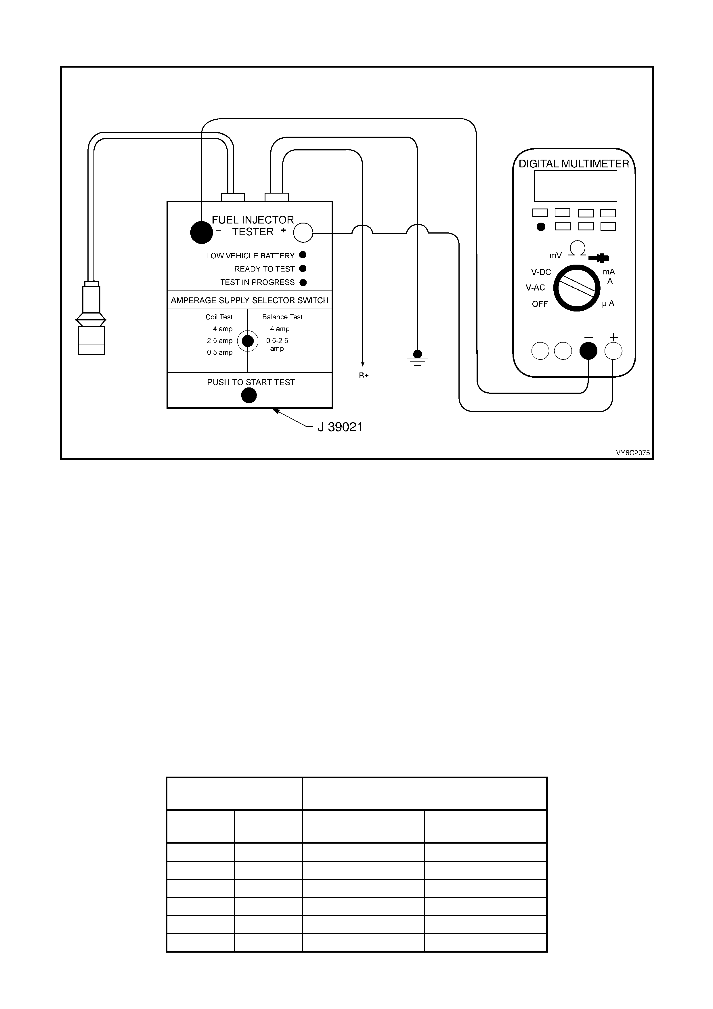
2.8 V6 PCM – FUEL INJECTOR BALANCE TEST
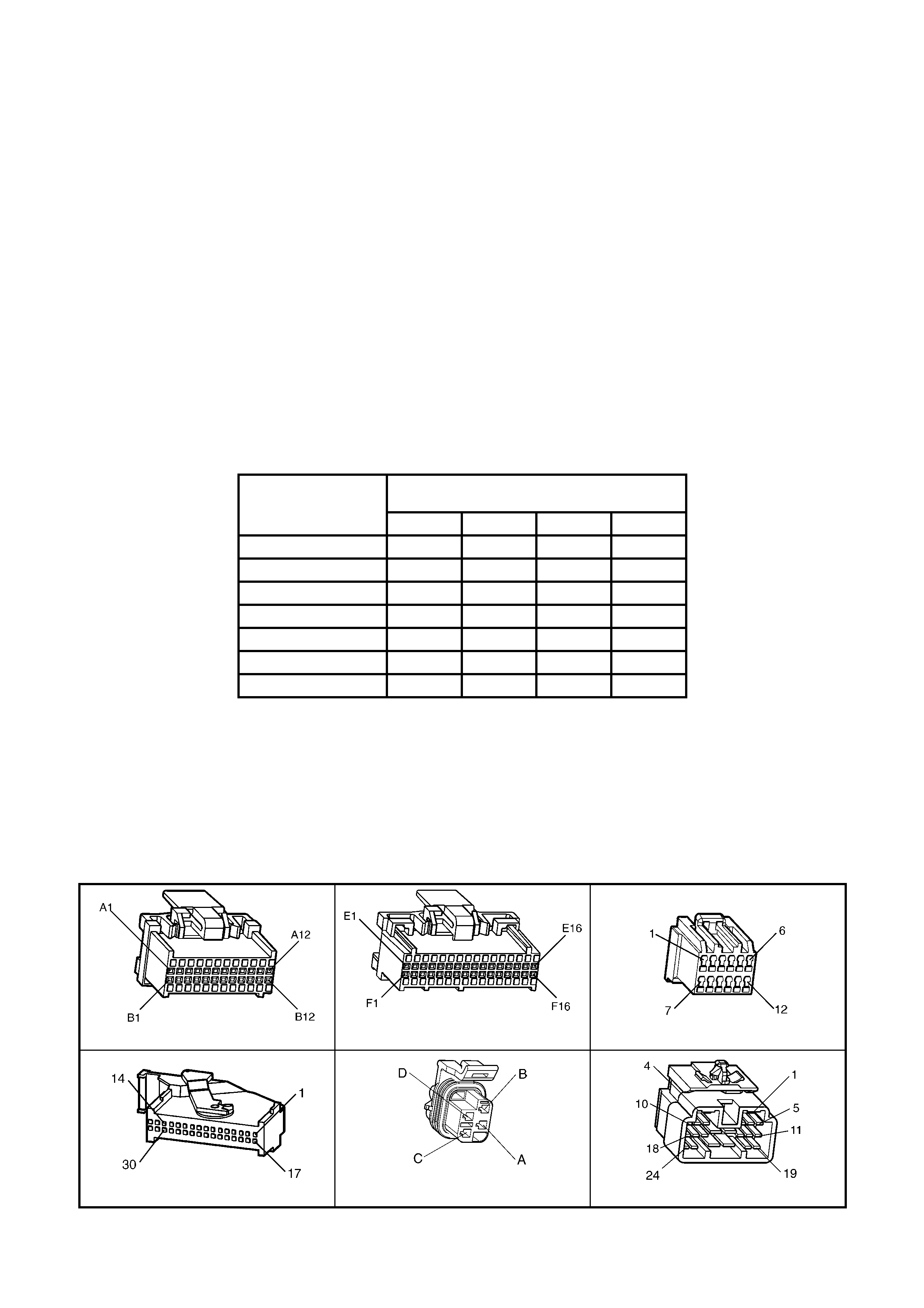
Figure 6C2-2C-15 – Fuel Injector Balance Test Equipment
TEST DESCRIPTION:
NOTE: The number(s) below refer to the step number(s) on the diagnostic table.
CAUTION: Wrap a shop towel around the fuel pressure connection in order to reduce the risk of fire and
personal injury. The towel will absorb any fuel leakage that occurs during the connection of the fuel
pressure gauge. Place the towel in an approved container w hen the connection of the fuel pressure gauge
is complete.
4. The engine coolant temperature must be below the operating temperature in order to avoid irregular fuel
pressure readings due to Hot Soak fuel boiling.
5. The f uel press ure should be within the specified range. If the fuel press ure is not within the specif ied range, go
to Fuel System Diagnosis in Section 6C2-2A.
6. The fuel pressure should reach a steady value. If the fuel pressure does not reach a steady value, go to Fuel
System Diagnosis.
7. If the pressure drop value for each fuel injector is within 10 kPa (1.5 psi) of the average pressure drop value, the
fuel injectors are flowing properly. Calculate the pressure drop value for each fuel injector by subtracting the
second pressure reading from the first pressure reading. Refer to the illustration above.
Running the engine after each injector test will prevent the engine from flooding.
V6 PCM – FUEL INJECTOR BALANCE TEST
STEP ACTION VALUE YES NO
1. Was the "On-Board Diagnostic" (OBD) System Check
performed? Go to Step 2 Go to
OBD
System Check
in this Section.
2. Was the Fuel Injector Coil Test Procedure performed?
Go to Step 3 Go to Table 2.9
Fuel Injector Coil
Test – ECT
Between
10 – 35° C in
this Section.
3. Is the engine coolant temperature above the specified
value? 94 °C Go to Step 4 Go to Step 5
4. 1. Allow the engine to cool below the specified value.
Is the engine coolant temperature below the specified
value?
94 °C Go to Step 5 –

STEP ACTION VALUE YES NO
5. CAUTION: Wrap a shop tow el around the fuel pressure
connection in order to reduce the risk of fire and
personal injury. The tow el will absorb any fuel leakage
that occurs during the connection of the fuel pressure
gauge. Place the towel in an approved container when
the connection of the fuel pressure gauge is complete.
1. Relieve fuel pressure. Refer to 6C2-3 SERVICE
OPERATIONS for the procedure.
2. Connect the Fuel Gauge Schrader Fitting Adapter
AU453 to the fuel rail, then connect SD28018 fuel
pressure gauge to the Schrader Fitting Adaptor.
3. Place the bleed hose of the fuel pressure gauge into
an approved petrol container.
4. Connect Tech 2 and use it to energise the fuel pump.
5. Bleed the air out of the fuel pressure gauge.
6. Observe the reading on the fuel pressure gauge.
Is the fuel pressure within the specified limits?
270 –350
kPa Go to Step 6 Go to
Fuel System
Diagnosis in
6C2-2A
DIAGNOSTIC
TABLES
6. 1. Turn the fuel pump OFF.
Does the fuel pressure remain constant? Go to Step 7 Go to
Fuel System
Diagnosis in
6C2-2A
DIAGNOSTIC
TABLES
7. 1. Connect the J 39021 Fuel Injector Tester to a fuel
injector.
2. Set the amperage supply selector switch on the fuel
injector tester to the Balance Test 0.5-2.5 amp
position.
3. Turn the fuel pump ON then OFF in order to
pressurise the fuel system.
4. Record the fuel pressure indicated by the fuel
pressure gauge after the fuel pressure stabilises. This
is the 1st pressure reading (refer to (1) in the
illustration).
5. Energise the fuel injector by depressing the Push to
Start Test button on the fuel injector tester.
6. Record the fuel pressure indicated by the fuel
pressure gauge after the fuel pressure gauge needle
has stopped moving. This is the 2nd pressure reading
(refer to (2) in the illustration).
7. Subtract the 2nd pressure reading from the 1st
pressure reading for the fuel injector. The result is the
pressure drop value.
8. Run the engine after each test to clear the residual
fuel from the cylinder.
Was test completed?
Go to Step 8 –
8. 1. Repeat Step 7 for each fuel injector.
2. Obtain a pressure drop value for each fuel injector.
3. Add all of the individual pressure drop values. This is
the total pressure drop.
4. Divide the total pressure drop by the number of fuel
injectors. This is the average pressure drop.
Does any fuel injector have a pressure drop value that is
either higher than the average pressure drop or lower than
the average pressure drop by the specified value?
10 kPa Go to Step 9 Go to 6C2-2B
SYMPTOMS.
9. NOTE: Do not repeat any portion of this test before running
the engine in order to prevent the engine from flooding.
1. Re-test any fuel injector that does not meet the
specification. Refer to procedure in Step 7.
Does any fuel injector still have a pressure drop value that
is either higher than the average pressure drop or lower
than the average pressure drop by the specified value?
10 kPa Go to Step 10 Go to 6C2-2B
SYMPTOMS.
10. 1. Replace the faulty fuel injector(s). Refer to Fuel
Injector Replacement in 6C2-3 SERVICE
OPERATIONS.
Is the replacement complete?
System OK –
2.9 V6 PCM – FUEL INJECTOR COIL TEST – ECT BETWEEN 10 – 35° C
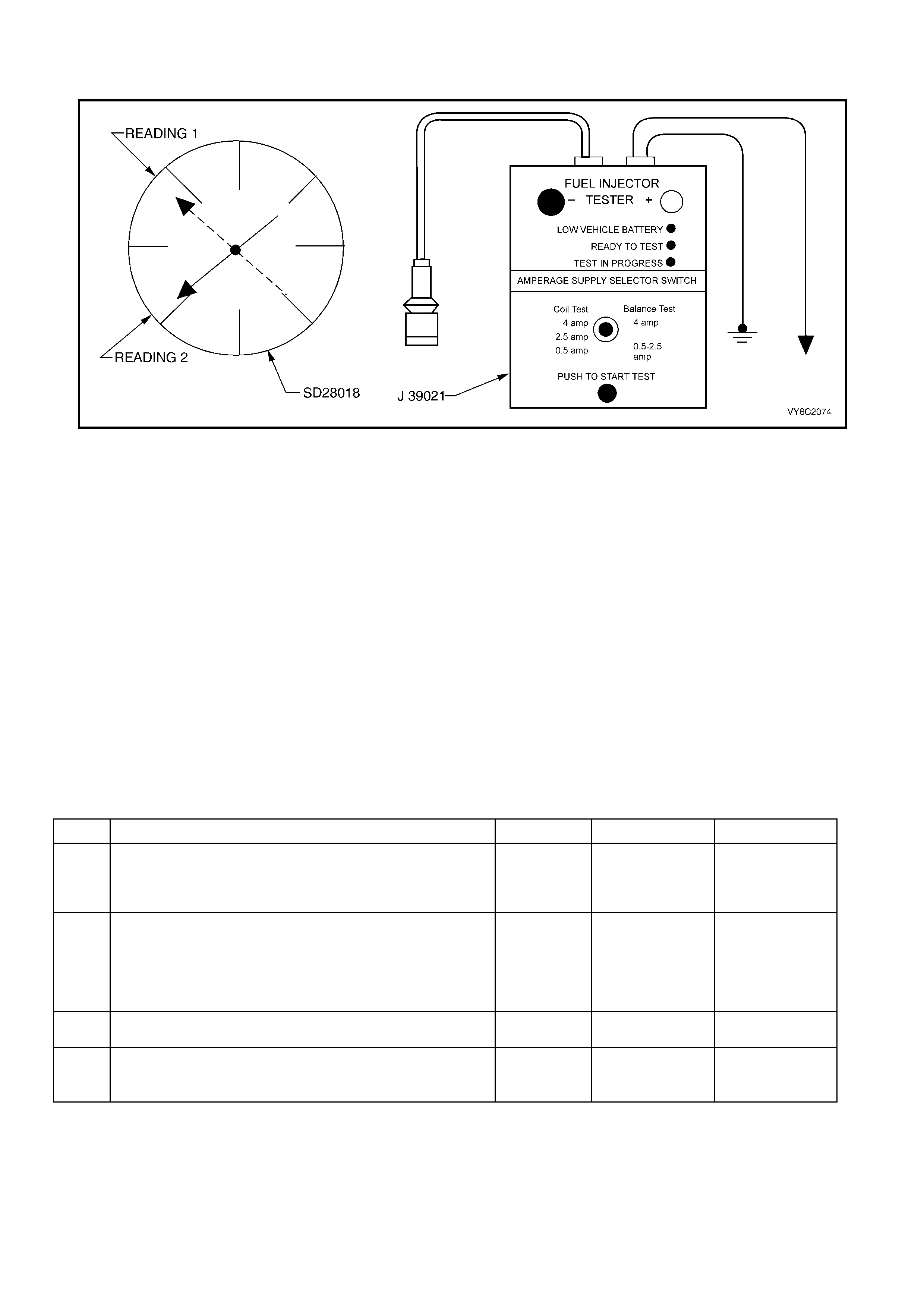
Figure 6C2-2C-16 – Fuel Injector Coil Test
TEST DESCRIPTION:
NOTE: The number(s) below refer to the step number(s) on the diagnostic table.
CAUTION: Wrap a shop towel around the fuel pressure connection in order to reduce the risk of fire and
personal injury. The towel will absorb any fuel leakage that occurs during the connection of the fuel
pressure gauge. Place the towel in an approved container w hen the connection of the fuel pressure gauge
is complete.
2. The engine coolant tem perature aff ects the ability of the fuel injector tester to detect a faulty fuel injec tor. If the
engine coolant tem perature is NOT between 10° C and 35° C, go to T able 2.10 – Fuel Inj ector Coil Tes t – ECT
Outside 10 – 35° C.
3. The first second of the voltage displayed by the DMM may be inaccurate due to the initial current surge.
Therefore, record the lowest voltage displayed by the DMM after the first second of the test. The voltage
displayed by the DMM s hould be within the specif ied range (ref er to the ex am ple). T he voltage displayed by the
DMM may increase throughout the tes t as the f uel injec tor windings warm and the res istance of the fuel injector
windings changes. An erratic voltage reading (large fluctuations in voltage that do not stabilise) indicates an
intermittent connection within the fuel injector.
Example:
Resistance
(11.4 – 12.6 Ohms) Voltage Specification Between 10° C – 35° C
(5.7 – 6.6 Volts)
Fuel Injector Number Voltage Reading Pass/Fail
1 6.3 P
2 5.9 P
3 6.2 P
4 6.1 P
5 4.8 F
6 6.0 P

V6 PCM – FUEL INJECTOR COIL TEST – ECT BETWEEN 10 – 35° C
STEP ACTION VALUE YES NO
1. Was the "On-Board Diagnostic" (OBD) System Check
performed? Go to Step 2 Go to
OBD
System Check
in this Section.
2. 1. Connect Tech 2.
2. Check the engine coolant temperature.
Is the engine coolant temperature within the specified
value?
10 – 35° C Go to Step 3 Go to Table
2.10, Fuel
Injector Coil Test
– ECT Outside
10– 35° C.
3. 1. Turn the ignition ON.
NOTE: In order to prevent flooding of a single cylinder and
possible engine damage, relieve the fuel pressure before
performing the fuel injector coil test procedure.
2. Relieve the fuel pressure. Refer to the Fuel Pressure
Relief Procedure, in 6C2-3 SERVICE OPERATIONS.
3. Access the fuel injector electrical connectors, as
required.
4. Connect the J 39021 fuel injector tester to B+ and
ground.
5. Set the amperage supply selector switch on the fuel
injector tester to the ‘Coil Test 0.5 Amp’ position.
6. Connect the leads from a Digital Multimeter (DMM) to
the fuel injector tester. Refer to the illustration
associated with the test description.
7. Set the DMM to the tenths scale (0.0).
8. Connect the fuel injector tester to a fuel injector.
IMPORTANT: Check the engine coolant temperature
again in order to ensure that the correct Table is being
used.
9. Press the ‘Push to Start Test’ button on the fuel
injector tester.
10. Observe the voltage reading on the DMM.
IMPORTANT: The voltage reading may rise during the
test.
11. Record the lowest voltage observed after the first
second of the test.
12. Repeat Steps 8 through 11 for each fuel injector.
Did any fuel injector have an erratic voltage reading (large
fluctuations in voltage that do not stabilise) or voltage
readings outside of the specified value?
5.7 – 6.6 V Go to Step 4 Go to Table 2.8,
Fuel Injector
Balance Test.
4. 1. Replace the faulty fuel injector(s). Refer to Fuel
Injector Replacement in 6C2-3 SERVICE
OPERATIONS.
Is the replacement complete?
Go to Table 2.8,
Fuel Injector
Balance Test in
this Section.
2.10 V6 PCM – FUEL INJECTOR COIL TEST – ECT OUTSIDE 10 – 35° C
Figure 6C2-2C-17 – Fuel Injector Coil Test
TEST DESCRIPTION:
NOTE: The number(s) below refer to the step number(s) on the diagnostic table.
CAUTION: Wrap a shop towel around the fuel pressure connection in order to reduce the risk of fire and
personal injury. The towel will absorb any fuel leakage that occurs during the connection of the fuel
pressure gauge. Place the towel in an approved container w hen the connection of the fuel pressure gauge
is complete.
2. The engine coolant tem perature aff ects the ability of the fuel injector tester to detect a faulty fuel injec tor. If the
engine coolant temperature is NOT outside 10° C and 35° C, refer to Table 2.9, Fuel Injector Coil Test – ECT
Between 10 – 35° C.
3. The first second of the voltage displayed by the DMM may be inaccurate due to the initial current surge.
Therefore, record the lowest voltage displayed by the DMM after the first second of the test. The voltage
displayed by the DMM may increase throughout the test as the fuel injector windings warm and the resistance
of the fuel injector windings changes. An erratic voltage reading (large fluctuations in voltage that do not
stabilise) indicates an intermittent connection within the fuel injector.
From the voltages rec orded, identify the highest voltage, excluding any voltages above 9.5 volts. Subtract each
voltage that is not above 9.5 volts from the highest voltage. Record each subtracted value (refer to the
Example). Any fuel injector with a subtracted value that is greater than 0.6 volts is faulty. Replace the fuel
injector. Any fuel injector with a recorded voltage above 9.5 volts is also faulty. Replace the fuel injector.
Example:
Highest Voltage
Reading (7.1 Volts) Voltage Specification Outside 10° C – 35° C
(0.6 Volts)
Injector
Number Voltage Subtracted Value Pass/Fail
1 9.8 – F
2 6.6 0.5 P
3 6.9 0.2 P
4 5.8 1.3 F
5 7.0 0.1 P
6 7.1 0.0 P

V6 PCM – FUEL INJECTOR COIL TEST – ECT OUTSIDE 10 – 35° C
STEP ACTION VALUE YES NO
1. Was the "On-Board Diagnostic" (OBD) System Check
performed? Go to Step 2 Go to
OBD
System Check
in this Section.
2. 1. Connect Tech 2
2. Check the engine coolant temperature.
Is the engine coolant temperature outside the specified
value?
10 – 35° C Go to Step 3 Go to Table 2.9
Fuel Injector Coil
Test - ECT
Between 10 –
35° C.
3. 1. Turn the ignition OFF.
NOTE: In order to prevent flooding of a single cylinder
and possible engine damage, relieve the fuel pressure
before performing the fuel injector coil test procedure.
2. Relieve the fuel pressure. Refer to the Fuel Pressure
Relief Procedure in 6C2-3 SERVICE OPERATIONS.
3. Access the fuel injector electrical connectors as
required.
4. Connect the J 39021 Fuel Injector Tester to B+ and
ground.
5. Set the amperage supply selector switch on the fuel
injector tester to the ‘Coil Test 0.5 Amp’ position.
6. Connect the leads from a Digital Multimeter (DMM) to
the fuel injector tester. Refer to the illustration
associated with the test description.
7. Set the DMM to the tenths scale (0.0).
8. Connect the fuel injector tester to a fuel injector.
IMPORTANT: Check the engine coolant temperature
again in order to ensure that the correct Table is being
used.
9. Press the ‘Push to Start Test’ button on the fuel
injector tester.
10. Observe the voltage reading on the DMM.
IMPORTANT: The voltage reading may rise during the
test.
11. Record the lowest voltage observed after the first
second of the test.
12. Repeat Steps 8 through 11 for each fuel injector.
13. Identify the highest voltage reading recorded from the
recorded readings.
14. Subtract any other voltage reading recorded from the
highest voltage reading recorded.
15. Repeat Step 14 for all the remaining fuel injectors.
Is any value that resulted from subtracting greater than the
specified value?
0.6 Volts Go to Step 4 Go to Table 2.8
Fuel Injector
Balance Test.
4. 1. Replace any fuel injector that had any of the following:
• A subtracted value exceeding 0.6 volts.
• An initial reading above 9.5 volts.
• An erratic reading.
Refer to Fuel Injector Replacement in 6C2-3 SERVICE
OPERATIONS.
Is the replacement complete?
Go to Table 2.8
Fuel Injector
Balance Test.
–
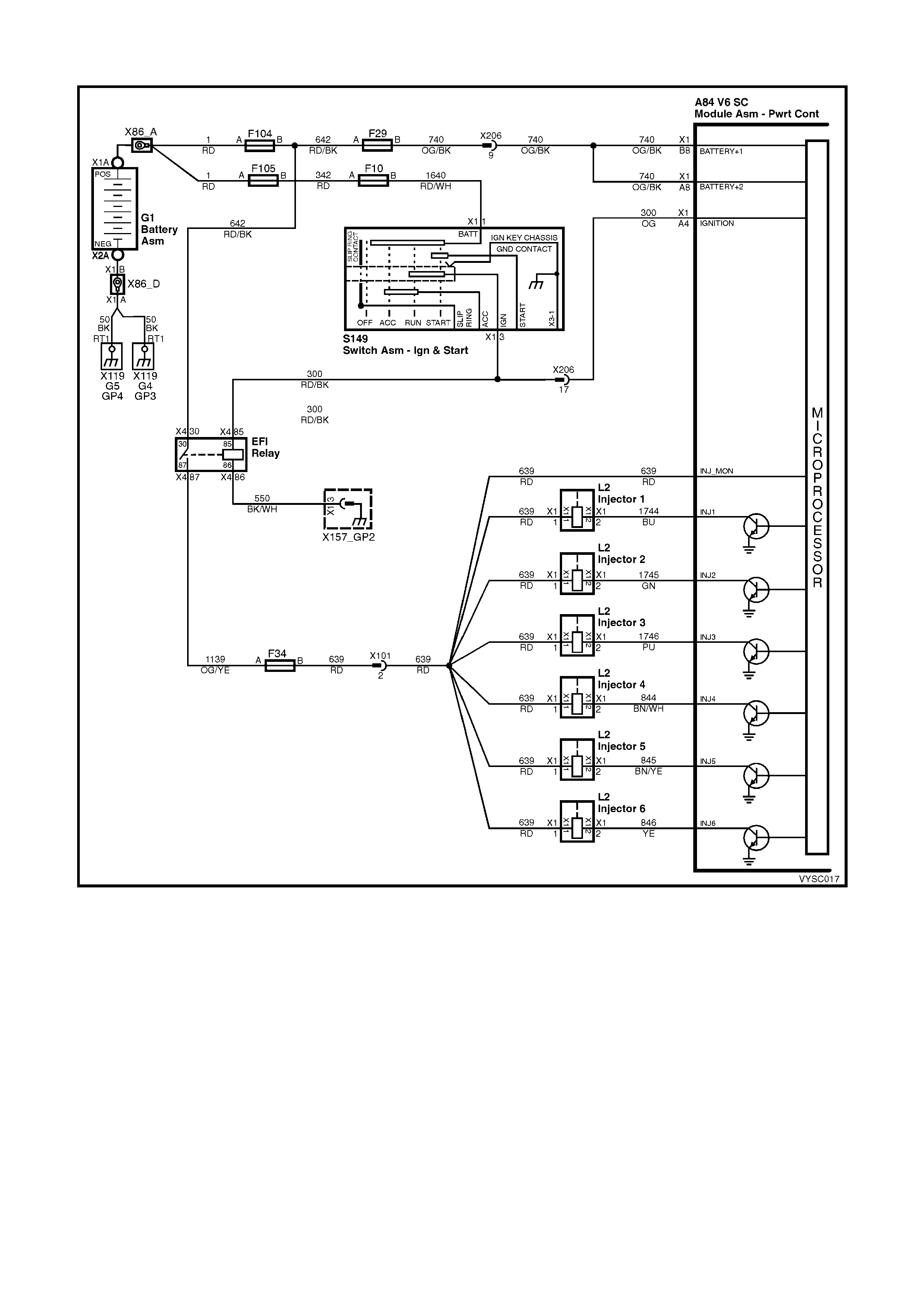
2.11 V6 PCM – FUEL INJECTOR CIRCUIT DIAGNOSIS
Figure 6C2-2C-18 – Fuel Injector Circuit
CIRCUIT DESCRIPTION:
The PCM will enable an injector on the intake stroke of each cylinder. Individual cylinder fuel control is referred to as
Sequential Multiport Fuel Injection (SFI).
Battery voltage is supplied directly to the fuel injectors. The PCM controls each injector by grounding the control
circuit via an internal switch called a driver. The primary function of the driver is to supply the ground for the
component being controlled.
DIAGNOSTIC AIDS:
• For an intermittent condition, refer to 6C2-2B SYMPTOMS in this Section.
TEST DESCRIPTION:
NOTE: The number(s) below refer to the step number(s) on the diagnostic table.
4. This step checks to see if each injector is functioning properly, electrically.
6. This step checks to see if there is a short to ground in the injector ignition feed circuits.
9. This step checks for an open or short to ground in the injector driver circuit.
A84 V6 S/C X1 A84 V6 S/C X3 L2 X206
Figure 6C2-2C-19
V6 PCM – FUEL INJECTOR CIRCUIT DIAGNOSIS
STEP ACTION VALUE YES NO
1. Was the "On-Board Diagnostic" (OBD) System Check
performed? Go to Step 2 Go to
OBD
System Check
in this Section.
2. 1. Check injector fuse F34. If faulty, replace fuse.
Was a problem found? Go to Step 3 Go to Step 6
3. 1. Turn ignition OFF.
2. Disconnect all the injector harness connectors.
3. Turn ON the ignition leaving the engine OFF.
4. Using a test lamp connected to ground, probe each
injector harness ignition feed circuit.
Does the test lamp illuminate for all injectors?
Go to Step 4 Go to Step 8
4. 1. Turn ignition OFF.
2. Connect the injector test lamp (ST 8329) to isolate the
injector harness to each of the injectors one at a time.
3. Start the engine and idle.
Does the test lamp flash for all injectors?
Go to Step 5 Go to Step 9
5. 1. Inspect the injector harness terminals for correct
terminal tension, on the connector’s that did not flash
the test lamp.
2. Replace terminal as necessary.
Was a repair necessary?
System OK Go to Step 13
6. 1. Turn ignition OFF.
2. Disconnect the injector harness connectors.
3. Using a test lamp connected to B+, probe the injector
harness ignition feed circuit at each injector.
Does the test lamp illuminate?
Go to Step 11 Go to Step 7
7. 1. Measure the resistance of each injector that is
powered by the fuse that is open, using a DMM.
Does any injector measure less than the specified value?
11.4 Ω Go to Step 13 Go to Step 12
8. 1. Repair the injector ignition feed circuit that did not
illuminate the test light.
Is the action complete?
Verify Repair –
9. 1. Turn ignition OFF.
2. Disconnect the PCM connector A84 X3.
3. Check the injector driver circuit that did not flash the
test light, for an open or short to ground.
Is the injector driver circuit open or shorted to ground?
Go to Step 10 Go to Step 15
10. 1. Repair injector driver circuit for an open or short to
ground.
Is the action complete?
Verify Repair –
11. 1. Repair the grounded ignition feed circuit to the
injectors.
Is the action complete?
Verify Repair –
12. 1. Repair short to volatge in the injector ignition feed
circuit.
Is the action complete?
Verify Repair –
13. 1. Replace the faulty injector(s) that was isolated. Refer
to Fuel Injector Replacement, in 6C2-3 SERVICE
OPERATIONS.
Is the action complete?
Verify Repair –

STEP ACTION VALUE YES NO
14. 1. Replace PCM. Refer to 6C2-3 SERVICE
OPERATIONS, for PCM Programming and Security
Link procedure.
Is action complete?
Verify Repair –
15. 1. Inspect the appropriate injector circuit for the following:
• Poor connections at the injector and the PCM
terminal.
• Intermittent short to ground.
• Intermittent opens.
If a problem is found, repair the circuit as necessary.
Did you find and correct the condition?
Verify Repair Go to Step 14