
SECTION 6C2-2 - DIAGNOSIS – V6
SUPERCHARGED ENGINE
IMPORTANT
Before p erf orming any Service O p eratio n o r ot her p roced ure describ ed in th is Sect ion , refer t o Sect ion 00
CAUTIONS AND NOTES for correct workshop practices with regard to safety and/or property damage.
CONTENTS
1. GENERAL DESCRIPTION
1.1 DIAGNOSTIC PRECAUTIONS
1.2 BLOCKING DRIVE WHEELS
1.3 VISUAL/PHYSICAL INSPECTION
1.4 BASIC KNOWLEDGE & TOOLS REQUIRED
1.5 ELECTROSTATIC DISCHARGE DAMAGE
1.6 DIAGNOSTIC INFORMATION
SELF DIAGNOSTICS
CHECK POWERTRAIN MALFUNCTION
INDICATOR LAMP (MIL)
INTERMITTENT CHECK POWERTRAIN (MIL)
DATA LINK CONNECTOR (DLC)
2. STRATEGY BASED DIAGNOSTICS
3. DIAGNOSTIC TROUBLE CODES
CURRENT DIAGNOSTIC TROUBLE CODES
HISTORY DIAGNOSTIC TROUBLE CODE
HOW DTC HISTORY WORKS
HOW TO USE DTC HISTORY CODE
INFORMATION
READING DTCS
CLEARING DTCS
CLEARING DTC HISTORY
IGNITION CYCLE DEFAULT
PCM SLEEP TEST
PCM LEARNING ABILITY
TRANSMISSION ADAPT FUNCTION
4. TABLE A – V6 SUPERCHARGED PCM
ON-BOARD DIAGNOSTIC (OBD)
SYSTEM CHECK
5. POWERTRAIN OBD SYSTEM CHECK
DLC TECH 2
TECH 2 EXPLANATION
5.1 TECH 2 USES – POWERTRAIN CONTROL
MODULE (PCM)
MODE F0: NORMAL MODE
MODE F1: DIAGNOSTIC TROUBLE CODES
MODE F2: DATA DISPLAY
MODE F3: SNAPSHOT
MODE F4: MISC. TESTS
MODE F5: FUNCTION TESTS
MODE F6: STALL DATA
TECH 2 USE WITH INTERMITTENT FAULTS
TECH 2 LIMITATIONS
5.2 TECH 2 : PCM NORMAL MODE
TECH 2: PCM NORMAL MODE DESCRIPTIONS
TECH 2: ENGINE DATA
TECH 2: ENGINE DATA DESCRIPTIONS
TECH 2: AUTOMATIC TRANSMISSION DATA
TECH 2: AUTOMATIC TRANSMISSION DATA
DESCRIPTIONS
6. DIAGNOSTIC TABLES
6.1 INTRODUCTION
6.2 WRITING THE REPAIR ORDER
6.3 QUESTIONS
"WHO"? QUESTIONS
"WHAT"? QUESTIONS
"WHEN"? QUESTIONS
"WHERE"? QUESTIONS
"HOW"? QUESTIONS
SUMMARY
VERIFYING THE COMPLAINT
EEPROM
1. GENERAL DESCRI PTI O N
This is where to start all driveability and emissions diagnosis, once you read and understand Section 6C2-1
GENERAL INFORMATION in this Section. The beginning of Section 6C2-2A contains reference material such as
wiring diagrams, control m odule terminal end views, and engine component locations. Remember, this inform ation
is for ref erence only and is not intended to be used as a star t to diagnosis. Always start diagnosis on the page titled
“Powertrain OBD System Chec k” . This chec k ver ifies that the diagnos tic circ uits are operating properly, then directs
you to the correct Service Information location for specific diagnosis.
If the initial steps in the Powertrain OBD System Check reveal a pr oblem , or if the engine does not star t, you will be
using one or m ore tables in Section 6C2-2A in this Section for diagnosis. T he Powertrain OBD System Check will
send you to the correct table. T hese tables f ollow the Powertrain OBD Sys tem Check and problem s that prevent the
engine from starting.
If the Powertrain OBD System Check shows that diagnostic trouble codes have been stored, proceed to the
appropriate Diagnostic Trouble Code (DTC) diagnosis pages. If more than one diagnostic trouble code has been
stored, always start diagnostic trouble code diagnosis with the lowest diagnostic trouble code number and work
upward. Diagnostic trouble code diagnosis pages start immediately after the diagnosis tables in Section 6C2-2A.
1. 1 DIAGNOSTIC PRECAUTIONS
The Following Requirements Must Be Observed When Working On Vehicles.
1. Before removing any PCM system component, disconnect the battery ground lead.
2. Never start the engine without the battery being solidly connected.
3. Never separate the battery from the on board electrical system while the engine is running.
4. When charging the battery, disconnect the battery from the vehicle's electrical system.
5. Never subject the PCM to temperatures above 80° C i.e. paint oven. Always remove control unit first if this
temperature is to be exceeded.
6. Ensure that all cable harness plugs are connected solidly and that battery terminals are thoroughly clean.
7. The powertrain managem ent s ystem harnes s connec tors are des igned to fit in only one way; there are indexing
tabs and slots on both halves of the connector. Forcing the connector into place is not necessary if it is being
installed with the proper orientation. Failure to take care to match the indexing tabs and slots to ensure the
connector is being installed correctly can cause damage to the connector, the module, or other vehicle
components or systems.
8. Never connect or disconnect a PCM wiring harness connector when the ignition is switched ON.
9. Before attempting any electric Arc welding on the vehicle, disconnect the battery leads and the PCM
connectors.
10. When steam cleaning engines, do not direct the steam cleaning nozzle at PCM system components. If this
happens, corrosion of the terminals can take place.
11. Use only the test equipment specified in the diagnostic tables, since other test equipment may either give
incorrect results or damage good components.
12. For all voltage measurements using a voltmeter, a digital multimeter with an internal impedance rating of at
least 10 million ohms per volt (10 megohms) such as the DMM J 39200, must be used .
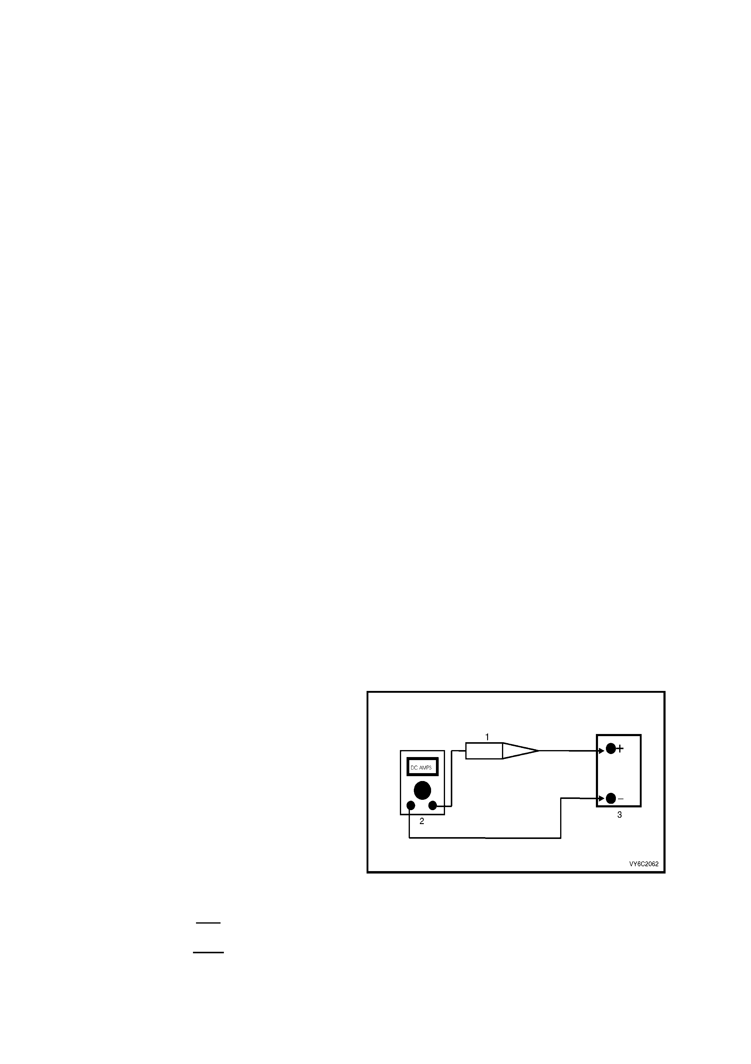
13. When a test light is specified, a "low-power"
test light must be used. Do not use a high -
wattage test light. While a particular brand of
test light is not suggested, a sim ple test on any
test light will ensure it to be OK for PCM circuit
testing. Connect an accurate ammeter (such as
the high-im pedance digital m ultim eter ) in series
with the test light being tested, and power the
test light-ammeter circuit with the vehicle
battery.
Legend:
1. Test Lamp
2. Digital Multimeter, Set to DC Amps
3. 12 Volt Battery
If the ammeter indicates less than 0.3 A (300 mA)
current flow, the test light is OK to use.
If the am m eter indic ates more than 0.3 A (300 mA)
current flow, the test light is NOT OK to use.
Figure 6C2-2-1

1.2 BLOCKING DRIVE WHEELS
The vehicle drive wheels should always be chocked and the parking brake firmly applied while checking any
system.

1.3 VISUAL/PHYSICAL INSPECTION
A car ef ul vis ual and physical ins pection mus t be per f or med as par t of any diagnostic proc edure. This c an of ten lead
to fixing a problem without further steps. Inspect all the wires in the engine compartment for bad connections,
burned or chafed spots, pinched wires, or contact with sharp edges or hot exhaust manifolds. Check beneath the air
cleaner, the compressor, the generator, etc. This visual/physical inspection is very important. The inspection must
be done carefully and thoroughly.

1.4 BASIC KNOWLEDGE AND TOOLS REQUIRED
To use this service manual most effectively, a general understanding of basic electrical circuits and circuit testing
tools is required. You should be familiar with wiring diagrams, the meaning of voltage, ohms, amps, the basic
theories of electricity, and understand what happens in an open or shorted circuit.
To perform system diagnosis, the following tools are required.
• A Tech 2
• A test light
• A digital multimeter with 10 megohms impedance
• A vacuum gauge
• A fuel pressure gauge and suitable fittings
• Fuel injector coil/balance tester
• IAC motor analyser
Familiarise yourself with the tools and their uses before attempting diagnosis. Special tools that are required for
system service and the ones described above are illustrated in Section 6 SPECIAL TOOLS, at the end of this
Section.

1.5 ELECTROS TATIC DISCHARGE DAMAGE
Electronic components used to control the systems are often designed to carry very low voltage. They are very
susc eptible to dam age caused by electr ostatic discharge. It is possible for less than 100 volts of static electricity to
cause damage to some electronic components.
By comparison, it takes as much as 4,000 volts for a person to even feel the zap of a static discharge.
There are several ways for a person to becom e statically charged. The m ost common methods of charging are by
fric tion and by induction. An ex ample of charging by friction is a per son sliding acr oss a car seat, in which a charge
of as much as 25,000 volts can build.
Charging by induction occurs when a person with well-insulated shoes stands near a highly charged object and
mom entarily touches ground. Charges of the same polarity are drained off, leaving the person highly charged with
the opposite polarity. Static charges of either type can cause damage, therefore, use care when handling and
testing the electronic components.
NOTE: To prevent possible Electrostatic Discharge damage:
Do Not touch the PCM connector pins or soldered components on the PCM circuit board.
1.6 DIAGNOSTIC INFORMATION
The diagnostic tables and functional checks in this manual are designed to locate a faulty circuit or component
through logic based on the process of elimination. The tables are prepared with the understanding that the vehicle:
• Functioned correctly at the time of assembly.
• There are no multiple faults.
• The problem currently exists.
The PCM perf orm s a c ontinual self -diagnosis on cert ain control f unctions . This diagnostic c apability is supported by
the diagnostic procedures. The PCM indicates the source of a fault through the use of Diagnostic Trouble Codes
(DT C’s ). The DT C’s are two digit codes . When a f ault is detec ted by the PCM, a diagnostic trouble code will set and
the Check Powertrain Malfunction Indicator Lamp (MIL) indicator may be activated.
SELF-DIAGNOSTICS
The PCM performs system self diagnostics. The PCM can detect and often isolate system faults. W hen a fault is
detected, the PCM sets a DT C that represents the ar ea of the fault. The PCM m ay or may not turn ON the "Check
Powertrain" Malfunction Indicator Lamp (MIL).
CHECK POWERTRAIN MALFUNCTION INDICATOR LAMP (MIL)
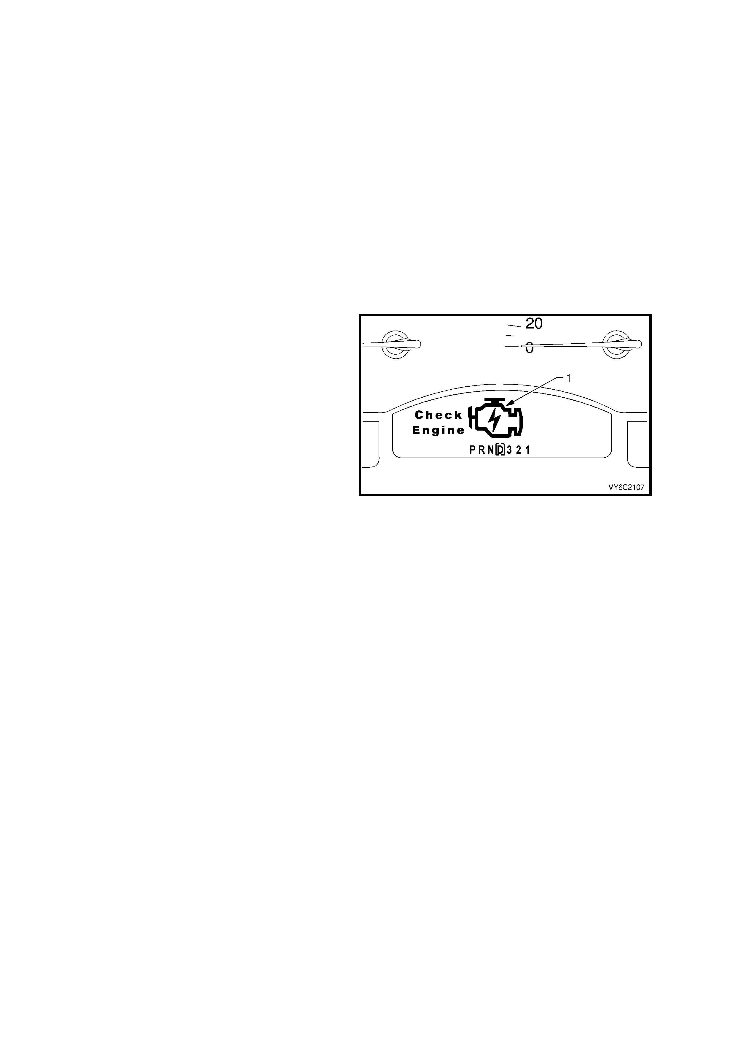
The instrument receives Check Powertrain MIL
information from the PCM via the serial data bus
normal mode message. On receiving this message,
the instrument will activate the Check Powertrain
MIL (1). The Check Powertrain MIL is a symbol of
an engine with the words ”Check Engine” next to
the engine symbol.
If the PCM detects a problem that requires that the
lamp be activated, it will command the instrument
to activate the Check Powertr ain MIL. Not all DTCs
require the Check Powertrain MIL to be ac tivated. If
the Check Powertrain MIL is activated, the self-
diagnostic system has detected a problem. If the
problem goes away, the Check Powertrain MIL will
be deactivated after 10 seconds or once the
ignition has been cycled, but a Diagnostic Trouble
Code (DTC) will remain stored in the PCM.
If the instrument does not receive a normal mode
message from the PCM, the instrument will display
“Servi ce Error Contact Retailer”.
Figure 6C2-2-2 – Check Powertrain MIL
W hen the Check Powertrain MIL rem ains activated, or when a fault is suspected due to a driveability or emissions
problem , per f orm the ” On- Board Diagnos tic System Chec k”. Ref er to POWERTRAIN OBD SYSTEM CHECK in this
Section. These checks will help identify faults which may not be detected if other diagnostics are performed.
INTERMITTENT CHECK POWERTRAIN MALFUNCTION INDICATOR LAMP (MIL)
In the case of an ”intermittent” problem, the Check Powertrain MIL may activate for ten seconds and then
disappear. The corresponding DTC will be stored. The DTC will rem ain stored until the battery voltage to the PCM
has been disconnected or until it is erased using Tech 2. When unexpected diagnostic trouble codes appear,
chances are that these diagnostic trouble codes were set by an intermittent fault.
An intermittent DTC may not re-set. If an intermittent fault occurs, do not use a Diagnostic Trouble Code Table.
Consult the "Diagnostic Aids" on the facing page. The diagnostic table corresponds to the intermittent diagnostic
trouble code.
Section 6C2-2B, SYMPTOMS TABLES also covers the topic of "Intermittents." A physical inspection of the
applicable sub-system most often will resolve the problem. Tech 2 also has several features which can help in
diagnosing intermittent problems.
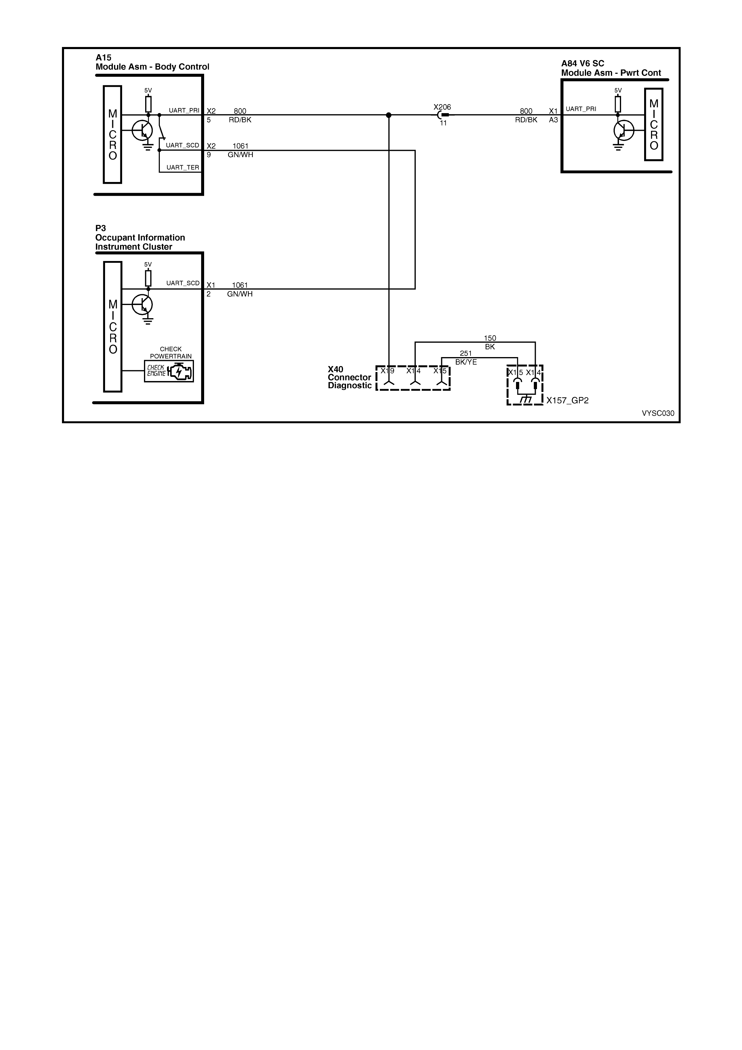
Figure 6C2-2-3 – Check Powertrain Lamp Circuit
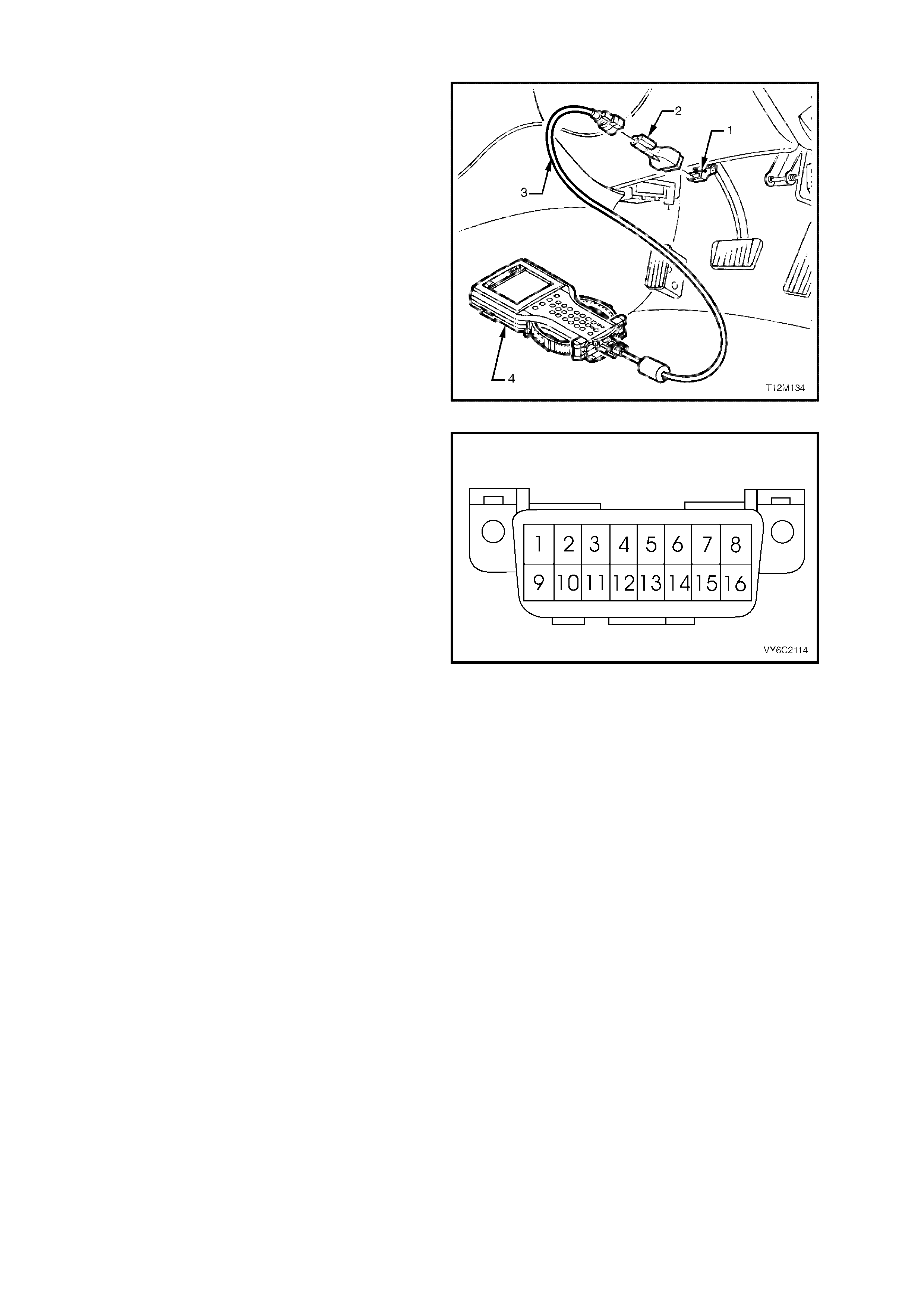
DATA LINK CONNECTOR (DLC)
The DLC is a standardised 16 way connector
located below the instr ument panel and clos e to the
steering column.
Legend:
1. Data Link Connector (DLC)
2. DLC Adaptor
3. DLC Cable
4. Tech 2
Figure 6C2-2-4 – Data Link Connector (DLC) Location
1. The DLC pin 1 is the Secondary UART serial
data circ uit. T ech 2 does not com m unicate with
anything on terminal 1 this is only used for
engineering purposes.
2. Pin 2 is the Class II serial data circuit that is
only used in GEN III V8 engine applications.
This circuit is used to communicate only to the
GEN III V8, PCM.
3. Pin 4 is the ground cir cuit for T ech 2, while Pin
5 is an auxiliary ground, that s hould be used to
ground the Diagnostic Test Enable Circuits,
where used.
4. The DLC pin 9 is the prim ary UART serial data
circuit. Tech 2 uses this circuit to read serial
data information from the PCM, BCM,
Instruments, Occupant Climate Control,
Supplemental Inflatable Restraint System and
the ABS/TCS Control Modules.
5. The DLC pin 12 is the ABS/TCS Diagnostic
Test Enable circuit. T his circuit when jum pered
to DLC pin 5 will cause the ABS/TCS Control
Module to enter the Diagnostic Mode and f lash
out ABS/TCS diagnostic trouble codes.
6. T he DLC is designed to provide battery voltage
to pin 16 from fuse F29. This circuit is used to
power Tech 2.
Figure 6C2-2-5 Data Link Connector (DLC)
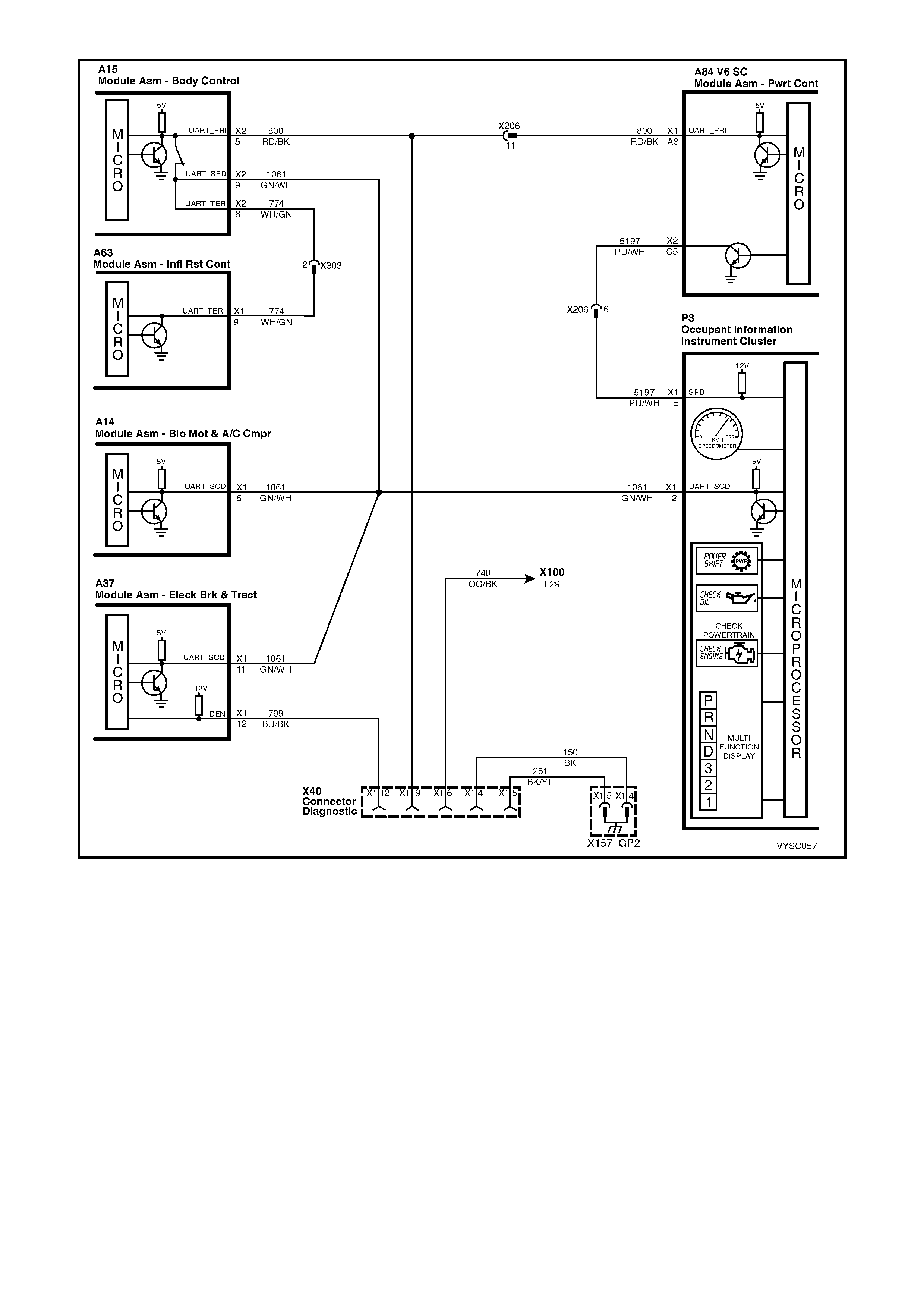
Figure 6C3-2-6 – Data Link Connector Circuits

2. STRATEGY BASED DIAGNOSTICS
The strategy based diagnostic is a uniform approach to repair all Electrical/Electronic systems. The diagnostic flow
can always be used to resolve an Electrical/Electronic system problem and is a starting point when repairs are
necessary. The steps below are defined to instruct the technician how to proceed with a diagnostic. Steps below
also refer to step numbers found on the Strategy Based Diagnostic table.
1. Verify the Customer Concern: To verify the customer concern, the technician should know the normal
operation of the system.
2. Preliminary Check: Conduct a thorough visual and operational inspection, review the service history, detect
unusual sounds or odours, and gather diagnostic trouble code information to achieve effective repair.
3. Check Bulletins and Other Service Information: This should include Dealer letters, and Service Techlines
and Service Training publications.
4. Service Information (Manual) System Check(s): System checks verify proper operation of the system. This
will lead the technician in an organised approach to diagnostics.
5. Service Diagnostics (Paper/Electronic)
5.a DTC Stored: Follow the designed DTC table exactly to make an effective repair.
5.b Symptom, No DTC: Select the symptom from the symptom tables and follow the diagnostic paths
or suggestions to complete the repair, or refer to the applicable component/system checks in
Section 6C2-2C FUNCTIONAL CHECKS, in this Section.
5.c No Published Diagnostics: Analyse the complaint and develop a plan for diagnostics. Utilise the wiring
diagrams and theory of operation.
Call Technical Assistance for similar cases where repair history may be available. Combine Technician
knowledge with efficient use of the available service information.
5.d Intermittent: Conditions that are not always present are intermittent. To resolve intermittents, perform the
following steps:
5.d.1 Observe history DTCs, DTC modes.
5.d.2 Evaluate the symptoms and conditions described by the customer.
5.d.3 Use a check sheet or other method to identify the circuit or electrical system component.
5.d.4 Follow the suggestions for intermittent diagnosis found in the service documentation.
The Tech 2 and DMM have data capturing capabilities that can assist in detection of intermittents.
5.e Vehicle Operates As Designed/No Trouble Found: This c ondition may exist when the vehicle is found to
be operating normally. The condition described by the customer may be normal. Verify against another
vehicle that is operating normally. The condition may be intermittent. Contact Technical Assistance if the
concern is common. Verify the complaint under the conditions described by the customer before releasing
the vehicle.
6. Re-examine the Concern: When the complaint cannot be successfully found or isolated, a re-evaluation is
necessary. The complaint should be re-verified and could be intermittent or normal as per step 5.c or 5.d.
7. Repair and Verificat ion Tests: After isolating the cause, the repair should be m ade. T hen validate for proper
operation and verify that the symptom has been corrected. This may involve road testing or other methods to
verify the complaint has been resolved under the following conditions:
• Conditions noted by the customer.
• If a DTC was diagnosed, verify a repair by duplicating conditions for setting the DTC.
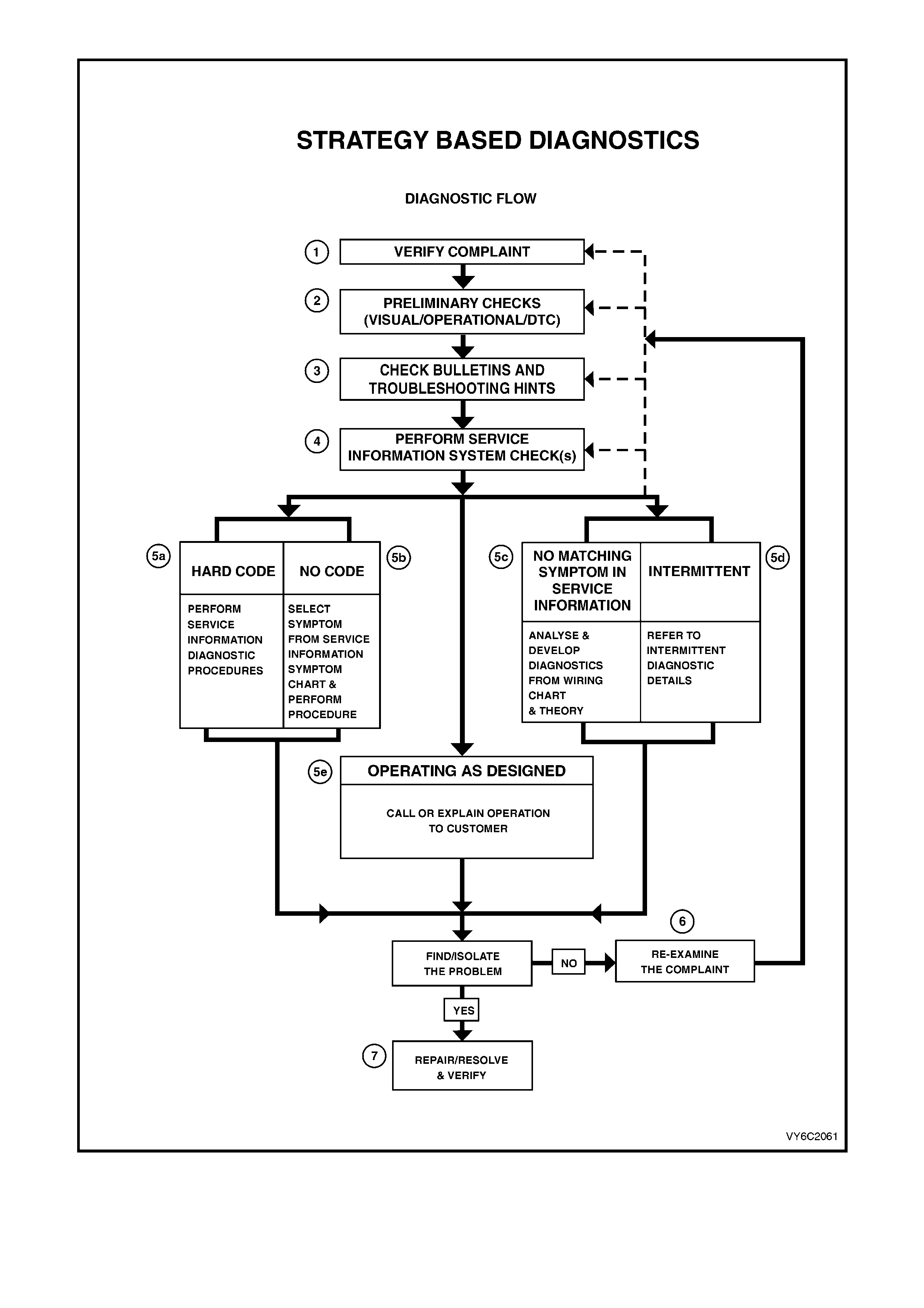
Figure 6C2-2-7 – Strategy Based Diagnostic Table

3. DIAGNOSTIC TROUBLE CODES
CURRENT DIAGNOSTIC TROUBLE CODES
A current diagnostic trouble code is one that is set in the vehicle at this time. The current diagnostic trouble code
can be displayed on Tech 2 by pressing the appropriate button at the appropriate menu. When the diagnostic
trouble code is displayed, a code descriptor will also be listed on the Tech 2 screen. Use of the correct diagnostic
trouble code table will find the cause of the problem.
HISTORY DIAGNOSTIC TROUBLE CODE
A history Diagnostic Tr ouble Code (DTC) is one that was a current trouble code at som e point previously, however,
the fault that caused the diagnostic trouble code to be logged is no longer present. The way to identify whether a
DTC is current or history is to look at the DTC history information parameter "IGN CYCLES". If the number is “0”,
the DTC is current, any other number means it's a history DTC. The diagnostic trouble code can be displayed on
Tec h 2 by pressing the proper button at the appropriate m enu. Use of the diagnostic trouble code tables to find the
cause of the problem for the history diagnostic trouble code may lead to replacement of good components.
W henever a his tory code is s et, refer to Section 6C2-2B SYM PTOM S and also look at the "Diagnostic Aids " listed
on the diagnos tic trouble codes facing page for criteria to s et the DTC. History diagnostic trouble c odes are usually
caused by intermittent conditions.
HOW DTC HISTORY WORKS
When a DTC is set, up to eleven (11) parameters will always be stored with it. The first four (4) parameters are:
1 "Engine speed" - RPM when DTC set .
2. "Time from start" - how long the engine had been running when the DTC set.
3. Times occurred, - number (#) of DTC occurrences.
4. "Ignition cycles" - since DTC last appeared.
Depending upon the DTC, up to 7 additional parameters that are related to this specific DTC are also stored. For
exam ple, if DTC 21 T P Sensor Circuit High Voltage were set, the var iable par ameters would be; TPS signal, mas s
air flow, battery voltage, reference voltage and RH LTFT.
HOW TO USE DTC HISTORY CODE INFORMATION
Based upon the inf orm ation that is stor ed in DTC his tory, the Technician can obtain the DT C c riteria when the DTC
set and should be able to get the DTC to become current again by repeating the criteria.
READING DTCS
The provision for communicating with the PCM is the Data Link Connector (DLC). It is attached to the instrument
panel lower right hand trim, directly beneath the steering column. It is used in the assembly plant to receive
information in checking that the engine and transmission are operating properly before they leave the plant. The
diagnostic trouble code( s) st ored in the PCM's m emory can be read with the use of T ech 2, (a handheld diagnostic
scanner plugged into the DLC).
CLEARING DTCS
To clear the c urrent diagnostic trouble code f rom the m em or y of the PCM, either to determ ine if the m alf unction will
occur again or because repair has been completed, the PCM power feed must be disconnected for at least thirty
(30) sec onds. The PCM power feed c an be disconnected by turning the ignition "OFF" and disconnecting fu se F 29
or the positive battery terminal. Tech 2 has a special mode that must be used to clear both history and current
diagnostic trouble codes.
NOTE: To prevent PCM damage, the ignition must be "OFF" when disconnecting or reconnecting PCM power.
CLEARING DTC HISTORY
Tec h 2 is the only tool capable of clearing the DTC history. Disconnecting the battery or removing fus e F29 will not
erase DTC history. Tech 2 sends a special message into the PCM to erase this memory.
IGNITION CYCLE DEFAULT
If the ignition is cycled ("OFF" and "ON") 50 times without a particular fault re-appearing, that DTC will be erased
from PCM memory and the ignition cycle counter in the PCM will be reset to zero.
PCM SLEEP TEST
After the ignition switch is turned "OFF," the PCM will continue to operate for several seconds. During this shut
down, the PCM will return the IAC back to a position to be used on the next start-up, de-energising all the solenoids
and relays, then the PCM will "go to sleep". The PCM can be checked for this sleep test by monitoring the voltage of
DLC terminal "6", it should go from 5 volts to 0 volts. Tech 2 will display updated data until the sleep mode is
activated then the PCM will no longer send out serial data and Tech 2 will display DLC DATA LOST.

PCM LEARNING ABILITY
The PCM has a "learning" ability which allows it to make corrections for minor variations in the engine or
transmission system to improve driveability .
TRANSMISSION ADAPT FUNCTION
The HYDRA-MATIC 4L60-E uses a feedback line pressure control system which has the ability to adapt the
system's line pressure to compensate for normal wear of clutch fibre plates, seals, springs, etc. This "learning"
feature is similar to what is used for engine fuel control, short term fuel correction, long term fuel trim.
The HYDRA-MATIC 4L60-E transmission only uses the adapt function for the 1-2 upshift. The PCM monitors
engine speed to determine if the s hif t is oc cur r ing too fas t ( hars h) or too s low (sof t) and adj usts the pr ess ur e control
solenoid to maintain the correct shif t feel. The line pressure can adapt to values ranging from 35 kPa below, to 70
kPa above normal line pressure.
If the battery is disconnected, to clear diagnos tic trouble c odes or f or other repair, the "learning" pr ocess resets and
begins again. A change m ay be noted in the vehicle's perform ance. T o "teach" the vehicle, res et the IAC valve and
ensure that the engine is at operating temperature. The vehicle should be driven at part throttle, with moderate
acceleration and idle conditions until normal performance returns.

4. TABLE A – V6 SUPERCHARGED PCM
ON-BOARD DIAGNOSTIC (OBD) SYSTEM CHECK
STEP ACTION VALUE YES NO
1. 1. Install Tech 2 scan tool to Data Link Connector.
2. Select V6 Engine.
Does Tech 2 display Identification Data?
Go to Step 2 Go to Table A-2
in this Section
2. 1. Ignition "ON".
2. Using Tech 2 scan tool, check for DTC 31.
Is DTC 31 set?
Go to DTC 31
Table Go to Step 3
3. Does engine crank?
Go to Step 4 Go to
Table A-4.0
4. 1. Using Tech 2 scan tool, select Current DTC(s).
Are any Diagnostic Trouble Codes displayed? Refer to
Applicable DTC
Table.
Start with lowest
DTC
Go to Step 5
5. Does engine start and continue to run?
Go to Step 6 Go to
Table A-3.1
6. 1. Ignition "ON", engine "STOPPED".
2. Compare Tech 2 scan tool data with typical values
shown on scan data page.
Are values normal or within typical ranges?
Go to Step 7 Refer to
indicated
"Component(s) –
System" checks
in this Section.
7. 1. Run engine until normal operating temperature is
reached.
2. Run engine at 1500 revolutions per minute for 2
minutes, then idle engine.
3. Compare Tech 2 scan data with typical values
shown on Scan Data page in this Section.
Are values normal or within typical ranges?
Refer to
"Symptom"
Diagnosis
Tables" in
Section 6C1-2B
in this Section.
Refer to
indicated
"Component(s) –
System "checks
in this Section.
Figure 6C2-2-8 – Example of On-Board Diagnostic System Check

5. POWERTRAIN OBD SYSTEM CHECK
After the visual and physical underhood inspection, the Powertrain OBD System Check is the starting point for all
diagnostic procedures or finding the cause of an emissions test failure.
All diagnostic procedures must always begin with the Powertrain OBD System Check. This check represents an
organised approach for identifying system problems.
The ‘Powertrain OBD System Check’ makes an initial check of the system, which then directs the Technician to
other tables in Section 6C2-2A DIAGNO STIC TABLES. It mus t be used as a star ting point for all proc edures. The
entire Section is set up in a specific order, that is, the Powertrain OBD System Check will lead the technician to
other tables, and those tables may lead to still other tables. THE SEQUENCE MUST BE FOLLOWED. The
engine/transmission control system uses many input signals and controls many output functions. If the correct
diagnostic sequence is not followed, incorrect diagnosis and replacement of serviceable parts may happen.
Diagnostic tables incorporate diagnosis procedures using a Tech 2 where possible. This Tech 2 is a sm all hand-
held computer in itself. Its job is to give information to a technician about what is happening in the powertrain
management system.
The Data Link Connector (DLC) is used by the assem bly plant to perform end-of -line tests . This connector can also
be used by the Technician to m onitor certain inputs and outputs, as seen by the electronic control module. Tech 2
reads and displays the information (serial data) supplied to the DLC from the Powertrain Control Module (PCM).
The correct procedure to diagnose a problem is to follow three basic steps.
1. Are the On-Board Diagnostics working?: This is determined by performing the Powertrain OBD System
Check. Since this is the starting point for the diagnostic procedures or finding the cause of a failure, always
begin here.
If the On- Board Diagnostics ar en't working, the Powertrain O BD System Check will lead to a diagnostic table in
this section to correct the problem. If the On-Board Diagnostics are working correctly, the next step is:
2. Is there a Diagnostic Trouble Code stored?: If a diagnostic trouble code is stored, go directly to the
numbered diagnostic trouble code table in Section 6C2-2A DIAGNOSTIC TABLES. This will determine if the
fault is still present. If no diagnostic trouble code is stored, then:
3. Observe Serial Data transmitted by the PCM: This involves reading the information available on the Serial
Data Stream with a Tech 2 . Information on this tool and the meaning of the various displays can be found in the
succ eeding paragraphs. T ypical data readings under a par ticular oper ating condition can be found on the "T ech
2 Data" page.
DLC TECH 2
The PCM can communicate a variety of information through the DLC connector. This data is transmitted at a high
frequency which requires a Tech 2 for interpretation.
TECH 2 EXPLANATION
To explain how Tech 2 works, let's think for a minute about how a television works. A television is an electronic
device that r eceives and proces ses inf ormation, and s ends out inform ation in a f orm that c an be understood by the
person watching it. The television receives a signal (from a transmitting station) that is not usable to the person.
The television processes it, then sends the signal to a screen. The person can then see the information that the
television trans mitting station s ent out. T ech 2 is like the televis ion because it also pr ocesses inform ation, sent to it
by the PCM.
The inf or mation is s ent out of the PCM to the Data Link Connector (D LC) s er ial data line. T ec h 2 plugs into the data
link connector, and the information is sent to the tool on its cable. Tech 2 processes the information, and "sends"
the signal to a display screen on the tool.
Just like a televis ion, you can selec t which "station" you want to s ee. The diff erence is instead of s eeing the picture
on a television, you "see" the display screen, and the "stations" that you can select on a Tech 2 are the different
input and output signals that are being processed by the PCM.
Tec h 2 has the ability to send m essages back to the PCM to do dif ferent things suc h as switch outputs "OFF " and
"ON." This allows the technician to control the PCM. This control only lasts as long as Tech 2 is connected.
5.1 TECH 2 USES - POWERTRAIN CONTROL MODULE (PCM)
Tech 2 is a useful and quick way of comparing operating parameters of a poorly operating engine or transmission
with a known good one. For example, a sensor may shift its value but not set a DTC. Comparison with a known
good vehicle may uncover this problem.
Tech 2 allows a quick check of sensors and switches which are inputs to the PCM. The PCM in the vehicle sends
out information to Tech 2 at a very fast rate, and the display on the tool can update quicker than a digital multimeter.
Tec h 2 allows a technic ian to manipulate wiring harness es or c omponents under the vehic le while observing Tech 2
readout. This can help in locating intermittent connections.
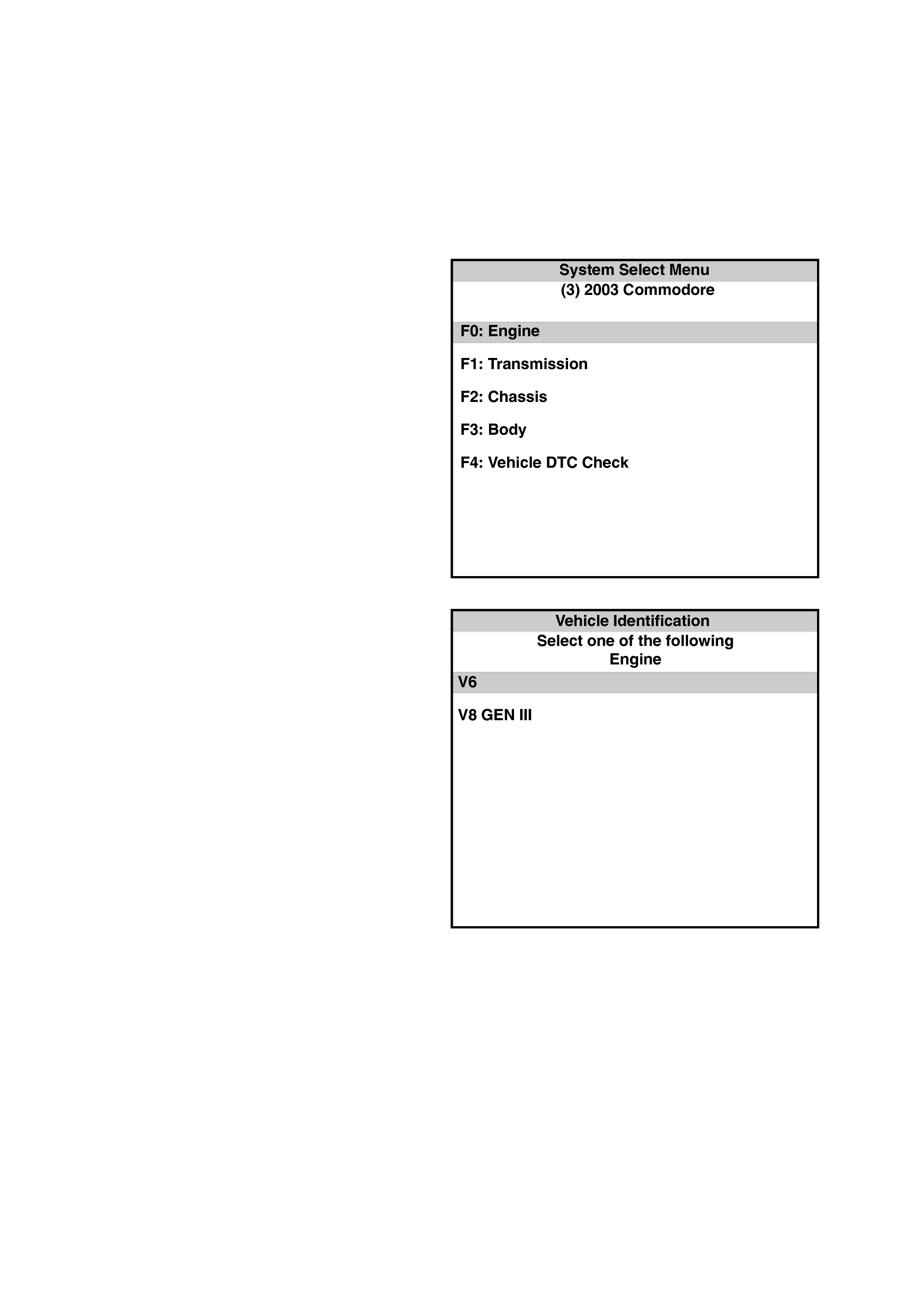
After you enter the c orrect vehicle inf ormation, the f irst display on Tech 2 will reques t what type of system to select
from.
The following is a list of systems the Tech 2 will
display:
F0: Engine
F1: Transmission
F2: Chassis
F3: Body
F4: Vehicle DTC Check
Figure 6C2-2 -9
After selecting F0: ENGINE, Tech 2 will display:
V6
V8 GEN III
Figure 6C2-2 -10
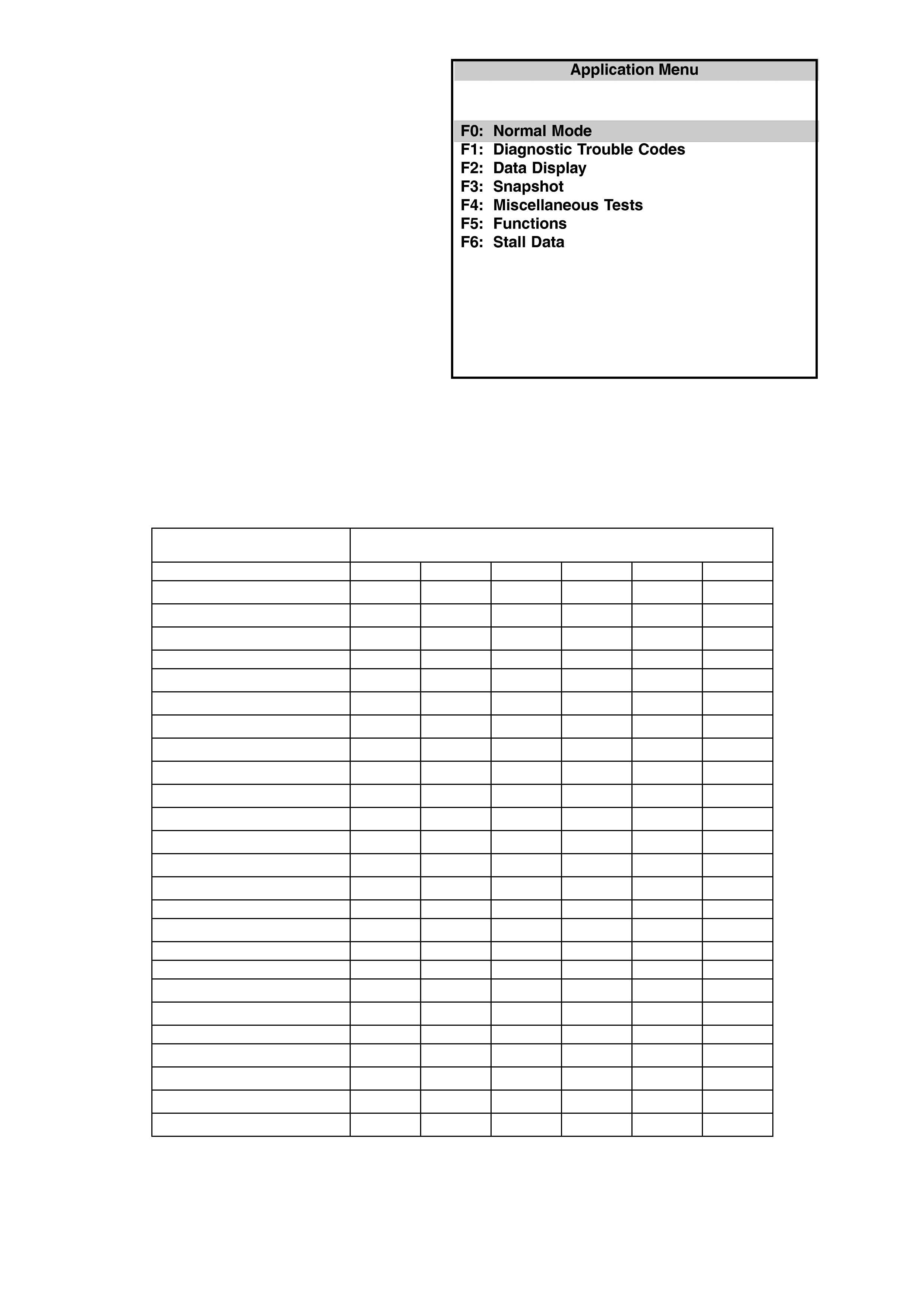
Once the correct engine has been selected, Tech 2
will now display the Application Menu with the
following eight functions for diagnosis and service
of the PCM system.
F0: Normal Mode
F1: Diagnostic Trouble Codes
F2: Data Display
F3: Snapshot
F4: Miscellaneous Tests
F5: Function Tests
F6: Stall Data
Figure 6C2-2-11
MODE F0: NORMAL MODE
In this mode, the will display various engine and transmission data and vehicle information.
The following PCM Normal Mode controller usage table, indicates specific Control Modules using the PCM supplied
report status information:
PCM Normal Mode Controller Usage Table
PCM Normal Mode
Parameters Used by:
String BCM INST ECC ABS/ETC SRS AUDIO
Engine Speed √
√√
√
Coolant Temperature √
√√
√ √
√√
√
Vehicle Speed √
√√
√ √
√√
√
√
√√
√
A/C Clutch
A/C Pressure √
√√
√
Low Speed Fan Request √
√√
√
Low Fan Run ON √
√√
√
Theft Status √
√√
√
PCM DTC Status √
√√
√
Check Powertrain MIL √
√√
√
MFD Message √
√√
√
Fuel Used √
√√
√
Fuel Flow Rate (Instantaneous) √
√√
√
Engine Type
√
√√
√
Transmission Coding
Fuel Type √
√√
√ √
√√
√
Engine Oil Change
Transmission Oil Change
Shift Pattern √
√√
√
Torque Multiplier
√
√√
√
High Coolant Temperature
Oil Pressure Switch √
√√
√
PRNDL Switch √
√√
√
Commanded Gear √
√√
√
PCM Chime √
√√
√

MODE F1: DIAGNOSTIC TROUBLE CODES
In this test mode, DTCs stored by the PCM may be displayed or cleared. W hen entering this m ode there are four
modes:
F0: Read Current DTC
F1: Read History DTC
F2: Clear Current DTC
F4: Clear History DTC
MODE F2: DATA DISPLAY
In this test mode, Tech 2 continuously monitors system data, such as: engine speed data, engine coolant
temperature etc. When entering this mode, there are three modes;
F0: All Data
Displays all engine input and output data.
F1: Inputs
Displays all input data to the PCM.
F2: Outputs
Displays all output data from the PCM.
MODE F3: SNAPSHOT
In this tes t mode, Tech 2 c aptures data bef or e and af ter a s naps hot trigger ing c ondition which may or may not set a
DTC.
MODE F4: MISC. TESTS
In this test mode, Tech 2 performs software override commands of the PCM, to assist in problem isolation during
diagnostics.
F0: OUTPUT TESTS
F0: Fuel Pump
F1: Fuel Pump Speed (Supercharged)
F2: A/C Clutch
F3: Check Powertrain Lamp
F4: High Fan
F5: Canister Purge
F6: Starter Relay
F1: IAC SYSTEM
F0: RPM Control: Used to control engine RPM from 600 RPM to 1675 RPM.
F1: IAC Control: Used to control the IAC open or closed with 25 step increments.
F2: IAC Reset: Used to reset IAC if the IAC is lost or if IAC has been replaced.
F3: Base Idle: Used to set the engine to base idle.
F2: RESET CELLS
Resets all LT Fuel Trim values to 0%
F3: BYPASS SPARK
With the engine running, this command turns off the bypass control circuit.
F4: A/F RATIO
With the engine running, forces air fuel ratio from 11.7 to 17.7.
F5: BOOST CONTROL SOLENOID
With the engine running, increments the boost control PWM signal from 0% to 100% at 4% points per change.

MODE F5: FUNCTION TESTS
The Function Tests mode performs functional tests on the PCM system which help verify proper operation. In this
mode, fault conditions are automatically logged by Tech 2.
Tech 2 also has the ability to send commands to the PCM, instructing the PCM to perform various functions or
tasks. This provides a quick way to determine if a device is operational or not.
In the F5 mode, the following tests can be performed:
F0: IAC Circuit
Designed to confirm IAC motor functions OK and is not losing track of position. Monitor the engine speed.
Repeatedly c ycles the IAC m otor in and out and then m onitors the engine speed. If OK, then ignition "OFF "
and start repeatedly, then stabilise. If the value of final RPM - initial RPM is greater than a calibrated
threshold, then the IAC circuit has failed.
F1: O2 Sensor
Designed to confirm oxygen sensor is functioning OK and not biased or slow responding. Monitors oxygen
sensor voltages and cross counts when in "Closed Loop" and forces rich/lean "Open Loop" operation.
F2: Power Balance
Designed to identify low power output from individual cylinders. Automatically cycles each injector "OFF"
then "ON" while monitoring and recording the RPM drop for each cylinder.
F3: Wiring Harness
Designed to confirm no interm ittent open or shor t circuits; exits in selected circuits . Engine is at idle in "N".
Tec hnician s hould wiggle powertrain harness. T ec h 2 m onitors inputs that should rem ain r elatively stable at
idle such as: ECT, IAT, TP Sensor, VSS, CAM signal present, 18X signal present, EST lines, injector
voltage monitor , batter y, ignition. If discontinuity occurs, Tech 2 logs failure and prompts technician to check
appropriate circuit.
F4: Low Fan
Designed to confirm that the PCM will send a command to the BCM to turn "ON" the low speed fan.
MODE F6: STALL DATA
Designed to capture nine (9) particular data values, when the engine is in a stall condition. This is very similar to
DTC History mode. The PCM will store the first stall condition values, then count the number of stalls after the first.
NOTE: Stall data will be erased from the PCM memory whenever DTC HISTORY DATA is cleared.
TECH 2 : STALL DATA
SCAN POSITION UNITS DISPLAYED
ENGINE SPEED RPM
TIME FROM START TIME
TIMES OCCURRED NUMBER
IGNITION CYCLES NUMBER
IDLE AIR CONTROL STEPS
VEHICLE SPEED KM/H
BATTERY VOLTAGE VOLTS
THROTTLE ANGLE 0-100%
A/C REQUEST NO/YES

TECH 2 USE WITH INTERMITTE NT FAULTS
Tec h 2 allows manipulation of wiring harnesses or c omponents under the bonnet with the engine not running, while
observing Tech 2 readout.
Tech 2 can be plugged in and observed while driving the vehicle under the condition when the "Check Powertrain"
lamp turns ON m om entarily or when the engine dr iveability is m om entarily poor. If the problem seems to be related
to certain parameters that can be checked on Tech 2, they should be checked while driving the vehicle. If there
does not seem to be any connection between the problem and any specific circuit, Tech 2 can be used to m onitor
each parameter, watching f or a period of time to s ee if ther e is any change in the readings that indic ates intermittent
condition.
Tec h 2 can c aptur e and s tore data when the problem oc cur s , so it c an be played back at a s lower rate to determine
what happened to the system. This is called the "SNAPSHOT" mode.
Tech 2 is an easy way to compare the operating parameters of a poorly operating engine with those of a known
good one. For exam ple, a s ensor m ay shift in value but not set a DT C. Com paring the s ensor's readings with those
of a known good vehicle may uncover the problem.
Tec h 2 saves tim e in diagnosis and helps to pr event the replacement of ser viceable parts. The key to using Tec h 2
successfully is the technician's ability to understand the system being diagnosed, as well as understanding Tech 2
operation and limitations . The technician should read the Tech 2 oper ator’s m anual to becom e fam iliar with Tech 2
operation.
With an understanding of the data which the tool displays, and knowledge of the circuits involved, the tool can be
very useful in obtaining information which would be more difficult or impossible to obtain with other equipment.
Tec h 2 does not mak e the use of diagnostic tables unnec essary, nor can it indicate exactly where a pr oblem is in a
particular circuit. Diagnostic Tables incorporate diagnosis procedures that require the use of a Tech 2 .
TECH 2 LIMITATIONS
Tech 2 must receive the signal from the PCM in order to display any useable information. If the PCM sends no
signals to the data link c onnec tor , or the c onnec tion to T ec h 2 is def ec tive, Tech 2 will only display, "WAITING FOR
DAT A - NO DATA RECEIVED FROM PCM." T he Powertrain OBD Syst em Check instructs the Technic ian what to
do if this happens.
Tec h 2 has a f ew lim itations. If T ech 2 is dis playing a PCM "output" function, it displays only the com m and given by
the PCM. That does not mean that the desired action took place. This is similar to the automatic transmission
dashboard gears hift indicator. Jus t because the gearshif t P R N D L pointer indicates the transm ission is in DRIVE
does not mean that the transmission is actually in that gear. To be sure, you must check the linkage and adjustment
at the transmission.
When using Tech 2 to observe one of the PCM "output" functions, such as an idle air control motor, or a TCC
solenoid, the technician must not assume the indicated is the same as the actual. If Tech 2 is displaying TCC
solenoid as being "O N," but the wire to power it is disc onnec ted or defective, the PCM in s ome cas es has no way of
knowing it. The display may indicate the command is "ON," but the device may not be operating!
Tec h 2 saves tim e in diagnosis and helps to pr event the replacement of ser viceable parts. The key to using Tec h 2
successfully for diagnosis is the technician's ability to understand the system being diagnosed, as well as an
understanding of Tech 2's limitations.
With an understanding of the data Tech 2 displays, and knowledge of the circuits involved, Tech 2 is useful in
obtaining information which is difficult or impossible to retrieve with other methods.
Remember, Tech 2 does NOT make using diagnostic tables unnecessary, nor can it tell you exactly where a
problem is in a circuit. Most diagnostic tables incorporate diagnosis procedures that require the use of a Tech 2 .

5.2 TECH 2 : PCM NORMAL MODE
Tech 2 Normal Mode in the table may be used for comparison if a status report is being sent from the PCM.
1. After completing the Powertrain OBD System Check
2. Finding the on-board diagnostics are functioning properly and
3. No DTCs are displayed.
A TECH 2 THAT DISPLAYS FAULTY DATA SHOULD NOT BE USED, AND THE PROBLEM SHOULD BE
REPORTED TO THE MANUFACTURER. THE USE OF A FAULTY TECH 2 CAN RESULT IN MISDIAGNOSIS
AND UNNECESSARY PARTS REPLACEMENT.
Only the parameters listed are us ed in Section 6C2- 2A DIAGNOSTIC T ABLES for diagnos is . For more des c r iption
on the values and use of Tech 2 to diagnos e PCM inputs , refer to the applic able diagnosis table in this Section. If all
values are within the range illustrated, refer to Section 6C2-2B SYMPTOMS.
Test Description: The number(s) below refer to the number(s) on Tech 2, Normal Mode Data Stream table.
1. Tech 2 FO: NORMAL MODE will display scan positions that will be displayed in order. Tech 2 will display nine
(9) sc an position param eters at a tim e. The down arr ow button will s croll down through all of the scan positions
one at a time. After the last parameter is displayed, pressing the down arrow button again, will display scan
position parameters starting at the top of the list again.
2. UNITS DISPLAYED are the available ways of displaying what each parameter is currently operating in, or a
value that is being sensed or being issued by the PCM.
3. TYPICAL DATA VALUE is separated into two parts. Thes e displayed values are typical of a normally operating
vehicle. The IG NITION ON comparis on should be perform ed first as this may lead to a quick identif ication of a
failure. The ENGINE RUNNING data should be compared to the IGNITION ON data as a diagnostic check to
make sure the component or system is operating properly .
4. IGNITION ON values are the typical values that should be seen on Tech 2 with the ignition ON and engine
stopped. Temperature sensors should be compared to the actual temperatures by allowing the sensor to cool
overnight and then comparing their values. A difference of 3-5° C from the actual temperature may indicate a
problem with the s ensor . Us e the diagnostic aids table f or that s ens or to c ompare the r es istanc e to temperatur e
values.
5. ENGINE RUNNING typical data values are an average of display values recorded from normally operating
vehicles at norm ally operating tem perature. T hey are intended to represent what a norm ally functioning system
would typically display.

TECH 2: PCM Normal Mode
TYPI CAL DATA VALUE S
SCAN POSITION Q UNITS DISPLAYED R IGNITION ON T ENGINE RUNNING U
ENGINE SPEED RPM 0 RPM 600 - 650 RPM
(± 50 RPM IN DRIVE )
COOLANT TEMPERATURE DEGREES C Varies +96 C
VEHICLE SPEED km/h 0 0
A/C CLUTCH ON /OFF OFF OFF
A/C PRE SSURE kPa 896 kPa 800 - 1000 kPa A/ C OFF
1600 - 1900 kPa A/C ON
LOW SPEED FAN REQUEST ON / OFF OFF OFF
LOW FAN RUN ON Y E S / NO NO NO
THEFT STATUS NO START / START START START
PCM DTC STATUS NO DTC(s)/DTC(s )
SET NO DTC(s) NO DTC(s)
CHECK POWERTRAIN
MALFUNCTION INDICAT OR
LAMP (MIL) OFF/ON ON OFF
FUEL USED L 00.00 1 - 2 L/Hour
FUEL FLOW RATE 00.00 1 - 2 L/Hour
ENGINE TYPE V6,
V6 SUPERCHARGED,
GEN III V8 V6 SUPERCHARGED V6 SUPERCHARGED
TRANSMISSION CODING MANUAL TRANS.
AUTO TRANS. MANUAL TRANS.
AUTO TRANS. MANUAL TRANS.
AUTO TRANS.
FUEL TYPE PETROL / LPG PETROL PETROL
ENGINE OI L CHANGE OKAY /
SERVICE REQUIRED OKAY OKAY
TRANSMISSION OIL CHANGE OKAY /
SERVICE REQUIRED OKAY OKAY
SHIFT PATTERN POWER/ECONOMY ECONOMY ECONOMY
TORQUE MULTIP LI ER
HIGH COOLANT TEMPERATURE YES/NO NO NO
OIL PRESSURE SWITCH OFF/ON OFF OFF
PRNDL SWITCH INVALID /
P,R,N,D,3,2,1
INVALID
OR
GEAR SELECTED
INVALID
OR
GEAR SELECTED
COMMANDED GEAR P/N R, 1 P/N P/N
PCM CHIME YES/NO NO NO

TECH 2: PCM NORMAL MODE DESCRIPTIONS
A list of explanations for each data message displayed on Tech 2 is listed below. This information will assist in
diagnosing em is sion or dr iveability problems . T he displays can be viewed while the vehicle is being driven. Ref er to
the Powertrain OBD System Check for additional information.
ENGINE SPEED: Tech 2 Displays a range of 0 to 9999 RPM
The engine speed is computed by the PCM from the crankshaft reference input. It should remain close to desired
idle speed under various engine loads with engine idling.
COOLANT TEMPERATURE: Tech 2 Displays a range of -39°C to 140°C
The Engine Coolant T emperature (ECT ) sensor is m ounted in the cylinder head of the left bank. The PCM applies
5.0 volts to the ECT sensor circuit. The sensor is a thermistor which changes internal resistance as temperature
changes. W hen the sensor is cold ( internal resistanc e high), the PCM monitor s a high signal voltage and interprets
the voltage as a cold engine. As the sensor warms (internal resistance decreases), the voltage signal decreases
and the PCM interprets the lower voltage as a warm engine.
VEHICLE SPEED: Tech 2 Displays a range of 0 to 255 km/h
The vehicle speed sensor signal is converted into km/h for display.
A/C CLUTCH: Tech 2 Displays "ON" or "OFF"
Represents the commanded state of the A/C clutch control relay. Clutch should be engaged when ON is displayed.
A/C PRESSURE: Tech 2 Displays a range of 0 to 3195 kPa
The kPa displayed indicates that the PCM is monitoring an A/C Refrigerant Pressure signal voltage. A voltage which
is too high or too low will not allow the A/C compressor clutch to engage.
LOW SPEED FAN REQUEST: Tech 2 Displays "ON" or "OFF
Indicates if the engine cooling fan low speed relay has been commanded ON or OFF.
LOW FAN RUN ON: Tech 2 Displays "NO" or "YES"
This indicates if the PCM is requesting the BCM to turn the Low Speed Fan ON at key OFF.
THEFT STATUS: Tech 2 Displays "NO START" or "START"
Indicates the status of the Theft Deterrent System.
PCM DTC STATUS: Tech 2 Displays "NO DTC(s)" or “DTC SET”
Indicates if a DTC is set. This does not indicate what DTC is set, just informs that DTC(s) are or are not set.
CHECK POWERTRAIN MALFUNCTION INDICATOR LAMP (MIL): Tech 2 Displays "OFF" or "ON"
Indicated if the instrument panel Malfunction Indicator Lamp is ON or OFF.
FUEL USED: Tech 2 Displays a range of 0 to 1000 Litres
When the key is turned ON, and the engine is running, the PCM will calculate FUEL USED during each ignition
cycle.
FUEL FLOW RATE: Tech 2 Displays a range of 0 to 100 litres
Indicates fuel consumption in litres per hour.
ENGINE TYPE: Tech 2 Displays Engine Type
The Tech 2 uses this information for proper Tech 2 software.
TRANSMISSION CODING: Tech 2 Displays “MANUAL” or “AUTOMATIC”
The Tech 2 uses this information for proper Tech 2 software.
FUEL TYPE: Tech 2 Displays “PETROL” or “LPG”
The will display what fuel type the PCM software is set up for.
ENGINE OIL CHANGE: The Tech 2 Displays “OKAY” or “SERVICE REQUESTED”
The will display the status of the engine oil change condition. This display is currently not in use.
TRANSMISSION OIL CHANGE: The Tech 2 Displays “OKAY” or “SERVICE REQUESTED”
The will display the status of the transmission oil change condition. This display is currently not in use.
SHIFT PATTERN: Tech 2 Displays “ECONOMY” or “POWER”
This display shows the state of the POWER/ECONOMY switch.
TORQUE MULTIPLIER: Tech 2 Displays a range of 0 – 13
This display shows a calculated value derived from the Transmission Slip and Commanded Gear values. The
calculated value is used by the ABS/TCS Module.
HIGH COOLANT TEMPERATURE: Tech 2 Displays "NO" or "YES"
This is an indication to the PCM that the engine is running hot.

LOW COOLANT LEVEL: Tech 2 Displays "NO" or "YES"
This is an indication to the PCM that the coolant level is low. If so, the Instrument will activate the Low Coolant MIL.
(Only with GEN III V8 Engine)
OIL PRESSURE SWITCH: Tech 2 Displays "OFF" or "ON"
This is an indication to the PCM if the oil pressure is high or low. If the oil pressure is low, the Instrument will
activate the Check Oil warning icon in the Multi Function Display (MFD).
PRNDL SWITCH: Tech 2 Displays “INVALID” or “P, R, N, D, 3, 2, 1”
This displays if the vehic le is not equipped with a PRNDL switch (INVALID), or if equipped, indicates what gear the
driver has selected.
COMMANDED GEAR: Tech 2 Displays “1, 2, 3, 4”
The gear that the PCM is com manding the tr ansmis sion to be in. In PARK, Tec h 2 will display "1", the comm anded
state of the shift.
PCM CHIME: Tech 2 Displays "NO" or "YES"
This is an indication to the instrument panel allowing the instrument panel to chime if a problem or fault is detected.
TECH 2: ENGINE DATA
The Tech 2 Scan Data listed in the table may be used for comparison:
1. After completing the Powertrain OBD System Check
2. Finding the on-board diagnostics are functioning properly and
3. No diagnostic DTC’s are displayed.
A TECH 2 THAT DISPLAYS FAULTY DATA SHOULD NOT BE USED, AND THE PROBLEM SHOULD BE
REPORTED TO THE MANUFACTURER. THE USE OF A FAULTY TECH 2 CAN RESULT IN MISDIAGNOSIS
AND UNNECESSARY PARTS REPLACEMENT.
Only the parameters listed, are used in Sections 6C2-2A DIAGNOSTIC TABLES, for diagnosis. For more
description on the values and use of Tech 2 to diagnose PCM inputs, re fer to the applicable diagnosis table in this
Section. If all values are within the range illustrated, refer to Section 6C2-2B SYMPTOMS.
Test Description: The number(s) below refer to the number(s) on Tech 2 Engine Data Stream table.
1. Tech 2 F2: DATA LIST will display scan position's that will be displayed in order. Tech 2 will display nine (9)
scan position par ameter s at a time. The down arrow button will scroll down through all of the s c an positions one
at a time . After the last par ameter is displayed, pressing the down arrow button again, will dis play scan position
parameters starting at the top of the list again.
2. UNITS DISPLAYED are the available ways of displaying what each parameter is currently operating in, or a
value that is being sensed or being issued by the PCM.
3. TYPICAL DATA VALUE is separated into two parts. Thes e displayed values are typical of a normally operating
vehicle. The IG NITION ON comparis on should be perform ed first as this may lead to a quick identif ication of a
failure. The ENGINE RUNNING data should be compared to the IGNITION ON data as a diagnostic check to
make sure the component or system is operating properly .
4. IGNITION ON values are the typical values that should be seen on Tech 2 with the ignition ON, and engine
stopped. Temperature sensors should be compared to the actual temperatures by letting the sensor stabilise
overnight and then comparing their values. A difference of 3-5° C from the actual temperature may indicate a
problem with the s ensor . Us e the diagnostic aids table f or that s ens or to c ompare the r es istanc e to temperatur e
values.
5. ENGINE RUNNING typical data values are an average of display values recorded from normally operating
vehicles at norm ally operating tem perature. T hey are intended to represent what a norm ally functioning system
would typically display.

TECH 2 : Engine Data
TYPICAL DATA VALUE S
SCAN POSITION Q UNITS DISPLAYED R IGNITION ON T ENGI NE RUNNING U
ENGINE SPEED RPM 0 RPM ± 100 RPM FROM DESI RED RPM
(± 50 RPM IN DRIVE)
DESIRED IDLE S PEED RPM 0 RP M PCM IDLE COMMAND
(VARIES WITH TEMPERATURE)
ENG. COOLANT TEMP (ECT) VOLTS VARIES VARIES
COOLANT TEMPERATURE DEGREES C VARIES VARIES
IAT SENSOR (INTAKE AIR TEMP) DEGREES C VARIES VARIES
MAF SENSOR FREQUENCY Hz 0 Hz 2200-2500 Hz
MASS AI R FLOW GRAM /SEC 0 g/s 5 – 10 g/s
MASS AI R FLW/CYL mg/ s 0.0 m g/ s 140 to 150 m g/ s
TPS SI GNA L VOLTS 0.25 – 1.25 V 0.25 – 1.25 V
THROTTLE ANGLE 0-100 % 0 % 0 %
RH 02 SENSOR READY YES/NO NO YES
LH 02 SENSOR READY YES/NO NO YES
RH 02 SENSOR mV 447 mV 100-1000 mV AND VARY ING
LH 02 SENSOR mV 447 mV 100-1000 mV AND V ARYING
RH ST FUEL TRIM + 100% to –100% +0% +10% to –10%
LH ST FUEL TRIM + 100% to –100% +0% +10% to –10%
LT FUEL TRIM R + 100% to –100 % +10% to –10% + 10% to –10%
LT FUEL TRIM L + 100% to –100 % +10% to –10% + 10% to –10%
LTFT ENABLED YES / NO NO NO
FUELLING MODE OPEN / CLOSED
LOOP OPEN LOOP CLOS E D LOOP
LTFT CELL CELL # 0 1
RH O2 STATUS RICH / LEAN LEAN LEAN
LH O2 STATUS RICH / LEAN LEAN LEAN
RH O2 CROSS CNTS COUNTS 0 VA RIES
LH O2 CROSS CNTS COUNTS 0 VARIES
STFT DELTA 0 – 100 % 0 % 0 %
LTFT DELTA 0 – 100 % 0 % 0 %
DECEL FUEL CUTOFF NO/YES NO NO
INJ. PULSE TIME ms VARIES 3.25 ms
INJECTOR V OLTA G E VOLTS 11.4 V 14.0 V
AIR / FUE L RATIO % 0.0 : 1 14.7 : 1
PURGE PWM % 0 % 10 %
BATTERY VOLTAGE VOLTS 11.3 V 14.0 V
REFERENCE V O LTS VOLTS 4.99 V 4.99 V
CAM SIGNAL MISSING/PRESENT MISSING PRESENT
IAC POSITION STEPS 169 STEPS 22 STEPS
LITRES P ER HOUR L/HR 00.00 1 – 2 L/hour
IDLE RPM V A RIANT. RPM 0 RPM 0 RPM
SPARK MODE BYPASS/EST BYPASS EST
SPARK ADVANCE DEGREES BTDC 14 ° BTDC + 14° BTDC
KNOCK SI GNAL KNOCK/NONE NONE NONE
KNOCK RETARD # OF DEGREE S 0 ° 0 °
TCC SOLENOID ON / OFF OFF OFF
VEHICLE SPEED KM / H 0 KM/H 0 KM/H
A/C REQUEST ON /OFF OFF OFF
A/C CLUTCH ON /OFF OFF OFF
A/C PRE S S. VOLTS VOLTS 1 – 2 V 1 – 2 V
A/C PRE S SURE kPa 352 kPa 600 – 700 kPa A/C OFF
800 – 1000 kPa A/C ON

TECH 2 : Engine Data (Continued)
TYPICAL DATA VALUE S
SS
S
SCAN POSITION Q
QQ
Q UNITS DISPLAYED R
RR
R IGNITION "ON" T
TT
T ENGINE RUNNING U
UU
U
HIGH SPEED FAN ON / OFF OFF OFF
LOW SPEED FAN REQUEST ON / OFF OFF OFF
THEFT STATUS NO START/START START START
STARTER RELAY OFF/ON ON OFF
FUEL PUMP RELAY ON / OFF OFF ON
SUPERCHARGE D OP TION
(Yes or No depending on what
engine is s el ected) YES/NO YES/NO YES/NO
PWM BOOST
(Only if Supercharged engine is
selected) % 0% 100%
SUPERCHARGER FUEL PUMP
STATE LOW SPEED/
HIGH SPEED HIGH SPEED LOW SPEED
CRANK TIME SEC 0.0 SEC 0.5 SEC
DTC STA T US NO DTC(s)/
DTC(s) SET NO DTC(s) NO DTC(s)
TIME FROM START TIME 0:00:00 VARIES
PROM I.D. FOUR DIGIT NUMB E R
(VARIES WITH PROM
UPDATES) 8808 8808
CHECK POWERTRAIN LAMP OFF/0N ON OFF
REQUESTE D TORQUE Nm 214Nm 642Nm
(Nm W ILL DECREASE WITH ENGINE
LOAD)
ACTUAL T ORQUE Nm 0 Nm
35-45 Nm
(Nm WILL CLOSELY FOLLOW
REQUEST ED TORQUE ONCE WHEEL
SPIN IS DETECTED)

TECH 2: ENGINE DATA DESCRIPTIONS
A list of explanations for each data message displayed on Tech 2 begins as follows. This information will assist in
track ing down emission or dr iveability problem s, since the displays can be viewed while the vehicle is being driven.
Refer to the "On-Board Diagnostic System Check" for additional information.
ENGINE SPEED - Range 0 – 9999 RPM – Engine speed is com puted by the PCM from the crankshaft reference
input. It should remain close to desired idle under various engine loads with engine idling.
DESIRED IDLE - Range 0 – 3175 RPM – The idle speed that is commanded by the PCM. The PCM will
compensate for various engine loads to keep the engine at the desired idle speed.
ECT SENSOR VOLTS/ENG COOLANT TEMP – Range –40°
°°
° C to 151°
°°
° C / 0 – 5 VOLTS – The Engine Coolant
Temperature (ECT) sensor is mounted in the inlet manifold and sends engine coolant temperature information to
the PCM. The PCM applies 5 volts to the coolant temperature sensor circuit. The sensor is a thermistor which
changes internal resistance as temperature changes. W hen the sensor is cold (internal resistance high), the PCM
monitors a high signal voltage which it interprets as a cold engine. As the sensor warms (internal resistance
decreases), the voltage signal will decrease and the PCM will interpret the lower voltage as a warm engine.
IAT SENSOR VOLTS/IAT – Range –40°
°°
° C to 151°
°°
° C – The PCM converts the resistance of the intake air
temperature sensor to degrees. Intak e Air Tem p (IAT) is used by the PCM to adjust fuel delivery and spark tim ing
according to incoming air density.
MAF SENSOR FREQUENCY – Range 0-10,192 Hz – The s ignal that is sent f rom the Mas s Air Flow (MAF) sens or
to the PCM is in the for m of a frequency output. This f requency output changes as the dem and of engine air intake
changes.
MASS AIR FLOW - Range 0-246 gm/s. – The Mass Air Flow (MAF) sens or meas ures the change in the intak e air
flow which results from engine load and speed changes. As intake air flow increases, the air in the inlet manifold
also increases and additional fuel is required.
MASS AIR FLOW/CYL - Range 0-1000 mg/s. - Calculated air flow per each cylinder.
TPS SIGNAL - Range 0 to 5.00 Volts – Used by the PCM to determine the amount of throttle demanded by the
driver. Should read 0.25 - 1.25 volt at idle to above 4 volts at wide open throttle.
TPS ANGLE - Range 0- 100% – Com puted by the PCM f rom TP sensor voltage (Throttle pos ition) should read 0%
at idle, 100% at Wide Open Throttle (WOT).
RH/LH OXYGEN SENSOR READY – Tech 2 Displays "YES" or "NO". Indicates if the 02 sensors have reached
operating temperature.
RH/LH OXYGEN SENSOR – Range 0-1192 – Represents the exhaust sensor output voltage. Should fluctuate
constantly within a range between 100 m V (Lean exhaust) and 1000 m V (Rich exhaust) when operating in "Closed
Loop".
ST FU EL TRIM R/L – Ran ge –100% to 0% to +100% – Short Term Fuel Trim represents a short-term correction to
fuel delivery by the PCM in response to the amount of tim e the oxygen sensor voltage spends above or below the
450 mV threshold. If the oxygen sensor voltage has mainly been below 450 mV, indicating a lean air/fuel mixture,
STFT will increase to tell the PCM to increase fuel delivery to compensate for the indicated lean condition. Under
certain conditions such as extended idle and high ambient temperatures, canister purge may cause STFT to read
less than –10%.
LT FUEL TRIM R/L –100% to 0% to +100% – LTFT is derived by the PCM from the STFT value and is used for
long-term c or r ect ion of f uel deliver y. A value of 0% indicates that fuel delivery requires no compens ation to maintain
a 14.7:1 air/fuel ratio. A value below 0% means that the fuel system has been rich and fuel delivery is being reduced
(decreas ed injector pulse width) to m aintain a 14.7 to 1 A/F ratio. A value above 0% indicates that a lean condition
exists and the PCM has been compensating by adding fuel (increased injector pulse width). LTFT tends to follow
STFT, a value of less than -10% due to canister purge at idle should not be considered unusual.
LTFT ENABLE - Tech 2 Displays "YES" or "NO". – The Long Term Fuel Trim is enabled by the PCM when a long
term fuel correction is required. A YES indicates that the LTFT is enabled, a NO indicates that it is not.
FUELLING M ODE – T ech 2 Displays "OPEN" or "CL OSED" – "Closed Loop" dis played indicates that the PCM is
controlling fuel delivery according to oxygen sensor voltage. In "Open Loop", the PCM ignores the oxygen sensor
voltage and bases the amount of fuel to be delivered on TP Sensor, MAF, coolant and IAT sensor inputs only.
"Closed Loop" operation should begin when the 02 sensor becomes active, engine coolant temperature exceeds
50° C for m ore than 30 seconds and the PCM has seen an RPM of 1,200 or greater for 10 seconds. At extrem ely
high temperature or when towing a trailer, it is pos s ible f or the s ystem to remain in "O pen Loop" oper ation to contr ol
catalytic converter temperatures.
LONG TERM FUEL TRIM CELL (LTFT CELL) – Range 0-34 – LTFT cell is dependent upon engine speed and
ma ss air f low readings and canister pur ge. A plot of RPM vs MAF is brok en into 34 cells. LT FT cell indicates which
cell is currently active.
RH/LH O2 ST ATUS – T ech 2 Displays "RICH" or "LEAN" – Indicates whether exhaus t oxygen sensor voltage is
above (rich) or below (lean) the 450 mV oxygen sensor thres hold voltage. Should change constantly indicating that
the PCM is controlling the air/fuel mixture properly.

RH/LH O2 CROSS CNTS – Range 0-255 – The number of times the oxygen sensor voltage crosses over the
rich/lean threshold during a two second interval.
STFT/LTFT DELTA – Range 0-100%. – The difference (Delta) in % of the STFT/LTFT counts from each bank.
This value is used by the PCM to determine bank to bank fuel trim balance.
DECEL FUEL CUT OF F – T ech 2 Displays "YES" or "NO" – “Yes” dis played indicates that the PCM has detected
conditions appropr iate to operate in deceler ation fuel c ut-off m ode. T he PCM will comm and deceleration fuel cut-of f
mode when a sudden decrease in throttle position has been detected while the vehicle is travelling over a certain
KM/H. While in deceleration f uel cut-of f mode, the PCM will decr ease the am ount of fuel delivered by entering open
loop and decreasing the injector pulse width.
INJ. PULSE WIDTH TIME – Range 0.0 – 999.9 ms. - The "ON" time of the injector as determined by the PCM.
INJECTOR VOLTAGE - Range 0 – 14.0 Volts. System voltage monitoring
AIR/FUEL RATIO - Range 0.00 : 99.99 - The reading reflects the commanded value. This should be at or near
14.7. A lower number indicates a richer commanded air fuel mixture while a higher number indicates a leaner
mixture.
PURGE PWM - Range 0 - 100% - A propor tional signal used to control EVAP Canist er Pur ge f unction. 0% im plies
the valve is commanded fully closed, while 100% implies that the valve is fully open.
BATTERY VOLTAGE – Range 0-25.5 volts – This represents the system voltage measured by the PCM at its
ignition No. 1 feed.
REFERENCE VOLTS – Range 0-5.00 Volts – Indicates the voltage that is supplied to various sensors from the
PCM.
CAM SIGNAL – Range Missing or Present – Signal sent to the PCM by the Cam Sensor. This indicates
movement of the camshaft. This signal is used by the PCM to initiate sequential injection.
IAC POSITION – Range 0-255 Counts – Displays the commanded position of the idle air control pintle in counts.
The higher the number of counts, the greater the commanded idle speed. Idle air control should respond fairly
quickly to changes in engine load to maintain desired idle RPM.
LITRES Per Hour – Range 0-100 - Indicates fuel consumption in litres per hour.
IDLE RPM VARIANT – Range 0-9999 RPM – Indicates the variation in RPM between sampling's of the engine
speed.
SPARK MODE – Tech 2 displays "BYPASS" or "EST" – Indicates what mode of ignition timing the vehicle is
operating under.
SPARK ADVANCE – Range –90 Degree to +90 Deg ree – This is a dis play of the spark advanc e (EST) c alc ulation
which the PCM is issuing to the ignition s ystem . It computes the desired spark advance using data such as engine
temperature, rpm, load, vehicle speed, and operating mode.
KNOCK SIGNAL – Tech 2 Displays "KNOCK" or "NONE" – Indicates whether or not a knock signal is being
detected by the PCM. Should read "NONE" at idle.
KNOCK RETARD – Range 0 Degrees to 90 Degrees – Indicates the amount of spark advance the PCM is
removing from EST in response to the Knock sensor (ESC) signal. Should read 0 degrees at idle.
TCC SOL ENOID – Tech 2 Displays "ON" or "OFF ". – Indicates if the transm ission T CC Solenoid is com m anded
ON or OFF.
VEHICLE SPEED – Range 0-255 km/h – The vehicle speed sensor signal is converted into kph for display.
A/C REQU EST – Tech 2 Displays "YES" o r "NO" – Repr esents the s tate of the A/C reques t s erial data input f r om
the BCM or Occupant Climate Control Module.
A/C CLUTCH – Tech 2 Displays "ON" or "OFF" – Represents the commanded state of the A/C clutch control
relay. Clutch should be engaged when "ON" is displayed.
A/C PRESSURE – Tech 2 Displays 0.0 – 5.00 Volts – Represents the A/C Refrigerant Pressure Sensor signal.
The amount of pressure indicates the amount of load that the A/C compressor is placing on the engine.
The PCM uses this information to adjust idle speed and to control the cooling fans.
A/C PRESSURE – Range 0 – 3195 kPa – The kPa displayed indicates that the PCM is monitoring an A/C
Refrigerant Pressure signal voltage which is too high or too low to allow the A/C compressor clutch to engage.
HIGH SPEED FAN – Tech 2 Displays "ON" or "OFF – Indicates if the engine cooling fan high speed relay has
been commanded ON or OFF.
LOW SPEED FAN REQUEST – Tech 2 Displays "ON" or "OFF – Indicates if the engine cooling fan low speed
relay has been commanded ON or OFF.
THEFT STATUS – Tech 2 Displays "NO START" or "START". – Indicates the status of the Theft Deterrent
System.
STARTER RELAY – Tech 2 Displays "OFF " or "ON" – If the indicates ON, then the vehicle will start. As long as
the Theft Deterrent System is working properly, the should indicate "ON". Tech 2 should display “OFF”, once the
engine is started.

FUEL PUMP RELAY – Tech 2 Displays "ON" or "OFF”. – Indicates if the Fuel Pump is ON or OFF.
SUPERCHARGER OPTION – Tech 2 Displays "YES" or "NO" – Under normal driving conditions the should
indicate NO. When the vehicle is accelerated the should indicate YES indicating the Supercharger is being
commanded ON.
PWM BOOST-– Tech 2 Displays 0% to 100%. – Under normal driving conditions, the Tech 2 will display 100%
Boost PWM. When in reverse gear or at a high engine load, the Tech 2 will display 0%.
SUPERCHARGER FUEL PUMP STATE – Tech 2 Displays "LOW SPEED" or "HIGH SPEED" – Under normal
driving conditions the s hould display Low Speed. When the vehicle is accelerated the fuel pump will switch speeds
and the should display High Speed.
CRANK TIME – Range 0 - 99.9 Seconds. – Indicates the duration of the engine crank time.
DTC ST ATUS – Tech 2 Displays "NO DTC(s)" or “DTC SET” – Indicates if a DT C is set. This does not indicate
what DTC is set, just informs that DTC are or are not set.
TIM E FRO M ST ART – T ech 2 Displays 0:00:00. – Indic ates the hours, m inutes and seconds the engine has been
running.
CHECK POWERTRAIN MALFUNCT ION INDICAT OR LAMP (MIL) – T ech 2 Displays "OFF" or "ON" – Indicated
if the instrument panel Malfunction Indicator Lamp is "ON", or "OFF".
REQUESTED TORQUE – Tech 2 Displays 0 – 614 Nm of Torque - Indicates what Nm torque signal the ABS/TCS
module is sending to the PCM.
ACTUAL TORQUE – Tech 2 Displays 0 – 614 Nm of Torque – Indicates the PCM Nm torque response back to
the ABS/TCS module.
TECH 2: AUTOMATIC TRANSMISSION DATA
The Tech 2 scan data listed in the table may be used for comparison:
1. After completing the "On-Board Diagnostic System Check",
2. Finding the on-board diagnostics are functioning properly and
3. No diagnostic DTCs are displayed.
A TECH 2 THAT DISPLAYS FAULTY DATA SHOULD NOT BE USED, AND THE PROBLEM SHOULD BE
REPORTED TO THE MANUFACTURER. THE USE OF A FAULTY TECH 2 CAN RESULT IN MISDIAGNOSIS
AND UNNECESSARY PARTS REPLACEMENT.
Only the parameters listed are used in this manual for diagnosis. For more description on the values and use of
Tec h 2 to diagnose PCM inputs, ref er to the applicable diagnosis table in Sectio n 6C2-2A DIAGNOSTIC T ABLES.
If all values are within the range illustrated, refer to Section 6C2-2B SYMPTOMS.
Test Description: Number(s) below refer to circled number(s) on Tech 2 Transmission Data Stream.
1. Tech 2 "F2: DATA LIST" will display scan position's that will be displayed in order. Tech 2 will display nine (9)
scan position parameters at a time. The "DOWN ARROW" button will scroll down through all of the scan
positions one at a time. After "CHECK POWERTRAIN LAMP (MIL)" parameter is displayed, pressing the
"DOWN ARROW" button again, will display scan position parameters starting at the top of the list again.
2. "Units Displayed" are the available ways of displaying what each param eter is curr ently operating in, or a value
that is being sensed or being out-putted by the PCM.
3. "Typical Data Value" is separated into two parts. These displayed values are typical of a normally operating
vehicle. The ignition "ON" comparison should be performed first as this may lead to a quick identification of a
failure. The engine running data should be compared to the ignition "ON" data as a diagnostic check to make
sure the component or system is operating properly.
4. Ignition "ON" values are the typical values that should be seen on Tech 2 with the ignition "ON," and engine
stopped. Temperature sensors should be compared to the actual temperatures by letting the sensor sit
overnight and then comparing their values. A difference of 3-5 degrees C from the actual temperature may
indicate a problem with the sensor. Use the diagnostic aids Table for that sensor to compare the resistance to
temperature values.
Some "O N" or "O FF " switches may display an abnor mal st ate. If the T able s tates this pos ition is abnor mal, then
this m ay be caus ed by an open or s hort to ground, depending upon the norm al state of the s witch. Refer to the
specific diagnostic table in Section 6C2-2A DIAGNOSTIC TABLES for more information.
5. "ENGINE RUNNING" typical data values are an average of display values recorded from normally operating
vehicles at normal operating temperature, and are intended to represent what a normally functioning system
would typically display.

TECH 2 : AUTOMATIC TRANSMISSION DATA
TYPICAL DATA VALUE S
SS
S
SCAN POSITION Q
QQ
Q UNITS DISPLAYED R
RR
R IGNITION “ON” T
TT
T ENGINE RUNNING U
UU
U
ENGINE SPEED RPM 0 RPM ± 100 RPM FROM DESIRED RPM
(± 50 RPM IN DRIVE)
VEHICLE SPEED KM/H 0 0
TPS SIGNAL VOLTS 0.25V – 1.25V 0.25V – 1.25V
THROTTLE ANGLE % 0% 0%
ECT SENSOR VOLTS VOLTS 1.9 V
(VARIES) 1.96 V
(VARIES)
COOLANT TEMP °C +96 °C (VARIES) +96 °C(VARIES)
TFT SENSOR VOLTS 2.8 V
(VARIES) 2.8 V
(VARIES)
TFT °C 94 °C (VARIES) 94 °C(VARIES)
TFP SWITCH A 0V – 12V 12 V 12 V
TFP SWITCH B 0V –12 V 0 V 0 V
TFP SWITCH C 0V – 12V 12 V 12 V
TFP GEAR P/N R, D, 3, 2,1 P/N P/N
PRNDL SWITCH INVALID /
P,R,N,D,3,2,1
INVALID
OR
GEAR SELECTED
INVALID
OR
GEAR SELECTED
TRANSMISSION RANGE (TR) P,R,N,D,3,2,1 -P- -P-
TR SWITCH P CLOSED 0V/
OPEN 12 V CLOSED 0V CLOSED 0 V
1–2 SHIFT SOLENOID A ON/OFF OFF ON
2-3 SHIFT SOLENOID B ON/OFF OFF ON
1-2 SHIFT SOL. A FDBK ON/OFF OFF ON
2-3 SHIFT SOL. B FDBK ON/OFF OFF ON
1-2 SHIFT TIME SEC 0.00 0.00
2 - 3 SHIFT TIME SEC 0.00 0.00
COMMANDED. PCS MILLIAMPS 0 MA 900 to 1000 MA
ACTUAL PCS MILLIAMPS 0 MA 900 to 1000 MA
PCS DUTY CYCLE % 0 % 55 to 65 %
TCC SOLENOID ON/OFF OFF OFF
TCC PWM SOLENOID % 0% 0%
TCC SOLENOID FDBK ON/OFF OFF OFF
TRANS SLIP SPEED RPM 0 +700 to 800 RPM
SHIFT PATTER N POWER/ECONOMY/
CRUISE ECONOMY ECONOMY
3 - 2 DOWNSHIFT ENABLE YES/NO NO NO
3 - 2 DOWNSHIFT SOL. FDBK OFF/ON OFF OFF
LT 1 - 2 SHIFT. ADAPT kPa 0 kPa 0 kPa
LT 2 - 3 SHIFT. ADAPT kPa 0 kPa 0 kPa
SHORT TERM SHIFT ADAPT kPa - 32 kPa - 30 to -40 kPa
ADAPT SHIFT STATUS DISABLED/ENABLED ENABLED ENABLED
SHIFT ADAPT CELL 0 0 0
GEAR RATIO RATIO % 1.00:1 3.06:1
COMMANDED GEAR 1234 P/N P/N
BATTERY VOLTAGE VOLTS 12.6 V 13.5 - 14.5V
TIME FROM START TIME 0:00:00 VARIES
CHECK POWERTRAIN (MIL) OFF/ON ON OFF

TECH 2: AUTOMATIC TRANSMISSION DATA DESCRIPTIONS
A list of explanations for each data message displayed on Tech 2 begins as follows. This information will assist in
track ing down emission or dr iveability problem s, since the displays can be viewed while the vehicle is being driven.
Refer to the "On-Board Diagnostic System Check" for additional information.
ENGINE SPEED – Range 0-9999 RPM – Displays the PCM's interpretation of actual engine speed, as received
from the reference input signal. Displays in increments of 1 RPM. Often useful to detect if extra reference pulses
are suspected. A sudden high RPM indication while at a steady throttle would indicate electrical interference in the
refer enc e input signal c irc uit. This inter f er ence is us ually caused by PCM wires too c lose to ignition s ec ondary wires
or an open reference ground circuit.
VEHICLE SPEED – Range 0-255 km/h – Displays the PCM's interpretation of vehicle speed as received from the
PCM. Also useful for checking speedometer accuracy.
TPS VOLTAGE – Range 0-5.00 Volts – This position shows the T hrottle Position sensor signal input to the PCM.
Values read will be in voltage and will interpret the throttle opening to the PCM. T he voltage should between 0.25 -
1.25 volts with the throttle closed and go up to approximately 4.5 volts at Wide Open Throttle (WOT).
THROTTLE ANGLE – Range 0-100% – This display is the PCM's interpretation of the percentage of throttle
opening. TPS angle should display zero (0%) with the throttle closed and 100% at Wide Open Throttle (WOT).
ECT SENSOR VOLTS/ENG COOLANT TEMP – Range –40°
°°
° C to 151°
°°
° C / 0 – 5.00 Volts – T he Engine Coolant
Tem perature ( ECT) sens or is m ounted in the inlet manif old and sends engine tem perature inf orm ation to the PCM.
The PCM applies 5 Volts to the coolant temperature sensor circuit. The sensor is a thermistor which changes
internal resis tance as temperatur e c hanges. When the s ens or is c old (inter nal res istanc e high) , the PCM monitors a
high signal voltage which it interprets as a cold engine. As the sensor warms (internal resistance decreases), the
voltage signal will decrease and the PCM will interpret the lower voltage as a warm engine.
TFT SENSOR VO L T S/TRANS FLUID TEMP – Range –40°
°°
° C to 151 °
°°
° C / 0 – 5.00 Volts – T his pos ition will display
the PCM's interpretation of temperature in the transmission. The Transmission Fluid Temperature (TFT) sensor is
mounted in the valve body and is wired to the PCM. The PCM monitors the difference in voltage between two
terminals, and Tech 2 will display TFT in voltage and a temperature shown in degrees Celsius. The TFT sensor
reading should read close to the air tem perature when the transmission is cold, and increases as the transmission
fluid tem perature incr eases. After the engine is started the tem perature s hould rise steadily to about 82 ° C to 94° C
then stabilise.
TFP SWITCH A/B/C VOLTS – Range 0 Volts or 12 VOLTS – These values represent the three fluid pressure
switch ass em bly signals. These lines are norm ally high and are taken low as the f luid press ure switch interprets the
manual valve position. The sequence of these signals is decoded by the PCM to determine the appropriate gear
range. Zero volts indicates closed, and 12 volts indicates open.
TFP GEAR – Tech 2 Displays P/N-R,D,3,2,1 – This value represents the decoded sequence of the Transmission
Fluid Pressure Manual Valve Position Switch Assembly (TFP). The TFP is used to determine the manual valve
position. The manual valve position is an input to the PCM used to control line pressure, TCC, and shift solenoid
operation.
PRNDL SWITCH – Tech 2 Displays Invalid or P, R, N, D, 3, 2, 1 – This display is invalid if the vehicle is not
equipped with a PRNDL switch or, if equipped, indicates what gear the driver has selected.
1-2 SHIFT SOLENOID A, 2-3 SHIFT SOLENOID B – T he 2 Displays "ON" or "OFF" – This displays the "ON" or
"OFF" state of the two shift solenoids. The shift solenoids are turned "OFF" or "ON" to change gears.
1-2 AND 2-3 SHIFT SOLENOID FEEDBACK – Tech 2 Displays "ON" or "OFF" – These values represent the true
electrical state of the solenoids. The PCM uses this information to set malfunction DTC(s).
1-2 SHIFT TIM E – Tech 2 Displays T ime – This value repres ents the time tak en to shift fr om firs t gear to second
gear. This information is only accurate if the shift was adaptable.
2-3 SHIFT TIM E – Tech 2 Displays T ime – This value r epresents the tim e taken to s hift fr om s econd gear to thir d
gear. This information is only accurate if the shift was adaptable.
COMMANDED PCS – Tech 2 Range 0 to 1000 Milliamps – This value represents the commanded pressure
control solenoid current. The com manded current is determ ined from the m anual valve position, transm ission fluid
temperature, transmission output speed, shift solenoid state, TCC, A/C status, engine speed, TCC slip and the
throttle pos ition sensor . The com manded pressur e control s olenoid current is then us ed to control the transm iss ion
line pressure.
ACTUAL PCS – Tech 2 Range 0 to 1000 Milliamps – This value represents the actual pressure control solenoid
current. This value should always be very similar to the desired pressure control solenoid current. If the actual
deviates from the desired by 0.16 amps, a DTC will set.
PCS DUT Y CYCLE – T ech 2 Range 0 to 100 % – This value represents the pres sure control solenoid duty cycle.
This value is determined by the desired pressure control solenoid current.

TCC SOLENOID – Tech 2 Displays "ON" or "OFF" – The Torque Converter Clutch (TCC) solenoid is an
electronically controlled exhaus t valve. W hen energised (provided an gr ound) by the PCM, the TCC solenoid stops
converter signal fluid from exhausting. The closing of the solenoid valve causes converter signal fluid pressure to
increase and shift the converter clutch apply valve into the apply position.
This value represents the status of the Torque Converter Clutch (TCC) solenoid. This status is determined by
throttle position, transmission output speed, transmission range, engine coolant temperature, transmission fluid
temperature, and TCC slip.
TCC PWM SOLENOID – Tech 2 Displays 0 to 100 % – A proportional signal used to control TCC function. 0%
implies that the TCC solenoid is commanded fully closed, while 100% implies that the TCC solenoid is fully open.
TRANS SLIP SPEED – T ech 2 Displays RPM – This displays the calculated difference between the engine RPM
and the transmission input shaft RPM. This TCC slip RPM should be +/- 30 to the actual engine RPM if TCC is
applied.
SHIFT PATTERN - Tech 2 Displays ECONOMY, POWER OR CRUISE – This display shows the state of the
Economy/ Power switch or the Cruise Switch.
3-2 DOWNSHIFT ENABLE – Tech 2 Displays "YES" or "NO" – This value represents the state of the 3-2
downshift contr ol solenoid. T his devic e regulates the re lease of the 3- 4 clutch and the apply of the 2-4 band. The 3-
2 solenoid is normally "NO", except during a 3-2 downshift when it switches to "YES". The solenoid will be NO in
first gear. The solenoid YES state is determined by throttle position, vehicle speed, and the commanded gear.
3-2 DOWNSHIFT SOL FDBK – Tech 2 Displays "OFF" or "ON" – These values r epres ent the tr ue electr ic al state
of the solenoid and circuit. The PCM uses this information to set a DTC.
LONG TERM 1–2 SHIFT ADAPT –
LONG TERM 2–3 SHIFT ADAPT –
SHORT TERM 1–2 SHIFT ADAPT –
AD AP T S HI FT S TATU S – This value indicates if the c urrent sh ift will update the 1-2 adapt tables which ar e used to
modify line pressure. The following are used to determine if the shift should be adapted.
Braking pressures (manual gear ranges).
Long shift delay is the time the solenoid changes state until the shift starts.
Long shift time.
Throttle range.
Changes of throttle.
Hot mode.
Transmission fluid temperature range.
Manual gear ranges (1, 2).
If shift starts too soon after the solenoid state changes.
Diagnostic failure.
SH IF T AD APT C EL L – This value displays the cell that the PCM is operating in. T here are three cells available to
adapt the shift. T hese cells are; Light throttle, Medium throttle and Full throttle. T hese three c ells are very s imilar to
LTFT cell used by the engine.
GEAR RATIO – This display represents the gear ratio of the comm anded gear. 1st 3.06:1, 2nd 1.63:1, 3rd 1.00:1,
4th 0.69:1, Rev 2.29 :1.
COM MANDED GEAR – Tech 2 Disp lays 1, 2, 3, 4 – The gear that the PCM is c ommanding the trans miss ion to be
in. In Park, Tech 2 will display "1", the commanded state of the shift.
BATTERY VOLTAGE – Range 0-25.5 VOLTS – This represents the system voltage m easured by the PCM at its
ignition No. 1 feed.
TIM E FR OM START – T ech 2 Displays 0:00:00 – Indicates the hours, m inutes and seconds the engine has been
running.
CHECK POWERTRAIN LAMP – Tech 2 Displays "OFF" or "ON" – Indicated if the instrument panel Powertrain
MIL is "ON", or "OFF".
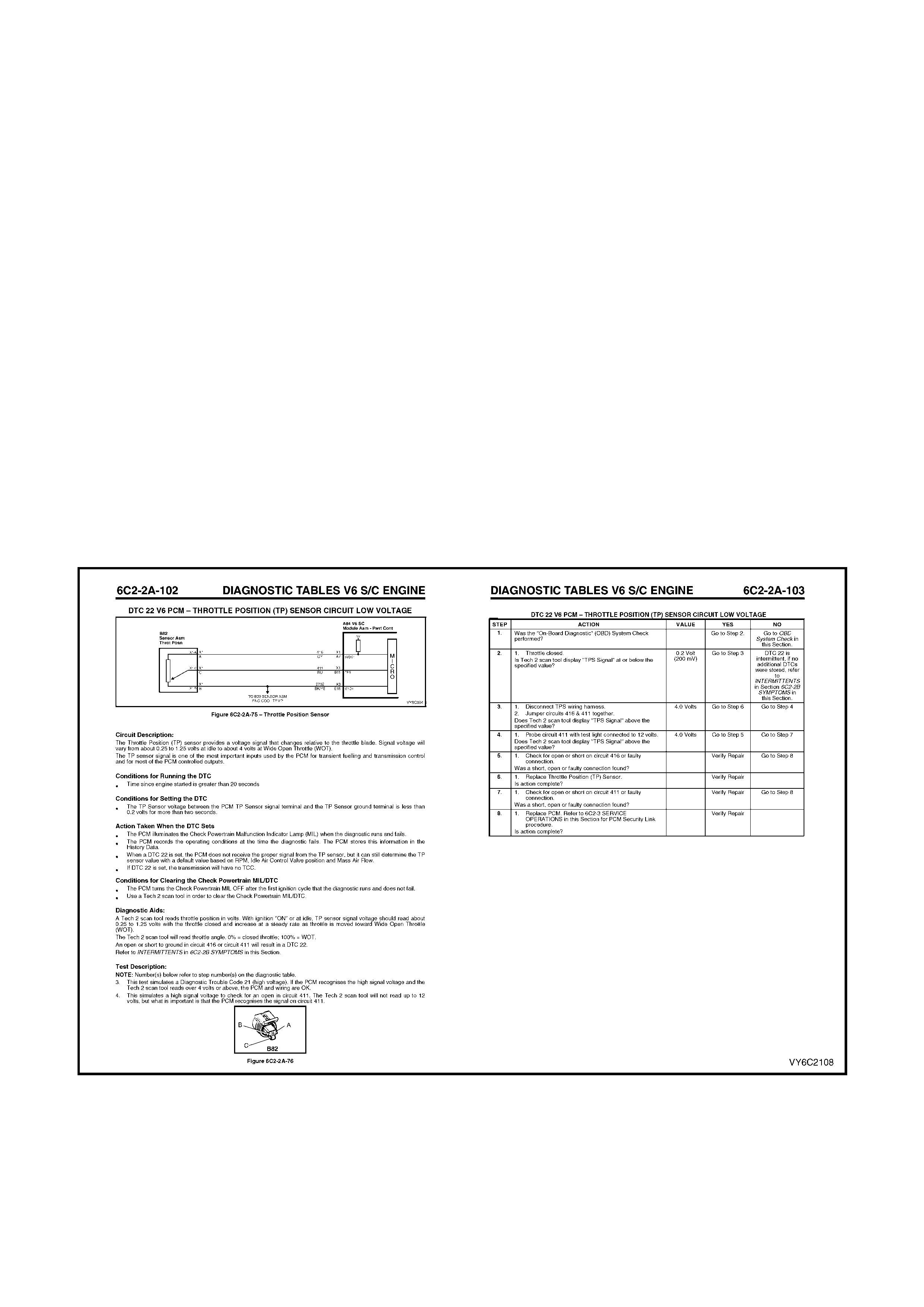
6. DIAGNOSTIC TABLES
6.1 INTRODUCTION
The diagnostic tables are designed to provide fast and efficient means of fault location for all engine and
transmission f unc tions ass oc iated with the PCM. Each diagnostic table us es 2 pages; a table on the right side page,
and a facing page on the left side page. The left side "facing page" contains pertinent information, including
diagnostic trouble code setting parameters and circuit diagrams. The table steps are explained by the
corresponding numbered paragraph on the left side facing page.
When diagnosing any problem, always begin with the ON-BOARD DIAGNOSTIC SYST EM CHECK . The O n-Board
Diagnostic System Check will lead you to the other tables. DO NOT GO DIRECTLY TO A SPECIFIC TABLE or
false diagnos is and replac ement of s er viceable par ts c ould r es ult. Af ter a f ault is c or r ected and all DTC’s have been
cleared, repeat the On-Board Diagnostic System Check to assure that the proper repairs have been made.
The "A" Table pages and the diagnostic trouble code diagnostics pages are constructed in a similar fashion. The
box at the top of the left page contains a wiring diagram showing the components involved in each circuit.
Immediately below the box is a brief circuit description. On the facing right-hand page a troubleshooting table for
diagnosing c onditions. Step number s on the r ight-hand page nex t to the ac tion box es in the table r elate to the items
in the Test Description on the left-hand page. These items provide an explanation of each test in the table.
The appropriate step in any of the trouble shooting tables will instruct you either to make a specific repair or to
continue diagnosis. If further diagnosis is needed, the step will specify where to continue.
The Yes or No column in any diagnostic table will instruct you either to make a specific repair or to continue
diagnosis. If further diagnosis is needed, the Yes or No column will specify where to continue.
If the condition is intermittent, the trouble shooting table will direct you to the diagnostic aids on the facing page.
This section gives suggestions for diagnosing intermittent conditions and explains how some faults can occur.
Remember, tables are for solving active conditions or diagnostic trouble codes, not intermittent conditions. Use
symptom diagnosis for solving intermittent conditions.
Figure 6C2-2-12 Typical Diagnostic Flow Table
6.2 WRITING THE REPAIR ORDER
The repair order is one of the most im portant tools
a Technician can have. Like his other tools, the
repair order must be highly accurate to give him the
greatest help.
It's up to the Service Adviser to supply the
Technician with this highly accurate tool. Problems
begin for the Technician when the repair order is
incomplete or is incorrect.
An incomplete repair order doesn't provide the
Technician with a good starting point for the
diagnosis. Consequently, the Technician may
waste time, using a “shotgun” approach attempting
to find the problem.
An incorrectly written repair order can lead the
Technician down the wrong diagnostic path,
preventing him from finding the problem.
Consequently, a Service Adviser needs to write an
accurate and complete repair order.
This is accom plished by asking the cus tomer these
important questions: WHO? WHAT? WHEN?
WHERE? and HOW?
Figure 6C2-2-13 An Incomplete Repair Order
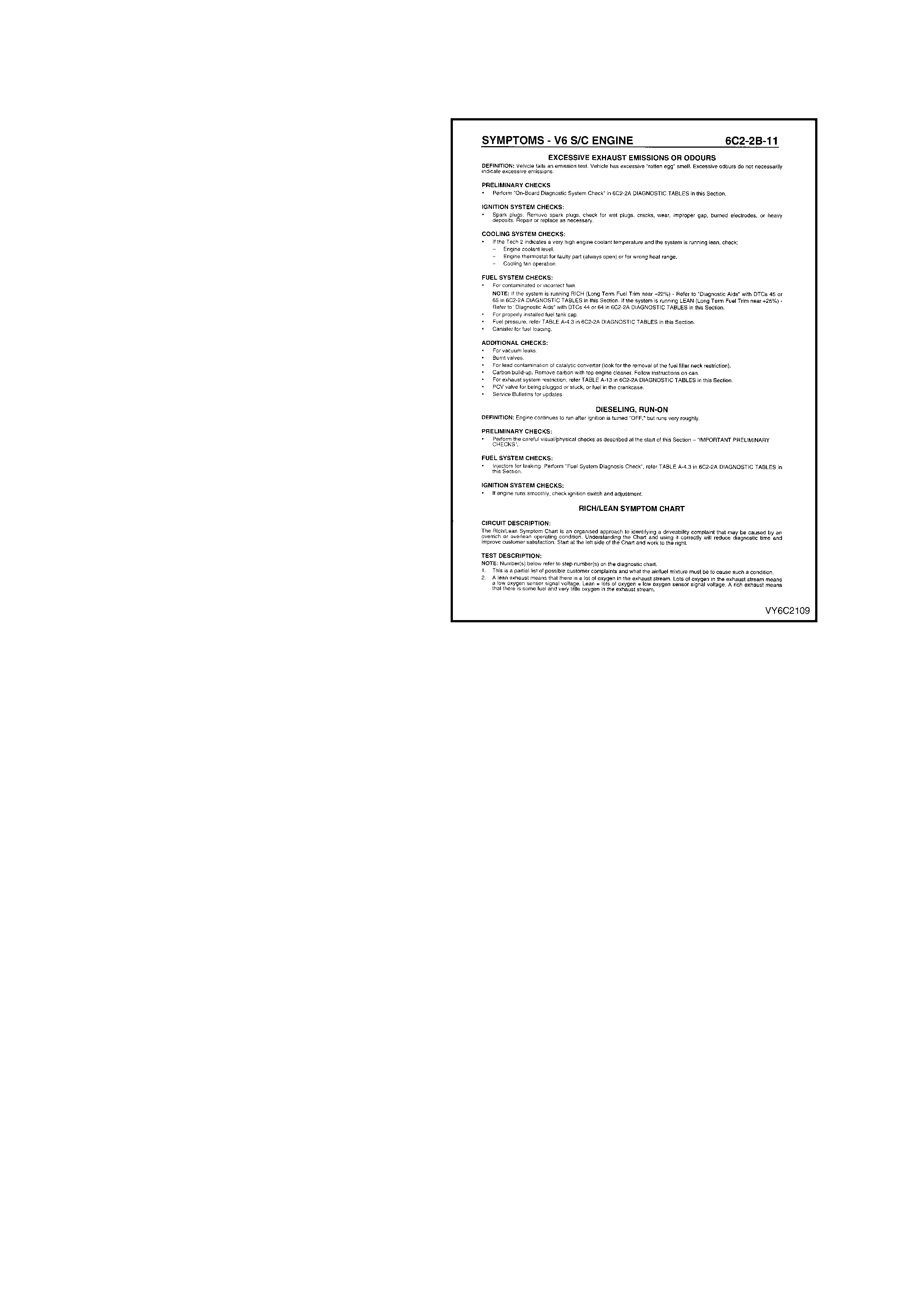
6.3 QUESTIONS
"WHO"? QUESTIONS
WHO"? is the first question you need to ask. As
you begin to fill out the repair order, you need to
find out who was driving the vehicle when the
problem occurred and talk directly to that person if
at all possible.
This allows you to give first-hand inf or mation on the
problem to the Technician, which is critical to
diagnosing the problem. If you can't talk directly to
this person, get their name and phone number so
the Technician can call the customer if needed.
"WHAT"? QUESTIONS
The next step is to find out "WHAT"? the problem
is. If it's a driveability problem, and it seems to be
complex, bring the Technician who's going to work
on the vehicle into the picture if at all possible.
Allow the Technician to question the customer
directly, so he can get the information he needs to
help him diagnose the pr oblem . Again, this is s o he
can get first-hand knowledge of the problem.
If you don't involve the Technician with the
custom er, you need to ask if the Check Powertrain
MIL is ON all the tim e, com ing ON and OF F during
the same key cycle, or is never ON.
Figure 6C2-2-14 Typical Symptomatic
Diagnostic Table
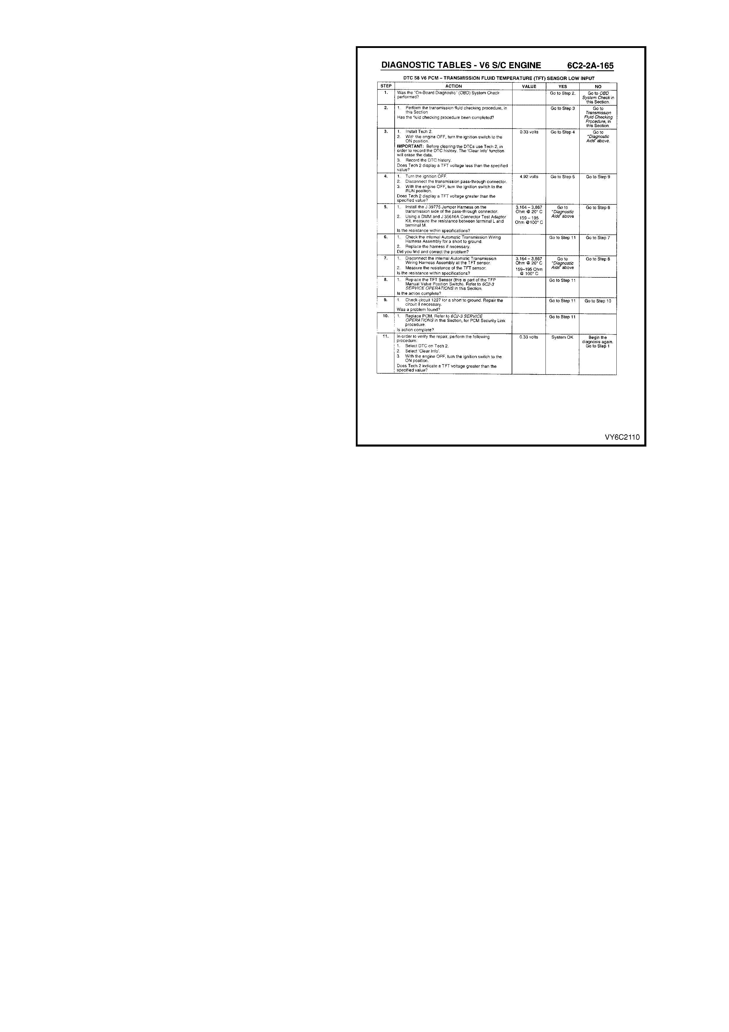
This is important to the Technician because this
informs him/her which diagnostic direction to take.
These tables are different from one another. If a
Technician is following the wrong table, a lot of time
is wasted. So, ask the customer questions about
the "Check Powertrain" lamp.
Other good "WHAT"? questions are; “Under what
conditions did the problem occur?”
Were they accelerating, decelerating, or coasting?
Were they driving in the city or on the freeway?
What were the environmental conditions? Was it
raining? snowing? Hot? cold? The technician may
need to duplicate these conditions as closely as
possible if he is to find the cause of the problem.
"WHEN"? QUESTIONS
WHEN"? questions are the next step. If the
customer says the "Check Powertrain" MIL was
ON, you need to ask when the Check Powertrain
MIL came ON and how long it has been "ON." Is
the Check Powertrain MIL ON before or during
starting, or when the engine is running?
More im portant, you need to ask when the problem
first oc curred. Maybe it began af ter the vehicle was
serviced f or a related pr oblem or for som ething that
appears to be totally unrelated.
The Technician also needs to know if the problem
has become worse. This information may give the
Tec hnician s ome clues as to what the problem may
be.
"WHERE"? QUESTIONS
W HERE"? is the nex t question. The location where
the problem oc c urs may give the technician an idea
as to what may be contributing to the problem,
such as electromagnetic interference from
overhead power lines.
"HOW"? QUESTIONS
To round out your questioning, you need to ask the
customer "HOW"? often the problem occurs. This
can give the T echnician direc tion as to what type of
system may be causing the problem; electrical,
mechanical, vacuum, etc.
Figure 6C2-2-15 Typical Diagnostic Table
SUMMARY
In summary, you need to obtain the following information from the customer:
• Who the principal driver is.
• What the problem is.
• When the problem began.
• Where the problem occurs.
• How often the problem occurs.
Complete answers to these questions will aid the technician in diagnosing the problem.

VERIFYING THE COMPLAINT
Engine Compartment Inspection
The most important step in diagnosing a driveability complaint is to verify the complaint. This means you have to
duplicate the problem if possible.
Start by performing an engine compartment inspection. Check the integrity of all the electrical connections and
vacuum hoses, etc. Also, check the wire routing for the possibility of Electromagnetic Interference (EMI).
Checking For Stored Diagnostic Trouble Codes
As you check for diagnostic trouble codes, keep in mind that intermittent faults may not store a diagnostic trouble
code. So proceed with verifying the complaint, even if no diagnostic trouble codes are stored.
If a diagnostic trouble code is stored, check the service bulletins for the particular vehicle you're working on.
Road Testing The Vehicle
This step is optional if the repair order states.
• The driveability problem is intermittent.
• You did not find any problems under the bonnet .
• No diagnostic trouble codes are stored.
Then you need to road test the vehicle in order to recreate the problem.
This is an important step because the problem has to be present in order to repair the problem.
Most intermittent driveability problems are repeatable. That is what road testing is all about.
Before you go on your road test, review the vehicle's s ervice his tory. This inf orm ation can give you clues as to what
may be causing the driveability problem and what you need to watch.
Read the repair order and think about what systems could possibly cause the problem. This is essential to finding
the problem. Think about how the system or systems in question works, what inputs are needed and what could
cause the problem.
Check all the inputs required for a circuit, whether the circuit actually has trouble or if you only suspect trouble. All
inputs are needed and m ust be within a "normal" r ange. You will want to pay attention to these system s and circuits
during and after the road test.
As you're road testing, put Tech 2 in the Snapshot Mode so you can capture the system data when the problem
occurs.
Do not discount the other information the Tech 2 snapshot mode can supply you with.
Don't Forget The Basics
Whether or not you find anything wrong during the road test, don't forget the basics.
Electrical connections such as power feeds and grounds are vital to the operation of almost all of the vehicle
systems.
No matter how good the system is, it is still working in combination with the engine. If the engine is not in good
condition, the computer system can't make up for the condition.
Compare performance problems, such as lack of power, with a comparable vehicle. This will let you know if the
customer complaint really is a problem or something that is normal.
If you can't repeat the problem, and you need more information for diagnosing, call the customer who was driving
the vehicle when the problem occurred. This type of professionalism will probably help you diagnose the problem.
EEPROM
If a vehicle is just starting to have an intermittent driveability problem and it has accumulated more than 30,000
kilometres, chances are that the EEPROM calibration is not at fault.
If the vehicle was running properly for such a long time, the original EEPROM calibrations are not the problem since
the EEPROM calibrations don't change, the chances of the EEPROM going bad are rare. There may however be an
updated EEPROM calibration for a particular condition, so check service bulletins for calibration updates.