
SECTION 6C2-3 - SERVICE OPERATIONS –
V6 SUPERCHARGED ENGINE
IMPORTANT
Before performing any Service Operation or other procedure described in this Section, refer to Section 00
CAUTIONS AND NOTES for correct workshop practices with regard to safety and/or property damage.
CONTENTS
1. GENERAL DESCRIPTION
1.1 SERVICE PRECAUTIONS
2. ELECTRONIC CONTROL
2.1 POWERTRAIN CONTROL MODULE
REMOVE
REINSTALL
PCM SECURITY LINK
2.2 PROM UNIT
REMOVE
REINSTALL
FUNCTIONAL CHECK
2.3 CAMSHAFT POSITION SENSOR
REMOVE
REINSTALL
2.4 ENGINE COOLANT TEMPERATURE
(ECT) SENSOR
REMOVE
REINSTALL
2.5 INTAKE AIR TEMPERATURE (IAT)
SENSOR
REMOVE
REINSTALL
2.6 MASS AIR FLOW (MAF) SENSOR
REMOVE
REINSTALL
2.7 OXYGEN SENSOR
REMOVE
REINSTALL
2.8 THROTTLE POSITION (TP) SENSOR
REMOVE
REINSTALL
2.9 VEHICLE SPEED SENSOR
REMOVE
REINSTALL
3. FUEL CONTROL SYSTEM
3.1 FUEL PUMP RELAY
FUEL PRESSURE RELIEF PROCEDURE
3.2 THROTTLE STOP SCREW – RESET
PROCEDURE
INSPECT
CHECK OR RESET
3.3 MODULAR FUEL SENDER ASM
REMOVE
REINSTALL
FUEL STRAINER AND FUEL LEVEL
SENSOR
FUEL PUMP ASSEMBLY
3.4 FUEL PUMP CONTROL MODULE (V6
SUPERCHARGED ENGINE)
REMOVE
REINSTALL
3.5 FUEL SYSTEM PRESSURE TEST
PROCEDURE
3.6 FUEL FILTER
REMOVE
REINSTALL
LEAK TESTING
3.7 FUEL PRESSURE REGULATOR
REMOVE
REINSTALL
3.8 FUEL RAIL SUPPLY AND RETURN HOSES
REPLACE
3.9 AIR CLEANER ASSEMBLY
REMOVE
REINSTALL
3.10 THROTTLE CABLE
REMOVE
REINSTALL
ADJUST
3.11 THROTTLE BODY
REMOVE
CLEAN AND INSPECT
THROTTLE BODY CLEANING PROCEDURE
REINSTALL
THROTTLE BODY IAC VALVE COUNT
CHECKING PROCEDURE
3.12 RAIL AND INJECTORS
REMOVE
REINSTALL
3.13 IDLE AIR CONTROL VALVE
REMOVE
CLEAN
REINSTALL
3.14 THROTTLE PEDAL ASSEMBLY
4. DIRECT IGNITION SYSTEM (DIS)
4.1 GENERAL SERVICE INFORMATION
TIMING ADJUSTMENT
CHECK EST SPARK TIMING OPERATION
4.2 IGNITION COIL(S)
REMOVE
TEST
REINSTALL
4.3 DIS MODULE
REMOVE
REINSTALL
4.4 CRANKSHAFT SENSOR
REMOVE
REINSTALL
4.5 KNOCK SENSORS
CHECKING KNOCK SENSOR OPERATION
REMOVE
REINSTALL
4.6 SPARK PLUG LEADS
REMOVE
BENCH TESTING SPARK PLUG LEADS
REINSTALL
4.7 SPARK PLUGS
REMOVE
CLEANING AND INSPECTION
REINSTALL
SPARK PLUG DIAGNOSIS
ANALYSIS OF SPARK PLUG CONDITION
5. AUTOMATIC TRANSMISSION
5.1 1-2 SHIFT SOLENOID
REMOVE
REINSTALL
5.2 2-3 SHIFT SOLENOID
REMOVE
REINSTALL
Techline
Techline

5.3 3-2 CONTROL SOLENOID
REMOVE
REINSTALL
5.4 PRESSURE CONTROL SOLENOID
REMOVE
REINSTALL
5.5 TRANSMISSION FLUID PRESSURE (TFP)
MANUAL VALVE POSITION SWITCH ASM
AND TRANSMISSION FLUID TEMP
SWITCH (TFT) SENSOR
REMOVE
REINSTALL
5.6 TCC "PWM" SOLENOID
REMOVE
REINSTALL
5.7 TCC ENABLE SOLENOID
REMOVE
REINSTALL
6. MISCELLANEOUS SYSTEMS
6.1 EVAPORATIVE EMISSION CONTROL CANISTER
REPLACE
6.2 CANISTER PURGE SOLENOID
REPLACE
6.3 SUPERCHARGER SYSTEM
SUPERCHARGER OIL LEVEL CHECK
SUPERCHARGER – REPLACE
6.4 BOOST CONTROL SOLENOID
REPLACE
6.5 BY-PASS VALVE ACTUATOR
REMOVE
REINSTALL
CHECKING ADJUSTMENT OF BY-PASS
VALVE ACTUATOR
6.6 A/C REFRIGERANT PRESSURE SENSOR
REMOVE
REINSTALL
1. GENERAL DESCRIPTION
This Section describes the proper service procedures to repair components of the Powertrain Management
System, used with the V6 Supercharged engine. Emphasis is placed on the proper procedures and repair of
components related to this specific system.
1.1 SERVICE PRECAUTIONS
The following requirements must be observed when working on vehicles:
1. Before removing any PCM system component, disconnect the battery ground lead.
2. Never start the engine without the battery being solidly connected.
3. Never disconnect the battery from the on board electrical system while the engine is running.
4. When charging the battery, disconnect it from the vehicle's electrical system.
5. Never subject the PCM to temperatures above 80° C; i.e. paint oven. Always remove PCM first if this
temperature is to be exceeded.
6. Ensure that all cable harness plugs are connected solidly and that battery terminals are thoroughly clean.
7. The engine management system harness connectors are designed to fit in only one way; there are indexing
tabs and slots on both halves of the connector. Forcing the co nnector into place is not necessar y if it is be ing
installed with the proper orientation. Failure to take care to match the indexing tabs and slots to ensure the
connector is being installed correctly can cause damage to the connector, the module, or other vehicle
components or s ystem s .
8. Never connect or disconnect a cable harness plugs at the PCM when the ignition is switched "ON."
9. Before attempting any electric arc welding on the vehicle, disconnect the battery leads and the PCM
connectors.
10. When steam cleaning engines, do not direct the steam cleaning nozzle at PCM system components. If this
happens, corrosion of the terminals can take place.
11. Use only the test equipment specified in the diagnostic Tables, since other test equipment may either give
incorrect results or damage good components.
12. All vol tag e meas urements using a vo ltmeter mus t us e a dig ital voltmeter with an inter na l impedance r at in g of at
least 10 million ohms per volt (10 megohm/volt).
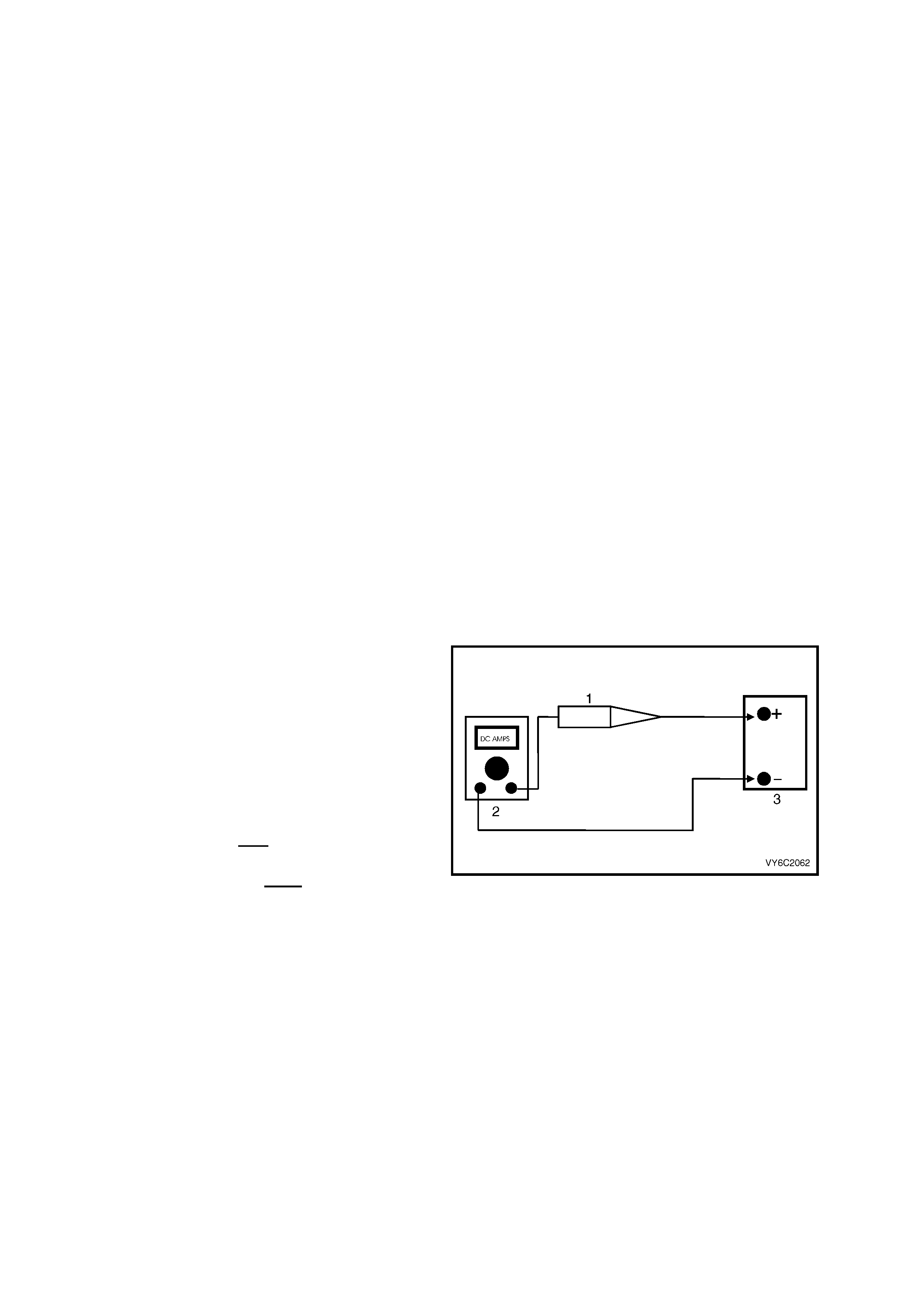
13. When a test light ( 1) is s pec ified, a " low-p ower"
test light must be used. Do not use a high –
wattage test light. While a particular brand of
test ligh t is no t sug geste d, a sim ple t est o n an y
test light will ensure it to be OK for PCM c ircuit
testing. Connect an accurate (2) Ammeter
(such as a high-impedance digital multimeter)
in series with the test light being tested, and
power the test light-ammeter circuit with the
ve hicle batt ery (3).
If the am meter indicat es less tha n 0.3 Am p current
flow (300 mA), the test light is OK to use.
If the ammeter indicates more than 0.3 Amp
current flow (or 300 mA), the test light is NOT OK
to use.
Figure 6C2-3-1
14. When fasteners are removed, always reinstall them at the same location from which they were removed. If a
fastener needs to be replaced, use the correct part number fastener for that application. If the correct part
number fastener is not available, a fastener of equal size and strength (or stronger) may be used. Fasteners
that are not to be re-used, or those requiring thread locking compound will be identified. The correct torque
value must be used when installing fasteners that require it. If the above conditions are not followed, parts or
system damage could result.
2. ELECTRONIC CONTROL
2.1 POWERTRAIN CONTROL MODULE
LT Section No. – 02-245
Service of the Powertrain Control Module (PCM)
should normally consist of either replacement of
the PCM or PROM assembly.
If the diagnostic procedures call for the PCM to be
replaced, the PROM and PCM should be checked
first to see if the y are the c orrect parts. If the y are,
remove the PROM from the faulty PCM and install
it in the new service PCM. THE SERVICE PCM
WILL NOT CONTAIN A PROM. Trouble Code 51
indicates the PROM is installed improperly or has
malfunctioned. When Code 51 is obtained, check
the PROM installation for not being fully seated in
the socket. If it is installed correctly and Code 51
still shows, replace the PROM. Once the PCM is
replaced, you must then perform the Security Link
procedure. Refer to this section for the Security
Link procedure.
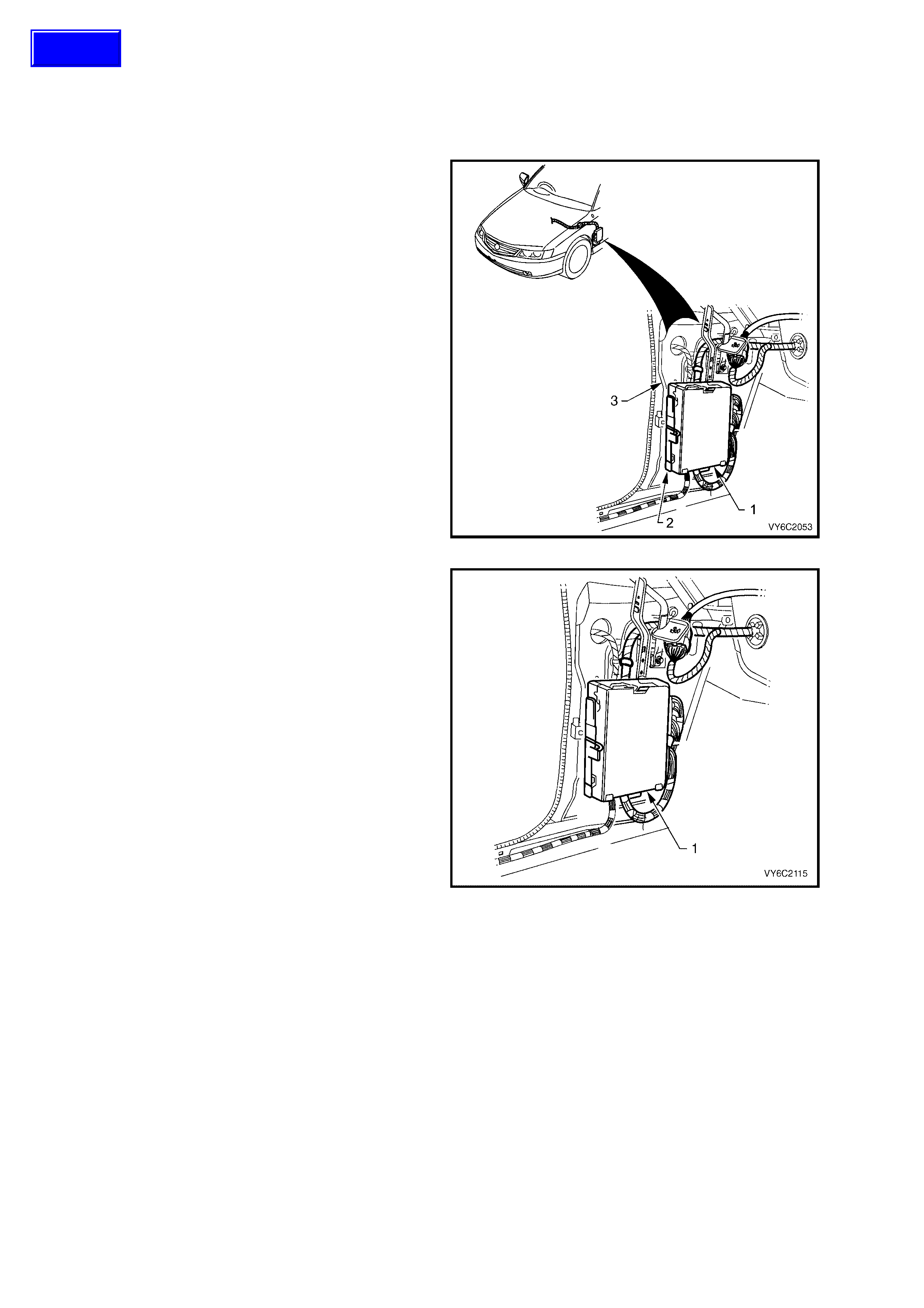
Figure 6C2-3-2 – PCM Location
NOTE: W hen replacing the production PCM with a
service PCM (controller) (1), it is important to
transfer the broadcast code and production PCM
number to the service PCM label. This will allow
positive identification of PCM parts throughout the
service life of the vehicle.
IMPORTANT: To prevent internal PCM damage,
the ignition must be "OFF" when disconnecting or
reconnecting power to PCM (for example, battery
cables, PCM connec tors, Engine Control fus e F29,
jumper cables, etc.).
Figure 6C2-3-3 – PCM Mounting
REMOVE
1. Disconnect battery ground lead.
IMPORTANT: Disconnection of the battery affects
certain veh ic le el ec tr on ic system s . Refer to Sec tio n
00 CAUTIONS, 5. Battery Disconnection
Procedures before disconnecting the battery.
2. Remove lef t han d f ront s hroud pa nel l o wer trim
assembly (cowl panel trim), refer Section 1A3,
INSTRUM ENT PANEL AND CONSOLE in the
MY 2003 VY and V2 Series Service
Information.
Techline
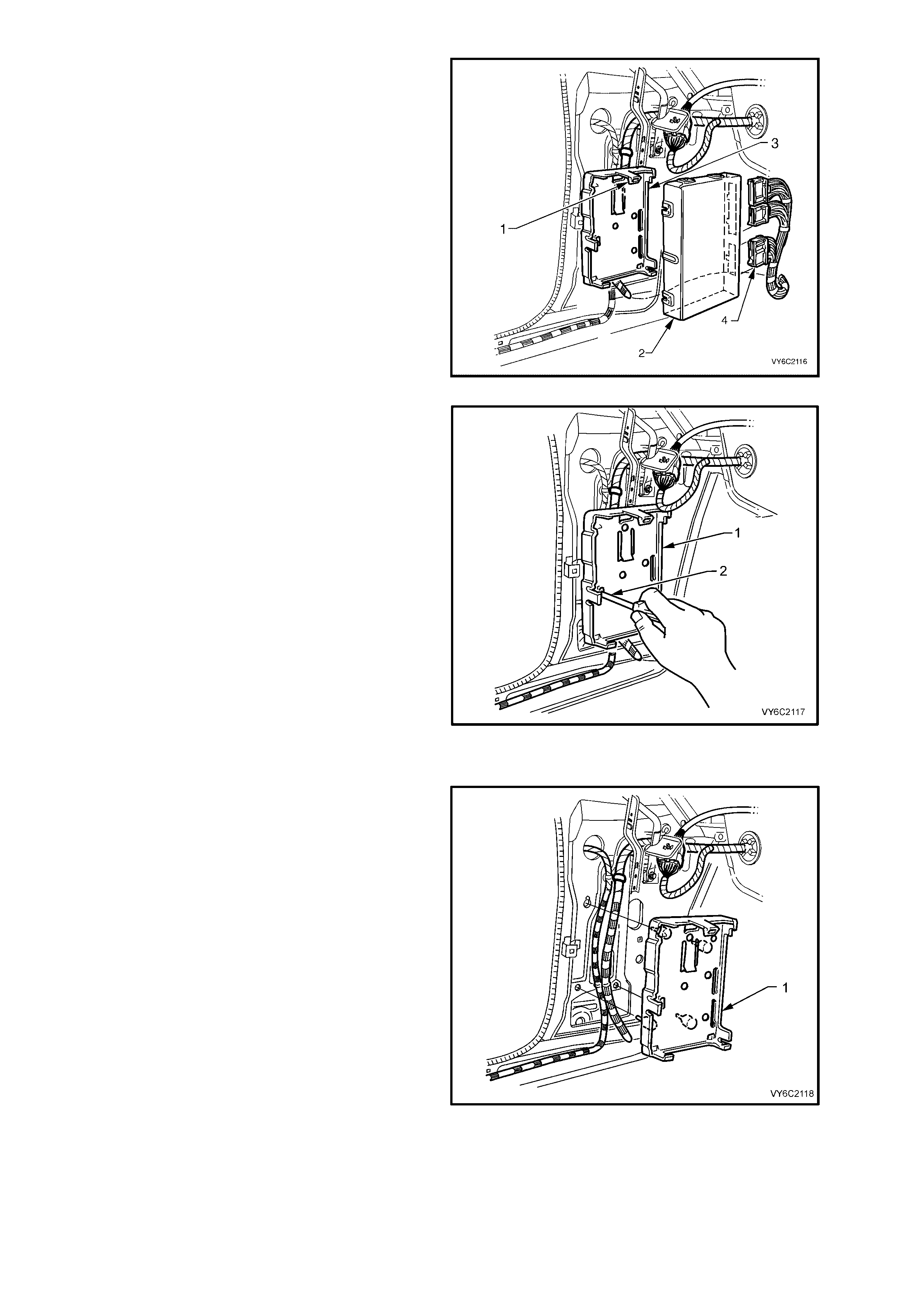
3. Lift up mounting bracket to PCM upper
retaining tang (1), pull PCM (2) out then up to
remove it from the mounting bracket (3).
4. Remove wiring harness connectors (4) from
PCM, remove PCM (2) from vehicle.
5. If necessary, remove PCM PROM, refer
2.2, PROM UNIT - Remove, in this Section.
IMPORTANT: Replacement controllers are
supplied without a PROM so care should be taken
when removing the PROM from the defective
controller as it will be reused in the new controller.
Do not rem ove the pl astic c over of the PRO M. Use
of unapproved removal methods may cause
damage to the PROM or PROM socket.
Figure 6C2-3-4 – PCM Removal
6. If required, remove PCM mounting bracket (1)
by inserting a screwdriver into the retaining
tang slot (2), lever the screwdriver to release
tang. Pull br acket ( 1) out then down, to rel ease
from the cowl panel.
Figure 6C2-3-5 – PCM Mounting Bracket Removal
REINST ALL
1. If removed, r eins tal l PC M mounting brac ket (1) ,
engaging bracket leg into slotted hole in cowl
panel. Lift up bracket and engage bracket
lower retainers and retaining tang into cowl
panel.
2. If required, install PROM into new PCM, refer
2.2, PROM UNIT - Reinstall, in this Section.
3. Reconnect wiring harn es s connectors to PCM.
4. Assemble PCM into mounting bracket,
ensurin g wiring harn ess is routed in fr ont of the
mounting bracket.
5. Reinstall cowl panel trim, Refer to Section
1A3, INSTRUMENT PANEL AND CONSOLE,
in the MY 2003 VY and V2 Series Service
Information.
6. Reconnect battery ground lead, start vehicle
and allow to idle. Check vehicle for correct
operation.
Figure 6C2-3-6 – PCM Mounting Bracket Reinstallation

PCM SECURITY LINK
Whenever the PCM and/or BCM have been replaced, the new PCM and/or BCM must be security linked to each
other. If this procedure is not performed, the vehicle will not crank.
The PCM to BCM linking procedure is as follows:
• Connect TECH 2 to DLC and select:
• Diagnostic / (3) 20 03 / VY Comm odore / Body / B ody Contro l Module / Securit y / BCM Li nk to PCM an d follo w
TECH 2 instructions.
For additional information regarding TECH 2 and TECH 2 test modes (including this linking procedure), refer to
Tec h 2 Diagnosis F or BC M in Se ction 12J BO DY CONT ROL MO DULE in the MY 200 3 VY and V2 S eries Serv ice
Information.
2.2 PROM UNIT
LT Section No. – 02-245
NOTE: A DTC 51 indicates a faulty PROM, or
incorrect installation.
IMPORTANT: The ignit io n shoul d al ways be "OFF "
when installing or removing the PCM connectors.
REMOVE
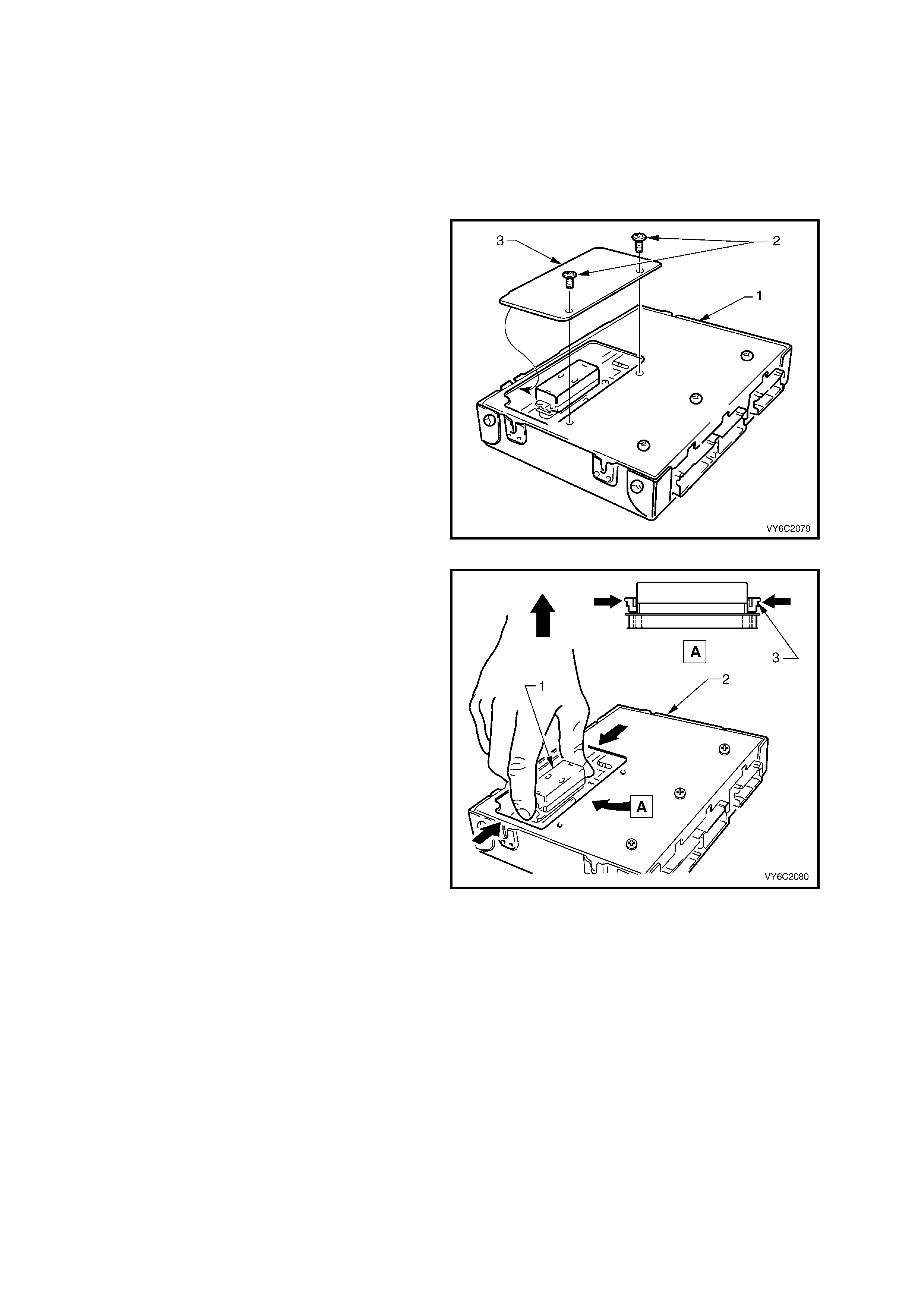
1. Remove PCM (1) from passenger
compartment, refer 2.1, POWERTRAIN
CONTROL MODULE - Remove, in this
Section.
2. Using a No.15 Torx bit, remove PCM PROM
access cover screws (2), then remove access
cover (3).
IMPORTANT: DO NOT remove any other screws.
Figure 6C2-3-7 – Access Cover Removal
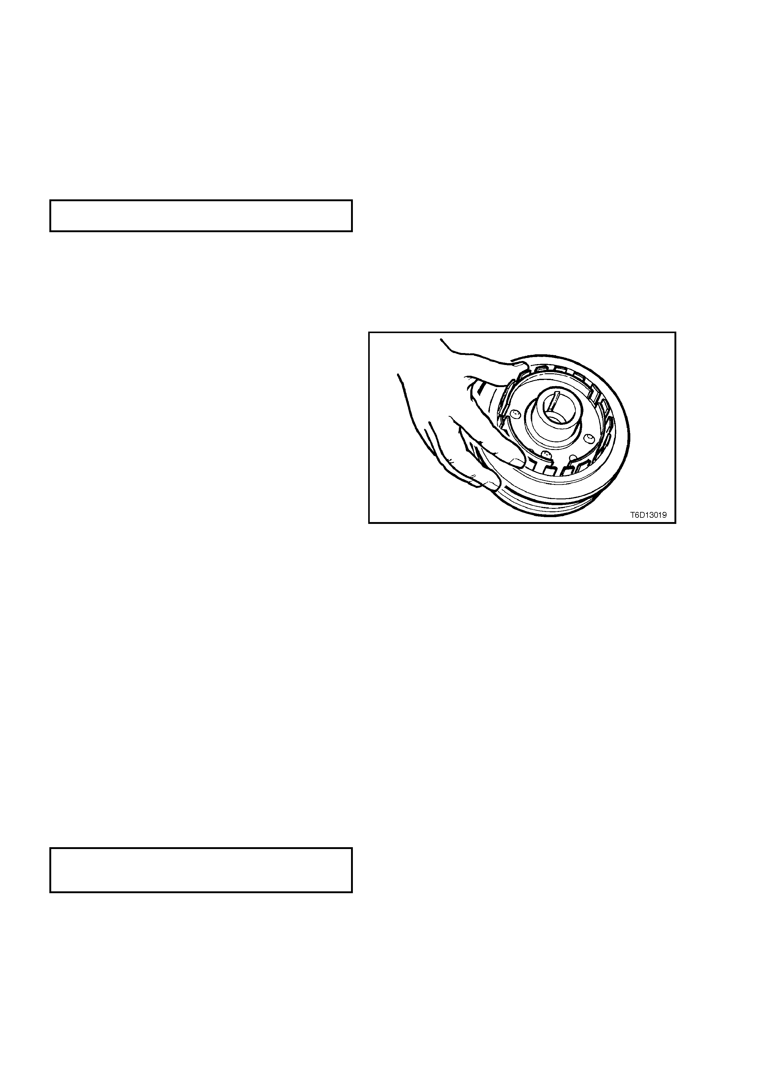
3. Remove PROM (1) from PCM (2) by using
thumb and finger to push retaining clips (3) in
towards the PROM (1), then lift the PROM
straight up and out of the socket.
Figure 6C2-3-8 – PROM Removal
IMPORTANT: DO NOT remove the PROM
cover (1). Use of unapproved PROM removal
methods will cause damage to the PROM or
PROM socket (2).
Figure 6C2-3-9 – PROM
REINST ALL
1. Remove new PROM from its packaging and check the part num ber making sure it is the correct replacement
component.
2. Referr ing to Figure 6C2-3- 8, install P ROM (1) in PRO M sock et, ensuring t hat small n otches in the PRO M ali gn
with the small notches in the PROM socket.
3. Gently press down on the ends of the PROM until the retaining clips (3) click into the PROM socket.
4. Reinstall PROM access cover onto PCM then, using No.15 Torx bit, reinstall and tighten access cover screws
securely.
5. Reinstall PCM, refer 2.1, POWERTRAIN CONTROL MODULE - Reinstall, in this Section.
FUNCTIONAL CHECK
1. Turn ignition "ON."
2. If DTC 51 occurs or if the Powertrain Malfunction Indicator Lamp (MIL) is constantly activated with no DTC’s,
the PROM is not fully seated or is defective. In this event, remove or reinstall the PROM as per previous
instructions.
2.3 CAMSHAFT POSITION SENSOR
LT Section No. – 02-000
Figure 6C2-3-10 – Camshaft/Crankshaft Position Sensors
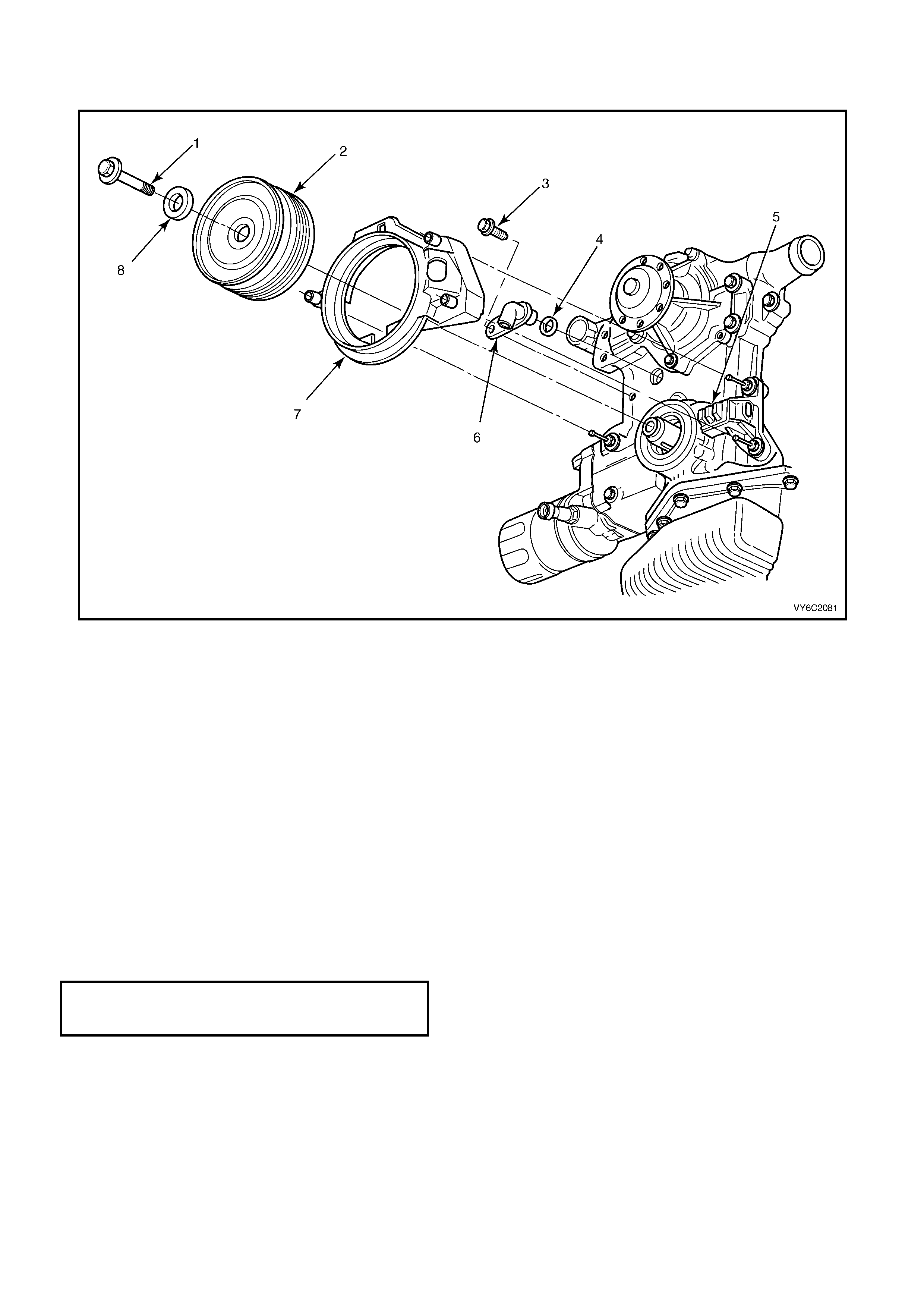
Legend
1. Crankshaft Balancer Retaining Bolt
2. Crankshaft Balancer
3. Screw – Camshaft Sensor Retaining
4. O-Ring – Camshaft Sensor Sealing
5. Sensor – Crankshaft Position
6. Sensor – Camshaft Position
7. Shield – Sensor
8. Washer
REMOVE
1. Dis c onnect batter y ground l ead.
2. Lift up retaining tang and disconnect wiring harness connector from camshaft position sensor (6).
3. Remove camshaft position sensor to front cover retaining screw (3).
4. Remove camshaft position sensor (6) and O-ring (4) from front cover.
REINST ALL
1. Apply light engine oil to O-ring (4) on new camshaft position sensor (6).
2. Assemble camshaft position sensor (6) into front cover hole.
3. Install camshaft position sensor (6) to front cover retaining bolt (3) and tighten to the correct torque
specification.
CAMSHAFT POSITION SENSOR
RETAINING SCREW
TORQUE SPECIFICATION 11 Nm
4. Reconnect wiring harness connector to camshaft position sensor (6).
5. Rec onn ec t batter y ground l ead.
2.4 ENGINE COOLANT TEMPERATURE (ECT) SENSOR
LT Section No. – 02-000
IMPORTANT: Care must be taken when handling PCM engine coolant sensor. Damage to sensor will affect the
operatio n of th e engine managem ent system. Ensur e t hat t he c or rec t s e ns or is lo c ated bef or e s erv ic e is attempted.
The ECT sensor is located in the rear of the intake manifold below the engine thermostat housing.
REMOVE
1. Dis c onnect batter y ground l ead.
IMPORTANT: Disconnection of the battery affects certain vehicle electronic systems. Refer to Sections 00
CAUTIONS, 5. Battery Disconnection Procedures before disconnecting the battery.
2. Depressurise engine cooling system by removing radiator cap in two stages.
CAUTION: Do not remove radiator cap while the engine coolant temperature is above 50°
°°
° C.
3. The ECT sensor is installed into a "wet" engine coolant passage (in the intak e manifold, below the thermostat
housing). Therefore, before removing the ECT sensor from the engine, position an appropriate coolant drain
pan beneath the engine coolant, then remove the lower radiator hose at the radiator to drain the coolant.
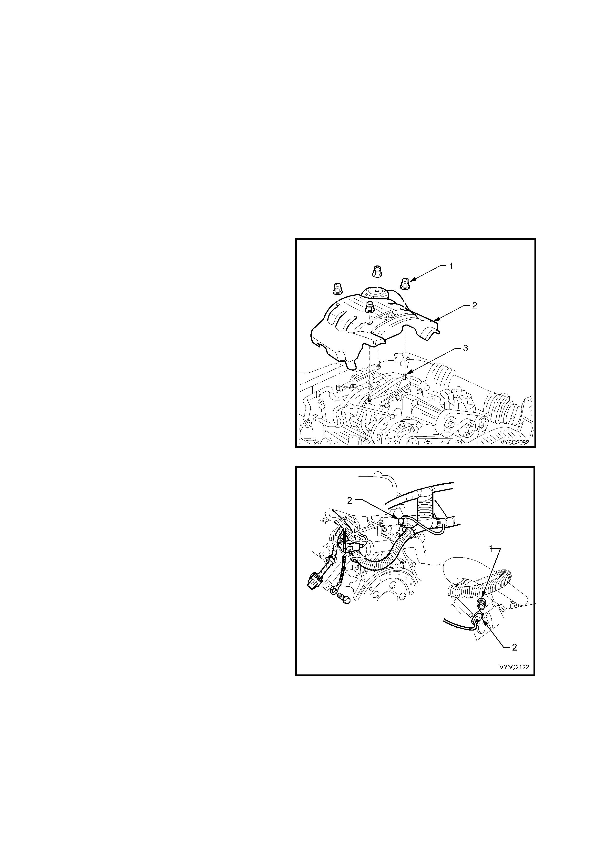
4. Remove four dome nuts (1) securing the
engine dress cover assembly (2) to the inlet
manifold studs (3), then lift and remove the
cover assembly (2) from the engine.
Figure 6C2-3-11 – V6 Supercharged Engine Dress Cover
5. Lift up retaining tang and disconnect wiring
harness connector (2) from Engine Coolant
Temperature (ECT) sensor (1). Lift connector
up away from sensor.
6. Carefully move powertrain wiring harness
down under the ECT sensor to allow tool
access to the sensor.
7. Using a 19 mm ring spanner, carefully loosen
and remove PCM engine coolant temperature
sensor.
Figure 6C2-3-12 – ECT Sensor Location

REINST ALL
1. Apply Loctite 242 (or equivalent) to the cleaned sensor threads.
2. Reinstall ECT sensor to intake manifold and tighten to the correct torque specification.
ENGINE COOLANT
TEMPERATURE SENSOR
TORQUE SPECIFICATION 18 Nm
3. Reconnect wiring harness connector onto ECT sensor.
NOTE: Recheck that the wiring harness connector and harness are correctly positioned. Damage to the harness
could occur if not correctly positioned at this time.
4. Rec onn ec t batter y ground l ead.
5. Ref ill the engi ne coolant s ystem , refer to Section 6B2, ENGINE COOLING - V6 S/C ENGINE in the MY 2003
VY and V2 Series Service Information.
6. Reinstal l engine dress co ver to the inlet m anif old, ens uring that s tud gr omm ets in dress c over rem ain in place.
Tighten securing dome nuts to the correct torque specification.
ENGINE DRESS
COVER DOMED NUT
TORQUE SPECIFICATION 5 Nm
2.5 INTAKE AIR TEMP ERATURE (IAT) SENSOR
LT Section No. – 03-250
REMOVE
NOTE: Care must be taken when handling IAT Sensor. Damage to IAT sensor will affect proper operation of the
fuel control system.
1. Dis c onnect batter y ground l ead.
2. Lift up tang on IAT sensor wiring harness
connector (1) and pull connector from sensor
(5).
3. Loosen intake air duct adaptor clamp that is
located closest to air cleaner assembly.
4. Disconnect air duct, with mass air flow sensor
attached, from air cleaner upper housing.
5. Unclip 5 retaining clips holding the air cleaner
upper housing (2) in place.
6. Separate the upper and lower air cleaner
housings.
IMPORTANT: Air filter should remain in the lower
housing.
7. Remove air cleaner upper housing and place
on bench.
8. Using a pair of side cutters, cut across the IAT
sensor retainer (4) to remove it. Once
removed, discard retainer.
9. Pull out IAT sensor (5) from air cleaner upper
housing.
Figure 6C2-3--13 IAT Sensor Removal
REINST ALL
1. Push new IAT sensor (5) into air cleaner upper housing (2), with triangular tang on the mounting flange
locating on the mating rib of the air cleaner upper housing.
2. Position the upper air cleaner housing assembly, with the IAT sensor on the work bench, pushing up into the
air cleaner upper housing.
3. Position new retainer (4) onto IAT sensor and then using a 20 m m socket, push the retainer full y onto the IAT
sensor.
4. Reassemble the air cleaner upper housing onto the air cleaner lower housing, ensuring that air filter element
remains in position.
5. Snap 5 retainer clips up into place over the top of the air cleaner upper housing.
6. Reconnect wiring harness connector (1) to IAT sensor (5).
7. Carefully assemble intake air duct and mass air flow sensor onto air cleaner upper housing.
IMPORTANT: Align notch on air cleaner housing adaptor with notch in air duct adaptor and notch in clamp.
8. Tighten air duct clamp securely.
9. Check that mass air flow sensor wiring harness connector has remained firmly in place.
10. Reconnec t batter y ground l ead.
2.6 MASS AIR FLOW (MAF) SENSOR
LT Section No. – 03-250
REMOVE
NOTE: Care must be taken when handling MAF sensor. Damage to MAF sensor will affect proper operation of
PCM control.
1. Dis c onnect batter y ground l ead.
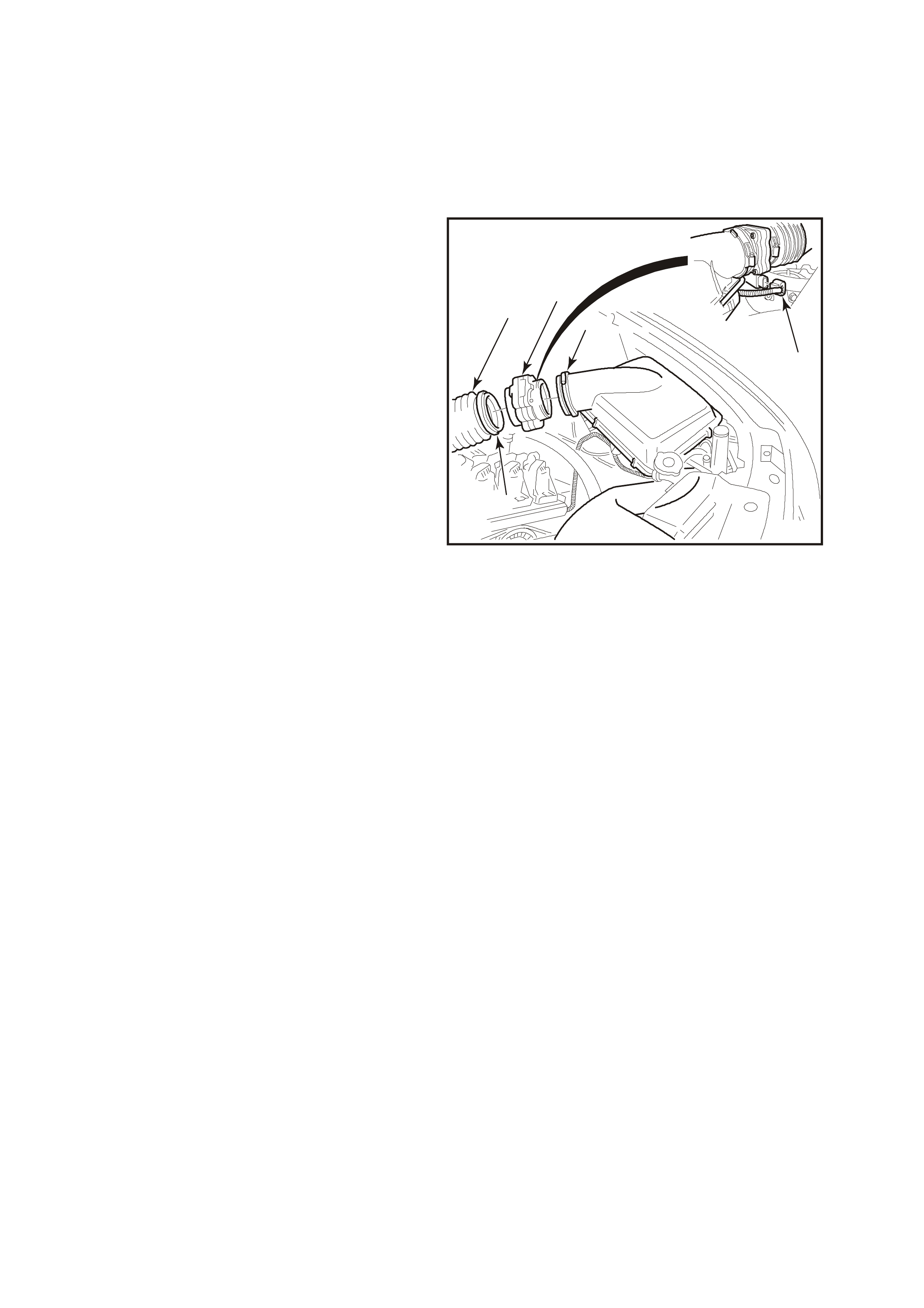
2. Lift up tang on MAF sensor wiring harness
connector (3) and pull connector from
sensor (1).
3. Loosen clamp (2) on air duct adaptor, closest
to MAF sensor (1).
4. Loosen clamp (4) on air duct (5) at MAF sensor
(1) and pull back air duct (5) from sensor.
NOTE: Air duct adaptor (between air cleaner and
MAF sensor), both clamps, air duct and MAF
sensor itself have locating notches.
5. Remove MAF sensor (1) from air duct
adaptor (5).
5
4
1
3
4303
2
Figure 6C2-3-14 – MAF Sensor Removal
REINST ALL
1. Reinstall MAF sensor (1) into air duct adaptor (5) and air duct, aligning all notches. Install clamps, aligning
notches, tighten clamps securely.
2. Reconnect MAF sensor wiring harness connector (3).
3. Rec onn ec t batter y ground l ead.
4. Start vehicle and check for air leaks.
2.7 OXYGEN SENSOR
LT Section No. – 00-450
NOTE 1: The oxygen sensor uses a permanently attached pigtail and connector. This pigtail should not be
rem oved from the ox ygen sens or. Damage or r emova l of the pigta il or connector will affec t proper operation of the
oxygen sensor.
NOTE 2: Take care when handling the oxygen sensor. The in-line electrical connector and louvred end must be
kept free of grease, dirt or other contaminants. Avoid using any cleaning solvents. Do not drop or roughly handle
the oxygen sensor.
NOTE 3: The ox ygen sens or ma y be diff icult to remove when e ngine tem perature is belo w 60° C. Excessive force
may damage threads in exhaust pipe, or on the sensor.
NOTE 4: The V6 Supercharged application requires a four wire heated oxygen sensor. Be sure that any
replacements are of the correct type for this engine.
REMOVE
1. Dis c onnect batter y ground l ead.
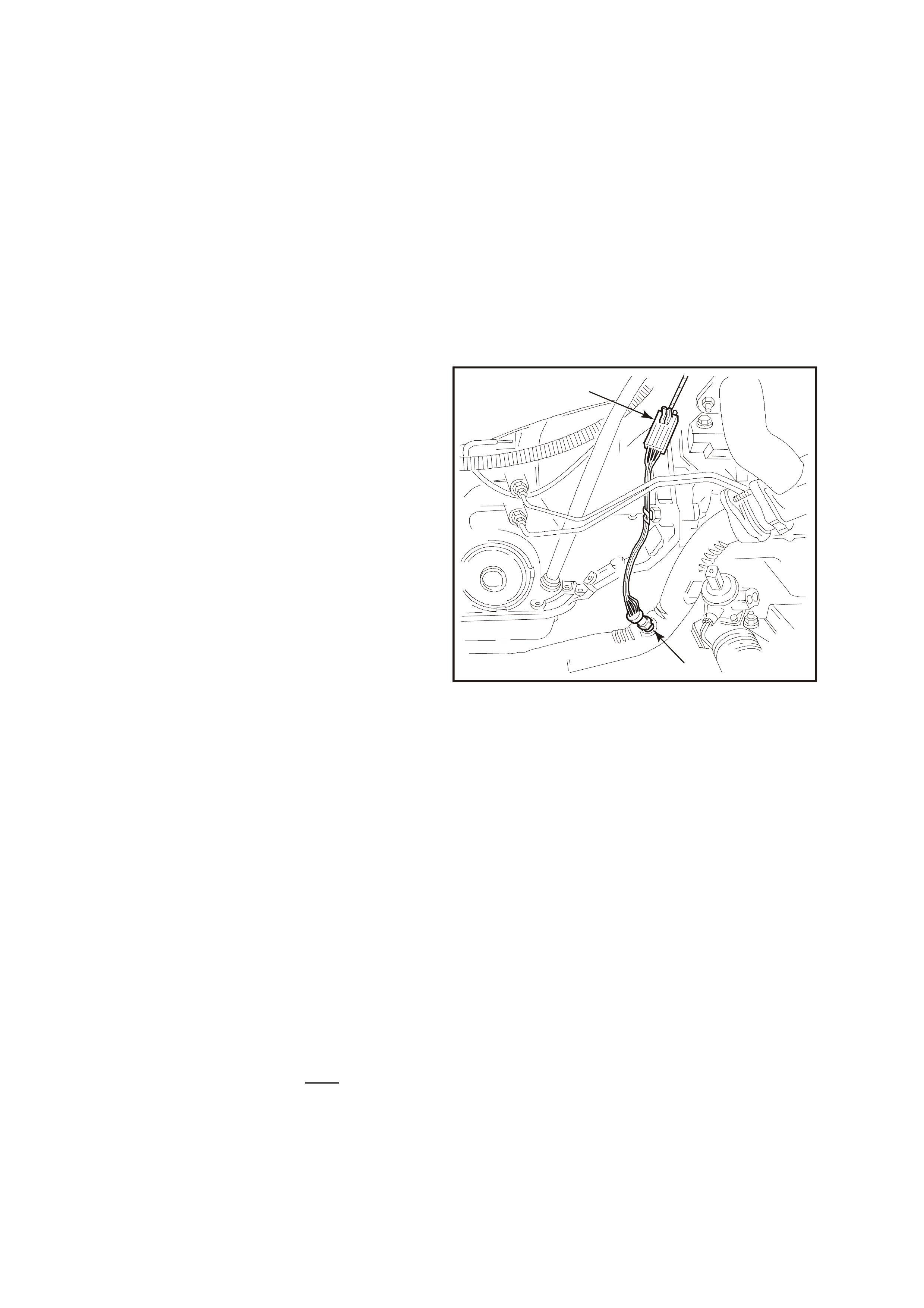
2. Lift the retaining tang on oxygen sensor wiring
harness connector (1) and pull connector from
sensor pigtail connector.
For RH sensor, the connector is located at the
rear of the RH cylinder head and is accessed
from the rear of the engine compartment. The
sensor pigtail leads are further retained by a
clip attached to the torque converter housing,
refer Figure 6C2-3-14.
For LH sensor, the connector is located at the
rear of the LH cylinder head and is accessed
from the rear of the engine compartment, refer
Figure 6C2-3-1 5.
2
4306
1
Figure 6C2-3-15 – RH Sensor Location
(Four Wire Sensor)
3. Raise vehicle and place on suitable safety
stands. Refer to Section 0A GENERAL
INFORMATION, in the MY 2003 VY and V2
Series Service Information.
4. Carefully unscrew oxygen sensor (2) from
exhaust pipe, refer NOTE 3, above.
REINST ALL
IMPORTANT: A special anti-seize compound is
used on the oxygen sensor threads. The
compound consists of a liquid graphite and very
sm all glass be ads . The graphit e will burn a wa y, but
the glass beads will remain, making the sensor
easier to remove at some future time.
Genuine replacement sensors already have the
compound applied to the threads. If a sensor is
rem oved f r om an engi ne, a nd, if for an y reas on it is
to be reinstalled, the threads must have the
specified anti-seize compound applied before
reinstallation.
Specified anti-seize compound is available from
authorised Parts Outlets as part number 5613695.
1. If necessary, coat threads of oxygen sensor
with specified anti-seize compound.
2. Reinstall oxygen sensor (2) into exhaust pipe
and tighten to the correct torque specification.
OXYGEN SENSOR TO
EXHAUST PIPE
TORQUE SPECIFICATION 40 – 50 Nm
3. Remove safety stands and lower the vehicle.
4. Reconnect oxygen sensor wiring harness
connector (1).
IMPORTANT: Ensure that the RH sensor pigtail
leads are retained by a clip attached to the torque
converter housing, refer Figure 6C2-3-14.
5. Rec onn ec t batter y ground l ead.
2
4307
1
Figure 6C2-3-16 – LH Sensor Location
(Four Wire Sensor)
2.8 THROTTLE POSITION (TP) SENSOR
LT Section No. – 03-300
REMOVE
1. Dis c onnect batter y ground l ead.
2. Remove four dome nuts securing the engine dress cover assembly to the inlet manifold studs, lift off and
remove t he cover assembly.
3. Loosen rear air duct clamp to throttle body and remove air duct.
4. Disconnect throttle cable, and if fitted cruise control cable from throttle body linkage.
5. Remove the three (3) retaining nuts to throttle cable bracket on side of throttle body.
6. Remove the two (2) throttle body retaining nuts and throttle body.
7. Lift up retaining tang on TP sensor wiring harness connector and pull connector from sensor.
8. Remove the two TP sensor to throttle body
attaching screws (4).
9. Remove sensor (1) from throttle body (2)
taking care not to lose the drive adaptor (3).
NOTE: The driv e adaptor (3) is a plastic c over that
loosely slides over the end of the throttle shaft, on
the TP sens or side of th e throttle bod y. It is kept in
place when the TP sensor is in position on the
throttle body. The drive ad aptor can e asily fa ll from
the throttle shaft after the TP sensor is removed.
41
2
4308
3
Figure 6C2-3-17 – TP Sensor Removal
REINST ALL
1. Check that the drive adaptor is in place on the throttle valve shaft, refer to previous NOTE.
2. W ith throttle valve in the norm ally closed (idle) position, install TP sensor on to throttle valve shaft and throttle
body at a position 30 degrees clockwise past throttle body attaching screw holes.
3. Rotat e TP sensor anti-clock wise, aligning th e screw attachi ng holes in th e throttle bod y, then install TP s ensor
attaching screws and tighten to the correct torque specification.
TP SENS O R TO TH R OTTL E B ODY
ATTACHING SCREW
TORQUE SPECIFICATION 1 – 1.5 Nm
4. Reinstall throttle body, reinstall the two attaching nuts and tighten to the specified torque.
THROTTLE BODY
ATTACHING NUTS
TORQUE SPECIFICATION 15 – 20 Nm
5. Reinstall throttle body cable attaching bracket, secure with the attaching nuts and tighten to the specified
torque.
THROTTLE CABLE BRACKET
ATTACHING NUT
TORQUE SPECIFICATION 10 Nm
6. Install air cleaner duct to throttle body, and tighten clamp.
7. Reconnect TP sensor wiring harness connector.
8. Reinstall engine dress cover to the inlet manifold, ensuring that stud grommets in the dress cover remain in
place . Tighten securing dome nuts to the correct torque specification.
ENGINE DRESS COVER
DECORATIVE NUT
TORQUE SPECIFICATION 4 – 6 Nm
9. Rec onn ec t batter y ground l ead.

2.9 VEHICLE SPEED SENSOR
LT Section No. – 04-200
REMOVE
1. Raise rear of vehicle and support on safety
stands, Refer to Section 0A, GENERAL
INFORMATION in the MY 2003 VY and V2
Series Service Information.
2. Raise tang on VSS wiring harness connector
(2) and pull connector from VSS (3).
3. Remove VSS to transmission extension
housing bolt (1).
4. Remove VSS and O-Ring seal from extension
housing by slowly prying out sensor with a flat
screwdriver.
REINST ALL
1. Coat the VSS O-ring seal with a thin film of
transmission fluid.
2. Reinstall new VSS and O-ring into
transmission extension housing.
3. Reinstall retaining bolt (1) and tighten to the
correct torque specification.
VSS RETAINING SCREW
TORQUE SPECIFICATION 11 Nm
4. Reconnect wiring harness connector (2) to
VSS (3).
5. Remove safety stands and lower vehicle.
1
2
4310
3
Figure 6C2-3--18– VSS Location Automatic
Transmission
3. FUEL CONTROL SYSTEM
3.1 FUEL PUMP RELAY
LT Section No. – 02-250
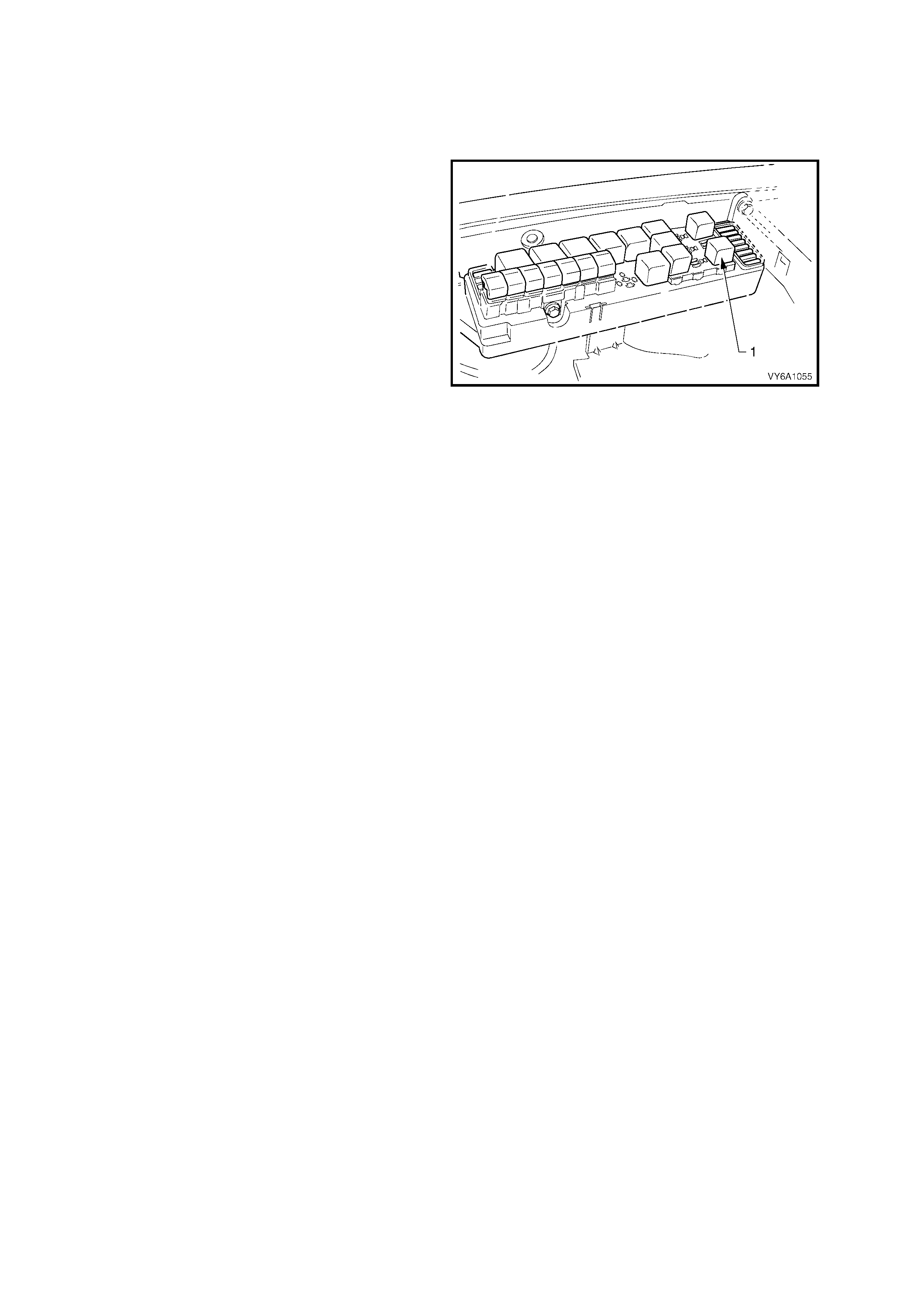
The fuel pump relay (1) is located in a relay
housing, in the engine compartment. The relay
housing is positioned forward of the right side strut
tower. Other than checking for loose connectors,
the only service possible is replacement.
FUEL PRESSURE RELIEF PROCEDURE
1. Depressurise fuel system, as follows:
a. Remove the fuel pump relay (1) from the
underhood electrical centre.
b. With the throttle closed, crank the engine.
The engine may start and idle until any
pressurised fuel in the delivery system is
exhausted.
c. When the engine stops, crank for
approximately 10 seconds to ensure that
all built-up pressure has been exhausted.
d. Reinstall the fuel pump relay.
Figure 6C2-3-19 – Fuel Pump Relay Location
3.2 THROTTLE STOP SCREW - RESET PROCEDURE
LT Section No. –
IMPORTANT: The idle speed for this V6 Supercharged engine application must be checked every 80,000 km. If
the IAC valve counts are greater than 25 at idle, the throttle body must be removed and cleaned. Refer to
Throttle Body Cleaning Procedure in this Section.
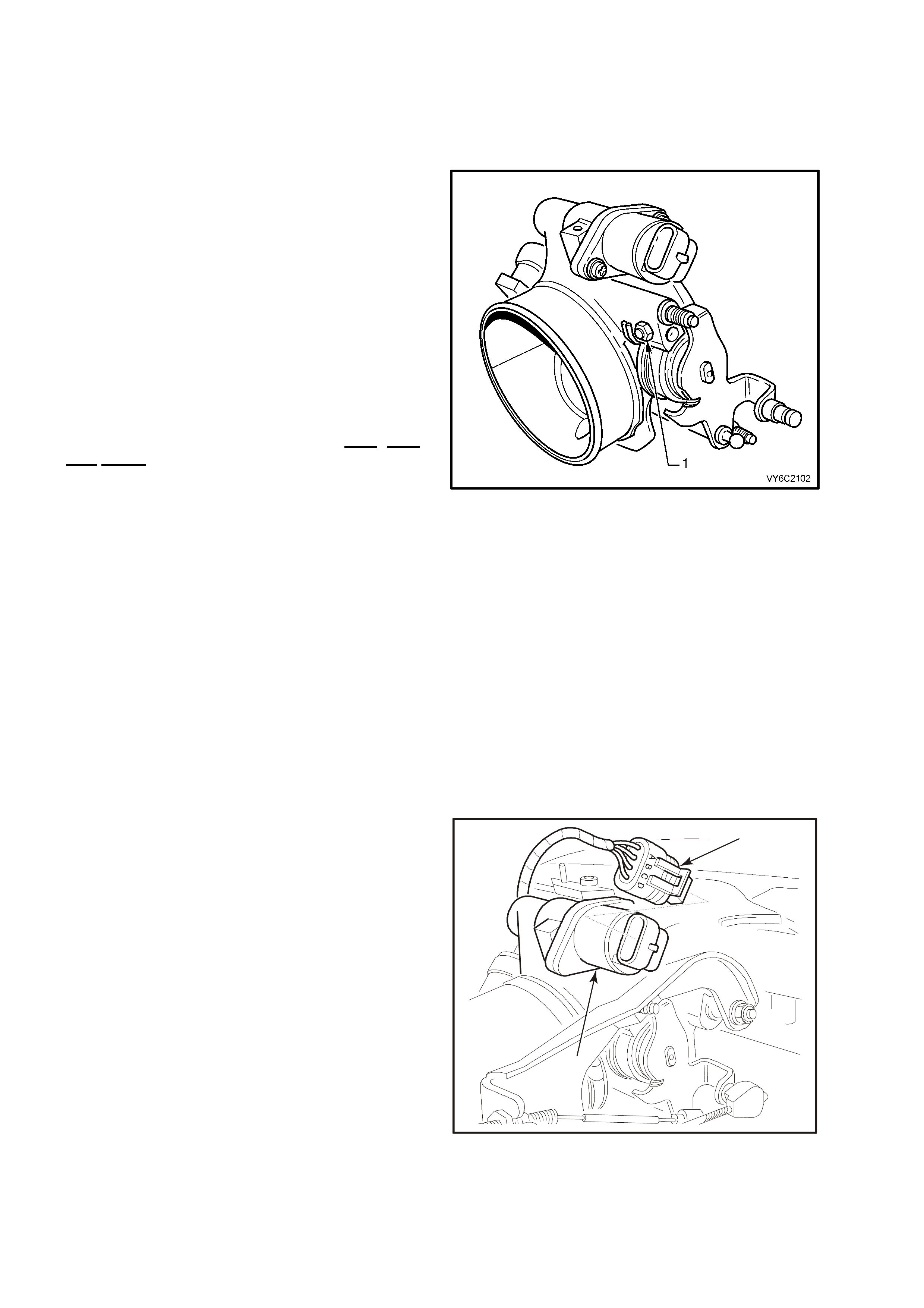
Throttle Stop Screw (1) controls the minimum
throttle ope ning (nominal "closed throttl e" position).
It is preset at the factory and must not be reset
unless:
a. T he scr ew is k nown t o hav e been inad verte ntl y
reset,
–OR–
b. Clearly instructed to do so by a diagnostic
table.
Engine idle speed, which will vary with engine
temperature, is PCM - controlled and is not
adjustable.
PCM - Controlled idle speed (IAC) and the
Throttle stop screw setting (RPM) ARE NOT
THE SAME!
Throttle stop screw setting (RPM) must always be
less than the PCM controlled idle speed, and is
check ed only after tem porarily disabling the PCM's
method of controlling idle speed; the Idle Air
Control (IAC) system. The throttle stop screw
setting is the least likely cause of an abnormal idle
condition.
Therefore, resetting the screw should only be
considered as a last resort. An incorrect setting is
likely to cause a deterioration in idle stability.
Figure 6C2-3-20 – Throttle Stop Screw Location
INSPECT
Before any adjustments are made, ensure that no vacuum leaks exist. Check all vacuum hoses, MAF air ducts,
inlet manifold gasket, throttle body-to-manifold attachment, and any vacuum-operated devices. The engine must
also be at normal operating temperature before any checking or resetting is attempted.
WITH THIS ENGINE CONTROL SYSTEM, ANY VACUUM LEAK WILL RESULT IN A LOW/ROUGH IDLE
SPEED.
CHECK OR RESET
1. Before performing this procedure, perform the
On-Board Diagnostic System Check. Refer to
Section 6C2-2A DIAGNOST IC TABLES.
2. Before performing steps 3 – 10, ensure that the
IAC system is functioning properly. Refer
Diagnostic TABLE A-7.1 (IAC System Check)
in Section 6C 2-2A , DIAGN OST IC TABLE S and
follow it to the "NO TROUBLE FOUND - IAC
OK" step before proceeding.
3. Engine must be at normal operating
temperature (above 90° C), preferable
achieved by driving for at least 15 minutes,
before continuing.
4. Set parking brake and block drive wheels.
Ensure transmission selector is in the ‘Park'
position.
5. Remove four dome nuts securing the engine
dress cover assembly to the inlet manifold
studs, lift and remove the cover assembly.
1
2
4311
Figure 6C2-3-21 – IAC Valve Harness Removed

6. Verify that the throttle cable and throttle linkage are not binding. The throttle lever attached to the throttle
butterfly shaft must be able to open fully, and shut fully and freely every time the accelerator pedal is fully
depressed and slowly released. Refer "3.10 THROTTLE CABLE – Adjust" in this Section if throttle cable
adjustment is required.
7. Install Tech 2, and select; Miscellaneous Tests / IAC System / Base Idle.
8. Ignition “ON”, engine running.
NOTE: If the vehicle has travelled less than 3,000 km, do not reset the throttle stop screw unless the RPM is
above 600. Otherwise, RPM should be 500 – 600. If reset is necessary, adjust throttle stop screw to obtain
engine speed of 450 – 550 RPM.
9. Using Tech 2, activate the ‘Base Idle’ test and follow the on-screen instructions on Tech 2.
10. Adjust the throttle stop screw to obtain engine idle speed of 450 – 550 rpm.
11. Reinstall engine dress cover to the inlet manifold, ensuring that stud grommets in the dress cover remain in
place. Tighten securing dome nuts to the correct torque specification.
ENGINE DRESS
COVER DOME NUT
TORQUE SPECIFICATION 4 – 6 Nm
3.3 MODULAR FUEL SENDER ASSEMBLY
LT Section No. – 03-074
REMOVE
IMPORTANT: Do not handle the modular fuel sender assembly by the fuel pipes.
1. Relieve the fuel system pressure. Refer to the
Fuel Pressure Relief Procedure in this
Section.
2. Dis c onnect batter y ground l ead.
3. Remove fuel tank, Refer to Section 8A, FUEL
TANK, in the MY 2003 VY and V2 Series
Service Information.
4. Rem ove the m odular fuel s ender ret aining r ing,
using Tool No. J39765 Fuel Sender Locknut
Wrench.
CAUTION: When removing the modular fuel
sender assembly from the fuel tank, the
reservo ir buck et on the fuel send er as sembl y is
full of fuel. The modular fuel sender assembly
must be tipped slightly during removal in order
to avoid damage to the float. Place any
remaining fuel into an approved container once
the modular fuel sender assembly is removed
from the fuel tank.
NOTE: The modular fuel sender assembly will
spring-up when the locking ring is rem o ved.
5. Pull the modular fuel sender straight up while
draining the fuel from the reservoir.
6. Clea n the fuel send er as s e mbly O-Ring s e al in g
surface.
7. Inspect the fuel sender assembly O-Ring
sealing surface.
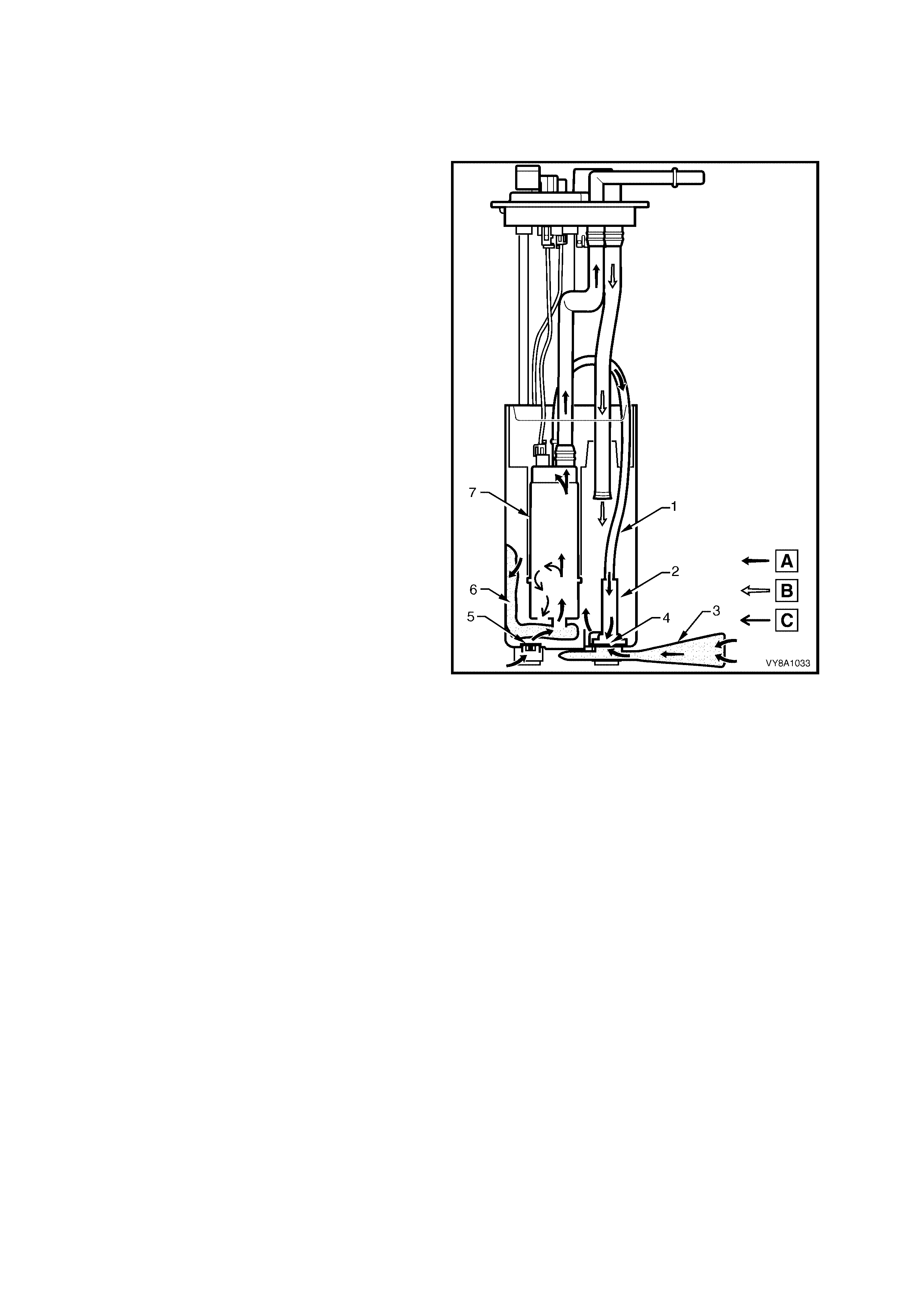
Legend
A. Fuel Flow In
B. Fuel Flow Return
C. Fuel Vapour
1. Aspirator
2. Jet Pump Filter
3. External Strainer
4. Primary Umbrella Valve
5. Secondary Umbrella Valve
6. Internal Strainer
7. Roller Vane Fuel Pump
Figure 6C2-3-22 – Modular Fuel Sender Assembly
REINST ALL
IMPORTANT: Always replace the fuel sender O-Ring when reinstalling the fuel sender assembly.
1. Position the new fuel sender assembly O-ring on the fuel tank.
IMPORTANT: Care should be taken not to fold or twist the fuel pump strainer when installing the fuel sender
assem bly, as this wi ll restrict f uel flow. Also, ensure that th e fuel pum p strainer d oes not interf ere with full travel of
float arm.
2. Reinstall the fuel sender assembly and the fuel sender assembly retainer ring using the J 39765 Fuel Sender
Locknut Wrench.
3. Reinstall fuel tank, Refer to Section 8A1 FUEL TANK, in the MY 2003 VY and V2 Series Service Information.
4. Rec onn ec t batter y grou nd lead.
5. Inspect system to ensure that no fuel leaks are evident.
FUEL STRAINER AND FUEL LEVEL SENSOR
NOTE: The f uel strainer is not serviced separat ely. Should the strainer be clogged or damaged, the com plete fuel
module assembly must be replaced.
FUEL PUMP ASSEMBLY
NOTE: The fuel pump for the V6 Supercharged engine is not serviced separately. The complete Modular Fuel
Sender Assembly must be replaced, if the pump is found to be faulty.
3.4 FUEL PUMP CONTROL MODULE (V6 SUPE RCHARGED ENGINE)
REMOVE
1. Dis c onnect batter y ground l ead.
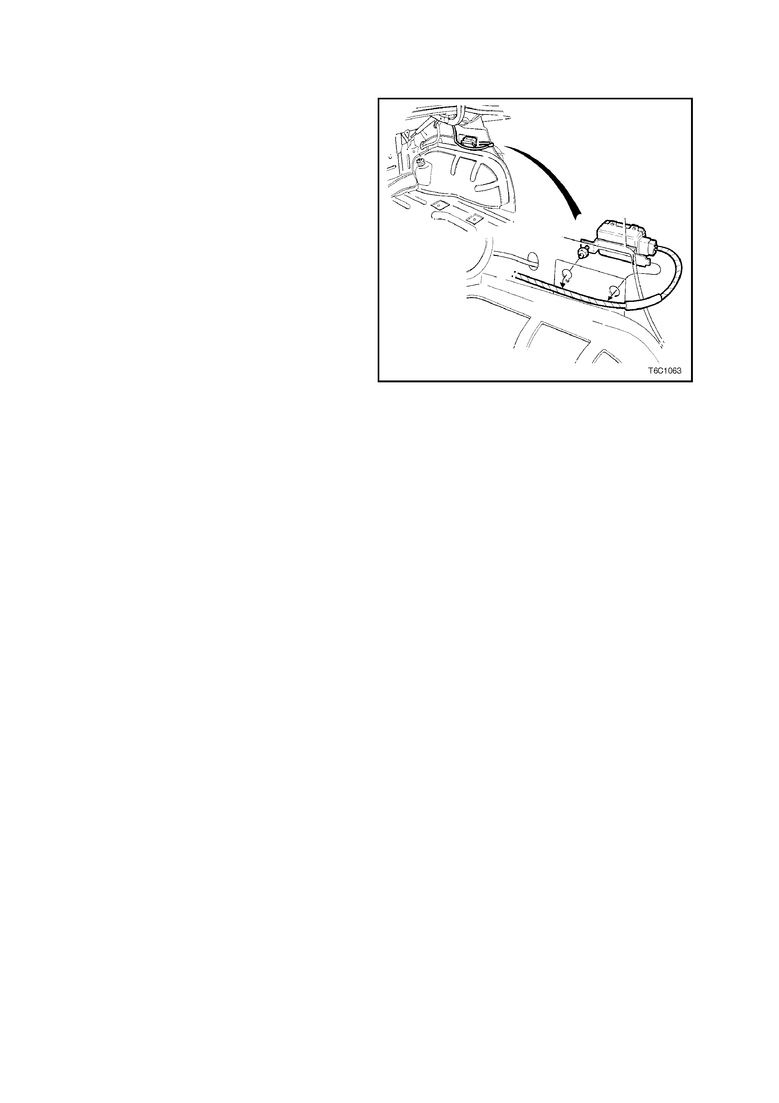
2. Move right rear upper wheelhouse trim cover to
gain access to fuel pump control module
retaining bolt.
3. Remove control module retaining bolt.
4. Remove module from upper wheelhouse
brace, disengage module cover front tab from
brace locating hole.
5. Disconnect body harness connector from
module.
REINST ALL
1. Reconnect body wiring harness connector to
module.
2. Reinstall module to upper wheelhouse brace,
engaging module front tab to brace locating
hole.
3. Install retaining bolt.
4. Install right rear upper wheelhouse trim cover.
5. Conn ec t battery ground lead.
NOTE: If necessary, check fuel pump control
module operation, refer to Table A-4.1 FUEL
PUMP ELECTRICAL CIRCUITS, in Section
6C2-2A DIAGNOSTIC TABLES.
Figure 6C2-3-23 Fuel Pump Control Module Location
3.5 FUEL SYSTEM PRESSURE TEST
PROCEDURE
A Fuel S ystem Pr ess ur e Test is par t of s everal of the Diagnostic T ables an d S ymp tom check s . To perf orm this tes t,
follow this procedure:
CAUTION: To reduce the risk of fire or personal injury, it is necessary to relieve fuel system pressure
before performing this test. See "Fuel Pressure Relief Procedure" in this Section.
IMPORTANT: At no time m ust the fuel in let hose or return line hose be clamped or bent over as this will cause a
permanent kinking of the inner section of the hose assembly and will result in restricted fuel flow.
1. Relieve fuel pressure as described in 3.1 FUEL PUMP RELAY – Fuel Pressure Relief Procedure, in this
Section. Turn ignition "OFF."
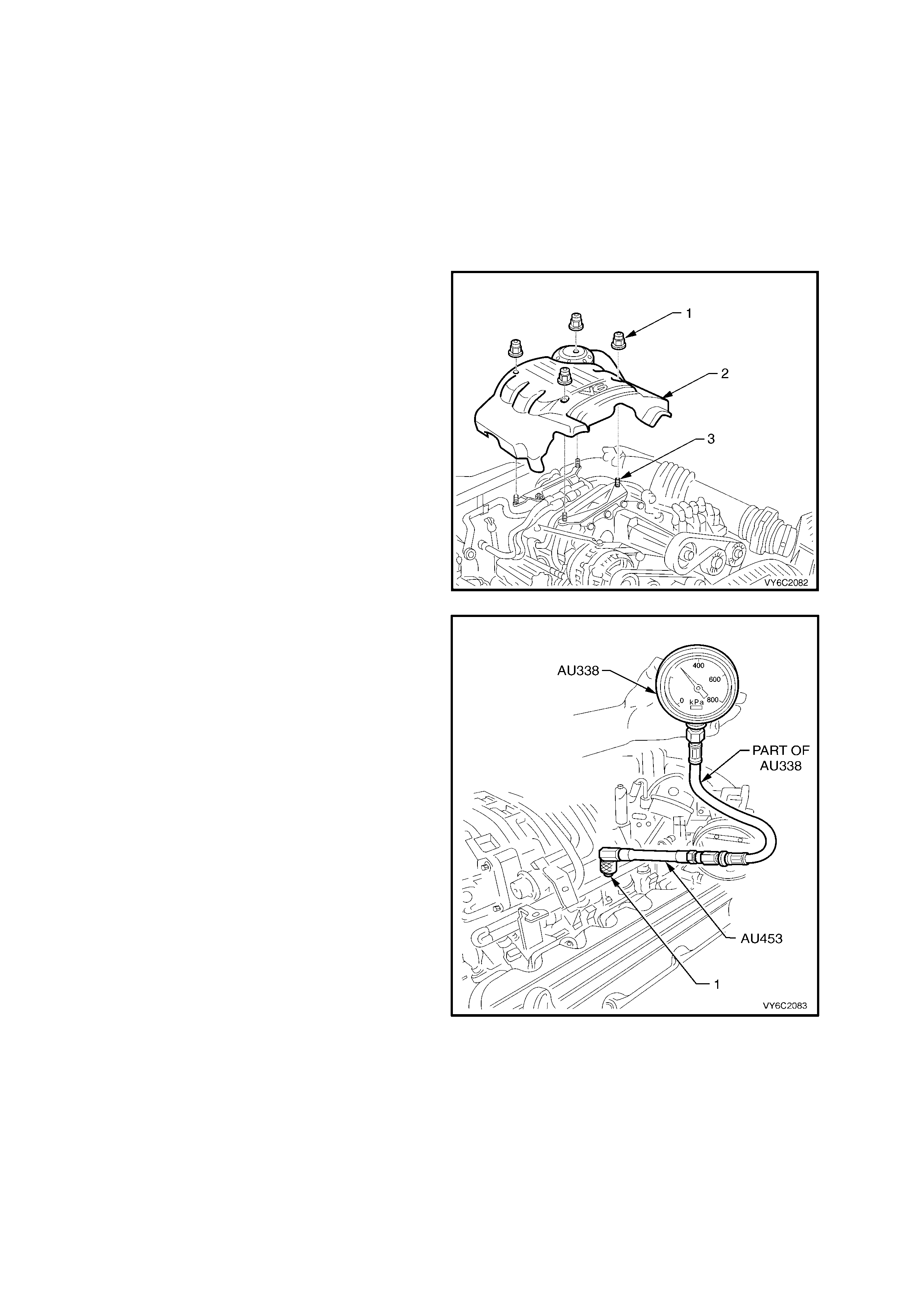
2. Remove four dome nuts (1) securing the
engine dress cover assembly (2) to the intake
manifold studs (3), then lift and remove the
cover assembly (2) from the engine.
Figure 6C2-3-24 – V6 Supercharged Engine Dress Cover
3. Remove Schrader valve cap on fuel rail fitting.
Connect a daptor, Tool AU453 to t he Schra der
valve fitting (1), located on engine fuel rail.
4. Connect fuel gauge AU338 and hose, to
Schrader valve adaptor, then proceed to
step 5.
Figure 6C2-3-25 – Fuel Gauge Installation V6
Supercharged Engine
5. With Tech 2 installed, enable fuel pump to pressurise the fuel system.
6. Fuel gauge re ading shou ld be 290 – 410 k Pa for the V6 SUP ERCHARG ED engine app lication. If this pres sure
is not reached, R efer to Table A-4.1 FUEL PUMP ELECT RICAL CIRCUIT S, in Section 6C2- 2A DIAGNOS TIC
TABLES.
7. Relieve fuel pressure as described in 3.1 FUEL PUMP RELAY – Fuel Pressure Relief Procedure, in this
Section.
8. Remove fuel pressure gauge and adaptor.
9. Reinstall Schrader valve cap.
10. Check for fuel leaks as described in 3.6 FUEL FILTER – Leak Testing, in this Section.
3.6 FUEL FILTER
LT Section No. – 03-075
REMOVE
IMPORTANT: Relieve the fuel system pressure
before servicing any fuel system connection.
Refer to the Fuel Pressure Relief Procedure in
3.1, FUEL PUMP RELAY – Fuel Pressure Relief
Procedure, in this Section.
1. Relieve fuel pressure as described in
3.1, FUEL PUMP RELAY - Fuel Pressure
Relief Procedure in this Sec tion .
2. Dis c onnect batter y ground l ead.
3. Raise rear of vehicle and support on safety
stands, refer to Section 0A, GENERAL
INFORMATION in the MY 2003 VY and V2
Series Service Information.
4. Place a drain tray beneath fuel filter.
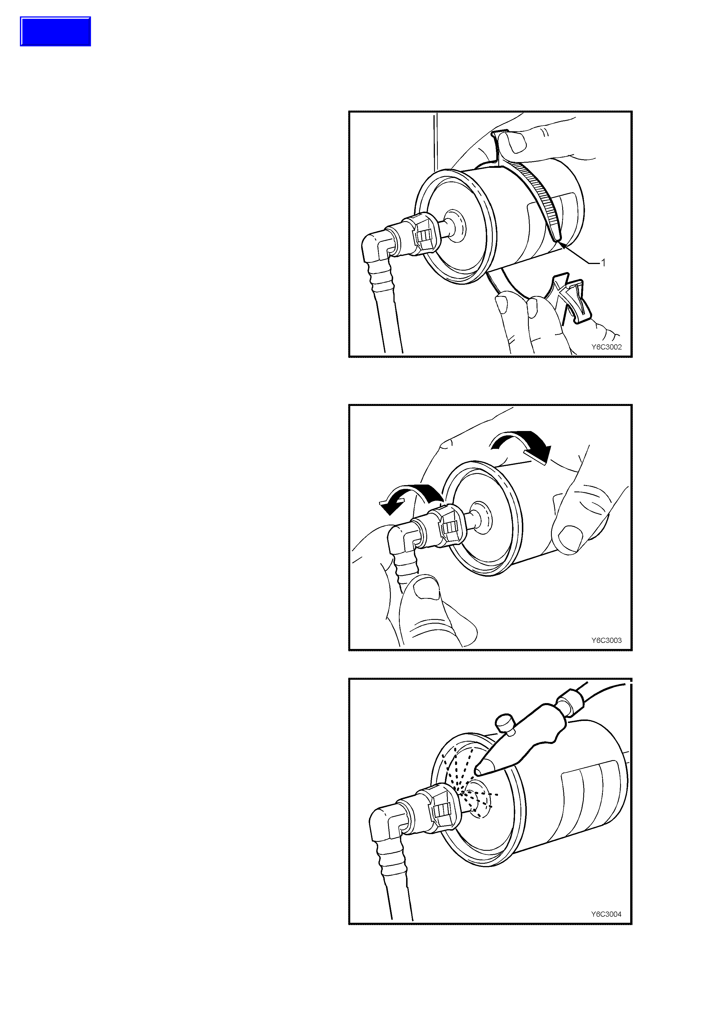
5. Remove the fuel filter from the retaining
bracket (1) with the fuel lines still connected to
the fuel filter to allow easier access.
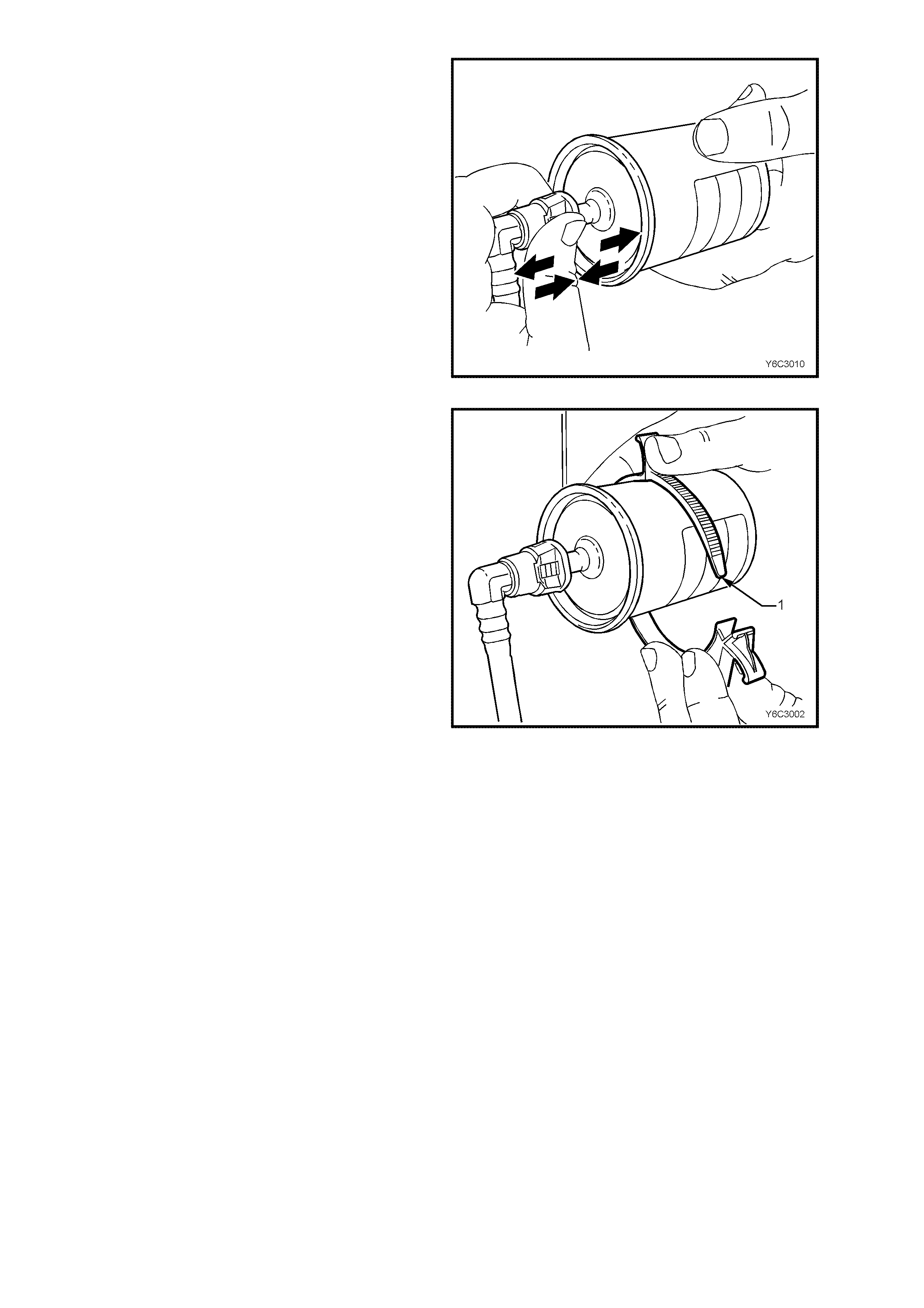
Figure 6C2-3-26
Quick Connect Fittings (Plastic Collar)
6. Grasp the quick-connect fittings on each side
of the fuel filter. Twist the female connectors
1/4 turn in each directio n in order to loos e n any
dirt within the quic k-connec t fittin g.
Figure 6C2-3-27
7. Using compressed air, blow any dirt out of the
quick-connect fitting to aid the release of any
tension or binding on the release tabs .
CAUTION: Wear safety glasses when using
compressed air, in order to prevent eye injury.
Figure 6C2-3-28
Techline
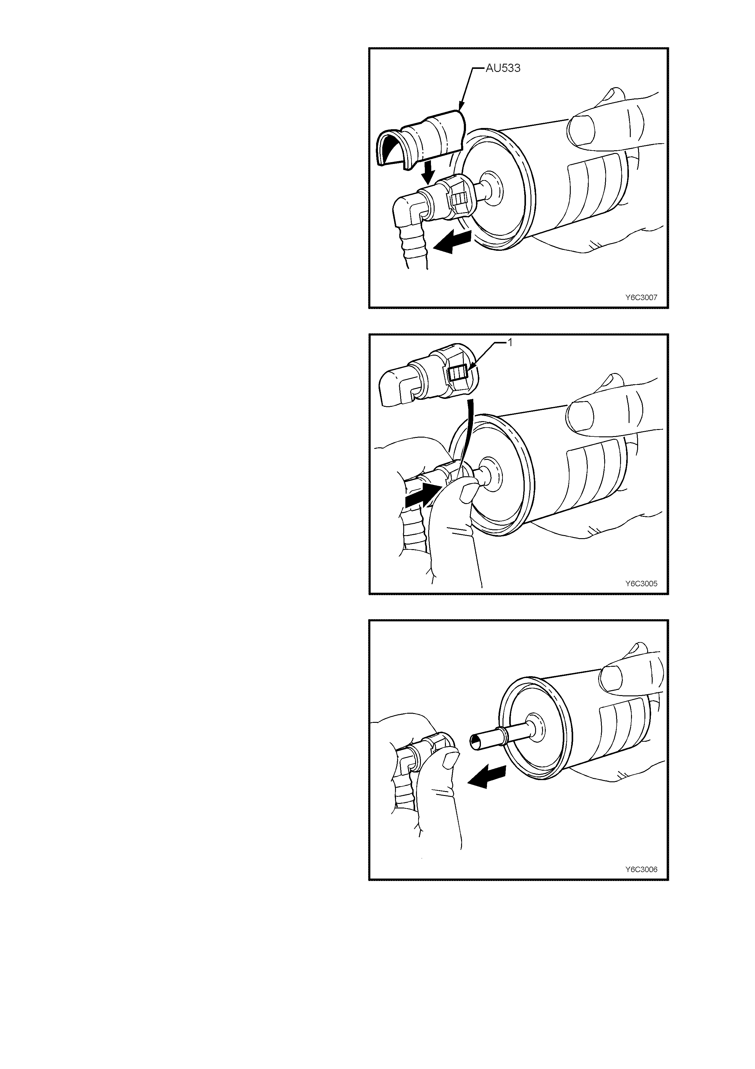
8. Use Tool No. AU533 to squeeze the release
tabs, by pushing down on the quick connect
fitting. This action compresses both release
tabs. With AU533 in place, push the
connection together to release tension on the
locking tabs and then pull to separate the two
components. Repeat this operation for the
second connection, to release the fuel filter.
NOTE: Tool No AU533 is available in two pipe
sizes; Red for 5/16” and Blue for 3/8”. Only the
blue (3/8”) tool is required for this operation.
9. Remove fuel filter from vehicle and discard
safely, remembering that some fuel will still
remain in the filter.
Figure 6C2-3-29
If Tool No. AU533 is not available, an alternative
method of removing the filter, is as follows:
10. Hold the fuel f ilter firm ly in one hand to support
the filter.
11. Using your o ther hand, gr asp one of the quick -
connect fittings and squeeze the plastic
retainer release tabs (1) on each side of the
fitting whi le pushing the fitti ng firmly toward the
fuel filter to release any tension on the release
tabs.
Figure 6C2-3-30
12. With the tension release tabs still held in the
squeezed position, move the complete quick-
connect fitting away from the fuel filter to
separate the connector fitting from the fuel
filter.
13. Apply the sam e method f rom steps 10 to 12 for
the remaining quick-connect fitting.
Figure 6C2-3-31
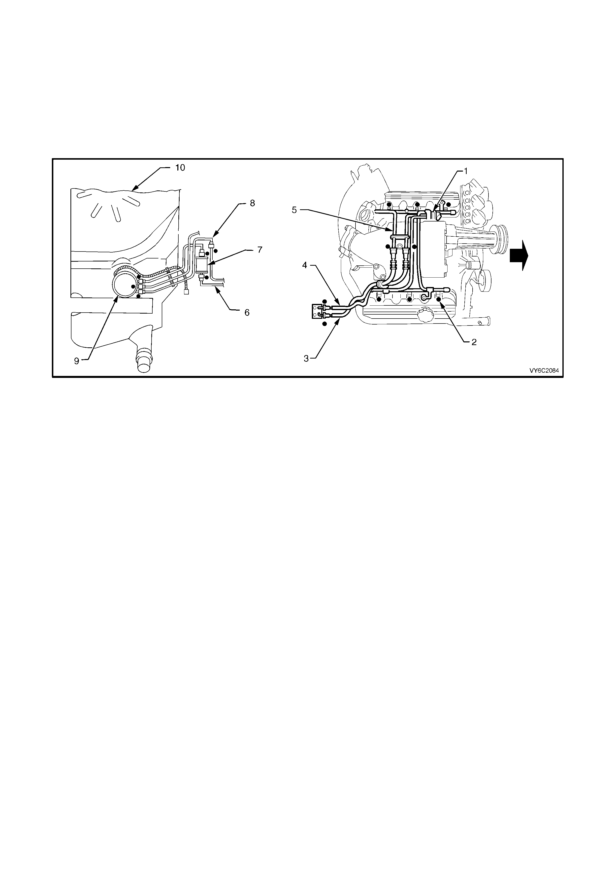
REINST ALL
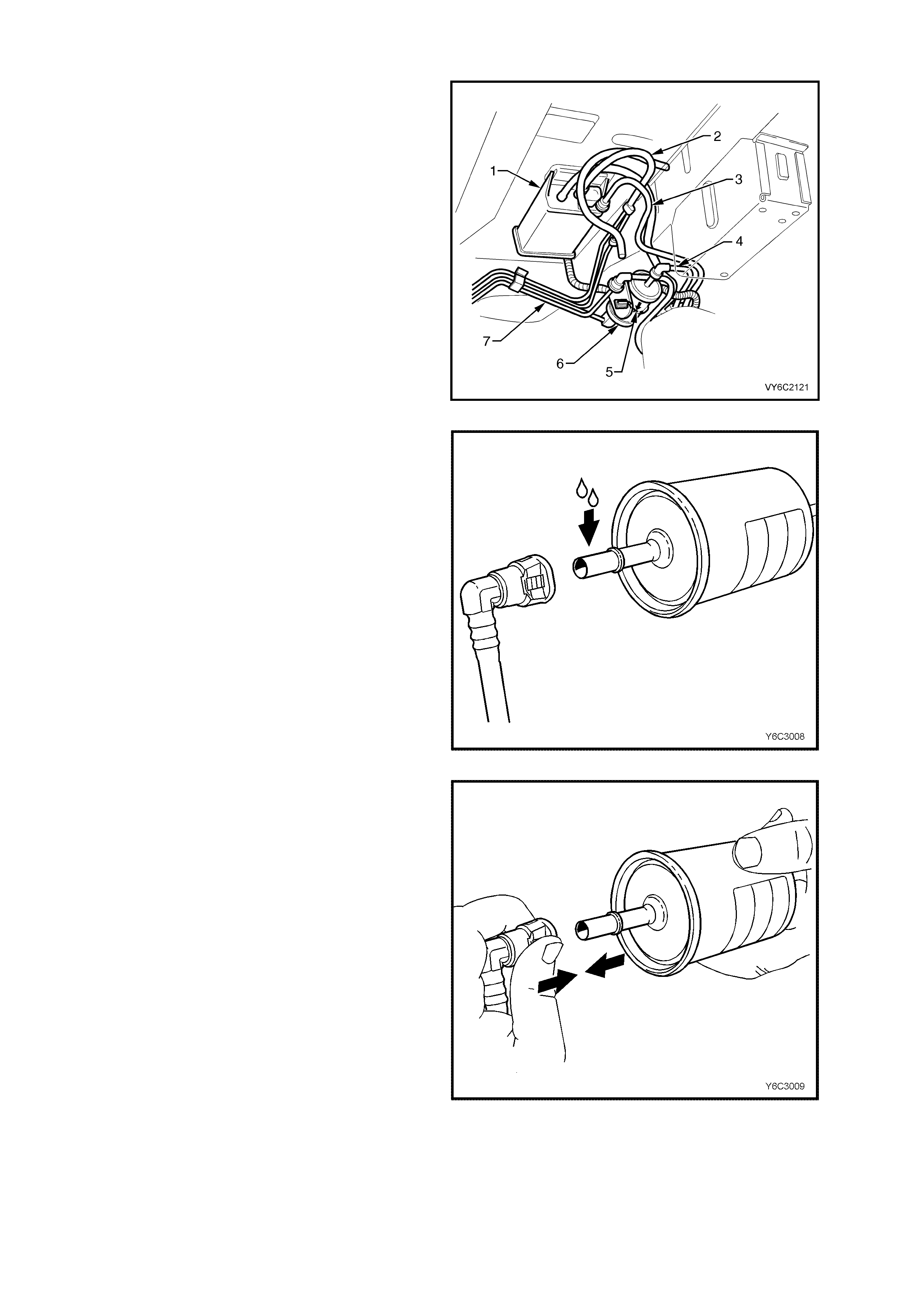
IMPORTANT: The fuel filter (6) must be installed
with the flow arrow (5) on its body pointing in the
same direction as the fuel flow to the front of the
vehicle.
Legend:
1. Evaporative Emission Control Canister
2. Vapour Line to Purge Solenoid
3. Fuel Tank Vapour Line
4. Fuel Feed Line from Modular Fuel Sender
Assembly
5. Fuel Flow Direction Arrow
6. Fuel Filter
7. Fuel Return Line
Figure 6C2-3-32 – Fuel Filter Installation
IMPORTANT: In or der t o r educ e t he ris k of fire and
personal injury, before connecting fuel filter quick-
connect fittings, always apply a few drops of clean
engine oil to the male ends of the fuel filter. This
will ensure proper reconnection and prevent a
possible fuel leak.
During normal operation, the O-ring located in the
fem ale connec tor will s wel l and ma y prevent proper
reconnection if not lubr icated.
1. Apply a few drops of clean engine oil to each
male fuel filter end.
Figure 6C2-3-33
2. Push both th e quic k -conne ct f itting a nd the fuel
filter together, causing the retaining tabs to
snap into place. Apply this method to both
ends of the fuel filter and the respective quick-
connect fittings.
Figure 6C2-3-34
3. Once installed, pull and push on both the
quick-connect fitting and the fuel filter in order
to make sure the connection is secure. Apply
this method to each end of the fuel filter and
the respective quick-connect fittings.
Figure 6C2-3-35
4. Re-install the fuel filter to the retaining
bracket (1).
5. Conn ec t battery ground lead.
6. Check for fuel leaks , refer to 3.6 FUEL FILTER
– Leak Testing in this Section.
7. Remove safety stands and lower vehicle.
Figure 6C2-3-36
LEAK TESTING
Before s tarting the eng ine, f ollowing th e insta llation of any fu el s ystem com ponent, check the fue l system for le aks
using the following procedure:
1. Check to ensure that there is a sufficient level of fuel in the fuel tank.
2. Us e Tech 2 "O utpu t Test" for "Fue l P ump." En abl in g t he ou tput test will ac ti vat e t he f uel pum p to pr es s uris e the
fuel system.
3. W ith fuel pr essur e appl ied t o the s ystem , check fuel s ystem for leaks , partic ularl y at points m ark ed ( ), shown
next.
Figure 6C2-3-37 – Leak Testing V6 Supercharged Engine
Legend
1. Fuel Pressure Regulator.
2. Fuel Injector (6 places).
3. Fuel Pressure Supply Line.
4. Fuel Return Line.
5. Fuel Rail.
6. Fuel Pressure Supply Line.
7. Fuel Filter.
8. Fuel Return Line.
9. Modular Fuel Sender Assembly.
10. Fuel Tank.
3.7 FUEL PRESSURE REGULATOR
LT Section No. – 03-375
IMPORTANT: T he fuel pressure regulator and fuel return hose is onl y serviced as a com plete assembly. The fuel
pressure return hose cannot be removed from the fuel pressure regulator.
REMOVE
1. Relieve fuel pressure as described in
3.1 FUEL PUMP RELAY – Fuel Pressure
Relief Procedure, in this Section.
2. Dis c onnect batter y ground l ead.
3. Remove four dome nuts securing the engine
dress cover assembly to the inlet manifold
studs, lift off and remove cover assembly.
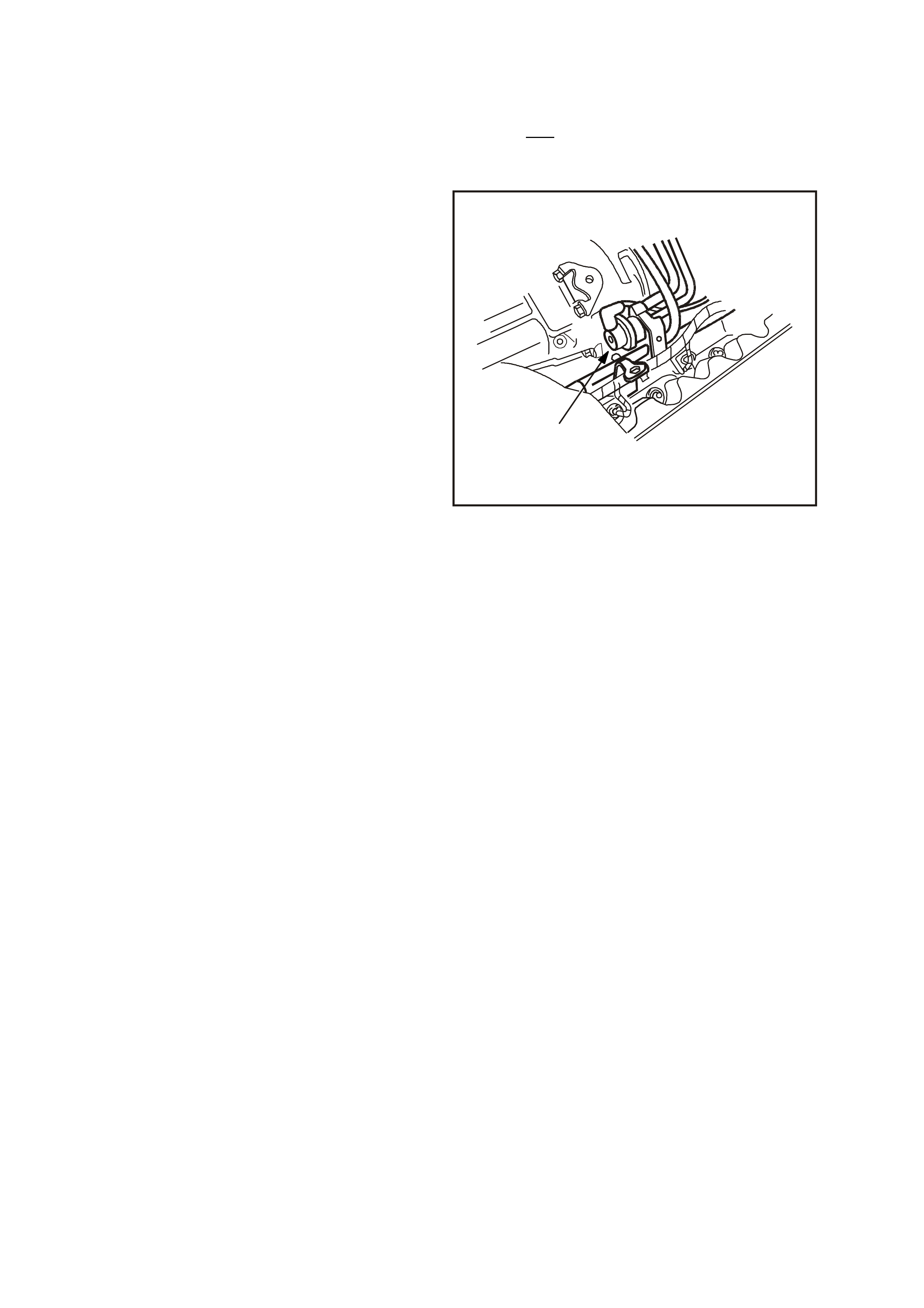
4. Disconnect vacuum hose from fuel pressure
regulator.
5. Clean any dirt from the fuel pressure regulator
retaining ring.
6. Using snap ring tool, remove snap ring from
fuel pressure regulator.
4236
1
Figure 6C2-3-38 – Fuel Pressure Regulator Location
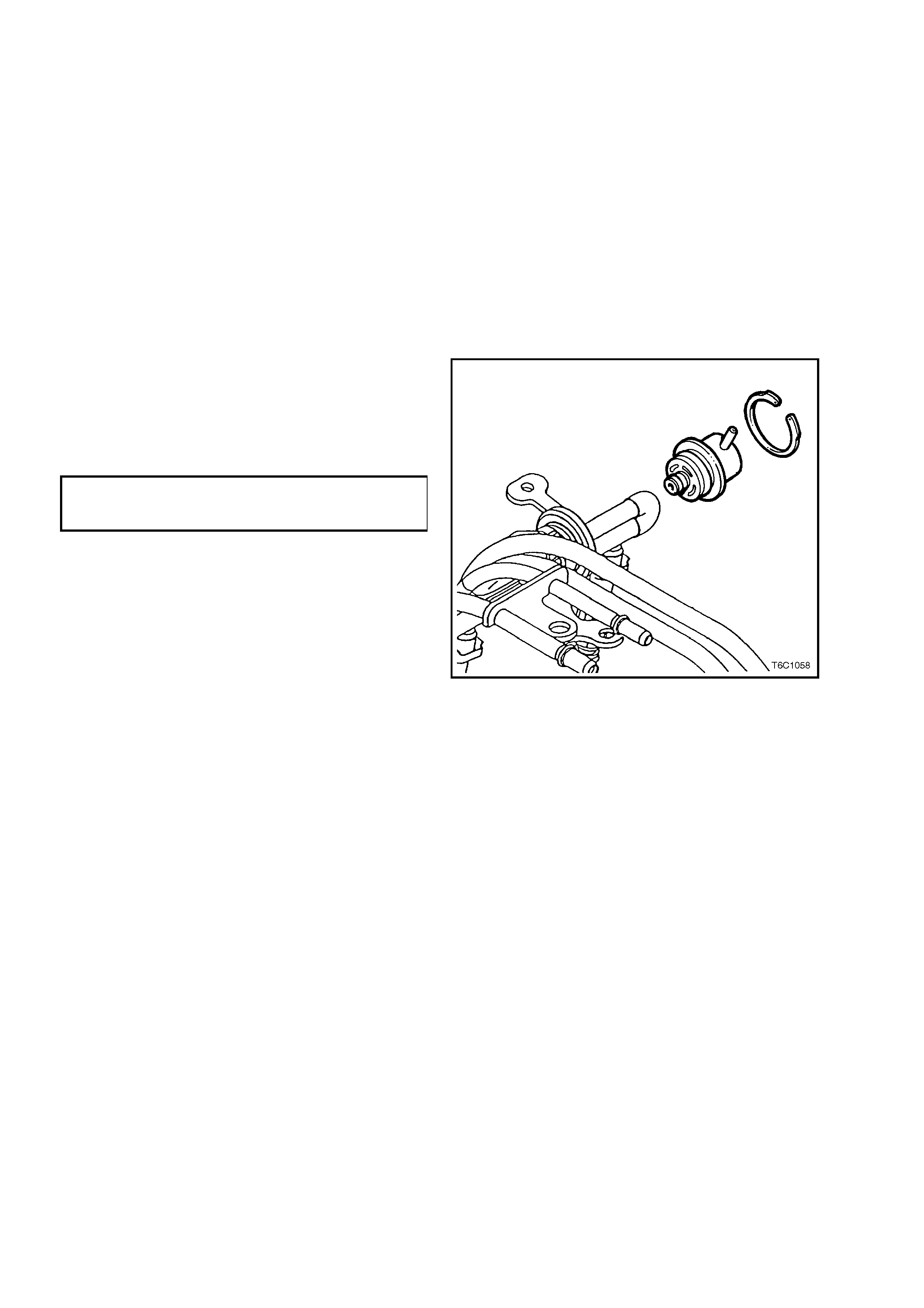
7. Using a shop towel to catc h an y spil led fue l, lif t
and t wist the fuel press ure r egulator in or der to
remove the fuel pressure regulator from the
fuel pressure regulator housing.
8. Cover the fuel pressure regulator housing to
prevent contamination from entering the fuel
system.
9. Using Tool No. 7371 for this engine
application, disconnect fuel return hose quick
connect at dash panel connection, only if
replacing fuel pressure regulator.
REINST ALL
1. If a new fuel pressure regulator is not being
installed, fit new O-rings to the fuel pressure
regulator and lightly lubricate the O-rings with
clean engin e oil.
2. Install the fuel pressure regulator in the fuel
pressure regulator housing.
3. Install the retaining snap ring to the fuel
pressure regulator using commercially
available snap ring pliers.
4. Reins tall the v acuum hose to the f uel pressure
regulator.
5. Reinstall the fuel return hose quick connect to
dash panel connector.
6. Rec onn ec t batter y ground l ead.
7. Check f or fuel le ak s; ref er in 3.6 FUEL FILTER
– Leak Testing, in this Section.
8. Reinstall engine dress cover, ensuring that
stud grommets in dress cover remain in place.
Tighten securing dome nuts to the correct
torque specification.
ENGINE DRESS
COVER DOME NUT
TORQUE SPECIFICATION 4 – 6 Nm
NOTE 1: Compressed air must never be used to
test or clean a fuel pressure regulator, as damage
to the fuel pressure regulator may result.
NOTE 2: In order to prevent damage to the fuel
pressure regulator do not immerse in solvent.
Figure 6C2-3-39 – Fuel Pressure Regulator Removal
3.8 FUEL RAIL SUPPLY AND RETURN HOSES
LT Section No. – 03-375
REPLACE
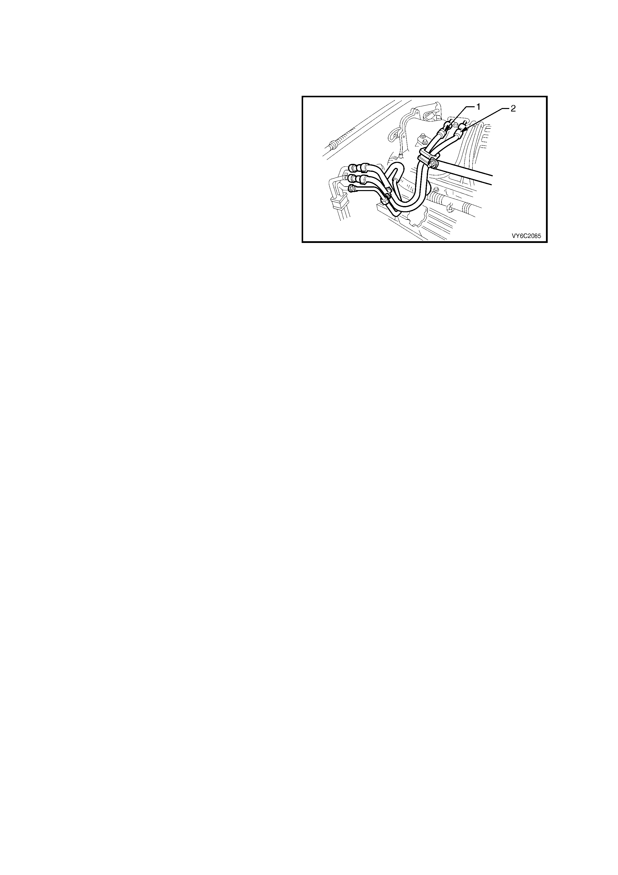
The fuel supply hose (1) is an assembly with the
fuel rail. Both components are NOT serviced
separately. For removal or replacement of the fuel
supply hose, refer to Fuel Rail and Injectors in
this Section.
The fuel return hose (2) is an assembly with the
fuel pres sure regulat or. Both c omponents are NOT
serviced separately. For removal or replacement,
refer to the Fuel Pressure Regulator in this
Section.
Figure 6C2-3-40 Fuel Lines
3.9 AIR CLEANER ASSEMBLY
LT Section No. – 03-250
REMOVE
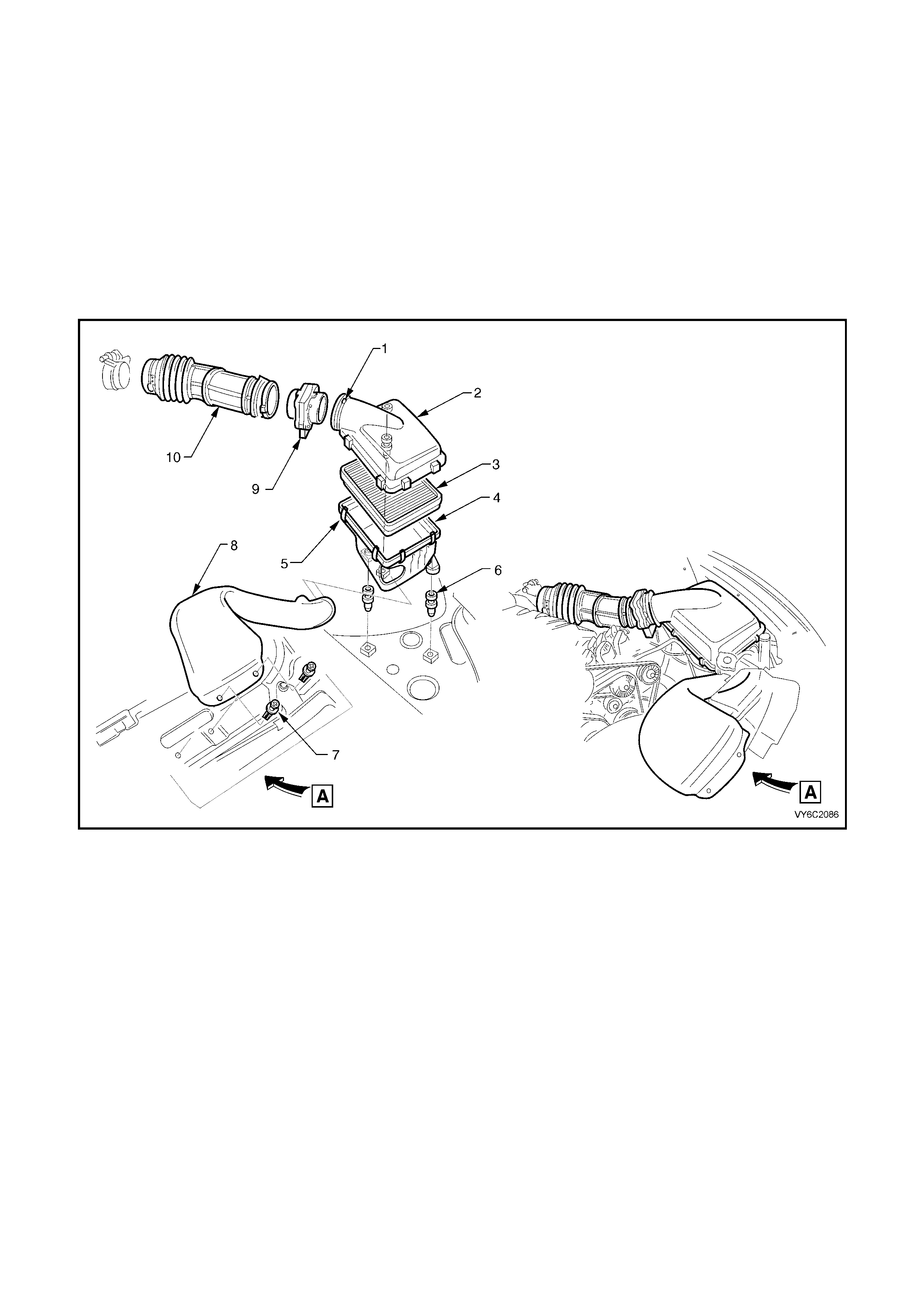
1. Loosen air duct clamp (1), then disconnect the mass air flow sensor (9) from the upper air cleaner housing (2).
2. Pull up retaining tang on IAT sensor wiring harness connector (not shown) and remove connector from sensor.
3. Unclip 5 clips (5) securing the air cleaner upper housing (2).
4. Remove air cleaner upper housing (2) and air cleaner element (3) as an assembly.
5. Remove the two scrivets (7) securing the pre-filter intake duct (8) to the radiator upper shroud.
6. Remove three fasteners (6) securing air cleaner lower housing (4) to fender inner panel insulators.
7. Disengage the pre-filter air intake duct (8) from the lower housing (4), then remove air cleaner lower housing
(4).
Figure 6C2-3-41 – Air Cleaner Housing Removal – V6 Supercharged Engine
Legend
1. Hose Clamp
2. Upper Air Cleaner Housing.
3. Air Cleaner Element.
4. Lower Air Cleaner Housing.
5. Clips (5 places)
6. Fasteners ( 3 places)
7. Scrivets (2 places).
8. Pre-Filter Intake Air Duct.
9. Mass Air Flow (MAF) Sensor.
10. Air Intake Duct to Throttle Body.

REINST ALL
1. Ass em ble air clea ner lo wer hous ing onto m ounti ng ins ulat ors. Rei nstal l secur ing nuts and ti ghten to the corr ect
torque specification.
AIR CLEANER LOWER
HOUSING NUT
TORQUE SPECIFICATION 5 – 7 Nm
2. Engage the pre-filter in the air intake duct into the lower housing and secure duct to radiator upper shroud,
using two scri vets.
3. Assem ble the air c leaner el ement into t he air cl eaner upper housing and place th e upper ho using a nd elem ent
assembly onto the lower air cleaner housing, ensuring that air filter element remains in position.
4. Snap the 5 retainer clips into place to the top of the air cleaner upper housing.
5. Reconnect wiring harness connector to IAT sensor.
6. Carefully assemble air duct adaptor onto air cleaner upper housing.
NOTE: Align notch on air cleaner housing adaptor with notch in air duct adaptor and notch in clamp.
7. Tighten air duct clamp securely.
8. Check that mass air flow sensor wiring harness connector has remained firmly in place.
9. Rec onn ec t batter y ground l ead.

3.10 THROTTLE CABLE
LT Section No. – 03-325
REMOVE
1. Remove four dome nuts securing the engine dress cover assembly to the inlet manifold studs, lift off and
remove t he cover assembly.
2. Loosen outer cable lock nuts at throttle body mounting bracket.
3. Remove inner cable from throttle body linkage.
4. Disconnect outer cable from mounting bracket.
5. Remove instrument panel lower right side trim assembly retainers and lower trim, Refer to
Section 1A3, INSTRUM ENT PANEL AND CONSOLE, in the MY2003 VY and V2 Series Service Information.
6. Disconnect inner cable plastic spacer from throttle pedal lever.
7. Withdraw cable assembly from engine compartment.
REINST ALL
1. Assemble outer cable into dash panel.
2. Attach inner cable to throttle pedal lever.
3. Install outer cable to mounting bracket.
4. Attach inner cable to throttle body linkage.
5. Adjust cable as in following instructions.
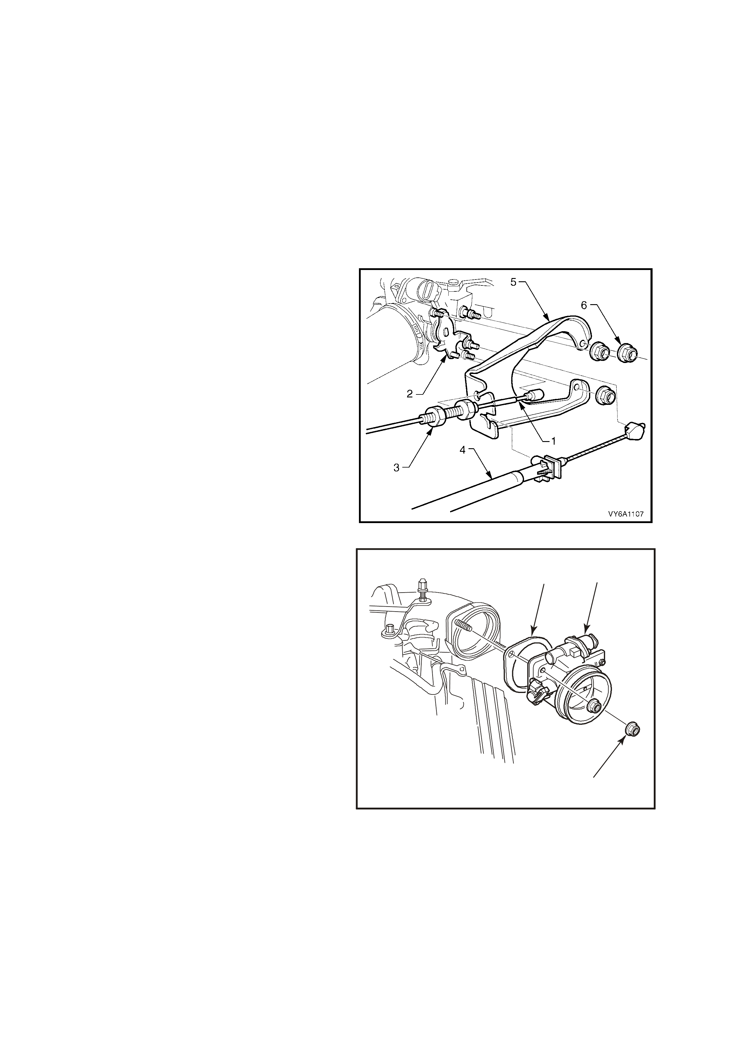
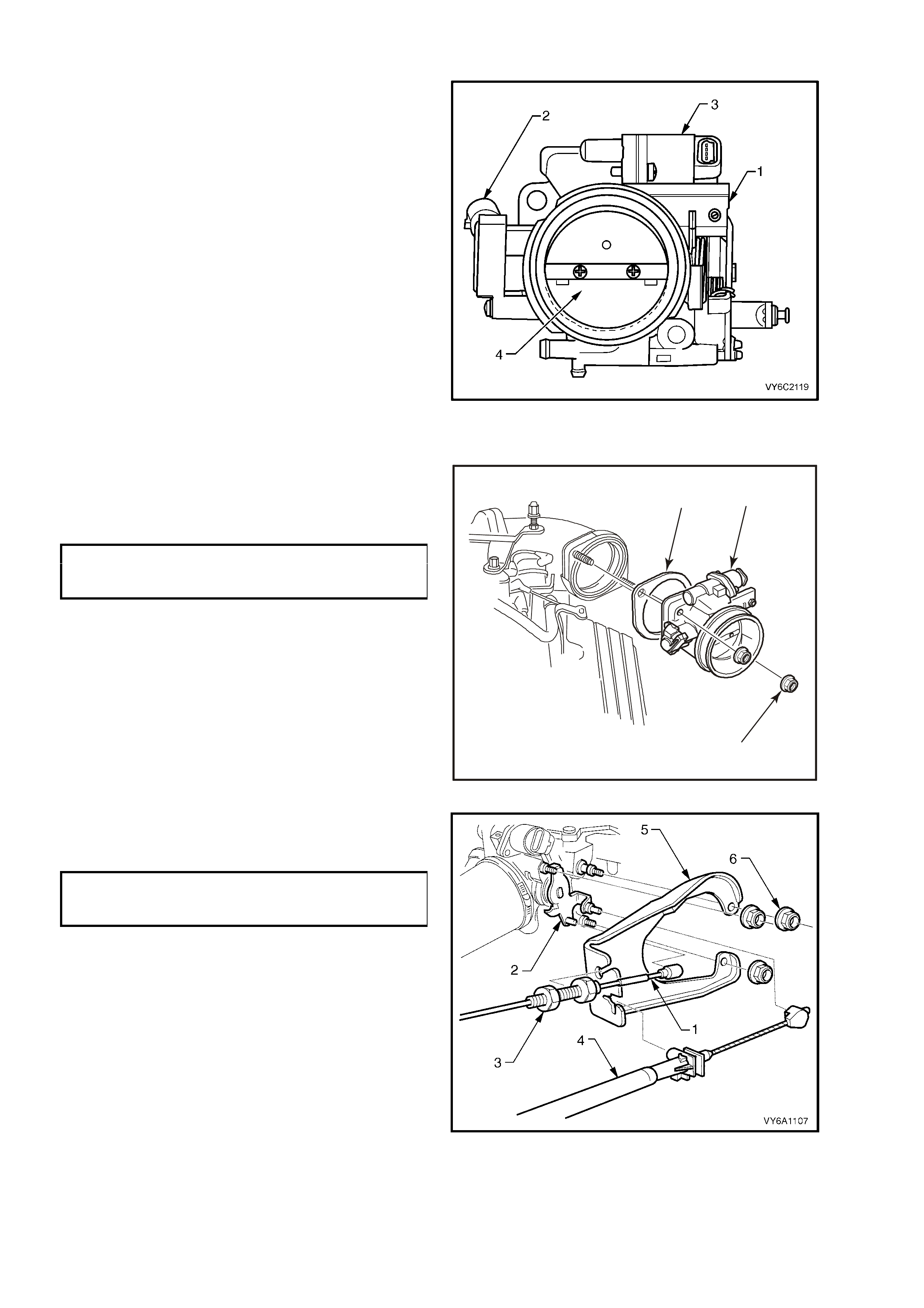
Figure 6C2-3-42 Throttle Cable V6 Supercharged Engine
Legend
1. Cable Adjusting Nuts (Do not
remove)
2. Mounting bracket
3. Mounting bracket nuts (3 places).
4. Correct Outer Cable Positioning
5. Cruise control cable.
6. Throttle cable.
7. Main wiring harness.
8. Main wiring harness retention clip.
9. Throttle cable.
10. Inner cable.
11. Throttle pedal lever.
12. Clip
13. Cruise control ca ble.
14. Lower clip.
15. Bracket.
16. Throttle cable.
17. Upper clip.
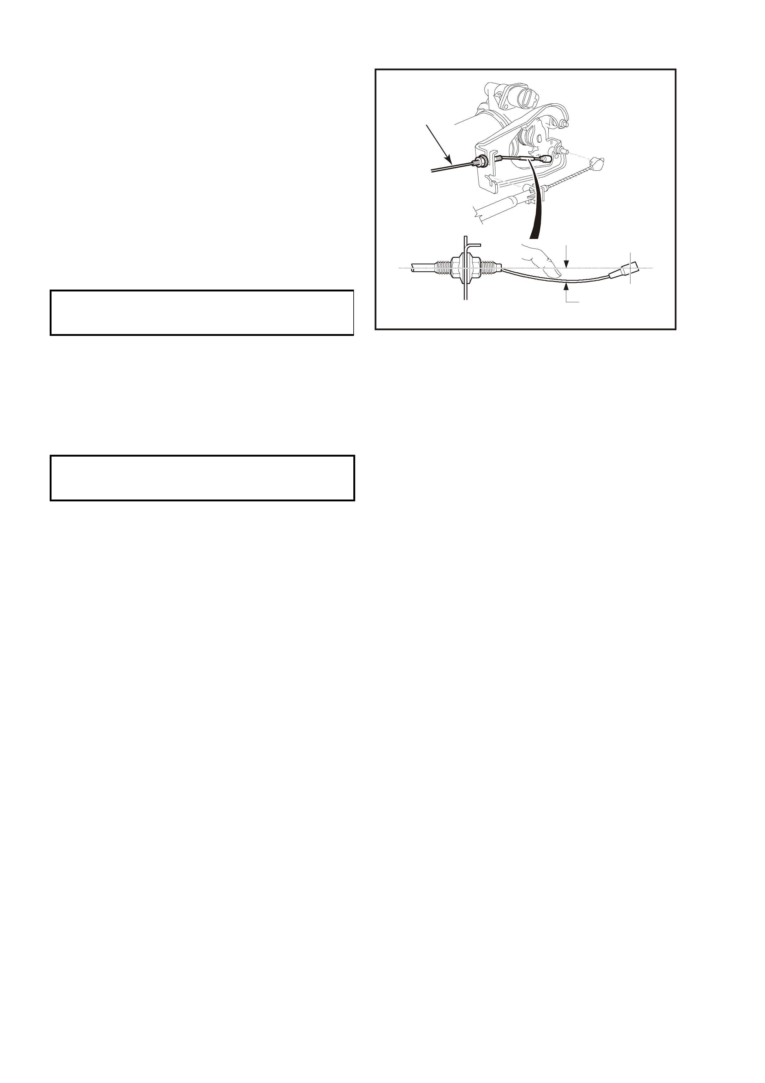
ADJUST
1. Remove instrument panel lower right side trim
(if not already rem oved, Ref er to Section 1 A3,
INSTRUM ENT P ANEL AND CONSOLE, in the
MY 2003 VY and V2 Series Service
Information.
2. Ensure throttle pedal is free to move from
closed to fully open position. Check that throttle
pedal comes to rest at the correct closed
throttle position (against pedal stop).
3. Adjust o uter ca ble lock nuts so that inner c able
has a deflection of 10 – 15 mm (2) without
moving the throttle linkage from idle stop.
4. Tighten cable lock nuts to the correct torque
specification.
OUTER THROTTLE
CABLE LOCK NUT
TORQUE SPECIFICATION 2 – 5 Nm
5. Check for Wide Open Throttle and smooth
operation of throttle pedal.
6. Reinstall engine dress cover to the intake
manif old, ensurin g that stu d gromm ets in dres s
cover remain in place.
7. Tighten securing dome nuts to the correct
torque specification.
1
2
4322
Figure 6C2-3-43
ENGINE DRESS
COVER DOME NUT
TORQUE SPECIFICATION 4 – 6 Nm
8. Refit instrument panel lower right side trim,
Refer to Section 1A3, INSTRUMENT PANEL
AND CONSOLE, in the MY 2003 VY and V2
Series Service Information.
3.11 THROTTLE BODY
LT Section No. – 03-300
REMOVE
1. Disconnect battery ground lead.
2. Remove four dome nuts securing the engine dress cover assembly to the intake manifold studs, lift off and
remove the cover assembly.
3. Disconnect wiring harness connectors from IAC valve and TP sensor.
4. Loosen air duct clamp at throttle body.
5. Remove air flow duct from throttle body.
6. Disconnect the emission control purge hose from the throttle body connection.
7. Loosen both hose clamps securing the crankcase ventilation hose, then remove the hose and clamps from the
engine.
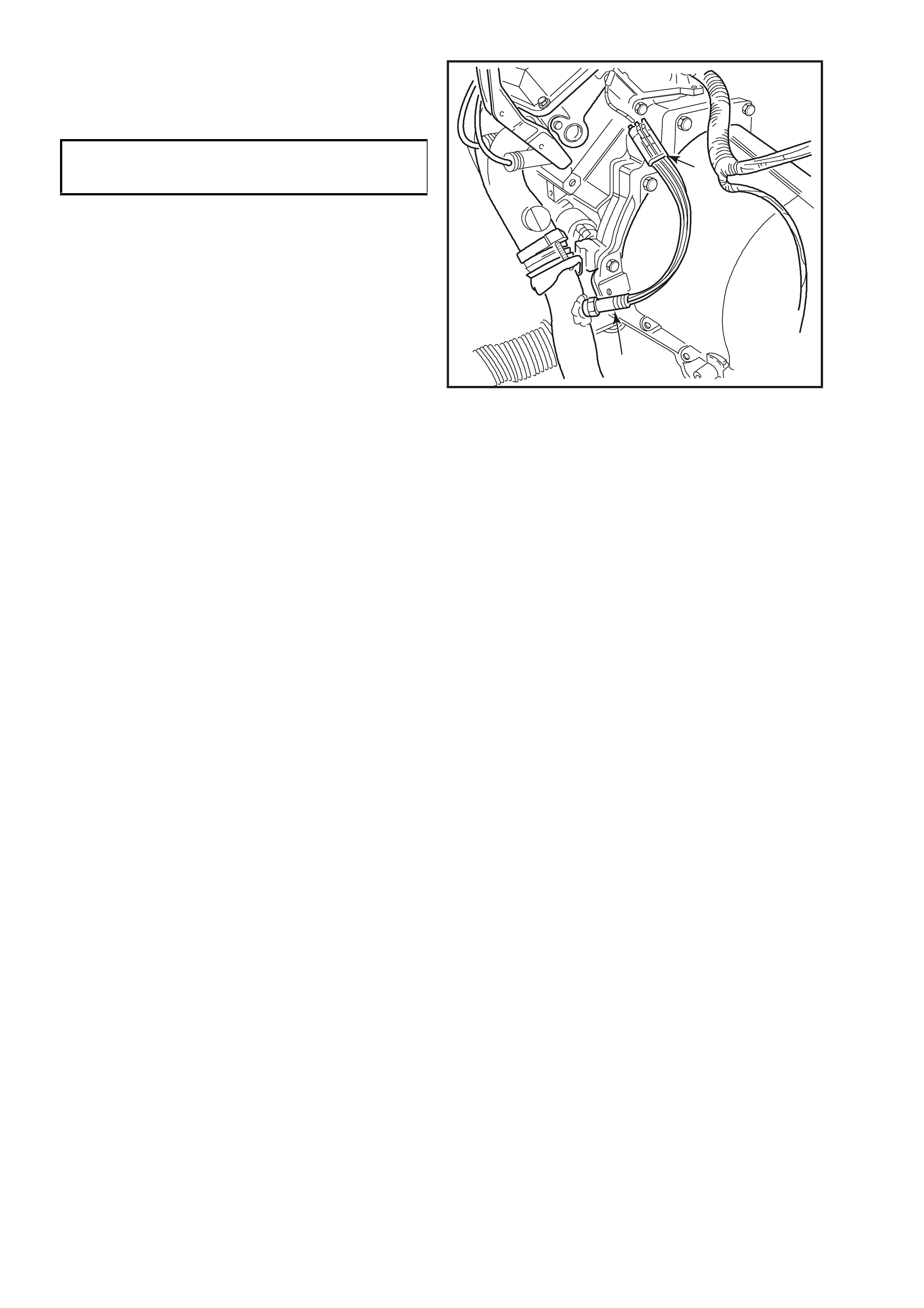
8. Disconnect throttle inner cable (1) from throttle
body linkage (2). Loosen outer throttle cable
lock nuts (3) at mounting bracket (5) and lay
cable away from engine.
9. If vehicle is fitted with cruise control,
disconnect cruise control outer cable (4) from
the mounting bracket (5) and push inner cable
forward off throttle body linkage (2).
10. If required, remove the mounting bracket (5)
retaining nuts (6) and remove bracket from the
throttle body.
Figure 6C2-3-44
11. Remove throttle body to intake manifold
attaching nuts (3).
12. Remove throttle body and gasket (1) from
manifold.
3
4324
1
2
Figure 6C2-3-45
CLEAN AND INSPECT
Gasket surfaces on throttle body and manifold.
IMPORTANT: If re-using the old throttle body, you must perform the throttle body Cleaning Procedure before
reinstalling.
NOTE: There is a specific throttle body assembly for this engine application. When replacing the throttle body
always refer to the current PartFinder® CD ROM for the correct part number.
THROTTLE BODY CLEANING PROCEDURE
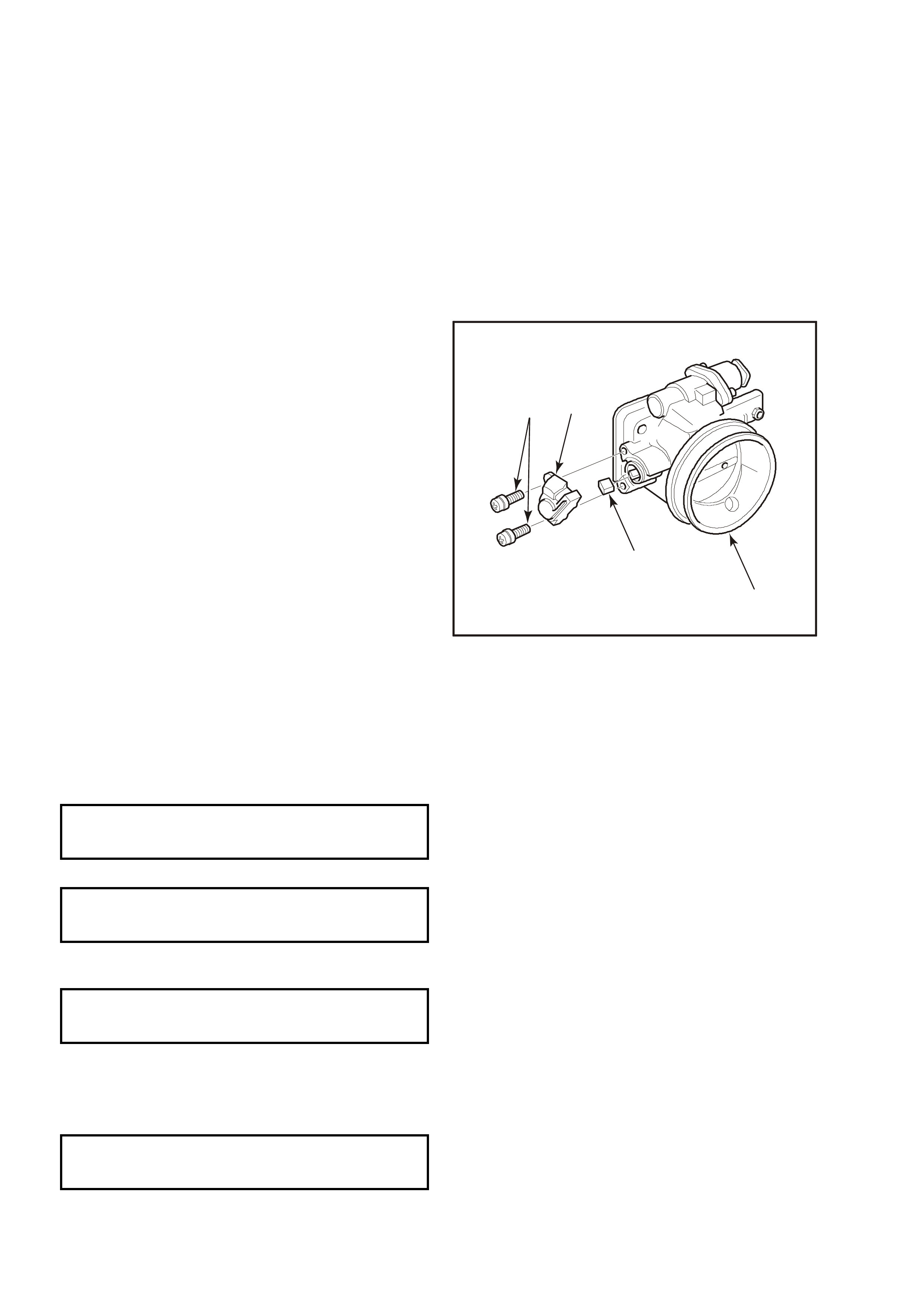
1. Remove throttle body (1) from vehicle.
2. Remove the TP sensor (2) and IAC valve (3)
from the throttle body.
3. Using an approved injector cleaner, clean the
carbon build up around the pintle of the IAC
valve (3).
4. On the throttle body, clean the carbo n build up
around the IAC air port, throttle body bore and
throttle blade (4).
5. Reinstall TP sensor (2) and IAC valve (3) to the
throttle body (1).
6. Continue with the reinstallation of the throttle
body to the engine.
Figure 6C2-3-46 Throttle Body Cleaning
REINST ALL
1. Install a new throttle body gasket (1), then the
throttle body (2) to intake manifold.
2. Install throttle body attaching nuts (3) and
tighten to the correct torque specification.
THROTTLE BODY
ATTACHING NUT
TORQUE SPECIFICATION 15 – 20 Nm
3. Reinst all canister purge control hose to throttle
body.
4. Reinstall engine positive crankcase ventilation
hose to throttle body and tighten hose clamps
to secure.
5. Reinstall wiring harness connectors to IAC
valve and TP Sensor.
3
4324
12
Figure 6C2-3-47
6. Reinstall throttle cable mounting bracket (5)
attaching nuts (6) and tighten to the correct
torque specification.
THROTTLE CABLE
BRACKET NUT
TORQUE SPECIFICATION 10 Nm
7. Reconnect inner throttle cable (1) to throttle
body linkage (2).
8. If vehicle is fitted with cruise control, reinstall
cruise control cable (4) to throttle body linkage.
9. Install air duct onto throttle body, align clamp
and air duct locating notches. Tighten air duct
clamp at throttle body securely.
10. Reconnec t batter y ground l ead.
11. Start engine then look and listen for air leaks.
12. Check throttle cable adjustment, refer
3.10, FUEL CONTROL SYSTEM – Throttle
Cable Adjust in this Section.
Figure 6C2-3-48

13. Check cruis e control c able adj ustm ent, Refer to Section 12E, C RUISE CONT ROL in the MY 200 3 VY and V2
Series Service Information.
14. Reinstall engine dress cover to the inlet manifold, ensuring that stud grommets in the dress cover remain in
place.
15. Tighten securing dome nuts to the correct torque specification.
ENGINE DRESS
COVER DOME NUT
TORQUE SPECIFICATION 4 – 6 Nm
THROTTLE BODY IAC VALVE COUNT CHECKING PROCEDURE
1. Start engine and run until normal operating temperature (85° C) is reached.
2. Ensure transmission is in Park or Neutral.
3. Turn off all accessories (A/C, radio etc.)
4. Install Tech 2 and display Engine Data.
5. Confirm the IAC valve counts are at 15 or less, at idle.
If the counts are not at 15 or less, perform the Throttle Stop Screw Reset Procedure if the screw has been
tampered with. If the Throttle Stop Screw has not been tampered with, replace the throttle body.

3.12 RAIL AND INJECTORS
LT Section No. – 03-375
IMPORTANT: The fuel inlet hose is an integral part of the fuel rail. Both components are NOT serviced separately.
REMOVE
1. Relieve fuel pressure Refer 3.1 FUEL PUMP RELAY – Fuel Pressure Relief Procedure in this Sect ion.
2. Dis c onnect batter y ground l ead.
3. Thoroughly clean around injector to intake manifold ports, using compressed air.
CAUTION: Always wear eye protection when using compressed air to clean around components such as
these, to avoid eye damage!
4. Remove four dome nuts securing the engine dress cover assembly to the inlet manifold studs, lift off and
remove t he cover assembly.
5. Remove alternator bracket.
6. Use Tool No. 7371 for the fuel supply (1) and
7370 for the fuel return quick connectors (3).
Open, then close over the fuel line to be
disconnected (view ‘A’)
7. While pushing on the quick connect with one
hand, push the release tool into the quick
connect with the other. Pull back on the quick
connect to disconnect.
8. Repeat for the other line, then plug all
openings to prevent foreign matter entry.
Figure 6C2-3-49 – Fuel Line Connections
9. Remove vacuum hose from fuel pressure
regulator (4).
10. Disconnect fuel pr es sur e r e gulator ( 4) f r om fuel
rail (5). Refer to Fuel Pressure Regulator in
this Section.
11. Disconnect electrical connectors from injectors.
12. Remove four nuts (2), and one bolt (1),
securing fuel rail (5) to supercharger body.
13. Remove fuel rail assembly (5) from
supercharger.
Figure 6C2-3-50 – Supercharged Engine Fuel Rail
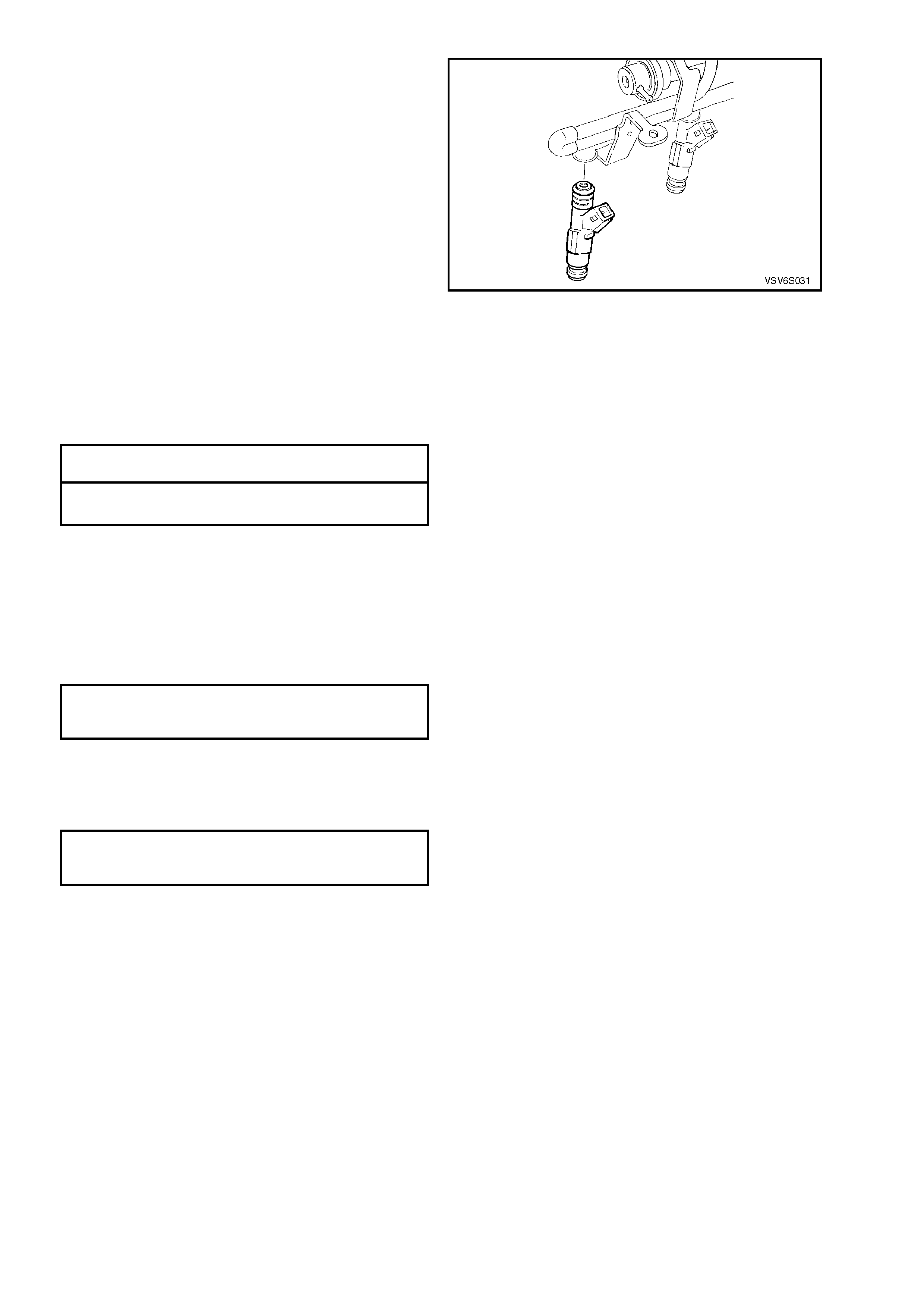
14. Remove injector retaining clips. Withdraw
injectors from fuel rail.
IMPORTANT: During the servicing process, to
prevent dirt and other contaminants from entering
the fue l pass ages, cap all f ittings and plug all h oles
with clean shop rag.
Figure 6C2-3-51 – Fuel Injector Installation
REINST ALL
Reinstallation is the reverse to the removal process, except for the following:
1. Reinstall each fuel injector to the fuel rail, using new O-rings, lubricated with a smear of clean engine oil.
2. Reinstall the fuel rail to the supercharger body, securing with four nuts and one bolt, tightening to the correct
torque specification.
FUEL RAIL ATTACHING BOLT
TORQUE SPECIFICATION 20 – 30 Nm
FUEL RAIL ATTACHING NUT
TORQUE SPECIFICATION 8 – 12 Nm
3. Reinstall connectors to fuel injectors, checking that each is securely installed.
4. Re- c onnect eac h f ue l h os e quick connec t to the c orr ec t dash panel c o nnec t or. While holding the pipe, p us h t h e
quick connect onto the pipe until a click is heard. Tug on each to ensure that the connection is secure.
NOTE: The tagged line and hose are on the fuel return.
5. Reinstall the fuel pressure regulator to the fuel rail.
6. Reinstall the vacuum hose to the fuel pressure regulator.
7. Reinstall the alternator bracket, tightening the fasteners to the correct torque specification.
GENERATOR BRACKET
BOLT AND NUT
TORQUE SPECIFICATION 40 – 60 Nm
8. Reinstall battery ground cable.
9. With Tech 2 connected, command Fuel Pump "ON", using Output Test and inspect fuel system for leaks.
10. Reinstall engine dress cover to the inlet manifold, ensuring that stud grommets in the dress cover remain in
place. Tighten securing dome nuts to the correct torque specification.
ENGINE DRESS COVER
DOME NUT
TORQUE SPECIFICATION 4 – 6 Nm
3.13 IDLE AIR CONTROL VALVE
LT Section No. – 03-300
REMOVE
1. Dis c onnect batter y ground l ead.
2. Remove four dome nuts securing the engine
dress cover assembly to the inlet manifold
studs, lift off and remove the cover assembly.
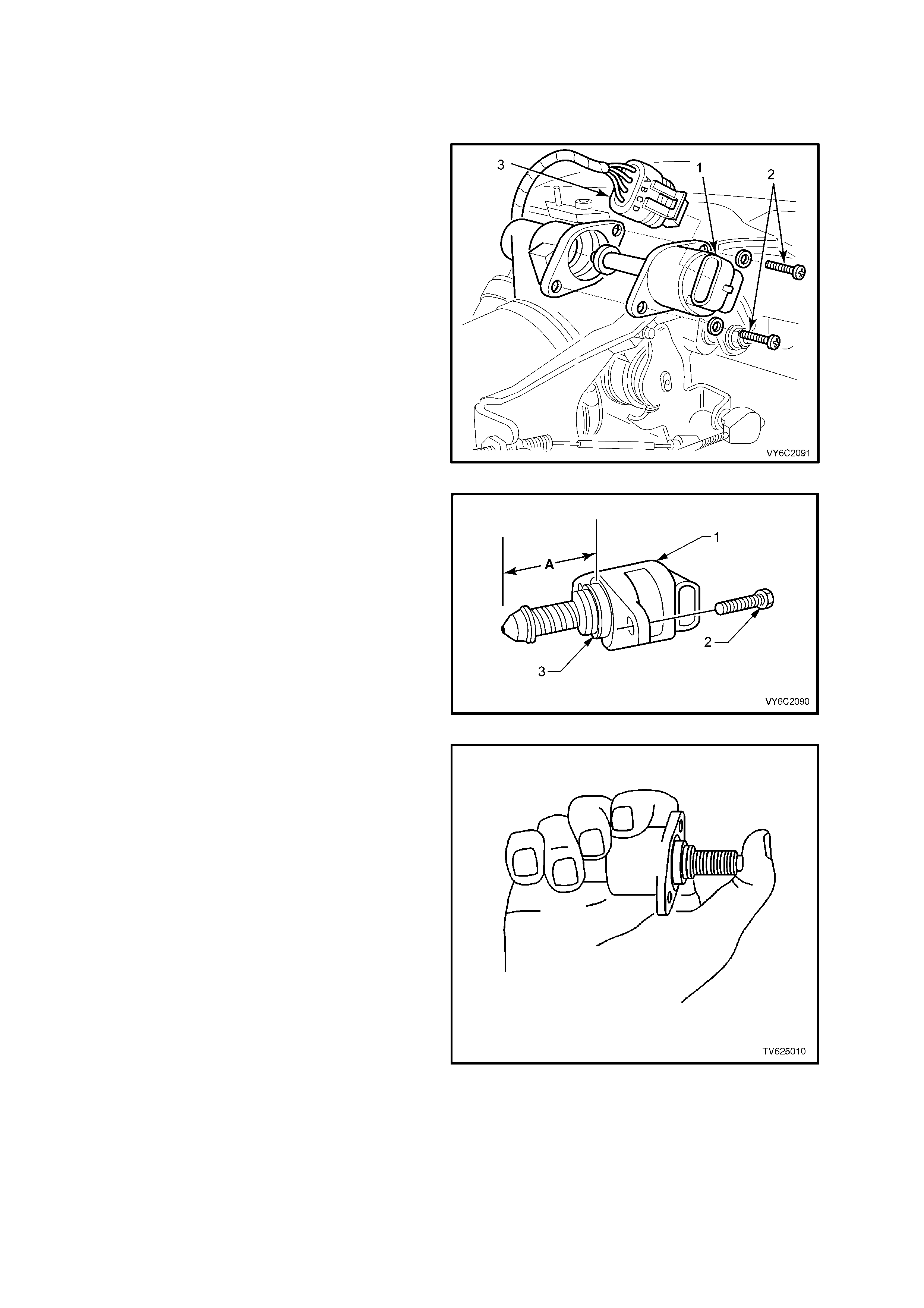
3. Lift up retaining tang on IAC valve wiring
harness connector (3) and pull connector from
IAC valve (1).
4. Remove IAC valve to throttle body attaching
screws (2).
5. Remove IAC valve (1) from throttle body.
CLEAN
IAC valve sealing surfaces on throttle body, to
assure proper seal of O-ring and contact of IAC
valve flange.
IMPORTANT: When insta lling a n ew IAC va lve, be
sure it has the correct part number.
Figure 6C2-3-52 – IAC Valve Removal
IMPORTANT: Before installing a new IAC valve,
measure distance "A" between tip of valve pintle
and the flange mounting surface. If it is greater
than 28 mm, it m us t be reduc ed to prevent d amage
to the valve when it is installed.
Figure 6C2-3-53 – IAC Measured Distance
6. To reduce the length of the pintle extension,
exert firm pressure on valve pintle to retract it.
(A slight side-to-side movement may be
helpful).
Figure 6C2-3-54 – IAC Retraction Method
REINST ALL
1. Lubr icate IAC valv e O-ring with li ght engine oil.
If necessary, in stall on to valve assembly.
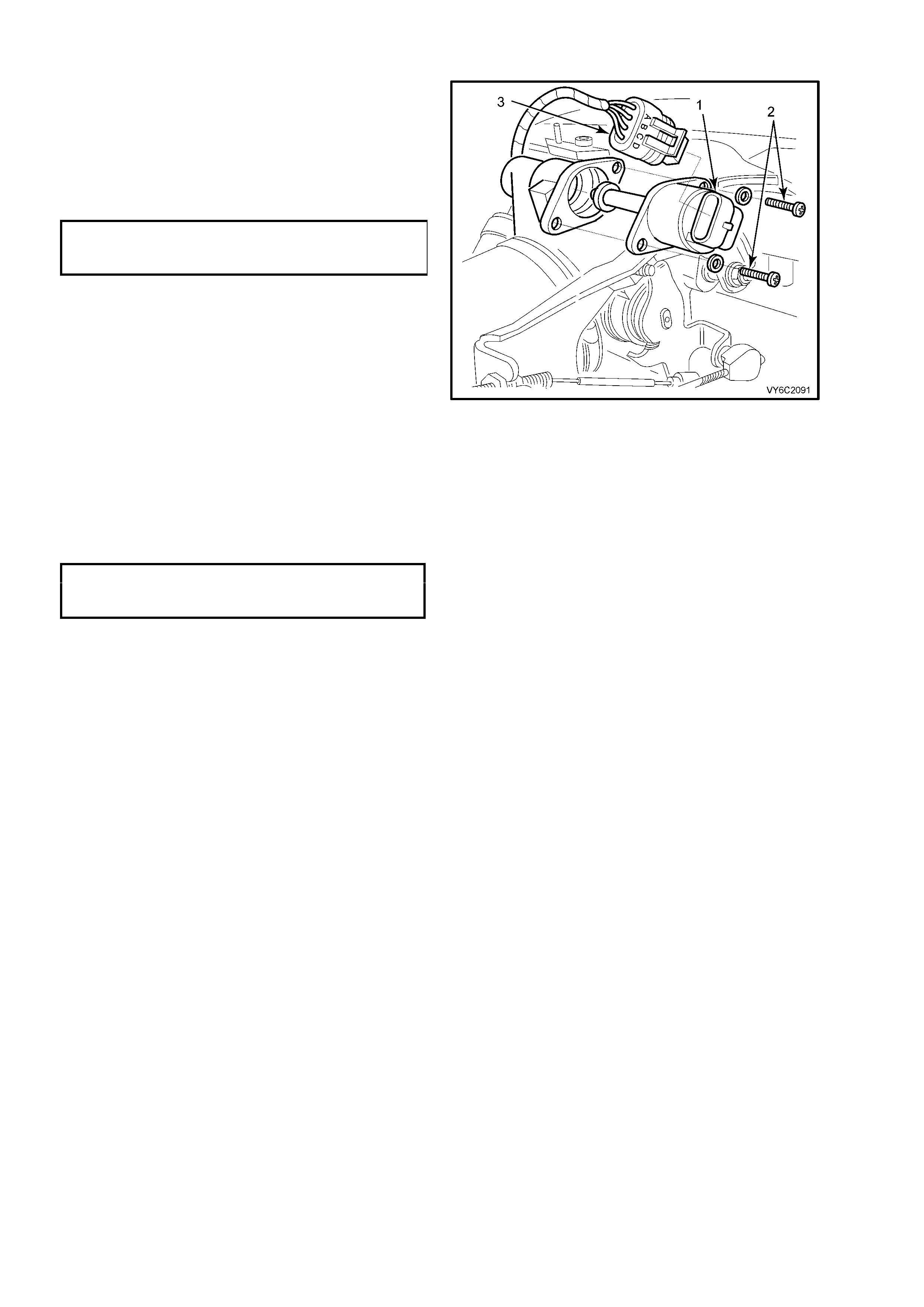
2. Reinstall IAC valve (1) into throttle body with
wiring harness connector (3) facing up, as
shown.
3. Install IAC valve attaching screws (2) and
tighten to the correct torque specification.
IAC VALVE TO THROTTLE
BODY SCREW
TORQUE SPECIFICATION 1.0 – 1.5 Nm
4. Reinstall the IAC valve wiring harness
connector (3).
5. Reinstall battery ground lead.
6. If required, clear any DTC’s using Tech 2.
7. Start engine, and allow engine to run for 5
seconds then turn engine OFF to "Reset" the
IAC valve; OR
Use Tech 2. Select ‘IAC RESET’ to reset the
IAC valve.
8. Reinstall engine dress cover to the inlet
manifold, ensuring that stud grommets in the
dress cover remain in place. Tighten securing
dome nuts to the correct torque specification.
ENGINE DRESS
COVER DOME NUT
TORQUE SPECIFICATION 4 – 6 Nm
Figure 6C2-3-55 - IAC Valve Reinstall

3.14 THROTTLE PEDAL ASSEMBLY
GENERA L DESCRIPTION
The s ervice operations f or the throttle pedal ass emblies for MY 2003 VY and V2 Series vehicles fitted with V6 S/C
engines is the same as vehicles with V6 engines, refer to Section 6C1-3, 3.14 THROTTLE PEDAL ASSEMBLY.
NOTE: There are differences in the throttle cable adjustment procedures for the various engines available. The
service procedure for the throttle pedal assembly does not require the throttle cable adjustment to be altered.
However, if throttle cable adjustment is required, refer to the correct Section for the appropriate engine option.

4. DIRECT IGNITION SYSTEM (DIS)
4.1 GENERAL SERVICE INFORMATION
TIMING ADJUSTMENT
The Direc t Ignition S ystem ( DIS) system fully contro ls the spark tim ing. No adjust ment for s park timing is pr ovided.
There are no timing marks on the crankshaft balancer or engine.
CHECKING EST SPARK TIMING OPERATION
The PCM will force the Electronic Spark Timing (EST) spark advance to 10 degrees BTDC when Tech 2 is used,
and B y-Pass m ode is s elec ted. T o chec k for EST operatio n, ru n the e ngine with t he thr ottle f ixed at a stea dy 1,60 0
– 1,800 rpm , then enter the "By-Pass" m ode of oper ation, using T ech 2. If the engin e speed cha nges (drops ), EST
spark timing is operating. An EST system fault will set a DTC. Use appropriate DTC Table in 6C2-2A to correctly
diagnose the system .
4.2 IGNITION COIL/S
LT Section No. – 02-225
REMOVE
1. Dis c onnect batter y ground l ead.
IMPORTANT: Disconnection of the battery affects certain vehicle electronic systems. Refer to Section 00
CAUTIONS, 5. Battery Disconnection Procedures before disconnecting the battery.
2. Remove spark plug leads from coil towers,
noting lead numbering with reference to coil
tower numbers.
NOTE 1: Slightly twist spark plug leads before
removing from coil towers
NOTE 2: All sp ar k plug leads and c o il terminals ar e
number ed to c orr espond to the cylinder n umbering.
On service replacement coils the cylinder
numbering does not appear on top of any coil
assembly, refer to cylinder numbering on the
module.
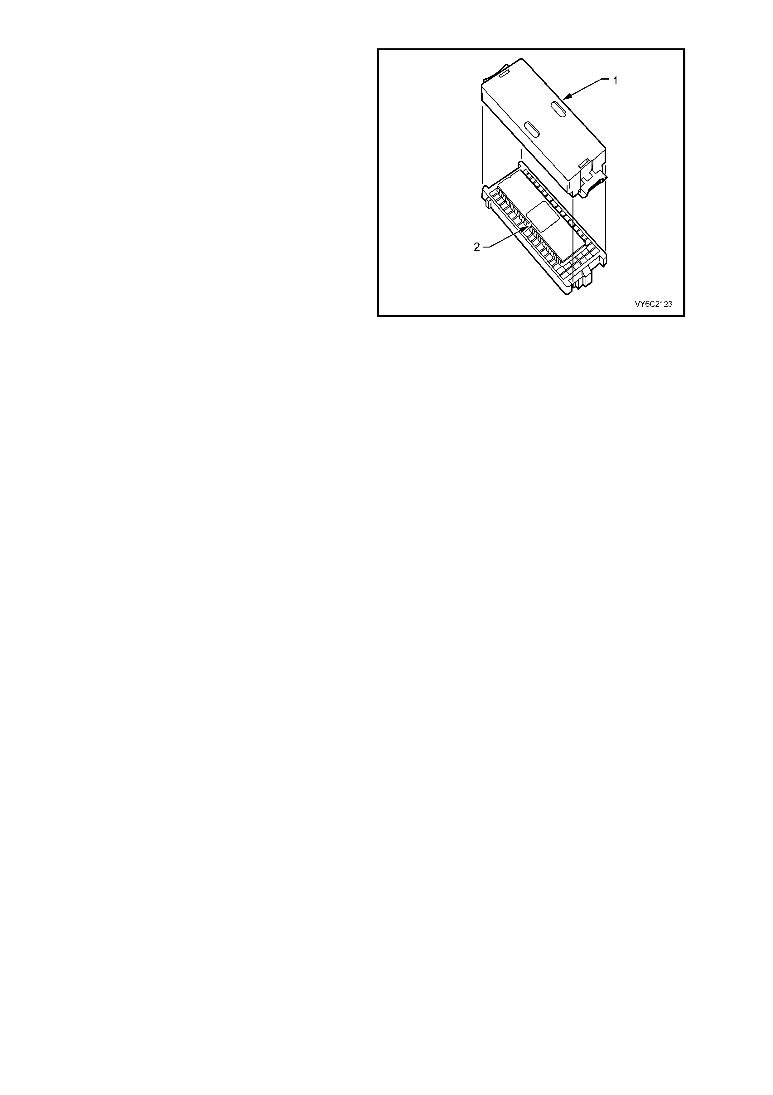
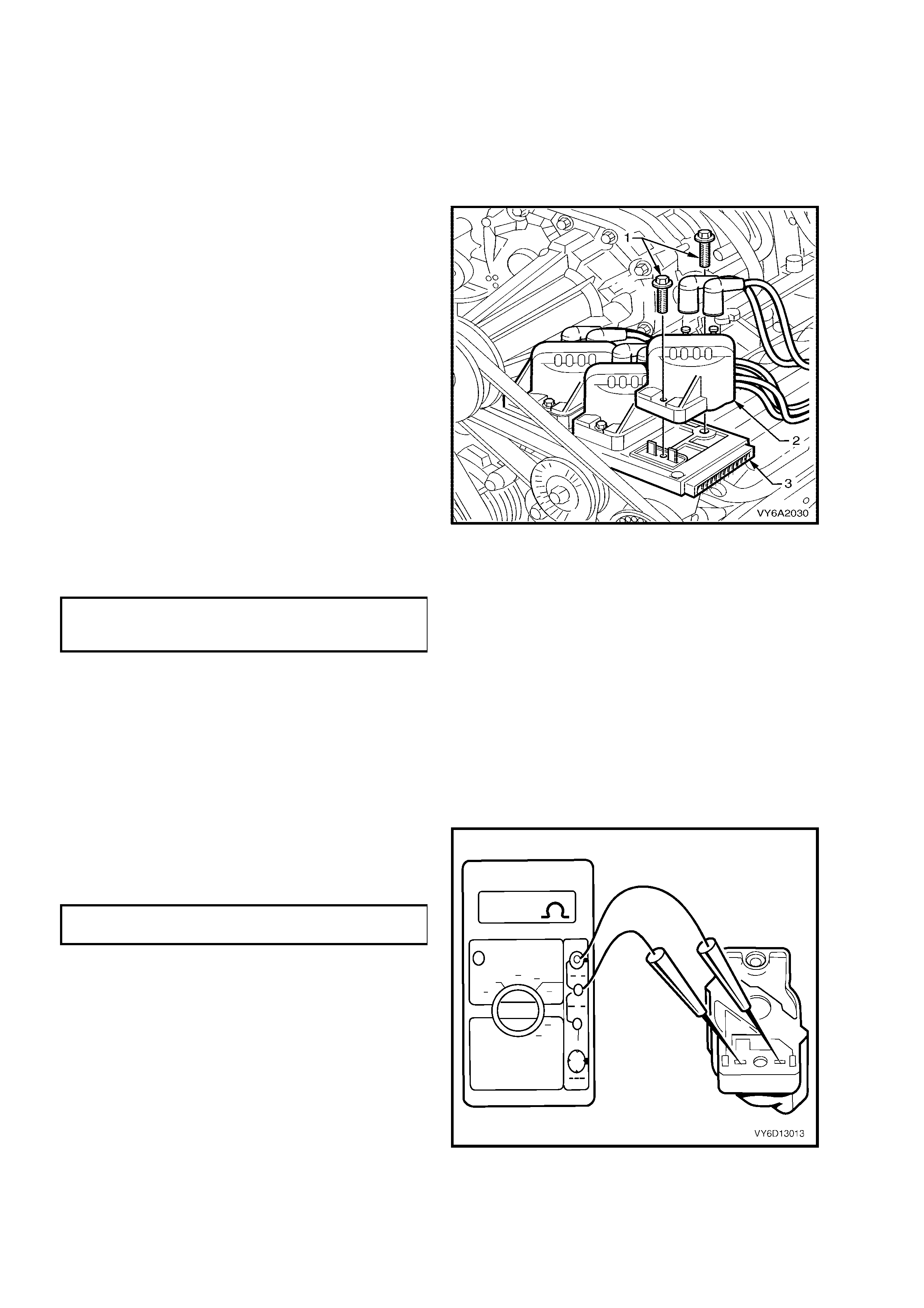
3. Remove screws (1) securing coil(s) to module
and mounting plate.
4. Pull coil(s) (2) from module (3), taking care not
to bend module terminals.
5. Install coil(s) (2) onto module (3), aligning
module terminals with mating slots on
underside of coil.
6. Reins t al l c oi l sec uri ng s c rews ( 1) a nd t ig hten to
the correct torque specification.
DIS IGNITION COIL TO MOUNTING
PLATE SCREW
TORQUE SPECIFICATION 5.0 Nm
7. Reconnect spark plug leads (3) to coil
term inals, ensuring correct lead to coi l term inal
relationship.
8. Reconnect battery ground lead, start engine
and ensure eng ine operate s corr ectl y.
Figure 6C2-3-56 – Ignition Coil To Module.
TEST
1. Visually inspect the removed coil/s for any
signs of external damage or spark tracking.
2. Using a Digital Multimeter (DMM) set to
resistance, measure the coil primary winding
resistance by probing into terminals from the
underside of the coil assembly.
IGNITION PRIMARY WINDING
RESISTANCE SPECIFICATION 0.3 – 1.5 Ω
NOTE: Some DMM lead probes may be too large
to contact the primary winding connections inside
the coil housing. If this is the case, use a suitable
size test terminal from J35616-A Connector Test
Adaptor Kit.
Figure 6C2-3-57
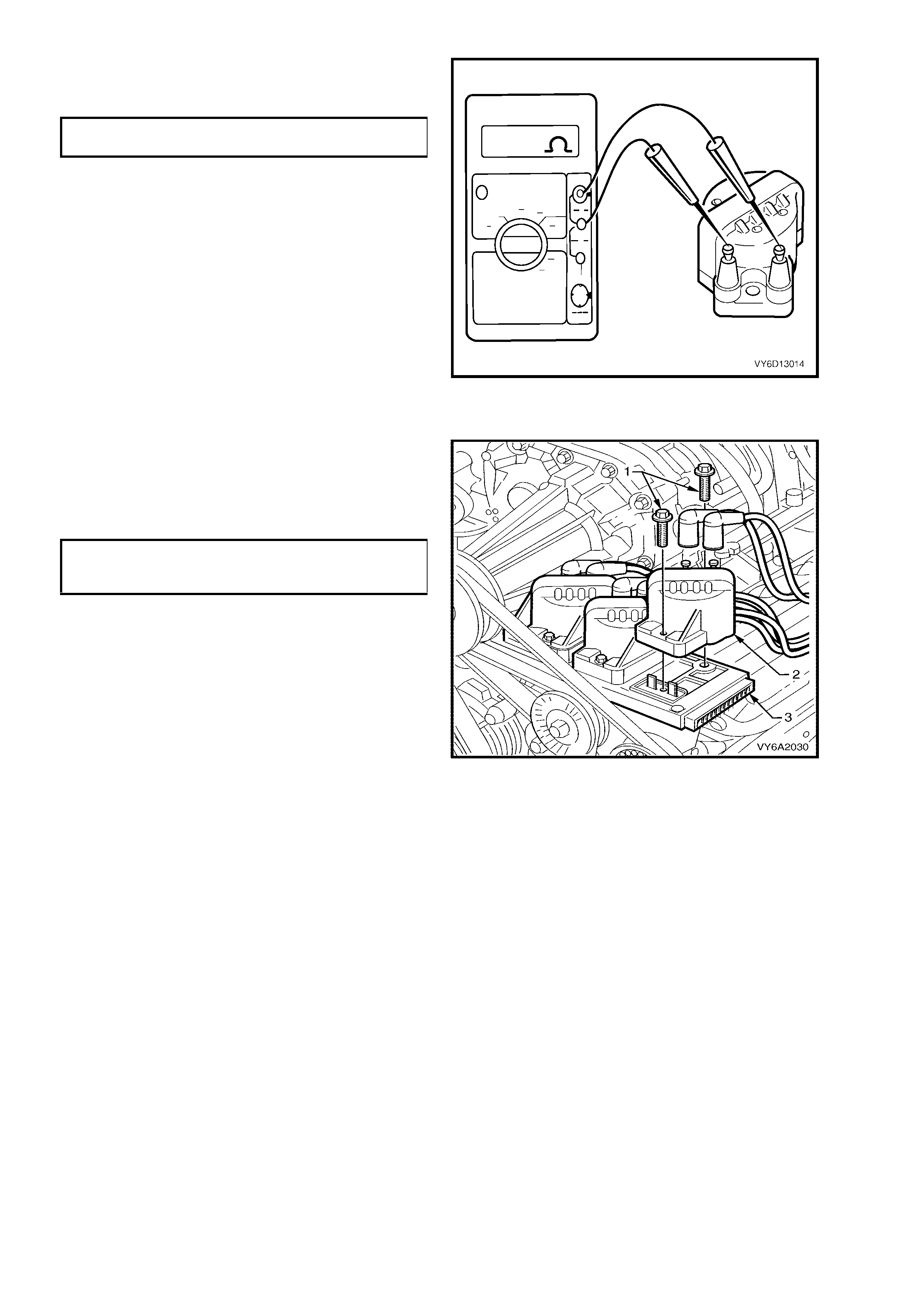
3. Check the resistance of the coil secondary
windings to ensure that the reading is within
specifications.
IGNITION SECONDARY WINDING
RESISTANCE SPECIFICATION 5,000 – 7,000 Ω
4. Replace any coil assembly whose primary
and/or secondary winding resistances are
outside the specified levels.
Figure 6C2-3-58
REINST ALL
1. Reinstall coil/s (2) onto module (4), aligning
module terminals with mating slots on
underside of coil.
2. Reins t al l c oi l sec uri ng s c rews ( 1) a nd t ig hten to
the correct torque specification.
DIS IGNITION COIL TO
MOUNTING PLA TE SCREW
TORQUE SPECIFICATION 5.0 Nm
3. Reconnect spark plug leads (3) to coil
term inals, ensuring correct lead to coi l term inal
relationship.
4. Reconnect battery ground lead, start engine
and ensure eng ine operate s corr ectl y.
Figure 6C2-3-59 – Ignition Coil To Module
4.3 DIS MODULE
LT Section No. – 02-225
REMOVE
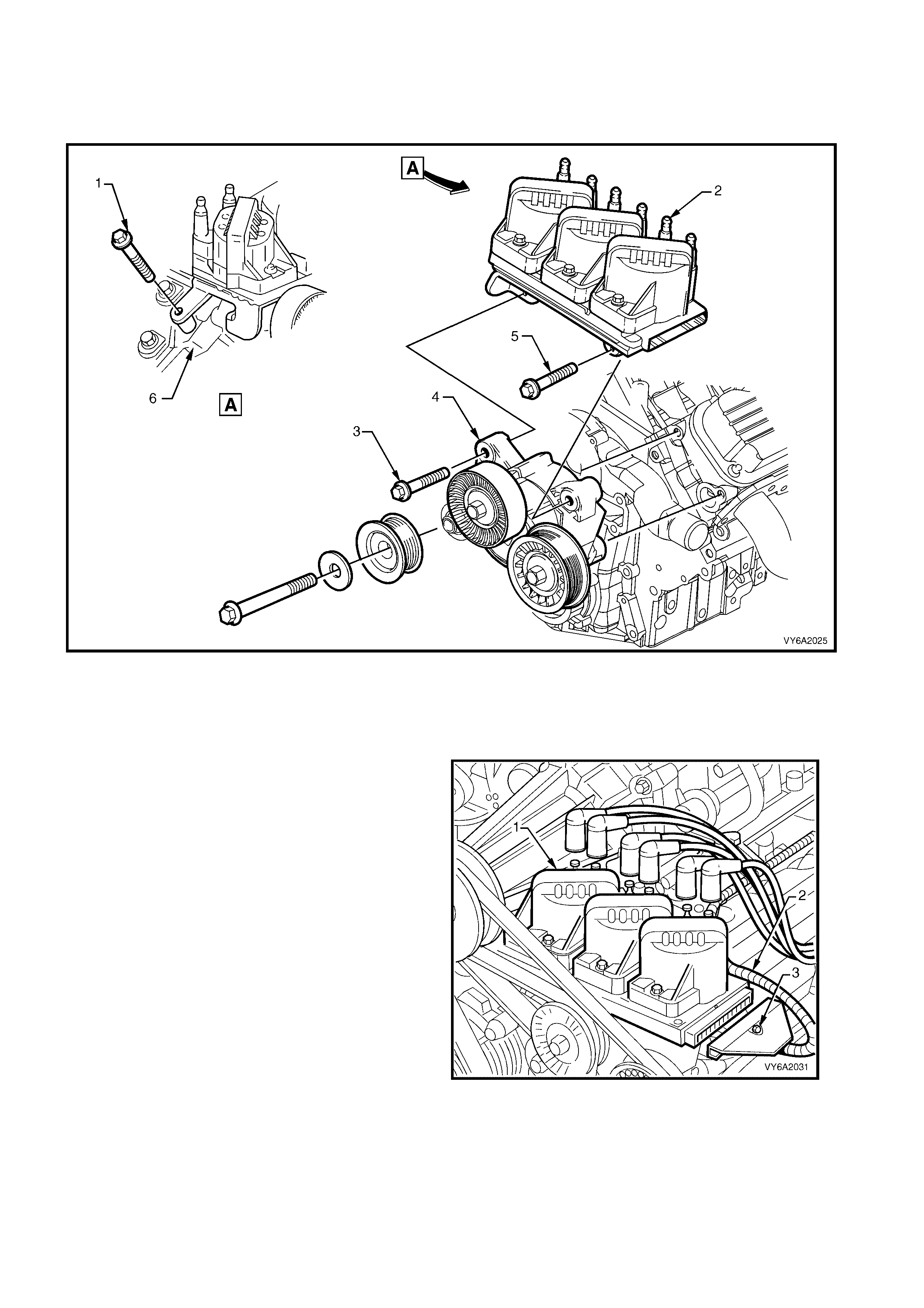
Figure 6C2-3-60
Legend
1. Bolt (tighten first)
2. DIS Module and Ignition Coils Assembly
3. Bolt (tighten third)
4. Drive Belt Tensioner Assembly Bracket
5. Bolt (tighten second)
6. Left Hand Cylinder Head
1. Dis c onnect batter y ground l ead.
2. Remove all spark plug leads from coil towers
(1), noting lead numbering with reference to
coil towers numbers.
NOTE 1: Slightly twist spark plug leads before
removing from coil towers
NOTE 2: All sp ar k plug leads and c o il terminals ar e
number ed to c orr espond to the cylinder n umbering.
On service replacement coils, the cylinder
numbering does not appear on top of any coil
assembly, refer to cylinder numbering on the
module.
3. Loosen screw attaching 14-pin wiring harness
connector (3) to module until you can pull
connector from module.
4. Remove bolts securing the DIS module and
coil assembly, to the left hand cylinder head
(refer Figure 6C2-3-58). Place the DIS module
and coil assembly carefully to one side.
5. Remove coils from module, taking care not
to bend module terminals. Refer to
4.2 IGNITION COIL/S, Remove in this Section.
Figure 6C2-3-61 – DIS Ignition Module Remove

REINST ALL
1. When replacing a DIS module assembly, remove module to coil terminal and 14 pin harness connector terminal
seals from original module. Install onto new module, taking care not to damage seals. If any seals is/are
damaged, replace with new parts.
2. Place coils onto module, aligning module terminals with mating slots on underside of coil. Refer to
4.2 IGNITION COIL/S, Reinstall, in this Section.
3. Reinstall ignition module assembly (5) to mounting plate, locating raised lugs (2) on both module and plate
together.
NOTE: T he lugs on t he un derside of the m odule will onl y mate with the m ounting plate ho les i n one way, to e nsure
correct assembly relationship.
4. Reinstall screws (3) securing coils and module to mounting plate and tighten in the sequence described in
Figure 6C2 – 3 - 68 and to the correct torque specification.
DIS IGNITION COIL TO MOUNTING
PLATE SCREW
TORQUE SPECIFICATION 4.0 – 5.0 Nm
5. Reinstall DIS module and coil assembly to the left hand cylinder head, securing with the two retaining bolts,
tightened to the correct torque specification.
DIS MODULE AND COIL ASSEMBLY
MOUNTING BOLT
TORQUE SPECIFICATION 40 – 50 Nm
6. Reconnect spark plug leads to coil terminals, ensuring correct lead to coil terminal relationship.
7. Reconnect 14-pin wiring harness connector to module assembly and tighten attaching screw to the correct
torque specification.
DIS MODULE HARNESS
CONNECTOR SCREW
TORQUE SPECIFICATION 0.6 – 1.2 Nm
8. Snap powertrain wiring harness retainer onto coil and module assembly and it's mounting plate.
9. Rec onn ec t batter y ground l ead.
10. Start engine and ensure engine operates correctly.
4.4 CR ANKSHAFT SENS OR
LT Section No. – 02-000
REMOVE
1. Remove battery ground lea d.
2. Remove the four dome nuts securing the engine dress cover, then remove the cover assembly.
3. Remove both engine accessory drive belts. Refer 2.9 SUPERCHARGER DRIVE BELT in Section 6A1-2
ENGINE MECHANICAL – V6 SUPERCHARGED ENGINE for the outer belt and 2.7 DRIVE BELT, in Section
6A1-1 ENGINE MECHANICAL V6 ENGINE, for the inner belt.
4. Remove the crankshaft balancer.
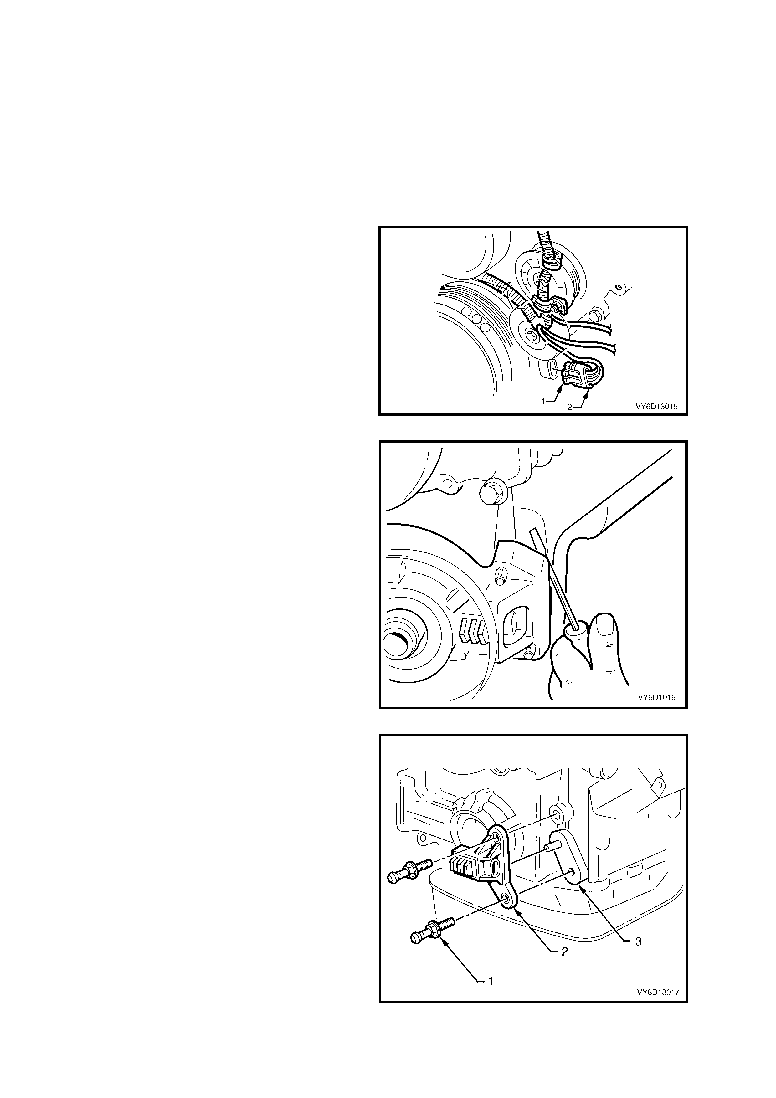
5. Disconnect the crankshaft position sensor
connector (2) by using a fine bladed
screwdriver to lever the locking tang away (1)
from the sensor, then pull on the conn ector (2)
to remove.
Figure 6C2-3-62
6. Rem ove the s ensor shie ld by car efull y leveri ng
each corner from the front cover studs, then
move the shield to and fro until it comes clear.
Figure 6C2-3-63
7. Remove the studs (1) that attach the sensor (2)
to the front cover (3).
8. Rem ove the sensor ( 2) from the f ront cover (3)
and carefully set to one side.
Figure 6C2-3-64
REINST ALL
1. Using a suitable tap, clean the threads in the
front of the cylinder block of old sealant.
2. Reins tall the s ensor onto the f ront cover dowel
pin.
3. Apply Loctite 242 or equivalent to the cleaned
sensor mounting stud threads.
4. Reinstall the attaching studs and tighten to the
correct torque specification.
SENSOR TO FRONT COVER
TORQUE SPECIFICATION 25 Nm
5. Reinstall the shield onto the front cover studs,
ensuring that the shield retainers are fully
engaged over the ends of the studs.
6. Reinstall the wiring harness connector to the
sensor, ensuring that the locking tang is fully
engaged.
7. Visually inspect the interrupter rings mounted
on the rear of the crankshaft balancer, for any
damage or distortion. Replace the crankshaft
pulley if damage or distortion is found.
Figure 6C2-3-65
8. Reinstall the crankshaft pulley. Refer to
2.19 CRANKSHAFT BALANCER in Section
6A1-1 ENGINE MECHANICAL – V6 ENGINE.
NOTE: Do not install the drive belts at this stage.
9. Rotate the crankshaft to check that the
interrupter rings do not contact the sensor. If
contact is made with the sensor at any point
then the rings are distorted, requiring balancer
replacement.
10. Reinstall the engine accessory drive belts.
Refer 2.7 DRIVE BELT, in Section 6A1-1
ENGINE MECHANICAL V6 ENGINE, for the
inner belt and 2.9 SUPERCHARGER DRIVE
BELT in Section 6A1-2 ENGINE
MECHANICAL – V6 SUPERCHARGED
ENGINE for the outer belt.
11. Reinstall the en gine dres s cover , tighte ning the
domed retaining nuts to the correct
specification.
ENGINE DRESS
COVER DOME NUT
TORQUE SPECIFICATION 4 – 6 Nm
12. Reinstall the battery ground lead.
13. Start the engine and ensure that the engine
operates correctly.
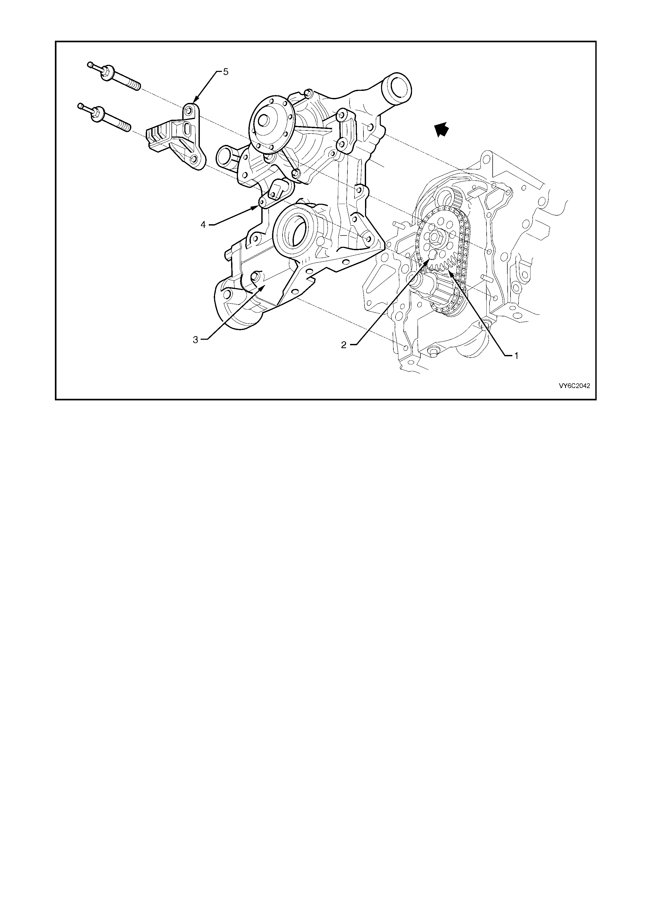
Figure 6C2-3-66 Camshaft/Crankshaft Position Sensors
Legend
1. Camshaft Sprocket
2. Camshaft Sensor Interrupter Magnet
3. Front Cover
4. Camshaft Sensor
5. Crankshaft Sensor
4.5 KNOCK SENSORS
LT Section No. – 02-000
CHECKING KNOCK SENSOR OPERATION
The PCM's knock sensor input will reduce t he EST spark advance wh en detonati on is present. T his sensor signals
the PCM of engine noise, and the PCM determines if the noise is detonation, or normal mechanical noise. The
PCM can be "tricked" into thinking that detonation is present by lightly ‘rapping' on the engine with a small hammer.
To c heck the "knock retard" f unc tion of the i gn ition system, run the engi ne with t he throttle fixed at a ste ady 1,600 –
1,800 RPM, quickly and repeatedly ‘rap' on the engine block, cylinder head, or intake manifold with a small
hamm er. T he engine spee d shoul d drop, due t o the ti m ing advanc e being re duc ed. W hen you stop ‘rapp ing' on the
engine, the engine speed should return to the original level.
CAUTION: Each knock sensor screws into the cylinder block coolant jacket. If the engine coolant is hot,
take extreme caution to prevent personal injury caused by hot coolant draining from the cylinder block.
REMOVE
NOTE: Exercise extreme care when handling knock sensors. To avoid visually undetectable damage, do not drop a
knock sensor.
1. Allow the engine to cool to ambient temperature (less than 50° C), then carefully remove the radiator cap.
2. Place a clean container (of at least 12 litres capacity) under the engine for the engine coolant to drain into.
NOTE: To reduc e t he impact on the en vir o nment and maintenance costs , whe ne ver t he c o ola nt is drained f r om the
engine, the service records are to be checked to determine when the coolant was last changed. If more than six
months life is lef t before th e next coolan t change, t hen the dr ained coola nt can b e re-used. For further inform ation,
refer to Section 6B2 ENGINE COOLING – V6 SUPERCHARGED.
3. Drain engine coolant into drain tray by disconnecting radiator lower hose (1) from the front cover connection.
4. Raise the fr ont of the vehicl e and support with s afety stands. Ref er to Section 0A GENERAL INFORMATION,
in the MY 2003 VY and V2 Series Service Information for details of jacking points.
5. Identify the correct wiring harness connector
(1) (oval s haped), v iew ‘A’. Do not c onfus e with
the oil pressure sensor connector (2), view ‘B’.
6. Squeeze t he 'wide ends' of the c onnector, then
pull to release the connector from the sensor.
NOTE: While the right hand sensor is detailed, the
procedure for the left hand sensor is similar.
Figure 6C2-3-67
7. Remove the bolts that attach the heat shield (3 or 8).
8. Remove the heat shield/s (2 or 5).
9. Place a suitable drain tray beneath the engine.
10. Loosen, the n remove the s ensor from the cylinder block, using a 22 m m socket with uni versal joint a nd socket
extension bars.
CAUTION: Take extreme care to avoid scalding from residual hot coolant draining from the sensor hole.
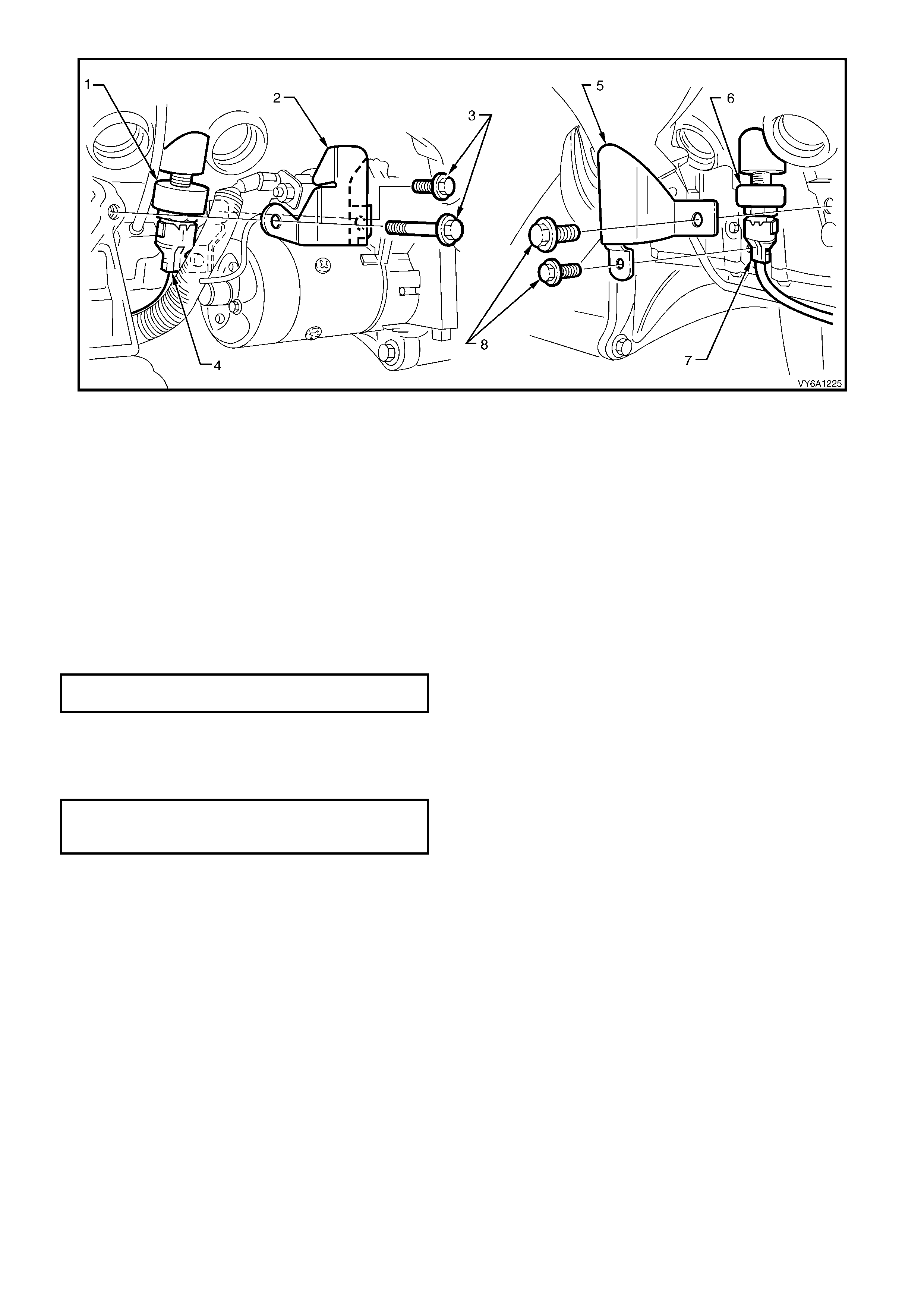
Figure 6C2-3-68
Legend
1. Lef t Hand Kn ock Senso r
2. Knock Sensor Shield LHS
3. Attaching Bolts
4. Wiring Harness Connector
5. Knock Sensor Shield RHS.
6. Right Hand Knock Sensor
7. Wiring Harness Connector
8. Attaching Bolts
REINST ALL
1. Check that the sensor threads are undamaged.
2. If the original sensor is being reinstalled, clean the old sealant from the sensor threads and apply a light coating
of Loctite 242 or equivalent.
NOTE: The threads on a new sensor are c oated with a seala nt during product ion. Do not appl y additio nal sealant.
This will reduce the effectiveness of the sensor.
3. Reinstall the sensor, then tighten to the correct torque specification. Do not over-tighten.
KNOCK SENSOR
TORQUE SPECIFICATION 16 – 22 Nm
4. Reconnect the wiring harness connector to the sensor, ensuring that the connector is securely fitted onto
sensor.
5. Reins tall the k nock sensor heat shiel d, securing with t wo attaching bolts for each shield . Tighten to the cor rect
torque specification.
HEAT SHIELD
ATTACHING BOLT
TORQUE SPECIFICATION 25 – 35 Nm
6. Refill the cooling system and test coolant concentration.
7. Pressure test the cooling system for leaks. Refer to Section 6B2 ENGINE COOLING – V6 SUPERCHARGED.
8. Reconnect the battery ground lead, start the engine and check for coolant leaks and correct engine operation.
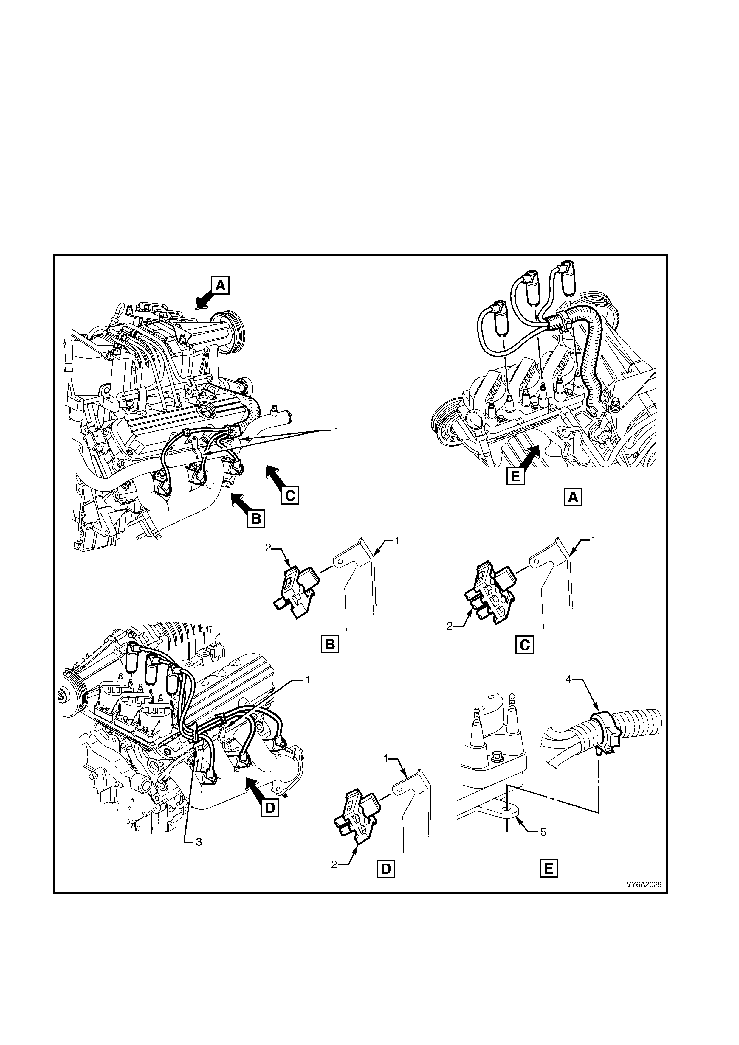
4.6 SPARK PLUG LEADS
LT Section No. – 02-030
REMOVE
NOTE: Pulling or bend ing s park plug leads c an cause hidden damage. F ollo w the rem oval steps caref ully to a void
damage.
1. Firmly grasp the boot at the end of the spark plug lead, both at the spark plug and the coil end.
NOTE: Grasp the boot, not the cable.
2. Twist the boot in both directions to relieve any suction and to break the seal.
3. Pull the boot straight off the spark plug and ignition coil.
4. Repeat this procedure for each spark lead at both the spark plug and the coil ends.
5. Carefully remove the spark plug leads from the support brackets and lift from the engine.
Figure 6C2-3-69 – Spark Plug Lead Routing and Security – V6 Supercharged Engine
Legend
1. Spark Plug Lead Support Bracket
2. Clip – Spark Plug Lead Support Bracket
3. Dipstick Tube Bracket
4. Harness Retainer
5. Ignition Coil and DIS Module Tab
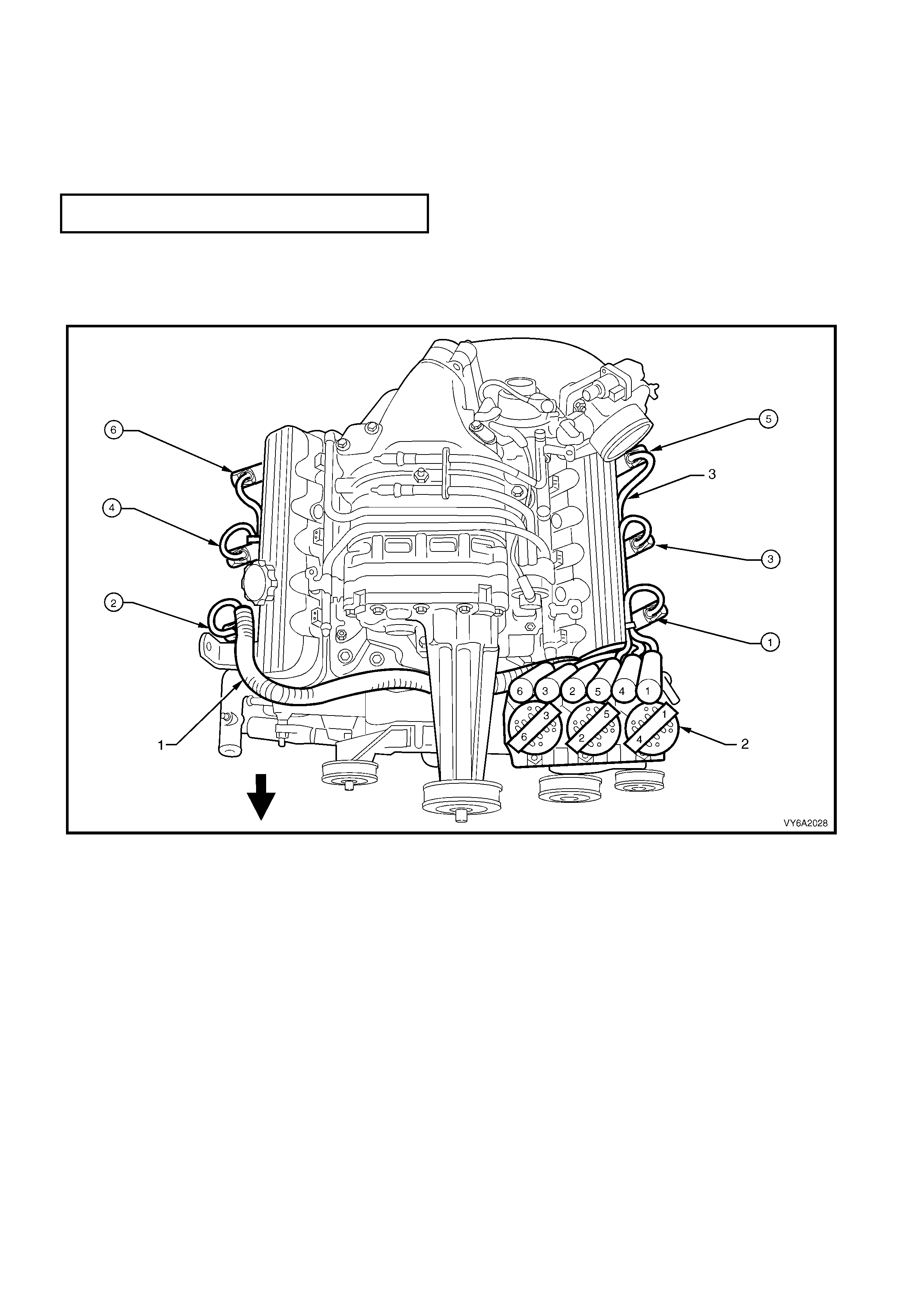
BENCH TESTING SPARK PLUG LEADS
1. Connect an ohmmeter capable of reading to 50 kilohms to each end of the lead.
2. Record the reading of each lead.
3. Measure and record the length of each lead.
4. For each lead, calculate the resistance over 30 cm.
5. Compare the resistance reading of each lead to the specification.
‘ELECTRICFIL’ SPARK PLUG LEAD
RESISTANCE per 30 cm 475 Ohms
6. Replace any lead/s with resistance values that are significantly different from the specification.
REINST ALL
IMPORTANT: Ens ure tha t all lea ds are c or rec tl y route d and fit each to its c or res pond ing s par k plug an d the ignit io n
coil post.
Figure 6C2-3-70 - Spark Plug Numbering
Legend
1. Right Hand Spark Plug Lead Harness Assembly
2. Ignition Coil and DIS Module Assembly
3. Left Hand Spark Plug Lead
1. As with th e rem oval proc ess, alwa ys hand le the lea ds b y each boot an d push squ arel y onto the spark plug and
ignition coil post.
2. Reinstall the spark plug leads to their respective support, ensuring that each is pushed firmly to each support.
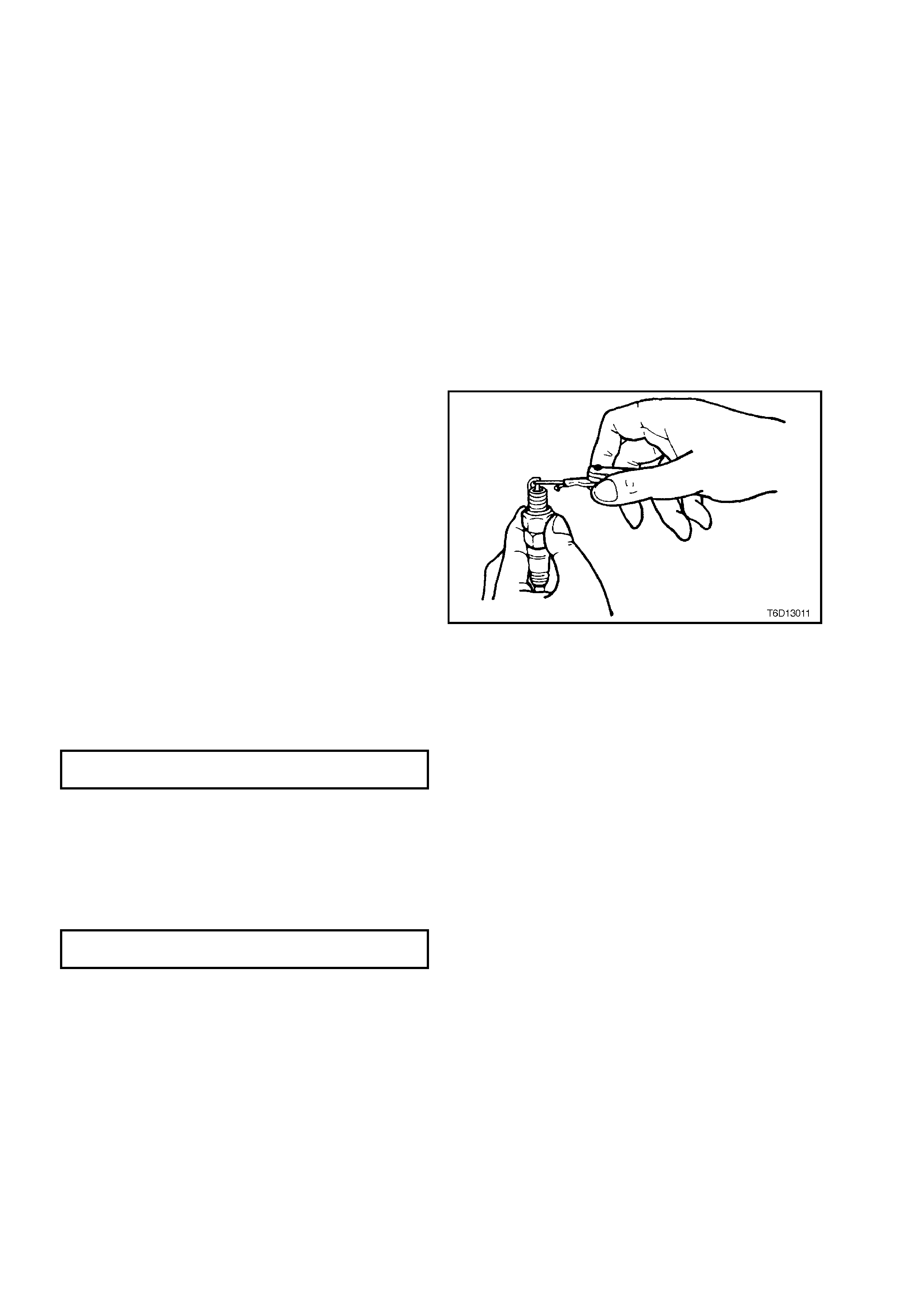
4.7 SPAR K PLUGS
LT Section No. – 02-030
REMOVE
1. Remove spark plug leads from each spark plug, remembering to only grasp the lead boot and twist in both
directions to relieve any suction and to break the seal.
2. Pull the boot straight off the spark plug.
3. Repeat this procedure for each spark lead.
4. Using a jet of compressed air remove any foreign material from around each spark plug cavity.
CAUTION: Use eye protection during this operation to prevent eye damage
5. Using a 16 mm spark plug socket and suitable equipment, loosen then remove each spark plug.
IMPORTANT: Af ter spark plug removal, place each in order of rem oval. This will enable an y a bnormal spark plug
condition to be identified with the correct cylinder.
6. Plug all spark plug holes in each cylinder head to prevent foreign material ingress.
CLEANING AND INSPECTION
1. Replace any plug that has cracked insulation,
broken insulation or loose electrodes.
2. Clean any oil from the plugs using a
degreasing agent.
3. Dry the plugs using compressed air.
4. Clean the spark plugs as per the
manufacturer's instructions using a purpose-
built machine (sand blasting type).
5. Inspect the spark plugs for defects. Refer to
4.7 SPARK PLUGS, Spark Plug Diagnosis in
this Sec tion for identificat ion of the c ondition of
spark plugs.
6. Ensure that the threads are clean and in good
order.
7. Use a round wire feeler gauge to check the
spark plug gap.
8. Adjust the gap to the correct specification by
gently bendi ng the out er elec trode.
Figure 6C2-3-71
SPARK PLUG GAP
V6 SUPERCHARGED ENGINE 1.3 mm
REINST ALL
1. Remove the rag/s from the spark plug holes.
2. Fit each spark plug carefully to avoid
damaging the thread.
3. Tighten the plugs to the correct torque
specification using a 16 mm spark plug socket.
SPARK PLUG
TORQUE SPECIFICATION 15 – 25 Nm
4. Reinstall spark plug leads to all spark plugs
after installation.

SPARK PLUG DIAGNOSIS
Poor Spark Plug Per formance
A spark plug can perform poorly due to wear, dirt, ca rbon fouling, excessive electrode wear, a broken insulator or
excessive gap.
NOTE 1: When re-gapping a spark plug, always make the gap adjustment by bending the ground (side) electrode.
NOTE 2: When replacing spark plugs, use genuine spark plugs or recommended of the correct heat range.
Worn or Dirty Plugs
Worn or dirty plugs can give satisfactory operation while the vehicle is idling, but break down under load.
This can cause:
•
••
•
poor fuel economy
•
••
•
power loss
•
••
•
acceleration loss
•
••
•
difficult starting
•
••
•
gener al l y poor engin e perf o rmance.
Carbon Fouling
Carbon fouling is indicated by black carbon deposits. The black deposits are usually the result of slow-speed
driving and short runs. In these circumstances, the optimum engine operating temperature is seldom reached.
Fouling can also be caused by:
•
••
•
worn piston rings
•
••
•
f ault y ignit ion
•
••
•
rich fuel mixture
•
••
•
spark plugs that are rated too cold.
Excessive Ele c trod e We a r
This often indicates:
•
••
•
the engine is operating at high speeds
•
••
•
the engine is operating at levels that are consistently greater than normal
•
••
•
a plug that is rated too hot
•
••
•
excessively lean fuel mixture
•
••
•
plug/s overheating due to insufficient tightening (caused by combustion gases leaking past the threads).
Broken Insulator
IMPORTANT: Do not use a spark plug with a broken insulator.
Broken insulators are usually the result of improper installation or carelessness.
Breaks in the upper insulator can result from a poor fitting spark plug socket or an outside blow. The cracked
insulator m a y not show up until oil or mois ture penetra tes the crac k. T he crack is often jus t below the c rimpe d part
of the shell and may not be visible.
Break s in the lo wer insu lator often r esult f rom c areles s re- gapping and ar e usua lly vis ible. T his can als o res ult f rom
the plug operating too hot. For example, in periods of high speed operation or under heavy loads.
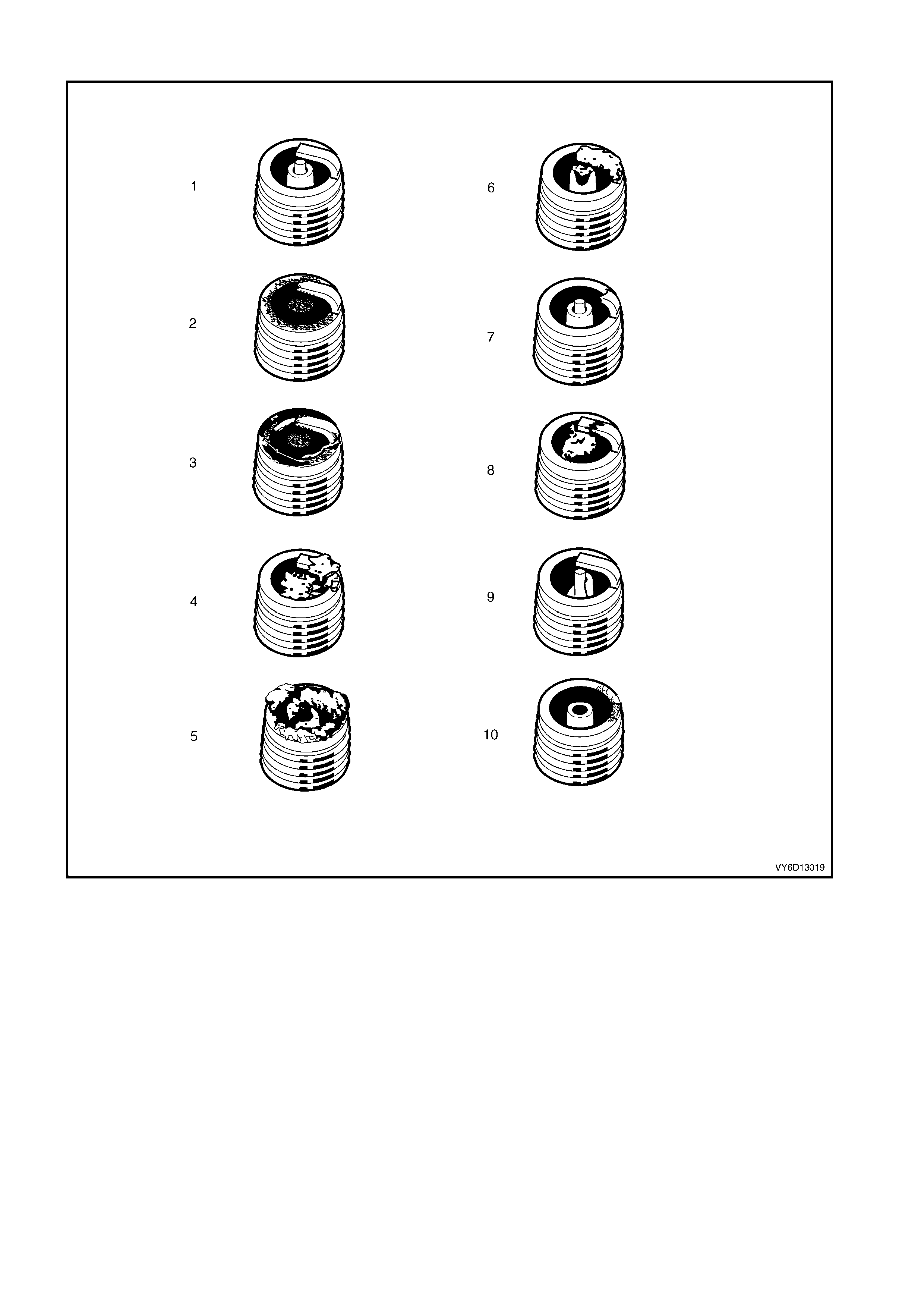
ANALYSIS OF SPARK PLUG CONDITION
Figure 6D1-3-72
Legend
1. Normal 5. Deposit fouling B 8. Pre-ignition
2. Carbon fouled 6. Deposit fouling C 9. Heated shock failure
3. Oil fouled 7. Detonation 10. Insufficient installation torque
4. Deposit fouling A
Normal Operation (1)
Brown or greyish-tan deposits and slight e lectrode wear indicate correct spark plug heat ra nge and mixed periods
of high and low speed driving.
Carbon Fouled (2)
Dry, fluffy black carbon deposits possibl y due to poor ignition output, weak coil, faulty spark plug leads, excessive
idling, s low sp eeds under light load. If spar k plu g temperatures rem ain t oo lo w for norm al com bus tion, the depos its
are not burned off.
Oil Fouled (3)
Wet, oily deposits with minor electrode wear possibly due to oil leaking past worn piston rings.
Breaking in a new or recently overhauled engine before the rings are fully seated may also result in this condition.

Deposit Fouling A (4)
Red brown, yellow and white coloured coatings on the insulator tip which are by-products of combustion. They
come from the fuel and the lubricating oil which generally contain additives. Most powdery deposits have no
adverse effect on spark plug operation; however, they may cause intermittent missing under severe operating
conditions.
Deposit Fouling B (5)
Deposits sim ilar to t hose identif ied in Depos it f oulin g A ( 4). T hese are a lso by-pro ducts of com bus tion fr om the f uel
and lubric ating o il. Exc essive val ve stem clearanc es and/or def ective int ake valve seals allow too m uch oil t o enter
the combustion chamber. The deposits will accumulate on the portion of the spark plug that projects into the
cham ber and will be hea vie st on th e side f acing the int ak e valve. W hen you detec t this c ondi tion i n onl y one or two
cylinders, check the seals.
Deposit Fouling C (6)
Most powd ery deposits identified in Deposit f ouling A (4) have no advers e effec t on the operation of the spark plug
as long as they remain powdery.
Under cert ain cond it ions of oper at io n ho we ver , t hes e d epos its melt a nd f orm a s hin y gl a ze coat in g o n th e ins ulat o r.
W hen hot, this acts as a g o od e lec tric a l conduct or a llo wing th e c urr ent to f lo w al o ng t he dep os it ins t ead of s par k ing
across the gap.
Detonation (7)
Commonly referred to as engine knock or ‘pinging’, detonation causes severe shocks inside the combustion
chamber causing damage to parts.
Pre-ignition (8)
Burnt or blistered insulator tip and badly eroded electrodes probably due to the excessive heat.
This is often caused by a cooling system blockage, sticking valves, improperly installed spark plugs or plugs that
are the wrong heat rating (too hot).
Sustained high speed with a heavy load can produce temperatures high enough to cause pre-ignition.
Heat Shock Failure (9)
A rapid increase in spark plug tip temperature under severe operating conditions can cause heat shock and result
in fractured insulators. This is a common cause of broken and cracked insulator tips.
Insufficient Installation Torque (10)
Poor contact between the spark plug and the cylinder head seat.
The lac k of proper he at transf er that results f rom poor s eat contact ca uses overheati ng of the sp ark plug. In many
cases, severe damage occurs, as shown.
Dirty threads in the cylinder head can cause the plug to seize before it is seated.
IMPORTANT: The recommended installation torque may be obtained before the taper seat engages with the
cylinder hea d.
Ensure that the cylinder head and spark plug threads are free of deposits, burrs and scale before installation.
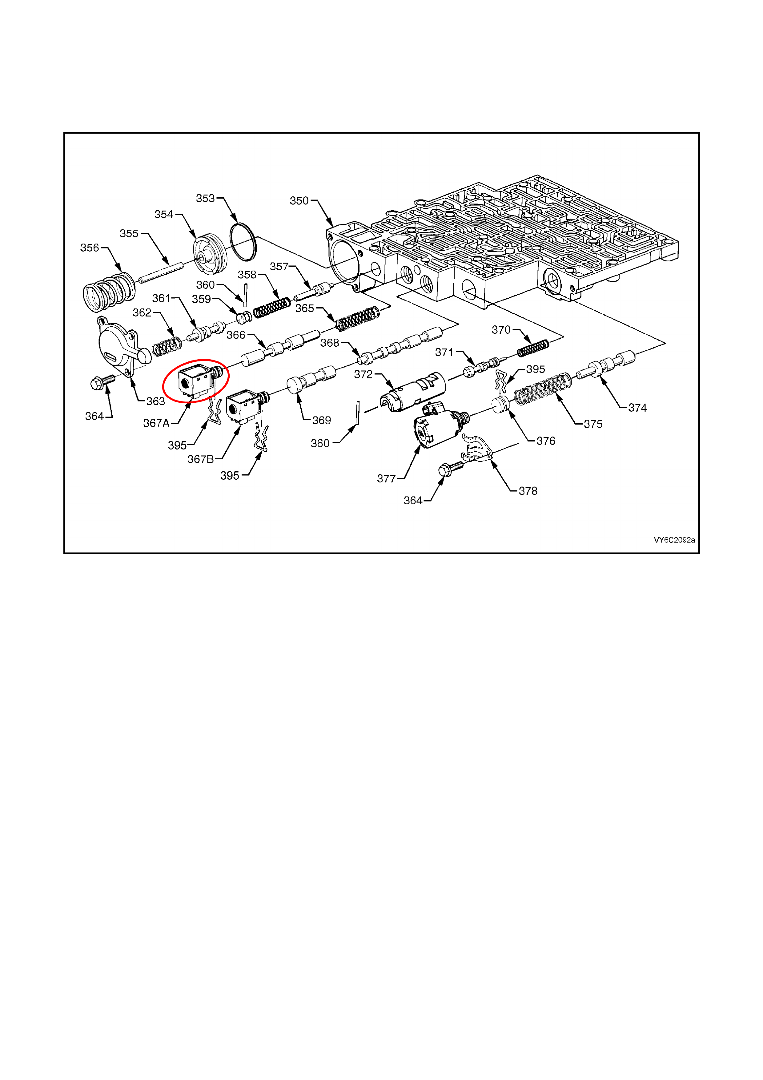
5. AUTOMATIC TRANSMI SSI ON
LT Section No. – 04-275
5.1 1-2 SHIFT SOLENOID ‘A’
Figure 6C2-3-73 – 1-2 Shift Solenoid Location
REMOVE
1. Dis c onnect batter y ground l ead.
CAUTION: To avoid personal injury from accidental hot oil spillage, perform fluid change only when
transmission fluid is cold.
2. Raise vehicle and support on safety stands. Refer to Section 0A, GENERAL INFORMATION in the MY 2003
VY and V2 Series Service Information.
3. Clean all dirt from around oil pan and transmission case.
4. Place drain tray under transmission.
5. While supporting the oil pan, remove the oil pan bolts from the front and both sides.
6. Loos en the r e ar oi l p an b olts b y about 4 turns each and, while st il l s upp orti ng th e oil pan, light ly tap the sides of
the oil pan with a rubber hammer to break the gasket seal.
7. Lower the front of the oil pan and drain the fluid into a suitable container, then remove the rear oil pan bolts
completely and remove the oil pan from the transmission.
8. Remove old oil pan gasket and discard.
9. Remove the fluid filter. Refer 3.1 FLUID CHANGE AND FILTER REPLACEMENT, in Section 7C4
AUTOMATIC TRANSMISSION -–ON-VEHICLE SERVICING, in the MY 2003 VY and V2 Series Service
Information.
10. Disconnect 1-2 shift solenoid (367A) electrical connector.
11. Remove solenoid retainer (395) by using a small flat blade screwdriver. Pry the retainer down until it can be
grasped.
NOTE: The 1–2 shift solenoid has a slight spring pressure behind it, and may pop out on its own after retainer is
removed.
12. Remove solenoid assembly (367A) with O-ring seal. Ensure that 1–2 shift valve (366) remains in place.

REINST ALL
1. Push solenoid assembly (367A) into valve body.
2. Hold sole no id in plac e with finger pressur e whi le insta ll ing retai ner (395) .
3. Reconnect 1-2 shift solenoid (367A) electrical connector.
4. Install new fluid filter and seal. Refer 3.1 FLUID CHANGE AND FILTER REPLACEMENT, in Section 7C4
AUTOMATIC TRANSMISSION -–ON-VEHICLE SERVICING, in the MY 2003 VY and V2 Series Service
Information.
5. Clean oil pan and case mating surfaces. Check that magnet is still magnetised, and attached to the oil pan.
6. Install new oil pan gasket and reinstall oil pan and retaining bolts, tightening to the correct torque specification.
TRANSMISSION OIL PAN BOLTS
TORQUE SPECIFICATION 11 Nm
7. Lower vehicle and add approximately 4.8 litres of DEXRON â III automatic transmission fluid.
8. Rec onn ec t batter y grou nd lead.
9. Check transmission fluid level. Refer to "Fluid Checking Procedure" in this Section 7C4.
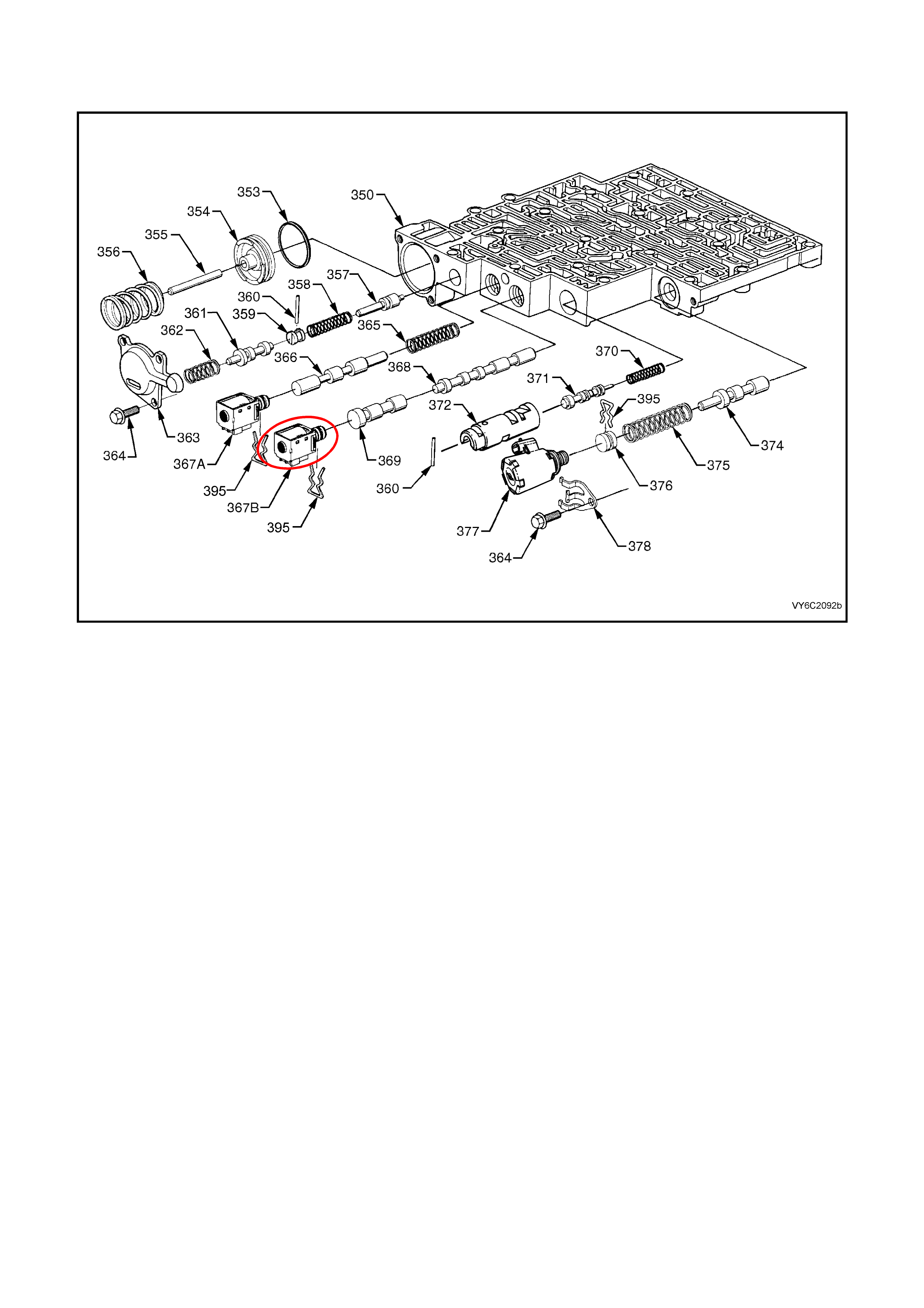
5.2 2-3 SHIFT SOLENOID ‘B’
LT Section No. – 04-275
Figure 6C2-3-74 – 2-3 Shift Solenoid Location
REMOVE
1. Dis c onnect batter y ground l ead.
CAUTION: To avoid personal injury from accidental hot oil spillage, perform fluid change only when
transmission fluid is cold.
2. Raise vehicle and support on safety stands. Refer to Section 0A, GENERAL INFORMATION in the MY 2003
VY and V2 Series Service Information.
3. Clean all dirt from around oil pan and transmission case.
4. Place drain tray under transmission.
5. While supporting the oil pan, remove the oil pan bolts from the front and both sides.
6. Loos en the r e ar oi l p an b olts b y about 4 turns each and, while st il l s upp orti ng th e oil pan, light ly tap the sides of
the oil pan with a rubber hammer to break the gasket seal.
7. Lower the front of the oil pan and drain the fluid into a suitable container, then remove the rear oil pan bolts
completely and remove the oil pan from the transmission.
8. Remove old oil pan gasket and discard.
9. Remove the fluid filter. Refer 3.1 FLUID CHANGE AND FILTER REPLACEMENT, in Section 7C4
AUTOMATIC TRANSMISSION -–ON-VEHICLE SERVICING, in the MY 2003 VY and V2 Series Service
Information.
10. Disconnect 2–3 shift solenoid (367B) electrical connector.
11. Remove solenoid retainer (395) by using a small flat blade screwdriver. Pry the retainer down until it can be
grasped.
NOTE: The 2–3 shift solenoid has a slight spring pressure behind it, and may pop out on its own after retainer is
removed.
12. Remove solenoid assembly (367B) with O-ring seal. Ensure that 2–3 shuttle valve (369) remains in place.

REINST ALL
1. Push solenoid assembly (367B) into valve body.
2. Hold sole no id in plac e with finger pressur e whi le insta ll ing retai ner (395) .
3. Reconnect 2–3 shift solenoid (367B) electrical connector.
4. Install new fluid filter and seal. Refer 3.1 FLUID CHANGE AND FILTER REPLACEMENT, in Section 7C4
AUTOMATIC TRANSMISSION – ON-VEHICLE SERVICING, in the MY 2003 VY and V2 Series Service
Information.
5. Clean oil pan and case mating surfaces. Check that magnet is still magnetised, and attached to the oil pan.
6. Install new oil pan gasket and reinstall oil pan and retaining bolts, tightening to the correct torque specification.
TRANSMISSION OIL PAN BOLTS
TORQUE SPECIFICATION 11 Nm
7. Lower vehicle and add approximately 4.8 litres of DEXRON â III automatic transmission fluid.
8. Rec onn ec t batter y grou nd lead.
9. Check transmission fluid level. Refer to "Fluid Checking Procedure" in this Section 7C4.
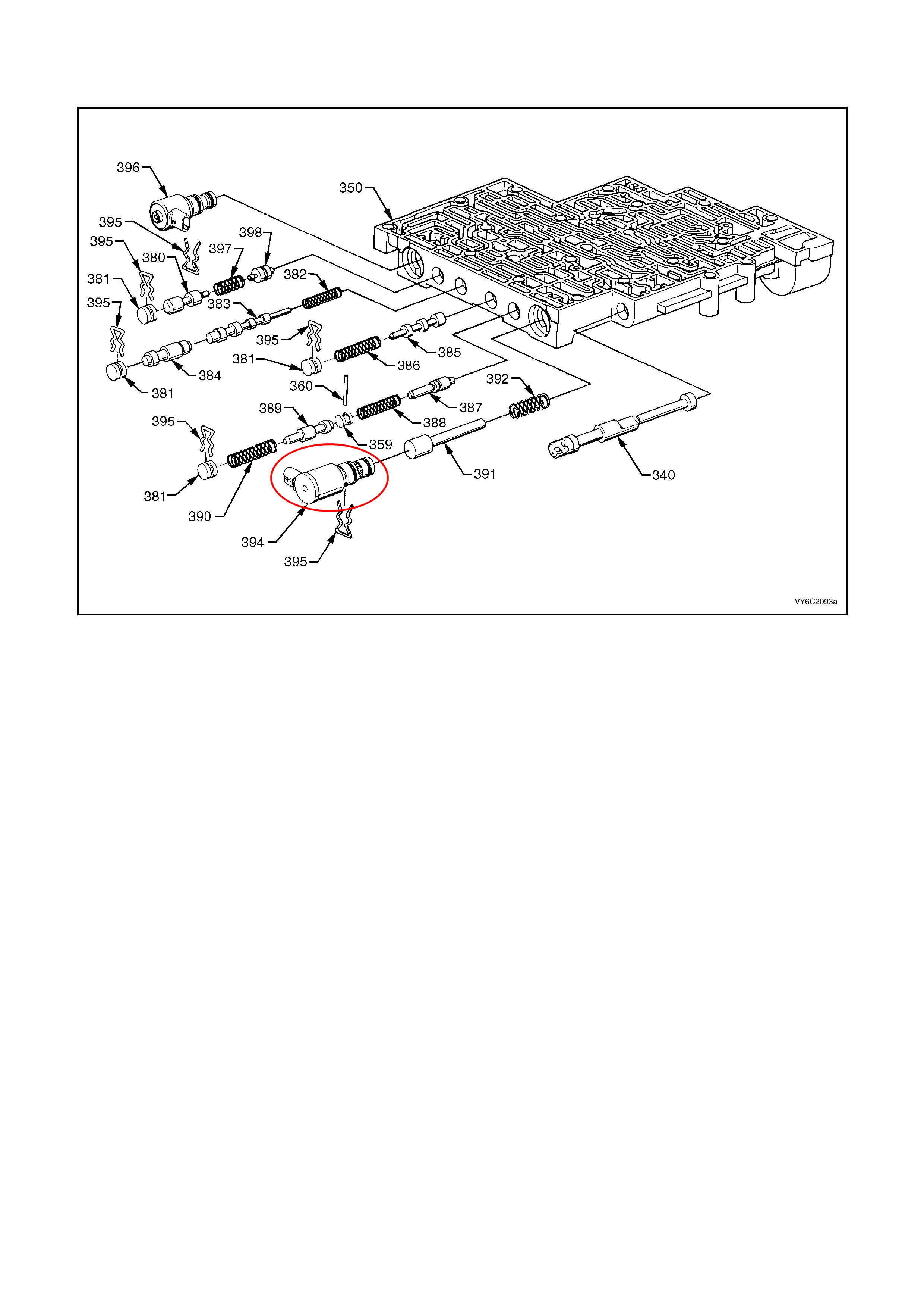
5.3 3-2 CONTROL SOLENOID
LT Section No. – 04-275
Figure 6C2-3-75 – 3-2 Shift Solenoid Location
REMOVE
1. Dis c onnect batter y ground l ead.
CAUTION: To avoid personal injury from accidental hot oil spillage, perform fluid change only when
transmission fluid is cold.
2. Raise vehicle and support on safety stands. Refer to Section 0A, GENERAL INFORMATION in the MY 2003
VY and V2 Series Service Information.
3. Clean all dirt from around oil pan and transmission case.
4. Place drain tray under transmission.
5. While supporting the oil pan, remove the oil pan bolts from the front and both sides.
6. Loos en the r e ar oi l p an b olts b y about 4 turns each and, while st il l s upp orti ng th e oil pan, light ly tap the sides of
the oil pan with a rubber hammer to break the gasket seal.
7. Lower the front of the oil pan and drain the fluid into a suitable container, then remove the rear oil pan bolts
completely and remove the oil pan from the transmission.
8. Remove old oil pan gasket and discard.
9. Remove the fluid filter. Refer 3.1 FLUID CHANGE AND FILTER REPLACEMENT, in Section 7C4
AUTOMATIC TRANSMISSION -–ON-VEHICLE SERVICING, in the MY 2003 VY and V2 Series Service
Information.
10. Disconnect 3-2 control solenoid (394) electrical connector.
11. Remove solenoid retainer (395) by using a flat blade screwdriver.
NOTE: The 3-2 control solenoid has spring pressure behind it and may pop out after retainer is removed.
12. Remove solenoid assembly (394) with O-ring seal.

REINST ALL
1. Push solenoid assembly with O-ring seal (394) into valve body.
2. Hold solenoid firmly in place with finger pressure while installing retainer (395).
3. Reconnect 3-2 control solenoid electrical connector.
4. Install new fluid filter and seal. Refer 3.1 FLUID CHANGE AND FILTER REPLACEMENT, in Section 7C4
AUTOMATIC TRANSMISSION – ON-VEHICLE SERVICING, in the MY 2003 VY and V2 Series Service
Information.
5. Clean oil pan and case mating surfaces. Check that magnet is still magnetised, and attached to the oil pan.
6. Install new oil pan gasket and reinstall oil pan and retaining bolts, tightening to the correct torque specification.
TRANSMISSION OIL PAN BOLTS
TORQUE SPECIFICATION 11 Nm
7. Lower vehicle and add approximately 4.8 litres of DEXRON â III automatic transmission fluid.
8. Rec onn ec t batter y grou nd lead.
9. Check transmission fluid level. Refer to "Fluid Checking Procedure" in this Section 7C4.
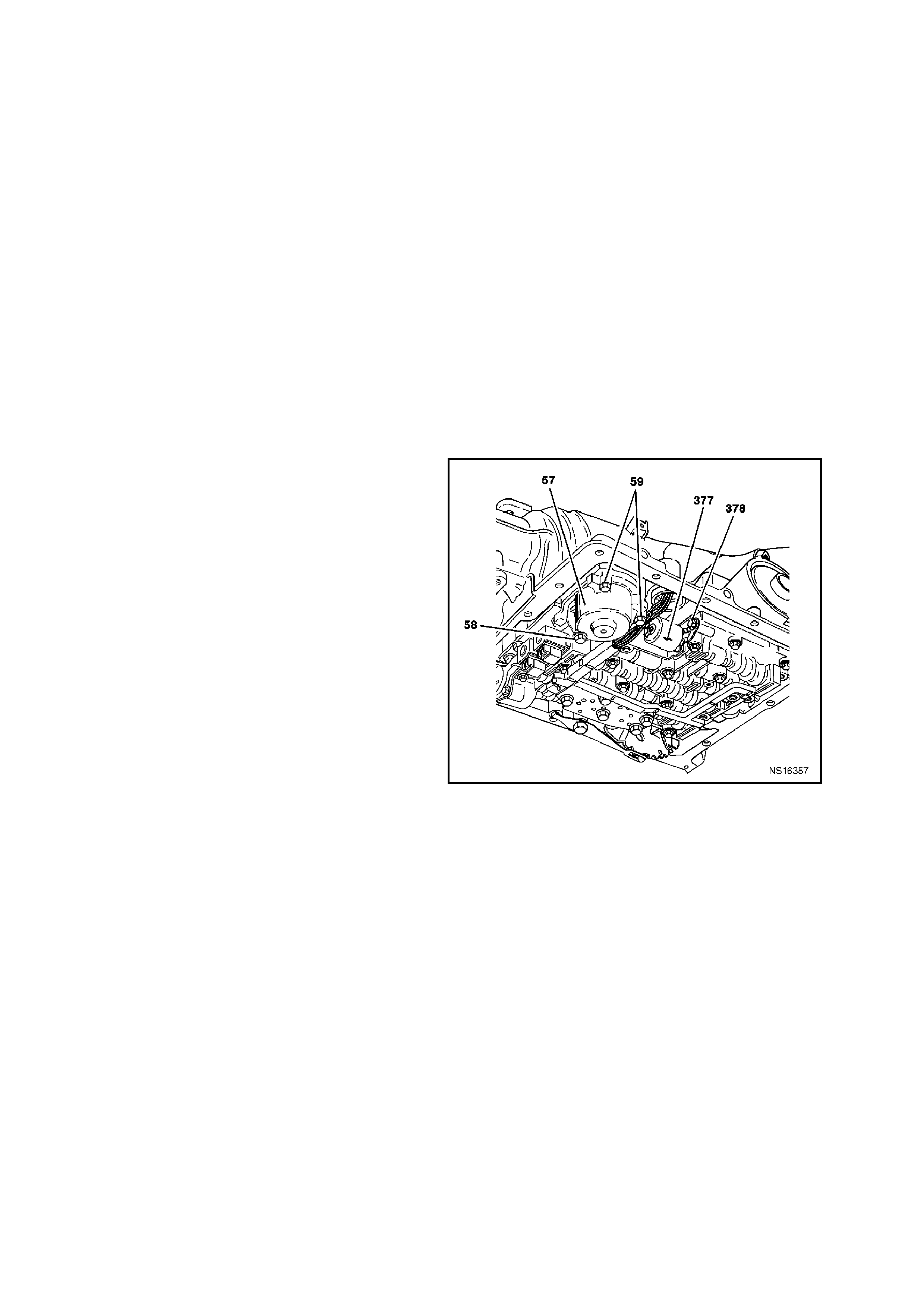
5.4 PRESSURE CONTROL SOLENOID
LT Section No. – 04-275
REMOVE
1. Dis c onnect batter y ground l ead.
CAUTION: To avoid personal injury from accidental hot oil spillage, perform fluid change only when
transmission fluid is cold.
2. Raise vehicle and support on safety stands. Refer to Section 0A, GENERAL INFORMATION in the MY 2003
VY and V2 Series Service Information.
3. Clean all dirt from around oil pan and transmission case.
4. Place drain tray under transmission.
5. While supporting the oil pan, remove the oil pan bolts from the front and both sides.
6. Loos en the r e ar oi l p an b olts b y about 4 turns each and, while st il l s upp orti ng th e oil pan, light ly tap the sides of
the oil pan with a rubber hammer to break the gasket seal.
7. Lower the front of the oil pan and drain the fluid into a suitable container, then remove the rear oil pan bolts
completely and remove the oil pan from the transmission.
8. Remove old oil pan gasket and discard.
9. Remove the fluid filter. Refer 3.1 FLUID CHANGE AND FILTER REPLACEMENT, in 7C4 AUTOMATIC
TRANSMI SSIO N -–ON -V E HICLE SER VICING, in the MY 2003 VY and V2 Series Service Inf ormation.
10. Remove thr e e 1- 2 ac cumulator cover b olts ( 5 8)
(59)
NOTE: Accumulator will be full of fluid.
11. Remove 1–2 accumulator cover assembly (57).
12. Remove pressure control solenoid (377)
electrical connector.
13. Rem ove pressure con trol sole noid retainer bolt
(364A), then retainer (378).
14. Remove pressure control solenoid assembly
(377).
Figure 6C2-3-76 – Pressure Control Solenoid Location
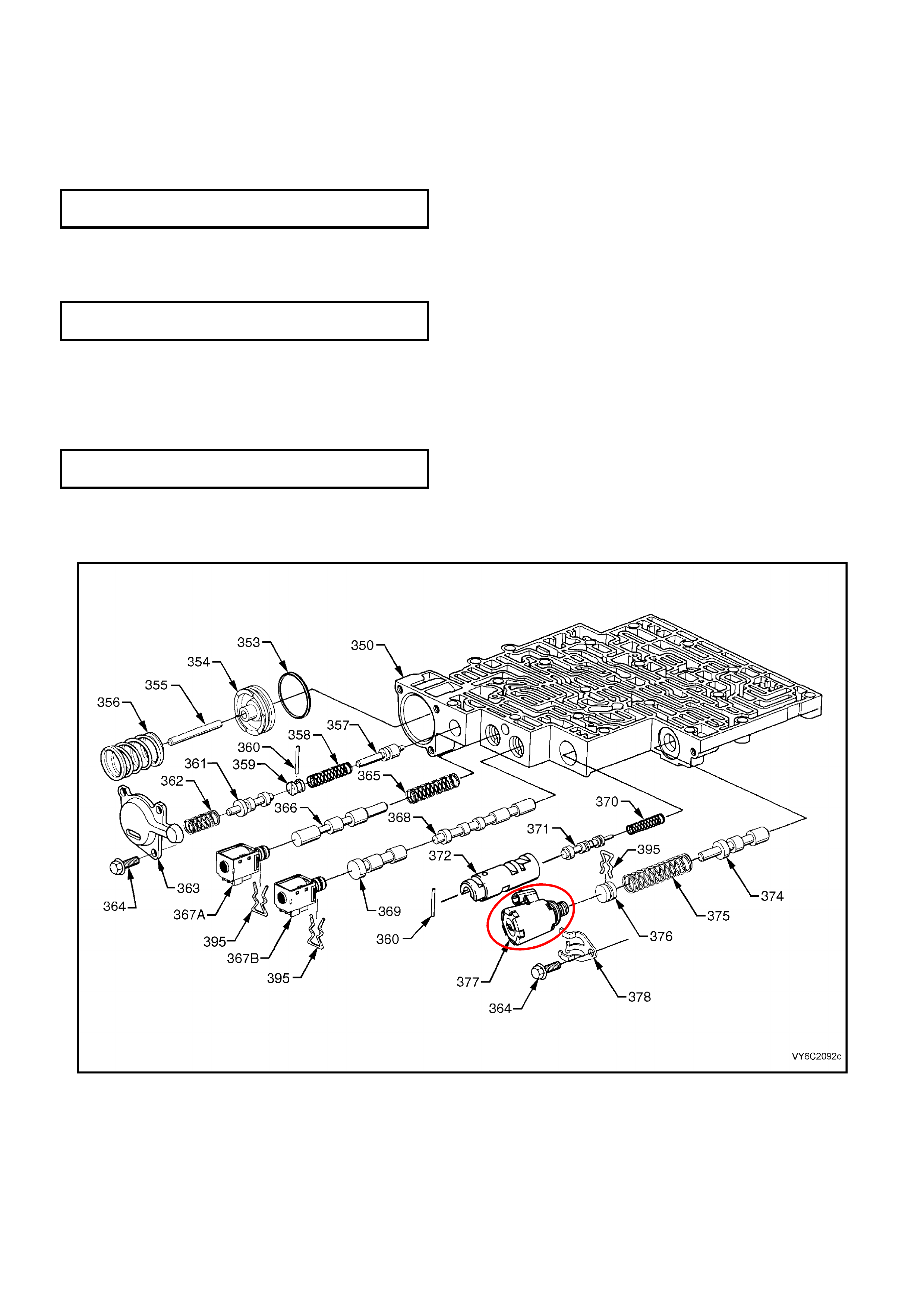
REINST ALL
1. Reins tall sol eno id ass embly (37 7).
NOTE: Solenoid has a flat cut out on one side of it's retaining flange that goes toward retaining bolt. Solenoid
retainer has a matching flat to allow the retainer to be correctly installed
2. Reinstall solenoid retainer (378).
3. Reinstall solenoid retainer bolt (364A), tightening to the correct torque specification.
SOLENOID RETAINER BOLT
TORQUE SPECIFICATION 11 Nm
4. Reinstall pressure control solenoid electrical connector.
5. Reinstall 1–2 accumulator cover assembly (57).
6. Reinstall accumulator cover bolts (58) (59) and tighten to the correct torque specification.
ACCUMULATOR COVER BOLT
TORQUE SPECIFICATION 11 Nm
7. Install new fluid filter and seal. Refer 3.1 FLUID CHANGE AND FILTER REPLACEMENT, in 7C4
AUTOMATIC TRANSMISSION -–ON-VEHICLE SERVICING, in the MY 2003 VY and V2 Series Service
Information.
8. Clean oil pan and case mating surfaces. Check that magnet is still magnetised, and attached to the oil pan.
9. Install new oil pan gasket and reinstall oil pan and retaining bolts, tightening to the correct torque specification.
TRANSMISSION OIL PAN BOLTS
TORQUE SPECIFICATION 11 Nm
10. Lower vehicle and add approximately 4.8 litres of DEXRON â III automatic transmission fluid.
11. Reconnec t batter y ground l ead.
12. Check transmission fluid level. Refer to "Fluid Checking Procedure" in this Section 7C4.
Figure 6C2-3-77 – Pressure Control Solenoid Assembly
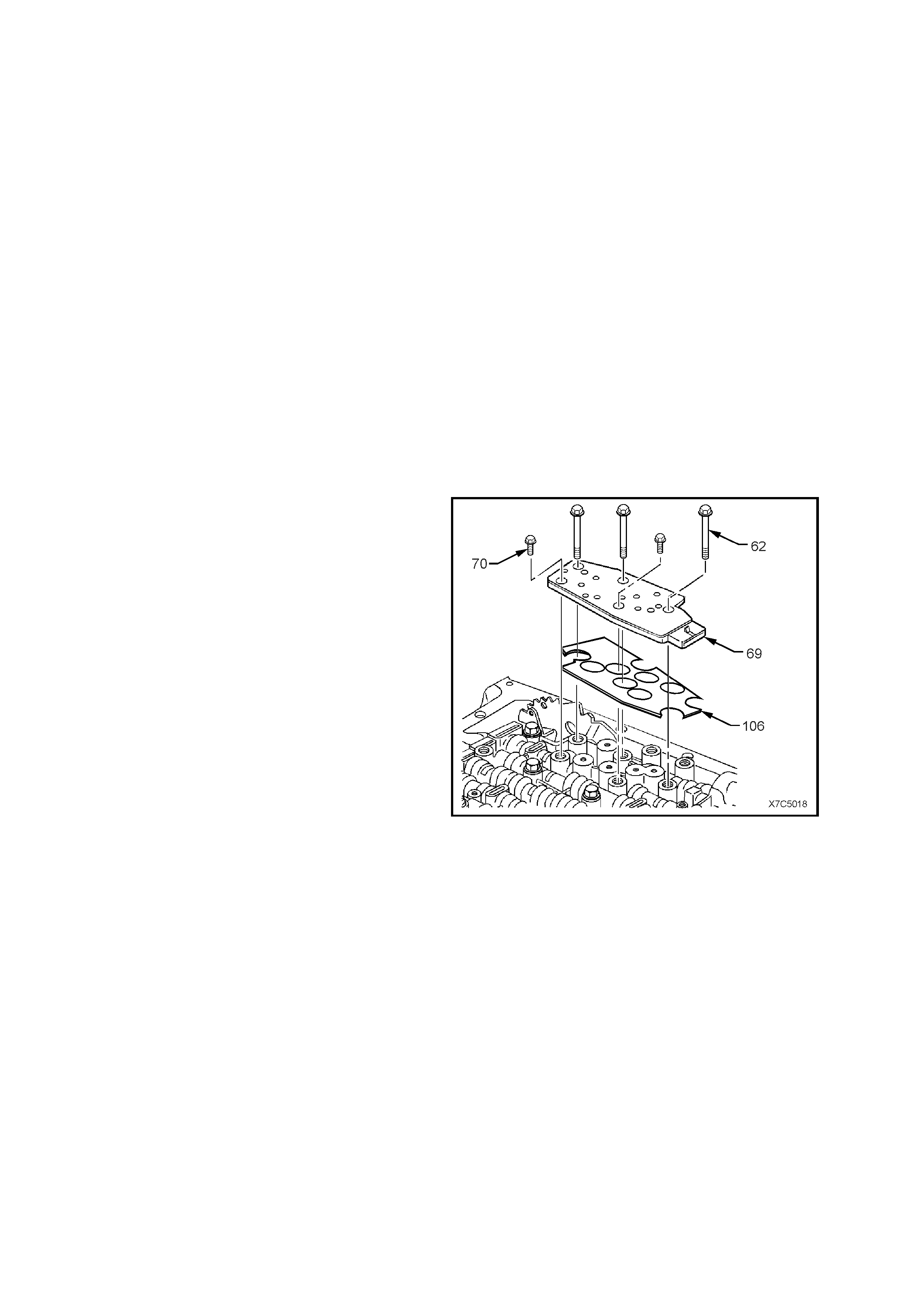
5.5 TRANSMISSION FLUID PRESSURE MANUAL VALVE SWITCH ASSEMBLY (TFP)
AND TRANSMISSION FLUID TEMPERATURE (TFT) SENSOR
LT Section No. – 04-275
REMOVE
1. Dis c onnect batter y ground l ead.
CAUTION: To avoid personal injury from accidental hot oil spillage, perform fluid change only when
transmission fluid is cold.
2. Raise vehicle and support on safety stands. Refer to Section 0A, GENERAL INFORMATION in the MY 2003
VY and V2 Series Service Information.
3. Clean all dirt from around oil pan and transmission case.
4. Place drain tray under transmission.
5. While supporting the oil pan, remove the oil pan bolts from the front and both sides.
6. Loos en the r e ar oi l p an b olts b y about 4 turns each and, while st il l s upp orti ng th e oil pan, light ly tap the sides of
the oil pan with a rubber hammer to break the gasket seal.
7. Lower the front of the oil pan and drain the fluid into a suitable container, then remove the rear oil pan bolts
completely and remove the oil pan from the transmission.
8. Remove old oil pan gasket and discard.
9. Remove the fluid filter. Refer 3.1 FLUID CHANGE AND FILTER REPLACEMENT, in Section 7C4
AUTOMATIC TRANSMISSION -–ON-VEHICLE SERVICING, in the MY 2003 VY and V2 Series Service
Information.
1. Remove the Transmission Fluid Pressure
Manual Valve Position Switch Assembly (TFP)
retaining bolts.
2. Remove the TFP (69) and shield (106) from
the valve body.
Figure 6C2-3-78
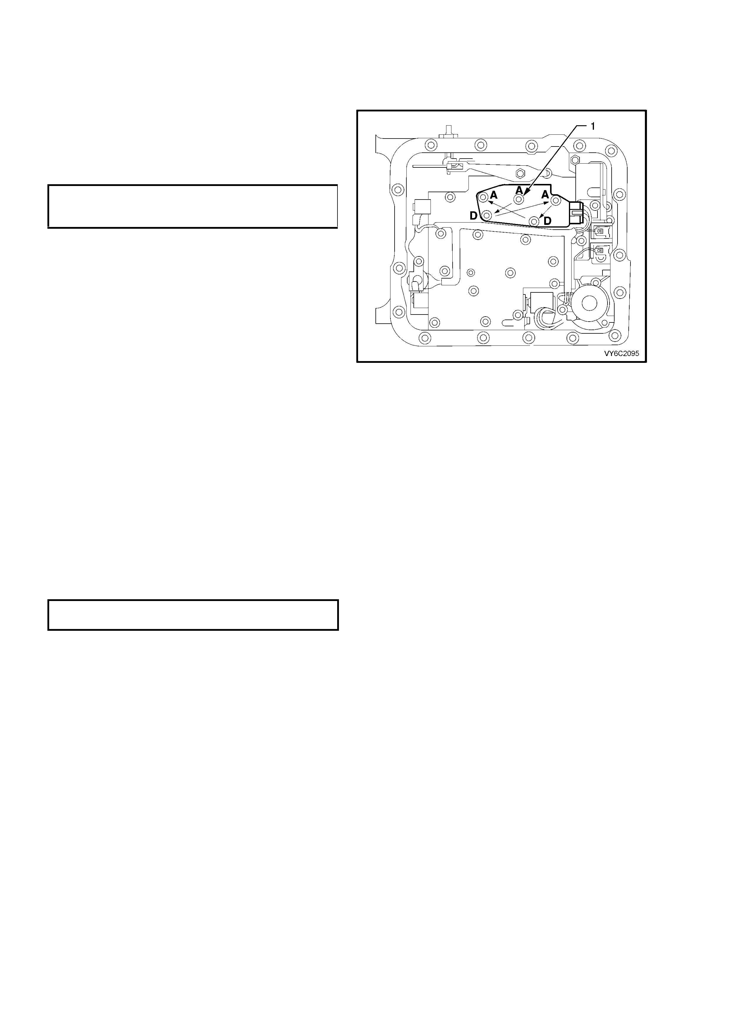
REINST ALL
1. Reinstall transmission fluid pressure switch
assembly (69) and shield (106) to the control
valve body.
2. Install five (5) trans fluid pressure switch
assembly retaining valve body bolts (62 – ‘A’
and 70 – ‘D’). Starting at ‘1’ and work ing in the
pattern shown by the arrows, tighten bolts to
the correct torque specification.
TRANSMISSION FLUID
PRESSURE SWITCH BOLT
TORQUE SPECIFICATION 11 Nm
Figure 6C2-3-79
3. Reinstall transmission fluid pressure switch
assem bl y electrical connector.
4. Install new fluid filter and seal. Refer
3.1 FLUID CHANGE AND FILTER
REPLACEMENT, in Sec ti o n 7C 4 AUTOMAT I C
TRANSMISSION – ON-VEHICLE SERVICING,
in the MY 2003 VY and V2 Series Service
Information.
5. Clean oil pan and case mating surfaces.
Check that magnet is still magnetised, and
attached to the oil pan.
6. Install new oil pan gasket and reinstall oil pan
and retaining bolts, tightening to the correct
torque specification.
TRANSMISSION OIL PAN BOLTS
TORQUE SPECIFICATION 11 Nm
7. Lower vehicle and add approximately 4.8 litres
of DEXRON â III automatic transmission fluid.
8. Rec onn ec t batter y grou nd lead.
9. Check transmission fluid level. Refer to
"Fluid Checking Procedure" in this Section 7C4.
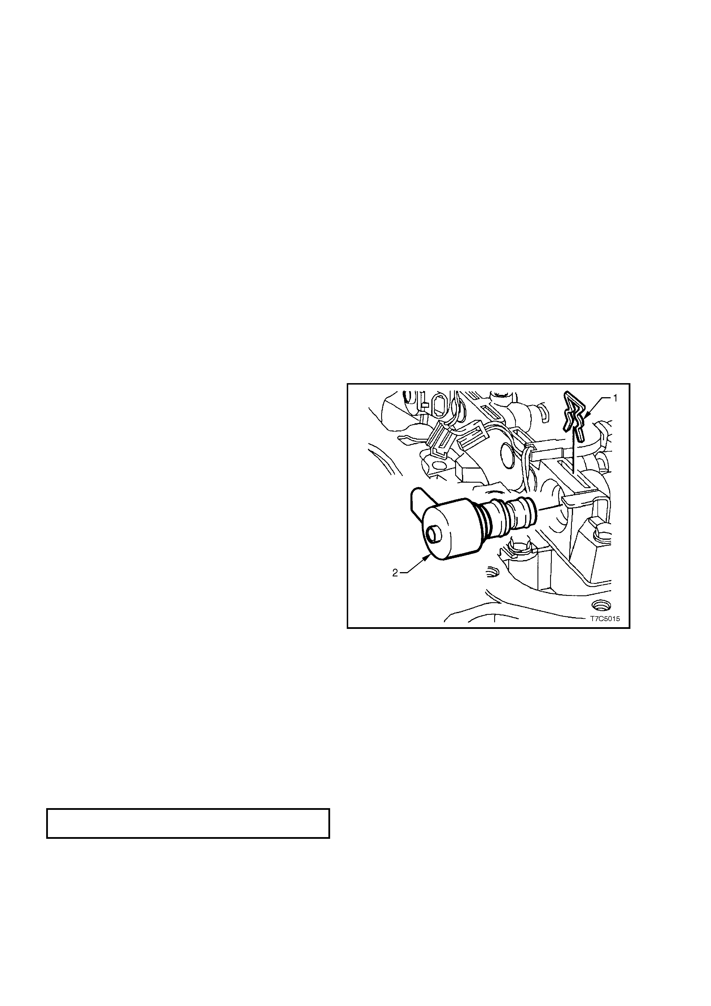
5.6 TCC "PWM" SOLENOID
LT Section No. – 04-275
REMOVE
1. Dis c onnect batter y ground l ead.
CAUTION: To avoid personal injury from accidental hot oil spillage, perform fluid change only when
transmission fluid is cold.
2. Raise vehicle and support on safety stands. Refer to Section 0A, GENERAL INFORMATION in the MY 2003
VY and V2 Series Service Information.
3. Clean all dirt from around oil pan and transmission case.
4. Place drain tray under transmission.
5. While supporting the oil pan, remove the oil pan bolts from the front and both sides.
6. Loos en the r e ar oi l p an b olts b y about 4 turns each and, while st il l s upp orti ng th e oil pan, light ly tap the sides of
the oil pan with a rubber hammer to break the gasket seal.
7. Lower the front of the oil pan and drain the fluid into a suitable container, then remove the rear oil pan bolts
completely and remove the oil pan from the transmission.
8. Remove old oil pan gasket and discard.
9. Remove the fluid filter. Refer 3.1 FLUID CHANGE AND FILTER REPLACEMENT, in Section 7C4
AUTOMATIC TRANSMISSION – ON-VEHICLE SERVICING, in the MY 2003 VY and V2 Series Service
Information.
10. Disconnect TCC "PWM" solenoid electrical connector.
11. Remove solenoid retainer (1) by using a flat
bladed screwdriver.
12. Remove TCC "PWM" Solenoid assembly (2)
with O-ring seal.
Figure 6C2-3-80 – TCC “PWM” Solenoid Location
REINST ALL
1. Reinstall TCC "PWM" Solenoid with O-ring assembly.
2. Reinstall TCC "PWM" Solenoid retainer.
3. Reinstall TCC "PWM" solenoid electrical connector.
4. Install new fluid filter and seal. Refer 3.1 FLUID CHANGE AND FILTER REPLACEMENT, in Section 7C4
AUTOMATIC TRANSMISSION – ON-VEHICLE SERVICING, in the MY 2003 VY and V2 Series Service
Information.
5. Clean oil pan and case mating surfaces. Check that magnet is still magnetised, and attached to the oil pan.
6. Install new oil pan gasket and reinstall oil pan and retaining bolts, tightening to the correct torque specification.
TRANSMISSION OIL PAN BOLTS
TORQUE SPECIFICATION 11 Nm
7. Lower vehicle and add approximately 4.8 litres of DEXRON â III automatic transmission fluid.
8. Rec onn ec t batter y grou nd lead.
9. Check transmission fluid level. Refer to "Fluid Checking Procedure" in this Section. 7C4
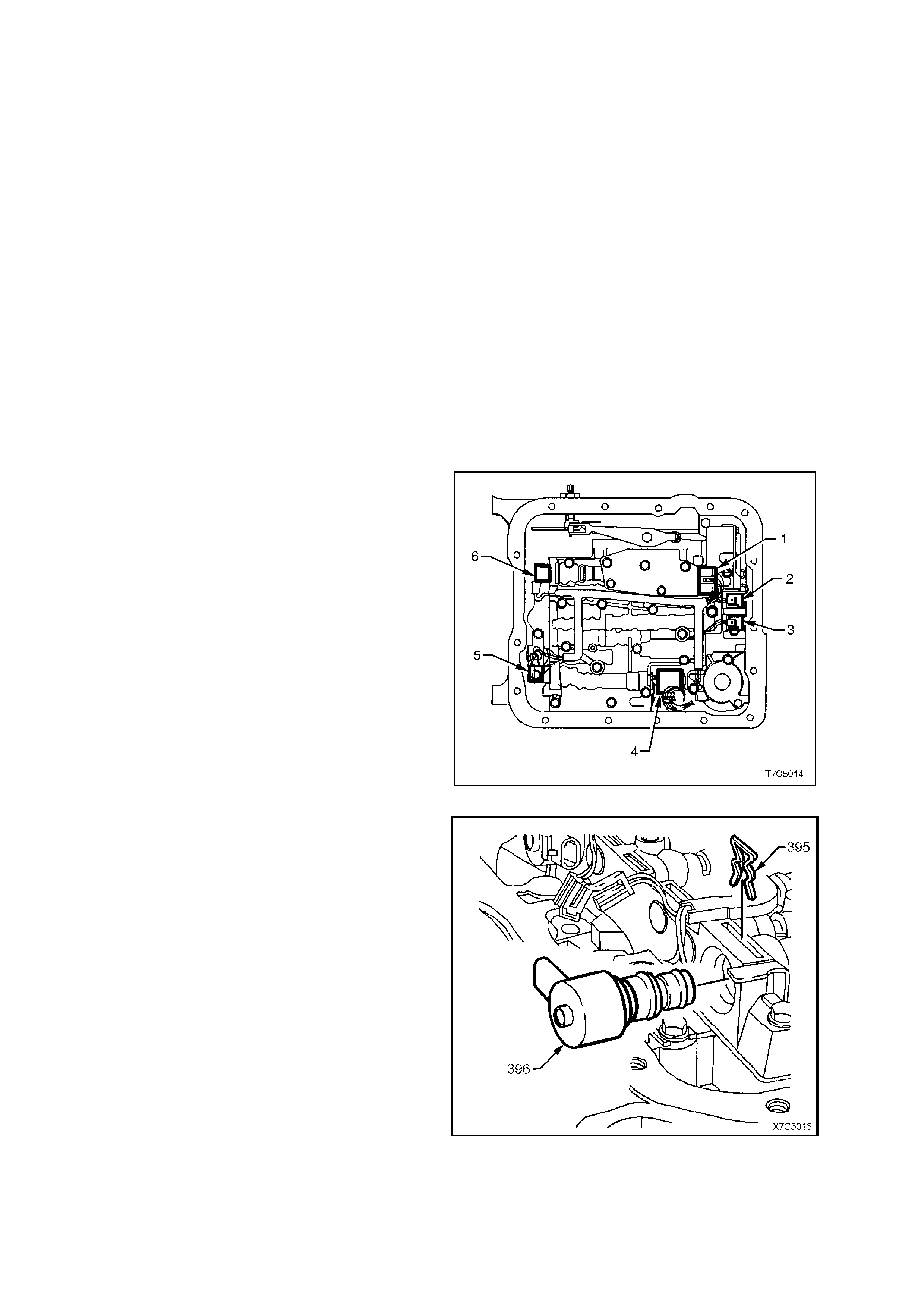
5.7 TCC ENABLE SOLENOID & INTERNAL HARNESS ASSEMBLY
LT Section No. –
REMOVE
1. Dis c onnect batter y ground l ead.
CAUTION: To avoid personal injury from accidental hot oil spillage, perform fluid change only when
transmission fluid is cold.
2. Raise vehicle and support on safety stands. Refer to Section 0A, GENERAL INFORMATION in the MY 2003
VY and V2 Series Service Information.
3. Clean all dirt from around oil pan and transmission case.
4. Place drain tray under transmission.
5. While supporting the oil pan, remove the oil pan bolts from the front and both sides.
6. Loos en the r e ar oi l p an b olts b y about 4 turns each and, while st il l s upp orti ng th e oil pan, light ly tap the sides of
the oil pan with a rubber hammer to break the gasket seal.
7. Lower the front of the oil pan and drain the fluid into a suitable container, then remove the rear oil pan bolts
completely and remove the oil pan from the transmission.
8. Remove old oil pan gasket and discard.
9. Remove the fluid filter. Refer 3.1 FLUID CHANGE AND FILTER REPLACEMENT, in Section 7C4
AUTOMATIC TRANSMISSION – ON-VEHICLE SERVICING, in the MY 2003 VY and V2 Series Service
Information.
10. Disconnect wiring harness connectors from all
electrical components, except the Torque
Converter Clutch (TCC) Solenoid (this solenoid
is hard wired and cannot successfully be
disconnected):
Legend:
1. Transmission Fluid Pressure Manual Valve
Position Switch Assembly (TFP).
2. 1-2 Shift Valve Solenoid.
3. 2-3 Shift Valve Solenoid.
4. Pressure Control Solenoid (PCS).
5. TCC Pulse Width Modulated (TCC PWM)
Solenoid.
6. 3-2 Control Solenoid.
NOTE: The security tang on the PCS (4), is located
at the rear of the connector.
Figure 6C2-3-81
11. Remove the TCC Pulse Width Modulated
(PWM) solenoid retainer clip (395), then the
solenoid (396).
NOTE: This step is necessary to allow access to
one of the TCC Enable Solenoid retaining bolts
underneath it.
Figure 7C2-3-82

12. Remove two bolts (68) holding the TCC
solenoid assembly.
Figure 7C2-3-83
13. Lift the TCC solenoid assembly from oil pump.
NOTE: If removal of the wiring harness/TCC
Solenoid from the transmission case is required, it
will not be pos sible until the control v alve body has
been removed.
Figure 7C5-84
14. As required, remove the control valve body
from the transmission, refer 1.6 CONTROL
VALVE BODY AND WIRING HARNESS, in
Section 7C5 AUTOMATIC TRANSMISSION –
UNIT REPAIR, in the MY 2003 VY and V2
Series Service Information.
15. Support the rear of the transmission, then
remove the rear crossmember and
engine mount. Refer 3.14 TRANSMISSION
ASSEMBLY, Remove, in Section 7C4
AUTOMATIC TRANSMISSION – ON-
VEHICLE SERVICING, in the MY 2003 VY
and V2 Series Ser v ice Infor mation.
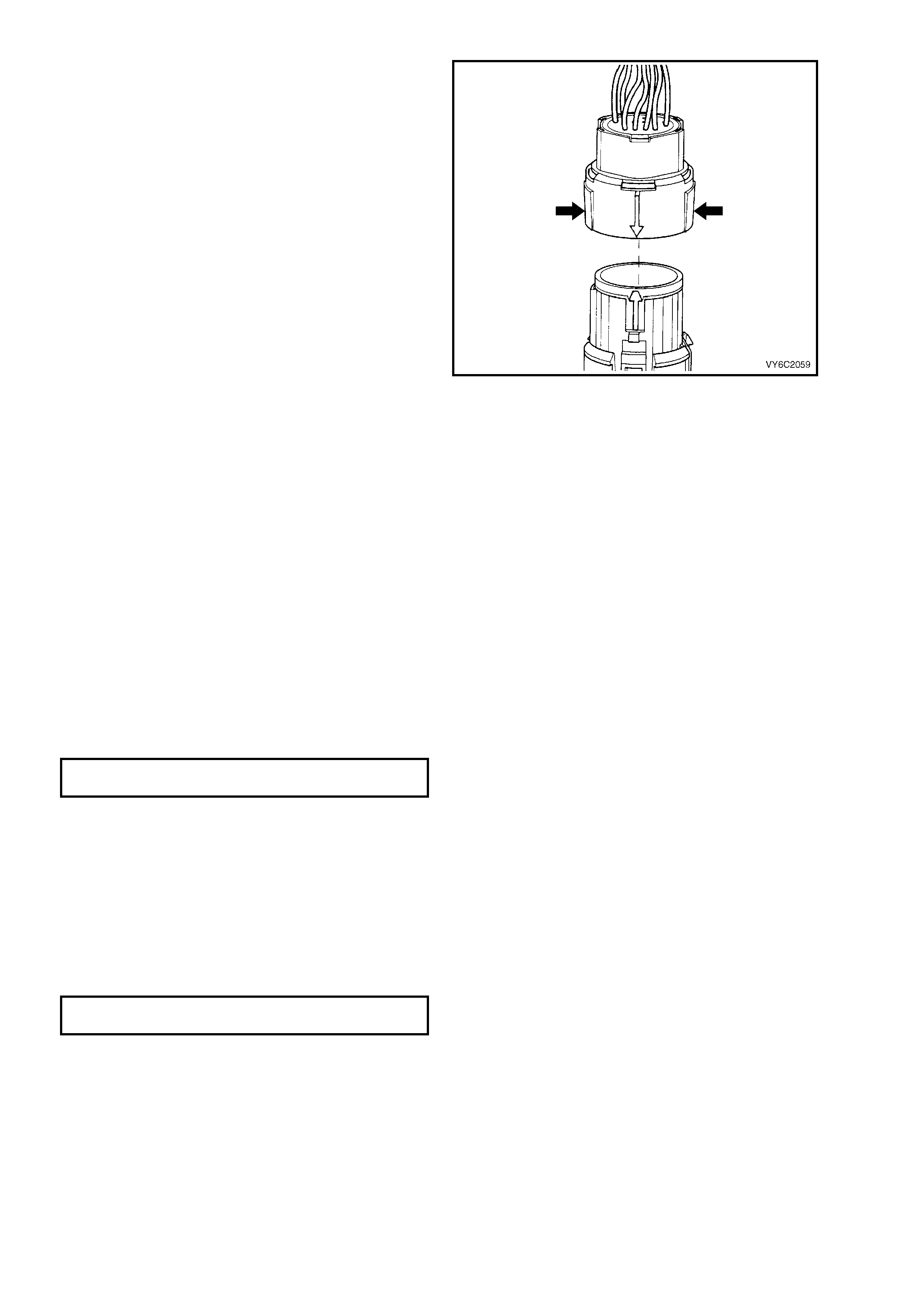
16. Lower the rear of the transmission to provide
sufficient clearance (without placing undue
stress on any electrical wiring or engine cooling
system hoses) and remove the electrical
connector to the transmission, as follows:
NOTE: When lowering the rear of the
transmission, take care that the engine exhaust
manifold does not hit the firewall.
a. Roll back the dust boot from the pass-
through connector, to gain access to the
connector.
b. Squeeze the widest part of the connector
inwards ( bold arr o ws), the n pull DI RECTLY
UPWARDS.
IMPORTANT: Do not wriggle the connector
from side to side during the disconnection
process. If this does occur, there is a real
possibility of the connector pins being
permanently damaged.
Figure 6C2-3-85
17. Place a 12 point 1-5/16" deep well socket (or 34.5 mm I.D. pipe with a slight chamfer on the inside) over the top
of the transmission pass-thru connector.
IMPORTANT: T his may be difficult due to the clearance of the floor pan transm ission tunnel and the transmission
case.
18. Using a suitable lever, pry downward on the top of the socket (or pipe) to compress the connector retaining
lugs, push the pass thru connector down, through and out of the transmission case.
REINST ALL
1. Coat TCC Ena ble So len oi d and pas s- thru c on nec tor O- rings with petroleum j ell y then ins tal l ne w T CC EN AB LE
solenoid and wiring harness assembly into the transmission case. Check that each of the four lugs is clear of
the case, to ensure correct fitment.
2. Reinstall control valve body, refer 3.10 CONTROL VALVE BODY AND ASSOCIATED COMPONENTS, in
Section 7C5 AUTOMATIC TRANSMISSION – UNIT REPAIR, in the MY 2003 VY and V2 Series Service
Information.
3. Install TCC "ON-OFF" solenoid assembly.
4. Reinstall TCC "ON-OFF" solenoid bolts and tighten to the correct torque specification.
TCC SOLENOID BOLT
TORQUE SPECIFICATION 11 Nm
5. Reinstall TCC "PWM" Solenoid assembly and retain with the spring clip.
6. TCC "PWM" solenoid electrical connector.
7. Ensure that the wiring harness is located correctly over the control valve body bolt heads.
8. Reinstall all electrical connectors onto components.
9. Install new fluid filter and seal. Refer 3.1 FLUID CHANGE AND FILTER REPLACEMENT, in Section 7C4
AUTOMATIC TRANSMISSION -–ON-VEHICLE SERVICING, in the MY 2003 VY and V2 Series Service
Information.
10. Clean oil pan and case mating surfaces. Check that magnet is still magnetised, and attached to the oil pan.
11. Install new oil pan gasket and reinstall oil pan and retaining bolts, tightening to the correct torque specification.
TRANSMISSION OIL PAN BOLTS
TORQUE SPECIFICATION 11 Nm
12. Lower vehicle and add approximately 4.8 litres of DEXRON â III automatic transmission fluid.
13. Reconnec t batter y ground l ead.
14. Check transmission fluid level. Refer to "Fluid Checking Procedure" in this Section 7C4.
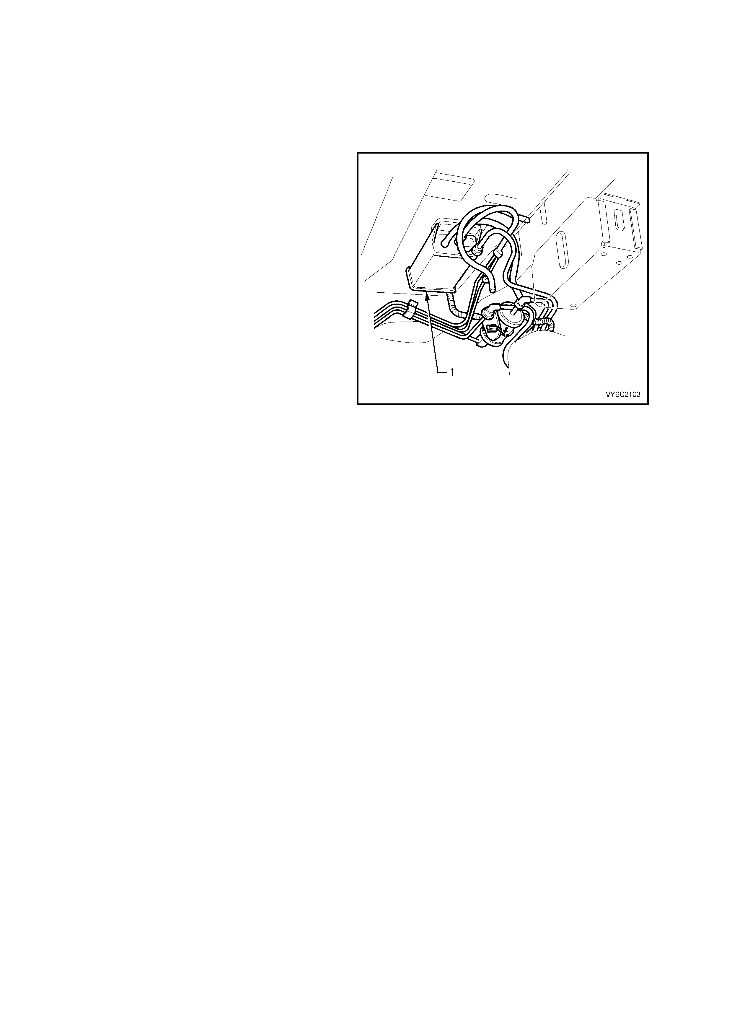
6. MISCELLA NEOUS SYSTEMS
6.1 EVAPORATIVE EMISSION CONTROL CANISTER
LT Section No. – 03-165
REPLACE
1. The Emission Control Canister (1) is located
underneath the vehicle adjacent to the fuel
filter. For Canister removal and reinstallation
procedures, Refer to Section 6E2 EMISSION
CONTROL – V6 SUPERCHARGED ENGINE,
in the MY 2003 VY and V2 Series Service
Information.
Figure 6C2-3-86
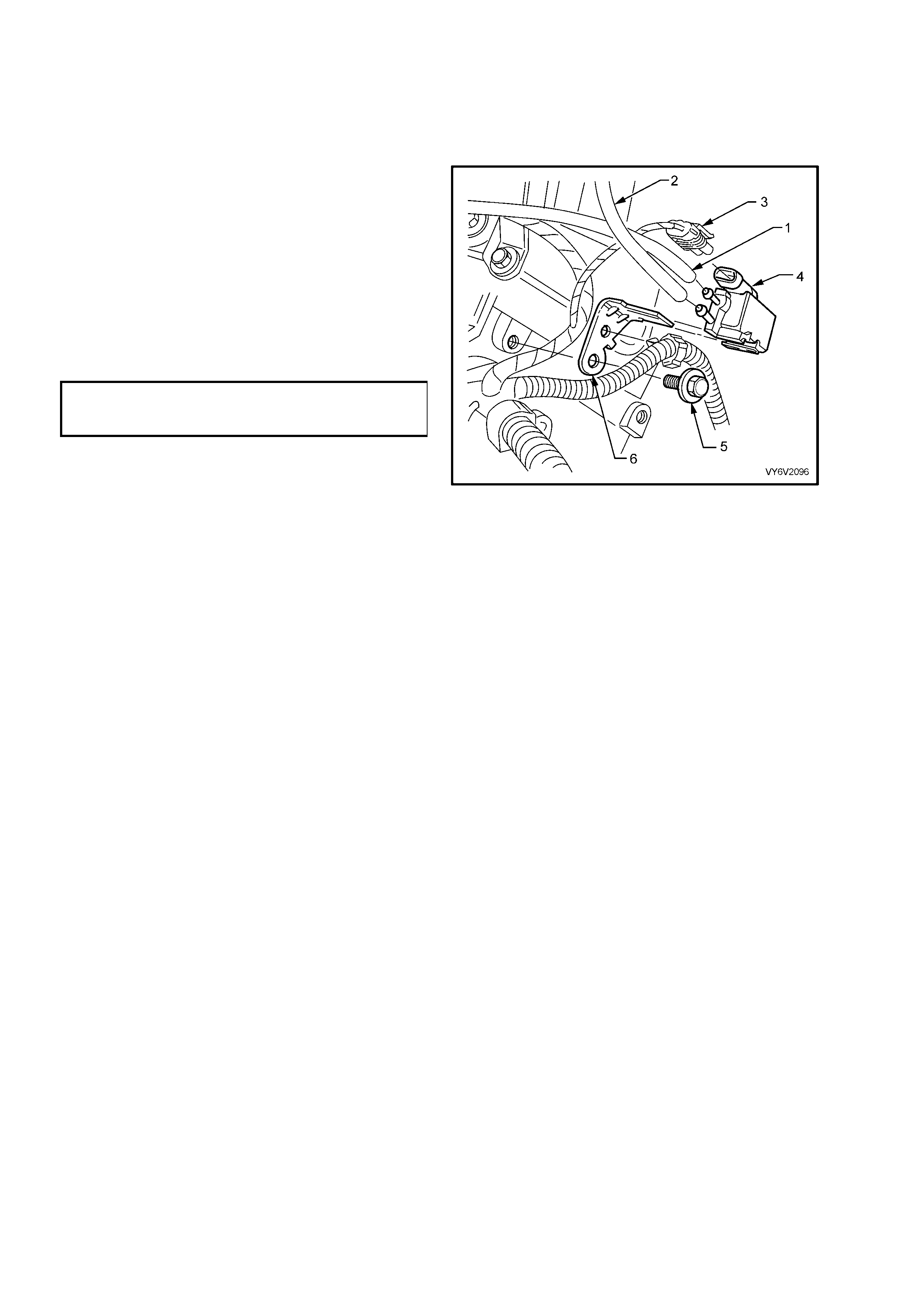
6.2 CANISTER PURGE SOLENOID
LT Section No. – 03-165
REPLACE
1. Dis c onnect batter y ground l ead.
2. Mark hoses on canister purge solenoid (top –
‘1’ and lower ‘2’) and pull hoses from
solenoid (4).
3. Pull up on solenoid wiring harness connector
and pull connector from solenoid (4).
4. Remove bolt (5) from solenoid bracket (6)
(located at the rear of the right hand cylinder
head), then remove solenoid.
5. Reinstall canister purge solenoid (4) to rear of
cylinder head and install bracket bolt (5).
Tighten bolt to the correct torque specification.
PURGE CONTROL SOLE NOID
BRACKET BOLT
TORQUE SPECIFICATION 30 – 40 Nm
6. Rec onnect hoses (1 and 2) and wiring har ness
connector (3) to canister purge solenoid (4),
ensuring connections are correct.
7. Rec onn ec t batter y ground l ead.
Figure 6C2-3-87
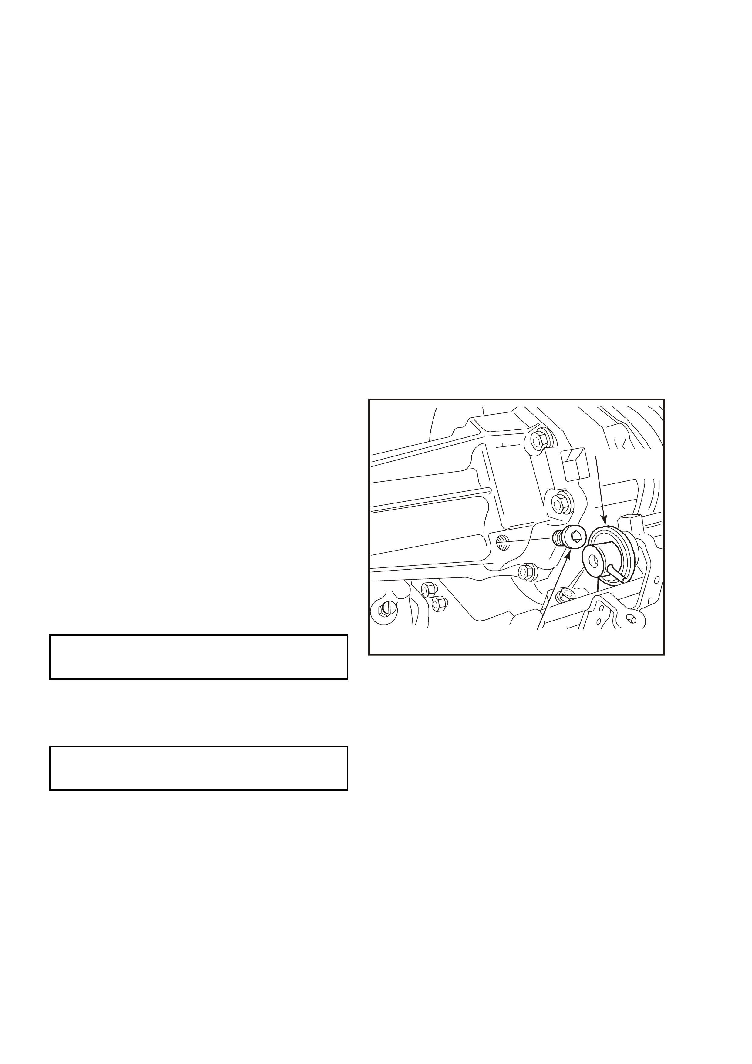
16.3 SUPERCHARGER SYSTEM
LT Section No. – 00-375
IMPORTANT: T o minim ise the chances of un wanted fuel spra y and underhood f uel spill, always depressurise the
fuel pipes bef ore per form ing s ervice that r equires rem oving or disc onnec ting of any portion of the fuel s yste m , refer
3.1 FUEL PUMP RELAY – Fuel Pressure Relief Procedure, in this Secti on.
SUPERCHARGER OIL LEVEL CHECK
IMPORTANT: A small amount of oil seepage through the front seal, (behind the pulley) of the supercharger
assem bly is a norm al c ondi tion. T his oi l se epage is ca used b y m inute tr aces of oi l esc aping around the s eal due to
norm al pressure build u p in the oil cavit y within the super charger assem bly. A build up of belt dust and/or air borne
dust can adhere to the thin oil film, which causes the oil seepage to appear worse than it really is. The
supercharger assembly should not be replaced due to the seepage described. If the supercharger oil is visually
drippin g or pud dl ing f r om the s uperc harger f ront s ea l, t he s up erc har ger as s embly will n eed to be replac ed. R efer to
Section 6A2, ENGINE MECHANICAL – V6 SUPERCHARGED ENGINE, in the MY 2003 VY and V2 Series
Service Information.
NOTE 1: Do not remove the oil plug (2) when the engine is warm. The engine should be cool to the touch.
Approximately 2-3 hours after running. Removing the oil plug at warm engine temperature can cause hot oil to
overflow. This could result in oil loss and possible personal injury.
NOTE 2: The supercharger oil level should be checked at the specified service intervals outlined in the MY 2003
VY and V2 Series, Owner's Handbook.
1. Remove four dome nuts securing the engine dress cover assembly to the inlet manifold studs, lift off and
remove t he cover assembly.
2. To prevent contamination of the supercharger
oil, clean the area around the oil fill plug before
removing.
3. Using a 3/16" Allen key socket, remove
supercharger oil filler plug.
4. Check oil level, which should be maintained to
a level at the bottom of threads in the oil filler
plug inspection hole in the supercharger
housing.
IMPORTANT: Do not us e petrole um bas ed oil. Us e
only GM P/N 12345982 synthetic oil. Use of any
other oil may cause supercharger failure.
5. Reinstall oil filler plug, e nsuring sealing O ring
is in place. Tighten plug to the correct torque
specification.
SUPERCHARGER OIL
FILLER PLUG
TORQUE SPECIFICATION 10 Nm
6. Reinstall engine dress cover to the mounting
brackets, ensuring that stud grommets in the
dress cover remain in place. Tighten securing
dome nuts to the correct torque specification.
ENGINE DRESS
COVER DOME NUT
TORQUE SPECIFICATION 4 – 6 Nm
2
4336
1
Figure 6C2-3-88
SUPERCHARGER – REPLACE
For Supercharger removal and reinstallation instructions, Refer to Section 6A2, ENGINE MECHANICAL – V6
SUPERCHARGED ENGINE, in the MY 2003 VY and V2 Series Service Information.
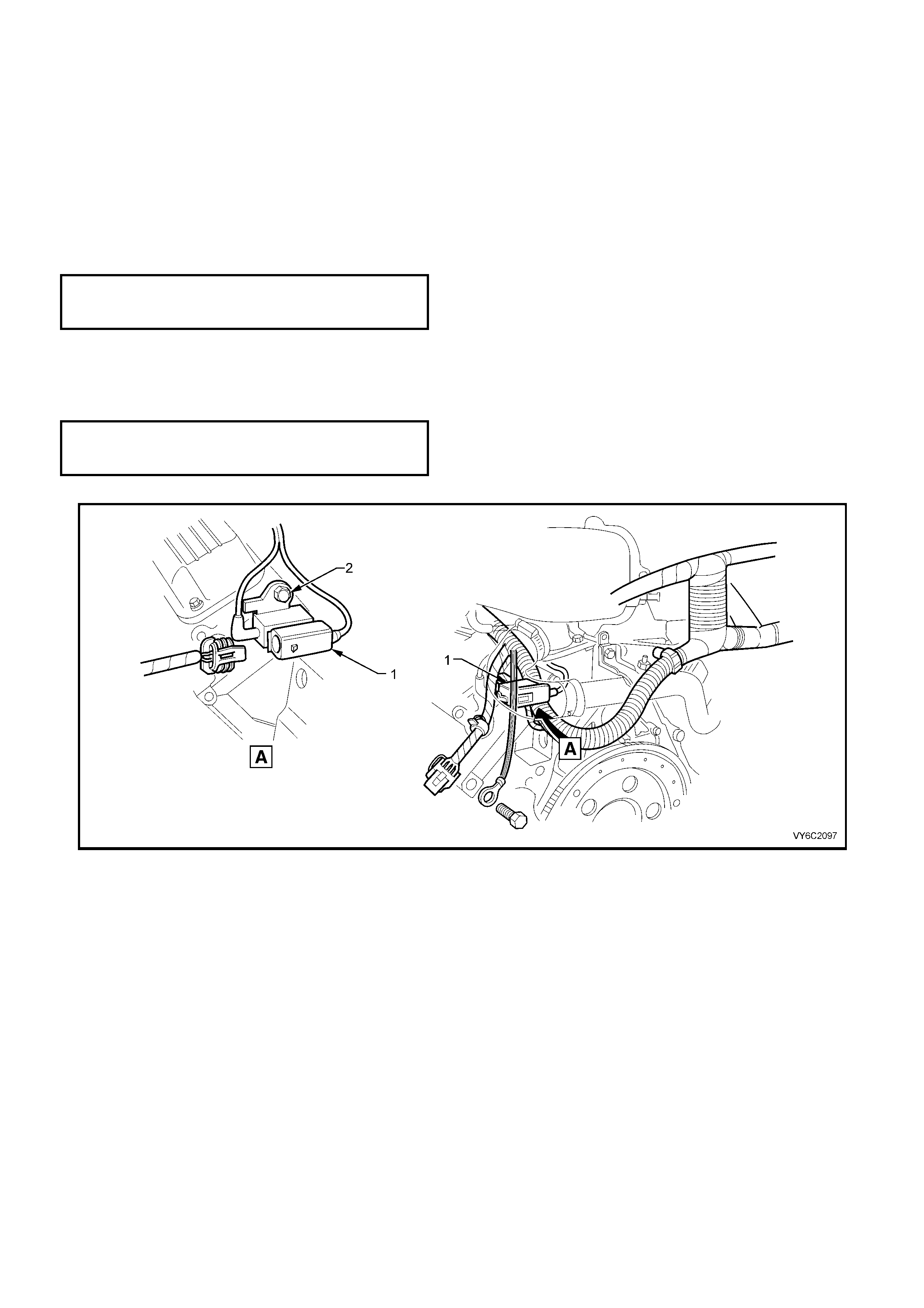
6.4 BOOST CONTROL SOLENOID
LT Section No. – 03-300
REPLACE
1. Remove four dome nuts securing the engine dress cover assembly to the intake manifold studs, lift off and
remove t he cover assembly.
2. Remove boost source and signal hoses from solenoid ports, taking note of each location.
3. Pull back retaining tang on wiring harness connector and remove connector from solenoid (1).
4. Remove solenoid bracket to cylinder head attaching bolt (2) and remove solenoid (1).
5. Reinstall solenoid to cylinder head, install and tighten the attaching bolt (2) to the correct torque specification.
BOOST CONTROL SOLENOID
BRACKET BOLT
TORQUE SPECIFICATION 8 Nm
6. Re-connect boost source and signal hose to solenoid ports.
7. Reinstall wiring harness connector to solenoid.
8. Reinstall engine dress cover to the mounting brackets, ensuring that stud grommets in dress cover remain in
place. Tighten securing dome nuts to the correct torque specification.
ENGINE DRESS
COVER DOME NUT
TORQUE SPECIFICATION 4 – 6 Nm
Figure 6C2-3-89 – Boost Control Solenoid Location
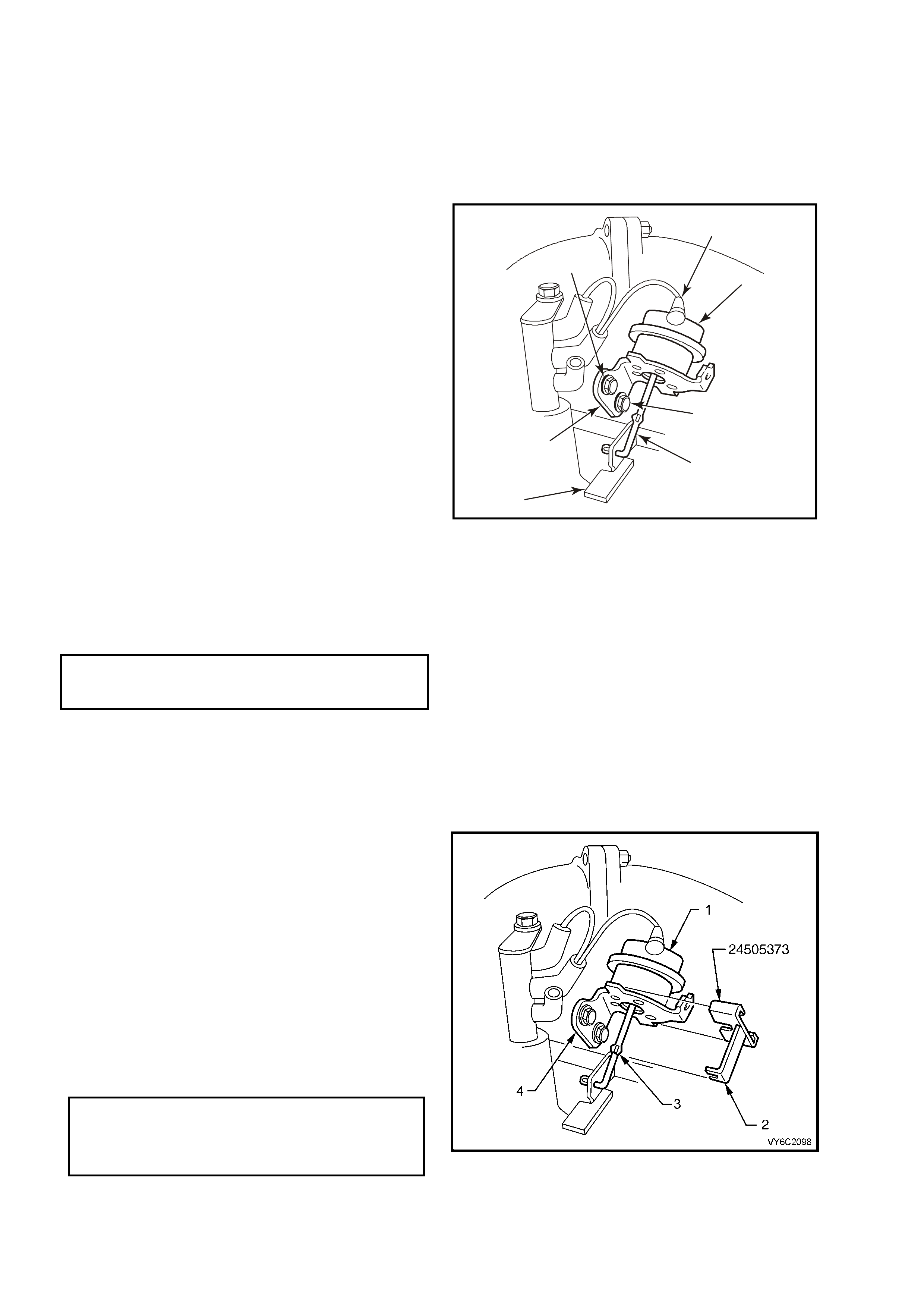
6.5 BY-PASS VALVE ACTUATOR
LT Section No. – 03-300
REMOVE
1. Remove four dome nuts securing the engine
dress cover assembly to the intake manifold
studs, lift off and remove the cover assembly.
2. Disconnect vacuum hose (1) from actuator
port.
3. Using a pointed scribe, mark position of the
actuator mounting bracket around head of
securing bolts (7). This will aid in reinstallation
to ensure that actuator (2) is reassembled in
the same position.
4. Remove two bolts (3) sec ur ing actu ator brac k et
(6) to the supercharger housing.
5. Lift actuator assembly (2) upwards and then
down to cause the by-pass valve to actuator
rod lever (5) to rotate clockwise through 180°
from the ‘at rest’ position. Disengage actuator
rod (4) from the lever (5) by sliding out the
crimped end of the rod from slot in the lever,
the remove the actuator (2).
1
2
7
4
3
4338
5
6
Figure 6C2-3-90 By-Pass Valve Actuator
REINST ALL
Reinstallation of the by-pass valve actuator is the reverse of removal procedures, noting the following points:
1. If reinstalling the original by-pass valve actuator, ensure that aligning marks made on actuator bracket on
removal, are aligned before final tightening of bolts to the correct torque specification.
BY-PASS VALVE ACTUATOR
BRACKET BOLT
TORQUE SPECIFICATION 26 Nm
2. If necessary, check by-pass valve actuator adjustment as detailed in the following procedure.
CHECKING ADJUSTMENT OF BY-PA SS VALVE ACTUATOR
1. Ensure that the ignition is switched to the "OFF" position.
2. Remove four dome nuts securing the engine dress cover assembly to the intake manifold studs, lift off and
remove t he cover assembly.
3. Install Tool No. 24505373 onto the By-Pass
Valve Actuator (1).
NOTE: If Tool No. 24505373 does not fit properly
onto the by-pass valve actuator (1) and the swaged
section (3), of the actuator rod, then the actuator
bracket (4) and/or linkage may be bent, and/or
need adjustment. After the adjustment has been
made and the tool is properly installed onto the
valve, remove the tool and refer to Table
2.6 V6 PCM – SUPERCHARGED ENGINE
BOOST CONTROL SYSTEM FUNCTIONAL
CHECK, in 6C2-2C FUNCTIONAL CHECKS, in
this Section, Step 21 for correct operation of the
by-pass valve actuator (1).
Figure 6C2-3-91 By-Pass Valve Actuator Tool Installation
BY-PASS VALVE ACTUATOR
BRACKET TO SUPERCHARGER
HOUSING SECURING BOL T
TORQUE SPECIFICATION 26 Nm
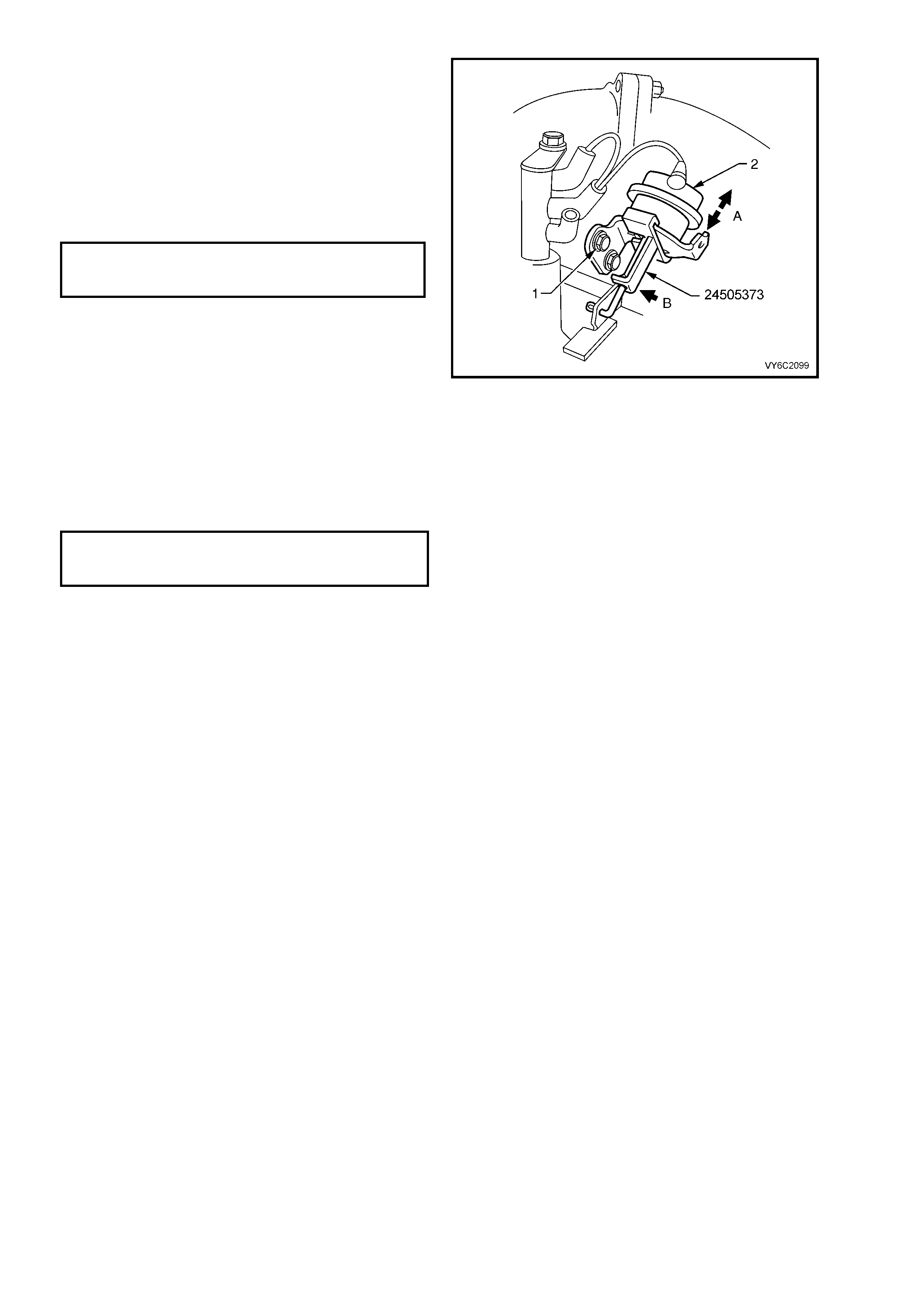
4. If Tool No. 24505373 does not easily fit on the
bracket and swaged portion of the actuator rod,
loosen the actuator bracket to supercharger
housing bolts (2) and slide actuator (3) up or
down (‘A’) until the correct position is reached
and the tool c an be installe d without for ce (‘B’).
With Tool No.24505373 still installed, tighten
bracket to supercharger bolts (1) to the correct
torque specification, without moving actuator
position.
BYPASS VALVE ACTUATOR
ATTACHING BOLT
TORQUE SPECIFICATION 26 Nm
5. Remove Tool No. 24505373.
6. When the adjustment has been checked
and/or corrected, refer to Table
2.6 V6 PCM – SUPERCHARGED ENGINE
BOOST CONTROL SYSTEM FUNCTIONAL
CHECK, in Section 6C2-2C FUNCTIONAL
CHECKS, to check for proper operation of the
by-pass va lv e actu ator.
Figure 6C2-3-92 By-Pass Valve Actuator Adjustment
7. Reinstall engine dress cover to the mounting
brack ets, ens uring that stu d grom m ets in dress
cover remain in place. Tighten securing dome
nuts to the correct torque specification.
ENGINE DRESS COVER
ATTACHING DOME NUT
TORQUE SPECIFICATION 4 – 6 Nm
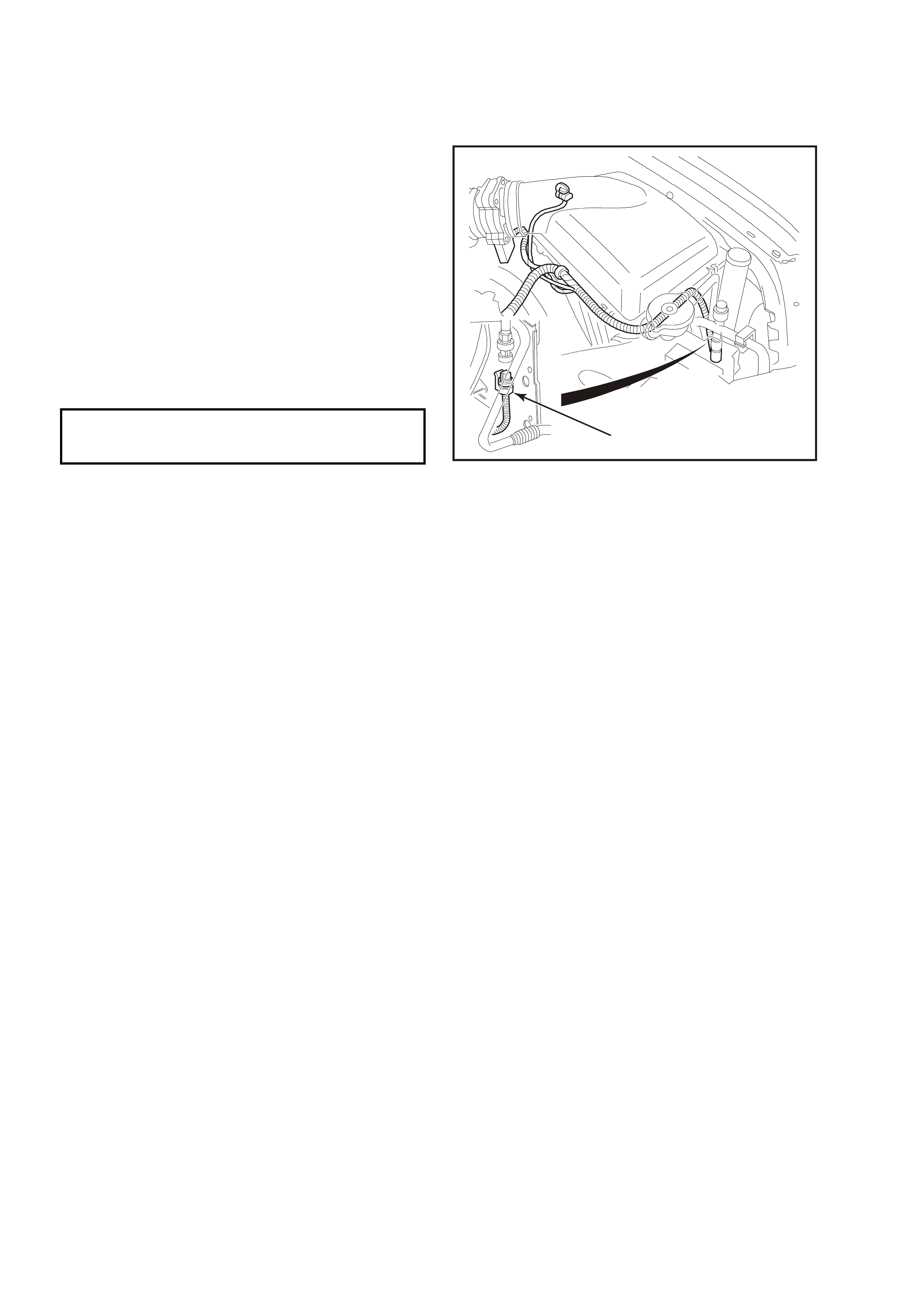
6.6 A/C REFRIGERANT PRESSURE SENSOR
LT Section No. – 08-200
REMOVE
1. Disconnect the electrical connector (1) at the
pressure sensor.
CAUTION: While there is a Schrader valve
under the pressure sensor, slight refrigerant
loss may occur, when the sensor is initially
loosened. F or t his re aso n , wear prot ectiv e h and
and eye wear, during this operation.
2. Using suitable socket equipment, remove the
sensor from the high pressure line.
REINST ALL
1. Reinstall pressure sensor to the high pressure
line, tightening to the correct torque
specification.
A/C REFRIGERANT
PRESSURE SENSOR
TORQUE SPECIFICATION 5 – 7 Nm
2. Reinstall electrical connector (1) to the
pressure sensor.
1
4261
Figure 6C2-3-93 – A/C Refrigerant Pressure Sensor