
SECTION 6C3-1 - GENERAL INFORMATION –
GEN III V8 ENGINE
IMPORTANT:
Before perfo rming any Service Operat ion or oth er procedure described in this Section, refer to Section 00
CAUTIONS AND NOTES for correct workshop practices with regard to safety and/or property damage.
CONTENTS
1 GENERAL DESCRIPTION
1.1 POWERTRAIN CONTROL MODULE (PCM))
PCM POWER SUPPLIES
PCM FIVE VOLT REFERENCE CIRCUITS
SERIAL DATA COMMUNICATIONS
DIAGNOSTIC INFORMATION
RECORDING TEST RESULTS (DIAGNOSTIC
EXECUTIVE)
PCM PROGRAMMING
PCM/PIM/BCM SECURITY LINK
PCM MEMORY FUNCTIONS
1.2 POWERTRAIN INTERFACE MODULE (PIM)
PIM DIAGNOSTIC TROUBLE CODES
STARTER RELAY
1.3 ENGINE INFORMATION SENSORS
AND SIGNALS
ENGINE COOLANT TEMPERATURE
(ECT) SENSOR
ENGINE COOLANT LEVEL SWITCH
MASS AIR FLOW (MAF) SENSOR
INTAKE AIR TEMPERATURE (IAT) SENSOR
MANIFOLD ABSOLUTE PRESSURE
(MAP) SENSOR
SPEED DENSITY SYSTEM
HEATED OXYGEN SENSORS (HO2S)
THROTTLE POSITION (TP) SENSOR
KNOCK SENSOR (KS)
PARK, REVERSE, NEUTRAL, DRIVE, LOW
(PRNDL) SWITCH
A/C REQUEST SIGNAL AND A/C CLUTCH
CONTROL WITH OCC
A/C REQUEST SIGNAL AND A/C CLUTCH
CONTROL WITHOUT OCC
A/C REFRIGERANT PRESSURE SENSOR
VEHICLE SPEED SENSOR (VSS)
CRANKSHAFT POSITION (CKP) SENSOR
CAMSHAFT POSITION (CMP) SENSOR
BATTERY VOLTAGE
TRANSMISSION POWER/ECONOMY SWITCH
THEFT DETERRENT SYSTEM
ENGINE OIL PRESSURE SENSOR
MANUAL TRANSMISSION REVERSE
INHIBIT SOLENOID
BRAKE PEDAL SWITCHES
1.4 FUEL CONTROL SYSTEM
SYSTEM OVERVIEW
COMPONENTS
FUEL METERING MODES OF OPERATION
FUEL METERING SYSTEM COMPONENT
DESCRIPTION
FUEL PUMP ELECTRICAL CIRCUITS FOR
UTILITY WITH GEN III V8 ENGINE
1.5 IDLE AIR CONTROL (IAC) VALVE
IDLE AIR CONTROL VALVE POSITION RESET
1.6 ELECTRONIC IGNITION SYSTEM
IGNITION SYSTEM OVERVIEW
COMPONENTS
CIRCUITS AFFECTING IGNITION CONTROL
RESULTS OF INCORRECT OPERATION
NOTEWORTHY IGNITION INFORMATION
1.7 CRANKCASE VENTILATION SYSTEM
RESULTS OF INCORRECT OPERATION
1.8 EVAPORATIVE EMISSION CONTROL
RESULTS OF INCORRECT OPERATION
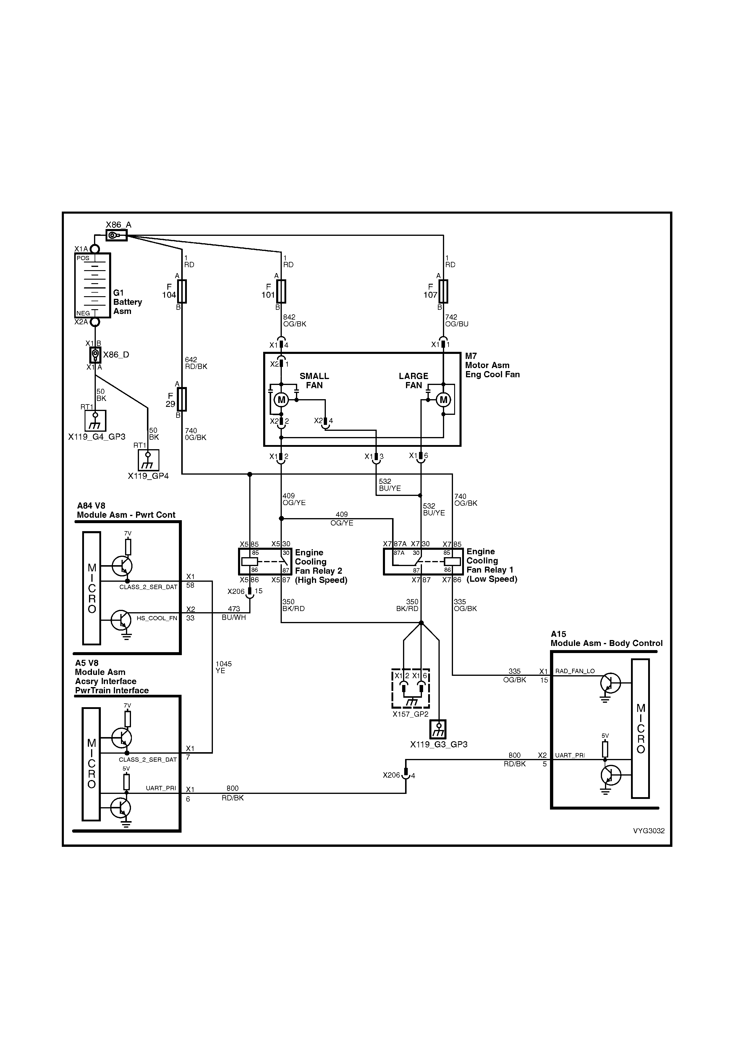
1.9 ELECTRIC COOLING FANS
OPERATION
1.10 A/C CLUTCH CONTROL
OCC SYSTEM
STANDARD A/C SYSTEM
1.11 ELECTRONIC TRACTION CONTROL
ENGINE SPARK AND THROTTLE POSITION
INTERVENTION
1.12 AIR INTAKE SYSTEM
1.13 AUTOMATIC TRANSMISSION SENSORS
AND SIGNALS
1-2 (A) AND 2-3 (B) SHIFT SOLENOID VALVES
3-2 SHIFT SOLENOID VALVE
TRANSMISSION PRESSURE CONTROL
SOLENOID
TORQUE CONVERTER CLUTCH SOLENOID
VALVE
TORQUE CONVERTER CLUTCH PWM
SOLENOID VALVE
TRANSMISSION FLUID PRESSURE (TFP)
MANUAL VALVE POSITION SWITCH
VEHICLE SPEED SENSOR
AUTOMATIC TRANSMISSION FLUID
TEMPERATURE SENSOR
ELECTRICAL CONNECTOR
1.14 ABBREVIATIONS AND GLOSSARY OF TERMS
Techline

1. GENERAL DESCRI PTI O N
The engine used in this vehicle uses a Powertrain Control Module (PCM) to control exhaust emissions while
maintaining excellent driveability and fuel econom y. The PCM m aintains a desired air/f uel ratio at precisely 14.7 to
1. To m aintain a 14.7 to 1 air f uel ratio the PCM monitor s the output signal from two ox ygen sensors . The PCM will
either add or subtr act f uel pulses bas ed on the oxygen sensors output signal. T his m ethod of f eed back fuel c ontrol
is called CLOSED LOOP.
In addition to fuel control, the PCM also controls the following systems.
• The Ignition Dwell
• The Ignition Timing
• The Idle Speed
• The Engine Electric Cooling Fans
• The Fuel Pump
• The Instrument Panel Check Powertrain Malfunction Indicator Lamp (MIL) icon.
• The A/C Compressor Clutch
• The Automatic Transmission Functions
• The Manual Transmission Reverse Inhibit
• Theft Deterrent
The PCM also interfaces with other vehicle control modules, such as the Powertrain Interface Module (PIM),
Instruments, and Body Control Module (BCM). The following diagram contains a list of the various operating
conditions sensed by the PCM, and the various systems controlled. Details of basic operation, diagnosis, and
service are covered in this Section.
The PCM has a built-in diagnostic system that identifies operational pr oblems and alerts the driver by activating the
Check Powertrain Malfunction Indicator Lamp (MIL) icon in the instrument panel. If the lamp is activated while
driving, it does not m ean that the engine should be stopped imm ediately, but the cause of the activation should be
checked as soon as is reasonably possible. The PCM has built in back-up systems that in all but the most severe
faults will allow the vehicle to operate in a near normal manner until repairs can be made.
Below the instrument panel is a Data Link Connector (DLC) which is used by the assembly plant for a computer
check-out of the powertrain management system. The DLC is also used in service to help diagnose the system
using Tech 2. Refer to Section 6C3-2, DIAGNOSIS for further details.
The locations of the Engine Management System (EMS) components are shown in Figures 6C3-1-2 through
6C3-1-5.
For the Transmission Management System components and their locations, refer to Figure 6C3-1-6 in this Section.
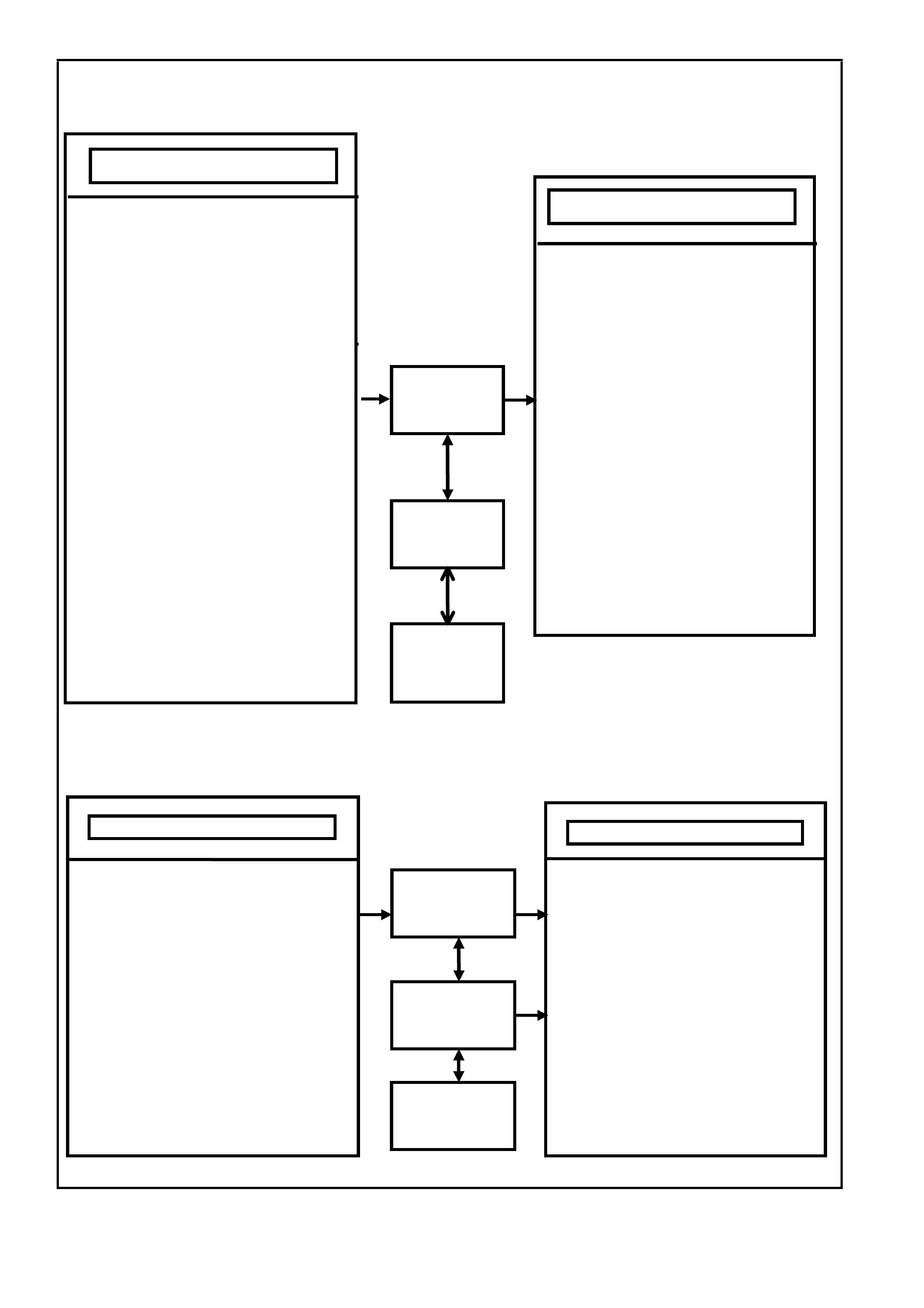
Engine Controls
transmission controls
NOTE: Some parameters may travel through one or more controllers for input or output controls.
Figure 6C3-1-1 – PCM Operating Conditions Sensed and Systems Controlled
• A/C Pressure Sensor
• A/C Request "ON" or "OFF"
• Battery Voltage
• Camshaft Position (CMP)
• Crankshaft Position (CKP)
• DLC Data Stream Input
• Engine Coolant Level Switch
• Engine Coolant Temperature (ECT)
• Engine Cooling Fan Response
• Engine Knock (KS)
• Engine Speed (RPM)
• Exhaust Gas Oxygen Content
• Intake Air Temperature (IAT)
• Mass Air Flow (MAF)
• Manifold Absolute Pressure (MAP)
• Oil Pressure Sensor
• Spark Retard Signal
• Stop Lamp Switch
• Throttle Position (TP)
• Transmission Gear Position (TFP)
• Theft Deterrent Signal
• Vehicle Speed (VSS)
POWERTRAIN
CONTROL
MODULE (PCM)
• Air Conditioning Compressor Clutch
• Canister Purge Solenoid
• Diagnostics
• - Malfunction Indicator Lamp (MIL)
• - DLC Data Stream Output
• - Field Service Mode
• Electric Engine Cooling Fans
• Electronic Spark Control (ESC)
• Electronic Spark Timing (EST)
• Fuel Control
- Fuel Injectors
- Fuel Pump
• Idle Air Control
• Torque Management
• Battery Voltage
• Power/Economy Switch
• Engine Speed (RPM)
• Engine Coolant Temperature (ECT)
• Stop Lamp Switch
• Throttle Position (TP Sensor)
• Transmission Fluid Temperature (TFT)
• Transmission Gear Position (TFP)
• Vehicle Speed Sensor (VSS)
• Pressure Control Solenoid (PCS)
• Transmission Fluid Pressure (TFP)
Switch Assembly
• TCC Enable Solenoid
• TCC PW M Solenoid
• 3-2 Shift Solenoid
• 1-2 Shift Solenoid – ‘A’
• 2-3 Shift Solenoid – ‘B’
• Diagnostics
• - Malfunction Indicator Lamp (MIL)
• - DLC Data Stream Output
• Manual Transmission Reverse
Inhibit
POWERTRAIN
CONTROL
MODULE (PCM)
OPERATING PARAMETERS SENSED SYSTEM CONTROLLED
POWERTRAIN
INTERFACE
MODUL E (P IM)
POWERTRAIN
INTERFACE
MODULE (PIM)
BODY
CONTROL
MODUL E (B C M)
BODY
CONTROL
MODULE (BCM)
OPERATING PARAMETERS SENSED
SYSTEMS CONTROLLED
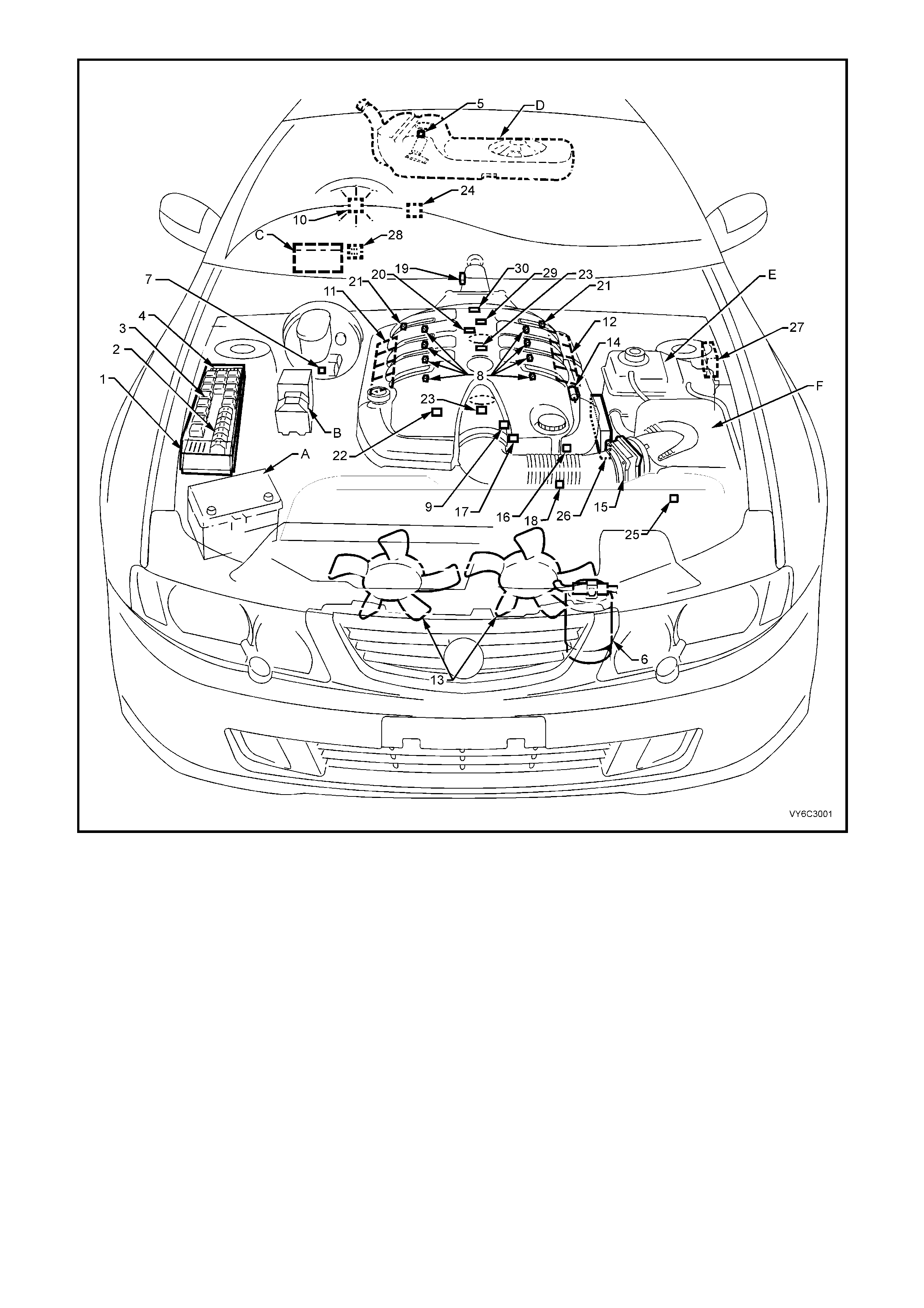
Figure 6C3-1-2 – Component Locations – GEN III V8 Engine RHD (LHD Similar)
Legend
1. Underhood Electrical Centre
2. Fusible Links
3. Relays – Mini & Micro
4. Underhood Fuses
5. Fuel Pressure Regulator (in Fuel Tank)
6. A/C Accumulator Tank
7. Brake Hydraulic Failure Switch
8. Fuel Injectors (8)
9. Idle Air Control (IAC) Valve
10. Check Powertrain Malfunction Indicator Lamp
(MIL)
11. Ignition Coil/Module Right Bank
12. Ignition Coil/Module Left Bank
13. Engine Cooling Fans (2)
14. Canister Purge Solenoid
15. Mass Air Flow (MAF) Sensor
16. Engine Coolant Temperature (ECT) Sensor
17. Throttle Position (TP) Sensor
18. Intake Air Temperature (IAT) Sensor
19. Vehicle Speed Sensor (VSS)
20. Camshaft Position (CMP) Sensor
21. Heated Oxygen (HO2S) Sensor (2)
22. Crankshaft Position (CKP) Sensor
23. Knock Sensors (KS) (2)
24. OCC In - Car Air Temperature Sensor
25. A/C Refrigerant Pressure Sensor
26. Powertrain Control Module (PCM)
27. Powertrain Interface Module (PIM) - Inside vehicle
behind left kick panel
28. Diagnostic Link Connector (DLC)
29. Oil Pressure Sensor
30. Manifold Absolute Pressure (MAP) Sensor
A Battery
B A.B.S./T.C.S. Module
C BCM
D Fuel Tank
E Surge Tank (With Low Coolant Level Switch)
F Air Cleaner
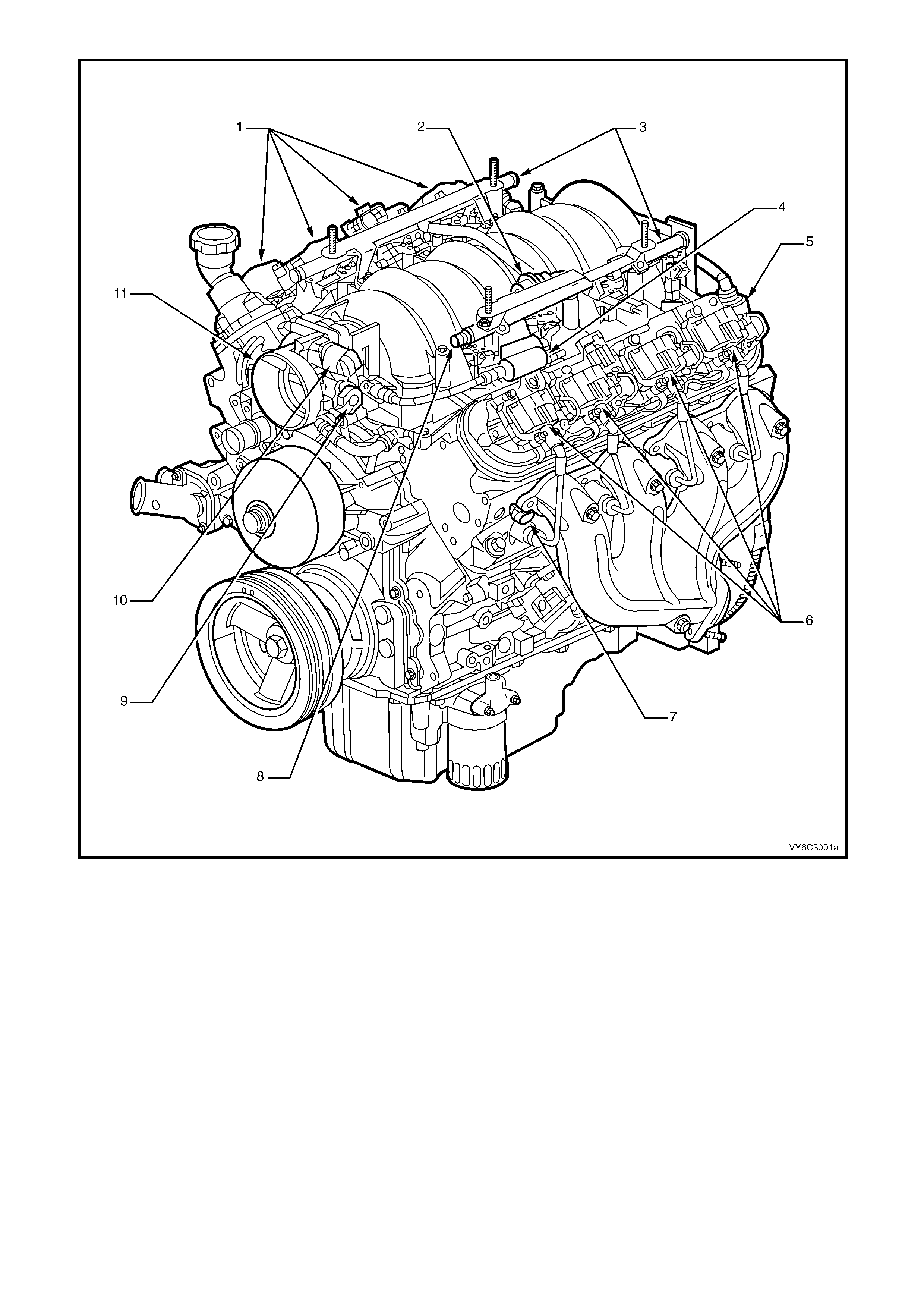
Figure 6C3-1-3 GEN III V8 Engine View Left-Hand Side
Legend
1. Right-Hand Ignition Coils/Modules
2. Fuel Pulse Dampener
3. Fuel Rail with Injectors
4. Evaporative Canister Purge Solenoid
5. Crankcase Vent
6. Left-Hand Ignition Coils/Modules
7. Engine Coolant Temperature (ECT) Sensor
8. Fuel Pressure Gauge Test Connector
9. Throttle Position (TP) Sensor
10. Idle Air Control (IAC) Valve
11. Throttle Body
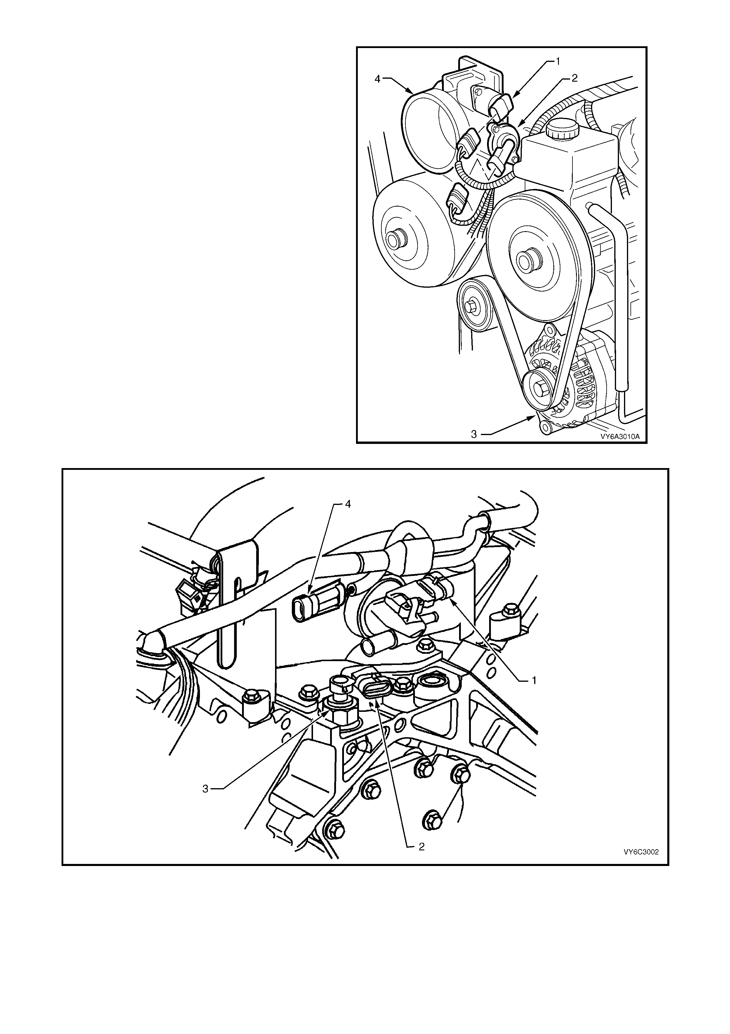
Legend
1. Idle Air Control (IAC) Valve
2. Throttle Position (TP) Sensor
3. Generator
4. Throttle Body
Figure 6C3-1-4 – GEN III V8 Engine Front View
Figure 6C3-1-5 GEN III V8 Engine Rear View
Legend
1. Manifold Absolute Pressure (MAP) Sensor
2. Camshaft Position (CMP) Sensor 3. Oil Pressure Sensor
4. Connector to Knock Sensor Jumper Harness
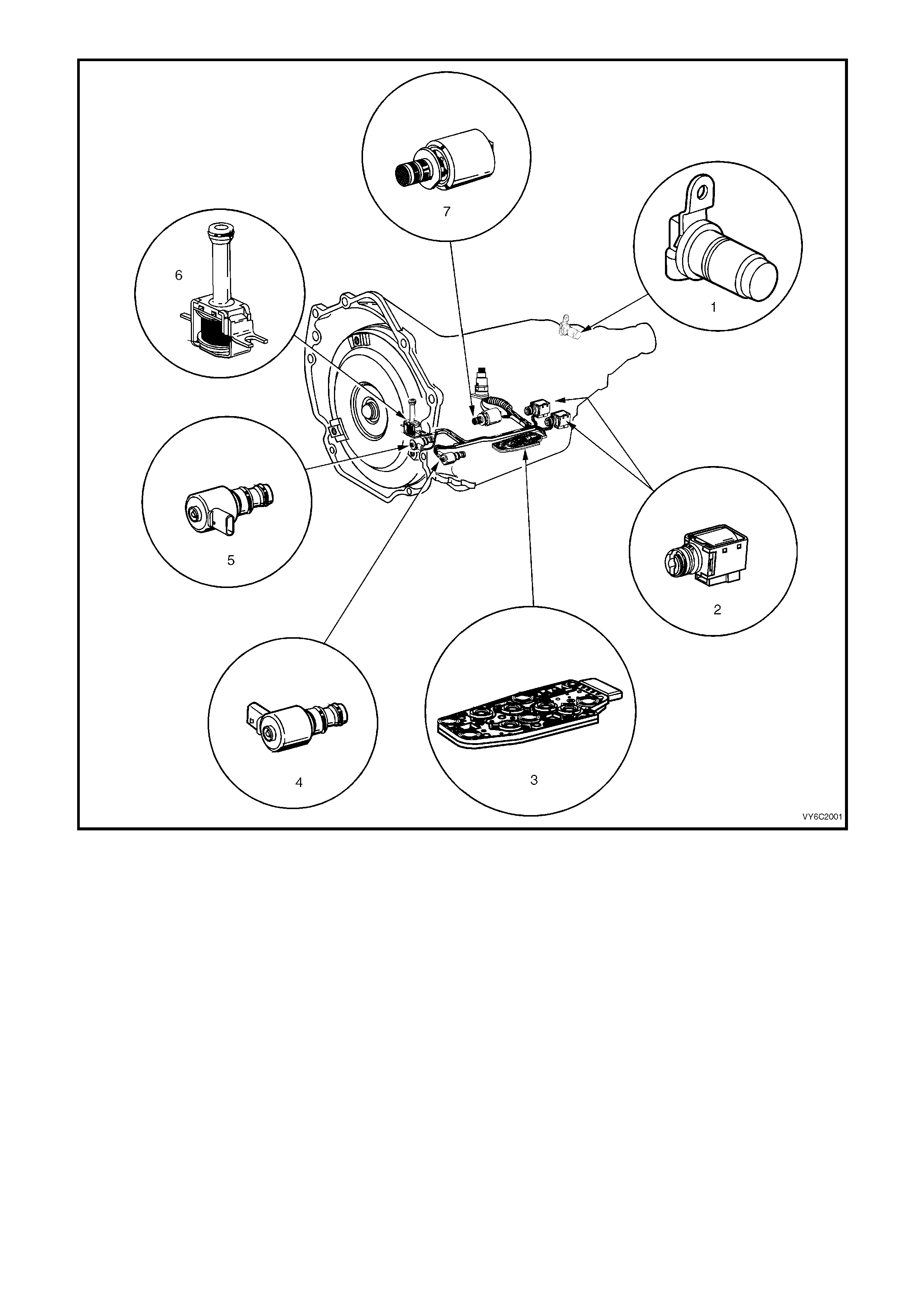
Figure 6C3-1-6 Automatic Transmission Internal Electronic Component Locations
Legend
1. Vehicle Speed Sensor
2. 1-2 Shift Solenoid ‘A’ and 2-3 Shift Solenoid ‘B’
3. Automatic Transmission Fluid Pressure (TFP) Manual
Valve Position Switch
4. 3-2 Downshift Control Solenoid
5. Torque Converter Clutch Pulse Width Modulation
(TCC PWM) Solenoid Valve
6. Torque Converter Clutch (TCC) Solenoid Valve
7. Pressure Control Solenoid (PCS) Valve
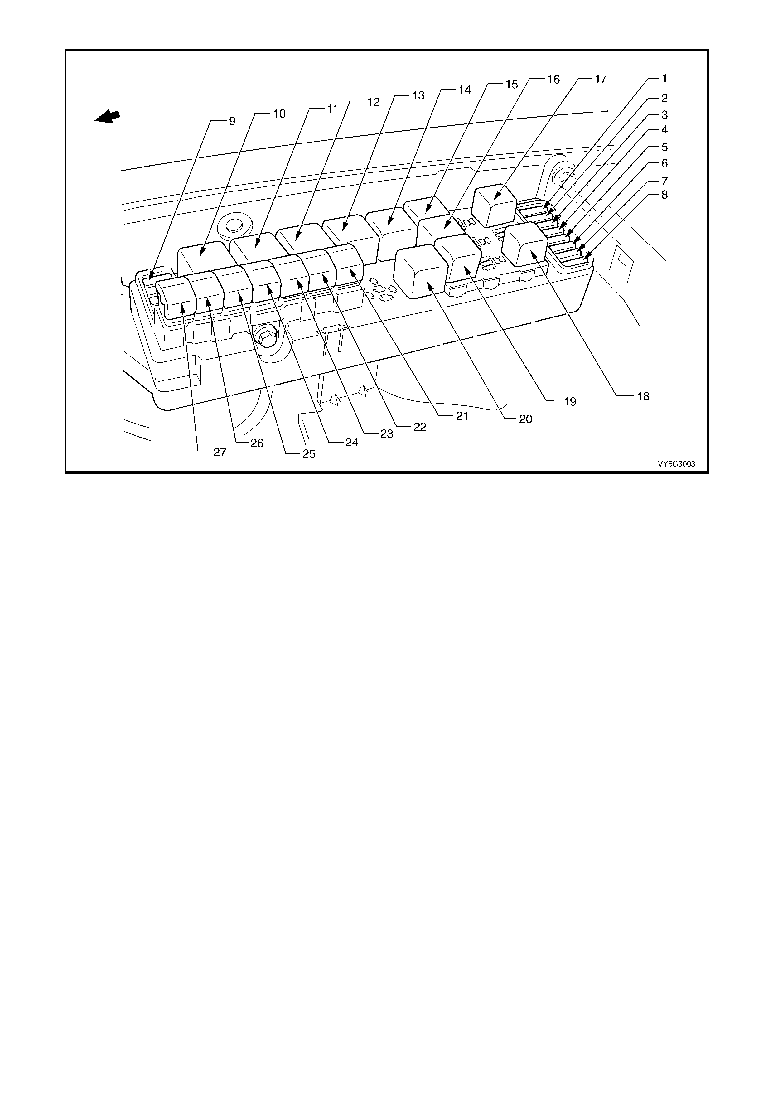
Figure 6C2-1-7 – Engine Compartment Fuse/Relay/Fusible Link Locations
Legend
Fuses
1. Fuel Pump Fuse – F28
2. Engine Control / BCM – F29
3. RH Headlamps – F30
4. LH Headlamps – F31
5. Automatic Transmission – F32
6. Engine Sensors – F33
7. Injectors / Ignition – F34
8. Injectors / Ignition – F35
9. Throttle Relaxer Module – F36
Relays
10. Start – R1
11. Blower Fan – R2
12. Headlamp (High Beam) – R3
13. Engine Control (EFI) – R4
14. Engine Cooling Fan Relay 2 – (High Speed) – R5
15. Horn – R8
16. A/C Compressor – R11
17. Fog Lamp – R10
18. Fuel Pump – R16
19. Headlamp (Low Beam) – R14
20. Engine Cooling Fan Relay 1 – (Low Speed) – R7
Fusible Links
21. Engine Cooling Fan (Large) – F107 (30A)
22. Blower Fan – F106 (60A)
23. Main – F105 (60A)
24. Engine – F104 (60A)
25. ABS – F103 (60A)
26. Lighting – F102 (60A)
27. Engine Cooling Fan (Small) – F101 (30A)
1.1 POWERTRAIN CONTROL MODULE (PCM)
The Powertr ain Control Module ( PCM), is located in
the engine compartment. The PCM is the control
centre of the vehicle. It controls the following:
• Fuel metering system.
• Transmission shifting.
• Ignition timing.
• Knock control.
• Evaporative Emission Control System (EECS)
Purge.
• Cooling fans.
• A/C system.
• Malfunction Indicator Lamp (MIL)
• Theft Deterrent (Injector control).
The PCM constantly monitors the information from
various sensors, and controls the systems that
affect vehicle performance. The PCM also
perfor ms a diagnos tic function of the system . It can
recognise operational problems. The PCM also
alerts the driver through the Malfunction Indicator
Lamp (MIL) via the Class II serial data
communication line to the Powertrain Interface
Module (PIM). This is where the PIM converts the
Class II serial data communication to Universal
Asynchronous Receiving/Transmitting (UART).
This UART serial data communication is then sent
from the PIM to the Instrument panel cluster, via
the Serial data Bus. When the PCM detects a
malfunction, it stores a Diagnostic Trouble Code
(DTC).
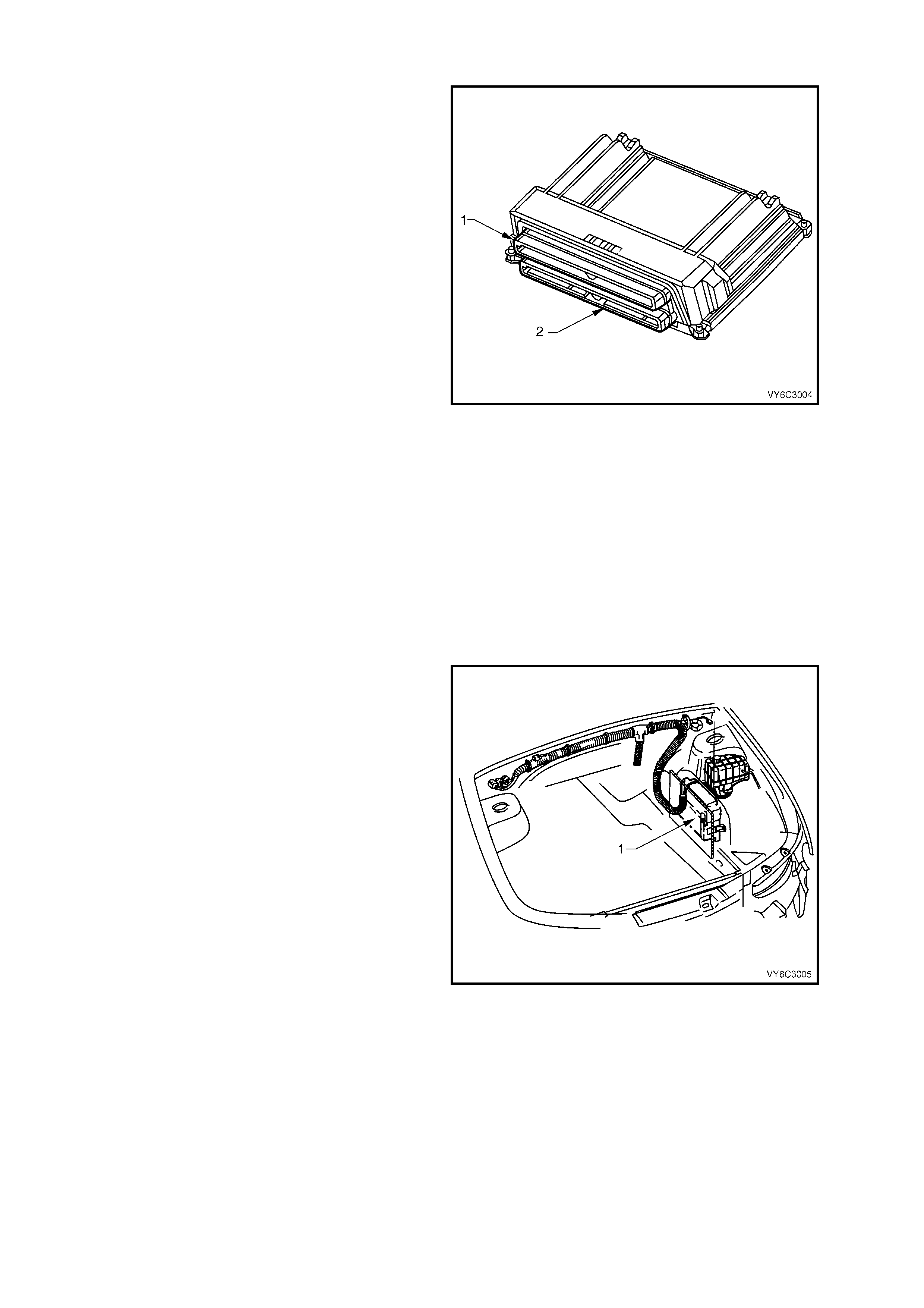
Figure 6C3-1-8 – Powertrain Control Module
Legend:
1. Connector A84 X1 – BLUE
2. Connector A84 X2 – RED
A stored DTC will identify the problem areas. This
will assist the Technician in making repairs.
The PCM supplies either 5.0 or 12.0 volts to power
various sensors or switches. This is done through
resistanc e in the PCM. The resistanc e is so high in
value that a test lamp will not illuminate when
connected to the circuit. In some cases, even an
ordinary shop voltmeter will not give an accurate
reading because its resistance is too low.
Therefore, a digital multimeter (DMM) (J 39200)
with at least 10 megohms input impedance is
required to ensure accurate voltage readings.
The PCM controls output circuits such as the
injector s, IAC, cooling fan relays, etc. by controlling
the ground or circuits through transistors or a
device called a “Driver” in the PCM. The two
exceptions to this are the fuel pump relay control
circuit and the automatic transmission pressure
control solenoid (PCS). The fuel pump relay is the
only PCM c ontrolled circ uit where the PCM controls
the +12 volts sent to the coil of the relay. The
ground side of the f uel pump relay coil is connected
to engine ground. The PCM supplies current to the
PCS and m onitors how muc h current retur ns to the
PCM on a separate terminal. The PCM also
receives and transmits serial data via the
Powertrain Interface Module (PIM) and the serial
data bus.
Figure 6C3-1-9 – Powertrain Control Module
Legend:
1. Powertrain Control Module (PCM) Location

PCM POWER SUPPLIES
Battery voltage is applied to PCM terminals X 1-20 and X 1- 57 at all times via f us e F 29 and ignition voltage is applied
to PCM terminal X1-19 via fuse F10 whenever the ignition switch is in the ON or START position. The PCM is
grounded from terminals X1-01, X1-40, X2-01, and X2-40 to ground points X119 at the Rear Left and Front Right
sides of the engine block.
PCM FIVE VOLT REFERENCE CIRCUITS
The PCM has two, five volt reference circuits. The five volt reference circuit number one supplies five volts to the
following sensors:
• The Throttle Position (TP) Sensor
• The Manifold Absolute Pressure (MAP) Sensor
• Oil Pressure Sensor
The five volt reference circuit number two, supplies five volts to the following sensor:
• The A/C Pressure Sensor
The PCM monitors the voltage on the 5.0 volt reference circuit. The following DTCs will set if the voltage is out of
range.
A failure in a five volt reference circuit will set either DTC P1635 or P1639.
DTC P1635 FIVE VOLT REFERENCE #1 CIRCUIT
Conditions for running DTC P1635
• The ignition is on.
Conditions for setting DTC P1635
• The five volt reference #1 circuit is out of range.
• All of the above conditions are present for greater than 2 seconds.
Action taken when DTC P1635 Sets
• The PCM activates the Malfunction Indicator Lamp (MIL) when the diagnostic runs and fails.
• The PCM records the operating conditions at the time the diagnostic fails. The PCM stores this information in
the Freeze Frame/Failure Records.
Conditions for clearing the Malfunction Indicator Lamp (MIL) and DTC P1635
• The PCM deactivates the Malfunction Indicator Lamp (MIL) after one ignition cycle that the diagnostic runs and
does not fail.
• A last test failed (Current DTC) clears when the diagnostic runs and does not fail.
DTC P1639 FIVE VOLT REFERENCE #2 CIRCUIT
Conditions for running DTC P1639
• The ignition is on.
Conditions for setting DTC P1639
• The five volt reference #2 circuit is out of range.
• All of the above conditions are present for greater than 2 seconds.
Action taken when DTC P1639 Sets
• The PCM activates the Malfunction Indicator Lamp (MIL) when the diagnostic runs and fails.
• The PCM records the operating conditions at the time the diagnostic fails. The PCM stores this information in
the Freeze Frame/Failure Records.
Conditions for clearing the Malfunction Indicator Lamp (MIL) and DTC P1639
• The PCM deactivates the Malfunction Indicator Lamp (MIL) after one ignition cycle that the diagnostic runs and
does not fail.
• A last test failed (Current DTC) clears when the diagnostic runs and does not fail.
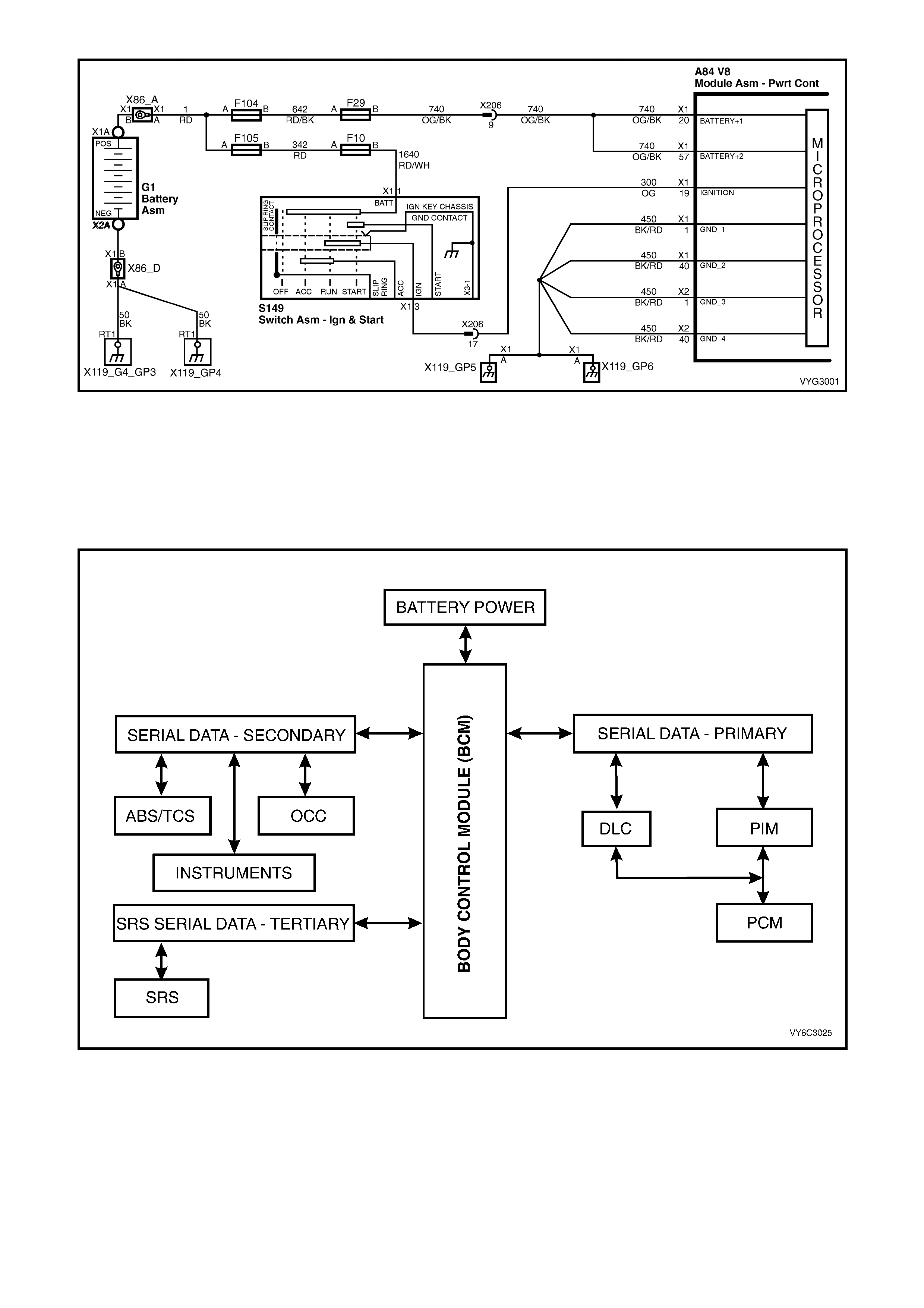
Figure 6C3-1-10 – PCM Battery, Ignition and Ground Circuits
SERIAL DA TA COMMUNICATION
Various devices; system control modules of the vehicle, as well as TECH 2 communicate with each other. The
communication between control m odules and communication with the TECH 2 diagnostic scan tool is achieved on
the ser ial comm unication lines using serial data. Serial data transf ers infor mation in a linear f ashion - over a single
line, one bit at a tim e. The ser ial data line is r eferr ed to as the ‘data bus’. Ex cluding the GEN III V8 PCM, all c ontrol
modules communicating on the data bus communicate using UART communication.
Figure 6C3-1-11 – System Overview - Serial Communication
UART is a 5 volt data line that toggles the voltage to ground (0 volts) at a fixed bit pulse width during
communication. UART transmits data at the rate of 8.2 kilobits per second (8192 bits/sec). With UART
communication, when there is no communication on the data line, the system voltage will be 5 volts.

The GEN III V8 PCM us es Class 2 comm unication.
This type of communication toggles the data line
from 0 volts to 7 volts at either a s hor t or long puls e
width at a rate of 10.4 kilobits per second
(average). With Class 2 communication, when
there is no communication on the data line, the
system voltage will be 0 volts.
As the ‘Class 2’ communication is different to
UART (different languages), communication
between the modules is incom patible, and as such,
requires a Powertrain Interface Module (PIM) to
convert Class 2 communication into UART, and
UART into Class 2 (a translator).
TECH 2 is able to communicate with both UART
and Class 2 control modules.
On all MY 2003 VY and V2 Series models, the
BCM is the Bus Master of the serial data
com munication system. The BCM periodically polls
(surveys) each device on the data bus and
requests status data.
T212J1012
11
0
1
00
1
0
1
0
5V
0V
UART
CLASS 2
11 1
111
000 0
000
7V
0V
Figure 6C3-1-12 – Serial Data Digital Wave Form
On vehicles fitted with a GEN III V8, the devices (control modules) the BCM polls are:
• Powertrain Interface Module (PIM).
• Instrument cluster (INS).
• Antilock Brake/Traction Control System (ABS/TCS) Module.
• Supplemental Restraint System (SRS) Sensing and Diagnostic Module (SDM).
• Occupant Climate Control (OCC) Module.
• TECH 2.
The data provided by each device may be utilised by any device connected to the bus.
Each device has a unique response Message Identifier Word (MIW) for ease of identification.
The bus master ( BCM) polls each device with a serial data m essage which includes that devic es MIW . The device
responds by putting a s erial data m ess age onto the bus which inc ludes its MIW and data, of which is retrieved and
utilised by any device requiring it.
The BCM polls each device for a status update, once every 300 milliseconds. The exception to this being the PIM
(GEN III V8) which is polled twice every 300 milliseconds. The PIM will construct a serial data message from
inform ation requested from the PCM via the Class 2 com munic ation. This cons tructed serial data m essage is then
placed on the serial data bus.
When the ignition switch is turned from the OFF position to the ON position, the BCM will communicate with the
PCM via the PIM for theft deterrent purposes. If the BCM does not receive an OK TO START message from the
PIM within 0.5 seconds of ignition on, the auxiliary data bus is isolated via switching from the BCM.
The isolation of the auxiliary data bus during this period eliminates the possibility of a device failure other than the
BCM, or PIM, causing a problem on the serial data bus and inhibiting theft deterrent communications.
This period (short loop time) continues until the PIM responds with an acknowledgment or for a maximum of five
seconds after which the BCM will switch to the standard polling sequence and a no start condition will occur.
Following succ essful theft deterrent com munica tions, the BCM begins sequential polling of devices on the bus and
normal system operation is established.
When the ignition switch is in the OFF position, the BCM continues to poll, allowing for TECH 2 communications
and external control of the bus prior to the ignition being switched on.
DIAGNOSTIC INFORMATION
The Diagnos tic Tables (Section 6C3-2A) and Functional Check s (Section 6C3-2C) in this Service Infor mation, are
designed to locate a faulty circuit or component through logic based on the process of elimination. These tables
have been prepared with the understanding that the vehicle:
• Functioned correctly at the time of assembly.
• There are no multiple faults.
• The problem currently exists.
The PCM perf orms a continual self-diagnosis on certain control functions. The PCM indicates the source of a fault
through the use of Diagnostic Trouble Codes (DTCs). The DTCs are four digit codes (P0XXX or P1XXX). W hen a
fault is detected by the PCM, a DTC will be set and stored in the memory of the PCM and the Check Powertrain
Malfunction Indicator Lamp (MIL) may be activated.
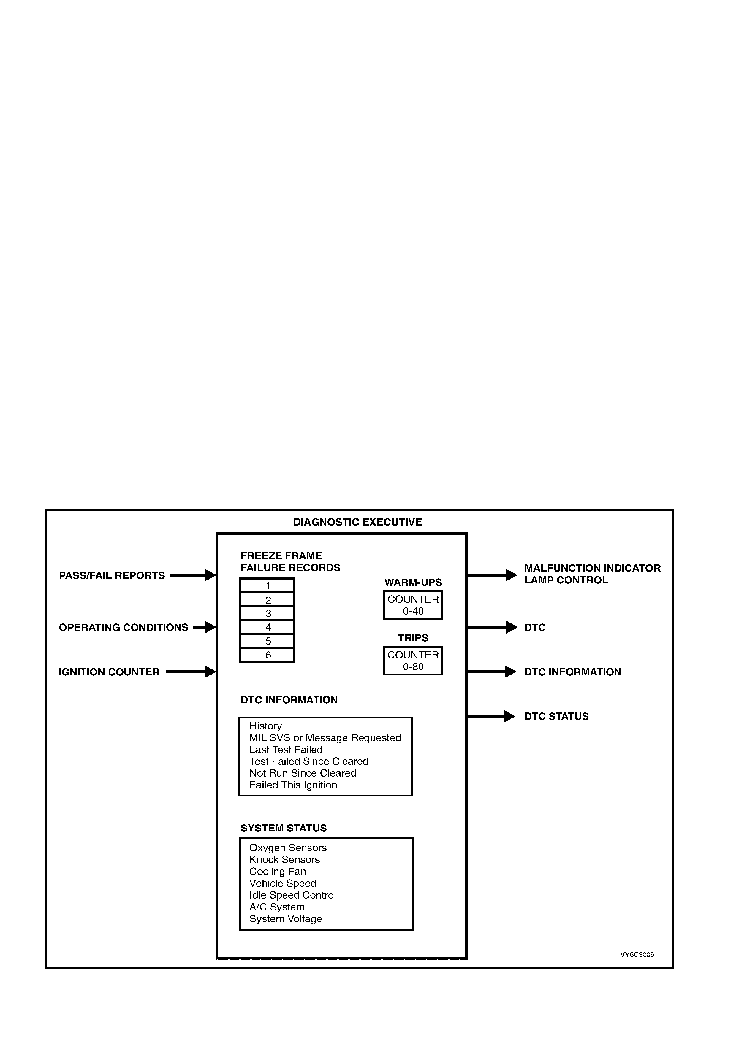
RECORDING TEST RESULTS (DIAGNOSTIC EXECUTIVE)
The Diagnostic Exec utive is a unique s egment of the PCM s oftware which is designed to c o-ordinate and prioritise
the diagnostic procedures as well as define the protocol for recording and displaying their results. The main
responsibilities of the Diagnostic Executive are:
• DTC Information
DTC Information indicates the status of the diagnostic testing for a specific DTC. It contains information on pass
/ fail status of the test, when the diagnostic test failed and if the DTC is requesting the activation of the
Malfunction Indicator Lamp (MIL).
• Freeze Frame / Failure Records
Freeze fram e / failur e records ar e stored any time a diagnostic tes t fails. T he PCM has the ability to store up to
six freeze frame / failure records. W hen a diagnostic test fails, records are stored in the first fail position. If a
different diagnostic test fails, a second fail record position. Additional failed diagnostic tests for different DTCs
also store fail records until the fail record memory is full. The PCM has the ability to store six freeze frame /
failure r eco rds , if mor e than s ix DTC f reeze f r ame / f ailure r ec ords ar e st ored, the f ail r ec ords ar e replac ed on a
first in, first out basis.
The freeze frame / failure records data list has 32 parameters for data capture. W hen a DTC is set, the PCM
will capture all 32 parameters at the time the DTC is logged.
In addition to the regular data list parameters found in the freeze frame / failure records data list, there is
additional information available about the DTC diagnostics:
• First Odometer - Vehicle kilometre value when the DTC failure first recorded.
• Last Odometer - Vehicle kilometre value when the DTC fail is recorded.
• Fail Counter - Number of ignition cycles with failure (DTC was set).
• Pass Counter - Number of ignition cycles with diagnostic passes (DTC was not set again).
• Not Run Counter - Number of ignition cycles without diagnostic run (DTC conditions were not tested).
• System Status
T he System Status (I/M Flag) stores inf orm ation on which diagnostics have run. If a s ystem diagnostic has run,
the system status flag (yes/no) will be set.
• Warm-Up Cycles
Records the number of warm-up cycles that have been achieved since the DTC was set
Figure 6C3-1-13 – Diagnostic Executive
TECH 2 SCAN TOOL: FREEZE FRAME / FAILURE RECORDS DA TA DISPLAY
SCAN POSITION Q UNITS DISPLAYED R DATA VALUE S
Engine Speed rpm Varies
Desired Idl e Speed rpm Varies
Eng. Coolant Temp (ECT) Degrees C Varies
Start Up E CT Degrees C Varies
Throttle P osition 0 – 100% 0 – 100%
Engine Load % %
Baro kPa kPa
Baro Sensor Volts Volts Volts
MAP Sensor kPa kPa
MAP Sensor Volts Volts Volts
Mass Air Fl ow gram /sec gram /sec
Fuel Syst em St atus Open Loop/Closed Loop Open Loop/Closed Loop
Left Short Term Fuel Trim (Bank 1) % +20% to –20%
Right Short Term Fuel Trim (Bank 2) % +20% to –20%
Left Long Term Fuel Trim (Bank 1) % +20% to –20%
Right Long Term Fuel Tri m (Bank 2) % +20% to –20%
inject i on pul se bank 1 ms ms
inject i on pul se bank 2 ms ms
Air Fuel Rati o Ratio 14.7:1
Transm i ssion Range Park, Reverse, Neutral ,
Drive , Drive 3, Dri ve 2, Dri ve 1, Invalid Park, Reverse, Neutral ,
Drive, Drive 3, Dri ve 2, Dri ve 1, Invalid
Current Gear 1,2,3,4 1,2,3,4
A/T Output Speed (Auto Trans ) rpm rpm
TCC Brake Switch ON / OFF ON / OFF
TCC Solenoid ON / OFF ON / OFF
TCC PWM ON / OFF ON / OFF
Vehicl e S peed km /h km /h
Time From Start Time 0:00:00
First Odometer km km
Last Odometer km km
Fail Counter # #
Pass Count er # #
Not Ran Counter # #
PCM PROGRAMMING
The PCM for this vehicle application does not
contain a removable PROM, instead it uses an
EEPROM (Flash Memory) which is non removable.
From the factory, the PCM is programmed with the
proper calibrations for vehicle operation. In the
event that the PCM is replaced, or an updated
calibration is required to correct a vehicle's
operating condition, the new PCM or the new
calibration will require the use of the Tech 2 scan
tool for down loading to the EEPROM (Flash
Memory). Down loading is accomplished through
the vehicle Data Link Connector (DLC) using the
Tech 2 scan tool.
The service replacement PCM EEPROM (Flash
Memory) will not be programm ed. DTC P0601 and
P0602 indicates the Flash Memory is not
programmed or has malfunctioned.
NOTE: The PCM used in this vehicle application is
not interchangeable with any other V8 GEN III
program. Only the PCM part number for this vehicle
must be used.
Refer to Section 6C3-3 SERVICE OPERATIONS
for this service programming procedure.
Figure 6C3-1-14 – Powertrain Control Module Location
Legend:
1. Powertrain Control Module (PCM)

DTC P0601 POWERTRAIN CONTROL MODULE (PCM) MEMORY
Conditions for running DTC P0601
• The ignition switch is in the crank position or the run position.
Conditions for setting DTC P0601
• The PCM is unable to correctly read data from the EEPROM (flash memory).
Action taken when DTC P0601 Sets
• The PCM activates the Malfunction Indicator Lamp (MIL) when the diagnostic runs and fails.
• The PCM records the operating conditions at the time the diagnostic fails. The PCM stores this information in
the Freeze Frame/Failure Records.
Conditions for clearing the Malfunction Indicator Lamp (MIL) and DTC P0601
• A last test failed (Current DTC) clears when the diagnostic runs and does not fail.
• A History DTC clears after forty consecutive warm-up cycles, if this or any other emission related diagnostic
does not report any failures.
• Use Tech 2 in order to clear the MIL/DTC.
DTC P0602 POWERTRAIN CONTROL MODULE (PCM) NOT PROGRAMMED
Conditions for running DTC P0602
• The ignition switch is in the run position.
Conditions for setting DTC P0602
• No software data is present in the PCM.
Action taken when DTC P0602 Sets
• The PCM activates the Malfunction Indicator Lamp (MIL) when the diagnostic runs and fails.
• The PCM records the operating conditions at the time the diagnostic fails. The PCM stores this information in
the Freeze Frame/Failure Records.
Conditions for clearing the Malfunction Indicator Lamp (MIL) and DTC P0602
• A last test failed (Current DTC) clears when the diagnostic runs and does not fail.
• A History DTC clears after forty consecutive warm-up cycles, if this or any other emission related diagnostic
does not report any failures.
• Use Tech 2 to clear the MIL/DTC.
PCM/PIM/BCM SECURITY LINK
Once the PCM, PIM and or BCM have been replaced, the new module(s) must be security linked to each other
using the Tech 2 and TIS. If the procedure is not performed, the engine will not crank or run.
For more detail on this linking procedure, refer to TECH 2 DIAGNOSIS FOR BCM in Section 12J BCM. The
procedure, is to be performed as follows:
• Connect TECH 2 to DLC and select:
• Diagnostic / (3) 2003 / VY Commodore / Body / Body Control Module / Security / BCM Link to PCM/PIM.
• The procedure ‘BCM Link to PCM/PIM’ will first ask to select the installed engine. If GEN III V8 is selected, a
TIS Enable Programming approval is required.
• Connect TECH 2 to a T IS terminal and s elec t ”Enable Pr ogramming”. After returning to the vehicle, again selec t
the linking procedure. The BCM is linked first, followed by the PIM and finally, the PCM – PIM linking is
performed automatically.
For additional information regarding TECH 2 and TECH 2 test modes (including this linking procedure), refer to
TECH 2 DIAGNOSIS FOR BCM in Section 12J BCM in the MY 2003 VY and V2 Series Service Information.
PCM MEMORY FUNCTIONS
The following list contains the two types of memory within the PCM.
• RAM
• EEPROM (Flash Memory)
RAM
Random Ac cess Mem ory (RAM) is the m icroproc essor sc ratch pad. T he processor can write into, or read f rom this
memory as needed. This memory is volatile and needs a constant supply of B+ voltage to be retained. If the B+
voltage is lost, the memory is lost.

EEPROM (FLASH MEMORY)
A new Service Programming System (SPS) has been incorporated with this GEN III PCM. This SPS enables
technicians to directly update the data stored in the Powertrain Control Module (PCM). The part of the PCM which
contains the specific calibration data for a particular vehicle and engine combination is commonly referred to as the
EEPROM. EEPROM is an acronym for Electrically Erasable Programmable Read Only Memory. In effect, the data
in the memory matches the PCM to the vehicle to provide optimum performance, driveability and emissions control.
Sometimes EEPROM data is updated to modify engine operations. For example, the EEPROM calibration data may
be changed to adjust ignition timing in order to eliminate a potential detonation condition or improve idle quality .
Before the SPS was implemented, the procedure for updating EEPROM data was to simply replace the PCM
EEPROM unit.
The relative ease of changing engine data has led to increased use of aftermarket EEPROMs designed to enhance
performance. Unfortunately, such “HOT” EEPROMs often cause engine emissions to exceed regulated standards.
In such instances, installation of an aftermarket EEPROM is considered tampering. Governing bodies ruled that
emission-related control modules must be tamper resistant. These tamper-resistant EEPROMs are soldered in
place as an integral part of the PCM. Updating the EEPROM data is accomplished through flash programming.
Flash programming refers to the SPS used to transfer (or download) PCM data from a computer terminal and
compact disk-read only memory (CD-ROM) to the vehicle’s PCM. The system is designed so that the vehicle
verification procedures are required to eliminate EEPROM tampering that could increase engine emission levels.
There are three main flash programming techniques listed below:
1. Direct Programming (Pass Through)
This is where the vehicle’s Data Link Connector (DLC) is connected directly to a computer terminal. On screen
directions are then followed for downloading.
2. Remote Programming
Reprogramming information is downloaded from a computer terminal to Tech 2. Tech 2 is then connected to the
vehicle’s Data Link Connector (DLC). On screen directions are then followed for downloading.
3. Off-Board Programming
The off-board programming method is used when a re-programmable PCM must be programmed separate from
the vehicle. For example, an independent repair facility may find it necessary to replace a faulty PCM. On flash
programming equipped vehicles, the replacement PCM must be programmed with data for the specific Vehicle
Identification Number (VIN) or the vehicle may not operate properly.
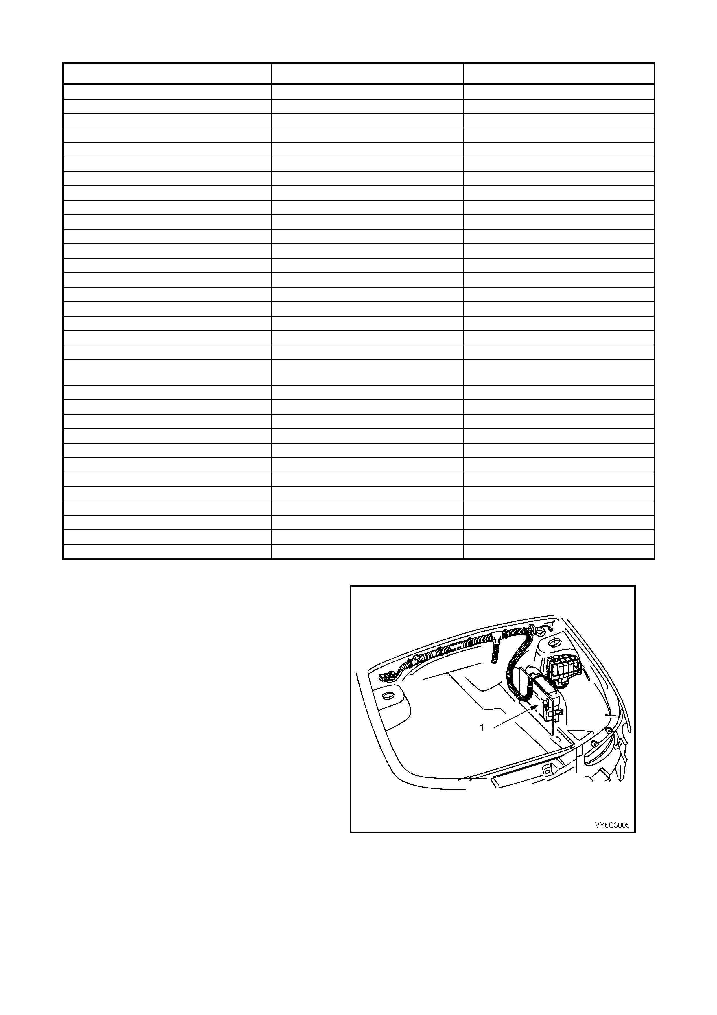
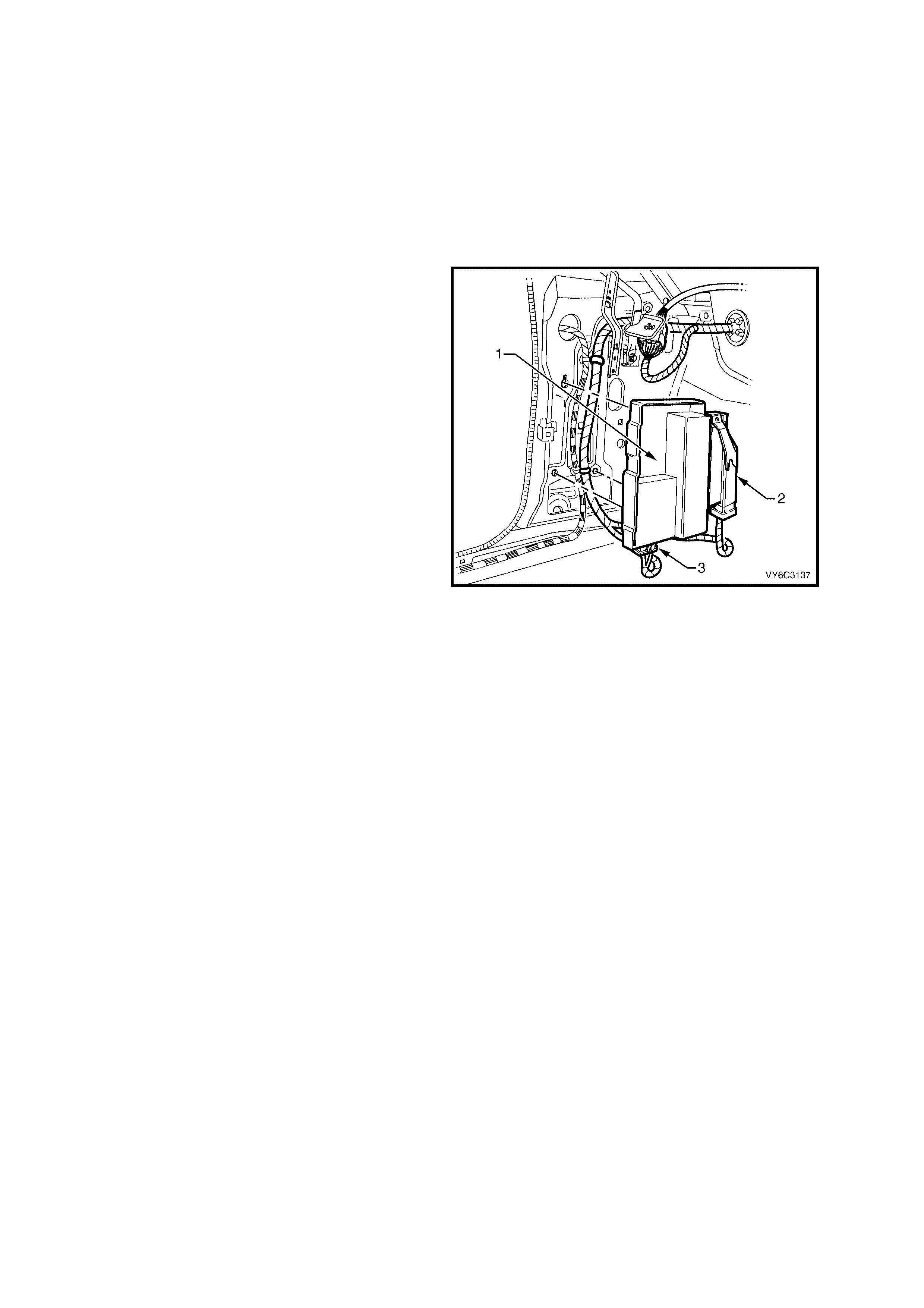
1.2 POWERTRAIN INTERFACE MODULE (PIM)
The Powertrain Interface Module (PIM) (1), is
located in the passenger compartment behind the
left kick panel. The PIM (1) acts as a
communication translator between the PCM and
other control modules that use a different serial
data protocol. The GEN III V8 PCM uses Class II
serial data to communicate, while other control
modules in the vehicle are designed to transmit
serial data via the conventional Universal
Asynchronous Receive and Transmit (UART)
protocol.
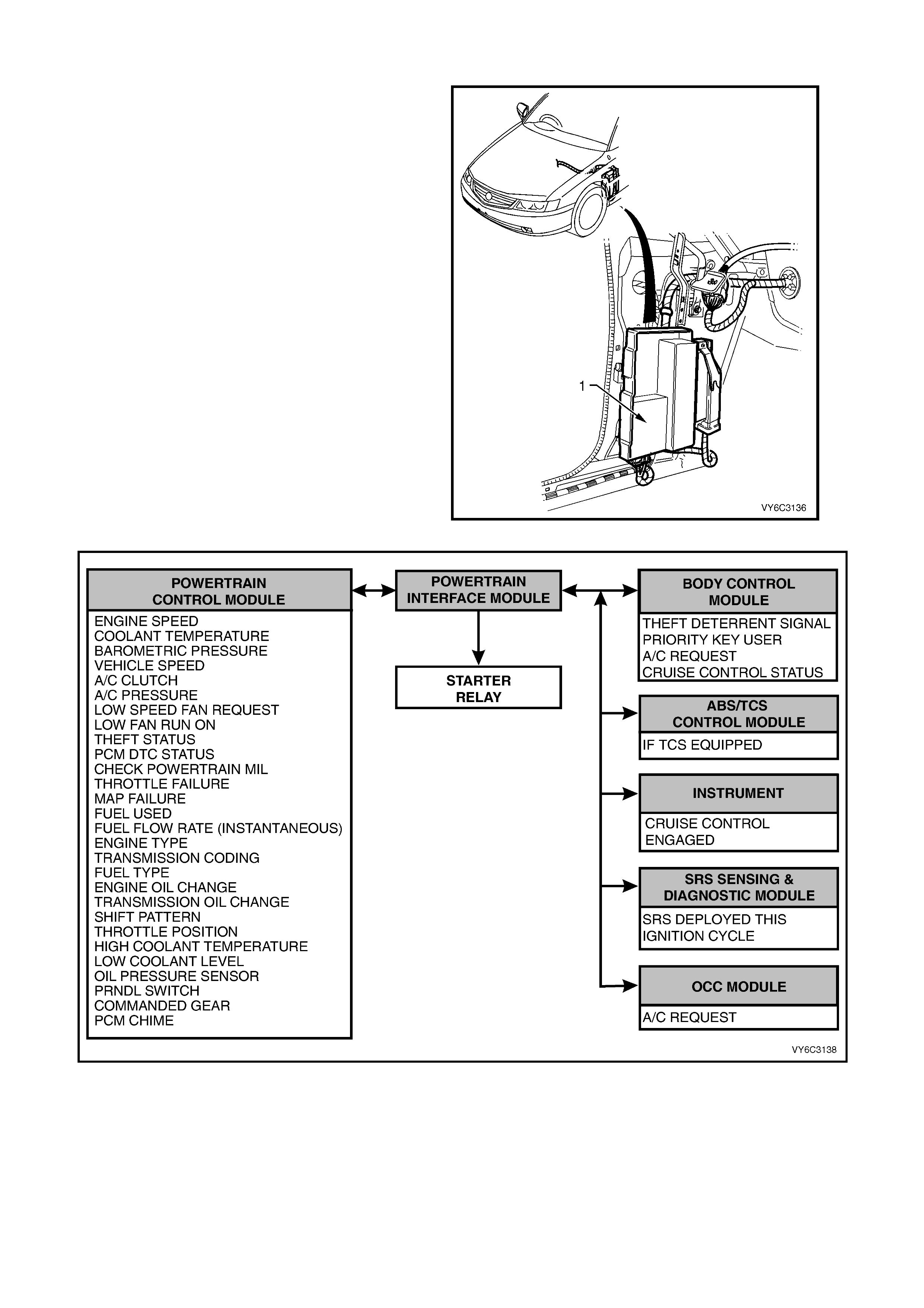
Since these two types of serial data are not
compatible, the PIM is required to transmit data in
either dire ction between the PCM and other control
modules. The PIM will interpret the serial data
inform ation and tr anslate UART to Class II or Class
II to UART to support the appropriate vehicle
control module operation. The PIM is also used to
control the operation of the starter relay.
Figure 6C3-1-15 – PIM Location
Figure 6C3-1-16 – PIM Communication

PIM DIAGNOSTIC TROUBLE CODES
A PIM m alfunction m ay af fect vehicle operation and m ay interrupt starter motor operation. For PIM diagnosis refer
to Section 6C3-2A DIAGNOSTIC TABLES in this Section, for PIM DTC diagnosis. There are four (4) PIM DTCs
that will set. Each of these DTCs have corresponding diagnostic tables.
The PIM does not have the memory to store any DTC information, so only a current DTC, using Tech 2, can be
displayed. Once the fault is corrected, the DTC is no longer active.
DTC DTC DESCRIPTION
B2002 Low Speed Fan No BCM Response
B2006 No Serial Data From PCM
B2007 Starter Relay Voltage High
B2009 EEPROM Checksum Error
There are twenty (20) other PIM DTCs that will also set whenever DTC B2006 sets. These DTCs indicate the loss
of part of the Class II serial data. If there is a problem with the Class II serial data circuit, and the PIM does not
receive any of this information, a DTC B2006 will set. The Powertrain On Board Diagnostic (OBD) System Check
will identify a problem with the serial data circuit or other circuits, and direct the Technician in the proper direction for
diagnosis. As ther e are no PIM DT C tables ass ociated with these twenty (20) PIM DTCs, always diagnose the PCM
first.
DTC DTC DESCRIPTION
B2017 No Throttle Position Sensor (TPS) Information
B2018 No A/C Clutch Information
B2019 No Engine Speed Information
B2020 No Vehicle Speed Information
B2021 No Commanded Gear Information
B2022 No Transmission Type
B2023 No Low Speed Fan Run On Information
B2024 No Low Speed Fan Request Information
B2025 No Engine Coolant Temp (ECT) Information
B2026 No Fuel Flow Rate Information
B2027 No Fuel Used Counter Information
B2028 No A/C Pressure Information
B2029 No PRNDL Information
B2030 No Engine Oil Information
B2031 No Oil Pressure Information
B2032 No Shift Information
B2033 No Malfunction Indicator Lamp (MIL) Information
B2034 No Low Coolant Level Information
B2035 No Barometric Pressure Information
B2036 No PCM Information
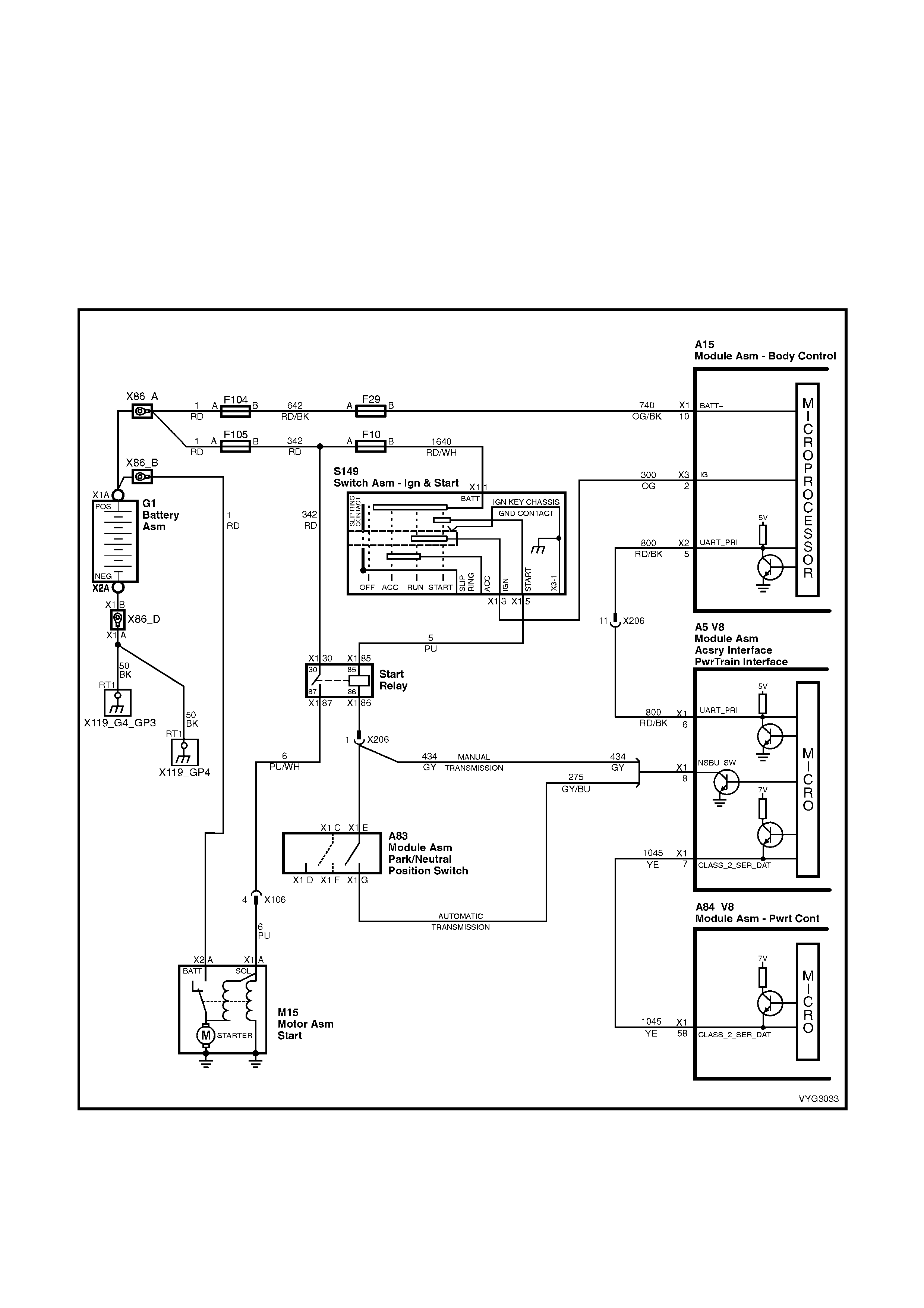
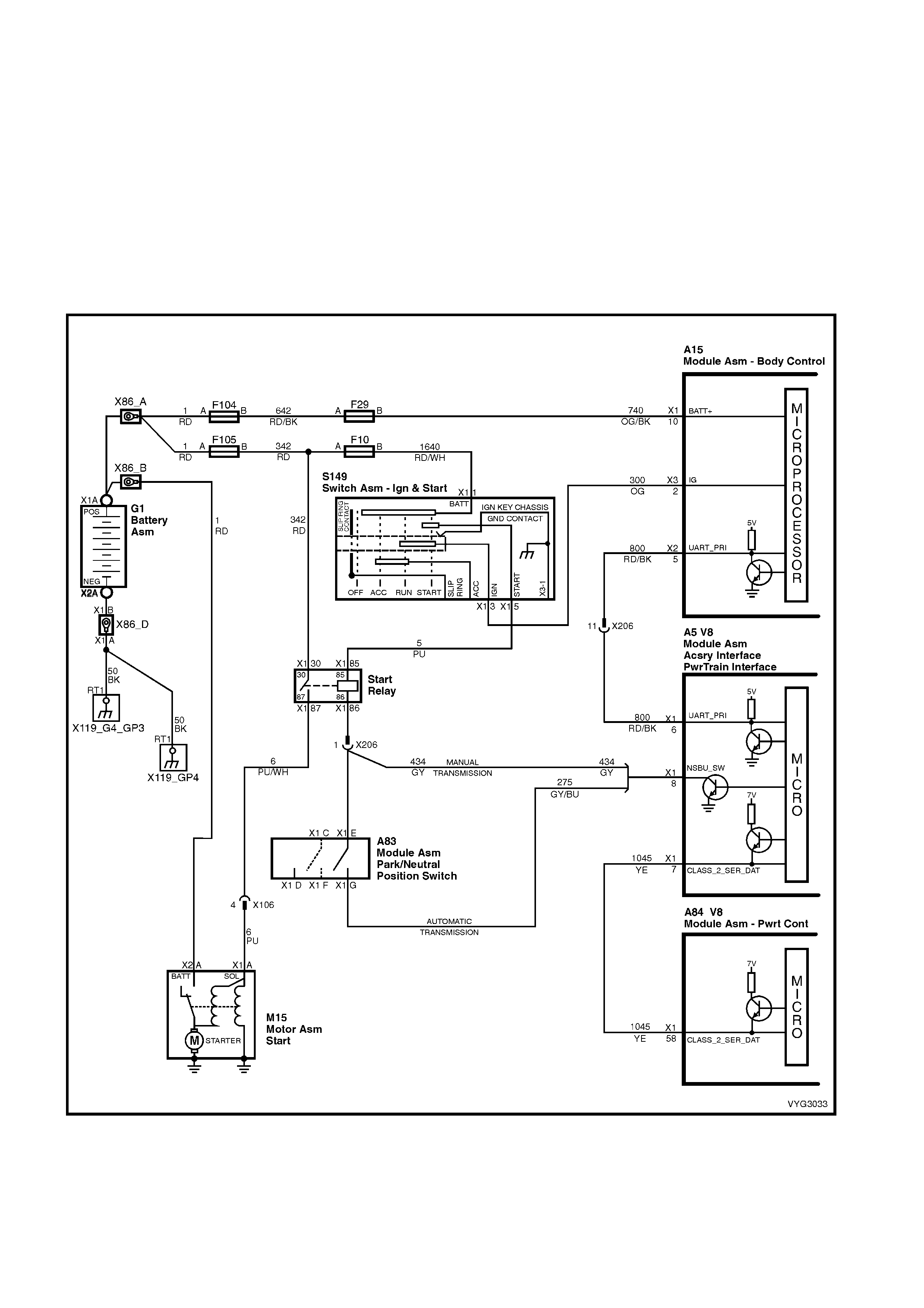
STARTER RELAY
The PIM als o c ontrols the oper ation of the s tarter r elay. When the ignition s witch is turned to on, the PIM will enable
the starter relay for one second, if the PIM does not receive the correct theft deterrent signal from the BCM it will
disable the starter relay. If the PIM receives the correct signal from the BCM, it will continue to enable the start relay.
Once the engine has started and the engine speed is above 500 RPM the PIM will disable the starter relay,
preventing starter engagement while the engine is running.
If the ser ial data bus between the BCM and the PIM should fail ( no polling from the BCM f or m or e than 10 minutes)
after suc cess ful thef t deterrent c om m unications , the PIM will allow subsequent starts , however there will be a crank
delay of one second. If the PIM receives valid communication, normal operation will resume.
If the Class II serial data bus between the PIM and the PCM should fail (no communications for 20 seconds) after
successful theft deterrent communications, the PCM will allow subsequent starts, however there will be a crank
delay of one second. If communications between the PCM and the PIM are re-established, normal operation will
resume.
Figure 6C3-1-17 – Starter Circuit
DTC B2002 LOW SPEED FAN NO BCM RESPONSE
Conditions for running DTC B2002
• The ignition is ON.
Conditions for setting DTC B2002
• The PIM sends a Low Speed request signal to the BCM , with no response back from the BCM.
Action taken when DTC B2002 Sets
• The PIM will display the DTC only when current.
Conditions for clearing DTC B2002
• A current DTC will clear when the PIM receives a Low Speed Fan Response from the BCM.
Figure 6C3-1-18 – Cooling Fan Circuit

DTC B2006 NO SERIAL DATA FROM PCM
Conditions for running DTC B2006
• The ignition switch is on.
• The ignition voltage is between 5.0 and 17 volts.
Conditions for setting DTC B2006
• PIM does not receive any serial data communication from the PCM.
Action taken when DTC B2006 Sets
• The PIM will display the DTC only when current.
Conditions for clearing DTC B2006
• A current DTC will clear when the PIM receives serial data from the PCM.
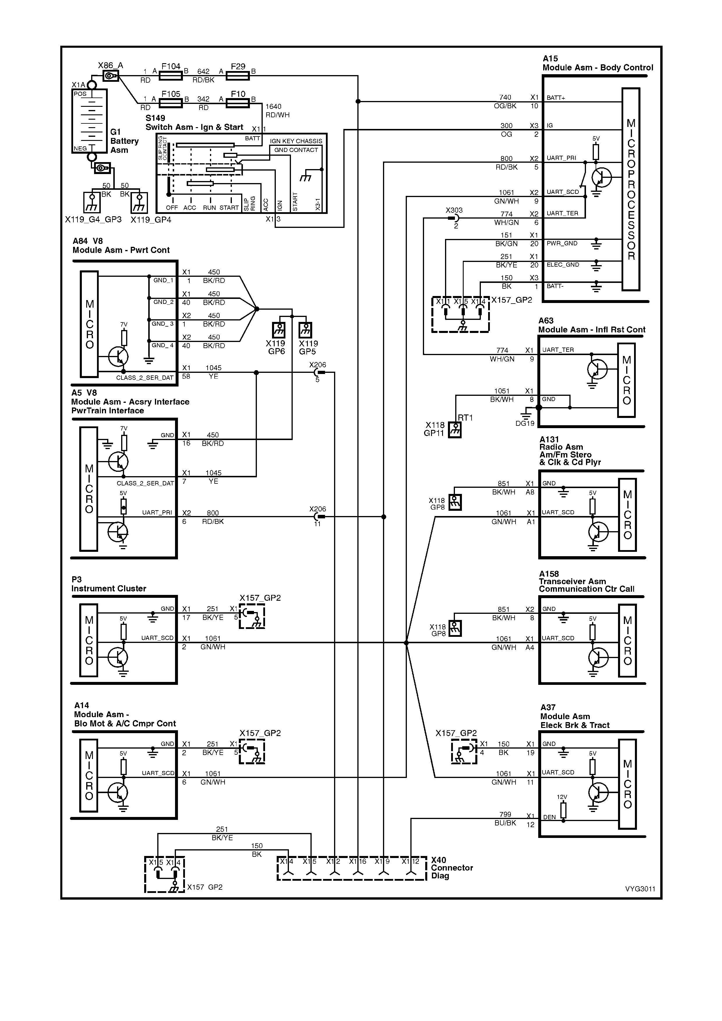
Figure 6C3-1-19 – Serial Data Circuit
DTC B2007 STA RTER RELAY VOLTAGE HIGH
Conditions for running DTC B2007
• The ignition switch is in the crank position.
• The ignition voltage is between 5.0 and 17 volts.
Conditions for setting DTC B2007
• PIM detects high voltage on the starter relay control circuit.
Action taken when DTC B2007 Sets
• The PIM will display the DTC only when current.
• The Malfunction Indicator Lamp (MIL) (MIL) will not illuminate.
Conditions for clearing DTC B2007
• A current DTC will clear when the PIM no longer detects a high voltage on the starter relay circuit.
Figure 6C3-1-20 – Starter Relay Circuit
DTC B2009 PIM EEPROM CHECKSUM ERROR
Conditions for running DTC B2009
• The ignition switch is in the crank position or run position.
Conditions for setting DTC B2009
• The PIM is unable to correctly read data from its memory.
Action taken when DTC B2009 Sets
• The PIM will display the DTC only when current.
Conditions for clearing DTC B2009
• A current DTC will clear when the PIM is able to correctly read data.
The only action taken if DTC B2009 is set, is to
replace the PIM (1) assembly.
Legend:
1. Powertrain Interface Module (PIM)
2. Throttle Relaxer Control Module
3. PIM W i ring Harness Connector
Figure 6C3-1-21 – Powertrain Interface Module (PIM)
1.3 ENGINE INFORMATION SENSORS AND SIGNALS
ENGINE COOLANT TEMPERATURE (ECT) SENSOR
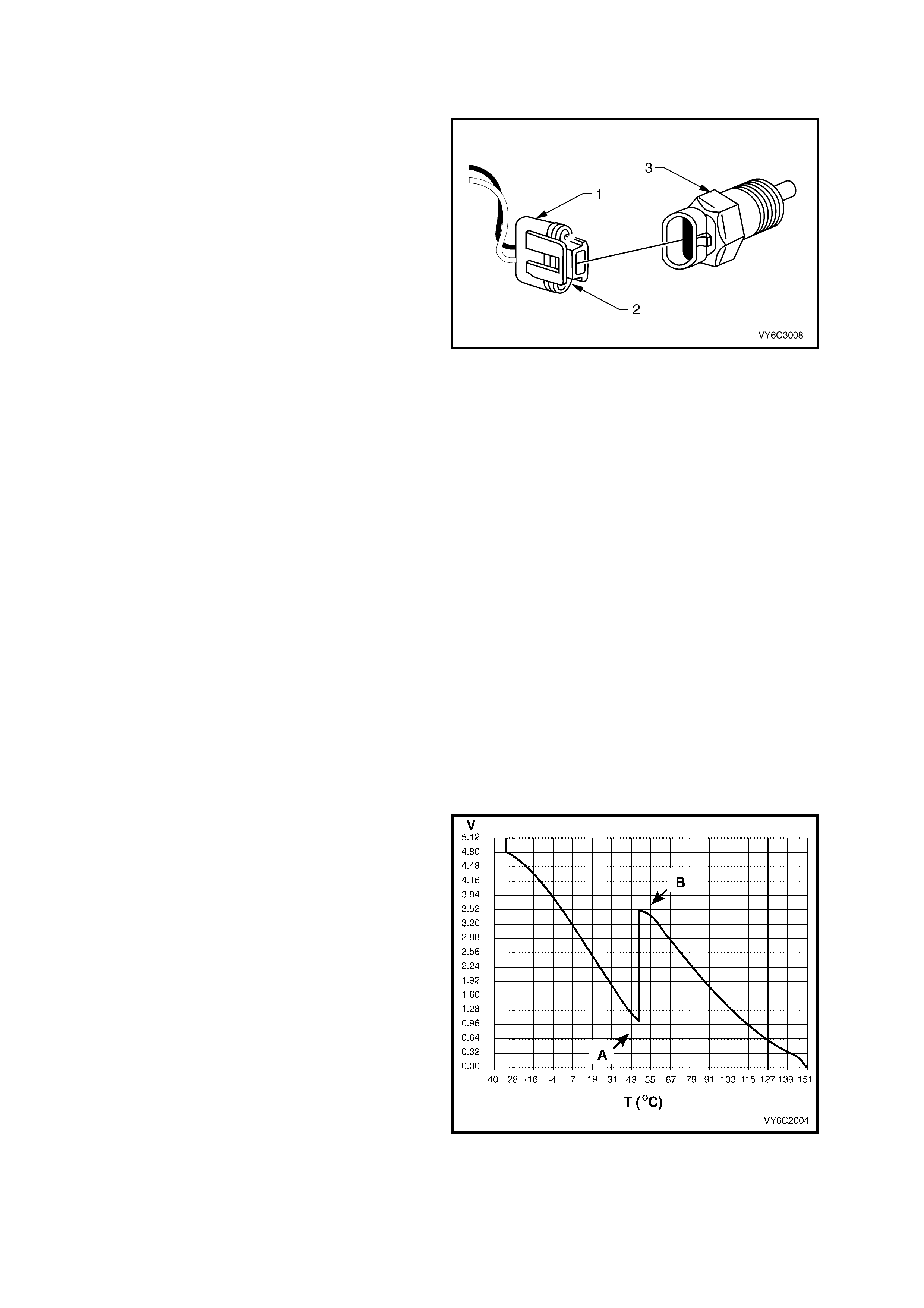
The Engine Coolant Tem peratur e (ECT) s ensor (3)
is a thermistor, (a resistor that changes value
based on temperature) mounted in the engine
coolant stream. Low engine coolant temperature
produces a high s ensor res istance (29 kilohm s at –
20° C) while high engine coolant temperature
causes low sensor resistance (180 ohms at 100°
C).
The PCM supplies a 5 volt signal voltage to the
sensor through an internal resistor network and
monitors the circuit voltage, which will change when
connected to the sensor.
The circuit voltage will vary depending on the
resistance of the coolant temperature sensor. The
circuit voltage will be close to the 5 volt level when
the sensor is cold, and will decrease as the sensor
warms. Engine coolant temperature affects most
systems controlled by the PCM.
The PCM uses a dual pull up resistor network to
increase the r esolution through the entire operating
range of engine coolant temperature. When the
coolant temperature is less than 51° C both the 4K
and 348 ohm res istors are used ( point ‘A’ in Figure
6C3-1-23). W hen the coolant temperature reaches
51° C, the PCM switches a short across the 4K
resistor and only the 348 ohm resistor is used
(point ‘B’ in Figure 6C3-1-23).
Figure 6C3-1-22
Engine Coolant Temperature (ECT) Sensor
Legend:
1. ECT Electrical Connector
2. Connector Tab
3. Engine Coolant Temperature (ECT) Sensor
As the engine warms, the sensor resistance
becomes less and the voltage at the PCM coolant
temperature sensor signal terminal should
decrease from approximately 4.5 volts when cold
to 0.9 volts at 51° C. At this temperature the PCM
switches the short across the 4k resistor, the
voltage will then rise to 3.5 volts. The voltage will
again decrease as the coolant temperature
increases until at normal engine operating
temperature (95° C), the voltage should be less
than 2.0 volts.
The following DTCs will set when the PCM detects
a malfunction in the engine coolant temperature
sensor circuit:
• DTC P0117: ECT Sensor Circuit Low Voltage.
• DTC P0118: ECT Sensor Circuit High Voltage.
• DTC P0125: ECT Excessive Time to Closed
Loop Fuel Control.
• DTC P1114: ECT Sensor Circuit Intermittent
Low Voltage.
• DTC P1115: ECT Sensor Circuit Intermittent
High Voltage.
• DTC P1258: Engine Coolant Over Temp Fuel
Disable
Figure 6C3-1-23 – ECT Temperature vs Voltage

Section 6C3-2C FUNCTIONAL CHECKS, contains
a table to check for sensor resistance values
relative to temperature.
Figure 6C3- 1-shows the ECT s ensor loc ation in the
left hand cylinder head.
Figure 6C3-1-24
Engine Coolant Temperature (ECT) Sensor Location
DTC P0117 ENGINE COOLANT TEMPERATURE SENSOR CIRCUIT LOW VOLTAGE
Conditions for running DTC P0117
• The engine run time is greater than 10 seconds.
Conditions for setting DTC P0117
• The engine coolant temperature is greater than 139°C.
• All conditions met for at least 45 seconds.
Action taken when DTC P0117 Sets
• The PCM activates the Malfunction Indicator Lamp (MIL) when the diagnostic runs and fails.
• The PCM will substitute a coolant temperature default value.
The PCM arrives at this default value, by using current intake air temperature, then counting upward to 116°C at
a rate of approximately 7 degrees per minute.
• The PCM will turn on the electric engine cooling fans. This is a FAIL-SAFE action by the PCM to prevent a
possible engine overheat condition, since the DTC indicates an unknown actual coolant temperature.
• The PCM records the operating conditions at the time the diagnostic fails. The PCM stores this information in
the Freeze Frame/Failure Records.
Conditions for clearing the Malfunction Indicator Lamp (MIL) and DTC P0117
• The PCM deactivates the Malfunction Indicator Lamp (MIL) when the diagnostic runs and does not fail.
• A last test failed (current DTC) clears when the diagnostic runs and does not fail.
DTC P0118 ENGINE COOLANT TEMPERATURE SENSOR CIRCUIT HIGH VOLTAGE
Conditions for running DTC P0118
• The engine run time is greater than 10 seconds.
Conditions for setting DTC P0118
• The engine coolant temperature is less than –38.9° C.
• All conditions met for at least 45 seconds.
Action taken when DTC P0118 Sets
• The PCM activates the Malfunction Indicator Lamp (MIL) when the diagnostic runs and fails.
• The PCM will substitute a coolant temperature default value.
The PCM arr ives at this default value, by using current intak e air temperatur e, then counting upward to 116° C
at a rate of approximately 7° C per minute.
• The PCM will turn on the electric engine cooling fans. This is a FAIL-SAFE action by the PCM to prevent a
possible engine overheat condition, since the DTC indicates an unknown actual coolant temperature.
• The PCM records the operating conditions at the time the diagnostic fails. The PCM stores this information in
the Freeze Frame/Failure Records.
Conditions for clearing the Malfunction Indicator Lamp (MIL) and DTC P0118
• The PCM deactivates the Malfunction Indicator Lamp (MIL) when the diagnostic runs and does not fail.
• A last test failed (current DTC) clears when the diagnostic runs and does not fail.

DTC P0125 ENGINE COOLANT TEMPERATURE SENSOR EXCESS TIME TO CLOSED LOOP FUEL CONTROL
Conditions for running DTC P0125
• DTCs P0112, P0113, P0117, P0118 are not set.
• The engine is running.
• The engine coolant temperature is between -36° C and 40° C at engine start-up.
• The intake air temperature is greater than –7° C.
• The vehicle speed is greater than 1.6 km/h.
Conditions for setting DTC P0125
• The closed loop coolant temperature of 34° C is not reached within a predetermined time. The maximum
allowable time depends on the start-up coolant temperature and the amount of airflow into the engine. The
range for the time is from 2 minutes and 20 seconds to 22 minutes and 30 seconds.
Action taken when DTC P0125 Sets
• The PCM stores the DTC information into memory when the diagnostic runs and fails.
• The Malfunction Indicator Lamp (MIL) will not be activated.
• The PCM records the operating conditions at the time the diagnostic fails. The PCM stores this information in
the Freeze Frame/Failure Records.
Conditions for clearing the Malfunction Indicator Lamp (MIL) and DTC P0125
• A last test failed (current DTC) clears when the diagnostic runs and does not fail.
DTC P1114 ENGINE COOLANT TEMPERATURE SENSOR CIRCUIT INTERMITTENT LOW VOLTAGE
Conditions for running DTC P1114
• The engine run time is greater than 10 seconds.
Conditions for setting DTC P1114
• The engine coolant temperature is greater than 139° C for at least one second.
Action taken when DTC P1114 Sets
• The PCM stores the DTC information into memory when the diagnostic runs and fails.
• The Malfunction Indicator Lamp (MIL) will not be activated.
• The PCM records the operating conditions at the time the diagnostic fails. The PCM stores this information in
the Freeze Frame/Failure Records.
Conditions for clearing the Malfunction Indicator Lamp (MIL) and DTC P1114
• A last test failed (current DTC) clears when the diagnostic runs and does not fail.
DTC P1115 ENGINE COOLANT TEMPERA TURE SENSOR CIRCUIT INTERMITTENT HIGH VOLTAGE
Conditions for running DTC P1115
• The engine run time is greater than 60 seconds.
Conditions for setting DTC P1115
• The engine coolant temperature is less than –35°C for at least one second.
Action taken when DTC P1115 Sets
• The PCM stores the DTC information into memory when the diagnostic runs and fails.
• The Malfunction Indicator Lamp (MIL) will not be activated.
• The PCM records the operating conditions at the time the diagnostic fails. The PCM stores this information in
the Freeze Frame/Failure Records.
Conditions for clearing the Malfunction Indicator Lamp (MIL) and DTC P1115
• A last test failed (current DTC) clears when the diagnostic runs and does not fail.
DTC P1258 ENGINE COOLANT OVER TEMP FUEL DISABLED
Conditions for running DTC P1258
• DTCs P0117, P0118, are not set.
• The engine is running.
Conditions for setting DTC P1258
• The engine coolant temperature is greater than 132° C.
• The above conditions present for greater than 10 seconds.
Action taken when DTC P1258 Sets
• The PCM will randomly disable several injectors.
• The PCM activates the Malfunction Indicator Lamp (MIL) when the diagnostic runs and fails.
• The PCM records the operating conditions at the time the diagnostic fails. The PCM stores this information in
the Freeze Frame/Failure Records.
Conditions for clearing the Malfunction Indicator Lamp (MIL) and DTC P1258
• The PCM deactivates the Malfunction Indicator Lamp (MIL) when the diagnostic runs and does not fail.
• A last test failed (current DTC) clears when the diagnostic runs and does not fail.
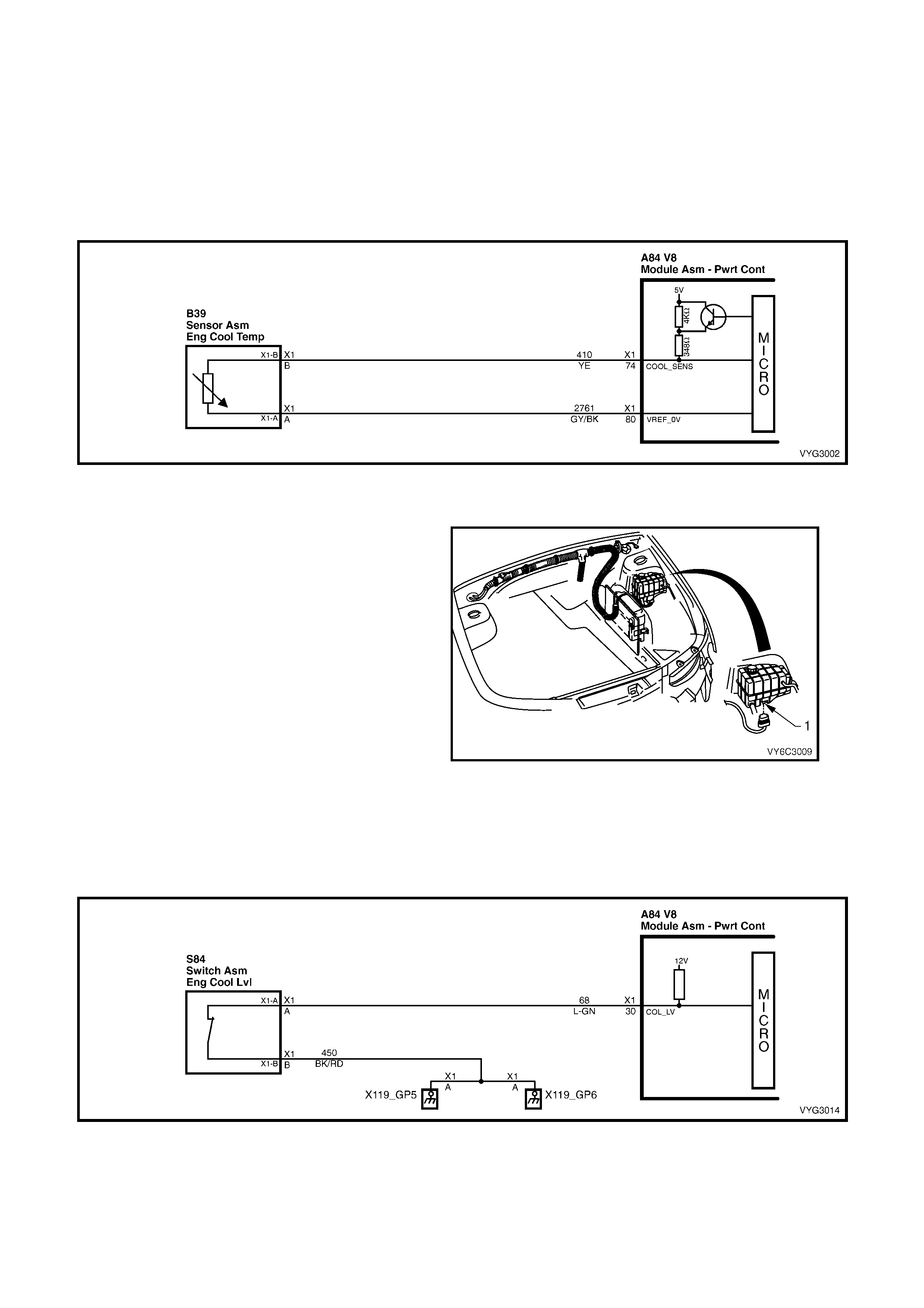
Figure 6C3-1-25 – Engine Coolant Temperature (ECT) Sensor Circuit
ENGINE COOLANT LEVEL SWITCH
The engine coolant level switch is a reed switch
and is used to inform the PCM when the coolant
level is at a calibrated low level. When the engine
coolant is at norm al operating level, the float inside
the surge tank will rise, the magnet in the float will
cause the reed s witc h contacts to close, pulling the
PCM supplied voltage low. When the coolant level
is low, the f loat will fall, the r eed s witch c ontac ts will
open, causing the PCM voltage signal to go high.
The PCM will then send a serial data message to
the instrument cluster instructing the instrument
panel cluster to activate the Low Coolant warning
lamp icon.
For diagnosis of the engine coolant level switch,
refer to Section 6C3-2C FUNCTIONAL CHECKS.
The engine coolant level switch is located in the
coolant s urge tank. T he engine coolant level switch
is serviceable only by replacing the surge tank.
Refer to Section 6B3 ENGINE COOLING, GEN III
V8 ENGINE, for surge tank replacement.
Figure 6C3-1-26 – Coolant Level Switch Location
Figure 6C3-1-27 – Engine Coolant Level Switch Circuit
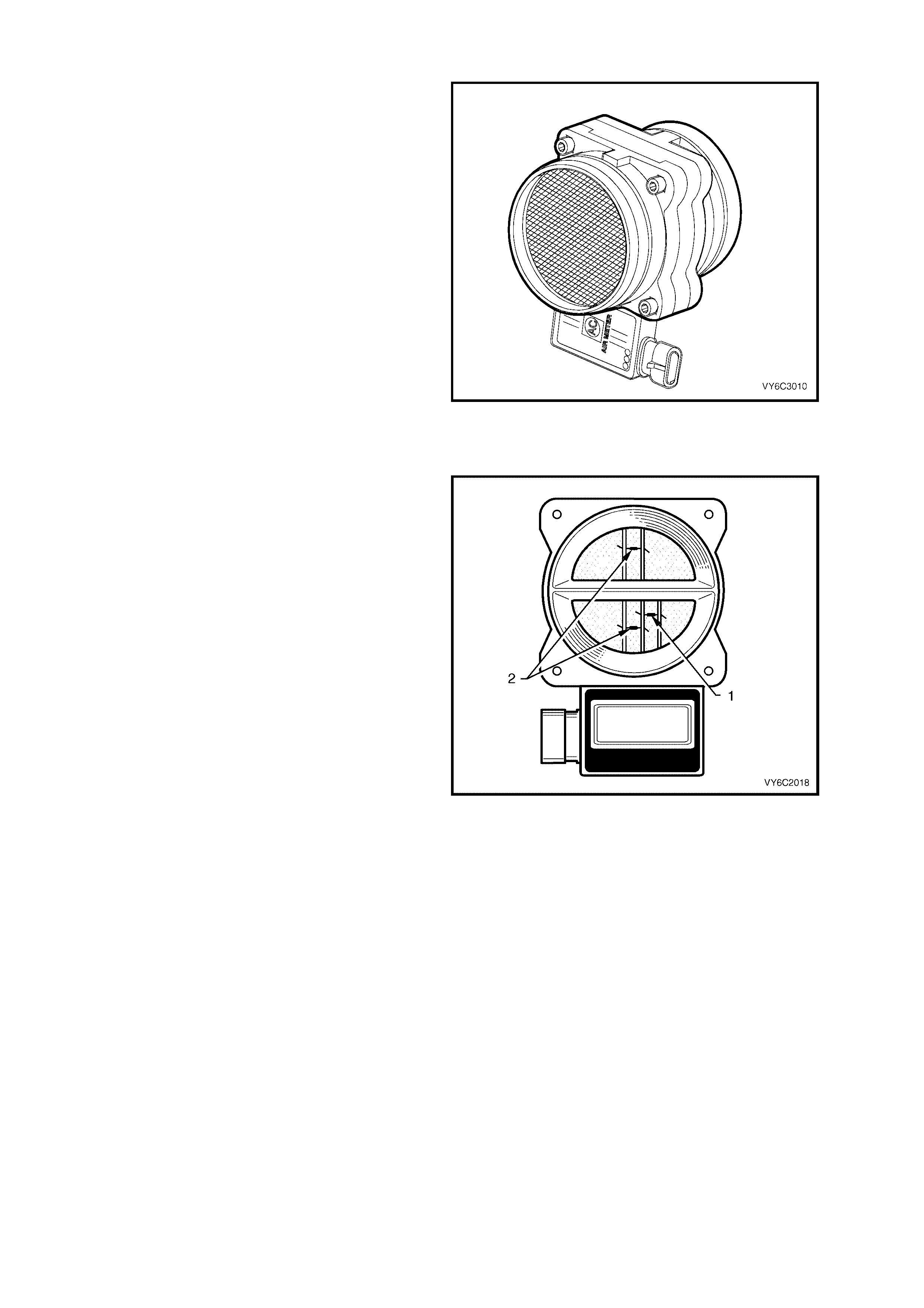
MASS AIR FLOW (MAF) SENSOR
The Mass Air Flow (MAF) sensor utilises a heated
element type of operation. Heated elements in the
MAF are plac ed in the air f low stream of the engine
intake system. The heating elements are
maintained at a constant temperature differential
above the air temperature.
The amount of elec tric al power requir ed to maintain
the heated element at the proper temperature is a
direct function of the mass flow rate of the air past
the heated elements.
The following DTCs are set when the PCM detects
a malfunction in the MAF sensor circuit:
• DTC P0101: Mass Air Flow System
Performance.
• DTC P0102: MAF Sensor Circuit Low
Frequency.
• DTC P0103: MAF Sensor Circuit High
Frequency.
Figure 6C3-1-28 – Mass Air Flow (MAF) Sensor
Three sensing elements are used in this system.
One senses ambient air temperature (1) and uses
two calibrated resis tor s to es tablis h a voltage that is
always a function of ambient temperature. This
ambient sensor is mounted in the lower half of the
sensor housing.
The other two sens ing elem ents (2) are heated to a
predetermined temperature that is significantly
above ambient air temperature. The two heated
elements are connected electrically in parallel and
mounted directly in the air flow stream of the
sensor housing.
One sensor is in the top and the other sensor is in
the bottom of the sensor housing. This is done so
that the air meter is less sensitive to upstream
ducting configurations that could skew the flow of
air through the housing.
As air passes over the heated elements during
engine operation they begin to cool. By measuring
the amount of electrical power required to maintain
the heated elements at the predetermined
temperature above ambient temperature the mass
air flow rate can be determined.
Once the mass air flow sensor has developed an
internal signal related to the mass air flow rate, it
must send this information to the PCM.
Figure 6C3-1-29 – MAP Sensor Elements
In order to preserve the accuracy and resolution of
the sm all voltage s ignal in the mass air flow sensor,
it is converted to a frequency signal by a voltage
oscillator and sent to the PCM.
The s ignal that is sent from the MAF sensor is sent
in the form of a frequency output. A large quantity
of air passing through the sensor (such as when
accelerating) will be indicated as a high frequency
output. A small quantity of air passing through the
sensor will be indicated as a low frequency output
(such as when decelerating or at idle). The Tech 2
scan tool displays MAF sensor information in
frequency, and in grams per second. At idle the
readings should be low and increase with engine
RPM.
If a problem occurs in the MAF sensor circuit, the
PCM will store a DTC in its memory. The PCM will
activate the Malfunction Indicator Lamp (MIL),
indicating there is a problem. If this occurs, the
PCM will calculate a subs titute mass air flow signal
based on speed density; i.e. RPM, MAP and IAT.
No field service adjustment is necessary or
possible with this MAF sensor.
Legend:
1. Air Cleaner Housing
2. Mass Air Flow (MAF) Sensor
3. Intake Air Temperature (IAT) Sensor.
Figure 6C3-1-30 – MAF Sensor Location
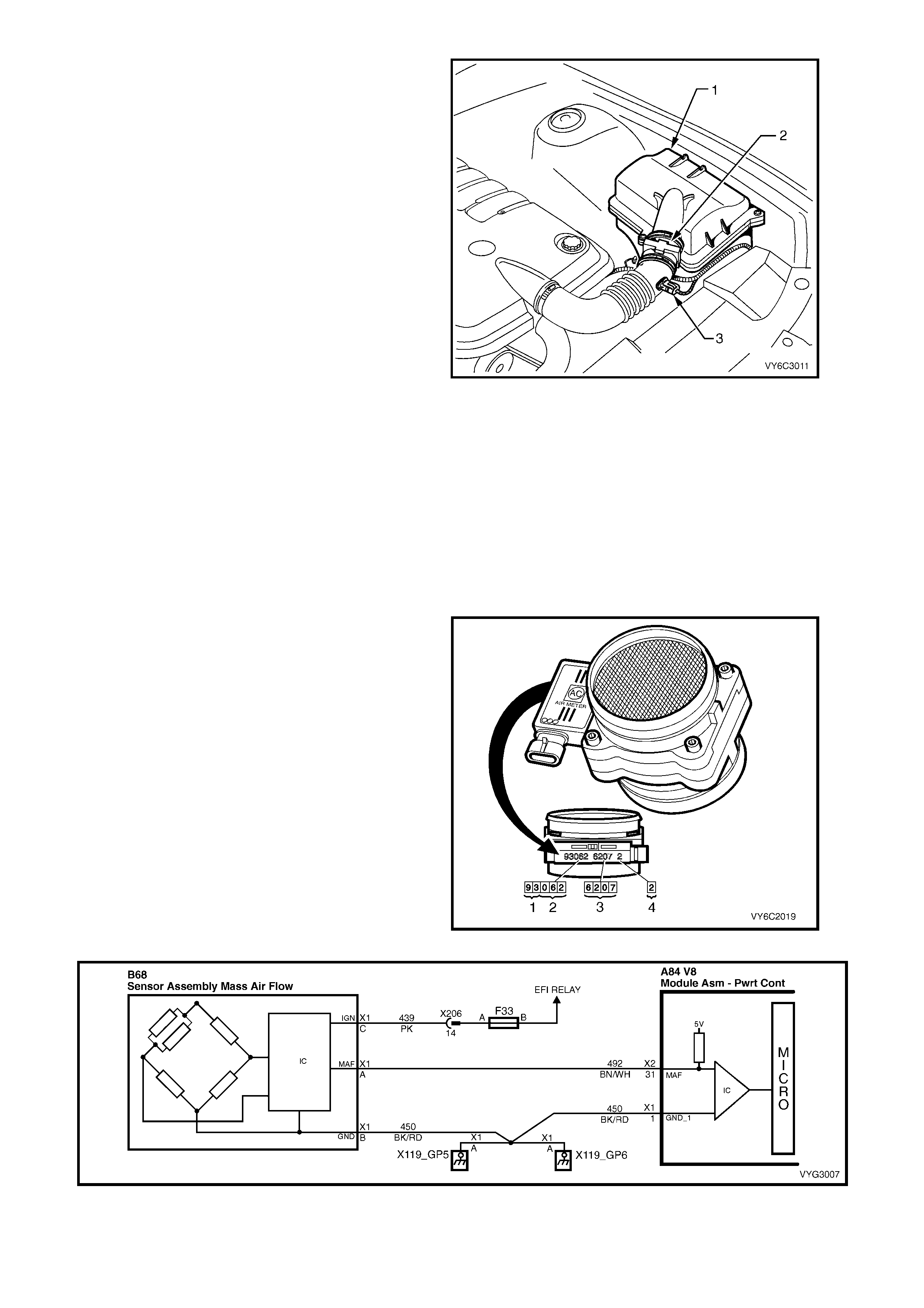
The Mas s Air Flow sensor identification is m ade up
of four number groups:
Legend:
1. Year
2. Julian Date (Day of the Year)
3. Last Four Digits of Part Number
4. Flow Stand Number
Figure 6C3-1-31 – MAF Sensor Identification
Figure 6C3-1-32 – MAF Sensor Simplified Schematic Circuit

DTC P0101 MASS AIR FLOW SYSTEM PERFORMANCE
Conditions for running DTC P0101
• DTCs P0102, P0103, P0107, P0108, P0121, P0122, P0123 are not set.
• The engine is running.
• The throttle position angle is less than 50% and the engine vacuum (BARO-MAP) is greater than 65 kPa.
• The system voltage is greater than 11 volts but less than 16 volts.
• The change in throttle position is less than 3%.
• All above conditions stable for two seconds.
Conditions for setting DTC P0101
• The MAF frequency is 50% different from the speed density calculation.
• The conditions met for at least five seconds.
Action taken when DTC P0101 Sets
• The PCM activates the Malfunction Indicator Lamp (MIL) when the diagnostic runs and fails.
• The PCM records the operating conditions at the time the diagnostic fails. The PCM stores this information in
the Freeze Frame/Failure Records.
• The PCM utilises speed density (RPM, MAP, IAT) for fuel management.
Conditions for clearing the Malfunction Indicator Lamp (MIL) and DTC P0101
• The PCM deactivates the Malfunction Indicator Lamp (MIL) after one ignition cycle that the diagnostic runs and
does not fail.
• A last test failed (current DTC) clears when the diagnostic runs and does not fail.
DTC P0102 MASS AIR FLOW SENSOR CIRCUIT LOW FREQUENCY
Conditions for running DTC P0102
• The engine speed is greater than 300 RPM.
• The system voltage is at least 11 volts.
Conditions for setting DTC P0102
• The MAF frequency is 50% different from the speed density calculation.
• The conditions met for at least five seconds.
Action taken when DTC P0102 Sets
• The PCM activates the Malfunction Indicator Lamp (MIL) when the diagnostic runs and fails.
• The PCM utilises speed density (RPM, MAP, IAT) for fuel management.
• The PCM records the operating conditions at the time the diagnostic fails. The PCM stores this information in
the Freeze Frame/Failure Records.
• The PCM utilises speed density (RPM, MAP, IAT) for fuel management.
Conditions for clearing the Malfunction Indicator Lamp (MIL) and DTC P0102
• The PCM deactivtes the Malfunction Indicator Lamp (MIL) after one ignition cycle that the diagnostic runs and
does not fail.
• A last test failed (current DTC) clears when the diagnostic runs and does not fail.
DTC P0103 MASS AIR FLOW SENSOR CIRCUIT HIGH FREQUENCY
Conditions for running DTC P0103
• The engine speed is greater than 300 RPM.
• The system voltage is at least 11 volts.
Conditions for setting DTC P0103
• The MAF frequency is greater than 11,250 Hz.
• The conditions met for at least one seconds.
Action taken when DTC P0103 Sets
• The PCM activates the Malfunction Indicator Lamp (MIL) when the diagnostic runs and fails.
• The PCM utilises speed density (RPM, MAP, IAT) for fuel management.
• The PCM records the operating conditions at the time the diagnostic fails. The PCM stores this information in
the Freeze Frame/Failure Records.
Conditions for clearing the Malfunction Indicator Lamp (MIL) and DTC P0103
• The PCM deactivates the Malfunction Indicator Lamp (MIL) after one ignition cycle that the diagnostic runs and
does not fail.
• A last test failed (current DTC) clears when the diagnostic runs and does not fail.

Figure 6C3-1-33 – Mass Air Flow Sensor Circuit
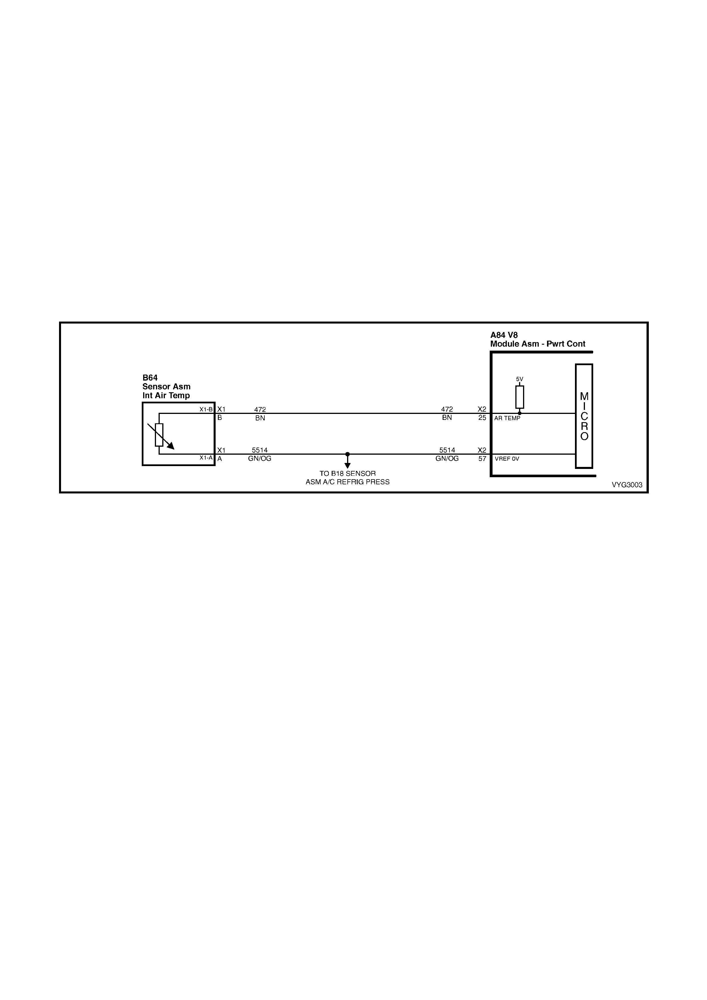
INTAKE AIR TEMPERATURE (IAT) SENSOR
The Intake Air Temperature (IAT) sensor is a
thermistor, (a resistor that changes resistance with
changes in temperature) mounted in the air intake
duct, after the Mass Air Flow (MAF) sensor. Low
intake air temperature produces high resistance in
the sensor, approximately 101k ohms at -40°C,
while high intake air temperature causes low
sensor resistance, approximately 80 ohms at
130°C.
The PCM:
1. Supplies a 5 volt signal voltage to the sensor
through a resistor in the PCM, and
2. Monitors the intake air temperature circuit
voltage, which will change when connected to
the intake air temperature sensor.
The circuit voltage will vary depending on the
resistance of the IAT sensor. The voltage will be
close to the 5 volt level when the sensor is cold,
and will decrease as the sensor warms.
The IAT sensor signal voltage is used by the PCM
to assist in calculating the fuel injector pulse width,
idle speed, canister purge and electronic spark
timing.
Figure 6C3-1-34 – Intake Air Temperature (IAT) Sensor
The following DTCs are set if the PCM detects a
malfunction in the IAT sensor circuit:
• DTC P0112: IAT Sensor Circuit Low Voltage.
• DTC P0113: IAT Sensor Circuit High Voltage.
• DTC P1111: IAT Sensor Circuit Intermittent High
Voltage.
• DTC P1112: IAT Sensor Circuit Intermittent Low
Voltage.
Legend:
1. Air Cleaner Housing
2. Mass Air Flow (MAF) Sensor
3. Intake Air Temperature (IAT) Sensor.
Figure 6C3-1-35
Intake Air Temperature (IAT) Sensor Location

DTC P0112 INTAKE AIR TEMPERATURE SENSOR CIRCUIT LOW VOLTAGE
Conditions for running DTC P0112
• DTC(s) P0101, P0102, P0103, P0117, P0118, are not set.
• The engine run time is greater than 30 seconds.
• The vehicle speed is less than 40 km/h.
Conditions for setting DTC P0112
• The Intake Air Temperature is greater than 139° C.
• The conditions met for at least 20 seconds.
Action taken when DTC P0112 Sets
• The PCM stores the DTC information into memory when the diagnostic runs and fails.
• The Malfunction Indicator Lamp (MIL) will not be activated.
• The PCM will substitute a default Intake Air Temperature value of 25° C.
• The PCM records the operating conditions at the time the diagnostic fails. The PCM stores this information in
the Freeze Frame/Failure Records.
Conditions for clearing the Malfunction Indicator Lamp (MIL) and DTC P0112
• A last test failed (current DTC) clears when the diagnostic runs and does not fail.
DTC P0113 INTAKE AIR TEMPERATURE SENSOR CIRCUIT HIGH VOLTAGE
Conditions for running DTC P0113
• DTC(s) P0101, P0102, P0103, P0117, P0118, are not set.
• The engine run time is greater than 100 seconds.
• The engine coolant temperature is greater than 0° C.
• The vehicle speed is less than 11 km/h.
Conditions for setting DTC P0113
• The Intake Air Temperature is at or below –35° C.
• The conditions met for at least 20 seconds.
Action taken when DTC P0113 Sets
• The PCM stores the DTC information into memory when the diagnostic runs and fails.
• The Malfunction Indicator Lamp (MIL) will not be activated.
• The PCM will substitute a default Intake Air Temperature value of 25° C.
• The PCM records the operating conditions at the time the diagnostic fails. The PCM stores this information in
the Freeze Frame/Failure Records.
Conditions for clearing the Malfunction Indicator Lamp (MIL) and DTC P0113
• A last test failed (current DTC) clears when the diagnostic runs and does not fail.
DTC P1111 INTAKE AIR TEMPERATURE SENSOR CIRCUIT INTERMITTENT HIGH VOLTAGE
Conditions for running DTC P1111
• DTC(s) P0101, P0102, P0103, P0117, P0118, are not set.
• The engine run time is greater than 100 seconds.
• The engine coolant temperature is greater than 0° C.
• The vehicle speed is less than 11 km/h.
• The Mass Air Flow is less than 15 g/s.
Conditions for setting DTC P1111
• The Intake Air Temperature is at or below –35° C.
• The conditions present for 0.3 seconds.
Action taken when DTC P1111 Sets
• The PCM stores the DTC information into memory when the diagnostic runs and fails.
• The Malfunction Indicator Lamp (MIL) will not be activated.
• The PCM will substitute a default Intake Air Temperature value of 25° C.
• The PCM records the operating conditions at the time the diagnostic fails. The PCM stores this information in
the Freeze Frame/Failure Records.
Conditions for clearing the Malfunction Indicator Lamp (MIL) and DTC P1111
• A last test failed (current DTC) clears when the diagnostic runs and does not fail.
DTC P1112 INTAKE AIR TEMPERATURE SENSOR CIRCUIT INTERMITTENT LOW VOLTAGE
Conditions for running DTC P1112
• DTC(s) P0101, P0102, P0103, P0117, P0118, are not set.
• The engine run time is greater than 30 seconds.
• The vehicle speed is less than 40 km/h.
Conditions for setting DTC P1112
• The Intake Air Temperature is at or above 139° C.
• The conditions present for 0.3 seconds.
Action taken when DTC P1112 Sets
• The PCM stores the DTC information into memory when the diagnostic runs and fails.
• The Malfunction Indicator Lamp (MIL) will not be activated.
• The PCM will substitute a default Intake Air Temperature value of 25° C.
• The PCM records the operating conditions at the time the diagnostic fails. The PCM stores this information in
the Freeze Frame/Failure Records.
Conditions for clearing the Malfunction Indicator Lamp (MIL) and DTC P1112
• A last test failed (current DTC) clears when the diagnostic runs and does not fail.
Figure 6C3-1-36 – Intake Air Temperature Sensor Circuit
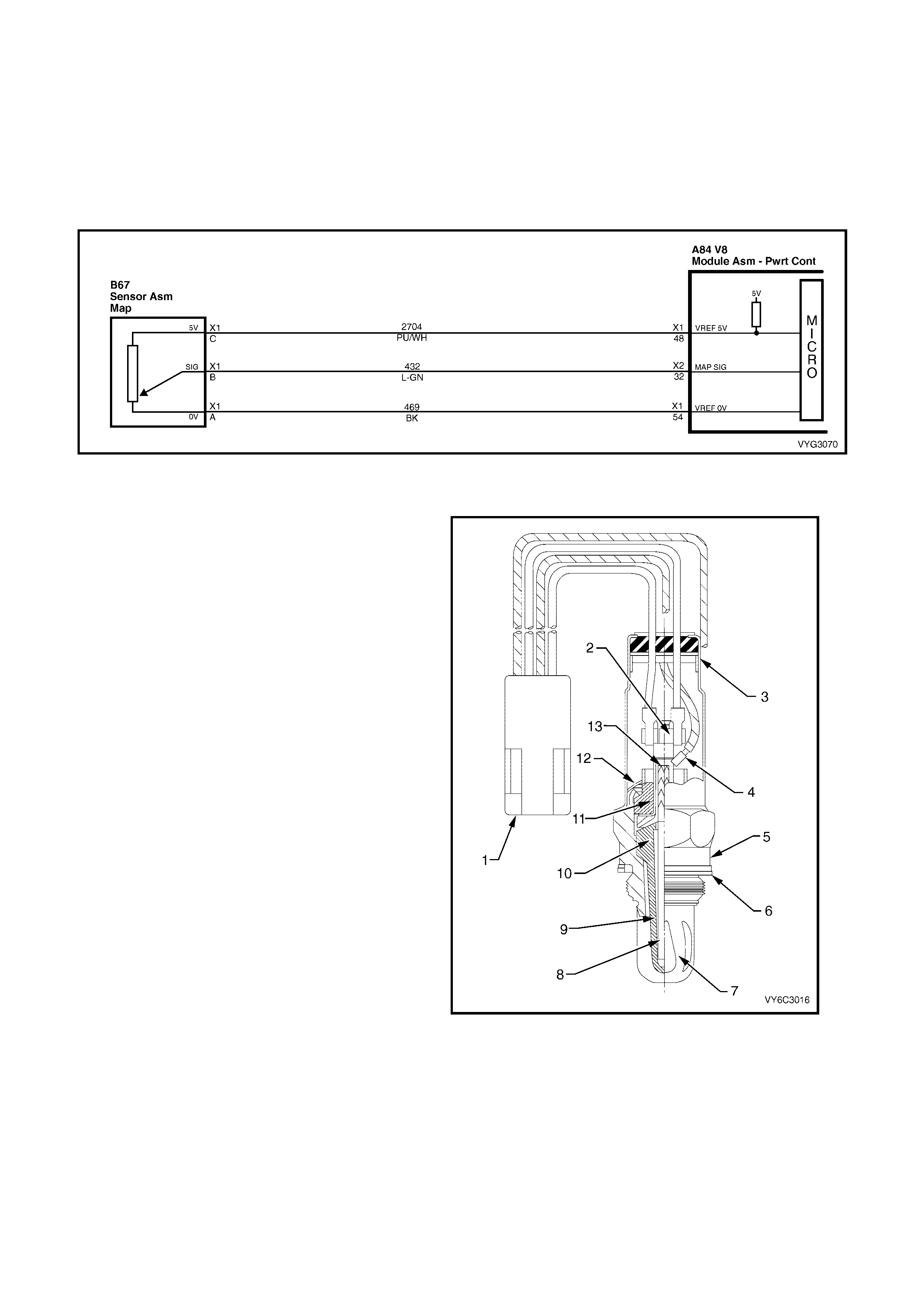
MANIFOLD ABSOLUTE PRESSURE (MAP) SENSOR
The Manifold Absolute Pressure (MAP) sensor
measures the changes in the intake manifold
pressure which result from engine load (intake
manifold vacuum) and RPM changes and converts
these into a voltage output.
The c ontrol module s ends a 5-volt supply voltage to
the MAP sensor. As the manifold pressure
changes, the output voltage of the sensor also
changes. By monitoring the sensor output voltage,
the control module knows the manifold pressure.
A closed throttle during engine coast down would
produce a relatively low MAP output, while a wide
open throttle would produce a high output. This
high output is produced because the pressure
inside the manifold is the same as outside the
manifold during wide open throttle, so it measures
100% of outside air pressure (atmospheric
pressure). The MAP sensor is also used, to
measure barometric pressure, allowing the control
module to m ak e adjustm ents f or differ ent operating
altitudes.
With the engine running, the MAP output voltage
signal should vary from about 1.0 to 1.5 volts at
idle, to about 4.0 to 4.5 volts at wide open throttle.
This MAP output voltage signal is sent to the
control module MAP sensor input signal terminal.
With ignition on and engine stopped, the manifold
pressure is equal to atmospheric (or barometric)
pressure and the signal voltage output will be high,
close to 5 volts at s ea level. T his voltage is us ed by
the PCM as an indication of engine load and the
atmospheric pressure, referred to as BARO.
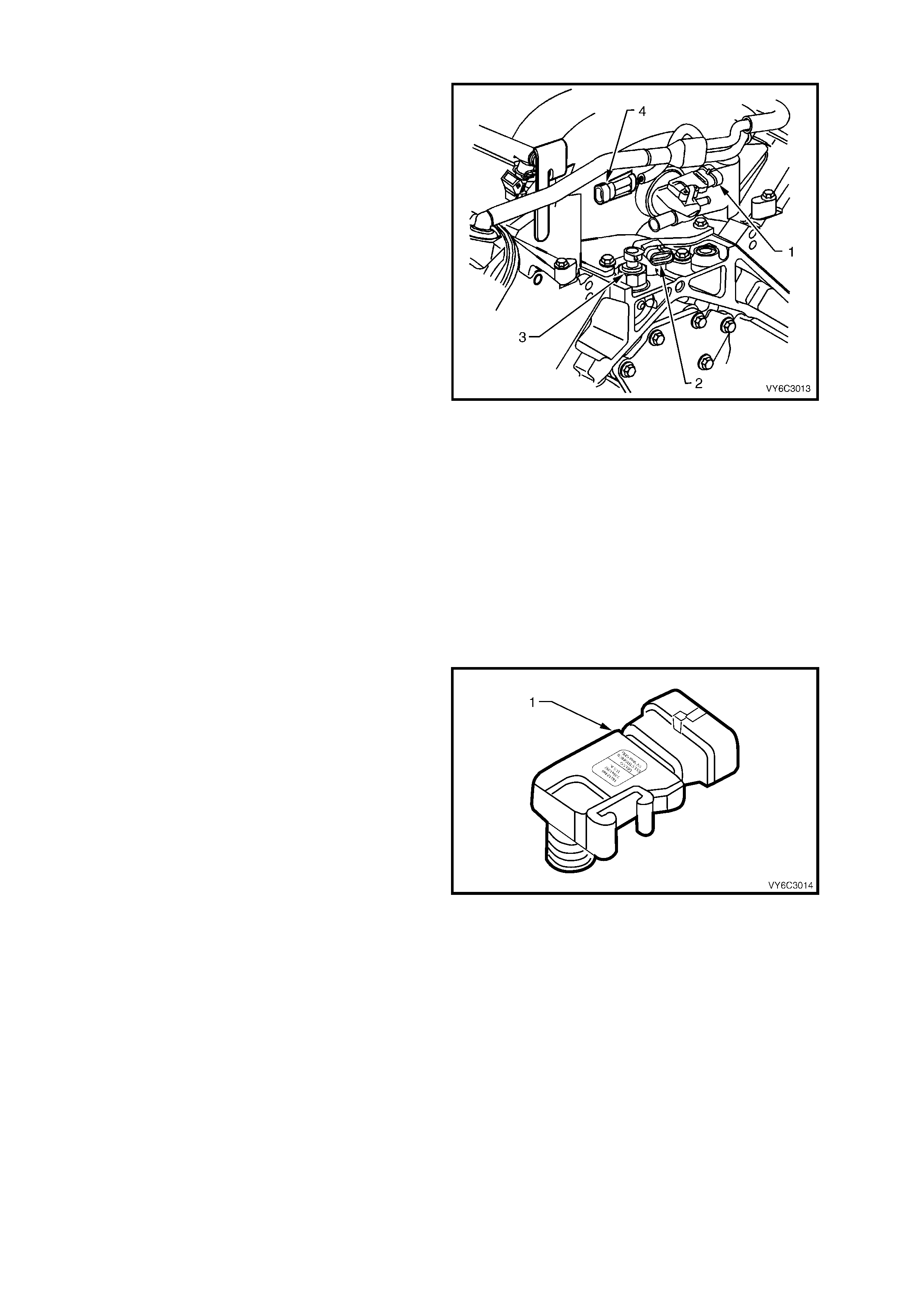
Figure 6C3-1-37
Manifold Absolute Pressure (MAP) Sensor Location
Legend:
1. Manifold Absolute Pressure (MAP) Sensor
2. Camshaft Position (CMP) Sensor
3. Oil Pressure Sensor
4. Connector to Knock Sensor Jumper Harness
The MAP sensor (1) is used for the following:
• Altitude determination.
• Ignition timing control.
• Speed density fuel management default.
Figure 6C3-1-38
Manifold Absolute Pressure (MAP) Sensor

SPEED DENSITY SYSTEM
Three specific data sensors provide the PCM with
the basic information for the fuel management
portion of its operation. That is three specific
signals to the PCM establish the engine speed and
air dens ity factor s. The engine speed s ignal comes
from the Crankshaft Position (CKP) Sensor.
The PCM us es this inf or mation to determine engine
speed (RPM). Air density is derived from IAT and
MAP sensor inputs. The IAT sensor measures the
air tem perature that is entering the engine. T he IAT
signal works in conjunction with the MAP sensor to
determ ine air dens ity. This inf or mation f r om the IAT
and MAP sensors is used by the PCM to control
injector pulse width.
The speed density system is only needed when
there is a Mass Air Flow (MAF) sensor m alfunc tion.
If the PCM detects a malfunction with the MAF
sensor circuit, the PCM will default to Speed
Density fuel management.
The following DTCs are set if the PCM detects a
malfunction in the MAP sensor circuit:
• DTC P0107: MAP Sensor Circuit Low Voltage.
• DTC P0108: MAP Sensor Circuit High Voltage.
Legend:
1. Manifold Absolute Pressure (MAP) Sensor
2. MAP Sensor Harness Connector
Figure 6C3-1-39
Manifold Absolute Pressure (MAP) Sensor Location
DTC P0107 MANIFOLD ABSOLUTE PRESSURE SENSOR CIRCUIT LOW VOLTAGE
Conditions for running DTC P0107
• No TP or ECT sensor DTCs are set.
• The engine is running.
• The TP angle is above 20% when the engine speed is greater than 1200 RPM.
OR
• The TP angle is below 18% when the engine speed is below 1000 RPM.
Conditions for setting DTC P0107
• The MAP sensor voltage is less than 0.10 volts.
• The conditions present for at least two seconds.
Action taken when DTC P0107 Sets
• The PCM activates the Malfunction Indicator Lamp (MIL) when the diagnostic runs and fails.
• The PCM records the operating conditions at the time the diagnostic fails. The PCM stores this information in
the Freeze Frame/Failure Records.
Conditions for clearing the Malfunction Indicator Lamp (MIL) and DTC P0107
• T he PCM deactivates the Malf unction Indic ator Lam p (MIL) after one ignition cycle that the diagnostic runs and
does not fail.
• A last test failed (current DTC) clears when the diagnostic runs and does not fail.
DTC P0108 MANIFOLD ABSOLUTE PRESSURE SENSOR CIRCUIT HIGH VOLTAGE
Conditions for running DTC P0108
• No TP or ECT sensor DTCs are set.
• The engine is running.
• The TP angle is above 20% when the engine speed is greater than 1000 RPM.
OR
• The TP angle is below 18% when the engine speed is below 1200 RPM.
Conditions for setting DTC P0108
• The MAP sensor voltage is greater than 4.3 volts.
• The conditions present for at least four seconds.
Action taken when DTC P0108 Sets
• The PCM activates the Malfunction Indicator Lamp (MIL) when the diagnostic runs and fails.
• The PCM records the operating conditions at the time the diagnostic fails. The PCM stores this information in
the Freeze Frame/Failure Records.
Conditions for clearing the Malfunction Indicator Lamp (MIL) and DTC P0108
• T he PCM deactivates the Malf unction Indicator Lam p (MIL) after one ignition cycle that the diagnostic runs and
does not fail.
• A last test failed (current DTC) clears when the diagnostic runs and does not fail.
Figure 6C3-1-40 – MAP Sensor Circuit
HEATED OXYGEN SENSORS (HO2S)
The GEN III V8 engine incorporates the use of
Heated Exhaust Gas Oxygen Sensors (HO2S). The
oxygen sensors are the key to closed-loop fuel
control. The PCM uses information from the
oxygen sensors to precisely fine tune its fuel
injector pulse width calculations, based on the
unused, left-over oxygen content in the exhaust.
The system uses, two four wire heated oxygen
sensors. The oxygen sensors have a Zirconia
element that, when heated to temperatures above
360° C, produces voltages based on the amount of
oxygen content surrounding the tip, as compar ed to
oxygen in the atmosphere.
The sensors are mounted in the exhaust pipe with
the sensing portion exposed to the exhaust gas
stream. When the sensor has reached an operating
temperature of more than 360° C, it acts as a
voltage generator, producing a rapidly changing
voltage of between 10 - 1000 millivolts. This voltage
output is dependent upon the ox ygen content in the
exhaust gas, as compared to the sensor's
atmospheric oxygen reference cavity. The
refer ence cavity of an oxygen sensor is exposed to
the atmosphere through the connector, by air
entering the atmospheric chamber by moving
through the wires between the conductor material
and the insulation.
The oxygen sensors have an internal heating
element that is used to heat the Zirconia element
faster inside the sensors, thereby decreasing the
amount of time before the fuel control system can
begin running in closed loop.
Figure 6C3-1-41
Sectioned – Heated Oxygen Sensor (HO2S) Cutaway
The heated oxygen sensors have four wires, with two for the internal Positive Temperature Co-efficient (PTC)
thermistor type heater circuit. One of these wires has 12 volts continually applied to the heater element
whenever the ignition is on. The other wire is f or the heater element ground. When the sensor is cold, m ax im u m
current (approximately 4 amps) flows through the heater circuit and gradually reduces to approximately 0.5
amps as the sensor reaches full operating tem perature. The other two sensor wires are for the sensor's signal
to the PCM, and the sensor ground.
Legend (Figure 6C3-1-14)
1. Four Wire In-Line Connector
2. Heater Termination
3. Water Shield Assembly
4. Sensor Lead
5. Sensor Body
6. Seat Gasket
7. Outer Electrode and Protective Coating
8. Rod Heater
9. Inner Electrode
10. Zirconia Element
11. Insulator
12. Clip Ring
13. Gripper
The reference cavity of a heated oxygen sensor is
exposed to the atmosphere by the air that passes
between the wire strands and insulation of the
oxygen sensor leads. The signal and heater leads
used on the oxygen sensor are of the stranded
type. Stranded leads have small spaces between
the wire strands and the insulation. These spaces
allow a satisfactory amount of air to pass through
the lead to maintain an adequate air reference.
When the sensor is cold, it produces either no
voltage, or an unusable, slowly changing one. Also
when cold, its internal electrical resistance is
extremely high – many million ohms. The PCM
always supplies a steady 450 millivolt, very low
current bias voltage to the oxygen sensor circuit.
When the sensor is cold and not producing any
voltage, the PCM detects only this steady bias
voltage. As the sensor begins heating, its internal
resistance decreases and it begins producing a
rapidly changing voltage that will overshadow the
PCM's supplied steady bias voltage.
When the PCM detects the changing voltage, it
knows the oxygen sensor is hot and its output
voltage can be used for fine-tuning the fuel injector
pulse width.
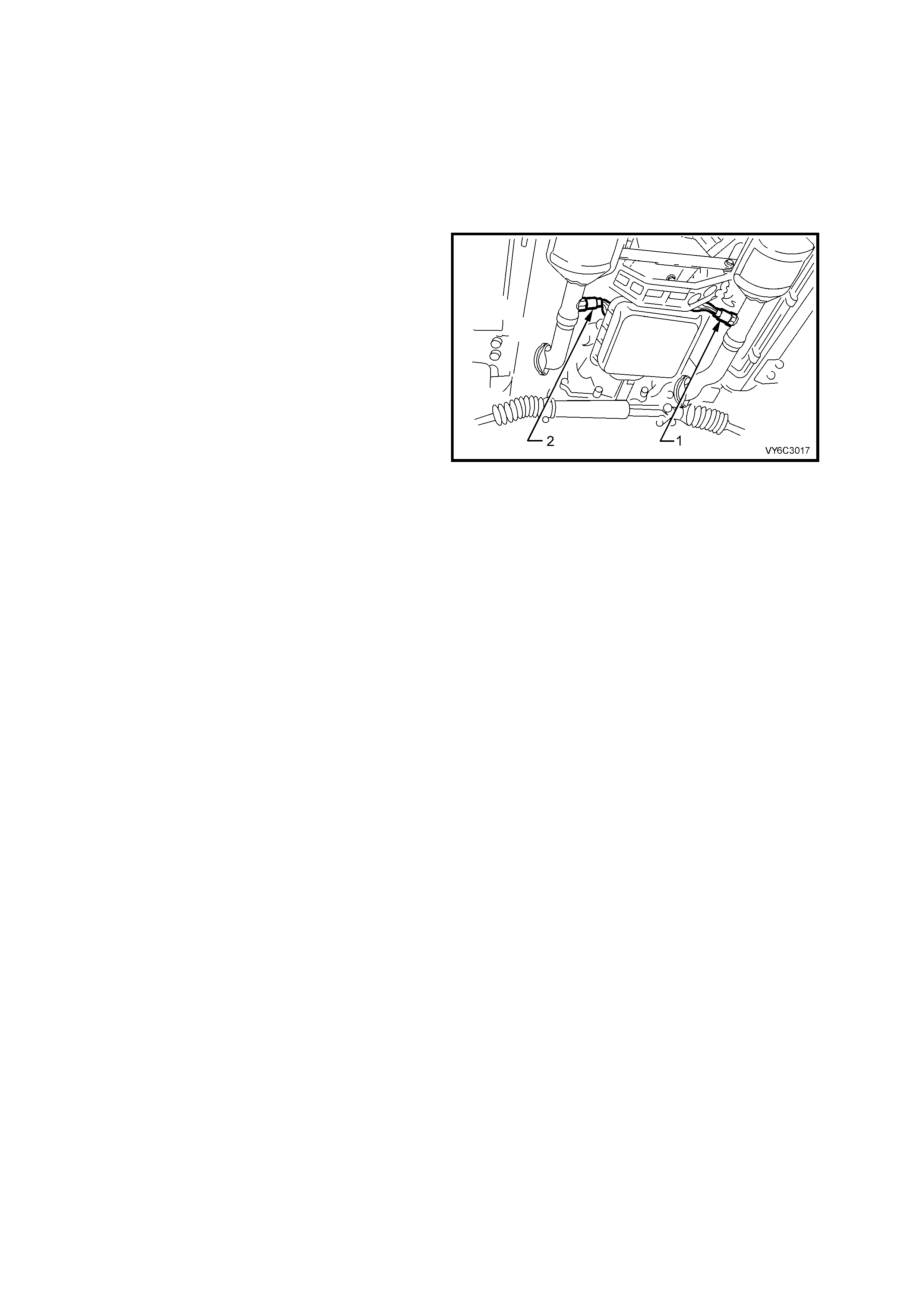
Figure 6C3-1-42
Heated Oxygen Sensor (HO2S) Locations
Legend:
1. Right Hand Oxygen Sensor, Bank 2 Sensor 1
2. Left Hand Oxygen Sensor, Bank 1 Sensor 1
The PCM monitors the oxygen sensor's changing voltage for going above and below a mid-range voltage band
(approximately 300 - 600 millivolts), to help decide when to operate in the closed-loop mode.
When the fuel system is correctly operating in the closed-loop mode, the oxygen sensor voltage output is rapidly
changing several tim es per second, f luctuating from approximately 100m V (high oxygen content – lean mixture) to
900mV ( low ox ygen content – rich m ixture). T he PCM monitors the c hanging voltage, and decides the needed fuel
mixture correction.
The oxygen sensors are mounted in the exhaust pipes and are referred to as Bank 1 Sensor 1 (left exhaust pipe)
and Bank 2 Sensor 1 (right exhaust pipe).
NOTE: As an OBD requirement, Bank 1 is always identified by the location of cylinder No. 1. Therefore, it is a
generic term used for all ‘V’ car engines.
The following DTCs set when the PCM detects a HO2S signal circuit that is low:
DTC P0131: Bank 1 Sensor 1 HO2S.
DTC P0151: Bank 2 Sensor 1 HO2S.
The following DTCs set when the PCM detects a HO2S signal circuit that is high:
DTC P0132: Bank 1 Sensor 1 HO2S.
DTC P0152: Bank 2 Sensor 1 HO2S.
The following DTCs set when the PCM detects no HO2S activity:
DTC P0134: Bank 1 Sensor 1 HO2S.
DTC P0154: Bank 2 Sensor 1 HO2S.
A fault in the oxygen sensor heater element or its ignition feed or ground results in an increase in time to Closed
Loop fuel control. This may cause increased emissions, especially at start-up. The following DTCs set when the
PCM detects a malfunction in the HO2S heater circuits:
• DTC P0135: Bank 1 Sensor 1 HO2S heater.
• DTC P0155: Bank 2 Sensor 1 HO2S heater.

RESPONSE TIME
Not only is it necessary for the oxygen sensors to produce voltage signals for rich or lean exhaust, it is also
impor tant to respond quick ly to changes . If the oxygen sensors res pond slowly, the customer m ay complain of poor
fuel economy, rough idle, surging or lack of performance. The PCM will set a DTC that indicates degraded HO2S
performance if a HO2S response switching, transition time, or ratio problem is detected.
DTC P1133: Insufficient Switching Bank 1 Sensor 1.
DTC P1134: Transition Time Ratio Bank 1 Sensor 1.
DTC P1153: Insufficient Switching Bank 2 Sensor 1.
DTC P1154: Transition Time Ratio Bank 2 Sensor 1.
OXYGEN SENSOR CONTAMINANTS
Carbon
Black carbon or soot deposits result from over-rich air-fuel mixtures. However, carbon does not harm an oxygen
sensor. Deposits can be burned off in the vehicle by running the engine at part throttle for at least two minutes.
Silica
Certain RTV silicon gasket materials give off vapour as they cure that may contaminate the oxygen sensor. This
contamination is usually caused by the vapours being pulled from the PCV system, into the combustion chamber
and passed on to the exhaust system. The sand like particles from the RTV silica embed in the molecules of the
oxygen sensor element and plug up the surface. W ith the outside of the oxygen sensor elem ent not able to sense
all of the oxygen in the exhaust system it results in lazy oxygen sensor response and engine control. The oxygen
sensor will have a whitish appearance on the outside if it has been contaminated.
There is also a possibility of silica contamination caused by silicon in the fuel. Some oil companies have used
silicone to raise the octane rating of their fuel. Careless fuel handling practices with transport containers can result
in unacceptable concentrations of silicone in the fuel at the pump.
Silica contamination can be caused by silicon in lubricants used to install vacuum hoses on fittings. Do not use
silicon sealers on gaskets or exhaust joints.
Lead
Lead glazing of the sensors can be introduced when regular, or leaded fuel is burned. It is difficult to detect lead
contamination by visual inspection.
Other Substances
Oil deposits will ultimately prevent oxygen sensor operation. The sensor will have a dark brown appearance.
Causes of high oil consumption should be checked.
The additives in ethylene glycol can also af fec t oxygen sensor perf orm anc e. This produces a coloured appear ance.
If antifreeze enters the exhaust system , you will lik ely encounter other , more obvious, s ym ptoms of cooling system
trouble. If for example the engine had a head gasket failure where coolant did enter the combustion chamber it
would be a good idea to check the oxygen sensor operation after the head gasket was repaired.
Multiple Faults
If you encounter multiple or repeated oxygen sensor failures on the same vehicle, consider contamination.
Leaded fuel, silic a contam ination f rom uncur ed, low-grade (unapproved) RTV s ealant, and high oil c onsum ption are
possible causes.
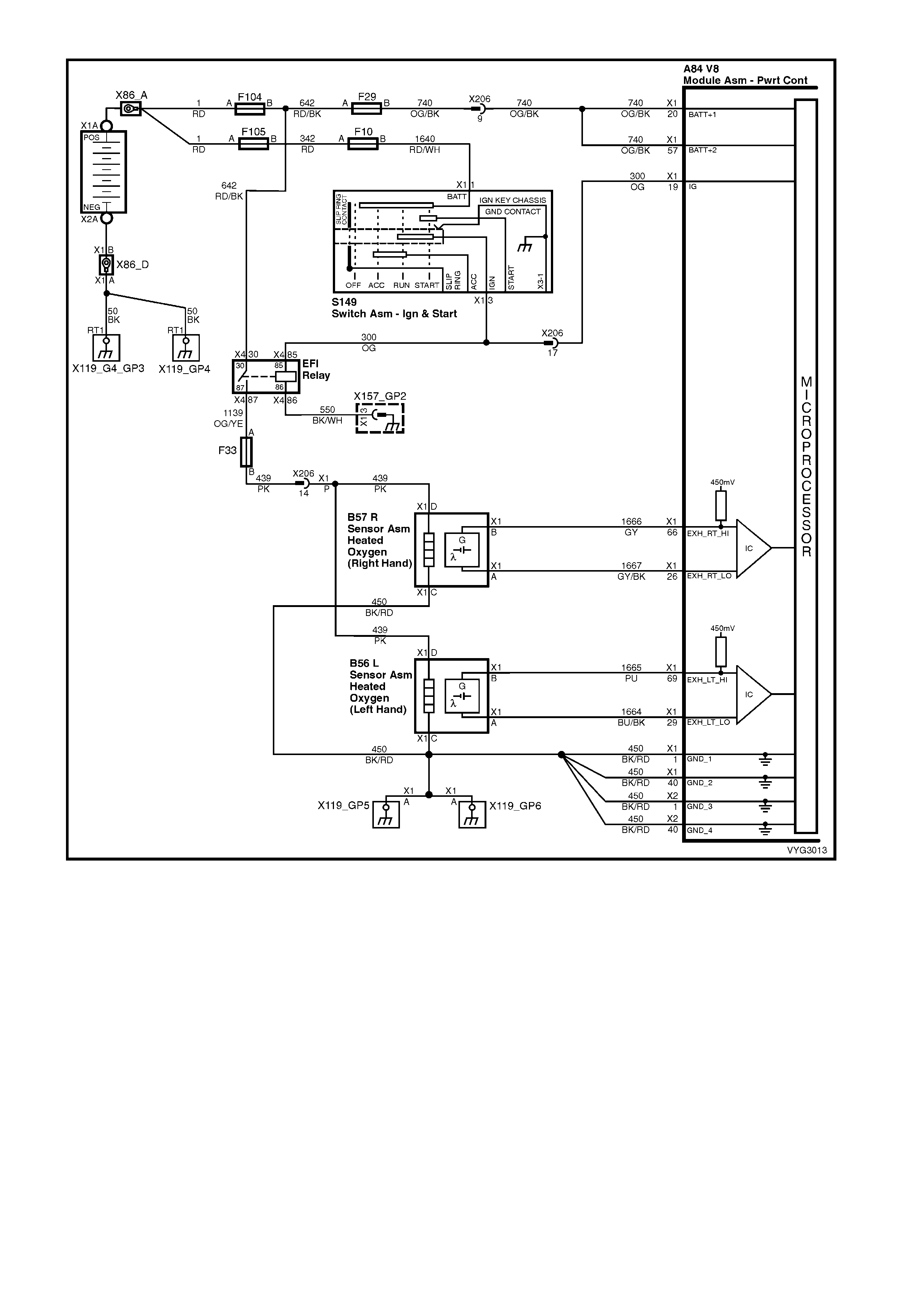
Figure 6C3-1-43 – Oxygen Sensor Circuits
DTC P0131 HEATED OXYGEN SENSOR CIRCUIT LOW VOLTAGE BANK 1 SENSOR 1
Conditions for running DTC P0131
Criteria 1
• DTCs P0101, P0102, P0103, P0112, P0113, P0117, P0118, P0121, P0122, P0123, P0335, P0336, P0351-
P0358, P1258 are not set.
• The engine coolant temperature is greater than 48° C.
• The ignition voltage is greater than 9.0 volts.
• The fuel system is operating in Closed Loop.
• The fuel trim learn is enabled.
• The air/fuel ratio is between 14.5:1 and 14.7:1.
• The TP angle is between 0% and 70%.
Criteria 2
• DTCs P0101, P0102, P0103, P0112, P0113, P0117, P0118, P0121, P0122, P0123, P0335, P0336, P0351-
P0358, P1258 are not set.
• The ignition voltage is greater than 9.0 volts.
• The Power Enrichment mode is enabled for at least 0.5 seconds.

Conditions for setting DTC P0131
Criteria 1
• The HO2S signal voltage remains below 200 mV.
• The Criteria 1 conditions are present for at least 33 seconds.
Criteria 2
• The HO2S signal voltage remains below 360 mV.
• The Criteria 2 conditions are present for at least five seconds.
Action taken when DTC P0131 Sets
• The PCM activates the Malfunction Indicator Lamp (MIL) when the diagnostic runs and fails.
• The PCM records the operating conditions at the time the diagnostic fails. The PCM stores this information in
the Freeze Frame/Failure Records.
• Open Loop Fuelling.
Conditions for clearing the Malfunction Indicator Lamp (MIL) and DTC P0131
• The PCM deactivates the Malfunction Indicator Lamp (MIL) after one ignition cycle that the diagnostic runs and
does not fail.
• A last test failed (current DTC) clears when the diagnostic runs and does not fail.
DTC P0132 HEATED OXYGEN SENSOR CIRCUIT HIGH VOLTAGE BANK 1 SENSOR 1
Conditions for running DTC P0132
Criteria 1
• DTCs P0101, P0102, P0103, P0112, P0113, P0117, P0118, P0121, P0122, P0123, P0335, P0336, P0351-
P0358, P1258 are not set.
• The ignition voltage is greater than 9.0 volts.
• The fuel system is operating in Closed Loop.
• The fuel trim learn is enabled.
• The air/fuel ratio is between 14.5:1 and 14.7:1.
Criteria 2
• DTCs P0101, P0102, P0103, P0112, P0113, P0117, P0118, P0121, P0122, P0123, P0335, P0336, P0351-
P0358, P1258 are not set.
• The ignition voltage is greater than 9.0 volts.
• Deceleration Fuel Cut-Off mode is enabled for greater than one second.
Conditions for setting DTC P0132
Criteria 1
• The HO2S signal voltage remains above 775 mV.
• The Criteria 1conditions are present for at least 33 seconds.
Criteria 2
• The HO2S signal voltage remains above 540 mV.
• The Criteria 2 conditions are present for at least five seconds.
Action taken when DTC P0132 Sets
• The PCM activates the Malfunction Indicator Lamp (MIL) when the diagnostic runs and fails.
• The PCM records the operating conditions at the time the diagnostic fails. The PCM stores this information in
the Freeze Frame/Failure Records.
• Open Loop Fuelling.
Conditions for clearing the Malfunction Indicator Lamp (MIL) and DTC P0132
• The PCM deactivates the Malfunction Indicator Lamp (MIL) after one ignition cycle that the diagnostic runs and
does not fail.
• A last test failed (current DTC) clears when the diagnostic runs and does not fail.

DTC P0133 HEATED OXYGEN SENSOR SLOW RESPONSE BANK 1 SENSOR 1
Conditions for running DTC P0133
• DTCs P0101, P0102, P0103, P0112, P0113, P0117, P0118, P0121, P0122, P0123, P0335, P0336, P0351-
P0358, P1258 are not set.
• The engine coolant temperature is greater than 65° C.
• The ignition voltage is greater than 9.0 volts.
• The fuel system is operating in Closed Loop.
• The engine speed is between 1000 RPM and 2300 RPM.
• The engine air flow is between 20 g/s and 50 g/s.
• The EVAP canister purge duty cycle is greater than 0%.
• The engine run time is greater than 120 seconds.
Conditions for setting DTC P0133
• The Lean to Rich response (below 300 mV to above 600 mV) average time is greater than 100 milliseconds.
• The Rich to Lean response (above 600 mV to below 300 mV) average time is greater than 100 milliseconds.
Action taken when DTC P0133 Sets
• The PCM activates the Malfunction Indicator Lamp (MIL) when the diagnostic runs and fails.
• The PCM records the operating conditions at the time the diagnostic fails. The PCM stores this information in
the Freeze Frame/Failure Records.
• Open Loop Fuelling.
Conditions for clearing the Malfunction Indicator Lamp (MIL) and DTC P0133
• The PCM deactivates the Malfunction Indicator Lamp (MIL) after one ignition cycle that the diagnostic runs and
does not fail.
• A last test failed (current DTC) clears when the diagnostic runs and does not fail.
DTC P0134 HEATED OXYGEN SENSOR INSUFFICIENT ACTIVITY BA NK 1 SENSOR 1
Conditions for running DTC P0134
• DTCs P0101, P0102, P0103, P0112, P0113, P0117, P0118, P0121, P0122, P0123, P0335, P0336, P0351-
P0358, P1258 are not set.
• The ignition voltage is greater than 9.0 volts.
• The fuel system is operating in Closed Loop.
• The engine run time is greater than 70 seconds.
• The engine coolant temperature is greater than 48° C.
Conditions for setting DTC P0134
• The HO2S signal voltage is steady between 350 mV and 550 mV.
• The conditions are present for at least 70 seconds.
Action taken when DTC P0134 Sets
• The PCM activates the Malfunction Indicator Lamp (MIL) when the diagnostic runs and fails.
• The PCM records the operating conditions at the time the diagnostic fails. The PCM stores this information in
the Freeze Frame/Failure Records.
• Open Loop Fuelling.
Conditions for clearing the Malfunction Indicator Lamp (MIL) and DTC P0134
• The PCM deactivates the Malfunction Indicator Lamp (MIL) after one ignition cycle that the diagnostic runs and
does not fail.
• A last test failed (current DTC) clears when the diagnostic runs and does not fail.
DTC P0135 HEATED OXYGEN SENSOR HEATER CIRCUIT BANK 1 SENSOR 1
Conditions for running DTC P0135
• DTCs P0101, P0102, P0103, P0112, P0113, P0117, P0118, P0121, P0122, P0123, P0335, P0336, P0351-
P0358, P1258 are not set.
• The intake air temperature and the engine coolant temperature are less than 50°C and are within 8°C of each
other at engine start-up.
• The ignition voltage is between 10.0 volts and 18.0 volts.
• The engine air flow is less than 18 g/s.

Conditions for setting DTC P0135
• The HO2S voltage remains between 300 mV and 700 mV for a predetermined amount of time (depends on
engine coolant temperature and air flow).
Action taken when DTC P0135 Sets
• The PCM activates the Malfunction Indicator Lamp (MIL) when the diagnostic runs and fails.
• The PCM records the operating conditions at the time the diagnostic fails. The PCM stores this information in
the Freeze Frame/Failure Records.
Conditions for clearing the Malfunction Indicator Lamp (MIL) and DTC P0135
• The PCM deactivates the Malfunction Indicator Lamp (MIL) after one ignition cycle that the diagnostic runs and
does not fail.
• A last test failed (current DTC) clears when the diagnostic runs and does not fail.
DTC P0151 HEATED OXYGEN SENSOR CIRCUIT LOW VOLTAGE BANK 2 SENSOR 1
Conditions for running DTC P0151
Criteria 1
• DTCs P0101, P0102, P0103, P0112, P0113, P0117, P0118, P0121, P0122, P0123, P0335, P0336, P0351-
P0358, P1258 are not set.
• The engine coolant temperature is greater than 48° C.
• The ignition voltage is greater than 9.0 volts.
• The fuel system is operating in Closed Loop.
• The fuel trim learn is enabled.
• The air/fuel ratio is between 14.5:1 and 14.7:1.
• The TP angle is between 0% and 70%.
Criteria 2
• DTCs P0101, P0102, P0103, P0112, P0113, P0117, P0118, P0121, P0122, P0123, P0335, P0336, P0351-
P0358, P1258 are not set.
• The ignition voltage is greater than 9.0 volts.
• The Power Enrichment mode is enabled for at least 0.5 seconds.
Conditions for setting DTC P0151
Criteria 1
• The HO2S signal voltage remains below 200 mV.
• The Criteria 1 conditions are present for at least 33 seconds.
Criteria 2
• The HO2S signal voltage remains below 360 mV.
• The Criteria 2 conditions are present for at least five seconds.
Action taken when DTC P0151 Sets
• The PCM activates the Malfunction Indicator Lamp (MIL) when the diagnostic runs and fails.
• The PCM records the operating conditions at the time the diagnostic fails. The PCM stores this information in
the Freeze Frame/Failure Records.
• Open Loop Fuelling.
Conditions for clearing the Malfunction Indicator Lamp (MIL) and DTC P0151
• The PCM deactivates the Malfunction Indicator Lamp (MIL) after one ignition cycle that the diagnostic runs and
does not fail.
• A last test failed (current DTC) clears when the diagnostic runs and does not fail.
DTC P0152 HEATED OXYGEN SENSOR CIRCUIT HIGH VOLTAGE BANK 2 SENSOR 1
Conditions for running DTC P0152
Criteria 1
• DTCs P0101, P0102, P0103, P0112, P0113, P0117, P0118, P0121, P0122, P0123, P0335, P0336, P0351-
P0358, P1258 are not set.
• The ignition voltage is greater than 9.0 volts.
• The fuel system is operating in Closed Loop.
• The fuel trim learn is enabled.
• The air/fuel ratio is between 14.5:1 and 14.7:1.

Criteria 2
• DTCs P0101, P0102, P0103, P0112, P0113, P0117, P0118, P0121, P0122, P0123, P0335, P0336, P0351-
P0358, P1258 are not set.
• The ignition voltage is greater than 9.0 volts.
• Deceleration Fuel Cut-Off mode is enabled for greater than one second.
Conditions for setting DTC P0152
Criteria 1
• The HO2S signal voltage remains above 775 mV.
• The Criteria 1 conditions are present for at least 33 seconds.
Criteria 2
• The HO2S signal voltage remains above 540 mV.
• The Criteria 2 conditions are present for at least five seconds.
Action taken when DTC P0152 Sets
• The PCM activates the Malfunction Indicator Lamp (MIL) when the diagnostic runs and fails.
• The PCM records the operating conditions at the time the diagnostic fails. The PCM stores this information in
the Freeze Frame/Failure Records.
• Open Loop Fuelling.
Conditions for clearing the Malfunction Indicator Lamp (MIL) and DTC P0152
• The PCM deactivates the Malfunction Indicator Lamp (MIL) after one ignition cycle that the diagnostic runs and
does not fail.
• A last test failed (current DTC) clears when the diagnostic runs and does not fail.
DTC P0153 HEATED OXYGEN SENSOR SLOW RESPONSE BANK 2 SENSOR 1
Conditions for running DTC P0153
• DTCs P0101, P0102, P0103, P0112, P0113, P0117, P0118, P0121, P0122, P0123, P0335, P0336, P0351-
P0358, P1258 are not set.
• The engine coolant temperature is greater than 65° C.
• The ignition voltage is greater than 9.0 volts.
• The fuel system is operating in Closed Loop.
• The engine speed is between 1000 RPM and 2300 RPM.
• The engine air flow is between 20 g/s and 50 g/s.
• The EVAP canister purge duty cycle is greater than 0%.
• The engine run time is greater than 120 seconds.
Conditions for setting DTC P0153
• The Lean to Rich response (below 300 mV to above 600 mV) average time is greater than 100 milliseconds.
• The Rich to Lean response (above 600 mV to below 300 mV) average time is greater than 100 milliseconds.
Action taken when DTC P0153 Sets
• The PCM activates the Malfunction Indicator Lamp (MIL) when the diagnostic runs and fails.
• The PCM records the operating conditions at the time the diagnostic fails. The PCM stores this information in
the Freeze Frame/Failure Records.
• Open Loop Fuelling.
Conditions for clearing the Malfunction Indicator Lamp (MIL) and DTC P0153
• The PCM deactivates the Malfunction Indicator Lamp (MIL) after one ignition cycle that the diagnostic runs and
does not fail.
• A last test failed (current DTC) clears when the diagnostic runs and does not fail.
DTC P0154 HEATED OXYGEN SENSOR INSUFFICIENT ACTIVITY BA NK 2 SENSOR 1
Conditions for running DTC P0154
• DTCs P0101, P0102, P0103, P0112, P0113, P0117, P0118, P0121, P0122, P0123, P0335, P0336, P0351-
P0358, P1258 are not set.
• The ignition voltage is greater than 9.0 volts.
• The fuel system is operating in Closed Loop.
• The engine run time is greater than 70 seconds.
• The engine coolant temperature is greater than 48° C.

Conditions for setting DTC P0154
• The HO2S signal voltage is steady between 350 mV and 550 mV.
• The conditions are present for at least 70 seconds.
Action taken when DTC P0154 Sets
• The PCM activates the Malfunction Indicator Lamp (MIL) when the diagnostic runs and fails.
• The PCM records the operating conditions at the time the diagnostic fails. The PCM stores this information in
the Freeze Frame/Failure Records.
• Open Loop Fuelling.
Conditions for clearing the Malfunction Indicator Lamp (MIL) and DTC P0154
• The PCM deactivates the Malfunction Indicator Lamp (MIL) after one ignition cycle that the diagnostic runs and
does not fail.
• A last test failed (current DTC) clears when the diagnostic runs and does not fail.
DTC P0155 HEATED OXYGEN SENSOR HEATER CIRCUIT BANK 2 SENSOR 1
Conditions for running DTC P0155
• DTCs P0101, P0102, P0103, P0112, P0113, P0117, P0118, P0121, P0122, P0123, P0335, P0336, P0351-
P0358, P1258 are not set.
• The intake air temperature and the engine coolant temperature are less than 50° C and are within 8° C of each
other at engine start-up.
• The ignition voltage is between 10.0 volts and 18.0 volts.
• The engine air flow is less than 18 g/s.
Conditions for setting DTC P0155
• The HO2S voltage remains between 300 mV and 700 mV for a predetermined amount of time (depends on
engine coolant temperature and air flow).
Action taken when DTC P0155 Sets
• The PCM activates the Malfunction Indicator Lamp (MIL) when the diagnostic runs and fails.
• The PCM records the operating conditions at the time the diagnostic fails. The PCM stores this information in
the Freeze Frame/Failure Records.
Conditions for clearing the Malfunction Indicator Lamp (MIL) and DTC P0155
• The PCM deactivates the Malfunction Indicator Lamp (MIL) after one ignition cycle that the diagnostic runs and
does not fail.
• A last test failed (current DTC) clears when the diagnostic runs and does not fail.
DTC P0171 FUEL SYSTEM LEAN BANK 1
Conditions for running DTC P0171
• DTCs P0101, P0102, P0103, P0107, P0108, P0112, P0113, P0117, P0118, P0121, P0122, P0123, P0335,
P0336, P0351-P0358, P1111, P1112, or P1258 are not set.
• The engine coolant temperature is between 50° C and 115° C.
• The Barometric pressure is greater than 74 kPa.
• The MAF is between 5.0 g/s and 90 g/s.
• The MAP pressure is between 26 kPa and 90 kPa.
• The IAT is between –20° C and 90° C.
• The engine speed is between 400 RPM and 3000 RPM.
• The TP sensor angle is less than 90%.
• The vehicle speed is less than 137 km/h.
Conditions for setting DTC P0171
• The average Long Term Fuel Trim cell values are above a predetermined threshold.
• All the above conditions are present for at least six seconds.
Action taken when DTC P0171 Sets
• The PCM activates the Malfunction Indicator Lamp (MIL) when the diagnostic runs and fails.
• The PCM records the operating conditions at the time the diagnostic fails. The PCM stores this information in
the Freeze Frame/Failure Records.

Conditions for clearing the Malfunction Indicator Lamp (MIL) and DTC P0171
• The PCM deactivates the Malfunction Indicator Lamp (MIL) after one drive trip that the diagnostic runs and
does not fail within the same conditions that the DTC last failed.
NOTE: If the failure was during a non-typical driving condition, the Malfunction Indicator Lamp (MIL) may
remain on longer than one drive trip. Review the Freeze Frame/Failure Records for the last failure conditions.
• A last test failed (current DTC) clears when the diagnostic runs and does not fail.
DTC P0172 FUEL SYSTEM RICH BANK 1
Conditions for running DTC P0172
• DTCs P0101, P0102, P0103, P0107, P0108, P0112, P0113, P0117, P0118, P0121, P0122, P0123, P0335,
P0336, P0351-P0358, P1111, P1112, or P1258 are not set.
• The engine coolant temperature is between 50° C and 115° C.
• The Barometric pressure is greater than 74 kPa.
• The MAF is between 5.0 g/s and 90 g/s.
• The MAP pressure is between 26 kPa and 90 kPa.
• The IAT is between –20° C and 90° C.
• The engine speed is between 400 RPM and 3000 RPM.
• The TP sensor angle is less than 90%.
• The vehicle speed is less than 137 km/h.
Conditions for setting DTC P0172
• The average Long Term Fuel Trim cell values are above a predetermined threshold.
• All the above conditions are present for at least 49 seconds.
Action taken when DTC P0172 Sets
• The PCM activates the Malfunction Indicator Lamp (MIL) when the diagnostic runs and fails.
• The PCM records the operating conditions at the time the diagnostic fails. The PCM stores this information in
the Freeze Frame/Failure Records.
Conditions for clearing the Malfunction Indicator Lamp (MIL) and DTC P0172
• The PCM deactivates the Malfunction Indicator Lamp (MIL) after one drive trip that the diagnostic runs and
does not fail within the same conditions that the DTC last failed.
NOTE: If the failure was during a non-typical driving condition, the Malfunction Indicator Lamp (MIL) may
remain on longer than one drive trip. Review the Freeze Frame/Failure Records for the last failure conditions.
• A last test failed (current DTC) clears when the diagnostic runs and does not fail.
DTC P0174 FUEL SYSTEM LEAN BANK 2
Conditions for running DTC P0174
• DTCs P0101, P0102, P0103, P0107, P0108, P0112, P0113, P0117, P0118, P0121, P0122, P0123, P0335,
P0336, P0351-P0358, P1111, P1112, or P1258 are not set.
• The engine coolant temperature is between 50° C and 115° C.
• The Barometric pressure is greater than 74 kPa.
• The MAF is between 5.0 g/s and 90 g/s.
• The MAP pressure is between 26 kPa and 90 kPa.
• The IAT is between –20° C and 90° C.
• The engine speed is between 400 RPM and 3000 RPM.
• The TP sensor angle is less than 90%.
• The vehicle speed is less than 137 km/h.
Conditions for setting DTC P0174
• The average Long Term Fuel Trim cell values are above a predetermined threshold.
• All the above conditions are present for at least six seconds.
Action taken when DTC P0174 Sets
• The PCM activates the Malfunction Indicator Lamp (MIL) when the diagnostic runs and fails.
• The PCM records the operating conditions at the time the diagnostic fails. The PCM stores this information in
the Freeze Frame/Failure Records.

Conditions for clearing the Malfunction Indicator Lamp (MIL) and DTC P0174
• The PCM deactivates the Malfunction Indicator Lamp (MIL) after one drive trip that the diagnostic runs and
does not fail within the same conditions that the DTC last failed.
NOTE: If the failure was during a non-typical driving condition, the Malfunction Indicator Lamp (MIL) may
remain on longer than one drive trip. Review the Freeze Frame/Failure Records for the last failure conditions.
• A last test failed (current DTC) clears when the diagnostic runs and does not fail.
DTC P0175 FUEL SYSTEM RICH BANK 2
Conditions for running DTC P0175
• DTCs P0101, P0102, P0103, P0107, P0108, P0112, P0113, P0117, P0118, P0121, P0122, P0123, P0335,
P0336, P0351-P0358, P1111, P1112, or P1258 are not set.
• The engine coolant temperature is between 50° C and 115° C.
• The Barometric pressure is greater than 74 kPa.
• The MAF is between 5.0 g/s and 90 g/s.
• The MAP pressure is between 26 kPa and 90 kPa.
• The IAT is between -20° C and 90° C.
• The engine speed is between 400 RPM and 3000 RPM.
• The TP sensor angle is less than 90%.
• The vehicle speed is less than 137 km/h.
Conditions for setting DTC P0175
• The average Long Term Fuel Trim cell values are above a predetermined threshold.
• All the above conditions are present for at least 49 seconds.
Action taken when DTC P0175 Sets
• The PCM activates the Malfunction Indicator Lamp (MIL) when the diagnostic runs and fails.
• The PCM records the operating conditions at the time the diagnostic fails. The PCM stores this information in
the Freeze Frame/Failure Records.
Conditions for clearing the Malfunction Indicator Lamp (MIL) and DTC P0175
• The PCM deactivates the Malfunction Indicator Lamp (MIL) after one drive trip that the diagnostic runs and
does not fail within the same conditions that the DTC last failed.
NOTE: If the failure was during a non-typical driving condition, the Malfunction Indicator Lamp (MIL) may
remain on longer than one drive trip. Review the Freeze Frame/Failure Records for the last failure conditions.
• A last test failed (current DTC) clears when the diagnostic runs and does not fail.
DTC P1133 HEATED OXYGEN SENSOR INSUFFICIENT SWITCHING BANK 1 SENSOR 1
Conditions for running DTC P1133
• DTCs P0101, P0102, P0103, P0107, P0108, P0112, P0113, P0117, P0118, P0121, P0122, P0123, P0335,
P0336, P0351-P0358, P1111, P1112, or P1258 are not set.
• The fuel system is operating in Closed Loop.
• The engine run time is greater than 2.0 seconds.
• The engine speed is greater than 1000 RPM but less than 2300 RPM.
• The ignition voltage is greater than 9.0 volts.
• The engine coolant temperature is greater than 65° C.
• The MAF is between 20 g/s and 50 g/s.
• The EVAP purge duty cycle is greater than 0%.
Conditions for setting DTC P1133
• The PCM determines that within 100 seconds the HO2S lean to rich switches are less than 30 and rich to lean
switches are less than 30.
Action taken when DTC P1133 Sets
• The PCM stores the DTC information into memory when the diagnostic runs and fails.
• The Malfunction Indicator Lamp (MIL) will not be activated.
• The PCM records the operating conditions at the time the diagnostic fails. The PCM stores this information in
the Freeze Frame/Failure Records.
Conditions for clearing the Malfunction Indicator Lamp (MIL) and DTC P1133
• A last test failed (current DTC) clears when the diagnostic runs and does not fail.

DTC P1134 HEATED OXYGEN SENSOR TRANSITION TIME RATIO BANK 1 SENSOR 1
Conditions for running DTC P1134
• DTCs P0101, P0102, P0103, P0107, P0108, P0112, P0113, P0117, P0118, P0121, P0122, P0123, P0335,
P0336, P0351-P0358, P1111, P1112, or P1258 are not set.
• The fuel system is operating in Closed Loop.
• The engine run time is greater than 2.0 seconds.
• The engine speed is greater than 1000 RPM but less than 2300 RPM.
• The ignition voltage is greater than 9.0 volts.
• The engine coolant temperature is greater than 65° C.
• The MAF is between 20 g/s and 50 g/s.
• The EVAP purge duty cycle is greater than 0%.
Conditions for setting DTC P1134
• The PCM determines that the HO2S transition time ratio is not at the expected value.
Action taken when DTC P1134 Sets
• The PCM stores the DTC information into memory when the diagnostic runs and fails.
• The Malfunction Indicator Lamp (MIL) will not be activated.
• The PCM records the operating conditions at the time the diagnostic fails. The PCM stores this information in
the Freeze Frame/Failure Records.
Conditions for clearing the Malfunction Indicator Lamp (MIL) and DTC P1134
• A last test failed (current DTC) clears when the diagnostic runs and does not fail.
DTC P1153 HEATED OXYGEN SENSOR INSUFFICIENT SWITCHING BANK 2 SENSOR 1
Conditions for running DTC P1153
• DTCs P0101, P0102, P0103, P0107, P0108, P0112, P0113, P0117, P0118, P0121, P0122, P0123, P0335,
P0336, P0351-P0358, P1111, P1112, or P1258 are not set.
• The fuel system is operating in Closed Loop.
• The engine run time is greater than 2.0 seconds.
• The engine speed is greater than 1000 RPM but less than 2300 RPM.
• The ignition voltage is greater than 9.0 volts.
• The engine coolant temperature is greater than 65° C.
• The MAF is between 20 g/s and 50 g/s.
• The EVAP purge duty cycle is greater than 0%.
Conditions for setting DTC P1153
• The PCM determines that within 100 seconds the HO2S lean to rich switches are less than 30 and rich to lean
switches are less than 30.
Action taken when DTC P1153 Sets
• The PCM stores the DTC information into memory when the diagnostic runs and fails.
• The Malfunction Indicator Lamp (MIL) will not be activated.
• The PCM records the operating conditions at the time the diagnostic fails. The PCM stores this information in
the Freeze Frame/Failure Records.
Conditions for clearing the Malfunction Indicator Lamp (MIL) and DTC P1153
• A last test failed (current DTC) clears when the diagnostic runs and does not fail.
DTC P1154 HEATED OXYGEN SENSOR TRANSITION TIME RATIO BANK 2 SENSOR 1
Conditions for running DTC P1154
• DTCs P0101, P0102, P0103, P0107, P0108, P0112, P0113, P0117, P0118, P0121, P0122, P0123, P0335,
P0336, P0351-P0358, P1111, P1112, or P1258 are not set.
• The fuel system is operating in Closed Loop.
• The engine run time is greater than 2.0 seconds.
• The engine speed is greater than 1000 RPM but less than 2300 RPM.
• The ignition voltage is greater than 9.0 volts.
• The engine coolant temperature is greater than 65° C.
• The MAF is between 20 g/s and 50 g/s.
• The EVAP purge duty cycle is greater than 0%.
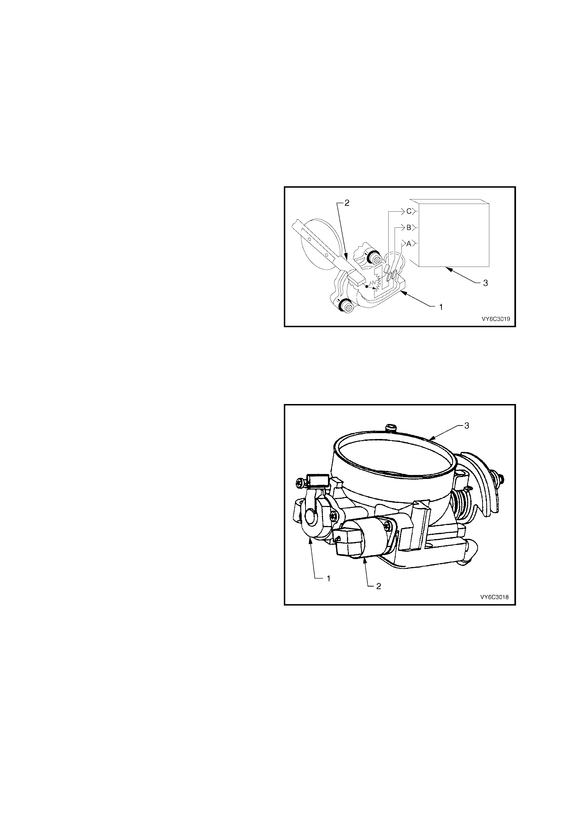
Conditions for setting DTC P1154
• The PCM determines that the HO2S transition time ratio is not at the expected value.
Action taken when DTC P1154 Sets
• The PCM stores the DTC information into memory when the diagnostic runs and fails.
• The Malfunction Indicator Lamp (MIL) will not be activated.
• The PCM records the operating conditions at the time the diagnostic fails. The PCM stores this information in
the Freeze Frame/Failure Records.
Conditions for clearing the Malfunction Indicator Lamp (MIL) and DTC P1154
• A last test failed (current DTC) clears when the diagnostic runs and does not fail.
THROTTLE POSITION (TP) SENSOR
The Throttle Position (TP) sensor (1) is connected
to the throttle shaft (2) on the throttle body. It is a
potentiometer with one end (A) connected to 5 volts
from the PCM (3) and the other end (B) to PCM
ground. A third wire (C) connects from a sliding
contact in the TP sensor to the PCM allowing the
PCM to measure the voltage from the TP sensor.
As the throttle is m oved (ac celerator pedal moved) ,
the output of the TP sensor changes. At a closed
throttle position, the output of the TP sensor is
below 1.25V. As the throttle valve opens, the output
increases so that, at wide-open throttle (W OT ), the
output voltage should be about 4 volts.
By monitoring the output voltage from the TP
sensor, the PCM c an determ ine fuel delivery based
on throttle valve angle (driver demand). A broken or
loose TP sensor can cause intermittent bursts of
fuel from the injectors, and an unstable idle,
because the PCM interprets the throttle is moving.
Figure 6C3-1-44 – TP Sensor - Typical Arrangement
The T P sensor (1) is not adjustable and there is no
set value for voltage at closed throttle because the
actual voltage at closed throttle can vary from
vehicle to vehicle due to tolerances. The PCM has a
special program built into it that can adjust for the
tolerances in the TP sensor voltage reading at idle.
The PCM us es the reading at closed throttle idle for
the zero reading (0% throttle) so no adjustment is
necessary.
Even if the TP sensor voltage reading was to be
changed by tampering, throttle body cok ing, stick ing
cable or any other reason, the T P sensor will still be
0%. The PCM will learn what the closed throttle
value is, every time the throttle comes back to
closed throttle.
The following DTCs are set when the PCM detects
a malfunction with the TP sensor circuits:
• DTC P0121: TP Sensor Circuit Insufficient Activity.
• DTC P0122: TP Sensor Circuit Low Voltage.
• DTC P0123: TP Sensor Circuit High Voltage.
• DTC P1121: TP Sensor Circuit Intermittent High
Voltage.
• DTC P1122: TP Sensor Circuit Intermittent Low
Voltage.
Figure 6C3-1-45 – Throttle Position (TP) Sensor
Legend:
1 Throttle Position (TP) Sensor
2 Idle Air Control (IAC) Valve
3 Throttle Body

DTC P0121 THROTTLE POSITION SENSOR CIRCUIT INSUFFICIENT ACTIVITY
Conditions for running DTC P0121
• No MAP sensor or TP sensor DTCs.
• The engine run time is greater than 10 seconds.
• The engine coolant temperature is greater than 0°C.
• The IAC is between 0 and 255 counts.
• The MAP is less than 55 kPa.
OR
• The MAP is greater than 65 kPa.
• MAP is steady.
Conditions for setting DTC P0121
• The predicted throttle angle does not match the actual throttle angle.
• All conditions are met for at least 20 seconds.
Action taken when DTC P0121 Sets
• The PCM activates the Malfunction Indicator Lamp (MIL) when the diagnostic runs and fails.
• The PCM records the operating conditions at the time the diagnostic fails. The PCM stores this information in
the Freeze Frame/Failure Records.
• The PCM uses a default TP sensor value.
Conditions for clearing the Malfunction Indicator Lamp (MIL) and DTC P0121
• The PCM deactivates the Malfunction Indicator Lamp (MIL) when the diagnostic runs and does not fail.
• A last test failed (current DTC) clears when the diagnostic runs and does not fail.
DTC P0122 THROTTLE POSITION SENSOR CIRCUIT LOW VOLTAGE
Conditions for running DTC P0122
• The ignition switch is ON or the engine is running.
Conditions for setting DTC P0122
• The TP sensor signal voltage is less than 0.2 volts.
Action taken when DTC P0122 Sets
• The PCM activates the Malfunction Indicator Lamp (MIL) when the diagnostic runs and fails.
• The PCM records the operating conditions at the time the diagnostic fails. The PCM stores this information in
the Freeze Frame/Failure Records.
• The PCM uses a default TP sensor value.
• The transmission TCC will not apply.
• High transmission line pressure.
• Fixed transmission shift points, hard shifts and no fourth gear in hot mode.
Conditions for clearing the Malfunction Indicator Lamp (MIL) and DTC P0122
• The PCM deactivates the Malfunction Indicator Lamp (MIL) when the diagnostic runs and does not fail.
• A last test failed (current DTC) clears when the diagnostic runs and does not fail.
DTC P0123 THROTTLE POSITION SENSOR CIRCUIT HIGH VOLTAGE
Conditions for running DTC P0123
• The ignition switch is ON or the engine is running.
Conditions for setting DTC P0123
• The TP sensor signal voltage is greater than 4.8 volts.
• Conditions present for at least ten seconds.
Action taken when DTC P0123 Sets
• The PCM activates the Malfunction Indicator Lamp (MIL) when the diagnostic runs and fails.
• The PCM records the operating conditions at the time the diagnostic fails. The PCM stores this information in
the Freeze Frame/Failure Records.
• The PCM uses a default TP sensor value.
• The transmission TCC will not apply.
• High transmission line pressure.
• Fixed transmission shift points, hard shifts and no fourth gear in hot mode.
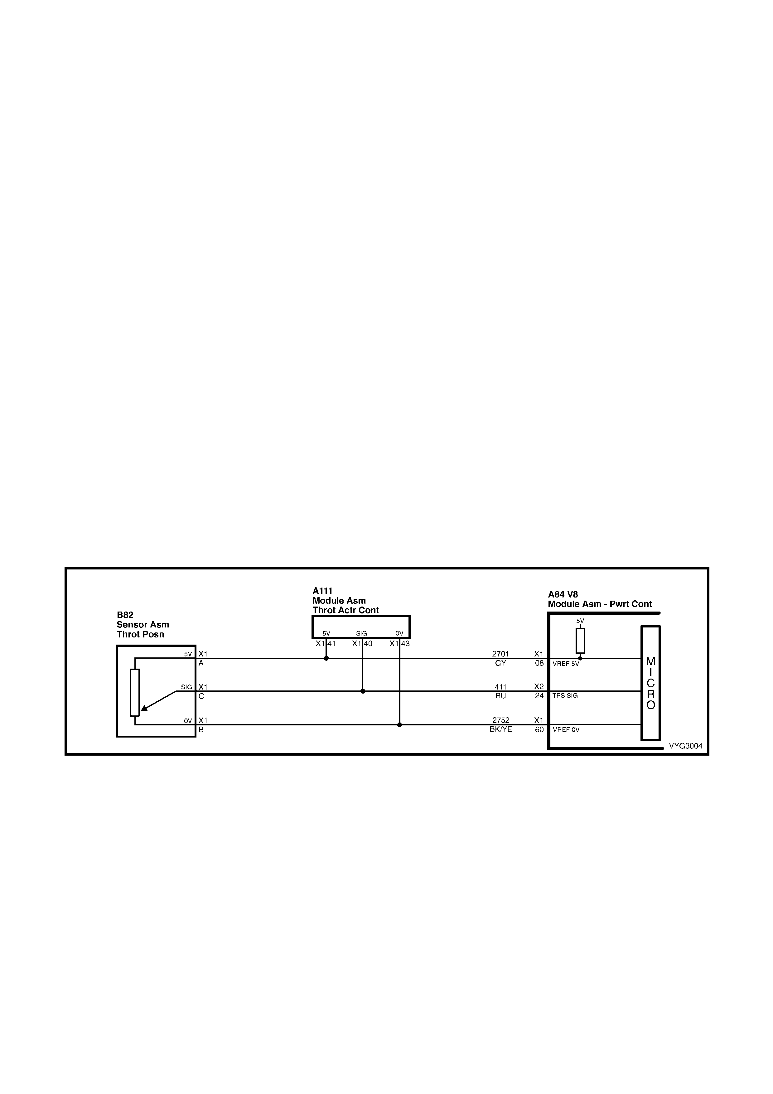
Conditions for clearing the Malfunction Indicator Lamp (MIL) and DTC P0123
• The PCM deactivates the Malfunction Indicator Lamp (MIL) when the diagnostic runs and does not fail.
• A last test failed (current DTC) clears when the diagnostic runs and does not fail.
DTC P1121 THROTTLE POSITION SENSOR CIRCUIT INTERMITTENT HIGH VOLTAGE
Conditions for running DTC P1121
• The ignition switch is ON or the engine is running.
Conditions for setting DTC P1121
• The TP sensor signal voltage is greater than 4.8 volts.
Action taken when DTC P1121 Sets
• The PCM stores the DTC information into memory when the diagnostic runs and fails.
• The Malfunction Indicator Lamp (MIL) will not be activated.
• The PCM records the operating conditions at the time the diagnostic fails. The PCM stores this information in
the Freeze Frame/Failure Records.
Conditions for clearing the Malfunction Indicator Lamp (MIL) and DTC P1121
• A last test failed (current DTC) clears when the diagnostic runs and does not fail.
DTC P1122 THROTTLE POSITION SENSOR CIRCUIT INTERMITTENT LOW VOLTAGE
Conditions for running DTC P1122
• The ignition switch is ON or the engine is running.
Conditions for setting DTC P1122
• The TP sensor signal voltage is less than 0.2 volts.
Action taken when DTC P1122 Sets
• The PCM stores the DTC information into memory when the diagnostic runs and fails.
• The Malfunction Indicator Lamp (MIL) will not be activated.
• The PCM records the operating conditions at the time the diagnostic fails. The PCM stores this information in
the Freeze Frame/Failure Records.
Conditions for clearing the Malfunction Indicator Lamp (MIL) and DTC P1122
• A last test failed (current DTC) clears when the diagnostic runs and does not fail.
Figure 6C3-1-46 – Throttle Position Sensor Circuits
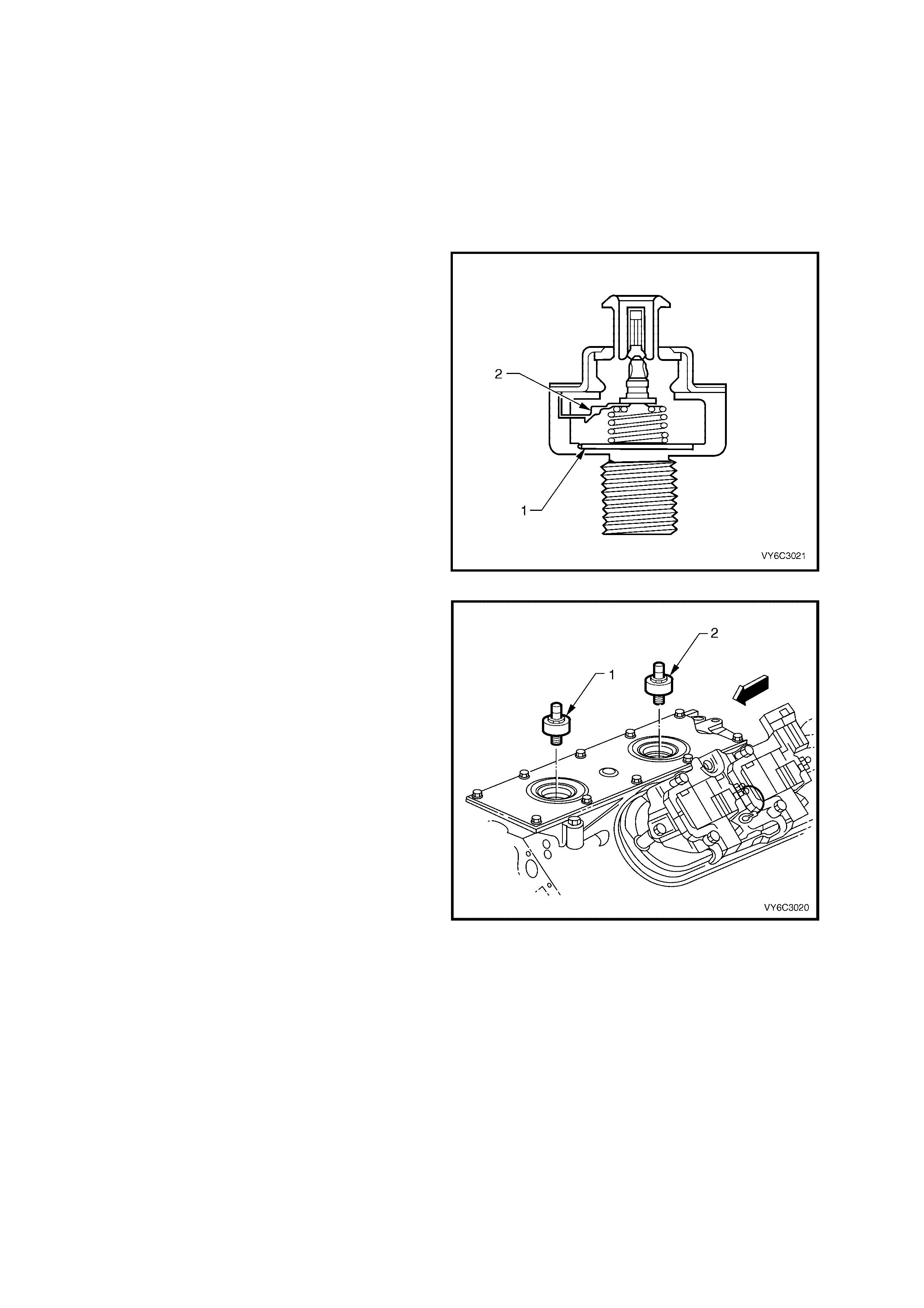
KNOCK SENSORS (KS)
Varying octane levels in today's petrol may cause detonation in some engines. Detonation is caused by an
uncontrolled pres sure in the com bustion cham ber. T his uncontro lled pressure c ould produce a flam e fr ont opposite
to that of the normal flame front produced by the spark plug.
The rattling sound normally associated with detonation is the result of two or more opposing pressures (flame
fronts) colliding within the combustion chamber. Though light detonation is sometimes considered normal, heavy
detonation could result in engine damage. Light detonation occurs when the point of m aximum pressure has been
exceeded. T o control spar k k nock , two knock sensors are used on the GEN III V8 engine. This system is designed
to retard spar k tim ing up to 20° to reduc e spark k noc k in the engine. T his allows the engine to use m axim um s park
advance to improve driveability and fuel economy.
The knock sensors detect abnormal mechanical
vibration (spark knocking) in the engine. There are
several calibrations of knock sensors because
each engine produces a different frequency of
mechanical noise. The knock sensor is specifically
chosen for this engine to best detec t engine knock ,
over all the other noises in the engine.
The knock sensor, produces an AC output voltage
that increases with the severity of the knock. This
AC signal voltage to the PCM is processed by a
Digital Signal Noise Enhancement Filter (DSNEF)
module. This DSNEF module is used to determine
if the AC signal coming in is noise or actual
detonation. This DSNEF module is part of the PCM
and cannot be replaced.
Figure 6C3-1-47 – Knock (KS) Sensor
The processed knock sensor signal is then
supplied to the PCM. The PCM then adjusts the
ignition control system to reduce the spark
advance. How muc h the tim ing is retar ded is based
upon the amount of time knock is detected. After
the detonation stops, the tim ing will gradually return
to its calibrated value of spar k advance. T he Knock
Sensor system will only retard timing after the
following conditions are met:
• The engine run time is greater than 20
seconds.
• The engine speed is greater than 1650 RPM.
• T he engine coolant tem perature is greater than
70°C.
• T he manif old absolute pressur e is less than 60
kPa.
DTC P0325 indicates an internal PCM malfunction
related to the knock sensor system. DTCs P0327
and P0332 indicate that a knock sensor or knock
sensor circuit is malfunctioning.
Figure 6C3-1-48 – Knock Sensor Location

DTC P0325 KNOCK SENSOR SYSTEM
Conditions for running DTC P0325
• The engine run time is greater than 20 seconds.
• The engine speed is between 1650 and 3000 RPM.
• The MAP is at or about 48 kPa.
• The engine coolant temperature is greater than 70° C.
• The throttle angle is greater than 0.5%.
• The TP sensor angle is steady within 1%.
• Battery voltage is between 10 and 16 volts.
Conditions for setting DTC P0325
• A malfunction with the knock sensor system or circuits within the PCM are faulty.
• All above conditions present for at least three seconds.
Action taken when DTC P0325 Sets
• The PCM activates the Malfunction Indicator Lamp (MIL) when the diagnostic runs and fails.
• The PCM records the operating conditions at the time the diagnostic fails. The PCM stores this information in
the Freeze Frame/Failure Records.
Conditions for clearing the Malfunction Indicator Lamp (MIL) and DTC P0325
• The PCM deactivates the Malfunction Indicator Lamp (MIL) after one ignition cycle that the diagnostic runs and
does not fail.
• A last test failed (current DTC) clears when the diagnostic runs and does not fail.
DTC P0327 KNOCK SENSOR CIRCUIT FRONT SENSOR
Conditions for running DTC P0327
• The engine run time is greater than 20 seconds.
• The engine speed is between 1650 and 3000 RPM.
• The MAP is at or about 48 kPa.
• The engine coolant temperature is greater than 70° C.
• The throttle angle is greater than 0.5%.
• Battery voltage is between 10 and 16 volts.
Conditions for setting DTC P0327
• The PCM determines that the frequency is less than or greater than the expected amount for at least three
seconds.
Action taken when DTC P0327 Sets
• The PCM activates the Malfunction Indicator Lamp (MIL) when the diagnostic runs and fails.
• The PCM records the operating conditions at the time the diagnostic fails. The PCM stores this information in
the Freeze Frame/Failure Records.
Conditions for clearing the Malfunction Indicator Lamp (MIL) and DTC P0327
• The PCM deactivates the Malfunction Indicator Lamp (MIL) after one ignition cycle that the diagnostic runs and
does not fail.
• A last test failed (current DTC) clears when the diagnostic runs and does not fail.
DTC P0332 KNOCK SENSOR CIRCUIT REAR SENSOR
Conditions for running DTC P0332
• The engine run time is greater than 20 seconds.
• The engine speed is between 1650 and 3000 RPM.
• The MAP is at or about 48 kPa.
• The engine coolant temperature is greater than 70° C.
• The throttle angle is greater than 0.5%.
• Battery voltage is between 10 and 16 volts.
Conditions for setting DTC P0332
• The PCM determines that the frequency is less than or greater than the expected amount for at least three
seconds.
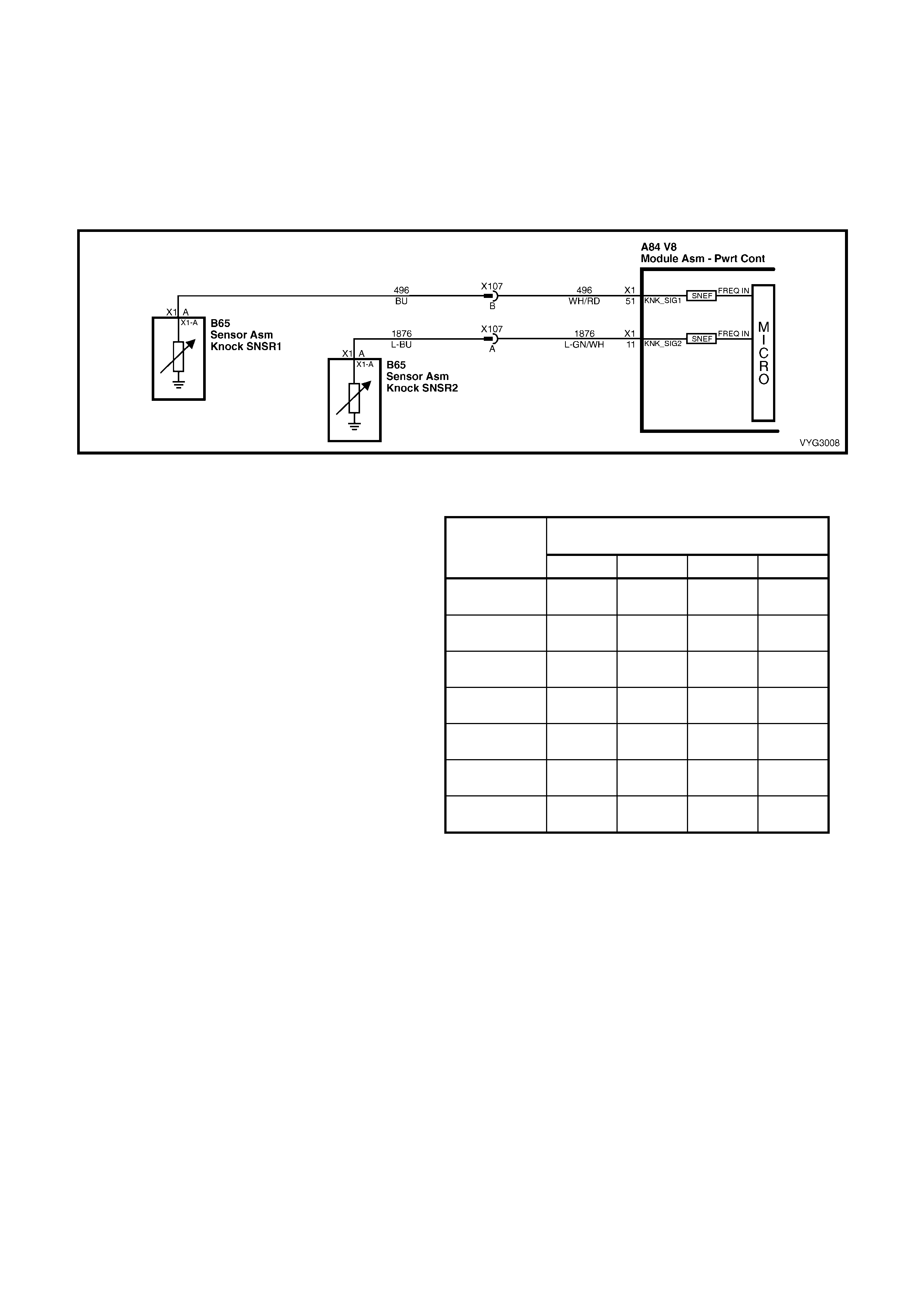
Action taken when DTC P0332 Sets
• The PCM activates the Malfunction Indicator Lamp (MIL) when the diagnostic runs and fails.
• The PCM records the operating conditions at the time the diagnostic fails. The PCM stores this information in
the Freeze Frame/Failure Records.
Conditions for clearing the Malfunction Indicator Lamp (MIL) and DTC P0332
• The PCM deactivates the Malfunction Indicator Lamp (MIL) after one ignition cycle that the diagnostic runs and
does not fail.
• A last test failed (current DTC) clears when the diagnostic runs and does not fail.
Figure 6C3-1-49 – Knock Sensor Circuit
PARK, REVERSE, NEUTRAL, DRIVE, LOW (PRNDL) SWITCH
TECH 2 ‘P RNDL’ DISPLAY
(P, A, B, C,)
GEAR
POSITION
SELECTED P A B C
PARK (P ) CLOSED
(0 V) CLOSED
(0 V) OPEN
(12 V) OPEN
(12 V)
REVERSE (R) OPEN
(12 V) CLOSED
(0 V) CLOSED
(0 V) OPEN
(12 V)
NEUTRAL (N) CLOSED
(0 V) OPEN
(12 V) CLOSED
(0 V) OPEN
(12 V)
DRIVE 4 (D) OPEN
(12 V) OPEN
(12 V) CLOSED
(0 V) CLOSED
(0 V)
DRIVE (3) CLOSED
(0 V) CLOSED
(0 V) CLOSED
(0 V) CLOSED
(0 V)
DRIVE (2) OPEN
(12 V) CLOSED
(0 V) OPEN
(12 V) CLOSED
(0 V)
DRIVE (1) CLOSED
(0 V) OPEN
(12 V) OPEN
(12 V) CLOSED
(0 V)
The transmission PRNDL switch is a multi-signal
switch which sends signals to the PCM to indicate
gear lever position. Par k, Reverse, Neutral, Drive, 3,
2, or 1. The PCM will then determine the signal from
the PRNDL switch and send a command to the
instruments via the PIM and the serial data normal
mode m ess age com manding the instr uments to turn
ON the correct gear indicator lamp for the gear that
has been selected.
The PRNDL switch uses four disc rete circuits to pull
four PCM voltages low in various combinations to
indicate each gear range. The voltage level of the
circuits is repr es ented as CLO SED = gr ounded (0V) ,
and OPEN = open (12V). The four states displayed
represents P, A, B, and C inputs.
Tech 2 will display all four circuits (P, A, B, C) and
the appropriate open and closed state, to represent
the gear selected. If the gear selected does not
match the OPEN/CLOSED state as displayed in the
table or on the scan tool, or the appropriate
instrum ents gear lamp does not light up f or the gear
selected, there is a fault in the PRNDL select circuit
or in the MFD of the Instrument.
For additional details of the PRNDL switch location
and adjustment, refer to Section 7C4 AUTOMATIC
TRANSMISSION – ON-VEHICLE SERVICING in
the MY 2003 VY and V2 Series Service Information.
Figure 6C3-1-50 – Transmis s ion Range / PRNDL
Switch Valid Input Combinations
The f ollowing DT Cs are set when the PCM detects
a malfunction with the transmission range switch:
• DTC P0705: Transmission Range Switch
Circuit.
• DTC P0706: Transmission Range Switch
Performance.
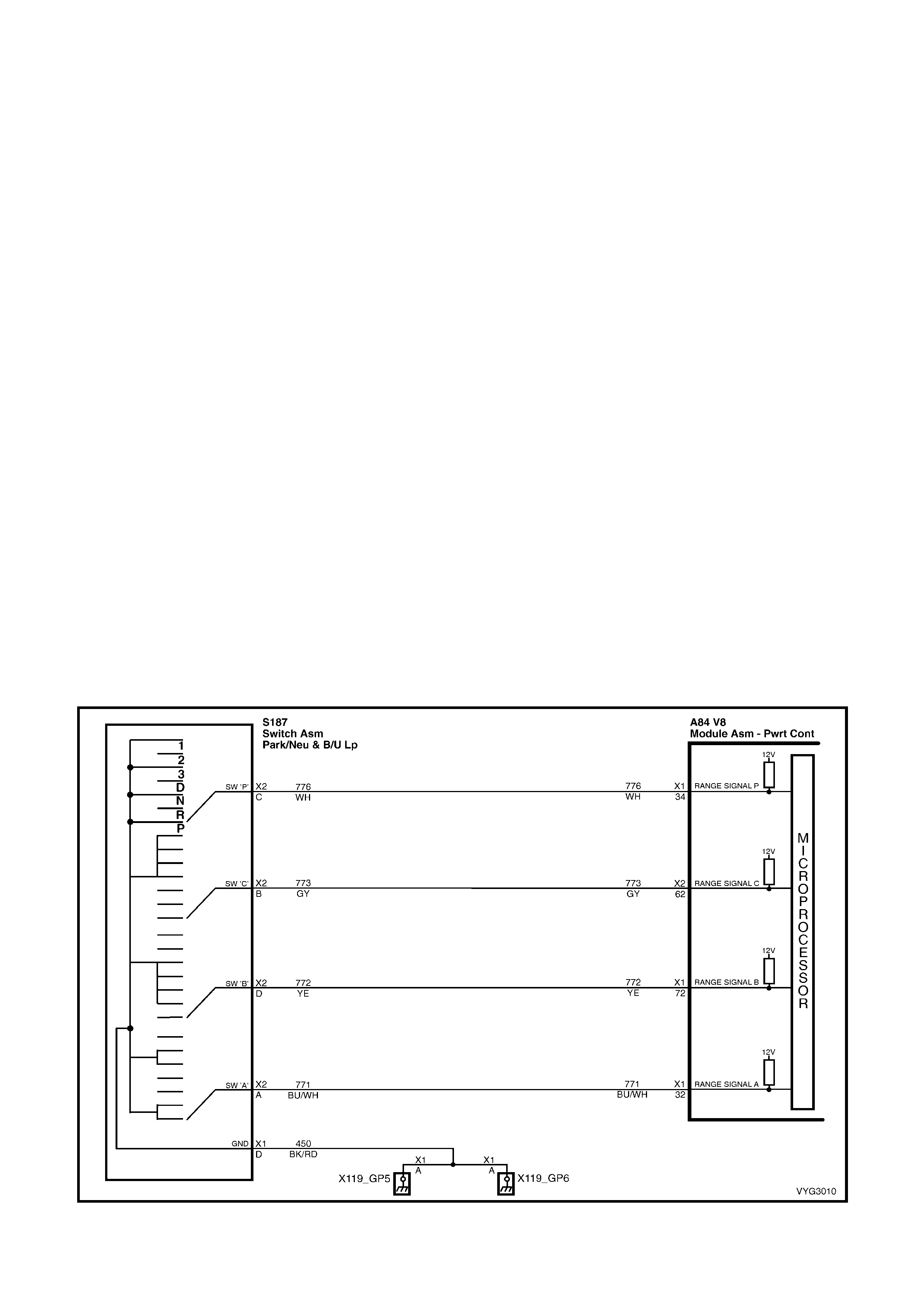
DTC P0705 TRANSMISSION RANGE SWITCH CIRCUIT
Conditions for running DTC P0705
• The ignition is on.
Conditions for setting DTC P0705
• The Transmission Range Switch inputs indicate an invalid combination.
• The above condition is present for longer than 30 seconds.
Action taken when DTC P0705 Sets
• The PCM stores the DTC information into memory when the diagnostic runs and fails.
• The Malfunction Indicator Lamp (MIL) will not be activated.
• The PCM records the operating conditions at the time the diagnostic fails. The PCM stores this information in
the Freeze Frame/Failure Records.
Conditions for clearing the Malfunction Indicator Lamp (MIL) and DTC P0705
• A last test failed (current DTC) clears when the diagnostic runs and does not fail.
• The PCM cancels the DTC default actions when the fault no longer exists and the ignition switch is OFF long
enough in order to power down the PCM.
DTC P0706 TRANSMISSION RANGE SWITCH PERFORMANCE
Conditions for running DTC P0706
• The ignition is ON.
Conditions for setting DTC P0706
• The Transmission Range Switch inputs indicate an invalid combination.
• The above condition is present for longer than 30 seconds.
Action taken when DTC P0706 Sets
• The PCM stores the DTC information into memory when the diagnostic runs and fails.
• The Malfunction Indicator Lamp (MIL) will not be activated.
• The PCM records the operating conditions at the time the diagnostic fails. The PCM stores this information in
the Freeze Frame/Failure Records.
Conditions for clearing the Malfunction Indicator Lamp (MIL) and DTC P0706
• A last test failed (current DTC) clears when the diagnostic runs and does not fail.
• The PCM cancels the DTC default actions when the fault no longer exists and the ignition switch is OFF long
enough in order to power down the PCM.
Figure 6C3-1-51 – Transmission PRNDL Switch Circuit

A/C REQUEST SIGNAL AND A/C CLUTCH CONTROL WITH OCC
The Oc cupant Clim ate Control ( OCC) m odule r equests the PCM to tur n the A/C com pres sor clutc h on or off via the
PIM and the serial data bus normal mode m essage. The OCC module monitors inform ation from it’s sensors and
switches and determines if the A/C compressor clutch should be on or off. The OCC control module will then
request the PCM to turn the A/C compressor clutch on or off when required.
The PCM on receiving a request to turn on the A/C compressor will:
1. Adjust the Idle Air Control (IAC) valve position to compensate for the additional load placed on the engine by the
air conditioning compressor.
2. Energise the A/C compressor relay, to operate the A/C compressor if the pressure in the A/C system is within
the correct operating range.
Low Pressure High Pressure RPM
Cut Out Cut In Cut Out Cut In Off On
180 240 2900 2000 4800 4000
The PCM on receiving a request to turn on the A/C compressor, monitors the A/C pressure, coolant temperature
and RPM to determine A/C clutch operation.
There ar e two DTCs assoc iated with the A/C system . DTC P1539 is set when, the PCM detects voltage on the A/C
clutch status terminal when the system has not requested A/C. A short to voltage at any point in the A/C status
circuit, or the A/C relay contacts are stuck.
DTC P1546 is set when the PCM activates the relay, voltage s hould be present at both the A/C com pressor clutch
and the A/C clutch status circuit at the PCM. If the voltage is not present, DTC P1546 will set.
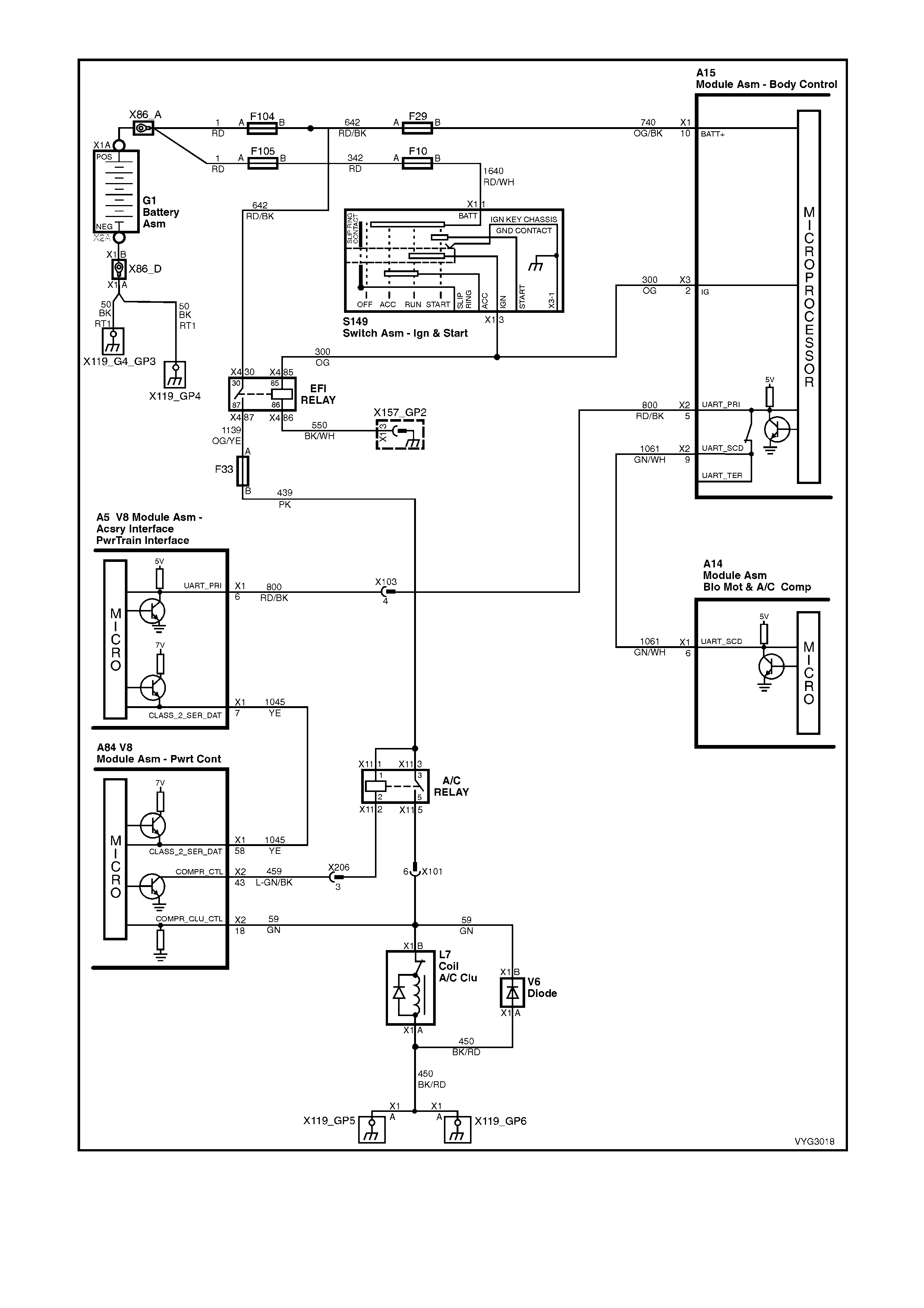
Figure 6C3-1-52 – A/C Request Signal With OCC Circuit

A/C REQUEST SIGNAL AND A/C CLUTCH CONTROL WITHOUT OCC
The BCM reques ts the PCM to turn the A/C com press or on or off via the PIM and the serial data bus normal mode
message. The BCM monitors the voltage at BCM terminal X3-5 to determine the status of the momentary A/C
Master switch. When the A/C master switch is pressed, 12 volts is applied to the BCM terminal X3-5. The BCM
sees this high voltage as an A/C master switch input signal.
On receiving the A/C m aster switch input signal, the BCM requests the PCM to energise the A/C clutch via the PIM
and the serial data bus normal mode message, if the ignition is on and the blower motor is operating. If the A/C
master switch is pressed again the BCM will request the PCM to turn off the A/C compressor.
The operating status of the system will be rem em bered by the BCM, when the ignition is switched from on to off or
when the blower is switched off. If the blower is off and the A/C master switch is pressed, then the next time the
blower is switched on the air conditioning will be turned on. Turning the ignition off will cancel this button press
function.
The system will reset to off when the battery is disconnected.
The PCM uses this signal to:
1. Adjust the Idle Air Control (IAC) valve position to compensate for the additional load placed on the engine by
the air conditioning compressor.
2. Energise the A/C com pressor relay, to operate the A/C compressor if the pressure in the A/C system is within
the correct operating range.
Low Pressure High Pressure RPM
Cut Out Cut In Cut Out Cut In Off On
180 240 2900 2000 4800 4000
The PCM monitors the A/C Pressure Sensor to determine A/C system pressure.
There ar e two DTCs assoc iated with the A/C system . DTC P1539 is set when, the PCM detects voltage on the A/C
clutch status terminal when the system has not requested A/C. A short to voltage at any point in the A/C status
circuit, or the A/C relay contacts are stuck.
DTC P1546 is set when the PCM activates the relay, voltage s hould be present at both the A/C com pressor clutch
and the A/C clutch status circuit at the PCM. If the voltage is not present, DTC P1546 will set.
Figure 6C3-1-53 – Heater and Air Conditioning Controls
Legend
1. Blower Fan Switch
2. Blower Fan Speed Position Indicator
3. Temperature Control
4. Temperature Control Position Indicator
5. Mode Position Switch
6. Mode Position Switch Indicator
7. Heated Rear Window Switch
8. Heated Rear Window Switch ON Indicator LED
9. A/C Switch
10. A/C ON Indicator LED
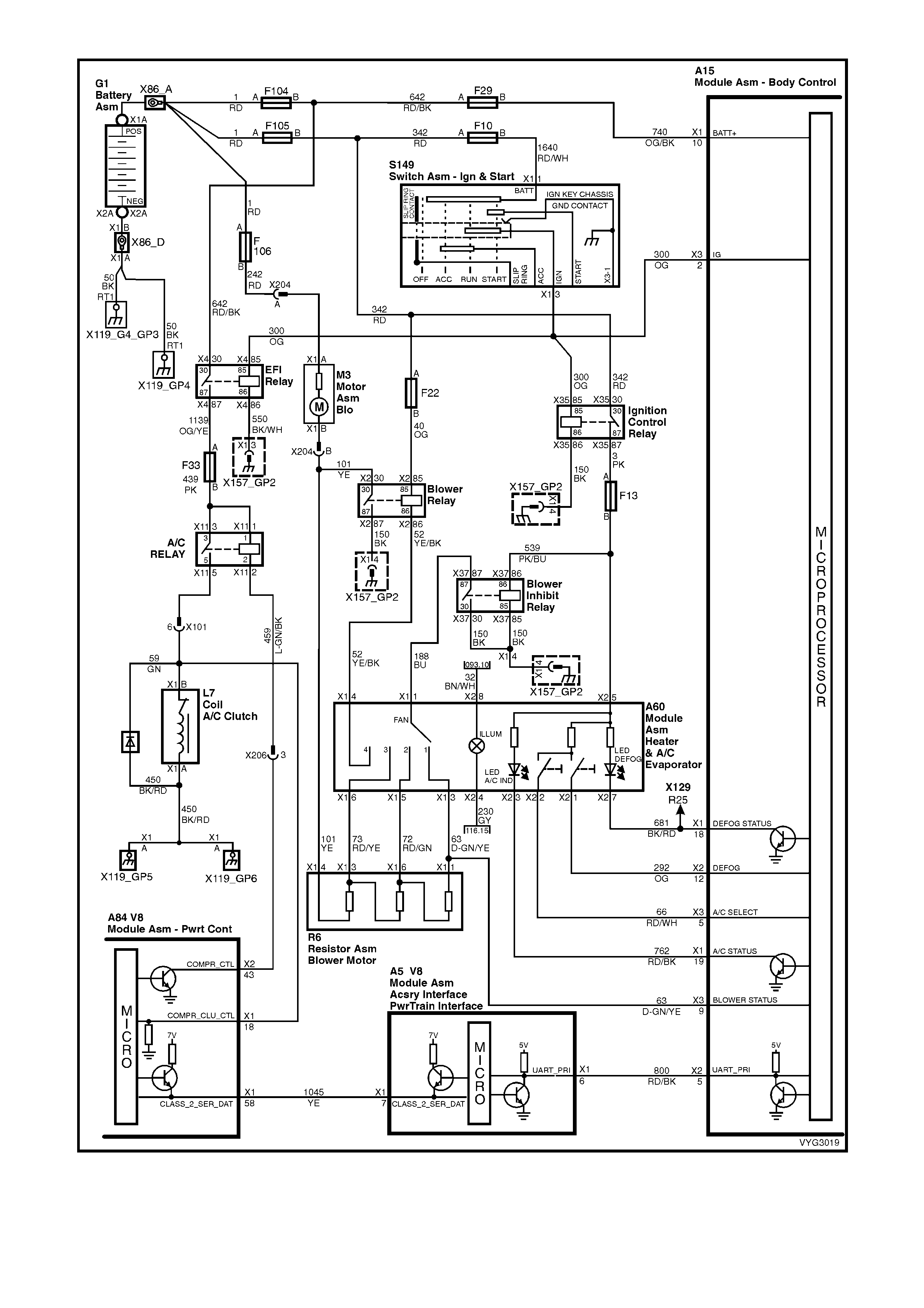
Figure 6C3-1-54 – A/C Request Signal Without OCC

DTC P1539 A/C CLUTCH STATUS CIRCUIT HIGH VOLTAGE
Conditions for running DTC P1539
• The A/C clutch is not requested.
Conditions for setting DTC P1539
• Voltage is detected on the A/C status circuit for more than 15 seconds after the PCM has disengaged the A/C
clutch relay.
Action taken when DTC P1539 Sets
• The PCM stores the DTC information into memory when the diagnostic runs and fails.
• The Malfunction Indicator Lamp (MIL) will not be activated.
• The PCM records the operating conditions at the time the diagnostic fails. The PCM stores this information in
the Freeze Frame/Failure Records.
Conditions for clearing the Malfunction Indicator Lamp (MIL) and DTC P1539
• A last test failed (current DTC) clears when the diagnostic runs and does not fail.
DTC P1546 A/C CLUTCH STATUS CIRCUIT LOW VOLTAGE
Conditions for running DTC P1546
• The A/C clutch is requested.
Conditions for setting DTC P1546
• The PCM commands the A/C ON and the PCM does not detect a voltage on the A/C clutch status line for more
than five seconds.
Action taken when DTC P1546 Sets
• The PCM stores the DTC information into memory when the diagnostic runs and fails.
• The Malfunction Indicator Lamp (MIL) will not be activated.
• The PCM records the operating conditions at the time the diagnostic fails. The PCM stores this information in
the Freeze Frame/Failure Records.
Conditions for clearing the Malfunction Indicator Lamp (MIL) and DTC P1546
• A last test failed (current DTC) clears when the diagnostic runs and does not fail.

Figure 6C3-1-55 – A/C Clutch Circuit, with OCC
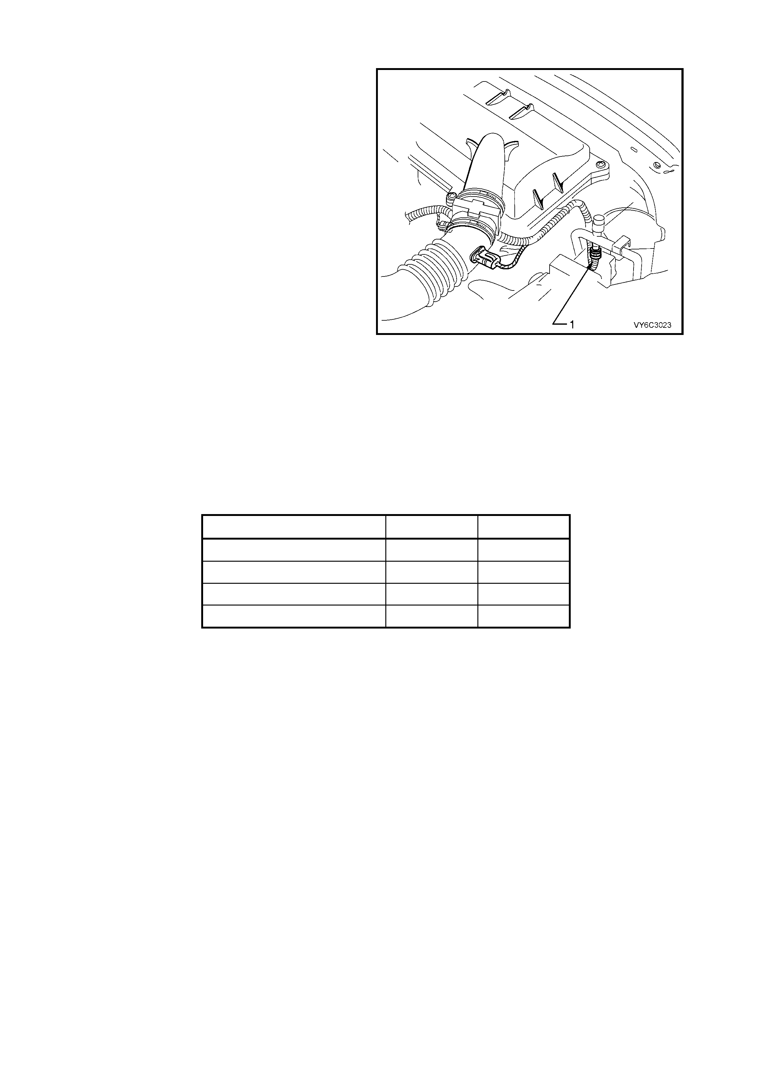
A/C REFRIGERANT PRESSURE SENSOR
The A/C Refrigerant Pressure Sensor (1) is a
sealed gauge ref erence capac itive pressure sens or
with on board s ignal conditioning. It provides a zero
to five volt output and requires a five volt regulated
power supply.
In operation the sensor senses applied pressure
via the deflection of a two piece c er amic diaphr agm
with one half being a parallel plate capacitor.
Changes in capacitance influenced by the
refrigerant pressure under the ceramic diaphragm
are converted to an analogue output by the
sensor’s integral signal electronics.
The pressure sensor’s electronics are on a flexible
circuit board contained in the upper section of the
sensor. They provide linear calibration of the
capacitance signal from the ceramic sensing
diaphragm.
Benefits of using the pressure Sensor over a
normal type pressure switch is that the sensor is
constantly monitoring pressures and sending
signals to the Powertrain Control Module (PCM).
The norm al type pressure s witch only has an upper
and lower cut-out point. The PCM will disengage
the A/C compressor at Low or High refrigerant
pressures and control the operation of the engine
cooling fans.
If there is a failure in the A/C Pressure Sensor
circuit DTC P0530 will set.
Figure 6C3-1-56 –
A/C Refrigerant Pressure Sensor Location
Action ON OFF
Low Pressure Compressor Cut at 240 kPa at 180kPa
High Pressure Compressor Cut at 2400 kPa at 2900 kPa
Engine Cooling Fan Low Speed at 1500 kPa at 1250 kPa
Engine Cooling Fan High Speed at 2600 kPa at 2300 kPa
DTC P0530 A/C REFRIGERANT PRESSURE SENSOR CIRCUIT
Conditions for running DTC P0530
• The PCM detects an A/C request.
Conditions for setting DTC P0530
• A/C refrigerant pressure Sensor indicates A/C refrigerant pressure is at or below 25 kPa for five seconds.
OR
• A/C refrigerant pressure Sensor indicates A/C refrigerant pressure is at or above 3140 kPa for five seconds.
Action taken when DTC P0530 Sets
• The PCM stores the DTC information into memory when the diagnostic runs and fails.
• The Malfunction Indicator Lamp (MIL) will not be activated.
• The PCM records the operating conditions at the time the diagnostic fails. The PCM stores this information in
the Freeze Frame/Failure Records.
Conditions for clearing the Malfunction Indicator Lamp (MIL) and DTC P0530
• A last test failed (current DTC) clears when the diagnostic runs and does not fail.
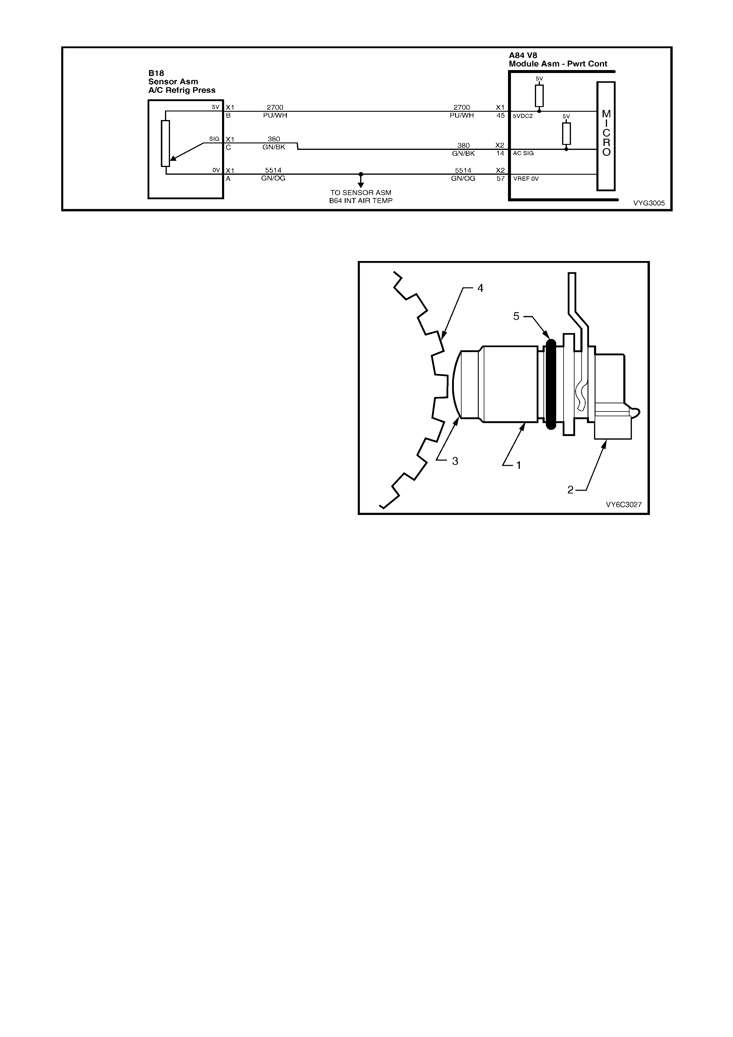
Figure 6C3-1-57 – A/C Refrigerant Pressure Sensor Circuit
VEHICLE SPEED SENSOR (VSS)
The PCM receives vehicle speed information from
the Vehicle Speed Sensor (VSS) located on the
rear of the transmission. Locations are shown in
Figure 6C3-1-59 for the automatic transmission
VSS (‘A’) and manual transmission (‘B’). The VSS
basically consis ts of a m agnetic core and a c oil. As
the output s haft turns, the teeth on the output s haft
concentrate the magnetic field, causing the
magnetic f lux to increas e and then decreas e as the
teeth move in and out of the magnetic field,
inducing a voltage into the coil, first in a positive
and then in a negative direction.
This AC voltage produc ed in the VSS sensor circ uit
is fed into the PCM, the PCM filters and shapes this
signal. The PCM then c ounts the number of pulses
received in a given time, to determine the vehicle
speed.
Once the PCM has calculated the vehicle speed it
then pulses circuit 5197 (Purple/White wire) to
ground, this will cause the 12 volts at term inal X1-5
of the instruments to be pulled down to less than
0.2 volts. The instruments determines the vehicle
speed and the kilometres from the number of
pulses it receives. The PCM also transmits vehicle
speed information to other control modules via the
serial data bus normal mode message.
There are three DTCs associated with the VSS.
DTC P0502 will set when the output from the VSS
is too low.
DTC P0503 will set when the VSS signal is
intermittent. DTC P0608 will set when the
com manded s tate of the VSS output driver and the
actual state of the driver do not match.
Figure 6C3-1-58 Vehicle Speed Sensor
To Reluctor Wheel
Legend:
1. Reluctor Wheel (Rotor) 3. Electrical Connector
2. O-Ring 4. Magnetic Pickup
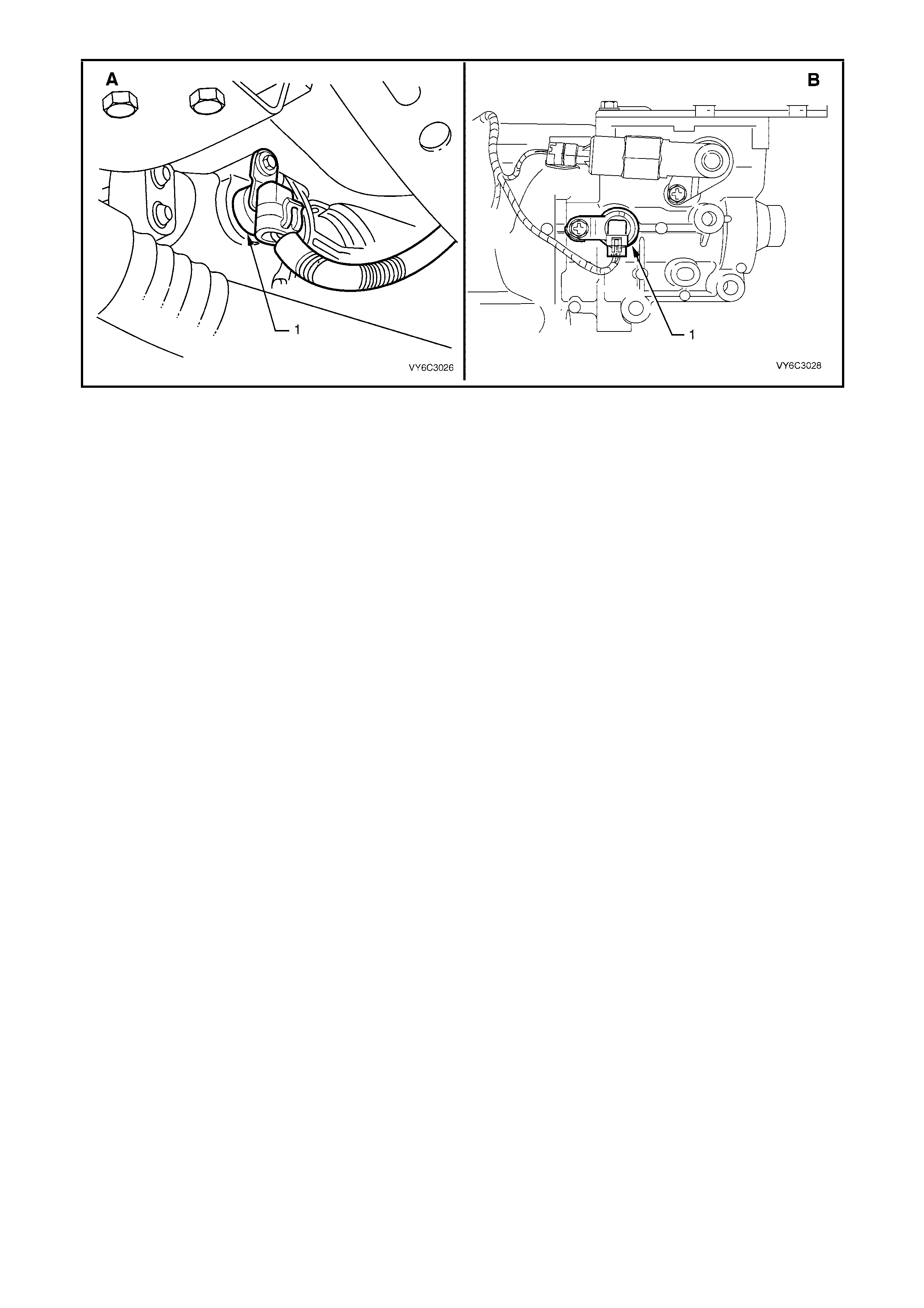
Figure 6C3-1-59 – Vehicle Speed Sensor Locations
DTC P0502 VEHICLE SPEED SENSOR CIRCUIT LOW INPUT
Conditions for running DTC P0502
• No MAP sensor DTCs P0107 or P0108.
• No Throttle Position DTCs P0122 or P0123.
• No TFP manual valve position switch DTC P1810.
• The transmission is not in park or neutral.
• The Throttle Position angle is greater than 15%.
• The engine vacuum is 0-105 kPa.
• The engine speed is greater than 3000 RPM.
• The engine torque is between 40 – 543 Nm.
Conditions for setting DTC P0502
• The transmission output speed is less than 150 RPM for at least three seconds.
Action taken when DTC P0502 Sets
• The PCM stores the DTC information into memory when the diagnostic runs and fails.
• The Malfunction Indicator Lamp (MIL) will not be activated.
• The PCM commands maximum line pressure.
• The PCM inhibits TCC engagement.
• The PCM freezes shift adapts from being updated.
• The PCM records the operating conditions at the time the diagnostic fails. The PCM stores this information in
the Freeze Frame/Failure Records.
Conditions for clearing the Malfunction Indicator Lamp (MIL) and DTC P0502
• A last test failed (current DTC) clears when the diagnostic runs and does not fail.
DTC P0503 VEHICLE SPEED SENSOR CIRCUIT INTERMITTENT
Conditions for running DTC P0503
• No TFP manual valve position switch DTC P1810.
• The time since the last gear range change is greater than six seconds.
• The engine speed is greater than 300 RPM for five seconds.
• The engine is not in fuel cutoff.
• The transmission output speed rise does not exceed 600 RPM within six seconds.
Conditions for setting DTC P0503
• The transmission output speed drop is greater than 1300 RPM for three seconds when the transmission is not
in park or neutral.
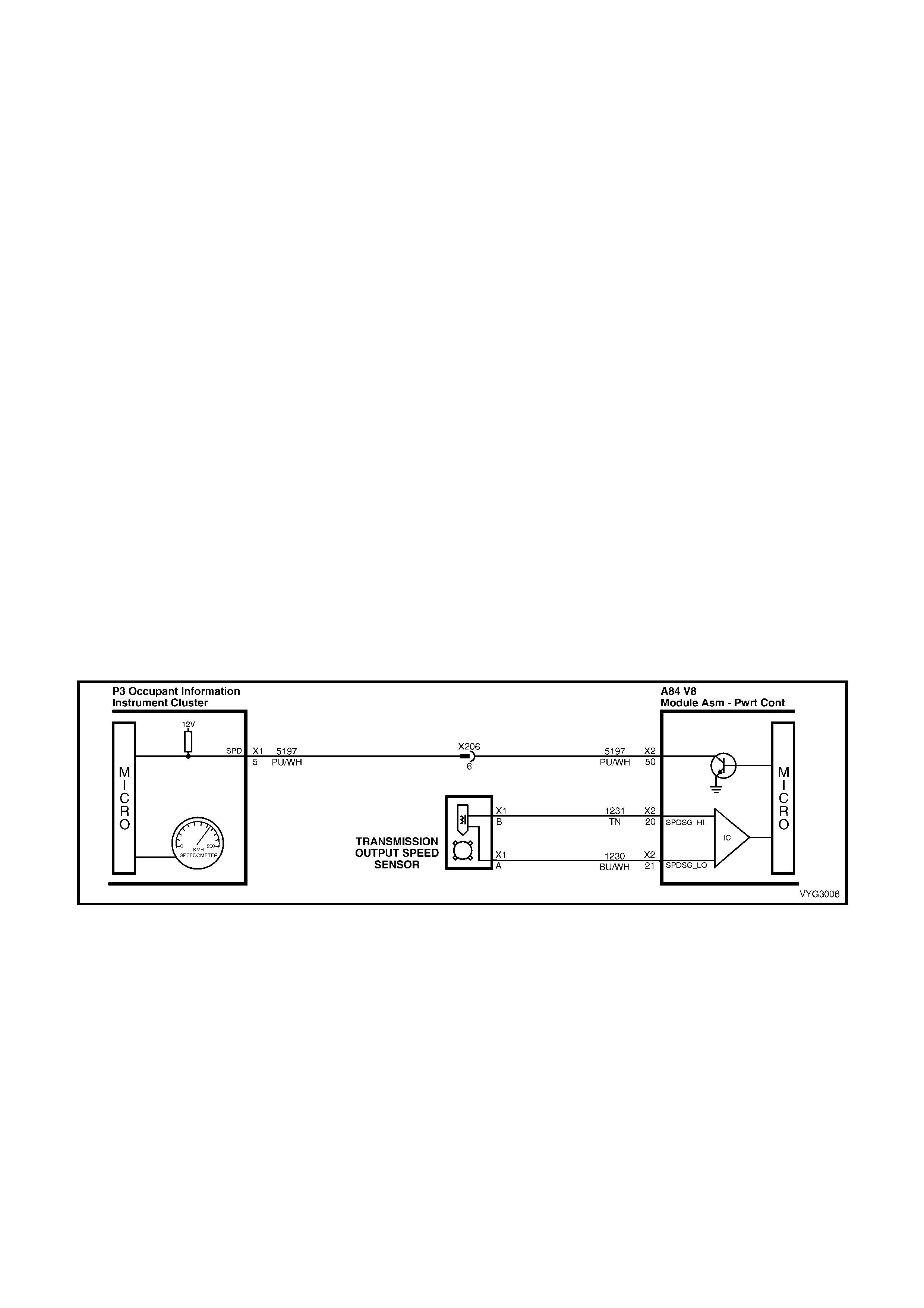
Action taken when DTC P0503 Sets
• The PCM stores the DTC information into memory when the diagnostic runs and fails.
• The Malfunction Indicator Lamp (MIL) will not be activated.
• The PCM commands second gear only.
• The PCM commands maximum line pressure.
• The PCM inhibits 4th gear if the transmission is in hot mode.
• The PCM inhibits TCC engagement.
• The PCM freezes shift adapts from being updated.
• The PCM records the operating conditions at the time the diagnostic fails. The PCM stores this information in
the Freeze Frame/Failure Records.
Conditions for clearing the Malfunction Indicator Lamp (MIL) and DTC P0503
• A last test failed (current DTC) clears when the diagnostic runs and does not fail.
DTC P0608 VEHICLE SPEED SENSOR OUTPUT CIRCUIT
Conditions for running DTC P0608
• The engine speed is greater than 600 RPM.
• The ignition voltage is between 6.0 and 16.0 volts.
Conditions for setting DTC P0608
• The PCM detects that the commanded state of the driver and the actual state of the control circuit do not
match.
• This condition must be present for at least ten seconds.
Action taken when DTC P0608 Sets
• The PCM stores the DTC information into memory when the diagnostic runs and fails.
• The Malfunction Indicator Lamp (MIL) will not be activated.
• The PCM records the operating conditions at the time the diagnostic fails. The PCM stores this information in
the Freeze Frame/Failure Records.
Conditions for clearing the Malfunction Indicator Lamp (MIL) and DTC P0608
• A last test failed (current DTC) clears when the diagnostic runs and does not fail.
Figure 6C3-1-60 – Vehicle Speed Sensor Circuit
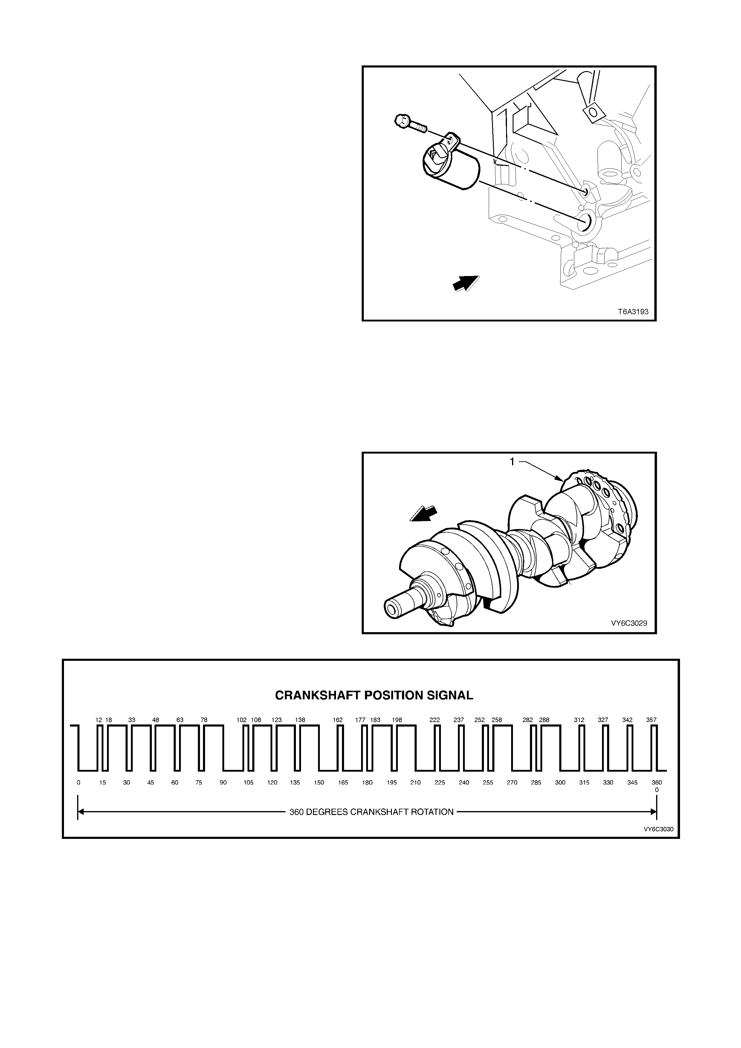
CRANKSHAFT POSITION (CKP) SENSOR
The Crankshaft Position Sensor (CKP) is mounted
in the right rear of the engine block behind the
starter. The CKP sensor works in conjunction with
a 24X reluctor wheel mounted on the rear of the
crankshaft. The CKP sensor has a battery power
supply, a ground, and a signal circuit.
As the crankshaft rotates, the reluctor wheel teeth
interrupt a magnetic field produced by a magnet
within the sensor. The sensor’s internal circuitry
detects this and produces a signal which the PCM
reads. The PCM uses this signal to accurately
measure crankshaft position and engine speed.
The reluctor wheel is mounted on the rear of the
crankshaft. The 24X reluctor wheel uses two
different width notches (12° and 3°) that are 15°
apart. This pulse width encoded pattern allows
cylinder position identification within 90 degrees of
crankshaft rotation. In some cases, cylinder
identification can be located in 45 degrees of
crankshaft rotation. This reluctor wheel also has
dual track notches that are out of phase. The duel
track design allows for quicker starts and accuracy.
NOTE: T he engine will not run if the PCM does not
receive a CKP signal. With no CKP signal, the
PCM will not issue any injector pulses.
Figure 6C3-1-61 – Crankshaft Position Sensor
(CKP) Location
The PCM monitors the CKP sensor signal circuit
for m alfunctions. The PCM sets a DT C P0335 or a
DTC P0336 when the CKP sensor is out of the
normal operating range.
Legend:
1. Reluctor
Figure 6C3-1-62 – Crankshaft Position Sensor Reluctor
Figure 6C3-1-63 Crankshaft Position Sensor Signal

DTC P0335 CRANKSHAFT POSITION SENSOR CIRCUIT
Conditions for running DTC P0335
• DTCs P0101, P0102, P0103, P0341, P0342, P0343 are not set.
• The CMP sensor is transitioning.
• The ignition voltage is between 5 and 17.0 volts.
• The MAF is greater than 3 g/s.
Conditions for setting DTC P0335
• The PCM determines no signal from the CKP sensor for at least three seconds.
Action taken when DTC P0335 Sets
• The PCM activates the Malfunction Indicator Lamp (MIL) when the diagnostic runs and fails.
• The PCM records the operating conditions at the time the diagnostic fails. The PCM stores this information in
the Freeze Frame/Failure Records.
Conditions for clearing the Malfunction Indicator Lamp (MIL) and DTC P0335
• The PCM deactivates the Malfunction Indicator Lamp (MIL) when the diagnostic runs and does not fail.
• A last test failed (current DTC) clears when the diagnostic runs and does not fail.
DTC P0336 CRANKSHAFT POSITION SENSOR CIRCUIT PERFORMANCE
Conditions for running DTC P0336
• The ignition voltage is between 5 and 17.0 volts.
• The engine speed is greater than 400 RPM.
Conditions for setting DTC P0336
• The PCM determines no signal from the CKP sensor or the signal is out of range for at least one second.
Action taken when DTC P0336 Sets
• The PCM activates the Malfunction Indicator Lamp (MIL) when the diagnostic runs and fails.
• The PCM records the operating conditions at the time the diagnostic fails. The PCM stores this information in
the Freeze Frame/Failure Records.
Conditions for clearing the Malfunction Indicator Lamp (MIL) and DTC P0336
• The PCM deactivates the Malfunction Indicator Lamp (MIL) when the diagnostic runs and does not fail.
• A last test failed (current DTC) clears when the diagnostic runs and does not fail.
DTC P0654 ENGINE SPEED OUTPUT CIRCUIT
Conditions for running DTC P0654
• The engine speed is greater than 600 RPM.
• The ignition voltage is between 6.0 and 16.0 volts.
Conditions for setting DTC P0654
• The PCM detects that the commanded state of the driver and the actual state of the control circuit do not
match.
• All of the conditions are present for a minimum of 10.0 seconds.
Action taken when DTC P0654 Sets
• The PCM stores the DTC information into memory when the diagnostic runs and fails.
• The Malfunction Indicator Lamp (MIL) will not be activated.
• The PCM records the operating conditions at the time the diagnostic fails. The PCM stores this information in
the Freeze Frame/Failure Records.
Conditions for clearing the Malfunction Indicator Lamp (MIL) and DTC P0654
• A last test failed (current DTC) clears when the diagnostic runs and does not fail.
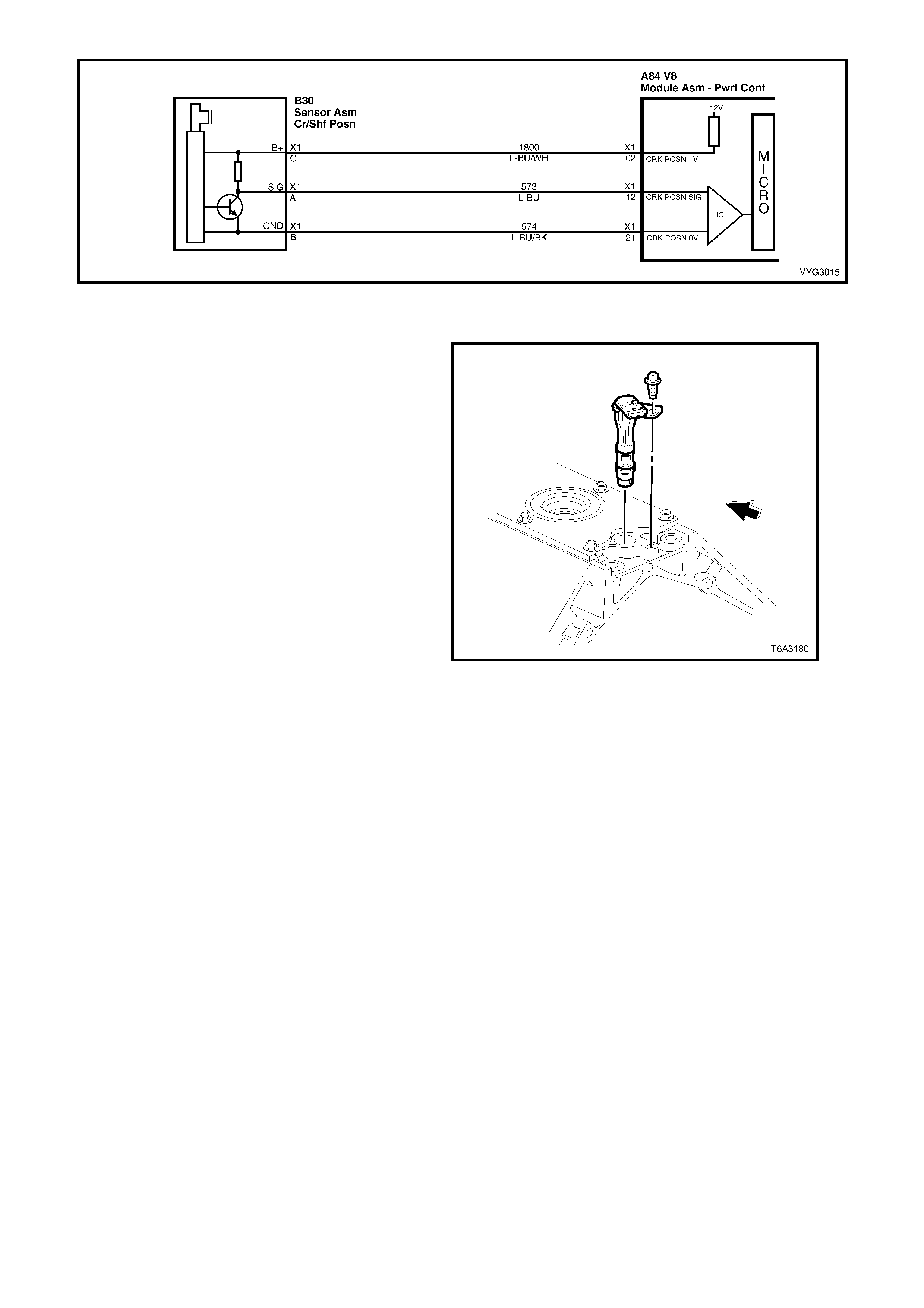
Figure 6C3-1-64 – Crankshaft Position Sensor Circuit
CAMSHA FT POSITION (CMP) SENSOR
The Camshaft Position Sensor (CMP) is mounted
through the top of the engine bloc k at the rear of the
valley cover and works in conjunction with a 1X
reluctor wheel on the camshaft. The reluctor wheel
is ins ide the engine, im mediately in front of the r ear
cam bearing. The PCM provides a 12 volt power
supply to the CMP sensor as well as a ground and a
signal circuit.
The PCM uses the CMP signal in order to
determine whether a cylinder is on a firing or
exhaust stroke. As the camshaft rotates, the
reluctor wheel interrupts a magnetic field produced
by a magnet within the CMP sensor. The CMP
sensor’s internal circuitry detects this and produces
a signal which the PCM reads. The PCM uses this
1X signal in combination with the Crankshaft
Position Sensor 24X signal in order to determine
the crankshaft position and stroke.
If the PCM is receiving a 24X Crankshaft Position
sensor signal, the engine will start even if there is
no CMP s ensor s ignal. The PCM cannot determ ine
when a particular cylinder is on either a firing or
exhaust stroke by the 24X signal alone, the PCM
requires the CMP signal in order to determ ine if the
cylinder is on either the firing or exhaust stroke.
Figure 6C3-1-65–Camshaft Position Sensor
(CMP) Location
If there is no CMP signal present the system attempts synchronisation and looks for an increase in MAF signal
indicating the engine started. If the PCM does not detect a MAF increase, the PCM assumes it is incorrectly
synchronised to the exhaus t s tr oke and re-s ynchronises to the opposite c am pos ition. A slightly longer cranking time
may be a symptom of this condition.
This diagnostic for the Camshaft Position Sensor checks for camshaft position sensor signal. The PCM also
monitor s the CMP sensor signal c ircuit f or m alfunctions . The f ollowing DTCs are s et when the PCM detects a CMP
sensor that is out of the normal operating range:
• DTC P0341: Camshaft Position (CMP) Sensor Circuit Performance.
• DTC P0342: Camshaft Position (CMP) Sensor Circuit Low Voltage.
• DTC P0343: Camshaft Position (CMP) Sensor Circuit High Voltage.
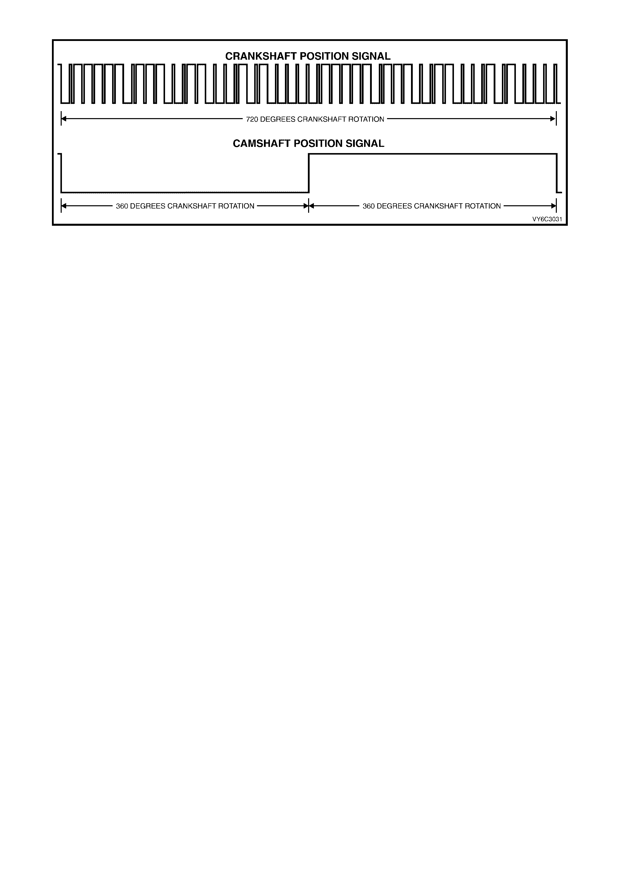
Figure 6C3-1-66 – Camshaft and Crankshaft Position Sensor Signal
DTC P0341 CAMSHAFT POSITION SENSOR CIRCUIT PERFORMANCE
Conditions for running DTC P0341
• The ignition voltage is between 5 and 17.0 volts.
• The engine speed is greater than 400 RPM.
Conditions for setting DTC P0341
• The PCM detects that a CMP to CKP mismatch has occurred for at least 10 seconds.
Action taken when DTC P0341 Sets
• The PCM activates the Malfunction Indicator Lamp (MIL) when the diagnostic runs and fails.
• The PCM records the operating conditions at the time the diagnostic fails. The PCM stores this information in
the Freeze Frame/Failure Records.
Conditions for clearing the Malfunction Indicator Lamp (MIL) and DTC P0341
• The PCM deactivates the Malfunction Indicator Lamp (MIL) when the diagnostic runs and does not fail.
• A last test failed (current DTC) clears when the diagnostic runs and does not fail.
DTC P0342 CAMSHAFT POSITION SENSOR CIRCUIT LOW VOLTAGE
Conditions for running DTC P0342
• The ignition voltage is between 5 and 17.0 volts.
• The engine speed is greater than 400 RPM.
Conditions for setting DTC P0342
• The PCM detects the CMP sensor signal is low when the signal should be high for at least one second.
Action taken when DTC P0342 Sets
• The PCM activates the Malfunction Indicator Lamp (MIL) when the diagnostic runs and fails.
• The PCM records the operating conditions at the time the diagnostic fails. The PCM stores this information in
the Freeze Frame/Failure Records.
Conditions for clearing the Malfunction Indicator Lamp (MIL) and DTC P0342
• The PCM deactivates the Malfunction Indicator Lamp (MIL) when the diagnostic runs and does not fail.
• A last test failed (current DTC) clears when the diagnostic runs and does not fail.
DTC P0343 CAMSHAFT POSITION SENSOR CIRCUIT HIGH VOLTAGE
Conditions for running DTC P0343
• The ignition voltage is between 5 and 17.0 volts.
• The engine speed is greater than 400 RPM.
Conditions for setting DTC P0343
• The PCM detects the CMP sensor signal is high when the signal should be low for at least one second.
Action taken when DTC P0343 Sets
• The PCM activates the Malfunction Indicator Lamp (MIL) when the diagnostic runs and fails.
• The PCM records the operating conditions at the time the diagnostic fails. The PCM stores this information in
the Freeze Frame/Failure Records.
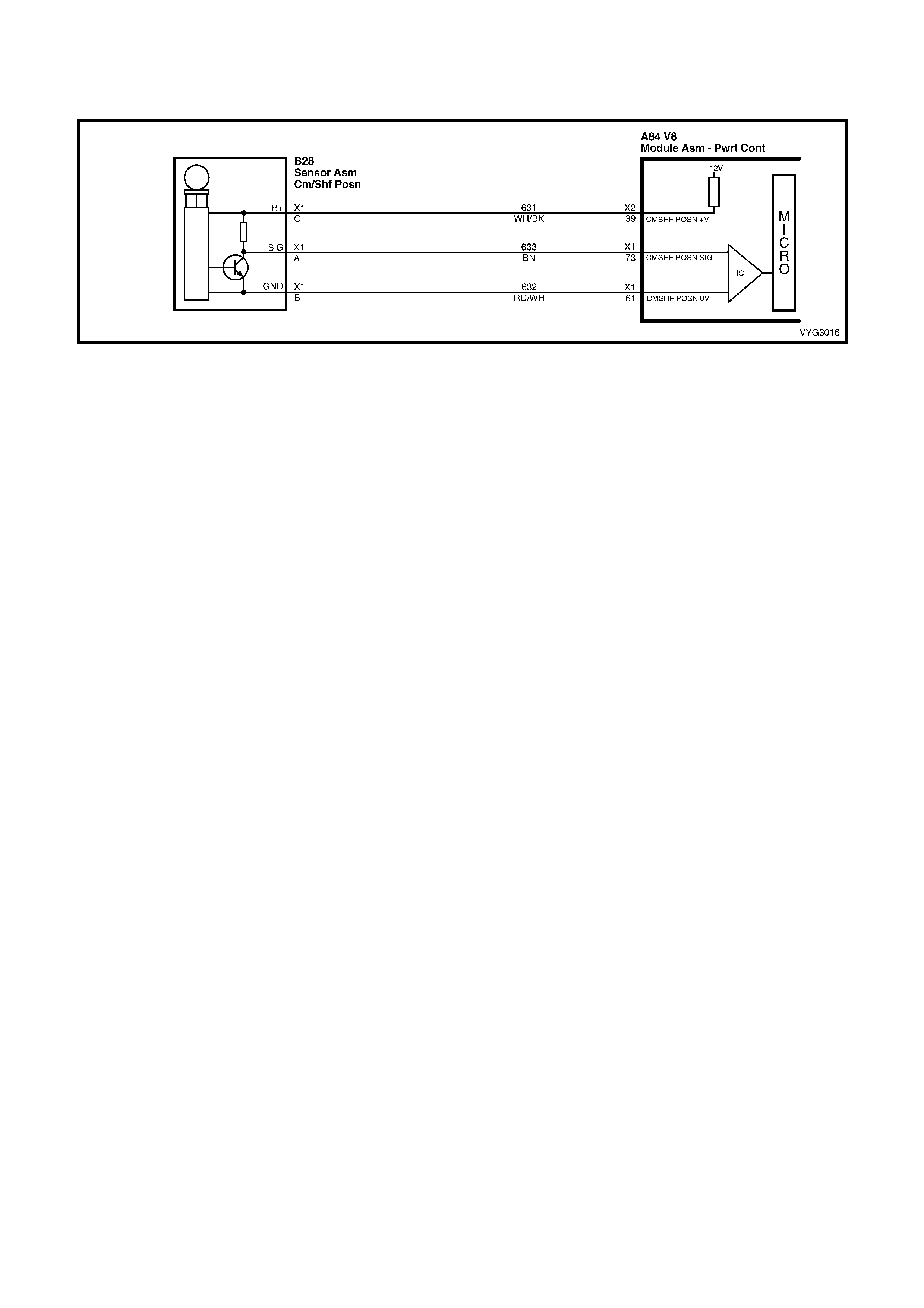
Conditions for clearing the Malfunction Indicator Lamp (MIL) and DTC P0343
• The PCM deactivates the Malfunction Indicator Lamp (MIL) when the diagnostic runs and does not fail.
• A last test failed (current DTC) clears when the diagnostic runs and does not fail.
Figure 6C3-1-67 – Camshaft Position Sensor Circuit
BATTERY VOLTAGE
The PCM continually monitors battery voltage. W hen the battery voltage is low, the ignition system may deliver a
weak spark and the injector mechanical movement takes longer to open the injector.
The Powertrain Control Module will compensate by:
1. Increasing the ignition coil dwell time if the battery voltage is less than 12 volts.
2. Increasing the engine idle RPM if battery voltage drops below 10 volts.
3. Increasing the injector pulse width if the battery voltage drops below 10 volts.
On vehicles equipped with autom atic tr ansm iss ion, Diagnostic T rouble Code (D TC) P0563 will set when the ignition
is ON and PCM voltage is more than 17 volts for about 5 seconds.
Diagnostic Trouble Code (DTC) P0562 will set when the ignition is ON and PCM voltage is too low.
DTC P0562 SYSTEM VOLTAGE LOW
Conditions for running DTC P0562
• The engine run time is greater than 10 seconds.
• The engine speed is greater than 1000 RPM.
• The vehicle speed is greater than 8 km/h.
Conditions for setting DTC P0562
• The PCM senses system voltage is too low.
• All of the above conditions are present for five seconds.
Action taken when DTC P0562 Sets
• The PCM stores the DTC information into memory when the diagnostic runs and fails.
• The Malfunction Indicator Lamp (MIL) will not be activated.
• The PCM will command a high idle speed.
• The transmission will default to third gear.
• The PCM will inhibit TCC operation.
• The PCM records the operating conditions at the time the diagnostic fails. The PCM stores this information in
the Freeze Frame/Failure Records.
Conditions for clearing the Malfunction Indicator Lamp (MIL) and DTC P0562
• A last test failed (current DTC) clears when the diagnostic runs and does not fail.
DTC P0563 SYSTEM VOLTAGE HIGH
Conditions for running DTC P0563
• The engine is running longer than 10 seconds.
Conditions for setting DTC P0563
• The PCM senses system voltage above 17 volts.
• All of the above conditions are present for five seconds.

Action taken when DTC P0563 Sets
• The PCM stores the DTC information into memory when the diagnostic runs and fails.
• The Malfunction Indicator Lamp (MIL) will not be activated.
• The PCM will disable most outputs.
• The transmission will default to third gear.
• The PCM will inhibit TCC operation.
• The PCM will cycle the cooling fans ON and OFF every few seconds during the time the condition is present.
• The PCM records the operating conditions at the time the diagnostic fails. The PCM stores this information in
the Freeze Frame/Failure Records.
Conditions for clearing the Malfunction Indicator Lamp (MIL) and DTC P0563
• A last test failed (current DTC) clears when the diagnostic runs and does not fail.
Figure 6C3-1-68 – Battery Power Supply Circuit
TRANSMISSION POWER/ECONOMY SWITCH
The Power/Economy (PWR) switch is used to
modify upshifts and shift times. The driver can
select either Economy or Power mode with the
switch (1) located in the centre console. A third
mode, Cruise, is available via a switch located on
the indicator stalk (where fitted).
Two icons are located in the instrument cluster
Multi-Function Display (MFD) that display POWER
or CRUISE when activated, to inform the driver of
the mode that is enabled.
The PCM provides a voltage signal of about 12
volts, and monitors the status of this circuit. In the
Econom y position, the switch is open and the PCM
voltage status signal remains high, about 12 volts.
The PCM does not allow shift point changes in the
Economy mode. When the transmission switch is
pressed to the Power position the switch is
momentarily closed and the PCM voltage status
signal is mom entarily pulled low, to about 0.5 volts.
The PCM senses this m omentary voltage drop and
enables Power mode (alternate shift pattern tables
to be utilised).
Figure 6C3-1-69 – Transmission Power/Economy Switch
(RHD Drive Shown – LHD Opposite)
In the Power mode, the Torque Converter Clutch (TCC) can be applied in 3rd and 4th gears. When the TCC is
applied in 3rd gear it will stay applied until the normal 4th gear upshift criteria is met. W hen the 3-4 upshift occurs,
the TCC will be released mom entarily. Also, in the Power m ode while in D gear select position, the PCM will delay
the 1-2 and 2-3 shifts while under light throttle. The shift patterns will be the same in the Economy and Power
modes if the T hrottle Position (T P) s ensor is between 80% – 100%. The Power m ode should be us ed when towing,
as applying the TCC in 3rd and 4th gear reduces slippage in the torque converter and thus reduces heat build up.
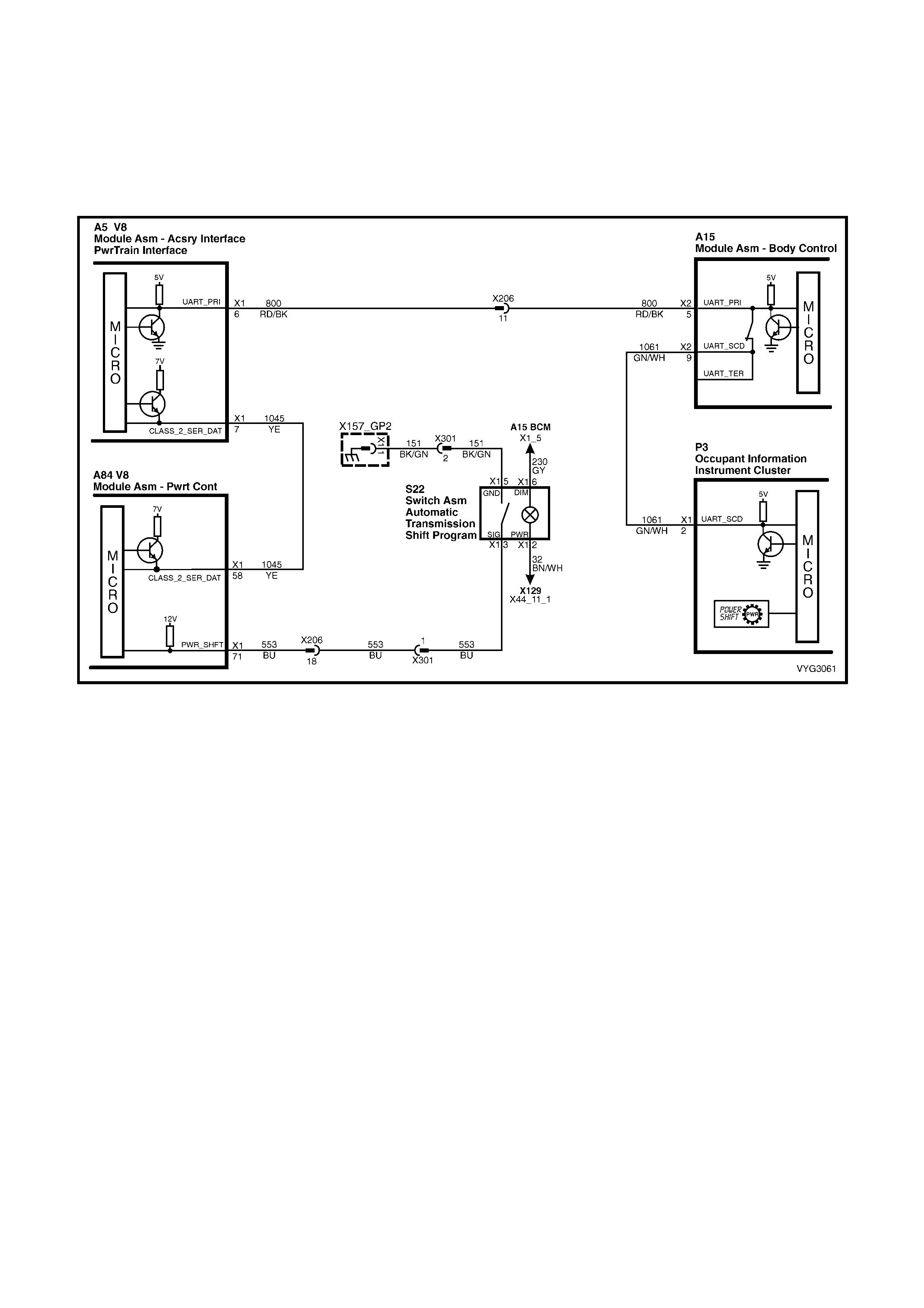
In Cruise m ode operation, when the driver activates the cruise c ontrol, the POW ER lam p and Power m ode will turn
OFF (if vehicle was in power mode) and a CRUISE lamp will illuminate on the instrument panel. The transm ission
shift patter n will switch to cruis e shif t pattern. When in c ruise m ode the PCM will m odify the trans m ission calibration
so that transmission shift activity is reduced.
When the key is turned ON, the PCM shift mode is set to the last mode that was previously selected
(Power/Economy). The cruise control is set to OFF at every key ON cycle.
For replacement of the ‘PWR’ switch, refer to Section 7C4 AUTOMATIC TRANSMISSION - ON VEHICLE
SERVICING in the MY 2003 VY and V2 Series Service Information.
Figure 6C3-1-70 – Power/Economy Switch Circuit
THEFT DETERRENT SYSTEM
The theft deter rent system on MY 2003 VY and V2 Series Models, uses a rem ote coded k ey to arm and dis arm the
system, as well as electrically lock or unlock all doors and tailgate (station wagon), or operate the boot unlock
mechanism (sedan models).
The thef t deterrent alert indicator LED is us ed to indicate the state of the system . A flashing LED indicates that the
system is ar m ed and consequently the vehicle cannot be started. When the LED is turned off, the BCM is dis arm ed
and the engine can be started. The theft deterrent LED is incorporated into the left hand warning display panel in the
instruments and is a stylised, closed padlock.
When the ignition switch is tur ned f r om of f to on, the BCM will transmit s ecur ity inform ation to the PIM via the UART
serial data bus, c irc uit 800. T he PIM c ompares the r ece ived sec ur ity inform ation with it’s stored security infor mation
and if the inf ormation m atches, the PIM will enable the starter r elay, and supply security inform ation (password) via
Class 2 serial data to the PCM. If the pass wor d matches the pas sword stored in the PCM, the system enables the
fuel injection. The PCM will return on OK to start message to the BCM via the PIM, which tells the BCM to switch
from s hort loop mode to the long loop mode. If the PIM does not s end a pass word or if the PCM does not r eceive it,
the vehicle will not start unless the PCM is in Vehicle Theft Deterrent (VTD) Fail-Enable mode. The BCM will only
transm it the correct s ecurity infor mation to the PIM if the BCM has been disarmed via the rem ote coded k ey. If the
BCM, PIM, or PCM lose communication with each other after the system has received the correct password, the
PCM goes into VTD Fail-Enable mode. This allows the driver to restart the vehicle on future ignition cycles until
com munic ations between the BCM, PIM or PCM are restor ed. If the BCM, PIM or PCM lose com m unication before
the PCM receives the BCM password, the PCM disables the f uel injection until communication is restored. In both
cases DTC P1626 sets. The PCM will not disable the fuel injection once the PCM enables the fuel within a given
ignition cycle in order to prevent stalling as a result of theft deterrent system faults.
NOTE 1: Regardless of the engine configuration, it is very important that the remote coded key reader is aligned
correctly with the ignition lock assembly. Misalignment with the remote coded key contact may occur resulting in
intermittent or no engine cranking or starting.
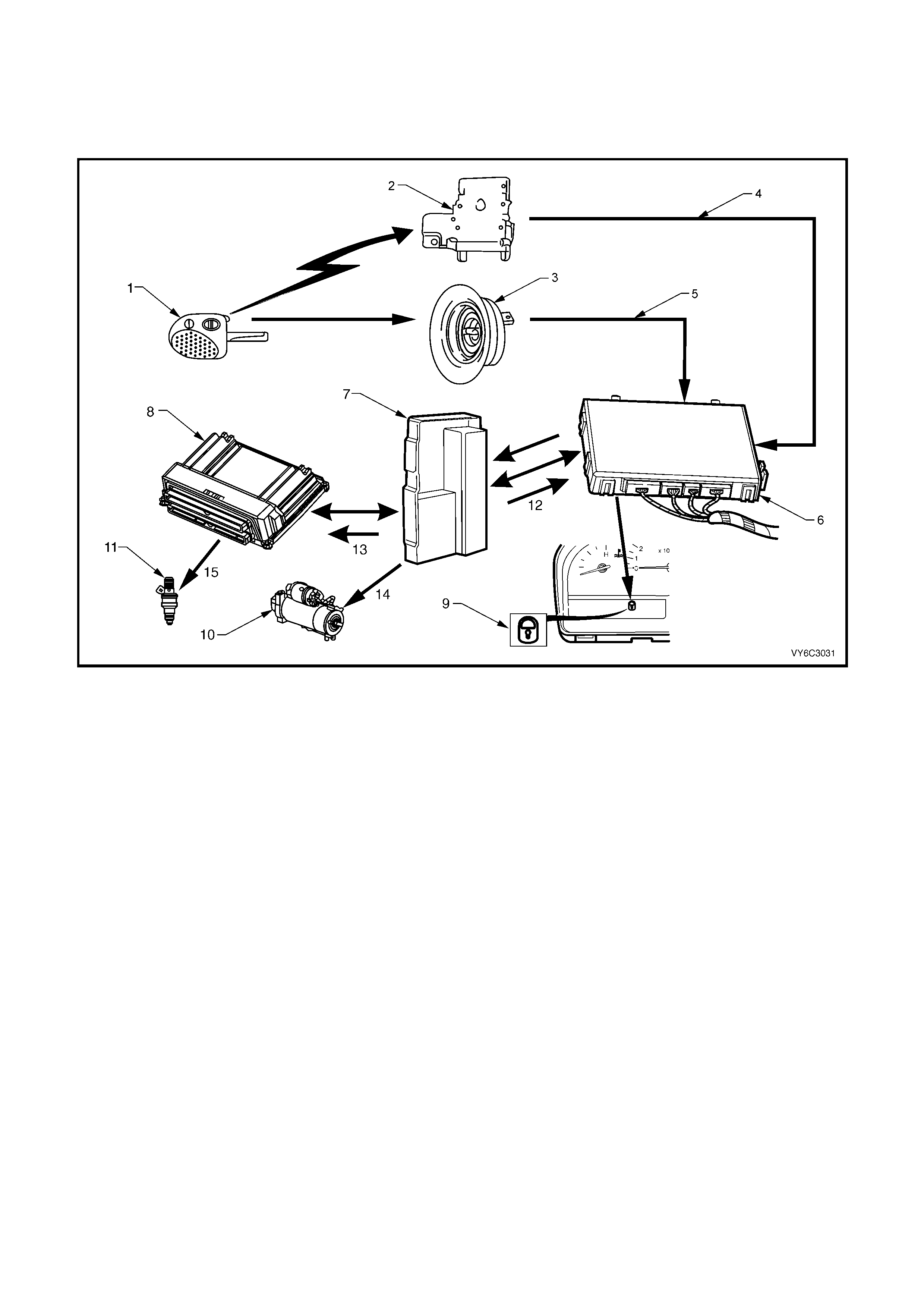
NOTE 2: Should the engine crank briefly when the ignition switch is turned to the START position (ie. due to
mis aligned or a faulty r emote coded k ey reader) then pr essing the unlock button on the remote coded k ey will also
disarm the theft deterrent system.
Refer to Section 12J BODY CO NT ROL MODULE in the MY 2003 VY and V2 Series Service Information for further
information and diagnosis.
Figure 6C3-1-71 – Theft Deterrent System
Legend
1. Remote Coded Key
2. Remote Receiver Module
3. Remote Coded Key Reader Assembly
4. S i gnal from Remote Receiver Module to BCM
5. S i gnal from Key Reader to BCM
6. B ody Control Module (BCM)
7. P owertrain Interface Module (PIM)
8. P owertrain Control Module (PCM)
9. Thef t Deterrent A l ert Indic ator LED
10. Starter Motor
11. Fuel Inject ors (1 of 8)
12. OK to Start from PIM
13. Securit y Code f rom BCM/P IM
14. Signal from PIM to Start Relay
15. Signal from PCM for I nj ector Control
DTC P1626 THEFT DETERRENT SYSTEM FUEL ENABLE CIRCUIT
Conditions for running DTC P1626
• The ignition is ON or the engine is cranking.
Conditions for setting DTC P1626
• The system has reached fuel enable decision point.
• The PCM is in Fail Enable Mode due to loss of communication with the PIM after the system received the
correct password earlier in the ignition cycle.
• The PCM does not receive the password message from the PIM prior to the theft deterrent Fuel Decision Point.
Action taken when DTC P1626 Sets
• The PCM enables the fuel injection on future ignition cycles only if the PCM is in Fail-Enable Mode.
• The PCM activates the Malfunction Indicator Lamp (MIL) when the diagnostic runs and fails.
NOTE: This DTC is usually set if communication is lost. The Malfunction Indicator Lamp (MIL) may not operate.
• The PCM records the operating conditions at the time the diagnostic fails. The PCM stores this information in
the Freeze Frame/Failure Records.
Conditions for clearing the Malfunction Indicator Lamp (MIL) and DTC P1626
• The PCM deactivates the Malfunction Indicator Lamp (MIL) after one ignition cycle that the diagnostic runs and
does not fail.
• A last test failed (current DTC) clears when the diagnostic runs and does not fail.

DTC P1630 THEFT DETERRENT POWERTRAIN CONTROL MODULE IN LEARN MODE
Conditions for running DTC P1630
• The PCM is in the learn password mode.
Conditions for setting DTC P1630
• The PCM is ready to learn a new password from the PIM, but the PIM is not sending a valid password or not
sending a password at all.
Action taken when DTC P1630 Sets
• The engine cranks but may not start.
• The PCM activates the Malfunction Indicator Lamp (MIL) when the diagnostic runs and fails.
• The PCM records the operating conditions at the time the diagnostic fails. The PCM stores this information in
the Freeze Frame/Failure Records.
Conditions for clearing the Malfunction Indicator Lamp (MIL) and DTC P1630
• T he PCM deactivates the Malf unction Indicator Lam p (MIL) after one ignition cycle that the diagnostic runs and
does not fail.
• A last test failed (current DTC) clears when the diagnostic runs and does not fail.
DTC P1631 THEFT DETERRENT PASSWORD INCORRECT
Conditions for running DTC P1631
• The ignition is on and the PCM is waiting for the correct password.
Conditions for setting DTC P1631
• The PCM detects an incorrect password from the PIM.
Action taken when DTC P1631 Sets
• The engine cranks but may not start.
• The PCM activates the Malfunction Indicator Lamp (MIL) when the diagnostic runs and fails.
• The PCM records the operating conditions at the time the diagnostic fails. The PCM stores this information in
the Freeze Frame/Failure Records.
Conditions for clearing the Malfunction Indicator Lamp (MIL) and DTC P1631
• T he PCM deactivates the Malf unction Indicator Lam p (MIL) after one ignition cycle that the diagnostic runs and
does not fail.
• A last test failed (current DTC) clears when the diagnostic runs and does not fail.
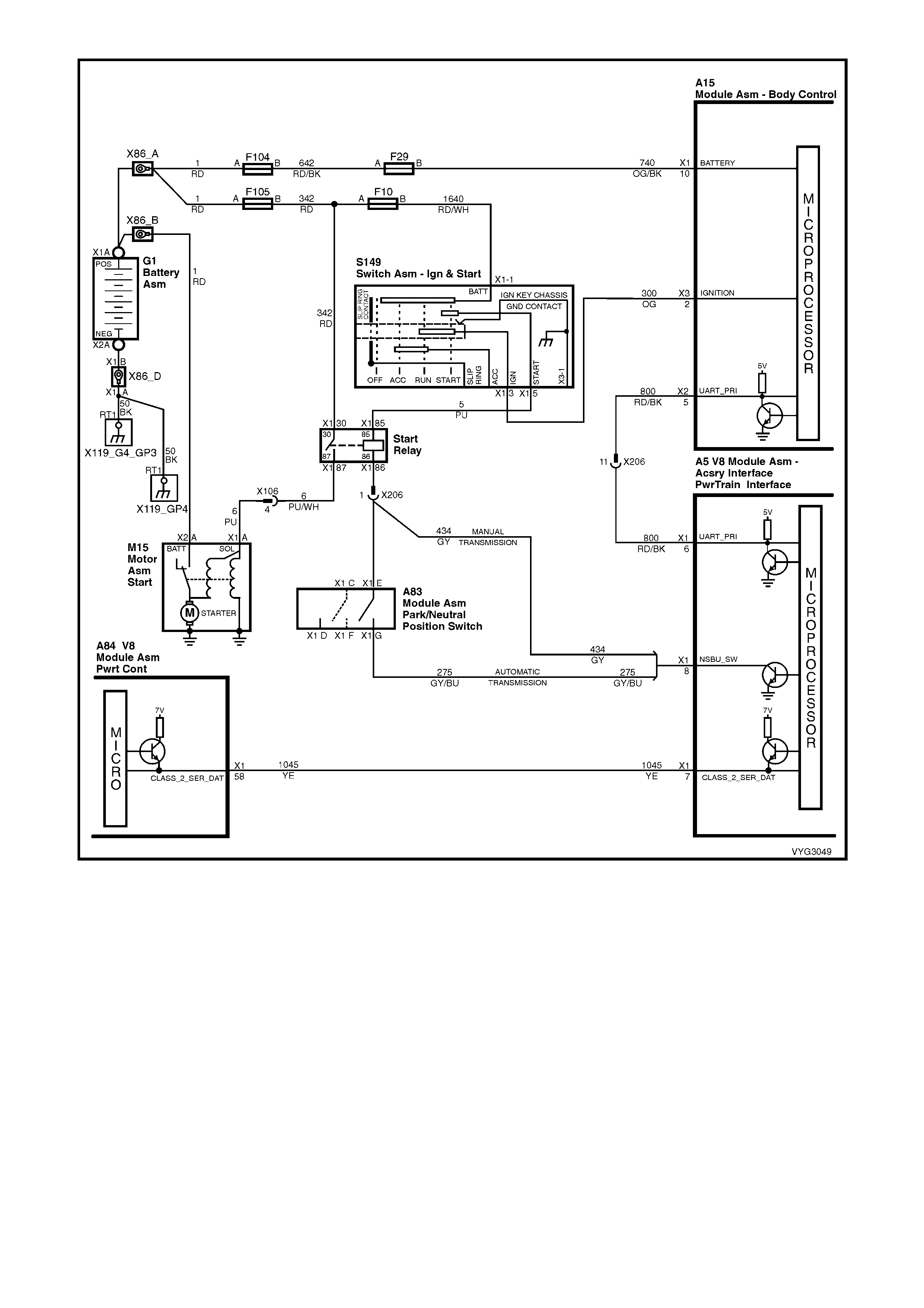
Figure 6C3-1-72 – Theft Deterrent Circuit

ENGINE OIL PRESSURE SENSOR
The Engine O il Pressure s ensor (1) is scr ewed into
the oil gallery at the top rear of the engine block.
The sensor has a five volt reference voltage, a
ground and a signal circuit. The PCM monitors the
voltage on the signal circuit. This voltage will vary
depending on engine oil pressure. T he oil pressure
sensor is used to determine when the oil pressure
is below a certain value. By monitoring the voltage,
the PCM calculates the engine oil pressure and
determines when to activate the ‘Check Oil’
warning icon in the Multi Function Dis play (MFD) in
the Instrument. The PCM will only command the
Instrum ent to activate the ‘Check Oil’ warning icon,
if the oil pressure is below a specified value. This
value increases with RPM. The PCM commands
the Instrument to activate the ‘Check Oil’ warning
icon via the serial data bus normal mode message.
When the PCM detects a malfunction in the oil
pressure sensor circuit, the following DTCs will set:
• DTC P0522: Engine Oil Pressure Circuit Low
Voltage
• DTC P0523: Engine Oil Pressure Circuit High
Voltage
Figure 6C3-1-73 – Oil Pressure Sensor Location
DTC P0522 ENGINE OIL PRESSURE SENSOR LOW VOLTAGE
Conditions for running DTC P0522
• The engine is running.
Conditions for setting DTC P0522
• The engine oil pressure sensor voltage is less than 0.48 volts.
Action taken when DTC P0522 Sets
• The PCM activates the Malfunction Indicator Lamp (MIL) when the diagnostic runs and fails.
• The PCM records the operating conditions at the time the diagnostic fails. The PCM stores this information in
the Freeze Frame/Failure Records.
• ‘Check Oil’ warning icon will bw activated.
Conditions for clearing the Malfunction Indicator Lamp (MIL) and DTC P0522
• The PCM deactivates the Malf unction Indicator Lam p (MIL) after one ignition cycle that the diagnostic runs and
does not fail.
• A last test failed (Current DTC) will clear when the diagnostic runs and does not fail.
DTC P0523 ENGINE OIL PRESSURE SENSOR HIGH VOLTAGE
Conditions for running DTC P0523
• The engine is running.
Conditions for setting DTC P0523
• The engine oil pressure sensor voltage is greater than 4.5 volts.
Action taken when DTC P0523 Sets
• The PCM activates the Malfunction Indicator Lamp (MIL) when the diagnostic runs and fails.
• The PCM records the operating conditions at the time the diagnostic fails. The PCM stores this information in
the Freeze Frame/Failure Records.
• Oil warning lamp will illuminate.
Conditions for clearing the Malfunction Indicator Lamp (MIL) and DTC P0523
• A last test failed (Current DTC) will clear when the diagnostic runs and does not fail.
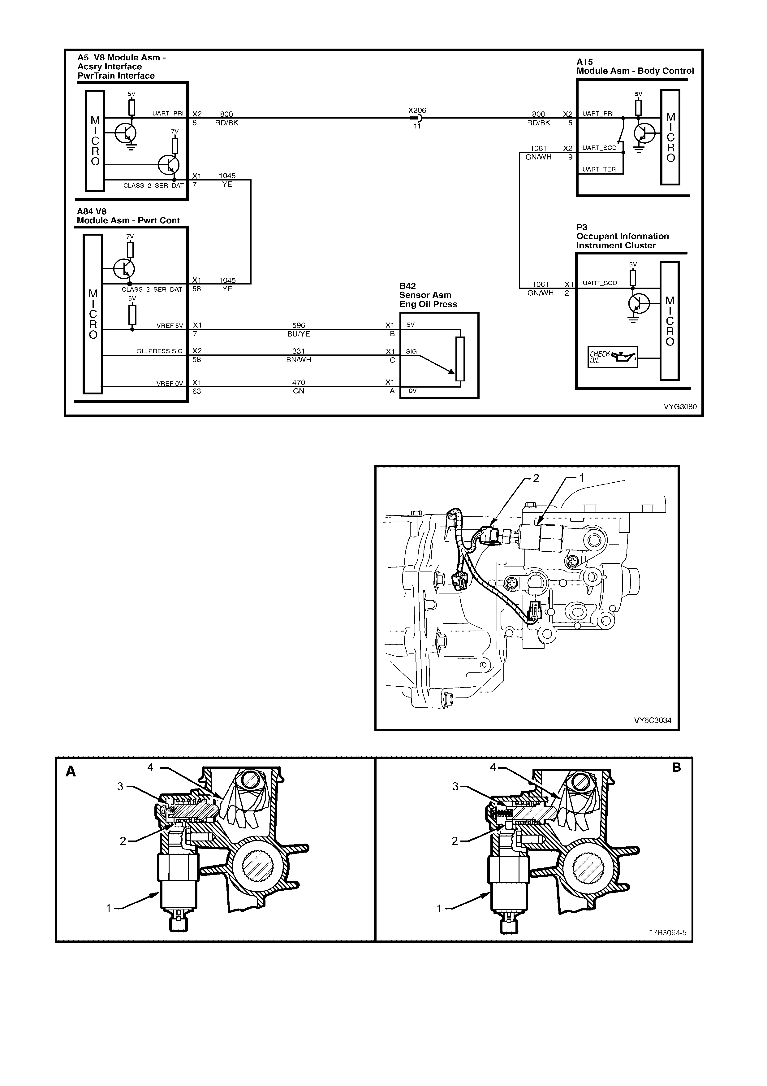
Figure 6C3-1-74 – Oil Pressure Sensor Circuit
MANUAL TRANSMISSION REVERSE INHIBIT SOLENOID
The manual transmission is fitted with a reverse
inhibit mechanism that prevents the selection of
reverse gear when above a speed of 8 km/h. If the
engine is running and the vehicle speed is less than
8 km /h, the reverse inhibit solenoid is energised by
the PCM, pulling the solenoid plunger down, this
allows the Reverse Inhibit plunger to move,
enabling selection of reverse gear.
Above 8 km/h, the PCM de-energises the reverse
inhibit solenoid, causing the solenoid plunger to
block the movement of the spring loaded Reverse
Inhibit plunger. When activated, the rear offset
lever is blocked from rotating to the reverse
selection position.
Legend:
1. Reverse Inhibit Solenoid
2. Reverse Inhibit Harness Connector
Figure 6C3-1-75 – Reverse Inhibit Solenoid
Figure 6C3-1-76 – Reverse Inhibit Solenoid Operation View
Legend
A Road Speed Less than 8 km/h
B Road Speed Greater than 8 km/h
1. Reverse Inhibit Solenoid.
2. Solenoid Plunger.
3. Reverse Inhibit Plunger.
4. Rear Offset Lever.
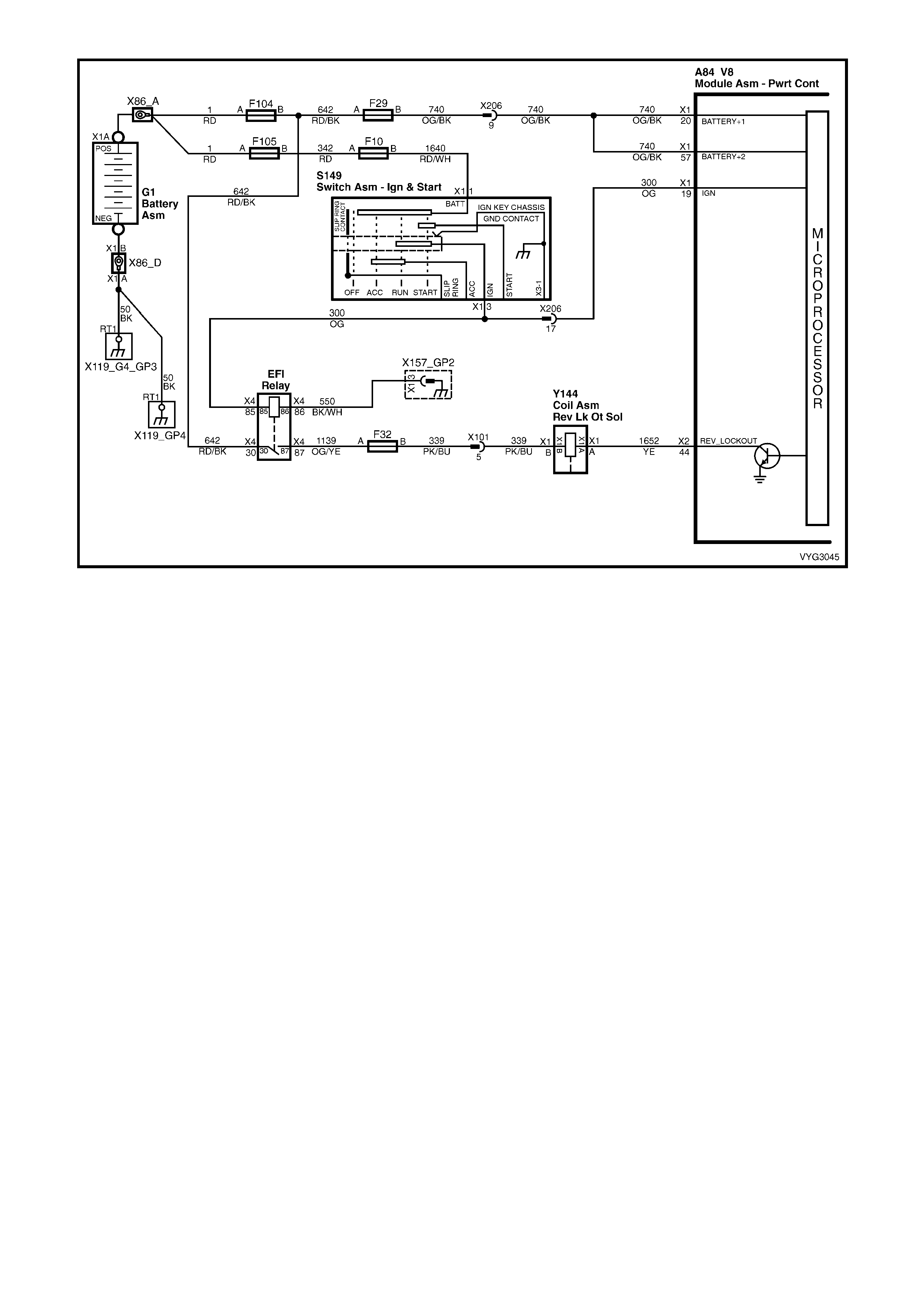
Figure 6C3-1-77 – Reverse Inhibit Solenoid Circuit
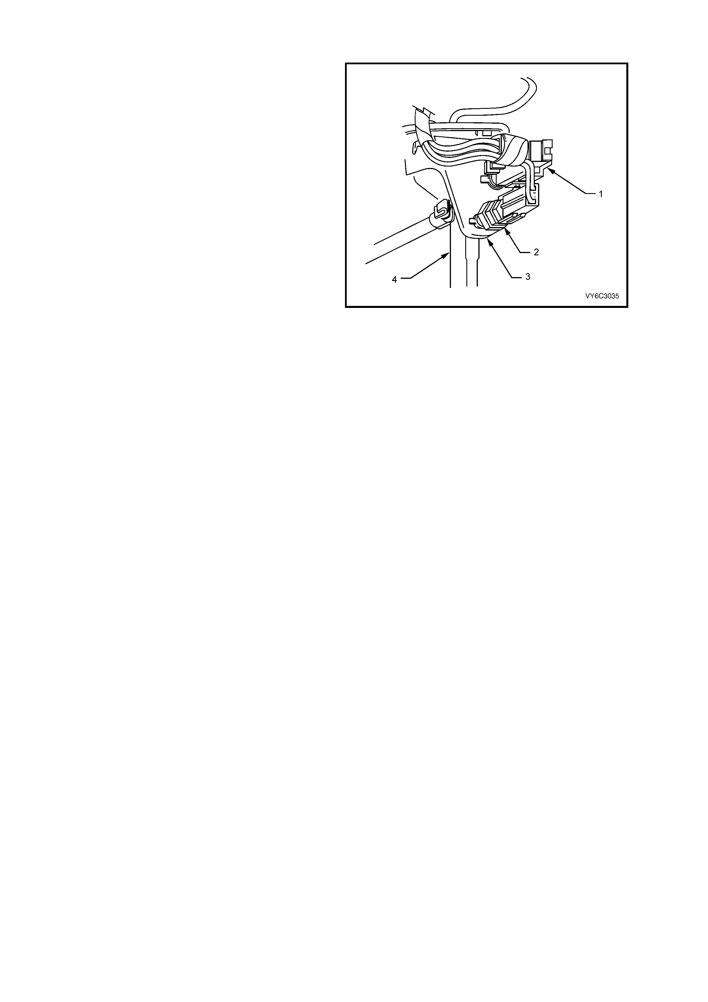
BRAKE PEDAL SWITCHES
There are two electrical switches mounted on the
brake pedal support bracket.
Stop Lamp Switch
The stop lamp switch (2) is a norm ally open switch
that supplies B+ from fuse F5 to the rear brake
lamps when the brake pedal is depressed. It also
supplies 12 volts to the cruise control actuator and
a brake applied 12 volt input signal to terminal 14 of
the ABS or ABS/TCS control module.
Whenever the ABS or ABS/TCS control module
does not receive this signal at start up, the ABS or
ABS/TCS self test will begin as soon as vehicle
speed is at approximately 6 km/h. If the driver
depresse s the brak e pedal during this initial ABS or
ABS/TCS cycle, the self test will not occur until the
vehicle speed is approximately 18 km/h. Also, if at
any time during Traction Control mode the brakes
are manually applied, this brake switch signals the
ABS or ABS/TCS control module to inhibit brake
intervention and allow for manual braking (engine
torque management may still occur if necessary).
This stop lamp switch 12 volt signal is also used
to signal the cruise control module to disengage
when the brake pedal is depressed. For all
service oper ations on the stop lam p switch, ref er to
Section 12B LIGHTING SYSTEM MY 2003 VY
and V2 Series Service Information.
Figure 6C3-1-78 – Brake Pedal Switches Location
Legend
1. Cruise Control Release Switch
2. Stop Lamp Switch
3. Brake Pedal Support Bracket
4. Brake Pedal
Cruise Control Release Switch
The cruise control s witch (1) is a nor mally closed switch, and supplies a 12 volt signal from the Low Tr action Lamp
(through a resistor adjacent to the Low Traction Lamp) to the PCM and the Cruise Control Actuator. When the
brake pedal is depressed, the 12 volt supply signal is removed from the PCM and the Cruise Control Actuator.
When the PCM determines that this 12 volt signal has been removed, the PCM will disengage the automatic
transmission Torque Converter Clutch (TCC) until this 12 volt signal is re-established to the PCM. Also, the cruise
control actuator will deactivate the c ruise control operation ( the cruise set speed will be retained in m em ory). Onc e
the brake pedal is released, the cruise set speed can be re-established by selecting the cruise resume switch.
Also, associated on this cruise control release switch (1) circuit is the ABS/T CS module Low Traction icon control.
The ABS/TCS module will supply a ground signal to the Instruments when traction control is being requested. When
the PCM receives this ground signal, the PCM will inhibit TCC operation and activate the engine torque
management operation. The cruise control will also be deactivated.
If there is a problem with the circuit between the Low Traction icon and the PCM, DTC P0719 or P0724 will set.
Both switches are used to signal the cruise control module so that if one should fail, the second switch will still
generate a signal to the cruise control module to disengage the cruise control operation. When either DTC P0719 or
P0724 is present, the cruise control is disabled because of the loss of signal from the brake switch input.
For all service operations on the cruise electrical release switch, refer to Section 12E CRUISE CONTROL in the
MY 2003 VY and V2 Series Service Information.
DTC P0719 BRAKE SWITCH CIRCUIT LOW INPUT
Conditions for running DTC P0719
• No VSS assembly DTCs P0502 or P0503.
• The ignition switch is in the RUN position.
Conditions for setting DTC P0719
• The PCM detects an open brake switch circuit (0 volts) for 15 minutes without changing for 2 seconds, and the
following events occur seven times:
– The vehicle speed is less than 8 km/h;
– Then the vehicle speed is 8 – 32 km/h for four seconds;
– Then the vehicle speed is greater than 32 km/h for six seconds.
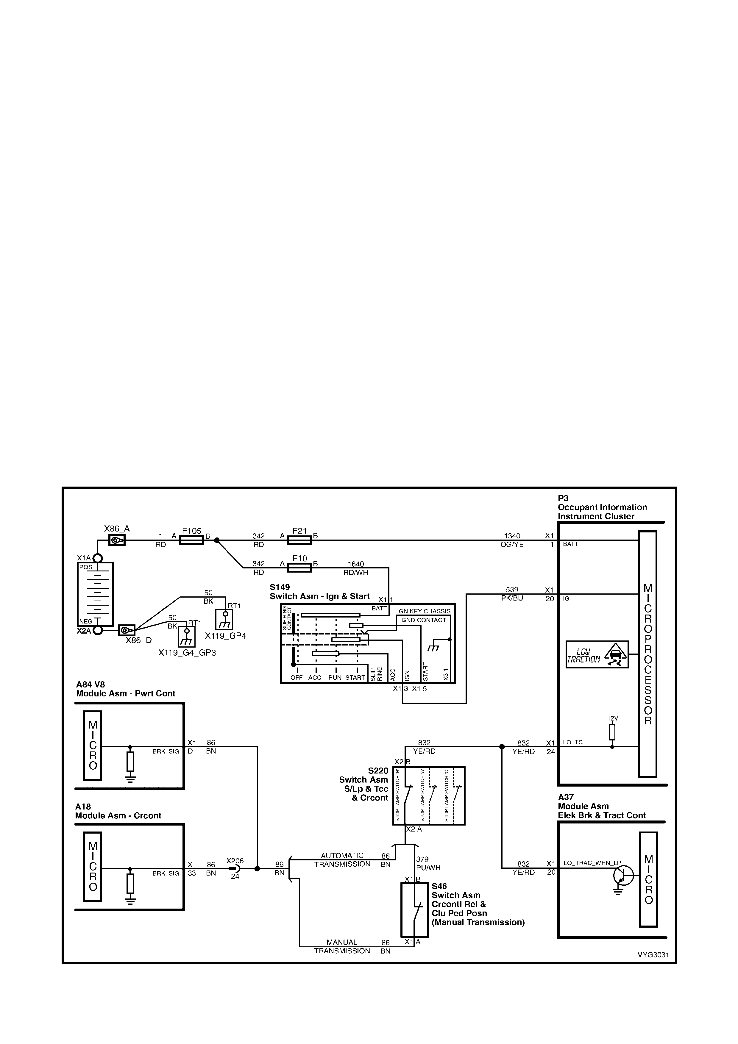
Action taken when DTC P0719 Sets
• The PCM stores the DTC information into memory when the diagnostic runs and fails.
• The Malfunction Indicator Lamp (MIL) will not be activated.
• The PCM disregards the brake switch input for TCC scheduling.
• The PCM records the operating conditions at the time the diagnostic fails. The PCM stores this information in
the Freeze Frame/Failure Records.
Conditions for clearing the Malfunction Indicator Lamp (MIL) and DTC P0719
• A last test failed (current DTC) clears when the diagnostic runs and does not fail.
DTC P0724 BRAKE SWITCH CIRCUIT HIGH INPUT
Conditions for running DTC P0724
• No VSS assembly DTCs P0502 or P0503.
• The ignition switch is in the RUN position.
Conditions for setting DTC P0724
• The PCM detects an closed brake switch circuit (12 volts) without changing for 2 seconds, and the following
events occur seven times:
– The vehicle speed is greater than 32 km/h for six seconds;
– Then the vehicle speed is 8 – 32 km/h for four seconds;
– The vehicle speed is less than 8 km/h.
Action taken when DTC P0724 Sets
• The PCM stores the DTC information into memory when the diagnostic runs and fails.
• The Malfunction Indicator Lamp (MIL) will not be activated.
• The PCM records the operating conditions at the time the diagnostic fails. The PCM stores this information in
the Freeze Frame/Failure Records.
Conditions for clearing the Malfunction Indicator Lamp (MIL) and DTC P0724
• A last test failed (current DTC) clears when the diagnostic runs and does not fail.
Figure 6C3-1-79 – Brake Pedal Switch
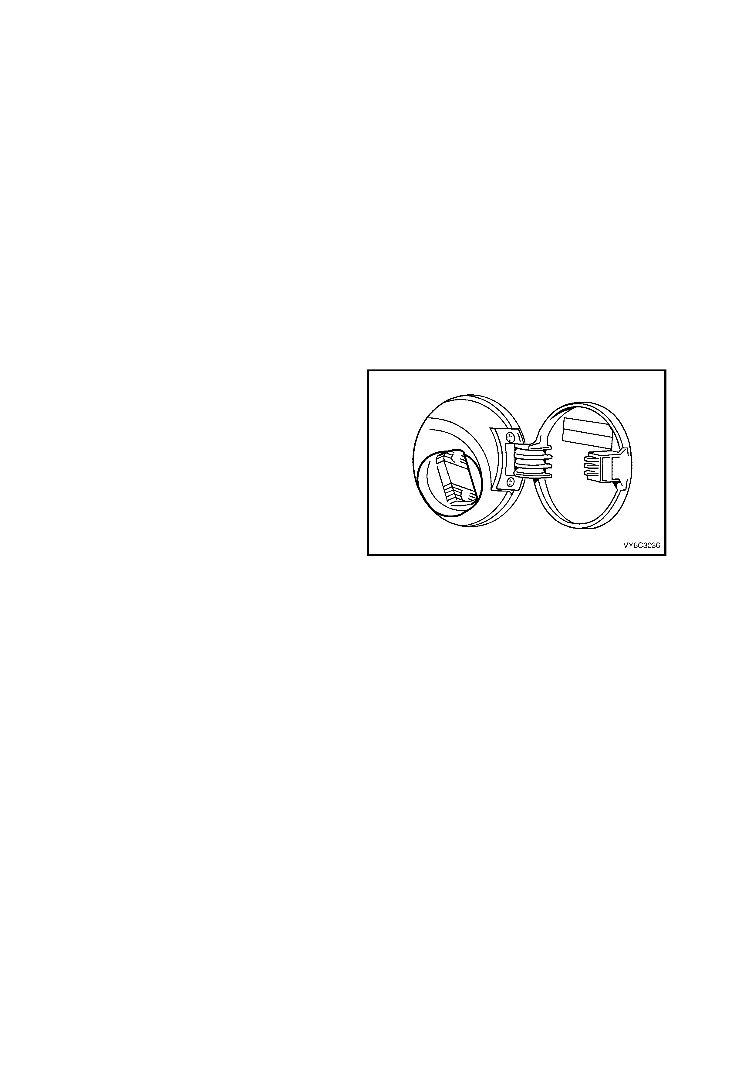
1.4 FUEL CONTROL SYSTEM
SYSTEM OVERVIEW
An electric f uel pum p, located in the f uel tank with the fuel sender assem bly, pumps fuel through an in-line f uel filter
to the fuel rail assembly. The pump provides fuel at a pressure greater than is needed by the injectors. The fuel
pressure regulator, part of the modular fuel sender assembly, keeps fuel available to the injectors at a regulated
pressure. A separate pipe returns unused fuel to the fuel tank.
COMPONENTS
Fuel Tank Vent Valve
The fuel tank vent valve is located in the rear of the vehicle near the fuel tank. The fuel tank vent valve is a
pressur e/vacuum relief valve. W hen the f uel tank pressu re exceeds a spec ified pressur e, the valve opens allowing
the tank pr essur e to bleed of f. When the f uel tank is in a vacuum c ondition, the vent valve opens when the vacuum
is within a specified range allowing fresh air to be pulled in.
Fuel Tank
The f uel tank is cons tructed from a special plastic and is located under the rear com partm ent f loor. It is secur ed to
the vehicle by three metal straps that attach to the frame.
Fuel Tank Filler Pipe
The fuel tank filler pipe has a built-in restrictor and deflector in order to prevent refuelling with leaded fuel.
Fuel Filler Cap
NOTE: If a fuel filler cap requires replacem ent, use
only a f uel f iller c ap of the same type. Failure to use
the correct fuel filler cap can result in a serious
malfunction of the fuel and evaporative emission
systems.
The fuel filler cap incorporates a torque-limiting
device which prevents the cap from being over
tightened. To ins tall the cap, turn the cap clockwise
until you hear three audible clicks. This indicates
that the cap is correctly torqued and fully seated.
Figure 6C3-1-80 – Fuel Filler Cap
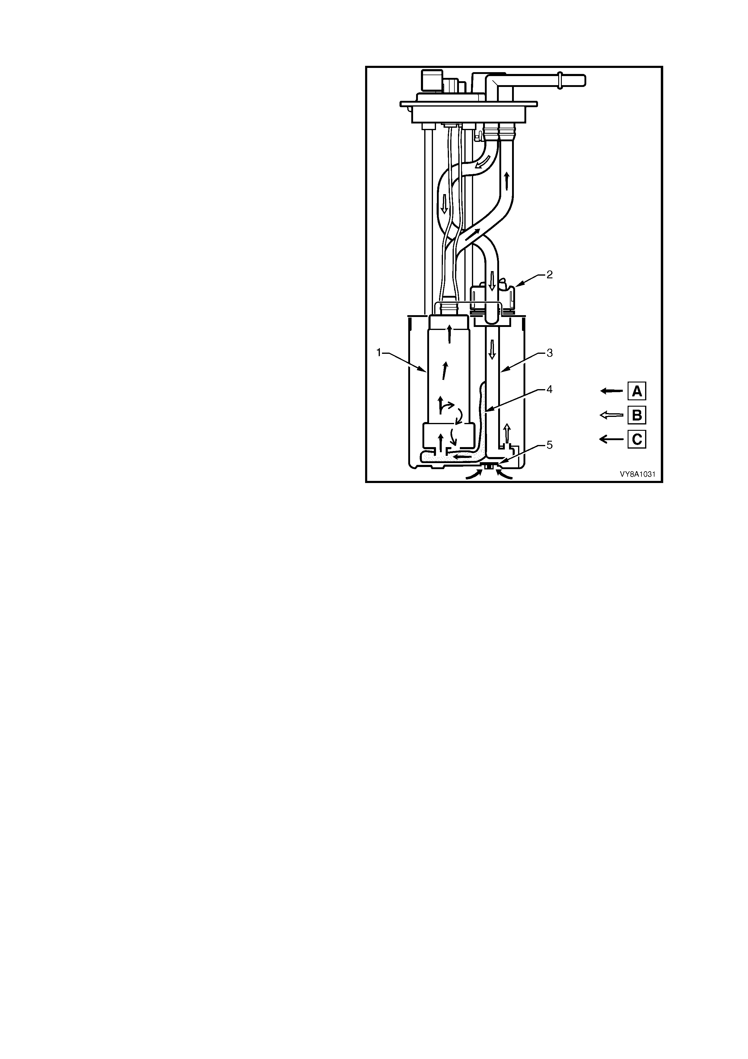
Modular Fuel Sender Assembly
The fuel sender assembly, mounted inside the fuel
tank, is attached to the top of the fuel tank . T he fuel
sender assembly consists of the following major
components:
• The fuel level sensor
• The fuel pump
• The fuel pressure regulator
• The fuel pump strainer
NOTE: Ther e are no ser viceable com ponents in the
part of the fuel sender assembly is the fuel lever
sensor. All other components require replacement
of the complete fuel sender assembly.
Legend:
A. Fuel Flow In
B. Fuel Flow Return
C. Fuel Vapour
1. Single Turbine Fuel Pump
2. Fuel Pressure Regulator
3. Jet Pump Standpipe
4. Internal Strainer
5. Primary Umbrella Valve
Figure 6C3-1-81 – Modular Fuel Sender Assembly
Fuel Pump
The fuel pump attaches to the modular fuel sender assembly inside the fuel tank and is an electric, high pressure
single turbine fuel pump. The fuel pump provides fuel to the fuel rail assembly at a specified flow and pressure.
Excess fuel returns to the fuel tank by the return pipe, located at the output side of the in-line fuel filter.
The fuel pum p deliver s a constant f low of f uel to the engine even during low f uel conditions and aggress ive vehicle
manoeuvr es. T he PCM contr ols the electr ic f uel pum p operation through a f uel pum p relay. T he fuel pump flex pipe
has a quick-connect fitting. The fuel return hose attaches to the fuel pressure regulator. The fuel pump flex pipe
acts to dampen the fuel pulses and noise generated by the fuel pump.
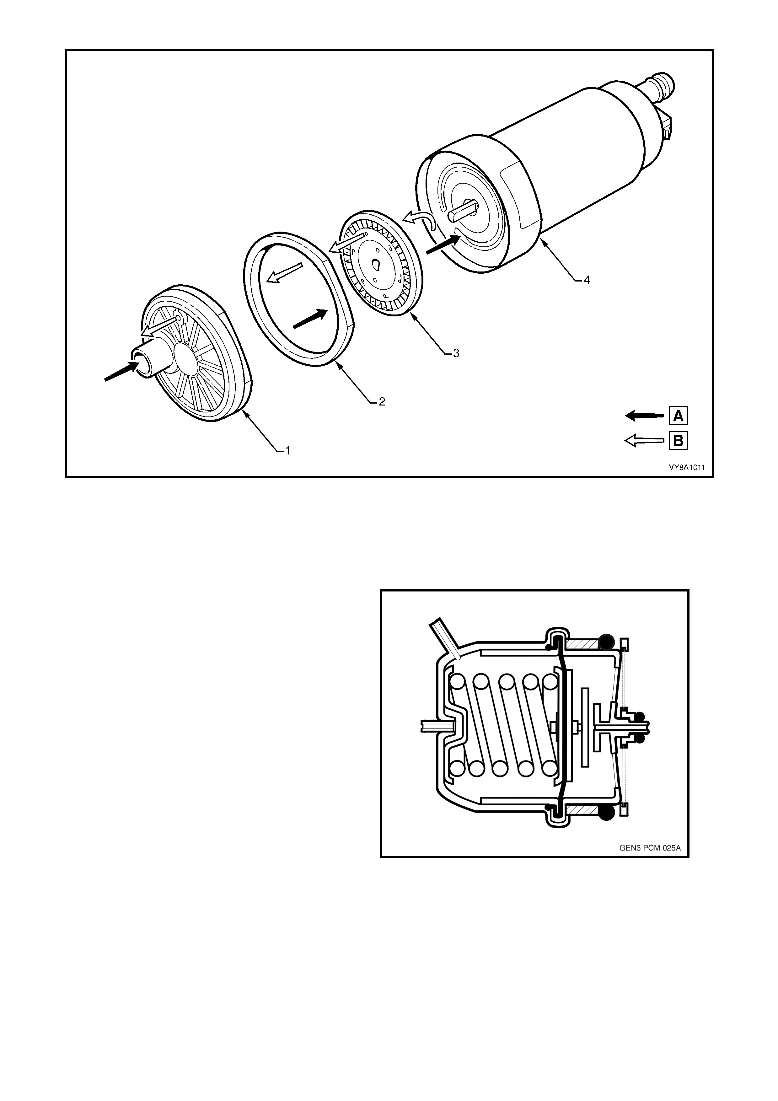
Figure 6C3-1-82 – Single Turbine Fuel Pump
Legend
A Fuel Flow
B Vapour Return 1. Inlet Body
2. Impeller Housing 3. Impeller
4. Fuel Housing
Fuel Pressure Regulator Assembly
The fuel pressure regulator is located in the
modular fuel sender and is a diaphragm operated
relief valve with fuel pump pressure on one side
and atmospheric pressure combined with
mechanical spring pressure on the other. The
function of the regulator is to maintain a regulated
pressure at the injectors at all times by controlling
the flow into the return line. With the ignition ON
and the engine OFF, system fuel pressure at the
pressure test connection should be 380 – 440 kPa.
If the pressure is too low, poor performance could
result. If the pressure is too high, excessive odour
and Diagnostic Trouble Codes (DTC) P0132,
P0152, P0172, or P0175 may result. Refer to
Fuel System Diagnosis in Section 6C3-2A
DIAGNOSTIC TABLES, for information on
diagnosing fuel pressure conditions.
Figure 6C3-1-83 – Fuel Pressure Regulator

Fuel Pump Strainer
The f uel pump s tr ainer ( 5) is made of woven plastic
and is attached to the lower end of the fuel pump.
The strainers their functions are to filter
contaminants and to wick fuel.
The fuel pump strainer is self-cleaning and
normally requires no maintenance. Fuel stoppage
at this point indicates that the fuel tank contains an
abnormal amount of sediment or water. Clean the
fuel tank and replace fuel sender assembly, as the
strainer is not serviced separately.
Legend:
A. Fuel Flow In
B. Fuel Flow Return
C. Fuel Vapour
1. Single Turbine Fuel Pump
2. Fuel Pressure Regulator
3. Jet Pump Standpipe
4. Internal Strainer
5. Primary Umbrella Valve
Figure 6C3-1-84 – Modular Fuel Sender Assembly
In-Line Fuel Filter
The f uel f eed pipe has a s teel f ilter ins talled bef or e the f uel inj ect ion system . T he paper f ilter element traps par ticles
in the fuel that may damage the injection system. The filter housing is made to withstand maximum fuel system
pressur e, exposure to fuel additives , and changes in temper ature. Quick- Connect fittings are used at both the filter
inlet and outlet, which are sealed with O-rings.
The fuel filter is to be changed at prescribed service intervals, refer to Section 0B LUBRICATION & SERVICE in
the MY 2003 VY and V2 Series Service Information. A restricted fuel filter should be replaced.
NOTE: For filter replacement, refer to Section 6C3-3 SERVICE OPERATIONS for the necessary procedure, which
mu st be followed, both in the sequence of r emoval and installation of a replacement f ilter. Failure to obser ve these
instructions will most probably cause permanent damage to the flexible line, resulting in unnecessary parts
replacement and expense.
Fuel Feed and Return Pipes
The fuel f eed pipe c arries fuel fr om the f uel tank to the f uel rail assem bly. The fuel retur n pipe carries f uel from the
T-connector located on the outlet side of the fuel filter back to the fuel tank. The fuel pipes consist of three sections:
• The rear fuel pipe assem blies are located from the top of the fuel tank to the chassis fuel pipes. The rear fuel
pipes are constructed of nylon.
• T he c hass is f uel pipes are loc ated under the vehic le and c onnect the r ear fuel pipes to the engine c ompartment
connecting fuel pipe. These pipes are constructed of steel.
• The engine compartment connecting fuel pipe connects the chassis fuel pipe to the engine fuel rail. This fuel
pipe is constructed of nylon.
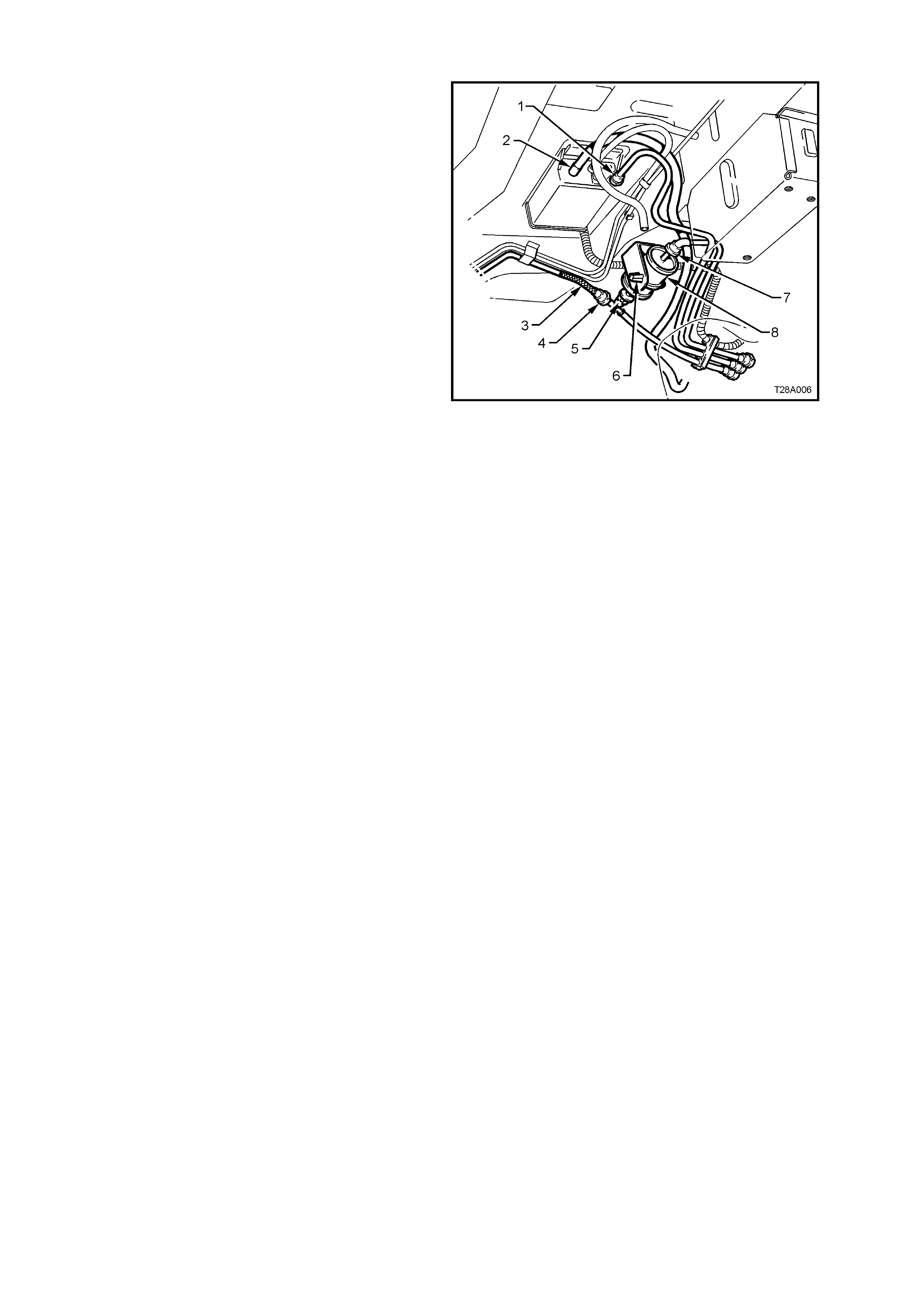
Nylon Fuel Pipes
IMPORTANT: In order to Reduce the Risk of Fire
and Personal Injury:
• If nylon fuel pipes are nicked, scratched or
damaged during installation, Do Not attempt to
repair the sections of the nylon fuel pipes.
Replace them.
• When installing new fuel pipes, Do Not
hamm er directly on the fuel harness body clips
as it m ay dam age the nylon pipes resulting in a
possible leak.
• Always cover nylon vapour pipes with a wet
towel before using a torch near them. Also,
never expose the vehicle to temperatures
higher than 115° C for more than one hour, or
more than 90° C for any extended period.
• Before connecting fuel pipe fittings, always
apply a few drops of clean engine oil to the
male pipe ends. This will ensure proper
reconnection and prevent a possible fuel leak.
During norm al operation, the O-rings loc ated in
the female connector will swell and may
prevent proper reconnection if not lubricated.
Nylon fuel pipes are designed to perform the same
job as the steel or flexible fuel pipes or hoses that
they replace. Nylon pipes are constructed to
withstand maximum fuel system pressure,
exposure to fuel additives, and changes in
temperature. There are three sizes of nylon pipes
used: 3/8” ID for the fuel feed, 5/16” ID for the fuel
return, and 1/2" ID for the vent.
Heat resistant rubber hose and/or corrugated
plastic conduit pr otect the sec tions of the pipes that
are exposed to chafing, high temperature or
vibration.
NOTE: Nylon fuel pipes are somewhat flexible and
can be formed around gradual turns under the
vehicle. However, if nylon fuel pipes ar e f orced into
sharp bends, the pipes will kink and res trict the f uel
flow. Also, once exposed to fuel, nylon pipes may
become stiffer and are more likely to kink if bent
too far. Take special care when working on a
vehicle with nylon fuel pipes.
Figure 6C3-1-85 – Fuel Filter Location
Legend:
1. Quick-Connect, Fuel Tank Vapour Line to Canister
2. Hose, Filler Neck Breather
3. Flexible Line, Fuel Feed to Engine
4. Quick-Connect, Fuel Feed Line
5. Quick-Connect, Fuel Filter T-piece
6. Retaining Tangs, Fuel Filter Strap
7. Quick-Connect, Fuel Feed Line from Fuel Tank
8. Filter, Fuel
Quick-Connect Fittings
Quick -Connect f ittings provide a sim plified m eans of installing and connecting fuel system com ponents. T he fittings
consist of a unique female connector and a compatible male pipe end. O-rings, located inside the female connector,
provide the fuel seal. Integral locking tabs or fingers hold the fittings together.
Fuel Pipe O-Rings
O-rings seal the threaded c onnections in the f uel s ystem and are made of s pec ial material. Ser vice the O -r ing seals
with the correct service part.
Evaporative Pipes and Hoses
The evaporative pipes extend from the fuel sender assembly and the evaporative canister vent solenoid to the
evaporative canister. The evaporative purge pipe extends from the evaporative canister to the evaporative purge
valve in the engine compartment. The rear pipes and the engine compartment pipe are constructed of nylon. The
chassis evaporative purge pipe is constructed of steel.
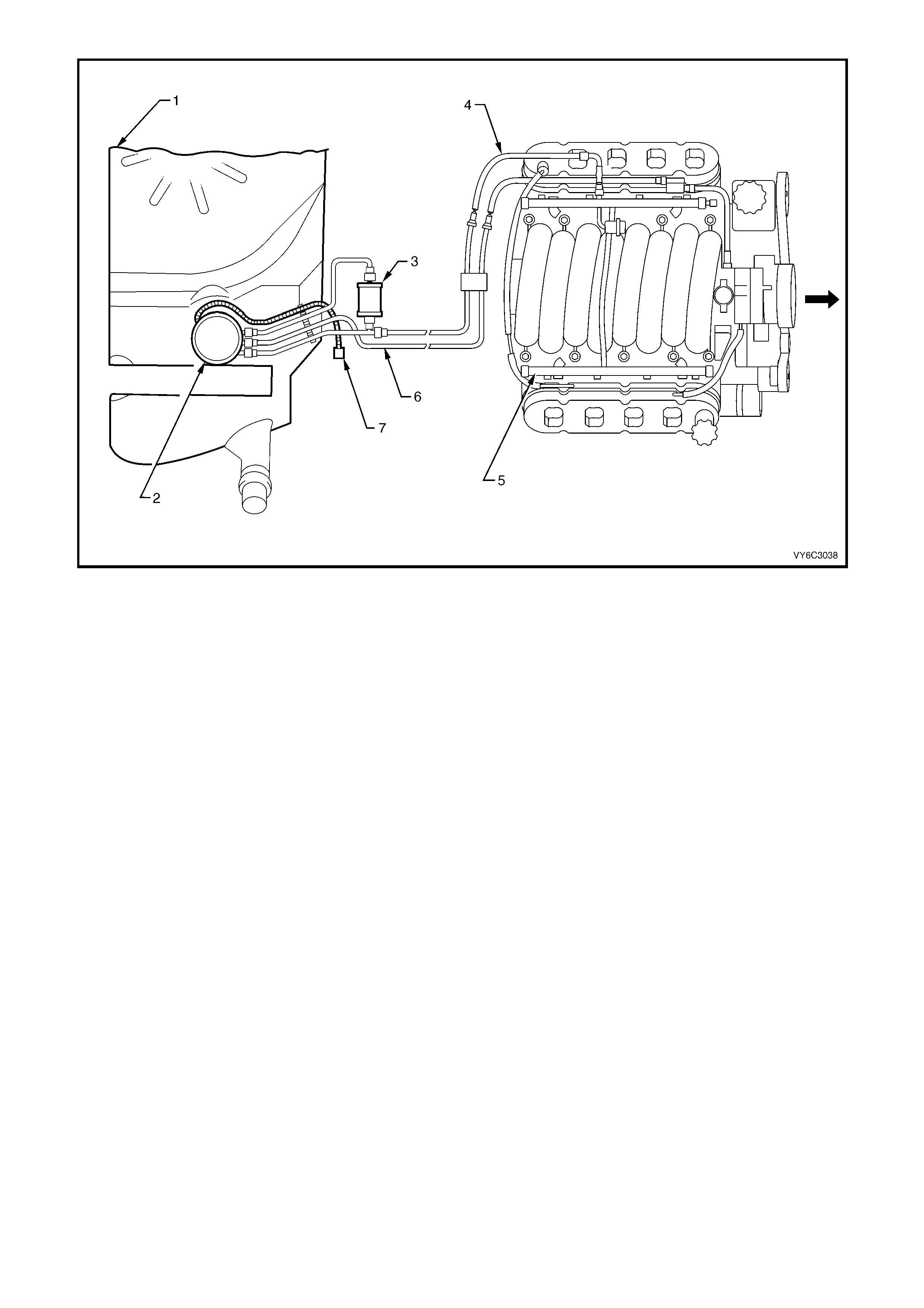
Figure 6C3-1-86 – Fuel Lines
Legend
1. Fuel Tank
2. Modular Fuel Sender Assembly
3. Fuel Filter
4. Fuel Feed Pipe
5. Fuel Rail Assembly
6. Vapour Line
7. Fuel Pump Harness Connector
FUEL METERING MODES OF OPERATION
Modes Of Operation
The PCM looks at voltages from several sensors to determine how much fuel to give the engine. The fuel is
delivered under one of several conditions called modes. The PCM controls all modes.
Starting Mode
W ith the ignition s witch in the ON position (bef ore engaging the starter) , the PCM energises the fuel pum p relay for
two seconds, allowing the fuel pum p to build system pressure. The PCM first check s speed density, then switches
to the Mass Air Flow (MAF) sensor. The PCM also uses the Engine Coolant T emperature (ECT ), Throttle Position
(TP) , and Manifold Absolute Press ure (MAP) sensor s to determine the proper air/f uel ratio fo r s tarting. This ranges
from 8.5:1 to 14.7:1 depending on coolant temperature. The PCM controls the amount of fuel delivered in the
starting mode by changing the pulse width of the injectors. This is done by pulsing the injectors for very short times.
Sequential Fuel Injection Mode
When the engine is first cranked over, all injectors will be energised once, simultaneously. After the engine has
been started and a good ca mshaf t signal has been proc essed, the PCM will energise eac h individual injector in the
normal firing order. This mode of operation helps to stabilise idle, reduce emissions and reduce fluctuations in the
fuel pressure.
Clear Flood Mode
If the engine f loods, clear the engine by pressing the accelerator pedal down all the way. The PCM then pulses the
injectors at an air /fuel ratio of 20:1. The PCM holds this injec tor rate as long as the throttle s tays wide open and the
engine speed is below 300 RPM. If the throttle position becomes less than 80 percent, the PCM returns to the
starting mode.
Run Mode
The run mode has two conditions called O pen Loop, and Closed Loop. When the engine is firs t started, and engine
speed is above a predetermined RPM, the system begins Open Loop operation. The PCM ignores the signal from
the Heated Oxygen Sensors (HO2S) and calculates the air/fuel ratio based on inputs from the ECT, MAF, MAP, and
TP sensors. The system stays in Open Loop until meeting the following conditions:

• Both HO2S have varying voltage output, showing that they are hot enough to operate properly. (This depends
on temperature.)
• The Engine Coolant Temperature (ECT) sensor is above a specified temperature.
• A specific amount of time has elapsed after starting the engine.
Specific values for the above conditions exist for each different engine, and are stored in the Electrically Erasable
Programmable Read Only Memory (EEPROM).
The system begins closed loop operation after reaching these values. In Closed Loop, the PCM calculates the
air/fuel ratio (injector on-time) based on the signal from various sensors, but mainly the HO2S. This allows the
air/fuel ratio to stay very close to 14.7:1.
Acceleration Mode
W hen the driver press es on the acc elerator pedal, air f low into the cylinders inc reases r apidly, while fuel f low tends
to lag behind. To prevent possible hesitation, the PCM increases the pulse width to the injectors to provide extra
fuel acceleration. The PCM determines the amount of fuel required based on Throttle Position, Coolant
Temperature, Manifold Air Pressure, Mass Air Flow and Engine Speed.
Catalyst Protection Mode
During sustained heavy loads the PCM increases the pulse width to the injectors to provide extra fuel, to prevent the
catalytic converter from overheating.
Deceleration Mode
When the driver releases the accelerator pedal, air flow into the engine is reduced. The PCM looks at the
corresponding changes in Throttle Position, Manifold Air Pressure and Mass Air Flow. The PCM shuts OFF fuel
completely if the deceleration is very rapid, or for long periods (such as long closed throttle coast-down). The fuel
shuts OFF in order to conserve fuel and prevent HC emissions.
Fuel Cut Off Mode
To prevent possible engine damage from over-speed, the PCM cuts off the injectors when the engine speed is
above approximately 6200 RPM. Also, see Rapid Deceleration in Deceleration Mode.
Open Loop Mode
After the engine is running, the PCM will operate the fuel control system in the open loop mode. In open loop, the
PCM ignores the signal from the oxygen sensors, and calculates the air/fuel ratio injector pulse width based on
inputs from the CKP signal (RPM input) and these sensors: MAF, MAP, IAT, ECT and TP sensor.
The s ystem will stay in the open loop mode until all the c losed loop mode c r iteria have been m et, or not at idle, refer
to open loop idle mode description.
In open loop, the calculated puls e width may give an air/fuel ratio other than 14.7 to 1. An exam ple of this would be
when the engine is cold, because a richer mixture is needed to ensure good driveability.
Closed Loop Mode
In closed loop mode, the PCM initially calculates injec tor puls e width based on the sam e sensor s used in open loop.
The dif ference is that in closed loop, the PCM uses the oxygen s ensor signals to modif y and precisely fine tune the
fuel pulse width calculations in order to precisely maintain the 14.7 to 1 air/fuel ratio that allows the catalytic
converter to operate at its maximum conversion efficiency.
Power Enrichment (PE) Mode
The power enrichment mode delivers a rich mixture to the cylinders during a large throttle position change
command from the driver. During the power enrichment mode, the PCM will not make fuelling changes based on
the oxygen sensor signals.
Battery Voltage Correction Mode
When battery voltage is low, the PCM compensates for the weak spark delivered by the ignition system in the
following ways:
• Increasing the amount of fuel delivered.
• Increasing the idle RPM.
• Increasing ignition dwell time.
Adaptive Learning
Adaptive learning is the ability of the PCM to determine and remember its most recent operating experience. The
PCM uses this rem embered inf ormation to learn f rom experience and to m ake adjustm ents with respect to what it
learnt. If the engine were to develop a r est ric ted f uel f ilter , the PCM will change the f uel inj ect or puls e width richer to
compensate for this condition and will remember to keep this fuel injection pulse in memory until the restriction is
corrected. After the restriction has been fixed, the PCM will eventually go back to the original preprogrammed fuel
injection pulse. Adaptive learning is an on-going process that continues throughout the life of the engine.

Short Term Fuel Trim
Short T erm Fuel Trim (STFT) represents short term corrections to the fuel injector pulse width calculations, based
on the oxygen sensor input signals to the PCM.
When the engine is star ted c old, in open loop, the PCM will control the fuel injection pulse width based upon various
sensor inputs such as RPM, ECT, IAT , MAP, MAF and TP sensor until the oxygen sens ors becom e hot enough to
operate properly. During this open loop period, both Short T er m Fuel Trim ( ST F T ) and Long Ter m Fuel Trim (LTFT )
are disabled and will read 0% on a Tech 2 scan tool.
When the oxygen sensors have reached normal operating temperature, they will produce a varying voltage to the
PCM and provide a good indication of what has happened in the combustion chambers.
At this time the PCM will switch from open loop to closed loop and the STFT will start to constantly monitor the
oxygen sensor signals, so that the PCM can modify fuel injector pulse width with greater accuracy than in open
loop.
STFT monitors the oxygen sensor signals so that it can adjust the fuel injector pulse width to maintain an air/fuel
ratio of 14.7 to 1 f or max imum catalytic converter ef ficiency. An STFT value of 0% is equivalent to an air/f uel ratio of
14.7 to 1 and an average oxygen sensor signal voltage of 450 mV.
The normal position for STFT is 0%, any change from this value indicates the STFT is changing the fuel injector
pulse width. The amount of pulse width change depends upon how far the STFT value is from 0%. If the STFT
value is above 0%, the fuel injector pulse width is being increased, thus adding more fuel. If the STFT value is
below 0%, the fuel injector pulse width is being decreased, thus removing fuel.
If an engine has a r es tr icted fuel filter , the low f uel pres s ure will res ult in les s f uel being inj ec ted and allows more air
into the charge than is needed to ignite the amount of fuel the fuel injector has injected, therefore, a lean air/fuel
ratio exists in the combustion chamber. After combustion has taken place, the exhaust gases still contain more
oxygen content than nor mal and the oxygen sensors read this as low voltage, say 200 mV. The ST FT detects that
the oxygen sensor signals are low and will increase the value to richen up the air/fuel mixture. On a Tech 2 scan
tool it will display ST FT as a value above 0%. T his STFT change will increase the injector pulse width allowing the
fuel injectors to stay open longer and inject more fuel.
If the additional fuel was injected and the oxygen sensor signal voltages are still low, the STFT will continue to
increase its value until the oxygen sensor signal voltages go above 450 mV. If the STFT continues to detect low
oxygen sensor signal voltages it will continue to try and compensate for the lean exhaust condition until it runs out of
its authority in the particular Long T er m Fuel Trim (L T F T ) c ell it's oper ating in. At this point, the PCM will reset STFT
to 0% and go through this procedure again until it can control the system.
If after a specif ied am ount of resets have been tr ied and failed, the PCM k nows that it cannot contr ol for the failur e
and the STFT will remain at its maximum value.
STFT values ar e bas ed on the oxygen sensor s ignal voltage readings , theref or e, STF T is used by the PCM to make
quick changes to the fuel injector pulse width over a short period of time.
Long Term Fuel Trim
LTFT is used to adjust for engine to engine variation and to adjust for engine aging. LTFT is a portion of the PCM
memor y used to adjus t fuel deliver y ac ross all operating conditions of the engine. T he PCM m onitors the ST FT and
will adjust the long term trend of the f uel injector pulse width if the STF T has been at a value f or a certain per iod of
time. LTFT is used to change the long term fuel injector pulse width and is only operational when the fuel control
system is in Closed Loop. A normal LTFT value is 0% and should follow the STFT value.
If an engine has a restric ted fuel filter, the low fuel pr essure will result in les s fuel being injected and will caus e the
STFT value to go higher than 0%, say 2%. If this STFT value change does not compensate for the restricted fuel
filter, the PCM will continue to increase the STFT value. The STFT may climb as high as its maximum calibrated
value if there is a severe restriction. The PCM will continue to monitor STFT as it climbs, but it will not make any
changes to the f uel injector puls e width for a specif ic period of time. Af ter a specif ic period of time has elapsed and
the STFT value has remained above say +8%, the LTFT will move up to say 4% and wait again to detect if the
STFT has dropped bac k down to 0%. If not, the ST F T will gradually move toward its maximum c alibr ated value limit
until it gains control of the fuel injection system. If STFT and LTFT are both set at their maximum value limit, the
fuel control system is out of the limits of control and will set a Diagnostic Trouble Code and go into open loop
operation.
The PCM will keep the lates t LTFT values stor ed in its LTFT m emor y cells . MAF sensor r eadings and engine RPM
are used by the LTFT to determine what cell to read. LTFT values are stored in the PCM's long term memory, for
use each time the engine's RPM and load matches one of the LTFT cells. All LTFT values are reset to 0% when the
PCM's long term mem ory power s upply is disconnec ted. The Tec h 2 scan tool also has the ability to reset LTFT to
0% with a special command.
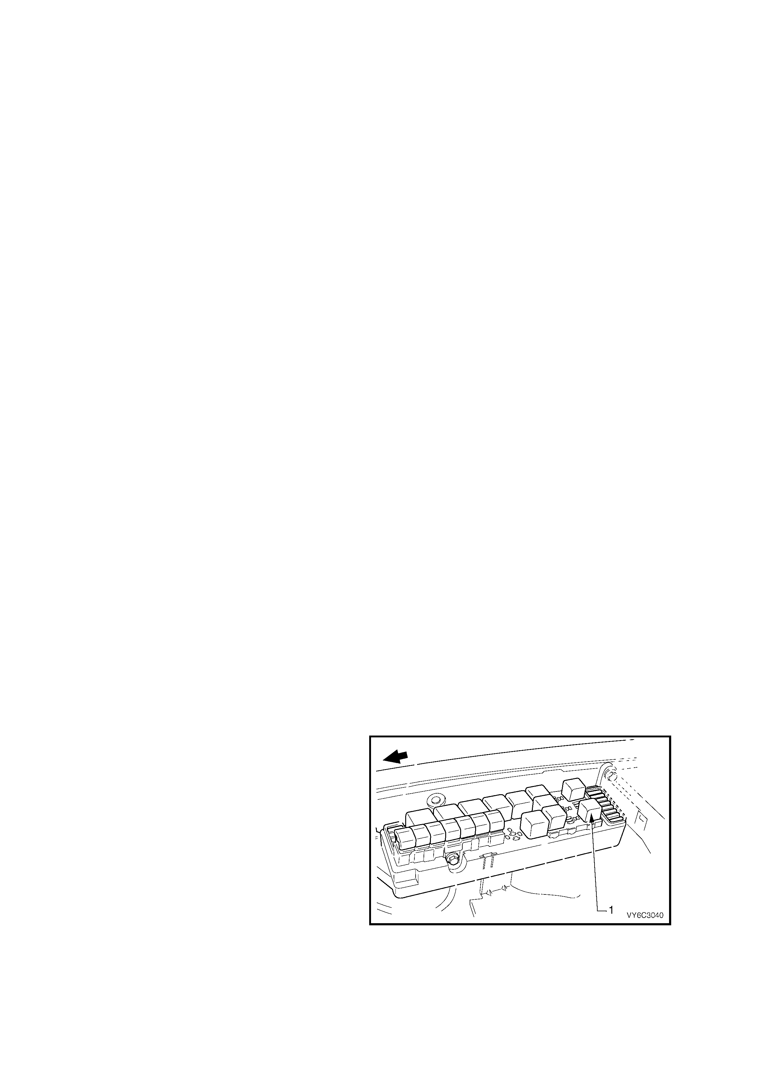
Long Term Fuel Trim Cell
The LTFT function of the PCM is divided up into cells 0-22 arranged by MAP sensor readings and Engine RPM.
Each cell corresponds to a region on a MAP vs. RPM table. Each region is calibrated to a LTFT value of 0%. A
value of 0% in a given block indic ates no fuel adjus tment is needed f or that engine load c ondition. A higher number,
say + 4%, indicates that the PCM has detected a lean exhaus t indication under thos e conditions, and is adding f uel
(increas ing fuel injec tor pulse width) to com pensate. Conversely, a lower number, say -6%, indicates that the PCM
has detected a rich exhaust indication under those load conditions, and is subtracting fuel (decreasing fuel injector
pulse width) to compensate.
As the vehicle is driven from a standing start and accelerated or decelerated from various engine speeds, the
engine's LTFT calibration will change from one cell to another cell. As the LTFT changes cell so does STFT,
however, STFT will only make short term corrections in whatever LTFT cell the engine is operating in. When the
engine is idling, it can be in one of two cells. Depending upon canister purge, the engine will idle in cell 20. If the
engine was running at idle and the canister purge was on, we would be in cells 16-19 depending on AC clutch
status and PRNDL position.
Whatever cell the engine is operating in, the PCM will read that cell's particular LT FT value and electr onically adjust
the fuel injector base pulse width to compensate for a rich or lean condition in the engine. If an engine has a
restricted fuel filter and the customer has driven the vehicle like this for quite som e time, the LTFT value would be
high, and the PCM would be compensating for this condition by adding more fuel. Because the STFT value is above
0%, LTFT will also be greater than 0% in most of the cells to compensate for the lean exhaust. If you suspect a
driveability problem ass ociated with an over rich or over lean c ondition, then use the STFT value to detect what the
fuel control system is doing at the present time. Use the LTFT to identify what the system has learned over a
greater period of time to compensate for the condition.
Use the LTFT cells to determine if the fuel control system is commanding rich or lean throughout the operating
range. If it is only rich or lean at idle or part throttle, look for components that would cause problems in these areas.
All LTFT cell values are reset to 0% when long term memory power to the PCM is removed.
The Tech 2 scan tool has the ability to reset all LTFT cells to 0%.
FUEL METERING SYSTEM COMPONENT DESCRIPTION
The fuel metering system consists of the following parts:
• The fuel supply components (fuel tank, pump, pipes).
• The fuel pump electrical circuit.
• The fuel rail.
• The fuel injectors.
• The fuel pressure regulator.
• The throttle body.
• The Idle Ai r Control (IAC) valve.
• The Throttle Position (TP) Sensor.
System Overview
An electric fuel pump, located in the fuel tank with the fuel sender assembly, supplies fuel through an in-line fuel
filter at a pressure greater than is needed by the injectors. The fuel pressure regulator, part of the fuel sender
assembly, keeps fuel available to the injectors at a regulated pressure.
Fuel Pump Electrical Circuit
When the ignition switch is turned to the ON or
Crank position after having been off for at least 10
seconds, the PCM will immediately energise the
fuel pump relay to operate the fuel pump. This
builds up the fuel pressure quickly. If the engine is
not cranked within two seconds, the PCM will shut
the fuel pump relay off and wait until the engine is
cranking. As soon as the engine begins cranking,
the PCM will sense the engine turning from the
crankshaft position signal, and turn the relay on
again to run the fuel pump.
If there is a fault with the fuel pump relay control
circuit, DTC P0230 will set.
Figure 6C3-1-87 – Fuel Pump Relay Location
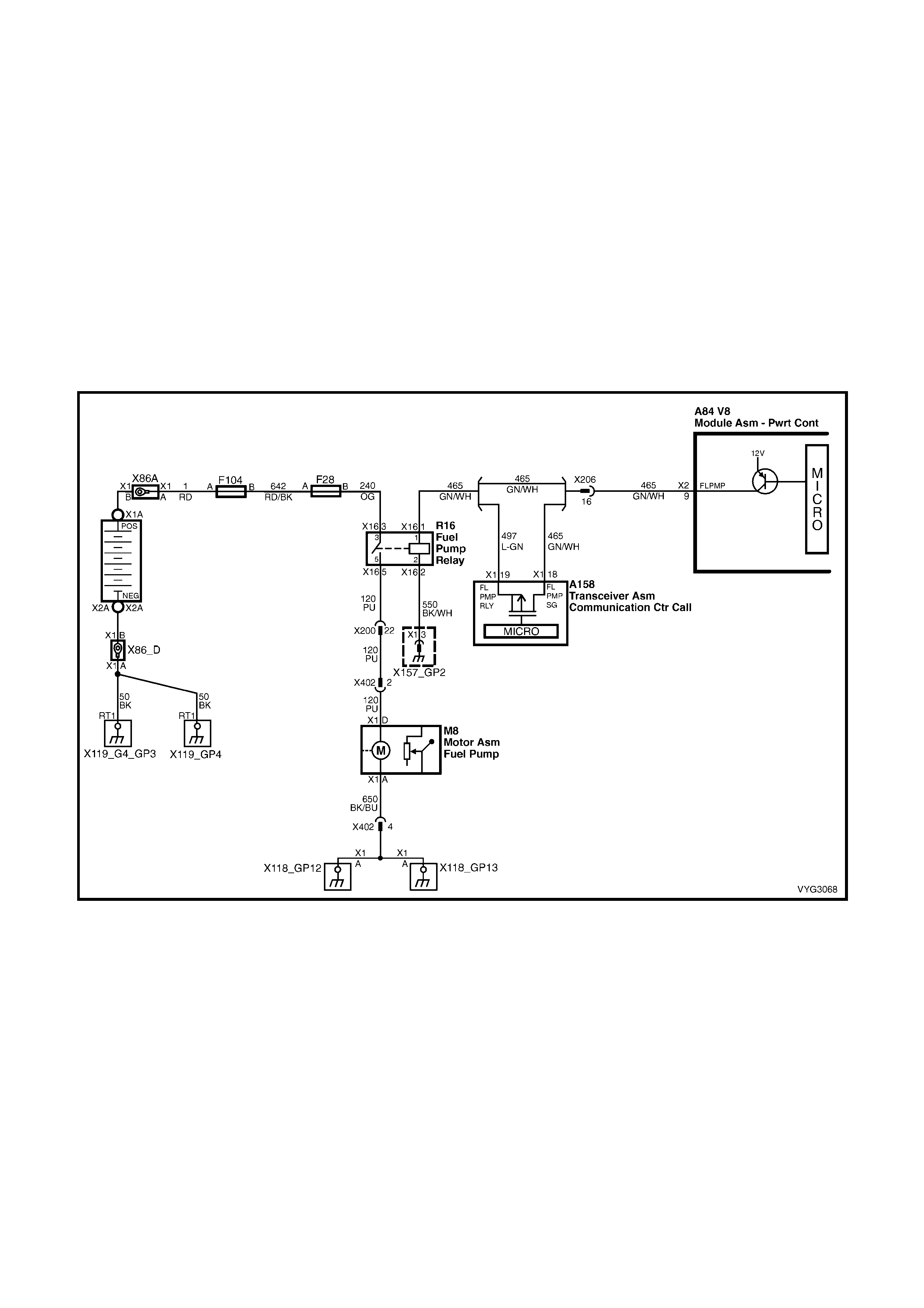
DTC P0230 FUEL PUMP CONTROL CIRCUIT
Conditions for running DTC P0230
• The engine speed is greater than 400 RPM.
• The ignition voltage is between 6.0 volts and 16.0 volts.
Conditions for setting DTC P0230
• The PCM detects that the commanded state of the circuit and the actual state of the circuit do not match.
• All of the above conditions present for at least ten seconds.
Action taken when DTC P0230 Sets
• The PCM activates the Malfunction Indicator Lamp (MIL) when the diagnostic runs and fails.
• The PCM records the operating conditions at the time the diagnostic fails. The PCM stores this information in
the Freeze Frame/Failure Records.
Conditions for clearing the Malfunction Indicator Lamp (MIL) and DTC P0230
• The PCM deactivates the Malfunction Indicator Lamp (MIL) after one ignition cycle that the diagnostic runs and
does not fail.
• A last test failed (current DTC) clears when the diagnostic runs and does not fail.
Figure 6C3-1-88 – Fuel Pump Relay Circuit
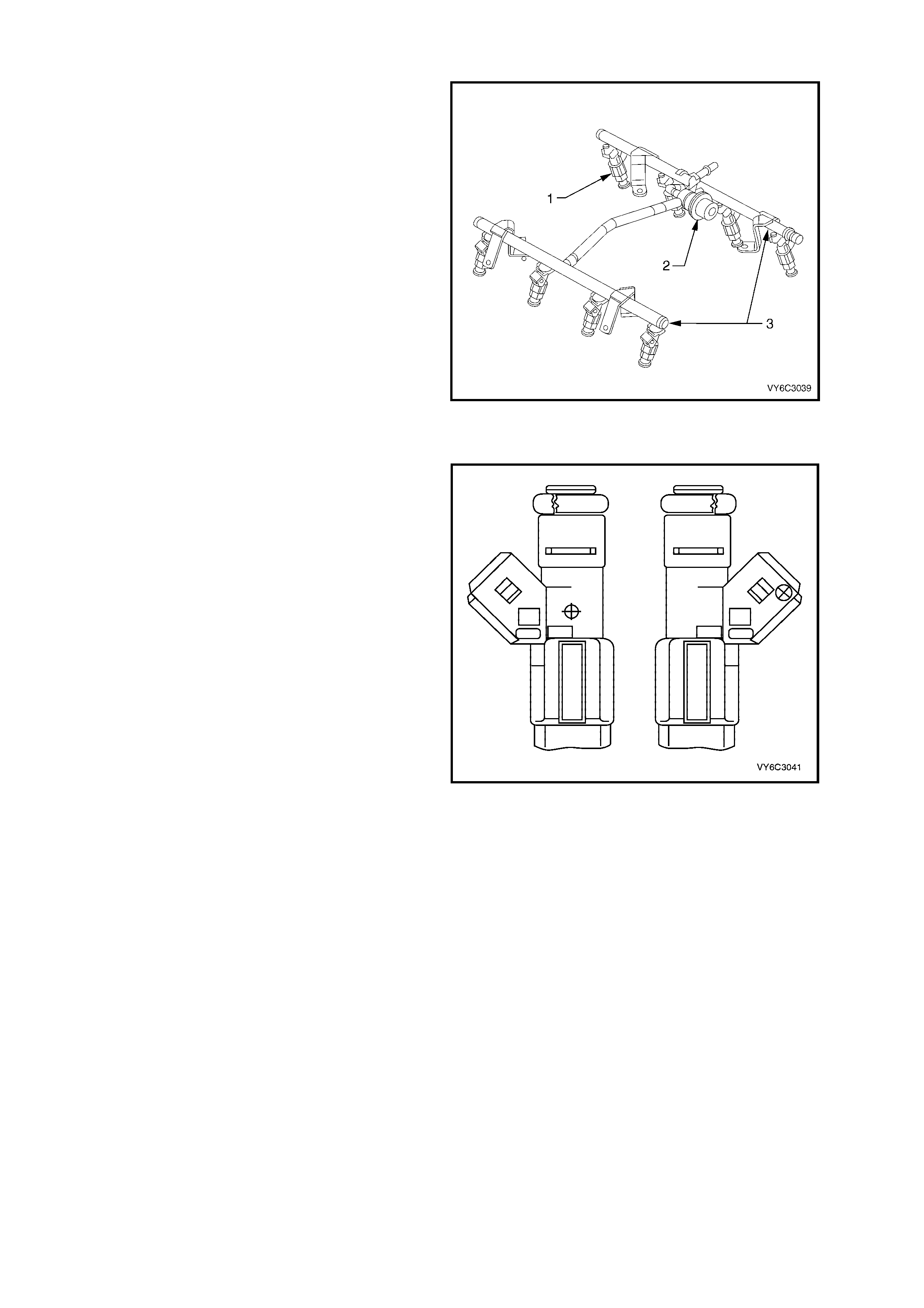
Fuel Rail Assembly
The f uel r ail as sembly attaches to the engine intake
manifold and performs the following functions:
• It positions the injectors (1) in the intake
manifold.
• It distributes fuel evenly to the injectors.
• It integrates the fuel pulse dampener into the
fuel metering system.
Legend:
1. Fuel Injector
2. Fuel Pulse Dampener
3. Fuel Rail
Figure 6C3-1-89 – Fuel Rail Assembly
Fuel Injectors
The fuel injectors are electrically operated flow
control valves. They are supplied with battery
voltage from the ignition switch via fuse F10, the
EFI relay and fuse F34 and F35. The injectors are
controlled by the PCM providing the ground circuit.
The injectors are never fully energised on, as that
would flood the engine with too much fuel. The
PCM supplies the ground circuit in short pulses.
The longer the dur ation of the pulses (puls e width),
the mor e fuel is inj ected into the engine. Inside, the
injector s have a coil of electr ical wire that becom es
an electromagnet when energised. The resistance
of these windings is important for the PCM to
operate correctly.
The top-feed fuel injector assembly is a solenoid
operated device, controlled by the PCM, that
meter s press urised fuel to a single engine cylinder.
The PCM energises the injector solenoid, which
opens a ball valve, allowing fuel to flow past the ball
valve, and through a recessed flow director plate.
The director plate has multiple machine holes that
control the fuel flow, generating a conical spray
pattern of finely atomised fuel at the injector tip.
Fuel is directed at the intake valve, causing it to
become further atomised and vaporised before
entering the combustion chamber.
Figure 6C3-1-90 – Fuel Injector
An injector stuck partly open can cause a loss
of pressure after engine shutdown. Consequently,
longer cranking time may result. There
are no DTCs associated with the injectors.
Refer to Fuel Injector Balance Test in
Section 6C3-2C FUNCTIONAL CHECKS, for
diagnosis of the injectors.
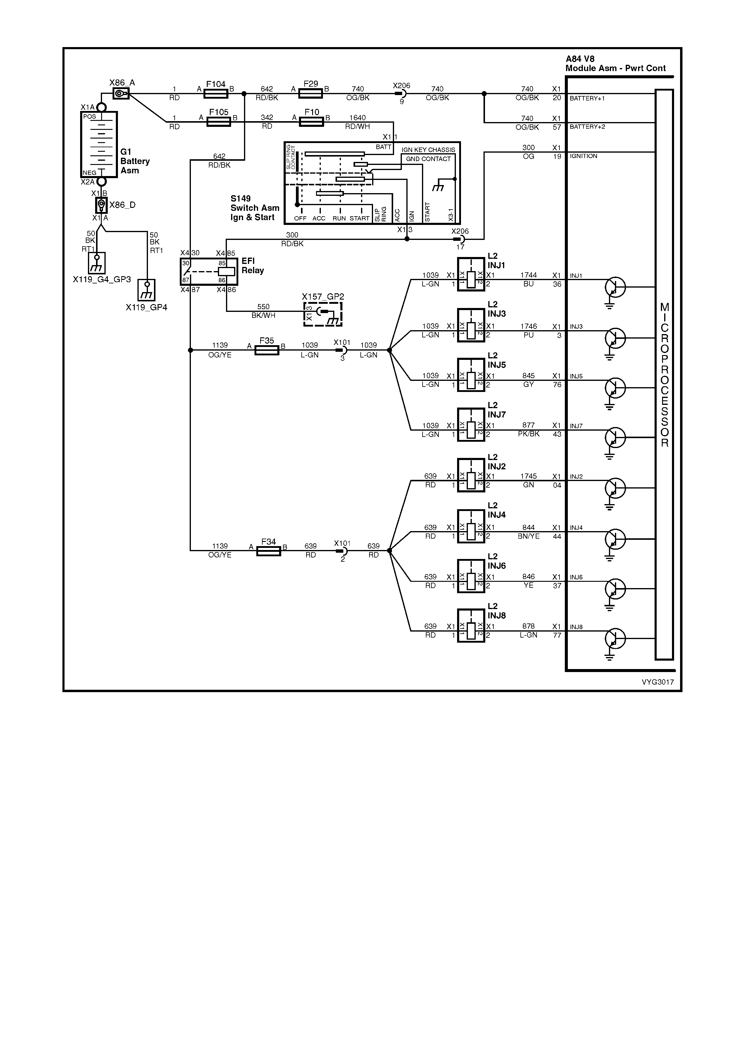
Figure 6C3-1-91 – Fuel Injector Circuit
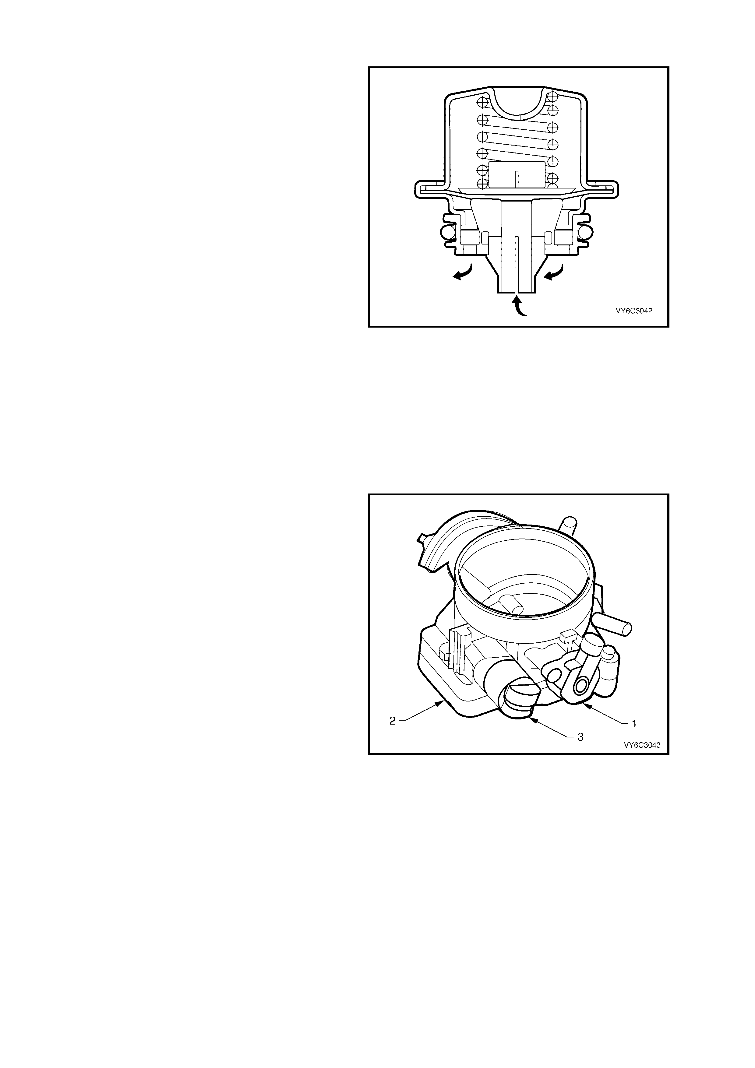
Fuel Pulse Dampener
The fuel pulse dampener is fitted inside a housing
on the fuel rail assem bly. The fuel pulse dampener
is diaphragm operated, with fuel pump pr essure on
one side and spr ing pressur e of the other side. The
function of the dampener is to reduce fuel
pulsation.
Figure 6C3-1-92 – Fuel Pulse Dampener
Accelerator Controls
The ac celerator contr ol sys tem is cable operated.
Two different type of accelerator control cable
systems are used, one where Electronic Traction
Control (T CS) is fitted and the other without TCS.
Therefore use the specific cable for each
application. Cable adjus tm ent is provided, ref er to
Section 6C3-3 SERVICE OPERATIONS.
Throttle Body Assembly
The throttle body assembly attaches to the intake
manifold and controls air flow into the engine,
thereby controlling engine output. The driver opens
the throttle valve within the throttle body through the
accelerator controls. During engine idle, the throttle
valve is almost closed. A fixed air bypass orifice
and the Idle Air Control (IAC) valve (3) control the
air flow.
Engine coolant flows thr ough a coolant cavity in the
bottom of the throttle body and prevents throttle
valve icing during cool weather operation. The
throttle body also provides the location for mounting
the Throttle Position (TP) sensor (1).
Legend:
1. TP Sensor
2. Throttle Body Assembly
3. IAC Valve
Figure 6C3-1-93 – Throttle Body Assembly
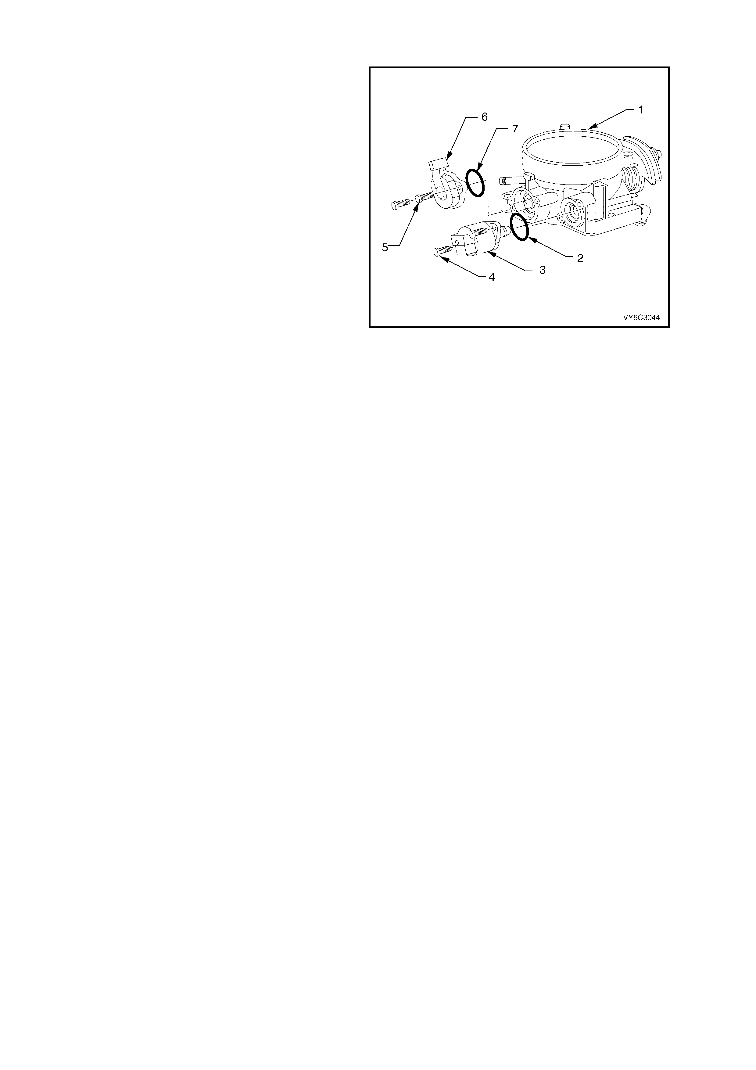
Throttle Position (TP) Sensor
The T hrottle Pos ition (T P) sens or is mounted to the
throttle shaf t on the throttle body. The T P sensor is
a potentiome ter which is s upplied a 5 volt referenc e
and a ground circuit from the PCM. The signal
circuit connects from a sliding contact in the TP
sensor to the PCM. This allows the PCM to
measure the voltage from the TP sensor. As the
throttle is depressed, the output of the TP sensor
changes. At a closed throttle position, the output of
the TP sensor is below 1.25V. As the throttle valve
opens, the output increases. At a wide-open
throttle, the TP sensor output voltage should be
greater than 4 volts.
Legend:
1. Throttle Body
2. IAC Valve O-Ring Seal
3. IAC Valve
4. IAC Valve Attaching Screws
5. TP Sensor Attaching Screws
6. TP Sensor
7. TP Sensor O-Ring Seal
Figure 6C3-1-94 – Throttle Position (TP) Sensor
Speed Density System Description
Three specific data sensors provide the PCM with the basic information for the fuel management portion of its
operation. T hat is, thr ee specific signals to the PCM establis h the engine speed and air density factors. The engine
speed signal comes from the Crankshaft Position Sensor (CKP).
The PCM uses this inf orm ation to deter mine engine speed ( RPM). Air density is derived fr om IAT and MAP sensor
inputs. The IAT sensor measures the air temperature that is entering the engine. The IAT signal works in
conjunction with the MAP sensor to determine air density. As the intake manifold pressure also increases, additional
fuel is r equired and this inf or mation c omes f r om the IAT and MAP sens ors to be used by the PCM to control injector
pulse width.
The speed density system is used to:
1. Monitor Mass Air Flow (MAF) sensor operation (to determine if there is a MAF sensor malfunction).
2. Take over fuelling management operation when there is a Mass Air Flow (MAF) sensor malfunction.
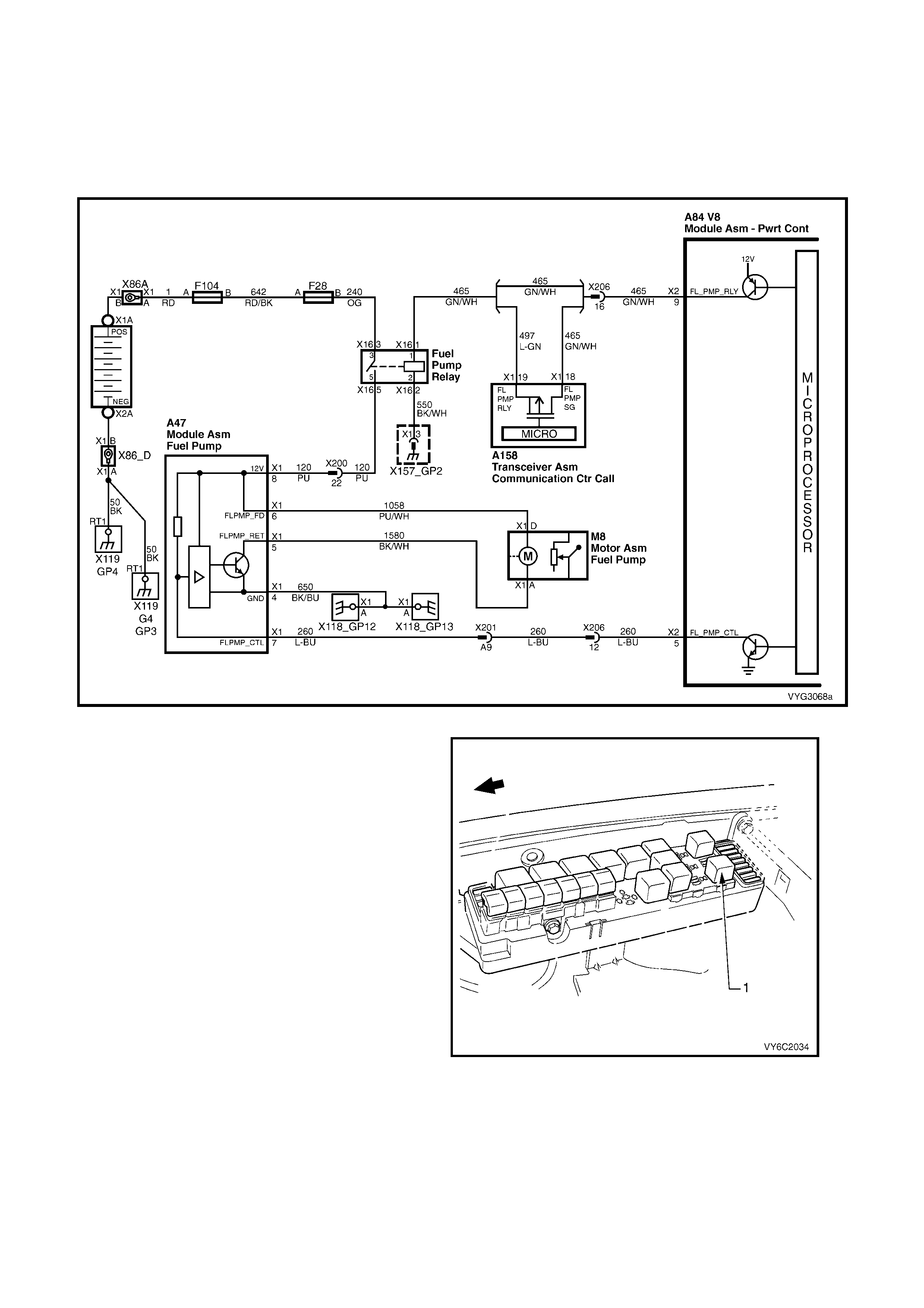
FUEL PUMP ELECTRICAL CIRCUITS FOR UTILITY WITH THE GEN III V8 ENGINE
When the ignition switch is turned to ON or CRANK after having been OFF for at least 10 seconds, the PCM will
immediately energise the fuel pump relay, which will then activate the Fuel Pump Contr ol Module to oper ate the f uel
pump. This builds up the fuel pressure quickly. If the engine is not cranked within two seconds, the PCM will shut
the f uel pum p relay OFF and wait until the engine is crank ed. As soon as the engine begins crank ing, the PCM will
sense the engine turning from the crankshaft reference input, and turn the relay ON again to run the fuel pump.
A failed fuel pump relay circuit will cause a no start condition.
Figure 6C2-1-95 Fuel Pump Electrical Circuits V6 Supercharged Engine
The fuel pum p r elay (1) is located in the under hood
electrical centre in the engine compartment.
Figure 6C2-1-96 Fuel Pump Relay Location

Fuel Pump Control Module
When the Utility is fitted with the GEN III V8 engine,
a two speed Fuel Pump and a Fuel Pump Control
module ( 1) is us ed. T he Fuel Pum p Control Module
(1) is m ounted c entrally, behind the back panel trim
behind the seats, above the driveline floor tunnel
(4) and secured by two screws (3), as shown. The
Fuel Pump Control Module can vary the fuel pump
output depending on the required engine load.
When the ignition is first turned ON, the PCM
energises the f uel pum p relay, which applies power
to the Fuel Pump Control Module. The fuel pump
will then pressurise the fuel system.
The purpose for the Fuel Pump Control Module is
to supply more fuel volume under heavy engine
load conditions, such as the situation where the
tray is fully loaded and/or the vehicle is towing a
fully loaded trailer.
The PCM controls the current flow through the fuel
pump with a Pulse W idth Modulation (PW M) s ignal
at 128 Hertz (Hz) to the fuel pump control module.
The fuel pump control module controls the current
flow through the fuel pum p depending on the PWM
signal received from the PCM.
Figure 6C2-1-97 Fuel Pump Control Module Location
Under nor mal driving conditions the required f uel volume is less , so the fuel pum p operates at a duty c ycle of 67%
ON; i.e. the PCM controls the fuel pump circuit, via the fuel pump control module at 67% ON and 33% OFF, at a
frequency of 128 Hz.
W hen the engine load is increased, as measured by the Mass Air Flow sensor, the fuel pump control module will
switch fr om the norm al duty cycle (67%) to a higher duty cycle (100%) based on the c omm and from the PCM. This
higher duty cycle will increase the curr ent supply through the fuel pum p, increas ing the fuel volum e deliver ed by the
fuel pump.
Another feature of this Fuel Pump Control Module is that, when the fuel pump is running at the lower duty cycle
(norm al driving conditions), less fuel will need to be diverted back to the fuel tank (from the f uel filter T -piece). T his
lower volume of returned fuel will result in lower emissions (fuel tank vapours).
Also with the fuel pum p running at a lower duty cycle (norm al driving c onditions), the voltage output required to run
the pump is lower. This will require less generator output and will decrease overall vehicle fuel usage.
Refer to Table 2.7 Fuel Pump Electrical Circuit (Utility Only), in Section 6C3-2A DIAGNOSTIC TABLES, for
diagnosis of the fuel pump electrical circuit. for this vehicle application.
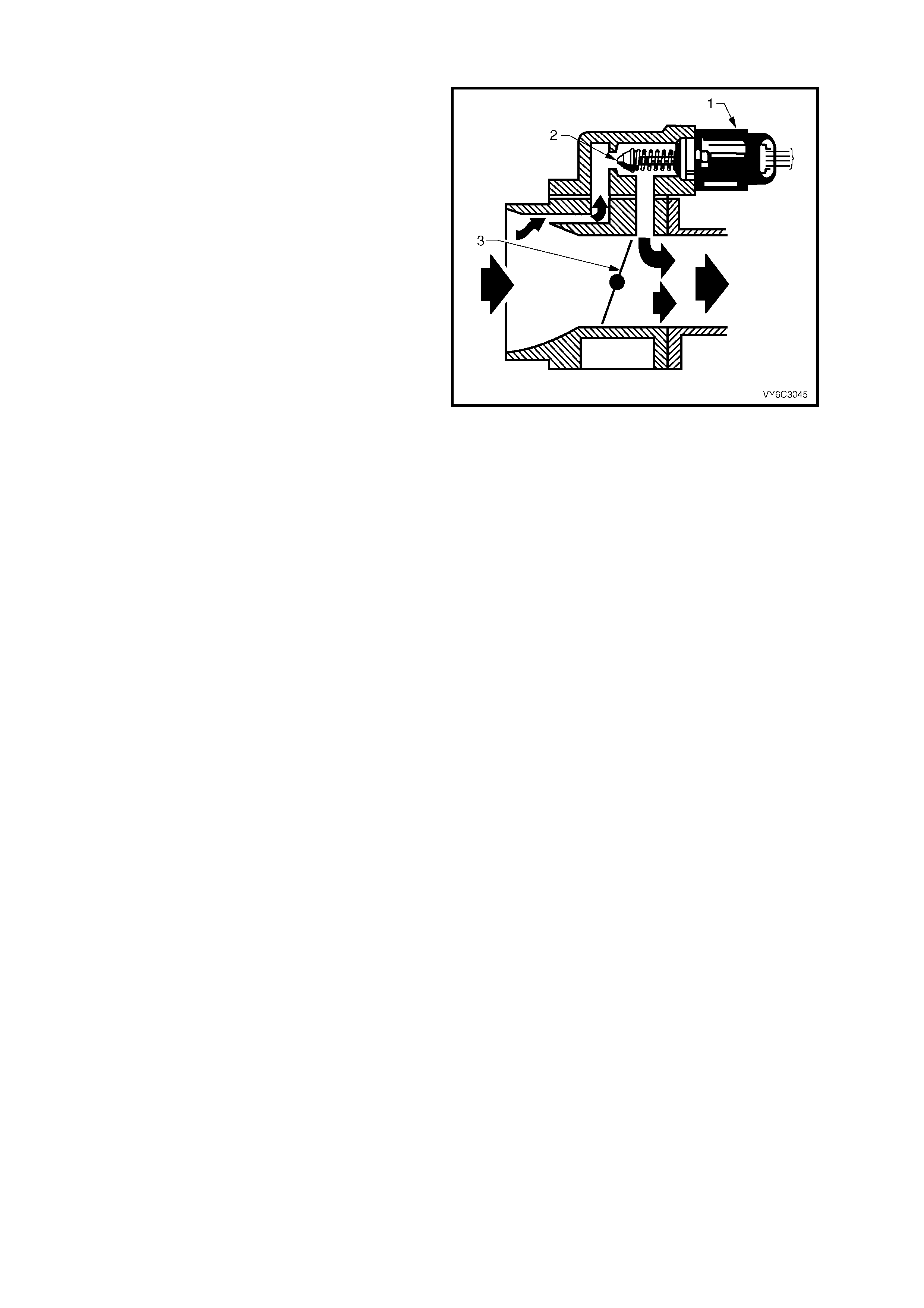
1.5 IDLE AIR CONTROL (IAC) VALVE
The purpos e of the Idle Air Contr ol (IAC) Valve is to
control engine idle speed, while preventing stalls
due to changes in engine load. The IAC valve,
mounted to the throttle body, controls a portion of
bypass air. An orifice located in the throttle body
also supplies a constant amount of bypass air.
By moving a conical valve, k nown as a pintle (2), in
towards the seat (to decrease air f low); or out away
from the seat (to increase air flow), a controlled
amount of air can be bypassed. If engine speed is
too low, more air is bypassed to increase RPM. If
engine speed is too high, less air is bypassed to
decrease RPM.
The PCM moves the IAC Valve (1) in small steps,
called counts. These can be measured and
displayed by Tec h 2, whic h plugs into the Data Link
Connector (DLC). The PCM calculates the proper
position of the IAC valve during idle, based on
battery voltage, coolant temperature, engine load,
and engine RPM. If the RPM drops below
specification and the throttle valve is closed, the
PCM senses a near stall condition and calculates a
new valve position in order to prevent stalling.
• Engine idle speed is a function of total air flow
into the engine. Idle speed is based on IAC
valve pintle position + crankcase ventilation
valve flow + throttle valve opening + bypass
orifice air flow + calibrated vacuum loss
through accessories.
• Controlled idle speed is programmed into the
PCM, which determines the correct IAC valve
pintle position to maintain the desired idle
speed for all engine operating conditions and
loads.
Figure 6C3-1-98 – Idle Air Control (IAC) Valve Air Flow
Legend:
1. IAC Valve
2. Throttle Plate
3. IAC Valve Pintle
• The minimum idle air rate is set at the factory
with a stop screw. This setting allows enough
air flow by the throttle valve to cause the IAC
valve pintle to be positioned a calibrated
number of s teps (c ounts ), f r om the seat, dur ing
controlled idle operation and also to prevent
the throttle valve from jamming in the throttle
body housing bore.
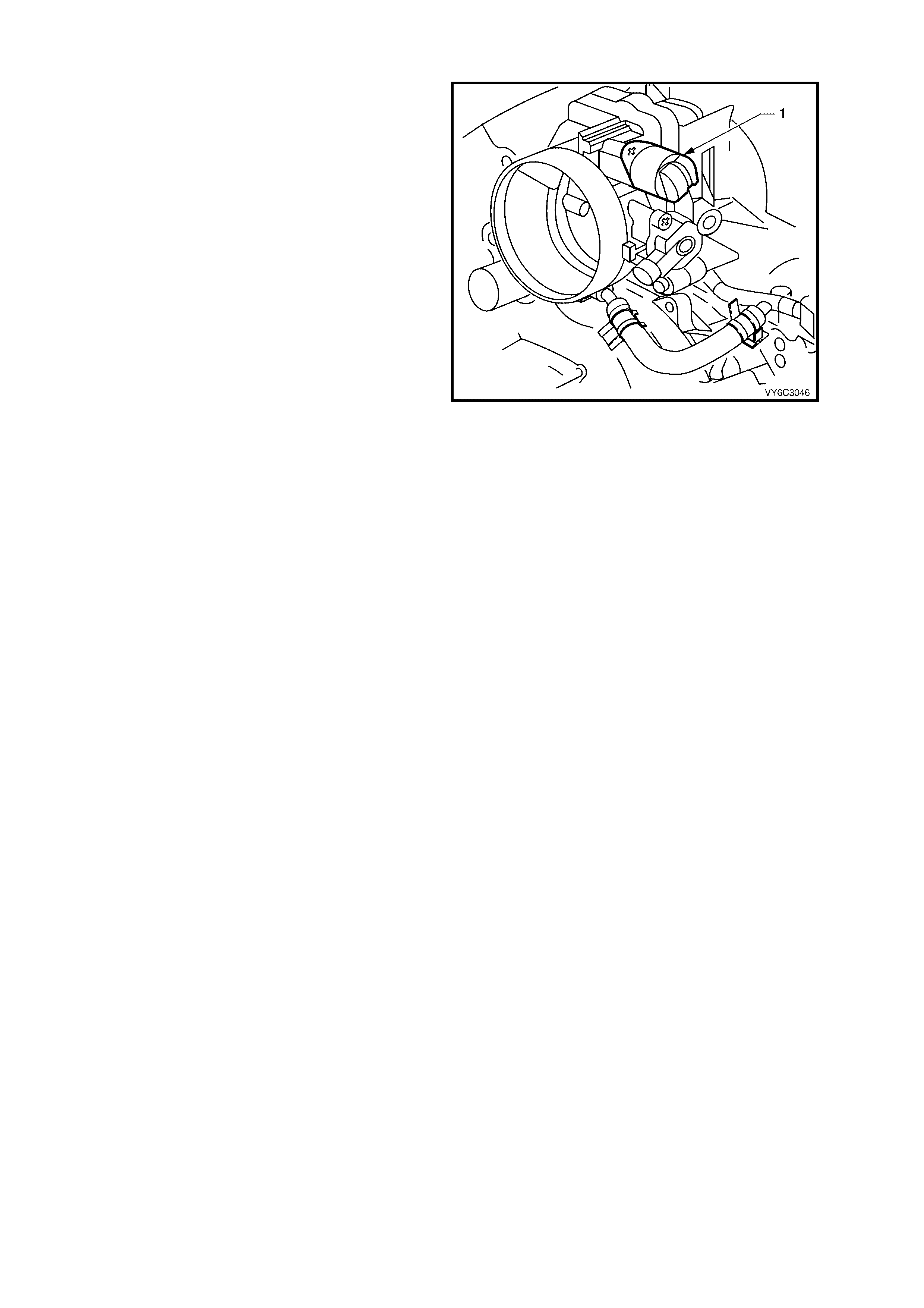
IDLE AIR VALVE POSITION RESET
If the IAC valve (1) electrical connector is
disconnected and reconnected with the engine
running, the idle speed may be wrong. If this
occurs, reset the IAC valve by depressing the
accelerator pedal slightly, start and run the engine
for five seconds, then turn the ignition OFF for ten
seconds.
Figure 6C3-1-99 – IAC Valve Location
DTC P0506 IDLE SPEED LOW
Conditions for running DTC P0506
• DTCs P0101, P0102, P0103, P0107, P0108, P0112, P0113, P0117, P0118, P0171, P0172, P0174, P0175,
P0443, are not set.
• The engine run time is greater than 60 seconds.
• The engine coolant temperature is greater than 60° C.
• The intake air temperature is greater than –10° C.
• The barometric pressure is greater than 65 kPa.
• The ignition voltage is between 9.0 and 17.0 volts.
• The vehicle speed is no more than 2 km/h.
Conditions for setting DTC P0506
• The actual idle speed is 100 RPM less than the desired idle speed.
• All of the above conditions are present for 15 seconds.
Action taken when DTC P0506 Sets
• The PCM activates the Malfunction Indicator Lamp (MIL) when the diagnostic runs and fails.
• The PCM records the operating conditions at the time the diagnostic fails. The PCM stores this information in
the Freeze Frame/Failure Records.
Conditions for clearing the Malfunction Indicator Lamp (MIL) and DTC P0506
• The PCM deactivates the Malfunction Indicator Lamp (MIL) after the first ignition cycle that the diagnostic runs
and does not fail.
• A last test failed (current DTC) clears when the diagnostic runs and does not fail.
DTC P0507 IDLE SPEED HIGH
Conditions for running DTC P0507
• DTCs P0101, P0102, P0103, P0107, P0108, P0112, P0113, P0117, P0118, P0171, P0172, P0174, P0175,
P0443, are not set.
• The engine run time is greater than 60 seconds.
• The engine coolant temperature is greater than 60° C.
• The intake air temperature is greater than –10° C.
• The barometric pressure is greater than 65 kPa.
• The ignition voltage is between 9.0 and 17.0 volts.
• The vehicle speed is no more than 2 km/h.
Conditions for setting DTC P0507
• The actual idle speed is 100 RPM more than the desired idle speed.
• All of the above conditions are present for 15 seconds.
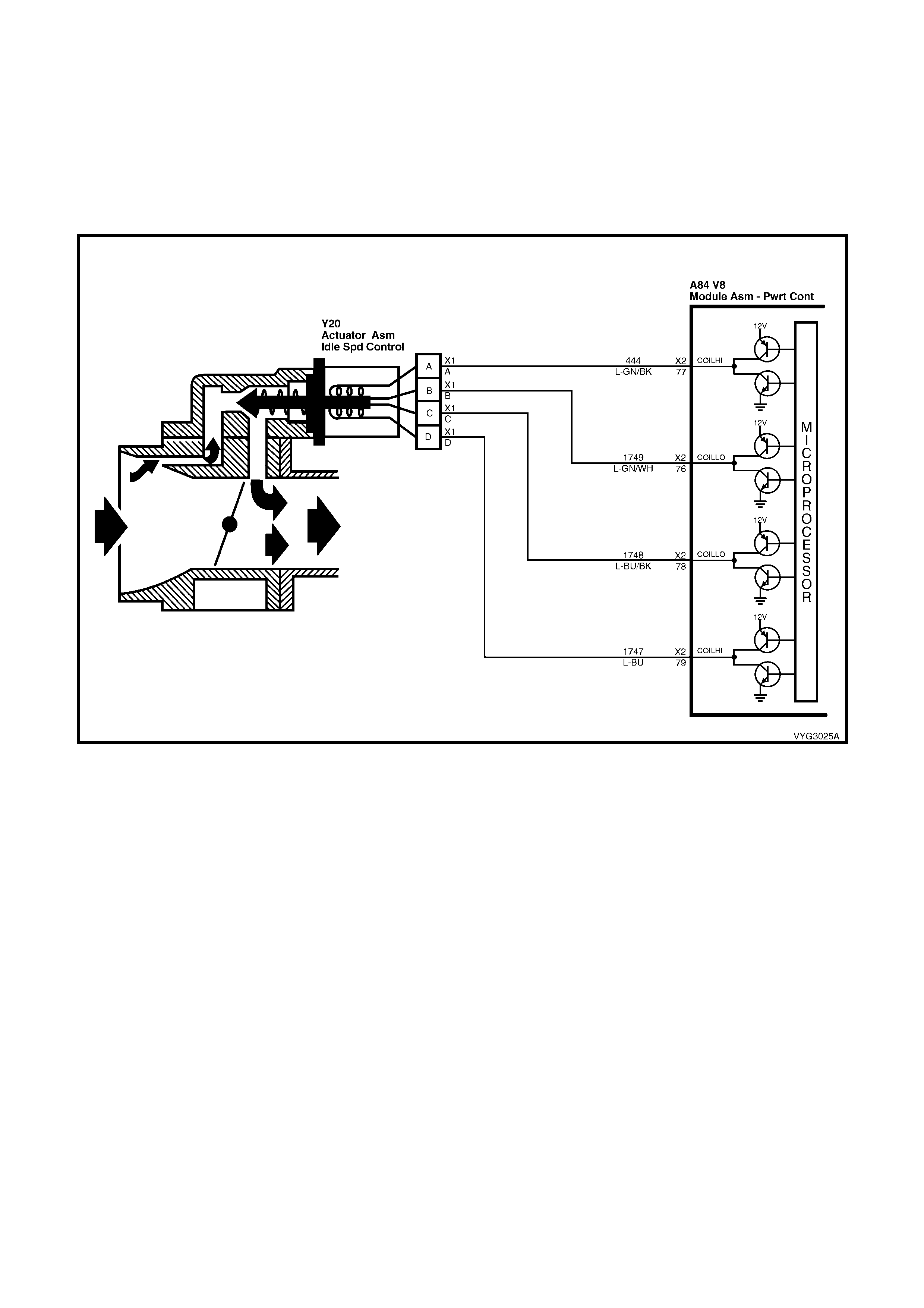
Action taken when DTC P0507 Sets
• The PCM activates the Malfunction Indicator Lamp (MIL) when the diagnostic runs and fails.
• The PCM records the operating conditions at the time the diagnostic fails. The PCM stores this information in
the Freeze Frame/Failure Records.
Conditions for clearing the Malfunction Indicator Lamp (MIL) and DTC P0507
• The PCM deactivates the Malfunction Indicator Lamp (MIL) after the first ignition cycle that the diagnostic runs
and does not fail.
• A last test failed (current DTC) clears when the diagnostic runs and does not fail.
Figure 6C3-1-100 – IAC Valve Circuits
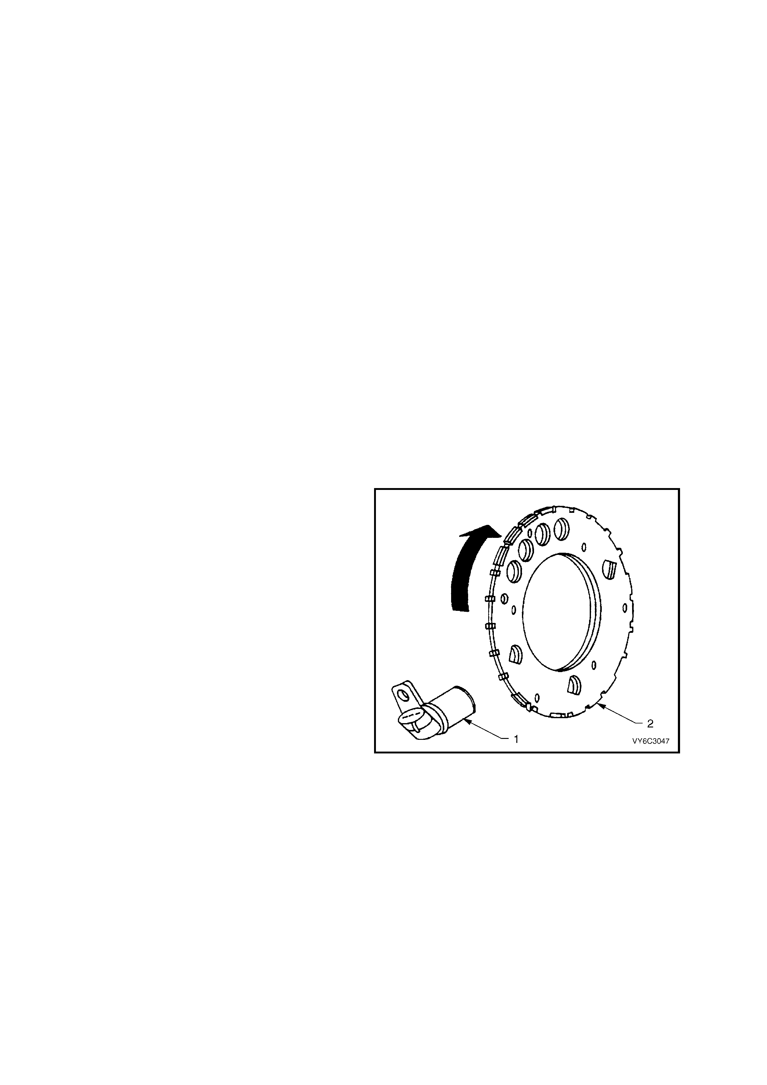
1.6 ELECTRONIC IGNITION SYSTEM
The ignition system on the GEN III V8 engine features a multiple coil ignition and is known as coil near plug. The
spark plug leads are short compared with a distributor ignition system. Eight ignition coils/modules are individually
mounted above each cylinder on the rock er covers and f ire sequentially. T here is an Ignition Control (IC) c ircuit for
each ignition coil/module. The eight ignition control circuits are connected to the PCM. All timing decisions are made
by the PCM, which triggers each coil/module individually. Each ignition coil/module has a power feed, a ground
circuit and a reference low circuit.
IGNITION SYSTEM OVERVIEW
The electronic ignition system provides a spark to ignite the compressed air/fuel mixture at the correct time. To
provide optim um engine per formanc e, fuel ec onom y, and control of exhaus t em issions, the PCM c ontrols the s park
advance of the ignition system.
The elec tronic ignition s ystem does not us e the conventional distr ibutor and coil. The ignition system consis ts of the
following components/circuits:
• Eight ignition coils/modules
• Eight Ignition Control (IC) circuits
• Camshaft Position (CMP) sensor
• 1X Camshaft reluctor wheel
• Crankshaft Position (CKP) sensor
• 24X Crankshaft reluctor wheel
• Related connecting wires
• Powertrain Control Module (PCM)
COMPONENTS
Crankshaft Position Sensor (CKP) and Reluctor
Wheel
The Crankshaft Position (CKP) Sensor (1) is
located in the right rear of the engine, behind the
starter and is a dual magneto resistive type sensor.
This sensor is not speed dependent. The dual micro
switches monitor both notches of the reluctor wheel
for greater accuracy. The CKP sensor works in-
conjunction with a 24X reluctor wheel (2).
The reluctor wheel is mounted on the rear of the
crankshaft. The 24X reluctor wheel uses two
different width notches that are 12 and 3 degrees
apart. This pulse width encoded pattern allows
cylinder position identification within 90 degrees of
crankshaft rotation. In some cases, cylinder
identification can be located in 45 degrees of
crankshaft rotation. This reluctor wheel also has
dual track notches that are 180 degrees out of
phase. The dual track design allows for quicker
starts and accuracy.
The PCM also receives a 4X signal from the
Crankshaft Position Sensor. The PCM utilises the
4X signal for the following:
• Misfire
• Tachometer output
• Spark control
• Fuel Control
• Certain diagnostics
Figure 6C3-1-101
Crankshaft Position Sensor and Reluctor Wheel
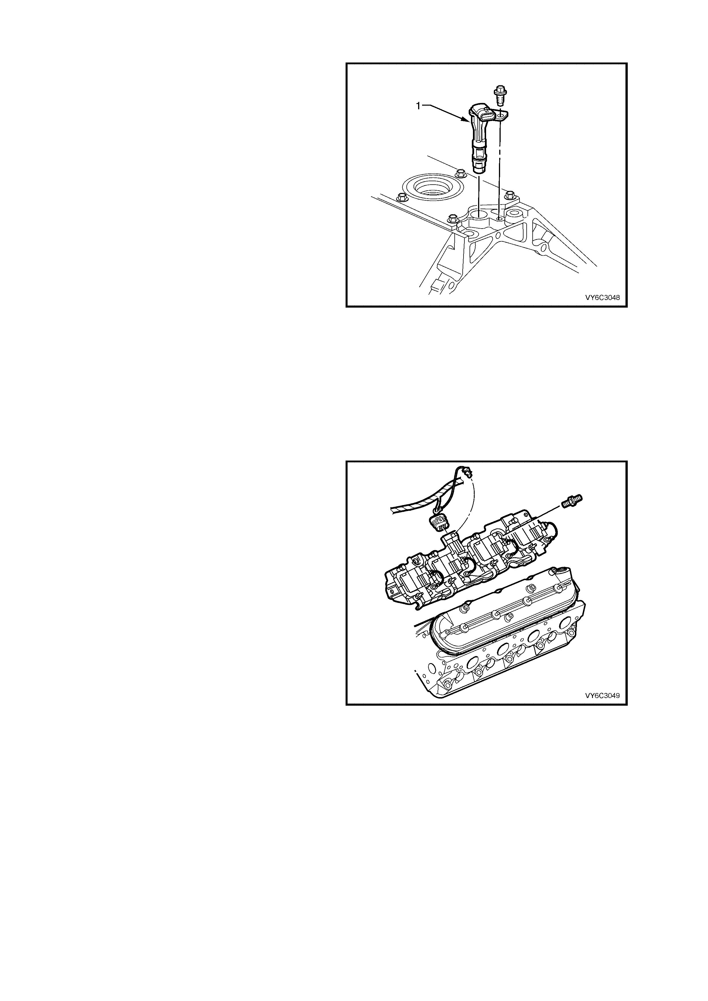
Camshaft Position Sensor (CMP)
The Camshaft Position (CMP) Sensor (1) is
mounted through the top of the engine block at the
rear of the valley cover. T he CMP sensor work s in-
conjunction with a 1X reluctor wheel. The reluctor
wheel is located at the rear of the camshaft. The
CMP sensor is used to determine whether a
cylinder is on the firing or the exhaust stroke. As
the cam s haf t r otates, the r eluc tor wheel interrupts a
magnetic field produced by a magnet within the
sensor. The CMP sensor ’s internal circuitry detects
this and produces a signal which is used by the
PCM. The PCM uses this signal in combination
with the CKP 24X signal to determine crankshaft
position and stroke.
The CKP signal m ust be available for the engine to
start. The CMP signal is not needed to start and
operate the engine. The PCM can determine when
a particular cylinder is on either a firing or exhaust
stroke by the 24X signal. The CMP sensor is used
to determine what stroke the engine is on. The
system will attempt to synchronise and look for an
increase in the MAF signal. An increase in the MAF
signal indicates the engine has started. If the PCM
does not detect an increase in the MAF signal, a
re-sync will occur to the opposite cam position. A
slightly longer cranking time may be a symptom of
this condition.
Figure 6C3-1-102 – Camshaft Position (CMP) Sensor
Ignition Coils/Module
The ignition system on this engine features a
m ultiple coil ignition and is k nown as coil near plug,
as the secondary ignition wires are short, when
compared to a distributor ignition system. Eight
ignition coils/modules are individually mounted to
an ignition coil mounting bracket that is, in turn
bolted to each rocker cover.
There is an Ignition Control (IC) circuit for each
ignition coil/module and each is fired sequentially.
The eight ignition control circuits are connected to
the PCM, where all timing decisions are made. The
PCM then, triggers each coil/module individually.
The ignition coil/ modules are supplied with the
following circuits:
• Ignition feed circuit
• Ignition control circuit
• Ground circuit
• Reference low circuit
Figure 6C3-1-103 – Ignition Coils/Module Location
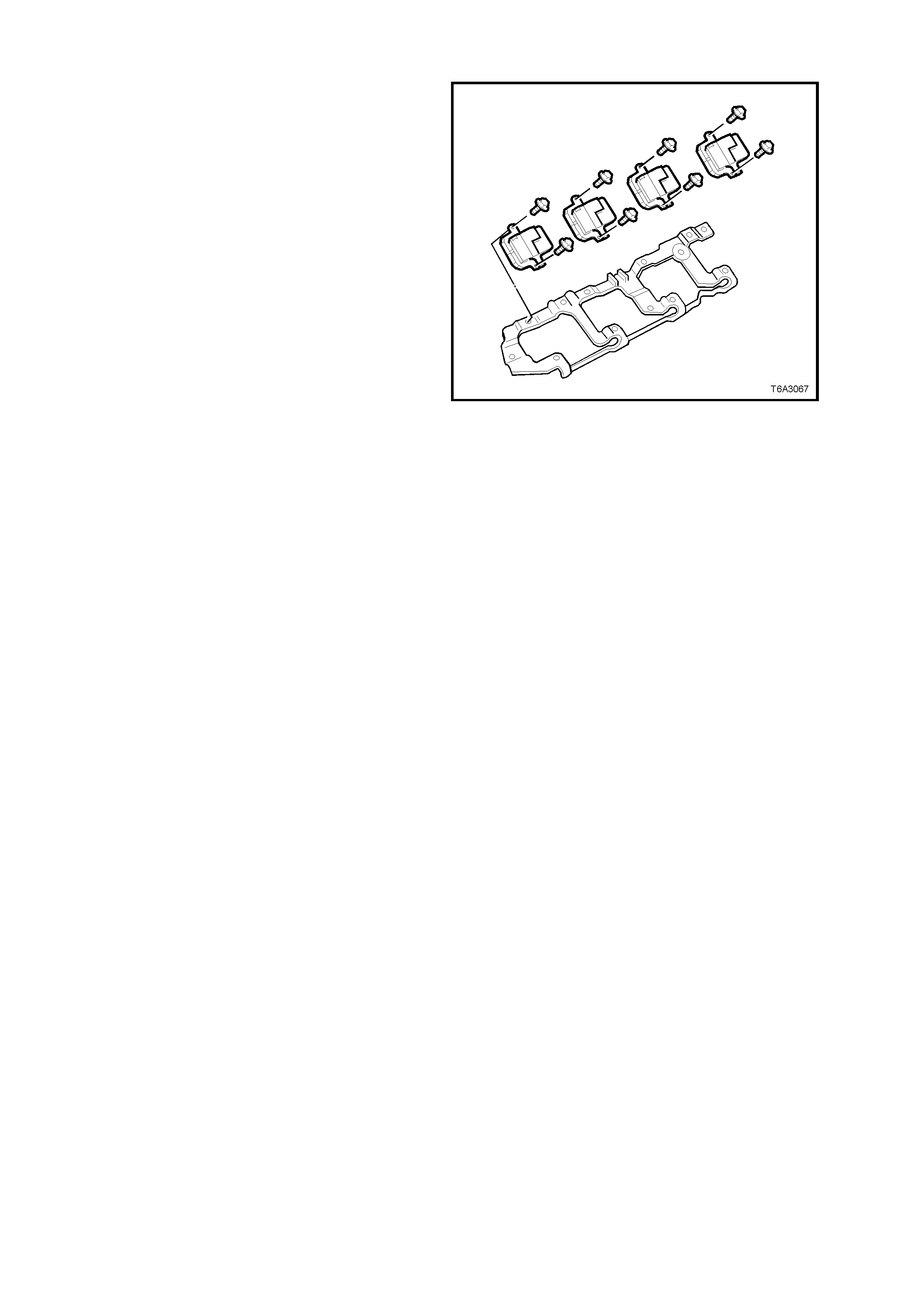
Ignition Coils
The ignition feed circuits are fused separately for
each bank of the engine. T he two f us es als o s upply
the injectors for that bank of the engine. Each
coil/module is serviced separately.
This system puts out very high ignition energy for
plug firing. Because the ignition wires are shorter,
less energy is lost to ignition wire resistance. Also,
since the f iring is sequential, each coil has far mor e
time to saturate as opposed to the three in a waste
spark arrangement. Furthermore, no energy is lost
to the resistance of a waste spark system.
Figure 6C3-1-104 – Ignition Coils/Modules
CIRCUITS AFFECTING IGNITION CONTROL
To properly control ignition timing, the PCM relies on the following information:
• Mass Air Flow
• Engine Load (manifold pressure or vacuum)
• Atmospheric (Barometric) Pressure
• Engine Coolant Temperature
• Intake Air Temperature
• Throttle Position Sensor
• Crankshaft Position Sensor
• Engine Speed
• Automatic Transmission Range from the Transmission Range Switch (TFP)
The PCM is responsible for m aintaining correct spark and fuel injection tim ing for all driving conditions. To provide
optimum dr iveability and emissions . The PCM c alculates the des ired spar k advance f rom inf orm ation received from
the sensors and triggers the appropriate ignition coil/module at the desired time to provide the spark advance
needed.
RESULTS OF INCORRECT OPERATION
An ignition control circuit that is open, grounded, or short circuited will set an ignition control circuit DTC. If a fault
occurs in the IC output circuit when the engine is running, the engine will exper ience a misfir e. DTC P0351 through
DTC P0358 will set when a malfunction is detected with an Ignition Control circuit.
If the engine cr anks but will not run or imm ediately stalls, Engine Cranks But W ill Not Run diagnostic table must be
used to determine if the failure is in the ignition system or the fuel system. If DTC P0341, P0342, P0343, P0335,
P0336 is set, the appropriate diagnostic trouble code table must be used for diagnosis.
NOTEWORTHY IGNITION INFORMATION
There ar e im portant c onsiderations to point out when servicing the ignition sys tem . The following inform ation will list
some of these to help the technician in servicing the ignition system.
• The ignition coil’s secondar y voltage output capability is very high - mor e than 40,000 volts. Avoid body contact
with ignition high voltage secondary components when the engine is running, or personal injury may result.
• The 24X crank shaft position sensor is the most cr itical part of the ignition system . If the sensor is dam aged so
that pulses are not generated, the engine will not start.
• Crank shaf t pos ition s ens or c learanc e is very important. The sens or must not contac t the rotating interrupter ring
at any time or s ensor damage will r es ult. If the interr upter r ing is bent, the inter r upter r ing blades will destr oy the
sensor.
• Ignition timing is not adjustable. There are no timing marks on the crankshaft balancer or timing chain cover.

• Be car eful not to dam age the sec ondary ignition wires or boots when ser vicing the ignition system. Rotate eac h
boot to dislodge it fr om the plug or c oil tower before pulling it f rom either a spark plug or the ignition coil. Never
pierce a sec ondary ignition wire or boot f or any testing purpos es! F uture problems will occ ur if pinpoints or test
lights are pushed through the insulation for testing.
DTC P0351 IGNITION CONTROL #1 CIRCUIT DTC P0352 IGNITION CONTROL #2 CIRCUIT
DTC P0353 IGNITION CONTROL #3 CIRCUIT DTC P0354 IGNITION CONTROL #4 CIRCUIT
DTC P0355 IGNITION CONTROL #5 CIRCUIT DTC P0356 IGNITION CONTROL #6 CIRCUIT
DTC P0357 IGNITION CONTROL #7 CIRCUIT DTC P0358 IGNITION CONTROL #8 CIRCUIT
Conditions for running DTC P0351 – P0358
• The ignition voltage is between 9.0 and 17.0 volts
Conditions for setting DTC P0351 – P0358
• The PCM detects the ignition control circuit is grounded, open or shorted to a voltage.
• All conditions met for at least 15 seconds.
Action taken when DTC P0351 – P0358 Sets
• The PCM activates the Malfunction Indicator Lamp (MIL) when the diagnostic runs and fails.
• The PCM records the operating conditions at the time the diagnostic fails. The PCM stores this information in
the Freeze Frame/Failure Records.
Conditions for clearing the Malfunction Indicator Lamp (MIL) and DTC P0351 – P0358
• The PCM deactivates the Malfunction Indicator Lamp (MIL) when the diagnostic runs and does not fail.
• A last test failed (current DTC) clears when the diagnostic runs and does not fail.
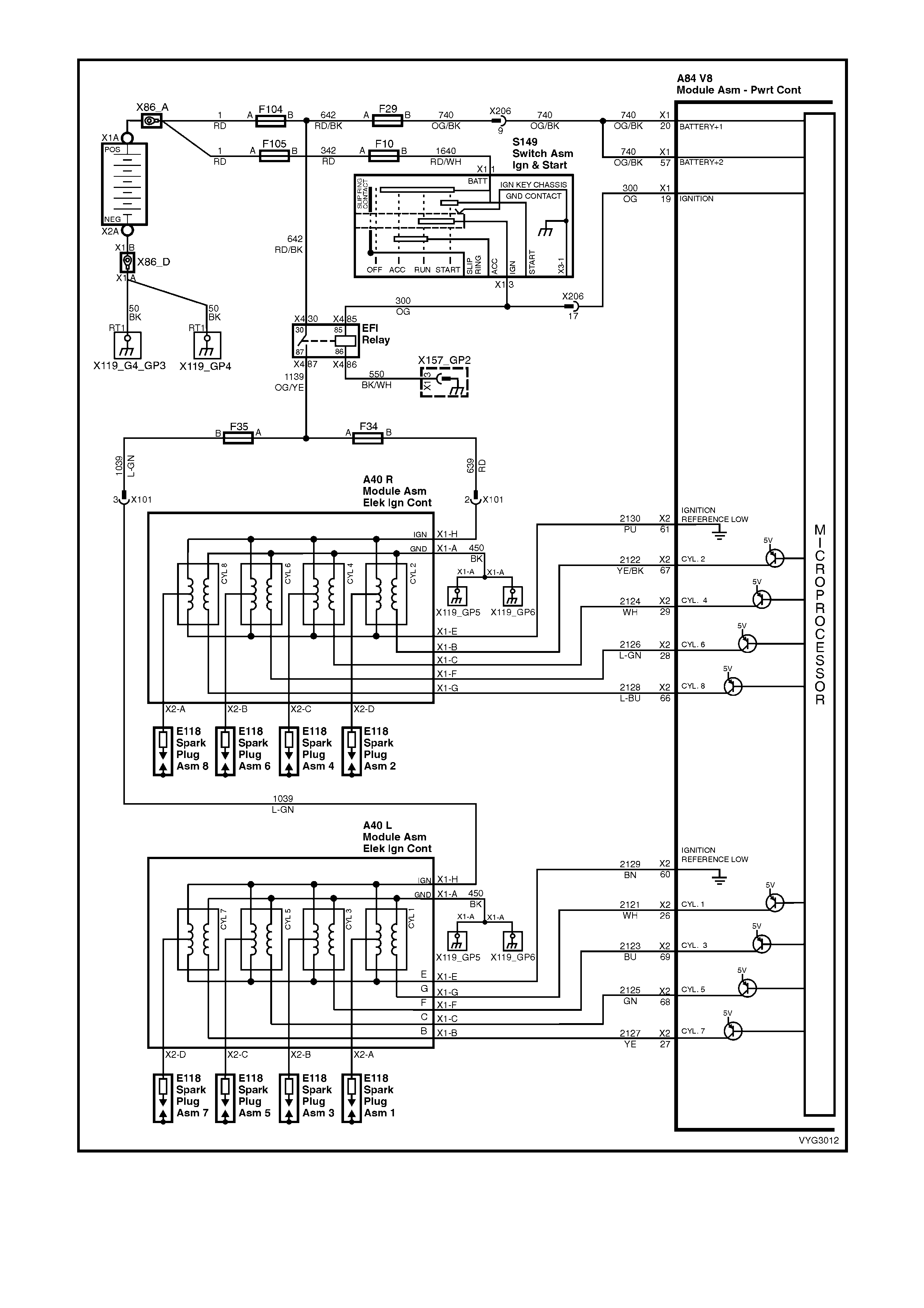
Figure 6C3-1-105 – Ignition System Circuits
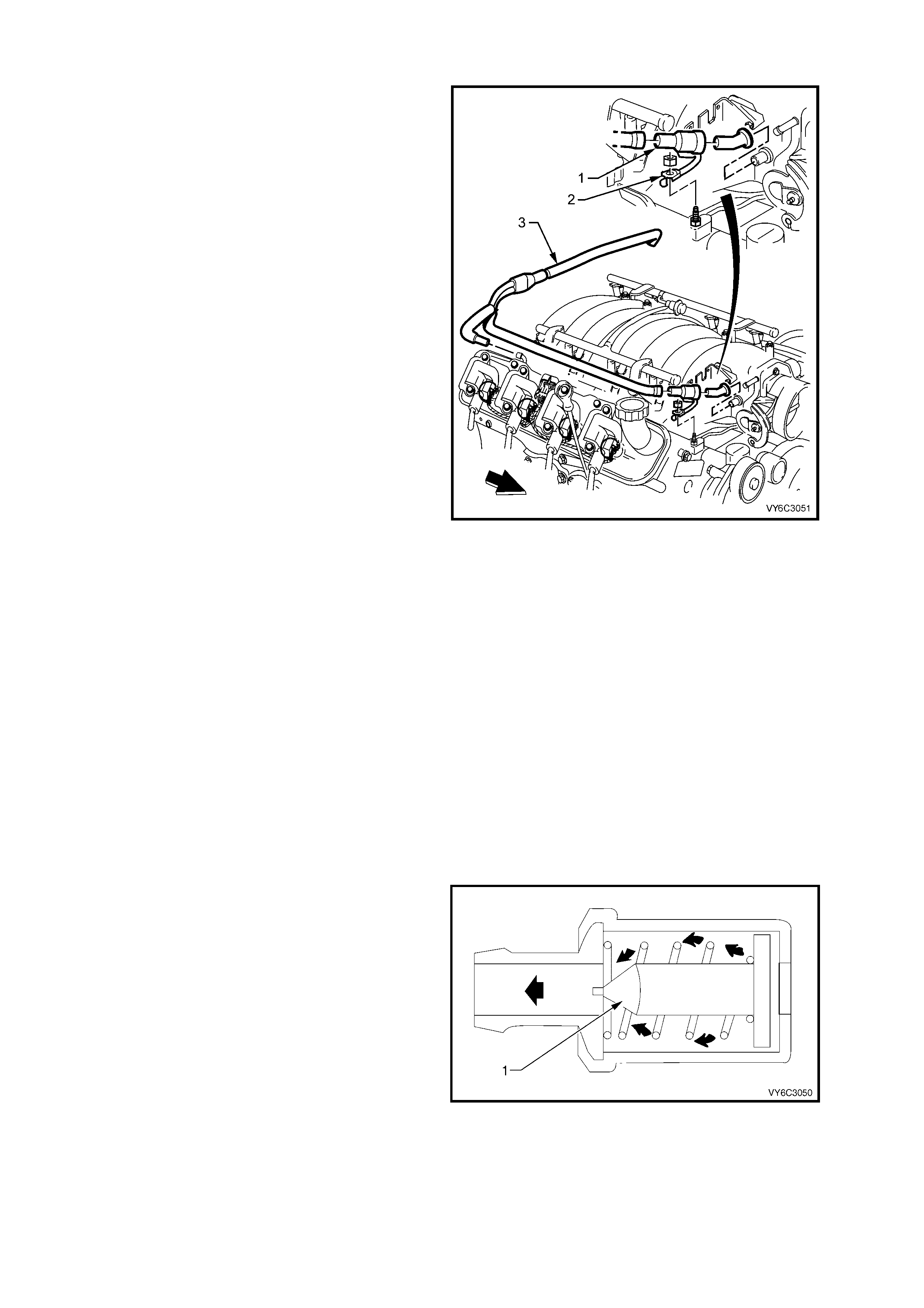
1.7 CRANKCASE VENTILATION SYSTEM
A closed crankcase ventilation system is used to
provide a more complete scavenging of crankcase
vapours. Fr es h air f r om the thr ottle body is supplied
to the crankcase, mixed with blow-by gases and
then passed through a crankcase ventilation valve
into the intake manifold.
The primary control is through the crankcase
ventilation valve which meters the flow at a rate
depending on manifold vacuum. To maintain idle
quality, the crankcase ventilation valve restricts the
flow when intake manifold vacuum is high. If
abnormal operating conditions arise, the system is
designed to allow excessive amounts of blow-by
gases to back f low through the crankc as e vent tube
into the engine air inlet to be consumed by normal
combustion.
The engine ventilation system was developed to
minimise oil consumption and ensure that oil
ingestion could not occur during high speed
cornering manoeuvres. Filtered fresh air is routed
from up stream of the throttle blade to the front of
the right rocker cover via a formed rubber hose.
To reduce the potential of oil pullover into the
throttle bore area due to bac k f low of the ventilation
system, the fitting in the right side rocker cover is
located between a shield from the rocker arms.
Blow-by gases are routed from the rear of both
rock er covers , through m oulded nylon lines to a tee
fitting located on the centreline of the engine at the
rear of the intake manifold. From there, a single
nylon line carries the gases through an externally
mounted, horizontal PCV valve and enters the
intake manifold behind the throttle body.
The dual draw system was developed to meet
vehicle manoeuvre requirements. During sustained
max imum lateral ac c elerations , the outboar d roc ker
cover may fill with oil. The dual draw system
passively switches, allowing the PCV valve to draw
on the rocker cover with the least resistance. This
results in the system drawing on the air filled, or
inboard rocker cover and eliminates oil pullover due
to drawing on the oil-filled outboard rocker cover.
Figure 6C3-1-106 – Crankcase Ventilation System Routing
Legend:
1. PCV Valve
2. Heat Conducting Strap
3. Fresh Air Piping
RESULTS OF INCORRECT OPERATION
A plugged PCV valve or hose may cause:
• Rough idle.
• Stalling or slow idle speed.
• Oil leaks.
• Sludge in engine.
A leaking valve or hose would cause:
• Rough idle.
• Stalling.
• High idle speed.
For replac ement of the PCV and related crank case
hoses, ref er to Sectio n 6E3 EMISSIO N CONTROL
– GEN III V8 ENGINE in the MY 2003 VY and V2
Series Service Information.
Figure 6C3-1-107 – PCV Cutaway
Legend:
1. Check Valve
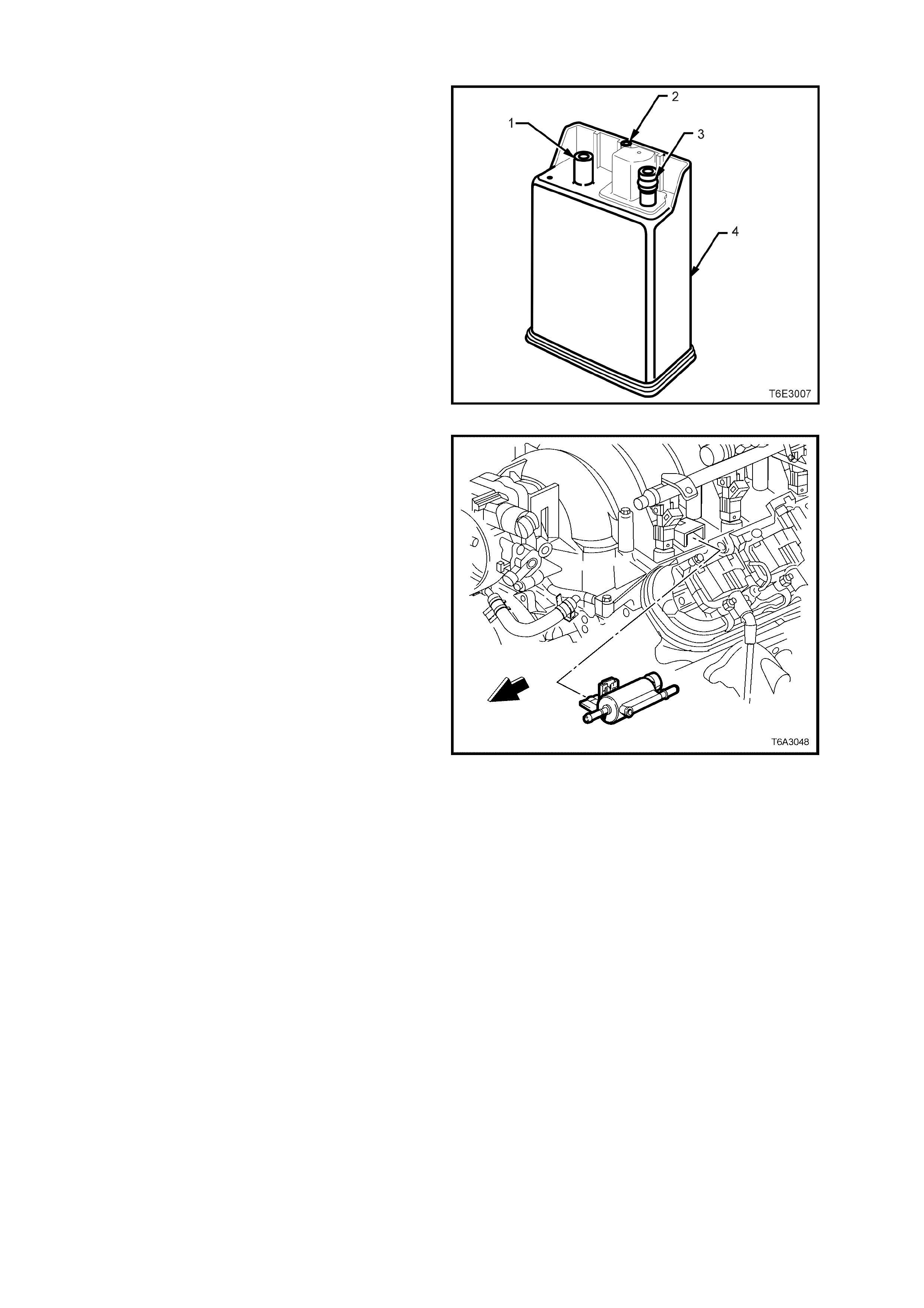
1.8 EVAPORATIVE EMISSION CONTROL SYSTEM
The Evaporative Emission Control System (EECS)
used on this vehicle is the charcoal canister
storage method. This method transfers fuel vapour
from the fuel tank to an activated carbon (charcoal)
storage device (canister located under the rear of
the vehicle) to hold the vapours when the vehicle is
not operating. W hen the engine is running, the fuel
vapour is purged from the carbon element by intake
air flow and consumed in the normal combustion
process.
Legend:
1. Air Vent Port
2. Canister Purge Port
3. Vapour From Fuel Tank Port
4. Vapour Canister
Figure 6C3-1-108 – Fuel Vapour Canister
The EECS purge solenoid valve allows manifold
vacuum to purge the canister. The Powertrain
Control Module (PCM) supplies a ground signal to
energise the EECS purge solenoid valve (purge
ON). The EECS purge solenoid control is Pulse
Width Modulated (PWM) or turned ON and OFF
several times a second.
The PCM controlled PWM output is commanded
when the appropriate conditions have been met:
• Engine coolant temperature is below 30° C at
cold start up.
• Engine has been running longer than 2
minutes.
OR
• Engine coolant temperature is above 30° C at
warm start up.
• Engine has been running longer than 30
seconds.
• Engine is not in Decel Fuel Cutoff Mode.
• Throttle opening is less than 96%.
• Engine is in Closed Loop mode or Open Loop
mode.
• A higher purge rate is used under conditions
that are likely to produce large amounts of
vapour, when the following conditions have
been met: Intake air temperature is above 50°
C.
Figure 6C3-1-109 – Canister Purge Solenoid Location
OR
• Engine coolant temperature is above 100° C.
• Engine has been running for more than 15
minutes.
EECS purge PWM duty cycle varies ac cor ding to oper ating conditions deter mined by mass air f low, fuel trim and
intake air temperature. The EECS purge will be re-enabled when TP angle decreases below 96%.
The canister (located under the rear of the vehicle) cannot be repaired, and is serviced only as an assembly.
Periodically check the canister at the time or distance intervals specified in the MY 2003 VY and V2 Series
Owner’s Handbook. Also refer to Section 0B LUBRICATION AND SERVICE.
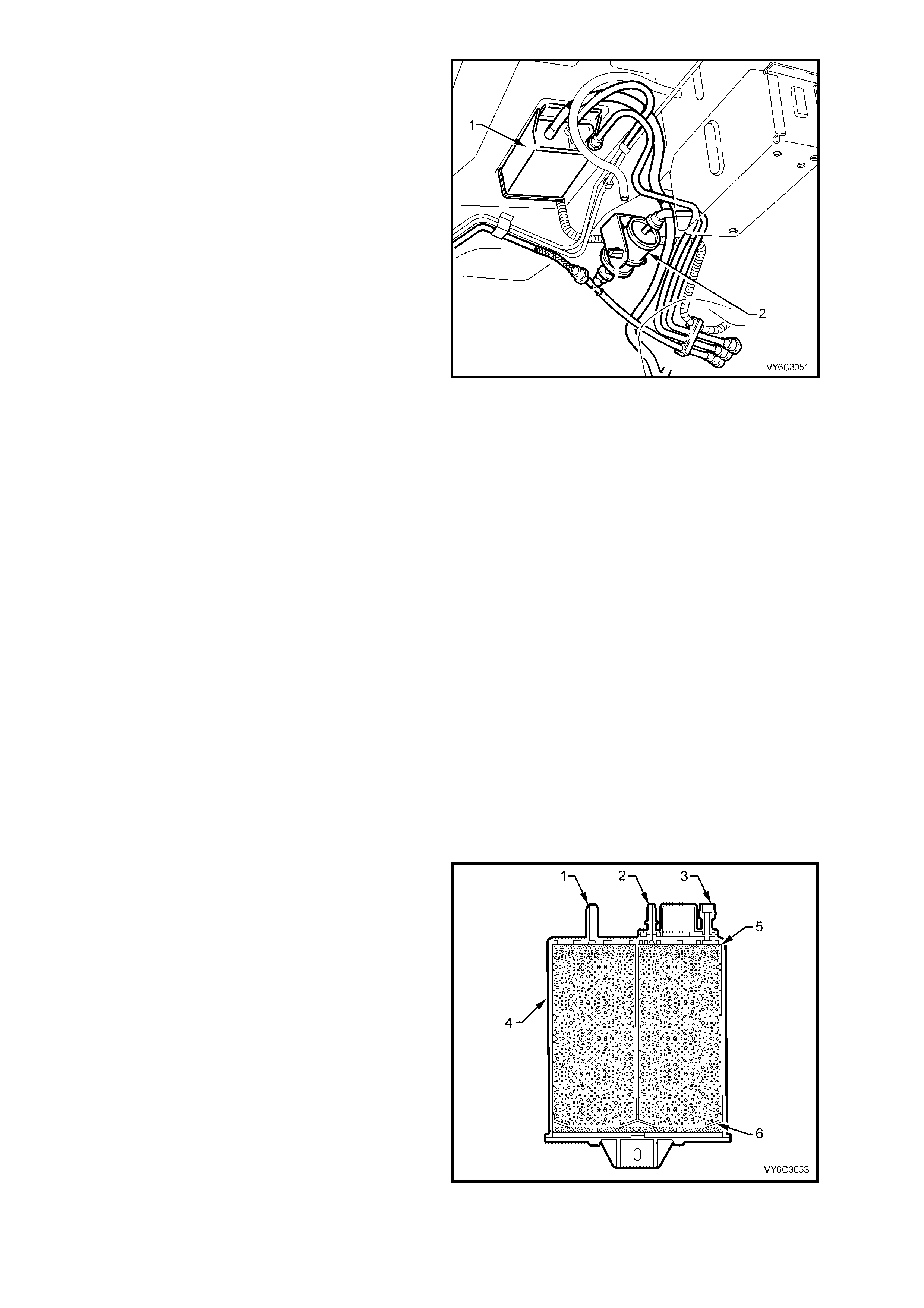
The fuel vapour canister is mounted in a bracket
underneath the vehicle, located near the fuel filter.
This canister is a three port design. Fuel vapour is
absorbed by the charc oal within the canister. When
the engine is running at idle speed and above idle,
air is drawn into the canister through the air vent
port (atmospheric port) at the top of the canister
assembly. The air mixes with the fuel vapour and
the mixture is dr awn into the intak e manif old via the
canister purge line.
The upperm ost port on the c anister is controlled by
a PCM controlled canister purge solenoid. The
canister purge solenoid controls the manifold
vacuum signal from the throttle body. The port
below the canister purge port is the vapour inlet
from the fuel tank. The fresh air inlet port (air vent
port) on the canister is open to the atm osphere via
a hose that vents under the vehicle.
Legend:
1. Evaporative Canister (Under Vehicle
Near Fuel Filter)
2. Fuel Filter
Figure 6C3-1-110 – Canister Location
RESULTS OF INCORRECT OPERATION
Poor idle, stalling and poor driveability can be
caused by:
– Inoperative canister purge solenoid.
– Damaged canister.
– Hoses split, cracked and/or not connected
to the proper tubes.
– Throttle body and canister hoses
interchanged on the purge solenoid
connections.
NOTE: The canister connection is marked
with CAN.
Evidence of fuel loss or fuel vapour odour can be
caused by:
– Liquid fuel leaking from fuel lines.
– Cracked or damaged canister.
– Disconnected, incorrectly routed, kinked,
deteriorated or damaged vapour hoses, or
control hoses.
If the solenoid is stuc k open, or the control c ircuit is
shorted to ground, the canister will purge to the
intake manifold all the time. This can allow extra
fuel at idle or during warm-up, which can cause
rough or unstable idle or a rich fuel operation.
If the canister purge solenoid is always closed, the
canister can become over loaded with fuel,
resulting in fuel odour.
A failure in the Evapor ative Canister purge solenoid
or Circuit will result in DTC P0443.
Legend:
1. Air Vent Port
2. Canister Purge Port
3. Vapour From Fuel Tank Port
4. Evaporative Canister
5. Volume Compensator
6. Charcoal Bed
Figure 6C3-1-111 – Sectioned View of Canister

DTC P0443 EVAP PURGE SOLENOID CONTROL CIRCUIT
Conditions for running DTC P0443
• The engine speed is greater than 400 RPM.
• The ignition voltage is between 6.0 and 16.0 volts.
Conditions for setting DTC P0443
• The PCM detects that the commanded state of the circuit and the actual state of the circuit do not match.
• The conditions are present for at least ten seconds.
Action taken when DTC P0443 Sets
• The PCM activates the Malfunction Indicator Lamp (MIL) when the diagnostic runs and fails.
• The PCM records the operating conditions at the time the diagnostic fails. The PCM stores this information in
the Freeze Frame/Failure Records.
Conditions for clearing the Malfunction Indicator Lamp (MIL) and DTC P0443
• The PCM deactivates the Malfunction Indicator Lamp (MIL) after one ignition cycle that the diagnostic runs and
does not fail.
• A last test failed (current DTC) clears when the diagnostic runs and does not fail.
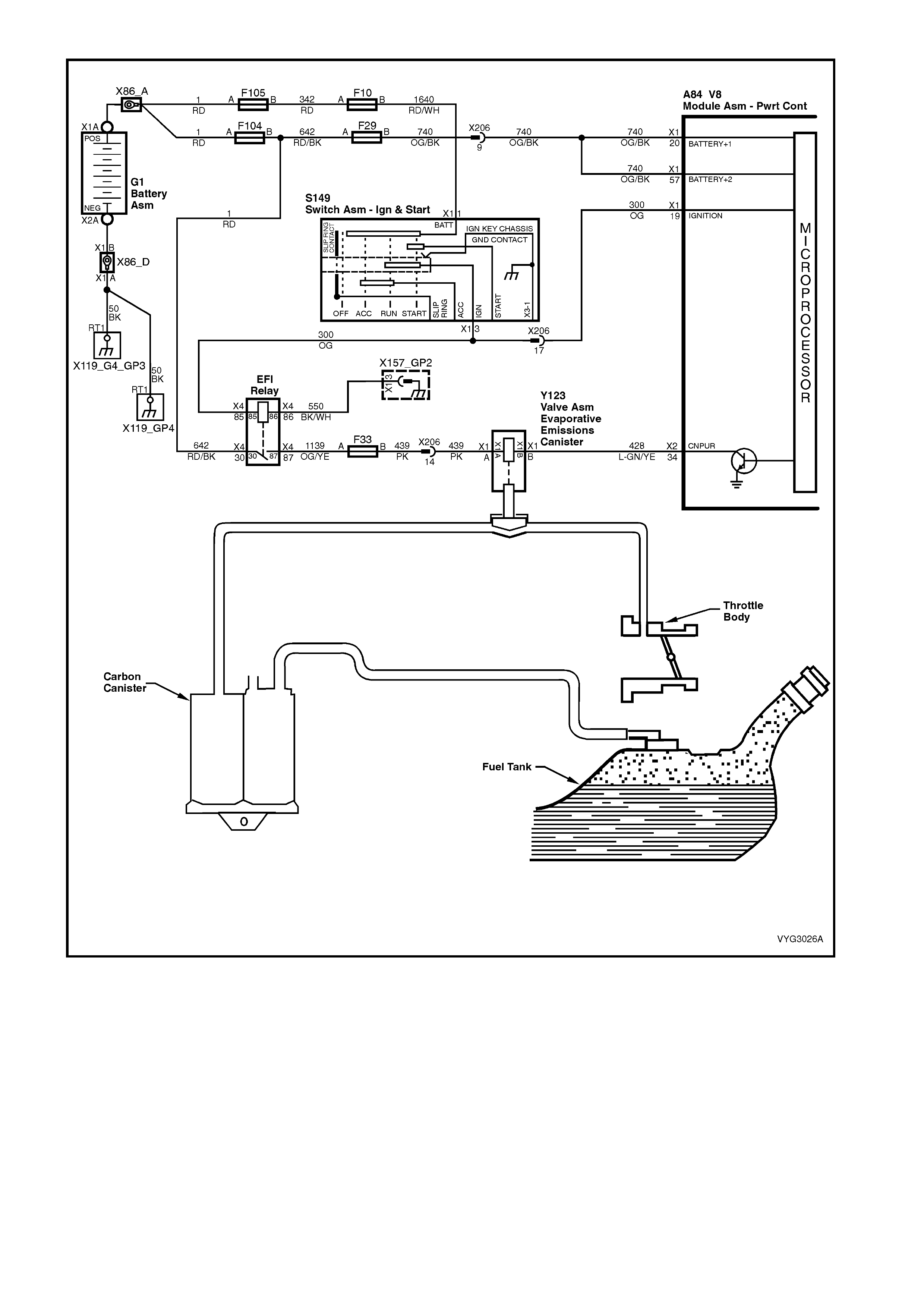
Figure 6C3-1-112 – Evaporative Emission Control Schematic
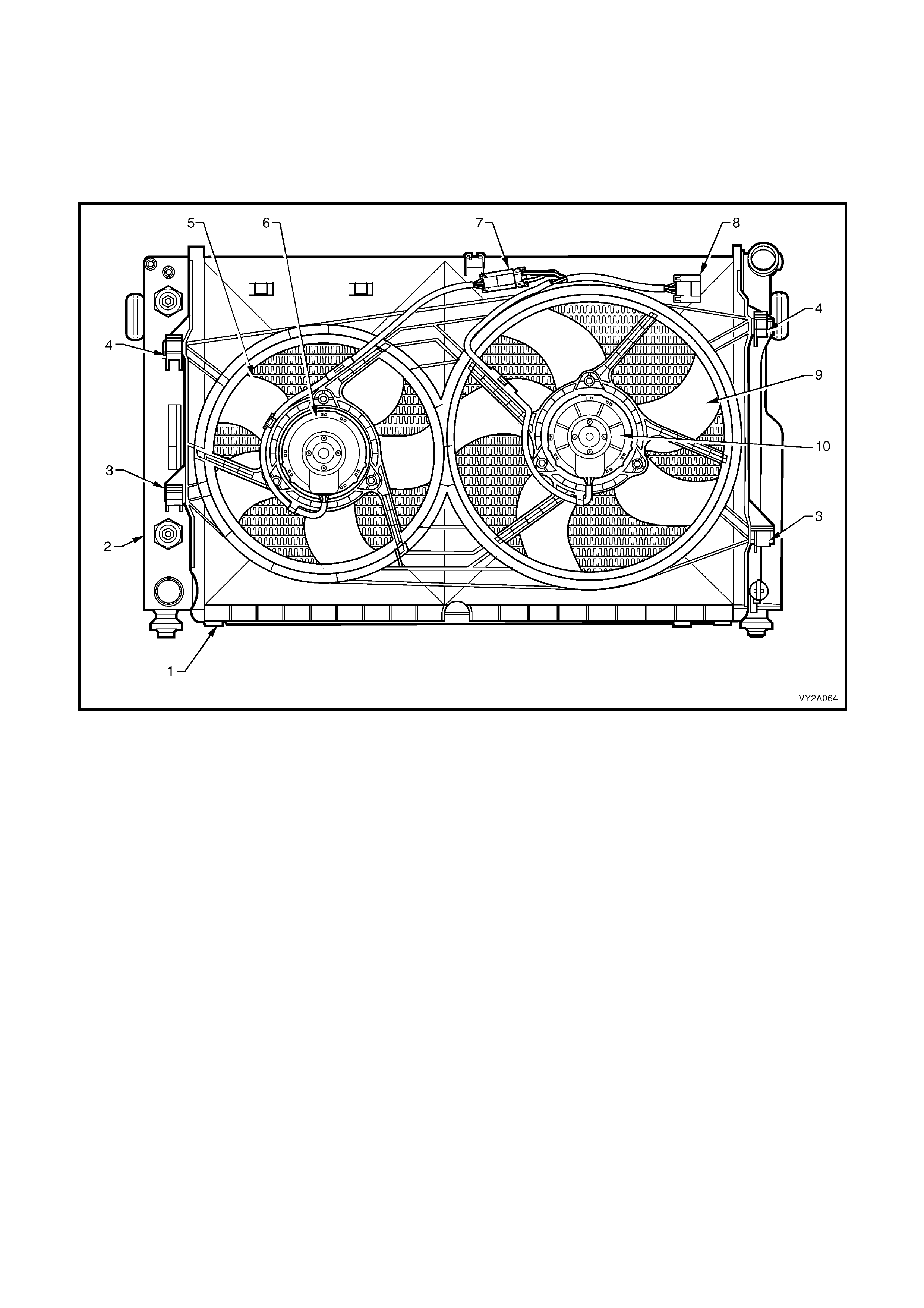
1.9 ELECTRIC COOLING FANS
The cooling system for the GEN III V8 engine, includes two, double speed, engine cooling fan motors, both of
which, drive fans with five, asymm etric al blades, to reduce air noise. T he right f an is 342 m m in diam eter and has a
motor rated at 220 W atts (Right), while the left fan is 293 m m in diameter with a motor power rating of 180 W atts
(Left).
W hen operating at stage 1, the left fan motor operates at 2,050 rpm and the right, at 2,300. W hen in stage 2, the
left fan operates at 2,350 ± 150 rpm and the right, at 2,750 ± 150 rpm.
Figure 6C3-1-113 – Cooling Fans, GEN III V8
Legend
1. Fan Shroud
2. Radiator
3. Fan Shroud Lower Support
4. Fan Shroud Upper Support/Locking Retainer
5. Left Fan – 5 Blade, 293 mm Diameter
6. Left Fan Motor – 180 Watt, Double Speed
7. Left Fan Motor Harness Connector (4 Terminal)
8. Left and Right Fan Motor Harness Connector (6 terminal)
9. Right Fan – 5 Blade, 342 mm Diameter
10. Right Fan Motor – 220 Wa tt, Double Speed
OPERATION
To achieve the dual speed requirement, the electrical circuitry for the GEN III V8 cooling fans have two negative and
two positive ter minals . To r educe the heat burden on the electric al connectors , the current draw is dir ected through
separate negative terminals at the joint connector (‘8’ in Figure 6C3-1-110), for each fan motor.
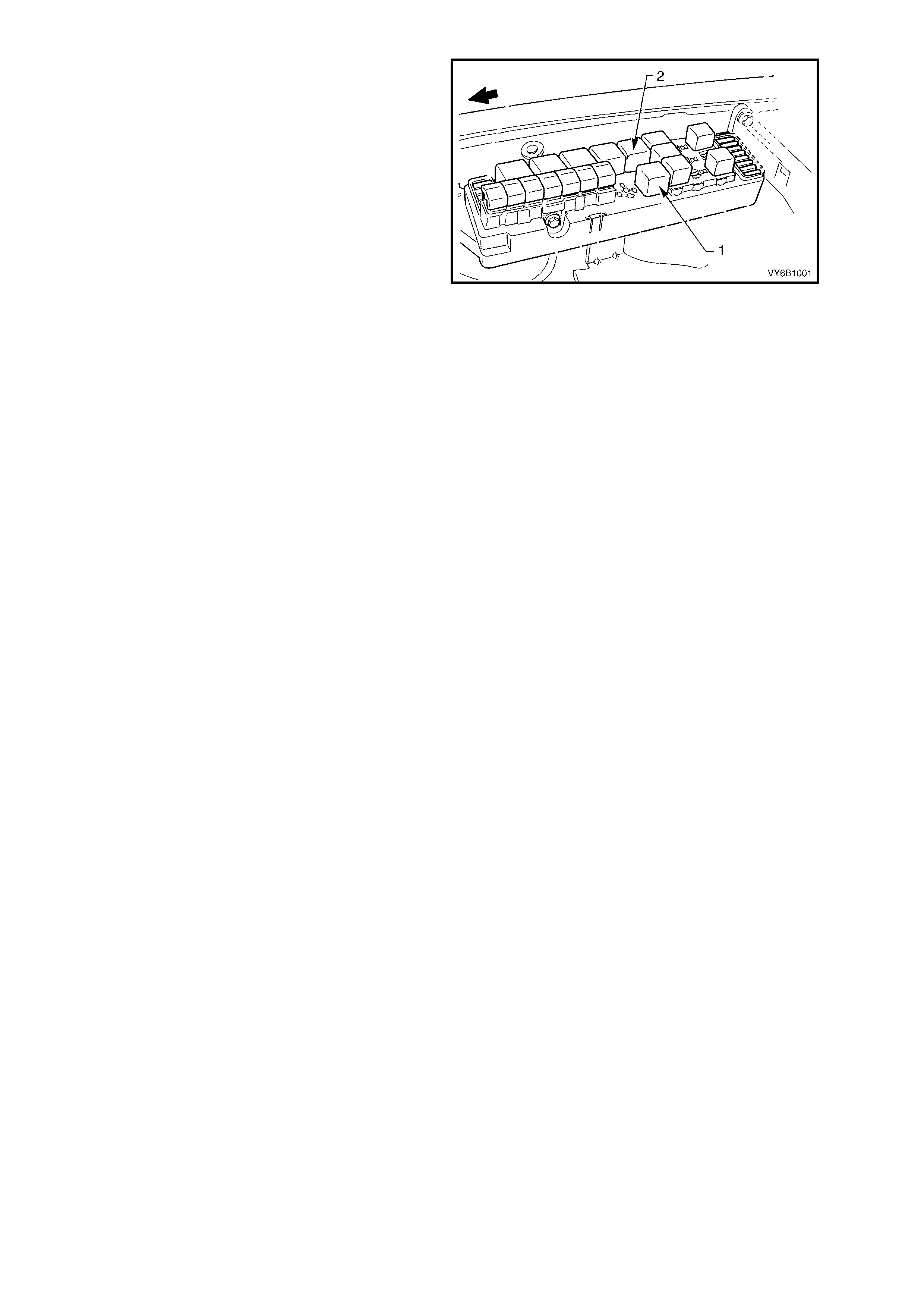
The positive terminals are permanently connected
to battery voltage, via fusible links F101 (sm all fan)
and F107 (large fan).
The engine cooling fan Low Speed Relay (1) is
energised by the BCM. W hen the PCM determ ines
that the low speed fan relay should be enabled, the
PCM will send a message on the Class 2 serial
data circuit to the PIM. The PIM will then convert
the PCM Class 2 message to a UART message
and supply this UART message to the BCM, via a
serial data Normal Mode Message to the BCM on
circuit 800 (Red/Black wire). This message will
request the BCM to supply the needed ground
signal for the Low Speed Relay (R7) to operate.
After the BCM provides the ground signal for the
Low Speed Relay, the BCM will send a message
back to the PIM confirming that the ground signal
was commanded.
A failure in this BCM response communication, will
cause a PIM DTC B2002 to set.
Figure 6B1-114 – Underhood Fuse & Relay Centre
The PCM determines when to enable stage 1,
based on inputs from the A/C request signal,
Engine Coolant Temperatur e (ECT) s ensor and the
Vehicle Speed Sensor (VSS).
There are also suppression capacitors
incorporated into the fan motor wiring circuits.
These suppression capacitors help eliminate fan
motor noise through the radio speakers. If these
capacitors are open, then noise will be present
through the radio speakers. If either of these
capacitors were shorted to ground, the fan motors
could run continuously or the fuse or fusible link
could fail.
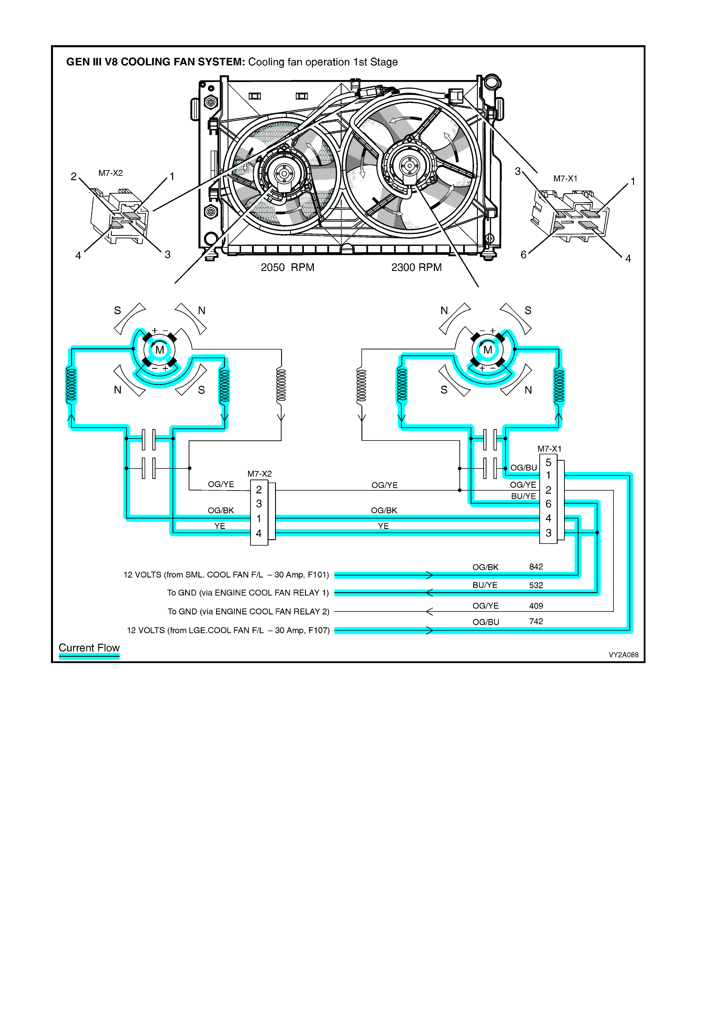
Figure 6C3-1-115 – GEN III V8 Cooling Fan Operation – Stage 1
Stage One Fan Operation
The cooling fan low speed relay 1 (R7) will be turned ON when:
• The A/C request indicated (YES) and either:
• the vehicle speed is less than 30 km/h.
or
• The coolant temperature is greater than 98° C.
or
• If the coolant temper ature is greater than 113° C, when the ignition is s witched of f , the r elay is ener gised f or
approximately four minutes, this is known as Low Fan Run On.
or
• If an engine coolant temper ature s ens or fault is detec ted and a DT C s uc h as DTC P0117, P0118, P1114 or
P1115 is set.
The cooling fan low speed relay will be turned OFF when any of the following conditions have been met:
• An A/C request is not indicated (NO) and the coolant temperature is less than 95° C.
or
• An A/C request is indic ated (YES) and the vehicle speed is greater than 50 km /h and A/C press ure is less than
1,170 kPa and the coolant temperature is less than 98° C.

Figure 6C3-1-116 – GEN III V8 Cooling Fan Operation – Stage 2
Stage Two Fan Operation
The engine cooling fan high speed relay 2 (R5) is controlled by the PCM. The PCM will only turn ON the engine
cooling fan high speed relay fan if the engine cooling fan low speed relay has been ON for two seconds and the
following conditions are satisfied.
• There is a BCM message response fault which will cause a PIM DTC B2002.
• An engine coolant tem perature sensor fault is detected and a DT C such as DTC P0117, P0118, P1114 or
P1115 is set.
• Coolant temperature greater than 108° C.
• The A/C refrigerant pressure is greater than 2,400 kPa.
If the low speed fan was OFF when the criteria was met to turn the high speed fan ON, the high speed fan will come
ON 5 sec onds after the low speed f an is turned ON. If both the engine cooling fan relays are ON, the PCM will turn
OFF the high speed relay when:
• The engine coolant temperature is less than 102° C.
• A/C request not indicated (NO).
• A/C request indicated (YES) and A/C pressure is less than 1,900 kPa.
NOTE: All cooling fans will be turned off if the vehicle speed is greater than 104 km/h.
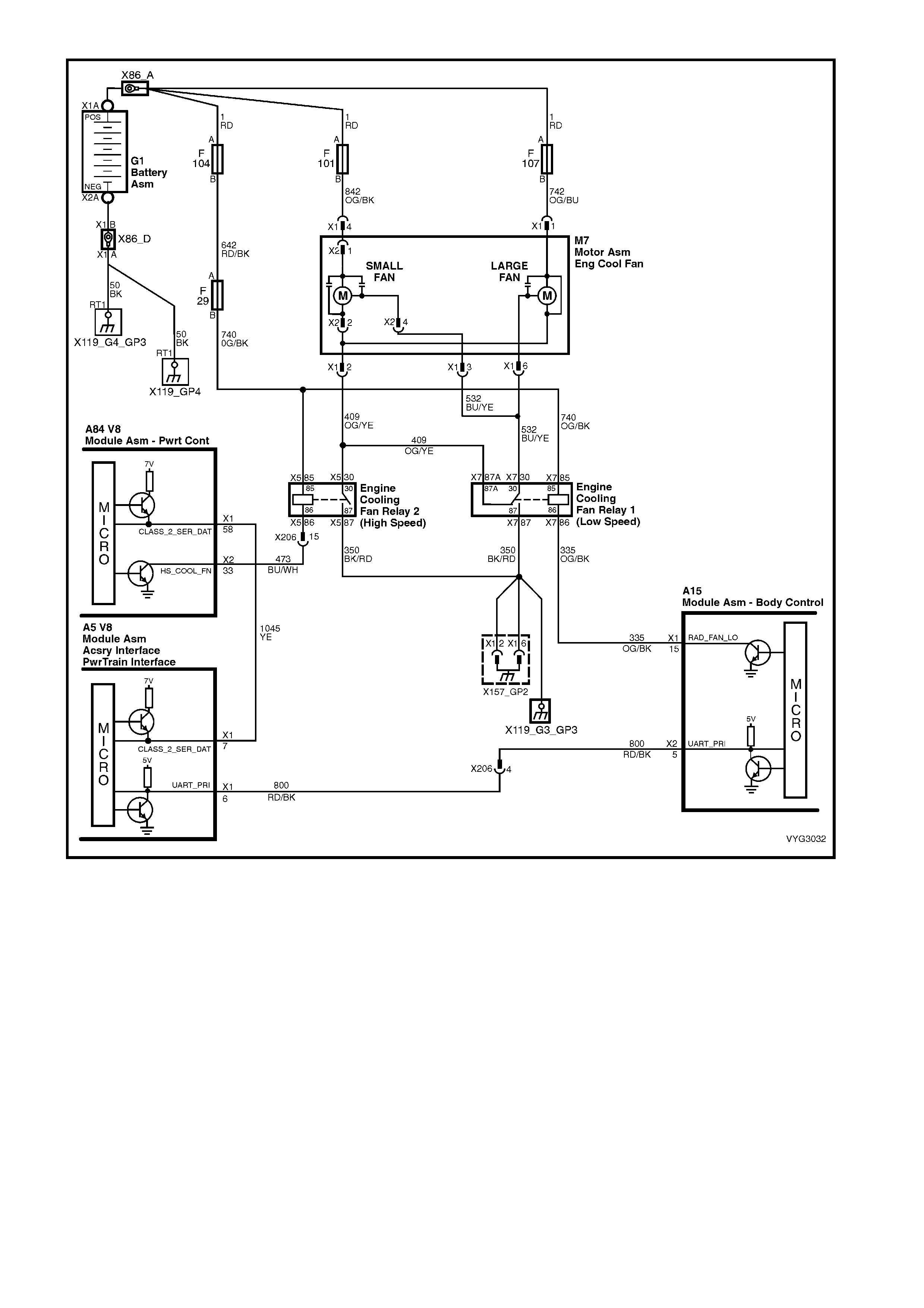
Figure 6C3-1-117 – Engine Cooling Fan Circuit
DTC P0481 COOLING FAN HIGH SPEED RELAY CONTROL
Conditions for running DTC P0481
• The engine speed is greater than 600 RPM.
• The ignition voltage is between 6.0 and 16.0 volts.
Conditions for setting DTC P0481
• The PCM detects that the commanded state of the driver and the actual state of the control circuit do not
match.
• The conditions must be present for a minimum of 10 seconds.
Action taken when DTC P0481 Sets
• The PCM activates the Malfunction Indicator Lamp (MIL) when the diagnostic runs and fails.
• The PCM records the operating conditions at the time the diagnostic fails. The PCM stores this information in
the Freeze Frame/Failure Records.
Conditions for clearing the Malfunction Indicator Lamp (MIL) and DTC P0481
• The PCM deactivates the Malfunction Indicator Lamp (MIL) after one ignition cycle that the diagnostic runs and
does not fail.
• A last test failed (current DTC) clears when the diagnostic runs and does not fail.

DTC B2002 LOW SPEED FAN NO BCM RESPONSE
Conditions for running DTC B2002
• The ignition is on.
Conditions for setting DTC B2002
• The PIM sends a Low Speed request signal to the BCM , with no response back from the BCM.
Action taken when DTC B2002 Sets
• The PIM will display the DTC only when current.
• The Malfunction Indicator Lamp (MIL) will not illuminate.
Conditions for clearing the Malfunction Indicator Lamp (MIL) and DTC B2002
• A current DTC will clear when the PIM receives a Low Speed Fan Response from the BCM.
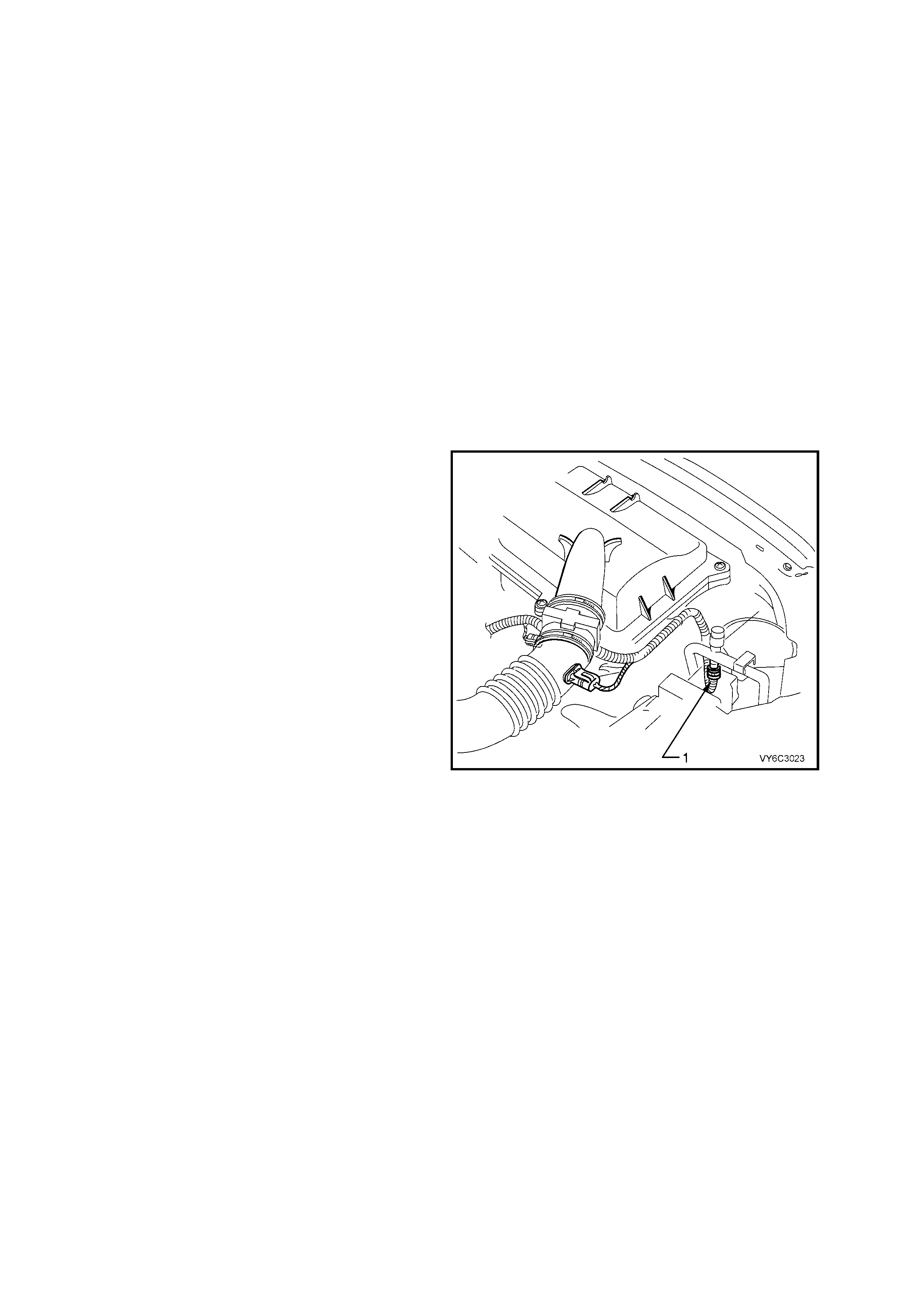
1.10 A/C CLUTCH CONTROL
This vehicle uses two types of A/C clutch controls;
one with standard A/C and the other uses an
Occupant Climate Control (OCC) control module.
OCC SYSTEM
W ith the OCC system , when the A/C is requested,
the electronic climate control module will supply a
signal to the PCM, via the serial data line. When
the PCM receives the serial data request on PCM
terminal A84 X1-58, it indicates that air conditioning
has been requested and approxim ately 1/2 second
after the PCM receives this signal, it will energise
the A/C control relay. This serial data signal to the
PCM is also used to adjust the idle speed before
turning ON the A/C compressor relay. If this signal
is not available to the PCM, the A/C compressor
will be inoperative.
The BCM also supplies the ground signal from
BCM terminal A15 X1-15 to the low speed cooling
fan relay (R7).
This A/C system also incorporates an A/C
Refrigerant Pressure Sensor (1). The A/C
Refrigerant Pressure Sensor signal indicates high
side refrigerant pressure to the PCM. The PCM
uses this information to adjust the idle air control
valve to compensate for the higher engine loads
present with high A/C refrigerant pressures. A fault
in the A/C Refrigerant Pressure Sensor signal will
cause DTC P0530 to set.
The PCM will not energise the A/C control relay if
any of the following conditions are present:
• High coolant temperature
• Low A/C system pressure
• High A/C system pressure
• Wide open throttle
• High engine RPM
Figure 6C3-1-118 – A/C Refrigerant Pressure
Sensor Location
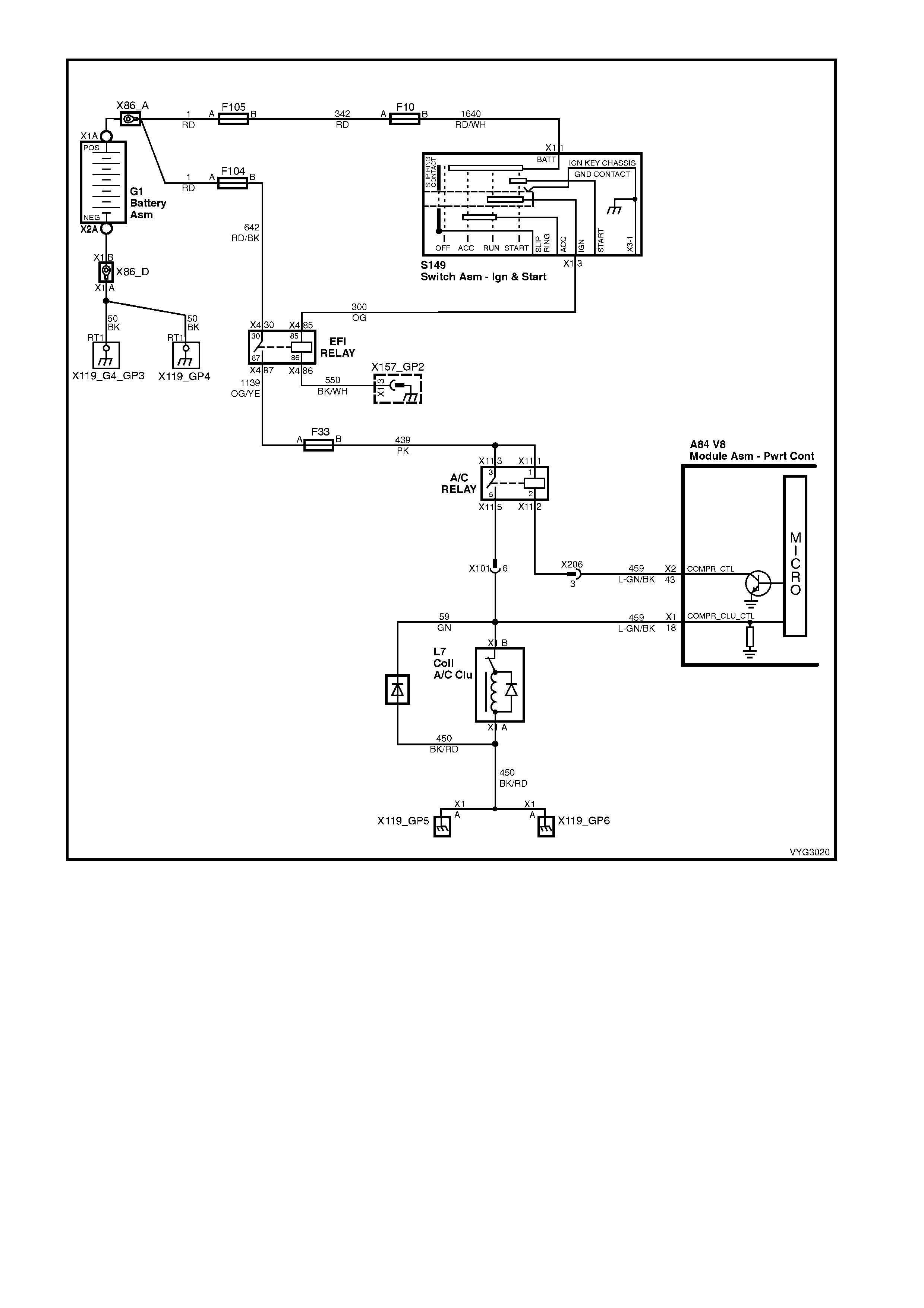
Figure 6C3-1-119 – Air Conditioning Circuit with OCC

STANDARD A/C SYSTEM
On vehicles equipped with the non OCC system,
the power flow is different. With the blower fan
switched ON and the air conditioning switched ON,
switched ignition voltage is supplied from fuse F13
through the A/C master switch and then to the
BCM. The BCM will then supply a ser ial data signal
to the PCM requesting A/C.
If the BCM does not receive a ground signal from
the blower switch to BCM terminal A15 X3-9, the
BCM will not supply the serial data request f or A/C.
Once the PCM receives this serial data signal, the
PCM will energise the A/C compressor relay (1).
The BCM also supplies the ground signal from
BCM terminal A15 X1-15 to the low speed cooling
fan relay.
This serial data signal to the PCM is also used to
adjust the idle speed before turning ON the A/C
compressor relay. If this signal is not available to
the PCM, the A/C compressor will be inoperative.
This system, as on the OCC system, also
incorporates an A/C Refrigerant Pressure Sensor.
Figure 6C3-1-120 – A/C Relay Location
The A/C Refrigerant Pressure Sensor signal
indicates high side refrigerant pressure to the
PCM. The PCM uses this information to adjust the
idle air control valve to compensate for the higher
engine loads present with high A/C refrigerant
pressures. A fault in the A/C Refrigerant Pressure
Sensor signal will cause DTC P0530 to set.
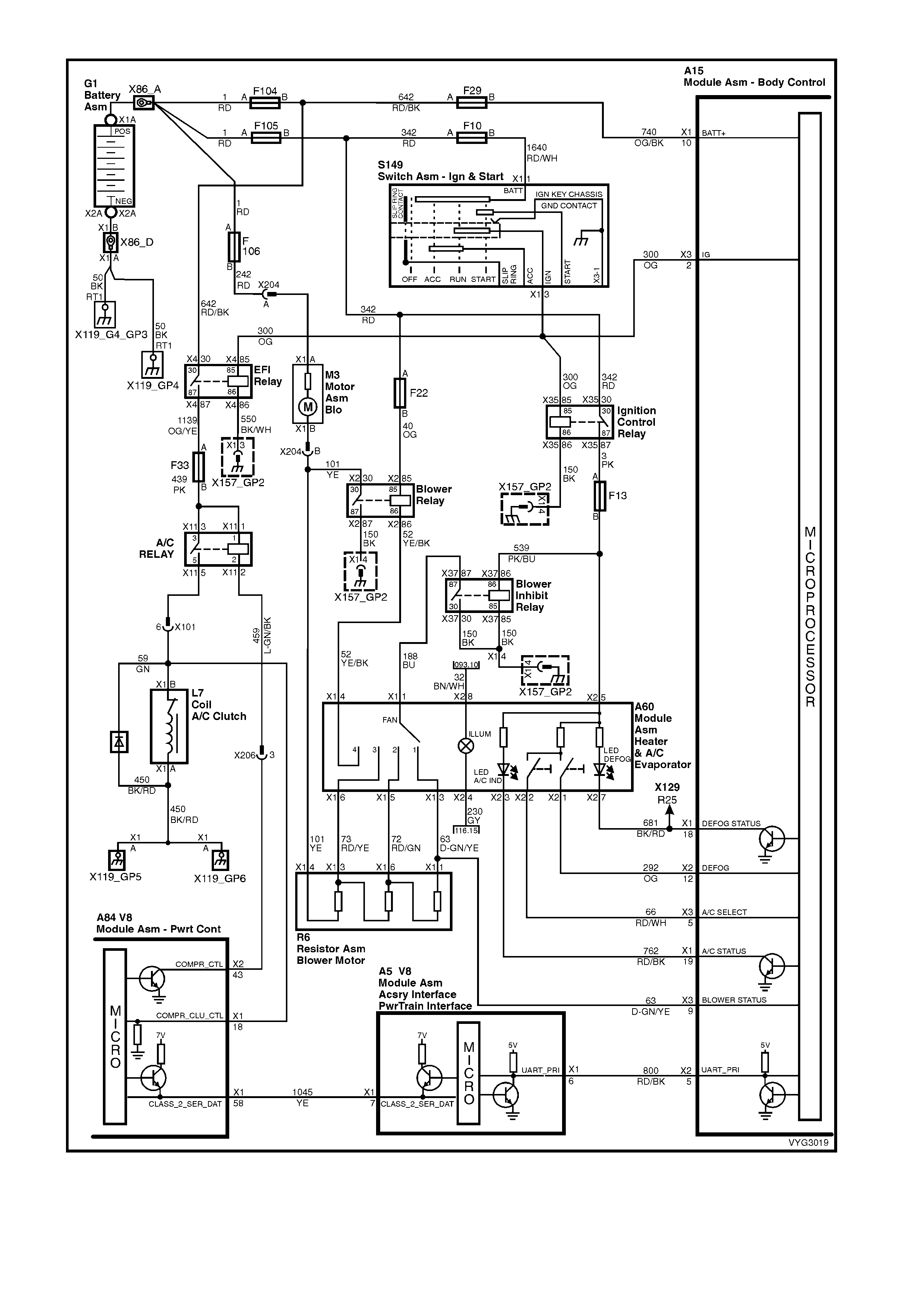
Figure 6C3-1-121 – Air Conditioning Circuit, without OCC
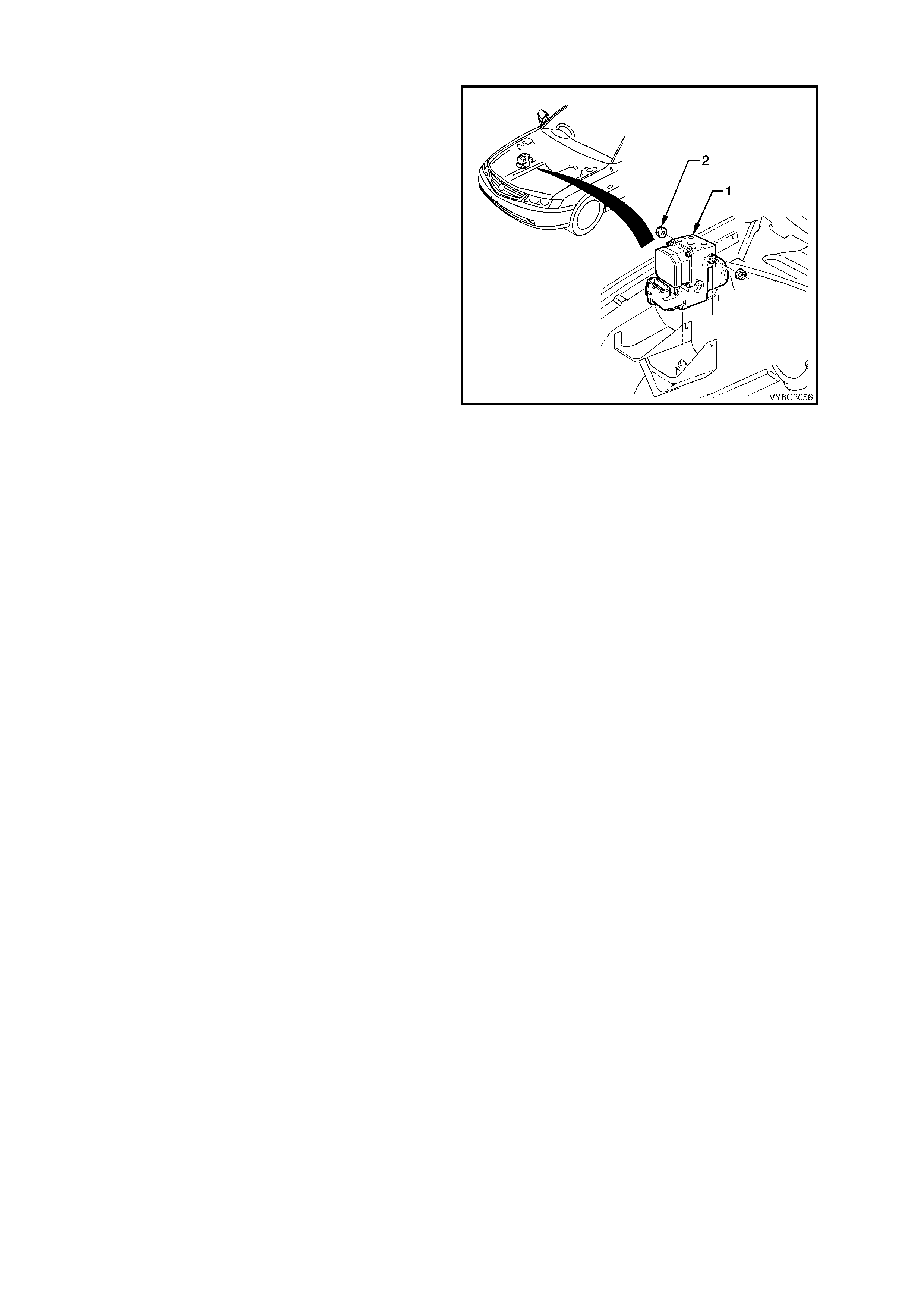
1.11 ELECTRONIC TRACTION CONTROL
When the ABS/TCS control module senses spin
from the drive wheels due to too much engine
torque for the road conditions, it enters the traction
control mode.
The ABS/TCS m odule monitors both front and rear
wheel speeds through the wheel speed sensors. If
at any time during acceleration the ABS/TCS
module detects drive wheel slip, it will request:
• The PCM, via the spark retard circuit, to retard
the amount of spark advance.
• The PCM, to restrict transmission downshifting.
• The throttle relaxer control module to reduce
the engine throttle opening by a certain
percentage to bring engine torque into a
specific range.
The throttle relaxer control module accomplishes
this by commanding the throttle relaxer to override
the accelerator pedal cable and physically reduce
the throttle body butterfly opening by winding the
throttle cable back.
This is achieved via two high speed Pulse Width
Modulated (PWM) circuits between the ABS/TCS
module and the thr ottle relaxer control m odule. T he
ABS/TCS control module sends a message to the
throttle relaxer control module on the requested
throttle position (DKR) circuit. The throttle relaxer
control module then reports the modified throttle
position opening back to the ABS/TCS control
module via the actual throttle position (DKI) circuit.
Figure 6C3-1-122 – ABS/TCS Module Location
Legend:
1. ABS/TCS Hydraulic Modulator
2. Nut (2 places)
Simu ltaneously with engine spark retard and thr ottle position intervention, the ABS/T CS control module will activate
the ABS isolation valves, turn on the ABS pump motor and supply brake pressure to the over spinning wheel(s).
The isolation valves isolate the front brake hydraulic circuits from the master cylinder and rear brake hydraulic
circuits. Once the rear brake hydraulic circuits are isolated, pressure can be applied to the rear wheels without
affecting any other brake hydraulic circuits. The ASS/TCS module opens the priming valve, allowing fluid to be
drawn from the m aster cylinder to the pump m otor, tur ns on the ABS pump m otor to apply pressur e, begins cycling
the ABS assembly's inlet and outlet valves, and closes the switching valve, ensuring fluid is directed to the wheel
not back into the master cylinder.
The inlet and outlet valve c ycling aids in obtaining m aximum road surf ace traction in the same m anner as the Anti-
Lock Brake mode. The difference between Traction Control and Anti-Lock Brak e m ode is that brake fluid pressure
is increased to lessen wheel spin (Traction Control mode), rather than reduced to allow greater wheel spin (Anti-
Lock Brake mode).
If at any time during T r ac tion Control mode, the br akes ar e manually applied, the brake switch s ignals the ABS/T CS
module to inhibit brake intervention and allow for manual braking (throttle reduction and spark retard intervention
can still occur if necessary).
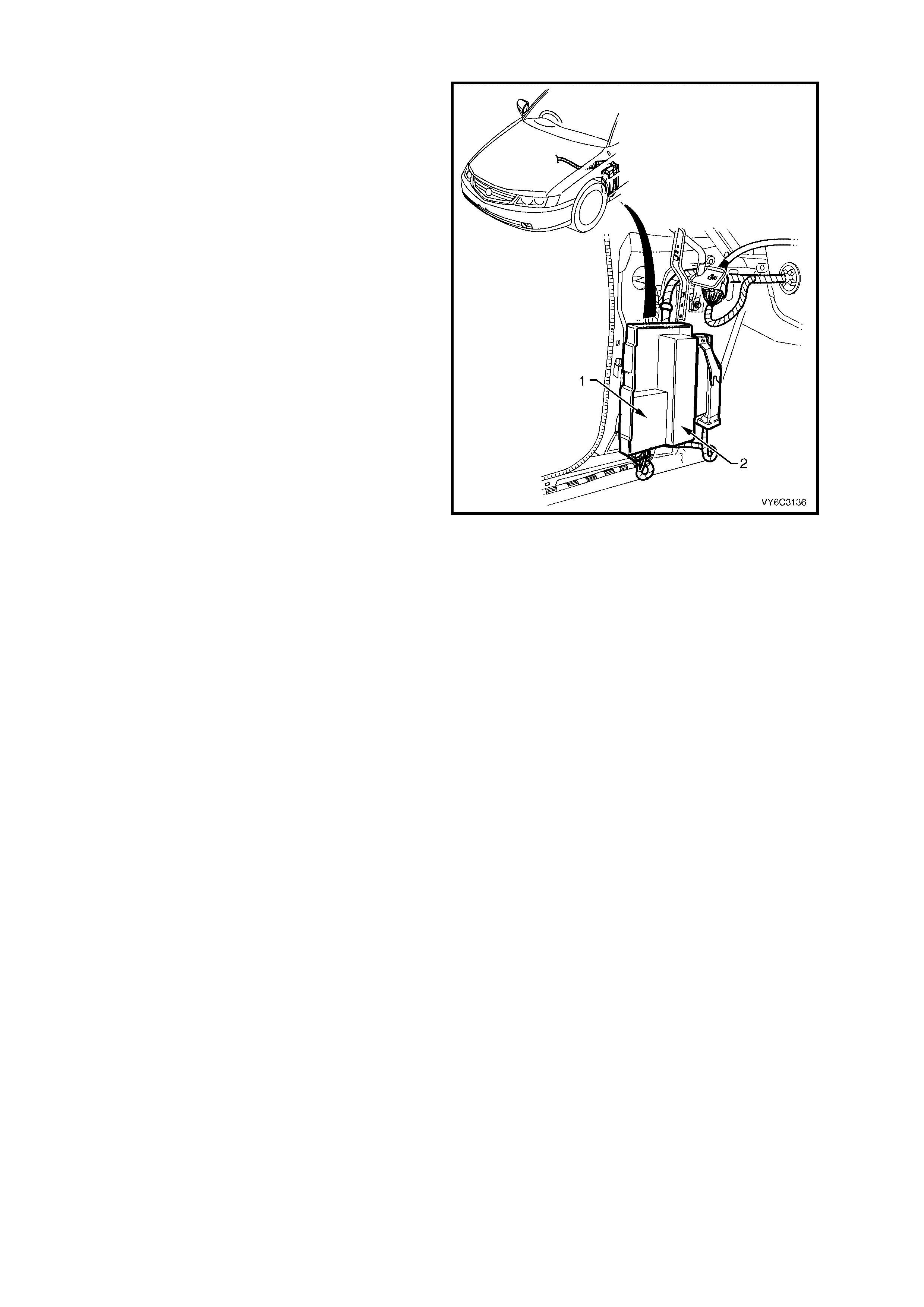
ENGINE SPARK AND THROTTLE POSITION INTERVENTION
Simultaneously to brake intervention, the ABS/TCS
control module communicates with the Powertrain
Control Module (PCM) (via the Powertr ain Interfac e
Module (PIM) (1) and the Throttle Relaxer Control
Module (2) requesting the PCM to retard the spark
advance and for the throttle relaxer control module
to reduce the throttle opening.
With the engine running, the PCM continually
supplies and m onitors a 12 volt pull- up to the spar k
retard circuit. The ABS/TCS control module
requests spark retard by pulling this voltage low.
The PCM then responds by reducing the spark
advance of the engine and restricting transmission
downshifting.
The ABS/TCS control module constantly sends a
Pulse Width Modulated (PWM) signal at 90% with
a frequenc y of 100 Hz to the throttle relaxer control
module on the requested throttle position line
(DKR). This signal is to indicate to the throttle
relaxer control module that the traction control
system (TCS) is in a state of readiness.
With the engine idling, the ABS/TCS control
module constantly sends a Pulse W idth Modulated
(PWM) signal with a duty cycle of 90% to the
throttle relaxer control module via the requested
throttle position line (DKR). The throttle relaxer
control module responds on the actual throttle
position line (DKI) with a PWM signal with a duty
cycle of 9%.
When the ABS/TCS control module determines
that a reduction in throttle is requir ed, it r educes the
PWM signal on the requested throttle position line
(DKR), from 90% (no throttle reduction) to as low
as approximately 14% (maximum throttle
reduction). The throttle relaxer control module then
drives the throttle relaxer motor, overriding the
accelerator pedal command (drivers foot), pulling
the throttle cable back, and thus, closing the
amount of throttle opening.
If there is a malfunction between the ABS/TCS
module and the PCM, an ABS/T CS DTC will set. If
there is a malfunction between the ABS/TCS
module and the throttle relaxer control module,
refer to Section 5B ABS & ABS/TCS.
Figure 6C3-1-123 – Throttle Relaxer Control Module
Legend:
1. Throttle Relaxer Control Module
2. Powertrain Interface Module
For further description on the Anti-Lock
Brake (ABS) system, Electronic Traction Control
(TCS) system Throttle Relaxer Control
Module operation and DTC diagnosis, refer to
Section 5B ABS & ABS/TCS.
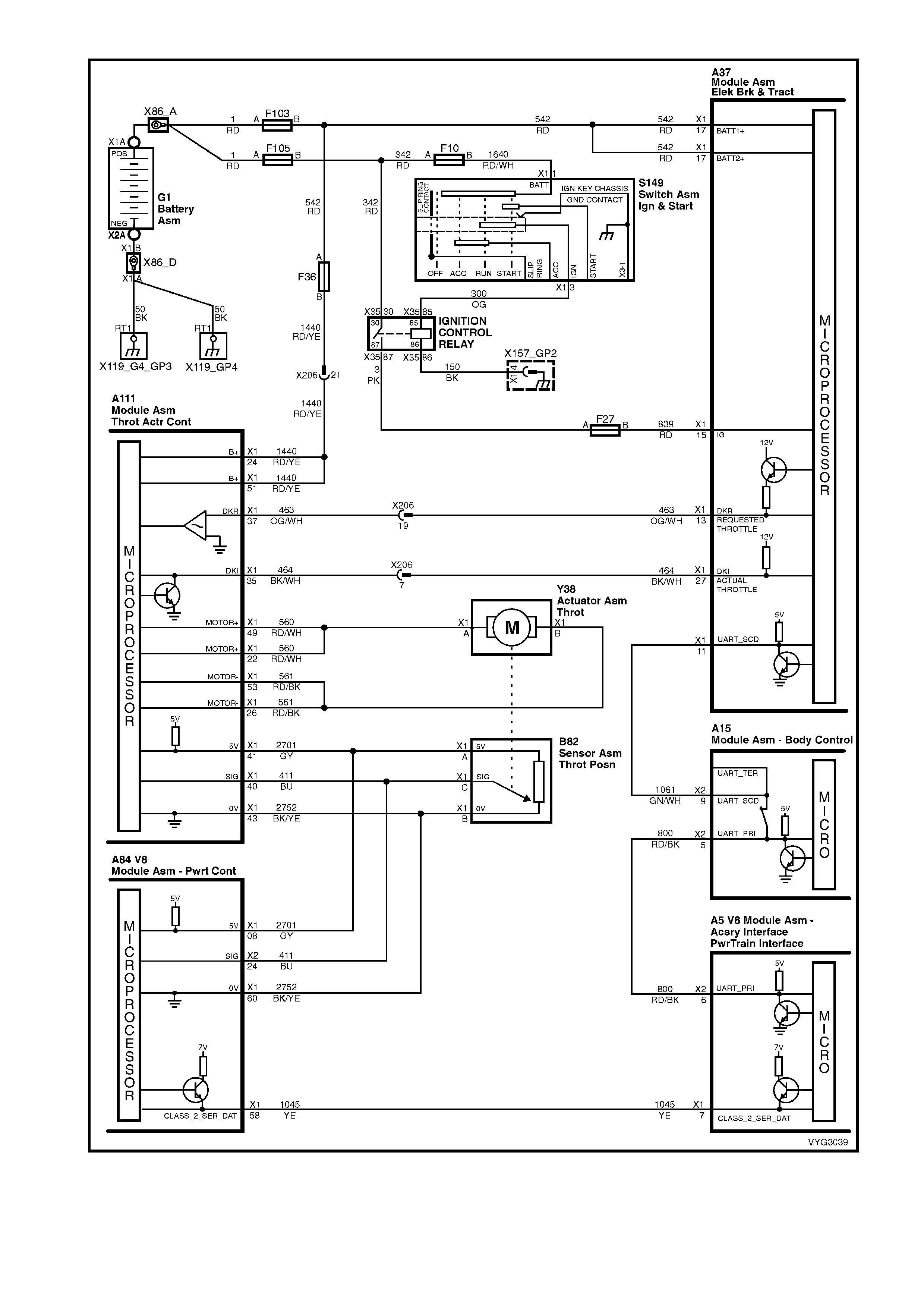
Figure 6C3-1-124 Throttle Relaxer and ABS/TCS Circuits
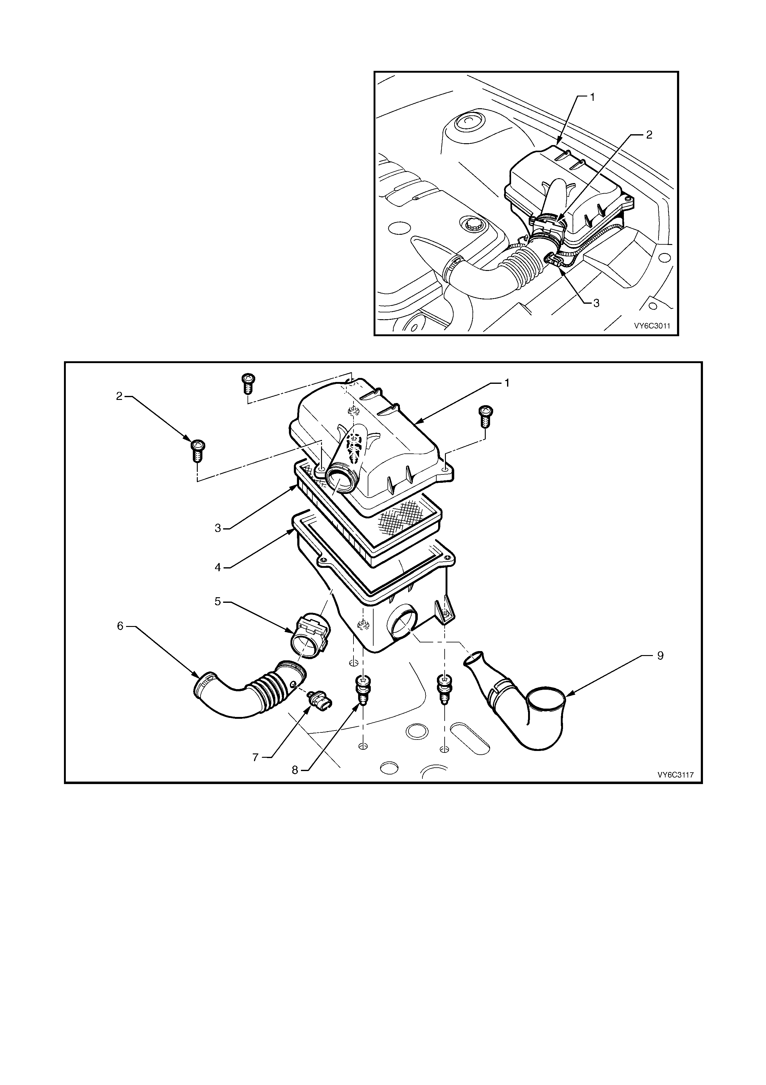
1.12 AIR INTAKE SYSTEM
The air intak e s ystem draws outs ide air through the
front of the air cleaner assembly and filter element
of the forward mounted air cleaner. The air is then
routed through the MAF s ensor and into the throttle
body to the intak e m anif old. T he air is then directed
into the intake manifold runners, through the
cylinder heads and into the cylinders.
If the Mass Air Flow (MAF) Sensor is installed
backwards, the system will run rich. An arrow
marked on the plastic portion of the sensor
indicates correct air flow direction. The arrow must
point toward the engine.
Legend:
1. Air Cleaner Housing
2. Mass Air Flow (MAF) Sensor
Figure 6C3-1-125 – Air Cleaner Location
Figure 6C3-1-126 – Air Cleaner Housing Assembly
Legend
1. Air Cleaner Housing Upper Body
2. Air Cleaner Housing Top Cover Retaining Screws (3)
3. Air Cleaner Filter
4. Air Cleaner Housing Lower Body
5. Mass Air Flow (MAF) Sensor
6. Air Intake Duct to Throttle Body
7. Intake Air Temperature (IAT)
8. Sensor Air Cleaner Housing Retaining Screws (3)
9. Air Inlet to Air Cleaner Housing, Cold Air Duct
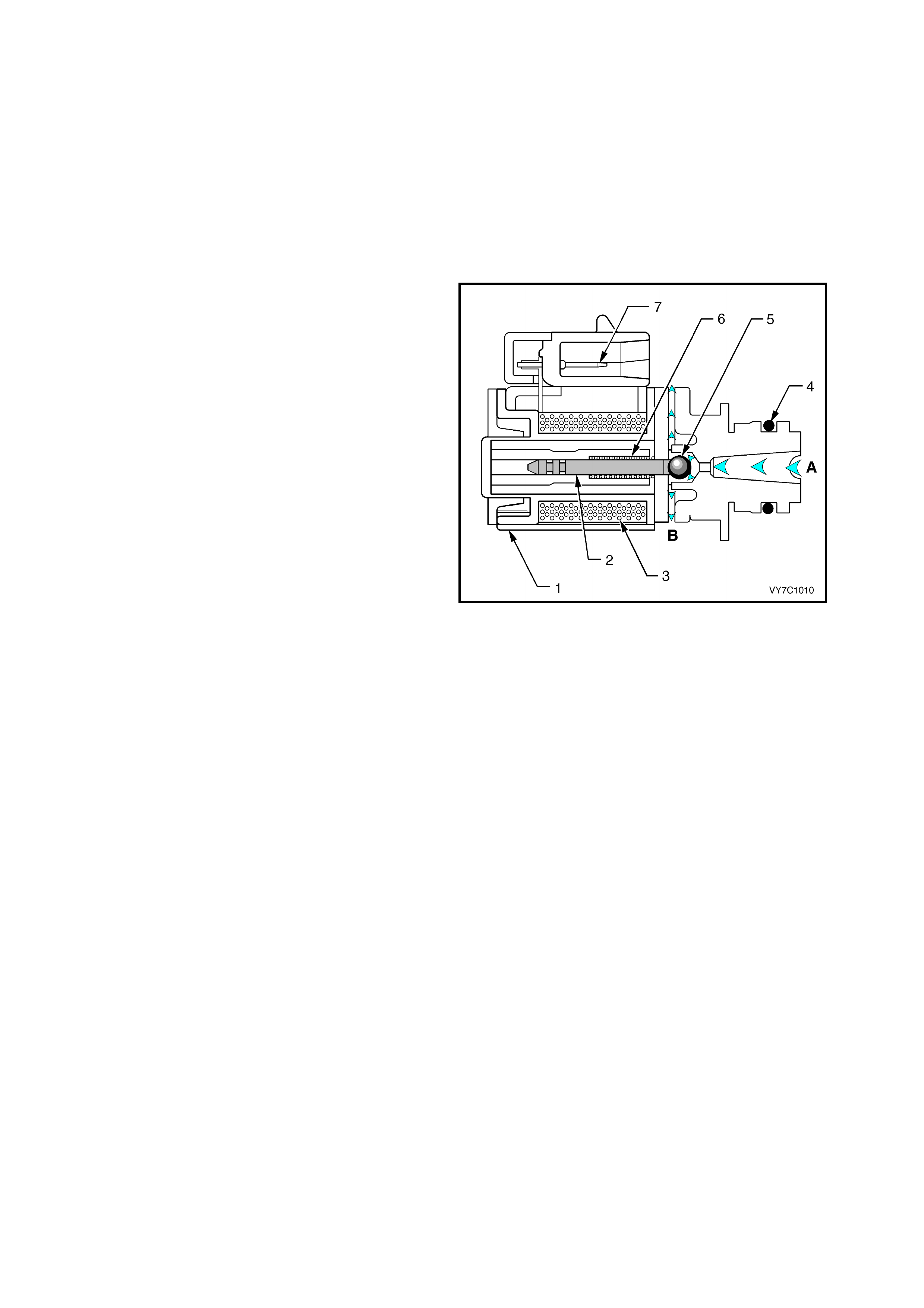
1.13 AUTOMATIC TRANSMISSION SENSORS & SIGNALS
1-2 (A) AND 2-3 (B) SHIFT SOLENOID VA LVES
IMPORTANT: T he shif t solenoid valve resis tance
should measure 19-24 ohms minimum when
measured at 20° C. The shift solenoid current
flow should not exceed 0.75 amps. The shift
solenoid should energise at a voltage of 7.5 volts
or more (measured across the terminals). The
shift solenoid should de-energise when the
voltage is one volt or less. If both solenoids lose
power, only third gear engages.
The 1-2 and 2-3 shift solenoid valves (also called
A and B solenoids) are identical devices that
control the movement of the 1-2 and 2-3 shift
valves ( the 3-4 shif t valve is not directly controlled
by a shift solenoid). The solenoids are normally
open exhaust valves that work in four
combinations to shift the transmission into
different gears.
The PCM energises each solenoid by grounding
the solenoid through an internal quad driver. This
sends current through the coil winding in the
solenoid and m oves the inter nal plunger out of the
exhaust position. When ON, the solenoid
redirects fluid to move a shift valve.
IMPORTANT: T he manual valve c an hydraulically
override the shift solenoids. Only in D4 do the shift
solenoid states totally determine what gear the
transmission is in. In the other manual valve
positions, the trans mis sion shifts hydraulic ally and
the shift solenoid states CATCH UP when the
throttle pos ition and the vehicle speed fall into the
correct ranges. Diagnostic trouble codes P0751,
P0753, P0756 and P0758 indicate shift solenoid
performance and circuit voltage faults.
The PCM-controlled shift solenoids eliminate the
need for throttle valve and governor pressures to
control shift valve operation.
Legend:
Figure 6C3-1-127 – Shift Solenoids A & B
1. Frame
2. Plunger
3. Coil Assembly
4. O-Ring
5. Metering Ball
6. Spring
7. Wiring Harness Connector Terminals
A Signal Fluid
B Exhaust

DTC P0751 1-2 SHIFT SOLENOID ‘A’ VALVE PERFORMANCE
Conditions for running DTC P0751
• No Throttle Position DTCs P0122 or P0123.
• No VSS assembly DTCs P0502 or P0503.
• No TCC solenoid valve DTC P0740.
• No TCC stuck ON DTC P0742.
• No 1-2 SS valve DTC P0753.
• No 2-3 SS valve DTC P0758.
• No 3-2 SS valve assembly DTC P0785.
• No TFP manual valve position switch DTC P1810.
• No TCC PWM solenoid valve DTC P1860.
• The engine speed is greater than 300 RPM for 5 seconds.
• The engine is not in fuel cutoff.
• The gear range is D.
• The Throttle Position angle is 10-35%.
• The Throttle Position angle is constant +/- 5%.
• The PCM commands a 1-2, 2-3, and 3-4 shift.
• The TCC is commanded ON.
• The vehicle speed is greater than 8 km/h.
• The transmission fluid temperature is 20-130° C.
Conditions for setting DTC P0751
• DTC P0751 sets if the following conditions occur three times:
– Within 2 seconds, the engine speed in 2nd gear is 80 RPM greater than the last speed in 1st gear.
– Within 2 seconds, the engine speed in 3rd gear is 50 RPM less than the last speed in 2nd gear.
– Within 2 seconds, the engine speed in 4th gear is 10 RPM greater than the last speed in 3rd gear.
• All of the above conditions are met and one of the following conditions occurs:
Condition 1
– The speed ratio is 0.95 to 1.2 (speed ratio is engine speed divided by transmission output speed).
– The TCC slip speed is 200-1000 RPM for 4 seconds.
Condition 2
– The speed ratio is 0.65 to 0.8.
– The TCC slip speed is -20 to +40 RPM for 4 seconds.
Action taken when DTC P0751 Sets
• The PCM activates the Malfunction Indicator Lamp (MIL) when the diagnostic runs and fails.
• The PCM commands D2 line pressure.
• The PCM inhibits 3-2 downshifts if the vehicle speed is greater than 48 km/h.
• The PCM freezes shift adapts from being updated.
• The PCM records the operating conditions at the time the diagnostic fails. The PCM stores this information in
the Freeze Frame/Failure Records.
Conditions for clearing the Malfunction Indicator Lamp (MIL) and DTC P0751
• The PCM deactivates the Malfunction Indicator Lamp (MIL) during the first ignition cycle that diagnostic runs
and and does not fail.
• The PCM cancels the DTC default actions when the fault no longer exists and the ignition switch is OFF long
enough in order to power down the PCM.
• A last test failed (current DTC) clears when the diagnostic runs and does not fail.

DTC P0753 1-2 SHIFT SOLENOID ‘A’ CIRCUIT ELECTRICAL
Conditions for running DTC P0753
• The system voltage is between 8.0 and 18 volts.
• The engine speed is greater than 300 RPM for 5 seconds.
• The engine is not in fuel cutoff.
Conditions for setting DTC P0753
• The PCM commands the solenoid ON and the voltage input remains high (12 volts).
OR
• The PCM commands the solenoid OFF and the voltage input remains low (0 volts).
Action taken when DTC P0753 Sets
• The PCM activates the Malfunction Indicator Lamp (MIL) when the diagnostic runs and fails.
• The PCM commands D2 line pressure.
• The PCM inhibits 3-2 downshift if the vehicle speed is greater than 48 km/h.
• The PCM freezes shift adapts from being updated.
• The PCM records the operating conditions at the time the diagnostic fails. The PCM stores this information in
the Freeze Frame/Failure Records.
Conditions for clearing the Malfunction Indicator Lamp (MIL) and DTC P0753
• The PCM deactivates the Malfunction Indicator Lamp (MIL) during the first ignition cycle that the diagnostic runs
and does not fail.
• A last test failed (current DTC) clears when the diagnostic runs and does not fail.
DTC P0756 2-3 SHIFT SOLENOID ’B’ VALVE PERFORMANCE
Conditions for running DTC P0756
• No Throttle Position DTCs P0122 or P0123.
• No VSS assembly DTCs P0502 or P0503.
• No TCC solenoid valve DTC P0740.
• No TCC stuck ON DTC P0742.
• No 1-2 SS valve DTC P0751.
• No 2-3 SS valve DTC P0758.
• No 3-2 SS valve assembly DTC P0785.
• No TFP manual valve position switch DTC P1810.
• No TCC PWM solenoid valve DTC P1860.
• The vehicle speed is greater than 8 km/h.
• The gear range is D4.
• The engine vacuum is 0-105 kPa.
• The engine torque is 0-542 Nm.
• The Throttle Position angle is 10-50%.
• The Throttle Position angle is constant +/- 7%.
• The PCM commands a 1-2, 2-3, and 3-4 shift.
• The engine speed is greater than 300 RPM for 5 seconds.
• The engine is not in fuel cutoff.
• The transmission fluid temperature is 20-130° C.
Conditions for setting DTC P0756
• DTC P0756 sets if the following conditions occur three times:
– Third gear is commanded for 2 to 6 seconds.
– The s peed ratio, in 3r d gear, does not drop m ore than 0.3 fr om the last speed ratio, in 2nd gear, (s peed ratio
is engine speed divided by transmission output speed).
– The TCC slip speed, in 3rd gear, remains 400 RPM higher than the last TCC slip speed, in 2nd gear.

• All of the above conditions are met for 1.5 seconds and one of the following conditions occurs:
Condition 1
– First gear is commanded for 1.5 seconds.
– The TP angle is greater than 25%.
– The transmission output speed is 400-1500 RPM.
– The speed ratio is 0.7 to 3.0.
– The TCC slip speed is -2000 to 0 RPM for 1.5 seconds.
Condition 2
– Fourth gear is commanded for 1.5 seconds.
– The transmission output speed is 1000-3000 RPM.
– The speed ratio is 1.68 to 3.0.
– The TCC slip speed is 1000 to 3000 RPM for 1 second.
Action taken when DTC P0756 Sets
• The PCM activates the Malfunction Indicator Lamp (MIL) when the diagnostic runs and fails.
• The PCM commands 3rd gear only.
• The PCM inhibits TCC engagement.
• The PCM commands maximum line pressure.
• The PCM freezes shift adapts from being updated.
• The PCM records the operating conditions at the time the diagnostic fails. The PCM stores this information in
the Freeze Frame/Failure Records.
Conditions for clearing the Malfunction Indicator Lamp (MIL) and DTC P0756
• T he PCM deac tivates the Malfunction Indic ator Lamp ( MIL) dur ing the f irs t ignition c ycle that the diagnostic runs
and does not fail.
• The PCM cancels the DTC default actions when the fault no longer exists and the ignition switch is OFF long
enough in order to power down the PCM.
• A last test failed (current DTC) clears when the diagnostic runs and does not fail.
DTC P0758 2-3 SHIFT SOLENOID ‘B’ CIRCUIT ELECTRICAL
Conditions for running DTC P0758
• The system voltage is between 8.0 and 18 volts.
• The engine speed is greater than 300 RPM for 5 seconds.
• The engine is not in fuel cutoff.
Conditions for setting DTC P0758
• The PCM commands the solenoid ON and the voltage input remains high (12 volts).
OR
• The PCM commands the solenoid OFF and the voltage input remains low (0 volts).
Action taken when DTC P0758 Sets
• The PCM activates the Malfunction Indicator Lamp (MIL) when the diagnostic runs and fails.
• The PCM commands 3rd gear only.
• The PCM commands maximum line pressure.
• The PCM inhibits TCC engagement.
• The PCM freezes shift adapts from being updated.
• The PCM records the operating conditions at the time the diagnostic fails. The PCM stores this information in
the Freeze Frame/Failure Records.
Conditions for clearing the Malfunction Indicator Lamp (MIL) and DTC P0758
• The PCM deactivates the Malfunction Indicator Lamp (MIL) during the first ignition cycle that the diagnostic runs
and does not fail.
• A last test failed (current DTC) clears when the diagnostic runs and does not fail.

Figure 6C3-1-128 – Transmission Solenoid Electrical Circuits
3-2 SHIFT SOLENOID VALVE ASSEMBLY
IMPORTANT: The 3-2 shift solenoid valve
assembly resistance should be a minimum of
20-24 ohms at 20° C.
The 3-2 shift solenoid valve assembly is an
ON/OFF solenoid that is used in order to improve
the 3-2 downshift. The solenoid regulates the
release of the 3-4 clutch and the 2-4 band apply.
If a voltage fault is detected in the 3-2 shift
solenoid circuit, diagnostic trouble code P0785 will
set.
Legend
1 Housing
2 Metering Ball
3 O-Ring
4 Fluid Screen
5 Plunger
6 Coil Assembly
7 Connector Terminals
8 Spring
A Pressure Apply (AFL)
B Exhaust
C Pressure Control (3-2 Signal)
Figure 6C3-1-129 – 3-2 Shift Solenoid
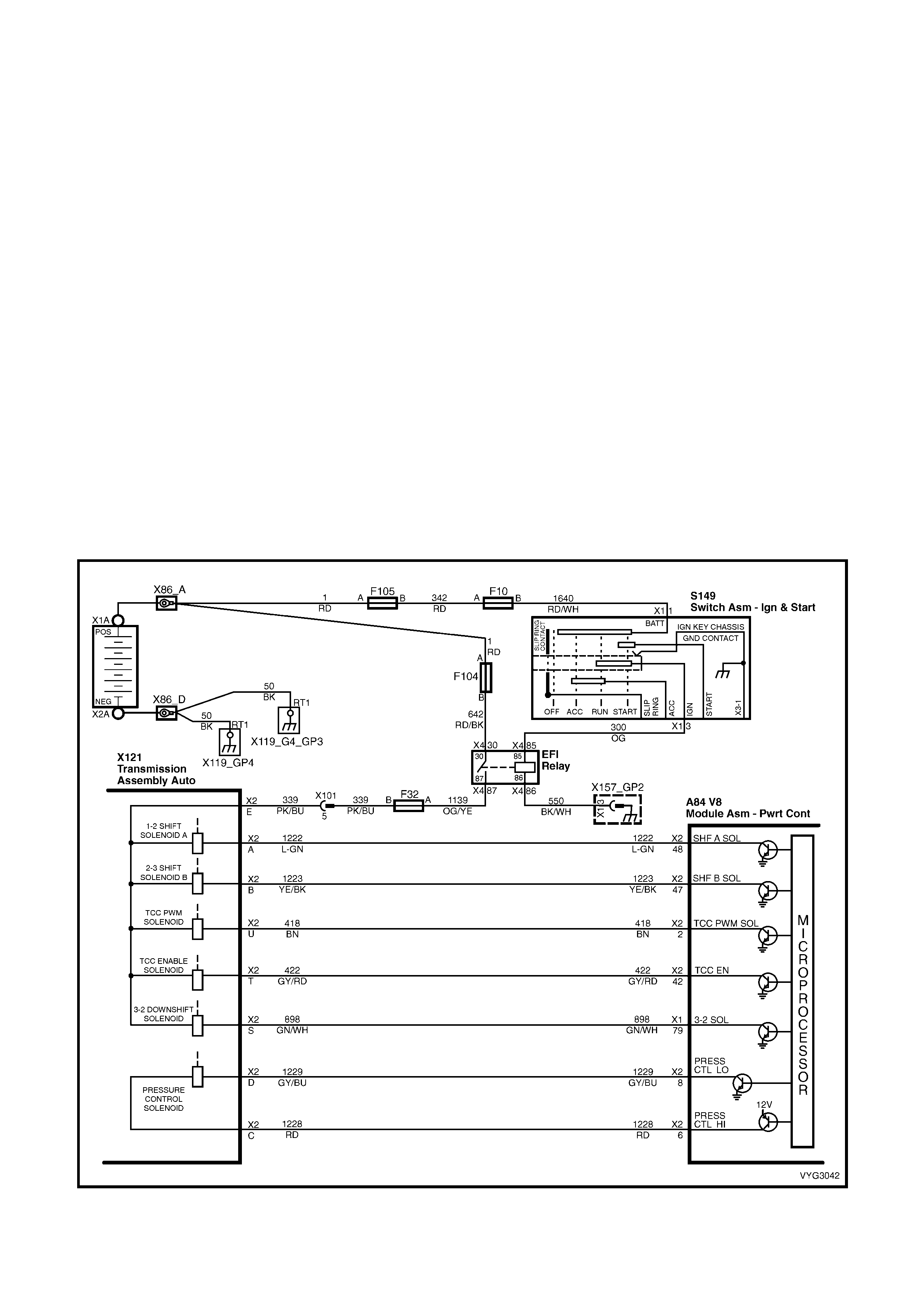
DTC P0785 3-2 SHIFT SOLENOID CIRCUIT ELECTRICAL
Conditions for running DTC P0758
• The system voltage is between 8.0 and 18 volts.
• The engine speed is greater than 300 RPM for 5 seconds.
• The engine is not in fuel cutoff.
Conditions for setting DTC P0758
• The PCM commands the solenoid ON and the voltage input remains high (12 volts).
OR
• The PCM commands the solenoid OFF and the voltage input remains low (0 volts).
Action taken when DTC P0758 Sets
• The PCM activates the Malfunction Indicator Lamp (MIL) when the diagnostic runs and fails.
• The PCM commands a soft landing to 3rd gear.
• The PCM commands maximum line pressure.
• The PCM inhibits TCC engagement.
• The PCM inhibits 4th gear if the transmission is in hot mode.
• The PCM freezes shift adapts from being updated.
• The PCM records the operating conditions at the time the diagnostic fails. The PCM stores this information in
the Freeze Frame/Failure Records.
Conditions for clearing the Malfunction Indicator Lamp (MIL) and DTC P0758
• The PCM deactivates the Malfunction Indicator Lamp (MIL) during the first ignition cycle that the diagnostic runs
and does not fail.
• A last test failed (current DTC) clears when the diagnostic runs and does not fail.
Figure 6C3-1-130 – Transmission Solenoid Electrical Circuits
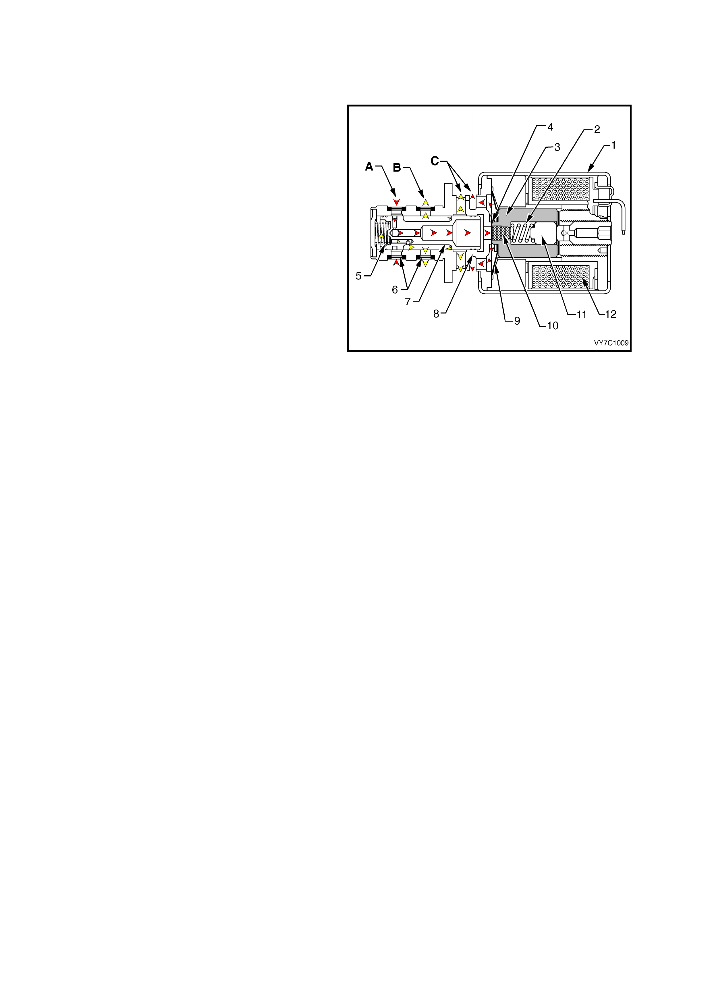
TRANSMISSION PRESSURE CONTROL SOLENOID
IMPORTANT: Transmission pressure control
solenoid resistance should measure 3-5 ohms
when measured at 20° C.
The transmission pressure control solenoid is an
electronic pressure regulator that controls pressure
based on the current flow through its coil winding.
The magnetic field produced by the coil moves the
solenoid's internal valve which varies pressure to
the pressure regulator valve.
The PCM controls the pressure control solenoid by
commanding current between 100 and 1100
milliamps. This changes the duty cycle of the
solenoid, which can range between 5 percent and
95 percent (typically less than 60 percent). 1100
milliamps corresponds to minimum line pressure,
and 100 milliamps corresponds to maximum line
pressure If the solenoid loses power, the
transmission defaults to maximum line pressure.
The PCM commands the line pressure values,
using inputs such as the throttle position sensor.
The pressure control solenoid takes the place of
the throttle valve or the vacuum m odulator that was
used on the past model transmissions.
If the duty cycle drops below 5 percent or rises
above 95 percent, DTC P0748 will set.
Legend:
Figure 6C3 -1-131 – Pressure Control Solenoid
1. Frame
2. Spring
3. Armature
4. Variable Bleed Orifice
5. Spool Valve Spring
6. Fluid Screens
7. Spool Valve
8. Spool Valve Sleeve
9. Damper Spring
10. Restrictor
11. Push Rod
12. Coil Assembly
A Actuator Feed Limit Fluid
B Torque Signal Fluid
C Exhausts
DTC P0748 PC SOLENOID CIRCUIT ELECTRICAL
Conditions for running DTC P0748
• The system voltage is between 8.0 and 18 volts.
• The engine is running.
Conditions for setting DTC P0748
• The PC solenoid value duty cycle reaches its high limit (approximately 95%) or low limit (approximately 0%) for
200 milliseconds.
Action taken when DTC P0748 Sets
• The PCM does not activate the Malfunction Indicator Lamp (MIL).
• The PC solenoid valve is OFF.
• The PCM freezes shift adapts from being updated.
• The PCM records the operating conditions at the time the diagnostic fails. The PCM stores this information in
the Freeze Frame/Failure Records.
Conditions for clearing the Malfunction Indicator Lamp (MIL) and DTC P0748
• A last test failed (current DTC) clears when the diagnostic runs and does not fail.
• The PCM cancels the DTC default actions when the fault no longer exists and the ignition switch is OFF long
enough in order to power down the PCM.
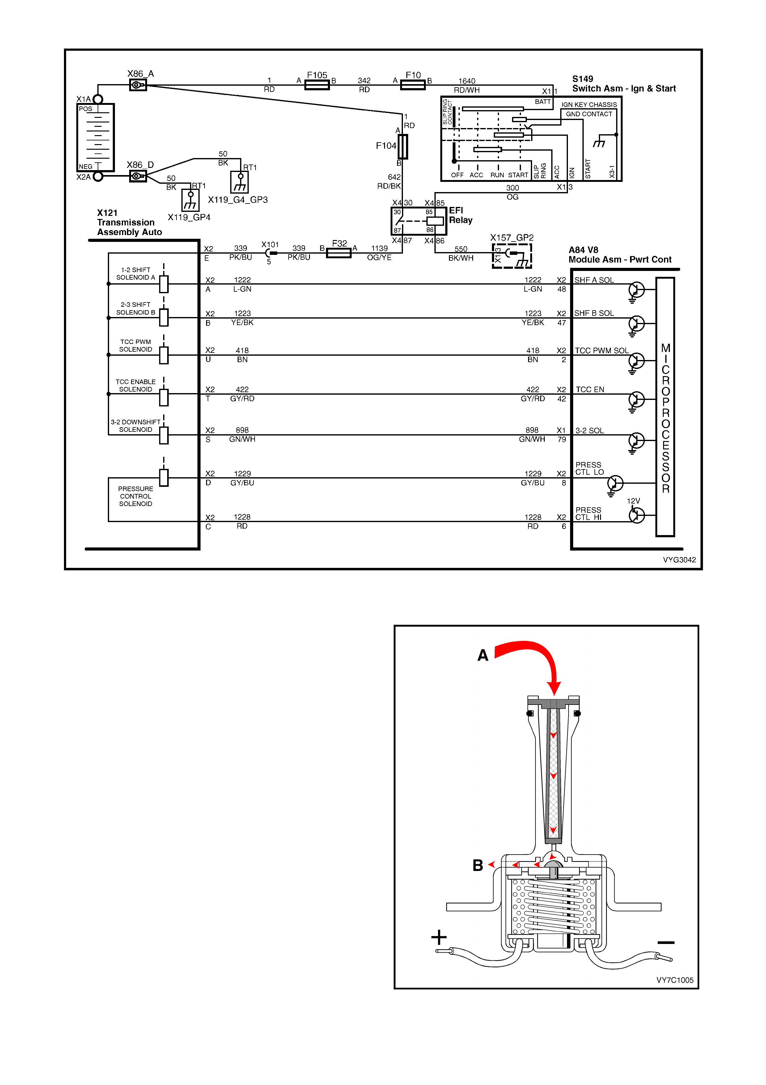
Figure 6C3-1-132 Transmission Solenoid Electrical Circuits
TORQUE CONVERTER CLUTCH SOLENOID VALVE
IMPORTANT: The TCC solenoid resistance should
be 21-26 ohms minimum when measured at 20° C. If a
fault is detected in the TCC solenoid circuit, code
P0740 will set.
The torque converter clutch solenoid valve is a
normally open exhaust valve that is used to control
torque converter clutch apply and release. When
grounded (energised) by the PCM, the TCC solenoid
valve stops converter signal oil from exhausting. This
causes converter signal oil pressure to increase and
shifts the TCC solenoid valve into the apply position.
The brak e s witch is an input to the PCM, and the PCM
directly controls the TCC apply based on the brake
switch status.
Legend:
A Converter Feed Fluid
B Exhaust
Figure 6C3-1-133 – Torque Converter Clutch Solenoid

DTC P0740 TCC ENABLE SOLENOID CIRCUIT ELECTRICAL
Conditions for running DTC P0740
• The system voltage is between 8.0 and 18 volts.
• The engine speed is greater than 300 RPM for 5 seconds.
• The engine is not in fuel cutoff.
Conditions for setting DTC P0740
• The PCM commands the solenoid ON and the voltage input remains high (12 volts).
OR
• The PCM commands the solenoid OFF and the voltage input remains low (0 volts).
Action taken when DTC P0740 Sets
• The PCM does not activate the Malfunction Indicator Lamp (MIL).
• The PCM inhibits TCC engagement.
• The PCM inhibits 4th gear if the transmission is in hot mode.
• The PCM freezes shift adapts from being updated.
• The PCM records the operating conditions at the time the diagnostic fails. The PCM stores this information in
the Freeze Frame/Failure Records.
Conditions for clearing the Malfunction Indicator Lamp (MIL) and DTC P0740
• A last test failed (current DTC) clears when the diagnostic runs and does not fail.
• The PCM cancels the DTC default actions when the fault no longer exists and the ignition switch is OFF long
enough in order to power down the PCM.
DTC P0742 TCC SYSTEM STUCK ON
Conditions for running DTC P0742
• No MAP sensor DTCs P0107 or P0108.
• No Throttle Position DTCs P0122 or P0123.
• No VSS assembly DTCs P0502 or P0503.
• No TCC solenoid valve DTC P0740.
• No TFP manual valve position switch DTC P1810.
• No TCC PWM solenoid valve DTC P1860.
• The Throttle Position angle is 10-45%.
• The engine speed is greater than 300 RPM for 5 seconds.
• The engine is not in fuel cutoff.
• The engine speed is 1000-3500 RPM.
• The engine torque is 54-542 Nm.
• The engine vacuum is 0-105 kPa.
• The speed ratio is 0.65-1.30 (the speed ratio is engine speed divided by output speed).
• The vehicle speed is 32-88 km/h.
• The commanded gear is not 1st.
• The gear range is D.
• The gear range does not change within 6 seconds.
• The PCM commands the TCC OFF.
Conditions for setting DTC P0742
• DTC P0742 sets if the following condition occurs three times:
– The TCC slip speed is -20 to +30 RPM for 4 seconds.
Action taken when DTC P0742 Sets
• The PCM activates the Malfunction Indicator Lamp (MIL) during the second consecutive trip in which the
conditions for setting the DTC are met.
• The PCM freezes shift adapts from being updated.
• The PCM stores DTC P0742 in PCM history during the second consecutive trip in which the conditions for
setting the DTC are met.
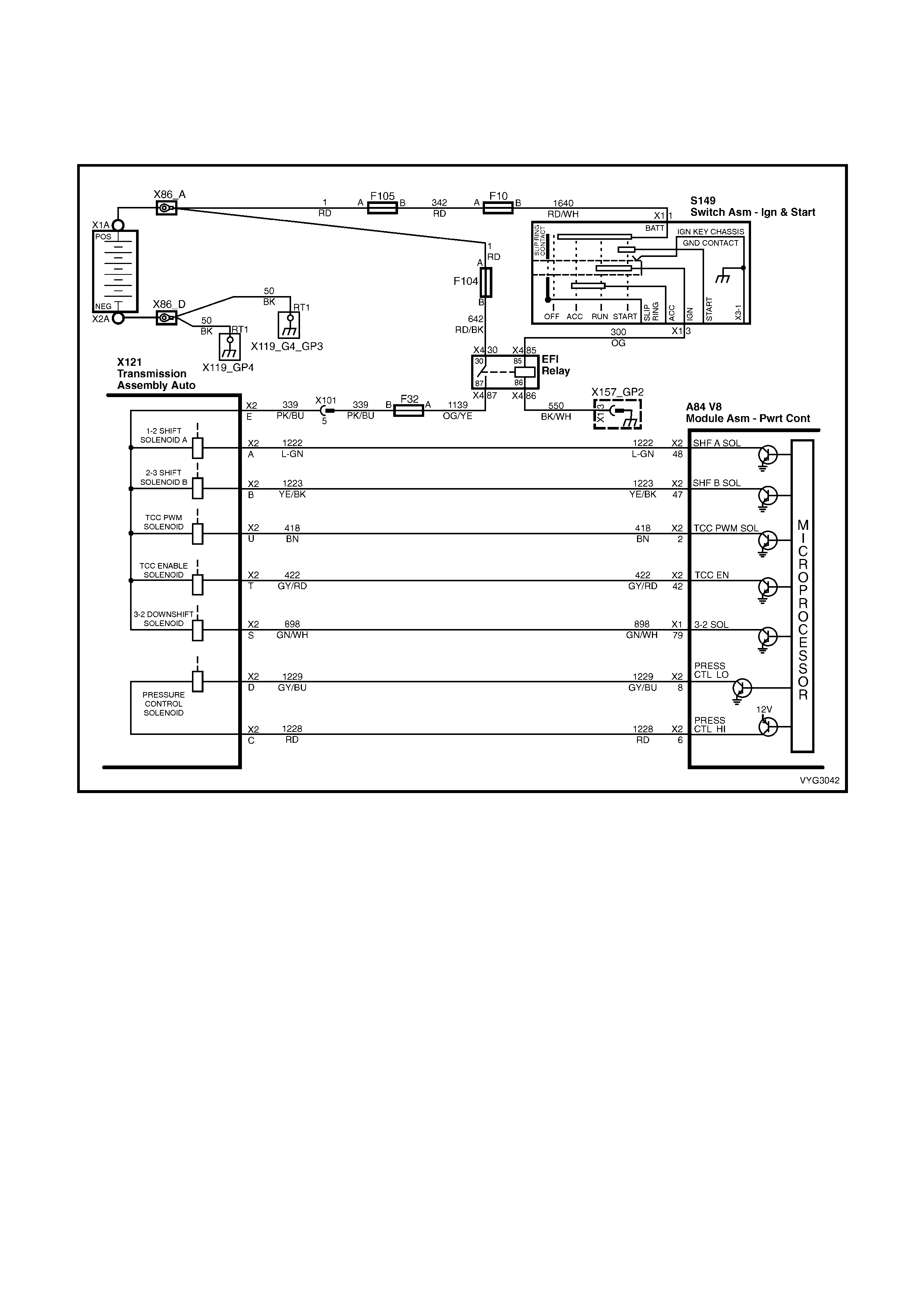
Conditions for clearing the Malfunction Indicator Lamp (MIL) and DTC P0742
• The PCM deactivates the Malfunction Indicator Lamp (MIL) during the first ignition cycle that the diagnostic runs
and does not fail.
• The PCM cancels the DTC default actions when the fault no longer exists and the ignition switch is OFF long
enough in order to power down the PCM.
Figure 6C3-1-134 – Transmission Solenoid Electrical Circuits
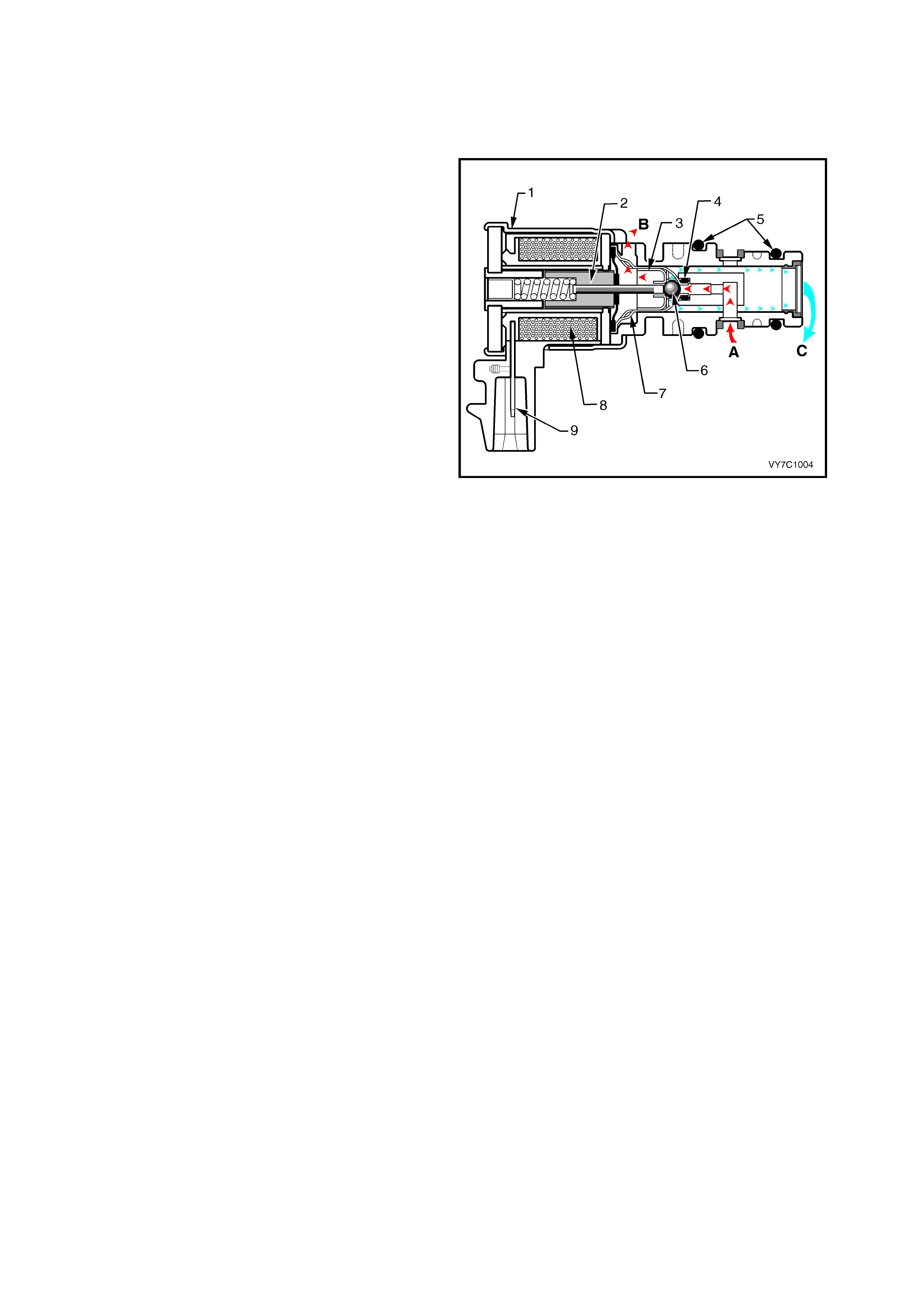
TORQUE CONVERTER CLUTCH PWM SOLENOID VALVE
IMPORTANT: TCC PWM solenoid valve
resistance should be 10 – 11 ohms when
measured at 20° C, and 13 – 15 ohms when
measured at 100° C.
The torque converter clutch PWM solenoid valve
controls the fluid acting on the converter clutch
valve, which then controls the TCC apply and
release. This solenoid is attached to the control
valve body assembly within the transmission.
The TCC PWM solenoid valve provides smooth
engagement of the torque converter clutch by
operating on a negative duty cycle a variable
percent of ON time.
If a f ault is detec ted in the TCC PWM cir cuit, code
P1860 will set.
Legend:
1 Housing
2 Armature
3 Exhaust Seat
4 Internal O-Ring
5 O-Rings
6 Metering Ball
7 Inlet Seat
8 Coil Assembly
9 Connector Terminal
A Actuator Feed Limit (AFL) Fluid
B Exhaust
C Converter Clutch Signal (CC SIGNAL) Fluid
Figure 6C3-1-135 – TCC PWM Solenoid
DTC P1860 TCC PWM SOLENOID CIRCUIT
Conditions for running DTC P1860
• The system voltage is between 8.0 and 18 volts.
• The engine speed is greater than 300 RPM for 5 seconds.
• The engine is not in fuel cutoff.
• The PCM commands 1st gear.
• The TCC duty cycle is less than 10% or greater than 90%.
Conditions for setting DTC P1860
• The PCM commands the solenoid ON and the voltage input remains high (12 volts).
OR
• The PCM commands the solenoid OFF and the voltage input remains low (0 volts).
Action taken when DTC P1860 Sets
• The PCM activates the Malfunction Indicator Lamp (MIL) when the diagnostic runs and fails.
• The PCM inhibits TCC engagement.
• The PCM inhibits 4th gear if the transmission is in hot mode.
• The PCM freezes shift adapts from being updated.
• The PCM records the operating conditions at the time the diagnostic fails. The PCM stores this information in
the Freeze Frame/Failure Records.
Conditions for clearing the Malfunction Indicator Lamp (MIL) and DTC P1860
• The PCM deactivates the Malfunction Indicator Lamp (MIL) during the first ignition cycle that the diagnostic runs
and does not fail.
• A last test failed (current DTC) clears when the diagnostic runs and does not fail.
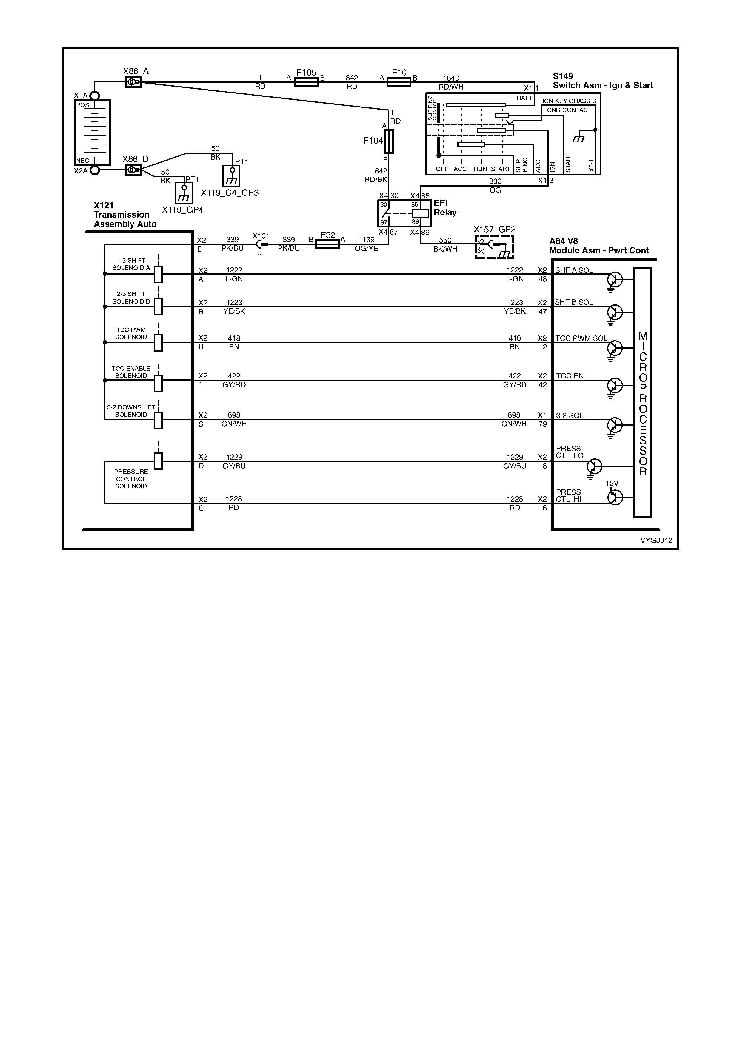
Figure 6C3-1-136 – Transmission Solenoid Electrical Circuits

TRANSMISSION FLUID PRESSURE MANUAL VALVE POSITION SWITCH ASSEMBLY
This gear range sensing device called a
Transmission Fluid Pressure (TFP) manual valve
position switch assembly is used by the PCM to
sense which gear range has been selected by the
vehicle operator. The TFP manual valve position
switch is located on the valve body and consists of
five pressure switches, two normally closed and
three normally open, combined into one unit.
The normally open fluid pressure switches are the
D4, LO and Reverse fluid pressure switches. They
are normally open and electrical current is stopped
at these switches when no fluid pressure is
present. Fluid pressure moves the diaphragm and
contact element until the contact element touches
both the positive contact and the ground contact.
This creates a closed circuit and allows current to
flow from the positive contact, through the switch
and to ground. The normally closed fluid pressure
switches are the D2 and D3 fluid pressure
switches. They are normally closed and electrical
current is free to flow from the positive contact to
the ground contact when no fluid pressure is
present. Fluid pressure moves the diaphragm to
disconnect the positive and ground contacts. This
opens the switch and stops current from flowing
through the switch.
The PCM applies system voltage to the TFP
manual valve position switch assembly on three
separate wires. An open circuit measures 12 Volts
while a grounded circuit measures 0 Volts. The
switches are opened or closed by fluid pressure.
The combination of which switches are open and
closed is used by the PCM to determine actual
manual valve position. The TFP manual valve
position switch assembly however cannot
distinguish between park and neutral because the
monitored valve body pressures are identical in
both cases.
LO This switch will have hydraulic pressure
applied to it in manual 1s t gear only and will be
closed.
REV This switch will have hydraulic pressure
applied to it in reverse only and will be closed.
D2 This switch will have hydraulic pressure
applied to it in manual 1st and 2nd gear and
will be open.
D3 This switch will have hydraulic pressure
applied to it in manual 1st, 2nd and 3rd gear
and will be open.
D4 This switch will have hydraulic pressure
applied to it in all drive gears except reverse
and will be closed.
Figure 6C3-1-137 – Transmission Fluid Pressure (TFP)
Manual Valve Position Switch
Legend:
1. O-Ring 4. Contact Element
2. Diaphragm 5. Body
3. Contact
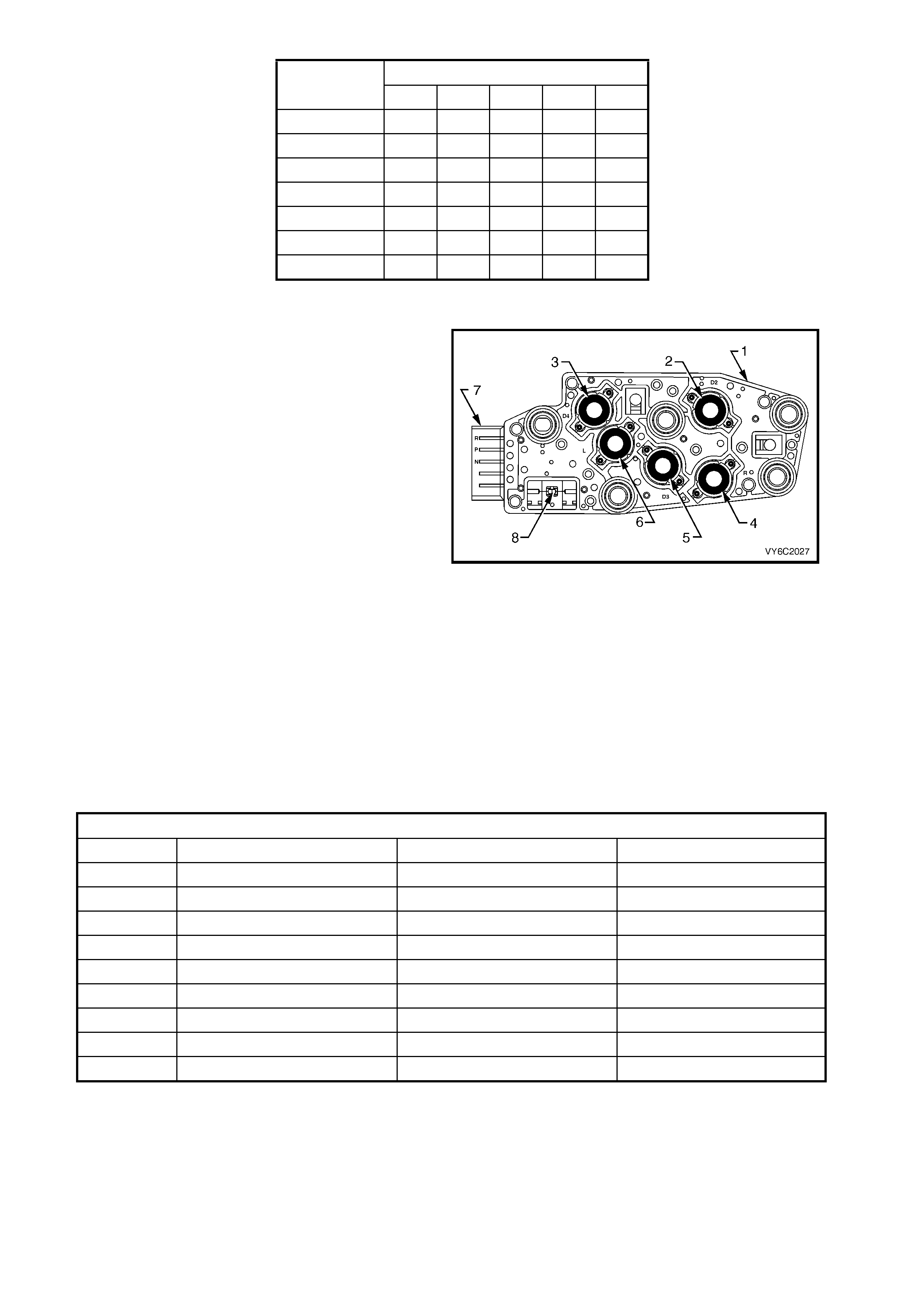
RANGE FLUID PRESSURE
INDICATOR REV D4 D3 D2 LO
PARK
REVERSE X
NEUTRAL
D X
3 X X
2 X X X
1 X X X X
Pressure Applied to TFP Manual Valve Switches
Thes e TFP m anual valve position switch inputs ar e
used to help control line pr essure, torque converter
clutch apply and shift solenoid operation. To
monitor TFP manual valve position switch
operation, the PCM compares the actual voltage
com bination of the switches to a TFP m anual valve
position switch combination Table stored in its
memory.
There are two possible combinations of the
switches within the TFP manual valve position
switch assembly that do not represent an actual
gear range. If either of these combinations are
detected by the PCM, DTC 1810 will s et. DTC 1810
will also set if a valid gear range combination
appears at the wrong time.
Legend:
1. Transmission Fluid Pressure Manual Valve
Position Switch
2. D2 Indicator Switch
3. D4 Indicator Switch
4. Reverse Indicator Switch
5. D3 Indicator Switch
6. LO Indicator Switch
7. Five Pin Connector Terminal
8. Transmission Fluid Temperature Sensor
Figure 6C3-1-138 – TFP Manual Valve Switch Assembly
VALID COMBINATION TABLE
RANGE SIGNAL A RANGE SIGNAL B RANGE SIGNAL C
PARK 12V / OPEN 0V / GROUNDED 12V / OPEN
REVERSE 0V / GROUNDED 0V / GROUNDED 12V / OPEN
NEUTRAL 12 V / OPEN 0V / GROUNDED 12V / OPEN
D 12V / OPEN 0V / GROUNDED 0V / GROUNDED
3 12V / OPEN 12V / OPEN 0V / GROUNDED
2 12V / OPEN 12V / OPEN 12V / OPEN
1 0V / GROUNDED 12V / OPEN 12V / OPEN
ILLEGAL 0V / GROUNDED 12V / OPEN 0V / GROUNDED
ILLEGAL 0V / GROUNDED 0V / GROUNDED 0V / GROUNDED
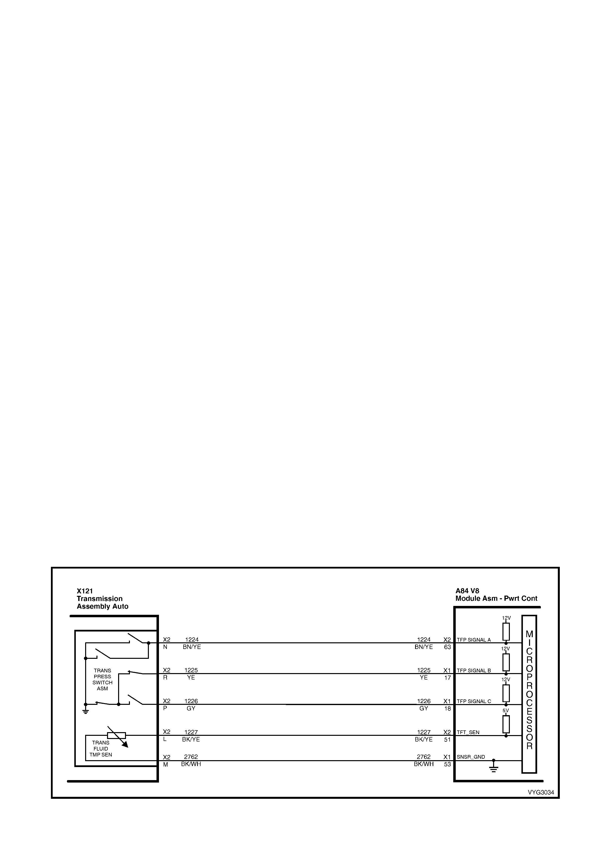
DTC P1810 TFP MANUAL VALVE POSITION SWITCH CIRCUIT
Conditions for running DTC P1810
• No VSS assembly DTCs P0502 or P0503.
• The system voltage is between 8.0 and 18 volts.
• The engine speed is greater than 300 RPM for 5 seconds.
• The engine is not in fuel cutoff.
• The engine torque is 54-542 Nm.
• The engine vacuum is 0-105 kPa.
Conditions for setting DTC P1810
Condition1
• The PCM detects an invalid TFP manual valve position switch state for 60 seconds.
Condition 2
• The engine speed is less than 80 RPM for 0.1 seconds; then the engine speed is 80-550 RPM for 0.07
seconds; then the engine speed is greater the 550 RPM.
• The vehicle speed is less than 3 km/h.
• The PCM detects a gear range of 2, D or R during an engine start.
• All conditions are met for 5 seconds.
Condition 3
• The TP angle is 8-45%.
• The PCM commands 4th gear.
• The TCC is locked ON.
• The speed ratio is 0.65-0.8 (speed ratio is engine speed divided by transmission output speed).
• The PCM detects a gear range of P or N when operating in D.
• All conditions are met for 10 seconds.
Action taken when DTC P1810 Sets
• The PCM activates the Malfunction Indicator Lamp (MIL) when the diagnostic runs and fails.
• The PCM commands D2 line pressure.
• The PCM commands D4 shift pattern.
• The PCM freezes shift adapts from being updated.
• The PCM records the operating conditions at the time the diagnostic fails. The PCM stores this information in
the Freeze Frame/Failure Records.
Conditions for clearing the Malfunction Indicator Lamp (MIL) and DTC P1810
• T he PCM deac tivates the Malfunction Indic ator Lamp ( MIL) dur ing the f irs t ignition c ycle that the diagnostic runs
and does not fail.
• A last test failed (current DTC) clears when the diagnostic runs and does not fail.
Figure 6C3-1-139 – TFP Switch Assembly Circuit
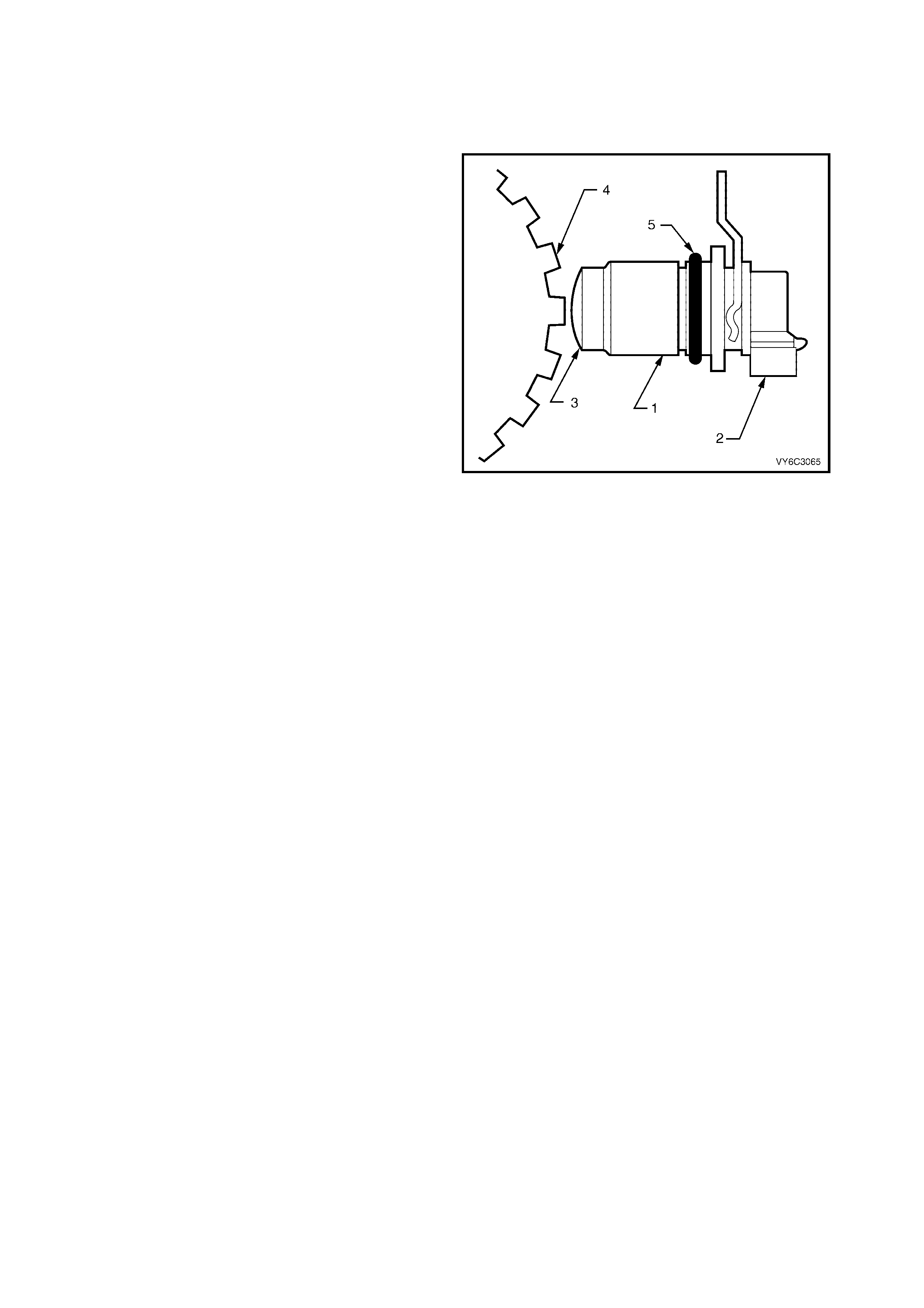
VEHICLE SPEED SENSOR
IMPORTANT: The sensor voltage is model
dependent and varies with speed from a minimum
of 0.5 volts AC at 100 RPM to m ore than 100 volts
AC at 8000 RPM.
The Vehicle Speed Sensor (or Transmission
Output Speed Sensor) controls shift points and
calculates the TCC slip. The speed sensor
contains a c oil that gives off a continuous magnetic
field. A rotor rotates past the sensor and the rotor
teeth break the magnetic field. Each break in the
field sends a pulse to the VSSB (Vehicle Speed
Sensor Buf f er ). The VSSB sends two signals to the
PCM. The first is a 2002 pulse per mile (PPM)
signal that is used by the engine. The second is the
transmission/transfer case 40 pulse per revolution
(PPR) signal that is used in order to control the
transmission.
The Vehicle Speed Sensor is located on the
transmission extension housing. Trans Output
Speed = Transfer Case Speed.
DTC P0502, P0503 and P0608 will set if a fault
exists in the vehic le speed sens or. Ref er to fr ont of
this Section for detailed information on the VSS.
DTC P1870 will set if there is a slipping condition
with the transmission.
Legend:
1. Vehicle Speed Sensor
2. Electrical Connector
3. Magnetic Pick-Up
4. Rotor
5. Sealing O-Ring
Figure 6C3-1-140 – Vehicle Speed Sensor
DTC P1870 TRANSMISSION COMPONENT SLIPPING
Conditions for running DTC P1870
• No Throttle Position DTCs P0122 or P0123.
• No VSS DTCs P0502, P0503.
• No TCC solenoid valve DTC P0740.
• No 1-2 SS valve DTC P0753.
• No 2-3 SS valve DTC P0758.
• No 3-2 SS valve assembly DTC P0785.
• No TCC PWM solenoid valve DTC P1860.
• The engine speed is greater than 300 RPM for 5 seconds.
• The engine is not in fuel cutoff.
• The vehicle speed is 56 – 105 km/h.
• The speed ratio is 0.67 – 0.90 (the speed ratio is the engine speed divided by the transmission output speed).
• The engine speed is 1200 – 3500 RPM.
• The engine torque is 54 – 542 Nm.
• The gear range is D4.
• The commanded gear is not 1st gear.
• The throttle position angle is 10 – 50%.
• The TFT is between 20 – 130° C.
• The shift solenoid performance diagnostic counters are zero.
Conditions for setting DTC P1870
DTC P1870 sets if the following conditions occur for three TCC cycles.
• The TCC is commanded ON for 5 seconds.
• The TCC is at maximum duty cycle for 1 second.
• The TCC slip speed is 80-800 RPM for 7 seconds.
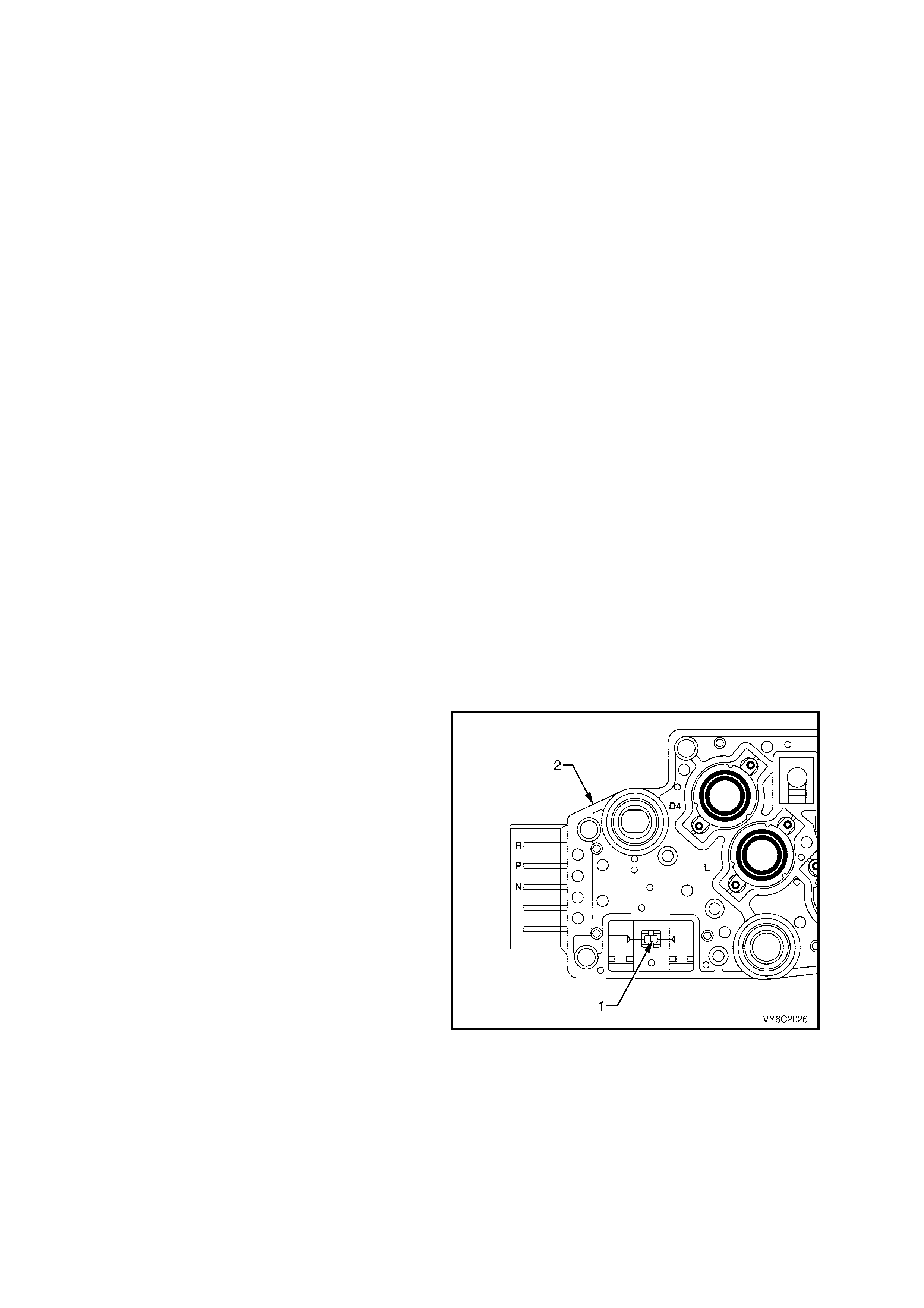
IMPORTANT: The following actions may occur before the DTC sets:
If the TCC is commanded ON and at maximum duty cycle for 5 seconds, the Throttle Position angle is 10-40%, and
the transmission slip counter has incremented to either 1 or 2 (out of 3 to increment the fail counter for the current
ignition cycle), then the following slip conditions and actions may increment the fail counter for the current ignition
cycle:
These conditions must occur sequentially.
Condition 1
• If the TCC slip speed is 80 – 800 RPM for 7 seconds, then the PCM will command maximum line pressure and
freeze shift adapts from being updated.
Condition 2
• If condition 1 is met and the TCC slip speed is 80 – 800 RPM for 7 seconds, then the PCM will command the
TCC OFF for 1.5 seconds.
Condition 3
• If condition 2 is met and the TCC slip speed is 80 – 800 RPM for 7 seconds, then the fail counter on the current
ignition cycle is incremented.
• The above slip conditions and actions may be disregarded if the TCC is commanded OFF at any time as a
result of a driving manoeuvre (sudden acceleration or deceleration).
Action taken when DTC P1870 Sets
• The PCM activates the Malfunction Indicator Lamp (MIL) when the diagnostic runs and fails.
• The PCM inhibits TCC engagement.
• The PCM commands maximum line pressure.
• The PCM inhibits 4th gear if the transmission is in hot mode.
• The PCM freezes shift adapts from being updated.
• The PCM records the operating conditions at the time the diagnostic fails. The PCM stores this information in
the Freeze Frame/Failure Records.
Conditions for clearing the Malfunction Indicator Lamp (MIL) and DTC P1870
• The PCM deactivates the Malfunction Indicator Lamp (MIL) during the first ignition cycle that the diagnostic runs
and does not fail.
• A last test failed (current DTC) clears when the diagnostic runs and does not fail.
AUTOMATIC TRANSMISSION FLUID TEMPERATURE SENSOR
The Automatic Transmission Fluid Temperature
(TFT) Sensor (1) is part of the Automatic
Transmission Fluid Pressure (TFP) manual valve
position switch assembly (2). This sensor helps
control torque converter clutch apply and shift
quality. The T FT s ensor is a resistor , or thermis tor,
which changes value based on tem perature. At low
temperatures the resistance is high and at high
temperatures the resistance is low.
The PCM sends a 5 volt signal to the TFT
sensor and the PCM m easures the voltage drop in
the circuit. You will measure a high voltage
when the transmission is cold and a low
voltage when the transmission is hot. Refer
to the Temperature vs Resistance table in
Section 6C3-4 SPECIFICATIONS in this Section.
If the TFT sensor circuit has a fault, DTC P0711,
DTC P0712 or P0713 is set. A DTC P0712
indicates a short circuit condition, while a DTC
P0713 indicates an open circuit condition. DTC
P0218 is set if the transmission is operating at a
high temperature for a period of time.
Figure 6C3-1-141 – TFT Sensor Location

DTC P0218 TRANSMISSION FLUID OVER-TEMPERATURE
Conditions for running DTC P0218
• No TFT sensor DTCs P0711, P0712, P0713.
• The ignition switch is in the RUN position for 5 seconds.
Conditions for setting DTC P0218
• The TFT is greater than 130°C for 10 minutes (600 seconds).
Action taken when DTC P0218 Sets
• The PCM activates the Malfunction Indicator Lamp (MIL) when the diagnostic runs and fails.
• The PCM freezes shift adapts from being updated.
• The PCM records the operating conditions at the time the diagnostic fails. The PCM stores this information in
the Freeze Frame/Failure Records.
Conditions for clearing the Malfunction Indicator Lamp (MIL) and DTC P0218
• The PCM deactivates the Malfunction Indicator Lamp (MIL) during the first ignition cycle that the diagnostic runs
and does not fail.
• A last test failed (current DTC) clears when the diagnostic runs and does not fail.
• The PCM cancels the DTC default actions when the fault no longer exists and the ignition switch is OFF long
enough in order to power down the PCM.
DTC P0711 TFT SENSOR CIRCUIT RANGE/PERFORMANCE
Conditions for running DTC P0711
• No VSS assembly DTCs P0502, P0503.
• No transmission component slipping DTC P1870.
• The system voltage is between 8.0 volts and 18 volts.
• The engine is running for 409 seconds (6.8 minutes).
• The vehicle speed is greater than 8 km/h for 409 seconds cumulative during the current ignition cycle.
• The TCC slip speed is greater than 120 RPM for 409 seconds cumulative during the current ignition cycle.
• The TFT at startup is between –40 and +21° C.
• The TFT is between –38° C and +15° C.
• The engine coolant temperature (ECT) is greater than 70° C and has changed by 50° C since startup.
Conditions for setting DTC P0711
• The TFT does not change more than 1.5° C for 409 seconds since startup.
• The TFT changes more than 20° C in 200 milliseconds, 14 times within 7 seconds.
Action taken when DTC P0711 Sets
• The PCM stores the DTC information into memory when the diagnostic runs and fails.
• The Malfunction Indicator Lamp (MIL) will not be activated.
• The PCM records the operating conditions at the time the diagnostic fails. The PCM stores this information in
the Freeze Frame/Failure Records.
IMPORTANT: The actions listed below are in order of highest to lowest priority:
• The PCM determines a default TFT using the following matrix:
1. If any ECT DTCs P0117 or P0118 are set, then the default TFT is equal to 135° C.
2. If the ECT is 125°C or more, then the default TFT is equal to 135° C.
3. If the engine run time is less than 300 seconds and:
– No intake air temperatur e (IAT) DTCs P0112 or P0113 are s et and IAT is available, then the def ault TFT is
equal to IAT.
– Any IAT DTCs P0112 or P0113 are set or IAT is NOT available, then the default TFT is equal to 90° C.
4. If the engine run time is greater than 300 seconds and no IAT DTCs P0112 or P0113 are set and IAT is
available and ECT is between 40° C and 125° C and:
– IAT at startup is less than 15° C, then the default TFT is equal to the ECT plus 5° C.
– IAT at startup is greater than 35° C, then the default TFT is equal to the ECT plus 10° C.
– IAT at startup is between 15° C and 35° C, then the default TFT is equal to the ECT.
5. If the engine run time is greater than 300 seconds and any IAT DTCs P0112 or P0113 are set or IAT is
NOT available, then the default TFT is equal to the ECT.
6. If the engine run tim e is greater than 300 seconds and IAT is less than 40° C, then the default T FT is equal
to 60° C.
• The PCM freezes shift adapts from being updated.
• The PCM stores DTC P0711 in PCM memory

Conditions for clearing the Malfunction Indicator Lamp (MIL) and DTC P0711
• A last test failed (current DTC) clears when the diagnostic runs and does not fail.
• The PCM cancels the DTC default actions when the fault no longer exists and the ignition switch is OFF long
enough in order to power down the PCM.
DTC P0712 TFT SENSOR CIRCUIT LOW INPUT
Conditions for running DTC P0712
• The system voltage is between 8.0 volts and 18 volts.
• The ignition switch is in the RUN position.
Conditions for setting DTC P0712
• The TFT sensor indicates a signal voltage less than 0.2 volts for 10 seconds.
Action taken when DTC P0712 Sets
• The PCM stores the DTC information into memory when the diagnostic runs and fails.
• The Malfunction Indicator Lamp (MIL) will not be activated.
• The PCM records the operating conditions at the time the diagnostic fails. The PCM stores this information in
the Freeze Frame/Failure Records.
IMPORTANT: The actions listed below are in order of highest to lowest priority.
• The PCM determines a default TFT using the following matrix:
1. If any ECT DTCs P0117 or P0118 are set, then the default TFT is equal to 135° C.
2. If the ECT is 125°C or more, then the default TFT is equal to 135° C.
3. If the engine run time is less than 300 seconds and:
– No intake air temperatur e (IAT) DTCs P0112 or P0113 are s et and IAT is available, then the def ault TFT is
equal to IAT.
– Any IAT DTCs P0112 or P0113 are set or IAT is NOT available, then the default TFT is equal to 90° C.
4. If the engine run time is greater than 300 seconds and no IAT DTCs P0112 or P0113 are set and IAT is
available and ECT is between 40 and 125° C and:
– IAT at startup is less than 15° C, then the default TFT is equal to the ECT plus 5° C.
– IAT at startup is greater than 35° C, then the default TFT is equal to the ECT plus 10° C.
– IAT at startup is between 15° C and 35° C, then the default TFT is equal to the ECT.
5. If the engine run time is greater than 300 seconds and any IAT DTCs P0112 or P0113 are set or IAT is
NOT available, then the default TFT is equal to the ECT.
6. If the engine run tim e is greater than 300 seconds and IAT is less than 40° C, then the default T FT is equal
to 60° C.
• The PCM freezes shift adapts from being updated.
• The PCM stores the DTC information into memory when the diagnostic runs and fails.
• The Malfunction Indicator Lamp (MIL) will not be activated.
• The PCM records the operating conditions at the time the diagnostic fails. The PCM stores this information in
the Freeze Frame/Failure Records.
Conditions for clearing the Malfunction Indicator Lamp (MIL) and DTC P0712
• A last test failed (current DTC) clears when the diagnostic runs and does not fail.
• The PCM cancels the DTC default actions when the fault no longer exists and the ignition switch is OFF long
enough in order to power down the PCM.
DTC P0713 TFT SENSOR CIRCUIT HIGH INPUT
Conditions for running DTC P0713
• The system voltage is between 8.0 volts and 18 volts.
• The ignition switch is in the RUN position.
Conditions for setting DTC P0713
• The TFT sensor indicates a signal voltage greater than 4.92 volts for 10 seconds.
Action taken when DTC P0713 Sets
• The PCM stores the DTC information into memory when the diagnostic runs and fails.
• The Malfunction Indicator Lamp (MIL) will not be activated.
• The PCM records the operating conditions at the time the diagnostic fails. The PCM stores this information in
the Freeze Frame/Failure Records.
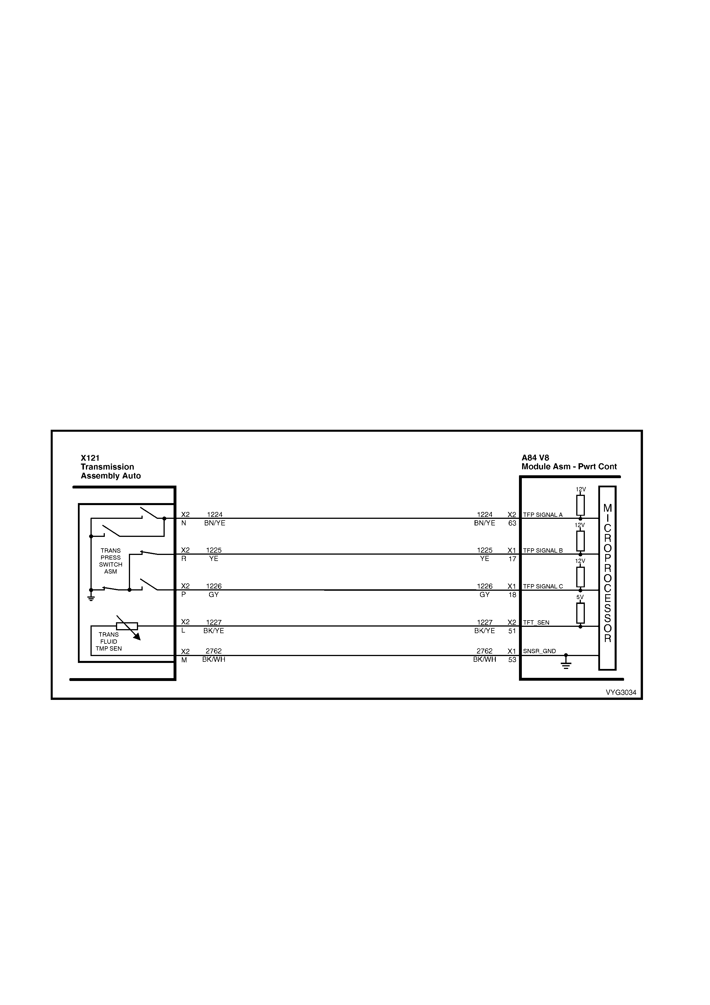
IMPORTANT: The actions listed below are in order of highest to lowest priority.
• The PCM determines a default TFT using the following matrix:
1. If any ECT DTCs P0117 or P0118 are set, then the default TFT is equal to 135° C.
2. If the ECT is 125°C or more, then the default TFT is equal to 135° C.
3. If the engine run time is less than 300 seconds and:
– No intake air temperatur e (IAT) DTCs P0112 or P0113 are s et and IAT is available, then the def ault TFT is
equal to IAT.
– Any IAT DTCs P0112 or P0113 are set or IAT is NOT available, then the default TFT is equal to 90° C.
4. If the engine run time is greater than 300 seconds and no IAT DTCs P0112 or P0113 are set and IAT is
available and ECT is between 40°C and 125° C and:
– IAT at startup is less than 15° C, then the default TFT is equal to the ECT plus 5° C.
– IAT at startup is greater than 35° C, then the default TFT is equal to the ECT plus 10° C.
– IAT at startup is between 15° C and 35° C, then the default TFT is equal to the ECT.
5. If the engine run time is greater than 300 seconds and any IAT DTCs P0112 or P0113 are set or IAT is NOT
available, then the default TFT is equal to the ECT.
6. If the engine run tim e is greater than 300 seconds and IAT is less than 40° C, then the def ault TFT is equal to
60° C.
• The PCM freezes shift adapts from being updated.
• The PCM stores the DTC information into memory when the diagnostic runs and fails.
Conditions for clearing the Malfunction Indicator Lamp (MIL) and DTC P0713
• A last test failed (current DTC) clears when the diagnostic runs and does not fail.
• The PCM cancels the DTC default actions when the fault no longer exists and the ignition switch is OFF long
enough in order to power down the PCM.
Figure 6C3-1-142 – TFT Circuit
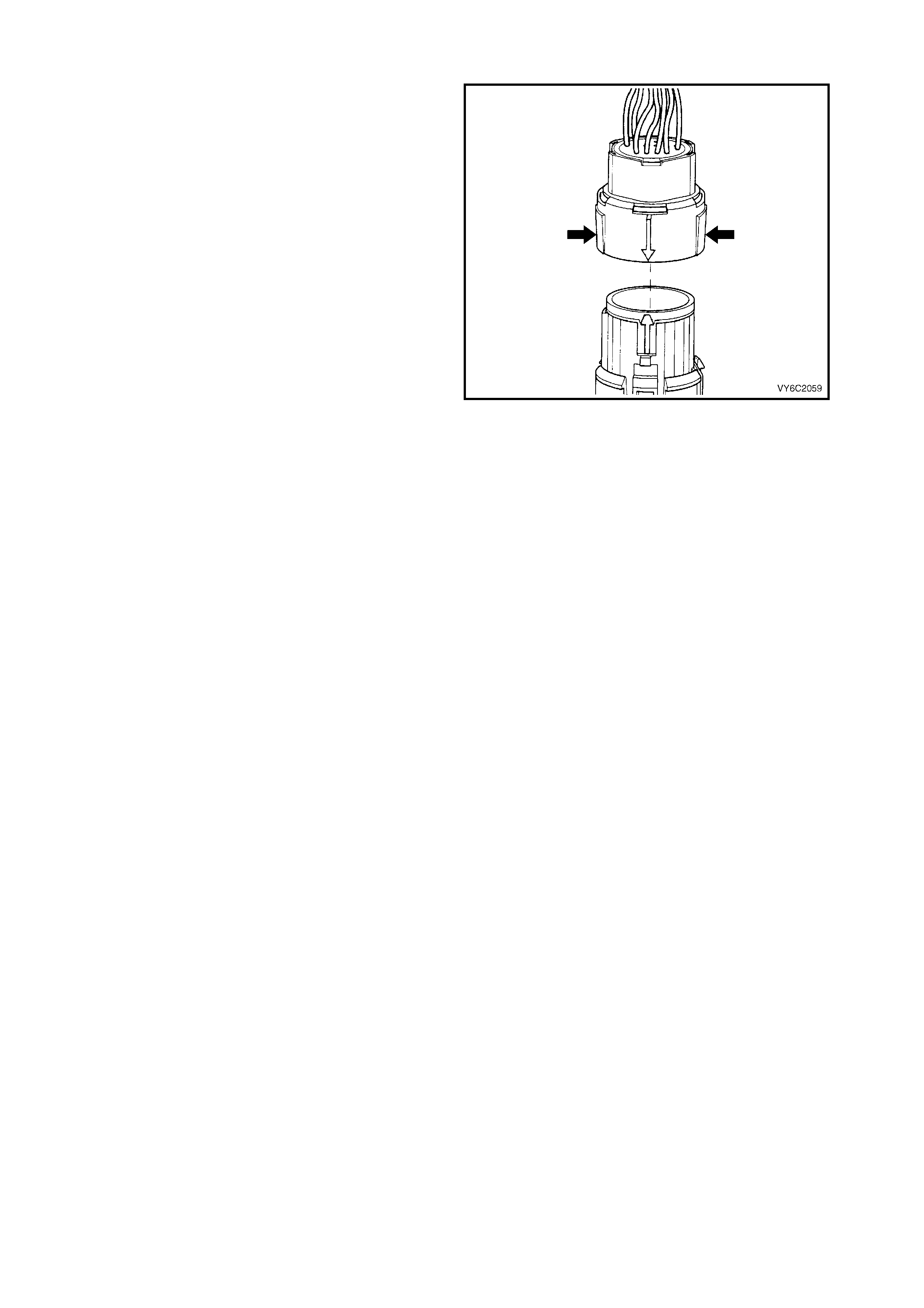
ELECTRICAL CONNECTOR
The transmission electrical connector is an
important part of the transmission operating
system. Any interference with the electrical
connection can cause the transmission to set
Diagnostic Trouble Codes (DTCs) or affect proper
operation.
The following items can affect the electrical
connection:
• Bent pins in the connec tor fr om rough handling
during connection and disconnection.
• Wires bac k ing away from the pins or bec oming
uncrim ped ( in either the internal or the ex ternal
wiring harness).
• Dirt contamination entering the connector
when disconnected.
• Pins in the internal wiring connector backing
out of the connector or pushed out of the
connector during reconnection.
• Excessive transmission fluid leaking into the
connector, wicking up into the external wiring
harness and degrading the wire insulation.
• Moisture intrusion in the connector.
• Low pin retention in the external connector
from excessive connection and disconnection
of the wiring connector assembly.
• Pin corrosion from contamination.
Figure 6C3-1-143
• Damaged connector assembly.
Remember the following points:
• In order to remove the connector, squeeze
the two tabs toward each other and pull
straight up without pulling by the wires.
• Lim it twisting or wiggling the connector during
removal. Bent pins can occur.
• Do not pry the connector off with a
screwdriver or other tool.
• Visually inspect the seals to ensure that they
are not damaged during handling.
• In order to reinstall the external wiring
connector, first align the pins by lining up the
arrows on each half of the connector. Push
the connector straight down into the
transmission without twisting or angling the
mating parts.
• The connector should click into place with a
positive feel and/or noise.
IMPORTANT: Whenever the transmission
external wiring connector is disconnected from
the internal harness and the engine is operating,
DTCs will set. Clear these DTCs after
reconnecting the external connector.

1.14 ABBREVIATIONS AND GLOSSARY OF TERMS
Abbreviations used in this Section are listed below in alphabetical order with an explanation of the abbreviation.
POWERTRAIN MANAGEMENT
AC - ALTERNATING CURRENT – A current whose polarity is constantly changing between positive and negative.
A/C - AIR CONDITIONING
A/F - AIR/FUEL (A/F RATIO)
ANALOG SIGNAL – An electrical signal that varies in voltage within a given parameter.
BAROMETRIC PRESSURE – Atmospheric pressure. May be called BARO, or barometric absolute pressure.
BATTERY – Stores chemical energy and converts the chemical energy into electrical energy. This provides DC
current for the vehicle’s electrical systems.
CAT. CONV – CATALYTIC CONVERTER – A muffler-shaped device fitted in the exhaust system between the
engine and the m uffler. The purpos e of the catalytic converter is to chem ically c onvert engine producing gases into
environmentally safe gases. HC, CO, and NOx emitted by the engine, are converted to water vapour, carbon
dioxide, and nitrogen.
MALFUNCTION INDICATO R LAM P (MIL) – A warning indicator icon located in the Multi F unc tion Display (MFD) in
the Instrument and controlled by the PCM, sending a serial data Normal Mode message to the Instrument. The
lamp is activated by the PCM when it detects a fault in the engine management system.
CKT – CIRCUIT
CLOSED LOOP – A fuel c ontr ol mode of operation that us es the signal f r om the exhaus t ox ygen sensor, in order to
control the air/fuel ratio precisely at a 14.7 to 1 ratio. This allows maximum efficiency of the catalytic converter.
CO – CARBON MONOXIDE – One of the pollutants found in the engine exhaust.
DIAGNOST IC TROUBLE CODE – T he PCM can detect f aults in the engine m anagement s ystem . If a fault occurs,
the PCM may turn on the Malfunction Indicator Lamp (MIL) and a four digit code number will set. A diagnostic
trouble code can be read from the PCM using Tech 2. This DTC will indicate the area of the fault.
DIGITAL SIGNAL – An electrical signal that is either ON or OFF.
DLC - DATA LINK CONNECTOR – Used at the assembly plant to evaluate the engine management system. For
service, it allows the use of Tech 2 in performing system checks.
DLC DATA STREAM – An output from the PCM, initiated by Tech 2. This output is a digital signal, used by
assem bly plant test equipment and the Tech 2 scan tool. T his signal is transm itted from the PCM to the Data Link
Connector(DLC).
DMM (10 Meg.) – DIGITAL MULTIMETER – A multipur pos e meter that has c apability of measur ing Voltage, Amps,
and Ohms.
DRIVER – An electronic device, usually a power transistor, that operates like an electrical switch turning a circuit
ON and OFF.
DUTY CYCLE – The time, in percentage, that a circuit is ON versus OFF .
ENGINE COOL ANT T EM PERAT URE (ECT ) SENSOR – A s ensor that s enses the engine c oolant tem perature and
sends that information to the powertrain control module.
EECS – EVAPORATIVE EMISSIONS CONTROL SYSTEM – Used to prevent petrol vapours from the fuel tank
from entering into the atmosphere. The vapours are stored in a canister located under the vehicle. The canister
contains an activated charcoal element. The petrol vapours are purged from the canister into the manifold to be
burned in the engine.
EMI O R EL ECT R ICAL NOISE – An unwanted signal interfering with another needed signal. Common examples are
an electric razor's effect on a television or AM radio reception while driving under high voltage power lines.
EPROM – ERASABLE PROGRAMMABLE READ ONL Y MEM ORY – Type of Read Only Mem ory (ROM) that can
be erased with ultraviolet light and reprogrammed.
ESD – ELECTROSTATIC DISCHARGE – The discharge of static electricity, which has built up on an insulated
material.
EEPROM – ELECTRICALLY ERASABLE PROGRAMMABLE READ ONLY MEMORY – Type of read only
mem ory (ROM) that c an be electrically programm ed, eras ed and reprogram med us ing a scan tool. Also r eferred to
as Flash Memory.
FUSE - A thin m etal s trip which m elts when exc essive c urrent f lows through it, creating an open cir cuit, protecting a
circuit from damage.
HC – HYDROCARBONS (HC) – Any unburned fuel leaving the engine from incomplete combustion.
IAC VALVE – IDLE AIR CONTROL VALVE – Installed on the throttle body unit and controlled by the PCM to
regulate idle air flow and thus idle RPM.
IAT SENSOR – INTAKE AIR TEMPERATURE SENSOR – A sensor that senses incoming air temperature and
sends the information to the PCM.

IDEAL M IXTURE – T he air/fuel ratio which pr ovides the best perf orm ance, while maintaining m axim um conversion
of exhaust emissions, typically 14.7 to 1 on petrol engines.
IGN – IGNITION
INPUTS – Information from sensors (MAF, TPS, etc.) and switches (A/C request, etc.) used by the PCM to
determine how to control its outputs.
INTERMITTENT – An electrical signal that occurs now and then; not continuously. In electrical circuits, refers to
occasional open, short, or ground in a circuit.
IPC – INSTRUMENT PANEL CLUSTER
LOW – A voltage less than a specific threshold. Operates the same as a ground and may, or may not, be
connected to chassis ground.
MAF – MASS AIR FLOW SENSOR – A device that monitors the amount of air flow coming in the engine intake.
The MAF sensor sends a signal to the PCM.
N.C. – NORMALLY CLOSED – Switch contacts that are closed when they are in the normal operating position.
N.O. – NORMALLY OPEN – Switch contacts that are normally open when in the normal operating position.
NOx – NITROGEN OXIDE – One of the pollutants found in spark ignition engine exhaust. They are formed from
normal combustion and increase in severity with combustion temperatures.
OXYGEN SENSO R – The exhaus t gas ox ygen sensor is loc ated in the ex haus t manif old. T he O 2 s ensor measur es
the oxygen in the exhaust manif old after the c ombus tion process. T he O2 sensor produces a small electric al signal
based on the amount of oxygen in the exhaust gas.
OPEN LOOP – The PCM control of the fuel control system without the use of the oxygen sensor information.
OUTPUT – Functions that typically include solenoids and relays that are controlled by the PCM.
PIM – POW ERT RAIN INTERFACE MODULE – The PIM acts as a communication translator between the PCM and
other on-boar d c ontroller s that us e a dif ferent ser ial data protoc ol. The GEN III V8 PCM uses the new Class II ser ial
data to c ommunic ate, while other contr oller s on the vehic le are des igned to tr ans mit serial data via the c onventional
Universal Asynchronous Receive Transmit (UART) protocol. Since these two types of serial data are not
compatible, a translator or PIM is required to transmit data in either direction between the PCM and other
controllers.
PCM – POW ERTRAIN CONT ROL MODULE – A metal ca sed box, containing electr onic circ uitry, which electrically
monitors and controls the transmission system and emission systems on the engine management system. It also
activates the Malfunction Indicator Lamp (MIL) when a malfunction occurs in the system.
PCV – POSIT IVE CRANKCASE VENT ILATION – Method of rebur ning crank cas e fum es , rather than pas sing them
directly into the atmosphere.
PROM – PROGRAMM ABLE READ ONLY MEMORY – An electr onic term used to describe the engine c alibration
unit. A plug-in memory unit that instructs the PCM how to operate for a particular vehicle.
PULSE WIDT H MODULATED (PWM ) – A digital signal turned ON and OFF f or a percentage of available on-plus-
off cycle time. A signal that is 30% ON and 70% OFF would be called a 30% ON PWM signal.
QUAD DRIVER – A transistor, in the PCM, capable of operating four separate outputs. Outputs can be either ON-
OFF or pulse width modulated.
RAM – RANDOM ACCESS MEM ORY – Is the micr oproc es sor s "sc ratc h pad". The proc ess or can write into or read
from this mem ory as needed. T his mem ory is volatile and needs a constant supply of voltage to be retained. If the
voltage is lost or removed, this memory is lost.
SERIAL DATA – Serial data is a series of rapidly changing voltage signals pulsed from high to low. These signals
are typically 5 volts (UART), 7 volts (Class II), and 12 or 0 volts (high or low) and are transmitted through a wire
often referred to as the Serial Data Circuit.
SFI – SEQUENTIAL FUEL INJECTION – Method of injec ting fuel into the engine. A fuel inj ector is plac ed at each
inlet port of a cy linder head, directly in front of the intake valve, mounted in the intake manifold.
SOLENOID – An electromagnetic coil, which creates a magnetic field, when current flows through it and causes a
plunger or ball to move.
SWITCH – Opens and closes circuits, thereby controlling current flow.
TCC – TORQUE CONVERTER CLUTCH – A PCM controlled solenoid in an automatic transmission which
positively couples the transmission input shaft to the engine.
TECH 2 – T he T ech 2 is a hand held com puter , designed to aid in diagnosis and repair of autom otive system s with
electronic controls/interfaces. The Tech 2 connects to the vehicle’s Data Link Connector (DLC).
TP SENSOR – T HROTTLE POSITION – A sensor that sends a signal to the PCM. The PCM can determ ine, from
this signal, the current throttle position and the rate of throttle opening / closing.
VACUUM, MANIFOLD – A vacuum source from below the throttle plate.

VACUUM, PORTED – Vacuum source from a small port in the throttle body. With the throttle closed, there is no
vacuum bec ause the port is on the air c leaner side of the throttle blade and is ex posed to engine vacuum only after
the throttle is open.
VSS – VEHICLE SPEED SENSOR – A permanent magnet type sensor, which produces an AC voltage, which is
sent to the PCM to determine vehicle speed.
UART – UNIVERSAL ASYNCHRONOUS RECEIVE AND TRANSMIT – A method of communicating between
electronic devices.
WOT – WIDE OPEN THROTTLE – A throttle position opening greater than 80%.
AUTOMATIC TRANSMISSION
AT – Automatic Transmission
BUMP – A sudden and forceful apply of a clutch or a band.
CHUGGLE – A buck ing or jerk ing. This condition m ay be m ost noticeable when the converter c lutch is engaged. It
is similar to the feel of towing a trailer.
DC – Direct Current
DELAYED – A condition where a s hift is expected but does not occur for a period of time. T his could be descr ibed
as a clutch or band engagement that does not occur as quickly as expected during a part throttle or wide open
throttle application of the accelerator, or during m anual downshifting to a lower range. This term is also defined as
LATE or EXTENDED.
DOUBLE BUMP (DOUBLE FEEL) – Two sudden and forceful applications of a clutch or a band downshifting
during a zero throttle coastdown.
DRIVE LINK NOISE – A whine or growl that incr eases or fades with vehicle s peed and is most noticeable under a
light throttle acceleration. It may also be noticeable in PARK or NEUTRAL operating ranges with the vehicle
stationary.
EARLY – A condition where the shift occurs before the vehicle has reached proper speed. This condition tends to
labour the engine after the upshift.
END BUMP – A firmer feel at the end of a shift than at the start of the shift. T his is also defined as END FEEL or
SLIP BUMP.
ENGINE BRAKING – A condition where the engine is used to slow the vehicle on closed throttle or low gear.
TCS – Electronic Traction Control
FINAL DRIVE NOISE – A hum related to vehicle speed which is most noticeable under a light throttle acceleration.
FIRM – A notic eably quick applic ation of a c lutch or band that is cons ider ed normal with a m edium to heavy throttle.
This apply should not be confused with HARSH or ROUGH.
FLARE – A quick increase in engine RPM along with a momentary loss of torque. This most generally occurs during
a shift. This condition is also defined as SLIPPING.
FULL THROTTLE DETENT DOWNSHIFT – A quick application of the accelerator pedal to its full travel, f orcing a
downshift.
HARSH (ROUGH) – A more noticeable application of a clutch or band than FIRM. This condition is considered
undesirable at any throttle position.
HEAVY THROTTLE – Approximately 3/4 of accelerator pedal travel (75% throttle position).
HUNTING – A quick repeating series of upshifts and downshifts that causes a noticeable change in engine RPM,
such as a 4-3-4 shift pattern. This condition is also defined as BUSYNESS.
INITIAL FEEL – A distinctly firmer feel at the start of a shift than at the finish of the shift.
LATE – A shift that occurs when the engine RPM is higher than normal for a given amount of throttle.
LIGHT THROTTLE – Approximately 1/4 of accelerator pedal travel (25% throttle position).
MEDIUM THROTTLE – Approximately 1/2 of accelerator pedal travel (50% throttle position).
MINIMUM THROTTLE – The least amount of throttle opening required for an upshift.
OBD – On Board Diagnostic
OSS – Output (Shaft) Speed Sensor
PC – Pressure Control
PLANET ARY GEAR NO ISE – A whine related to vehicle speed, which is m ost notic eable in FIRST gear, SECOND
gear, FOURTH gear or REVERSE. The condition may become less noticeable, or go away, after an upshift.
PM – Permanent Magnet
PUMP NOISE – A high pitched whine that increases in intensity with engine RPM. This condition may also be
noticeable in all operating ranges with the vehicle stationary or moving.
RPM – Revolutions Per Minute

SHIFT CONDITION DEFINITIONS
SHUDDER – A repeating jerk ing condition sim ilar to CHUGGLE but more severe and rapid. T his condition m ay be
most noticeable during certain ranges of vehicle speed.
SLIPPING – A noticeable inc rease in engine RPM without a vehicle speed incr ease. A slip usually occurs dur ing or
after initial clutch or band apply.
SOFT – A slow, almost unnoticeable clutch or band apply wi th very little shift feel.
SS – Shift Solenoid
SURGE – A repeating engine related condition of acceleration and deceleration that is less intense than
CHUGGLE.
TAP – Transmission Adaptive Pressure
TFP – Transmission Fluid Pressure
TFT – Transmission Fluid Temperature
TIE-UP – A condition where two opposing c lutch and/or bands are attempting to apply at the same time caus ing the
engine to labour with a noticeable loss of engine RPM.
TORQUE CONVERTER NOISE – A whine usually noticed when a vehicle is stopped and the transmission is in
DRIVE or REVERSE. The noise will increase with engine RPM.
TV – Throttle Valve
WIDE OPEN THROTTLE (WOT) – Full travel of the accelerator pedal (100% throttle position).
ZERO THROTTLE COASTDOWN – A full release of the accelerator pedal while the vehicle is in motion and in
drive range.