
SECTION 6C3-2 - DIAGNOSIS –
GEN III V8 ENGINE
IMPORTANT
Before performing any Service Operation or other procedure described in this Section, refer to Section
00 CAUTIONS AND NOTES for correct workshop practices with regard to safety and/or property damage.
CONTENTS
1. GENERAL DESCRIPTION
1.1 DIAGNOSTIC PRECAUTIONS
1.2 BLOCKING DRIVE WHEELS
1.3 VISUAL/PHYSICAL INSPECTION
1.4 BASIC KNOWLEDGE AND TOOLS REQUIRED
1.5 ELECTROSTATIC DISCHARGE DAMAGE
1.6 DIAGNOSTIC INFORMATION
SELF DIAGNOSTICS
CHECK POWERTRAIN MALFUNCTION
INDICATOR LAMP (MIL)
INTERMITTENT CHECK POWERTRAIN
MALFUNCTION INDICATOR LAMP (MIL)
DATA LINK CONNECTOR (DLC)
2. STRATEGY BASED DIAGNOSTICS
3. DIAGNOSTIC TROUBLE CODES
HOW TO USE THE FREEZE FRAME/FAILURE
RECORDS INFORMATION
READING THE DTCS
CLEARING THE DTCS
CLEARING THE DTC HISTORY CODE
IGNITION CYCLE DEFAULT
PCM SLEEP TEST
PCM LEARNING ABILITY
TRANSMISSION ADAPT FUNCTION
4. POWERTRAIN OBD SYSTEM CHECK
4.1 POWERTRAIN OBD SYSTEM CHECK CHART
4.2 POWERTRAIN OBD SYSTEM CHECK
DLC AND TECH 2
TECH 2 EXPLANATION
5. TECH 2 USES
5.1 POWERTRAIN CONTROL MODULE
5.2 POWERTRAIN INTERFACE MODULE (PIM)
5.3 WITH INTERMITTENT FAULTS
5.4 TECH 2 LIMITATIONS
6. TECH 2 DISPLAY MODES
6.1 PIM NORMAL MODE
TEST DESCRIPTION
TECH 2: PIM NORMAL MODE DESCRIPTIONS
6.2 ENGINE DATA
SCAN POSITION
TECH 2: ENGINE DATA DESCRIPTIONS
6.3 FUEL TRIM DATA
TEST DESCRIPTION
FUEL TRIM DATA DESCRIPTIONS
6.4 FREEZE FRAME/FAILURE RECORDS DATA
DISPLAY
SCAN POSITION
6.5 PIM DATA DISPLAY
TEST DESCRIPTION
PIM DATA DISPLAY DESCRIPTIONS
6.6 AUTOMATIC TRANSMISSION DATA
AUTOMATIC TRANSMISSION DATA
DESCRIPTIONS
7. DIAGNOSTIC TABLES
7.1 INTRODUCTION
7.2 WRITING THE REPAIR ORDER
7.3 QUESTIONS
"WHO"? QUESTIONS
"WHAT"? QUESTIONS
"WHEN"? QUESTIONS
"WHERE"? QUESTIONS
"HOW"? QUESTIONS
SUMMARY
7.4 VERIFYING THE COMPLAINT
ENGINE COMPARTMENT INSPECTION
CHECKING FOR STORED DIAGNOSTIC
TROUBLE CODES
ROAD TESTING THE VEHICLE
DON’T FORGET THE BASICS
EEPROM
1. GENERAL DESCRI PTI O N
This is where to start all driveability and emissions diagnosis, once you read and understand
Section 6C3-1 GENERAL INFORMATION in this Section. The beginning of Section 6C3-2A DIAGNOSTIC
TABLES contains reference material, wiring diagrams, control m odule terminal end views, and engine component
locations. Remember, this information is for reference; do not start diagnosis using these pages. ALWAYS start
diagnosis on the page titled Powertrain OBD System Check. This check verifies that the diagnostic circuits are
operating properly, then sends you to the correct service information page for diagnosis.
If the initial steps in the Powertrain OBD System Check reveals a problem, or if the engine does not start, you will be
using one or more tables in Section 6C3-2A DIAGNOSTIC TABLES for diagnosis. The Powertrain OBD System
Check will send you to the cor rect table. Thes e tables follow the Powertrain OBD System Check and problem s that
prevent the engine from starting.
If the Powertrain OBD System Check shows that Diagnostic Trouble Codes have been stored, proceed
to the appropriate Diagnostic Trouble Code (DTC) diagnosis pages. If more than one Diagnostic Trouble Code
has been stored, always start Diagnostic Trouble Code diagnosis with the lowest Diagnostic Trouble Code
number and wor k upward. Diagnostic T rouble Code diagnosis pages start im mediately af ter the diagnosis tables in
Section 6C3-2A DIAGNOSTIC TABLES.
1. 1 DIAGNOSTIC PRECAUTIONS
IMPORTANT: The following requirements must be observed when working on vehicles:
1. Before removing any PCM system component, disconnect the battery earth lead.
2. Never start the engine without the battery being solidly connected.
3. Never separate the battery from the on board electrical system while the engine is running.
4. When charging the battery, disconnect the battery from the vehicle's electrical system.
5. Never subject the PCM to temperatures above 80° C i.e. paint oven. Always remove control unit first if this
temperature is to be exceeded.
6. Ensure that all cable harness plugs are connected solidly and that battery terminals are thoroughly clean.
7. The powertrain managem ent s ystem harnes s connec tors are des igned to fit in only one way; there are indexing
tabs and slots on both halves of the connector. Forcing the connector into place is not necessary if it is being
installed with the proper orientation. Failure to take care to match the indexing tabs and slots to ensure the
connector is being installed correctly can cause damage to the connector, the module, or other vehicle
components or systems.
8. Never connect or disconnect the cable harness plugs at the PCM when the ignition is switched ON.
9. Before attempting any electric Arc welding on the vehicle, disconnect the battery leads and the PCM
connectors.
10. When steam cleaning engines, do not direct the steam cleaning nozzle at PCM system components. If this
happens, corrosion of the terminals can take place.
11. Use only the test equipment specified in the diagnostic tables, since other test equipment may either give
incorrect results or damage good components.
12. For all voltage measurements using a voltmeter, a digital multimeter with an internal impedance rating of at
least 10 million ohms per volt (10 megohms) such as the DMM J 39200, must be used .
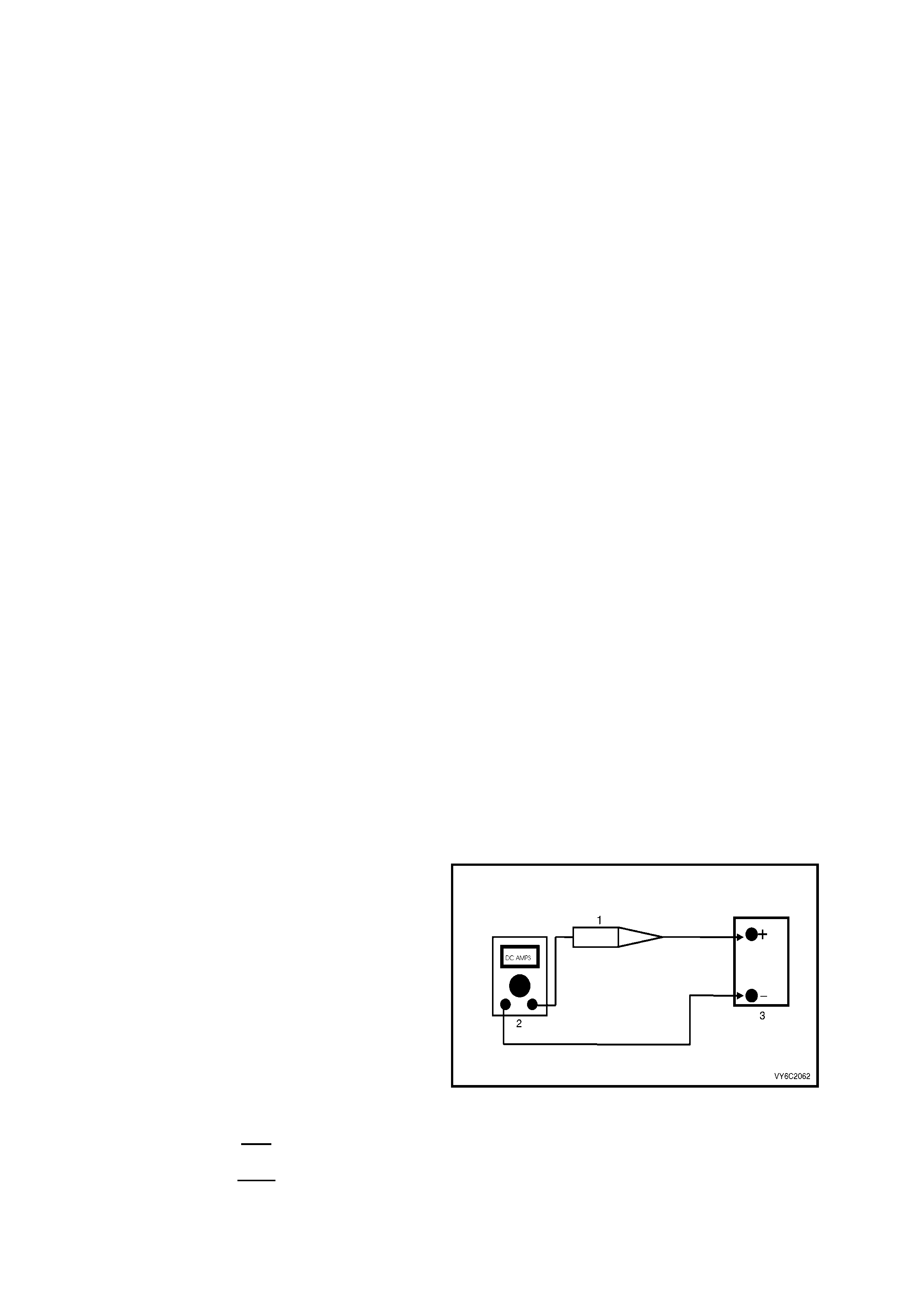
13. When a test light is specified, a "low-power"
test light must be used. Do not use a high -
wattage test light. While a particular brand of
test light is not suggested, a sim ple test on any
test light will ensure it to be OK for PCM circuit
testing. Connect an accurate ammeter (such as
the high-im pedance digital m ultim eter ) in series
with the test light being tested, and power the
test light-ammeter circuit with the vehicle
battery.
Legend:
1. Test Lamp
2. Digital Multimeter, Set to DC Amps
3. 12 Volt Battery
If the ammeter indicates less than 0.3 A (300 mA)
current flow, the test light is OK to use.
If the am m eter indic ates more than 0.3 A (300 mA)
current flow, the test light is NOT OK to use.
Figure 6C3-2-1

1.2 BLOCKING DRIVE WHEELS
The vehicle drive wheels should always be chocked and the parking brake firmly applied while checking any
system.

1.3 VISUAL/PHYSICAL INSPECTION
A car ef ul vis ual and physical ins pection mus t be per f ormed as part of any diagnostic proc edure. This c an of ten lead
to fixing a problem without further steps. Inspect all the wires in the engine compartment for bad connections,
burned or chafed spots, pinched wires, or contact with sharp edges or hot exhaust manifolds. Check beneath the air
cleaner, the compressor, the generator, etc. This visual/physical inspection is very important. The inspection must
be done carefully and thoroughly.

1.4 BASIC KNOWLEDGE AND TOOLS REQUIRED
To use this service information most effectively, a general understanding of basic electrical circuits and circuit
testing tools is required. You should be familiar with wiring diagrams, the meaning of voltage, ohms, amps, the
basic theories of electricity, and understand what happens in an open or shorted circuit.
To perform system diagnosis, the following tools are required.
• A Tech 2.
• A test light.
• A digital multimeter with 10 megohms impedance.
• A vacuum gauge.
• A fuel pressure gauge and suitable fittings.
• Fuel injector coil/balance tester.
• IAC motor analyser.
Familiarise yourself with the tools and their uses before attempting diagnosis. Special tools that are required for
system service and the ones described above are illustrated in Section 6C3-6 SPECIAL TOOLS.

1.5 ELECTROS TATIC DISCHARGE DAMAGE
Electronic components used to control the systems are often designed to carry very low voltage. They are very
susc eptible to dam age caused by electr ostatic discharge. It is possible for less than 100 volts of static electricity to
cause damage to some electronic components.
By comparison, it takes as much as 4,000 volts for a person to even feel the zap of a static discharge.
There are several ways for a person to become statically charged. The m ost common m ethods of charging are by
fric tion and by induction. An ex ample of charging by friction is a per son sliding acr oss a car seat, in which a charge
of as much as 25,000 volts can build.
Charging by induction occurs when a person with well-insulated shoes stands near a highly charged object and
momentar ily touches earth. Char ges of the s ame polarity are drained off , leaving the per son highly charged with the
opposite polarity. Static charges of either type can cause damage, therefore, use care when handling and testing
the electronic components.
NOTE: To prevent poss ible Electros tatic Disc harge damage, DO NO T TOUCH the PCM connec tor pins or soldered
components on the PCM circuit board.
1.6 DIAGNOSTIC INFORMATION
The diagnostic tables and functional checks in this Section are designed to locate a faulty circuit or component
through logic based on the process of elimination. The tables are prepared with the understanding that the vehicle:
• Functioned correctly at the time of assembly.
• There are no multiple faults.
• The problem currently exists.
The PCM perf orm s a c ontinual self -diagnosis on cert ain control f unctions . This diagnostic c apability is supported by
the diagnostic procedures. The PCM indicates the source of a fault through the use of Diagnostic Trouble Codes
(DT Cs). T he DT Cs are f our digit c odes. When a fault is detec ted by the PCM, a diagnostic trouble code will set and
the Check Powertrain MIL may be activated.
SELF-DIAGNOSTICS
The PCM performs system self diagnostics. The PCM can detect and often isolate system faults. W hen a fault is
detected, the PCM sets a DTC that represents the area of the fault. The PCM may or may not activate the Check
Powertrain MIL.
CHECK POWERTRAIN MALFUNCTION INDICATOR LAMP (MIL)
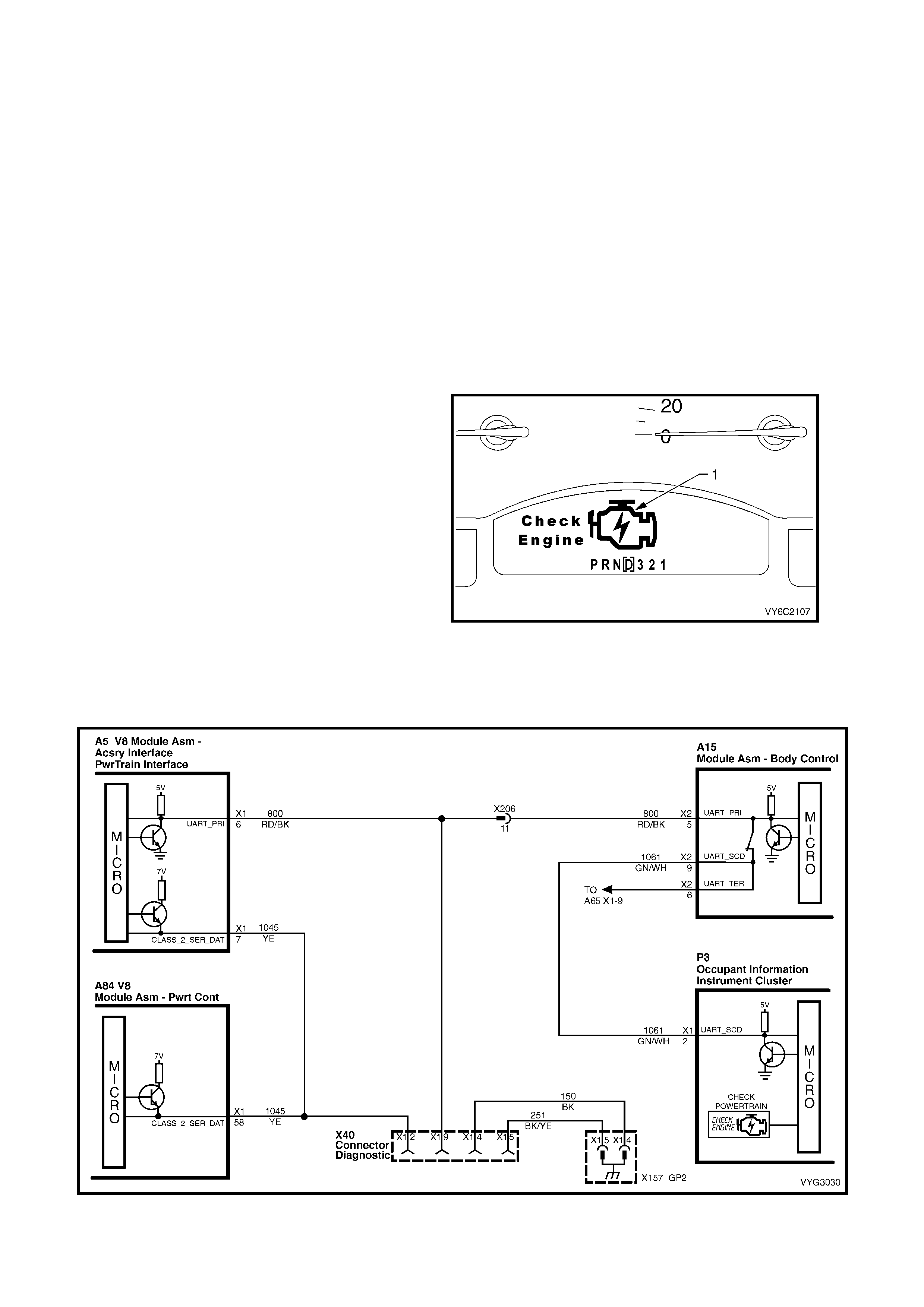
The instruments receive Malfunction Indicator
Lamp ( MIL) inf orm ation f rom the PCM via the ser ial
data bus normal mode message.
The PCM will com mand the ins truments to activate
the icon (1). When a DTC has been set and the
DTC requires the icon to be activated in the
instrument Multi Function Display (MFD).
If the instruments do not receive a normal
mode message from the PCM, the MIL will be
activated continuously. When the MIL remains
activated when the engine is running, or when
a fault is suspected due to a driveability or
emissions problem, perform the “On-Board
Diagnostic System Check". Refer to
POWERTRAIN OBD SYSTEM CHECK in this
Section. T hes e chec ks will help identif y faults which
may not be detected if other diagnostics are
performed.
Figure 6C3-2-2 – Check Powertrain MIL Symbol
Figure 6C3-2-3 – Check Powertrain Malfunction Indicator Lamp Circuit
INTERMITTENT CHECK POWERTRAIN MALFUNCTION INDICATOR LAMP (MIL)
In the case of an "intermittent" problem, the Check Powertrain MIL may be activated for ten seconds and then
disappear. The corr esponding Diagnostic Trouble Code will be stored. The DT C will r emain stored until the batter y
voltage to the PCM has been disconnected or until it is erased using Tech 2. W hen unexpected diagnostic trouble
codes appear, chances are that these diagnostic trouble codes were set by an intermittent fault.
An intermittent DTC may not re-set. If an intermittent fault occurs, do not use a Diagnostic Trouble Code Table.
Consult the "Diagnostic Aids" on the facing page. The diagnostic table corresponds to the intermittent diagnostic
trouble code.
Section 6C3-2B, SYMPTOMS also covers the topic of "Intermittents." A physical inspection of the applicable sub-
system most often will resolve the problem. Tech 2 also has several features which can help in diagnosing
intermittent problems.
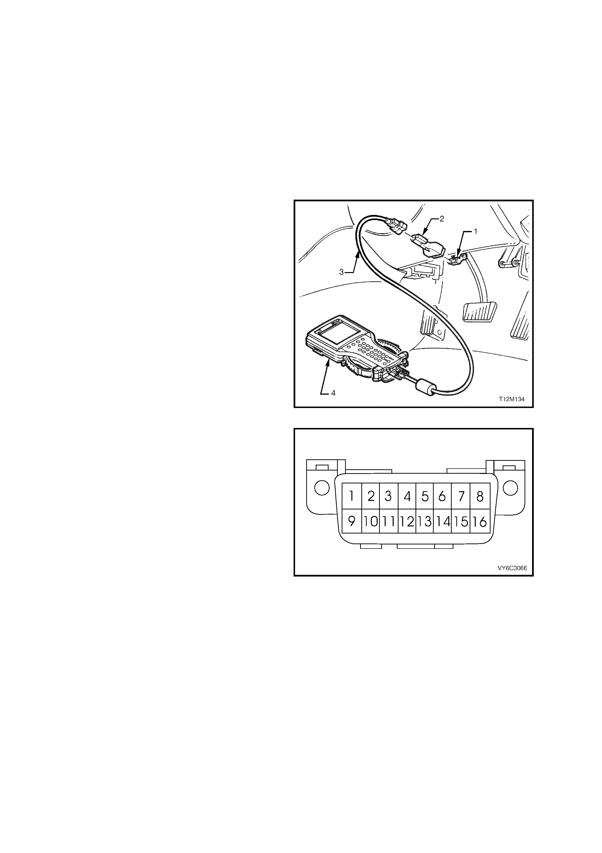
DATA LINK CONNECTOR (DLC)
The DLC is a standardised 16 way connector
located below the instr ument panel and close to the
steering column.
Legend:
1. Data Link Connector (DLC)
2. DLC Adaptor
3. DLC Cable
4. Tech 2
Figure 6C3-2-4 – Data Link Connector (DLC) Location
1. The DLC pin 1 is the Secondary UART serial
data circ uit. T ech 2 does not com m unicate with
anything on terminal 1 this is only used for
engineering purposes.
2. Pin 4 is the ground cir cuit for T ech 2, while Pin
5 is an auxiliary ground, that s hould be used to
ground the Diagnostic Enable Circuits.
3. The DLC pin 9 is the prim ary UART serial data
circuit. Tech 2 uses this circuit to read serial
data information from the PCM, BCM,
Instruments, Occupant Climate Control,
Supplemental Inflatable Restraint System and
the ABS/TCS Control Modules.
4. The DLC pin 12 is the ABS/TCS Diagnostic
Tes t Enable circuit. When jum pered to DLC pin
5, this circuit will cause the ABS/TCS Control
Module to enter the Diagnostic Mode and f lash
out ABS/TCS diagnostic trouble codes.
5. T he DLC is designed to provide battery voltage
to pin 16 from fuse F29. This circuit is used to
power Tech 2.
Figure 6C3-2-5 Data Link Connector (DLC)
Legend:
1. Secondary Serial Data (UART)
2. Serial Data (Class 2)
4. Ground
5. Ground
6. Diagnostic Enable
9. Primary Serial Data (UART)
12. ABS/TCS Diagnostic Enable
16. Battery Voltage
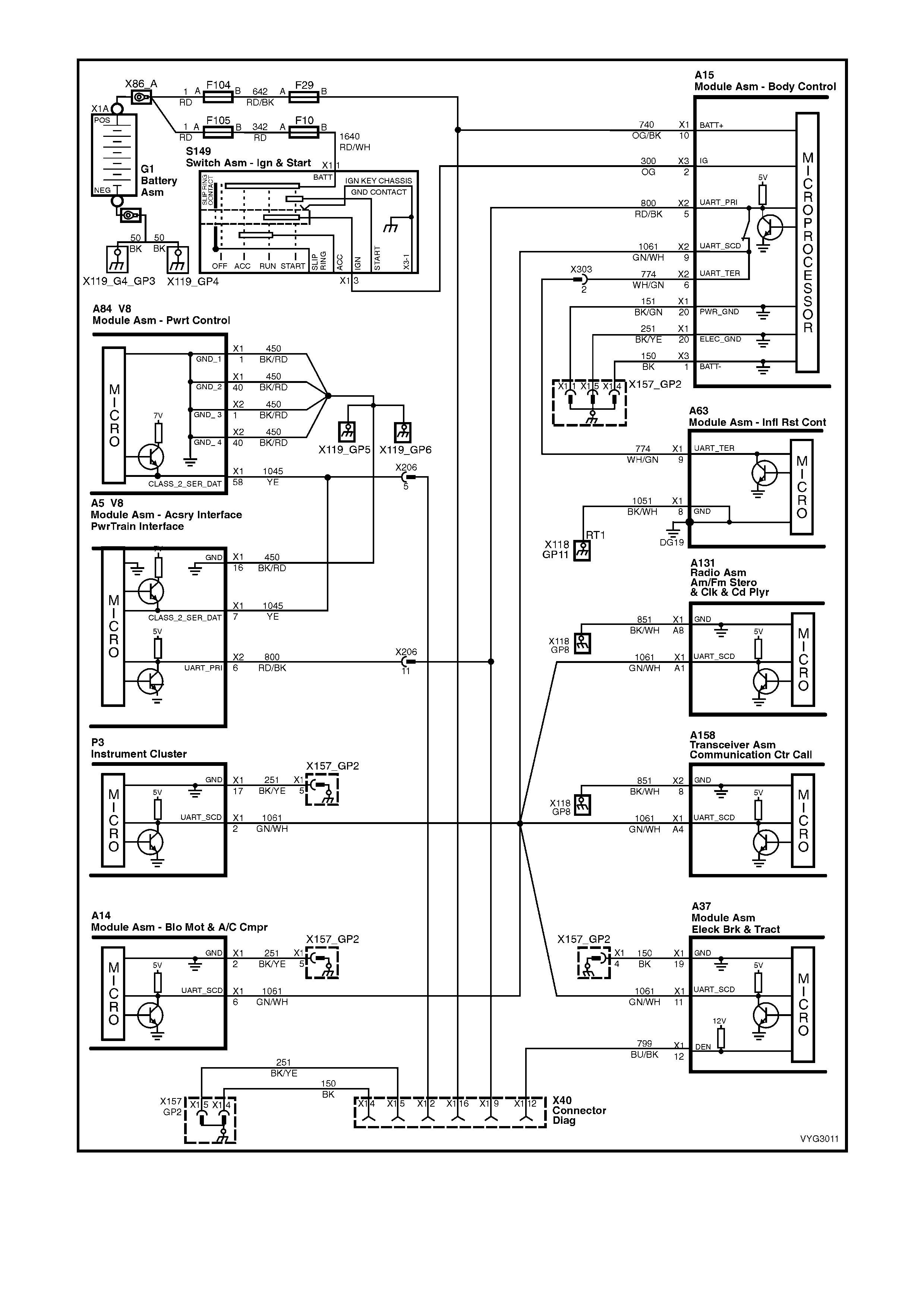
Figure 6C3-2-6 Data Link Connector Circuits

2. STRATEGY BASED DIAGNOSTICS
The strategy based diagnostic is a uniform approach to repair all Electr ical/Electronic system s. The diagnostic flow
can always be used to resolve an Electrical/Electronic system problem and is a starting point when repairs are
necessary. The steps below are defined to instruct the Technician how to proceed with a diagnostic. Steps below
also refer to step numbers found on the Strategy Based Diagnostic table.
1. Verify the Customer Concern: To verify the customer concern, the Technician should know the normal
operation of the system.
2. Preliminary Check: Conduct a thorough visual and operational inspection, review the service history, detect
unusual sounds or odours, and gather diagnostic trouble code information to achieve effective repair.
3. Check Bulletins an d Other Serv ice Information: This s hould include videos, All Dealer Letters , and T echline
Bulletins.
4. Perform Information System Check(s): System checks verify proper operation of the system. This will lead
the Technician in an organised approach to diagnostics.
5. Service Diagnostics (Paper/Electronic)
5a DTC Stored: Follow the designed DTC table exactly to make an effective repair.
5b Symptom, No DTC: Select the symptom from the symptom tables and follow the diagnostic paths or
suggestions to complete the repair, or refer to the applicable component/system checks in
Section 6C3-2C FUNCTIONAL CHECKS, in this Section.
5c No Published Diagnostics: Analyse the complaint and develop a plan for diagnostics. Utilise the wiring
diagrams and theory of operation.
Call technical assistance for similar cases where repair history may be available. Combine Technician
knowledge with efficient use of the available service information.
5d Intermittent: Conditions that are not always present are intermittent. To resolve interm ittents, perform the
following steps:
1. Observe history DTCs, DTC modes.
2. Evaluate the symptoms and conditions described by the customer.
3. Use a check sheet or other method to identify the circuit or electrical system component.
4. Follow the suggestions for intermittent diagnosis found in the service documentation.
The Tech 2 and DMM have data capturing capabilities that can assist in detection of intermittents.
5e Vehicle Operates As Designed/No Trouble Found: This c ondition m ay exist when the vehicle is f ound to
be operating normally. The condition described by the customer may be normal. Verify against another
vehicle that is operating normally. The condition may be intermittent. Contact Technical Assistance if the
concern is common. Verify the complaint under the conditions described by the customer before releasing
the vehicle.
6. Re-examine the Concern: When the complaint cannot be successfully found or isolated, a re-evaluation is
necessary. The complaint should be re-verified and could be intermittent or normal as per step 5.3 or 5.5.
7. Repair and Verificat ion Tests: After isolating the cause, the repair should be m ade. T hen validate for proper
operation and verify that the symptom has been corrected. This may involve road testing or other methods to
verify the complaint has been resolved under the following conditions:
• Conditions noted by the customer.
• If a DTC was diagnosed, verify a repair by duplicating conditions for setting the DTC.
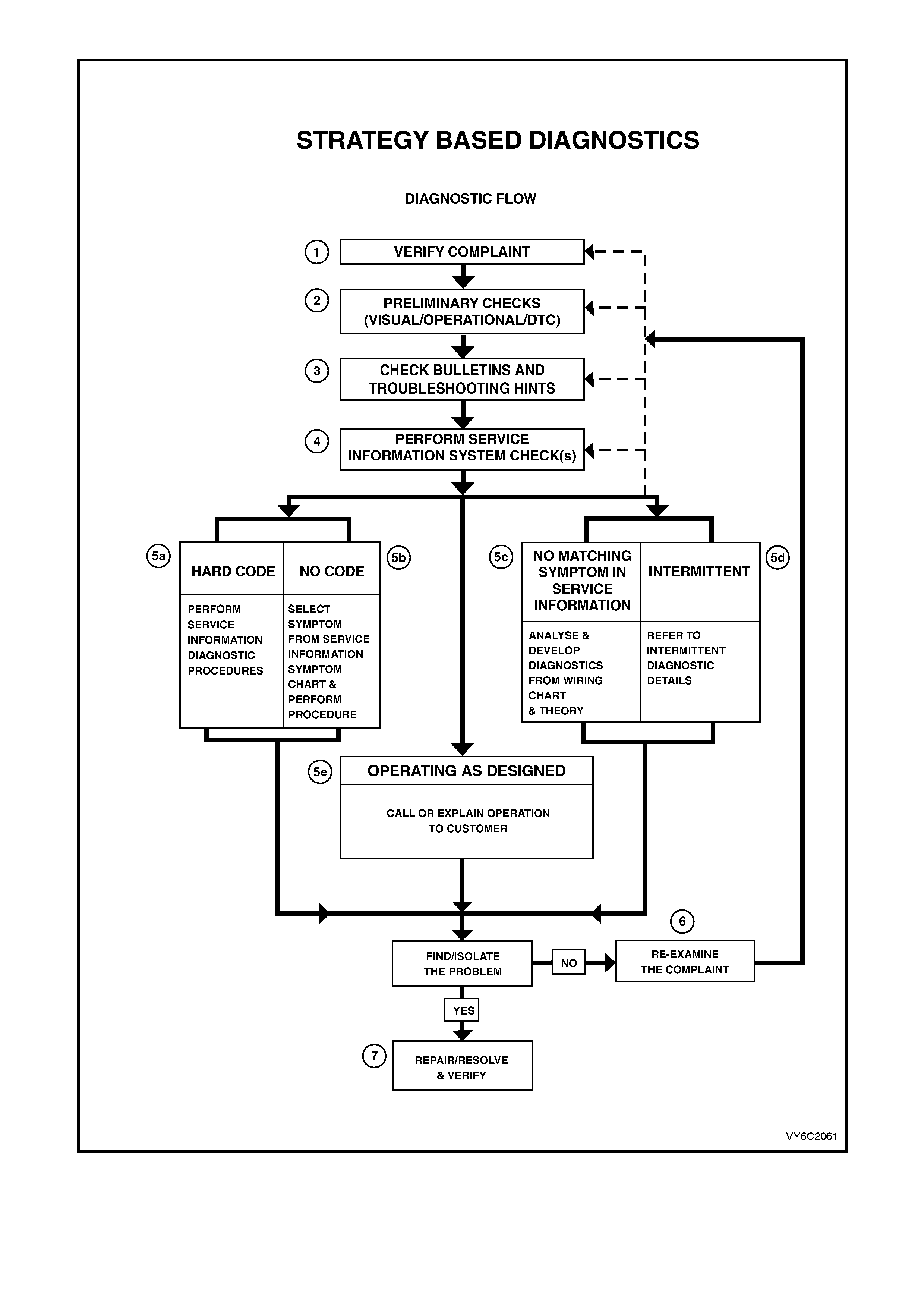
Figure 6C3-2-7 – Strategy Based Diagnostic Table

3. DIAGNOSTIC TROUBLE CODES
DTCs are stored with various additional information:
• History: fault has been detected by the control module but might not be set at the moment.
• MIL SVS or Message Requested: Malfunction Indicator Lamp (MIL) has been activated.
• Last Test Failed.
• Test Failed Since Code Cleared.
• Not Ran Since Code Cleared: controller has not tested yet if fault is active.
• Failed This Ignition.
HOW TO USE THE FREEZE FRAME / FAILURE RECORDS INFORMATION
When a PCM DTC is set, there will be a Freeze Frame/Failure Record for that DTC. The Freeze Frame/ Failure
Records data list has 32 parameters for data capture. When a DTC is set, the control module will capture all 32
parameters at the time the DTC is logged. When a Technician is diagnosing a DTC, this Freeze Frame/Failure
Record information can be retrieved and reviewed to assist in diagnosis.
In addition to the regular data list parameters found in the Freeze Frame/Failure Records data list, there is
additional information available about the DTC diagnostics:
• FIRST ODOMETER - vehicle kilometre value when the DTC failure first recorded
• LAST ODOMETER - vehicle kilometre value when the DTC fail is recorded
• FAIL COUNTER - number of ignition cycles with failure (DTC was set)
• PASS COUNTER - number of ignition cycles with diagnostic passes (DTC was not set again)
• NOT RUN COUNTER - number of ignition cycles without diagnostic run (DTC conditions were not tested)
READING THE DTCS
The provision for communicating with the PCM/PIM is the Data Link Connector (DLC). The DLC is located below
the instrument panel cover assembly. The DLC connector is used in assembly plants to receive information in
checking that the engine and transmission and other sub-systems are operating properly before they leave the
plant. The Diagnostic Trouble Code(s) stored in the PCM/PIM memory can be read with a Tech 2 scan tool.
CLEARING THE DTCS
To clear a current Diagnostic Trouble Code from the memory of the PCM, the PCM power feed must
be disconnected for at least ten (10) seconds, or Tech 2 must be used. The battery power feed can be
disconnected by:
• Disconnecting the negative battery terminal
• Removing the Fuse F29 in the engine compartment fuse/relay panel.
Tech 2 has a special mode that can be used to clear both history and current diagnostic trouble codes. This mode is
labelled Clear DTC Information found under Diagnostic Trouble Codes.
NOTE: To prevent PCM damage, the ignition must be OFF when disconnecting or reconnecting PCM power.
CLEARING THE DTC HISTORY CODE
Tech 2 is the only tool capable of clearing the DTC history code. Disconnecting the battery will not erase DTC
history. Tech 2 sends a special message to the PCM to erase the DTCs.
IGNITION CYCLE DEFAULT
If the ignition is c ycled (O FF and ON) 50 tim es without a particular fault resetting, that DT C will be c leared from the
PCM memory and the ignition cycle counter in the PCM will reset to zero.
PCM SLEEP TEST
After the ignition s witch is turned OFF the PCM will continue to operate for several seconds. During this shut down,
the PCM will set the IAC valve to a pos ition to be us ed on the next s tar tup, de-ener gis e all the s olenoids and r elays,
etc. and go to s leep. Tec h 2 will dis play updated data until the s leep mode is ac tivated then the PCM will no longer
send out serial data and Tech 2 will display DLC Data Lost.
PCM LEARNING ABILITY
The PCM has a "lear ning" ability which allows the PCM to m a k e c or rec tions f or minor var iations in the engine or the
transmission system to improve driveability .

TRANSMISSION ADAPT FUNCTION
The HYDRA-MATIC 4L60-E uses a feedback line pressure control system which has the ability to adapt the
system's line pres sure to compens ate for nor m al wear of the c lutch plates, seals , spr ings, etc. T his lear ning feature
is similar to what is used for engine fuel control, short term fuel correction, and long term fuel trim.
The HYDRA-MATIC 4L60-E transm ission only uses the adapt function for the 1-2 up-shift. The PCM monitors the
engine speed to determine if the shift is occurring too fast (harsh) or too slow (soft). The PCM will adjust the
pressure control solenoid to maintain the correct shift feel. The line pressure can adapt to values ranging from 35
kPa below, to 70 kPa above normal line pressure.
Whenever the battery is disconnected, the "learning" process resets. A change may be noted in the vehicle's
perfor m ance. T o teach the vehicle, r eset the IAC valve and ensure that the engine is at operating tem peratur e. The
vehicle should be driven at part throttle with moderate acceleration and idle conditions until normal performance
returns.
Diagnostic tables contain diagnosis procedures using a Tech 2 scan tool whenever possible. Tech 2 contains
information about what is happening in the engine/transmission management system.

4. POWERTRAIN OBD SYSTEM CHECK
4.1 PO WERTRAIN OBD SYSTEM CHE CK CHART
STEP ACTION VALUE YES NO
1. 1. Install Tech 2 to Data Link Connector.
2. Select V8 GEN III Engine.
Does Tech 2 display Identification Data?
Go to Step 2 Go to Table A-2
in this Section
2. 1. Turn ignition “ON” and wait 5 seconds.
2. Turn ignition to “START” position.
Does engine crank?
Go to Step 3 Go to
Table A-4.0
3. 1. Using Tech 2, select ”Read DTC Info Ordered by
Priority”.
Are any Diagnostic Trouble Codes displayed?
Refer to
Applicable DTC
Table.
Start with lowest
DTC
Go to Step 4
4. Does engine start and continue to run?
Go to Step 5 Go to
Table A-3.1
5. 1. Ignition "ON", engine "STOPPED".
2. Compare Tech 2 data with typical values shown on
scan data page.
Are values normal or within typical ranges?
Go to Step 6 Refer to
indicated
"Component(s) –
System" checks
in this Section.
6. 1. Ignition "ON", engine "RUNNING".
3. Compare Tech 2 data with typical values shown on
scan data page.
Are values normal or within typical ranges?
Refer to
Diagnostic Aids Refer to
indicated
"Component(s) –
System" checks
in this Section.
Figure 6C3-2-8 – Example of Powertrain On-Board Diagnostic (OBD) System Check

4.2 POWERTRAIN OBD SYSTEM CHE CK
After the vis ual and physical underhood ins pection, the POW ERTRAIN O BD SYST EM CHECK is the starting point
for all diagnostic procedures or finding the cause of an emissions test failure.
All diagnostic procedures must always begin with the POWERTRAIN OBD SYSTEM CHECK.
The POWERTRAIN OBD SYSTEM CHECK represents an organised approach for identifyi ng system problems.
The POWERTRAIN OBD SYSTEM CHECK makes an initial check of the system and directs the Technician to
other tables in this Section. It m ust be used as a starting point for all procedures. The entire Section is set up in a
specific order. The POWERTRAIN OBD SYSTEM CHECK will lead the Technician to other tables, and those
tables may lead to still other tables. THE SEQUENCE MUST BE FOLLOWED. The engine/transmission control
system uses many input signals and controls many output functions. If the correct diagnostic sequence is not
followed, incorrect diagnosis and replacement of serviceable parts may occur.
Diagnostic tables incorporate diagnosis procedur es using a T ech 2 s can tool where poss ible. This T ech 2 sc an tool
is a sm all hand- held com puter in its elf. Its func tion is to give inf orm ation to a T echnic ian about what is happening in
the powertrain management system.
The Data Link Connector (DLC) is us ed by the assembly plant to perform end of line tests . This connector can also
be used by a Technician to monitor certain inputs and outputs as seen by the Powertrain Control Module (PCM).
Tech 2 reads and displays the information (serial data) supplied to the data link connector from the PCM.
The correct procedure to diagnose a problem is to follow three basic steps.
1. Are the On-Board Diagnostics working? This is determined by performing the Powertrain OBD System
Check. Since this is the starting point for the diagnostic procedures or finding the cause of a failure, always
begin here.
If the On- Board Diagnostics ar en't working, the Powertrain O BD System Check will lead to a diagnostic table in
this section to correct the problem. If the On-Board Diagnostics are working correctly, the next step is:
2. Is there a Diagnostic T rouble Code stored? If a diagnostic trouble code is stored, go directly to the numbered
diagnostic trouble code table in this Section. This will determine if the fault is still present. If no diagnostic
trouble code is stored, then:
3. Observe Serial Data transmitted by the PCM: This involves reading the information available on the Serial
Data Stream with Tech 2. Information on this tool and the meaning of the various displays can be found in the
succeeding paragraphs. Typical data readings under a particular operating condition can be found on Tech 2
DATA pages.
DLC AND TECH 2
The PCM can communicate a variety of information through the DLC connector. This data is transmitted at a high
frequency which requires a Tech 2 scan tool for interpretation.
TECH 2 EXPLANATION
To explain how Tech 2 works, let's think for a minute about how a television works. A television is an electronic
device that receives and processes inform ation and sends out inf ormation in a f orm that can be unders tood by the
person watching it. The television receives a signal (from a transmitting station) that is not usable to the person.
The television processes it, then sends the signal to a screen. The person can then see the information that the
television transmitting station s ent out. Tech 2 is like the television bec ause it pr oc es ses the information sent to it by
the PCM.
The information is sent out of the PCM to the Data Link Connector (DLC) serial data line. Tech 2 plugs into the Data
Link Connector and the information is sent to the tool on its cable. Tech 2 processes the information and "sends"
the signal to a display screen on the tool.
Just like a television, you can select which "station" that you want to see. The difference is, instead of seeing the
picture on a television, you "see" the display screen. The "stations" that you can select on a Tech 2 scan tool are the
different input and output signals that are being processed by the PCM.
Tec h 2 f or the G EN III V8 engine has the ability to send mes sages to the PCM to do dif f er ent things , suc h as switch
outputs OFF and ON. This allows the Technician to control the PCM. This control only lasts as long as Tech 2 is
connected.

5. TECH 2 USES
5.1 POWERTRAIN CONTROL MODULE
Using Tech 2 is a very useful and quick way of comparing operating parameters of a poorly operating engine or
transmission with a known good one. For example, a sens or may shift its value but not s et a DT C. Comparis on with
a known good vehicle may uncover this problem.
Tech 2 allows a quick check of sensors and switches which are inputs to the PCM. The PCM in the vehicle sends
out information to Tech 2 at a very fast rate (Class II serial data), and the display on the tool can update quicker
than a digital multimeter. Tech 2 allows a Technician to manipulate wiring harnesses or components under the
vehicle while observing Tech 2 readout. This can help in locating intermittent connections.
After you enter the proper vehicle inform ation, the first display on Tech 2 will ask for what type of system to select
from.
The following is a list of systems that Tech 2 can display:
F0: ENGINE
F1: TRANSMISSION
F2: CHASSIS
F3: BODY
F4: VEHICLE DTC CHECK
After selecting ‘F0: ENGINE’, Tech 2 will display:
V6
V8 GEN III
Once the correct engine has been selected, T ech 2 will now have five test modes for diagnosis and service of the
PCM system. The five test modes are as follows:
MODE F0: DIAGNOSTIC TROUBLE CODES
In this test m ode, DTCs stored by the PCM may be displayed or cleared. W hen entering this mode there are four
modes:
F0. READ DTC INFO ORDERED BY PRIORITY:
DTC will be displayed in the order of priority.
F1. CLEAR DTC INFORMATION:
Clears all DTC(s) in the vehicle’s PCM memory. Also clears Freeze Frame/Failure Records, so before clearing
codes, be sure to retrieve Freeze Frame / Failure Records.
F2. DTC INFORMATION:
Shows codes which are set that match the criteria. Each code has its own page of information. If multiple codes
are set, the user must page through the display of codes:
F0: HISTORY: This DTC search will display only DTCs that are stored in the PCM memory as valid faults,
but are currently not active.
F1: MIL SVS or MESSAGE REQUESTED: This DTC s earch will display only DTCs that ar e requesting the
Malfunction Indicator Lamp (MIL) to be activated.
F2: LAST TEST FAILED: This DTC search will display only DTCs that failed the last time the test ran.
F3: TEST FAILED SINCE CODE CLEARED: This DTC search will display all DTCs that have reported a
test failure since the last time DTCs were cleared.
F4: NOT RAN SINCE CODE CLEARED: This DTC search will display only DTCs that have not ran since
DTCs were last cleared. Any displayed DTCs have not run, theref ore their condition ( passing or failing)
is unknown.
F5: F AILED T H IS IGN IT I ON: This D T C s ear c h will display all DTCs that have f a iled at least onc e dur ing the
current ignition cycle.
F3: FREEZE FRAME / FAILURE RECORDS:
Shows Freeze Frame / Failure Records information. Freeze Frame / Failure Records are types of
snapshots in the memory of the vehicle’s controller.
MODE F1: DATA DISPLAY
This mode displays data parameters for the controller being diagnosed. When entering this mode, there are two
modes:
F0: ENGINE DATA:
In this test mode, Tech 2 continuously monitors system data, such as engine speed data, engine coolant
temperature, etc.

F1: FUEL TRIM DATA:
In this test mode, Tech 2 continuously monitors system data, such as engine speed data, engine coolant
temperature, HO2S, Fuel Trim Cell etc.
MODE F2: SNAPSHOT
In this tes t mode, T ec h 2 c aptures data bef or e and af ter a s naps hot trigger ing c ondition which may or may not set a
DTC.
MODE F3: MISC. TESTS
In this test mode, Tech 2 performs software override commands of the PCM, to assist in problem isolation during
diagnostics:
F0: OUTPUT TESTS
F0: FUEL PUMP
F1: A/C CLUTCH
F2: CHECK POWERTRAIN LAMP
F3: HIGH FAN
F4: CANISTER PURGE
F1: IAC SYSTEM
F0: RPM CONTROL: Used to control engine RPM from 600 RPM to 1675 RPM.
F1: IAC CONTROL: Used to control IAC steps from 0 to 120.
F2: IAC RESET: Used to reset IAC if the IAC is lost or if IAC has been replaced.
F3: BASE IDLE: Used to set the engine to base idle.
F2: RESET CELLS
Resets all LT Fuel Trim values to 0%
F3: 02 LOOP STATUS
With the engine running, Open or Closed Loop fuel control can be commanded.
With the engine running, forces air fuel ratio from 11.7 to 17.7.
MODE F4: FUNCTION TESTS
This mode performs functional tests on the PCM system which help verify proper operation. In this mode, fault
conditions are automatically logged by Tech 2.
Tech 2 also has the ability to send commands to the PCM, instructing the PCM to perform various functions or
tasks. This provides a quick way to determine if a device is operational or not. In the F4 mode, the following tests
can be performed:
F0: IAC CIRCUIT:
Designed to conf irm IAC m otor f unctions OK and is not los ing track of position. Monitors the engine speed.
Repeatedly cycles the IAC motor in and out and then monitors the engine speed. If OK, turn ignition OFF
and star t repeatedly, then stabilise idle. If the value of final idle RPM is greater than a calibrated threshold,
then the IAC circuit has failed.
F1: POWER BALANCE:
Designed to identif y low power output fr om individual cylinders. Autom atically cycles each injector OFF and
ON while monitoring and recording the RPM drop for each cylinder.
F3: WIRING HARNESS:
Designed to confirm no intermittent open or short circuits exist in selected circuits. Engine is at idle in N.
Tec hnician should wiggle power train harness. T ech 2 monitors inputs that should rem ain relatively static at
idle such as: ECT, IAT, T P Sensor, VSS, CAM signal present, EST lines, injector voltage monitor, battery,
ignition. If discontinuity occurs, Tech 2 logs DTC and prompts Technician to check the appropriate circuit.
F4: FUEL INJECTOR BALANCE:
Designed to check function of each injector while the engine is not running. A fuel pressure gauge has to be
connected to the fuel rail and pressure drop has to be recorded after turning ON each injector.

5.2 PO WERTRAIN INTERFACE MODULE (PIM)
The PIM in the vehic le sends out inf or mation to T ech 2 at a ver y fast rate ( UART serial data) , and the display on the
tool can update quicker than a digital multimeter. Tech 2 allows a Technician to manipulate wiring harnesses or
components under the vehicle while observing the Tech 2 readout. This can help in locating intermittent
connections.
After you enter the proper vehicle information, the first display on the Tech 2 will ask for what type of system to
select from.
The following is a list of systems the Tech 2 will display:
F0: ENGINE
F1: TRANSMISSION
F2: CHASSIS
F3: BODY
F4: DTC CHECK OR VEHICLE DTC CHECK
After selecting F3: BODY, the scan tool will display:
Body Control Module
Powertrain Interface Module
SRS
Instrument
Electronic Climate Control
Telematics Module
Other
When ‘Powertrain Interface Module’ has been selected, Tech 2 will now have five test modes for diagnosis and
service of the PIM system. The five test modes are as follows:
MODE F0: PIM NORMAL MODE
In this test mode, Tech 2 monitors data sent from the PIM to other vehicle system control modules on the serial
data line. This data represents the normal bus communication executed during ignition ON. The PIM keeps the
other control m odules that are c onnected on the serial data line, inform ed about the status of the PCM param eters.
These parameters are collected from the PIM via serial data communication with the PCM.
The Malfunction Indicator Lamp (MIL) in the instrument cluster is driven only with this status report in the PIM's
Norm al Mode bus message. If PCM Malfunc tion Indicator Lamp ( MIL) status report indic ates OFF, the Malfunc tion
Indicator Lamp (MIL) in the instrument panel should not be activated.
The following PIM Normal Mode controller usage table indicates specific Control Modules using the PCM supplied
report status information:

PIM NORMAL MODE CONTROLLER USAGE TABLE
PIM NORMAL MODE SCAN TOOL
PA RAMETERS USED BY:
Tech 2 Stri ng BCM INST ECC ABS/ETC SRS Audio
Engine Speed √
√√
√
Coolant Tem perature √
√√
√ √
√√
√
Barometric Pressure *
Vehicl e S peed √
√√
√
√
√√
√
A/C Clutch
A/C Pressure √
√√
√
Low Speed Fan Request √
√√
√
Low Fan Run ON √
√√
√
Theft St atus √
√√
√
PCM DTC Status √
√√
√
Check P owertrain CPL √
√√
√
Throttle Failure *
√
√√
√
MAP Failure *
Fuel Used √
√√
√
Fuel Flow Rate √
√√
√
Engine Type √
√√
√
Transm i ssion Coding
Fuel Type √
√√
√
Engine Oil Change √
√√
√
Transm i ssion Oil Change √
√√
√
Shift Pattern √
√√
√
Throttle Position * √
√√
√
High Coolant Temperature
Low Coolant Level *
√
√√
√
Oil Pressure Sensor √
√√
√
PRNDL Switch √
√√
√
Commanded Gear √
√√
√
PCM Chim e √
√√
√
* Indicates Only With GEN III V8 Engine
MODE F1: DIAGNOSTIC TROUBLE CODES
In this test mode, DTCs stored by the PCM may be displayed or cleared. W hen entering this mode there are two
modes:
F0. READ CURRENT DTC INFORMATION:
DTCs will be displayed in the PIM by priority or in sequence.
F1. CLEAR DTC INFORMATION:
Tech 2 will clear all stored DTCs from the PIM memory .
MODE F2: DATA DISPLAY
In this test mode, Tech 2 continuously monitors system data such as: starter relay, password learning, engine oil
change etc.
MODE F3: SNAPSHOT
In this tes t mode, T ec h 2 c aptures data bef or e and af ter a s naps hot trigger ing c ondition which may or may not set a
DTC.
MODE F4: MISC. TESTS
In this test mode, Tech 2 performs software override commands of the PIM to assist in problem isolation during
diagnostics.
F0: STARTER RELAY

5.3 WITH INTERMITTENT FAULTS
Tec h 2 allows manipulation of wiring harnesses or c omponents under the bonnet with the engine not running, while
observing Tech 2 readout.
Tec h 2 can be plugged in and obser ved while driving the vehicle under the condition when the Malfunction Indicator
Lamp (MIL) is activated momentarily or when the engine driveability is momentarily poor. If the problem seems to be
related to certain parameters that can be checked on Tech 2, they should be checked while driving the vehicle. If
there does not seem to be any connection between the problem and any specific circuit, Tech 2 can be used to
monitor eac h parameter , watching f or a period of time to s ee if there is any change in the readings that indicates an
intermittent condition.
Tec h 2 can c aptur e and s tore data when the problem occ urs , s o it c an be played back at a slower rate to deter mine
what happened to the system. This is called the SNAPSHOT mode.
Tech 2 is an easy way to compare the operating parameters of a poorly operating engine with those of a known
good one. For exam ple, a s ensor m ay shift in value but not set a DT C. Com paring the s ensor's readings with those
of a known good vehicle may uncover the problem.
Tec h 2 saves tim e in diagnosis and helps to pr event the replacement of ser viceable parts. The key to using Tec h 2
succ essfully is the Tec hnician's ability to unders tand the sys tem being diagnos ed, as well as understanding T ech 2
operation and its limitations. The Technician should read the Tech 2 operator’s manual to become familiar with
Tech 2 operation.
With an understanding of the data which the tool displays, and knowledge of the circuits involved, the tool can be
very useful in obtaining information which would be more difficult or impossible to obtain with other equipment.
Tec h 2 does not mak e the use of diagnostic tables unnec essary, nor can it indicate exactly where a pr oblem is in a
particular circuit. Diagnostic Tables incorporate diagnosis procedures that require the use of a Tech 2 scan tool.

5.4 TECH 2 LIMITATIONS
Tech 2 must receive the signal from the PCM in order to display any useable information. If the PCM sends no
signals to the data link connec tor, or the connec tion to Tech 2 is defective, T ech 2 will only dis play, WAITING FOR
DATA – NO DATA RECEIVED FROM PCM. The Powertrain OBD System Check instructs the Technician what to
do if this happens.
Tec h 2 has a f ew lim itations. If T ech 2 is dis playing a PCM "output" function, it displays only the com m and given by
the PCM. That does not mean that the desired action took place. This is similar to the automatic transmission
dashboard gears hift indicator. Jus t because the gearshif t P R N D L pointer indicates the transm ission is in DRIVE
does not mean that the transmission is actually in that gear. To be sure, you must check the linkage and adjustment
at the transmission.
When using Tech 2 to observe one of the PCM "output" functions, such as an idle air control motor, or a TCC
solenoid, the Technician must not assume the indicated is the same as the actual. If Tech 2 is displaying TCC
solenoid as being ON , but the wire to power it is disconnected or defec tive, the PCM in som e cases has no way of
knowing it. The display may indicate the command is ON, but the device may not be operating!
Tec h 2 saves tim e in diagnosis and helps to pr event the replacement of ser viceable parts. The key to using Tec h 2
successfully for diagnosis is the Technician's ability to understand the system being diagnosed, as well as an
understanding of Tech 2's limitations.
With an understanding of the data Tech 2 displays, and knowledge of the circuits involved, Tech 2 is useful in
obtaining information which is difficult or impossible to retrieve with other methods.
Remember, Tech 2 does NOT make using diagnostic tables unnecessary, nor can it tell you exactly where a
problem is in a circuit. Most diagnostic tables incorporate diagnosis procedures that require the use of a Tech 2
scan tool.

6. TECH 2 DISPLAY MODES
6.1 PIM NORMAL MODE
The Tech 2 PIM Normal Mode in the following table may be used for comparison, if a status report is being sent
from the PIM.
1. After completing the Powertrain OBD System Check
2. Finding the on-board diagnostics are functioning properly and;
3. No diagnostic DTCs are displayed.
IMPORTANT: Do not use a Tech 2 that displays faulty data. Report the condition to the scan tool manufacturer.
The use of a faulty scan tool can result in misdiagnosis and the unnecessary replacement of parts. Only the
param eters lis ted below are used in this Sec tion for diagnosing. If Tec h 2 displays other param eters , the values are
not recommended for use in diagnosis.
NOTE: Only the param eters listed, are used in this Section for diagnosis. For more description on the values and
use of Tech 2 to diagnosis PCM/PIM inputs, refer to the applicable diagnosis table in this Section. If all values are
within the range illustrated, refer to Section 6C3-2B SYMPTOMS.
TEST DESCRIPTION:
NOTE: The number(s) below refer to the number(s) on the Tech 2 Scan Data Normal Mode table.
1. Tech 2 – FO: PCM/PIM NORMAL MODE will display scan positions that will be displayed in order. Tech 2 will
display nine (9) scan position parameters at a time. The down arrow button will scroll down through all of the
scan positions one at a time. Af ter TIME FRO M ST ART param eter is displayed, pres s ing the down arro w button
again will display scan position parameters starting at the top of the list again.
2. UNITS DISPLAYED are the available ways of displaying what each parameter is currently operating in, or a
value that is being sensed or being issued by the PCM.
3. TYPICAL DATA VALUE is separated into two parts. Thes e displayed values are typical of a normally operating
vehicle. The IG NITION ON comparis on should be perform ed first as this may lead to a quick identif ication of a
failure. The ENGINE RUNNING data should be compared to the IGNITION ON data as a diagnostic check to
make sure the component or system is operating properly.
4. IGNITION ON values are the typical values that should be seen on Tech 2 with the ignition ON and engine
stopped. Temperature sensors should be compared to the actual temperatures by allowing the sensor to cool
overnight and then comparing their values. A difference of 3-5° C from the actual temperature may indicate a
problem with the s ensor . Us e the diagnostic aids table f or that s ens or to c ompare the res is tance to temperatur e
values.
5. ENGINE RUNNING typical data values are an average of display values recorded from normally operating
vehicles at norm ally operating tem perature. T hey are intended to represent what a norm ally functioning system
would typically display.
TECH 2 SCAN TOOL: PIM NORMAL MODE
TYPI CAL D ATA VALUE S
SCAN POSITION Q UNITS DISPLAYED R IGNITION ON T ENGINE RUNNING U
ENGINE SPEED RPM 0 RPM 600 - 650 RPM
(± 50 RPM IN DRIVE)
COOLANT TEMPERATURE DEGREES C Varies +96 C
BAROMETRIC PRESSURE
kPa 0 to 200 kPa
(VARIES) 0 to 200 kPa
(VARIES)
VEHICLE SPEED km/h 0 km/h 0 km/h
A/C CLUTCH ON /OFF OFF OFF
A/C PRESSURE kPa 300 – 1200 kPa 300 – 1200 kPa A/ C OFF
500 – 1900 kPa A/C ON
LOW SPEED FAN REQUEST ON / OFF OFF OFF
LOW FAN RUN ON YES / NO NO NO
THEFT STATUS (only BCM-PIM) NO START / START START START
PCM DTC STA T US NO DTC/DTC(s ) S ET NO DTC NO DTC
CHECK POWERTRAIN MIL OFF/ON OFF OFF
THROTTLE FAILURE YES/NO NO NO
MAP FAI LURE YES/NO NO NO
FUEL USED L 00.00 1 – 2 L

TECH 2 SCAN TOOL: PIM NORMAL MODE (CONTINUED)
TYPI CAL D ATA VALUE S
SCAN POSITION Q UNITS DISPLAYED R IGNITION ON T ENGINE RUNNING U
FUEL FLOW RATE 00.00 1 – 4 L/Hour
ENGINE TYPE V6,
V6 SUPERCHARGED
V8 GEN III V8 GEN III V8 GEN III
TRANSMISSION CODING MANUAL TRANS.
AUTOMATIC TRANS. MANUAL TRANS.
AUTOMATIC TRANS. MANUAL TRANS.
AUTOMATIC TRANS.
FUEL TYPE PETROL / LPG PETROL PETROL
ENGINE OI L CHANGE OKAY / SERVICE
REQUESTED OKAY OKAY
TRANSMISSION OIL CHANGE OKAY / SERVICE
REQUESTED OKAY OKAY
SHIFT PATTERN POW ER/ECONOMY ECONOMY ECONOMY
THROTTLE POSITION
0-100 % 0% 0%
HIGH COOLANT TEMPERA TURE YES/NO NO NO
LOW COOLANT LEVE L YES/NO NO NO
OIL PRESSURE SWITCH OFF/ON OFF OFF
PRNDL SWITCH INVALID /
P,R,N,D,3,2,1 –P– –P–
COMMANDED GEAR P/N R, 1 –P/N– –P /N–
PCM CHIME YES/NO NO NO
TECH 2 SCAN TOOL: PIM NORMAL MODE DESCRIPTIONS
A list of explanations for each data message displayed on Tech 2 is listed below. This information will assist in
diagnosing em is sion or dr iveability problems . T he displays can be viewed while the vehicle is being driven. Ref er to
the Powertrain OBD System Check for additional information.
ENGINE SPEED: Tech 2 Displays a range of 0 to 9999 RPM
The engine speed is computed by the PCM from the fuel control reference input. It should remain close to desired
idle speed under various engine loads with engine idling.
COOLANT TEMPERATURE: Tech 2 Displays a range of -39°C to 140°C
The Engine Coolant T emperatur e (ECT) Sensor is mounted in the cylinder head of the left bank . The PCM applies
5.0 volts to the ECT sensor circuit. The sensor is a thermistor which changes internal resistance as temperature
changes. W hen the sensor is cold ( internal resistanc e high), the PCM monitor s a high signal voltage and interprets
the voltage as a cold engine. As the sensor warms (internal resistance decreases), the voltage signal decreases
and the PCM interprets the lower voltage as a warm engine.
BAROMETRIC PRESSURE *: Tech 2 Displays a range of 0 to 200 kPa
The BARO reading is dis played in k Pa and r epres ents the altitude of the vehic le f or the tr ans mission c ontrol. At s ea
level the BARO reading is about 101 kPa. At 3,048 meters the BARO reading is about 96 kPa.
VEHICLE SPEED: Tech 2 Displays a range of 0 to 255 km/h
The vehicle speed sensor signal is converted into km/h for display.
A/C CLUTCH: Tech 2 Displays "ON" or "OFF"
Represents the commanded state of the A/C clutch control relay. Clutch should be engaged when ON is displayed.
A/C PRESSURE: Tech 2 Displays a range of 0 to 3195 kPa
The kPa displayed indicates that the PCM is monitoring an A/C Refrigerant Pressure signal voltage which is too
high or too low to allow the A/C compressor clutch to engage.
LOW SPEED FAN REQUEST: Tech 2 Displays "ON" or "OFF
Indicates if the engine cooling fan low speed relay has been commanded ON or OFF.
LOW FAN RUN ON: Tech 2 Displays "NO" or "YES"
This indicates if the PCM is requesting the BCM to turn the Low Speed Fan ON at key OFF.
THEFT STATUS: Tech 2 Displays "NO START" or "START"
Indicates the status of the Theft Deterrent System.

PCM DTC STATUS: Tech 2 Displays "NO DTC" or “DTC SET”
Indicates if a DTC is set. This does not indicate what DTC is set, just informs that DTC(s) are or are not set.
MALFUNCTION INDICATOR LAMP (MIL): Tech 2 Displays "OFF" or "ON"
Indicated if the instrument panel Malfunction Indicator Lamp (MIL) is activated or not.
THROTTLE FAILURE *: Tech 2 Displays "NO" or "YES"
Indicates if the throttle position sensor has failed. This is reported from the PCM to the PIM.
MAP FAILURE *: Tech 2 Displays "NO" or "YES"
Indicates if the Map sensor has failed. This is reported from the PCM to the PIM.
FUEL USED: Tech 2 Displays a range of 0 to 1000 Litres
When the key is turned ON and the engine is running, the PCM will calculate FUEL USED during each ignition
cycle.
FUEL FLOW RATE: Tech 2 Displays a range of 0 to 100 litres
Indicates fuel consumption per litres per hour.
ENGINE TYPE: Tech 2 Displays Engine Type
The Tech 2 uses this information for proper Tech 2 scan tool software.
TRANSMISSION CODING: Tech 2 Displays “MANUAL” or “AUTOMATIC”
The Tech 2 uses this information for proper Tech 2 scan tool software.
FUEL TYPE: Tech 2 Displays “PETROL” or “LPG”
The scan tool will display what fuel type the PCM software is set up for.
ENGINE OIL CHANGE: The Tech 2 Displays “OKAY” or “SERVICE REQUESTED”
The scan tool will display the status of the engine oil change condition.
TRANSMISSION OIL CHANGE: The Tech 2 Displays “OKAY” or “SERVICE REQUESTED”
The scan tool will display the status of the transmission oil change condition.
SHIFT PATTERN: Tech 2 Displays “ECONOMY” or “POWER”
This display shows the state of the POWER/ECONOMY switch.
THROTTLE POSITION *: Tech 2 Displays a range of 0 to 100%
Computed by the PCM from TP sensor voltage (T hrottle Position) should read 0% at idle and 100% at Wide Open
Throttle (WOT).
HIGH COOLANT TEMPERATURE: Tech 2 Displays "NO" or "YES"
This is an indication from the PCM that the engine is running hot.
LOW COOLANT LEVEL *: Tech 2 Displays "NO" or "YES"
This is an indication from the PCM that the coolant level is low, and the Instrument will activate the Low Coolant
warning icon in the MFD.
OIL PRESSURE SENSOR: Tech 2 Displays "OFF" or "ON"
This is an indication to the PCM if the oil pressure is high or low. If the oil pressure is low, the Instrument will
activate the Low Oil Warning icon in the MFD.
PRNDL SWITCH: Tech 2 Displays “INVALID” or “P, R, N, D, 3, 2, 1”
This displays if the vehic le is not equipped with a PRNDL switch (INVALID), or if equipped, indicates what gear the
driver has selected.
COMMANDED GEAR: Tech 2 Displays “1, 2, 3, 4”
The gear that the PCM is com manding the tr ansmis sion to be in. In PARK, Tec h 2 will display "1", the comm anded
state of the shift.
PCM CHIME: Tech 2 Displays "NO" or "YES"
This is a indication to the instrument panel allowing the instrument panel to chime if a problem or fault is detected.
* Only with GEN III V8 Engine

6.2 ENGINE DATA
The Tech 2 data listed in the following table may be used for comparison:
1. After completing the Powertrain OBD System Check.
2. Finding the on-board diagnostics are functioning properly and;
3. No diagnostic DTCs are displayed.
A TECH 2 THAT DISPLAYS FAULTY DATA SHOULD NOT BE USED, AND THE PROBLEM SHOULD BE
REPORTED TO THE MANUFACTURER. THE USE OF A FAULTY TECH 2 CAN RESULT IN MISDIAGNOSIS
AND UNNECESSARY PARTS REPLACEMENT.
Only the parameters listed, are used in this Section for diagnosis. For more description on the values and use of
Tech 2 to diagnose PCM inputs, refer to the applicable diagnosis table in this Section. If all values are within the
range illustrated, refer to Section 6C3-2B SYMPTOMS in this Section.
SCAN POSITION:
NOTE: The number(s) below refer to the number(s) on the Tech 2 Engine Data table.
1. T ech 2 F0: ENG INE DATA will display scan positions that will be disp layed in order. Tech 2 will dis play nine (9)
scan position par ameters at a time. T he down arrow button will scr oll down through all of the s can positions one
at a time. After TIME FROM ST ART parameter is displayed, pressing the down arrow button again will display
scan position parameters starting at the top of the list again.
2. UNITS DISPLAYED are the available ways of displaying what each parameter is currently operating in, or a
value that is being sensed or being issued by the PCM.
3. TYPICAL DATA VALUE is separated into two parts. Thes e displayed values are typical of a normally operating
vehicle. The IG NITION ON comparis on should be perform ed first as this may lead to a quick identif ication of a
failure. The ENGINE RUNNING data should be compared to the IGNITION ON data as a diagnostic check to
make sure the component or system is operating properly.
4. IGNITION ON values are the typical values that should be seen on Tech 2 with the ignition ON and engine
stopped. Temperature sensors should be compared to the actual temperatures by letting the sensors stabilise
overnight and then comparing their values. A difference of 3-5° C from the actual temperature may indicate a
problem with the s ensor . Us e the diagnostic aids table f or that s ens or to c ompare the res is tance to temperatur e
values.
5. ENGINE RUNNING typical data values are an average of display values recorded from normally operating
vehicles at norm ally operating tem perature. T hey are intended to represent what a norm ally functioning system
would typically display.
TECH 2 SCAN TOOL: ENGINE DATA
UNITS DI SPLAYED R TYPICAL DATA VALUE S
SCAN POSITION Q I G NI TION ON T E NGINE RUNNING U
ENGINE SPEED RPM 0 RPM ± 100 RPM FROM DESIRED
RPM (± 50 RPM IN DRIVE)
DESIRED IDLE S PEED RPM 0 RPM PCM IDLE C OMMAND ( VAR IES
WITH TEMPERATURE)
ENG. COOLANT T EMP (ECT) DEGREES C VARIES +96° C
START UP ECT DEGREES C VARIES VARIES
INTAKE AIR TEMPERATURE DEGREES C VARIES VARIES
MANIFOLD ABSOLUTE
PRESSURE SENSOR kPa VARIES VARIES
MANIFOLD ABSOLUTE
PRESSURE SENSOR VOLTS VOLTS 4.5 – 4.8 Vol t s 4.5 – 4.8 Vol ts
MASS AI R FLOW GRAM /SEC 0 g/s 5 -10 g/s
MAF SENSOR FREQUENCY Hz 0 Hz 2200-2500 Hz
BARO kPa VARIES VARIES
BARO SENSOR VOLTS VOLTS 4.6 VOLTS 4.5 VOLTS
THROTTLE POSI TI ON 0-100 % 0 % 0 %
THROTTLE POSI TION SENSOR VOLTS 0.25 – 1.25 V 0.25 – 1.25 V
FUEL SYSTEM STATUS OPEN LOOP/ CLOS ED
LOOP OPEN LOOP CLOSED LOOP
INJECTION PULSE BANK 1 ms 0.00 m s 2.50 - 3.50 ms
INJECTION PULSE BANK 2 ms 0.00 m s 2.50 - 3.50 ms
AIR FUEL RA TI O RATIO : 1 0.0 : 1 14. 6:1
SPARK ADVANCE DEGREES 0° CA 13° CA
IGNITION COIL CYL. 1 OKAY / FAULT OKAY OKAY
IGNITION COIL CYL. 2 OKAY / FAULT OKAY OKAY
IGNITION COIL CYL. 3 OKAY / FAULT OKAY OKAY

TECH 2 SCAN TOOL: ENGINE DATA (CONTINUED)
UNITS DI SPLAYED R TYPICAL DATA VALUE S
SCAN POSITION Q I G NI TION ON T E NGINE RUNNING U
IGNITION COIL CYL. 4 OKAY / FAULT OKAY OKAY
IGNITION COIL CYL. 5 OKAY / FAULT OKAY OKAY
IGNITION COIL CYL. 6 OKAY / FAULT OKAY OKAY
IGNITION COIL CYL. 7 OKAY / FAULT OKAY OKAY
IGNITION COIL CYL. 8 OKAY / FAULT OKAY OKAY
KNOCK PRESENT YES / NO NO YES
KNOCK RETARD DEGREES 0.0° CA 0.0° CA
CAMSHAFT ACTIVITY COUNTS 0 INCREMENTING FROM 0 UP TO
65,535
PURGE PWM % 0% 17%
HIGH SPEED FAN OFF / ON OFF OFF
A/C REQUEST ON / OFF ON ON
A/C CLUTCH ON / OFF OFF OFF
A/C PRESSURE kPa VARIES VARIES
A/C PRESSURE SENSOR VOLTS VARIES VARIES
REVERS E LOCK-OUT SOL ON/OFF ON ON
TRANSMISSION RANGE
PARK, REVERSE,
NEUTRAL, DRIVE 4 OD,
DRIVE 3 / D, DRIVE 2,
DRIVE 1, INVALID
PARK/NEUTRAL PARK/NEUTRAL
COMMANDED GEAR 1,2, 3,4 3 1
TCC SOLENOID ON / OFF OFF OFF
TCC PWM SOLENOID % 0% 0%
TCC BRAKE SWITCH CLOSED/OPEN CLOSED CLOSED
ENGINE OI L PRESSURE kPa 9 kPa 200 – 250 kPa
ENGINE OI L P RE S SURE SENSOR VOLTS 0.5 VOLTS 1.5 V O LTS
THEFT STATUS NO START / START START START
COOLANT LEVEL SWITCH ON / OFF OFF OFF
IDLE AI R CONTROL STEP S 169 (VARIE S ) 52 (VA RI ES)
DESIRED IAC AIRFLOW 0-64 g/s VARIABLE 5.8 g/s
VEHICLE SPEED km /h 0 km/h 0 km/h
BATTERY VOLTAGE volts 12 14
DTC STA T US NO DTC / DTCs SET NO DTC NO DT C
TIME FROM START TIME 0:00:00 VARIES
TECH 2 SCAN TOOL: ENGINE DATA DESCRIPTIONS
A list of explanations for each data message displayed on Tech 2 is listed below. This information will assist in
diagnosing em is sion or dr iveability problems . T he displays can be viewed while the vehicle is being driven. Ref er to
the Powertrain OBD System Check for additional information.
ENGINE SPEED: Tech 2 Displays a range of 0 to 9999 RPM
The engine speed is computed by the PCM from the fuel control reference input. It should remain close to desired
idle under various engine loads with engine idling.
DESIRED IDLE SPEED: Tech 2 Displays a range of 0 to 3175 RPM
The idle speed that is commanded by the PCM. The PCM will compensate for various engine loads to keep the
engine at the desired idle speed.
ENGINE COOLANT TEMPERATURE: Tech 2 Displays a range of -39° C to 140° C
The Engine Coolant T emperatur e (ECT) Sensor is mounted in the cylinder head of the left bank . The PCM applies
5.0 volts to the ECT sensor circuit. The sensor is a thermistor which changes internal resistance as temperature
changes. W hen the sensor is cold ( internal resistanc e high), the PCM monitor s a high signal voltage and interprets
the voltage as a cold engine. As the sensor warms (internal resistance decreases), the voltage signal decreases
and the PCM interprets the lower voltage as a warm engine.
START UP ECT: Tech 2 Displays a range of –39° C to 140° C
The s can tool dis plays the Engine Coolant Temperature at the time the engine was st arted. The PCM uses Start Up
ECT for certain DTCs.

IAT: Tech 2 Displays a range of -39° C to 104° C
The PCM converts the resistance of the Intake Air Temperature Sensor to degrees. The PCM uses the Intake Air
Temperature (IAT) in order to adjust fuel delivery and spark timing according to incoming air density.
MAP: Tech 2 Displays a range of 10 to 105 kPa/0.00 to 5.0 volts
The Manifold Absolute Pressure (MAP) Sensor measures the change in the intake manifold pressure from engine
load and speed changes. As the intake manifold pressure increases, the intake vacuum decreases resulting in a
higher MAP sensor voltage and kPa reading. The PCM uses the MAP sensor signal f or the following: (1) Updating
the BARO reading; (2) Enabling factor for several of the diagnostics.
MASS AIR FLOW: Tech 2 Displays a range of 0 to 246 Grams/Sec
The Mass Air Flow (MAF) sensor measures the change in the intake air flow which results from engine load and
speed changes. As intake air flow increases, the air in the intake manifold also increases and additional fuel is
required.
MAF: Tech 2 Displays a range of 0 to 10,192 Hz
The signal that is sent from the Mass Air Flow (MAF) sensor to the PCM is in the form of a frequency output. This
frequency output changes as the demand of engine air intake changes.
BARO: Tech 2 Displays a range of 10 to 105 kPa/0.00 to 5.00 Volts
The Barometric Pressure reading is determined from the MAP sensor signal. The PCM monitors the MAP signal
during key up and Wide Open Throttle (WOT) conditions. The Barometric Pressure compensates for altitude
differences.
TPS ANGLE: Tech 2 Displays a range of 0 to 100%
Computed by the PCM from the TP sensor voltage. The TP angle should read 0% at idle to greater than 80% at
Wide Open Throttle.
TPS VOLTAGE: Tech 2 Displays a range of 0 to 5.10 Volts
Used by the PCM to determine the amount of throttle demanded by the driver. The TPS voltage should read
between 0.25 - 1.25 volts at idle to greater than 4 volts at wide open throttle.
FUEL SYSTEM STATUS: Tech 2 Displays “OPEN LOOP” or “CLOSED LOOP”
CLOSED LOOP indicates that the PCM is controlling fuel delivery according to oxygen sensor voltages. In OPEN
LOOP, the PCM ignores the oxygen sensor voltages and bases the amount of fuel to be delivered on TP sensor,
engine coolant, and MAF sensor inputs only.
INJECTION PULSE BANK 1 / BANK 2: Tech 2 displays a range of 0 to 100 m/sec
The indicated amount of time the PCM commands each injector ON during each engine cycle. A longer injector
pulse width causes more fuel to be delivered. The Injector Pulse Width increases with increased engine load.
AIR /FUEL RATIO: Tech 2 Displays a range of 0.00 : 99.99
The Air Fuel ratio is determined from the Heated Oxygen Sensor output. The PCM uses the fuel trim to adjust
fuelling to attempt to maintain an air fuel ratio of 14.7:1. A lower value indicates a richer commanded air fuel mixture
while a higher value indicates a leaner mixture.
SPARK ADVANCE: Tech 2 Displays a range of -64 to 64°
The scan tool displays the amount of degrees the PCM commands the spark advance on the Ignition Control (IC)
circuit. The PCM computes the desired spark advance using the following: (1) Engine Coolant Temperature; (2)
Engine Speed (RPM); (3) Load; (4) Vehicle Speed. The PCM adjusts the timing.
IGNITION COIL CYL. 1 through 8: Tech 2 Displays “OKAY” or “FAULT”
This indicates if there is a fault in an ignition coil driver circuit. If a fault is present, the Tech 2 will display FAULT,
and a DTC will set.
KNOCK PRESENT: Tech 2 Displays “YES” or “NO”
Indicates whether or not a knock signal is being detected by the PCM. Should read NO at idle.
KNOCK RETARD: Tech 2 Displays a range of 0.0° to 16°
Knock Retard indicates the am ount of s park the PCM rem oves f rom the IC spark advance in response to the signal
from the Knock Sensors.
CAMSHAFT ACTIVITY: Tech 2 Displays a range of 0 to 65535 counts
The counts increment as the PCM detects the Camshaft sensor signal voltage.
PURGE PWM: Tech 2 Displays a range of 0 to 100%
The PCM commands the PWM duty cycle of the EVAP Purge Solenoid valve. 0% displayed indicates no purge;
100% displayed indicates full purge.
HIGH SPEED FAN: Tech 2 Displays "OFF" or "ON"
Indicates if the engine cooling fan high speed relay has been commanded ON or OFF.

A/C REQUEST: Tech 2 Displays “ON” or “OFF”
The A/C Request displays the s tate of the A/C r equest input circuit fr om the BCM or OCC m odule. The PCM uses
the A/C request signal in order to determine whether the A/C compressor operation is being requested.
A/C CLUTCH: Tech 2 Displays “ON” or “OFF”
The A/C Clutch represents the commanded state of the A/C clutch control relay. W hen the scan tool displays ON,
the A/C clutch should be engaged.
A/C PRESSURE: Tech 2 Displays 103 to 3,116 kPa
This parameter represents the A/C Refrigerant Pressure Sensor signal. The amount of pressure indicates the
amount of load that the A/C c ompres sor plac es on the engine. The PCM uses this information in order to adj us t idle
and in order to control the cooling fans.
A/C PRESSURE SENSOR: Tech 2 Displays 0.00 – 5.00 Volts
REVERSE LOCK-OUT SOL: Tech 2 Displays “ON” or “OFF”
This indicates the status of the manual transmission reverse lock-out solenoid. W hen the scan tool indicates ON,
the transmission can be shifted into reverse gear. W hen the scan tool indicates OFF, the transmission cannot be
shifted into reverse gear.
TRANSMISSION RANG E: Tech 2 Displays “Park/Neutral - Reverse - Drive 4 - Driv e 3 - Drive 2 - Drive 1” - or
“Invalid”
Tech 2 displays the transmission gear position.
COMMANDED GEAR: Tech 2 Displays “1-4”
Tech 2 displays which gear the transmission is in. An illegal transmission position displays 9.
TCC SOLENOID: Tech 2 Displays “ON” or “OFF”
Indicates if the TCC enable Solenoid is commanding the TCC ON or OFF.
TCC PWM SOLENOID: Tech 2 Displays “0%” or “100%”
This parameter is the commanded state of the TCC PW M solenoid. Tech 2 displays 100% when the commanded
state of the solenoid requests ON. The scan tool displays 0% when the solenoid is not ON.
TCC BRAKE SWITCH: Tech 2 Displays “Open” or “Closed”
This parameter indicates the state of the TCC brake switch circuit input. Tech 2 displays OPEN when the vehicle
brakes are applied. The torque converter clutch disengages. The scan tool displays CLOSED when the vehicle
brakes are released. This allows the torque converter clutch to engage.
ENGINE OIL PRESSURE: Tech 2 Displays a range of 0 to 992 kPa/0.0 to 5.0 Volts
The Engine Oil Pressure Sensor measures the engine oil pressure. As the RPM increases from the idle position,
the engine oil pressure will also increase. W hen the oil pressure reaches a predeterm ined low value, the PCM will
turn ON the Oil Pressure Warning lamp.
THEFT STATUS: Tech 2 Displays "NO START" or "START"
Indicates the status of the Theft Deterrent System.
COOLANT LEVEL SWITCH: Tech 2 Displays “OFF” or “ON”
The scan tool will display ON if the coolant level is low. If the coolant level is normal, the scan tool will display OFF.
IDLE AIR CONTROL: Tech 2 Displays a range of 0 to 255 Counts
Displays the commanded position of the Idle Air Control pintle in counts. The higher the number of counts, the
greater the commanded idle speed. The Idle Air Control valve should respond quickly to changes in engine load.
DESIRED IAC AIRFLOW: Tech 2 Displays a range of 0 to 64 Gra ms Per Second (g/s)
This parameter displays the calculated airflow in the IAC passage.
VEHICLE SPEED: Tech 2 Displays a range of 0 to 255 km/h
The vehicle speed sensor signal is converted into km/h for display.
BATTERY VOLTAGE: Tech 2 Displays a range of 0 to 25.5 volts
This represents the system voltage measured at the PCM.
DTC STATUS: Tech 2 Displays "NO DTC" or “DTC SET”
Indicates if a DTC is set. This does not indicate what DTC is set, just informs that DTC (s) are or are not set.
TIME FROM START: Tech 2 Displays “00:00:00”
Indicates the hours, minutes and seconds the engine has been running.

6.3 FUEL TRIM DATA
The Tech 2 scan Data listed in the table may be used for comparison.
1. After completing the Powertrain OBD System Check.
2. Finding the on-board diagnostics are functioning properly and:
3. No diagnostic DTCs are displayed.
IMPORTANT: Do not use a Tech 2 that displays faulty data. Report the condition to the scan tool manufacturer.
The use of a faulty tech 2 can result in misdiagnosis and the unnecessary replacement of parts. Only the
param eters lis ted below are used in this m anual f or diagnos ing. If a s can tool displays other param eters , the values
are not recommended for use in diagnosis.
NOTE: Only the parameters listed are used in this Service Information for diagnosis. For more description on the
values and use of Tech 2 to diagnosis PCM inputs, refer to the applicable diagnosis table in this Section. If all the
values are within the range illustrated, refer to Section 6C3-2B SYMPTOMS in this Section.
TEST DESCRIPTION:
NOTE: The number(s) below refer to the number(s) on the Tech 2 Fuel Trim Data table.
1. The SCAN POSITION refers to the Tech 2 FUEL TRIM DATA LIST that will be displayed in order.
2. UNITS DISPLAYED are the available ways of displaying what each parameter is currently operating in, or a
value that is being sensed or being issued by the PCM.
3. T YPICAL DAT A VALUE is separated into two parts. T hese displayed values are typical of a normally operating
vehicle. The IG NITION ON comparis on should be perform ed first as this may lead to a quick identif ication of a
fault. The ENGINE RUNNING data should be compared to the IGNITION ON data as a diagnostic check to
make sure the component or the system is operating properly.
4. IGNIT ION ON values are the typical values that should be seen on T ech 2 with the ignition ON and the engine
OFF. T he temperature sensors should be compared to the actual tem peratures by letting the sensors stabilise
overnight and then com paring their values. A dif ferenc e of 3 to 5° C from the actual temperatur e may indicate a
problem with the s ensor . Us e the diagnostic aids table f or that s ens or to c ompare the res is tance to temperatur e
values.
Some O N or OF F s witches may display an abnormal state. If the table states this pos ition is abnormal, then this
may be caused by an open or short to earth, depending upon the normal state of the switch. Refer to the stated
reference in the MY 2003 VY and V2 Series Service Information for more information on diagnosing these
situations.
5. ENGINE RUNNING typical data values are an average of display values recorded from normally operating
vehicles at norm ally operating tem perature. T hey are intended to represent what a norm ally functioning system
would typically display.
TECH 2 SCAN TOOL: FUEL TRIM DATA
TYPI CAL D ATA VALUE S
SCAN POSITION Q UNITS DISPLAYEDR IGNITION ON T ENGI NE RUNNING U
ENGINE SPEED RPM 0 RPM ±100 RPM FROM DESIRE D RP M
(± 50 RPM IN DRIVE)
DESIRED IDLE S P EED RPM 650 RPM PCM IDLE COMMAND (VA RIES
WITH TEMPERATURE)
ENGINE COOLANT TEMPERATURE
(ECT) °C VARIES 96°C
INTAKE AIR TEMPERATURE DEGREES C VARIES VARIES
MANIFOLD ABSOLUTE PRESSURE
SENSOR kPa VARIES VARIES
MANIFOLD ABSOLUTE PRESSURE
SENSOR VOLTS VOLTS VARIES VARIES
MASS AI R FLOW GRAM /S EC 0.00 g/s 5 -10 g/s
MAF FREQUENCY Hz 0 Hz 2200 – 2500 Hz
BAROMETRIC PRESSURE kPa VARIES VARIES
BAROMETRIC PRESSURE VOLTS VARIES VARIES
THROTTLE POSI TI ON 0-100 % 0 % 0 %
THROTTLE POSI TION SENSOR VOLTS 0.25 – 1.25 V 0.25 – 1.25 V
AIR FUEL RA TI O RATIO 0.0: 1 0.0: 1 14. 6:1
FUEL SYSTEM STATUS OPEN LOOP/
CLOSED LOOP OPEN LOOP CLOSED LOOP
ENGINE LOA D % 0% 1%

TECH 2 SCAN TOOL: FUEL TRIM DATA (CONTINUED)
TYPI CAL D ATA VALUE S
SCAN POSITION Q UNITS DISPLAYEDR IGNITION ON T ENGI NE RUNNING U
LEFT O2 SENSOR READY YES/NO NO YES
RIGHT O2 SENSOR READY YES/NO NO YES
LEFT O2 SENS OR mV 447m V 10-1000 mV AND VARY I NG
RIGHT O2 SENS OR mV 447mV 10-1000 mV AND VARYING
LEFT SHORT TERM FUEL TRIM % 0% +10% to –10%
RIGHT SHORT TERM FUEL TRIM % 0% +10% to –10%
LEFT LONG TERM FUEL TRIM % +10% to –10% +10% to –10%
RIGHT LONG TERM FUEL TRIM % +10% to –10% +10% to –10%
FUEL TRIM CELL CELL # 20 17
FUEL TRIM LEARN DISABLED/ENABLED DISABLED ENABLED
LEFT STFT AVERAGE
(SHORT TE RM FUE L T RIM) % 0% 0%
RIGHT STFT AVERAGE
(SHORT TE RM FUE L T RIM) % 0% 0%
LEFT LTFT AVERAGE
(LONG TERM FUEL TRIM) % 0% 0%
RIGHT LTFT AVERAGE
(LONG TERM FUEL TRIM) % 0% 0%
INJECTION PULSE BANK 1 ms 0.00 ms 2.50 – 3.50 m s
INJECTION PULSE BANK 2 ms 0.00 ms 2.50 – 3.50 m s
SPARK ADVANCE DEGREES 0°CA 14° CA
KNOCK RET ARD DEGREES 0.0° CA 0.0° CA
FUEL TRIM DIAGNOSTIC INHIBIT YES/NO YES NO
TIME FROM START HH:MM:SS 00:00:00 VARIES WITH ENGINE RUN TIME
FUEL TRIM DATA DESCRIPTIONS
An explanation for each data message displayed on Tech 2 is listed below. This information will assist in tracking
emission or driveability problems, since the displays can be viewed while the vehicle is being driven. Refer to the
Powertrain OBD System Check for additional information.
ENGINE SPEED: Tech 2 Displays a range of 0 to 9999 RPM
The engine speed is computed by the PCM from the fuel control reference input. It should remain close to desired
idle under various engine loads with engine idling.
DESIRED IDLE SPEED: Tech 2 Displays a range of 0 to 3175 RPM
The idle speed that is commanded by the PCM. The PCM will compensate for various engine loads to keep the
engine at the desired idle speed.
ENGINE COOLANT TEMPERATURE: Tech 2 Displays a range of -39° C to 140° C
The Engine Coolant T emperatur e (ECT) Sensor is mounted in the cylinder head of the left bank . The PCM applies
5.0 volts to the ECT sensor circuit. The sensor is a thermistor which changes internal resistance as temperature
changes. W hen the sensor is cold ( internal resistanc e high), the PCM monitor s a high signal voltage and interprets
the voltage as a cold engine. As the sensor warms (internal resistance decreases), the voltage signal decreases
and the PCM interprets the lower voltage as a warm engine.
IAT: Tech 2 Displays a range of -39° C to 104° C
The PCM converts the resistance of the Intake Air Temperature Sensor to degrees. The PCM uses the Intake Air
Temperature (IAT) in order to adjust fuel delivery and spark timing according to incoming air density.
MAP: Tech 2 Displays a range of 10 to 105 kPa/0.00 to 5.0 volts
The Manifold Absolute Pressure (MAP) Sensor measures the change in the intake manifold pressure from engine
load, and speed changes. As the intake manifold pressure increases, the intake vacuum decreases resulting in a
higher MAP sensor voltage and kPa reading. The PCM uses the MAP sensor signal f or the following: (1) Updating
the BARO reading; (2) Enabling factor for several of the diagnostics.
MAF: Tech 2 Displays a range of 0 to 10,192 Hz
The s ignal that is sent from the Mass Air Flow (MAF) Sensor to the PCM is in the form of a f requency output. This
frequency output changes as the demand of engine air intake changes.
MASS AIR FLOW: Tech 2 Displays a range of 0 to 246 Grams/Sec
The Mass Air Flow (MAF) Sensor measures the change in the intake air flow which results from engine load and
speed changes. As intake air flow increases, the air in the inlet manifold also increases and additional fuel is
required.

BARO: Tech 2 Displays a range of 10 to 105 kPa/0.00 to 5.00 Volts
The Barometric Pressure reading is determined from the MAP sensor signal. The PCM monitors the MAP signal
during key up and Wide-Open Throttle (WOT) conditions. The Barometric Pressure compensates for altitude
differences.
TPS ANGLE: Tech 2 Displays a range of 0 to 100%
Computed by the PCM from the TP sensor voltage. The TP angle should read 0% at idle to greater than 80% at
Wide Open Throttle.
TPS VOLTAGE: Tech 2 Displays a range of 0 to 5.10 Volts
Used by the PCM to determine the amount of throttle demanded by the driver. The TPS voltage should read
between 0.25 - 1.25 volts at idle to greater than 4 volts at wide open throttle.
AIR /FUEL RATIO: Tech 2 Displays a range of 0.00 : 99.99
The Air Fuel ratio is determined from the Heated Oxygen sensor outputs. The PCM uses the fuel trim to adjust
fuelling to attempt to maintain an Air Fuel Ratio of 14.7:1. A lower value indicates a richer commanded air fuel
mixture while a higher value indicates a leaner mixture.
FUEL SYSTEM STATUS: Tech 2 Displays “OPEN LOOP” or “CLOSED LOOP”
Closed Loop indicates that the PCM is controlling f uel delivery ac cording to oxygen sensor voltages. In Open Loop,
the PCM ignores the oxygen sensor voltage and bases the amount of fuel to be delivered on TP sensor, engine
coolant, and MAF sensor inputs only.
ENGINE LOAD: Tech 2 Displays a range of 0% to 100%
The PCM c alculates the engine load f r om engine speed and MAF sens or readings . The Engine Load increases with
an increase in RPM or airflow.
LEFT HO2S SENSOR READY (BANK 1) / RIGHT HO2S SENSOR READY (BANK 2): Tech 2 Displays “YES”
or “NO”
Indicates if the HO2S Sensors have reached operating temperature.
LEFT HO2S SENSOR (BANK 1) / RIGHT HO2S SENSOR (BANK 2): Tech 2 Displays a range of 0 to 1000 mV
The HO2S Bank 1 and Bank 2 Sensors parameter represents the fuel control exhaust oxygen sensor output
voltage. The voltage fluctuates constantly within a range between 10 mV (lean exhaust) and 1000 mV (rich
exhaust), while operating in Closed Loop.
LEFT SHORT TERM FUEL TRIM / RIGHT SHORT TERM FUEL TRIM: Tech 2 Displays the Percentage
The Short Term Fuel Trim represents a short-term correction to fuel delivery the PCM makes in response to the
amount of tim e the fuel contr ol oxygen sens or voltage spends above or below the 450 mV thr eshold. If the oxygen
sensor voltage mainly remains less than 450 mV, indicating a lean air/fuel mixture, short term fuel trim increases
into the positive range above 0% and the PCM adds fuel. If the oxygen sensor voltage stays mainly above the
threshold, the shor t term f uel trim decreas es below 0% into the negative range. The PCM reduces the fuel delivery
in order to compensate for the indicated rich condition. Under certain conditions such as an extended idle and a
high ambient temperature, the canister purge may cause the Short Term Fuel Trim to read in the negative range
during normal operation. The Fuel Trim values at maximum authority may indicate an excessively rich or lean
system.
LEFT LONG TERM FUEL TRIM / RIGHT LONG TERM FUEL TRIM: Tech 2 Displays the Percentage
The PCM derives the Long Term Fuel Trim from the Short Term Fuel Trim value. The Long Term Fuel Trim
represents a long-term correction of fuel delivery. A value of 0% indicates that the fuel delivery requires no
compensation in order to maintain the PCM commanded air/fuel ratio. A negative value significantly below 0%
indicates that the fuel system is rich and the PCM is reducing the fuel delivery (decreased injector pulse width). A
positive value significantly greater than 0% indicates that a lean condition exists and the PCM compensates by
adding f uel (increased injector puls e width). F uel trim values at m axim um authority indicates an exces sively rich or
lean system.
FUEL TRIM CELL: Tech 2 Displays a range of 0 to 23
The PCM determ ines from MAF and RPM inputs which fuel c ell to operate the engine in. A plot of RPM vs MAF is
broken into 24 cells. The fuel trim cell displayed on the scan tool is the cell that the engine is operating under.
FUEL TRIM LEARN: Tech 2 displays “ENABLED” or “DISABLED”
When conditions are appropriate f or enabling long ter m fuel tr im corr ections, the scan tool displays ENABLED. This
indicates that the long term fuel trim is responding to the short term fuel trim. If the scan tool displays DISABLED,
then long term fuel trim will not respond to changes in short term fuel trim.
LEFT SHORT TERM FUEL TRIM AVERAGE / RIGHT SHORT TERM FUEL TRIM AVERAGE: Tech 2 Displays
the Percentage
This parameter indicates the average of the short term fuel trim cells. The short term fuel trim cells are rated
(weighted) for the am ount of which they are used. F or exam ple, the PCM rates an idle cell higher than a wide open
throttle c ell. If a fuelling m alfunction is occurr ing in the idle cell and the wide open cell, the average would be more
affected by the idle cell. A negative value significantly below 0% indicates that the fuel system is rich and the PCM is
reducing the fuel delivery (decreased injector pulse width). A positive value significantly greater than 0% indicates
that a lean condition exis ts and the PCM is c om pensating by adding fuel (increas ed injector pulse width). When the
average of the cells reaches a predetermined high or low, a fuel trim DTC sets.

LEFT L ONG T ERM FUEL T RIM AVERAGE / RIGHT LONG TERM FUEL T RIM AVERAG E: Tech 2 Disp lays the
Percentage
This parameter indicates the average of all long term fuel trim cells. The long term fuel trim cells are rated
(weighted) for the amount of which they are used. For exam ple, an idle c ell is rated higher than a wide open throttle
cell. If a fuelling malfunction occurs in the idle cell and the wide open cell, the average would be more affected by
the idle cell than the wide open cell. A negative value significantly below 0% indicates that a lean condition exists
and the PCM compensates by adding fuel (increased injector pulse width). W hen the average of the cells reach a
predetermined high or low, a fuel trim DTC sets.
INJECTION PULSE BANK 1 / BANK 2: Tech 2 Displays a range of 0 to 100 m/sec
The indicated amount of time the PCM commands each injector ON during each engine cycle. A longer injector
pulse width causes more fuel to be delivered. The Injector Pulse Width increases with an increased engine load.
SPARK ADVANCE: Tech 2 Displays a range of -64° to 64°
The scan tool displays the amount of degrees the PCM commands the spark advance on the Ignition Control (IC)
circuit. The PCM computes the desired spark advance using the following: (1) Engine Coolant Temperature; (2)
Engine Speed (RPM); (3) Load; (4) Vehicle Speed. The PCM adjusts the timing.
KNOCK RETARD: Tech 2 Displays a range of 0.0° to 16°
Knock Retard indicates the am ount of s park the PCM rem oves f rom the IC spark advance in response to the signal
from the Knock Sensors.
FUEL TRIM DIAGNOSTIC INHIBIT: Tech 2 Displays “YES” or “NO”
The s can tool displays No when the PCM determines that certain par am eters pr ohibit the Fuel Trim diagnostic from
running. The scan tool displays Yes when the PCM determines that the Fuel Trim diagnostic is allowed to run.
TIME FROM START: Tech 2 Displays 00:00:00
Indicates the hours, minutes and seconds the engine has been running.

6.4 FREEZE FRAME / FAILURE RE CORDS DATA DISPLAY
The Tech 2 FR EEZE F RAME / FAILURE RECO RDS in the table may be used for identif ication of conditions at time
of DTC set.
1. After completing the Powertrain OBD System Check
2. If DTC(s) are set, review Freeze Frame/Failure Records.
IMPORTANT: Do not use a Tech 2 that displays faulty data. Report the condition to the scan tool manufacturer.
The use of a faulty Tech 2 can result in misdiagnosis and the unnecessary replacement of parts. Only the
param eters listed below are used in this Service Inform ation for diagnosing. If a Tech 2 disp lays other parameter s,
the values are not recommended for use in diagnosis.
SCAN POSITION:
NOTE: The numbers below refer to the numbers on the TECH 2 SCAN TOOL FREEZE FRAME / FAILURE
RECORDS table.
1. The CAPS refers to the Tech 2 FREEZE FRAME / FAILURE RECORDS that will be displayed in order.
2. UNITS DISPLAYED are the available ways of displaying what each parameter is currently operating in, or a
value that is being sensed or being issued by the PCM.
3. T he values shown in the DATA VALUE co lum n indicates the c aptured data values at the tim e the DTC was s et.
These values are based on KEY ON time and/or ENGINE RUN time and will vary.
TECH 2 SCAN TOOL: FREEZE FRAME / FAILURE RECORDS DATA DISPLAY
SCAN POSITION Q UNITS DIS PLAYE D R DATA VALUE S
ENGINE SPEED RPM VARIES
DESIRED IDLE SPEED RPM VARIES
ENG. COOLANT TEMP (ECT) DEGREES C VARIES
START UP ECT DEGREES C VARIES
THROTTLE POSITION 0-100 % VARIES
ENGINE LOAD % %
BAROMETRIC PRESSURE kPa kPa
BAROMETRIC PRESSURE VOLTS VOLTS
MANIFOLD ABSOLUTE
PRESSURE SENSOR kPa kPa
MANIFOLD ABSOLUTE
PRESSURE SENSOR VOLTS VOLTS
MASS AIR FLOW GRAM /SEC GRAM /SEC
FUEL SYSTEM STATUS OPEN LOOP/
CLOSED LOOP OPEN LOOP/
CLOSED LOOP
LEFT SHORT TERM FUEL TRIM % +0% to -0%
RIGHT SHORT TERM FUEL TRIM % +0% to -0%
LEFT LONG TERM FUEL TRIM % +10% to –10%
RIGHT LONG TERM FUEL TRIM % +10% to –10%
INJECTION PULSE BANK 1 ms ms
INJECTION PULSE BANK 2 ms ms
AIR FUEL RA TI O 00.0 – 17:1 14.6:1
TRANSMISSION RANGE COMMANDED GEAR 1 / 2 / 3 / 4
COMMANDED GEAR DRIVE 1 / 2 / 3 / 4 DRIV E 1 / 2 / 3 / 4
AT OUTPUT S P EED 0 – 8192 RPM RPM VARIE S
TCC BRAKE SWITCH OPEN / CLOSED OPEN / CLOSED
TCC SOLENOID ON / OFF ON / OFF
TCC PWM SOLENOID ON / OFF ON / OFF
VEHICLE SPEED km/h km/h
TIME FROM START TIME (00:00:00) VA RI E S
FIRST ODOMETER km km
LAST ODOMETER km km
FAIL COUNT E R # #
PASS COUNTER # #
NOT RAN COUNTER # #

6.5 PIM DATA DISPLAY
IMPORTANT: Do not use a Tech 2 that displays faulty data. Report the condition to the scan tool manufacturer.
The use of a faulty Tech 2 can result in misdiagnosis and the unnecessary replacement of parts. Only the
parameters listed below are used in this Service Information for diagnosing. If a scan tool displays other
parameters, the values are not recommended for use in diagnosis.
NOTE: Only the parameters listed are used in this Section for diagnosis. For more description on the values and
use of Tech 2 to diagnosis PIM inputs, refer to the applicable diagnosis table in Section 6C3-2A DIAGNOSTIC
TABLES. If all values are within the range illustrated, refer to Section 6C3-2B SYMPTOMS.
TEST DESCRIPTION:
NOTE: The numbers below refer to the numbers on the TECH 2 SCAN TOOL PIM DATA DISPLAY table.
1. SCAN POSIT ION – Tec h 2 FO: PIM DATA DISPLAY will display scan position's that will be displayed in order .
Tech 2 will display nine (9) scan position parameters at a tim e. The down button will scroll down through all of
the sc an positions one at a tim e. After LOW SPEED FAN RUN-ON par ameter is dis played, pr essing the down
arrow button again will display scan position parameters starting at the top of the list again.
2. UNITS DISPLAYED are the available ways of displaying what each parameter is currently operating in, or a
value that is being sensed or being issued by the PCM.
3. TYPICAL DATA VALUE is separated into two parts. Thes e displayed values are typical of a normally operating
vehicle. The IG NITION ON comparis on should be perform ed first as this may lead to a quick identif ication of a
failure. The ENGINE RUNNING data should be compared to the IGNITION ON data as a diagnostic check to
make sure the component or system is operating properly.
4. IGNITION ON values are the typical values that should be seen on Tech 2 with the ignition ON and engine
stopped. Temperature sensors should be compared to the actual temperatures by letting the sensors stabilise
overnight and then comparing their values. A difference of 3-5° from the actual temperature may indicate a
problem with the s ensor . Us e the diagnostic aids table f or that s ens or to c ompare the res is tance to temperatur e
values.
5. ENGINE RUNNING typical data values are an average of display values recorded from normally operating
vehicles at norm ally operating tem perature. T hey are intended to represent what a norm ally functioning system
would typically display.
TECH 2 SCAN TOOL: PIM DATA DISPLAY
TYPICAL DATA VALUE S
SCAN POSITION Q UNITS DIS PLAYE D R IGNITION ON T ENGINE RUNNING U
STARTER RELAY OFF/ON ON OFF
FUEL CONTINUE OF F /ON YES YES
FUEL DISABLE TIME-OUT OFF/ON OFF OFF
FUEL DISABLE CYCLE IGN OFF/ON OFF OFF
AUTO LEARN ACTIVE YES/NO NO NO
PIM THEFT DETERRENT
COMMUNICATION LOST YES/NO NO NO
PASS WORD LEARNING YES/NO NO NO
PIM DTC STATUS NO DTC
DTCs SET NO DTC NO DTC
SOFTW ARE VERSION
TWO DIGIT NUMBER
(VARIES WITH PIM
SOFTW ARE
UPDATES)
5.6 5.6
PIM CLASS 2 COMMUNICATION ENABLED/DISABLED ENABLED ENABLED
A/C CLUTCH OFF/ON OFF OFF
CHECK POWERTRAIN MIL OFF/ON OFF OFF
LOW COOLANT LEVEL YES/NO NO NO
OIL PRESSURE SWITCH OFF/ON OFF OFF
ENGINE OI L CHA NGE OKAY / SERVICE
REQUESTED OKAY OKAY
ENGINE OIL LIFE RESET YES/NO NO NO
SHIFT PATTE RN ECONOMY / POWER E CONOMY E CONOMY
LOW SPEED FAN REQUEST OFF/ON OFF OFF
LOW SPE ED FAN RUN ON YES/NO NO NO

PIM DATA DISPLAY DESCRIPTIONS
A list of explanations for each data message displayed on Tech 2 begins as follows. This information will assist in
track ing em ission or driveability problems, s ince the displays can be viewed while the vehicle is being driven. Refer
to Powertrain OBD System Check for additional information.
START RELAY: Tech 2 Displays "OFF" or "ON"
The scan tool displays ON when the Start Relay is enabled.
FUEL CONTINUE: Tech 2 Displays "OFF" or "ON"
Tech 2 displays ON if the proper Theft Deterrent signal is sent from the PIM to the PCM for fuel control.
FUEL DISABLE TIME-OUT: Tech 2 Displays "OFF" or "ON"
Tech 2 displays ON when the PCM sends a message back to the PIM indicating PCM is satisfied with Theft
Deterrent signal and is allowing fuel injection.
FUEL DISABLE CYCLE IGN: Tech 2 Displays "OFF" or "ON"
Tec h 2 dis plays OFF when the PCM secur ity has f ailed. Engine will not be fuelled until the ignition has been cycled
from ON to OFF to ON.
AUTO LEARN ACTIVE: Tech 2 Displays "YES" or "NO"
Tech 2 displays YES if the PCM is in automatic password learning mode.
PIM THEFT DETERRENT COMMUNICA TION LOST: Tech 2 Displays "YES" or "NO"
Tech 2 indicates YES if there is a Theft Deterrent communication loss between the PIM and PCM.
PASSWORD LEARNING: Tech 2 Displays "YES" or "NO"
Tech 2 displays YES if the PIM is in a current Password Learn mode. PCM will learn CLASS II security code from
PIM on the next ignition cycle.
PCM DTC STATUS: Tech 2 Displays “NO DTCs” or “DTCs SET”
Indicates if a DTC is set. This does not indicate what DTC is set, just informs that DTC (s) are or are not set.
PIM DTCs STATUS: Tech 2 Displays “NO DTCs” or “DTCs SET”
Indicates if a DTC is set. This does not indicate what DTC is set, just informs that DTC (s) are or are not set.
SOFTWA RE VERSION: Tech 2 Displays Number of Software ID in PIM.
PIM COMMUNICATION DISABLE - Tech 2 Displays "ON" or "OFF"
A/C CLUTCH: Tech 2 Displays "ON" or "OFF"
Represents the commanded state of the A/C clutch control relay. Clutch should be engaged when ON is displayed.
MALFUNCTION INDICATOR LAMP (MIL): Tech 2 Displays "OFF" or "ON"
Indicated if the instrument panel (MIL) is ON or OFF.
LOW COOLANT LEVEL: Tech 2 Displays "NO" or "YES"
This is an indication to the PCM that the coolant level is low. If the c oolant level is low, the Instruments will activate
the Low Coolant icon in the Multi Function Display (MFD) after seeing the “YES” status on the serial data line.
OIL PRESSURE SENSOR: Tech 2 Displays "OFF" or "ON"
This is an indication to the PCM if the oil pres sure is low. If the oil pr essure is low, the Instr uments will activate the
Check Oil icon, after receiving this message from the PIM.
ENGINE OIL CHANGE: The Tech 2 Displays “OKAY” or “SERVICE REQUESTED”
The scan tool will display the status of the engine oil change condition.
ENGINE OIL LIFE RESET: Tech 2 Displays "OFF" or "ON"
The scan tool will display ON when the SERVICE REQUESTED is indicated on the instrument panel. The reset
function can be performed at the instrument panel trip computer.
SHIFT PATTERN: Tech 2 Displays “ECONOMY” or “POWER”
This display shows the state of the POWER/ECONOMY switch.
LOW SPEED FAN REQUEST: Tech 2 Displays "ON" or "OFF”
Indicates if the engine cooling fan low speed relay has been commanded ON or OFF.
LOW FAN RUN ON: Tech 2 Displays "NO" or "YES"
The scan tool will indicate YES if the PCM is comm anding the BCM to enable the Low Fan Relay when the key is
turned OFF.

6.6 AUTOMATIC TRANSMISSION DATA
Use the scan tool data values under the following conditions:
• The Powertrain On-Board Diagnostic (OBD) System Check is complete.
• The on-board diagnostics are functioning properly.
• No DTCs are present.
The following values represent a typical display recorded from a properly functioning system.
IMPORTANT: Do not use a Tech 2 that displays faulty data. Report the condition to the scan tool manufacturer.
The use of a faulty scan tool can result in misdiagnosis and the unnecessary replacement of parts. Only the
param eters listed below are used in this Service Inform ation for diagnosing. If a Tech 2 disp lays other parameter s,
the values are not recommended for use in diagnosis.
The following scan tool values below were recorded under the following conditions:
• Engine at Idle
• Upper radiator hose hot
• Closed throttle
• Transmission in PARK
• Closed Loop operation
• Accessories OFF
• Brake pedal not applied
TECH 2 SCAN TOOL: AUTOMATIC TR ANSMISSION DATA
SCAN TOOL PARAMETER UNITS DISPLAYED IGNITION ON ENGINE RUNNING
Engine Torque Nm 0 Nm 4 – 8 Nm
Throttle P osition 0% – 100% 0% 0%
Throttle P osition Sensor VOLTS 0 Volts 0.25 – 1.25 V
Engine Speed RPM 0 RPM V a ri es
AT Output S peed (Autom atic Transmis sion) RPM 0 RPM 0 RPM
Vehicl e S peed km/h 0 km/ h 0 km/ h
Commanded Gear 1, 2, 3, 4, 3 1
1-2 Shift S olenoi d A ON/OFF OFF ON
2-3 Shift S olenoi d B ON/OFF OFF ON
3-2 Downshift Solenoid ON/OFF OFF ON
Speed Ratio Ratio 0:1 8.00:1
TFP Switch A VOLTS 12 V 12 V
TFP Switch B VOLTS 0 V 0 V
TFP Switch C VOLTS 12 V 12 V
Engine Coolant Temperature ° C 93° C Varies
Transm i ssion Fluid Temperature ° C 69° C Vari es
TFT Sensor (Transmi s sion Fluid Temperature) VOLTS 2.8 V Varies
Intak e A i r Temperature ° C 37° C Varies
Transmi s sion Hot Mode ON/OFF OFF OFF
Actual PCS (Pressure Control Sol enoi d) mA 0 mA Varies
(1055-1074 Milliamps)
Commanded PCS (P ressure Control S o l enoi d) mA 0 mA Varies
(1055-1074 Milliamps)
PCS Duty Cyc l e (Pressure Cont rol Solenoid) % 2 % Varies (62-64%)
TCC Mode 0-5 0 0
TCC Solenoid (Torque Converter Clutch) ON/OFF OFF OFF
TCC PWM Solenoid 0% – 100% 0% 0%
TCC Slip Speed (Torque Converter Clutc h) RPM 0 RPM +/- 50 RPM
from Engine Speed
TCC Brake Switch (Torque Converter Clutch) OPEN/CLOS E D CLOSED CLOSED
Transm i ssion Range (TR) P a rk/Neutral, Reverse,
Drive 4, Drive 3/D, Drive
2, Drive 1
Park/Neutral Park/Neutral
TR Switch P (Trans mission Range) OPEN 12 V/ CLOS ED 0
VOLTS CLOSED 0 VOLTS CLOSED 0 VOLTS
TR Switch A (Trans mission Range) OPEN 12 V/ CLOS ED 0
VOLTS CLOSED 0 VOLTS CLOSED 0 VOLTS
TR Switch B (Trans mission Range) OPEN 12 V/ CLOS ED 0
VOLTS OPEN 12 V OPEN 12 V

TECH 2 SCAN TOOL: AUTOMATIC TR ANSMISSION DATA (CONTINUED)
SCAN TOOL PARAMETER UNITS DISPLAYED IGNITION ON ENGINE RUNNING
TR Switch C (Transmission Range) OPEN 12 V/CLOSE D 0
VOLTS OPEN 12 V OPEN 12 V
Latest S hi ft SECONDS 0.00 s ec Varies
1-2 Shift Ti me SECONDS 0.00 sec Vari es
2-3 Shift Ti me SECONDS 0.00 sec Vari es
3-4 Shift Ti me SECONDS 0.00 sec Vari es
Adapt Shi ft Status Enabled / Disabled Enabled/Disabled Disabled
A/C Clutch (Air Conditioni ng) ON/OFF OFF OFF
Battery Voltage VOLTS 12.0 V 12-14 Volts
Shift Patt ern P ower/E conomy/ Crui se Economy Economy
DTC Status No DTC/DTC Set No DTC No DTC
Time From Start H/M/S (00:00:00) 00:00:00 Varies
1–2 AND 2–3 SHIFT ADAPT DATA DISPLAY
SCAN TOOL
PARAMETER UNITS
DISPLA YED IGNITION
ON ENGINE
RUNNING
1-2 Shift Ti me Sec 00:00 00:00
1-2 Shift Error Sec 00.00 00:00
Current TAP Cel l 0-16 0 Varies
Adapt Shi ft Status Enabled / Disabled Disabled Disabled
Throttle P osition Percentage 0% Varies
1-2 TAP Cell 4 kPa 0.00 Varies
1-2 TAP Cell 5 kPa -34.48 Varies
1-2 TAP Cell 6 kPa -39.65 Varies
1-2 TAP Cell 7 kPa -48.27 Varies
1-2 TAP Cell 8 kPa -55.17 Varies
1-2 TAP Cell 9 kPa -18.97 Varies
1-2 TAP Cell 10 kPa 60. 34 Vari es
1-2 TAP Cell 11 kPa 31. 03 Vari es
1-2 TAP Cell 12 kPa 27. 59 Vari es
1-2 TAP Cell 13 kPa 10. 34 Vari es
1-2 TAP Cell 14 kPa 17. 24 Vari es
1-2 TAP Cell 15 kPa 5.17 Varies
1-2 TAP Cell 16 kPa -10.34 Varies
2-3 Shift Ti me Sec 0.02 0.02
2-3 Shift Error Sec 0.50 0.50
Current TAP Cel l 0-16 0 Varies
Adapt Shi ft Status Enabled / Disabled Disabled Disabled
Throttle P osition Percentage 0 Varies
2-3 TAP Cell 4 kPa 0.00 Varies
2-3 TAP Cell 5 kPa 13. 79 Vari es
2-3 TAP Cell 6 kPa 27. 59 Vari es
2-3 TAP Cell 7 kPa 41. 38 Vari es
2-3 TAP Cell 8 kPa 55. 17 Vari es
2-3 TAP Cell 9 kPa 68. 96 Vari es
2-3 TAP Cell 10 kPa 68. 96 Vari es
2-3 TAP Cell 11 kPa 10. 34 Vari es
2-3 TAP Cell 12 kPa 0.00 Varies
2-3 TAP Cell 13 kPa 0.00 Varies
2-3 TAP Cell 14 kPa 0.00 Varies
2-3 TAP Cell 15 kPa 0.00 Varies
2-2 TAP Cell 16 kPa 0.00 Varies

AUTOMATIC TRANSMISSION DATA DISPLAY DESCRIPTIONS
ENGINE TORQUE
Displays a range of 0-9999 Nm. This parameter indicates the amount of torque that is delivered from the engine.
THROTTLE POSITION
Displays a range of 0-100%. The TP angle is computed by the PCM from the TP Sensor voltage. The TP angle
should read 0% at idle and 100% at Wide Open Throttle (WOT).
THROTTLE POSITION SENSOR
Displays a range of 0.00-5.00 volts. The TP Sensor is used by the PCM to determine the amount of throttle
demanded by the driver. Voltage is below 1 volt at idle and above 4 volts at Wide Open Throttle (WOT).
ENGINE SPEED
Displays a range of 0-8192 RPM. This parameter indicates the rotational speed of the engine expressed as
revolutions per minute.
AT OUTPUT SPEED (AUTOMATIC TRANSMISSION)
Displays a range of 0-8192 RPM. This parameter indicates the rotational speed of the transmission output shaft
expressed as revolutions per minute.
VEHICLE SPEED
Displays a range of 0-255 km/h. This parameter is the input signal from the vehicle speed sensor assembly.
COMMANDED GEAR
Displays 1, 2, 3 or 4. This parameter indicates the current commanded state of the shift solenoids.
1-2 SHIFT SOLENOID A
Displays ON or OFF. This parameter is the commanded state of the 1-2 shift solenoid valve. ON represents a
commanded energised state (current is flowing through the solenoid). OFF represents a non-commanded state
(current is not flowing through the solenoid).
2-3 SHIFT SOLENOID B
Displays ON or OFF. This parameter is the commanded state of the 2-3 shift solenoid valve. ON represents a
commanded energised state (current is flowing through the solenoid). OFF represents a non-commanded state
(current is not flowing through the solenoid).
3-2 DOWNSHIFT SOLENOID
Displays ON or OF F. T his param eter indic ates if the 3- 2 shift solenoid valve as sem bly is currently comm anded ON
or O FF. The solenoid com m anded state is based on the transmiss ion tem perature. T he solenoid will change s tates
during a 3-2 downshift to regulate the appropriate pressure. The commanded state of the solenoid occurs at
approximately 48 km/h with a throttle increase.
SPEED RATIO
Displays a range of 0.00:1 to 8.00:1. T his parameter indic ates engine speed divided by tr ansmission output speed.
This value is used to estimate transmission gear ratio.
TFP SWITCH A/B/C
Displays Open 12 V/Closed 0 V, Open 12 V/Closed 0 V, Open 12 V/Closed 0 V. These parameters are the three
inputs from the Transmission Fluid Pressure Manual Valve Position Switch Assembly. Closed represents a 0
voltage signal. Open represents a B+ voltage signal.
ENGINE COOLANT TEMPERATURE
Displays a range of - 40°C to 151° C. This param eter is the input signal of the Engine Coolant T em perature Sensor
(ECT) . The engine coolant temperature is high ( 151° C) when the signal voltage is low (0 V), and the engine coolant
temperature is low (-40°C) when the signal voltage is high (5 V).
TRANSMISSION FLUID TEMPERATURE
Displays a range of -40° C to 151° C. This parameter is the input signal of the transmission fluid temperature
sensor. Transmission fluid temperature is high (151° C) when signal voltage is low (0 V), and transmission fluid
temperature is low (-40° C) when signal voltage is high (5 Volts).
TFT SENSOR (TRANSMISSION FLUID TEMPERATURE)
Displays a range of 0.00- 5.00 V. When the transmiss ion f luid is c old, the s ens or r es istanc e is high and the PCM will
sense high signal voltage. As the transmission fluid temperature warms to a normal operating temperature, the
sensor resistance becomes less and the voltage decreases.
INTAKE AIR TEMPERATURE
Displays a range of -40° C to 215° C. T he IAT Sensor is a therm istor that is used to monitor the temperature of the
air enter ing the intake m anif old. T he PCM applies 5 volts to the sensor on a 5 volt refer ence cir cuit. When the air is
cool, the resistanc e in the sensor will be high. If the air is warm, the sens or resis tance will be low and the PCM will
sense a low voltage signal. The PCM converts the signal of the IAT sensor to ° C. Intake Air Temperature is used
by the PCM to adjust fuel delivery and spark timing.

TRANSMISSION HOT MODE
Displays ON or OFF. This parameter monitors transmission temperature. ON indicates that the transmission
temperature has exceeded 135° C.
ACTUAL PCS (PRESSURE CONTROL SOLENOID)
Displays a range of 0.00-1.10 amps. T his parameter is the actual current of the pressure contr ol solenoid circuit at
the control module. Zero amp (no current flow) indicates actual higher line pressure. Actual lower line pressure is
indicated by 1.1 amps (high current flow).
COMMANDED PCS (PRESSURE CONTROL SOLENOID)
Displays a range of 000-1100 Milliam ps . This param eter is the com m anded c urrent of the pressur e control solenoid
circuit. Zero Milliamps (no current flow) indicates commanded higher line pressure. Commanded lower line pressure
is indicated by 1100 Milliamps (high current flow).
PCS DUTY CYCLE (PRESSURE CONTROL SOLENOID)
Displays a range of 0- 100%. T h is par ameter is the commanded state of the pr es sur e c ontrol s olenoid ex pres s ed as
a percent of energised ON time. Zero percent indicates zero ON time (non-energised) or no current flow.
Approximately 60% at idle indicates maximum ON time (energised) or high current flow.
TCC MODE
Displays a range of 0 through to 5. Zero (0) or OFF Mode indicates that the PCM commands the TCC OFF at a
calibrated minimum throttle. The calibrated minimum throttle is different at low vehicle speeds than it is at high
vehicle speeds.
OFF Mode is also active when the transm ission is in the wrong gear range, the engine or the transmission is cold,
the brake input indicates that the brakes are ON, a downshift or upshift is initiated, the engine is at idle, the
transmission is in HOT Mode or a misfire is detected. One (1) or RELEASE Mode indicates that the PCM
commands the release of the TCC. Two (2) or Apply Mode indicates that the PCM commands the apply of the TCC.
Application pressure varies based on normal or performance operations, hot conditions or if the cruise control is
active. APPLY Mode is used under normal driving conditions. All apply pressure is dependent on throttle position
and vehicle speed.
Three (3) or APPLY ENABLE Mode indicates that enabling conditions are met for applying the TCC (enabling
conditions include vehic le speed, gear s election, tr ans mission temperatur e, throttle angle, br ake switch status, etc.).
Four ( 4) or LOCKED Mode indicates that the PCM comm ands full capac ity of the T CC when the transmiss ion is in
fourth gear and the vehicle speed is greater than a calibrated value.
When variable TCC apply pressure stops (APPLY Mode), maximum TCC pressure is used. Five (5) or COAST
Mode indicates that the PCM com mands apply of the TCC when the transmission is in fourth gear and the throttle
and vehicle speed are not high enough to enable APPLY Mode, but high enough to keep the TCC applied. W hen
COAST Mode is active, TCC apply pressure is set to a predetermined amount.
TCC SOLENOID
Displays ON or OFF. This parameter is the commanded state of the TCC solenoid. ON indicates a commanded
energised state ( curr ent is flowing through the solenoid). O FF indic ates a com m anded non- energised s tate (cur rent
is not flowing through the solenoid). This commanded state occurs at various vehicle speeds between applications.
TCC PWM SOLENOID
Displays a range of 0- 100%. This param eter is the comm anded perc entage of ON tim e of the T CC PW M s olenoid.
Approxim ately 90 percent r epresents an ON (ener gised) com manded state. Zer o perc ent repr esents an OF F (non-
energised) commanded state. This commanded state is applied at a vehicle speed between approximately 0-16
km/h.
TCC SLIP SPEED (TORQUE CONVERTER CLUTCH)
Displays a range of – 4080 to + 4079 RPM. This parameter is the difference between transmission output speed
and engine speed. A negative value indicates that the engine speed is less than the output speed (deceleration).
A positive value indicates that the engine speed is greater than the output speed (acceleration). A value of zero
indicates that the engine speed is equal to the output speed (TCC applied).
TCC BRAKE SWITCH
Displays OPEN or CLOSED. T his parameter indicates the state of the br ake switch circ uit input. OPEN indicates a
zero voltage input (brake switch open, brake pedal applied). CLOSED indicates a B+ voltage input (brake switch
closed, brake pedal released).
TRANSMISSION RANGE (TR)
Displays PARK / NEUTRAL, REVERSE, PARK/NEUTRAL, DRIVE 4 O/D, DRIVE 3/D, DRIVE 2, DRIVE 1. The
scan tool displays the decoded pos ition of the trans m ission Park /Neutral range switch (PRNDL). T his inf orm ation is
then sent to the instrument panel and is displayed to the operator.
TR SWITCH P (TRANSMISSION RANGE)
Displays OPEN 12 V/CLOSED 0 V. This param eter is the input from the automatic transm iss ion Park/Neutral range
switch. OPEN represents a B+ voltage signal and CLOSED represents a 0 voltage signal.

TR SWITCH A (TRANSMISSION RANGE)
Displays OPEN 12 V/CLOSED 0 V. This param eter is the input from the automatic transm iss ion Park/Neutral range
switch. OPEN represents a B+ voltage signal and CLOSED represents a 0 voltage signal.
TR SWITCH B (TRANSMISSION RANGE)
Displays OPEN 12 V/CLOSED 0 V. This param eter is the input from the automatic transm iss ion Park/Neutral range
switch. OPEN represents a B+ voltage signal and CLOSED represents a 0 voltage signal.
TR SWITCH C (TRANSMISSION RANGE)
Displays OPEN 12 V/CLOSED 0 V. This param eter is the input from the automatic transm iss ion Park/Neutral range
switch. OPEN represents a B+ voltage signal and CLOSED represents a 0 voltage signal.
LATEST SHIFT
Displays a range of 0.00-6.38 seconds. This parameter is the actual time of the last upshift. This value is only
accurate if the shift was adaptable.
1-2 SHIFT TIME
Displays a range of 0.00-6.38 seconds. This parameter is the actual time of the last 1-2 shift. The shift time is based
on the engine RPM drop after the commanded 1-2 shift. This value is only accurate if the shift was adaptable.
2-3 SHIFT TIME
Displays a range of 0.00-6.38 seconds. This parameter is the actual time of the last 2-3 shift. The shift time is based
on the engine RPM drop after the commanded 2-3 shift. This value is only accurate if the shift was adaptable.
3-4 SHIFT TIME
Displays a range of 0.00-6.38 seconds. This parameter is the actual time of the last 3-4 shift. The shift time is based
on the engine RPM drop after the commanded 3-4 shift. This value is only accurate if the shift was adaptable.
ADAPT SHIFT STATUS
Displays ENABLED or DISABLED. ENABLED indicates that the proper operating conditions were all within the
proper operating range during the last shif t and that the shift tim e was accurate. This shift infor mation is then used
through the adaptive function in order to update the adapt cells. DISABLED indicates that not all of the operating
conditions were met in order to enable this function and that the adapt cells were not updated.
A/C CLUTCH
Displays ON or OFF. This param eter indic ates the com manded s tate of the A/C contr ol relay. The clutch should be
engaged when ON is displayed.
BATTERY VOLTAGE
Displays a range of 0.0-25.5 V. This represents the system voltage measured by the PCM at its ignition feed.
SHIFT PATTERN
Displays ECONOMY, POWER, CRUISE. This parameter indicates the shift pattern that is currently being used.
Through electronic oper ation, the PCM can change the shift patter n for ECONOMY (norm al driving), POW ER ( late
upshift points, reduc ed shift times , TCC apply in third and fourth), and CRUISE (earlier downshifts and later upshift
points).
TIME FROM START
Displays a range of 0:00:00 to 18:12:15 hr/min/sec. This parameter measures how long the engine has been
operating. When the ignition switch is turned OFF, the value is reset to zero.
1-2 TAP CELL (4-16)
Displays kPa. T his par ameter dis plays the amount of pr es su re var ied f rom a c alibrated bas e line pres s ur e for shif ts .
Each T AP Cell is based on a c alibr ated s hif t tor que value. Each TAP Cell value is c alc ulated fr om the last shift time.
This cell pressure is used in addition to the calibrated base line pressure to adjust the application of a clutch or band
during the next shift.
2-3 TAP CELL (4-16)
See 1-2 Tap Cell (4-16)
CURRENT TAP (TRANSMISSION ADAPTIVE PRESSURE) CELL
Displays a TAP cell range of 0-16. This parameter indicates the current throttle position cell used f or line pressure
modification (adaptation).
CURRENT TAP (TRANSMISSION ADAPTIVE PRESSURE) MEMORY
Displays a range of -70 to +70 kPa. This parameter is the amount of pressure that is added to or subtracted from
base line pressure to adjust the holding effort of a clutch or band, while shifting.
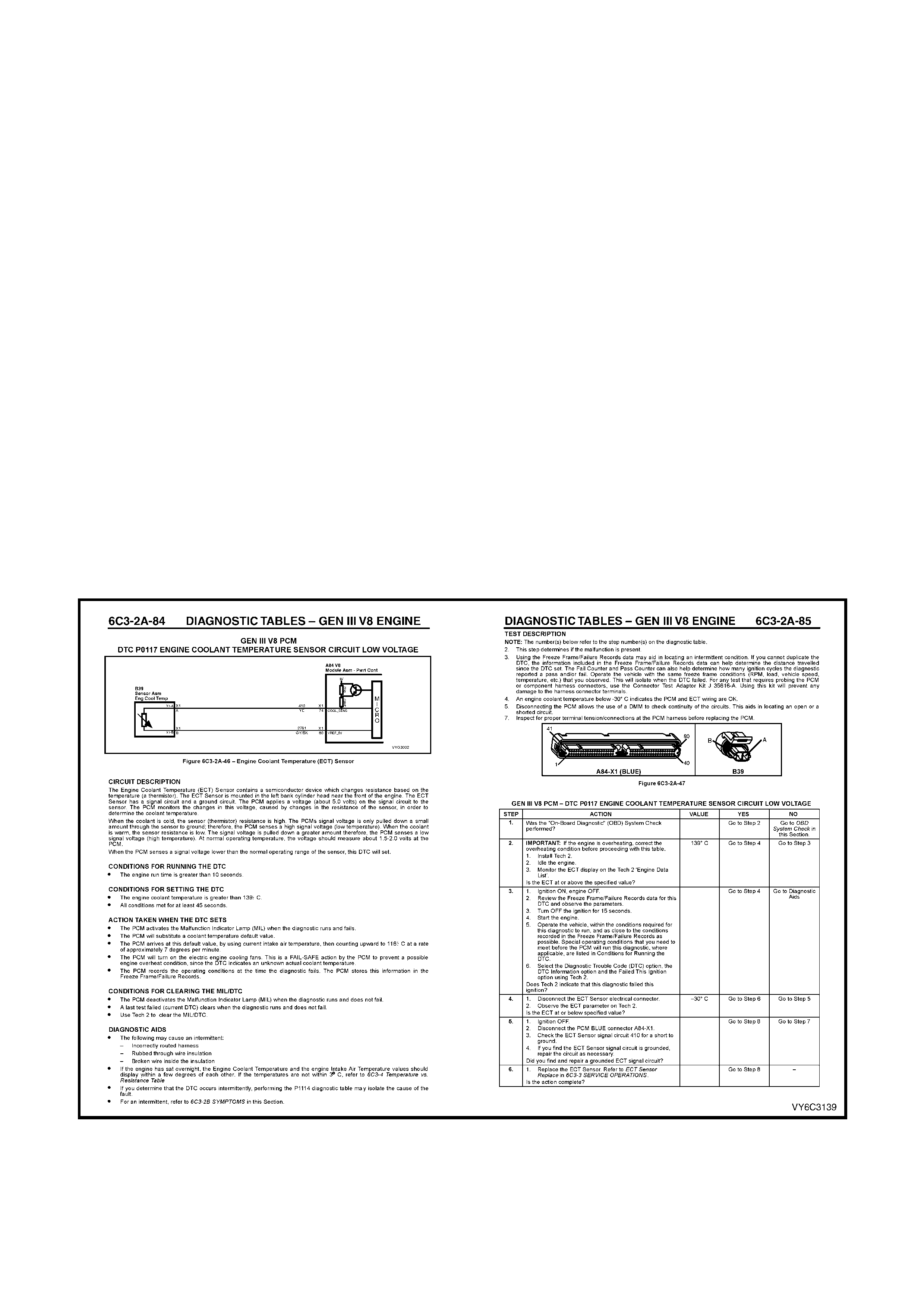
7. DIAGNOSTIC TABLES
7.1 INTRODUCTION
The diagnostic tables are designed to provide fast and efficient means of fault location for all engine and
transmission functions associated with the PCM. Usually, each diagnostic table uses 2 specific pages; a table on
the right side page, and a facing page on the left side page. The left side "facing page" contains pertinent
inform ation, inc luding Diagnostic Trouble Code setting param eters and circuit diagram s. T he diagnostic table s teps
are explained by the corresponding, numbered paragraph on the left side facing page.
When diagnosing any problem, always begin with THE O N- BOARD DIAG NO ST IC SYST EM CHECK. T his will lead
you to the other tables. DO NOT GO DIRECTLY TO A SPECIFIC TABLE or false diagnosis and replacement of
serviceable parts could result. After a fault is corrected and all DTCs have been cleared, repeat the ON-BOARD
DIAGNOSTIC SYSTEM CHECK to assure that the proper repairs have been made.
The "A" Table pages and the Diagnos tic Trouble Code diagnostic s pages are constr ucted in a similar fashion. The
box at the top of the left page contains a wiring diagram showing the components involved in each circuit.
Immediately below the box is a brief circuit description. On the facing right-hand page a troubleshooting table for
diagnosing c onditions. Step numbers on the right- hand page nex t to the action box es in the table relate to the items
in the Test Description on the left-hand page. These items provide an explanation of each test in the table.
The appropriate step in any of the trouble shooting tables will instruct you either to make a specific repair or to
continue diagnosis. If further diagnosis is needed, the step will specify where to continue.
The Yes or No column in any diagnostic table will instruct you either to make a specific repair or to continue
diagnosis. If further diagnosis is needed, the Yes or No column will specify where to continue.
If the condition is intermittent, the trouble shooting table will direct you to the diagnostic aids on the facing page.
This section gives suggestions for diagnosing intermittent conditions and explains how some faults can occur.
Remember, tables are for solving active conditions or Diagnostic Trouble Codes, NOT intermittent conditions.
Refer to Section 6C3-2B SYMPTOMS for solving intermittent conditions.
Figure 6C3-2-9 – Typical Diagnostic Flow Table
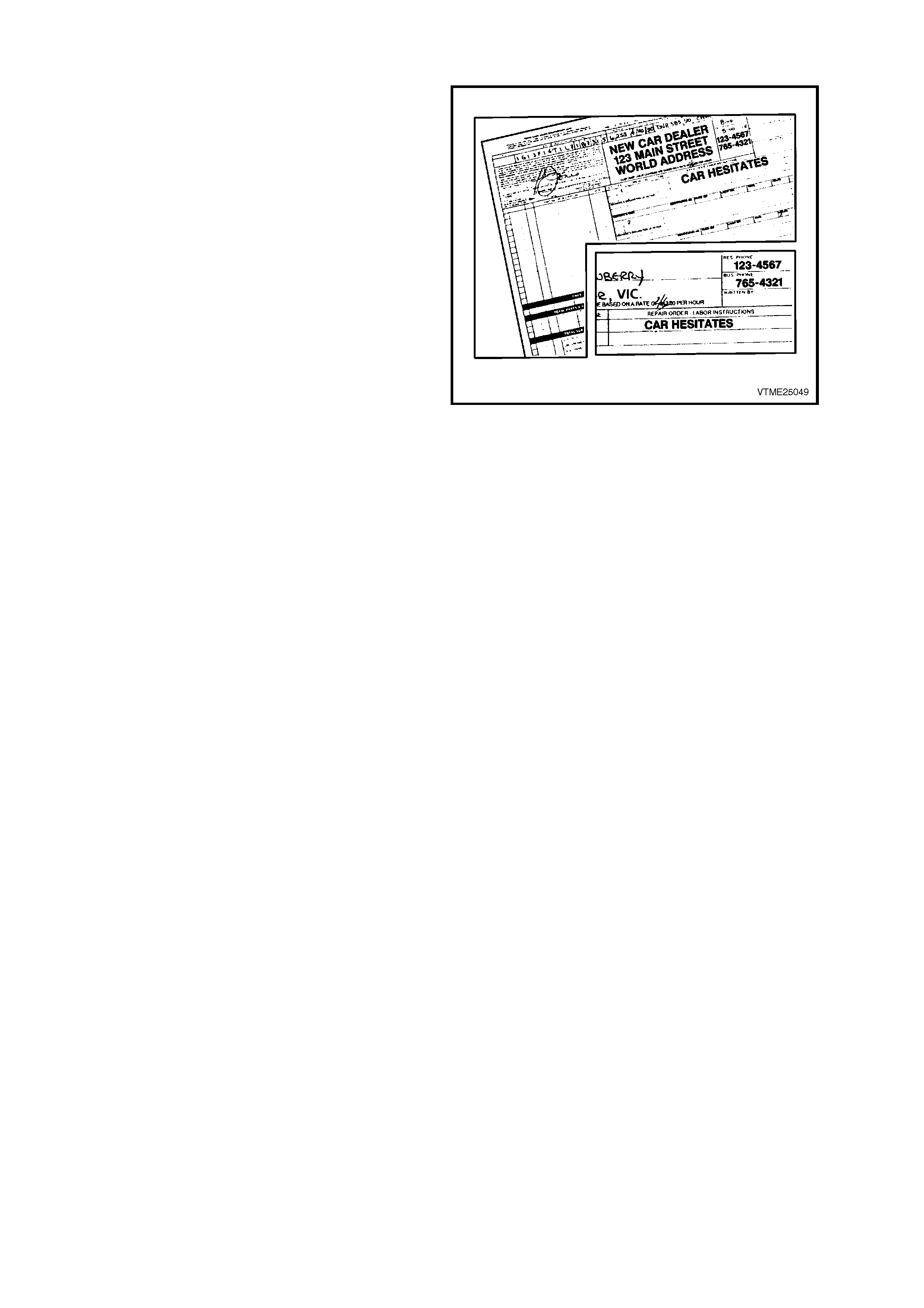
7.2 WRITING THE REPAIR ORDER
The Repair Order is one of the most important tools
any Technician can have. Like his/her other tools,
the Repair Order (R/O) must be highly accurate to
give them the greatest help.
It's up to the Service Adviser to supply the
Technician with this highly accurate tool. Problems
begin for the Technician when the repair order is
incomplete or is incorrect.
An incomplete repair order doesn't provide the
Technician with a good starting point for the
diagnosis. Consequently, time is wasted, using a
“shotgun” approach attempting to find the problem.
An incorrectly written repair order can also
inadvertently, lead the Technician down the wrong
diagnostic path, preventing the problem f rom being
solved.
Consequently, the Service Adviser MUST write an
accurate and complete R/O. This is accomplished
by asking the driver ques tions grouped into various
categories such as;
WHO? WHAT? WHEN? WHERE? and HOW?
Figure 6C3-2-10 – An Incomplete Repair Order
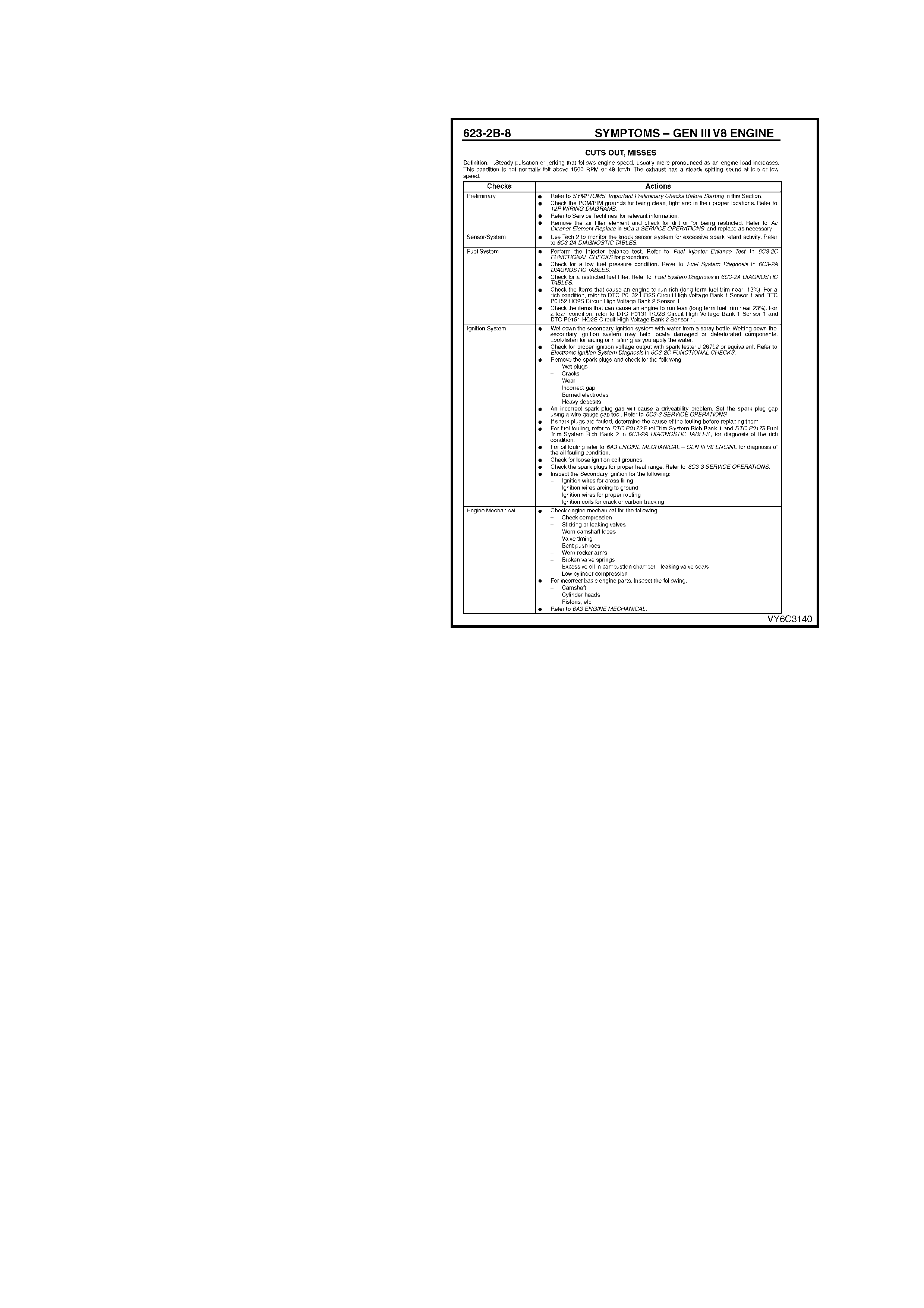
7.3 QUESTIONS
"WHO"? QUESTIONS
"WHO"? is the first question that must be asked. As
you begin to fill out the repair order, you need to
find out who was driving the vehicle when the
problem occurred and talk directly to that person if
at all possible.
This allows you to give first-hand inf or mation on the
problem to the Technician, which is critical to
diagnosing the problem. If you can't talk directly to
this person, get their name and phone number so
the Technician can call the driver if needed.
"WHAT"? QUESTIONS
The next step is to find out "WHAT?" the problem
is. If it's a driveability problem, and it seems to be
complex, bring the Technician who's going to work
on the vehicle into the picture if at all possible.
Allow the Technician to question the driver directly,
so he can get the inf orm ation he needs to help him
diagnose the problem. Again, this is so he can get
first-hand knowledge of the problem.
If you don't involve the Technician with the driver,
you need to ask if the Malfunction Indicator Lamp
(MIL) is ON all the time, coming ON and OFF
during the same key cycle, or is never ON, etc.
Figure 6C3-2-11 – Typical Symptomatic Diagnostic Table
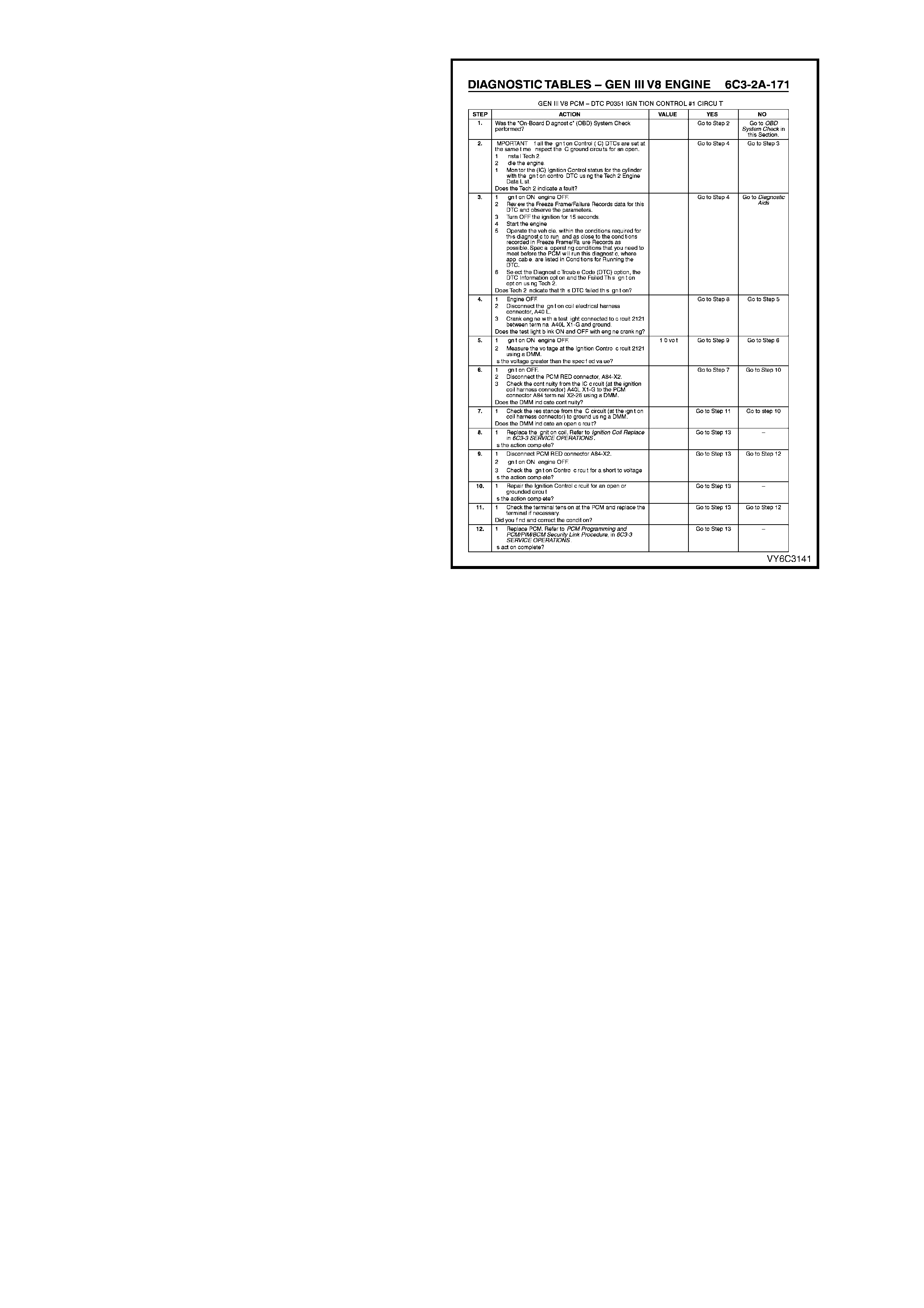
This is important to the Technician because this
informs him which diagnostic direction to take.
These tables are different from one another. If a
Technician is following the wrong table, a lot of time
is wasted. So, ask the driver questions about the
Malfunction Indicator Lamp (MIL).
Other good "WHAT"? questions are; “Under what
conditions did the problem occur?”
Were they accelerating, decelerating, or coasting?
Were they driving in the city or on the freeway?
What were the environmental conditions? Was it
raining? snowing? hot? cold? The Technician may
need to duplicate these conditions as closely as
possible if he is to find the cause of the problem.
"WHEN"? QUESTIONS
“W HEN"? questions are the next step. If the driver
says the Malfunction Indicator Lamp ( MIL) was ON,
you need to ask when the Malfunction Indicator
Lamp (MIL) came ON and how long it has been
ON. Is the Malfunction Indicator Lamp (MIL) ON
before or during starting, or when the engine is
running?
More im portant, you need to ask when the problem
first oc curred. Maybe it began af ter the vehicle was
serviced f or a related pr oblem or for som ething that
appears to be totally unrelated.
The Technician also needs to know if the problem
has become worse. This information may give the
Tec hnician s ome clues as to what the problem m ay
be.
"WHERE"? QUESTIONS
"WHERE"? is the next question. The location
where the problem occurs m ay give the T echnician
an idea as to what may be contributing to the
problem, such as electromagnetic interference
from overhead power lines.
"HOW"? QUESTIONS
To round out your questioning, you need to ask the
driver "HOW "? often the problem occurs. This can
give the Technician direction as to what type of
system may be causing the problem: electrical,
mechanical, vacuum, etc.
Figure 6C3-2-12 – Typical Diagnostic Table
SUMMARY
In summary, you need to obtain the following
information from the driver:
• Who the principal driver is.
• What the problem is.
• When the problem began.
• Where the problem occurs.
• How often the problem occurs.
Complete answers to these questions will aid the
Technician in diagnosing the problem.

7.4 VERIFYING THE COMPLAINT
ENGINE COMPARTMENT INSPECTION
The most important step in diagnosing a driveability complaint is to verify the complaint. This means you have to
duplicate the problem if possible.
Start by performing an engine compartment inspection. Check the integrity of all the electrical connections and
vacuum hoses, etc. Also, check the wire routing for the possibility of Electromagnetic Interference (EMI).
CHECKING FOR STORED DIAGNOSTIC TROUBLE CODES
As you check f or Diagnostic Trouble Codes, keep in m ind that inter mittent faults may not store a Diagnostic T rouble
Code. So proceed with verifying the complaint, even if no diagnostic trouble codes are stored.
If a diagnostic trouble code is stored, check the service bulletins for the particular vehicle you're working on.
ROAD TESTING THE VEHICLE
This step is optional if the repair order states.
• The driveability problem is intermittent.
• You did not find any problems under the bonnet .
• No Diagnostic Trouble Codes are stored.
Then you need to road test the vehicle in order to re-create the problem.
This is an important step because the problem has to be present in order to repair the problem.
Most intermittent driveability problems are repeatable. That is what road testing is all about.
Before you go on your road test, review the vehicle's s ervice his tory. This inf orm ation can give you clues as to what
may be causing the driveability problem and what you need to watch.
Read the repair order and think about what systems could possibly cause the problem. This is essential to finding
the problem. Think about how the system or systems in question works, what inputs are needed and what could
cause the problem.
Check all the inputs required f or a circuit, whether the circuit actually has trouble or if you only suspect trouble. All
inputs are needed and m ust be within a "normal" r ange. You will want to pay attention to these system s and circuits
during and after the road test.
As you're road testing, put Tech 2 in the snapshot mode so you can capture the system data when the problem
occurs.
Do not discount the other information the Tech 2 snapshot mode can supply you with.
DON'T FORGET THE BASICS
Whether or not you find anything wrong during the road test, don't forget the basics.
Electrical connections such as power feeds and earths are vital to the operation of almost all of the vehicle systems.
No matter how good the system is, it is still working in combination with the engine. If the engine is not in good
condition, the computer system can't make up for the condition.
Compare performance problems, such as lack of power, with a comparable vehicle. This will let you know if the
driver complaint really is a problem or something that is normal.
If you can't repeat the problem, and you need more information for diagnosing, call the driver who was driving the
vehicle when the problem occurred. This type of professionalism will probably help you diagnose the problem.
EEPROM
If a vehicle is just starting to have an intermittent driveability problem and it has accumulated more than 30,000
kilometres, chances are that the EEPROM calibration is not at fault.
If the vehicle was r unning proper ly for suc h a long time, the original EEPROM c alibr ations are not the problem since
the EEPROM calibrations don't change, the chances of the EEPROM going bad are rare. T here may, however, be
an updated EEPROM calibration for a particular condition, so check service bulletins for calibrations updates.