
SECTION 6C3-2A - DIAGNOSTIC TABLES –
GEN III V8 ENGINE
IMPORTANT
Before performing any Service Operation or other procedure described in this Section, refer to Section 00
CAUTIONS AND NOTES for correct workshop practices with regard to safety and/or property damage.
CONTENTS
1. GENERAL INFORMATION
1.1 SYSTEM COMPONENT LOCATIONS
1.2 PCM WIRING DIAGRAMS
1.3 PCM CONNECTOR END VIEWS
PCM CONNECTOR A84-X1 (BLUE)
PCM CONNECTOR A84-X2 (RED)
1.4 PCM CONNECTOR TERMINAL DEFINITIONS
PCM CONNECTOR A84-X1 (BLUE)
PCM CONNECTOR A84-X2 (RED)
1.5 PIM CONNECTOR END VIEW
1.6 PIM CONNECTOR TERMINAL DEFINITIONS
1.7 ENGINE CONTROL CONNECTOR END VIEWS
1.8 AUTOMATIC TRANSMISSION IN-LINE
HARNESS END VIEWS
1.9 AUTOMATIC TRANSMISSION INTERNAL
CONNECTOR END VIEWS
1.10 ENGINE DIAGNOSTIC TROUBLE CODES
(DTC) – GEN III V8 – PCM
1.11 DIAGNOSTIC TROUBLE CODES (DTC) –
PIM GEN III V8 – PIM
1.12 DIAGNOSTIC TROUBLE CODES (DTC) –
GEN III V8 AUTOMATIC TRANSMISSION
2. GENERAL DIAGNOSTIC TABLES
2.1 TABLE A-1 – ON-BOARD DIAGNOSTIC (OBD)
SYSTEM CHECK
2.2 TABLE A-2 – CHECK POWERTRAIN
MALFUNCTION INDICATOR LAMP
2.3 DATA LINK CONNECTOR DIAGNOSIS
2.4 ENGINE CRANKS BUT DOES NOT RUN
2.5 ENGINE CONTROL RELAY DIAGNOSIS
2.6 FUEL PUMP RELAY CIRCUIT DIAGNOSIS
2.7 FUEL PUMP ELECTRICAL CIRCUIT
(UTILITY ONLY)
2.8 FUEL SYSTEM DIAGNOSIS
2.9 STARTER CRANKING CIRCUIT
3. DIAGNOSTIC TROUBLE CODE TABLES
DTC P0101 - MASS AIR FLOW SYSTEM
PERFORMANCE
DTC P0102 - MASS AIR FLOW SENSOR
CIRCUIT LOW FREQUENCY
DTC P0103 - MASS AIR FLOW SENSOR
CIRCUIT HIGH FREQUENCY
DTC P0107 - MANIFOLD ABSOLUTE
PRESSURE SENSOR CIRCUIT LOW
VOLTAGE
DTC P0108 - MANIFOLD ABSOLUTE
PRESSURE SENSOR CIRCUIT HIGH
VOLTAGE
DTC P0112 - INTAKE AIR TEMPERATURE
SENSOR CIRCUIT LOW VOLTAGE
DTC P0113 - INTAKE AIR TEMPERATURE
SENSOR CIRCUIT HIGH VOLTAGE
DTC P0117 - ENGINE COOLANT
TEMPERATURE SENSOR CIRCUIT
LOW VOLTAGE
DTC P0118 - ENGINE COOLANT
TEMPERATURE SENSOR CIRCUIT
HIGH VOLTAGE
DTC P0121 - THROTTLE POSITION
SENSOR CIRCUIT INSUFFICIENT
ACTIVITY
DTC P0122 - THROTTLE POSITION
SENSOR CIRCUIT LOW VOLTAGE
DTC P0123 - THROTTLE POSITION
SENSOR CIRCUIT HIGH VOLTAGE
DTC P0125 - ENGINE COOLANT
TEMPERATURE SENSOR EXCESSIVE
TIME TO CLOSED LOOP FUEL CONTROL
DTC P0131 - HEATED OXYGEN SENSOR
CIRCUIT LOW VOLTAGE BANK 1
SENSOR 1
DTC P0132 - HEATED OXYGEN SENSOR
CIRCUIT HIGH VOLTAGE BANK 1
SENSOR 1
DTC P0133 - HEATED OXYGEN SENSOR
SLOW RESPONSE BANK 1 SENSOR 1
DTC P0134 - HEATED OXYGEN SENSOR
INSUFFICIENT ACTIVITY BANK 1 SENSOR 1
DTC P0135 - HEATED OXYGEN SENSOR
HEATER CIRCUIT BANK 1 SENSOR 1
DTC P0151 - HEATED OXYGEN SENSOR
CIRCUIT LOW VOLTAGE BANK 2
SENSOR 1
DTC P0152 - HEATED OXYGEN SENSOR
CIRCUIT HIGH VOLTAGE BANK 2
SENSOR 1
DTC P0153 - HEATED OXYGEN SENSOR
SLOW RESPONSE BANK 2 SENSOR 1
DTC P0154 - HEATED OXYGEN SENSOR
INSUFFICIENT ACTIVITY BANK 2 SENSOR 1
DTC P0155 - HEATED OXYGEN SENSOR
HEATER CIRCUIT BANK 2 SENSOR 1
DTC P0171 - FUEL SYSTEM LEAN BANK 1
DTC P0172 - FUEL SYSTEM RICH BANK 1
DTC P0174 - FUEL SYSTEM LEAN BANK 2
DTC P0175 - FUEL SYSTEM RICH BANK 2
DTC P0218 - TRANSMISSION FLUID OVER-
TEMPERATURE
DTC P0230 – FUEL PUMP CONTROL CIRCUIT
DTC P0325 – KNOCK SENSOR SYSTEM
DTC P0327 – KNOCK SENSOR CIRCUIT
FRONT SENSOR
DTC P0332 – KNOCK SENSOR CIRCUIT
REAR SENSOR
DTC P0335 – CRANKSHAFT POSITION
SENSOR CIRCUIT
DTC P0336 – CRANKSHAFT POSITION
SENSOR CIRCUIT PERFORMANCE
DTC P0341 – CAMSHAFT POSITION
SENSOR CIRCUIT PERFORMANCE
DTC P0342 – CAMSHAFT POSITION
SENSOR CIRCUIT LOW VOLTAGE
DTC P0343 – CAMSHAFT POSITION
SENSOR CIRCUIT HIGH VOLTAGE
DTC P0351 – IGNITION CONTROL #1 CIRCUIT
DTC P0352 – IGNITION CONTROL #2 CIRCUIT

DTC P0353 – IGNITION CONTROL #3 CIRCUIT
DTC P0354 – IGNITION CONTROL #4 CIRCUIT
DTC P0355 – IGNITION CONTROL #5 CIRCUIT
DTC P0356 – IGNITION CONTROL #6 CIRCUIT
DTC P0357 – IGNITION CONTROL #7 CIRCUIT
DTC P0358 – IGNITION CONTROL #8 CIRCUIT
DTC P0443 – EVAP PURGE SOLENOID
CONTROL CIRCUIT
DTC P0481 – COOLING FAN HIGH SPEED
RELAY CONTROL
DTC P0502 – VEHICLE SPEED SENSOR
CIRCUIT LOW INPUT
DTC P0503 – VEHICLE SPEED SENSOR
CIRCUIT INTERMITTENT
DTC P0506 – IDLE SPEED LOW
DTC P0507 – IDLE SPEED HIGH
DTC P0522 – ENGINE OIL PRESSURE
SENSOR LOW VOLTAGE
DTC P0523 – ENGINE OIL PRESSURE
SENSOR HIGH VOLTAGE
DTC P0530 – A/C REFRIGERANT
PRESSURE SENSOR CIRCUIT
DTC P0562 – SYSTEM VOLTAGE LOW
DTC P0563 – SYSTEM VOLTAGE HIGH
DTC P0601 – POWERTRAIN CONTROL
MODULE MEMORY
DTC P0602 – POWERTRAIN CONTROL
MODULE NOT PROGRAMMED
DTC P0608 – VEHICLE SPEED OUTPUT
CIRCUIT
DTC P0654 – ENGINE SPEED OUTPUT
CIRCUIT
DTC P0705 – TRANSMISSION RANGE
SWITCH CIRCUIT
DTC P0706 – TRANSMISSION RANGE
SWITCH PERFORMANCE
DTC P0711 – TFT SENSOR CIRCUIT
RANGE/ PERFORMANCE
DTC P0712 – TFT SENSOR CIRCUIT LOW
INPUT
DTC P0713 – TFT SENSOR CIRCUIT HIGH
INPUT
DTC P0719 – BRAKE SWITCH CIRCUIT
LOW INPUT
DTC P0724 – BRAKE SWITCH CIRCUIT
HIGH INPUT
DTC P0740 – TCC ENABLE SOLENOID
CIRCUIT ELECTRICAL
DTC P0742 – TCC SYSTEM STUCK ON
DTC P0748 – PC SOLENOID CIRCUIT
ELECTRICAL
DTC P0751 – 1-2 SHIFT SOLENOID VALVE
PERFORMANCE
DTC P0753 – 1-2 SHIFT SOLENOID CIRCUIT
ELECTRICAL
DTC P0756 – 2-3 SHIFT SOLENOID VALVE
PERFORMANCE
DTC P0758 – 2-3 SHIFT SOLENOID CIRCUIT
ELECTRICAL
DTC P0785 – 3-2 SHIFT SOLENOID CIRCUIT
ELECTRICAL
DTC P0801 – REVERSE INHIBIT SOLENOID
CIRCUIT FAULT
DTC P1111 – INTAKE AIR TEMPERATURE
SENSOR CIRCUIT INTERMITTENT HIGH
VOLTAGE
DTC P1112 – INTAKE AIR TEMPERATURE
SENSOR CIRCUIT INTERMITTENT LOW
VOLTAGE
DTC P1114 – ENGINE COOLANT
TEMPERATURE SENSOR CIRCUIT
INTERMITTENT LOW VOLTAGE
DTC P1115 – ENGINE COOLANT
TEMPERATURE SENSOR CIRCUIT
INTERMITTENT HIGH VOLTAGE
DTC P1121 – THROTTLE POSITION
SENSOR CIRCUIT INTERMITTENT HIGH
VOLTAGE
DTC P1122 – THROTTLE POSITION
SENSOR CIRCUIT INTERMITTENT LOW
VOLTAGE
DTC P1258 – ENGINE COOLANT OVER
TEMP FUEL DISABLED
DTC P1539 – A/C CLUTCH STATUS
CIRCUIT HIGH VOLTAGE
DTC P1546 – A/C CLUTCH STATUS
CIRCUIT LOW VOLTAGE
DTC P1626 – THEFT DETERRENT SYSTEM
FUEL ENABLE CIRCUIT
DTC P1630 – THEFT DETERRENT
POWERTRAIN CONTROL MODULE IN
LEARN MODE
DTC P1631 – THEFT DETERRENT
PASSWORD INCORRECT
DTC P1635 – 5 VOLT REFERENCE #1 CIRCUIT
DTC P1639 – 5 VOLT REFERENCE #2 CIRCUIT
DTC P1810 – TFP VALVE POSITION
SWITCH CIRCUIT
DTC P1860 – TCC PWM SOLENOID CIRCUIT
DTC P1870 – TRANSMISSION COMPONENT
SLIPPING
DTC B2002 – LOW SPEED FAN NO BCM
RESPONSE
DTC B2006 – NO SERIAL DATA FROM PCM
DTC B2007 – STARTER RELAY VOLTAGE HIGH
DTC B2009 – EEPROM CHECKSUM ERROR
1. GENERAL INFORMAT ION
1.1 SYSTEM COMPONENT LOCATIONS
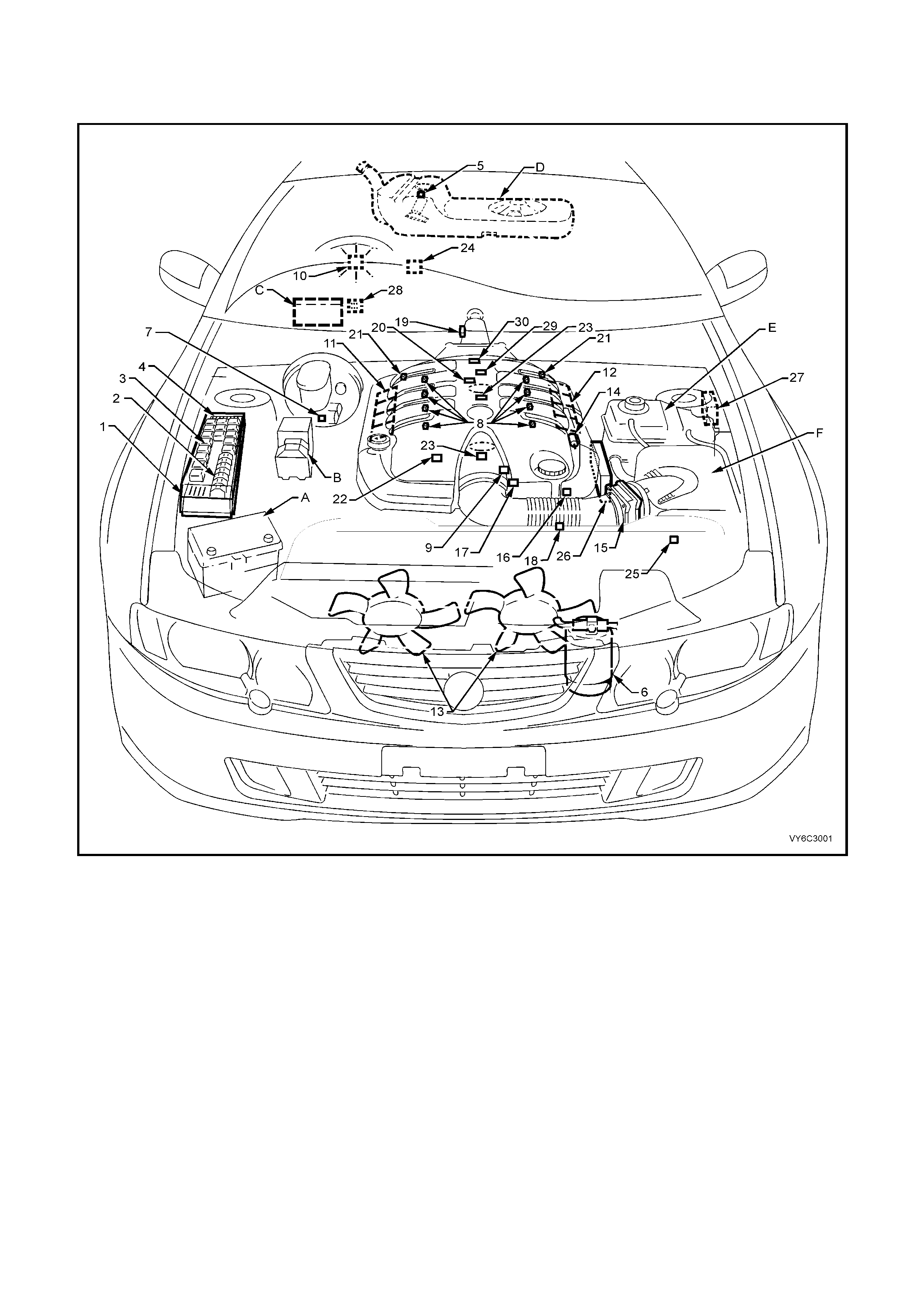
Figure 6C3-2A-1 – Component Locations – GEN III V8 Engine RHD (LHD Similar)
Legend
1. Underhood Electrical Centre
2. Fusible Links
3. Relays – Mini & Micro
4. Underhood Fuses
5. Fuel Pressure Regulator (in Fuel Tank)
6. A/C Accumulator Tank
7. Brake Hydraulic Failure Switch
8. Fuel Injectors (8)
9. Idle Air Control (IAC) Valve
10. Check Powertrain MIL
11. Ignition Coil/Module Right Bank
12. Ignition Coil/Module Left Bank
13. Engine Cooling Fans (2)
14. Canister Purge Solenoid
15. Mass Air Flow (MAF) Sensor
16. Engine Coolant Temperature (ECT) Sensor
17. Throttle Position (TP) Sensor
18. Intake Air Temperature (IAT) Sensor
19. Vehicle Speed Sensor (VSS)
20. Camshaft Position (CMP) Sensor
21. Heated Oxygen (HO2S) Sensor (2)
22. Crankshaft Position (CKP) Sensor
23. Knock Sensors (KS) (2)
24. OCC In - Car Air Temperature Sensor
25. A/C Refrigerant Pressure Sensor
26. Powertrain Control Module (PCM)
27. Powertrain Interface Module (PIM) - Inside vehicle
behind left kick panel
28. Diagnostic Link Connector (DLC)
29. Oil Pressure Sensor
30. Manifold Absolute Pressure (MAP) Sensor
A Battery
B ABS/TCS Module
C BCM
D Fuel Tank
E Surge Tank (With Low Coolant Level Switch)
F Air Cleaner
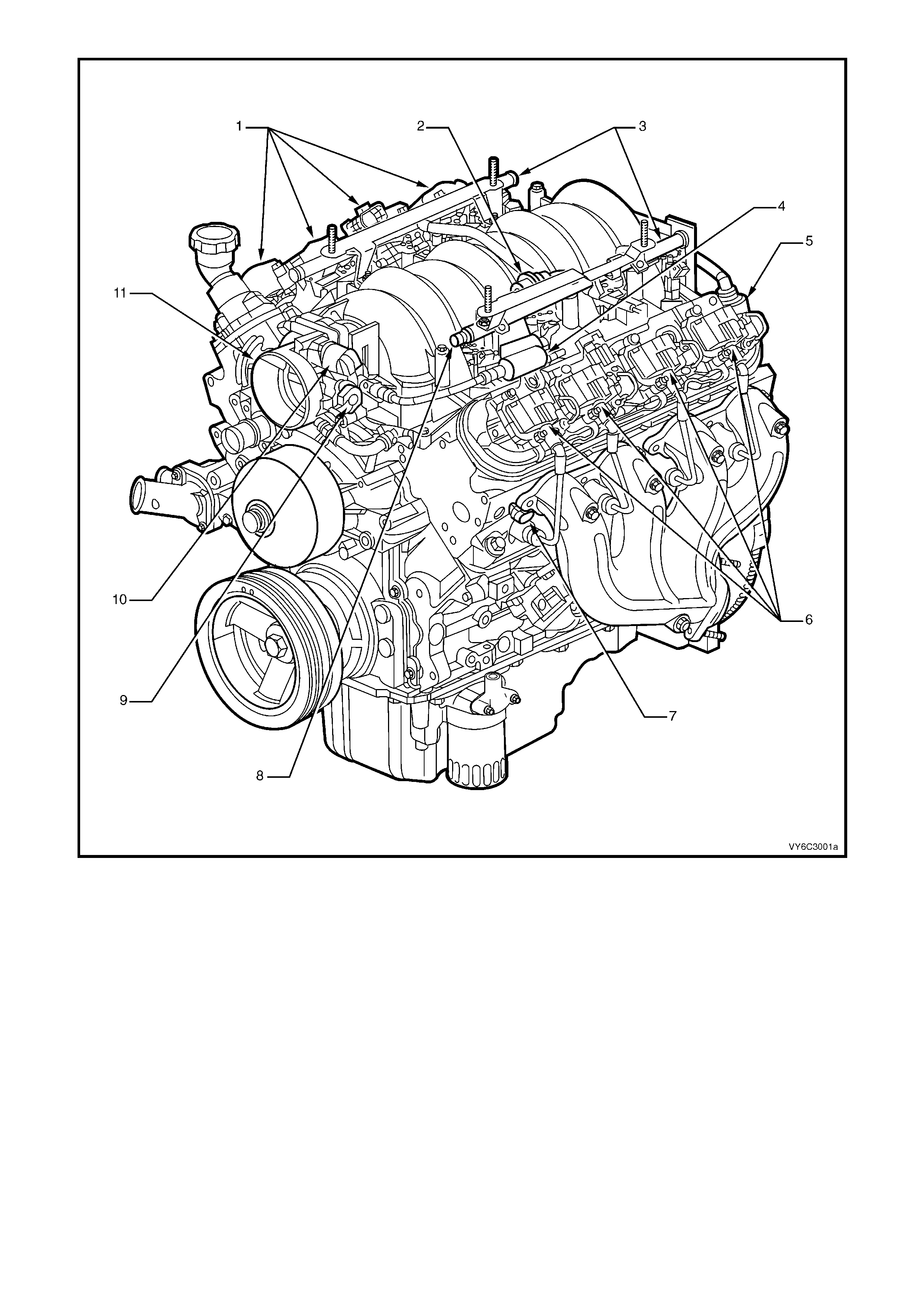
Figure 6C3-2A-2 GEN III V8 Engine View Left-Hand Side
Legend
1. Right-Hand Ignition Coils/Modules
2. Fuel Pulse Dampener
3. Fuel Rail with Injectors
4. Evaporative Canister Purge Solenoid
5. Crankcase Vent
6. Left-Hand Ignition Coils/Modules
7. Engine Coolant Temperature (ECT) Sensor
8. Fuel Pressure Gauge Test Connector
9. Throttle Position (TP) Sensor
10. Idle Air Control (IAC) Valve
11. Throttle Body

Legend
1. Idle Air Control (IAC) Valve
2. Throttle Position (TP) Sensor
3. Generator
4. Throttle Body
Figure 6C3-2A-3 GEN III V8 Engine Front View
Figure 6C3-2A-4 GEN III V8 Engine Rear View
Legend
1. Manifold Absolute Pressure (MAP) Sensor
2. Camshaft Position (CMP) Sensor 3. Oil Pressure Sensor
4. Connector to Knock Sensor Jumper Harness
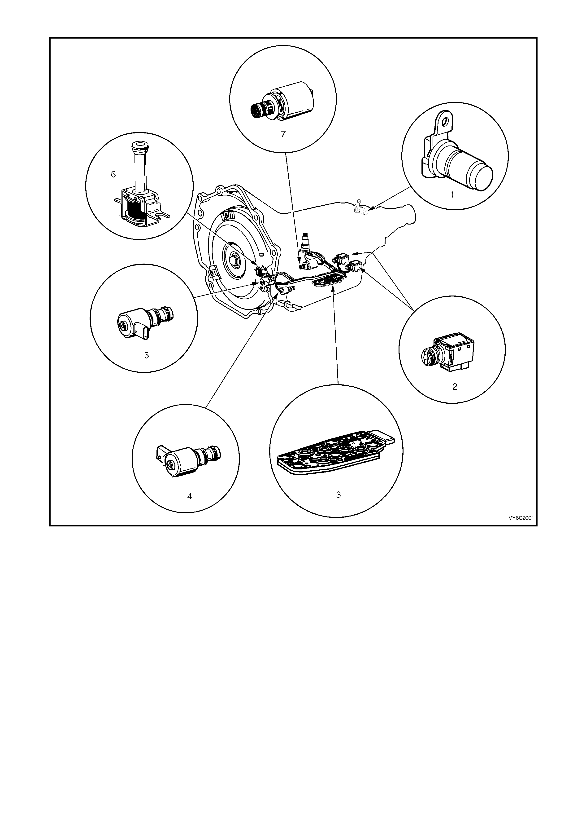
Figure 6C3-2A-5 Automatic Transmission Internal Electronic Component Locations
Legend
1. Vehicle Speed Sensor
2. 1-2 Shift Solenoid ‘A’ and 2-3 Shift Solenoid ‘B’
3. Automatic Transmission Fluid Pressure (TFP) Manual Valve Position Switch
4. 3-2 Downshift Control Solenoid
5. Torque Converter Clutch Pulse Width Modulation (TCC PWM) Solenoid Valve
6. Torque Converter Clutch (TCC) Solenoid Valve
7. Pressure Control Solenoid (PCS) Valve
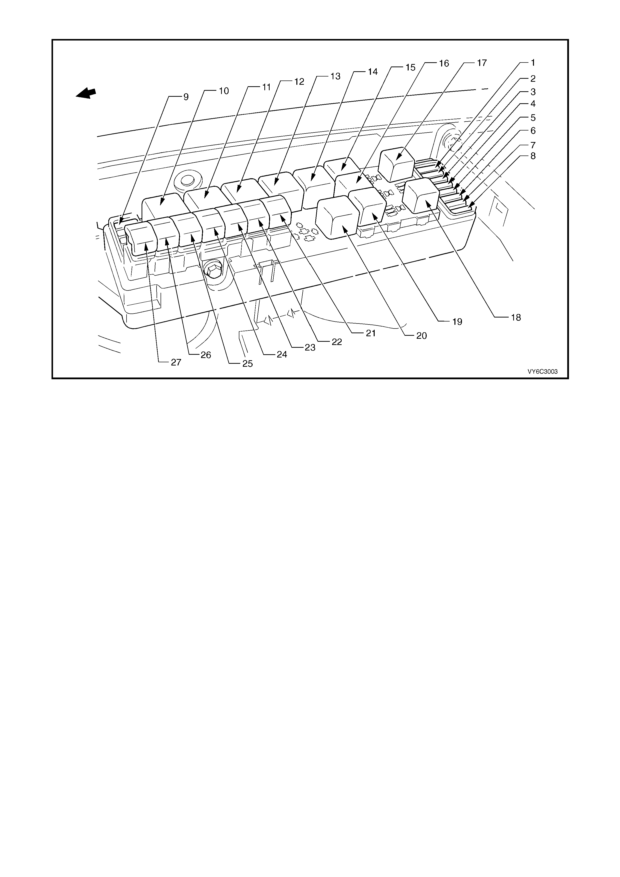
Figure 6C2-2A-6 – Engine Compartment Fuse/Relay/Fusible Link Locations
Legend
Fuses
1. Fuel Pump Fuse – F28
2. Engine Control / BCM – F29
3. RH Headlamps – F30
4. LH Headlamps – F31
5. Automatic Transmission – F32
6. Engine Sensors – F33
7. Injectors / Ignition – F34
8. Injectors / Ignition – F35
9. Throttle Relaxer Module – F36
Relays
10. Start – R1
11. Blower Fan – R2
12. Headlamp (High Beam) – R3
13. Engine Control (EFI) – R4
14. Engine Cooling Fan Relay 2 (High Speed) – R5
15. Horn – R8
16. A/C Compressor – R11
17. Fog Lamp – R10
18. Fuel Pump – R16
19. Headlamp (Low Beam) – R14
20. Engine Cooling Fan Relay 1 (Low Speed) – R7
Fusible Links
21. Engine Cooling Fan LT – F101 (30A)
22. Blower Fan – F106 (60A)
23. Main – F105 (60A)
24. Engine – F104 (60A)
25. A.B.S. – F103 (60A)
26. Lighting – F102 (60A)
27. Engine Cooling Fan RT – F107 (30A)
1.2 PCM WIRING DIAGRAMS
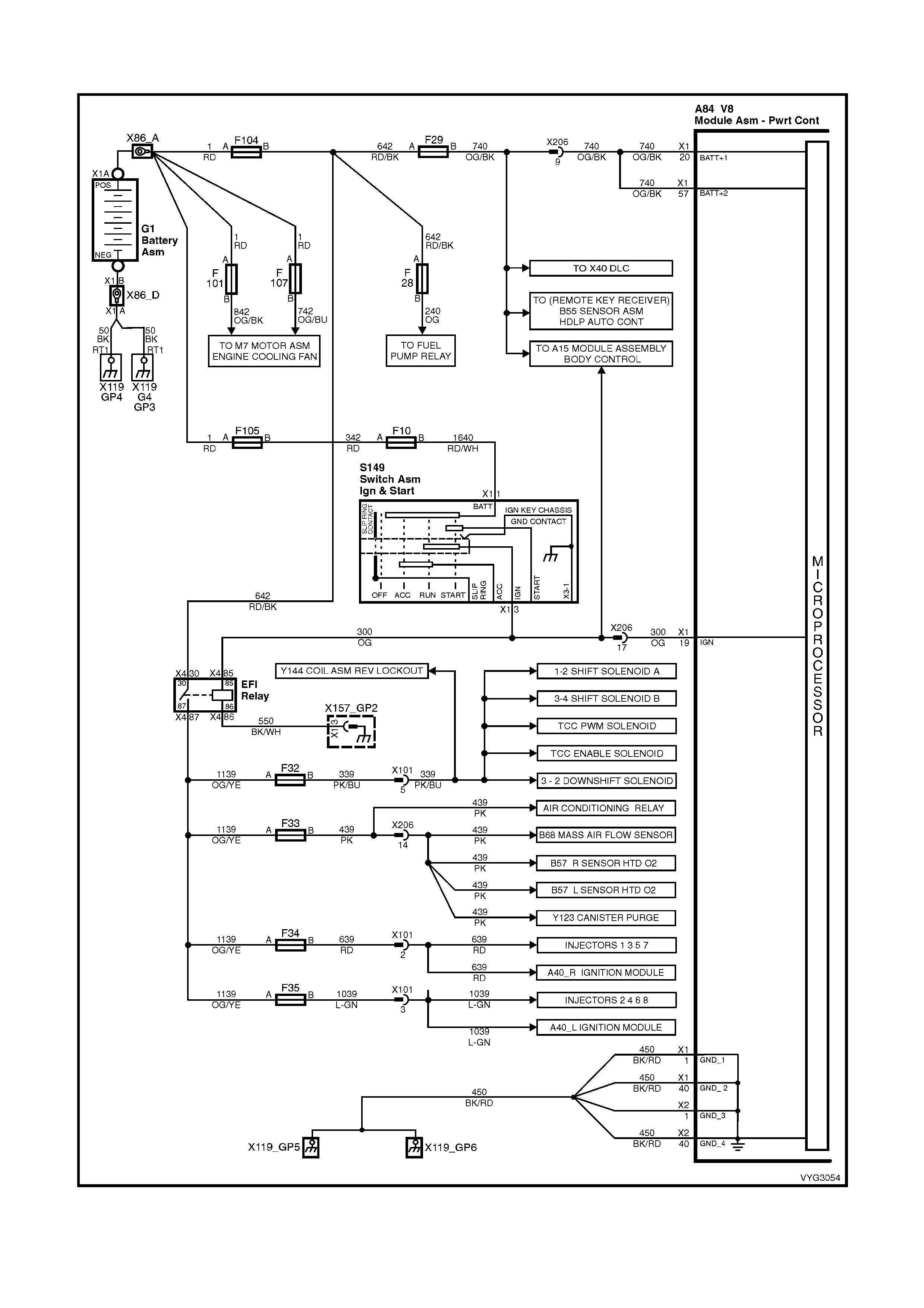
Figure 6C3-2A-7 – GEN III V8 Powertrain Controls Schematics (1 of 14) – Fused Power Circuits
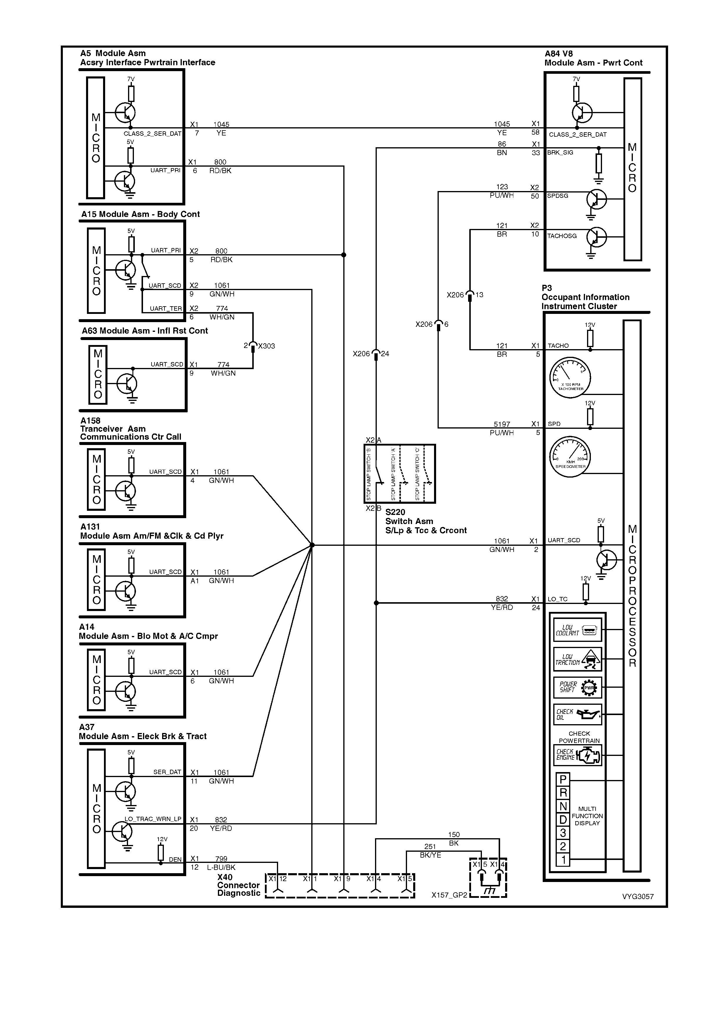
Figure 6C3-2A-8 – GEN III V8 Powertrain Control Schematics (2 of 14)
DLC and Instruments Lamps Circuits
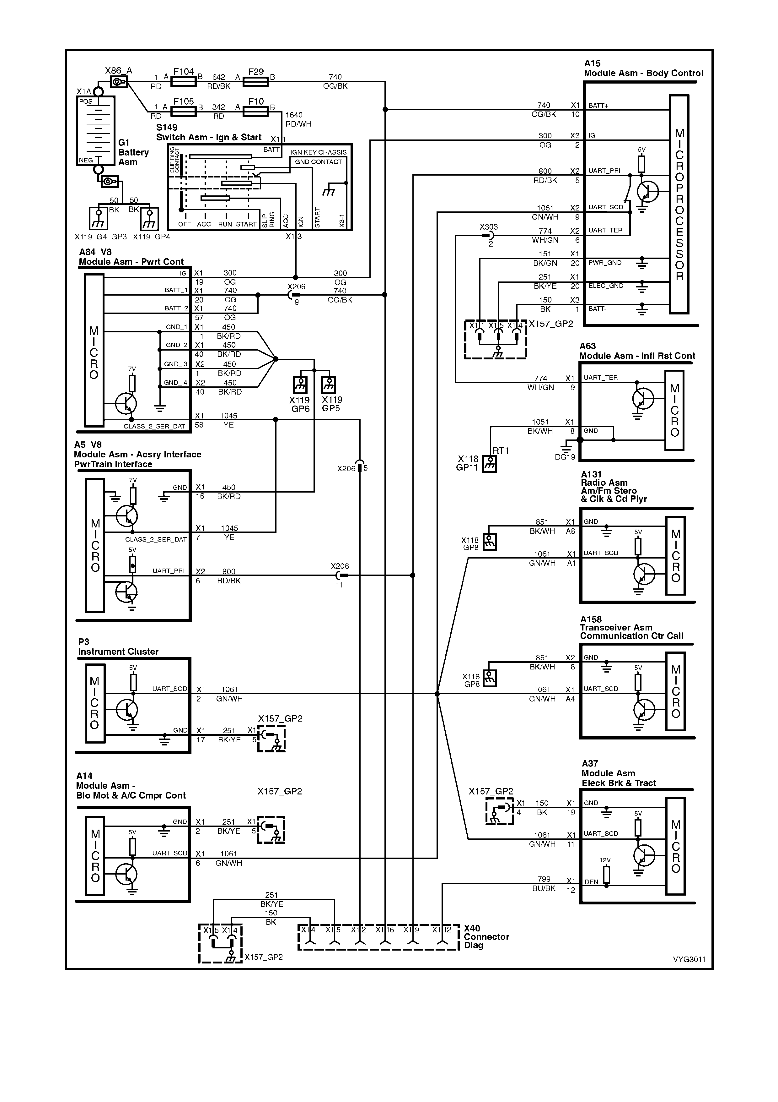
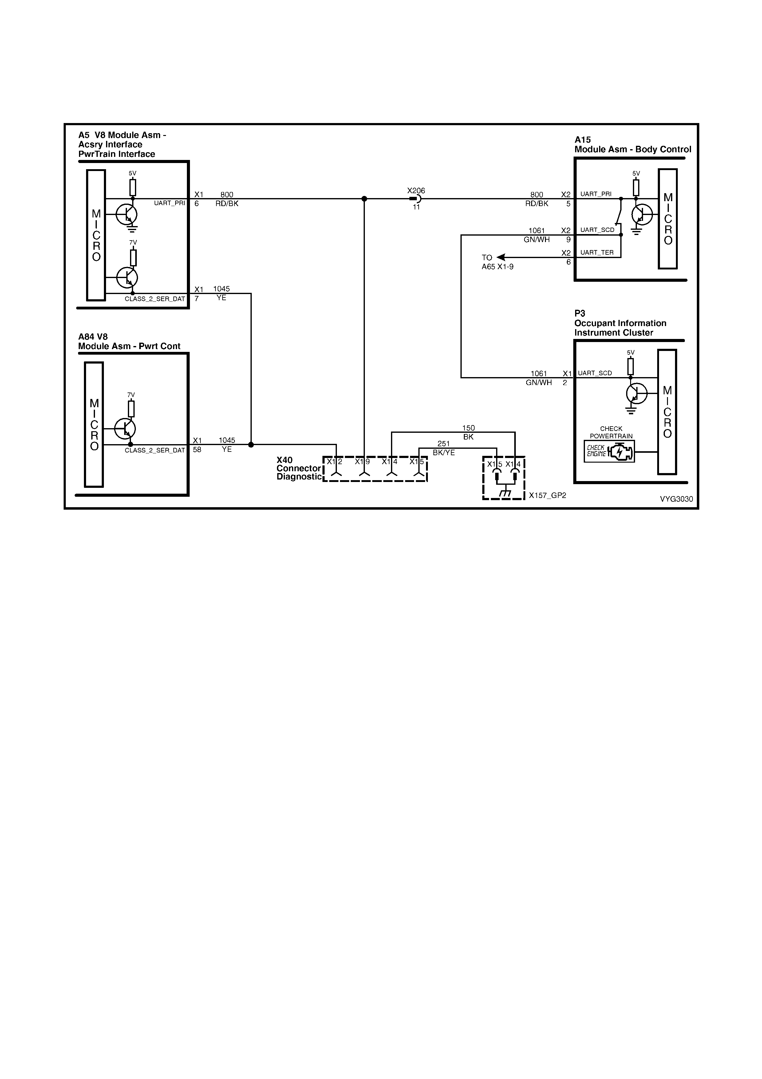
Figure 6C3-2A-9 – GEN III V8 Powertrain Control Schematics (3 of 14)
Serial Data Circuits
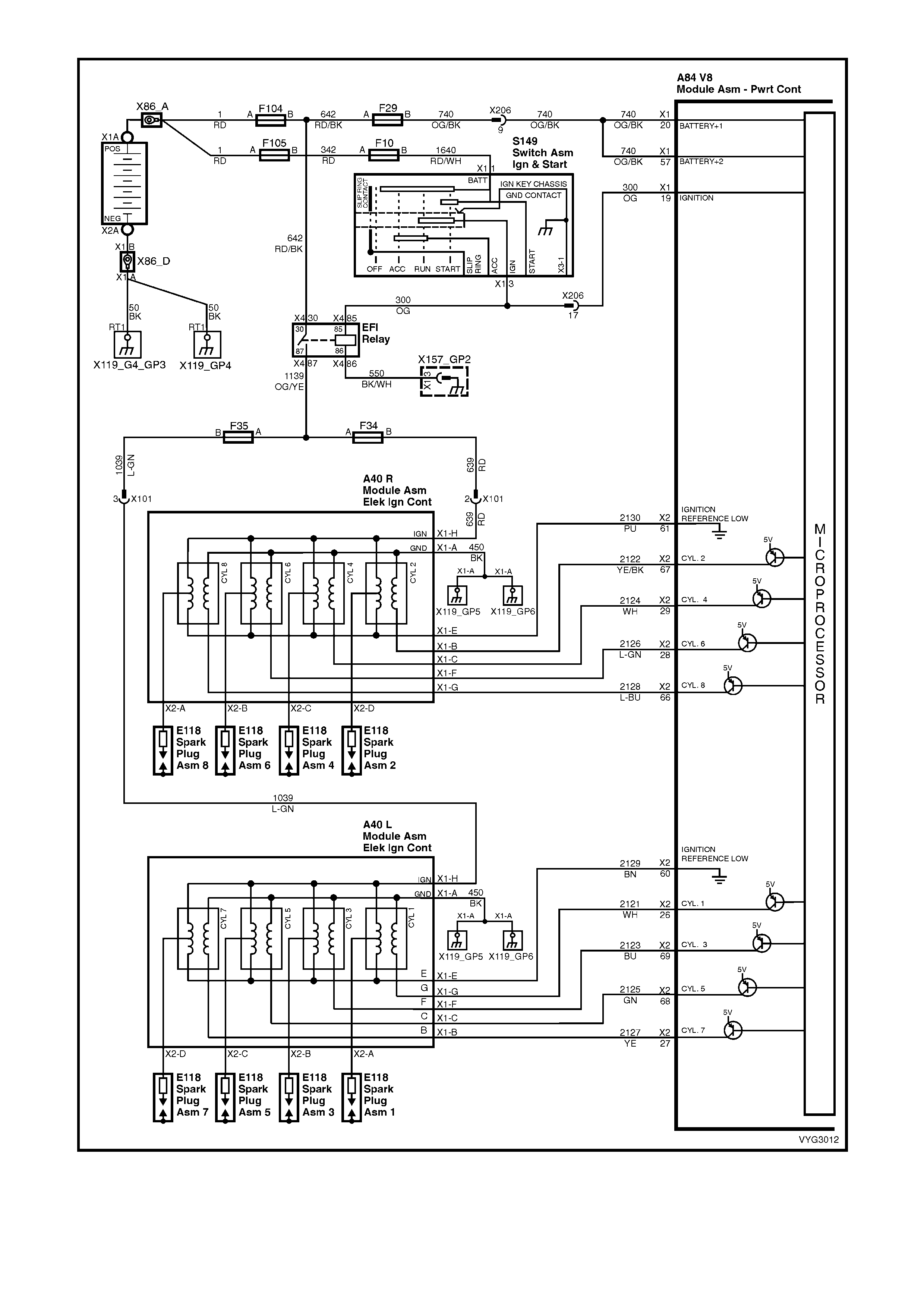
Figure 6C3-2A-10 – GEN III V8 Powertrain Control Schematics (4 of 14)
Ignition Module Circuits
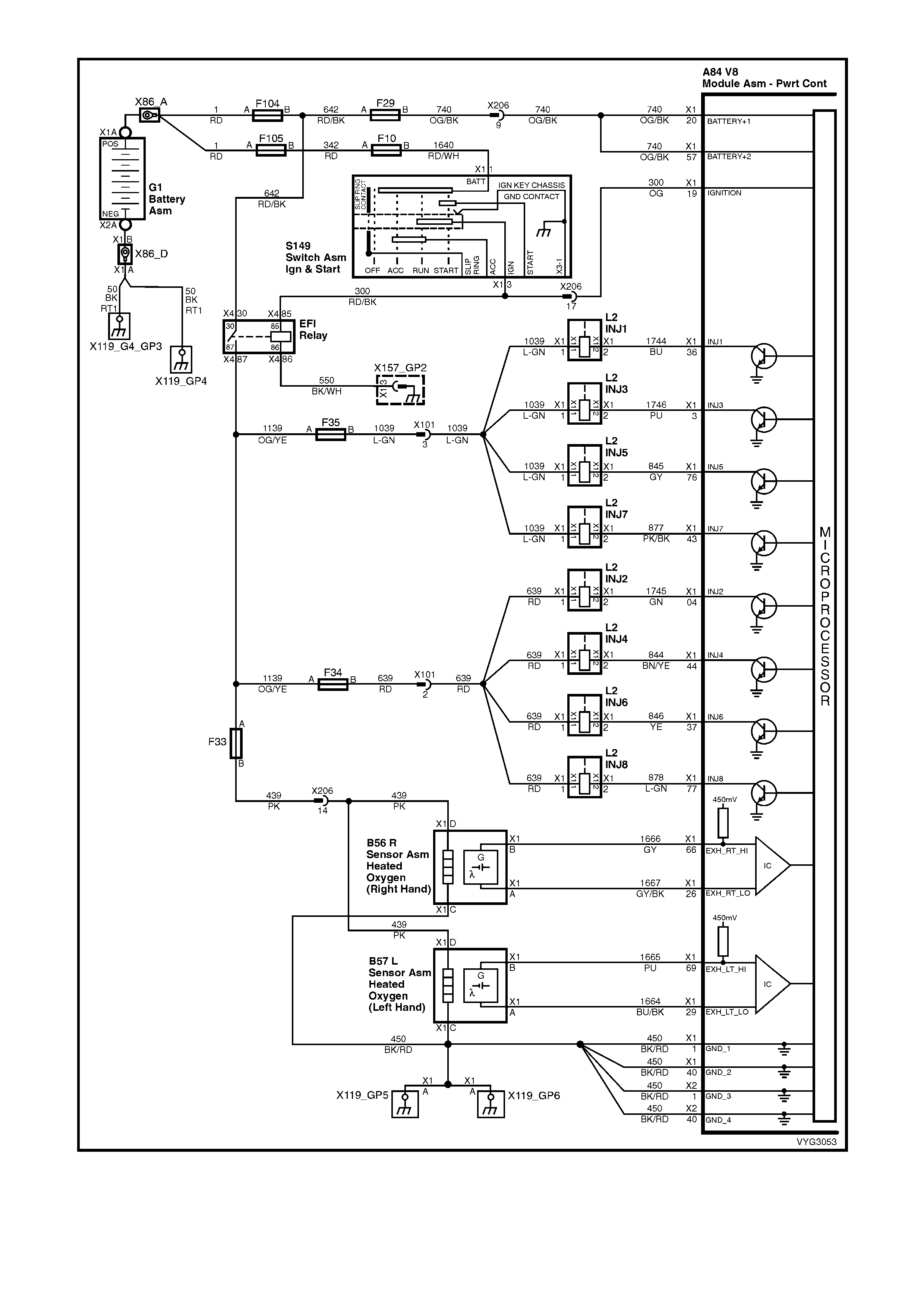
Figure 6C3-2A-11 – GEN III V8 Powertrain Control Schematics (5 of 14)
Injectors, Heated Oxygen Sensor Circuits

Figure 6C3-2A-12 – GEN III V8 Powertrain Control Schematics (6 of 14)
CKP, CMP, MAF, ECT, TP and MAP Circuits
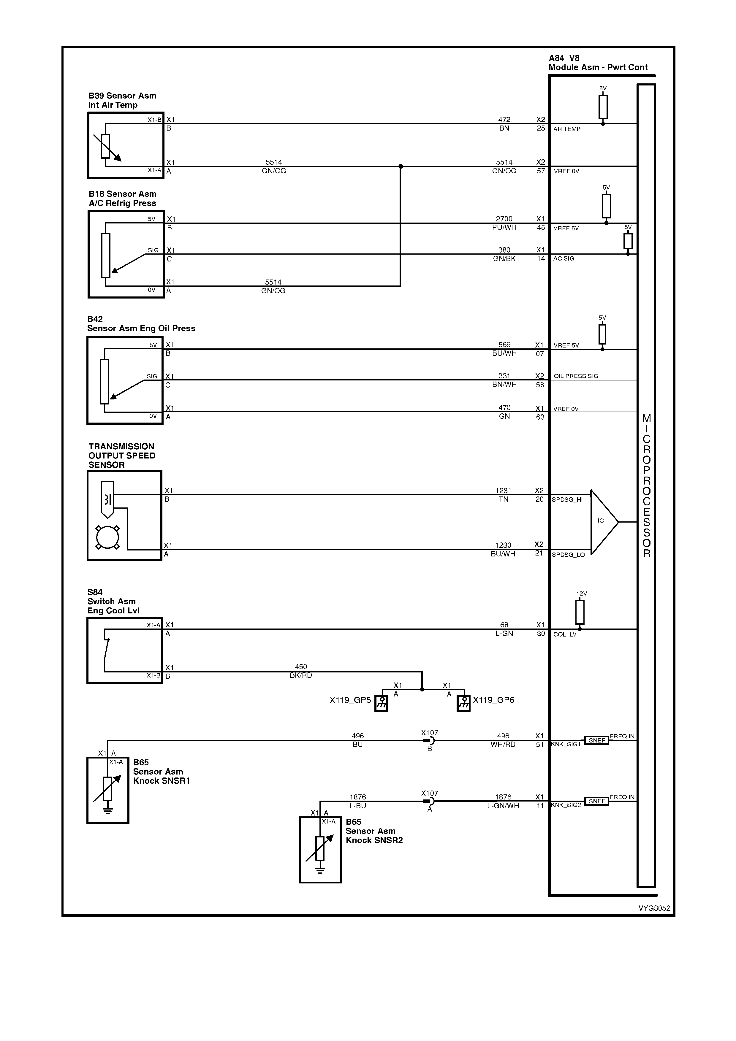
Figure 6C3-2A-13 – Powertrain Control Schematics (7 of 14)
IAT, A/C Pressure Sensor, Oil Pressure, VSS, Low Coolant and KS Circuits GEN III V8
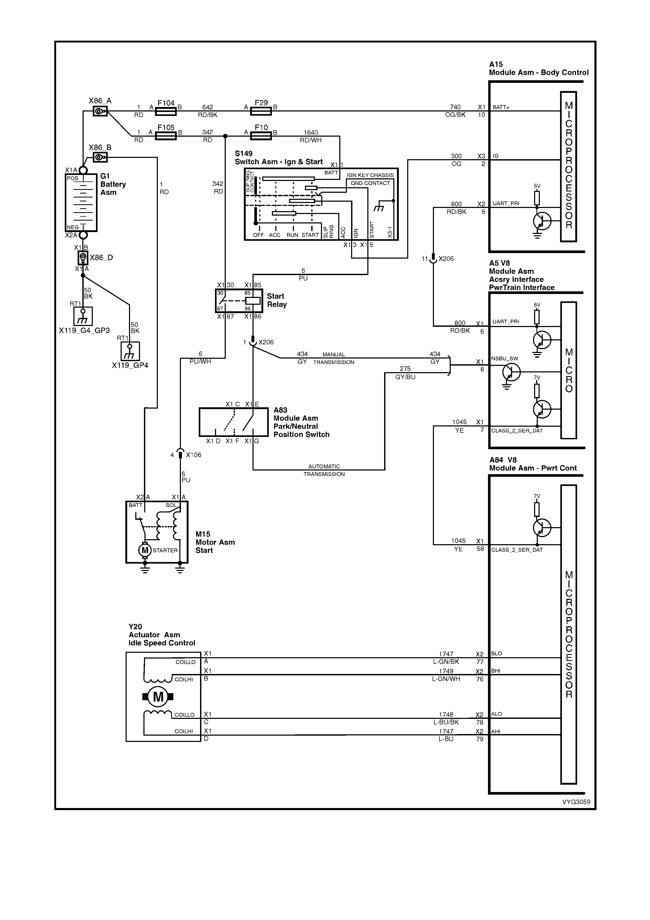
Figure 6C3-2A-14 – GEN III V8 Powertrain Control Schematics (8 of 14)
Start Relay, IAC Valve Circuits
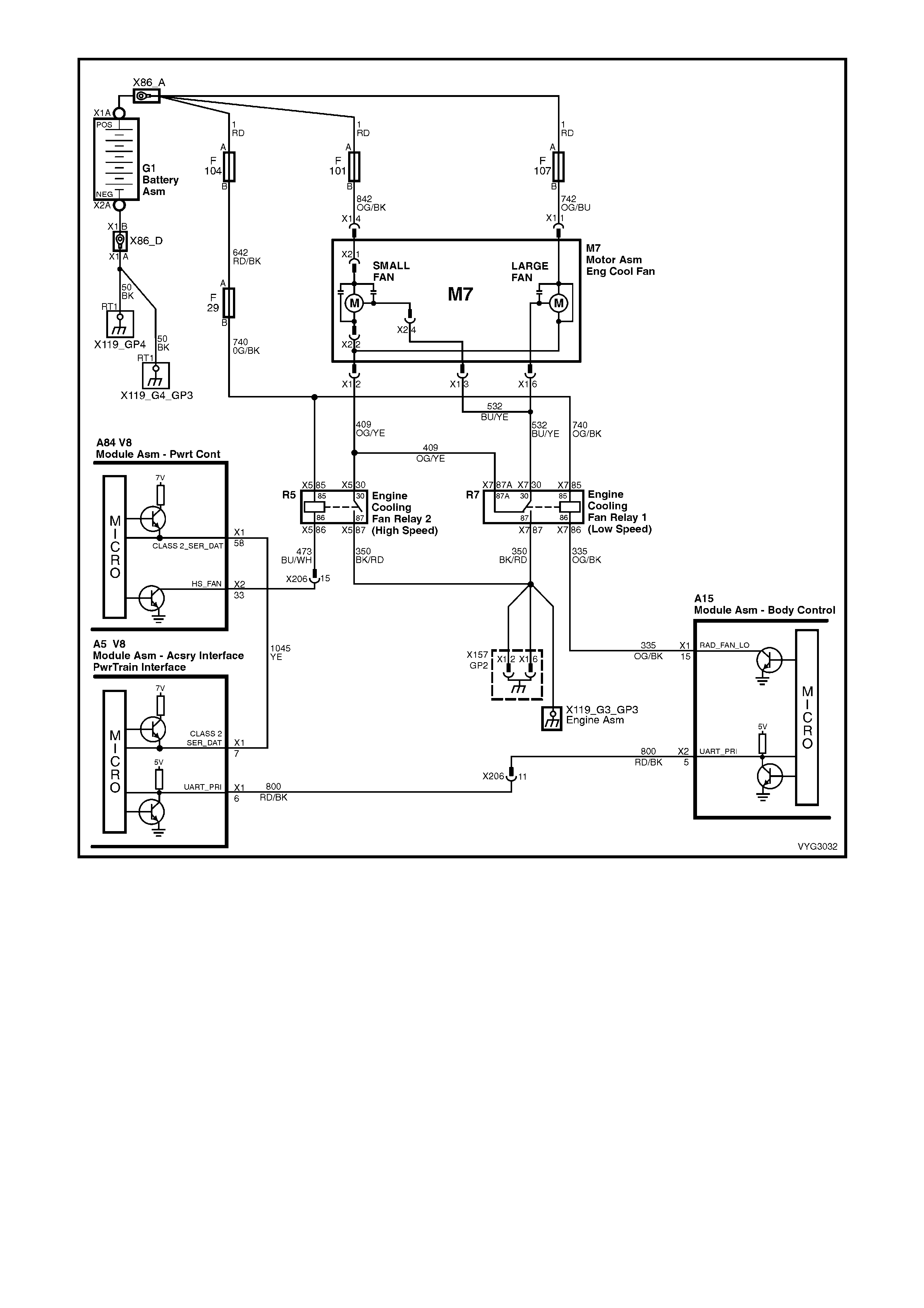
Figure 6C3-2A-15 – GEN III V8 Powertrain Control Schematics (9 of 14)
Engine Cooling Fan Circuits
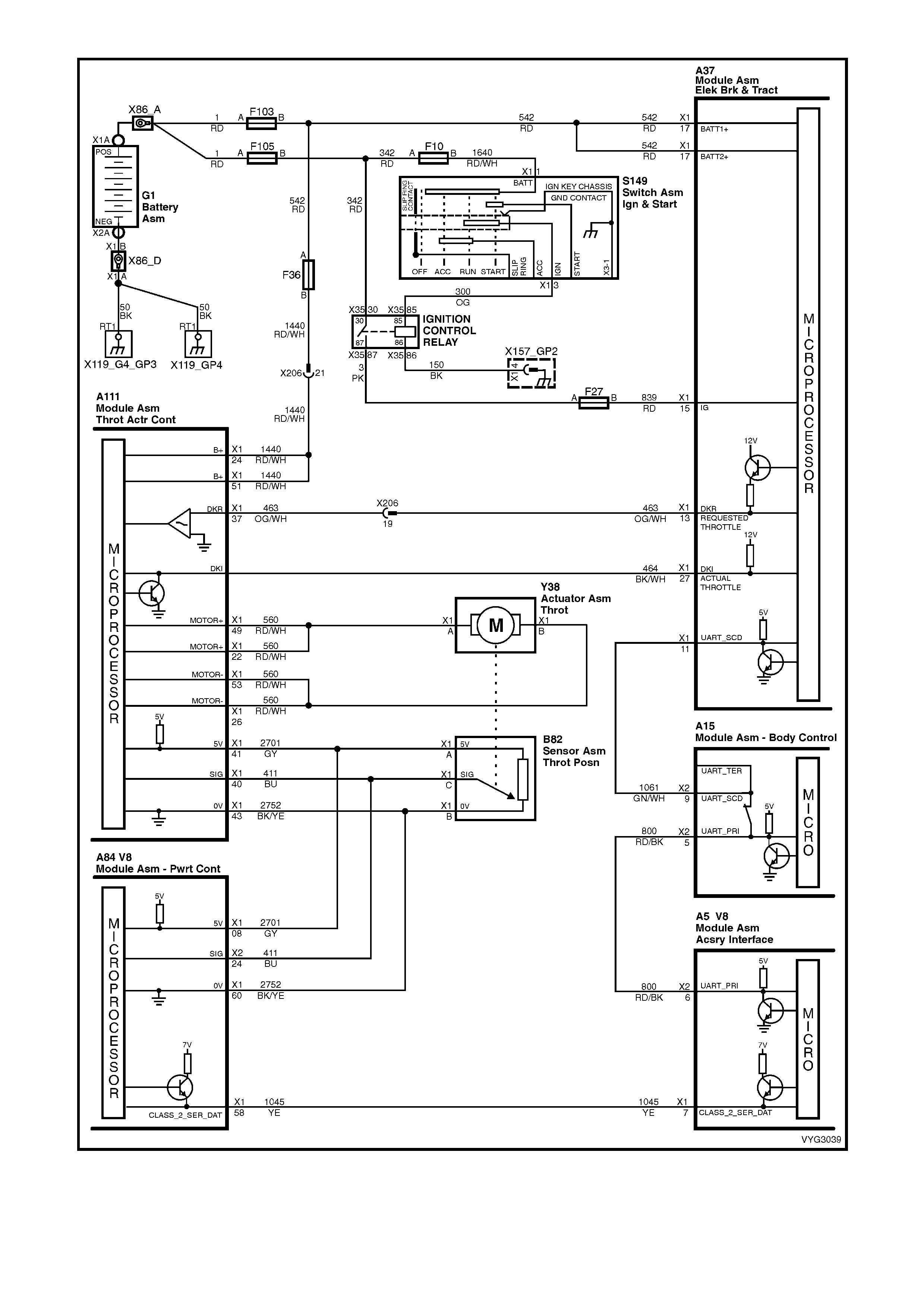
Figure 6C3-2A-16 – GEN III V8 Powertrain Control Schematics (10 of 14)
Throttle Relaxer, Tachometer Signal Circuits
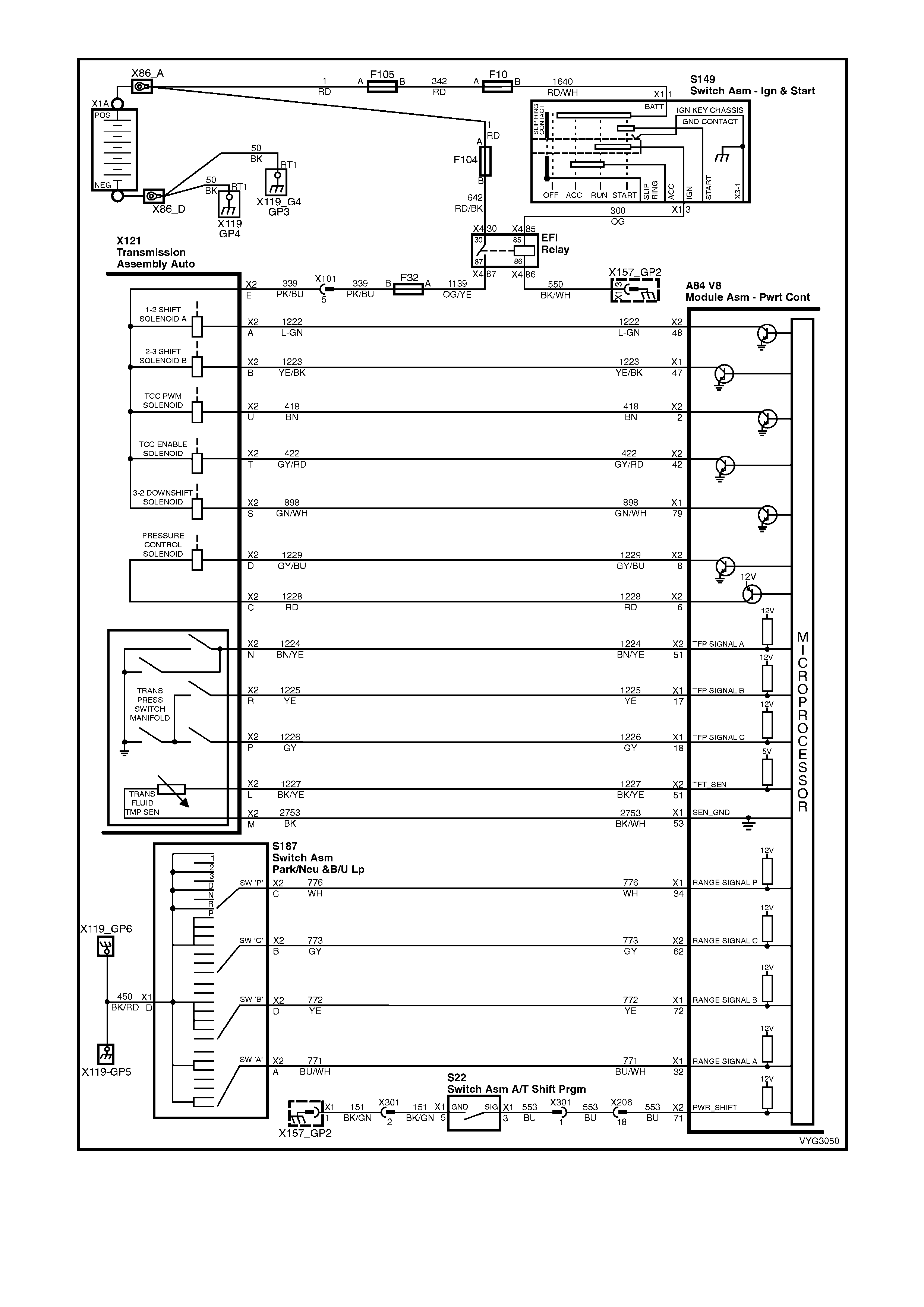
Figure 6C3-2A-17 – GEN III V8 Powertrain Control Schematics (11 of 14)
Transmission, Power/Economy Circuits
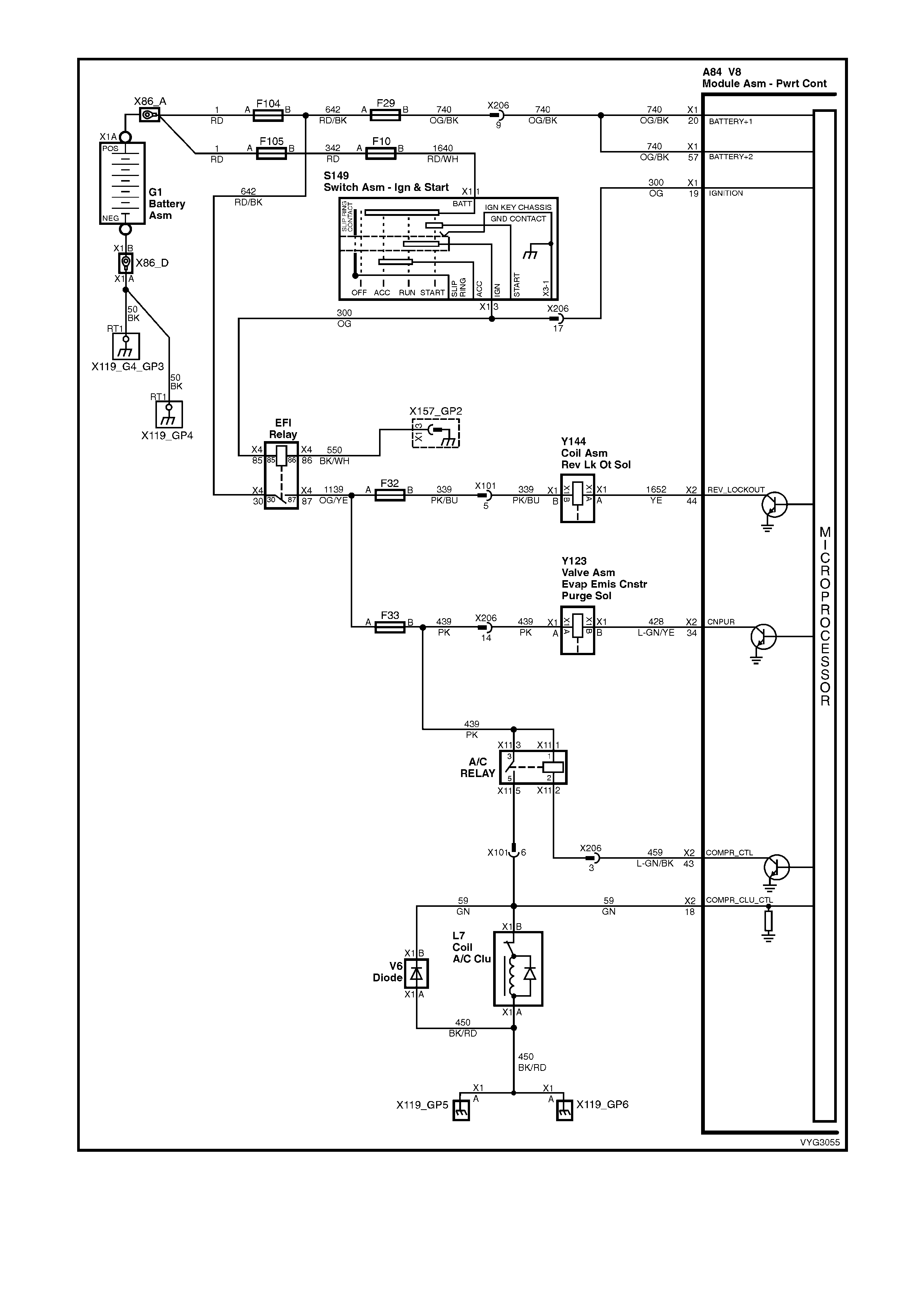
Figure 6C3-2A-18 – GEN III V8 Powertrain Control Schematics (12 of 14)
Reverse Inhibit Solenoid, Canister Purge Solenoid, OCC Air Conditioning Circuits
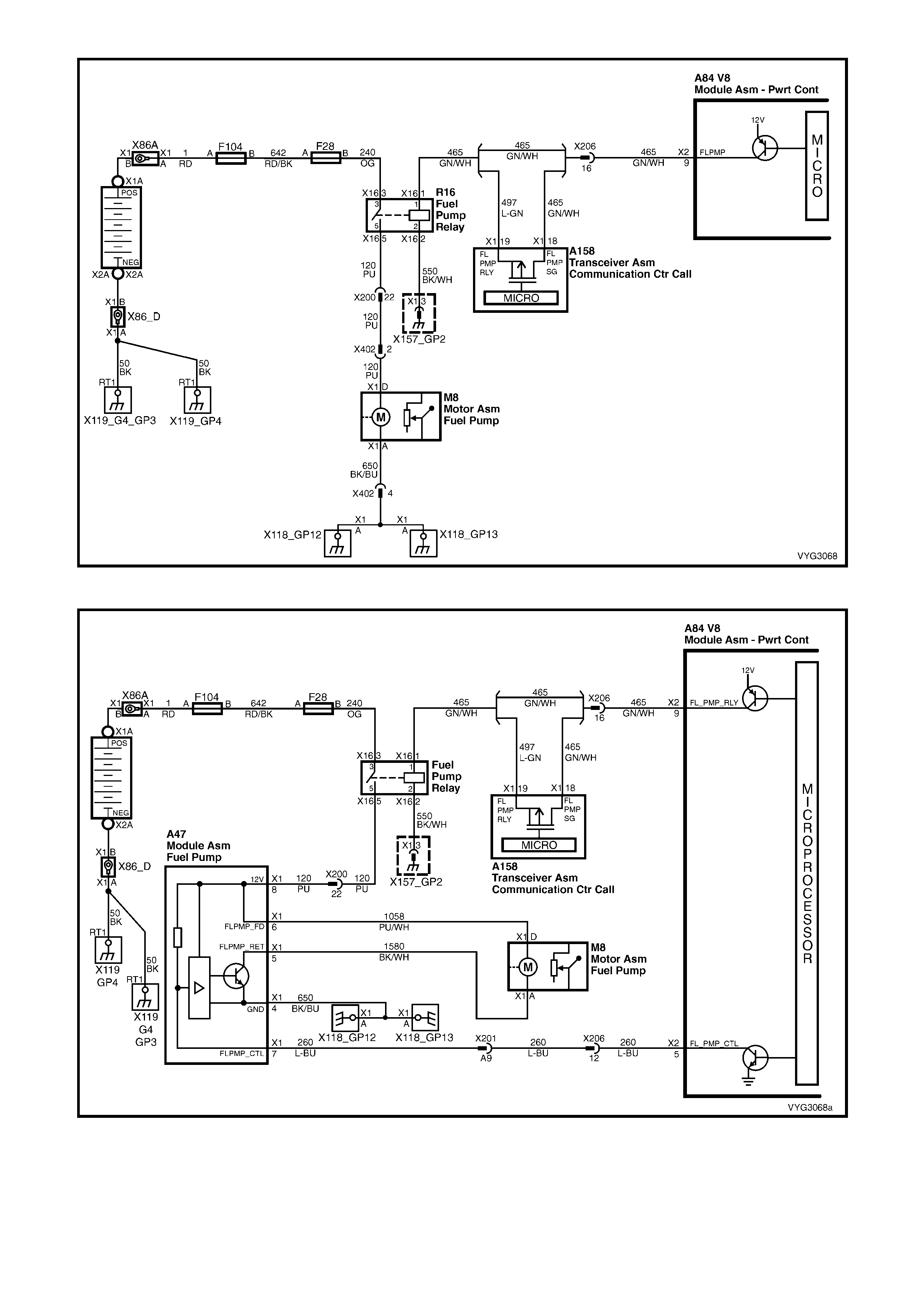
Figure 6C3-2A-19 – GEN III V8 Powertrain Control Schematics (13 of 14)
Fuel Pump Control and Telematics Module Circuits
Figure 6C3-2A-20 – GEN III V8 Powertrain Control Schematics (14 of 14)
Fuel Pump Control (Utility Only) and Telematics Module Circuits
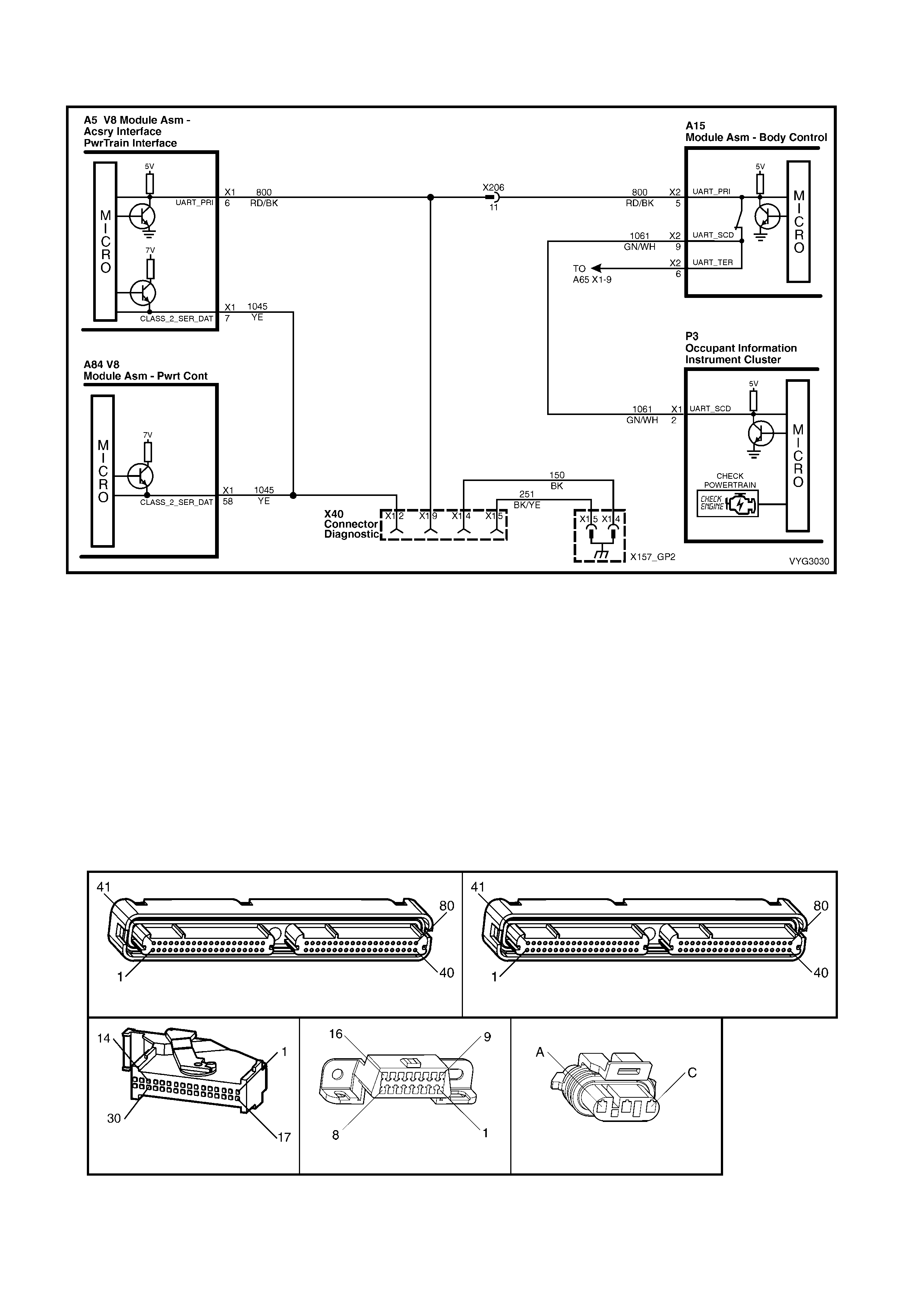
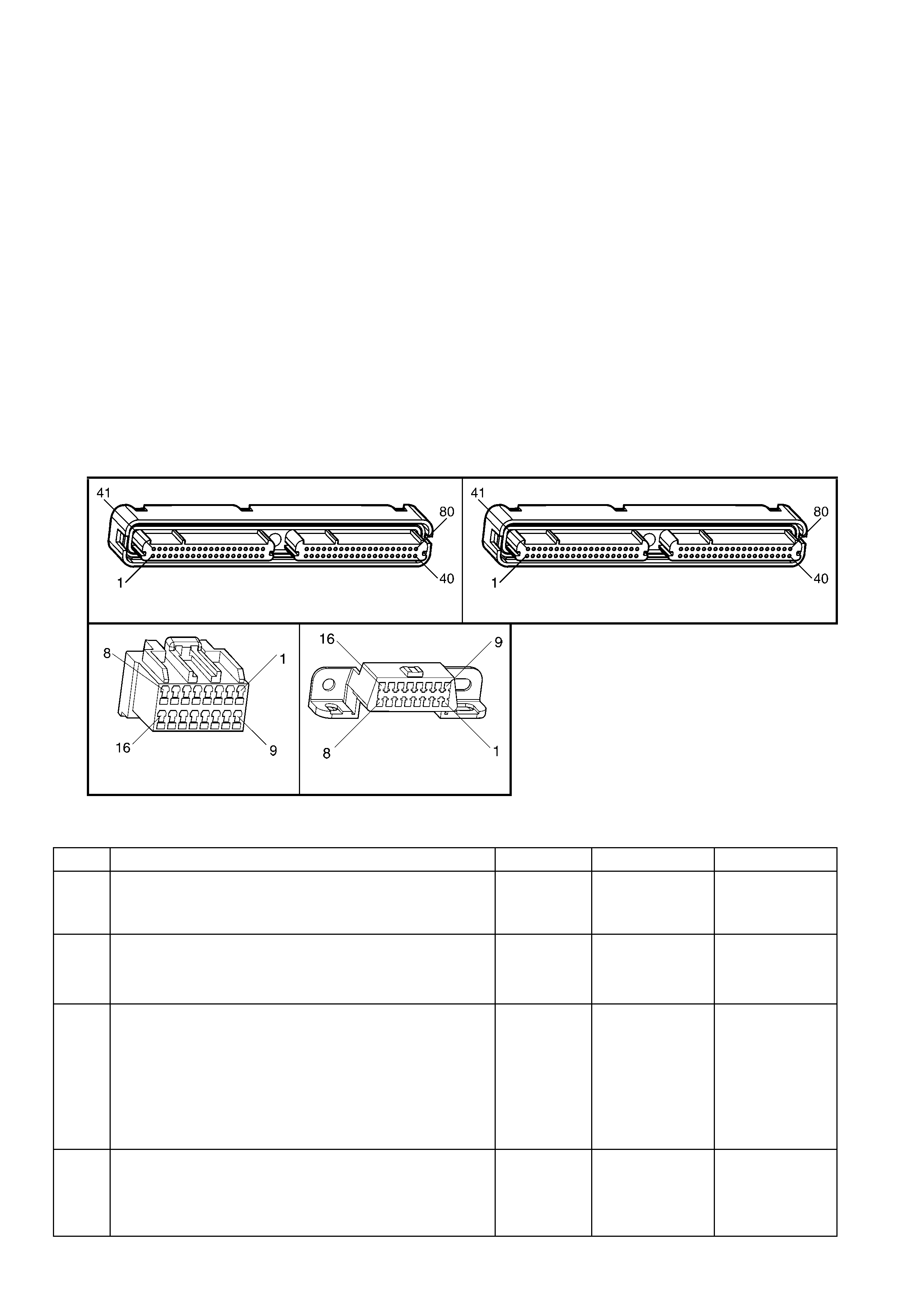
1.3 PCM CONNECTOR END VIEWS
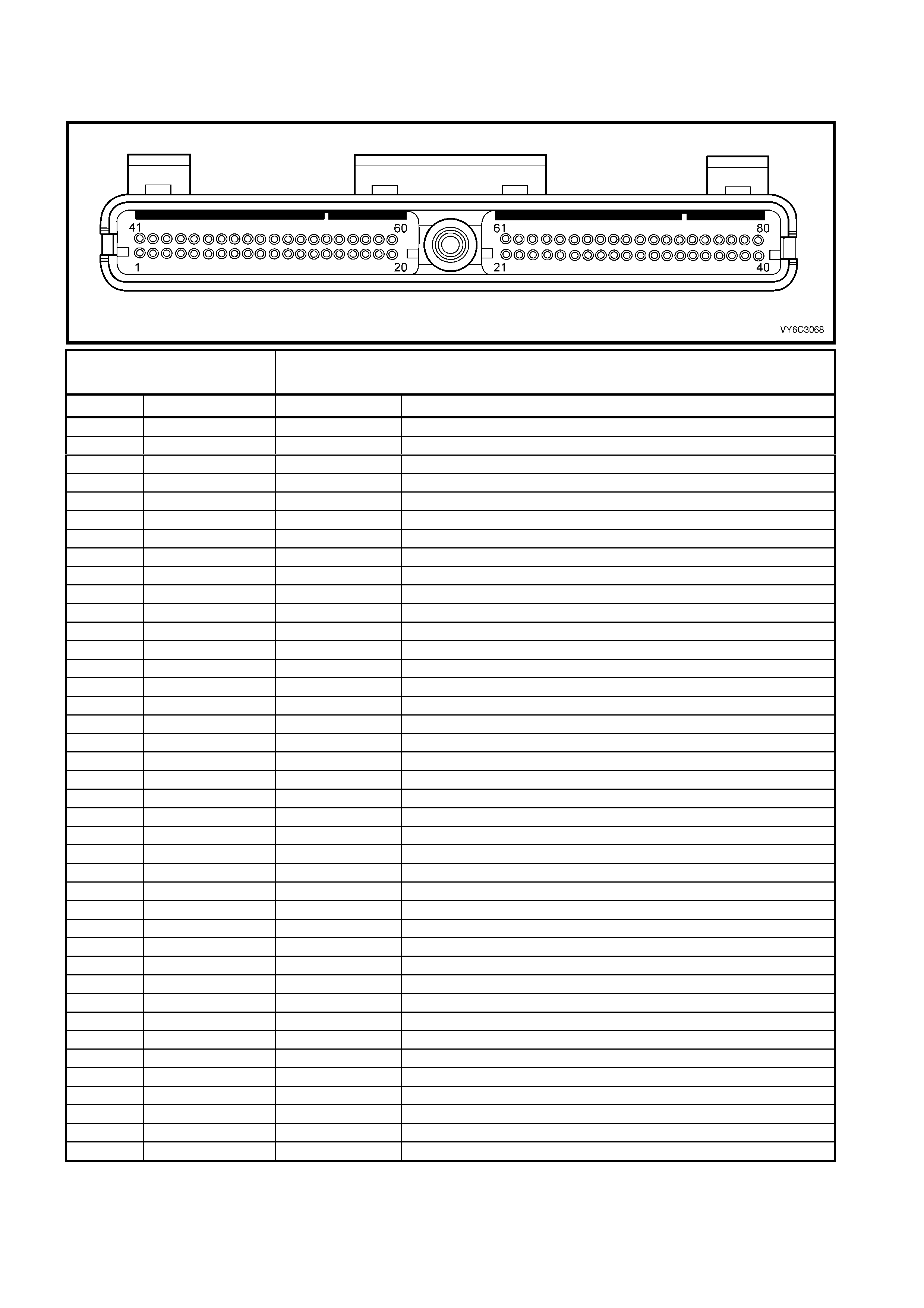
PCM CONNECTOR A84–X1 (BLUE)
Connector Part
Information PCM Connector A84–X1 (Blue) – 80 Pin Connector
Pin Wire Colour Circuit No. Function
1 Black/Red 450 System Ground
2 Light Blue/White 1800 Crankshaft Pos iti on Sensor Ignition Voltage Feed
3 Purple 1746 Fuel Injector #3 Driver
4 Green 1745 Fuel Injector #2 Driver
5 Not Used – –
6 Not Used – –
7 Blue/Yellow 596 Oil Pressure Sensor 5 Volt Reference
8 Grey 2701 Throttle Positi on Sensor 5 Volt Reference
9 Not Used – –
10 Not Used – –
11 Light Green/White 1876 Rear Knock Sensor Input Signal
12 Light Blue 573 Crankshaft Position Sensor Input Signal
13 Not Used – –
14 Not Used – –
15 Not Used – –
16 Not Used – –
17 Yellow 1225 Transmission Range B Input
18 Grey 1226 Transmission Range C Input
19 Orange 300 Ignition Positive Voltage
20 Orange 740 Battery Feed
21 Light Blue/Black 574 Crankshaft Position Sensor Reference Low
22 Not Used – –
23 Not Used – –
24 Not Used – –
25 Not Used – –
26 Grey/Black 1667 Bank 2 Sensor 1 Heated Oxygen Sensor Signal Low
27 Not Used – –
28 Not Used – –
29 Blue/Black 1664 Bank 1 Sensor 1 Heated Oxygen Sensor Signal Low
30 Light Green 68 Engine Coolant Level Switch Input Signal
31 Not Used – –
32 Blue/White 771 PRNDL A
33 Brown 86 Torque Converter Clutch/Cruise Brake Switch Input Signal
34 White 776 PRNDL P
35 Not Used – –
36 B l ue 1744 Fuel Injector #1 Driver
37 Yellow 846 Fuel Injector #6 Driver
38 Not Used – –
39 Not Used – –
40 Black/Red 450 System Ground
PCM CONNECTOR A84–X1 (BLUE) – CONTINUED
Connector Part Information PCM Connector A84–X1 (Blue) – 80 Pin Connector
Pin Wire Colour Circuit No. Function
41 Not Used – –
42 Not Used – –
43 Pink/Bl ack 877 Fuel I nj ect or #7 Driver
44 Brown/Yellow 844 Fuel Injector #4 Driver
45 Purple/W hi te 2700 A/C Refrigerant Press ure Sensor 5 Volt Reference
46 Not Used – –
47 Not Used – –
48 Purple/W hi te 2704 Manifold Absol ut e Press ure Sens or 5 Volt Referenc e
49 Not Used – –
50 Not Used – –
51 White/Red 496 Front Knock Sensor Input Signal
52 Not Used – –
53 Black/W hite 2762 Transm iss i on Fluid Temperature Sens or Ground
54 Black 469 Manifold Absolute Pressure Sensor Ground
55 Not Used – –
56 Not Used – –
57 Orange 740 Battery Feed
58 Yellow 1045 Seri al Dat a (Class II )
59 Not Used – –
60 Black/Yel l ow 2752 Throttl e Posit i on Sensor Ground
61 Red/White 632 Camshaft Position Sensor Reference Low
62 Not Used – –
63 Green 470 Oil Pressure Sensor Ground
64 Not Used – –
65 Not Used – –
66 Grey 1666 Bank 2 Sensor 1 Heated Oxygen Sensor Signal High
67 Not Used – –
68 Not Used – –
69 Purple 1665 Bank 1 S ensor 1 Heated Oxygen Sensor Signal Hi gh
70 Not Used – –
71 Blue 553 Power/Economy Switch Input
72 Yellow/Red 772 PRNDL B
73 Brown 633 Camshaft Position Sensor Input Signal
74 Yellow 410 Engine Coolant Temperature Sensor Signal
75 Not Used – –
76 Grey 845 Fuel Injector #5 Driver
77 Li ght Green 878 Fuel Injector #8 Driver
78 Not Used – –
79 Green/White 898 3-2 Shift Solenoid Control
80 Grey/Black 2761 E ngi ne Cool ant Tem perat ure Sensor Ground

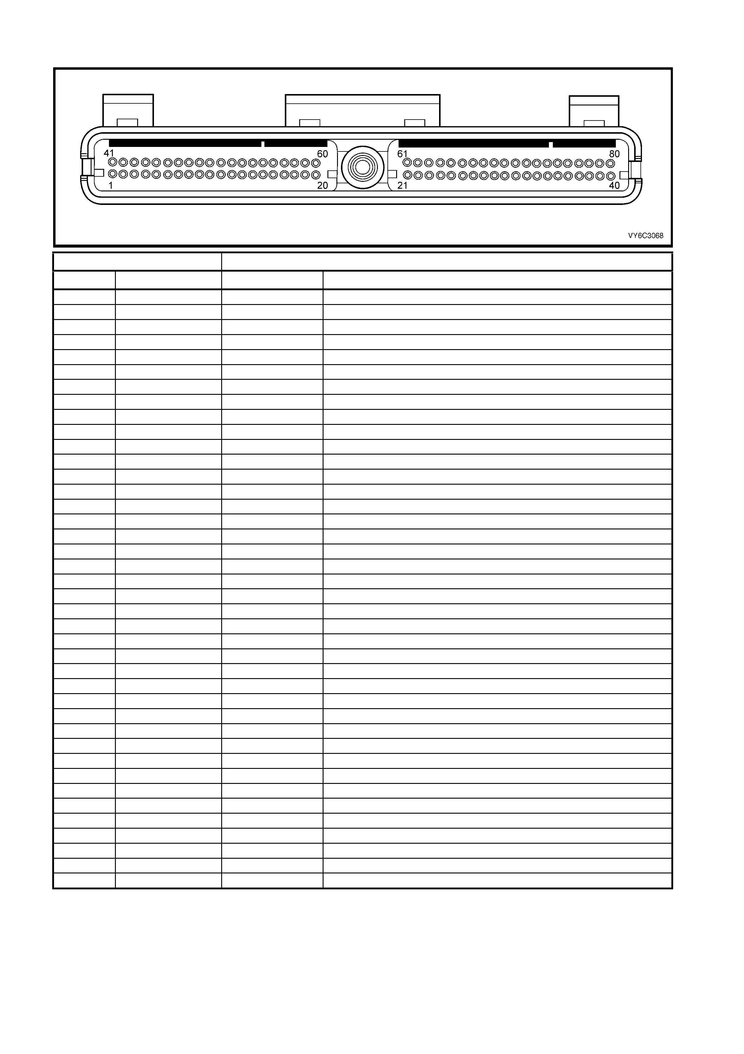
PCM CONNECTOR A84–X2 (RED)
Connector Part Information PCM Connector A84–X2 (Red) – 80 Pin Connector
Pin Wire Colour Circuit No. Function
1 Black/Red 450 System Ground
2 Brown 418 Torque Converter Clutch Pulse Width Modulation Solenoid Control
3 Not Used – –
4 Not Used – –
5 Light Blue 260 Fuel Pump Control Signal (V8 Utility)
6 Red 1228 Pressure Control Solenoid Signal High
7 Not Used – –
8 Grey/Blue 1229 Pressure Control Solenoid Signal Low
9 Green/White 465 Fuel Pump Relay Control
10 Brown 121 Tachometer Output Signal
11 Not Used – –
12 Not Used – –
13 Not Used – –
14 Green/Black 380 A/C Refrigerant Pressu re S ensor Input S i gnal
15 Not Used – –
16 Not Used – –
17 Not Used – –
18 Green 59 A/C Compressor Clutch Rela y Feedback
19 Not Used – –
20 Tan 1231 Vehicle Speed Sensor Signal Low
21 Blue/White 1230 Vehic l e Speed Sensor Signal High
22 Not Used – –
23 Not Used – –
24 B l ue 411 Throttle Positi on Sensor Input Signal
25 Brown 472 Intak e Air Temperature Sensor Signal
26 White 2121 Ignition Coil/Module Control #1
27 Yellow 2127 Ignit i on Coil/Module Control #7
28 Lt Green 2126 Ignition Coil/Module Cont rol #6
29 White 2124 Ignition Coil/Module Control #4
30 Not Used – –
31 Brown/W hite 492 Mass Air Flow Sensor Signal
32 Lt Green 432 Manifol d A bsol ut e Press ure Sens or Input Signal
33 Blue/White 335 Engi ne Cool i ng Fan Relay High Speed Control
34 Lt Green/Yellow 428 Evaporative Emiss i on Canister Purge Solenoid Control
35 Not Used – –
36 Not Used – –
37 Not Used – –
38 Not Used – –
39 White/Black 631 Camshaft Sensor Ignition Voltage Feed
40 Black/Red 450 System Ground

PCM CONNECTOR A84–X2 (RED) (CONTINUED)
Connector Part Information PCM Connector A84–X2 (Red) – 80 Pin Connector
Pin Wire Colour Circuit No. Function
41 Not Used – –
42 Grey/Red 422 Torque Converter Cl utch Enable Solenoid Control
43 Light Green/Black 459 A/C Clutch Relay Control
44 Yellow 1652 Manual Transmis sion Reverse Lock-Out Solenoid Control
45 Not Used – –
46 Not Used – –
47 Yellow/Black 1223 2-3 Shift Solenoid ‘B’ Control
48 Li ght Green 1222 1-2 Shi ft Solenoi d ‘A’ Control
49 Not Used – –
50 Purple/White 5197 Vehicle Speed Sensor Output Signal
51 Black/Yel l ow 1227 Transm iss i on Fluid Temperature Sens or Input Signal
52 Not Used – –
53 Grey/Black 1687 Electroni c Traction Control, Spark Retard Signal
54 Not Used – –
55 Not Used – –
56 Not Used – –
57 Green/Orange 2753 Intake Air Temperature / A/C Refrigerant P ressure Sensor Ground
58 Brown/White 331 Oil Pressure Sensor Input Signal
59 Not Used – –
60 Brown 2129 Ignition Reference Low
61 Purple 2130 Ignition Reference Low
62 Grey 773 PRNDL Terminal ‘C’
63 Brown/Yellow 1224 Transmission Range A Input
64 Not Used – –
65 Not Used – –
66 Lt Blue 2128 Ignition Coil/Module Control #8
67 Yellow/Black 2122 Ignition Coil/Module Cont rol #2
68 Green 2125 Ignition Coil/ Module Cont rol #5
69 B l ue 2123 Igniti on Coil/ Module Cont rol #3
70 Not Used – –
71 Not Used – –
72 Not Used – –
73 Not Used – –
74 Not Used – –
75 Not Used – –
76 Lt Green/W hite 1748 Idle Air Control Valve Coil B High
77 Lt Green/Black 1747 Idl e Air Cont rol Val ve Coi l B Low
78 Lt Blue/ Black 444 Idle Air Cont rol Valve Coil A Low
79 Lt Blue 1749 Idle Air Control Val ve Coil A High
80 Not Used – –

1.4 PCM CONNECTOR TERMINAL DEFINITIONS
PCM CONNECTOR A84–X1 (BLUE).
1 – SYSTEM GROUND – This terminal should have zero volts. This circuit is connected directly to engine ground.
2 – CRANKSHAFT POSITION SENSOR IGNITION VOLTAGE FEED – This voltage should be always be B+
anytime the ignition is ON. It is a regulated voltage output from the PCM and supplies B+ to the CKP sensor.
3 – F UEL INJECT OR #3 DRIV ER – W ith the engine O FF and the i gnition ON, t he voltage s hould be B+. W ith the
engine ru nning at idle, th e c harging s ystem inc reases the batter y volta ge slight l y, so this volta ge will increas e. W ith
higher engine RPM or more engine load, the resulting increase in injector pulse frequency or injector pulse width
will cause this voltage to become slightly less.
4 – F UEL INJECT OR #2 DRIV ER – W ith the engine O FF and the i gnition ON, t he voltage s hould be B+. W ith the
engine ru nning at idle, th e c harging s ystem inc reases the batter y volta ge slight l y, so this volta ge will increas e. W ith
higher engine RPM or more engine load, the resulting increase in injector pulse frequency or injector pulse width
will cause this voltage to become slightly less.
5 – NOT USED
6 – NOT USED
7 – OIL PRESSURE SENSOR 5V REFERENCE – This voltage should always be 5 volts whenever the ignition is
ON. The reference voltage is a regulated voltage from the PCM, and supplies 5 volts to the oil pressure sensor.
8 – THROTT LE POSIT ION SEN SOR 5 VOL T REF ERENC E – This volt age sh oul d always be 5 vo lts whenever the
ignition is ON. The reference voltage is a regulated voltage from the PCM, and supplies 5 volts to the TP sensor.
9 – NOT USED
10 – NOT USED
11 – REAR KNOCK SENSOR INPUT SIGNAL – The knock sensor detects when detonation is occurring in the
combustion chambers. When detected, the PCM will reduce the amount of spark advance being delivered on the
EST output circuits to the ignition COIL/MODULES.
12 – CRANKSHAFT POSITION SENSOR INPUT SIGNAL – This terminal could be called the ‘tach’ input. It
provides th e PC M with RP M and crank shaf t positio n inf orm ation. T he PCM uses this sign al to c ontro l fuel inj ect ion,
and spark timing.
13 – NOT USED
14 – NOT USED
15 – NOT USED
16 – NOT USED
17 – TRANSMISSION RANGE B INPUT – The PCM sends out a buffered B+ signal to the pressure switch
assembly located in the automatic transmission valve body. The B+ signal must pass through either a normally
open or norm ally closed switch to reach ground. W hen the switches are closed , the signal should be n ear 0 volts.
The PCM monitors the status of these signals to determine which gear servo is actually receiving hydraulic apply
pressure.
18 – TRANSMISSION RANGE C INPUT – The PCM sends out a buffered B+ signal to the pressure switch
assembly located in the automatic transmission valve body. The B+ signal must pass through either a normally
open or norm ally closed switch to reach ground. W hen the switches are closed , the signal should be n ear 0 volts.
The PCM monitors the status of these signals to determine which gear servo is actually receiving hydraulic apply
pressure.
19 – IGNITI ON POSIT IVE VOLT AGE – This is the wak e up signal to the PC M from the ignition sw itch. It is not the
power su pply to th e PCM, it onl y tells the PCM th at the ign ition sw itch is O N. The v oltage sho uld equ al the battery
voltage when the key is in either the RUN, or CRANK position.
20 – BATT ERY FEED – This s upplies the PC M with full tim e B+ volts. T his cir cuit stays hot even when the ignit ion
is turned OFF. The battery voltage feed circuit receives it’s voltage from fuse F29.
21 – CRANKSHAFT POSITION SENSOR REFERENCE LOW – This terminal should always be zero volts. It is
connected from the PCM to the CKP sensor and provides the ground signal needed for the sensor to operate.
22 – NOT USED
23 – NOT USED
24 – NOT USED
25 – NOT USED
26 – BANK 2 SE NSOR 1 HE ATED OXY GEN SEN SOR SIG N AL LOW – This ter m inal shou ld ha ve zer o v olts. I t is
connected from the PCM to the HO2S. This terminal ground’s the PCM circuitry for the HO2S voltage monitor
inside the PCM.
27 – NOT USED
28 – NOT USED

29 – BANK 1 SE NSOR 1 HE ATED OXY GEN SEN SOR SIG N AL LOW – This ter m inal shou ld ha ve zer o v olts. I t is
connected from the PCM to the HO2S. This terminal ground’s the PCM circuitry for the HO2S voltage monitor
inside the PCM.
30 – ENGINE COOLANT LEVEL SWITCH INPUT SIGNAL – This term inal indic ates to the PCM wh en the co olant
level is low. When the PCM receives this signal from the Engine Coolant Level switch, the PCM will send a serial
data message to the Instrument to activate the Low Coolant Warning icon.
31 – NOT USED
32 – PRNDL A – This circuit along with the circuits on PCM BLUE connector A84-X1, pins 34, 72 and PCM RED
connector A84-X2, pin 62 indicate to th e PCM what trans mission gear th e driver has s elected. The P CM will the n
send a command via the serial data line to the Instrument to indicate to the driver what gear has been selected.
33 – TORQUE CONVERTER CLUTCH/CRUISE BRAKE SWITCH INPUT SIGNAL – This signal indicates to the
PCM when the driver has depressed the brake pedal. The PCM will then disengage the TCC and or cruise if
activated. This circuit also indicates to the PCM and cruise control actuator when the ABS/TCS module is
requesting the Low Traction lamp ON.
34 – PRNDL P – T his circ uit along with the circu its on PCM BLU E connector A84- X1, pins 32, 72 & X2-62 in dicate
to the PCM wh at transm iss ion gear the dr iver h as sele cted. T he PCM will the n send a com m and via th e seri al data
line to the Instrument to indicate to the driver what gear has been selected.
35 – NOT USED
36 – FU EL IN JECT OR #1 DRIV ER – W ith the en gine O FF and th e ignit ion O N, the v oltage s hou ld be B +. W ith the
engine running at idle, the charging system increases battery voltage slightly, so this voltage will increase. With
higher engine RPM or more engine load, the resulting increase in injector pulse frequency or injector pulse width
will cause this voltage to become slightly less.
37 – FU EL IN JECT OR #6 DRIV ER – W ith the en gine O FF and th e ignit ion O N, the v oltage s hou ld be B +. W ith the
engine running at idle, the charging system increases battery voltage slightly, so this voltage will increase. With
higher engine RPM or more engine load, the resulting increase in injector pulse frequency or injector pulse width
will cause this voltage to become slightly less.
38 – NOT USED
39 – NOT USED
40 – SYSTEM GROUND – This terminal should have zero volts. This circuit is connected directly to engine ground.
41 – NOT USED
42 – NOT USED
43 – FU EL IN JECT OR #7 DRIV ER – W ith the en gine O FF and th e ignit ion O N, the v oltage s hou ld be B +. W ith the
engine ru nning at idle, th e c harging s ystem inc reases the batter y volta ge slight l y, so this volta ge will increas e. W ith
higher engine RPM or more engine load, the resulting increase in injector pulse frequency or injector pulse width
will cause this voltage to become slightly less.
44 – FU EL IN JECT OR #4 DRIV ER – W ith the en gine O FF and th e ignit ion O N, the v oltage s hou ld be B +. W ith the
engine ru nning at idle, th e c harging s ystem inc reases the batter y volta ge slight l y, so this volta ge will increas e. W ith
higher engine RPM or more engine load, the resulting increase in injector pulse frequency or injector pulse width
will cause this voltage to become slightly less.
45 – A/C REFRIGERANT PRESSURE SENSOR 5 VOLT REFERENCE – This voltage should always be 5 volts
anytim e the ignition is ON. It is a regulated vo ltage output f rom the PCM, and sup plies 5 volts to the A/C Press ure
Sensor.
46 – NOT USED
47 – NOT USED
48 – MANIFOLD ABSOLUTE PRESSURE SENSOR 5 VOLT REFERENCE – This voltage should always be 5
volts anytime the ignition is ON. It is a regulated voltage output from the PCM and supplies 5 volts to the MAP
Sensor.
49 – NOT USED
50 – NOT USED
51 – FRONT KNOCK SENSOR – The Knock Sensor detects when detonation is occurring in the combustion
chambers. When detected, the PCM will reduce the amount of spark advance being delivered on the EST output
circuits to the ignition COIL/MODULES.
52 – NOT USED
53 – TRANSMISSION FLUID TEMPERATURE SENSOR GROUND – This terminal should be zero volts. It is
connected through the PCM circuitry to engine ground.
54 – MANIFOLD ABSOLUTE PRESSURE S ENSOR GROUND – T his term inal s hou ld ha ve zer o volts . T his c ircui t
is connected directly to ground through the PCM.
55 – NOT USED
56 – NOT USED

57 – BATT ERY FEED – This s upplies the PC M with full tim e B+ volts. T his cir cuit stays hot even when the ignit ion
is turned off. The battery voltage feed circuit receives it’s voltage fuse F29.
58 – SERIAL DATA (CLASS II) –This is a dedicated line for the Tech 2 communication. The circuit connects the
PCM to the PI M. Tech 2 can talk to the PCM by sending a m essage and ask ing it to respond. The c ommunication
carried on C lass II dat a stream s are prior itised. The n ormal volta ge on this l ine is 0 volts, but when comm unication
is occurring, the voltage will fluctuate from 0 – 7 volts indicating communication.
59 – NOT USED
60 – THROTTLE POSITION SENSOR GROUND – This terminal should have zero volts. This circuit is connected
directly to ground through the PCM.
61 – CAMSHAFT POSITION SENSOR REFERENCE LOW – This terminal should always be zero volts. It is
connected from the PCM to the CMP sensor and provides the ground signal needed for the sensor to operate.
62 – NOT USED
63 – OIL PRESSURE SENSOR GROUND – This terminal should always be zero volts. It is connected from the
PCM to the oil pressure sensor and provides the ground signal needed for the sensor to operate.
64 – NOT USED
65 – NOT USED
66 – B ANK 2 SENSOR 1 HE ATED OXYGEN SENSOR SIGNAL HIGH – W ith the ignition ON and the engine not
running, t he volta ge shoul d be 350 – 450 m illivolts (0.350 0 .450 volts) . This is the PCM s upplied HO 2S circ uit bias
voltage. When the HO2S is hot and the engine is running, the voltage should be rapidly changing, somewhere
between 10 – 1000 millivolts (0.010 – 1.0 volts).
67 – NOT USED
68 – NOT USED
69 – B ANK 1 SENSOR 1 HE ATED OXYGEN SENSOR SIGNAL HIGH – W ith the ignition ON and the engine not
running, t he volta ge shoul d be 350 – 450 m illivolts (0.350 0 .450 volts) . This is the PCM s upplied HO 2S circ uit bias
voltage. When the HO2S is hot and the engine is running, the voltage should be rapidly changing, somewhere
between 10 – 1000 millivolts (0.010 – 1.0 volts).
70 – NOT USED
71 – POWER/ECONO MY SW ITCH INPUT – T he PC M sends a sign al of about 12 vol ts, and m onitors the status of
this circuit. In the ECONOMY position the switch is open, the PCM voltage status signal remains high – about 12
volts, and the PCM does not allow shift point changes. When the transmission switch is pressed to the POWER
position the switch is momentarily closed and the PCM voltage status signal is momentarily pulled low. The PCM
senses the momentary voltage signal drop and enables POWER mode shifting.
72 – PRNDL B – This circuit along with the circuits on PCM BLUE Connector A84-X1, pins 32, 34 and RED
connector A84-X2, pin 62 indicate to the PCM what transmission gear the driver has selected. The PCM will then
send a command via the serial data line to the Instrument to indicate to the driver what gear has been selected.
73 – CAMSHAFT POSITION SENSOR INPUT SIGNAL – This signal indicates to the PCM when number 1 cylinder
is on the compression stroke. The PCM uses this signal for correct injector and ignition coil sequencing.
74 – ENGINE COOLANT TEMPERATURE SENSOR SIGNAL – The PCM sends a 5 volt signal voltage to the
Engine Coolant Temperature sensor, which is a temperature variable resistor called a thermistor. The sensor,
being also connected to ground, will alter the voltage according to engine coolant temperature. As the engine
coolant temperature increases, the voltage seen on terminal A84-X1 74 decreases. At 0° C engine coolant
temperature, the voltage will be above 4 volts. At normal operating temperature, the voltage will be less than 2
volts. The PCM uses this signal for fuelling.
75 – NOT USED
76 – FU EL IN JECT OR #5 DRIV ER – W ith the en gine O FF and th e ignit ion O N, the v oltage s hou ld be B +. W ith the
engine ru nning at idle, th e c harging s ystem inc reases the batter y volta ge slight l y, so this volta ge will increas e. W ith
higher engine RPM or more engine load, the resulting increase in injector pulse frequency or injector pulse width
will cause this voltage to become slightly less.
77 – FU EL IN JECT OR #8 DRIV ER – W ith the engi ne O FF and th e ignit ion ON , the volt age sh ould b e B+. W ith the
engine ru nning at idle, th e c harging s ystem inc reases the batter y volta ge slight l y, so this volta ge will increas e. W ith
higher engine RPM or more engine load, the resulting increase in injector pulse frequency or injector pulse width
will cause this voltage to become slightly less.
78 – NOT USED
79 – 3-2 SHIFT SOLENOID CONTROL – The 3-2 shift solenoid is a normally closed, pulse width modulated
solenoid us e d to c ontro l the 3- 2 do wnshif t. The PCM oper ates the 3- 2 s hif t s oleno id at a f r equency of 50 Hz (cycles
per second). The soleno id is constantly fed B+ and the PCM contr ols the length of time the path to ground for the
electrical circuit is closed.
80 – ENGINE COOLANT TEMPERATURE SEN SOR GROUND – T his term inal s hould ha ve zer o vol ts. T his circuit
is connected directly to ground through the PCM.

PCM CONNECTOR A84-X2 (RED)
1 – SYSTEM GROUND – This terminal should have zero volts. This circuit is connected directly to engine ground.
2 – TORQUE CONVERTER CLUTCH PULSE WIDTH MODULATION SOLENOID CONTROL – The PCM uses
the pulse width modulation (PWM) TCC apply solenoid to smoothly engage the torque converter clutch after the
TCC ENABLE solenoid is energised. By varying the duty cycle pulse width modulation, the PCM can slowly engage
the torque converter clutch, allowing very smooth TCC engagement.
3 – NOT USED
4 – NOT USED
5 – FUEL PUMP CONTROL – T he GEN I II V8 en gined Ut ility uses a two s peed f uel pum p, the sam e as that fitted
to those MY 2003 VY and V2 Series vehicles fitted with the V6 Supercharged engine. A duty cycle ground signal
on this circuit varies with engine load changes. Under normal driving conditions, the duty cycle ground signal
supplied from the PCM to the Fu el Pump Control Module (terminal 7 of the F uel Pump Control M odule) is at 67%
dut y cycle. This 67% du ty cycle runs the Fuel Pump at a lo wer f uel f lo w rat e. When the vehicl e is i n a h eavy eng in e
load condition, the PCM will switch from 67% duty cycle to 100% duty cycle. This will cause the Fuel Pump to
operate at a hi gh f uel f lo w rate to c ompensate f or the high er engi ne l oad c on dit io n. This change i n duty cycles does
not change the fuel system operating fuel pressure, but changes the fuel flow rate.
6 – PRESSURE CONTROL SOLENOID HIGH – The duty cycle, and amount of current flow to the PCS, is
controlled by the PCM. T his circ uit is the B+ sup ply line fr om the PC M to the PC S. The duty c ycle and c urrent are
controlled by the PCM.
7 – NOT USED
8 – PRESSURE CONTROL SOLENOID LOW – T he 4L60-E aut omatic tr ansmission uses an electrica l solenoid to
control hydraulic press ure inside the transm ission. T his elec trical so lenoid a llows the PCM to c ontrol l ine pre ssure,
similar to other autom atic transmissions that use a throttle valve cable or vacuum modulator. The dut y cycle, and
amount of cur rent f lo w to the PCS, ar e bot h c ontr o lled b y the PCM. B y m oni tori ng this lin e, t he PCM can de te rmine
if the commanded current has gone to the PCS and returned to the PCM.
9 – FUEL PUMP (FP) RELAY CONTROL – Turning t he ignition ON causes the PCM to energise (+12V) the Fuel
Pump Relay. If no crankshaft reference input pulses are received, the PCM turns OFF the relay. As soon as the
PCM receives crankshaft reference input pulses, the PCM will turn the Fuel Pump Relay ON again.
10 – TACHOMETER OUTPUT SIGNAL – This signal is used to operate the tachometer located in the instrument
panel cluster. The PCM determines the signal based from the CKP sensor.
11 – NOT USED
12 – NOT USED
13 – NOT USED
14 – A/C REFRIGERANT PRESSURE SENSOR INPUT SIGNAL – The signal that is sent from the pressure
sensor to the PCM indicates to the PCM what the A/C pressure is. Depending on the voltage, this signal will
indicate to the PCM if A/C pressure is too LOW or too HIGH.
15 – NOT USED
16 – NOT USED
17 – NOT USED
18 – A/C CLUTCH STATUS – This circuit is a feed back signal to the PCM indicating that the A/C compressor
rela y has suppl ie d the s ig n al to the co mpres sor c lutch. The PCM uses this cir cuit to deter mine if there is a f ault with
the A/C compressor relay.
19 – NOT USED
20 – VEHICLE S PEED SE NSOR SIG N AL LOW – T he tr ansm iss ion has an o utput s haft spee d sens or us ed b y the
PCM to calculate Vehicle Speed, and to help determine various transmission shifting functions. It is a magnetic
inducti ve sensor that g enerates a n AC voltag e signal sent to the PCM. If measured with the digital AC multi meter,
no voltage will appear until the output shaft begins turning.
21 – VEHICLE SP EED S E NSO R SIG NAL HIGH – The trans mission h as an out p ut shaft spe ed se ns or use d b y th e
PCM to calculate vehicle speed, and to help determine various automatic transmission shifting functions. It is a
magnetic inductive sensor that generates an AC voltage signal sent to the PCM. If measured with the digital AC
multimeter, no voltage will appear until the output shaft begins turning.
22 – NOT USED
23 – NOT USED
24 – T HROTT LE PO SITI ON SENSOR INPUT SIG N AL – The TP sens or input vo ltage, which f ollows ac tual thro ttle
changes, is var iable f rom 0 to 5 vo lts. T ypically th e vol tage is less th an 1 vo lt at i dle, and 4 to 5 volts at wid e-open
throttle.

25 – INTAKE AIR TEMPER ATURE S ENSOR SIG N AL – The PCM sends a 5 vol t signal vo ltag e to the IAT sensor ,
which is a temperature – variable – resistor called a thermistor. The sensor is also connected to ground, and will
alter the signal voltage according to incoming air temperature. As the air tem perature increases, the voltage seen
on this terminal decreases. At 0° C, the voltage will be above 4 volts. At normal operating temperature (10° C to
80° C) the voltage will be less than 4 volts.
26 – IGNITION COIL/MODULE CONTROL #1 – This terminal is the EST output signal for cylinder #1. This
terminal is connected from the PCM to the #1 ignition coil/module connector terminal X1-G.
27 – IGNITION COIL/MODULE CONTROL #7 – This terminal is the EST output signal for cylinder #7. This
terminal is connected from the PCM to the #7 ignition coil/module connector terminal X1-B.
28 – IGNITION COIL/MODULE CONTROL #6 – This terminal is the EST output signal for cylinder #6. This
terminal is connected from the PCM to the #6 ignition coil/module connector terminal X1-F.
29 – IGNITION COIL/MODULE CONTROL #4 – This terminal is the EST output signal for cylinder #4. This
terminal is connected from the PCM to the #4 ignition coil/module connector terminal X1-C.
30 – NOT USED
31 – M ASS AIR F LOW SENSOR SIG NAL – The PCM s upplies a 5-volt s ignal volta ge to the mass air flow sensor
on this circuit. The mass air flow sensor pulses the 5-volt signal to ground. These ground pulses occur at a very
fast rate – from less than 500 per second (500 Hz) with no airflow through the sensor, to upwards of many
thousands of pulses per second at high air flow rates such as during acceleration. If measured, the voltage seen
will be between 0.5 and 4.5 volts, depending on air flow through the sensor.
32 – MANIFOLD ABSOLUTE PRESSURE SENSOR INPUT SIGNAL – The voltage seen will vary with intake
manifold pressure. With the ignition ON but the engine not running (High manifold pressure), the voltage will be
above 4 volts. At this time the sensor actually is measuring the barometric pressure, so this voltage will change with
both barometric pressure and altitude changes. W hen the engine is running at idle, the manifold pressure is quite
low because of engine vac uum, and the voltage will also be lo w, 1 to 2 volts. The voltage is variable, m ostly from
engine load changes, but can also change with barometric pressure or altitude changes. This input is typically
called the engine load input.
33 – ENGINE COOLING FAN REL AY HIGH SPEED CONTROL – This terminal will have battery voltage until th e
PCM energises the high speed cooling fan relay by supplying the ground; then it will be close to zero. The inputs
that cause t he PCM to energis e the hi gh speed f an rel ay are the e ngine c oolant t em perature and th e A/ C Pres sure
sensors. (The Body Control Module operates the cooling fan low speed relay).
34 – EVAPORATIVE EMISSION CANISTER PURGE SOLENOID CONTROL – The PCM operates a normally
closed solenoid valve, which controls vacuum to purge the evaporative emissions storage canister of stored fuel
vapours. The PCM turns ON the pulse width modulated control of the purge solenoid to control purging of the
stored vapours. If the PCM is not e nerg is ing the purge s olen oid , the voltage meas ured at t his ter minal sho ul d equa l
battery voltage. If the PCM is controlling the solenoid, the measured voltage will be between battery voltage and
0.50 volts.
35 – NOT USED
36 – NOT USED
37 – NOT USED
38 – NOT USED
39 – CAMSHAFT SENSOR IGNITION VOLTAGE FEED – This voltage should be always be B+ anytime the
ignition is ON. It is a regulated voltage output from the PCM, and supplies B+ to the CMP sensor.
40 – SYSTEM GROUND – This terminal should have zero volts. This circuit is connected directly to the engine
ground.
41 – NOT USED
42 – TORQUE CONVERTER CLUTCH SOLENOID CONTROL – The PCM is used to either open or provide a
path to ground for the torque converter solenoid. When the PCM provides a path to ground, the TCC solenoid is
considered ON and voltage should be near 0 volts. The PCM uses both the TCC enable solenoid and the TCC
PWM sol enoid to control the torque converte r clutch.
43 – A/C CLUTCH RELAY CONTROL – When the A/C is requested, the BCM or OCC will communicate to the
PCM through t he PI M v ia t he s erial d ata l ine, r equ es ti ng A/C. T he PCM s up pl ies the gr ou nd pat h on th is terminal to
energise the A/C con tr ol re l a y. When the PC M does e n erg ise th e A/C contro l r elay, the v olt age wi ll b e c lose to zero
volts.
44 – MANUAL TRANSM ISSION R EVER SE LOCK-OUT SOLENOID CONTROL – If the v ehicle is eq ui ppe d with a
manual transmission, this solenoid will prevent the transmission from going into reverse gear when the vehicle
speed is above 8 km/h. When the vehicle speed is below 8 km/h the PCM will supply the ground signal to the
solenoid wh ich will allow th e trans miss ion to be sh if ted int o r e vers e gear . The PC M looks at the VSS input si gna l to
determine vehicle speed for reverse shifting. If there is a fault with this circuit, DTC P0801 will set.
45 – NOT USED

46 – NOT USED
47 – 2-3 SHIFT SOL ENOID ‘B’ CO NT RO L – T he PC M is used to either op en or pr ov ide a pat h to gr o und f o r the 2-
3 shift s olen oid. When the PCM pro vides a path to gr ound , the 2-3 sh if t soleno id is cons idere d ON and t he vo ltage
should read close to 0 volts.
48 – 1-2 SHIFT SOL ENOID ‘ A’ CONT RO L – T he PC M is us ed to eit her open or prov ide a pat h to gr o und f o r the 1-
2 shift s olen oid. When the PCM pro vides a path to gr ound , the 1-2 sh if t soleno id is cons idere d ON and t he vo ltage
should read close to 0 volts.
49 – NOT USED
50 – VEHICLE S PEED S ENSOR OUT PUT SIG NAL – T he PCM altern ately gr ound’s t his signa l, in pu lses, when it
receives a vehicle spe ed signal f rom the vehicle spee d sensor in the tr ansmis sion. This puls ing action tak es place
about 6250 times per kilom etr e. The instr ument clus ter and c ruis e c ontr o l module c alc ula te v eh ic le spe ed based on
the time between pulses.
51 – TRANSMISSION FLUID TEMPERATURE SENSOR INPUT SIGNAL – The PCM sends a 5 volt signal voltage
out to the transmission fluid temperature sensor, which is a temperature-variable-resistor called a thermistor. The
sensor, being also connected to ground, will alter the voltage according to transmission fluid temperature. As the
fluid temperature increases, the voltage seen on this terminal will decrease.
52 – NOT USED
53 – ELECTRONIC TRACTION CONTROL SPARK RETARD SIGNAL – The ABS/TCS module will ground a
signal to the PCM when torque reduction is requested from the ABS/TCS module for traction control. This signal
should match closely with Torque Achieved Nm signal, when traction control is being requested.
54 – NOT USED
55 – NOT USED
56 – NOT USED
57 – INTAKE AIR TEMPERATURE SENSOR & A/C REFRIGERANT PRESSURE SENSOR GROUND – This
terminal should be zero volts. It is connected through the PCM circuitry to engine ground.
58 – OIL PRESSURE SENSOR INPUT SIGN AL – This signal indicates to the PCM when the oil pressure is low.
When the PCM receives this predetermined voltage from the oil pressure sensor, the PCM will turn ON the oil
warning lamp.
59 – NOT USED
60 – IGNITION REFERENCE LOW – This terminal should always be zero volts. It is the ground signal for the
ignition coil/modules 1, 3, 5 & 7.
61 – IGNITION REFERENCE LOW – This terminal should always be zero volts. It is the ground signal for the
ignition coil/modules 2, 4, 6 & 8.
62 – PRNDL C – T his circuit, al ong with th e circ uits on PCM ( BLUE) connector A 84 X1- 32, 34 and 72 , ind icates to
the PCM what transmission gear the driver has selected. The PCM will then send a command via the serial data
line to the Instrument to indicate to the driver what gear has been selected.
63 – TRANSMISSION RANGE A INPUT – The PCM sends out a buffered 12 volt signal to the transmission fluid
pressur e switch assem bly, locate d in the autom atic tra nsmis sion valve bod y. The 12 vo lt signa l mus t pass thr ough
either a norm all y open or n orm ally clos ed s witch to re ach gr ound . W hen the swit ches ar e clos ed, t he s ignal shoul d
be near 0 volts. T he PCM monitors the status of thes e signals to det ermine which gear servo is actually receiving
hydraulic apply pressure.
64 – NOT USED
65 – NOT USED
66 – IGNITION COIL/MODULE CONTROL #8 – This terminal is the EST output signal for cylinder #8. This
terminal is connected from the PCM to the #8 ignition coil/module connector terminal X1-G.
67 – IGNITION COIL/MODULE CONTROL #2 – This terminal is the EST output signal for cylinder #2. This
terminal is connected from the PCM to the #2 ignition coil/module connector terminal X1-B.
68 – IGNITION COIL/MODULE CONTROL #5 – This terminal is the EST output signal for cylinder #5. This
terminal is connected from the PCM to the #5 ignition coil/module connector terminal X1-C.
69 – IGNITION COIL/MODULE CONTROL #3 – This terminal is the EST output signal for cylinder #3. This
terminal is connected from the PCM to the #3 ignition coil/module connector terminal X1-F.
70 – NOT USED
71 – NOT USED
72 – NOT USED
73 – NOT USED
74 – NOT USED
75 – NOT USED

76 – IDLE AIR CONTROL VALVE COIL B HIGH – T his ter minal connec ts the Id l e Air Co ntrol valve, loc a ted on the
throttle b od y, to the PC M. It is dif ficult to pr edic t what t he vol tage will be, and th e m eas urement is unusab le f or an y
service procedures.
77 – IDLE AIR CONTROL VALVE COIL B LOW – This term inal connects the Idle Air Contro l valv e, locat ed on the
throttle b od y, to the PC M. It is dif ficult to pr edic t what t he vol tage will be, and th e m eas urement is unusab le f or an y
service procedures.
78 – IDLE AIR CONTROL VALVE COIL A LOW – This term inal connects the Idle Air Contro l valv e, locat ed on the
throttle b od y, to the PC M. It is dif ficult to pr edic t what t he vol tage will be, and th e m eas urement is unusab le f or an y
service procedures.
79 – IDLE AIR CONTROL VALVE COIL A HIGH – This terminal c onnec ts the Idle Air Co ntrol va lv e, loc a ted on the
throttle b od y, to the PC M. It is dif ficult to pr edic t what t he vol tage will be, and th e m eas urement is unusab le f or an y
service procedures.
80 – NOT USED
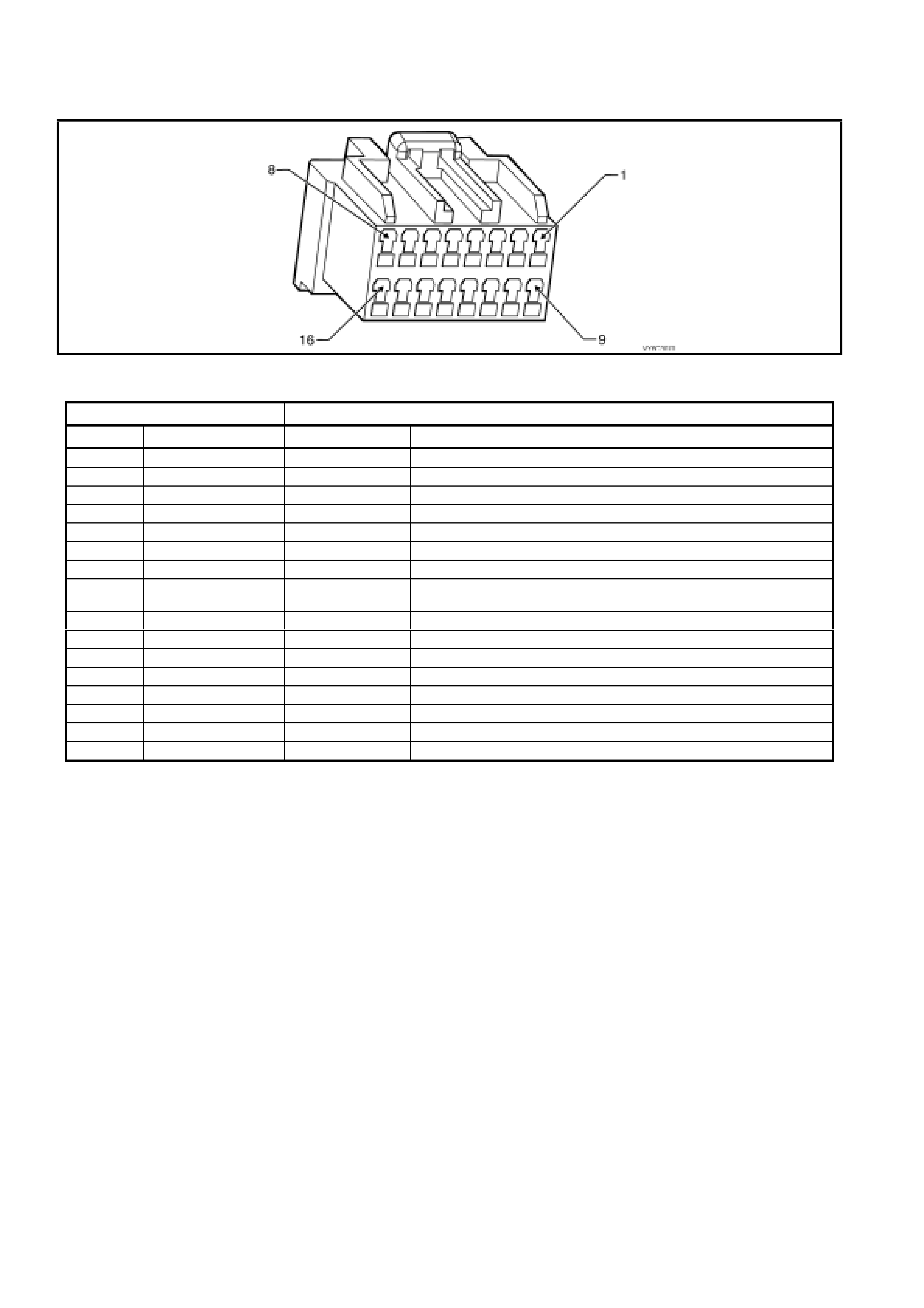
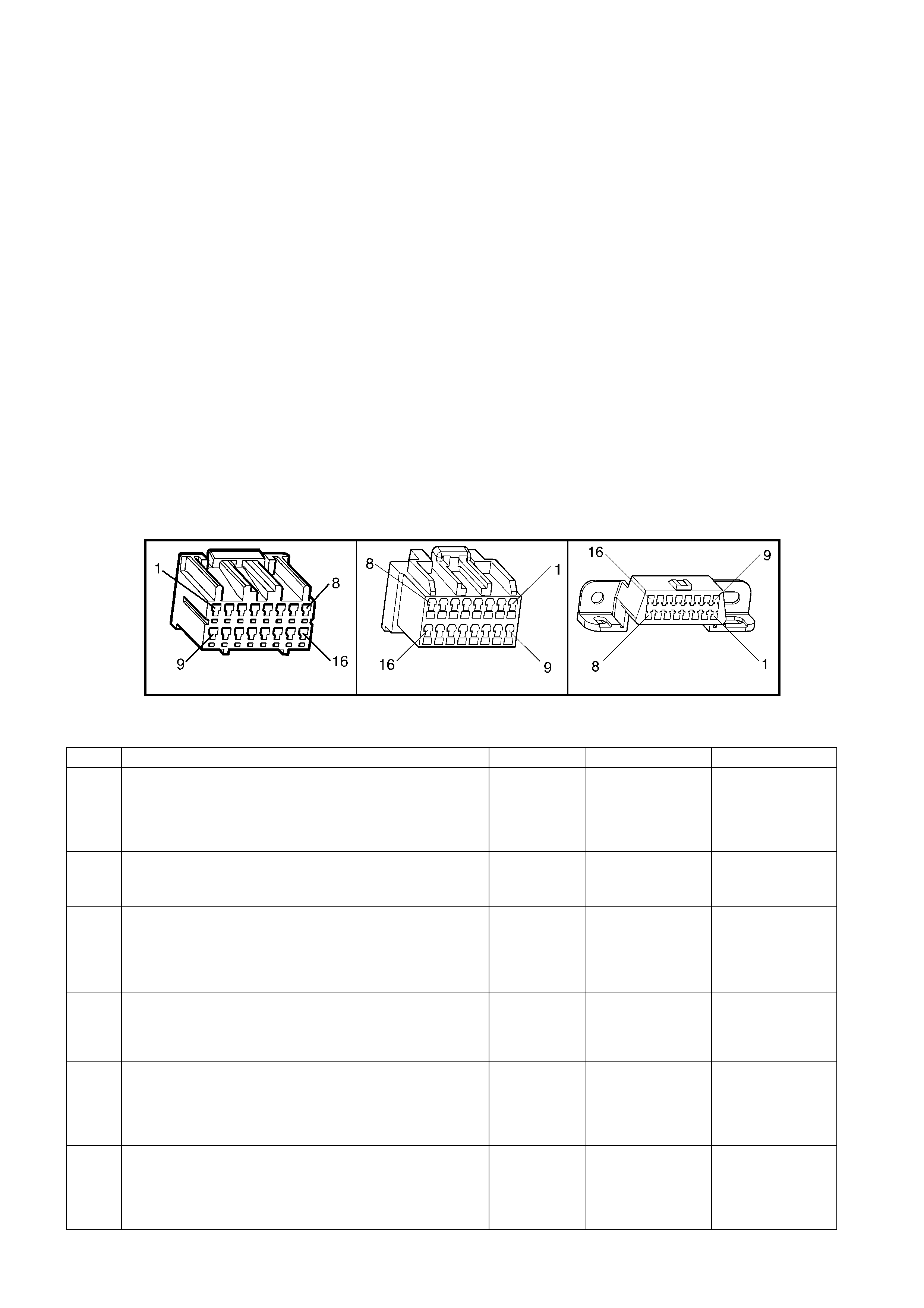
1.5 PIM CONNECTOR END VIEW
PIM CONNECTOR
Figure 6C3-2A-21
Connector Part Information PIM Connector A5 – X 1 16 Pin Connector
Pin Wire Colour Circuit No. Function
1 Not Used – –
2 Not Used – –
3 Not Used – –
4 Not Used – –
5 Not Used – –
6 Red/Black 800 UART Serial Data
7 Yellow 5072 Class II Seri al Data
8 Gr ey/Blu e (Aut omatic )
Grey (Manual) 275 (Automatic)
434 (Manual) Starter Relay Control
9 Not Used – –
10 Not Used – –
11 Not Used – –
12 Not Used – –
13 Not Used – –
14 Not Used – –
15 Orange 300 Ignition Feed
16 Black/Red 450 System Ground

1.6 PIM CONNECTOR TERMINAL DEFINITIONS
1 – NOT USED
2 – NOT USED
3 – NOT USED
4 – NOT USED
5 – NOT USED
6 – SERIAL DATA (UART) – This is a dedicated line for Tech 2 communications. The circuit connects the PIM,
BCM, and ABS/T CS, Ins trum ent, O CC, SRS. Tec h 2 can talk to each of these m odules b y sending a m essage to a
controller a nd as king only it to r es p ond . The com munic atio n r at e is at 81 92 bau d. The normal vo lta ge on t his c irc uit
is about 5 v olts , but wh en t he ign it ion is turn e d ON and th e modul es are c om municati ng, the vol tag e wil l vary an d if
read with a DMM may read about 2.5 volts.
7 – SERI AL DATA (CL ASS II) – T his is dedica ted lin e for com m unication betwe en the PCM and PIM or t he PCM
and Tech 2. The circuit connects between the PCM, PIM and DLC, terminal 2. Tech 2 can communicate with the
PCM by sending a m essage to the PCM and asking it to respond. T he communication rate is at 10,400 baud an d
the voltage on this circuit is normally 0 volts but is driven high to approximately 7 volts when communication is
occurring. Class II communication is prioritised, so this signal may not be constant.
8 – ST ARTER RELAY CONTROL – When the PIM receives the proper Theft Deterrent signal from the BCM, the
PIM will supply a ground signal to the Start Relay. This will allow the vehicle to crank.
If an impr oper T heft Deterrent s ignal is s ensed b y the PIM, then th e PIM wil l not supp ly a ground s igna l to the Start
Relay, and the PIM will not send a message to the PCM to allow fuel injection.
9 – NOT USED
10 – NOT USED
11 – NOT USED
12 – NOT USED
13 – NOT USED
14 – NOT USED
15 – IGNITION FEED – This is the power sup ply to the PI M from the ig nition swit ch. The volt age should equ al the
battery voltage when the key is in either the RUN, or CRANK position.
16 – SYSTEM GROUND – This terminal should have zero volts. This circuit is connected directly to engine ground.
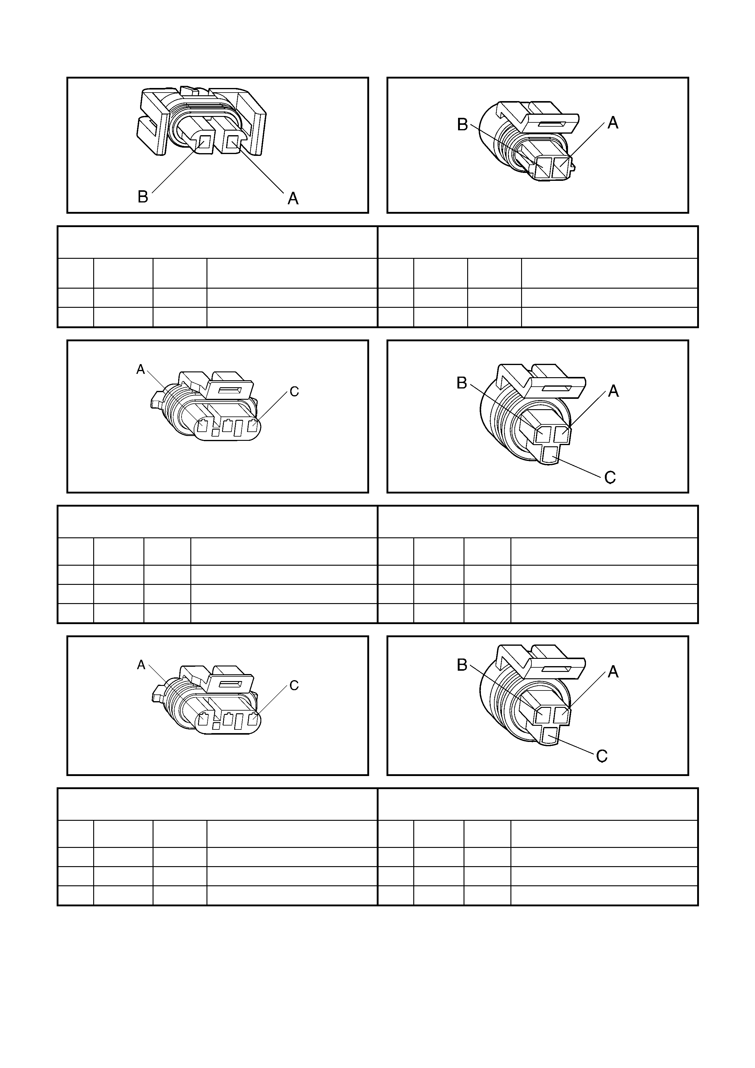
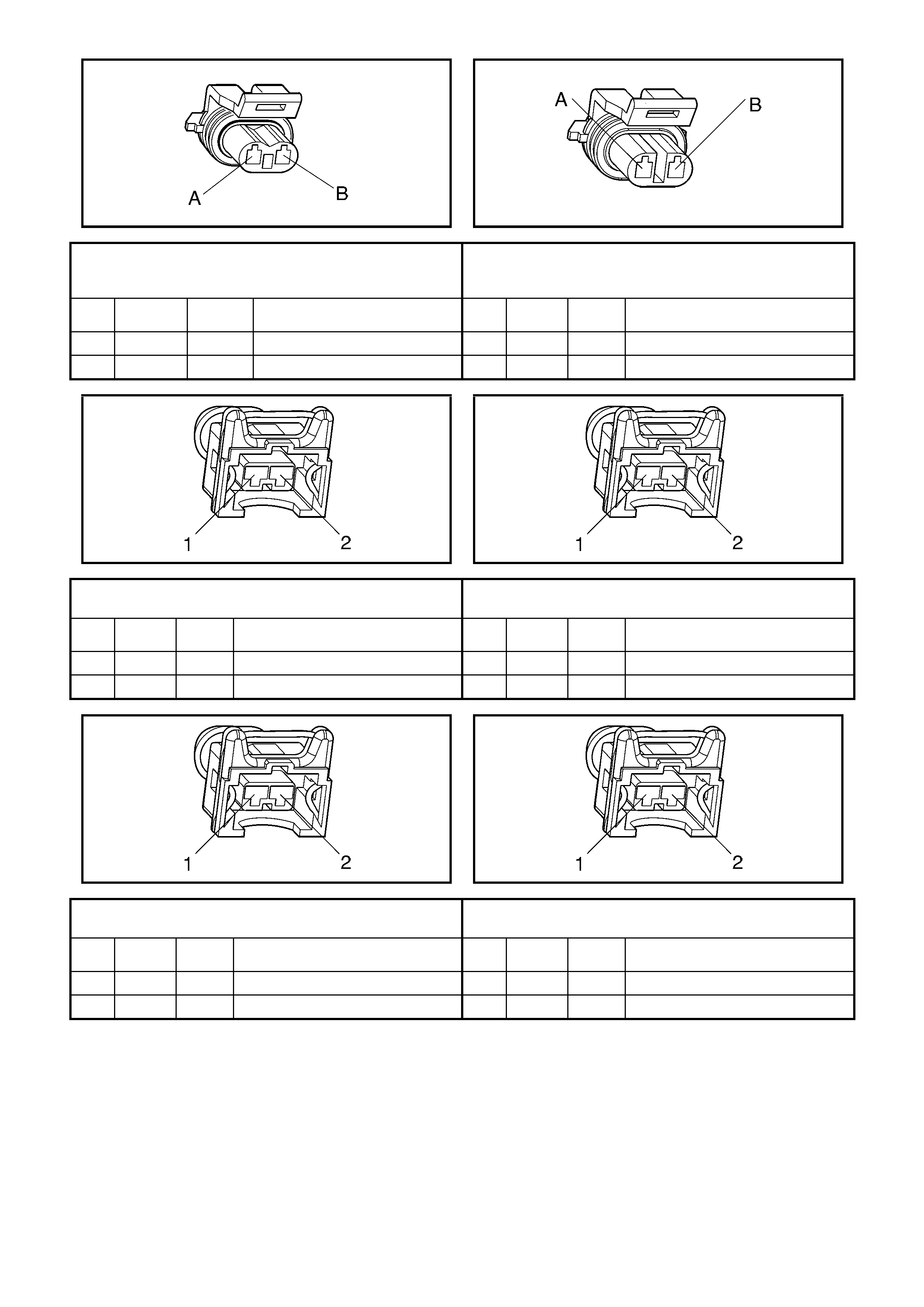
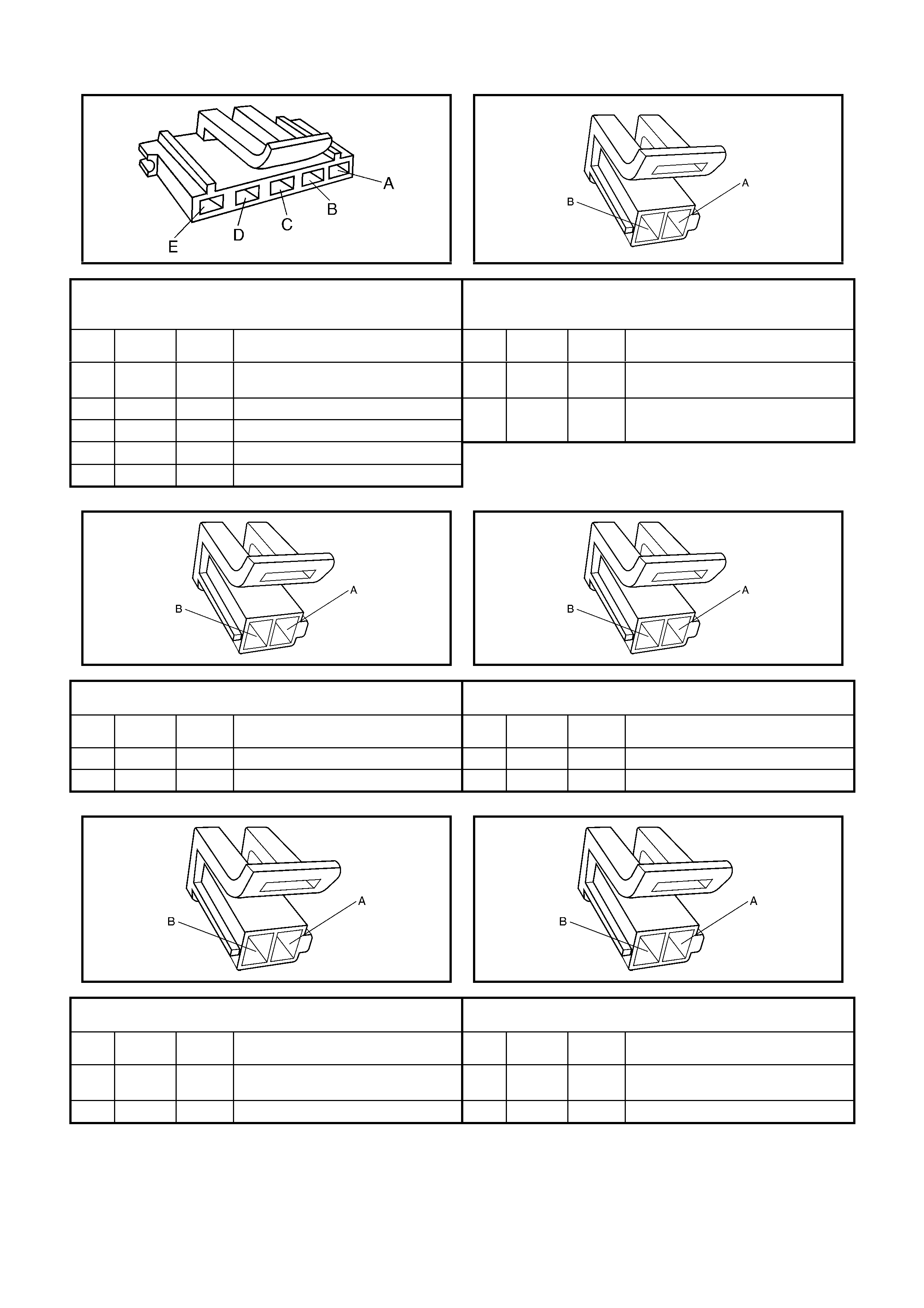
1. 7 ENGINE CONTROL CONNECTOR END VIEWS
L7
A/C Compressor Clutch Connector B39
Engine Coolant Temperature (ECT) Sensor Connector
Pin Wire
Colour Circuit
No. Function Pin Wire
Colour Circuit
No. Function
A BK/RD 450 Ground A GY/BK 2761 Sensor Ground
B GN 59 B+ from Relay R11 B YE 410 Sensor Signal
B28
Camshaft Position (CMP) Sensor Connector B18
A/C Refrigerant Pressure Sensor Connector
Pin Wire
Colour Circuit
No. Function Pin Wire
Colour Circuit
No. Function
A BN 633 Sensor Signal A GN/OG 2753 Sensor Ground
B RD/WH 632 Sensor Ground B PU/WH 2700 5 Volt Reference
C WH/BK 631 Sensor Voltage Supply (B+) C GN/BK 380 Sensor Signal
B30
Crankshaft Position (CKP) Sensor Connector B42
Oil Pressure Sensor Connector
Pin Wire
Colour Circuit
No. Function Pin Wire
Colour Circuit
No. Function
A L-BU 573 Sensor Signal A GN 470 Sensor Ground
B L-BU/BK 574 Sensor Ground B BU/YE 596 5 Volt Reference
C L-BU/WH 1800 Sensor Voltage Supply (B+) C BN/WH 331 Sensor Signal
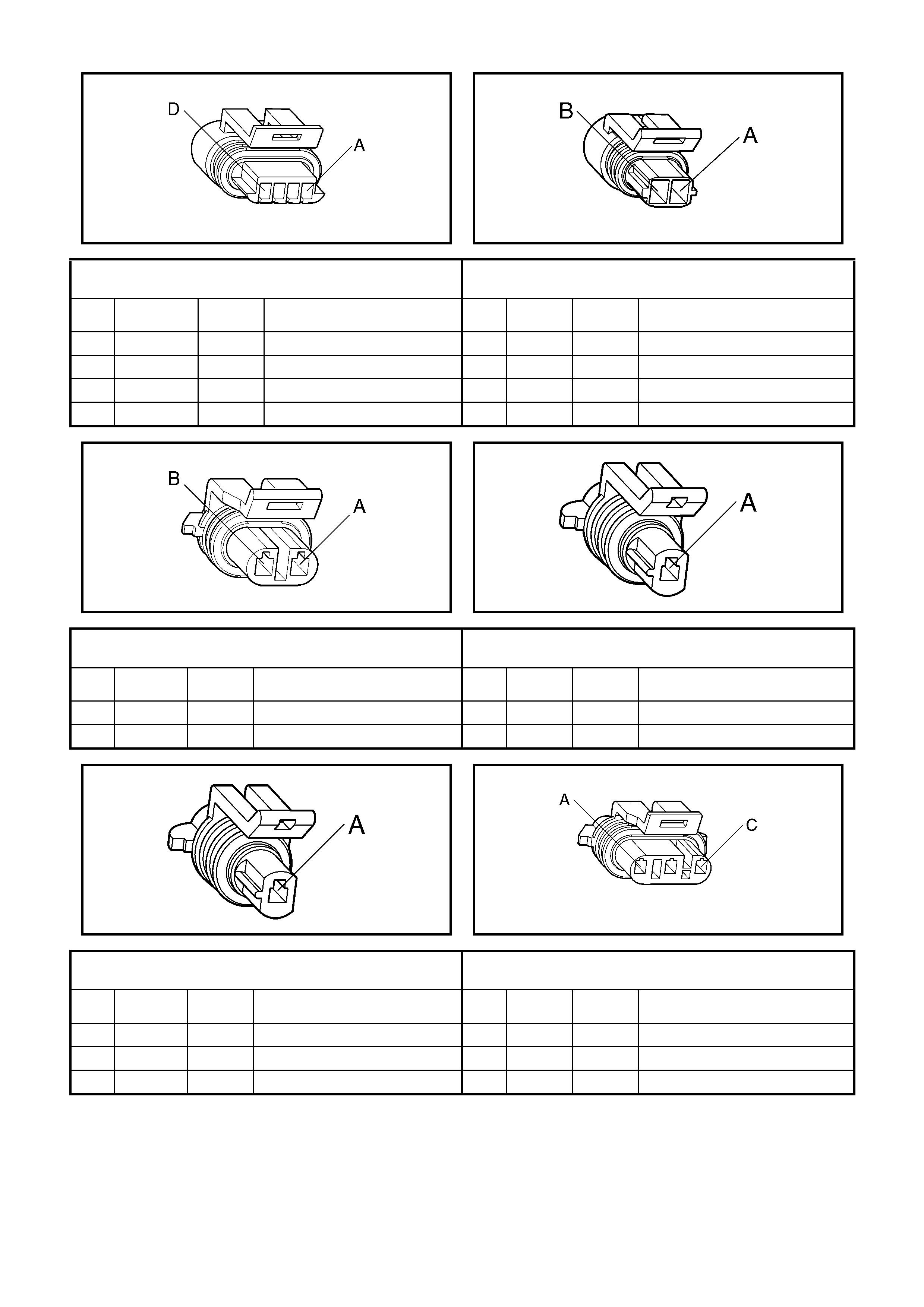
Y123
Evaporative Emission (EVAP) Canister Purge Solenoid
Connector
S84
Engine Coolant Level Switch Connector
Pin Wire
Colour Circuit
No. Function Pin Wire
Colour Circuit
No. Function
A PK 439 B+ from F33 A L-GN 68 Switch Signal Circuit
B L-GN/YE 428 Purge Control PWM B BK/RD 450 Switch Ground
L2
Fuel Injector #1 Connector L2
Fuel Injector #2 Connector
Pin Wire
Colour Circuit
No. Function Pin Wire
Colour Circuit
No. Function
1 L-GN 1039 Injector Voltage Supply – F35 1 RD 639 Injector Voltage Supply – F34
2 BU 1744 Injector Control 2 GN 1745 Injector Control
L2
Fuel Injector #3 Connector L2
Fuel Injector #4 Connector
Pin Wire
Colour Circuit
No. Function Pin Wire
Colour Circuit
No. Function
1 L-GN 1039 Injector Voltage Supply – F35 1 RD 639 Injector Voltage Supply – F34
2 PU 1746 Injector Control 2 BN/YE 844 Injector Control

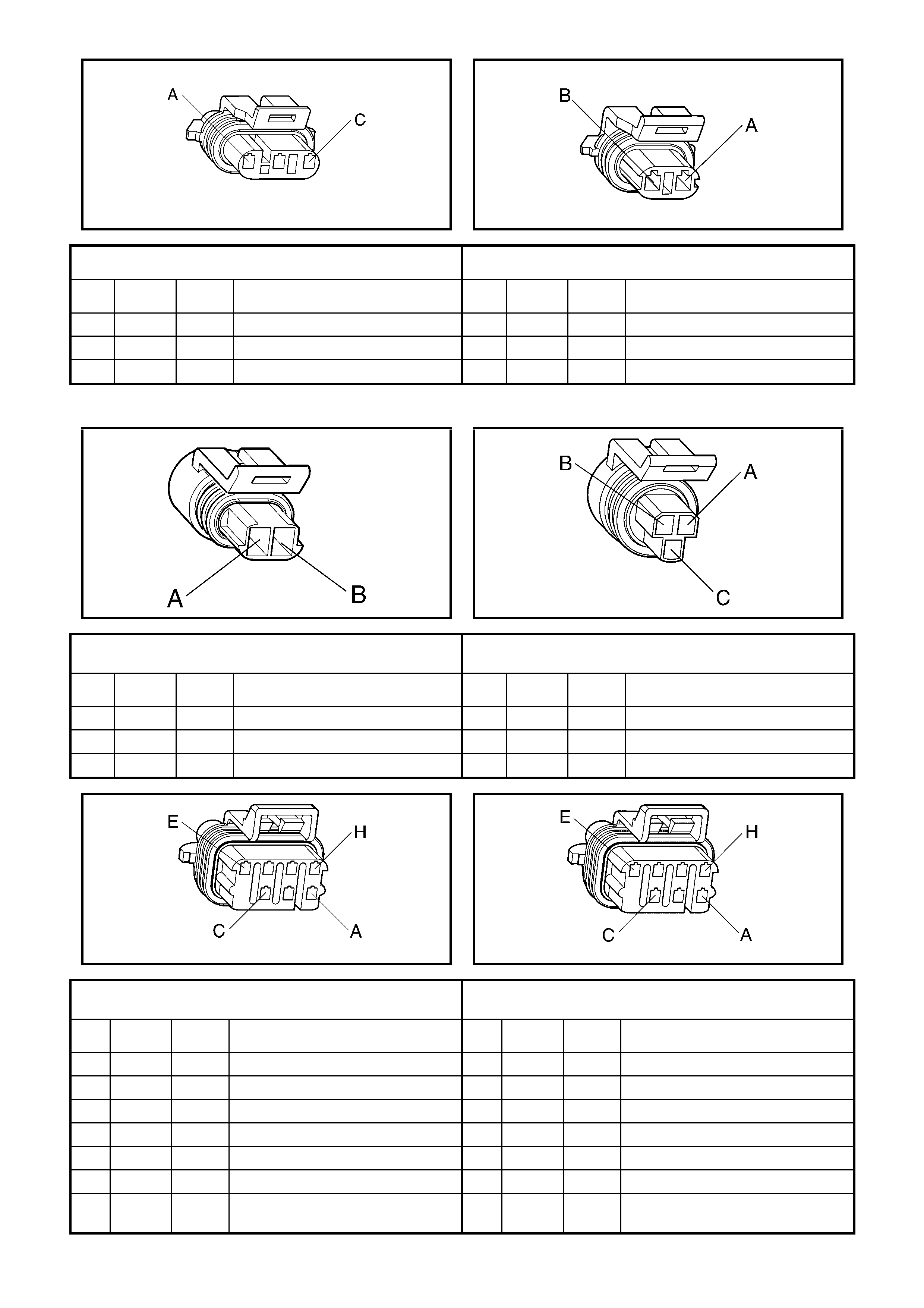
L2
Fuel Injector #5 Connector L2
Fuel Injector #6 Connector
Pin Wire
Colour Circuit
No. Function Pin Wire
Colour Circuit
No. Function
1 L-GN 1039 Injector Voltage Supply – F35 1 RD 639 Injector Voltage Supply – F34
2 GY 845 Injector Control 2 YE 846 Injector Control
L2
Fuel Injector #7 Connector L2
Fuel Injector #8 Connector
Pin Wire
Colour Circuit
No. Function Pin Wire
Colour Circuit
No. Function
1 L-GN 1039 Injector Voltage Supply – F35 1 RD 639 Injector Voltage Supply – F34
2 PK/BU 877 Injector Control 2 L-GN 878 Injector Control
B56-L
Left Heated Oxygen (HO2S) Sensor Connector B57-R
Right Heated Oxygen (HO2S) Sensor Connector
Pin Wire
Colour Circuit
No. Function Pin Wire
Colour Circuit
No. Function
A BU/BK 1664 Sensor Signal Low A GY/BK 1667 Sensor Signal Low
B PU 1665 Sensor Signal High B GY 1666 Sensor Signal High
C BK/RD 450 Heater Circuit Ground C BK/RD 450 Heater Circuit Ground
D PK 439 Heater Voltage Supply – F33 D PK 439 Heater Voltage Supply – F33
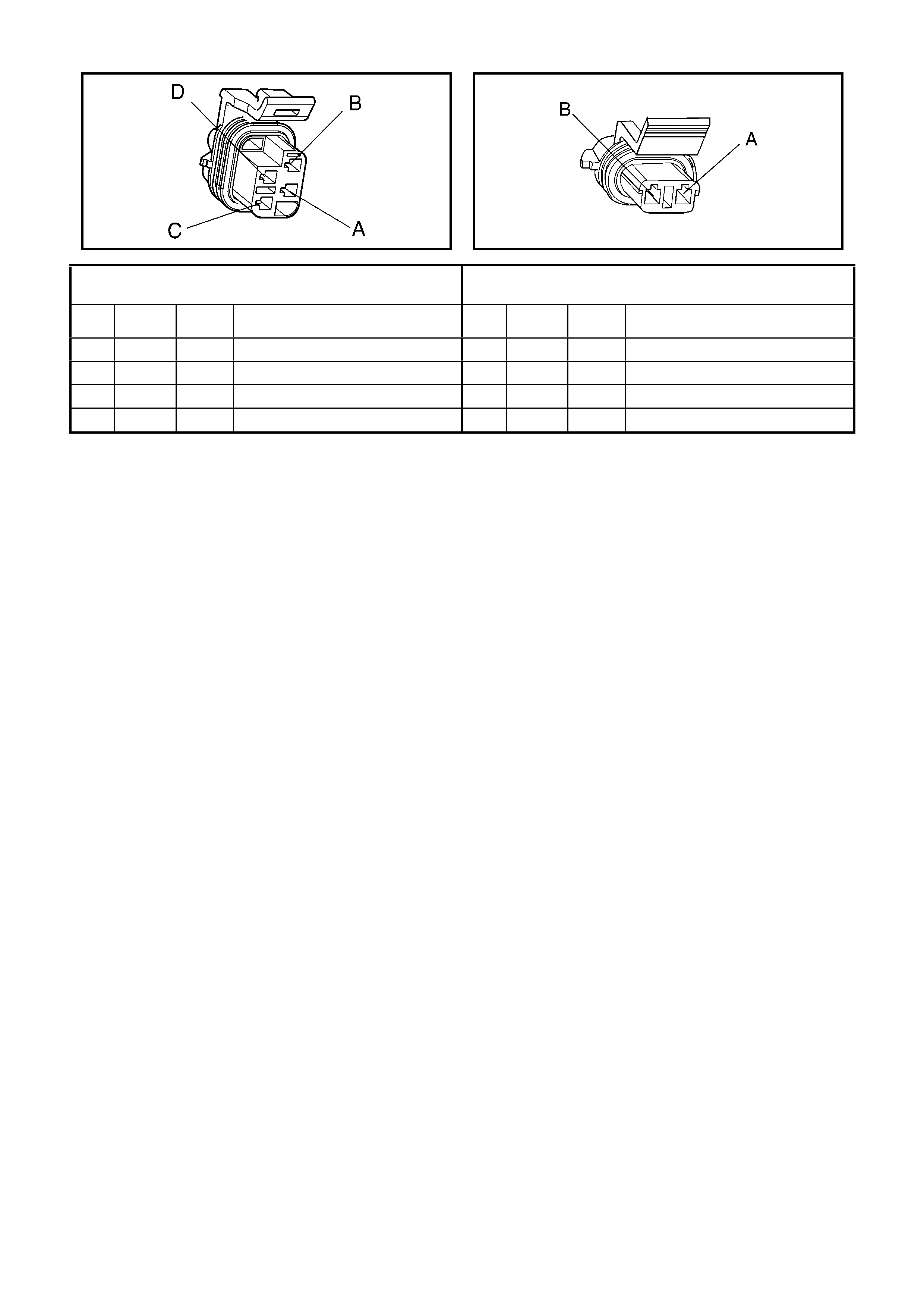
Y20
Idle Air Control (IAC) Valve Connector B64
Intake Air Temperature (IAT) Sensor Connector
Pin Wire
Colour Circuit
No. Function Pin Wire
Colour Circuit
No. Function
A L-GN/BK 444 IAC Coil 1 Low A GN/OG 2753 Sensor Ground
B L-GN/WH 1749 IAC Coil 1 High B BN 472 Sensor Signal
C L-BU/BK 1748 IAC Coil 2 Low
D L-BU 1747 IAC Coil 2 High
X107
Knock Sensor Patch Harness Connector B65
Front Knock Sensor (KS) Connector
Pin Wire
Colour Circuit
No. Function Pin Wire
Colour Circuit
No. Function
A L-GN/WH 1876 Knock Sensor 2 Signal A WH/RD 496 Sensor Signal
B BU 496 Knock Sensor 1 Signal
B65
Rear Knock Sensor (KS) Connector B92
Manifold Absolute Pressure (MAP) Sensor Connector
Pin Wire
Colour Circuit
No. Function Pin Wire
Colour Circuit
No. Function
A L-GN/WH 1876 Sensor Signal A BK 469 Sensor Ground
B L-GN 432 Sensor Signal
C PU/WH 2704 5 Volt Reference
B68
Mass Air Flow (MAF) Sensor Connector Y144
Manual Transmission Reverse Inhibit Connector
Pin Wire
Colour Circuit
No. Function Pin Wire
Colour Circuit
No. Function
A BN/WH 492 Sensor Signal A YE 1652 Solenoid Control
B BK/RD 450 Sensor Ground B PK/BU 339 Solenoid Voltage Supply – F32
C PK 439 Sensor Voltage Supply – F33
X121 – X1
Vehicle Speed Sensor (VSS) Connector B82
Throttle Position (TP) Sensor Connector
Pin Wire
Colour Circuit
No. Function Pin Wire
Colour Circuit
No. Function
A BU/WH 1230 VSS Signal High A GY 2701 5 Volt Reference
B TN 1231 VSS Signal Low B BK/YE 2752 Sensor Ground
C BU 411 Sensor Signal
A40 – L
Left Bank, Ignition Module Connector A40 – R
Right Bank, Ignition Module Connector
Pin Wire
Colour Circuit
No. Function Pin Wire
Colour Circuit
No. Function
A BK 450 Ignition Coil/Module Ground A BK 450 Ignition Coil/Module Ground
B YE 2127 Ignition Coil Control #7 B YE/BK 2122 Ignition Coil Control #2
C GN 2125 Ignition Coil Control #5 C W H 2124 Ignition Coil Control #4
E BN 2129 Ignition Reference Low E PU 2130 Ignition Reference Low
F BU 2123 Ignition Coil Control #3 L-GN 2126 Ignition Coil Control #6
G WH 2121 Ignition Coil Control #1 F L-BU 2128 Ignition Coil Control #8
H L-GN 1039 Ignition Coil/Module Power Supply
F35 G RD 639 Ignition Coil/Module Power Supply
F34
S187 – X2
PRNDL Switch Connector Y38
Throttle Relaxer Connector
Pin Wire
Colour Circuit
No. Function Pin Wire
Colour Circuit
No. Function
A BU/WH 771 PRNDL Switch Input A A RD/WH 560 Throttle Relaxer Motor B+
B GY 773 PRNDL Switch Input C B RD/BK 561 Throttle Relaxer Motor Ground
C W H 776 PRNDL Switch Input P
D YE/RD 772 PRNDL Switch Input B

1.8 AUTOMATIC TRANSMISSION IN-LINE HARNESS CONNECTOR END VIEWS
X121-X2
Automatic Transmission Wiring – Engine Side X121-X2
Automatic Transmission Wiring – Transmission Side
Pin Wire
Colour Circuit
No. Function
A L-GN 1222 1-2 Shift Solenoid (A) Valve Control
B YE/BK 1223 2-3 Shift Solenoid (B) Valve Control
C RD 1228 Pressure Control Solenoid (PCS) Valve HIGH
D GY/BU 1229 PCS Valve LOW
E PK/BU 339 Transmission Solenoid Power – F32
L BK/YE 1227 Transmission Fluid Temperature (TFT) Sensor HIGH
M BK/WH 2762 TFT Sensor LOW
N BN/YE 1224 Range Signal A
P GY 1226 Range Signal C
R YE 1225 Range Signal B
S GN/WH 898 3-2 Shift Solenoid Valve Assembly Control
T GY/RD 422 Torque Converter Clutch Enable Solenoid Valve Control
U BN 418 Torque Converter Clutch Pulse Width Modulation Solenoid
Valve Control
1.9 AUTOMATIC TRANSMISSION INTERNAL CONNECTOR END VIEW S
Automatic Transmission Fluid Pressure (TFP) Manual
Valve Position Switch Connector Torque Converter Clutch Pulse Width Modulated (TCC
PWM) Solenoid Valve Connector,
Transmission Harness
Pin Wire
Colour Circuit
No. Function Pin Wire
Colour Circuit
No. Function
A BR 1227
Transmission Fluid Temperature (TFT)
Sensor Signal A RD 339 Transmission Solenoid Power
B GY 1230 TFT Sensor Ground
C PU 1224 Range Signal A Input
B TN 418
Torque Converter Clutch Pulse Width
Modulated Solenoid Valve Cont rol
D OG 1226 Range Signal C Input
E DK-BU 1225 Range Signal B Input
1-2 Shift Solenoid ‘A’ (SS) Valve Connector,
Transmission Side 2-3 Shift Solenoid ‘B’ (SS) Valve Connector,
Transmission Side
Pin Wire
Colour Circuit
No. Function Pin Wire
Colour Circuit
No. Function
A RD 339 Transmission Solenoid Power A RD 339 Transmission Solenoid Power
B L-GN 1222 1-2 Shift Solenoid (A ) Valve Control B YE 1223 2-3 Shift Solenoid (B) Valve Control
3-2 Shift Solenoid (SS) Valve Assembly Connector,
Transmission Side Pressure Control Solenoid (PCS) Valve Connector,
Transmission Side
Pin Wire
Colour Circuit
No. Function Pin Wire
Colour Circuit
No. Function
A WH 898
3-2 Shift Solenoid Valve Assembly
Control A PU 1228
Pressure Cont rol Solenoi d (PCS )
Valve HIGH Control
B RD 339 Transmission Solenoid Power B L-BU 1229 PCS Valve LOW Control

Torque Converter Clutch (TCC) Enable Solenoid Valve
Connector, Transmission Side
Pin Wire
Colour Circuit
No. Function
A RD 339 Transmission Solenoid Power
B BK 422
Torque Converter Clutch Solenoid
Valve Control

1.10 ENGINE DIAGNOSTIC TROUBLE CODES (DTC) – GEN III V8 – PCM
DTC DESCRIPTION ILLUMINATE MIL
P0101 MAF Sens or Performance Yes
P0102 MAF Sensor Circuit Low Frequency Yes
P0103 MAF Sensor Circuit High Frequency Yes
P0107 MAP Sensor Circuit Low Voltage Yes
P0108 MAP Sensor Circuit High Voltage Yes
P0112 IAT Sensor Circuit Low Voltage No
P0113 IAT Sensor Circuit High Voltage No
P0117 ECT Sensor Circuit Low Voltage Yes
P0118 ECT Sensor Circuit High Voltage Yes
P0121 TP Sensor Circuit Insufficient Activity Yes
P0122 TP Sensor Circuit Low Voltage Yes
P0123 TP Sensor Circuit High Voltage Yes
P0125 ECT Excessive Time to Closed Loop No
P0131 HO2S Circuit Low Voltage Bank 1 Sensor 1 Yes
P0132 HO2S Circuit High Voltage Bank 1 Sensor 1 Yes
P0133 HO2S Slow Response Bank 1 Sensor 1 Yes
P0134 HO2S Insufficient Activity Bank 1 Sensor 1 Yes
P0135 HO2S Heater Circuit Bank 1 Sensor 1 Yes
P0151 HO2S Circuit Low Voltage Bank 2 Sensor 1 Yes
P0152 HO2S Circuit High Voltage Bank 2 Sensor 1 Yes
P0153 HO2S Slow Response Bank 2 Sensor 1 Yes
P0154 HO2S Insufficient Activity Bank 2 Sensor 1 Yes
P0155 HO2S Heater Circuit Bank 2 Sensor 1 Yes
P0171 Fuel Trim System Lean Bank 1 Yes
P0172 Fuel Trim System Rich Bank 1 Yes
P0174 Fuel Trim System Lean Bank 2 Yes
P0175 Fuel Trim System Rich Bank 2 Yes
P0230 Fuel Pump Control Circuit Yes
P0325 Knock Sensor System Yes
P0327 Knock Sensor Circuit Front Yes
P0332 Knock Sensor Circuit Rear Yes
P0335 CKP Sensor Circuit Yes
P0336 CKP Sensor Circuit Performance Yes
P0341 CMP Sensor Circuit Performance Yes
P0342 CMP Sensor Circuit Low Voltage Yes
P0343 CMP Sensor Circuit High Voltage Yes
P0351 Ignition Control #1 Circuit Yes
P0352 Ignition Control #2 Circuit Yes
P0353 Ignition Control #3 Circuit Yes
P0354 Ignition Control #4 Circuit Yes
P0355 Ignition Control #5 Circuit Yes
P0356 Ignition Control #6 Circuit Yes
P0357 Ignition Control #7 Circuit Yes
P0358 Ignition Control #8 Circuit Yes
P0443 EVAP Purge Solenoid Control Circuit Yes
P0481 High Speed Cooling Fan Relay Driver Circuit Yes
P0502 Vehicle Speed Sensor Circuit Low Input No
P0503 Vehicle Speed Sensor Circuit Intermittent No
P0506 Idle Speed Low Yes
P0507 Idle Speed High Yes

DTC DESCRIPTION ILLUMINATE MIL
P0522 Engine Oil Pressure Sensor Low Input Yes
P0523 Engine Oil Pressure Sensor High Input Yes
P0530 A/C Ref r igerant Pr es sur e S ensor Circu it No
P0562 System Voltage Low No
P0563 System Voltage High No
P0601 PCM Memory Yes
P0602 PCM Not Progr am med Yes
P0608 VSS Output Circuit No
P0654 Engine Speed Output Circuit No
P1111 IAT Sensor Intermittent High Voltage No
P1112 IAT Sensor Intermittent Low Voltage No
P1114 ECT Sensor Intermittent Low Voltage No
P1115 ECT Sensor Intermittent High Voltage No
P1121 TP Sensor Intermittent High Voltage No
P1122 TP Sensor Intermittent Low Voltage No
P1258 Engine Coolant Over Temp Fuel Disable Yes
P1539 A/C Clutch Status Circuit High Voltage No
P1546 A/C Clutch Status Circuit Low Voltage No
P1626 Theft Deterrent System Fuel Enable Circuit Yes
P1630 PCM In Learn Mod e Yes
P1631 Theft Deterrent Password Incorrect Yes
P1635 5 Volt Reference #1 Circuit Yes
P1639 5 Volt Reference #2 Circuit Yes

1.11 DIAGNOSTIC TROUBLE CODES (DTC) – GEN III V8 – PIM
DTC DESCRIPTION ILLUMINATE MIL
B2002 Low Speed Fan No BCM Response No
B2006 No Serial Data From PCM No
B2007 Starter Relay Voltage High No
B2009 EEPROM Checksum Error No

1.12 DIAGNOSTIC TROUBLE CODES (DTC) – GEN III V8 – AUTOMATIC TR ANSMISSION
DTC DESCRIPTION ILLUMINATE MIL
P0218 Transmission Fluid Over-temperature No
P0500 Vehicle Speed Sensor Circuit Yes
P0502 Vehicle Speed Sensor Circuit Low No
P0503 Vehicle Speed Sensor Circuit Intermittent No
P0705 PRNDL Range Fault No
P0706 PRNDL Switch Fault No
P0711 TFT Sensor Circuit Range/Performance No
P0712 TFT Sensor Circuit Low No
P0713 TFT Sensor Circuit High No
P0719 Brake Switch Circuit Low No
P0724 Brake Switch Circuit High No
P0740 TCC Enable Solenoid Circuit Electrical No
P0742 TCC System Stuck On Yes
P0748 PC Sol eno id Circ ui t Electr ical No
P0751 1-2 SS Valve Performance Yes
P0753 1-2 SS Circuit Electrical Yes
P0756 2-3 SS Valve Performance Yes
P0758 2-3 SS Circuit Electrical Yes
P0785 3-2 SS Circuit Electrical Yes
P1810 TFP Switch Circuit Fault No
P1860 TCC PWM Solenoid Circuit Electrical No
P1870 Transmission Component Slipping No
2. GENERAL DIAGNOSTIC TABLES
2.1 TABLE A-1 – GEN III V8 PCM –
ON-BOARD DIAGNOSTIC (OBD) SYSTEM CHECK
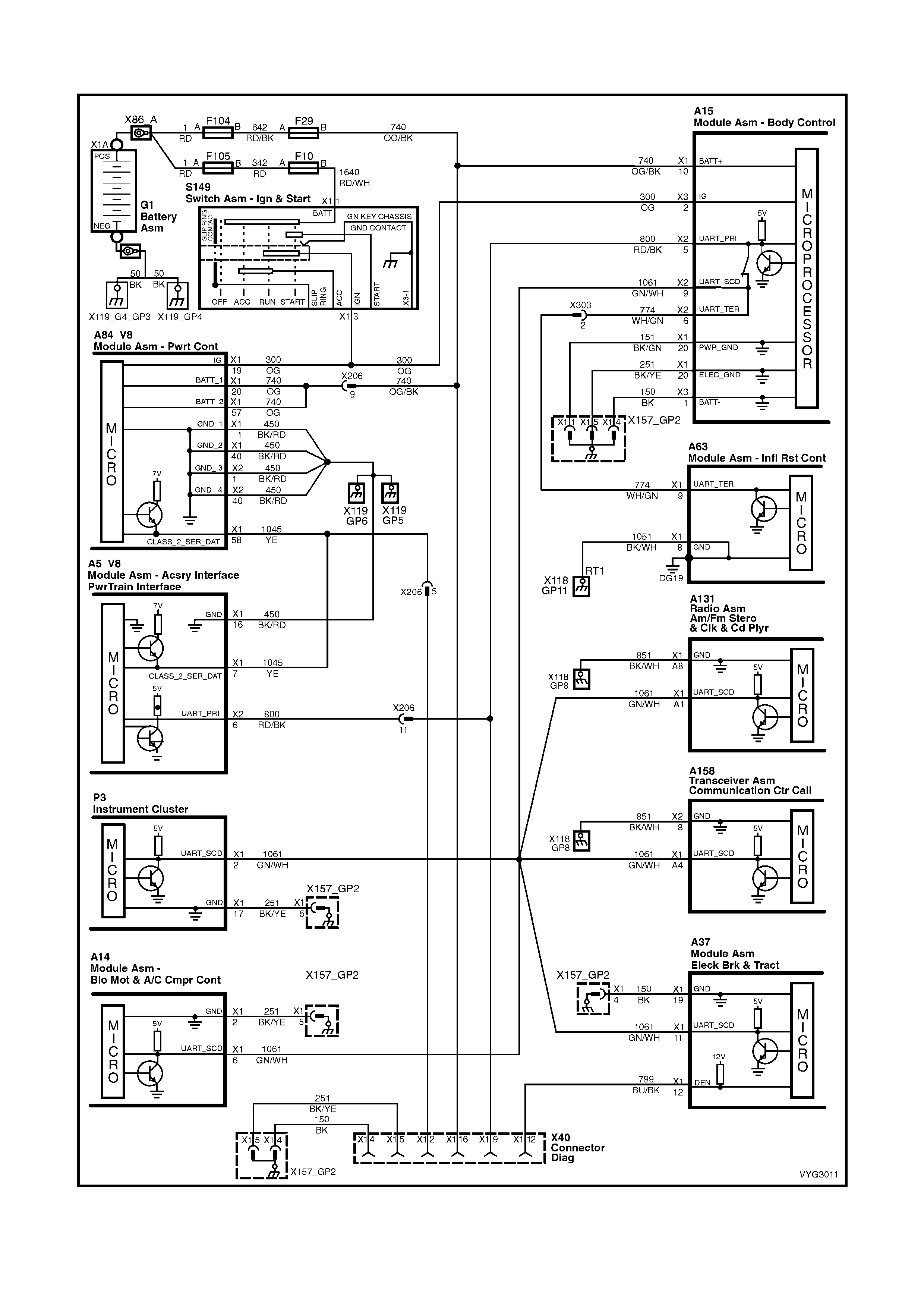
Figure 6C3-2A-22 – Check Powertrain MIL and Serial Data Circuits
CIRCUIT DESCRIPTION
The Powertrain OBD System Check is an organised approach to identifying a problem created by an electronic
engine control system malfunction. The Powertrain OBD System Check is the starting point for any driveability
complaint diagnosis. The Powertrain OBD System Check directs the service technician to the next logical step in
diagnosing a complaint. DO NOT PERFORM THIS CHECK IF NO DRIVEABILITY COMPLAINT EXISTS.
Understanding and using the table correctly will reduce the diagnostic time and prevent the replacement of good
parts.
IMPORTANT: This vehicle is equipped with a Powertrain Control Module (PCM) utilising an Electrically Erasable
Programmable Read Only Memory (EEPROM). Program the new PCM when diagnostics call for replacement of
the PCM. Refer to PCM Replacement Programming in Sectio n 6C3- 3 SE RVI CE O PERATION S.
IMPORTANT: This vehicle is equipped with a Powertrain Interface Module (PIM). This PIM is the vehicle serial
data translator between Class II and UART serial data.
DIAGNOSTIC AIDS
IMPORTANT: If an intermittent condition exists, inspect the PCM wiring harnesses for improper installation of
electrical components. Inspect for aftermarket theft deterrent devices, lights, and cellular phones. Ensure that no
aftermarket equipment is connected to the Class II circuit. A cellular phone signal communication may cause an
intermittent condition.
• The PIM will co ntrol the s ta rter m otor oper ation , whil e the PC M will contr ol the f uel injector PW M. If the PCM is
non-func tio na l, the veh icle may crank but will not start.
• If BCM DT C 7 and or DTC 17 are s et, the BCM is probabl y causin g the problem . Refer to BCM DT C tables in
Section 12J BCM.
• If multiple DTCs are set, inspect the EFI relay for proper operation. This relay protects the battery from a
parasitic draw.
• The following components are powered by the EFI relay:
– Injectors/Ignition coils
– Transmission
– EVAP Solenoid
– MAF Sensor
– Heated Oxygen Sensors
– A/C Relay
• It is benef icial t o revie w the Free ze Fram e Data and/or Fail R ecords . Use the odom eter inform ation and th e fail
counter in order to determine how frequently and how recently the DTC set. This information, and the other
operating conditions when the DTC set, may help diagnose an intermittent problem. Capturing the stored info
preserves data that the PCM will lose when instructed to Clear Info at the end of a diagnostic table, or if you
disconn ect the PCM or r eplace the PCM dur ing a diagnos tic proced ure. Revie w the captured inf o at the end of
the diagnos t ic pr ocedure in order to catc h the nex t DT C in the eve nt t here ar e multiple DTCs s tored. F ol low t h e
order of priority as listed above.
• If the engine is mis-firing and no DTCs are set, refer to , Cuts Out, Misses in Section 6C3-2B SYMPTOMS.
TEST DESCRIPTION
NOTE: The number(s) below refer to the step number(s) on the diagnostic table.
1. This check is used to establish if the PCM can supply Class 2 serial data for Tech 2 use. If Tech 2 can
communicate with the PCM then the PCM power and ground circuits are OK.
2. This check is to see if the PIM has received a valid thef t deterrent message f rom the BCM. If the PIM has not
received a v alid thef t deterrent signal f rom the BCM th e engine wil l not crank. If the vehicle will not crank , refer
to Starter Cranking Circuit to diagnose the starter cranking circuit.
3. This test deter mines if any DT Cs are s tor ed in the PC M mem ory. To determ ine if a DT C is cur r ent, sel ec t “DTC
Information / Failed This Ignition”.
4. This test is used to determine the cause of a "Cranks But Will Not Run," although the PCM is powered up, a
"Cranks But Will Not Run" symptom could exist because of a PCM problem or the vehicle electrical system.
5. Look at all the parameters to determine if one is not in a normal state with just the ignition "ON" and engine
stopped. F or ex am ple, look at th e ECT va lue to s ee if the value is shif ted above o r bel ow wher e it sho uld b e. If
so, refer "Diagnostic Aid Table" on DTC P0118.
6. Look at all the parameters to determine that all values are within typical ranges for normal operating
temperatures at idle. Keep in mind that a basic engine problem may alter sensor value.
A15 – X3 A5 X40
Figure 6C3-2A-23
GEN III V8 PCM – POWERTRAIN OBD SYSTEM CHECK
STEP ACTION VALUE YES NO
1. 1. Install Tech 2 to Data Link Connector.
2. Select V8 GEN III Engine.
Does Tech 2 display Identification Data?
Go to Step 2 Go to
Data Link
Connector
Diagnosis,
in this Section
2. 1. Turn ignition “ON” and wait 5 seconds.
2. Turn ignition to “START” position.
Does engine crank?
Go to Step 3 Go to Starter
Cranking Circuit,
in this Section
3. 1. Using Tech 2, select ”Read DTC Info Ordered by
Priority”.
Are any Diagnostic Trouble Codes displayed?
Refer to
Applicable DTC
Table.
Start with lowest
DTC
Go to Step 4
4. Does engine start and continue to run?
Go to Step 5 Go to Engine
Cranks But Will
Not Run, in this
Section.
5. 1. Ignition "ON", engine "STOPPED".
2. Compare Tech 2 data with typical values shown on
scan data page.
Are values normal or within typical ranges?
Go to Step 6 Refer to
indicated
"Component(s) –
System" ch ec ks
in this Section.
6. 1. Ignition "ON", engine "RUNNING".
3. Compare Tech 2 data with typical values shown on
scan data page.
Are values normal or within typical ranges?
Refer to
Diagnostic Aids Refer to
indicated
"Component(s) –
System" ch ec ks
in this Section.
2.2 TABLE A-2 – GEN III V8 –
CHECK POWE RTRAIN MALFUNCTION INDICATOR LAMP (MIL)
Figure 6C3-2A-24 – Check Powertrain Malfunction Indicator lamp (MIL)
CIRCUIT DESCRIPTION:
The Powertrain Control Module (PCM) controls the Check Powertrain Malfunction Indicator Lamp (MIL) icon, via
serial data communication to the Instrument on the serial data circuit. When the PCM determines that the Check
Powertrain MIL should be activated, the PCM will send a message to the instruments via the serial data circuit
normal mode message, requesting the Check Powertrain MIL "ON”. The Instrument will then activate the Check
Powertrain MIL.
TEST DESCRIPTION:
NOTE: Number(s) below refer to step number(s) on the diagnostic table.
2. This test confirms that the Instrument MFD has passed its system check.
3. Disconnecting the Mass Air Flow Sensor should cause DTC 32 to set and the PCM to command the Check
Powertrain Lamp “ON” via the serial data normal mode message. If the DTC does not set then the internal
diagnostics of the PCM are not functioning correctly.
4. This test checks that the serial data normal mode message displays "ON" when the DTC sets.
A84–X1 (BLUE) A84-X2 (RED)
P3 X40 B68
Figure 6C3-2A-25

TABLE A-1 GEN III V8 PCM – NO "CHECK POWERTRAIN" MALFUNCTION INDICATOR LAMP (MIL)
STEP ACTION VALUE YES NO
1. Was the "On-Board Diagnostic" (OBD) System Check
performed? Go to Step 2 Go to
OBD System
Check in this
Section/
2. 1. Turn the ignition "ON".
2. Observe the Instrument Multi Function Display
(MFD).
Does the MFD display "OK!" once the “System Check” is
completed?
Go to Step 3 Refer to 12C
INSTRUMENTS
3. 1. Disconnect the Mass Air Flow Sensor connector
B68.
2. Start the engine and allow to idle for 20 seconds.
Does the MFD display the "Check Powertrain MIL"?
Check
Powertrain MIL
is operating
correctly
Go to Step 4
4. 1. Connect Tech 2 to the DLC.
2. With Tech 2 connected, select F0: Normal Mode,
with the Mass Air Flow Sensor connector B68, still
disconnected.
3. Start the engine and monitor the "Normal Mode"
data display.
Does the "Normal Mode" display "Check Powertrain
Lamp" display "ON"?
Refer to 12C
INSTRUMENTS Go to Step 5.
5. 1. Replace PCM. Refer to 6C3-3 Service Operations,
for PCM Security Link proc edure
Is action complete?
Verify Repair
2.3 GEN III V8 PCM – DATA LINK CONNECTOR DIAGNOSIS
Figure 6C3-2A-26 – Check Powertrain Malfunction Indicator Lamp (MIL)
CIRCUIT DESCRIPTION
Use a properly functioning T ech 2 with the diagnostic tables in this section. DO NOT use the ‘Clear DTC’ function
unless instructed by a diagnostic procedure.
IMPORTANT: This vehicle, equipped with a Powertrain Control Module (PCM), utilises an Electrically Erasable
Programm able Read Only Mem ory (EEPROM). Program the new PCM when the diagnostics call for replacement
of the PCM. Refer to PCM Replacement/ Programming in Section 6C3-3 SERVICE OPERATIONS.
DIAGNOSTIC AIDS
• If there is a fault with the PIM power feed or ground circuit, Tech 2 will not communicate with the PIM.
• If BCM DTC 007 is set, it indicates there is a problem (open) in circuit 800 (UART serial data circu it) between
the BCM and the PIM.
• If PIM DTC B2006 is set, it indicates there is a problem (open, short to ground, or short to voltage) in circuit
1045 (Class II Serial data circuit) between the PIM and the PCM.
• The following Table assumes that Tech 2 is fully functional.
TEST DESCRIPTION
NOTE: The number(s) below refer to the step number(s) on the diagnostic table.
3. This step checks to see if the PCM is receiving all of the power supplies.
4. This step is checking the Ground circuits at the PCM.
12. This step checks to see if the Class II serial data circuit is shorted to ground.
13. This step checks to see if the Class II serial data circuit is shorted to voltage.
A84–X1 (BLUE) A84-X2 (RED)
A5 x40
Figure 6C3-2A-27
GEN III V8 PCM – DATA LINK CONNECTOR DIAGNOSIS
STEP ACTION VALUE YES NO
1. Was the “On-Board Diagnostic” (OBD) System Check
performed? Go to Step 2 Go to
OBD System
Check
in this Section.
2. 3. Ignition ON, engine OFF.
4. Connect Tech 2 to the Diagnostic Link Connector
(DLC).
Does Tech 2 power-up?
Go to Step 3 Go to Step 7
3. 1. Ignition OFF.
2. Disconnect PCM connectors A84-X1 and A84-X2.
3. Ignition ON.
4. Probe each PCM battery and PCM ignition feed circuit
in PCM connectors, A84 X1-20 and A84 X1-57 (circuit
740, Orange wire) and A84 X1-19 (circuit 300, Orange
wire), using a test lamp connected to a known good
ground.
Does the test lamp illuminate at each terminal?
Go to Step 4 Go to Step 16
4. 1. Ignition OFF.
2. PCM connectors still disconnected.
3. Probe PCM ground circuits with a test light connected
to B+.
Is the test light ON for all ground circuits?
Go to Step 5 Go to Step 17

STEP ACTION VALUE YES NO
5. 1. Ignition OFF.
2. Reconnect both PCM connectors.
3. Connect Tech 2 to the DLC.
4. Ignition ON, engine OFF.
Does Tech 2 display Engine ID Information?
Go to OBD
System Check in
this Section.
Go to Step 6
6. Will the engine crank over? Go to Step 10 Refer to Starter
Cranking Circuit,
in this Section
7. 1. Ignition ON, engine OFF.
2. Probe the DLC terminal X1-16, circuit 740
(Orange/Black wire), with a test lamp connected to the
battery ground.
Is the test lamp illuminated?
Go to Step 8 Repair circuit
740 as required
(including fuse
F29)
8. 1. Probe the DLC terminal X1-4, circuit 150 (Black wire),
with a test lamp connected to B+.
Is the test lamp illuminated?
Go to Step 9 Repair circuit
150 as required.
9. 1. Inspect the Tech 2 connections to the DLC, including
proper terminal tension at the DLC.
Was a problem found?
Go to Powertrain
OBD System
Check Table
Refer Tech 2
Operators
Manual for Tech
2 Self Test
10. Will the engine start and run? Go to Step 18 Go to Step 14
11. 1. Disconnect PCM BLUE connector A84-X1 and PIM
connector A5.
2. Check for an open in the Class II serial data circuit
1045 (Yellow wire) between PCM BLUE connector
A84-X1, terminal X1-58, and PIM connector A5,
terminal X1-7.
Was a problem found?
Repair open in
circuit 5072. Go to Step 12
12. 1. Using test light connected to B+, probe the Class II
serial data circuit at the DLC X40, terminal X1-2, circuit
1045 (Yellow wire).
Is the test lamp illuminated?
Repair short to
ground in circuit
1045
Go to Step 13
13. 1. Using a test light connected to a known good ground,
probe the Class II serial data circuit at the DLC,
terminal 2, circuit 1045 (Yellow wire).
Is the test light illuminated?
Repair short to
voltage in circuit
1045.
Verify repair
Replace PCM,
refer PCM
Replacement in
6C3-3 Service
Operations
14. 1. Connect the Tech 2 to the DLC.
2. Select Body / Powertrain Interface Module (PIM) /
Diagnostic Trouble Codes.
Is PIM DTC B2006 set?
Go to Step 11 Go to Step 15
15.
In Step 14, were any other PIM DTC(s) set? Go to applicable
PIM DTC Table Go to Step 18
16. 1. Check for open circuit or short to ground and repair
power circuit that did not light test light.
Is action complete?
Verify Repair —
17. 1. Repair open in ground circuit that did not light test
light.
Is action complete?
Verify Repair —
18. 1. Repair open in Class II Serial Data circuit from DLC to
PCM.
Is action complete?
Verify Repair —
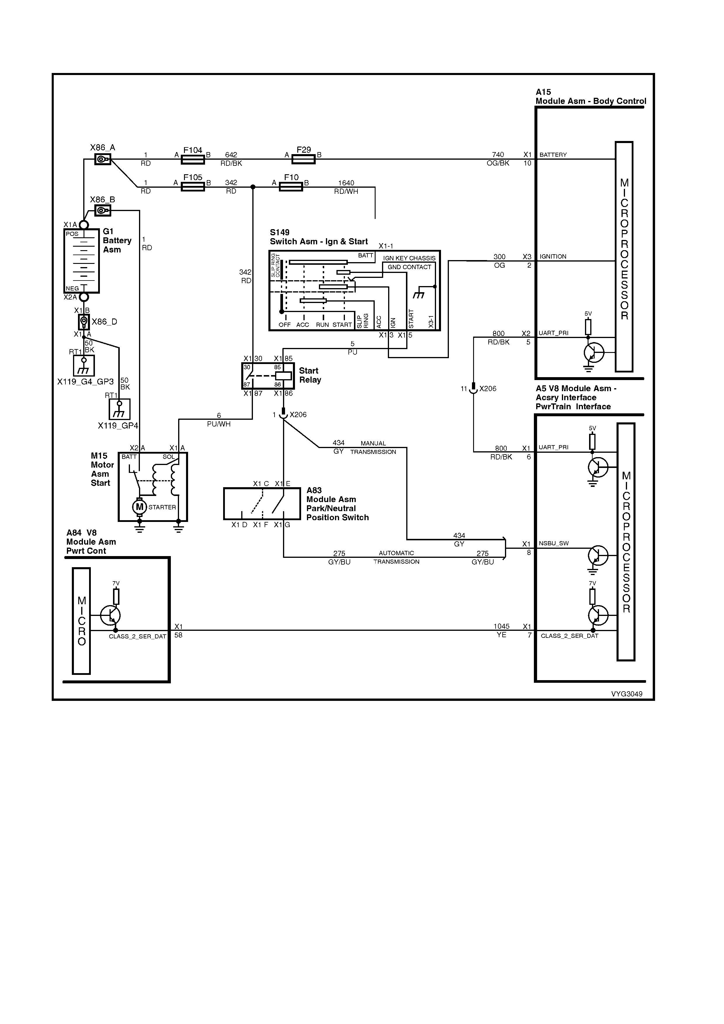
2.4 GEN III V8 PCM – ENGINE CRANKS BUT DOES NOT RUN
Figure 6C3-2A-28
CIRCUIT DESCRIPTION
The Engine Cranks but does not run diagnostic table assumes that the battery condition and engine cranking
speed are OK. If the battery condition and the cranking speed are not OK, refer to Section 12A BATTERY &
CABLES and Section 6D3-2 STARTING SYSTEM. Make sure that there is adequate fuel in the tank.
DIAGNOSTIC AIDS
• Check the duct work between the Mass Air Flow (MAF) Sensor and the throttle body for air leaks.
• A malfunctioning MAF Sensor may cause a no start or a stall after start. If you suspect this, disconnect the
MAF Se ns or. The PC M wil l default to th e s pe ed dens ity (M AP, I AT , RPM) in or der to c a lc ul ate the lo ad and t he
air flow.
• If this corrects the condition and the connections are OK, replace the MAF Sensor.
• If the steps above check OK, refer to Section 6C3-2B SYMPTOMS.

TEST DESCRIPTION
NOTE: The number(s) below refer to the step number(s) on the diagnostic table.
2. This step checks to see if any PIM DTC(s) are set.
7. The ignition feed circuit for the camshaft and crankshaft position sensors is internally connected within the
PCM. A short to ground on either circuit will cause a no start condition.
B28 B30
Figure 6C3-2A-29
GEN III V8 PCM – ENGINE CRANKS BUT DOES NOT RUN
STEP ACTION VALUE YES NO
1. Was the "On-Board Diagnostic" (OBD) System Check
performed? Go to Step 2 Go to
OBD System
Check
in this Section.
2. Are any PIM DTC(s) set? Go to applicable
PIM DTC Tables Go to Step 3
3. 1. Ignition ON, engine OFF.
2. Probe both sides of the fuses listed below using a test
lamp connected to ground.
– F29
– F33
– F34
– F35
Does the test lamp illuminate on both sides of all the fuses?
Go to Step 4 Go to EFI Relay
Diagnosis for
further diagnosis
4. 1. Using Tech 2, select the PCM Diagnostic Trouble
Code (DTC) and the DTC Information options.
Does Tech 2 display any of the following DTC(s) P0230,
P0335, P0336, P0602?
Go to the
applicable DTC
table
Go to Step 5
5. 1. Using Tech 2, Monitor the “Theft Status” display in
Engine Data.
Does Tech 2 display NO START?
Go to Theft
Deterrent
System in 12J
BCM
Go to Step 6
6. 1. Monitor the engine speed while cranking the engine.
Is engine RPM indicated on Tech 2? Go to Step 10 Go to Step 7
7. 1. Disconnect the Crankshaft Position (CKP) Sensor
electrical con nect or.
2. Measure the voltage at the ignition feed circuit at the
CKP electrical connector using a DMM.
Does the DMM display near the specified value?
B+ Go to Step 14 Go to Step 8
8. 1. Disconnect the Camshaft Position (CMP) sensor
electrical con nect or.
2. Measure the voltage at the ignition feed circuit at the
CMP electrical connector using a DMM.
Does the DMM display near the specified value?
B+ Go to Step 15 Go to Step 9
9. 1. Inspect the camshaft and crankshaft position sensor
ignition feed circuits for a short to ground.
Did you find and correct the condition?
Go to Step 17 Go to Step 16
10. 1. Check the engine coolant temperature using Tech 2.
Is the engine coolant temperature on Tech close to the
actual engine temperature?
Go to Step 11 Go to DTC
P0118 ECT
Sensor Circuit
High Voltage
Table
11. 1. Enable the fuel pump using Tech 2.
Does the fuel pump operate?
Go to Step 12 Go to Fuel Pump
Relay Circuit
Diagnosis Table
12. 1. Ignition OFF.
2. Install the fuel pressure gauge. Refer to Fuel System
Diagnosis in this Section.
3. Ignition ON, engine OFF.
4. Observe the fuel pressure.
Is the fuel pressure within the specific range?
380-420 kPa Go to Step 13 Go to Fuel
System
Diagnosis Table

STEP ACTION VALUE YES NO
13. Perform the following additional checks:
• Check the duct between the Mass Air Flow (MAF)
Sensor and the throttle body for air leaks.
• Check that the throttle angle is at 0% at a closed
throttle. If the throttle angle is not at 0%, refer to DTC
P0122/P0123.
• A malfunctioning MAF Sensor may cause a no start or
a stall after a start. If you suspect this, disconnect the
MAF Sensor. The PCM will default to the speed
density (MAP, IAT, RPM) in order to calculate the
engine load and the intake air flow. If disconnecting the
MAF Sensor corrects the condition and the
connections are OK, replace the MAF Sensor.
• Inspect for an engine mechanical failure that causes
an engine not to start (i.e. timing chain, low
compression).
• Compare MAP/BARO parameters to another vehicle.
The parameter values should be close to each other.
Did you find and correct the condition?
Go to Step 17 Go to Hard Start
for diagnosis in
6C3-2B
SYMPTOMS.
14. 1. Replace the CKP Sensor, refer to Crankshaft Position
Sensor Replace in 6C3-3 SERVICE OPERATIONS.
Is the action complete?
Go to Step 17 —
15. 1. Replace the CMP Sensor, refer to Camshaft Position
Sensor Replace in 6C3-3 SERVICE OPERATIONS.
Is the action complete?
Go to Step 17 —
16. 1. Replace PCM. Refer to PCM Programming and
PCM/PIM/BCM Security Link Procedure in 6C3-3
SERVICE OPERATIONS.
Is action complete?
Go to Step 17 —
17. 1. Using Tech 2, select Diagnostic Trouble Codes (DTC),
then the Clear DTC Information option .
2. Attempt to start the engine.
Does the engine start and continue to run?
Go to Step 18 Go to Step 3
18. 1. Idle the engine at the normal operating temperature.
2. Using Tech 2, select Diagnostic Trouble Codes (DTC),
DTC Information, then Failed This Ignition option.
Are any DTC(s) displayed?
Go to the
applicable DTC
table
Go to Step 19
19. 1. Using Tech 2, check for any other DTC(s).
Does Tech 2 display any DTC(s) that you have not
diagnosed?
Go to the
applicable DTC
table
System OK

2.5 GEN III V8 PCM – ENGINE CONTROL RELAY DIAGNOSIS
Figure 6C3-2A-30
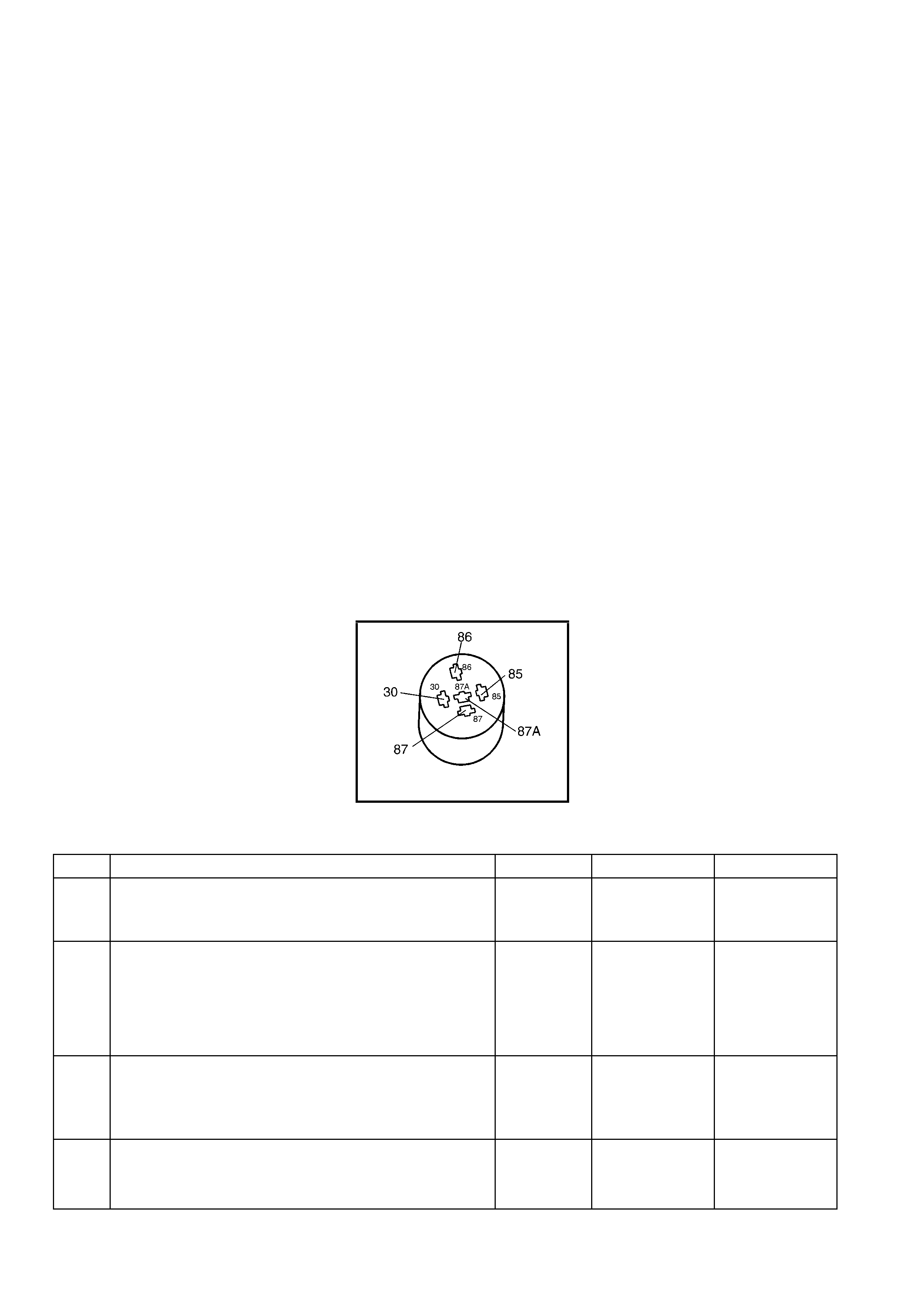
CIRCUIT DESCRIPTION
The EFI relay protects the battery from a parasitic draw. The following components are powered by the EFI relay:
• Injectors/Ignition coils
• Transmission
• A/C System
• EVAP Solenoid
• MAF Sensor
• Heated Oxygen Sensors
DIAGNOSTIC AIDS
• The following may cause an intermittent:
– Poor connections. Check for adequate terminal tension.
– Corrosion.
– Incorrectly routed harness.
– Rubbed through wire insulation.
– Broken wire inside the insulation.
TEST DESCRIPTION
NOTE: The number(s) below refer to the step number(s) on the diagnostic table.
IMPORTANT: For any test that requires probing the PCM or a component harness connector, use the Connector
Test Adaptor Kit J35616-A. Using this kit prevents damage to the harness connector terminals.
2. This test checks the fusible link F104 power feed to the EFI relay.
3. This test checks the fused power feed ignition circuit.
4. This test is checking the ground circuit of the EFI relay.
5. This step isolates the circuit from the EFI relay. All of the circuits at the relay are good if the test lamp
illuminates.
X4 (Part of X100)
Figure 6C3-2A-31
GEN III V8 PCM – EFI (ENGINE CONT.) RELAY DIAGNOSIS
STEP ACTION VALUE YES NO
1. Was the "On-Board Diagnostic" (OBD) System Check
performed? Go to Step 2 Go to
OBD System
Check
in this Section.
2. 1. Ignition OFF.
2. Remove the engine compartment Fuse/Relay panel
cover, then remove the Engine Control relay R4.
3. Probe the fusible link F104 power feed circuit to the
EFI relay harness, terminal 30, with a test lamp
connected to ground.
Does the test lamp illuminate?
Go to Step 3 Go to Step 8
3. 1. Ignition ON, engine OFF.
2. Probe the fused ignition feed circuit to the Engine
Control relay harness terminal 85 with a test lamp
connected to ground.
Does the test lamp illuminate?
Go to Step 4 Go to Step 9
4. 1. Ignition OFF.
2. Probe the ground circuit to the relay harness terminal
86 with a test lamp, connected to B+.
Does the test lamp illuminate?
Go to Step 5 Go to Step 10

STEP ACTION VALUE YES NO
5. 1. Ignition OFF.
2. Jump the Engine Control relay B+ feed circuit terminal
30 and the Engine Control relay load circuit terminal 87
together, using a fused jumper wire.
3. Probe the following fuses with a test lamp connected
to ground:
– F32
– F33
– F34
– F35
Does the test lamp illuminate for all fuses?
Go to Step 6 Go to Step 11
6. 1. Check for poor terminal contact at the Engine Control
relay harness connector.
Did you find and correct the condition?
System OK Go to Step 7
7. 1. Replace the Engine Control relay.
Is the action complete? System OK –
8. 1. Repair the open in fusible link F104 circuit to the
Engine Control relay.
Is the action complete?
System OK –
9. 1. Repair the fused ignition feed circuit to the Engine
Control relay. Replace fuse if open.
Is the action complete?
System OK –
10. 1. Repair the open in the ground circuit for the Engine
Control relay.
Is the action complete?
System OK –
11. 1. Repair open in the Engine Control relay load circuit, or
open in fuse(s) circuit that did not illuminate the test
light.
Is the action complete?
System OK –
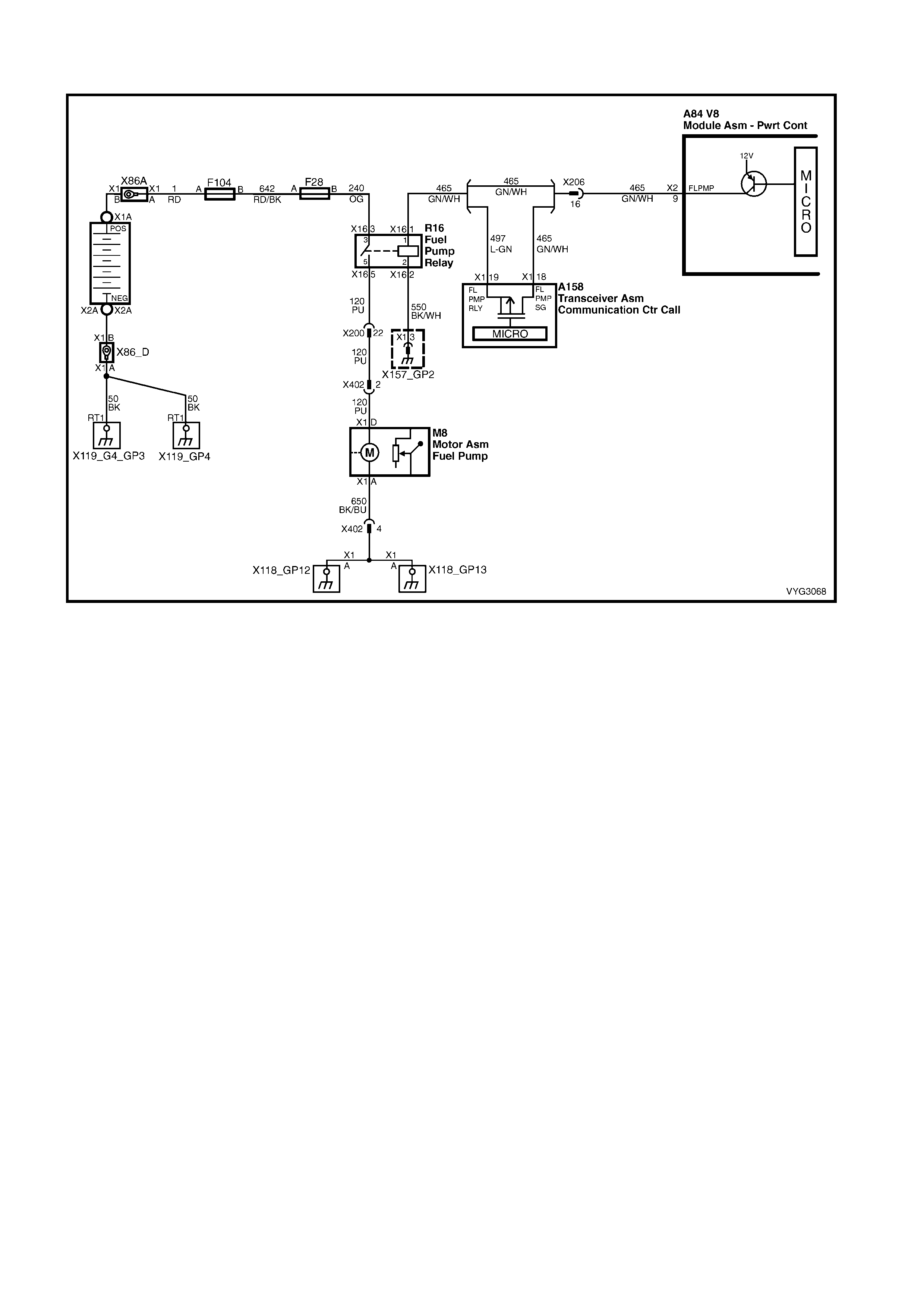
2.6 GEN III V8 PCM – FUEL PUMP RELAY CIRCUIT DIAGNOSIS
Figure 6C3-2A-32 – Fuel Pump Relay Circuit
CIRCUIT DESCRIPTION
W hen the igniti on s witc h is O N, the PCM ac t iv ates the in- tank f uel pump. The fuel pump rem ains O N as long as the
PCM receives reference pulses from the CKP system. If there are no reference pulses, the PCM turns the fuel
pump OFF after about 2-3 seconds.
The pump deliv er s f uel t o t he fuel r a il an d i nj ect ors an d, b ec aus e this is a s i ngle line system, f uel is a lso dir e c ted t o
the pressure regulator located in the fuel sender module assembly, in the fuel tank. The system pressure then,
remains at 380-440 k Pa. Excess fuel is return ed to the fuel tank, f rom the pressure regulator. W hen the engine is
stopped, a Tech 2 in the output controls function can turn ON the fuel pump.
Improper fuel system pressure may result in one or many of the following symptoms:
• Cranks but will not run
• Cuts out, may feel like an ignition problem
• Poor fuel economy
• Loss of power
• Hesitation
• DTCs
DIAGNOSTIC AIDS
• The following conditions may have caused the fuel pump fuse to open:
– The fuse was faulty.
– There is an intermittent short in the fuel pump power feed circuit.
– The fuel pump has an intermittent internal problem.
• For an intermittent condition, refer to Section 6C3-2B SYMPTOMS.
TEST DESCRIPTION
NOTE: The number(s) below refer to the step number(s) on the diagnostic table.
3. This test checks for the proper fused power feed to the fuel pump relay.
4. This test checks to see if the ground signal is present at the fuel pump relay.
5. The test lamp only illum inates for two seconds even thoug h Tech 2 commanded position is ON. You will have
to command the fuel pump OFF then ON to re-enable the PCM fuel pump control.
12. Inspect the fuel pump fuse for an open. If the fuse is open, check the circuit for a short to ground.
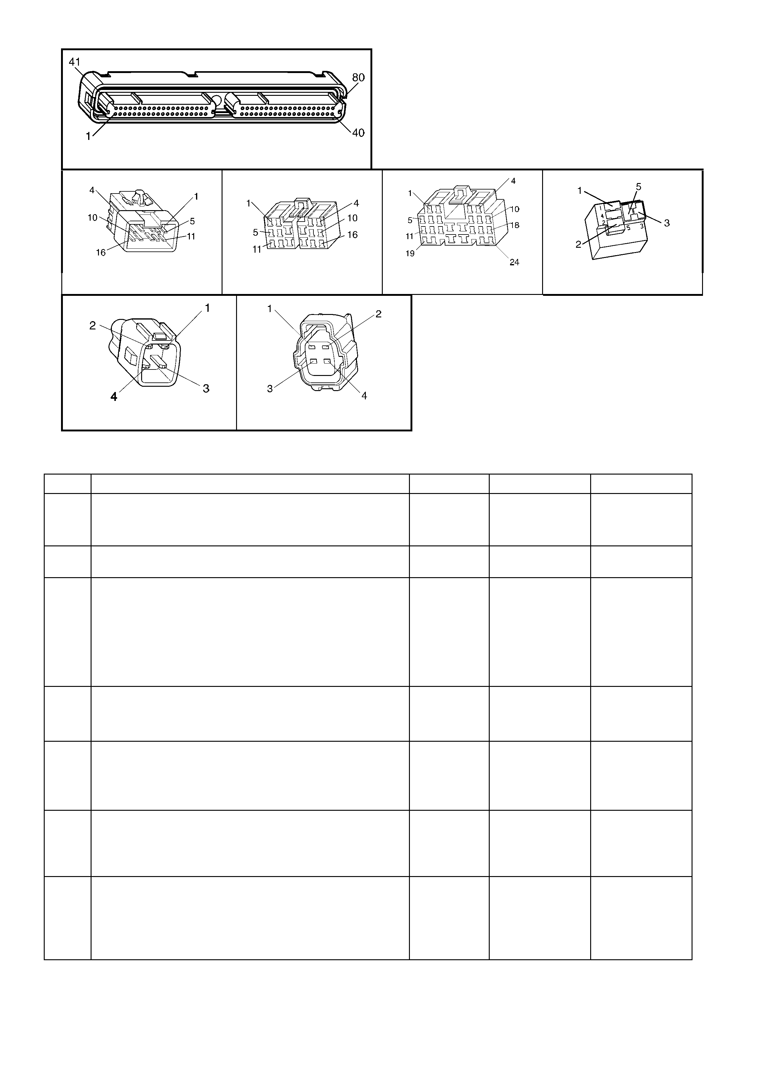
A84-X2 (RED)
X200 X200A X206 X16 – (PART OF X100)
X402 X402A
Figure 6C3-2A-33
GEN III V8 PCM – FUEL PUMP RELAY CIRCUIT DIAGNOSIS
STEP ACTION VALUE YES NO
1. Was the "On-Board Diagnostic" (OBD) System Check
performed? Go to Step 2 Go to
OBD System
Check
in this Section.
2. 1. Check the fuel pump fuse, F28.
Is the fuse open? Go to Step 9 Go to Step 3
3. 1. Install Tech 2 to the DLC.
2. Remove the fuel pump relay R16 from the underhood
electrical centr e, X 100.
3. Ignition ON, engine OFF.
4. Probe the fused power feed circuit 240, in the fuel
pump relay R16 harness connector terminal 3, with a
test lamp, connect ed to groun d.
Does the test lamp illuminate?
Go to Step 4 Go to Step 12
4. 1. Probe the ground circuit 550 in the fuel pump relay
harness connector R16, terminal 2, with a test lamp
connected to B+.
Does the test lamp illuminate?
Go to Step 5 Go to Step 13
5. 1. Probe the fuel pump relay control circuit 465, in the
fuel pump relay R16 harness connector terminal 1,
with a test lamp, connected to ground.
2. Cycle the fuel pump ON and OFF using Tech 2.
Does the test lamp turn ON and OFF?
Go to Step 6 Go to Step 11
6. 1. Jumper the fused power feed circuit 240 to the fuel
pump circuit 120 (load), in the fuel pump relay R16
harness connector R16, terminals 3 to 5, using a fused
jumper wire.
Does the fuel pump operate?
Go to Step 18 Go to Step 7
7. 1. Leave the fused jumper wire connected.
2. Disconnect the fuel pump harness connector X402 at
the fuel pump module.
3. Probe the power feed circuit, in the fuel pump harness
connector, with a test lamp, connected to ground.
Does the test lamp illuminate?
Go to Step 8 Go to Step 14

STEP ACTION VALUE YES NO
8. 1. Leave the fused jumper wire connected.
2. Connect a test lamp, between the fused power feed
circuit and the ground circuit in the fuel pump harness
connector X402, terminals 4 and 2.
Does the test lamp illuminate?
Go to Step 25 Go to Step 15
9. 1. Ignition OFF.
2. Remove the fuel pump fuse F28.
3. Disconnect the fuel pump harness connector X402 at
the fuel pump.
4. Probe the load circuit 240, terminal 5, for the fuel pump
relay R16 in the underhood electrical centre, with a
test lamp, connect ed to B+.
Does the test lamp illuminate?
Go to Step 16 Go to Step 10
10. 1. Probe the fused power feed circuit 240 for the fuel
pump relay, at the engine compartment fuse/relay
panel, with a test lamp, connected to B+.
Does the test lamp illuminate?
Go to Step 20 Go to Step 21
11. 1. Ignition OFF.
2. Disconnect the PCM RED connector, A84-X2.
3. Check the continuity of the fuel pump relay control
circuit, from the relay harness connector to the PCM
RED connector, using a DMM.
Does the DMM display the specified value or lower?
5 Ω Go to Step 22 Go to Step 17
12. 1. Repair the open fused power feed circuit to the relay.
Replace fuse if open.
Is the action complete?
Go to Step 26 –
13. 1. Repair the open relay ground circuit.
Is the action complete? Go to Step 26 –
14. 1. Repair the open circuit between the fuel pump relay
and fuel pump.
Is the action complete?
Go to Step 26 –
15. 1. Repair the open in the ground circuit 650 to the fuel
pump.
Is the action complete?
Go to Step 26 –
16. 1. Repair the short to ground in the fuel pump relay load
circuit between the relay and the fuel pump.
Is the action complete?
Go to Step 26 –
17. 1. Repair open or short to ground in the fuel pump relay
control circuit.
Is the action complete?
Go to Step 26 –
18. 1. Check for poor connections at the relay.
Was a problem found? Go to Step 26 Go to Step 19
19. 1. Replace the fuel pump relay, R16.
Is the action complete? Go to Step 26 –
20. 1. Repair the short to ground in the fuel pump relay fused
power feed circuit between the relay and the fuse.
Is the action complete?
Go to Step 26 –
21. 1. Ignition OFF.
2. Reinstall the fuel pump relay.
3. Install a new fuse.
4. Connect the fuel pump harness to the fuel pump.
5. Ignition ON, engine OFF.
6. Command the fuel pump relay ON using Tech 2.
Is the Fuel Pump fuse open?
Go to Step 24 Intermittent
conditions.
Refer to
Diagnostic Aids
22. 1. Check for a poor connection at the PCM.
Did you find and correct the condition? Go to Step 26 Go to Step 23
23. 1. Replace PCM. Refer to 6C3-3 SERVICE
OPERATIONS, for PCM Programming and
PCM/PIM/BCM Security Link Procedure.
Is action complete?
Go to Step 26 –
24. 1. Inspect the fuel pump harness at the fuel tank for a
short to ground.
2. If a short is found, repair the circuit as nec es sary .
Was a problem found?
Go to Step 26 Go to Step 25
25. 1. Replace the fuel pump.
Is the action complete? Go to Step 26 –

STEP ACTION VALUE YES NO
26. 1. Select the Diagnostic Trouble Codes (DTC) option and
the Clear DTC Information option, using Tech 2.
2. Attempt to start the engine.
Does the engine start and continue to run?
Go to Step 27 Go to Step 2
27. 1. Idle the engine until the normal operating temperature
is reached.
2. Select the Diagnostic Trouble Code (DTC) option.
Are any DTCs displayed?
Go to applicable
DTC table System OK

2.7 GEN III V8 PCM – FUEL PUMP ELECTRICAL CIRCUIT (UTILITY ONLY)
Figure 6C2-2A-34 – Fuel Pump Electrical Circuit
CIRCUIT DESCRIPTION:
W hen the ignition switch is f irst turned "ON", the PCM energises the Fuel Pump Relay which applies power to the
Fuel Pump Control Module. The Fuel Pump Relay will remain "ON" as long as the engine is cranking or running
and the PCM is receiving reference pulses. If no reference pulses are present, the PCM de-energises the Fuel
Pump Relay within 2 seconds after the ignition is turned "ON" or the engine is stopped. The Fuel Pump delivers
fuel to the fuel rail and injectors and, because this is a single line system, fuel is also directed to the pressure
regulator l ocated in the in-tank fuel s ender module as sem bly. The system then, rem ains at 380 – 440 k Pa. Excess
fuel is returned to the fuel tank from the pressure regulator. When the engine is stopped, the Fuel Pump can be
turned "ON" by using the Tech 2 output controls function.
The PCM a lters Fuel P ump speed b y applying or rem oving a 67% dut y cycle on the F uel Pum p PWM dr iver circui t
260 to the Fuel Pump Control Module. Under normal driving conditions, the PCM will apply a 67% PWM ground
signal to the Fuel Pump Control Module circuit 260. This 67% duty cycle will command the Fuel Pump Control
Module t o run the fuel pum p at a lo wer speed, (lo wer fuel vo lume, lo w voltage su pplied to f uel pump, bet ween 7 to
9 volts) . W hen high er f uel volume is requ ired due to in cr eased en gine loa d, th e PCM will rem ove the supp lie d 67%
PW M ground signal from circuit 260. This will cause the Fuel Pump Control Module to switch internally and allow
the Fuel Pump to run at a higher speed (higher fuel volum e, system voltage applie d to fuel pump). The PC M also
compensates for low system voltage by comm anding the Fuel Pum p Control Module to s witch to high speed Fuel
Pump , when system voltage is low.
TEST DESCRIPTION:
NOTE: Number(s) below refer to step number(s) on the diagnostic table.
3. Checks that fuel pressure is sufficient for the vehicle to start.
4. Ensures that the Fuel Pump PWM driver circuit and the PCM are capable of controlling fuel pump speed.
5. Verifies that the Fuel Pump feed and ground circuits are OK between the Fuel Pump Control Module and the
Fuel Pump and that the Fuel Pump can deliver adequate pressure to the fuel rail.
6. Checks the feed circuit to the Fuel Pump Control Module.
8. Ensures that the Fuel Pump PWM driver circuit is not shorted to ground.
13. Checks the feed circuit to the Fuel Pump Relay contacts.
14. Checks the ground circuit for the Fuel Pump Relay coil.
15. Ensures that the Fuel Pump Relay driver circuit is OK and that the PCM is capable of controlling the Fuel Pump
Relay. Using the Tech 2 scan tool to command the Fuel Pump Relay allows only a 2 second "ON" time.
21. Checks the Fuel Pump Relay driver circuit for a short to ground.
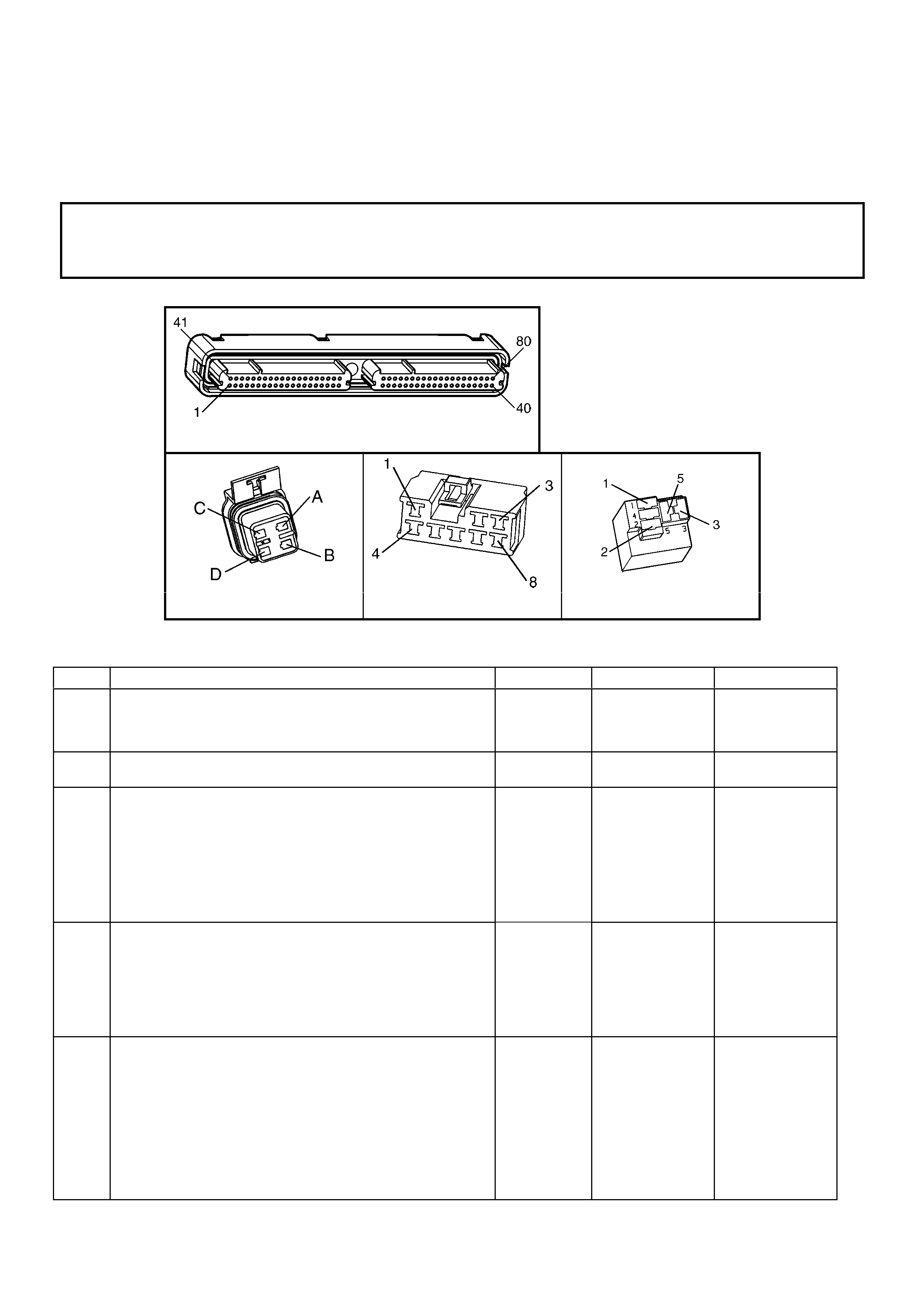
26. If the Fuel Pump is operating but incorrect pressure is noted, the Fuel Pump wiring is OK. Go to Table 2.6.
28. Determines whether the problem is being caused by an open in the Fuel Pump feed circuit or the Fuel Pump
ground circuit.
31. Ensures that the Fuel Pump speed control PWM circuit is OK and that the PCM can control the Fuel Pump
speed control PWM driver.
37. The fuel pump is not serviced separately from the Modular Sender Assembly. If the pump is confirmed as being
faulty, then the complete Modular Sender Assembly must be replaced.
NOTICE:
When performing this diagnostic Table, make certain that the drive wheels are blocked and the parking
brake is firmly applied.
A84-X2 (RED)
M8 A47 X16 (Part of X100)
Figure 6C3-2A-35
GEN III V8 PCM – FUEL PUMP ELECTRICAL CIRCUIT (UTILITY ONLY)
STEP ACTION VALUE YES NO
1. Was the "On-Board Diagnostic" (OBD) System Check
performed? – Go to Step 2 Go to
OBD System
Check
in this Section.
2. Are any DTC’s set? – Go to DTC Table
first Go to step 3
3. 1. Connect Fuel Pressure Gauge and adaptor to the fuel
pressure tap fitting.
2. Turn the ignition switch to the "ON" position.
3. Select “Fuel Pump Relay Output Control” with Tech 2.
4. Observe the pressure gauge while activating the fuel
pump "ON" with Tech 2.
5. Note fuel pressure on Fuel Pressure Gauge.
Is proper fuel pressure indicated?
380 to 440
kPa Go to Step 4 Go to Step 5
4. 1. Engine idling.
2. Observe the Fuel Pressure Gauge at idle.
3. Using Tech 2, select Fuel Pump Speed , and select
High Speed.
Does the fuel pressure increase slightly from the idle
position when the fuel pump ‘High Speed’ is turned "ON",
then turned "OFF"?
– No problem
found Go to Step 31
5. 1. Ignition "OFF".
2. Disconnect Fuel Pump Control Module.
3. Connect a fused jumper wire between Fuel Pump
Control Module harness connector A47, terminal X1-6
(Fuel Pump power feed circuit) and Battery +12 volts.
4. Connect a second jumper between the Fuel Pump
Control Module harness connector A47 terminal X1-5
(Fuel Pump ground circuit) and chassis ground.
5. Note the fuel pressure on the Fuel Pressure Gauge.
Is proper fuel pressure indicated?
380 to 440
kPa Go to Step 6 Go to Step 26

STEP ACTION VALUE YES NO
6. 1. Ignition "OFF".
2. Disconnect the jumpers from the Fuel Pump Control
Module connector.
3. Connect a test light between the Fuel Pump Control
Module harness connector A47 terminal X1-8 (Fuel
Pump Control Module relay feed circuit) and ground.
4. Ignition "ON".
5. Using the Tech 2 output control functions, command
the Fuel Pump Relay "ON".
6. Observe the test light.
Did the test light turn "ON"?
– Go to Step 7 Go to Step 13
7. 1. Probe A47 terminal X1-4 (Fuel Pump Control Module
ground circuit) with a test light to +12 volts.
Is the test light "ON"?
– Go to Step 8 Go to Step 25
8. 1. Ignition "OFF".
2. Disconnect the PCM connector A84-X2 (RED).
3. Probe the Fuel Pump Control Module PWM driver
circuit X2-5 at the PCM connector with a test light
connected to +12 volts.
Is the test light "ON"?
– Go to Step 9 Go to Step 10
9. Locate and repair short to ground in the Fuel Pump Control
Module PWM driver circuit .
Is action complete?
– Go to Step 39 –
10. 1. Ignition "OFF".
2. Reconnect PCM and Fuel Pump Control Module
connectors.
3. Ignition "ON".
4. Install a Digital Multimeter (DMM) to measure voltage
between the Fuel Pump Control Module connector A47
terminal X1-7 (Fuel Pump Control Module PW M driver
circuit) and A47 terminal X1-4 (ground circuit ).
5. Using the Tech 2 relay output test function, command
the Fuel Pump Relay "ON" and "OFF".
Does the voltage measure at or above the specified value
while the Fuel Pump Relay is commanded "ON"?
2 – 4 volts Go to Step 11 Go to Step 38
11. 1. Ignition "ON".
2. Using a test light, back-probe between the Fuel Pump
Module connector A47 terminal X1-6 (Fuel Pump
power feed circuit) and A47 terminal X1-5 (Fuel Pump
ground circuit).
3. Using the Tech 2 output test functions, command the
Fuel Pump Relay "ON" and "OFF".
4. Observe the test light.
Is the test light "ON" while the Fuel Pump Relay is
commanded "O N"?
– Go to Step 12 Go to Step 34
12. 1. Check for a poor connection at the Fuel Pump Control
Module.
2. If a problem is found, replace faulty terminals as
necessary.
Was a problem found?
– Go to Step 39 Refer to
Diagnostic Aids
in this
diagnostic.
13. 1. Ignition "OFF".
2. Remove the Fuel Pump Relay R16.
3. Ignition "ON".
4. Probe the Fuel Pump Relay fused power feed circuit
240 with a test light to ground.
Is the test light "ON"?
– Go to Step 14 Go to Step 19
14. 1. With the Fuel Pump Relay R16 still removed, connect
test light between the Fuel Pump Relay power feed
circuit 240 and the Fuel Pump Relay ground circuit 550
(X16 terminal 2).
Is the test light "ON"?
– Go to Step 15 Go to Step 20
15. 1. Connect the test light between the Fuel Pump Relay
control circuit 465 (X16-1) and ground circuit 550 (X16-
2).
2. Using the Tech 2 output control function, command the
Fuel Pump Relay "ON".
Is the test light "ON" when the Fuel Pump Relay is
commanded "O N"?
– Go to Step 16 Go to Step 21

STEP ACTION VALUE YES NO
16. 1. Connect a fused jumper wire between Fuel Pump
Relay connector power feed circuit 240 (terminal X16-
3) and output power feed circuit 120 (terminal X16-5).
2. Probe the Fuel Pump power feed circuit at the Fuel
Pump Control Module A47 harness connector, terminal
X1-6 with a test light to ground.
Is the test light "ON"?
– Go to Step 17 Go to Step 24
17. 1. Check for a faulty terminal connection at the Fuel
Pump Relay.
2. If a problem is found, repair terminals as necessary.
Was a problem found?
– Go to Step 39 Go to Step 18
18. 1. Replace the Fuel Pump Relay, R16.
Is action complete? – Go to Step 39 –
19. 1. Locate and repair open in Fuel Pump Relay fused
power feed circuit 240.
Is action complete?
– Go to Step 39 –
20. 1. Locate and repair open in Fuel Pump Relay ground
circuit 550.
Is action complete?
– Go to Step 39 –
21. 1. Ignition "OFF".
2. Disconnect the PCM connector A84-X2 (RED).
3. Probe the Fuel Pump Relay control circuit X2-5 at the
PCM connector with a test light to + 12 volts.
Is test light "ON"?
– Go to Step 22 Go to Step 23
22. 1. Locate and repair short to ground in the Fuel Pump
Relay control circuit 465.
Is action complete?
– Go to Step 39 –
23. 1. Check for the following conditions:
• Fuel Pump Relay control circuit 465 for an open
between the Fuel Pump Relay and the PCM.
• Fuel Pump Relay control circuit 465 for a poor
terminal connection at PCM A84-X2 (RED),
terminal X2-9.
2. If a problem is found, repair as necessary.
Was a problem found?
– Go to Step 39 Go to Step 38
24. 1. Check for an open or poor connection in the Fuel
Pump Control Module A47 Fuel Pump power feed
circuit 1058.
Was a problem found?
– Go to Step 39 Go to Step 35
25. 1. Locate and repair open in Fuel Pump Control Module
A47 ground circuit 650.
Is action complete?
– Go to Step 39 –
26. 1. Remove the fuel tank filler cap and listen for the Fuel
Pump running.
Is the Fuel Pump running?
– Go to
2.6 Fuel System
Diagnosis
Go to Step 27
27. 1. Using fused jumper wires, jumper Fuel Pump Control
Module A47 terminal X1-6 circuit 1058 to +12 volts,
and jumper terminal X1-5 circuit to ground.
2. Raise the vehicle.
3. Disconnect the Fuel Pump electrical connector at the
fuel tank patch harness.
4. Connect a test light between the Fuel Pump electrical
connector power feed circuit , and fuel pump
ground circuit at PCM s ide of connector .
Is the test light "ON"?
– Go to Step 36 Go to Step 28
28. 1. Probe the Fuel Pump power feed circuit 1058 at the
Fuel Pump electrical connector with a test light
connected to chassis ground.
Is the test light "ON"?
– Go to Step 30 Go to Step 29
29. 1. Locate and repair open in the Fuel Pump power feed
circuit 1058.
Is action complete?
– Go to Step 39 –
30. 1. Locate and repair open in the Fuel Pump ground
circuit 1580.
Is action complete?
– Go to Step 39 –

STEP ACTION VALUE YES NO
31. 1. Ignition "OFF"
2. Using a test light, backprobe between the Fuel Pump
Control Module A47 terminal X1-7 (Fuel Pump Control
Module PWM circuit ) and terminal X1-8 (Fuel Pump
Control Module Fuel Pump Relay circuit).
3. Ignition "ON", engine idling.
4. Observe the test light while the engine is idling.
5. Using Tech 2, select Fuel P ump Speed a nd select
High Speed.
Is the test light "ON" but dull when the engine is idling, and
brighter when the fuel pump high speed is turned "ON"?
– Go to Step 32 Go to Step 33
32. 1. Using a DMM, backprobe between Fuel Pump control
module A84 terminal X1-5 (Fuel Pump ground circuit )
and terminal X1-6 (Fuel Pump power supply circuit ).
2. Engine idling for longer than 15 seconds.
3. Observe the voltage on the DMM while the engine is
idling.
4. Using Tech 2, select Fuel Pump Speed , and
select High Speed.
• Idle speed voltage is the first value shown.
• Fuel Pump High Spee d voltage is t he s ec o nd
value shown.
Does the voltage measure near the specified values?
8 – 9 volts
at idle.
+12 volts
with fuel
pump at
high speed
Go to Step 36 Go to Step 34
33. 1. Check for the following conditions:
• Fuel Pump PWM driver circuit for an open or short
to voltage between the Fuel Pump Control Module
and the PCM.
• Fuel Pump PWM driver circuit for a poor terminal
connection at the PCM, A84-X2 (RED),
Terminal 5.
2. If a problem is found, repair as necessary.
Was a problem found?
– Go to Step 39 Go to Step 38
34. 1. Check terminal connections at the Fuel Pump Control
Module A47.
2. If a problem is found, repair faulty terminal(s) as
necessary.
Was a problem found?
– Go to Step 39 Go to Step 35
35. 1. Replace the Fuel Pump Control Module A47.
Is action complete? – Go to Step 39
36. 1. Remove the Fuel Sender Module Assembly. Refer to
8A FUEL TANK.
2. Check terminal connections at the Fuel Pump, M8.
3. If a problem is found, repair faulty terminal as
necessary.
Was a problem found?
– Go to Step 39 Go to Step 37
37. 1. Replace the Fuel Sender Module assembly.
Is action complete? – Go to Step 39 –
38. 1. Replace PCM. Refer to PCM Programming and
PCM/PIM/BCM Security Link Procedure, in 6C-3
SERVICE OPERATIONS.
Is action complete?
– Go to Step 39 –
39. 1. Ignition "ON", select Fuel Pump Relay output control
with Tech 2.
2. Observe the Fuel Pressure Gauge while turning the
fuel pump "ON" with Tech 2.
3. Note the fuel pressure on the Fuel Pressure Gauge.
Is proper fuel pressure indicated?
380 to 440
kPa Go to Step 40 Go to Step 5
40. 1. Ignition "OFF".
2. Fuel Pressure Gauge still installed.
3. Ignition "ON", engine idling.
4. Observe the Fuel Pressure Gauge at idle.
5. Using Tech 2, select Fuel Pump Speed, and select
High Speed.
Does the fuel pressure increase slightly from the idle
position when the fuel pump High Speed is turned "ON"?
– Repair complete.
If a driveability
symptom exists,
Refer to 6C3-2B
SYMPTOMS in
this Section.
Go to Step 2
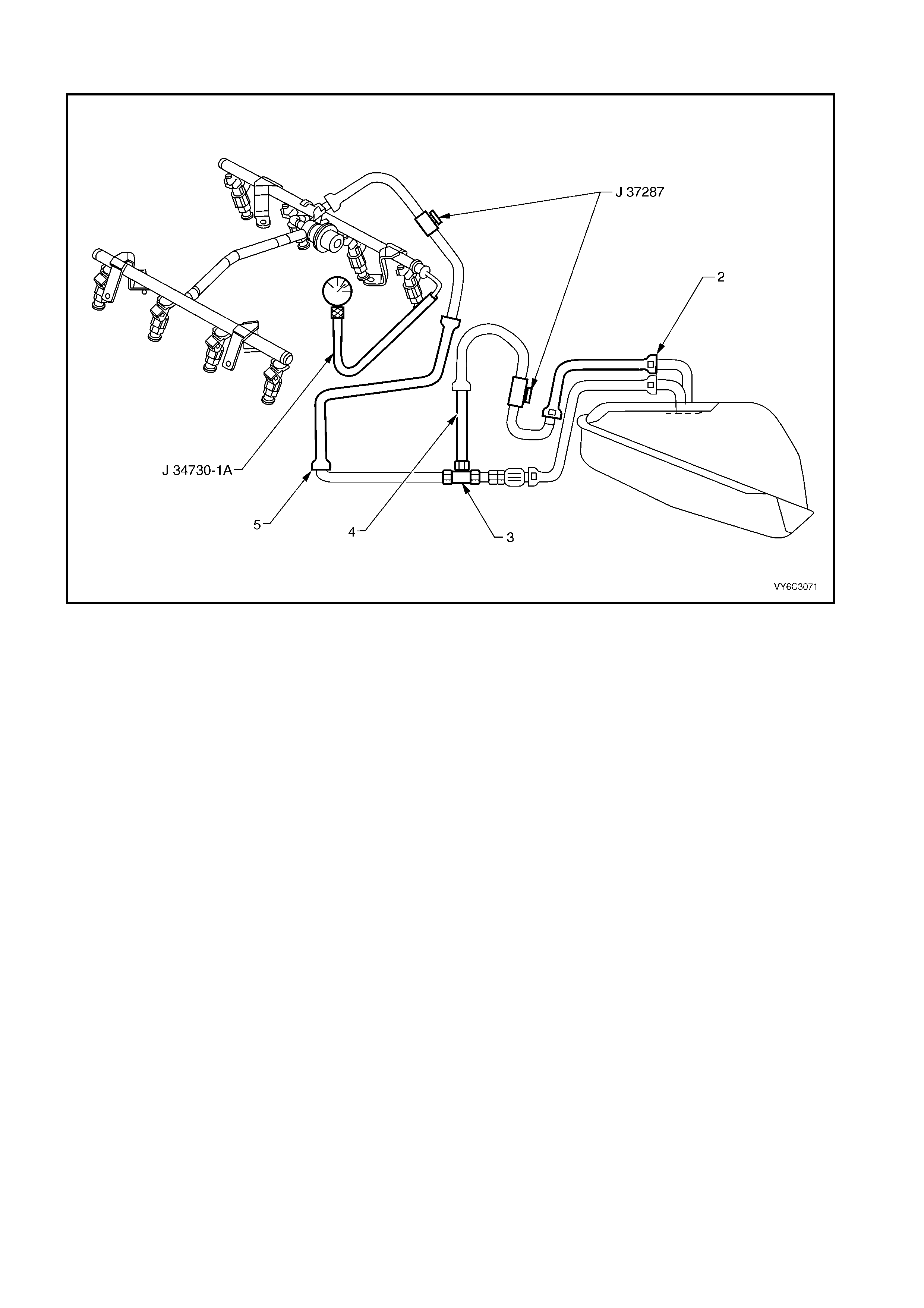
2.8 GEN III V8 PCM – FUEL SYSTEM DIAGNOSIS
Figure 6C3-34 – Fuel System Testing
Legend
1. J 37287 Fuel Line Shut-off Adaptor
2. Rear Fuel Return Pipe
3. T-connector
4. Fuel Return Pipe
5. Fuel Feed Pipe
6. J 34730-1A Fuel Pressure Gauge
CIRCUIT DESCRIPTION
W hen the ign iti on is tur n ed O N, the Po wer trai n C ontr o l Mod ul e (PC M) s upp lies po wer to t he in- ta nk fuel pum p. The
in-tank fuel pump remains ON as long as the engine is cranking or running and the PCM receives reference pulses.
If there are no reference pulses, the PCM turns the in-tank fuel pump OFF 2 seconds after the ignition switch is
turned ON or 2 seconds after the ignition stops running.
The electric fuel pump attaches to the fuel sender assembly inside the fuel tank. The fuel pump supplies fuel
through an i n-line fuel f ilter to the f uel rail assem bly. The f uel pump provi des fuel at a pres sure above t he pres sure
needed b y the fue l inj ectors . T he fuel pres sure r egulat or k eeps the f uel ava ilab le to the fuel injector s at a r egulat e d
pressure. The fuel pressure regulator attaches to the fuel sender assem bly return pipe . Unused fuel returns to the
fuel tank by a separate f uel return p ipe. The fuel r eturn pipe attac hes to a T -connector in th e fuel feed p ipe on the
outlet side of the fuel filter.
TEST DESCRIPTION
NOTE: Number(s) below refer to the step number(s) on the diagnostic table.
2. When the ignition switch is ON and the fuel pump is running, the fuel pressure indicated by the fuel pressure
gauge should read 380-440 kPa. The spring pressure inside the fuel pressure regulator controls the fuel
pressure.
3. A fuel system that drops more than 34 kPa in 10 minutes has a leak in one or more of the following areas:
– The fuel pipes
– The fuel pump check valve
– The fuel pump flex pipe
– The valve or valve seat within the fuel pressure regulator
– The fuel injector(s)
4. A fuel s ystem that drops m ore tha n 14 kPa in 10 m inutes after bein g rel ieved to 6 9 k Pa indicates a leak ing fue l
pump check valve.

5. Fuel pressure that drops-off during acceleration, cruise, or hard cornering may cause a lean condition. A lean
condition can cause a loss of power, surging, or misfire. You can diagn ose a lean condition usin g a Tech 2. If
an extrem ely lean condit ion occur s, the heat ed ox ygen sensor (s) will stop to ggling. T he heat ed ox ygen s ensor
output voltage(s) will drop below 300 mV. The fuel injector pulse width will increase.
IMPORTANT: Make sur e the f uel system is not op erating in th e F ue l Cut-O f f Mode. If s o, this can c aus e f als e T ec h
2 readings.
10. A rich condition may result from the fuel pressure being above 440 kPa. A rich condition may cause DTC
P0132, DTC P0152, DTC P0172 or DTC P0175 to set. Driveability conditions associated with rich conditions
can include hard starting followed by black smoke and a strong sulphur smell in the exhaust.
11. T his test deter m ines if the high f uel press ure is due t o a res tricted f uel re turn p ipe or if the h igh fue l press ure is
due to a faulty fuel pressure regulator.
12. A lean condition may result from the fuel pressure being below 380 kPa. A lean condition may cause DTC
P0131, DTC P0151, DTC P0171 or DTC P0174 to set. Driveability conditions associated with lean conditions
can include hard starting (when the engine is cold), hesitation, poor driveability, lack of power, surging, and
misfiring.
NOTE: Do not allow the fuel pressure to exceed 500 kPa. Fuel pressure in excess of 500 kPa may damage the fuel
pressure regulator.
13. Res tric tin g the f uel r eturn pipe with t he J 372 87 f uel pi p e s hut-of f adaptor c auses the f uel pr es sur e to r ise abo ve
the regulated fuel pressure. Using a Tech 2 to pressurise the fuel s ystem, the fuel pressure should rise above
440 kPa (62 psi) as the valve on the fuel pipe shut-off adaptor connected to the fuel return pipe becomes
partially closed.
18. Check the spark plug associated with a particular fuel injector for fouling or saturation in order to determine if
that particular fuel injector is leaking. If checking the spark plug associated with a particular fuel injector for
fouling or saturation does not determine that a particular fuel injector is leaking, use the following procedure:
1. Remove the fuel rail, but leave the fuel pipe connected to the fuel rail. Refer to Fuel Rail Assembly
Replacement in Section 6C3-3 SERVICE OPERATIONS.
2. Lift the fuel rail just enough to leave the fuel injector nozzles in the fuel injector ports.
CAUTION: In order to reduce the risk of fire and personal injury that may result from fuel spraying on
the engine, verify that the fuel rail is positioned over the fuel injector ports. Also verify that the fuel
injector retainin g clip s ar e intact.
3. Pressurise the fuel system using Tech 2 and Fuel Pump Enable.
4. Inspect the fuel injector nozzle for leaks.
GEN III V8 PCM – FUEL SYSTEM DIAGNOSIS
STEP ACTION VALUE YES NO
1. Was the "On-Board Diagnostic" (OBD) System Check
performed?
Go to Step 2 Go to
OBD System
Check
in this Section.
2. CAUTION: Wrap a shop towel around the fuel
pressure connection in order to reduce the risk of
fire and personal injury. The towel will absorb any
fuel that may leak from the pressure gauge. Place
the towel in an approved container when the
connection of the fuel pressure gauge is complete.
1. Ignition OFF.
2. Air conditioning OFF.
3. Install the J34730-1A fuel pres sure gaug e.
4. Place the bleed hose of the fuel pressure gauge
into an approved petrol conta i ner.
5. Ignition ON.
6. Bleed the air out of the fuel pressure gauge.
7. Ignition OFF for 10 seconds.
8. Ignition ON.
IMPORTANT: The fuel pump will run for approximately
2 seconds. Cycle the ignition as necessary in order to
achieve the highest possible fuel pressure.
9. Observe the fuel pressure with the fuel pump
running.
Is the fuel pressure within the specified limits?
380-440 kPa Go to Step 3 Go to Step 10

STEP ACTION VALUE YES NO
3. IMPORTANT: The fuel pressure may vary slightly when
the fuel pump stops running. After the fuel pump stops
running, the fuel pressure should stabilise and remain
constant.
Does the fuel pressure drop more than the specified
value in 10 minutes?
34 kPa Go to Step 8 Go to Step 4
4. 1. Relieve the fuel pressure to the upper specified
value.
Does the fuel pressure drop more than the lower
specified value in 10 minutes?
69 kPa
14 kPa
Go to Step 17 Go to Step 5
5. 1. Do you suspect the fuel pressure of dropping off
during acceleration, cruise, or hard cornering?
Go to Step 6 Go to Section
6C3-2B
Symptoms
6. 1. Inspect the following items for a restriction:
• The fuel filter.
• The fuel feed pipe.
Did you find a restriction?
Go to Step 21 Go to Step 7
7. 1. Remove the fuel sender assembly. Refer to Fuel
Sender Assembly Replacement in 6C3-3 SERVICE
OPERATIONS.
2. Inspect the following items:
– The fuel pump strainer for a restriction.
– The fuel pump flex pipe for leaks.
– The fuel pressure regulator for leaks.
– The fuel pressure regulator fuel return flex pipe
for leaks.
– Verify the fuel pump is correct for this vehicle.
Did you find a problem in any of these areas?
Go to Step 21 Go to Step 17
8. 1. Relieve the fuel pressure. Refer to Fuel Pressure
Relief Procedure in 6C3-3 SERVICE
OPERATIONS.
2. Disconnect the fuel feed pipe from the fuel rail.
Refer Quick Connect Fitting(s) Service (Metal
Collar) in 6C3-3 SERVICE OPERATIONS.
3. Install the J37287 fuel pipe shut-off adaptor
between the fuel feed pipe and the fuel rail.
4. Open the valve on the fuel feed pipe shut-off
adaptor.
5. Pressurise the fuel system using Tech 2.
6. Place the bleed hose of the fuel pressure gauge
into an approved petrol container.
7. Bleed the air out of the fuel pressure gauge.
8. Wait for the fuel pressure to build.
9. Close the valve in the fuel feed pipe shut-off
adaptor.
Does the fuel pressure remain constant?
Go to Step 9 Go to Step 18
9. NOTE: This step will require an assistant.
1. Open the valve in the fuel feed pipe shut-off
adaptor.
2. Relieve the fuel pressure. Refer to Fuel Pressure
Relief Procedure in 6C3-3 SERVICE
OPERATIONS.
3. Raise the vehicle.
4. Disconnect the steel fuel return pipe at the nylon
rear return pipe. Refer Quick Connect Fitting(s)
Service (Plastic Collar) in 6C3-3 SERVICE
OPERATIONS.
5. Drain any remaining fuel from the pipes into an
approved petrol conta iner .
6. Install the J37287 fuel pipe shut-off adaptor
between the steel fuel return pipe and rear nylon
return pipe.
7. Pressurise the fuel system using Tech 2.
8. Wait for the fuel pressure to build.
9. Close the valve in the fuel pipe shut-off adaptor that
is connected to the fuel return pipe.
Does the fuel pressure remain constant?
Go to Step 16 Go to Step 17
10. Is the fuel pressure above the specific value?
440 kPa Go to Step 11 Go to Step 12

STEP ACTION VALUE YES NO
11. 1. Relieve the fuel pressure. Refer to Fuel Pressure
Relief Procedure in 6C3-3 SERVICE
OPERATIONS.
2. Disconnect the steel fuel return pipe at the nylon
rear return pipe. Refer Quick Connect Fitting(s)
Service (Plastic Collar) in 6C3-3 SERVICE
OPERATIONS.
3. Drain any remaining fuel from the fuel pipes into an
approved petrol container.
4. Attach a length of flexible fuel hose to the steel fuel
return pipe attached to the T-connector.
5. Place the open end of the flexible fuel hose into an
approved petrol container.
6. Turn ON the fuel pump using Tech 2.
7. Observe the fuel flow with the fuel pump running.
Is there fuel flow?
Go to Step 20 Go to Step 19
12. Is the fuel pressure above the specified value?
0 kPa Go to Step 13 Go to Step 14
13. NOTE: This step will require an assistant.
1. Relieve the fuel pressure. Refer to Fuel Pressure
Relief Procedure in 6C3-3 SERVICE
OPERATIONS.
2. Raise the vehicle.
3. Disconnect the steel fuel return pipe at the nylon
rear return pipe. Refer Quick Connect Fitting(s)
Service (Plastic Collar) in 6C3-3 SERVICE
OPERATIONS.
4. Drain any remaining fuel from the fuel pipes into an
approved petrol conta iner .
5. Install the J37287 fuel pipe shut-off adaptor
between the steel fuel return pipe and the nylon
rear fuel return pipe.
6. Open the valve on the fuel pipe shut-off adaptor.
7. Pressurise the fuel system using Tech 2.
8. Place the bleed hose of the fuel pressure gauge
into an approved petrol conta i ner.
9. Bleed the air out of the fuel pressure gauge.
10. Slowly close the valve in the fuel pipe shut-off
adaptor that is connected to the fuel return pipe.
NOTE: Do not allow the fuel pressure to exceed 500
kPa. Fuel pressure in excess of 500 kPa may damage
the fuel pressure regulator.
Does the fuel pressure rise above the specified value?
440 kPa Go to Step 16 Go to Step 7
14. 1. Refer to “Fuel Pump Relay Circuit Diagnostic Table”
in this Section, to diagnose the fuel pump electrical
circuit.
Did you find a problem with the fuel pump electrical
circuit?
Go to Step 21 Go to Step 15
15. 1. Inspect the following items:
• The fuel filter for obstructions.
• The fuel feed pipe.
• The fuel pump strainer for obstructions.
• The fuel pump flex pipe for leaks.
Did you find a problem in any of these areas?
Go to Step 21 Go to Step 17
16. 1. Faulty fuel pressure regulator. Replace the fuel
sender assembly. Refer to Fuel Sender Assembly in
6C3-3 SERVICE OPERATIONS.
Is the action complete?
System OK –
17. 1. Faulty fuel pump. Replace the fuel sender
assembly. Refer to Fuel Sender Assembly in 6C3-3
SERVICE OPERATIONS.
Is the action complete?
System OK –
18. 1. Locate and replace any leaking fuel injector(s).
Is the action complete? System OK –
19. 1. Locate and correct the restriction in the steel fuel
return pipe or the T-connector .
Is the action complete?
System OK –

STEP ACTION VALUE YES NO
20. 1. Inspect the nylon rear fuel return pipe for a
restriction.
Did you find a restriction?
Go to Step 21 Go to Step 16
21. 1. Repair the problem as necessary.
Is the action complete? System OK –
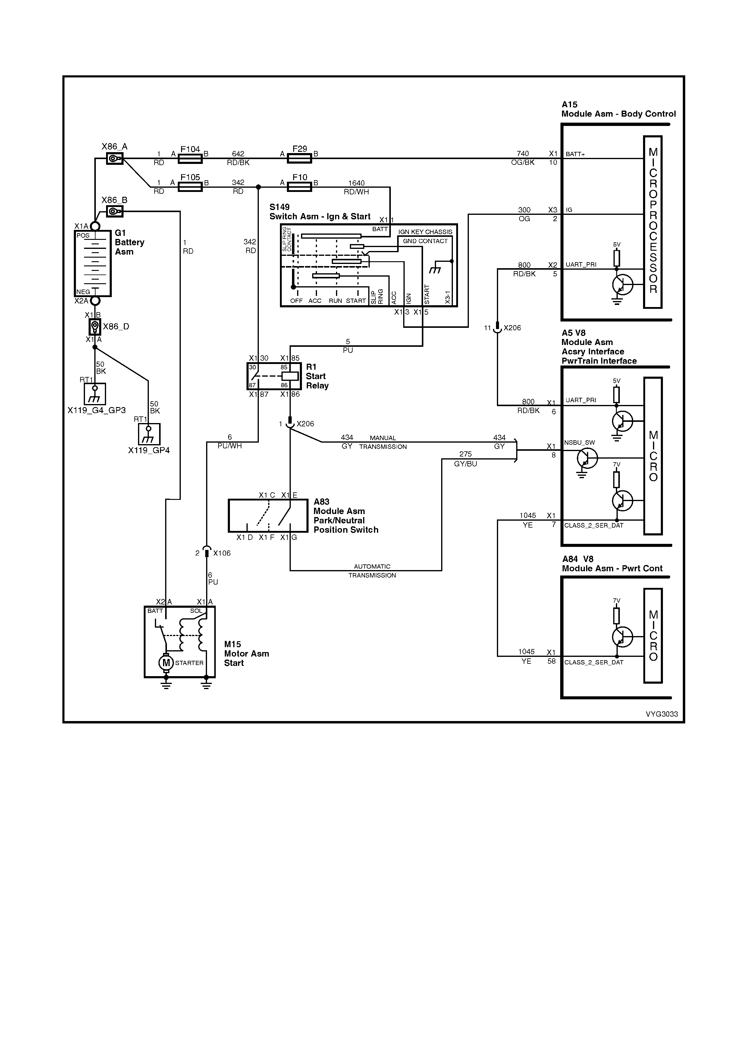
2.9 GEN III V8 PCM – STARTER CRANKING CIRCUIT
Figure 6C3-35 – Starter Cranking Circuit
CIRCUIT DESCRIPTION
When the ignition is turned to the ON position, battery power is supplied from a fusible link to the Start Relay R1,
terminal X1-30. As the ignition switch is turned to the START position, power is also supplied from the ignition
switch S149 to the Start Relay R1, at terminal X1-85. The Powertrain Interface Module (PIM) supplies the ground
signal needed to energise the start relay from X1-86 which allows power to the starter motor solenoid.
When the BCM receives the correct theft deterrent signal, the BCM will send a command via the serial data (UART)
to the PIM to allo w star ter motor oper ation. At the sa me time the PIM will s en d a c ommand via the ser ia l data Clas s
II circuit to the PCM to allow fuel injector pulses.
If the PCM determines that an improper theft deterrent signal was sent from the PIM, or no theft deterrent signal
was sent, the PCM will not allow fuel injection pulses. When the start relay receives this ground signal from the
PIM, the rela y will be energ ised, al lo wing the st arter motor to oper ate.
If there is a prob lem with t h e thef t d eter rent sign al from the BCM to t he PC M, or a ground or p o wer f eed prob l em at
the PIM, DTC P1626, P16 3 0, or P1631 wil l set.
If there is a high voltage problem on the starter relay PIM control circuit, PIM DTC P2007 will set.
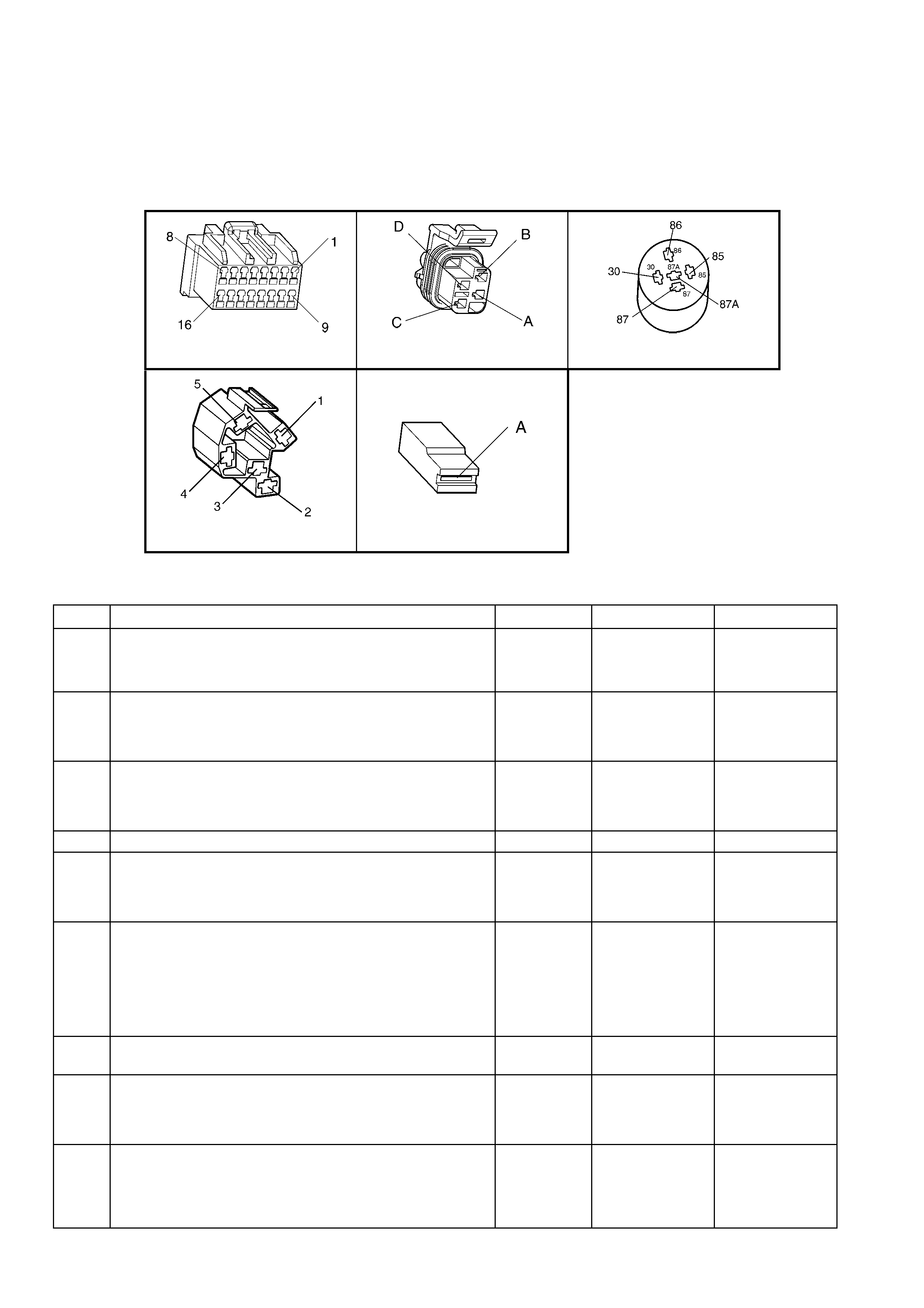
TEST DESCRIPTION
NOTE: The number(s) below refer to the step number(s) on the diagnostic table.
3. T his step c hecks to see if DTC P1626, DTC P163 0 or DT C P1631 are set. Eithe r of these DT Cs could prev ent
the vehicle from starting.
6. T his step checks to see if power is being applied to the starter motor. If the test light illuminates, the problem is
with the starter motor.
14. This step checks the adjustment of the Neutral start switch.
A5 S187 X1 - PART OF X100
S149-X1 M15 – X1
Figure 6C3-2A-36
GEN III V8 PCM – STARTER CRANKING CIRCUIT
STEP ACTION VALUE YES NO
1. Was the "On-Board Diagnostic" (OBD) System Check
performed? Go to Step 2 Go to
OBD System
Check
in this Section.
2. 1. Observe the Theft Deterrent LED on the Instrument
panel.
2. Key ON, engine OFF.
Is the Theft LED flashing?
Go to Theft
Deterrent
System, in
12J BCM.
Go to Step 3
3. 1. Install Tech 2.
2. Using Tech 2, check for a DTC P1626, DTC P1630 or
DTC P1631, in the PCM.
Are any DTC(s) set?
Go to the
appropriate DTC
Table
Go to Step 4
4. Does Tech 2 display PIM serial data? Go to Step 5 Go to Step 21
5. 1. Ignition ON, engine OFF.
2. Using Tech 2, select the PIM Normal Mode data list.
Does the PIM Normal Mode “Theft Status” message
display START?
Go to Step 6 Go to Step 23
6. 1. Ignition OFF.
2. Using a test light, probe the starter solenoid M15,
terminal X1-A with test light connected to ground.
3. Have an assistant turn the ignition switch to the
START position, note the test light.
Does the test light illuminate when the ignition switch is
turned to the START position?
Refer to
6D3-2 Starting
System
Go to Step 7
7. 1. Check fusible link F105.
Was fusible link blown? Go to Step 17 Go to Step 8
8. 1. Remove the start relay, R1.
2. With a test light connected to ground, probe the start
relay harness connector, terminal X1-30.
Does the test light illuminate?
Go to Step 9 Go to Step 19
9. 1. With the start relay still removed and the test light
connected to ground, probe the start relay harness
connector terminal X1-85.
2. Turn the ignition to the START position.
Did the test light illuminate?
Go to Step 11 Go to Step 18

STEP ACTION VALUE YES NO
10. 1. Check for an open circuit between the starter solenoid
connector terminal X1-A and the start relay connector
terminal X1-87.
Was a problem found?
Verify Repair Go to Step 12
11. 1. Ignition OFF.
2. Remove the Start Relay, R1.
3. Connect a test light between the relay harness
connector terminals X1-85 and X1-86.
4. Turn the ignition switch to the START position.
Does the test light illuminate when the ignition switch is
turned to the START position?
Go to Step 10 Go to Step 13
12. 1. Replace the start relay.
Is the action complete? System OK –
13. Is the vehicle equipped with a manual transmission? Go to Step 16 Go to Step 14
14. 1. Ignition ON engine OFF.
2. With a test light connected to B+, probe terminals X1-E
and X1-G, at the Neutral Start Switch A83.
Did the test light illuminate at both terminals?
Go to Step 20 Go to Step 15
15. 1. Check the adjustment of the neutral start switch.
NOTE: If the test light illuminated at only one terminal and
adjustment of neutral start switch does not fix the problem,
replace the switch.
Does test lamp now illuminate at both terminals?
System OK –
16. 1. Check for open in the start relay control circuit 434
from the PIM to the Start Relay.
Was a problem found?
System OK Go to Step 21
17. 1. Repair the short to ground in the faulty circuit.
2. Replace the fusible link as necessary.
Is the action complete?
System OK –
18. 1. Repair the open in the ignition circuit.
Is the action complete? System OK –
19. 1. Check for an open circuit including the fusible link,
F105.
Is the action complete?
System OK –
20. 1. Check for an open in circuit 275 from PIM terminal X1-
8 to the neutral start switch, terminal X1-G.
Was a problem found?
Verify Repair Go to Step 23
21. 1. Check the PIM power feed circuit and ground circuit for
opens or shorts.
Was a problem found?
Verify Repair Go to Step 22
22. 1. Check for an open, short to ground or short to voltage
in the UART circuit.
Was a problem found?
Verify Repair Go to Step 23
23. 1. Check for poor connection at PIM.
Was a problem found? Verify Repair Go to Step 24
24. 1. Replace PIM. Refer to Powertrain Interface Module
Replacement, in 6C3-3 SERVICE OPERATIONS.
Is action complete?
Verify Repair –
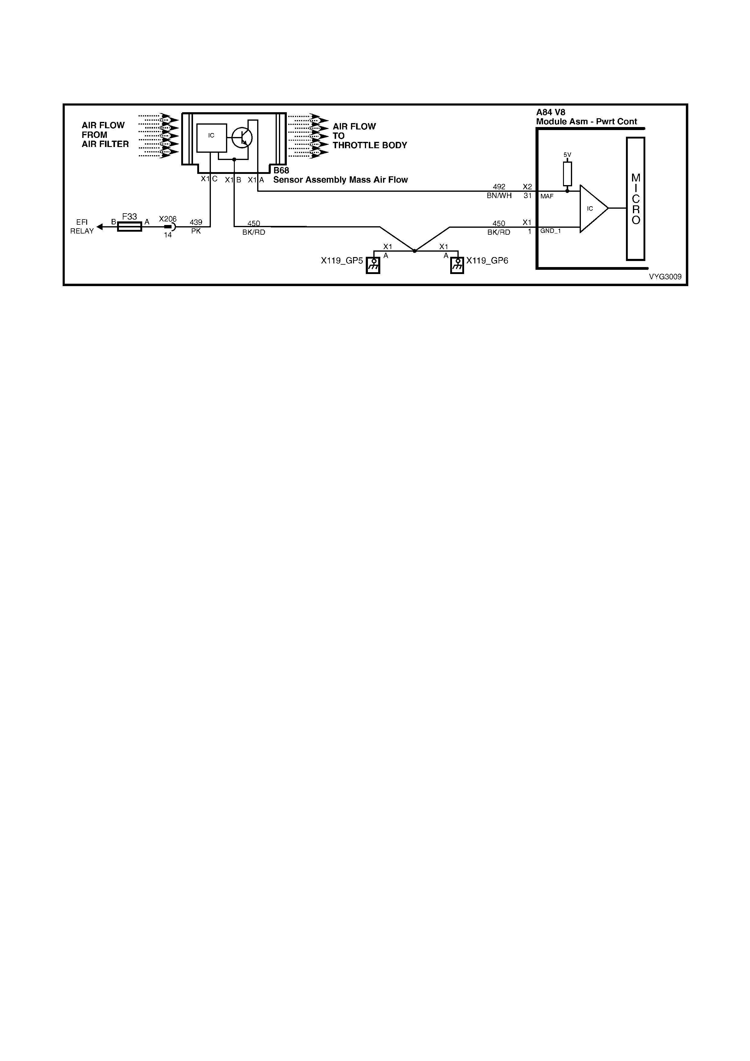
3. DIAGNOSTIC TROUBLE CODE TABLES
GEN III V8 PCM – DTC P0101 MASS AIR FLOW SYSTEM PERFORMANCE
Figure 6C3-2A-37 – Mass Air Flow
CIRCUIT DESCRIPTION
The Mass Air Flow (MAF) Sensor m easures the amount of air ingested by the engine. The direct m easurement of
the air entering the engine is more accurate than calculating the airflow from the MAP, the IAT and the engine
speed (speed/density). The MAF sensor has a battery feed, ground, and a signal circuit.
The MAF Sensor used on this engine is a hot wire type and is used to measure air flow rate. The MAF output
frequency is a func tion of th e po wer requ ir ed t o keep the air f low sensing elements ( hot wire) at a f ix ed temperature
above t he ambien t temperatur e. Air flo wing through th e sensor c ools the sens ing elem ents. T he am ount of coolin g
is prop ortiona l to t he am ount of a ir flo w. T he MAF Se nsor requ ires a gre ater amount of c urrent in order to m aintain
the hot wires at a constant tem perature as the air f low increases . T he MAF Sens or c onverts the c hanges in current
draw to a frequency signal read by the PCM. The PCM calculates the air flow (grams per second) based on this
signal.
The PCM monitors the MAF Sensor frequenc y. The PCM can determ ine if the sensor is stuck low, stuck high, not
provid ing th e airflow val ue ex pec ted f or a giv en op er at ing c on dit ion , or that the s ignal appe ar s to be stuc k bas ed on
a lack of signal variation expected during the normal operation. This diagnostic checks the range/performance of
the MAF Sensor.
The MAF s ystem performance or rationality diagnostic uses the MAP, the IAT, and the engine speed to calculate
an expected airflow rate. The PCM then compares the rate to the actual measured airflow from the MAF Sensor.
The PCM only compares the actual MAF value and the calculated value during conditions where the values are
likely to match. This DTC sets if the actual MAF reading is not within a predetermined range of the calculated
reading.
CONDITIONS FOR RUNNING THE DTC
• DTCs P0102, P0103, P0107, P0108, P0121, P0122, P0123 are not set.
• The engine is running.
• The throttle position angle is less than 50% and the engine vacuum (BARO-MAP) is greater than 65 kPa.
• The system voltage is greater than 11 volts but less than 16 volts.
• The change in thrott le pos it ion is les s than 3%.
• All above conditions stable for two seconds.
CONDITIONS FOR SETTING THE DTC
• The MAF frequency is 50% different from the speed density calculation.
• The conditions met for at least five seconds.
ACTION TAKEN WHEN THE DTC SETS
• The PCM illuminates the Check Powertrain MIL when the diagnostic runs and fails.
• The PCM records the operating conditions at the time the diagnostic fails. The PCM stores this information in
the Freeze Frame/Failure Records.
• The PCM utilises speed density (RPM, MAP, IAT) for fuel management.
CONDITIONS FOR CLEARING THE MIL/DTC
• The PCM deactivates the Check Powertrain MIL after one ignition c ycle that the diagnostic runs and does not
fail.
• A last test failed (current DTC) clears when the diagnostic runs and does not fail.
• Use Tech 2 to clear the MIL/DTC.
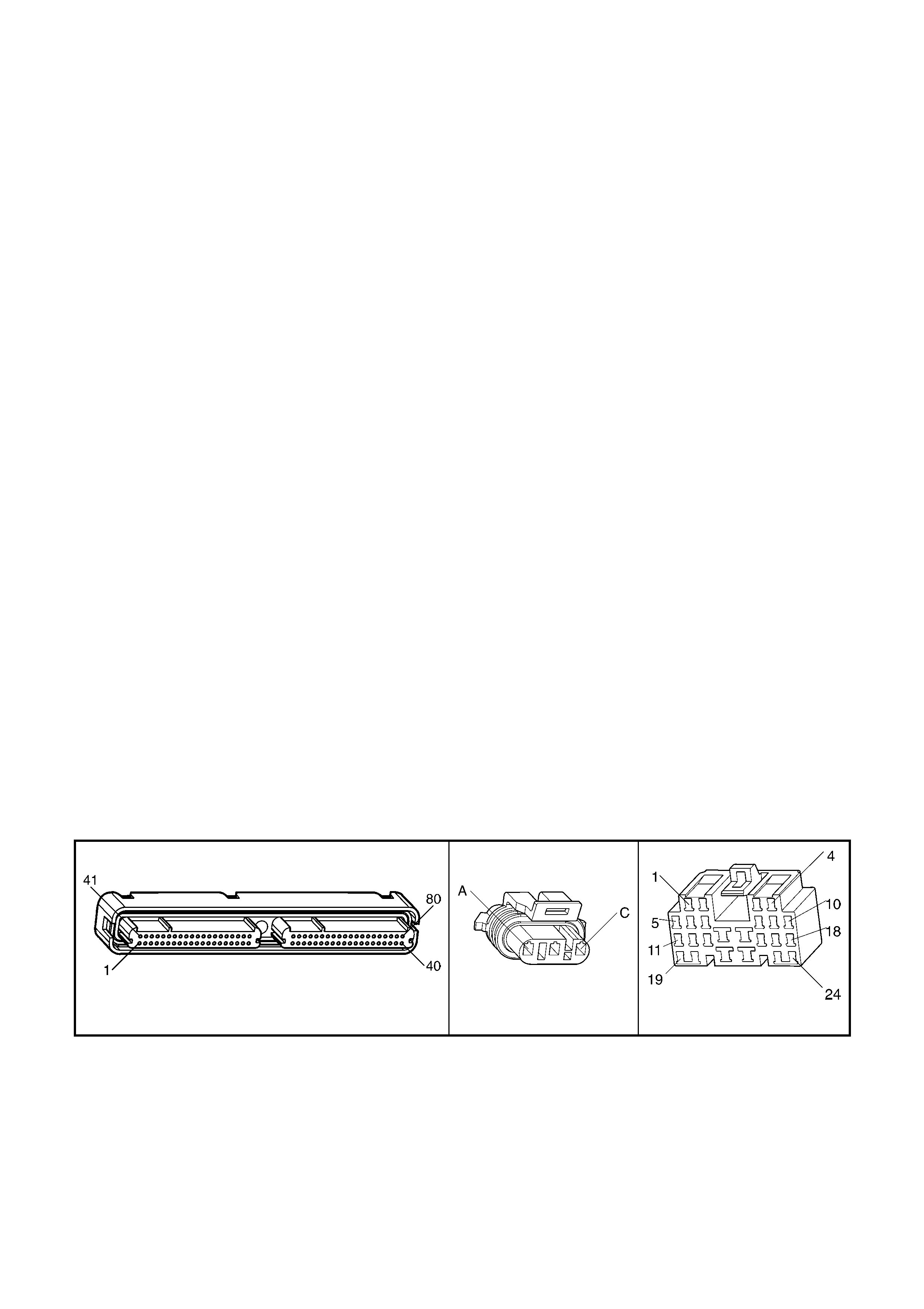
DIAGNOSTIC AIDS
• Inspect the EFI relay for correct operation if you cannot find any problems with the ignition feed circuit to the
component. Probe both sides of the fuse with a test lamp connected to ground in order to determine if a voltage
is supplied to the fuse. Refer to EFI Relay Diagnosis table in this Section.
• The following may cause an intermittent:
– Incorrectly routed harness
– Rubbed through wire insulation
– Broken wire inside the insulation
• For an intermittent fault, refer to Section 6C3-2B SYMPTOMS in this Section.
• Any un-metered air may cause this DTC to set. Check for the following:
– An engine vacuum leak
– The PCV system for vacuum leaks
– An incorrect PCV valve
– The engine oil dip stick not fully seated
TEST DESCRIPTION
NOTE: The number(s) below refer to the step number(s) on the diagnostic table.
2. The MAF system performance or rationalit y diagnostic uses the MAP Sensor signal along with other inputs in
order to calculate an expected airflow rate.
The PCM then c om pares t he exp ected flow ra te to t he ac tual m easured air flo w from the MAF Se nsor. T he f irst
few steps of this table verify that the MAP Sensor is working properly. Correct any MAP Sensor DTCs first.
Refer to DTC P0107 MAP Sens or C irc uit Lo w Vo lta ge if the MAP Se ns or vo lta ge is less than .0 8 v olts . Ref er to
DTC P0108 MAP Sensor Circuit High Voltage if the MAP Sensor voltage is greater than 4.0 volts.
3. Twist the sensor towards the front of the vehicle and lift upward in order to remove the MAP sensor.
6. Using the Freeze Frame/Failure Records data may aid in locating an intermittent condition. If you cannot
duplicat e the DTC, t he inform ation include d in the F reeze Fram e/Failure Rec ords dat a can help de termine t he
distance tra velled since the DTC sets. The Fail Coun ter and Pass Cou nter can also help det ermine how m any
ignition cycles the diagnostic reported a pass and/or a fail. Operate the vehicle within the same freeze frame
conditions (RPM, load, vehicle speed, temperature etc.) that you observed. This will isolate when the DTC
failed. For an y test that requires probing the PCM or component harness connectors, use the Connector Test
Adaptor Kit J35616-A. Using this kit prevents any damage to the harness connector terminals.
7. An y un-metered a ir c aus es this DT C to s et. C hec k the PCV system for vacuum leaks. Als o ins pect the dip s t i ck
is seated correctly and the oil filler cap is tight.
8. This step verifies the signal circuit from the MAF Sensor electrical connector to the PCM.
9. This step verifies whether a ground and B+ circuit is available.
10. This step checks the signal circuit for an open.
11. This step checks the signal circuit for a short to B+.
A84-X2 (RED) B92 X206
Figure 6C3-2A-38

GEN III V8 PCM – DTC P0101 MASS AIR FLOW SYSTEM PERFORMANCE
STEP ACTION VALUE YES NO
1. Was the "On-Board Diagnostic" (OBD) System Check
performed? Go to Step 2 Go to
OBD System
Check
in this Section.
2. If any MAP sensor DTCs are set, refer to the applicable
DTC before proceeding.
1. Idle the engine.
2. Monitor the MAP Sensor voltage parameter using
Tech 2.
Is the MAP Sensor voltage outside of the specified range?
0.08 – 4
volts Go to DTC
P0107 or P0108
Table
Go to Step 3
3. 1. Turn OFF the ignition.
2. Remove the MAP Sensor from the intake manifold,
leaving the electri cal harnes s conn ect ed.
3. Connect a hand operated vacuum pump to the MAP
sensor.
4. Ignition ON, engine OFF.
5. Observe the MAP Sensor display while slowly applying
vacuum up to 20 inches Hg as indicated on the pump
gauge. Each 1 inch of vacuum applied should result in
a 3 to 4 kPa drop in the MAP sensor value on Tech 2
and the value should change smoothly with each
increase in vacuum.
Did the MAP Sensor value change smoothly through the
entire range of the test without any erratic readings?
Go to Step 4 Go to Step 19
4. 1. Apply 20 inches Hg vacuum to the MAP sensor.
Is the MAP Sensor reading on Tech 2 the same or less
than the specified value?
34 kPa Go to Step 5 Go to Step 19
5. 1. Disconnect the vacuum source from the MAP Sensor.
Does the MAP Sensor reading return to the original value? Go to Step 6 Go to Step 19
6. 1. Ignition ON, engine OFF.
2. Review the Freeze Frame/Failure Records data for this
DTC and observe the parameters.
3. Turn OFF the ignition for 15 seconds.
4. Start the engine.
5. Operate the vehicle, within the conditions required for
this diagnostic to run, and as close to the conditions
recorded in the Freeze Frame/Failure Records as
possible. Special operating conditions that you need to
meet before the PCM will run this diagnostic, where
applicable, are listed in Conditions for Running the
DTC.
6. Select the Diagnostic Trouble Code (DTC) option, the
DTC Information option, and the Failed This Ignition
option, using Tech 2.
Does Tech 2 indicate that this DTC failed this ignition?
Go to Step 7 Go to Diagnostic
Aids
7. 1. Check for the following conditions:
– Objects blocking the MAF Sensor inlet screen.
– Intake manifold vacuum leaks.
– Vacuum leaks at the throttle body.
– Crankcase ventilation valve faulty, missing, or
incorrectly installed.
2. If you find a condition, repair as necessary.
Did you find and correct the condition?
Go to Step 21 Go to Step 8
8. 1. Ignition OFF.
2. Disconnect the MAF Sensor connector.
3. Ignition ON, engine OFF.
4. Measure the voltage between the MAF Sensor signal
circuit 492 the battery ground using a DMM.
Is the voltage near the specified value?
5.0 volts Go to Step 9 Go to Step 10
9. 1. Connect a test lamp between the MAF Sensor ignition
feed, circuit 439 and the ground circuit 450 at the MAF
Sensor harness connector.
Is the test lamp illuminated?
Go to Step 13 Go to Step 12
10. Is the voltage less than the specified value? 4.5 volts Go to Step 14 Go to Step 11

STEP ACTION VALUE YES NO
11. 1. Ignition ON.
2. Disconnect the PCM RED connector A84-X2.
3. Ignition ON, engine OFF.
4. Measure the voltage between the MAF Sensor signal
circuit and the battery ground using a DMM.
Is the voltage near the specified value?
0.0 volts Go to Step 20 Go to Step 17
12. 1. Connect a test lamp between the MAF sensor ignition
feed circuit 439 and the battery ground.
Is the test lamp illuminated?
Go to Step 15 Go to Step 16
13. 1. Check for a poor connection at the MAF sensor.
2. If you find a poor connection, replace the faulty
terminal(s).
Did you find a poor connection?
Go to Step 21 Go to Step 18
14. 1. Check the MAF sensor signal circuit 492 between the
PCM and the MAF sensor for the following:
– An open circuit.
– A short to ground.
– A short to the MAF sensor ground circuit.
2. Repair the circuit if the MAF sensor signal circuit is
open or shorted.
Did you find the MAF sensor signal circuit open or shorted?
Go to Step 21 Go to Step 20
15. 1. Locate and repair the open in the ground circuit 450 to
the MAF sensor.
Is the action complete?
Go to Step 21 –
16. 1. Locate and repair the open in the ignition feed circuit
439 to the MAF sensor.
Is the action complete?
Go to Step 21 –
17. 1. Locate and repair the short to voltage in the MAF
sensor signal circuit.
Is the action complete?
Go to Step 21 –
18. 1. Replace the MAF sensor. Refer to ‘MAF Sensor
Replace’ in 6C3-3 SERVICE OPERATIONS.
Is the action complete?
Go to Step 21 –
19. 1. Replace the MAP sensor. Refer to ‘MAP Sensor
Replace’ in 6C3-3 SERVICE OPERATIONS.
Is the action complete?
Go to Step 21 –
20. 1. Replace PCM. Refer to PCM Programming and
PCM/PIM/BCM Security Link Procedure, in 6C3-3
SERVICE OPERATIONS.
Go to Step 21 –
21. 1. Select the Diagnostic Trouble Code (DTC) option and
the Clear DTC Information option using Tech 2.
2. Idle the engine at the normal operating temperature.
3. Select the ‘Diagnostic Trouble Code (DTC)’ option, the
‘DTC Information’ option and the ‘Failed This Ignition’
option, using Tech 2.
4. Operate the vehicle within the Conditions for Running
the DTC as specified in the supporting text, if
applicable.
Does Tech 2 indicate that this DTC reset?
Go to Step 2 Go to Step 22
22. 1. Using Tech 2, check for any other DTC.
Does Tech 2 display any DTCs that you have not
diagnosed?
Go to applicable
DTC Table in
this Section
System OK
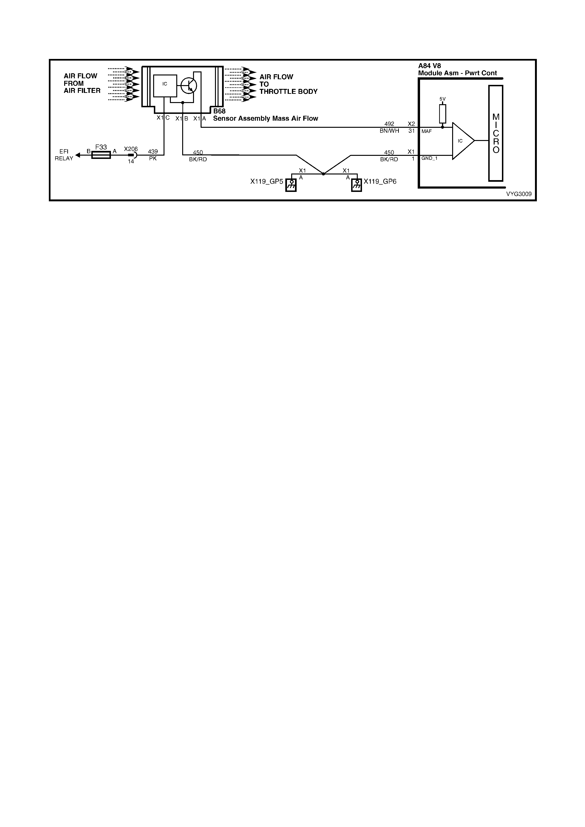
GEN III V8 PCM – DTC P0102 MASS AIR FLOW SENSOR CIRCUIT LOW FREQUENCY
Figure 6C3-3-39 – Mass Air Flow Sensor
CIRCUIT DESCRIPTION
The Mass Air Flow (MAF) Sensor measures the amount of air entering the engine via the inlet tract. The direct
measurement of the air entering the engine is more accurate than calculating the airflow from the MAP, IAT and the
engine speed (speed/density). The MAF Sensor has a battery feed, a ground and a signal circuit.
The MAF Sensor used on this engine is a hot wire type. The MAF output frequency is a function of the power
required to keep the air flow sensing elements (hot wires) at a fixed temperature above the ambient temperature.
Air flowing through the sensor cools the sensing elements. The amount of cooling is proportional to the amount of
air flow. The MAF Sensor requires a greater amount of current in order to maintain the hot wires at a constant
temper ature as the air flo w increas es. T he MAF Se nsor converts the changes in c urrent dr aw to a freque nc y signal
read by the PCM. The PCM calculates the air flow (grams per second) based on this signal.
The PCM monitors the MAF Sensor frequency. The PCM determines if the sensor is stuck low, stuck high, not
provid ing th e airflow val ue ex pec ted f or a giv en op er at ing c on dit ion , or that the s ignal appe ar s to be stuc k bas ed on
a lack of signal variation expected during the normal operation. This diagnostic checks for too low an airflow rate.
This DTC sets when the PCM detects that the MAF Sensor frequency is below a predetermined value.
CONDITIONS FOR RUNNING THE DTC
• The engine speed is greater than 300 RPM.
• The system voltage is at least 11.0 volts.
CONDITIONS FOR SETTING THE DTC
• The MAF frequency is less than 2048 Hz with the engine running.
• The conditions met for at least five seconds.
ACTION TAKEN WHEN THE DTC SETS
• The PCM activates the Check Powertrain MIL when the diagnostic runs and fails.
• The PCM utilises speed density (RPM, MAP, IAT) for fuel management.
• The PCM records the operating conditions at the time the diagnostic fails. The PCM stores this information in
the Freeze Frame/Failure Records.
CONDITIONS FOR CLEARING THE MIL/DTC
• The PCM deactivates the Check Powertrain MIL after one ignition c ycle that the diagnostic runs and does not
fail.
• A last test failed (current DTC) clears when the diagnostic runs and does not fail.
• Use Tech 2 to clear the MIL/DTC.
DIAGNOSTIC AIDS
• Inspect the EFI relay for proper operation if you cannot find any problems with the ignition feed circuit to the
component. Probe both sides of the fuse with a test lamp connected to ground in order to determine if a voltage
is supplied to the fuse. Refer to EFI Relay Diagnosis.
• The following may cause an intermittent:
– Incorrectly routed wiring harness.
– Rubbed through wire insulation.
– Broken wire inside the insulation.
• For an intermittent, refer to Section 6C3-2B SY MPTOMS.
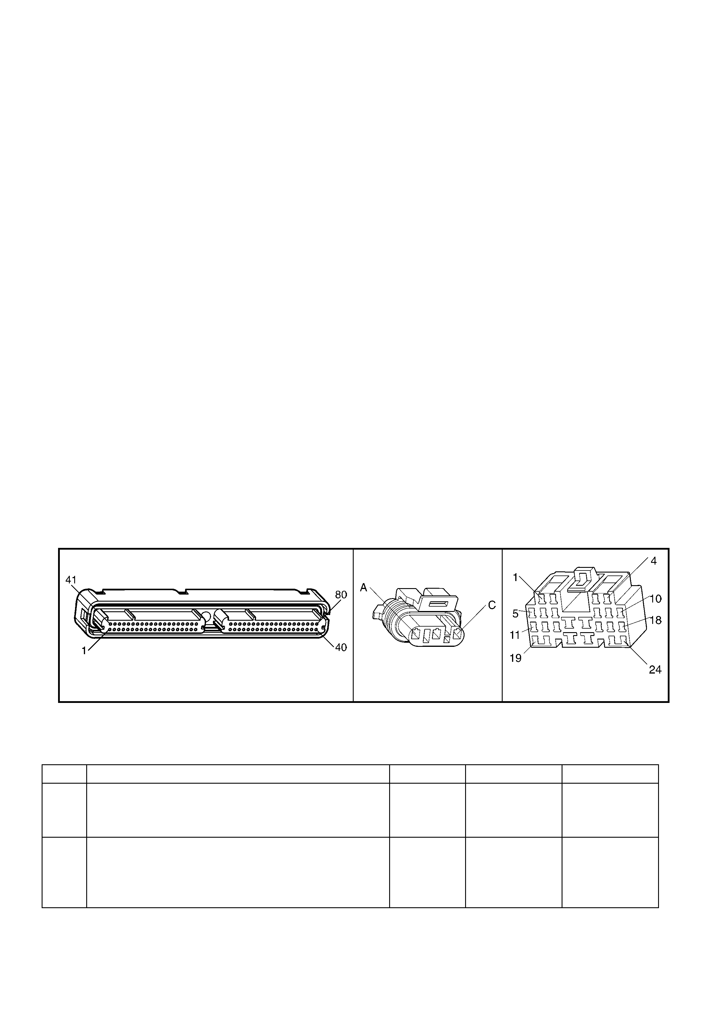
• Any un-metered air may cause this DTC to set. Check for the following:
– An engine vacuum leak.
– The PCV system for vacuum leaks.
– An incorrect PCV valve.
– The engine oil dip stick not fully seated.
– The engine oil fill cap loose or missing.
TEST DESCRIPTION
NOTE: The number(s) below refer to the step number(s) on the diagnostic table.
2. Monitoring the MAF s ensor fr equency wi ll det erm ine if the f ault is pres ent or the m alf unctio n is intermittent. F or
any test tha t requires probing th e PCM or c omponent harness conn ectors, us e the Connec tor Test Adap tor Kit
J35616-A. Using this kit will prevent any damage to the harness connector terminals.
3. Using the Freeze Frame/Failure Records data may aid in locating an intermittent condition. If you cannot
duplicat e the DTC, t he inform ation include d in the F reeze Fram e/Failure Rec ords dat a can help de termine t he
distance travelled since the DTC set. The Fail Counter and Pass Counter can also help determine how many
ignition cycles the diagnostic reported a pass and/or a fail.
Operate th e vehicle within t he same freeze fram e conditions (RPM , load, vehicl e speed, temperatur e etc.) that
you observ ed. This will iso late when the DT C failed. For an y test that r equires probi ng the PCM or com ponent
harness connectors, use the Connector Test Adaptor Kit J35616- A. Using this k it prevents an y damage to the
harness connector terminals.
4. This step checks whether the MAF sensor signal circuit is open or shorted to a ground. If 5.0 volts is present
the circuit is OK.
5. This step checks whether the B+ supply and the ground circuit are OK.
6. This step checks whether the B+ is available at the MAF Sensor.
10. Inspect the fuse f or being open. Ins pect the MAF sen sor ignition f eed circuit for a short to ground if the fuse is
open. Inspec t the EF I rela y f or proper operat ion if you can not f ind an y problem s with the ign ition f eed circu it to
the component. Probe both sides of the fuse with a test lamp connected to ground in order to determine if a
voltage is suppl ied to the f use. Refer to the EFI Rela y Diagnosis table in t his Sec tion, for f urther dia gnosis of
the relay. Multiple DTCs set when a malfunction occurs with the ignition relay or the EFI feed circuit. The
following DTCs may set: P0102, P0443, P0740, P1860, and HO2S heater DTCs.
12. Inspect for proper terminal tension/connections at the PCM harness before replacing the PCM.
A84-X2 (RED) B92 X206
Figure 6C3-2A-40
GEN III V8 PCM – DTC P0102 MASS AIR FLOW SENSOR CIRCUIT LOW FREQUENCY
STEP ACTION VALUE YES NO
1. Was the "On-Board Diagnostic" (OBD) System Check
performed? Go to Step 2 Go to
OBD System
Check
in this Section.
2. 1. Install Tech 2.
2. Idle the engine.
3. Monitor the MAF Sensor frequency display on the
Tech 2 ‘Engine Data List’.
Is the MAF Sensor frequency below the specified value?
10 Hz Go to Step 4 Go to Step 3

STEP ACTION VALUE YES NO
3. 1. Ignition ON, engine OFF.
2. Review the Freeze Frame/Failure Records data for this
DTC and observe the parameters.
3. Turn OFF the ignition for 15 seconds.
4. Start the engine.
5. Operate the vehicle, within the conditions required for
this diagnostic to run and as close to the conditions
recorded in the Freeze Frame/Failure Records as
possible. Special operating conditions that you need to
meet before the PCM will run this diagnostic, where
applicable, are listed in Conditions for Running the
DTC.
6. Select the ‘Diagnostic Trouble Code (DTC)’ option, the
‘DTC Information’ and the ‘Failed This Ignition’ option
using Tech 2.
Does Tech 2 indicate that this DTC failed this ignition?
Go to Step 4 Go to
Diagnostic Aids
4. 1. Ignition OFF.
2. Disconnect the MAF Sensor connector.
3. Ignition ON, engine OFF.
4. Measure the voltage between the MAF sensor signal
circuit 492 and the battery ground using a DMM.
Is the voltage near the specified value?
5.0 volts Go to Step 5 Go to Step 8
5. 1. Connect a test lamp, between the MAF Sensor ignition
feed circuit 439 and the ground circuit 450 at the MAF
Sensor harness connector.
Is the test lamp illuminated?
Go to Step 7 Go to Step 6
6. 1. Connect a test lamp, between the MAF Sensor ignition
feed circuit 439 and the battery ground.
Is the test lamp illuminated?
Go to Step 9 Go to Step 10
7. 1. Check for a poor connection at the MAF Sensor
harness terminals.
2. If you find a poor connection, replace the faulty
terminal(s).
Did you find a poor connection?
Go to Step 13 Go to Step 11
8. 1. Check the MAF Sensor signal circuit between the PCM
and the MAF Sensor for the following:
– An open circuit.
– Short to ground.
– Short to the MAF Sensor ground circuit.
– Short to voltage.
2. If you find the MAF Sensor signal circuit is open or
shorted, repair the circuit as necessary.
Did you find the MAF Sensor signal circuit open or
shorted?
Go to Step 13 Go to Step 12
9. 1. Locate and repair the open in the ground circuit to the
MAF Sensor.
Is the action complete?
Go to Step 13 –
10. 1. Repair the ignition feed circuit to the MAF Sensor.
Is the action complete? Go to Step 13 –
11. 1. Replace the MAF Sensor. Refer to MAF Sensor
Replace in 6C3-3 SERVICE OPERATIONS.
Is the action complete?
Go to Step 13 –
12. 1. Replace PCM. Refer to PCM Programming and
PCM/PIM/BCM Security Link Procedure, in 6C3-3
SERVICE OPERATIONS.
Is action complete?
Go to Step 13 –
13. 1. Select the Diagnostic Trouble Code (DTC) option and
the Clear DTC Information option using Tech 2.
2. Idle the engine at the normal operating temperature.
3. Select the ‘Diagnostic Trouble Code (DTC)’ option, the
‘DTC Information’ option and the ‘Failed This Ignition’
option, using Tech 2.
4. Operate the vehicle within the Conditions for Running
the DTC as specified in the supporting text, if
applicable.
Does Tech 2 indicate that this DTC reset?
Go to Step 2 Go to Step 14

STEP ACTION VALUE YES NO
14. 1. Using Tech 2, check for any other DTC.
Does Tech 2 display any DTCs that you have not
diagnosed?
Go to the
applicable DTC
table
System OK
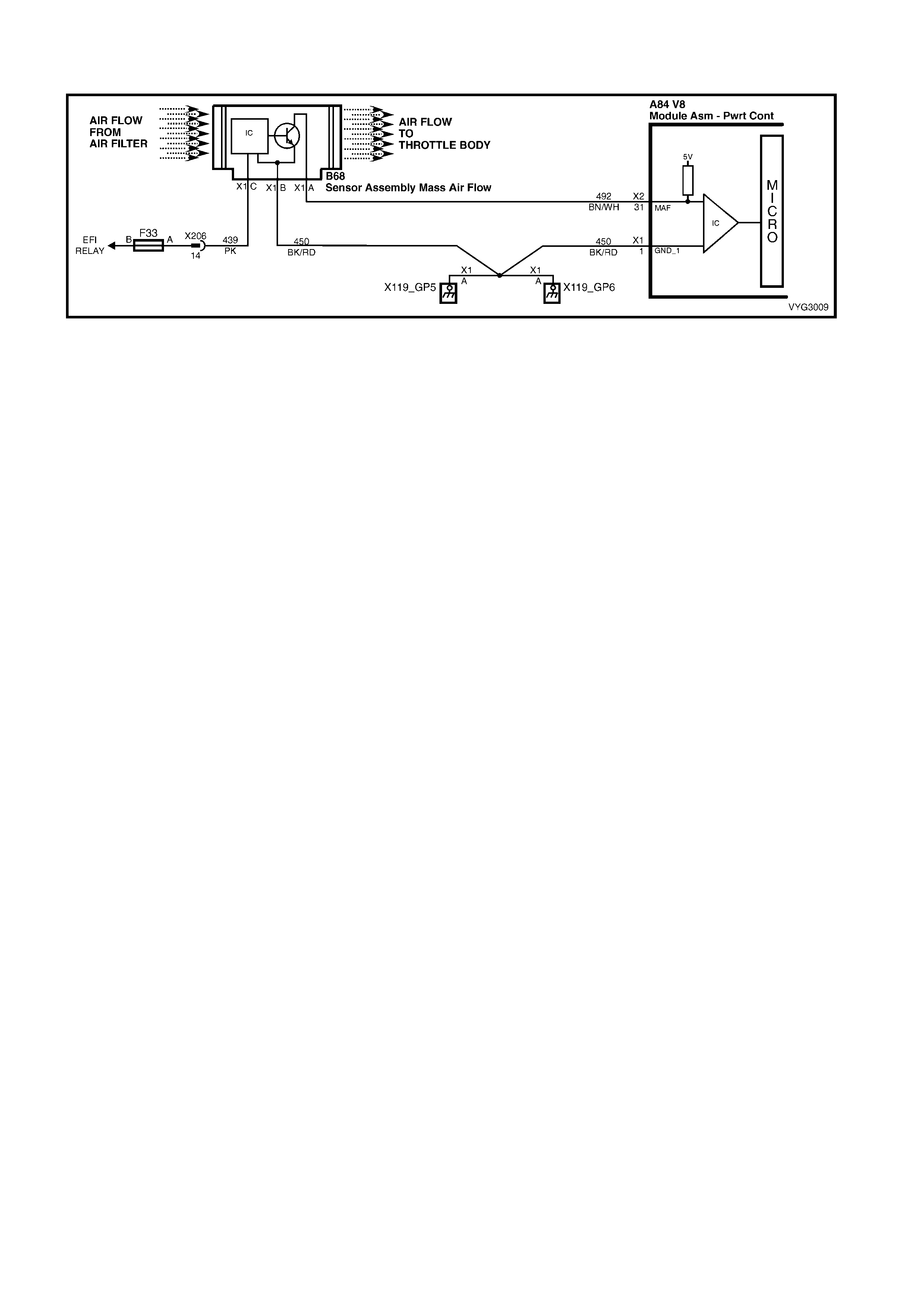
GEN III V8 PCM – DTC P0103 MASS AIR FLOW SENSOR CIRCUIT HIGH FREQUENCY
Figure 6C3-2A-41 – Mass Air Flow Sensor
CIRCUIT DESCRIPTION
The Mass Air Flow (MAF) Sensor measures the amount of air entering the engine via the inlet tract. The direct
measurement of the air entering the engine is more accurate than calculating the airflow from the MAP, IAT, and
the engine speed (speed/density). The MAF Sensor has a battery feed, a ground and a signal circuit.
The MAF S ensor use d on this engine is a hot wire type. T his engine uses th e MAF Sens or in ord er to meas ure air
flow rate. The MAF output f requenc y is a func tion of th e power re quired t o keep the air f low sens ing elem ents (hot
wires) at a fixed temperature above the ambient temperature. Air flowing through the sensor cools the sensing
elements. The amount of cooling is proportional to the amount of air flow. The MAF Sensor requires a greater
amount of current in order to maintain th e hot wires at a constant tem perature as the air flow increases. T he MAF
sensor converts the changes in current draw to a frequency signal read by the PCM. The PCM calculates the air
flow (grams per second) based on this signal.
The PCM monitors the MAF Sensor frequency. The PCM determines if the sensor is stuck low, stuck high, nor
provid ing th e airflow val ue ex pec ted f or a giv en op er at ing c on dit ion , or that the s ignal appe ar s to be stuc k bas ed on
a lack of signal variation ex pected durin g the norm al operation. This di agnostic chec ks for too high an a irflow rate.
This DTC sets when the PCM detects that the MAF sensor frequency is above a predetermined value.
CONDITIONS FOR RUNNING THE DTC
• The engine speed is greater than 300 RPM.
• The system voltage is at least 11.0 volts.
CONDITIONS FOR SETTING THE DTC
• The MAF frequency is greater than 11,250 Hz.
• The conditions met for at least one second.
ACTION TAKEN WHEN THE DTC SETS
• The PCM activates the Check Powertrain MIL when the diagnostic runs and fails.
• The PCM utilises speed density (RPM, MAP, IAT) for fuel management.
• The PCM records the operating conditions at the time the diagnostic fails. The PCM stores this information in
the Freeze Frame/Failure Records.
CONDITIONS FOR CLEARING THE MIL/DTC
• The PCM deactivates the Check Powertrain MIL after one ignition c ycle that the diagnostic runs and does not
fail.
• A last test failed (current DTC) clears when the diagnostic runs and does not fail.
• Use Tech 2 to clear the MIL/DTC.
DIAGNOSTIC AIDS
• Water entering the air intake system that reaches the MAF Sensor could cause this DTC to set. The water
rapidly cools the hot wires in the sensor, causing a false indication of excessive airflow. Check the following
areas for evidence (witness marks) of water intrusion:
– Air system
– Intake air system
• Inspect the EFI relay for proper operation if you cannot find any problems with the ignition feed circuit to the
component. Probe both sides of the fuse with a test lamp connected to ground in order to determine if a voltage
is supplied to the fuse. Refer to EFI Relay Diagnosis in this Section.
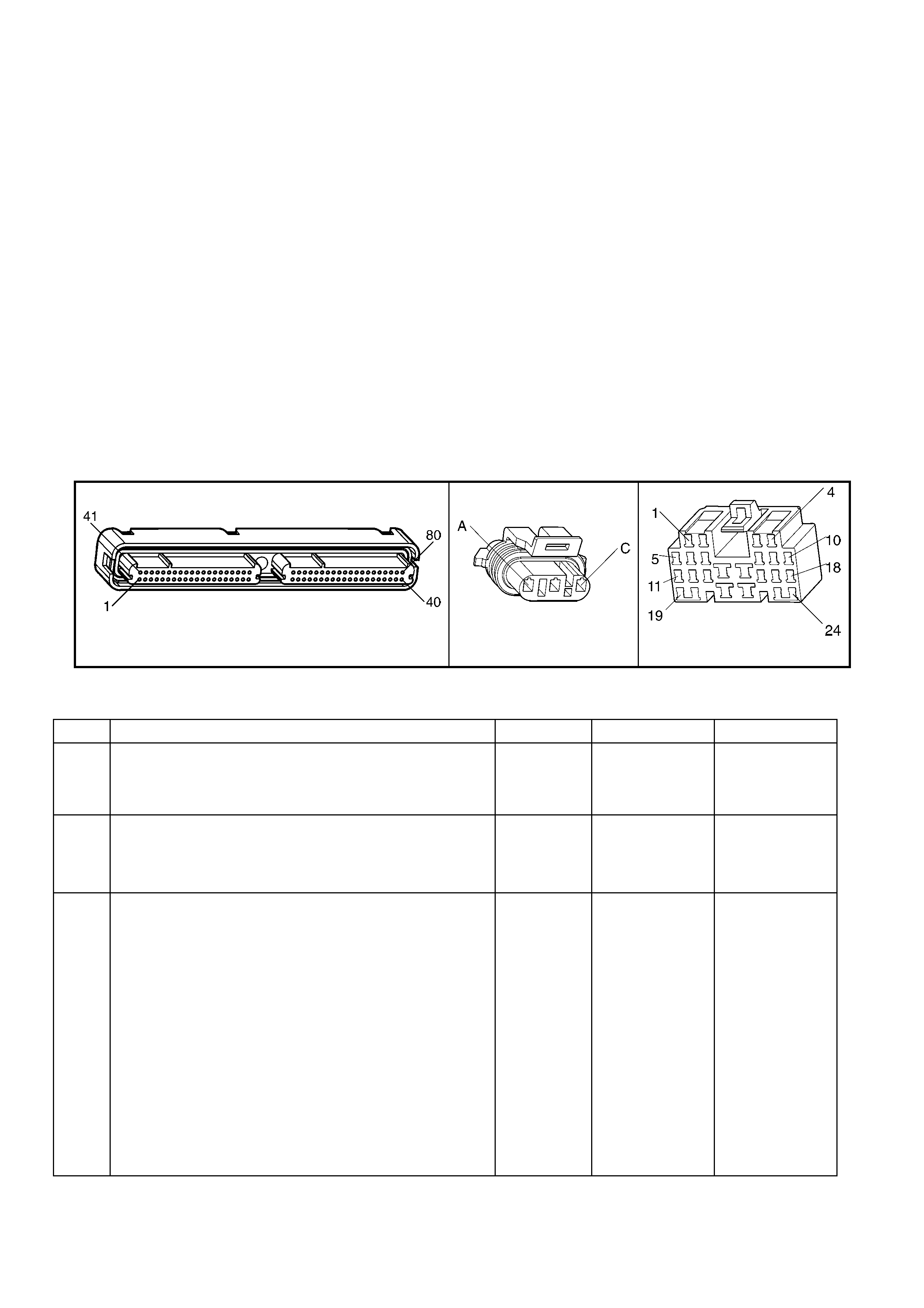
• The following may cause an intermittent:
– Incorrectly routed wiring harness
– Rubbed through wire insulation
– Broken wire inside the insulation
– A poor connection in the ignition feed circuit to the MAF Sensor can cause a DTC P0103 to set.
For an intermittent, refer to Section 6C3-2B SY MPTOMS.
TEST DESCRIPTION
NOTE: The number(s) below refer to the step number(s) on the diagnostic table.
2. Monitoring the MAF Sensor frequency determines if the fault is present or the malfunction is intermittent.
A poor connection at the MAF Sensor or at the fuse causes this DTC to set.
For any test that requ ires p r obin g th e PCM or c omponent h arnes s conn ec tor s, use the Co nnector T es t A dapt or
Kit J35616-A. Using this kit prevents any damage to the harness connector terminals.
3. Using the Freeze Frame/Failure Records data may aid in locating an intermittent condition. If you cannot
duplicat e the DT C, the inform ation include d in the F reeze Fram e/Failur e Records dat a can hel p determine t he
distance travelled since the DTC set. The Fail Counter and Pass Counter can also help determine how many
ignition cycles the diagnostic reported a pass and/or a fail. Operate the vehicle within the same freeze frame
conditions (RPM, load, vehicle speed, temperature etc.) that you observed. This will isolate when the DTC
failed.
4. This step c heck s fo r electro-m agnetic interf erenc e on t he MAF Sensor signa l circ uit. T here s houl d be n o signa l
indicated on Tech 2 with the sensor disconnected.
A84–X2 (RED) B92 X206
Figure 6C3-2A-39
GEN III V8 PCM – DTC P0103 MASS AIR FLOW SENSOR CIRCUIT HIGH FREQUENCY
STEP ACTION VALUE YES NO
1. Was the "On-Board Diagnostic" (OBD) System Check
performed? Go to Step 2 Go to
OBD System
Check
in this Section.
2. 1. Idle the engine.
2. Monitor the MAF Sensor display on the Tech 2 Engine
Data List.
Is the MAF sensor frequency above the specified value?
11,250 Hz Go to Step 4 Go to Step 3
3. 1. Ignition ON, engine OFF.
2. Review the Freeze Frame/Failure Records data for this
DTC and observe the parameters.
3. Turn OFF the ignition for 15 seconds.
4. Start the engine.
5. Operate the vehicle, within the conditions required for
this diagnostic to run, and as close to the conditions
recorded in the Freeze Frame/Failure Records as
possible. Special operating conditions that you need to
meet before the PCM will run this diagnostic, where
applicable, are listed in Conditions for Running the
DTC.
6. Select the Diagnostic Trouble Code (DTC) option, the
DTC Information option and the ‘Failed This Ignition’
option, using Tech 2.
Does Tech 2 indicate that this DTC failed this ignition?
Go to Step 4 Go to Diagnostic
Aids

STEP ACTION VALUE YES NO
4. 1. Ignition OFF.
2. Disconnect the MAF Sensor connector.
3. Idle the engine.
4. Monitor the MAF Sensor frequency using Tech 2.
Does Tech 2 indicate a MAF Sensor frequency?
Go to Step 7 Go to Step 5
5. 1. Check for a poor connection at the MAF Sensor
harness terminals.
2. Replace the faulty terminal(s) if you find a poor
connection.
Did you find and correct the condition?
Go to Step 10 Go to Step 6
6. 1. Replace the MAF Sensor. Refer to MAF Sensor
Replace, in 6C3-3 SERVICE OPERATIONS.
Is the action complete?
Go to Step 10 –
7. 1. Check the MAF Sensor harness for incorrect routing at
the following locations:
– Near secondary ignition wires or components.
– Other high current components. Such as
solenoids, relays, and motors.
2. Correct the harness routing if you find incorrect
routing.
Did you find and correct the condition?
Go to Step 10 Go to Step 8
8. 1. Check the MAF Sensor signal circuit terminal
connections at the PCM RED connector.
2. Replace the faulty terminal(s) if you find a poor
connection.
Did you find and correct the condition?
Go to Step 10 Go to Step 9
9. 1. Replace PCM. Refer to PCM Programming and
PCM/PIM/BCM Security Link Procedure, in 6C3-3
SERVICE OPERATIONS.
Is action complete?
Go to Step 10 –
10. 1. Select the Diagnostic Trouble Code (DTC) option and
the Clear DTC Information option using Tech 2.
2. Idle the engine at the normal operating temperature.
3. Select the ‘Diagnostic Trouble Code (DTC)’ option, the
‘DTC Information’ option and the ‘Failed This Ignition’
option, using Tech 2.
4. Operate the vehicle within the Conditions for Running
the DTC as specified in the supporting text, if
applicable.
Does Tech 2 indicate that this DTC reset?
Go to Step 2 Go to Step 11
11. 1. Using Tech 2, check for any other DTC.
Does Tech 2 display any DTCs that you have not
diagnosed?
Go to applicable
DTC table System OK
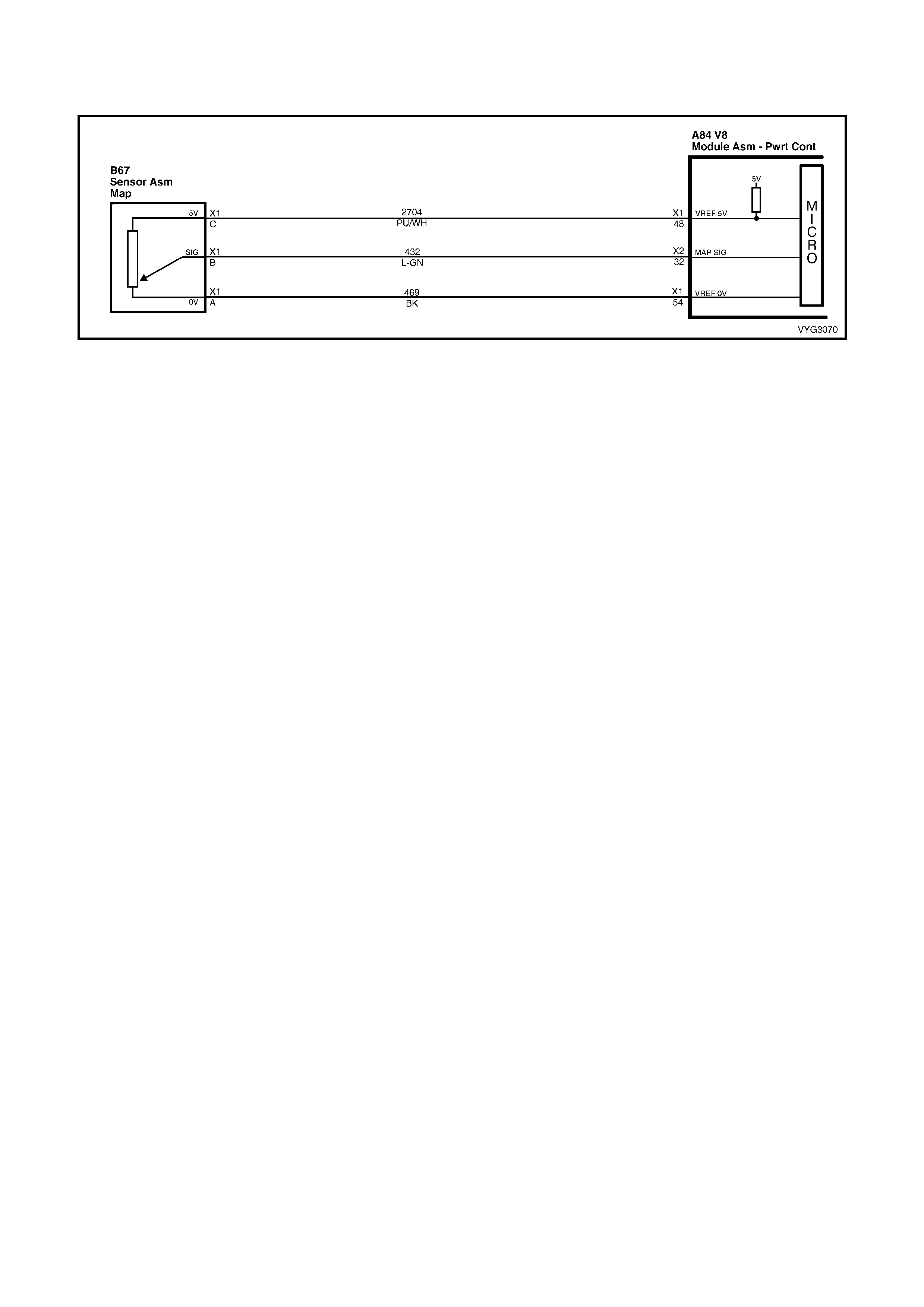
GEN III V8 PCM - DTC P0107 MANIFOLD ABSOLUTE PRESSURE SENSOR
CIRCUIT LOW VOLTAGE
Figure 6C3-2A-40 – Manifold Absolute Pressure Sensor
CIRCUIT DESCRIPTION
The Manifold Absolute Pressure (MAP) Sensor is mounted to the rear of the intake manifold. The MAP Sensor
measures the pressure changes within the intake manifold which is an indication of the engine load. The MAP
Sensor has a 5.0 volt reference, a ground, and a signal circuit.
The MAP Sensor contains a diaphragm which changes the resistance based on pressure. When the manifold
pressu re is l ow (h igh v acuu m), the s ensor outp ut vo ltage is lo w. W hen the m anif old pr essur e is h igh ( low vacuum) ,
the sensor out put vo lta ge is hig h.
The MA P Sensor vo ltage (depend ing on a ltitude) can range from 1.0 – 1.5 volts at idle (h igh vacuum ) to 4.0 – 4. 9
volts at wide open throttle (low vacuum).
When the PCM senses a signal voltage lower than the normal operating range of the sensor, this DTC will set.
CONDITIONS FOR RUNNING THE DTC
• No TP or ECT sensor DTCs are set.
• The engine is running.
• The TP angle is above 20% when the engine speed is greater than 1200 RPM.
OR
• The TP angle is below 18% when the engine speed is below 1000 RPM.
CONDITIONS FOR SETTING THE DTC
• The MAP sensor voltage is less than 0.10 volts.
• The conditions met for at least two seconds.
ACTION TAKEN WHEN THE DTC SETS
• The PCM activates the Check Powertrain MIL when the diagnostic runs and fails.
• The PCM records the operating conditions at the time the diagnostic fails. The PCM stores this information in
the Freeze Frame/Failure Records.
CONDITIONS FOR CLEARING THE MIL/DTC
• The PCM deactivates the Check Powertrain MIL after one ignition c ycle that the diagnostic runs and does not
fail.
• A last test failed (current DTC) clears when the diagnostic runs and does not fail.
• Use Tech 2 to clear the MIL/DTC.
DIAGNOSTIC AIDS
• The following may cause an intermittent:
– Incorrectly routed wiring harness
– Rubbed through wire insulation
– Broken wire inside the insulation
• The PCM 5.0 volt r eferenc e circuits ar e interna lly con nected wit hin th e PCM. If a ll the MA P Sensor c ircuits are
OK, inspect the following component circuit for malfunctions:
– A/C Refriger ant Pres s ure S ens or
For an intermittent, refer Section 6C3-2B SYMPTOMS.
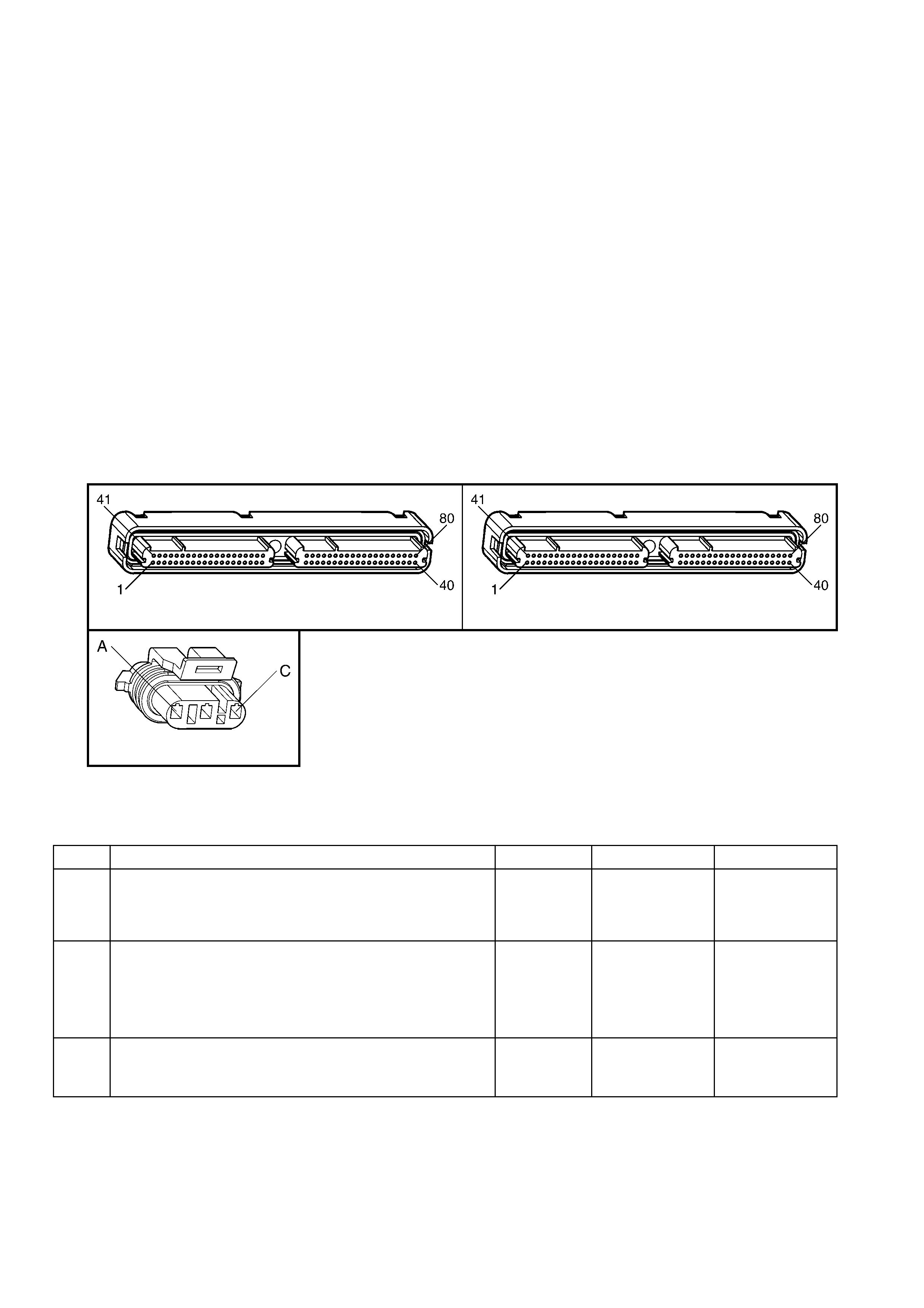
TEST DESCRIPTION
NOTE: The number(s) below refer to the step number(s) on the diagnostic table.
2. If the DTC P1635 sets at the same time, this indicates that the 5.0 Volt reference circuit is either shorted to
ground or shorted to voltage. The 5.0 volt reference circuit is internally connected within the PCM. The A/C
Refrigerant Pressure Sensor may be causing this DTC to set. Refer to DTC P1635 for further diagnosis.
3. This step determines if the malfunction is present.
4. Using the Freeze Frame/Failure Records data may aid in locating an intermittent condition. If you cannot
duplicat e the DT C, the inform ation include d in the F reeze Fram e/Failur e Records dat a can hel p determine t he
distance travelled since the DTC set. The Fail Counter and Pass Counter can also help determine how many
ignition cycles the diagnostic reported a pass and/or fail.
Operate t he veh icle wit hin t he sam e free ze fram e c onditions ( RPM, load, vehic le s peed, tem peratur e, etc .) that
you observed . This will isol ate when the DT C failed.
5. If Tech 2 displays 5.0 volts, the MAP Sensor signal, 5.0 volt reference circuit, and the PCM are OK. For any
test that requires probing the PCM or component harness connectors, use the Connector Test Adaptor Kit J
35616-A. Using this kit will prevent any damage to the harness connector terminals.
6. If Tech 2 displays 5.0 volts, the MAP sensor signal circuit and the PCM is OK. For any test that requires
probing the PCM or components harness connectors, use the Connector Test Adaptor Kit J 35616-A. Using
this kit will prevent any damage to the harness connector terminals.
7. Disconnecting the PC M a ll o ws us in g a D MM in or der t o c hec k the conti nu it y of th e cir cuits . This a ids i n l oc ati ng
an open or shorted circuit.
A84–X1 (BLUE) A84-X2 (RED)
B92
Figure 6C3-2A-41
GEN III V8 PCM – DTC P0107 MANIFOLD ABSOLUTE PRESSURE SENSOR CIRCUIT LOW VOLTAGE
STEP ACTION VALUE YES NO
1. Was the "On-Board Diagnostic" (OBD) System Check
performed? Go to Step 2 Go to
OBD System
Check
in this Section.
2. 1. Install Tech 2.
2. Idle the engine.
3. Monitor the ‘Failed This Ignition’ option under the DTC
Informat ion option usin g Tech 2.
Did DTC P1635 fail this ignition cycle?
Go to DTC
P1635
5 Volt Reference
Circuit
Go to Step 3
3. 1. Monitor the MAP Sensor voltage on ‘Engine Data List’
on Tech 2.
Is the MAP Sensor voltage below the specified value?
0.10 volts Go to Step 5 Go to Step 4

STEP ACTION VALUE YES NO
4. 1. Ignition ON, engine OFF.
2. Review the ‘Freeze Frame/Failure Records’ data for
this DTC and observe the parameters.
3. Turn OFF the ignition for 15 seconds.
4. Start the engine.
5. Operate the vehicle, within the conditions required for
this diagnostic to run, and as close to the conditions
recorded in the ‘Freeze Frame/Failure Records’ as
possible. Special operating conditions that you need to
meet before the PCM will run this diagnostic, where
applicable, are listed in ‘Conditions for Running’ the
DTC.
6. Select the ‘Diagnostic Trouble Code (DTC)’ option, the
‘DTC Information’ option and The ‘Failed This Ignition’
option, using Tech 2.
Does Tech 2 indicate that this DTC failed this ignition?
Go to Step 5 Go to
Diagnostic Aids
5. 1. Disconnect the MAP Sensor electrical connector.
2. Jumper the 5.0 volt reference circuit and the MAP
Sensor signal circuit together at the MAP Sensor
harness connec tor.
3. Observe the MAP Sensor voltage display on Tech 2.
Is the MAP Sensor voltage near the specified value?
5.0 volts Go to Step 11 Go to Step 6
6. 1. Connect a test lamp, between B+ and the MAP Sensor
signal circuit at the MAP Sensor harness connector.
2. Observe the MAP Sensor voltage display on Tech 2.
Is the MAP Sensor voltage near the specified value?
5.0 volts Go to Step 7 Go to Step 9
7. 1. Ignition OFF.
2. Disconnect the PCM BLUE connector A84-X1.
3. Check the 5.0 volt reference circuit for an open or
short to ground.
4. If you find the 5.0 volt reference circuit is open or
shorted to ground, repair the circuit as necessary.
Did you find the 5.0 volt reference circuit open or shorted to
ground?
Go to Step 13 Go to Step 8
8. 1. Check the 5.0 volt reference circuit for a poor
connection at the PCM.
2. Replace the terminal if necessary.
Did th e terminal require replacement?
Go to Step 13 Go to Step 12
9. 1. Ignition OFF.
2. Disconnect the PCM RED connector A84-X2.
3. Check the MAP sensor signal circuit for the following:
– Open circuit
– Short to ground
– Short to sensor ground circuit
4. If you find the MAP Sensor signal circuit is open or
shorted to ground, repair the circuit as necessary.
Did you find the MAP Sensor signal circuit open or shorted
to ground?
Go to Step 13 Go to Step 10
10. 1. Check the MAP Sensor signal circuit for a poor
connection at the PCM and replace the terminal if
necessary.
Did th e terminal require replacement?
Go to Step 13 Go to Step 12
11. 1. Replace the MAP Sensor. Refer to MAP Sensor
Replace, in 6C3-3 SERVICE OPERATIONS.
Is the action complete?
Go to Step 13 –
12. 1. Replace PCM. Refer to PCM Programming and
PCM/PIM/BCM Security Link Procedure, in 6C3-3
SERVICE OPERATIONS.
Is action complete?
Go to Step 13 –

STEP ACTION VALUE YES NO
13. 1. Select the Diagnostic Trouble Code (DTC) option and
the Clear DTC Information option using Tech 2.
2. Idle the engine at the normal operating temperature.
3. Select the ‘Diagnostic Trouble Code (DTC)’ option, the
‘DTC Information’ option and the ‘Failed This Ignition’
option, using Tech 2.
4. Operate the vehicle within the Conditions for Running
the DTC as specified in the supporting text, if
applicable.
Does Tech 2 indicate that this DTC reset?
Go to Step 2 Go to Step 14
14. 1. Using Tech 2, check for any other DTC.
Does Tech 2 display any DTCs that you have not
diagnosed?
Go to the
applicable DTC
table
System OK

GEN III V8 PCM - DTC P0108 MANIFOLD ABSOLUTE PRESSURE SENSOR
CIRCUIT HIGH VOLTAGE
Figure 6C3-3-42 – Manifold Absolute Pressure Sensor
CIRCUIT DESCRIPTION
The Manifold Absolute Pressure (MAP) Sensor is mounted to the rear of the intake manifold. The MAP Sensor
measures the pressure changes within the intake manifold which is an indication of the engine load. The MAP
Sensor has a 5.0 volt reference, a ground, and a signal circuit.
The MAP Sensor contains a diaphragm which changes the resistance based on pressure. When the manifold
pressu re is l ow (h igh v acuu m), the s ensor outp ut vo ltage is lo w. W hen the m anif old pr essur e is h igh ( low vacuum) ,
the sensor out put vo lta ge is hig h.
The MA P Sens or v olt age (depending on a lti tud e) can r ange f r om 1.0- 1.5 volts at i dle ( hi gh vacuum ) to 4.0-4 .9 volts
at wide open throttle (low vacuum).
When the PCM senses a signal voltage higher than the normal operating range of the sensor, this DTC will set.
CONDITIONS FOR RUNNING THE DTC
• No TP or ECT sensor DTCs are set.
• The engine is running.
• The TP angle is above 20% when the engine speed is greater than 1000 RPM.
OR
• The TP angle is below 18% when the engine speed is below 1200 RPM.
CONDITIONS FOR SETTING THE DTC
• The MAP sensor voltage is greater than 4.3 volts.
• The conditions met for at least four seconds.
ACTION TAKEN WHEN THE DTC SETS
• The PCM activates the Check Powertrain MIL when the diagnostic runs and fails.
• The PCM records the operating conditions at the time the diagnostic fails. The PCM stores this information in
the Freeze Frame/Failure Records.
CONDITIONS FOR CLEARING THE MIL/DTC
• The PCM deactivates the Check Powertrain MIL after one ignition c ycle that the diagnostic runs and does not
fail.
• A last test failed (current DTC) clears when the diagnostic runs and does not fail.
• Use Tech 2 in order to clear the MIL/DTC.
DIAGNOSTIC AIDS
• The following may cause an intermittent:
– Incorrectly routed harness
– Rubbed through wire insulation
– Broken wire inside the insulation
• The PCM 5.0 volt r eferenc e circuits ar e interna lly con nected wit hin th e PCM. If a ll the MA P Sensor c ircuits are
OK, inspect the following component circuit for malfunctions:
– A/C Refriger ant Pres s ure S ens or
For an intermittent, refer to Section 6C3-2B SY MPTOMS.
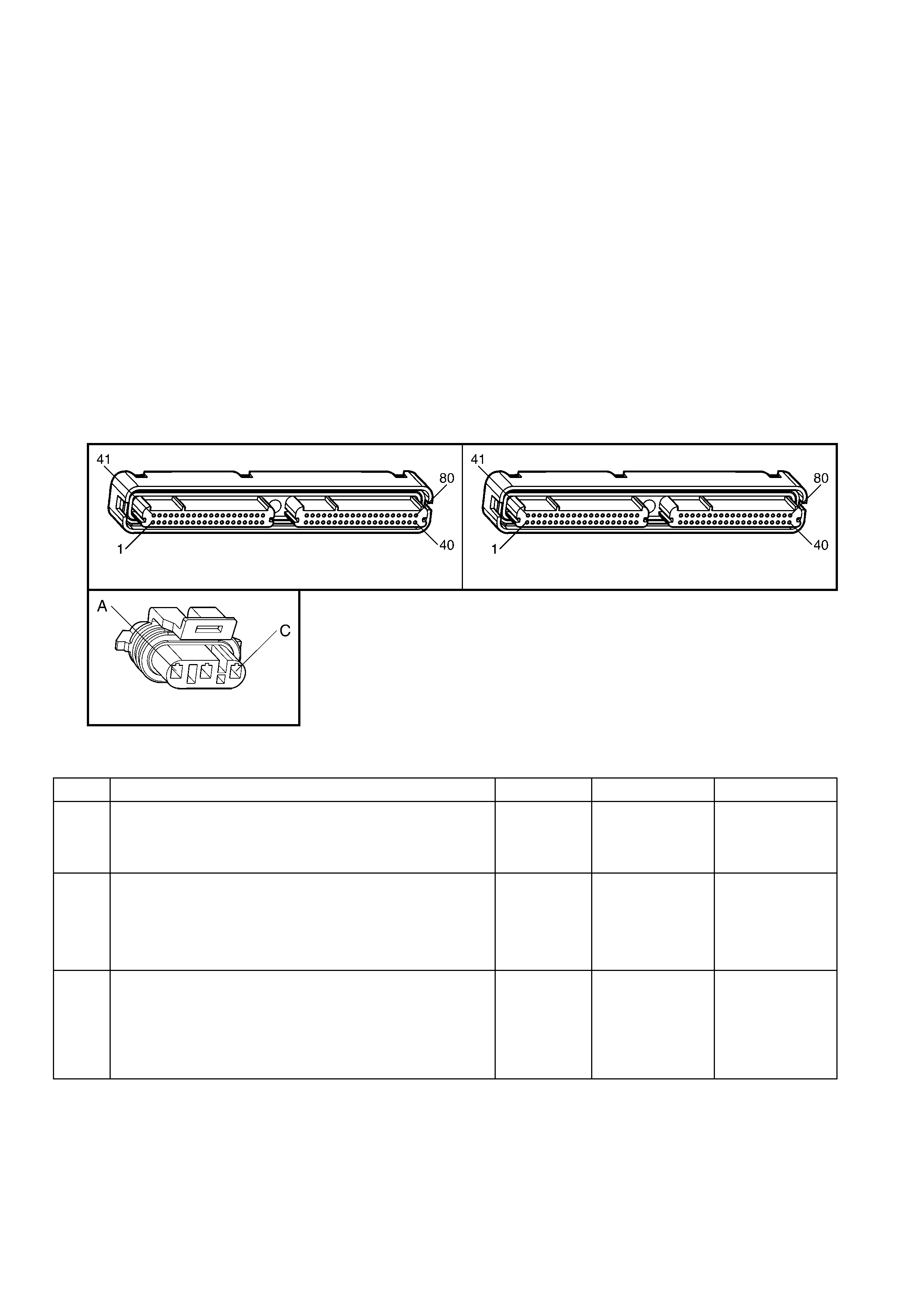
TEST DESCRIPTION
NOTE: The number(s) below refer to the step number(s) on the diagnostic table.
2. If the DTC P1635 sets at the same time, this indicates that the 5.0 volt reference circuit is either shorted to
ground or shorted to voltage. The 5.0 volt reference circuit is internally connected within the PCM. The A/C
Refrigerant Pressure Sensor may be causing this DTC to set. Refer to DTC P1635 for further diagnosis.
3. This step determines if the malfunction is present.
4. Using the Freeze Frame/Failure Records data may aid in locating an intermittent condition. If you cannot
duplicat e the DTC, t he inform ation include d in the F reeze Fram e/Failure Rec ords dat a can help de termine t he
distance travelled since the DTC set. The Fail Counter and Pass Counter can also help determine how many
ignition cycles the diagnostic reported a pass and/or fail. Operate the vehicle with the same freeze frame
conditions (RPM, load, vehicle speed, temperature, etc.) that you observed.
This will isolate when the DTC failed. For any test that requires probing the PCM or component harness
connectors, use the Connector Test Adaptor Kit J 35616-A. Using this kit will prevent any damage to the
harness connector terminals.
5. This step checks whether the signal circuit is shorted to a voltage.
6. This step checks whether t he ground circuit is available at the M AP Sensor. For any test that req uires probing
the PCM or com ponent harness connectors, use the Connector Test Adaptor Kit J 35616-A. Using this k it will
prevent any damage to the harness connector terminals.
A84–X1 (BLUE) A84-X2 (RED)
B92
Figure 6C3-2A-43
GEN III V8 PCM – DTC P0108 MA NIFOLD ABSOLUTE PRESSURE SENSOR CIRCUIT HIGH VOLTAGE
STEP ACTION VALUE YES NO
1. Was the "On-Board Diagnostic" (OBD) System Check
performed? Go to Step 2 Go to
OBD System
Check
in this Section.
2. 1. Install Tech 2.
2. Run the engine at idle.
3. Monitor the ‘Failed This Ignition’ option under the ‘DTC
Information’ option using Tech 2.
Did DTC P1635 fail this ignition cycle?
Go to DTC
P1635 – 5 Volt
Reference
Circuit
Go to Step 3
3. IMPORTANT: If the engine idle is rough, unstable or
incorrect, repair the idle condition before using this table.
Refer to 6C3-2B SYMPTOMS in this Section.
1. Monitor the MAP Sensor voltage on ‘Engine Data List’
on Tech 2.
Is the MAP Sensor voltage above the specified value?
4.3 volts Go to Step 5 Go to Step 4

STEP ACTION VALUE YES NO
4. 1. Ignition ON, engine OFF.
2. Review the Freeze Frame/Failure Records data for this
DTC and observe the parameters.
3. Turn OFF the ignition for 15 seconds.
4. Start the engine.
5. Operate the vehicle, within the conditions required for
this diagnostic to run, and as close to the conditions
recorded in the Freeze Frame/Failure Records as
possible. Special operating conditions that you need to
meet before the PCM will run this diagnostic, where
applicable, are listed in Conditions for Running the
DTC.
6. Select the Diagnostic Trouble Code (DTC) option, the
DTC Information option and the Failed This Ignition
option, using Tech 2.
Does Tech 2 indicate that this diagnostic failed this
ignition?
Go to Step 5 Go to
Diagnostic Aids
5. 1. Disconnect the MAP Sensor electrical connector.
2. Observe the MAP Sensor voltage display on Tech 2.
Is the MAP Sensor voltage below the specified value?
1.0 volts Go to Step 6 Go to Step 7
6. 1. Probe the sensor ground circuit with a test lamp, to B+.
Is the test lamp illuminated? Go to Step 8 Go to Step 9
7. 1. Check the MAP sensor signal circuit for a short to
voltage or a short to the 5.0 volt reference circuit.
2. Repair the MAP Sensor signal circuit if the circuit is
shorted.
Is the MAP Sensor signal circuit shorted?
Go to Step 14 Go to Step 11
8. 1. Measure the voltage at the 5.0 volt reference circuit to
the battery ground using a DMM.
Is the voltage near the specified value?
5.0 volts Go to Step 12 Go to Step 13
9. 1. Check for a poor sensor ground terminal connection at
the PCM RED connector A84-X2.
2. Replace the faulty terminal if a problem is found.
Did th e terminal require replacement?
Go to Step 14 Go to Step 10
10. 1. Check continuity of the MAP Sensor ground circuit.
2. Repair the open or the poor connection if the MAP
sensor ground circuit measures over the specified
value.
Did you find and correct the condition?
5 Ω Go to Step 14 Go to Step 11
11. 1. Replace PCM. Refer to PCM Programming and
PCM/PIM/BCM Security Link Procedure in 6C3-3
SERVICE OPERATIONS.
Is action complete?
Go to Step 14 –
12. 1. Replace the MAP Sensor. Refer to MAP Sensor
Replace in 6C3-3 SERVICE OPERATIONS.
Is the action complete?
Go to Step 14 –
13. 1. Repair the 5.0 volt reference circuit for a short to
voltage.
Is the action complete?
Go to Step 14 –
14. 1. Select the Diagnostic Trouble Code (DTC) option and
the Clear DTC Information option using Tech 2.
2. Idle the engine at the normal operating temperature.
3. Select the ‘Diagnostic Trouble Code (DTC)’ option, the
‘DTC Information’ option and the ‘Failed This Ignition’
option, using Tech 2.
4. Operate the vehicle within the Conditions for Running
the DTC as specified in the supporting text, if
applicable.
Does Tech 2 indicate that this DTC reset?
Go to Step 2 Go to Step 15
15. 1. Using Tech 2, check for any other DTC.
Does Tech 2 display any DTCs that you have not
diagnosed?
Go to the
applicable DTC
table
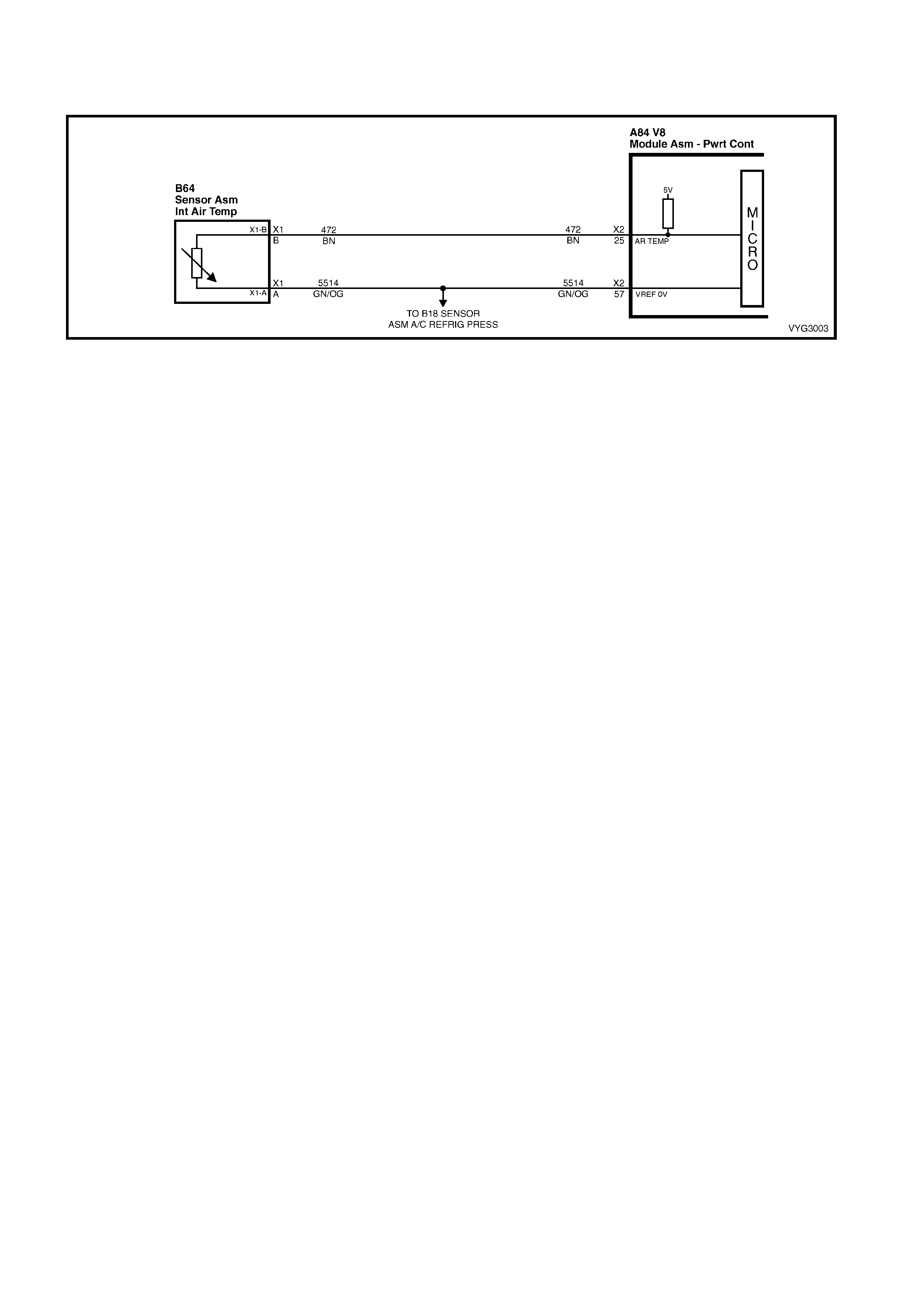
GEN III V8 PCM - DTC P0112 INTAKE AIR TEMPERATURE SENSOR
CIRCUIT LOW VOLTAGE
Figure 6C3-2A-44 – Intake Air Temperature Sensor
CIRCUIT DESCRIPTION
The Intak e Air T em perature (IAT ) Sensor contains a s em ic onductor dev ice wh ich c hanges res istance b ased on the
temper ature (a ther mistor ). The IAT Sensor is loc ated in the air int ake duct of the engine air ind uction s ystem. T he
IAT Sens or has a sig nal circ uit and a groun d circuit. T he PCM appl ies 5.0 vo lts on the sig nal circuit t o the sensor .
The PCM monitors the changes in this voltage, caused by changes in the resistance of the sensor, in order to
determine intake air temperature.
When the intake air is cold, the sensor (thermistor) resistance is high. The PCM’s signal voltage is only pulled down
a small amount through the sensor to a ground; therefore, the PCM senses a high signal voltage (low temperature).
When the intake air is warm, the sensor resistance is low. The signal voltage is pulled down a greater amount;
therefore, the PCM senses a low signal voltage (high temperature).
When the PCM senses a signal voltage lower than the normal operating range of the sensor, this DTC will set.
CONDITIONS FOR RUNNING THE DTC
• DTC(s) P0101, P01 02, P01 03, P01 17, P0 118, are not set.
• The engine run time is greater than 30 seconds.
• The vehicle speed is less than 40 km/h.
CONDITIONS FOR SETTING THE DTC
• The Intake Air Temperature is greater than 139° C.
• The conditions met for at least 20 seconds.
ACTION TAKEN WHEN THE DTC SETS
• The PCM stores the DTC information into memory when the diagnostic runs and fails.
• The Check Powertrain MIL will not be activated.
• The PCM will substitute a default Intake Air Temperature value of 25° C.
• The PCM records the operating conditions at the time the diagnostic fails. The PCM stores this information in
the Freeze Frame/Failure Records.
CONDITIONS FOR CLEARING THE MIL/DTC
• A last test failed (current DTC) clears when the diagnostic runs and does not fail.
• Use Tech 2 to clear the MIL/DTC.
DIAGNOSTIC AIDS
• The following may cause an intermittent:
– Incorrectly routed wiring harness
– Rubbed through wire insulation
– Broken wire inside the insulation
• If the en gin e h as sat o ver n ight, the En gin e Coolant T em per ature and the eng in e Intak e Air T emperatur e va lu es
should d ispl a y wit hin a few degr e es of each o t her. If th e temperatur es are not within 3 ° C, r ef er to Tem per atur e
vs. Resistance Table in Section 6C3-4 SPECIFICATIONS, in this Section.
• If you determine that the DTC occurs intermittently, performing the P1112 diagnostic table may isolate the
cause of the fault.
For an intermittent, refer to Section 6C3-2B SY MPTOMS in this Section.
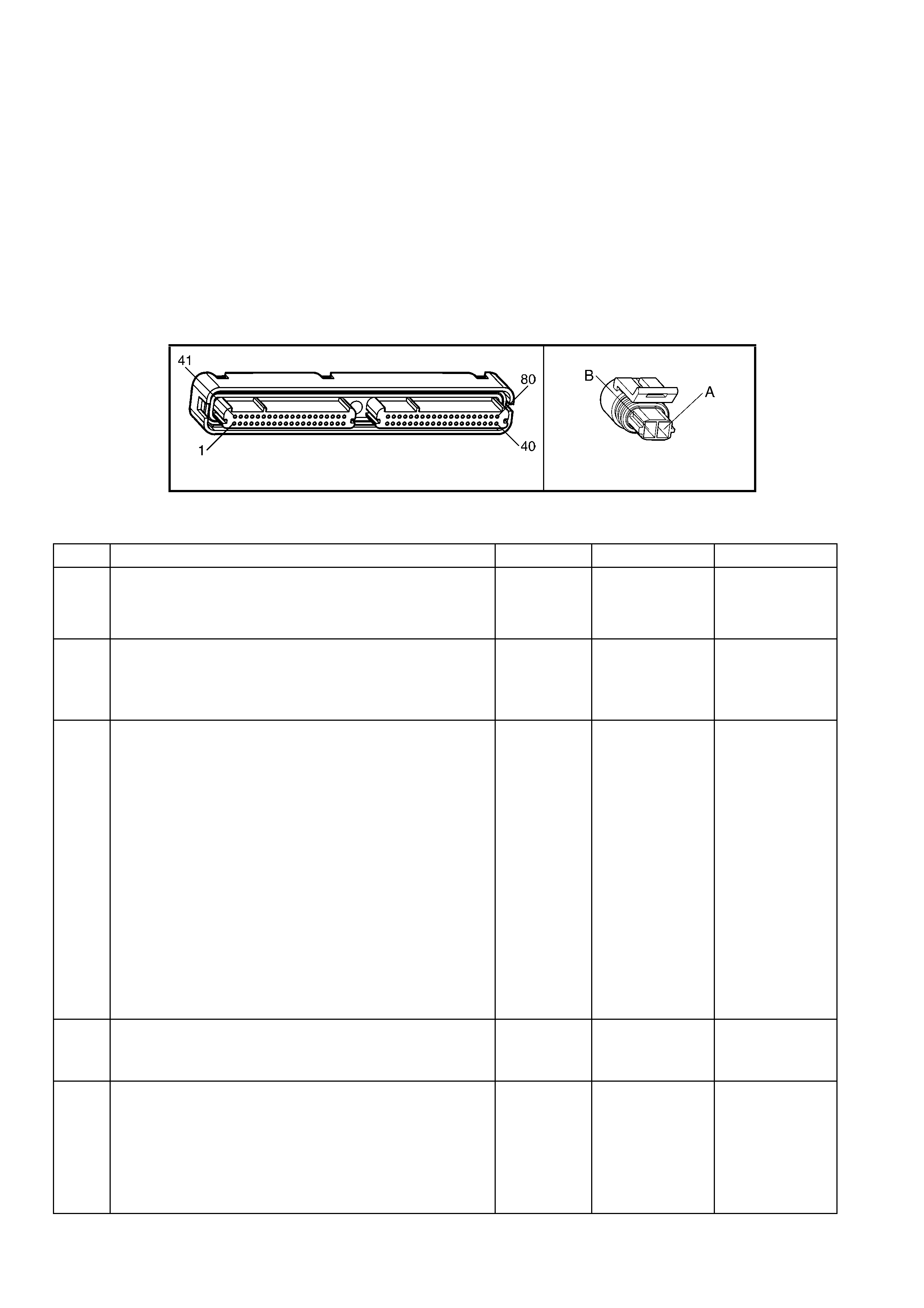
TEST DESCRIPTION
NOTE: Number(s) below refer to the step number(s) on the diagnostic table.
2. This step determines if the malfunction is present.
3. Using the Freeze Frame/Failure Records data may aid in locating an intermittent condition. If you cannot
duplicat e the DTC, t he inform ation include d in the F reeze Fram e/Failure Rec ords dat a can help de termine t he
distance travelled since the DTC set. The Fail Counter and Pass Counter can also help determine how many
ignition cycles the diagnostic reported a pass and/or fail. Operate the vehicle with the same freeze frame
conditions (RPM, load, vehicle speed, temperature, etc.) that you observed.
This will isolate when the DTC failed. For any test that requires probing the PCM or component harness
connectors, use the Connector Test Adaptor Kit J 35616-A. Using this kit will prevent any damage to the
harness connector terminals.
4. An intake air temperature below –30° C indicates the PCM and IAT wiring are OK.
5. Disconnecting the PCM allows the use of a DMM to check continuity of the circuits. This aids in locating an
open or a shorted circuit.
A84-X2 (RED) B64
Figure 6C3-2A-45
GEN III V8 PCM – DTC P0112 INTAKE AIR TEMPERATURE SENSOR CIRCUIT LOW VOLTAGE
STEP ACTION VALUE YES NO
1. Was the "On-Board Diagnostic" (OBD) System Check
performed? Go to Step 2 Go to
OBD System
Check
in this Section.
2. 1. Install Tech 2.
2. Idle the engine.
3. Monitor the IAT display on Tech 2 ‘Engine Data List’.
Is the IAT above the specified value?
139° C Go to Step 4 Go to Step 3
3. 1. Ignition ON engine OFF.
2. Review the Freeze Frame/Failure Records data for this
DTC and observe the parameters.
3. Turn OFF the ignition for 15 seconds.
4. Start the engine.
5. Operate the vehicle, within the conditions required for
this diagnostic to run, and as close to the conditions
recorded in the Freeze Frame/Failure Records as
possible. Special operating conditions that you need to
meet before the PCM will run this diagnostic, where
applicable, are listed in Conditions for Running the
DTC.
6. Select the Diagnostic Trouble Code (DTC) option, the
DTC Information option and the Failed This Ignition
option using Tech 2.
Does Tech 2 indicate that this diagnostic failed this
ignition?
Go to Step 4 Go to Diagnostic
Aids
4. 1. Disconnect the IAT sensor electrical connector.
2. Observe the IAT display on Tech 2.
Is the IAT at the specified value?
–39° C Go to Step 6 Go to Step 5
5. 1. Ignition OFF.
2. Disconnect the PCM RED connector A84-X2.
3. Check the IAT Sensor signal circuit for a short to
ground.
4. If you find the IAT sensor signal circuit is grounded,
repair the circuit as neces sary .
Is the IAT Sensor signal circuit grounded?
Go to Step 8 Go to Step 7

STEP ACTION VALUE YES NO
6. 1. Replace the IAT Sensor. Refer to IAT Sensor Replace
in 6C3-3 SERVICE OPERATIONS.
Is the action complete?
Go to Step 8 –
7. 1. Replace PCM. Refer to PCM Programming and
PCM/PIM/BCM Security Link Procedure in 6C3-3
SERVICE OPERATIONS.
Is action complete?
Go to Step 8 –
8. 1. Select the Diagnostic Trouble Code (DTC) option and
the Clear DTC Information option using Tech 2.
2. Idle the engine at the normal operating temperature.
3. Select the ‘Diagnostic Trouble Code (DTC)’ option, the
‘DTC Information’ option and the ‘Failed This Ignition’
option, using Tech 2.
4. Operate the vehicle within the Conditions for Running
the DTC as specified in the supporting text, if
applicable.
Does Tech 2 indicate that this DTC reset?
Go to Step 2 Go to Step 9
9. 1. Using Tech 2, check for any other DTCs.
Does Tech 2 display any DTCs that you have not
diagnosed?
Go to the
applicable DTC
table
System OK
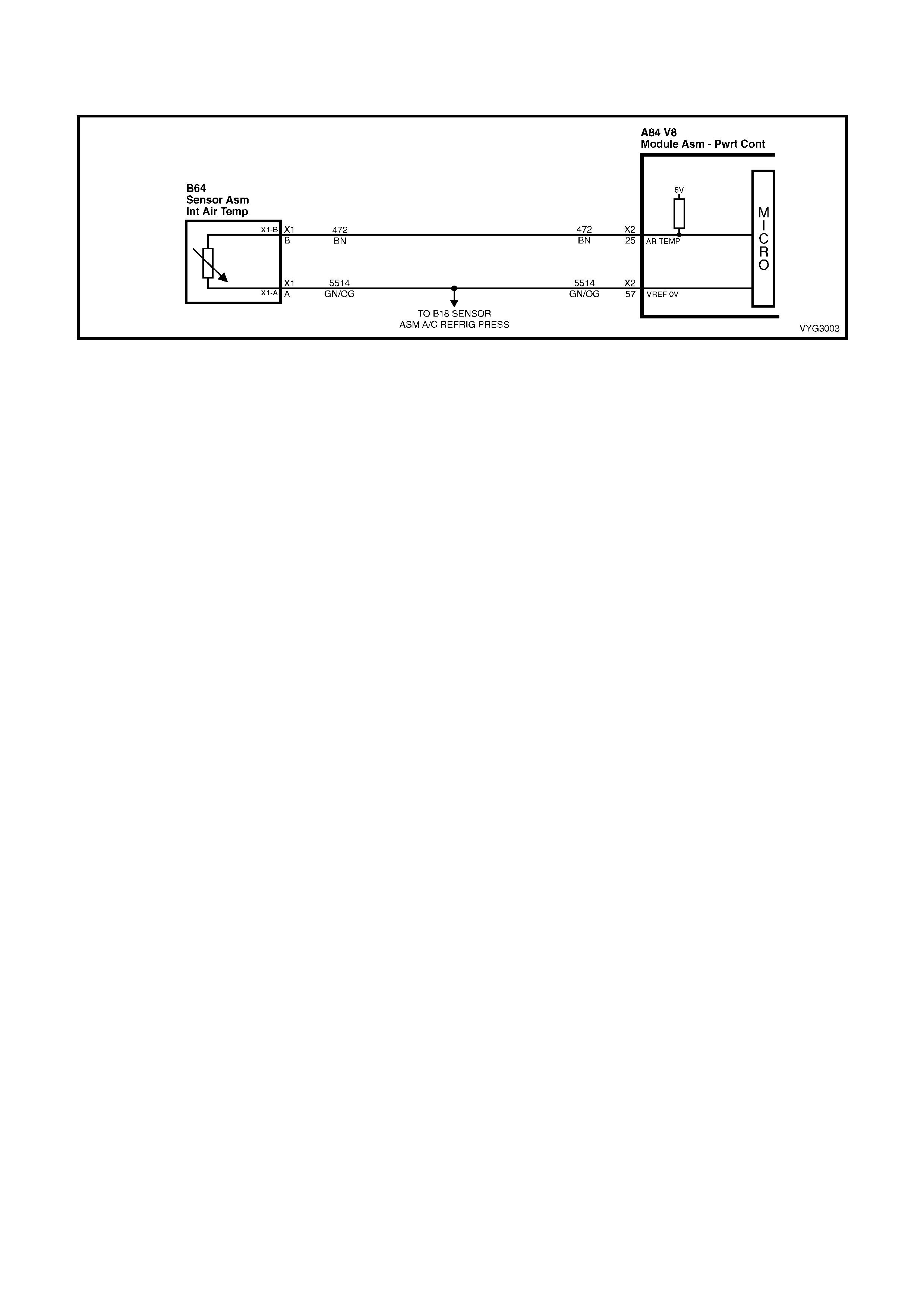
GEN III V8 PCM - DTC P0113 INTAKE AIR TEMPERATURE SENSOR
CIRCUIT HIGH VOLTAGE
Figure 6C3-2A-46 – Intake Air Temperature Sensor
CIRCUIT DESCRIPTION
The Intak e Air T em perature (IAT ) Sensor contains a s em ic onductor dev ice wh ich c hanges res istance b ased on the
temper ature (a ther mistor ). The IAT Sensor is loc ated in the air int ake duct of the engine air ind uction s ystem. T he
IAT Sens or has a sig nal circ uit and a groun d circuit. T he PCM appl ies 5.0 vo lts on the sig nal circuit t o the sensor .
The PCM monitors the changes in this voltage, caused by changes in the resistance of the sensor, in order to
determine intake air temperature.
When the intake air is cold, the sensor (thermistor) resistance is high. The PCM’s signal voltage is only pulled down
a small amount thr ough the sensor to a ground t herefo re, the PC M sens es a high signa l volta ge (lo w tem perature) .
When the intake air is warm, the sensor resistance is low. The signal voltage is pulled down a greater amount
therefore, the PCM senses a low signal voltage (high temperature).
When the PCM senses a signal voltage higher than the normal operating range of the sensor, this DTC will set.
CONDITIONS FOR RUNNING THE DTC
• DTC(s) P0101, P01 02, P01 03, P01 17, P0 118, are not set.
• The engine run time is greater than 100 seconds.
• The engine coolant temperature is greater than 0° C.
• The vehicle speed is less than 11 km/h.
CONDITIONS FOR SETTING THE DTC
• The Intake Air Temperature is at or below –35°C .
• The conditions met for at least 20 seconds.
ACTION TAKEN WHEN THE DTC SETS
• The PCM stores the DTC information into memory when the diagnostic runs and fails.
• The Check Powertrain MIL will not be illuminated.
• The PCM will substitute a default Intake Air Temperature value of 25° C.
• The PCM records the operating conditions at the time the diagnostic fails. The PCM stores this information in
the Freeze Frame/Failure Records.
CONDITIONS FOR CLEARING THE MIL/DTC
• A last test failed (current DTC) clears when the diagnostic runs and does not fail.
• Use Tech 2 to clear the MIL/DTC.
DIAGNOSTIC AIDS
• The following may cause an intermittent:
– Incorrectly routed harness
– Rubbed through wire insulation
– Broken wire inside the insulation
• If the en gin e h as sat o ver n ight, the En gin e Coolant T em per ature and the eng in e Intak e Air T emperatur e va lu es
should display within a few degrees of each other. If the temperatures are not within 3° C, refer to the
Temperature vs. Resistance Table in Section 6C3-4 S PECIFICATIONS, in this Section.
• If you determine that the DTC occurs intermittently, performing the P1111 diagnostic table may isolate the
cause of the fault.
For an intermittent, refer to Section 6C3-2B SY MPTOMS in this Section.
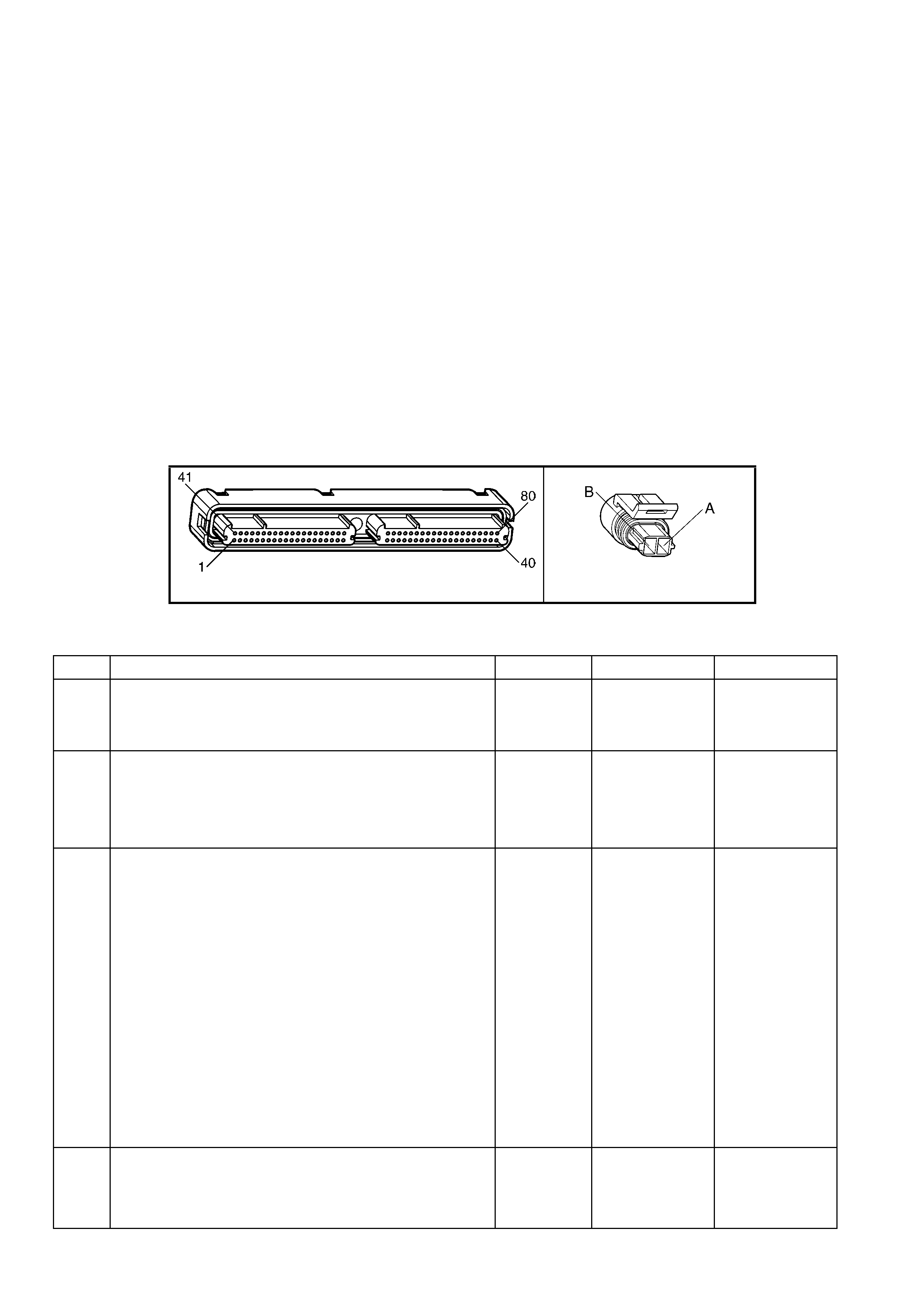
TEST DESCRIPTION
NOTE: Number(s) below refer to the step number(s) on the diagnostic table.
2. This step determines if the malfunction is present. For any test that requires probing the PCM or component
harness connectors, use the Connector Test Adaptor Kit J35616-A. Using this kit will prevent any damage to
the harness connector terminals.
3. Using the Freeze Frame/Failure Records data may aid in locating an intermittent condition. If you cannot
duplicat e the DTC, t he inform ation include d in the F reeze Fram e/Failure Rec ords dat a can help de termine t he
distance travelled since the DTC set. The Fail Counter and Pass Counter can also help determine how many
ignition cycles the diagnostic reported a pass and/or fail. Operate the vehicle with the same freeze frame
conditions (RPM, load, vehicle speed, temperature, etc.) that you observed.
This will isolate when the DTC failed. For any test that requires probing the PCM or component harness
connectors, use the Connector Test Adaptor Kit J 35616-A. Using this kit will prevent any damage to the
harness connector terminals.
4. An intak e air temperature abov e 140° C indica tes the PCM and IAT wiring are O K.
5 An intake air temperature above 140° C indicates an open IAT ground circuit.
6. Disconnect ing th e PCM all ows us ing D MM to c heck conti nuit y of the c ircuits . Thi s aids in locatin g an op en o r a
shorted circuit.
8 Disc onnect ing the P CM al lo ws usin g a DM M to chec k conti nuit y of the circ uits. T his aids in locating an op en or
a shorted circuit.
A84-X2 (RED) B64
Figure 6C3-2A-47
GEN III V8 PCM – DTC P0113 INTAKE AIR TEMPERATURE SENSOR CIRCUIT HIGH VOLTAGE
STEP ACTION VALUE YES NO
1. Was the "On-Board Diagnostic" (OBD) System Check
performed? Go to Step 2 Go to
OBD System
Check
in this Section.
2. 1. Install Tech 2.
2. Idle the engine.
3. Monitor the IAT sensor display on the Tech 2 ‘Engine
Data List’.
Is the IAT at or below the specified value?
–35° C Go to Step 4 Go to Step 3
3. 1. Ignition ON, engine OFF.
2. Review the Freeze Frame/Failure Records data for this
DTC and observe the parameters.
3. Turn OFF the ignition for 15 seconds.
4. Start the engine.
5. Operate the vehicle, within the conditions required for
this diagnostic to run, and as close to the conditions
recorded in the Freeze Frame/Failure Records as
possible. Special operating conditions that you need to
meet before the PCM will run this diagnostic, where
applicable, are listed in Conditions for Running the
DTC.
6. Select the ‘Diagnostic Trouble Code (DTC)’ option, the
‘DTC Information’ option and the ‘Failed This Ignition’
option, using Tech 2.
Does Tech 2 indicate that this diagnostic failed this
ignition?
Go to Step 4 Go to Diagnostic
Aids
4. 1. Disconnect the IAT Sensor electrical connector.
2. Jumper the IAT harness connector terminals together.
3. Observe the IAT parameter on Tech 2.
Is the IAT at the specified value?
139° C Go to Step 9 Go to Step 5

STEP ACTION VALUE YES NO
5. 1. Jumper the IAT signal circuit 472 to a known good
ground.
Is the IAT at the specified value?
139° C Go to Step 8 Go to Step 6
6. 1. Ignition OFF.
2. Disconnect the PCM RED connector A84-X2.
3. Check the IAT Sensor signal circuit 472 for an open.
Is the IAT Sensor signal circuit open?
Go to Step 7 Go to Step 11
7. 1. Repair the IAT Sensor signal circuit.
Is the action complete? Go to Step 12 –
8. 1. Ignition OFF.
2. Disconnect both the PCM connectors.
3. Check the IAT Sensor ground circuit for an open.
Is the IAT Sensor ground circuit open?
Go to Step 10 Go to Step 11
9. 1. Replace the IAT Sensor. Refer to IAT Sensor Replace
in 6C3-3 SERVICE OPERATIONS.
Is the action complete?
Go to Step 12 –
10. 1. Repair the IAT Sensor ground circuit.
Is action complete? Go to Step 12 –
11. 1. Replace PCM. Refer to PCM Programming and
PCM/PIM/BCM Security Link Procedure in 6C3-3
SERVICE OPERATIONS.
Is action complete?
Go to Step 12 –
12. 1. Select the Diagnostic Trouble Code (DTC) option and
the Clear DTC Information option using Tech 2.
2. Idle the engine at the normal operating temperature.
3. Select the ‘Diagnostic Trouble Code (DTC)’ option, the
‘DTC Information’ option and the ‘Failed This Ignition’
option, using Tech 2.
4. Operate the vehicle within the Conditions for Running
the DTC as specified in the supporting text, if
applicable.
Does Tech 2 indicate that this DTC reset?
Go to Step 2 Go to Step 13
13. 1. Using Tech 2 check for any other DTCs.
Does Tech 2 display any DTCs that you have not
diagnosed?
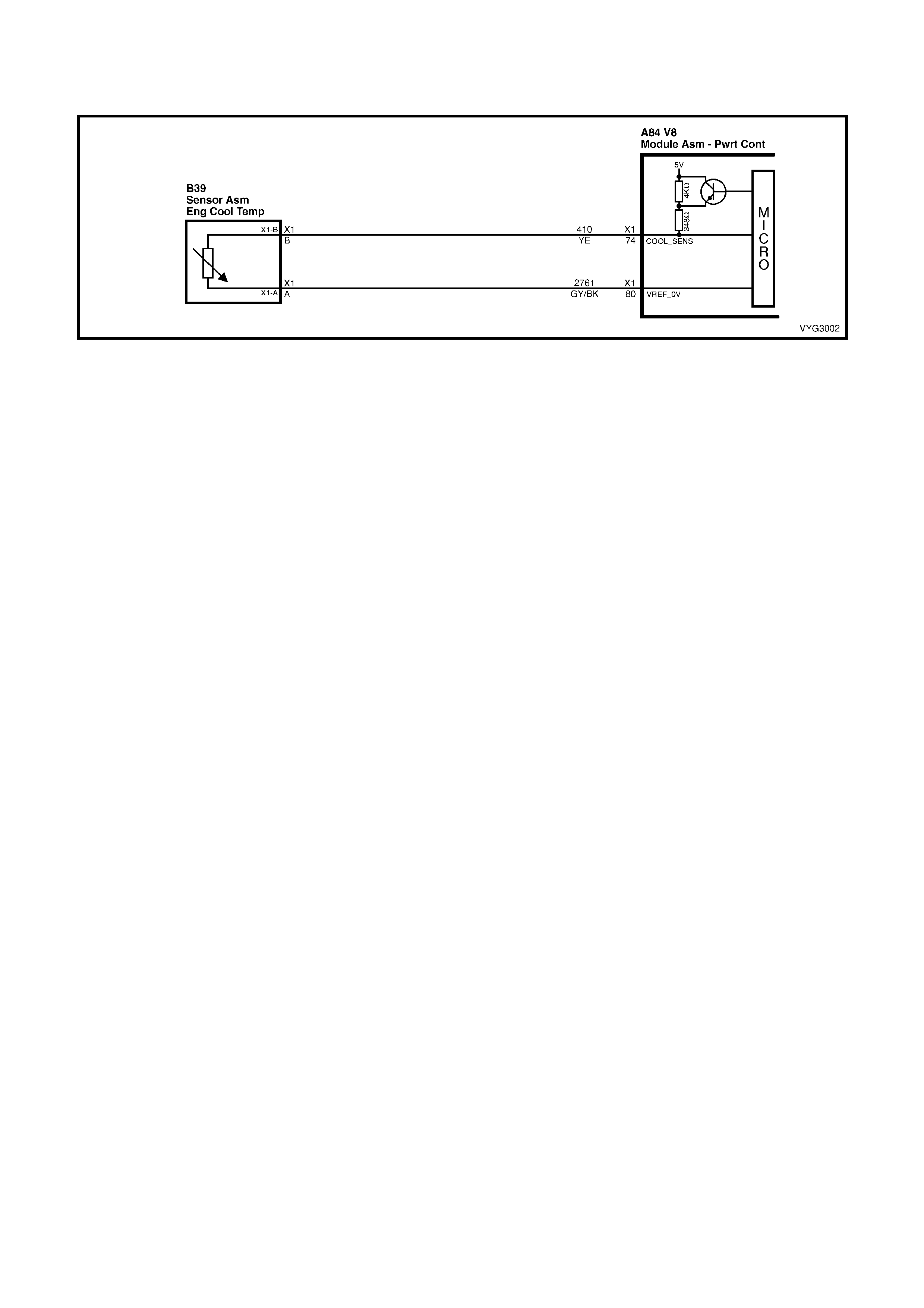
GEN III V8 PCM - DTC P0117 ENGINE COOLANT TEMPERATURE SENSOR
CIRCUIT LOW VOLTAGE
Figure 6C3-2A-46 – Engine Coolant Temperature (ECT) Sensor
CIRCUIT DESCRIPTION
The Engi ne Cool ant Tem perature ( ECT ) Sensor cont ains a sem ic onductor d evic e which ch anges resis tanc e based
on the tem perature (a thermistor). The ECT Sensor is mounted in the left bank cylinder head near the front of the
engine. The ECT Sensor has a signal circuit and a gr ound circuit. The PCM applies a vo ltage (about 5.0 volts) on
the signal circuit to the sensor. The PCM monitors the changes in this voltage, caused by changes in the resistance
of the sensor, in order to determine the coolant temperature.
W hen the co ol ant is c o ld, t he s ens or ( ther mistor) r esis tanc e is h igh . T he PCMs s i gna l vol tag e is on ly pulled do wn a
small amount through the sensor to ground; therefore, the PCM senses a high signal voltage (low temperature).
When the coolant is warm, the sensor resistance is low. The signal voltage is pulled down a greater amount
therefore, the PCM senses a low signal voltage (high temperature). At normal operating temperature, the voltage
should measure about 1.5-2.0 volts at the PCM.
When the PCM senses a signal voltage lower than the normal operating range of the sensor, this DTC will set.
CONDITIONS FOR RUNNING THE DTC
• The engine run time is greater than 10 seconds.
CONDITIONS FOR SETTING THE DTC
• The engine coolant temperature is greater than 139° C.
• All conditions met for at least 45 seconds.
ACTION TAKEN WHEN THE DTC SETS
• The PCM activates the Check Powertrain MIL when the diagnostic runs and fails.
• The PCM will substitute a coolant temperature default value.
• The PCM arr ives at th is default va lue, b y using curr ent intak e air tem perature, the n counting u pward to 11 6° C
at a rate of approximately 7 degrees per minute.
• The PCM will turn on the electric engine cooling fans. This is a FAIL-SAFE action by the PCM to prevent a
possible engine overheat condition, since the DTC indicates an unknown actual coolant temperature.
• The PCM records the operating conditions at the time the diagnostic fails. The PCM stores this information in
the Freeze Frame/Failure Records.
CONDITIONS FOR CLEARING THE MIL/DTC
• The PCM deactivates the Check Powertrain MIL when the diagnostic runs and does not fail.
• A last test failed (current DTC) clears when the diagnostic runs and does not fail.
• Use Tech 2 to clear the MIL/DTC.
DIAGNOSTIC AIDS
• The following may cause an intermittent:
– Incorrectly routed harness
– Rubbed through wire insulation
– Broken wire inside the insulation
• If the en gin e h as sat o ver n ight, the En gin e Coolant T em per ature and the eng in e Intak e Air T emperatur e va lu es
should display within a few degrees of each other. If the temperatures are not within 3° C, refer to
Section 6C3-4 SP ECIF I CATIO NS, Temperature vs. Resistance Table.
• If you determine that the DTC occurs intermittently, performing the P1114 diagnostic table may isolate the
cause of the fault.
• For an intermittent, refer to Section 6C3-2B SY MPTOMS in this Section.
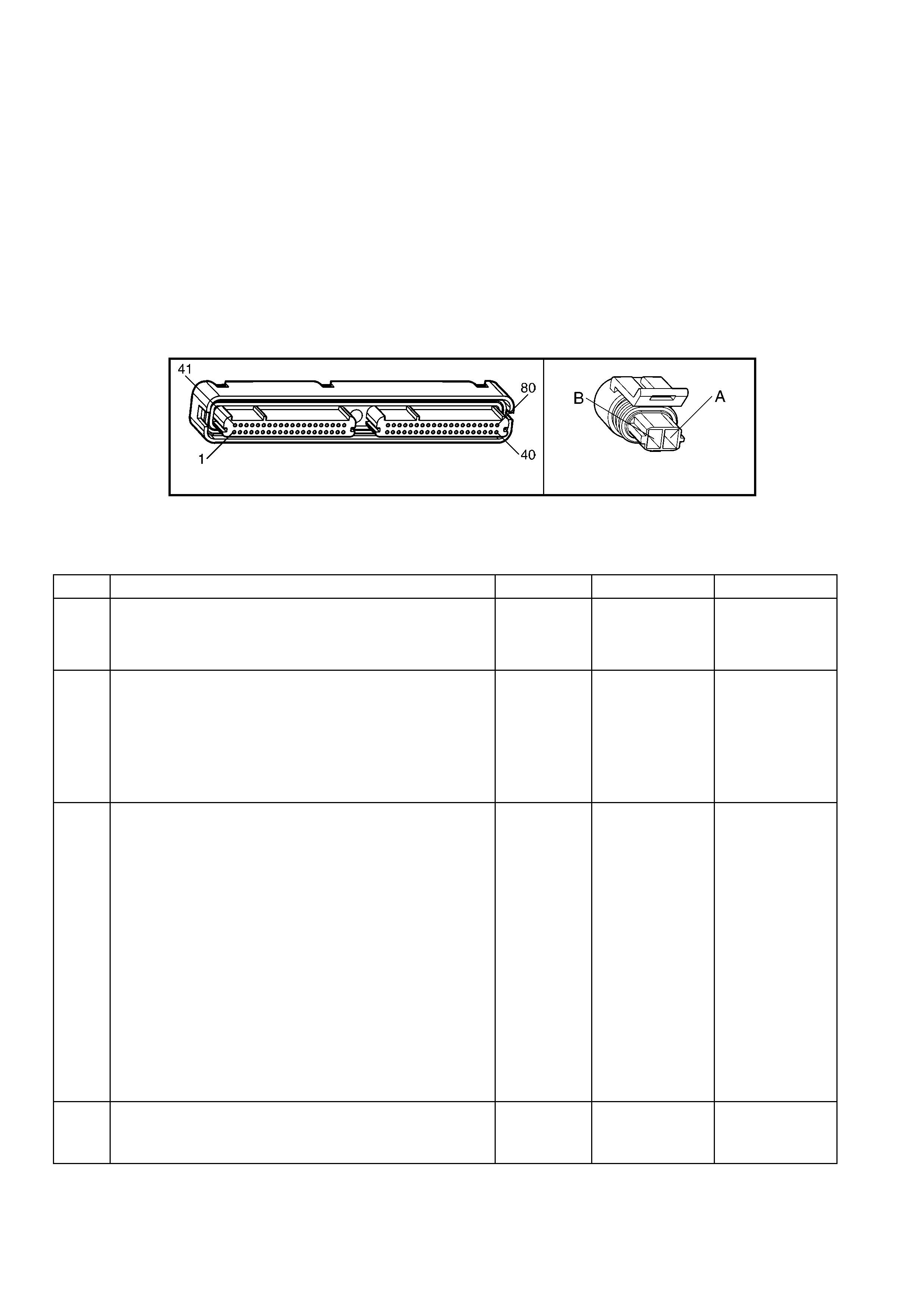
TEST DESCRIPTION
NOTE: The number(s) below refer to the step number(s) on the diagnostic table.
2. This step determines if the malfunction is present.
3. Using the Freeze Frame/Failure Records data may aid in locating an intermittent condition. If you cannot
duplicat e the DTC, t he inform ation include d in the F reeze Fram e/Failure Rec ords dat a can help de termine t he
distance travelled since the DTC set. The Fail Counter and Pass Counter can also help determine how many
ignition cycles the diagnostic reported a pass and/or fail. Operate the vehicle with the same freeze frame
conditions (RPM, load, vehicle speed, temperature, etc.) that you observed. This will isolate when the DTC
failed. For an y test that requires probing the PCM or component harness connectors, use the Connector Test
Adaptor Kit J 35616-A. Using this kit will prevent any damage to the harness connector terminals.
4. An engine coolant temperature below -30° C indicates the PCM and ECT wiring are OK.
5. Disconnecting the PCM allows the use of a DMM to check continuity of the circuits. This aids in locating an
open or a shorted circuit.
7. Inspect for proper terminal tension/connections at the PCM harness before replacing the PCM.
A84-X1 (BLUE) B39
Figure 6C3-2A-47
GEN III V8 PCM – DTC P0117 ENGINE COOLANT TEMPERATURE SENSOR CIRCUIT LOW VOLTAGE
STEP ACTION VALUE YES NO
1. Was the "On-Board Diagnostic" (OBD) System Check
performed? Go to Step 2 Go to
OBD System
Check
in this Section.
2. IMPORTANT: If the engine is overheating, correct the
overheating condition before proceeding with this table.
1. Install Tech 2.
2. Idle the engine.
3. Monitor the ECT display on the Tech 2 ‘Engine Data
List’.
Is the ECT at or above the specified value?
139° C Go to Step 4 Go to Step 3
3. 1. Ignition ON, engine OFF.
2. Review the Freeze Frame/Failure Records data for this
DTC and observe the parameters.
3. Turn OFF the ignition for 15 seconds.
4. Start the engine.
5. Operate the vehicle, within the conditions required for
this diagnostic to run, and as close to the conditions
recorded in the Freeze Frame/Failure Records as
possible. Special operating conditions that you need to
meet before the PCM will run this diagnostic, where
applicable, are listed in Conditions for Running the
DTC.
6. Select the Diagnostic Trouble Code (DTC) option, the
DTC Information option and the Failed This Ignition
option using Tech 2.
Does Tech 2 indicate that this diagnostic failed this
ignition?
Go to Step 4 Go to Diagnostic
Aids in this
Table
4. 1. Disconnect the ECT Sensor electrical connector.
2. Observe the ECT parameter on Tech 2.
Is the ECT at or below specified value?
–30° C Go to Step 6 Go to Step 5

STEP ACTION VALUE YES NO
5. 1. Ignition OFF.
2. Disconnect the PCM BLUE connector A84-X1.
3. Check the ECT Sensor signal circuit 410 for a short to
ground.
4. If you find the ECT Sensor signal circuit is grounded,
repair the circuit as neces sary .
Did you find and repair a grounded ECT signal circuit?
Go to Step 8 Go to Step 7
6. 1. Replace the ECT Sensor. Refer to ECT Sensor
Replace in 6C3-3 SERVICE OPERATIONS.
Is the action complete?
Go to Step 8 –
7. 1. Replace PCM. Refer to PCM Programming and
PCM/PIM/BCM Security Link Procedure, in 6C3-3
SERVICE OPERATIONS.
Is action complete?
Go to Step 8 –
8. 1. Select the Diagnostic Trouble Code (DTC) option and
the Clear DTC Information option using Tech 2.
2. Idle the engine at the normal operating temperature.
3. Select the Diagnostic Trouble Code (DTC) option, the
DTC Information option and the Failed This Ignition
option using Tech 2.
4. Operate the vehicle within the Conditions for Running
the DTC as specified in the supporting text, if
applicable.
Does Tech 2 indicate that this DTC reset?
Go to Step 2 Go to Step 9
9. 1. Using Tech 2, check for any other DTCs.
Does Tech 2 display any DTCs that you have not
diagnosed?
Go to the
applicable DTC
table
System OK

GEN III V8 PCM – DTC P0118 ENGINE COOLANT TEMPERATURE SENSOR
CIRCUIT HIGH VOLTAGE
Figure 6C3-2A-48 – Engine Coolant Temperature (ECT) Sensor
CIRCUIT DESCRIPTION
The Engi ne Coolant Tem perature(E CT) Sensor c ontains a sem iconductor devic e which chang es resistance based
on the tem perature (a thermistor). The ECT Sensor is mounted in the left bank cylinder head near the front of the
engine. The ECT Sensor has a signal circuit and a gr ound circuit. The PCM applies a vo ltage (about 5.0 volts) on
the signal circuit to the sensor. The PCM monitors the changes in this voltage, caused by changes in the resistance
of the sensor, in order to determine the coolant temperature.
W hen the co ol ant is c o ld, t he s ens or ( ther mistor) r esis tanc e is h igh . T he PCMs s i gna l vol tag e is on ly pulled do wn a
small amount through the sensor to ground; therefore, the PCM senses a high signal voltage (low temperature).
When the coolant is warm, the sensor resistance is low. The signal voltage is pulled down a greater amount
therefore, the PCM senses a low signal voltage (high temperature). At normal operating temperature, the voltage
should measure about 1.5-2.0 volts at the PCM.
When the PCM senses a signal voltage higher than the normal operating range of the sensor, this DTC will set.
CONDITIONS FOR RUNNING THE DTC
• The engine run time is greater than 10 seconds.
CONDITIONS FOR SETTING THE DTC
• The engine coolant temperature is less than –38.9° C.
• All conditions met for at least 45 seconds.
ACTION TAKEN WHEN THE DTC SETS
• The PCM activates the Check Powertrain MIL when the diagnostic runs and fails.
• The PCM will substitute a coolant temperature default value.
• The PCM arr ives at th is default va lue, b y using curr ent intak e air tem perature, the n counting u pward to 11 6° C
at a rate of approximately 7 degrees per minute.
• The PCM will turn on the electric engine cooling fans. This is a FAIL-SAFE action by the PCM to prevent a
possible engine overheat condition, since the DTC indicates an unknown actual coolant temperature.
• The PCM records the operating conditions at the time the diagnostic fails. The PCM stores this information in
the Freeze Frame/Failure Records.
CONDITIONS FOR CLEARING THE MIL/DTC
• The PCM deactivates the Check Powertrain MIL when the diagnostic runs and does not fail.
• A last test failed (current DTC) clears when the diagnostic runs and does not fail.
• Use Tech 2 to clear the MIL/DTC.
DIAGNOSTIC AIDS
• The following may cause an intermittent:
– Incorrectly routed harness.
– Rubbed through wire insulation.
– Broken wire inside the insulation.
• If the en gin e h as sat o ver n ight, the En gin e Coolant T em per ature and the eng in e Intak e Air T emperatur e va lu es
should display within a few degrees of each other. If the temperatures are not within 3° C, refer to the
Temperature vs. Resistance table in Section 6C3-4 SPECIFICATIONS.
• If you determine that the DTC occurs intermittently, performing the P1115 diagnostic table may isolate the
cause of the fault.
• For an intermittent, refer to Section 6C3-2B SY MPTOMS.
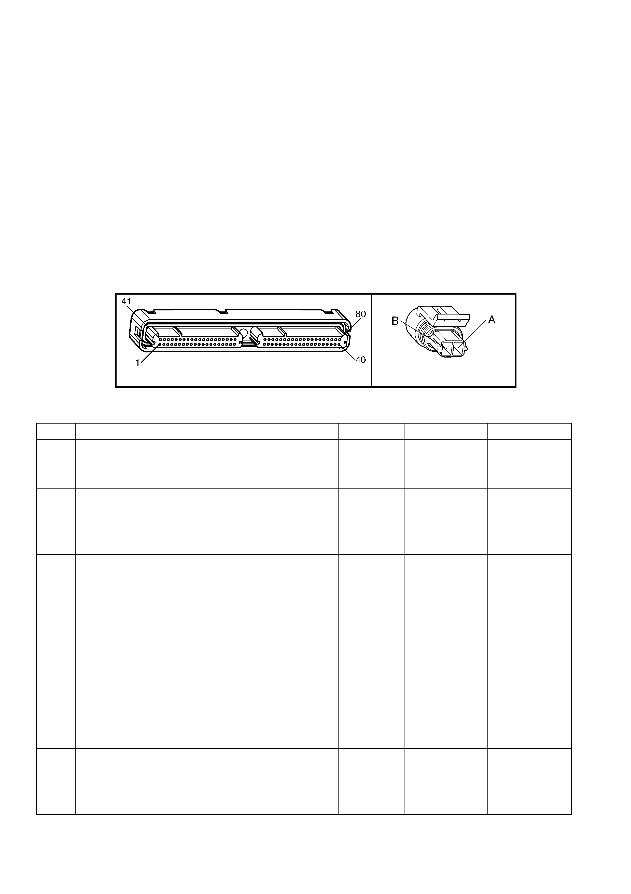
TEST DESCRIPTION
NOTE: The number(s) below refer to the step number(s) on the diagnostic table.
2. This step determines if the malfunction is present. For any test that requires probing the PCM or component
harness connectors, use the Connector Test Adaptor Kit J 35616-A. Using this kit will prevent any damage to
the harness connector terminals.
3. Using the Freeze Frame/Failure Records data may aid in locating an intermittent condition. If you cannot
duplicat e the DTC, t he inform ation include d in the F reeze Fram e/Failure Rec ords dat a can help de termine t he
distance travelled since the DTC set. The Fail Counter and Pass Counter can also help determine how many
ignition cycles the diagnostic reported a pass and/or fail. Operate the vehicle with the same freeze frame
conditions (RPM, load, vehicle speed, temperature, etc.) that you observed. This will isolate when the DTC
failed. For an y test that requires probing the PCM or component harness connectors, use the Connector Test
Adaptor Kit J 35616-A. Using this kit will prevent any damage to the harness connector terminals.
4. An engine coolant temperature above 140° C indicates the PCM and ECT wiring are OK.
5. An engine coolant temperature above 140° C indicates an open ECT sensor ground circuit.
6. Disconnecting the PCM allows the use of a DMM to check continuity of the circuits. This aids in locating an
open or a shorted circuit.
8. Disconnecting the PCM allows the use of a DMM to check continuity of the circuits. This aids in locating an
open or a shorted circuit.
12. Inspect for proper terminal tension/connections at the PCM harness before replacing the PCM.
A84-X1 (BLUE) B39
Figure 6C3-2A-49
GEN III V8 PCM – DTC P0118 ENGINE COOLANT TEMPERATURE SENSOR CIRCUIT HIGH VOLTAGE
STEP ACTION VALUE YES NO
1. Was the "On-Board Diagnostic" (OBD) System Check
performed? Go to Step 2 Go to
OBD System
Check
in this Section.
2. 1. Install Tech 2.
2. Idle the engine.
3. Monitor the ECT display on the Tech 2 ‘Engine Data
List’.
Is the ECT at or above the specified value?
–38.9° C Go to Step 4 Go to Step 3
3. 1. Turn ON the ignition leaving the engine OFF.
2. Review the Freeze Frame/Failure Records data for this
DTC and observe the parameters.
3. Turn OFF the ignition for 15 seconds.
4. Start the engine.
5. Operate the vehicle, within the conditions required for
this diagnostic to run, and as close to the conditions
recorded in the Freeze Frame/Failure Records as
possible. Special operating conditions that you need to
meet before the PCM will run this diagnostic, where
applicable, are listed in Conditions for Running the
DTC.
6. Select the Diagnostic Trouble Code (DTC) option, the
DTC Information option and the Failed This Ignition
option using Tech 2.
Does Tech 2 indicate that this DTC failed this ignition?
Go to Step 4 Go to Diagnostic
Aids
4. 1. Disconnect the ECT sensor electrical connector.
2. Jumper the ECT Sensor harness connector terminals
together.
3. Observe the ECT parameter on Tech 2.
Is the ECT at the specified value?
140° C Go to Step 9 Go to Step 5

STEP ACTION VALUE YES NO
5. 1. Jumper the ECT Sensor signal circuit 410 to a known
good ground.
Is the ECT Sensor signal at the specified value?
140° C Go to Step 8 Go to Step 6
6. 1. Ignition OFF.
2. Disconnect the PCM BLUE connector A84-X1.
3. Check the ECT Sensor signal circuit 410 for an open
circuit.
Is the ECT Sensor signal circuit grounded?
Go to Step 7 Go to Step 11
7. 1. Repair the ECT Sensor signal circuit.
Is the action complete? Go to Step 14 –
8. 1. Ignition OFF.
2. Disconnect the PCM connectors.
3. Check the ECT Sensor ground circuit 2761 for an
open.
Was a problem found?
Go to Step 10 Go to Step 12
9. 1. Replace the ECT Sensor. Refer to ECT Sensor
Replace in 6C3-3 SERVICE OPERATIONS, in this
Section.
Is the action complete?
Go to Step 14 –
10. 1. Repair the ECT Sensor ground circuit.
Is the action complete? Go to Step 14 –
11. 1. Check for a short to voltage on the signal circuit.
Did you find and correct the condition? Go to Step 14 Go to Step 12
12. 1. Check for faulty connections at the PCM.
Did you find and correct the condition? Go to Step 14 Go to Step 13
13. 1. Replace PCM. Refer to PCM Programming and
PCM/PIM/BCM Security Link Procedure in 6C3-3
SERVICE OPERATIONS.
Is action complete?
Go to Step 14 –
14. 1. Select the Diagnostic Trouble Code (DTC) option and
the Clear DTC Information option using Tech 2.
2. Idle the engine at the normal operating temperature.
3. Select the Diagnostic Trouble Code (DTC) option, the
DTC Information option and the Failed This Ignition
option using Tech 2.
4. Operate the vehicle within the Conditions for Running
the DTC as specified in the supporting text, if
applicable.
Does Tech 2 indicate that this DTC reset?
Go to Step 2 Go to Step 15
15. 1. Using Tech 2, check for any other DTCs.
Does Tech 2display any DTCs that you have not
diagnosed?
Go to the
applicable DTC
table
System OK
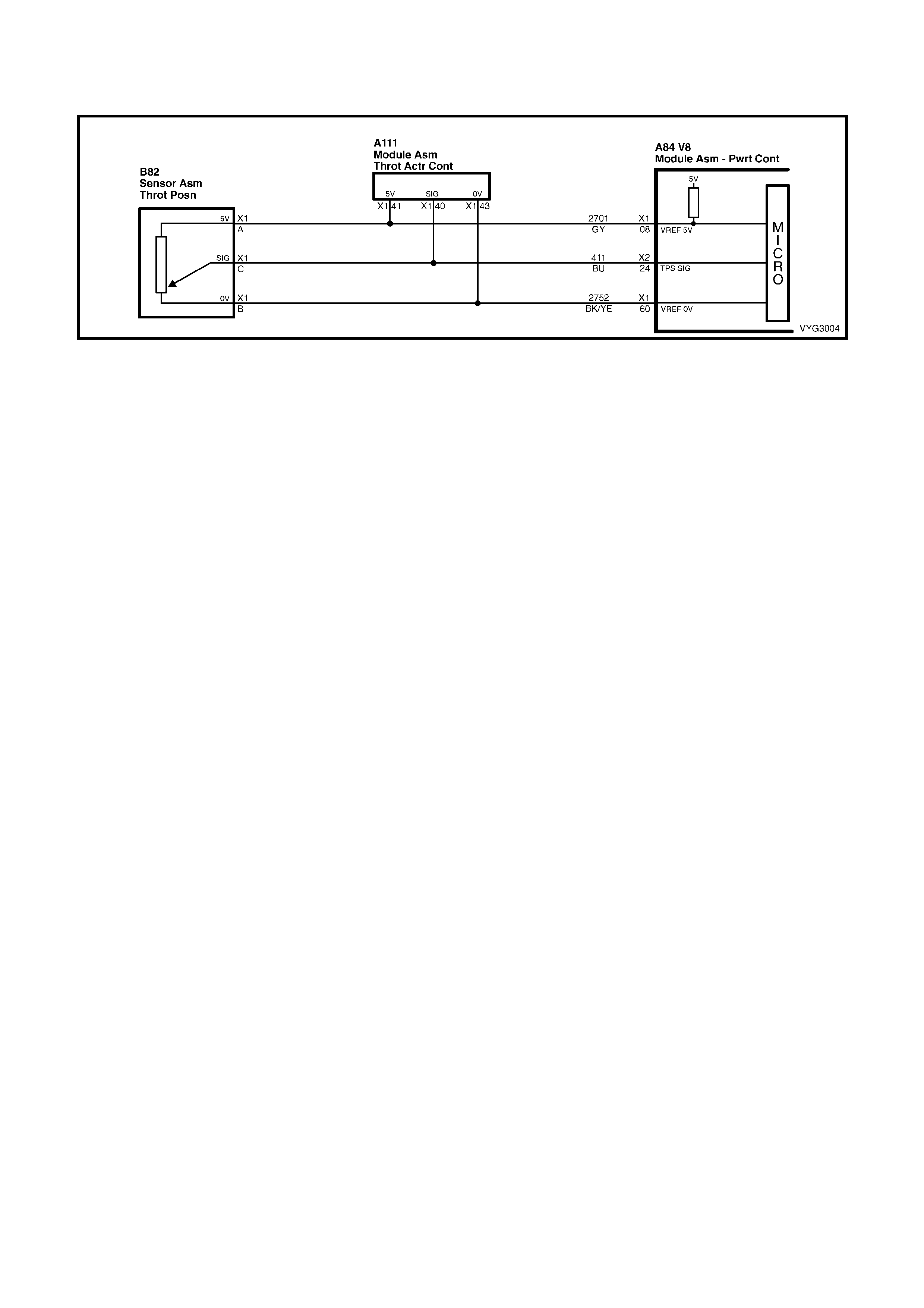
GEN III V8 PCM – DTC P0121 THROTTLE POSITION SENSOR
CIRCUIT INSUFFICIENT ACTIVITY
Figure 6C3-2A-50 – Throttle Position (TP) Sensor
CIRCUIT DESCRIPTION
The T hr ottle P os it ion ( T P) Sens or is a pot entiom eter . The T P sens or is mounted to th e lef t s ide of the thr o ttl e bo d y.
The T P Sensor pr ovides a voltag e signa l that chan ges r elative t o thrott le blade angle. This s ignal volt age is o ne of
the most important inputs used by the PCM. The TP Sensor has a 5.0 volt reference, a ground and a signal circuit.
TP Sensor Signal voltage should be about 0.6 volt at idle. The TP Sensor voltage should increase to above 4.0
volts at wide open throttle (WOT).
This diagnostic compares actual throttle position from the TP Sensor to a predicted throttle position value. The
predicted throttle position is calculated from engine speed and other inputs. If the PCM detects the predicted
throttle position is below the actual TP sensor value, this DTC will set.
CONDITIONS FOR RUNNING THE DTC
• No MAP sensor or TP sensor DTCs are set.
• The engine run time is greater than 10 seconds.
• The engine coolant temperature is greater than 0° C.
• The IAC is between 0 and 255 counts.
• The MAP is less than 55 kPa.
OR
• The MAP is greater than 65 kPa.
• MAP is steady.
CONDITIONS OF SETTING THE DTC
• The predicted throttle angle does not match the actual throttle angle.
• All conditions are met for at least 20 seconds.
ACTION TAKEN WHEN THE DTC SETS
• The PCM activates the Check Powertrain MIL when the diagnostic runs and fails.
• The PCM records the operating conditions at the time the diagnostic fails. The PCM stores this information in
the Freeze Frame/Failure Records.
• The PCM uses a default TP sensor value.
CONDITIONS FOR CLEARING THE MIL/DTC
• The PCM deactivates the Check Powertrain MIL when the diagnostic runs and does not fail.
• A last test failed (current DTC) clears when the diagnostic runs and does not fail.
• Use Tech 2 to clear the MIL/DTC.
DIAGNOSTIC AIDS
• The following may cause an intermittent:
– Incorrectly routed harness.
– Rubbed through wire insulation.
– Broken wire inside the insulation.
• The PCM 5.0 volt reference circuits are internally connected within the PCM. If all the TP sensor circuits are
OK, inspect the A/C Refrigerant Pressure Sensor for malfunctions.
• If it is determined that the DTC occurs intermittently, performing the DTC P1121 diagnostic table may isolate
the cause of the fault.
• For an intermittent, refer to Section 6C3-2B SY MPTOMS, in this Section.
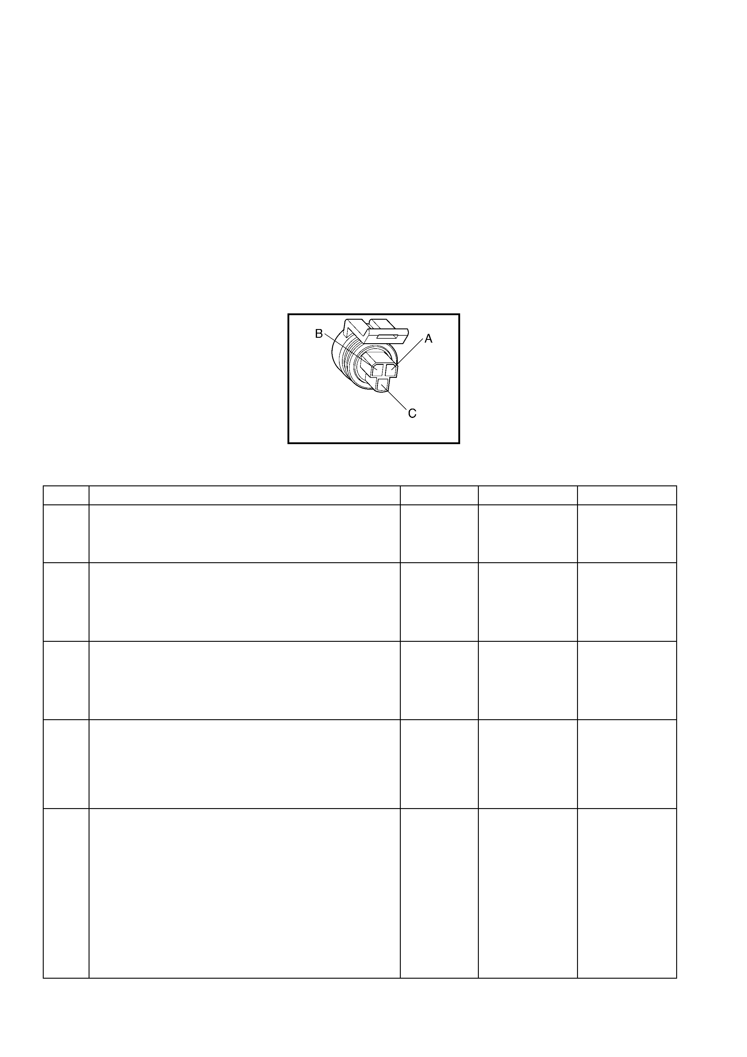
TEST DESCRIPTION
NOTE: The number(s) below refer to the step number(s) on the diagnostic table.
2. If DTC P1635 sets at the sam e time, this indicates th at the 5.0 vo lt refer ence circ uit is either shorted to gr ound
or shorted to voltage. The 5.0 volt reference circuit is internally connected within the PCM.
3. The MAP value should change with the engine speed. If a MAP Sensor voltage changes, there is no
malfunction with the MAP Sensor.
4. This step checks for an intermittent connection at the sensor.
8. If the TP Sensor voltage changes, there is no malfunction with the TP Sensor wiring or the PCM.
9. Using Free ze Fram e/Failure Rec ords data m ay aid in locat ing an int erm ittent condition. If you cannot dupl icate
the DTC, the information included in the Freeze Frame/Failure Records data can help determine the distance
travelled since the DTC set. The Fail Counter and Pass Counter can also help determine how many ignition
cycles the diagnostic reported a pass and/or a fail. Operate vehicle within the same freeze frame conditions
(RPM, load, vehicle speed, temperature etc.) that you observed. This will isolate when the DTC failed. For an
intermittent condition, refer to Section 6C3-2B SYMPTOMS in this Section.
11. This checks the 5.0 volt reference circuit, signal circuit, and the PCM. If Tech 2 displayed 5.0 volts, the TP
Sensor circuits are OK.
B82
Figure 6C3-2A-51
GEN III V8 PCM – DTC P0121 THROTTLE POSITION SENSOR CIRCUIT INSUFFICIENT ACTIVITY
STEP ACTION VALUE YES NO
1. Was the "On-Board Diagnostic" (OBD) System Check
performed? Go to Step 2 Go to
OBD System
Check
in this Section.
2. 1. Install Tech 2.
2. Idle the engine.
3. Monitor the ‘Failed This Ignition’ option under ‘DTC
Information’, using Tech 2.
Did the DTC P1635 fail this ignition?
Go to DTC
P1635 5 Volt
Reference
Circuit Table
Go to Step 3
3. 1. Start the engine.
2. Monitor the MAP Sensor voltage, using Tech 2.
3. Increase the engine speed to the specified value.
Does the MAP Sensor voltage change when the engine
speed changed?
2000 RPM Go to Step 8 Go to Step 4
4. 1. Ignition ON, engine OFF.
2. Move the MAP Sensor electrical connector, the
harness and the PCM connectors (by hand only) while
observing the Tech 2 display.
Is the MAP value affected by moving the harness or
connectors?
Go to Step 16 Go to Step 5
5. 1. Remove the MAP Sensor from the intake manifold but
leave the electrical harness connected.
2. Connect a hand operated vacuum pump to the MAP
Sensor.
3. Observe the MAP display while slowly applying
vacuum up to 20 inches Hg as indicated on the pump
gauge. Each 1 inch of vacuum applied should result in
a 3 to 4 kPa drop in the MAP Sensor value on Tech 2
and the value should change smoothly with each
increase in the vacuum.
Did the MAP value change smoothly through the entire
range of the test without an erratic reading?
Go to Step 6 Go to Step 17

STEP ACTION VALUE YES NO
6. 1. Apply 20 inches Hg vacuum to the MAP Sensor.
Is the MAP Sensor reading the same or less than the
specified value?
34 kPa Go to Step 7 Go to Step 17
7. 1. Disconnect the vacuum source from the MAP Sensor.
Does the MAP Sensor reading return to its original value? Go to Step 8 Go to Step 17
8. 1. Ignition ON, engine OFF.
2. Monitor the TP Sensor voltage while moving the
accelerator pedal from the closed throttle to a wide
open throttle.
Does the TP Sensor voltage go from below the specified
value to above the specified value?
Below 1.0
volt to above
4.0 volts
Go to Step 9 Go to Step 10
9. 1. Ignition ON, engine OFF.
2. Review the Freeze Frame/Failure Records data for this
DTC and record the parameters.
3. Turn OFF the ignition for 15 seconds.
4. Start the engine.
5. Operate the vehicle within the conditions required for
this diagnostic to run, and as close to the conditions
recorded in Freeze Frame/Failure Records as
possible. Special operating conditions that you need to
meet before the PCM will run this diagnostic, where
applicable, are listed in Conditions for Running the
DTC.
6. Select the Diagnostic Trouble Code (DTC) option, the
DTC Information option and the Failed This Ignition
option using Tech 2.
Does Tech 2 indicate that this diagnostic failed this
ignition?
Go to Step 10 Go to Diagnostic
Aids
10. 1. Disconnect the TP Sensor.
2. Observe the TP Sensor display on Tech 2.
Is the TP Sensor voltage near the specified value?
0.0 volts Go to Step 11 Go to Step 13
11. 1. Jump the TP Sensor 5.0 volt reference circuit 2701 to
the TP Sensor signal circuit 411 using a fused jumper
wire.
Is the TP Sensor voltage near the specified value?
5.0 volts Go to Step 12 Go to Step 14
12. 1. Replace the TP Sensor. Refer to TP Sensor Replace,
in 6C3-3 SERVICE OPERATIONS.
Is the action complete?
Go to Step 18
13. 1. Check for the following conditions:
• TP signal circuit 411 for a short to voltage.
• TP Sensor ground circuit 2752 for high resistance
between the PCM and the TP Sensor.
• TP Sensor ground circui t for a poor connect ion.
If you find a problem, repair the wiring harness as
necessary.
Did you find and correct the condition?
Go to Step 18 Go to Step 15
14. 1. Check for the following conditions:
• TP Sensor signal circuit 411 or 5 volt reference circuit
2701 for a poor connection.
• TP Sensor signal circuit or 5 volt reference circuit for
high resistance between the PCM and the TP sensor.
If you find a problem, repair the wiring harness as
necessary.
Did you find and correct the condition?
Go to Step 18 Go to Step 15
15. 1. Replace PCM. Refer to PCM Programming and
PCM/PIM/BCM Security Link Procedure, in 6C3-3
SERVICE OPERATIONS.
Is action complete?
Go to Step 18 –
16. 1. Locate and repair the affected circ uit.
Is the action complete? Go to Step 18 –

STEP ACTION VALUE YES NO
17. 1. Replace the MAP Sensor. Refer to MAP Sensor
Replace, in 6C3-3 SERVICE OPERATIONS.
Is the action complete?
Go to Step 18 –
18. 1. Select the Diagnostic Trouble Code (DTC) option and
the Clear DTC Information option using Tech 2.
2. Idle the engine at the normal operating temperature.
3. Select the ‘Diagnostic Trouble Code (DTC)’ option, the
‘DTC Information’ option and the ‘Failed This Ignition’
option using Tech 2.
4. Operate the vehicle within the Conditions for Running
the DTC as specified in the supporting text, if
applicable.
Does Tech 2 indicate that this test reset?
Go to Step 2 Go to Step 19
19. 1. Using Tech 2, check for any other DTCs.
Does Tech 2 display any DTCs that you have not
diagnosed?
Go to the
applicable DTC
table
System OK
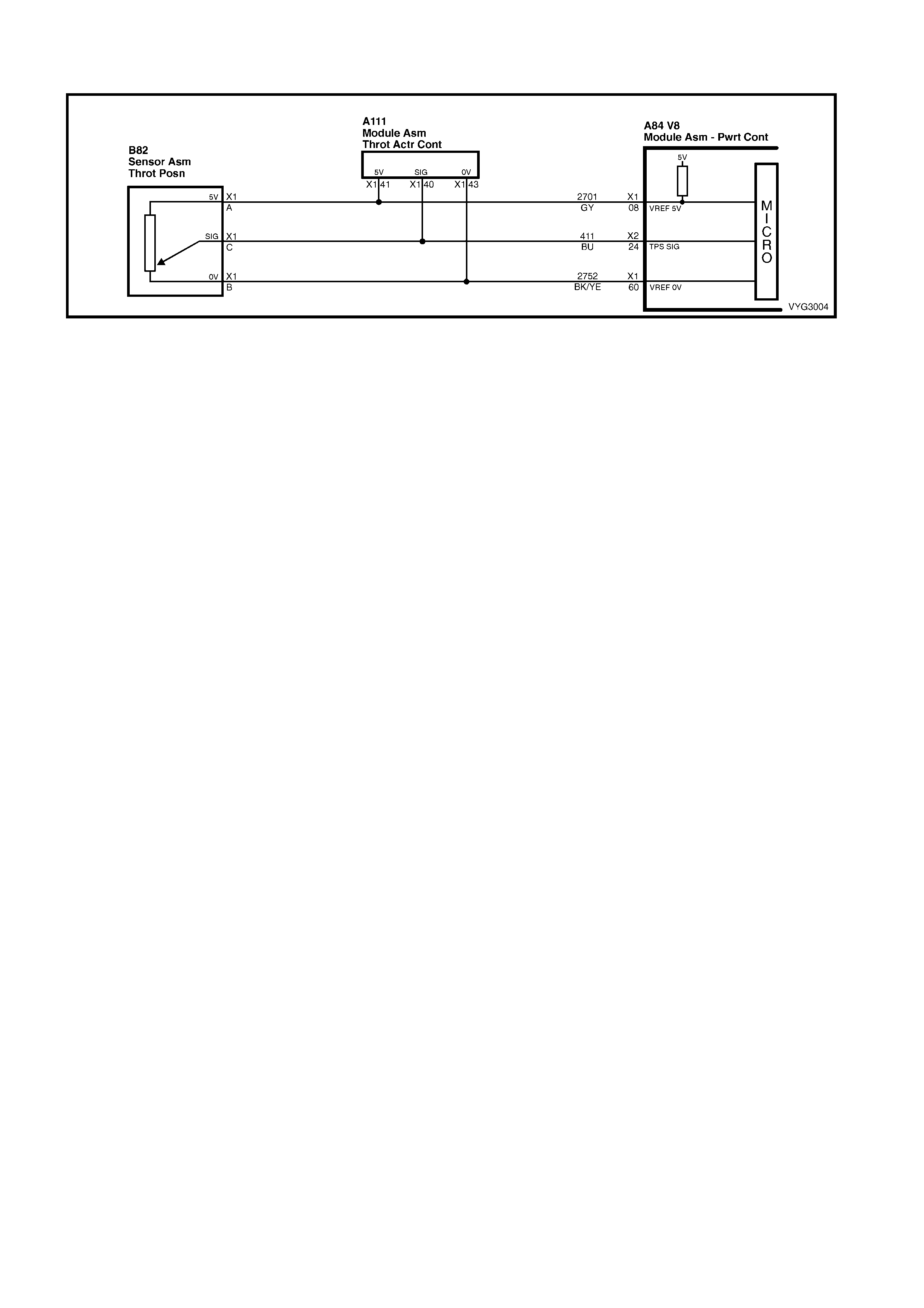
GEN III V8 PCM – DTC P0122 THROTTLE POSITION SENSOR CIRCUIT LOW VOLTAGE
Figure 6C3-2A-52 – Throttle Position (TP) Sensor
CIRCUIT DESCRIPTION
The Thr ottle Position (TP) Sensor is a pot ent iometer . T he T P Sens or is m ounted to the lef t s ide of the thr ot tl e body.
The T P Sensor pr ovides a voltag e signa l that chan ges r elative t o thrott le blade angle. This s ignal volt age is o ne of
the most important inputs used by the PCM. The TP Sensor has a 5.0 volt reference, a ground and a signal circuit.
TP Sens or Signal voltage s hould b e about 0.6 volt at i dle. The T P Sensor S ignal voltage s hould inc rease to above
4.0 volts at wide open throttle (WOT).
When the PCM senses a signal voltage lower than the normal operating range of the sensor, this DTC will set.
CONDITIONS FOR RUNNING THE DTC
• The ignition switch is ON or the engine is running.
CONDITIONS OF SETTING THE DTC
• The TP sensor signal voltage is less than 0.2 volts.
ACTION TAKEN WHEN THE DTC SETS
• The PCM activates the Check Powertrain MIL when the diagnostic runs and fails.
• The PCM records the operating conditions at the time the diagnostic fails. The PCM stores this information in
the Freeze Frame/Failure Records.
• The PCM uses a default TP sensor value.
• The transmission TCC will not apply.
• High transmission line pressure.
• Fixed transmission shift points, hard shifts and no fourth gear in hot mode.
CONDITIONS FOR CLEARING THE MIL/DTC
• The PCM deactivates the Check Powertrain MIL when the diagnostic runs and does not fail.
• A last test failed (current DTC) clears when the diagnostic runs and does not fail.
• Use Tech 2 to clear the MIL/DTC.
DIAGNOSTIC AIDS
• The following may cause an intermittent:
– Incorrectly routed harness
– Rubbed through wire insulation
– Broken wire inside the insulation
• The PCM 5.0 volt reference circuits are internally connected within the PCM. If all the TP Sensor circuits are
OK, inspect the A/C Refrigerant Pressure Sensor for malfunctions.
• If it is determined that the DTC occurs intermittently, performing the DTC P1122 diagnostic table may isolate
the cause of the fault.
• For an intermittent, refer to Section 6C3-2B SY MPTOMS in this Section.
TEST DESCRIPTION
NOTE: The number(s) below refer to the step number(s) on the diagnostic table.
2. If DTC P1635 sets at the sam e time, this indicates th at the 5.0 vo lt refer ence circ uit is either shorted to gr ound
or shorted to voltage. The 5.0 volt reference circuit is internally connected within the PCM.
3. This step verifies that a malfunction is present.
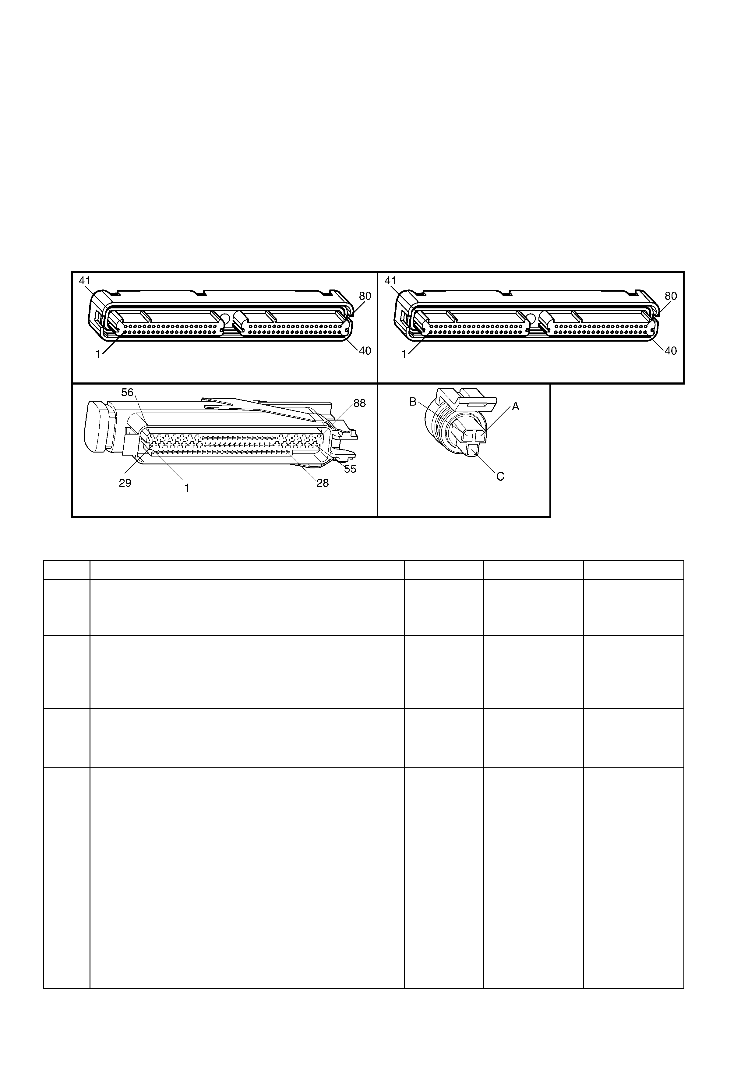
4. Using Fr eeze Fr ame/Fa ilure Records data m ay aid in locating an interm ittent con dition. If you cann ot duplic ate
the DTC, the information included in the Freeze Frame/Failure Records data can help determine the distance
travelled since the DTC set. The Fail Counter and Pass Counter can also help determine how many ignition
cycles the diagnostic reported a pass and/or a fail. Operate vehicle within the same freeze frame conditions
(RPM, load, vehicle speed, temperature etc.) that you observed. This will isolate when the DTC failed. For an
intermittent condition, refer to Section 6C3-2B SYMPTOMS, in this Section.
5. This determines if the short is caused by the Throttle Relaxer Control Module. After repairs are made,
reconnect the Throttle Relaxer Contr ol Module a nd clear an y DTCs that set when the Throttle Relax er Control
Module was disc onnec t ed.
6. If Tech 2 indicates 5.0 volts, the TP Sensor circuits and PCM are OK.
8. Disconnecting the PCM will allow the use of a DMM to check continuity of the c ircuits. This will aid in locating
an open or shorted circuit.
10. Disconnect ing the PCM will allow the use of a DMM to check continuit y of the circuits. This will aid in locating
an open or shorted circuit.
A84–X1 (BLUE) A84-X2 (RED)
A111 B82
Figure 6C3-2A-53
GEN III V8 PCM – DTC P0122 THROTTLE POSITION SENSOR CIRCUIT LOW VOLTAGE
STEP ACTION VALUE YES NO
1. Was the "On-Board Diagnostic" (OBD) System Check
performed? Go to Step 2 Go to
OBD System
Check
in this Section.
2. 1. Install Tech 2.
2. Idle the engine.
3. Monitor the ‘Failed This Ignition’ option under ‘DTC
Information’, using Tech 2.
Did DTC P1635 fail this ignition?
Go to DTC
P1635
5 Volt Reference
Circuit Table
Go to Step 3
3. 1. Ignition ON, engine OFF.
2. W ith the throttle closed, monitor the TP Sensor display
on Tech 2.
Is the TP Sensor voltage below the specified value?
0.2 volts Go to Step 5 Go to Step 4
4. 1. Ignition ON, engine OFF.
2. Review the Freeze Frame/Failure Records data for this
DTC and record the parameters.
3. Turn OFF the ignition for 15 seconds.
4. Start the engine.
5. Operate the vehicle, within the conditions required for
this diagnostic to run, and as close to the conditions
recorded in Freeze Frame/Failure Records as
possible. Special operating conditions that you need
meet before the PCM will run this diagnostic, where
applicable, are listed in Conditions for Running the
DTC.
6. Select the Diagnostic Trouble Code (DTC) option, the
DTC Information option and the Failed This Ignition
option using Tech 2.
Does Tech 2 indicate that this DTC failed this ignition?
Go to Step 5 Go to Diagnostic
Aids

STEP ACTION VALUE YES NO
5. IMPORTANT: After you complete this diagnosis reconnect
the Throttle Relaxer Control Module. Also, clear the
Throttle Relaxer Control Module DTCs that set when the
Throttle Relaxer Control Module was disconnected.
1. Ignition OFF.
2. Disconnect the Throttle Relaxer Control Module, A111.
3. Ignition ON.
Is the TP Sensor Signal voltage still below the specified
value?
0.2 volts Go to Step 6 Go to
5.9 Diagnostic
Charts in 5B
ABS & ABS/TCS
for further
diagnosis of the
Throttle Relaxer
Control Module.
6. 1. Disconnect the TP sensor electrical connector.
2. Jumper the 5.0 volt reference circuit 2701 and the TP
signal circuit 411 together at the TP sensor harness
connector.
3. Observe the TP sensor voltage display on Tech 2.
Is the TP sensor voltage above the specified value?
4.7 volts Go to Step 12 Go to Step 7
7. 1. Connect a test lamp, between B+ and the TP sensor
signal cir cuit 411 at the TP sensor harne ss conne ctor.
2. Observe the TP Sensor voltage display on Tech 2.
Is the TP sensor voltage above the specified value?
4.7 volts Go to Step 8 Go to Step 10
8. 1. Ignition OFF.
2. Disconnect the PCM BLUE connector, A84-X1.
3. Check the 5.0 volt reference circuit for an open or
short to ground.
4,. If the 5.0 volt reference circuit is open or shorted to
ground, repair the circuit as ne ces sary .
Did you find and correct the condition?
Go to Step 14 Go to Step 9
9. 1. Check the 5.0 volt reference circuit for a poor
connection at the PCM.
2. If you find a poor connection replace the terminal as
necessary.
Did you find and correct the condition?
Go to Step 14 Go to Step 13
10. 1. Ignition OFF.
2. Disconnect the PCM RED connector A84-X2.
3. Check for an open, or short to ground on the TP
Sensor signal circuit 411. Also check for a short circuit
between the TP Sensor signal circuit and the Throttle
Relaxer Control Module, A111.
4. If you find the TP Sensor signal circuit is open or
shorted, repair the circuit as necessary.
Did you find and correct the condition?
Go to Step 14 Go to Step 11
11. 1. Check the 5.0 volt reference circuit 2701 for a poor
connection at the PCM.
2. If you find a poor connection replace the terminal as
necessary.
Did you find and correct the condition?
Go to Step 14 Go to Step 13
12. 1. Replace the TP Sensor. Refer to TP Sensor Replace,
in 6C3-3 SERVICE OPERATIONS.
Is the action complete?
Go to Step 14 –
13. 1. Replace PCM. Refer to PCM Programming and
PCM/PIM/BCM Security Link Procedure, in 6C3-3
SERVICE OPERATIONS.
Is action complete?
Go to Step 14 –
14. 1. Select the Diagnostic Trouble Code (DTC) option and
the Clear DTC Information option using Tech 2.
2. Idle the engine at the normal operating temperature.
3. Select the Diagnostic Trouble Code (DTC) option, the
DTC Information option and the Failed This Ignition
option using Tech 2.
4. Operate the vehicle within the Conditions for Running
the DTC as specified in the supporting text, if
applicable.
Does Tech 2 indicate that this DTC reset?
Go to Step 2 Go to Step 15
15. 1. Using Tech 2, check for any other DTCs.
Does Tech 2 display any DTCs that you have not
diagnosed?
Go to the
applicable DTC
table
System OK

GEN III V8 PCM – DTC P0123 THROTTLE POSITION SENSOR CIRCUIT HIGH VOLTAG E
Figure 6C3-2A-54 – Throttle Position (TP) Sensor
CIRCUIT DESCRIPTION
The Thr ottle Position (TP) Sensor is a pot ent iometer . T he T P Sens or is m ounted to the lef t s ide of the thr ot tl e body.
The T P Sensor pr ovides a voltag e signa l that chan ges r elative t o thrott le blade angle. This s ignal volt age is o ne of
the most important inputs used by the PCM. The TP Sensor has a 5.0 volt reference, a ground and a signal circuit.
TP Sensor Signal voltage should be about 0.6 volt at idle. The TP Sensor voltage should increase to above 4.0
volts at wide open throttle (WOT).
When the PCM senses a signal voltage higher than the normal operating range of the sensor, this DTC will set.
CONDITIONS FOR RUNNING THE DTC
• The ignition switch is ON or the engine is running.
CONDITIONS OF SETTING THE DTC
• The TP sensor signal voltage is greater than 4.8 volts.
• Conditions present for at least ten seconds.
ACTION TAKEN WHEN THE DTC SETS
• The PCM activates the Check Powertrain MIL when the diagnostic runs and fails.
• The PCM records the operating conditions at the time the diagnostic fails. The PCM stores this information in
the Freeze Frame/Failure Records.
• The PCM uses a default TP sensor value.
• The transmission TCC will not apply.
• High transmission line pressure.
• Fixed transmission shift points, hard shifts and no fourth gear in hot mode.
CONDITIONS FOR CLEARING THE MIL/DTC
• The PCM deactivates the Check Powertrain MIL when the diagnostic runs and does not fail.
• A last test failed (current DTC) clears when the diagnostic runs and does not fail.
• Use Tech 2 to clear the MIL/DTC.
DIAGNOSTIC AIDS
• The following may cause an intermittent:
– Incorrectly routed harness
– Rubbed through wire insulation
– Broken wire inside the insulation
• The PCM 5.0 volt reference circuits are internally connected within the PCM. If all the TP Sensor circuits are
OK, inspect the A/C Refrigerant Pressure Sensor for malfunctions.
• If it is determined that the DTC occurs intermittently, performing the DTC P1121 diagnostic table may isolate
the cause of the fault.
• For an intermittent, refer to Section 6C3-2B SY MPTOMS in this Section.
TEST DESCRIPTION
NOTE: The number(s) below refer to the step number(s) on the diagnostic table.
2. If DTC P1635 sets at the same time, this indicates that the 5.0 volt reference circuit is either shorted to a
ground or shorted to a voltage. The 5.0 volt reference circuit is internally connected within the PCM.
3. This step verifies that a malfunction is present.
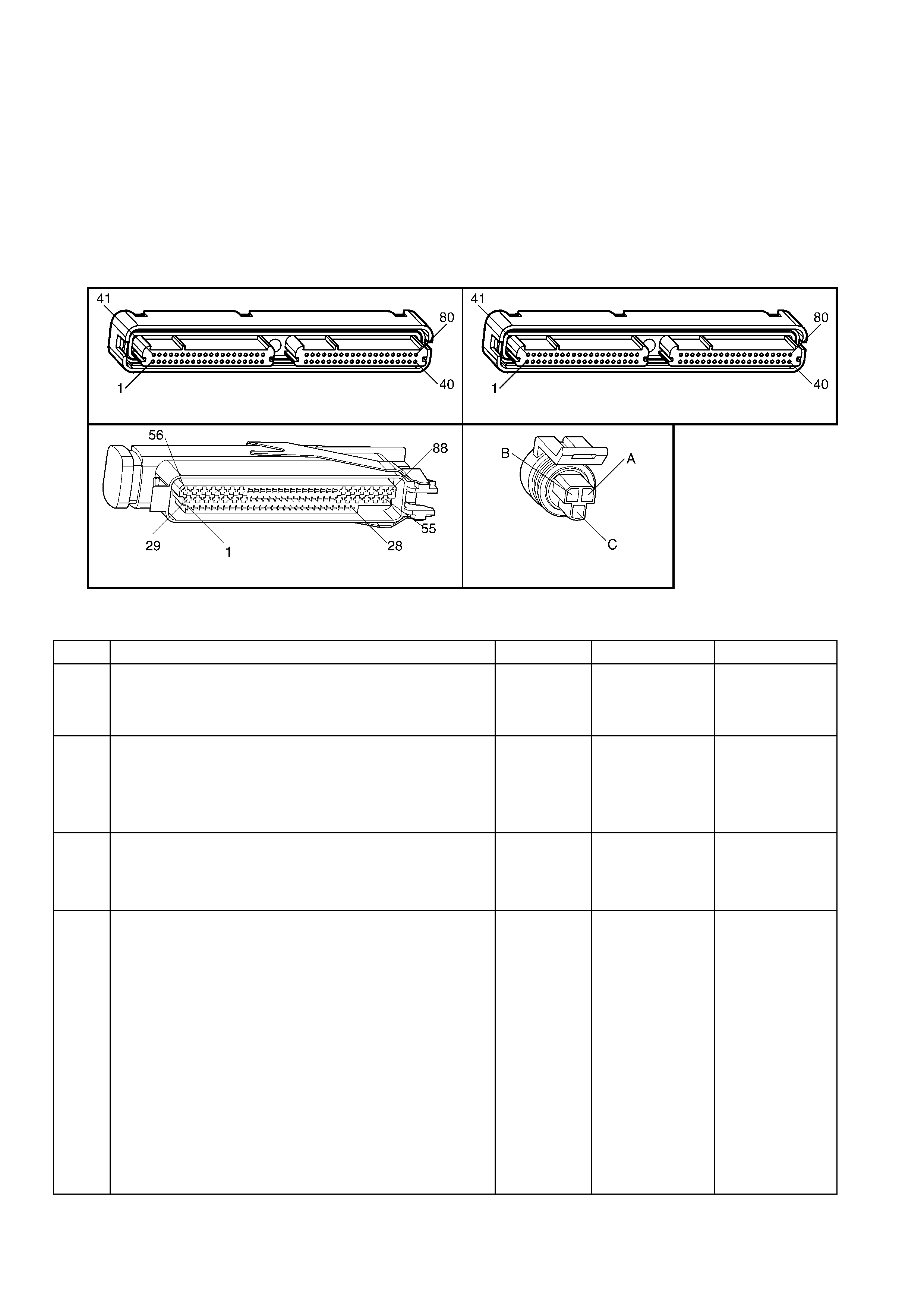
4. Using Free ze Fram e/Failure Rec ords data m ay aid in locat ing an int erm ittent condition. If you cannot dupl icate
the DTC, the information included in the Freeze Frame/Failure Records data can help determine the distance
travelled since the DTC set. The Fail Counter and Pass Counter can also help determine how many ignition
cycles the diagnostic reported a pass and/or a fail. Operate vehicle within the same freeze frame conditions
(RPM, load, vehicle speed, temperature etc.) that you observed. This will isolate when the DTC failed. For an
intermittent condition, refer to Section 6C3-2B SYMPTOMS in this Section.
5. Vehicles eq uippe d with El ec tronic T rac tion Control wi ll have t o discon nect the T hrottl e Relaxer Contro l Module.
This will determine if the short is caused by the Throttle Relaxer Control Module. After repairs are made,
reconnect the Throttle Relaxer Control Module and clear the DTCs that set when the Throttle Relaxer Control
Module was disc onnec t ed.
7. This checks whether the ground circuit is available to the TP Sensor. Check for poor electrical connections at
the TP Sensor.
A84–X1 (BLUE) A84-X2 (RED)
A111 B82
Figure 6C3-2A-55
GEN III V8 PCM – DTC P0123 THROTTLE POSITION SENSOR CIRCUIT HIGH VOLTAGE
STEP ACTION VALUE YES NO
1. Was the "On-Board Diagnostic" (OBD) System Check
performed? Go to Step 2 Go to
OBD System
Check
in this Section.
2. 1. Install Tech 2.
2. Idle the engine.
3. Monitor the ‘Failed This Ignition’ option under the ‘DTC
Information’ opti on, usi ng Tec h 2.
Did the DTC P1635 fail this ignition?
Go to DTC
P1635
5 Volt Reference
Circuit Table
Go to Step 3
3. 1. Ignition ON, engine OFF.
2. With the throttle closed, observe the TP Sensor
voltage display on Tech 2.
Is the TP Sensor voltage above the specified value?
4.7 volts Go to Step 5 Go to Step 4
4. 1. Ignition ON, engine OFF.
2. Review the Freeze Frame/Failure Records data for this
DTC and record the parameters.
3. Turn OFF the ignition for 15 seconds.
4. Start the engine.
5. Operate the vehicle, within the conditions required for
this diagnostic to run, and as close to the conditions
recorded in Freeze Frame/Failure Records as
possible. Special operating conditions that you need
meet before the PCM will run this diagnostic, where
applicable, are listed in Conditions for Running the
DTC.
6. Select the Diagnostic Trouble Code (DTC) option, the
DTC Information option and the Failed This Ignition
option using Tech 2.
Does Tech 2 indicate that this DTC failed this ignition?
Go to Step 5 Go to Diagnostic
Aids

STEP ACTION VALUE YES NO
5. 1. Ignition OFF.
2. Disconnect the Throttle Relaxer Control Module, A111.
3. Ignition ON.
Is the TP Sensor voltage above the specified value?
4.7 volts Go to Step 6 Go to
5.9 Diagnostic
Charts in 5B
ABS & ABS/TCS
for further
diagnosis of the
Throttle Relaxer
Control Module
6. 1. Disconnect the TP Sensor electrical connector.
2. Observe the TP Sensor voltage display on Tech 2.
Is the TP Sensor voltage below the specified value?
0.20 volts Go to Step 7 Go to Step 10
7. 1. Probe the sensor ground circuit 2752 at the TP Sensor
harness connector with a test lamp, connected to B+.
Does the test lamp illuminate?
Go to Step 8 Go to Step 11
8. 1. Measure the voltage at the 5.0 volt reference circuit
2701 to ground using a DMM.
Is the voltage greater than the specified value?
5.0 volts Go to Step 14 Go to Step 9
9. 1. Replace the TP Sensor. Refer to TP Sensor Replace,
in 6C3-3 SERVICE OPERATIONS.
Is the action complete?
Go to Step 15 –
10. 1. Ignition OFF.
2. Disconnect the PCM connectors A84-X1 and A84 X-2.
3. Check for a short to voltage on the TP sensor signal
circuit 411. Also check for a short circuit between the
TP sensor signal circuit and the Throttle Relaxer
Control Module A111.
4. If you find the TP Sensor signal circuit shorted, repair
the circuit as necessary.
Did you find and correct the condition?
Go to Step 15 Go to Step 13
11. 1. Check for an open TP Sensor ground circuit.
2. If you find TP Sensor ground circuit open, repair the
circuit as neces sary .
Did you find and correct the condition?
Go to Step 15 Go to Step 12
12. 1. Ignition OFF.
2. Disconnect the PCM connectors A84-X1 and A84-X2.
3. Check the TP Sensor ground circuit for a good
connection at the PCM.
4. If you find a poor connection at the TP Sensor ground
circuit, repair the circuit as necessary.
Did you find and correct the condition?
Go to Step 15 Go to Step 13
13. 1. Replace PCM. Refer to PCM Programming and
PCM/PIM/BCM Security Link Procedure in 6C3-3
SERVICE OPERATIONS.
Is action complete?
Go to Step 15 –
14. 1. Repair the 5 volt reference circuit for a short to voltage.
Refer to Electrical Diagnosis/Repair Procedures in 12P
WIRING DIAGRAMS.
Is the action complete?
Go to Step 15 –
15. 1. Select the Diagnostic Trouble Code (DTC) option and
the Clear DTC Information option using Tech 2.
2. Idle the engine at the normal operating temperature.
3. Select the Diagnostic Trouble Code (DTC) option, the
DTC Information option and the Failed This Ignition
option using Tech 2.
4. Operate the vehicle within the Conditions for Running
the DTC as specified in the supporting text, if
applicable.
Does Tech 2 indicate that this DTC reset?
Go to Step 2 Go to Step 16
16. 1. Using Tech 2, check for any other DTCs.
Does Tech 2 display any DTCs that you have not
diagnosed?
Go to the
applicable DTC
table
System OK

GEN III V8 ENGINE – DTC P0125 ENGINE COOLANT TEMPERATURE (ECT) SENSOR
EXCESS TIME TO CLOSED LOOP FUEL CONTROL
Figure 6C3-2A-56 – Engine Coolant Temperature (ECT) Sensor
CIRCUIT DESCRIPTION
The PCM monitors the ECT Sensor in order to determine how long it takes the engine to reach the coolant
temper ature requir ed f or Closed Lo op operat ions. DT C P01 25 sets if the PC M determ ines that the eng ine d oes not
reach C losed Lo op tem perature in a s pecif ied am ount of tim e. T his test will n ot r un if either the intak e air or eng ine
coolant temperature is too low at start-up. The PCM will only run this DTC on a cold start and only once per cold
start.
CONDITIONS FOR RUNNING THE DTC
• DTCs P0112, P0113, P0117, P0118 are not set.
• The engine is operating.
• The engine coolant temperature is between –36° C and 40° C at engine start-up.
• The intake air temperature is greater than –7° C.
• The vehicle speed is greater than 1.6 km/h.
CONDITIONS FOR SETTING THE DTC
• The closed loop coolant temperature of 34° C is not reached within a predetermined time. The maximum
allowable time depends on the start-up coolant temperature and the amount of airflow into the engine. The
range for the time is from 2 minutes and 20 seconds to 22 minutes and 30 seconds.
ACTION TAKEN WHEN THE DTC SETS
• The PCM stores the DTC information into memory when the diagnostic runs and fails.
• The Check Powertrain MIL will not be illuminated.
• The PCM records the operating conditions at the time the diagnostic fails. The PCM stores this information in
the Freeze Frame/Failure Records.
CONDITIONS FOR CLEARING THE MIL/DTC
• The Check Powertrain MIL will not be activated.
• A last test failed (current DTC) clears when the diagnostic runs and does not fail.
• Use Tech 2 to clear the DTC.
DIAGNOSTIC AIDS
Using the F reeze Fram e/Failure Records dat a may aid in locatin g an interm ittent condition. If you cannot duplic ate
the DTC, the information included in the Freeze Frame/Failure Records data can help determine the distance
travelled since the DT C s et. T he Fa il Counter an d Pas s Coun ter c an a lso he lp de term ine ho w m any igniti on c ycles
the diagnos tic reporte d a pass and/or f ail. Operate th e vehicle wit hin the sam e freeze fr ame c ondition (RPM , load,
vehicle speed, temperature etc.) that you observed. This will isolate when the DTC failed. For an intermittent
condition, refer to Section 6C3-2B SY MPTOMS in this Section.
• If the engine has sat overnight, the engine coolant temperature and intake air temperature values should
displa y withi n a f ew de gree s of eac h ot her . If the temperatur es ar e no t with in 3 ° C , r ef er to th e Temperature v s.
Resistance Table in Section 6C3-4 SPECIFICATIONS, in this Section.
• If you determine that the DTC occurs intermittently, performing the P1114 or P1115 diagnostic table may
isolate the cause of the fault.
• An engine coolant temperature exceeding 34° C indicates that the engine is capable of reaching the proper
temperature, but not necessarily in the correct amount of time.
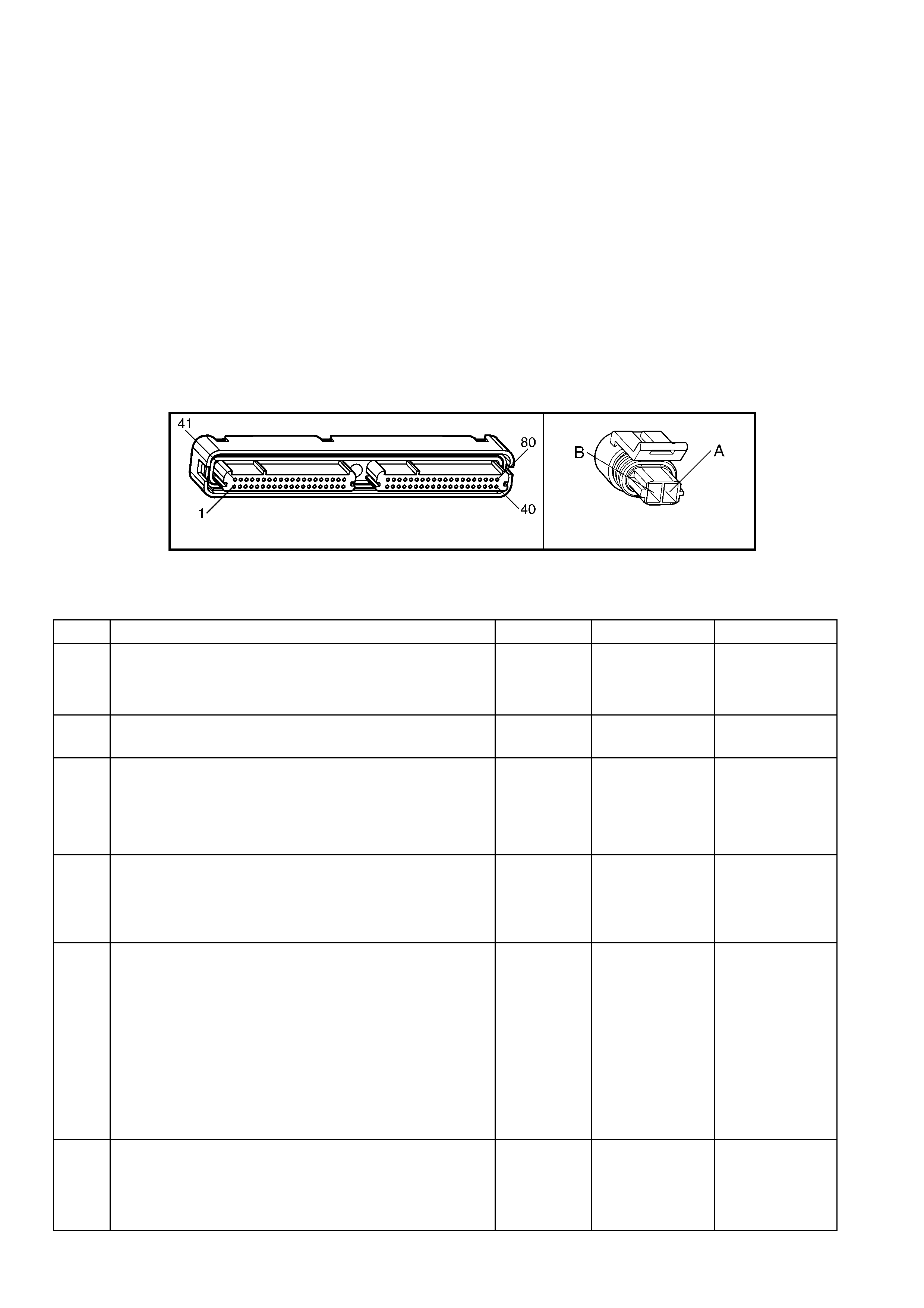
Repeat this diagnostic table on a cold engine, and measure the time required to reach the temperature
threshold. W hen starting a cold engine, m easure the amount of time it takes the engine to reach the specified
temperature. The engine should reach the specified temperature within 5 minutes or less. If the engine does
not reach the specified temperature within 5 minutes, check the following:
– Coolant level
– Thermostat operation
– Are fans on at all times?
Refer to Section 6B3 ENGINE COOLING for additional information.
TEST DESCRIPTION
NOTE: The number(s) below refer to the step number(s) on the diagnostic table.
2. An ECT failure could cause a DTC P0125 to set, so correct any ECT DTCs that are set. For any test that
requires probing t he PCM or a component harness c onnector, use the Connec tor Tes t Adaptor Kit J 35616-A.
Using this kit prevents damage to the harness connector terminals.
6. If it is obvious that the e ngine is not reaching full operating temperature, for exam ple the radiator hoses never
get very warm, or there is a complaint of little or no heat from the radiator, you can skip this step.
9. This DTC will not report a pass. The Tech 2 status for this DTC will never report a pass. Tech 2 will only display
when the diagnostic fails. The repair is not complete if Tech 2 indicates that the diagnostic ran and failed.
A84-X1 (BLUE) B39
Figure 6C3-2A-57
GEN III V8 ENGINE – DTC P0125 ENGINE COOLANT TEMPERATURE (ECT) SENSOR EXCESS TIME TO
CLOSED LOOP FUEL CONTROL
STEP ACTION VALUE YES NO
1. Was the "On-Board Diagnostic" (OBD) System Check
performed? Go to Step 2 Go to
OBD System
Check
in this Section.
2. Are any Engine Coolant Temperature DTCs set?
Go to applicable
DTC table Go to Step 3
3. 1. Install Tech 2.
2. Ignition ON, engine OFF.
3. Disconnect the ECT Sensor.
Does Tech 2 indicate the ECT sensor is at or below the
specified value?
–35° C Go to Step 4 Go to DTC
P0117 ECT
Sensor Circuit
Low Voltage
Table
4. 1. Jumper the terminals of the ECT Sensor harness
connector together using a jumper wire.
Does Tech 2 indicate the ECT is at or above the specified
value?
139° C Go to Step 5 Go to DTC
P0118 ECT
Sensor Circuit
High Voltage
Table
5. 1. Reconnect the ECT Sensor.
2. Idle the engine.
3. Observe the ECT Sensor display on the Tech 2
‘Engine Data List’.
IMPORTANT: Allow the engine to warm-up if it has not
already reached the specified temperature. 5 minutes is the
maximum amount of time it should take to reach this
temperature from a cold start. Less time is required if the
engine is already warm.
Does Tech 2 indicate the engine coolant temperature
reaches the specified value?
34° C The cooling
system must be
rechecked on a
cold start. Refer
to Diagnostic
Aids
Go to Step 6
6. 1. Measure the resistance of the ECT Sensor using a
DMM. Refer to Temperature vs. Resistance Table in
6C3-4 SPECIFICATIONS.
Is the ECT resistance close to the value indicated in the
Temperature Vs Resistance Table?
Go to Step 7 Go to Step 8

STEP ACTION VALUE YES NO
7. 1. Check the following for an engine cooling system
problem:
• Thermostat operation.
• Coolant level.
• Coolant to water ratio.
• Cooling fan operation, etc.
Refer to 6B3 ENGINE COOLING.
Is the action complete?
Go to Step 9 –
8. 1. Replace the ECT Sensor. Refer to ECT Sensor
Replace in 6C3-3 SERVICE OPERATIONS.
Is the action complete?
Go to Step 9 –
9. 1. Select the Diagnostic Trouble Code (DTC) option and
the Clear DTC Information option using Tech 2.
2. Idle the engine at the normal operating temperature.
3. Select the Diagnostic Trouble Code (DTC) option, the
DTC Information option and the Failed This Ignition
option using Tech 2.
4. Operate vehicle within the Conditions for Running the
DTC as specified in the supporting text, if applicable.
Does Tech 2 indicate that this DTC reset?
Go to Step 2 Go to Step 10
10. 1. Using Tech 2, check for any other DTCs.
Does Tech 2 display any DTCs that you have not
diagnosed?
Go to the
applicable DTC
table
System OK
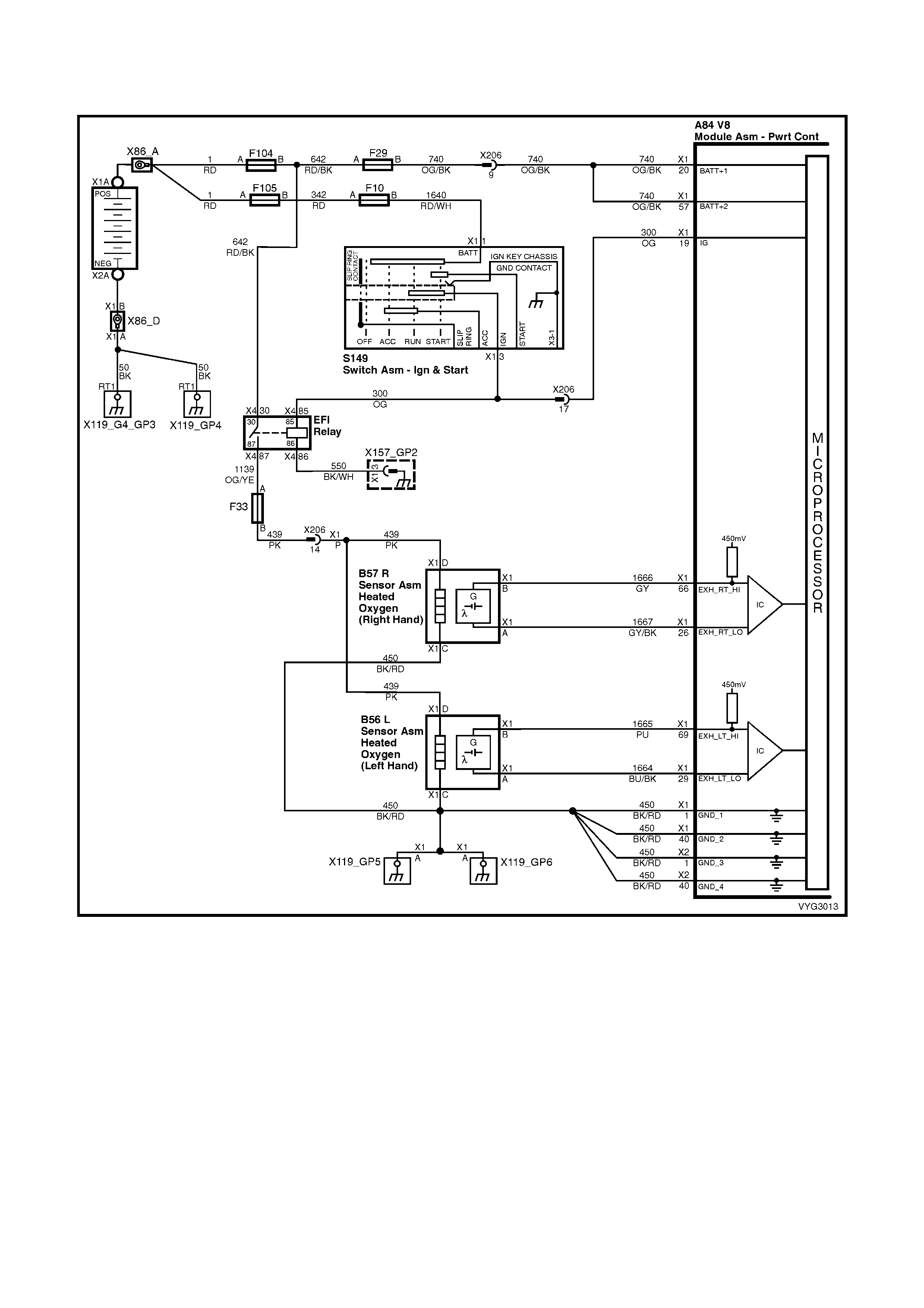
GEN III V8 PCM – DTC P0131 HEATED OXYGEN SENSOR (HO2S) CIRCUIT LOW
VOLTAGE BANK 1 SENSOR 1
Figure 6C3-2A-58 – Oxygen Sensor Circuits
CIRCUIT DESCRIPTION
The PCM s upplies a voltage of about 450 m V betwee n the HO2S hig h and low s ignal circuits . The ox ygen s ensor
varies the voltage over a range from about 1000 mV when the exhaust is rich, down through about 10 mV when the
exhaust is lean.
The PCM monitors and stores the Heated Oxygen Sensor (HO2S) voltage information. The PCM evaluates the
HO2S voltage samples in order to determine the amount of time the HO2S voltage was out of range. The PCM
compares the stored HO2S voltage samples, taken within each sample period, and determines if majority of the
samples are out of the operating range.
The PCM monitors the HO2S voltage for being fixed below a predetermined voltage. If the PCM detects the voltage
is below a predetermined voltage, a DTC will set.

CONDITIONS FOR RUNNING THE DTC
Criteria 1
• DTCs P0101, P0102, P0103, P0112, P0113, P0117, P0118, P0121, P0122, P0123, P0335, P0336, P0351-
P0358, P1258 ar e not set.
• The engine coolant temperature is greater than 48° C.
• The ignition voltage is greater than 9.0 volts.
• The fuel system is operating in Closed Loop.
• The fuel trim learn is enabled.
• The air/fuel ratio is between 14.5:1 and 14.7:1.
• The TP angle is between 0% and 70%.
Criteria 2
• DTCs P0101, P0102, P0103, P0112, P0113, P0117, P0118, P0121, P0122, P0123, P0335, P0336, P0351-
P0358, P1258 ar e not set.
• The ignition voltage is greater than 9.0 volts.
• The Power Enrichment mode is enabled for at least 0.5 seconds.
CONDITIONS FOR SETTING THE DTC
Criteria 1
• The HO2S signal voltage remains below 200 mV.
• The Criteria 1 conditions are present for at least 33 seconds.
Criteria 2
• The HO2S signal voltage remains below 360 mV.
• The Criteria 2 conditions are present for at least five seconds.
ACTION TAKEN WHEN THE DTC SETS
• The PCM activates the Check Powertrain MIL when the diagnostic runs and fails.
• The PCM records the operating conditions at the time the diagnostic fails. The PCM stores this information in
the Freeze Frame/Failure Records.
• Open Loop Fuelling.
CONDITIONS FOR CLEARING THE MIL/DTC
• The PCM deactivates the Check Powertrain MIL after one ignition c ycle that the diagnostic runs and does not
fail.
• A last test failed (current DTC) clears when the diagnostic runs and does not fail.
• Use Tech 2 to clear the MIL/DTC.
DIAGNOSTIC AIDS
• The PCM sets this DTC when the vehicle runs out of fuel.
• Heated Oxygen Sens or ( H O 2S) wire: Se ns or pig t ail m a y be in c o ntac t with th e exhaust manif old or the ex ha us t
system.
• An oxygen supply inside the HO2S is necessary for proper operation. The HO2S wires provide the supply of
oxygen. Inspect the HO2S wires and connections for breaks or contamination.
IMPORTANT: Under no circumstances are the wiring harness connectors associated with the heated oxygen
sensor circuits to be sealed in any way, by using grease or other substances. To do so, would result in an
inadequate supply of reference air to be able to reach the atmospheric reference cavity of each sensor,
resulting in a DT C to be set. If a flexible s ealant is us ed (i.e. gr ease), then this would be dra wn into the sensor
cavity, poisoning the sensor, resulting in a prem ature failure. Also, shou ld connector dam age be evident, t hen
the sensor and le ad m ust be r eplac ed, as s olderi ng of the wir ing would a lso n egate the ‘breath ing’ c apab ilit y of
the sensor wiring.
• Check for intermittent ground in signal wire between connector and sensor.
• Lean injector(s): Perform the Injector Balance Test.
• Fuel cont amination: W ater near the in-tank fuel pump inlet can be de livered to the inj ectors. T he water caus es
a lean exhaust and can set a DTC.
• Fuel pressure: System will be lean if fuel pressure is low. Refer to Fuel System Diagnosis Table in this
Section.
• Exhaust leaks: An exhaust leak near the HO2S can cause a lean condition.
• Vacuum or crankcase leaks can cause a lean condition.
• If the above are OK, the HO2S may be at fault.
• For an intermittent condition, refer to Section 6C3-2B SYMPTOMS in this Section.
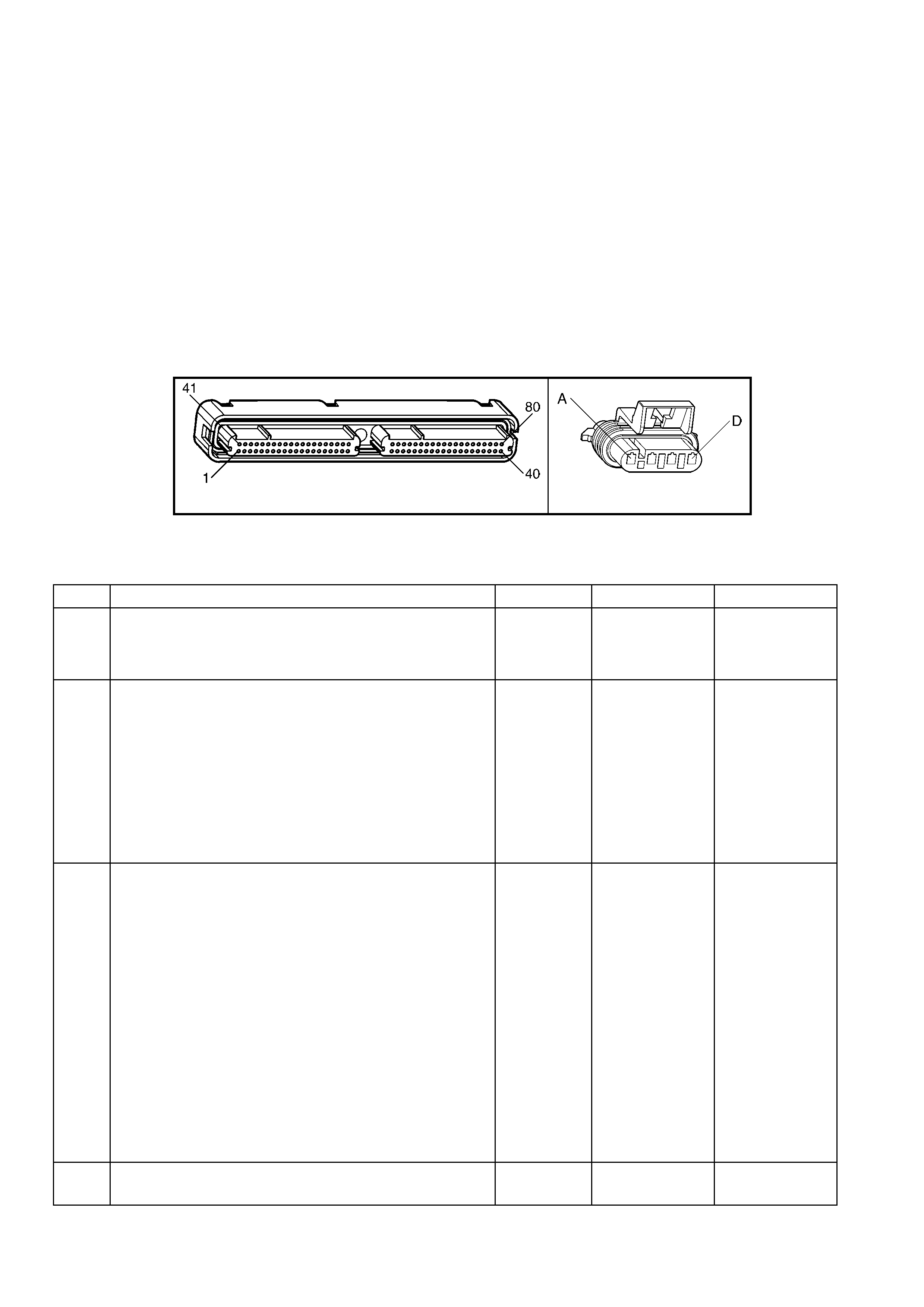
TEST DESCRIPTION
NOTE: The number(s) below refer to the step number(s) on the diagnostic table.
2. If the HO2S voltage is fixed well below 200 mV this indicates a short to ground. If the voltage is fixed near or
above 200 mV, this indicates a short to a PCM ground. When the HO2S voltage is fixed near 200 mV, indicates
the DTC set when the fuel s ystem was in a Power Enrichm ent mode of operation. This DTC sets if the HO2S
voltage is less than 360 mV during a Power Enrichment mode of operation.
3. Using the Freeze Frame/Failure Records data may aid in locating an intermittent condition. If you cannot
duplicat e the DTC, t he inform ation include d in the F reeze Fram e/Failure Rec ords dat a can help de termine t he
distance travelled since the DTC set. The Fail Counter and Pass Counter can also help determine how many
ignition cycles the diagnostic reported a pass and/or fail. Operate the vehicle within the same freeze frame
condition (RPM, load, vehicle speed, temperature etc.) that you observed. This will isolate when the DTC
failed.
4. Disconnecting the HO2S should cause the HO2S voltage to display the bias voltage. A voltage staying near 0.0
volts indicates the high circuit is grounded.
5. Disconnect ing th e PCM all ows usin g a DMM to check continu ity of the c ircuits. T his a ids i n locat ing an open or
shorted circuit.
A84-X1 (BLUE) B56_L
Figure 6C3-2A-59
GEN III V8 PCM –
DTC P0131 HEATED OXYGEN SENSOR (HO2S) CIRCUIT LOW VOLTAGE BANK 1 SENSOR 1
STEP ACTION VALUE YES NO
1. Was the "On-Board Diagnostic" (OBD) System Check
performed? Go to Step 2 Go to
OBD System
Check
in this Section.
2. IMPORTANT: Check the HO2S for being secure before
proceeding with this DTC. A sensor that is loose could
cause this DTC to set.
1. Install Tech 2.
2. Idle the engine at the normal operating temperature.
3. Operate the vehicle within parameters specified under
Conditions for Running the DTC in the supporting text.
4. Monitor the HO2S voltage display on the Engine Data
List using Tech 2.
Is the HO2S voltage less than the specified value?
200 mV Go to Step 4 Go to Step 3
3. 1. Ignition ON, engine OFF.
2. Review the Freeze Frame/Failure Records data for this
DTC and observe the parameters.
3. Turn OFF the ignition for 15 seconds.
4. Idle the engine.
5. Operate the vehicle, within the conditions required for
this diagnostic to run, and as close to the conditions
recorded in the Freeze Frame/Failure Records as
possible. Special operating conditions that you need to
meet before the PCM will run this diagnostic, where
applicable, are listed in Conditions for Running the
DTC.
6. Select the Diagnostic Trouble Code (DTC), the DTC
Information option and the Failed This Ignition option
using Tech 2.
Does Tech 2 indicate that this diagnostic failed this
ignition?
Go to Step 4 Go to Diagnostic
Aids
4. 1. Disconnect the HO2S, harness connector B56_L.
Is the HO2S voltage within the specified range? 350-550 mV Go to Step 7 Go to Step 5

STEP ACTION VALUE YES NO
5. 1. Ignition OFF.
2. Disconnect the PCM BLUE connector A84-X1.
3. Check the HO2S signal circuit 1665 for a short to
ground or a short to the sensor ground circuit 1664.
Is the HO2S signal circuit shorted?
Go to Step 6 Go to Step 8
6. 1. Repair the HO2S signal circuit.
Is the action complete? Go to Step 9 –
7. 1. Replace Oxygen Sensor. Refer to 2.8 Heated Oxygen
Sensor, in 6C3-3 SERVICE OPERATIONS.
Is action complete?
Go to Step 9
8. 1. Replace PCM. Refer to PCM Programming and
PCM/PIM/BCM Security Link Procedure, in 6C3-3
SERVICE OPERATIONS.
Is action complete?
Go to Step 9 –
9. 1. Select the Diagnostic Trouble Code (DTC) option and
the Clear DTC Information option using Tech 2.
2. Idle the engine at the normal operating temperature.
3. Select the Diagnostic Trouble Code (DTC) option, the
DTC Information option and the Failed This Ignition
option using Tech 2.
4. Operate the vehicle within the Conditions for Running
the DTC as specified in the supporting text, if
applicable.
Does Tech 2 indicate that this DTC reset?
Go to Step 2 Go to Step 10
10. 1. Using Tech 2, check for any other DTCs.
Does Tech 2 display any DTCs that you have not
diagnosed?
Go to the
applicable DTC
table
System OK

GEN III V8 PCM – DTC P0132 HEATED OXYGEN SENSOR (HO2S) CIRCUIT HIGH
VOLTAGE BANK 1 SENSOR 1
Figure 6C3-2A-60 – Oxygen Sensor Circuits
CIRCUIT DESCRIPTION
The PCM s upplies a voltage of about 450 m V betwee n the HO2S hig h and low s ignal circuits . The ox ygen s ensor
varies the voltage over a range from about 1000 mV when the exhaust is rich, down through about 10 mV when the
exhaust is lean.
The PCM monitors and stores the Heated Oxygen Sensor (HO2S) voltage information. The PCM evaluates the
HO2S voltage samples in order to determine the amount of time the HO2S voltage was out of range. The PCM
compares the stored HO2S voltage samples, taken within each sample period, and determines if majority of the
samples are out of the operating range.
The PCM monitors the HO2S voltage for being fixed above a predetermined voltage. If the PCM detects the
voltage is above the predetermined voltage, a DTC will set.

CONDITIONS FOR RUNNING THE DTC
Criteria 1
• DTCs P0101, P0102, P0103, P0112, P0113, P0117, P0118, P0121, P0122, P0123, P0335, P0336, P0351-
P0358, P1258 ar e not set.
• The ignition voltage is greater than 9.0 volts.
• The fuel system is operating in Closed Loop.
• The fuel trim learn is enabled.
• The air/fuel ratio is between 14.5:1 and 14.7:1.
Criteria 2
• DTCs P0101, P0102, P0103, P0112, P0113, P0117, P0118, P0121, P0122, P0123, P0335, P0336, P0351-
P0358, P1258 ar e not set.
• The ignition voltage is greater than 9.0 volts.
• Deceleration Fuel Cut-Off mode is enabled for greater than one second.
CONDITIONS FOR SETTING THE DTC
Criteria 1
• The HO2S signal voltage remains above 775 mV.
• The Criteria 1 conditions are present for at least 33 seconds.
Criteria 2
• The HO2S signal voltage remains above 540 mV.
• The Criteria 2 conditions are present for at least five seconds.
ACTION TAKEN WHEN THE DTC SETS
• The PCM activates the Check Powertrain MIL when the diagnostic runs and fails.
• The PCM records the operating conditions at the time the diagnostic fails. The PCM stores this information in
the Freeze Frame/Failure Records.
• Open Loop Fuelling.
CONDITIONS FOR CLEARING THE MIL/DTC
• The PCM deactivates the Check Powertrain MIL after one ignition c ycle that the diagnostic runs and does not
fail.
• A last test failed (current DTC) clears when the diagnostic runs and does not fail.
• Use Tech 2 to clear the MIL/DTC.
DIAGNOSTIC AIDS
• Check the HO2S electrical connections for evidence of water intrusion. Water present in the connector will
cause the B+ supply to the heater to bleed over to the signal circuit.
• Fuel pressure: The system goes rich if the pressure is too high. The PCM compensates for some increase.
However, if the fuel pressure is too high, a DTC may set. Refer to Fuel System Diagnosis Table in this
Section.
• Rich injector(s): Perform the Injector Balance Test.
• Leaking injector: Refer to the Fuel System Diagnosis Table in this Section.
• Evaporative emissions (EVAP) canister purge. Check for fuel saturation. If full of fuel, check the canister control
and hoses. Refer to Sectio n 6C3-1, EVAP Control Syst em description in this Section.
• MAF sensor: Disconnect the MAF sensor and see if the rich condition is corrected. If so, check for proper
installa tion. If install ation is OK, replac e the M AF sens or. If the MAF sensor is installed back wards, the s ystem
goes rich. The plastic portion of the sensor has arrows cast into it indicating proper air flow direction. The
arrows must point towards the engine.
• An ox ygen supply inside the HO2S is necessar y f or proper operation. The HO2S wires provides the supply of
oxygen. Inspect the HO2S wires and connections for breaks or contamination.
IMPORTANT: Under no circumstances are the wiring harness connectors associated with the heated oxygen
sensor circuits to be sealed in any way, by using grease or other substances. To do so, would result in an
inadequate supply of reference air to be able to reach the atmospheric reference cavity of each sensor,
resulting in a DT C to be set. If a flexible s ealant is us ed (i.e. gr ease), then this would be dra wn into the sensor
cavity, poisoning the sensor, resulting in a prem ature failure. Also, shou ld connector dam age be evident, t hen
the sensor and le ad m ust be r eplac ed, as s olderi ng of the wir ing would a lso n egate the ‘breath ing’ c apab ilit y of
the sensor wiring.
• TP sensor: An intermittent TP sensor output causes the system to go rich, due to a false indication of the
engine accelerating. For an intermittent condition, refer to Section 6C3-2B SYMPTOMS in this Section.

TEST DESCRIPTION
NOTE: The number(s) below refer to the step number(s) on the diagnostic table.
2. This DTC also sets during a deceler ation fuel cut-off. Inspect item s which could cause a rich exhaust during a
decelerati on (leaking inj ectors, st uck injectors , etc.). Refer to Cond itions for Setti ng the DTC. The eng ine must
be at the norm al opera ting tem perature bef ore perfor ming this test. For an y test that requ ires probin g the PCM
or a component harness connector, use the Connector Test Adaptor Kit J 35616-A. Using this kit prevents
damage to the harness connector terminals.
3. Using the Freeze Frame/Failure Records data may aid in locating an intermittent condition. If you can not
duplicat e the DT C, the inform ation include d in the F reeze Fram e/Failur e Records dat a can hel p determine t he
distance travelled since the DTC set. The Fail Counter and Pass Counter can also aid in determining how
many ignition cycles the diagnostic reported a pass and/or a fail. Operate the vehicle within the same freeze
frame conditions (RPM, load, vehicle speed, temperature etc.) that the PCM recorded. This will isolate when
the DTC failed. Refer to Section 6C3-2B SYMPTOMS.
5. Disconnecting the HO2S should cause the HO2S voltage to display a bias voltage.
9. Review the system mechanisation. Check for a short between the HO2S signal circuit and any other wires
powered by this fuse that run together inside the same harness.
A84-X1 (BLUE) B56_L
Figure 6C3-2A-61
GEN III V8 PCM –
DTC P0132 HEATED OXYGEN SENSOR (HO2S) CIRCUIT HIGH VOLTAGE BANK 1 SENSOR 1
STEP ACTION VALUE YES NO
1. Was the "On-Board Diagnostic" (OBD) System Check
performed? Go to Step 2 Go to
OBD System
Check
in this Section.
2. 1. Install Tech 2.
2. Idle the engine at the normal operating temperature.
3. Operate the vehicle within parameters specified under
Conditions for Running the DTC in the supporting text.
4. Monitor the HO2S voltage display on the Engine Data
List using Tech 2.
Is the HO2S voltage greater than the specified value?
775 mV Go to Step 4 Go to Step 3
3. 1. Ignition ON, engine OFF.
2. Review the Freeze Frame/Failure Records data for this
DTC and observe the parameters.
3. Turn OFF the ignition for 15 seconds.
4. Idle the engine.
5. Operate the vehicle, within the conditions required for
this diagnostic to run, and as close to the conditions
recorded in the Freeze Frame/Failure Records as
possible. Special operating conditions that you need to
meet before the PCM will run this diagnostic, where
applicable, are listed in Conditions for Running the
DTC.
6. Select the Diagnostic Trouble Code (DTC), the DTC
Information option and the Failed This Ignition option
using Tech 2.
Does Tech 2 indicate that this DTC failed this ignition?
Go to Step 4 Go to Diagnostic
Aids
4. 1. Ignition ON, engine OFF.
2. Remove the HO2S heater fuse while monitoring the
HO2S voltage using Tech 2.
Does the voltage drop to within the specified range when
the power to the heater is disconnected?
350-550 mV Go to Step 5 Go to Step 7

STEP ACTION VALUE YES NO
5. 1. Reinstall the fuse.
2. Disconnect the HO2S, harness connector B56_L.
Does Tech 2 indicate the HO2S voltage within the specified
value?
350-550 mV Go to Step 10 Go to Step 6
6. 1. Ignition ON, engine OFF.
2. Remove the HO2S heater fuse while monitoring the
HO2S voltage using Tech 2.
Does the voltage drop to within the specified range when
the power to the heater is disconnected?
350-550 mV Go to Step 9 Go to Step 8
7. 1. Ignition OFF.
2. Disconnect the PCM BLUE connector A84-X1.
3. Disconnect the HO2S, harness connector B56_L.
4. Ignition ON.
5. Check for voltage on the HO2S sensor signal circuit
1665 at the PCM harness connector using a DMM.
Is a voltage present?
Go to Step 8 Go to Step 11
8. 1. Repair the short to voltage in the HO2S signal circuit
1665.
Is the action complete?
Go to Step 12 –
9. 1. Repair the short between the HO2S signal circuit 1665
and the HO2S heater B+ circuit 439.
Is the action complete?
Go to Step 12 –
10. 1. Replace the HO2S.
Is the action complete? Go to Step 12 –
11. 1. Replace PCM. Refer to PCM Programming and
PCM/PIM/BCM Security Link Procedure in 6C3-3
SERVICE OPERATIONS.
Is action complete?
Go to Step 12 –
12. 1. Select the Diagnostic Trouble Code (DTC) option and
the Clear DTC Information option using Tech 2.
2. Idle the engine at the normal operating temperature.
3. Select the Diagnostic Trouble Code (DTC) option, the
DTC Information option and the Failed This Ignition
option using the Tech 2.
4. Operate the vehicle within the Conditions for Running
the DTC as specified in the supporting text, if
applicable.
Does the Tech 2 indicate that this DTC reset?
Go to Step 2 Go to Step 13
13. 1. Using Tech 2, check for any other DTCs.
Does Tech 2 display any DTCs that you have not
diagnosed?
Go to the
applicable DTC
table
System OK

GEN III V8 PCM –DTC P0133 HEATED OXYGEN SENSOR (HO2S) SLOW
RESPONSE BANK 1 SENSOR 1
Figure 6C3-2A-62 – Oxygen Sensor Circuits
CIRCUIT DESCRIPTION
The PCM continuously monitors the Heated Oxygen Sensor (HO2S) activity for 100 seconds. During the monitor
period the PCM counts the number of times that the HO2S responds from rich to lean and from lean to rich and
adds the amount of time it took to complete all transitions. With this information, the PCM can determine the
average time for all transitions. If the average response time is too slow, the DTC will set.
The PCM d etermines the lean t o rich trans ition whe n the HO2S voltage c hanges from les s than 300 m V to greater
than 600 mV. T he PCM determines the r ich to le an tr a ns ition whe n th e HO2S vo lt age c h an ges from m ore than 6 00
mV to less than 300 mV. An HO2S that responds too slowly is more likely defective. Replace the HO2S.

CONDITIONS FOR RUNNING THE DTC
• DTCs P0101, P0102, P0103, P0112, P0113, P0117, P0118, P0121, P0122, P0123, P0335, P0336, P0351-
P0358, P1258 ar e not set.
• The engine coolant temperature is greater than 65° C.
• The ignition voltage is greater than 9.0 volts.
• The fuel system is operating in Closed Loop.
• The engine speed is between 1000 RPM and 2300 RPM.
• The engine air flow is between 20 g/s and 50 g/s.
• The EVAP canister purge duty cycle is greater than 0%.
• The engine run time is greater than 120 seconds.
CONDITIONS FOR SETTING THE DTC
• The Lean to Rich response (below 300 mV to above 600 mV) average time is greater than 100 milliseconds.
• The Rich to Lean response (above 600 mV to below 300 mV) average time is greater than 100 milliseconds.
ACTION TAKEN WHEN THE DTC SETS
• The PCM activates the Check Powertrain MIL when the diagnostic runs and fails.
• The PCM records the operating conditions at the time the diagnostic fails. The PCM stores this information in
the Freeze Frame/Failure Records.
• Open Loop Fuelling.
CONDITIONS FOR CLEARING THE MIL/DTC
• The PCM deactivates the Check Powertrain MIL after one ignition c ycle that the diagnostic runs and does not
fail.
• A last test failed (current DTC) clears when the diagnostic runs and does not fail.
• Use Tech 2 to clear the MIL/DTC.
DIAGNOSTIC AIDS
• This diagnostic only runs once per ignition cycle.
• A malfunction in the HO2S heater circuits cause a DTC to set. Check HO2S heater circuit for intermittent
opens/connections.
• An oxygen supply inside the HO2S is necessary for proper operation. The HO2S wires provide the
supply of oxygen. Inspect the HO2S wires and connections for breaks or contamination. Refer to
Section 12P, Electrical Diagnosis Repair Procedures.
IMPORTANT: Under no circumstances are the wiring harness connectors associated with the heated oxygen
sensor circuits to be sealed in any way by using grease or other substances. To do so, would result in an
inadequate supply of reference air to be able to reach the atmospheric reference cavity of each sensor,
resulting in a DT C to be set. If a flexible s ealant is us ed (i.e. gr ease), then this would be dra wn into the sensor
cavity, poisoning the sensor, resulting in a prem ature failure. Also, shou ld connector dam age be evident, t hen
the sensor and le ad m ust be r eplac ed, as s olderi ng of the wir ing would a lso n egate the ‘breath ing’ c apab ilit y of
the sensor wiring.
• Using the Freeze Frame/Failure Records data may aid in locating an intermittent condition. If you cannot
duplicat e the DT C, the inform ation include d in the F reeze Fram e/Failur e Records dat a can hel p determine t he
distance travelled since the DTC set. The Fail Counter and Pass Counter can also help determine how many
ignition cycles the diagnostic reported a pass and/or fail. Operate the vehicle within the same freeze frame
conditions (RPM, load, vehicle speed, temperature etc.) that you observed. This will isolate when the DTC
failed. For an intermittent condition, refer to Section 6C3-2B SYMPTOMS in this Section.
TEST DESCRIPTION
NOTE: The number(s) below refer to the step number(s) on the diagnostic table.
2. T his step determ ines if the fault is pres ent. This test ma y take 5 minutes for the diagnost ic to run. For an y t est
that requires probing the PCM or a component harness connector, use the Connector Test Adaptor Kit J
35616-A. Using this kit prevents damage to the harness connector terminals.
3. When DTCs P0133 and P0153 are set at the same time, it is a good indication that a fuel contamination
problem is present.
4. An exhaust leak 15 – 30 cm away from the HO2S can cause a DTC to set.
6. This step checks the integrity of the signal circuit to the PCM.
7. This step checks the integrity of the signal circuit to the PCM.
8. Certain RTV silicone gasket materials give off vapours that can contaminate the HO2S. There is also a
possibili ty of silicone c ontam ination cause d by silic one in the f uel. If the sensor s appe ar to be contam inated by
silico ne and all the sil icone sealant is a non silicone b ase, advise t he customer to try a dif ferent fuel c ompan y.
A missing fuel filler restrictor indicates the customer may have used leaded fuel.

A84-X1 (BLUE) B56_L
Figure 6C3-2A-63
GEN III V8 PCM – DTC P0133 HEATED OXYGEN SENSOR (HO2S) SLOW RESPONSE BANK 1 SENSOR 1
STEP ACTION VALUE YES NO
1. Was the "On-Board Diagnostic" (OBD) System Check
performed? Go to Step 2 Go to
OBD System
Check
in this Section.
2. IMPORTANT: If any DTCs are set (except P0153), refer to
those DTCs before proceeding with this diagnostic table.
1. Install Tech 2.
2. Idle the engine at the normal operating temperature.
3. Operate the vehicle, within parameters specified under
Conditions for Running the DTC as specified in the
supporting text.
4. Monitor the Failed This Ignition option under the DTC
Informat ion option usin g Tech 2.
Did DTC P0133 fail this ignition?
Go to Step 3 Go to Diagnostic
Aids
3. Did DTC P0153 also fail this ignition? Go to Step 8 Go to Step 4
4. 1. Check for an exhaust system leak. After you inspect
the exhaust system, return to this diagnostic.
2. If you find an exhaust leak, repair the exhaust leak as
necessary.
Did you isolate an exhaust leak?
Go to Step 2 Go to Step 5
5. 1. Inspect the following items:
• Ensure that the HO2S is securely installed.
• Check for corrosion on the terminals.
• Check the terminal tension at the HO2S harness
connector B56_L and at the PCM, BLUE
connector terminals X1-69 and X1-29.
• Check for damaged wiring.
Did you find a problem in any of the above areas?
Go to Step 9 Go to Step 6
6. 1. Disconnect the Bank 1 HO2S.
2. Monitor the Bank 1 HO2S voltage on the Tech 2
‘Engine Data List’.
Does Tech 2 indicate a voltage within the specified range?
350-550 mV Go to Step 7 Go to Step 10
7. 1. Jumper the Bank 1 HO2S high circuit 1665 and low
(PCM side) circuit 1664.
2. Monitor the Bank 1 HO2S voltage using Tech 2.
Does Tech 2 indicate a voltage below specified value?
200 mV Go to Step 12 Go to Step 11
8. IMPORTANT: Determine and correct the cause of the
contamination before replacing a sensor.
1. Check for the following conditions:
• Fuel contamination
• Use of improper RTV sealant
• Engine oil/coolant consumption
2. Replace the affected Heated Oxygen sensor(s).
Is the action complete?
Go to Step 13 –
9. 1. Repair the conditions as necessary.
Is the action complete? Go to Step 13 –
10. 1. Repair the open Bank 1 HO2S low signal circuit or the
grounded Bank 1 HO2S high signal circuit.
Is the action complete?
Go to Step 13 –

STEP ACTION VALUE YES NO
11. 1. Repair the open Bank 1 HO2S high signal circuit 1665
or the faulty PCM connections.
Is the action complete?
Go to Step 13 –
12. 1. Replace the Bank 1 HO2S.
Is the action complete? Go to Step 13 –
13. 1. Select the Diagnostic Trouble Code (DTC) option and
the Clear DTC Information option using Tech 2.
2. Idle the engine at the normal operating temperature.
3. Select the Diagnostic Trouble Code (DTC) option, the
DTC Information option and the Failed This Ignition
option using Tech 2.
4. Operate the vehicle, within the Conditions for Running
the DTC, as specified in the supporting text, if
applicable.
Does Tech 2 indicate that this DTC reset?
Go to Step 2 Go to Step 14
14. 1. Using Tech 2, check for any other DTCs.
Does Tech 2 display any DTCs that you have not
diagnosed?
Go to the
applicable DTC
table
System OK

GEN III V8 PCM – DTC P0134 HEATED OXYGEN SENSOR (HO2S) INSUFFICIENT
ACTIVITY BANK 1 SENSOR 1
Figure 6C3-2A-64 – Oxygen Sensor Circuits
CIRCUIT DESCRIPTION
The PCM s upplies a voltage of about 450 m V betwee n the HO2S hig h and low s ignal circuits . The ox ygen s ensor
varies the voltage over a range from about 1000 mV when the exhaust is rich, down through about 10 mV when the
exhaust is lean.
The PCM monitors and stores the Heated Oxygen Sensor (HO2S) voltage information. The PCM evaluates the
HO2S voltage samples in order to determine the amount of time the HO2S voltage was out of range. The PCM
compares the stored HO2S voltage samples taken within each sample period and determines if majority of the
samples are out of the operating range.
The PCM monitors the HO2S voltage and detects if the voltage goes out of the bias range. If the PCM does not
detect the voltage went out of the bias range, the DTC will set.

CONDITIONS FOR RUNNING THE DTC
• DTCs P0101, P0102, P0103, P0112, P0113, P0117, P0118, P0121, P0122, P0123, P0335, P0336, P0351-
P0358, P1258 ar e not set.
• The ignition voltage is greater than 9.0 volts.
• The fuel system is operating in Closed Loop.
• The engine run time is greater than 70 seconds.
• The engine coolant temperature is greater than 48° C.
CONDITIONS FOR SETTING THE DTC
• The HO2S signal voltage is steady between 350 mV and 550 mV.
• The conditions are present for at least 70 seconds.
ACTION TAKEN WHEN THE DTC SETS
• The PCM activates the Check Powertrain MIL when the diagnostic runs and fails.
• The PCM records the operating conditions at the time the diagnostic fails. The PCM stores this information in
the Freeze Frame/Failure Records.
• Open Loop Fuelling.
CONDITIONS FOR CLEARING THE MIL/DTC
• The PCM deactivates the Check Powertrain MIL after one ignition c ycle that the diagnostic runs and does not
fail.
• A last test failed (current DTC) clears when the diagnostic runs and does not fail.
• Use Tech 2 to clear the MIL/DTC.
DIAGNOSTIC AIDS
• An oxygen supply inside the HO2S is necessary for proper operation. The HO2S wires provides the
supply of oxygen. Inspect the HO2S wires and connections for breaks or contamination. Refer to
Section 12P, Electrical Diagnosis/ Repair Procedures.
IMPORTANT: Under no circumstances are the wiring harness connectors associated with the heated oxygen
sensor circuits to be sealed in any way, by using grease or other substances. To do so, would result in an
inadequate supply of reference air to be able to reach the atmospheric reference cavity of each sensor,
resulting in a DT C to be set. If a flexible s ealant is us ed (i.e. gr ease), then this would be dra wn into the sensor
cavity, poisoning the sensor, resulting in a prem ature failure. Also, shou ld connector dam age be evident, t hen
the sensor and le ad m ust be r eplac ed, as s olderi ng of the wir ing would a lso n egate the ‘breath ing’ c apab ilit y of
the sensor wiring.
• Using the Freeze Frame/Failure Records data may aid in locating an intermittent condition. If you cannot
duplicat e the DTC, t he inform ation include d in the F reeze Fram e/Failure Rec ords dat a can help de termine t he
distance travelled since the DTC set. The Fail Counter and Pass Counter can also help determine how many
ignition cycles the diagnostic reported a pass and/or fail. Operate the vehicle within the same freeze frame
conditions (RPM, load, vehicle speed, temperature etc.) that you observed. This will isolate when the DTC
failed. For an intermittent condition, refer to Section 6C3-2B SYMPTOMS, in this Section.
TEST DESCRIPTION
NOTE: The number(s) below refer to the step number(s) on the diagnostic table.
2. The engine must be at normal operating temperature before performing this test. For any test that requires
probing the PCM or a component harness connector, use the Connector Test Adaptor Kit J 35616-A. Using this
kit prevents damage to the harness connector terminals.
3. Using the Freeze Frame/Failure Records data may aid in locating an intermittent condition. If you can not
duplicat e the DTC, t he inform ation include d in the F reeze Fram e/Failure Rec ords dat a can help de termine t he
distance travelled since the DTC set. The Fail Counter and Pass Counter can also aid in determining how
many ignition cycles the diagnostic reported a pass and/or a fail. Operate the vehicle within the same freeze
frame conditions (RPM, load, vehicle speed, temperature etc.) that the PCM recorded. This will isolate when
the DTC failed. Refer to Section 6C3-2B SYMPTOMS in this Section.
4. If Tech 2 indicates the HO2S voltage goes below 200 mV, this indicates the HO2S circuits and PCM are OK.
5. This step checks whether the signal circuit from the PCM is OK.
6. Disconnecting the PCM allows the use of a DMM to check continuity of the circuits. This aids in locating an
open or shorted circuit.
7. Disconnecting the PCM allows the use of a DMM to check continuity of the circuits. This aids in locating an
open or shorted circuit.

A84-X1 (BLUE) B56_L
Figure 6C3-2A-65
GEN III V8 PCM –
DTC P0134 HEATED OXYGEN SENSOR (HO2S) INSUFFICIENT ACTIVITY BANK 1 SENSOR 1
STEP ACTION VALUE YES NO
1. Was the "On-Board Diagnostic" (OBD) System Check
performed? Go to Step 2 Go to
OBD System
Check
in this Section.
2. IMPORTANT: Check the HO2S for being secure before
proceeding with this DTC. A sensor that is loose could
cause this DTC to set.
1. Install Tech 2.
2. Idle the engine at the normal operating temperature.
3. Operate the engine above 1200 RPM for two minutes.
4. Monitor the HO2S voltage display on the Tech 2
‘Engine Data List’.
Does Tech 2 indicate the Bank 1 HO2S voltage varying
outside the specified value?
350-550 mV Go to Step 3 Go to Step 4
3. 1. Ignition ON, engine OFF.
2. Review the Freeze Frame/Failure Records data for this
DTC and observe the parameters.
3. Turn OFF the ignition for 15 seconds.
4. Idle the engine.
5. Operate the vehicle, within the conditions required for
this diagnostic to run, and as close to the conditions
recorded in Freeze Frame/Failure Records a possible.
Special operating conditions that need to be met
before the PCM will run this diagnostic where
applicable, are listed in Conditions for Running the
DTC.
6. Select the Diagnostic Trouble Code (DTC) option, the
DTC Information option and the Failed This Ignition
option using Tech 2.
Does Tech 2 indicate that this DTC failed this ignition?
Go to Step 4 Go to Diagnostic
Aids
4. 1. Ignition ON, engine OFF.
2. Disconnect the Bank 1 HO2S.
3. Jumper the HO2S high circuit 1665 and low (PCM
side) circuit 1664.
4. Monitor the Bank 1 HO2S voltage using Tech 2.
Is the Bank 1 HO2S voltage below the specified value?
200 mV Go to Step 8 Go to Step 5
5. 1. Connect HO2S signal circuit 1665 to a known good
ground, using a fused jumper wire.
Does Tech 2 display Bank 1 HO2S voltage measure below
the specified value?
200 mV Go to Step 6 Go to Step 7
6. 1. Ignition OFF.
2. Disconnect the PCM BLUE connector A84-X1.
3. Check the continuity of the Bank 1 HO2S low circuit
1664.
4. Repair the open or the poor connection if the Bank 1
HO2S low circuit measures over the specified value.
Did you find and correct the Bank 1 HO2S 1 low circuit
condition?
2 Ω Go to Step 13 Go to Step 9

STEP ACTION VALUE YES NO
7. 1. Ignition OFF.
2. Disconnect the PCM BLUE connector A84-X1.
3. Check the continuity of the Bank 1 HO2S signal circuit
1665.
4. Repair the open or the poor connection if the Bank 1
HO2S circuit 1665 measures over the specified value.
Did you find and correct the Bank 1 HO2S 1 signal circuit
condition?
2 Ω Go to Step 13 Go to Step 10
8. 1. Check for a poor Bank 1 HO2S signal or low circuit
terminal connection at the Bank 1 HO2S harness
connector B56_L and replace the terminal(s) if
necessary.
Did any terminals require replacement?
Go to Step 13 Go to Step 11
9. 1. Check for a poor Bank 1 HO2S low circuit terminal
connection at the PCM, and replace the terminal if
necessary.
Did any terminals require replacement?
Go to Step 13 Go to Step 12
10. 1. Check for a poor Bank 1 HO2S signal circuit terminal
connection at the PCM, and replace the terminal if
necessary.
Did any terminals require replacement?
Go to Step 13 Go to Step 12
11. 1. Replace the Bank 1 HO2S.
Is the action complete? Go to Step 13 –
12. 1. Replace PCM. Refer to PCM Programming and
PCM/PIM/BCM Security Link Procedure, in 6C3-3
SERVICE OPERATIONS, in this Section.
Is action complete?
Go to Step 13 –
13. 1. Select the Diagnostic Trouble Code (DTC) option and
the Clear DTC Information option using Tech 2.
2. Idle the engine at the normal operating temperature.
3. Select the Diagnostic Trouble Code (DTC) option, the
DTC Information option and the Failed This Ignition
option using Tech 2.
4. Operate the vehicle within the Conditions for Running
the DTC as specified in the supporting text, if
applicable.
Does Tech 2 indicate that this DTC reset?
Go to Step 2 Go to Step 14
14. 1. Using Tech 2, check for any other DTCs.
Does Tech 2 display any DTCs that you have not
diagnosed?
Go to the
applicable DTC
table
System OK

GEN III V8 PCM –DTC P0135 HEATED OXYGEN SENSOR (HO2S) HEATER
CIRCUIT BANK 1 SENSOR 1
Figure 6C3-2A-66 – Oxygen Sensor Circuits
CIRCUIT DESCRIPTION
The PCM supplies a bias voltage (approximately 450 mV) on the Heated Oxygen Sensor (HO2S) signal high and
low circuits. W hen you turn the ignition to the ON position, battery voltage is supplied to the HO2S heater. As the
heater reaches the operating temperature, the HO2S voltage responds by changing from a bias voltage range to
the normal operation. Typically, as the HO2S reaches the operating temperature, the HO2S voltage goes from a
bias volta ge to a volt age be low 300 m V. Dependi ng on the ex haust gas c ontent, it is poss ible for the HO2S volta ge
to go above 450 mV.
The PCM runs the heater test only on a cold start (depends on the cum ulative air flow) and only once an ignition
cycle. When you start the engine the PCM monitors the HO2S voltage. When the HO2S voltage goes above or
below the bias range threshold, the PCM determines how much time it took. If the PCM detects that the process
took too long for the HO2S to enter into normal operating range, a DTC will set. The time the process takes the
HO2S to reach operating temperature is based on the amount of air that flows into the engine.

CONDITIONS FOR RUNNING THE DTC
• DTCs P0101, P0102, P0103, P0112, P0113, P0117, P0118, P0121, P0122, P0123, P0335, P0336, P0351-
P0358, P1258 ar e not set.
• The intak e air tem perature and the e ngine c oolant tem peratur e are les s than 50 ° C and are within 8° C of each
other at engine start-up.
• The ignition voltage is between 10.0 volts and 18.0 volts.
• The engine air flow is less than 18 g/s.
CONDITIONS FOR SETTING THE DTC
• The HO2S voltage remains between 300 mV and 700 mV for a predetermined amount of time (depends on
engine coolant temperature and air flow).
ACTION TAKEN WHEN THE DTC SETS
• The PCM activates the Check Powertrain MIL when the diagnostic runs and fails.
• The PCM records the operating conditions at the time the diagnostic fails. The PCM stores this information in
the Freeze Frame/Failure Records.
CONDITIONS FOR CLEARING THE MIL/DTC
• The PCM deactivates the Check Powertrain MIL after one ignition c ycle that the diagnostic runs and does not
fail.
• A last test failed (current DTC) clears when the diagnostic runs and does not fail.
• Use Tech 2 to clear the MIL/DTC.
DIAGNOSTIC AIDS
• Using the Freeze Frame/Failure Records data may aid in locating an intermittent condition. If you cannot
duplicat e the DTC, t he inform ation include d in the F reeze Fram e/Failure Rec ords dat a can help de termine t he
distance travelled since the DTC Set. The Fail Counter and Pass Counter can also help determine how may
ignition cycles the diagnostic reported a pass and/or a fail. Operate the vehicle within the same freeze frame
conditions (RPM, load, vehicle speed, temperature etc.) that you observed. This will isolate when the DTC
failed. For an intermittent condition, refer to Section 6C3-2B SYMPTOMS in this Section.
• The heater diagnostic will only run on a cold start and run once per ignition cycle.
• Inspect the EFI relay for proper operation if you cannot find any problems with the ignition feed circuit to the
component. Pr obe bo th sid e of the f use with a t est la m p connec ted to gro und in or der to d eterm ine if a v oltage
is supplied to the fuse. Refer to EFI Relay Diagnosis Table in this Section.
• An oxygen suppl y inside th e HO2S is necessary for p roper operation. The HO2S wires provides the suppl y of
oxygen. Inspect the HO2S wires and connections for breaks or contamination.
IMPORTANT: Under no circumstances are the wiring harness connectors associated with the heated oxygen
sensor circuits to be sealed in any way, by using grease or other substances. To do so, would result in an
inadequate supply of reference air to be able to reach the atmospheric reference cavity of each sensor,
resulting in a DT C to be set. If a flexible s ealant is us ed (i.e. gr ease), then this would be dra wn into the sensor
cavity, poisoning the sensor, resulting in a prem ature failure. Also, shou ld connector dam age be evident, t hen
the sensor and le ad m ust be r eplac ed, as s olderi ng of the wir ing would a lso n egate the ‘breath ing’ c apab ilit y of
the sensor wiring.
TEST DESCRIPTION
NOTE: The number(s) below refer to the step number(s) on the diagnostic table.
2. Allow the engine to cool before performing this test. If the sensor is at the operating temperature the HO2S
voltage will stay high or low. If the HO2S voltage stays between 300-700 mV indicates the HO2S heater is
inoperat ive. For an y test t h at requir es pr obing the PCM or a c om ponent har ness connect or, us e the Conne ctor
Test Adaptor Kit J 35616-A. Using this kit will prevent damage to the harness connector terminals.
3. If mor e than one HO2 S DTC is set, th is is a go od indication that the HO 2S fuse is open. Check all the relat ed
circuits go ing to a ll the hea t ed oxygen s ens ors f or a shor t to gro und . If all the wir ing c hec k s to be O K, it ma y be
necessary to disconnect each HO2S one at a time to locate a shorted sensor.
4. This step checks whether a B+ supply is available at the sensor.
5. This step checks whether a ground is available at the sensor.
6. This step checks whether the HO2S heater element is internally open.
7. Inspect the ignition feed circuits at the engine compartment Fuse/Relay panel for poor connections.
8. Check the ground circuits for an open if more then one heater DTC sets.

A84-X1 (BLUE) B56_L
Figure 6C3-2A-67
GEN III V8 PCM – DTC P0135 HEATED OXYGEN SENSOR (HO2S) HEA TER CIRCUIT BANK 1 SENSOR 1
STEP ACTION VALUE YES NO
1. Was the "On-Board Diagnostic" (OBD) System Check
performed? Go to Step 2 Go to
OBD System
Check
in this Section.
2. IMPORTANT: Allow the engine to cool for about one half
hour before proceeding with this table.
1. Ignition OFF.
2. Install Tech 2.
3. Ignition ON, engine OFF.
4. Monitor the HO2S voltage display on the Tech 2
‘Engine Data List’, for about one minute.
Does the HO2S voltage go from a bias voltage to above or
below the specified range?
300-700 mV Go to Diagnostic
Aids Go to Step 3
3. 1. Inspect the HO2S heater fuse F33 for an open.
Is the HO2S heater fuse open? Go to Step 11 Go to Step 4
4. 1. Raise the vehicle and support on safety stands.
2. Disconnect the HO2S electrical connector B56_L.
3. Probe the ignition feed circuit 439 at the HO2S
electrical connector (PCM side), using a test lamp
connected to a known good ground (do not use the
HO2S heater ground or the HO2S low circuits).
Does the test lamp illuminate?
Go to Step 5 Go to Step 7
5. 1. Connect the test lamp, between the HO2S ignition
feed circuit 439 and the HO2S heater ground, circuit
450.
Does the test lamp illuminate?
Go to Step 6 Go to Step 8
6. 1. Measure the resistance between the HO2S ignition
feed circuit, terminal X1-D and the HO2S heater
ground circuit, terminal X1-C at the HO2S connector
B56_L, using a DMM .
Is the HO2S resistance within the specified range?
3.5 – 14.0Ω Go to Step 9 Go to Step 10
7. 1. Repair the open in the HO2S ignition feed circuit to the
HO2S.
Is the action complete?
Go to Step 12 –
8. 1. Repair the open in the HO2S heater ground circuit.
Is the action complete? Go to Step 12 –
9. 1. Check for a poor connection at the HO2S harness
terminals.
Did you find a poor connection?
Go to Step 12 Go to Step 10
10. 1. Replace the HO2S.
Is the action complete? Go to Step 12 –
11. 1. Locate and repair the short to ground in the HO2S
ignition feed circuit, 439.
2. Replace the faulty fuse.
Is the action complete?
Go to Step 12 –

STEP ACTION VALUE YES NO
12. 1. Select the Diagnostic Trouble Code (DTC) option and
the Clear DTC Information option using Tech 2.
2. Idle the engine at the normal operating temperature.
3. Select the Diagnostic Trouble Code (DTC) option, the
DTC Information option and the Failed This Ignition
option using Tech 2.
4. Operate the vehicle within the Conditions for Running
the DTC as specified in the supporting text, if
applicable.
Does Tech 2 indicate that this DTC reset?
Go to Step 2 Go to step 13
13. 1. Using Tech 2, check for any other DTCs.
Does Tech 2 display any DTCs that you have not
diagnosed?
Go to the
applicable DTC
table
System OK

GEN III V8 PCM – DTC P0151 HEATED OXYGEN SENSOR (HO2S) CIRCUIT LOW
VOLTAGE BANK 2 SENSOR 1
Figure 6C3-2A-68 – Oxygen Sensor Circuits
CIRCUIT DESCRIPTION
The PCM s upplies a voltage of about 450 m V betwee n the HO2S hig h and low s ignal circuits . The ox ygen s ensor
varies the voltage over a range from about 1000 mV when the exhaust is rich, down through about 10 mV when the
exhaust is lean.
The PCM monitors and stores the heated oxygen sensor (HO2S) voltage information. The PCM evaluates the
HO2S voltage samples in order to determine the amount of time the HO2S voltage was out of range. The PCM
compares the stored HO2S voltage samples, taken within each sample period, and determines if majority of the
samples are out of the operating range.
The PCM monitors the HO2S voltage for being fixed below a predetermined voltage. If the PCM detects the voltage
is below a predetermined voltage, a DTC will set.

CONDITIONS FOR RUNNING THE DTC
Criteria 1
• DTCs P0101, P0102, P0103, P0112, P0113, P0117, P0118, P0121, P0122, P0123, P0335, P0336, P0351-
P0358, P1258 ar e not set.
• The engine coolant temperature is greater than 48° C.
• The ignition voltage is greater than 9.0 volts.
• The fuel system is operating in Closed Loop.
• The fuel trim learn is enabled.
• The air/fuel ratio is between 14.5:1 and 14.7:1.
• The TP angle is between 0% and 70%.
Criteria 2
• DTCs P0101, P0102, P0103, P0112, P0113, P0117, P0118, P0121, P0122, P0123, P0335, P0336, P0351-
P0358, P1258 ar e not set.
• The ignition voltage is greater than 9.0 volts.
• The Power Enrichment mode is enabled for at least 0.5 seconds.
CONDITIONS FOR SETTING THE DTC
Criteria 1
• The HO2S signal voltage remains below 200 mV.
• The Criteria 1 conditions are present for at least 33 seconds.
Criteria 2
• The HO2S signal voltage remains below 360 mV.
• The Criteria 2 conditions are present for at least five seconds.
ACTION TAKEN WHEN THE DTC SETS
• The PCM activates the Check Powertrain MIL when the diagnostic runs and fails.
• The PCM records the operating conditions at the time the diagnostic fails. The PCM stores this information in
the Freeze Frame/Failure Records.
• Open Loop Fuelling.
CONDITIONS FOR CLEARING THE MIL/DTC
• The PCM deactivates the Check Powertrain MIL after one ignition c ycle that the diagnostic runs and does not
fail.
• A last test failed (current DTC) clears when the diagnostic runs and does not fail.
• Use Tech 2 to clear the MIL/DTC.
DIAGNOSTIC AIDS
• Heated Oxygen Sens or ( H O 2S) wire: Se ns or pig t ail m a y be in c o ntac t with th e exhaust manif old or the ex ha us t
system.
• An oxygen supply inside the HO2S is necessary for proper operation. The HO2S wires provide the supply of
oxygen. Inspect the HO2S wires and connections for breaks or contamination.
IMPORTANT: Under no circumstances are the wiring harness connectors associated with the heated oxygen
sensor circuits to be sealed in any way, by using grease or other substances. To do so, would result in an
inadequate supply of reference air to be able to reach the atmospheric reference cavity of each sensor,
resulting in a DT C to be set. If a flexible s ealant is us ed (i.e. gr ease), then this would be dra wn into the sensor
cavity, poisoning the sensor, resulting in a prem ature failure. Also, shou ld connector dam age be evident, t hen
the sensor and le ad m ust be r eplac ed, as s olderi ng of the wir ing would a lso n egate the ‘breath ing’ c apab ilit y of
the sensor wiring.
• Check for intermittent ground in signal wire between connector and sensor.
• Lean injector(s): Refer to the Injector Balance Test, in this Section 6C3-2C.
• Fuel cont amination: W ater near the in-tank fuel pump inlet can be de livered to the inj ectors. T he water caus es
a lean exhaust and can set a DTC.
• Fuel pressure: System will be lean if fuel pressure is low. Refer to the Fuel System Diagnosis Table in this
Section.
• Exhaust leaks: An exhaust leak near the HO2S can cause a lean condition.
• Vacuum or crankcase leaks can cause a lean condition.
• If the above are OK, the HO2S may be at fault.
• For an intermittent condition, refer to Section 6C3-2B SYMPTOMS, in this Section.
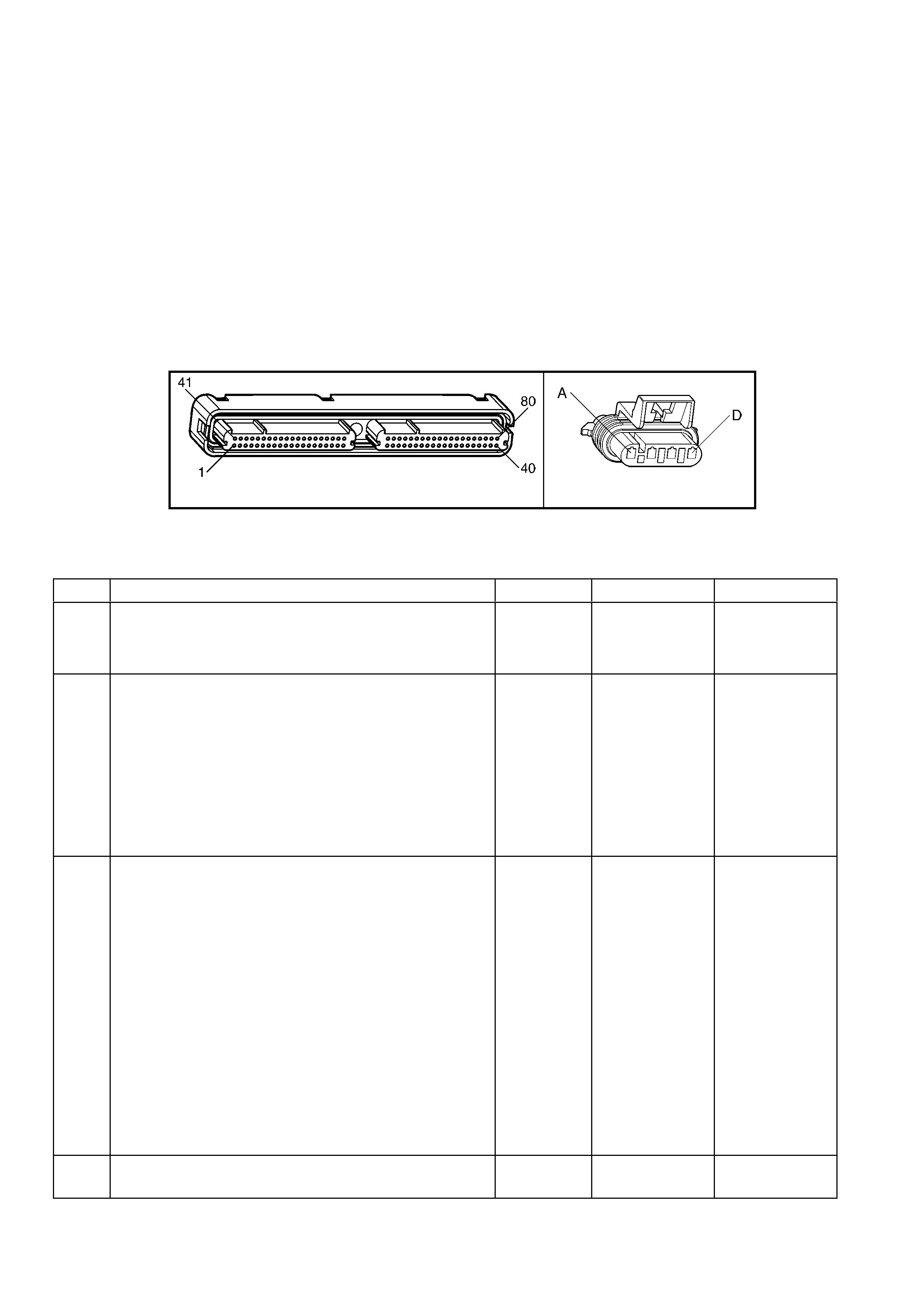
TEST DESCRIPTION
NOTE: The number(s) below refer to the step number(s) on the diagnostic table.
2. If the HO2S voltage is fix well below 200 mV this indicates a short to battery ground or chassis ground. If the
voltage is f ix near or abov e 200 mV, this ind ic ates a s h or t to a PCM groun d. When the HO2S voltag e is f ix near
200 mV, i ndicates the DT C set when t he fue l syst em was in a Po wer E nrichm ent m ode of operation . T his D TC
sets if the HO2S voltage is less than 360 mV during a Power Enrichment mode of operation.
3. Using the Freeze Frame/Failure Records data may aid in locating an intermittent condition. If you cannot
duplicat e the DTC, t he inform ation include d in the F reeze Fram e/Failure Rec ords dat a can help de termine t he
distance travelled since the DTC set. The Fail Counter and Pass Counter can also help determine how many
ignition cycles the diagnostic reported a pass and/or fail. Operate the vehicle within the same freeze frame
condition (RPM, load, vehicle speed, temperature etc.) that you observed. This will isolate when the DTC
failed.
4. Grounding th e lo w side circ uit of the HO 2S shou ld cau se the HO2S vo ltage to d ispla y a bias volt age. A vo ltage
staying near 0.0 volts indicates the low circuit is open, or the high circuit is open or grounded.
5. Disconnecting the PCM allows the use of a DMM to check continuity of the circuits. This aids in locating an
open or shorted circuit.
A84-X1 (BLUE) B57_R
Figure 6C3-2A-69
GEN III V8 PCM –
DTC P0151 HEATED OXYGEN SENSOR (HO2S) CIRCUIT LOW VOLTAGE BANK 2 SENSOR 1
STEP ACTION VALUE YES NO
1. Was the "On-Board Diagnostic" (OBD) System Check
performed? Go to Step 2 Go to
OBD System
Check
in this Section.
2. IMPORTANT: Check the HO2S for being secure before
proceeding wi th this DTC. A sensor that is loose could
cause this DTC to set.
1. Install Tech 2.
2. Idle the engine at the normal operating temperature.
3. Operate the vehicle within parameters specified under
Conditions for Running the DTC in the supporting text.
4. Monitor the HO2S voltage display on the Tech 2
“Engine Data List’.
Is the HO2S voltage less than the specified value?
200 mV Go to Step 4 Go to Step 3
3. 1. Ignition ON, engine OFF.
2. Review the Freeze Frame/Failure Records data for this
DTC and observe the parameters.
3. Turn OFF the ignition for 15 seconds.
4. Idle the engine.
5. Operate the vehicle, within the conditions required for
this diagnostic to run, and as close to the conditions
recorded in the Freeze Frame/Failure Records as
possible. Special operating conditions that you need to
meet before the PCM will run this diagnostic, where
applicable, are listed in Conditions for Running the
DTC.
6. Select the Diagnostic Trouble Code (DTC) option, the
DTC Information option and the Failed This Ignition
option using Tech 2.
Does Tech 2 indicate that this diagnostic failed this
ignition?
Go to Step 4 Go to Diagnostic
Aids
4. 1. Disconnect the HO2S, harness connector B57_R.
Is the HO2S voltage within the specified range? 350-550 mV Go to Step 7 Go to Step 5

STEP ACTION VALUE YES NO
5. 1. Ignition OFF.
2. Disconnect the PCM BLUE connector A84-X1
3. Check the HO2S signal circuit 1666 for a short to
ground or a short to the sensor ground circuit, 1667.
Is the HO2S signal circuit shorted?
Go to Step 6 Go to Step 8
6. 1. Repair the HO2S signal circuit.
Is the action complete? Go to Step 8 –
7. 1. Replace Oxygen Sensor. Refer to 2.8 Heated Oxygen
Sensor, in 6C3-3 SERVICE OPERATIONS.
Is action complete?
Go to Step 9 –
8 1. Replace PCM. Refer to PCM Programming and
PCM/PIM/BCM Security Link Procedure, in 6C3-3
SERVICE OPERATIONS.
Is action complete?
Go to Step 9 –
9. 1. Select the Diagnostic Trouble Code (DTC) option and
the Clear DTC Information option using Tech 2.
2. Idle the engine at the normal operating temperature.
3. Select the Diagnostic Trouble Code (DTC) option, the
DTC Information option and the Failed This Ignition
option using Tech 2.
4. Operate the vehicle within the Conditions for Running
the DTC, as specified in the supporting text, if
applicable.
Does Tech 2 indicate that this DTC reset?
Go to Step 2 Go to Step 10
10. 1. Using Tech 2, check for any other DTCs.
Does Tech 2 display any DTCs that you have not
diagnosed?
Go to the
applicable DTC
table
System OK

GEN III V8 PCM – DTC P0152 HEATED OXYGEN SENSOR (HO2S) CIRCUIT
HIGH VOLTAGE BANK 2 SENSOR 1
Figure 6C3-2A-70 – Oxygen Sensor Circuits
CIRCUIT DESCRIPTION
The PCM s upplies a voltage of about 450 m V betwee n the HO2S hig h and low s ignal circuits . The ox ygen s ensor
varies the voltage over a range from about 1000 mV when the exhaust is rich, down through about 10 mV when the
exhaust is lean.
The PCM monitors and stores the Heated Oxygen Sensor (HO2S) voltage information. The PCM evaluates the
HO2S voltage samples in order to determine the amount of time the HO2S voltage was out of range. The PCM
compares the stored HO2S voltage samples, taken within each sample period, and determines if majority of the
samples are out of the operating range.
The PCM monitors the HO2S voltage for being fixed above a predetermined voltage. If the PCM detects the
voltage is above the predetermined voltage, a DTC will set.

CONDITIONS FOR RUNNING THE DTC
Criteria 1
• DTCs P0101, P0102, P0103, P0112, P0113, P0117, P0118, P0121, P0122, P0123, P0335, P0336, P0351-
P0358, P1258 ar e not set.
• The ignition voltage is greater than 9.0 volts.
• The fuel system is operating in Closed Loop.
• The fuel trim learn is enabled.
• The air/fuel ratio is between 14.5:1 and 14.7:1.
Criteria 2
• DTCs P0101, P0102, P0103, P0112, P0113, P0117, P0118, P0121, P0122, P0123, P0335, P0336, P0351-
P0358, P1258 ar e not set.
• The ignition voltage is greater than 9.0 volts.
• Deceleration Fuel Cut-Off mode is enabled for greater than one second.
CONDITIONS FOR SETTING THE DTC
Criteria 1
• The HO2S signal voltage remains above 775 mV.
• The Criteria 1 conditions are present for at least 33 seconds.
Criteria 2
• The HO2S signal voltage remains above 540 mV.
• The Criteria 2 conditions are present for at least five seconds.
ACTION TAKEN WHEN THE DTC SETS
• The PCM activates the Check Powertrain MIL when the diagnostic runs and fails.
• The PCM records the operating conditions at the time the diagnostic fails. The PCM stores this information in
the Freeze Frame/Failure Records.
• Open Loop Fuelling.
CONDITIONS FOR CLEARING THE MIL/DTC
• The PCM deactivates the Check Powertrain MIL after one ignition c ycle that the diagnostic runs and does not
fail.
• A last test failed (current DTC) clears when the diagnostic runs and does not fail.
• Use Tech 2 to clear the MIL/DTC.
DIAGNOSTIC AIDS
• Check the HO2S electrical connections for evidence of water intrusion. Water present in the connector will
cause the B+ supply to the heater to bleed over to the signal circuit.
• Fuel pressure: The system goes rich if the pressure is too high. The PCM compensates for some increase.
However, if the fuel pressure is too high, a DTC may set. Refer to Fuel System Diagnosis Table in this
Section.
• Rich injector(s): Perform the Injector Balance Test.
• Leaking injector: Refer to the Fuel System Diagnosis Table in this Section.
• Evaporative emissions (EVAP) canister purge. Check for fuel saturation. If full of fuel, check the canister control
and hoses. Refer to Section 6C3-1, EVAP Control System Description in this Section.
• MAF Sensor: Disconnect the MAF Sensor and see if the rich condition is correct. If so, check for proper
installation. If installation OK, replace the MAF Sensor.
• An oxygen suppl y inside th e HO2S is necessary for p roper operation. The HO2S wires provides the suppl y of
oxygen. Inspect the HO2S wires and connections for breaks or contamination.
IMPORTANT: Under no circumstances are the wiring harness connectors associated with the heated oxygen
sensor circuits to be sealed in any way, by using grease or other substances. To do so, would result in an
inadequate supply of reference air to be able to reach the atmospheric reference cavity of each sensor,
resulting in a DT C to be set. If a flexible s ealant is us ed (i.e. gr ease), then this would be dra wn into the sensor
cavity, poisoning the sensor, resulting in a prem ature failure. Also, shou ld connector dam age be evident, t hen
the sensor and le ad m ust be r eplac ed, as s olderi ng of the wir ing would a lso n egate the ‘breath ing’ c apab ilit y of
the sensor wiring.
• TP Sensor: An intermittent TP Sensor output causes the system to go rich, due to a false indication of the
engine accelerating. For an intermittent condition, refer to Section 6C3-2B SYMPTOMS in this Section.
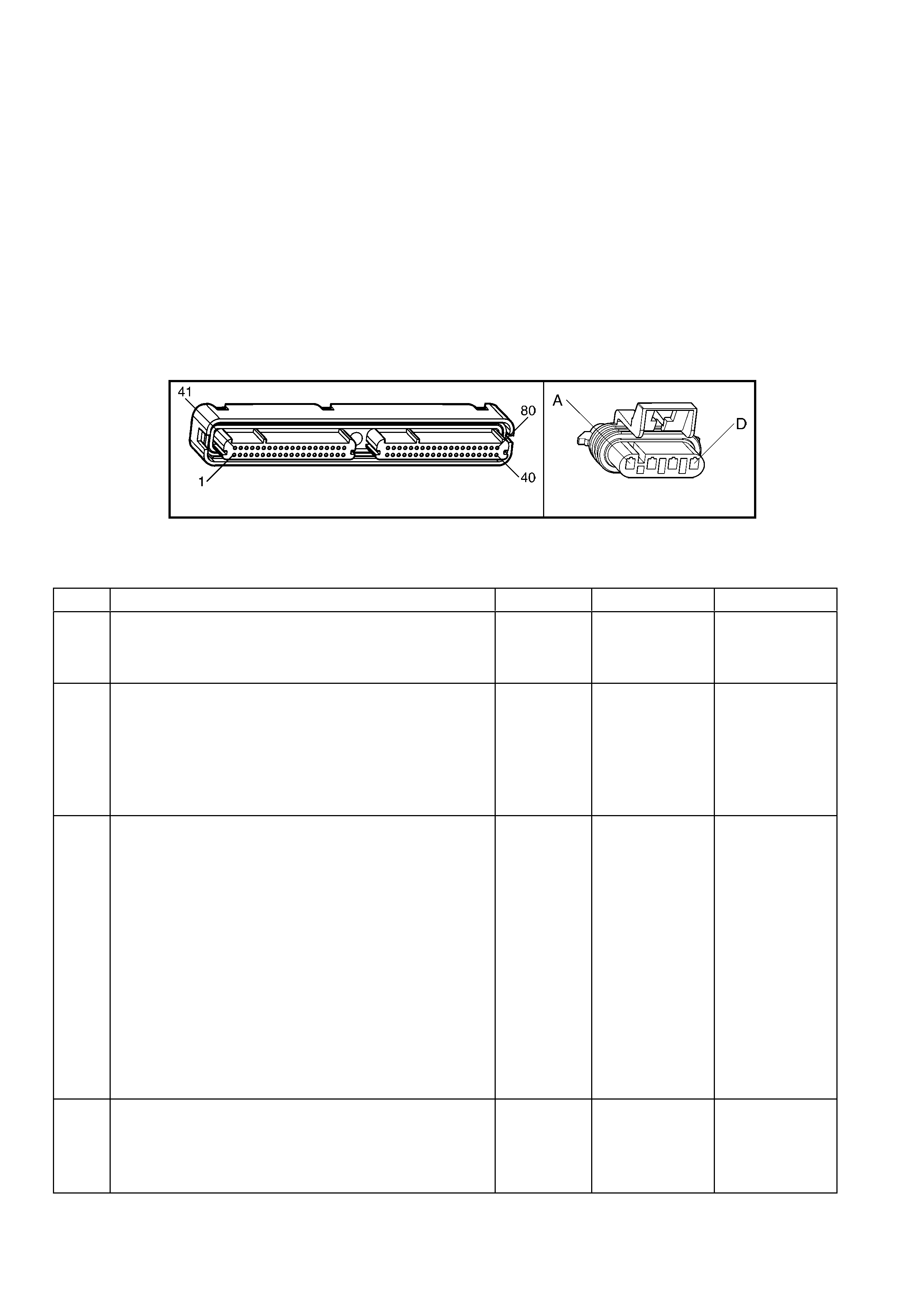
TEST DESCRIPTION
NOTE: The number(s) below refer to the step number(s) on the diagnostic table.
2. T his DTC als o sets during a decelerati on fuel cut-of f. Inspect items which c ould cause a rich exha ust during a
deceleration (leaking injectors, stuck injectors, etc.). Refer to Conditions for Setting the DTC.
T he engine m ust be at th e norm al operating temper ature before p erform ing this test. F or any test t hat requir es
probing the PCM or a component harness connector, use the Connector Test Adaptor Kit J 35616-A. Using this
kit prevents damage to the harness connector terminals.
3. Using the Freeze Frame/Failure Records data may aid in locating an intermittent condition. If you can not
duplicat e the DTC, t he inform ation include d in the F reeze Fram e/Failure Rec ords dat a can help de termine t he
distance travelled since the DTC set. The Fail Counter and Pass Counter can also aid in determining how
many ignition cycles the diagnostic reported a pass and/or a fail. Operate the vehicle within the same freeze
frame conditions (RPM, load, vehicle speed, temperature etc.) that the PCM recorded. This will isolate when
the DTC failed. Refer to Section 6C3-2B SYMPTOMS in this Section.
5. Grounding the low side circuit of the HO2S should cause the HO2S voltage to display a bias voltage.
9. Review the system mechanisation. Check for a short between the HO2S signal circuit and any other wires
powered by this fuse that runs together inside the same harness.
A84-X1 (BLUE) B57_R
Figure 6C3-2A-71
GEN III V8 PCM –
DTC P0152 HEATED OXYGEN SENSOR (HO2S) CIRCUIT HIGH VOLTAGE BANK 2 SENSOR 1
STEP ACTION VALUE YES NO
1. Was the "On-Board Diagnostic" (OBD) System Check
performed? Go to Step 2 Go to
OBD System
Check
in this Section.
2. 1. Install Tech 2.
2. Idle the engine at the normal operating temperature.
3. Operate the vehicle within parameters specified under
Conditions for Running the DTC in the supporting text.
4. Monitor the HO2S voltage display on the Tech 2
‘Engine Data List’.
Is the HO2S voltage greater than the specified value?
775 mV Go to Step 4 Go to Step 3
3. 1. Ignition ON, engine OFF.
2. Review the Freeze Frame/Failure Records data for this
DTC and observe the parameters.
3. Turn OFF the ignition for 15 seconds.
4. Idle the engine.
5. Operate the vehicle, within the conditions required for
this diagnostic to run, and as close to the conditions
recorded in the Freeze Frame/Failure Records as
possible. Special operating conditions that you need to
meet before the PCM will run this diagnostic, where
applicable, are listed in Conditions for Running the
DTC.
6. Select the Diagnostic Trouble Code (DTC) option, the
DTC Information option and the Failed This Ignition
option using Tech 2.
Does Tech 2 indicate that this DTC failed this ignition?
Go to Step 4 Go to Diagnostic
Aids
4. 1. Ignition ON, engine OFF.
2. Remove the HO2S heater fuse F33 while monitoring
the HO2S voltage using Tech 2.
Does the voltage drop to within the specified range when
the power to the heater is disconnected?
350-550 mV Go to Step 5 Go to Step 7

STEP ACTION VALUE YES NO
5. 1. Reinstall the fuse.
2. Disconnect the HO2S, harness connector B57_R.
Does Tech 2 indicate the HO2S voltage within the specified
value?
350-550 mV Go to Step 10 Go to Step 6
6. 1. Ignition ON, engine OFF.
2. Remove the HO2S heater fuse while monitoring the
HO2S voltage using a Tech 2.
Does the voltage drop to within the specified range when
the power to the heater is disconnected?
350-550 mV Go to Step 9 Go to Step 8
7. 1. Ignition OFF.
2. Disconnect the PCM BLUE connector A84-X1.
3. Disconnect the HO2S harness connector B72_R.
4. Ignition ON.
5. Check for voltage on the HO2S sensor signal circuit
1666 at the PCM harness connector using a DMM.
Is the voltage present?
Go to Step 8 Go to Step 11
8. 1. Repair the short to voltage in the HO2S signal circuit.
Is the action complete? Go to Step 12 –
9. 1. Repair the short between the HO2S signal circuit 1666
and the HO2S heater B+ circuit 439.
Is the action complete?
Go to Step 12 –
10. 1. Replace the HO2S.
Is the action complete? Go to Step 12 –
11. 1. Replace PCM. Refer to PCM Programming and
PCM/PIM/BCM Security Link Procedure, in 6C3-3
SERVICE OPERATIONS in this Section.
Is action complete?
Go to Step 12 –
12. 1. Select the Diagnostic Trouble Code (DTC) option and
the Clear DTC Information option using Tech 2.
2. Idle the engine at the normal operating temperature.
3. Select the Diagnostic Trouble Code (DTC) option, the
DTC Information option and the Failed This Ignition
option using Tech 2.
4. Operate the vehicle, within the Conditions for Running
the DTC, as specified in the supporting text, if
applicable.
Does Tech 2 indicate that this DTC reset?
Go to Step 2 Go to Step 13
13. 1. Using Tech 2, check for any other DTCs.
Does Tech 2 display any DTCs that you have not
diagnosed?
Go to the
applicable DTC
table
System OK
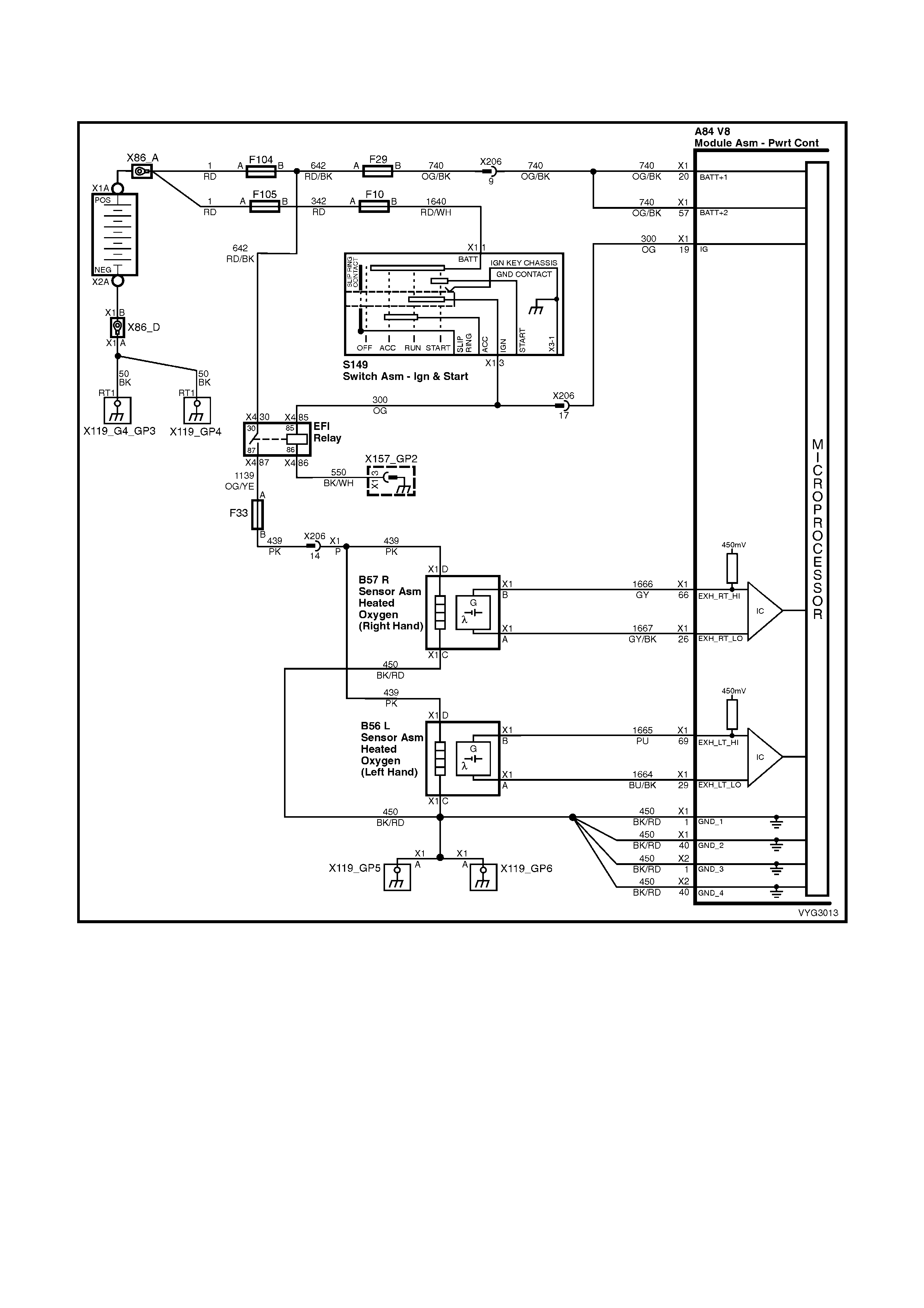
GEN III V8 PCM – DTC P0153 HEATED OXYGEN SENSOR (HO2S)
SLOW RESPONSE BANK 2 SENSOR 1
Figure 6C3-2A-72 – Oxygen Sensor Circuits
CIRCUIT DESCRIPTION
The PCM continuously monitors the Heated Oxygen Sensor (HO2S) activity for 100 seconds. During the monitor
period the PCM counts the number of times that the HO2S responds from rich to lean and from lean to rich and
adds the amount of time it took to complete all transitions. With this information, the PCM can determine the
average time for all transitions. If the average response time is too slow, the DTC will set.
The PCM determ ines the lean to rich trans ition when the HO2S voltage changes from les s than 300 mV to greater
than 600 m V. T he PCM determ ines the ric h to lean transition when the HO2S voltage changes fr om m ore than 600
mV to less than 300 mV. An HO2S that responds too slowly is more likely defective. Replace the HO2S.
CONDITIONS FOR RUNNING THE DTC
• DTCs P0101, P0102, P0103, P0112, P0113, P0117, P0118, P0121, P0122, P0123, P0335, P0336, P0351-
P0358, P1258 are not set.
• The engine coolant temperature is greater than 65° C.
• The ignition voltage is greater than 9.0 volts.

• The fuel system is operating in Closed Loop.
• The engine speed is between 1000 RPM and 2300 RPM.
• The engine air flow is between 20 g/s and 50 g/s.
• The EVAP canister purge duty cycle is greater than 0%.
• The engine run time is greater than 120 seconds.
CONDITIONS FOR SETTING THE DTC
• The Lean to Rich response (below 300 mV to above 600 mV) average time is greater than 100 milliseconds.
• The Rich to Lean response (above 600 mV to below 300 mV) average time is greater than 100 milliseconds.
ACTION TAKEN WHEN THE DTC SETS
• The PCM activates the Check Powertrain MIL when the diagnostic runs and fails.
• The PCM records the operating conditions at the time the diagnostic fails. The PCM stores this information in
the Freeze Frame/Failure Records.
• Open Loop Fuelling.
CONDITIONS FOR CLEARING THE MIL/DTC
• The PCM deactivates the Check Powertrain MIL after one ignition cycle that the diagnostic runs and does not
fail.
• A last test failed (current DTC) clears when the diagnostic runs and does not fail.
• Use Tech 2 to clear the MIL/DTC.
DIAGNOSTIC AIDS
• This diagnostic only runs once per ignition cycle.
• A malfunction in the HO2S heater circuits cause a DTC to set. Check HO2S heater circuit for intermittent
opens/connections.
• An oxygen supply inside the HO2S is necessary for proper operation. The HO2S wires provide the supply of
oxygen. Inspect the HO2S wires and connections for breaks or contamination. Refer to Electrical
Diagnosis/Repair Procedures in Section 12P WIRING DIAGRAMS.
IMPORTANT: Under no circumstances are the wiring harness connectors associated with the heated oxygen
sensor circuits to be sealed in any way, by using grease or other substances. To do so, would result in an
inadequate supply of reference air to be able to reach the atmospheric reference cavity of each sensor,
resulting in a DT C to be set. If a flexible s ealant is used (i.e. grease), then this would be drawn into the sensor
cavity, poisoning the sensor, resulting in a premature failure. Also, should connector damage be evident, then
the sensor and lead m ust be replac ed, as soldering of the wiring would also negate the ‘breathing’ capability of
the sensor wiring.
• Using the Freeze Frame/Failure Records data may aid in locating an intermittent condition. If you cannot
duplicate the DTC, the inform ation included in the Freeze Frame/Failure Records data can help determ ine the
distance travelled since the DTC set. The Fail Counter and Pass Counter can also help determine how many
ignition cycles the diagnostic reported a pass and/or fail. Operate the vehicle within the same freeze frame
conditions (RPM, load, vehicle speed, temperature etc.) that you observed. This will isolate when the DTC
failed. For an intermittent condition, refer to Section 6C-2B SYMPTOMS in this Section.
TEST DESCRIPTION
NOTE: The number(s) below refer to the step number(s) on the diagnostic table.
2. T his step determines if the fault is pr esent. This test m ay take 5 m inutes for the diagnos tic to run. For any test
that requires probing the PCM or a component harness connector, use the Connector Test Adaptor Kit J 35616-
A. Using this kit prevents damage to the harness connector terminals.
3. When DTCs P0133 and P0153 are set at the same time, it is a good indication that a fuel contamination
problem is present.
4. An exhaust leak 15 – 30 cm away from the HO2S can cause a DTC to set.
6. This step checks the integrity of the signal circuit to the PCM.
7. This step checks the integrity of the signal circuit to the PCM.
8. Certain RTV silicone gasket materials give off vapours that can contaminate the HO2S. There is also a
possibility of s ilicone contam ination caused by silicone in the fuel. If the s ensors appear to be contam inated by
silicone and all the s ilicone s ealant is a non s ilicone bas e, advis e the c ust omer to try a differ ent fuel company. A
missing fuel filler restrictor indicates the customer may have used leaded fuel.

A84-X1 (BLUE) B57_R
Figure 6C3-2A-73
GEN III V8 PCM – DTC P0153 HEATED OXYGEN SENSOR (HO2S) SLOW RESPONSE BANK 2 SENSOR 1
STEP ACTION VALUE YES NO
1. Was the "On-Board Diagnostic" (OBD) System Check
performed? Go to Step 2 Go to
OBD System
Check
in this Section.
2. IMPORTANT: If any DTCs are set (except P0153), refer to
those DTCs before proceeding with this diagnostic table.
1. Install Tech 2.
2. Idle the engine at the normal operating temperature.
3. Operate the vehicle, within parameters specified under
Conditions for Running the DTC, as specified, in the
supporting text.
4. Monitor the Failed This Ignition option under the DTC
Information option using Tech 2.
Did DTC P0153 fail this ignition?
Go to Step 3 Go to
Diagnostic Aids
3. Did DTC P0133 also fail this ignition? Go to Step 8 Go to Step 4
4. 1. Check for an exhaust system leak. Refer to 8B
EXHAUST SYSTEM. After you inspect the exhaust
system, return to this diagnostic.
2. If you find an exhaust leak, repair the exhaust leak as
necessary.
Did you isolate an exhaust leak?
Go to Step 2 Go to Step 5
5. 1. Inspect the following items:
• Ensure that the HO2S is securely installed.
• Check for corrosion on the terminals.
• Check the terminal tension at the HO2S harness
connector B57_R and at the PCM BLUE
connector and terminals X1-66 and X1-26.
• Check for damaged wiring.
Did you find a problem in any of the above areas?
Go to Step 9 Go to Step 6
6. 1. Disconnect the Bank 2 HO2S.
2. Monitor the Bank 2 HO2S voltage on the Engine Data
List using Tech 2.
Does Tech 2 indicate a voltage within the specified range?
350-550 mV Go to Step 7 Go to Step 10
7. 1. Jumper the Bank 2 HO2S high (circuit 1666) and low
(PCM side) circuit 1667.
2. Monitor the Bank 2 HO2S voltage using Tech 2.
Does Tech 2 indicate a voltage below specified value?
200 mV Go to Step 12 Go to Step 11
8. IMPORTANT: Determine and correct the cause of the
contamination before replacing a sensor. Check for the
following conditions:
• Fuel contamination
• Use of improper RTV sealant
• Engine oil/coolant consumption
2. Replace the affected Heated Oxygen sensor(s).
Is the action complete?
Go to Step 13 –
9. 1. Repair the conditions as necessary.
Is the action complete? Go to Step 13 –
10. 1. Repair the open Bank 2 HO2S low signal circuit or the
grounded Bank 2 HO2S high signal circuit.
Is the action complete?
Go to Step 13 –

STEP ACTION VALUE YES NO
11. 1. Repair the open Bank 2 HO2S high signal circuit 1666
or the faulty PCM connections.
Is the action complete?
Go to Step 13 –
12. 1. Replace the Bank 2 HO2S.
Is the action complete? Go to Step 13 –
13. 1. Select the Diagnostic Trouble Code (DTC) option and
the Clear DTC Information option using Tech 2.
2. Idle the engine at the normal operating temperature.
3. Select the Diagnostic Trouble Code (DTC) option, the
DTC Information option and the Failed This Ignition
option using Tech 2.
4. Operate the vehicle, within the Conditions for Running
the DTC, as specified in the supporting text, if
applicable.
Does Tech 2 indicate that this DTC reset?
Go to Step 2 Go to Step 14
14. 1. Using Tech 2, check for any other DTCs.
Does Tech 2 display any DTCs that you have not
diagnosed?
Go to the
applicable DTC
table
System OK

GEN III V8 PCM – DTC P0154 HEATED OXYGEN SENSOR (HO2S) INSUFFICIENT
ACTIVITY BANK 2 SENSOR 1
Figure 6C3-2A-74 – Oxygen Sensor Circuits
CIRCUIT DESCRIPTION
The PCM supplies a voltage of about 450 mV between the HO2S high and low signal circuits. The oxygen sensor
varies the voltage over a r ange f r om about 1000 mV when the exhaust is r ich, down through about 10 mV when the
exhaust is lean.
The PCM monitors and stores the Heated Oxygen Sensor (HO2S) voltage information. The PCM evaluates the
HO2S voltage samples in order to determine the amount of time the HO2S voltage was out of range. The PCM
compares the stored HO2S voltage samples, taken within each sample period, and determines if majority of the
samples are out of the operating range.
The PCM monitors the HO2S voltage and detects if the voltage goes out of the bias range. If the PCM does not
detect the voltage went out of the bias range, the DTC will set.

CONDITIONS FOR RUNNING THE DTC
• DTCs P0101, P0102, P0103, P0112, P0113, P0117, P0118, P0121, P0122, P0123, P0335, P0336, P0351-
P0358, P1258 are not set.
• The ignition voltage is greater than 9.0 volts.
• The fuel system is operating in Closed Loop.
• The engine run time is greater than 70 seconds.
• The engine coolant temperature is greater than 48° C.
CONDITIONS FOR SETTING THE DTC
• The HO2S signal voltage is steady between 350 mV and 550 mV.
• The conditions are present for at least 70 seconds.
ACTION TAKEN WHEN THE DTC SETS
• The PCM activates the Check Powertrain MIL when the diagnostic runs and fails.
• The PCM records the operating conditions at the time the diagnostic fails. The PCM stores this information in
the Freeze Frame/Failure Records.
• Open Loop Fuelling.
CONDITIONS FOR CLEARING THE MIL/DTC
• The PCM deactivates the Check Powertrain MIL after one ignition cycle that the diagnostic runs and does not
fail.
• A last test failed (current DTC) clears when the diagnostic runs and does not fail.
• Use Tech 2 to clear the MIL/DTC.
DIAGNOSTIC AIDS
• An oxygen supply inside the HO2S is necessary for correct operation. The HO2S wires provide the supply of
oxygen. Inspect the HO2S wires and connections for breaks or contamination. Refer to Electrical
Diagnosis/Repair Procedures in Section 12P WIRING DIAGRAMS.
IMPORTANT: Under no circumstances are the wiring harness connectors associated with the heated oxygen
sensor circuits to be sealed in any way, by using grease or other substances. To do so, would result in an
inadequate supply of reference air to be able to reach the atmospheric reference cavity of each sensor,
resulting in a DT C to be set. If a flexible s ealant is used (i.e. grease), then this would be drawn into the sensor
cavity, poisoning the sensor, resulting in a premature failure. Also, should connector damage be evident, then
the sensor and lead m ust be replac ed, as soldering of the wiring would also negate the ‘breathing’ capability of
the sensor wiring.
• Using the Freeze Frame/Failure Records data may aid in locating an intermittent condition. If you cannot
duplicate the DTC, the inform ation included in the Freeze Frame/Failure Records data can help determ ine the
distance travelled since the DTC set. The Fail Counter and Pass Counter can also help determine how many
ignition cycles the diagnostic reported a pass and/or fail. Operate the vehicle within the same freeze frame
conditions (RPM, load, vehicle speed, temperature etc.) that you observed. This will isolate when the DTC
failed.
• For an intermittent condition, refer to Section 6C3-2B SYMPTOMS in this Section.
TEST DESCRIPTION
NOTE: The number(s) below refer to the step number(s) on the diagnostic table.
2. The engine must be at normal operating temperature before performing this test. For any test that requires
probing the PCM or a component har ness c onnector , us e the Connector Test Adaptor Kit J 35616- A. Using this
kit prevents damage to the harness connector terminals.
3. Using the Freeze Frame/Failure Records data may aid in locating an intermittent condition. If you can not
duplicate the DTC, the information included in the Freeze Frame/Failure Records data can help determine the
distance travelled s inc e the DT C s et. T he F ail Counter and Pass Counter can als o aid in deter mining how many
ignition cycles the diagnostic reported a pass and/or a fail. Operate the vehicle within the same freeze frame
conditions (RPM, load, vehicle s peed, temperatur e etc.) that the PCM rec orded. This will isolate when the DT C
failed. refer to Section 6C3-2B SYMPTOMS in this Section.
4. If Tech 2 indicates the HO2S voltage goes below 200 mV, this indicates the HO2S circuits and PCM are OK.
5. This step checks whether the signal circuit from the PCM is OK.
6. Disconnecting the PCM allows us ing a DMM to check continuity of the circuits. T his aids in loc ating an open or
shorted circuit.
7. Disc onnecting the PCM allows using a DMM to check continuity of the cir cuits. Th is aids in locating an open or
shorted circuit.

A84-X1 (BLUE) B57_R
Figure 6C3-2A-75
GEN III V8 PCM –
DTC P0154 HEATED OXYGEN SENSOR (HO2S) INSUFFICIENT ACTIVITY BANK 2 SENSOR 1
STEP ACTION VALUE YES NO
1. Was the "On-Board Diagnostic" (OBD) System Check
performed? Go to Step 2 Go to
OBD System
Check
in this Section.
2. IMPORTANT: Check the HO2S for being secure before
proceeding with this DTC. A sensor that is loose could
cause this DTC to set.
1. Install Tech 2.
2. Idle the engine at the normal operating temperature
3. Operate the engine above 1200 RPM for two minutes.
4. Monitor the HO2S voltage display on the Engine Data
List using Tech 2.
Does Tech 2 indicate the Bank 2 HO2S voltage varying
outside the specified value?
350-550 mV Go to Step 3 Go to Step 4
3. 1. Ignition ON, engine OFF.
2. Review the Freeze Frame/Failure Records data for
this DTC and observe the parameters.
3. Turn OFF the ignition for 15 seconds.
4. Idle the engine.
5. Operate the vehicle, within the conditions required for
this diagnostic to run, and as close to the conditions
recorded in Freeze Frame/Failure Records a possible.
Special operating conditions that need to be met
before the PCM will run this diagnostic where
applicable, are listed in Conditions for Running the
DTC.
6. Select the Diagnostic Trouble Code (DTC) option, the
DTC Information option and the Failed This Ignition
option on Tech 2.
Does Tech 2 indicate that this DTC failed this ignition?
Go to Step 4 Go to Diagnostic
Aids
4. 1. Ignition ON, engine OFF.
2. Disconnect the Bank 2 HO2S.
3. Jumper the HO2S high (circuit 1666) and low (PCM
side) circuit 1667, using a fused jumper wire.
4. Monitor the Bank 2 HO2S voltage using Tech 2.
Is the Bank 2 HO2S voltage below the specified value?
200 mV Go to Step 8 Go to Step 5
5. 1. Connect HO2S signal circuit 1666 to a known god
ground, using a fused jumper wire.
Does Tech 2 display Bank 2 HO2S voltage below the
specified value?
200 mV Go to Step 6 Go to Step 7
6. 1. Ignition OFF.
2. Disconnect the PCM BLUE connector A84-X1.
3. Check the continuity of the Bank 2 HO2S low circuit.
4. Repair the open or the poor connection if the Bank 2
HO2S low circuit measures over the specified value.
Did you find and correct the Bank 2 HO2S low circuit
condition?
2Ω Go to Step 13 Go to Step 9

STEP ACTION VALUE YES NO
7. 1. Ignition OFF.
2. Disconnect both PCM connectors.
3. Check the continuity of the Bank 2 HO2S signal circuit
1666.
4. Repair the open or the poor connection if the Bank 2
HO2S circuit 1666 measures over the specified value.
Did you find and correct the Bank 2 HO2S low circuit
condition?
2 Ω Go to Step 13 Go to Step 10
8. 1. Check for a poor Bank 2 HO2S signal or low circuit
terminal connection at the Bank 2 HO2S harness
connector B57_R and replace the terminal(s) if
necessary.
Did any terminals require replacement?
Go to Step 13 Go to Step 11
9. 1. Check for a poor Bank 2 HO2S low circuit terminal
connection at the PCM, and replace the terminal if
necessary.
Did any terminals require replacement?
Go to Step 13 Go to Step 12
10. 1. Check for a poor Bank 2 HO2S signal circuit terminal
connection at the PCM, and replace the terminal if
necessary.
Did any terminals require replacement?
Go to Step 13 Go to Step 12
11. 1. Replace the Bank 2 HO2S.
Is the action complete? Go to Step 13 –
12. 1. Replace PCM. Refer to PCM Programming and
PCM/PIM/BCM Security Link Procedure, in 6C3-3
SERVICE OPERATIONS.
Is action complete?
Go to Step 13 –
13. 1. Select the Diagnostic Trouble Code (DTC) option and
the Clear DTC Information option using Tech 2
2. Idle the engine at the normal operating temperature.
3. Select the Diagnostic Trouble Code (DTC) option, the
DTC Information option and the Failed This Ignition
option using Tech 2.
4. Operate the vehicle, within the Conditions for Running
the DTC, as specified in the supporting text, if
applicable.
Does Tech 2 indicate that this DTC reset?
Go to Step 2 Go to Step 14
14. 1. Using Tech 2, check for any other DTCs.
Does Tech 2 display any DTCs that you have not
diagnosed?
Go to the
applicable DTC
table
System OK
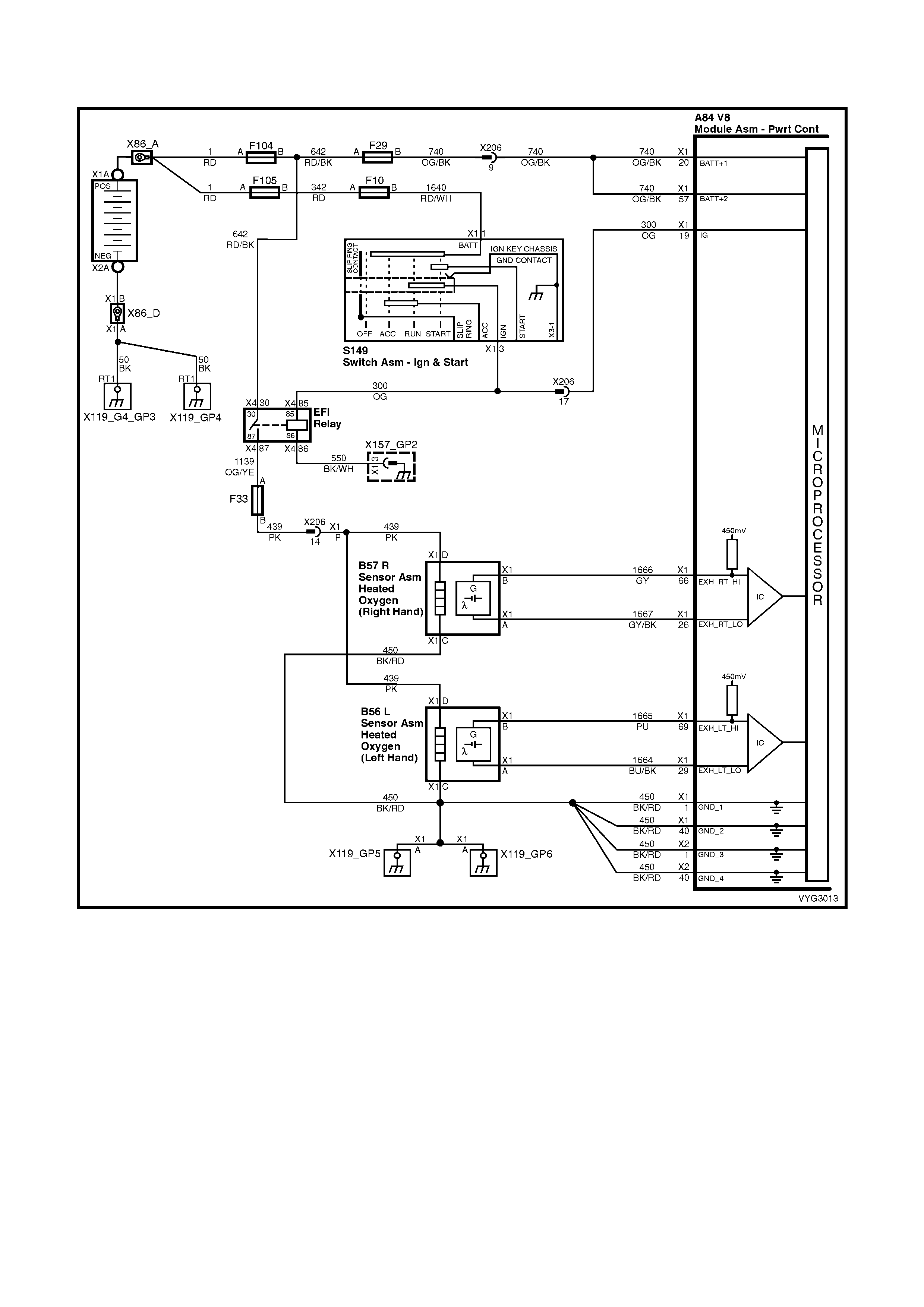
GEN III V8 PCM – DTC P0155 HEATED OXYGEN SENSOR (HO2S) HEATER
CIRCUIT BANK 2 SENSOR 1
Figure 6C3-2A-76 – Oxygen Sensor Circuits
CIRCUIT DESCRIPTION
The PCM supplies a bias voltage (approximately 450 mV) on the Heated Oxygen Sensor (HO2S) signal high and
low circuits. W hen you turn the ignition to the On position, battery voltage is supplied to the HO2S heater. As the
heater reaches the operating temperature, the HO2S voltage responds by changing from a bias voltage range to the
normal operation. Typically, as the HO2S reaches the operating temperature, the HO2S voltage goes from a bias
voltage to a voltage below 300 mV. Depending on the exhaus t gas c ontent, it is poss ible f or the HO2S voltage to go
above 450 mV.
The PCM runs the heater test only on a cold start (depends on the cumulative air flow) and only once an ignition
cycle. When you start the engine the PCM monitors the HO2S voltage. When the HO2S voltage goes above or
below the bias range threshold, the PCM determines how much time it took. If the PCM detects that the process
took too long for the HO2S to enter into normal operating range, a DTC will set. The time the process takes the
HO2S to reach operating temperature is based on the amount of air that flows into the engine.

CONDITIONS FOR RUNNING THE DTC
• DTCs P0101, P0102, P0103, P0112, P0113, P0117, P0118, P0121, P0122, P0123, P0335, P0336, P0351-
P0358, P1258 are not set.
• T he intake air temper ature and the engine coolant tem perature are less than 50° C and are within 8° C of each
other at engine start-up.
• The ignition voltage is between 10.0 volts and 18.0 volts.
• The engine air flow is less than 18 g/s.
CONDITIONS FOR SETTING THE DTC
• The HO2S voltage remains between 300 mV and 700 mV for a predetermined amount of time (depends on
engine coolant temperature and air flow).
ACTION TAKEN WHEN THE DTC SETS
• The PCM activates the Check Powertrain MIL when the diagnostic runs and fails.
• The PCM records the operating conditions at the time the diagnostic fails. The PCM stores this information in
the Freeze Frame/Failure Records.
CONDITIONS FOR CLEARING THE MIL/DTC
• The PCM deactivates the Check Powertrain MIL after one ignition cycle that the diagnostic runs and does not
fail.
• A last test failed (current DTC) clears when the diagnostic runs and does not fail.
• Use Tech 2 to clear the MIL/DTC.
DIAGNOSTIC AIDS
• Using the Freeze Frame/Failure Records data may aid in locating an intermittent condition. If you cannot
duplicate the DTC, the information included in the Freeze Frame/Failure Records data can help determine the
distance travelled since the DTC Set. The Fail Counter and Pass Counter can also help determine how may
ignition cycles the diagnostic reported a pass and/or a fail. Operate the vehicle within the same freeze frame
conditions (RPM, load, vehicle speed, temperature etc.) that you observed. This will isolate when the DTC
failed. For an intermittent condition, refer to Section 6C3-2B SYMPTOMS in this Section.
• The heater diagnostic will only run on a cold start and run once per ignition cycle.
• Inspect the EFI relay for proper operation if you cannot find any problems with the ignition feed circuit to the
com ponent. Pr obe both s ides of the f us e with a test lamp connec ted to gr ound in order to determine if a voltage
is supplied to the fuse. Refer to EFI Relay Diagnosis Table in this Section.
• An oxygen supply inside the HO2S is necessary for proper operation. The HO2S wires provides the supply of
oxygen. Inspect the HO2S wires and connections for breaks or contamination.
TEST DESCRIPTION
NOTE: The number(s) below refer to the step number(s) on the diagnostic table.
2. Allow the engine to cool before performing this test. If the sensor is at the operating temperature, the HO2S
voltage will stay high or low. If the HO2S voltage s tays between 300 – 700 m V, this indicates the HO2S heater
is inoperative. For any test that requires probing the PCM or a component harness connector, use the
Connector Test Adaptor Kit J 35616-A. Using this kit will prevent damage to the harness connector terminals.
3. If more than one HO2S DTC is set, this is a good indication that the HO2S fuse is open. Check all the relate
circuits going to all the heated oxygen sensors f or a short to gr ound. If all the wiring chec ks to be OK, it m ay be
necessary to disconnect each HO2S one at a time to locate a shorted sensor.
4. This step checks whether a B+ supply is available at the sensor.
5. This step checks whether a ground is available at the sensor.
6. This step checks whether the HO2S heater element is internally open.
7. Inspect the ignition feed circuits at the engine compartment Fuse & Relay panel for poor connections.
8. Check the ground circuits for an open if more then one heater DTC sets.
A84-X1 (BLUE) B57_R
Figure 6C3-2A-77

GEN III V8 PCM – DTC P0155 – HEATED OXYGEN SENSOR (HO2S) HEATER CIRCUIT BANK 2 SENSOR 1
STEP ACTION VALUE YES NO
1. Was the "On-Board Diagnostic" (OBD) System Check
performed? Go to Step 2 Go to
OBD System
Check
in this Section.
2. IMPORTANT: Allow the engine to cool for about one half
hour before proceeding with this table.
1. Ignition OFF.
2. Install Tech 2.
3. Ignition ON, engine OFF.
4. Monitor the HO2S voltage display on the Tech 2
Engine Data List for about one minute.
Does the HO2S voltage go from a bias voltage to above or
below the specified range?
300-700 mV Go to Diagnostic
Aids Go to Step 3
3. 1. Inspect the HO2S heater fuse F33 for an open.
Is the HO2S heater fuse open? Go to Step 11 Go to Step 4
4. 1. Raise the vehicle and support on safety stands.
2. Disconnect the HO2S electrical connector B57_R.
3. Probe the ignition feed circuit 439 at the HO2S
electrical connector (PCM side) using a test lamp
connected to ground (a known good ground. Do not
use the HO2S heater ground or the HO2S low
circuits).
Does the test lamp illuminate?
Go to Step 5 Go to Step 7
5. 1. Connect the test lamp between the HO2S ignition feed
circuit 439 and the HO2S heater ground, circuit 450.
Does the test lamp illuminate?
Go to Step 6 Go to Step 8
6. 1. Measure the resistance between the HO2S ignition
feed circuit terminal X1-D and the HO2S heater
ground circuit terminal X1-C at the HO2S connector
B57_R, using a DMM
Is the HO2S resistance within the specified range?
3.5 – 14.0 Ω Go to Step 9 Go to Step 10
7. 1. Repair the open in the HO2S ignition feed circuit to the
HO2S.
Is the action complete?
Go to Step 12 –
8. 1. Repair the open in the HO2S heater ground circuit.
Is the action complete? Go to Step 12 –
9. 1. Check for a poor connection at the HO2S harness
terminals.
Did you find a poor connection?
Go to Step 12 Go to Step 10
10. 1. Replace the HO2S. Refer to 2.8 Heated Oxygen
Sensor, in 6C3-3 SERVICE OPERATIONS.
Is the action complete?
Go to Step 12 –
11. 1. Locate and repair the short to ground in the HO2S
ignition feed circuit 439.
2. Replace the faulty fuse.
Is the action complete?
Go to step 12 –
12. 1. Select the Diagnostic Trouble Code (DTC) option and
the Clear DTC Information option, using Tech 2.
2. Idle the engine at the normal operating temperature.
3. Select the Diagnostic Trouble Code (DTC) option, the
DTC Information option and the Failed This Ignition
option using Tech 2.
4. Operate the vehicle within the Conditions for Running
the DTC as specified in the supporting text, if
applicable.
Does Tech 2 indicate that this DTC reset?
Go to Step 2 Go to step 13
13. 1. Using Tech 2, check for any other DTCs.
Does Tech 2 display any DTCs that you have not
diagnosed?
Go to the
applicable DTC
table
System OK

GEN III V8 PCM – DTC P0171 FUEL SYSTEM LEAN BANK 1
Figure 6C3-2A-78 – Oxygen Sensor Circuits
CIRCUIT DESCRIPTION
The PCM controls a Closed Loop air/fuel metering system in order to provide the best possible combination of
driveability, fuel economy, and emission control. The PCM monitors the heated oxygen sensor signal voltage and
adjusts the fuel delivery based on the signal voltage while in Closed Loop.
A change m ade to the fuel delivery changes the Long and Short Term Fuel Trim values. The Short Term Fuel Trim
values change rapidly in response to the HO2S signal voltages. These changes fine tune the engine fuelling. The
Long Term Fuel Trim values change in response to trends in Short Term Fuel Trim. The Long Term Fuel Trim
makes coarse adjustments to fuelling in order to re-centre and restore control to Short Term Fuel Trim. You can use
Tech 2 to monitor the Short and Long Term Fuel Trim. The ideal fuel trim values are around 0%.
A positive Fuel Trim value indicates that the PCM is adding fuel in order to compensate for a lean condition. A
negative Fuel Trim value indicates that the PCM is reducing the amount of fuel in order to compensate for a rich
condition. If the PCM detects an excessively Rich or Lean condition, the PCM sets a DT C. The long term fuel trim
diagnostic parameter is an aver age of s ever al of the long term s peed/load lear n cells , which the PCM selec ts based
on the engine speed and the engine load.
Techline

CONDITIONS FOR RUNNING THE DTC
• DTCs P0101, P0102, P0103, P0107, P0108, P0112, P0113, P0117, P0118, P0121, P0122, P0123, P0335,
P0336, P0351-P0358, P1111, P1112, or P1258 are not set.
• The engine coolant temperature is between 50° C and 115° C.
• The Barometric pressure is greater than 74 kPa.
• The MAF is between 5.0 g/s and 90 g/s.
• The MAP pressure is between 26 kPa and 90 kPa.
• The IAT is between -20° C and 90° C.
• The engine speed is between 400 RPM and 3000 RPM.
• The TP sensor angle is less than 90%.
• The vehicle speed is less than 137 km/h.
CONDITIONS FOR SETTING THE DTC
• The average Long Term Fuel Trim cell values are above a predetermined threshold.
• All the above conditions are present for at least six seconds.
ACTION TAKEN WHEN THE DTC SETS
• The PCM activates the Check Powertrain MIL when the diagnostic runs and fails.
• The PCM records the operating conditions at the time the diagnostic fails. The PCM stores this information in
the Freeze Frame/Failure Records.
• Open Loop Fuelling.
CONDITIONS FOR CLEARING THE MIL/DTC
• The PCM deactivates the Check Powertrain MIL after the first drive trip that the diagnostic runs and does not
fail, within the same conditions that the DTC last failed.
NOTE: If the last failure was during a non-typical driving condition, the MIL may remain ON longer than the one
drive trip. Review the Freeze Frame/Failure Records for the last failure conditions.
• A last test failed (Current DTC) clears when the diagnostic runs and does not fail.
• Use Tech 2 to clear the MIL/DTC.
DIAGNOSTIC AIDS
• This DTC sets if the engine runs out of fuel.
• A fuel delivery malfunction causes this DTC to set. Thoroughly inspect all items that cause a lean condition.
• For an intermittent condition, refer to Section 6C3-2B SYMPTOMS in this Section.
TEST DESCRIPTION
NOTE: The number(s) below refer to the step number(s) on the diagnostic table.
2. This step determines whether the fault is present. For any test that requires probing the PCM or a component
harness connector, use the Connector Test Adaptor Kit J 35616-A. Using the kit prevents damage to the
harness connector terminals.
3. Using the Freeze Frame/Failure Records data may aid in locating an intermittent condition. If you cannot
duplicate the DTC, the inform ation included in the Freeze Frame/Failure Records data can help determ ine the
distance travelled since the DTC set. The Fail Counter and Pass Counter can also help determine how many
ignition cycles the diagnostic reported a pass and/or a fail. Operate the vehicle within the same freeze frame
conditions (RPM, load, vehicle speed, temperature etc.) that you observed. This will isolate when the DTC
failed.
For an intermittent condition, refer to Section 6C3-2B SYMPTOMS in this Section .
4. If DT C 174 is also s et indic ates both bank s of the engine ar e operating lean. Ins pec t the items that would cause
both banks to operate lean.
5. A vacuum leak causes DTCs P0171 and P0174 to set at the same time. Inspect all areas of the engine for a
vacuum leak . Also ins pect the PCV valve fo r being the corr ect one f or this application. Make sure the engine oil
fill cap is in place and that it is tight. Check that the engine oil dip stick is fully seated.

GEN III V8 PCM – DTC P0171 FUEL SYSTEM LEAN BANK 1
STEP ACTION VALUE YES NO
1. Was the "On-Board Diagnostic" (OBD) System Check
performed? Go to Step 2 Go to
OBD System
Check
in this Section.
2. IMPORTANT: If any DTCs are set, except P0171 and
P0174, refer to those DTCs before proceeding with this
diagnostic.
1. Install Tech 2.
2. Idle the engine at the normal operating temperature.
3. Fuel system in Closed Loop.
4. Monitor the LTFT Bank 1 display on the Fuel Trim
Data List using Tech 2.
Is the LTFT less than the specified value indicated?
24% Go to Step 3 Go to Step 4
3. 1. Ignition ON engine OFF.
2. Review the Freeze Frame/Failure Records data for
this DTC and observe the parameters.
3. Turn OFF the ignition for 15 seconds.
4. Start the engine.
5. Operate the vehicle, within the conditions required for
this diagnostic to run, and as close to the conditions
recorded in Freeze Frame/Failure Records as
possible. Special operating conditions that need to be
met before the PCM will run the diagnostic, where
applicable, are listed in Conditions for Running the
DTC.
6. Select the Diagnostic Trouble Code (DTC) option, the
DTC Information option and the Failed This Ignition
option using Tech 2.
Does Tech 2 indicate that this DTC failed this ignition?
Go to Step 4 Go to Diagnostic
Aids
4. Is DTC P0174 also set? Go to Step 5 Go to Step 6
5. 1. Inspect the following items:
• Vacuum hoses for splits, kinks, and proper
connections. Refer to Vacuum Hose Routing
Diagrams in 6E3 EMISSION CONTROL.
• Crankcase ventilation valve and/or system for
leaks. Refer to Crankcase Ventilation System
Description in 6C3-1 GENERAL INFORMATION,
in this Section.
• Contaminated Fuel.
• PCM and sensor grounds are clean, tight and in
the proper locations.
• Air induction system after MAF sensor for vacuum
leaks.
• Engine mechanical failure. Refer to 6A3 ENGINE
MECHANICAL – GEN III V8.
Did you find any problems in any of the above areas?
Go to Step 7 Go to Fuel
System
Diagnosis Table
6. 1. Inspect the following items:
• Bank 1 exhaust leaks and missing or loose
exhaust hardware.
• Bank 1 HO2S 1 is installed securely and the
electrical connector not contacting exhaust
system or ignition wires.
• Engine mechanical failure. Refer to 6A3 ENGINE
MECHANICAL – GEN III V8.
• Vacuum leaks that will only affect bank 1, such as
the intake manifold, injector O rings, etc.
Was a problem found in any of the above areas?
Go to Step 7 Go to Fuel
System
Diagnosis Table
in this Section.
7. 1. Repair or replace any faulty items found.
Is the action complete? Go to Step 8 –

STEP ACTION VALUE YES NO
8. 1. Select the Diagnostic Trouble Code (DTC) option and
the Clear DTC Information option using Tech 2.
2. Idle the engine at the normal operating temperature.
3. Select the Diagnostic Trouble Code (DTC) option, the
DTC Information option and the Failed This Ignition
option using Tech 2.
4. Operate the vehicle, within the Conditions for Running
the DTC, as specified in the supporting text, if
applicable.
Does Tech 2 indicate that this DTC reset?
Go to Step 2 Go to step 9
9. 1. Using Tech 2, check for any other DTCs.
Does Tech 2 display any DTCs that you have not
diagnosed?
Go to the
applicable DTC
table
System OK
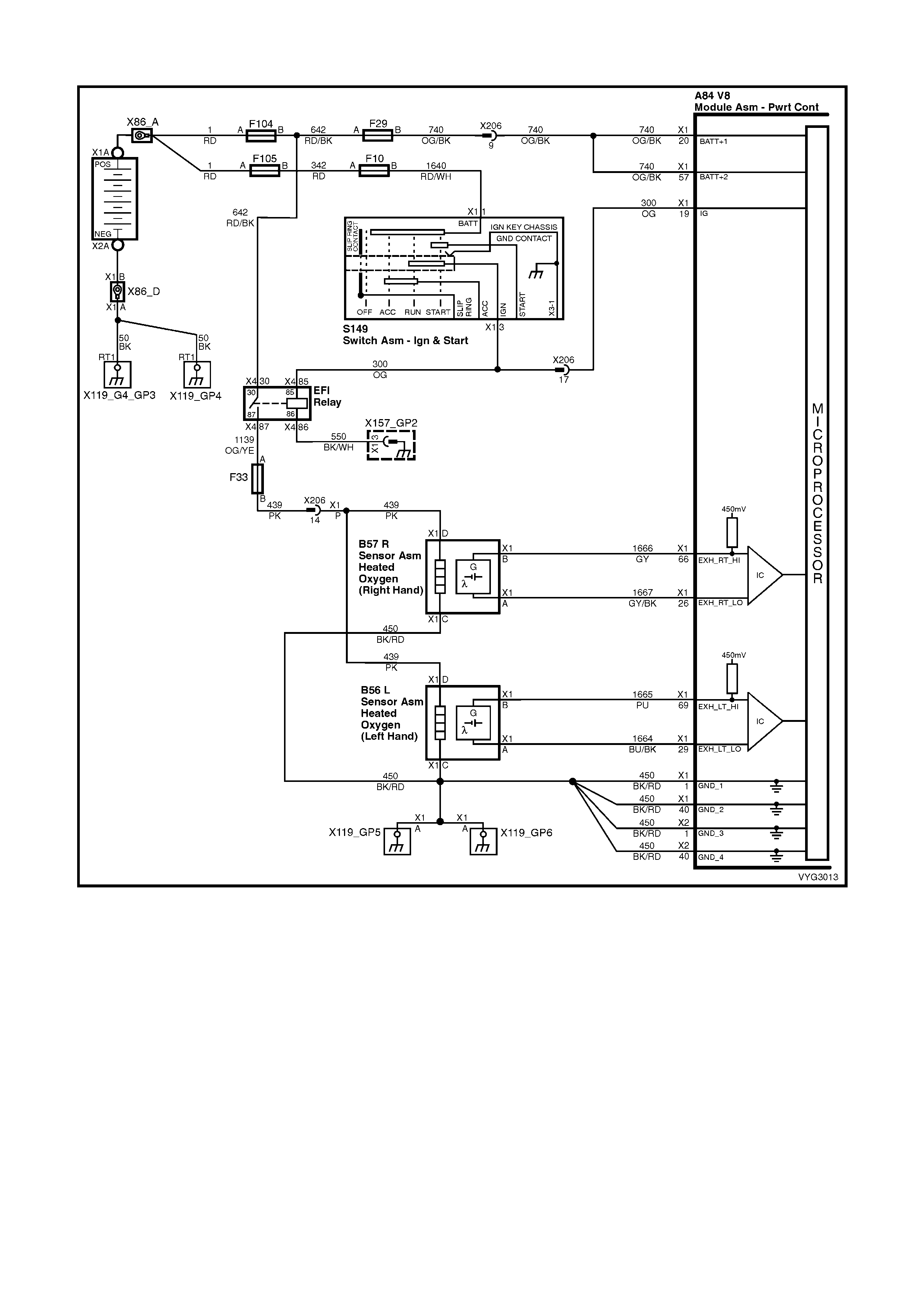
GEN III V8 PCM – DTC P0172 FUEL SYSTEM RICH BANK 1
Figure 6C3-2A-79 – Oxygen Sensor Circuits
CIRCUIT DESCRIPTION
The PCM controls a Closed Loop air/fuel metering system in order to provide the best possible combination of
driveability, fuel economy, and emission control. The PCM monitors the heated oxygen sensor signal voltage and
adjusts the fuel delivery based on the signal voltage while in Closed Loop. A change made to the fuel delivery
changes the Long and Short Term Fuel Trim values.
The Short Term Fuel Trim values c hange r apidly in response to the HO2S s ignal voltages. T hese changes fine tune
the engine fuelling. The Long Term Fuel Trim values change in response to trends in Short Term Fuel Trim. The
Long T erm Fuel Trim m akes coarse adjus tments to fuelling in order to re-c entre and restore contr ol to Short Term
Fuel Trim.
You can use Tech 2 to monitor the Short and Long Term Fuel Trim. The ideal fuel trim values are around 0%. A
positive Fuel Trim value indicates that the PCM is adding fuel in order to compensate for a lean condition. A
negative Fuel Trim value indicates that the PCM is reducing the amount of fuel in order to compensate for a rich
condition. If the PCM detects an excessively Rich or Lean condition, the PCM sets a DT C. The long term fuel trim
diagnostic param eter is an average of several of the long term s peed/load learn cells which the PCM selects based
on the engine speed and the engine load.

CONDITIONS FOR RUNNING THE DTC
• DTCs P0101, P0102, P0103, P0107, P0108, P0112, P0113, P0117, P0118, P0121, P0122, P0123, P0335,
P0336, P0351-P0358, P1111, P1112, or P1258 are not set.
• The engine coolant temperature is between 50° C and 115° C.
• The Barometric pressure is greater than 74 kPa.
• The MAF is between 5.0 g/s and 90 g/s.
• The MAP pressure is between 26 kPa and 90 kPa.
• The IAT is between –20° C and 90° C.
• The engine speed is between 400 RPM and 3000 RPM.
• The TP sensor angle is less than 90%.
• The vehicle speed is less than 137 km/h.
CONDITIONS FOR SETTING THE DTC
• The average Long Term Fuel Trim cell values are above a predetermined threshold.
• All the above conditions are present for at least 49 seconds.
ACTION TAKEN WHEN THE DTC SETS
• The PCM activates the Check Powertrain MIL when the diagnostic runs and fails.
• The PCM records the operating conditions at the time the diagnostic fails. The PCM stores this information in
the Freeze Frame/Failure Records.
CONDITIONS FOR CLEARING THE MIL/DTC
• The PCM deactivates the Check Powertrain MIL after one drive trip that the diagnostic runs and does not fail
within the same conditions that the DTC last failed.
NOTE: If the failure was during a non-typical driving condition, the Check Powertrain MIL may remain on longrer
than one drive trip. Review the Freeze Frame/Failure Records for the last failure conditions.
• A last test failed (current DTC) clears when the diagnostic runs and does not fail.
• Use Tech 2 to clear the MIL/DTC.
DIAGNOSTIC AIDS
• For an intermittent condition, refer to Section 6C3-2B SYMPTOMS in this Section.
TEST DESCRIPTION
NOTE: The number(s) below refer to the step number(s) on the diagnostic table.
2. This step determines whether the fault is present.
3. Using the Freeze Frame/Failure Records data may aid in locating an intermittent condition. If you cannot
duplicate the DTC, the inform ation included in the Freeze Frame/Failure Records data can help determ ine the
distance travelled since the DTC set. The Fail Counter and Pass Counter can also help determine how many
ignition cycles the diagnostic reported a pass and/or a fail. Operate the vehicle within the same freeze frame
conditions (RPM, load, vehicle speed, temperature etc.) that you observed. This will isolate when the DTC
failed. For an intermittent condition, refer to Section 6C3-2B SYMPTOMS in this Section .
4. If DTC P0175 is also set, then both banks are operating rich. Inspect items that would cause both banks to
operate rich.
5. Excessive fuel in the oil will cause DTCs P0172 and P0175 to set at the same time. Remove the PCV valve
from the intake manifold and plug with a suitable stopper. Also, disconnect the fresh air pipe from the rocker
cover and plug with a suitable stopper . If the long term and short term fuel trim values increase, indicates there
is fuel in the oil.
GEN III V8 PCM – DTC P0172 FUEL SYSTEM RICH BANK 1
STEP ACTION VALUE YES NO
1. Was the "On-Board Diagnostic" (OBD) System Check
performed? Go to Step 2 Go to
OBD System
Check
in this Section.

STEP ACTION VALUE YES NO
2. IMPORTANT: If any DTCs are set, except P0172 and
P0175, refer to those DTCs before proceeding with this
diagnostic.
1. Install Tech 2.
2. Idle the engine at the normal operating temperature.
3. Fuel system in Closed Loop.
4. Monitor the LTFT Bank 1 display on the Fuel Trim
Data List using Tech 2.
Is the LTFT greater than the specified value indicated?
-13% Go to Step 3 Go to Step 4
3. 1. Ignition ON, engine OFF.
2. Review the Freeze Frame/Failure Records data for
this DTC and observe the parameters.
3. Turn OFF the ignition for 15 seconds.
4. Start the engine.
5. Operate the vehicle, within the conditions required for
this diagnostic to run, and as close to the conditions
recorded in Freeze Frame/Failure Records as
possible. Special operating conditions that need to be
met before the PCM will run the diagnostic, where
applicable, are listed in Conditions for Running the
DTC.
6. Select the Diagnostic Trouble Code (DTC) option, the
DTC Information option and the Failed This Ignition
option using Tech 2.
Does Tech 2 indicate that this DTC failed this ignition?
Go to Step 4 Go to Diagnostic
Aids
4. Is DTC P0175 also set? Go to Step 5 Go to Step 6
5. 1. Inspect the following items:
• Collapsed air intake duct.
• The air filter element for being restricted.
• MAF sensor for being installed in the proper direction
and for foreign objects blocking the inlet screen. Refer
to MAF Sensor Replacement in 6C3-3 SERVICE
OPERATIONS, in this Section.
• For fuel in the pressure regulator line. Refer to Fuel
System Diagnosis Table in this Section.
• Check for the incorrect MAP/BARO display. Compare
to another vehicle.
• For excessive fuel in the crankcase. Change oil as
necessary.
Was a problem found in any of the above areas?
Go to Step 7 Go to Fuel
System
Diagnosis Table,
in this Section
6. IMPORTANT: When the fuel system check is finished,
return to this table.
1. Inspect the Bank 1 injectors for leaking, refer to Fuel
System Diagnosis Table in this Section.
Are any injectors leaking?
Go to Step 7 Go to Step 8
7. 1. Repair or replace any faulty items found.
Is the action complete? Go to Step 9 –
8. 1. Replace the faulty HO2S.
Is the action complete? Go to Step 9 –
9. 1. Select the Diagnostic Trouble Code (DTC) option and
the Clear DTC Information option using Tech 2.
2. Idle the engine at the normal operating temperature.
3. Select the Diagnostic Trouble Code (DTC) option, the
DTC Information option and the Failed This Ignition
option using Tech 2.
4. Operate the vehicle within the Conditions for Running
the DTC, as specified in the supporting text, if
applicable.
Does Tech 2 indicate that this DTC reset?
Go to Step 2 Go to Step 10
10. 1. Using Tech 2, check for any other DTCs.
Does Tech 2 display any DTCs that you have not
diagnosed?
Go to the
applicable DTC
table
System OK
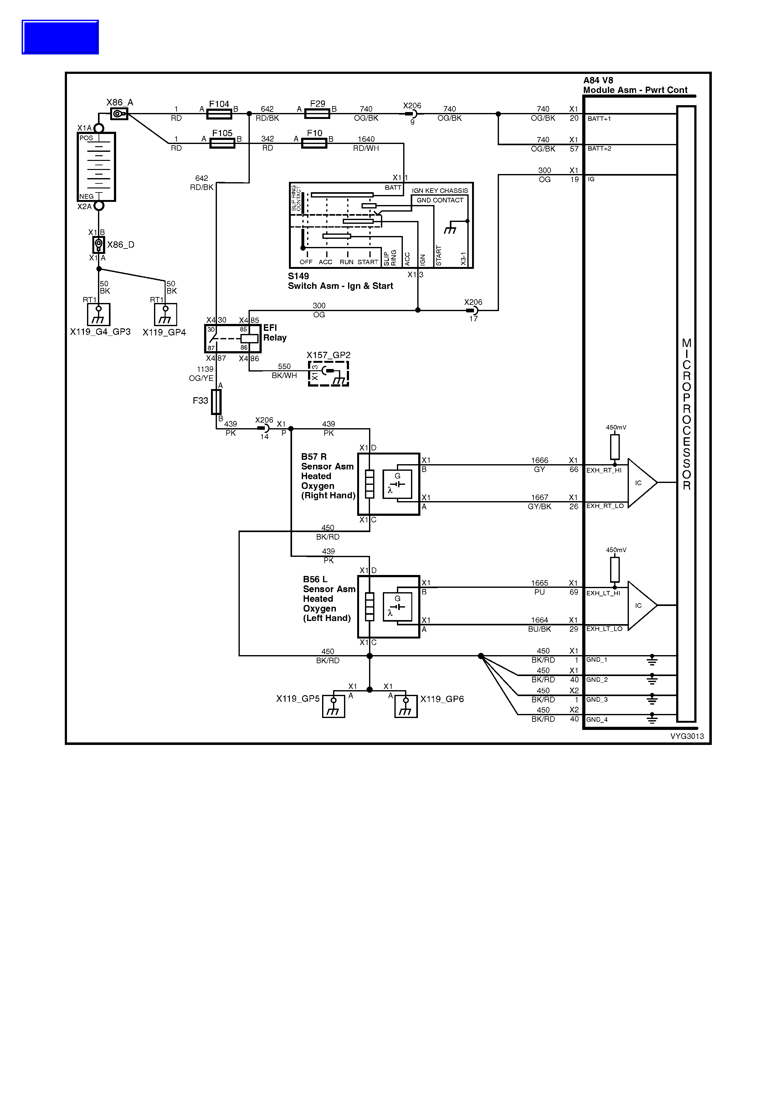
GEN III V8 PCM – DTC P0174 FUEL SYSTEM LEAN BANK 2
Figure 6C3-2A-80 – Oxygen Sensor Circuits
CIRCUIT DESCRIPTION
The PCM controls a Closed Loop air/fuel metering system in order to provide the best possible combination of
driveability, fuel economy, and emission control. The PCM monitors the heated oxygen sensor signal voltage and
adjusts the fuel delivery based on the signal voltage while in Closed Loop. A change made to the fuel delivery
changes the Long and Short Term Fuel Trim values.
The Short Term Fuel Trim values c hange r apidly in response to the HO2S s ignal voltages. T hese changes fine tune
the engine fuelling. The Long Term Fuel Trim values change in response to trends in Short Term Fuel Trim. The
Long T erm Fuel Trim m akes coarse adjus tments to fuelling in order to re-c entre and restore contr ol to Short Term
Fuel Trim.
You can use Tech 2 to monitor the Short and Long Term Fuel Trim. The ideal fuel trim values are around 0%. A
positive Fuel Trim value indicates that the PCM is adding fuel in order to compensate for a lean condition. A
negative Fuel Trim value indicates that the PCM is reducing the amount of fuel in order to compensate for a rich
condition. If the PCM detects an excessively Rich or Lean condition, the PCM sets a DT C. The long term fuel trim
diagnostic param eter is an average of several of the long term s peed/load learn cells which the PCM selects based
on the engine speed and the engine load.
Techline

CONDITIONS FOR RUNNING THE DTC
• DTCs P0101, P0102, P0103, P0107, P0108, P0112, P0113, P0117, P0118, P0121, P0122, P0123, P0335,
P0336, P0351-P0358, P1111, P1112, or P1258 are not set.
• The engine coolant temperature is between 50° C and 115° C.
• The Barometric pressure is greater than 74 kPa.
• The MAF is between 5.0 g/s and 90 g/s.
• The MAP pressure is between 26 kPa and 90 kPa.
• The IAT is between -20° C and 90° C.
• The engine speed is between 400 RPM and 3000 RPM.
• The TP sensor angle is less than 90%.
• The vehicle speed is less than 137 km/h.
CONDITIONS FOR SETTING THE DTC
• The average Long Term Fuel Trim cell values are above a predetermined threshold.
• All the above conditions are present for at least six seconds.
• Open Loop Fuelling.
ACTION TAKEN WHEN THE DTC SETS
• The PCM activates the Check Powertrain MIL when the diagnostic runs and fails.
• The PCM records the operating conditions at the time the diagnostic fails. The PCM stores this information in
the Freeze Frame/Failure Records.
CONDITIONS FOR CLEARING THE MIL/DTC
• The PCM deactivates the Check Powertrain MIL after one drive trip that the diagnostic runs and does not fail
within the same conditions that the DTC last failed.
NOTE: If the f ailure was during a non-typical driving condition, the Chec k Powertrain MIL may rem ain on longer
than one drive trip. Review the Freeze Frame/Failure Records for the last failure conditions.
• A last test failed (current DTC) clears when the diagnostic runs and does not fail.
• Use Tech 2 to clear the MIL/DTC.
DIAGNOSTIC AIDS
• This DTC sets if the engine runs out of fuel.
• A fuel delivery malfunction causes this DTC to set. Thoroughly inspect all items that cause a lean condition.
• For an intermittent condition, refer to in this Section .
TEST DESCRIPTION
NOTE: The number(s) below refer to the step number(s) on the diagnostic table.
2. This step determines whether the fault is present. For any test that requires probing the PCM or a component
harness connector, use the Connector Test Adaptor Kit J 35616-A. Using the kit prevents damage to the
harness connector terminals.
3. Using the Freeze Frame/Failure Records data may aid in locating an intermittent condition. If you cannot
duplicate the DTC, the inform ation included in the Freeze Frame/Failure Records data can help determ ine the
distance travelled since the DTC set. The Fail Counter and Pass Counter can also help determine how many
ignition cycles the diagnostic reported a pass and/or a fail. Operate the vehicle within the same freeze frame
conditions (RPM, load, vehicle speed, temperature etc.) that you observed. This will isolate when the DTC
failed. For an intermittent condition, refer to Section 6C3-2B SYMPTOMS in this Section.
4. If DTC P0174 is also set this indicates both banks of the engine are operating lean. Inspect the items that would
cause both banks to operate lean.
5. A vacuum leak causes DTCs P0171 and P0174 to set at the same time. Inspect all areas of the engine for a
vacuum leak. Also, ins pec t the PCV valve f or being the c orr ec t one for this application. Make sure the engine oil
fill cap is in place and that it is tight. Check that the engine oil dip stick is fully seated.

GEN III V8 PCM – DTC P0174 FUEL SYSTEM LEAN BANK 2
STEP ACTION VALUE YES NO
1. Was the "On-Board Diagnostic" (OBD) System Check
performed? Go to Step 2 Go to
OBD System
Check
in this Section.
2. IMPORTANT: If any DTCs are set, except P0171 and
P0174, refer to those DTCs before proceeding with this
diagnostic.
1. Install Tech 2.
2. Idle the engine at the normal operating temperature.
3. Fuel system in Closed Loop.
4. Monitor the LTFT Bank 2 display on the Fuel Trim
Data List using Tech 2.
Is the LTFT less than the specified value indicated?
24% Go to Step 3 Go to Step 4
3. 1. Ignition ON, engine OFF.
2. Review the Freeze Frame/Failure Records data for
this DTC and observe the parameters.
3. Turn OFF the ignition for 15 seconds.
4. Start the engine.
5. Operate the vehicle, within the conditions required for
this diagnostic to run, and as close to the conditions
recorded in Freeze Frame/Failure Records as
possible. Special operating conditions that need to be
met before the PCM will run the diagnostic, where
applicable, are listed in Conditions for Running the
DTC.
6. Select the Diagnostic Trouble Code (DTC) option, the
DTC Information option and the Failed This Ignition
option using Tech 2.
Does Tech 2 indicate that this DTC failed this ignition?
Go to Step 4 Go to Diagnostic
Aids
4. Is DTC P0171 also set? Go to Step 5 Go to Step 6
5. 1. Inspect the following items:
• Vacuum hoses for splits, kinks, and proper
connections. Refer to Vacuum Hose Routing
Diagrams in 6E3 EMISSION CONTROL in this
Section.
• Crankcase ventilation valve and/or system for
leaks. Refer to Crankcase Ventilation System
Description in 6C3-1 GENERAL INFORMATION,
in this Section.
• Contaminated Fuel.
• PCM and sensor grounds are clean, tight and in
the proper locations.
• Air induction system after MAF sensor for vacuum
leaks.
• Engine mechanical failure. Refer to 6A3 ENGINE
MECHANICAL in this Section.
Was a problem found in any of the above areas?
Go to Step 7 Go to Fuel
System
Diagnosis Table
6. 1. Inspect the following items:
• Bank 2 exhaust leaks and missing or loose
exhaust hardware.
• Bank 2 HO2S 1 is installed securely and the
electrical connector not contacting exhaust
system or ignition wires.
• Engine mechanical failure. Refer to 6A3 ENGINE
MECHANICAL – GEN III V8 ENGINE.
• Vacuum leaks that will only affect bank 2, such as
the intake manifold, the injector O rings, etc.
Was a problem found in any of the above areas?
Go to Step 7 Go to Fuel
System
Diagnosis Table
in this Section.
7. 1. Repair or replace any faulty items found.
Is the action complete? Go to Step 8 –

STEP ACTION VALUE YES NO
8. 1. Select the Diagnostic Trouble Code (DTC) option and
the Clear DTC Information option using Tech 2.
2. Idle the engine at the normal operating temperature.
3. Select the Diagnostic Trouble Code (DTC) option, the
DTC Information option and the Failed This Ignition
option using Tech 2.
4. Operate the vehicle, within the Conditions for Running
the DTC, as specified in the supporting text, if
applicable.
Does Tech 2 indicate that this DTC reset?
Go to Step 2 Go to step 9
9. 1. Using Tech 2, check for any other DTCs.
Does Tech 2 display any DTCs that you have not
diagnosed?
Go to the
applicable DTC
table
System OK
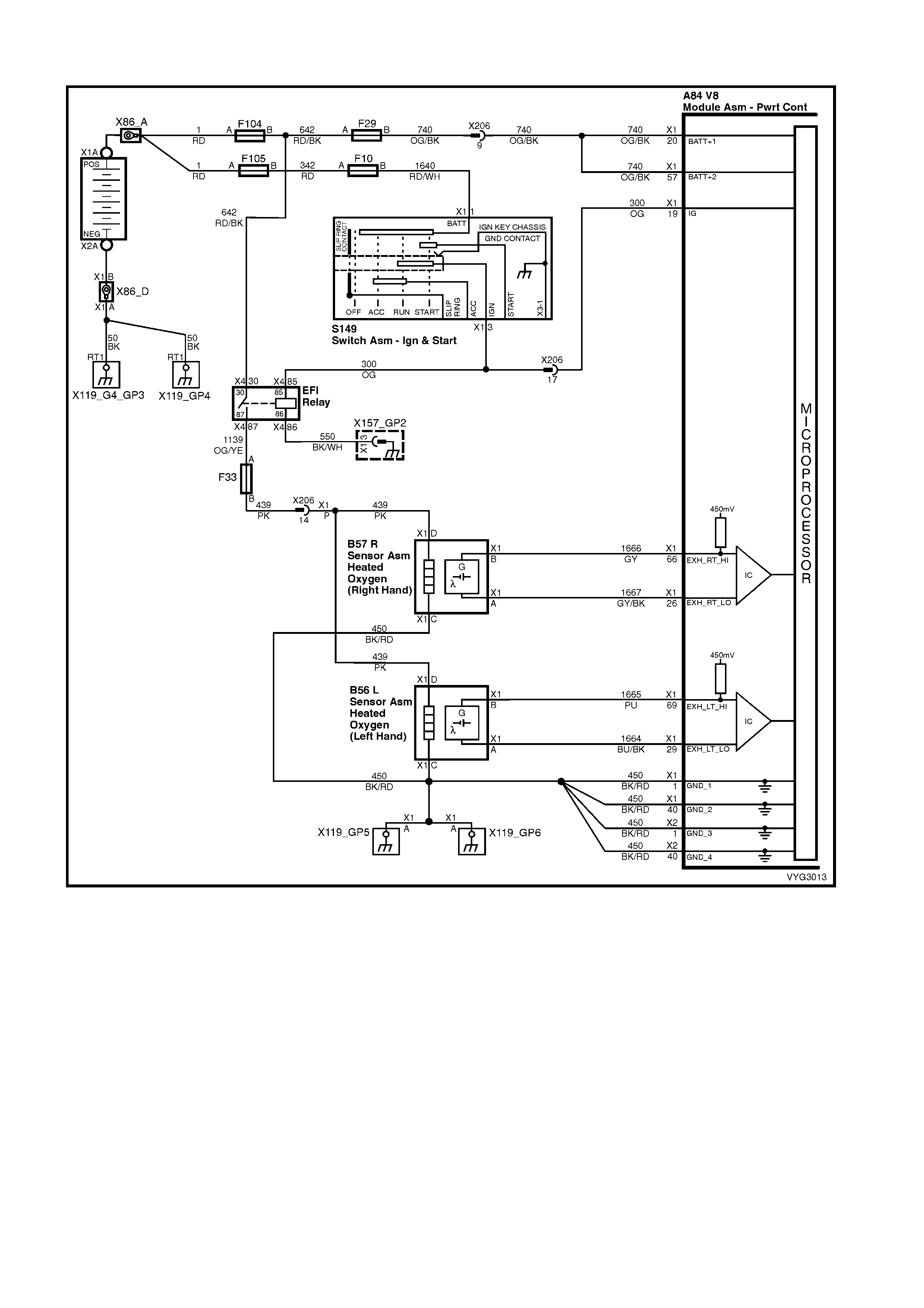
GEN III V8 PCM – DTC P0175 FUEL SYSTEM RICH BANK 2
Figure 6C3-2A-81 – Oxygen Sensor Circuits
CIRCUIT DESCRIPTION
The PCM controls a Closed Loop air/fuel metering system in order to provide the best possible combination of
driveability, fuel economy, and emission control. The PCM monitors the heated oxygen sensor signal voltage and
adjusts the fuel delivery based on the signal voltage while in Closed Loop. A change made to the fuel delivery
changes the Long and Short Term Fuel Trim values.
The Short Term Fuel Trim values c hange r apidly in response to the HO2S s ignal voltages. T hese changes fine tune
the engine fuelling. The Long Term Fuel Trim values change in response to trends in Short Term Fuel Trim. The
Long T erm Fuel Trim m akes coarse adjus tments to fuelling in order to re-c entre and restore contr ol to Short Term
Fuel Trim.
You can use Tech 2 to monitor the Short and Long Term Fuel Trim. The ideal fuel trim values are around 0%. A
positive Fuel Trim value indicates that the PCM is adding fuel in order to compensate for a lean condition. A
negative Fuel Trim value indicates that the PCM is reducing the amount of fuel in order to compensate for a rich
condition. If the PCM detects an excessively Rich or Lean condition, the PCM sets a DT C. The long term fuel trim
diagnostic parameter is an aver age of s ever al of the long term s peed/load lear n cells , which the PCM selec ts based
on the engine speed and the engine load.

CONDITIONS FOR RUNNING THE DTC
• DTCs P0101, P0102, P0103, P0107, P0108, P0112, P0113, P0117, P0118, P0121, P0122, P0123, P0335,
P0336, P0351-P0358, P1111, P1112, or P1258 are not set.
• The engine coolant temperature is between 50° C and 115° C.
• The Barometric pressure is greater than 74 kPa.
• The MAF is between 5.0 g/s and 90 g/s.
• The MAP pressure is between 26 kPa and 90 kPa.
• The IAT is between -20° C and 90° C.
• The engine speed is between 400 RPM and 3000 RPM.
• The TP sensor angle is less than 90%.
• The vehicle speed is less than 137 km/h.
CONDITIONS FOR SETTING THE DTC
• The average Long Term Fuel Trim cell values are above a predetermined threshold.
• All the above conditions are present for at least 49 seconds.
ACTION TAKEN WHEN THE DTC SETS
• The PCM activates the Check Powertrain MIL when the diagnostic runs and fails.
• The PCM records the operating conditions at the time the diagnostic fails. The PCM stores this information in
the Freeze Frame/Failure Records.
CONDITIONS FOR CLEARING THE MIL/DTC
• The PCM deactivates the Check Powertrain MIL after one drive trip that the diagnostic runs and does not fail
within the same conditions that the DTC last failed.
NOTE: If the f ailure was during a non-typical driving condition, the Chec k Powertrain MIL may rem ain on longer
than one drive trip. Review the Freeze Frame/Failure Records for the last failure conditions.
• A last test failed (current DTC) clears when the diagnostic runs and does not fail.
• Use Tech 2 to clear the MIL/DTC.
DIAGNOSTIC AIDS
• For an intermittent condition, refer to Section 6C3-2B SYMPTOMS in this Section.
TEST DESCRIPTION
NOTE: The number(s) below refer to the step number(s) on the diagnostic table.
2. This step determines whether the fault is present.
3. Using the Freeze Frame/Failure Records data may aid in locating an intermittent condition. If you cannot
duplicate the DTC, the inform ation included in the Freeze Frame/Failure Records data can help determ ine the
distance travelled since the DTC set The Fail Counter and Pass Counter can also help determine how many
ignition cycles the diagnostic reported a pass and/or a fail. Operate the vehicle within the same freeze frame
conditions (RPM, load, vehicle speed, temperature etc.) that you observed. This will isolate when the DTC
failed. For an intermittent condition, refer to Section 6C3-2B SYMPTOMS in this Section .
4. If DTC P0175 is also set, then both banks are operating rich. Inspect items that would cause both banks to
operate rich.
5. Excessive fuel in the oil will cause DTCs P0172 and P0175 to set at the same time. Remove the PCV valve
from the intake manifold and plug with a suitable stopper. Also, disconnect the fresh air pipe from the rocker
cover and plug with a suitable stopper . If the long term and short term fuel trim values increase, indicates there
is fuel in the oil.
GEN III V8 PCM – DTC P0175 FUEL SYSTEM RICH BANK 2
STEP ACTION VALUE YES NO
1. Was the "On-Board Diagnostic" (OBD) System Check
performed? Go to Step 2 Go to
OBD System
Check
in this Section.

STEP ACTION VALUE YES NO
2. IMPORTANT: If any DTCs are set, except P0172 and
P0175, refer to those DTCs before proceeding with this
diagnostic.
1. Install Tech 2.
2. Idle the engine at the normal operating temperature.
3. Fuel system in Closed Loop.
4. Monitor the LTFT Bank 2 display on the Fuel Trim
Data List using Tech 2.
Is the LTFT greater than the specified value indicated?
–13% Go to Step 3 Go to Step 4
3. 1. Ignition ON, engine OFF.
2. Review the Freeze Frame/Failure Records data for
this DTC and observe the parameters.
3. Turn OFF the ignition for 15 seconds.
4. Start the engine.
5. Operate the vehicle, within the conditions required for
this diagnostic to run, and as close to the conditions
recorded in Freeze Frame/Failure Records as
possible. Special operating conditions that need to be
met before the PCM will run the diagnostic, where
applicable, are listed in Conditions for Running the
DTC.
6. Select the Diagnostic Trouble Code (DTC) option, the
DTC Information option and the Failed This Ignition
option using Tech 2.
Does Tech 2 indicate that this DTC failed this ignition?
Go to Step 4 Go to
Diagnostic Aids
4. Is DTC P0172 also set? Go to Step 5 Go to Step 6
5. 1. Inspect the following items:
• Collapsed air intake duct.
• Restricted air filter element.
• Correctly installed MAF Sensor. Check for
direction and objects blocking the inlet screen.
Refer to MAF Sensor Replace in 6C3-3 SERVICE
OPERATIONS, in this Section.
• Fuel in the pressure regulator line. Refer to Fuel
System Diagnosis Table in this Section.
• Incorrect MAP/BARO display. Compare to another
vehicle.
• Excessive fuel in the crankcase. Change oil as
necessary.
Was a problem found in any of the above areas?
Go to Step 7 Go to Fuel
System
Diagnosis Table
6. IMPORTANT: When the fuel system check is finished,
return to this table.
1. Inspect the Bank 2 injectors for leaking, refer to Fuel
System Diagnosis Table in this Section.
Are any injectors leaking?
Go to Step 7 Go to Step 8
7. 1. Repair or replace any faulty items found.
Is the action complete? Go to Step 9 –
8. 1. Replace the faulty HO2S.
Is the action complete? Go to Step 9 –
9. 1. Select the Diagnostic Trouble Code (DTC) option and
the Clear DTC Information option using Tech 2.
2. Idle the engine at the normal operating temperature.
3. Select the Diagnostic Trouble Code (DTC) option, the
DTC Information option and the Failed This Ignition
option using Tech 2
4. Operate the vehicle within the Conditions for Running
the DTC, as specified in the supporting text, if
applicable.
Does Tech 2 indicate that this DTC reset?
Go to Step 2 Go to Step 10
10. 1. Using Tech 2, check for any other DTCs.
Does Tech 2 display any DTCs that you have not
diagnosed?
Go to the
applicable DTC
table
System OK

GEN III V8 PCM – DTC P0218 TRANSMISSION FLUID OVER-TEMPERATURE
Figure 6C3-2A-82 – Transmission Fluid Pressure Switch Assembly
CIRCUIT DESCRIPTION
The f low of trans mission f luid starts in the oil pan and is drawn through the filter, transm ission case and into the oil
pump assem bly. The oil pum p assem bly pressur ises the fluid and directs it to the pressur e regulator valve where it
becomes the main supply of fluid to the various components and hydraulic circuits in the transmission.
Hot fluid exiting the torque c onverter f lows through the conver ter clutch apply valve and into the transm iss ion cooler
lines to the oil cooler loc ated in the vehicle radiator (and auxiliar y c ooler if equipped). From the cooler, fluid returns
to cool and lubricate the f ront of the tr ansmis sion. In forward drive r anges, D4 fluid f rom the m anual valve is routed
through an orificed cup plug in the rear of the transmission case to feed the rear lube fluid circuit.
When the Powertrain Control Module (PCM) detects a high transmission fluid temperature (TFT) for a long period of
time, then DTC P0218 sets.
CONDITIONS FOR RUNNING THE DTC
• No TFT sensor DTCs P0711, P0712, P0713.
• The ignition switch is in the RUN position for 5 seconds.
CONDITIONS FOR SETTING THE DTC
• The TFT is greater than 130° C for 10 minutes (600 seconds).
ACTION TAKEN WHEN THE DTC SETS
• The PCM activates the Check Powertrain MIL when the diagnostic runs and fails.
• The PCM freezes shift adapts from being updated.
• The PCM records the operating conditions at the time the diagnostic fails. The PCM stores this information in
the Freeze Frame/Failure Records.
CONDITIONS FOR CLEARING THE MIL/DTC
• T he PCM deactivates the Chec k Powertrain MIL dur ing the first ignition cycle that the diagnostic runs and does
not fail.
• A last test failed (current DTC) clears when the diagnostic runs and does not fail.
• The PCM cancels the DTC default actions when the fault no longer exists and the ignition switch is OFF long
enough in order to power down the PCM.
• Use Tech 2 to clear the MIL/DTC.
DIAGNOSTIC AIDS
• The TFT displayed on Tech 2 should rise steadily to a normal operating temperature, then stabilise.
• Verify the customer's driving habits, trailer towing, overloading the vehicle, etc.
TEST DESCRIPTION
NOTE: The number(s) below refer to the step number(s) on the diagnostic table.
3. This step checks for air flow restrictions or damage which may result in the transmission overheating.

GEN III V8 PCM – DTC P0218 TRANSMISSION FLUID OVER-TEMPERATURE
STEP ACTION VALUE YES NO
1. Was the "On-Board Diagnostic" (OBD) System Check
performed? Go to Step 2 Go to
OBD System
Check
in this Section.
2. 1. Install Tech 2.
2. Ignition ON, engine OFF.
IMPORTANT: Before clearing the DTC, use Tech 2 in
order to record the Failure Records. Using the Clear Info
function erases the Failure Records from the PCM.
3. Record th e DTC Failure Record s.
4. Clear the DTC.
5. Perform the transmission fluid checking procedure,
refer to Transmission Fluid Checking Procedure in
7C4 A/T ON-VEHICLE SERVICING.
Was the Transmission Fluid Checking Procedure
performed?
Go to Step 3 Go to
Transmission
Fluid Checking
Procedure, in
7C3 A/T
HYDRAULIC
AND
MECHANICAL
DIAGNOSIS
3. 1. Inspect the engine cooling system and transmission
cooling system for the following conditions:
• Air flow restrictions.
• Air flow blockage.
• Debris.
2. Inspect the transmission cooling system for damaged
cooler lines.
Was a condition found?
Go to Step 6 Go to Step 4
4. 1. Perform the line pressure check procedure, refer to
Line Pressure Check Procedure in 7C3 A/T
HYDRAULIC AND MECHANICAL DIAGNOSIS.
Was a condition found?
Go to Step 6 Go to Step 5
5. 1. Inspect the torque converter stator for damage, refer
to Torque Converter Diagnosis Procedure in 7C3 A/T
HYDRAULIC AND MECHANICAL DIAGNOSIS.
Was a condition found?
Go to Step 6 Go to
Diagnostic Aids
6. 1. Perform the following procedure in order to verify the
repair:
• Select DTC.
• Select Clear Info.
• Ignition ON, engine OFF.
• Verify that Tech 2 indicates a TFT less than
129° C for at least five seconds.
Is the TFT less than 129° C for at least five seconds?
System OK Go to Step 1
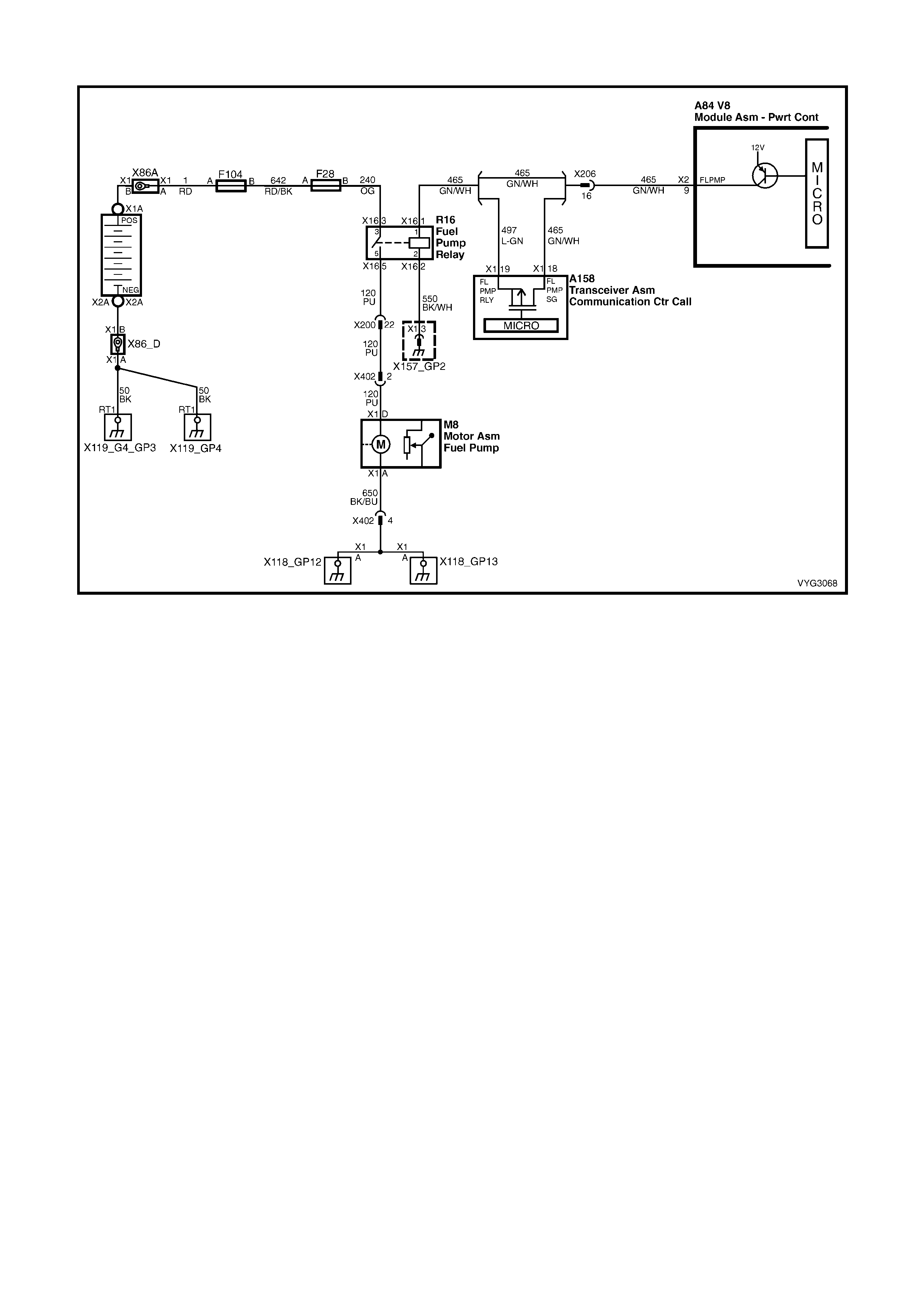
GEN III V8 PCM – DTC P0230 FUEL PUMP CONTROL CIRCUIT
Figure 6C3-2A-83 – Fuel Pump Circuit
CIRCUIT DESCRIPTION
When you turn the ignition switch to the ON position, the PCM activates the in-tank fuel pump. The fuel pump
rem ains ON as long as the PCM rec eives referenc e pulses from the CKP sensor. If there are no reference pulses ,
the PCM turns the f uel pump OF F af ter about 2-3 s ec onds . T he PCM c ontrols the f uel pump r elay by applying B+ to
the control cir cuit via an inter nal s witch c alled a driver . T he pr imary function of the driver is to supply a voltage to the
fuel pump relay. The driver has a fault line which the PCM monitors.
When the PCM commands the fuel pump ON, the voltage of the control circuit should be high (near battery
voltage). When the PCM commands the control circuit to the fuel pump OFF, the voltage potential of the circuit
should be low (near 0 volts). This DTC sets when the PCM detects the fuel pump control circuit is shorted to
ground, after the engine has been running. If the short occurs before key ON, the DTC will not set, and the fuel
pump will not operate.
CONDITIONS FOR RUNNING THE DTC
• The engine speed is greater than 400 RPM.
• The ignition voltage is between 6.0 volts and 16.0 volts.
CONDITIONS FOR SETTING THE DTC
• The PCM detects that the commanded state of the circuit and the actual state of the circuit do not match.
• All of the above conditions present for at least ten seconds.
ACTION TAKEN WHEN THE DTC SETS
• The PCM activates the Check Powertrain MIL when the diagnostic runs and fails.
• The PCM records the operating conditions at the time the diagnostic fails. The PCM stores this information in
the Freeze Frame/Failure Records.
CONDITIONS FOR CLEARING THE MIL/DTC
• The PCM deactivates the Check Powertrain MIL after one ignition cycle that the diagnostic runs and does not
fail.
• A last test failed (current DTC) clears when the diagnostic runs and does not fail.
• Use Tech 2 to clear the MIL/DTC.
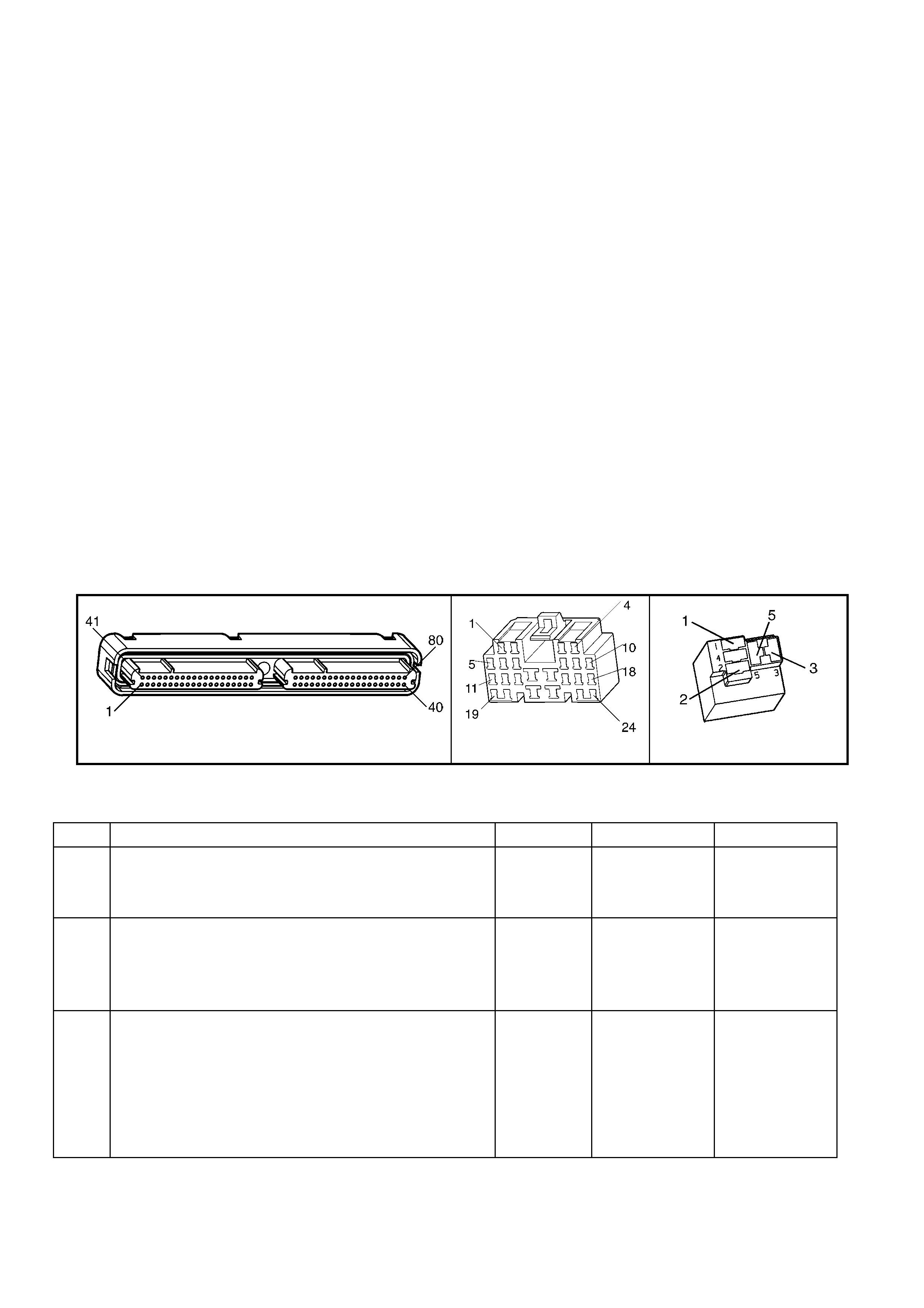
DIAGNOSTIC AIDS
• The following may cause an intermittent:
− Poor connections: Check for adequate terminal tension
− Corrosion
− Incorrectly routed harness
− Rubbed through wire insulation
− Broken wire inside the insulation
• Using the Freeze Frame/Failure Records data may aid in locating an intermittent condition. If you cannot
duplicate the DTC, the information included in the Freeze Frame/Failure Records data can help determine the
distance travelled since the DTC set. The Fail Counter and Pass Counter also help determine how many
ignition cycles the diagnostic reported a pass and/or a fail. Operate the vehicle within the same freeze frame
conditions (RPM, load, vehicle speed, temperature etc.) that you observed. This will isolate when the DTC
failed.
• For an intermittent condition, refer to Section 6C3-2B SYMPTOMS in this Section .
TEST DESCRIPTION
NOTE: The number(s) below refer to the step number(s) on the diagnostic table.
2. Listen for an audible click when the relay operates. Command both the ON and the OFF states. Repeat the
commands as necessary.
3. This check can detect a partially shorted coil which would cause excessive current flow. Leaving the circuit
energised for 2 minutes allows the coil to warm up. When warm, the coil may short (goes above 0.75 Amp).
5. Identify and test the relay coil terminals in order to avoid improper diagnosis.
12. If you do not find any trouble in the control circuit or the connection at the PCM, the PCM may be
malfunctioning. However, this is an extremely unlikely failure. Before replacing the PCM, inspect for poor
connections at the PCM harness connectors.
13. The repair is not complete if Tech 2 indicates that the diagnostic ran and failed.
A84-X2 (RED) X206 X16 (PART OF X100)
Figure 6C3-2A-84
GEN III V8 PCM – DTC P0230 FUEL PUMP CONTROL CIRCUIT
STEP ACTION VALUE YES NO
1. Was the "On-Board Diagnostic" (OBD) System Check
performed? Go to Step 2 Go to
OBD System
Check
in this Section.
2. 1. Ignition ON, engine OFF.
1. Command the fuel pump relay ON and OFF using
Tech 2.
Does the fuel pump relay turn ON and OFF when
commanded?
Go to Step 3 Go to Step 5
3. 1. Ignition Off
2. Disconnect the PCM RED connector A84-X2.
3. Ignition ON, engine OFF.
4. Measure the current from the relay control circuit in
the PCM harness connector to B+ for 2 minutes using
a DMM, with the 10 AMP scale selected.
Does the current draw measure less than the specified
value shown (but not zero)?
0.75 Amp Go to
Diagnostic Aids Go to Step 4

STEP ACTION VALUE YES NO
4. 1. Ignition OFF.
2. Remove the fuel pump relay (R16) from the engine
compartment fuse & relay panel, X100.
3. Measure the resistance from the relay control circuit in
the PCM harness connector to ground using a DMM.
Refer to the wiring schematic for the proper terminal
identification.
Does the DMM display infinite resistance?
Go to Step 11 Go to Step 10
5. 1. Ignition OFF.
2. Remove the fuel pump relay (R16) from the engine
compartment fuse & relay panel, X100.
3. Connect a test lamp between the ground circuit 550
and the control circuit 465 at the engine compartment
fuse and relay panel, X100.
4. Ignition ON, engine OFF.
5. Command the fuel pump relay ON and OFF using
Tech 2.
Does the test lamp turn ON and OFF when commanded?
Go to Step 8 Go to Step 6
6. 1. Check the resistance from the fuel pump relay ground
circuit 550 at the fuse & relay panel to a known good
ground using a DMM.
Is the resistance within the specified range?
0 – 5 Ω Go to Step 7 Go to Step 9
7. 1. Ignition OFF.
2. Reinstall the fuel pump relay.
3. Disconnect the PCM RED connector A84-X2.
4. Ignition ON, engine OFF.
5. Probe the relay control circuit 465 in the PCM RED
harness connector A84 terminal X2-9 with a fused
jumper wire connected to B+.
Does the relay operate?
Go to Step 12 Go to Step 10
8. 1. Check the connections at the relay.
Did you find and correct the condition? Go to Step 13 Go to Step 11
9. 1. Repair the open fuel pump relay ground circuit.
Is the action complete? Go to Step 13 –
10. 1. Repair open or short to ground in the fuel pump relay
control circuit.
Is the action complete?
Go to Step 13 –
11. 1. Replace the relay.
Is this action complete? Go to Step 13 –
12. 1. Replace PCM. Refer to PCM Programming and
PCM/PIM/BCM Security Link Procedure in 6C3-3
SERVICE OPERATIONS.
Is action complete?
Go to Step 13 –
13. 1. Select the Diagnostic Trouble Code (DTC) option and
the Clear DTC Information option using Tech 2.
2. Idle the engine at the normal operating temperature.
3. Select the Diagnostic Trouble Code (DTC) option, the
DTC Information option and the Failed This Ignition
option using Tech 2.
4. Operate the vehicle, within the Conditions for Running
the DTC, as specified in the supporting text, if
applicable.
Does Tech 2 indicate that this DTC reset?
Go to Step 2 Go to Step 14
14. 1. Using Tech 2, check for any other DTCs.
Are any DTCs displayed that you have not diagnosed? Go to the
applicable DTC
table
System OK

GEN III V8 PCM – DTC P0325 KNOCK SENSOR SYSTEM
Figure 6C3-2A-85 – Knock Sensor Circuits
CIRCUIT DESCRIPTION
The KS system monitors both Knock Sensors in order to determine if detonation is present. If the KS system
determines that excessive knock (detonation) is present, the PCM retards the spark timing based on the signals
from the KS system . W hen knock is present, the KS system voltage input signal to the PCM goes high. T he PCM
then retar ds timing until no k nock is present. When the KS s ystem is m alf unctioning, the KS c ircuit voltage going to
the PCM goes low. The PCM interprets this low signal as no spark knock.
CONDITIONS FOR RUNNING THE DTC
• The engine run time is greater than 20 seconds.
• The engine speed is between 1650 and 3000 RPM.
• The MAP is at or about 48 kPa.
• The engine coolant temperature is greater than 70° C.
• The throttle angle is greater than 0.5%.
• The TP sensor angle is steady within 1%.
• Battery voltage is between 10 and 16 volts.
CONDITIONS FOR SETTING THE DTC
• A malfunction with the knock sensor system or circuits within the PCM are faulty.
• All above conditions present for at least three seconds.
ACTION TAKEN WHEN THE DTC SETS
• The PCM activates the Check Powertrain MIL when the diagnostic runs and fails.
• The PCM records the operating conditions at the time the diagnostic fails. The PCM stores this information in
the Freeze Frame/Failure Records.
CONDITIONS FOR CLEARING THE MIL/DTC
• The PCM deactivates the Check Powertrain MIL after one ignition cycle that the diagnostic runs and does not
fail.
• A last test failed (current DTC) clears when the diagnostic runs and does not fail.
• Use Tech 2 to clear the MIL/DTC.
DIAGNOSTIC AIDS
• If the diagnostic test does not run, review the Conditions for Running the DTC.
• For an intermittent condition, refer to Section 6C3-2B SYMPTOMS in this Section.
TEST DESCRIPTION
NOTE: The number(s) below refer to the step number(s) on the diagnostic table.
2. This DTC indicates an internal PCM problem.

GEN III V8 PCM – DTC P0325 KNOCK SENSOR SYSTEM
STEP ACTION VALUE YES NO
1. Was the "On-Board Diagnostic" (OBD) System Check
performed? Go to Step 2 Go to
OBD System
Check
in this Section.
2. 1. Replace PCM. Refer to PCM Programming and
PCM/PIM/BCM Security Link Procedure, in 6C3-3
SERVICE OPERATIONS.
Is action complete?
Go to Step 3 –
3. 1. Select the Diagnostic Trouble Code (DTC) option and
the Clear DTC option using Tech 2.
2. Idle the engine at the normal operating temperature.
3. Select the Diagnostic Trouble Code (DTC) option, the
DTC Information option and the Failed This Ignition
option using Tech 2.
4. Operate vehicle within the Conditions for Running the
DTC as specified in the supporting test, if applicable.
Does Tech 2 indicate that this DTC reset?
Go to Step 2 Go to Step 4
4. 1. Using Tech 2, check for any other DTCs.
Does Tech 2 display any DTCs that you have not
diagnosed?
Go to applicable
DTC table System OK

GEN III V8 PCM – DTC P0327 KNOCK SENSOR CIRCUIT FRONT SENSOR
Figure 6C3-2A-86 – Knock Sensor Circuits
CIRCUIT DESCRIPTION
The Knoc k Sensor (KS) system detects engine detonation. The PCM retar ds the spark timing bas ed on the signals
from the knock sensors. The Knock Sensors produce an AC voltage. The Knock Sensor voltages are an input to
the PCM. The amount of AC voltage produced is proportional to the amount of knock.
An operating engine produces a normal amount of engine mechanical vibration (noise). The Knock Sensors
produce an AC voltage signal from this noise. When an engine operates, the PCM learns the minimum and
maximum frequency of the noise the engine produces. W hen the PCM determ ines that this frequency is less than
or greater than the expected amount, a Knock Sensor DTC will set.
CONDITIONS FOR RUNNING THE DTC
• The engine run time is greater than 20 seconds.
• The engine speed is between 1650 and 3000 RPM.
• The MAP is at or about 48 kPa.
• The engine coolant temperature is greater than 70° C.
• The throttle angle is greater than 0.5% and steady.
• Battery voltage is between 10 and 16 volts.
CONDITIONS FOR SETTING THE DTC
• The PCM determines that the frequency is less than or greater than the expected amount for at least three
seconds.
ACTION TAKEN WHEN THE DTC SETS
• The PCM activates the Check Powertrain MIL when the diagnostic runs and fails.
• The PCM records the operating conditions at the time the diagnostic fails. The PCM stores this information in
the Freeze Frame/Failure Records.
CONDITIONS FOR CLEARING THE MIL/DTC
• The PCM deactivates the Check Powertrain MIL after one ignition cycle that the diagnostic runs and does not
fail.
• A last test failed (current DTC) clears when the diagnostic runs and does not fail.
• Use Tech 2 to clear the MIL/DTC.
DIAGNOSTIC AIDS
• Check the Knock Sensor for correct installation. A Knock Sensor that is loose or over torqued may cause the
DTC P0327 to set.
• For an intermittent, refer to Section 6C3-2B SYMPTOMS in this Section.
TEST DESCRIPTION
NOTE: The number(s) below refer to the step number(s) on the diagnostic table.
2. This verifies the malfunction is present. Tech 2 will display DTC Ran=Yes and Pass=Int.
3. If the failure is inter mittent, this indicates the diagnostic passed this ignition c ycle and failed this ignition cycle. At
this point, the resis tance of the Knock Sensors should be verified to be in the correct range. If the Knock Sensor
resistances are correct, check the KS system wiring connections.
4. T his test will isolate the Knock Sensor f rom the rest of the circuit. T ap on the engine block j ust below the intake
manifold between the timing chain cover and the valley cover.

A84-X1 (BLUE) B65 X107
Figure 6C3-2A-87
GEN III V8 PCM – DTC P0327 KNOCK SENSOR CIRCUIT FRONT SENSOR
STEP ACTION VALUE YES NO
1. Was the "On-Board Diagnostic" (OBD) System Check
performed? Go to Step 2 Go to
OBD System
Check
in this Section.
2. IMPORTANT: If an engine knock can be heard, repair the
engine mechanical problem before proceeding with this
diagnostic.
1. Ignition ON, engine OFF.
2. Review the Freeze Frame/Failure Records data for
this DTC and observe the parameters.
3. Turn OFF the ignition for 15 seconds.
4. Start the engine.
5. Operate the vehicle, within the conditions required for
this diagnostic to run, and as close to the conditions
recorded in Freeze Frame/Failure Records as
possible. Special operating conditions that you need to
meet before the PCM will run this diagnostic, where
applicable, are listed in Conditions for Running the
DTC.
6. Select the Diagnostic Trouble Code (DTC) option, the
DTC Information option and the Failed This Ignition
option using Tech 2.
Does Tech 2 indicate that this DTC failed this ignition?
Go to Step 3 Go to
Diagnostic Aids
3. 1. Disconnect the Knock Sensor electrical connector
X107 located behind the intake manifold.
2. Measure the resistance of the front Knock Sensor by
connecting a DMM between the front Knock Sensor
signal circuit 496, on the sensor side, and the engine
block.
3. Set the DMM to the 400 kΩ scale.
Is the resistance of the Knock Sensor within the specified
range?
93 – 107 kΩ Go to Step 4 Go to Step 6
4. 1. Connect a DMM between the front Knock Sensor
signal circuit, on the sensor side, and the engine block
2. Set the DMM to the AC voltage scale.
3. Tap on the front of the engine while observing the
signal indicated on the DMM.
Is any signal indicated on the DMM while tapping on the
engine near the Knock Sensor?
Go to Step 5 Go to Step 7
5. 1. Disconnect the PCM BLUE connector A84-X1.
2. Check the KS signal circuit between the PCM and the
Knock Sensor connector X107 for the following:
• An open.
• A short to voltage.
• A short to ground.
Was a problem found and corrected?
Go to Step 10 Go to Step 8

STEP ACTION VALUE YES NO
6. 1. Remove the intake manifold. Refer to 6A3 ENGINE
MECHANICAL.
2. Check for an open or a short to ground in the signal
circuit 496 between the Knock Sensor jumper harness
connector, located at the back of the intake manifold,
and the Knock Sensor connector.
Was a problem found and corrected?
Go to Step 10 Go to Step 7
7. 1. Replace the Knock Sensor. Refer to Knock Sensor
Replace in 6C3-3 SERVICE OPERATIONS.
Is the action complete?
Go to Step 10
8. 1. Check the KS signal circuit for a poor terminal
connection at the PCM connector A84_X1 terminal 51.
Was a problem found and corrected?
Go to Step 10 Go to Step 9
9. 1. Replace PCM. Refer to PCM Programming and
PCM/PIM/BCM Security Link Procedure, in 6C3-3
SERVICE OPERATIONS
Is action complete?
Go to Step 10 –
10. 1. Select the Diagnostic Trouble Code (DTC) option and
the Clear DTC Information option using Tech 2.
2. Idle the engine at the normal operating temperature.
3. Select the Diagnostic Trouble Code (DTC) option, the
DTC Information option and the Failed This Ignition
option using Tech 2.
4. Operate the vehicle, within the Conditions for Running
the DTC, as specified in the supporting text, if
applicable.
Does Tech 2 indicate that this DTC reset?
Go to Step 2 Go to Step 11
11. 1. Using Tech 2, check for any other DTCs.
Does Tech 2 display any DTCs that you have not
diagnosed?
Go to the
applicable DTC
table
System OK
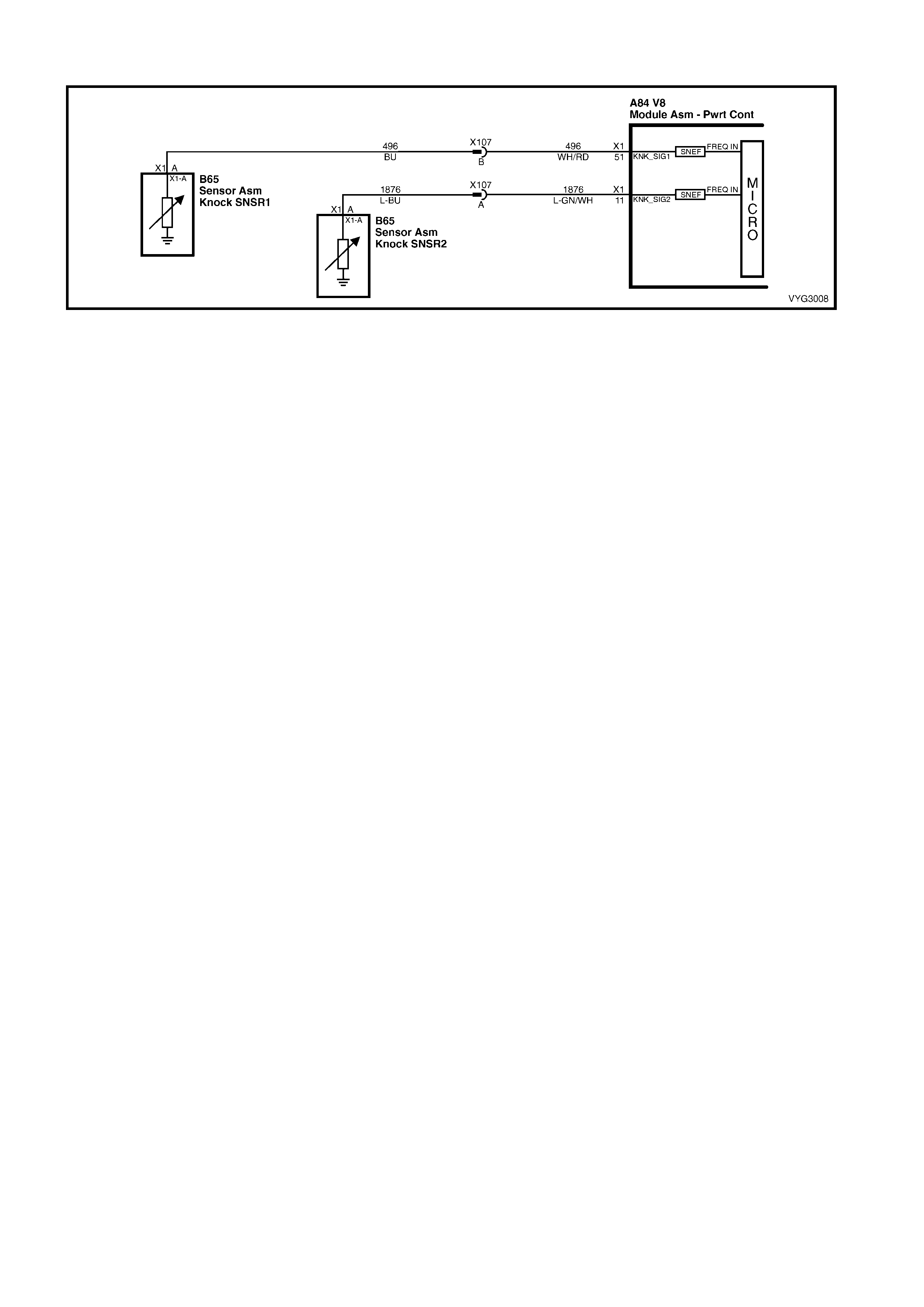
GEN III V8 PCM – DTC P0332 KNOCK SENSOR CIRCUIT REAR SENSOR
Figure 6C3-2A-88 – Knock Sensor Circuits
CIRCUIT DESCRIPTION
The Knoc k Sensor (KS) system detects engine detonation. The PCM retar ds the spark timing bas ed on the signals
from the knock sensors. The Knock Sensors produce an AC voltage. The Knock Sensor voltages are an input to
the PCM. The amount of AC voltage produced is proportional to the amount of knock.
An operating engine produces a normal amount of engine mechanical vibration (noise). The Knock Sensors
produce an AC voltage signal from this noise. When an engine operates, the PCM learns the minimum and
maximum frequency of the noise the engine produces. W hen the PCM determ ines that this frequency is less than
or greater than the expected amount, DTC P0332 will set.
CONDITIONS FOR RUNNING THE DTC
• The engine run time is greater than 20 seconds.
• The engine speed is between 1650 and 3000 RPM.
• The MAP is at or about 48 kPa.
• The engine coolant temperature is greater than 70° C.
• The throttle angle is greater than 0.5% and steady.
• Battery voltage is between 10 and 16 volts.
CONDITIONS FOR SETTING THE DTC
• The PCM determines that the frequency is less than or greater than the expected amount for at least three
seconds.
ACTION TAKEN WHEN THE DTC SETS
• The PCM activates the Check Powertrain MIL when the diagnostic runs and fails.
• The PCM records the operating conditions at the time the diagnostic fails. The PCM stores this information in
the Freeze Frame/Failure Records.
CONDITIONS FOR CLEARING THE MIL/DTC
• The PCM deactivates the Check Powertrain MIL after one ignition cycle that the diagnostic runs and does not
fail.
• A last test failed (current DTC) clears when the diagnostic runs and does not fail.
• Use Tech 2 to clear the MIL/DTC.
DIAGNOSTIC AIDS
• Check the Knock Sensor for correct installation. A Knock Sensor that is loose or over torqued may cause the
DTC P0332 to set.
• For an intermittent, refer to Section 6C3-2B SYMPTOMS in this Section.
TEST DESCRIPTION
NOTE: The number(s) below refer to the step number(s) on the diagnostic table.
2. This verifies the malfunction is present. Tech 2 will display DTC Ran=Yes and Pass=Int.
3. If the failure is intermittent, this indicates the diagnostic passed this ignition cycle and failed this ignition cycle. At
this point, the resistance of the Knock Sensors should be verified to be in the correct range. If the Knock Sensor
resistances are correct, check the KS system wiring connections.
4. This test will isolate the Knock Sensor from the rest of the circuit. Tap on the engine block just below the intake
manifold between the timing chain cover and the valley cover.

A84-X1 (BLUE) B65 X107
Figure 6C3-2A-89
GEN III V8 PCM – DTC P0332 KNOCK SENSOR CIRCUIT REAR SENSOR
STEP ACTION VALUE YES NO
1. Was the "On-Board Diagnostic" (OBD) System Check
performed? Go to Step 2 Go to
OBD System
Check
in this Section.
2. IMPORTANT: If an engine knock can be heard, repair the
engine mechanical problem before proceeding with this
diagnostic.
5. Ignition ON, engine OFF.
6. Review the Freeze Frame/Failure Records data for
this DTC and observe the parameters.
3. Turn OFF the ignition for 15 seconds.
4. Start the engine.
5. Operate the vehicle, within the conditions required for
this diagnostic to run, and as close to the conditions
recorded in Freeze Frame/Failure Records as
possible. Special operating conditions that you need to
meet before the PCM will run this diagnostic, where
applicable, are listed in Conditions for Running the
DTC.
6. Select the Diagnostic Trouble Code (DTC) option, the
DTC Information option and the Failed This Ignition
option using Tech 2.
Does Tech 2 indicate that this DTC failed this ignition?
Go to Step Go to
Diagnostic Aids
3. 1. Disconnect the Knock Sensor electrical connector
X107 located behind the intake manifold.
2. Measure the resistance of the rear Knock Sensor by
connecting a DMM between the rear Knock Sensor
signal circuit 1876, on the sensor side, and the engine
block.
3. Set the DMM to the 400 kΩ scale.
Is the resistance of the Knock Sensor within the specified
range?
93 – 107 kΩ Go to Step 4 Go to Step 6
4. 1. Connect a DMM between the rear Knock Sensor
signal circuit 1876, on the sensor side, and the engine
block.
2. Set the DMM to the AC voltage scale.
3. Tap on the rear of the engine while observing the
signal indicated on the DMM.
Is any signal indicated on the DMM while tapping on the
engine near the Knock Sensor?
Go to Step 5 Go to Step 7
5. 1. Disconnect the PCM BLUE connector A84-X1.
2. Check the KS signal circuit between the PCM and the
Knock Sensor connector X107 for the following:
• An open.
• A short to voltage.
• A short to ground.
Was a problem found and corrected?
Go to Step 10 Go to Step 8

STEP ACTION VALUE YES NO
6. 1. Remove the intake manifold. Refer to 6A3 ENGINE
MECHANICAL.
2. Check for an open or a short to ground in the signal
circuit 1876 between the Knock Sensor jumper
harness connector, located at the rear of the intake
manifold, and the Knock Sensor connector.
Was a problem found and corrected?
Go to Step 10 Go to Step 7
7. 1. Replace the Knock Sensor. Refer to Knock Sensor
Replace in 6C3-3 SERVICE OPERATIONS.
Is the action complete?
Go to Step 10
8. 1. Check the KS signal circuit for a poor terminal
connection at the PCM connector A84-X1, terminal 11.
Was a problem found and corrected?
Go to Step 10 Go to Step 9
9. 1. Replace PCM. Refer to PCM Programming and
PCM/PIM/BCM Security Link Procedure, in 6C3-3
SERVICE OPERATIONS
Is action complete?
Go to Step 10 –
10. 1. Select the Diagnostic Trouble Code (DTC) option and
the Clear DTC Information option using Tech 2.
2. Idle the engine at the normal operating temperature.
3. Select the Diagnostic Trouble Code (DTC) option, the
DTC Information option and the Failed This Ignition
option using Tech 2.
4. Operate the vehicle, within the Conditions for Running
the DTC, as specified in the supporting text, if
applicable.
Does Tech 2 indicate that this DTC reset?
Go to Step 2 Go to Step 11
11. 1. Using Tech 2, check for any other DTCs.
Does Tech 2 display any DTCs that you have not
diagnosed?
Go to the
applicable DTC
table
System OK
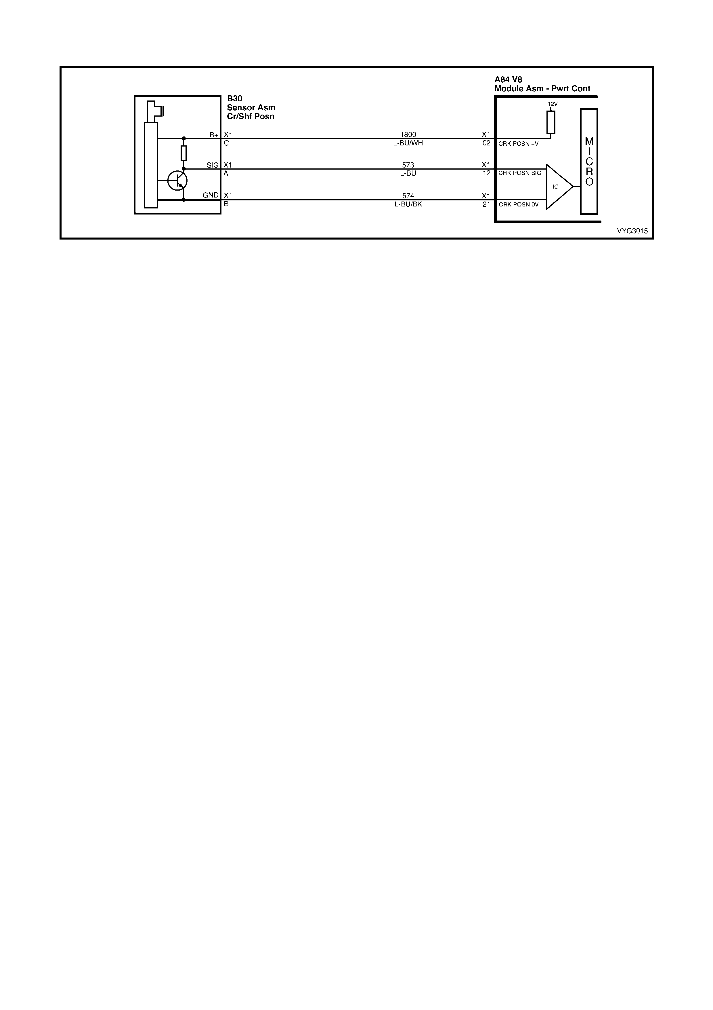
GEN III V8 PCM – DTC P0335 CRANKSHAFT POSITION SENSOR CIRCUIT
Figure 6C3-2A-90 – Crankshaft Position (CKP) Sensor
CIRCUIT DESCRIPTION
The Crank shaf t Position Sensor (CKP) is m ounted in the right rear of the engine block behind the starter. The CKP
Sensor work s in conj unction with a 24X reluc tor wheel m ounted on the rear of the crank s haft. T he CKP Sensor has
a B+ power supply, a ground, and a signal circuit.
As the crankshaft rotates, the reluctor wheel teeth interrupt a magnetic field produced by a magnet within the
sensor. T he s ensor’s internal circ uitry detects this and produces a signal which the PCM reads . The PCM us es this
signal to accurately measure crankshaft velocity which is a variable used to detect engine speed for spark and
fuelling.
CONDITIONS FOR RUNNING THE DTC
• DTCs P0101, P0102, P0103, P0341, P0342, P0343 are not set.
• The CMP sensor is transitioning.
• The ignition voltage is between 5 and 17.0 volts.
• The MAF is greater than 3 g/s.
CONDITIONS FOR SETTING THE DTC
• The PCM determines no signal from the CKP sensor for at least three seconds.
ACTION TAKEN WHEN THE DTC SETS
• The PCM activates the Check Powertrain MIL when the diagnostic runs and fails.
• The PCM records the operating conditions at the time the diagnostic fails. The PCM stores this information in
the Freeze Frame/Failure Records.
• The engine will not start.
CONDITIONS FOR CLEARING THE MIL/DTC
• The PCM deactivates the Check Powertrain MIL when the diagnostic runs and does not fail.
• A last test failed (current DTC) clears when the diagnostic runs and does not fail.
• Use Tech 2 to clear the MIL/DTC.
DIAGNOSTIC AIDS
• The following problems may cause this DTC to set:
– Poor connections/terminal tension at the sensor.
– Crankshaft reluctor wheel damage or improper installation.
– The sensor coming in contact with the reluctor wheel.
• Using Freeze Fram e/Failure Records data m ay aid in locating an intermittent condition. If you cannot duplicate
the DTC, the information included in the Freeze Frame/Failure Records data can aid in determining the distance
travelled s ince the DTC set. T he F ail Counter and Pass Counter can als o help in deter mining how many ignition
cycles the diagnostic r eported a pass and/or a fail. O perate the vehicle within the sam e f reeze fram e conditions
(RPM, load, vehicle speed, temperature etc.) that you observed. This will isolate when the DTC failed. For an
intermittent condition, refer to Section 6C3-2B SYMPTOMS in this Section .
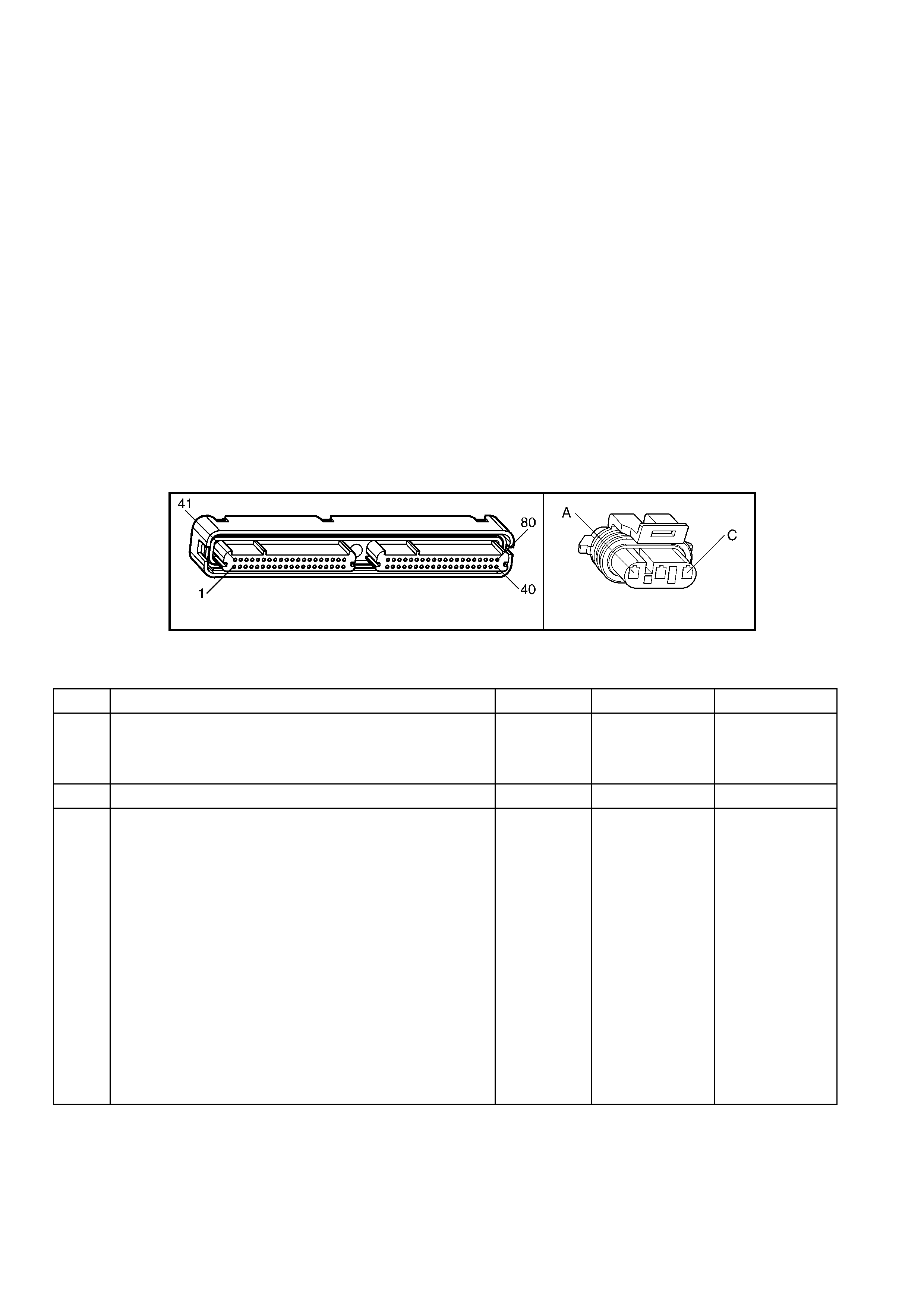
• Excess crankshaft end play will cause the CKP Sensor reluctor wheel to move out of alignment with the CKP
sensor. This could result in any one of the following:
– A no start
– A start and stall
– Erratic performance
An im proper ly installed propeller s haft could c ause exces s crank shaf t end play. Refer to Section 6A3 ENG INE
MECHANICAL – GEN III V8 ENGINE for excess crankshaft end play diagnosis.
• For an intermittent, refer to Section 6C3-2B SYMPTOMS in this Section .
TEST DESCRIPTION
NOTE: The number(s) below refer to the step number(s) on the diagnostic table.
3. This step determines if the fault is present.
6. T his st ep simulates a CKP Sens or s ignal to the PCM. If the PCM r eceives the s ignal, the f uel pump will operate
for about two s econds. If the fuel pum p operates , the pr oblem is either term inal c ontact at the CKP Sensor , the
CKP Sensor or, the CKP Sensor reluctor wheel.
7. This test determines if the CKP Sensor signal circuit or if the PCM is faulty.
12. To inspect the reluctor wheel, remove the starter and rotate the crankshaft while viewing the reluctor wheel
through the CKP Sensor hole. If you cannot determ ine if the r eluc tor wheel is damaged, the oil pan may have to
be removed.
15. Before replacing the PCM, check the PCM harness connections.
16. The repair is not complete if Tech 2 indicates that the diagnostic ran and failed.
A84–X1 (BLUE) B30
Figure 6C3-2A-91
GEN III V8 PCM – DTC P0335 CRANKSHAFT POSITION SENSOR CIRCUIT
STEP ACTION VALUE YES NO
1. Was the "On-Board Diagnostic" (OBD) System Check
performed? Go to Step 2 Go to
OBD System
Check
in this Section.
2. Does the engine start and continue to run? Go to Step 3 Go to Step 4
3. 1. Ignition ON, engine OFF.
2. Review the Freeze Frame/Failure Records data for
this DTC and observe the parameters.
3. Turn OFF the ignition for 15 seconds.
4. Start the engine.
5. Operate the vehicle within the conditions required for
this diagnostic to run, and as close to the conditions
recorded in Freeze Frame/Failure Records as
possible. Special operating conditions that you need to
meet before the PCM will run this diagnostic, where
applicable, are listed in Conditions for Running the
DTC.
6. Select the Diagnostic Trouble Code (DTC) option, the
DTC Information option and the Failed This Ignition
option using Tech 2
Does Tech 2 indicate that this diagnostic failed this
ignition?
Go to Step 4 Go to
Diagnostic Aids

STEP ACTION VALUE YES NO
4. Caution: Before proceeding, remove fuses F34 and F35
for the ignition coil and fuel injector feed circuits in
order to prevent personal injury from engine rotation,
sparks, and excessive engine fuelling.
1. Ignition ON, engine OFF.
2. Raise the vehicle and support on safety stands.
3. Disconnect the Crankshaft Position (CKP) Sensor.
4. Connect a test lamp to ground.
5. Probe the CKP Sensor ignition feed circuit 1800 at the
PCM side of CKP Sensor harness connector, B30.
Is the test lamp illuminated?
Go to Step 5 Go to Step 8
5. 1. Connect the test lamp between the CKP sensor
ignition feed circuit 1800 and the CKP sensor ground
circuit 574.
Is the test lamp illuminated?
Go to Step 6 Go to Step 9
6. 1. Momentarily connect the test lamp between the CKP
sensor signal circuit 573 and the CKP sensor ignition
feed circuit 1800.
Does the fuel pump operate when ignition voltage was
applied to the CKP sensor signal circuit?
Go to Step 11 Go to Step 7
7. 1. Connect the CKP sensor.
2. Disconnect the PCM BLUE connector, A84-X1.
3. Using test lead jumpers, from connector kit J 35616-A,
reconnect the reference Low and ignition feed circuits
(terminals X1-02 and X1-21) from the PCM harness to
PCM.
4. Probe the CKP sensor signal circuit 573 with a DMM
set to the 40 V AC scale using the brown jumper, from
connector kit J 35616-A.
5. Crank the engine.
Is the voltage within the specified range?
4.0 – 6.0 V Go to Step 15 Go to Step 10
8. 1. Check for an open or a short to ground in the CKP
ignition feed circuit.
Did you find and repair the condition?
Go to Step 16 Go to Step 15
9. 1. Check for an open or a poor connection in the CKP
ground circuit.
Did you find and repair the condition?
Go to Step 16 Go to Step 15
10. 1. Check the CKP Sensor signal circuit for the following:
• An open.
• A short to ground.
• A short to voltage.
Did you find and repair the condition?
Go to Step 16 Go to Step 11
11. 1. Remove the CKP Sensor and visually inspect the CKP
Sensor for the following conditions:
• Physical damage.
• Loose or improper installation.
• Wiring routed too closely to secondary ignition
components.
• Poor connections/terminal tension at the sensor.
Did you find and correct the condition?
Go to Step 16 Go to Step 12
12. 1. Visually inspect the CKP Sensor reluctor wheel for
damage.
Did you find and correct the condition?
Go to Step 16 Go to Step 13
13. 1. Check for poor connections/terminal tension at the
CKP sensor.
Did you find and correct the condition?
Go to Step 16 Go to Step 14
14. 1. Replace the CKP Sensor. Refer to Crankshaft Position
Sensor Replace, in 6C3-3 SERVICE OPERATIONS, in
this Section.
Go to Step 16 –

STEP ACTION VALUE YES NO
15. 1. Replace PCM. Refer to PCM Programming and
PCM/PIM/BCM Security Link Procedure, in 6C3-3
SERVICE OPERATIONS.
Is the action complete?
Go to Step 16 –
16. 1. Select the Diagnostic Trouble Code (DTC) option and
the Clear DTC Information option using Tech 2.
2. Idle the engine at the normal operating temperature.
3. Select the Diagnostic Trouble Code (DTC) option, the
DTC Information option and the Failed This Ignition
option using Tech 2.
4. Operate the vehicle, within the Conditions for Running
the DTC, as specified in the supporting text, if
applicable.
Does Tech 2 indicate that this DTC reset?
Go to Step 2 Go to Step 17
17. 1. Using Tech 2, check for any other DTCs.
Are any DTCs displayed that you have not diagnosed? Go to the
applicable DTC
table
System OK
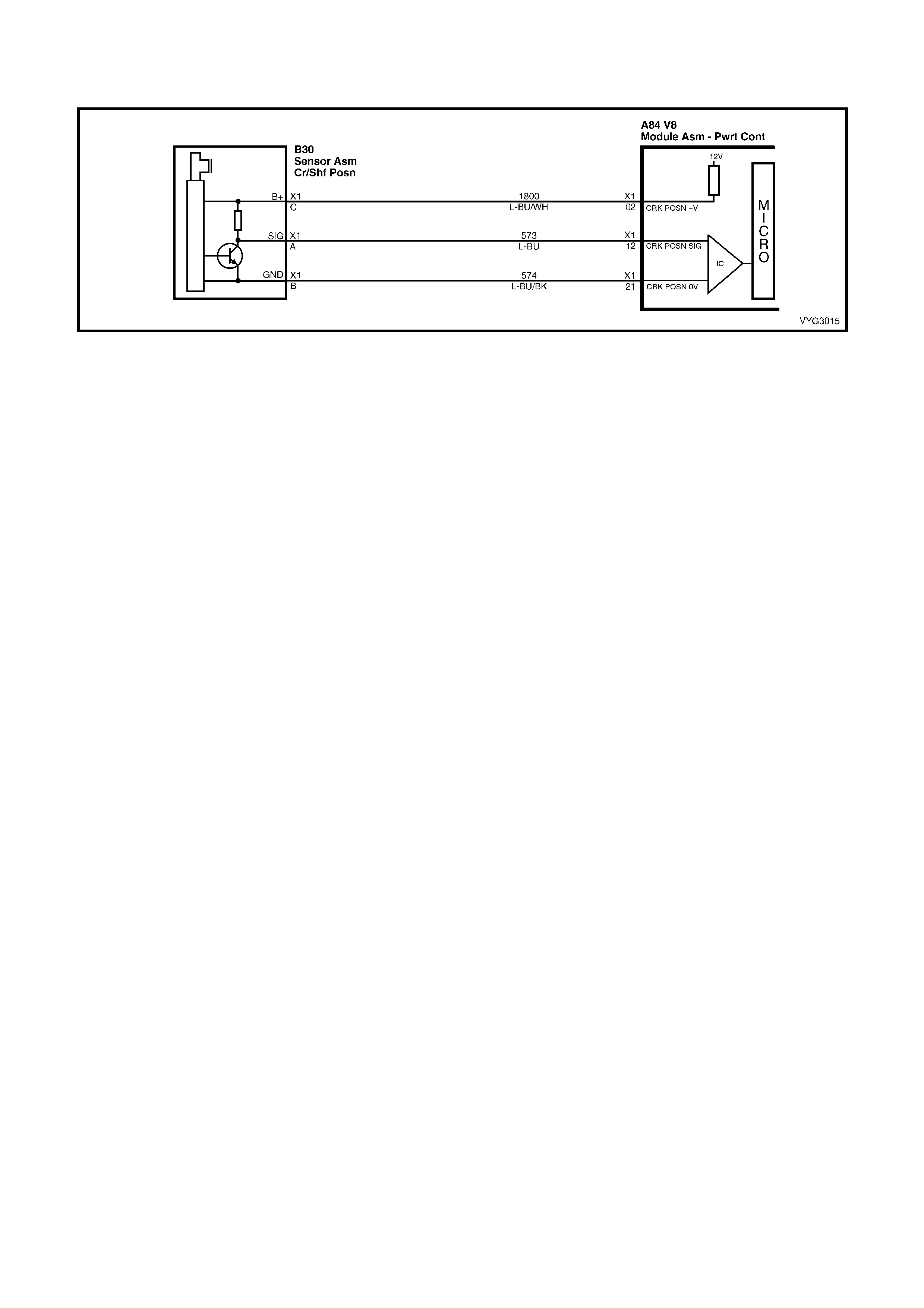
GEN III V8 PCM – DTC P0336 CRANKSHAFT POSITION SENSOR
CIRCUIT PERFORMANCE
Figure 6C3-2A-92 – Crankshaft Position (CKP) Sensor Circuit
CIRCUIT DESCRIPTION
The Crank shaf t Position Sensor (CKP) is m ounted in the right rear of the engine block behind the starter. The CKP
sensor work s in conj unction with a 24X reluctor wheel m ounted on the rear of the crank shaft. The CKP Sensor has
a B+ power supply, a ground, and a signal circuit.
As the crankshaft rotates, the reluctor wheel teeth interrupt a magnetic field produced by a magnet within the
sensor. T he s ensor’s internal circ uitry detects this and produces a signal which the PCM reads . The PCM us es this
signal to accurately measure crankshaft velocity, which is a variable used to detect engine speed for spark and
fuelling.
CONDITIONS FOR RUNNING THE DTC
• The ignition voltage is between 5 and 17.0 volts.
• The engine speed is greater than 400 RPM.
CONDITIONS FOR SETTING THE DTC
• The PCM determines no signal from the CKP sensor or the signal is out of range for at least one second.
ACTION TAKEN WHEN THE DTC SETS
• The PCM activates the Check Powertrain MIL when the diagnostic runs and fails.
• The PCM records the operating conditions at the time the diagnostic fails. The PCM stores this information in
the Freeze Frame/Failure Records.
CONDITIONS FOR CLEARING THE MIL/DTC
• The PCM deactivates the Check Powertrain MIL when the diagnostic runs and does not fail.
• A last test failed (current DTC) clears when the diagnostic runs and does not fail.
• Use Tech 2 to clear the MIL/DTC.
DIAGNOSTIC AIDS
• The following problems may cause this DTC to set:
– Poor connections/terminal tension at the sensor.
– Crankshaft reluctor wheel damage or improper installation.
– The sensor coming in contact with the reluctor wheel.
• If the crankshaft rotates backwards, this DTC will set but this condition only occurs with vehicles fitted with a
manual transmission. This condition can occur when a vehicle is on an incline and the clutch is released and
the engine stalls.
• Using Freeze Fram e/Failure Records data m ay aid in locating an intermittent condition. If you cannot duplicate
the DTC, the information included in the Freeze Frame/Failure Records data can aid in determining the distance
travelled since the DTC set. The Fail Counter and Pass Counter can also aid determining how many ignition
cycles the diagnostic r eported a pass and/or a fail. O perate the vehicle within the sam e f reeze fram e conditions
(RPM, load, vehicle speed, temperature etc.) that you observed. This will isolate when the DTC failed.
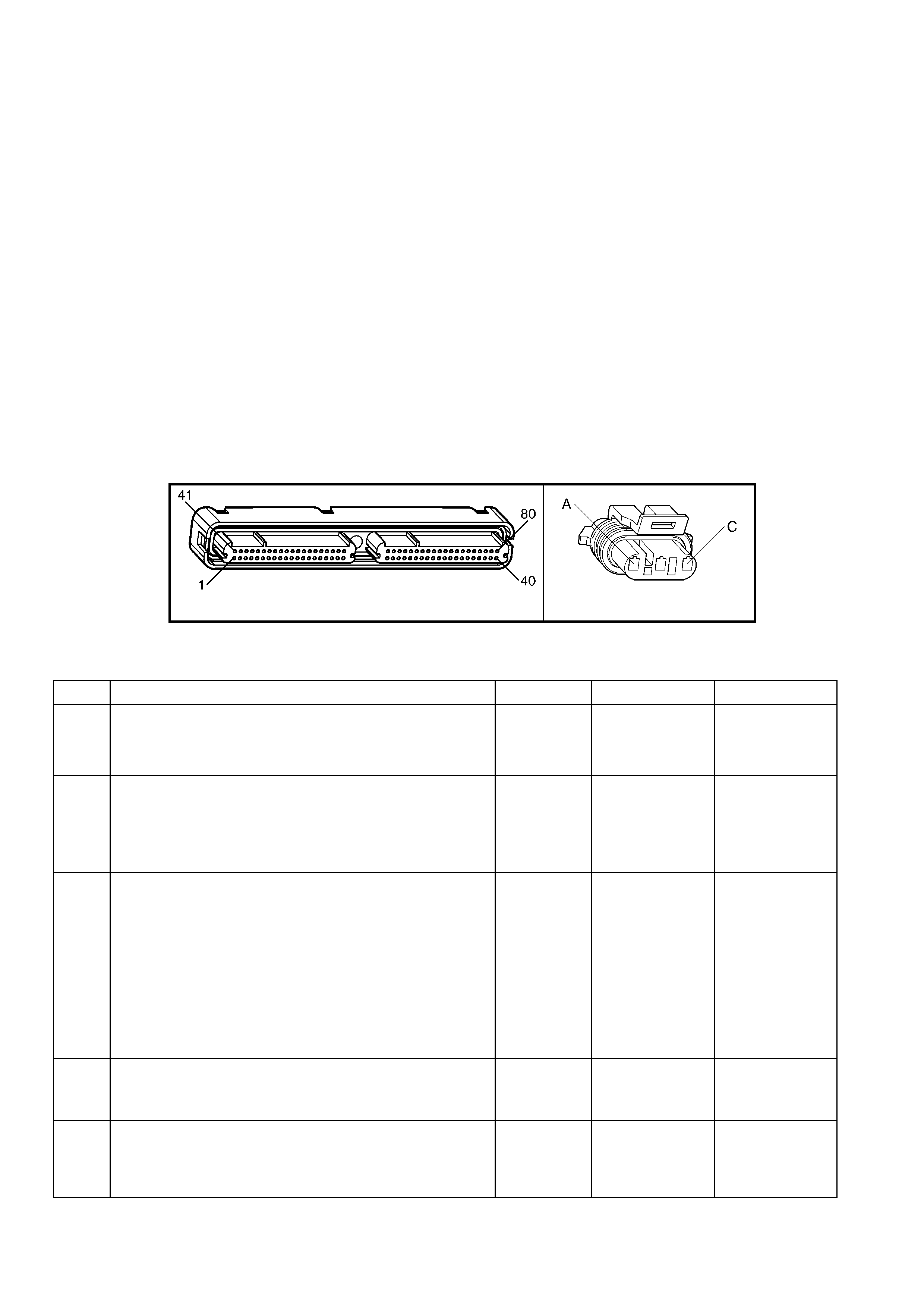
• Excess crankshaft end play will cause the CKP Sensor reluctor wheel to move out of alignment with the CKP
Sensor. This could result in any one of the following:
– A no start.
– A start and stall.
– Erratic performance.
An im proper ly installed propeller s haft could c ause exces s crank shaf t end play. Refer to Section 6A3 ENG INE
MECHANICAL in MY 2003 VY and V2 Series Service Information for excess crankshaft end play diagnosis.
• For an intermittent, refer to Section 6C3-2B SYMPTOMS in this Section .
TEST DESCRIPTION
NOTE: The number(s) below refer to the step number(s) on the diagnostic table.
2. This step verifies that the malfunction is present.
3. This step checks for EMI (Electro Magnetic Interference) on the CKP sensor circuits.
6. Vertical lines across the face of the sensor could indicate foreign material passing between the CKP Sensor
and the reluctor wheel. Non vertic al lines acr os s the f ac e of the s ensor may indicate a crack in the CKP Sensor.
Either of these conditions causes this DTC to set
7. Damage to the reluctor wheel would affect the CKP Sensor output. To inspect the reluctor wheel, remove the
starter and rotate the crankshaft while viewing the reluctor wheel through the CKP sensor hole. If you cannot
determ ine if the r eluctor wheel is dam aged, the oil pan m ay have to be rem oved. If this condition exists, refer to
Section 6A3 ENGINE MECHANICAL in MY 2003 VY and V2 Series Service Information for crankshaft
replacement.
A84–X1 (BLUE) B30
Figure 6C3-2A-93
GEN III V8 PCM – DTC P0336 CRANKSHAFT POSITION SENSOR CIRCUIT PERFORMANCE
STEP ACTION VALUE YES NO
1. Was the "On-Board Diagnostic" (OBD) System Check
performed? Go to Step 2 Go to
OBD System
Check
in this Section.
2. IMPORTANT: IF DTC P0335 is also set, diagnose DTC
P0335 before proceeding with this DTC.
1. Install Tech 2.
2. Idle the engine for 2 minutes.
Does Tech 2 indicate that DTC P0336 failed this ignition?
Go to Step 3 Intermittent
condition. Refer
to Diagnostic
Aids
3. 1. Visually inspect all circuits going to the Crankshaft
Position Sensor for the following:
– Routed too close to secondary ignition wires or
components.
– Routed too close to after-market add on electrical
equipment.
– Routed too close to solenoids, relays and motors.
2. If you find incorrect routing, correct the harness
routing.
Did you find and correct the condition?
Go to Step 9 Go to Step 4
4. 1. Check the terminal contact at the CKP Sensor.
2. Repair/replace the terminal if you find a problem.
Did you find and correct the condition?
Go to Step 9 Go to Step 5
5. 1. Check the terminal contact at the PCM for the CKP
Sensor circuits.
2. Repair/replace the terminal if you find a problem.
Did you find and correct the condition?
Go to Step 9 Go to Step 6

STEP ACTION VALUE YES NO
6. 1. Remove the CKP Sensor. Refer to Crankshaft Position
Sensor Replace, in 6C3-3 SERVICE OPERATIONS in
this Section .
2. Inspect the CKP Sensor for signs of damage.
Did you find and correct the condition?
Go to Section
6A3 ENGINE
MECHANICAL.
Go to Step 7
7. 1. Inspect the CKP reluctor wheel for damage.
Did you find and correct the condition?
Go to Section
6A3 ENGINE
MECHANICAL
Go to Step 8
8. 1. Replace the CKP Sensor. Refer to Crankshaft Position
Sensor Replace, in 6C3-3 SERVICE OPERATIONS in
this Section .
Is the action complete?
Go to Step 9 –
9. 1. Select the Diagnostic Trouble Code (DTC) option and
the Clear DTC Information option using Tech 2.
2. Idle the engine at the normal operating temperature.
3. Select the Diagnostic Trouble Code (DTC) option, the
DTC Information option and the Failed This Ignition
option using Tech 2.
4. Operate the vehicle, within the Conditions for Running
the DTC, as specified in the supporting text, if
applicable.
Does Tech 2 indicate that this DTC reset?
Go to Step 2 Go to Step 10
10. 1. Using Tech 2, check for any other DTCs.
Does Tech 2 display any DTCs that you have not
diagnosed?
Go to the
applicable DTC
table
System OK

GEN III V8 PCM – DTC P0341 CAMSHAFT POSITION SENSOR CIRCUIT PERFORMANCE
Figure 6C3-2A-94 – Camshaft Position (CMP) Sensor
CIRCUIT DESCRIPTION
The Camshaft Position sensor is mounted through the top of the engine block at the rear of the valley cover. The
CMP sensor work s in conj unction with a 1X reluctor wheel on the cam shaft. The reluc tor wheel is inside the engine
imm ediately in front of the rear cam bearing. T he PCM provides a 12 volt power supply to the CMP sensor as well
as a ground and a signal circuit.
The CMP sensor determines whether a cylinder is on a firing stroke or on an exhaust stroke. As the camshaft
rotates, the reluc tor wheel interrupts a m agnetic f ield produced by a magnet within the sensor. T he sens ors inter nal
circuitr y detects this and pr oduces a signal which the PCM reads . T he PCM uses this 1X signal in c om bination with
the Crankshaft Position sensor 24X signal in order to determ ine crankshaft position and stroke. This diagnostic for
the Camshaft Position sensor checks for a loss of Camshaft Position sensor signal.
Observe that as long as the 24X signal is available, the engine starts even if there is no Camshaft Position sensor
signal. The PCM can determine when a particular cylinder is on either a firing or exhaust stroke by the 24X signal
alone, but the PCM requires the cam signal in order to determine which (firing or exhaust). The system attempts
synchronisation and looks for an incr ease in MAF signal indicating the engine started. If the PCM does not detect a
MAF increase, the PCM assumes it incorrectly synchronised to the exhaust stroke and re-synchs to the opposite
cam position. A slightly longer cranking time may be a symptom of this condition.
CONDITIONS FOR RUNNING THE DTC
• The ignition voltage is between 5 and 17.0 volts.
• The engine speed is greater than 400 RPM.
CONDITIONS FOR SETTING THE DTC
• The PCM detects that a CMP to CKP mismatch has occurred for at least 10 seconds.
ACTION TAKEN WHEN THE DTC SETS
• The PCM activates the Check Powertrain MIL when the diagnostic runs and fails.
• The PCM records the operating conditions at the time the diagnostic fails. The PCM stores this information in
the Freeze Frame/Failure Records.
CONDITIONS FOR CLEARING THE MIL/DTC
• The PCM deactivates the Check Powertrain MIL when the diagnostic runs and does not fail.
• A last test failed (current DTC) clears when the diagnostic runs and does not fail.
• Use Tech 2 to clear the MIL/DTC.
DIAGNOSTIC AIDS
• The following mechanical problems may cause this DTC to set:
– Poor connections/terminal tension at the sensor.
– Camshaft reluctor wheel damage.
– The sensor coming in contact with the reluctor wheel.
• Using Freeze Fram e/Failure Records data m ay aid in locating an intermittent condition. If you cannot duplicate
the DTC, the information included in the Freeze Frame/Failure Records data can aid in determining the distance
travelled since the DTC set. The Fail Counter and Pass Counter can also aid determining how many ignition
cycles the diagnostic r eported a pass and/or a fail. O perate the vehicle within the sam e f reeze fram e conditions
(RPM, load, vehicle speed, temperature etc.) that you observed. This will isolate when the DTC failed.
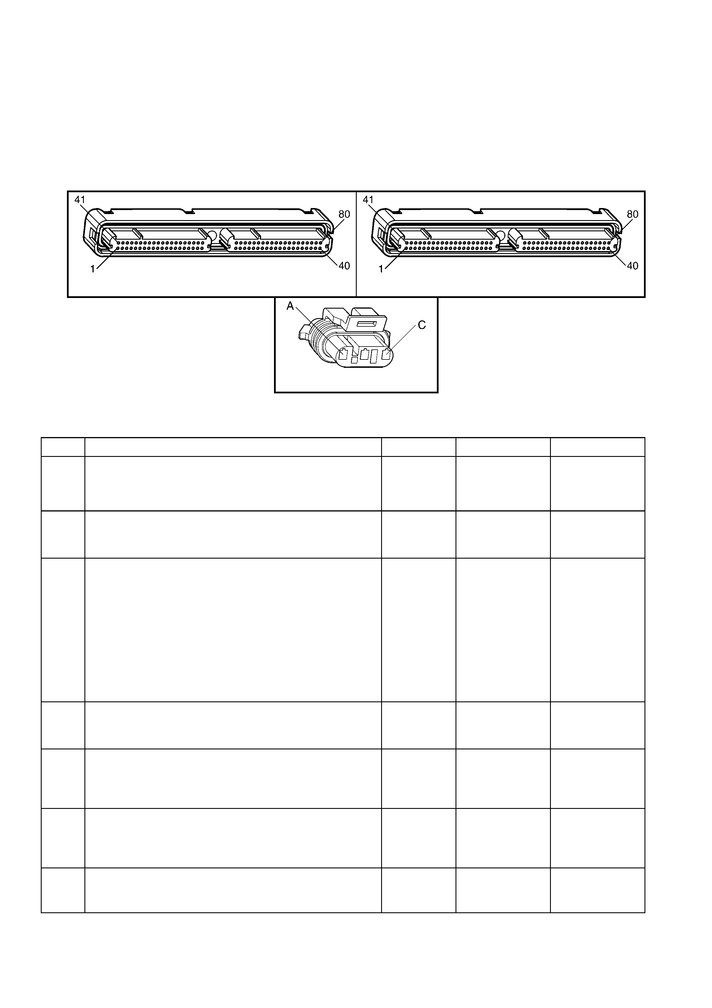
TEST DESCRIPTION
NOTE: The number(s) below refer to the step number(s) on the diagnostic table.
2. This step verifies that the malfunction is present.
3. This step checks for EMI (Electro Magnetic Interference) on the CMP sensor circuits.
6. Vertical lines across the face of the sensor could indicate foreign material passing between the CMP sensor
and the reluctor wheel. This condition could cause this DTC to set.
7. Damage to the reluctor ring would affect the CMP sensor output. If this condition exists, refer to
Section 6A3 ENGINE MECHANICAL in the MY 2003 VY and V2 Series Service Information for camshaft
replacement procedures.
A84–X1 (BLUE) A84-X2 (RED)
B28
Figure 6C3-2A-95
GEN III V8 PCM – DTC P0341 CAMSHAFT POSITION SENSOR CIRCUIT PERFORMA NCE
STEP ACTION VALUE YES NO
1. Was the "On-Board Diagnostic" (OBD) System Check
performed? Go to Step 2 Go to
OBD System
Check
in this Section.
2. 1. Install Tech 2.
2. Idle the engine for 2 minutes.
Does Tech 2 indicate that DTC P0341 failed this ignition?
Go to Step 3 Go to
Diagnostic Aids
3. 1. Inspect all Camshaft Position sensor circuits for the
following:
– Routed too close to secondary ignition wires or
components
– Routed too close to after-market add on electrical
equipment
– Routed too close to solenoids, relays and motors
2. If you find incorrect routing, correct the harness
routing.
Did you find and correct the condition?
Go to Step 9 Go to Step 4
4. 1. Check the terminal contact at the CMP sensor.
2. If you find a problem, repair/replace the terminal(s).
Did you find and correct the condition?
Go to Step 9 Go to Step 5
5. 1. Check the terminal contact at the PCM for the CMP
sensor circuits.
2. Repair/replace the terminal if you find a problem.
Did you find and correct the condition?
Go to Step 9 Go to Step 6
6. 1. Remove the CMP sensor. Refer to Camshaft Position
Sensor Replace in 6C3-3 SERVICE OPERATIONS.
2. Inspect the CMP sensor for signs of damage.
Did you find and correct the condition?
Go To Section
6A3 ENGINE
MECHANICAL
Go to Step 7
7. 1. Inspect the CMP reluctor ring for damage.
Did you find and correct the condition?
Go To Section
6A3 ENGINE
MECHANICAL
Go to Step 8

STEP ACTION VALUE YES NO
8. 1. Replace the CMP Sensor. Refer to Camshaft Position
Sensor Replace in 6C3-3 SERVICE OPERATIONS.
Is the action complete?
Go to Step 9 –
9. 1. Select the Diagnostic Trouble Code (DTC) option and
the Clear DTC Information option using Tech 2.
2. Idle the engine at the normal operating temperature.
3. Select the Diagnostic Trouble Code (DTC) option, the
DTC Information, the Failed This Ignition using Tech 2.
4. Operate the vehicle within the Conditions for Running
the DTC as specified in the supporting text, if
applicable.
Does Tech 2 indicate that this DTC reset?
Go to Step 2 Go to Step 10
10. 1. Using Tech 2, check for any other DTCs.
Does Tech 2 display any DTCs that you have not
diagnosed?
Go to the
applicable DTC
table
System OK

GEN III V8 PCM – DTC P0342 CAMSHAFT POSITION SENSOR CIRCUIT LOW VOLTAGE
Figure 6C3-2A-96 – Camshaft Position (CMP) Sensor
CIRCUIT DESCRIPTION
The Camshaft Position sensor is mounted through the top of the engine block at the rear of the valley cover. The
CMP sensor works in conjunction with a 1X reluctor ring on the camshaft. The reluctor ring is inside the engine
imm ediately in front of the rear cam bearing. T he PCM provides a 12 volt power supply to the CMP sensor as well
as a ground and a signal circuit.
The CMP sensor determines whether a cylinder is on a firing stroke or on an exhaust stroke. As the camshaft
rotates, the reluctor ring interrupts a magnetic field produced by a magnet within the sensor. The sensors internal
circuitr y detects this and pr oduc es a s ignal, which the PCM reads . The PCM uses this 1X s ignal in combination with
the Crankshaft Position sensor 24X signal in order to determ ine crankshaft position and stroke. This diagnostic for
the Camshaft Position sensor checks for a loss of Camshaft Position sensor signal.
Note that, as long as the 24X signal is available, the engine will start even if there is no Camshaft Position sensor
signal. The PCM can determine when a particular cylinder is on either a firing or exhaust stroke by the 24X signal
alone, but the PCM requires the cam signal in order to determine which (firing or exhaust). The system attempts
synchronisation and looks for an incr ease in MAF signal indicating the engine started. If the PCM does not detect a
MAF increase, the PCM assumes it incorrectly synchronised to the exhaust stroke and re-synchronises to the
opposite cam position. A slightly longer cranking time may be a symptom of this condition.
CONDITIONS FOR RUNNING THE DTC
• The ignition voltage is between 5 and 17.0 volts.
• The engine speed is greater than 400 RPM.
CONDITIONS FOR SETTING THE DTC
• The PCM detects the CMP sensor signal is low when the signal should be high for at least one second.
ACTION TAKEN WHEN THE DTC SETS
• The PCM activates the Malfunction Indicator Lamp (MIL) when the diagnostic runs and fails.
• The PCM records the operating conditions at the time the diagnostic fails. The PCM stores this information in
the Freeze Frame/Failure Records.
CONDITIONS FOR CLEARING THE MIL/DTC
• The PCM deactivates the Malfunction Indicator Lamp (MIL) when the diagnostic runs and does not fail.
• A last test failed (current DTC) clears when the diagnostic runs and does not fail.
• Use Tech 2 to clear the MIL/DTC.
DIAGNOSTIC AIDS
• The following mechanical problems may cause this DTC to set:
– Poor connections/terminal tension at the sensor.
– Camshaft reluctor ring damage.
– The sensor coming in contact with the reluctor ring.
• Using Freeze Fram e/Failure Records data m ay aid in locating an intermittent condition. If you cannot duplicate
the DTC, the information included in the Freeze Frame/Failure Records data can aid in determining the
distance travelled since the DTC set. The Fail Counter and Pass Counter can also aid determining how many
ignition cycles the diagnostic reported a pass and/or a fail. Operate the vehicle within the same freeze frame
conditions (RPM, load, vehicle speed, temperature etc.) that you observed. This will isolate when the DTC
failed.
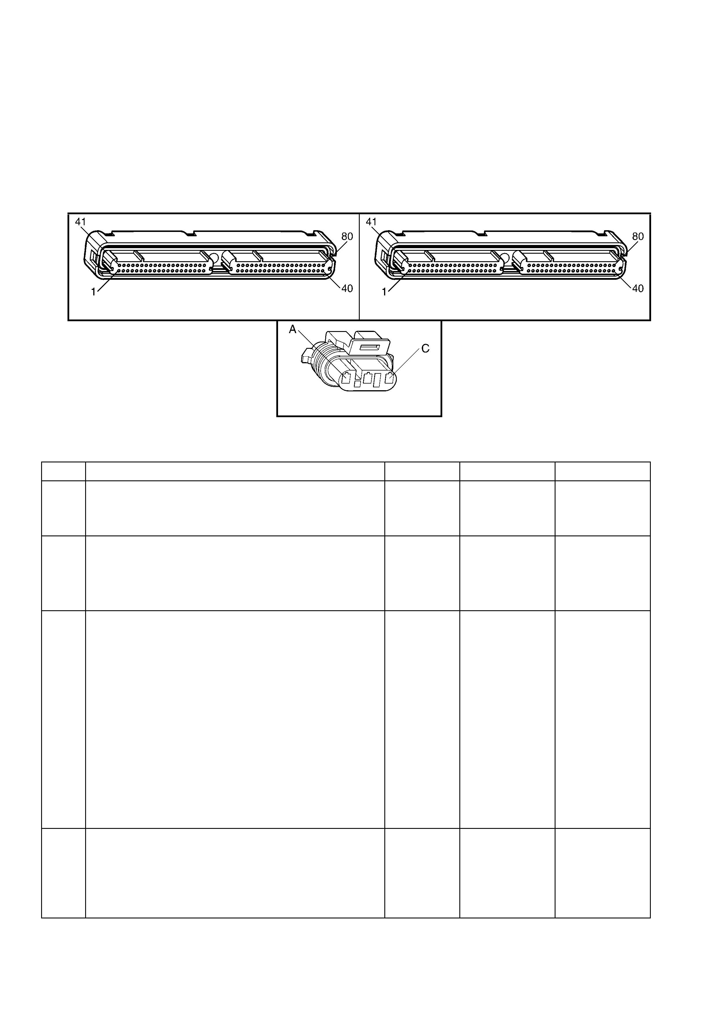
TEST DESCRIPTION
NOTE: The number(s) below refer to the step number(s) on the diagnostic table.
2. This step verifies that the fault is present. The Camshaft activity counter will start at 0 with key ON, then
increment up to 65535 then back to 0 and increment up again.
4. This step tests the Camshaft Position sensor ignition feed circuit from the PCM to the CMP.
5. This step checks the Camshaft Position sensor ground circuit from the PCM to the CMP.
6. T his step chec k s the Cam shaf t Position sens or signal c ircuit. Applying a voltage causes the CAM signal activity
counter to increment.
7. This step checks the continuity of the Camshaft Position sensor ignition feed circuit from the PCM to the CMP.
9. This step checks the continuity of the Camshaft Position sensor ground circuit from the PCM to the CMP.
A84–X1 (BLUE) A84-X2 (RED)
B28
Figure 6C3-2A-97
GEN III V8 PCM – DTC P0342 CAMSHAFT POSITION SENSOR CIRCUIT LOW VOLTAGE
STEP ACTION VALUE YES NO
1. Was the "On-Board Diagnostic" (OBD) System Check
performed? Go to Step 2 Go to
OBD System
Check
in this Section.
2. 1. Install Tech 2.
2. Idle the engine.
3. Monitor the CAM signal activity counter in the Tech 2
Engine Data List.
Does the Tech 2 parameter increment?
Go to Step 3 Go to Step 4
3. 1. Ignition ON, engine OFF.
2. Review the Freeze Frame/Failure Records data for
this DTC and observe the parameters.
3. Turn OFF the ignition for 15 seconds.
4. Idle the engine.
5. Operate the vehicle within the conditions required for
this diagnostic to run, and as close to the conditions
recorded in Freeze Frame/Failure Records as
possible. Special operating conditions that you need to
meet before the PCM will run this diagnostic, where
applicable, are listed in Conditions for Running the
DTC.
6. Select the Diagnostic Trouble Code (DTC) option, the
DTC Information, the Failed This Ignition using Tech 2.
Does Tech 2 indicate that this diagnostic failed this
ignition?
Go to Step 4 Refer to
Diagnostic Aids
4. 1. Ignition OFF.
2. Disconnect the Camshaft Position Sensor (CMP).
3. Ignition ON, engine OFF.
4. Measure the Camshaft Position sensor ignition feed
voltage using a DMM at B28 X1-C.
Does the DMM display near the specified value?
B+ Go to Step 5 Go to Step 7

STEP ACTION VALUE YES NO
5. 1. Measure the Camshaft Position sensor ignition feed
circuit 631 to the Camshaft Position sensor ground
circuit 632 using a DMM.
Does the DMM display the specified voltage?
B+ Go to Step 6 Go to Step 9
6. 1. Start the engine.
2. Monitor the CAM signal activity counter in the Tech 2
Engine Data List.
3. Momentarily and repeatedly probe the signal circuit
with a test lamp connected to B+.
Does the CAM signal activity counter increment when the
test lamp contacts the signal circuit?
Go to Step 15 Go to Step 10
7. 1. Ignition OFF.
2. Disconnect the PCM RED connector A84-X2.
3. Test the continuity of the CMP ignition feed circuit 631
using a DMM.
Is there continuity and is the resistance within the specified
range?
0 – 5 Ω Go to Step 8 Go to Step 12
8. 1. Inspect the CMP ignition feed circuit 631 for the
following:
– A grounded circuit.
– A poor connection.
Did you find and correct the condition?
Go to Step 19 Go to Step 16
9. 1. Ignition OFF.
2. Disconnect the PCM BLUE connector A84-X1.
3. Test the continuity of the CMP ground circuit 632
using a DMM.
Is there continuity and is the resistance within the specified
range?
0 – 5 Ω Go to Step 16 Go to Step 13
10. 1. Ignition OFF.
2. Disconnect the PCM BLUE connector A84-X1.
3. Test the continuity of the CMP signal circuit 633 using
a DMM.
Is there continuity and is the resistance within the specified
range?
0 – 5 Ω Go to Step 11 Go to Step 14
11. 1. Ignition ON, engine OFF.
2. Test the CMP signal circuit for the following:
– A grounded circuit.
– A circuit shorted to a voltage.
Did you find and correct the condition?
Go to Step 19 Go to Step 16
12. 1. Repair open in circuit 631 between PCM and
connector B28 X1-C.
Is action complete?
Go to Step 19 –
13. 1. Check for open in the CMP ground circuit 632.
Was a problem found? Go to Step 19 Go to Step 16
14. 1. Repair open in the CMP signal circuit.
Is the action complete? Go to Step 19 –
15. 1. Inspect for poor connections at the CMP harness
connector.
2. If you find a poor connection repair the connector as
necessary.
Did you find and correct the condition?
Go to Step 19 Go to Step 17
16. 1. Inspect the PCM harness connector for poor
connections.
2. If you find a poor connection repair the connector as
necessary.
Did you find and correct the condition?
Go to Step 19 Go to Step 18
17. 1. Replace the CMP sensor. Refer to Camshaft Position
Sensor Replace in 6C3-3 SERVICE OPERATIONS.
Is action complete?
Go to Step 19 –

STEP ACTION VALUE YES NO
18. 1. Replace PCM. Refer to PCM Programming and
PCM/PIM/BCM Security Link Procedure, in 6C3-3
SERVICE OPERATIONS.
Is action complete?
Go to Step 19 –
19. 1. Select the Diagnostic Trouble Code (DTC) option and
the Clear DTC Information option using Tech 2.
2. Idle the engine at the normal operating temperature.
3. Select the Diagnostic Trouble Code (DTC) option, the
DTC Information, the Failed This Ignition using Tech 2.
4. Operate the vehicle within the Conditions for Running
the DTC as specified in the supporting text, if
applicable.
Does Tech 2 indicate that this DTC reset?
Go to Step 2 Go to Step 20
20. 1. Using Tech 2, check for any other DTCs.
Does Tech 2 display any DTCs that you have not
diagnosed?
Go to applicable
DTC Table System OK
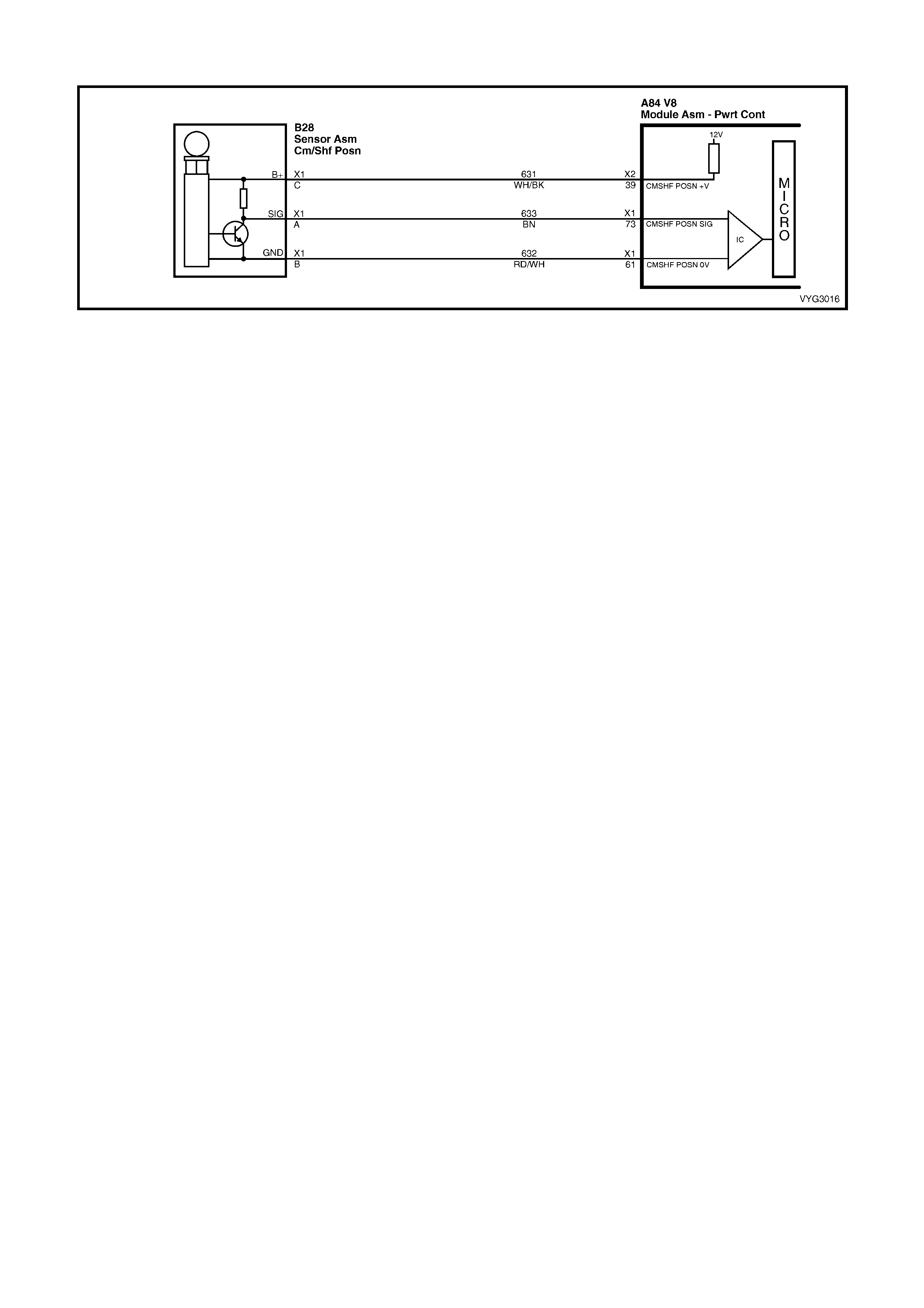
GEN III V8 PCM – DTC P0343 CAMSHAFT POSITION SENSOR CIRCUIT HIGH VOLTAGE
Figure 6C3-2A-98 – Camshaft Position (CMP) Sensor
CIRCUIT DESCRIPTION
The Camshaf t Pos ition ( CMP) Sens or is mounted thr ough the top of the engine bloc k at the r ear of the valley cover.
The CMP s ensor work s in c onjunction with a 1X r eluctor r ing on the cam shaf t. T he reluctor r ing is inside the engine
imm ediately in front of the rear cam bearing. T he PCM provides a 12 volt power supply to the CMP sensor as well
as a ground and a signal circuit.
The CMP sensor determines whether a cylinder is on a firing stroke or on an exhaust stroke. As the camshaft
rotates, the reluctor ring interrupts a magnetic field produced by a magnet within the sensor. The sensors internal
circuitr y detects this and pr oduc es a s ignal, which the PCM reads . The PCM uses this 1X s ignal in combination with
the Crankshaft Position sensor 24X signal in order to determ ine crankshaft position and stroke. This diagnostic for
the Camshaft Position sensor checks for a loss of Camshaft Position sensor signal.
Note that, as long as the 24X signal is available, the engine will star t, even if there is no Cam shaft Position sens or
signal. The PCM can determine when a particular cylinder is on either a firing or exhaust stroke by the 24X signal
alone, but the PCM requires the cam signal in order to determine which (firing or exhaust). The system attempts
synchronisation and looks for an incr ease in MAF signal indicating the engine started. If the PCM does not detect a
MAF increase, the PCM assumes it incorrectly synchronised to the exhaust stroke and re-synchronises to the
opposite cam position. A slightly longer cranking time may be a symptom of this condition.
CONDITIONS FOR RUNNING THE DTC
• The ignition voltage is between 5 and 17.0 volts.
• The engine speed is greater than 400 RPM.
CONDITIONS FOR SETTING THE DTC
• The PCM detects the CMP sensor signal is stuck high when the signal should be low for at least one second.
ACTION TAKEN WHEN THE DTC SETS
• The PCM activates the Check Powertrain MIL when the diagnostic runs and fails.
• The PCM records the operating conditions at the time the diagnostic fails. The PCM stores this information in
the Freeze Frame/Failure Records.
CONDITIONS FOR CLEARING THE MIL/DTC
• The PCM deactivates the Check Powertrain MIL when the diagnostic runs and does not fail.
• A last test failed (current DTC) clears when the diagnostic runs and does not fail.
• Use Tech 2 to clear the MIL/DTC.
DIAGNOSTIC AIDS
• The following mechanical problems may cause this DTC to set:
– Poor connections/terminal tension at the sensor.
– Camshaft reluctor wheel damage.
– The sensor coming in contact with the reluctor ring.
• Using Freeze Fram e/Failure Records data m ay aid in locating an intermittent condition. If you cannot duplicate
the DTC, the information included in the Freeze Frame/Failure Records data can aid in determining the
distance travelled since the DTC set. The Fail Counter and Pass Counter can also aid determining how many
ignition cycles the diagnostic reported a pass and/or a fail. Operate the vehicle within the same freeze frame
conditions (RPM, load, vehicle speed, temperature etc.) that you observed. This will isolate when the DTC
failed.
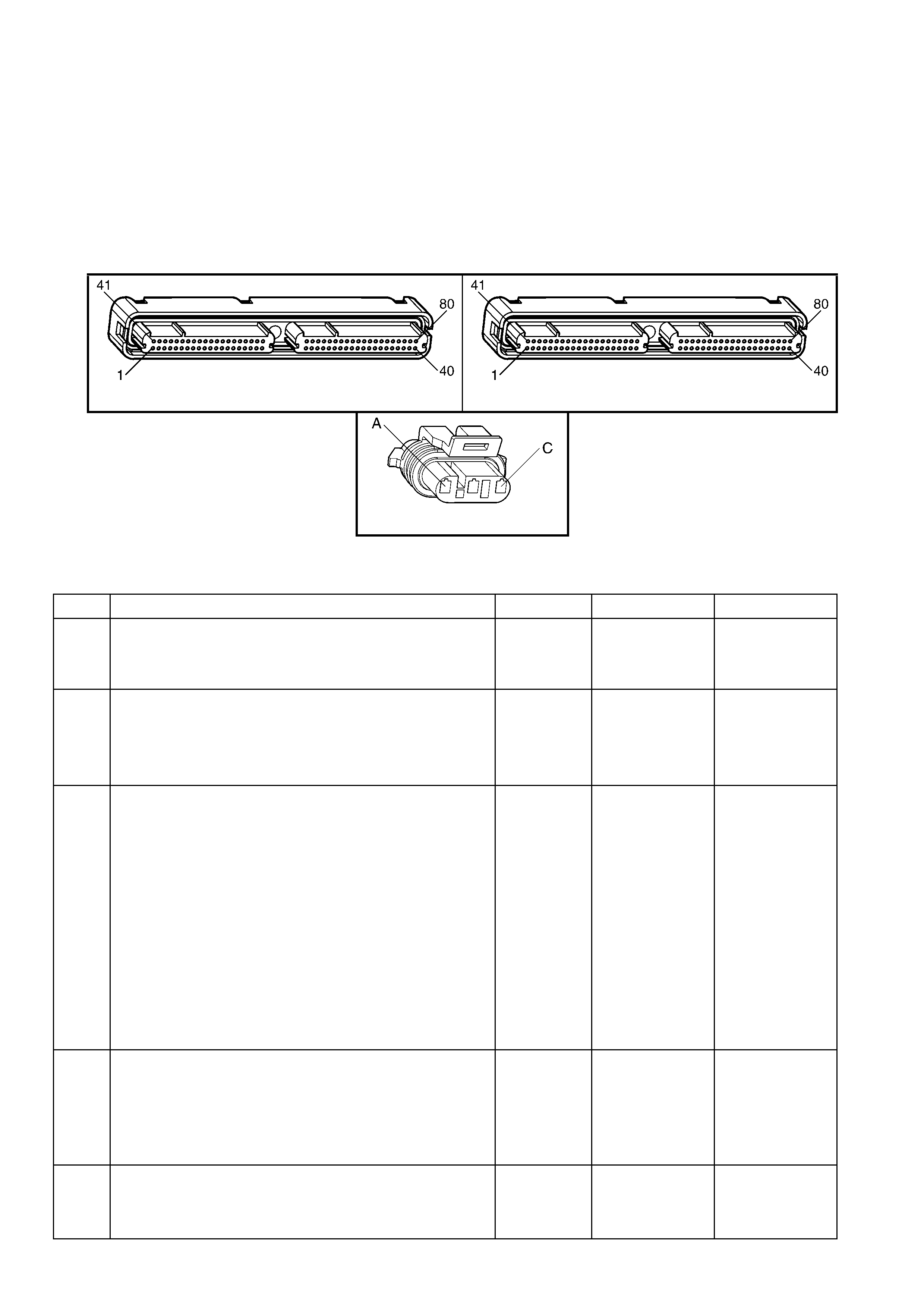
TEST DESCRIPTION
NOTE: The number(s) below refer to the step number(s) on the diagnostic table.
2. This step verifies that the fault is present. The Camshaft activity counter will start at 0 with key ON, then
increment up to 65535 then back to 0 and increment up again.
4. This step tests the Camshaft Position sensor ignition feed circuit from the PCM to the CMP.
5. This step checks the Camshaft Position sensor ground circuit from the PCM to the CMP.
6. T his step chec k s the Cam shaf t Position sens or signal c ircuit. Applying a voltage causes the CAM signal activity
counter to increment.
7. This step checks the Camshaft Position sensor ignition feed circuit from the PCM to the CMP.
9. This step checks the Camshaft Position sensor ground circuit from the PCM to the CMP.
A84–X1 (BLUE) A84-X2 (RED)
B28
Figure 6C3-2A-99
GEN III V8 PCM – DTC P0343 CAMSHAFT POSITION SENSOR CIRCUIT HIGH VOLTAGE
STEP ACTION VALUE YES NO
1. Was the "On-Board Diagnostic" (OBD) System Check
performed? Go to Step 2 Go to
OBD System
Check
in this Section.
2. 1. Install Tech 2.
2. Idle the engine.
3. Monitor the CAM signal activity counter in the Tech 2
Engine Data List.
Does the Tech 2 parameter increment?
Go to Step 3 Go to Step 4
3. 1. Ignition ON, engine OFF.
2. Review the Freeze Frame/Failure Records data for
this DTC and observe the parameters.
3. Turn OFF the ignition for 15 seconds.
4. Idle the engine.
5. Operate the vehicle within the conditions required for
this diagnostic to run, and as close to the conditions
recorded in Freeze Frame/Failure Records as
possible. Special operating conditions that you need to
meet before the PCM will run this diagnostic, where
applicable, are listed in Conditions for Running the
DTC.
6. Select the Diagnostic Trouble Code (DTC) option, the
DTC Information, the Failed This Ignition using Tech 2.
Does Tech 2 indicate that this DTC failed this ignition?
Go to Step 4 Go to Diagnostic
Aids
4. 1. Ignition OFF.
2. Disconnect the Camshaft Position Sensor (CMP).
3. Ignition ON, engine OFF.
4. Measure the Camshaft Position sensor ignition feed,
circuit 631, voltage using a DMM.
Does the DMM display near the specified value?
B+ Go to Step 5 Go to Step 7
5. 1. Measure the Camshaft Position sensor ignition feed
circuit to the Camshaft Position sensor ground circuit
(632) using a DMM.
Does the DMM display the specified voltage?
B+ Go to Step 6 Go to Step 9

STEP ACTION VALUE YES NO
6. 1. Start the engine.
2. Monitor the CAM signal activity counter in the Tech 2
Engine Data List.
3. Momentarily and repeatedly probe the signal circuit
with the test lamp connected to B+.
Dopes the CAM signal activity counter increment when the
test lamp contacts the signal circuit?
Go to Step 15 Go to Step 10
7. 1. Ignition OFF.
2. Disconnect the PCM RED connector A84-X2.
3. Test the continuity of the CMP ignition feed circuit
using a DMM.
Is there continuity and is the resistance within the specified
range?
0 – 5 Ω Go to Step 8 Go to Step 12
8. 1. Inspect the CMP ignition feed circuit for the following:
– A grounded circuit.
– A poor connection.
Did you find and correct the condition?
Go to Step 19 Go to Step 16
9. 1. Ignition OFF.
2. Disconnect the PCM BLUE connector A84-X1.
3. Test the continuity of the CMP ground circuit using a
DMM.
Is there continuity and is the resistance within the specified
range?
0 – 5 Ω Go to Step 16 Go to Step 13
10. 1. Ignition OFF.
2. Disconnect the PCM BLUE connector A84-X1.
3. Test the continuity of the CMP signal circuit using A
DMM.
Is there continuity and is the resistance within the specified
range?
0 – 5 Ω Go to Step 11 Go to Step 12
11. 1. Ignition OFF.
2. Test the CMP signal circuit for the following:
– A grounded circuit.
– A circuit shorted to a voltage.
Did you find and correct the condition?
Go to Step 19 Go to Step 16
12. 1. Inspect the CMP ignition feed circuit for an open.
2. If you find an open circuit, repair the CMP ignition feed
circuit.
Did you find and correct the condition?
Go to Step 19 Go to Step 16
13. 1. Repair the CMP ground circuit for an open.
Is the action complete? Go to Step 19 –
14. 1. Repair the CMP signal circuit for an open.
Is the action complete? Go to Step 19 –
15. 1. Inspect for poor connections at the CMP harness
connector.
2. If you find a poor connection repair the connector as
necessary.
Did you find and correct the condition?
Go to Step 19 Go to Step 17
16. 1. Inspect the PCM harness connector for poor
connections.
2. If you find a poor connection repair the connector as
necessary.
Did you find and correct the condition?
Go to Step 19 Go to Step 18
17. 1. Replace the CMP sensor. Refer to Camshaft Position
Sensor Replace, in 6C3-3 SERVICE OPERATIONS.
Is action complete?
Go to Step 19 –
18. 1. Replace PCM. Refer to PCM Programming and
PCM/PIM/BCM Security Link Procedure, in 6C3-3
SERVICE OPERATIONS.
Is action complete?
Go to Step 19 –

STEP ACTION VALUE YES NO
19. 1. Select the Diagnostic Trouble Code (DTC) option and
the Clear DTC Information option using Tech 2.
2. Idle the engine at the normal operating temperature.
3. Select the Diagnostic Trouble Code (DTC) option, the
DTC Information, the Failed This Ignition using Tech 2.
4. Operate the vehicle within the Conditions for Running
the DTC as specified in the supporting text, if
applicable.
Does Tech 2 indicate that this DTC reset?
Go to Step 2 Go to Step 20
20. 1. Using Tech 2, check for any other DTCs.
Does Tech 2 display any DTCs that you have not
diagnosed?
Go to applicable
DTC Table System OK

GEN III V8 PCM – DTC P0351 IGNITION CONTROL #1 CIRCUIT
Figure 6C3-2A-100 – Ignition System Circuit

CIRCUIT DESCRIPTION
The ignition system on this engine uses an individual ignition coil/module for each cylinder. The PCM controls the
ignition system operation. There are eight Ignition Control ( IC) circuits, one per c ylinder, that c onnect the PCM and
ignition coil/modules. Each ignition coil/module has a power feed, an engine ground circuit and a reference low
circuit. T he PCM causes a spark to occur by supplying a voltage to the IC circuit which signals the ignition module
to trigger the ignition coil and fire the spark plug. Sequencing and tim ing are PCM controlled. T his DTC sets when
the IC circuit is out of range.
CONDITIONS FOR RUNNING THE DTC
• The ignition voltage is between 9.0 and 17.0 volts
CONDITIONS FOR SETTING THE DTC
• The PCM detects the Ignition Control circuit is grounded, open or shorted to a voltage.
• All conditions met for at least 15 seconds.
ACTION TAKEN WHEN THE DTC SETS
• The PCM activates the Malfunction Indicator Lamp (MIL) when the diagnostic runs and fails.
• The PCM records the operating conditions at the time the diagnostic fails. The PCM stores this information in
the Freeze Frame/Failure Records.
CONDITIONS FOR CLEARING THE MIL/DTC
• The PCM deactivates the Malfunction Indicator Lamp (MIL) when the diagnostic runs and does not fail.
• A last test failed (current DTC) clears when the diagnostic runs and does not fail.
• Use Tech 2 to clear the MIL/DTC.
DIAGNOSTIC AIDS
• The following may be the cause of an intermittent:
– Poor connections; check for adequate terminal tension.
– Corrosion.
– Incorrectly routed harness.
– Rubbed through wire insulation.
– Broken wire inside the insulation.
• Using the Freeze Frame/Failure Records data may aid in locating an intermittent condition. If you cannot
duplicate the DTC, the information included in the Freeze Frame/Failure Records data can help determine the
distance travelled since the DTC Set. The Fail Counter and Pass Counter can also help determine how may
ignition cycles the diagnostic reported a pass and/or a fail. Operate the vehicle within the same freeze frame
conditions (RPM, load, vehicle speed, temperature etc.) that you observed. This will isolate when the DTC
failed.
• For an intermittent condition, refer to Section 6C3-2B SYMPTOMS in this Section.
TEST DESCRIPTION
NOTE: The number(s) below refer to the step number(s) on the diagnostic table.
2. This step verifies that the fault is present.
4. This step checks the integrity of the IC circuit and the PCM output.
8. This step checks for a short to voltage on the IC control circuit.
A84–X2 (RED) A40 L
Figure 6C3-2A-101

GEN III V8 PCM – DTC P0351 IGNITION CONTROL #1 CIRCUIT
STEP ACTION VALUE YES NO
1. Was the "On-Board Diagnostic" (OBD) System Check
performed? Go to Step 2 Go to
OBD System
Check
in this Section.
2. IMPORTANT: If all the Ignition Control (IC) DTCs are set
at the same time, inspect the IC ground circuits for an
open.
1. Install Tech 2.
2. Idle the engine.
2. Monitor the (IC) Ignition Control status for the cylinder
with the ignition control DTC using the Tech 2 Engine
Data List.
Does the Tech 2 indicate a fault?
Go to Step 4 Go to Step 3
3. 1. Ignition ON, engine OFF.
2. Review the Freeze Frame/Failure Records data for
this DTC and observe the parameters.
3. Turn OFF the ignition for 15 seconds.
4. Start the engine.
5. Operate the vehicle, within the conditions required for
this diagnostic to run, and as close to the conditions
recorded in Freeze Frame/Failure Records as
possible. Special operating conditions that you need to
meet before the PCM will run this diagnostic, where
applicable, are listed in Conditions for Running the
DTC.
6. Select the Diagnostic Trouble Code (DTC) option, the
DTC Information option and the Failed This Ignition
option using Tech 2.
Does Tech 2 indicate that this DTC failed this ignition?
Go to Step 4 Go to
Diagnostic Aids
4. 1. Engine OFF.
2. Disconnect the ignition coil electrical harness
connector, A40 L.
3. Crank engine with a test light connected to circuit
2121 between terminal A40L X1-G and ground.
Does the test light blink ON and OFF with engine
cranking?
Go to Step 8 Go to Step 5
5. 1. Ignition ON, engine OFF.
2. Measure the voltage at the Ignition Control circuit
2121 using a DMM.
Is the voltage greater than the specified value?
1.0 volt Go to Step 9 Go to Step 6
6. 1. Ignition OFF.
2. Disconnect the PCM RED connector, A84-X2.
3. Check the continuity from the IC circuit (at the ignition
coil harness connector) A40L X1-G to the PCM
connector A84 terminal X2-26 using a DMM.
Does the DMM indicate continuity?
Go to Step 7 Go to Step 10
7. 1. Check the resistance from the IC circuit (at the ignition
coil harness connector) to ground using a DMM.
Does the DMM indicate an open circuit?
Go to Step 11 Go to step 10
8. 1. Replace the ignition coil. Refer to Ignition Coil Replace
in 6C3-3 SERVICE OPERATIONS.
Is the action complete?
Go to Step 13 –
9. 1. Disconnect PCM RED connector A84-X2.
2. Ignition ON, engine OFF.
3. Check the Ignition Control circuit for a short to voltage.
Is the action complete?
Go to Step 13 Go to Step 12
10. 1. Repair the Ignition Control circuit for an open or
grounded circuit.
Is the action complete?
Go to Step 13 –

STEP ACTION VALUE YES NO
11. 1. Check the terminal tension at the PCM and replace
the terminal if necessary.
Did you find and correct the condition?
Go to Step 13 Go to Step 12
12. 1. Replace PCM. Refer to PCM Programming and
PCM/PIM/BCM Security Link Procedure, in 6C3-3
SERVICE OPERATIONS.
Is action complete?
Go to Step 13 –
13. 1. Select the Diagnostic Trouble Code (DTC) option and
the Clear DTC Information option using Tech 2.
2. Idle the engine at the normal operating temperature.
3. Select the Diagnostic Trouble Code (DTC) option, the
DTC Information option and the Failed This Ignition
option using Tech 2.
4. Operate the vehicle, within the Conditions for Running
the DTC, as specified in the supporting text, if
applicable.
Does Tech 2 indicate that this DTC reset?
Go to Step 2 Go to Step 14
14. 1. Using Tech 2, check for any other DTCs.
Does Tech 2 display any DTCs that you have not
diagnosed?
Go to the
applicable DTC
table
System OK

GEN III V8 PCM – DTC P0352 IGNITION CONTROL #2 CIRCUIT
Figure 6C3-2A-102 – Ignition System Circuit

CIRCUIT DESCRIPTION
The ignition system on this engine uses an individual ignition coil/module for each cylinder. The PCM controls the
ignition system operation. There are eight Ignition Control ( IC) circuits, one per c ylinder, that c onnect the PCM and
ignition coil/modules. Each ignition coil/module has a power feed, an engine ground circuit and a reference low
circuit. T he PCM causes a spark to occur by supplying a voltage to the IC circuit which signals the ignition module
to trigger the ignition coil and fire the spark plug. Sequencing and tim ing are PCM controlled. T his DTC sets when
the IC circuit is out of range.
CONDITIONS FOR RUNNING THE DTC
• The ignition voltage is between 9.0 and 17.0 volts
CONDITIONS FOR SETTING THE DTC
• The PCM detects the Ignition Control circuit is grounded, open or shorted to a voltage.
• All conditions met for at least 15 seconds.
ACTION TAKEN WHEN THE DTC SETS
• The PCM activates the Malfunction Indicator Lamp (MIL) when the diagnostic runs and fails.
• The PCM records the operating conditions at the time the diagnostic fails. The PCM stores this information in
the Freeze Frame/Failure Records.
CONDITIONS FOR CLEARING THE MIL/DTC
• The PCM deactivates the Malfunction Indicator Lamp (MIL) when the diagnostic runs and does not fail.
• A last test failed (current DTC) clears when the diagnostic runs and does not fail.
• Use Tech 2 to clear the MIL/DTC.
DIAGNOSTIC AIDS
• The following may be the cause of an intermittent:
– Poor connections; check for adequate terminal tension.
– Corrosion.
– Incorrectly routed harness.
– Rubbed through wire insulation.
– Broken wire inside the insulation.
• Using the Freeze Frame/Failure Records data may aid in locating an intermittent condition. If you cannot
duplicate the DTC, the information included in the Freeze Frame/Failure Records data can help determine the
distance travelled since the DTC Set. The Fail Counter and Pass Counter can also help determine how may
ignition cycles the diagnostic reported a pass and/or a fail. Operate the vehicle within the same freeze frame
conditions (RPM, load, vehicle speed, temperature etc.) that you observed. This will isolate when the DTC
failed.
• For an intermittent condition, refer to Section 6C3-2B SYMPTOMS in this Section.
TEST DESCRIPTION
NOTE: The number(s) below refer to the step number(s) on the diagnostic table.
2. This step verifies that the fault is present.
4. This step checks the integrity of the IC circuit and the PCM output.
9. This step checks for a short to voltage on the IC control circuit.
A84–X2 (RED) A40 R
Figure 6C3-2A-103

GEN III V8 PCM – DTC P0352 IGNITION CONTROL #2 CIRCUIT
STEP ACTION VALUE YES NO
1. Was the "On-Board Diagnostic" (OBD) System Check
performed? Go to Step 2 Go to
OBD System
Check
in this Section.
2. IMPORTANT: If all the Ignition Control (IC) DTCs are set
at the same time, inspect the IC ground circuits for an
open.
1. Install Tech 2.
2. Idle the engine.
3. Monitor the (IC) Ignition Control status for the cylinder
with the ignition control DTC using the Tech 2 Engine
Data List.
Does the Tech 2 indicate a fault?
Go to Step 4 Go to Step 3
3. 1. Ignition ON, engine OFF.
2. Review the Freeze Frame/Failure Records data for
this DTC and observe the parameters.
3. Turn OFF the ignition for 15 seconds.
4. Start the engine.
5. Operate the vehicle, within the conditions required for
this diagnostic to run, and as close to the conditions
recorded in Freeze Frame/Failure Records as
possible. Special operating conditions that you need to
meet before the PCM will run this diagnostic, where
applicable, are listed in Conditions for Running the
DTC.
6. Select the Diagnostic Trouble Code (DTC) option, the
DTC Information option and the Failed This Ignition
option using Tech 2.
Does Tech 2 indicate that this DTC failed this ignition?
Go to Step 4 Go to Diagnostic
Aids
4. 1. Engine OFF.
2. Disconnect the ignition coil electrical harness
connector, A40 L.
3. Crank engine with a test light connected to circuit
2122 between terminal A40R X1-B and ground.
Does the test light blink ON and OFF with engine
cranking?
Go to Step 8 Go to Step 5
5. 1. Ignition ON, engine OFF.
2. Measure the voltage at the Ignition Control circuit
2122 using a DMM.
Is the voltage greater than the specified value?
1.0 volt Go to Step 9 Go to Step 6
6. 1. Ignition OFF.
2. Disconnect the PCM RED connector, A84-X2.
3. Check the continuity from the IC circuit (at the ignition
coil harness connector) A40R X1-B to the PCM
connector A84 terminal X2-67 using a DMM.
Does the DMM indicate continuity?
Go to Step 7 Go to Step 10
7. 1. Check the resistance from the IC circuit (at the ignition
coil harness connector) to ground using a DMM.
Does the DMM indicate an open circuit?
Go to Step 11 Go to step 10
8. 1. Replace the ignition coil. Refer to Ignition Coil Replace
in 6C3-3 SERVICE OPERATIONS.
Is the action complete?
Go to Step 13 –
9. 1. Disconnect PCM RED connector A84-X2.
2. Ignition ON, engine OFF.
3. Check the Ignition Control circuit 2122 for a short to
voltage.
Is the action complete?
Go to Step 13 Go to Step 12
10. 1. Repair the Ignition Control circuit for an open or
grounded circuit.
Is the action complete?
Go to Step 13 –

STEP ACTION VALUE YES NO
11. 1. Check the terminal tension at the PCM and replace
the terminal if necessary.
Did you find and correct the condition?
Go to Step 13 Go to Step 12
12. 1. Replace PCM. Refer to PCM Programming and
PCM/PIM/BCM Security Link Procedure, in 6C3-3
SERVICE OPERATIONS.
Is action complete?
Go to Step 13 –
13. 1. Select the Diagnostic Trouble Code (DTC) option and
the Clear DTC Information option using Tech 2.
2. Idle the engine at the normal operating temperature.
3. Select the Diagnostic Trouble Code (DTC) option, the
DTC Information option and the Failed This Ignition
option using Tech 2.
4. Operate the vehicle, within the Conditions for Running
the DTC, as specified in the supporting text, if
applicable.
Does Tech 2 indicate that this DTC reset?
Go to Step 2 Go to Step 14
14. 1. Using Tech 2, check for any other DTCs.
Does Tech 2 display any DTCs that you have not
diagnosed?
Go to the
applicable DTC
table
System OK
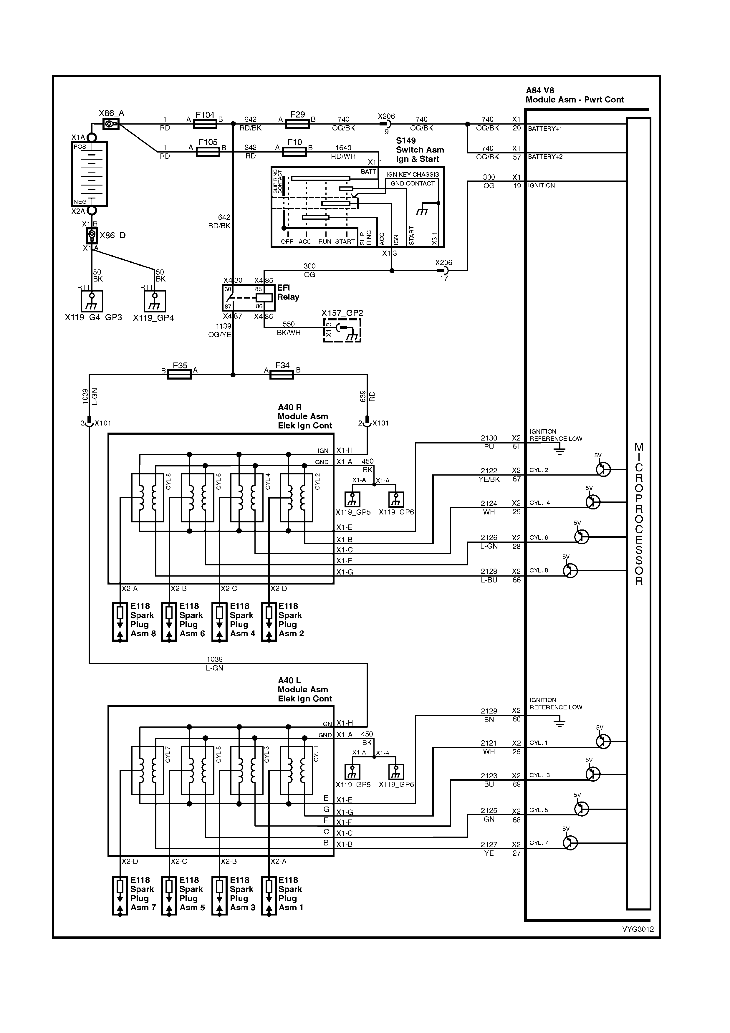
GEN III V8 PCM – DTC P0353 IGNITION CONTROL #3 CIRCUIT
Figure 6C3-2A-104 – Ignition System Circuit

CIRCUIT DESCRIPTION
The ignition system on this engine uses an individual ignition coil/module for each cylinder. The PCM controls the
ignition system operation. There are eight Ignition Control ( IC) circuits, one per c ylinder, that c onnect the PCM and
ignition coil/modules. Each ignition coil/module has a power feed, an engine ground circuit and a reference low
circuit. T he PCM causes a spark to occur by supplying a voltage to the IC circuit which signals the ignition module
to trigger the ignition coil and fire the spark plug. Sequencing and tim ing are PCM controlled. T his DTC sets when
the IC circuit is out of range.
CONDITIONS FOR RUNNING THE DTC
• The ignition voltage is between 9.0 and 17.0 volts
CONDITIONS FOR SETTING THE DTC
• The PCM detects the Ignition Control circuit is grounded, open or shorted to a voltage.
• All conditions met for at least 15 seconds.
ACTION TAKEN WHEN THE DTC SETS
• The PCM activates the Malfunction Indicator Lamp (MIL) when the diagnostic runs and fails.
• The PCM records the operating conditions at the time the diagnostic fails. The PCM stores this information in
the Freeze Frame/Failure Records.
CONDITIONS FOR CLEARING THE MIL/DTC
• The PCM deactivates the Malfunction Indicator Lamp (MIL) when the diagnostic runs and does not fail.
• A last test failed (current DTC) clears when the diagnostic runs and does not fail.
• Use Tech 2 to clear the MIL/DTC.
DIAGNOSTIC AIDS
• The following may be the cause of an intermittent:
– Poor connections; check for adequate terminal tension.
– Corrosion.
– Incorrectly routed harness.
– Rubbed through wire insulation.
– Broken wire inside the insulation.
• Using the Freeze Frame/Failure Records data may aid in locating an intermittent condition. If you cannot
duplicate the DTC, the information included in the Freeze Frame/Failure Records data can help determine the
distance travelled since the DTC Set. The Fail Counter and Pass Counter can also help determine how may
ignition cycles the diagnostic reported a pass and/or a fail. Operate the vehicle within the same freeze frame
conditions (RPM, load, vehicle speed, temperature etc.) that you observed. This will isolate when the DTC
failed.
• For an intermittent condition, refer to Section 6C3-2B SYMPTOMS in this Section.
TEST DESCRIPTION
NOTE: The number(s) below refer to the step number(s) on the diagnostic table.
2. This step verifies that the fault is present.
4. This step checks the integrity of the IC circuit and the PCM output.
10. This step checks for a short to voltage on the IC control circuit.
A84–X2 (RED) A40 L
Figure 6C3-2A-105

GEN III V8 PCM – DTC P0353 IGNITION CONTROL #3 CIRCUIT
STEP ACTION VALUE YES NO
1. Was the "On-Board Diagnostic" (OBD) System Check
performed? Go to Step 2 Go to
OBD System
Check
in this Section.
2. IMPORTANT: If all the Ignition Control (IC) DTCs are set
at the same time, inspect the IC ground circuits for an
open.
1. Install Tech 2.
2. Idle the engine.
4. Monitor the (IC) Ignition Control status for the cylinder
with the ignition control DTC using the Tech 2 Engine
Data List.
Does the Tech 2 indicate a fault?
Go to Step 4 Go to Step 3
3. 1. Ignition ON, engine OFF.
2. Review the Freeze Frame/Failure Records data for
this DTC and observe the parameters.
3. Turn OFF the ignition for 15 seconds.
4. Start the engine.
5. Operate the vehicle, within the conditions required for
this diagnostic to run, and as close to the conditions
recorded in Freeze Frame/Failure Records as
possible. Special operating conditions that you need to
meet before the PCM will run this diagnostic, where
applicable, are listed in Conditions for Running the
DTC.
6. Select the Diagnostic Trouble Code (DTC) option, the
DTC Information option and the Failed This Ignition
option using Tech 2.
Does Tech 2 indicate that this DTC failed this ignition?
Go to Step 4 Go to
Diagnostic Aids
4. 1. Engine OFF.
2. Disconnect the ignition coil electrical harness
connector, A40 L.
3. Crank engine with a test light connected to circuit
2123 between terminal A40L X1-F and ground.
Does the test light blink ON and OFF with engine
cranking?
Go to Step 8 Go to Step 5
5. 1. Ignition ON, engine OFF.
2. Measure the voltage at the Ignition Control circuit
2123 using a DMM.
Is the voltage greater than the specified value?
1.0 volt Go to Step 9 Go to Step 6
6. 1. Ignition OFF.
2. Disconnect the PCM RED connector, A84-X2.
3. Check the continuity from the IC circuit (at the ignition
coil harness connector) A40L X1-F to the PCM
connector A84 terminal X2-69 using a DMM.
Does the DMM indicate continuity?
Go to Step 7 Go to Step 10
7. 1. Check the resistance from the IC circuit (at the ignition
coil harness connector) to ground using a DMM.
Does the DMM indicate an open circuit?
Go to Step 11 Go to step 10
8. 1. Replace the ignition coil. Refer to Ignition Coil Replace
in 6C3-3 SERVICE OPERATIONS.
Is the action complete?
Go to Step 13 –
9. 1. Disconnect PCM RED connector A84-X2.
2. Ignition ON, engine OFF.
3. Check the Ignition Control circuit 2123 for a short to
voltage.
Is the action complete?
Go to Step 13 Go to Step 12
10. 1. Repair the Ignition Control circuit for an open or
grounded circuit.
Is the action complete?
Go to Step 13 –

STEP ACTION VALUE YES NO
11. 1. Check the terminal tension at the PCM and replace
the terminal if necessary.
Did you find and correct the condition?
Go to Step 13 Go to Step 12
12. 1. Replace PCM. Refer to PCM Programming and
PCM/PIM/BCM Security Link Procedure, in 6C3-3
SERVICE OPERATIONS.
Is action complete?
Go to Step 13 –
13. 1. Select the Diagnostic Trouble Code (DTC) option and
the Clear DTC Information option using Tech 2.
2. Idle the engine at the normal operating temperature.
3. Select the Diagnostic Trouble Code (DTC) option, the
DTC Information option and the Failed This Ignition
option using Tech 2.
4. Operate the vehicle, within the Conditions for Running
the DTC, as specified in the supporting text, if
applicable.
Does Tech 2 indicate that this DTC reset?
Go to Step 2 Go to Step 14
14. 1. Using Tech 2, check for any other DTCs.
Does Tech 2 display any DTCs that you have not
diagnosed?
Go to the
applicable DTC
table
System OK

GEN III V8 PCM – DTC P0354 IGNITION CONTROL #4 CIRCUIT
Figure 6C3-2A-106 – Ignition System Circuit

CIRCUIT DESCRIPTION
The ignition system on this engine uses an individual ignition coil/module for each cylinder. The PCM controls the
ignition system operation. There are eight Ignition Control ( IC) circuits, one per c ylinder, that c onnect the PCM and
ignition coil/modules. Each ignition coil/module has a power feed, an engine ground circuit and a reference low
circuit. T he PCM causes a spark to occur by supplying a voltage to the IC circuit which signals the ignition module
to trigger the ignition coil and fire the spark plug. Sequencing and tim ing are PCM controlled. T his DTC sets when
the IC circuit is out of range.
CONDITIONS FOR RUNNING THE DTC
• The ignition voltage is between 9.0 and 17.0 volts
CONDITIONS FOR SETTING THE DTC
• The PCM detects the Ignition Control circuit is grounded, open or shorted to a voltage.
• All conditions met for at least 15 seconds.
ACTION TAKEN WHEN THE DTC SETS
• The PCM activates the Malfunction Indicator Lamp (MIL) when the diagnostic runs and fails.
• The PCM records the operating conditions at the time the diagnostic fails. The PCM stores this information in
the Freeze Frame/Failure Records.
CONDITIONS FOR CLEARING THE MIL/DTC
• The PCM deactivates the Malfunction Indicator Lamp (MIL) when the diagnostic runs and does not fail.
• A last test failed (current DTC) clears when the diagnostic runs and does not fail.
• Use Tech 2 to clear the MIL/DTC.
DIAGNOSTIC AIDS
• The following may be the cause of an intermittent:
– Poor connections; check for adequate terminal tension.
– Corrosion.
– Incorrectly routed harness.
– Rubbed through wire insulation.
– Broken wire inside the insulation.
• Using the Freeze Frame/Failure Records data may aid in locating an intermittent condition. If you cannot
duplicate the DTC, the information included in the Freeze Frame/Failure Records data can help determine the
distance travelled since the DTC Set. The Fail Counter and Pass Counter can also help determine how may
ignition cycles the diagnostic reported a pass and/or a fail. Operate the vehicle within the same freeze frame
conditions (RPM, load, vehicle speed, temperature etc.) that you observed. This will isolate when the DTC
failed.
• For an intermittent condition, refer to Section 6C3-2B SYMPTOMS in this Section.
TEST DESCRIPTION
NOTE: The number(s) below refer to the step number(s) on the diagnostic table.
2. This step verifies that the fault is present.
4. This step checks the integrity of the IC circuit and the PCM output.
11. This step checks for a short to voltage on the IC control circuit.
A84–X2 (RED) A40 R
Figure 6C3-2A-107

GEN III V8 PCM – DTC P0354 IGNITION CONTROL #4 CIRCUIT
STEP ACTION VALUE YES NO
1. Was the "On-Board Diagnostic" (OBD) System Check
performed? Go to Step 2 Go to
OBD System
Check
in this Section.
2. IMPORTANT: If all the Ignition Control (IC) DTCs are set
at the same time, inspect the IC ground circuits for an
open.
1. Install Tech 2.
2. Idle the engine.
5. Monitor the (IC) Ignition Control status for the cylinder
with the ignition control DTC using the Tech 2 Engine
Data List.
Does the Tech 2 indicate a fault?
Go to Step 4 Go to Step 3
3. 1. Ignition ON, engine OFF.
2. Review the Freeze Frame/Failure Records data for
this DTC and observe the parameters.
3. Turn OFF the ignition for 15 seconds.
4. Start the engine.
5. Operate the vehicle, within the conditions required for
this diagnostic to run, and as close to the conditions
recorded in Freeze Frame/Failure Records as
possible. Special operating conditions that you need to
meet before the PCM will run this diagnostic, where
applicable, are listed in Conditions for Running the
DTC.
6. Select the Diagnostic Trouble Code (DTC) option, the
DTC Information option and the Failed This Ignition
option using Tech 2.
Does Tech 2 indicate that this DTC failed this ignition?
Go to Step 4 Go to
Diagnostic Aids
4. 1. Engine OFF.
2. Disconnect the ignition coil electrical harness
connector, A40 L.
3. Crank engine with a test light connected to circuit
2124 between terminal A40R X1-C and ground.
Does the test light blink ON and OFF with engine
cranking?
Go to Step 8 Go to Step 5
5. 1. Ignition ON, engine OFF.
2. Measure the voltage at the Ignition Control circuit
2124 using a DMM.
Is the voltage greater than the specified value?
1.0 volt Go to Step 9 Go to Step 6
6. 1. Ignition OFF.
2. Disconnect the PCM RED connector, A84-X2.
3. Check the continuity from the IC circuit (at the ignition
coil harness connector) A40R X1-C to the PCM
connector A84 terminal X2-29 using a DMM.
Does the DMM indicate continuity?
Go to Step 7 Go to Step 10
7. 1. Check the resistance from the IC circuit (at the ignition
coil harness connector) to ground using a DMM.
Does the DMM indicate an open circuit?
Go to Step 11 Go to step 10
8. 1. Replace the ignition coil. Refer to Ignition Coil Replace
in 6C3-3 SERVICE OPERATIONS.
Is the action complete?
Go to Step 13 –
9. 1. Disconnect PCM RED connector A84-X2.
2. Ignition ON, engine OFF.
3. Check the Ignition Control circuit 2124 for a short to
voltage.
Is the action complete?
Go to Step 13 Go to Step 12
10. 1. Repair the Ignition Control circuit for an open or
grounded circuit.
Is the action complete?
Go to Step 13 –

STEP ACTION VALUE YES NO
11. 1. Check the terminal tension at the PCM and replace
the terminal if necessary.
Did you find and correct the condition?
Go to Step 13 Go to Step 12
12. 1. Replace PCM. Refer to PCM Programming and
PCM/PIM/BCM Security Link Procedure, in 6C3-3
SERVICE OPERATIONS.
Is action complete?
Go to Step 13 –
13. 1. Select the Diagnostic Trouble Code (DTC) option and
the Clear DTC Information option using Tech 2.
2. Idle the engine at the normal operating temperature.
3. Select the Diagnostic Trouble Code (DTC) option, the
DTC Information option and the Failed This Ignition
option using Tech 2.
4. Operate the vehicle, within the Conditions for Running
the DTC, as specified in the supporting text, if
applicable.
Does Tech 2 indicate that this DTC reset?
Go to Step 2 Go to Step 14
14. 1. Using Tech 2, check for any other DTCs.
Does Tech 2 display any DTCs that you have not
diagnosed?
Go to the
applicable DTC
table
System OK

GEN III V8 PCM – DTC P0355 IGNITION CONTROL #5 CIRCUIT
Figure 6C3-2A-108 – Ignition System Circuit

CIRCUIT DESCRIPTION
The ignition system on this engine uses an individual ignition coil/module for each cylinder. The PCM controls the
ignition system operation. There are eight Ignition Control ( IC) circuits, one per c ylinder, that c onnect the PCM and
ignition coil/modules. Each ignition coil/module has a power feed, an engine ground circuit and a reference low
circuit. T he PCM causes a spark to occur by supplying a voltage to the IC circuit which signals the ignition module
to trigger the ignition coil and fire the spark plug. Sequencing and tim ing are PCM controlled. T his DTC sets when
the IC circuit is out of range.
CONDITIONS FOR RUNNING THE DTC
• The ignition voltage is between 9.0 and 17.0 volts
CONDITIONS FOR SETTING THE DTC
• The PCM detects the Ignition Control circuit is grounded, open or shorted to a voltage.
• All conditions met for at least 15 seconds.
ACTION TAKEN WHEN THE DTC SETS
• The PCM activates the Malfunction Indicator Lamp (MIL) when the diagnostic runs and fails.
• The PCM records the operating conditions at the time the diagnostic fails. The PCM stores this information in
the Freeze Frame/Failure Records.
CONDITIONS FOR CLEARING THE MIL/DTC
• The PCM deactivates the Malfunction Indicator Lamp (MIL) when the diagnostic runs and does not fail.
• A last test failed (current DTC) clears when the diagnostic runs and does not fail.
• Use Tech 2 to clear the MIL/DTC.
DIAGNOSTIC AIDS
• The following may be the cause of an intermittent:
– Poor connections; check for adequate terminal tension.
– Corrosion.
– Incorrectly routed harness.
– Rubbed through wire insulation.
– Broken wire inside the insulation.
• Using the Freeze Frame/Failure Records data may aid in locating an intermittent condition. If you cannot
duplicate the DTC, the information included in the Freeze Frame/Failure Records data can help determine the
distance travelled since the DTC Set. The Fail Counter and Pass Counter can also help determine how may
ignition cycles the diagnostic reported a pass and/or a fail. Operate the vehicle within the same freeze frame
conditions (RPM, load, vehicle speed, temperature etc.) that you observed. This will isolate when the DTC
failed.
• For an intermittent condition, refer to Section 6C3-2B SYMPTOMS in this Section.
TEST DESCRIPTION
NOTE: The number(s) below refer to the step number(s) on the diagnostic table.
2. This step verifies that the fault is present.
4. This step checks the integrity of the IC circuit and the PCM output.
12. This step checks for a short to voltage on the IC control circuit.
A84–X2 (RED) A40 L
Figure 6C3-2A-109

GEN III V8 PCM – DTC P0355 IGNITION CONTROL #5 CIRCUIT
STEP ACTION VALUE YES NO
1. Was the "On-Board Diagnostic" (OBD) System Check
performed? Go to Step 2 Go to
OBD System
Check
in this Section.
2. IMPORTANT: If all the Ignition Control (IC) DTCs are set
at the same time, inspect the IC ground circuits for an
open.
1. Install Tech 2.
2. Idle the engine.
6. Monitor the (IC) Ignition Control status for the cylinder
with the ignition control DTC using the Tech 2 Engine
Data List.
Does the Tech 2 indicate a fault?
Go to Step 4 Go to Step 3
3. 1. Ignition ON, engine OFF.
2. Review the Freeze Frame/Failure Records data for
this DTC and observe the parameters.
3. Turn OFF the ignition for 15 seconds.
4. Start the engine.
5. Operate the vehicle, within the conditions required for
this diagnostic to run, and as close to the conditions
recorded in Freeze Frame/Failure Records as
possible. Special operating conditions that you need to
meet before the PCM will run this diagnostic, where
applicable, are listed in Conditions for Running the
DTC.
6. Select the Diagnostic Trouble Code (DTC) option, the
DTC Information option and the Failed This Ignition
option using Tech 2.
Does Tech 2 indicate that this DTC failed this ignition?
Go to Step 4 Go to
Diagnostic Aids
4. 1. Engine OFF.
2. Disconnect the ignition coil electrical harness
connector, A40 L.
3. Crank engine with a test light connected to circuit
2125 between terminal A40L X1-C and ground.
Does the test light blink ON and OFF with engine
cranking?
Go to Step 8 Go to Step 5
5. 1. Ignition ON, engine OFF.
2. Measure the voltage at the Ignition Control circuit
2125 using a DMM.
Is the voltage greater than the specified value?
1.0 volt Go to Step 9 Go to Step 6
6. 1. Ignition OFF.
2. Disconnect the PCM RED connector, A84-X2.
3. Check the continuity from the IC circuit (at the ignition
coil harness connector) A40L X1-C to the PCM
connector A84 terminal X2-68 using a DMM.
Does the DMM indicate continuity?
Go to Step 7 Go to Step 10
7. 1. Check the resistance from the IC circuit (at the ignition
coil harness connector) to ground using a DMM.
Does the DMM indicate an open circuit?
Go to Step 11 Go to step 10
8. 1. Replace the ignition coil. Refer to Ignition Coil Replace
in 6C3-3 SERVICE OPERATIONS.
Is the action complete?
Go to Step 13 –
9. 1. Disconnect PCM RED connector A84-X2.
2. Ignition ON, engine OFF.
3. Check the Ignition Control circuit 2125 for a short to
voltage.
Is the action complete?
Go to Step 13 Go to Step 12
10. 1. Repair the Ignition Control circuit for an open or
grounded circuit.
Is the action complete?
Go to Step 13 –

STEP ACTION VALUE YES NO
11. 1. Check the terminal tension at the PCM and replace
the terminal if necessary.
Did you find and correct the condition?
Go to Step 13 Go to Step 12
12. 1. Replace PCM. Refer to PCM Programming and
PCM/PIM/BCM Security Link Procedure, in 6C3-3
SERVICE OPERATIONS.
Is action complete?
Go to Step 13 –
13. 1. Select the Diagnostic Trouble Code (DTC) option and
the Clear DTC Information option using Tech 2.
2. Idle the engine at the normal operating temperature.
3. Select the Diagnostic Trouble Code (DTC) option, the
DTC Information option and the Failed This Ignition
option using Tech 2.
4. Operate the vehicle, within the Conditions for Running
the DTC, as specified in the supporting text, if
applicable.
Does Tech 2 indicate that this DTC reset?
Go to Step 2 Go to Step 14
14. 1. Using Tech 2, check for any other DTCs.
Does Tech 2 display any DTCs that you have not
diagnosed?
Go to the
applicable DTC
table
System OK

GEN III V8 PCM – DTC P0356 IGNITION CONTROL #6 CIRCUIT
Figure 6C3-2A-110 – Ignition System Circuit

CIRCUIT DESCRIPTION
The ignition system on this engine uses an individual ignition coil/module for each cylinder. The PCM controls the
ignition system operation. There are eight Ignition Control ( IC) circuits, one per c ylinder, that c onnect the PCM and
ignition coil/modules. Each ignition coil/module has a power feed, an engine ground circuit and a reference low
circuit. T he PCM causes a spark to occur by supplying a voltage to the IC circuit which signals the ignition module
to trigger the ignition coil and fire the spark plug. Sequencing and tim ing are PCM controlled. T his DTC sets when
the IC circuit is out of range.
CONDITIONS FOR RUNNING THE DTC
• The ignition voltage is between 9.0 and 17.0 volts
CONDITIONS FOR SETTING THE DTC
• The PCM detects the Ignition Control circuit is grounded, open or shorted to a voltage.
• All conditions met for at least 15 seconds.
ACTION TAKEN WHEN THE DTC SETS
• The PCM activates the Malfunction Indicator Lamp (MIL) when the diagnostic runs and fails.
• The PCM records the operating conditions at the time the diagnostic fails. The PCM stores this information in
the Freeze Frame/Failure Records.
CONDITIONS FOR CLEARING THE MIL/DTC
• The PCM deactivates the Malfunction Indicator Lamp (MIL) when the diagnostic runs and does not fail.
• A last test failed (current DTC) clears when the diagnostic runs and does not fail.
• Use Tech 2 to clear the MIL/DTC.
DIAGNOSTIC AIDS
• The following may be the cause of an intermittent:
– Poor connections; check for adequate terminal tension.
– Corrosion.
– Incorrectly routed harness.
– Rubbed through wire insulation.
– Broken wire inside the insulation.
• Using the Freeze Frame/Failure Records data may aid in locating an intermittent condition. If you cannot
duplicate the DTC, the information included in the Freeze Frame/Failure Records data can help determine the
distance travelled since the DTC Set. The Fail Counter and Pass Counter can also help determine how may
ignition cycles the diagnostic reported a pass and/or a fail. Operate the vehicle within the same freeze frame
conditions (RPM, load, vehicle speed, temperature etc.) that you observed. This will isolate when the DTC
failed.
• For an intermittent condition, refer to Section 6C3-2B SYMPTOMS in this Section.
TEST DESCRIPTION
NOTE: The number(s) below refer to the step number(s) on the diagnostic table.
2. This step verifies that the fault is present.
4. This step checks the integrity of the IC circuit and the PCM output.
13. This step checks for a short to voltage on the IC control circuit.
A84–X2 (RED) A40 R
Figure 6C3-2A-111

GEN III V8 PCM – DTC P0356 IGNITION CONTROL #6 CIRCUIT
STEP ACTION VALUE YES NO
1. Was the "On-Board Diagnostic" (OBD) System Check
performed? Go to Step 2 Go to
OBD System
Check
in this Section.
2. IMPORTANT: If all the Ignition Control (IC) DTCs are set
at the same time, inspect the IC ground circuits for an
open.
1. Install Tech 2.
2. Idle the engine.
7. Monitor the (IC) Ignition Control status for the cylinder
with the ignition control DTC using the Tech 2 Engine
Data List.
Does the Tech 2 indicate a fault?
Go to Step 4 Go to Step 3
3. 1. Ignition ON, engine OFF.
2. Review the Freeze Frame/Failure Records data for
this DTC and observe the parameters.
3. Turn OFF the ignition for 15 seconds.
4. Start the engine.
5. Operate the vehicle, within the conditions required for
this diagnostic to run, and as close to the conditions
recorded in Freeze Frame/Failure Records as
possible. Special operating conditions that you need to
meet before the PCM will run this diagnostic, where
applicable, are listed in Conditions for Running the
DTC.
6. Select the Diagnostic Trouble Code (DTC) option, the
DTC Information option and the Failed This Ignition
option using Tech 2.
Does Tech 2 indicate that this DTC failed this ignition?
Go to Step 4 Go to Diagnostic
Aids
4. 1. Engine OFF.
2. Disconnect the ignition coil electrical harness
connector, A40 L.
3. Crank engine with a test light connected to circuit
2126 between terminal A40R X1-F and ground.
Does the test light blink ON and OFF with engine
cranking?
Go to Step 8 Go to Step 5
5. 1. Ignition ON, engine OFF.
2. Measure the voltage at the Ignition Control circuit
2126 using a DMM.
Is the voltage greater than the specified value?
1.0 volt Go to Step 9 Go to Step 6
6. 1. Ignition OFF.
2. Disconnect the PCM RED connector, A84-X2.
3. Check the continuity from the IC circuit (at the ignition
coil harness connector) A40R X1-F to the PCM
connector A84 terminal X2-28 using a DMM.
Does the DMM indicate continuity?
Go to Step 7 Go to Step 10
7. 1. Check the resistance from the IC circuit (at the ignition
coil harness connector) to ground using a DMM.
Does the DMM indicate an open circuit?
Go to Step 11 Go to step 10
8. 1. Replace the ignition coil. Refer to Ignition Coil Replace
in 6C3-3 SERVICE OPERATIONS.
Is the action complete?
Go to Step 13 –
9. 1. Disconnect PCM RED connector A84-X2.
2. Ignition ON, engine OFF.
3. Check the Ignition Control circuit 2126 for a short to
voltage.
Is the action complete?
Go to Step 13 Go to Step 12
10. 1. Repair the Ignition Control circuit for an open or
grounded circuit.
Is the action complete?
Go to Step 13 –

STEP ACTION VALUE YES NO
11. 1. Check the terminal tension at the PCM and replace
the terminal if necessary.
Did you find and correct the condition?
Go to Step 13 Go to Step 12
12. 1. Replace PCM. Refer to PCM Programming and
PCM/PIM/BCM Security Link Procedure, in 6C3-3
SERVICE OPERATIONS.
Is action complete?
Go to Step 13 –
13. 1. Select the Diagnostic Trouble Code (DTC) option and
the Clear DTC Information option using Tech 2.
2. Idle the engine at the normal operating temperature.
3. Select the Diagnostic Trouble Code (DTC) option, the
DTC Information option and the Failed This Ignition
option using Tech 2.
4. Operate the vehicle, within the Conditions for Running
the DTC, as specified in the supporting text, if
applicable.
Does Tech 2 indicate that this DTC reset?
Go to Step 2 Go to Step 14
14. 1. Using Tech 2, check for any other DTCs.
Does Tech 2 display any DTCs that you have not
diagnosed?
Go to the
applicable DTC
table
System OK

GEN III V8 PCM – DTC P0357 IGNITION CONTROL #7 CIRCUIT
Figure 6C3-2A-112 – Ignition System Circuit

CIRCUIT DESCRIPTION
The ignition system on this engine uses an individual ignition coil/module for each cylinder. The PCM controls the
ignition system operation. There are eight Ignition Control ( IC) circuits, one per c ylinder, that c onnect the PCM and
ignition coil/modules. Each ignition coil/module has a power feed, an engine ground circuit and a reference low
circuit. T he PCM causes a spark to occur by supplying a voltage to the IC circuit which signals the ignition module
to trigger the ignition coil and fire the spark plug. Sequencing and tim ing are PCM controlled. T his DTC sets when
the IC circuit is out of range.
CONDITIONS FOR RUNNING THE DTC
• The ignition voltage is between 9.0 and 17.0 volts
CONDITIONS FOR SETTING THE DTC
• The PCM detects the Ignition Control circuit is grounded, open or shorted to a voltage.
• All conditions met for at least 15 seconds.
ACTION TAKEN WHEN THE DTC SETS
• The PCM activates the Malfunction Indicator Lamp (MIL) when the diagnostic runs and fails.
• The PCM records the operating conditions at the time the diagnostic fails. The PCM stores this information in
the Freeze Frame/Failure Records.
CONDITIONS FOR CLEARING THE MIL/DTC
• The PCM deactivates the Malfunction Indicator Lamp (MIL) when the diagnostic runs and does not fail.
• A last test failed (current DTC) clears when the diagnostic runs and does not fail.
• Use Tech 2 to clear the MIL/DTC.
DIAGNOSTIC AIDS
• The following may be the cause of an intermittent:
– Poor connections; check for adequate terminal tension.
– Corrosion.
– Incorrectly routed harness.
– Rubbed through wire insulation.
– Broken wire inside the insulation.
• Using the Freeze Frame/Failure Records data may aid in locating an intermittent condition. If you cannot
duplicate the DTC, the information included in the Freeze Frame/Failure Records data can help determine the
distance travelled since the DTC Set. The Fail Counter and Pass Counter can also help determine how may
ignition cycles the diagnostic reported a pass and/or a fail. Operate the vehicle within the same freeze frame
conditions (RPM, load, vehicle speed, temperature etc.) that you observed. This will isolate when the DTC
failed.
• For an intermittent condition, refer to Section 6C3-2B SYMPTOMS in this Section.
TEST DESCRIPTION
NOTE: The number(s) below refer to the step number(s) on the diagnostic table.
2. This step verifies that the fault is present.
4. This step checks the integrity of the IC circuit and the PCM output.
14. This step checks for a short to voltage on the IC control circuit.
A84–X2 (RED) A40 L
Figure 6C3-2A-113

GEN III V8 PCM – DTC P0357 IGNITION CONTROL #7 CIRCUIT
STEP ACTION VALUE YES NO
1. Was the "On-Board Diagnostic" (OBD) System Check
performed? Go to Step 2 Go to
OBD System
Check
in this Section.
2. IMPORTANT: If all the Ignition Control (IC) DTCs are set
at the same time, inspect the IC ground circuits for an
open.
1. Install Tech 2.
2. Idle the engine.
8. Monitor the (IC) Ignition Control status for the cylinder
with the ignition control DTC using the Tech 2 Engine
Data List.
Does the Tech 2 indicate a fault?
Go to Step 4 Go to Step 3
3. 1. Ignition ON, engine OFF.
2. Review the Freeze Frame/Failure Records data for
this DTC and observe the parameters.
3. Turn OFF the ignition for 15 seconds.
4. Start the engine.
5. Operate the vehicle, within the conditions required for
this diagnostic to run, and as close to the conditions
recorded in Freeze Frame/Failure Records as
possible. Special operating conditions that you need to
meet before the PCM will run this diagnostic, where
applicable, are listed in Conditions for Running the
DTC.
6. Select the Diagnostic Trouble Code (DTC) option, the
DTC Information option and the Failed This Ignition
option using Tech 2.
Does Tech 2 indicate that this DTC failed this ignition?
Go to Step 4 Go to
Diagnostic Aids
4. 1. Engine OFF.
2. Disconnect the ignition coil electrical harness
connector, A40 L.
3. Crank engine with a test light connected to circuit
2127 between terminal A40L X1-B and ground.
Does the test light blink ON and OFF with engine
cranking?
Go to Step 8 Go to Step 5
5. 1. Ignition ON, engine OFF.
2. Measure the voltage at the Ignition Control circuit
2127 using a DMM.
Is the voltage greater than the specified value?
1.0 volt Go to Step 9 Go to Step 6
6. 1. Ignition OFF.
2. Disconnect the PCM RED connector, A84-X2.
3. Check the continuity from the IC circuit (at the ignition
coil harness connector) A40L X1-B to the PCM
connector A84 terminal X2-27 using a DMM.
Does the DMM indicate continuity?
Go to Step 7 Go to Step 10
7. 1. Check the resistance from the IC circuit (at the ignition
coil harness connector) to ground using a DMM.
Does the DMM indicate an open circuit?
Go to Step 11 Go to step 10
8. 1. Replace the ignition coil. Refer to Ignition Coil Replace
in 6C3-3 SERVICE OPERATIONS.
Is the action complete?
Go to Step 13 –
9. 1. Disconnect PCM RED connector A84-X2.
2. Ignition ON, engine OFF.
3. Check the Ignition Control circuit 2127 for a short to
voltage.
Is the action complete?
Go to Step 13 Go to Step 12
10. 1. Repair the Ignition Control circuit for an open or
grounded circuit.
Is the action complete?
Go to Step 13 –

STEP ACTION VALUE YES NO
11. 1. Check the terminal tension at the PCM and replace
the terminal if necessary.
Did you find and correct the condition?
Go to Step 13 Go to Step 12
12. 1. Replace PCM. Refer to PCM Programming and
PCM/PIM/BCM Security Link Procedure, in 6C3-3
SERVICE OPERATIONS.
Is action complete?
Go to Step 13 –
13. 1. Select the Diagnostic Trouble Code (DTC) option and
the Clear DTC Information option using Tech 2.
2. Idle the engine at the normal operating temperature.
3. Select the Diagnostic Trouble Code (DTC) option, the
DTC Information option and the Failed This Ignition
option using Tech 2.
4. Operate the vehicle, within the Conditions for Running
the DTC, as specified in the supporting text, if
applicable.
Does Tech 2 indicate that this DTC reset?
Go to Step 2 Go to Step 14
14. 1. Using Tech 2, check for any other DTCs.
Does Tech 2 display any DTCs that you have not
diagnosed?
Go to the
applicable DTC
table
System OK
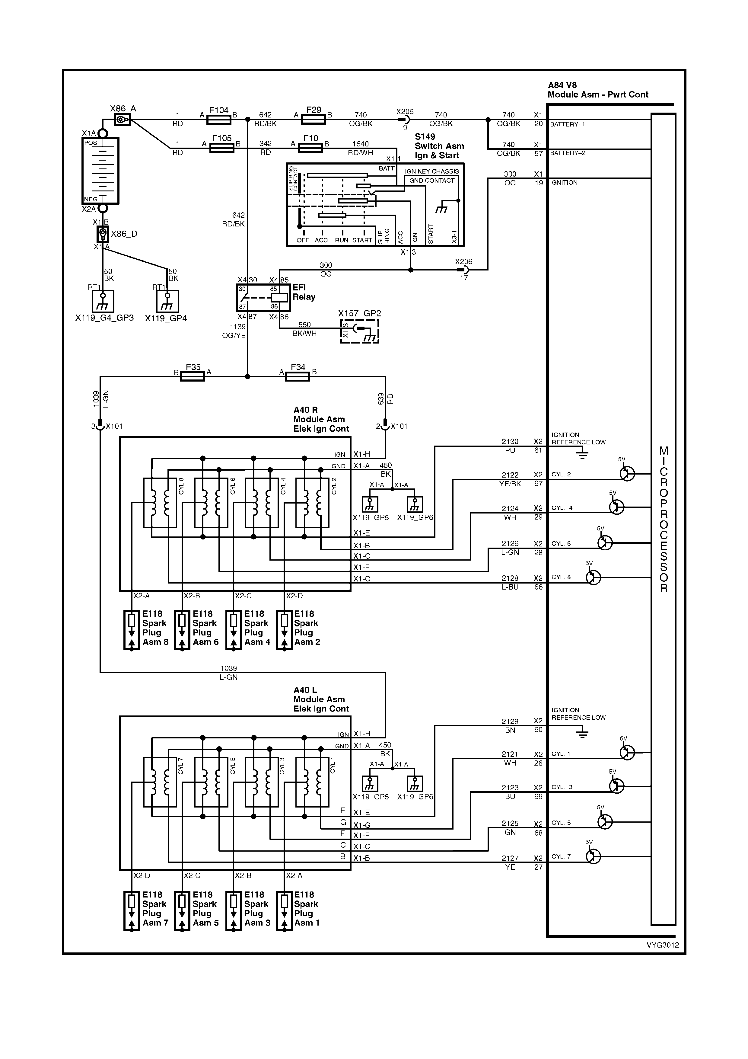
GEN III V8 PCM – DTC P0358 IGNITION CONTROL #8 CIRCUIT
Figure 6C3-2A-114 – Ignition System Circuit

CIRCUIT DESCRIPTION
The ignition system on this engine uses an individual ignition coil/module for each cylinder. The PCM controls the
ignition system operation. There are eight Ignition Control ( IC) circuits, one per c ylinder, that c onnect the PCM and
ignition coil/modules. Each ignition coil/module has a power feed, an engine ground circuit and a reference low
circuit. T he PCM causes a spark to occur by supplying a voltage to the IC circuit which signals the ignition module
to trigger the ignition coil and fire the spark plug. Sequencing and tim ing are PCM controlled. T his DTC sets when
the IC circuit is out of range.
CONDITIONS FOR RUNNING THE DTC
• The ignition voltage is between 9.0 and 17.0 volts
CONDITIONS FOR SETTING THE DTC
• The PCM detects the Ignition Control circuit is grounded, open or shorted to a voltage.
• All conditions met for at least 15 seconds.
ACTION TAKEN WHEN THE DTC SETS
• The PCM activates the Malfunction Indicator Lamp (MIL) when the diagnostic runs and fails.
• The PCM records the operating conditions at the time the diagnostic fails. The PCM stores this information in
the Freeze Frame/Failure Records.
CONDITIONS FOR CLEARING THE MIL/DTC
• The PCM deactivates the Malfunction Indicator Lamp (MIL) when the diagnostic runs and does not fail.
• A last test failed (current DTC) clears when the diagnostic runs and does not fail.
• Use Tech 2 to clear the MIL/DTC.
DIAGNOSTIC AIDS
• The following may be the cause of an intermittent:
– Poor connections; check for adequate terminal tension.
– Corrosion.
– Incorrectly routed harness.
– Rubbed through wire insulation.
– Broken wire inside the insulation.
• Using the Freeze Frame/Failure Records data may aid in locating an intermittent condition. If you cannot
duplicate the DTC, the information included in the Freeze Frame/Failure Records data can help determine the
distance travelled since the DTC Set. The Fail Counter and Pass Counter can also help determine how may
ignition cycles the diagnostic reported a pass and/or a fail. Operate the vehicle within the same freeze frame
conditions (RPM, load, vehicle speed, temperature etc.) that you observed. This will isolate when the DTC
failed.
• For an intermittent condition, refer to Section 6C3-2B SYMPTOMS in this Section.
TEST DESCRIPTION
NOTE: The number(s) below refer to the step number(s) on the diagnostic table.
2. This step verifies that the fault is present.
4. This step checks the integrity of the IC circuit and the PCM output.
15. This step checks for a short to voltage on the IC control circuit.
A84–X2 (RED) A40 R
Figure 6C3-2A-115

GEN III V8 PCM – DTC P0358 IGNITION CONTROL #8 CIRCUIT
STEP ACTION VALUE YES NO
1. Was the "On-Board Diagnostic" (OBD) System Check
performed? Go to Step 2 Go to
OBD System
Check
in this Section.
2. IMPORTANT: If all the Ignition Control (IC) DTCs are set
at the same time, inspect the IC ground circuits for an
open.
1. Install Tech 2.
2. Idle the engine.
9. Monitor the (IC) Ignition Control status for the cylinder
with the ignition control DTC using the Tech 2 Engine
Data List.
Does the Tech 2 indicate a fault?
Go to Step 4 Go to Step 3
3. 1. Ignition ON, engine OFF.
2. Review the Freeze Frame/Failure Records data for
this DTC and observe the parameters.
3. Turn OFF the ignition for 15 seconds.
4. Start the engine.
5. Operate the vehicle, within the conditions required for
this diagnostic to run, and as close to the conditions
recorded in Freeze Frame/Failure Records as
possible. Special operating conditions that you need to
meet before the PCM will run this diagnostic, where
applicable, are listed in Conditions for Running the
DTC.
6. Select the Diagnostic Trouble Code (DTC) option, the
DTC Information option and the Failed This Ignition
option using Tech 2.
Does Tech 2 indicate that this DTC failed this ignition?
Go to Step 4 Go to
Diagnostic Aids
4. 1. Engine OFF.
2. Disconnect the ignition coil electrical harness
connector, A40 L.
3. Crank engine with a test light connected to circuit
2128 between terminal A40R X1-G and ground.
Does the test light blink ON and OFF with engine
cranking?
Go to Step 8 Go to Step 5
5. 1. Ignition ON, engine OFF.
2. Measure the voltage at the Ignition Control circuit
2128 using a DMM.
Is the voltage greater than the specified value?
1.0 volt Go to Step 9 Go to Step 6
6. 1. Ignition OFF.
2. Disconnect the PCM RED connector, A84-X2.
3. Check the continuity from the IC circuit (at the ignition
coil harness connector) A40R X1-G to the PCM
connector A84 terminal X2-66 using a DMM.
Does the DMM indicate continuity?
Go to Step 7 Go to Step 10
7. 1. Check the resistance from the IC circuit (at the ignition
coil harness connector) to ground using a DMM.
Does the DMM indicate an open circuit?
Go to Step 11 Go to step 10
8. 1. Replace the ignition coil. Refer to Ignition Coil Replace
in 6C3-3 SERVICE OPERATIONS.
Is the action complete?
Go to Step 13 –
9. 1. Disconnect PCM RED connector A84-X2.
2. Ignition ON, engine OFF.
3. Check the Ignition Control circuit 2128 for a short to
voltage.
Is the action complete?
Go to Step 13 Go to Step 12
10. 1. Repair the Ignition Control circuit for an open or
grounded circuit.
Is the action complete?
Go to Step 13 –

STEP ACTION VALUE YES NO
11. 1. Check the terminal tension at the PCM and replace
the terminal if necessary.
Did you find and correct the condition?
Go to Step 13 Go to Step 12
12. 1. Replace PCM. Refer to PCM Programming and
PCM/PIM/BCM Security Link Procedure, in 6C3-3
SERVICE OPERATIONS.
Is action complete?
Go to Step 13 –
13. 1. Select the Diagnostic Trouble Code (DTC) option and
the Clear DTC Information option using Tech 2.
2. Idle the engine at the normal operating temperature.
3. Select the Diagnostic Trouble Code (DTC) option, the
DTC Information option and the Failed This Ignition
option using Tech 2.
4. Operate the vehicle, within the Conditions for Running
the DTC, as specified in the supporting text, if
applicable.
Does Tech 2 indicate that this DTC reset?
Go to Step 2 Go to Step 14
14. 1. Using Tech 2, check for any other DTCs.
Does Tech 2 display any DTCs that you have not
diagnosed?
Go to the
applicable DTC
table
System OK
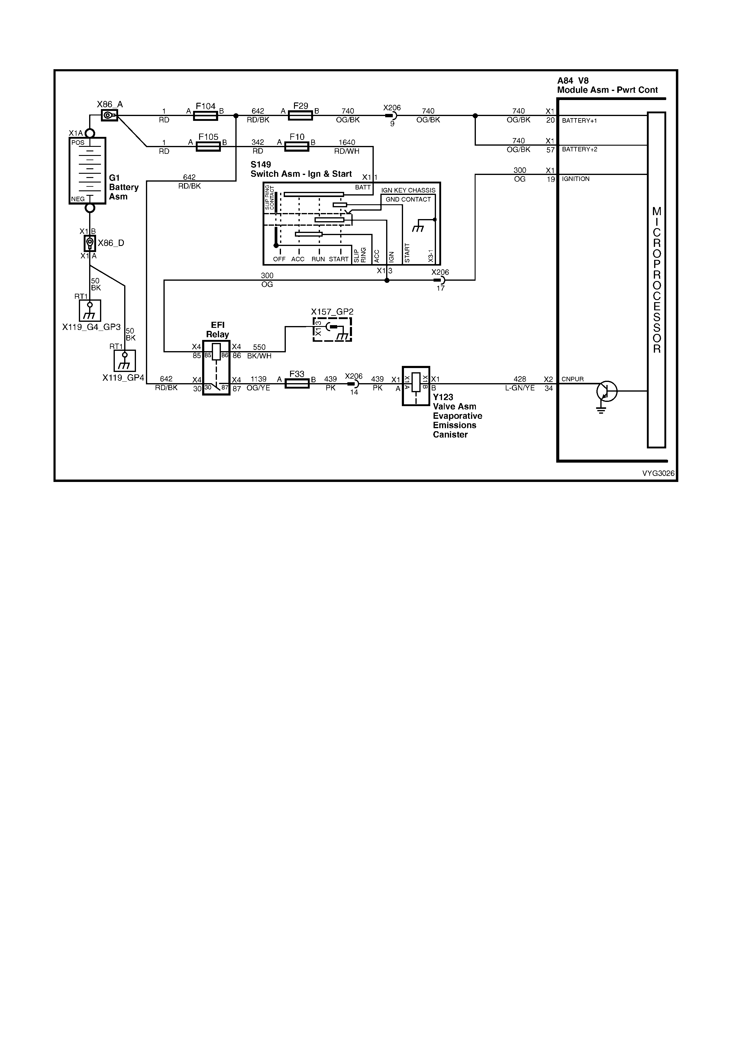
GEN III V8 PCM – DTC P0443 EVAP PURGE SOLENOID CONTROL CIRCUIT
Figure 6C3-2A-116 – Evaporative Purge Solenoid Control Circuit
CIRCUIT DESCRIPTION
An ignition voltage is supplied dire ctly to the EVAP solenoid relay coil. The PCM c ontrols the solenoid by grounding
the control cir cuit via an internal switch c alled a driver. The pr imar y function of the driver is to supply the ground for
the controlled component. Each driver has a fault line, which the PCM monitors. The voltage of the control circuit
should be low (near 0 volt) , when the PCM comm ands a c omponent ON . The voltage potential of the c ircuit should
be high (near the battery voltage), when the PCM commands the control circuit to a component OFF. If the fault
detection circ uit sens es a voltage other than what the PCM expec ted, the f ault line s tatus changes c ausing the DTC
to set.
CONDITIONS FOR RUNNING THE DTC
• The engine speed is greater than 400 RPM.
• The ignition voltage is between 6.0 and 16.0 volts.
CONDITIONS FOR SETTING THE DTC
• The PCM detects that the commanded state of the circuit and the actual state of the circuit does not match.
• The conditions are present for at least ten seconds.
ACTION TAKEN WHEN THE DTC SETS
• The PCM activates the Check Powertrain MIL when the diagnostic runs and fails.
• The PCM records the operating conditions at the time the diagnostic fails. The PCM stores this information in
the Freeze Frame/Failure Records.
CONDITIONS FOR CLEARING THE MIL/DTC
• The PCM deactivates the Check Powertrain MIL after one ignition cycle that the diagnostic runs and does not
fail.
• A last test failed (current DTC) clears when the diagnostic runs and does not fail.
• Use Tech 2 to clear the MIL/DTC.
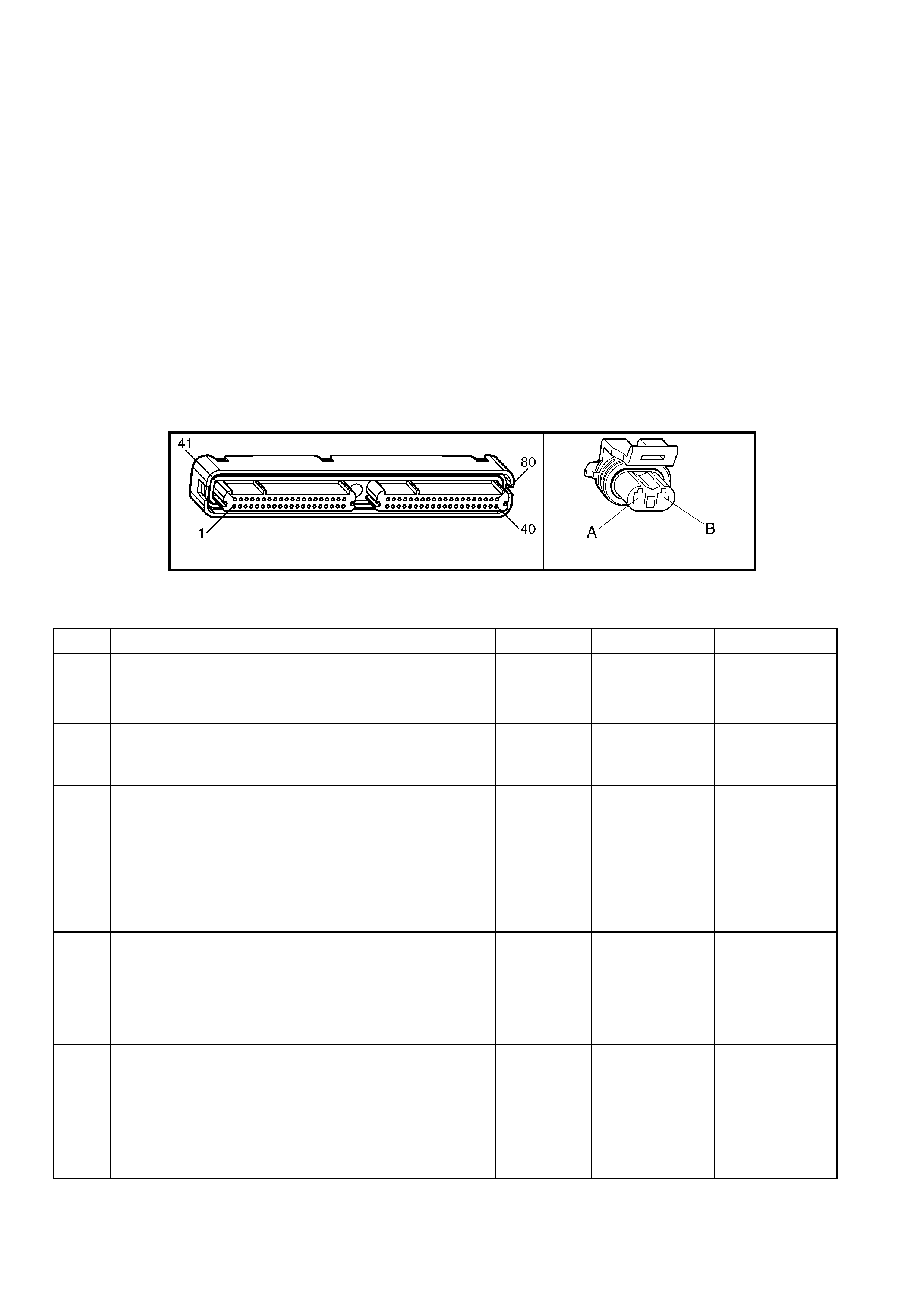
DIAGNOSTIC AIDS
• Using Freeze Fram e/Failure Records data m ay aid in locating an intermittent condition. If you cannot duplicate
the DTC, the information included in the Freeze Frame/Failure Records data can aid in determining the
distance travelled since the DTC set. The Fail Counter and Pass Counter can also aid determining how many
ignition cycles the diagnostic reported a pass and/or fail. Operate the vehicle within the same freeze frame
conditions (RPM, load, vehicle speed, temperature etc.) that you observed. This will isolate when the DTC
failed.
• For an intermittent, refer to Section 6C3-2B SYMPTOMS.
TEST DESCRIPTION
NOTE: The number(s) below refer to the step number(s) on the diagnostic table.
IMPORTANT: The engine must be running in order to command the EVAP Purge Solenoid Valve ON and OFF.
2. Listen for an audible click when the solenoid operates. Be sure that both the ON and the OFF states are
commanded. Repeat the commands as necessary.
3. This check can detect a partial short which would cause excessive current flow. Leaving the circuit energised
for 2 minutes allows the c oil to warm up. When warm , the c oil m ay open (Amps drop to 0), or short (goes above
0.75 Amp).
13. If no tr ouble is found in the control c irc uit or the connec tion at the PCM, the PCM may be faulty, however, this is
an extremely unlikely failure.
A84–X2 (RED) Y123
Figure 6C3-2A-117
GEN III V8 PCM – DTC P0443 EVAP PURGE SOLENOID CONTROL CIRCUIT
STEP ACTION VALUE YES NO
1. Was the "On-Board Diagnostic" (OBD) System Check
performed? Go to Step 2 Go to
OBD System
Check
in this Section.
2. 1. Idle the engine at the normal operating temperature.
2. Command the solenoid ON and OFF using Tech 2.
Does the solenoid turn ON and OFF when commanded?
Go to Step 3 Go to Step 5
3. 1. Ignition OFF.
2. Disconnect the PCM RED connector A84-X2.
3. Ignition ON, engine OFF.
4. Measure the current, from the solenoid control circuit
428 in the PCM harness connector, to ground for 2
minutes using a DMM on the 10 Amp scale.
Does the current draw measure less than the specified
value shown but not 0?
0.75 Amp Go to Diagnostic
Aids Go to Step 4
4. 1. Ignition OFF.
2. Disconnect the solenoid.
3. Measure the resistance, from the solenoid control
circuit 428 in the PCM harness connector, to ground
using a DMM.
Does the DMM display infinite resistance?
Go to Step 12 Go to Step 10
5. 1. Ignition OFF.
2. Disconnect solenoid Y123.
3. Connect a test lamp between solenoid harness
connector, Y123 terminals X1-A and X1-B.
4. Idle the engine at the normal operating temperature.
5. Command the solenoid ON and OFF using Tech 2.
Does the test lamp turn ON and OFF when commanded?
Go to Step 8 Go to Step 6

STEP ACTION VALUE YES NO
6. 1. With the test lamp connected to ground, probe the
ignition feed circuit 439 in the solenoid harness
connector.
Is the test lamp illuminated?
Go to Step 7 Go to Step 11
7. 1. Ignition OFF.
2. Reconnect the solenoid.
3. Disconnect the PCM RED connector A84-X2.
4. Ignition ON, engine OFF.
5. W ith a fused jumper wire connected to ground, probe
the solenoid control circuit 428 in the PCM harness
connector A84 terminal X2-34.
Does the solenoid operate?
Go to Step 9 Go to Step 10
8. 1. Check the connection at the solenoid?
Was a problem found and corrected? Go to Step 14 Go to Step 12
9. 1. Check the connection at the PCM.
Was a problem found and corrected? Go to Step 14 Go to Step 13
10. 1. Repair open or short to ground in the solenoid control
circuit.
Is the action complete?
Go to Step 14 –
11. 1. Repair the faulty solenoid ignition feed circuit.
Is the action complete? Go to Step 14 –
12. 1. Replace the solenoid.
Is the action complete? Go to Step 14 –
13. 1. Replace PCM. Refer to PCM Programming and
PCM/PIM/BCM Security Link Procedure, in 6C3-3
SERVICE OPERATIONS.
Is action complete?
Go to Step 14 –
14. 1. Select the Diagnostic Trouble Code (DTC) option and
the Clear DTC Information option using Tech 2.
2. Idle the engine at the normal operating temperature.
3. Select the Diagnostic Trouble Code (DTC) option, the
DTC Information option and the Failed This Ignition
option using Tech 2.
4. Operate the vehicle, within the Conditions for Running
the DTC, as specified in the supporting text, if
applicable.
Does Tech 2 indicate that this DTC reset?
Go to Step 2 Go to Step 15
15. 1. Using Tech 2, check for any other DTCs.
Does Tech 2 display any DTCs that you have not
diagnosed?
Go to the
applicable DTC
table
System OK
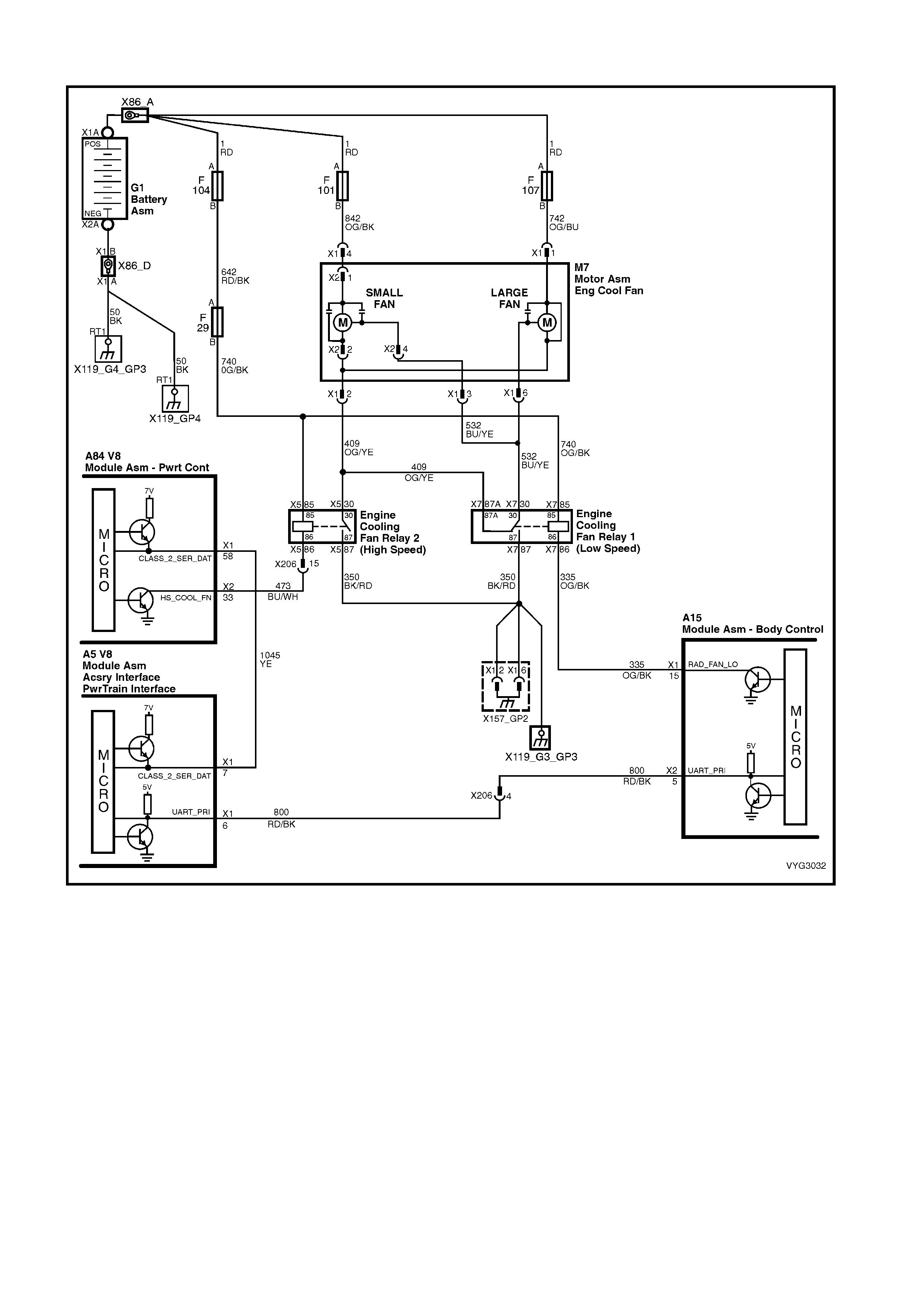
GEN III V8 PCM – DTC P0481 COOLING FAN HIGH SPEED RELAY CONTROL
Figure 6C3-2A-118 – Cooling Fan Circuits
CIRCUIT DESCRIPTION
Battery voltage is supplied directly to the cooling fan relay coils. The PCM controls the relay by grounding the control
circuit via an internal switch called a driver. The primary function of the driver is to supply the ground for the
controlled component. Each driver has a fault line which the PCM monitors. When the PCM commands a
com ponent O N, the voltage of the c ontr ol cir cuit s hould be low (near 0 volts). When the PCM commands the control
circuit to a c omponent OFF, the voltage potential of the circuit should be high (near the battery voltage). If the fault
detection circ uit sens es a voltage other than what the PCM expec ted, the f ault line s tatus changes c ausing the DTC
to set.
The relay controls the high current flow to the cooling fans. This allows the PCM driver to only have to control the
relatively low current used by the relay.
CONDITIONS FOR RUNNING THE DTC
• The engine speed is greater than 600 RPM.
• The ignition voltage is between 6.0 and 16.0 volts.
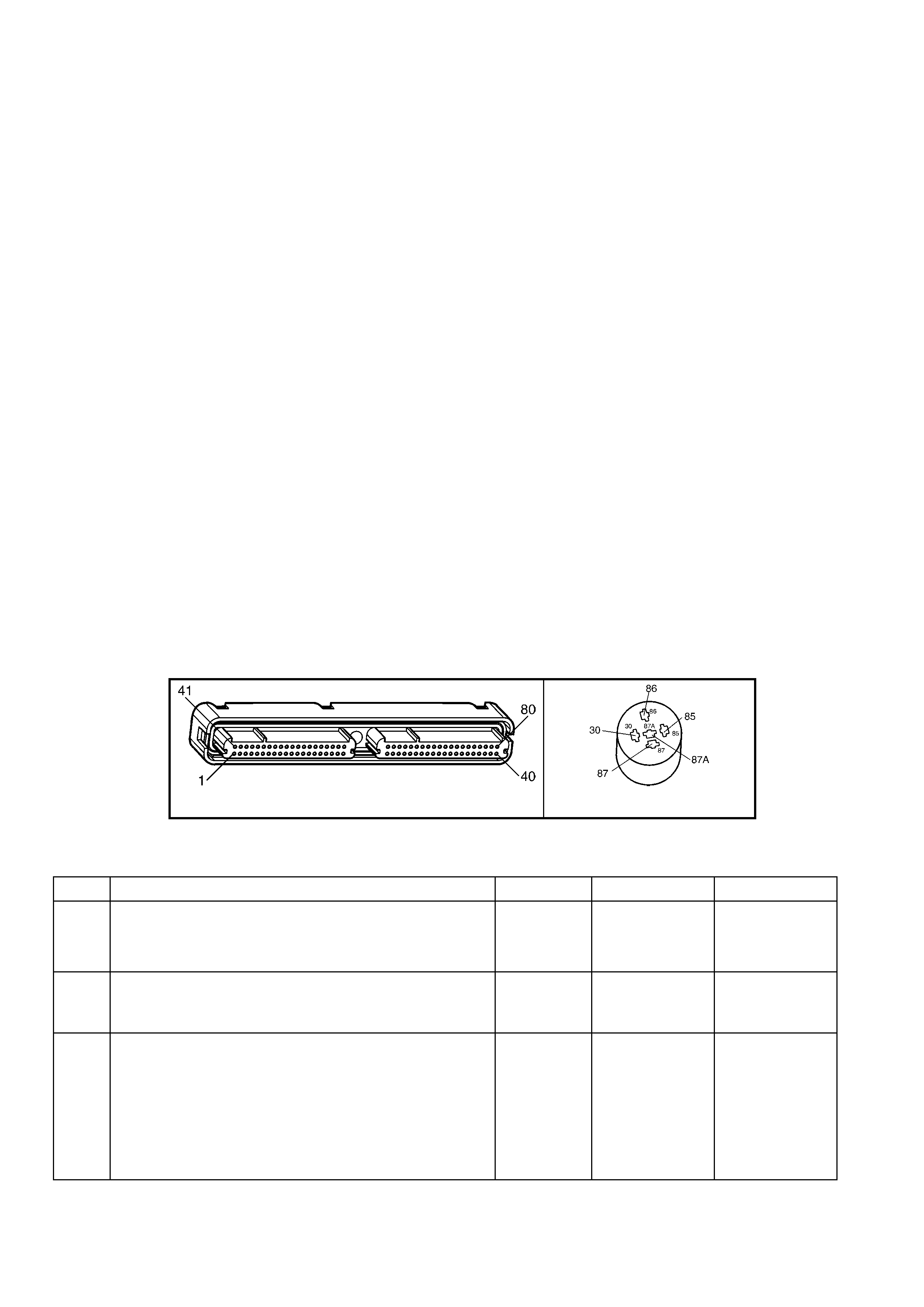
CONDITIONS FOR SETTING THE DTC
• The PCM detects that the commanded state of the driver and the actual state of the control circuit do not
match.
• The conditions must be present for a minimum of 10 seconds.
ACTION TAKEN WHEN THE DTC SETS
• The PCM activates the Check Powertrain MIL when the diagnostic runs and fails.
• The PCM records the operating conditions at the time the diagnostic fails. The PCM stores this information in
the Freeze Frame/Failure Records.
CONDITIONS FOR CLEARING THE MIL/DTC
• The PCM deactivates the Check Powertrain MIL after the first ignition cycle that the diagnostic runs and does
not fail.
• A last test failed (current DTC) clears when the diagnostic runs and does not fail.
• Use Tech 2 to clear the MIL/DTC.
DIAGNOSTIC AIDS
• Using the Freeze Frame/Failure Records data may aid in locating an intermittent condition. If you cannot
duplicate the DTC, the information included in the Freeze Frame/Failure Records data can aid in determining
the distance travelled since the DTC reported a pass and/or fail. Operate the vehicle within the same freeze
frame conditions (RPM, load, vehicle speed, temperature, etc.) that you observed. This will isolate when the
DTC failed.
• For an intermittent, refer to Section 6C3-2B SYMPTOMS, in this Section.
TEST DESCRIPTION
NOTE: The number(s) below refer to the step number(s) on the diagnostic table.
2. Listen f or an audible c lick when the r elay operates. Com mand both ON and O FF s tates. Repeat the c ommands
if necessary.
3. This check can detect a partially shorted coil which would cause excessive current flow. Leaving the circuit
energised for 2 minutes allows the coil to warm up. W hen warm, the coil may open (Amps drop to 0), or short
(goes above 0.75 Amps).
13. If you do not find any trouble in the control circuit or the connection at the PCM, the PCM may be faulty.
A84–X2 (RED) X5 (PART OF X100)
Figure 6C3-2A-119
GEN III V8 PCM – DTC P0481 COOLING FAN HIGH SPEED RELAY CONTROL
STEP ACTION VALUE YES NO
1. Was the "On-Board Diagnostic" (OBD) System Check
performed? Go to Step 2 Go to
OBD System
Check
in this Section.
2. 1. Ignition ON, engine OFF.
2. Command the relay ON and OFF using Tech 2.
Does the relay turn ON and OFF when commanded?
Go to Step 3 Go to Step 5
3. 1. Ignition OFF.
2. Disconnect the PCM RED connector, A84-X2.
3. Ignition ON.
4. Measure current from the relay control circuit 473 in
the PCM harness connector to ground for 2 minutes
using a DMM on 10 Amp scale.
Does the current draw measure less than the specified
value (but not 0)?
0.75 Amp Go to
Diagnostic Aids Go to Step 4

STEP ACTION VALUE YES NO
4. 1. Ignition OFF.
2. Disconnect the relay.
3. Measure the resistance, from the relay control circuit
473 in the PCM harness connector, to ground using a
DMM.
Does the DMM display infinite resistance?
Go to Step 12 Go to Step 10
5. 1. Ignition OFF.
2. Disconnect the relay.
3. Connect a test lamp between the relay control circuit
473 and the relay B+ supply circuit 740, at the
underhood fuse and relay electrical centre, X100.
4. Ignition ON.
5. Command the relay ON and OFF using Tech 2.
Does the test lamp turn ON and OFF with each command?
Go to Step 8 Go to Step 6
6. 1. Probe the relay B+ supply circuit 740 at the underhood
fuse and relay electrical centre, X100 with a test lamp
connected to ground.
Is the test lamp ON?
Go to Step 7 Go to Step 11
7. 1. Ignition OFF.
2. Reconnect the relay.
3. Disconnect the PCM RED connector A84-X2.
4. Ignition ON.
5. Probe the relay control circuit 473 in the PCM harness
connector A83, terminal X2-33 with a fused jumper
wire connected to ground.
Does the relay operate?
Go to Step 9 Go to Step 10
8. 1. Check the connections at the relay.
Did you find and correct the condition? Go to Step 14 Go to Step 12
9. 1. Check the connections at the PCM.
Did you find and correct the condition? Go to Step 14 Go to Step 13
10. 1. Repair open or short to ground in the relay control
circuit.
Is action complete?
Go to Step 14 –
11. 1. Repair the relay B+ supply circuit.
Is action complete? Go to Step 14 –
12. 1. Replace the relay.
Is action complete? Go to Step 14 –
13. 1. Replace PCM. Refer to PCM Programming and
PCM/PIM/BCM Security Link Procedure, in 6C3-3
SERVICE OPERATIONS.
Is action complete?
Go to Step 14 –
14. 1. Select the Diagnostic Trouble Code (DTC) option and
the Clear DTC Information option using Tech 2.
2. Idle the engine at the normal operating temperature.
3. Select the Diagnostic Trouble Code (DTC) option, the
DTC Information option and the Failed This Ignition
option using Tech 2.
4. Operate the vehicle, within the Conditions for Running
the DTC, as specified in the supporting text, if
applicable.
Does Tech 2 indicate that this DTC reset?
Go to Step 2 Go to Step 15
15. 1. Using Tech 2, check for any other DTCs.
Does Tech 2 display any DTCs that you have not
diagnosed?
Go to the
applicable DTC
table
System OK
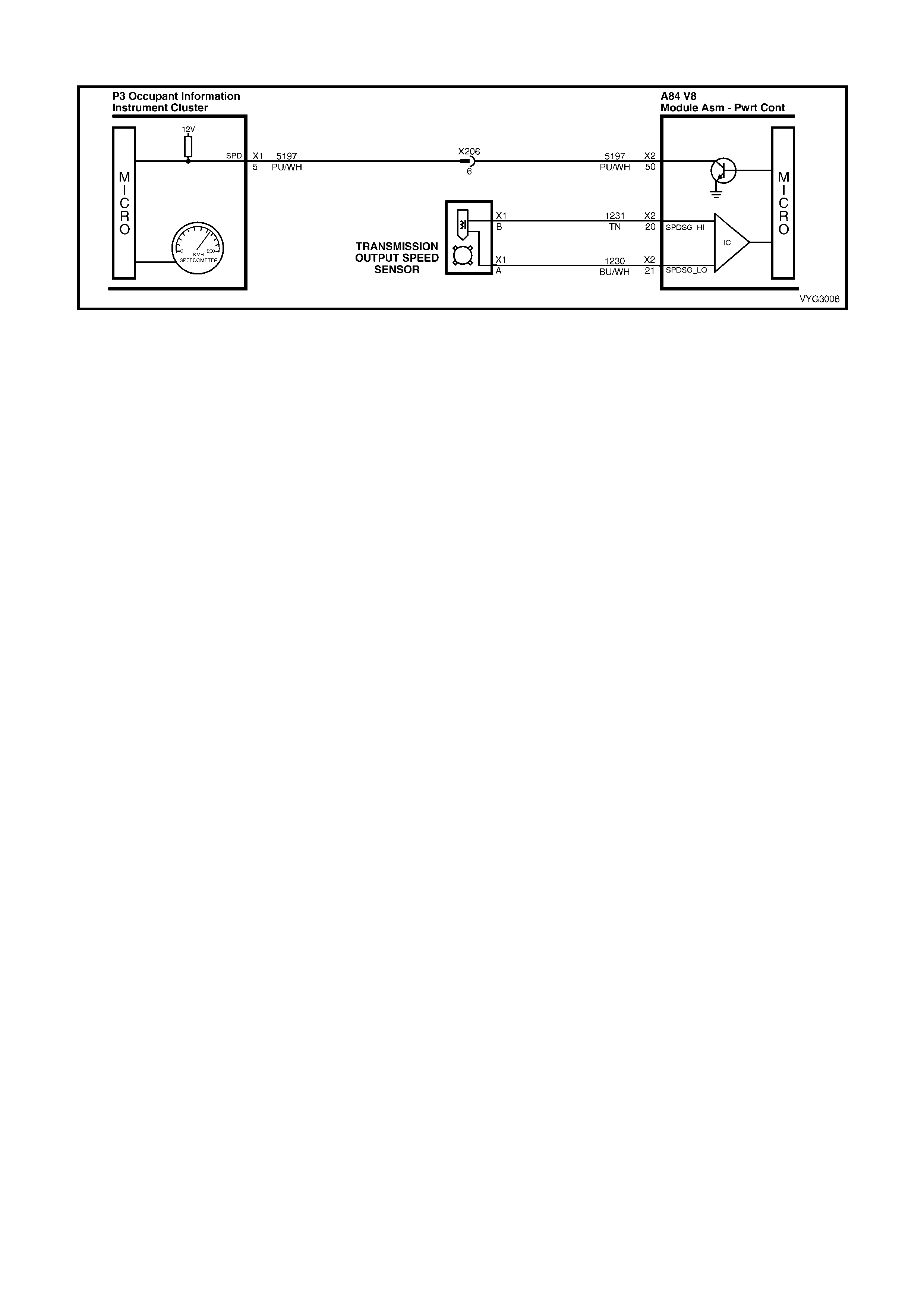
GEN III V8 PCM – DTC P0502 VEHICLE SPEED SENSOR CIRCUIT LOW INPUT
Figure 6C3-2A-120 – Vehicle Speed Sensor (VSS) Circuit
CIRCUIT DESCRIPTION
The Vehicle Speed Sensor (VSS) assembly provides vehicle speed information to the Powertrain Control Module
(PCM). The VSS assembly is a Permanent Magnet (PM) generator. The PM generator produces a pulsing AC
voltage as rotor teeth on the transmission output shaft pass through the sensor's magnetic field. The AC voltage
level and the number of pulses increase as the speed of the vehicle increases. The PCM converts the pulsing
voltage to vehicle speed. The PCM uses the Vehicle Speed Signal to determine shift tim ing and Torque Converter
Clutch (TCC) scheduling.
If the PCM detects a low vehicle speed when there is a high engine speed in a drive gear r ange, then DTC P0502
sets.
CONDITIONS FOR RUNNING THE DTC
• No MAP sensor DTCs P0107 or P0108.
• No Throttle Position DTCs P0122 or P0123.
• No TFP manual valve position switch DTC P1810.
• The transmission is not in park or neutral.
• The Throttle Position angle is greater than 15%.
• The engine vacuum is 0 – 105 kPa.
• The engine speed is greater than 3000 RPM.
• The engine torque is between 40 – 543 Nm.
CONDITIONS FOR SETTING THE DTC
• The transmission output speed is less than 150 RPM for at least three seconds.
ACTION TAKEN WHEN THE DTC SETS
• The PCM stores the DTC information into memory when the diagnostic runs and fails.
• The Check Powertrain MIL will not be activated.
• The PCM commands a 1-2 upshift at approximately 4800 rpm and then remains in second gear.
• The PCM commands maximum line pressure.
• The PCM inhibits TCC engagement.
• The PCM freezes shift adapts from being updated.
• The PCM records the operating conditions at the time the diagnostic fails. The PCM stores this information in
the Freeze Frame/Failure Records.
CONDITIONS FOR CLEARING THE MIL/DTC
• A last test failed (current DTC) clears when the diagnostic runs and does not fail.
• Use Tech 2 to clear the MIL/DTC.
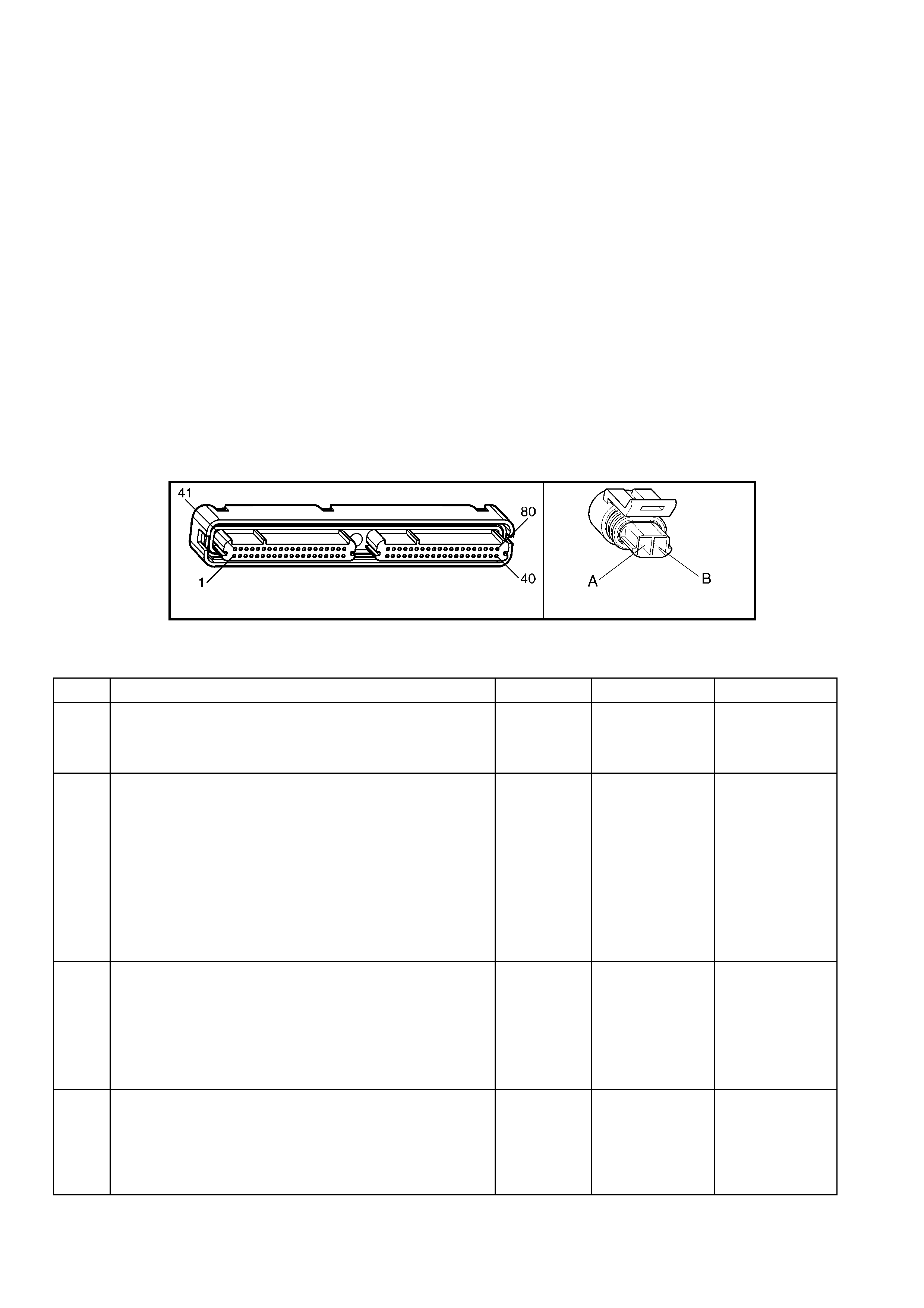
DIAGNOSTIC AIDS
• Inspect the wiring at the PCM, the VSS connector and all other circuit connecting points for the following
conditions:
– A backed out terminal
– A damaged terminal
– Reduced terminal tension
– A chafed wire
– A broken wire inside the insulation
– Moisture intrusion
– Corrosion
• When diagnosing for an intermittent short or open condition, massage the wiring harness while watching the
test equipment for a change.
TEST DESCRIPTION
NOTE: The number(s) below refer to the step number(s) on the diagnostic table.
2. Disable the T raction Control System (TCS) (if fitted) when perform ing this step. When the ignition k ey is cycled
to the OFF position and then cycled back ON, the traction control system defaults to ON.
3. This step tests the VSS assembly circuit.
4. This step tests the VSS assembly for a short to ground.
5. This step tests the integrity of the VSS assembly.
A84–X2 (RED) X121-X1
Figure 6C3-2A-121
GEN III V8 PCM – DTC P0502 VEHICLE SPEED SENSOR CIRCUIT LOW INPUT
STEP ACTION VALUE YES NO
1. Was the "On-Board Diagnostic" (OBD) System Check
performed? Go to Step 2 Go to
OBD System
Check
in this Section.
2. 1. Install Tech 2.
2. Ignition ON, engine OFF.
3. Clear the DTC, using Tech 2.
4. Raise the rear of the vehicle and support the final
drive assembly on safety stands.
5. Start the engine.
6. Disable the traction control system (if fitted).
7. Place the transmission in any drive range.
With the drive wheels rotating, does the Transmission VSS
display on Tech 2 increase wi th the drive wheel speed?
Go to
Diagnostic Aids Go to Step 3
3. 1. Ignition OFF.
2. Disconnect the powertrain wiring harness connector
from the VSS assembly.
3. Using a DMM and the J 35616-A connector test
adaptor kit, measure the resistance of the VSS
assembly.
Does the resistance measure within the specified range?
1377 – 3355
Ω Go to Step 4 Go to Step 14
4. 1. With the powertrain wiring harness connector still
disconnected from the VSS assembly, measure the
resistance from either terminal of the VSS assembly to
ground, using a DMM.
Does the resistance measure greater than the specified
value?
50 kΩ Go to Step 5 Go to Step 14

STEP ACTION VALUE YES NO
5. 1. Place the transmission in Neutral.
2. Select AC volts on a DMM.
3. Place the transmission in Neutral and then rotate the
propeller shaft by hand.
4. Measure the AC voltage from terminal X121-X1-A and
X1-B of the VSS assembly.
Does the voltage measure greater than the specified
value?
0.3 volts AC Go to Step 6 Go to Step 13
6. 1. Reconnect the powertrain wiring harness connector to
the VSS assembly.
2. Disconnect the PCM RED connector, A84-X2.
3. Measure the resistance between the PCM RED
connector terminals X2-20 and X2-21.
Does the resistance measure within the specified range?
1377 – 3355
Ω Go to Step 7 Go to Step 8
7. 1. With the PCM RED connector still disconnected,
measure the resistance from terminal X2-21 to
ground.
Does the resistance measure greater than the specified
value?
50 kΩ Go to Step 9 Go to Step 10
8. Does the resistance in step 6 measure greater than the
specified value? 3355 Ω Go to Step 11 Go to Step 12
9. 1. Reconnect the PCM RED connector, A84-X2.
2. Disconnect the powertrain wiring harness connector
X121-X1 from the VSS assembly.
3. Ignition ON, engine OFF.
4. Test circuit 1230 of the VSS assembly for a short to
voltage.
5. Test circuit 1231 of the VSS assembly for a short to
voltage.
Did you find and correct the condition?
Go to Step 16 Go to Step 15
10. 1. Test circuit 1230 of the VSS assembly for a short to
ground.
Did you find and correct the condition?
Go to Step 16 –
11. 1. Test circuit 1230 of the VSS assembly for an open.
2. Test circuit 1231 of the VSS assembly for an open.
Did you find and correct the condition?
Go to Step 16 –
12. 1. Test circuit 1230 and circuit 1231 of the VSS
assembly for a short together.
Did you find and correct the condition?
Go to Step 16 –
13. 1. Remove the VSS assembly. Refer to 7C4 ON-
VEHICLE SERVICING – AUTOMATIC
TRANSMISSION or 7B2 MANUAL TRANSMISSION
GEN III V8 ENGINE.
2. Inspect the output shaft speed sensor rotor for
damage or misalignment.
Did you find and repair the damaged condition?
Go to Step 16 Go to Step 14
14. 1. Replace the VSS assembly. Refer to 7C4 ON-
VEHICLE SERVICING – AUTOMATIC
TRANSMISSION or 7B2 MANUAL TRANSMISSION
GEN III V8 ENGINE.
Is the replacement complete?
Go to Step 16 –
15. 1. Replace PCM. Refer to PCM Programming and
PCM/PIM/BCM Security Link Procedure, in 6C3-3
SERVICE OPERATIONS.
Is the replacement complete?
Go to Step 16 –

STEP ACTION VALUE YES NO
16. 1. Perform the following procedure in order to verify the
repair:
– Using Tech 2, select Diagnostic Trouble Codes.
– Select Clear DTC Information and then clear DTCs.
– Operate the vehicle, so that the transmission output
speed is greater than 250 RPM for two seconds.
Was the above condition verified?
Step 16 Go to Step 1

GEN III V8 PCM – DTC P0503 VEHICLE SPEED SENSOR CIRCUIT INTERMITTENT
Figure 6C3-2A-122 – Vehicle Speed Sensor (VSS) Circuit
CIRCUIT DESCRIPTION
The Vehicle Speed Sensor (VSS) assembly provides vehicle speed information to the powertrain control module
(PCM). The VSS assembly is a permanent magnet (PM) generator. The PM generator produces a pulsing AC
voltage as rotor teeth on the transmission output shaft pass through the sensor's magnetic field.
The AC voltage level and the num ber of pulses increase as the speed of the vehicle increases. T he PCM converts
the pulsing voltage to vehicle speed. T he PCM uses the Vehicle Speed Signal to determ ine shift tim ing and torque
converter c lutch (TCC) scheduling. When the PCM detects an unr ealistically large drop in vehicle speed, then DT C
P0503 sets.
CONDITIONS FOR RUNNING THE DTC
• No TFP manual valve position switch DTC P1810.
• The time since the last gear range change is greater than six seconds.
• The engine speed is greater than 300 RPM for five seconds.
• The engine is not in fuel cutoff.
• The transmission output speed rise does not exceed 600 RPM within six seconds.
CONDITIONS FOR SETTING THE DTC
• The transmiss ion output speed drop is greater than 1300 RPM for three seconds when the transm ission is not
in park or neutral.
ACTION TAKEN WHEN THE DTC SETS
• The PCM stores the DTC information into memory when the diagnostic runs and fails.
• The Check Powertrain MIL will not be activated.
• The PCM commands second gear only.
• The PCM commands a soft landing into third gear and then third gear only.
• The PCM inhibits 4th gear if the transmission is in hot mode.
• The PCM inhibits TCC engagement.
• The PCM freezes shift adapts from being updated.
• The PCM records the operating conditions at the time the diagnostic fails. The PCM stores this information in
the Freeze Frame/Failure Records.
CONDITIONS FOR CLEARING THE DTC
• A last test failed (current DTC) clears when the diagnostic runs and does not fail.
• Use Tech 2 to clear the DTC.

DIAGNOSTIC AIDS
• Inspect the wiring at the PCM, the VSS connector and all other circuit connecting points for the following
conditions:
– A backed out terminal
– A damaged terminal
– Reduced terminal tension
– A chafed wire
– A broken wire inside the insulation
– Moisture intrusion
– Corrosion
• When diagnosing for an intermittent short or open condition, massage the wiring harness while watching the
test equipment for a change.
TEST DESCRIPTION
NOTE: The number(s) below refer to the step number(s) on the diagnostic table.
2. Dis able the Traction Control ( TCS) System (T CS) (if f itted) when perform ing this step. W hen the ignition key is
cycled to the OFF position and then cycled back ON, the traction control system defaults to ON.
3. This step tests the VSS assembly circuit.
4. This step tests the VSS assembly for a short to ground.
5. This step tests the integrity of the VSS assembly.
A84–X2 (RED) X121-X1
Figure 6C3-2A-123
GEN III V8 PCM – DTC P0503 VEHICLE SPEED SENSOR CIRCUIT INTERMITTENT
STEP ACTION VALUE YES NO
1. Was the "On-Board Diagnostic" (OBD) System Check
performed? Go to Step 2 Go to
OBD System
Check
in this Section.
2. 1. Install Tech 2.
2. Ignition ON, engine OFF.
3. Clear the DTC, using Tech 2.
4. Raise the rear of the vehicle and support the final
drive assembly on safety stands.
5. Start the engine.
6. Disable the traction control system (if fitted).
7. Place the transmission in any drive range.
With the drive wheels rotating, does the Transmission VSS
display on Tech 2 increase wi th the drive wheel speed?
Go to
Diagnostic Aids Go to Step 3
3. 1. Ignition OFF.
2. Disconnect the powertrain wiring harness connector
from the VSS assembly.
3. Using a DMM and the J 35616-A connector test
adaptor kit, measure the resistance of the VSS
assembly.
Does the resistance measure within the specified range?
1377 – 3355
Ω Go to Step 4 Go to Step 14
4. 1. With the powertrain wiring harness connector still
disconnected from the VSS assembly, measure the
resistance from either terminal of the VSS assembly to
ground, using a DMM.
Does the resistance measure greater than the specified
value?
50 kΩ Go to Step 5 Go to Step 14

STEP ACTION VALUE YES NO
5. 1. Place the transmission in Neutral.
2. Select AC volts on a DMM.
3. Place the transmission in Neutral and then rotate the
propeller shaft by hand.
4. Measure the AC voltage from terminal ‘A’ and ‘B’ of
the VSS assembly.
Does the voltage measure greater than the specified
value?
0.3 volts AC Go to Step 6 Go to Step 13
6. 1. Reconnect the powertrain wiring harness connector to
the VSS assembly.
2. Disconnect the PCM RED connector, A84-X2.
3. Measure the resistance between the PCM RED
connector terminals X2-20 and X2-21.
Does the resistance measure within the specified range?
1377 – 3355
Ω Go to Step 7 Go to Step 8
7. 1. With the PCM RED connector still disconnected,
measure the resistance from terminal X2-21 to
ground.
Does the resistance measure greater than the specified
value?
50 kΩ Go to Step 9 Go to Step 10
8. Does the resistance in step 6 measure greater than the
specified value? 3355 Ω Go to Step 11 Go to Step 12
9. 1. Reconnect the PCM RED connector, A84-X2.
2. Disconnect the powertrain wiring harness connector
X121-X1 from the VSS assembly.
3. Ignition ON, engine OFF.
4. Test circuit 1230 the VSS assembly for a short to
voltage.
5. Test circuit 1231 of the VSS assembly for a short to
voltage.
Did you find and correct the condition?
Go to Step 16 Go to Step 15
10. 1. Test circuit 1230 of the VSS assembly for a short to
ground.
Did you find and correct the condition?
Go to Step 16 –
11. 1. Test circuit 1230 of the VSS assembly for an open.
2. Test circuit 1231 of the VSS assembly for an open.
Did you find and correct the condition?
Go to Step 16 –
12. 1. Test circuit 1230 and circuit 1231 of the VSS
assembly for a short together.
Did you find and correct the condition?
Go to Step 16 –
13. 1. Remove the VSS assembly. Refer to 7C4 ON-
VEHICLE SERVICING - AUTOMATIC
TRANSMISSION or 7B2 MANUAL TRANSMISSION
GEN III V8 ENGINE.
2. Inspect the output shaft speed sensor rotor for
damage or misalignment.
Did you find and repair the damaged condition?
Go to Step 16 Go to Step 14
14. 1. Replace the VSS assembly. Refer to 7C4 ON-
VEHICLE SERVICING - AUTOMATIC
TRANSMISSION or 7B2 MANUAL TRANSMISSION
GEN III V8 ENGINE.
Is the replacement complete?
Go to Step 16 –
15. 1. Replace PCM. Refer to PCM Programming and
PCM/PIM/BCM Security Link Procedure, in 6C3-3
SERVICE OPERATIONS.
Is the replacement complete?
Go to Step 16 –

STEP ACTION VALUE YES NO
16. 2. Perform the following procedure in order to verify the
repair:
– Using Tech 2, select Diagnostic Trouble Codes.
– Select Clear DTC Information and then clear DTCs.
– Operate the vehicle, so that the transmission output
speed is greater than 250 RPM for two seconds.
Was the above condition verified?
Step 16 Go to Step 1
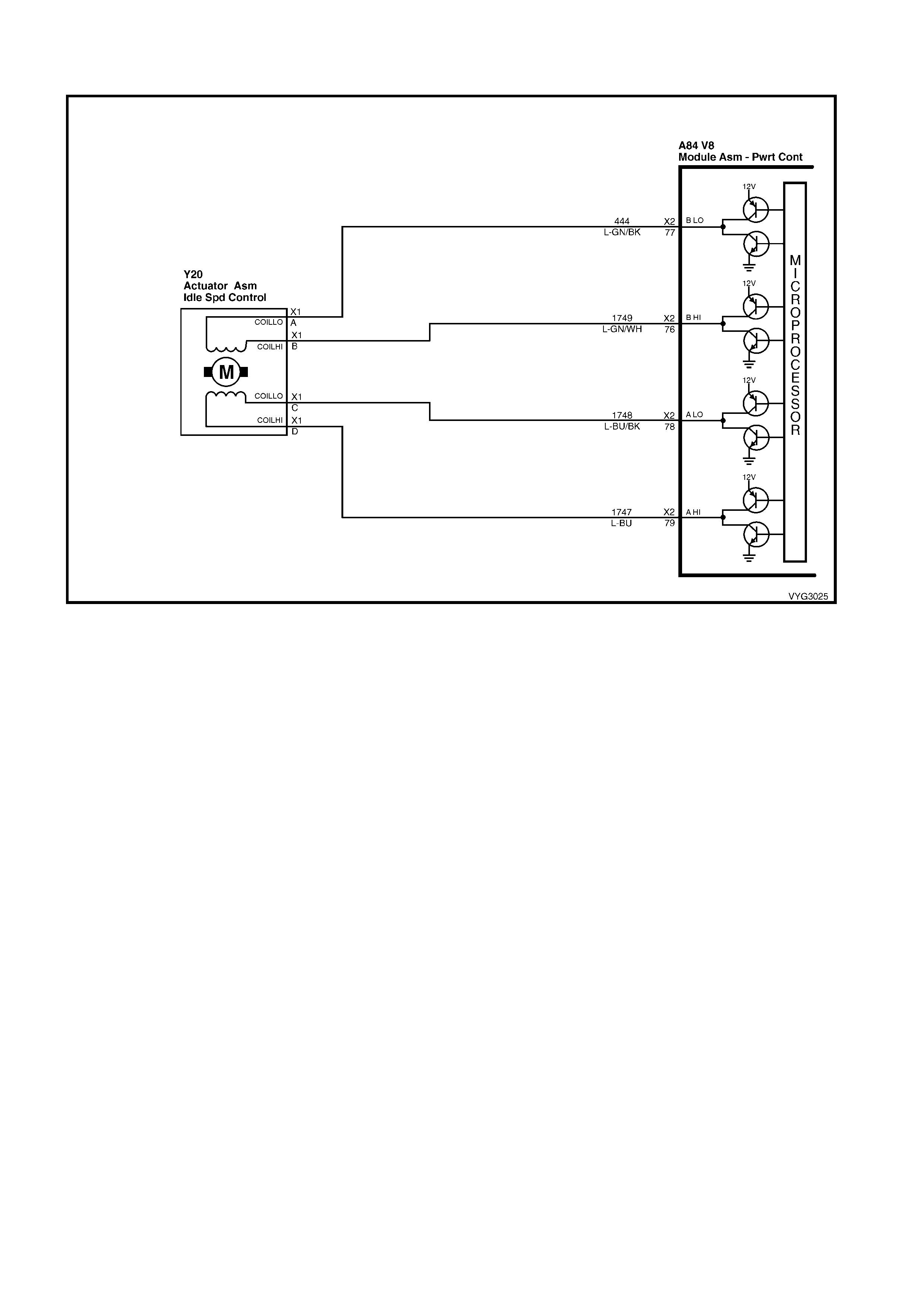
GEN III V8 PCM – DTC P0506 IDLE SPEED LOW
Figure 6C3-2A-124 – Idle Air Control (IAC) Valve Circuit
CIRCUIT DESCRIPTION
The Idle Air Control (IAC) valve is a PCM controlled stepper motor located on the thr ottle body. T he stepper m otor
drives a valve pintle which protrudes into a passage that bypasses the throttle plate. T he PCM comm ands the IAC
valve pintle to ex tend which dec r eases the idle s peed. The bypass air flow is reduc ed and the idle s peed dec reas es
as the pintle approaches its set. The PCM retracts the IAC valve pintle away from its seat to increase the idle
speed. T he retr acting of the IAC valve pintle allows m ore air to bypass the throttle plate. One of the PCMs uses f or
the IAC system is to m aintain a desired idle s peed. This DT C sets when the PCM detects an engine speed outside
of the IAC valve’s range of control.
CONDITIONS FOR RUNNING THE DTC
• DTCs P0101, P0102, P0103, P0107, P0108, P0112, P0113, P0117, P0118, P0171, P0172, P0174, P0175,
P0443, are not set.
• The engine run time is greater than 60 seconds.
• The engine coolant temperature is greater than 60° C.
• The intake air temperature is greater than –10° C.
• The barometric pressure is greater than 65 kPa.
• The ignition voltage is between 9.0 and 17.0 volts.
• The vehicle speed is no more than 2 km/h.
CONDITIONS FOR SETTING THE DTC
• The actual idle speed is 100 RPM less than the desired idle speed.
• All of the above conditions are present for 15 seconds.
ACTION TAKEN WHEN THE DTC SETS
• The PCM activates the Check Powertrain MIL when the diagnostic runs and fails.
• The PCM records the operating conditions at the time the diagnostic fails. The PCM stores this information in
the Freeze Frame/Failure Records.
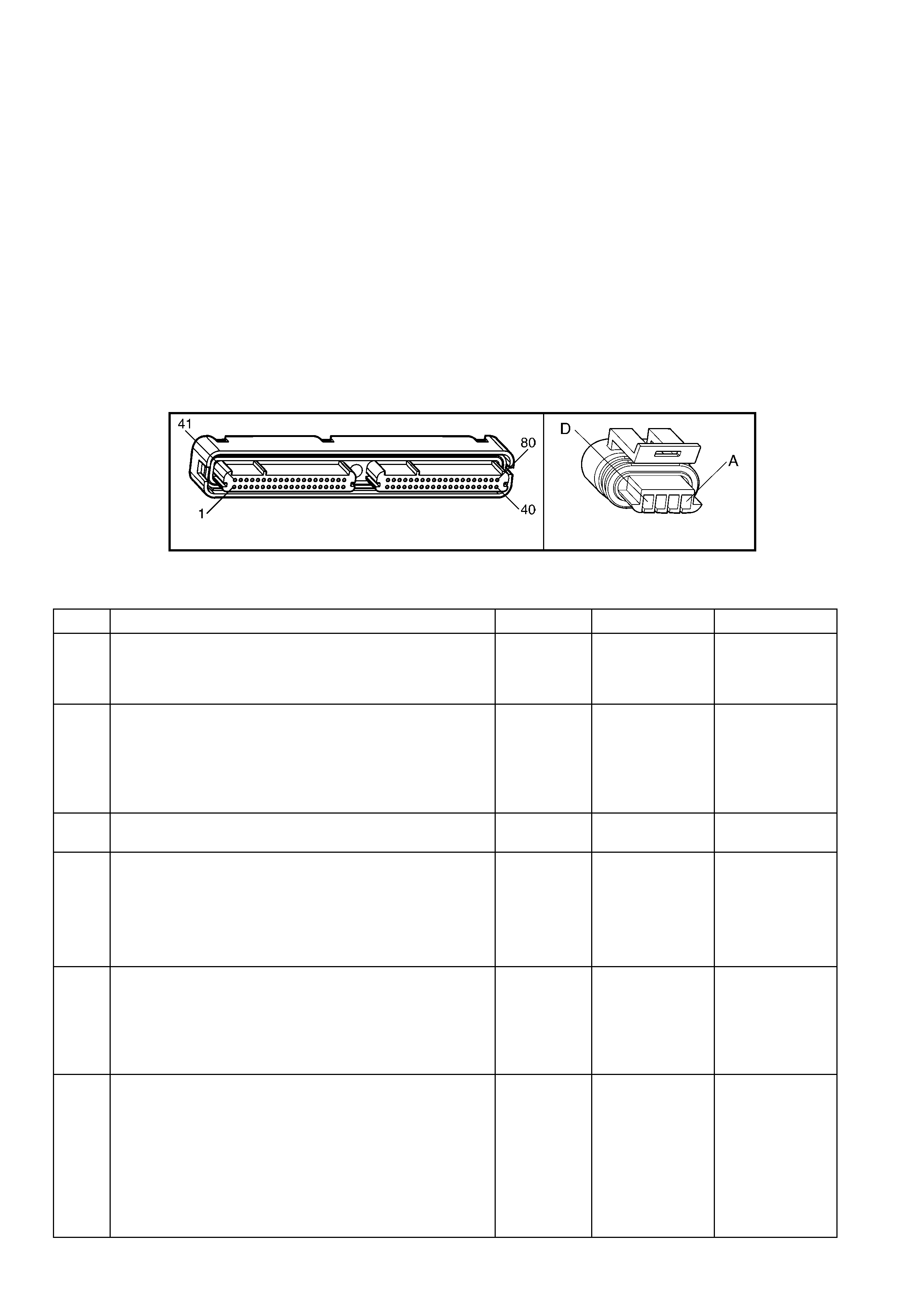
CONDITIONS FOR CLEARING THE MIL/DTC
• The PCM deactivates the Check Powertrain MIL after the first ignition cycle that the diagnostic runs and does
not fail.
• A last test failed (current DTC) clears when the diagnostic runs and does not fail.
• Use Tech 2 to clear the MIL/DTC.
DIAGNOSTIC AIDS
• Using the Freeze Frame/Failure Records data may aid in locating an intermittent condition. If you cannot
duplicate the DTC, the information included in the Freeze Frame/Failure Records data can aid in determining
the distance travelled since the DTC reported a pass and/or fail. Operate the vehicle within the same freeze
frame conditions (RPM, load, vehicle speed, temperature, etc.) that you observed. This will isolate when the
DTC failed.
• For an intermittent, refer to Section 6C3-2B SYMPTOMS, in this Section .
TEST DESCRIPTION
NOTE: The number(s) below refer to the step number(s) on the diagnostic table.
2. This tes t determ ines whether or not the engine can achieve the com m anded RPM, and if not, whether the RPM
is too high or too low.
A84–X2 Y20
Figure 6C3-2A-125
GEN III V8 PCM – DTC P0506 IDLE SPEED LOW
STEP ACTION VALUE YES NO
1. Was the "On-Board Diagnostic" (OBD) System Check
performed? Go to Step 2 Go to
OBD System
Check
in this Section.
2. 1. Idle the engine.
2. Using Tech 2, command engine speed up to 1500
RPM, down to 500 RPM, up to 1500 RPM, and then
EXIT.
Does the engine speed correspond, within 100 RPM, with
each command?
Go to
Diagnostic Aids Go to Step 3
3. Is the engine RPM less than 100 RPM above desired
RPM? Go to Step 4 Go to Step 5
4. 1. Check for the following conditions:
– Vacuum leaks.
– Throttle plate not closing properly.
– A faulty PCV valve.
Did you find and correct the condition?
Go to Step 13 Go to Step 6
5. 1. Check for the following conditions:
– Excessive deposits in the throttle body.
– Parasitic load on the engine (i.e. transmission problem
etc.).
Did you find and correct the conditions?
Go to Step 13 Go to Step 6
6. 1. Ignition OFF.
2. Disconnect the IAC harness connector and install the
appropriate IAC node light from kit J 37027-A.
3. Idle the engine.
4. Using Tech 2, command engine speed up to 1500
RPM, down to 500 RPM, up to 1500 RPM, while
observing the node light.
Do both of the LED’s on the node light cycle red and
green, but never OFF?
Go to Step 7 Go to Step 8

STEP ACTION VALUE YES NO
7. IMPORTANT: During the following test, it is possible to
over-extend the IAC valve pintle until it falls out of the
worm drive. If this occurs, manually screw the pintle shaft
into the worm drive about 2 turns to get it started, align the
keyways on the shaft with the keys in the housing and
gradually retract the pintle using the IAC driver tool.
1. Ignition OFF.
2. Remove the IAC valve.
3. Connect the IAC valve to the IAC Driver tool from kit
J37027-A.
4. Hold the IAC valve with a finger over the pintle in case
it is over extended. Using the driver tool retract and
extend the pintle.
Does the pintle move steadily with each flash of the IAC
driver light?
Go to Step 9 Go to Step 10
8. 1. Check for the following conditions:
– Faulty connection
– Open circuit
– Short to ground
– Short to B+
Did you find and correct the condition?
Go to Step 13 Go to Step 11
9. 1. Check the IAC passages.
Is the action complete? Go to Step 13 –
10. 1. Replace the IAC valve. Refer to Idle Air Control Valve
Replace, in 6C3-3 SERVICE OPERATIONS.
Is the action complete?
Go to Step 13 –
11. 1. Check the connections at the PCM.
Did you find and correct the condition? Go to Step 13 Go to Step 12
12. 1. Replace PCM. Refer to PCM Programming and
PCM/PIM/BCM Security Link Procedure, in 6C3-3
SERVICE OPERATIONS.
Is action complete?
Go to Step 13 –
13. 1. Select the Diagnostic Trouble Code (DTC) option and
the Clear DTC Information option using Tech 2.
2. Idle the engine at the normal operating temperature.
3. Select the Diagnostic Trouble Code (DTC) option, the
DTC Information option and the Failed This Ignition
option using Tech 2.
4. Operate the vehicle, within the Conditions for Running
the DTC, as specified in the supporting text, if
applicable.
Does Tech 2 indicate that this DTC reset?
Go to Step 2 Go to Step 14
14. 1. Using Tech 2, check for any other DTCs.
Does Tech 2 display any DTCs that you have not
diagnosed?
Go to the
applicable DTC
table
System OK
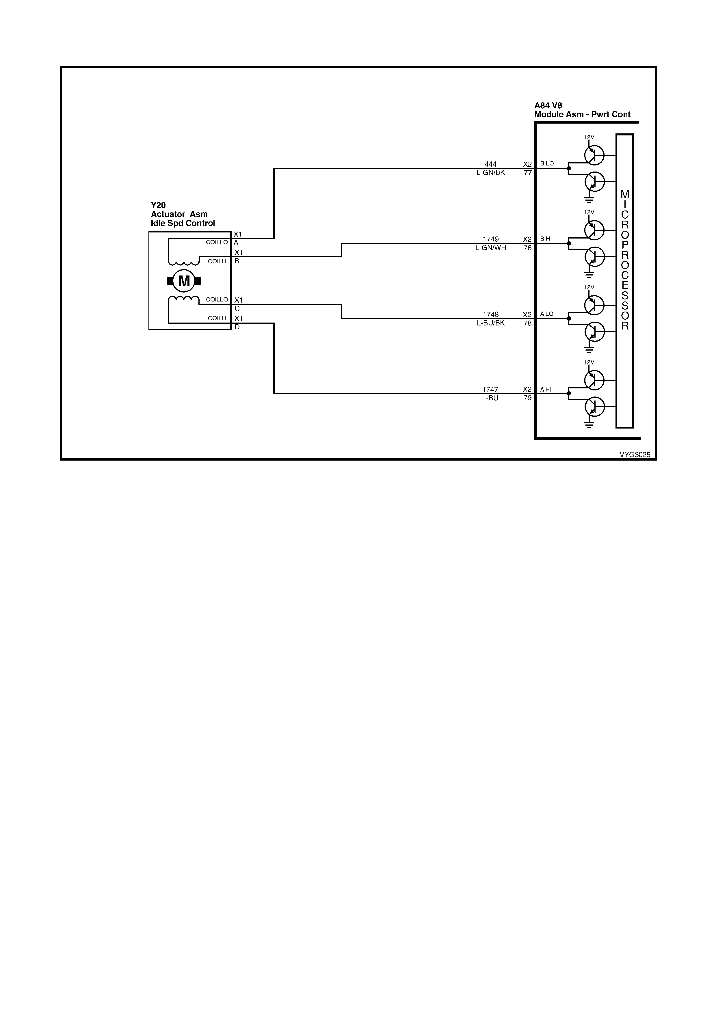
GEN III V8 PCM – DTC P0507 IDLE SPEED HIGH
Figure 6C3-2A-126 – Idle Air Control (IAC) Valve Circuit
CIRCUIT DESCRIPTION
The Idle Air Control (IAC) valve is a PCM controlled stepper motor located on the thr ottle body. T he stepper m otor
drives a valve pintle which protrudes into a passage that bypasses the throttle plate. T he PCM comm ands the IAC
valve pintle to extend to decrease the idle speed. The bypass air flow is reduced and the idle speed decreases as
the pintle appr oaches its s eat. The PCM retrac ts the IAC valve pintle away from its seat to inc rease the idle speed.
The retr ac ting of the IAC valve pintle allows more air to bypass the throttle plate. One of the PCM’s uses f or the IAC
system is to maintain a desired idle speed. This DTC sets when the PCM detects an engine speed outside of the
IAC valve’s range of control.
CONDITIONS FOR RUNNING THE DTC
• DTCs P0101, P0102, P0103, P0107, P0108, P0112, P0113, P0117, P0118, P0171, P0172, P0174, P0175,
P0443, are not set.
• The engine run time is greater than 60 seconds.
• The engine coolant temperature is greater than 60° C.
• The intake air temperature is greater than –10° C.
• The barometric pressure is greater than 65 kPa.
• The ignition voltage is between 9.0 and 17.0 volts.
• The vehicle speed is no more than 1.6 km/h.
CONDITIONS FOR SETTING THE DTC
• The actual idle speed is 100 RPM greater than the desired idle speed.
• All of the above conditions are present for 15 seconds.
ACTION TAKEN WHEN THE DTC SETS
• The PCM activates the Check Powertrain MIL when the diagnostic runs and fails.
• The PCM records the operating conditions at the time the diagnostic fails. The PCM stores this information in
the Freeze Frame/Failure Records.

CONDITIONS FOR CLEARING THE MIL/DTC
• The PCM deactivates the Check Powertrain MIL after the first ignition cycle that the diagnostic runs and does
not fail.
• A last test failed (current DTC) clears when the diagnostic runs and does not fail.
• Use Tech 2 to clear the MIL/DTC.
DIAGNOSTIC AIDS
• Using the Freeze Frame/Failure Records data may aid in locating an intermittent condition. If you cannot
duplicate the DTC, the information included in the Freeze Frame/Failure Records data can aid in determining
the distance travelled since the DTC reported a pass and/or fail. Operate the vehicle within the same freeze
frame conditions (RPM, load, vehicle speed, temperature, etc.) that you observed. This will isolate when the
DTC failed.
• For an intermittent, refer to Section 6C3-2B SYMPTOMS in this Section.
TEST DESCRIPTION
NOTE: The number(s) below refer to the step number(s) on the diagnostic table.
2. This test deter m ines whether or not the engine can ac hieve the com m anded RPM, and if not, whether the RPM
is too high or too low.
A84–X2 Y20
Figure 6C3-2A-127
GEN III V8 PCM – DTC P0507 IDLE SPEED HIGH
STEP ACTION VALUE YES NO
1. Was the "On-Board Diagnostic" (OBD) System Check
performed? Go to Step 2 Go to
OBD System
Check
in this Section.
2. 1. Idle the engine.
2. Using Tech 2, command engine speed up to 1500
RPM, down to 500 RPM, up to 1500 RPM, and then
EXIT.
Does the engine speed correspond, within 100 RPM, with
each command?
Go to Diagnostic
Aids Go to Step 3
3. Is the engine RPM greater than 100 RPM above Desired
RPM? Go to Step 4 Go to Step 5
4. 1. Check for the following conditions:
– Vacuum leaks.
– Throttle plate not closing properly.
– A faulty PCV valve.
Did you find and correct the condition?
Go to Step 12 Go to Step 6
5. 1. Check for the following conditions:
– Excessive deposits in the throttle body.
– Parasitic load on the engine (i.e. transmission
problem etc.).
Did you find and correct the conditions?
Go to Step 13 Go to Step 6
6. 1. Ignition OFF.
2. Disconnect the IAC harness connector and install the
appropriate IAC node light from kit J 37027-A.
3. Idle the engine.
4. Using Tech 2, command engine speed up to 1500
RPM, down to 500 RPM, up to 1500 RPM, while
observing the node light.
Do both of the LED’s on the node light cycle red and
green, but never OFF?
Go to Step 7 Go to Step 8

STEP ACTION VALUE YES NO
7. IMPORTANT: During the following test, it is possible to
over-extend the IAC valve pintle until it falls out of the
worm drive. If this occurs, manually screw the pintle shaft
into the worm drive about 2 turns to get it started, align the
keyways on the shaft with the keys in the housing and
gradually retract the pintle using the IAC driver tool.
1. Ignition OFF.
2. Remove the IAC valve.
3. Connect the IAC valve to the IAC Driver tool from kit
J37027-A.
4. Hold the IAC valve with a finger over the pintle in case
it is over extended. Using the driver tool retract and
extend the pintle.
Does the pintle move steadily with each flash of the IAC
driver light?
Go to Step 8 Go to Step 9
8. 1. Check for the following conditions:
– Faulty connection
– Open circuit
– Short to ground
– Short to B+
Did you find and correct the condition?
Go to Step 12 Go to Step 10
9. 1. Replace the IAC valve. Refer to Idle Air Control Valve
Replace, in 6C3-3 SERVICE OPERATIONS.
Is the action complete?
Go to Step 12 –
10. 1. Check the connections at the PCM.
Did you find and correct the condition? Go to Step 12 Go to Step 11
11. 1. Replace PCM. Refer to PCM Programming and
PCM/PIM/BCM Security Link Procedure, in 6C3-3
SERVICE OPERATIONS.
Is action complete?
Go to Step 12 –
12. 1. Select the Diagnostic Trouble Code (DTC) option and
the Clear DTC Information option using Tech 2.
2. Idle the engine at the normal operating temperature.
3. Select the Diagnostic Trouble Code (DTC) option, the
DTC Information option and the Failed This Ignition
option using Tech 2.
4. Operate the vehicle, within the Conditions for Running
the DTC, as specified in the supporting text, if
applicable.
Does Tech 2 indicate that this DTC reset?
Go to Step 2 Go to Step 13
13. 1. Using Tech 2, check for any other DTCs.
Does Tech 2 display any DTCs that you have not
diagnosed?
Go to the
applicable DTC
table
System OK

GEN III V8 PCM – DTC P0522 ENGINE OIL PRESSURE SENSOR LOW VOLTAGE
Figure 67C3-2A-128 – Oil Pressure Sensor Circuit
CIRCUIT DESCRIPTION
The Engine Oil Pressure Sensor is mounted in the top rear of the engine. The Engine Oil Pressure Sensor
meas ur es changes in engine oil pr ess ur e. T he Engine O il Pr ess ur e Sensor has a 5.0 volt referenc e, a ground and a
signal circuit.
The Engine Oil Pressure Sensor changes resistance based on engine oil pressure.
The Engine O il Pressure Sens or is used to deter mine when the oil press ure is below a certain threshold. When the
oil pressure reaches a predetermined value, the PCM will determine this as low oil pressure. The PCM will then
send a serial data message to the Instrument Panel (IP) cluster to activate the ‘Check Oil’ warning icon.
When the PCM senses a signal voltage lower than the normal operating range of the sensor, this DTC will set.
CONDITIONS FOR RUNNING THE DTC
• Engine running.
CONDITIONS FOR SETTING THE DTC
• Engine Oil Pressure Sensor voltage is less than 0.48 volts.
ACTION TAKEN WHEN THE DTC SETS
• The PCM activates the Check Powertrain MIL when the diagnostic runs and fails.
• The PCM records the operating conditions at the time the diagnostic fails. The PCM stores this information in
the Freeze Frame/Failure Records.
• The ‘Check Oil’ icon will be activated in the Instrument MFD.
CONDITIONS FOR CLEARING THE MIL/DTC
• T he PCM deactivates the Check Powertrain MIL, after the first ignition cycle that the diagnostic runs and does
not fail.
• A last test failed (Current DTC) will not clear when the diagnostic runs and does not fail.
• Use Tech 2 to clear the MIL/DTC.
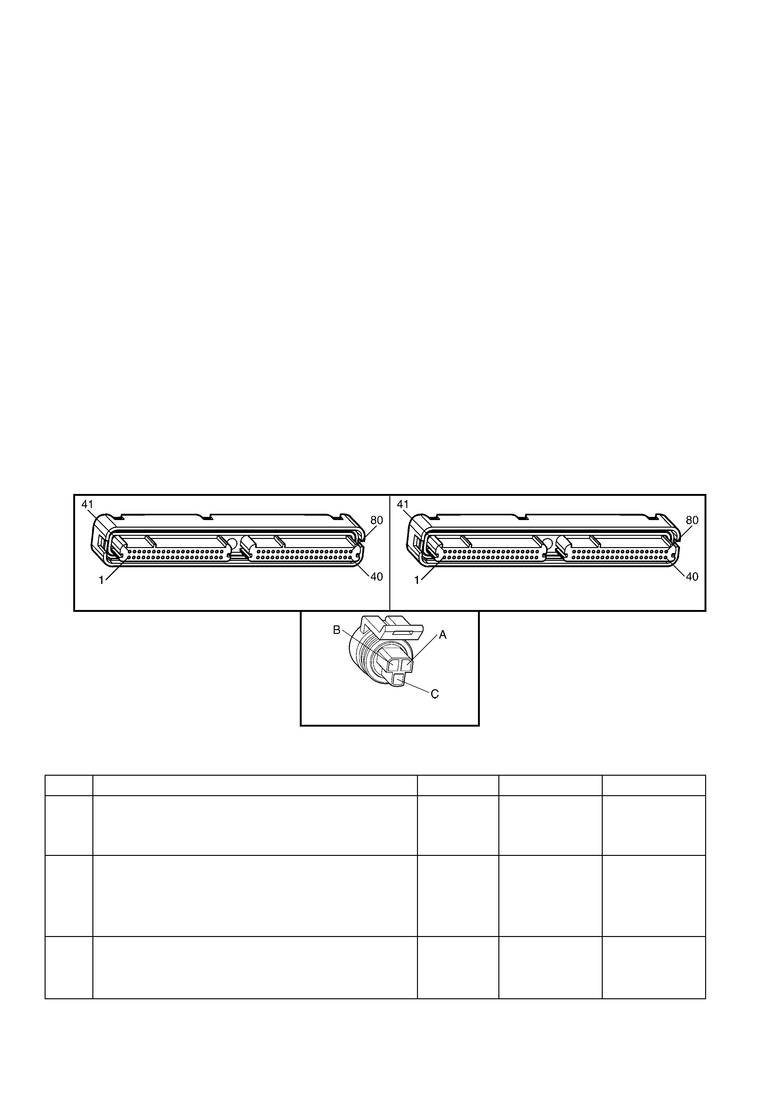
DIAGNOSTIC AIDS
• The following may cause an intermittent:
– Incorrectly routed harness
– Rubbed through wire insulation
– Broken wire inside the insulation
• The PCM 5.0 volt re ferenc e circ uits are inter nally connected within the PCM. If all the Engine Oil sensor circuits
check to be OK, inspect related 5.0 volt reference circuits. Refer to DTC P1635.
• If there is a failure with the ‘Check Oil’ icon, more than likely it is an instrument cluster fault.
• Using the Freeze Frame/Failure Records data may aid in locating an intermittent condition. If you cannot
duplicate the DTC, the information included in the Freeze Frame/Failure Records data can aid in determining
the distance travelled since the DTC reported a pass and/or fail. Operate the vehicle within the same freeze
frame conditions (RPM, load, vehicle speed, temperature, etc.) that you observed. This will isolate when the
DTC failed.
• For an intermittent, refer to Section 6C3-2B SYMPTOMS in this Section.
TEST DESCRIPTION
NOTE: The number(s) below refer to the step number(s) on the diagnostic table.
3. This step determines if the malfunction is present. For any test that requires probing of the PCM or any
com ponent har ness c onnec tors , us e the Connector T es t Adaptor Kit J 35616- A. Us ing this kit prevents damage
to the harness connector terminals.
5. If Tech 2 displays 5.0 volts, this indicates that the Engine Oil Pressure sensor signal 5.0 volt reference circuit
and PCM are OK.
6. If Tech 2 displays 5.0 volts, this indicates that the Engine Oil Pressure sensor signal circuit and the PCM are
OK.
7. Disconnecting the PCM allows the use of a DMM to check the continuity of the circuits. T his aids in loc ating an
open or shorted circuit.
A84–X1 (BLUE) A84-X2 (RED)
B42
Figure 6C3-2A-129
GEN III V8 PCM – DTC P0522 ENGINE OIL PRESSURE SENSOR LOW VOLTAGE
STEP ACTION VALUE YES NO
1. Was the "On-Board Diagnostic" (OBD) System Check
performed? Go to Step 2 Go to
OBD System
Check
in this Section.
2. 1. Install Tech 2.
2. Idle the engine.
3. Monitor the Failed This Ignition under DTC Information
for DTC P1635 using Tech 2.
Did DTC P1635 fail this ignition cycle?
Go to DTC
P1635 5 Volt
Reference #1
Circuit
Go to Step 3
3. 1. Idle the engine and monitor the Engine Oil Pressure
voltage using Tech 2.
Is the Engine Oil Pressure voltage at or below the specified
value?
0.48 volts Go to Step 5 Go to Step 4

STEP ACTION VALUE YES NO
4. 1. Ignition ON, engine OFF.
2. Review the Freeze Frame/Failure Records data for
this DTC and observe parameters.
3. Turn OFF the ignition for 15 seconds.
4. Operate the vehicle within the conditions required for
this diagnostic to run, and as close to the conditions
recorded in the Freeze Frame/Failure Records as
possible. Special operating conditions that you need to
meet before the PCM will run this diagnostic, where
applicable, are listed in Conditions for Running the
DTC.
5. Select the Diagnostic Trouble Code (DTC) option, the
DTC Information option and the Failed This Ignition
option using Tech 2.
Does Tech 2 indicate that this DTC failed this ignition?
Go to Step 5 Go to
Diagnostic Aids
5. 1. Disconnect the Engine Oil Pressure sensor electrical
connector, B42.
2. Ignition ON, engine OFF.
3. Jumper the 5.0 volt reference circuit and the engine oil
pressure signal circuit together at the Engine Oil
Pressure sensor harness connector.
4. Observe the Engine Oil Pressure voltage display on
Tech 2.
Is the Engine Oil Pressure voltage near the specified
value?
5.0 volts Go to Step 11 Go to Step 6
6. 1. Connect a test lamp between B+ and the Engine Oil
Pressure sensor signal circuit 331 at the Engine Oil
Pressure sensor harness connector, B42.
2. Observe the Engine Oil Pressure voltage display on
Tech 2.
Is the Engine Oil Pressure voltage at the specified value?
5.0 volts Go to Step 7 Go To Step 9
7. 1. Ignition OFF.
2. Disconnect the PCM BLUE connector, A84-X1.
3. Check the 5.0 volt reference circuit for an open or
short to ground.
4. Repair the 5.0 volt reference circuit if it is open or
shorted to ground.
Was the 5.0 volt reference circuit open or shorted to
ground?
Go to Step 13 Go to Step 8
8. 1. Check the 5.0 volt reference circuit for a poor
connection at the PCM.
2. Replace the terminal if necessary.
Did the Terminal require replacement?
Go to Step 13 Go to Step 12
9. 1. Ignition OFF.
2. Disconnect the PCM RED connector, A84-X2.
3. Check the Engine Oil Pressure signal circuit 331 for
the following:
– Open circuit
– Short to ground
– Short to sensor ground circuit.
4. Repair the Engine Oil Pressure sensor signal circuit if
it is open or shorted to ground.
W as the Engine Oil Pressure signal circuit open or shorted
to ground?
Go to Step 13 Go to Step 10
10. 1. Check the Engine Oil Pressure Sensor signal circuit
for a poor connection at the PCM.
2. If you find a poor connection, replace the terminal.
Did the terminal require replacement?
Go to Step 13 Go to Step 12

STEP ACTION VALUE YES NO
11. IMPORTANT: Before replacing the Engine Oil Pressure
sensor, perform an engine oil pressure check. Refer to
6A3 ENGINE MECHANICAL – GEN III V8 ENGINE.
1. Replace the Engine Oil Pressure sensor.
Is the action complete?
Go to Step 13 –
12. 1. Replace PCM. Refer to PCM Programming and
PCM/PIM/BCM Security Link Procedure, in 6C3-3
SERVICE OPERATIONS.
Is action complete?
Go to Step 13 –
13. 1. Select the Diagnostic Trouble Code (DTC) option and
the Clear DTC option using Tech 2.
2. Idle the engine at the normal operating temperature.
3. Select the Diagnostic Trouble Code (DTC) option, the
DTC Information option and the Failed This Ignition
option using Tech 2.
4. Operate vehicle, within the Conditions for Running this
DTC, as specified in the supporting text, if applicable.
Does Tech 2 indicate that this DTC reset?
Go to Step 2 Go to Step 14
14. 1. Using Tech 2, check for any other DTCs.
Does Tech 2 display any DTCs that you have not
diagnosed?
Go to the
applicable DTC
table
System OK
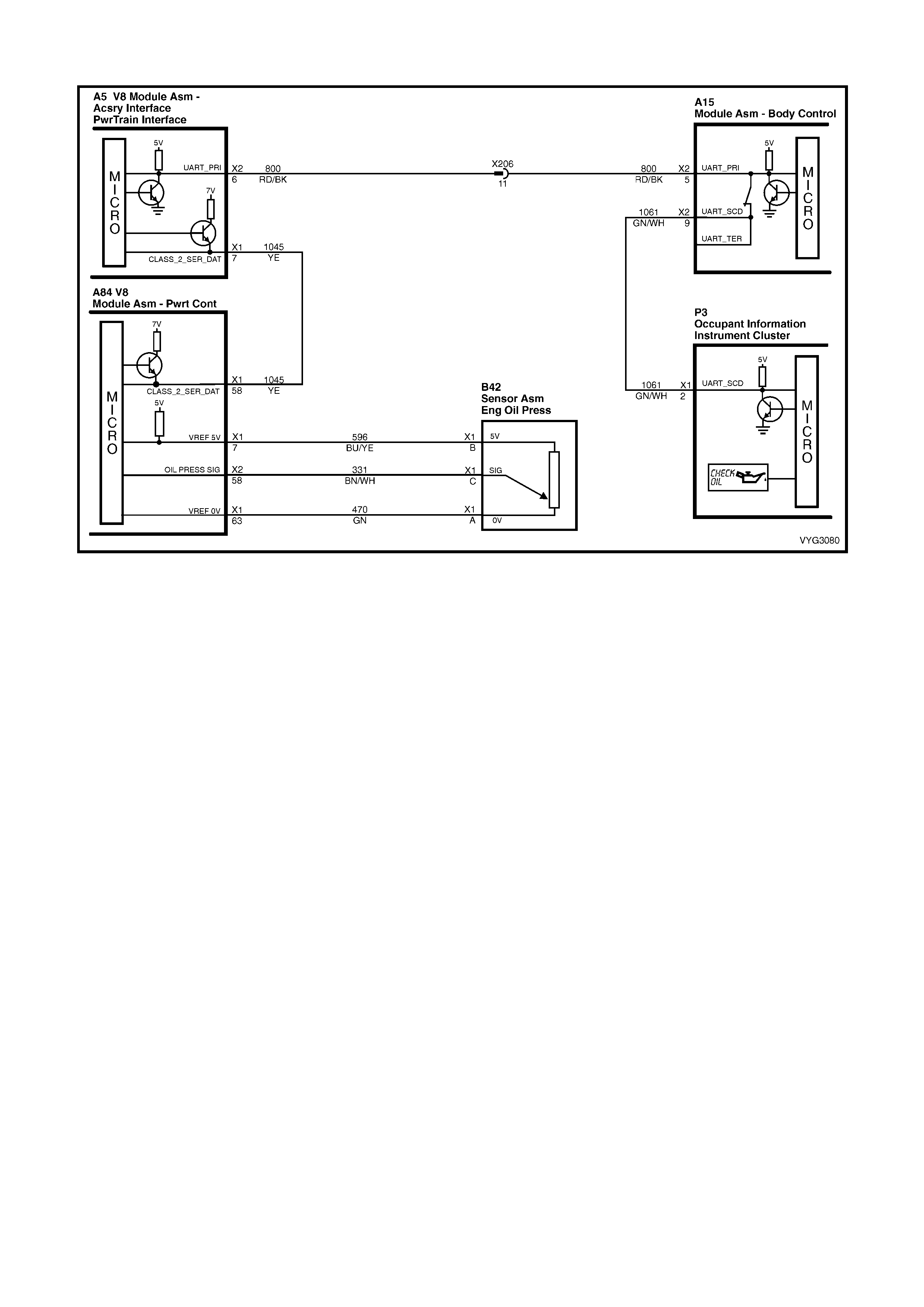
GEN III V8 PCM – DTC P0523 ENGINE OIL PRESSURE SENSOR HIGH VOLTAGE
Figure 67C3-2A-130 – Oil Pressure Sensor Circuit
CIRCUIT DESCRIPTION
The Engine Oil Pressure Sensor is mounted in the top rear of the engine. The Engine Oil Pressure Sensor
meas ur es changes in engine oil pr ess ur e. T he Engine O il Pr ess ur e Sensor has a 5.0 volt referenc e, a ground and a
signal circuit.
The Engine Oil Pressure Sensor changes resistance based on engine oil pressure.
The Engine O il Pressure Sens or is used to deter mine when the oil press ure is below a certain threshold. When the
oil pressure reaches a predetermined value, the PCM will determine this as high oil pressure. The PCM will then
send a serial data message to the Instrument Panel (IP) cluster to activate the ‘Check Oil’ warning icon.
When the PCM senses a signal voltage higher than the normal operating range of the sensor, this DTC will set.
CONDITIONS FOR RUNNING THE DTC
• Engine running.
CONDITIONS FOR SETTING THE DTC
• Engine Oil Pressure Sensor voltage is greater than 4.9 volts.
ACTION TAKEN WHEN THE DTC SETS
• The PCM activates the Check Powertrain MIL when the diagnostic runs and fails.
• The PCM records the operating conditions at the time the diagnostic fails. The PCM stores this information in
the Freeze Frame/Failure Records.
• The ‘Check Oil’ icon will be activated in the Instrument MFD.
CONDITIONS FOR CLEARING THE MIL/DTC
• T he PCM deactivates the Check Powertrain MIL, after the first ignition cycle that the diagnostic runs and does
not fail.
• A last test failed (Current DTC) will clear when the diagnostic runs and does not fail.
• Use Tech 2 to clear the MIL/DTC.
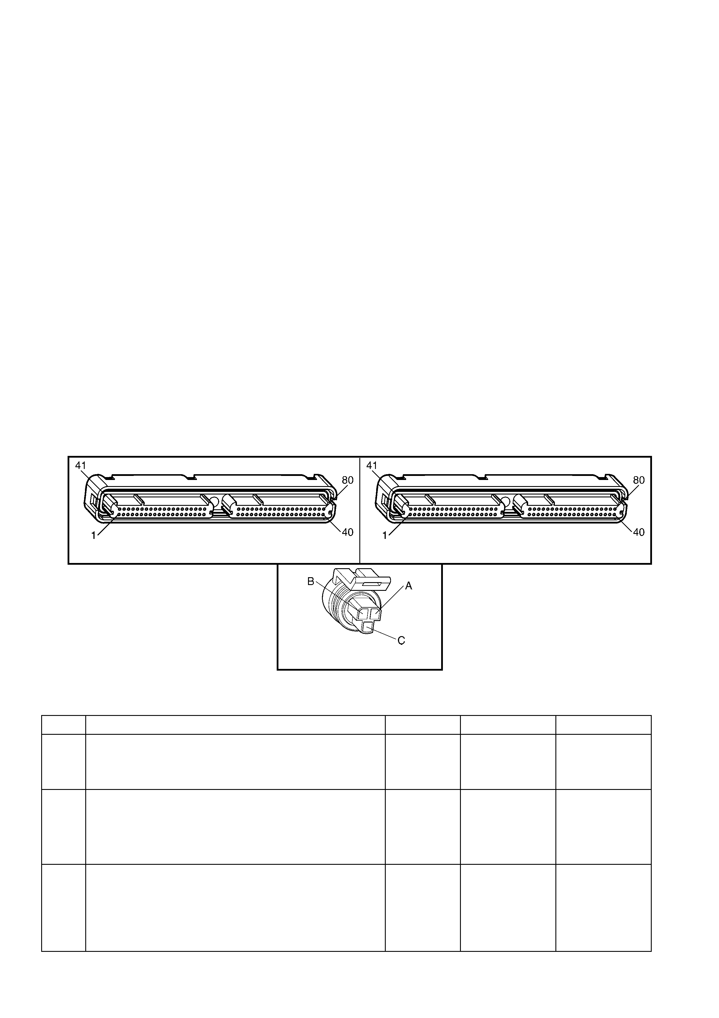
DIAGNOSTIC AIDS
• The following may cause an intermittent:
– Incorrectly routed harness
– Rubbed through wire insulation
– Broken wire inside the insulation
• The PCM 5.0 volt re ferenc e circ uits are inter nally connected within the PCM. If all the Engine Oil sensor circuits
check to be OK, inspect related 5.0 volt reference circuits. Refer to DTC P1635.
• If there is a failure with the ‘Check Oil’ icon, more than likely it is an instrument cluster fault.
• Using the Freeze Frame/Failure Records data may aid in locating an intermittent condition. If you cannot
duplicate the DTC, the information included in the Freeze Frame/Failure Records data can aid in determining
the distance travelled since the DTC reported a pass and/or fail. Operate the vehicle within the same freeze
frame conditions (RPM, load, vehicle speed, temperature, etc.) that you observed. This will isolate when the
DTC failed.
• For an intermittent, refer to Section 6C3-2B SYMPTOMS in this Section.
TEST DESCRIPTION
NOTE: The number(s) below refer to the step number(s) on the diagnostic table.
3. This step determines if the malfunction is present. For any test that requires probing of the PCM or any
com ponent har ness c onnec tors , us e the Connector T es t Adaptor Kit J 35616- A. Us ing this kit prevents damage
to the harness connector terminals.
5. If Tech 2 displays 5.0 volts, this indicates that the Engine Oil Pressure sensor signal 5.0 volt reference circuit
and PCM are OK.
6. If Tech 2 displays 5.0 volts, this indicates that the Engine Oil Pressure sensor signal circuit and the PCM are
OK.
7. Disconnecting the PCM allows the use of a DMM check the continuity of the circuits. This aids in locating an
open or shorted circuit.
A84–X1 (BLUE) A84-X2 (RED)
B42
Figure 6C3-2A-131
GEN III V8 PCM – DTC P0523 ENGINE OIL PRESSURE SENSOR HIGH VOLTAGE
STEP ACTION VALUE YES NO
1. Was the "On-Board Diagnostic" (OBD) System Check
performed? Go to Step 2 Go to
OBD System
Check
in this Section.
2. 1. Install Tech 2.
2. Idle the engine.
3. Monitor the Failed This Ignition under DTC Information
for DTC P1635 using Tech 2.
Did DTC P1635 fail this ignition cycle?
Go to DTC
P1635 5 Volt
Reference #1
Circuit table
Go to Step 3
3. 1. Install Tech 2.
2. Idle the engine.
3. Monitor the Engine Oil Pressure sensor voltage using
Tech 2.
Is the Engine Oil Pressure voltage at or above the
specified value?
4.5 volts Go to Step 5 Go to Step 4

STEP ACTION VALUE YES NO
4. 1. Ignition ON, engine OFF.
2. Review the Freeze Frame/Failure Records data for
this DTC and observe parameters.
3. Turn OFF the ignition for 15 seconds.
4. Operate the vehicle within the conditions required for
this diagnostic to run, and as close to the conditions
recorded in the Freeze Frame/Failure Records as
possible. Special operating conditions that need to be
met before the PCM will run this diagnostic, where
applicable, are listed in Conditions for Running the
DTC.
5. Select the Diagnostic Trouble Code (DTC) option, the
DTC Information option and the Failed This Ignition
option using Tech 2.
Does Tech 2 indicate that this DTC failed this ignition?
Go to Step 5 Go to
Diagnostic Aids
5. 1. Disconnect the Engine Oil Pressure sensor electrical
connector, B42.
2. Observe the Engine Oil Pressure voltage display on
Tech 2.
Is the Engine Oil Pressure voltage less than the specified
value?
1.0 volt Go to Step 6 Go to Step 7
6. 1. Probe the sensor ground circuit 470 with a test lamp to
B+.
Is the test lamp illuminated?
Go to Step 8 Go to Step 9
7. 1. Check the Engine Oil Pressure sensor signal circuit
331 for a short to voltage or a short to the 5.0 volt
reference circuit.
2. Repair the Engine Oil Pressure sensor signal circuit if
it is shorted.
Was the Engine Oil Pressure sensor signal circuit shorted?
Go to Step 14 Go to Step 12
8. 1. Measure the voltage at the 5.0 volt reference circuit
596 to ground, using a DMM.
Is the voltage greater than the specified value?
5.0 volts Go to Step 13 Go to Step 9
9. 1. Check for a poor sensor ground terminal connection at
the PCM BLUE connector A84-X1, terminal X1-63.
2. If you find a problem, replace the faulty terminal.
Did the terminal require replacement?
Go to Step 14 Go to Step 10
10. 1. Check the continuity of the Engine Oil Pressure
sensor ground circuit.
2. If you find that the Engine Oil Pressure sensor ground
circuit measures over the specified value, repair the
open or the poor connection.
Was a condition found and corrected?
0 – 5 Ω Go to step 14 Go to Step 11
11. 1. Replace PCM. Refer to PCM Programming and
PCM/PIM/BCM Security Link Procedure, in 6C3-3
SERVICE OPERATIONS.
Is action complete?
Go to Step 14 –
12. IMPORTANT: Before replacing the Engine Oil Pressure
sensor, perform an engine oil pressure check. Refer to
6C3 ENGINE MECHANICAL – GEN III V8 ENGINE.
1. Replace the Engine Oil Pressure sensor.
Is the action complete?
Go to Step 14 –
13. 1. Repair the 5.0 volt reference circuit for a short to
voltage.
Is the action complete?
Go to Step 14 –

STEP ACTION VALUE YES NO
14. 1. Select the Diagnostic Trouble Code (DTC) option and
the Clear DTC option using Tech 2.
2. Idle the engine at the normal operating temperature.
3. Select the Diagnostic Trouble Code (DTC) option, the
DTC Information option and the Failed This Ignition
option using Tech 2.
4. Operate vehicle, within the Conditions for Running this
DTC, as specified in the supporting text, if applicable.
Does Tech 2 indicate that this DTC reset?
Go to Step 2 Go to Step 15
15. 1. Using Tech 2, check for any other DTCs.
Does Tech 2 display any DTCs that you have not
diagnosed?
Go to the
applicable DTC
table
System OK

GEN III V8 PCM – DTC P0530 A/C REFRIGERANT PRESSURE SENSOR CIRCUIT
Figure 6C3-2A-132 – A/C Refrigerant Pressure Sensor Circuit
CIRCUIT DESCRIPTION
The A/C system uses an A/C Refrigerant Pressure Sensor mounted in the high side of the A/C system to monitor
A/C refrigerant pressure. The PCM utilises this information in order to turn ON the engine coolant fan high speed
relay when the A/C refrigerant pressure is high.
The A/C Refrigerant Pressure Sensor operates much like other 3-wire sensors. The PCM supplies a 5.0 volt
reference to the sensor. The sensor supplies a signal circuit to the PCM. As the A/C pressure increases or
decreases, the resistance of the sensor changes and varies the signal voltage to the PCM.
The PCM m onitors the A/C Ref rigerant Pres sure Sensor s ignal circuit and can determ ine when the A/C pressure is
too high or too low. The PCM disables the A/C compressor clutch and sets a DTC P0530 when the pressures are
out of range ( high or low) for a predeter mined tim e. The PCM dis ables the A/C com pressor in order to prevent A/C
compressor damage.
CONDITIONS FOR RUNNING THE DTC
• The PCM detects an A/C request.
CONDITIONS FOR SETTING THE DTC
• A/C Refrigerant Pressure Sensor indicates A/C refrigerant pressure is at or below 25 kPa for five seconds.
OR
• A/C Refrigerant Pressure Sensor indicates A/C refrigerant pressure is at or above 3140 kPa for five seconds.
ACTION TAKEN WHEN THE DTC SETS
• The PCM stores the DTC information into memory when the diagnostic runs and fails.
• The Check Powertrain MIL will not be illuminated.
• The PCM records the operating conditions at the time the diagnostic fails. The PCM stores this information in
the Freeze Frame/Failure Records.
CONDITIONS FOR CLEARING THE MIL/DTC
• A last test failed (current DTC) clears when the diagnostic runs and does not fail.
• Use Tech 2 to clear the MIL/DTC.
DIAGNOSTIC AIDS
• If the test did not f ail this ignition c ycle, move the related elec trical harnes s and the connectors while monitor ing
Tech 2.
• For an intermittent, refer to Section 6C3-2B SYMPTOMS in this Section.
TEST DESCRIPTION
NOTE: The number(s) below refer to the step number(s) on the diagnostic table.
3. This step checks if the A/C pressure sensor signal circuit 380 is shorted to voltage.
4. Jumping the sensor signal circuit to ground checks if the signal circuit is OK. If the signal circuit is OK the
voltage displayed on TECH 2 will be less than 0.2 volts.
5. Jumping the sensor signal circuit to the sensor ground circuit checks if the signal ground circuit is OK. If the
signal ground circuit is OK the voltage displayed on TECH 2 will be less than 0.2 volts.
6. This test step checks the 5 volt reference circuit 2700. An open in a shared 5 volt reference circuit can cause
other DTC's to be set. If no other DTC's were set, the circuit must have an open between the sensor and the
circuits wiring harness splice.
7. This test step check if circuits 2700 and 380 are shorted together.

A84–X1 (BLUE) A84-X2 (RED)
B18
Figure 6C3-2A-133
GEN III V8 – DTC P0530 A/C REFRIGERANT PRESSURE SENSOR CIRCUIT
STEP ACTION VALUE YES NO
1. Was the "On-Board Diagnostic" (OBD) System Check
performed? Go to Step 2 Go to
OBD System
Check
2. 1. Ignition ON, engine OFF.
2. Install TECH 2, and display A/C pressure sensor
voltage.
Is the A/C pressure sensor voltage at or above the
specified value?
4.0 V Go to Step 3 Go to Step 9
3. 1. Disconnect A/C pressure sensor electrical
connector B18.
3. Using a Digital Multimeter (DMM) check the voltage
at terminal X1-C circuit 380 of harness connector
B18.
Is voltage greater than specified value?
5.0 V Go to Step 12 Go to Step 4
4. 1. W ith A/C pressure sensor electrical connector B18
disconnected.
2. Using fused jumper wire, jumper the A/C pressure
sensor signal circuit 380 of harness connector B18
terminal X1-C to a known good ground.
Does TECH 2 indicate A/C pressure sensor voltage at
or below the specified value?
0.2 V Go to Step 5 Go to Step 11
5. 1. With A/C pressure sensor electrical connector
disconnected.
2. Using fused jumper wire, jumper circuit 380, A/C
pressure sensor signal terminal X1-C to circuit
5514 sensor ground terminal X1-A of harness
connector B18.
Does TECH 2 indicate A/C pressure sensor voltage at
or below the specified value?
0.2 V Go to Step 6 Go to Step 13
6. 1. With A/C pressure sensor electrical connector
disconnected.
2. Using a DMM measure voltage on circuit 2700 at
terminal X1-B of harness connector B18.
Is the voltage at specified value?
5.0 V Go to Step 7 Go to Step 14
7. 1. W ith A/C pressure sensor electrical connector B18
disconnected.
2. Disconnect all PCM connectors.
3. Using a DMM check for continuity between circuit
2700 and 380.
Is there continuity?
Go to Step 15 Go to Step 8
8. Replace A/C pressure sensor.
Is action complete? Verify Repair –
9. Is the A/C pressure sensor voltage at or below the
specified value? 0.2 V Go to Step 10 Go to Step 6

STEP ACTION VALUE YES NO
10. Check for short to ground in A/C pressure sensor signal
circuit 380.
Was a problem found?
Verify Repair Go to Step 16
11. Check for open or poor terminal retention in A/C
pressure sensor signal circuit 380.
Was a problem found?
Verify Repair Go to Step 16
12. Check A/C pressure sensor signal circuit 380 for short
to voltage.
Was a problem found?
Verify Repair Go to Step 16
13. Check for open or poor terminal retention in ground
circuit 5514 to A/C pressure sensor.
Was a problem found?
Verify Repair Go to Step 16
14. Check for open, poor terminal retention, short to ground
or short to voltage in 5 volt reference circuit 2700.
Is action complete?
Verify Repair Go to Step 16
15. Repair short between circuits 380 and 2700.
Is action complete? Verify Repair –
16. Replace PCM. Refer to PCM Programming and
PCM/PIM/BCM Security Link Procedure, in 6C3-3
SERVICE OPERATIONS.
Is action complete?
Verify Repair –
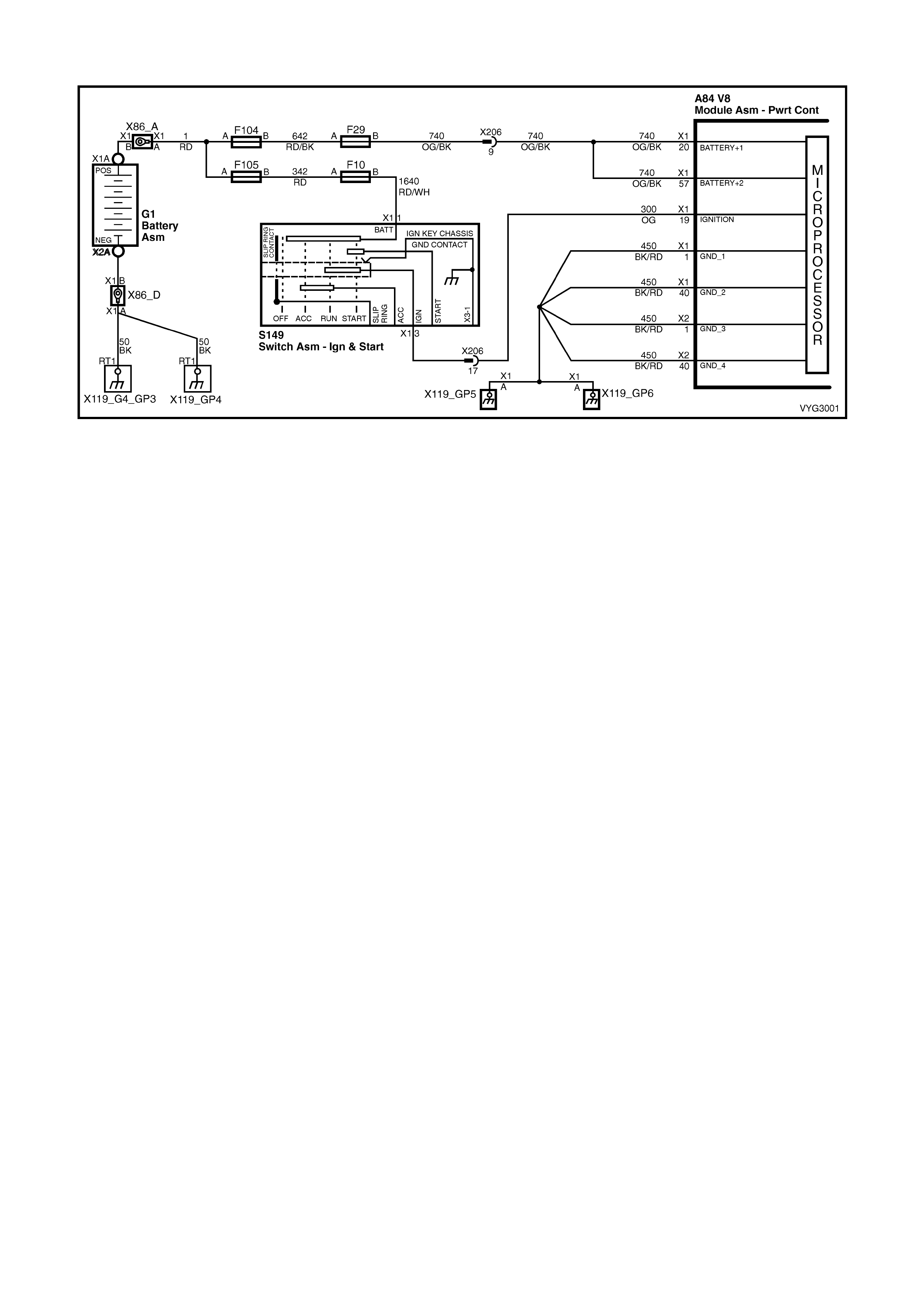
GEN III V8 PCM – DTC P0562 SYSTEM VOLTAGE LOW
Figure 6C3-2A-134 – PCM Power and Ground Circuits
CIRCUIT DESCRIPTION
The PCM continuously monitors the system voltage. The system voltage information is taken from the PCM’s
ignition feed circuit. Voltages below 8.0 volts or above 17.1 volts cause improper system operation and/or
com ponent damage. T he PCM operates in a def ault mode if a PCM voltage DTC sets . If the system voltage is low,
the PCM raises the idle s peed in order to increas e the generator output. The PCM dis ables mos t outputs to protect
the hardware if the s ystem voltage is high. T ec h 2 will not display data if system voltage is outs ide this r ange. Us e a
DMM in order to monitor the system voltage in order to check to see if the fault is currently present.
CONDITIONS FOR RUNNING THE DTC
• The engine is running longer than ten seconds.
• The engine speed is greater than 1000 RPM.
• The vehicle speed is greater than 8 km/h.
CONDITIONS FOR SETTING THE DTC
• The PCM senses system voltage below 8.5 volts.
• All of the above conditions are present for five seconds.
ACTION TAKEN WHEN THE DTC SETS
• The PCM stores the DTC information into memory when the diagnostic runs and fails.
• The Check Powertrain MIL will not be activated.
• The PCM will command a high idle speed.
• The transmission will default to third gear.
• The PCM will inhibit TCC operation.
• The PCM records the operating conditions at the time the diagnostic fails. The PCM stores this information in
the Freeze Frame/Failure Records.
CONDITIONS FOR CLEARING THE MIL/DTC
• A last test failed (current DTC) clears when the diagnostic runs and does not fail.
• Use Tech 2 to clear the MIL/DTC.
DIAGNOSTIC AIDS
• An extremely low voltage (below 7.5 volts) may cause the loss of serial data. An open ignition feed circuit
causes a No Start and the MIL will not illuminate. A low system voltage may cause other DTCs to set.
• Using the Freeze Frame/Failure Records data may aid in locating an intermittent condition. If you cannot
duplicate the DTC, the information included in the Freeze Frame/Failure Records data can aid in determining
the distance travelled since the DTC reported a pass and/or fail. Operate the vehicle within the same Freeze
Frame conditions (RPM, load, vehicle speed, temperature, etc.) that you observed. This will isolate when the
DTC failed.
• For an intermittent, refer to Section 6C3-2B SYMPTOMS, in this Section.

TEST DESCRIPTION
NOTE: The number(s) below refer to the step number(s) on the diagnostic table.
2. This step checks the Charging system under load at idle. The voltage should remain above 8.0 volts.
A84–X1 (BLUE)
Figure 6C3-2A-135
GEN III V8 PCM – DTC P0562 SYSTEM VOLTAGE LOW
STEP ACTION VALUE YES NO
1. Was the "On-Board Diagnostic" (OBD) System Check
performed? Go to Step 2 Go to
OBD System
Check
in this Section.
2. 1. Start the engine.
2. Load the electrical system by turning ON the
headlights and the heater fan to High.
3. Measure the battery voltage at the battery using a
DMM.
Is the battery voltage less than the specified value?
8.0 volts Go to
12A BATTERY
& CABLES
Go to Step 3
3. 1. Ignition OFF.
2. Disconnect the PCM BLUE connector A84-X1.
3. Ignition ON, engine OFF.
4. Measure the voltage at terminal X1-19 for the ignition
feed circuit using a DMM.
Is the voltage less than the specified value?
8.0 volts Go to Step 7 Go to Step 4
4. 1. Check for faulty connections at the PCM.
Did you find and correct the condition? Go to Step 8 Go to Step 5
5. 1. Ignition OFF.
2. Reconnect the PCM.
3. Ignition ON, engine OFF.
4. Monitor the Failed This Ignition option under the
Diagnostic Trouble Codes (DTC) option using Tech 2.
Did this DTC fail this ignition?
Go to Step 6 DTC is
intermittent. Go
to Diagnostic
Aids
6. 1. Replace PCM. Refer to PCM Programming and
PCM/PIM/BCM Security Link Procedure, in 6C3-3
SERVICE OPERATIONS.
Is action complete?
Go to Step 8 –
7. 1. Repair the faulty ignition feed circuit to the PCM.
Is the action complete? Go to Step 8 –
8. 1. Select the Diagnostic Trouble Code (DTC) option and
the Clear DTC Information option using Tech
2. Idle the engine at the normal operating temperature.
3. Select the Diagnostic Trouble Code (DTC) option, the
DTC Information option and the Failed This Ignition
option using Tech 2.
4. Operate the vehicle within the Conditions for Running
the DTC, as specified in the supporting text, if
applicable.
Does Tech 2 indicate that this DTC reset?
Go to Step 2 Go to Step 9
9. 1. Using Tech 2, check for any other DTCs.
Does Tech 2 display any DTCs that you have not
diagnosed?
Go to the
applicable DTC
table
System OK

GEN III V8 PCM – DTC P0563 SYSTEM VOLTAGE HIGH
Figure 6C3-2A-136 – PCM Power and Ground Circuits
CIRCUIT DESCRIPTION
The PCM continuously monitors the System Voltage. The System Voltage information is taken from the PCM’s
ignition feed circuit. Voltages below 8.0 volts or above 17.1 volts cause improper system operation and/or
com ponent damage. T he PCM operates in a def ault mode if a PCM voltage DTC sets . If the system voltage is low,
the PCM raises the idle s peed in order to increas e the generator output. The PCM dis ables mos t outputs to protect
the hardware, if the system voltage is high. Tech 2 will not display data if system voltage is outside this range. Use a
DMM to monitor the system voltage to check if the fault is currently present.
CONDITIONS FOR RUNNING THE DTC
• The engine run time is longer than 10 seconds.
CONDITIONS FOR SETTING THE DTC
• The PCM senses system voltage above 17 volts.
• All of the above conditions are present for five seconds.
ACTION TAKEN WHEN THE DTC SETS
• The PCM stores the DTC information into memory when the diagnostic runs and fails.
• The Check Powertrain MIL will not be illuminated.
• The PCM will disable most outputs.
• The transmission will default to third gear.
• The PCM will inhibit TCC operation.
• The PCM will cycle the cooling fans ON and OFF every few seconds during the time the condition is present.
• The PCM records the operating conditions at the time the diagnostic fails. The PCM stores this information in
the Freeze Frame/Failure Records.
CONDITIONS FOR CLEARING THE MIL/DTC
• A last test failed (current DTC) clears when the diagnostic runs and does not fail.
• Use Tech 2 to clear the MIL/DTC.
DIAGNOSTIC AIDS
• Check the generator voltage sense circuit for high resistance or loose connections. These could cause an
intermittent overcharging condition. Refer to Section 6D3-1 CHARGING SYSTEM – GEN III V8 ENGINE.
• Using the Freeze Frame/Failure Records data may aid in locating an intermittent condition. If you cannot
duplicate the DTC, the information included in the Freeze Frame/Failure Records data can aid in determining
the distance travelled since the DTC reported a pass and/or fail. Operate the vehicle within the same freeze
frame conditions (RPM, load, vehicle speed, temperature, etc.) that you observed. This will isolate when the
DTC failed.
• For an intermittent, refer to Section 6C3-2B SYMPTOMS, in this Section.

TEST DESCRIPTION
NOTE: The number(s) below refer to the step number(s) on the diagnostic table.
2. This step checks for excessive generator output. The voltage should remain below 17.1 volts.
GEN III V8 PCM – DTC P0563 SYSTEM VOLTAGE HIGH
STEP ACTION VALUE YES NO
1. Was the "On-Board Diagnostic" (OBD) System Check
performed? Go to Step 2 Go to
OBD System
Check
in this Section.
2. IMPORTANT: If DTC P1635 and/or P1639 are set, refer to
those DTCs for further diagnosis.
1. Turn OFF all the accessories.
2. Measure the battery voltage at the battery using a
DMM .
3. Operate the engine at a speed above 2000 RPM.
Is the battery voltage less than the specified value?
17.1 volts Go to
Diagnostic Aids Go to Step 3
3. 1. Repair the Starting/Charging system.
Is the repair complete? Go to Step 4 –
4. 1. Select the Diagnostic Trouble Code (DTC) option and
the Clear DTC Information option using Tech 2.
2. Idle the engine at the normal operating temperature.
3. Select the Diagnostic Trouble Code (DTC) option, the
DTC Information option and the Failed This Ignition
option using Tech 2.
4. Operate the vehicle, within the Conditions for Running
the DTC, as specified in the supporting text, if
applicable.
Does Tech 2 indicate that this DTC reset?
Go to Step 2 Go to Step 5
5. 1. Using Tech 2, check for any other DTCs.
Does Tech 2 display any DTCs that you have not
diagnosed?
Go to the
applicable DTC
table
System OK
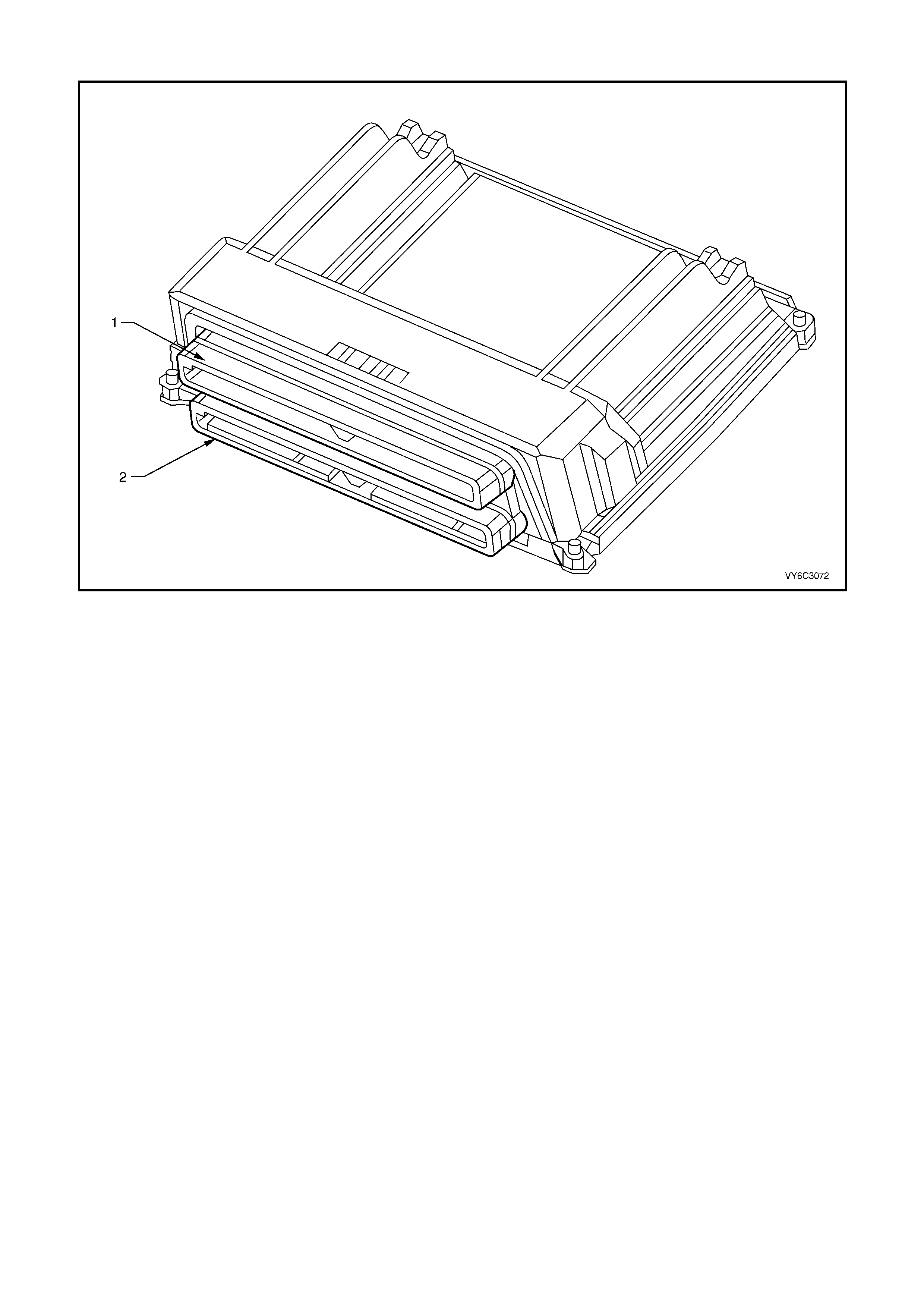
GEN III V8 PCM – DTC P0601 POWERTRAIN CONTROL MODULE (PCM) MEMORY
Figure 6C3-2A-137 – PCM Connector Ports
Legend
1. Connector A84-X1 – BLUE 2. Connector A84-X2 – RED
CIRCUIT DESCRIPTION
The PCM EEPROM contains data which is essential to running the engine and transmission. The PCM continuously
checks the integrity of this data.
CONDITIONS FOR RUNNING THE DTC
• The ignition switch is in the CRANK or RUN position.
CONDITIONS FOR SETTING THE DTC
• The PCM is unable to correctly read data from the EEPROM (flash memory).
ACTION TAKEN WHEN THE DTC SETS
• The PCM activates the Check Powertrain MIL when the diagnostic runs and fails.
• The PCM records the operating conditions at the time the diagnostic fails. The PCM stores this information in
the Freeze Frame/Failure Records.
CONDITIONS FOR CLEARING THE MIL/DTC
• A last test failed (Current DTC) clears when the diagnostic runs and does not fail.
• Use Tech 2 in order to clear the MIL/DTC.
DIAGNOSTIC AIDS
• Replace the PCM even if this DTC exists only in history.
• For an intermittent, refer to Section 6C3-2B SYMPTOMS, in this Section.
TEST DESCRIPTION
NOTE: The number(s) below refer to the step number(s) on the diagnostic table.
2. This DTC indicates an internal PCM problem.

GEN III V8 PCM – DTC P0601 POWERTRAIN CONTROL MODULE (PCM) MEMORY
STEP ACTION VALUE YES NO
1. Was the "On-Board Diagnostic" (OBD) System Check
performed? Go to Step 2 Go to
OBD System
Check
in this Section.
2. 1. Replace PCM. Refer to PCM Programming and
PCM/PIM/BCM Security Link Procedure, in 6C3-3
SERVICE OPERATIONS.
Is the action complete?
Verify
System OK –
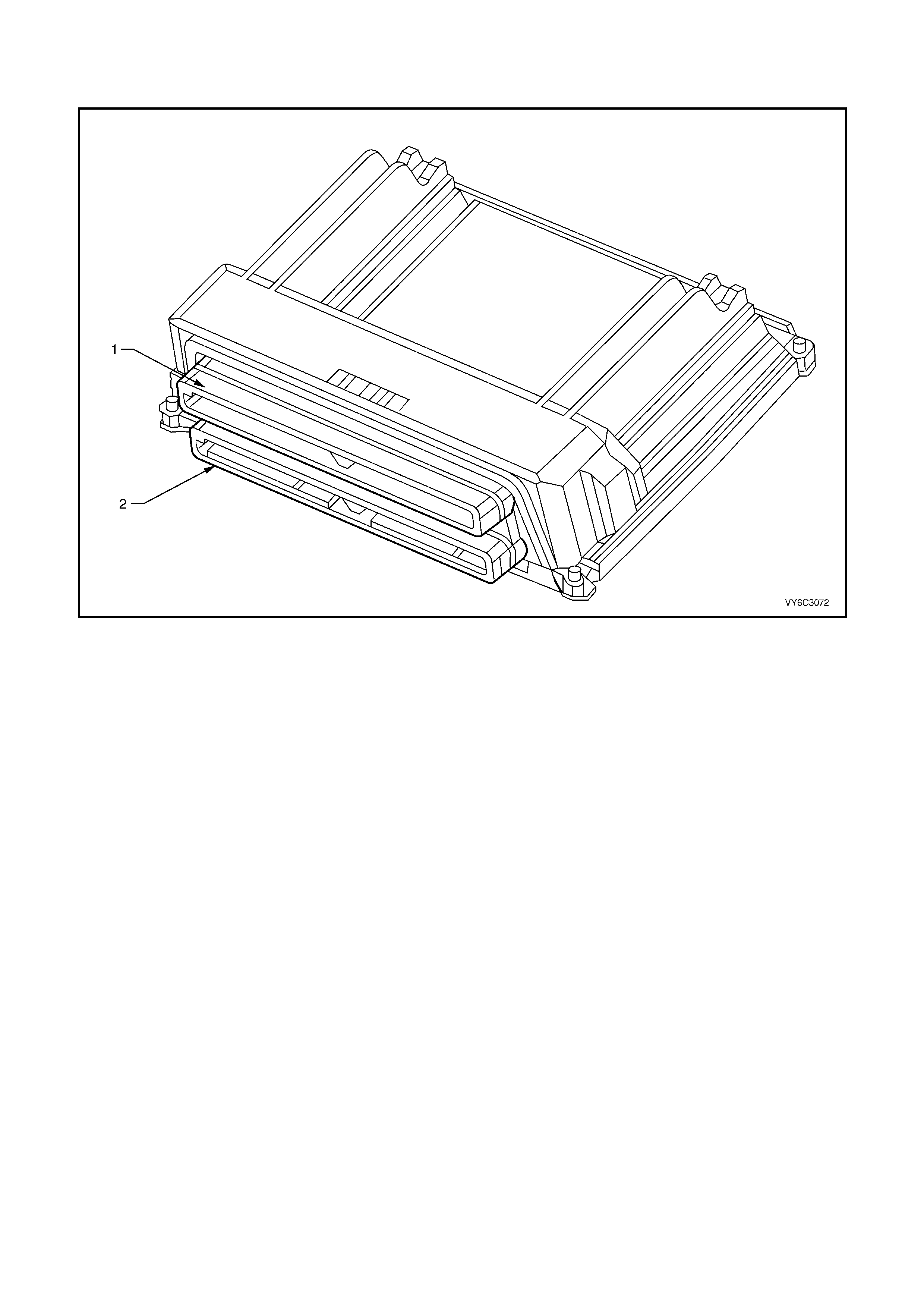
GEN III V8 PCM - DTC P0602 POWERTRAIN CONTROL MODULE
(PCM) NOT PROGRAMMED
Figure 6C3-2A-138 – PCM Connector Ports
Legend
1. Connector A84-X1 – BLUE 2. Connector A84-X2 – RED
CIRCUIT DESCRIPTION
This DTC indic ates that the PCMs inter nal EEPROM is not f lashed with any vehicle software. If you install a servic e
PCM and do not flash the EEPRO M, the engine will not run. T his DT C indic ates that an un-f las hed PCM caus es the
engine cranks but will not run situation.
CONDITIONS FOR RUNNING THE DTC
• The ignition switch is in the run position.
CONDITIONS FOR SETTING THE DTC
• No software data is present in the PCM.
ACTION TAKEN WHEN THE DTC SETS
• The PCM activates the Check Powertrain MIL when the diagnostic runs and fails.
• The PCM records the operating conditions at the time the diagnostic fails. The PCM stores this information in
the Freeze Frame/Failure Records.
CONDITIONS FOR CLEARING THE MIL/DTC
• The PCM deactivates the Check Powertrain MIL after one ignition cycle that the diagnostic runs and does not
fail.
• A last test failed (Current DTC) clears when the diagnostic runs and does not fail.
• Use Tech 2 to clear the MIL/DTC.
TEST DESCRIPTION
NOTE: The number(s) below refer to the step number(s) on the diagnostic table.
3. If the flashing routine f ails, verify that the equipment used is f unctioning properly and that all cable connections
are clean and tight. Also, make sure that the software you download is correct for the PCM being flashed. If
everything checks out OK, and a second attempt fails, the PCM is faulty.

GEN III V8 PCM – DTC P0602 POWERTRAIN CONTROL MODULE (PCM) NOT PROGRAMMED
STEP ACTION VALUE YES NO
1. Was the "On-Board Diagnostic" (OBD) System Check
performed? Go to Step 2 Go to
OBD System
Check
in this Section.
2. 1. Program the PCM with the correct software. Refer to
PCM Programming in 6C3-3 SERVICE OPERATIONS.
Does DTC P0602 reset?
Go to Step 3 Go to Step 5
3. 1. Verify that the equipment being used is functioning
properly and that all the cable connections are clean
and tight.
2. Attempt to program the PCM again.
Does DTC P0602 reset?
Go to Step 4 Go to Step 5
4. 1. Replace PCM. Refer to PCM Programming and
PCM/PIM/BCM Security Link Procedure, in 6C3-3
SERVICE OPERATIONS.
Is action complete?
Go to Step 5 –
5. 1. Select the Diagnostic Trouble Code (DTC) option and
the Clear DTC Information option using Tech 2.
2. Idle the engine at the normal operating temperature.
3. Select the Diagnostic Trouble Code (DTC) option, the
DTC Information option and the Failed This Ignition
option using Tech 2.
4. Operate the vehicle, within the Conditions for Running
the DTC, as specified in the supporting text, if
applicable.
Does Tech 2 indicate that this DTC reset?
Go to Step 2 Go to Step 6
6. 1. Using Tech 2, check for any other DTCs.
Does Tech 2 display any DTCs that you have not
diagnosed?
Go to the
applicable DTC
table
System OK

GEN III V8 PCM – DTC P0608 VEHICLE SPEED OUTPUT CIRCUIT
Figure 6C3-2A-139 – Vehicle Speed Sensor Circuit
CIRCUIT DESCRIPTION
Various components apply a voltage to the Vehicle Speed Output circuit. The PCM creates the Vehicle Speed
Output s ignal by rapidly grounding this cir cuit via an internal switch c alled a driver. The dr iver operates at the sam e
rate as the VSS s ignal input. T he various c omponents r ecognis e the voltage being pulled to gr ound as an indication
of vehicle speed.
The PCM dr iver s upplies the ground for the c omponent being contr olled. Eac h driver has a fault line which the PCM
monitors. When the PCM commands a component ON, the voltage of the control circuit should be LOW (near 0
volts). When the PCM com m ands the control c ircuit to a com ponent OFF, the voltage potential of the circuit should
be HIGH (near battery voltage). If the fault detection circuit senses a voltage other than what is expected, the fault
line status changes causing the DTC to set.
CONDITIONS FOR RUNNING THE DTC
• The engine speed is greater than 600 RPM.
• The ignition voltage is between 6.0 and 16.0 volts.
CONDITIONS FOR SETTING THE DTC
• The PCM detects that the commanded state of the driver and the actual state of the control circuit do not
match.
• This condition must be present for at least ten seconds.
ACTION TAKEN WHEN THE DTC SETS
• The PCM stores the DTC information into memory when the diagnostic runs and fails.
• The Check Powertrain MIL will not be activated.
• The PCM records the operating conditions at the time the diagnostic fails. The PCM stores this information in
the Freeze Frame/Failure Records.
CONDITIONS FOR CLEARING THE MIL/DTC
• A last test failed (current DTC) clears when the diagnostic runs and does not fail.
• Use Tech 2 to clear the MIL/DTC.
DIAGNOSTIC AIDS
• Using the Freeze Frame/Failure Records data may aid in locating an intermittent condition. If you cannot
duplicate the DTC, the information included in the Freeze Frame/Failure Records data can aid in determining
the distance travelled since the DTC reported a pass and/or fail. Operate the vehicle within the same freeze
frame conditions (RPM, load, vehicle speed, temperature, etc.) that you observed. This will isolate when the
DTC failed.
• For an intermittent, refer to Section 6C3-2B SYMPTOMS, in this Section.
• If vehicle is fitted with cruise control, disconnecting the cruise control module will isolate the cruise control
system from the rest of the vehicle systems.
• It may also be necessary to remove (disconnect) the Navigation System (where fitted), to isolate it as being a
cause of the problem.

TEST DESCRIPTION
NOTE: The number(s) below refer to the step number(s) on the diagnostic table.
3. This step determines if the Instrument is capable of controlling the speedometer.
5. Further circuit diagnosis may require instrument panel removal. The circuit from the PCM to the speedometer
must be checked for being open, shorted to ground or, voltage. If you do not find any trouble, follow the
appropriate instrument panel diagnostic procedure.
7. The repair is not complete if Tech 2 indicates that the DTC reset.
A84–X2 (RED) P3
Figure 6C3-2A-140
GEN III V8 PCM – DTC P0608 VEHICLE SPEED OUTPUT CIRCUIT
STEP ACTION VALUE YES NO
1. Was the "On-Board Diagnostic" (OBD) System Check
performed? Go to Step 2 Go to
OBD System
Check
in this Section.
2. 1. Ignition OFF.
2. Connect Tech 2 to the DLC.
3. Raise the drive wheels and support on safety stands.
4. Start the engine.
5. Disable the traction control system (if fitted).
6. Allow the engine to idle in gear.
Does Tech 2 display vehicle speed information in
Instrument Data Display?
Go to
Diagnostic Aids Go to Step 3
3. 1. Ignition ON, engine OFF.
2. Install Tech 2.
3. Using Tech 2, select Body, Instruments,
Miscellaneous Tests, Gauge Control Tests,
Speedometer.
4. Press the UP soft key on Tech 2 .
Does the speedometer read the same as the Tech 2
commanded output?
Go to Step 6 Go to Step 4
4. 1. Ignition OFF.
2. Disconnect the PCM RED connector, A84-X2.
3. Ignition ON, engine OFF.
4. Connect a DMM between the PCM harness terminal
X2-50 for VSS output and ground.
Is voltage at specified value?
B+ Go to Step 6 Go to Step 5
5. 1. Check for open, short to ground or short to voltage in
VSS output circuit.
Was a problem found and rectified?
Go to Step 7 Go to 12C
INSTRUM ENTS
6. 1. Disconnect Instrument connector P3, Cruise Control
Connector A18 and Navigation System A139 (if fitted).
2. Ignition ON, engine OFF.
3. Using a DMM, probe PCM connector A84-X2, terminal
X2-50.
Is voltage greater than specified value?
1.0 volt Go to Step 5 Go to Step 7
7. 1. Replace PCM. Refer to PCM Programming and
PCM/PIM/BCM Security Link Procedure, in 6C3-3
SERVICE OPERATIONS.
NOTE: If speedometer is still inoperative, refer to 12C
INSTRUMENTS for further diagnosis.
Is action complete?
Go to Step 8 –

STEP ACTION VALUE YES NO
8. 1. Select the Diagnostic Trouble Code (DTC) option and
the Clear DTC Information option using Tech 2.
2. Idle the engine at the normal operating temperature.
3. Select the Diagnostic Trouble Code (DTC) option, the
DTC Information option and the Failed This Ignition
option using Tech 2.
4. Operate the vehicle, within the Conditions for Running
the DTC, as specified in the supporting text, if
applicable.
Does Tech 2 indicate that this DTC reset?
Go to Step 2 Go to Step
9. 1. Using Tech 2, check for any other DTCs.
Does Tech 2 display any DTCs that you have not
diagnosed?
Go to the
applicable DTC
table
System OK
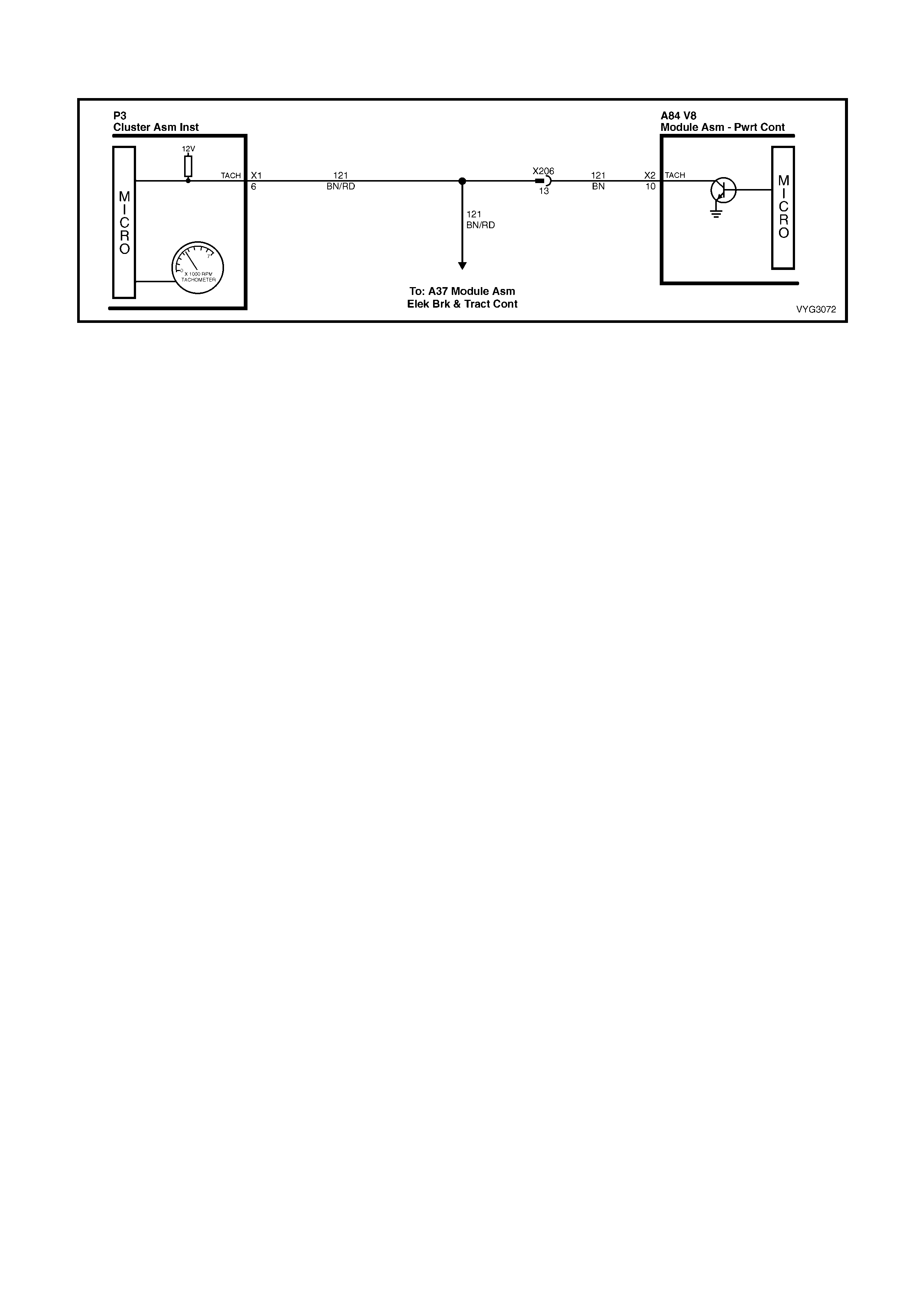
GEN III V8 PCM – DTC P0654 ENGINE SPEED OUTPUT CIRCUIT
Figure 6C3-2A-141 – Engine Speed Output
CIRCUIT DESCRIPTION
The PCM s upp li es a v olt ag e to the Eng in e Spe ed Out put c irc u it. T he PC M c r eat e s the En gi ne Sp eed O utp ut s ignal
by rapidly grounding this circuit via an internal switch called a driver. The other components on this circuit
recognise the voltage being pulled to ground as an indication of engine speed.
The PCM driver supplies the ground for the component being controlled. Each driver has a fault line which the PCM
monitors. When the PCM commands a component ON, the voltage of the control circuit should be LOW (near 0
volts) . W hen the PC M com m ands the contr ol cir cuit to a component O FF, the v oltage potent ial of the cir cuit shoul d
be HIGH (near batt ery voltage). If the fault detection cir cuit senses a voltag e other than what is expected, the faul t
line status changes causing the DTC to set.
CONDITIONS FOR RUNNING THE DTC
• The engine speed is greater than 600 RPM.
• The ignition vo ltage is between 6.0 and 16. 0 volts .
CONDITIONS FOR SETTING THE DTC
• The PCM detects that the commanded state of the driver and the actual state of the control circuit do not
match.
• All of the conditions are present for a minimum of 10 seconds.
ACTION TAKEN WHEN THE DTC SETS
• The PCM stores the DTC information into memory when the diagnostic runs and fails.
• The Check Powertrain MIL will not be activated.
• The PCM records the operating conditions at the time the diagnostic fails. The PCM stores this information in
the Freeze Frame/Failure Records.
CONDITIONS FOR CLEARING THE MIL/DTC
• A last test failed (current DTC) clears when the diagnostic runs and does not fail.
• Use Tech 2 to clear the MIL/DTC.
DIAGNOSTIC AIDS
• Using the Freeze Frame/Failure Records data may aid in locating an intermittent condition. If you cannot
duplicate the DTC, the information included in the Freeze Frame/Failure Records data can aid in determining
the distance travelled since the DTC reported a pass and/or fail. Operate the vehicle within the same freeze
frame conditions (RPM, load, vehicle speed, temperature, etc.) that you observed. This will isolate when the
DTC failed.
• For an intermittent, refer to Section 6C3-2B SY MPTOM S in this Section.
TEST DESCRIPTION
NOTE: The number(s) below refer to the step number(s) on the diagnostic table.
IMPORTANT: If the instrument panel is completely inoperative, refer to Section 12C INSTRUMENTS.
3. This step determines if the Instrument is capable of controlling the tachometer.
5. Further circuit diagnosis may require instrument panel removal. Check the circuit from the PCM to the
tachom eter f or being op en, s horted t o groun d or, volta ge. If you can not f ind an y troubl e, follo w the appr opr iate
instrument panel diagnostic procedure.
7. The repair is not complete if Tech 2 indicates that the diagnostic ran and failed.

A84–X2 (RED) P3
Figure 6C3-2A-142
DTC III V8 PCM – DTC P0654 ENGINE SPEED OUTPUT CIRCUIT
STEP ACTION VALUE YES NO
1. Was the "On-Board Diagnostic" (OBD) System Check
performed? Go to Step 2 Go to
OBD System
Check
in this Section.
2. With the engine running, does the vehicle tachometer
indicate engine RPM? Go to
Diagnostic Aids Go to Step 3
3. 1. Ignition ON, engine OFF.
2. Install Tech 2.
3. Using Tech 2, select Body, Instruments, Miscellaneous
Tests, Gauge Control Tests, Tachometer.
4. Depress the UP soft key on Tech 2.
Does the tachometer read the same as commanded
output?
Go to Step 4 Further
diagnosis
required. Refer
to 12C
INSTRUMENTS
4. 1. Ignition OFF.
2. Disconnect the PCM RED connector, A84-X2.
3. Ignition ON, engine OFF.
4. Connect DMM between the PCM harness terminal X2-
10 for Tachometer output and ground.
Is voltage at specified value?
7 – 10 volts Go to Step 6 Go to Step 5
5. 1. Check for open, short to ground, or short to voltage in
Tachometer output circuit.
Was a problem found?
Go to Step 7 Further
diagnosis
required. Refer
to 12C
INSTRUMENTS
6. 1. Replace PCM. Refer to PCM Programming and
PCM/PIM/BCM Security Link Procedure, in 6C3-3
SERVICE OPERATIONS.
NOTE: If the Tachometer is still inoperative, refer to 12C
INSTRUMENTS.
Is action complete?
Go to Step 7 –
7. 1. Select the Diagnostic Trouble Code (DTC) option and
the Clear DTC Information option using Tech 2
2. Idle the engine at the normal operating temperature.
3. Select the Diagnostic Trouble Code (DTC) option, the
DTC Information option and the Failed This Ignition
option using Tech 2.
4. Operate the vehicle, within the Conditions for Running
the DTC, as specified in the supporting text, if
applicable.
Does Tech 2 indicate that this DTC reset?
Go to Step 2 Go to Step 8
8. 1. Using Tech 2, check for any other DTCs.
Does Tech 2 display any DTCs that you have not
diagnosed?
Go to the
applicable DTC
table
System OK
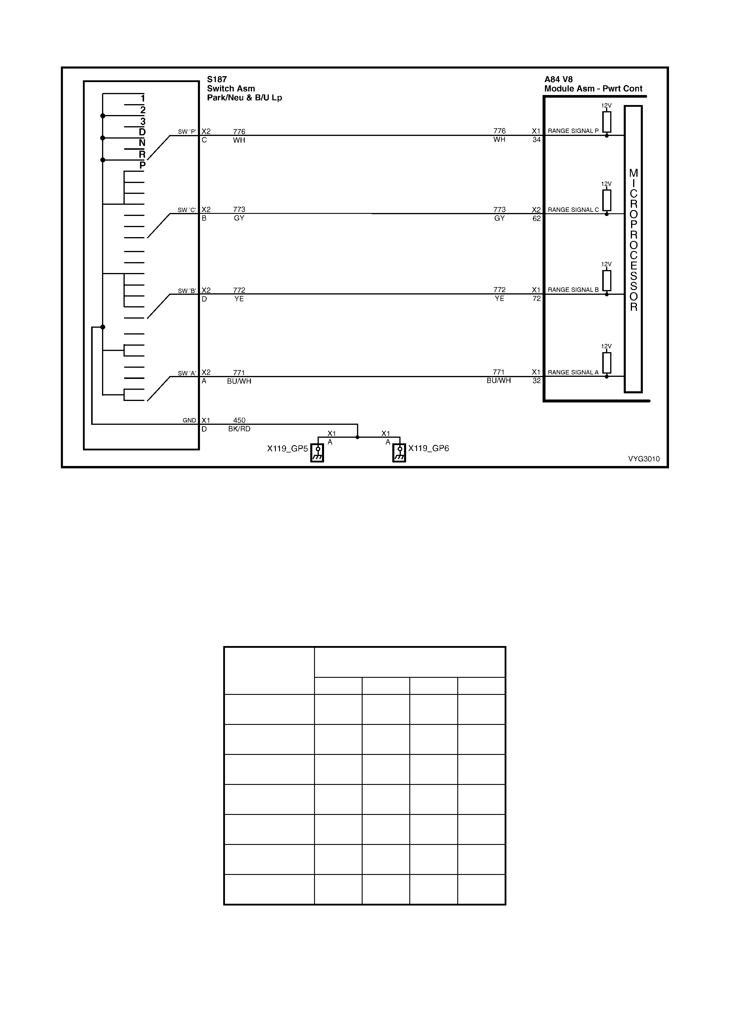
GEN III V8 PCM – DTC P0705 TRANSMISSION RANGE SWITCH CIRCUIT
Figure 6C3-2A-Figure 6C3-2A-143 – PRNDL Switch Circuit
CIRCUIT DESCRIPTION
The Transmission Range (TR) Switch is part of the Transmission PRNDL switch mounted on the transmission
manual s haft. T he f our in puts f rom the transm is sion range s witch ind icate to t he PCM whic h pos ition is sel ected b y
the trans mission s el ect or l e ver . The input v olt age le ve l at th e PCM is hig h ( B +) wh en th e trans miss ion r ang e swi tch
is open an d lo w whe n th e s witc h is c l os ed to ground. T he st ate of eac h in put is avail ab le f or dis p lay on Tech 2. The
four parameters represent transmission range switch P (Parity), A, B, and C inputs respectively.
W hen the PCM detects an invalid transm ission range input com bination, then DT C P0705 sets. Val id transm ission
range input combinations are shown in the Transmission Range Switch Valid Combination table.
TRANSMISSION RANGE SWITCH VALID COMBINATION TABLE
Gear Selector
Position Tech 2 TR Switch P/A/B/C Display
P A B C
Park (P) Closed
0 V Closed
0 V Open
12 V Open
12 V
Reverse (R) Open
12 V Closed
0 V Closed
0 V Open
12 V
Neutral (N) Closed
0 V Open
12 V Closed
0 V Open
12 V
D Open
12 V Open
12 V Closed
0 V Closed
0 V
3 Closed
0 V Closed
0 V Closed
0 V Closed
0 V
2 Open
12 V Closed
0 V Open
12 V Closed
0 V
1 Closed
0 V Open
12 V Open
12 V Closed
0 V
CONDITIONS FOR RUNNING THE DTC
• The ignition is ON.

CONDITIONS FOR SETTING THE DTC
• The Transmission Range Switch inputs indicate an invalid combination.
• The above condition is present for longer than 30 seconds.
ACTION TAKEN WHEN THE DTC SETS
• The PCM stores the DTC information into memory when the diagnostic runs and fails.
• The Check Powertrain MIL will not be activated.
• The PCM records the operating conditions at the time the diagnostic fails. The PCM stores this information in
the Freeze Frame/Failure Records.
CONDITIONS FOR CLEARING THE DTC
• A last test failed (current DTC) clears when the diagnostic runs and does not fail.
• The PCM cancels the DTC default actions when the fault no longer exists and the ignition switch is OFF long
enough in order to power down the PCM.
DIAGNOSTIC AIDS
• Inspect the wiring at the PCM, the Transmission Range Switch and all other circuit connecting points for the
following conditions:
– A backed out terminal
– A damaged terminal
– Reduced terminal tension
– A chafed wire
– A broken wire inside the insulation
– Moisture intrusion
– Corrosion
• If after a complete inspection and testing of the system the condition does not reveal, observe , TR Switch
P/A/B/C d isplay while m oving the conn ectors and wiring. A chan ge in the T R Switch displa y should id entif y the
location of the condition.
TEST DESCRIPTION
NOTE: The number(s) below refer to the step number(s) on the diagnostic table.
2. If the TR Switch dis play corr esponds with all gear sele ctor pos itions , the conditi on m ay be interm ittent. Ref er to
Diagnostic Aids for intermittent diagnosis.
3. Disconnecting the Transmission Range Switch connector will cause the PCM to interpret all the circuits as
open and P/A/B/ C will display all Open 12 V. This would ind icate that circuits f rom the TR Switch to the PCM
and the PCM are all OK.
4. By reconnec ting the T R S witch a nd a ll T ech 2 TR Swit ch P/ A/B/C disp la y Open 12 V , the c ond ition c oul d be in
the engine ground circuit 450.
7. By providing t he gro und for each T ransmis sion Range S witch c ircuit, th e PCM s hould res pond b y cha nging t he
TR Switch P/A/B/C display from Open 12 V to Closed 0 V. For the circuits that do not change, an open circuit
must exist.
12. Before replacing the PCM, ensure that all connectors, wiring and components have been tested.
A84–X1 (BLUE) A84-X2 (RED)
S187 A83
Figure 6C3-2A-144

GEN III V8 PCM – DTC P0705 TRANSMISSION RANGE SWITCH CIRCUIT
STEP ACTION VALUE YES NO
1. Was the "On-Board Diagnostic" (OBD) System Check
performed? Go to Step 2 Go to
OBD System
Check
in this Section.
2. 1. Install Tech 2.
2. Select PARK.
3. Ignition ON.
4. Observe the TR Switch P/A/B/C display on Tech 2
while selecting each gear position.
5. Compare display, with each gear position selected, to
the Transmission Range Switch Valid Combinations
table.
Does the Tech 2 display match the Transmission Range
Switch Valid Combinations table for each gear position?
Go to
Diagnostic Aids Go to Step 3
3. 1. Disconnect the Transmission Range Switch 4-way
connector, S187.
Does the TR Switch P/A/B/C display on Tech 2 show the
specified values?
P: Open 12 V
A: Open 12 V
B: Open 12 V
C: Open 12 V
Go to Step 4 Go to Step 13
4. 1. Reconnect the Transmission Range Switch 4-way
connector, S187.
Does the TR Switch P/A/B/C display on Tech 2 show the
specified values?
P: Open 12 V
A: Open 12 V
B: Open 12 V
C: Open 12 V
Go to Step 5 Go to Step 7
5. 1. Inspect the Transmission Neutral Start and Backup
Switch 5-way connector (A83) for being disconnected
or poor terminal contact at ground circuit 450.
Was a condition found?
Go to Step 10 Go to Step 6
6. 1. Inspect circuit 450 from the Transmission Neutral Start
and Backup Switch 5-way connector A83 for an open
condition.
Was an open condition found?
Go to Step 10 Go to Step 11
7. 1. Use a fused jumper wire to ground each terminal of the
Transmission Range Switch 4-way connector, while
observing TR Switch P/A/B/C display.
2. Note the display change as each circuit is grounded.
Does each of the TR Switch P/A/B/C displays on Tech 2
change from Open 12 V to Closed 0 V when grounded?
Go to Step 11 Go to Step 8
8. 1. For the circuit or circuits that did not change status in
Step 7, inspect the circuit, from the Transmission
Range Switch connector to the PCM, for an open
condition or for circuit s being s horted tog ether.
Was an open or shorted together condition found?
Go to Step 10 Go to Step 9
9. 1. Inspect for poor connections at the PCM.
Was a condition found? Go to Step 10 Go to Step 12
10. 1. Repair the wiring as necessary.
Is the repair complete?
Go to Step 14 Go to Wiring
Repair
Procedures in
12P WIRING
DIAGRAMS
11. 1. Replace the Transmission Range Switch. Refer to
Neutral Start and Back-up Lamp Switch Replacement.
Is the replacement complete?
Go to Step 14 Go to Neutral
Start and Back-
up Lamp Switch
Replace in 7C4
AUTO TRANS
ON-VEHICLE
SERVICING
12. Replace PCM. Refer to PCM Programming and
PCM/PIM/BCM Security Link Procedure, in 6C3-3
SERVICE OPERATIONS.
Is replacement the complete?
Go to Step 14 Go to Powertrain
Control Module
Replace in
6C3-3 SERVICE
OPERATIONS

STEP ACTION VALUE YES NO
13. 1. Check for a short to ground in the circuit/s that Tech 2
displays as being closed (0V).
Was a problem found?
Go to Step 14 Go to Step 12
14. 1. Clear the DTCs.
2. Observe the TR Switch P/A/B/C displays on Tech 2
while selecting each gear position.
3. Compare the Tech 2 display with each gear position
selected, to the Transmission Range Switch Valid
Combinations table.
Does the Tech2 display match the Transmission Range
Switch Valid Combinations table for each gear position?
System OK –

GEN III V8 PCM – DTC P0706 TRANSMISSION RANGE SWITCH PERFORMANCE
Figure 6C3-2A-Figure 6C3-2A-145 – PRNDL Switch Circuit
CIRCUIT DESCRIPTION
The Transmission Range (TR) Switch is part of the Transmission PRNDL switch mounted on the transmission
manual s haft. T he f our in puts f rom the transm is sion range s witch ind icate to t he PCM whic h pos ition is sel ected b y
the transmission selector lever. The input voltage level at the PCM is high (B+), when the transmission range
switch is open and low, when the switch is closed to ground. The state of each input is available for display on Tech
2. The four parameters represent transmission range switch P (Parity), A, B, and C inputs respectively.
W hen the PCM detects an invalid transm ission range input com bination, then DT C P0706 sets. Val id transm ission
range input combinations are shown in the Transmission Range Switch Valid Combination table.
TRANSMISSION RANGE SWITCH VALID COMBINATION TABLE
Gear Selector
Position Tech 2 TR Switch P/A/B/C Display
P A B C
Park (P) Closed
0 V Closed
0 V Open
12 V Open
12 V
Reverse (R) Open
12 V Closed
0 V Closed
0 V Open
12 V
Neutral (N) Closed
0 V Open
12 V Closed
0 V Open
12 V
D Open
12 V Open
12 V Closed
0 V Closed
0 V
3 Closed
0 V Closed
0 V Closed
0 V Closed
0 V
2 Open
12 V Closed
0 V Open
12 V Closed
0 V
1 Closed
0 V Open
12 V Open
12 V Closed
0 V
CONDITIONS FOR RUNNING THE DTC
• The ignition is ON.
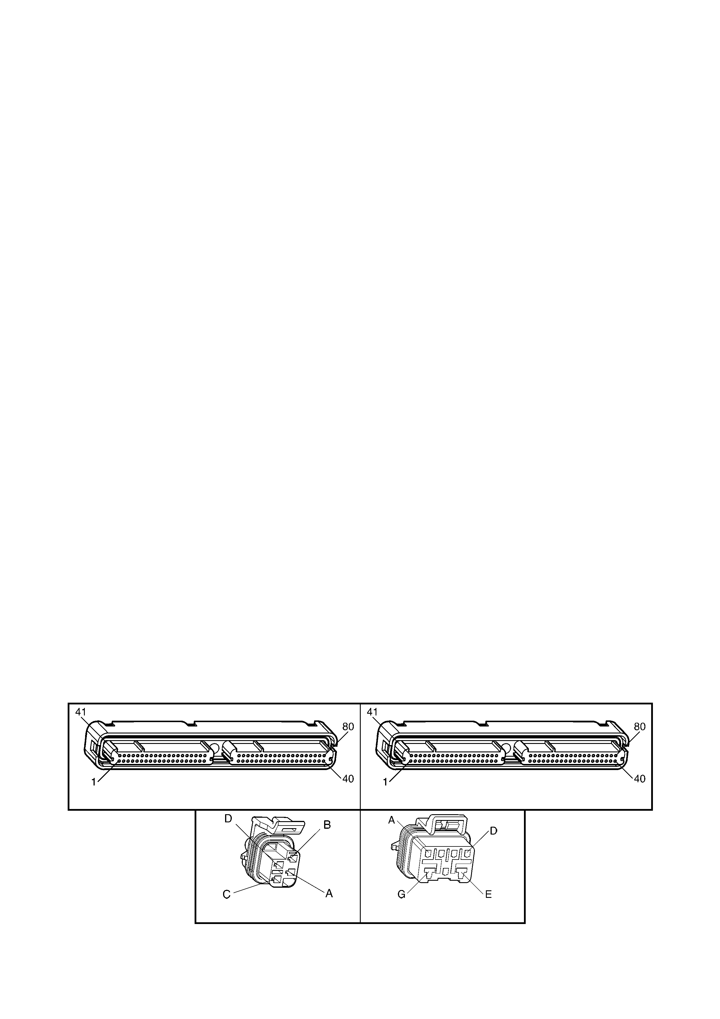
CONDITIONS FOR SETTING THE DTC
• The Transmission Range Switch inputs indicate an invalid combination.
• The above condition is present for longer than 30 seconds.
ACTION TAKEN WHEN THE DTC SETS
• The PCM stores the DTC information into memory when the diagnostic runs and fails.
• The Check Powertrain MIL will not be activated.
• The PCM records the operating conditions at the time the diagnostic fails. The PCM stores this information in
the Freeze Frame/Failure Records.
CONDITIONS FOR CLEARING THE DTC
• A last test failed (current DTC) clears when the diagnostic runs and does not fail.
• The PCM cancels the DTC default actions when the fault no longer exists and the ignition switch is OFF long
enough in order to power down the PCM.
DIAGNOSTIC AIDS
• Inspect the wiring at the PCM, the Transmission Range Switch and all other circuit connecting points for the
following conditions:
– A backed out terminal
– A damaged terminal
– Reduced terminal tension
– A chafed wire
– A broken wire inside the insulation
– Moisture intrusion
– Corrosion
• If after a complete inspection and testing of the system the condition does not reveal, observe TR Switch
P/A/B/C d isplay while m oving the conn ectors and wiring. A chan ge in the T R Switch displa y should id entif y the
location of the condition.
TEST DESCRIPTION
NOTE: The number(s) below refer to the step number(s) on the diagnostic table.
2. If the TR Switch dis play corr esponds with all gear sele ctor pos itions , the conditi on m ay be interm ittent. Ref er to
Diagnostic Aids for intermittent diagnosis.
3. Disconnecting the Transmission Range Switch connector will cause the PCM to interpret all the circuits as
open and P/A/ B/C will dis pla y all ‘Open 12 V’. This would ind icate that c ircuits f rom the T R Switch to the PC M
and the PCM are all OK.
4. By reconnecting the TR Switch and all Tech 2 TR Switch P/A/B/C displays are; ‘Open 12 V’, the condition could
be in the engine ground circuit 450.
7. By providing t he gro und for each T ransmis sion Range S witch c ircuit, th e PCM s hould res pond b y cha nging t he
TR Switch P/A/B/C display from Open 12 V to Closed 0 V. For the circuits that do not change, an open circuit
must exist.
12. Before replacing the PCM, ensure that all connectors, wiring and components have been tested.
A84–X1 (BLUE) A84-X2 (RED)
S187 A83
Figure 6C3-2A-146

GEN III V8 PCM – DTC P0706 TRANSMISSION RANGE SWITCH PERFORMANCE
STEP ACTION VALUE YES NO
1. Was the "On-Board Diagnostic" (OBD) System Check
performed? Go to Step 2 Go to
OBD System
Check
in this Section.
2. 1. Install Tech 2.
2. Transmission in PARK.
3. Ignition ON.
4. Observe the TR Switch P/A/B/C display on Tech 2
while selecting each gear position.
5. Compare display, with each gear position selected, to
the Transmission Range Switch Valid Combinations
table.
Does the Tech 2 display match the Transmission Range
Switch Valid Combinations table for each gear position?
Go to
Diagnostic Aids Go to Step 3
3. 1. Disconnect the Transmission Range Switch 4-way
connector, S187.
Does the TR Switch P/A/B/C display on Tech 2 show the
specified values?
P: Open 12 V
A: Open 12 V
B: Open 12 V
C: Open 12 V
Go to Step 4 Go to Step 13
4. 1. Reconnect the Transmission Range Switch 4-way
connector, S187.
Does the TR Switch P/A/B/C display on Tech 2 show the
specified values?
P: Open 12 V
A: Open 12 V
B: Open 12 V
C: Open 12 V
Go to Step 5 Go to Step 7
5. 1. Inspect the Transmission Neutral Start and Backup
Switch 5-way connector, A83 for being disconnected
or poor terminal contact at ground circuit 450.
Was a condition found?
Go to Step 10 Go to Step 6
6. 1. Inspect circuit 450 from the Transmission Neutral Start
and Backup Switch 5-way connector, A83 for an open
condition.
Was an open condition found?
Go to Step 10 Go to Step 11
7. 1. Use a fused jumper wire to ground each terminal of the
Transmission Range Switch 4-way connector, S187
while observing TR Switch P/A/B/C display.
2. Note the display change as each circuit is grounded.
Does each of the TR Switch P/A/B/C displays on Tech 2
change from Open 12 V to Closed 0 V when grounded?
Go to Step 11 Go to Step 8
8. 1. For the circuit or circuits that did not change status in
Step 7, inspect the circuit, from the Transmission
Range Switch connector to the PCM, for an open
condition or for circuit s being s horted tog ether.
Was an open or shorted together condition found?
Go to Step 10 Go to Step 9
9. 1. Inspect for poor connections at the PCM.
Was a condition found? Go to Step 10 Go to Step 12
10. 1. Repair the wiring as necessary.
Is the repair complete? Go to Step 14 Go to Wiring
Repair
Procedures in
12P WIRING
DIAGRAMS
11. 1. Replace the Transmission Range Switch, A83. Refer
to Neutral Start and Back-up Lamp Switch Replace.
Is the replacement complete?
Go to Step 14 Go to Neutral
Start and Back-
up Lamp Switch
Replace in 7C4
AUTO TRANS
ON-VEHICLE
SERVICING
12. 1. Replace PCM. Refer to PCM Programming and
PCM/PIM/BCM Security Link Procedure, in 6C3-3
SERVICE OPERATIONS.
Is replacement the complete?
Go to Step 14 Go to Powertrain
Control Module
Replace in
6C3-3 SERVICE
OPERATIONS

STEP ACTION VALUE YES NO
13. 1. Check for a short to ground in the circuit/s that Tech 2
displays as being closed (0V).
Was a problem found?
Go to Step 14 Go to Step 12
14. 1. Clear the DTCs.
2. Observe the TR Switch P/A/B/C displays on Tech 2
while selecting each gear position.
3. Compare the Tech 2 display with each gear position
selected, to the Transmission Range Switch Valid
Combinations table.
Does display match the Transmission Range Switch Valid
Combinations table for each gear position?
System OK –

GEN III V8 PCM – DTC P0711 TFT SENSOR CIRCUIT RANGE/PERFORMANCE
Figure 6C3-2A-147 – Transmission Fluid Pressure Manual Valve Position Switch Assembly Circuit
CIRCUIT DESCRIPTION
The autom atic Transm ission Fluid T emperature (T FT) sensor is part of the autom atic Transm ission Fluid Pre ssure
(TFP) manual valve position switch. The TFT sensor is a resistor, or thermistor, which changes value based on
temperature. The sensor has a negative-temperature coefficient. This means that as the temperature increases,
the resistance decreases, and as the temperature decreases, the resistance increases.
The Powertrain Control Module (PCM) supplies a 5-volt reference signal to the sensor on circuit 1227 and
meas ures the voltage drop in the circuit. W hen the transmis sion fluid is cold, th e sensor resistanc e is high and the
PCM detects h ig h sign al vo ltag e. As the f lu id t emperatur e warms to a nor mal operatin g temperatur e, t he r esistanc e
becomes less and the signal voltage decreases. The PCM uses this information to control shift quality and torque
converter clutch apply.
When the PCM detects one of the following unusual conditions, then DTC P0711 sets.
• An unrealistically large change in transmission temperature.
• A transmission temperature which remains constant for a period of time in which a measurable amount of
change is expected.
CONDITIONS FOR RUNNING THE DTC
• No VSS assembly DTCs P0502, P0503.
• No transmission component slipping DTC P1870.
• The system voltage is between 8.0 volts and 18 volts.
• The engine is running for 409 seconds (6.8 minutes).
• The vehicle speed is greater than 8 km/h for 409 seconds cumulative during the current ignition cycle.
• The TCC slip speed is greater than 120 RPM for 409 seconds cumulative during the current ignition cycle.
• The TFT at startup is between –40 and +21° C.
• The TFT is between –38 and +15° C.
• The engine coolant temperature (ECT) is greater than 70° C and has changed by 50° C since startup.
CONDITIONS FOR SETTING THE DTC
• The TFT does not change more than 1.5° C for 409 seconds since startup.
OR
• The TFT changes more than 20°C in 200 milliseconds, 14 times within 7 seconds.
ACTION TAKEN WHEN THE DTC SETS
• The PCM stores the DTC information into memory when the diagnostic runs and fails.
• The Check Powertrain MIL will not be activated.
• The PCM records the operating conditions at the time the diagnostic fails. The PCM stores this information in
the Freeze Frame/Failure Records.
IMPORTANT: The actions listed below are in order of highest to lowest priority.
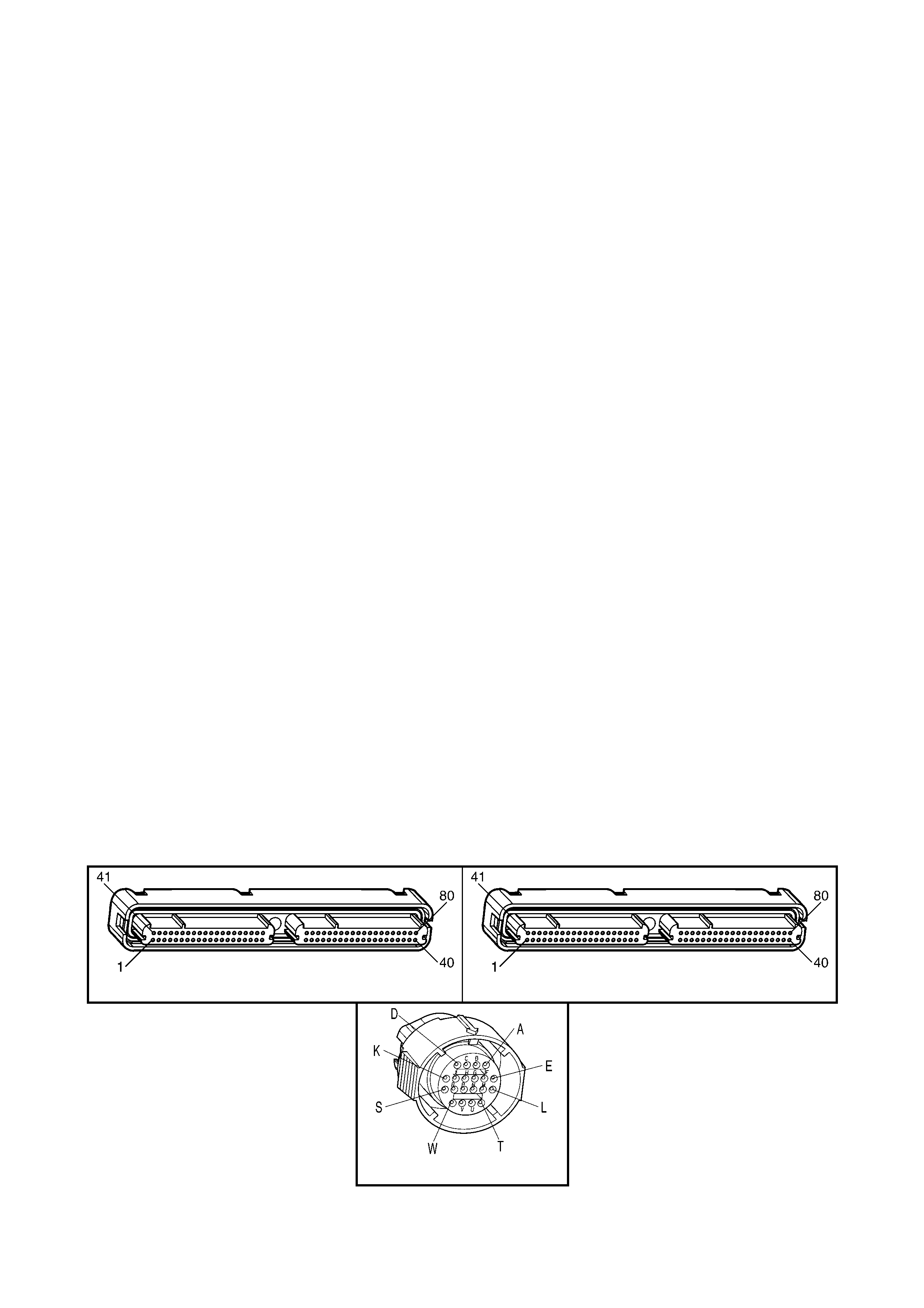
• The PCM determines a default TFT, using the following matrix:
1. If any ECT DTCs P0117 or P0118 are set, then the default TFT is equal to 135° C.
2. If the ECT is 125° C or more, then the default TFT is equal to 135° C.
3. If the engine run time is less than 300 seconds and:
– No intake air temperature (IAT) DTCs P0112 or P0113 are set and IAT is available, then the default
TFT is equal to IAT.
– Any IAT DTCs P0112 or P0113 are set or IAT is NOT available, then the default TFT is equal to 90° C.
4. If the engine run time is greater than 300 seconds and no IAT DTCs P0112 or P0113 are set and IAT is
available and ECT is between 40 and 125° C and:
– IAT at startup is less than 15° C, then the default TFT is equal to the ECT plus 5° C.
– IAT at startup is greater than 35° C, then the default TFT is equal to the ECT plus 10° C.
– IAT at startup is between 15 and 35° C, then the default TFT is equal to the ECT.
5. If the engine run time is greater than 300 seconds and any IAT DTCs P0112 or P0113 are set or IAT is
NOT available, then the default TFT is equal to the ECT.
6. If the engine run time is greater than 300 seconds and ECT is less than 40° C, then the default TFT is
equal to 60° C.
• The PCM freezes shift adapts from being updated.
CONDITIONS FOR CLEARING THE DTC
• A last test failed (current DTC) clears when the diagnostic runs and does not fail.
• The PCM cancels the DTC default actions when the fault no longer exists and the ignition switch is OFF long
enough in order to power down the PCM.
DIAGNOSTIC AIDS
• Inspect the wiring at the PCM, the transmission connector and all other circuit connecting points for the
following conditions:
– A backed out terminal
– A damaged terminal
– Reduced terminal tension
– A chafed wire
– A broken wire inside the insulation
– Moisture intrusion
– Corrosion
TEST DESCRIPTION
NOTE: The number(s) below refer to the step number(s) on the diagnostic table.
5. This step tes ts f or an interm ittent s hort or open c ondit ion in the en gine wiring h arnes s. T he test l ight is used as
a resistor in the circuit.
6. This step determines if the PCM or the TFT sensor is causing a steady, unchanging TFT reading.
A84–X1 (BLUE) A84-X2 (RED)
X121-X2
Figure 6C3-2A-148

GEN III V8 PCM – P0711 TFT SENSOR CIRCUIT RANGE/PERFORMANCE
STEP ACTION VALUE YES NO
1. Was the "On-Board Diagnostic" (OBD) System Check
performed? Go to Step 2 Go to
OBD System
Check
in this Section.
2. 1. Perform the transmission fluid checking procedure.
Refer to Transmission Fluid Checking Procedure in
7C4, ON-VEHICLE SERVICING.
Did you perform the fluid checking procedure?
Go to Step 3 Go to
Transmission
Fluid Checking
Procedure in
7C4, ON-
VEHICLE
SERVICING
3. 1. Install Tech 2.
2. Ignition ON, engine OFF.
IMPORTANT: Before clearing the DTC, use Tech 2 to
record the Failure Records. Using the Clear Info function
erases the Failure Records from the PCM.
3. Record the DTC Failure Records.
4. Clear the DTC.
5. Select TFT on Tech 2.
7. Drive the vehicle and observe Tech 2 for either of the
following con diti on s:
– The TFT does not change more than 1.5° C in 409
seconds since startup.
– The TFT changes more than 20° C in 200
milliseconds14 times within 7 seconds (unrealistic
change).
Did either of the conditions occur?
Go to Step 4 Go to
Diagnostic Aids
4. Did Tech 2 display a condition in which the TFT does not
change by more than the specified value in 409 seconds
since startup?
1.5° C Go to Step 6 Go to Step 5
5. 1. Ignition OFF.
2. Disconnect the transmission 20-way connector, X121-
X2.
3. Install the J 39775 jumper harness on the engine side
of the 20-way connector.
4. Using the J 35616-A connector test adaptor kit,
connect a test light from terminal L to terminal M (refer
to wiring harness connector X121-X2).
5. Ignition ON.
6. While observing display, move or wriggle the wiring
harness at the A84-X1 BLUE and A84-X2 RED PCM
connectors to the transmission 20-way connector.
Does the TFT change by more than the specified value?
20° C Go to Step 7 Go to Step 8
6. 1. Ignition OFF.
2. Disconnect the transmission 20-way connector.
3. Ignition ON.
Does Tech 2 display the same condition as in Step 4?
Go to Step 11 Go to Step 10
7. 1. Inspect circuits 1227 and 2753, of the engine wiring
harness, for an intermittent open or short condition.
2. Repair the circuits if necessary.
Did you find an intermittent open or shorted condition?
Go to Step 12 Go to Step 11
8. 1. Inspect circuits 1227 and 1230 of the automatic
transmission (A/T) wiring harness assembly, for an
intermittent open or short condition. Refer to Test
Procedures in 12P WIRING DIAGRAMS.
Did you find an intermittent open or shorted condition?
Go to Step 9 Go to Step 10
9. 1. Replace the automatic transmission wiring harness
assembly. Refer to Control Valve Body and Wiring
Harness Replace, in 7C4 IN-VEHICLE SERVICING.
Is the replacement complete?
Go to Step 12 –

STEP ACTION VALUE YES NO
10. 1. Replace the TFT Sensor (this sensor is part of the TFP
Manual Valve Position Switch). Refer to Control Valve
Body and Wiring Harness Replace, in 7C4 IN-
VEHICLE SERVICING.
Is the replacement complete?
Go to Step 12 –
11. 1. Replace PCM. Refer to PCM Programming and
PCM/PIM/BCM Security Link Procedure, in 6C3-3
SERVICE OPERATIONS.
Is the replacement complete?
Go to Step 12 –
12. 1. Perform the following procedure in order to verify the
repair:
a. Using Tech 2, select ‘DTC’, then select ‘Clear
Info’.
b. Drive the vehicle and ensure that the following
conditions are met:
– The TFT changes by more than 2.25° C for
11 seconds since startup
– The TFT does not change by more than 20°
C within 200 milliseconds for a period of at
least 11 seconds.
Were the above conditions verified?
Go to Step 1 System OK

GEN III V8 PCM – DTC P0712 TFT SENSOR CIRCUIT LOW INPUT
Figure 6C3-2A-149 – Transmission Fluid Pressure Manual Valve Position Switch Assembly Circuit
CIRCUIT DESCRIPTION
The autom atic Tr ansmiss ion Fluid Tem perature (T FT) Sensor is part of the autom atic Transm iss ion Fluid Pres sure
(TFP) manual valve position switch. The TFT sensor is a resistor, or thermistor, which changes value based on
temperature. The sensor has a negative-temperature coefficient. This means that as the temperature increases,
the resistance decreases, and as the temperature decreases, the resistance increases.
The Powertrain Control Module (PCM) supplies a 5-volt reference signal to the sensor on circuit 1227 and
meas ures the voltage drop in the circuit. W hen the transmis sion fluid is cold, th e sensor resistanc e is high and the
PCM detects h ig h sign al vo ltag e. As the f lu id t emperatur e warms to a nor mal operatin g temperatur e, t he r esistanc e
becomes less and the signal voltage decreases. The PCM uses this information to control shift quality and torque
converter clutch apply.
When the PCM detects a continuous short to ground, in the TFT signal circuit or in the TFT sensor, then DTC
P0712 sets.
CONDITIONS FOR RUNNING THE DTC
• The system voltage is between 8.0 volts and 18 volts.
• The ignition switch is in the RUN position.
CONDITIONS FOR SETTING THE DTC
• The TFT sensor indicates a signal voltage less than 0.2 volts for 10 seconds.
ACTION TAKEN WHEN THE DTC SETS
• The PCM stores the DTC information into memory when the diagnostic runs and fails.
• The Check Powertrain MIL will not be activated.
• The PCM records the operating conditions at the time the diagnostic fails. The PCM stores this information in
the Freeze Frame/Failure Records.
IMPORTANT: The actions listed below are in order of highest to lowest priority.
• The PCM determines a default TFT using the following matrix:
1. If any ECT DTCs P0117 or P0118 are set, then the default TFT is equal to 135° C.
2. If the ECT is 125° C or more, then the default TFT is equal to 135° C.
3. If the engine run time is less than 300 seconds and:
– No intake air temperature (IAT) DTCs P0112 or P0113 are set and IAT is available, then the default
TFT is equal to IAT.
– Any IAT DTCs P0112 or P0113 are set or IAT is NOT available, then the default TFT is equal to 90° C.
4. If the engine run time is greater than 300 seconds and no IAT DTCs P0112 or P0113 are set and IAT is
available and ECT is between 40 and 125° C and:
– IAT at startup is less than 15°C, then the default TFT is equal to the ECT plus 5° C.
– IAT at startup is greater than 35° C, then the default TFT is equal to the ECT plus 10° C.
– IAT at startup is between 15 and 35° C, then the default TFT is equal to the ECT.
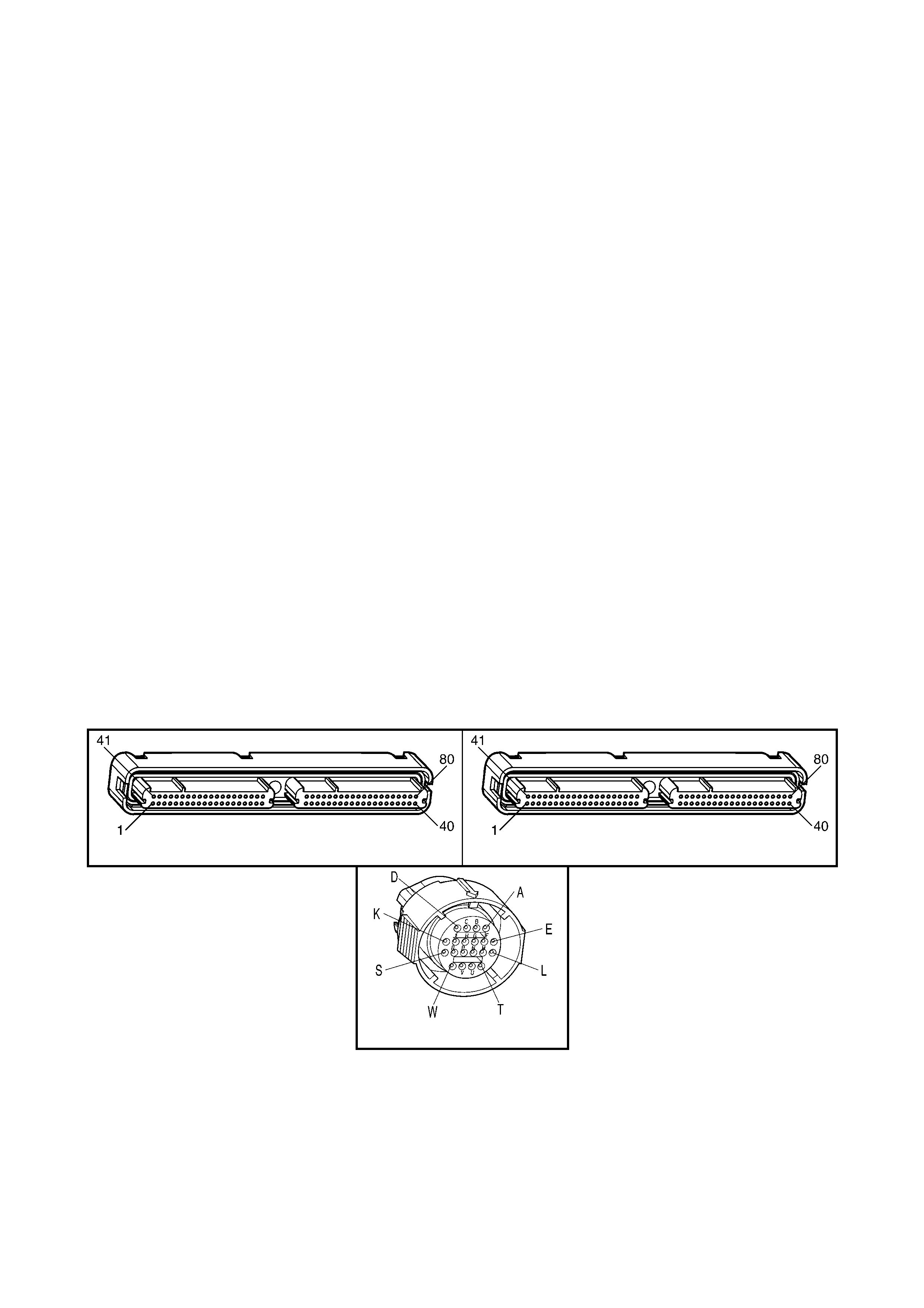
5. If the engine run time is greater than 300 seconds and any IAT DTCs P0112 or P0113 are set or IAT is
NOT available, then the default TFT is equal to the ECT.
6. If the engine run time is greater than 300 seconds and ECT is less than 40° C or more, then the default
TFT is equal to 60° C.
• The PCM freezes shift adapts from being updated.
CONDITIONS FOR CLEARING THE DTC
• A last test failed (current DTC) clears when the diagnostic runs and does not fail.
• The PCM cancels the DTC default actions when the fault no longer exists and the ignition switch is OFF long
enough in order to power down the PCM.
DIAGNOSTIC AIDS
• Inspect the wiring at the PCM, the transmission connector and all other circuit connecting points for the
following conditions:
– A backed out terminal
– A damaged terminal
– Reduced terminal tension
– A chafed wire
– A broken wire inside the insulation
– Moisture intrusion
– Corrosion
• When diagnosing for an intermittent short or open condition, massage the wiring harness while watching the
test equipment for a change.
• Use the T emperatur e vs R esistance t able whe n testin g the TFT sensor at variou s temper ature leve ls. Test the
TFT s ensor in order to ev aluate the poss ibilit y of a skewed (m is-sc aled) sensor. A skewed sensor can resu lt in
delayed garage shifts or TCC complaints.
• displays the transmission fluid temperature in degrees. After the transmission is operating, the fluid
temperature should rise steadily to a normal operating temperature, then stabilise.
• Verify customer driving habits, trailer towing, etc. Trailer towing should occur in D3.
TEST DESCRIPTION
NOTE: The number(s) below refer to the step number(s) on the diagnostic table.
4. This step creates an open in the TFT circuit in order to test for an internal fault.
A84–X1 (BLUE) A84-X2 (RED)
X121-X2
Figure 6C3-2A-150

GEN III V8 PCM – DTC P0712 TFT SENSOR CIRCUIT LOW INPUT
STEP ACTION VALUE YES NO
1. Was the "On-Board Diagnostic" (OBD) System Check
performed? Go to Step 2 Go to
OBD System
Check
in this Section.
2. 1. Perform the transmission fluid checking procedure.
Refer to Transmission Fluid Checking Procedure in
7C4, ON-VEHICLE SERVICING.
Did you perform the fluid checking procedure?
Go to Step 3 Go to
Transmission
Fluid Checking
Procedure in
7C4, ON-
VEHICLE
SERVICING
3. 1. Install Tech 2.
2. Ignition ON, engine OFF.
IMPORTANT: Before clearing the DTC, use Tech 2 to
record the Failure Records. Using the Clear Info function
erases the Failure Records from the PCM.
3. Record the DTC Failure Records.
4. Clear the DTC.
5. Select TFT on Tech 2.
Does Tech 2 display a TFT Sensor signal voltage less than
the specified value?
0.2 volts Go to Step 4 Go to Diagnostic
Aids
4. 1. Ignition OFF.
2. Disconnect the transmission 20-way connector, X121-
X2.
3. Ignition ON, engine OFF.
Does Tech 2 display a TFT Sensor signal voltage greater
than the specified value?
4.92 volts Go to Step 5 Go to Step 8
5. 1. Install the J 39775 jumper harness on the transmission
side of the 20-way connector.
2. Using a digital multimeter (DMM) and the J 35616-A
connector test adaptor kit, measure the resistance
between terminal L and terminal M.
Is the resistance within the specified range?
3088-3942 Ω
at 20°C
to
159-198 Ω
at 100°C
Go to
Diagnostic Aids Go to Step 6
6. 1. Inspect circuit 1227 of the automatic transmission
(A/T) wiring harness assembly for a short to ground
condition.
Did you find a short to ground condition?
Go to Step 10 Go to Step 7
7. 1. Disconnect the A/T wiring harness assembly at the
TFT sensor.
2. Measure the resistance of the TFT sensor.
Is the resistance within the specified range?
3088-3942 Ω
at 20°C
to
159-198 Ω
at 100°C
Go to
Diagnostic Aids Go to Step 9
8. 1. Inspect circuit 1227 of the engine wiring harness for a
short to ground condition.
2. Repair the circuit if necessary .
Did you find a short to ground condition?
Go to Step 12 Go to Step 11
9. 1. Replace the TFT Sensor (this sensor is part of the TFP
Manual Valve Position Switch). Refer to Control Valve
Body and Wiring Harness Replace, in 7C4 IN-
VEHICLE SERVICING.
Is the replacement complete?
Go to Step 12 –
10. 1. Replace the automatic transmission wiring harness
assembly. Refer to Control Valve Body and Wiring
Harness Replace, in 7C4 IN-VEHICLE SERVICING.
Is the replacement complete?
Go to Step 12 –
11. 1. Replace PCM. Refer to PCM Programming and
PCM/PIM/BCM Security Link Procedure, in 6C3-3
SERVICE OPERATIONS.
Is the replacement complete?
Go to Step 12 –

STEP ACTION VALUE YES NO
12. 1. Perform the following procedure in order to verify the
repair:
– Using Tech 2, select ‘DTC’, then select ‘Clear
Info’.
– Ignition ON, engine OFF.
– Verify that Tech 2 indicates a TFT Sensor signal
voltage greater than 0.2 volts for 10 seconds.
Was the above condition verified?
System OK Go to Step 2
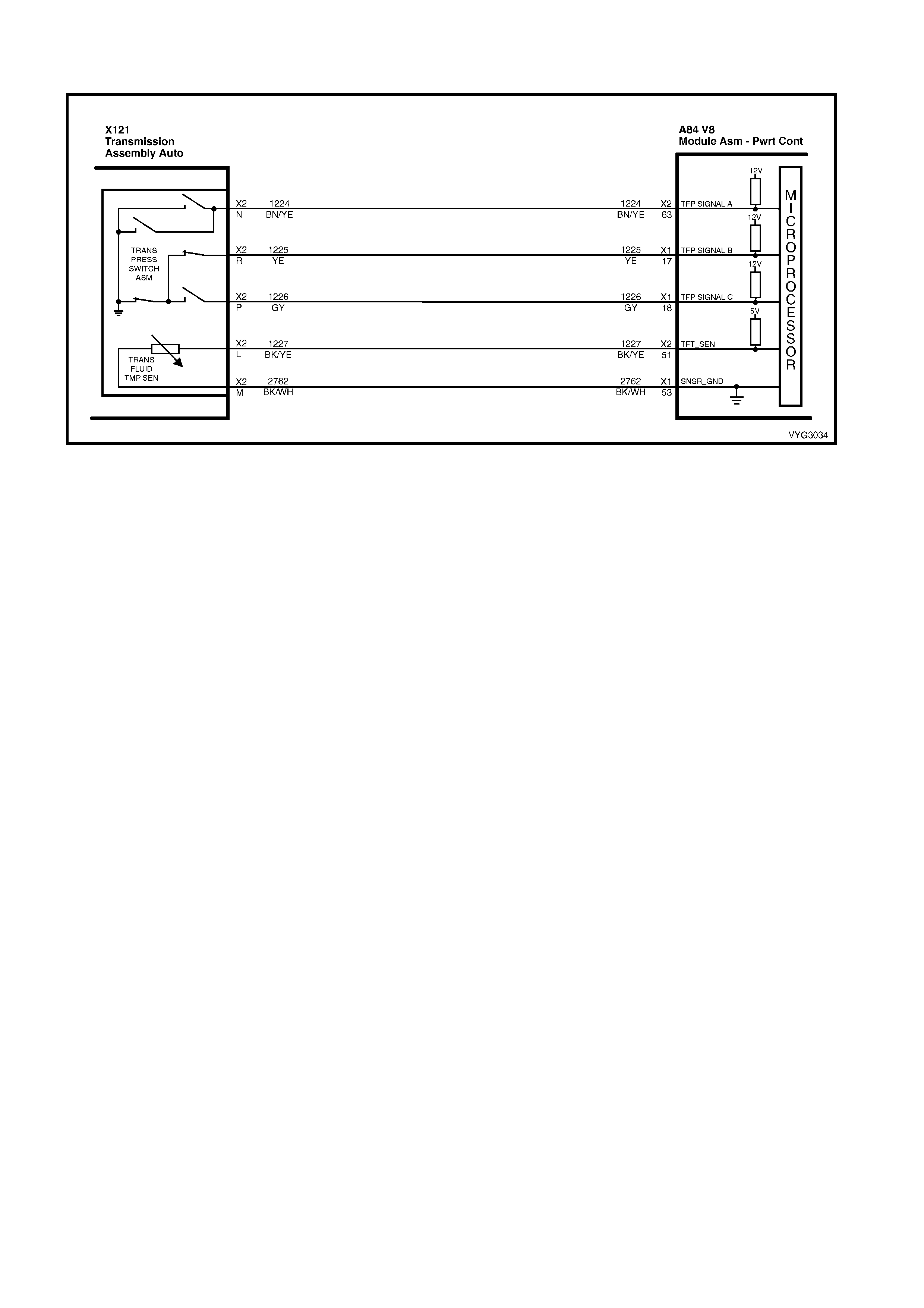
GEN III V8 PCM – DTC P0713 TFT SENSOR CIRCUIT HIGH INPUT
Figure 6C3-2A-151 – Transmission Fluid Pressure Manual Valve Position Switch Assembly Circuit
CIRCUIT DESCRIPTION
The autom atic Tr ansmiss ion Fluid Tem perature (T FT) Sensor is part of the autom atic Transm iss ion Fluid Pres sure
(TFP) manual valve position switch. The TFT sensor is a resistor, or thermistor, which changes value based on
temperature. The sensor has a negative-temperature coefficient. This means that as the temperature increases,
the resistance decreases, and as the temperature decreases, the resistance increases.
The Powertrain Control Module (PCM) supplies a 5-volt reference signal to the sensor on circuit 1227 and
meas ures the voltage drop in the circuit. W hen the transmis sion fluid is cold, th e sensor resistanc e is high and the
PCM detects h ig h sign al vo ltag e. As the f lu id t emperatur e warms to a nor mal operatin g temperatur e, t he r esistanc e
becomes less and the signal voltage decreases. The PCM uses this information to control shift quality and torque
converter clutch apply.
W hen the PCM det ects a continuo us open circuit or short to vo ltage in the TF T signal circ uit or in the T FT sensor,
then DTC P0713 sets.
CONDITIONS FOR RUNNING THE DTC
• The system voltage is between 8.0 volts and 18 volts.
• The ignition switch is in the ON position.
CONDITIONS FOR SETTING THE DTC
• The TFT sensor indicates a signal voltage greater than 4.92 volts for 10 seconds.
ACTION TAKEN WHEN THE DTC SETS
• The PCM stores the DTC information into memory when the diagnostic runs and fails.
• The Check Powertrain MIL will not be activated.
• The PCM records the operating conditions at the time the diagnostic fails. The PCM stores this information in
the Freeze Frame/Failure Records.
IMPORTANT: The actions listed below are in order of highest to lowest priority.
• The PCM determines a default TFT using the following matrix:
1. If any ECT DTCs P0117 or P0118 are set, then the default TFT is equal to 135° C.
2. If the ECT is 125°C or more, then the default TFT is equal to 135° C.
3. If the engine run time is less than 300 seconds and:
– No intake air temperature (IAT) DTCs P0112 or P0113 are set and IAT is available, then the default
TFT is equal to IAT.
– Any IAT DTCs P0112 or P0113 are set or IAT is NOT available, then the default TFT is equal to 90° C.
4. If the engine run time is greater than 300 seconds and no IAT DTCs P0112 or P0113 are set and IAT is
available and ECT is between 40 and 125° C and:
– IAT at startup is less than 15° C, then the default TFT is equal to the ECT plus 5° C.
– IAT at startup is greater than 35° C, then the default TFT is equal to the ECT plus 10° C.
– IAT at startup is between 15 and 35°C, then the default TFT is equal to the ECT.
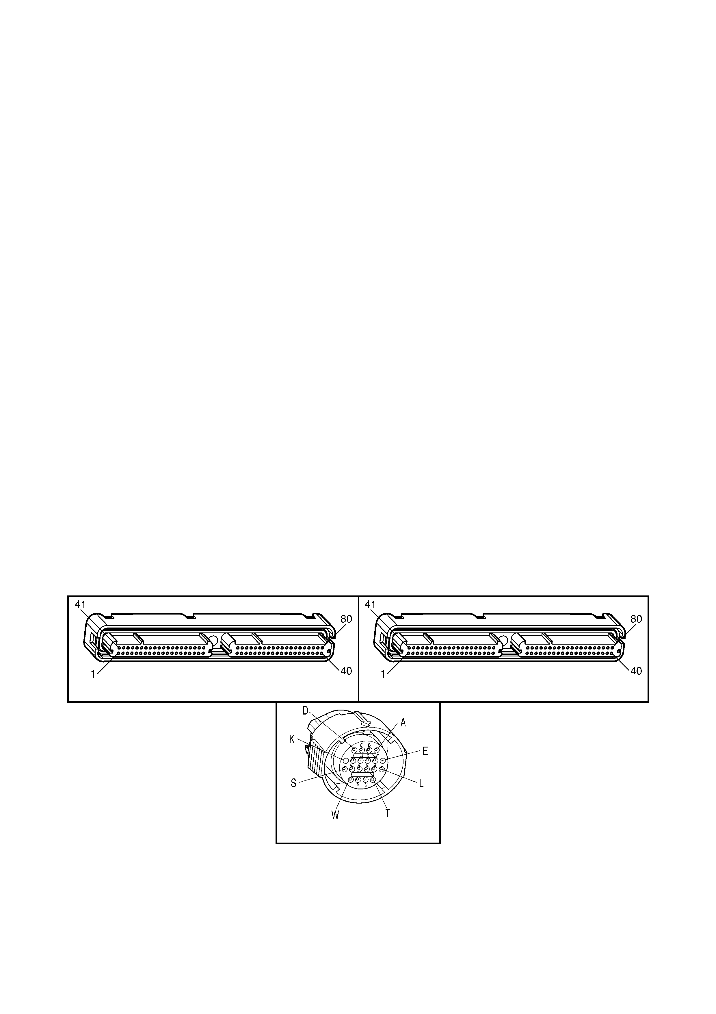
5. If the engine run time is greater than 300 seconds and any IAT DTCs P0112 or P0113 are set or IAT is
NOT available, then the default TFT is equal to the ECT.
6. If the engine r un time is gr eater tha n 300 s ec on ds and ECT is les s than 40°C, then the def au lt T FT is equal
to 60° C.
• The PCM freezes shift adapts from being updated.
CONDITIONS FOR CLEARING THE DTC
• A last test failed (current DTC) clears when the diagnostic runs and does not fail.
• The PCM cancels the DTC default actions when the fault no longer exists and the ignition switch is OFF long
enough in order to power down the PCM.
DIAGNOSTIC AIDS
• Inspect the wiring at the PCM, the transmission connector and all other circuit connecting points for the
following conditions:
– A backed out terminal
– A damaged terminal
– Reduced terminal tension
– A chafed wire
– A broken wire inside the insulation
– Moisture intrusion
– Corrosion
• When diagnosing for an intermittent short or open condition, massage the wiring harness while watching the
test equipment for a change.
• Us e the T em peratur e vs R esis tance table when testin g the T FT Sensor at variou s tem per ature lev els. Tes t the
TFT Sensor in or der t o evaluate t he pos sibili ty of a sk ewed (m is- scaled) s ensor. A sk ewed sensor can res ult i n
delayed garage shifts or TCC complaints.
• Tech 2 displays the transmission fluid temperature in degrees. After the transmission is operating, the fluid
temperature should rise steadily to a normal operating temperature, then stabilise.
TEST DESCRIPTION
NOTE: The number(s) below refer to the step number(s) on the diagnostic table.
3. This step verifies that a condition exists in the TFT sensor circuit.
4. This step simulates a TFT Sensor DTC P0712. If the PCM recognises high tem perature, the PCM and wiring
are functioning normally.
5. This step tests the TFT Sensor and automatic transmission (A/T) wiring harness assembly.
A84–X1 (BLUE) A84-X2RZ
X121-X2
Figure 6C3-2A-152

GEN III V8 PCM – DTC P0713 TFT SENSOR CIRCUIT HIGH INPUT
STEP ACTION VALUE YES NO
1. Was the "On-Board Diagnostic" (OBD) System Check
performed? Go to Step 2 Go to
OBD System
Check
in this Section.
2. 1. Perform the transmission fluid checking procedure.
Refer to Transmission Fluid Checking Procedure in
7C4, ON-VEHICLE SERVICING.
Did you perform the fluid checking procedure?
Go to Step 3 Go to
Transmission
Fluid Checking
Procedure in
7C4, ON-
VEHICLE
SERVICING
3. 1. Install Tech 2.
2. Ignition ON, engine OFF.
IMPORTANT: Before clearing the DTC, use Tech 2 to
record the Failure Records. Using the Clear Info function
erases the Failure Records from the PCM.
3. Record the DTC Failure Records.
4. Clear the DTC.
Does Tech 2 display a TFT Sensor signal voltage greater
than the specified value?
4.92 volts Go to Step 4 Go to Diagnostic
Aids
4. 1. Ignition OFF.
2. Disconnect the transmission 20-way connector, X121-
X2.
3. Install the J39775 jumper harness on the engine side
of connector
4. Install a fused jumper wire from terminal L to terminal
M on the jumper harness.
5. Ignition ON, engine OFF.
Does the TFT Sensor signal voltage drop to less than the
specified value?
0.2 volts Go to Step 5 Go to Step 9
5. 1. Ignition OFF.
2. Install the J 39775 jumper harness on the transmission
side of the connector X121-X2.
2. Using a digital multimeter (DMM) and the J 35616-A
connector test adaptor kit, measure the resistance
between terminal L and terminal M.
Is the resistance within the specified range?
3088-3942 Ω
at 20°C
to
159-198 Ω
at 100°C
Go to
Diagnostic Aids Go to Step 6
6. 1. Inspect circuits 1227 and 2753 of the automatic
transmission (A/T) wiring harness assembly for an
open condition.
Did you find an open circuit condition?
Go to Step 11 Go to Step 7
7. 1. Disconnect the A/T wiring harness assembly at the
TFT sensor.
2. Measure the resistance of the TFT sensor.
Is the resistance within the specified range?
3088-3942 Ω
at 20°C
to
159-198 Ω
at 100°C
Go to
Diagnostic Aids Go to Step 8
8. 1. Replace the TFT Sensor (this sensor is part of the TFP
Manual Valve Position Switch). Refer to Control Valve
Body and Wiring Harness Replace, in 7C4 IN-
VEHICLE SERVICING.
Is the replacement complete?
Go to Step 13 –
9. 1. Inspect circuit 1227 of the engine wiring harness for an
open or short to B+.
2. Repair the circuit if nece ss ary .
Did you find an open or short to B+ condition?
Go to Step 13 Go to Step 10
10. 1. Inspect circuit 2753 for an open condition.
2. Repair the circuit if necessary .
Did you find an open condition?
Go to Step 13 Go to Step 12

STEP ACTION VALUE YES NO
11. 1. Replace the automatic transmission wiring harness
assembly. Refer to Control Valve Body and Wiring
Harness Replace, in 7C4 IN-VEHICLE SERVICING.
Is the replacement complete?
Go to Step 13 –
12. 1. Replace PCM. Refer to PCM Programming and
PCM/PIM/BCM Security Link Procedure, in 6C3-3
SERVICE OPERATIONS.
Is the replacement complete?
Go to Step 13 –
13. 1. Perform the following procedure in order to verify the
repair:
– Using Tech 2, select ‘DTC’, then ‘Clear Info’.
– Ignition ON, engine OFF.
2. Verify that Tech 2 indicates a TFT Sensor signal
voltage less than 4.92 volts for 409 seconds (6.8
minutes).
Was the above condition verified?
System OK Go to Step 2
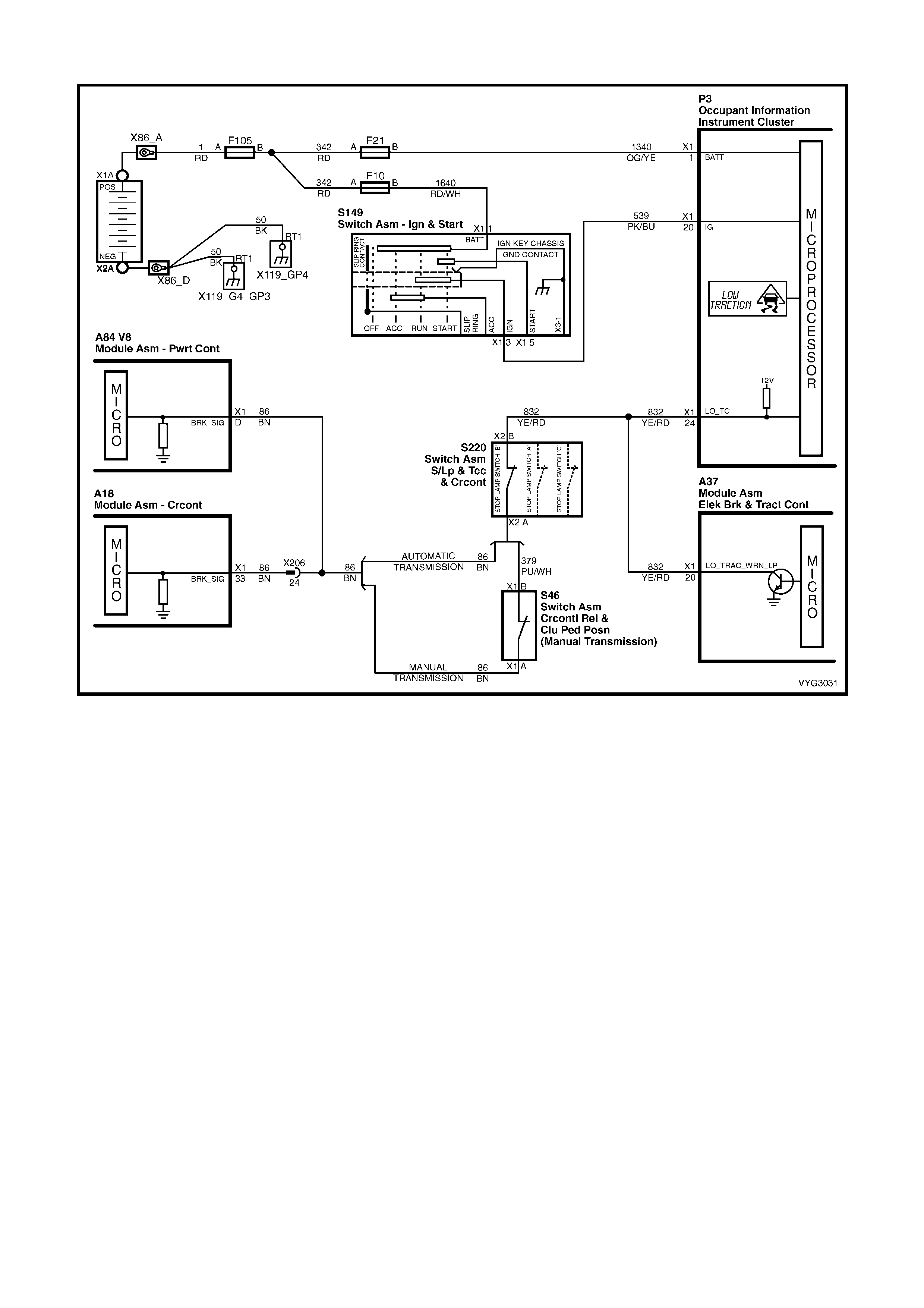
GEN III V8 PCM – DTC P0719 BRAKE SWITCH CIRCUIT LOW INPUT
Figure 6C3-2A-153 – Brake Switch Circuit
CIRCUIT DESCRIPTION
The brake switch indicates brake pedal status to the Powertrain Control Module (PCM). The brake switch is a
normally-closed switch that supplies voltage on circuit 86 to the PCM. Appl ying the brak e pedal opens the switch,
interrupting voltage to the PCM. W hen the brake pedal is released, the PCM receives a constant voltage signal. If
the PCM receives a zero voltage signal at the brake switch input, and the Torque Converter Clutch (TCC) is
engaged, the PCM de-energises the TCC solenoid valve. The PCM disregards the brake switch input for TCC
scheduling if there is a brake switch circuit fault (Refer to Diagnostic Aids).
When the PCM detects an open brake switch circuit (0 volts, low input) during accelerations, then DTC P0719 sets.
CONDITIONS FOR RUNNING THE DTC
• No VSS assembly DTCs P0502 or P0503.
• The ignition switch is in the RUN position.
CONDITIONS FOR SETTING THE DTC
• The PCM detec ts an ope n br ak e switch c ircuit ( 0 volts) for 15 m inutes witho ut ch anging for 2 s econds, an d the
following events occur seven times:
– The vehicle speed is less than 8 km/h;
– Then the vehicle speed is 8 – 32 km/h for four seconds;
– Then the vehicle speed is greater than 32 km/h for six seconds.
ACTION TAKEN WHEN THE DTC SETS
• The PCM stores the DTC information into memory when the diagnostic runs and fails.
• The Check Powertrain MIL will not be activated.
• The PCM disregards the brake switch input for TCC scheduling.
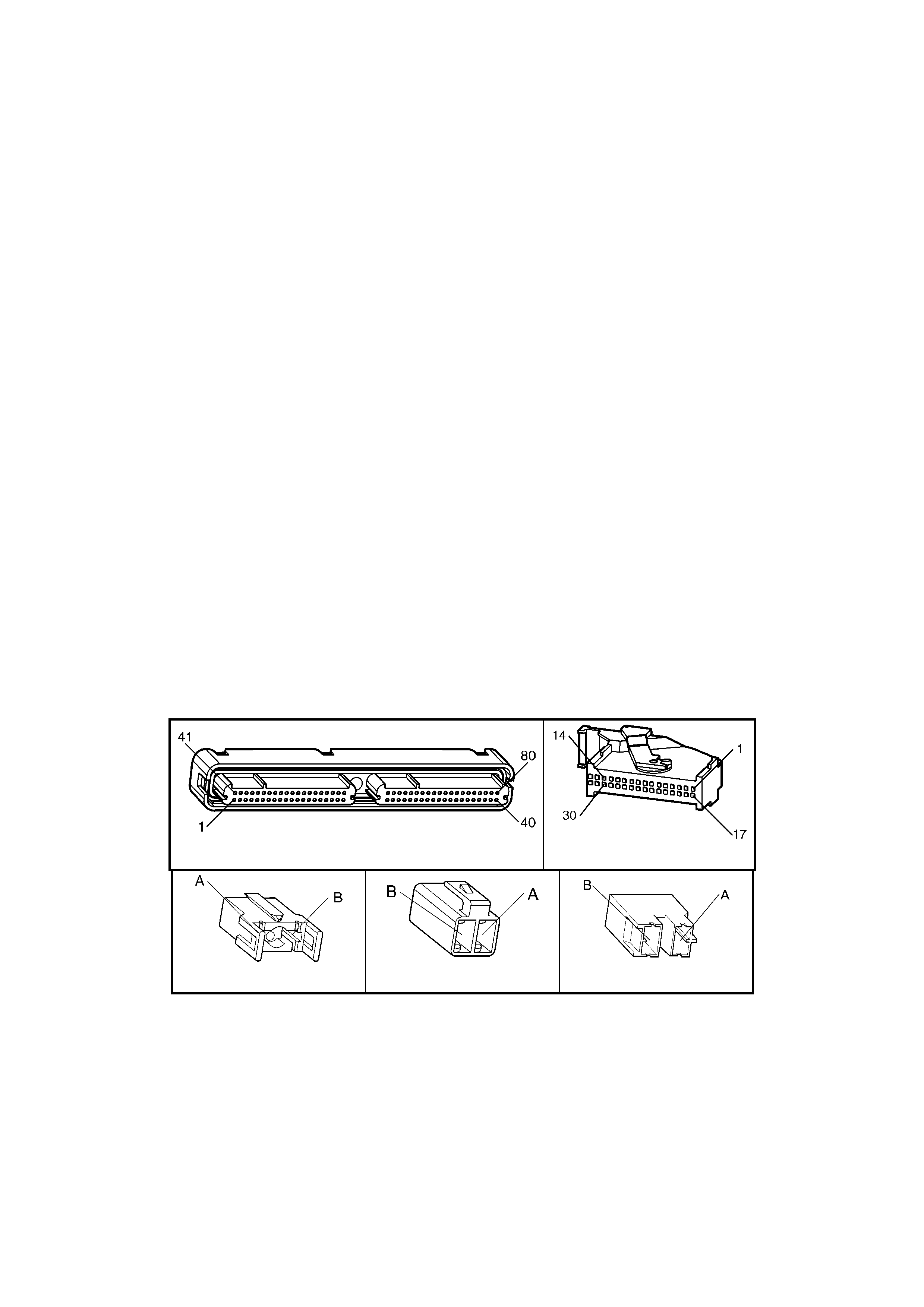
• The PCM records the operating conditions at the time the diagnostic fails. The PCM stores this information in
the Freeze Frame/Failure Records.
CONDITIONS FOR CLEARING THE DTC
• A last test failed (current DTC) clears when the diagnostic runs and does not fail.
• The PCM cancels the DTC default actions when the fault no longer exists and the ignition switch is OFF long
enough to power down the PCM.
DIAGNOSTIC AIDS
• Inspect the wiring at the PCM, the brake switch connector and all other circuit connecting points for the
following conditions:
- A backed out terminal
- A damaged terminal
- Reduced terminal tension
- A chafed wire
- A broken wire inside the insulation
- Moisture intrusion
- Corrosion
• When diagnosing for an intermittent short or open condition, massage the wiring harness while watching the
test equipment for a change.
• If the PCM detects a brake switch circuit fault, then the brake switch input is disregarded for TCC scheduling.
The PCM then uses throttle position and vehicle speed to determine TCC application and release.
• Use of these inputs may result in a noticeable harsh apply or abrupt release of the TCC.
• Ask about the customer's driving habits. Ask about unusual driving conditions (e.g. stop and go, expressway,
etc.).
• Inspect the brake switch for proper mounting and operation.
TEST DESCRIPTION
NOTE: The number(s) below refer to the step number(s) on the diagnostic table.
3. This step isolates the brake switch as a source for setting the DTC.
5. This step checks for a short to ground in circuit 832. If the vehicle is equipped with the Traction Control System
(TCS), the LOW TRAC warning icon in the Instrument Multi-Function Display (MFD) will be activated whenever
the engine is running and circuit 832 is shorted to ground.
A84–X1 (BLUE) P3
S220-X1 S220-X2 S220-X3
Figure 6C3-2A-154

GEN III V8 PCM – DTC P0719 BRAKE SWITCH CIRCUIT LOW INPUT
STEP ACTION VALUE YES NO
1. Was the "On-Board Diagnostic" (OBD) System Check
performed? Go to Step 2 Go to
OBD System
Check
in this Section.
2. 1. Install Tech 2.
2. Ignition ON, engine OFF.
IMPORTANT: Before clearing the DTC, use Tech 2 to
record the Failure Records. Using the Clear Info function
erases the Failure Records from the PCM.
3. Record the DTC Failure Records.
4. Clear the DTC.
5. Select TCC Brake Switch on Tech 2.
6. Disconnect the brake switch connector S220-X2 from
the brake switch.
7. Connect a Digital Multimeter (DMM) from circuit 832 of
the brake switch connector S220-X2 to ground.
Does the DMM display voltage above the specified value?
10 volts Go to Step 3 Go to Step 4
3. 1. Install a fused jumper wi re from circuit 832 to circuit 86
(or 379 if a manual transmission) of the brake switch
connector.
Did the TCC Brake Switch status change from Open to
Closed, on Tech 2?
Go to Step 7 Go to Step 6
4. 1. Inspect circuit 832 for an open circuit between brake
switch connector S220-X2, terminal X2-B and the
Instrument P3, terminal X1-24.
Was an open circuit found?
Go to Step 10 Go to Step 5
5. 1. Inspect circuit 832 for a short to ground condition.
2. Repair the circuit if necessary .
Did you find a short to ground condition?
Go to Step 10 Replace
Instrument.
Refer to 12 C
INSTRUMENT
6. 1. Inspect circuit 86 for a short to ground condition.
2. Repair the circuit if necessary .
Did you find a short to ground condition?
Go to Step 10 Go to Step 8
7. 1. Replace the brake switch. Refer to Stop Lamp Switch
Replace, in 12B LIGHTING SYSTEM.
Is the replacement complete?
Go to Step 10 –
8. 1. Inspect circuit 86 for an open condition.
2. Repair the circuit if necessary .
Did you find an open condition?
Go to Step 10 Go to Step 9
9. 1. Replace PCM. Refer to PCM Programming and
PCM/PIM/BCM Security Link Procedure, in 6C3-3
SERVICE OPERATIONS.
Is the replacement complete?
Go to Step 10 –
10. 1. Perform the following procedure in order to verify the
repair:
2. Select ‘DTC’, then ‘Clear Info’ on Tech 2.
3. Ignition ON, engine OFF.
4. Apply and release the brake pedal.
5. Verify that TCC Brake Switch status indicates Closed
(12 volts) with brake pedal depressed.
Was the above condition verified?
System OK Go to Step 2

GEN III V8 PCM – DTC P0724 BRAKE SWITCH CIRCUIT HIGH INPUT
Figure 6C3-2A-155 – Brake Switch Circuit
CIRCUIT DESCRIPTION
The brake switch indicates brake pedal status to the Powertrain Control Module (PCM). The brake switch is a
normally-closed switch that supplies voltage on circuit 86 to the PCM. Appl ying the brak e pedal opens the switch,
interrupting voltage to the PCM. W hen the brake pedal is released, the PCM receives a constant voltage signal. If
the PCM receives a zero voltage signal at the brake switch input, and the Torque Converter Clutch (TCC) is
engaged, the PCM de-energises the TCC solenoid valve. The PCM disregards the brake switch input for TCC
scheduling, if there is a brake switch circuit fault (Refer to Diagnostic Aids).
When the PCM detects a closed brake switch circuit (12 volts, high input) during decelerations, then DTC P0724
sets.
CONDITIONS FOR RUNNING THE DTC
• No VSS assembly DTCs P0502 or P0503.
• The ignition switch is in the RUN position.
CONDITIONS FOR SETTING THE DTC
• The PCM detects a closed brake switch circuit (12 volts) without changing for 2 seconds, and the following
events occur seven times:
– When the vehicle speed is greater than 32 km/h for six seconds.
– Then the vehicle speed is 8 – 32 km/h for four seconds;
– The vehicle speed is less than 8 km/h;
ACTION TAKEN WHEN THE DTC SETS
• The PCM stores the DTC information into memory when the diagnostic runs and fails.
• The Check Powertrain MIL will not be activated.
• The PCM records the operating conditions at the time the diagnostic fails. The PCM stores this information in
the Freeze Frame/Failure Records.
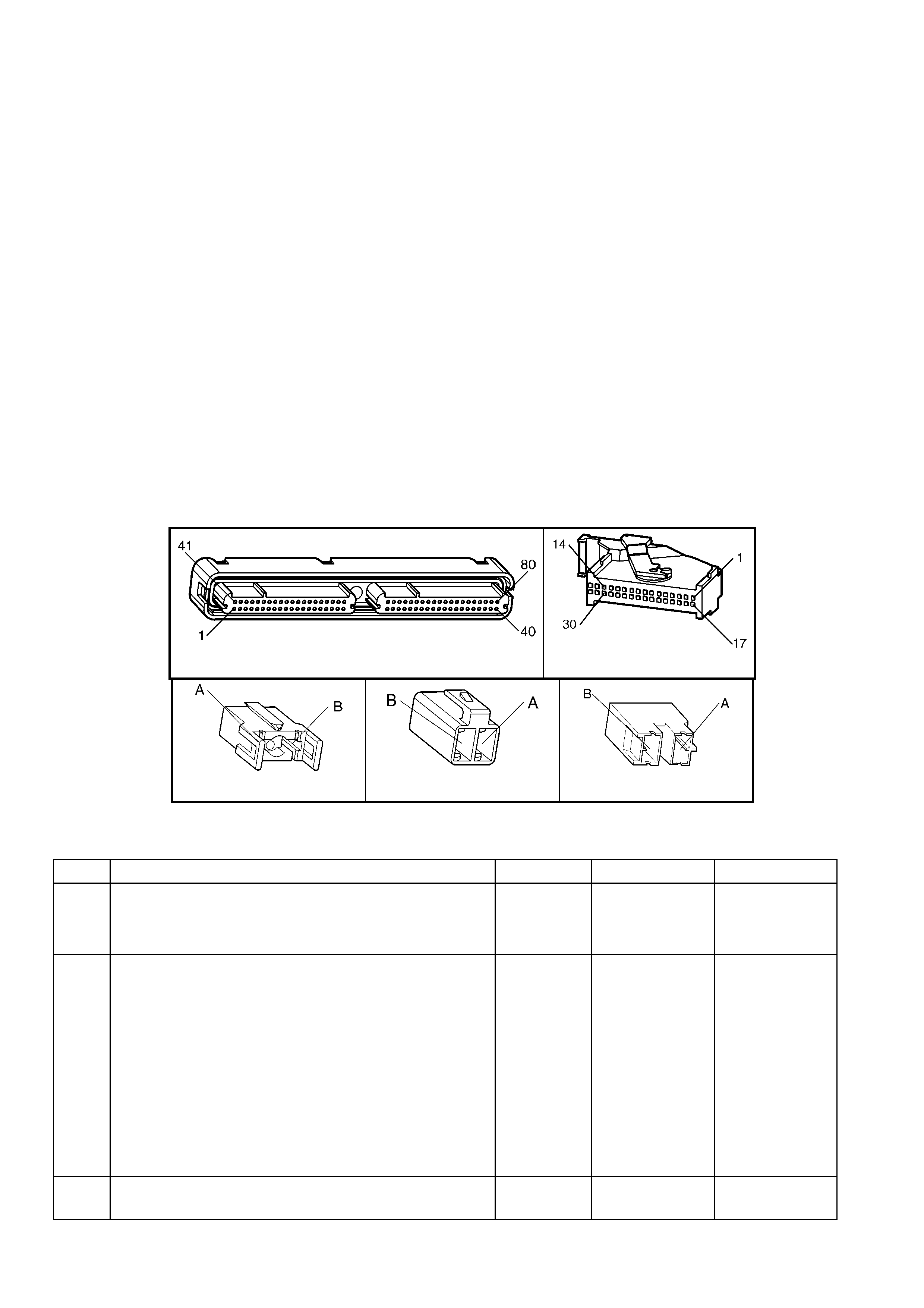
CONDITIONS FOR CLEARING THE DTC
• A last test failed (current DTC) clears when the diagnostic runs and does not fail.
• The PCM cancels the DTC default actions when the fault no longer exists and the ignition switch is OFF
long enough to power down the PCM.
DIAGNOSTIC AIDS
• Inspect the wiring at the PCM, the brake switch connector and all other circuit connecting points for the
following conditions:
– A backed out terminal
– A damaged terminal
– Reduced terminal tension
– A chafed wire
– A broken wire inside the insulation
– Moisture intrusion
– Corrosion
• When diagnosing for an intermittent short or open condition, massage the wiring harness while watching the
test equipment for a change.
• Ask about the customer’s driving habits or unusual driving conditions (e.g. stop & go, highway, etc.).
• Inspect the brake switch for proper mounting and operation.
TEST DESCRIPTION
NOTE: The number(s) below refer to the step number(s) on the diagnostic table.
2. This step isolates the brake switch as a source for setting the DTC.
A84–X1 (BLUE) P3
S220-X1 S220-X2 S220-X3
Figure 6C3-2A-156
GEN III V8 PCM – DTC P0724 BRAKE SWITCH CIRCUIT HIGH INPUT
STEP ACTION VALUE YES NO
1. Was the "On-Board Diagnostic" (OBD) System Check
performed? Go to Step 2 Go to
OBD System
Check
in this Section.
2. 1. Install Tech 2.
2. Ignition ON, engine OFF.
IMPORTANT: Before clearing the DTC, use Tech 2 to
record the Failure Records. Using the Clear Info function
erases the Failure Records from the PCM.
3. Record the DTC Failure Records.
4. Clear the DTC.
5. Select TCC Brake Switch on Tech 2.
6. Disconnect the brake switch connector from the brake
switch.
Did the TCC Brake Switch status change from Closed to
Open.
Go to Step 3 Go to Step 4
3. 1. Replace the brake switch.
Is the replacement complete? Go to Step 6 –

STEP ACTION VALUE YES NO
4. 1. Inspect circuit 86 for a short to voltage condition.
2. Repair the circuit if necessary .
Did you find a short to B+ condition?
Go to Step 6 Go to Step 5
5. 1. Replace PCM. Refer to PCM Programming and
PCM/PIM/BCM Security Link Procedure, in 6C3-3
SERVICE OPERATIONS.
Is the replacement complete?
Go to Step 6 –
6. 1. Perform the following procedure in order to verify the
repair:
2. Select ‘DTC’, then ‘Clear Info’ on Tech 2.
3. Ignition ON, engine OFF.
4. Apply and release the brake pedal.
5. Verify that TCC Brake Switch status indicates Open (0
volts) with brake pedal depressed.
Was the above condition verified?
System OK Go to Step 2
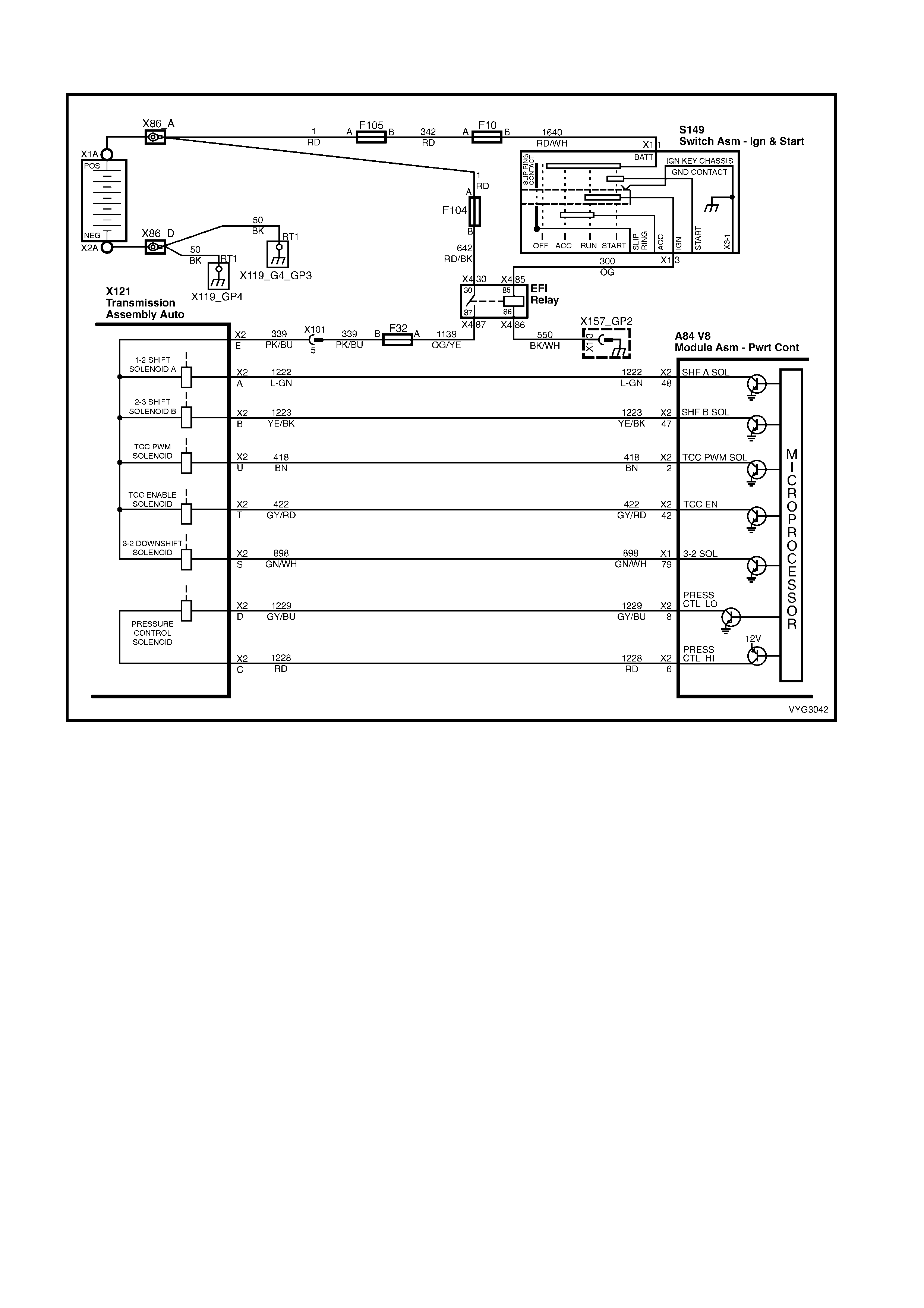
GEN III V8 PCM – DTC P0740 TCC ENABLE SOLENOID CIRCUIT ELECTRICAL
Figure 6C3-2A-157 – TCC Enable Circuit
CIRCUIT DESCRIPTION
The Torque Converter Clutch (TCC) solenoid valve is an electrical device that is used with the Torque Converter
Clutch Pulse Width Modulation (TCC PWM) solenoid valve, in order to control TCC apply and release. The TCC
solenoid v al ve attac hes t o t he tr ans mission c as e ass e mbl y extending int o th e pum p cover. T he TCC soleno i d va l ve
receives ignition voltage through circuit 339. The Powertrain Control Module (PCM) controls the solenoid by
providing the ground path on circuit 422. The PCM monitors the throttle position (TP) voltage, the vehicle speed
and other inputs in order to determine when to energise the TCC solenoid valve.
When the PCM detects a continuous open or a short to ground in the TCC solenoid valve circuit or in the TCC
solenoid valve, then DTC P0740 sets.
CONDITIONS FOR RUNNING THE DTC
• The system voltage is between 8.0 and 18 volts.
• The engine speed is greater than 300 RPM for 5 seconds.
• The engine is not in fuel cutoff.
CONDITIONS FOR SETTING THE DTC
• The PCM commands the solenoid ON and the voltage input remains high (12 volts).
OR
• The PCM commands the solenoid OFF and the voltage input remains low (0 volts).
ACTION TAKEN WHEN THE DTC SETS
• The PCM stores the DTC information into memory when the diagnostic runs and fails.
• The PCM does not activate the Check Powertrain MIL.
• The PCM inhibits TCC engagement.
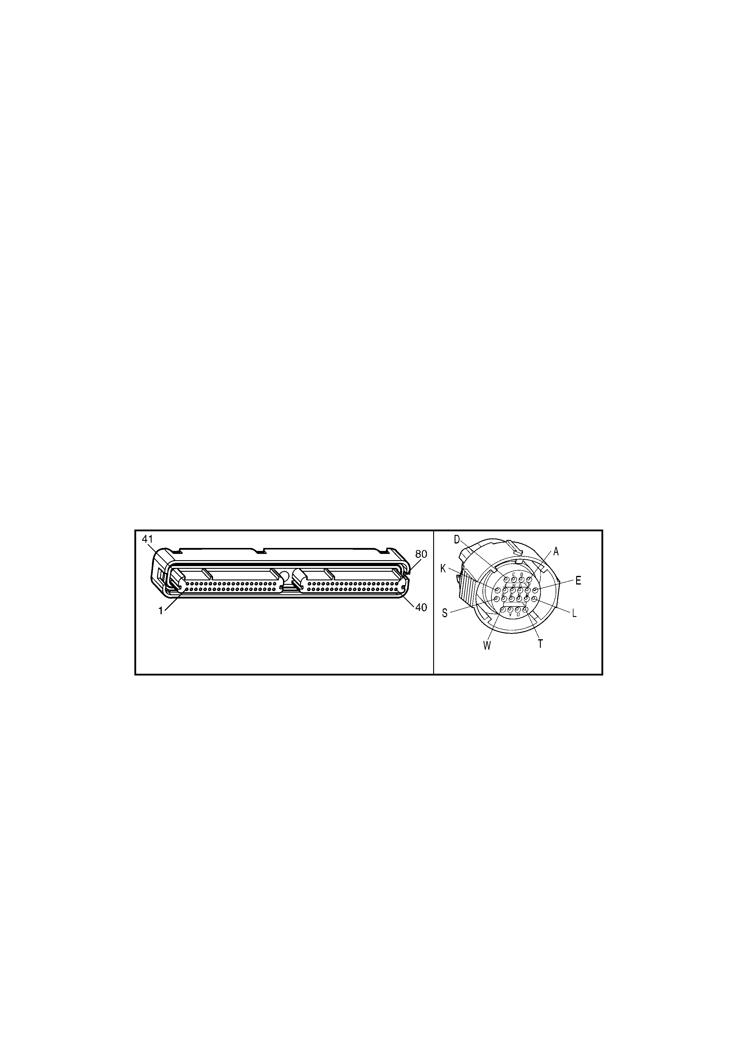
• The PCM inhibits 4th gear if the transmission is in hot mode.
• The PCM freezes shift adapts from being updated.
• The PCM records the operating conditions at the time the diagnostic fails. The PCM stores this information in
the Freeze Frame/Failure Records.
CONDITIONS FOR CLEARING THE DTC
• A last test failed (current DTC) clears when the diagnostic runs and does not fail.
• The PCM cancels the DTC default actions when the fault no longer exists and the ignition switch is OFF long
enough in order to power down the PCM.
DIAGNOSTIC AIDS
• Inspect the wiring at the PCM, the transmission connector and all other circuit connecting points for the
following conditions:
– A backed out terminal
– A damaged terminal
– Reduced terminal tension
– A chafed wire
– A broken wire inside the insulation
– Moisture intrusion
– Corrosion
• When diagnosing for an intermittent short or open condition, massage the wiring harness while watching the
test equipment for a change.
• With the TCC engaged, the TCC slip speed should be -20 to +40 RPM.
TEST DESCRIPTION
NOTE: The number(s) below refer to the step number(s) on the diagnostic table.
2. This step tests for voltage to the solenoid.
6. This step tests the ability of the PCM and wiring to control the ground circuit.
8. This step tests the resistance of the TCC solenoid valve and the automatic transmission (A/T) wiring harness
assembly.
A84–X2 (RED) X121-X2
Figure 6C3-2A-158

GEN III V8 PCM – DTC P0740 TCC ENABLE SOLENOID CIRCUIT ELECTRICAL
STEP ACTION VALUE YES NO
1. Was the "On-Board Diagnostic" (OBD) System Check
performed? Go to Step 2 Go to
OBD System
Check
in this Section.
2. 1. Install Tech 2.
2. Ignition ON, engine OFF.
IMPORTANT: Before clearing the DTC, use Tech 2 to
record the Freeze Frame/Failure Records. Using the Clear
Info function erases the Freeze Frame/Failure Records
from the PCM.
3. Record the DTC Freeze Frame/Failure records
4. Clear the DTC.
Are any of the following DTCs also set?
– P0753
– P0758
– P0785
– P1860
Go to Step 3 Go to Step 4
3. 1. Inspect fuse F32.
2. If the fuse is open, inspect the following components
for a short to ground condition:
– Circuit 339
– The solenoids
– The A/T wiring harness assembly
3. Repair the circuit, the solenoids, and the harness if
necessary.
Did you find a short to ground condition?
Go to Step 12 Go to Step 4
4. 1. Ignition OFF.
2. Disconnect the transmission 20-way connector X121-
X2 (additional DTCs may set).
3. Install the J 39775 jumper harness on the engine side
of the 20-way connector, X121-X2.
4. Ignition ON, engine OFF.
5. Connect a test lamp from cavity E of the J 39775
jumper harness to ground.
6. Refer to Connector X121-X2 end view, in this DTC
table.
Is the test lamp ON?
Go to Step 6 Go to Step 5
5. IMPORTANT: The condition that affects this circuit may
exist in other connecting branches of the circuit. Refer to
Power Distribution Diagrams in 12P WIRING DIAGRAMS.
1. Repair the open or short to ground in ignition feed
circuit 339 to the TCC solenoid valve.
Is the repair complete?
Go to Step 12 –
6. 1. Install the test lamp from cavities E to T of the J 39775
jumper harness.
2. Using the transmission Miscellaneous Tests function
on Tech 2, command the TCC solenoid valve ON and
OFF three times.
Does the test lamp turn ON, when the TCC solenoid valve
is commanded ON and OFF, when commanded OFF?
Go to Step 8 Go to Step 7
7. 1. Inspect circuit 422 of the engine wiring harness, for an
open, short to ground or short to power condition.
2. Repair the circuit if necessary .
Did you find an open, short to ground or short to power
condition?
Go to Step 12 Go to Step 9

STEP ACTION VALUE YES NO
8. 1. Install the J 39775 jumper harness on the transmission
side of the 20-way connector X121-X2.
2. Using a digital multimeter (DMM) and the J 35616-A
connector test adaptor kit, measure the resistance
between terminals T and E.
Is the resistance within the specified range?
21 – 33 Ω Go to Step 10 Go to Step 11
9. 1. Replace PCM. Refer to PCM Programming and
PCM/PIM/BCM Security Link Procedure, in 6C3-3
SERVICE OPERATIONS.
Is the replacement complete?
Go to Step-12 –
10. 1. Measure the resistance between terminal E and
ground, and between terminal T and ground.
Are both readings greater than the specified value?
250 kΩ Go to
Diagnostic Aids Go to Step 11
11. 1. Replace the automatic transmission wiring harness
assembly (this includes the TCC solenoid valve). Refer
to Control Valve Body and W iring Harness Replace, in
7C4 A/T ON-VEHICLE SERVICE OPERATIONS.
Is the replacement complete?
Go to Step 12 –
12. 1. Perform the following procedure in order to verify the
repair:
– Select ‘DTC’, then select ‘Clear Info’, on Tech 2.
2. Drive the vehicle in D with the TCC ON and OFF.
Ensure the following conditions are met:
– The PCM commands the TCC solenoid valve ON,
and the voltage input drops to zero.
– The PCM commands the TCC solenoid valve
OFF, and the voltage input increases to B+.
– All conditions are met for 5 seconds.
Were the above conditions verified?
System OK Go to Step 2

GEN III V8 PCM – DTC P0742 TCC SYSTEM STUCK ON
6C3-2A-159 – Automatic Transmission Solenoid Circuits
CIRCUIT DESCRIPTION
The T orque Converter Clutch (TCC) solenoid valve is a normall y- open exhaust valve that is used with the T orque
Converter Clutch Pulse Width Modulation (TCC PWM) solenoid valve in order to control fluid acting on the
converter clutch apply valve. The TCC solenoid valve attaches to the transmission case assembly extending into
the pump cover.
When energised by the Powertrain Control Module (PCM), th e TCC solenoid valve stops converter signa l oil from
exhausting. This causes converter signal oil pressure to increase and move the converter clutch apply valve
against spring force and into the apply position. In this position, release fluid is open to an exhaust port and
converter feed fluid fills the appl y fluid circuit. The converter feed fluid applies the T CC. W hen the PCM no longer
provides a ground path, the TCC solenoid valve de-energises and apply fluid exhausts, releasing the TCC.
When the PCM detects low torque converter slip when the PCM commands the TCC OFF, then DTC P0742 sets.
CONDITIONS FOR RUNNING THE DTC
• No MAP sensor DTCs P0107 or P0108.
• No Throttle Position DTCs P0122 or P0123.
• No VSS assembly DTCs P0502 or P0503.
• No TCC solenoid valve DTC P0740.
• No TFP manual valve position switch DTC P1810.
• No TCC PWM solenoid valve DTC P1860.
• The Throttle Position angle is 10-45%.
• The engine speed is greater than 300 RPM for 5 seconds.
• The engine is not in fuel cutoff.
• The engine speed is 1000-3500 RPM.

• The engine torque is 54-542 Nm
• The engine vacuum is 0-105 kPa.
• The speed ratio is 0.65-1.30 (the speed ratio is engine speed divided by output speed).
• The vehicle speed is 32-88 km/h.
• The commanded gear is not 1st.
• The gear range is D.
• The gear range does not change within 6 seconds.
• The PCM commands the TCC OFF.
CONDITIONS FOR SETTING THE DTC
• DTC P0742 sets if the following condition occurs three times:
– The TCC slip speed is -20 to +30 RPM for 4 seconds.
ACTION TAKEN WHEN THE DTC SETS
• The PCM activates the Check Powertrain MIL during the second consecutive trip in which the conditions for
setting the DTC are met.
• The PCM freezes shift adapts from being updated.
• The PCM records the operating conditions at the time the diagnostic fails. The PCM stores this information in
the Freeze Frame / Failure Records.
CONDITIONS FOR CLEARING THE MIL/DTC
• The PCM deactivates the Check Powertrain MIL during the first trip in which the diagnostic test runs and
passes.
• Use Tech 2 to clear the DTC.
• The PCM cancels the DTC default actions when the fault no longer exists and the ignition switch is OFF long
enough in order to power down the PCM.
DIAGNOSTIC AIDS
• The TCC fluid mechanically applies the TCC, possibly causing an engine stall, under the following conditions:
– The TCC is mechanically stuck ON
– The parking brake is applied
– Any gear range is selected
• A stuck TP sensor may set DTC P0742.
TEST DESCRIPTION
NOTE: The number(s) below refer to the step number(s) on the diagnostic table.
3. This step inspects the mechanical state of the TCC. When the PCM commands the TCC solenoid valve OFF,
the slip speed should increase.
GEN III V8 PCM – DTC P0742 TCC SYSTEM STUCK ON
STEP ACTION VALUE YES NO
1. Was the "On-Board Diagnostic" (OBD) System Check
performed? Go to Step 2 Go to
OBD System
Check
in this Section.
2. 1. Install Tech 2.
2. Ignition ON, engine OFF.
IMPORTANT: Before clearing the DTC, use Tech 2 to
record the Freeze Frame/Failure Records. Using the Clear
Info function erases the Freeze Frame/Failure Records
from the PCM.
3. Record the DTC Freeze Frame and Failure Records.
4. Clear the DTC.
5. Drive the vehicle in the D drive range in fourth gear
under steady acceleration, with a TP angle steady at
20%.
While Tech 2 TCC Enable status is NO, does Tech 2
display a TCC Slip Speed within the specified range?
–20 to +30
RPM Go to Step 3 Go to
Diagnostic Aids

STEP ACTION VALUE YES NO
3. 1. The TCC is hydraulically stuck ON. Inspect for the
following con diti on s:
– A restricted transmission cooler line.
– A clogged exhaust orifice in the TCC solenoid
valve.
– The converter clutch apply valve is stuck in the
apply position.
– A misaligned or damaged valve body gasket.
– A restricted release passage.
Did you find and correct the condition?
Go to Step 4 –
4. 1. Perform the following procedure in order to verify the
repair:
2. Select ‘DTC’, then ‘Clear Info’, on Tech 2.
3. Drive the vehicle in D under the following conditions:
– Hold the throttle at 25% and accelerate to 88
km/h.
– Ensure that TCC Slip Speed is 130 to 2000 RPM
for 4 seconds, with the TCC OFF.
Were the above conditions verified?
System OK Go to Step 2
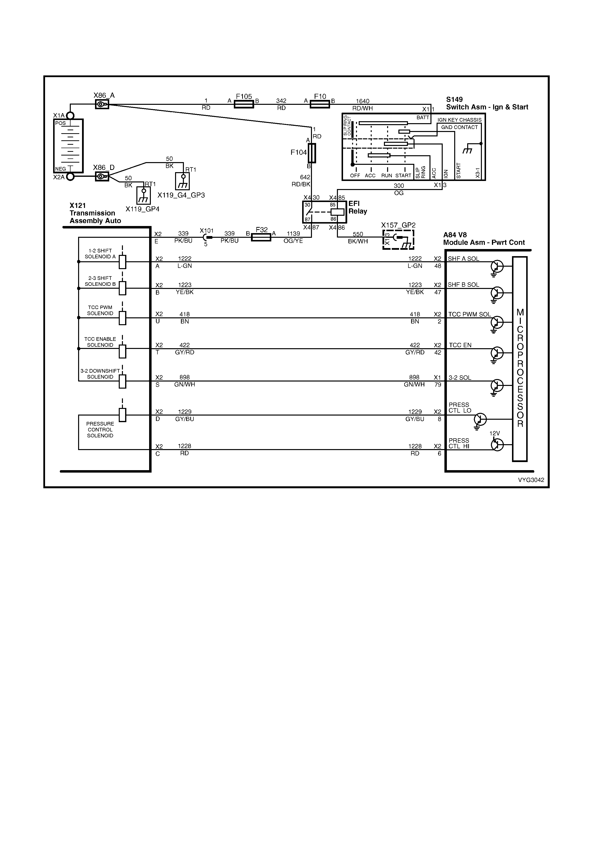
GEN III V8 PCM - DTC P0748 PRESSURE CONTROL (PC)
SOLENOID CIRCUIT ELECTRICAL
Figure 6C3-2A-160 – Automatic Transmission Solenoid Circuits
CIRCUIT DESCRIPTION
The Pressure Control (PC) solenoid valve is an electronic device that regulates transmission line pressure based
on the current flow through its coil winding. The magnetic field produced by the coil m oves the solenoid's internal
valve whic h var ies pr essur e to the press ure r egulat or va lve. T he Powertr ain Con tr ol Modul e (PCM) c ontrols the PC
solenoid va l ve by appl ying a varying amount of cur rent to the s ol en oid . The applie d c ur rent c an v ar y fr om 0.1 to 1. 1
amps. Low current (0.1 amp) indicates high line pressure. High current (1.1 amps) indicates low line pressure.
The duty cycle of the PC solenoid valve is expressed as a percentage of energised ON time. Zero percent indicates
zero ON time (non-energised) or no current flow. Approximately 60% at idle indicates maximum ON time
(energise d) or high curr ent flow. T he PCM determ ines the appropr iate line pres sure for a giv en load by com paring
the throttle position (TP) voltage, the engine speed and other inputs.
When the PCM detects a continuous open or short to ground in the PC solenoid valve circuit or the PC solenoid
valve, then DTC P0748 sets.
CONDITIONS FOR RUNNING THE DTC
• The system voltage is between 8.0 and 18 volts.
• The engine is running.
CONDITIONS FOR SETTING THE DTC
• The PC s olenoi d valve dut y c ycle reach es its h igh lim it ( approxim atel y 95%) or low limit ( approxim atel y 0%) f or
200 milliseconds.
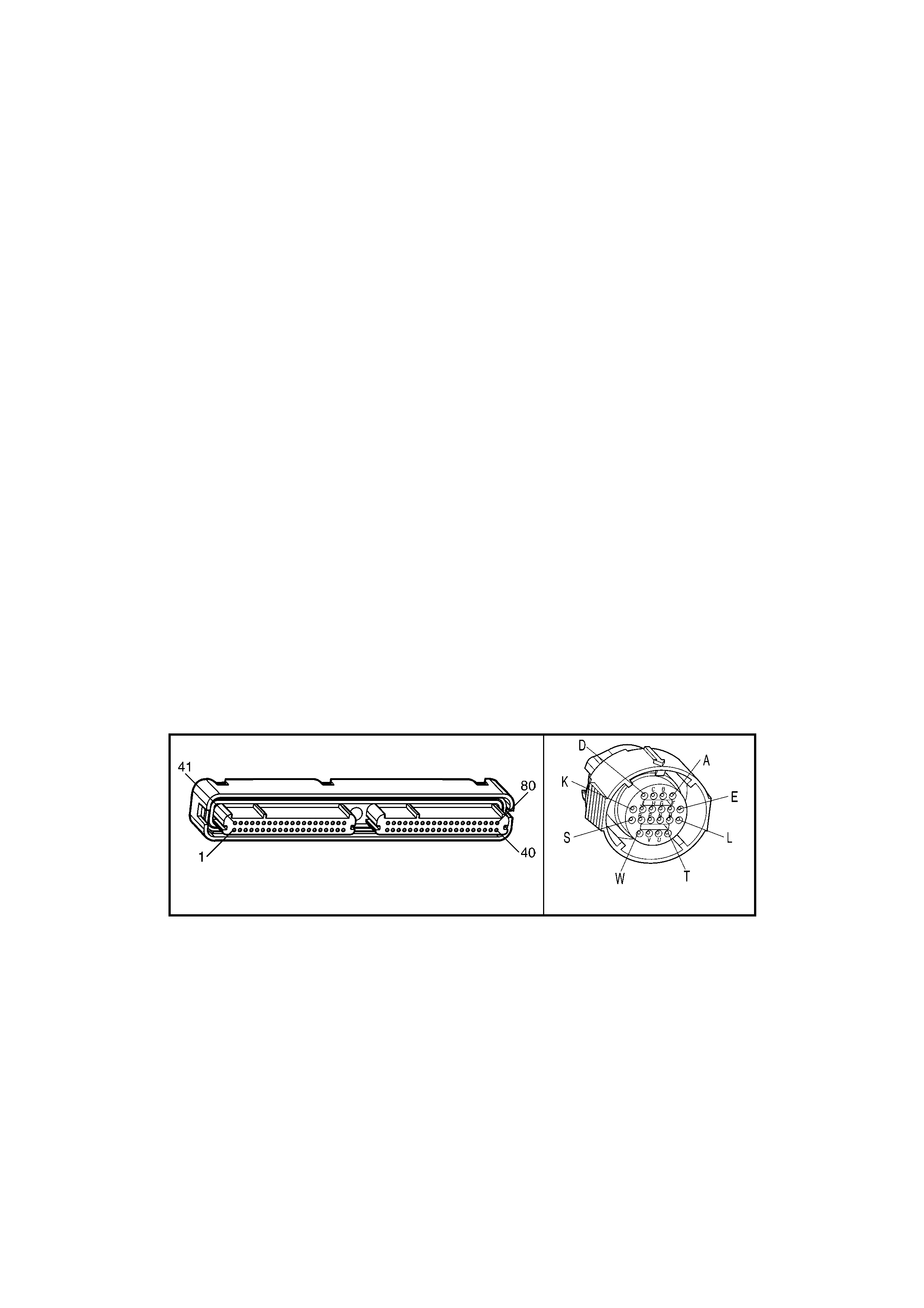
ACTION TAKEN WHEN THE DTC SETS
• The PCM stores the DTC information into memory when the diagnostic runs and fails
• The PCM does not activate the Check Powertrain MIL.
• The PC solenoid valve is commanded OFF.
• The PCM freezes shift adapts from being updated.
• The PCM records the operating conditions at the time the diagnostic fails. The PCM stores this information in
the Freeze Frame/Failure Records.
CONDITIONS FOR CLEARING THE DTC
• A last test failed (current DTC) clears when the diagnostic runs and does not fail.
• The PCM cancels the DTC default actions when the fault no longer exists and the ignition switch is OFF long
enough in order to power down the PCM.
DIAGNOSTIC AIDS
• Inspect the wiring at the PCM, the transmission connector and all other circuit connecting points for the
following conditions:
– A backed out terminal
– A damaged terminal
– Reduced terminal tension
– A chafed wire
– A broken wire inside the insulation
– Moisture intrusion
– Corrosion
• When diagnosing for an intermittent short or open condition, massage the wiring harness while watching the
test equipment for a change.
• DTC P0748 may set under low voltage conditions.
• caused by high electrical system demands.
TEST DESCRIPTION
NOTE: The number(s) below refer to the step number(s) on the diagnostic table.
2. This step tests the ability of the PCM to command the PC solenoid valve.
3. This step tests the PC solenoid valve and automatic transmission (A/T) wiring harness assembly for incorrect
resistance.
A84–X2 (RED) X121-X2
Figure 6C3-2A-161

GEN III V8 PCM – DTC P0748 PC SOLENOID CIRCUIT ELECTRICAL
STEP ACTION VALUE YES NO
1. Was the "On-Board Diagnostic" (OBD) System Check
performed? Go to Step 2 Go to
OBD System
Check
in this Section.
2. 1. Install Tech 2.
2. Ignition ON, engine OFF.
IMPORTANT: Before clearing the DTC, use Tech 2 to
record the Failure Records. Using the Clear Info function
erases the Failure Records from the PCM.
3. Record the DTC Failure Records.
4. Clear the DTC.
5. Start the engine.
6. Using the Transmission Miscellaneous Tests function
on Tech 2 , apply 100 milliamps through 1000
milliamps while observing Commanded PCS and
Actual PCS.
Is the Actual PCS always within the specified value of the
Commanded PCS?
160
milliamps Go to Diagnostic
Aids Go to Step 3
3. 1. Ignition OFF.
2. Disconnect the transmission 20-way connector, X121-
X2.
3. Install the J 39775 jumper harness on the transmission
side of the 20-way connector.
4. Using a DMM and the J 35616-A connector test
adaptor kit, measure the resistance between terminal
C and terminal D.
Is the resistance within the specified range?
3 – 7 Ω Go to Step 8 Go to Step 4
4. Is the resistance greater than the specified value? 7 Ω. Go to Step 5 Go to Step 6
5. 1. Inspect circuit 1228 and circuit 1229 of the A/T wiring
harness assembly, for an open condition.
Did you find an open condition?
Go to Step18 Go to Step 10
6. Is the resistance less than the specified value? 3 Ω Go to Step 7 –
7. 1. Inspect circuit 1228 and circuit 1229, of the A/T wiring
harness assembly, for a shorted together condition.
Did you find a shorted together condition?
Go to Step 18 Go to Step 10
8. 1. Measure the resistance from terminal C to the
transmissi on cas e.
Is the resistance greater than the specified value?
250 kΩ Go to Step 11 Go to Step 9
9. 1. Inspect circuit 1228 and circuit 1229, of the A/T wiring
harness assem bly , for a short to ground conditi on.
Did you find a short to ground condition?
Go to Step 18 Go to Step 10
10. 1. Replace the PC solenoid valve. Refer to PCS Valve
Replace, in 7C4 AUTOMATIC TRANSMISSION ON-
VEHICLE SERVICING.
Is the replacement complete?
Go to Step 20 –
11. 1. Disconnect the J 39775 jumper harness from the
transmissi on sid e of the 20-w ay connector X121-X2.
2. Reconnect the X121-X2 connector.
3. Disconnect the PCM RED connector A84-X2.
4. Using a DMM and the J 35616-A connector test
adaptor kit, measure the resistance between terminals
X2-6 and terminal X2-8.
Is the resistance within the specified range?
3 – 7 Ω Go to Step 16 Go to Step 12
12. Is the resistance greater than the specified value? 7 Ω Go to Step 13 Go to Step 14
13. 1. Inspect circuit 1228 and circuit 1229 of the engine
wiring harness for an open condition.
2. Repair the circuits if necessary.
Did you find and correct an open condition?
Go to Step 20 –
14. Is the resistance less than the specified value? 3 Ω Go to Step 15 –

STEP ACTION VALUE YES NO
15. 1. Inspect circuit 1228 and circuit 1229, of the engine
wiring harness, for a shorted together condition.
2. Repair the circuits if necessary.
Did you find and correct the shorted condition?
Go to Step 20 –
16. 1. Using a DMM and the J 35616-A connector test
adaptor kit, measure the resistance between connector
A84 X2-6 to ground.
Is the resistance less than the specified value?
9 Ω Go to Step 17 Go to Step 19
17. 1. Inspect circuit 1228 and circuit 1229, of the engine
wiring harness, for a short to ground condition.
2. Repair the circuits if necessary.
Did you find and correct the short to ground condition?
Go to Step 20 –
18. 1. Replace the automatic transmission wiring harness
assembly. Refer to Control Valve Body and Wiring
Harness Replace in 7C4 AUTOMATIC
TRANSMISSION ON-VEHICLE SERVICING.
Is the replacement complete?
Go to Step 20 –
19. 1. Replace PCM. Refer to PCM Programming and
PCM/PIM/BCM Security Link Procedure, in 6C3-3
SERVICE OPERATIONS.
Is the replacement complete?
Go to Step 20 –
20. 1. Perform the following procedure in order to verify the
repair:
– Select ‘DTC’, then ‘Clear Info’, using Tech 2.
– Start the engine and ensure that the difference
between PC Solenoid Actual Current and the PC
Solenoid Reference Current is less than 160
milliamps.
Was the above condition verified?
System OK Go to Step 2

GEN III V8 PCM – DTC P0751 1-2 SHIFT SOLENOID ‘A’ VALVE PERFORMANCE
Figure 6C3-2A-162 – Automatic Transmission Solenoid Circuits
CIRCUIT DESCRIPTION
The 1- 2 Shift So lenoid (S S) val ve contro ls the flu id flow ac ting on the 1-2 and 3-4 shift va lves. T he 1-2 SS valve is
a normally-open exhaust valve that is used with the 2-3 SS valve, in order to allow four different shifting
combinations.
When the PCM detects a 1 -1-4-4 or a 2-2-3-3 shift pattern, depending on the state of the mechanical failure, then
DTC P0751 sets.
CONDITIONS FOR RUNNING THE DTC
• No Throttle Position DTCs P0122 or P0123.
• No VSS assembly DTCs P0502 or P0503.
• No TCC solenoid valve DTC P0740.
• No TCC stuck ON DTC P0742.
• No 1-2 SS valve DTC P0753.
• No 2-3 SS valve DTC P0758.
• No 3-2 SS valve assembly DTC P0785.
• No TFP manual valve position switch DTC P1810.
• No TCC PWM solenoid valve DTC P1860.
• The engine speed is greater than 300 RPM for 5 seconds.
• The engine is not in fuel cutoff.
• The gear range is D.
• The Throttle Position angle is 10 – 35%.
• The Throttle Position angle is constant +/- 5%.

• The PCM commands a 1-2, 2-3, and 3-4 shift.
• The TCC is commanded ON.
• The vehicle speed is greater than 8 km/h.
• The transmission fluid temperature is 20 – 130° C.
CONDITIONS FOR SETTING THE DTC
• DTC P0751 sets if the following conditions occur three times:
– Within 2 seconds, the engine speed in 2nd gear is 80 RPM greater than the last speed in 1st gear.
– Within 2 seconds, the engine speed in 3rd gear is 50 RPM less than the last speed in 2nd gear.
– Within 2 seconds, the engine speed in 4th gear is 10 RPM greater than the last speed in 3rd gear.
• All of the above conditions are met and one of the following conditions occurs:
Condition 1
– The speed ratio is 0.95 to 1.2 (speed ratio is engine speed divided by transmission output speed).
– The TCC slip speed is 200-1000 RPM for 4 seconds.
Condition 2
– The speed ratio is 0.65 to 0.8.
– The TCC slip speed is -20 to +40 RPM for 4 seconds.
ACTION TAKEN WHEN THE DTC SETS
• The PCM activates the Check Powertrain MIL when the diagnostic runs and fails.
• The PCM commands D2 line pressure.
• The PCM inhibits 3-2 downshifts if the vehicle speed is greater than 48 km/h.
• The PCM freezes shift adapts from being updated.
• The PCM records the operating conditions at the time the diagnostic fails. The PCM stores this information in
the Freeze Frame/Failure Records.
CONDITIONS FOR CLEARING THE MIL/DTC
• The PCM deactivates the Check Powertrain MIL during the first consecutive trip in which the diagnostic test
runs and passes.
• The PCM cancels the DTC default actions when the fault no longer exists and the ignition switch is OFF long
enough in order to power down the PCM.
• A last test failed (current DTC) clears when the diagnostic runs and does not fail.
DIAGNOSTIC AIDS
• Verify that the transmission meets the specifications in the Shift Speed table.
• Other internal transmission failures may cause more than one shift to occur.
• Refer to the Shift Solenoid Valve State and Gear Ratio table in Sect ion 6C3-4 S P ECIFICATION S.
TEST DESCRIPTION
NOTE: The number(s) below refer to the step number(s) on the diagnostic table.
2. This step tests that the PCM commanded all shifts, that all shift solenoid valves responded correctly, but that all
the shifts did not occur.
A84–X2 (RED) X121-X2
Figure 6C3-2A-163

GEN III V8 PCM – DTC P0751 1-2 SHIFT SOLENOID VALVE PERFORMANCE
STEP ACTION VALUE YES NO
1. Was the "On-Board Diagnostic" (OBD) System Check
performed? Go to Step 2 Go to
OBD System
Check
in this Section.
2. 1. Install Tech 2.
2. Ignition ON, engine OFF.
IMPORTANT: Before clearing the DTC, use Tech 2 in
order to record the Freeze Frame/Failure Records. Using
the Clear Info function erases the Freeze Frame and
Failure Records from the PCM.
3. Record the DTC Freeze Frame/Failure Records.
4. Clear the DTC.
5. Drive the vehicle in D range under the following
conditions:
6. Accelerate the vehicle, ensuring that the PCM
commands 1st, 2nd, 3rd and 4th gears.
Did you detect a 1-1-4-4 or 2-2-3-3 shift pattern?
Go to Step 3 Go to
Diagnostic Aids
3. 1. Inspect the shift solenoid/hydraulic circuit for an
internal malf un ctio n.
2. Check for damaged seals on the shift solenoid valves.
Refer to Shift Solenoid Leak Test in 7C3 AUTOMATIC
TRANSMISSION – HYDRAULIC / MECHANICAL
DIAGNOSIS.
Did you find and correct the condition?
Go to Step 4 –
4. 1. Perform the following procedure in order to verify the
repair:
– Select ‘DTC’, then ‘Clear Info’, using Tech 2.
– Drive the vehicle in ‘D’ under the following
conditions (only if traffic and road conditions
permit):
• Hold the throttle at 20% and accelerate to 88
km/h.
• If the throttle moves more than 5%, stop the
vehicle and start over.
– Ensure the transmission properly shifts through all
gears as commanded by the PCM.
Did the transmission shift through all gears as commanded
by the PCM?
System OK Go to Step 2

GEN III V8 PCM – DTC P0753 1-2 SHIFT SOLENOID CIRCUIT ELECTRICAL
Figure 6C3-2A-164 – Automatic Transmission Solenoid Circuits
CIRCUIT DESCRIPTION
The 1- 2 Shift So lenoid (S S) val ve contro ls the flu id flow ac ting on the 1-2 and 3-4 shift va lves. T he 1-2 SS valve is
a normally-open exhaust valve that is used with the 2-3 SS valve in order to allow four different shifting
combinations. The solenoid attaches to the control valve body within the transmission. The 1-2 SS valve receives
ignition voltage through circuit 339. The powertrain control module (PCM) controls the solenoid by providing the
ground path on circuit 1222.
When the PCM detects a continuous open or short to ground in the 1-2 SS valve circuit or the 1-2 SS valve, then
DTC P0753 sets.
CONDITIONS FOR RUNNING THE DTC
• The system voltage is between 8.0 and 18 volts.
• The engine speed is greater than 300 RPM for 5 seconds.
• The engine is not in fuel cutoff.
CONDITIONS FOR SETTING THE DTC
• The PCM commands the solenoid ON and the voltage input remains high (12 volts).
OR
• The PCM commands the solenoid OFF and the voltage input remains low (0 volts).
ACTION TAKEN WHEN THE DTC SETS
• The PCM activates the Check Powertrain MIL when the diagnostic runs and fails.
• The PCM commands D2 line pressure.
• The PCM inhibits 3-2 downshift if the vehicle speed is greater than 48 km/h.
• The PCM freezes shift adapts from being updated.
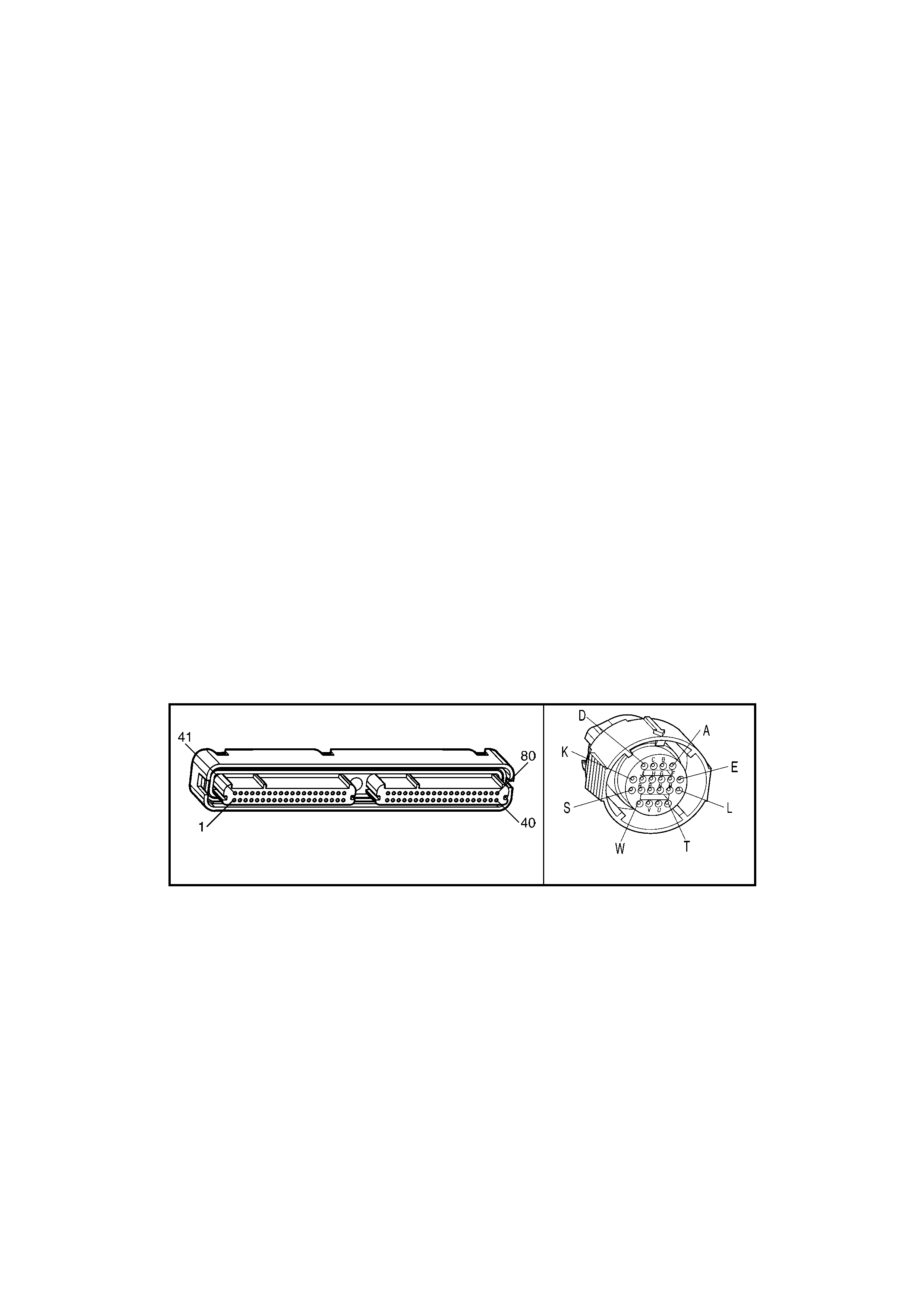
• The PCM records the operating conditions at the time the diagnostic fails. The PCM stores this information in
the Freeze Frame/Failure Records.
• The PCM freezes shift adapts from being updated.
CONDITIONS FOR CLEARING THE MIL/DTC
• The PCM de ac tivates th e Chec k Powertrain MIL during t he f ir st ign iti on cycle that th e diagnos t ic r uns an d does
not fail.
• A last test failed (current DTC) clears when the diagnostic runs and does not fail.
• Use Tech 2 to clear the DTC.
DIAGNOSTIC AIDS
• Inspect the wiring at the PCM, the transmission connector and all other circuit connecting points for the
following conditions:
– A backed out terminal
– A damaged terminal
– Reduced terminal tension
– A chafed wire
– A broken wire inside the insulation
– Moisture intrusion
– Corrosion
• When diagnosing for an intermittent short or open condition, massage the wiring harness while watching the
test equipment for a change.
• An open ignition feed circuit can cause multiple DTCs to set.
• Refer to the Shift Solenoid Valve State and Gear Ratio table.
TEST DESCRIPTION
NOTE: The number(s) below refer to the step number(s) on the diagnostic table.
4. This step tests the function of the 1-2 SS valve and the automatic transmission wiring harness assembly.
5. This step tests for power to the 1-2 SS valve from the ignition through the fuse.
7. This step tests the ability of the PCM and the wiring to control the ground circuit.
10. This step measures the resistance of the A/T wiring harness assembly and the 1-2 SS valve.
A84–X2 (RED) X121-X2
Figure 6C3-2A-165

GEN III V8 PCM – DTC P0753 1-2 SHIFT SOLENOID CIRCUIT ELECTRICAL
STEP ACTION VALUE YES NO
1. Was the "On-Board Diagnostic" (OBD) System Check
performed? Go to Step 2 Go to
OBD System
Check
in this Section.
2. 1. Install Tech 2.
2. Ignition ON, engine OFF.
IMPORTANT: Before clearing the DTC, use in order to
record the Freeze Frame/Failure Records. Using the Clear
Info function erases the Freeze Frame/Failure Records
from the PCM.
3. Record the DTC Freeze Frame and Failure Records.
4. Clear the DTC.
Are any of the following DTCs also set?
– P0740
– P0758
– P0785
– P1860
Go to Step 3 Go to Step 4
3. 1. Inspect fuse F32.
2. If the fuse is open, inspect the following components
for a short to ground condition:
– Circuit 339
– The solenoids
– The A/T wiring harness assembly
3. Repair the circuit, the solenoids, and the harness if
necessary.
Did you find a short to ground condition?
Go to Step 16 Go to Step 5
4. 1. Using the transmission Miscellaneous Tests function
on Tech 2, command the 1-2 SS valve ON and OFF
three times while listening to the bottom of the
transmission pan (a stethoscope may be necessary).
Did the solenoid click when commanded?
Go to
Diagnostic Aids Go to Step 5
5. 1. Ignition OFF.
2. Disconnect the transmission 20-way (X121-X2)
connector (additional DTCs may set).
3. Install the J 39775 jumper harness on the engine side
of the 20-way connector.
4. Ignition ON, engine OFF.
5. Connect a test lamp, from J 39775 jumper harness
cavity E, to ground.
Is the test lamp ON?
Go to Step 7 Go to Step 6
6. IMPORTANT: The condition that affects this circuit may
exist in other connecting branches of the circuit. Refer to
Power Distribution Diagrams in 12P WIRING DIAGRAMS.
1. Repair the open in ignition feed circuit 339 to the 1-2
SS valve.
Is the repair complete?
Go to Step 16 –
7. 1. Install a test lamp, from J 39775 jumper harness cavity
E, to cavity A.
2. Using the transmission Miscellaneous Tests function
on Tech 2, command the 1-2 SS valve ON and OFF
three times.
Is the test lamp ON when the 1-2 SS valve is commanded
ON, and OFF when commanded OFF?
Go to Step 10 Go to Step 8
8. 1. Inspect circuit 1222, of the powertrain wiring harness,
for an open, short to ground or short to power
condition.
2. Repair the circuit if necessary .
Did you find an open, short to ground or short to power
condition?
Go to Step 16 Go to Step 9

STEP ACTION VALUE YES NO
9. 1. Replace PCM. Refer to PCM Programming and
PCM/PIM/BCM Security Link Procedure, in 6C3-3
SERVICE OPERATIONS.
Is the replacement complete?
Go to Step16 –
10. 1. Install the J 39775 jumper harness on the transmission
side of the 20-way connector, X121-X2.
2. Using a DMM and the J 35616-A connector test
adaptor kit, measure the resistance between terminals
A and E.
Is the resistance within the range indicated?
19 – 31 Ω Go to Step 12 Go to Step 11
11. 1. Disconnect the A/T wiring harness assembly from the
1-2 SS valve.
2. Measure the resistance of the 1-2 SS valve.
Is the resistance within the range indicated?
19 – 31 Ω Go to Step 14 Go to Step 15
12. 1. Using A DMM, measure the resistance between
terminal A and ground, and between terminal E and
ground.
Are both readings greater than the specified value?
250 kΩ Go to Diagnostic
Aids Go to Step 13
13. 1. Disconnect the A/T wiring harness assembly from the
1-2 SS valve.
2. Using a DMM, measure the resistance from the
component's terminals to ground.
Are both readings greater than the specified value?
250 kΩ Go to Step 14 Go to Step 15
14. 1. Replace the automatic transmission wiring harness
assembly. Refer to Control Valve Body and Wiring Harness
Replace in 7C4 AUTOMATIC TRANSMISSION – ON-
VEHICLE SERVICING.
Is the replacement complete?
Go to Step 16 –
15. 1. Replace the 1-2 SS valve. Refer to 1-2 Shift Solenoid
Valve Replace, in 7C4 AUTOMATIC TRANSMISSION
– ON-VEHICLE SERVICING.
Is the replacement complete?
Go to Step 16 –
16. 1. Perform the following procedure in order to verify the
repair:
– Select ‘DTC’, then ‘Clear Info’, using Tech 2.
– Drive the vehicle in ‘D’ and ensure that the
following con diti on s are met:
• The PCM commands the 1-2 SS valve ON
and the voltage input drops to zero.
• The PCM commands the 1-2 SS valve OFF
and the voltage input increases to B+.
• All conditions are met for 5 seconds.
Were the above conditions verified?
System OK Go to Step 2

GEN III V8 PCM – DTC P0756 2-3 SHIFT SOLENOID VALVE PERFORMANCE
Figure 6C3-2A-166 – Automatic Transmission Solenoid Circuits
CIRCUIT DESCRIPTION
The 2-3 Shift Solenoid (SS) valve controls the fluid flow acting on the 2-3 shift valves. The 2-3 SS valve is a
normally-open exhaust valve that is used with the 1-2 SS valve, in order to allow four different shifting
combinations.
When the PCM detects a 1 -2-2-1 or a 4-3-3-4 shift pattern, depending on the state of the mechanical failure, then
DTC P0756 sets.
CONDITIONS FOR RUNNING THE DTC
• No Throttle Position DTCs P0122 or P0123.
• No VSS assembly DTCs P0502 or P0503.
• No TCC solenoid valve DTC P0740.
• No TCC Stuck ON DTC P0742.
• No 1-2 SS valve DTC P0753.
• No 2-3 SS valve DTC P0758.
• No 3-2 SS valve assembly DTC P0785.
• No TFP manual valve position switch DTC P1810.
• No TCC PWM solenoid valve DTC P1860.
• The vehicle speed is greater than 8 km/h.
• The gear range is D4.
• The engine vacuum is 0-105 kPa.
• The engine torque is 0-542 Nm.
• The Throttle Position angle is 10 – 50%.

• The Throttle Position angle is constant ± 7%.
• The PCM commands a 1-2, 2-3, and 3-4 shift.
• The engine speed is greater than 300 RPM for 5 seconds.
• The engine is not in fuel cutoff.
• The transmission fluid temperature is 20 – 130° C.
CONDITIONS FOR SETTING THE DTC
• DTC P0756 sets if the following conditions occur three times:
– Third gear is commanded for 2 to 6 seconds.
– The speed ratio, in 3rd gear, does not drop more than 0.3 from the last speed ratio, in 2nd gear, (speed
ratio is engine speed divided by transmission output speed).
– The TCC slip speed, in 3rd gear, remains 400 RPM higher than the last TCC slip speed, in 2nd gear.
• All of the above conditions are met for 1.5 seconds and one of the following conditions occurs:
Condition 1
– First gear is commanded for 1.5 seconds.
– The TP angle is greater than 25%.
– The transmission output speed is 400-1500 RPM.
– The speed ratio is 0.7 to 3.0.
– The TCC slip speed is -2000 to 0 RPM for 1.5 seconds.
Condition 2
– Fourth gear is commanded for 1.5 seconds.
– The transmission output speed is 1000-3000 RPM.
– The speed ratio is 1.68 to 3.0.
– The TCC slip speed is 1000 to 3000 RPM for 1 second.
ACTION TAKEN WHEN THE DTC SETS
• The PCM activates the Check Powertrain MIL when the diagnostic runs and fails.
• The PCM commands 3rd gear only.
• The PCM inhibits TCC engagement.
• The PCM commands maximum line pressure.
• The PCM freezes shift adapts from being updated.
• The PCM records the operating conditions at the time the diagnostic fails. The PCM stores this information in
the Freeze Frame/Failure Records.
CONDITIONS FOR CLEARING THE MIL/DTC
• The PCM de ac tivates th e Chec k Powertrain MIL during t he f ir st ign iti on cycle that th e diagnos t ic r uns an d does
not fail.
• The PCM cancels the DTC default actions when the fault no longer exists and the ignition switch is OFF long
enough in order to power down the PCM.
• Use Tech 2 to clear the DTC.
DIAGNOSTIC AIDS
• Verify that the transmission meets the specifications in the Shift Speed table.
• Other internal transmission failures may cause more than one shift to occur.
• Refer to the Shift Solenoid Valve State and Gear Ratio table in Sect ion 6C3-4 S P ECIFICATION S.
TEST DESCRIPTION
NOTE: The number(s) below refer to the step number(s) on the diagnostic table.
2. This step tests that the PCM commanded all shifts, that all shift solenoid valves responded correctly, but that all
the shifts did not occur.

A84–X2 (RED) X121-X2
Figure 6C3-2A-167
GEN III V8 PCM – DTC P0756 2-3 SHIFT SOLENOID VALVE PERFORMANCE
STEP ACTION VALUE YES NO
1. Was the "On-Board Diagnostic" (OBD) System Check
performed? Go to Step 2 Go to
OBD System
Check
in this Section.
2. 1. Install Tech 2.
2. Ignition ON, engine OFF.
IMPORTANT: Before clearing the DTC, use in order to
record the Freeze Frame/Failure Records. Using the Clear
Info function erases the Freeze Frame/Failure Records
from the PCM.
3. Record the DTC Freeze Frame/Failure Records.
4. Clear the DTC.
5. Drive the vehicle in D range and accelerate, checking
that the PCM commands 1st, 2nd, 3rd and 4th gears.
Did you detect a 1-2-2-1 or 4-3-3-4 shift pattern?
Go to Step 3 Go to Diagnostic
Aids
3. 1. Inspect the shift solenoid/hydraulic circuit for an
internal malf un ctio n.
2. Check for damaged seals on the Shift Solenoid valves.
Refer to Shift Solenoid Leak Test in 7C3 AUTOMATIC
TRANSMISSION – HYDRAULIC / MECHANICAL
DIAGNOSIS.
Did you find and correct the condition?
Go to Step 4 –
4. 1. Perform the following procedure in order to verify the
repair:
– Select ‘DTC’, then ‘Clear Info’, using Tech 2.
– Drive the vehicle in ‘D’ under the following
conditions (only if traffic and road conditions
permit):
• Hold the throttle at 40% and accelerate to 64
km/h.
• Stop the vehicle, engine idling.
• Hold the throttle at 15% and accelerate to 80
km/h.
– Ensure the transmission properly shifts through all
gears as commanded by the PCM.
Did the transmission shift through all gears as commanded
by the PCM?
System OK Go to Step 2

GEN III V8 PCM – P0758 2-3 SHIFT SOLENOID CIRCUIT ELECTRICAL
Figure 6C3-2A-168 – Automatic Transmission Solenoid Circuits
CIRCUIT DESCRIPTION
The 2-3 Shift Solenoid (SS) valve controls the fluid flow acting on the 2-3 shift valves. The 2-3 SS valve is a
norm all y-open ex ha us t va l ve that is us ed with th e 1- 2 SS val ve in or der to a llo w f our differ ent s hif ting c ombinations .
The s olenoid attac hes to th e control va lve bod y within the tr ansm ission. The 2- 3 SS valv e receives i gnition voltage
through circuit 339. The Powertrain Control Module (PCM) controls the solenoid by providing the ground path on
circuit 1223.
When the PCM detects a continuous open or short to ground in the 2-3 SS valve circuit or the 2-3 SS valve, then
DTC P0758 sets.
CONDITIONS FOR RUNNING THE DTC
• The system voltage is between 8.0 and 18 volts.
• The engine speed is greater than 300 RPM for 5 seconds.
• The engine is not in fuel cutoff.
CONDITIONS FOR SETTING THE DTC
• The PCM commands the solenoid ON and the voltage input remains high (12 volts).
OR
• The PCM commands the solenoid OFF and the voltage input remains low (0 volts).
ACTION TAKEN WHEN THE DTC SETS
• The PCM activates the Check Powertrain MIL when the diagnostic runs and fails.
• The PCM commands 3rd gear only.
• The PCM commands maximum line pressure.
• The PCM inhibits TCC engagement.

• The PCM freezes shift adapts from being updated.
• The PCM records the operating conditions at the time the diagnostic fails. The PCM stores this information in
the Freeze Frame/Failure Records.
CONDITIONS FOR CLEARING THE MIL/DTC
• The PCM de ac tivates th e Chec k Powertrain MIL during t he f ir st ign iti on cycle that th e diagnos t ic r uns an d does
not fail.
• A last test failed (current DTC) clears when the diagnostic runs and does not fail.
• Use Tech 2 to clear the DTC.
DIAGNOSTIC AIDS
• Inspect the wiring at the PCM, the transmission connector and all other circuit connecting points for the
following conditions:
– A backed out terminal
– A damaged terminal
– Reduced terminal tension
– A chafed wire
– A broken wire inside the insulation
– Moisture intrusion
– Corrosion
• When diagnosing for an intermittent short or open condition, massage the wiring harness while watching the
test equipment for a change.
• Refer to the Shift Solenoid Valve State and Gear Ratio table in Sect ion 6C3-4 S P ECIFICATIONS.
TEST DESCRIPTION
NOTE: The number(s) below refer to the step number(s) on the diagnostic table.
4. This step tests the function of the 2-3 SS valve and the automatic transmission wiring harness assembly.
5. This step tests for power to the 2-3 SS valve from the ignition through the fuse.
7. This step tests the ability of the PCM and the wiring to control the ground circuit.
10. This step measures the resistance of the A/T wiring harness assembly and the 2-3 SS valve.
A84–X2 (RED) X121-X2
Figure 6C3-2A-169

GEN III V8 PCM – DTC P0758 2-3 SHIFT SOLENOID CIRCUIT ELECTRICAL
STEP ACTION VALUE YES NO
1. Was the "On-Board Diagnostic" (OBD) System Check
performed? Go to Step 2 Go to
OBD System
Check
in this Section.
2. 1. Install Tech 2.
2. Ignition ON, engine OFF.
IMPORTANT: Before clearing the DTC, use in order to
record the Freeze Frame/Failure Records. Using the Clear
Info function erases the Freeze Frame/Failure Records
from the PCM.
3. Record the DTC Freeze Frame/Failure Records.
4. Clear the DTC, using Tech 2.
Are any of the following DTCs also set?
– P0740
– P0753
– P0785
– P1860
Go to Step 3 Go to Step 4
3. 1. Inspect fuse F32.
2. If the fuse is open, inspect the following components
for a short to ground condition:
– Circuit 339.
– The solenoids
– The A/T wiring harness assembly
3. Repair the circuit, the solenoids, and the harness if
necessary.
Did you find a short to ground condition?
Go to Step 16 Go to Step 5
4. 1. Using the transmission Miscellaneous Tests function
on Tech 2, command the 2-3 SS valve ON and OFF
three times while listening to the bottom of the
transmission pan (a stethoscope may be necessary).
Did the solenoid click when commanded?
Go to
Diagnostic Aids Go to Step 5
5. 1. Ignition OFF.
2. Disconnect the transmission 20-way connector X121-
X2 (additional DTCs may set).
3. Install the J 39775 jumper harness on the engine side
of connector X121-X2.
4. Ignition ON, engine OFF.
5. Connect a test lamp from J 39775 jumper harness
cavity E to ground.
Is the test lamp ON?
Go to Step 7 Go to Step 6
6. IMPORTANT: The condition that affects this circuit may
exist in other connecting branches of the circuit. Refer to
Power Distribution Diagrams in 12P WIRING DIAGRAMS.
1. Repair the open in ignition feed circuit 339 to the 2-3
SS valve.
Is the repair complete?
Go to Step 16 –
7. 1. Install a test lamp, from J 39775 jumper harness cavity
E, to cavity B.
2. Using the transmission Miscellaneous Tests function
on Tech 2, command the 2-3 SS valve ON and OFF
three times.
Is the test lamp ON when the 2-3 SS valve is commanded
ON, and OFF when commanded OFF?
Go to Step 10 Go to Step 8
8. 1. Inspect circuit 1223, of the powertrain wiring harness,
for an open, short to ground or short to power
condition.
2. Repair the circuit if necessary .
Did you find an open, short to ground or short to power
condition?
Go to Step 16 Go to Step 9

STEP ACTION VALUE YES NO
9. 1. Replace PCM. Refer to PCM Programming and
PCM/PIM/BCM Security Link Procedure, in 6C3-3
SERVICE OPERATIONS.
Is the replacement complete?
Go to Step16 –
10. 1. Install the J 39775 jumper harness to the transmission
side of connector X121-X2.
2. With a DMM and the J 35616-A connector test adaptor
kit, measure the resistance between terminals B and
E.
Is the resistance within the range indicated?
19 – 31 Ω Go to Step 12 Go to Step 11
11. 1. Disconnect the A/T wiring harness assembly from the
2-3 SS valve.
2. Measure the resistance of the 2-3 SS valve.
Is the resistance within the range indicated?
19 – 31 Ω Go to Step 14 Go to Step 15
12. 1. Using a DMM, measure the resistance between
terminal B and ground, and between terminal E and
ground.
Are both readings greater than the specified value?
250 kΩ Go to Diagnostic
Aids Go to Step 13
13. 1. Disconnect the A/T wiring harness assembly from the
2-3 SS valve.
2. Using A DMM, measure the resistance from the
component's terminals to ground.
Are both readings greater than the specified value?
250 kΩ Go to Step 14 Go to Step 15
14. 1. Replace the automatic transmission wiring harness
assembly. Refer to Control Valve Body and Wiring
Harness Replace in 7C4 AUTOMATIC
TRANSMISSION – ON-VEHICLE SERVICING.
Is the replacement complete?
Go to Step 16 –
15. 1. Replace the 2-3 SS valve. Refer to 2-3 Shift Solenoid
Valve Replace, in 7C4 AUTOMATIC TRANSMISSION
– ON-VEHICLE SERVICING.
Is the replacement complete?
Go to Step 16 –
16. 1. Perform the following procedure in order to verify the
repair:
– Select ‘DTC’, then ‘Clear Info’, using Tech 2.
– Drive the vehicle in ‘D’ and ensure the following
conditions are met:
• The PCM commands the 2-3 SS valve ON
and the voltage input drops to zero.
• The PCM commands the 2-3 SS valve OFF
and the voltage input increases to B+.
• All conditions are met for 5 seconds.
– Ensure the transmission properly shifts through all
gears as commanded by the PCM.
Were the above conditions verified?
System OK Go to Step 2
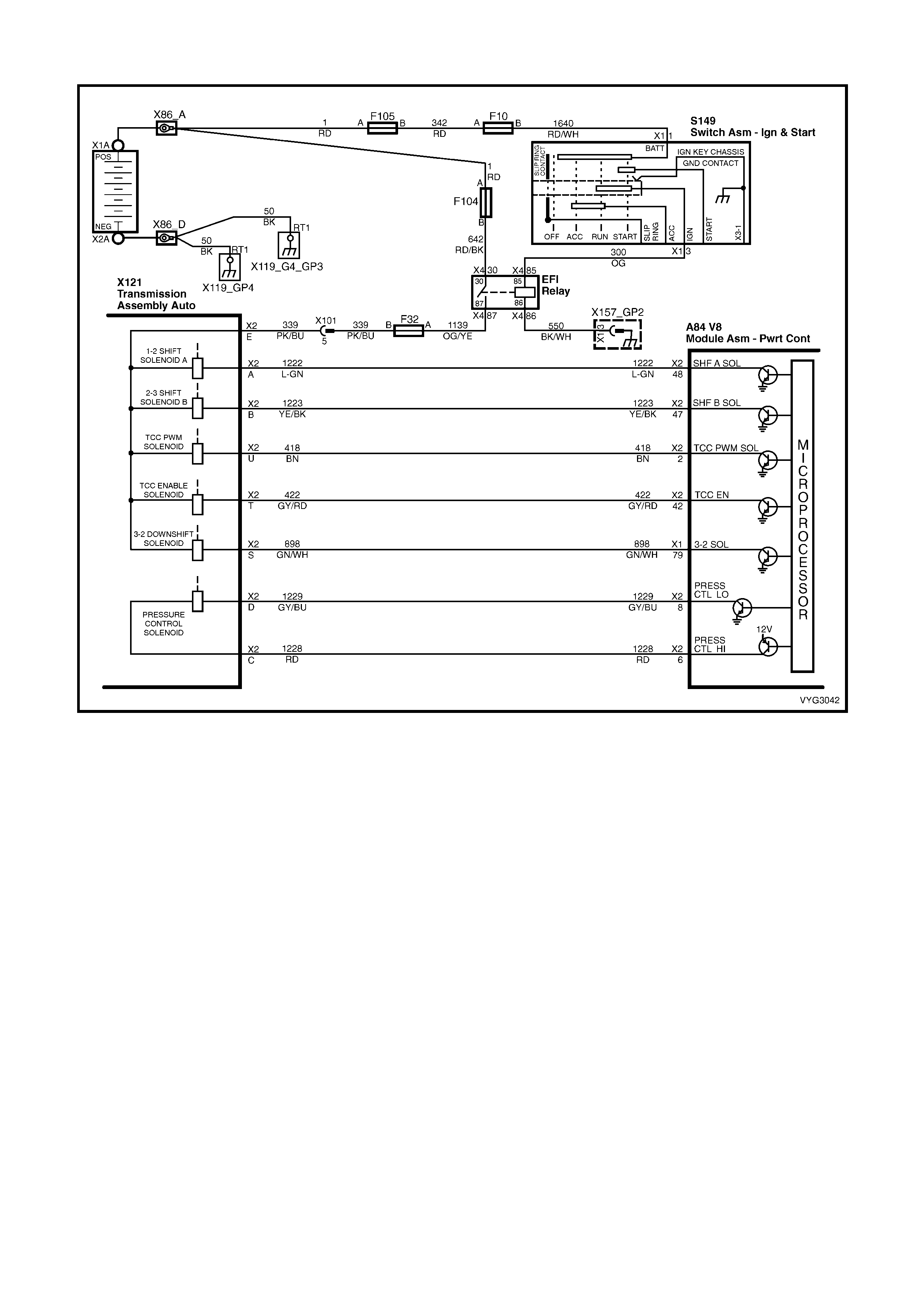
GEN III V8 PCM – DTC P0785 3-2 SHIFT SOLENOID CIRCUIT ELECTRICAL
Figure 6C3-2A-170 – Automatic Transmission Solenoid Circuits
CIRCUIT DESCRIPTION
The 3-2 Shif t Sole noid (SS ) valve is a normall y-closed, 3- port, ON/OF F device that contro ls the 3-2 downshif t. The
solenoid attaches to the control valve body within the transmission. The solenoid receives ignition voltag e through
circuit 3 39. The Po wertrain Contro l Module ( PCM) contr ols the solen oid by prov iding a grou nd path on c ircuit 898.
During a 3-2 do wnshif t, the 2-4 b and ap plies as t he 3-4 c lutch r eleases . The P CM v aries t he tim ing b etwee n the 3-
4 clutch release and the 2-4 band apply depending on the vehicle speed and the throttle position.
When the PCM detects a continuous open or short to ground in the 3-2 SS valve assembly circuit or the 3-2 SS
valve assembly, then DTC P0785 sets.
CONDITIONS FOR RUNNING THE DTC
• The system voltage is between 8.0 and 18 volts.
• The engine speed is greater than 300 RPM for 5 seconds.
• The engine is not in fuel cutoff.
CONDITIONS FOR SETTING THE DTC
• The PCM commands the solenoid ON and the voltage input remains high (12 volts).
OR
• The PCM commands the solenoid OFF and the voltage input remains low (0 volts).
ACTION TAKEN WHEN THE DTC SETS
• The PCM activates the Check Powertrain MIL when the diagnostic runs and fails.
• The PCM commands a soft landing to 3rd gear.
• The PCM commands maximum line pressure.
• The PCM inhibits TCC engagement.
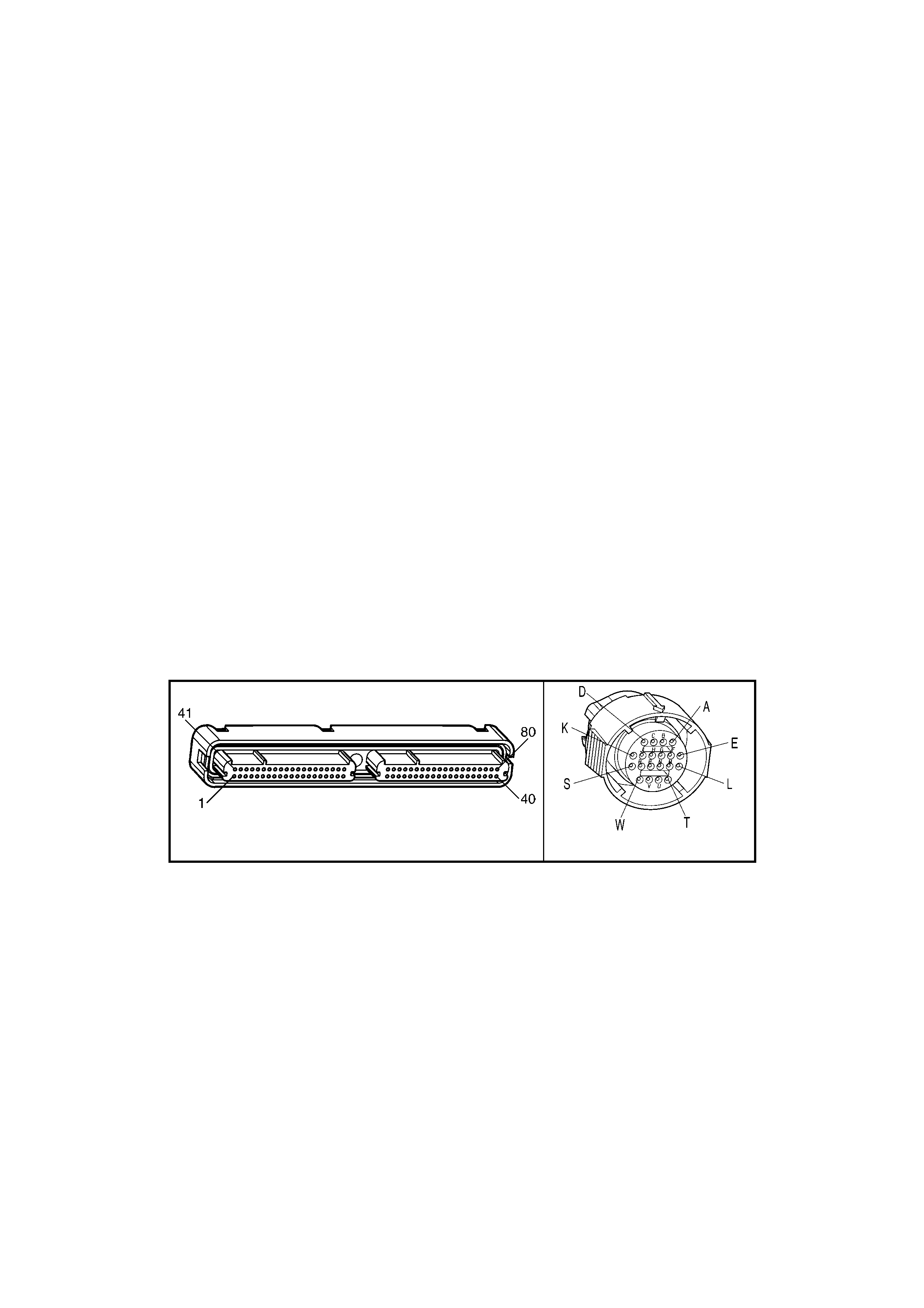
• The PCM inhibits 4th gear if the transmission is in hot mode.
• The PCM freezes shift adapts from being updated.
• The PCM records the operating conditions at the time the diagnostic fails. The PCM stores this information in
the Freeze Frame/Failure Records.
CONDITIONS FOR CLEARING THE MIL/DTC
• The PCM de ac tivates th e Chec k Powertrain MIL during t he f ir st ign iti on cycle that th e diagnos t ic r uns an d does
not fail.
• A last test failed (current DTC) clears when the diagnostic runs and does not fail.
• Use Tech 2 to clear the DTC.
DIAGNOSTIC AIDS
• Inspect the wiring at the PCM, the transmission connector and all other circuit connecting points for the
following conditions:
– A backed out terminal
– A damaged terminal
– Reduced terminal tension
– A chafed wire
– A broken wire inside the insulation
– Moisture intrusion
– Corrosion
• When diagnosing for an intermittent short or open condition, massage the wiring harness while watching the
test equipment for a change.
TEST DESCRIPTION
NOTE: The number(s) below refer to the step number(s) on the diagnostic table.
4. This step tests the ability of the PCM to control the solenoid.
5. This step tests for power to the 3-2 SS valve assembly.
7. This step tests the ability of the PCM and the wiring to control the ground circuit.
10. This step measures the resistance of the A/T wiring harness assembly and the 3-2 SS valve assembly.
A84–X2 (RED) X121-X2
Figure 6C3-2A-171

GEN III V8 PCM – DTC P0785 3-2 SHIFT SOLENOID CIRCUIT ELECTRICAL
STEP ACTION VALUE YES NO
1. Was the "On-Board Diagnostic" (OBD) System Check
performed? Go to Step 2 Go to
OBD System
Check
in this Section.
2. 1. Install Tech 2.
2. Ignition ON, engine OFF.
IMPORTANT: Before clearing the DTC, use in order to
record the Freeze Frame/Failure Records. Using the Clear
Info function erases the Freeze Frame/Failure Records
from the PCM.
3. Record the DTC Freeze Frame/Failure Records.
4. Clear the DTC.
Are any of the following DTCs also set?
– P0740
– P0753
– P0758
– P1860
Go to Step 3 Go to Step 4
3. 1. Inspect fuse F32.
2. If the fuse is open, inspect the following components
for a short to ground condition:
– Circuit 339
– The solenoids
– The A/T wiring harness assembly
3. Repair the circuit, the solenoids, and the harness if
necessary.
Did you find a short to ground condition?
Go to Step 16 Go to Step 5
4. IMPORTANT: The 3-2 shift solenoid valve will rapidly apply
when commanded ON by Tech 2.
1. Using the transmission Miscellaneous Tests function
on Tech 2, command the 3-2 SS valve ON and OFF
three times while listening to the bottom of the
transmission pan (a stethoscope may be necessary).
Did the solenoid click when commanded?
Go to
Diagnostic Aids Go to Step 5
5. 1. Ignition OFF.
2. Disconnect the transmission connector X121-X2
(additional DTCs may set).
3. Install the J 39775 jumper harness on the engine side
of connector X121-X2.
4. Ignition ON, engine OFF.
5. Connect a test lamp, from J 39775 jumper harness
cavity E, to ground.
Is the test lamp ON?
Go to Step 7 Go to Step 6
6. IMPORTANT: The condition that affects this circuit may
exist in other connecting branches of the circuit. Refer to
Power Distribution Diagrams in 12P WIRING DIAGRAMS.
1. Repair the open in ignition feed circuit 339 to the 3-2
SS valve assembly.
Is the repair complete?
Go to Step 16 –
7. 1. Install a test lamp, between J 39775 jumper harness
cavities E and S.
2. Using the transmission Miscellaneous Tests function
on Tech 2, command the 3-2 SS valve ON and OFF
three times.
Is the test lamp ON, when the solenoid is commanded ON
and OFF, when the solenoid is commanded OFF?
Go to Step 10 Go to Step 8
8. 1. Inspect circuit 898, of the powertrain wiring harness,
for an open, short to ground or short to power
condition.
2. Repair the circuit if necessary .
Did you find an open, short to ground or short to power
condition?
Go to Step 16 Go to Step 9

STEP ACTION VALUE YES NO
9. 1. Replace PCM. Refer to PCM Programming and
PCM/PIM/BCM Security Link Procedure, in 6C3-3
SERVICE OPERATIONS.
Is the replacement complete?
Go to Step16 –
10. 1. Install the J 39775 jumper harness on the transmission
side of connector X121-X2.
2. With a DMM and the J 35616-A connector test adaptor
kit, measure the resistance between terminals S and
E.
Is the resistance within the range indicated?
20 – 32 Ω Go to Step 12 Go to Step 11
11. 1. Disconnect the A/T wiring harness assembly from the
3-2 SS valve assembly.
2. Measure the resistance of the 3-2 SS valve assembly.
Is the resistance within the range indicated?
20 – 32 Ω Go to Step 14 Go to Step 15
12. 1. Measure the resistance between terminal S and
ground, and between terminal E and ground.
Are both readings greater than the specified value?
250 kΩ Go to
Diagnostic Aids Go to Step 13
13. 1. Disconnect the A/T wiring harness assembly from the
3-2 SS valve assembly.
2. Measure the resistance from the component’s
terminals to ground.
Are both measurements greater than the specified value?
250 kΩ Go to Step 14 Go to Step 15
14. 1. Replace the automatic transmission wiring harness
assembly. Refer to Control Valve Body and Wiring
Harness Replace, in 7C4 AUTOMATIC
TRANSMISSION – ON-VEHICLE SERVICING.
Is the replacement complete?
Go to Step 16 –
15. 1. Replace the 3-2 SS valve. Refer to 3-2 Shift Solenoid
Valve Replace, in 7C4 AUTOMATIC TRANSMISSION
– ON-VEHICLE SERVICING.
Is the replacement complete?
Go to Step 16 –
16. 1. Perform the following procedure in order to verify the
repair:
– Select ‘DTC’, then ‘Clear Info’, using Tech 2.
– Drive the vehicle in ‘3’ or ‘D’ and perform a 3-2
downshift. Ensure the following conditions are
met:
• The PCM commands the 3-2 SS valve ON
and the voltage input drops to zero.
• The PCM commands the 2-3 SS valve OFF
and the voltage input increases to B+.
• All conditions are met for 5 seconds.
Were the above conditions verified?
System OK Go to Step 2
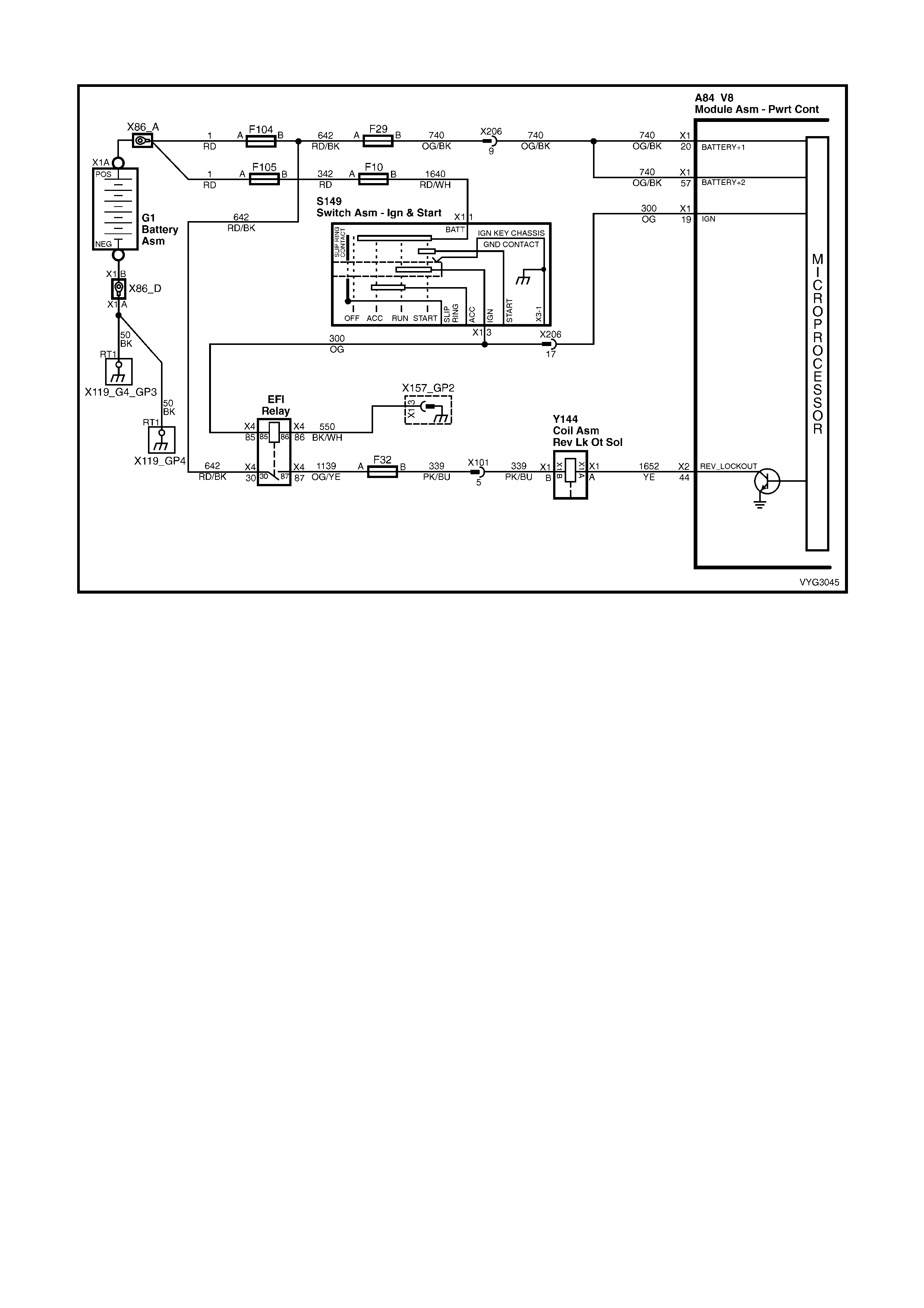
GEN III V8 PCM – DTC P0801 REVERSE INHIBIT SOLENOID CIRCUIT FAULT
Figure 6C3-2A-172 – Reverse Inhibit Solenoid Circuit
CIRCUIT DESCRIPTION
The EFI (Engine Control) relay supplies an ignition voltage through fuse F32 to the Reverse Inhibit Solenoid. The
PCM contr ols the s oleno id b y groun ding th e contro l cir cuit via an inter nal s witch c alled a driver . The dr iver su pplies
the ground for the component being controlled. Each driver has a fault line which the PCM monitors. When the
PCM commands a component ON, the voltage of the control circuit should be low (near 0 volts). When the PCM
commands the control circuit to a com ponent OFF, the voltage potential of the circuit should be high (near batter y
voltage).
When the Reverse Inhibit Solenoid is energised, the operator can shift the transmission into reverse. The PCM
enables the Re vers e Inh ibit Sole noid whene ver veh icle spee d is belo w 3 k m /h. When the vehic le spee d is ab ove 5
km/h, the PCM de-energises the solenoid, which prevents the operator from shifting the transmission into reverse.
CONDITIONS FOR RUNNING THE DTC
• The engine speed is greater than 600 RPM.
CONDITIONS FOR SETTING THE DTC
• The PCM detec ts t he c ommanded state of the c irc ui t and t he ac tua l stat e of the circ uit d o no t match f or at leas t
10 seconds.
ACTION TAKEN WHEN THE DTC SETS
• The PCM records the operating conditions at the time the diagnostic runs and fails. The PCM stores this
information in the Freeze Frame/Failure Records.
• The Check Powertrain MIL will not be activated.
CONDITIONS FOR CLEARING THE DTC
• A last test failed (current DTC) clears when the diagnostic runs and does not fail.
• Use Tech 2 to clear the DTC.
DIAGNOSTIC AIDS
• Inspect t he wiring at the PCM, the r everse i nhibit solenoid c onnector an d all oth er circuit connecting p oints for
the following conditions:
– A backed out terminal
– A damaged terminal
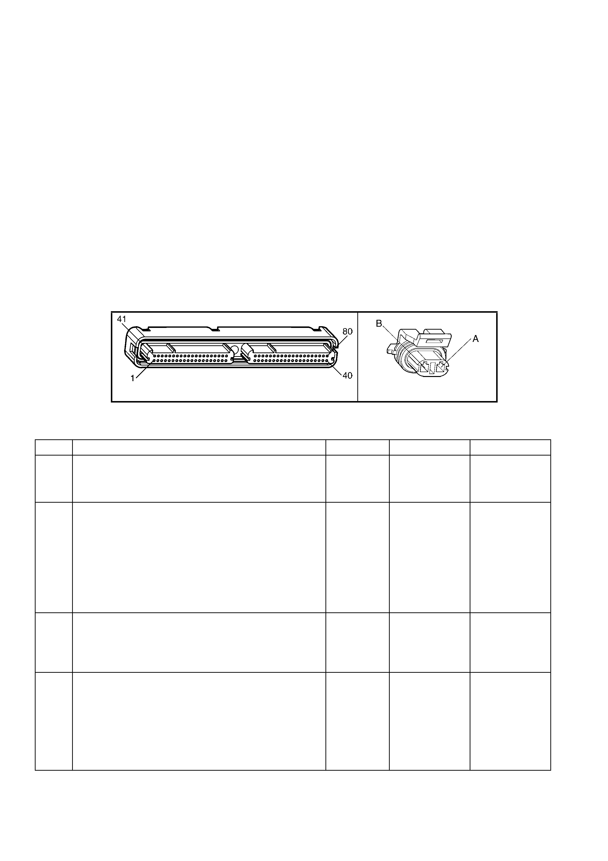
– Reduced terminal tension
– A chafed wire
– A broken wire inside the insulation
– Moisture intrusion
– Corrosion
• When diagnosing for an intermittent short or open condition, massage the wiring harness while watching the
test equipment for a change.
• Low s ystem voltage can cause th is DTC to set. W hen reviewing cap tured data, check if a low system voltage
condition was present at the time the DTC was stored in memory .
TEST DESCRIPTION
NOTE: The number(s) below refer to the step number(s) on the diagnostic table.
2. This step checks to see if the transmission can be shifted into reverse while the speedometer is indicating
vehicle speed.
3. This step indicates if Tech 2 will indicate the ON and OFF state of the reverse inhibit solenoid.
4. This step measures the current flow through the reverse inhibit solenoid.
6. This step checks to see if the PCM is commanding the solenoid ON and OFF.
8. This test checks if the reverse inhibit solenoid operates when grounded, with a fused jumper wire. If the
solenoid operates under these conditions then the PCM connector or PCM is faulty. If the solenoid does not
operate under these conditions then the solenoid ignition feed circuit is faulty.
A84–X2 (RED) Y144
Figure 6C3-2A-173
GEN III V8 PCM – DTC P0801 REVERSE INHIBIT SOLENOID CIRCUIT FAULT
STEP ACTION VALUE YES NO
1. Was the "On-Board Diagnostic" (OBD) System Check
performed? Go to Step 2 Go to
OBD System
Check
in this Section.
2. 1. Raise drive wheels off ground and supp ort vehi cl e.
2. Install Tech 2 and select Engine Data.
3. Ignition ON, engine running.
4. Shift the transmission into first gear and slowly release
the clutch to allow the drive wheels to rotate to 5 – 15
km/h.
5. While speedometer is reading 5 – 15 km/h, depress
clutch and try to shift into reverse gear.
Were you unable to shift into reverse gear?
Go to Step 3 Go to Step 4
3. 1. W hile the speedometer is reading 5 – 15 km/h, Tech 2
should indicate Reverse Inhibit as OFF, and when the
speedometer is reduced to 3 km/h or lower, Tech 2
should indicate ON.
Did reading show as suggested?
Go to Step 4 Go to Step 6
4. 1. Ignition OFF.
2. Disconnect the RED PCM connector, A84-X2.
3. Ignition ON.
4. Measure the current from the solenoid control circuit in
the PCM harness connector to ground for two minutes
using a DMM with the 10 amp scale selected.
Does the current-draw measure less than the value shown
(but not 0)?
1.5 Amps No trouble
found. Go to
Diagnostic Aids
Go to Step 5

STEP ACTION VALUE YES NO
5. 1. Ignition OFF.
2. Disconnect the reverse inhibit solenoid, Y144.
3. Measure the resistance from the solenoid control
circuit 1652 in the PCM harness connector to ground
using a DMM.
Does the DMM display infinite resistance?
Go to Step 13 Go to Step 11
6. 1. Ignition OFF.
2. Disconnect the reverse inhibit solenoid, Y144.
3. Connect a test lamp between the terminals in the
solenoid harness connector.
4. Ignition ON, engine running.
5. Rotate drive wheels to 5 – 15 km/h and then below 3
km/h.
Does the test lamp turn ON and OFF?
Go to Step 9 Go to Step 7
7. 1. Probe the ignition feed circuit 339 in the solenoid
harness connector with the test lamp connected to
ground.
Does the test lamp illuminate?
Go to Step 8 Go to Step 12
8. 1. Ignition OFF.
2. Reconnect the reverse inhibit solenoid, Y144.
3. Disconnect the RED PCM connector A84-X2.
4. Ignition ON.
5. Probe the solenoid control circuit 1652 in the PCM
harness connector with a fused jumper wire connector
to ground.
Does the solenoid operate?
Go to Step 10 Go to Step 12
9. 1. Check the connections at the reverse inhibit solenoid,
Y144.
Did you find and correct the condition?
Verify Repair Go to Step 13
10. 1. Check the connection at the PCM.
Was a problem found? Verify Repair Go to Step 14
11. 1. Repair open or short to ground or short to voltage in
the solenoid control circuit 1652.
Is the repair complete?
Verify Repair –
12. 1. Repair the faulty solenoid ignition feed circuit 339.
Is the repair complete? Verify Repair –
13. 1. Replace the reverse inhibit solenoid.
Is action complete? Verify Repair –
14. 1. Replace PCM. Refer to PCM Programming and
PCM/PIM/BCM Security Link Procedure, in 6C3-3
SERVICE OPERATIONS.
Is action complete?
Verify Repair –
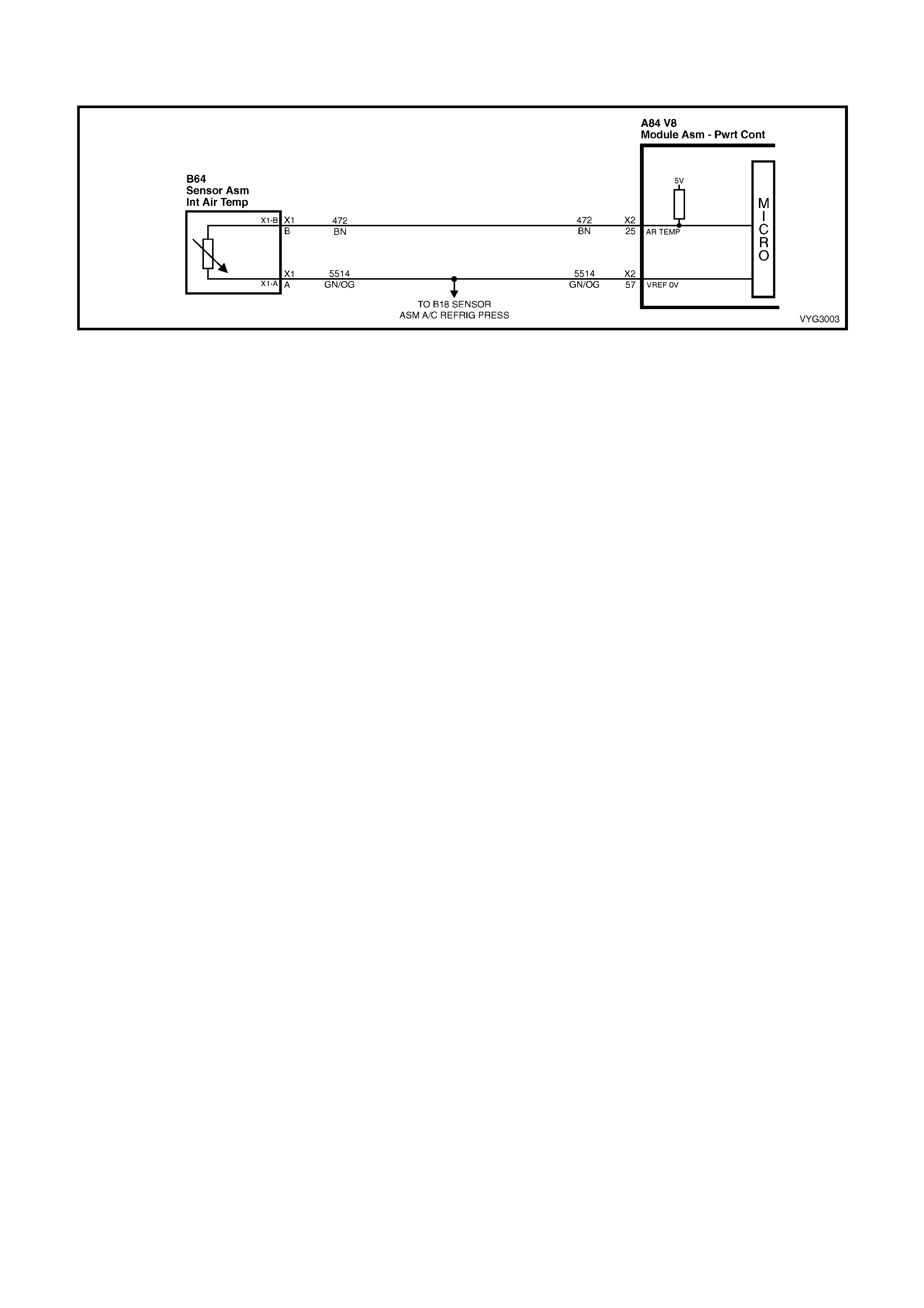
GEN III V8 PCM – DTC P1111 INTAKE AIR TEMPERATURE SENSOR CIRCUIT
INTERMITTENT HIGH VOLTAGE
Figure 6C3-2A-174 – Intake Air Temperature Sensor
CIRCUIT DESCRIPTION
The Intake Air Temperature (IAT) Sensor contains a semiconductor device which changes resistance based on
temperature (a thermistor). The IAT Sensor mounts in the air intake passage of the engine air induction system.
The IAT Sensor has a s ign al circ uit and a grou nd circ uit. T he PCM appl ies a vo lt age (abou t 5.0 v olts) o n the s ignal
circuit to the s e nsor . The PCM monitors c han ges in th i s vol tag e caus ed by chang es in t he r esis t anc e of th e s ensor ,
in order to determine the temperature of the intake air.
W hen the intake air is cold, the sens or (thermistor) resistance is h igh, and the PCM’s signal voltage is on ly pulled
down a small amount through the sensor to ground. The PCM senses a high signal voltage (low temperature).
W hen the intak e air is warm , the sensor r esistanc e is lo w, and the signal voltage is pul led do wn a great er am ount.
This causes the PCM to sense a low signal voltage (high temperature).
This DTC sets when the PCM senses a signal voltage higher than the normal operating range of the sensor.
CONDITIONS FOR RUNNING THE DTC
• DTC(s) P0101, P01 02, P01 03, P01 17, P0 118, are not set.
• The engine run time is greater than 100 seconds.
• The engine coolant temperature is greater than 0° C.
• The vehicle speed is less than 11 km/h.
• The Mass Air Flow is less than 15 g/s.
CONDITIONS FOR SETTING THE DTC
• The Intake Air Temperature is at or below –35° C.
• All conditions are present for 0.3 seconds.
ACTION TAKEN WHEN THE DTC SETS
• The PCM stores the DTC information into memory when the diagnostic runs and fails.
• The Check Powertrain MIL will not be activated.
• The PCM will substitute a default Intake Air Temperature value of 25° C.
• The PCM records the operating conditions at the time the diagnostic fails. The PCM stores this information in
the Freeze Frame/Failure Records.
CONDITIONS FOR CLEARING THE MIL/DTC
• A last test failed (current DTC) clears when the diagnostic runs and does not fail.
• Use Tech 2 to clear the MIL/DTC.
DIAGNOSTIC AIDS
• If the engine has sat overnight, the engine coolant temperature and intake air temperature values should
display within a few degrees of each other. If the temperatures are not within 3° C, refer to Temperature vs
Resistance, in Section 6C3-4 SPECIFICATIONS.
• For an intermittent, refer to Section 6C3-2B SY MPTOM S.
TEST DESCRIPTION
NOTE: The number(s) below refer to the step number(s) on the diagnostic table.
2. If DTC P0113 failed this ig n iti on, th is indicates a har d f ail ur e is pr es ent. When a har d f ailur e is pr es ent , both t he
hard and intermittent DTCs set.
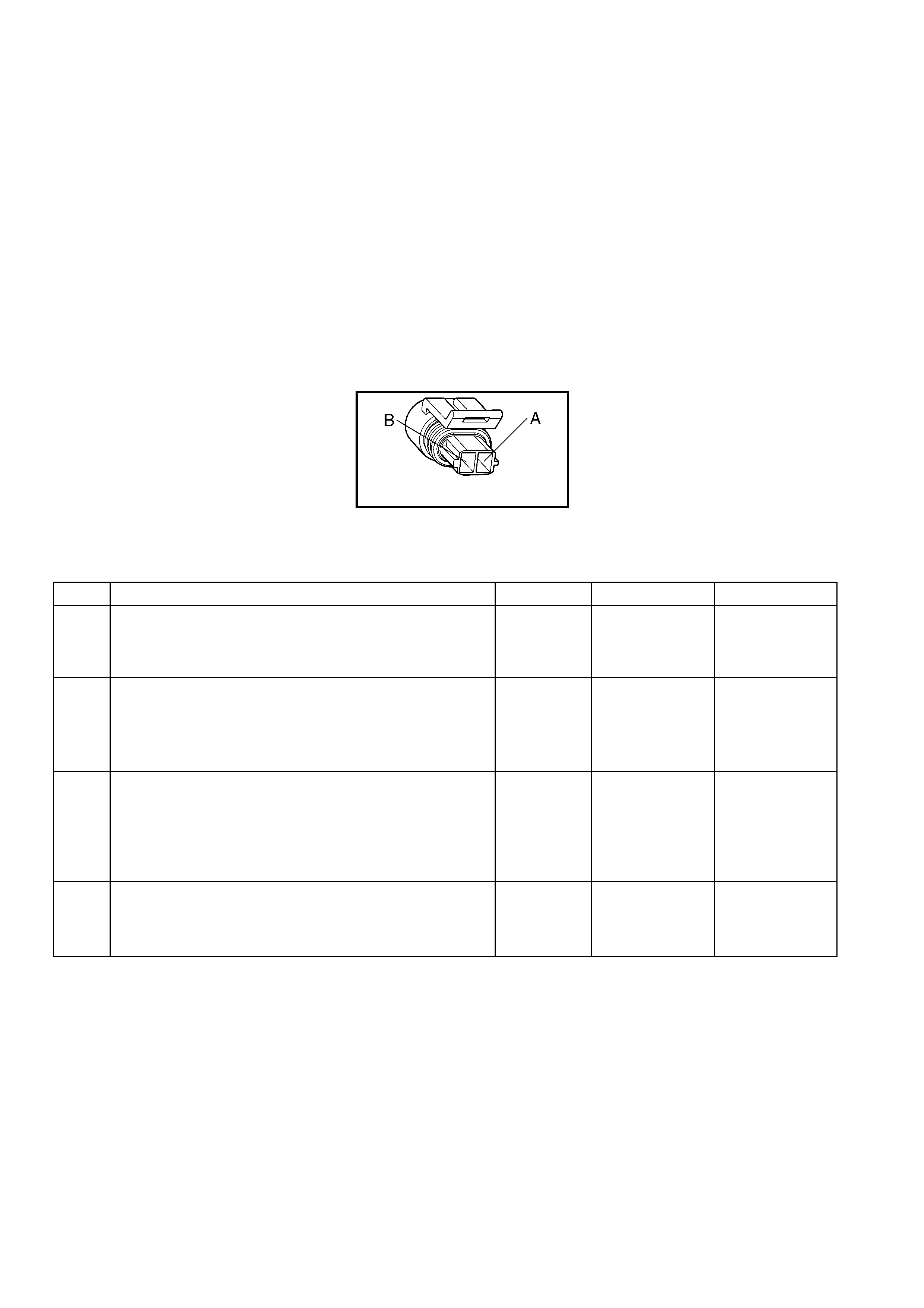
3. When moving related connectors, inspect the connectors for the following:
– Poor mating of the connector halves or a terminal not fully seated in the connector body (backed out).
– Im properly form ed or damaged t erminals. Car efully ref orm or r eplace all connecto r term inals in the relate d
circuits in order to ensure proper terminal contact tension.
– Poor terminal to wire connection. Inspect for poor crimps, crimping over wire insulation rather than the wire.
– Dirt or corrosion on the terminals. Inspect the connector seals for being there and for being damaged.
4. When moving the related wiring harness, inspect the wiring for the following:
– Wire insulation that is rubbed through, causing an intermittent short.
– Wiring broken inside the insulation.
5. Using the Freeze Frame/Failure Records data may aid in locating an intermittent condition. The Fail Counter
and Pass Counter c an als o help det erm ine ho w man y ignition c ycles the diag nosti c repor ted a pass and/or fail.
Operate the vehicle within the same freeze frame condition (RPM, load, vehicle speed, temperature etc.) that
you observed.
This will isolate when the DTC failed. For any test that requires probing the PCM or component harness
connectors , use the Connector Test Adaptor Kit J 35 616-A. Using this kit preve nts an y damage to t he harnes s
connector terminals.
B64
Figure 6C3-2A-175
GEN III V8 PCM –
DTC P1111 INTAKE AIR TEMPERA TURE SENSOR CIRCUIT INTERMITTENT HIGH VOLTAGE
STEP ACTION VALUE YES NO
1. Was the "On-Board Diagnostic" (OBD) System Check
performed? Go to Step 2 Go to
OBD System
Check
in this Section.
2. 1. Ignition ON, engine OFF.
2. Observe the affected sensor value on Tech 2 while
moving the related harness connectors (at the
component and the PCM).
Did DTC P0113, Fail This Ignition cycle?
Go to DTC
P0113 IAT
Sensor Circuit
High Voltage
Go to Step 3
3. 1. Ignition ON, engine OFF.
2. Observe the affected sensor value on Tech 2 while
moving the related harness connectors (at the
component and the PCM).
Does the sensor value change abruptly while moving the
related electrical harness?
Go to Step 6 Go to Step 4
4. 1. Observe the affected sensor value on Tech 2 while
moving the related wiring harnesses.
Does the sensor value change abruptly while moving the
related electrical harnesses?
Go to Step 7 Go to Step 5

STEP ACTION VALUE YES NO
5. 1. Ignition ON, engine OFF.
2. Review the Freeze Frame/Failure Records data for this
DTC and observe the parameters.
3. Turn OFF the ignition for 15 seconds.
4. Start the engine.
5. Operate the vehicle within the conditions required for
this diagnostic to run, and as close to the conditions
recorded in the Freeze Frame/Failure Records as
possible. Special operating conditions that you need to
meet before the PCM will run this diagnostic, where
applicable, are listed in Conditions for Running the
DTC.
6. Select the Diagnostic Trouble Code (DTC) option, the
DTC Information option and the Failed This Ignition
option using Tech 2.
Does Tech 2 indicate that this diagnostic failed this
ignition?
Go to Step 8 Refer to
Diagnostic Aids
6. 1. Repair the damaged connectors/terminals.
Is the repair complete? Go to Step 9 –
7. 1. Repair the faulty wiring.
Is the repair complete? Go to Step 9 –
8. 1. Re-inspect all the related circuits and the connectors.
2. Replace the sensor/component if all the circuits have
been checked thoroughly and no faults can be found.
Is the action complete?
Go to Step 9 –
9. 1. Select the Diagnostic Trouble Code (DTC) option and
the Clear DTC Information option using Tech 2.
2. Idle the engine at the normal operating temperature.
3. Select the Diagnostic Trouble Code (DTC) option, the
DTC Information option and the Failed This Ignition
option using Tech 2.
4. Operate the vehicle, within the Conditions for Running
the DTC, as specified in the supporting text, if
applicable.
Does Tech 2 indicate that this DTC reset?
Go to Step 2 Go to Step 10
10. 1. Using Tech 2, check for any other DTCs.
Does Tech 2 display any DTCs that you have not
diagnosed?
Go to the
applicable DTC
table
System OK

GEN III V8 PCM – DTC P1112 INTAKE AIR TEMPERATURE SENSOR CIRCUIT
INTERMITTENT LOW VOLTAGE
Figure 6C3-2A-176 – Intake Air Temperature Sensor
CIRCUIT DESCRIPTION
The Intake Air Temperature (IAT) Sensor contains a semiconductor device which changes resistance based on
temperature (a thermistor). The IAT Sensor mounts in the air intake passage of the engine air induction system.
The IAT Sensor has a s ign al circ uit and a grou nd circ uit. T he PCM appl ies a vo lt age (abou t 5.0 v olts) o n the s ignal
circuit to the s ensor. T he PCM m onitor s cha nges in th is vo ltage c aus ed b y chang es in the r esista nce of the sens or
in order to determine the intake air temperature.
W hen the intake air is cold, the sens or (thermistor) resistance is h igh, and the PCM’s signal voltage is on ly pulled
down a small amount through the sensor to ground. The PCM senses a high signal voltage (low temperature).
W hen the intak e air is warm , the sensor r esistanc e is lo w, and the signal voltage is pul led do wn a great er am ount.
This causes the PCM to sense a low signal voltage (high temperature).
This DTC sets when the PCM senses a signal voltage lower than the normal operating range of the sensor.
CONDITIONS FOR RUNNING THE DTC
• DTC(s) P0101, P01 02, P01 03, P01 17, P0 118, are not set.
• The engine run time is greater than 30 seconds.
• The vehicle speed is less than 40 km/h.
CONDITIONS FOR SETTING THE DTC
• The Intake Air Temperature is at or above 139° C.
• The conditions present for 0.3 seconds.
ACTION TAKEN WHEN THE DTC SETS
• The PCM stores the DTC information into memory when the diagnostic runs and fails.
• The Check Powertrain MIL will not be activated.
• The PCM will substitute a default Intake Air Temperature value of 25° C.
• The PCM records the operating conditions at the time the diagnostic fails. The PCM stores this information in
the Freeze Frame/Failure Records.
CONDITIONS FOR CLEARING THE MIL/DTC
• A last test failed (current DTC) clears when the diagnostic runs and does not fail.
• Use Tech 2 to clear the MIL/DTC.
DIAGNOSTIC AIDS
• If the engine has sat overnight, the engine coolant temperature and intake air temperature values should
display within a few degrees of each other. If the temperatures are not within 3° C, refer to Temperature vs
Resistance, in Section 6C3-4 SPECIFICATIONS.
• For an intermittent, refer to Section 6C3-2B SY MPTOMS.
TEST DESCRIPTION
NOTE: The number(s) below refer to the step number(s) on the diagnostic table.
2. If DTC P0112 failed this ig n iti on, th is indicates a har d f ail ur e is pr es ent. When a har d f ailur e is pr es ent , both t he
hard and intermittent DTCs set.

3. When moving related connectors, inspect the connectors for the following:
– Poor mating of the connector halves or a terminal not fully seated in the connector body (backed out).
– Im properly form ed or damaged t erminals. Car efully ref orm or r eplace all connecto r term inals in the relate d
circuits in order to ensure correct terminal contact tension.
– Poor terminal to wire connection. Inspect for poor crimps, crimping over wire insulation rather than the wire.
– Dirt or corrosion on the terminals. Inspect the connector seals for being there and for being damaged.
4. When moving the related wiring harness, inspect the wiring for the following:
– Wire insulation that is rubbed through, causing an intermittent short.
– Wiring broken inside the insulation.
5. Using the Freeze Frame/Failure Records data may aid in locating an intermittent condition. The Fail Counter
and Pass Counter c an als o help det erm ine ho w man y ignition c ycles the diag nosti c repor ted a pass and/or fail.
Operate the vehicle within the same freeze frame condition (RPM, load, vehicle speed, temperature etc.) that
you observed.
This will isolate when the DTC failed. For any test that requires probing the PCM or component harness
connectors , use the Connector Test Adaptor Kit J 35 616-A. Using this kit preve nts an y damage to t he harnes s
connector terminals.
B64
Figure 6C3-2A-177
GEN III V8 PCM –
DTC P1112 INTAKE AIR TEMPERATURE SENSOR CIRCUIT INTERMITTENT LOW VOLTAGE
STEP ACTION VALUE YES NO
1. Was the "On-Board Diagnostic" (OBD) System Check
performed? Go to Step 2 Go to
OBD System
Check
in this Section.
2. 1. Install Tech 2.
2. Run the engine at idle.
3. Monitor the Failed This Ignition option under the DTC
Informat ion option usin g Tech 2.
Did DTC P0112, Fail This Ignition cycle?
Go to DTC
P0112 IAT
Sensor Circuit
Low Voltage
Go to Step 3
3. 1. Ignition ON, engine OFF.
2. Observe the affected sensor value on Tech 2 while
moving the related harness connectors (at the
component and the PCM).
Does the sensor value change abruptly while the related
connector is being moved?
Go to Step 6 Go to Step 4
4. 1. Observe the affected sensor value on Tech 2 while
moving the related wiring harness.
Does the sensor value change abruptly while moving the
related electrical harness?
Go to Step 7 Go to Step 5

STEP ACTION VALUE YES NO
5. 1. Ignition ON, engine OFF.
2. Review the Freeze Frame/Failure Records data for this
DTC and observe the parameters.
3. Turn OFF the ignition for 15 seconds.
4. Start the engine.
5. Operate the vehicle, within the conditions required for
this diagnostic to run, and as close to the conditions
recorded in the Freeze Frame/Failure Records as
possible. Special operating conditions that you need to
meet before the PCM will run this diagnostic, where
applicable, are listed in Conditions for Running the
DTC.
6. Select the Diagnostic Trouble Code (DTC) option, the
DTC Information option and the Failed This Ignition
option using Tech 2.
Does Tech 2 indicate that this diagnostic failed this
ignition?
Go to Step 8 Refer to
Diagnostic Aids
6. 1. Repair the damaged connectors/terminals.
Is the repair complete? Go to Step 9 –
7. 1. Repair the faulty wiring.
Is the repair complete? Go to Step 9 –
8. 1. Re-inspect all the related circuits and the connectors.
2. Replace the sensor/component if all the circuits have
been checked thoroughly and no faults can be found.
Is the action complete?
Go to Step 9 –
9. 1. Select the Diagnostic Trouble Code (DTC) option and
the Clear DTC Information option using Tech 2.
2. Idle the engine at the normal operating temperature.
3. Select the Diagnostic Trouble Code (DTC) option, the
DTC Information option and the Failed This Ignition
option using Tech 2.
4. Operate the vehicle within the Conditions for Running
the DTC, as specified in the supporting text, if
applicable.
Does Tech 2 indicate that this DTC reset?
Go to Step 2 Go to Step 10
10. 1. Using Tech 2, check for any other DTCs.
Does Tech 2 display any DTCs that you have not
diagnosed?
Go to the
applicable DTC
table
System OK

GEN III V8 PCM – DTC P1114 ENGINE COOLANT TEMPERATURE SENSOR CIRCUIT
INTERMITTENT LOW VOLTAGE
Figure 6C3-2A-178 – Engine Coolant Temperature Sensor
CIRCUIT DESCRIPTION
The Engi ne Cool ant Tem perature ( ECT ) Sensor cont ains a sem ic onductor d evic e which ch anges resis tanc e based
on temper ature (a therm istor). T he ECT Sensor m ounts in the lef t bank c ylinder head near the front of the engine.
The ECT Sensor has a signal circuit and a ground circuit. The PCM applies a voltage (about 5.0 volts) on the signal
circuit to the sensor. The PCM monitors changes in this voltage caused by the changes in the resistance of the
sensor in order to determine the engine coolant temperature.
When the engine coolant is cold, the sensor (thermistor) resistance is high, and the PCM’s signal voltage is only
pulled down a small amount through the sensor to ground. The PCM senses a high signal voltage (low
temper ature). W hen the e ngin e coo lant is hot, th e sen sor re sistanc e is lo w, and the s igna l voltage is pu lled down a
greater amount. This causes the PCM to sense a low signal voltage (high temperature).
This DTC sets when the PCM senses a signal voltage lower than the normal operating range of the sensor.
CONDITIONS FOR RUNNING THE DTC
• The engine run time is greater than 10 seconds.
CONDITIONS FOR SETTING THE DTC
• The engine coolant temperature is greater than 139° C for at least one second.
ACTION TAKEN WHEN THE DTC SETS
• The PCM stores the DTC information into memory when the diagnostic runs and fails.
• The Check Powertrain MIL will not be activated.
• The PCM records the operating conditions at the time the diagnostic fails. The PCM stores this information in
the Freeze Frame/Failure Records.
CONDITIONS FOR CLEARING THE MIL/DTC
• A last test failed (current DTC) clears when the diagnostic runs and does not fail.
• Use Tech 2 to clear the MIL/DTC.
DIAGNOSTIC AIDS
• Electro-Magnetic Interference (EMI) can cause an intermittent DTC. Inspect the related circuits for being too
close to secondary ignition wires and the AC generator.
• If the engine has sat overnight, the engine coolant temperature and intake air temperature values should
display within a few degrees of each other. If the temperatures are not within 3° C, refer to Temperature vs.
Resistance Table in Section 6C3-4 SPECIFICATIONS.
• For an intermittent, refer to Section 6C3-2B SY MPTOMS.
TEST DESCRIPTION
NOTE: The number(s) below refer to the step number(s) on the diagnostic table.
2. If DTC P0117 failed this ig n iti on, th is indicates a har d f ail ur e is pr es ent. When a har d f ailur e is pr es ent , both t he
hard and intermittent DTC’s set.
3. When moving related connectors, inspect the connectors for the following:
–- Poor mating of the connector halves or a terminal not fully seated in the connector body (backed out).
– Improperly formed or damaged terminals. Carefully reform or replace all connector terminals in the related
circuits in order to ensure correct terminal contact tension.
– Poor terminal to wire connection. Inspect for poor crimps, crimping over wire insulation rather than the wire.

– Dirt or corrosion on the terminals. Inspect the connector seals for being there and for being damaged.
4. When moving the related wiring harness, inspect the wiring for the following:
– Wire insulation that is rubbed through, causing an intermittent short.
– Wiring broken inside the insulation.
5. Using the Freeze Frame/Failure Records data may aid in locating an intermittent condition. The Fail Counter
and Pass Counter c an als o help det erm ine ho w man y ignition c ycles the diag nosti c repor ted a pass and/or fail.
Operate the vehicle within the same freeze frame condition (RPM, load, vehicle speed, temperature etc.) that
you observed.
This will isolate when the DTC failed. For any test that requires probing the PCM or component harness
connectors , use the Connector Test Adaptor Kit J 35 616-A. Using this kit preve nts an y damage to t he harnes s
connector terminals.
B39
Figure 6C3-2A-179
GEN III V8 PCM –
DTC P1114 ENGINE COOLANT TEMPERATURE SENSOR CIRCUIT INTERMITTENT LOW VOLTAGE
STEP ACTION VALUE YES NO
1. Was the "On-Board Diagnostic" (OBD) System Check
performed? Go to Step 2 Go to
OBD System
Check
in this Section.
2. 1. Install Tech 2.
2. Run the engine at idle.
3. Monitor the Failed This Ignition option under the DTC
Informat ion option usin g Tech 2.
Did DTC P0117 fail this ignition cycle?
Go to DTC
P0117 ECT
Sensor Circuit
Low Voltage
Go to Step 3
3. 1. Ignition ON, engine OFF.
2. Observe the affected sensor value on Tech 2 while
moving the related harness connectors (at the
component and the PCM).
Does the sensor value change abruptly while a related
connector is being moved?
Go to Step 6 Go to Step 4
4. 1. Observe the affected sensor value on Tech 2 while
moving the related wiring harnesses.
Does the sensor value change abruptly while moving the
related electrical harnesses?
Go to Step 7 Go to Step 5
5. 1. Ignition ON, engine OFF.
2. Review the Freeze Frame/Failure Records data for this
DTC and observe the parameters.
3. Turn OFF the ignition for 15 seconds.
4. Start the engine.
5. Operate the vehicle within the conditions required for
this diagnostic to run, and as close to the conditions
recorded in the Freeze Frame/Failure Records as
possible. Special operating conditions that you need to
meet before the PCM will run this diagnostic, where
applicable, are listed in Conditions for Running the
DTC.
6. Select the Diagnostic Trouble Code (DTC) option, the
DTC Information option and the Failed This Ignition
option using Tech 2.
Does Tech 2 indicate that this diagnostic failed this
ignition?
Go to Step 8 Go to
Diagnostic Aids
6. 1. Repair the damaged connectors/terminals.
Is the repair complete? Go to Step 9 –

STEP ACTION VALUE YES NO
7. 1. Repair the faulty wiring.
Is the repair complete? Go to Step 9 –
8. 1. Re-inspect all the related circuits and the connectors.
2. Replace the sensor/component if all the circuits have
been checked thoroughly and no faults can be found.
Is the action complete?
Go to Step 9 –
9. 1. Select the Diagnostic Trouble Code (DTC) option and
the Clear DTC Information option using Tech 2.
2. Idle the engine at normal operating temperature.
3. Select the Diagnostic Trouble Code (DTC) option, the
DTC Information option and the Failed This Ignition
option using Tech 2.
4. Operate the vehicle, within the Conditions for Running
the DTC, as specified in the supporting text, if
applicable.
Does Tech 2 indicate that this DTC reset?
Go to Step 2 Go to Step 10
10. 1. Using Tech 2, check for any other DTC’s.
Does Tech 2 display any DTCs that you have not
diagnosed?
Go to the
applicable DTC
table
System OK
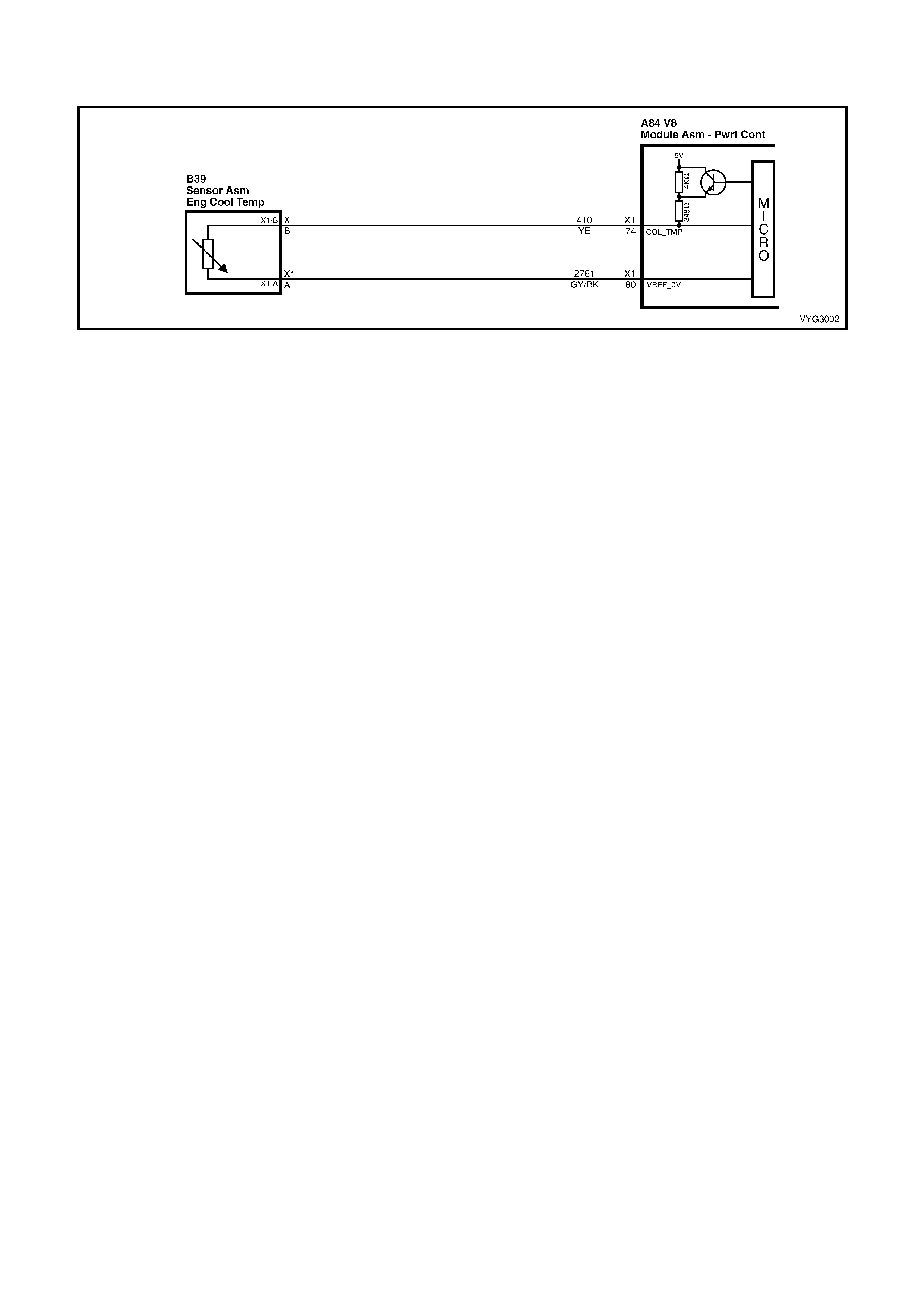
GEN III V8 PCM – DTC P1115 ENGINE COOLANT TEMPERATURE SENSOR CIRCUIT
INTERMITTENT HIGH VOLTAGE
Figure 6C3-2A-180 – Engine Coolant Temperature Sensor Circuit
CIRCUIT DESCRIPTION
The Engi ne Cool ant Tem perature ( ECT ) Sensor cont ains a sem ic onductor d evic e which ch anges resis tanc e based
on temper ature (a therm istor). T he ECT Sensor m ounts in the lef t bank c ylinder head near the front of the engine.
The ECT Sensor has a signal circuit and a ground circuit. The PCM applies a voltage (about 5.0 volts) on the signal
circuit to the sensor. The PCM monitors changes in this voltage caused by the changes in the resistance of the
sensor in order to determine the engine coolant temperature.
When the engine coolant is cold, the sensor (thermistor) resistance is high, and the PCM’s signal voltage is only
pulled down a small amount through the sensor to ground. The PCM senses a high signal voltage (low
temper ature). W hen the e ngin e coo lant is hot, th e sen sor re sistanc e is lo w, and the s igna l voltage is pu lled down a
greater amount. This causes the PCM to sense a low signal voltage (high temperature).
This DTC sets when the PCM senses a signal voltage higher than the normal operating range of the sensor.
CONDITIONS FOR RUNNING THE DTC
• The engine run time is greater than 60 seconds.
CONDITIONS FOR SETTING THE DTC
• The engine coolant temperature is less than –35° C for at least one second.
ACTION TAKEN WHEN THE DTC SETS
• The PCM stores the DTC information into memory when the diagnostic runs and fails.
• The Check Powertrain MIL will not be activated.
• The PCM records the operating conditions at the time the diagnostic fails. The PCM stores this information in
the Freeze Frame/Failure Records.
CONDITIONS FOR CLEARING THE MIL/DTC
• A last test failed (current DTC) clears when the diagnostic runs and does not fail.
• Use Tech 2 to clear the MIL/DTC.
DIAGNOSTIC AIDS
• Electro-Magnetic Interference (EMI) can cause an intermittent DTC. Inspect the related circuits for being too
close to secondary ignition wires and the generator.
• If the engine has sat overnight, the engine coolant temperature and intake air temperature values should
display within a few degrees of each other. If the temperatures are not within 3° C, refer to Temperature vs.
Resistance Table in Section 6C3-4 SPECIFICATIONS.
• For an intermittent, refer to Section 6C3-2B SY MPTOM S.
TEST DESCRIPTION
NOTE: The number(s) below refer to the step number(s) on the diagnostic table.
2. If DTC P0118 failed this ig n iti on, th is indicates a har d f ail ur e is pr es ent. When a har d f ailur e is pr es ent , both t he
hard and intermittent DTC’s set.
3. When moving related connectors, inspect the connectors for the following:
– Poor mating of the connector halves or a terminal not fully seated in the connector body (backed out).
– Im properly form ed or damaged t erminals. Car efully ref orm or r eplace all connecto r term inals in the relate d
circuits in order to ensure correct terminal contact tension.
– Poor terminal to wire connection. Inspect for poor crimps, crimping over wire insulation rather than the wire.

– Dirt or corrosion on the terminals. Inspect the connector seals for being there and for being damaged.
4. When moving the related wiring harness, inspect the wiring for the following:
– Wire insulation that is rubbed through, causing an intermittent short.
– Wiring broken inside the insulation.
5. Using the Freeze Frame/Failure Records data may aid in locating an intermittent condition. The Fail Counter
and Pass Counter c an als o help det erm ine ho w man y ignition c ycles the diag nosti c repor ted a pass and/or fail.
Operate the vehicle within the same freeze frame condition (RPM, load, vehicle speed, temperature etc.) that
you observed . This will isol ate when the DT C failed.
IMPORTANT: For any test that requires probing the PCM or component harness connectors, use the Connector
Test Adaptor Kit J 35616-A. Using this kit prevents any damage to the harness connector terminals.
B39
Figure 6C3-2A-181
GEN III V8 PCM –
DTC P1115 ENGINE COOLANT TEMPERATURE SENSOR CIRCUIT INTERMITTENT HIGH VOLTAGE
STEP ACTION VALUE YES NO
1. Was the "On-Board Diagnostic" (OBD) System Check
performed? Go to Step 2 Go to
OBD System
Check
in this Section.
2. 1. Install Tech 2.
2. Run the engine at idle.
3. Monitor the Failed This Ignition option under the DTC
Informat ion option usin g Tech 2.
Did DTC P0118 Fail This Ignition cycle?
Go to DTC
P0118 ECT
Sensor Circuit
High Voltage
Table
Go to Step 3
3. 1. Ignition ON, engine OFF.
2. Observe the affected sensor value on Tech 2 while
moving the related harness connectors (at the
component and the PCM).
Does the sensor value change abruptly while the related
connector is being moved?
Go to Step 6 Go to Step 4
4. 1. Observe the affected sensor value on Tech 2 while
moving the related wiring harness.
Does the sensor value change abruptly while moving the
related electrical harness?
Go to Step 7 Go to Step 5
5. 1. Ignition ON, engine OFF.
2. Review the Freeze Frame/Failure Records data for this
DTC and observe the parameters.
3. Turn OFF the ignition for 15 seconds.
4. Start the engine.
5. Operate the vehicle within the conditions required for
this diagnostic to run, and as close to the conditions
recorded in the Freeze Frame/Failure Records as
possible. Special operating conditions that you need to
meet before the PCM will run this diagnostic, where
applicable, are listed in Conditions for Running the
DTC.
6. Select the Diagnostic Trouble Code (DTC) option, the
DTC Information option and the Failed This Ignition
option using Tech 2.
Does Tech 2 indicate that this diagnostic failed this
ignition?
Go to Step 8 Go to
Diagnostic Aids
6. 1. Repair the damaged connectors/terminals.
Is the repair complete? Go to Step 9 –

STEP ACTION VALUE YES NO
7. 1. Repair the faulty wiring.
Is the repair complete? Go to Step 9 –
8. 1. Re-inspect all the related circuits and the connectors.
2. Replace the sensor/component if all the circuits have
been checked thoroughly and no faults can be found.
Is the action complete?
Go to Step 9 –
9. 1. Select the Diagnostic Trouble Code (DTC) option and
the Clear DTC Information option using Tech 2.
2. Idle the engine at the normal operating temperature.
3. Select the Diagnostic Trouble Code (DTC) option, the
DTC Information option and the Failed This Ignition
option using Tech 2.
4. Operate the vehicle, within the Conditions for Running
the DTC, as specified in the supporting text, if
applicable.
Does Tech 2 indicate that this DTC reset?
Go to Step 2 Go to Step 10
10. 1. Using Tech 2, check for any other DTCs.
Does Tech 2 display any DTCs that you have not
diagnosed?
Go to the
applicable DTC
table
System OK

GEN III V8 PCM – DTC P1121 THROTTLE POSITION SENSOR CIRCUIT
INTERMITTENT HIGH VOLTAGE
Figure 6C3-2A-182 – Throttle Position Sensor Circuit
CIRCUIT DESCRIPTION
The Thr ottle Position (TP) Sensor is a pot ent iometer . T he T P Sens or is m ounted to the lef t s ide of the thr ot tl e body.
The T P Sensor pr ovides a voltag e signa l that chan ges r elative t o thrott le blade angle. This s ignal volt age is o ne of
the most important inputs used by the PCM. The TP Sensor has a 5.0 volt reference, a ground and a signal circuit.
TP sensor signal voltage should be about 0.6 volt at idle. The TP Sensor voltage should increase to above 4.0 volts
at wide open throttl e (W OT ).
When the PCM senses a signal voltage higher than the normal operating range of the sensor, this DTC will set.
CONDITIONS FOR RUNNING THE DTC
• The ignition switch is on or the engine is running.
CONDITIONS FOR SETTING THE DTC
• The TP sensor signal voltage is greater than 4.8 volts.
ACTION TAKEN WHEN THE DTC SETS
• The PCM stores the DTC information into memory when the diagnostic runs and fails.
• The Check Powertrain MIL will not be activated.
• The PCM records the operating conditions at the time the diagnostic fails. The PCM stores this information in
the Freeze Frame/Failure Records.
CONDITIONS FOR CLEARING THE MIL/DTC
• A last test failed (current DTC) clears when the diagnostic runs and does not fail.
• Use Tech 2 to clear the MIL/DTC.
DIAGNOSTIC AIDS
• An intermittent DTC can be caused by Electro-Magnetic Interference (EMI). Inspect related circuits for being
too close to secondary ignition wires and the alternator.
• For an intermittent, refer to Section 6C3-2B SY MPTOMS.
TEST DESCRIPTION
NOTE: The number(s) below refer to the step number(s) on the diagnostic table.
2. If DTC P0123 failed this ig n iti on, th is indicates a har d f ail ur e is pr es ent. When a har d f ailur e is pr es ent , both t he
hard and intermittent DTCs set.
3. When moving related connectors, inspect the connectors for the following:
– Poor mating of the connector halves or a terminal not fully seated in the connector body (backed out).
– Im properly form ed or damaged t erminals. Car efully ref orm or r eplace all connecto r term inals in the relate d
circuits in order to ensure correct terminal contact tension.
– Poor terminal to wire connection. Inspect for poor crimps, crimping over wire insulation rather than the wire.
– Dirt or corrosion on the terminals. Inspect the connector seals for being there and for being damaged.
4. When moving the related wiring harness, inspect the wiring for the following:
– Wire insulation that is rubbed through, causing an intermittent short.
– Wiring broken inside the insulation.

5. Using the Freeze Frame/Failure Records data may aid in locating an intermittent condition. The Fail Counter
and Pass Counter c an also help det erm ine ho w man y ignition c ycles the diagn osti c repor ted a pass and/or fail.
Operate the vehicle within the same freeze frame condition (RPM, load, vehicle speed, temperature etc.) that
you observed . This will isol ate when the DT C failed.
IMPORTANT: For any test that requires probing the PCM or component harness connectors, use the Connector
Test Adaptor Kit J 35616-A. Using this kit prevents any damage to the harness connector terminals.
B82
Figure 6C3-2A-183
GEN III V8 PCM – DTC P1121 THROTTLE POSITION SENSOR CIRCUIT INTERMITTENT HIGH VOLTAGE
STEP ACTION VALUE YES NO
1. Was the "On-Board Diagnostic" (OBD) System Check
performed? Go to Step 2 Go to
OBD System
Check
in this Section.
2. 1. Install Tech 2.
2. Run the engine at idle.
3. Using Tech 2, monitor the Failed This Ignition under
DTC Information options, for DTC P0123.
Did DTC P0123 fail this ignition cycle?
Go to DTC
P0123 TP
Sensor Circuit
High Voltage
Table
Go to Step 3
3. 1. Install Tech 2.
2. Ignition ON, engine OFF.
3. Using Tech 2, observe affected sensor values while
moving related harness connectors (at component and
PCM).
Does sensor value change abruptly while a related
connector is being moved?
Go to Step 6 Go to Step 4
4. 1. Using Tech 2, observe affected sensor value while
moving related wiring harnesses.
Does sensor value change abruptly while moving related
electrical harnesses?
Go to Step 7 Go to Step 5
5. 1. Ignition ON, engine OFF.
2. Review the Freeze Frame/Failure Records data for this
DTC and observe the parameters.
3. Turn OFF the ignition for 15 seconds.
4. Start the engine.
5. Operate the vehicle, within the conditions required for
this diagnostic to run, and as close to the conditions
recorded in the Freeze Frame/Failure Records as
possible. Special operating conditions that you need to
meet before the PCM will run this diagnostic, where
applicable, are listed in Conditions for Running the
DTC.
6. Select the Diagnostic Trouble Code (DTC) option, the
DTC Information option and the Failed This Ignition
option using Tech 2.
Does Tech 2 indicate that this diagnostic failed this
ignition?
Go to Step 8 Go to
Diagnostic Aids
6. 1. Repair the damaged connectors/terminals.
Is the repair complete? Go to Step 9 –
7. 1. Repair the faulty wiring.
Is the repair complete? Go to Step 9 –

STEP ACTION VALUE YES NO
8. 1. Re-inspect all the related circuits and the connectors.
2. Replace the sensor/component if all the circuits have
been checked thoroughly and no faults can be found.
Is the action complete?
Go to Step 9 –
9. 1. Select the Diagnostic Trouble Code (DTC) option and
the Clear DTC Information option using Tech 2.
2. Idle the engine at normal operating temperature.
3. Select the Diagnostic Trouble Code (DTC) option, the
DTC Information option and the Failed This Ignition
option using Tech 2.
4. Operate the vehicle, within the Conditions for Running
the DTC, as specified in the supporting text, if
applicable.
Does Tech 2 indicate that this DTC reset?
Go to Step 2 Go to Step 10
10. 1. Using Tech 2, check for any other DTCs.
Does Tech 2 display any DTCs that you have not
diagnosed?
Go to the
applicable DTC
table
System OK
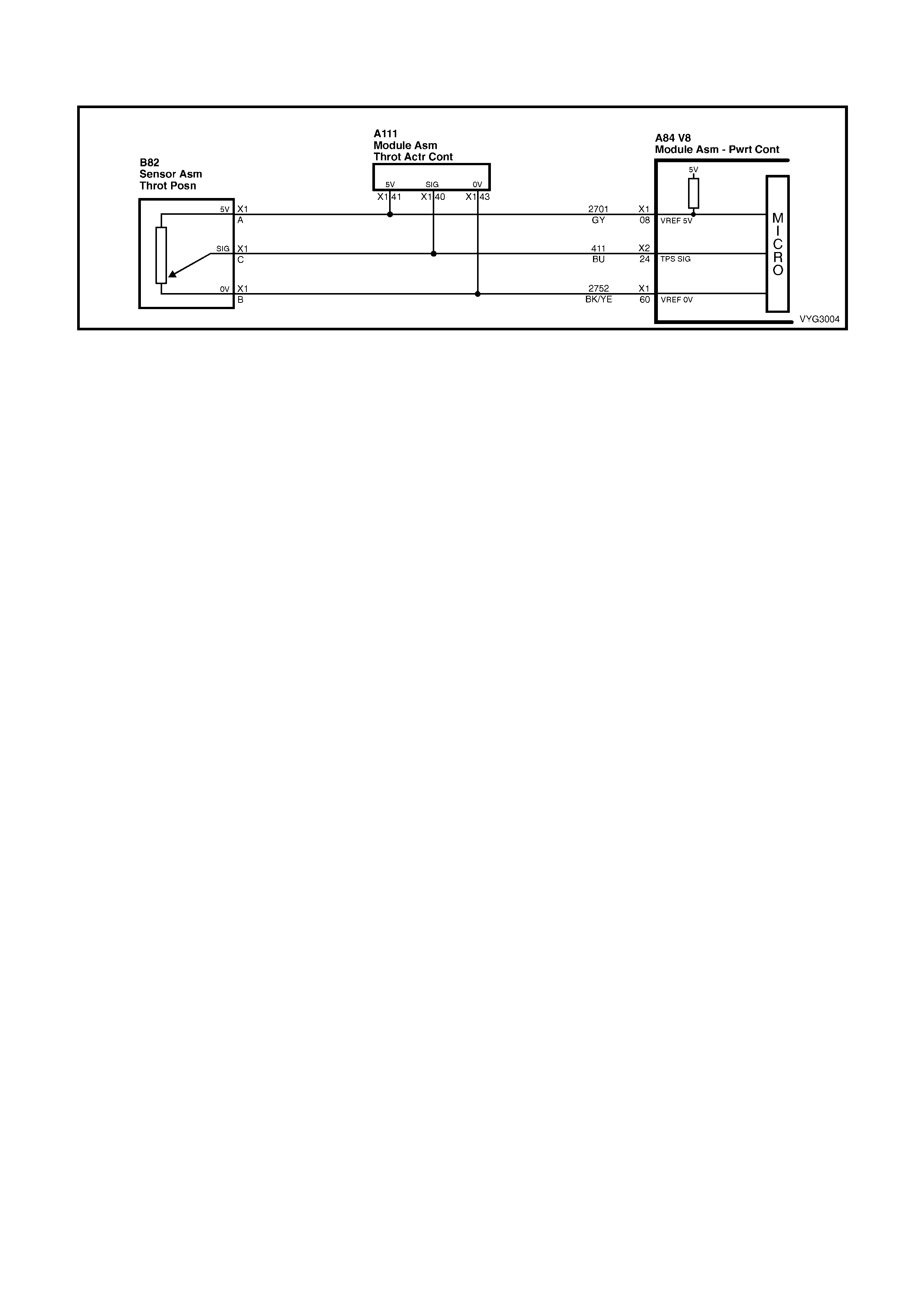
GEN III V8 PCM – DTC P1122 THROTTLE POSITION SENSOR CIRCUIT
INTERMITTENT LOW VOLTAGE
Figure 6C3-2A-184 – Throttle Position Sensor Circuit
CIRCUIT DESCRIPTION
The Thr ottle Position (TP) Sensor is a pot ent iometer . T he T P Sens or is m ounted to the lef t s ide of the thr ot tl e body.
The T P Sensor pr ovides a voltag e signa l that chan ges r elative t o thrott le blade angle. This s ignal volt age is o ne of
the most important inputs used by the PCM. The TP Sensor has a 5.0 volt reference, a ground and a signal circuit.
TP Sensor signal voltage should be about 0.6 volt at idle. The TP sensor voltage should increase to above 4.0 volts
at wide open throttl e (W OT ).
When the PCM senses a signal voltage lower than the normal operating range of the sensor, this DTC will set.
CONDITIONS FOR RUNNING THE DTC
• The ignition switch is ON or the engine is running.
CONDITIONS FOR SETTING THE DTC
• The TP sensor signal voltage is less than 0.2 volts.
ACTION TAKEN WHEN THE DTC SETS
• The PCM stores the DTC information into memory when the diagnostic runs and fails.
• The Check Powertr ain Lam p will not be acti vate d.
• The PCM records the operating conditions at the time the diagnostic fails. The PCM stores this information in
the Freeze Frame/Failure Records.
CONDITIONS FOR CLEARING THE MIL/DTC
• A last test failed (current DTC) clears when the diagnostic runs and does not fail.
• Use Tech 2 to clear the MIL/DTC.
DIAGNOSTIC AIDS
• An intermittent DTC can be caused by Electro-Magnetic Interference (EMI). Inspect related circuits for being
too close to secondary ignition wires and the alternator.
• For an intermittent, refer to Section 6C3-2B SY MPTOMS.
TEST DESCRIPTION
NOTE: The number(s) below refer to the step number(s) on the diagnostic table.
2. If DTC P0122 failed this ig n iti on, th is indicates a har d f ail ur e is pr es ent. When a har d f ailur e is pr es ent , both t he
hard and intermittent DTC’s set.
3. When moving related connectors, inspect the connectors for the following:
– Poor mating of the connector halves or a terminal not fully seated in the connector body (backed out).
– Im properly form ed or damaged t erminals. Car efully ref orm or r eplace all connecto r term inals in the relate d
circuits in order to ensure correct terminal contact tension.
– Poor terminal to wire connection. Inspect for poor crimps, crimping over wire insulation rather than the wire.
– Dirt or corrosion on the terminals. Inspect the connector seals for being there and for being damaged.
4. When moving the related wiring harness, inspect the wiring for the following:
– Wire insulation that is rubbed through, causing an intermittent short.
– Wiring broken inside the insulation.

5. Using the Freeze Frame/Failure Records data may aid in locating an intermittent condition. The Fail Counter
and Pass Counter c an als o help det erm ine ho w man y ignition c ycles the diag nosti c repor ted a pass and/or fail.
Operate the vehicle within the same freeze frame condition (RPM, load, vehicle speed, temperature etc.) that
you observed . This will isol ate when the DT C failed.
IMPORTANT: For any test that requires probing the PCM or component harness connectors, use the Connector
Test Adaptor Kit J 35616-A. Using this kit prevents any damage to the harness connector terminals.
B82
Figure 6C3-2A-185
GEN III V8 PCM – DTC P1122 THROTTLE POSITION SENSOR CIRCUIT INTERMITTENT LOW VOLTAGE
STEP ACTION VALUE YES NO
1. Was the "On-Board Diagnostic" (OBD) System Check
performed? Go to Step 2 Go to
OBD System
Check
in this Section.
2. 1. Install Tech 2.
2. Start the engine and run at idle.
3. Using Tech 2, monitor the Failed This Ignition under
the DTC Information option for DTC P0122.
Did DTC P0122 fail this ignition cycle?
Go to DTC
P0122 TP
Sensor Circuit
High Voltage
Table
Go to Step 3
3. 1. Install Tech 2.
2. Ignition ON, engine OFF.
3. Using Tech 2, observe affected sensor values while
moving related harness connectors (at component and
PCM).
Does sensor value change abruptly while a related
connector is being moved?
Go to Step 6 Go to Step 4
4. 1. Using Tech 2, observe affected sensor value while
moving related wiring harnesses.
Does sensor value change abruptly while moving related
electrical harnesses?
Go to Step 7 Go to Step 5
5. 1. Ignition ON, engine OFF.
2. Review the Freeze Frame/Failure Records data for this
DTC and observe the parameters.
3. Turn OFF the ignition for 15 seconds.
4. Start the engine.
5. Operate the vehicle, within the conditions required for
this diagnostic to run, and as close to the conditions
recorded in the Freeze Frame/Failure Records as
possible. Special operating conditions that you need to
meet before the PCM will run this diagnostic, where
applicable, are listed in Conditions for Running the
DTC.
6. Select the Diagnostic Trouble Code (DTC) option, the
DTC Information option and the Failed This Ignition
option using Tech 2.
Does Tech 2 indicate that this diagnostic failed this
ignition?
Go to Step 8 Go to Diagnostic
Aids
6. 1. Repair the damaged connectors/terminals.
Is the repair complete? Go to Step 9 –
7. 1. Repair the faulty wiring.
Is the repair complete? Go to Step 9 –

STEP ACTION VALUE YES NO
8. 1. Re-inspect all the related circuits and the connectors.
2. Replace the sensor/component if all the circuits have
been checked thoroughly and no faults can be found.
Is the action complete?
Go to Step 9 –
9. 1. Select the Diagnostic Trouble Code (DTC) option and
the Clear DTC Information option using Tech 2.
2. Idle the engine at normal operating temperature.
3. Select the Diagnostic Trouble Code (DTC) option, the
DTC Information option and the Failed This Ignition
option using Tech 2.
4. Operate the vehicle, within the Conditions for Running
the DTC, as specified in the supporting text, if
applicable.
Does Tech 2 indicate that this DTC reset?
Go to Step 2 Go to Step 10
10. 1. Using Tech 2, check for any other DTCs.
Does Tech 2 display any DTCs that you have not
diagnosed?
Go to the
applicable DTC
table
System OK
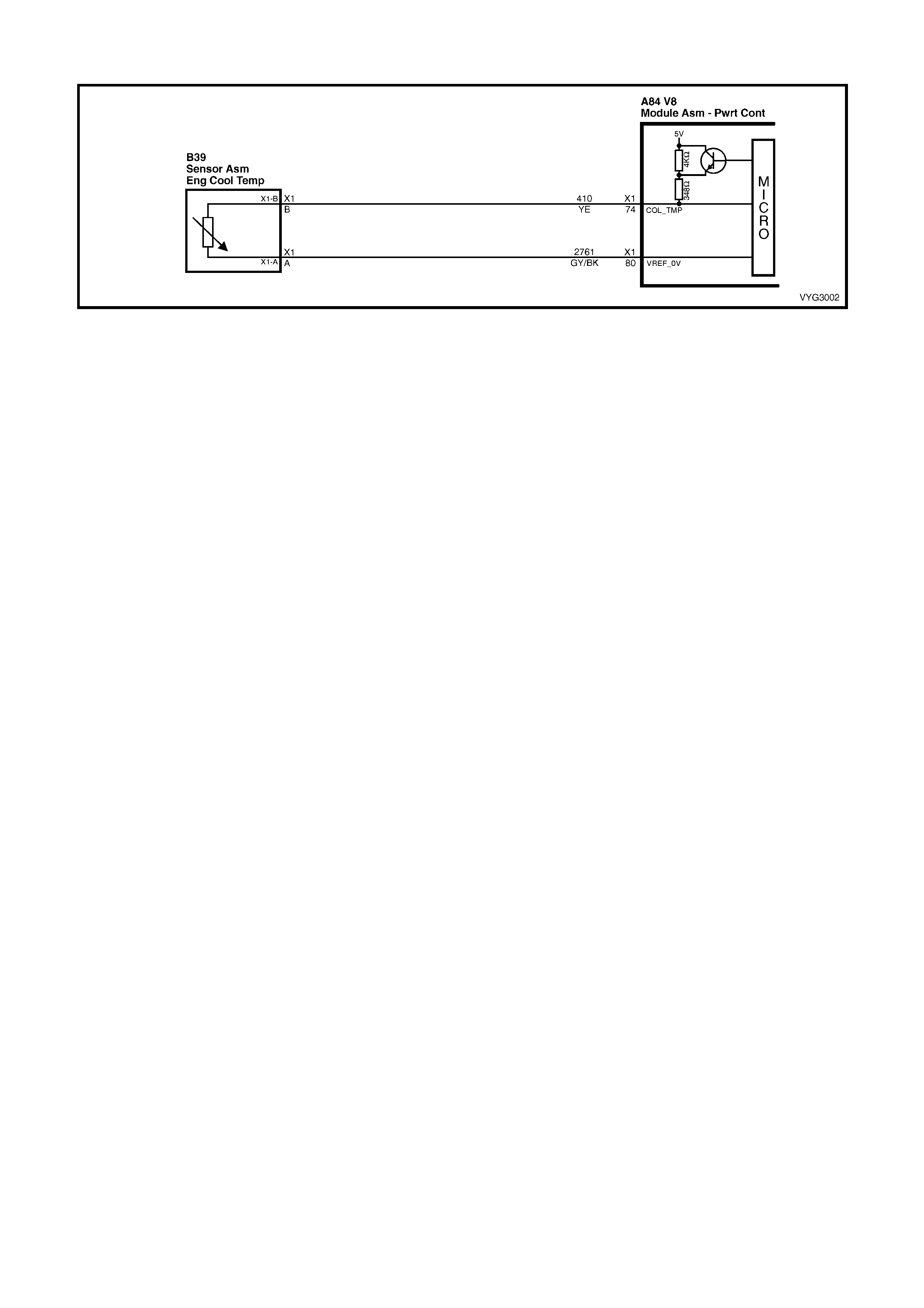
GEN III V8 PCM – DTC P1258 ENGINE COOLANT OVER TEMP FUEL DISABLED
Figure 6C3-2A-186 – Coolant Temperature Sensor Circuit
CIRCUIT DESCRIPTION
In order to reduce the engine temperature, the PCM has the ability to disable a number of fuel injectors during an
engine over temperatur e condition. T he PCM consi ders the engin e over tem perature whenev er the ECT reac hes a
predetermined tem perature. This DTC sets in order to show that the PCM detected an over temperature condition
and that the system engaged the protection mode.
CONDITION FOR RUNNING THE DTC
• DTCs P0117, P0118, are not set.
• The engine is running.
CONDITION FOR SETTING THE DTC
• The engine coolant temperature is greater than 132° C.
• The above conditions present for greater than 10 seconds.
ACTION TAKEN WHEN THE DTC SETS
• The PCM will randomly disable several injectors.
• The PCM activates the Check Powertrain MIL when the diagnostic runs and fails.
• The PCM records the operating conditions at the time the diagnostic fails. The PCM stores this information in
the Freeze Frame/Failure Records.
CONDITIONS FOR CLEARING THE MIL/DTC
• The PCM deactivates the Check Powertrain MIL when the diagnostic runs and does not fail.
• A last test failed (current DTC) clears when the diagnostic runs and does not fail.
• Use Tech 2 to clear the MIL/DTC.
DIAGNOSTIC AIDS
IMPORTANT: If an overheating condition exists, repair the overheat condition and change the engine oil and filter.
• Using the Freeze Frame/Failure Records data may aid in locating an intermittent condition. The Fail Counter
and Pass Counter c an als o help det erm ine ho w man y ignition c ycles the diag nosti c repor ted a pass and/or fail.
Operate the vehicle within the same freeze frame condition (RPM, load, vehicle speed, temperature etc.) that
you observed . This will isol ate when the DT C failed.
IMPORTANT: For any test that requires probing the PCM or component harness connectors, use the Connector
Test Adaptor Kit J 35616-A. Using this kit prevents any damage to the harness connector terminals.
• For an intermittent, refer to Section 6C3-2B SY MPTOM S.
TEST DESCRIPTION
NOTE: The number(s) below refer to the step number(s) on the diagnostic table.
2. A cooling system problem will enable the engine protection mode. Refer to Section 6B3 ENGINE COOLING,
for further diagnosis.

GEN III V8 PCM – DTC P1258 ENGINE COOLANT OVER TEMP FUEL DISABLED
STEP ACTION VALUE YES NO
1. Was the "On-Board Diagnostic" (OBD) System Check
performed? Go to Step 2 Go to
OBD System
Check
in this Section.
2. 1. Select the Diagnostic Trouble Code (DTC) option, the
DTC Information option and the Failed This Ignition
option using Tech 2.
Does Tech 2 display any DTCs related to the Engine
Coolant Temperature (ECT) sensor that you have not
diagnosed?
Go to the
applicable DTC Go to
Section 6B3
ENGINE
COOLING.

GEN III V8 PCM – DTC P1539 A/C CLUTCH STATUS CIRCUIT HIGH VOLTAGE
Figure 6C3-2A-187 – Air Conditioning Compressor Clutch Circuit
CIRCUIT DESCRIPTION
The PCM ac tivates the A/C c lutch relay when the PC M detects an A/C request. Voltage is pres ent at both the A/C
compressor clutch and the A/C clutch status terminal at the PCM when the relay is activated.
A DTC P1539 sets if the PCM detects voltage on the A/C clutch status terminal when the system has not requested
the A/C.
A short to voltage at any point in the A/C status circuit, or the A/C relay contacts being stuck, sets a DTC P1539.
CONDITIONS FOR RUNNING THE DTC
• The A/C clutch is not requested.
CONDITIONS FOR SETTING THE DTC
• Vol tage is detect ed on the A/C stat us circuit f or more than 15 s econds after the PCM has dis engaged the A/C
clut ch relay.
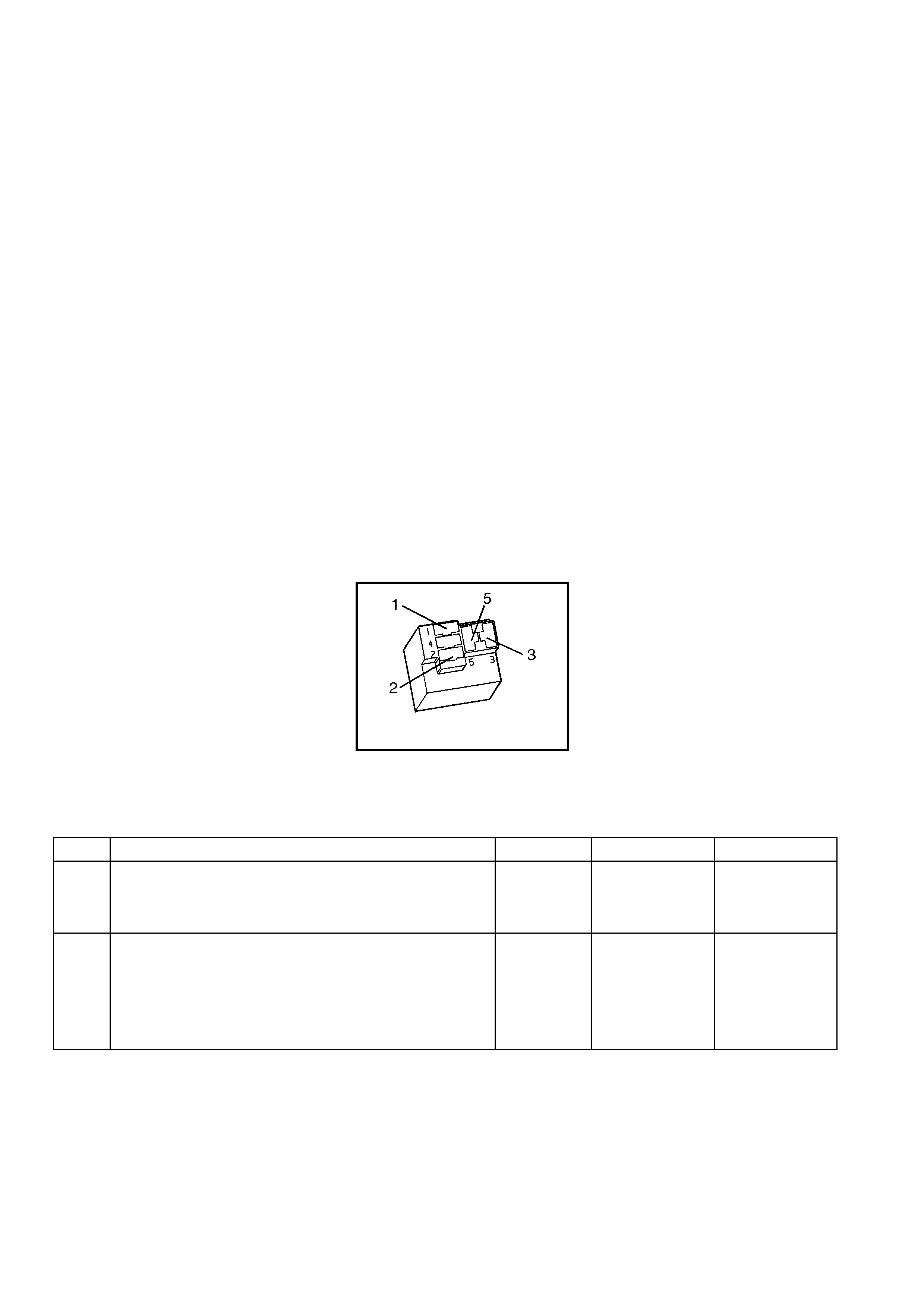
ACTION TAKEN WHEN THE DTC SETS
• The PCM stores the DTC information into memory when the diagnostic runs and fails.
• The Check Powertrain MIL will not be activated.
• The PCM records the operating conditions at the time the diagnostic fails. The PCM stores this information in
the Freeze Frame/Failure Records.
CONDITIONS FOR CLEARING THE MIL/DTC
• A last test failed (current DTC) clears when the diagnostic runs and does not fail.
• Use Tech 2 to clear the MIL/DTC.
DIAGNOSTIC AIDS
• T he A/C status c ircuit goes to the A/C com press or clutch and to the PCM from the A/C clutch rel ay. Inspect all
circuits going to these components.
• For an intermittent, refer to Section 6C3-2B SY MPTOM S.
TEST DESCRIPTION
NOTE: The number(s) below refer to the step number(s) on the diagnostic table.
2. If the PCM detects a voltage on the A/C status circuit with the A/C OFF, Tech 2 indicates the A/C status as ON.
3. If Tech 2 displayed YES in the RAN column and INT in the FAIL column, this indicates an intermittent
condition is present. Inspect the A/C status circuit for an intermittent short to B+. (Refer to
Section 6C3-2B SYMPTOMS). Using the Freeze Frame/Failure Records data aids in locating an intermittent
conditio n. The Fai l Counter and th e Pass Count er can also be used t o determ ine how m any ignition c ycles the
diagnostic reported a pass and/or a fail. Operate the vehicle within the same freeze frame condition (RPM,
load, vehicle speed, temperature etc.) that the PCM recorded. This will isolate when the DTC failed.
4. The relay is shorted internally if Tech 2 indicates that the test passed.
7. T his DTC will not report a pass . Status for this DT C will never report a pass. T ech 2 will onl y displa y when the
diagnostic fails. The repair is not complete if Tech 2 indicates that the diagnostic ran and failed.
X11 (PART OF X100)
Figure 6C3-2A-188
GEN III V8 PCM – DTC P1539 A/C CLUTCH STATUS CIRCUIT HIGH VOLTAGE
STEP ACTION VALUE YES NO
1. Was the "On-Board Diagnostic" (OBD) System Check
performed? Go to Step 2 Go to
OBD System
Check
in this Section.
2. IMPORTANT: Diagnose DTC P1546 first if it is set.
1. Install Tech 2.
2. Run the engine at idle, with the A/C OFF.
3. Monitor the A/C Status display on the Engine Data List
using Tech 2.
Does Tech 2 indicate the A/C Status is ON?
Go to Step 4 Go to Step 3

STEP ACTION VALUE YES NO
3. 1. Ignition ON, engine OFF.
2. Review the Freeze Frame/Failure Records data for this
DTC and observe the parameters.
3. Turn OFF the ignition for 15 seconds.
4. Run the engine at idle.
5. Operate the vehicle, within the conditions required for
this diagnostic to run, and as close to the conditions
recorded in the Freeze Frame/Failure Records as
possible. Special operating conditions that need to be
met before the PCM will run this diagnostic, where
applicable, are listed in Conditions for Running the
DTC.
6. Select the Diagnostic Trouble Code (DTC) option, the
DTC Information option and the Failed This Ignition
option using Tech 2.
Does Tech 2 indicate that this diagnostic failed this
ignition?
Go to Step 4 Refer to
Diagnostic Aids
4. 1. Ignition OFF.
2. Remove the A/C clutch relay, X11.
3. Run the engine at idle for 30 seconds.
4. Monitor the Failed This Ignition option under the DTC
Informat ion option usin g Tech 2.
Does Tech 2 indicate that DTC P1539 failed?
Go to Step 5 Go to Step 6
5. 1. Repair the short to B+ on the A/C clutch status circuit.
Is the action complete? Go to Step 7 –
6. 1. Replace the faulty A/C clutch relay, X11.
Is the action complete? Go to Step 7 –
7. 1. Select the Diagnostic Trouble Code (DTC) option, then
Clear DTC Information, using Tech 2.
2. Idle the engine at normal operating temperature.
3. Select the Diagnostic Trouble Code (DTC) option, the
DTC Information option and the Failed This Ignition
option using Tech 2.
4. Operate the vehicle, within the Conditions for Running
the DTC, as specified in the supporting text, if
applicable.
Does Tech 2 indicate that this DTC reset?
Go to Step 2 Go to Step 8
8. 1. Using Tech 2, check for any other DTCs.
Does Tech 2 display any DTCs that you have not
diagnosed?
Go to the
applicable DTC
table
System OK
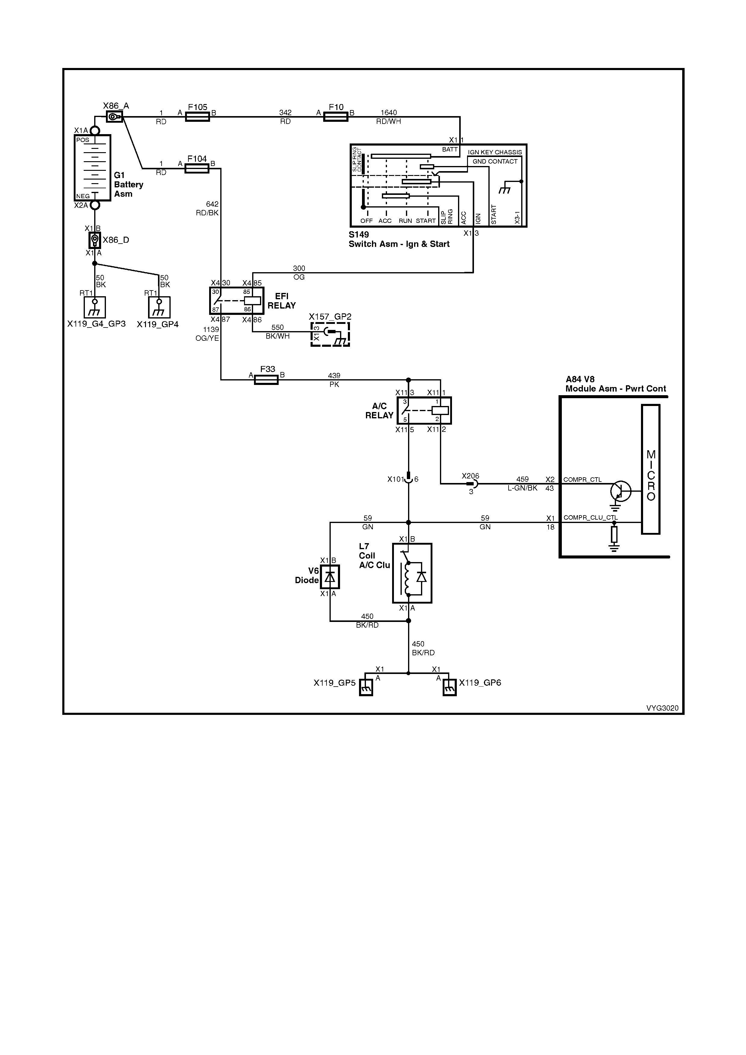
DTC P1546 A/C CLUTCH STATUS CIRCUIT LOW VOLTAGE
Figure 6C3-2A-189 – Air Conditioning Compressor Clutch Circuit
CIRCUIT DESCRIPTION
The PCM will activate the A/C clutch relay when the PCM detects that A/C has been requested. When the PCM
activates the re lay, voltag e s houl d be pres en t at bot h t he A /C c ompres s or c lutch and t he A/C c l utc h status c ir c uit at
the PCM.
CONDITIONS FOR RUNNING THE DTC
• The A/C clutch is requested.
CONDITIONS FOR SETTING THE DTC
• The PCM c om mands the A /C O N and t he PCM does n ot det ec t a volt age on the A /C c lutch s tat us li ne f or more
than five seconds.
ACTION TAKEN WHEN THE DTC SETS
• The PCM stores the DTC information into memory when the diagnostic runs and fails.
• The Check Powertrain MIL will not be activated.
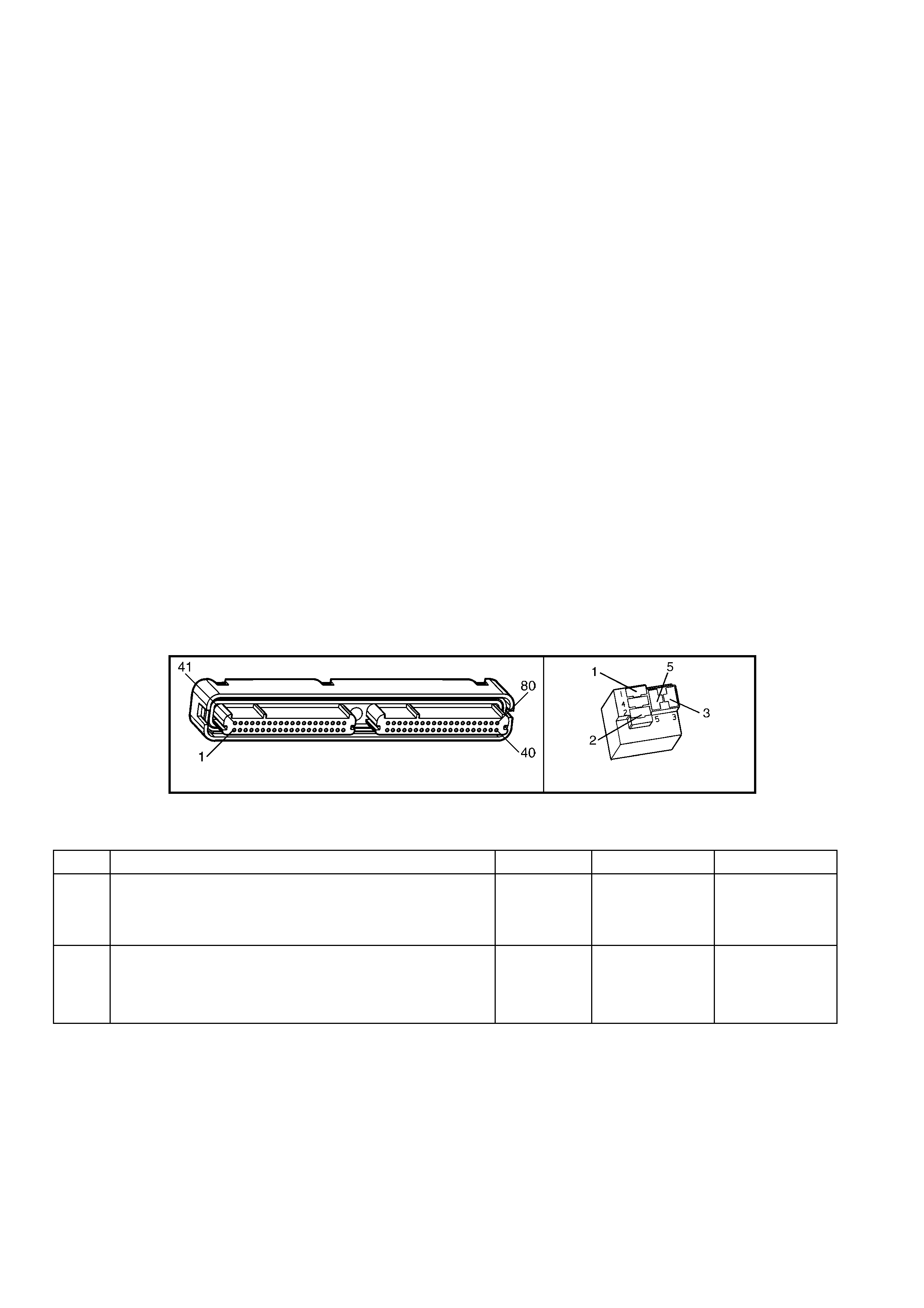
• The PCM records the operating conditions at the time the diagnostic fails. The PCM stores this information in
the Freeze Frame/Failure Records.
CONDITIONS FOR CLEARING THE MIL/DTC
• A last test failed (current DTC) clears when the diagnostic runs and does not fail.
• Use Tech 2 to clear the MIL/DTC.
DIAGNOSTIC AIDS
Before replacing any components, check for the following:
• Incorrectly routed harness.
• Rubbed through wire insulation.
• Broken wire inside the insulation.
• For an intermittent, refer to Section 6C3-2B SY MPTOM S.
TEST DESCRIPTION
NOTE: The number(s) below refer to the step number(s) on the diagnostic table.
2. This step checks the operation of the A/C compressor clutch. The PCM disables the A/C compressor clutch
when this DTC is set.
3. Using the Freeze Frame/Failure Records data may aid in locating an intermittent condition. The Fail Counter
and Pass Counter c an als o help det erm ine ho w man y ignition c ycles the diag nosti c repor ted a pass and/or fail.
Operate the vehicle within the same freeze frame condition (RPM, load, vehicle speed, temperature etc.) that
you observed . This will isol ate when the DT C failed.
4. This step checks whether the ignition voltage is available at the relay.
5. This step determines if the A/C r elay is at fault or the A /C s tatus c irc uit is at f ault. If the A/C c lutc h en gag es, thi s
indicates that the A/C Status circuit is OK.
6. If the A/C Status is displayed as OFF, this indicates the A/C status circuit is open between the splice and the
PCM. If the A/C Status is displayed as ON, this ind icates a f aulty connecti on at the A/C com pressor r elay or a
faulty relay.
12. This DTC will not report a pass. Tech 2 status for this DTC will never report a pass. Tech 2 will only display
when the diagnostic fails. The repair is not complete if Tech 2 indicates that the diagnostic ran and failed.
A84–X2 (RED) X11 (PART OF X100)
Figure 6C3-2A-190
GEN III V8 PCM – DTC P1546 A/C CLUTCH STATUS CIRCUIT LOW VOLTAGE
STEP ACTION VALUE YES NO
1. Was the "On-Board Diagnostic" (OBD) System Check
performed? Go to Step 2 Go to
OBD System
Check
in this Section.
2. 1. Install Tech 2.
2. Run the engine at idle, with the A/C ON, for the
specified length of time.
Does the A/C clutch operate properly?
5 minutes Go to Step 3 Go to Step 4

STEP ACTION VALUE YES NO
3. 1. Ignition ON, engine OFF.
2. Review Freeze Frame/Failure Records data for DTC
and note parameters.
3. Turn OFF the ignition for 15 seconds.
4. Run the engine at idle.
5. Operate the vehicle, within the conditions required for
this diagnostic to run, and as close to the conditions
recorded in Freeze Frame/Failure Records as
possible. Special operating conditions that you need to
meet before the PCM will run the diagnostic, where
applicable, are listed in Conditions for Setting the DTC.
6. Select the Diagnostic Trouble Code (DTC) option, the
DTC Information option and the Failed This Ignition
option using Tech 2.
Does Tech 2 indicate that this diagnostic failed this
ignition?
Go to Step 4 Refer to
Diagnostic Aids
4. 1. Ignition OFF.
2. Disconnect the A/C clutch relay, X11.
3. Ignition ON, engine OFF.
4. Probe the ignition feed circuit, at the A/C relay terminal
(switch side of relay), with a test lamp to ground.
Does the test lamp illuminate?
Go to Step 5 Go to Step 9
5. 1. Jump the ignition feed circuit to the A/C clutch status
circuit (load), at the engine compartment fuse & relay
panel, using a fused jumper wire.
Does the A/C clutch engage?
Go to Step 6 Go to Step 10
6. 1. Monitor the A/C Status display on the Engine Data List
using Tech 2 with the fused jumper still installed.
Does Tech 2 indicate the A/C Status as ON?
Go to Step 7 Go to Step 8
7. 1. Repair the faulty A/C clutch relay connection or faulty
A/C clutch relay.
Is the action complete?
Go to Step 12 –
8. 1. Check for an open A/C clutch status circuit from the
splice to the PCM.
Did you find and repair the condition?
Go to Step 12 Go to Step 11
9. 1. Repair the open ignition feed circuit to A/C relay.
Is the action complete? Go to Step 12 –
10. 1. Repair the open in A/C status circuit form the A/C relay
to splice.
Is the action complete?
Go to Step 12 –
11. 1. Replace PCM. Refer to PCM Programming and
PCM/PIM/BCM Security Link Procedure, in 6C3-3
SERVICE OPERATIONS.
Is action complete?
Go to Step 12 –
12. 1. Select the Diagnostic Trouble Code (DTC) option and
the Clear DTC Information option using Tech 2.
2. Idle the engine at normal operating temperature.
3. Select the Diagnostic Trouble Code (DTC) option, the
DTC Information option and the Failed This Ignition
option using Tech 2.
4. Operate the vehicle, within the Conditions for Running
the DTC, as specified in the supporting text, if
applicable.
Does Tech 2 indicate that this DTC reset?
Go to Step 2 Go to Step 13
13. 1. Using Tech 2, check for any other stored DTCs.
Does Tech 2 display any DTCs that you have not
diagnosed?
Go to the
applicable DTC
table
System OK
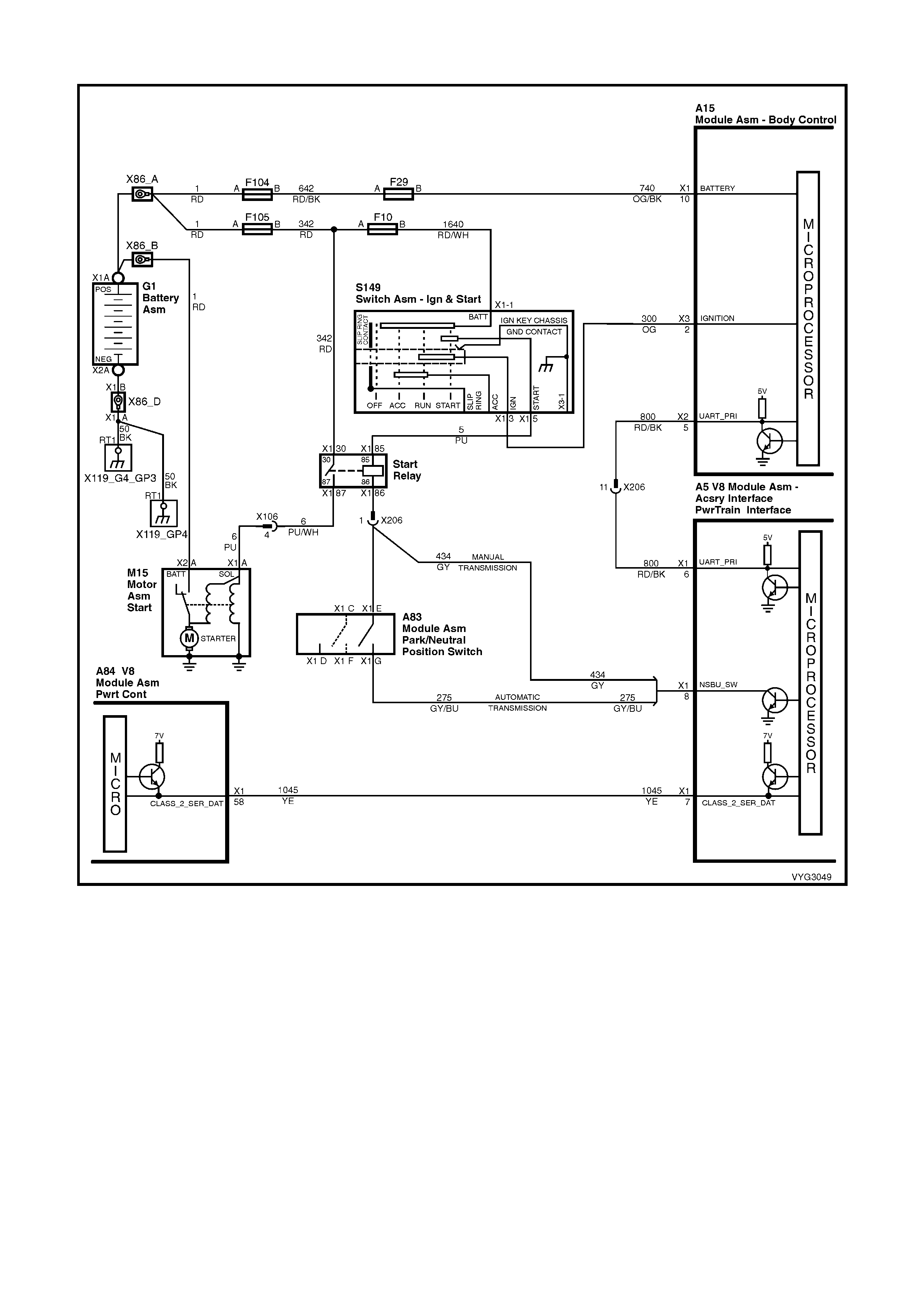
GEN III V8 PCM – DTC P1626 THEFT DETERRENT SYSTEM FUEL ENABLE CIRCUIT
Figure 6C3-2A-191 – Theft Deterrent System, Fuel System Enable Circuit
CIRCUIT DESCRIPTION
The Vehicle Theft Deterrent (VTD) system consists of the following components:
• Powertrain Control Module (PCM)
• Powertrain Interface Module (PIM)
• Body Control Module (BCM)
• Remote Receiver Module
After the Bod y Control M odu le (BCM) has conf irm ed the corr ect ke y has been used, the BC M sends a pass word to
the PIM via the U ART Serial Dat a circuit. The PIM will operate the star ter motor, and supp ly another pass word via
Class II Serial Data to the PCM. When this password matches the password stored in the PCM, the system
enables the fuel injection. If the BCM does not send a password or if the PCM does not receive it, th e vehicle will
not start unless the PCM is in VTD Fail-Enable mode.
If the BCM an d PCM lose c om m unications with each o ther af ter the s ystem has receiv ed the correc t pass word, the
PCM goes into VTD Fail-Enable mode. This allows the driver to restart the vehicle on future ignition cycles until
communications between the BCM and PCM are restored. If the BCM and PCM lose communication before the
PCM receives the BCM password, the PCM disables the fuel injection until communication is restored in order to

prevent vehicle theft. In both cases DTC P1626 sets. The PCM will not disable the fuel injection once the PCM
enables the fuel within a given ignition cycle in order to prevent stalling as a result of theft deterrent system faults.
CONDITIONS FOR RUNNING THE DTC
• The engine is cranking.
CONDITIONS FOR SETTING THE DTC
• The system has reached fuel enable decision point.
• The PCM is in Fail Enable Mode due to loss of communication with the PIM after the system received the
correct password earlier in the ignition cycle.
• The PCM does not receive the password message from the PIM prior to the theft deterrent Fuel Decision Point.
ACTION TAKEN WHEN THE DTC SETS
• The PCM enables the fuel injection on future ignition cycles only if the PCM is in Fail-Enable Mode.
• The PCM activates the Check Powertrain MIL when the diagnostic runs and fails.
NOTE: This DTC is usually set if communication is lost. The Check Powertrain MIL may not operate.
• The PCM records the operating conditions at the time the diagnostic fails. The PCM stores this information in
the Freeze Frame/Failure Records.
CONDITIONS FOR CLEARING THE MIL/DTC
• T he PCM deactivates the Check Powertrain MIL after one ignition c ycle that the diagnostic runs and does not
fail.
• A last test failed (current DTC) clears when the diagnostic runs and does not fail.
• Use Tech 2 to clear the MIL/DTC.
DIAGNOSTIC AIDS
• T he m ost likel y cause of D TC P162 6 is a loss of serial d ata com munic ation from the PIM to PCM. Check for a
loss of power or ground to the PIM or for other causes of communication loss. Check for the following:
- Open Class II circuit
- Grounded Class II circuit
- Shorted to voltage Class II circuit
- PIM ignition feed fault
- PIM ground fault
• If there is a problem on the Class II c ircuit, the P IM shoul d set a DT C B2006. Al ways check for this DT C when
P1626 is set.
• Using the Freeze Frame/Failure Records data may aid in locating an intermittent condition.
• T he Fail Count er and Pass Counter ca n also he lp deter mine how m any ignition cycles the diagnos tic report ed
a pass and/or fail. Operate the vehicle within the same freeze frame condition (RPM, load, vehicle speed,
temper atur e etc.) that you observe d. This will iso lat e when the DT C failed.
• For an intermittent, refer to Section 6C3-2B SY MPTOM S.
TEST DESCRIPTION
NOTE: The number(s) below refer to the step number(s) on the diagnostic table.
2. An eng ine that does not start and a DT C P1626 tha t is set, indic ates that there is a Class II Serial Data c irc uit
problem. There may be several PIM DTCs set if the Class II Serial Data circuit has malfunctioned.
3. If both PCM DTC P1626, and P1630 are set, check for a fault with either the PIM power feed or PIM ground
circuits.
4. An engine that does not crank indicates there is a problem with the Body Control Module or the Powertrain
Interface Module. If a BCM or PIM DTCs are set, refer to that DTC for diagnosis.
A84–X1 (BLUE) A5
Figure 6C3-2A-192

GEN III V8 PCM – DTC P1626 THEFT DETERRENT SYSTEM FUEL ENABLE CIRCUIT
STEP ACTION VALUE YES NO
1. Was the "On-Board Diagnostic" (OBD) System Check
performed? Go to Step 2 Go to
OBD System
Check
in this Section.
2. 1. Crank the engine.
Does the engine crank and run? Go to Step 9 Go to Step 3
3. 1. Using Tech 2, check for PCM DTC P1626, and P1630.
Are both DTCs set? Go to Step 5 Go to Step 4
4. Are any PIM DTCs set?
Go to
appropriate PIM
DTC
Go to Step 7
5. 1. Ignition OFF.
2. Remove PIM connector, A5.
3. Check for open, or short to ground in power feed and
ground circuits to PIM.
Was a problem found?
Go to Step 9 Go to Step 6
6. 1. Replace PIM. Refer 6C3-3 SERVICE OPERATIONS.
Is action complete? Go to Step 9 –
7. 1. Check for poor connection in Class II Serial Data
circuit from PCM to PIM.
Was a problem found?
Go to Step 8 Go to Step 9
8. 1. Repair open, short to ground, or short to voltage in
Class II Serial Data circuit.
Is action complete?
Go to Step 9 –
9. 1. Select the Diagnostic Trouble Code (DTC) option and
the Clear DTC Information option using Tech 2.
2. Idle the engine at normal operating temperature.
3. Select the Diagnostic Trouble Code (DTC) option, the
DTC Information option and the Failed This Ignition
option using Tech 2.
4. Operate the vehicle, within the Conditions for Running
the DTC, as specified in the supporting text, if
applicable.
Does Tech 2 indicate that this DTC reset?
Go to Step 2 Go to Step 10
10. 1. Using Tech 2, check for any other DTCs.
Does Tech 2 display any DTCs that you have not
diagnosed?
Go to the
applicable DTC
table
System OK
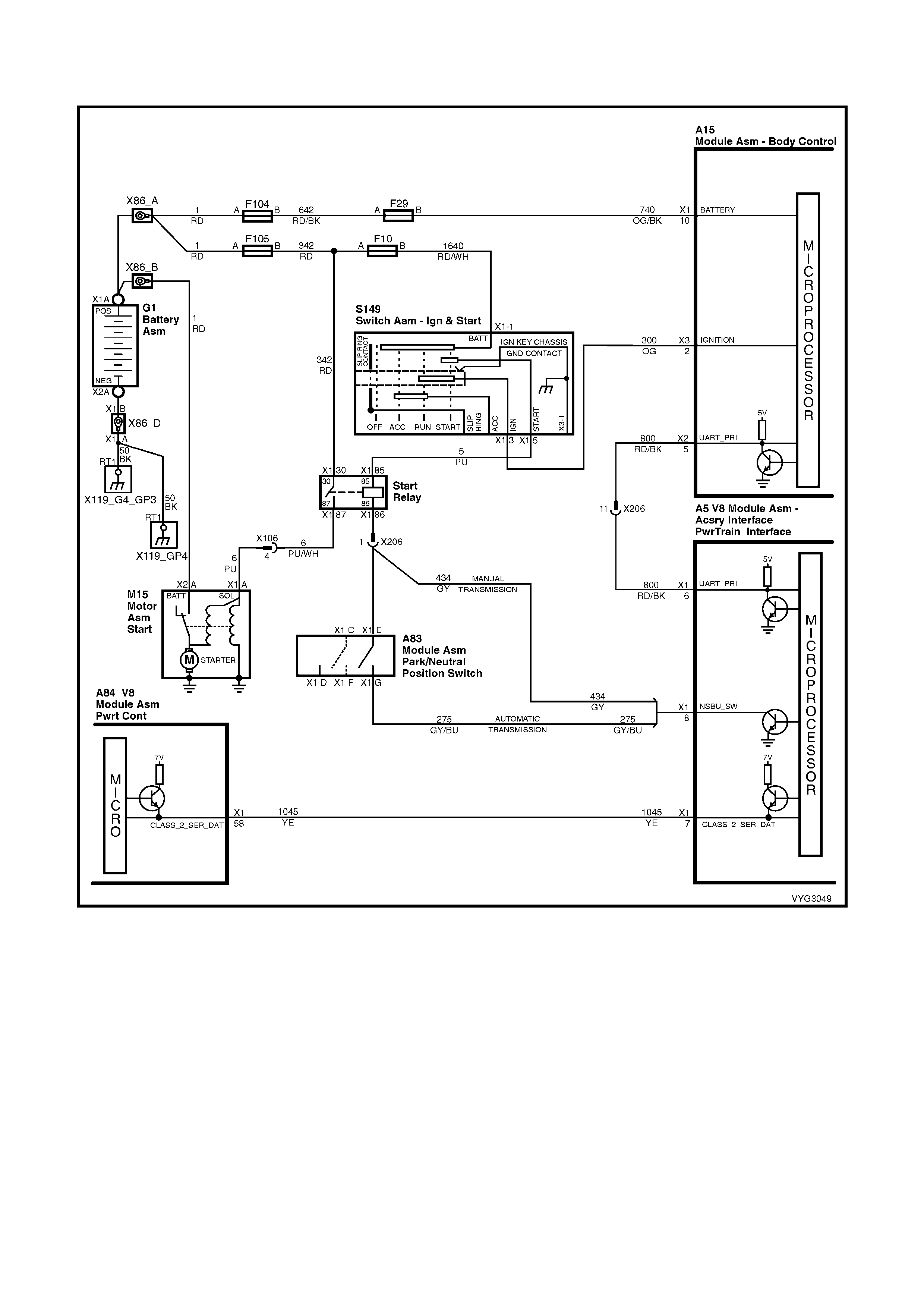
GEN III V8 PCM – DTC P1630 THEFT DETERRENT POWERTRAIN CONTROL
MODULE IN LEARN MODE
Figure 6C3-2A-193 – Theft Deterrent System, Fuel System Enable Circuit
CIRCUIT DESCRIPTION
This diagnostic test ch ecks f or the En able Pas sword L earning F lag ind icating the PCM is in learn pas sword mode.
This mode allo ws the PC M to learn th e pass word f rom the P owertr ain I nterf ace M odule (PI M) at ass em bly or when
serviced. The password needs to be learned whenever the PCM, or the PIM is replaced.
CONDITIONS FOR RUNNING THE DTC
• The PCM is in the learn password mode.
CONDITIONS FOR SETTING THE DTC
• The PCM is ready to learn a new password from the PIM, but the PIM is not sending a valid password or not
sending a password at all.

ACTION TAKEN WHEN THE DTC SETS
• The engine cranks but may not start.
• The PCM activates the Check Powertrain MIL when the diagnostic runs and fails.
• The PCM records the operating conditions at the time the diagnostic fails. The PCM stores this information in
the Freeze Frame/Failure Records.
CONDITION FOR CLEARING THE MIL/DTC
• The PCM deactivates the Check Powertrain MIL after one ignition c ycle that the diagnostic runs and does not
fail.
• A last test failed (current DTC) clears when the diagnostic runs and does not fail.
• Use Tech 2 to clear the MIL/DTC.
DIAGNOSTIC AIDS
• The PCM in learn mode is a DTC for servicing personnel, as an indication that the system has enabled the
learn m ode. This means the PCM is no w read y to lear n a new passwor d from the PIM. T his DTC set becaus e
the PIM never sent a valid password to the PCM while in learn mode. When this occurs, the vehicle is
vulnerable to vehicle theft.
• Also, if there is a problem with the UART serial data line between the BCM and PIM, this may cause this
condition.
• Inspect the BCM for DTCs that may apply to the UART circuit. If any are found, refer to these DTCs first.
• If both PCM DT Cs P1626, and P163 0 are set, c heck PIM power feed and grou nd c ircuits for opens or shorts. If
a problem was found with PIM ground circuit, repair ground circuit, then power down PCM (key OFF) for 30
seconds. Key ON and retest.
TEST DESCRIPTION
NOTE: The number(s) below refer to the step number(s) on the diagnostic table.
2. If both PCM DTC P1626, and P1630 are set, check for a fault with either the PIM power feed or PIM ground
circuits.
5. If a PIM, or BCM was replaced and were not linked, this may set the DTC. Performing the link procedure will
assure that all controllers are linked together.
A5
Figure 6C3-2A-194
GEN III V8 PCM – DTC P1630 THEFT DETERRENT POWERTRAIN CONTROL MODULE IN LEARN MODE
STEP ACTION VALUE YES NO
1. Was the "On-Board Diagnostic" (OBD) System Check
performed? Go to Step 2 Go to
OBD System
Check
in this Section.
2. 1. Using Tech 2, check for DTC P1626, and P1630.
Are both DTCs set? Go to Step 3 Go to Step 5
3. 1. Ignition OFF.
2. Remove PIM connector, A5.
3. Check for open or short to ground in power feed and
ground circuits to PIM.
Was a problem found and verified?
Go to Step 6 Go to Step 4
4. 1. Replace PIM. Refer 6C3-3 SERVICE OPERATIONS.
Is action complete? Go to Step 6 –

STEP ACTION VALUE YES NO
5. 1. Using Tech 2, link PCM to PIM. Refer to PCM
Programming and PCM/PIM/BCM Security Link
Procedure, in 6C3-3 SERVICE OPERATIONS.
2. Attempt to start vehicle.
Does vehicle crank and start?
Go to Step 6 Go to
Diagnostics, in
12J BODY
CONTROL
MODULE
6. 1. Select the Diagnostic Trouble Code (DTC) option and
the Clear DTC Information option using Tech 2.
2. Idle the engine at normal operating temperature.
3. Select the Diagnostic Trouble Code (DTC) option, the
DTC Information option and the Failed This Ignition
option using Tech 2.
4. Operate the vehicle, within the Conditions for Running
the DTC, as specified in the supporting text, if
applicable.
Does Tech 2 indicate that this DTC reset?
Go to Step 2 Go to Step 7
7. 1. Using Tech 2, check for any other DTCs
Does Tech 2 display any DTCs that you have not
diagnosed?
Go to the
applicable DTC
table
System OK

GEN III V8 PCM – DTC P1631 THEFT DETERRENT PASSWORD INCORRECT
Figure 6C3-2A-195 – Theft Deterrent System Circuit
CIRCUIT DESCRIPTION
This test checks for mismatched passwords between the PIM and PCM. Whenever replacing the PIM or PCM,
follow the Theft Learn procedure in order for the sy stem to learn the new password.
CONDITIONS FOR RUNNING THE DTC
• The ignition is on and the PCM is waiting for the correct password.
CONDITIONS FOR SETTING THE DTC
• The PCM detects an incorrect password from the PIM.
ACTION TAKEN WHEN THE DTC SETS
• The engine cranks but may not start.
• The PCM activates the Check Powertrain MIL when the diagnostic runs and fails.
• The PCM records the operating conditions at the time the diagnostic fails. The PCM stores this information in
the Freeze Frame/Failure Records.

CONDITIONS FOR CLEARING THE MIL/DTC
• T he PCM deactivates the Check Powertrain MIL after one ignition c ycle that the diagnostic runs and does not
fail.
• A last test failed (current DTC) clears when the diagnostic runs and does not fail.
• Use Tech 2 to clear the MIL/DTC.
DIAGNOSTIC AIDS
IMPORTANT: Remove any debris from the PCM module connector surfaces before servicing the PCM module.
• T he PCM in learn mode is a DTC for the personnel at the assembly plant, dealership, and the outside garage
as an indication that the system enables the learn mode. This means the PCM is now ready to learn a new
password from the PIM while in the learn mode. When this occurs, the vehicle is vulnerable to vehicle theft.
• If using Tech 2 and TIS for password linking, refer to BCM mode of Tech 2 for linking procedure. This Tech 2
operation will take approximately 2 minutes to perform. If no Tech 2 and TIS is available, the following DTC
P1631 diagnostic table must be followed.
TEST DESCRIPTION
NOTE: The number(s) below refer to the step number(s) on the diagnostic table.
2. The tim e criteria is a minimum required amount of time. The time lim it can exceed this lim it without interfering
with the Auto Learn Pr ocedur e. Use Tec h 2 (Auto Lear n Timer equals Inacti ve) in order to determ ine when th e
1 hour has expired.
4. If DTC P1631 is set, this indicates that you did not follow the procedure correctly. Perform the Re-learn
procedure aga in.
GEN III V8 PCM – DTC P1631 THEFT DETERRENT PASSWORD INCORRECT
STEP ACTION VALUE YES NO
1. Was the "On-Board Diagnostic" (OBD) System Check
performed? Go to Step 2 Go to
OBD System
Check
in this Section.
2. IMPORTANT NOTES:
• Check for any Theft Deterrent BCM or PIM DTCs
being set before proceeding with this table. If a BCM or
PIM DTC is set, refer to the appropriate DTC.
• Maintain the battery voltage while the PCM is in the
Learn Procedure. Follow this procedure exactly as
indicated or you will have to repeat the procedure from
the beginning.
• Performing the following procedure causes a DTC
P1630 to set when you complete the procedure. This
is the intended functionality. When P1630 sets, turn
OFF the ignition for 30 seconds, then turn ON the
ignition and P1630 clears. If the DTC P1630 does not
clear, go to the DTC P1630 table.
NOTE: Ensure the battery is fully charged.
1. Turn the ignition ON, leaving the engine OFF, for 3
hours and 10 minutes.
2. Turn ignition OFF for 30 seconds.
3. Turn the ignition ON, leaving the engine OFF, for 1
hour and 10 minutes.
4. Turn ignition OFF for 30 seconds.
5. Turn the ignition ON, leaving the engine OFF, for 1
hour and 10 minutes or until DTC P1630 sets.
6. Turn ignition OFF for 30 seconds.
7. Turn the ignition ON, leaving the engine OFF, for 1
hour and 10 minutes.
8. Turn ignition OFF for 30 seconds.
9. Turn the ignition ON, leaving the engine OFF, and wait
30 seconds.
10. Attempt to start the engine.
Does the engine start and operate normally?
Go to Step 3 Go to Step 4

STEP ACTION VALUE YES NO
3. IMPORTANT: Monitor all DTC status parameters and note
any additional DTCs before Clearing DTCs.
1. Clear the PCM DTCs.
2. Turn OFF the ignition for 30 seconds.
3. Attempt to start the engine.
Does the engine start and operate normally?
System OK Go to Step 4
4. 1. Are DTCs P1626, P1630, or P1631 set?
Go to applicable
DTC table Go to Step 2
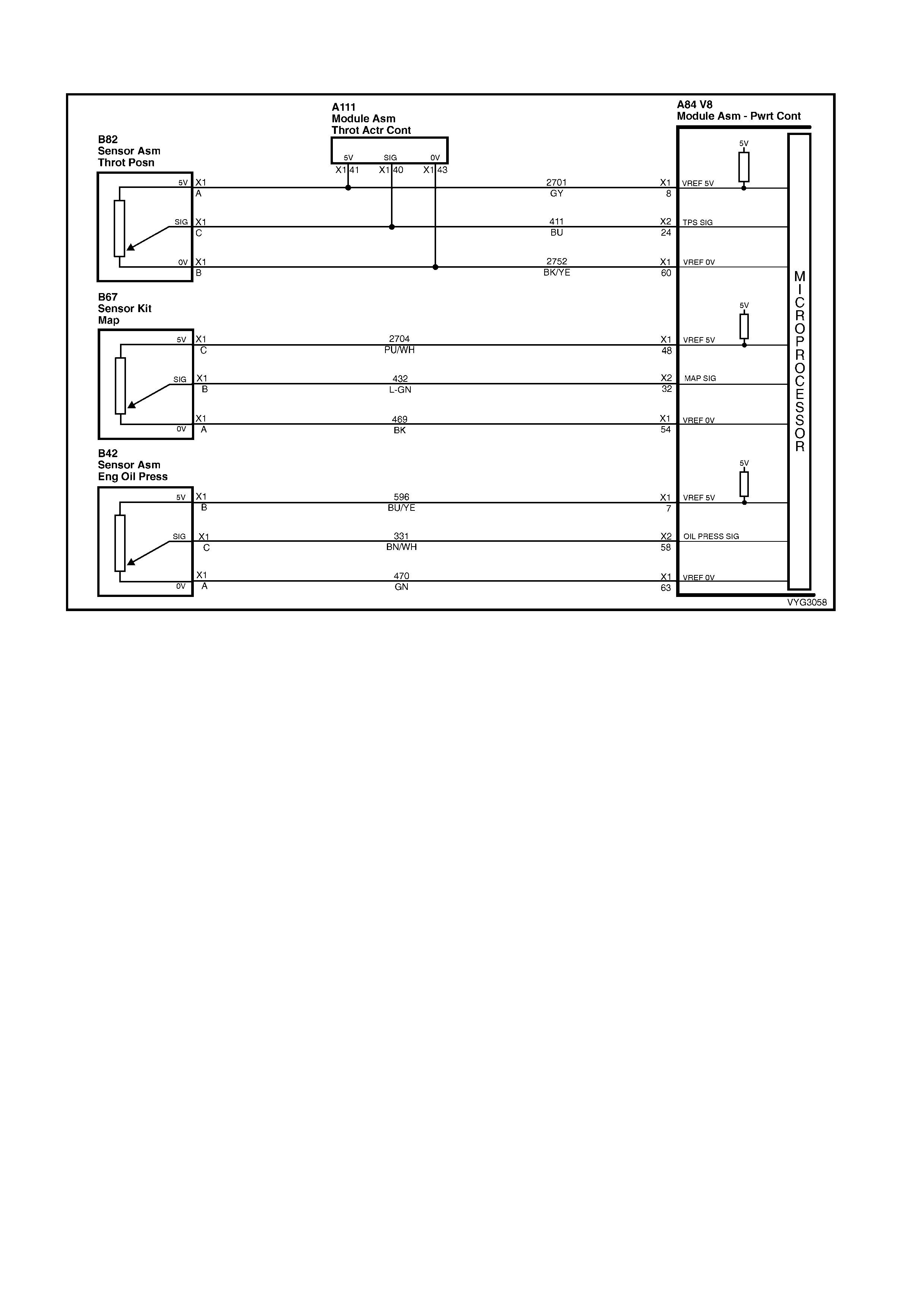
GEN III V8 PCM – DTC P1635 - 5 VOLT REFERENCE #1 CIRCUIT
Figure 6C3-2A-196 – 5 Volt Reference Circuits
CIRCUIT DESCRIPTION
The PCM uses a common 5.0 volt reference circuit as a sensor feed. This circuit supplies 5 volts to the following
sensors:
• TP Sensor
• MAP sensor
• Oil Press ur e Sens or
The PCM monitors the voltage on the 5.0 volt reference circuit. This DTC sets if the voltage is out of range.
CONDITIONS FOR RUNNING THE DTC
• The ignition is ON.
CONDITIONS FOR SETTING THE DTC
• The five volt reference #1 circuit is out of range.
• All of the above conditions are present for greater than 2 seconds.
ACTION TAKEN WHEN THE DTC SETS
• The PCM activates the Check Powertrain MIL when the diagnostic runs and fails.
• The PCM records the operating conditions at the time the diagnostic fails. The PCM stores this information in
the Freeze Frame/Failure Records.
CONDITIONS FOR CLEARING THE MIL/DTC
• T he PCM deactivates the Check Powertrain MIL after one ignition c ycle that the diagnostic runs and does not
fail.
• A last test failed (Current DTC) clears when the diagnostic runs and does not fail.
• Use Tech 2 to clear the MIL/DTC.
DIAGNOSTIC AIDS
• The Throttle Relaxer Control Module is also spliced into the TP circuits. If there is a problem with the Throttle
Relaxer Module or circuits, this could set this DTC. Inspect to determine that this is not causing the problem.
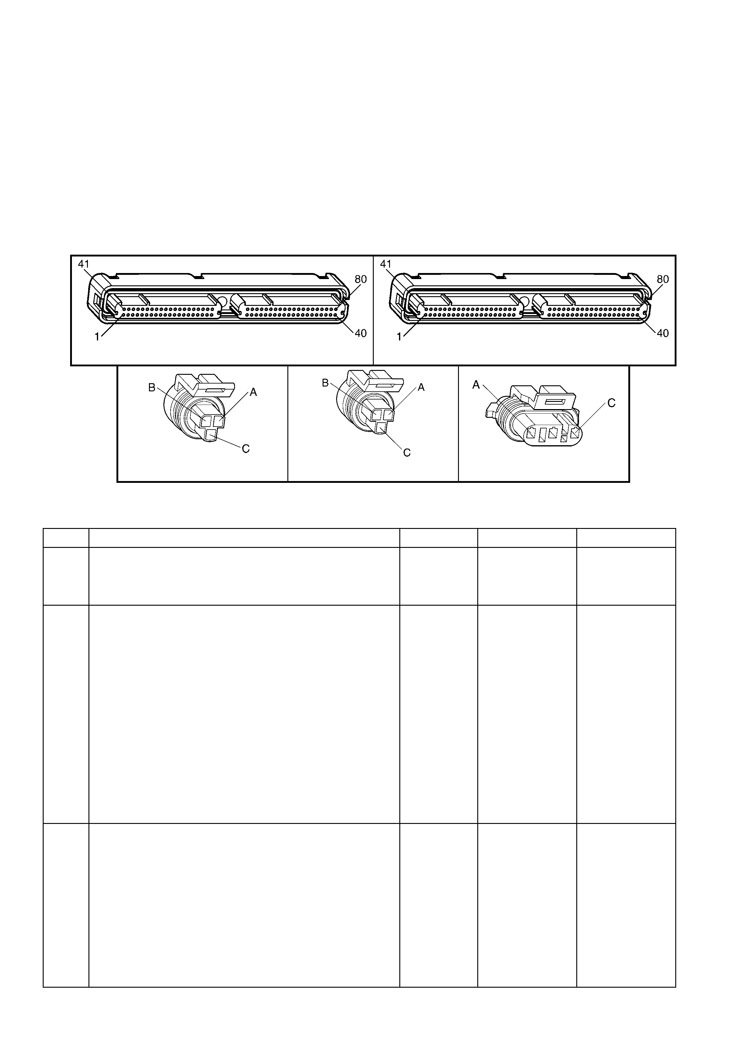
• Using the Freeze Frame/Failure Records data may aid in locating an intermittent condition. The Fail Counter
and Pass Counter c an als o help det erm ine ho w man y ignition c ycles the diag nosti c repor ted a pass and/or fail.
Operate the vehicle within the same freeze frame condition (RPM, load, vehicle speed, temperature etc.) that
you observed . This will isol ate when the DT C failed.
• For an intermittent, refer to Section 6C3-2B SY MPTOM S.
TEST DESCRIPTION
NOTE: The number(s) below refer to the step number(s) on the diagnostic table.
2. The 5.0 volt reference circuit for the sensors listed are tied together inside the PCM. This step separates the
5.0 volt reference circuits and isolates the 5.0 volt reference circuit which is shorted to voltage.
3. The 5.0 volt reference circuit for the sensors listed are tied together inside the PCM. This step separates the
5.0 volt reference circuits and isolates the 5.0 volt reference circuit which is shorted to ground.
4. This step isolates the 5.0 volt reference circuit from the sensor signal circuit.
A84-X1 (BLUE) A84-X2 (RED)
B42 B82 B92
Figure 6C3-2A-197
GEN III V8 PCM – DTC P1635 5 VOLT REFERENCE #1 CIRCUIT
STEP ACTION VALUE YES NO
1. Was the "On-Board Diagnostic" (OBD) System Check
performed? Go to Step 2 Go to
OBD System
Check
in this Section.
2. 1. Ignition OFF.
2. Disconnect the PCM BLUE harness connector, A84-
X1.
3. Ignition ON, engine OFF.
4. Connect the black lead of a DMM to ground. Select DC
volts.
5. Probe the PCM harness connector 5.0 volt reference
circuits for the following components using an Adaptor
from the Connector Test Adaptor Kit J 35616-A.
– TP Sensor, circuit 2701.
– MAP Sensor, circuit 2704.
– Oil Pressure Sensor circuit 596.
Do any of the circuits measure at or greater than specified
value?
5.0 volts Go to Step 4 Go to Step 3
3. 1. Ignition OFF.
2. Connect a test lamp to B+.
3. Ignition ON, engine OFF.
4. Probe the PCM harness connector 5.0 volt reference
circuits for the following components using an Adaptor
from the Connector Test Adaptor Kit J 35616-A.
– TP Sensor, circuit 2701.
– MAP Sensor, circuit 2704.
– Oil Pressure Sensor circuit 596.
Did the test lamp illuminate for any of the circuits?
Go to Step 5 Go to
Diagnostic Aids

STEP ACTION VALUE YES NO
4. 1. Disconnect the electrical connector at the sensor that
measured greater than the specified value.
2. Using a DMM, probe the affected 5.0 volt reference
circuit, at the PCM harness connector A84-X1 (BLUE),
using the Connector Test Adaptor Kit J 35616-A.
Does the DMM display a voltage greater than the specified
value?
5.0 volts Go to Step 8 Go to Step 6
5. 1. Disconnect the electrical connector at the sensor that
activated the test lamp.
2. Using a test lamp, probe the affected 5.0 volt reference
circuit, at the PCM harness connector, using the
Connector Test Adaptor Kit J 35616-A.
Does the test lamp illuminate on the affected circuit?
Go to Step 9 Go to Step 7
6. 1. Connect a DMM to ground.
2. Ignition ON, engine OFF.
3. Measure the voltage on the signal circuit at the
affected sensor.
Does the DMM display a voltage greater than the specified
value?
0.0 volts Go to Step 10 Go to Step 12
7. 1. Connect a test lamp to B+.
2. Ignition ON, engine OFF.
3. Probe the signal circuit at the affected sensor.
Is the test lamp activated?
Go to Step 11 Go to Step 12
8. 1. Repair the short to voltage on the appropriate 5.0 volt
reference circuit. Inspect the Throttle Relaxer Control
Module circuit also for short, if TP sensor was the
problem.
Is the action complete?
Go to Step 13 –
9. 1. Repair the short to ground on the appropriate 5.0 volt
reference circuit. Inspect the Throttle Relaxer Control
Module circuit also for short if TP sensor was the
problem.
Is the action complete?
Go to Step 13 –
10. 1. Repair the short to voltage on the appropriate sensor
signal cir cuit.
Is the action complete?
Go to Step 13 –
11. 1. Repair the short to ground on the appropriate sensor
signal cir cuit.
Is the action complete?
Go to Step 13 –
12. 1. Replace PCM. Refer to PCM Programming and
PCM/PIM/BCM Security Link Procedure, in 6C3-3
SERVICE OPERATIONS.
Is action complete?
Go to Step 13 –
13. 1. Select the Diagnostic Trouble Code (DTC) option and
the Clear DTC Information option using Tech 2.
2. Idle the engine at normal operating temperature.
3. Select the Diagnostic Trouble Code (DTC) option, the
DTC Information option and the Failed This Ignition
option using Tech 2.
4. Operate the vehicle, within the Conditions for Running
the DTC, as specified in the supporting text, if
applicable.
Does Tech 2 indicate that this DTC reset?
Go to Step 2 Go to Step 14
14. 1. Using Tech 2, check for any other DTCs.
Does Tech 2 display any DTCs that you have not
diagnosed?
Go to the
applicable DTC
table
System OK
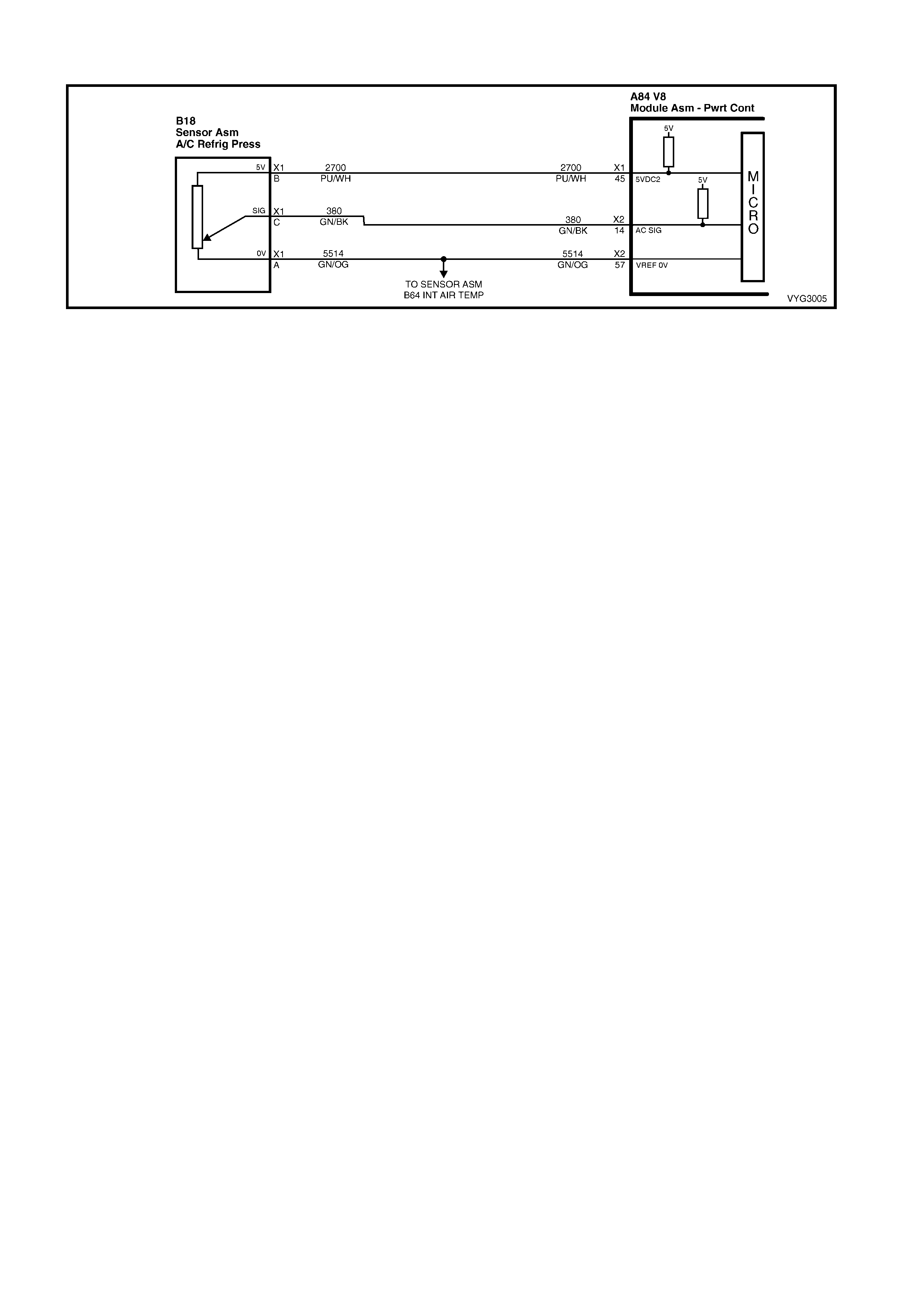
GEN III V8 PCM – DTC P1639 5 VOLT REFERENCE #2 CIRCUIT
Figure 6C3-2A-198 – A/C Pressure Sensor Circuit
CIRCUIT DESCRIPTION
The PCM uses a common 5.0 volt reference circuit as a sensor feed to the A/C Pressure Sensor.
The PCM monitors the voltage on the 5.0 volt reference circuit. This DTC sets if the voltage is out of range.
CONDITIONS FOR RUNNING THE DTC
• The ignition is on.
CONDITIONS FOR SETTING THE DTC
• The five volt reference #2 circuit is out of range.
• All of the above conditions are present for greater than 2 seconds.
ACTION TAKEN WHEN THE DTC SETS
• The PCM activates the Check Powertrain MIL when the diagnostic runs and fails.
• The PCM records the operating conditions at the time the diagnostic fails. The PCM stores this information in
the Freeze Frame/Failure Records.
CONDITIONS FOR CLEARING THE MIL/DTC
• T he PCM deactivates the Check Powertrain MIL after one ignition c ycle that the diagnostic runs and does not
fail.
• A last test failed (Current DTC) clears when the diagnostic runs and does not fail.
• Use Tech 2 to clear the MIL/DTC.
DIAGNOSTIC AIDS
• Using the Freeze Frame/Failure Records data may aid in locating an intermittent condition. The Fail Counter
and Pass Counter c an als o help det erm ine ho w man y ignition c ycles the diag nosti c repor ted a pass and/or fail.
Operate the vehicle within the same freeze frame condition (RPM, load, vehicle speed, temperature etc.) that
you observed. This will isolate when the DTC failed.
• For an intermittent, refer to Section 6C3-2B SY MPTOM S.
TEST DESCRIPTION
NOTE: The number(s) below refer to the step number(s) on the diagnostic table.
2. This step checks to see if the A/C Pressure Sensor is functioning properly.
3. This step checks to see if the A/C Pressure Sensor voltage is above or below the correct operating range.

A84–X1 (BLUE) A84-X2 (RED)
B18
Figure 6C3-2A-199
GEN III V8 PCM – DTC P1639 5 VOLT REFERENCE #2 CIRCUIT
STEP ACTION VALUE YES NO
1. Was the "On-Board Diagnostic" (OBD) System Check
performed? Go to Step 2 Go to
OBD System
Check
in this Section.
2. 1. Install Tech 2.
2. Run the engine at idle.
3. Monitor the A/C Pressure Sensor (kPa).
Is the A/C Pressure Sensor kPa within the specified range?
25 – 3,140
kPa Go to
Diagnostic Aids Go to Step 3
3. 1. Disconnect the A/C Pressure Sensor electrical
connector, B18.
2. Ignition ON, engine OFF.
3. Using a DMM, probe the A/C Pressure Sensor 5.0 volt
reference circuit at the A/C Pressure Sensor harness
connector with adaptors from the J 35616-A Connector
Test Adaptor Kit using a DMM connected to ground.
Is the voltage at or between the specified value?
4.8 – 5.4
volts Go to
Diagnostic Aids Go to Step 4
4. Is the voltage above the specified value? 5.4 volts Go to Step 5 Go to Step 6
5. 1. Check for short to voltage for the A/C Pressure Sensor
5 volt reference circuit.
Was a problem found?
Verify Repair Go to Step 7
6. 1. Check for an open or short to ground for the A/C
Pressure Sensor 5 volt reference circuit.
Was a problem found?
Verify Repair Go to Step 7
7. 1. Replace PCM. Refer to PCM Programming and
PCM/PIM/BCM Security Link Procedure, in 6C3-3
SERVICE OPERATIONS.
Is action complete?
Go to Step 8 –
8. 1. Select the Diagnostic Trouble Code (DTC) option and
the Clear DTC Information option using Tech 2.
2. Idle the engine at normal operating temperature.
3. Select the Diagnostic Trouble Code (DTC) option, the
DTC Information option and the Failed This Ignition
option using Tech 2.
4. Operate the vehicle, within the Conditions for Running
the DTC, as specified in the supporting text, if
applicable.
Does Tech 2 indicate that this DTC reset?
Go to Step 2 Go to Step 9
9. 1. Using Tech 2, check for any other DTCs.
Does Tech 2 display any DTCs that you have not
diagnosed?
Go to the
applicable DTC
table
System OK
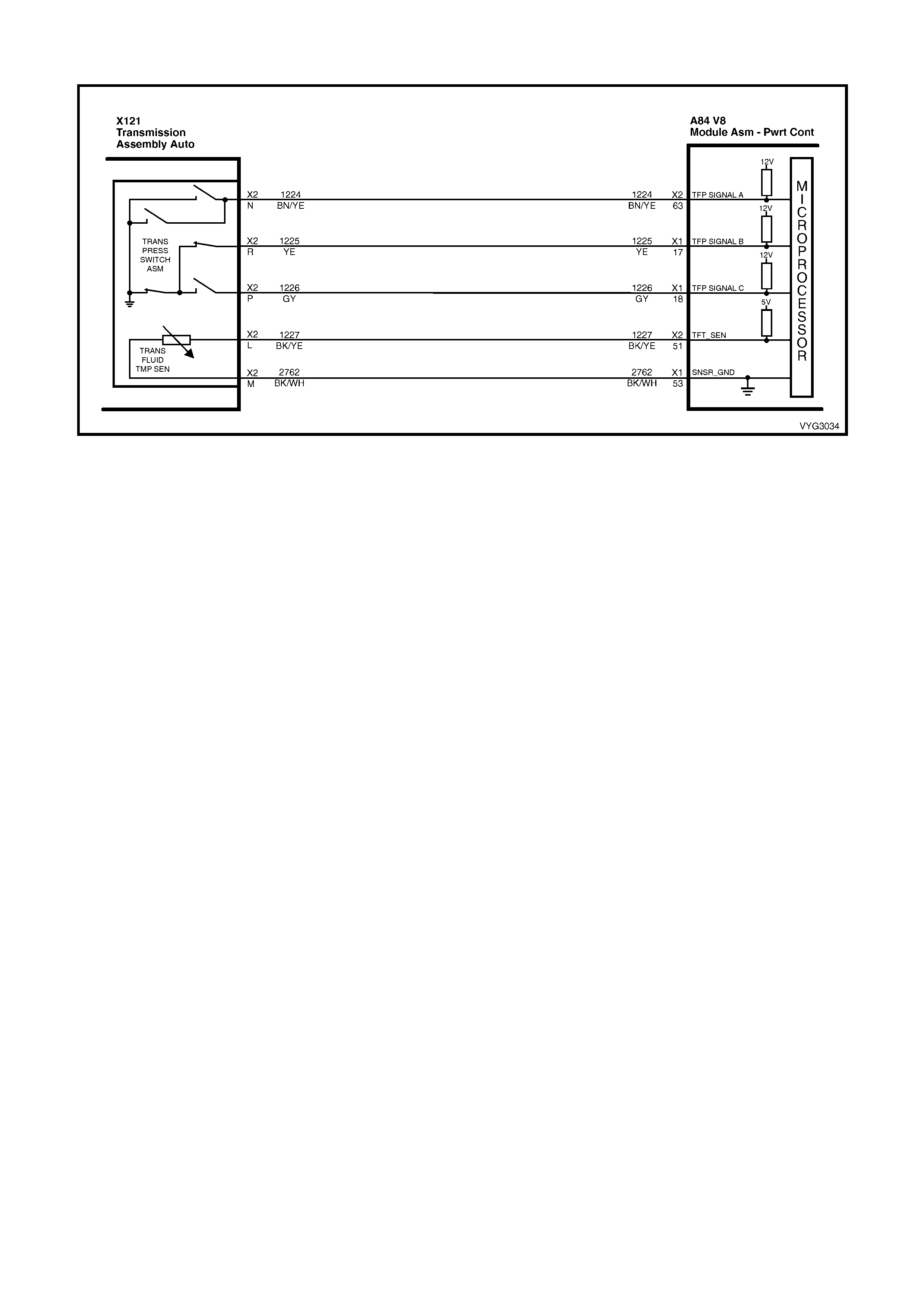
GEN III V8 PCM – DTC P1810 TFP VALVE POSITION SWITCH CIRCUIT
Figure 6C3-2A-200 – Automatic Transmission TFP Manual Valve Position Switch Circuit
CIRCUIT DESCRIPTION
The autom atic Transm ission Fluid Pressure (T FP) manual valve position s witch consists of five pressure switches
(two norm all y-close d and three nor m ally-open) and a Tr ansm ission F luid T emperatur e (T FT) Sensor com bined into
one unit.
The combined unit m ounts on the valve body. The Powertrain Control Module (PCM) supplies the battery voltage
for each range signal. By grounding one or more of the circuits through various combinations of the pressure
switches, the PCM detects which manual valve position you select.
The PCM compares the actual voltage combination of the switches to a TFP manual valve position switch
combination table stored in memory.
The TFP manual valve position switch cannot distinguish between PARK and NEUTRAL because the monitored
valve body pressures are identical. With the engine OFF and the ignition switch in the RUN position, the TFP
manual valve position switch indicates PARK/NEUTRAL.
Disconnecting the transmission 20-way (X121-X2) connector removes the ground potential for the three range
signals to the PCM. In this case, with the engine OFF, and the ignition switch in the RUN position, D2 will be
indicated.
W hen the PCM detects an in valid state of the TFP manual valve posit ion switch or the T FP manual valve position
switch circuit, by deciphering the TFP manual valve position switch inputs, then DTC P1810 sets.
CONDITIONS FOR RUNNING THE DTC
• No VSS assembly DTCs P0502 or P0503.
• The system voltage is between 8.0 and 18 volts.
• The engine speed is greater than 300 RPM for 5 seconds.
• The engine is not in fuel cutoff.
• The engine torque is 54 – 542 Nm.
• The engine vacuum is 0-105 kPa.
CONDITIONS FOR SETTING THE DTC
Condition1
• The PCM detects an invalid TFP manual valve position switch state for 60 seconds.
Condition 2
• The engine speed is less than 80 RPM for 0.1 seconds; then the engine speed is 80-550 RPM for 0.07
seconds; then the engine speed is greater than 550 RPM.
• The vehicle speed is less than 3 km/h.
• The PCM detects a gear range of 2, D or R during an engine start.
• All conditions are met for 5 seconds.

Condition 3
• The TP angle is 8-45%.
• The PCM commands 4th gear.
• The TCC is locked ON.
• The speed ratio is 0.65 – 0.8 (speed ratio is engine speed divided by transmission output speed).
• The PCM detects a gear range of P or N when operating in D.
• All conditions are met for 10 seconds.
ACTION TAKEN WHEN THE DTC SETS
• The PCM activates the Check Powertrain MIL when the diagnostic runs and fails.
• The PCM commands D2 line pressure.
• The PCM commands D4 shift pattern.
• The PCM freezes shift adapts from being updated.
• The PCM records the operating conditions at the time the diagnostic fails. The PCM stores this information in
the Freeze Frame/Failure Records.
CONDITIONS FOR CLEARING THE MIL/DTC
• The PCM de ac tivates th e Chec k Powertrain MIL during t he f ir st ign iti on cycle that th e diagnos t ic r uns an d does
not fail.
• A last test failed (current DTC) clears when the diagnostic runs and does not fail.
• Use Tech 2 to clear the DTC.
DIAGNOSTIC AIDS
• Refer to the TFP Manual Valve Position Switch Logic table for the normal range signals and the invalid
combinations. In the table, Closed is 0 volts, Open is 12 volts.
• Inspect the wiring at the PCM, the transmission connector and all other circuit connecting points for the
following conditions:
– A backed out terminal
– A damaged terminal
– Reduced terminal tension
– A chafed wire
– A broken wire inside the insulation
– Moisture intrusion
– Corrosion
• When diagnosing for an intermittent short or open condition, massage the wiring harness while watching the
test equipment for a change.
• Refer to TFP Manual Valve Position Switch Resistance Check or Functional Test Procedure in Section
6C3-2C FUNCTIONAL CHECKS, for further information.
TFP Manual Valve Position Switch Logic
Gear
Position Range
Signal A Range
Signal B Range
Signal C
Park Open 12 V Closed 0 V Open 12 V
Reverse Closed 0 V Closed 0 V Open 12 V
Neutral Open 12 V Closed 0 V Open 12 V
D Open 12 V Closed 0 V Closed 0 V
3 Open 12 V Open 12 V Closed 0 V
2 Open 12 V Open 12 V Open 12 V
1 Closed 0 V Open 12 V Open 12 V
Invalid Closed 0 V Open 12 V Closed 0 V
Invalid Closed 0 V Closed 0 V Closed 0 V
Table 1
TEST DESCRIPTION
NOTE: The number(s) below refer to the step number(s) on the diagnostic table.
3. This step tests the indicated range signal to the manual valve actually selected.
4. This step tests for correct voltage from the PCM to the transmission 20-way connector, X121-X2.

A84–X1 (BLUE) A84-X2 (RED)
X121-X2
Figure 6C3-2A-201
GEN III V8 PCM – DTC P1810 TFP VALVE POSITION SWITCH CIRCUIT
STEP ACTION VALUE YES NO
1. Was the "On-Board Diagnostic" (OBD) System Check
performed? Go to Step 2 Go to
OBD System
Check
in this Section.
2. 1. Perform the following inspections:
– Ensure that the transmission linkage from the
select lever to the manual valve is adjusted
correctly. Refer to Selector Linkage Adjustment in
7C4 A/T ON-VEHICLE SERVICING.
– Perform the Fluid Checking Procedure, in 7C4 A/T
ON-VEHICLE SERVICING.
Did you perform the inspections?
Go to Step 3 –
3. 1. Install Tech 2.
2. Ignition ON, engine OFF.
IMPORTANT: Before clearing the DTC, use Tech 2 to
record the Freeze Frame/Failure Records. Using the Clear
Info function erases the Freeze Frame/Failure Records
from the PCM.
3. Record the DTC Freeze Frame/Failure Records.
4. Clear the DTC.
5. While the engine is idling at normal operating
temperature, apply the brake pedal.
6. Select each transmission range: P, R, N, D, 3, 2 and 1.
7. Refer to TFP Manual Valve Position Switch Logic
Table, in this diagnostic table
Does each selected transmission range match the Tech 2
TFP Switch A/B/C display?
Go to
Diagnostic Aids Go to Step 4
4. 1. Ignition OFF.
2. Disconnect the transmission 20-way connector X121-
X2 (additional DTCs may set).
3. Install the J 39775 jumper harness on the engine side
of connector X121-X2.
4. Ignition ON, engine OFF.
5. Using a DMM and the J 35616-A Connector Test
Adaptor Kit, check the voltage at connector terminals
N, R and P.
Is B+ displayed on all three circuits?
B+ Go to Step 6 Go to Step 5
5. 1. Inspect the circuits that did not indicate B+ for an
open, proper terminal retention or short to ground
condition. Refer to Test Procedures, in 12P WIRING
DIAGRAMS.
Did you find an open or short to ground condition?
Go to Step 8 Go to Step 7

STEP ACTION VALUE YES NO
6. 1. To check that circuits 1224, 1225 and 1226 are not
shorted together, use a fused jumper wire between
ground and each circuit while monitoring the Tech 2
TFP Switch A/B/C display.
When a range signal circuit is grounded, are any other
range signal cir cui ts affe cted ?
Go to Step 8 Go to TFP
Manual Valve
Position Switch
Resistance
Check in
6C3-2C
FUNCTIONAL
CHECKS
7. 1. Replace PCM. Refer to PCM Programming and
PCM/PIM/BCM Security Link Procedure, in 6C3-3
SERVICE OPERATIONS.
Is the replacement complete?
Go to Step 9 –
8. 1. Repair the affected wiring as necessary. Refer to
Wiring Repair Procedures in 12P WIRING
DIAGRAMS.
Is the repair complete?
Go to Step 9 –
9. 1. Perform the following procedure in order to verify the
repair:
• Select DTC, then Clear Info, on Tech 2.
• Operate the vehicle under the following
conditions:
– Ignition ON, engine OFF for at least 2
seconds.
– Start the engine and idle for 5 seconds.
– Drive the vehicle in D until the TCC locks for
10 seconds.
– Run the engine for at least 60 seconds from
start up.
Were the above conditions verified?
System OK Go to Step 2

GEN III V8 PCM – DTC P1860 TCC PWM SOLENOID CIRCUIT
Figure 6C3-2A-202 – Automatic Transmission Solenoid Circuits
CIRCUIT DESCRIPTION
The Torque Converter Clutch Pulse W idth Modulation (TCC PWM) solenoid valve controls the fluid acting on the
convert er clutch va lve. The c onverter clutch valve cont rols the T CC applicatio n and releas e. The sole noid attac hes
to the control valve body within the transmission. The solenoid receives ignition voltage through circuit 339. The
Powertrain Control Module (PCM) controls the solenoid by providing a ground path on circuit 418.
Current flows through the solenoid coil according to the duty cycle (percentage of ON and OFF time). The TCC
PWM solenoid valve provides a smooth engagement of the Torque Converter Clutch by operating during a duty
cycle percent of ON time.
When the PCM detects a continuous open or short to ground in the TCC PWM solenoid valve circuit or the TCC
PWM solenoid valve, then DTC P1860 sets.
CONDITIONS FOR RUNNING THE DTC
• The system voltage is between 8.0 and 18 volts.
• The engine speed is greater than 300 RPM for 5 seconds.
• The engine is not in fuel cutoff.
• The PCM commands 1st gear.
• The TCC duty cycle is less than 10% or greater than 90%.
CONDITIONS FOR SETTING THE DTC
• The PCM commands the solenoid ON and the voltage input remains high (12 volts).
Or
• The PCM commands the solenoid OFF and the voltage input remains low (0 volts).
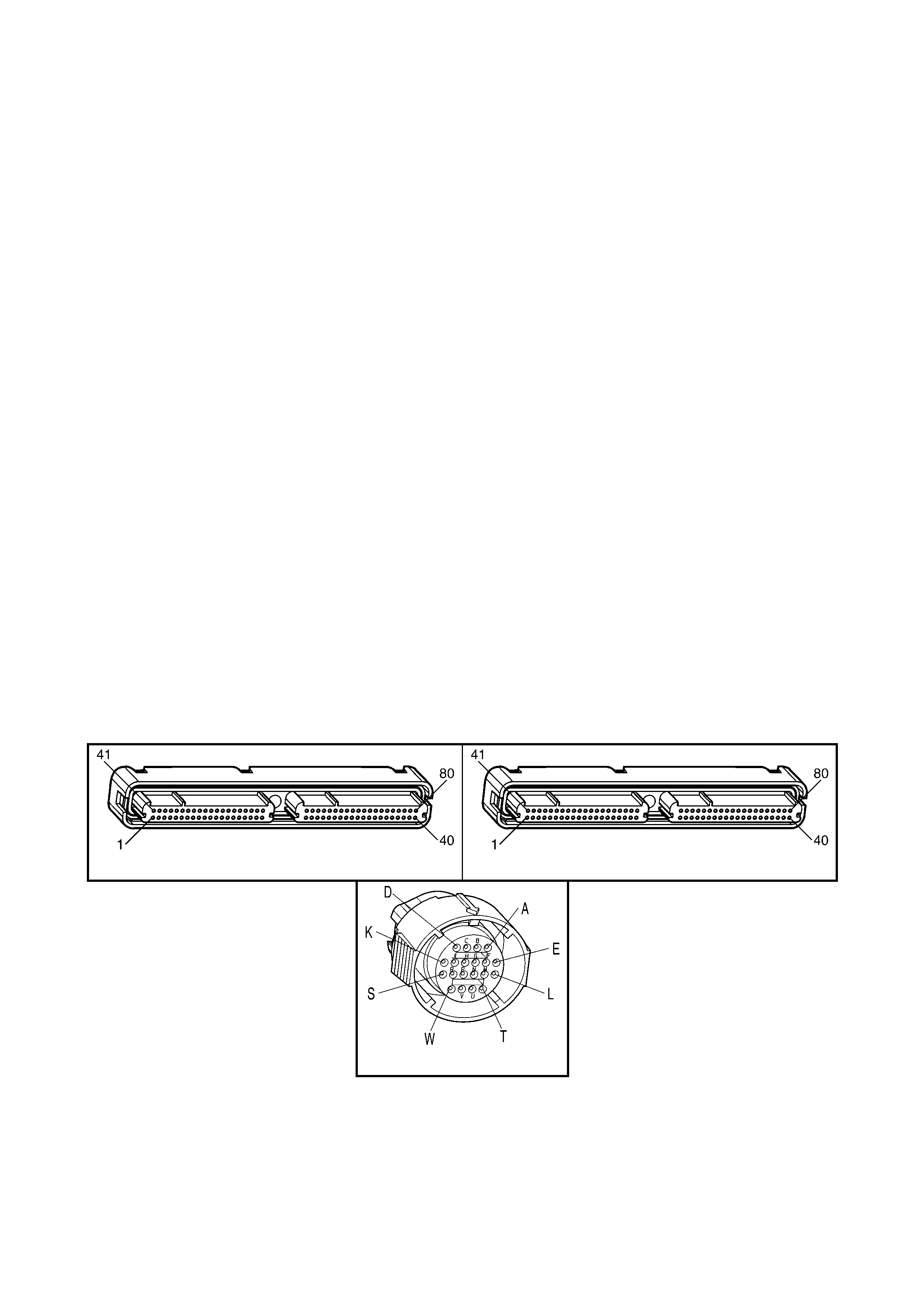
ACTION TAKEN WHEN THE DTC SETS
• The PCM activates the Check Powertrain MIL when the diagnostic runs and fails.
• The PCM inhibits TCC engagement.
• The PCM inhibits 4th gear if the transmission is in hot mode.
• The PCM freezes shift adapts from being updated.
• The PCM records the operating conditions at the time the diagnostic fails. The PCM stores this information in
the Freeze Frame/Failure Records.
CONDITIONS FOR CLEARING THE MIL/DTC
• The PCM de ac tivates th e Chec k Powertrain MIL during t he f ir st ign iti on cycle that th e diagnos t ic r uns an d does
not fail.
• A last test failed (current DTC) clears when the diagnostic runs and does not fail.
• Use Tech 2 to clear the DTC.
DIAGNOSTIC AIDS
• Inspect the wiring at the PCM, the transmission connector and all other circuit connecting points for the
following conditions:
– A backed out terminal
– A damaged terminal
– Reduced terminal tension
– A chafed wire
– A broken wire inside the insulation
– Moisture intrusion
– Corrosion
• When diagnosing for an intermittent short or open condition, massage the wiring harness while watching the
test equipment for a change.
TEST DESCRIPTION
NOTE: The number(s) below refer to the step number(s) on the diagnostic table.
4. This step tests for voltage to the solenoid.
6. This step tests the ability of the PCM and wiring to control the ground circuit.
8. This step tests the resistance of the TCC PWM solenoid valve and the automatic transmission (A/T) wiring
harness assembly.
A84-X1 (BLUE) A84-X2 (RED)
X121-X2
Figure 6C3-2A-203

GEN III V8 PCM – DTC P1860 TCC PWM SOLENOID CIRCUIT
STEP ACTION VALUE YES NO
1. Was the "On-Board Diagnostic" (OBD) System Check
performed? Go to Step 2 Go to
OBD System
Check
in this Section.
2. 1. Install Tech 2.
2. Ignition ON, engine OFF.
IMPORTANT: Before clearing the DTC, use in order to
record the Freeze Frame/Failure Records. Using the Clear
Info function erases the Freeze Frame/Failure Records
from the PCM.
3. Record the DTC Freeze Frame/Failure Records.
4. Clear the DTC.
Are any of the following DTCs also set?
– P0740
– P0753
– P0758
– P0785
Go to Step 3 Go to Step 4
3. 1. Inspect fuse F32.
2. If the fuse is open, inspect the following components
for a short to ground condition:
– Circuit 339
– The solenoids
– The A/T wiring harness assembly
3. Repair the circuit, the solenoids, and the harness if
necessary.
Did you find a short to ground condition?
Go to Step 15 Go to Step 4
4. 1. Ignition OFF.
2. Disconnect the transmission 20-way connector, X121-
X2 (additional DTCs may set).
3. Install J 39775 jumper harness on the engine side of
the connector, X121-X2.
4. Ignition ON, engine OFF.
5. Connect a lest lamp from J 39775 jumper harness
cavity E to ground.
Is the test lamp on?
Go to Step 6 Go to Step 5
5. IMPORTANT: The condition that affects this circuit may
exist in other connecting branches of the circuit. Refer to
Power Distribution Diagrams in 12P WIRING DIAGRAMS.
1. Repair the open in ignition feed circuit 339 to the TCC
PWM solenoid valve.
Is the repair complete?
Go to Step 15 –
6. 1. Install a test lamp from cavity E to cavity U of the
J 39775 jumper harness.
2. Using the transmission Miscellaneous Tests function
on Tech 2, command the TCC PWM solenoid valve
ON and OFF three times.
Does the test lamp turn ON when the TCC PWM solenoid
valve is commanded ON, and OFF when commanded
OFF?
Go to Step 8 Go to Step 7
7. 1. Inspect circuit 418 of the powertrain wiring harness for
an open, short to ground or short to power condition.
2. Repair the circuit if necessary .
Did you find an open, short to ground or short to power
condition?
Go to Step 15 Go to Step 9

STEP ACTION VALUE YES NO
8. 1. Install J 39775 jumper harness on the transmission
side of the 20-way connector X121-X2.
2. Using a DMM and the J 35616-A Connector Test
Adaptor Kit, measure the resistance between terminals
E and U.
Is the resistance within the specified range?
10 – 15 Ω Go to Step 11 Go to Step 10
9. 1. Replace PCM. Refer to PCM Programming and
PCM/PIM/BCM Security Link Procedure, in 6C3-3
SERVICE OPERATIONS.
Is the replacement complete?
Go to Step 15 –
10. 1. Disconnect the A/T wiring harness assembly at the
TCC PWM solenoid valve.
2. Measure the resistance of the TCC PWM solenoid
valve.
Is the resistance within the specified range?
10 – 15 Ω Go to Step 13 Go to Step 14
11. 1. Measure the resistance between terminal E and
ground, and between terminal U and ground.
Are both readings greater than the specified value?
250 kΩ Go to
Diagnostic Aids Go to Step 12
12. 1. Disconnect the A/T wiring harness assembly at the
TCC PWM solenoid valve.
2. Measure the resistance between each of the
component terminals and ground.
Are both readings greater than the specified value?
250 kΩ Go to Step 13 Go to Step 14
13. 1. Replace the automatic transmission wiring harness
assembly. Refer to Control Valve Body and Wiring
Harness Replace, in 7C4 A/T ON-VEHICLE
SERVICING.
Is the replacement complete?
Go to Step 15 –
14. 1. Replace the TCC PWM solenoid valve. Refer to TCC
PWM Solenoid Valve Replace, in 7C4 A/T ON-
VEHICLE SERVICING.
Is the replacement complete?
Go to Step 15 –
15. 1. Perform the following procedure in order to verify the
repair:
• Select DTC.
• Select Clear Info.
• Drive the vehicle in D with the TCC ON. Ensure
the following conditions are met:
– The PCM commands the TCC PW M solenoid
valve ON, and the voltage input drops to zero.
– The PCM commands the TCC PW M solenoid
valve OFF, and the voltage input increases to
B+.
– All conditions met for 5 secon d s.
Were the above conditions verified?
System OK Go to Step 2
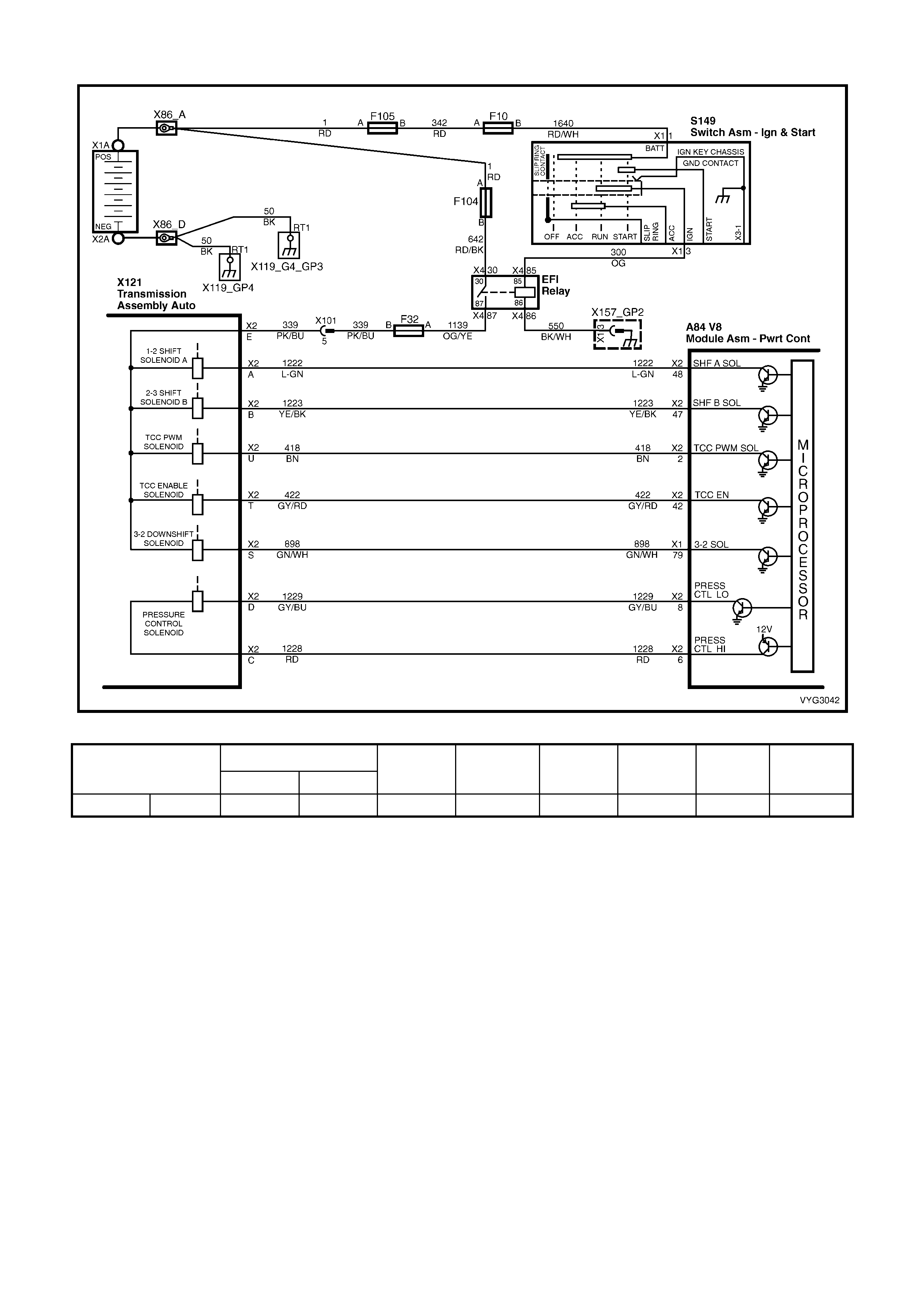
GEN III V8 PCM – DTC P1870 TRANSMISSION COMPONENT SLIPPING
Figure 6C3-2A-204 – Automatic Transmission Solenoid Circuits
Shift Solenoid
Range Gear 1-2 (A) 2-3 (B) TCC
Solenoid TCC PWM
Solenoid 2-4 Band Forward
Clutch 3-4
Clutch Torque
Converter
Clutch
Overdrive 4th ON OFF ON 90% (ON) Applied Applied Applied Applied
CIRCUIT DESCRIPTION
The Powertrain Control Module (PCM) monitors the difference between engine speed and transmission output
speed. In drive 3 range, with the TCC engaged, the engine speed should closely match the transmission output
speed. In D drive range, with the TCC engaged, the TCC slip speed should be –20 to +40 R PM. The table above
indicates solenoid states and transmission components that apply, during 4th gear, with the TCC commanded ON.
When the PCM detects excessive TCC slip when the TCC should be engaged, then DTC P1870 sets.
CONDITIONS FOR RUNNING THE DTC
• No Throttle Position DTCs P0122 or P0123.
• No VSS DTCs P0502, P0503.
• No TCC solenoid valve DTC P0740.
• No 1-2 SS valve DTC P0753.
• No 2-3 SS valve DTC P0758.
• No 3-2 SS valve assembly DTC P0785.
• No TCC PWM solenoid valve DTC P1860.
• The engine speed is greater than 300 RPM for 5 seconds.
• The engine is not in fuel cutoff.
• The vehicle speed is 56-105 km/h.
• The speed ratio is 0.67-0.90 (the speed ratio is the engine speed divided by the transmission output speed).

• The engine speed is 1200-3500 RPM.
• The engine torque is 54-542 N.m
• The gear range is D4.
• The commanded gear is not 1st gear.
• The throttle position angle is 10-50%.
• The TFT is between 20-130°C.
• The shift solenoid performance diagnostic counters are zero.
CONDITIONS FOR SETTING THE DTC
DTC P1870 sets if the following conditions occur for three TCC cycles.
• The TCC is commanded ON for 5 seconds.
• The TCC is at maximum duty cycle for 1 second.
• The TCC slip speed is 80-800 RPM for 7 seconds.
IMPORTANT: The following actions may occur before the DTC sets.
• If the T CC is com manded O N and at maximum dut y cycle f or 5 sec onds , the Throttle P os it ion an gl e is 10-4 0%,
and the tr ansm iss ion slip c ount er has increm ented t o eith er 1 or 2 ( out of 3 to inc rem ent the f ail cou nter f or t he
current ignition cycle), then the following slip conditions and actions may increment the fail counter for the
current ignition cycle:
These conditions must occur sequentially.
Condition 1
• If the TCC slip speed is 8 0-800 RPM for 7 seconds, then t he PCM will comm and maximum line pressure and
freeze shift adapts from being updated.
Condition 2
• If condition 1 is met and the TCC slip speed is 80-800 RPM for 7 seconds, then the PCM will command the
TCC OFF for 1.5 seconds.
Condition 3
• If Condit ion 2 is m et and the TCC slip s peed is 80-80 0 RPM f or 7 seconds, the n the fail c ounter on t he curre nt
ignition cycle is incremented.
• The above slip conditions and actions may be disregarded if the TCC is commanded OFF at any time as a
result of a driving manoeuvre (sudden acceleration or deceleration).
ACTION TAKEN WHEN THE DTC SETS
• The PCM activates the Check Powertrain MIL when the diagnostic runs and fails.
• The PCM inhibits TCC engagement.
• The PCM commands maximum line pressure.
• The PCM inhibits 4th gear if the transmission is in hot mode.
• The PCM freezes shift adapts from being updated.
• The PCM records the operating conditions at the time the diagnostic fails. The PCM stores this information in
the Freeze Frame/Failure Records.
CONDITIONS FOR CLEARING THE MIL/DTC
• The PCM de ac tivates th e Chec k Powertrain MIL during t he f ir st ign iti on cycle that th e diagnos t ic r uns an d does
not fail.
• A last test failed (current DTC) clears when the diagnostic runs and does not fail.
• Use Tech 2 to clear the DTC.
DIAGNOSTIC AIDS
• Int ernal transmission failures may set DTC P1870.
TEST DESCRIPTION
NOTE: The number(s) below refer to the step number(s) on the diagnostic table.
3. This step tests the torque converter for slippage while in a commanded lock-up state.

GEN III V8 PCM – DTC P1870 TRANSMISSION COMPONENT SLIPPING
STEP ACTION VALUE YES NO
1. Was the "On-Board Diagnostic" (OBD) System Check
performed? Go to Step 2 Go to
OBD System
Check
in this Section.
2. 1. Perform the transmission fluid checking procedure.
Refer to Transmission Fluid Checking Procedure in
7C4 A/T ON-VEHICLE SERVICING.
Did you perform the fluid checking procedure?
Go to Step 3 Go to
Transmission
Fluid Checking
Procedure in
7C4
3. 1. Install Tech 2.
2. Ignition ON, engine OFF.
IMPORTANT: Before clearing the DTC, use in order to
record the Freeze Frame/Failure Records. Using the Clear
Info function erases the Freeze Frame/Failure Records
from the PCM.
3. Record the DTC Freeze Frame/Failure Records.
4. Clear the DTC.
5. Drive the vehicle in D with the TCC commanded ON.
Is the TCC Slip Speed on Tech 2 between the specified
range for 7 seconds?
80-800 RPM Go to Step 4 Go to
Diagnostic Aids
4. 1. Inspect the torque converter clutch (TCC) solenoid
valve for the following conditions:
– Internal malfunction (such as s edim ent or damag e)
– Damaged seals
2. Inspect the torque converter clutch pulse width
modulation (TCC PWM) solenoid valve for the
following con diti on s:
– Internal malfunction (such as s edim ent or damag e)
– Damaged seals
Did you find a condition?
Go to Step 13 Go to Step 5
5. 1. Inspect the 1-2 shift solenoid (A) valve for the following
conditions:
– Internal malfunction (such as s edim ent or damag e)
– Damaged seals
2. Refer to Shift Solenoid Leak Test in 7C3 A/T
HYDRAULIC/MECHANICAL DIAGNOSIS.
3. Inspect the 2-3 shift solenoid (B) valve for the following
conditions:
– Internal malfunction (such as s edim ent or damag e)
– Damaged seals
4. Refer to Shift Solenoid Leak Test in 7C3 A/T
HYDRAULIC/MECHANICAL DIAGNOSIS.
Did you find a condition?
Go to Step 13 Go to Step 6
6. 1. Inspect the valve body assembly for a stuck regulator
apply valve. Refer to Control Valve Body, in 7C4 A/T
ON-VEHICLE SERVICING.
Did you find a condition?
Go to Step 13 Go to Step 7
7. 1. Inspect the torque converter assembly for the following
conditions:
– Stator roller clutch not holding
– Internal damage
Did you find a condition?
Go to Step 13 Go to Step 8

STEP ACTION VALUE YES NO
8. 1. Inspect the oil pump assembly for the following
conditions:
• Stuck converter clutch valve
• Converter clutch valve assembled backwards
• Incorrectly positioned converter clutch valve
retaining ring
• Incorrectly positioned pump to case gasket
• Restricted orifice cup plugs
• Damaged orifice cup plugs
• Over-tightened, or unevenly tightened pump body
to cover bolts
2. Refer to 7C5 UNIT REPAIR.
Did you find a condition?
Go to Step 13 Go to Step 9
9. 1. Inspect the input housing and shaft assembly for the
following con diti on s:
• Cut turbine shaft O-ring seal
• Damaged turbine shaft O-ring seal
• Restricted turbine shaft retainer and ball assembly
• Damaged turbine shaft retainer and ball assembly
2. Refer to 7C5 UNIT REPAIR.
Did you find a condition?
Go to Step 13 Go to Step 10
10. 1. Inspect the 2-4 band assembly for the following
conditions:
• Worn 2-4 band
• Damaged 2-4 band
• Incorrectly positioned 2-4 band
• Incorrectly assembled 2-4 band
• The band anchor pin is not engaged.
• Restricted apply passages in the 2-4 servo
assembly
• Blocked apply passages in the 2-4 servo
assembly
• Nicks or burrs on the servo pin
• Nicks or burrs on the pin bore in the case
• Damaged fourth servo piston
• Incorrectly assembled fourth servo piston
• Damaged band apply pin
• Incorrect band apply pin
• Damaged servo bore in the case
• Missing piston seals
• Cut piston seals
• Damaged piston seals
• Porosity in the pistons
• Porosity in the cover
• Porosity in the case
• Damaged piston seal grooves
• Plugged orifice cup plug
• Missing orifice cup plug
2. Refer to 7C5 UNIT REPAIR.
Did you find a condition?
Go to Step 13 Go to Step 11

STEP ACTION VALUE YES NO
11. 1. Inspect the forward clutch assembly for the following
conditions:
• Worn clutch plates
• Porosity in the forward clutch piston
• Damaged forward clutch piston
• Missing forward clutch piston inner and outer
seals
• Cut forward clutch piston inner and outer seals
• Damaged forward clutch piston inner and outer
seals
• Missing input housing to forward clutch housing
O-ring seal
• Cut input housing to forward clutch housing O-ring
seal
• Damaged input housing to forward clutch housing
O-ring seal
• Damaged forward clutch housing
• Damaged forward clutch housing retainer and ball
assembly
• Forward clutch housing retainer and ball assembly
is not sealing.
2. Refer to 7C5 UNIT REPAIR.
Did you find a condition?
Go to Step 13 Go to Step 12
12. 1. Inspect the 3-4 clutch assembly for the following
conditions:
• Worn clutch plates
• Porosity in the 3-4 clutch piston
• Damaged 3-4 clutch piston
• Missing 3-4 clutch inner and outer seals
• Cut 3-4 clutch inner and outer seals
• Damaged 3-4 clutch inner and outer seals
• Damaged 3-4 clutch spring assembly
• Damaged 3-4 clutch apply ring
• Damaged piston seal grooves
• Plugged orifice cup plug
• Missing orifice cup plug
2. Refer to 7C5 UNIT REPAIR.
Did you find a condition?
Go to Step 13 Go to
Diagnostic Aids
13. 1. Perform the following procedure in order to verify the
repair:
• Select DTC, then Clear Info on Tech 2.
• Operate the vehicle under the following conditions:
– Drive the vehicle in D, with the TCC ON, and
a throttle position of 10-50%.
– Ensure that the Tech 2 TCC Slip Speed is -20
to +40 RPM for at least 7 seconds.
Were the above conditions verified?
System OK Go to Step 2
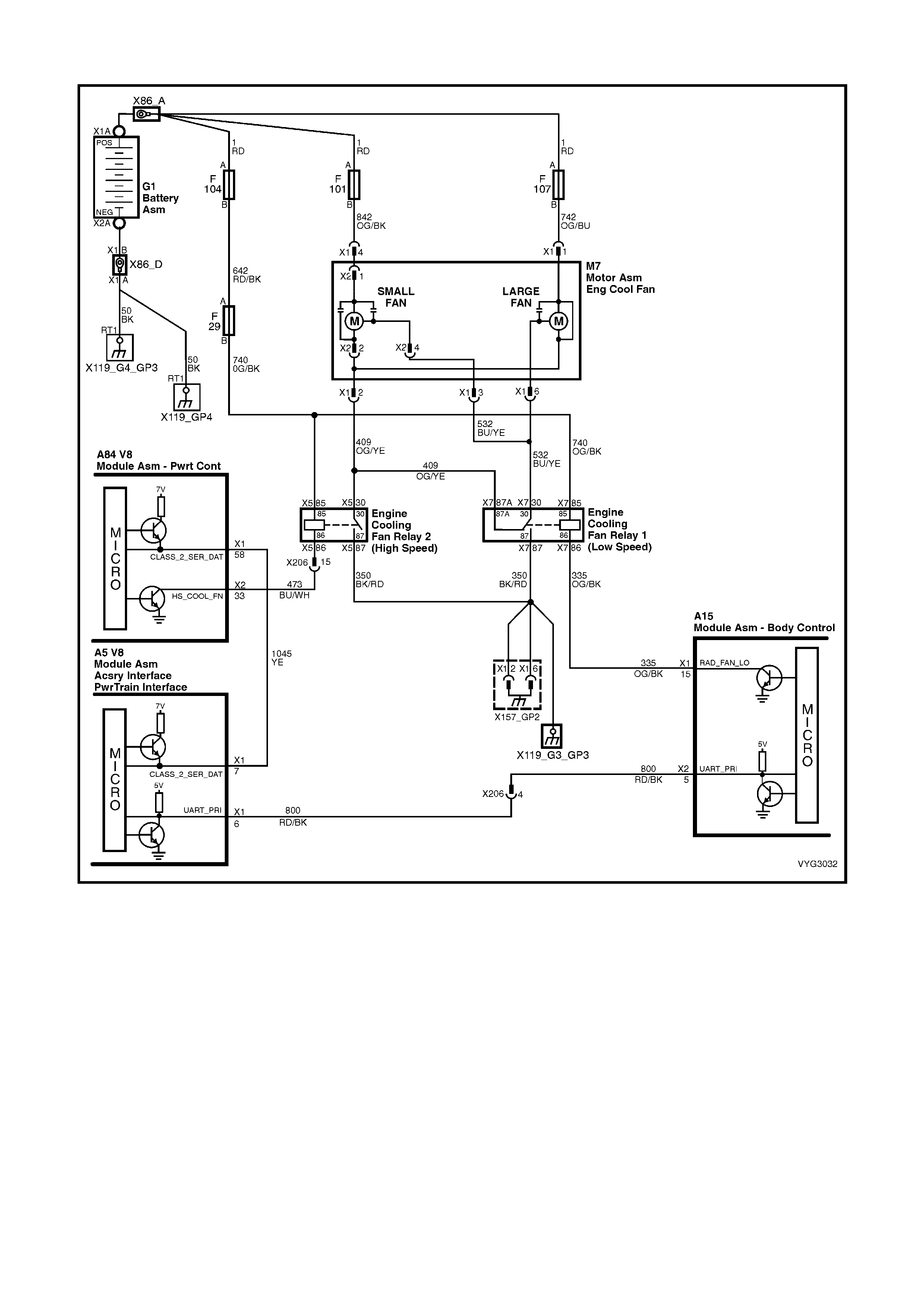
GEN III V8 PIM – DTC B2002 LOW SPEED FAN NO BCM RESPONSE
Figure 6C3-2A-205 – Cooling Fan Circuits
CIRCUIT DESCRIPTION
The PCM determines operation of the two speed engine cooling fans based on A/C request, engine coolant
temperature, A/C pressure sensor, and vehicle speed.
The engi ne cooling f an Low Sp eed Rela y is energis ed by the BCM. W hen the PCM de term ines that the lo w spee d
fan rela y should be en abled, the PCM will send a message on th e Class II serial data circuit to the PIM. T he PIM
will inturn convert the PCM Class II message to a UART message and supply this UART message to the BCM.
This PCM mess age will req uest the BCM to supp ly the nee ded ground signal f or the Lo w Speed Re lay to op erate .
After the BCM prov ides the grou nd si gnal f or the Lo w Spe ed Rela y, the BCM will send a m ess age back to the PI M
confirming that the ground signal was commanded. The PIM will convert this message from the BCM to Class II
and supply to the PCM.
CONDITIONS FOR RUNNING THE DTC
• The ignition is on.
CONDITIONS FOR SETTING THE DTC
• The PIM sends a Low Speed request signal to the BCM , with no response back from the BCM.

ACTION TAKEN WHEN THE DTC SETS
• The PIM will display the DTC only when current.
• The Check Powertrain MIL will not illuminate.
CONDITIONS FOR CLEARING THE DTC
• A current DTC will clear when the PIM receives a Low Speed Fan Response from the BCM.
DIAGNOSTIC AIDS
• For an intermittent, refer to Section 6C3-2B SY MPTOM S.
TEST DESCRIPTION
NOTE: The number(s) below refer to the step number(s) on the diagnostic table.
2. The test is determining if any BCM DTCs may be set. T here may be a BCM DTC that is related to this circuit,
and diagnosing this BCM DTC first may resolve the fault.
3. An open or short to ground on the UART serial data circuit will disable any communication between the PIM
and BCM.
GEN III V8 PIM – DTC B2002 LOW SPEED FAN NO BCM RESPONSE
STEP ACTION VALUE YES NO
1. Was the "On-Board Diagnostic" (OBD) System Check
performed? Go to Step 2 Go to
OBD System
Check
in this Section.
2. Are any BCM DTCs set?
Go to
appropriate BCM
DTC. Refer to
12J BODY
CONTROL
MODULE
Go to Step 3
3. 1. Run the engine at idle.
2. Using Tech 2, select LOW FAN.
Do the cooling fans operate when commanded ON, using
Tech 2?
Go to Step 4 Go to
Electric Cooling
Fan Control in
6C2-3
FUNCTIONAL
CHECKS for
further diagnosis
4. 1. Using Tech 2, select BCM “Normal Mode”.
2. While monitoring ‘BCM Low Fan Drive’, turn A/C ON
and then OFF.
Does the BCM ‘Low Fan Drive’ change from OFF to ON
when the cooling fans operate?
DTC B2002 is
intermittent.
Refer to
Diagnostic Aids
Refer to 12J
BODY
CONTROL
MODULE
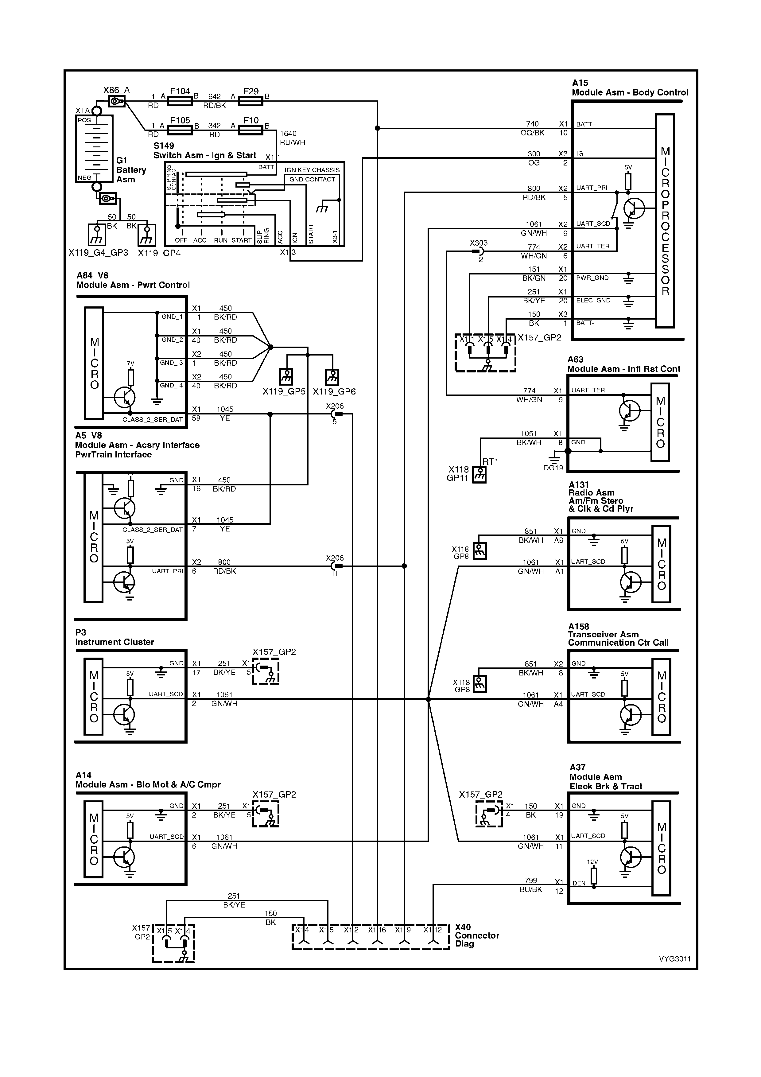
GEN III V8 PIM – DTC B2006 NO SERIAL DATA FROM PCM
Figure 6C3-2A-206 – Serial Data Circuit

CIRCUIT DESCRIPTION
The PIM rec eives inform ation from the PCM on the Class II serial data circu it. If there is a pr oblem with this circuit
or the PCM is not comm unicating, the PIM will detect this lack of information an d will set a DTC. Also, if there is a
problem with the serial data circuit, performing the Powertrain OBD System Check will lead you to the Data Link
Connector Diagnosis, where the problem that set this DTC will be diagnosed.
CONDITIONS FOR RUNNING THE DTC
• The ignition switch is ON.
• The ignition vo ltag e is bet ween 5.0 and 17 vo lts .
CONDITIONS FOR SETTING THE DTC
• PIM does not receive any serial data communication from the PCM.
ACTION TAKEN WHEN THE DTC SETS
• The PIM will display the DTC only when current.
• The Check Powertrain MIL will not illuminate.
CONDITIONS FOR CLEARING THE DTC
• A current DTC will clear when the PIM receives serial data from the PCM.
DIAGNOSTIC AIDS
• The following problems may cause this DTC to set:
– Poor connections/terminal tension at the PCM
– Poor connections/terminal tension at the PIM
• For an intermittent, refer to Section 6C3-2B SY MPTOM S.
TEST DESCRIPTION
NOTE: The number(s) below refer to the step number(s) on the diagnostic table.
1. The test confirms that the Powertrain OBD S yst em Check has been perf ormed
2. Diagnosis of this DTC will be perform ed using the Data Link Connector Diagnostic Table, found in the front of
this section. If there is an open, short to ground, or short to voltage in the Class II serial data circuit between
the PCM and the PIM, this will cause PIM DTC B2006 to set.
GEN III V8 PIM – DTC B2006 NO SERIAL DATA FROM PCM
STEP ACTION VALUE YES NO
1. Was the "On-Board Diagnostic" (OBD) System Check
performed? Go to Step 2 Go to
OBD System
Check
in this Section.
2. 1. Refer to Data Link Connector Diagnosis in the front of
this Volume for diagnosis of this PIM DTC.
Is action complete?
Verify Repair –
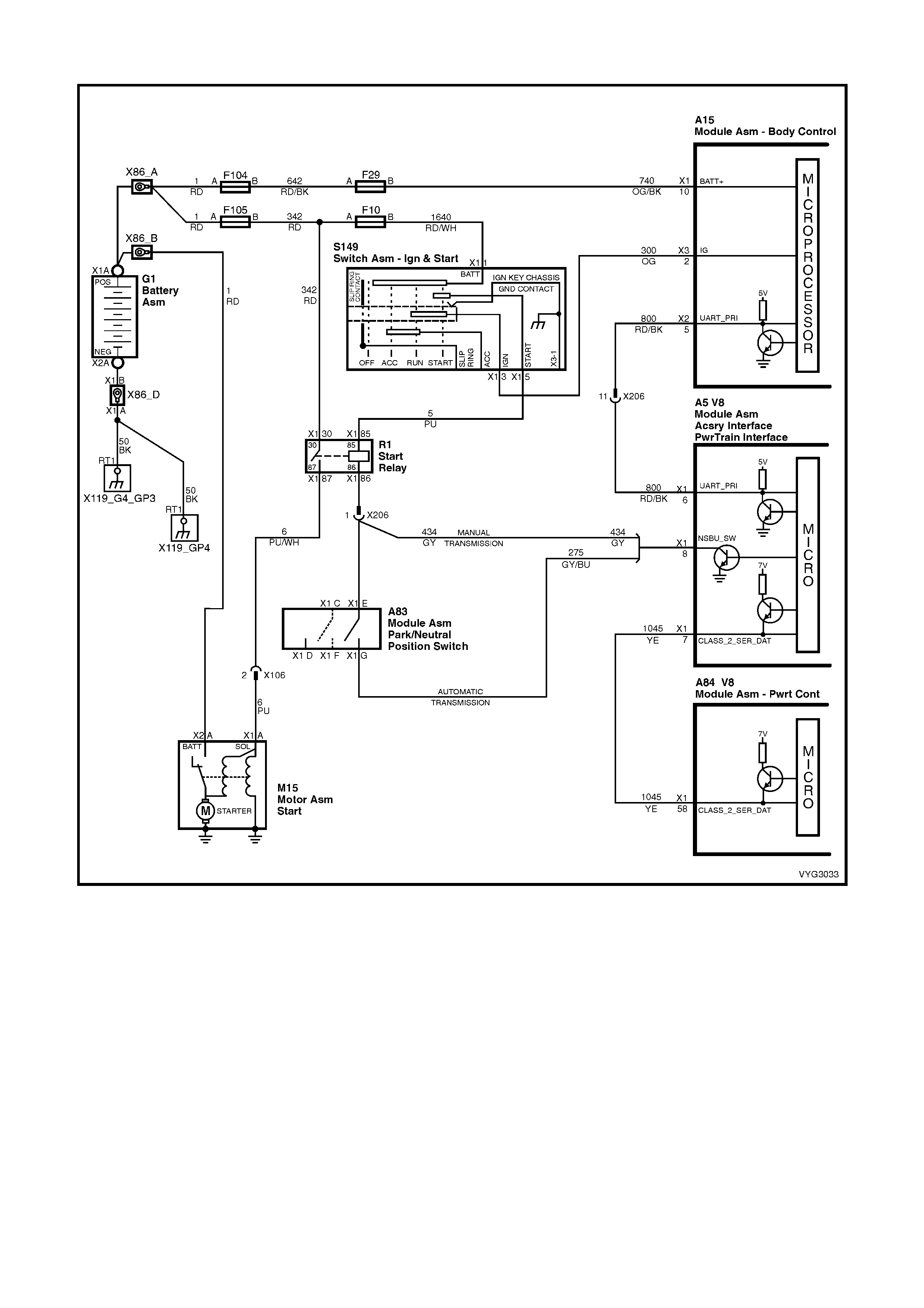
GEN III V8 PIM – DTC B2007 STARTER REL AY VOLTAGE HIGH
Figure 6C3-2A-207 – Starter Relay Circuit
CIRCUIT DESCRIPTION
When the key is turned to the crank position, power is supplied to the starter relay terminal 85. The PIM after
receivin g the pr oper theft deter rent sign al f rom the BC M will sup ply a gro und s ig n al t o t he s t ar ter re lay, ter minal 86.
This will ener gise t he star te r rela y and allo w the st arter m otor to op erate. If ther e is a problem with the s tart er relay
coil (shor ted internall y) or the s tarter rela y c ontrol circ uit (shorted to vo ltage) that is allowing 12 volts on the starter
relay control circuit, this will cause the PIM to set DTC B2007.
CONDITIONS FOR RUNNING THE DTC
• The ignition switch is in the crank position.
• The ignition vo ltag e is bet ween 5.0 and 17 vo lts .
CONDITIONS FOR SETTING THE DTC
• PIM detects high voltage on the starter relay control circuit.
ACTION TAKEN WHEN THE DTC SETS
• The PIM will display the DTC only when current.
• The Check Powertrain MIL will not illuminate.
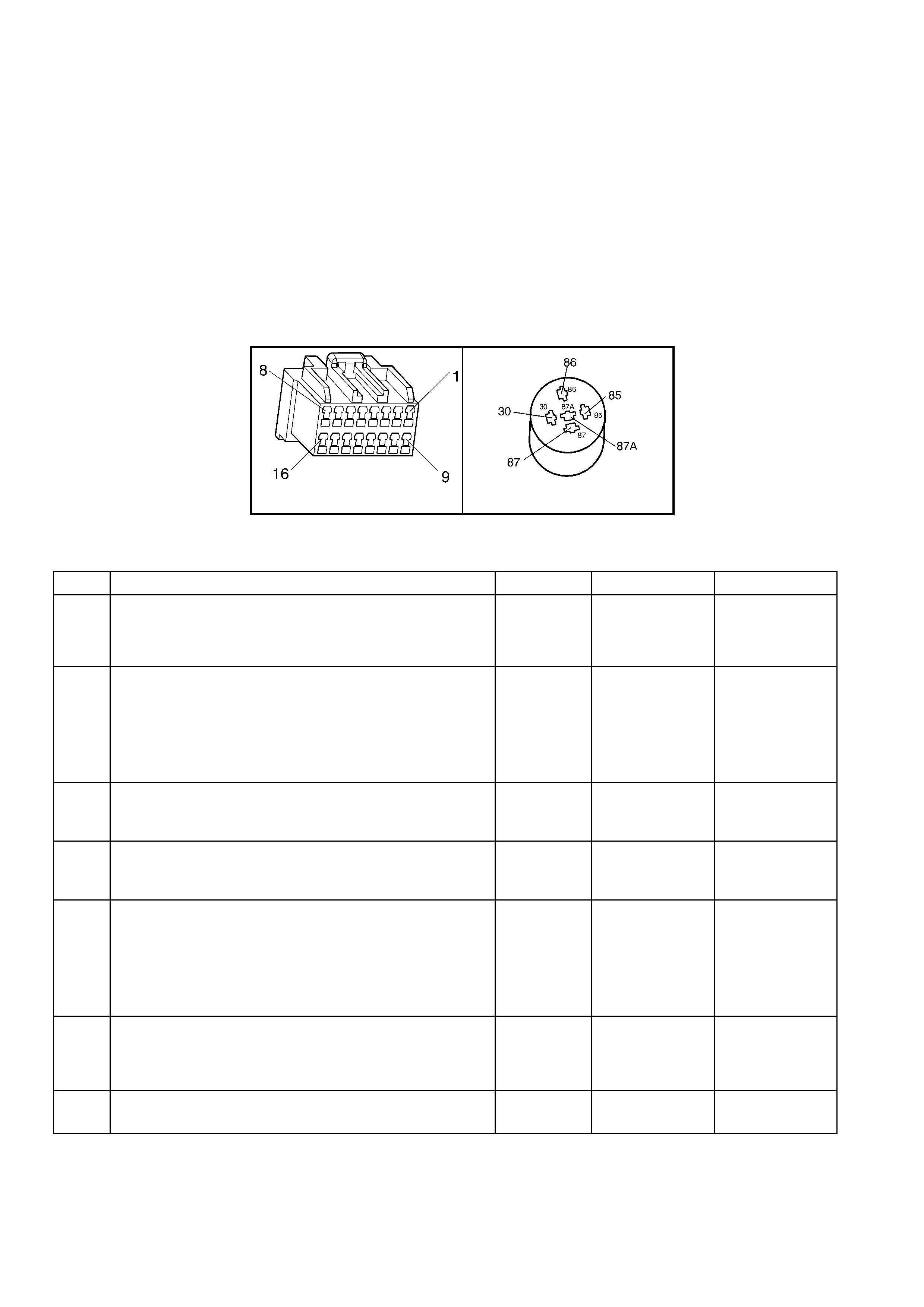
CONDITIONS FOR CLEARING DTC B2007
• A current DTC will clear when the PIM no longer detects a high voltage on the starter relay circuit.
DIAGNOSTIC AIDS
• The following may cause an intermittent:
– Incorrectly routed harness
– Rubbed through wire insulation
– Broken wire inside the insulation
• For an intermittent, refer to Section 6C3-2B SY MPTOM S.
TEST DESCRIPTION
NOTE: The number(s) below refer to the step number(s) on the diagnostic table.
2. This test ch ecks to see if the relay is causing the high v oltage problem.
5. This test checks to see if the PIM is caus ing the problem.
A5 X1 (PART OF X100)
Figure 6C3-2A-208
GEN III V8 PIM – DTC B2007 STARTER RELAY VOLTAGE HIGH
STEP ACTION VALUE YES NO
1. Was the "On-Board Diagnostic" (OBD) System Check
performed? Go to Step 2 Go to
OBD System
Check
in this Section.
2. 1. Ignition OFF.
2. Disconnect the PIM harness connector, A5.
3. Ignition ON.
4. Using a test light connected to ground, probe PIM
harness connector terminal for starter relay control.
Does test light illuminate?
Go to Step 3 Go to Step 5
3. 1. While the test light is still connected to PIM harness
connector, disconnect the starter relay.
Is test light still activated?
Go to Step 4 Go to Step 7
4. 1. Repair short to voltage in the starter relay control
circuit.
Is action complete?
Verify Repair –
5. 1. Ignition OFF.
2. Reconnect the PIM harness connector, A5.
3. Crank engine.
4. Using Tech 2, check to see if PIM DTC B2007 has
reset.
Did PIM DTC B2007 reset?
Go to Step 6 System OK
6. 1. Replace PIM. Refer to PIM Replace and
PCM/PIM/BCM Security Link Procedure, in 6C3-3
SERVICE OPERATIONS.
Is action complete?
System OK –
7. 1. Replace starter relay, X1.
Is action complete? System OK –
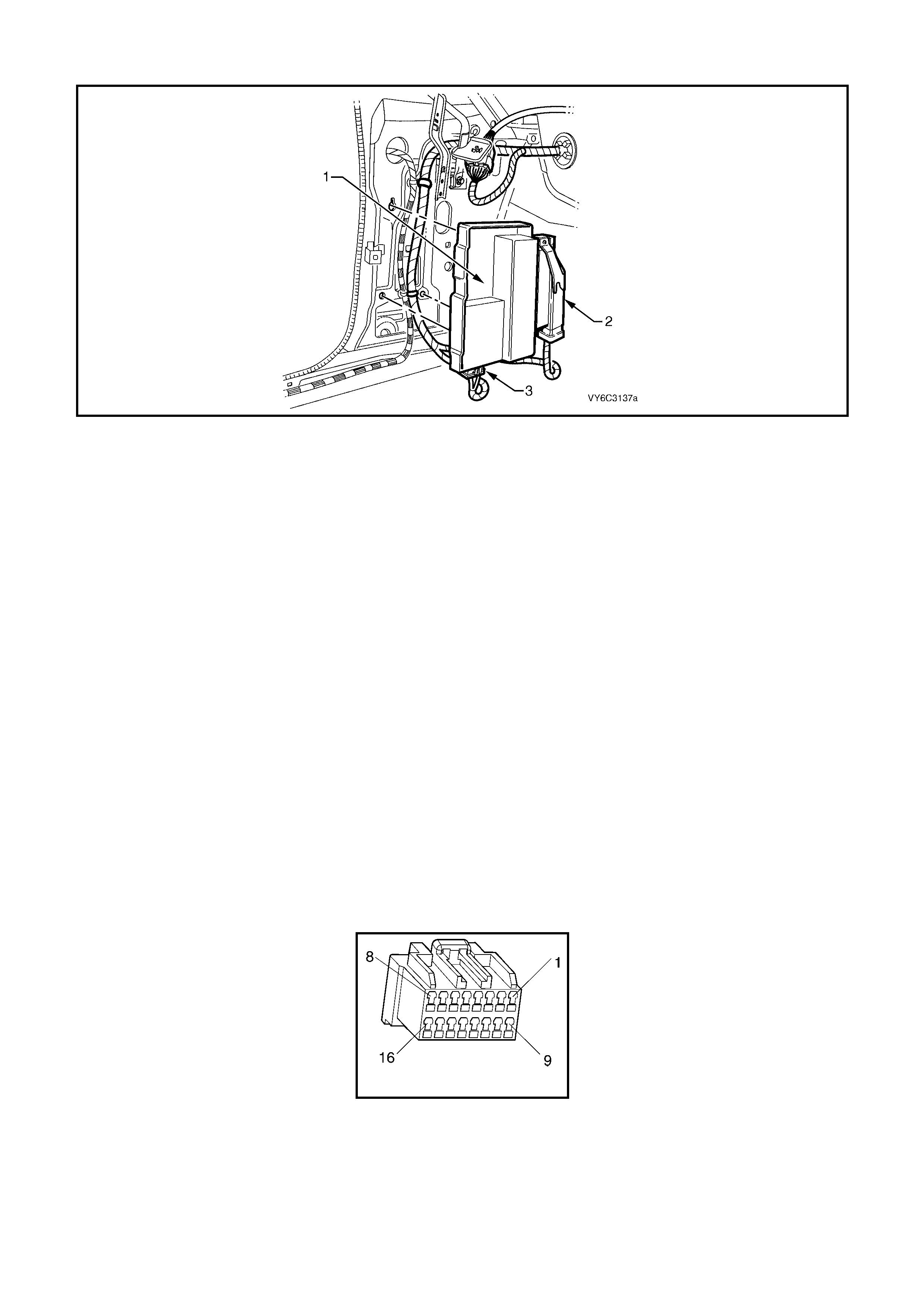
GEN III V8 PIM – DTC B2009 EEPROM CHECKSUM ERROR
Figure 6C3-2A-209 – Powertrain Interface Module Location
Legend
1. Powertrain Interface Module (PIM) 2. Throttle Relaxer Control Module 3. PIM Wiring Harness Connector
CIRCUIT DESCRIPTION
The PIM EEPROM contains data which is essential to running the engine. The PIM continuously checks the
integrity of this data.
CONDITIONS FOR RUNNING THE DTC
• The ignition switch is in the ‘CRANK’ or ‘ON’ position.
CONDITIONS FOR SETTING THE DTC
• The PIM is unable to correctly read data from its memory.
ACTION TAKEN WHEN THE DTC SETS
• The PIM will display the DTC only when current.
• The Check Powertrain MIL will not illuminate.
CONDITIONS FOR CLEARING DTC
• A current DTC will clear when the PIM is able to correctly read data.
DIAGNOSTIC AIDS
• For an intermittent, refer to Section 6C3-2B SY MPTOM S.
TEST DESCRIPTION
NOTE: The number(s) below refer to the step number(s) on the diagnostic table.
2. This DTC indicates an internal PIM problem.
A5
Figure 6C3-2A-210

GEN III V8 PCM – DTC B2009 EEPROM CHECKSUM ERROR
STEP ACTION VALUE YES NO
1. Was the "On-Board Diagnostic" (OBD) System Check
performed? Go to Step 2 Go to
OBD System
Check
in this Section.
2. 1. Replace PIM. Refer to PIM Replace and
PCM/PIM/BCM Security Link Procedure, in 6C3-3
SERVICE OPERATIONS.
Is action complete?
Go to Step 3 –
3. 1. Select the Diagnostic Trouble Code (DTC) option and
the Clear DTC Information option using Tech 2.
2. Idle the engine at normal operating temperature.
3. Select the Diagnostic Trouble Code (DTC) option
using Tech 2.
Does Tech 2 indicate that this DTC reset?
Go to Step 2 Go to Step 4
4. 1. Using Tech 2, check for any other DTCs.
Does Tech 2 display any DTCs that you have not
diagnosed?
Go to the
applicable DTC
table
System OK