
SECTION 6C3-2C - FUNCTIONAL CHECKS -
GEN III V8 ENGINE
IMPORTANT
Before performing any Service Operation or other procedure described in this Section, refer to Section
00 CAUTIONS AND NOTES for correct workshop practices with regard to safety and/or property damage.
The following pages are to be used when there is a custom er complaint and there are no diagnostic trouble codes
set, or one or more of the Tech 2 data values are not within the typical values. They are also to be used when
instructed from a DTC table. Before using these tables, you should refer to Section 6C3-2B SYMPTOMS, which
may direct you to using this Section.
The purpose of these tables is to diagnose Powertrain Control Module (PCM) controlled components or sub-
systems that do not have diagnostic trouble codes assigned to them. Another purpose of these tables is for
Technicians who feel confident that a particular part of the sub-system is not operating properly and wants only to
check that particular item for proper operation without going through lengthy diagnostic procedures.
CONTENTS
ENGINE COOLING FAN CONTROL
A/C REQUEST CIRCUIT DIAGNOSIS
A/C REFRIGERANT PRESSURE SENSOR CIRCUIT DIAGNOSIS
FUEL INJECTOR BALANCE TEST
FUEL INJECTOR COIL TEST - ECT BETWEEN 10-35°C
FUEL INJECTOR COIL TEST - ECT OUTSIDE 10-35°C
FUEL INJECTOR CIRCUIT DIAGNOSIS
ELECTRONIC IGNITION SYSTEM DIAGNOSIS
AUTOMATIC TRANSMISSION POWER/ECONOMY SWITCH
INSTRUMENT PANEL GEAR INDICATOR CHECK
ENGINE COOLANT LEVEL SWITCH DIAGNOSIS
MANUAL TRANSMISSION REVERSE INHIBIT SOLENOID DIAGNOSIS
AUTOMATIC TRANSMISSION WIRING HARNESS CHECK
AUTOMATIC TRANSMISSION FLUID PRESSURE (TFP) MANUAL
VALVE POSITION SWITCH RESISTANCE CHECK
AUTOMATIC TRANSMISSION FUNCTIONAL CHECK PROCEDURE
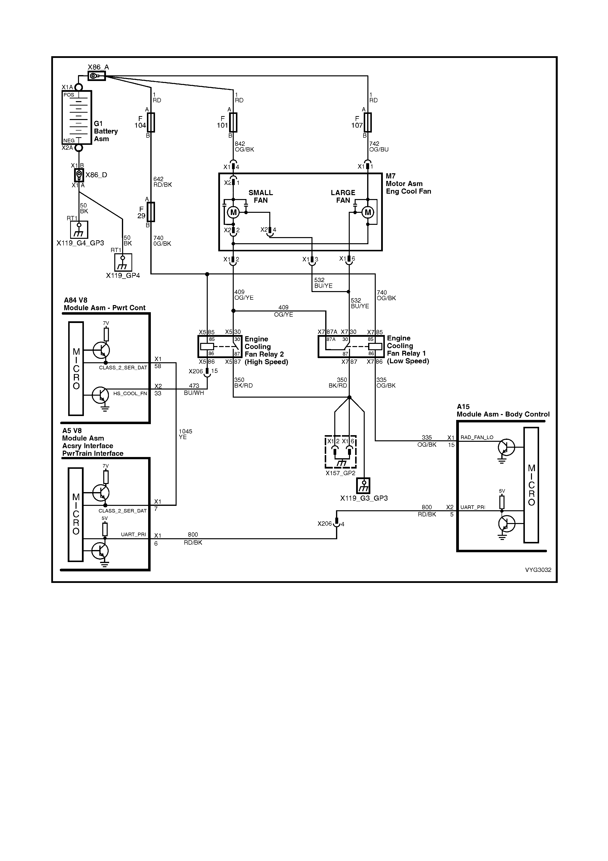
GEN III V8 PCM – ENGINE COOLING FAN CONTROL
Figure 6C3-2C-1 – Cooling Fan Circuits
CIRCUIT DESCRIPTION
The GEN III V8 engine has two, two speed electric engine cooling fan motors which provide the prim ary m eans of
moving air through the radiator. The cooling fans are used to cool engine coolant flowing through the radiator and
the refrigerant flowing through the A/C condenser (where fitted).
The engine c ooling f an high s peed relay is controlled by the PCM. The PCM controls the gr ound path f or the engine
cooling fan high speed relay.
The low speed of the engine cooling fans is c ontrolled by the PCM through ser ial data comm unication to the BCM.
The BCM controls the ground path for the engine cooling fan low speed relay.
Both relays are used to control the ground paths to the electric motors that drive both fans.
LOW SPEED ENGINE COOLING FAN
The engine cooling fan low speed relay is energised by the BCM. The PCM determines when to enable the low
speed engine cooling fan based on inputs from the A/C request signal, vehicle speed and engine coolant
temperature. The engine cooling low speed relay fan will be turned ON when:
• A/C request indicated (YES) and;
• Vehicle speed less than 30 km/h
OR
• Coolant temper ature is greater than a s pecified value and will rem ain on until coolant tem perature reduces to a
predetermined value.
HIGH SPEED ENGINE COOLING FAN
The high speed engine cooling fan relay is controlled by the PCM based on input from the Engine Coolant
Temperature Sensor (ECT) and the A/C Pressure Sensor. The PCM will only turn ON the high speed engine cooling
fan relay if the low speed engine cooling fan relay has been ON for 2 seconds and the following conditions are
satisf ied.
• There is a BCM message response fault which will cause a DTC to set.
• An engine coolant temperature sensor failure is detected, such as DTC P0117, P0118, P1114, P1115.
• Coolant temperature greater than a specified value.
• A/C pressure greater than a specified value.
If the low speed fan relay was OFF when the criteria was met to turn the fan high speed ON, the high speed fan
relay will operate 5 seconds after the low speed fan. T he engine cooling fan High speed relay can also be enabled
by the A/C Refrigerant Pressure Sensor. The A/C Refrigerant Pressure Sensor will provide a signal to the PCM
when A/C pressure becomes too high; approximately 2,600 kPa.
For replacement of the cooling fan motor, refer to Section 6B3 ENGINE COOLING.
TEST DESCRIPTION
NOTE: The number(s) below refer to the step number(s) on the diagnostic table.
2. This entire diagnos tic proc edur e must begin with a cold engine - at ambient air temperatur e. If the c oolant is hot
when diagnosis is performed, replacement of good parts will result. The fans should not be running if engine
coolant temperature is less than 99° C and air conditioning is not ON.
10. On A/C equipped vehicles, the engine cooling fan Low speed relay should be energised by the BCM, as soon
as the PCM energises the A/C clutch.
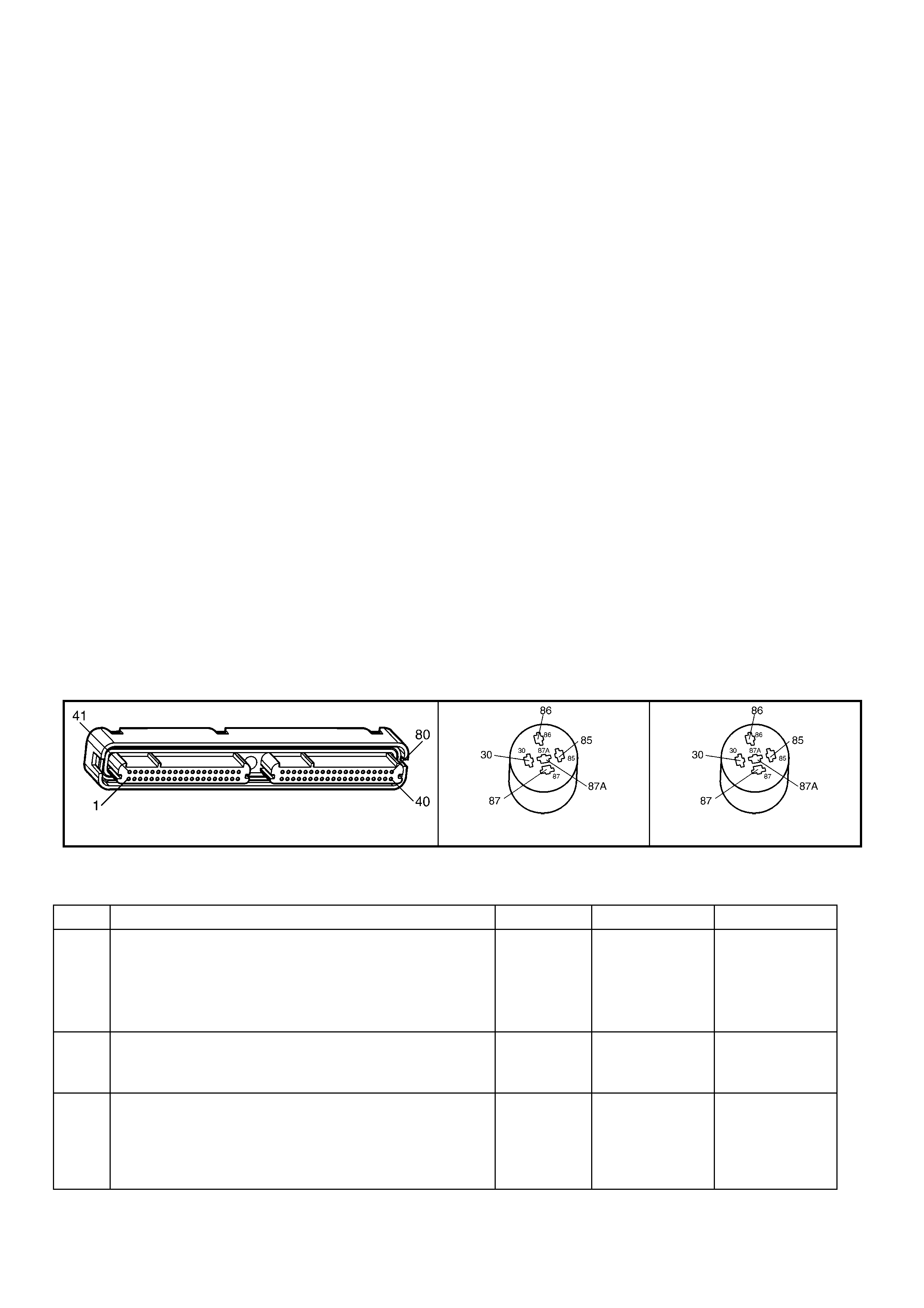
A84–X2 (RED) R5 (PART OF X100) R7 (PART OF X100)
Figure 6C3-2C-2
GEN III V8 PCM – ENGINE COOLING FAN CONTROL
STEP ACTION VALUE YES NO
1. Was the "On-Board Diagnostic" (OBD) System Check
performed? Go to Step 2 Go to
OBD System
Check
in 6C3-2A
DIAGNOSTIC
TABLES
2. 1. Ignition ON, engine OFF.
2. Engine coolant temperature below 99° C.
Are both engine cooling fan motors running ?
Go to Step 3 Go to Step 9
3. 1. Ignition OFF.
2. Remove the Engine Cooling Fan High Speed Relay
R5.
3. Ignition ON.
Do both fans continue to run ?
Go to Step 4 Go to Step 5

STEP ACTION VALUE YES NO
4. 1. Ignition ON.
2. Remove Engine Cooling Fan Low Speed Relay, R7.
Do both fans continue to run?
Go to Step 13 Go to Step 16
5. 1. Ignition ON.
2. Probe Engine Cooling Fan High Speed Relay harness
connector circuit 473 with a test light to +12 volts.
Is the test light ON?
Go to Step 6 Go to Step 8
6. 1. Ignition OFF.
2. Disconnect PCM RED connector A84-X2.
3. Ignition ON.
4. Using test light, probe Engine Cooling Fan High
Speed Relay harness connector circuit 473 with a test
light connected to +12 volts.
Is the test light ON?
Go to Step 14 Go to Step 7
7. 1. Replace PCM. Refer to PCM Programming and
PCM/PIM/BCM Security Link Procedure, in 6C3-3
SERVICE OPERATIONS.
Is action complete?
System OK –
8. Replace Engine Cooling Fan High Speed Relay, R5. System OK –
9. 1. Ignition ON.
2. Using Tech 2, select HIGH FAN relay control.
3. Turn ON HIGH FAN with Tech 2.
Do both cooling fans operate in high fan mode?
Go to Step 20 Go to Step 23
10. Is the vehicle equipped with A/C? Go to Step 11 Go to Step 12
11. 1. Start engine, allow to idle.
2. Turn A/C ON.
3. The fans should run when the A/C clutch engages.
Do the fans run when A/C clutch is engaged?
Go to Step 12 Go to Step 9
12. The engine cooling fan circuits are OK. System OK –
13. 1. Connect a test light to +12 volts.
2. Probe circuit 532 of Engine Cooling Fan Low Speed
Relay R7.
Is the test light ON?
Go to Step 15 –
14. Repair short to ground in circuit 473. System OK –
15. Repair short to ground in circuit 532. System OK –
16. 1. Ignition ON.
2. Probe Engine Cooling Fan Low Speed Relay harness
connector circuit 335 with a test light connected to +12
volts.
Is the test light ON?
Go to Step 17 Go to Step 21
17. 1. Ignition OFF.
2. Check for short to ground on circuit 335.
Was a short to ground found?
System OK Go to Step 18
18. Replace the BCM. Refer to 12J BODY CONTROL
MODULE. System OK –
19. 1. Reinstall Engine Cooling Fan High Speed Relay, R5.
2. Ignition ON.
3. Using Tech 2, select LOW FAN.
4. Turn ON LOW FAN with Tech 2.
Do the engine cooling motors run?
Go to Step 10 Go to Step 40
20. 1. Ignition ON.
2. Using Tech 2, select HIGH FAN relay control.
3. Turn ON HIGH FAN with Tech 2.
4. W hile fan is running, remove Engine Cooling Fan High
Speed Relay, R5.
Did the cooling fan motors reduce to a lower running
speed?
Go to Step 19 If engine cooling
motor is turned
OFF,
go to Step 40

STEP ACTION VALUE YES NO
21. 1. Check for short to ground in circuit 532.
Was a problem found? System OK Go to Step 22
22. 1. Replace Engine Cooling Fan Low Speed Relay, R7.
Is action complete? System OK –
23. 1. Check fusible links F104, F101, F107, and fusible link
1A for open.
Was a problem found?
Go to Step 29 Go to Step 24
24. 1. Ignition OFF.
2. Remove Engine Cooling Fan High Speed Relay, R5.
3. Ignition ON.
4. Probe relay socket, circuit 740 with a test light
connected to ground.
Is test light ON?
Go to Step 25 Go to Step 31
25. 1. Ignition ON.
2. Probe Engine Cooling Fan High Speed Relay socket
circuit 473 with a test light connected to +12 volts.
3. Using Tech 2, select HIGH FAN, enable fan ON, using
the up/down arrows.
Is test light ON?
Go to Step 26 Go to Step 30
26. 1. Ignition ON.
2. Reinstall Engine Cooling Fan High Speed Relay, R5.
3. Back-probe Engine Cooling Fan High Speed Relay
harness connector circuit 409 with test light connected
to +12 volts.
4. Using Tech 2, select HIGH FAN, enable fan ON.
Is test light ON?
Go to Step 27 Go to Step 32
27. 1. Ignition ON.
2. Disconnect both electric cooling fan wiring harness
connectors.
3. Probe both fan harness connectors, circuit 409 with a
test light to +12 volts.
4. Using Tech 2, select HIGH FAN, enable fan ON.
Is test light ON for both circuits ?
Go to Step 28 Go to Step 34
28. 1. Probe both fan harness connector power feed circuits
with a test light connected to ground.
Is test light ON for all circuits?
Go to Step 33 Go to Step 35
29. 1. Check for short to ground that caused fusible link to
blow.
2. Check that the engine cooling fan motor is not drawing
too much current.
Is action complete?
System OK –
30. 1. Check for open in circuit 473 from relay to PCM, or
faulty PCM connection.
Was a problem found?
System OK Go to Step 36
31. Repair open or short to ground in circuit 740.
Replace fuse if blown. System OK –
32. 1. With test light connected to +12 volts, back probe
Engine Cooling Fan High Speed Relay harness
connector circuit 350.
Does test light illuminate?
Go to Step 37 Go to Step 38
33. 1. Check for poor connection at both fan motors. If OK,
replace the electric fan motor that did not operate.
Was a problem found?
System OK –
34. 1. Check for open in circuit 409.
Was a problem found? System OK Go to Step 38
35. Repair open circuit in fan motor power circuit that did not
light test light. System OK –

STEP ACTION VALUE YES NO
36. 1. Replace PCM. Refer to PCM Programming and
PCM/PIM/BCM Security Link Procedure, in 6C3-3
SERVICE OPERATIONS.
Is action complete?
System OK –
37. Replace Engine Cooling Fan High Speed Relay, R5. System OK –
38. 1. Check both relays for open in ground circuit 350.
Was a problem found? System OK Go to Step 39
39. Replace Engine Cooling Fan Low Speed Relay, R7. System OK –
40. 1. Ignition OFF.
2. Remove Engine cooling Low Speed Relay, R7.
3. Probe relay socket, circuit 532 with a test light
connected to +12 volts.
Is test light ON?
Go to Step 45 Go to Step 41
41. 1. Ignition OFF.
2. Remove Engine Cooling Fan Low Speed Relay R7.
3. Ignition ON.
4. Probe relay socket, circuit 740 with test light
connected to ground.
Is test light ON?
Go to Step 42 Go to Step 47
42. 1. Ignition ON.
2. Probe Engine cooling Low Speed Relay socket, circuit
335 with a test light connected to +12 volts.
3. Using Tech 2, select LOW FAN, enable fan ON.
Is test light ON?
Go to Step 43 Go to Step 46
43. 1. Ignition ON.
2. Reinstall Engine Cooling Fan Low Speed Relay, R7.
3. Back-probe low speed cooling fan relay wiring harness
connector, circuit 532 with test light connected to +12
volts.
4. Using Tech 2, select LOW FAN, enable fan ON.
Is test light ON?
Go to Step 48 Go to Step 44
44. 1. Ignition OFF.
2. Disconnect both electric cooling fan wiring harness
connectors.
3. Probe both wiring harness connector circuits 532 with
test light connected to +12 volts.
4. Using Tech 2, select LOW FAN, enable fan ON.
Is test light ON?
Go to Step 52 Go to Step 50
45. 1. Repair short to ground in circuit 532.
Is action complete? System OK –
46. 1. Ignition ON.
2. Using Tech 2, select LOW FAN, enable fan ON.
3. Backprobe BCM A15, terminal X1-15 with a test light
connected to +12 volts.
Is test light ON?
Go to Step 51 Go to Step 53
47. 1. Repair open in circuit which causes test light not to
come ON.
Is action complete?
System OK –
48. 1. Replace Engine Cooling Fan Low Speed Relay, R7.
Is action complete? System OK –
49. Repair short to ground. System OK –
50. 1. Repair open in circuit 532.
Is action complete? System OK –
51. 1. Repair open in circuit 335 between BCM and Engine
Cooling Fan Low Speed Relay.
Is action complete?
System OK –

STEP ACTION VALUE YES NO
52. 1. Replace the engine cooling motor that did not operate.
Refer to 6B3 ENGINE COOLING – GEN III V8
ENGINE.
Is action complete?
System OK –
53. 1. Check for faulty connection at BCM, if OK replace
BCM. Refer to 12J BODY CONTROL MODULE.
Is action complete?
System OK –
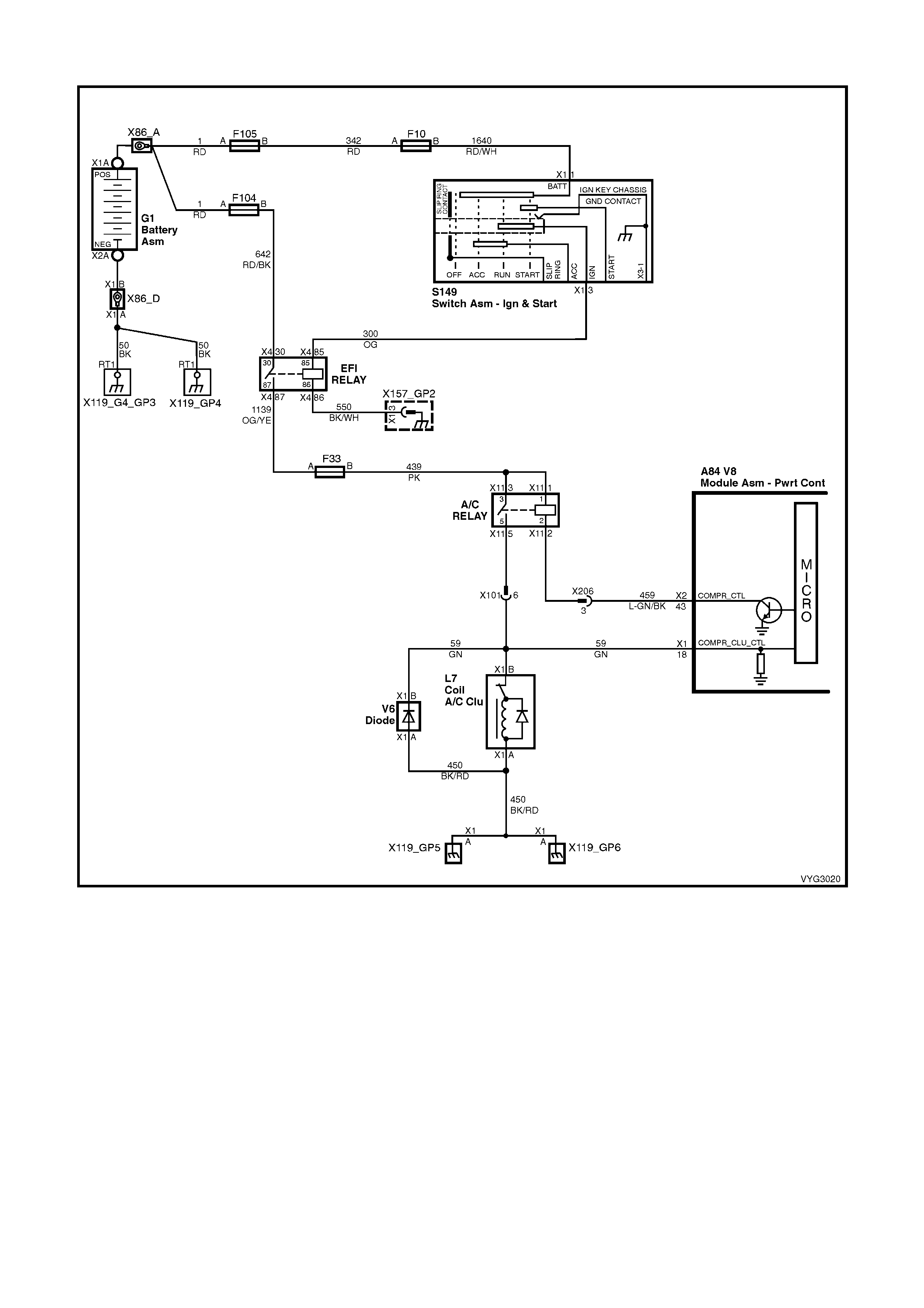
GEN III V8 PCM – A/C REQUEST CIRCUIT DIAGNOSIS
Figure 6C3-2C-3 – Air Conditioning Clutch Circuit
CIRCUIT DESCRIPTION
The A/C clutch relay is PCM c ontrolled to delay A/C clutch engagem ent after the A/C is turned ON. T his allows the
PCM to adjust engine RPM before the A/C clutch engages. The PCM will engage the A/C clutch any time A/C has
been requested unless any of the following conditions exist:
• High coolant temperature.
• Low A/C system pressure.
• High A/C system pressure.
• Wide open throttle.
• High engine RPM.
• Open A/C Pressure sensor signal or ground circuit.
When the heater and A/C control is placed in the A/C mode, a 12 volt signal is sent to the BCM. W hen the BCM
receives this 12 volt input, it will request A/C by sending a serial data message via the serial data line to the PCM.
W hen the PCM receives this m essage from the BCM, it will ground the A/C clutch relay control circuit to energise
the A/C relay. This is shown on Tech 2 as A/C request ON.
When a reques t f or A/C has been detec ted by the PCM, the PCM will ground the A/C clutch relay control circuit, the
relay contacts will close, and current will flow through the relay to the A/C compressor clutch.
When an A/C request has been detected by the PCM, the cooling fan(s) will be turned ON.
DIAGNOSTIC AIDS
• Ensure no PCM DTC(s) are stored before using this table. The PCM will not activate the A/C clutch with a
stored DT C. Als o, if the A/C Ref r igerant Pr es sur e Sens or s ignal or gr ound cir cuit is open, the A/C c lutch will not
engage and the cooling fans will be on high speed, but no DTC will set.
TEST DESCRIPTION
NOTE: The number(s) below refer to the step number(s) on the diagnostic table.
2. A/C DTCs will disable the A/C system. Repair A/C DTCs before proceeding.
3. This test determines if the A/C power fuse is open. If this fuse is open, the instrument panel, and the blower
relay will also be inoperative.
5. The request circuit is shorted to a voltage if Tech 2 displays A/C request as ON.
7. This test checks to see if the A/C control unit is capable of supplying the proper voltage.
8. This test checks the continuity between the BCM and the A/C control unit.
9. If the A/C Refrigerant Pressure Sensor ground circuit is open, this will cause the A/C clutch not to engage.
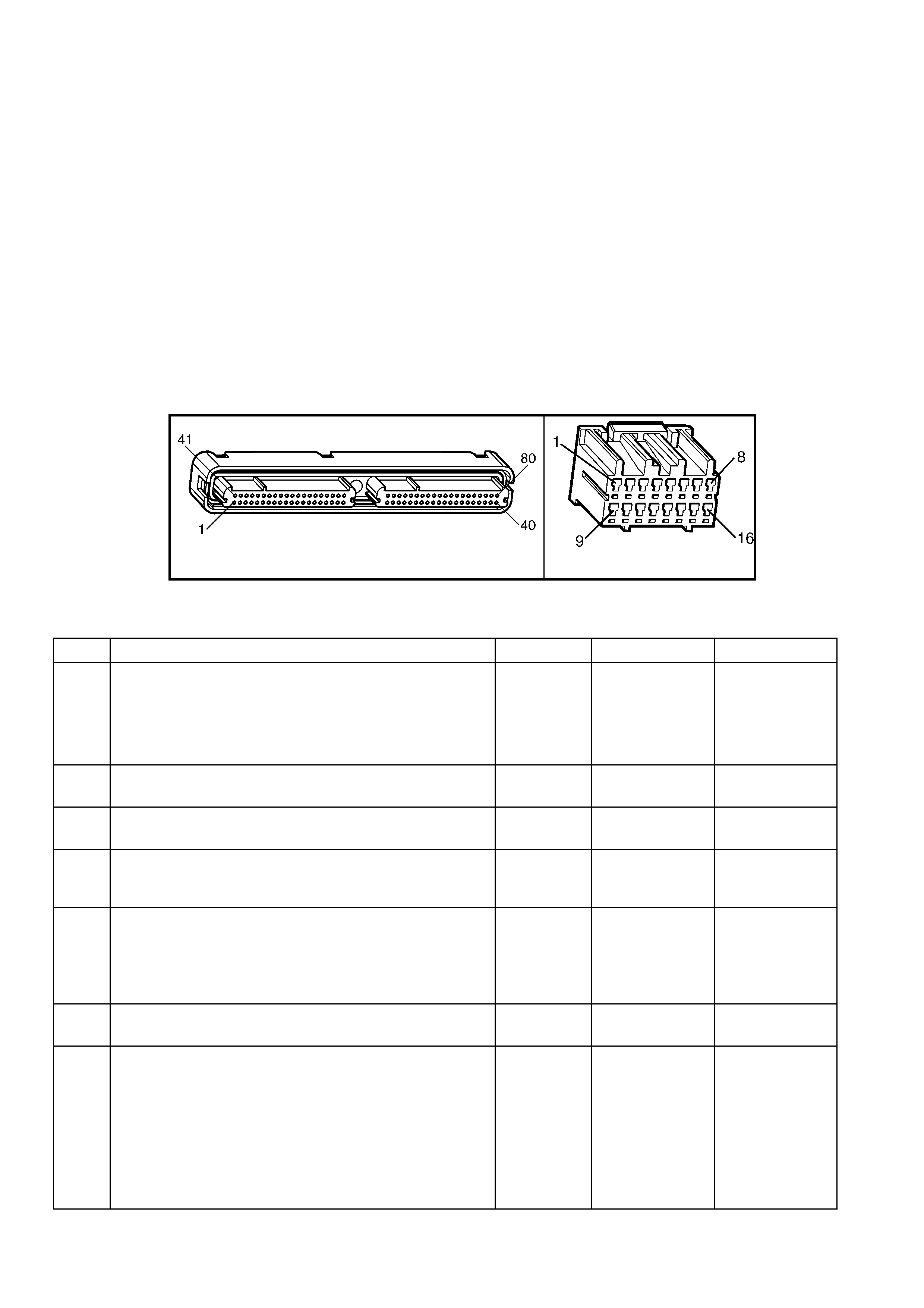
A84–X2 (RED) A15–X3
Figure 6C3-2C-4
GEN III V8 PCM – A/C REQUEST CIRCUIT DIAGNOSIS
STEP ACTION VALUE YES NO
1. Was the "On-Board Diagnostic" (OBD) System Check
performed? Go to Step 2 Go to
OBD System
Check
in 6C3-2A
DIAGNOSTIC
TABLES
2. Are any A/C DTCs set?
Go to applicable
DTC table Go to Step 3
3. 1. Check for blown F13 fuse.
Is fuse OK? Go to Step 5 Go to Step 4
4. 1. Repair short to ground in F13 fuse circuit, then replace
fuse.
Is action complete?
System OK –
5. 1. Install Tech 2.
2. Idle the engine with the A/C OFF, blower switch ON.
3. Monitor A/C request on the Engine Data List using
Tech 2 .
Does Tech 2 indicate A/C request as ON?
Go to Step 10 Go to Step 6
6. 1. Idle the engine with the A/C ON, blower switch ON.
Does Tech 2 indicate A/C request as YES? System OK Go to Step 7
7. 1. Ignition OFF.
2. Disconnect the BCM connector, A15-X3.
3. Ignition ON, engine OFF, with the A/C ON, blower
switch ON.
4. Back probe the A/C request circuit at the BCM
harness connector A15-X2, terminal X3-5, using a
DMM connected to ground:
Does the DMM display near the specified value when A/C
is enabled?
Non-OCC
System B+
OCC
System
2 – 4 Volts
Go to Step 12 Go to Step 8

STEP ACTION VALUE YES NO
8. 1. Ignition OFF.
2. Check the A/C request circuit for continuity between
the A/C control module and the BCM using a DMM.
Does the DMM indicate continuity?
Go to Step 9 Go to Step 11
9. 1. Refer to 2C HVAC SERVICING & DIAGNOSIS or 2F
OCC - DIAGNOSIS.
Is the action complete?
System OK –
10. 1. Inspect the A/C request circuit for an open or short to
voltage.
Did you find a problem and correct it?
System OK Go to Step 13
11. 1. Repair the open A/C request circuit between the A/C
control unit and the BCM.
Is the action complete?
System OK –
12. 1. Replace PCM. Refer to PCM Programming and
PCM/PIM/BCM Security Link Procedure, in 6C3-3
SERVICE OPERATIONS.
Is the action complete?
System OK –
13. 1. Inspect the A/C refrigerant pressure ground circuit for
an open.
Was a problem found?
System OK Go to Step 9
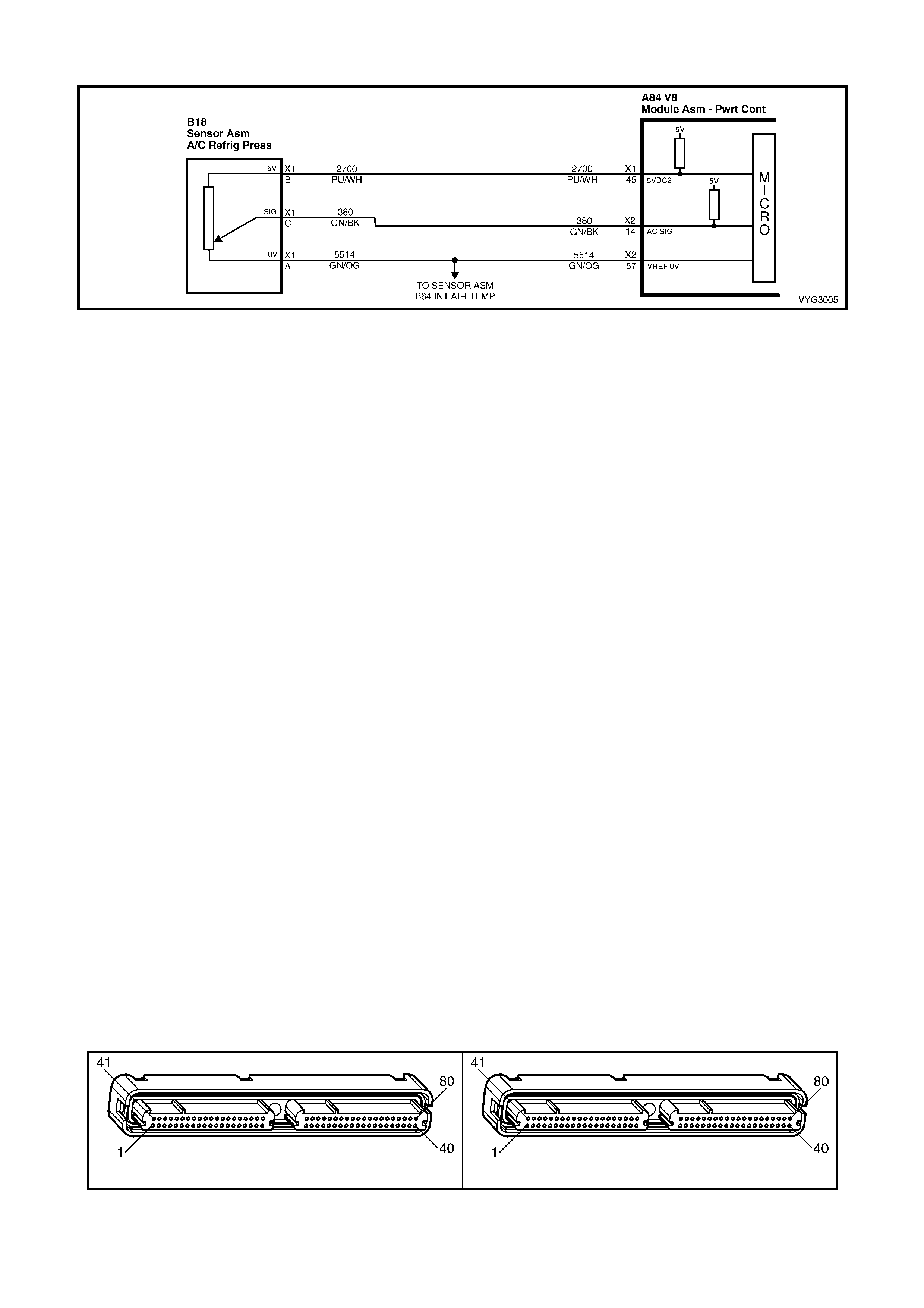
GEN III V8 PCM – A/C REFRIGERANT PRESSURE SENSOR CIRCUIT DIAGNOSIS
Figure 6C3 -2C-5 – Air Conditioning System Pressure Sensor Circuit
CIRCUIT DESCRIPTION
The PCM c ontrols the A/C c ompres sor c lutch to optimise the per f or mance of the A/C s ystem. The PCM determines
when to cycle the A/C compressor clutch by monitoring the A/C Refrigerant Pressure Sensor.
The A/C Refrigerant Pressure Sensor is also used by the PCM to enable the engine cooling fans when the A/C
compressor head pressure reaches a predetermined value.
The PCM energis es the A/C com pres sor clutch when the engine speed is less than 4800 RPM and the A/C system
is requested. If you request the A/C at engine speeds greater than 4800 RPM, the PCM will not energise the A/C
compressor clutch until the engine speed decreases to less than 4000 RPM.
Any one of the following conditions disables the A/C compressor clutch.
• The Throttle is commanded to Wide Open Throttle (WOT).
• The A/C head pressure is greater than 2895 kPa.
• The A/C head pressure is less than 176 kPa.
• The ignition voltage is less than 10 volts.
• The engine speed is greater than 4800 rpm.
• The engine coolant temperature is greater than 125° C.
The PCM also disables the A/C compressor when certain DTCs set.
DIAGNOSTIC AIDS
• Inspect the harness between the A/C clutch and PCM for intermittent connections. While the engine is
operating with the A/C enabled, move related electrical connectors and harnesses. This may aid in locating an
intermittent fault.
• For an intermittent, refer to Section 6C3-2B SYMPTOMS.
TEST DESCRIPTION
NOTE: The number(s) below refer to the step number(s) on the diagnostic table.
2. This step checks if the PCM can turn the A/C compressor ON.
3. This step checks for an A/C Refrigerant Pressure Sensor that is at a fixed value (stuck).
4. Inspect the A/C clutch st atus c irc uit bef or e replac ing the A/C Ref r igerant Pr ess ur e Sensor . Als o, a low refr iger ant
charge in the A/C system can cause an A/C system performance condition.
5. This check determines if the A/C refrigerant pressure is OK. If pressure is too high or too low the A/C system
maybe over charged or have a leak.
6. The PCM’s A/C clutch status circuit may not detect voltage when the A/C is commanded ON if the B+ supply
circuit to the A/C relay is intermittent. Inspect the relay connections and operation.
A84–X1 (BLUE) A84-X2 (RED)
L7 V6 B18
Figure 6C3-2C-6
GEN III V8 PCM – A/C REFRIGERANT PRESSURE SENSOR CIRCUIT DIAGNOSIS
STEP ACTION VALUE YES NO
1. Was the "On-Board Diagnostic" (OBD) System Check
performed? Go to Step 2 Go to
OBD System
Check
in 6C3-2A
DIAGNOSTIC
TABLES
2. IMPORTANT: If DTCs P0530, or P1546 are set, refer to
those tables.
1. Run the engine at idle.
2. Turn ON the A/C.
Does the A/C clutch engage?
Go to Step 3 Go to Step 4
3. 1. Observe the A/C High Side pressure display on the
Engine Data List using Tech 2.
2. Turn OFF the A/C for 10 seconds.
3. Turn ON the A/C for 10 seconds.
Did the A/C High Side pressure increase more than the
specified value when the A/C controls were turned ON?
27 kPa Refer to
Diagnostic Aids Go to Step 4
4. 1. Connect Tech 2 and select “Engine Data”.
Does Tech 2 indicate the A/C clutch ON? Go to Step 7 Go to Step 5
5. 1. Connect Tech 2 and select “Engine Data”.
2. Ignition ON, engine OFF.
Does Tech 2 display A/C pressure between specified
values?
300-2500
kPa Go to Step 6 Refer Air
Conditioning
Diagnosis in 2C,
3.0 Diagnosis.
6. 1. Ignition OFF.
2. Disconnect the A/C compressor clutch harness
connector.
3. Probe the A/C compressor clutch B+ supply circuit 59
to battery ground using a test lamp.
4. Run the engine at idle.
5. Turn ON the A/C.
Does the test lamp illuminate?
Go to Step 8 Go to Step 12
7. 1. Probe the A/C compressor clutch B+ supply circuit to
the A/C compressor clutch ground circuit using a test
lamp.
Does the test lamp illuminate?
Go to Step 9 Go to Step 9
8. 1. Repair the faulty A/C clutch connection or the open
A/C clutch coil.
Is the action complete?
System OK –
9. 1. Repair the open or the shorted A/C clutch B+ supply
circuit.
Is the action complete?
System OK –
10. 1. Repair the open A/C clutch ground circuit.
Is the action complete? System OK –
11. 1. Inspect the A/C refrigerant pressure sensor ground
circuit for an open.
Was a problem found?
System OK
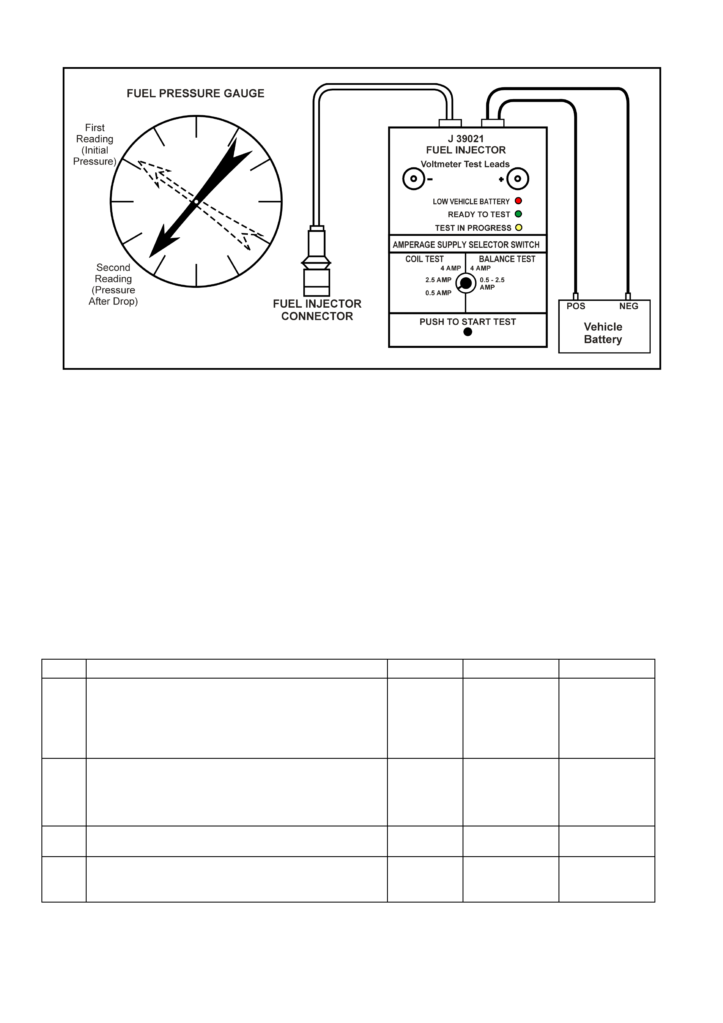
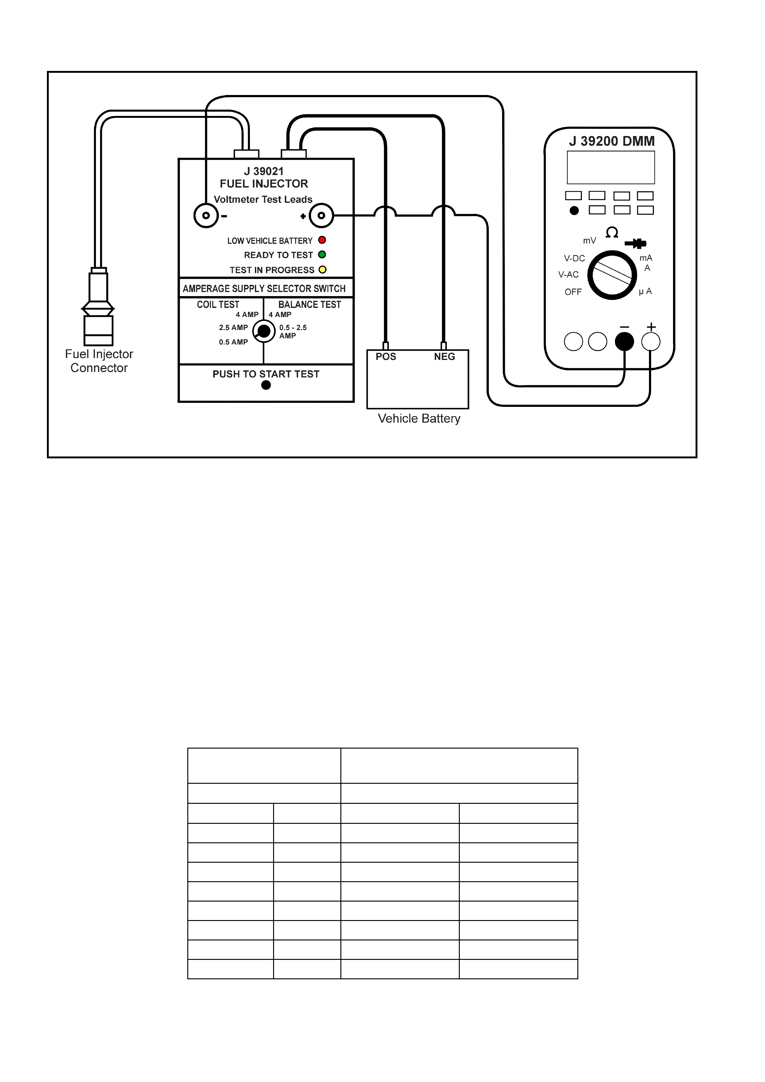
GEN III V8 PCM – FUEL INJECTOR BALANCE TEST
Figure 6C3-2C-7 – Circuit Diagram for Testing Injectors
TEST DESCRIPTION
CAUTION: Wrap a shop towel around the fuel pressure connection in order to reduce the risk of fire and
personal injury. The towel will absorb any fuel leakage that occurs during the connection of the fuel
pressure gauge. Place the towel in an approved container w hen the connection of the fuel pressure gauge
is complete.
NOTE: The number(s) below refer to the step number(s) on the diagnostic table.
4. The engine coolant temperature must be below the operating temperature in order to avoid irregular fuel
pressure readings due to Hot Soak fuel boiling.
5. T he f uel press ure should be within the specified range. If the fuel press ure is not within the specif ied range, go
to Fuel System Diagnosis in Section 6C3-2A DIAGNOSTIC TABLES.
6. The fuel pressure should reach a steady value. If the fuel pressure does not reach a steady value, go to
Fuel System Diagnosis.
7. If the pressure drop value for each fuel injector is within 10 kPa of the average pressure drop value, the fuel
injector s are f lowing properly. Calculate the pressure dr op value for eac h fuel inj ector by s ubtracting the second
pressure reading from the first pressure reading. Refer to the illustration above.
GEN III V8 PCM – FUEL INJECTOR BALANCE TEST
STEP ACTION VALUE YES NO
1. Was the "On-Board Diagnostic" (OBD) System Check
performed? Go to Step 2 Go to
OBD System
Check
in 6C3-2A
DIAGNOSTIC
TABLES
2. 1. Did you perform the Fuel Injector Coil Test Procedure?
Go to Step 3 Go to Fuel Inj.
Coil Test - EC T
Between
10-35° C in this
Section
3. Is the engine coolant temperature above the specified
value? 94° C Go to Step 4 Go to Step 5
4. 1. Allow the engine to cool below the specified value.
Is the engine coolant temperature below the specified
value?
94° C Go to Step 5 –

STEP ACTION VALUE YES NO
5. CAUTION: Wrap a shop tow el around the fuel pressure
connection in order to reduce the risk of fire and
personal injury. The tow el will absorb any fuel leakage
that occurs during the connection of the fuel pressure
gauge. Place the towel in an approved container when
the connection of the fuel pressure gauge is complete.
1. Connect the SD28018 fuel pressure gauge to the fuel
pressure test port.
2. Energise the fuel pump using Tech 2.
3. Place the bleed hose of the fuel pressure gauge into
an approved petrol container.
4. Bleed the air out of the fuel pressure gauge.
5. Observe the reading on the fuel pressure gauge.
Is the fuel pressure within the specified limits?
380-440 kPa Go to Step 6 Go to
Fuel System
Diagnosis in
6C3-2B
SYMPTOMS
6. 1. Fuel pump OFF
Does the fuel pressure remain constant? Go to Step 7 Go to
Fuel System
Diagnosis in
6C3-2B
SYMPTOMS
7. 1. Connect the J 39021 fuel injector tester to a fuel
injector.
2. Turn the amperage supply selector switch on the fuel
injector tester to the “Balance Test, 0.5 – 2.5 Amp”
position.
3. Turn the fuel pump ON then OFF to pressurise the fuel
system.
4. Record the fuel pressure indicated by the fuel
pressure gauge after the fuel pressure stabilises. This
is the 1st pressure reading (refer to Figure 6C3-2C-7).
5. Energise the fuel injector by depressing the ‘Push to
Start Test’ button on the fuel injector tester.
6. Record the fuel pressure indicated by the fuel
pressure gauge after the fuel pressure gauge needle
has stopped moving. This is the 2nd pressure reading
(refer to Figure 6C3-2C-7).
7. Repeat Steps 1 to 6 inclusive, for each fuel injector.
8. Subtract the 2nd pressure reading from the 1st
pressure reading for one fuel injector. The result is the
pressure drop value.
9. Obtain a pressure drop value for each fuel injector.
10. Add all of the individual pressure drop values. This is
the total pressure drop.
11. Divide the total pressure drop by the number of fuel
injectors. This is the average pressure drop.
Does any fuel injector have a pressure drop value that is
either higher than the average pressure drop or lower than
the average pressure drop by the specified value?
10 kPa Go to Step 8 Go to 6C3-2B
SYMPTOMS
8. IMPORTANT: Do not repeat any portion of this test before
running the engine in order to prevent the engine from
flooding.
1. Re-test any fuel injector that does not meet the
specification. Refer to procedure in Step 7.
Does any fuel injector still have a pressure drop value that
is either higher than the average pressure drop or lower
than the average pressure drop by the specified value?
10 kPa Go to Step 9 Go to 6C3-2B
SYMPTOMS
9. 1. Replace the faulty fuel injector(s). Refer to Fuel
Injector Replace in 6C3-3 SERVICE OPERATIONS.
Is the replacement complete?
System OK –
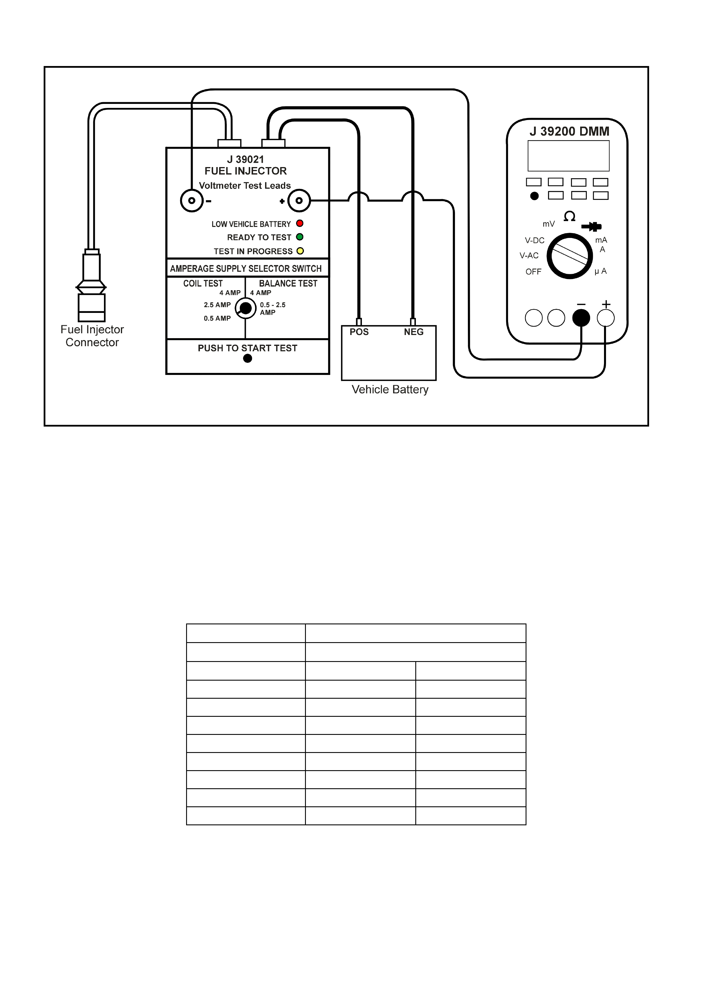
GEN III V8 PCM – FUEL INJECTOR COIL TEST - ECT BETWEEN 10 – 35°C
Figure 6C3-2C-8 –Circuit Diagram for Testing Injector Coil with ECT Between 10 °
°°
° – 35 °
°°
° C
TEST DESCRIPTION
NOTE: The number(s) below refer to the step number(s) on the diagnostic table.
2. T he engine coolant temperatur e affects the ability of the fuel inj ector tester to detect a faulty f uel inj ector. If the
engine coolant temperature is NOT between 10°C and 35°C, go to Fuel Inj. Coil Test - ECT Outside 10-35°C.
3. The first second of the voltage displayed by the DMM may be inaccurate due to the initial current surge.
Therefore, record the lowest voltage displayed by the DMM after the first second of the test. The voltage
displayed by the DMM should be within the specif ied range ( refer to the exam ple). T he voltage dis played by the
DMM may increase throughout the tes t as the f uel injec tor windings warm and the resistance of the fuel injector
windings changes. An erratic voltage reading (large fluctuations in voltage that do not stabilise) indicates an
intermittent connection within the fuel injector. Example
Resistance Voltage Specification at 10 – 35°C
11.4 – 12.6 Ω
ΩΩ
Ω 5.5 - 6.6 V
Fuel Injector No. Voltage Reading Pass/Fail
1 6.3 P
2 5.9 P
3 6.2 P
4 6.1 P
5 4.8 F
6 6.0 P
7 5.0 F
8 5.3 F
Table 1

GEN III V8 PCM – FUEL INJECTOR COIL TEST - ECT BETWEEN 10 - 35°C
STEP ACTION VALUE YES NO
1. Was the "On-Board Diagnostic" (OBD) System Check
performed? Go to Step 2 Go to
OBD System
Check
in 6C3-2A
DIAGNOSTIC
TABLES
2. 1. Connect Tech 2.
2. Check the engine coolant temperature.
Is the engine coolant temperature within the specified
value?
10° C – 35° C Go to Step 3 Go to Fuel Inj.
Coil Test -
ECT Outside
10-35° C in this
Section.
3. 1. Ignition ON.
NOTE: To prevent flooding of a single cylinder and
possible engine damage, relieve the fuel pressure before
performing the fuel injector coil test procedure.
2. Relieve the fuel pressure. Refer to the Fuel Pressure
Relief Procedure.
3. Access the fuel injector electrical connectors as
required.
4. Connect the J 39021 fuel injector tester to B+ and
ground.
5. Set the amperage supply selector switch on the fuel
injector tester to the “Coil Test, 0.5 Amp” position.
6. Connect the leads from a DMM to the fuel injector
tester. Refer to the illustration associated with the test
description.
7. Set the DMM to the tenths scale (0.0).
8. Connect the fuel injector tester to a fuel injector.
IMPORTANT: Check the engine coolant temperature again
to make sure that the correct table is being used.
9. Press the ‘Push to Start Test’ button on the fuel
injector tester.
10. Observe the voltage reading on the DMM.
IMPORTANT: The voltage reading may rise during the
test.
11. Record the lowest voltage observed after the first
second of the test.
12. Repeat Steps 8 through 11 for each fuel injector.
Did any fuel injector have an erratic voltage reading (large
fluctuations in voltage that do not stabilise) or voltage
readings outside of the specified value?
5.5 – 6.6 volts Go to Step 4 Go to Fuel
Injector Balance
Test in this
Section.
4. 1. Replace the faulty fuel injector(s). Refer to Fuel
Injector Replace, in 6C3-3 SERVICE OPERATIONS.
Is the replacement complete?
Go to Fuel
Injector Balance
Test in this
Section
–
GEN III V8 PCM – FUEL INJECTOR COIL TEST - ECT OUTSIDE 10 – 35°C
Figure 6C3-2C-9 –Circuit Diagram for Testing Injector Coil with ECT Outside 10 – 35°
°°
° C
TEST DESCRIPTION
NOTE: The number(s) below refer to the step number(s) on the diagnostic table.
2. The engine coolant temperature affects the ability of the fuel injector tester to detect a faulty fuel injector.
If the engine coolant temperature is NOT outside 10° C and 35° C, go to Fuel Inj Coil Test - ECT Between
10 – 35° C in this Section.
3. The first second of the voltage displayed by the DMM may be inaccurate due to the initial current surge.
Therefore, record the lowest voltage displayed by the DMM after the first second of the test. The voltage
displayed by the DMM may increase throughout the tes t as the fuel injector windings warm and the resistance
of the fuel injector windings changes. An erratic voltage reading (large fluctuations in voltage that do not
stabilise) indicates an intermittent connection within the fuel injector.
From the voltages rec or ded, identif y the highest voltage, excluding any voltages above 9.5 volts. Subtract eac h
voltage that is not above 9.5 volts from the highest voltage. Record each subtracted value (refer to the
Example). The subtracted value for any fuel injector with a subtracted value that is greater than 0.6 volt is
faulty. Replace the fuel injector. A fuel injector with a recorded voltage above 9.5 volts is also faulty. Replace
the fuel injector. Examples
Highest Voltage
Reading Acceptable Subtracted Value
Above/Below 10 – 35°C
7.1 V 0.6 V
Injector No. Voltage Subtracted Value Pass/Fail
1 9.8 -- F
2 6.6 0.5 P
3 6.9 0.2 P
4 5.8 1.3 F
5 7.0 0.1 P
6 7.1 0.0 P
7 9.6 -- F
8 6.0 1.1 F
Table 2

GEN III V8 PCM – FUEL INJECTOR COIL TEST - ECT OUTSIDE 10 - 35°C
STEP ACTION VALUE YES NO
1. Was the "On-Board Diagnostic" (OBD) System Check
performed? Go to Step 2 Go to
OBD System
Check
in 6C3-2A
DIAGNOSTIC
TABLES
2. 1. Connect Tech 2.
2. Check the engine coolant temperature
Is the engine coolant temperature outside the specified
value?
10° C – 35° C Go to Step 3 Go to Fuel Inj
Coil Test –
ECT Between
10-35°C in this
Section
3. 1. Ignition OFF.
NOTE: To prevent flooding of a single cylinder and
possible engine damage, relieve the fuel pressure before
performing the fuel injector coil test procedure.
2. Relieve the fuel pressure. Refer to the Fuel Pressure
Relief Procedure in 6C3-3 SERVICE OPERATIONS.
3. Access the fuel injector electrical connectors as
required.
4. Connect the J 39021 fuel injector tester to B+ and
ground.
5. Set the amperage supply selector switch on the fuel
injector tester to the “Coil Test, 0.5 Amp” position.
6. Connect the leads from a DMM to the fuel injector
tester. Refer to Figure 6C3-2C-9.
7. Set the DMM to the tenths scale (0.0).
8. Connect the fuel injector tester to a fuel injector.
IMPORTANT: Check the engine coolant temperature again
to make sure that the correct table is being used.
9. Press the ‘Push to Start Test’ button on the fuel
injector tester.
10. Observe the voltage reading on the DMM.
IMPORTANT: The voltage reading may rise during the
test.
11. Record the lowest voltage observed after the first
second of the test.
12. Repeat Steps 8 through 11 for each fuel injector.
13. Identify the highest voltage reading recorded from the
eight fuel injectors tested.
14. Subtract any other voltage reading recorded from the
highest voltage reading recorded.
15. Repeat Step 14 for all the remaining fuel injectors.
Is any value that resulted from subtracting greater than the
specified value?
0.6 volts
NOTE: Any
reading
above 9.5
volts indicates
a faulty fuel
injector.
Go to Step 4 Go to Fuel
Injector Balance
Test in this
Section
4. 1. Replace any fuel injector that had any of the following:
– A subtracted value exceeding 0.6 volts.
– An initial reading above 9.5 volts.
– An erratic reading.
Refer to Fuel Injector Replace in 6C3-3 SERVICE
OPERATIONS.
Is the replacement complete?
Go to Fuel
Injector Balance
Test in this
Section
–
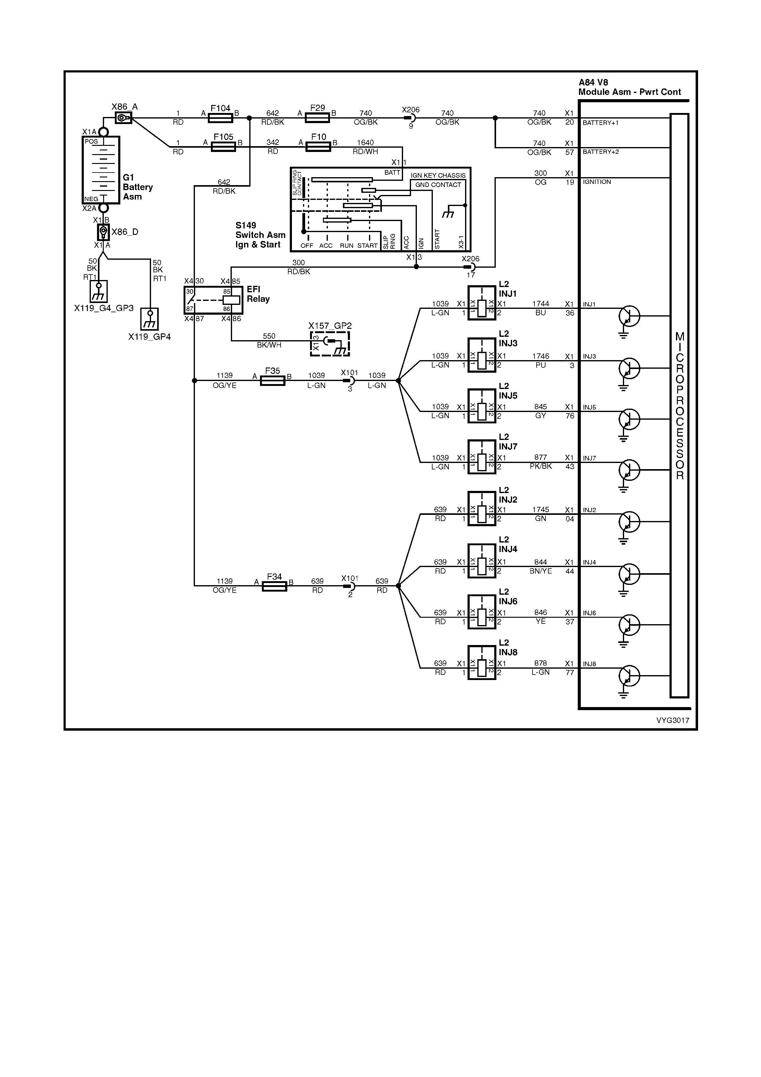
GEN III V8 PCM – FUEL INJECTOR CIRCUIT DIAGNOSIS
Figure 6C3-2C-10 – Fuel Injector Circuits
CIRCUIT DESCRIPTION
The PCM will enable an injector on the intake stroke of each cylinder. Individual cylinder fuel control is referred to as
Sequential Multi-port Fuel Injection (SFI).
Battery voltage is supplied directly to the fuel injectors. The PCM controls each injector by grounding the control
circuit via an internal switch called a driver. The primary function of the driver is to supply the ground for the
component being controlled.
DIAGNOSTIC AIDS
• For an intermittent condition, refer to Section 6C3-2B SYMPTOMS.
TEST DESCRIPTION
NOTE: The number(s) below refer to the step number(s) on the diagnostic table.
2. This step determines if a malfunction is present. For any test that requires probing the PCM or a component
harness connector, use the Connector Test Adaptor Kit J 35616-A. Using this kit prevents damage to the
harness connector terminals.
5. There are two ways to isolate a malfunctioning injector circuit.
6. Check injector connections before replacing the injector. A faulty connection causes an inoperative injector.
9. Check for an ignition feed circuit that is shorted open circuited.
10. Disc onnecting the PCM allows using a DMM to check continuity of the circuits. This will aid in locating an open
or shorted circuit.
A84–X2 (RED) L2
Figure 6C3-2C-11
GEN III V8 PCM – FUEL INJECTOR CIRCUIT DIAGNOSIS
STEP ACTION VALUE YES NO
1. Was the "On-Board Diagnostic" (OBD) System Check
performed? Go to Step 2 Go to
OBD System
Check
in 6C3-2A
DIAGNOSTIC
TABLES
2. IMPORTANT: This table assumes that there are no
Ignition Coil/Module circuit or mechanical malfunctions,
and DTCs P0351, P0352, P0353, P0354, P0355, P0356,
P0357, P0358 are not set.
1. Install Tech 2.
2. Run the engine at idle.
3. Monitor all the Ignition Coils on the Engine Data List
(there are a total of 8) using Tech 2.
Are any of the Ignition Coil indicating FAULT?
Go to Step 3 Refer to
Diagnostic Aids
3. Are the injector fuses F34 and F35 OK? Go to Step 4 Go to Step 7
4. 1. Ignition OFF.
2. Disconnect the injector(s) harness that the Ignition
Coil FAULT was indicating.
3. Ignition ON, engine OFF.
4. Using a test lamp connected to ground, probe the
injector harness ignition feed circuit.
Does the test lamp illuminate?
Go to Step 5 Go to Step 9
5. 1. Ignition OFF.
2. Connect the injector test lamp (J 34730-2C) to isolate
the injector harness.
3. Run the engine at idle.
Does the test lamp flash?
Go to Step 6 Go to Step 10
6. 1. Inspect the injector harness terminals for correct
terminal tension.
2. Replace terminal as necessary.
Does the terminal need replacing?
System OK Go to Step 14
7. 1. Ignition OFF.
2. Disconnect the injector harness connectors related to
the fuse that was open.
3. Using a test lamp connected to B+, probe the injector
harness ignition feed circuit.
Does the test lamp illuminate?
Go to Step 12 Go to Step 8
8. 1. Measure the resistance of each injector that is
powered by the fuse that is open using a DMM.
Does any injector measure less than the specified value?
11.4 Ω Go to Step 14 Go to Step 13
9. 1. Repair the injector ignition feed circuit to isolated
injector.
Is the action complete?
System OK –

STEP ACTION VALUE YES NO
10. 1. Ignition OFF.
2. Disconnect the PCM BLUE connector, A84-X1.
3. Check the injector driver circuit for an open or short to
ground.
Is the injector driver circuit open or shorted to ground?
Go to Step 11 Go to Step 15
11. 1. Repair injector driver circuit for an open or short to
ground.
Is the action complete?
System OK –
12. 1. Repair the grounded ignition feed circuit to the
injectors.
Is the action complete?
System OK –
13. 1. Repair intermittent short to ground in the injector
ignition feed circuit.
Is the action complete?
System OK –
14. 1. Replace the faulty injector(s) that was isolated. Refer
to Fuel Injector Replace, in 6C3-3 SERVICE
OPERATIONS.
Is the action complete?
System OK –
15. 1. Replace PCM. Refer to PCM Programming and
PCM/PIM/BCM Security Link Procedure, in 6C3-3
SERVICE OPERATIONS.
Is action complete?
System OK –
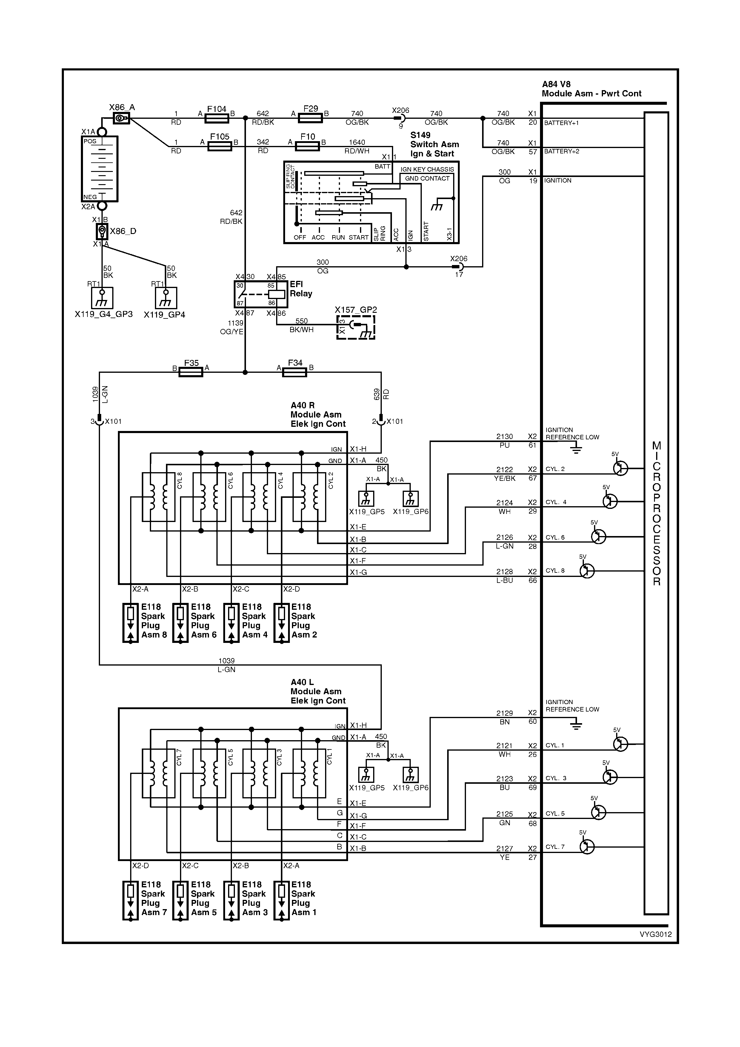
GEN III V8 PCM – ELECTRONIC IGNITION SYSTEM DIAGNOSIS
Figure 6C3-2C-12 – Ignition System Circuit
CIRCUIT DESCRIPTION
A Crankshaft Position (CKP) sensor determines the engine crankshaft position. The sensor is mounted and
protrudes into the r ear of the engine bloc k. T he sens or is near a s lotted wheel on the crankshaf t. T he r otation of the
slotted wheel causes a m agnetic flux c hange in the sensor. The signal creates the reference pulses needed by the
Powertrain Control Module (PCM). These signals in conjunction with the Camshaft Sensor trigger the correct
ignition coil to fire, at the correct time.
The ignition system on this engine uses an individual ignition coil/module for each cylinder. The PCM controls the
ignition system operation. There ar e eight Ignition Control (IC) circuits , one per cylinder, that c onnect the PCM and
the ignition coil/m odules. Each ignition coil/m odule has a power feed, a chassis ground circ uit, and a referenc e low
circuit. T he PCM causes a spark to occur by supplying voltage to the IC circuit, which s ignals the ignition m odule to
trigger the ignition coil and fire the spark plug. The PCM controls the sequencing and timing.
DIAGNOSTIC AIDS
The following may cause an intermittent:
• Check for poor connections. Check for adequate terminal tension.
• Corrosion
• Incorrectly routed harness
• Rubbed through wire insulation
• Broken wire inside the insulation
• Using Freeze Fram e/Failure Records data m ay aid in locating an interm ittent condition. If you cannot duplicate
the DTC, the information included in the Freeze Frame /Failure Records data can help determ ine the distance
travelled since the DTC set. The Fail Counter and Pass Counter can also help determine how many ignition
cycles the diagnostic reported a pas s and/or f ail. Oper ate vehicle within the s am e freeze fram e condition (RPM,
load, vehicle speed, temperature etc.) that you observed. This will isolate when the DTC failed.
• For an intermittent condition, refer to Section 6C3-2B SYMPTOMS.
TEST DESCRIPTION
NOTE: The number(s) below refer to the step number(s) on the diagnostic table.
3. Monitoring the Engine Data List Ignition Coil determines if a fault is present.
4. A good indication that the fuse is open is all the Ignition Coils are indicating FAULT on one side of the engine.
Inspect the ignition feed circuit for a grounded circuit.
8. If the fuse is open and no problem can be found with the ignition coil/module circuits, inspect the injector circuits
for being grounded. Fuse F34 and fuse F35 feed the ignition coil/module circuits and injector circuits.
A40 L A40 R COIL HARNESS CONNECTOR
Figure 6C3-2C-13
GEN III V8 PCM – ELECTRONIC IGNITION SYSTEM DIAGNOSIS
STEP ACTION VALUE YES NO
1. Was the "On-Board Diagnostic" (OBD) System Check
performed? Go to Step 2 Go to
OBD System
Check
in 6C3-2A
DIAGNOSTIC
TABLES
2. Are DTCs P0335, P0336, P0351-P0358 set?
Go to Applicable
DTC table Go to Step 3

STEP ACTION VALUE YES NO
3. IMPORTANT: This table assumes that there are no
Ignition Coil/Module circuit or mechanical malfunctions,
and DTCs P0351, P0352, P0353, P0354, P0355, P0356,
P0357, P0358 are not set.
1. Install Tech 2.
2. Run the engine at idle.
3. Monitor all the Ignition Coils on the Engine Data List
(There are a total of 8). using Tech 2.
Are any of the Ignition Coils indicating FAULT?
Go to Step 4 Intermittent
Condition. Go to
Diagnostic Aids
4. 1. Ignition ON, engine OFF.
2. Using a test light connected to ground, probe both
sides of both Ignition/Injector fuses.
Does test light illuminate at both terminals of both fuses?
Go to Step 5 Go to Step 8
5. 1. Ignition OFF.
2. Disconnect the ignition coil harness connector for the
Ignition Coil module that is indicating FAULT.
3. Ignition ON, engine OFF.
4. Probe the ignition feed circuit at the harness connector
using a test lamp connected to battery ground.
Does the test lamp illuminate?
Go to Step 6 Go to Step 10
6. 1. Using a test lamp, probe the ignition feed circuit at the
connector to Ignition Coil module to the coil/module
ground circuit 450.
Does the test lamp illuminate?
Go to Step 7 Go to Step 13
7. 1. Using a test lamp probe the ignition feed circuit at the
ignition coil/module electrical connector to the ignition
coil/module reference low circuit.
Does the test lamp illuminate?
Go to Step 21 Go to Step 17
8. 1. Inspect for an open ignition coil/module fuse.
2. Locate and repair the ignition feed circuit for a
grounded circuit if the fuse is open.
3. Replace the fuse.
Did you find and correct the problem?
System OK Go to Step 9
9. 1. Repair open in the ignition feed circuit between the
EFI relay and the splice.
Is the action complete?
System OK –
10. 1. Disconnect the ignition 8-way coil/module harness
connector for the Ignition Coil that is indicating FAULT.
2. Probe the ignition feed circuit at the ignition
coil/module main 8-way connector using a test lamp
connected to battery ground.
Does the test lamp illuminate?
Go to Step 11 Go to Step 12
11. 1. Repair the open circuit between the splice and the
ignition coil/module connector.
Is the action complete?
System OK –
12. 1. Repair the open ignition feed circuit between the fuse
block (open fuse) and splice.
Is the action complete?
System OK –
13. 1. Disconnect the ignition 8-way coil/module harness
connector for the Ignition Coil that is indicating FAULT.
2. Using a test light probe the ignition feed circuit at the
ignition coil/module 8-way connector to the ignition
coil/module ground circuit.
Does the test lamp illuminate?
Go to Step 14 Go to Step 16
14. 1. Check for a poor connection at the ignition coil/module
electrical 8-way connector.
2. Repair poor connections as necessary.
Did you find and correct the problem?
System OK Go to Step 15
15 1. Repair the open ground circuit between the main 8-
way connector and the ignition coil/module connector.
Is the action complete?
System OK –

STEP ACTION VALUE YES NO
16. 1. Repair the open ground circuit between the ground
and the main 8-way connector.
Is the action complete?
System OK –
17. 1. Disconnect the ignition 8-way coil/module harness
connector for the Ignition Coil that is indicating FAULT.
2. Probe the ignition feed circuit at the ignition
coil/module 8-way connector using a test lamp
connected to the Ignition Coil reference Low circuit.
Does the test lamp illuminate?
Go to Step 18 Go to Step 20
18. 1. Check for a poor connection at the 8-way ignition
coil/module electrical connector.
2. If a poor connection is found, repair as necessary.
Did you find and correct a problem?
System OK Go to Step 19
19. 1. Repair the open reference low circuit between the
main 8-way connector and the ignition coil/module
connector.
Is the action complete?
System OK –
20. 1. Repair the open reference low circuit between the
PCM and the splice.
Is the action complete?
System OK –
21. 1. Check for poor connections at the ignition coil/ module
8-way harness connector, ignition coil/ module
harness connector, and splices.
2. Repair poor connections as necessary.
Did you find and correct the problem?
System OK Go to Step 22
22. 1. Replace ignition coil/module.
Is the action complete? System OK –
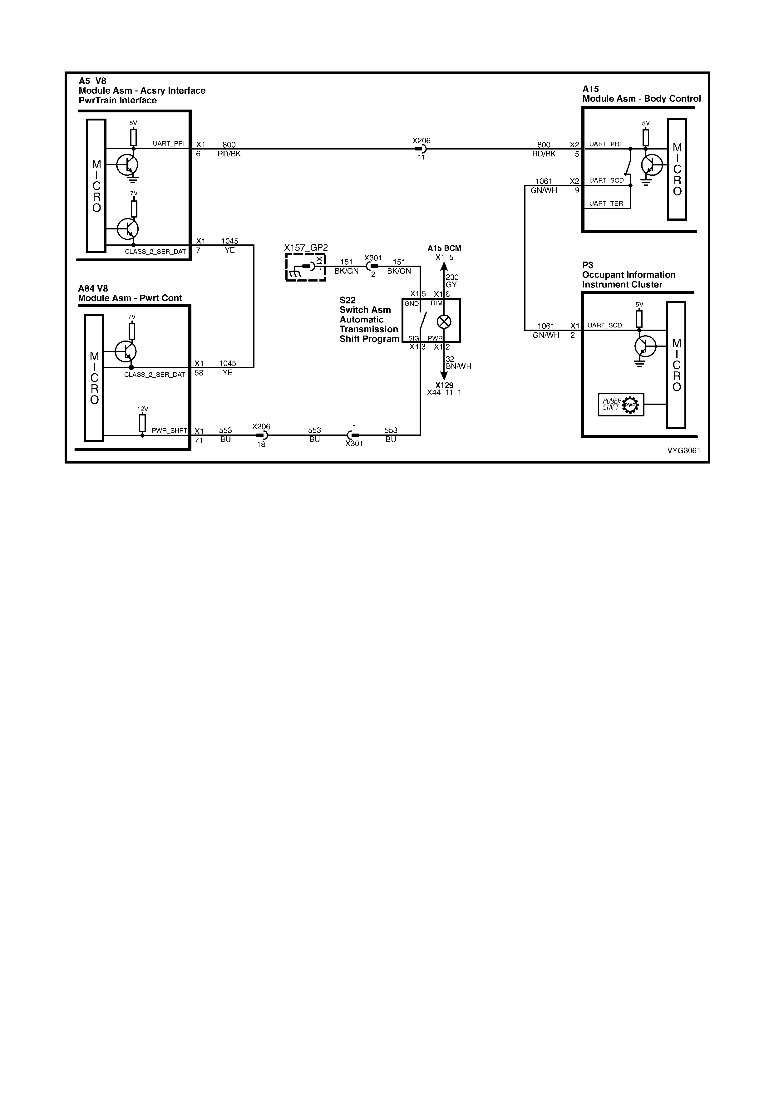
GEN III V8 PCM – AUTOMATIC TRANSMISSION POWER/ECONOMY SWITCH
Figure 6C3-2C-14 – Automatic Transmission Power/Economy Switch Circuit
CIRCUIT DESCRIPTION:
The driver can select three transmission shift modes, ECONOMY or POWER or CRUISE using a centre console
mounted switch for Power/Economy, and a cruise switch located on the indicator switch. The Power/Economy
switch is wired to the PCM and allows the driver to choose the Economy mode, for the best fuel economy in all
driving conditions through the increased use of TCC. Power mode provides later upshifts and higher line pressure in
the transmission.
The PCM s ends out a buf f er ed voltage s ignal, about 12 volts, and monitors the s tatus of this cir cuit. O nc e the driver
selects Power, the switch momentarily pulls low the buffered 12 volts, and the PCM will interpret this as a Power
selection and adjust the transmission shift pattern accordingly, and instructs the instrument panel to turn ON the
Power lamp. If while driving, the driver selects the Economy position, again the buffered 12 volts is momentarily
pulled low, and the PCM will adj ust the transm ission shift pattern and ins truct the instrum ent panel to turn OFF the
Power lamp.
When the key is turned ON, the PCM shift mode is set to the last mode that was previously selected
(Power/Economy). The cruise control is set to OFF at every key ON cycle.
In cruise mode operation, when the driver activates the cruise control, the Power lamp and power mode will turn
OFF (if vehicle was in power mode) and the transmission shift pattern will switch to cruise shift pattern. When in
cruise mode the PCM will modify the transmission calibration so that earlier downshift and later upshift points are
provided.
For replacement of the Power/Economy switch, refer to Section 7C4 AUTOMATIC TRANSMISSION - ON
VEHICLE SERVICING.
TEST DESCRIPTION:
NOTE: The number(s) below refer to the step number(s) on the diagnostic table.
2. This step tests for proper operation of the transmission POWER switch, the wiring and the PCM.
3. This step tests for proper POWER lamp illumination.
5. This step determines if the switch is faulty.
9. Some interior parts must be removed to disconnect and replace the transmission switch, Refer to
Section 1A3 INSTRUMENT PANEL AND CONSOLE.
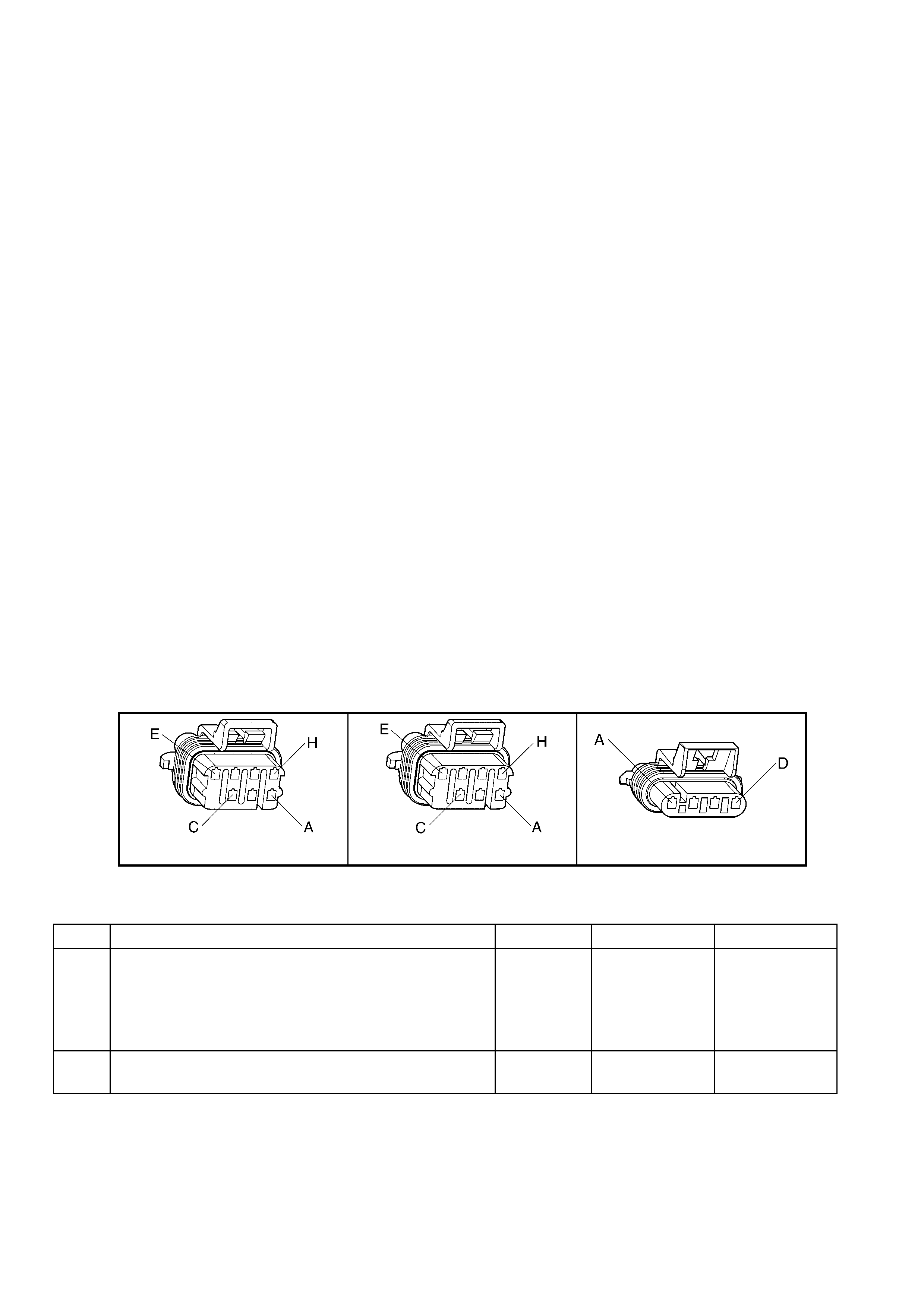
A84–X1 (BLUE) P3
S22 X157 X206 X301
Figure 6C3-2C-15
GEN III V8 PCM – AUTOMATIC TRANSMISSION POWER/ECONOMY SWITCH
STEP ACTION VALUE YES NO
1. Was the "On-Board Diagnostic" (OBD) System Check
performed? Go to Step 2 Go to
OBD System
Check
in 6C3-2A
DIAGNOSTIC
TABLES
2. 1. Ignition ON, engine OFF.
2. Install Tech 2.
3. Depress the Transmission POWER switch and
observe Tech 2
Does Tech 2 display a change between the Power or
Economy mode?
Go to Step 3 Go to Step 5
3. Is the POWER icon active, when Tech 2 displays
POWER? Go to Step 4 Go to 12C
INSTRUM ENTS
4. Is the POWER icon deactivated, when Tech 2 displays
ECONOMY?
No Problem
found with
switch operation.
Go to 12C
INSTRUM ENTS
5. 1. Disconnect the POWER switch from the wiring
harness connector S22.
2. Using a fused jumper wire, connect terminals X1-3
and X1-5 of the POWER switch wiring harness
connector S22 together.
Does Tech 2 display change between the Power or
Economy mode?
Go to Step 7 Go to Step 6
6. 1. Using a fused jumper wire, connect circuit 553 to
ground.
Does Tech 2 display a change between the Power or
Economy mode?
Go to Step 10 Go to Step 9
7. 1. Check the POWER switch connector for a poor
terminal connection.
Was a problem found?
Verify the Repair Go to Step 8
8. 1. Replace the faulty POW ER/ECONOMY switch.
Is the action complete? Verify the Repair –
9. 1. Check for an open or short to Ground in circuit 553, or
a faulty PCM connection for circuit 553.
Was a problem found?
Verify the Repair Go to Step 11
10. 1. Repair open in Ground circuit 151at Power/Economy
switch.
Is action complete?
Verify the Repair –
11. 1. Replace PCM. Refer to PCM Programming and
PCM/PIM/BCM Security Link Procedure, in 6C3-3
SERVICE OPERATIONS.
Is action complete?
Verify the Repair –
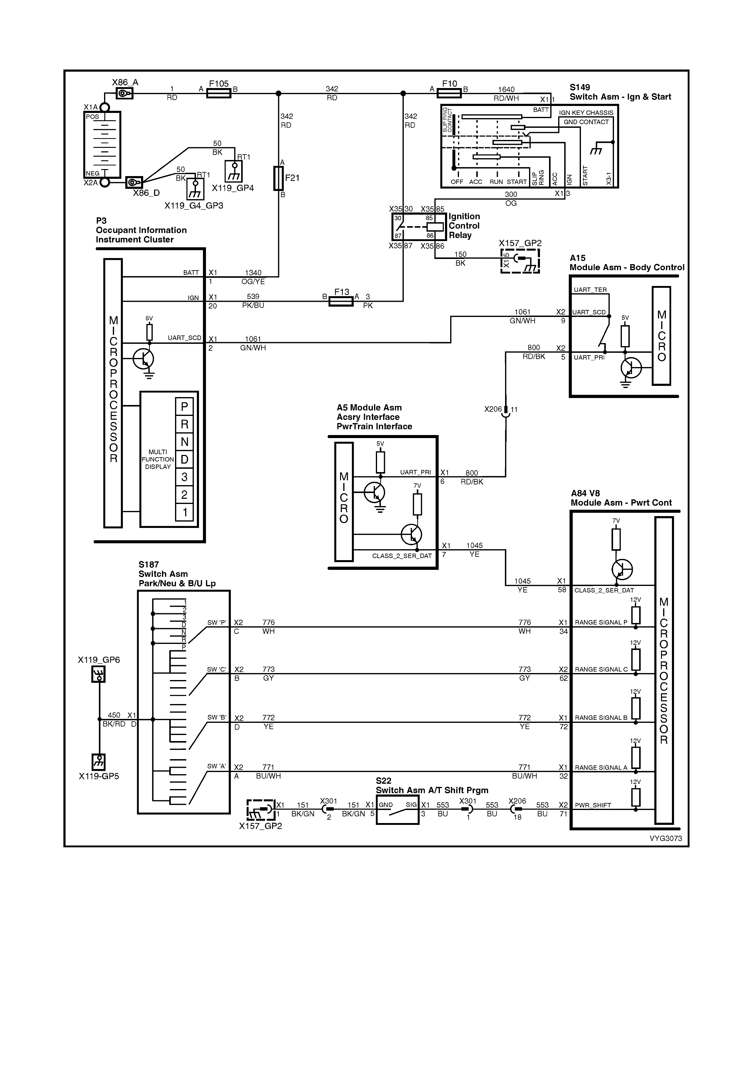
GEN III V8 PCM – INSTRUMENT PANEL GEAR INDICATOR CHECK
Figure 6C3-2C-16 – Instrument Panel Gear Indicator Circuit
CIRCUIT DESCRIPTION
The transmission PRNDL switch is a multi-signal switch assembly that signals the PCM the gear selected. The
PCM will then determine the signal from the PRNDL switch and send a com m and via serial data com m unication to
the instrument panel cluster to illuminate the correct gear indicator lamp.
The PRNDL switch uses four discrete circuits to pull four PCM voltages low in various combinations to indicate each
gear range. The voltage level of the circuits is represented as Closed = grounded, and Open = open circuit. The
four states displayed represents decoder P, A, B, and C inputs.
Tec h 2 will display all f our c ircuits ( P, A, B, C) and the appropriate Open and Closed to represent the gear selected.
If the gear s elected does not matc h the Open/Closed Table as dis played below on Tech 2, or the instrum ent panel
cluster gear lamp does not light up for the gear selected, there is a fault in the PRNDL select circuit or in the
instrument panel (IP) cluster.
DIAGNOSTIC AIDS
• Monitor T ech 2 while m oving related connectors and wiring harness. If a failure is indicated, the scan data will
change states from either Closed to Open or Open to Closed. Moving the gear selector slowly through each
gear while monitoring Tech 2 may also help isolate the problem.
• Any circuitry that is suspected as causing the interm ittent complaint, should be thoroughly checked for back ed
out term inals, im proper m ating, brok en locks , improperly form ed or damaged ter minals, poor ter minal to wiring
connection or physical damage to the wiring harness.
TEST DESCRIPTION
NOTE: The number(s) below refer to the step number(s) on the diagnostic table.
4. Any circuitry that is suspected as causing the interm ittent complaint, should be thoroughly checked for back ed
out term inals, im proper m ating, brok en locks , improperly form ed or damaged ter minals, poor ter minal to wiring
connection or physical damage to the wiring harness.
5. An invalid circuit will cause the PRNDL display to go out. Jumpering each circuit to ground simulates the
PRNDL switch operation and checks the circuitry and PCM. W hile the PRNDL switch is disconnected and the
circuits are not jumper ed to ground, Tech 2 should indic ate an Open value. A value that is indicated as Closed
with no jumper to ground indicates a grounded circuit or faulty PCM.
TRANSMISSION RANGE / PRNDL SWITCH VALID INPUT COMBINATIONS
GEAR POSITION
SELECTED TECH 2 PRNDL DI SPLAY
(P, A, B, C)
P A B C
PARK (P) LOW (0) LOW (0) HIGH (12) HIGH (12)
REVERS E (R) HIGH (12) LOW (0) LOW (0) HIGH (12)
NEUTRAL (N) LOW (0) HIGH (12) LOW (0) HIGH (12)
DRIVE 4 (D) HIGH (12) HIGH (12) LOW (0) LOW (0)
DRIVE 3 (3) LOW (0) LOW (0) LOW (0) LOW (0)
DRIVE 2 (2) HIGH (12) LOW (0) HIGH (12) LOW (0)
DRIVE 1 (1) LOW (0) HIGH (12) HIGH (12) LOW (0)
Table 3
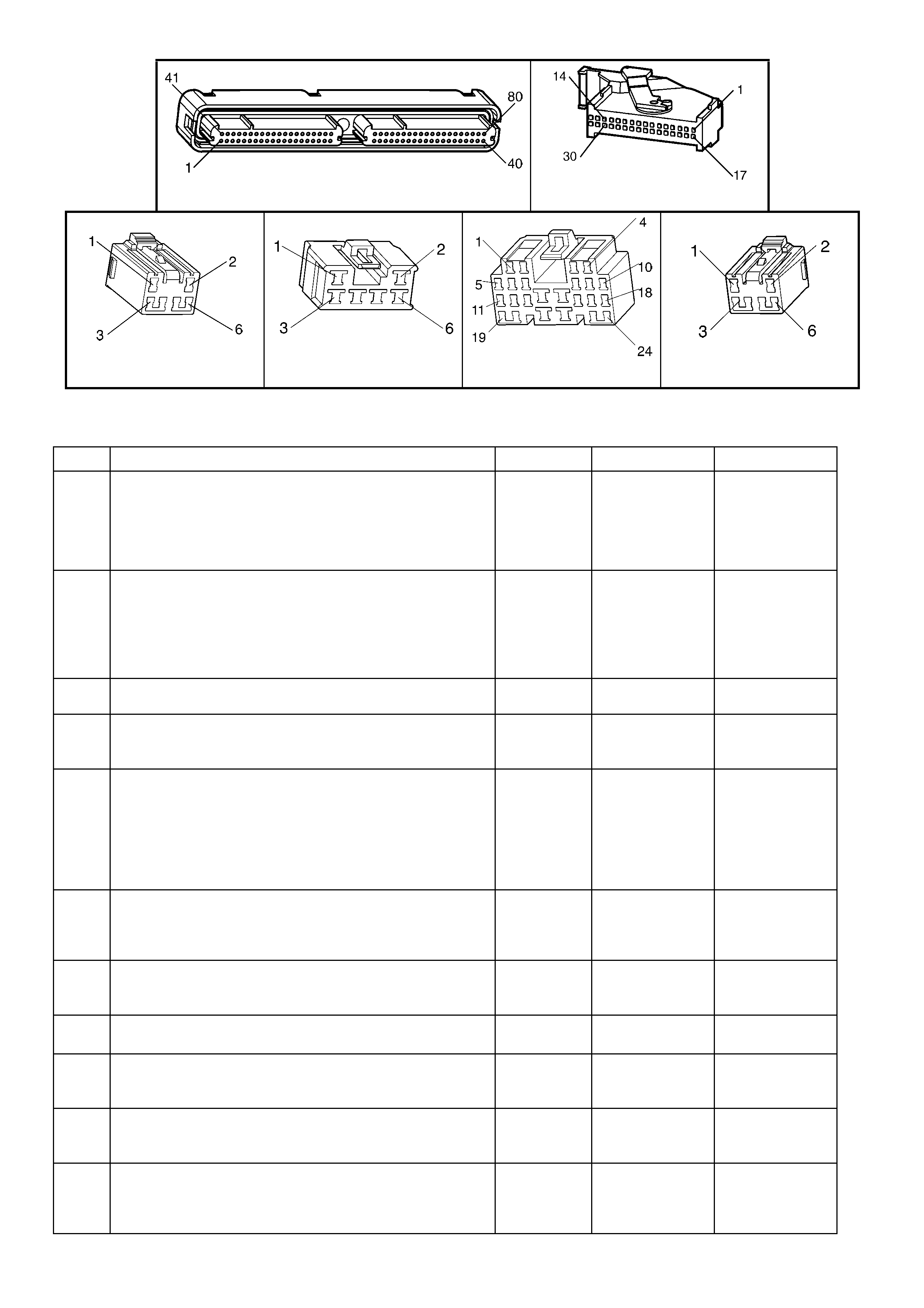
A84–X1 (BLUE) A84-X2 (RED)
P3 S187 S22
Figure 6C3-2C-17

GEN III V8 PCM – INSTRUMENT PANEL GEAR INDICATOR CHECK
STEP ACTION VALUE YES NO
1. Was the "On-Board Diagnostic" (OBD) System Check
performed? Go to Step 2 Go to
OBD System
Check
in 6C3-2A
DIAGNOSTIC
TABLES
2. 1. Ignition ON, engine OFF.
2. Install Tech 2.
3. Move the gear selector through all its ranges.
Does Tech 2 indicate an INVALID in any of the ranges?
Go to Step 3 Go to Step 10
3. 1. Compare Tech 2 values with the Transmission Range
Switch Valid Input Combinations table.
Are all the circuits indicated as Open?
Go to Step 4 Go to Step 5
4. 1. Check the transmission PRNDL switch ground circuit
for an open or poor connection and repair if
necessary.
Was a problem found?
Verify Repair Go to Step 5
5. 1. Moving the gear selector through all its ranges and
note which circuit did not correspond with the
Transmission Range Switch Valid Input Combination
table.
2. Disconnect the PRNDL switch electrical connector.
3. Jumper the circuit with the incorrect value to ground.
Does the jumpered circuit go from an OPEN value to a
CLOSED value?
Go to Step 8 Go to Step 6
6. 1. Check the affected circuit for an open or short to
ground and repair as necessary.
Was a problem found?
Verify Repair Go to Step 7
7. 1. Check for a poor connection at the PCM connector
and repair as necessary.
Was a problem found?
Verify Repair Go to Step 9
8. 1. Replace the PRNDL switch.
Is action complete? Verify Repair –
9. 1. Replace PCM. Refer to PCM Programming and
PCM/PIM/BCM Security Link Procedure, in 6C3-3
SERVICE OPERATIONS.
Is action complete?
Verify Repair –
10. Does Tech 2 indicate the same gear as the instrument
cluster? System OK.
Refer to
Diagnostic Aids
Go to step 11
11. 1. Refer to Diagnostics in 12C INSTRUMENTS.
Was a problem found and corrected? Verify Repair Go to Step 12
12. 1. Replace the instrument cluster.
Is action complete? Verify Repair –
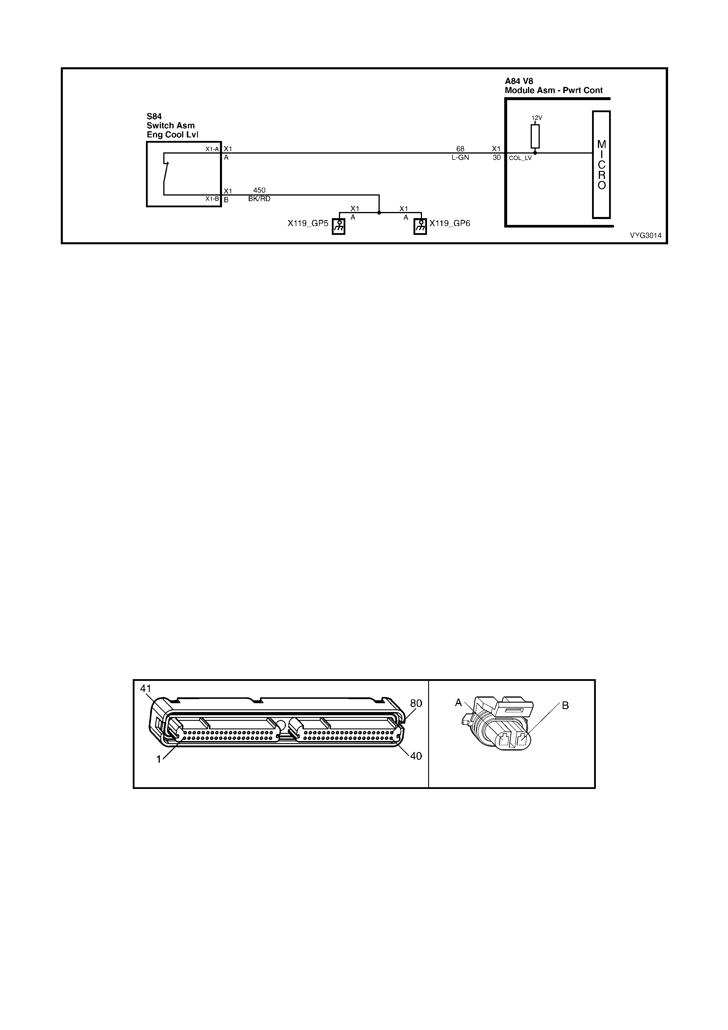
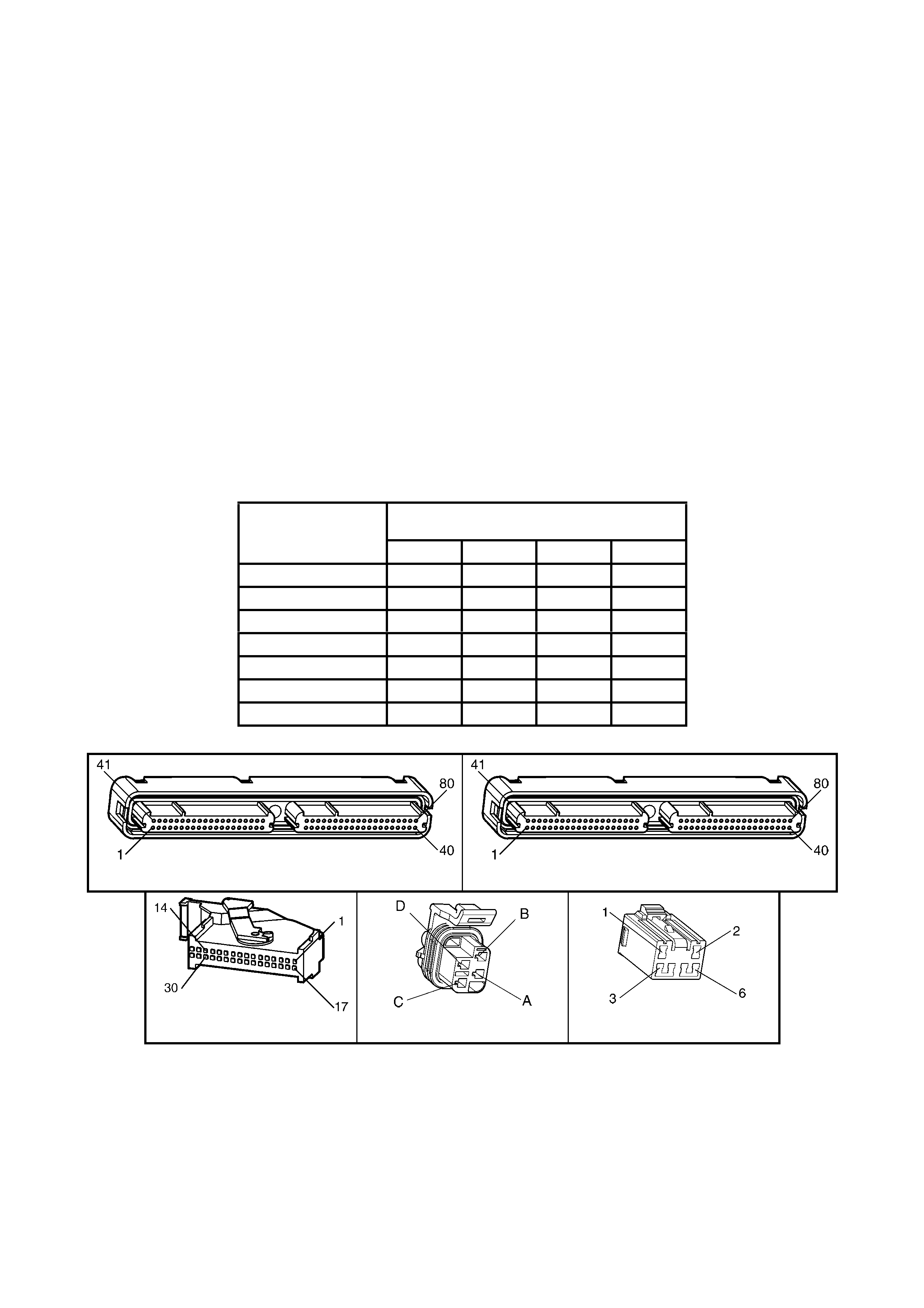
GEN III V8 PCM – ENGINE COOLANT LEVEL SWITCH DIAGNOSIS
Figure 6C3-2C-18 – Engine Coolant Level Switch Circuit
CIRCUIT DESCRIPTION
The engine coolant level switch is located in the coolant sur ge tank and is a f loat type s ensor. The PCM s upplies a
voltage to the engine coolant level switch which is a normally open switch.
When the coolant level is within an acceptable range the switch is closed. The switch opens when the engine
coolant level drops below a predetermined am ount. W hen the PCM does not detect a ground signal (switch open)
from the engine coolant level switch, the PCM will send a serial data m essage to the instrum ent cluster, which will
activate the “Low Coolant” icon in the Instrument, Multi Function Display (MFD).
DIAGNOSTIC AIDS
• The following may cause an intermittent:
– Poor connection; check for adequate terminal tension
– Corrosion
– Incorrectly routed harness
– Broken wire inside the insulation
• For an intermittent, refer to Section 6C3-2B SYMPTOMS.
• If the Low Coolant icon does not illuminate, and the engine c oolant level switch diagnosis table does not f ind a
problem with the switch, there is a problem with the instrument cluster.
TEST DESCRIPTION
NOTE: The number(s) below refer to the step number(s) on the diagnostic table.
4. This step checks the engine coolant level switch signal between the PCM and the Switch.
6. This step checks the engine coolant level switch ground circuit between the PCM and the Switch.
9. This step checks the engine coolant level switch signal for a short to ground.
10. This step checks for an open in the engine coolant level switch signal circuit between the PCM and the switch.
A84–X1 (BLUE) S84
Figure 6C3-2C-19

GEN III V8 PCM – ENGINE COOLANT LEVEL SWITCH DIAGNOSIS
STEP ACTION VALUE YES NO
1. Was the "On-Board Diagnostic" (OBD) System Check
performed? Go to Step 2 Go to
OBD System
Check
in 6C3-2A
DIAGNOSTIC
TABLES
2. IMPORTANT: This table assumes the coolant level is at
the correct level or the coolant level is low and the Low
Coolant icon did not activate. If the coolant level is low
refer to 6B3 ENGINE COOLING – GEN III V8 ENGINE for
further diagnosis of the cooling system.
1. Ignition ON, engine OFF.
Does the Instrument power up and activate the MFD?
Go to Step 3 Go to Diagnosis,
in 12C
INSTRUM ENTS
3. Is the customer concerned that the Low Coolant lamp is on
at all times? Go to Step 4 Go to Step 7
4. 1. Disconnect the Engine Coolant Level Switch.
2. Measure the voltage of the Engine Coolant Level
Switch signal circuit 68 using a DMM connected to
battery ground.
Does the DMM display near the specified value?
B+ Go to Step 5 Go to Step 10
5. 1. Jumper the engine coolant level switch signal circuit to
ground using a fused jumper wire.
2. Monitor the Low Coolant level state using Tech 2.
Does Tech 2 display Low Coolant Level as OFF?
Go to Step 6 Go to Step 17
6. 1. Jumper the engine coolant level switch signal circuit
68 to the Engine Coolant Level Switch ground circuit
450 using a fused jumper wire.
Does Tech 2 display Low Coolant Level as OFF?
Go to Step 11 Go to Step 15
7. 1. Disconnect the Engine Coolant Level Switch.
2. Measure the voltage of the Engine Coolant Level
Switch signal circuit 68 using a DMM connected to
ground.
Does the DMM display near the specified value?
B+ Go to Step 8 Go to Step 9
8. 1. Jumper the Engine Coolant Level Switch signal circuit
to ground using a fused jumper wire.
2. Monitor the Low Coolant Level state using Tech 2.
Does Tech 2 display Low Coolant Level as OFF?
Go to Step 11 Go to Step 17
9. 1. Ignition OFF.
2. Disconnect the BLUE PCM connector, A84-X1.
3. Check continuity of the Engine Coolant Level Switch
signal circuit 30, using a DMM connected to ground.
Does the DMM display continuity?
Go to Step 13 Go to Step 17
10. 1. Ignition OFF.
2. Disconnect the BLUE PCM connector, A84-X1.
3. Check continuity of the Engine Coolant Level Switch
signal circuit 68 between A84 X1-30 and S84 X1-A.
Does the DMM display continuity?
Go to Step 16 Go to Step 14
11. 1. Check for poor connection at the Engine Coolant
Level Switch harness connector.
2. If you find a poor connection, repair as necessary.
Was a problem found?
System OK Go to Step 12
12. 1. Replace the Engine Coolant Level Switch. Refer to
Coolant Level Switch Replace, in 6B3 ENGINE
COOLING – GEN III V8 ENGINE.
Is action complete?
System OK –
13. 1. Repair short to ground in the Engine Coolant Level
Switch signal circuit.
Is action complete?
System OK –

STEP ACTION VALUE YES NO
14. 1. Repair the engine coolant level switch circuit for an
open.
Is action complete?
System OK –
15. 1. Repair the engine coolant level switch ground circuit
for an open.
Is action complete?
System OK –
16. 1. Check for poor connection at PCM connector.
2. If you find a poor connection, repair as necessary.
Was a problem found?
Go to Step 17
17. 1. Replace PCM. Refer to PCM Programming and
PCM/PIM/BCM Security Link Procedure, in 6C3-3
SERVICE OPERATIONS.
Is action complete?
System OK –
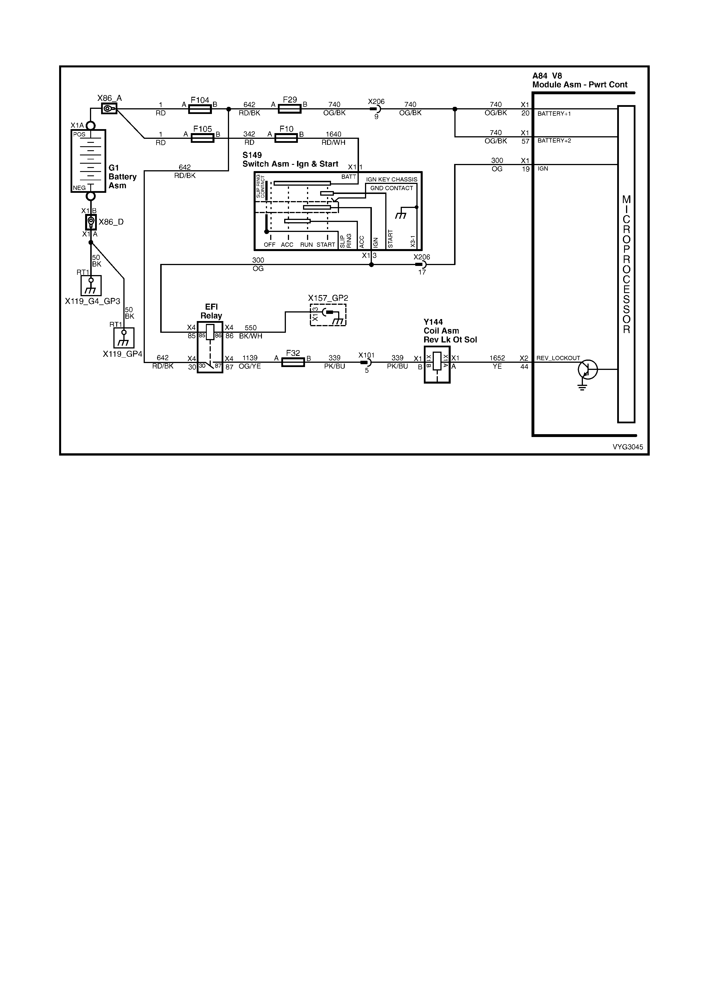
GEN III V8 PCM – MANUAL TRANSMISSION REVERSE INHIBIT SOLENOID DIAGNOSIS
Figure 6C3-2C-20 – Manual Transmission Reverse Inhibit Solenoid
CIRCUIT DESCRIPTION
The EFI (Engine Cont.) relay supplies an ignition voltage through fuse F32 to the Reverse Inhibit solenoid. The PCM
controls the solenoid by grounding the control circuit via an internal switch called a driver. The driver supplies the
ground for the component being controlled. Each driver has a fault line which the PCM monitors. When the PCM
commands a component ON, the voltage of the control circuit should be low (near 0 volts). When the PCM
commands the control circuit to a component OFF, the voltage potential of the circuit should be high (near battery
voltage).
When the Reverse Inhibit solenoid is energised, the operator can shift the transmission into reverse. The PCM
enables the Reverse Inhibit s olenoid whenever vehicle s peed is below 3 km /h. W hen the vehicle speed is above 5
km/h, the PCM de-energises the solenoid, which prevents the operator from shifting the transmission into reverse.
DIAGNOSTIC AIDS
• Monitor T ech 2 while m oving related connectors and wiring harness. If a failure is indicated, the scan data will
change s tates from either Low to High, or f rom High to Low. Moving the gear selec tor slowly through each gear
while monitoring Tech 2 may also help isolate the problem.
• Any circuitry that is suspected as causing the interm ittent complaint, should be thoroughly checked for back ed
out term inals, im proper m ating, brok en locks , improperly form ed or damaged ter minals, poor ter minal to wiring
connection or physical damage to the wiring harness.
• If the Revers e Inhibit Solenoid elec tr ically is work ing pr oper ly, but the transm iss ion will not shif t into r evers e, the
problem may be inside the transm iss ion. Ref er to Section 7B2 MANUAL TRANSMISSION for further diagnosis
of the Reverse Inhibit operation.
TEST DESCRIPTION
NOTE: The number(s) below refer to the step number(s) on the diagnostic table.
2. This step checks to see if the transmission can be shifted into reverse while the speedometer is indicating
vehicle speed.
3. This step indicates if Tech 2 will indicate the ON and OFF state of the reverse lock-out solenoid.

A84-X2 (RED) Y144
Figure 6C3-2C-21
GEN III V8 PCM – MANUAL TRANSMISSION REVERSE INHIBIT SOLENOID DIAGNOSIS
STEP ACTION VALUE YES NO
1. Was the "On-Board Diagnostic" (OBD) System Check
performed? Go to Step 2 Go to
OBD System
Check
in 6C3-2A
DIAGNOSTIC
TABLES
2. 1. Raise drive wheels off ground and support vehicle on
safety stands.
2. Install Tech 2 and select Engine Data.
3. Ignition ON, engine running.
4. Shift the transmission into first gear and slowly release
the clutch to allow the drive wheels to rotate to 5 – 15
km/h.
5. While speedometer is reading 5 – 15 km/h, depress
clutch and try to shift into reverse gear.
Were you able to shift into reverse gear?
Go to Step 4 Go to Step 3
3. 1. W hile the speedometer is reading 5 – 15 km/h, Tech 2
should indicate Reverse Lock-out as OFF, and when
the speedometer is reduced to 3 km/h or lower, Tech
2 should indicate ON.
Did the Tech 2 reading show as indicated?
Go to Step 4 Go to Step 6
4. 1. Ignition OFF.
2. Disconnect the RED PCM connector, A84-X2.
3. Ignition ON.
4. Measure the current from the solenoid control circuit
terminal X2-44 in the PCM harness connector to
ground for 2 minutes using a DMM on 10 Amp scale.
Does the current draw measure less than the value shown
(but not 0 Amps)?
1.5 Amp No trouble
found. Go to
Diagnostic Aids
Go to Step 5
5. 1. Ignition OFF.
2. Disconnect the solenoid, Y144.
3. Measure the resistance from the solenoid control
circuit 1652 in the PCM harness connector to ground
using a DMM.
Does the DMM display infinite resistance?
Go to Step 13 Go to Step 11
6. 1. Ignition OFF.
2. Disconnect the reverse lock-out solenoid, Y144.
3. Connect a test lamp between the terminals in the
solenoid harness connector.
4. Run the engine at idle.
5. Rotate drive wheels to 5 – 15 km/h and then below
3 km/h.
Does the test lamp turn ON and OFF?
Go to Step 9 Go to Step 7
7. 1. Probe the ignition feed circuit in the solenoid harness
connector with the test lamp connected to ground.
Does the test lamp illuminate?
Go to Step 8 Go to Step 12

STEP ACTION VALUE YES NO
8. 1. Ignition OFF.
2. Reconnect the solenoid, Y144
3. Disconnect the RED PCM connector, A84-X2.
4. Ignition ON.
5. Probe the solenoid control circuit 1652 in the PCM
harness connector with a fused jumper wire connected
to ground.
Does the solenoid operate?
Go to Step 10 Go to Step 11
9. 1. Check the connections at the solenoid.
Did you find and correct the condition? Verify Repair Go to Step 13
10. 1. Check the connection at the PCM.
Was a problem found? Verify Repair Go to Step 14
11. 1. Repair open or short to ground or short to voltage in
the solenoid control circuit.
Is the repair complete?
Verify Repair –
12. 1. Repair the faulty solenoid ignition feed circuit.
Is the repair complete? Verify Repair –
13. 1. Replace the solenoid.
Is action complete? Verify Repair –
14. 1. Replace PCM. Refer to PCM Programming and
PCM/PIM/BCM Security Link Procedure, in 6C3-3
SERVICE OPERATIONS.
Is action complete?
Verify Repair –
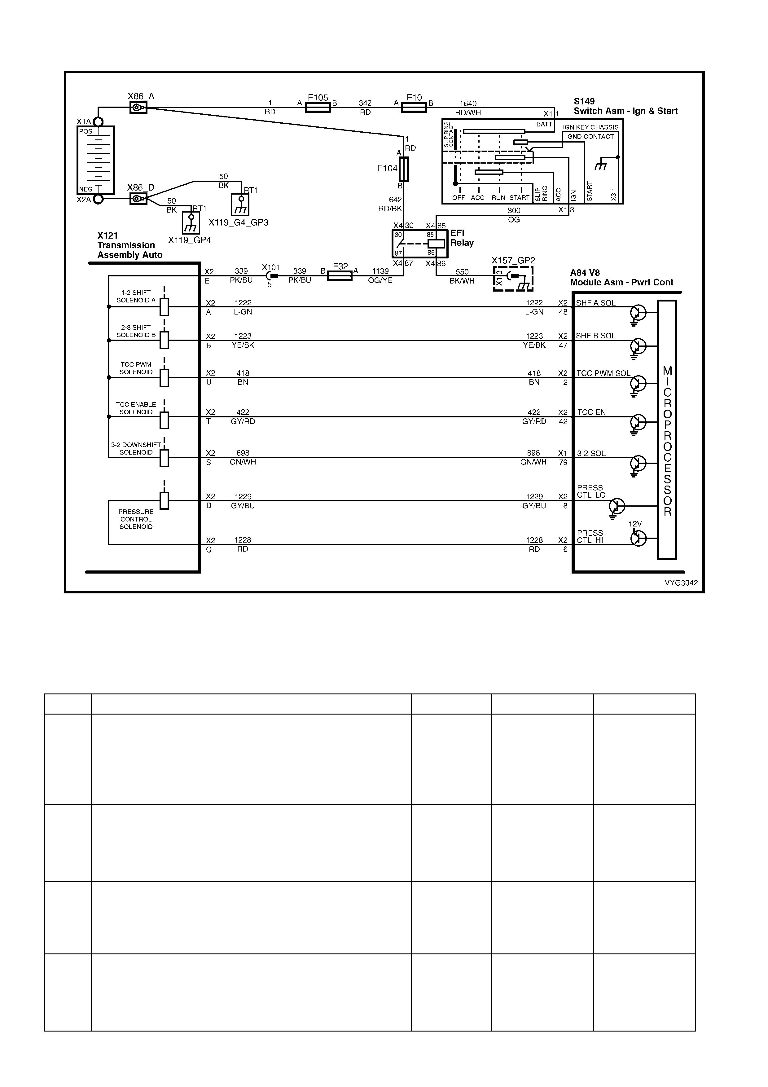
GEN III V8 PCM – AUTOMATIC TRANSMISSION WIRING HARNESS CHECK
Figure 6C3-2C-22 – Automatic Transmission Internal Circuits
NOTE: This procedure cannot be used for check ing the automatic transm ission fluid pressure (TFP) manual valve
position switch circuit, or the automatic transmission fluid temperature (TFT) sensor circuit. Refer to the TFP
Manual Valve Position Switch Resistance Check in this Section, for those circuits.
GEN III V8 PCM – AUTOMATIC TRANSMISSION WIRING HARNESS CHECK
STEP ACTION VALUE YES NO
1. 1. Install the J 39775 jumper harness on the
transmission side of the 20-way connector, X121-X2.
2. Using a DMM and a J 35616-A Connector Test
Adaptor Kit, measure the resistance between
terminals A and E (1-2 shift solenoid (A) valve).
Is the resistance within the specified range?
19-24 ohm
@ 20° C
to
24-31 ohm
@ 100° C
Go to Step 3 Go to Step 2
2. 1. Disconnect the 1-2 shift solenoid (SS) valve from the
automatic transmission wiring harness assembly.
2. Using a DMM, measure the resistance of the 1-2 SS
valve.
Is the resistance within the specified range?
19-24 ohm
@ 20°C
to
24-31 ohm
@ 100 °C
Go to Step 14 Go to Step 16
3. 1. Measure the resistance between terminals B and E (2-
3 shift solenoid (B) valve).
Is the resistance within the specified range?
19-24 ohm
@ 20°C
to
24-31 ohm
@ 100 °C
Go to Step 5 Go to Step 4
4. 1. Disconnect the 2-3 shift solenoid (SS) valve from the
A/T wiring harness assembly.
2. Using a DMM, measure the resistance of the 2-3 SS
valve.
Is the resistance within the specified range?
19-24 ohm
@ 20°C
to
24-31 ohm
@ 100 °C
Go to Step 14 Go to Step 16

STEP ACTION VALUE YES NO
5. 1. Measure the resistance between terminals T and E
(torque converter clutch solenoid valve).
Is the resistance within the specified range?
21-26 ohm
@ 20°C
to
26-33 ohm
@ 100 °C
Go to Step 6 Go to Step 14
6. 1. Measure the resistance between terminals U and E
(torque converter clutch pulse width modulation
solenoid valve).
Is the resistance within the specified range?
10-11 ohm
@ 20°C
to
13-15 ohm
@ 100 °C
Go to Step 8 Go to Step 7
7. 1. Disconnect the TCC PW M solenoid valve from the A/T
wiring harness assembly.
2. Using a DMM, measure the resistance of the TCC
PWM solenoid valve.
Is the resistance within the specified range?
10-11 ohm
@ 20°C
to
13-15 ohm
@ 100 °C
Go to Step 14 Go to Step 16
8. 1. Measure the resistance between terminals S and E (3-
2 shift solenoid valve assembly).
Is the resistance within the specified range?
20-24 ohm
@ 20°C
to
29-32 ohm
@ 100 °C
Go to Step 10 Go to Step 9
9. 1. Disconnect the 3-2 shift solenoid (SS) valve assembly
from the A/T wiring harness assembly.
2. Using a DMM, measure the resistance of the 3-2 SS
valve assembly.
Is the resistance within the specified range?
20-24 ohm
@ 20°C
to
29-32 ohm
@ 100 °C
Go to Step 14 Go to Step 16
10. 1. Measure the resistance between terminals C and D
(pressure control solenoid valve).
Is the resistance within the specified range?
3-5 ohm @
20°C
to
4-7 ohm @
100 °C
Go to Step 12 Go to Step 11
11. 1. Disconnect the pressure control (PC) solenoid valve
from the A/T wiring harness assembly.
2. Using a DMM, measure the resistance of the PC
solenoid valve.
Is the resistance within the specified range?
3-5 ohm @
20°C
to
4-7 ohm @
100 °C
Go to Step 14 Go to Step 16
12. 1. Using a DMM and the J 35616-A Connector Test
Adaptor Kit, measure the resistance from terminals A,
B, C, D, E, S, T and U of the A/T wiring harness
assembly to ground at the X121-X2, pass-thru
connector.
Is the resistance more than the specified value?
250 kΩ System OK Go to Step 13
13. 1. Disconnect the A/T wiring harness assembly from all
the components.
2. Measure the resistance from all the component
terminals to the transmission case.
Is the resistance more than the specified value?
250 kΩ Go to Step 14 Go to Step 16
14. 1. Inspect for high resistance or a short.
2. Inspect the A/T wiring harness assembly at the
transmission 20-way connector, and the component
connectors for the following conditions:
– Insufficient electrical connections
– Backed out, or damaged terminals
– A damaged terminal
– Reduced terminal tension
– A chafed wire that could short to bare metal or
other wiring
– A broken wire inside the insulation
– Moisture intrusion
– Corrosion
4. If diagnosing for a possible intermittent condition,
move or massage the A/T wiring harness assembly
while observing the test equipment for a change.
Did you find high resistance or a short?
Go to Step 1 Go to Step 15

STEP ACTION VALUE YES NO
15. 1. Replace the A/T wiring harness assembly. Refer to
7C4 A/T ON-VEHICLE SERVICING.
Is the replacement complete?
Go to Step 1 –
16. 1. Replace the faulty component.
Is the replacement complete? Go to Step 1 –
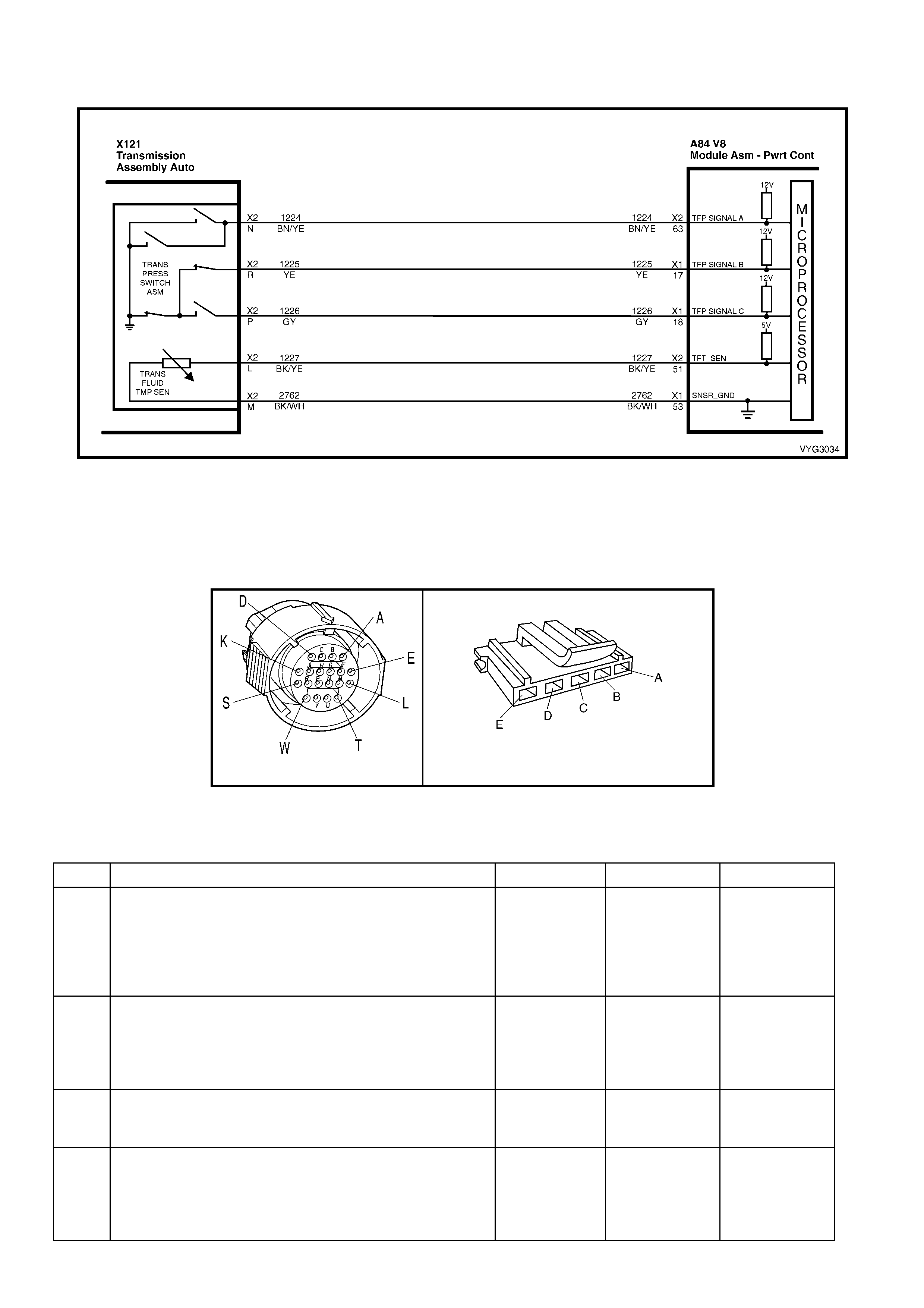
GEN III V8 PCM – AUTOMATIC TRANSMISSION FLUID PRESSURE (TFP) VALVE
POSITION SWITCH RESISTANCE CHECK
Figure 6C3-2C-23 – Automatic Transmission Fluid Pressure (TFP) Manual Valve Position Switch Circuit
NOTE: Whenever the transmission 20-way connector, X121-X2 is disconnected and the engine is running, multiple
DTCs will set. Be sure to clear these codes when y ou are finished with this procedure.
This proc edur e tests the automatic T r ansmiss ion Fluid Pr es sur e ( T F P) manual valve position switch circuits and the
automatic Transm ission Fluid T emperature (TFT ) sensor circuit. Do not use this procedure to test other automatic
transmission circuits. Refer to the Automatic Transmission Wiring Harness Check in this Section.
X121-X2 TFP MANUAL VALVE POSITION SWITCH
Figure 6C3-2C-24
GEN III V8 PCM –
AUTOMATIC TRANSMISSION FLUID PRESSURE (TFP) VALVE POSITION SWITCH RESISTANCE CHECK
STEP ACTION VALUE YES NO
1. 1. Install the J 39775 jumper harness on the
transmission side of the 20-way connector, X121-X2.
2. Using a DMM and the J 35616-A Connector Test
Adaptor Kit, measure the resistance from terminal N to
the transmission case.
Is the resistance greater than the specified value?
50 kΩ Go to Step 3 Go to Step 2
2. 1. Disconnect the A/T wiring harness connector from the
TFP manual valve position switch.
2. Measure the resistance from terminal C of the TFP
manual valve position switch to the switch housing.
Is the resistance greater than the specified value?
50 kΩ Go to Step 16 Go to Step 19
3. 1. Measure the resistance from terminal R of the J 39775
jumper harness to the transmission case.
Is the resistance less than the specified value?
200 ohm Go to Step 5 Go to Step 4
4. 1. Disconnect the A/T wiring harness connector from the
TFP manual valve position switch.
2. Measure the resistance from terminal E of the TFP
manual valve position switch to the switch housing.
Is the resistance less than the specified value?
200 ohm Go to Step 16 Go to Step 19

STEP ACTION VALUE YES NO
5. 1. Measure the resistance from terminal P of the J 39775
jumper harness to the transmission case.
Is the resistance greater than the specified value?
50 kΩ Go to Step 7 Go to Step 6
6. 1. Disconnect the A/T wiring harness connector from the
TFP manual valve position switch.
2. Measure the resistance from terminal D of the TFP
manual valve position switch to the switch housing.
Is the resistance greater than the specified value?
50 kΩ Go to Step 16 Go to Step 19
7. 1. Run the engine at idle.
2. Firmly apply the park brake.
3. Place the gear selector in R (Reverse).
4. Measure the resistance from terminal N of the J 39775
jumper harness to the transmission case.
Is the resistance less than the specified value?
200 ohm Go to Step 8 Go to Step 16
8. 1. Place the gear selector in 1 (First).
2. Measure the resistance from terminal N of the J 39775
jumper harness to the transmission case.
Is the resistance less than the specified value?
200 ohm Go to Step 9 Go to Step 16
9. 1. Place the gear selector in 3 (Third).
2. Measure the resistance from terminal R of the J 39775
jumper harness to the transmission case.
Is the resistance greater than the specified value?
50 kΩ Go to Step 10 Go to Step 16
10. 1. Place the gear selector in D (Drive).
2. Measure the resistance from terminal P of the J 39775
jumper harness to the transmission case.
Is the resistance less than the specified value?
200 ohm Go to Step 11 Go to Step 16
11. 1. Place the gear selector in 2 (Second).
2. Measure the resistance from terminal P of the J 39775
jumper harness to the transmission case.
Is the resistance greater than the specified value?
50 kΩ Go to Step 12 Go to Step 16
12. 1. Ignition OFF.
IMPORTANT: The resistance of the TFT sensor is
temperature dependent, and therefore varies far more than
any other device. Refer to Transmission Fluid Temperature
Sensor in this Section.
2. Measure the resistance from terminal L to terminal M
(TFT sensor) of the J 39775 jumper harness.
Is the resistance within the specified range?
3088 – 3942 Ω
@ 20°C
to
159 – 198 Ω
@ 100°C
Go to Step 13 Go to Step 14
13. 1. Measure the resistance from terminal L to the
transmission case.
2. Measure the resistance from terminal M to the
transmission case.
Are both resistances greater than the specified value?
50k Ω System OK Go to Step 14
14. 1. Disconnect the A/T wiring harness connector from the
TFP manual valve position switch.
IMPORTANT: The resistance of the TFT sensor is
temperature dependent, and therefore varies far more than
any other device. Refer to Transmission Fluid Temperature
Sensor in this Section.
2. Using a DMM, measure the resistance between
terminal A and terminal B of the TFP manual valve
position switch (TFT sensor).
Is the resistance within the specified range?
3088 – 3942 Ω
@ 20°C
to
159 – 198 Ω
@ 100°C
Go to Step 15 Go to Step 19
15. 1. Measure the resistance from TFP manual valve
position switch terminal A to the transmission case.
2. Measure the resistance from TFP manual valve
position switch terminal B to the transmission case.
Are both resistances greater than the specified value?
50k Ω Go to Step 16 Go to Step 19

STEP ACTION VALUE YES NO
16. 1. Inspect for high resistance or a short:
• Inspect the A/T wiring harness assembly for poor
electrical connections at the automatic
transmission 20-way connector, X121-X2 and at
the TFP manual valve position switch. Look for
the following conditions:
– A backed out terminal
– A damaged terminal
– Reduced terminal tension
– Moisture intrusion
– Corrosion
2. If diagnosing for an intermittent condition, wriggle the
wiring harness while watching the test equipment for a
change.
Did you find high resistance or a short?
Go to Step 1 Go to Step 17
17. 1. Disconnect the A/T wiring harness connector from the
TFP manual valve position switch.
2. Inspect the following circuits for an open or short:
- Circuit 1224 – (Purple wire)
- Circuit 1225 – (Dark Blue wire)
- Circuit 1226 – (Orange wire)
- Circuit 1227 – (Brown wire)
Did you find an open or shorted condition?
Go to Step 18 Go to Step 19
18. 1. Replace the A/T wiring harness assembly. Refer to
Control Valve Body and Wiring Harness Replace, in
7C4 A/T ON-VEHICLE SERVICING.
Is the replacement complete?
Go to Step 1 –
19. 1. Replace the TFP manual valve position switch. Refer
to Valve Body and Pressure Switch Replace, in 7C4
A/T ON-VEHICLE SERVICING.
Is the replacement complete?
Go to Step 1 –
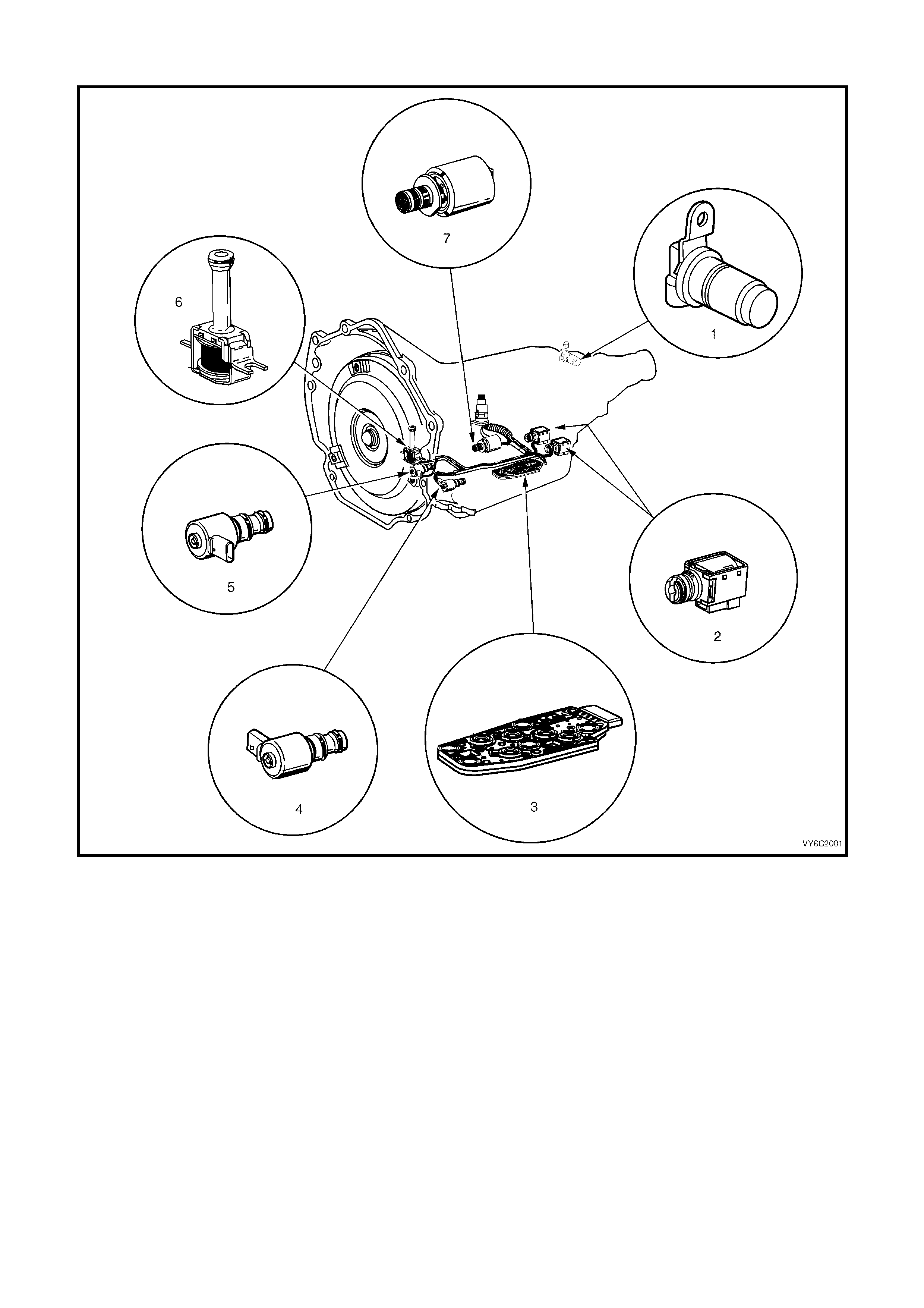
GEN III V8 PCM – AUTOMATIC TRANSMISSION FUNCTIONAL CHECK PROCEDURE
Figure 6C3-2C-25 – Automatic Transmission Solenoids and Sensors
Legend
1. Vehicle Speed Sensor
2. 1-2 Shift Solenoid ‘A’ and 2-3 Shift Solenoid ‘B’
3. Automatic Transmission Fluid Pressure (TFP) Manual
Valve Position Switch
4. 3-2 Downshift Control Solenoid
5. Torque Converter Clutch Pulse Width Modulation
(TCC PWM) Solenoid Valve
6. Torque Converter Clutch (TCC) Solenoid Valve
7. Pressure Control Solenoid (PCS) Valve
NOTE: The Functional Test Procedure is the first step in diagnosing mechanical or hydraulic transmission
conditions and provides procedures and references to the Section 6C3-2B SYMPTOMS and other Service
Information Sections for specific diagnostic information.

GEN III V8 PCM – AUTOMATIC TRANSMISSION FUNCTIONAL CHECK PROCEDURE
STEP ACTION VALUE YES NO
1. IMPORTANT: Engine performance can greatly affect
transmission performance. Ensure that the complaint is not
the result of poor engine performance before continuing.
1. Verify the customer complaint.
Has the customer complaint been verified?
Go to Step 2 –
2. IMPORTANT: Many transmissions have default actions
that take place once a DTC fault is detected. These actions
may be interpreted as being a transmission concern.
Has the Powertrain On Board Diagnostic (OBD) System
Check been performed?
Go to Step 3 Go to Powertrain
OBD System
Check Table
in 6C3-2A
DIAGNOSTIC
TABLES
3. 1. Perform a visual inspection. Look for the following
conditions:
• Vehicle damage
• Transmission oil pan damage. Refer to 7C4 ON-
VEHICLE SERVICING.
• Worn or damaged suspension parts. Refer to 3
FRONT SUSPENSION.
• Worn or damaged steering parts. Refer to 9
STEERING.
• Transmission range selector linkage damaged or
out of adjustment. Refer to Selector Linkage, in
7C4 ON-VEHICLE SERVICING.
• Loose, worn, damaged or missing:
– mounts or struts
– brackets
– mounting hardware
2. Transmission cooler or cooler line restrictions. Refer to
Transmission Cooler Reverse Flush and Flow Rate
Check, in 7C4 ON-VEHICLE SERVICING.
3. Fluid leaks. Refer to Fluid Leak Checking Procedure,
in7C4 ON-VEHICLE SERVICING .
Was an item identified that needs service?
Go to the
Appropriate
Repair or
Diagnosis
Section
Go to Step 4
4. 1. Perform the Transmission Fluid Checking Procedure.
Refer to 7C3 HYDRAULIC/MECHANICAL
DIAGNOSIS.
Is the procedure complete?
Go to Step 5 Go to
Transmission
Fluid Checking
Procedure in
7C3.
5. 1. Perform the Road Test Procedure. Refer to 7C3
HYDRAULIC/MECHANICAL DIAGNOSIS.
Did the vehicle exhibit any objectionable condition?
Go to Step 6 System OK
6. Did the vehicle exhibit objectionable torque converter
operation? Go to Step 15 Go to Step 7
7. Did the vehicle exhibit a noise condition?
Go to Noise and
Vibration
Diagnosis in
7C3
Go to Step 8
8. Did the vehicle exhibit a vibration condition? Go to Step 9 Go to Step 10
9. Did the vibration occur only during TCC apply or release?
Go to Step 15 Go to Noise and
Vibration
Diagnosis in
7C3
10. Did the vehicle exhibit a shift speed condition such as low
or high shift speeds?
Go to Shift
Speed
Diagnosis, in
7C3
Go to Step 11
11. 1. Did the vehicle exhibit any of the following shift quality
(feel) conditions?
• Harsh, soft, delayed or no engagement.
• Harsh, soft or delayed shifts.
• Shift shudder, flare or tie-up
Go to Step 12 Go to Step 13

STEP ACTION VALUE YES NO
12. 1. Perform the Line Pressure Check Procedure. Refer to
7C3 HYDRAULIC/MECHANICAL DIAGNOSIS.
Is the line pressure within specification?
Go to Shift
Quality (Feel), in
2.12 Symptom
Diagnosis, in
7C3
Go to Fluid
Diagnosis, in
2.12 Symptom
Diagnosis, in
7C3
13. 1. Did the vehicle exhibit any of the following shift pattern
conditions?
• No upshift or downshift.
• Only one or two forward gears.
• No First, Second, Third or Fourth gear.
• Slipping.
• Non-first gear start.
Go to Shift
Pattern
Diagnosis, in
2.12 Symptom
Diagnosis, in
7C3
Go to Step 14
14. 1. Did the vehicle exhibit any of the following range
performance conditions?
• No Park, Reverse or Drive.
• No engine braking.
• No gear selection.
• Incorrect gear selection.
Go to Range
Performance
Diagnosis, in
2.12 Symptom
Diagnosis, in
7C3
System OK
15. 1. Refer to Torque Converter Diagnosis Procedure, in
7C3 AUTOMATIC TRANSMISSION
HYDRAULIC/MECHANICAL DIAGNOSIS.
2. Did the vehicle exhibit any of the following TCC
conditions?
– Stuck on or off
– Early or late engagement
– Incorrect apply or release
– Soft or harsh apply
– Clunk or shudder
– No torque multiplication
– Excessive slip
– Poor acceleration
– Engine stalls
Go to Torque
Converter
Diagnosis, in
7C3
System OK