SECTION 6C3-3 - SERVICE OPERATIONS -
GEN III V8 ENGINE
IMPORTANT
Before performing any Service Operation or other procedure described in this Section, refer to Section
00 CAUTIONS AND NOTES for correct workshop practices with regard to safety and/or property damage.
CONTENTS
1. GENERAL DESCRIPTION
1.1 WHAT THIS SECTION CONTAINS
1.2 SERVICE PRECAUTIONS
2. ELECTRONIC COMPONENTS
2.1 POWERTRAIN CONTROL MODULE (PCM)
PCM REPLACEMENT
REMOVE
REINSTALL
PCM SERVICE PROGRAMMI NG
PCM/PIM/BCM SECURITY LINK
IDLE LEARN PROCEDURE
FUNCTIONAL CHECK
2.2 POWERTRAIN INTERFACE MODULE (PIM)
PIM REPLACEMENT
REMOVE
REINSTALL
PCM/PIM/BCM SECURITY LINK
FUNCTIONAL CHECK
2.3 ENGINE COOLANT TEMPERATURE (ECT)
SENSOR
REMOVE
REINSTALL
2.4 ENGINE COOLANT LEVEL SWITCH
2.5 INTAKE AIR TEMPERATURE (IAT) SENSOR
REMOVE
REINSTALL
2.6 MASS AIR FLOW (MAF) SENSOR
REMOVE
REINSTALL
2.7 MANIFOLD ABSOLUTE PRESSURE (MAP)
SENSOR
REMOVE
REINSTALL
2.8 HEATED OXYGEN SENSORS (HO2S)
IMPORTANT SERVICE NOTES
REMOVE
REINSTALL
2.9 THROTTLE POSITION (TP) SENSOR
REMOVE
REINSTALL
2.10 VEHICLE SPEED SENSOR
REMOVE
REINSTALL
2.11 IDLE AIR CONTROL VALVE
REMOVE
REINSTALL
2.12 CAMSHAFT POSITION (CMP) SENSOR
REMOVE
REINSTALL
3. FUEL SYSTEM
3.1 THROTTLE CONTROL CABLES – VEHICLES
WITH TCS
REMOVE
REINSTALL
3.2 THROTTLE CONTROL CABLES – VEHICLES
WITHOUT TCS
REMOVE
REINSTALL
3.3 THROTTLE RELAXER – VEHICLES WITH TCS
REMOVE
REINSTALL
3.4 THROTTLE CABLE ADJUSTMENT - ALL
3.5 THROTTLE BODY
REMOVE
REINSTALL
3.6 FUEL PUMP RELAY
REMOVE
REINSTALL
3.7 FUEL PRESSURE RELIEF PROCEDURE
3.8 FUEL GAUGE INSTALLATION PROCEDURE
3.9 QUICK CONNECT FITTINGS (METAL COLLAR)
REMOVE
REINSTALL
3.10 QUICK CONNECT FITTINGS (PLASTIC COLLAR)
REMOVE
REINSTALL
3.11 FUEL FILTER
REMOVE
REINSTALL
3.12 MODULAR FUEL SENDER ASSEMBLY
3.13 FUEL PULSE DAMPENER
REMOVE
REINSTALL
3.14 FUEL HOSE/PIPES (ENGINE COMPARTMENT)
REMOVE
REINSTALL
3.15 FUEL HOSE/PIPES (REAR PIPES)
REMOVE
REINSTALL
3.16 FUEL SYSTEM CLEANING
3.17 FUEL PRESSURE CONNECTION (SCHRADER
VALVE)
REMOVE
REINSTALL
3.18 FUEL RAIL ASSEMBLY
REMOVE
REINSTALL
3.19 FUEL INJECTOR
REMOVE
REINSTALL
3.20 FUEL SYSTEM PRESSURE TEST
3.21 FUEL SYSTEM LEAK TEST
3.22 THROTTLE PEDAL ASSEMBLY
4. IGNITION SYSTEM
4.1 IGNITION COIL/MODULE
REMOVE
REINSTALL
4.2 CRANKSHAFT POSITION (CKP) SENSOR
REMOVE
REINSTALL
4.3 KNOCK SENSORS
REMOVE
REINSTALL
4.4 SPARK PLUG LEAD/S
REMOVE
INSPECT
REINSTALL
Techline

4.5 SPARK PLUGS
REMOVE
CLEAN, INSPECT AND ADJUST
REINSTALL
SPARK PLUG DIAGNOSIS
ANALYSIS OF SPARK PLUG CONDITION
5. MISCELLANEOUS SYSTEMS
5.1 EVAPORATIVE EMISSION CONTROL SYSTEM
(EECS) CANISTER
5.2 EECS CANISTER PURGE SOLENOID
REMOVE
REINSTALL
EVAPORATIVE SYSTEM CLEANING
5.3 A/C REFRIGERANT PRESSURE SENSOR
REMOVE
REINSTALL
5.4 OIL PRESSURE SENSOR
REMOVE
REINSTALL
5.5 AIR CLEANER ASSEMBLY
REMOVE
REINSTALL
5.6 REVERSE INHIBIT SOLENOID (MANUAL
TRANSMISSION)
5.7 AUTOMATIC TRANSMISSION

1. GENERAL DESCRIPTION
This Section describes the correct service procedures to repair components of the Powertrain Management
System , used with the G EN III V8 en gine. Em phasis is placed on t he proper pro cedures an d repair of compone nts
related to this specific system.
1.1 WHAT THIS SECTION CONTAINS
This Section describes the correct service procedures to repair components of the Powertrain Management
Systems. Emphasis is placed on the proper procedures and repair of components related to the systems. The
service operation illustrations for each procedure in most cases will reside to the right of the text. In some cases the
illustrations may be above or below the text.
1.2 SERVICE PRECAUTIONS
The following requirements must be observed when working on vehicles:
1. Before removing any PCM/PIM or fuel system component, disconnect the battery ground lead.
IMPORTANT: Disconnection of the battery affects certain vehicle electronic systems. Refer to
Section 00 C AUTIONS, 5. Battery Disconnection Procedures before disconnecting the battery.
2. Never start the engine without the battery being solidly connected.
3. Never disconnect the battery from the on board electrical system while the engine is running.
4. When charging the battery, disconnect it from the vehicle's electrical system.
5. Never subject the PCM/PI M to tem per atures abo ve 8 0° C; i.e. pa int oven. Alwa ys remove PC M/PIM f irst, if this
temperature is to be exceeded.
6. Ensure that all cable harness plugs are connected solidly and that battery terminals are thoroughly clean.
7. The engine management system harness connectors are designed to fit in only one way; there are indexing
tabs and s lots on both halves of the connecto r. Forcing th e connector into place is not necess ary, if it is being
installed with the correct orientation. Failure to take care to match the indexing tabs and slots to ensure the
connector is being installed correctly can cause damage to the connector, the module, or other vehicle
components or s ystem s .
8. Never connect or disconnect a cable harness plug at the PCM/PIM when the ignition is switched ON.
9. Before attempting any electric arc welding on the vehicle, disconnect the battery leads and the PCM
connectors.
10. W hen steam cleaning eng i nes , do not direc t t he s tea m c leani ng n o zzl e at PC M/ PIM system c om ponents . If this
happens, corrosion of the terminals can take place.
11. Use only the test equipment specified in the diagnostic tables, since other test equipment may either give
incorrect results or damage good components.
12. All vol tag e meas urements using a vo ltmeter mus t us e a dig ita l vol tmeter with an i nter na l impedance r at in g of at
least 10 million ohms per volt (10 megohm/volt).
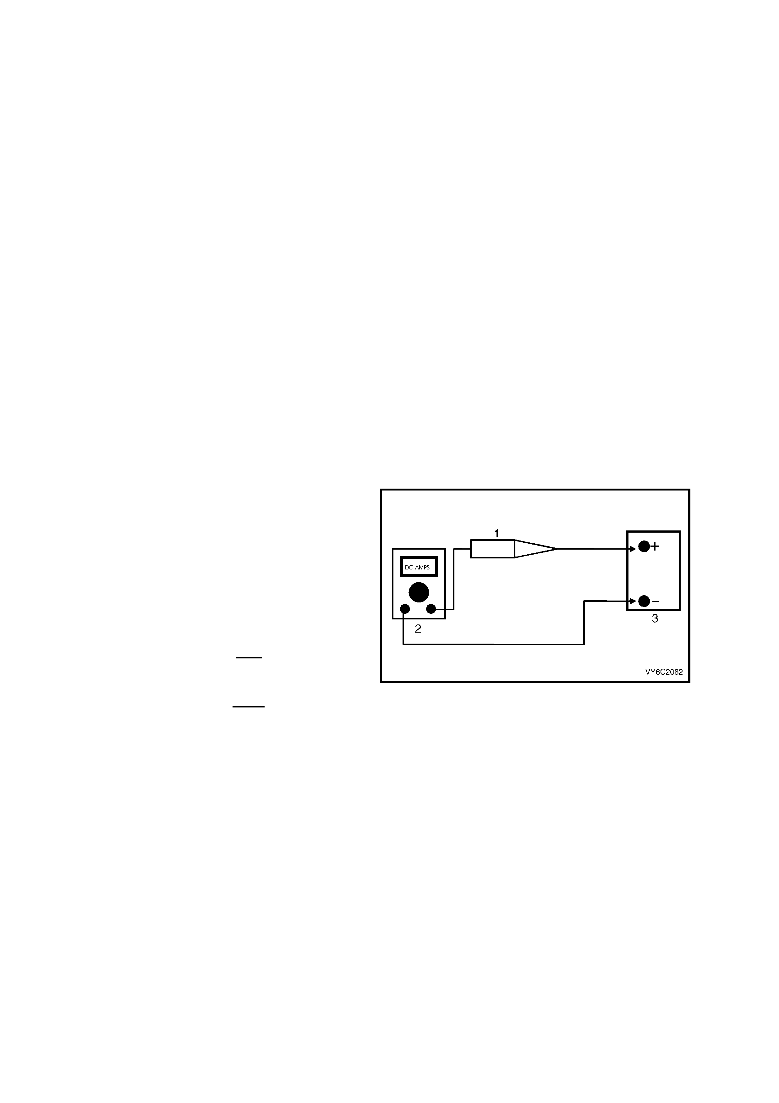
13. When a test light ( 1) is s pec ified, a " low-p ower"
test light must be used. Do not use a high –
wattage test light. While a particular brand of
test ligh t is no t sug geste d, a sim ple t est o n an y
test light will ensure it to be OK for PCM c ircuit
testing. Connect an accurate (2) Ammeter
(such as a high-impedance digital multimeter)
in series with the test light being tested, and
power the test light-ammeter circuit with the
ve hicle battery (3).
If the ammeter indicates less than 0.3 Amp
current flow (300 mA), the test light is OK to
use.
If the ammeter indicates more than 0.3 Amp
current flow (or 300 mA), the test light is NOT
OK to use.
Figure 6C3-3-1
14. When fasteners are removed, always reinstall them at the same location from which they were removed. If a
fastener needs to be replaced, use the correct part number fastener for that application. If the correct part
number fastener is not available, a fastener of equal size and strength (or stronger) may be used. Fasteners
that are not to be re-used, or those requiring thread locking compound will be identified. The correct torque
value must be used when installing fasteners that require it. If the above conditions are not followed, parts or
system damage could result.
2. ELECTRONIC COMPONENTS
2.1 POWERTR AIN CONTROL MODULE (PCM)
PCM REPLACEMENT
Service of the PCM should normally consist of
either replacement of the PCM or EEPROM (flash
memory) programming. If the diagnostic
procedures call for the PCM to be replaced, the
PCM should be first checked to ensure it is the
correct part. If it is, remove the faulty PCM and
insta ll the ne w PCM .
IMPORTANT: The PCM used in this vehicle
application is not interchangeable with any other
V8 GEN III pro gram . O nl y the PCM p art number f or
this vehicle must be used.
IMPORTANT: The replacement PCM EEPROM
will not be programmed.
DTC P0601 and P0602 indicates the EEPROM is
not programmed or has malfunctioned. Refer to
Service Programming for programming
procedures.
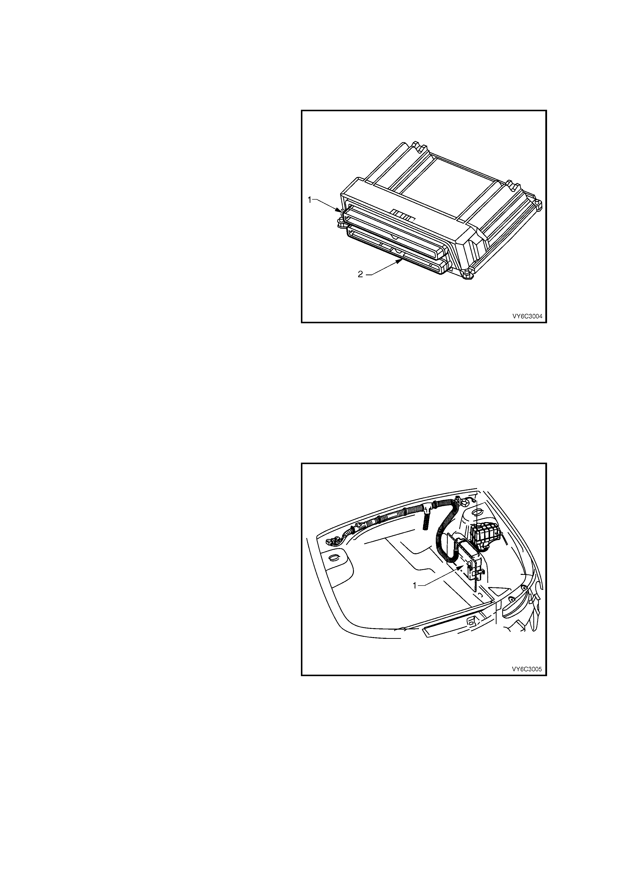
The PCM has two 80 pin connectors; A84-X1 Blue
(1) and A84-X2 Red (2).
IMPORTANT: The following operations must be
carried out whenever the PCM is replaced:
1. Programming of the EEPROM
2. The Idle Learn Procedure
3. The Functional Check
Also, whenever the PCM is disconnected or loses
power, the following operations must be carried
out:
Figure 6C3-3-2 – Powertrain Control Module
1. The Idle Learn Procedure
2. The Functional Check
Each of these operations are described in this
Section.
IMPORTANT: To prevent internal PCM damage,
the ignition must be OFF when disconnecting or
reconnecting power to the PCM.
IMPORTANT: Ensure that the cover is free of
contam inants (m oisture) bef ore servicing t he PCM.
The moisture flows into the PCM connector body
when the PCM is disconnected and the hood is
opened.
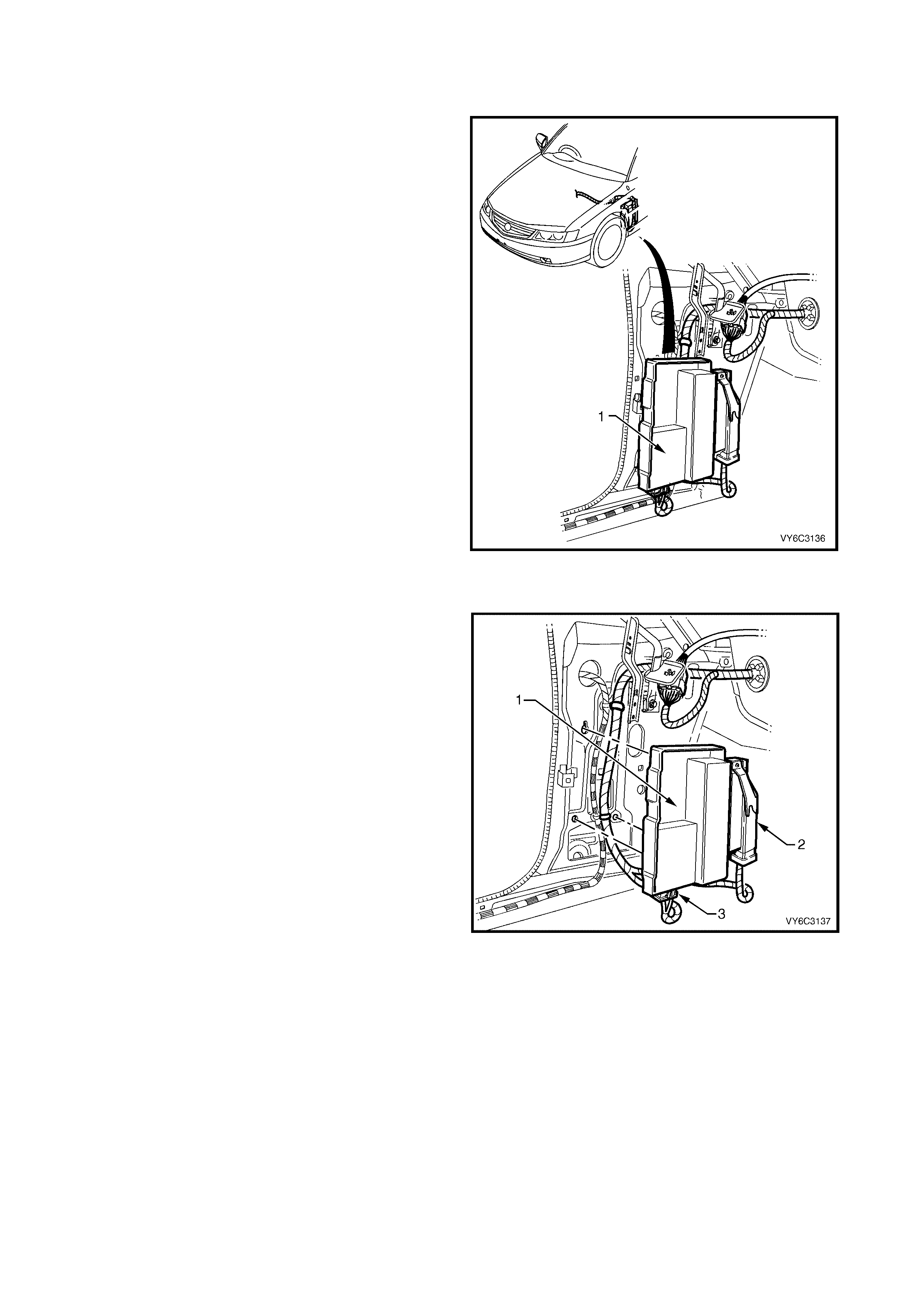
The location of the PCM (1) is by the left front
suspension tower, below the coolant surge tank.
Figure 6C3-3-3 – PCM Location
REMOVE
NOTE 1: Remove any debris from the PCM connector surfaces before servicing the PCM. Inspect the PCM module
connector gaskets when diagnosing or replacing the PCM. Ensure that the gaskets are installed correctly as they
prevent con taminant intrusion into the PC M.
NOTE 2: Do not touch the connec tor pins or s oldered com ponents on the c ircuit board i n order to preven t possible
electrostatic discharge damage to the PCM.
NOTE 3: To prevent internal damage to the PCM, the ignition must be OFF when disconnecting or reconnecting
the PCM connect ors .
1. Ignition OFF.
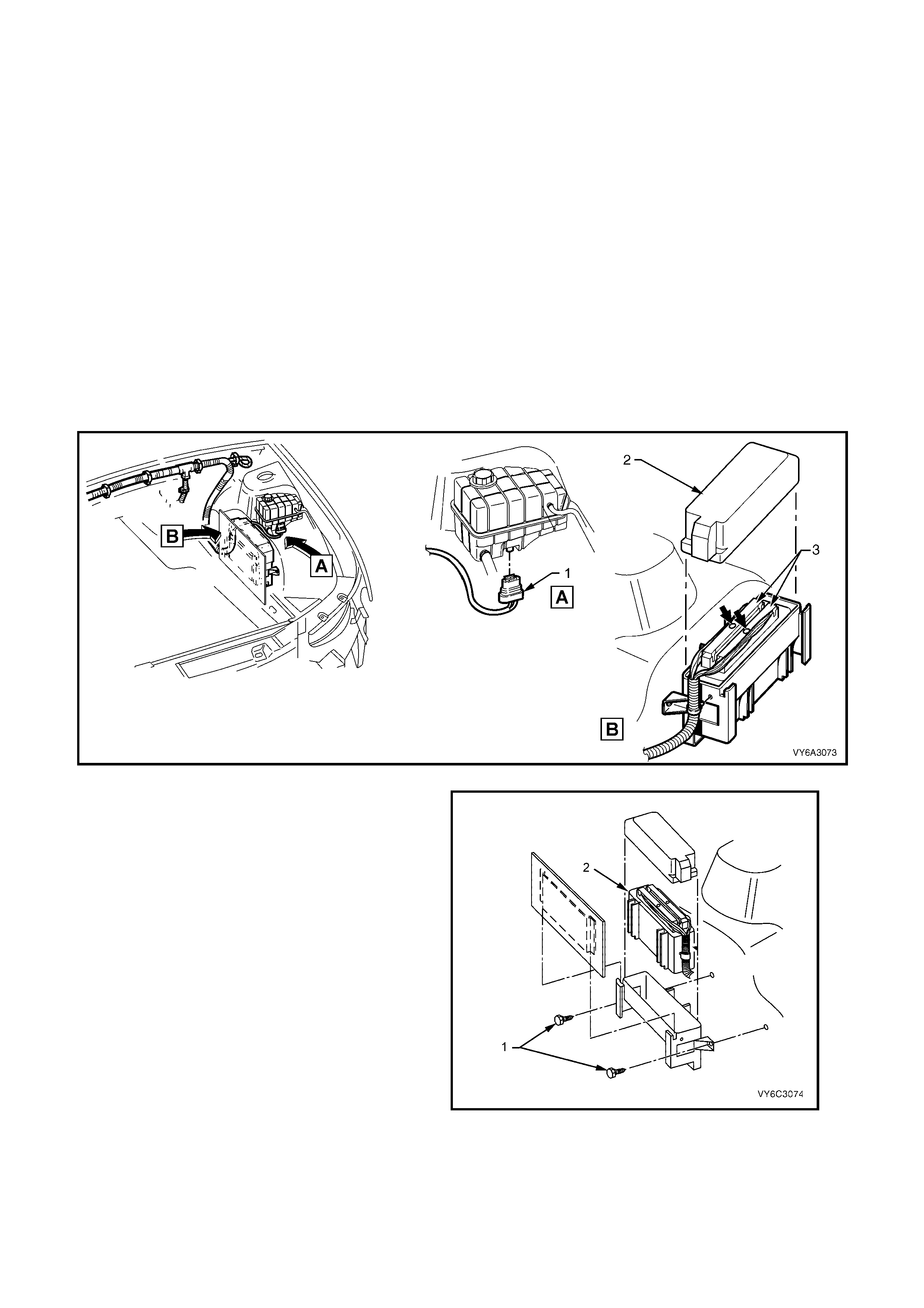
2. Disengage the coolant surge tank from its mounting points, refer Section 6B3 ENGINE COOLING –
GEN III V8 ENGINE.
IMPORTANT: The coolant surge tank may be HOT. Allow the coolant to cool before performing this procedure.
3. Lift the coolant surge tank up, turn it over and disconnect the wiring harness connector (1) from the coolant
level sensor. Set the surge tank to one side.
4. Remove the air cleaner assembly, refer 5.5 AIR CLE ANER ASSEM BLY in this Section.
5. Remove PCM harness connector cover (2).
6. Loosen the c onnector retainin g screws at each PC M connector (bo ld arro ws) an d rem ove the connectors f rom
the PCM.
Figure 6C3-3-4 – PCM Mounting
7. Remove the PCM (2) from the mounting
bracket by levering back the bracket retainers
at each end, while lifting up the PCM.
Figure 6C3-3-5 – PCM Mounting Assembly

REINST ALL
IMPORTANT: Do not touch the connector pins or soldered components on the circuit board in order to prevent
possible electrostatic discharge damage to the PCM.
IMPORTANT: To prevent internal damage to the PCM, the ignition must be OFF when disconnecting or
reconnect ing the PC M con nec tors .
1. Reinstall the PCM (1) to the mounting bracket (2).
2. Reconnect the PCM connectors and reinstall the connector securing screws.
3. Install PCM connector cover (3).
4. Reinstall coolant surge tank.
5. Reinstall air cleaner assembly.
IMPORTANT: If a new PCM is being installed, program the PCM memory using the following procedure.
PCM SERVICE PROGRAMMING
IMPORTANT: Follow the programming instructions completely and do not key OFF during programming unless
instructed. If the key is turned OFF during programming, possible PCM damage may occur.
IMPORTANT: Do not disconnect Tech 2 during each programming step.
1. Setup - Ensure that the following conditions have been met:
– The battery is fully charged, but not charging during programming.
– The ignition is ON.
– Ensure that all PCM connections are OK.
2. Connect Tech 2 to the vehicle and select; Service Programming System (SPS) / Request Info.
3. Connect Tech 2 to a TIS terminal and download latest software matching the vehicle. Refer to TIS
terminal/equipment users instructions.
4. Connect TECH 2 to the vehicle again and select Service Programming System (SPS) / Program ECU.
5. If the PCM fails to program, proceed as follows:
– Ensure that all PCM connections are OK.
– Attempt to re-program the PCM. If the PCM still cannot be programmed correctly, replace the PCM and
program it according to this procedure.
IMPORTANT: Once a new PCM has been programmed, it must be Security Linked. Refer to PCM/PIM/BCM
Security Link for linking procedure. If updating calibrations to the vehicle’s existing PCM hardware, no linking
procedure is necess ary.
PCM/PIM/BCM SECURITY LINK
Once the PCM, PIM and/ or BCM have been replaced, the modules must be security linked to each other. If the
procedure is not performed, the vehicle will not crank or run.
This linking procedure is found under ‘BODY CONTROL MODULE’ in Tech 2 and is performed as follows:
• Connect TECH 2 to DLC and select:
– Diagnostic / (3) 2003 / VY Commodore / Body / Body Control Module / Security / BCM Link to PCM/PIM.
• The procedure ‘BCM Link to PCM/PIM’ will first ask to select the installed engine. If GEN III V8 is selected, a
‘TIS Enable Programming’ is required.
• Connect Tech 2 to TIS terminal (with a registered Hardware Key installed) and select ‘Enable Programming’.
After r eturning to the veh icle, selec t the linking pr ocedur e again. The BCM a nd PIM are li nked f irst, followed b y the
PCM – PIM which is perfor med autom atic ally.
For additional information regarding Tech 2 and Tech 2 test modes (including this linking procedure), refer to
TECH 2 DIAGNOSIS FOR BCM in Section 12J BCM.
IMPORTANT: Af ter the ne w PCM has been l inked, you m us t then follo w the “Idl e Learn Proc edure” in order for the
PCM to learn and re-es tab li s h the IAC valve pos it ion.

IDLE LEARN PROCEDURE
W henever the PCM or the battery is disc onnected or the PC M loses power , the PCM’s learn ed position of the IAC
valve pintle is lost, resulting in an unstable idle.
Perform the following procedure in order to return the IAC valve pintle to the correct position:
Automatic Transmission
1. Ignition OFF.
2. Restore the PCM batter y feed.
3. Turn OFF the A/C controls (if fitted).
4. Set the park brake and block the drive wheels.
5. Run the engine at idle.
6. Shift the transmission selector to D (drive).
7. Allow the engine to idle for 10 minutes.
8. Turn ON the A/C controls.
9. Allow the engine to idle for 10 minutes.
10. Shift the transmission selector to P (park).
11. Allow the engine to idle for 10 minutes.
12. Turn OFF the A/C controls.
13. Allow the engine to idle for 10 minutes.
14. Turn OFF the engine for 30 seconds.
Manual Transmission
1. Ignition OFF.
2. Restore the PCM batter y feed.
3. Turn the A/C controls OFF.
4. Set the park brake and block the drive wheels.
5. Place the transmission in neutral.
6. Start the engine.
7. Turn the A/C controls ON.
8. Allow the engine to idle for 10 minutes.
9. Turn the A/C controls OFF.
10. Allow the engine to idle for 10 minutes.
11. Turn OFF the engine for 30 seconds.
FUNCTIONA L CHECK
1. Clear the Diagnostic Trouble Codes (DTCs).
2. Perform the Powertrain OBD System Check.
3. Start the engine and idle for one minute.
4. Use Tech 2 to check for DTC.
2.2 POWERTRAIN INTERFACE MODULE (PIM)
PIM REPLACEMENT
If the diagnostic procedures call for the PIM to be
replace d, it should be c heck ed first to ensur e it is the
correct part. If it is, remove the faulty unit and install
the new PIM.
IMPORTANT: To prevent internal PIM damage, the
ignition must be OFF when disconnecting or
reconnecting power to the PIM.
IMPORTANT: Remove any debris from the PIM
connector surfaces before servicing the PIM. Inspect
the PIM module connector when
diagnosing/replacing the PIM.
IMPORTANT: DO NOT TOUCH THE CONNEC TOR PINS
OR SOLDERED COMPONENTS ON THE CIRCUIT
BOARD IN ORDER TO PREVENT POSSIBLE
ELECTROSTATIC DISCHARGE (ESD) DAMAGE TO THE
PIM.
Figure 6C3-3-6 Powertrain Interface Module (PIM) Location
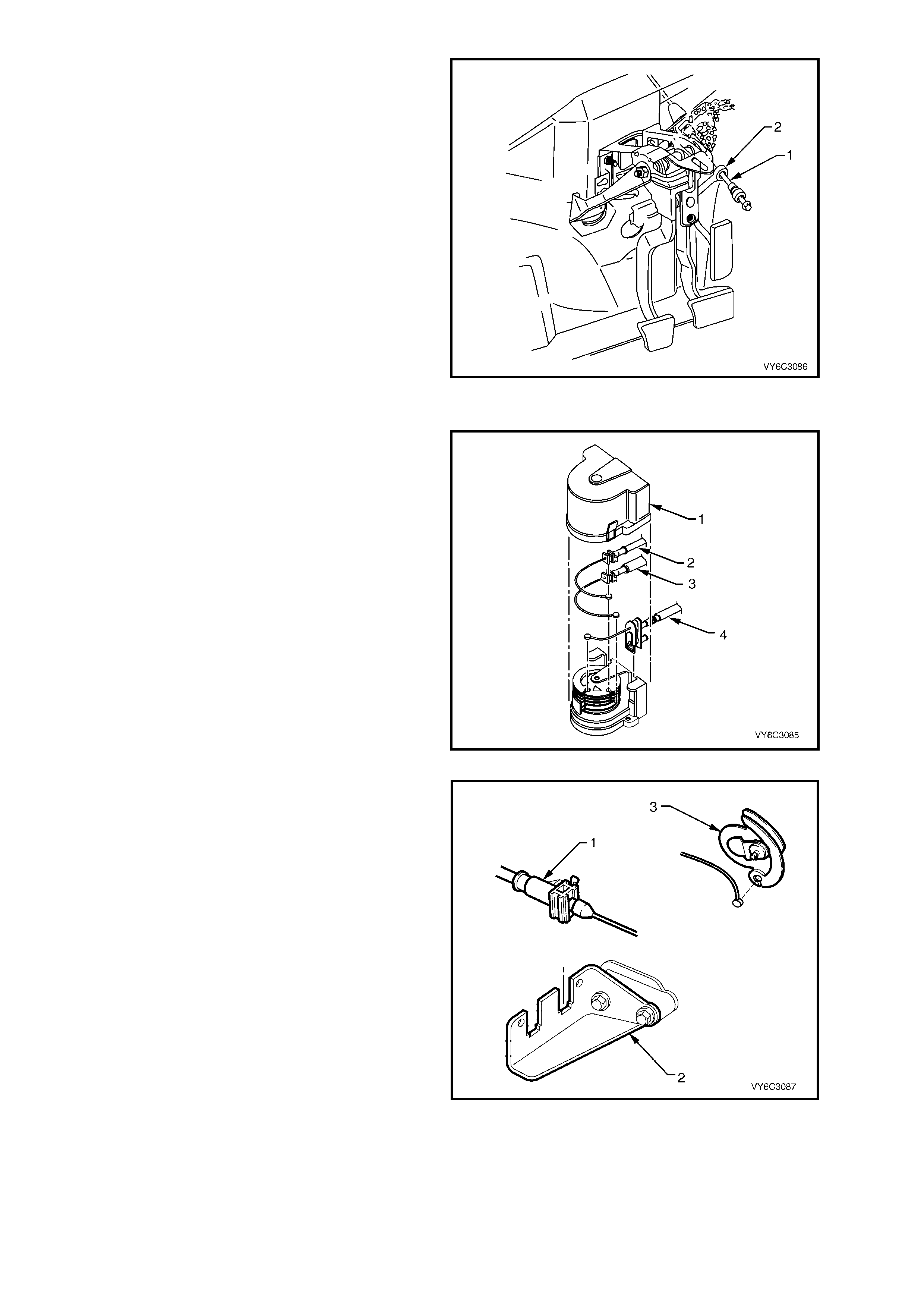
REMOVE
1. Ignition OFF.
2. Remove left hand front shroud panel lower trim
assembly (kick panel trim).
3. Remove PIM (1) from mounting bracket.
4. Remove wir ing harness connectors (2 and 3) from
the Throttle Relaxer Control Module and PIM.
5. Remove the Throttle Relaxer Control Module,
when the Traction Control System (TCS) is fitted
to the vehicle.
REINST ALL
1. Install wiring harness connector (3) to the PIM (1).
2. Reinstall the Throttle Relaxer Control Module and
wiring harness connector (2), to the new PIM,
when TCS is fitted to the vehicle.
3. Reinstall PIM to the mounting bracket.
4. Reinstall the left hand front shroud panel lower
trim assembly (kick panel trim).
Figure 6C3-3-7 Powertrain Interface Module (PIM)

PCM/PIM/BCM SECURITY LINK
Once the PCM, PIM and/ or BCM have been replaced, the modules must be security linked to each other. If the
procedure is not performed, the vehicle will not crank or run.
This linking procedure is found under ‘BODY CONTROL MODULE’ in Tech 2 and is performed as follows:
• Connect TECH 2 to DLC and select:
– Diagnostic / (3) 2003 / VY Commodore / Body / Body Control Module / Security / BCM Link to PCM/PIM.
• The procedure ‘BCM Link to PCM/PIM’ will first ask to select the installed engine. If GEN III V8 is selected, a
‘TIS Enable Programming’ is required.
• Connect Tech 2 to a TIS terminal (with a registered Hardware Key installed) and select ‘Enable Programming’.
After r eturning to the veh icle, selec t the linking pr ocedur e again. The BCM a nd PIM are li nked f irst, followed b y the
PCM – PIM which is perfor med autom atic ally.
For additional information regarding Tech 2 and Tech 2 test modes (including this linking procedure), refer to
TECH 2 DIAGNOSIS FOR BCM in Section 12J BCM.
FUNCTIONA L CHECK
1. Run the engine at idle for one minute.
2. Use Tech 2 to check for any PIM DTCs.
3. If any PIM DTC is set, refer to appropriate PIM DTC table.
2.3 ENGINE COOLANT TEMPERATURE (ECT) SENSOR
REMOVE
1. Raise the vehicle and support on safety stands. Refer to Section 0A GENERAL INFORMATION in the MY
2003 VY and V2 Series Service Information, for the location of jacking and support points.
2. Drain the engine coolant. Refer to Section 6B3 ENGINE COOLING – GEN III V8 ENGINE.
3. Lower the vehicle.
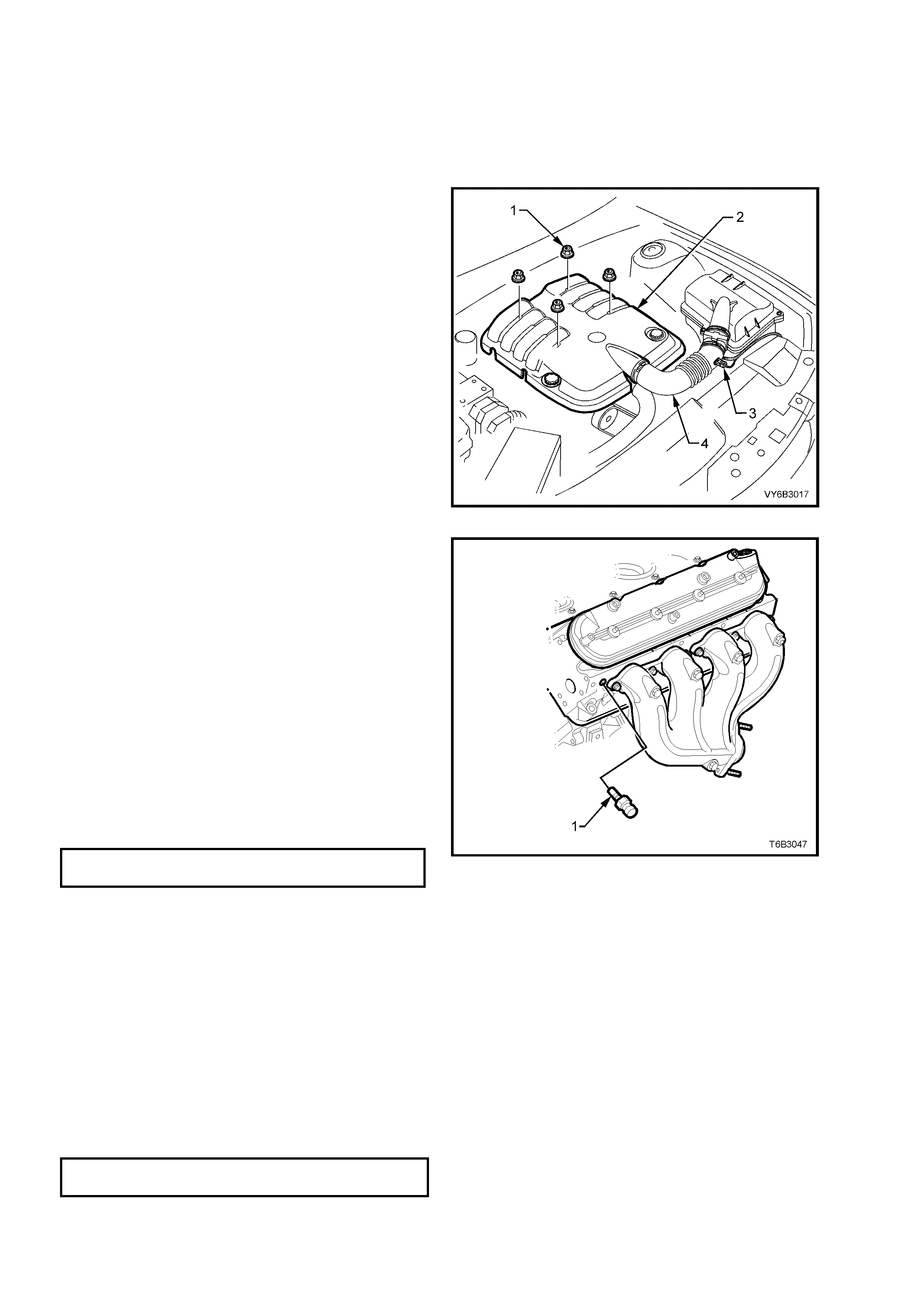
4. Remove th e engine dr ess cover m ounting nuts
(1) and the dress cover (2).
Figure 6C3-3-8 – Engine Dress Cover
5. Disconnect the electrical connector from the
ECT sensor (1).
6. Remove the No.1 spark plug lead from the
spark plug.
7. Remove the ECT sensor.
IMPORTANT: Us e care when handling th e coolant
sensor. Damage to the coolant sensor will affect
the operation of the fuel control sy stem.
REINST ALL
1. Coat the Engine Coolant Temperature (ECT)
sensor (1) thread with Loctite 242 or
equivalent.
2. Reinstall the ECT sensor into the left cylinder
head and tighten to the correct torque
specification.
ECT SENSOR
TORQUE SPECIFICATION 17 Nm
3. Tighten the ECT sensor to the specified torque.
4. Reinstall the No.1 spark plug lead onto the
spark plug.
5. Reconnect the ECT sensor electrical
connector.
6. Ref ill th e eng ine c oolant . Ref er to Section 6B3
ENGINE COOLING – GEN III V8 ENGINE.
Figure 6C3-3-9 – Engine Coolant Temperature
(ECT) Sensor
7. Start the engine and check for leaks.
8. Recheck the engine coolant level. Refer to
Section 6B3 ENGIN E COOLING – G EN III V8
ENGINE
9. Reinstall the engine dress cover and tighten
decorative nuts to the correct torque specification.
ENGINE DRESS COVER NUT
TORQUE SPECIFICATION 10 Nm


2.5 INTAKE AIR TEMP ERATURE (IAT) SENSOR
REMOVE
1. Disconnect battery ground lead.
IMPORTANT: Disconnection of the battery
affects certain vehicle electronic systems. Refer to
Sections 00 CAUTIONS, 5. Battery Disconnection
Procedures before disconnecting the battery.
NOTE: Care must be taken when handling the IAT
Sensor, as damage will affect the operation of the fuel
control sy stem .
2. Remove engine dress cover (2). Refer
2.3 Engine Coolant Temperature Sensor, in
this Section.
3. Lift the locking lever on the Intake Air
Temperature (IAT) sensor wiring harness
connector (3), then remove the connector.
4. Loosen the two intake duct clamps, then
remove the duct (4).
5. Using a pair of side cutting pliers, cut across
the IAT sensor retainer to remove it. Once
removed, discard the retainer.
6. Pull the IAT sensor from the intake duct.
Figure 6C3-3-10 – IAT Sensor Location
REINST ALL
1. Pus h a ne w IAT sensor into the air intak e duct,
with the tr iangular tang o n the mountin g flange
locating on the mating rib on the air intake
duct.
2. Position new retainer onto the IAT sensor (3),
then use a 20 mm socket to push the retainer
fully onto the IAT sensor.
3. Reinstall the air intake duct and tighten the
clamps at the MAF sensor and throttle body
ends.
4. Reconnect wiring harness connector to IAT
sensor (3).
5. Check that the mass air flow sensor wiring
harness connector has remained firmly in
place.
6. Reinstall the engine dress cover, reinstall the
four decorative nuts and tighten to the correct
torque specification.
ENGINE DRESS COVER NUT
TORQUE SPECIFICATION 10 Nm
7. Start the engine to ensure c or rec t operat ion .
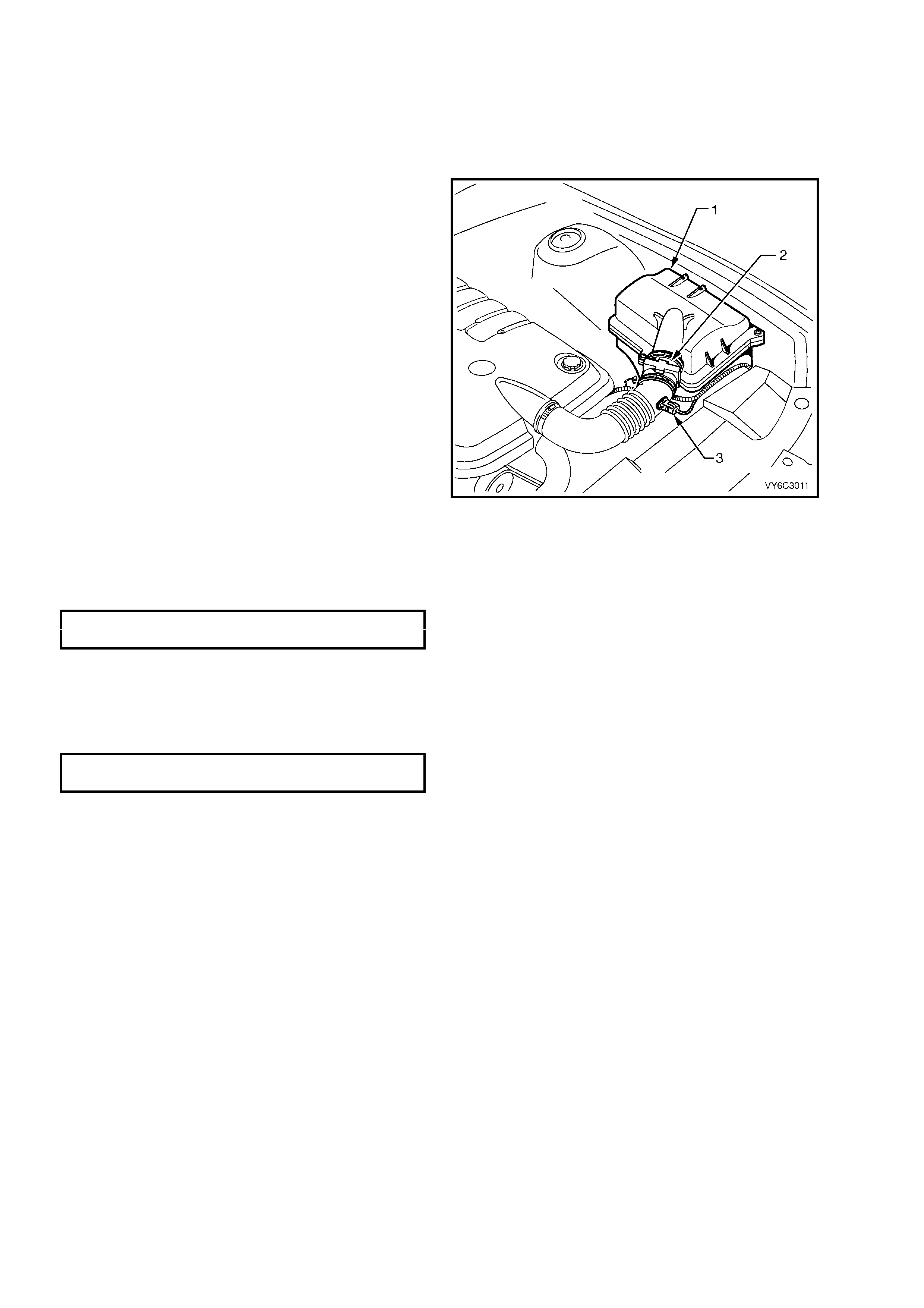
2.6 MASS AIR FLOW (MAF) SENSOR
REMOVE
NOTE: CARE MUST BE TAKEN WHEN HANDLING
THE MAF SENSOR AS DAMAGE WILL AFFECT THE
OPERATION OF PCM CONTROL.
1. Lift up the tang on the MAF sensor (2) wiring
harness connector and remove the connector
from sensor.
2. Loosen th e clamp on a ir intak e duct, closes t to
MAF sensor.
3. Loosen the clamp on the air duct at the MAF
sensor and pull back the air duct from the
sensor.
NOTE: The air duct adaptor (between air cleaner
and MAF sensor), retaining clamps, air duct and
MAF sensor ha ve loc at ing notches .
4. Remove MAF sensor (2) from air duct adaptor.
REINST ALL
IMPORTANT: The embossed arrows on the MAF
sensor indicate the correct air flow direction. The
arrows must point towards the engine.
1. Reinstal l the MAF sensor (2) into the a ir intake
duct.
NOTE: Ensure all notches are aligned.
2. Reinstall the retaining clamps, aligning
notches, tighten clamps to the specified torque.
INTAKE AIR DUCT CLAMP
TORQUE SPECIFICATION 1.5 – 2.5 Nm
3. Reconnect the MAF sensor wiring harness
connector.
4. Reinstall engine dress cover, reinstall the
decorative nuts and tighten to the correct
torque specification.
ENGINE DRESS COVER NUT
TORQUE SPECIFICATION 10 Nm
5. Start vehicle and check for air leaks.
Figure 6C3-3-11 – MAF Sensor Location
2.7 MANIFOLD ABSOLUTE PRESSURE (MAP) SENSOR
REMOVE
1. Remove engine dress cover. Refer
2.3 Engine Coolant Temperature Sensor, in
this Section.
2. Disconnec t the MAP senso r electrical con nector
(1).
3. Twist the MAP sensor (2) forward in order to
release it from the intake manifold adaptor.
4. Pull the MAP sensor upward.
REINST ALL
1. Lightly coat the MAP sensor seal with clean
engine oil.
2. Reinstall the MAP sensor by pushing it down to
engage it into the reta iner.
3. Connect the MAP sensor electrical connector.
4. Install engine dress cover. Refer to 2.5 Intake
Air Temperature (IAT) Sensor, in this Section.
5. Start the engine and check for normal operation.
Figure 6C3-3-12 – MAP Sensor Location
2.8 HEATED OXYGEN SENSORS (HO2S)
IMPORTANT SERVICE NOTES:
• The heated ox ygen sens ors have a perm anentl y attached pigta il a nd connect or. Do not rem ove the pig tail f rom
the sensor.
• Handle the oxygen sensor carefully. Do not drop it and keep it free of grease, dirt, or other contaminants. Do
not use cleaning solvents of any type.
• Do not repair the sensor or any of its parts. Replace the oxygen sensor if any damage is evident.
• Correct oxygen sensor operation requires an external air reference. This external air reference is obtained by
way of the oxygen sensor signal and heater wires. Any attempt to repair the wires, the connectors, or the
terminals results in the obstruction of the air reference and degrades the oxygen sensor performance.
• The heated ox ygen sens or ma y be difficult to r emove when th e engine tem perature is below 48 ° C. Excessive
force may damage the threads in the exhaust manifold or exhaust pipe.
• It may be necessary to lower the exhaust system to gain sufficient access to a HO2S and/or its connector.
Refer to Section 8B EXHAUST SYSTEM.
REMOVE
1. Raise front of vehicle and support on safety
stands. Refer to Section 0A GENERAL
INFORMATION, f or the location of jacking and
support points.
2. Disc onnect the HO2S elec trical c onnector from
the sensor to be removed.
NOTE: While the left hand sensor is shown, the
right is sim ilar .
3. Carefully remove the HO2S from the exhaust
pipe on the side to be removed.
T26C3008
1
3
Figure 6C3-3-13 – Left Hand HO2S
REINST ALL
IMPORTANT: A special anti-seize compound is used on the heated oxygen sensor threads. The compound
consists of graphite and glass beads suspended in fluid. The graphite will burn away, but the glass beads will
remain, making the sensor easier to remove. New or service sensors will have the compound applied to the
threads.
If a sens or is r em oved f rom an eng ine a nd is to be re ins talled, the thr eads m ust have anti-s eize com pound appl ied
before reinstallation. Specified anti-seize compound is available from authorised retailer parts outlets as part
number 5613695.
1. Coat the cleaned threads of the heated oxygen sensor with anti-seize compound, if required.
2. Reinstall the HO2S into the exhaust pipe and tighten to the specified torque.
OXYGEN SENSOR
TORQUE SPECIFICATION 41 Nm
3. Connect the HO2S electrical connector.
4. Lower the vehicle.
2.9 THROTTLE POSITION (TP) SENSOR
REMOVE
1. Remove engine dress cover. Refer
2.3 Engine Coolant Temperature Sensor, in
this Section.
2. Depress the power steering reservoir retaining
clip and lift it up on the reservoir and set aside.
3. Unbolt and remove the power steering
reservoir mounting bracket.
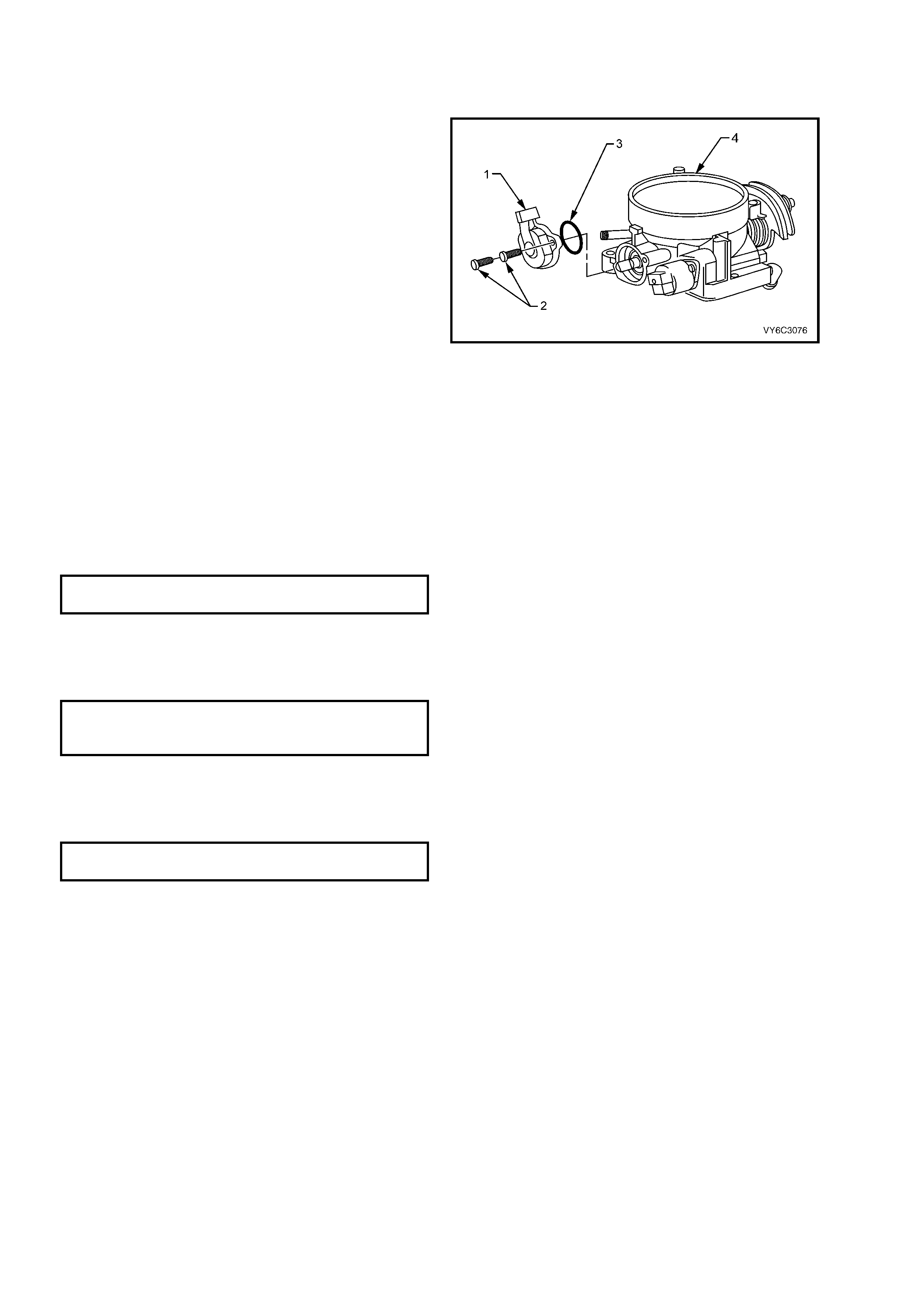
4. Disconnect the electrical connector from the
TP sensor (1).
5. Remove the TP sensor attaching screws (2).
6. Rem ove the T P sensor and O-ring (3) fr om the
throttle body (4).
Figure 6C3-3-14 – Throttle Position (TP) Sensor
REINST ALL
1. Reinstall the TP sensor O-ring on to the TP
sensor.
2. Reinstall the TP sensor to the throttle body
with the throttle va l ve in the closed pos it ion .
NOTE: Ensure the TP sensor lever lines up with
the TP sensor drive lever on the throttle shaft.
3. Reinstall the TP sensor attaching screws and
tighten to the specified torque.
TP SENSOR ATTACHING SCREW
TORQUE SPECIFICATION 2.0 Nm
4. Connect the TP sensor electrical connector.
5. Install the power steering reservoir mounting
bracket, tightening the bolts to the correct
torque specification.
POWER STEERING RESERVOIR
BRACKET TO CYLINDER HEAD BOLT
TORQUE SPECIFICATION 25 Nm
6. Ins tall the p ower s teering re servoir to m ounting
bracket.
7. Reins tal l eng ine dres s co ver , tight ening nuts to
the correct torque specification.
ENGINE DRESS COVER NUT
TORQUE SPECIFICATION 10 Nm
2.10 VEHICLE SPEED SENSOR
NOTE: This pr ocedur e r ef ers to the vehic le s peed s en s or fitted to v ehicles with a utomatic tr ansmiss ion. For manual
transmission vehicle speed sensor removal and reinstallation, refer to Section 7B2 M ANUAL TRANSMISSION –
GEN III V8 ENGINE.
REMOVE
1. Raise front of vehicle and support on safety
stands. Refer to Section 0A GENERAL
INFORMATION, f or the location of jacking and
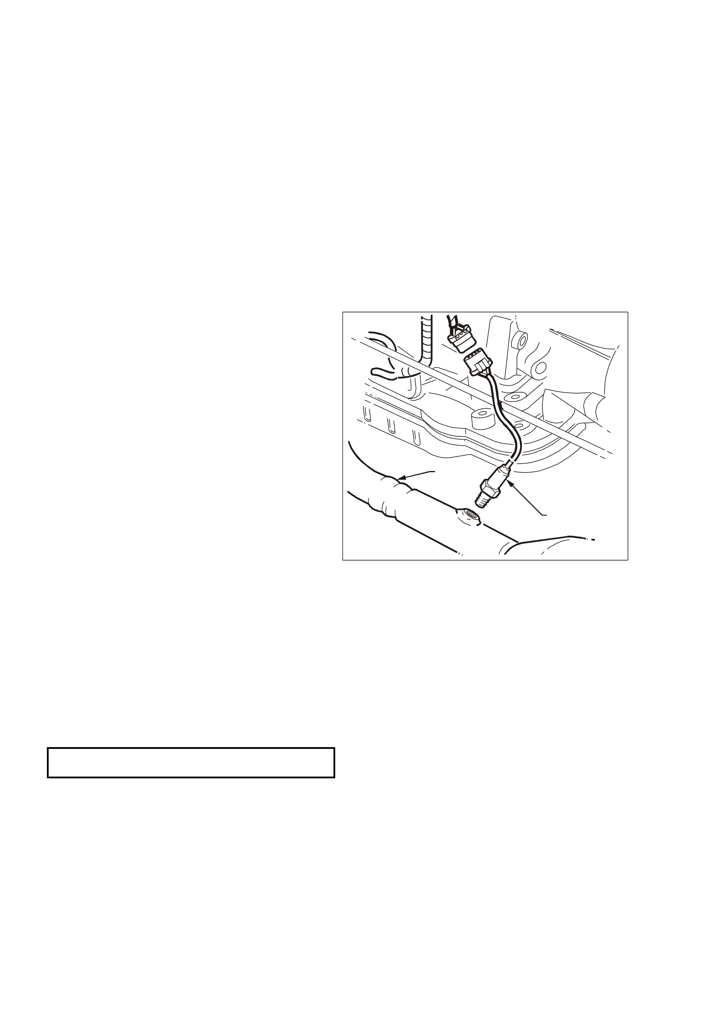
support points.
2. Disconnect the electrical connector from the
vehicle speed sensor (1).
3. Remove the vehicle speed sensor attaching
screw (2 ).
4. Remove the vehicle speed sensor (3) and the
O-ring. Use a suitable container to catch any
transmission fluid that may spill.
Figure 6C3-3-15 – Vehicle Speed Sensor
REINST ALL
1. Reins tal l the v ehicle s peed sensor with ne w O-
ring seal.
2. Reinstall the speed sensor bolt and tighten to
the specified torque.
SPEED SENSOR ATTACHING SCREW
TORQUE SPECIFICATION 11 Nm
3. Reconnect the electrical connector.
4. Lower the vehicle.
5. Check the transmission fluid and add as
required. Refer Transmission Fluid Checking
Procedure in Section 7C4 AUTOMATIC
TRANSMISSION, ON-VEHICLE SERVICING.
2.11 IDLE AIR CONTROL VALVE
REMOVE
1. Remove engine dress cover. Refer to
2.5 Intake Air Temperature Sensor, in this
Section for removal procedure.
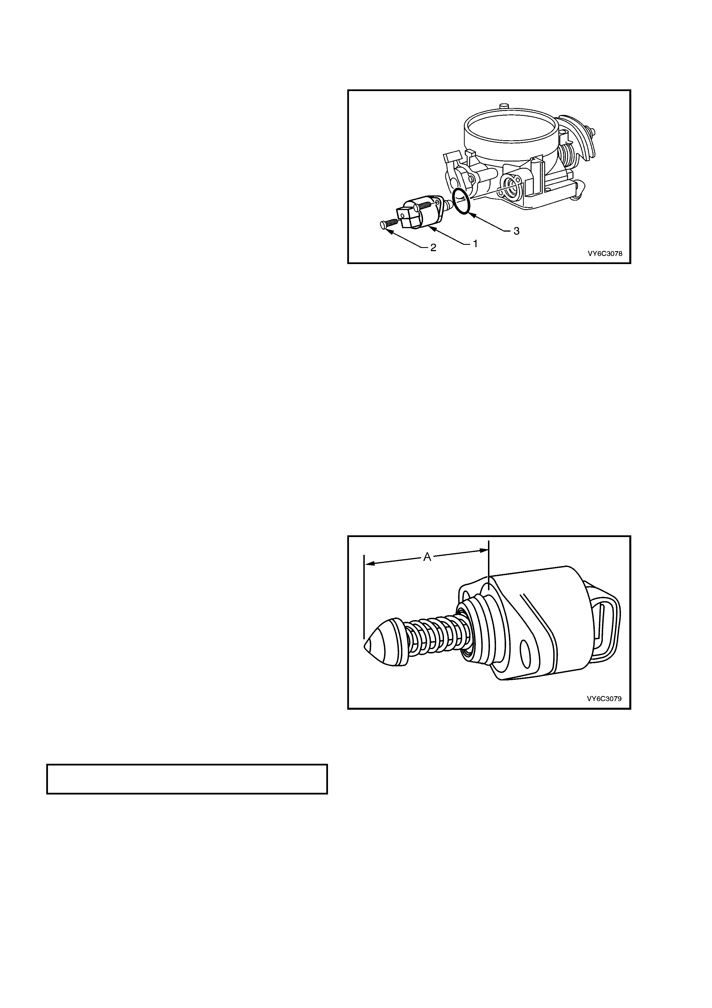
2. Disconnect the electrical connector from the
IAC valve (1).
3. Remove the IAC valve attaching screws (2).
4. Remove the IAC valve (1).
5. Remove the IAC valve O-ring seal (3).
NOTE: Do not push or pull on the IAC valve pintle
on valves that have been in service. The force
required to move the pintle may damage the
threads on the worm drive.
6. Clea n the I AC valve O- ring seali ng surf ace, the
pintle valve s eat an d the a ir passage us ing G M
cleaner 1052626 or equivalent. Use a shop
towel or p arts brus h to rem ove heav y deposits .
If the air passage has heavy deposits, remove
the throttle body for complete cleaning.
Figure 6C3-3-16 – Idle Air Control (IAC) Valve
NOTE: Shiny spots on the pintle or seat are
norm al, and d o not indic ate m isalignm ent or a bent
pintle shaft.
7. Inspect the IAC valve O-ring for cuts, cracks,
or distortion. Replace the O-ring if it is
damaged.
REINST ALL
IMPORTANT: If installing a new IAC valve, be sure
to replace it with an iden tic al part. T he pintle s hape
of the I AC valve and the diam eter of the IA C valve
are designed for specific applications.
1. Measure the distance between the tip of the
IAC valve pintle and the mounting surface (A).
If the distance is greater than 28 mm, use
finger pressure to slowly retract the pintle. The
force required to retract the pintle on a new
valve will not cause damage to the valve.
2. Lubricate the IAC valve O-ring with clean
engine oil.
3. Reinstall the IAC valve O-ring on the IAC
valve.
4. Reinstall the IAC valve.
5. Apply Loctite 242 or equivalent to the IAC
valve attaching screw threads.
6. Reinstall the IAC valve attaching screws and
tighten to the specified torque.
IAC VALVE ATTACHING SCREW
TORQUE SPECIFICATION 3 Nm
7. Connect the IAC valve electrical connector.
8. Reinstall engine dress cover.
9. Perform the Idle Learn Procedure and the
Functional Check. Refer to PCM
Replacement/ Programming in this Section.
Figure 6C3-3-17 – IAC Valve Measured Distance
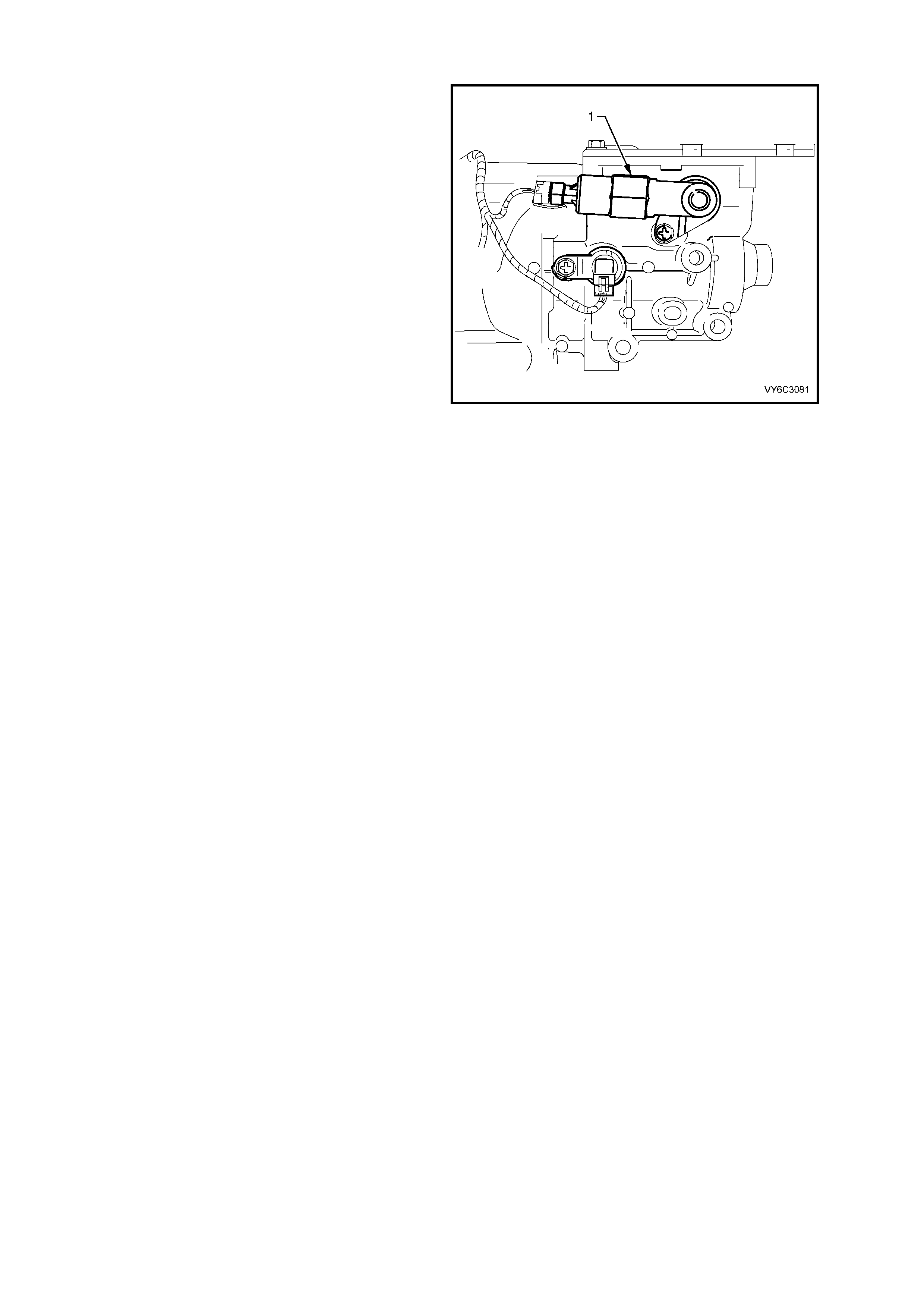
2.12 CAMSHAFT POSI TION (CMP) SENSOR
REMOVE
1. Disconnect the negative battery cable to avoid
possible f uel d ischar ge if an acc identa l attem pt
is made to start the engine.
IMPORTANT: Disconnection of the battery affects
certain vehicle electronic systems. Refer to
Section 00 CAUTIONS, 5. Battery Disconnection
Procedures before disconnecting the battery.
2. Remove engine dress cover. Refer
2.3 Engine Coolant Temperature Sensor, in
this Section.
3. Relieve fuel system pressure. Refer to
3.7 Fuel Pressure Relief Procedure in this
Section.
4. Remove the intake manifold. Refer to
Section 6A3 ENGINE MECHANICAL GEN III
V8 ENGINE.
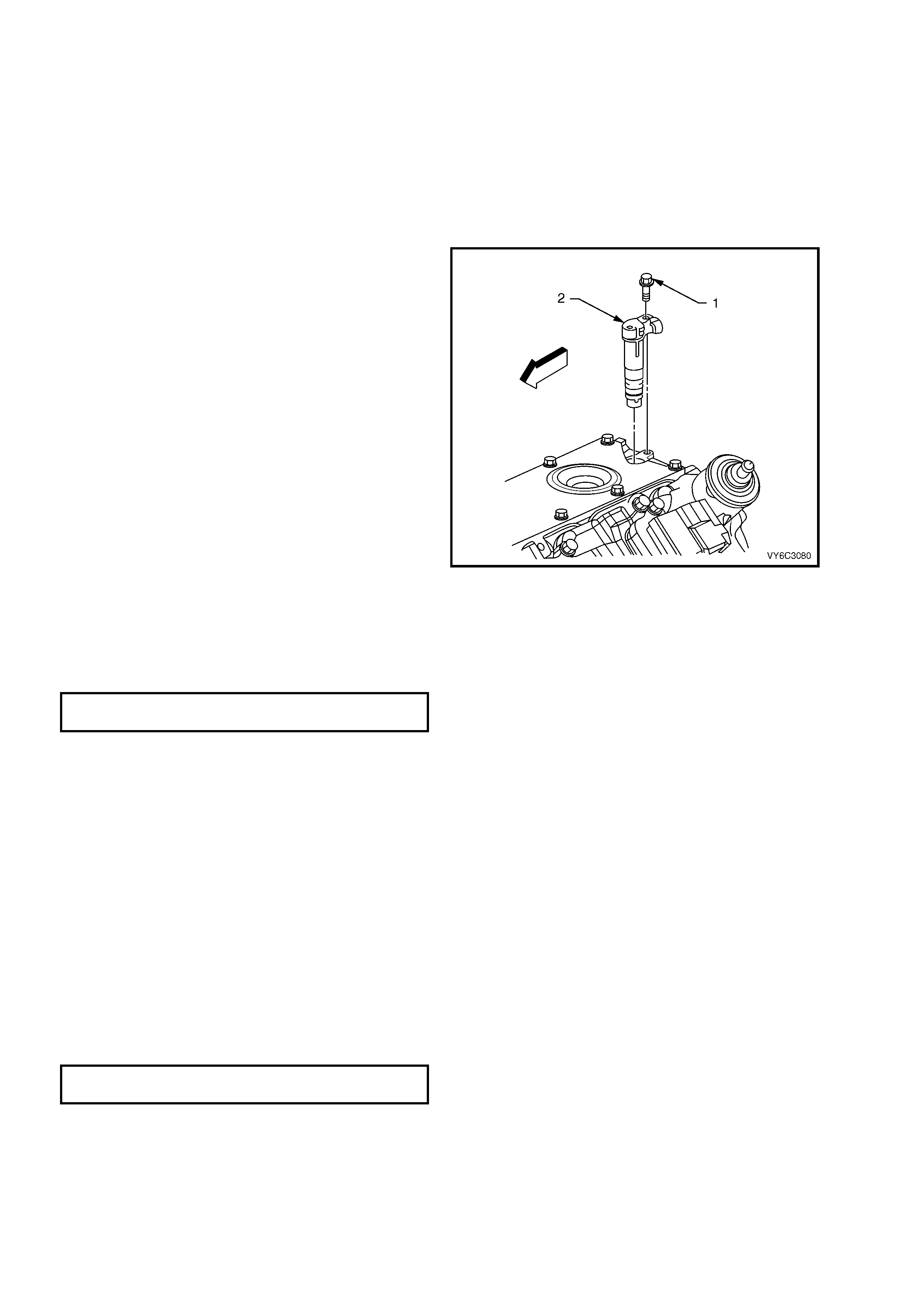
IMPORTANT: Clean the area around the CMP
before removal to avoid debris from entering the
engine.
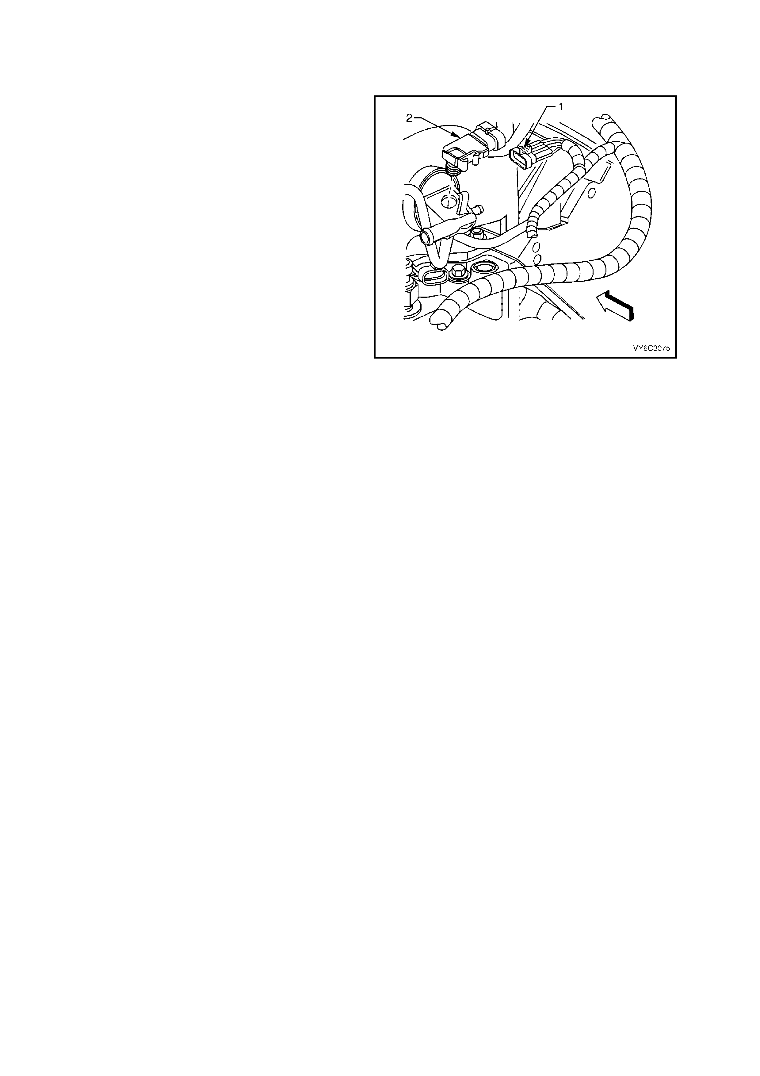
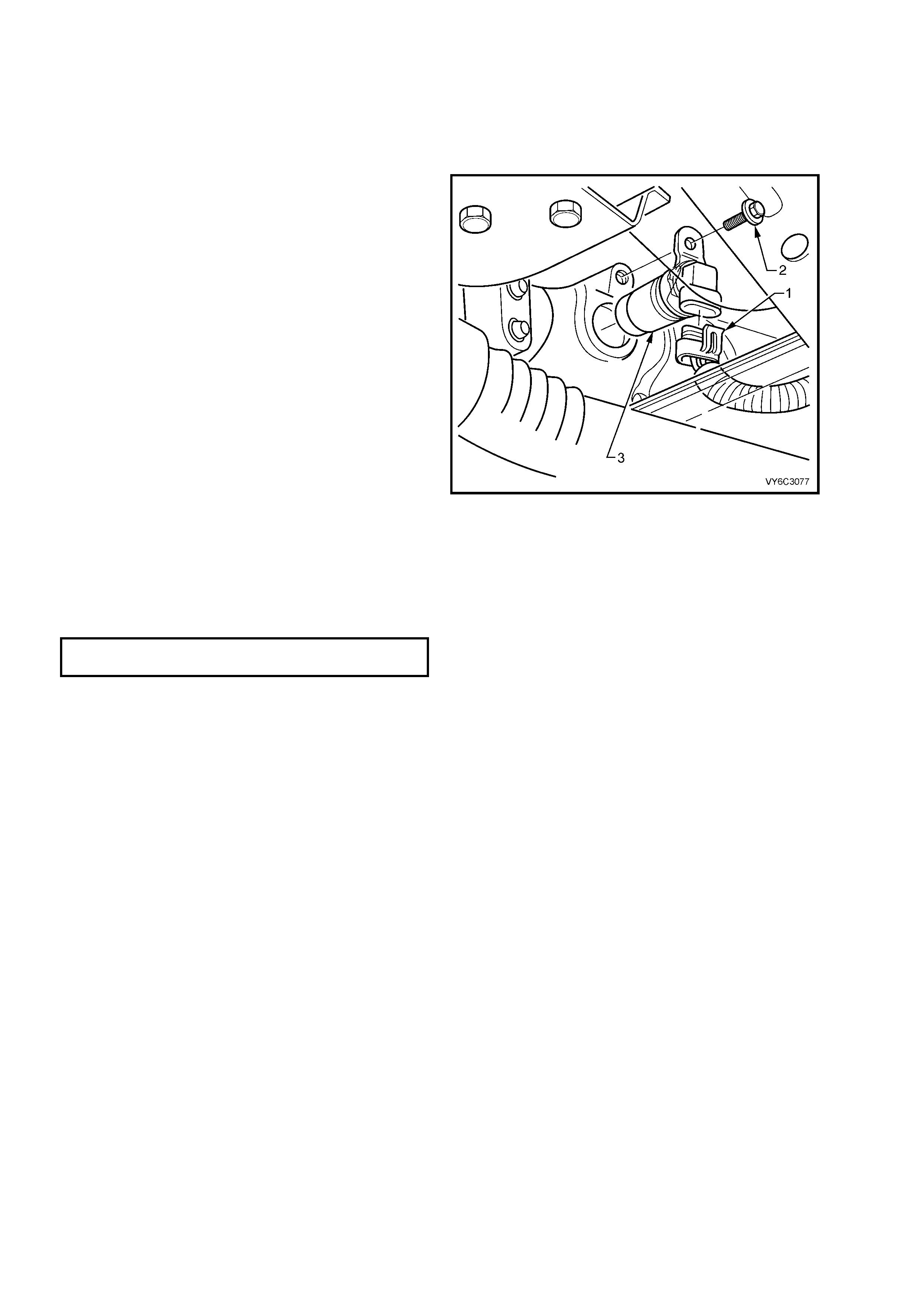
5. Remove the electrical connector from the
Camshaft Position (CMP) sensor (2).
6. Remove the CMP sensor retaining bolt (1).
7. Remove the CMP sensor.
Figure 6C3-3-18 – Camshaft Position Sensor
REINST ALL
1. Reinstall the CMP sensor.
2. Reinstall the CMP sensor retaining bolt and
tighten to the specified torque.
CAMSHAFT SENSOR RETAINING
BOLT TORQUE SPECIFICATION 25 Nm
3. Connect the CMP sensor electrical connector.
4. Reinstall the intake manifold. Refer to
Section 6A3 ENGINE MECHANICAL - GEN
III V8 ENGINE.
5. Inspect for leaks by:
– Turn the ignition switch ON for 2 seconds.
– Turn the ignition switch OFF for 10
seconds.
– Turn the ignition switch ON.
– Check for fuel leaks.
6. Perform the Idle Learn Procedure and the
Functional Check. Refer to PCM
Replacement/Programming, in this Section.
7. Reinstall engine dress cover and tighten
decorative nuts to the correct torque
specification.
ENGINE DRESS COVER NUT
TORQUE SPECIFICATION 10 Nm

3. FUEL SYSTEM
3.1 THROTTLE CONTROL CABLES – VEHICLES WITH TCS
NOTE: For cruise control cable replacement procedures (where fitted), refer to Section 12E CRUISE CONTROL.
• Two Throttle Control cable systems are used with the GEN III V8 Engine.
• Vehicles that do not have Traction Control System (TCS), are fitted with a single throttle cable.
• Vehicles that are fitted with TCS have two cables:
An accelerator pedal cable which is routed between the accelerator pedal and throttle relaxer, and a throttle
cable which is routed between the throttle relaxer and throttle body.
• Adjustment is only available on the throttle cables.
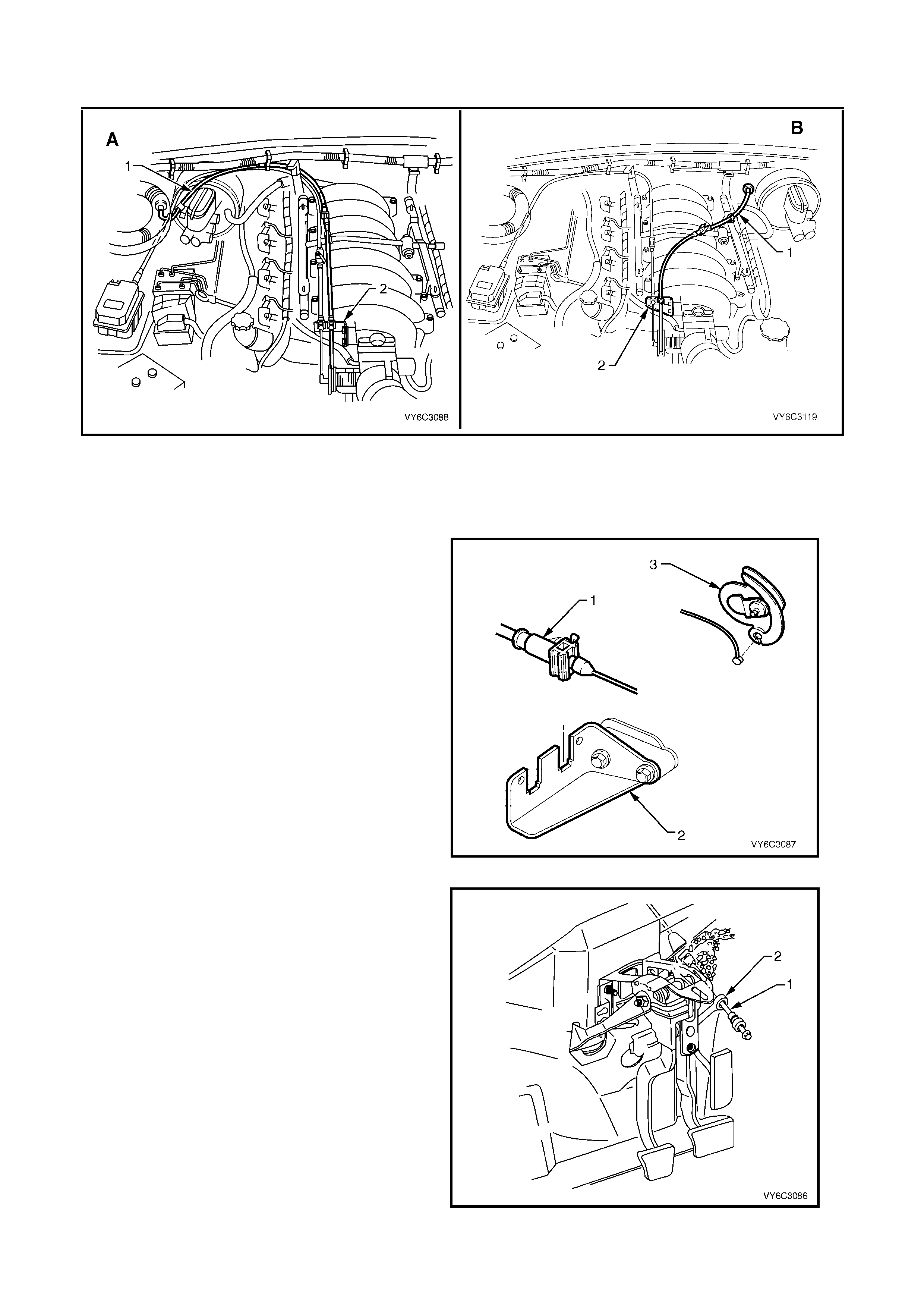
NOTE: View ‘A’ shows the RHD arrangement while view ‘B’ is for LHD vehicles.
Figure 6C3-3-19 – Accelerator Pedal Cable Routing, with TCS
Legend
1. Accelerator Pedal Cable 2. Throttle Relaxer 3. Throttle Cable
REMOVE
Accelerator Cable
1. Remove the throttle relaxer cover (1).
2. Remove the cruise control cable (2) (if fitted).
3. Remove the accelerator pedal cable (3).
4. Open the retainer clip at the brake booster, and
remove the cable from the clip.
Figure 6C3-3-20 – Throttle Relaxer
5. Remove the right instrument panel lower trim.
Refer to Section 1A3 INSTRUMENT PANEL
A ND CONSOLE.
6. Disconnect the accelerator pedal cable (1)
from the accele rator pedal lever (2).
7. Squeeze the accelerator pedal cable cover
tangs and push the cable through the dash
panel.
8. Remove the accelerator cable.
Figure 6C3-3-21 – Accelerator Pedal to Cable
Throttle Cable
1. Remove engine dress cover. Refer
2.3 Engine Coolant Temperature Sensor, in
this Section.
2. Remove the throttle relaxer cover (1).
3. Remove the throttle cable (4) from the throttle
relaxer.
4. Open the retainer clip at the intake manifold,
and remove the cable from the clip.
Figure 6C3-3-22 – Throttle Relaxer
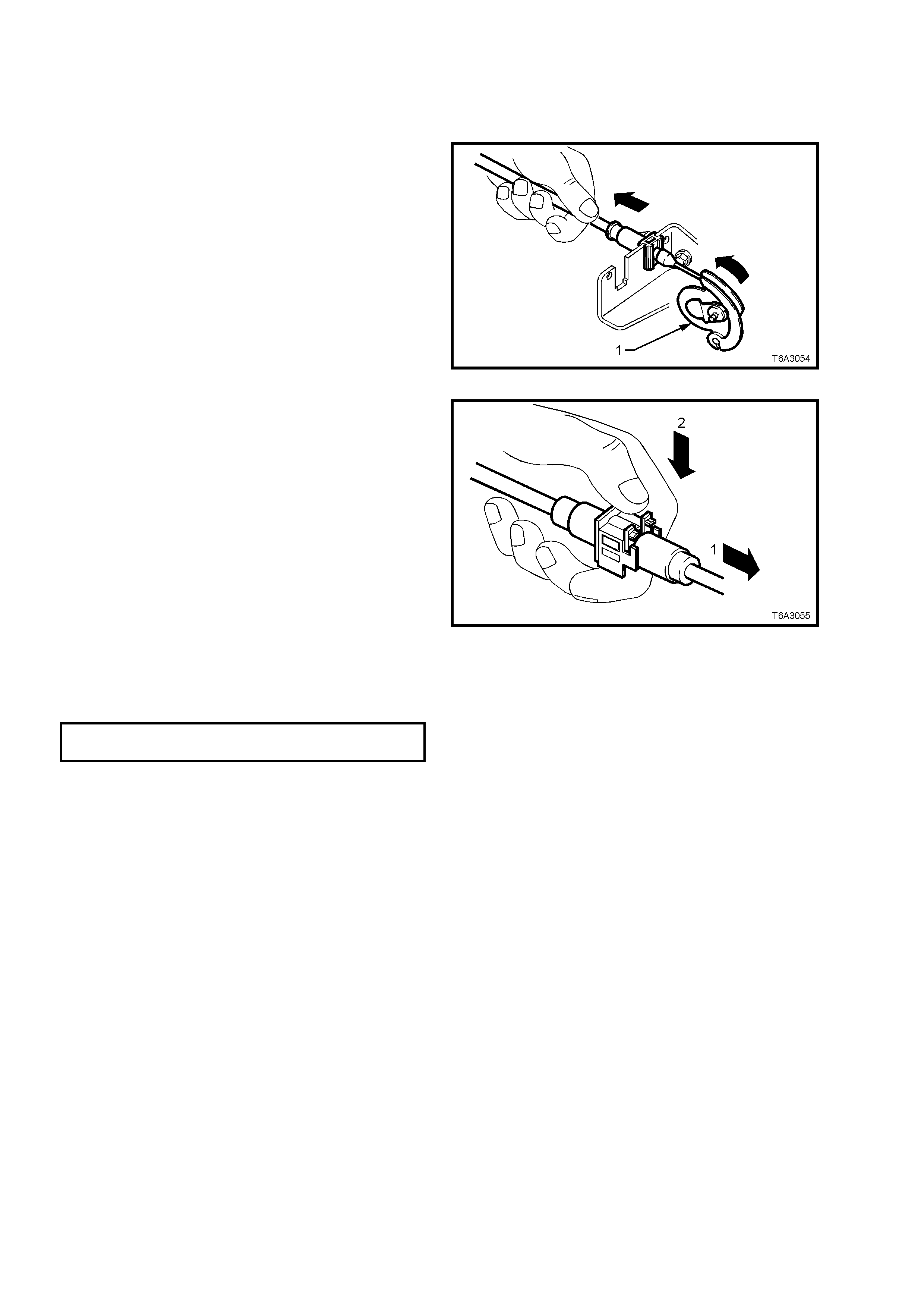
5. Lift the throttle cable (1) up at the throttle bod y
mounting bracket (2), then remove the cable
from the throttle body cam lever (3).
6. Remove throttle cable from the vehicle.
Figure 6C3-3-23 – Throttle Body Cable Mounting Bracket

REINST ALL
Accelerator Cable
1. Reinstall the accelerator pedal cable through the dash panel. Snap the retainer through the dash panel.
2. Reinstall the accelerator pedal cable through the slot in the accelerator pedal lever. Seat the retainer in the
accelerator pedal lever.
3. Attach the accelerator pedal cable to the brake booster cable retaining clip.
4. Attach the accelerator pedal cable to the throttle relaxer.
5. Attach the cruise control cable to the throttle relaxer (if fitted).
6. Reinstall the throttle relaxer cover.
7. Refit the instrument panel lower trim. Refer to Section 1A3 INSTRUMENT PANEL AND CONSOLE.
Throttle Cable
1. Reinstall the throttle cable to the throttle body cam lever.
2. Attach the throttle cable to the throttle body mounting bracket.
3. Attach the throttle cable to the retaining clip over the intake manifold.
4. Attach the throttle cable to the throttle relaxer.
5. Reinstall the throttle relaxer cover.
6. Reinstall the engine dress cover and tighten decorative nuts to the correct torque specification.
ENGINE DRESS COVER NUT
TORQUE SPECIFICATION 10 Nm
7. Adjust the throttle cable as described in this Section
3.2 THROTTLE CONTROL CABLE – VEHICLES WITHOUT TCS
NOTE: View ‘A’ shows the RHD arrangement while view ‘B’ is for LHD vehicles.
Figure 6C3-3-24 – Throttle Cable Routing, with Cruise Control, without TCS
Legend
1. Accelerator Cable 2. Throttle Body Mounting Bracket
REMOVE
1. Remove engine dress cover. Refer
2.3 Engine Coolant Temperature Sensor, in
this Section.
2. Lift the throttle cable (1) up at the throttle bod y
cable mounting bracket (2), and remove the
cable from the throttle body cam lever (3).
3. Remove the throttle cable from the retaining
clip over the intake manif ol d.
4. Open the retainer clip at the brake booster, and
remove the throttle cable from the clip.
Figure 6C3-3-25 – Throttle Body Cable Mounting Bracket
5. Remove the right instrument panel lower trim.
Refer to Section 1A3 INSTRUMENT PANEL
A ND CONSOLE.
6. Disconnect the throttle cable (1) from the
accelerator pedal lever (2).
7. Squeeze the throttle cable cover tangs and
push the cable through the dash panel.
8. Remove the throttle cable.
Figure 6C3-3-26 – Accelerator Pedal to Cable

REINST ALL
1. Reinstall the throttle cable through the dash panel. Snap the retainer through the dash panel.
2. Reinstall the throttle cable through the slot in the accelerator pedal lever. Seat the retainer in the accelerator
pedal le ver.
3. Attach the throttle cable to the brake booster cable retaining clip.
4. Attach the throttle cable to the retaining clip over the intake manifold.
5. Attach the throttle cable to throttle body mounting bracket.
6. Reinstall the throttle cable to the throttle body cam lever.
7. Adjust the throttle cable as described in the following Section.
8. Reinstall the engine dress cover and tighten decorative nuts to the correct torque specification.
ENGINE DRESS COVER NUT
TORQUE SPECIFICATION 10 Nm
9. Reinstall the right instrument panel lower trim. Refer to Section 1A3 INSTRUMENT PANEL AND CONSOLE.
3.3 THROTTLE RELAXER - VEHICLES WITH TCS
REMOVE
1. Remove engine dress cover. Refer 2.3 Engine Coolant Temperature Sensor, in this Section.
2. Remove the throttle relaxer cover (1).
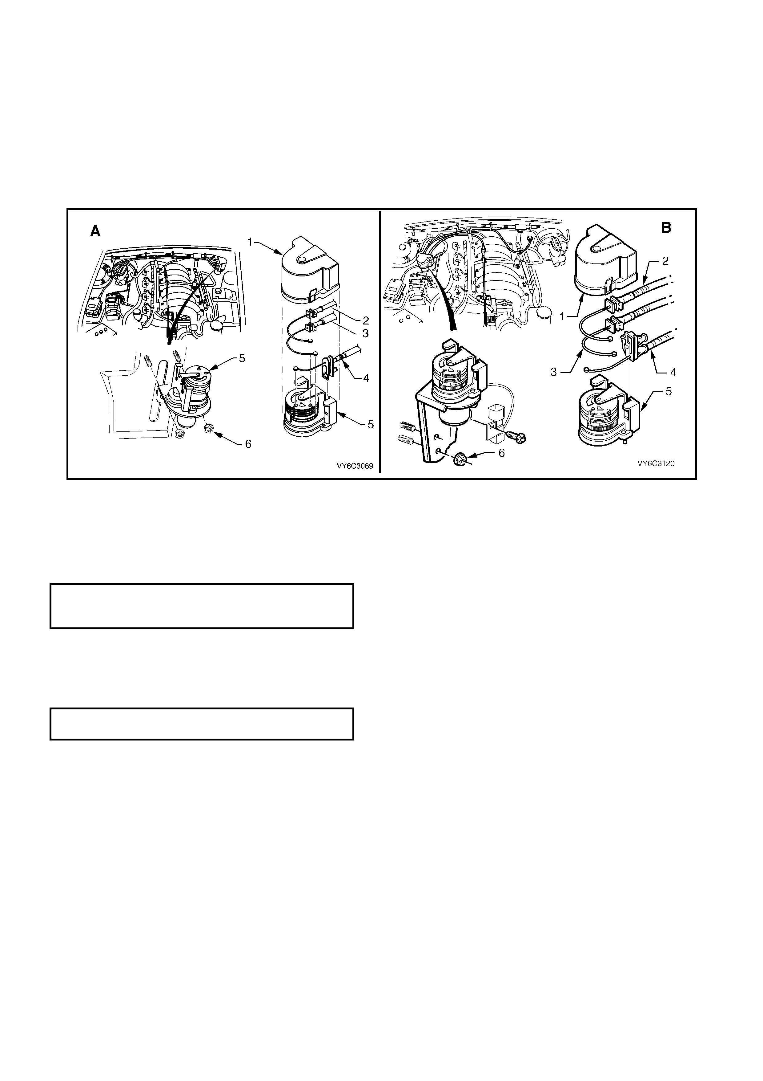
3. Disconnect the throttle relaxer electrical connector.
4. Remove the nuts attaching the relaxer assembly to the mounting bracket (6).
5. Remove the accelerator pedal, throttle and cruise control (if fitted) cables from the throttle relaxer (2, 3, 4).
NOTE: View ‘A’ shows the RHD arrangement while view ‘B’ is for LHD vehicles.
Figure 6C3-3-27 – Throttle Relaxer
REINST ALL
1. Reinstall the cables to the throttle relaxer assembly.
2. Reinstall the throttle relaxer assembly to the mounting bracket.
3. Tighten the assembly attaching nuts to the specified torque.
THROTTLE RELAXER
MOUNTING NUT
TORQUE SPECIFICATION 2 – 3 Nm
4. Connect the electrical connector.
5. Adjust the throttle cables as described in this Section.
6. Reinstall the throttle relaxer cover.
7. Reinstall the engine dress cover and tighten decorative nuts to the correct torque specification.
ENGINE DRESS COVER NUT
TORQUE SPECIFICATION 10 Nm
3.4 THROTTLE CABLE ADJUSTMENT – ALL
1. Remove engine dress cover. Refer
2.3 Engine Coolant Temperature Sensor, in
this Section.
2. With the throttle cabl e ful ly ins talle d, un lock the
adjustment locking lever.
3. Ensure throttle is in the closed position.
4. With adjuster unlocked, pull back on
accelerator cable until the throttle cam (1)
begins to move from the rest position.
Figure 6C3-3-28 – Throttle Cable Lock Released
5. Move the accelerator cable back towards the
throttle cam until the throttle cam is back at rest
(1).
6. While holding the accelerator cable at the cam
rest position, lock the cable locking lever (2).
NOTE: A small amount of slack in the inner cable
is desirable.
7. Using Tech 2, check the throttle angle. When
the accelerator is fully depressed the throttle
angle sho uld read 100% . When the acc elerator
is release d th e thr ot tle ang l e s hou ld r ea d 0%. If
correct results are not obtained, check the
cables for kinks or damage and repeat
procedure.
8. Reinstall engine dress cover and tighten
decorative nuts to the correct torque
specification.
ENGINE DRESS COVER NUT
TORQUE SPECIFICATION 10 Nm
Figure 6C3-3-29 – Throttle Cable Lock Adjuster
3.5 THROTTLE BODY
REMOVE
1. Disconnect the negati v e batter y cable .
IMPORTANT: Disconnection of the battery affects
certain vehicle electronic systems. Refer to
Section 00 CAUTIONS, 5. Battery Disconnection
Procedures before disconnecting the battery.
2. Remove engine dress cover. Refer to
2.3 Engine Coolant Temperature Sensor in
this Section for removal procedure.
3. Partially drain the cooling system in order to
remove the hoses at the throttle body. Refer
Section 6B3 COOLING SYSTEM – GEN III
V8 ENGINE.
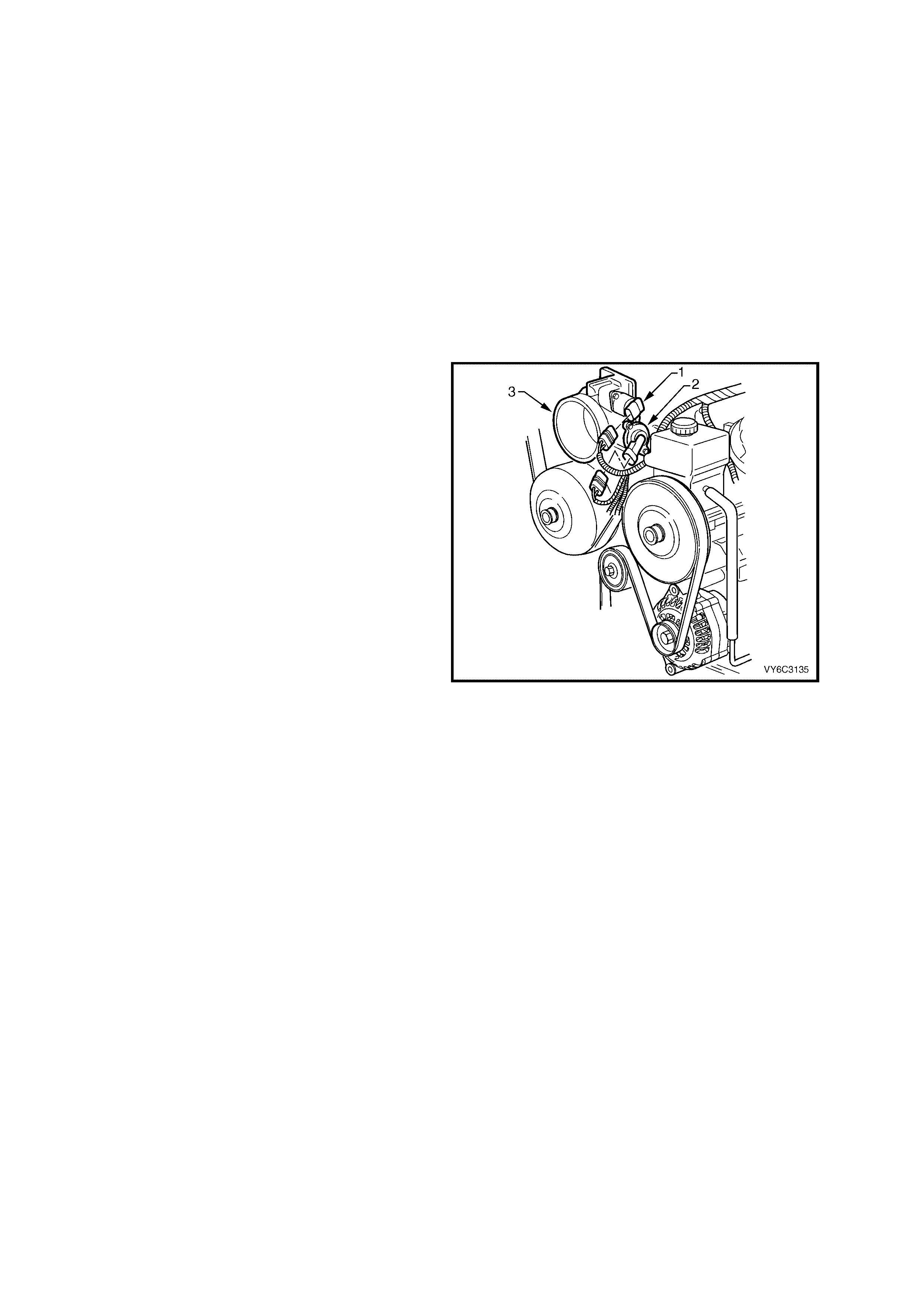
4. Remove the air intake duct from throttle body.
5. Disconnect the IAC valve (1) and TP Sensor
(2) electrical connectors.
6. Disconnect the throttle cable and the cruise
control cable (if fitted) from the throttle body
(3).
7. Disconnect the c r ank c as e ventilatio n hos e f r om
the throttle body.
8. Disconnect the EECS purge hose from the
throttle body.
9. Remove the throttle body attachi ng bolts .
10. Remove the throttle body (3) and the seal.
11. Discard the removed seal.
12. Clean the both sealing surfaces.
NOTE: To prevent d am age to the sea ling surf aces ,
it is preferred that only plastic scrapers are used for
cleaning deposits from machined alloy surfaces.
IMPORTANT: Do No t s oak the thr ottle b ody in cold
immersion type cleaner. The throttle valve has a
fact ory applie d sealing com pound (DAG m aterial is
applied to the outside edge of the valve and the
throttle bore) to prevent air bypass at closed
throttle. Stro ng s ol vents or brushin g wil l remove the
material. To clean the throttle body following
disassembly, use a spray type cleaner such as GM
1052626 or equivalent. Use a shop towel to
remove heavy deposits.
Also, the TP sensor and the IAC valve are
electrical components and should NOT come in
contact with solvent or cleaner, as damage may
result.
Figure 6C3-3-30 – Throttle Body Location
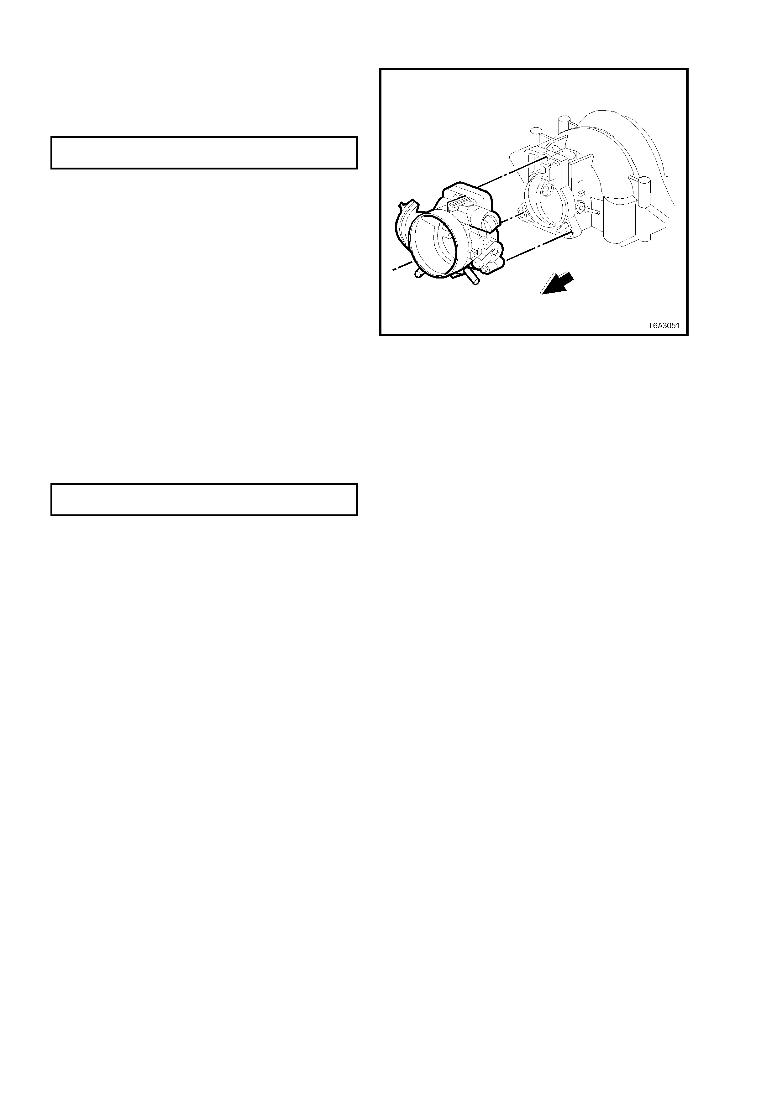
REINST ALL
1. Reinstall the throttle body with a new gasket
seal.
2. Reinstall the throttle body attaching bolts and
tighten to the specified torque.
THROTTLE BODY ATTACHING
BOLT TORQUE SPECIFICATION 12 Nm
3. Connect the crankcase ventilation hose to the
throttle body.
4. Connect the EECS purge hose to the throttle
body.
5. Connect the cooling hoses to the throttle body.
6. Connect the throttle cable and the cruise
control cable (if fitted).
7. Connect the TP sensor and the IAC valve
electrical connectors.
8. Reinstall the air intake duct.
9. Refill the cooling system.
10. Connect the negative battery cable.
11. With the engine OFF, check to see that the
accelerator pedal is free. Depress the
accelerator pedal to the floor and release.
12. Reinstall engine dress cover and tighten
decorative nuts to the correct torque
specification.
ENGINE DRESS COVER NUT
TORQUE SPECIFICATION 10 Nm
13. Perform the Idle Learn Procedure and the
Functional Check. Refer to PCM
Replacement/ Programming in this Section.
Figure 6C3-3-31 – Throttle Body to Intake Manifold
3.6 FUEL PUMP RELAY
REMOVE
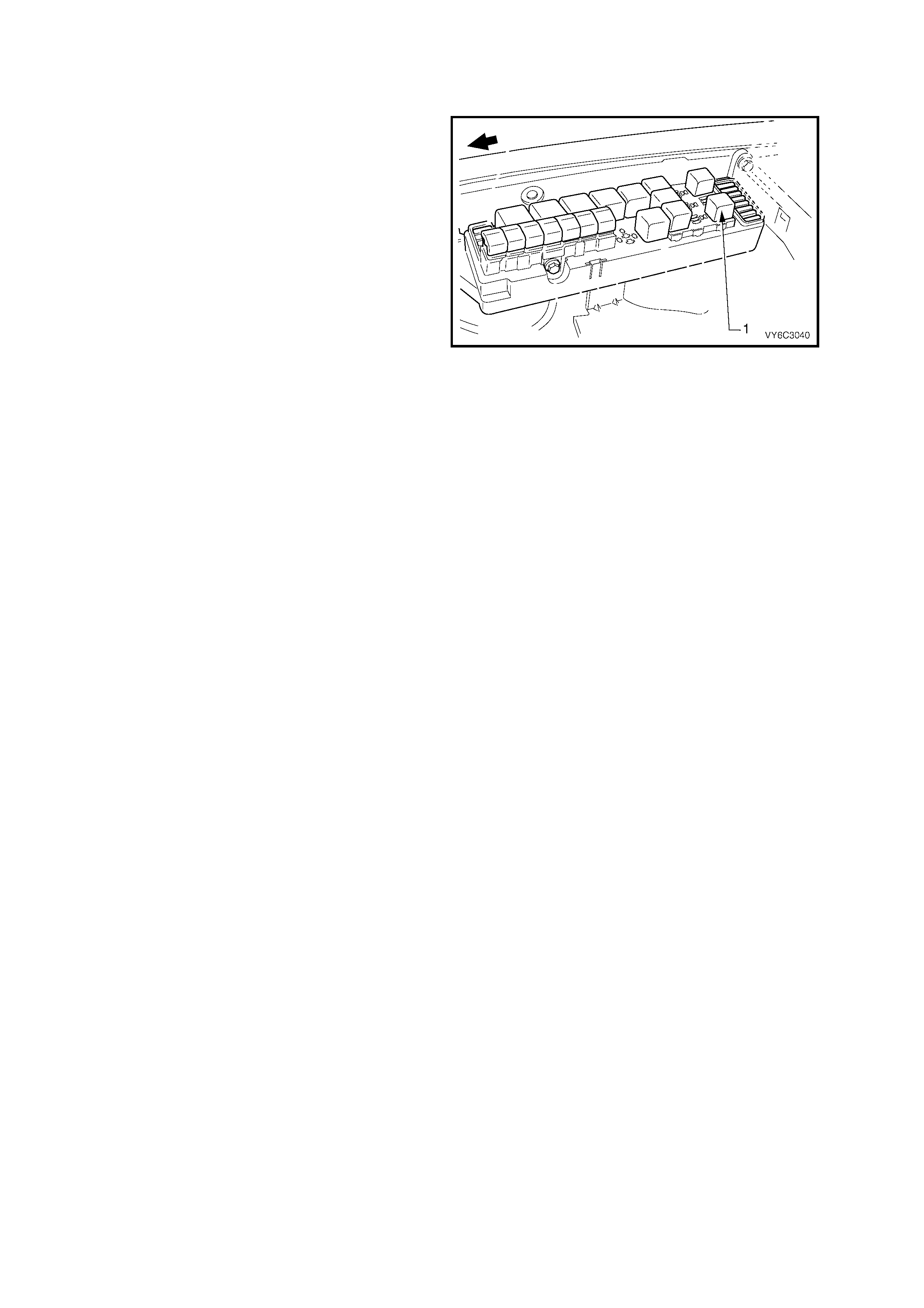
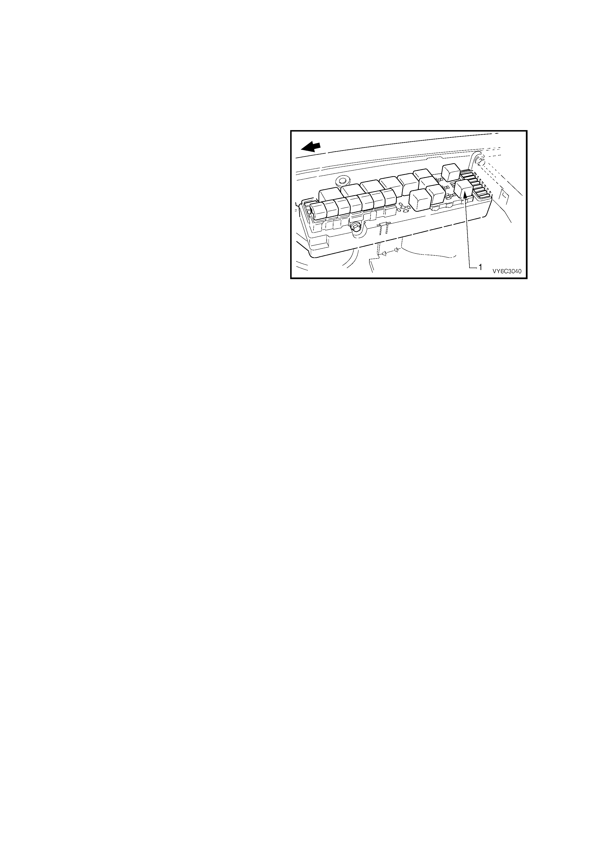
NOTE: The fuel pump relay is located in the
underhood fuse and relay housing, forward of the
right side s trut tower. O ther than c heck ing for loose
connectors, the only service possible is
replacement.
1. Ignition OFF.
2. Remove the fuse/relay panel cover.
3. Remove the fuel pump relay (1) by pulling
upward.
Figure 6C3-3-32 – Fuel Pump Relay Location
REINST ALL
1. Reinstall the f uel p u mp relay int o the f uel p ump
relay socket.
2. Verify relay operation by turning the key ON
and listening for relay operation (relay should
operate f or 2 seconds whe n k ey is tur ned ON ).
If relay did not operate, refer to Fuel Pump
Relay Circuit Diagnosis in this Section 6C3-2A.
3. Reinstall the fuse/relay panel cover.
3.7 FUEL PRESSURE RELIEF PROCEDURE
CAUTION: Relieve the fuel system pressure before servicing fuel system components in order to reduce
the risk of fire and personal injury.
After relieving the system pressure, a small amount of fuel may be released when servicing the fuel lines
or connections. In order to reduce the chance of personal injury, cover the fittings with a shop towel before
disconnecting. This will catch any fuel that may leak out. Place the towel in an approved container when
the disconnection is complete.
1. Remove cover from underhood fuse and relay
centre.
2. Remove fuel pump relay (1).
3. With throttle closed, crank engine.
NOTE: The engine m ay start and run until the fuel
supply remaining in the fuel delivery system is
depleted.
4. When the engine stops, re-energise the starter
motor for 10 seconds to ensure that the line
pressure has been fully relieved. The fuel
system is now safe to service.
5. Reinstall the fuel pump relay.
Figure 6C3-3-33 – Fuel Pump Relay Location
3.8 FUEL GAUGE INSTALLATION PROCEDURE
1. Relieve fuel system pressure as previously
described.
2. Ignition OFF.
3. Disconnect the negative battery cable in order
to avoid possible fuel discharge if an
accidental attempt is made to start the engine.
IMPORTANT: Disconnection of the battery affects
certain vehicle electronic systems. Refer to
Section 00 CAUTIONS, 5. Battery Disconnection
Procedures before disconnecting the battery.
4. Remove engine dress cover. Refer to
2.3 Engine Coolant Temperature Sensor in
this Section for removal procedure.
5. Loosen the f uel filler c ap in order to reliev e the
fuel tank vapour pressure.
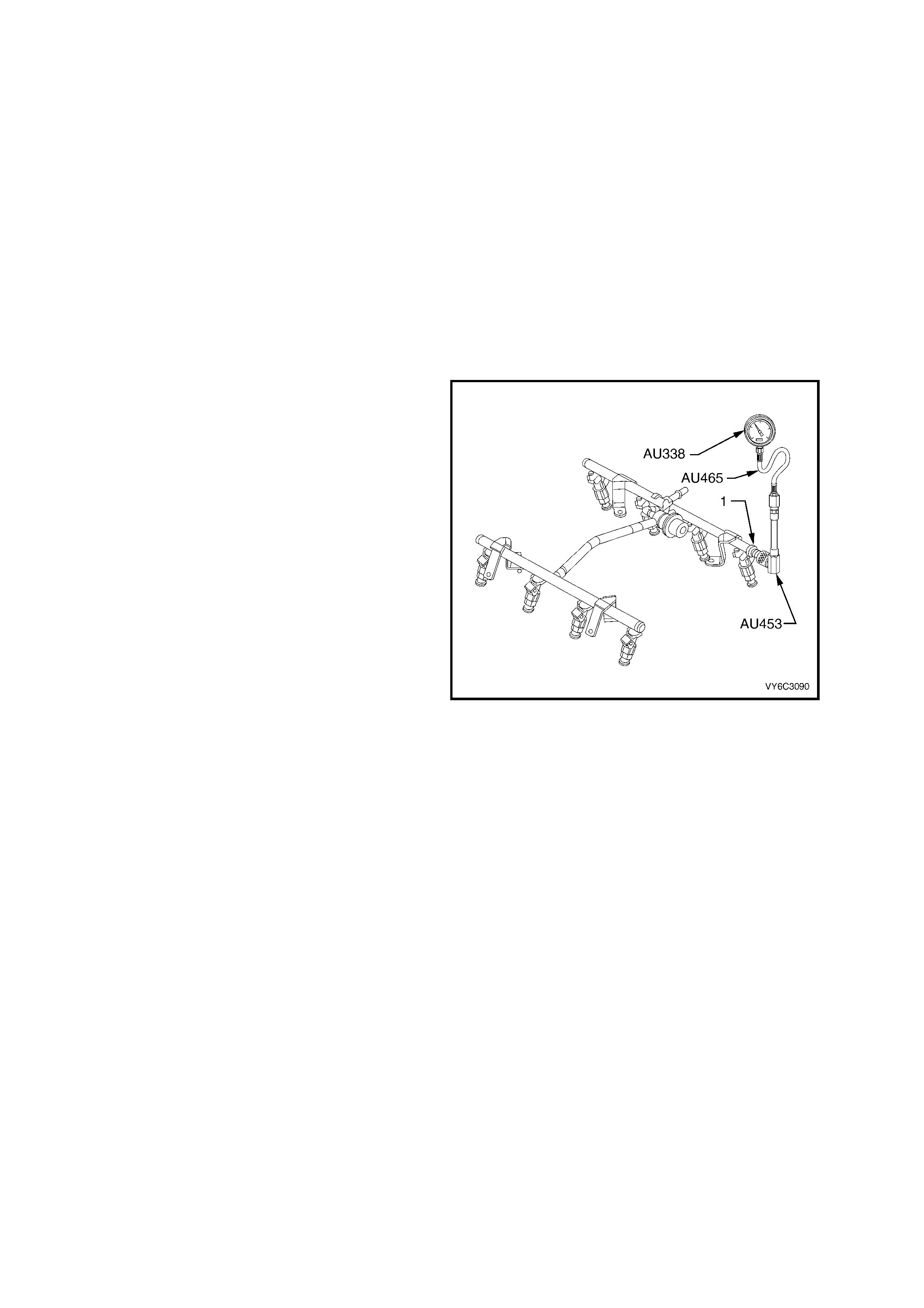
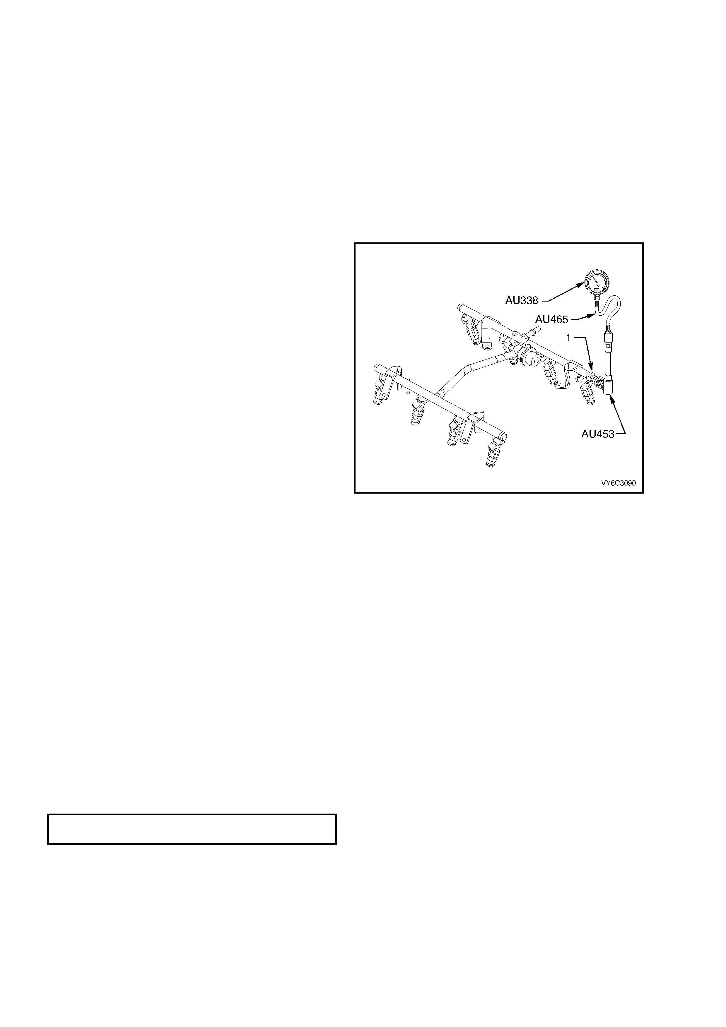
6. Connect the AU338 (or SD28018) fuel
pressure gauge and hose AU465, to the
AU453 fuel gauge Schrader fitting adaptor,
then connect to the fuel pressure testing valve
(1).
NOTE: Wrap a shop towel around the fitting while
connecting the gauge to avoid and/or capture any
fuel spillage.
7. Reinstall the bleed hose of the gauge into an
approved petrol container.
8. Open the valve on the gauge to bleed the
system pressure. Fuel connections are now
safe for servicing.
9. Drain any fuel remaining in the gauge into an
approved petrol container.
Figure 6C3-3-34 – Fuel Pressure Gauge Connected to
Schrader Valve
3.9 QUICK CONNECT FITTINGS (METAL COLLAR)
REMOVE
IMPORTANT: Relieve the fuel system pressure
before servicing any fuel system connection. Refer
to the 3.7 Fuel Pressure Relief Procedure in this
Section.
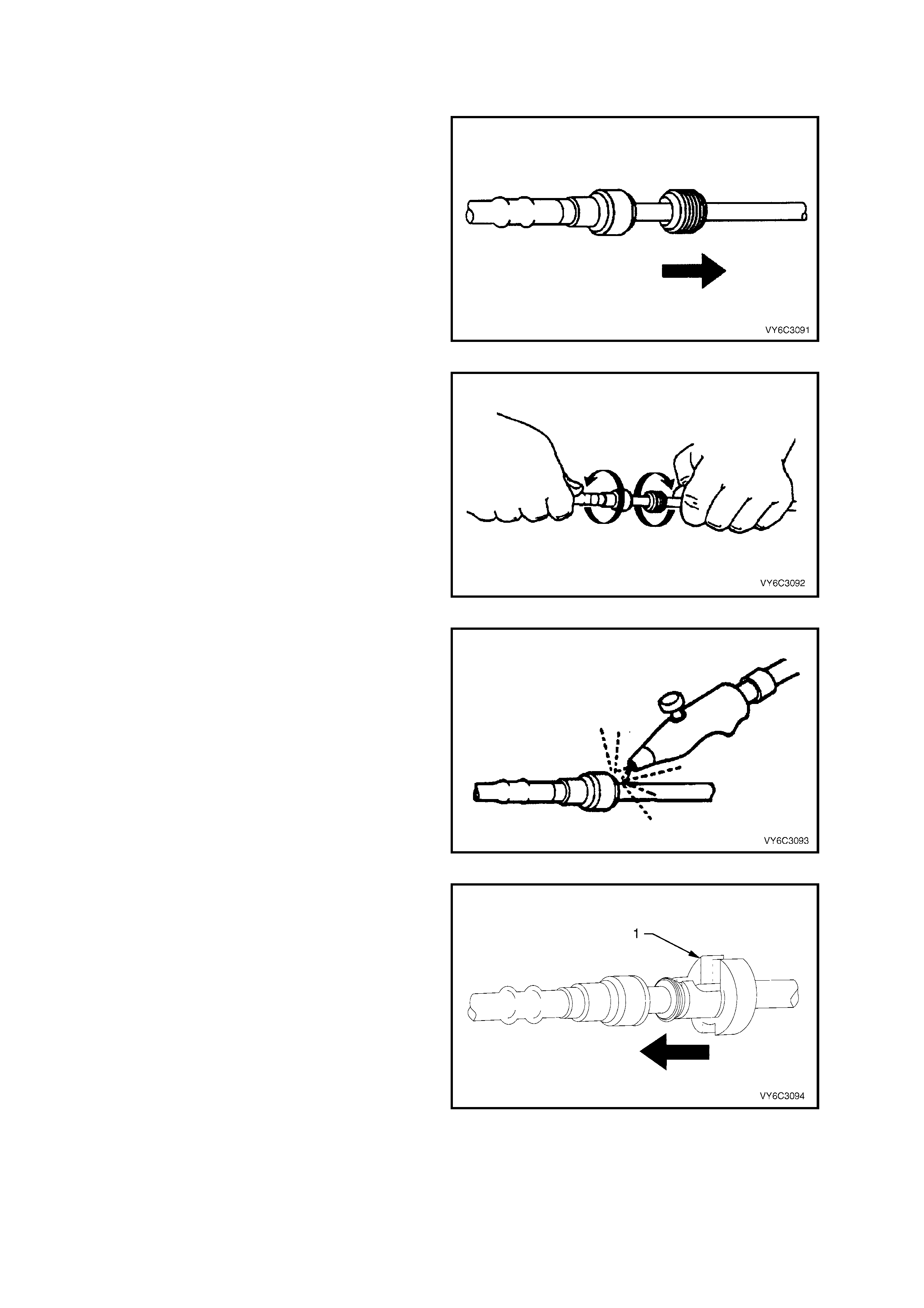
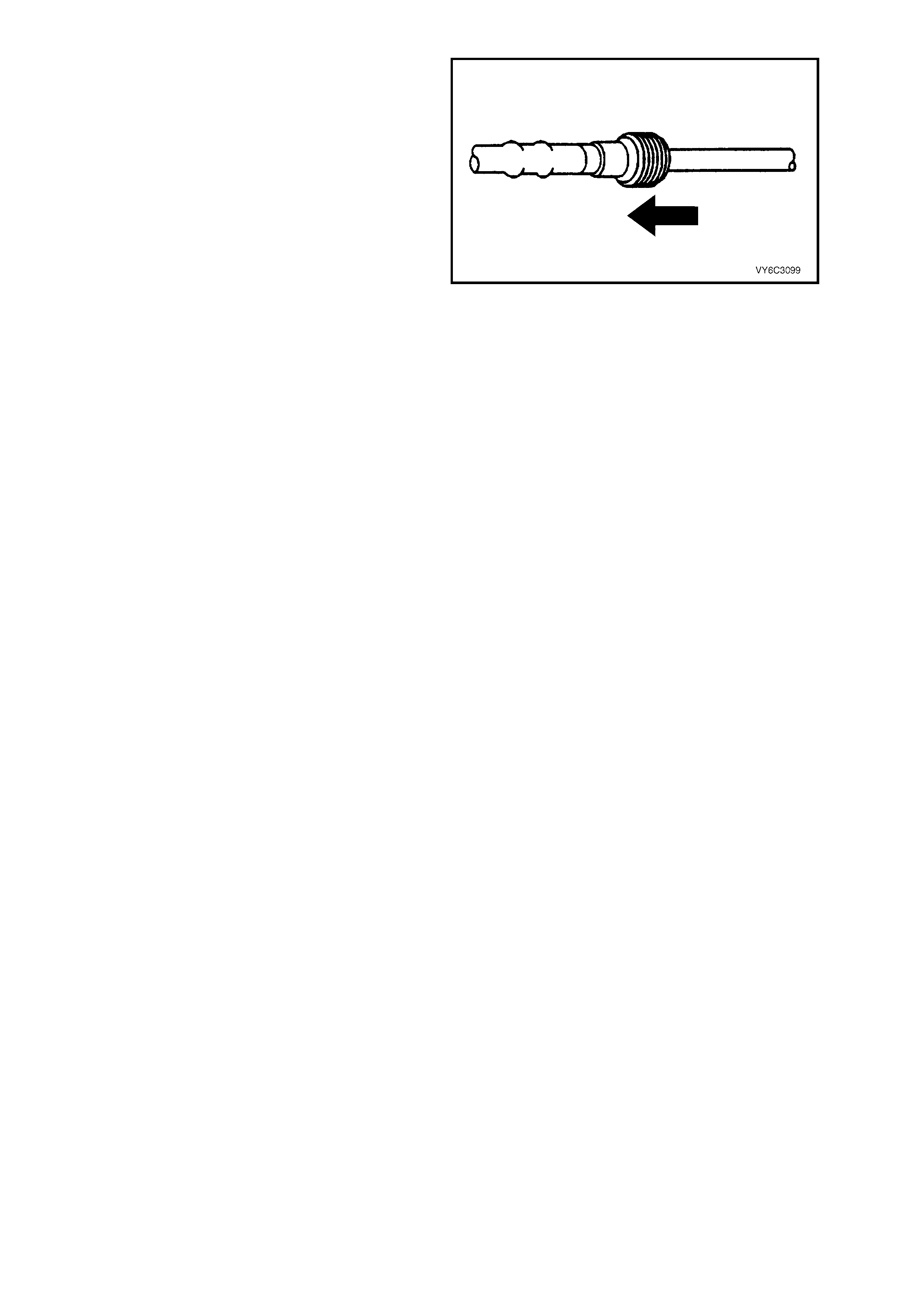
1. Slide the dust cover from the quick-connect
fitting.
Figure 6C3-3-35
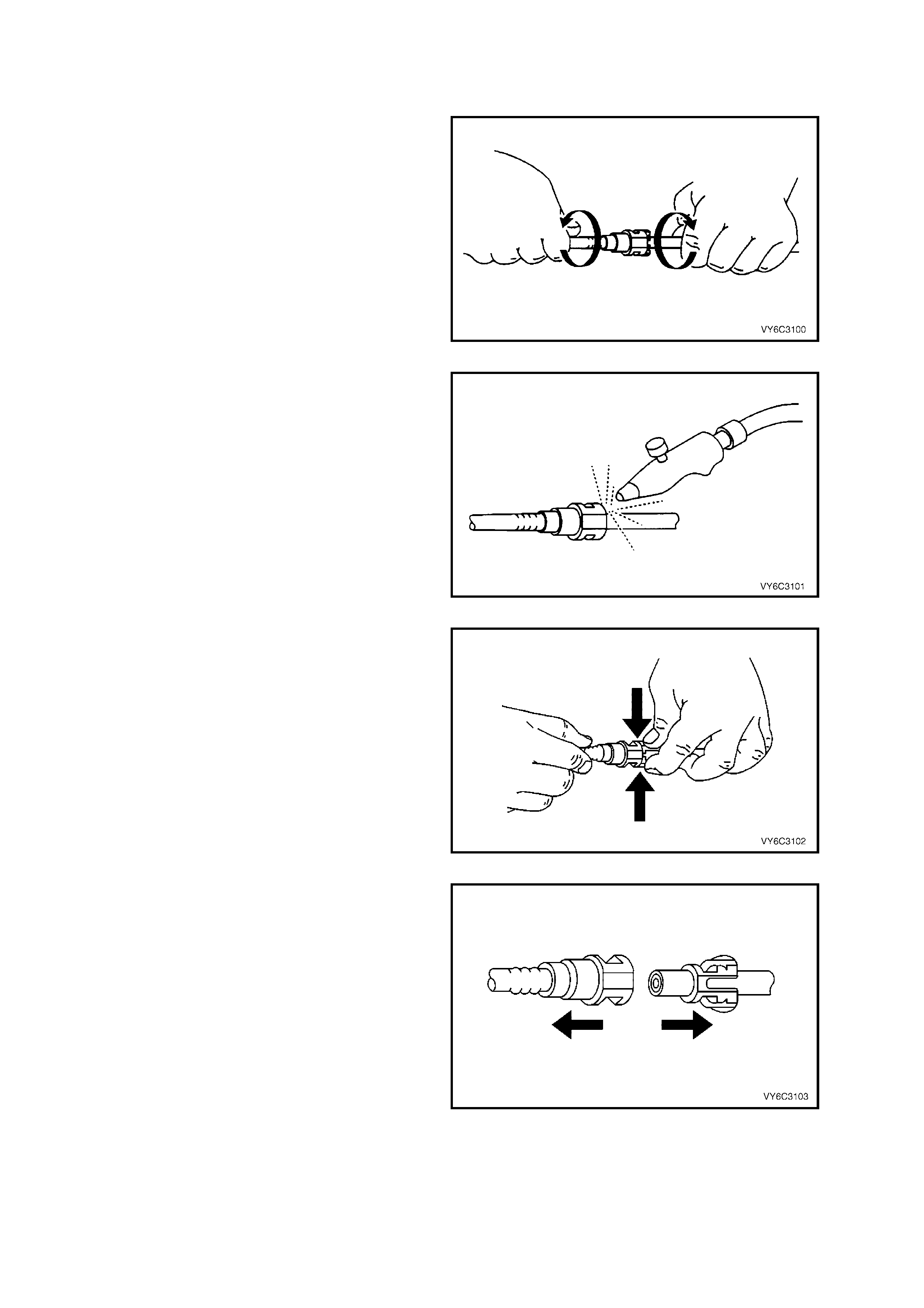
2. G rasp both s ides of the f itting. T wist the fem ale
connector 1/4 turn in each direction to loosen
any dirt within the fitti ng.
Figure 6C3-3-36
3. Blow dirt out of the fitting using compressed
air.
CAUTION: Wear safety glasses when using
compressed air, as flying dirt particles may
cause eye injury.
Figure 6C3-3-37
4. Choose the correct disconnection tool (1) for
the size and type of fitting. Insert the tool into
the female connector, then push inward to
release the locking tabs .
NOTE: Refer to specific Sections to determine the
correct tool for this task. Currently used examples
are:
7370 Used for 5/16” pipe fittings
7371 Used for 3/8” pipe fittings
J 41623-B Used for the automatic
transmission cooler line, quick
connect fittings at the transmission.
Figure 6C3-3-38
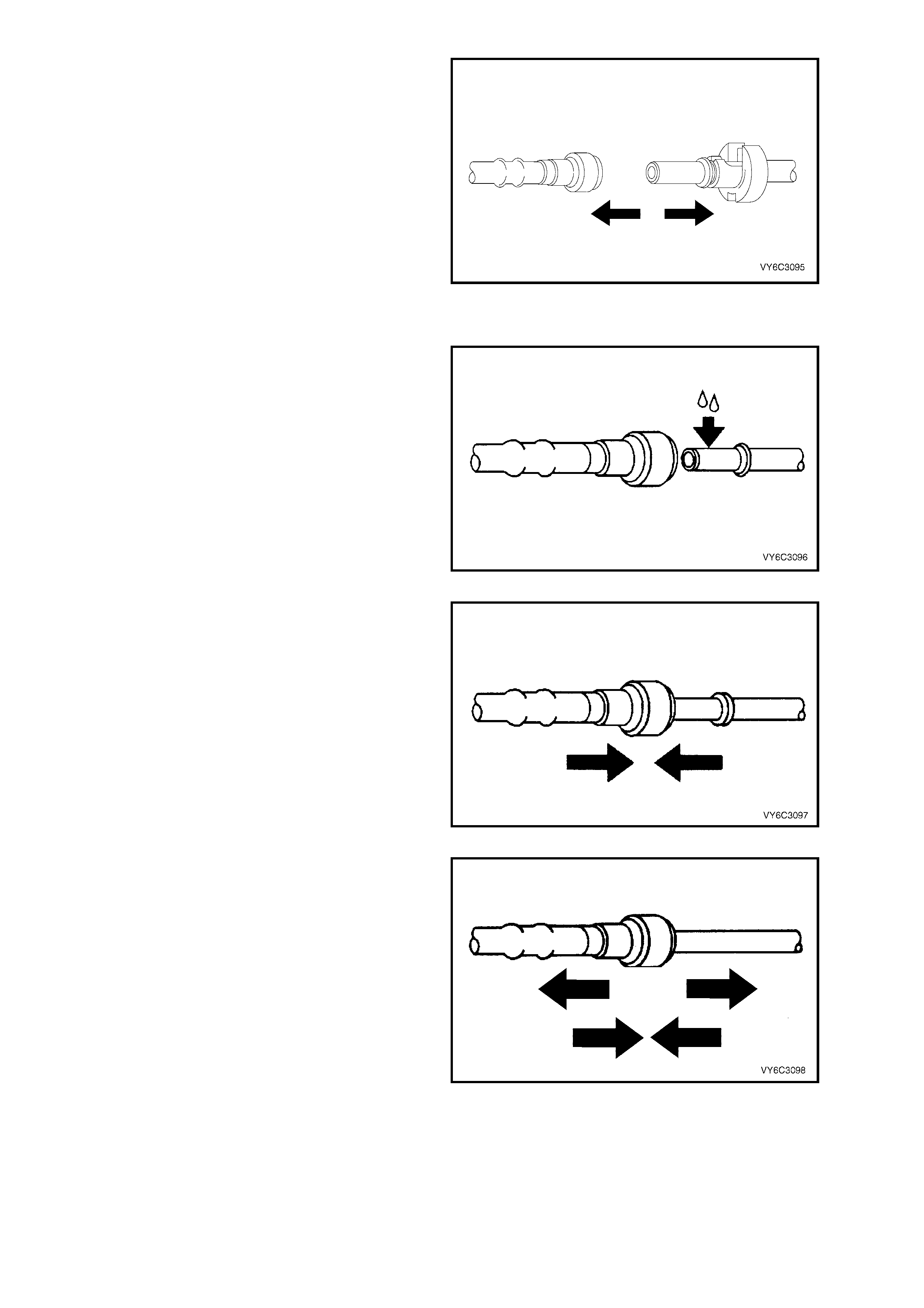
5. Pull the connection apart.
NOTE: If it is necessary to remove rust or burrs
from a fuel pipe, us e em ery cloth in a radia l motion
with the fuel pipe end in order to prevent damage
to the O-ring sealing surface.
6. Using a clean shop towel, wipe off the male
pipe end.
7. Inspect both ends of the fitting for dirt and
burrs. Clean or replace the components as
required.
Figure 6C3-3-39
REINST ALL
IMPORTANT: To reduce the risk of fire and
personal injury, always apply a few drops of clean
engine o il to the m ale pipe ends before c onnecting
fuel pipe fittings. This will ensure proper
reconnection and prevent a possible fuel leak.
NOTE: During nor m al operatio n, t he O-rin g loc ated
in the female connector will swell and m ay prevent
proper reconnection if not lubricated.
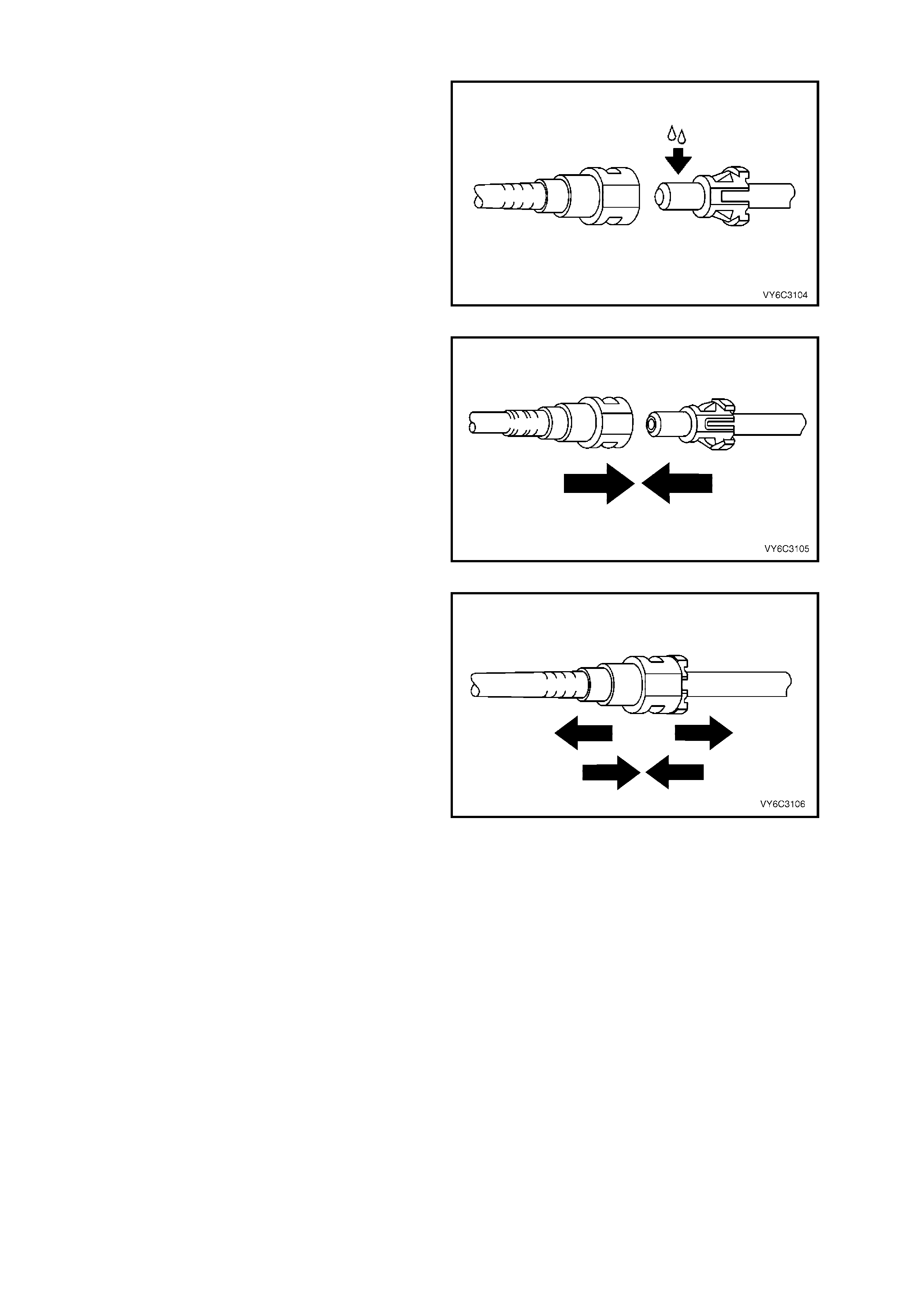
1. Apply a few drops of clean engine oil to the
male pipe end.
Figure 6C3-3-40
2. Push bot h sides of th e fitting to gether to c ause
the retaining tabs to snap into place.
Figure 6C3-3-41
3. Once installed, pull on both sides of the fitting
to ensure the connection is secure.
Figure 6C3-3-42
4. Reposition the dust cover over the quick-
connect fitting.
Figure 6C3-3-43
3.10 QUICK CONNECT FITTINGS (PL ASTIC COLL AR)
REMOVE
IMPORTANT: Relieve the fuel system pressure
before servicing any fuel system connection. Refer
to the 3.7 Fuel Pressure Relief Procedure in this
Section.
1. Grasp both sides of the quick-connect fitting.
Twist the female connector 1/4 turn in each
direction in order to loosen any dirt within the
quick-connect fitting.
Figure 6C3-3-44
2. Using compressed air, blow any dirt out of the
quick-connect fitting.
CAUTION: Wear safety glasses when using
compressed air, as flying dirt particles may
cause eye injury.
Figure 6C3-3-45
3. Squeeze the plastic retainer release tabs.
NOTE: An alternative method of releasing the
quick connec t f ittin g, is to u s e T ool No. AU533, tha t
is availab le in t wo si zes :
Red = 5/16” Fittings
Blue = 3/8” Fittings
Refer to 3.11 Fuel Filter, in this Section, for
information relating to the use of this tool.
Figure 6C3-3-46
4. Pull the connection apart.
Figure 6C3-3-47
REINST ALL
IMPORTANT: To reduce the risk of fire and
personal injury, always apply a few drops of clean
engine o il to the m ale pipe ends before c onnecting
fuel pipe fittings. This will ensure proper
reconnection and prevent a possible fuel leak.
NOTE: During nor m al operatio n, t he O-rin g loc ated
in the female connector will swell and m ay prevent
proper reconnection if not lubricated.
1. Apply a few drops of clean engine oil to the
male pipe end.
Figure 6C3-3-48
2. Push both sides of the quick-connect fitting
together in order to cause the retaining
tabs/fingers to snap into place.
Figure 6C3-3-49
3. Once installed, pull on both sides of the quick-
connect fitting in order to make sure the
connection is sec ure.
Figure 6C3-3-50
3.11 FUEL FILTER
REMOVE
IMPORTANT: T he pr ocedur e detailed h ere, MU ST be follo wed, b oth in th e seque nce of rem oval and insta llat ion of
a replacement filter. Failure to observe these instructions will most probably result in permanent damage to the
flexible line, resulting in unnecessary parts replacement and expense.
NOTE: The service interval for fuel filter replacement is every 40,000 km . Should replacement be required before
this distance because of a restricted fuel filter, inspect the fuel tank internally and clean thoroughly.
1. Relieve the fuel system pressure. Refer to the 3.7 Fuel Pressure Relief Procedure in this Section.
2. Disconnect the negati v e batter y cable .
IMPORTANT: Disconnection of the battery affects certain vehicle electronic systems. Refer to
Section 00 C AUTIONS, 5. Battery Disconnection Procedures before disconnecting the battery.
3. Raise the vehicle and support on safety stands. Refer to Section 0A GENERAL INFORMATION in the MY
2003 VY and V2 Series Service Information, for the location of jacking and support points.
4. Place a drain tray beneath fuel filter.
CAUTION: Even though the fuel system may
have been de-pressurised, the fuel filter and
lines will contain fuel that will be spilled during
this service operation. Therefore, ensure that
no naked flames or other ignition sources are
in the immediate area.
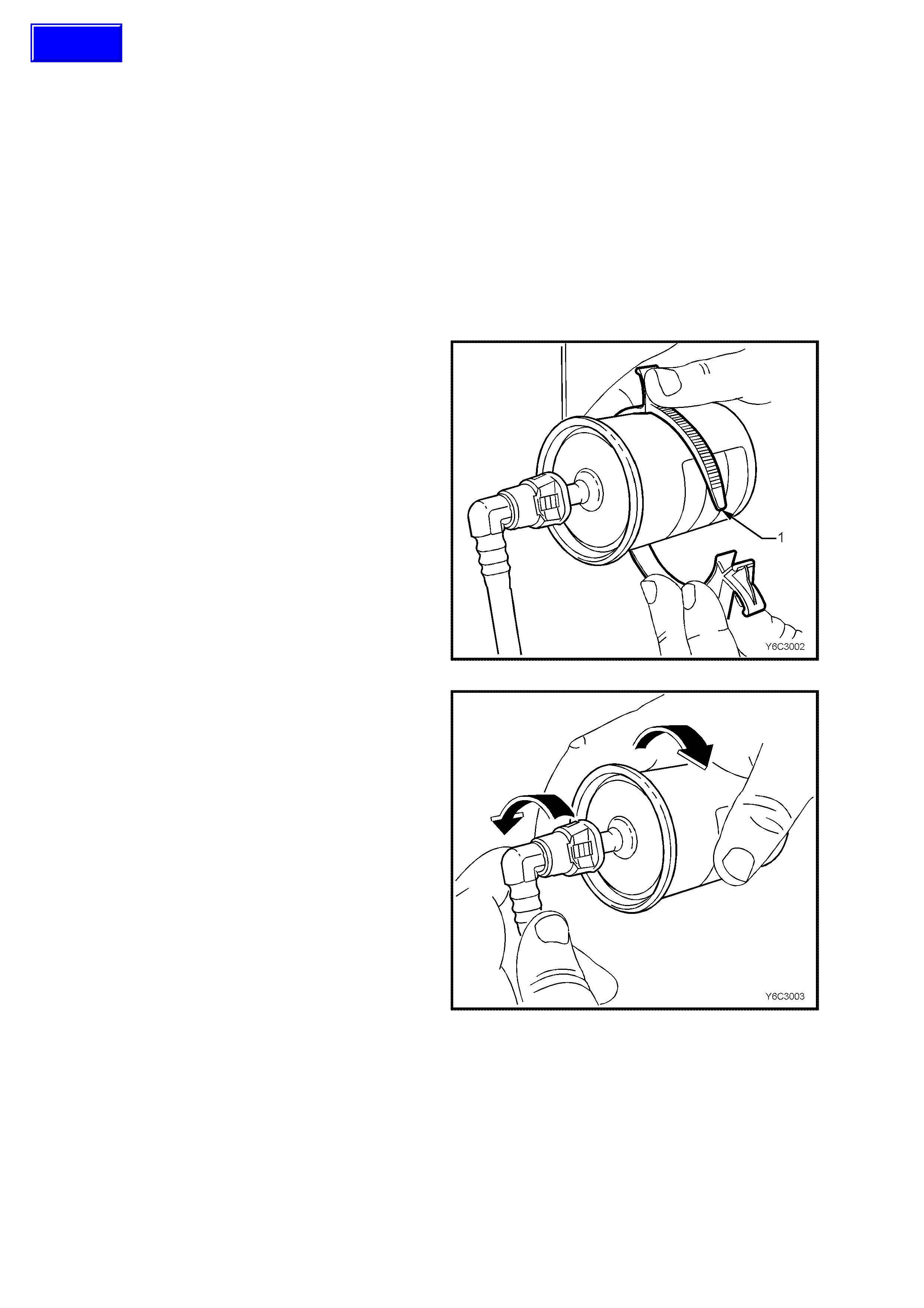
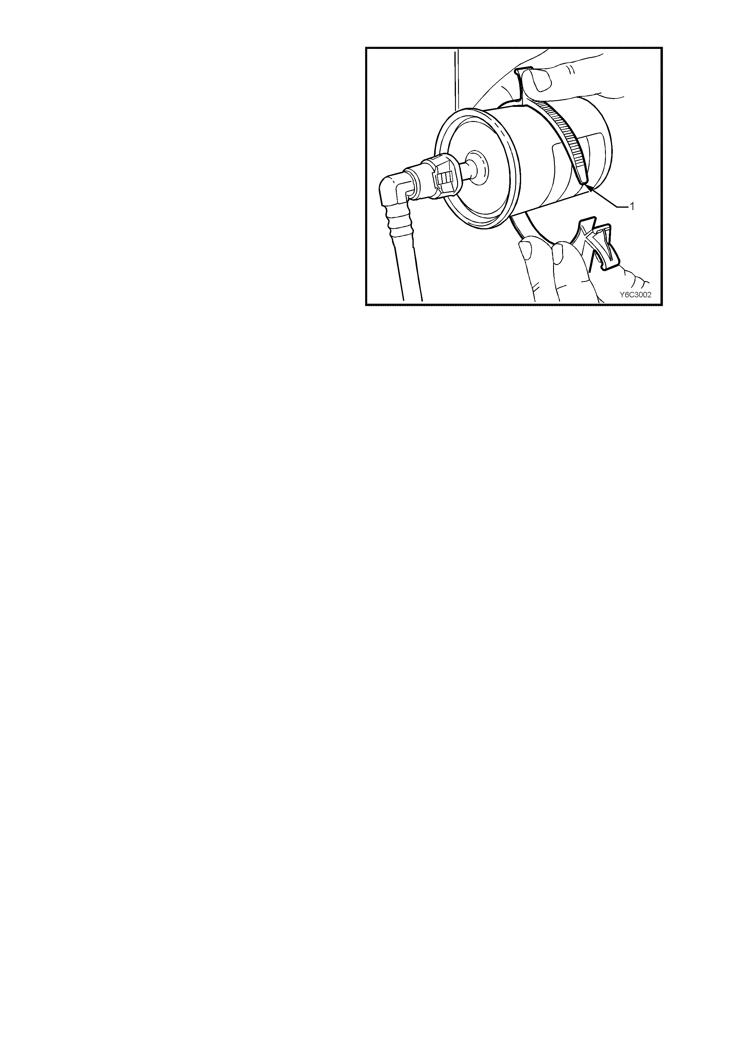
5. Remove the fuel filter from the retaining
bracket (1) with the fuel lines still connected to
the fuel filter to allow easier access.
Figure 6C3-3-51
6. While holding the filter in one hand, twist the
fuel tank, elbow connector, 1/4 turn in each
direction in order to loosen any dirt within the
quick-connect fitting.
7. W hile holding the quick c onnect fitting at th e T-
piece end, rotate the filter back and forth 1/4
turn to l oosen an y dirt trap ped wit hin that q uick
connect fitting.
IMPORTANT: Do not allow the T-piece to flex
during this operation.
Figure 6C3-3-52
Techline
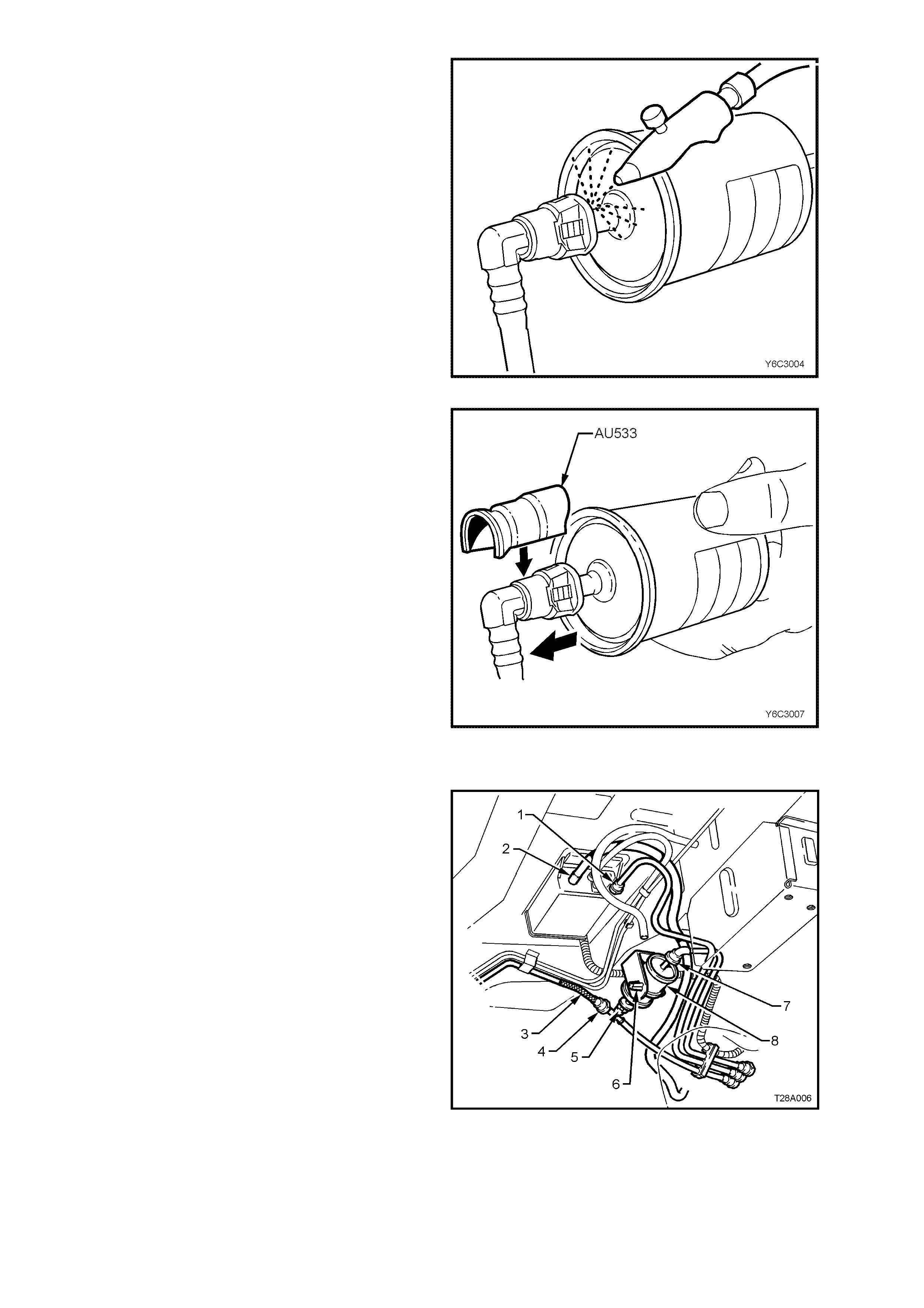
8. Using compressed air, blow any dirt out of the
quick-connect fitting to aid the release of any
tension or binding on the release tabs .
CAUTION: Wear safety glasses when using
compressed air, in order to prevent eye injury.
Figure 6C3-3-53
9. Use Tool No. AU533 to squeeze the release
tabs, by pushing down on the quick connect
fitting. This action compresses both release
tabs. With AU533 in place, push the
connection together to release tension on the
locking tabs and then pull to separate the two
components.
10. Repeat this operation for the second
connection, remembering to support the T-
piece connection, during the release process.
NOTE: Tool No AU533 is available in two pipe
sizes; Red for 5/16” and Blue for 3/8”. Only the
blue (3/8”) tool is required for this operation.
11. Remove fuel filter from vehicle and discard
safely, remembering that some fuel will still
remain in the filter.
Figure 6C3-3-54
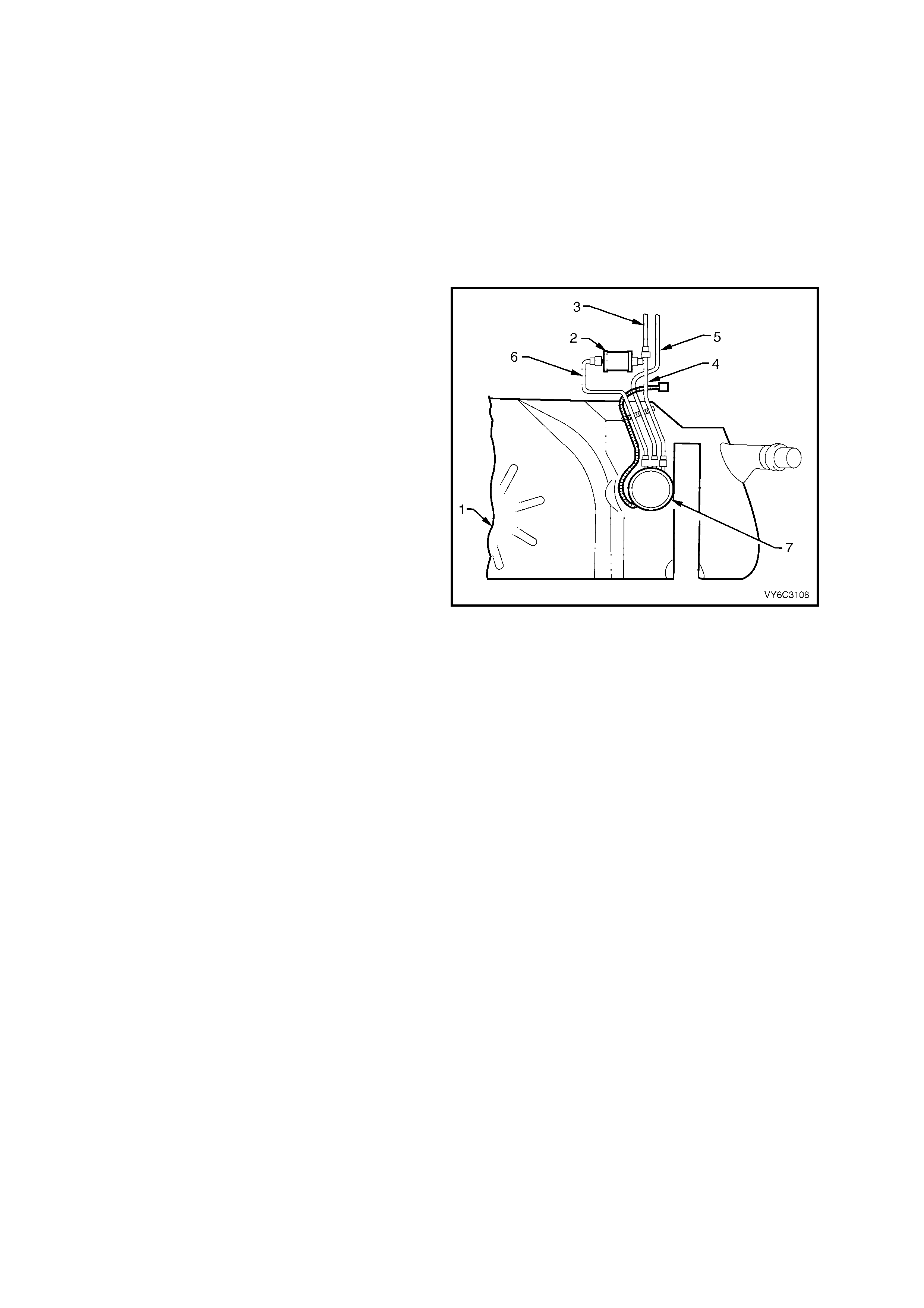
REINST ALL
IMPORTANT: The fuel filter must be installed with
the flow arrow on its body pointing in the same
direction as the fuel flow to the front of the vehicle.
Legend:
1. Quick-Connect, Fuel Tank Vapour Line to
Canister
2. Hose, Filler Neck Breather
3. Flexible Line, Fuel Feed to Engine
4. Quick-Connect, Fuel Feed Line
5. Quick-Connect, Fuel Filter T-piece
6. Retaining Tangs, Fuel Filter Strap
7. Quick-Connect, Fuel Feed Line from Fuel Tank
8. Filter, Fuel
Figure 6C3-3-55
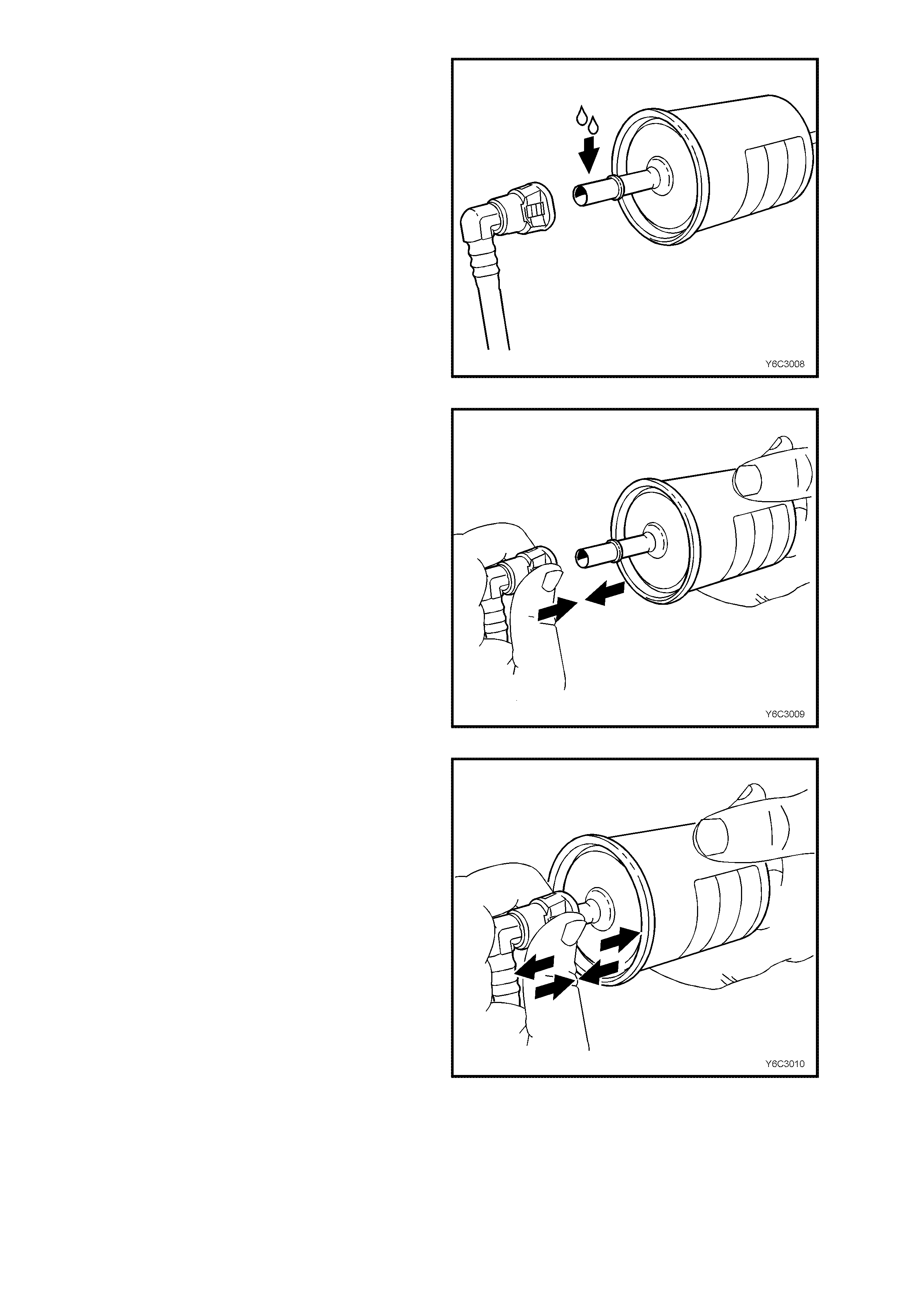
IMPORTANT: In or der to reduce the risk of fire and
personal injury, before connecting fuel filter quick-
connect fittings, always apply a few drops of clean
engine oil to the male ends of the fuel filter. This
will ensure proper reconnection and prevent a
possible fuel leak.
During normal operation, the O-ring located in the
fem ale connec tor will s wel l and ma y prevent proper
reconnection if not lubr ic ate d.
1. Apply a few drops of clean engine oil to each
male fuel filter end.
Figure 6C3-3-56
2. Push both the elbow quick-connect fitting and
the fuel filter together, causing the retaining
tabs to snap into place.
3. Repeat this installation process with the T-
piece quick connect fitting but firmly support
the fitting during the installation process to
prevent any possibilit y of the flexible line being
kinked.
Figure 6C3-3-57
4. Once installed, pull and push on both the
quick-connect fitting and the fuel filter in order
to make sure the connection is secure. Apply
this method to each end of the fuel filter and
the respective quick-connect fittings.
Figure 6C3-3-58
5. Re-install the fuel filter to the retaining bracket
(1).
6. Connect batter y ground lea d.
7. Check for fuel leaks, by completing the
follo wing proc ed ur e:
– Turn the ignition ON for 2 seconds.
– Turn the ignition OFF for 10 seconds.
– Turn the ignition ON.
– Check for fuel leaks at each of the quick
connect fittings.
8. Remove safety stands and lower vehicle.
9. Before starting the vehicle, carry out a
3.20 Fuel System Pressure Test, in this
Section.
10. Perform the Idle Learn Procedure and the
Functional Check. Refer to PCM
Replacement/ Programming in this Section.
Figure 6C3-3-59

3.13 FUEL PULSE DAMPENER
REMOVE
1. Relieve the fuel system pressure. Refer to
3.7 Fuel Pressure Relief Procedure in this
Section.
2. Disconnect the negati v e batter y cable .
IMPORTANT: Disconnection of the battery affects
certain vehicle electronic systems. Refer to
Section 00 CAUTIONS, 5. Battery Disconnection
Procedures before disconnecting the battery.
3. Remove engine dress cover. Refer to
2.3 Engine Coolant Temperature Sensor in
this Section for removal procedure.
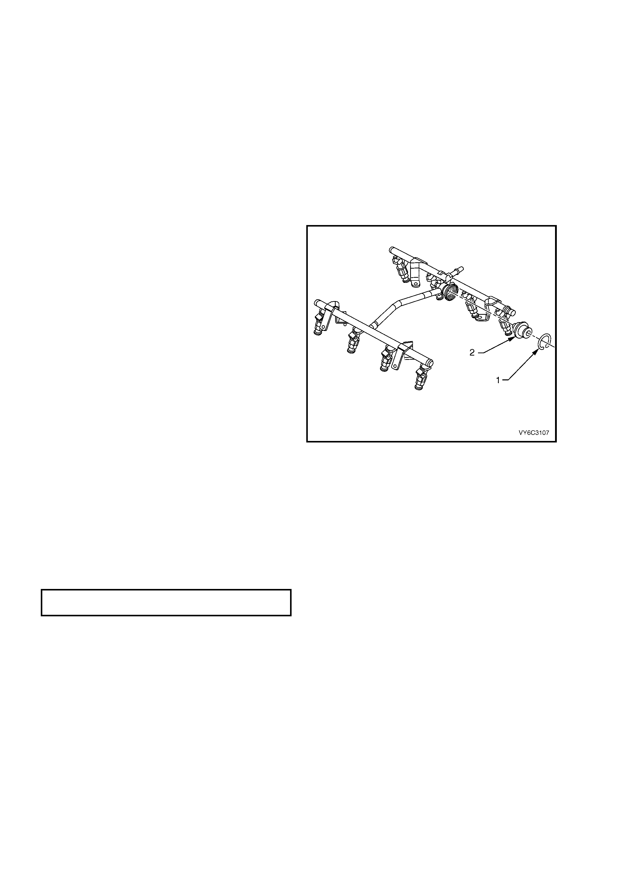
1. Clean any dirt from the fuel pulse dampener
retaining ring (1).
2. Remove the fuel pulse dampener retaining
circlip (1).
3. Discard the removed circlip.
4. Remove the fuel pulse dampener (2) from the
fuel rail.
5. Remove and discard the fuel pulse dampener
O-ring (not shown).
REINST ALL
1. Install the new O-ring on the fuel pulse
dampener (2).
2. Lubricate the fuel pulse dampener O-ring with
clean engin e oil.
3. Push the fuel pulse dampener into the fuel rail.
4. Reinstall a new fuel pulse dampener circlip (1).
5. Connect the negative battery cable.
6. Inspect for leaks:
– Turn the ignition switch ON for 2 seconds.
– Turn the ignition switch OFF for 10 seconds.
Figure 6C3-3-60 – Fuel Pulse Dampener
– Turn the ignition switch ON.
– Check for leaks.
7. Install engine dress cover and tighten
decorative nuts to the correct torque
specification.
ENGINE DRESS COVER NUT
TORQUE SPECIFICATION 10 Nm
8. Perform the Idle Learn Procedure and the
Functional Check. Refer to PCM Replacement/
Program ming in this Secti o n.
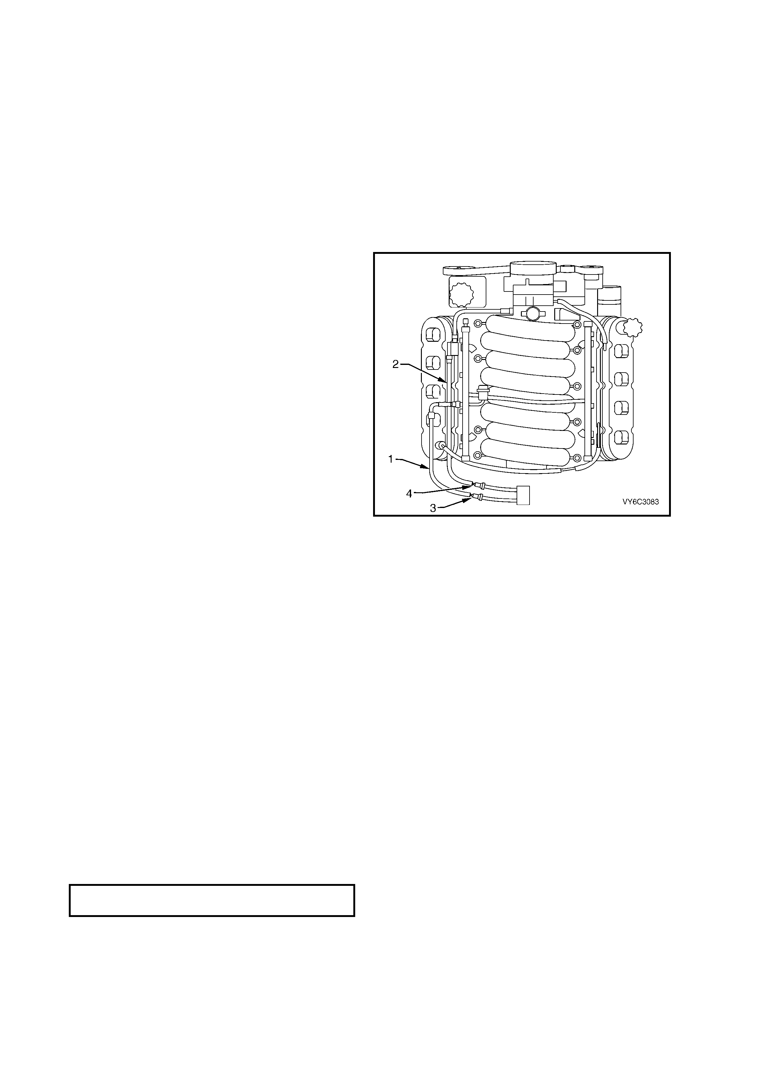
3.14 FUEL HOSE/ PIPES (ENGINE COMPARTMENT)
REMOVE
1. Relieve the fuel system pressure. Refer to the 3.7 Fuel Pressure Relief Procedure in this Section.
2. Loosen the fuel filler cap to relieve any vapour pressure.
3. Disconnect the negative battery cable.
IMPORTANT: Disconnection of the battery affects certain vehicle electronic systems. Refer to
Section 00 C AUTIONS, 5. Battery Disconnection Procedures before disconnecting the battery.
4. Remove engine dress cover. Refer to 2.3 Engine Coolant Temperature Sensor in this Section for removal
procedure.
5. Clean all the engine compartment connecting fuel pipe connections and the surrounding areas before
disconnecting to avoid possible contamination of the fuel system.
6. Disconnect the engine compartment fuel
feed pipe (1) at the fuel rail. Refer to
3.9 Quick Connect Fittings Service (Metal
Collar) in this Sec ti on.
7. Disconnect the engine compartment EECS
pipe (2) at the EECS canister purge solenoid.
Refer to 3.10 Qu ick Con nect Fit ting s Serv ice
(Plastic Collar) in this Section.
8. Disconnect the engine compartment fuel feed
pipe at the chassis fuel feed pipe (3). Refer to
3.9 Quick Connect Fittings Service (Metal
Collar) in this Sec ti on.
9. Disconnect the engine compartment EECS
pipe at the chassis EECS pipe (4). Refer to
3.10 Quick Conn ect F itting s Service (Pl astic
Collar) in this Sec ti on.
10. Cap the fuel pipes in order to prevent possible
fuel system contamination.
Figure 6C3-3-61 – Engine Compartment Hose/Pipes
REINST ALL
1. Remove the caps from the fuel pipes.
2. Connect the engine compartment fuel feed pipe to the chassis fuel feed pipe. Refer to 3.9 Quick Connect
Fittings Service (Metal Collar) in this Section.
3. Connect the eng in e c ompartment EECS pip e to t he c h as s is EEC S p ipe . Ref er to 3.10 Q u ic k Conn ect F itt ings
Service (Plastic Collar) in this Section.
4. Connect the engine compartment f uel feed pipe to the fuel rail. Refer to 3.9 Quick Connect Fittings Service
(Metal Collar) in this Section.
5. Connect the engine compartment EECS pipe to the EECS canister purge solenoid. Refer to 3.10 Quick
Connect Fittings Service (Plastic Collar) in this Section.
6. Tighten the fuel filler cap.
7. Connect the negative battery cable.
8. Inspect for leaks:
– Turn the ignition switch ON for 2 seconds.
– Turn the ignition switch OFF for 10 seconds.
– Turn the ignition switch ON.
– Check for leaks.
– Install engine dress cover and tighten decorative nuts to the correct torque specification.
ENGINE DRESS COVER NUT
TORQUE SPECIFICATION 10 Nm
9. Perform the Idle Learn Procedure and Functional Check. Refer to PCM Replacement/Programming in this
Section.
3.15 FUEL HOSE/PIPES (REAR PIPES)
REMOVE
1. Relieve the fuel system pressure. Refer to the 3.7 Fuel Pressure Relief Procedure in this Section.
2. Loosen the fuel filler cap to relieve any vapour pressure.
3. Disconnect the negati v e batter y cable .
IMPORTANT: Disconnection of the battery affects certain vehicle electronic systems. Refer to Section 00
CAUTIONS, 5. Battery Disconnection Procedures before disconnecting the battery.
4. Drain the fuel tank. Refer to Section 8A FUEL TANK.
5. Raise vehicle and support on safety stands. Refer to Section 0A GENERAL INFORMATION in the MY 2003
VY and V2 Series Service Information, for the location of jacking and support points.
6. Clean all the fuel and EECS pipe and hose
connections and the surrounding areas before
disconnecting, to avoid possible fuel system
contamination.
7. Remove the fuel filter (2). Refer 3.11 FUEL
FILTER, in this Section.
8. Disconnect the fuel feed line (3) at the T-piece
quick connect and th e fuel vap our line ( 5) from
the EECS carbon canister.
9. Remove the fue l tank (1). Refer to Section 8A
FUEL TANK.
10. Disconnect the fuel feed pipe (6), fuel return
pipe (4) and the vapour pipe (5) from the fuel
sender assembly (7). Refer to 3.10 Quick
Connect Fittings Service (Plastic Collar), in
this Section.
11. Cap all opened fuel lines to prevent possible
system contamination.
Figure 6C3-3-62 – Rear Hose/Pipes
REINST ALL
1. Remove the caps from the fuel pipes.
2. Connect the rear fuel feed, fuel return, and the EECS vapour pipe to the fuel sender assembly. Refer to
3.10 Quick Connect Fittings Service (Plastic Collar) in this Section.
3. Reinstall the fuel tank, refer to Section 8A FUEL TANK.
4. Lower the vehicl e to the ground.
5. Refill the fuel tank.
6. Connect the negative battery cable.
7. Tighten the fuel filler cap.
8. Inspect for leaks:
– Turn the ignition switch ON for 2 seconds.
– Turn the ignition switch OFF for 10 seconds.
– Turn the ignition switch ON.
– Check for leaks.
9. Perform the Idle Learn Procedure and the Functional Check. Refer to PCM Replacement/Programming in
this Section.

3.16 FUEL SYSTEM CLEANING
IMPORTANT: Only use oil free compressed air to blow out the fuel pipes.
NOTE: Inspect the fuel tank internally and clean the fuel tank if you find a blocked fuel filter.
1. Relieve the fuel system pressure. Refer to the 3.7 Fuel Pressure Relief Procedure in this Section.
2. Loosen the fuel filler cap to relieve any vapour pressure.
3. Disconnect the negati v e batter y cable .
IMPORTANT: Disconnection of the battery affects certain vehicle electronic systems. Refer to Section 00
CAUTIONS, 5. Battery Disconnection Procedures before disconnecting the battery.
4. Drain the fuel tank. Refer to Section 8A FUEL TANK.
5. Remove the fuel tank. Refer to Section 8A FUEL TANK.
6. Remove the modular fuel sender assembly. Refer to Section 8A FUEL TANK.
7. Inspect the fuel pump strainer. Replace fuel modular sender assembly if strainer is contaminated.
8. Inspect the fuel pump inlet for dirt and debris. Replace modular fuel sender assembly if strainer is
contaminated.
9. Flush the fuel tank with hot water several times.
IMPORTANT: W hen flushing the f uel tank, handle the fuel and water m ixture as a hazardo us material. Han dle the
fuel and water mixture in accordance with all applicable local, state, and federal laws and regulations.
10. Pour the water out of the modular fuel sender ass embly opening. R ock the tank to be s ure that rem oval of the
water from the tank is complete.
NOTE: Ensure all traces of water are removed from the tank before proceeding.
11. Reinstall the fuel sender assembly. Refer to Section 8A FUEL TANK.
12. Reinstall the fuel tank. Refer to Section 8A FUEL TANK.
13. Refill the fuel tank.
14. Reinstall the fuel filler cap.
15. Connect the negative battery cable.
16. Inspect for leaks:
– Turn the ignition switch ON for 2 seconds.
– Turn the ignition switch OFF for 10 seconds.
– Turn the ignition switch ON.
– Check for leaks.
17. Perform the Idle Learn Procedure and Functional Check. Refer to PCM Replacement /Programming in this
Section.
3.17 FUEL PRESSURE CONNECTION (SCHRADER VALVE)
REMOVE
1. Relieve the fuel system pressure. Refer to the 3.7 Fuel Pressure Relief Procedure in this Section.
2. Disconnect the negati v e batter y cable .
3. Remove engine dress cover. Refer to 2.3 Engine Coolant Temperature Sensor in this Section for removal
procedure.
4. Loosen fuel filler cap.
5. Remove fuel pressure connection valve
cap (1).
6. Clean the area around the fuel pressure
connection (2).
7. Remove th e fuel pres sure connecti on valve (3)
(Schrader valve) using a standard valve core
removal and installation tool.
Figure 6C3-3-63 – Fuel Pressure Connection Valve
(Schrader Valve)
REINST ALL
1. Reinstall the fuel pressure connection valve (3) (Schrader valve) using a standard valve core removal and
installation tool.
2. Reinstall the fuel pressure connection valve cap (1).
3. Tighten the fuel filler cap.
4. Connect the negative battery cable.
5. Inspect for leaks, by:
– Turn the ignition switch ON for 2 seconds.
– Turn the ignition switch OFF for 10 seconds.
– Turn the ignition switch ON.
– Check for leaks.
6. Install engine dress cover and tighten decorative nuts to the correct torque specification.
ENGINE DRESS COVER NUT
TORQUE SPECIFICATION 10 Nm
7. Perform the Idle Learn Procedure and Functional Check. Refer to PCM Replacement/Programming in this
Section.
3.18 FUEL RAIL ASSEMBLY
REMOVE
1. Remove engine dress cover. Refer to
2.3 Engine Coolant Temperature Sensor in
this Section for removal procedure.
2. Relieve the fuel system pressure. Refer to the
3.7 Fuel Pressure Relief Procedure in this
Section.
3. Loosen the f uel filler cap t o relieve any vapour
pressure.
4. Disconnect the negati v e batter y cable .
IMPORTANT: Disconnection of the battery affects
certain vehicle electronic systems. Refer to
Section 00 CAUTIONS, 5. Battery Disconnection
Procedures before disconnecting the battery.
5. Before removal, clean the fuel rail assembly
with a spra y t ype engine cleaner, if necessar y.
Do not soak fuel rails in liquid cleaning solvent.
6. Disconnect the fuel feed hose from the fuel
rail. Refer to 3.9 Quick Connect Fittings
Service (Metal Collar) in this Section.
7. Disconnect the accelerator cable from the
throttle body and remove the retaining clip
from the fuel rail.
8. Move the throttle cable aside.
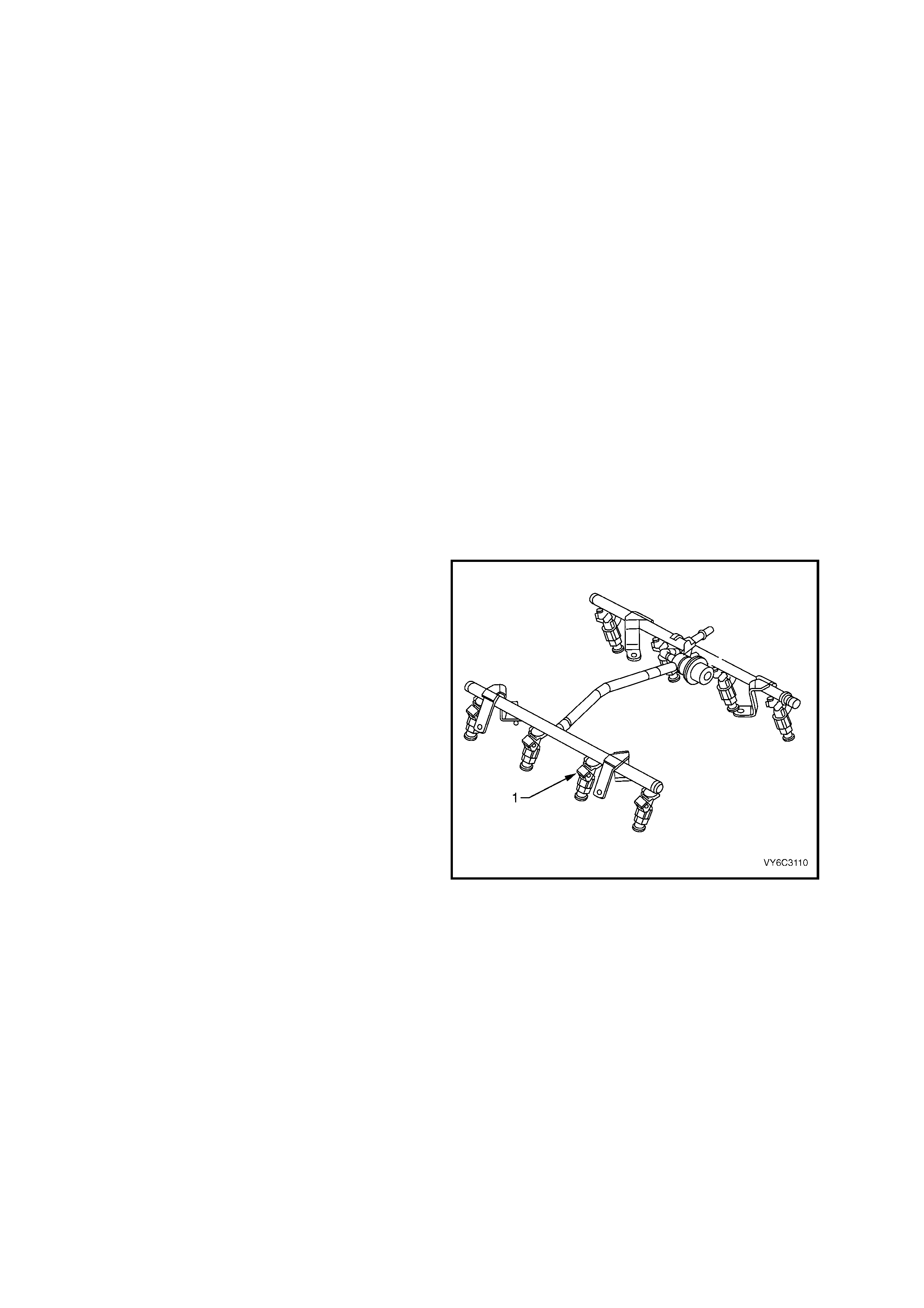
9. Disconnect the electrical connectors from the
fuel injectors (1). Identify the connectors with
their corresponding injectors to ensure correct
sequential injector firing order after
reassembly.
10. Disconnect the electrical harness from the fuel
rail brackets.
Figure 6C3-3-64 – Fuel Rail Assembly
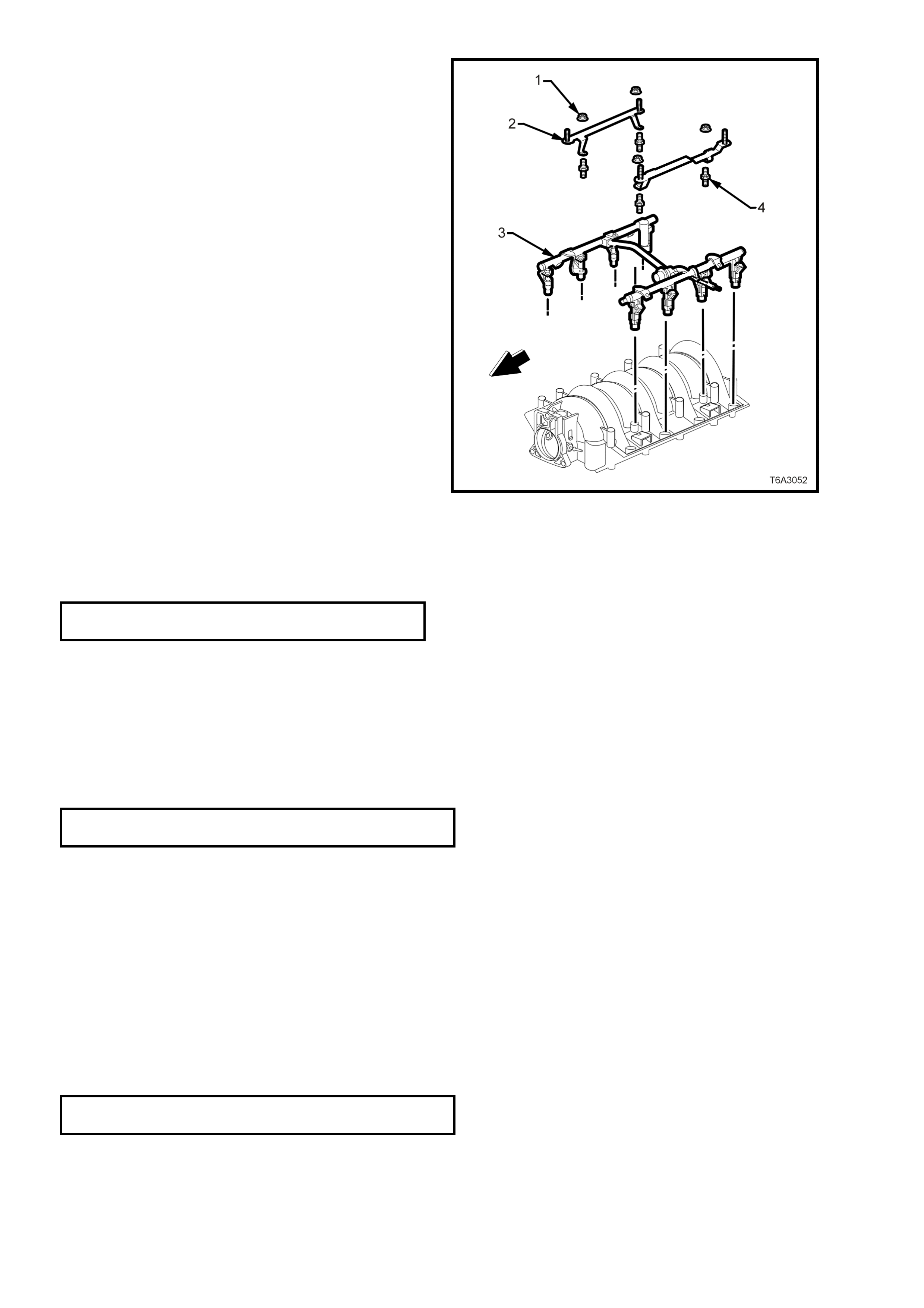
11. Remove the fuel nuts (1) securing the engine
dress cover brackets (2) to the fuel rail (3).
12. Remove the four double ended studs (4)
securing the fuel rail (3) to the intake manifold.
13. Car efull y lift the f uel rai l and inj ectors assem bl y
(3) clear of the intake manifold.
NOTE: Remove the fuel rail assembly carefully to
prevent damage to the injector electrical co nnector
terminals and the injector spray tips. Support the
fuel rail after the fuel rail is removed to avoid
damaging the fuel rail components.
14. Cap the fittings and plug the holes when
servicing the fuel system in order to prevent
dirt and oth er contam inants f rom entering ope n
pipes and passages.
15. Remove and discard the injector lower O-ring
seal from the spray tip end of each injector.
REINST ALL
1. Lubricate N EW, injector O -ring seals wit h c le an
engine oil and install to the spray tip end of
each injector.
2. Carefully reinstall the fuel rail and injectors (3)
to the intake manifold.
3. Apply Loctite 242 or equivalent to the cleaned
threads of the fuel rail bolts.
4. Reinstall the fuel rail attaching studs (4) and
tighten to the specified torque.
FUEL RAIL ATTACHING STUD
TORQUE SPECIFICATION 10 Nm
5. Connect the injector electrical connectors,
ensurin g that each connector is installe d to the
correct injector to ensure correct sequential
injector firing order.
Figure 6C3-3-61 Fuel Rail Removal
NOTE: Rotate the injectors as required to avoid stretching the wire harness.
6. Connect the electrical harness to the fuel rail bracket.
7. Reinstall the engine dress cover attaching brackets to the fuel rail attaching studs, reinstall the attaching nuts
and tighten to the correct torque specification.
ENGINE DRESS COVER BRACKET
NUT TORQUE SPECIFICATION 5 Nm
8. Reconnect the throttle cable to the throttle body and retaining clip.
9. Reconnect the fuel feed hose to the fuel rail fuel pipe. Refer to 3.9 Quick Connect Fittings Service (Metal
Collar) in this Section.
10. Tighten the fuel filler cap.
11. Reconnect the negative battery cable.
12. Inspect for leaks:
– Turn the ignition switch ON for 2 seconds.
– Turn the ignition switch OFF for 10 seconds.
– Turn the ignition switch ON.
– Check for leaks.
13. Reinstall engine dress cover and tighten decorative nuts to the correct torque specification.
ENGINE DRESS COVER NUT
TORQUE SPECIFICATION 10 Nm
14. Perform the Idle Learn Procedure and Functional Check. Refer to PCM Replacement/Programming in this
Section.
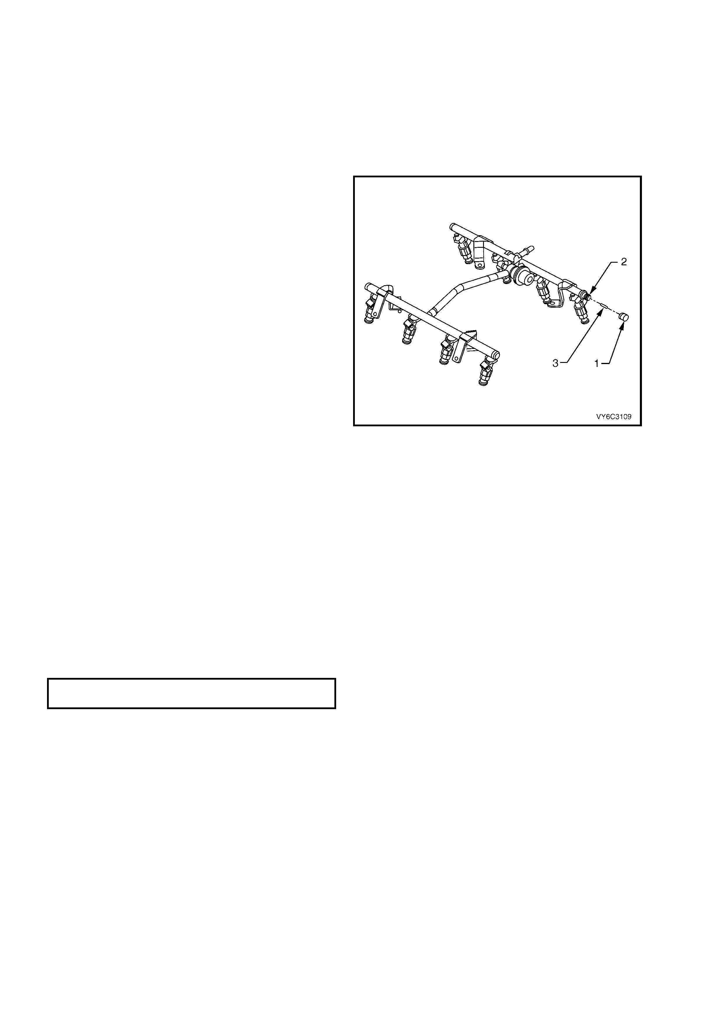
3.19 FUEL INJECTOR
REMOVE
IMPORTANT: Use care in removing the fuel injectors to prevent damage to the electrical connector pins on the
injector and to prevent damage to the nozzle. Service the fuel injector as a complete assembly only. The fuel
injector is an electrical component. Do Not immerse the fuel injector in any type of cleaner.
NOTE: The engine oil may be contaminated with fuel if the fuel injectors are leaking.
1. Relieve the fuel system pressure. Refer to the 3.7 Fuel Pressure Relief Procedure in this Section.
2. Loosen the fuel filler cap to relieve any vapour pressure.
3. Disconnect the negati v e batter y cable .
IMPORTANT: Disconnection of the battery affects certain vehicle electronic systems. Refer to
Section 00 C AUTIONS, 5. Battery Disconnection Procedures before disconnecting the battery.
4. Remove engine dress cover. Refer to 2.3 Engine Coolant Temperature Sensor in this Section for removal
procedure.
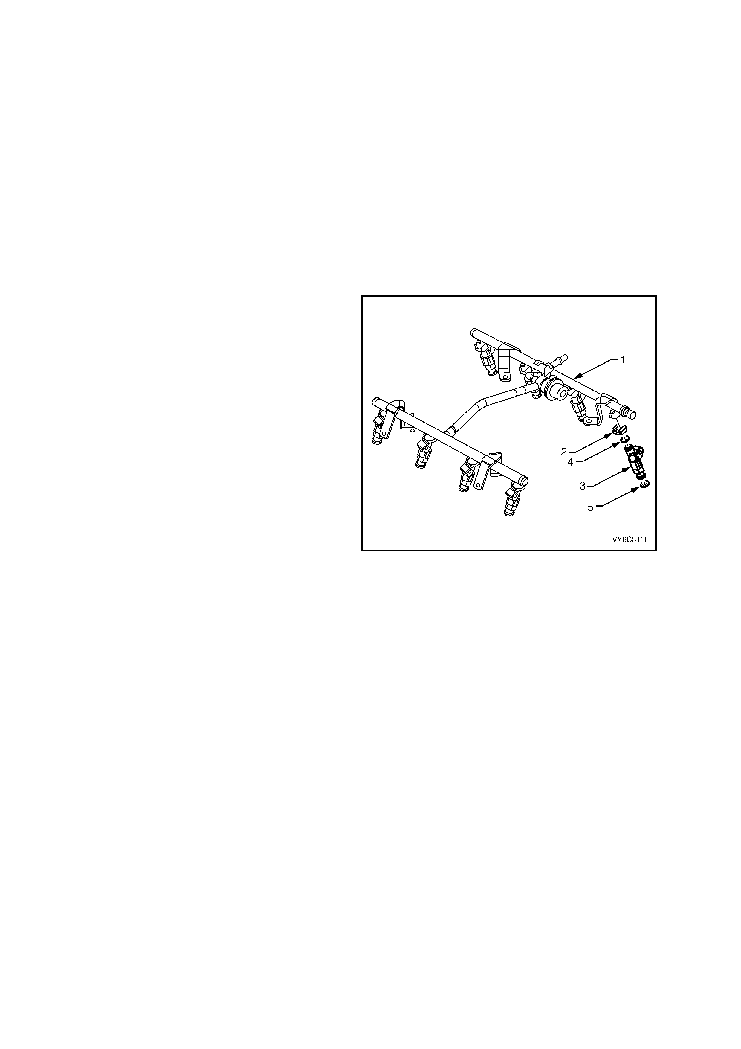
5. Remove the fuel rail assembly (1). Refer to 3.18 Fuel Rail Assembly in this Section.
6. Pull the injector retainer clip (2) to release the
injector from the fuel rail.
7. Remove the fuel injector (3).
8. Discard the injector retainer clip (2).
9. Remove and discard the injector O-ring seals
(4 and 5) from each end of the injector.
Figure 6C3-3-65 – Fuel Rail and Injectors
REINST ALL
IMPORTANT: When ordering new fuel injectors,
ensure to order the correct injector for the
application being serviced. The fuel injector
assembly is stamped with a part number
identification, a manufacturing date, a week code,
and a production plant number.
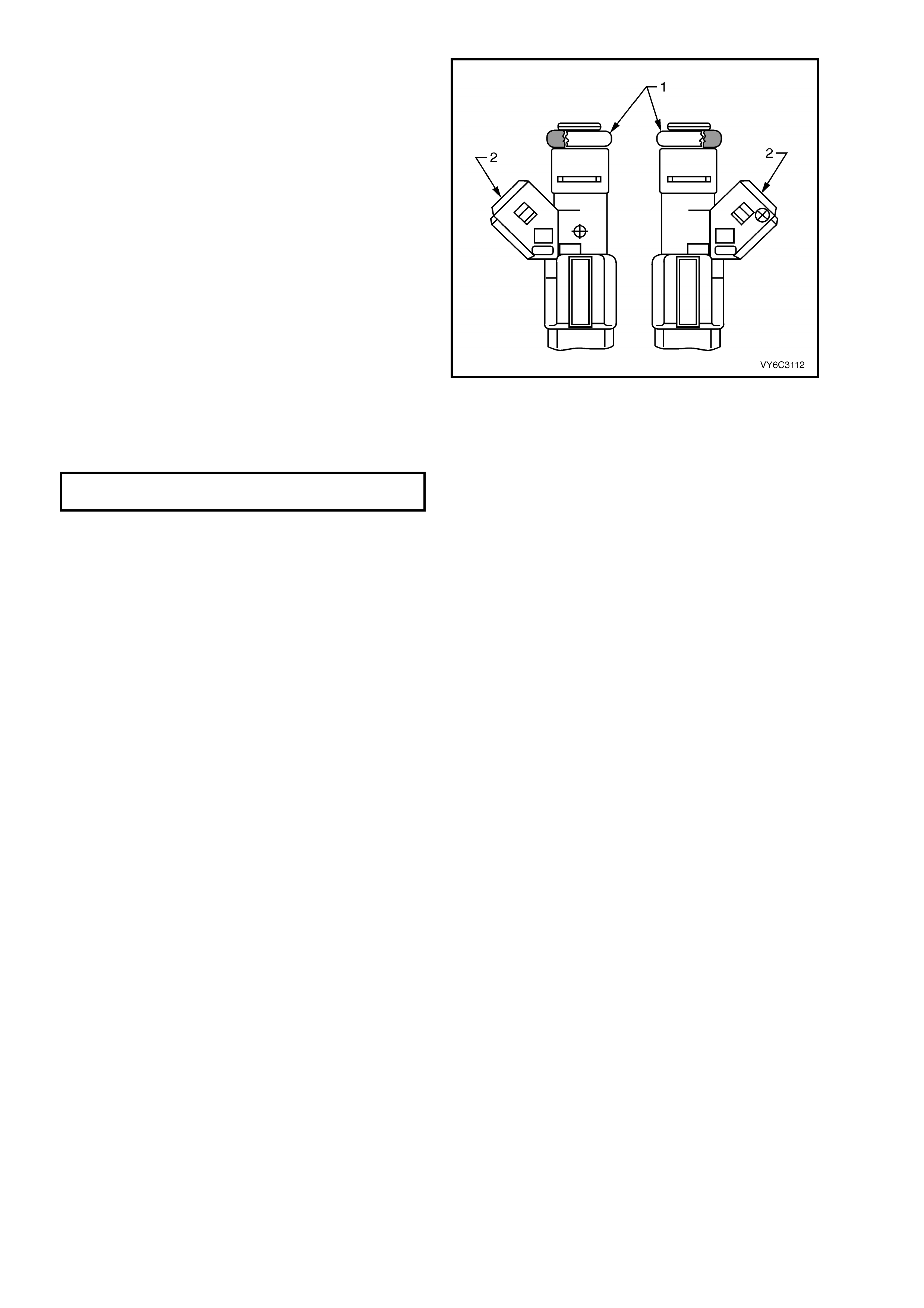
1. Lubricate a new injector O-ring seal (1) with
clean engin e oil and inst al l onto eac h inje ctor .
2. Push the fuel injector into the fuel rail injector
socket with the electrical connector (2) facing
outward. The retainer clip locks on to a flange
on the fuel rail injector socket.
3. Reinstall a NEW retainer clip to retain each
injector.
4. Reinstall the fuel rail assembly. Refer to
3.18 Fuel Rail Assembly in this Section.
5. Tighten the fuel filler cap.
6. Reconnect the negative battery cable.
7. Inspect for leaks:
– Turn the ignition switch ON for 2 seconds.
– Turn the ignition switch OFF for 10 seconds.
– Turn the ignition switch ON.
– Check for leaks.
8. Reinstall engine dress cover and tighten
decorative nuts to the correct torques
specification.
ENGINE DRESS COVER NUT
TORQUE SPECIFICATION 10 Nm
9. Perform the Idle Learn Procedure and the
Functional Check. Refer to PCM
Replacement/ Programming in this Section.
Figure 6C3-3-66 – Fuel Injector Identification
3.20 FUEL SYSTEM PRESSURE TEST
NOTE: This fuel s ystem pr essur e test is part of s everal of the Diag nost ic T ables and S ymptom check s. T o perf orm
this test, follow this procedure.
IMPORTANT: To reduce the risk of fire or personal injury, it is necessary to relieve fuel system pressure before
performing this test. See 3.7 Fuel Pressure Relief Procedure in this Sec ti on.
IMPORTANT: At no time mus t the fuel i nlet hos e or e vaporat ive hose b e clam ped or bent o ver, as this will ca use a
permanent kinking of the inner section of the hose assembly and will result in restricted fuel flow and premature
failure of the hose.
1. Remove the engine dress cover. Refer to 2.3 Engine Coolant Temperature Sensor in this Section for
removal procedure.
2. Relieve the fuel system pressure. Refer to the 3.7 Fuel Pressure Relief Procedure in this Section.
3. Loosen the fuel filler cap to relieve the fuel tank vapour pressure.
4. Remove the fuel test valve cap.
5. Connect the AU338 (or SD28018) fuel
pressure gauge to the AU465 Hose and AU453
fuel gauge Schrader fitting adaptor, then
connect to the fuel pressure testing valve (1).
Wrap a shop towel around the fitting while
connecting the gauge in order to avoid and/or
capture any fuel spillage.
6. Install the bleed hose of the gauge into an
approved petrol container.
7. Using Tech 2, enable fuel pump to pressurise
the system.
8. With fuel pump energised, open the valve to
bleed the air out of the fuel gauge.
Measure
1. Using Tech 2 once again, enable the fuel pump
to pressurise the system.
2. The fuel gauge reading should be 380 – 440
kPa for the GEN III V8 engine. If not, refer to
Fuel System Diagnosis in Section 6C3-2A
Diagnostic Tables, in this Section.
3. Relieve the fuel system pressure. Refer to
3.7 Fuel Pressure Relief Procedure in this
Section.
Figure 6C3-3-67 – Fuel Rail with Fuel Gauge
4. Remove fuel pressure gauge and adaptor.
5. Reinstall fuel test valve cap to the fuel rail
Schrader ada ptor .
6. Tighten the fuel filler cap.
7. Inspect for leaks:
– Turn the ignition switch ON for 2 seconds.
– Turn the ignition switch OFF for 10 seconds.
– Turn the ignition switch ON.
– Check for fuel leaks.
8. Reinstall engine dress cover and tighten
decorative nuts to the correct torque
specification.
ENGINE DRESS COVER NUT
TORQUE SPECIFICATION 10 Nm
9. Start engine and check for correct operation.
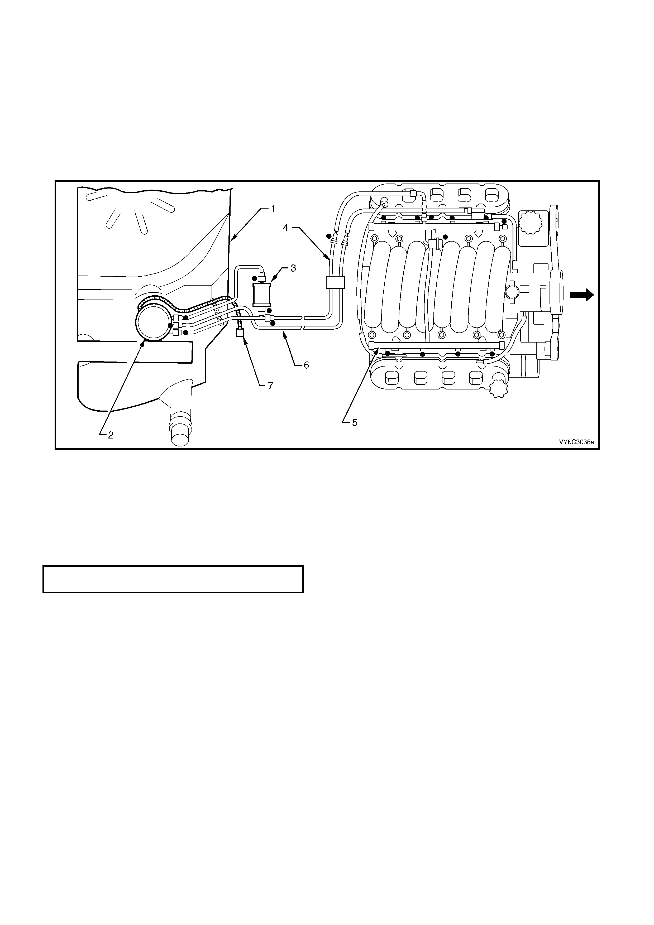
3.21 FUEL SYSTEM LEAK TEST
IMPORTANT: Following the installation of any fuel system component and before starting the engine, the fuel
system must be checked for leaks, using the following procedure:
1. Remove the engine decorative cover. Refer to 2.3 Engine Coolant Temperature in this Section for removal
procedure.
2. Turn the ignition switch ON for 2 seconds.
3. Turn the ignition switch OFF for 10 seconds.
4. Turn the ignition switch ON.
5. Check for leaks, particularly at points marked (l) in Figure 6C3-3-68.
Figure 6C3-3-68 – Potential Fuel System Leak Points
Legend
1. Fuel Tank
2. Modular Fuel Sender Assembly
3. Fuel Filter
4. Fuel Feed Pipe
5. Fuel Rail Assembly
6. Vapour Line
7. Fuel Pump Harness Connector
8. Reinstall engine dress cover and tighten decorative nuts to the correct torque specification.
ENGINE DRESS COVER NUT
TORQUE SPECIFICATION 10 Nm

3.22 THROTTLE PEDAL ASSEMBLY
GENERAL DESCRIPTION
The service operations for the throttle pedal assemblies for MY 2003 VY and V2 Series vehicles fitted with
GEN III V8 engines is the same as vehicles with V6 engines, refer to Section 6C1-3, 3.14 THROTTLE PEDAL
ASSEMBLY.
NOTE: There are differences in the throttle cable adjustment procedures for the various engines available. The
service procedure for the throttle pedal assembly does not require the throttle cable adjustment to be altered.
However, if throttle cable adjustment is required, refer to the correct Section for the appropriate engine option.
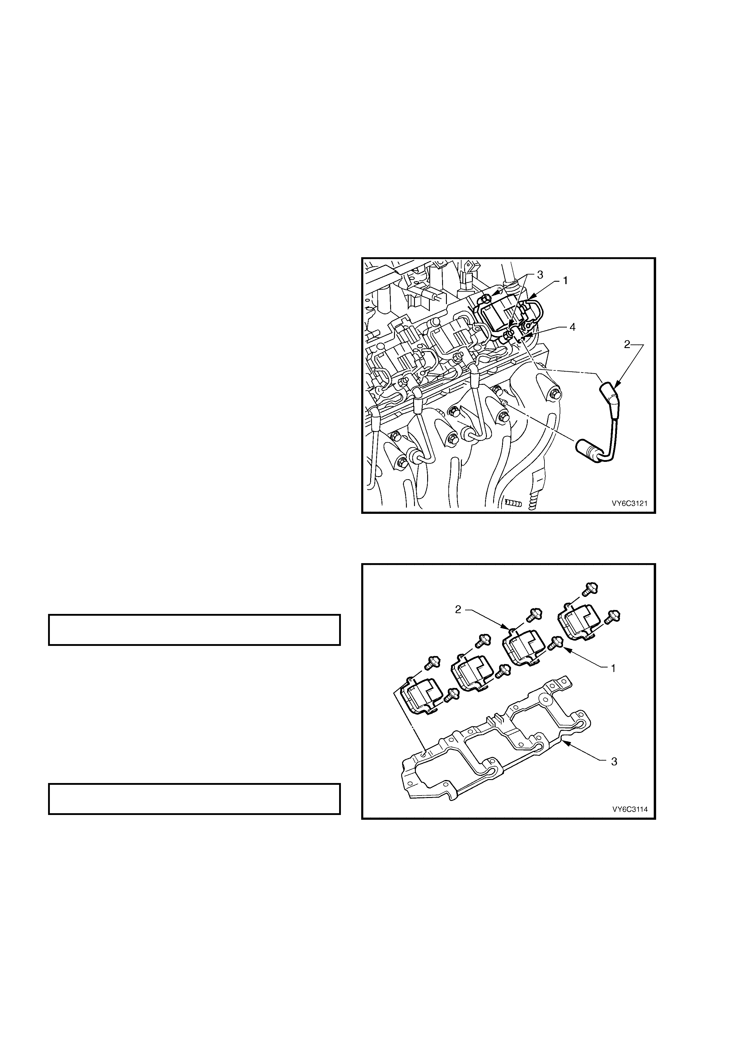
4. IGNITION SYSTEM
4.1 IGNITION COIL/MODULE
REMOVE
1. Remove engine dress cover. Refer to
2.3 Engine Coolant Temperature Sensor in
this Section for removal procedure.
2. Disconnect the negati v e batter y cable .
IMPORTANT: Disconnection of the battery affects
certain vehicle electronic systems. Refer to
Section 00 CAUTIONS, 5. Battery Disconnection
Procedures before disconnecting the battery.
3. Remove the Connector Protection Assurance
(CPA) loc k ( 1) se cur ing t he el ec tric al c o nn ec tor
to the ignition coil, then disconnect the wiring
harness connector/s from the coil/s being
removed.
4. Disconnect the spark plug wire (2) at the
ignition coil.
IMPORTANT: Never pull on the ignition lead.
Grasp the ignition coil boot and twist to break the
seal before pulling directly from each ignition coil.
5. Remove each of the ignition coil retaining
screws (3).
6. Remove the ignition coil/module/s (4) from the
mounting bracket.
Figure 6C3-3-69 – Ignition Coil/Module Location
REINST ALL
1. Reinstall the removed ignition coil/s (2).
2. Reinstall the ignition coil retaining screws (1),
then tighten to the correct torque specification.
IGNITION COIL RETAINING BOLT
TORQUE SPECIFICATION 12 Nm
3. Reconnect each spark plug wire to its
respectiv e ign iti on co il.
4. Reconnect the ignition coil harness connector.
5. Reinstall the CPA to secure the connector.
6. Reconnect the negative battery cable.
7. Reinstall engine dress cover and tighten
decorative nuts to the correct torque
specification.
ENGINE DRESS COVER NUT
TORQUE SPECIFICATION 10 Nm
8. Perform the Idle Learn Procedure and the
Functional Check. Refer to PCM
Replacement/ Programming in this Section.
Figure 6C3-3-70 – Ignition Coil/Modules
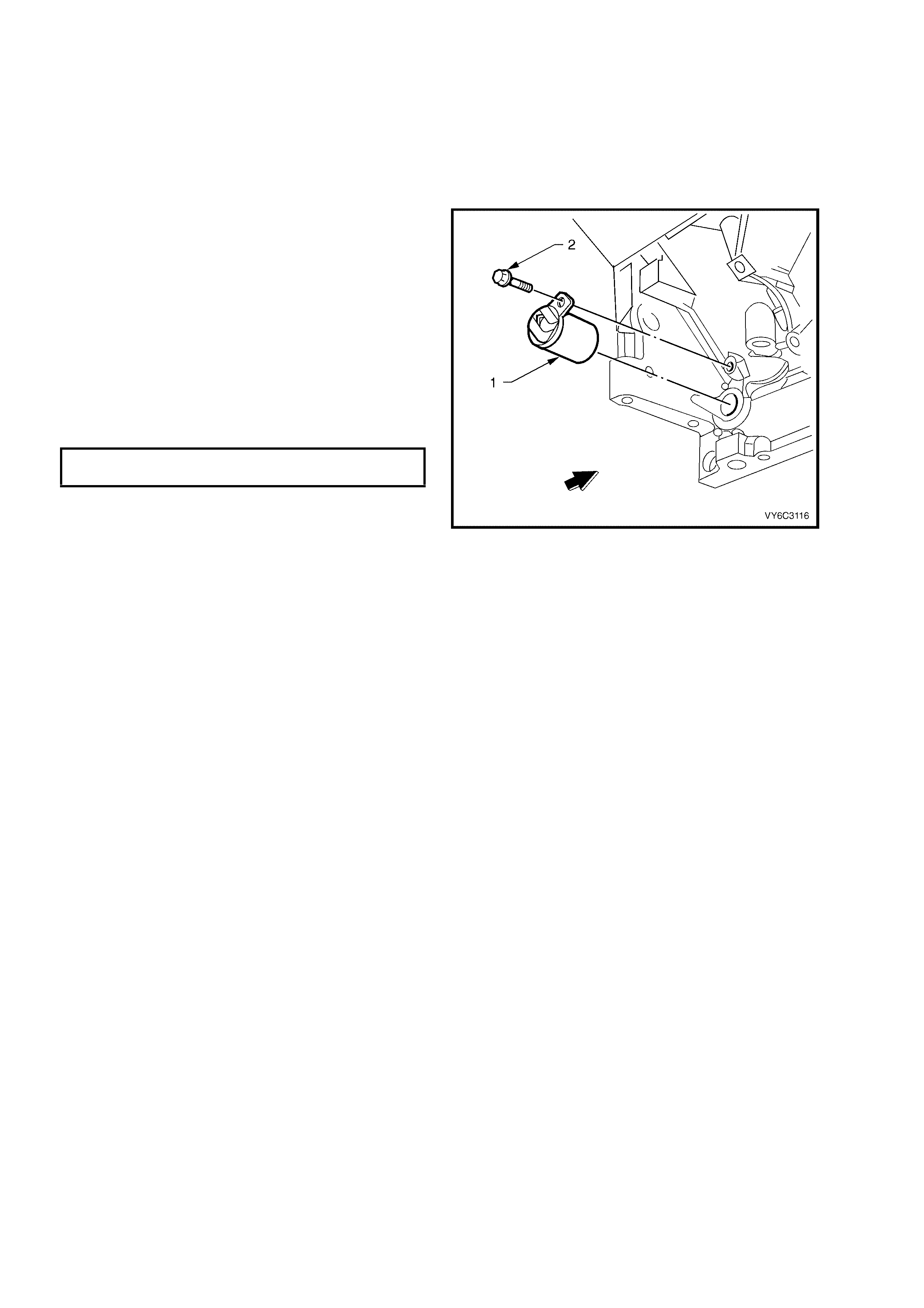
4.2 CR ANKSH AFT POS I TION (CKP) SENSOR
REMOVE
1. Disconnect the negati v e batter y cable .
IMPORTANT: Disconnection of the battery affects
certain vehicle electronic systems. Refer to
Section 00 CAUTIONS, 5. Battery Disconnection
Procedures before disconnecting the battery.
1. Remove the starter motor. Refer to
Section 6D3- 2 STARTING SYST EM.
2. Disconnect the electrical connector from the
crankshaft position sensor (1).
3. Remove the crankshaft position retaining bolt
(2).
4. Remove the sensor.
REINST ALL
1. Reinstall the crankshaft position sensor (1).
2. Reinstall the crankshaft position retaining bolt
(2) and tighten to the specified torque.
CKP SENSOR RETAINING BOLT
TORQUE SPECIFICATION 25 Nm
3. Reconnect the sensor electrical connector.
4. Reinstall the starter motor. Refer to
Section 6D3- 2 STARTING SYST EM.
5. Perform the Idle Learn Procedure and the
Functional Check. Refer to PCM
Replacement/ Programming in this Section.
Figure 6C3-3-71 – Crankshaft Position Sensor Location
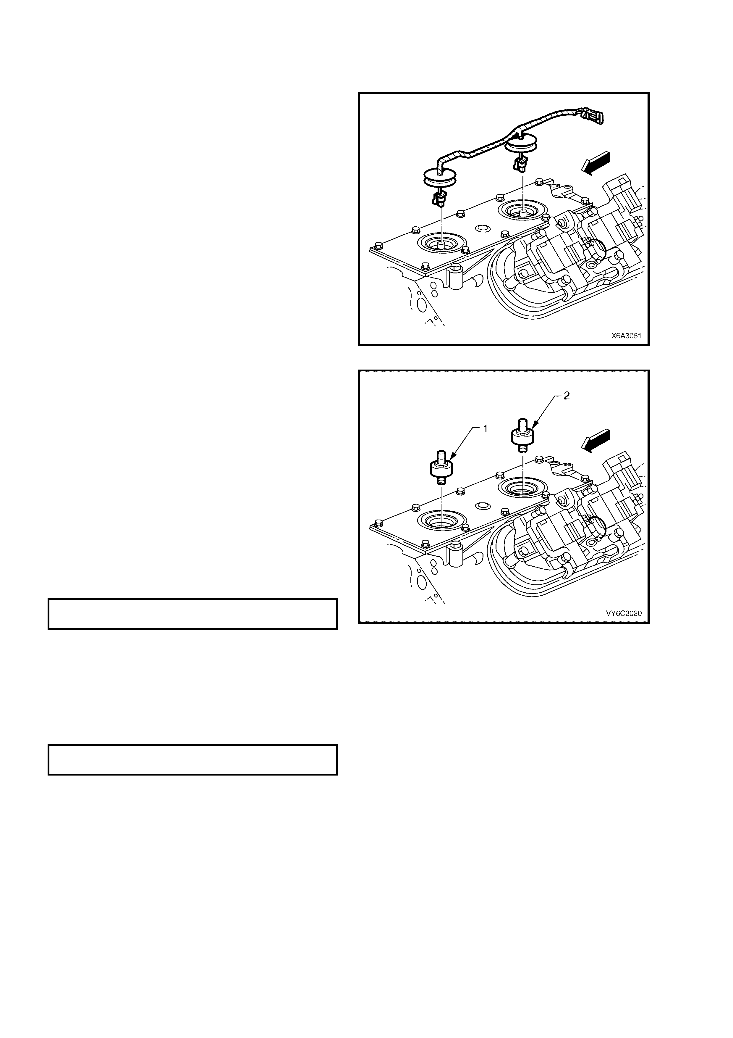
4.3 KNOCK SENSORS
REMOVE
1. Perform the fuel pressure relief procedure.
Refer to 3.7 Fuel Pressure Relief Procedure
in this Section.
2. Disconnect the negati v e batter y cable .
IMPORTANT: Disconnection of the battery affects
certain vehicle electronic systems. Refer to
Section 00 CAUTIONS, 5. Battery Disconnection
Procedures before disconnecting the battery.
3. Remove engine dress cover. Refer to
2.3 Engine Coolant Temperature Sensor in
this Section for removal procedure.
4. Remove the intake manifold. Refer to 2.14
Intake Manifold, in Section 6A3 ENGINE
MECHANICAL.
5. Remove the Knock Sensor patch wiring
harness.
Figure 6C3-3-72 – Knock Sensor Wiring Harness
6. Rem ove the Knock Sensor/s ( 1 and 2), using a
22 mm deep socket and suitable socket
equipment.
NOTE: Unless a deep socket is used, damage to
the sensor connector will result.
REINST ALL
NOTE: Do not appl y seala nt to the thread of a ne w
sensor as it is coated with a sealant during
production. Applying additional sealant may affect
the sensor's ability to detect engine knock.
NOTE: Ensure that the k nock sensor is never over
tightened, as damage to the sensor can occur.
1. Reins tal l the k nock s ensor(s) and tighten to t he
specified torque.
KNOCK SENSOR
TORQUE SPECIFICATION 15 Nm
2. Reinstall the knock sensor wiring harness.
3. Reinstall the intake manifold. Refer to 2.14
Intake Manifold, in Section 6A3 ENGINE
MECHANICAL.
4. Reinstall engine dress cover and tighten
decorative nuts to the correct torque
specification.
ENGINE DRESS COVER NUT
TORQUE SPECIFICATION 10 Nm
5. Perform the Idle Learn Procedure and the
Functional Check. Refer to PCM
Replacement/ Programming in this Section.
Figure 6C3-3-73 – Knock Sensors
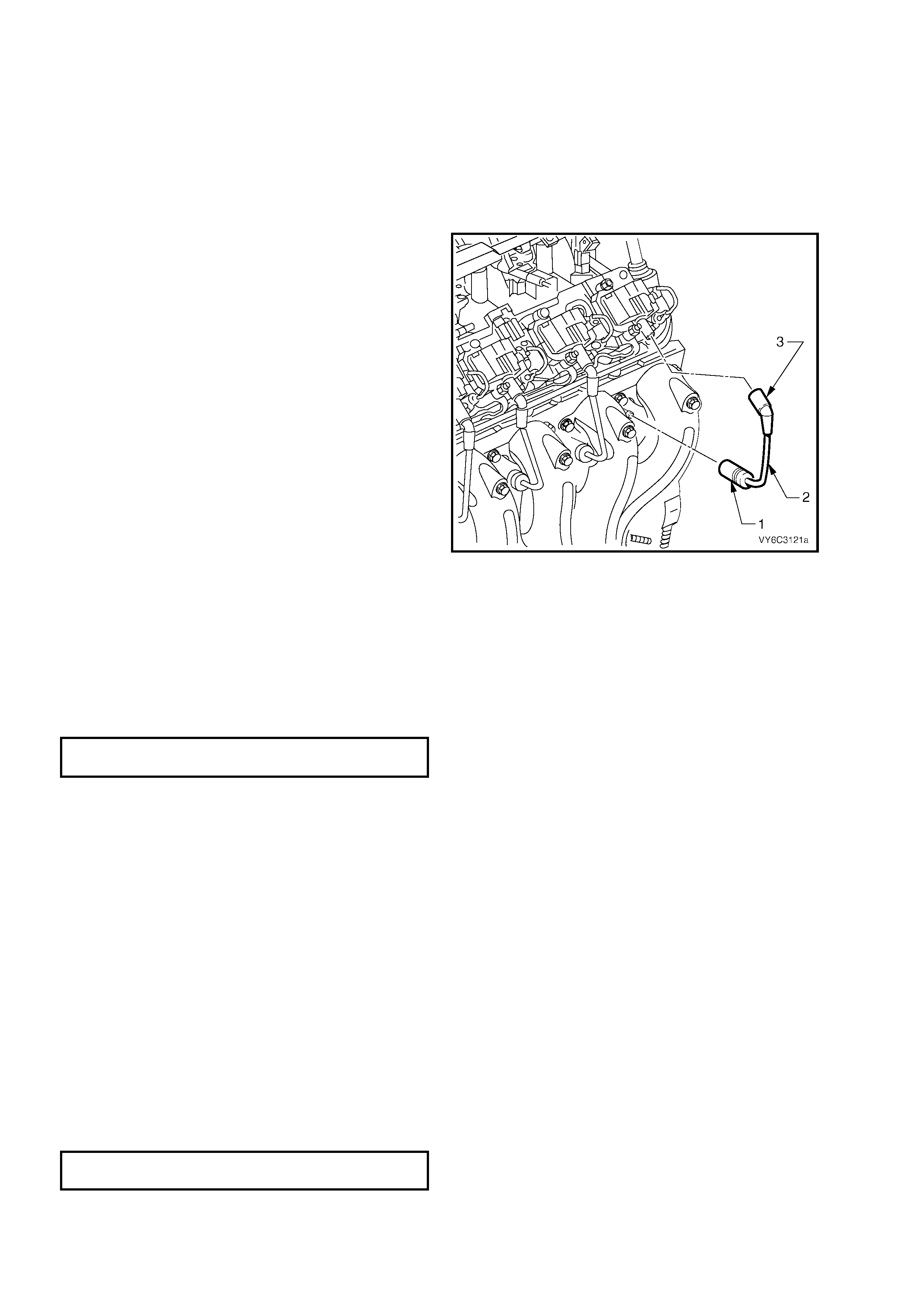
4.4 SPARK PLUG LEAD/S
REMOVE
IMPORTANT: Pulling or bending spark plug leads
can cause hidden damage. Follow the removal
steps carefully, to avoid such damage.
1. Remove the engine dress cover. Refer to
2.3 Engine Coolant Temperature Sensor in
this Section for removal procedure.
2. Firmly grasp the boot (1) at the spark plug end
of the lead.
IMPORTANT: Grasp the boot (1), not the
lead (2).
3. Twist the boot (1) in both directions, to relieve
any suction and to break the seal.
4. Pull the boot straight off the spark plug.
5. Repeat s teps ‘2’ a nd ‘3’ for the ignitio n coil en d
of the lead (3).
6. Carefully set the lead to one side.
7. Repe at steps 1 to 5 inclus ive, for the rem aining
leads, being careful to keep them in cylinder
number order, for further diagnosis (say, of
spark plug condition).
Figure 6C3-3-74
INSPECT
1. Connect and O hmmeter, capab le of accuratel y
reading to 20 kilohms (kΩ), to each end of a
lead.
2. Record the reading for each lead.
3. Compare the resistance readings taken,
against specification.
SPARK PLUG
LEAD RESISTANCE 700 Ω Maximum
4. Replace any lead that is significantly different
from the stated specification.
REINST ALL
Reinstal lat ion of th e s p ar k plug lea ds is es s ent ial ly,
the reverse of removal procedures except for:
1. O nly e ver hand le a s park plug le ad b y the boot
at each end. Never the lead itself.
2. ‘Feel’ for the centering of the lead connection
to the spark plug terminal.
3. Push on the boot until the lead connection is
fully engaged with t eh spark plug terminal.
This approach is needed to avoid potential
misfiring.
4. Repeat this procedure for the coil end of each
lead.
5. Reinstall engine dress cover and tighten
decorative nuts to the correct torques
specification.
ENGINE DRESS COVER NUT
TORQUE SPECIFICATION 10 Nm
6. Start the engine and check for correct
operation.
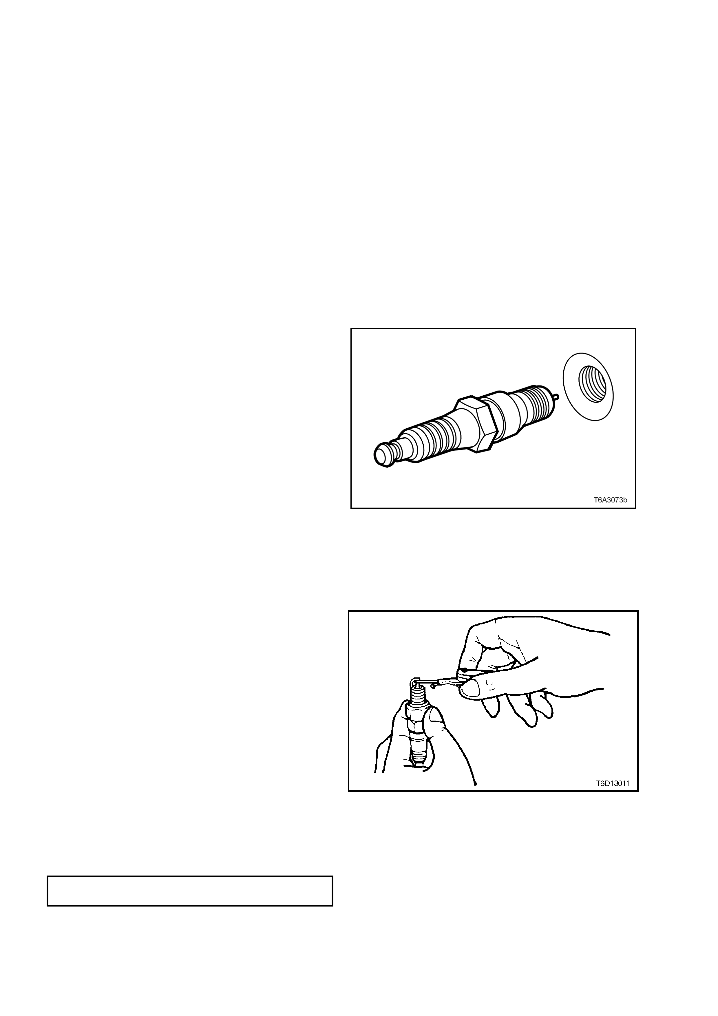
4.5 SPARK PLUGS
SERVIC E PRE CAUTIO NS
1. Allow the engine to cool (to at least 50°
°°
° C) before attempting to remove spark plugs. Attempting to
rem ove s park plugs from a hot eng in e ma y cause th e plu g/cylinder hea d t hreads to b in d, c aus ing tearin g of t he
alloy cylinder head threads.
2. Clean the spark plug recess area before removing any spark plug. Failure to do so could result in e ngine
damage because of dirt or other foreign material entering the cylinder head or by the contamination of the
cylinder head thre ads. The contam inated threads m ay then prevent the correct s eating of the new or replaced
plug. If required, use a ‘thread chaser’ to clean the threads of any contamination where this is suspected.
3. Only ev er handle the spark lug lead boot wh en removing the ‘near plug’ coil lead from a spark plug. DO
NOT pull on the lead itself. Twist the boot first, to break the seal then pull to remove.
REMOVE
1. Remove engine dress cover. Refer to
2.3 Engine Coolant Temperature Sensor in
this Section for removal procedure.
2. Remove the spark plug leads. Refer to
‘Service Precaution’ note #3, above).
3. Using a suitable spark plug socket, loosen the
spark plug/s, t hen r e-tight en to break a way an y
carbon deposits on the threads.
4. Loosen the spark plug/s once again but, this
time, only one or two turns. Then use
compressed air to remove any foreign m aterial
that may otherwise enter the combustion
chamber.
CAUTION: Wear eye protection to avoid
injury.
5. Continue to remove the spark plug. Repeat
steps 2 to 4 for each spark plug.
IMPORTANT: As each spark plug is removed,
place in or der. T his will e nable an y abnorm al spark
plug condition to be identified with the correct
cylinder.
Figure 6C3-3-75 – Spark Plug Removal
CLEAN, INSPECT AND ADJUST
1. Replace any plug that has cracked insulation,
broken insulation or loose electrodes.
2. Clean any oil from the plugs using a
degreasing agent.
3. Dry the plugs using compressed air.
4. Clean the spark plugs as per the
manufacturer's instructions using a purpose-
built machine (sand blasting type).
5. Inspect the spark plugs for defects. Refer to
Spark Plug Diagnosis in this Section for
identification of the condition of spark plugs.
6. Ensure that the threads are clean and in good
order.
7. Use a round wire feeler gauge to check the
spark plug gap.
8. Adjust the gap to the correct specification by
gently bendi ng the out er elec trode.
Figure 6C3-3-76
SPARK PLUG GAP
GEN III V8 Engine 1.5 mm

REINST ALL
1. Hand start each spark plug into the cylinder head thread.
2. Tighten the plugs to the correct torque specification using a spark plug socket.
SPARK PLUG TORQUE SPECIFICATION
New Cylinder Head Only 20 Nm
Existing Cylinder Head 15 Nm
3. Reinstall spark plug leads to all spark plugs after installation.
4. Reinstall engine dress cover tightening decorative nuts to the correct torque specification.
ENGINE DRESS COVER NUT
TORQUE SPECIFICATION 10 Nm
SPARK PLUG DIAGNOSIS
Poor Spark Pl ug Per formanc e
A spark plug can perform poorly due to wear, dirt, carbon fouling, excessive electrode wear, a brok en insulator or
excessive gap.
NOTE 1: When re-gapping a spark plug, always make the gap adjustment by bending the ground (side) electrode.
NOTE 2: When replacing spark plugs, use genuine spark plugs or recommended spark plugs of the correct heat
range.
Worn or Dirty Plugs
Worn or dirty plugs can give satisfactory operation while the vehicle is idling, but break down under load.
This can cause:
•
••
•
Poor fuel economy.
•
••
•
Power loss.
•
••
•
Acceleration loss.
•
••
•
Difficult starting.
•
••
•
Generally poor engine performance.
Carbon Fouling
Carbon fouling is indicated by black carbon deposits. The black deposits are usually the result of slow-speed
driving and short runs. In these circumstances, the optimum engine operating temperature is seldom reached.
Fouling can also be caused by:
•
••
•
Worn piston rings.
•
••
•
Faulty ignition.
•
••
•
Rich fuel mixture.
•
••
•
Spark plugs that are rated too cold.
Excessive Ele ctrode Wear
This often indicates:
•
••
•
T he engine is oper ati ng at hig h speeds .
•
••
•
The engine is operating at levels that are consistently greater than normal.
•
••
•
A plug that is rated too hot.
•
••
•
Excessively lean fuel mixture.
•
••
•
Plug/s overheating due to insufficient tightening (caused by combustion gases leaking past the threads).
Broken Insulator
IMPORTANT: Do not use a spark plug with a broken insulator.
Broken insulators are usually the result of improper installation or carelessness.
Breaks in the upper insulator can result from a poor fitting spark plug socket or an outside blow. The cracked
insulator m a y not show up until oil or mois ture penetra tes the crac k. T he crack is often jus t below the c rimpe d part
of the shell and may not be visible.
Break s in the lo wer insu lator often r esult f rom c areles s re- gapping and ar e usua lly vis ible. T his can als o res ult f rom
the plug operating too hot. For example, in periods of high speed operation or under heavy loads.
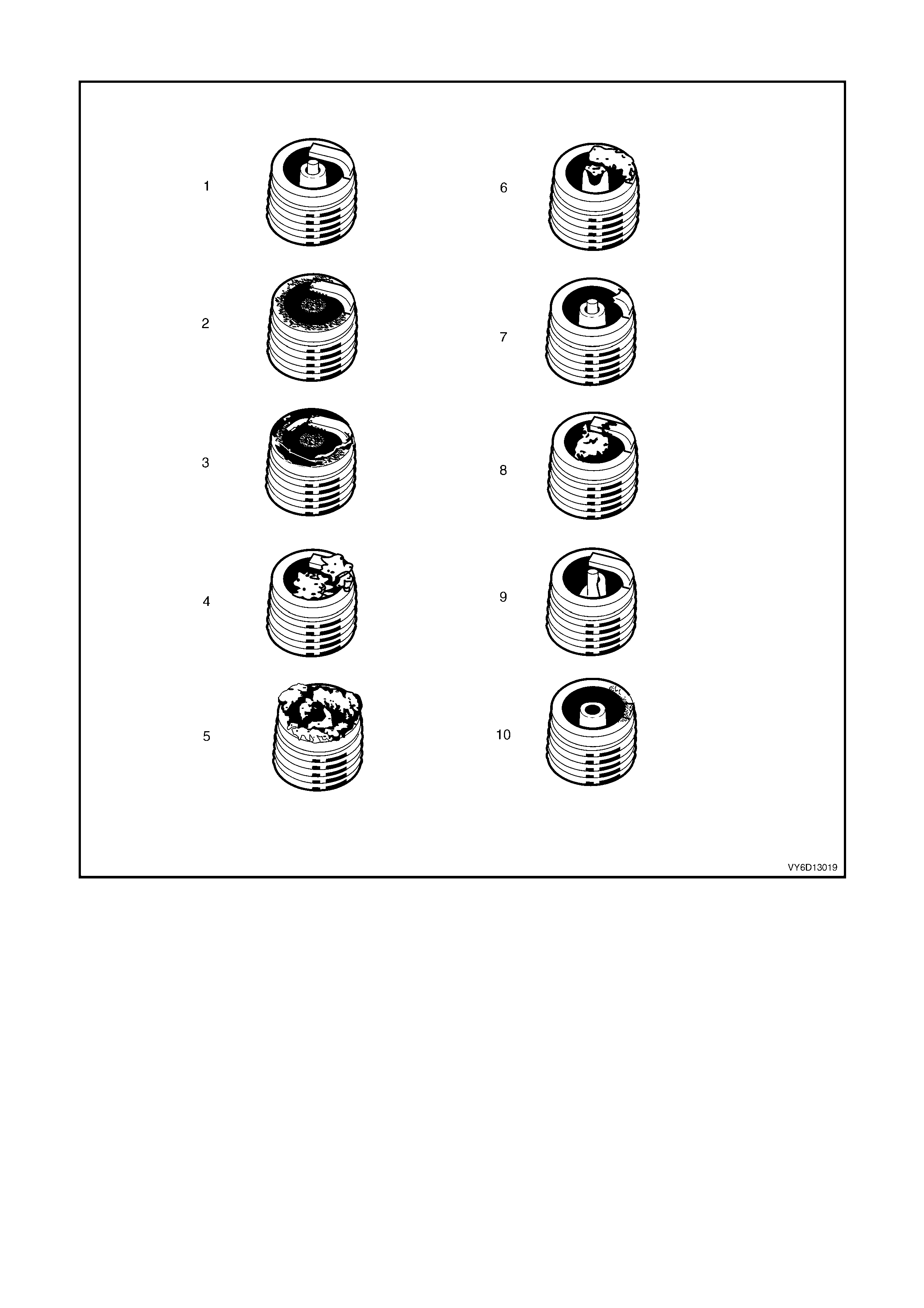
ANALYSIS OF SPARK PLUG CONDITION
Figure 6D1-3-77 – Spark Plug Conditions
Legend
1. Normal 5. Deposit fouling B 8. Pre-ignition
2. Carbon fouled 6. Deposit fouling C 9. Heated shock failure
3. Oil fouled 7. Detonation 10. Insufficient installation torque
4. Deposit fouling A
Normal Operation (1)
Brown or greyish-tan deposits and slight electrod e wear indicate correct spark plug heat range and mixed periods
of high and low speed driving.
Carbon Fouled (2)
Dry, fluffy black carbon deposits possibl y d ue to poor ignition out put, weak coil, faulty spark plug leads, excessive
idling, s low sp eeds under light load. If spar k plu g temperatures rem ain t oo lo w for norm al com bus tion, the depos its
are not burned off.
Oil Foul ed (3)
Wet, oily deposits with minor electrode wear possibly due to oil leaking past worn piston rings.
Breaking in a new or recently overhauled engine before the rings are fully seated may also result in this condition.

Deposit Fouling A (4)
Red brown, yellow and white coloured coatings on the insulator tip which are by-products of combustion. They
come from the fuel and the lubricating oil which generally contain additives. Most powdery deposits have no
adverse effect on spark plug operation; however, they may cause intermittent missing under severe operating
conditions.
Deposit Fouling B (5)
Deposits sim ilar to t hose identif ied in Depos it f oulin g A ( 4). T hese are a lso by-pro ducts of com bus tion fr om the f uel
and lubric ating o il. Exc essive val ve stem clearanc es and/or def ective int ake valve seals allow too m uch oil t o enter
the combustion chamber. The deposits will accumulate on the portion of the spark plug that projects into the
cham ber and will be hea vie st on th e side f acing the int ak e valve. W hen you detec t this c ondi tion i n onl y one or two
cylinders, check the seals.
Deposit Fouling C (6)
Most powd ery deposits identified in Deposit f ouling A (4) have no advers e effec t on the operation of the spark plug
as long as they remain powdery.
Under cert ain cond it ions of oper at io n ho we ver , t hes e d epos its melt a nd f or m a shin y gl a ze coat ing on th e i ns ulat or .
W hen hot, this ac ts as a g o od e lec tric a l c o nduct o r a llo wing th e c ur rent to flo w al o ng t he deposit ins t ead of s parking
across the gap.
Detonation (7)
Commonly referred to as engine knock or ‘pinging’, detonation causes severe shocks inside the combustion
chamber causing damage to parts.
Pre-ignition (8)
Burnt or blistered insulator tip and badly eroded electrodes probably due to the excessive heat.
This is often caused by a cooling system blockage, sticking valves, improperly installed spark plugs or plugs that
are the wrong heat rating (too hot).
Sustained high speed with a heavy load can produce temperatures high enough to cause pre-ignition.
Heat Shock Failure (9)
A rapid increase in spark plug tip temperature under severe operatin g conditions can cause heat shock and result
in fractured insulators. This is a common cause of broken and cracked insulator tips.
Insufficient Installation Torque (10)
Poor contact between the spark plug and the cylinder head seat.
The lac k of proper he at transf er that results f rom poor s eat contact ca uses overheati ng of the sp ark plug. In many
cases, severe damage occurs, as shown.
Dirty threads in the cylinder head can cause the plug to seize before it is seated.
IMPORTANT: The recommended installation torque may be obtained before the taper seat engages with the
cylinder hea d.
Ensure that the cylinder head and spark plug threads are free of deposits, burrs and scale before installation.

5. MISCELLA NEOUS SYSTEMS
5.1 EVAPORATIVE EMISSION CONTROL SYSTEM (EECS) CANISTER
The Evaporative Emission Control System
(EECS) Canister (1) is located underneath the
vehicle near the fuel filter. For Canister removal
and reinstallation procedures, refer to
Section 6E3 EMISSION CONTROL – GEN III V8
ENGINE.
Figure 6C3-3-78 – EECS Canister Location
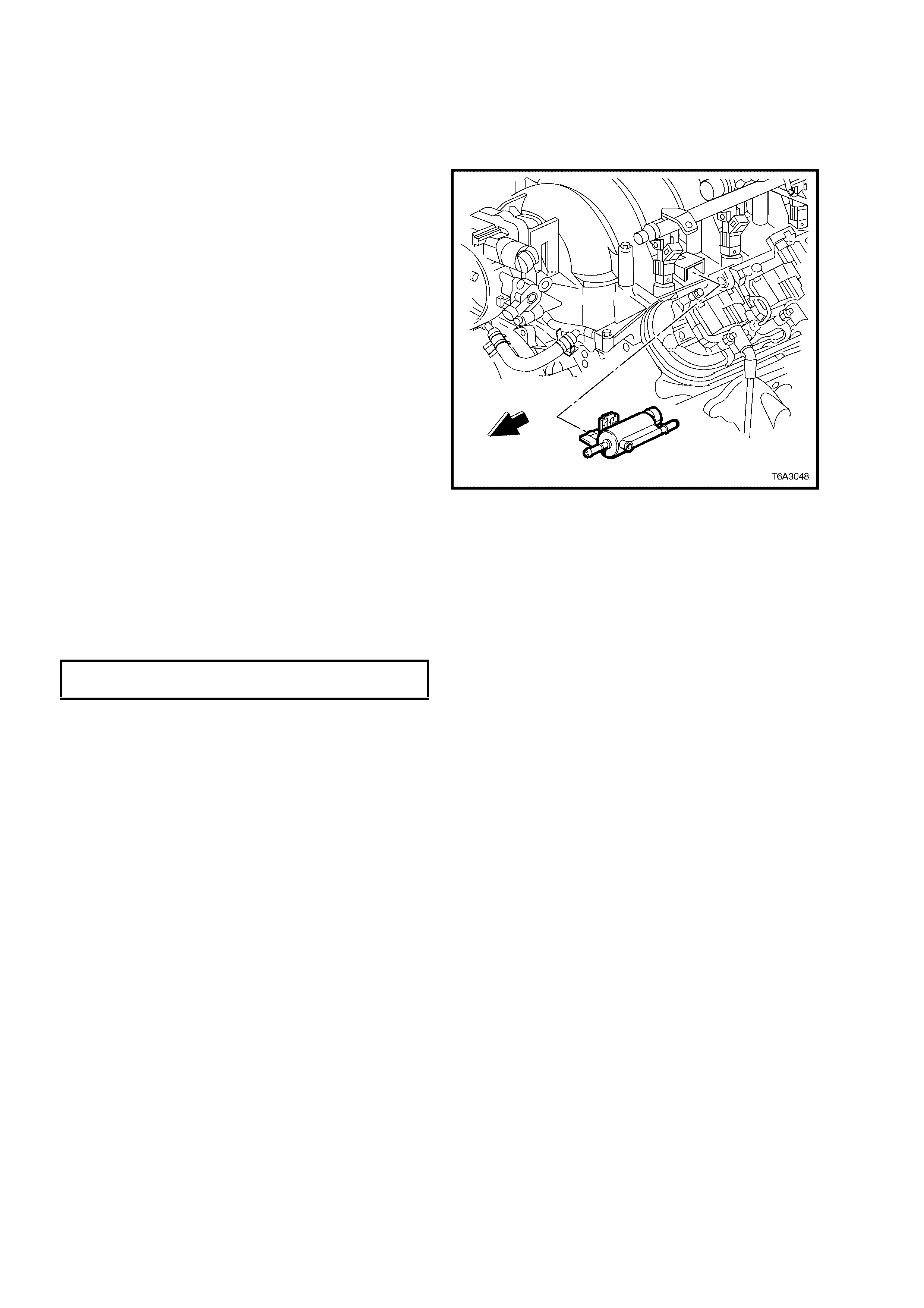
5.2 EECS CANISTER PURGE SOLENOID VALVE
REMOVE
1. Remove engine dress cover. Refer to
2.3 Engine Coolant Temperature Sensor in
this Section for removal procedure.
2. Disconnect the electrical connector from the
EECS purge solenoid.
3. Disconnect front hose by squeezing retaining
clip and pull hos e fr om solenoid.
4. Disconnect rear hose from the purge
solenoid valve using tool AU533. Refer to
3.10 Quick Conn ect F itting s Serv ice (Pl astic
Collar) in this Sec ti on.
5. Remove the EECS purge solenoid from the
bracket.
Figure 6C3-3-79 – EECS Purge Solenoid Valve Location
REINST ALL
1. Reinstall the EECS purge solenoid valve to the bracket.
2. Reconnect both hoses to the purge solenoid. Refer to 3.10 Quick Connect Fittings Service (Plastic Collar)
in this Section.
3. Reconnect the electrical connector to the EECS purge solenoid valve.
4. Reinstall engine dress cover, tightening the decorative nuts to the correct torque specification.
ENGINE DRESS COVER NUT
TORQUE SPECIFICATION 10 Nm
EVAPORATIVE SYSTEM CLEANING
1. Ignition OFF.
2. Remove the purge solenoid vacuum line from the solenoid. Refer to 3.10 Quick Connect Fittings Service
(Plastic Collar) in this Section.
3. Remove the evaporative purge solenoid valve from the engine. Refer 5.2 EECS Canister Purge Solenoid
Valve.
4. Lightly tap the purge solenoid valve on a clean work area looking for carbon particles or carbon dust exiting
either of the vacuum ports.
5. Reinstall the components and refer to P0443 EVAP Purge Solenoid Control Circuit, in Section 6C3-2A
DIAGNOSTIC TABLES, in this Section, if no carbon release is evident.
6. Continue with this service procedure if carbon is being released from the component.
7. Remove the charcoal canister from the vehicle. Refer to Section 6E3 EMISSION CONTROL – GEN III V8
ENGINE.
8. With both ends of the canister purge vapour supply hose open, blow air through hose to remove any carbon
particles that may be in the hose.
9. Remove purge hose between the purge solenoid and the throttle body and blow air through hose to remove
any carbon particles that may be in the hose.
10. Reinstall purge hose and canister to the vehicle, and connect all hoses.
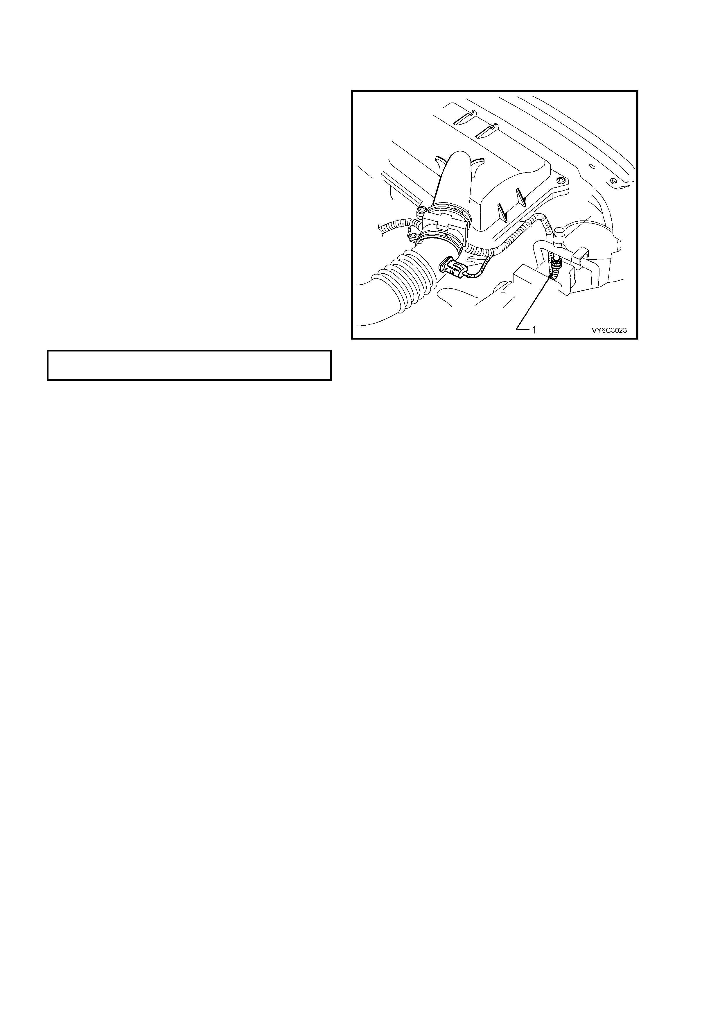
5.3 A/C REFRIGERANT PRESSURE SE NSOR
REMOVE
1. Remove the upper radiator panel shroud. Refer
to 2.16 Radiator, in Section 6B3 ENGINE
COOLING – GEN III V8 ENGINE.
2. Disconnect the electrical connector from the
A/C Refriger ant Pres s ure S ens or (1) .
3. Rem ove th e sens or f rom the high press ure l ine
and discard the seal.
NOTE: The sensor is mounted on a Schrader type
valve, so it is not necessary to discharge the A/C
system.
REINST ALL
1. Fit a new seal to the sensor fitting.
NOTE: Coat the seal with refrigerant oil.
2. Reinstall the A/C Refrigerant Pressure Sensor
to the high pressure line and tighten to the
specified torque.
A/C REFRIGERANT PRESSURE
SENSOR TORQUE SPECIFICATION 6 Nm
3. Reconnect the A/C refrigerant pressure
electrical connector.
4. Reinstall the radiator cover panel.
Figure 6C3-3-80 – A/C Refrigerant Pressure Sensor
Location
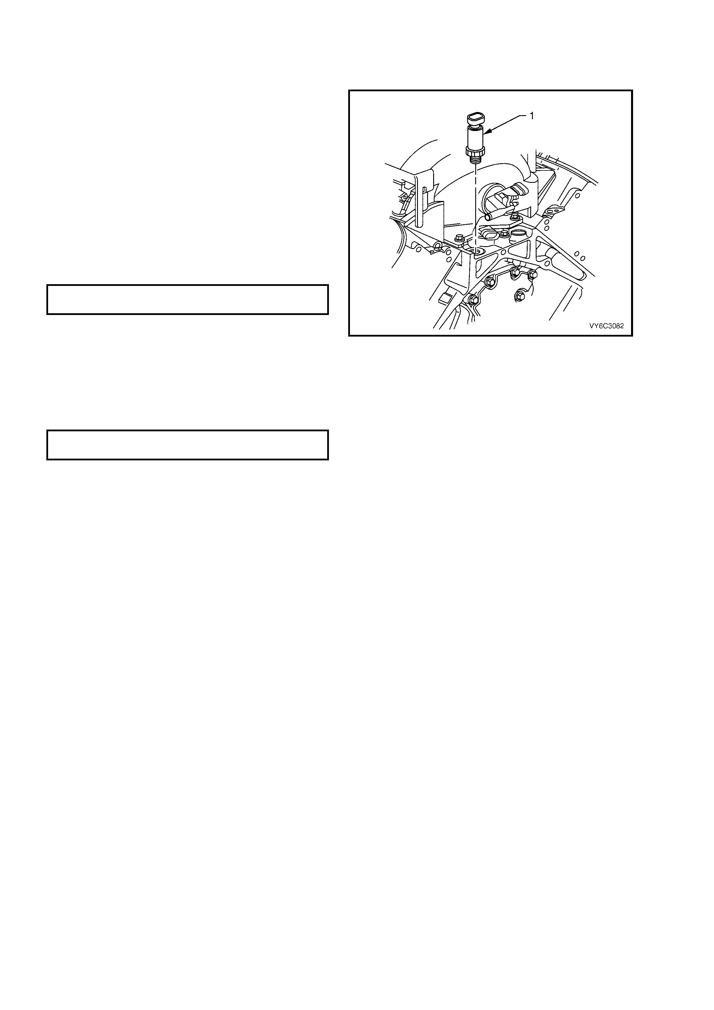
5.4 OIL PRESSURE SENSOR
REMOVE
1. Remove engine dress cover. Refer to
2.3 Engine Coolant Temperature Sensor in
this Section for removal procedure.
2. Clean around area of oil pressure sensor (1),
so that no foreign debris will enter engine.
3. Disconnect the oil pressure sensor electrical
connector.
4. Using tool J 41712, remove oil pressure
sensor.
REINST ALL
1. Reinstall the oil pressure sensor (1) and tighten
to the specified torque.
OIL PRESSURE SENSOR
TORQUE SPECIFICATION 20 Nm
2. Connect the oil pressure sensor electrical
connector.
3. Check engine oil level and top up if necessary.
4. Start engine and inspect for leaks.
5. Reinstall engine dress cover and tighten
retaining nuts to the correct torque
specification.
ENGINE DRESS COVER NUT
TORQUE SPECIFICATION 10 Nm
Figure 6C3-3-81 – Oil Pressure Sensor
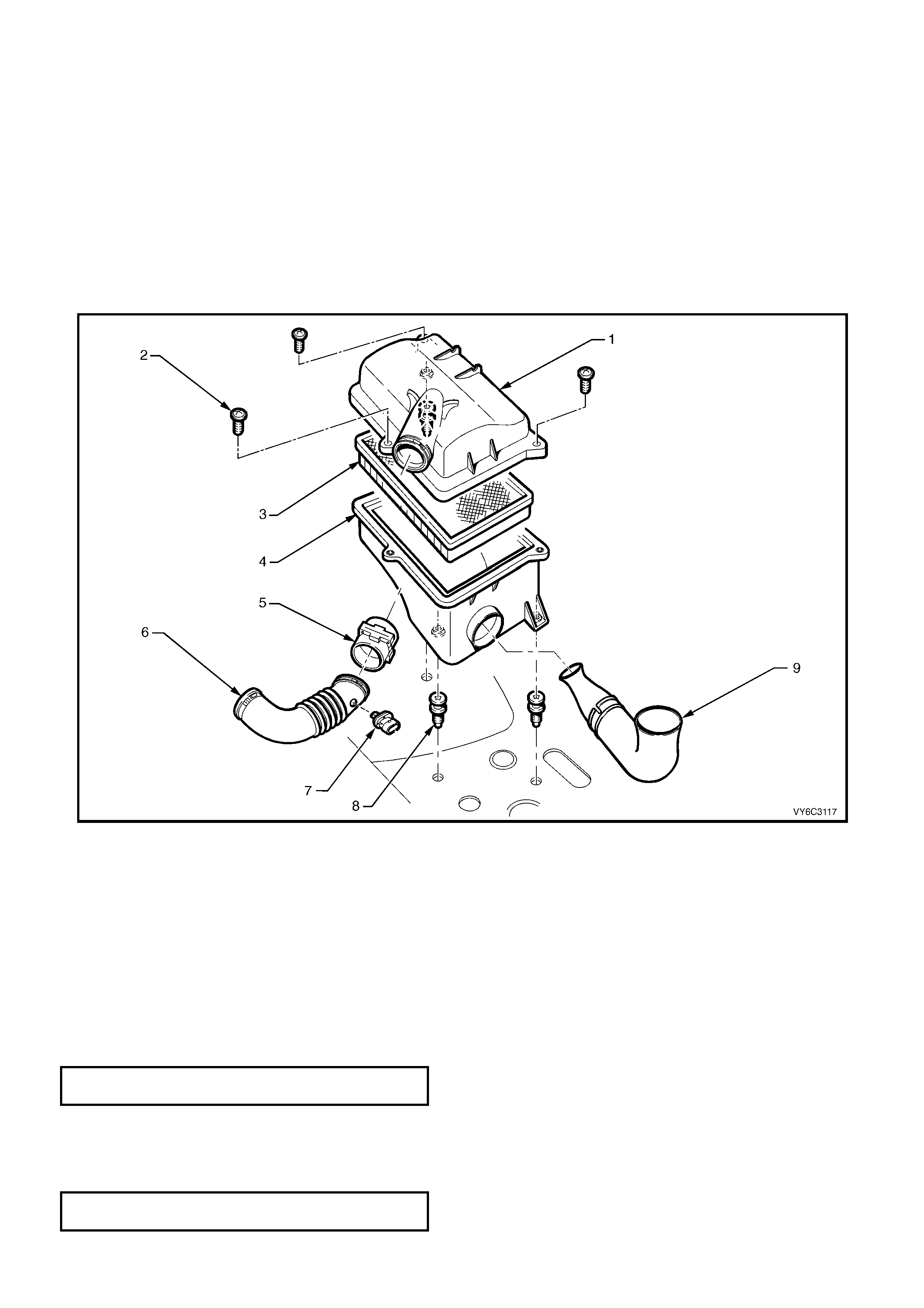
5.5 AIR CLEANER ASSEMBLY
REMOVE
1. Remove the engine dress cover. Refer 2.3 Engine Coo lant Temp eratu re Sensor, in this Section.
2. Disconnect the wiring harness connectors to the IAT Sensor (7) and the MAF Sensor (5).
3. Loosen the clamp securing the air intake duct to the throttle body, then loosen the clamp securing the MAF
Sensor to the air cleaner u pper bod y. Rem ove the duc t, together wit h the IAT Sens or and the MAF Se nsor, s till
installed.
4. Remove three retainer screws (2) securing the air cleaner upper body (1).
5. Remove air cleaner upper body (1) and air cleaner filter assembly (3).
6. Remove the three retainer screws (8) securing the air cleaner lower body (4) to the fender inner panel
insulators.
7. Disengage the air cleaner air inlet duct (9) from lower body (4), then remove air cleaner lower body (4).
Figure 6C3-3-82 – Air Cleaner Assembly
Legend
1. Air Cleaner Housing Upper Body
2. Air Cleaner Housing Top Cover Retaining Screws (3)
3. Air Cleaner Filter
4. Air Cleaner Housing Lower Body
5. Mass Air Flow (MAF) Sensor
6. Air Intake Duct to Throttle Body
7. Intake Air Temperature (IAT) Sensor
8. Air Cleaner Housing Retaining Screws (3)
9. Air Inlet to Air Cleaner Housing Duct
REINST ALL
1. Reinstall the air cleaner lower body onto the mounting insulators.
2. Reinstall the air cleaner inlet duct to the lower air cleaner lower body (9).
3. Reinstall the retaining screws and tighten to the correct torque specification.
AIR CLEANER LOWER HOUSING
SCREW TORQUE SPECIFICATION 10 Nm
4. Reassemble the air cleaner element into the air cleaner upper body and place the upper bod y onto the lower
air cleaner body.
5. Reinstall the three retaining screws securing the upper air cleaner bo dy to the lo wer and tighten to the correct
torque specification.
AIR CLEANER LOWER BODY
SCREW TORQUE SPECIFICATION 5.0 Nm

6. Reinstall the intake air duct and MAF sensor to the throttle body and upper air cleaner body. Reinstall and
tighten both duct clamps to the specified torque.
INTAKE AIR DUCT CLAMP
TORQUE SPECIFICATION 2 Nm
7. Reconnect wiring harn es s connector s to the IAT and MAF sensors .
8. Reinstall the engine dress cover and tighten decorative nuts to the correct torque specification.
ENGINE DRESS COVER NUT
TORQUE SPECIFICATION 10 Nm
9. Start the engine and check for correct operation, particularly taking note that no air leaks exist.