
SECTION 6D1-1A - CHARGING SYSTEM –
V6 ENGINE (100 AMP)
IMPORTANT
Before performing any Service Operation or other procedure described in this Section, refer to Section 00,
CAUTIONS AND NOTES for correct workshop practices with regard to safety and/or property damage.
CONTENTS
1. GENERAL INFORMATION
1.1 OPERATION
CIRCUIT OVERVIEW
STANDBY MODE
BACKUP MODE
WARNING LAMP CONDITIONS
2. MINOR SERVICE OPERATIONS
2.1 SAFETY PRECAUTIONS
2.2 MAINTENANCE AND ON-VEHICLE TESTING
REGULAR CHECKS
GENERATOR ON-VEHICLE CHECKS
3. MAJOR SERVICE OPERATIONS
3.1 GENERATOR
REMOVE
DISASSEMBLE
CLEANING AND INSPECTION
REASSEMBLE
REINSTALL
4. DIAGNOSIS
CIRCUIT DIAGRAM
5. SPECIFICATIONS
6. TORQUE WRENCH SPECIFICATIONS
7. SPECIAL TOOLS
1. GENERAL INFORMATION
This service information applies to all RHD models fitted with a V6 naturally aspirated or V6 supercharged engine
other than those with production options T82 (daytime running lights – Telstra option) or 9C1 (national police pack).
For charging system information relating to the VY Series Models with production option T82 or 9C1, refer to
Section 6D1-1B, CHARGING SYSTEM – V6 ENGINE (120 AMP).
The V6 engines are fitted with a Bosch KC–A 100 amp generator. This generator has different mounting
brackets for the two engines. For mounting bracket removal and installation information, refer to
Section 6A1 V6 ENGINE MECHANICAL or Section 6A2 V6 S/C ENGINE MECHANICAL.
The generator is three phase, incorporating a rotor with six pole pairs and two cooling fans; one on the drive-end
and one on the slip-ring end. The rotor is supported by ball bearings in both the drive and slip-ring end housings.
Surrounding the rotor is a stator, which has a three phase star connected output winding on a ring shaped
lamination pack.
The output of the stator winding is rectified by six diodes that are within the slip-ring end housing. Excitation current
is supplied to the rotor field coil via the voltage regulator, the brushes and slip-rings. The electronic voltage regulator
requires no adjustment in service.
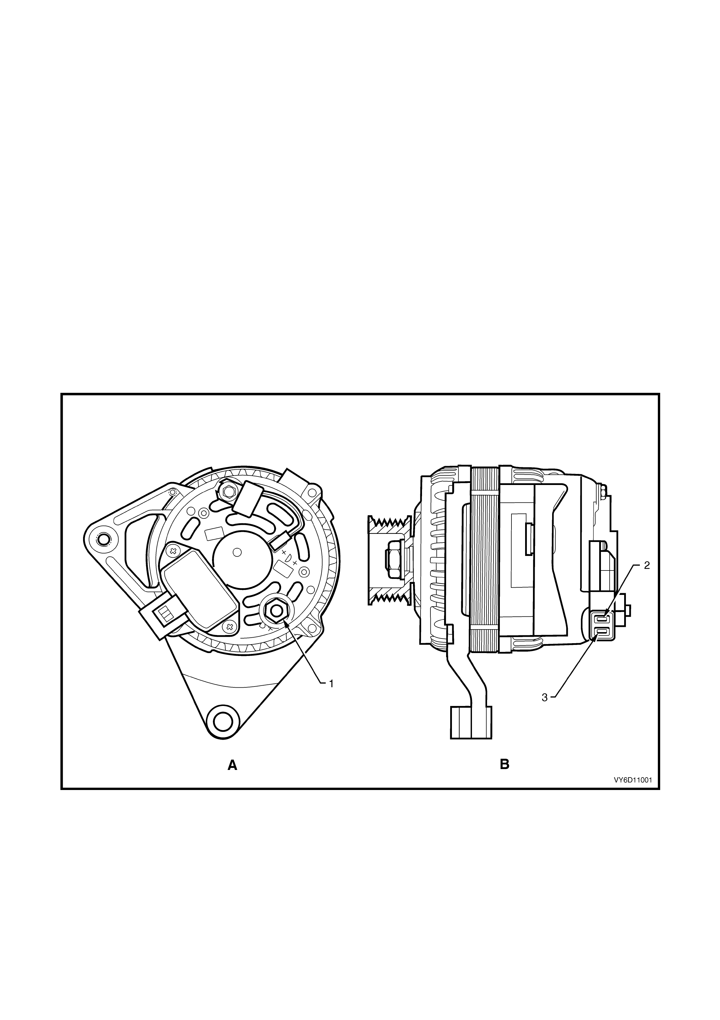
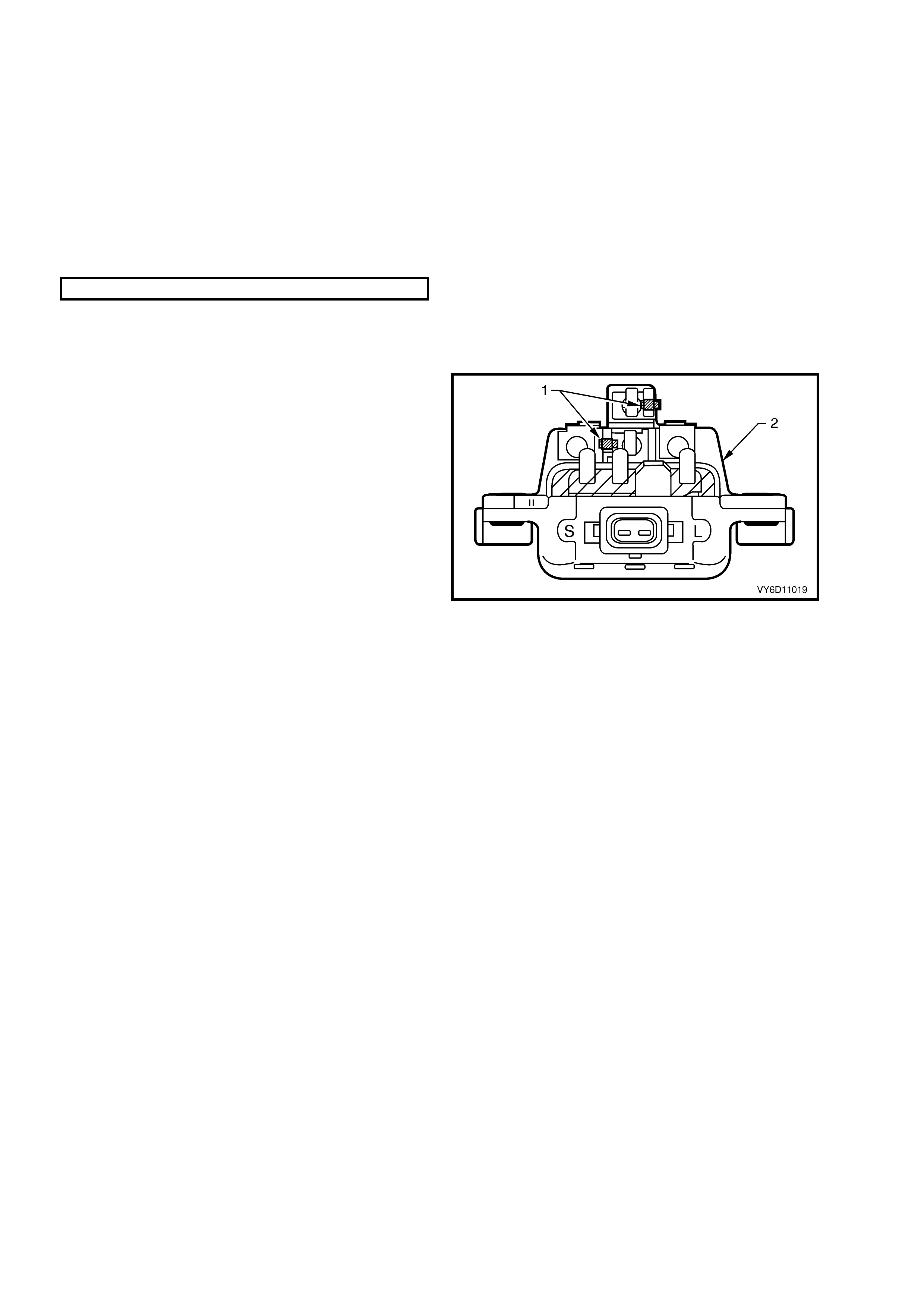
This generator has four external connections (refer to Figure 6D1-1A-1):
•
••
•
B+ lead to the battery positive terminal
•
••
•
L lead to the generator warning lamp (max. 2 watts)
•
••
•
S lead for battery voltage sensing
•
••
•
ground connection (via the installation bolts).
Figure 6D1-1A-2 shows an exploded view of the 100 amp generator.
Figure 6D1-1A-1
Legend
A. Rear View of Generator
B. Side View of Generator
1. Battery B+ Terminal 3. Regulator L Terminal (Warning Lamp)
2. Regulator S Terminal (Battery Sensing)
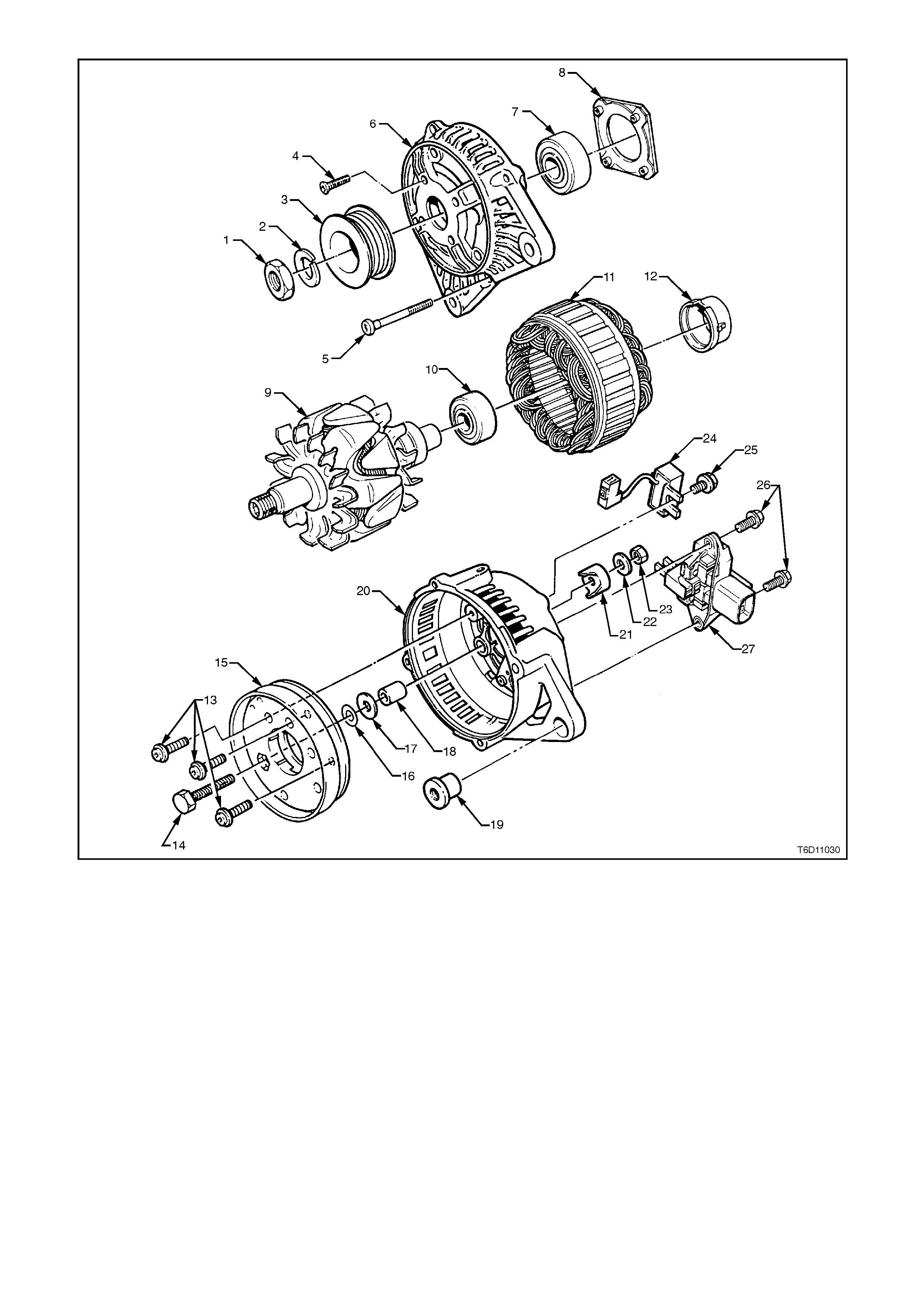
Figure 6D1-1A-2
Legend
1. Nut 10. Slip-ring End Bearing 19. Slip-ring End Housing Lug Sleeve
2. Lock Washer 11. Stator 20. Slip-ring End Housing
3. Drive Pulley 12. Slip-ring End Bearing Support Ring 21. Terminal Cover Bush
4. Bearing Retaining Plate Screw (4) 13. Rectifier Attaching Screws 22. Flat Washer
5. Through Bolt (4) 14. B+ Terminal Bolt 23. B+ Terminal Retaining Nut
6. Drive-end Housing 15. Rectifier Assembly 24. Suppressor
7. Drive-end Bearing 16. Mica Insulating Washer 25. Suppressor Attaching Screw
8. Bearing Retaining Plate 17. Insulating Washer 26. Regulator and Brush Screws
9. Rotor 18. Spacer 27. Regulator and Brush Assembly

1.1 OPERATION
CIRCUIT OVERVIEW
With the ignition switch in the ON position, current is supplied via the warning lamp to the L terminal of the regulator.
This allows current to flow from the generator B+ terminal, through the regulator brushes and rotor winding, to
complete the circuit.
The current through the rotor winding creates magnetic fields between adjacent rotor poles. As the rotor spins, the
stator windings cut through this field at right angles, which induces voltage. As the speed is increased, this induced
voltage increases. Current then flows through the three-phase diode bridge in the rectifier to convert the AC voltage
to DC. This is supplied to the B+ output and hence to the battery.
The regulator S terminal monitors the voltage to the battery. When this voltage reaches approximately 14.2 volts,
the regulator breaks the circuit through the rotor winding, causing the generator output voltage to drop. When the
regulator S terminal senses a voltage below a preset voltage, the regulator completes the circuit and voltage to the
battery again increases. This cycle repeats very rapidly.
If the warning lamp fails, the generator will self excite by using current from the phase connection until the voltage
builds up to regulating level.
IMPORTANT: Current will not flow through the rotor winding when the engine is cranking.
STANDBY MODE
With the ignition switch in the ON position and the engine at rest, the regulator defaults to active standby mode.
This limits the current through the rotor by switching on and off at a 50% duty cycle with a frequency of
approximately 4 kHz. This can be audible at times.
BACKUP MODE
The regulator compares voltage at the B+ terminal with voltage sensed at the S terminal. The regulator defaults to
backup mode if the difference exceeds a preset value. Backup mode limits the generator output voltage to a safe
level (approximately 1 – 3 volts above the normal setting).
WARNING LAMP CONDITIONS
The regulator illuminates the warning lamp when it detects fault conditions in the generator or external circuits. The
warning lamp remains illuminated (while the ignition switch is on) until the fault is repaired.
Fault conditions include the following:
1. Open circuit in the regulator battery sensing wire (S terminal).
2. Open circuit or excessive voltage drop in the B+ cable.
3. Open circuit in the generator phase connection.
4. Overcharging conditions.
5. Short circuit in the regulator output stage.
6. Open circuit in the rotor winding.
7. Poor contact in a wiring harness connector.
8. Poor contact between the rectifier and the regulator.
9. High resistance in the fusible link assembly.
10. Poor contact between the battery terminals and cables.
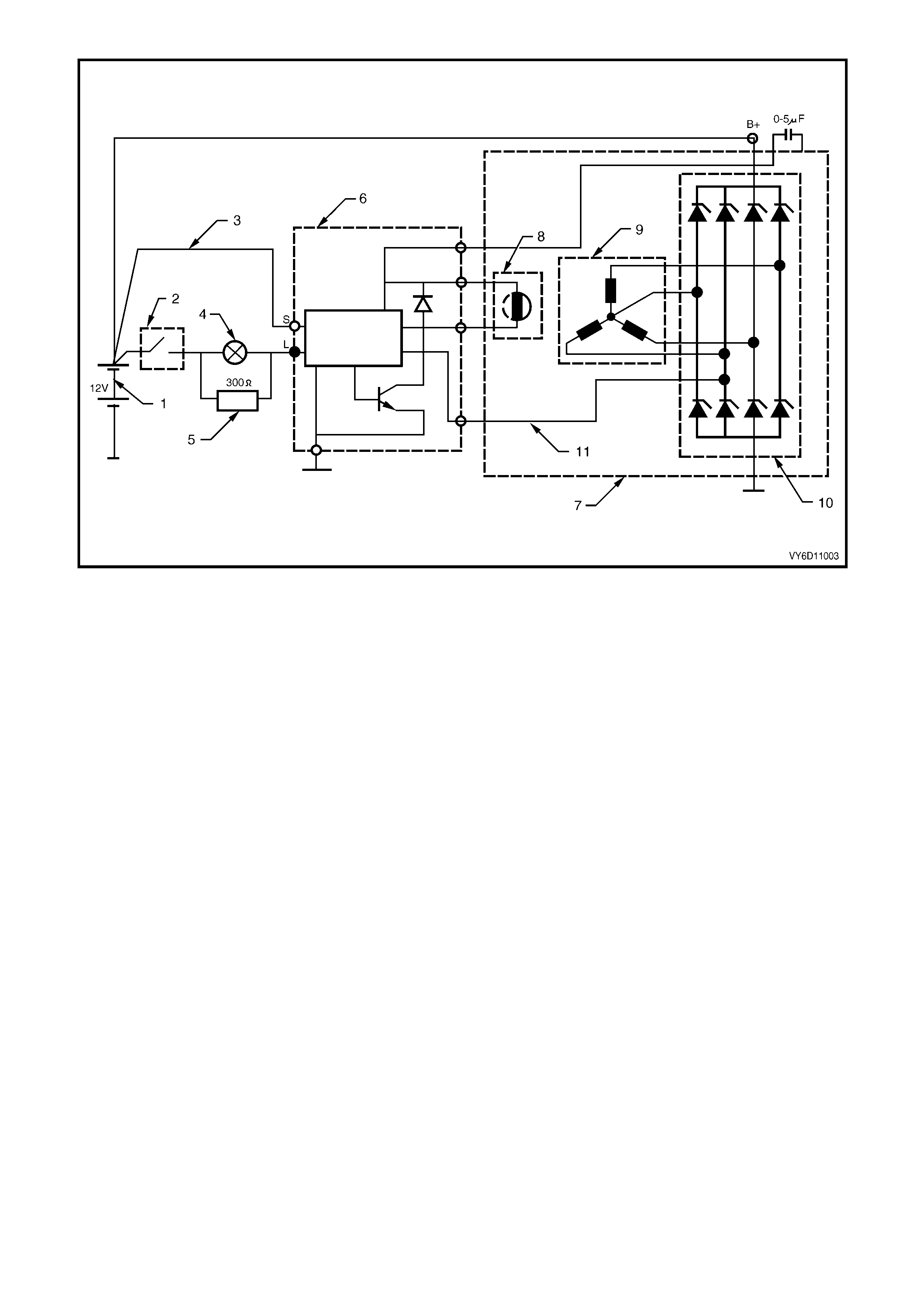
Figure 6D1-1A-3
Legend
1. Battery 5. Current Limiting Resister 9. Stator Windings
2. Ignition Switch 6. Regulator Assembly 10. Rectifier
3. Battery Sensing Wire 7. Generator Assembly 11. AC Signal Wi re
4. Warning Lamp 8. Rotor Field Winding

2. MINOR SERVICE OPERATIONS
2.1 SAFETY PRECAUTIONS
Observe the following precautions. Failure to observe these precautions will result in serious damage to the
generator.
•
••
•
Only use the generator and voltage regulator in a negative ground system.
•
••
•
Always refer to Section 00, CAUTIONS AND NOTES before disconnecting the battery.
•
••
•
When installing a battery, fit the positive (+) cable to the battery before fitting the negative cable.
•
••
•
When a slave battery is used for starting purposes, ensure that both batteries are connected in parallel, ie.
positive terminals connected and negative terminals connected.
•
••
•
Only use jumper leads that have surge protection.
•
••
•
Disconnect both battery cables when charging the battery. This isolates the generator from the battery and from
the external charging equipment.
•
••
•
Do not operate the generator within an open circuit (e.g. without a battery in the circuit).
•
••
•
Do not disconnect the battery while the generator is running.
•
••
•
Do not attempt to polarise the generator.
•
••
•
Ensure that the generator warning lamp illuminates when the ignition switch is in the ON position and the engine
is not running.
•
••
•
Do not connect the L terminal of the generator to 12 volts (the battery or ignition circuits). This damages the
generator warning lamp circuit.
•
••
•
Some battery powered timing lights can produce high transient voltages when connected or disconnected. Only
disconnect or connect timing lights when the engine is switched off.
NOTE: The generator warning lamp circuit assists in the excitation of the rotor field windings. Do not proceed until
faults in the generator warning lamp circuit have been repaired.
IMPORTANT: Ensure that the rating of the warning lamp does not exceed 2 watts.

2.2 MAINTENANCE AND ON-VEHICLE TESTING
REGULAR CHECKS
Check the following at regular intervals:
•
••
•
Generator terminals – for corrosion and loose connectors.
•
••
•
Wiring – for continuity and damaged insulation.
•
••
•
Mounting bolts – for tightness.
•
••
•
Drive belt – for alignment and wear.
•
••
•
Drive pulley – for damage and warping.
IMPORTANT: The drive-belt adjustment for the engine ancillaries (i.e. generator and water pump) is provided by a
spring-loaded tensioner. Therefore, the drive belt does not require adjustment.
Lubrication
High tolerance bearings are used in this generator. If the bearings are removed during the generator disassembly,
new bearings must be installed to restore the generator to original specification. The ball bearings supporting the
rotor shaft are pre-lubricated and sealed. Do not attempt to lubricate these during servicing.
IMPORTANT: Two special tools (Bosch tool numbers 9881 066 600 and 9881 066 601) are available to ensure
correct dismantling and assembly procedure of the rotor bearings. It is extremely difficult to remove the bearings
without damaging the rotor fans. The assembly tool ensures that the bearings are installed correctly and are
properly aligned, which will ensure long service life.
GENERATOR ON-VEHICLE CHECKS
Prerequisites
Before testing the generator output, ensure that:
•
••
•
all generator circuit connections are clean and tight
•
••
•
the generator is always connected to the battery during testing (to prevent damage to the diodes)
•
••
•
the battery is fully charged
•
••
•
the specific gravity does not vary more than 0.025 between cells. (It is recommended that the average specific
gravity is 1.260 or higher.) Refer to Section 12A, BATTERY AND CABLES.
Carry out a load test on the battery to determine its ability to supply and accept current. This is a good indicator of
the general condition of the battery. For details of battery testing refer to Section 12A, BATTERY AND CABLES.
Inspect the drive belt and tensioner markings to determine if the drive belt is within operating limits. Replace the belt
if it is excessively worn or outside the operating range of the tensioner.
For further details, refer to Section 6A1, ENGINE MECHANICAL – V6 ENGINE.
Regulating Voltage Test
1. Ensure that the ignition switch is in the OFF
position and all electrical equipment is turned
off.
2. Refer to Section 00, CAUTIONS AND NOTES
before disconnecting the battery.
3. Disconnect the battery ground cable at the
battery.
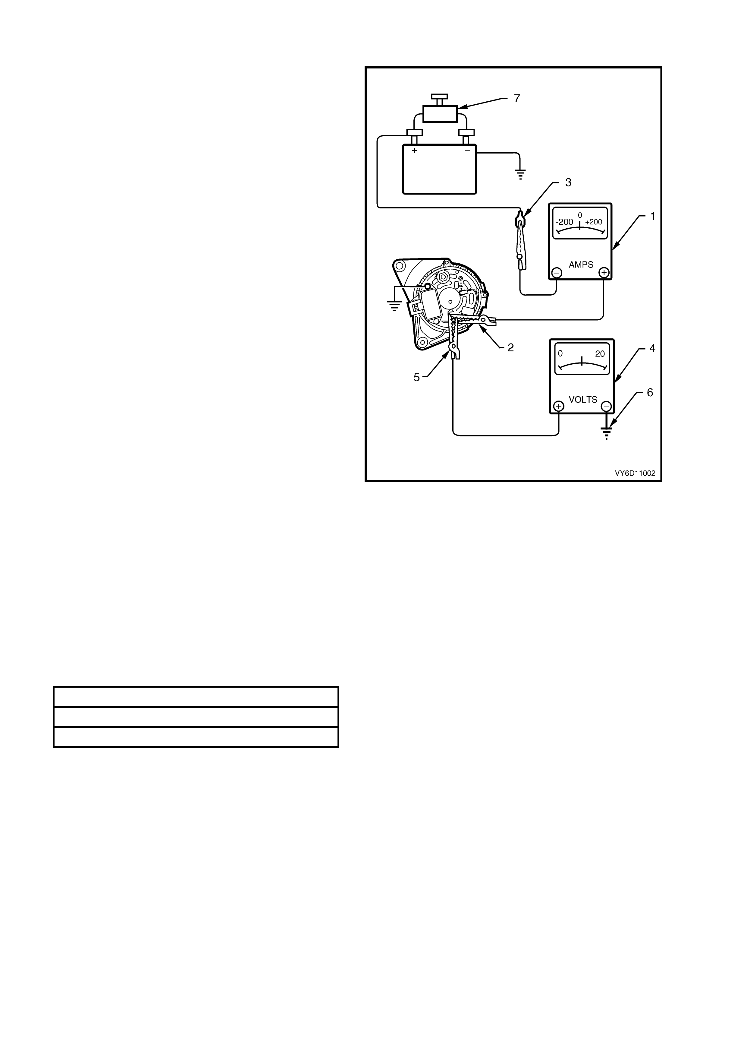
4. Disconnect the generator positive lead (red
wire) from the generator B+ terminal.Connect
the positive lead of an ammeter (amp scale of
zero – 100) (1) to the generator B+ terminal (2).
5. Connect the ammeter negative lead to the
disconnected generator positive lead (red
wire) (3).
6. Connect the positive lead of a voltmeter (0 – 20
volt scale) (4) to the generator B+ terminal (5).
7. Connect the voltmeter negative lead to a good
ground connection on the generator
housing (6).
CAUTION: Insulate the terminal of the generator
positive lead (red wire) to prevent contact with
any metal part of the vehicle. If the terminal is
grounded, damage to the charging circuit can
result when the battery is reconnected.
8. Reconnect the battery ground cable.
9. Fit a loading device (7) across the battery
terminals, e.g. an adjustable carbon pile.
IMPORTANT: The loading device must have a
minimum power consumption of 1000 watts.
10. Record the voltmeter reading before starting
the engine. (This reading should increase when
the engine is running, indicating generator
output.)
11. Start the engine.
12. Increase the engine speed and adjust the load
(using the ammeter reading) as outlined in the
chart below.
13. Check the generator output voltage (voltmeter
reading) against the specification.
Figure 6D1-1A-4
ENGINE RPM 1275
LOAD 5 – 10 amps
VOLTMETER READING 13.8 – 14.5 volts
Load Regulation Test
1. Connect the voltmeter, ammeter and carbon
pile as in the previous test.
2. Increase the engine speed to 1900 rpm
(approximately 6000 generator rpm).
3. Increase the load to 90% of full output
(approximately 90 amps).
IMPORTANT: If the decrease in the regulating
voltage is greater than 0.5 volt, the regulator is
defective. Replace the regulator.

Generator Output Test at Full Load
1. Connect the voltmeter, ammeter and carbon pile as in the previous test.
2. Increase the engine speed to 1900 rpm (approximately 6000 generator rpm).
3. Increase the load until the generator output voltage drops to 13.5 volts. Full generator output (100 amps) is
required; adjust the throttle as required to maintain this.
4. Record the ammeter reading.
IMPORTANT: Keep the time for this test to a minimum to avoid undue heating and high engine speeds.
5. If the generator does not provide 100 amps at approximately 6000 generator rpm, disassemble and inspect the
generator for faults. Refer to 3.1 GENERATOR in this Section.
CAUTION: On completion of the generator output test, return the engine to idle and disconnect the loading
device from the battery terminals. This prevents excessive battery discharge.
6. Disconnect the battery ground cable at the battery.
7. Remove the voltmeter and ammeter.
8. Reconnect the generator positive lead (red wire) to the generator B+ terminal.
9. Reconnect the battery ground cable to the battery.
Charging Circuit Voltage Drop Test
IMPORTANT: Ensure that the generator connections are clean and tight.
1. Connect the positive lead of a low range voltmeter to the generator positive terminal and the negative lead to
the battery positive post.
2. Switch the headlamps on.
3. Start the engine.
4. Increase the engine speed to approximately 2500 rpm.
5. Record the voltmeter reading.
6. Reduce the engine speed to idle.
7. Connect the voltmeter positive lead to the battery negative post and the negative lead to the generator housing.
8. Increase the engine speed to approximately 2500 rpm.
9. Record the voltmeter reading.
10. Reduce the engine speed to idle.
11. Check the two readings. If the readings exceed 0.3 volt, there is a high resistance in the charging circuit.
12. Trace the cause and correct the problem.
3. MAJOR SERVICE OPERATIONS
3.1 GENERATOR
LT Section – 02-140
REMOVE
1. Refer to Section 00, CAUTIONS AND NOTES
before disconnecting the battery.
2. Disconnect the battery ground lead.
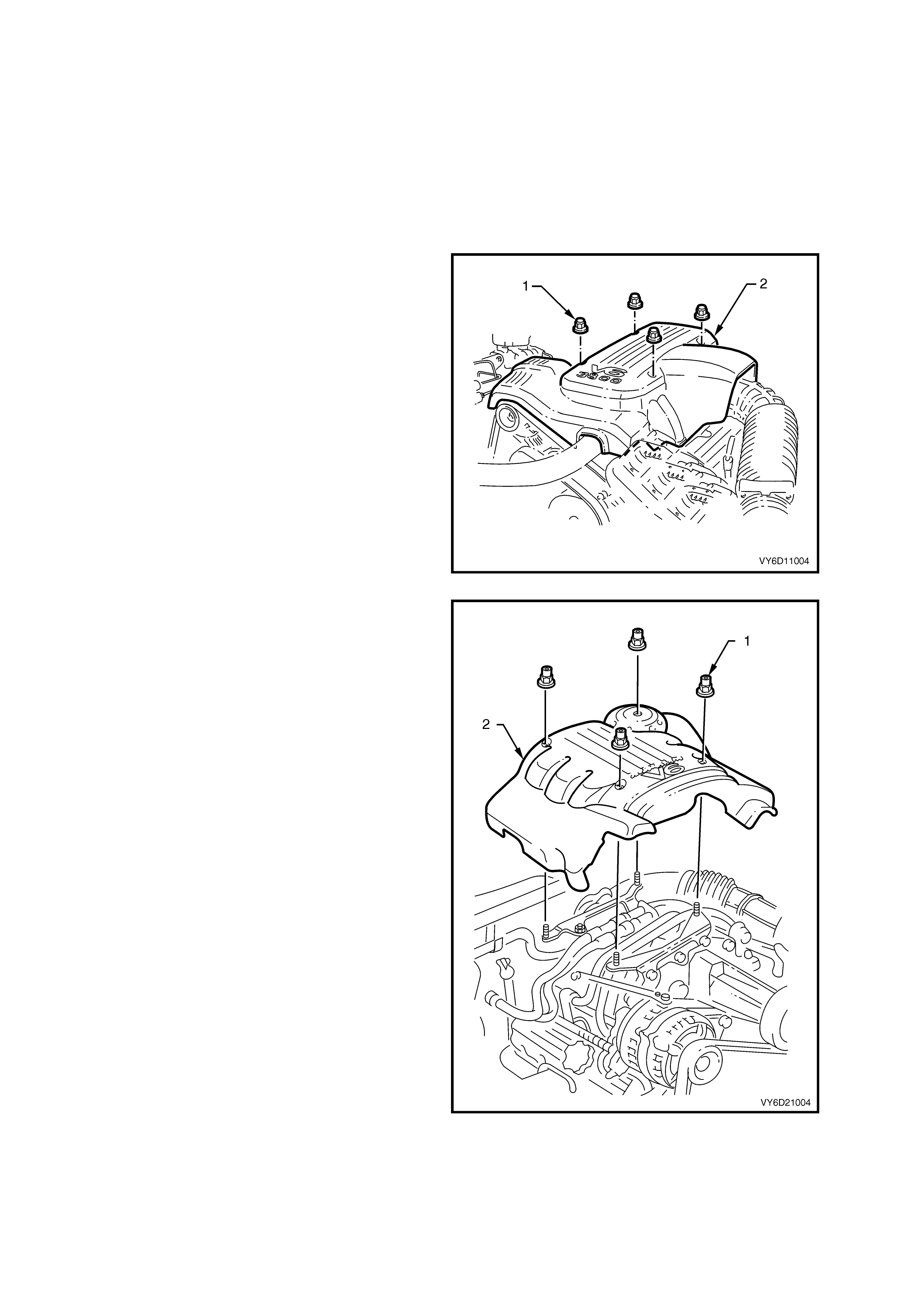
3. Remove the four dome nuts (1) securing the
engine dress cover assembly (2).
4. Lift off and remove the cover assembly. Refer
to Figure 6D1-1A-5 for the V6 engine and
Figure 6D1-1A-6 for the V6 supercharged
engine.
Figure 6D1-1A-5
Figure 6D1-1A-6
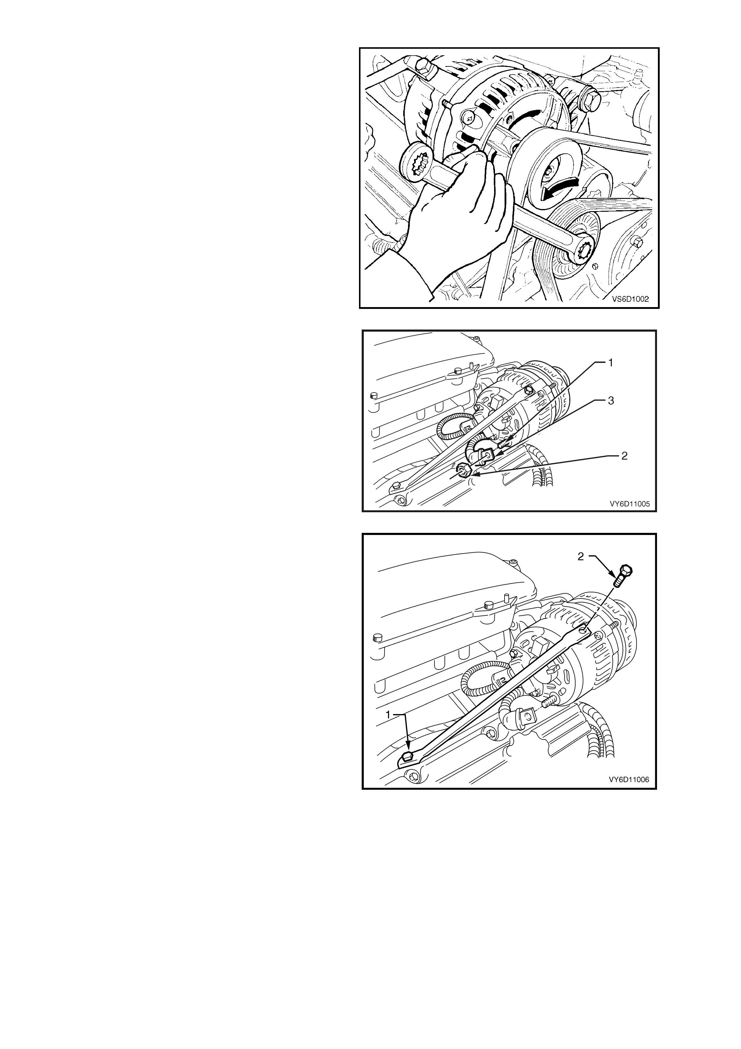
5. Use a 15 mm ring spanner on the drive belt
tensioner pulley pivot bolt to rotate the
tensioner pulley assembly anti-clockwise.
6. Turn the assembly and remove the drive belt
from the generator drive pulley.
7. Release the drive belt tensioner.
Figure 6D1-1A-7
8. Pull the battery harness cap back from the
B+ terminal (1), remove the nut (2) and the
positive lead (3).
Figure 6D1-1A-8
9. Loosen the brace-to-engine attaching bolt (1).
10. Remove the brace-to-generator attaching bolt
(2).
Figure 6D1-1A-9
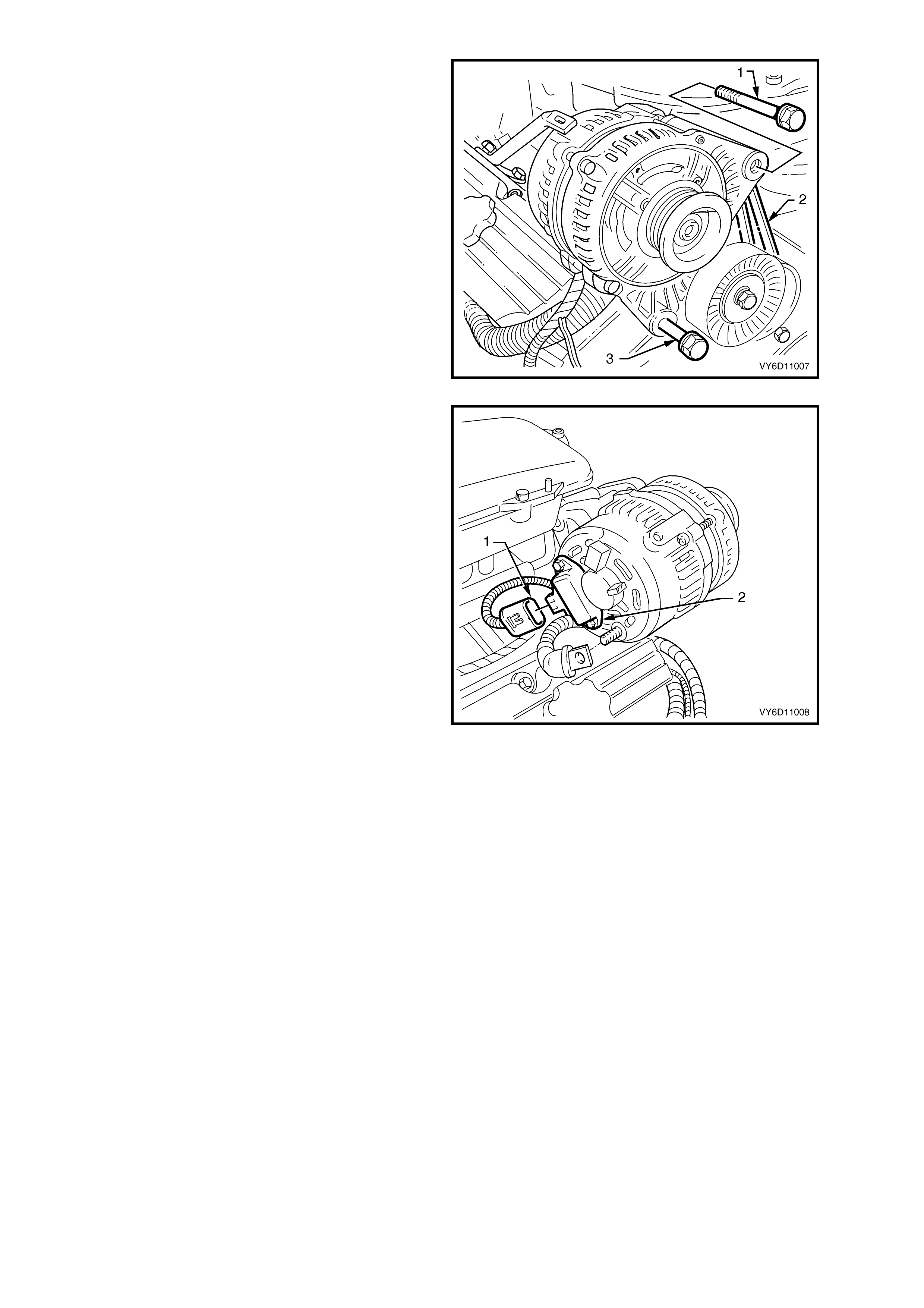
11. Remove the bolt (1) attaching the generator to
the drive-belt tensioner bracket (2).
12. Loosen the lower bolt (3).
Figure 6D1-1A-10
13. Swing the generator away from the intake
manifold.
14. Depress the connector retainer and remove the
battery harness connector (1) from the
regulator and brush assembly (2).
15. Remove the lower bolt on the drive-belt
tensioner bracket.
16. Remove the generator assembly.
Figure 6D1-1A-11
DISASSEMBLE
Precautions
When testing the generator for faulty components,
ensure that:
•
••
•
the RMS output of the AC type tester for
checking the rectifier diodes does not exceed
12.0 volts
•
••
•
the stator is disconnected before testing the
diodes
•
••
•
all diodes have the same Zener voltage (when
testing the diode breakdown voltages)
•
••
•
voltage does not exceed 110 V for a series test
lamp when testing the insulation on the rotor
and stator
•
••
•
the rectifier is disconnected from the stator
prior to testing the stator.
IMPORTANT: Due to the very low resistance value
of the stator winding, accurate readings might not
be achieved when using a conventional ohmmeter.
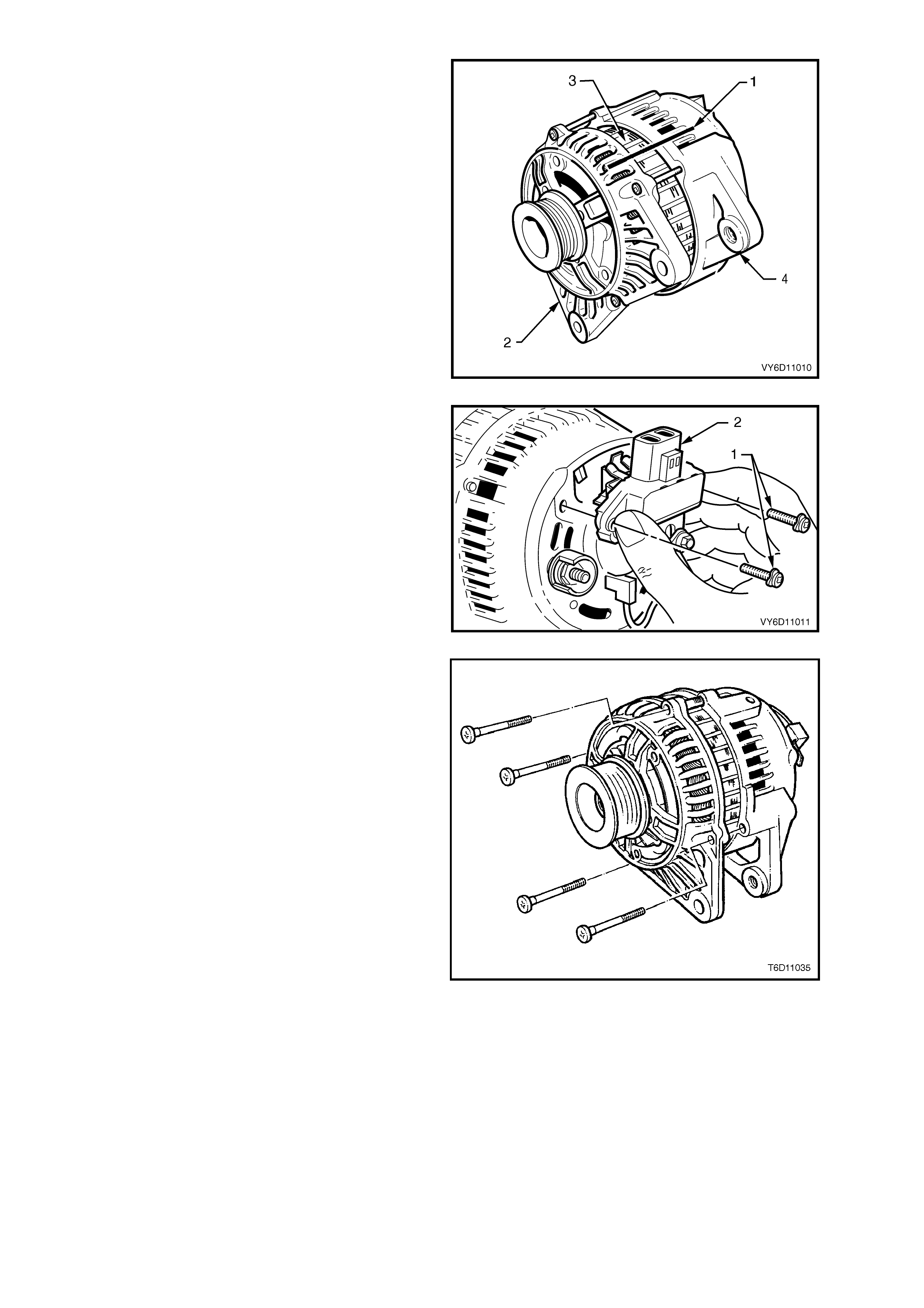
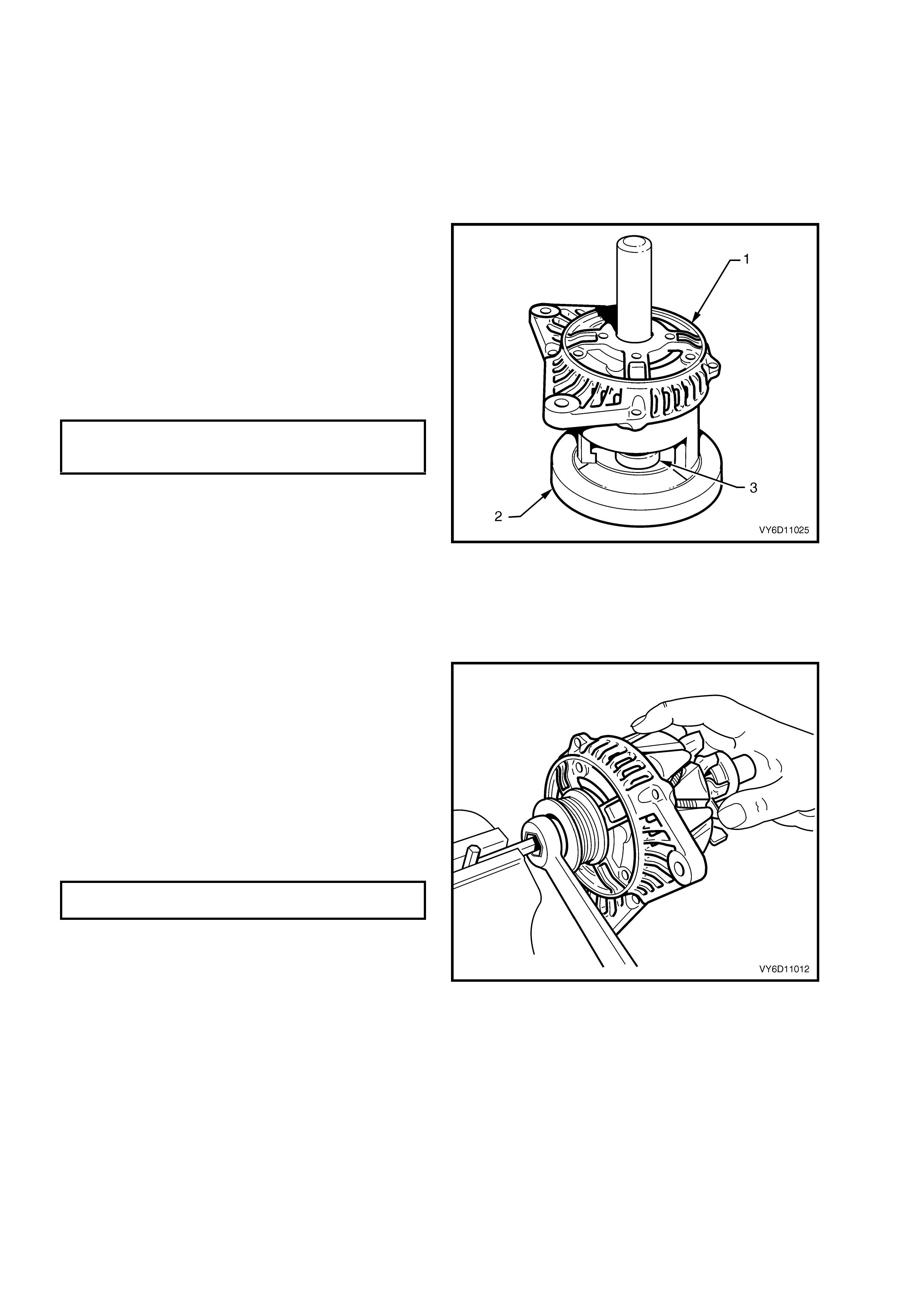
1. Use a permanent marking pen to draw aligning
marks (1) on the drive-end housing (2), the
stator frame (3) and the slip-ring end housing
(4).
Figure 6D1-1A-12
2. Remove the two screws (1) securing the
regulator and brush assembly (2).
3. Tilt the assembly towards the slip-ring and lift it
out taking care not to damage the brushes.
NOTE: Do not remove the regulator with the B+
supply cable connected.
Figure 6D1-1A-13
4. Remove the four through-bolts.
5. Carefully separate the slip-ring end housing
and stator (as an assembly) from the rotor and
drive-end housing.
NOTE: Do not lever against, or put strain on, the
stator windings.
Figure 6D1-1A-14
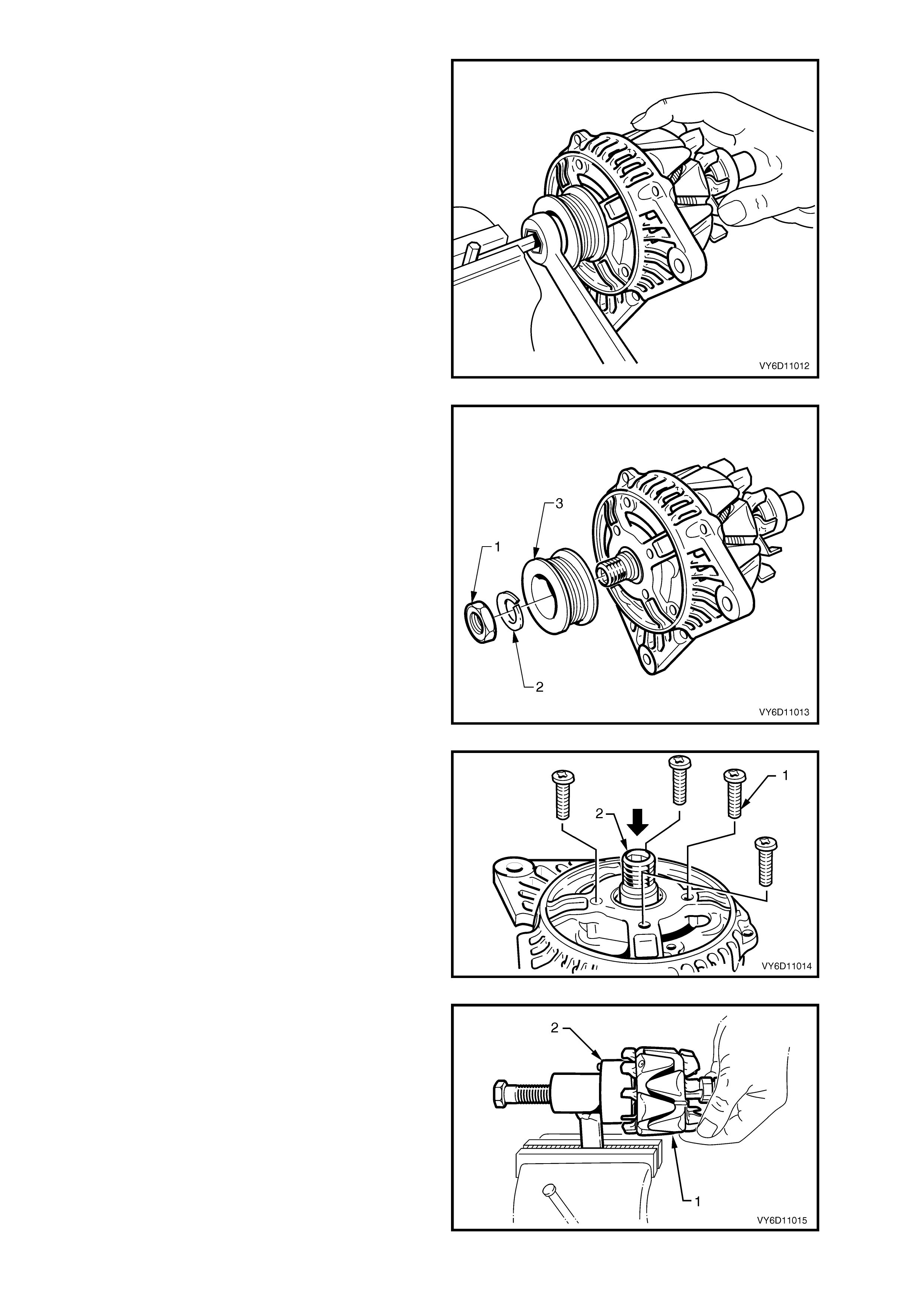
6. Clamp an 8 mm Allen key in a vice with the
long end extending out from the side of the
vice. (This assists in the removal of the drive
pulley.)
7. Place a 24 mm, external hex, deep socket onto
the pulley attaching nut.
8. Place a suitable spanner over the socket hex.
As an alternative, use a 24 mm deep socket
with a length of bar welded to the side of the
socket.
9. Position the internal hex of the rotor assembly
(and drive-end housing) onto the Allen key.
10. Loosen the drive pulley attaching nut.
11. Remove the drive-end housing from the Allen
key.
NOTE: Avoid mounting the rotor in a vice. The vice
jaws can damage the cooling fans and/or the rotor.
Figure 6D1-1A-15
12. Remove the drive pulley attaching nut (1), lock
washer (2) and drive pulley (3).
Figure 6D1-1A-16
13. Remove the four screws (1) that secure the
bearing retaining plate to the drive-end
housing.
14. Push the rotor shaft and front bearing (2) from
the drive-end housing.
NOTE: Do not use a press to force the rotor from
the drive-end housing. This can damage the
bearing retaining plate and/or the drive-end
housing.
Figure 6D1-1A-17
15. Remove the drive-end bearing from the rotor
assembly (1). Use Bosch tool 9981 066 601
(2).
NOTE: This process damages the bearing
retaining plate and the bearing. Replace these. The
bearing is a fine tolerance, high speed, noiseless
bearing. (Drive-end bearing No. 9900 069 006.)
Figure 6D1-1A-18
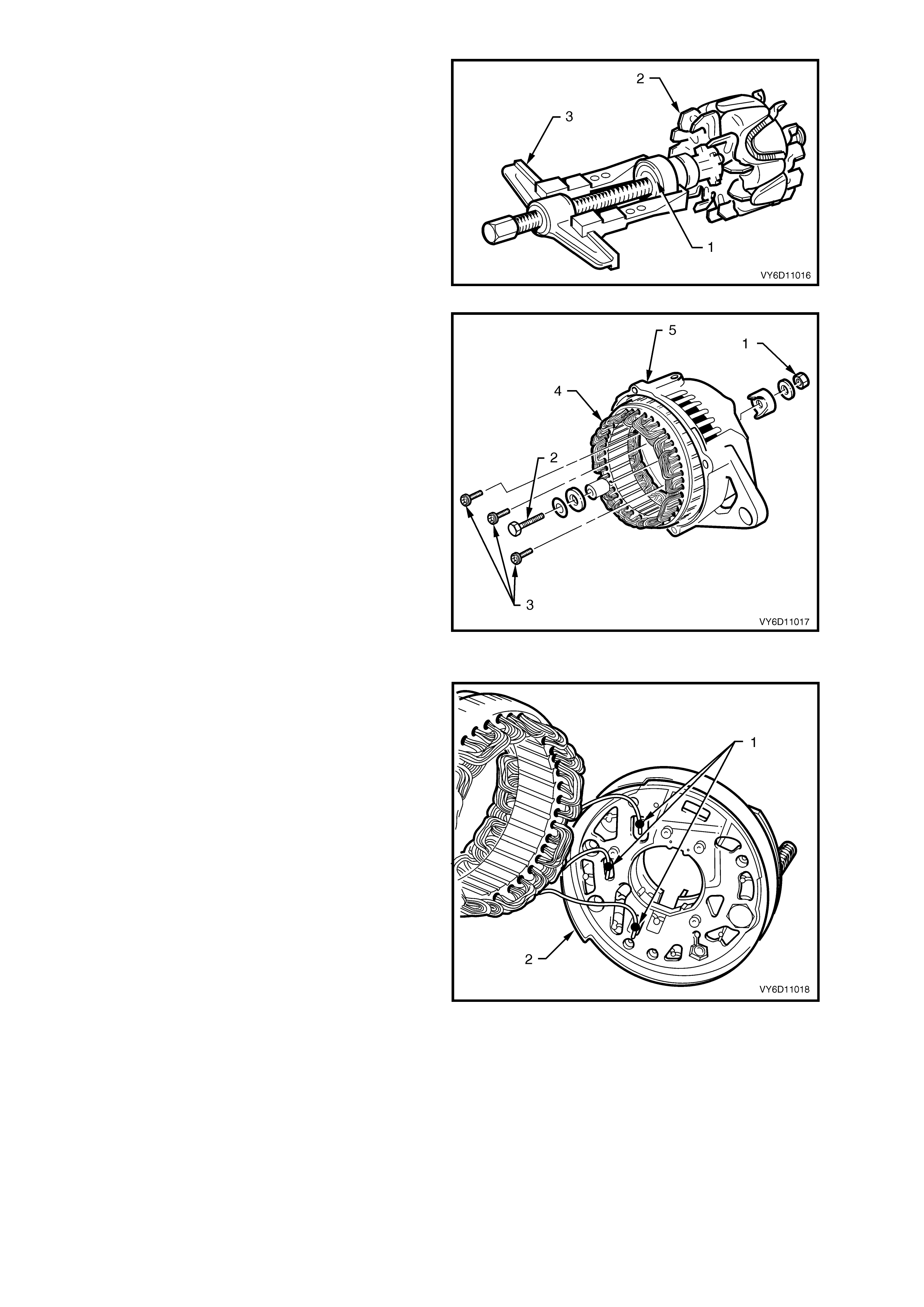
16. Remove the slip-ring end bearing (1) from the
rotor (2) using a suitable puller (3). Do not
distort the rear fan.
17. Remove the retaining plate from the rotor shaft.
Figure 6D1-1A-19
18. Remove the nut (1), wave washer, flat washer
and insulating washer from the B+ terminal
bolt (2).
19. Remove the suppressor lead connection from
the rectifier ‘+’ terminal.
20. Remove the three screws (3) attaching the
stator and rectifier assembly (4) to the slip-ring
end housing (5).
21. Remove the stator and rectifier as an
assembly.
22. Remove the spacer and mica insulating washer
from the B+ terminal bolt.
23. Remove the second mica insulating washer
from beneath the rectifier positive heat sink
(The washer might have adhered to the boss
on the inside of the slip-ring end housing).
IMPORTANT: Discard the two mica insulating
washers. Fit new washers and heatsink compound
on reassembly.
Figure 6D1-1A-20
24. Unsolder the three stator windings (1) from the
rectifier assembly (2), as follows:
Grasp the stator wires close to the wire loop
with a pair of pointed nose pliers.
Heat the joint with a soldering iron until the
solder starts to melt.
Apply a slight twisting motion to the wire and
pull it upwards and away.
NOTE: Use only as much heat as required to melt
the solder. Excessive heat can damage the diodes.
IMPORTANT: The rectifier assembly is serviced
only as a complete assembly.
Figure 6D1-1A-21
CLEANING AND INSPECTION
1. Clean and inspect the disassembled components.
NOTE: Do not clean the stator or rotor windings with cleaning solvent. This can damage the insulation.
2. Wash all components (except the stator, rotor, rectifier and regulator) in a suitable cleaning solvent.
CAUTION: Use a non-volatile agent in a well ventilated area. Observe the safety regulations and
precautions of the cleaning agent in use.
3. Carefully clean the rotor and stator with compressed air.
Check the Brushes
1. Check the length of the brushes protruding from the regulator brush holder; measure along the centre line of
each brush. If a brush length is less than specified, replace both brushes.
MINIMUM BRUSH LENGTH 3.8 mm
2. Check the brushes for abnormal wear or cracks.
3. Replace both brushes if either have abnormal wear or cracks.
Replace the Brushes
1. Unsolder the brush leads (1) from the regulator
brush holder assembly (2).
2. Bend the retaining lugs back and remove the
brushes and springs.
3. Inspect each brush spring for discolouration,
breakage, corrosion and uneven tension.
Replace if necessary.
4. Install a brush spring over each brush lead.
IMPORTANT: Ensure that the insulating sleeves
are fitted over the new brush leads.
5. Thread the new brush leads and springs into
the brush holder.
6. Pull the leads through the tabs until the brush is
protruding 12 mm from the holder.
7. Bend the tabs down.
8. Solder the brush leads in place.
Figure 6D1-1A-22
IMPORTANT: Do not allow the solder to run up the
lead. This inhibits the correct movement of the
brush.
9. Ensure that each brush moves smoothly in and
out of the holder.
Check the Diodes
The following test equipment is essential for
correctly testing the diodes:
•
••
•
DC output diode tester that does not exceed 14
volts output at the test probes.
•
••
•
Multimeter with a diode test feature that does
not exceed 14 volts output at the test probes.
•
••
•
AC tester rated at 12 volts RMS. This ensures
that the forward and reverse voltage checks
are not incorrect due to Zener breakdown.
•
••
•
Zener diode tester with a DC output in excess
of 30 volts. (This should incorporate internal
current limiting of 5 mA to prevent high
currents during testing.)
NOTE 1: Replace the rectifier assembly if any
diodes are faulty.
NOTE 2: Complete steps 1 to 5 before the Zener
voltage of each diode is tested.
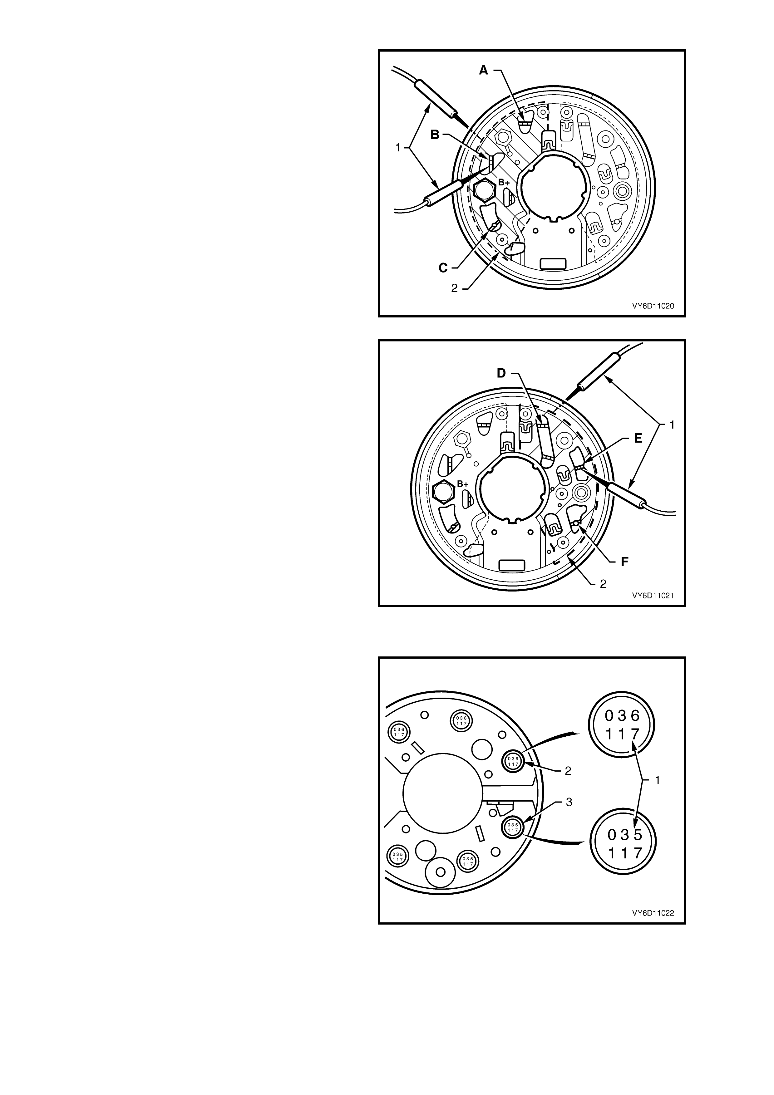
1. Attach the test probes (1) of the diode tester to
each positive diode in turn.
2. Attach the negative probe to the positive
heatsink (2) of the rectifier assembly.
3. Attach the positive probe to the positive diode
connections A, B and then C, as shown in
Figure 6D1-1A-22.
4. Check for a low resistance reading or the
forward voltage drop across the diode.
5. Reverse the probe connections and again test
each diode in turn.
6. Check for a high resistance reading or higher
reverse voltage.
7. Repeat the test to ensure that current is able to
flow in one direction only.
Figure 6D1-1A-23
8. Repeat the above procedure on the negative
heatsink.
9. Attach the test probes (1).
10. Attach the positive probe to the negative
heatsink (2) of the rectifier assembly.
11. Attach the negative probe to the negative diode
connections D, E and then F, as shown in
Figure 6D1-1A-23.
12. Check for a low resistance reading or the
forward voltage drop across the diode.
13. Reverse the probe connections and again test
each diode in turn.
14. Check for a high resistance reading or higher
reverse voltage.
15. Repeat the test to ensure that current is able to
flow in one direction only.
NOTE: When using an AC tester in steps 1 to 5,
ensure that the reverse voltage applied is less than
14 volts DC or 12 volts RMS.
Figure 6D1-1A-24
16. Identify the Zener voltage of each diode by
viewing the underside of the rectifier.
17. Record the numbers stamped into the base (1)
of each negative diode (2) and each positive
diode (3).
18. Check the numbers against the chart below.
NOTE: All diodes within a rectifier must have the
same Zener voltage.
IMPORTANT: The recommended Zener tester is:
Durst model 600 with 5 mA test current (Bosch
approved).
Figure 6D1-1A-25
Zener
Voltage
at 5 mA
Positive
Diode
Number
Negative
Diode
Number
Forward
Current
Rating
17.8 – 19.2 031 032 35 A
18.8 – 20.2 033 034 35 A
19.8 – 21.2 035 036 35 A
20.8 – 22.2 037 038 35 A
21.8 – 23.2 038 040 35 A
22.8 – 24.2 041 042 35 A
19. Test the Zener voltage (reverse bias) of the
positive diodes, as follows:
a. Connect the positive lead to the positive
heat sink.
b. Connect the negative lead of the tester to
each positive diode in turn.
c. Gradually increase the test voltage from
the Zener diode tester and read Zener
breakdown voltage.
NOTE: Ensure that the tester is current-limited to
5 mA.
20. Check that the voltage reading is steady; it
should not increase with increased voltage.
21. Test the Zener voltage (reverse bias) of the
negative diodes:
a. Connect the positive lead to the negative
heat sink.
b. Connect the negative lead of the tester to
each negative diode in turn.
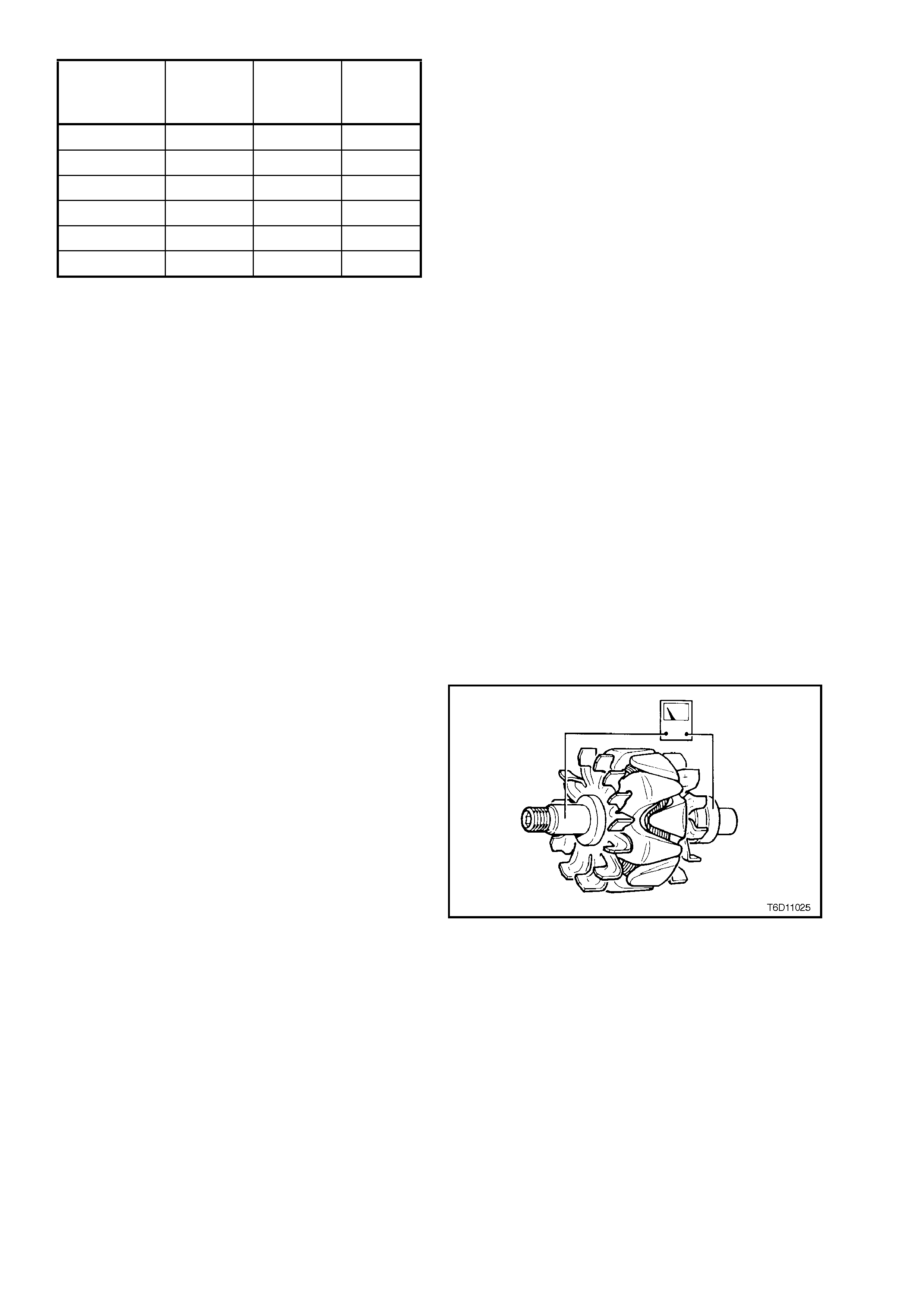
Check the Rotor
1. Test the rotor insulation between the slip-rings
and rotor core or shaft.
IMPORTANT: Use an insulation tester or a series
test lamp up to 110 V. An insulation tester should
indicate an open circuit (greater than 1 Megohm)
and a test light should not glow.
2. Replace the rotor if an open circuit does not
exist.
Figure 6D1-1A-26
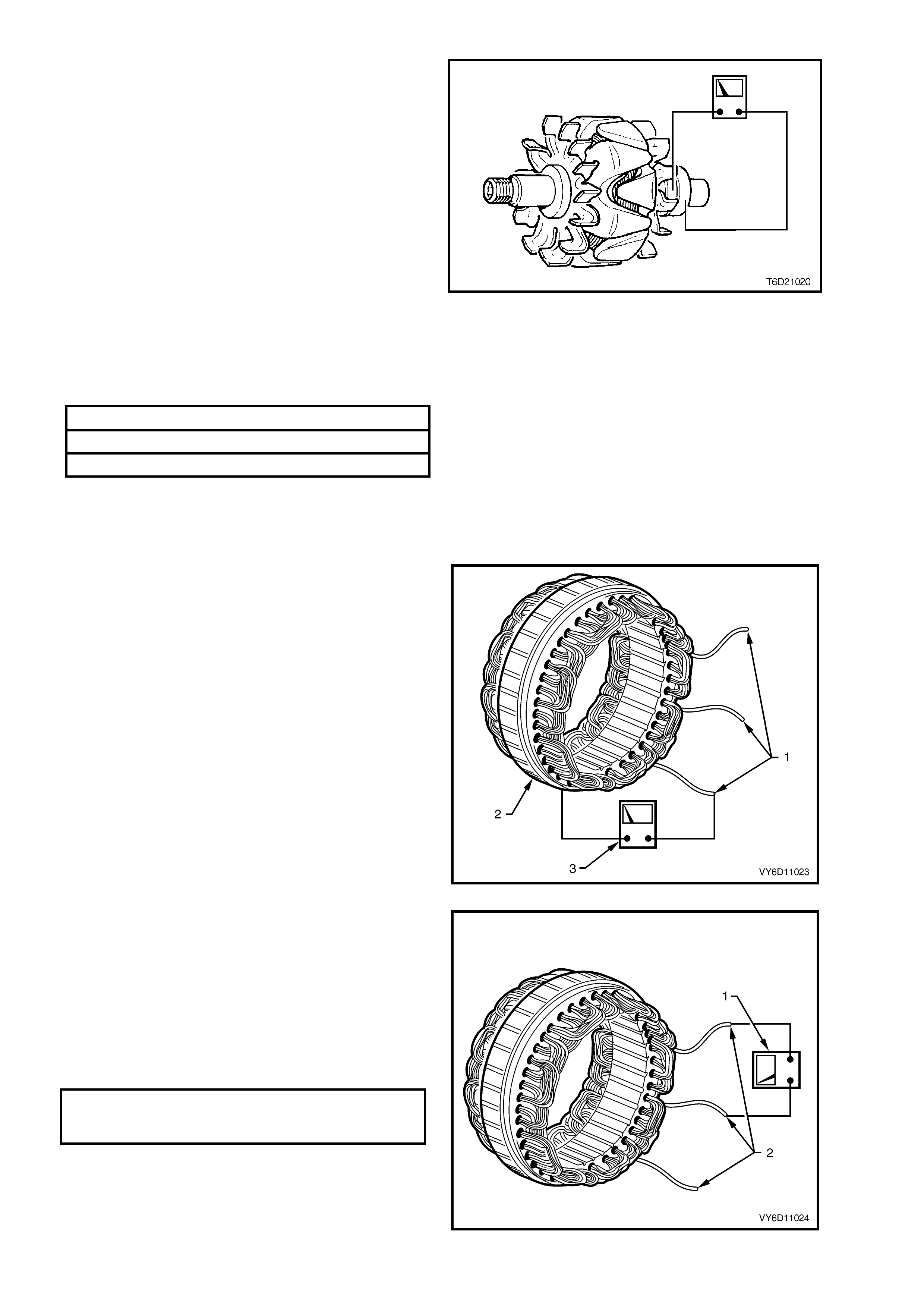
3. Test the rotor circuit, by connecting the
ohmmeter probes across the slip-rings.
4. Record the resistance reading.
5. Check the reading against the chart below.
NOTE: If the resistance of the rotor winding is not
to specification, replace the rotor.
6. Check the slip-rings for wear or damage.
7. Machine the slip-rings if they are worn, scored,
out-of-round beyond specifications or
damaged.
CAUTION: Exercise extreme care when
machining the slip-rings to avoid the turning
tool fouling the rear rotor cooling fan.
8. Check that the slip-rings are within
specifications (especially after machining).
9. Replace the rotor if the slip-ring is outside the
specifications.
Figure 6D1-1A-27
ROTOR WINDING RESISTANCE @ 20°C 1.97 – 2.23 ohms
SLIP-RING MINIMUM DIAMETER 26.7 mm
SLIP-RING MAXIMUM OUT-OF-ROUND 0.06 mm
Bearings
The bearings used in this generator are a high tolerance type. Use only genuine replacement bearings to restore
the generator to original specifications.
Check the Stator
1. Inspect the stator for damage, loose
connections or discoloured windings. Replace if
necessary.
2. Test the stator insulation between a stator lead
(1) and the stator frame.
IMPORTANT: Use an ohmmeter, a powered test
lamp rated up to 40 volts or an insulation tester.
3. Check that a test light does not glow and an
ohmmeter or an insulation tester indicates an
open circuit (greater than 1 Megohm).
4. Replace the stator if an open circuit does not
exist.
Figure 6D1-1A-28
5. Test the stator winding circuits by connecting
an ohmmeter (1) between any two stator leads
(2).
6. Check that the ohmmeter does not register a
significant resistance.
7. Repeat this test between the remaining stator
leads.
8. Replace the stator if the resistance in any of
the circuits is outside the specifications.
STATOR WINDING
PHASE-TO-PHASE
RESISTANCE @ 20°C 0.0486 – 0.0594 ohm
Figure 6D1-1A-29
REASSEMBLE
Refer to Figure 6D1-1A-2 for identification of
components.
1. Reassemble the generator in the reverse order
of the disassembly procedure.
CAUTION: It is important that all parts are
thoroughly dried before assembly, taking care
not to breathe the vapours in.
2. Fit a new drive-end bearing, with the bearing
plate, into the drive-end housing (1).
IMPORTANT: The special assembly tool (2)
(Bosch tool 9981 066 600) fits both bearings in one
operation. This reduces noise and provides
extended bearing life.
3. Insert a new slip-ring bearing (3) into the
recess in bearing assembly fixture.
4. Tighten the retaining screws to the correct
torque specification.
DRIVE-END HOUSING BEARING
RETAINER PLATE SCREW
TORQUE SPECIFICATION 2.1 – 3.0 Nm
5. Insert the rotor into the bearing assembly.
Ensure that the rotor shaft at the slip-ring end is
seated in the slip-ring bearing.
6. Place the drive-end housing onto the bearing
assembly fixture.
7. Insert the mandrel into the drive-end housing.
Figure 6D1-1A-30
8. Press the bearings into position.
9. Fit the drive pulley, washer and nut onto the
rotor shaft.
10. Clamp an 8 mm Allen key in a vice with the
long end extending out from the side of the
vice.
IMPORTANT: Do not mount the rotor in the vice.
This damages the rotor and or cooling fans.
11. Place the socket (used for the removal of the
pulley nut) onto the nut.
12. Position the drive-end housing with the internal
hex of the rotor shaft onto the Allen key.
13. Tighten the drive pulley nut to the correct
torque specification.
DRIVE PULLEY ATTACHING NUT
TORQUE SPECIFICATION 54 – 68 Nm
Figure 6D1-1A-31
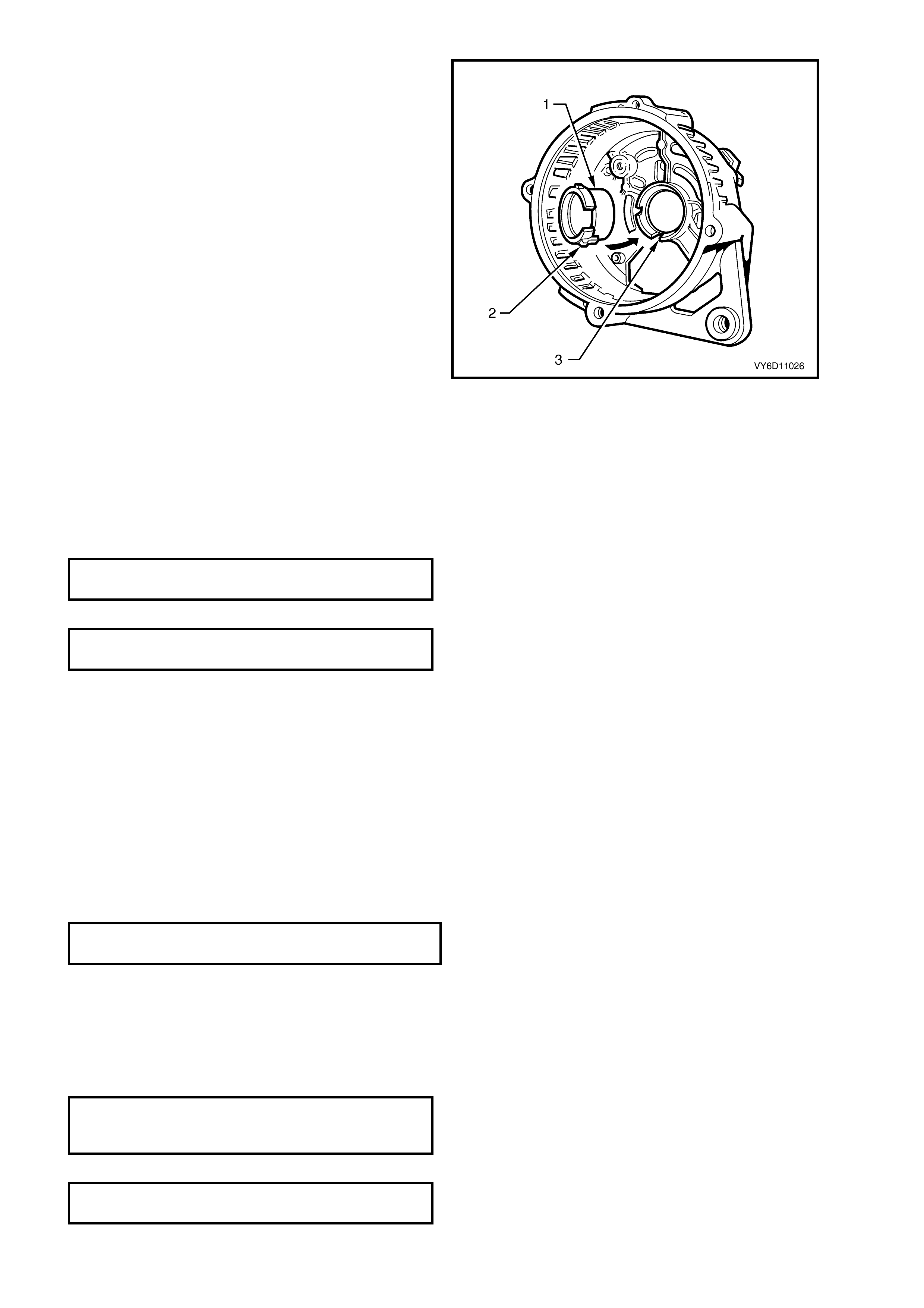
14. Inspect the support ring (1) for the slip-ring end
bearing. Check especially for cracks or signs of
damage.
15. If necessary, install a replacement support ring
by gently pressing it into the slip-ring end
housing by hand.
NOTE 1: Do not use excessive force.
NOTE 2: This support ring only locates correctly in
one position. Ensure that the long tang on its outer
diameter (2) locates into the mating slot in the end
housing (3).
16. Apply heatsink compound to both sides of the
new mica washers.
17. Fit the mica washers onto the rectifier positive
heatsink.
NOTE: Ensure that the washer with the largest hole
is fitted over the B+ terminal bolt. (The other mica
washer is fitted around the hole for the retaining
screw.)
18. Fit the insulating spacer over the B+ terminal
bolt.
19. Insert the rectifier into the slip-ring end housing.
20. Assemble the washers (insulating, flat then
wave) and the nut onto the B+ terminal. Leave
the nut finger tight.
Figure 6D1-1A-32
21. Install and tighten the rectifier retaining screws to the correct torque specification.
RECTIFIER RETAINING SCREW
TORQUE SPECIFICATION 1.6 – 2.3 Nm
22. Tighten the B+ terminal nut to the correct torque specification.
B+ TERMINAL NUT
TORQUE SPECIFICATION 7.5 – 8.5 Nm
23. Ensure that the mating surfaces of the stator frame are clean and free from damage.
24. Fit the stator into the slip-ring end housing.
NOTE: Ensure the position of the stator leads is correct.
25. Assemble the stator leads into the rectifier, as follows:
a. Insert the stator leads into the wire loops.
b. Close the loops to retain the stator leads.
c. Solder the leads into the wire loops using 60/40 resin-cored solder.
26. Manipulate the leads to ensure that they clear the internal fan when the rotor is assembled.
27. Assemble the rotor (drive-end housing) into the stator (slip-ring end plate assembly).
28. Accurately align the marks made prior to disassembly.
29. Install the through-bolts.
30. Tighten the through-bolts progressively and evenly to the correct torque specification.
THROUGH-BOLT
TORQUE SPECIFICATION 3.8 – 5.5 Nm
NOTE: Ensure that the slip-ring housing and drive-end housing are seated squarely on the stator frame. The air gap
between the rotor and stator windings should be equal at all points.
31. Install the regulator and brush assembly to the slip-ring end housing.
NOTE: Ensure that the regulator engages with the spring connectors on the rectifier and that the brushes are
located correctly onto the slip-rings.
32. Install the regulator and brush assembly securing screws and tighten them to the correct torque specification.
REGULATOR AND BRUSH ASSEMBLY
SECURING SCREW
TORQUE SPECIFICATION 1.6 – 2.3 Nm
33. Connect the suppressor lead to the rectifier ‘+’ terminal.
SUPPRESSOR FIXING SCREW
TORQUE SPECIFICATION 1.5 – 2.2 Nm
REINSTALL
1. Assemble the generator to the drive belt tensioner bracket and install the lower mounting bolt, leaving it loose.
2. Install the battery harness connector into the regulator assembly terminal block.
3. Check that the retainer clip on the connector locks into place.
4. Swing the generator up toward the intake manifold and install the generator to drive belt tensioner bracket
attaching bolt.
GENERATOR TO DRIVE BELT
TENSIONER BRACKET MOUNTING BOLT
TORQUE SPECIFICATION 20 – 34 Nm
5. Position the generator brace onto the generator housing and install the attaching bolt.
GENERATOR TO BRACE
ATTACHING BOLT
TORQUE SPECIFICATION 20 – 34 Nm
6. Install the battery harness positive lead (red wire) and nut onto the B+ terminal.
7. Tighten the nut to the correct torque specification.
BATTERY HARNESS TO
B+ TERMINAL NUT
TORQUE SPECIFICATION 5 – 12 Nm
8. Fit the cap over the B+ terminal.
9. Use a 15 mm ring spanner to rotate the drive belt tensioner assembly anti-clockwise.
10. Turn the assembly and fit the drive belt onto the generator drive pulley.
11. Release the tensioner.
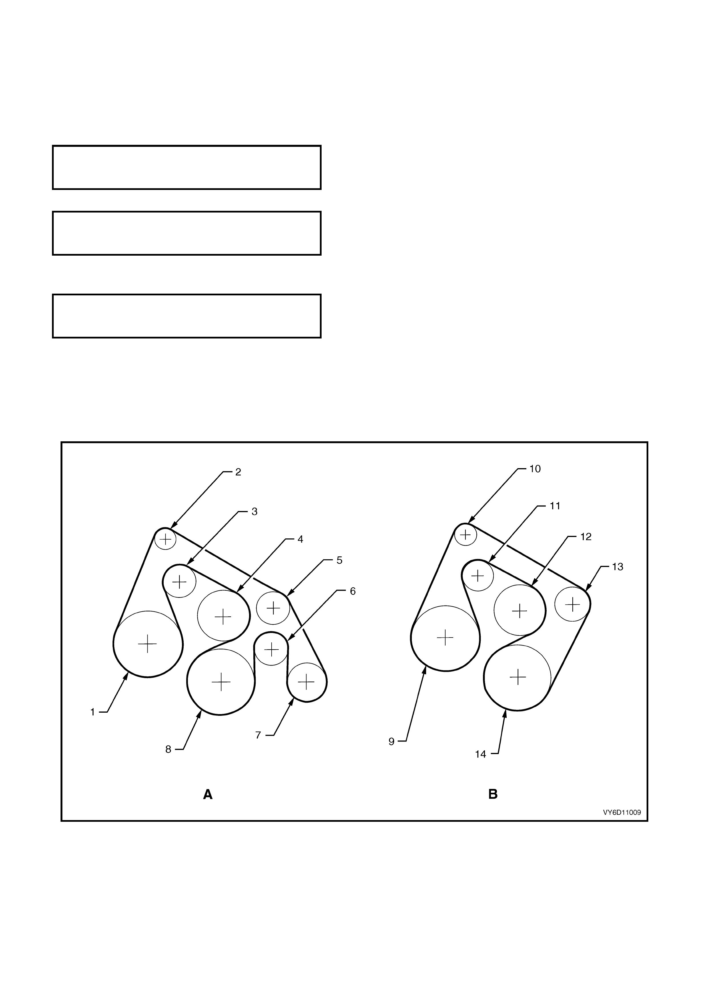
12. Ensure that the drive belt ribs are correctly positioned in all pulleys and the crankshaft balancer. Refer to Figure
6D1-1A-33 for the V6 engine and Figure 6D1-1A-34 for the V6 supercharged engine.
Figure 6D1-1A-33
Legend – V6 Engine
A. Vehicles With Air Conditioning (Long Drive Belt).
B. Vehicles Without Air Conditioning (Short Drive Belt).
1. Power Steering Pump 6. Idler 11. Tensioner
2. Generator 7. Air Conditioner Compressor 12. Coolant Pump
3. Tensioner 8. Crankshaft Pulley 13. Idler
4. Water Pump 9. Power Steering Pump 14. Crankshaft Pulley
5. Idler 10. Generator
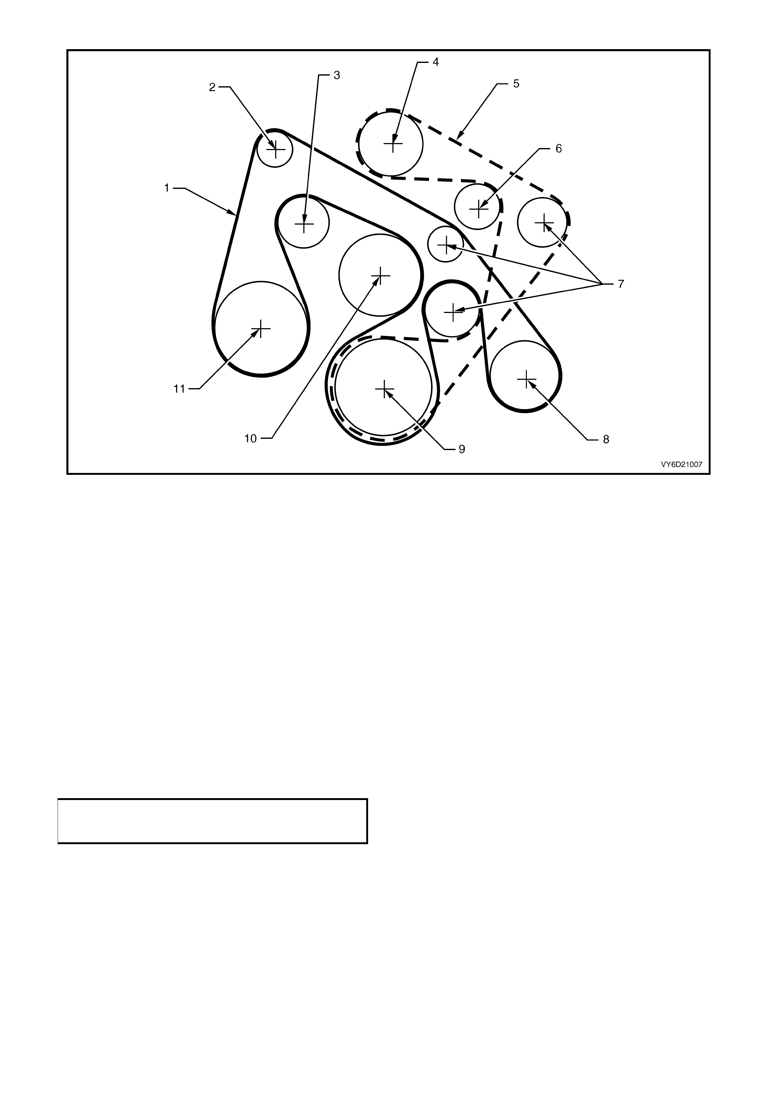
Figure 6D1-1A-34
Legend – V6 Supercharged Engine
1. Accessory Drive Belt (Inner) 5. Accessory Drive Belt (Outer) 9 Crankshaft Pulley
2. Generator 6. Tensioner Pulley 10. Coolant Pump
3. Tensioner Pulley 7. Idler Pulleys 11. Power Steering Pump
4. Supercharger 8. Air Conditioning Compressor
13. Reconnect the battery ground lead.
14. Start the engine.
15. Check the generator warning lamp operation.
16. Check that the drive belt is correctly aligned.
17. Check the generator output (refer to 2.2 MAINTENANCE AND ON-VEHICLE TESTING in this Section).
18. Check the voltage regulator operation (refer to 2.2 MAINTENANCE AND ON-VEHICLE TESTING in this
Section).
19. Turn the ignition switch to OFF.
20. Install the engine dress cover to the intake manifold ensuring that the stud grommets in the dress cover remain
in place.
21. Install and tighten the dress cover dome nuts to the correct torque specification.
ENGINE DRESS COVER TO
INTAKE MANIFOLD DOME NUT
TORQUE SPECIFICATION 5 – 12 Nm
4. DIAGNOSIS
Refer to Section 12A, BATTERY AND CABLES for battery testing.
UNDERCHARGED BATTERY
a. Defective battery
b. Loose connection in charging system
c. Corroded connections in charging circuit
d. Defective wiring
e. Faulty generator
f. Faulty voltage regulator
OVERCHARGED BATTERY
a. Shorted battery cell
b. Faulty voltage regulator
c. Short circuit in rotor winding
d. Voltage drop in sense wire
FAULTY INDICATOR LAMP OPERATION
(LAMP DOES NOT GLOW)
a. Burnt out bulb
b. Defective bulb socket
c. Defective wiring
d. Defective rectifier
e. Defective regulator
FAULTY INDICATOR LAMP OPERATION
(LAMP REMAINS ON)
a. Negative diode failure
b. Defective voltage regulator
c. Faulty generator
d. B+ cable off or broken
e. S cable off or broken
f. Battery overcharged
g. Open circuit in rotor winding
NOISY GENERATOR OPERATION
a. Normal magnetic hum
b. Badly discharged battery
c. Generator mounting brackets loose or bolts loose
d. Worn or frayed drive belt
e. Worn bearings
f. Loose drive pulley attaching nut
g. Open or shorted diodes
h. Open or shorted stator winding
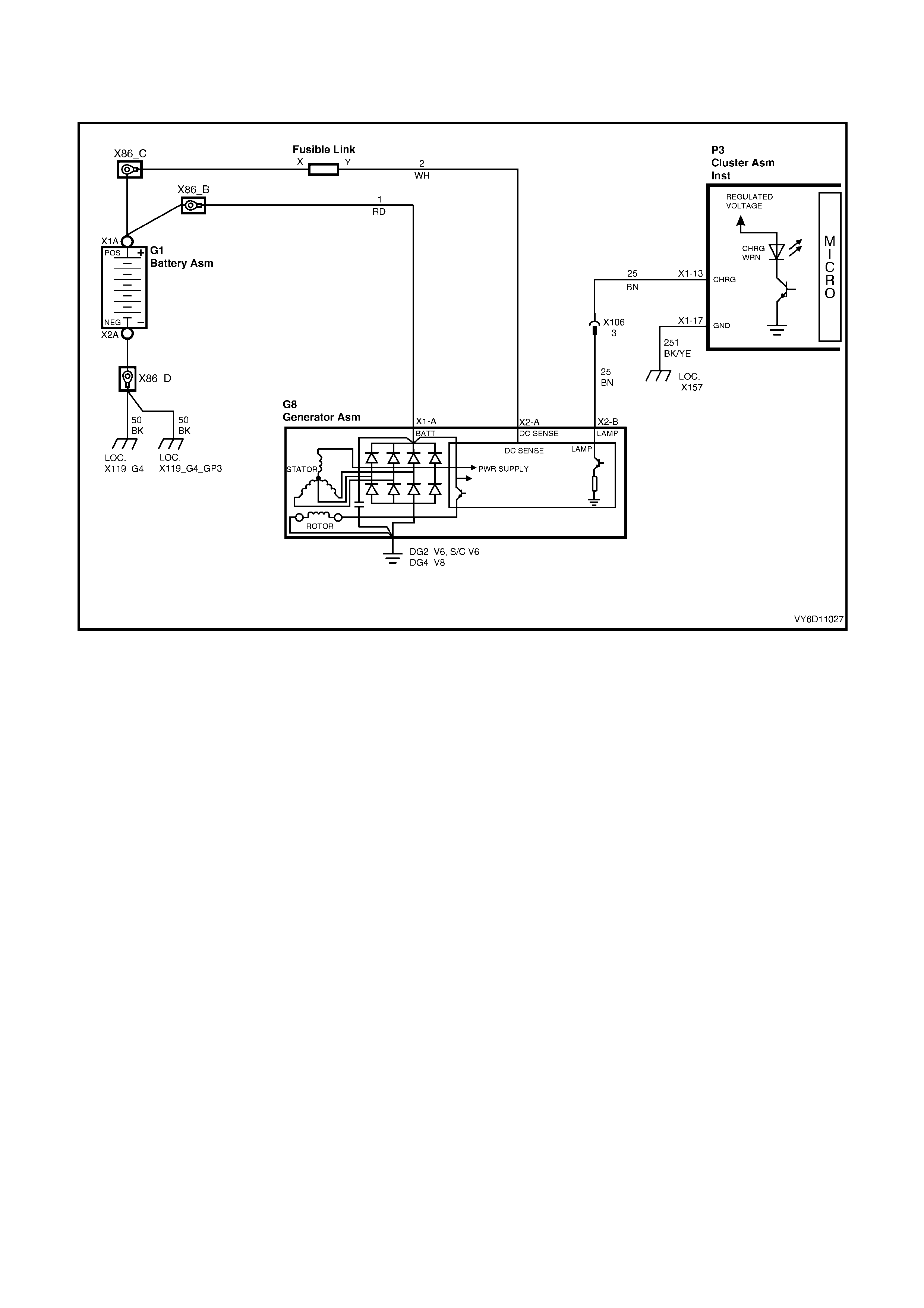
CIRCUIT DIAGRAM
Refer to the V6 engine charging circuit diagram (Figure 6D1-1A-35) to assist with diagnosing charging system
faults.
Figure 6D1-1A-35

5. SPECIFICATIONS
Ground Polarity........................................................... Negative
Nominal Voltage ......................................................... 12 volts
Nominal Output .......................................................... 100 amps
Stator Phases............................................................. 3
Stator Winding Connections....................................... Star
Number of Rotor Poles............................................... 12
Rotor Winding Resistance @ 20°C............................ 1.97 – 2.23 ohms
Slip-ring Minimum Diameter....................................... 26.7 mm
Slip-ring Maximum Out-of Round............................... 0.6 mm
Stator Winding Phase-to-Phase
Resistance@ 20°C..................................................... 0.0486 – 0.0594 ohm
Voltage Regulator Setting .......................................... 13.8 – 14.5 volts
Brush Length (extending from brush holder).............. 12 mm (new), 3.8 mm (min)

6. TORQUE WRENCH SPECIFICATIONS
Nm
Through-bolts................................................................................3.8 – 5.5
Drive-end Housing Bearing Retaining Plate Screws.....................2.1 – 3.0
Drive Pulley Attaching Nut ............................................................54 – 68
Regulator and Brush Assembly Securing Screws ........................1.6 – 2.3
B+ Terminal Nut............................................................................7.5 – 8.5
Battery Harness Terminal to B+ Terminal Nut..............................5 – 12
Rectifier Retaining Screw..............................................................1.6 – 2.3
Suppressor Fixing Screw ..............................................................1.5 – 2.2
Generator to Brace Attaching Bolt ................................................20 – 34
Generator to Drive Belt Tensioner Bracket Mounting Bolt............20 – 34
Engine Dress Cover to Intake Manifold Dome Nut .......................5 – 12
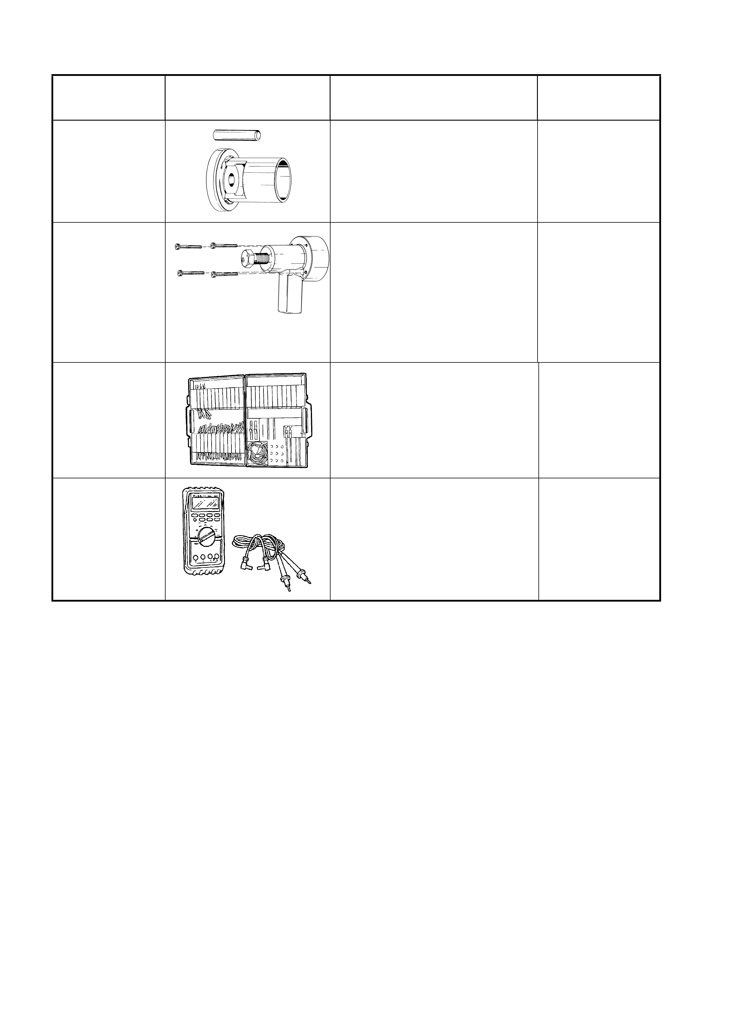
7. SPECIAL TOOLS
TOOL NUMBER ILLUSTRATION DESCRIPTION TOOL
CLASSIFICATION
9981 066 600
BEARING ASSEMBLY FIXTURE
Used for many applications for
pressing on and off components.
Previously released.
Desirable
9981 066 601 ROTOR BEARING REMOVAL
TOOL Used with forcing screw
E6661S and adaptor AU412 to
remove side bearing cups from final
drive screw adjusters.
Previously released.
Desirable
J35616-A
(KM609)
CONNECTOR TEST ADAPTOR
KIT
Used when carrying out electrical
diagnostic circuit checks.
Previously released.
Desirable
3588
(J39200)
DIGITAL MULTIMETER
Must have at least 10 MΩ input
impedance and be capable of
reading frequencies.
Previously released.
Available