
SECTION 6D3-1 - CHARGING SYSTEM –
GEN III V8 ENGINE
IMPORTANT
Before performing any Service Operation or other procedure described in this Section, refer to Section 00,
CAUTIONS AND NOTES for correct workshop practices with regard to safety and/or property damage.
CONTENTS
1. GENERAL INFORMATION
1.1 OPERATION
CIRCUIT OVERVIEW
STANDBY MODE
BACKUP MODE
WARNING LAMP CONDITIONS
2. MINOR SERVICE OPERATIONS
2.1 SAFETY PRECAUTIONS
2.2 MAINTENANCE AND ON-VEHICLE TESTING
REGULAR CHECKS
LUBRICATION
GENERATOR ON-VEHICLE CHECKS
3. MAJOR SERVICE OPERATIONS
3.1 GENERATOR
REMOVE
DISASSEMBLE
CLEANING AND INSPECTION
COMPONENT CHECKING
REASSEMBLE
REINSTALL
4. DIAGNOSIS
CIRCUIT DIAGRAM
5. SPECIFICATIONS
6. TORQUE WRENCH SPECIFICATIONS
7. SPECIAL TOOLS

1. GENERAL INFORM ATION
The GEN III V8 engine is fitted with a Mitsubishi 140 amp generator. This generator is mounted on the lower, left-
hand side of the engine. It has an internally m ounted regulator, a single lower m ounting lug but no external cooling
fans. For generator mounting bracket removal and installation information, refer to Section 6A3 GEN III V8
ENGINE MECHANICAL.
The generator is three phase, incorporating a rotor with six pole pairs and two cooling fans; one on the drive end
and one on the slip-ring end. The rotor is supported by ball bearing races in both the drive and slip-ring end
housings. The stator surrounds the rotor and has a three-phase star connected output winding on a ring shaped
lamination pack.
The output of the stator winding is rectified by eight diodes within the slip-ring end housing. Excitation current is
supplied to the rotor field coil via the voltage regulator, the brushes and slip-rings. The electronic voltage regulator
requires no adjustment in service.
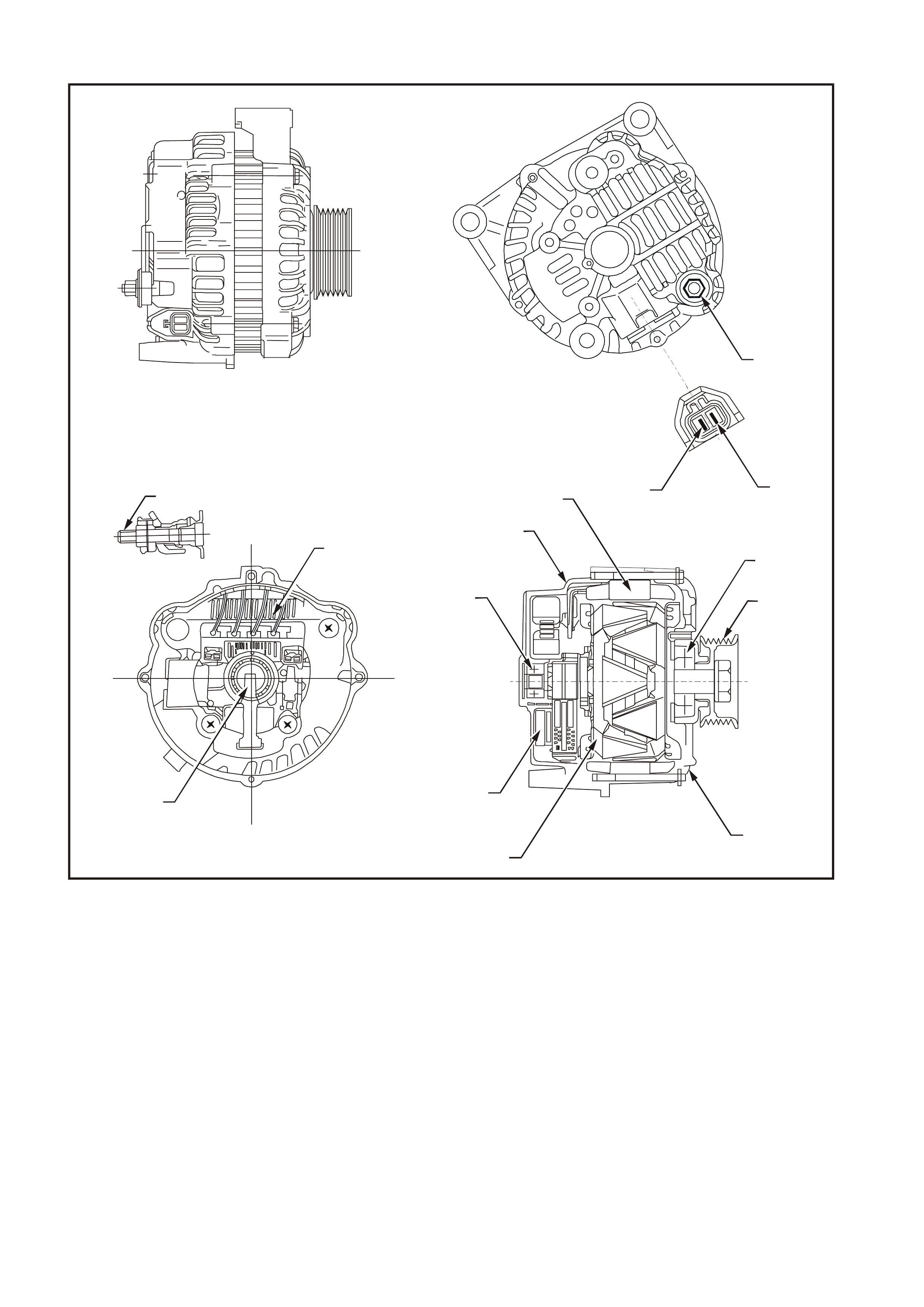
This generator has four external connections (refer to Figures 6D3-1-1 and 6D3-1-2):
•
••
•
B+ lead to the battery positive terminal
•
••
•
L lead to the generator warning lamp (max. 2 watts)
•
••
•
S lead for battery voltage sensing
•
••
•
ground connection (via the installation bolts).
T26D3101
2
3
9
1
6
7
8
5
4
12
13
14
11
10
Figure 6D3-1-1
Legend
1. Battery B+ Terminal 6. Front Bracket 11. Brushes
2. Warning Lamp (L Terminal) 7. Rotor 12. Bearing
3. Battery Sensing (S Terminal) 8. IC Regulator 13. Rear Bracket
4. Bearing 9. B+ Terminal Bolt 14. Stator
5. Pulley 10. Rectifier
T26D3102
1
2
3
4
5
6
7
8
9
10
12 13 14
15 16
17
18
19
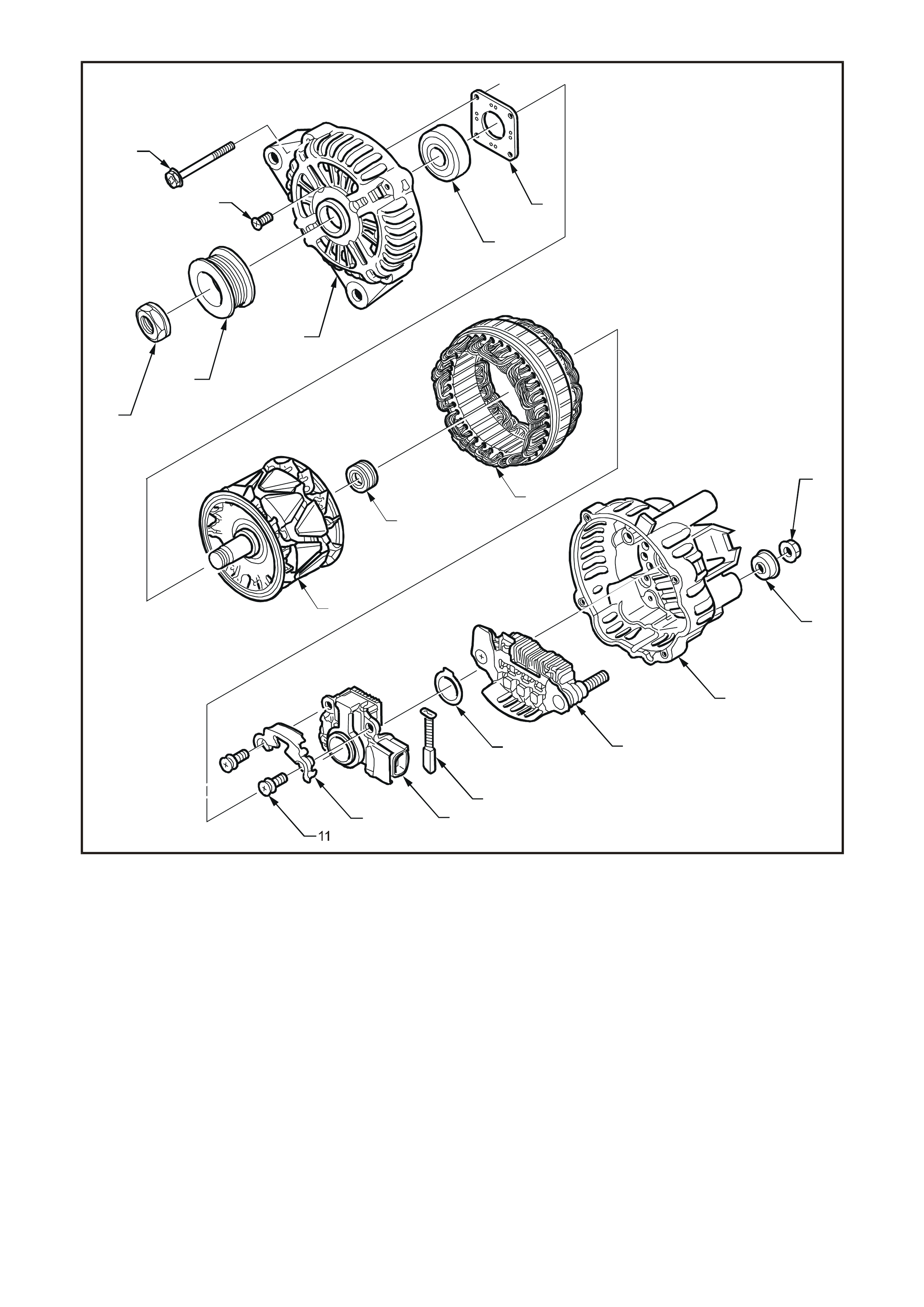
Figure 6D3-1-2
Legend
1. Through-bolt (X4) 7. Bearing Retaining Plate 14. Brush
2. Bearing Retaining Plate Screw (X4) 8. Rotor 15. Thrust Washer
3. Nut 9. Slip-ring End Bearing 16. Rectifier Assembly
4. Drive Pulley 10. Stator 17. Rear Bracket Assembly (Includes
5. Front Bracket Assembly (Includes 11. Regulator and Brush Screws items 11 – 16 and 18 – 19)
Items 2, 5, 6 and 7) 12. Brush Retaining Plate 18. Terminal Cover Bush
6. Front Bearing 13. Regulator 19. Nut

1.1 OPERA TION
CIRCUIT OVERVIEW
With the ignition switch in the ON position, current is supplied via the warning lamp to the L terminal of the regulator.
This allows current to flow (within the regulator) from the generator B+ terminal to the brushes and rotor winding.
The current in the rotor winding creates m agnetic fields between adjac ent rotor poles. As the r otor spins, the st ator
windings cut through this field at right angles, which induces voltage. As the speed increases, this induced voltage
increases . Current then flows through the thr ee-phase diode br idge in the rectifier to convert the AC voltage to DC.
This is supplied to the B+ output and then to the battery.
The regulator S terminal monitors the system voltage. When this voltage reaches approximately 14.2 volts, the
regulator breaks the circuit through the rotor winding, causing the generator output voltage to drop. When the
regulator S terminal senses a voltage below a preset value, the regulator completes the circuit and voltage to the
battery again increases. This cycle repeats very rapidly.
If the warning lamp fails, the generator self excites by using current from the phase connection until the voltage
builds up to the regulating level.
Current does not flow through the rotor winding when the engine is cranking.
STANDBY MODE
With the ignition switch in the ON position and the engine at rest, the regulator defaults to active standby mode. This
limits the current through the rotor by switching on and off at a 50% duty cycle with a frequency of approximately
4 kHz. This is audible at times.
BACKUP MODE
The regulator com pares voltage at the B+ terminal with voltage sensed at the S terminal. The regulator defaults to
backup mode if the difference exceeds a preset value. Backup mode limits the output voltage to a safe level
(approximately 1 – 3 volts above the normal setting).
WARNING LAMP CONDITIONS
The regulator illuminates the warning lamp when it detects f ault conditions in the generator or external circuits . The
warning lamp remains illuminated until all faults are repaired.
Fault conditions include:
1. Open circuit in the regulator battery sensing wire (S terminal).
2. Open circuit or excessive voltage drop in the B+ cable.
3. Open circuit in the generator phase connection.
4. Overcharging of the battery.
5. Short circuit in the regulator output stage.
6. Open circuit in the rotor winding.
7. Poor contact in a wiring harness connector.
8. Poor contact between the rectifier and the regulator.
9. High resistance in the fusible link assembly.
10. Poor contact between the battery terminals and cables.
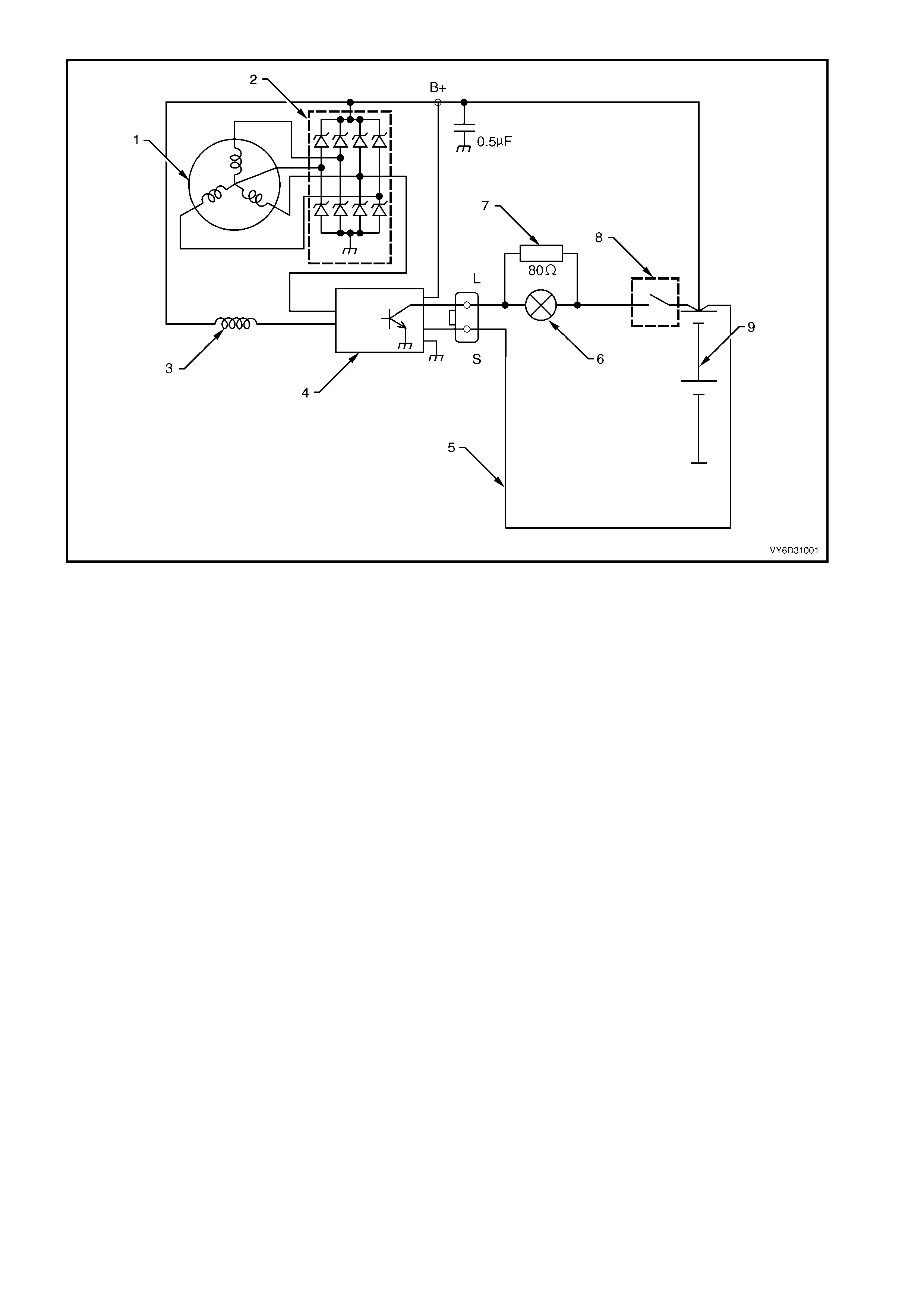
Figure 6D3-1-3
Legend
1. Stator 4. IC Regulator 7. Current Limiting Resister
2. Rectifier 5. Battery Sensing Wire 8. Ignition Switch
3. Rotor 6. Warning Lamp 9. Battery

2. MI NOR SERVICE OPERATIONS
2.1 SAFETY PRECAUTIONS
Observe the following precautions. Failure to observe these precautions will result in serious damage to the
generator.
•
••
•
Apply the generator and voltage regulator only on a negative ground system.
•
••
•
When installing a battery, fit the positive (+) cable to the battery before fitting the negative cable.
•
••
•
When a slave battery is used for starting purposes, ensure that both batteries are connected in parallel, ie.
positive terminals connected and negative terminals connected.
•
••
•
Only use jumper leads that have surge protection.
•
••
•
Disconnec t both battery cables when charging the battery. This is olates the generator f rom the batter y and from
the external charging equipment.
•
••
•
Do not operate the generator within an open circuit (i.e. without a battery in the circuit).
•
••
•
Do not disconnect the battery while the generator is running.
•
••
•
Do not attempt to polarise the generator.
•
••
•
Always ensure that the generator warning lamp illuminates when the ignition is switched to the ON position.
•
••
•
Do not connect the L terminal of the generator to 12 volts (the battery or ignition circuits). This damages the
warning lamp circuit.
•
••
•
Som e batter y powered tim ing lights can pr oduce high trans ient voltages when connected or disconnec ted. Only
disconnect or connect timing lights when the engine is switched off.

2.2 MAINTENANCE AND ON-VEHICLE TESTING
REGULAR CHECKS
Check the following at regular intervals:
•
••
•
Generator terminals for corrosion and loose connectors.
•
••
•
Wiring for damaged insulation.
•
••
•
Mounting bolts for tightness.
•
••
•
Drive belt for alignment and wear.
•
••
•
Drive pulley for damage.
IMPORTANT: T he drive-belt adjustm ent for the engine ancillaries (i.e. generator and water pump) is provided by a
spring-loaded tensioner. The drive belt does not require adjustment.
LUBRICATION
High tolerance bearings are used in this generator. If the bearings are rem oved during the generator disassem bly,
new bearings must be installed to restore the generator to original specification. The ball bearings supporting the
rotor shaft are pre-lubricated and sealed. Do not lubricate it during servicing.
IMPORTANT: Two special tools (Bosch tool numbers 9881 066 600 and 9881 066 601) are available to ensure
correct dismantling and assembly procedure of the rotor bearings. It is extremely difficult to remove the bearings
without damaging the rotor fans. The assembly tool ensures that the bearings are installed correctly and are
properly aligned, which ensures long service life.
GENERATOR ON-VEHICLE CHECKS
Prerequisites
Before testing the generator output, ensure that:
•
••
•
all generator circuit connections are clean and tight
•
••
•
the generator is always connected to the battery during testing (to prevent damage to the diodes)
•
••
•
the battery is fully charged
•
••
•
the specific gravity does not vary more than 0.025 between cells. It is recommended that the average specific
gravity is 1.260 or higher. Refer to Section 12A, BATTERY AND CABLES.
Carry out a load test on the battery to determine its ability to supply and accept current. T his is a good indicator of
the general condition of the battery. For details on battery testing, refer to Section 12A, BATTERY AND CABLES.
Inspect the drive belt and tens ioner markings to determine if the drive belt is within operating limits . Replace the belt
if it is excessively worn or outside the operating range of the tensioner. Refer to Section 6A3, ENGINE
MECHANICAL – GEN III V8 ENGINE.
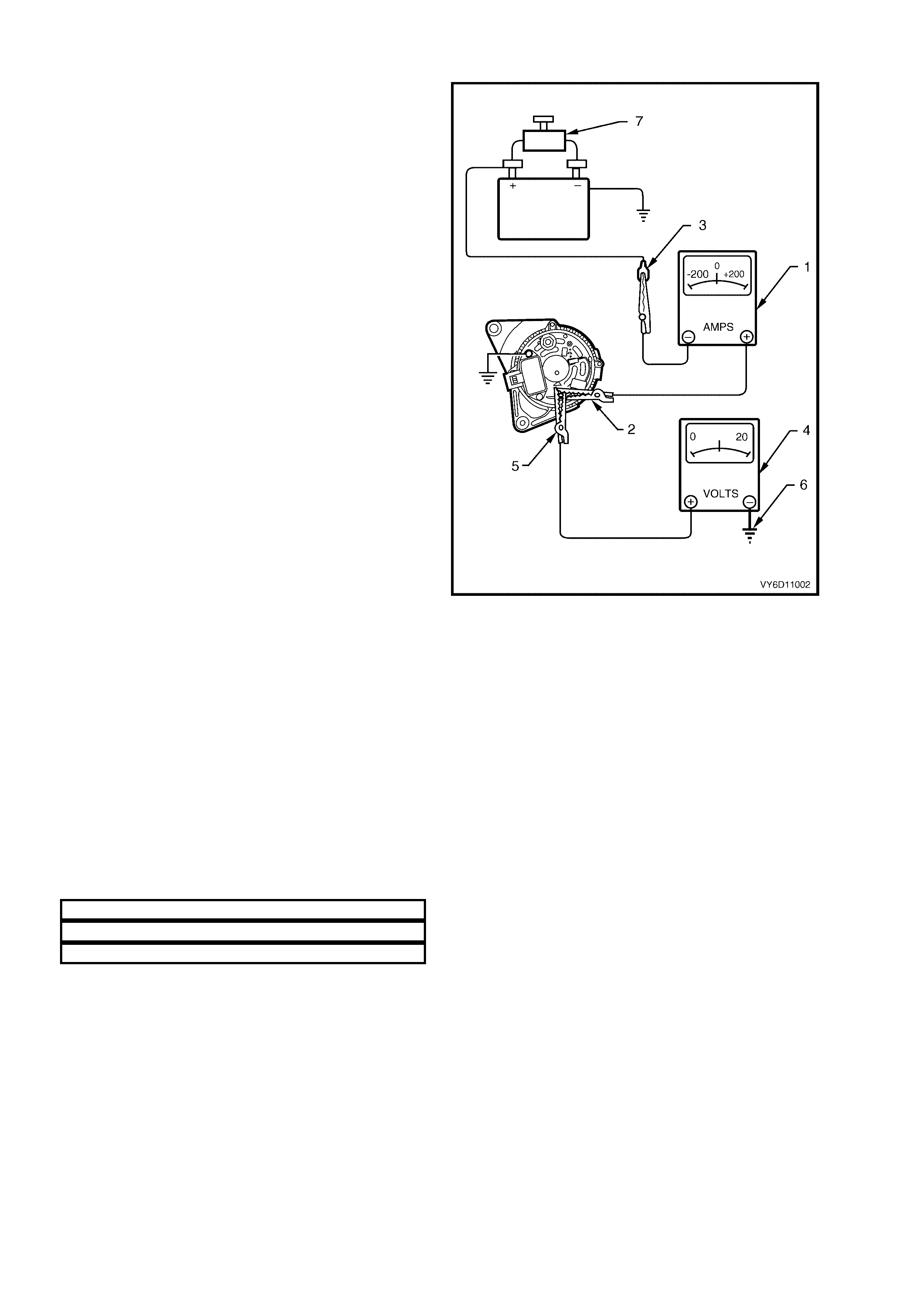
Regulating Voltage Test
Turn ignition switch to the OFF position and turn off
all electrical equipment.
1. Refer to Section 00, CAUT IONS AND NOTES
before disconnecting the battery.
Disconnect the battery ground cable from the
battery.
Disconnect the generator positive lead (red wire)
from the generator B+ terminal.
2. Connect the positive lead of an am meter (1) to
the generator B+ terminal (2).
NOTE: Ensure that the am meter is set to measure
at least 140 amps.
Connect the negative ammeter lead to the
disconnected generator positive lead (3).
3. Connect the positive lead of a voltmeter (4) to
the generator B+ terminal (5).
IMPORTANT: Set the voltmeter scale to 0 – 20
volts.
4. Connect the negative voltmeter lead to a good
ground connection on the generator housing
(6).
CAUTION: Insulate the terminal of the generator
positive lead (red wire) to prevent contact with
any metal part of the vehicle. If this occurs,
damage t o t he ch argin g circu it resu lts when t h e
battery is reconnected.
Reconnect the battery ground cable.
5. Fit a loading device across the battery
terminals, e.g. an adjustable carbon pile.
IMPORTANT: The loading device must have a
power consumption rating of at least 1000 watts.
6. Record the voltmeter reading before starting
the engine. ( This reading s hould inc reas e when
the engine is running, indicating generator
output.)
7. Start the engine.
8. Increase the engine speed and adjust the load
(using the ammeter reading) as outlined in the
chart below.
9. Check the generator output voltage (voltmeter
reading) against the specification.
ENGINE RP M 1300
LOAD 5 – 10 amps
VOLTMETER REA DI NG 13.8 – 14.5 volt s
Figure 6D3-1-4
Load Regulation Test
1. Connect the voltmeter, ammeter and carbon pile as in the previous test.
2. Increase the engine speed to 2350 rpm (approximately 5000 generator rpm).
3. Increase the load to 90% of full output (approximately 126 amps).
4. Replace the regulator if the decrease in the regulating voltage is greater than 0.5 volt.

Generator Output Test at Full Load
1. Connect the voltmeter, ammeter and carbon pile as in the previous test.
2. Increase the engine speed to 1900 rpm (approximately 6000 generator rpm).
3. Increase the load until the generator output voltage drops to 13.5 volts. Full generator output (140 amps) is
required; adjust the throttle to maintain this.
4. Record the ammeter reading.
IMPORTANT: Keep the time for this test to a minimum to avoid undue heating and high engine speeds.
5. If the generator does not provide 140 am ps at 6000 generator rpm, disassemble and inspect the generator for
faults. Refer to 3.1 GENERATOR in this Section.
CAUTION: On completion of the generator output test, return the engine to idle and disconnect the loading
device from the battery terminals. This prevents excessive battery discharge.
6. Disconnect the battery ground cable at the battery.
7. Remove the voltmeter and ammeter.
8. Reconnect the generator positive lead (red wire) to the generator B+ terminal.
9. Reconnect the battery ground cable to the battery.
Charging Circuit Voltage Drop Test
IMPORTANT: Ensure that the generator connections are clean and tight.
1. Connect a low range voltmeter positive lead to the generator positive terminal and the negative lead to the
battery positive post.
2. Switch the headlamps on.
3. Start the engine.
4. Increase the engine speed to approximately 2500 rpm.
5. Record the voltmeter reading.
6. Reduce the engine speed to idle.
7. Move the voltmeter positive lead to the battery negative post and the negative lead to the generator housing.
8. Increase the engine speed to approximately 2500 rpm.
9. Record the voltmeter reading.
10. Reduce the engine speed to idle.
11. Check the two readings. If the readings exceed 0.3 volt there is a high resistance in the charging circuit.
12. Trace the cause and correct the problem.
3. MAJOR SERVICE OPERATIONS
3.1 GENERATOR
LT Section – 02-140
REMOVE
CAUTION: The generator is in close proximity to an exhaust manifold. Allow the engine to cool before
removing the generator.
1. Refer to Section 00, CAUT IONS AND NOTES
before disconnecting the battery.
2. Disconnect the battery ground lead.
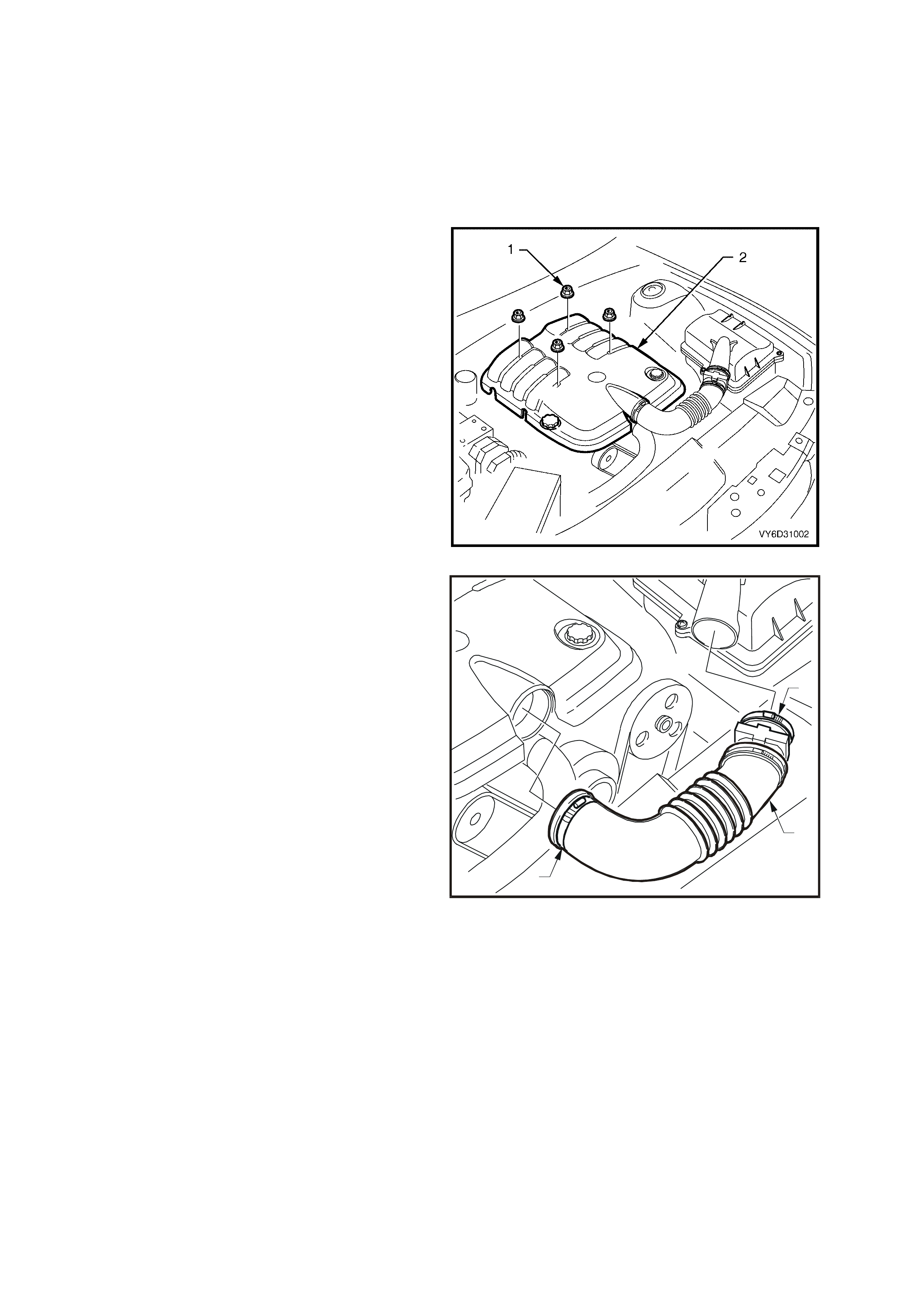
3. Remove the four dome nuts (1) that are
securing the engine dress cover assembly (2).
4. Lift the cover assembly off.
Figure 6D3-1-5
5. Loos en the clamps ( 1) that are securing the air
intake hose (2) to the throttle body and air filter.
6. Disconnect the wiring harness connector from
the mass airflow meter.
7. Remove the air intake hose and airflow meter
assembly.
T26D3106
1
1
2
Figure 6D3-1-6
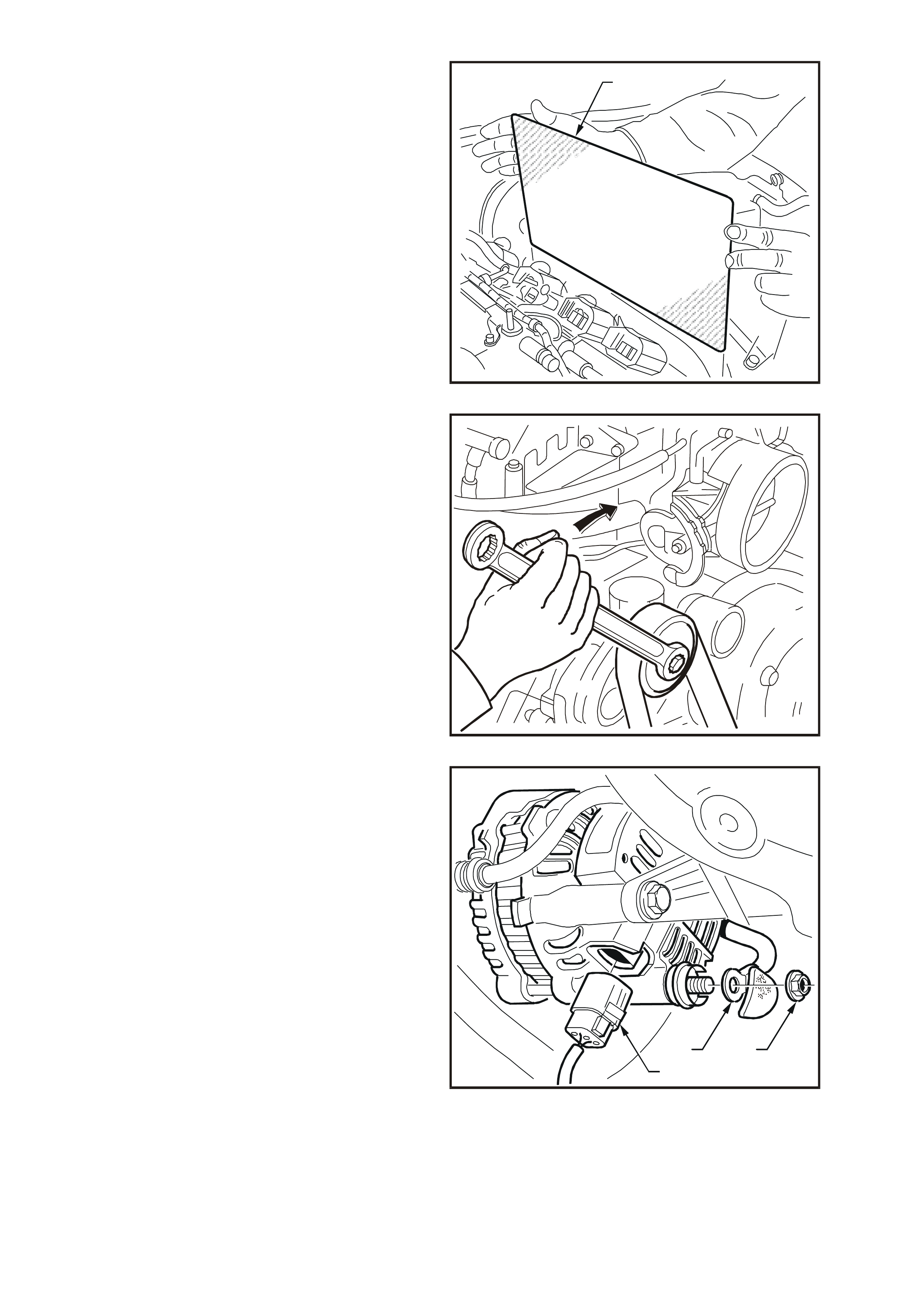
8. Lift and rem ove the Powertrain Control Module
(PCM) heat s hield (1) f rom the lef t-hand side of
engine compartment.
9. Remove the air filter housing assembly. Refer
to Section 6C3-3, SERVICE OPERATIONS –
GEN III V8 ENGINE.
T26D3107
1
Figure 6D3-1-7
10. Use a 15 mm ring spanner on the drive belt
tensioner pulley pivot bolt to rotate the
tensioner pulley assembly anti-clockwise.
11. Turn the assembly and remove the drive belt
from the generator drive pulley.
12. Release the drive belt tensioner.
13. Remove the power steering pump and
reservoir. Refer to Section 9, STEERING.
T26D3108
Figure 6D3-1-8
14. Pull the battery harness cap back from the B+
terminal and remove the nut (1) and positive
lead (2).
15. Depress the connector retainer (3) to release
the connector from the assembly.
16. Disconnect the generator connector.
1
2
3
T26D3109
Figure 6D3-1-9
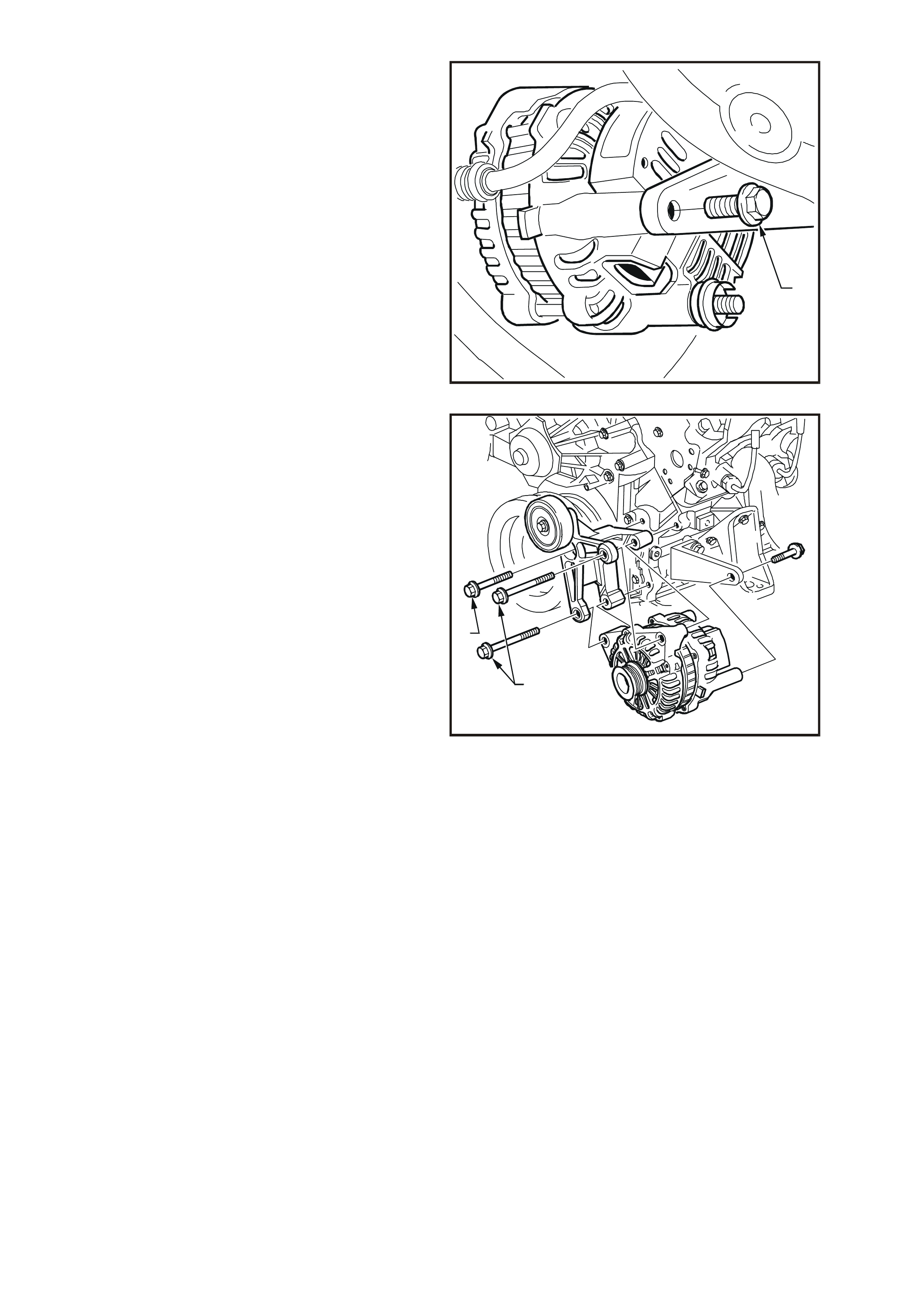
17. Remove the bolt (1) from the rear mounting
bracket.
1
T26D3110
Figure 6D3-1-10
18. Remove the two bolts (1) securing the
generator and mounting bracket to the engine.
19. Separate the generator from the mounting
bracket and lower the generator down onto the
stabiliser bar.
20. Remove the bolt securing the idler pulley
mounting bracket to the engine (2).
21. Remove the mounting bracket and idler pulley
assembly.
22. Lif t the generator up and out from between the
engine and the radiator.
T26D3111
2
1
Figure 6D3-1-11
DISASSEMBLE
Precautions
When testing the generator for faulty components, ensure that:
•
••
•
the RMS output of the AC type tester for checking the rectifier diodes does not exceed 12.0 volts
•
••
•
the stator is disconnected before testing the diodes
•
••
•
all diodes have the same Zener voltage (when testing the diode breakdown voltages)
•
••
•
voltage does not exceed 110 V for a series test lamp when testing the insulation on the rotor and stator
•
••
•
the rectifier is disconnected from the stator prior to testing the stator.
IMPORTANT: Due to the very low resistanc e value of the s tator winding, accurate readings m ight not be achieved
using a conventional ohmmeter.
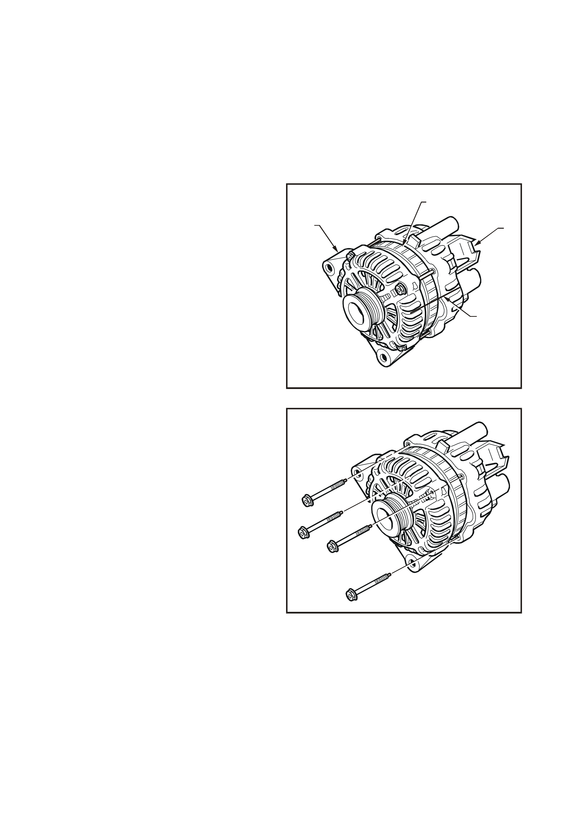
1. Using a permanent marking pen, mark the
relative positions of the drive end housing (1),
the stator frame (2) and the slip-ring end
housing (3).
T26D3113
1
2
3
4
Figure 6D3-1-12
2. Remove the four through-bolts.
3. Carefully separate the slip-ring end housing
and stator (as an assem bly) from the rotor and
drive end housing.
NOTE: Do not lever against, or put strain on, the
stator windings.
T26D3114
Figure 6D3-1-13
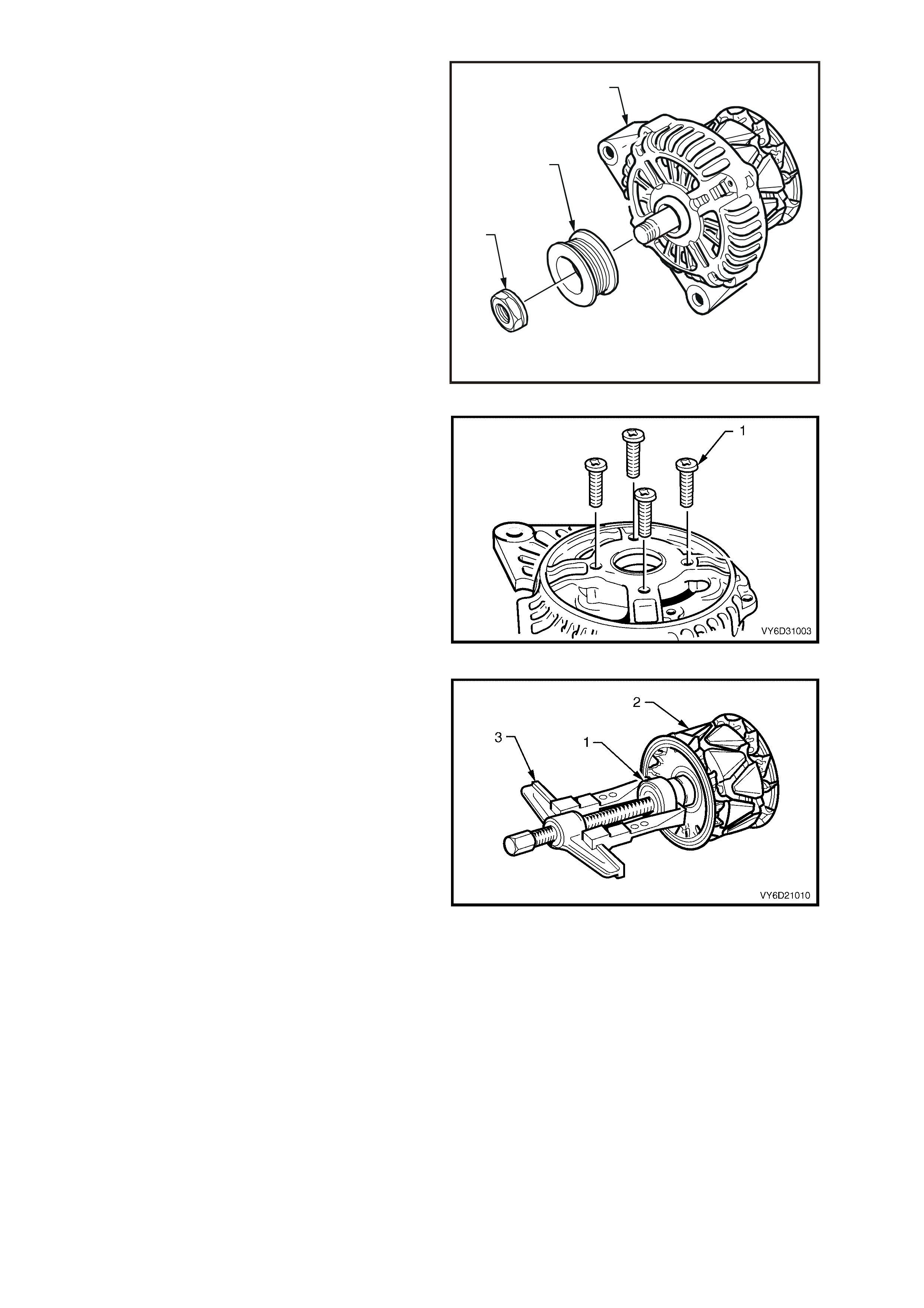
4. Clamp the rotor in a vice that has soft-jaws.
NOTE: Do not distort or damage the rotor poles.
5. Remove the drive pulley attaching nut (1).
6. Remove the drive pulley (2).
7. Remove the front bracket (3).
T26D3115
1
2
3
Figure 6D3-1-14
8. Remove the four screws (1) that secure the
bearing retaining plate to front bracket.
9. Press the bearing from the front bracket.
Figure 6D3-1-15
10. Remove the slip-ring end bearing (1) from the
rotor shaft (2) using a bearing puller (3).
NOTE: Do not distort the rear fan or damage the
plastic side of the slip-ring.
IMPORTANT: Replace both of these bearings.
11. Rem ove the nut, wave washer, flat washer and
insulating washer from the B+ terminal bolt.
12. Remove the rectifier retaining screw.
13. Remove the two brush holder retaining screws.
14. Remove the stator and rectifier (as an
assembly) from the rear bracket.
15. Unsolder and remove each brush and spring
assembly.
Figure 6D3-1-16
16. Unsolder the four stator windings that are
connected to the rectifier, as follows:
Grasp the stator wires close to the wire loop
with a pair of pointed nose pliers.
Heat the joint with a soldering iron until the
solder starts to melt.
Apply a slight twisting motion to the wire and
pull it upwards and away.
NOTE: Use only as much heat as required to melt
the solder. Excessive heat can damage the diodes.
IMPORTANT: Service the rectifier assembly only
as a complete assembly.
17. Unsolder the two joints connecting the brush
holder and regulator assembly to the rectifier.
18. Remove the brush holder assembly from the
rectifier.
T26D3118
Figure 6D3-1-17
CLEANING AND INSPECTION
1. Clean and inspect the disassembled components.
NOTE: Do not clean the stator or rotor windings with cleaning solvent. This can result in damage to the insulation.
2. Wash all components (except the stator, rotor, rectifier and regulator) in a suitable cleaning solvent.
CAUTION: Use a non-volatile agent in a well
ventilat ed area. Observe th e safety regulations an d
precautions of the cleaning agent in use.
3. Carefully clean the rotor and stator with compressed air.
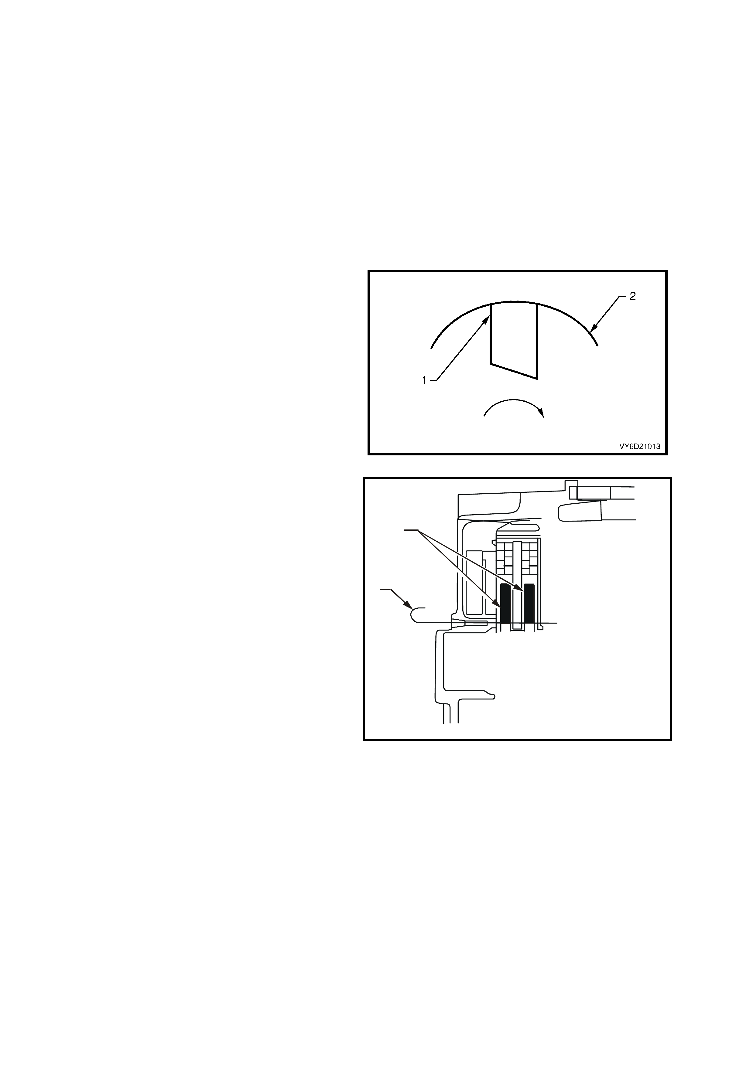
COMPONENT CHECKING
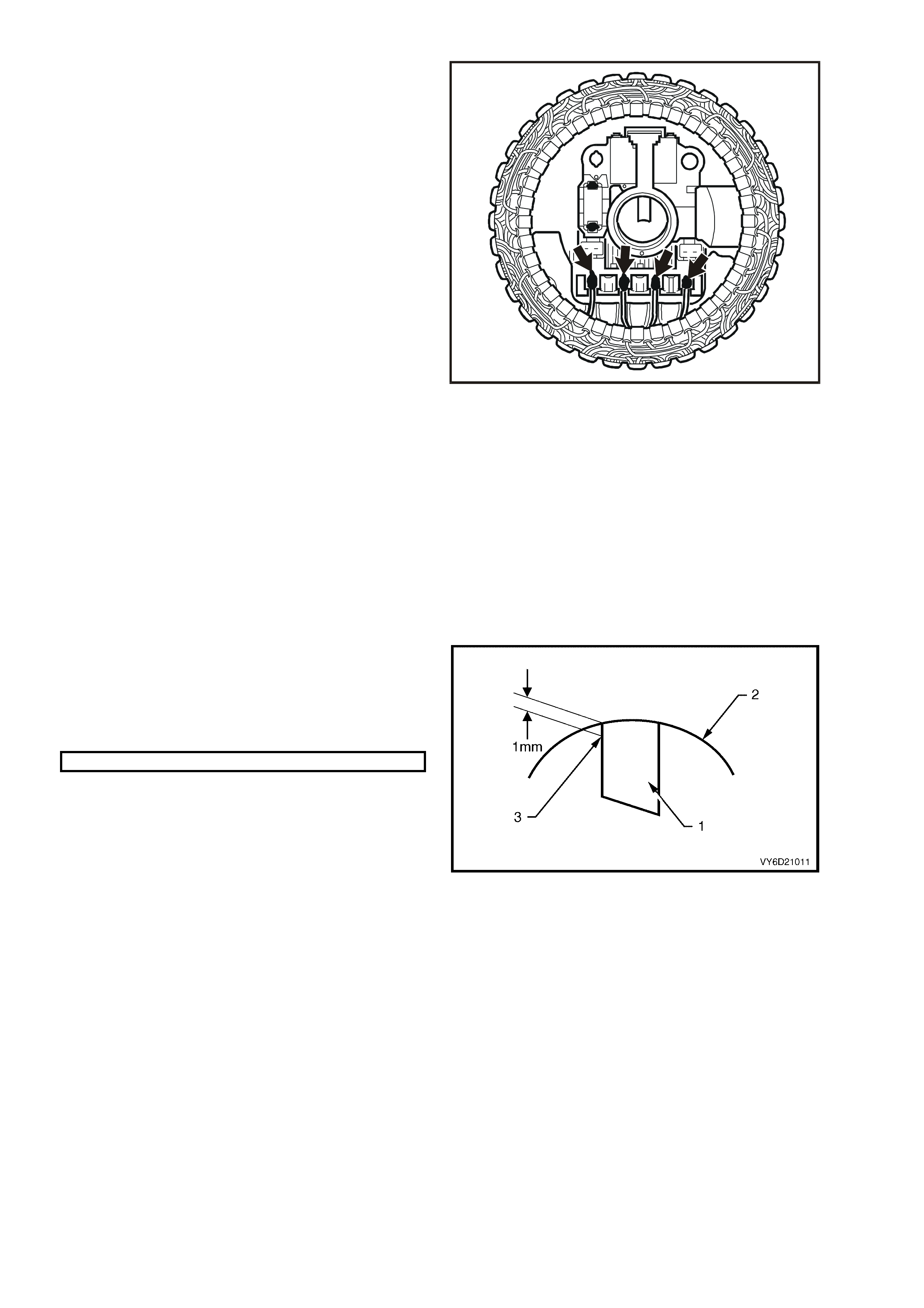
Check the Brushes
1. Check the length of each brush (1) protruding
from the regulator brush holder (2).
2. Measure along the centre line of each brush.
3. Check the brushes for abnormal wear or
cracks.
MINIMUM BRUSH LENGTH..................... 5 mm
NOTE: If the brush length is less than specified or
shows abnormal wear or cracks, replace both
brushes.
4. Clean the brushes and brush holder with a
clean cloth.
5. Check the brush holder for cracks and
damage.
6. Replace the brush holder as necessary.
7. Check that the brush s prings function c orrectly,
as follows:
a. Push the brush into the brush holder until
the wear limit line of the brush protrudes 1
mm from the brush holder moulding (3).
b. Release the brush.
c. Repeat this action to ensure that the spring
returns fully and smoothly.
Figure 6D3-1-18
Check the Diodes
The following test equipment is essential for correctly testing the diodes:
•
••
•
DC output diode tester that does not exceed 14 volts output at the test probes.
•
••
•
Multimeter with a diode test feature that does not exceed 14 volts output at the test probes.
•
••
•
AC tester rated at 12 volts RMS. This ensures that the forward and reverse voltage checks are not incorrect
due to Zener breakdown.
•
••
•
Zener diode tes ter with a DC output m or e than 30 volts . T his s hould inc orpor ate internal current lim iting of 5 mA
to prevent high currents during testing.
NOTE 1: Replace the rectifier assembly if any diodes are faulty.
NOTE 2: Complete steps 1 to 5 before testing the Zener voltage of each diode.
NOTE 3: When using an AC tes ter in steps 1 to 5, ens ure that the reverse voltage applied is less than 14 volts DC
or 12 volts RMS.
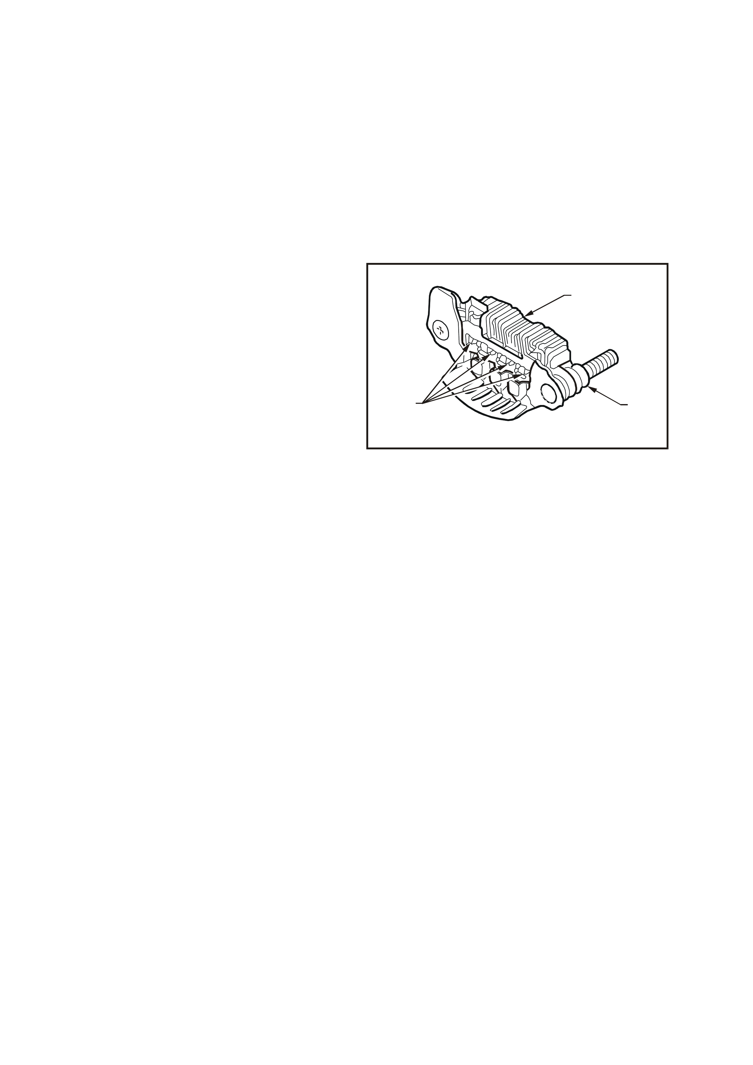
1. Attach the negative test probe of the diode
tester to each positive diode in turn.
2. Attach the negative probe to the positive
heatsink (1) of the rectifier assembly.
3. Attach the positive probe to the positive diode
connections (2).
4. Check for a low resistance reading or the
forward voltage drop across the diode.
5. Reverse the probe connections and again test
each diode in turn.
6. Check for a high resistance reading or higher
reverse voltage.
7. Repeat the test to ensure that c urrent is able to
flow in one direction only.
8. Repeat the above procedure on the negative
heatsink.
9. Attach the positive probe to the negative
heatsink of the rectifier assembly.
10. Attach the negative probe to the negative diode
connections.
T26D3120
3
12
Figure 6D3-1-19
11. Check for a low resistance reading or the forward voltage drop across the diode should be obtained.
12. Reverse the probe connections and again test each diode in turn.
13. Check for a high resistance reading or higher reverse voltage should be obtained.
14. Repeat the test to ensure that current is able to flow in one direction only.
15. Identify the Zener voltage of each diode. Refer to the numbers on the base of each diode.
NOTE: All diodes within a rect ifier mus t have the sam e
Zener voltage.
IMPORTANT: The recommended Zener tester is:
Durst model 600 with five mA test current (Bosch
approved).
16. Test the Zener voltage (reverse bias) of the positive diodes, as follows:
a. Connect the positive lead to the positive heat sink.
b. Connect the negative lead of the tester to each positive diode in turn.
c. Gradually increase the test voltage from the Zener diode tester and read the Zener breakdown voltage.
NOTE: Ensure that the tester is current limited to
5 mA.
17. Check that the voltage reading is steady; it should not increase with increased voltage.
18. Test the Zener voltage (reverse bias) of the negative diodes:
a. Connect the positive lead to the negative heat
sink.
b. Connect the negative lead of the tester to each
negative diode in turn.
19. Replace the rectifier assembly as necessary.
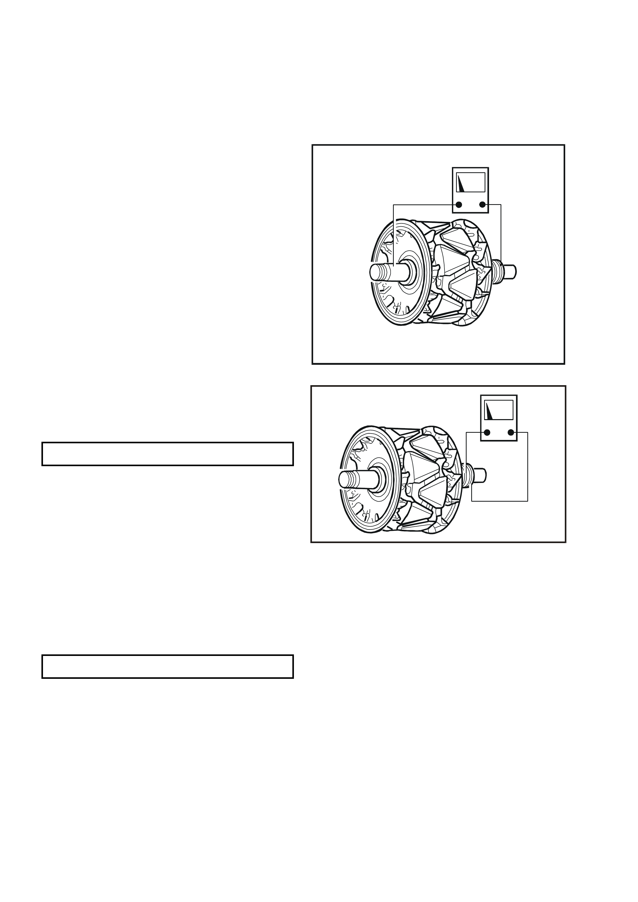
Check the Rotor
1. Clean any dirt or particles from the rotor with
compressed air and/or a clean cloth.
2. Test the rotor insulation between the slip-rings
and rotor shaft using an insulation tester or a
series test lamp up to 110 volts.
3. Check that the insulation tester indicates an
open circuit (greater than 1 Megohm) and a
test light does not glow.
4. Replace the rotor if an open circuit does not
exist.
T26D3121
Figure 6D3-1-20
5. Test the rotor f or an open circuit by connecting
the ohmmeter probes across the slip-rings.
NOTE: The r otor winding resis tanc e value might be
too small to measure with a conventional meter.
ROTOR WINDING
RESISTANCE @ 20°C 1.87 ohms
6. Replace the rotor if the rotor winding has an
open circuit.
7. Check the slip-rings for wear or damage.
8. Machine the slip-rings if they are worn, scored,
damaged or out-of-round beyond
specifications.
CAUTION: Extreme care must be exercised
when machining the slip-rings to avoid the
turning tool fouling the rear rotor cooling fan.
9. Check that the slip-rings are within
specifications (especially after machining).
10. Replace the rotor if the slip-ring is outside of
the specification.
SLIP-RING MINIMUM
OUTER DIAMETER 22.1 mm
T26D3122
Figure 6D3-1-21
Bearings
The bearings used in this generator are a high tolerance type. Use only genuine replacement during the
reconditioning process to restore the generator to original specifications.
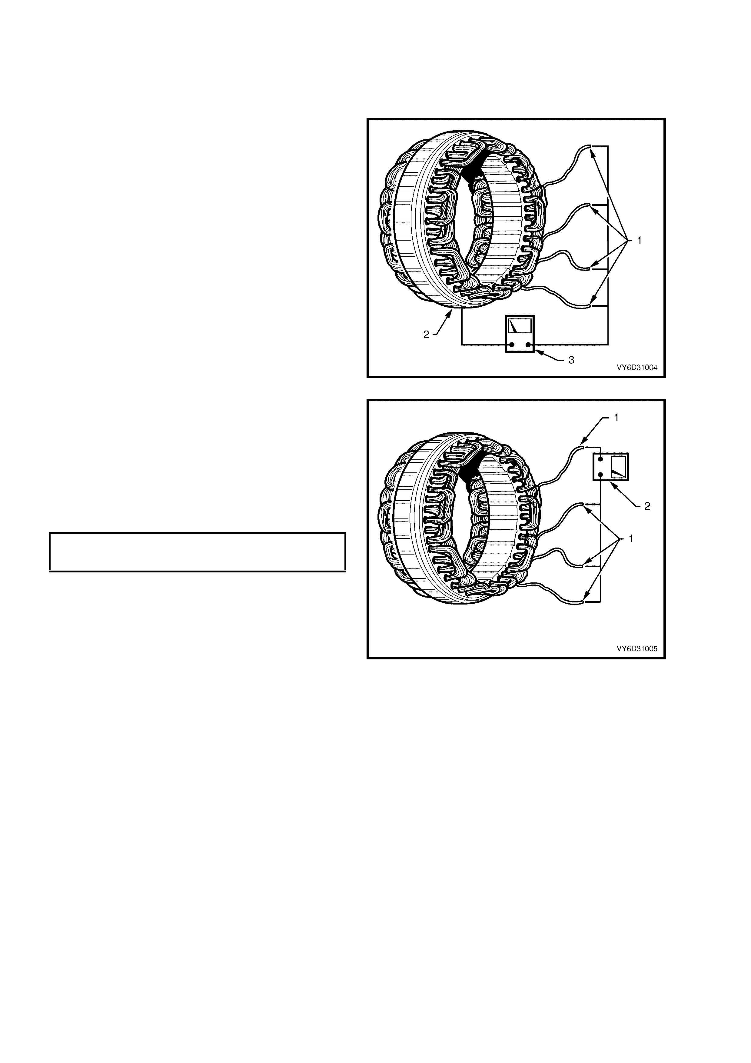
Check the Stator
1. Inspect the stator for damage, loose
connections or discoloured windings.
2. Replace the stator if necessary.
3. Test the stator insulation between any stator
lead (1) and the stator frame (2). Use a
powered test-lamp rated up to 40 volts, an
ohmmeter or an insulation tester (3).
4. Check that the test- lam p does not glow and the
ohmmeter or insulation tester indicates an open
circuit (greater than 1 Megohm).
5. Replace the stator if an open circuit does not
exist.
Figure 6D3-1-22
6. Test the stator winding circuits by connecting
any two stator leads (1) with an ohmmeter (2).
7. Check that the ohmmeter does not register a
significant resistance.
8. Repeat this test between the remaining stator
leads.
9. Replace the stator if it is outside the
specification.
STATOR WINDING
PHASE TO PHASE
RESISTANCE @ 20°C 0.05 ohm
Figure 6D3-1-23
REASSEMBLE
Refer to Figure 6D3 -1-1 for identification of components.
1. Reassemble the generator in the reverse order of
the disassembly procedure.
CAUTION: It is important that all parts are
thoroughly dried before assembly, taking care not
to breathe any vapours in.
2. Check the bearing box for oil.
3. Completely remove any oil on the bearing box to prevent bearing creep.
NOTE 1: Do not lubricate the bearings; they are
pre-lubricated.
NOTE 2: Do not apply grease to rotor bearings that
have resin bands.
4. Position each brush (1) in the brush holder (2)
as indicated in Figure 6D3-1-24.
5. Ensure that the new brushes extend at least
13 mm from the brush holder.
6. Solder the brushes, using high temperature
solder (melting point 230°C) and a 180 – 270
watt soldering iron.
NOTE: Do not use excessive heat as this can
damage rectifier.
Figure 6D3-1-24
7. Install the rotor and front bracket assembly in
the follows.
8. Push the brushes (1) fully back into the brush
holder in the rear bracket assembly.
9. Insert a suitable wire (2) f rom the outside of the
rear bracket assembly to hold the brushes in
the retracted position.
10. Carefully heat the area around the rear bracket
bearing box to 50 – 60°C. This aids in
assembly and avoids damaging the tight fitting
components.
11. Install the rotor into the rear assembly.
12. Align the front bracket, stator frame and rear
bracket accurately. Use the markings made
prior to disassembly.
IMPORTANT: When removing the wire, listen for
both brushes to click into position on the slip-ring.
13. Remove the wire.
T26D3126
2
1
Figure 6D3-1-25
NOTE: Do not over-tighten the B+ terminal nut. This
damages the insulating washer.
14. After assembly, rotate the pulley slowly by hand to
ensure that the rotor turns smoothly.
15. Tighten all fasteners to the correct torque
specifications.
DRIVE PULLEY ATTACHING NUT
TORQUE SPECIFICATION 99 – 137 Nm
THROUGH-BOLT
TORQUE SPECIFICATION 3.5 – 5.3 Nm
BEARING RETAINER SCREW
TORQUE SPECIFICATION 2.0 – 5.3 Nm
BRUSH HOLDER
RETAINING SCREW
TORQUE SPECIFICATION 2.0 – 5.3 Nm
RECTIFIER RETAINING SCREW
TORQUE SPECIFICATION 2.0 – 5.3 Nm
B+ TERMINAL NUT
TORQUE SPECIFICATION 12.8 – 18.6 Nm
REINSTALL
1. Install the generator by following the removal procedure in reverse order.
Tighten the following fasteners to the correct torque:
a. Mounting bracket bolt.
b. Generator retaining bolts.
c. Battery harness to B+ terminal nut (positive
lead to B+ terminal).
REAR MOUNTING BRACKET BOLT
TORQUE SPECIFICATION 40 – 60 Nm
GENERATOR AND
MOUNTING BRACKET BOLT
TORQUE SPECIFICATION 40 – 60 Nm
IDLER PULLEY
MOUNTING BRACKET BOLT
TORQUE SPECIFICATION 20 – 34 Nm
BATTERY HARNESS TO
B+ TERMINAL NUT
TORQUE SPECIFICATION 5 – 12 Nm
2. Install the power steering pump. Refer to Section 9, STEERING.
3. Carefully and accurately route the drive belt.
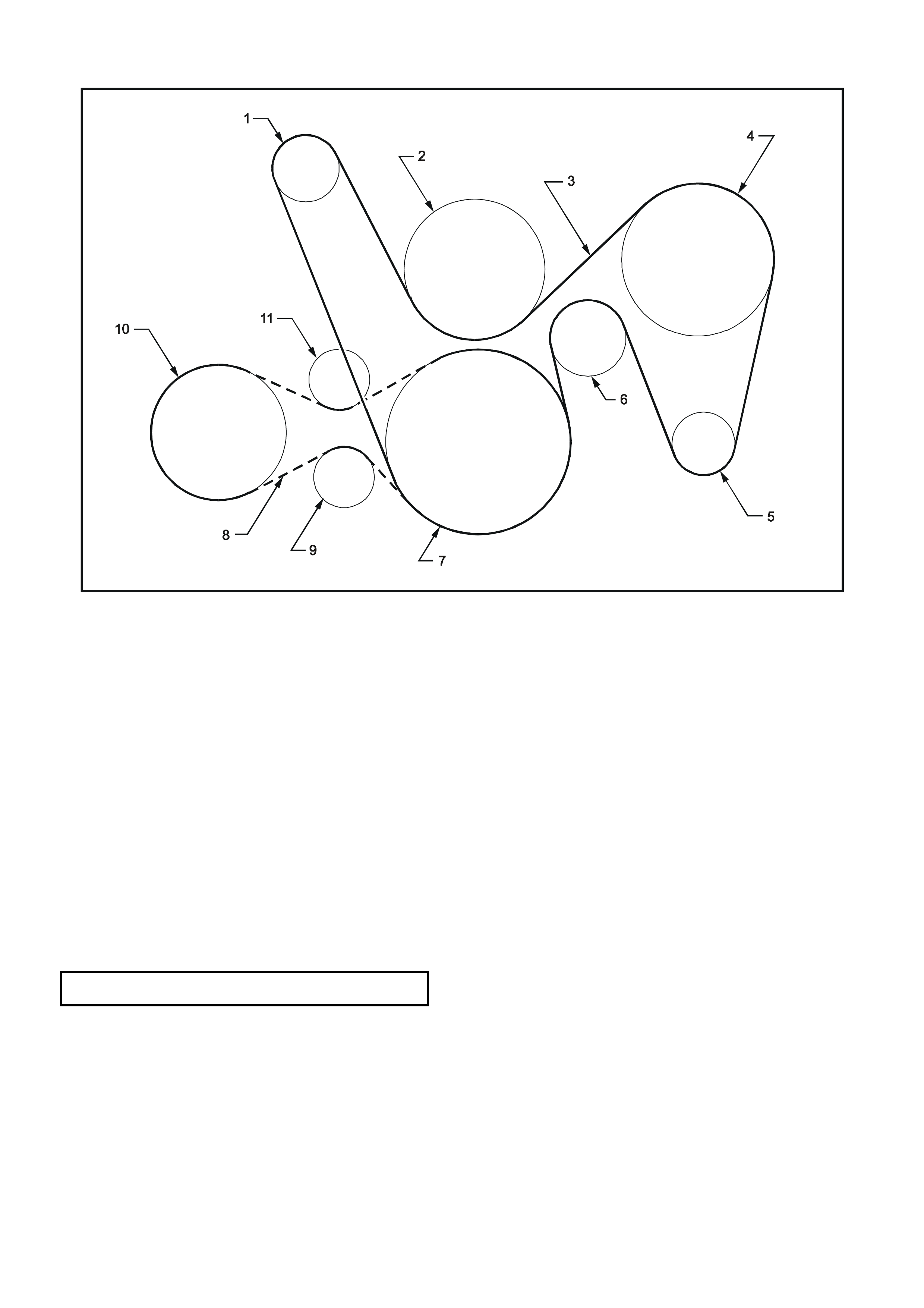
T26D3112
Figure 6D3-1-26
Legend
1. Tensioner 7. Crankshaft
2. Water Pump 8. Drive Belt (Air Conditioner Pump)
3. Drive Belt 9. Tensioner (Air Conditioner Pump Drive Belt)
4. Power Steering Pump 10. Air Conditioner Pump
5. Generator 11. Idler (Air Conditioner Pump Drive Belt)
6. Idler
4. Using a 15 mm ring spanner on the tensioner pulley pivot bolt, rotate the tensioner pulley clockwise and install
the drive belt onto:
a. the power steering pump
b. the generator
c. the idler pulleys.
5. Check that the drive belt ribs are correctly positioned in all of the drive belt grooves.
6. Install the cap over the B+ terminal.
7. Install the engine dress cover ensuring that the stud grommets in the dress cover remain in place.
8. Install the engine dress cover dome nuts.
9. Tighten the dome nuts to the correct torque specification.
ENGINE DRESS COVER DOME NUT
TORQUE SPECIFICATION 4 – 6 Nm
10. Reconnect the battery ground lead.
11. Start the engine.
12. Check the generator warning lamp operation.
13. Check the drive belt alignment.
14. Check the generator output. Refer to 2.2 MAINTENANCE AND ON-VEHICLE TESTING in this Section.
15. Check the voltage regulator operation. Refer to 2.2 MAINTENANCE AND ON-VEHICLE TESTING in this
Section.

4. DIAGNOSIS
Refer to Section 12A, BATTERY AND CABLES for battery testing.
UNDERCHARGED BATTERY
a. Defective battery
b. Loose connection in charging system
c. Corroded connections in charging circuit
d. Defective wiring
e. Faulty generator
f. Faulty voltage regulator
OVERCHARGED BATTERY
a. Shorted battery cell
b. Faulty voltage regulator
c. Short circuit in rotor winding
d. Voltage drop in sense wire
FAULTY INDICATOR LAMP OPERATION
(LAMP DOES NOT GLOW)
a. Burnt out bulb
b. Defective bulb socket
c. Defective wiring
d. Defective rectifier
e. Defective regulator
FAULTY INDICATOR LAMP OPERATION
(LAMP REMAINS ON)
a. Negative diode failure
b. Defective voltage regulator
c. Faulty generator
d. B+ cable off or broken
e. S cable off or broken
f. Battery overcharged
g. Open circuit in rotor winding
NOISY GENERATOR OPERATION
a. Normal magnetic hum
b. Badly discharged battery
c. Generator mounting brackets loose or bolts loose
d. Worn or frayed drive belt
e. Worn bearings
f. Loose drive pulley attaching nut
g. Open or shorted diodes
h. Open or shorted stator winding
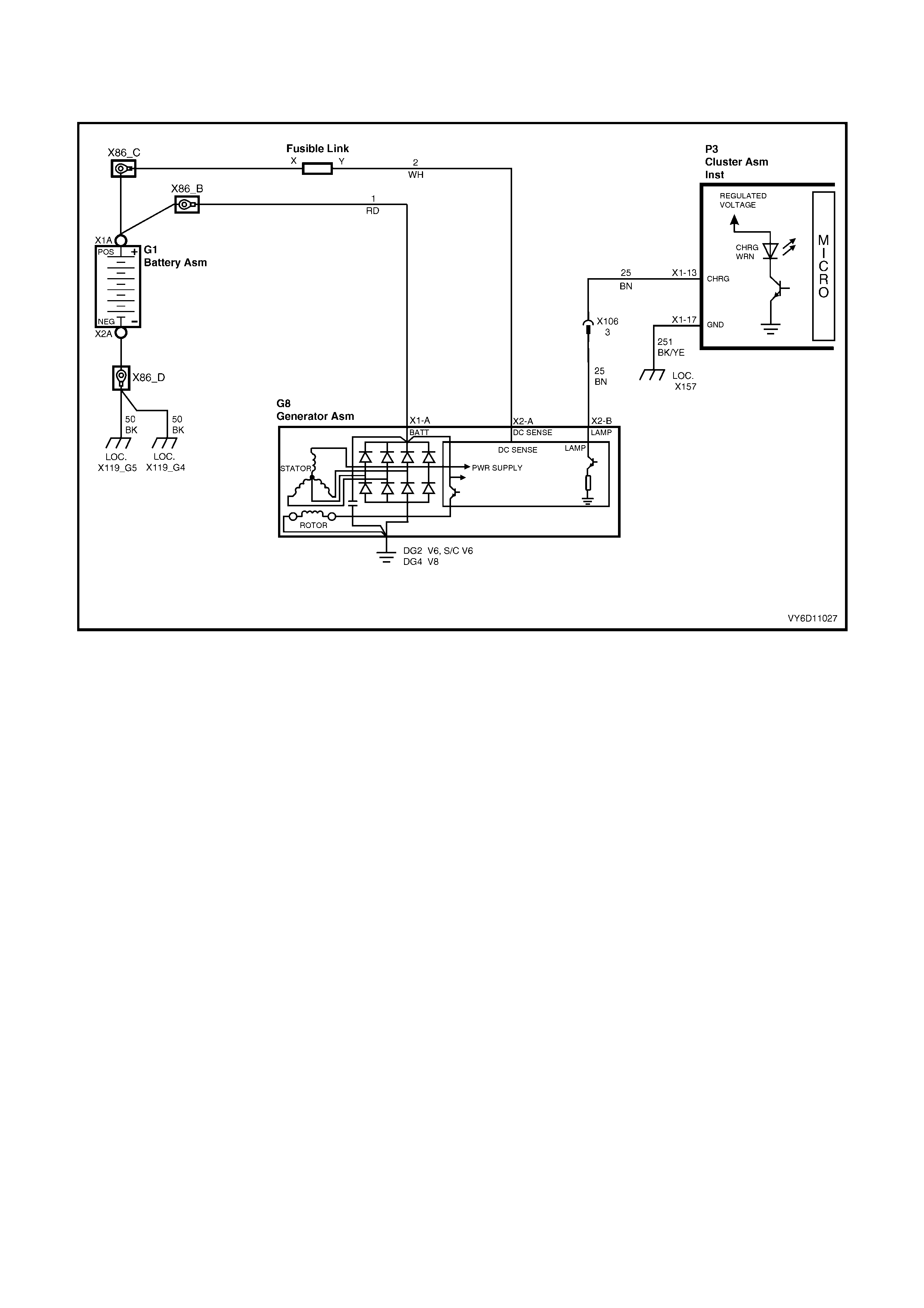
CIRCUIT DIAGRAM
Refer to the GEN III V8 engine charging circuit diagram (Figure 6D3-1-27) to assist with diagnosing charging
system faults.
Figure 6D3-1-27

5. SPECIFICATIONS
Ground Polarity.....................................................................Negative
Nominal Voltage....................................................................12 volts
Nominal Output.....................................................................140 amps
Voltage Regulator Setting.....................................................13.8 – 14.5 volts
Stator Phase to Phase Resistance @ 20°C .........................0.05 ohm
Rotor Winding Resistance @ 20°C.......................................1.87 ohms
Slip-ring Outer Diameter.......................................................22.7 mm
Slip-ring Service Limit...........................................................22.1 mm
Brush Length New ................................................................18.5 mm
Brush Length Service Limit...................................................5.0 mm
Direction of Rotation (viewed from pulley)............................Clockwise

6. TORQUE WRENCH SPECIFICATIONS
Nm
Drive Pulley Attaching Nut ............................................................99 – 137
Through-bolt..................................................................................3.5 – 5.3
Bearing Retainer Screw................................................................2.0 – 5.3
Brush Holder Retaining Screw......................................................2.0 – 5.3
Rectifier Retaining Screw..............................................................2.0 – 5.3
B+ Terminal Nut............................................................................12.8 – 18.6
Rear Mounting Bracket Bolt..........................................................40 – 60
Generator and Mounting Bracket Bolt...........................................40 – 60
Idler Pulley Mounting Bracket Bolt................................................20 – 34
Battery Harness to B+ Terminal Nut.............................................5 – 12
Engine Dress Cover Dome Nut.....................................................4 – 6
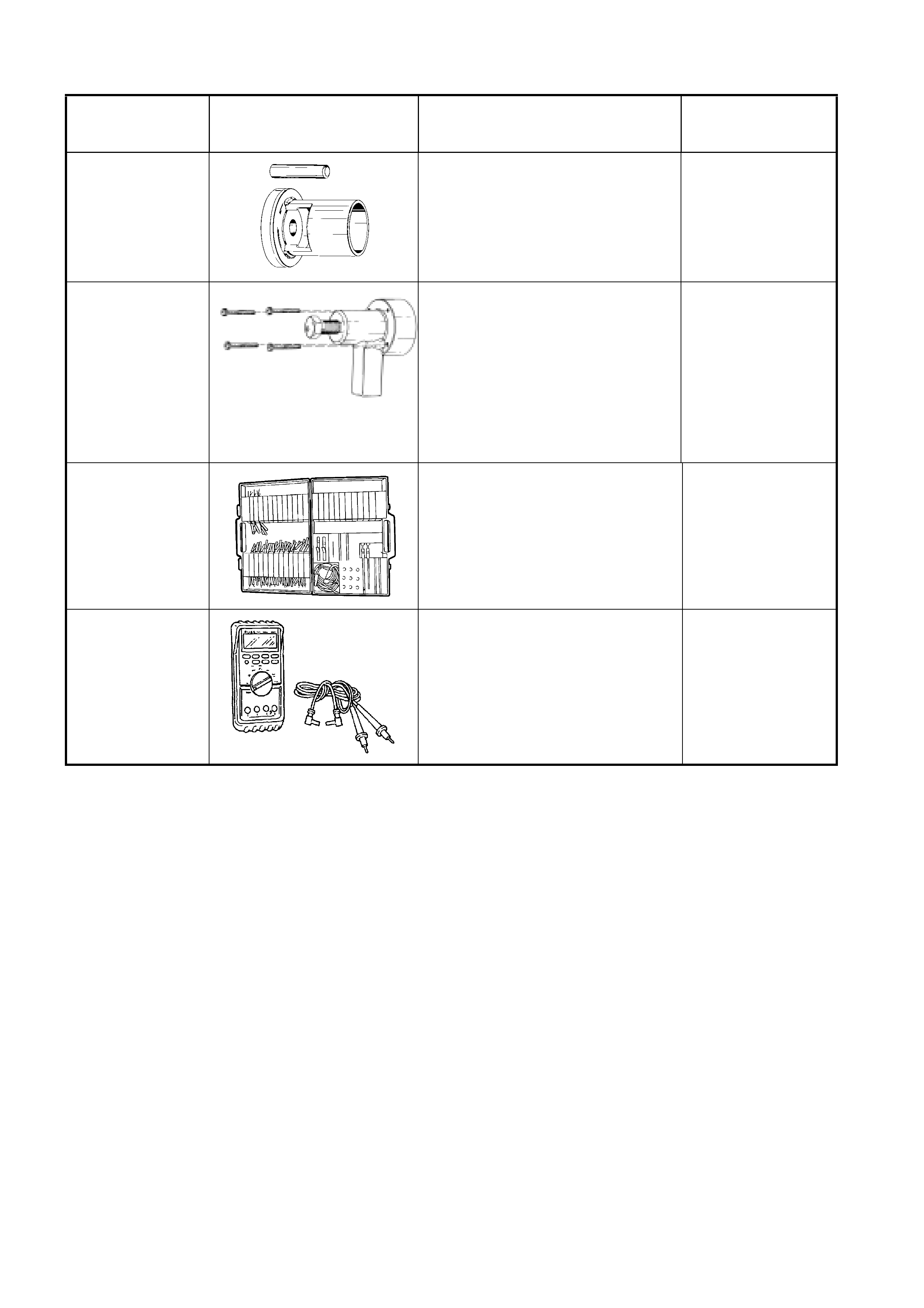
7. SPECIAL TOOLS
TOOL NUMBER ILLUSTRATION DESCRIPTION TOOL
CLASSIFICATION
9981 066 600
BEARING ASSEMBLY FIXTURE
Used for many applications for
pressing on and off components.
Previously released.
Desirable
9981 066 601 ROTOR BEARING REMOVAL
TOOL Used with forcing screw
E6661S and adaptor AU412 to
remove side bearing cups from final
drive screw adjusters.
Previously released.
Desirable
J35616-A
(KM609)
CONNECTOR TEST ADAPTOR
KIT
Used when carrying out electrical
diagnostic circuit checks.
Previously released.
Desirable
3588
(J39200)
DIGITAL MULTIMETER
Must have at least 10 MΩ input
impedance and be capable of
reading frequencies.
Previously released.
Available