
SECTION 6D3-2 - STARTING SYSTEM –
GEN III V8 ENGINE
IMPORTANT
Before performing any Service Operation or other procedure described in this Section, refer to Section 00
CAUTIONS AND NOTES for correct workshop practices with regard to safety and/or property damage.
CONTENTS
1. GENERAL INFORMATION
SOLENOID SWITCH
PLANETARY DRIVE TRAIN
ARMATURE
BRUSHES
1.1 OPERATION
CIRCUIT OVERVIEW
2. MINOR SERVICE OPERATIONS
2.1 SAFETY PRECAUTIONS
2.2 MAINTENANCE AND ON-VEHICLE TESTING
REGULAR CHECKS
ON-VEHICLE CHECKS
3. MAJOR SERVICE OPERATIONS
3.1 STARTER MOTOR
REMOVE
STARTER MOTOR BENCH TESTS
DISASSEMBLE
CLEANING AND INSPECTION
REASSEMBLE
REINSTALL
4. DIAGNOSIS
CIRCUIT DIAGRAM
5. SPECIFICATIONS
6. TORQUE WRENCH SPECIFICATIONS
7. SPECIAL TOOLS

1. GENERAL INFORMATION
The GEN III V8 engine is fitted with a Delco Remy, six-pole, four-brush starter motor. This consists of a solenoid
switch on a DC m otor that has per m anent m agnet excitation. T his has the advantage of low weight with high output
torque.
The Delco Rem y starter m otor does not have field coil windings or pole shoes. T hese parts have been replac ed by
perm anent magnets that are held in the pole housing by clips. The positive br ushes are now part of the brush plate
assembly.
SOLENOID SWITCH
The solenoid switch is used to activate the DC motor and has two windings; the pull-in winding and the hold-in
winding. The pull-in winding has heavier wire and is grounded through the DC motor winding and brushes. The
hold-in winding is grounded to the solenoid casing.
PLANETARY DRIVE TRAIN
The planetary drive train cons ists of an inter nally toothed ring gear and three planetary gear wheels which rotate on
needle bearings on the planetary drive shaft. The ring gear is keyed into the drive-end housing and is made from
high-grade polyamide with mineral additives.
When the starter motor is oper ated, the armature tur ns the planetar y gears inside the fix ed planetary ring gear. This
drives the planetary shaft at a reduced speed ratio (approximately 3.36:1) which turns the drive assembly. A fork
lever in the drive end housing forces the drive assembly to slide forward and engage with the engine
flexplate/flywheel ring gear to transmit cranking torque.
An internal clutch allows the drive assembly pinion gear to rotate freely when the engine starts. This prevents the
armature from being driven at excessive speed by the engine.
ARMATURE
The armature shaft is supported at each end by oil absorbent sintered metal bushes; one in the commutator end
shield and one in the planetar y drive shaf t. These bushes require lubrication only at the time of over haul. The front
end of the arm ature has a gear profile. T his m eshes with the three planetary gear wheels. These in turn m esh with
the internal teeth of the ring gear.
BRUSHES
A brush plate suppor ts f our com m utator brushes . This plate is f ixed to the comm utator end shield with two retaining
screws. T wo negative brushes are grounded to the pole hous ing. Two positive brushes ar e insulated from the pole
housing and connected to the solenoid switch M terminal.
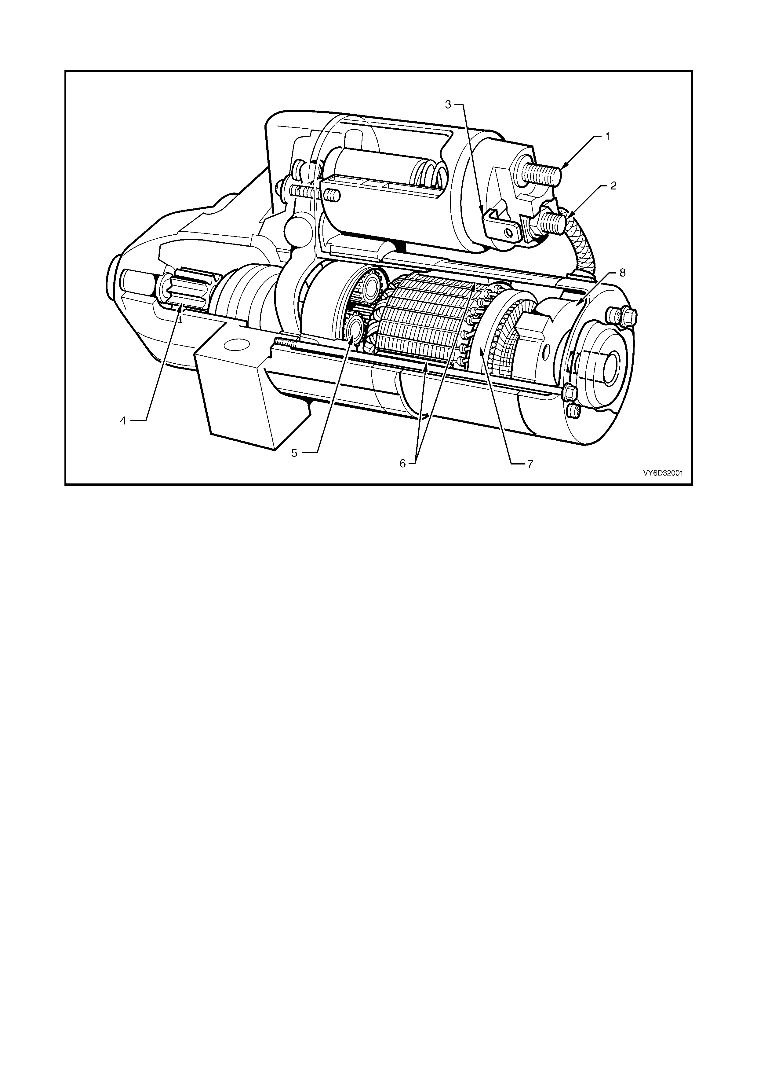
Figure 6D3-2-1
Legend
1. Solenoid Terminal 30 (Battery) 4. Drive Assembly 7. Armature
2. Solenoid M Terminal (Motor) 5. Planetary Gears 8. Brush Assembly
3. Solenoid Terminal 50 6. Permanent Magnets
T26D3201
1234
5
6
7
8
9
10
11
12
13
14
15
16
17
18
19
20
21
22
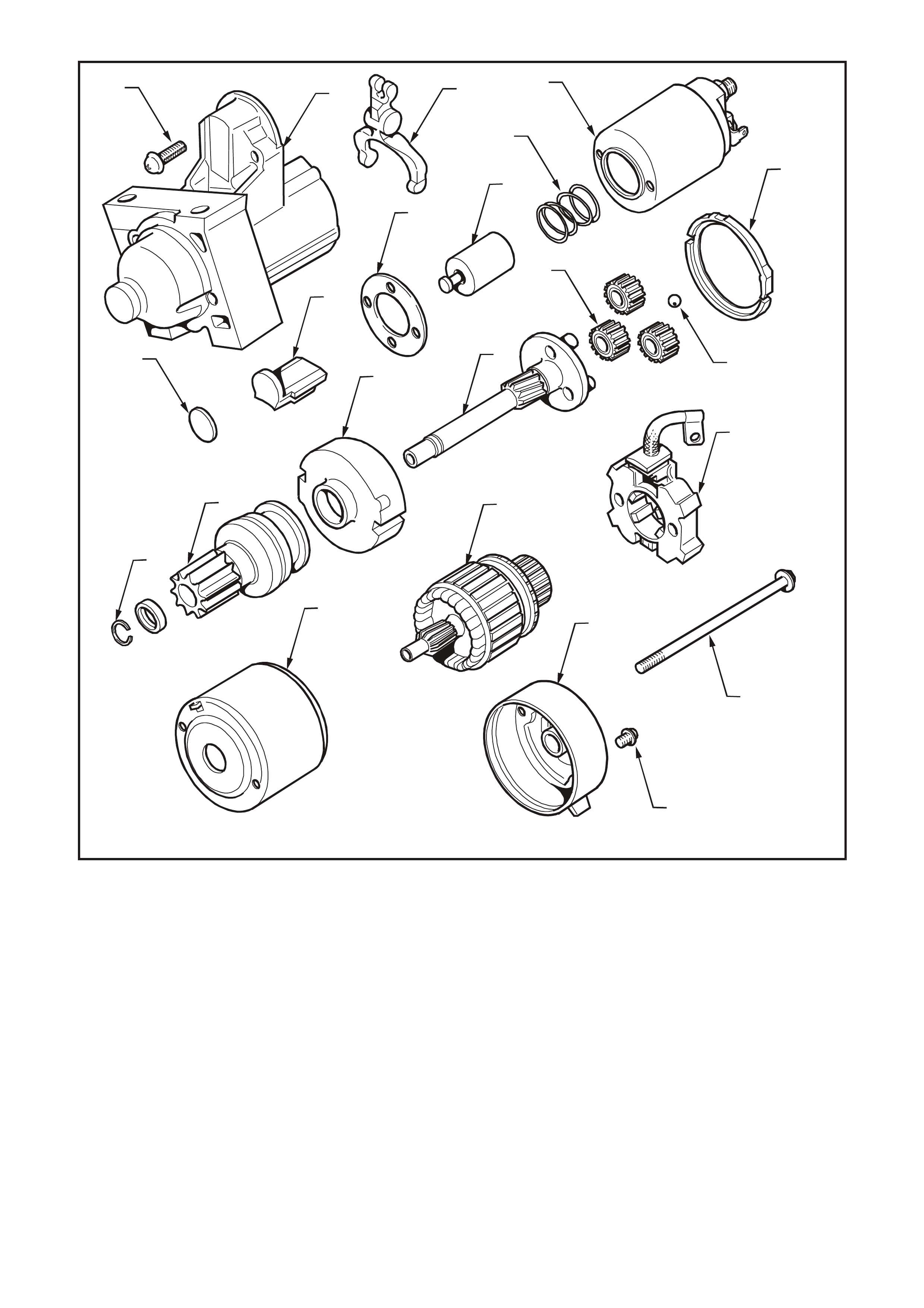
Figure 6D3-2-2
Legend
1. Solenoid switch mounting screw 9. Lever plate 16. Stopper ring and retainer
2. Drive-end housing 10. Sealing ring 17. Brush holder assembly
3. Fork lever 11. End float ball 18. Armature
4. Solenoid switch 12. Planetary gears 19. Field housing
5. Return spring 13. Drive shaft assembly 20. Through-bolt
6. Solenoid plunger 14. Gear assembly cover 21. Brush holder retaining screw
7. Solenoid switch spacer 15. Clutch gear assembly pinion 22. Commutator end shield
8. Rubber seal
1.1 OPERATION
CIRCUIT OVERVIEW
This starting system comprises:
•
••
•
battery
•
••
•
starter motor
•
••
•
ignition switch
•
••
•
neutral/back-up switch (on vehicles with automatic transmission)
•
••
•
Powertrain Interface Module (PIM)
•
••
•
Powertrain Control Module (PCM)
•
••
•
Body Control Module (BCM)
•
••
•
wiring.
The battery cable supplies a c onstant connec tion fr om the battery to terminal 30 of the solenoid switch. T he ignition
switch (and the neutral-start switch for automatic vehicles) controls the activation of the start relay.
With the ignition switch in the START position and the automatic transmission in P (park) or N (neutral), current
flows via the star t relay to term inal 50 of the s olenoid s witch. T his ac tivates the s olenoid s witch windings. T he pull- in
winding causes powerf ul magnetism to pull in the solenoid switch plunger. The hold-in winding holds the plunger in
and the pull-in winding deactivates.
The solenoid switch simultaneously closes the switch contacts to connect terminal 30 to the DC motor and pivots
the fork lever to engage the drive assembly to the flexplate/flywheel ring gear.
With the solenoid switch contacts closed, current flows from the battery through the DC motor, which spins and
provides cranking torque.
Figure 6D3-2-3
Legend
1. Battery 4. Neutral start switch 7. V8 PIM
2. Ignition switch 5. Neutral start bypass (manual trans) 8. V8 PCM
3. Start relay 6. Starter motor 9. BCM

2. MI NOR SERVICE OPERATIONS
2.1 SAFETY PRECAUTIONS
Observe the following precautions:
•
••
•
Refer to Section 00 CAUTIONS AND NOTES before disconnecting the battery.
•
••
•
Use the starter motor on a negative ground system only.
•
••
•
When installing a battery, fit the positive (+) cable to the battery first. Then fit the negative cable.
•
••
•
When using a slave battery for starting purposes, ensure that both batteries are connected in parallel, ie.
positive to positive terminals and negative to negative.
•
••
•
Only use jumper leads that have surge protection.
2.2 MAINTENANCE AND ON-VEHICLE TESTING
REGULAR CHECKS
Check the following at regular intervals:
•
••
•
Starter motor terminals – for corrosion and
loose connectors.
•
••
•
Wiring – for damaged insulation.
•
••
•
Mounting bolts – for tightness.
•
••
•
Battery terminals – for clean and secure
connections.
ON-VEHICLE CHECKS
Prerequisites
1. Ensure that the trans m ission is in P ( park ) or N
(neutral) and that the hand brake is applied.
2. Chock the wheels.
3. Turn all electrical loads off. e.g. Lights, fans
and entertainment system.
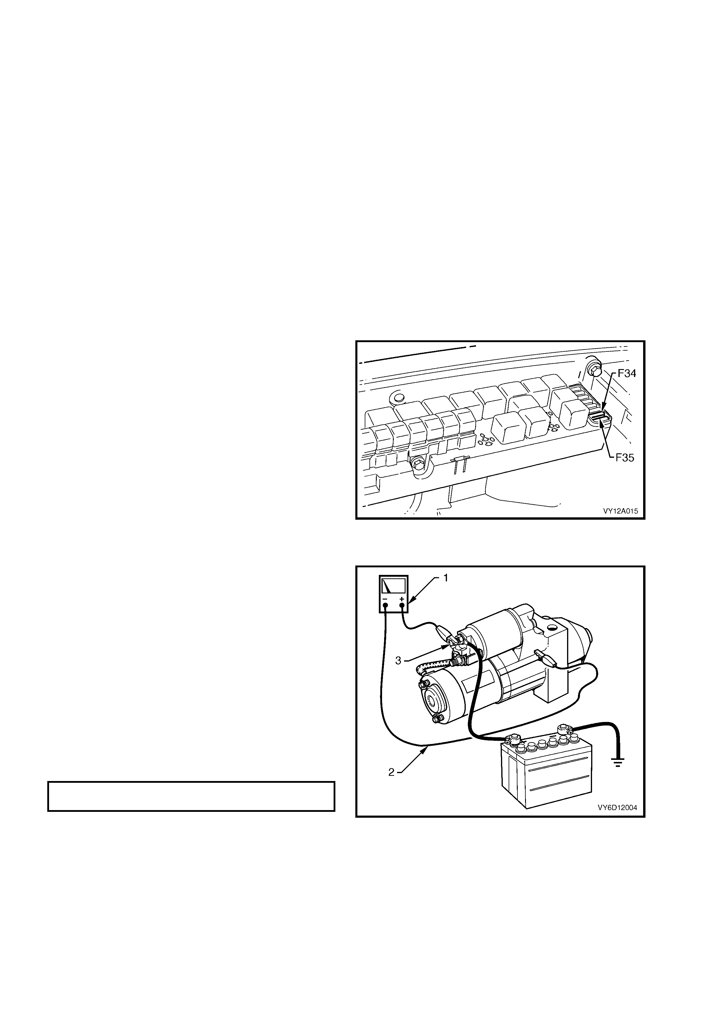
4. Remove fuses F34 and F35 from the engine
compartment fuse box to disable the ignition
and prevent the engine from starting. Refer to
Section 12O FUSES AND WIRING
HARNESSES.
Figure 6D3-2-4
Cranking voltage test
1. Connect the negative lead of a voltmeter (1) to
ground (2).
2. Connect the positive lead to terminal 30 (3) of
the solenoid switch.
NOTE: Do not crank the engine for more than
30 seconds at a time. Allow two minutes for the
starter motor to cool down between tests.
3. Crank the engine.
4. Record the voltage that displays during
cranking.
5. Remove and repair the starter motor if the
voltage is below the specifications and cranks
poorly. Refer to 3. MAJOR SERVICE
OPERATIONS in this section.
MINIMUM CRANKING
VOLTAGE 9 volts
Figure 6D3-2-5
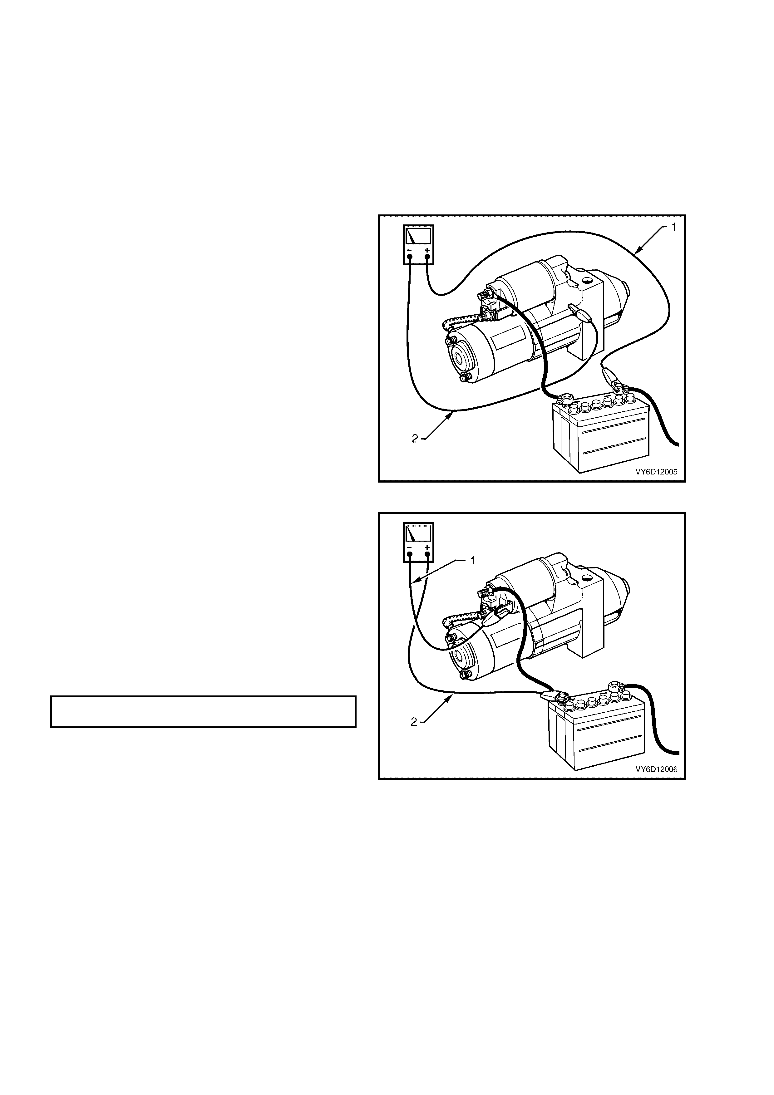
Bad-connection test
A bad connection appears as a voltage reading when the voltm eter leads are connec ted to two differ ent positive (or
negative) connections.
1. Connect the voltmeter positive lead to the positive battery post.
2. Connect the negative lead to the solenoid switch M terminal.
3. Record the voltage displayed while the engine is cranking.
4. Repeat this for the solenoid switch terminal 50, the positive battery terminal at the cable strands and the positive
battery terminal connector.
5. Restore all connections that show a significant resistance (voltage reading).
Starter motor ground test
1. Connect the voltmeter positive lead to the
negative battery post (1).
IMPORTANT: Connect the lead to the actual
battery post and not to the cable or connector.
2. Connect the voltmeter negative lead to the
starter motor housing (2).
3. Crank the engine.
4. Record the voltage that displays during
cranking.
6. Repeat this for the negative battery terminal at
the cable strands and the negative battery
terminal connector.
7. Restore all ground connections that show a
significant resistance.
Figure 6D3-2-6
Switching circuit test
1. Connect the negative lead of a voltmeter (1) to
the solenoid switch terminal 50.
2. Connect the positive lead to the positive battery
post (2).
3. Crank the engine.
4. Record the voltage that displays during
cranking.
5. If the voltage is above the s pec if ic ation, test the
solenoid switching cir cuit to locate the cause of
the high resistance and restore the connection.
MAXIMUM SWITCHING
CIRCUIT VOLTAGE DIFFERENCE 2.5 volt s
Figure 6D3-2-7

Current draw test
The c urrent draw can be m easured using a c urrent clam p in assoc iation with a m ultim eter or calculated as outlined
in the following procedure.
IMPORTANT: The battery must be fully charged and in serviceable condition before beginning this test.
1. Connect the positive lead of a voltmeter to the positive battery post.
2. Connect the negative lead of the voltmeter to the negative battery post.
3. Connect the positive lead of an ammeter to the positive battery post.
4. Connect the negative lead of the ammeter to a battery loading device, e.g. a carbon pile.
5. Connect the free lead of the battery loading device to the negative battery terminal.
6. Set the battery loading device to maximum resistance (open).
7. Crank the engine.
8. Record the voltage that displays during cranking.
9. With the ignition in the OFF position, adjust the battery loading device so that the voltmeter reading matches the
reading recorded in the last step.
10. Record the current draw from the battery loading device.
11. Set the battery loading device back to ‘open’.
12. Check that the current draw is within specifications.
CRANKING
CURRENT RANGE 120 – 140 amps
13. Remove and service the starter motor if the current draw is outside the specification.
3. MAJOR SERVICE OPERATIONS
3.1 STARTER MOTOR
LT Section – 02-070
REMOVE
CAUT ION 1: Th e starter motor is in clo se proximity to the right -hand exhaust manifold. Allow the engine to
cool before a ttempting to remove the starter motor.
CAUT ION 2: Do not allow the steering w heel to spin freely wh en the steering column is disconnected from
the steering rack. Damage to the restraint system clo ck spring can result rend ering this part of the system
inoperative. Ensure that the SRS clock spring remains in its centred position. Refer to Section 12M
OCCUPANT PROTECTION SYSTEM.
1. Refer to Section 00 CAUTIONS AND NOTES
before disconnecting the battery.
2. Disconnect the battery ground lead.
3. Jack up the front of the vehicle. For jacking
locations, refer to Section 0A GENERAL
INFORMATION.
4. Put safety stands in place.
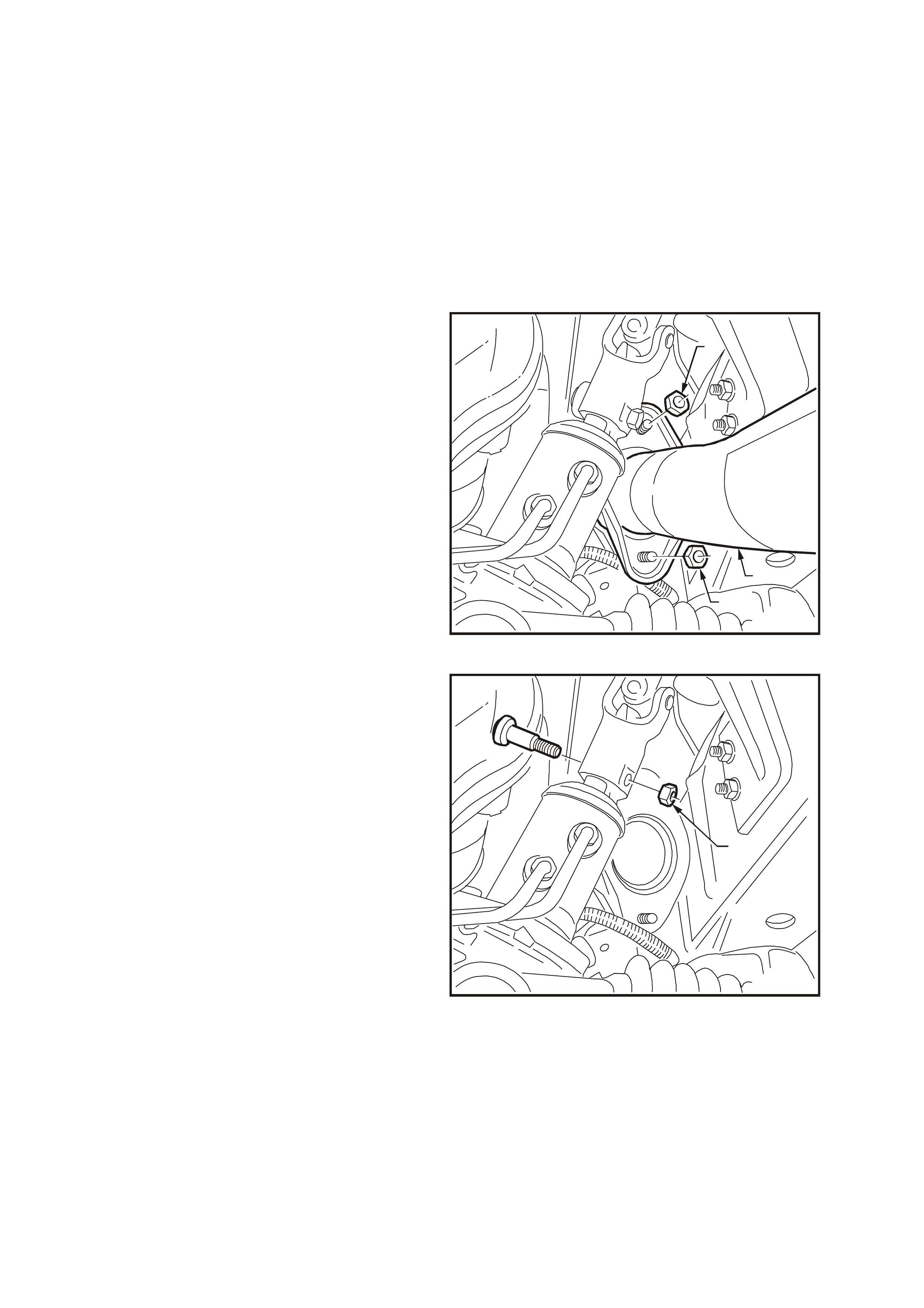
5. Rem ove the nuts (1) that secur e the right-hand
side exhaust engine pipe (2) to the manifold
flange.
6. Remove the bolts that secure the engine pipe
to the intermediate pipe.
7. Remove the engine pipe.
T26D3229
2
1
1
Figure 6D3-2-8
8. Remove the nut and bolt securing the steering
colum n universal joint to the s teering rack input
shaft (1).
9. Remove the universal joint from the input shaft.
T26D3230
1
Figure 6D3-2-9
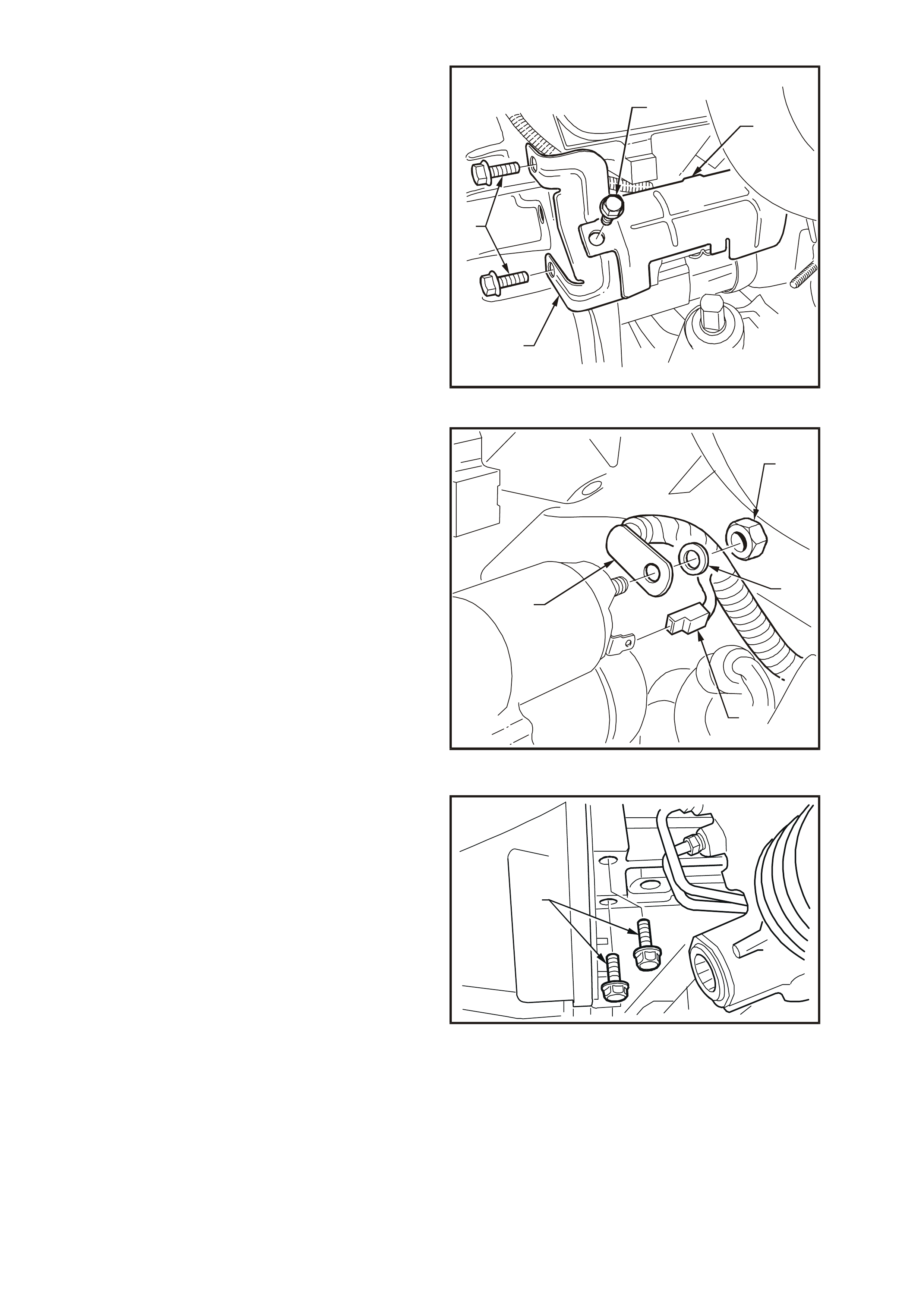
10. Remove the bolt securing the starter motor
heat shield to the mounting bracket (1)
11. Unclip the heat shield (2) f rom the s tarter m otor
solenoid.
12. Remove the heat shield.
13. Remove the two bolts (3) securing the heat
shield m ounting brack et (4) to the transm ission
bellhousing.
14. Remove the mounting bracket.
T26D3231
1
4
3
2
Figure 6D3-2-10
15. Pull the wiring harness connector f rom ter minal
50 of the solenoid switch (1).
16. Remove the nut (2), washer (3) and battery
lead (4) from terminal 30 of the solenoid switch.
T26D3207
2
1
3
4
Figure 6D3-2-11
17. Remove the starter motor mounting bolts (1).
T26D3206
1
Figure 6D3-2-12
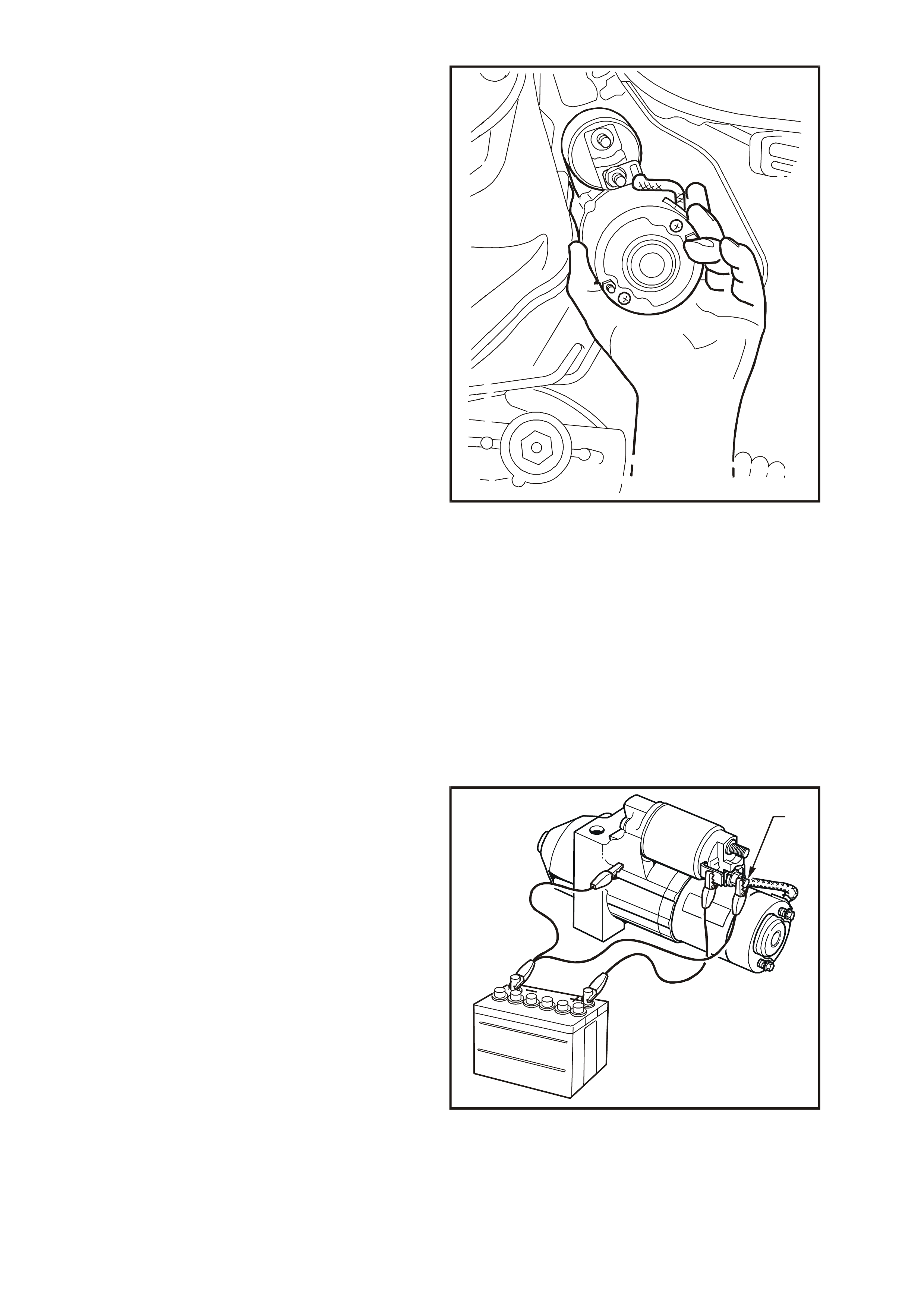
18. Manoeuvre the starter motor out and down
between the transmission bellhous ing and body
sub-frame.
T26D3208
Figure 6D3-2-13
STARTER MOTOR BENCH TESTS
Preliminary Checks
1. Check that the drive assembly is fully retracted.
2. Check that the drive assembly pinion turns freely on the planetary drive shaft.
3. Use a screwdriver to pry the drive assembly pinion to check that the planetary drive and armature rotate freely .
4. Perfor m the No Load Test ( outlined on the nex t page) if the dr ive as sembly is not fully retracted or the planetary
drive and armature do not rotate freely.
5. Disassemble and service the starter motor if it fails the No Load Test. Refer to 3. MAJOR SERVICE
OPERATIONS in this section.
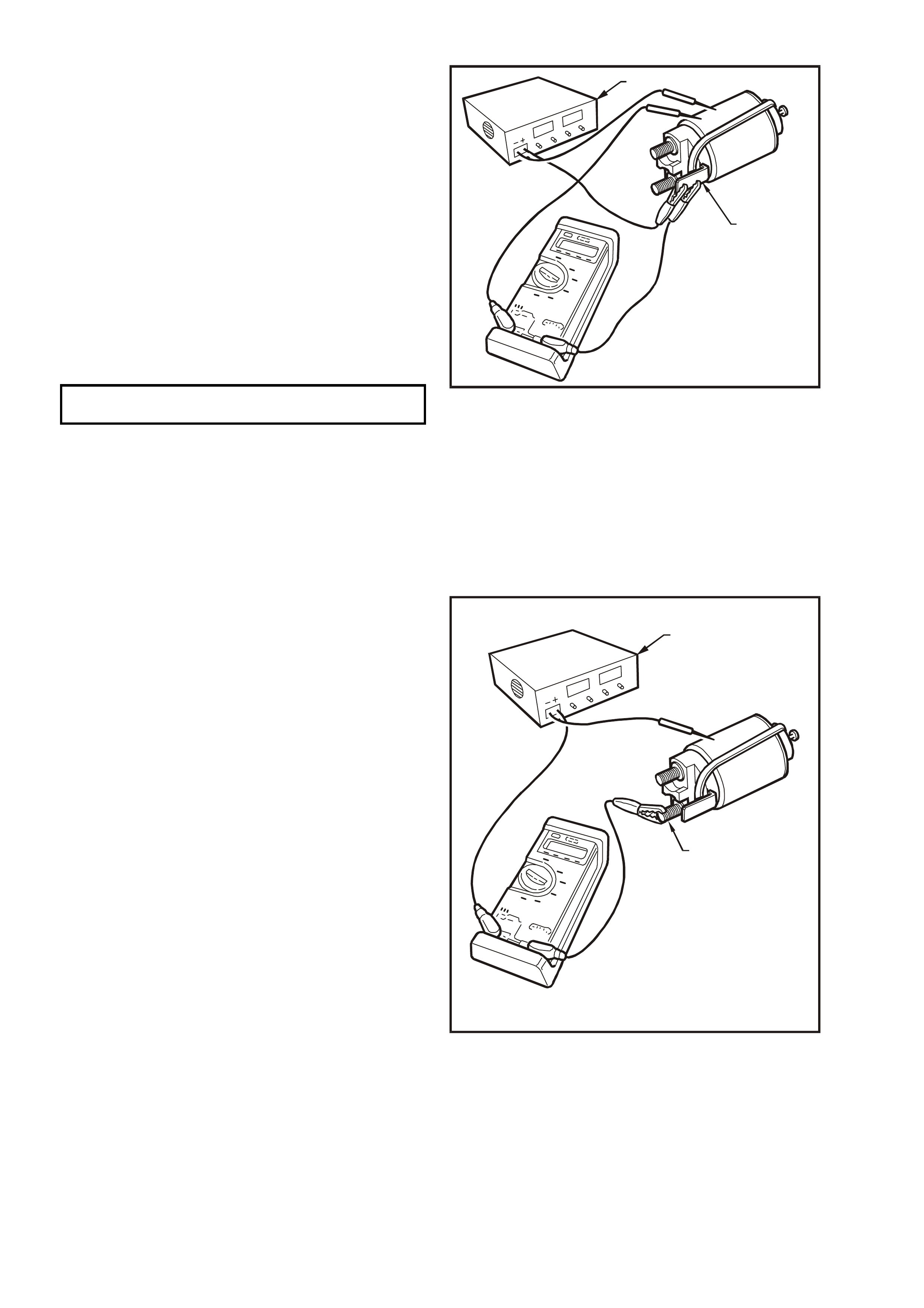
Pull-In Test
1. Remove the nut and washer from the M terminal of the solenoid switch.
2. Remove the field coil braided cable from the
M terminal.
3. Insulate the field coil braided cable.
4. Connect the starter motor to an auxiliary
battery, as follows:
a. Connect the battery negative post to the starter
motor housing (2) and the solenoid switch (3).
b. Connect the battery positive post to a free end
that can reach the solenoid switch.
5. Mom entarily hold the free end to term inal 50 of
the solenoid switch (4).
6. Check that the solenoid switch activates and
the drive assembly moves outward.
7. Disassemble and service the starter motor if
the solenoid switch activates but the drive
assembly does not move. Refer to 3. MAJOR
SERVICE OPERATIONS in this section.
8. Replace the solenoid switch if it does not
activate (there is no sound or movement).
T26D3202
1
Figure 6D3-2-14
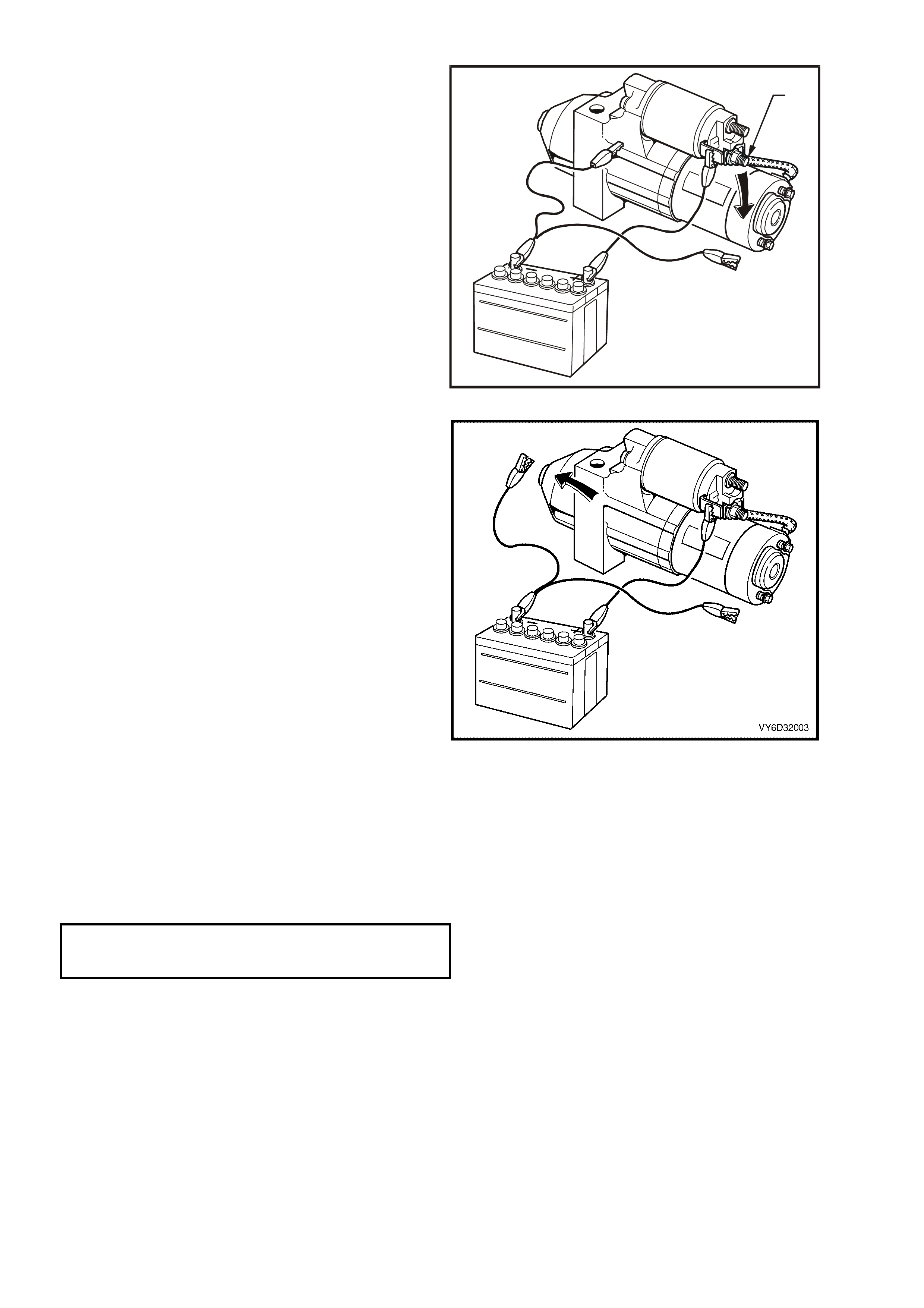
Hold-in Test
1. Connect the battery to the starter motor and
solenoid switch as for the Pull-In Test.
2. Disconnect the negative lead from the M
terminal of the solenoid switch (1).
3. Connect the lead from the battery positive post
to terminal 50 of the solenoid switch (2).
4. Check that drive assembly remains extended.
5. Disconnect the tes t lead f r om terminal 50 of the
solenoid switch.
6. Replace the solenoid switch if the drive
assembly returns back into the starter motor.
T26D3203
1
Figure 6D3-2-15
Drive assembly return test
1. Connect the battery to the starter motor and
solenoid switch as for the Hold-In Test.
2. Connect the test lead from the battery positive
post to terminal 50 of the solenoid switch (1).
3. Disconnect the negative lead from the drive-
end housing (2).
4. Check that the drive assembly returns back into
the starter motor.
5. Replace the solenoid switch if the drive
assembly does not retract.
Figure 6D3-2-16
No Load Test
1. Clamp the starter motor securely to a test bench.
2. Connect the starter motor as shown in Figure 6D3-2-17.
3. Close the start switch to activate the starter motor.
4. Record the speed of the planetary drive shaft,
current draw and the voltage.
5. Check that the readings are within the specifications.
RPM 2500
MAXIMUM CURRENT DRAW 90 amp s
TERMINAL VOLTAGE 11 volts
6. Disassemble and service the starter motor if the readings are not within the specifications. Refer to 3. MAJOR
SERVICE OPERATIONS in this section.
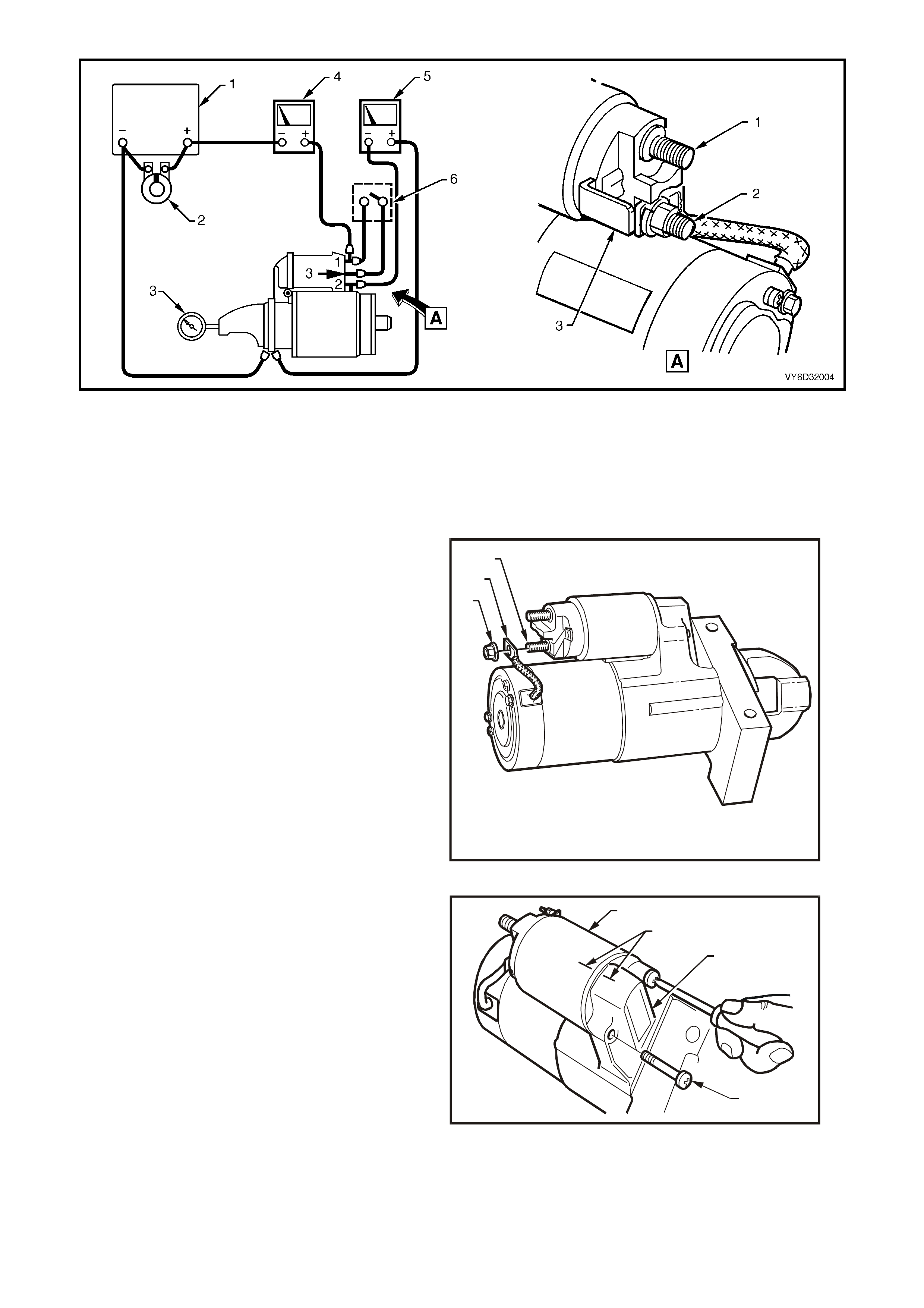
Figure 6D3-2-17
Legend
A. View of solenoid switch connections.
1. Battery 3. RPM indicator 5. Voltmeter
2. Carbon pile 4. Ammeter 6. Start switch
DISASSEMBLE
1. Clamp the star ter m otor , by the mounting lug in
the drive-end housing, in a vice with soft jaws.
2. Remove the nut (1) and braided cable (2) from
the solenoid switch M terminal (3).
T26D3209
123
Figure 6D3-2-18
3. Scribe aligning marks (1) on the drive end
housing (2) and the solenoid s witch housing (3)
to aid reassembly.
4. Remove the two solenoid switch mounting
screws (4). It may be necessary to loosen the
mounting screws using an impact driver.
NOTE: When using an impact driver, use care to
avoid damaging the drive end housing.
T26D3210
21
3
4
Figure 6D3-2-19
5. Remove the solenoid switch from drive end
housing.
IMPORTANT: Do not lose the plunger return
spring.
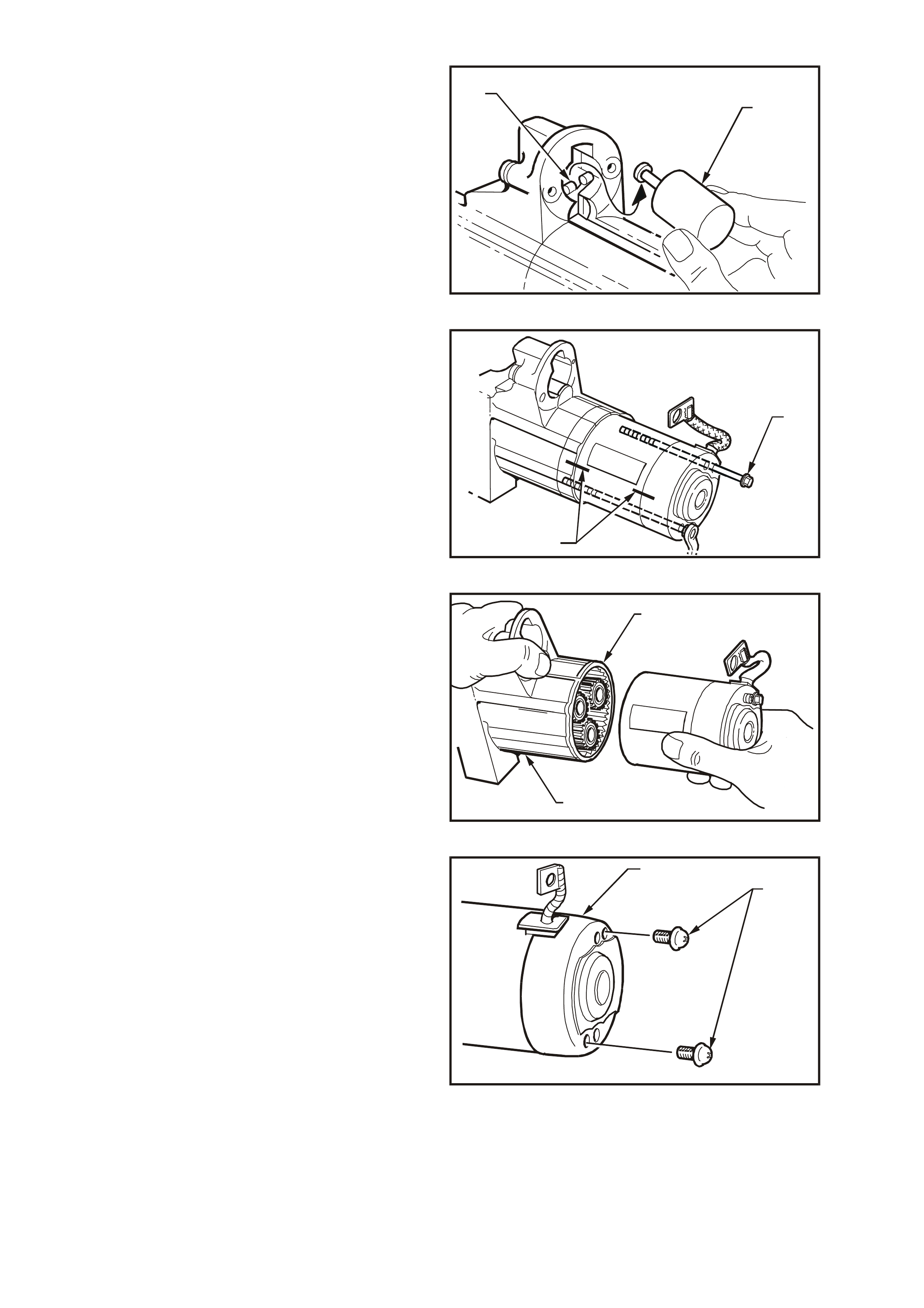
6. Unhook and remove the solenoid switch
plunger (1) from the drive assembly fork lever
(2).
T26D3211
21
Figure 6D3-2-20
7. Scribe aligning marks (1) on the drive end
housing, pole housing and commutator end
shield to aid reassembly.
8. Remove the two through-bolts (2).
T26D3212
2
1
Figure 6D3-2-21
9. Hold the sealing rubber (1) and the drive-end
housing (2) securely.
10. Remove the pole housing complete with the
armature and commutator end shield.
T26D3213
1
2
Figure 6D3-2-22
11. Remove the two screws (1) securing the
commutator end cover (2).
T26D3214
1
2
Figure 6D3-2-23
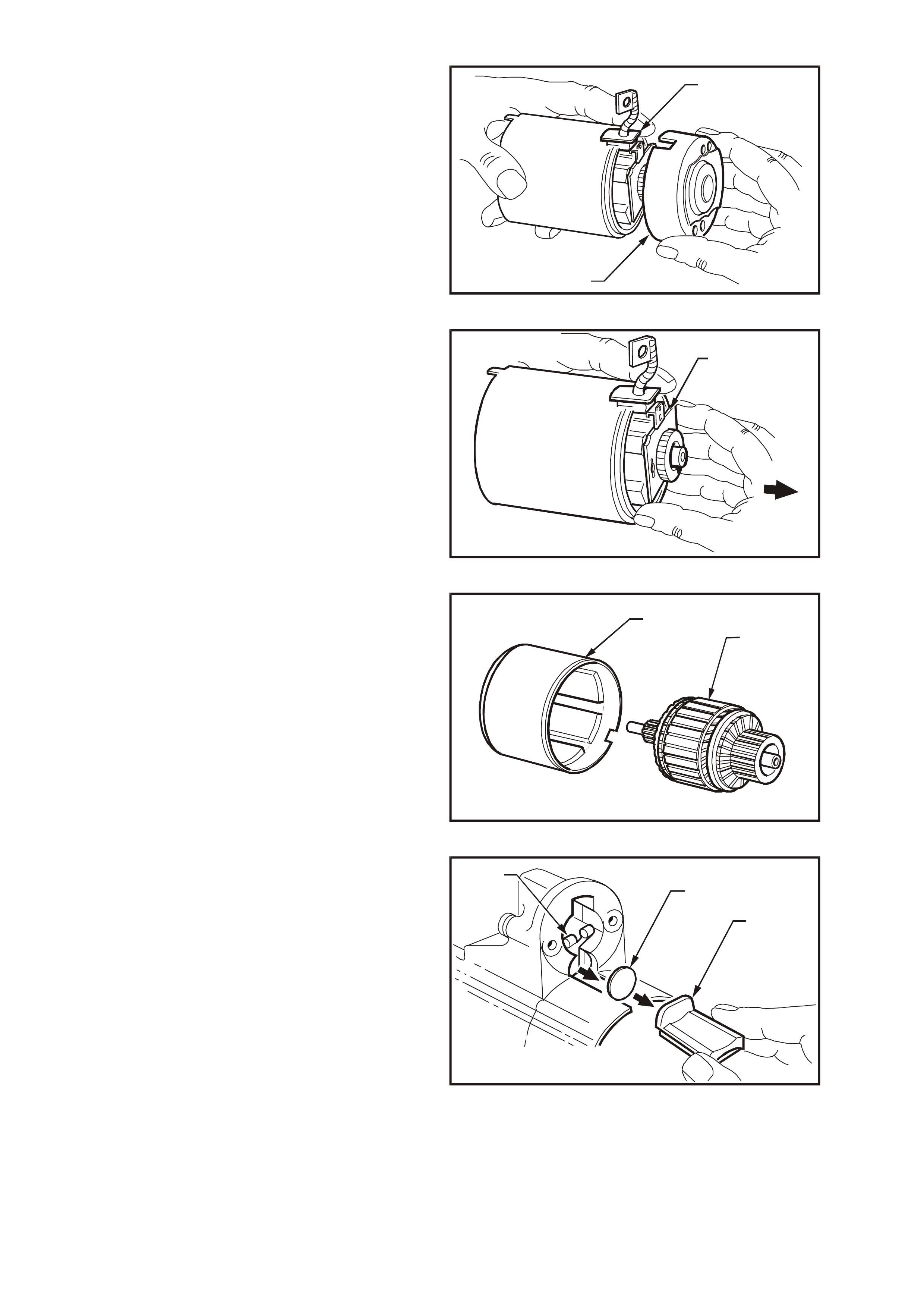
12. While holding the braided cable and rubber
seal (1), remove the commutator end cover (2).
T26D3215
1
2
Figure 6D3-2-24
13. Carefully remove the brush holder (1) from the
commutator.
T26D3216
1
Figure 746D3-2-25
14. Remove the armature (1) from the field housing
(2).
T26D3217
21
Figure 6D3-2-26
15. Take note of how the sealing rubber (1) is
installed.
16. Remove the sealing rubber from drive-end
housing.
17. Remove the fork lever plate (2).
18. Remove the drive assembly with the fork lever
(3).
19. Remove the planetary drive assembly.
20. Take note of the orientation of the fork lever.
21. Remove the fork lever from the drive assembly.
T26D3218
2
3
1
Figure 6D3-2-27
CLEANING AND INSPECTION
1. Clean and thoroughly inspect the disassembled components.
2. Wash all components (except the armature, brushes, solenoid switch and drive assembly) in a suitable cleaning
agent.
NOTE: Do not c lean the armatur e or permanent m agnets with cleaning solvent. Th is can damage the ins ulation or
contaminate the surfaces.
3. Clean the armature and permanent magnets with clean shop rags and compressed air.
NOTE: Do not clean the drive pinion assembly in solvent. This washes out the lubricant and can cause the drive
assembly to slip.
CAUTION: Use a non-volatile agent in a well ventilated area. Observe the safety regulations and
precautions issued by the manufacturer of the cleaning agent.
Check the Pole housing
1. Inspect the field housing and permanent magnet assembly for signs of damage, cracks and chips.
2. Replace the assembly if there are signs of damage.
Check the Armature
1. Check armature insulation res istanc e to gr ound
using a meggar or similar tester. A reading of
1 Megaohm or greater is required.
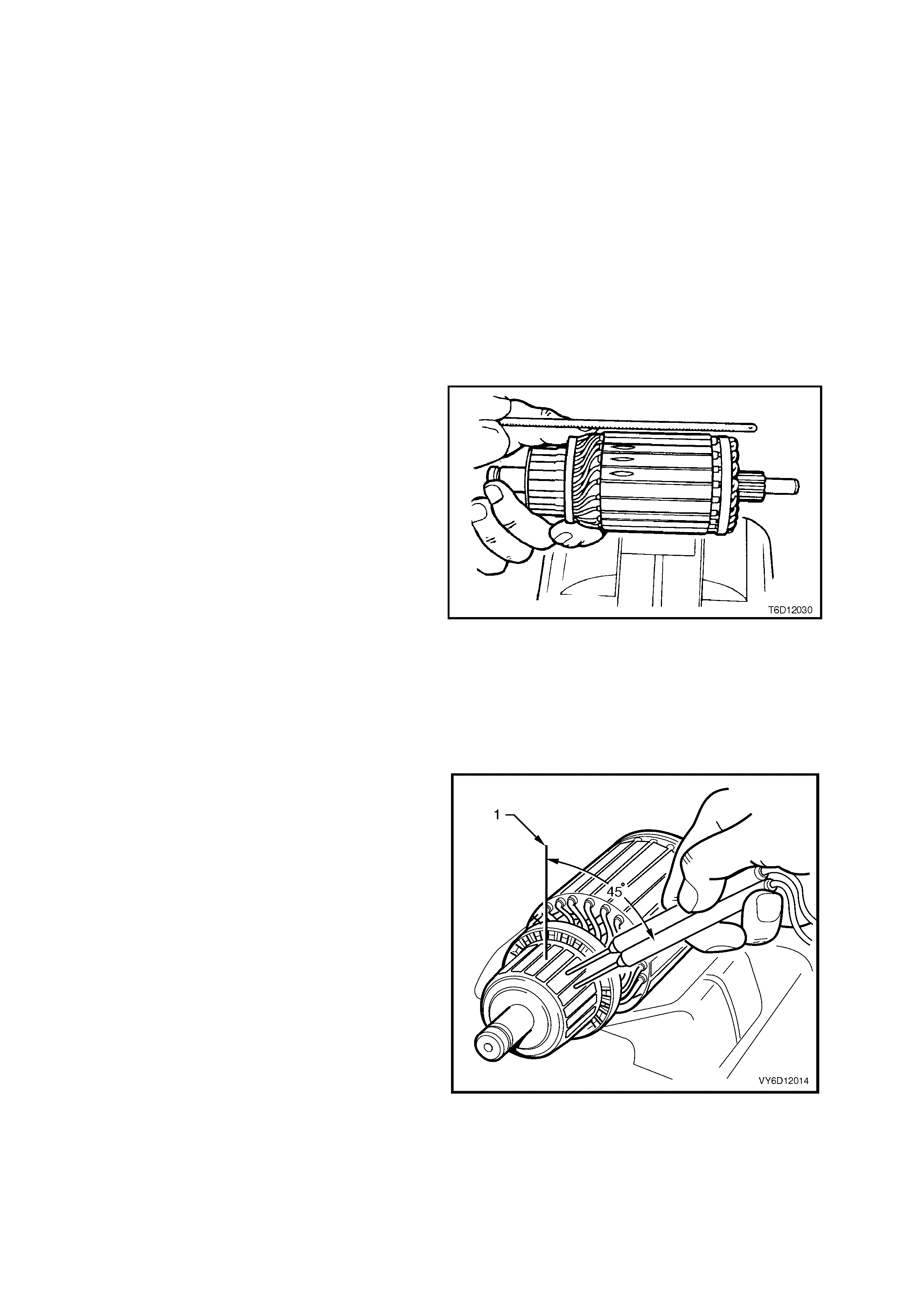
2. Check the armature for a short circuit.
3. Place the armature on a growler.
4. Switch the growler on.
5. Hold a hacksaw blade approximately 6 mm
above armature core and rotate the armature.
6. If the hacksaw blade vibrates significantly,
undercut the commutator, as follows:
a. Using a suitable small file, undercut
between each commutator segment to a
depth of approximately 0.8 mm.
b. Re-check the armature in the growler.
7. Replace the arm ature if the hacksaw blade still
vibrates significantly.
Figure 6D3-2-28
8. Exam ine the com mutator f or burnt or darkened s egments. A burnt or darkened com mutator s egment indicates
an open circuit winding attached to the segment.
9. Replace the armature if a segment is burnt or darkened.
10. Place the armature on a growler.
11. Use a voltmeter to measure the voltage
induced into the armature windings, as follows:
a. Choose two adjacent segments that are
approximately 45 degrees from the top of
the commutator (1).
b. Connect the voltmeter between the two
commutator segments.
12. Record the reading.
13. Rotate the armature in the growler so that the
next two commutator segments are in the
same position as the previous two.
14. Measure the voltage across these segments.
15. Record the reading.
16. Repeat these steps to measure the voltage
reading of all adjacent segments. The voltage
reading should be the same for each pair if
when positioned in the growler in the equivalent
location.
17. Replace the armature if a voltage reading
across any adjacent set of segments differs
significantly. This indicates that the armature
winding has an open circuit.
Figure 6D3-2-29
Check the Commutator
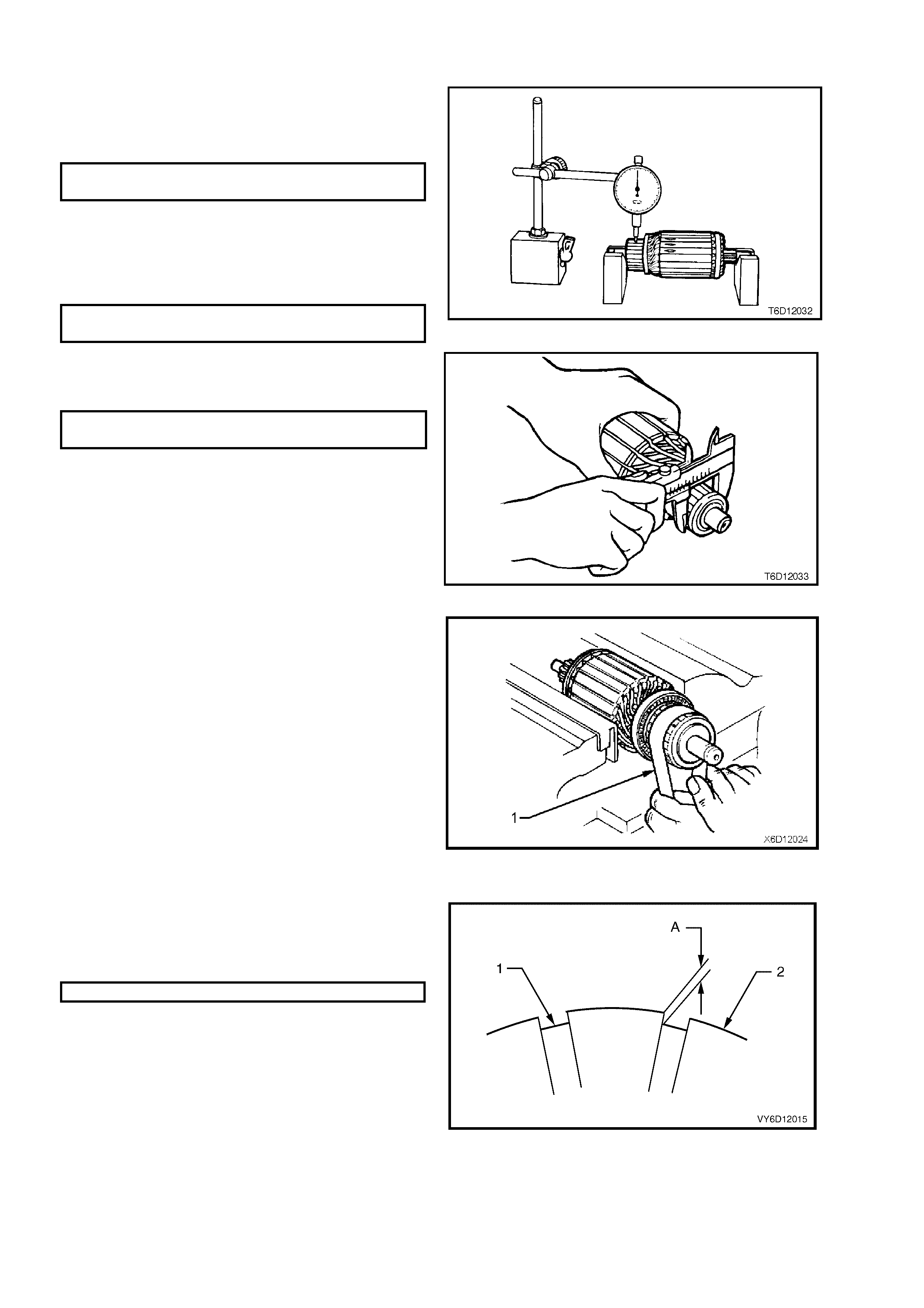
1. Check the armature laminations for out-of-
round using a dial gauge.
2. Replace the armature if the laminations are
out-of-round beyond specification.
MAXIMUM OUT-OF-ROUND OF
ARMATURE LAMINATIONS 0.1 mm
3. Check the commutator for worn or burnt
segments, high insulation between the
segments and for out-of-round.
4. Machine the commutator if any flaws exist or
the out-of-round value is outside specification.
MAXIMUM OUT-OF-ROUND
OF C OMMUTATOR 0.1mm
Figure 6D3-2-30
5. Check the commutator diameter.
6. Replace the armature if the commutator
diameter is below the specification.
MINI MUM COMMUTATOR
DIAMETER 28.4 mm
Figure 6D3-2-31
7. Machine the commutator, as follows:
NOTE: Do not clamp the armature by the
laminations when machining the commutator.
a. Turn the commutator in two stages; pre-
turning and finish turning.
b. Finish cut the commutator using a fine tool
of no more than 0.03 mm.
c. Polish the surface using 500 – 600 grade
emery cloth (1).
d. Brush out the commutator segment slots
using a stiff brush.
e. Check the diameter of the commutator.
8. Replace the armature if the diameter of the
commutator is less than the specification.
Figure 6D3-2-32
9. Chec k the depth of the insulating m ica (1) from
commutator surface (2).
10. Undercut the mica if the depth (A) is less than
0.2 mm.
DEPTH OF UNDERCUT 0.5 to 0.8 mm.
CAUTION: Use dust extraction when
undercutting.
11. Clean all dirt and debris from the commutator
segment slots.
12. Lightly polish the commutator to remove any
burrs.
13. Clean the commutator and ar mature thoroughly
with compressed air.
Figure 6D3-2-33
Check the Brushes
1. Check the brush holder springs for breakage and corrosion.
2. Replace the brush holder springs as necessary.
3. Check that each brush slides smoothly in the holder.
4. Check that all brush connections are good.
5. Check that the brushes are clean.
6. Check that brushes are not chipped.
7. Replace all of the brushes if a fault exists in any one of the brushes.
8. Check the length of each brush.
9. Replace all of the brushes if any brush is below specification.
MINIMUM BRUSH LENGTH 8 mm
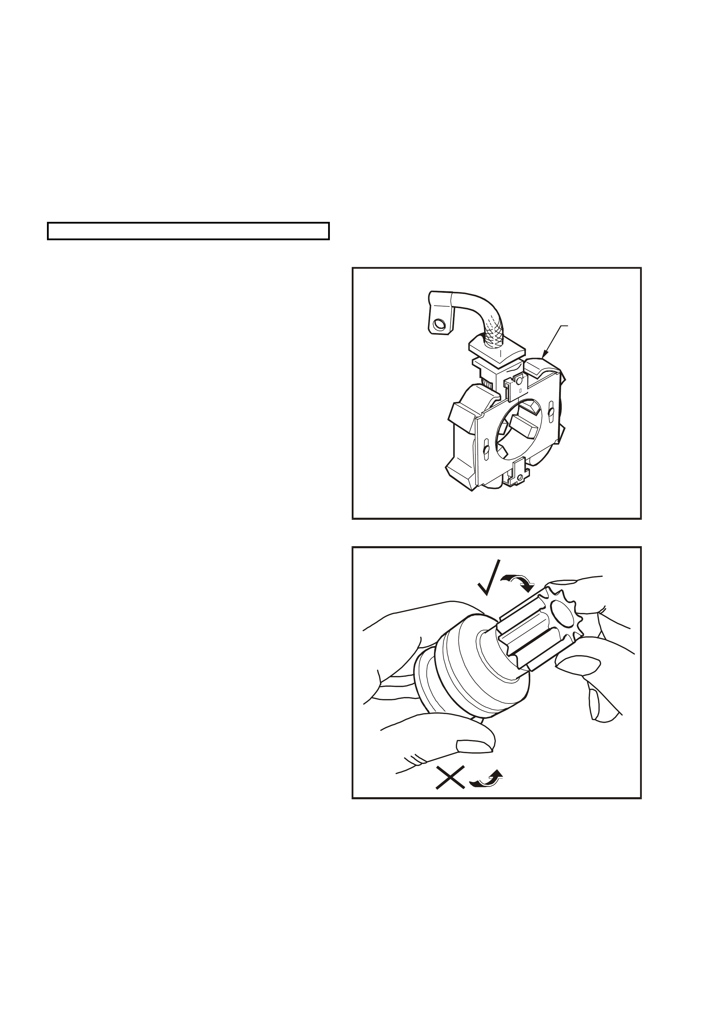
Check the Brush Plate Assembly
1. Check brush holder assembly (1) for cracks or
damage.
2. Replace the brush holder assembly as
necessary.
3. Connect the ohmmeter between a negative
brush holder and a positive brush holder.
4. Record the resistance.
5. Replace the brush plate assembly if an open
reading does not exist.
T26D3220
1
Figure 6D3-2-34
Check the Drive Assembly
1. Inspect the drive ass em bly pinion gear for worn
or chipped teeth or burrs.
2. Replace the drive assembly and inspect the
flexplate/flywheel ring gear teeth if the pinion
gear is damaged or broken. Refer to Section
6A3-1 ENGINE MECHANICAL – GEN III V8.
3. Check the operation of the pinion gear. Ensure
that that it rotates freely and smoothly in only
one direction.
4. Examine the internal bush of the pinion for
wear or scoring.
6. Replace the drive assembly if there is any sign
of damage or it rotates in both directions.
7. Inspect the fork lever contact surfaces and
pivots.
8. Replace the fork lever if it is damaged or
significantly worn.
T26D3221
Figure 6D3-2-35
Check the Bushes
1. Check the fit of the armature shaft in the commutator end shield.
2. Check the fit of the planetary drive shaft in the drive-end housing.
3. Replace the bushes if they are damaged or excessively worn.
4. Check the bush housings for wear from the shaft and for out-of-round.
5. Replace the housing if it is damaged or out-of-round.

Replace the Bushes
1. Remove the bushes, as follows:
a. Support the end shield using a very gentle grip in the vice.
b. Carefully tap the bush out with a suitable mandrel.
c. Repeat these steps for the drive-end bush.
2. Oil the new bushes as follows:
a. Seal the end of the bush.
b. Fill the bush with oil.
c. Seal the top of the bush.
d. Pressurise the oil until it seeps through the bush.
3. Gently press or tap each bush into position with a shouldered mandrel.
IMPORTANT: Do not ream sintered bushes.
Test the Solenoid Switch
1. Inspect the solenoid switch for any external
damage.
2. Replace the solenoid switch if it displays
significant damage.
3. Install the return spring and plunger into the
solenoid switch.
4. Check the movement of the plunger, as
follows:
a. Depress the plunger fully.
b. Release the plunger.
c. If the plunger sticks or binds in the switch
bore, clean or replace the solenoid switch
assembly as required.
T26D3222
Figure 6D3-2-36
5. Connect an ohm meter between term inal 50 (1)
and the M terminal (2).
6. Record the resistance reading.
7. Replace the solenoid switch if the resistance is
outside the specification.
PULL-IN WINDING
RESISTANCE @ 20° C 0.29 ohm
T26D3223
1
2
Figure 6D3-2-37
8. Connect an ohmmeter between the solenoid
switch housing (1) and terminal 50 (2).
9. Replace the solenoid switch if the resistance is
outside the specification.
HOLD-IN WINDING RESISTANCE
@ 20° C 0.98 ohm
T26D3224
1
2
Figure 6D3-2-38
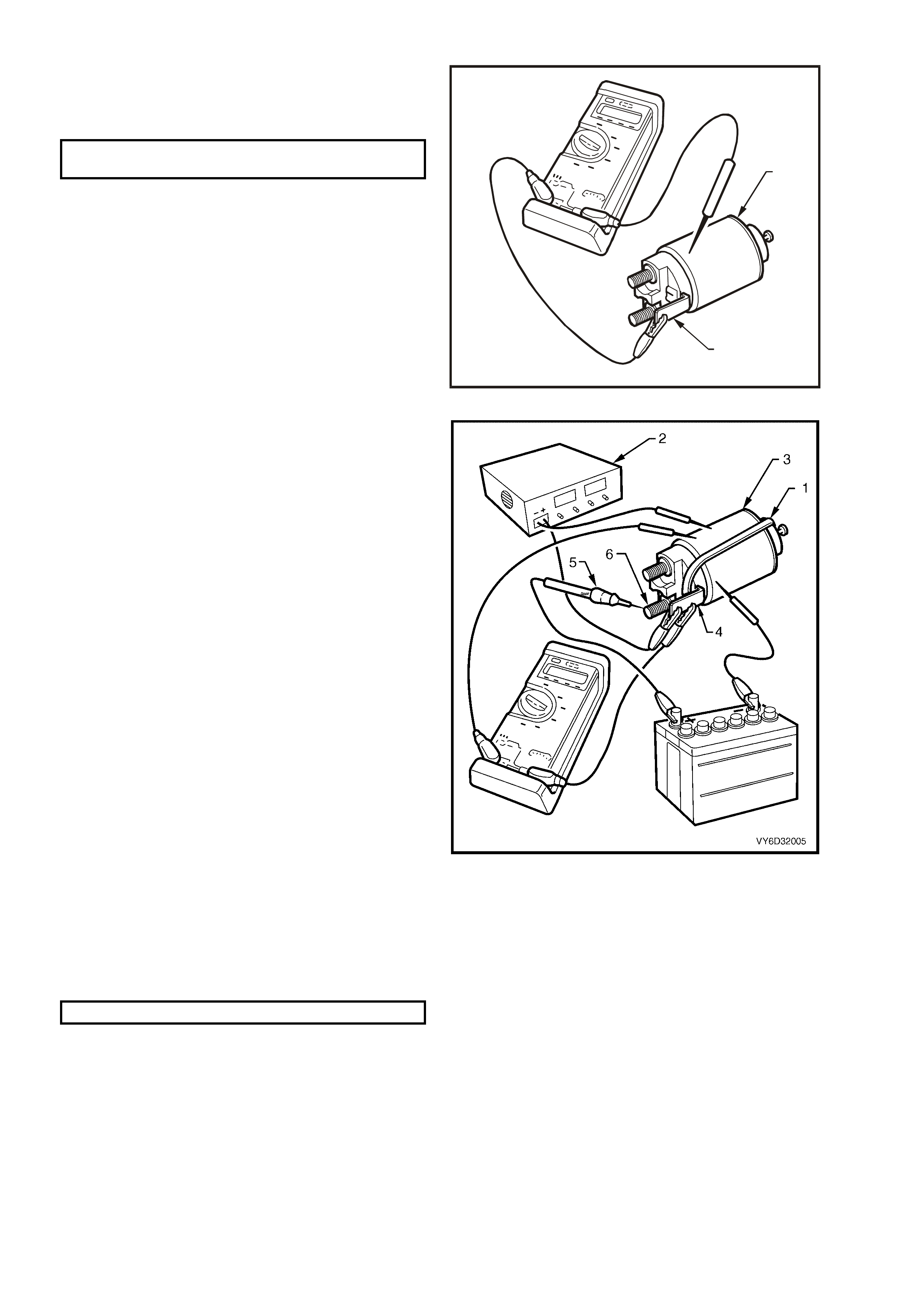
10. Fit a rubber band (1) around the plunger and
switch housing to avoid ejecting the plunger.
11. Hold the solenoid switch vertically with the
plunger pointing upwards.
12. Use a power supply (2) capable of supplying
30 amps or use a battery and a variable
resistor.
13. Set the power supply to 3.0 volts.
14. Connect the power supply negative lead to the
solenoid switch body (3).
15. Connect the power supply positive lead to
terminal 50 (4).
16. Connect a 12 volt test lamp (5) between
terminal30 (6) and the battery positive post.
17. Connect a voltmeter between terminal 50 and
the solenoid switch housing.
18. Press the solenoid plunger in until the tes t lamp
illuminates.
19. Allow the plunger to move out by 8 – 10 mm.
20. Hold the plunger in this position.
NOTE: The test duration for the following step
should be no more than TWO SECONDS.
21. Slowly inc rease the voltage on term inal 50 until
the plunger pulls in.
22. Record the voltmeter reading and remove the
voltage at terminal 50
23. Replace the solenoid switch if the voltage
reading is significantly higher than the
specification.
PULL-IN VOLTAGE @ 20°C 8 volts
24. Check the continuity across the main contacts
in the switch.
25. Increase the voltage on terminal 50 until the
plunger pulls in.
26. Ensure that the test lamp illuminates fully.
27. Replace the solenoid switch if the test lamp
illuminates poorly.
Figure 6D3-2-39
28. Set the power supply (1) to 24 volts.
29. Connect the power supply positive lead to
terminal 50 (2).
30. Connect the power supply negative lead to the
solenoid switch housing.
31. Press the plunger in fully.
32. Release the plunger. The hold-in winding
should hold the plunger in.
33. Replac e the s olenoid switch if the winding does
not hold the plunger.
34. Decrease the voltage until the plunger
releases.
35. Record the voltmeter reading.
36. Replace the solenoid switch if the voltage
reading is significantly higher than the
specification.
HOLD-IN VOLTAGE
SPECIFICATION @ 20°C 1.7 – 3.0 volts
37. Connect a 12 volt test lamp between terminal 30
and the 12 volt power supply.
38. Press the plunger in until the test lamp
illuminates.
39. Attempt to press the plunger into the solenoid
switch housing a further 1 mm.
40. Replace the solenoid switch if the plunger can
not move at least a further 1 mm.
T26D3226
1
2
Figure 6D3-2-40
41. Connect the positive lead of a 24 volt power
supply (1) to the voltmeter positive lead.
42. Connect the negative lead of a 24 volt power
supply to the solenoid switch housing.
43. Connec t the voltm eter negative lead to term inal
30 of the solenoid (2).
44. Press the plunger in fully.
45. Releas e the plunger. T he plunger should r eturn
to its rest position.
46. Replace the s olenoid switch if the plunger does
not return. This indicates that the windings
have inter-winding short circuit. When the
solenoid switch is connected in this way, the
winding fields are in opposition to each other.
T26D3227
1
2
Figure 6D3-2-41
REASSEMBLE
Refer to Figure 6D3-2-2 for identification of
components.
1. Reassemble the starter motor in the reverse
order of the disassembly procedure.
CAUTION: Dry all parts thoroughly before
assembly, taking care not to breathe in any
vapours.
2. Lubricate the following drive end housing,
com mutator end shield and the drive assem bly
to planetary drive bush with clean engine oil.
3. Lightly coat the following parts with
Molybdenum Disulphide grease (Holden
Specification HN 1271 or equivalent):
a. armature shaft helix
b. helix inside the drive assembly
c. inside of the ring gear
d. armature to commutator end shield
washers (thrust and adjustment).
4. Half fill the commutator end shield dust cover
with grease.
5. Fit the commutator end thrust washer (1) onto
the armature.
6. Fit the end shield.
7. Fit the adjustment washer/s.
8. Fit the horse shoe clip.
9. Measure the clearance between the
adjustment washer/s and the commutator end
cover.
10. Add, change or omit adjustment washers until
this clearance is within specification.
ARMATURE END PLAY
SPECIFICATION 0.5 – 2.0 mm
11. Remove the commutator end shield from the
armature.
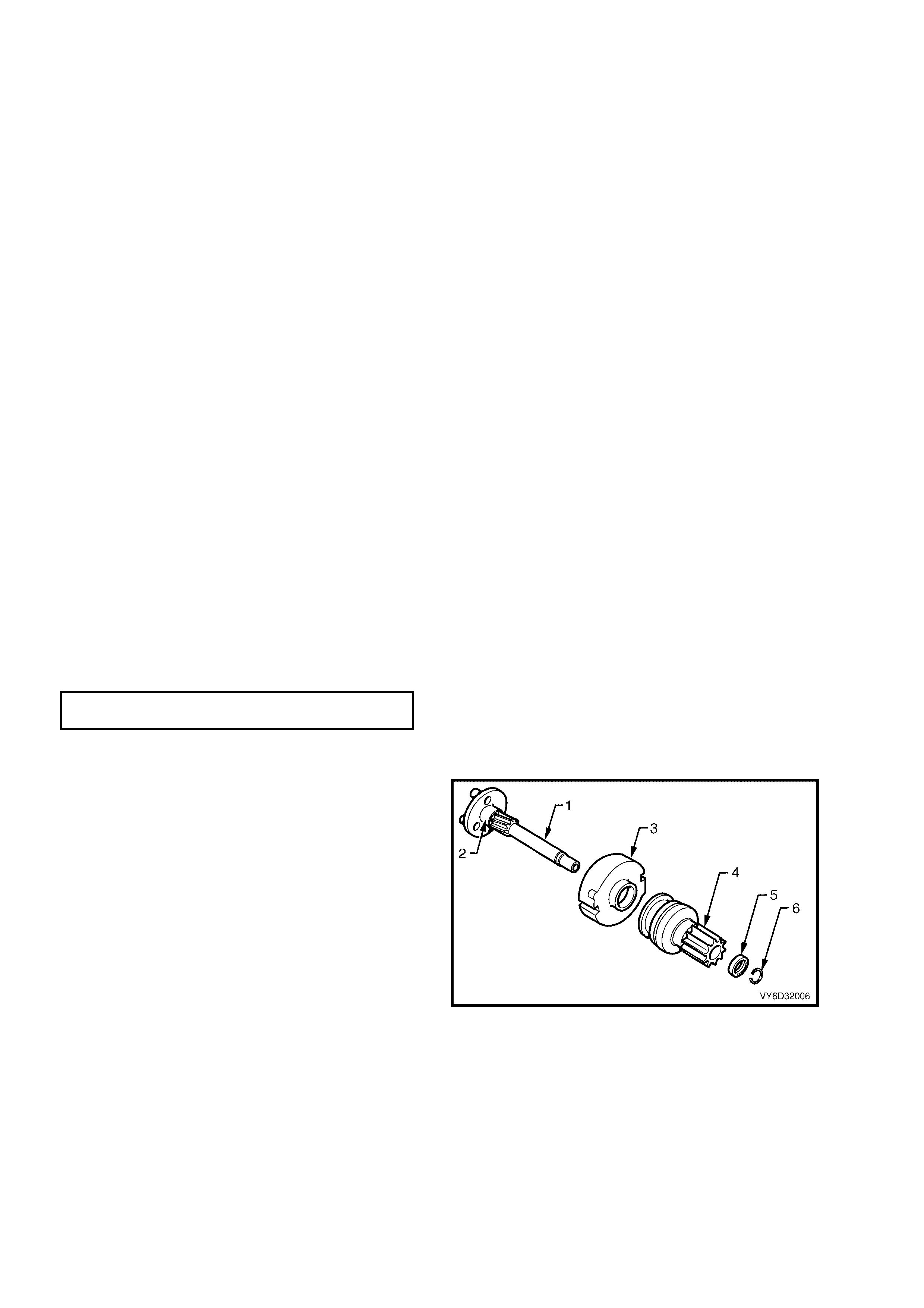
12. Assemble the drive components onto the
planetary drive shaft (1) as follows:
a. drive assembly bush (2)
gear assembly cover (3)
drive assembly (4)
stop ring retainer (5)
stop ring (6).
Figure 6D3-2-42
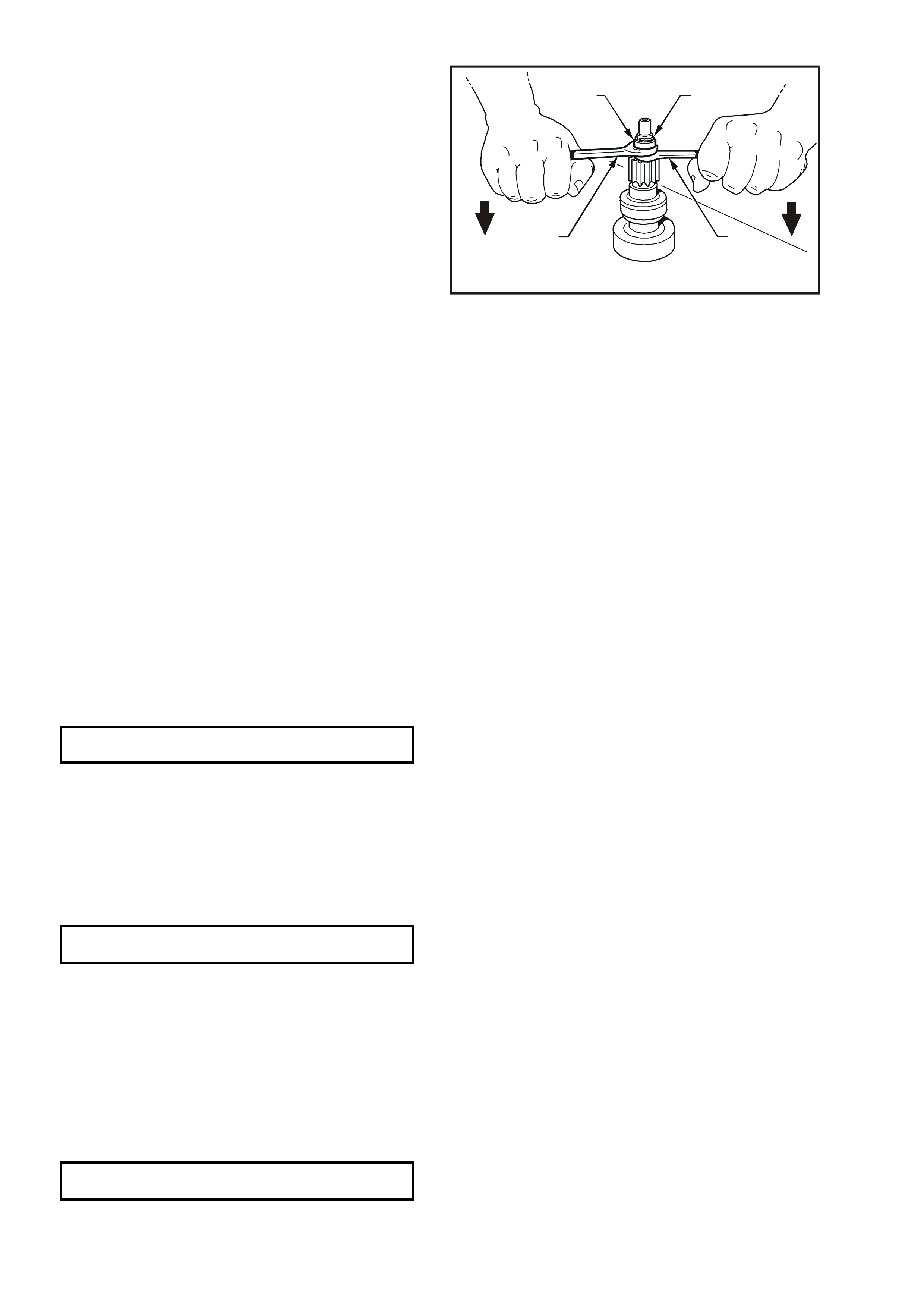
13. Secure the stop ring (1) with the stop ring
retainer (2), as follows:
a. Place the drive assembly on a firm surface
as illustrated in Figure 6D3-2-4.
b. Slide the stop ring retainer up to the stop
ring.
c. Fit two open-end spanners (3 and 4) in
between the stop ring retainer and the drive
assembly.
d. Lever the spanners against the retainer
until it clicks over the stop ring.
T26D3234
12
33
Figure 6D3-2-43
14. Check that the drive assembly moves freely up and dow n the planetary drive shaft.
15. Check the drive assembly clutch action.
16. Fit the fork lever.
17. Slide the planetary drive assembly into the drive end housing.
18. Rotate the planetary drive ring-gear to position it correctly in the drive end housing.
19. Position the fork lever pivot into the drive end housing.
20. Install the sealing rubber behind the fork lever pivot ensuring that the sealing rubber is aligned correctly.
21. Assemble the armature into the field frame assembly with the commutator at the rear of the housing.
22. Install the brush plate assembly onto the commutator, as follows:
a. Lightly grip the armature shaft in a vice with soft jaws.
b. Push two adjacent brushes into the brush holders.
c. Angle the brush plate assembly onto the commutator.
d. Press the remaining brushes into the brush holders.
e. Carefully manoeuvre the assembly onto the commutator.
NOTE: Do not use force when fitting the brush assembly.
23. Slide the commutator end shield onto the armature shaft.
24. Align the screw holes in the commutator end shield with the brush plate assembly.
25. Install the dust cover retaining screws.
DUST COVER SECURING SCREW
TORQUE SPE CIFICATION 1.4 – 2.0 Nm
26. Assemble the field frame assembly to the drive-end housing.
27. Check that the marks made prior to disassembly align.
28. Fit the armature into the planetary drive.
29. Rotate the pinion gear slightly to engage the armature gear.
30. Align the cutout in the pole housing with the sealing rubber in the drive end housing.
31. Install the through-bolts.
32. Tighten the through-bolts.
THROUGH-BOLT
TORQUE SPECIFICATION 7.5 Nm
33. Lightly coat the solenoid switch plunger with Molybdenum Disulphide grease (Holden Specification HN 1271 or
equivalent).
NOTE: If too much grease is applied, it can enter the contact chamber and cause contact problems.
34. Assemble the return spring and plunger into the solenoid switch.
35. Pull the pinion gear forward to make the fork lever more accessible.
36. Assemble the solenoid plunger onto the fork lever and into the drive-end housing.
37. Install the solenoid switch housing onto the drive-end housing ensuring that the marks made prior to
disassembly align. (Terminal 30 faces away from the field housing.)
38. Install and tighten the solenoid switch mounting screws.
SOLENOID SWITCH MOUNTING SCREW
TORQUE SPECIFICATION 5.5 Nm

39. Fit the braided cable onto the M terminal.
40. Fit the washer and nut to the M terminal.
THREADED M TERMINAL NUT
TORQUE SPECIFICATION 9.0 Nm
41. With the starter motor reassembled, perform a No Load Test. Refer to 3.1 STARTER MOTOR, STARTER
MOTOR BENCH TESTS in this section.
42. If the starter motor fails the No Load Test specification, check for tight brushes, dirty brushes and high
resistance connections.
43. Diagnose and repair all faults.
REINSTALL
1. Install the starter motor by following the removal procedure in the reverse order.
2. Tighten all fasteners to the correct torque specification.
STARTER MOTOR
MOUNTING BOLT
TORQUE SPECIFICATION 40 – 60 Nm
TERMINAL 30 (B+) NUT
TORQUE SPECIFICATION 6 – 10 Nm
3. Install the exhaust engine pipe ensuring that the engine pipe is clear of any underbody components. Refer to
Section 8B EXHAUST SYSTEM.
4. Assemble the steering components in accordance with Section 12M OCCUPANT PROTECTION SYSTEM.
5. Check that the starter motor operates correctly.

4. DIAGNOSIS
Many starting problems can be categorised as follows:
•
••
•
The starter motor will not crank the engine.
•
••
•
The engine will crank at normal speed but will not start.
•
••
•
The starter cranks the engine very slowly.
W hen investigating a starting problem, first check the Probable Faults below; removing the starter motor might not
be neces sary. If the engine crank s over at the nor mal speed but will not star t, the problem is in the ignition system,
the fuel system or the engine.
SYMPTOM PROBABLE FAULT
Speed, torque and current low. •
••
•
High resistance in the motor. Poor positive brush terminal connection or
brush condition. Burnt segments on the commutator.
Speed and torque low, current high. •
••
•
Tight or worn bearings, bent armature shaft, insufficient end-play, armature
polling, short-circuit in the armature or grounded armature.
Armature does not rotate. No current. •
••
•
Open circuit in the armature, positive brushes or solenoid. If the
commutator is burnt, there may be poor contact between the brushes and
the commutator and excessively worn or sticking brushes.
Armature does not rotate. High
current. •
••
•
Short-circuit in the solenoid switch. Armature physically prevented from
rotating.
Excessive brush movement causing
arcing at commutator. •
••
•
Low brush spring tension, worn or out-of-round commutator, thrown or high
segment on the commutator or insulation protruding between commutator
segments.
Excessive arcing at commutator. •
••
•
Defective armature winding, sticking brushes or dirty commutator.
Armature rotates but pinion does not
mesh with ring gear. •
••
•
Pinion bearing fouled or burred. Damaged flexplate/flywheel ring gear or
broken pinion teeth.
NO CRANKING, NO SOUND FROM SOLENOID
STEP ACTION RESULT YES NO
1. 1. Turn headlamps and dome lamps on, turn ignition
to start position. Lamps dim? Go to Step 2 Go to Step 3
2. 1. Check battery
2. Charge battery
3. Check generator
4. Check current draw
5. Check cranking voltage at battery posts
Is 9.6 volts
present? Go to Step 7 Test battery.
If OK repair
starter motor
3. 1. Turn on radio Operate OK? Go to Step 4 Go to Step 6
4. 1. Check voltage at solenoid switch terminal 50. Is 7.0 volts
present? Repair starter Go to Step 5
5. 1. With key in start position, check at ignition terminal
50. Is 7.0 volts
present? Repair wiring
ignition switch
starter motor
Replace ignition
switch
6. 1. Check engine main wiring harness fusible link and
ignition connections All OK? Go to Step 7 Repair as
necessary and
recheck starting
system
7. 1. Check voltage from engine block to battery
negative terminal, with key in start position
(Positive lead on block)
Is 0.5 volt or
more
present?
Clean and tighten
negative cable
connection and/or
replace cable
Go to Step 8
8. 1. Check cranking voltage at starter “B” terminal Is 9.0 volts
present? Check fuse and
engine to main
wiring harness
connectors
Clean and tighten
positive cable
connection and/or
replace cable
SLOW CRANKING, SOLENOID CLICKS OR CHATTERS
Ensure that the battery, cables and connections are in good order. Refer to Section 12A BATTERY AND CABLES.
IMPORTANT: Remove fuse F14 from the passenger compartment relay & fuse housing. This prevents fuel
injection and ignition during engine cranking. Refer to Section 12O FUSES AND WIRING HARNESSES.
Make all voltmeter readings with the ignition key in the START position.
Ensure that the engine is at room temperature or normal operating temperature and in good working order.
STEP ACTION RESULT YES NO
1. 1. Measure the cranking voltage at the battery posts. 9.6 volts or
more? Go to Step 2 Go to Step 3
2. 1. Measure the voltage from the battery negative
terminal to the engine block (positive lead on
block).
0.5 volts or
more? Repair negative
cable and
connections
Go to Step 4
3. 1. Charge and load test the battery. Battery OK? Repair starter Replace battery
4. 1. Measure the voltage at terminal 30 of the solenoid
switch.
2. Clean and tighten the starter motor connections.
9.0 volts or
more? Repair starter Go to Step 5
5. 1. Clean and tighten the positive cable connections. Connections
OK? Replace cable
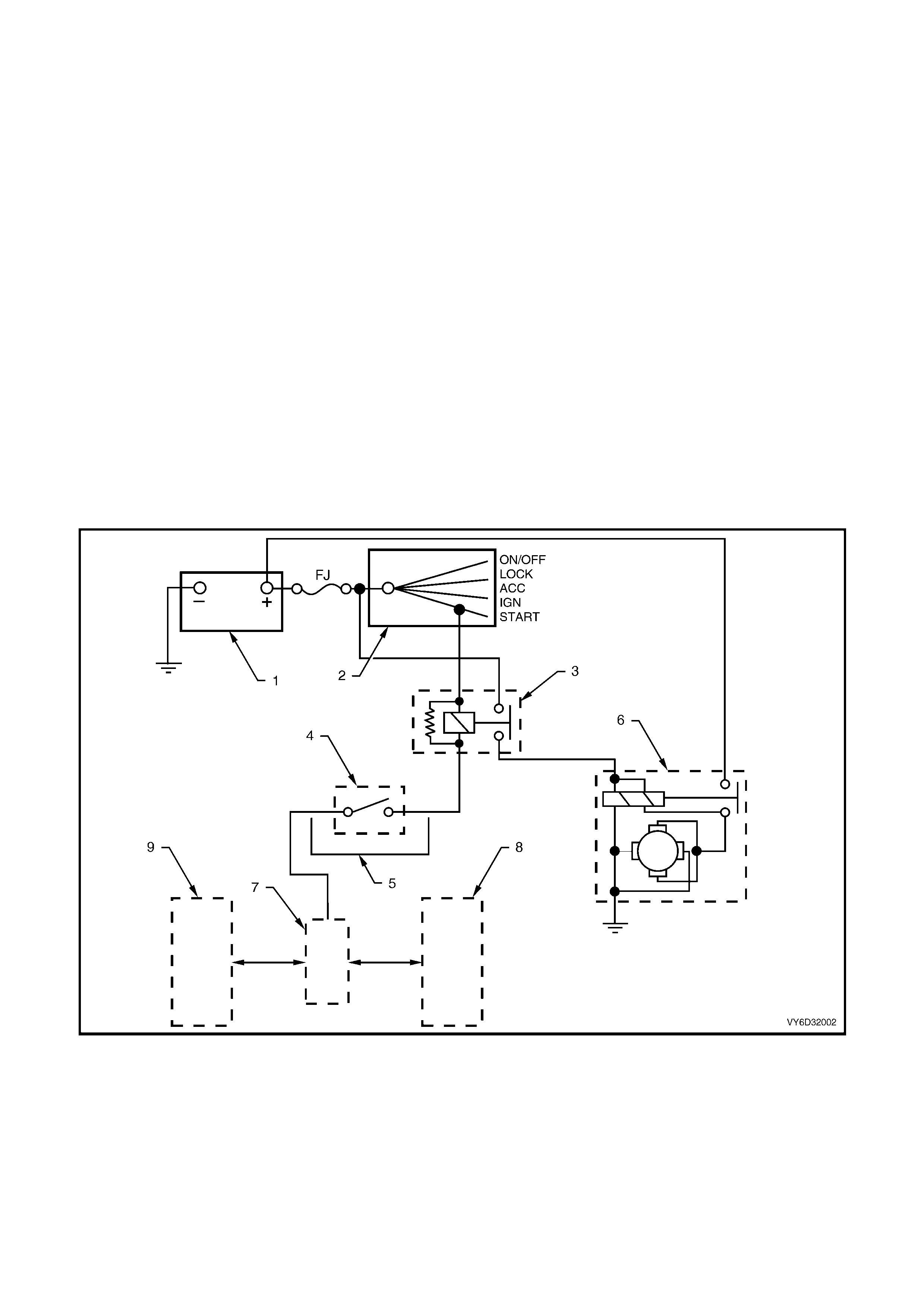
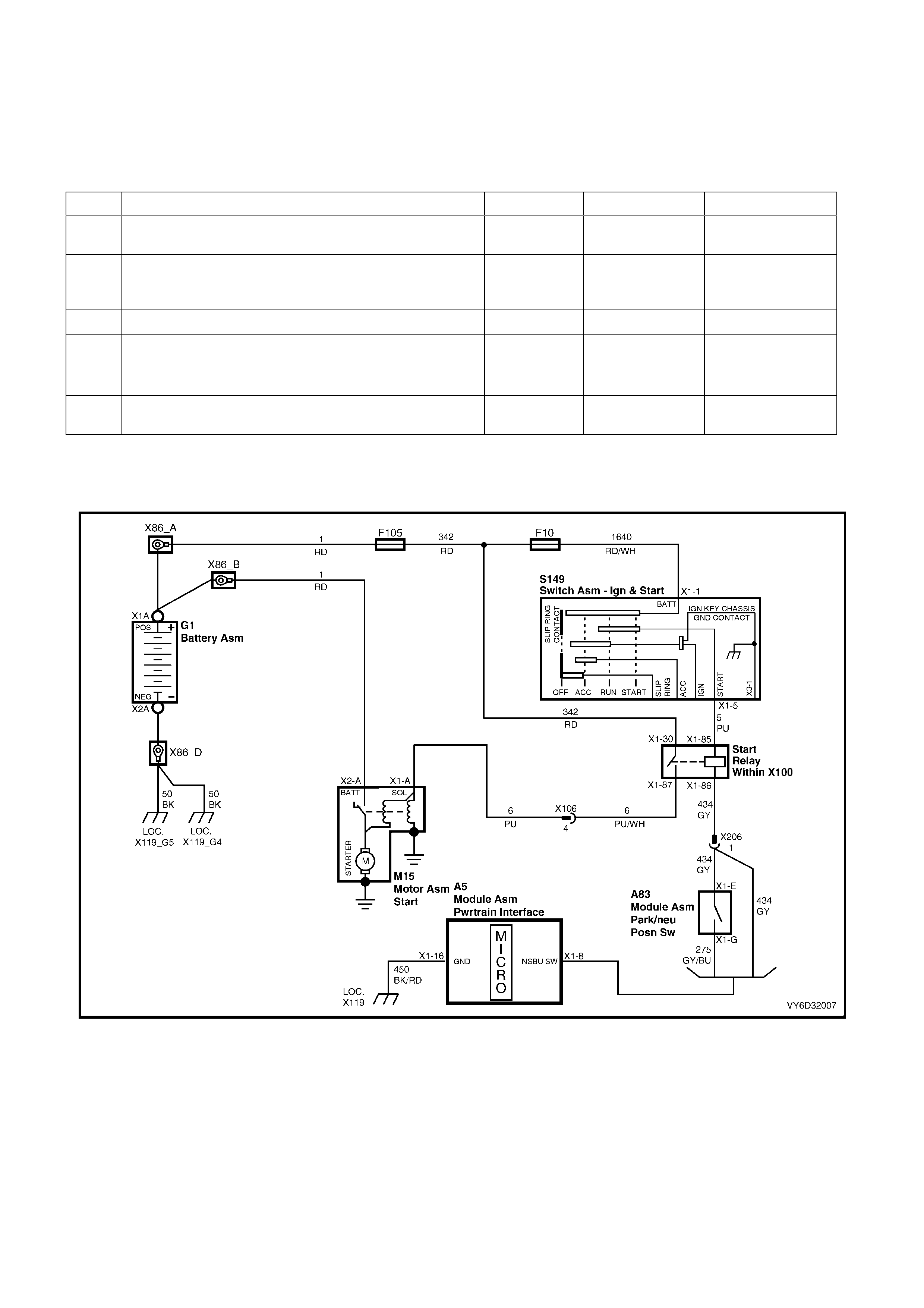
CIRCUIT DIAGRAM
Refer to the GEN III V8 engine starting circuit diagram (Figure 6D3-2-44) to assist with diagnosing starting system
faults.
Figure 6D3-2-44

5. SPECIFICATIONS
Type......................................................................................... Delco Remy
Description............................................................................... Six-pole, four brush planetary
drive train
Rotation (drive end view)......................................................... Clockwise
Number of pinion teeth............................................................ 10
No Load Test:
Minimum cranking voltage....................................................... 9 volts
Maximum current..................................................................... 90 amperes at 11 volts
RPM......................................................................................... 2500
Minimum Switching Circuit Voltage Difference........................ 2.5 volts
Lock test:
Maximum current (including solenoid)..................................... 760 amperes
Volts......................................................................................... 4 volts
Torque ..................................................................................... 19.5 Nm
Cranking current range............................................................ 120 – 140 amperes
Solenoid Test (Solenoid detached from starter motor):
Pull in voltage .......................................................................... 8 volts @ 20°C
Hold-in voltage......................................................................... 1.7 – 3.0 volts @ 20°C
Hold-in winding resistance....................................................... 0.98 ohm @ 20°C
Pull-in winding resistance........................................................ 0.29 ohm @ 20°C
Armature end play ................................................................... 0.5 – 2.0 mm
Armature laminations permissible out-of-round....................... 0.1 mm
Commutator:
Maximum permissible out-of-round......................................... 0.1 mm
New diameter........................................................................... 29.4 mm
Minimum diameter................................................................... 28.4 mm
Depth of undercut.................................................................... 0.5 – 8.0 mm
Brushes:
Minimum length ....................................................................... 8.0 mm

6. TORQUE WRENCH SPECIFICATIONS
Nm
Through-bolt.......................................................................... 7.5
Solenoid switch mounting screw........................................... 5.5
Terminal 30 (B+) nut............................................................. 6.0 – 10.0
Threaded M terminal nut....................................................... 9.0
Dust cover securing screw.................................................... 1.4 – 2.0
Starter motor mounting bolt .................................................. 40 – 60
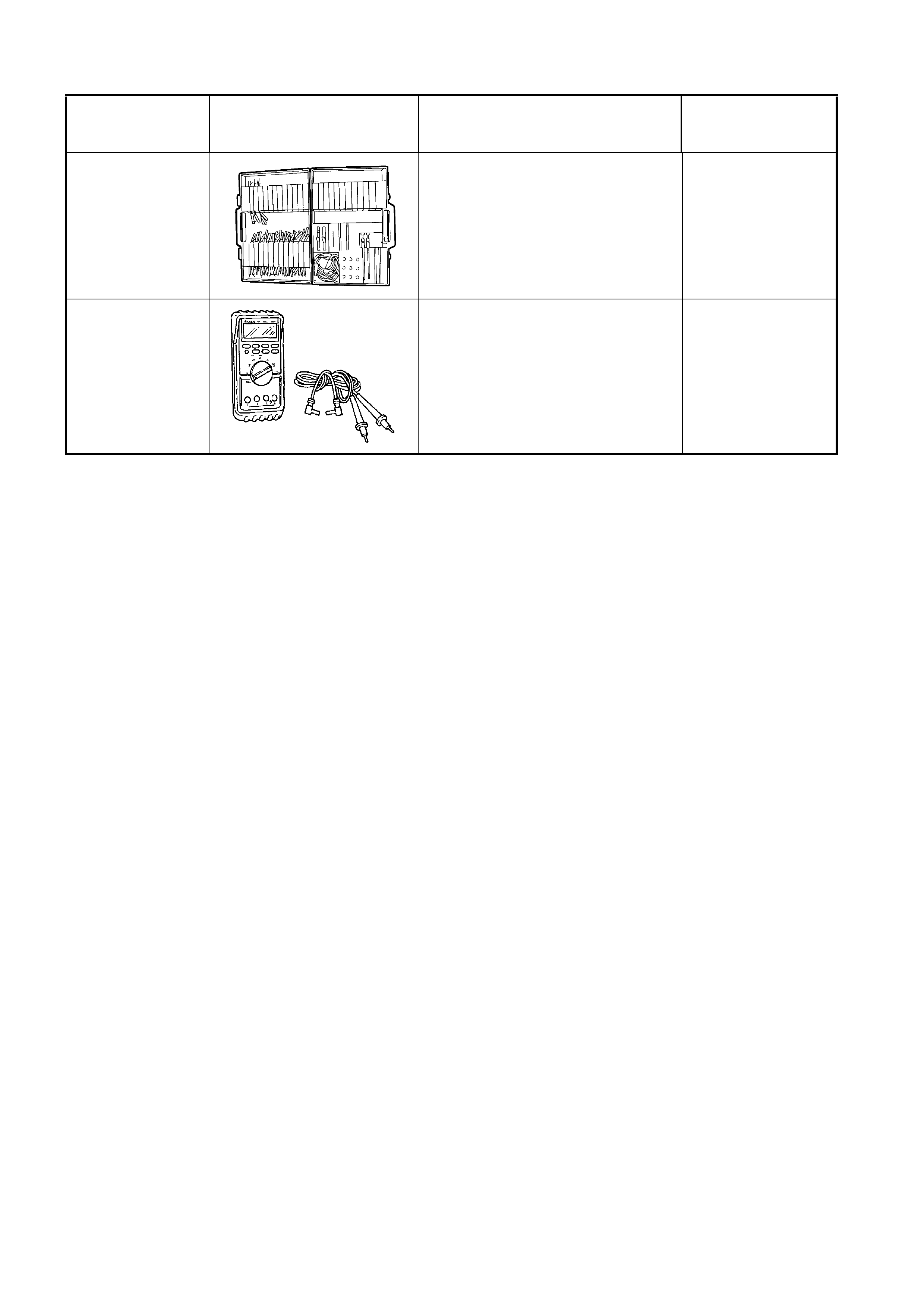
7. SPECIAL TOOLS
TOOL NUMBER ILLUSTRATION DESCRIPTION TOOL
CLASSIFICATION
J35616-A
(KM609)
CONNECTOR TEST ADAPTOR
KIT
Used when carrying out electrical
diagnostic circuit checks.
Previously released.
Desirable
3588
(J39200)
DIGITAL MULTIMETER
Must have at least 10 MΩ input
impedance and be capable of
reading frequencies.
Previously released.
Available