
SECTION 6E1 - EMISSION CONTROL –
V6 ENGINE
IMPORTANT
Before perfo rming any Service Operation or other procedu re described in this Section , refer to Section 00
CAUTIONS AND NOTES for correct workshop practices with regard to safety and/or property damage.
CONTENTS
1. GENERAL INFORMATION
1.1 VEHICLE EMISSION CONTROL
INFORMATION LABEL
1.2 EMISSIONS MANAGEMENT
1.3 ENGINE VENTILATION
RESULTS OF INCORRECT OPERATION
1.4 EVAPORATIVE EMISSION CONTROL
RESULTS OF INCORRECT OPERATION
1.5 EXHAUST GAS RECIRCULATION
PRINCIPLES OF OPERATION
1.6 THREE-WAY CATALYTIC CONVERTER
PRINCIPLES OF OPERATION
SERVICE NOTES
2. SERVICE OPERATIONS
2.1 POSITIVE CRANKCASE VENTILATION
VALVE
REPLACEMENT AND FUNCTIONAL
CHECK
2.2 EVAPORATIVE EMISSION CONTROL CANISTER
REMOVE
REINSTALL
SERVICE CHECKS
2.3 CANISTER PURGE SOLENOID VALVE
REMOVE
REINSTALL
2.4 LINEAR EGR VALVE
REMOVE
REINSTALL
3. DIAGNOSIS
3.1 POSITIVE CRANKCASE VENTILATION
3.2 EVAPORATIVE EMISSION CONTROL
4. SPECIAL TOOLS
5. TORQUE WRENCH SPECIFICATIONS
1. GENERAL INFORMATION
An emission control system is installed on MY 2003 VY Series and V2 Series II vehicles fitted with V6 engines.
These vehicles feature electronically controlled fuel injection and ignition systems and are designed to comply the
requirements of Australian Design Rule, ADR 37/01 and ECE R83.00 level B emission compliance.
In order to meet these specifications, the vehicles operate on unleaded petrol and are fitted with the following
emission control systems:
• Engine ventilation
• Evaporative emission control
• Three-way catalytic converter
• Exhaust gas recirculation
NOTE: Vehic les that ar e produc ed f or Indones ia are not fitted with oxygen s ens ors and a muffler is f itted in place of
the catalytic converter.
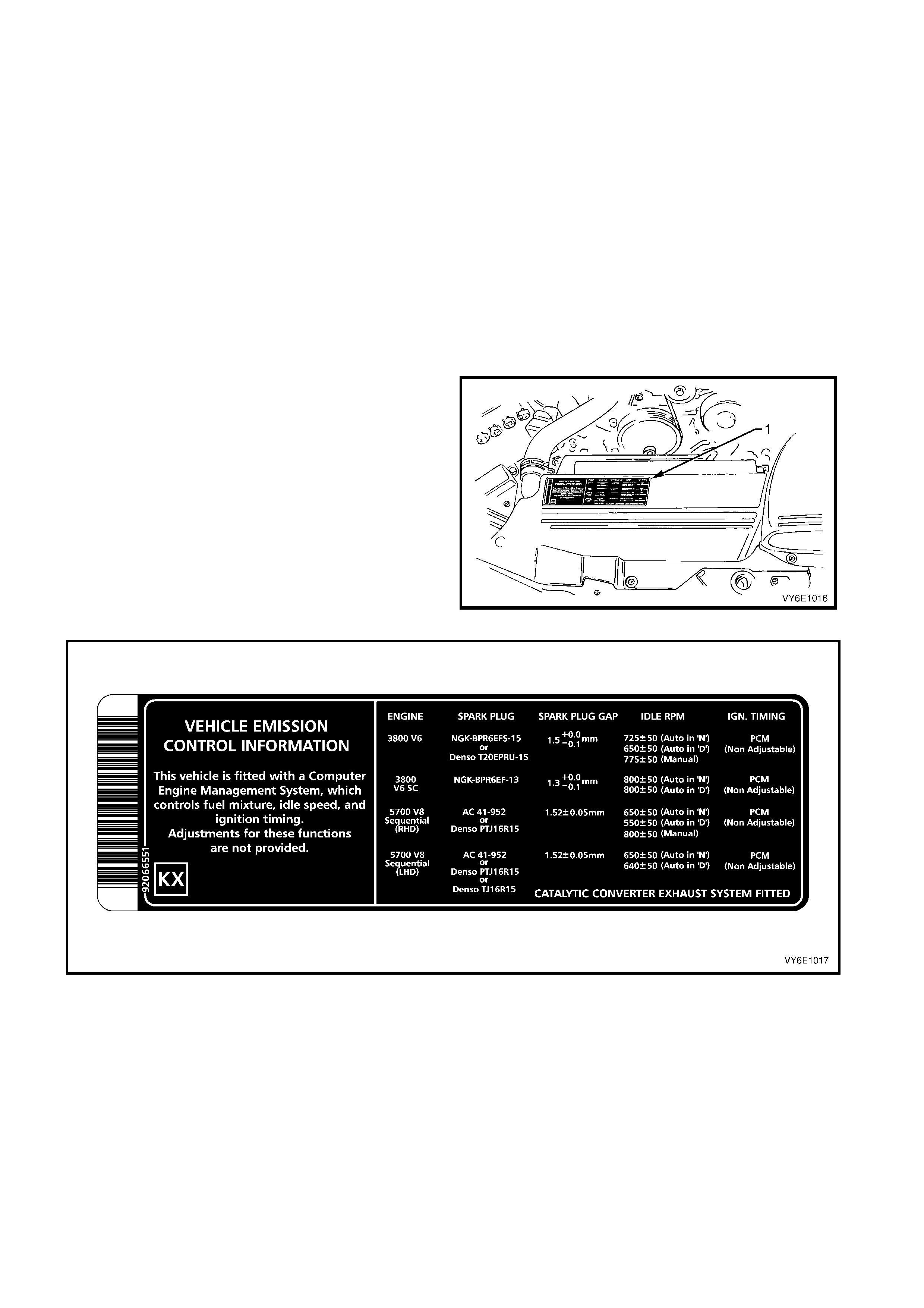
1.1 VEHICLE EMISSION CONTROL INFORMATION LABEL
The vehicle emission control information label is
located in the engine compartment.
The label contains im portant engine tune conditions to
achieve the correct emission levels, and should be
referred to before making any adjustments. For all
vehicles except for Brazil, refer to Figure 6E1-2. For
Brazil vehicles, refer to Figure 6E1-3.
Figure 6E1-1
Figure 6E1-2
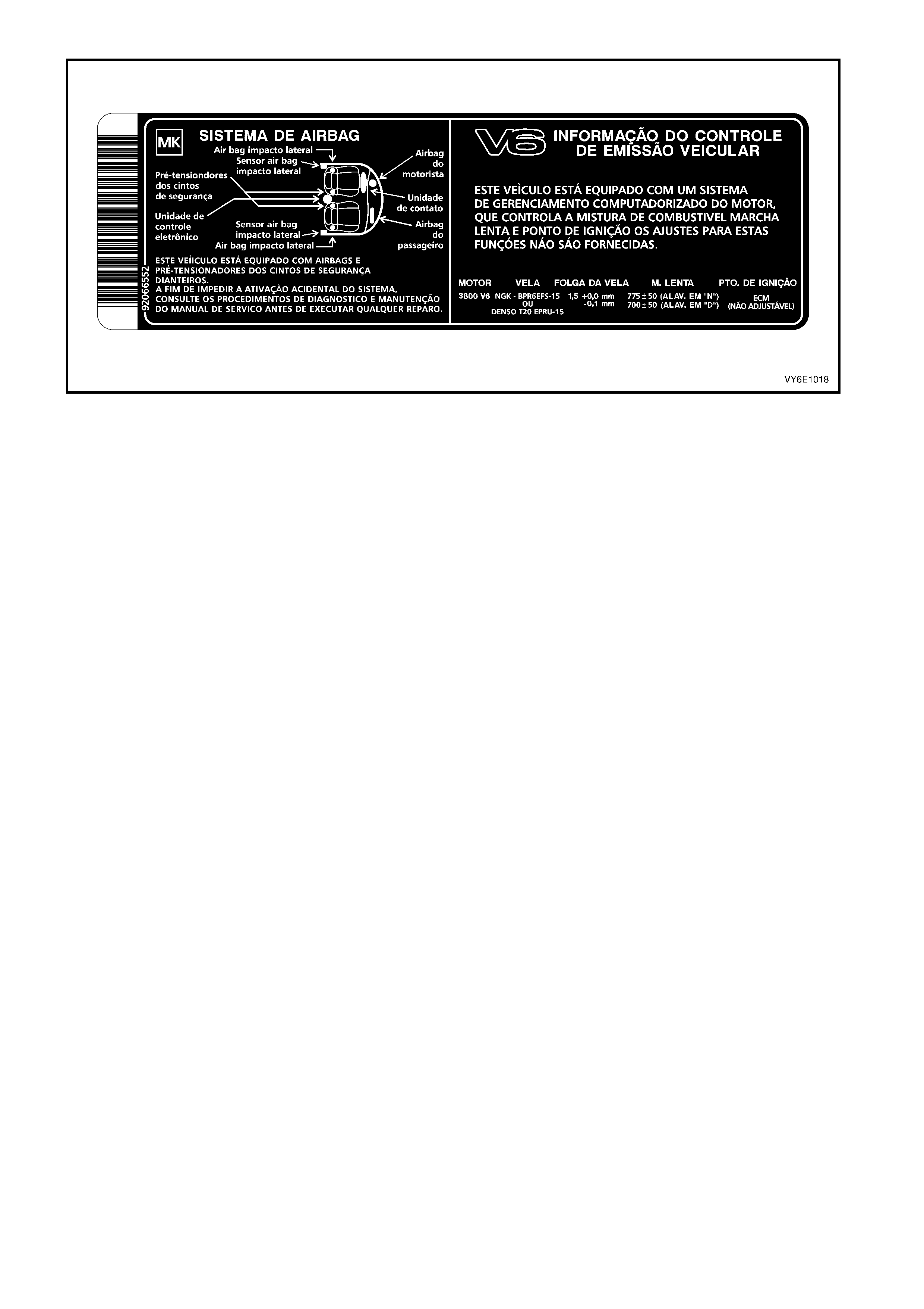
Figure 6E1-3
1.2 EMISSIONS MANAGEMENT
All aspects of engine air/f uel ratio and spark tim ing are
controlled by the Powertrain Control Module (PCM).
The mixture control is a closed loop system that
incorporates dual oxygen sensors (1), located in the
exhaust system engine pipes, f orward of eac h catalytic
converter.
While the engine ventilation system requires no
outside control, the operation of the evaporative
emission control system is controlled by the PCM via
an EVAP canister purge valve, mounted on the engine
intake manifold.
NOTE: Vehicles that are produced for Indonesia are
not fitted with oxygen sensors and a muffler is fitted in
place of the catalytic converter.
The PCM and associated systems are described in
Section 6C1 POWERTRAIN MANAGEMENT - V6
ENGINE.
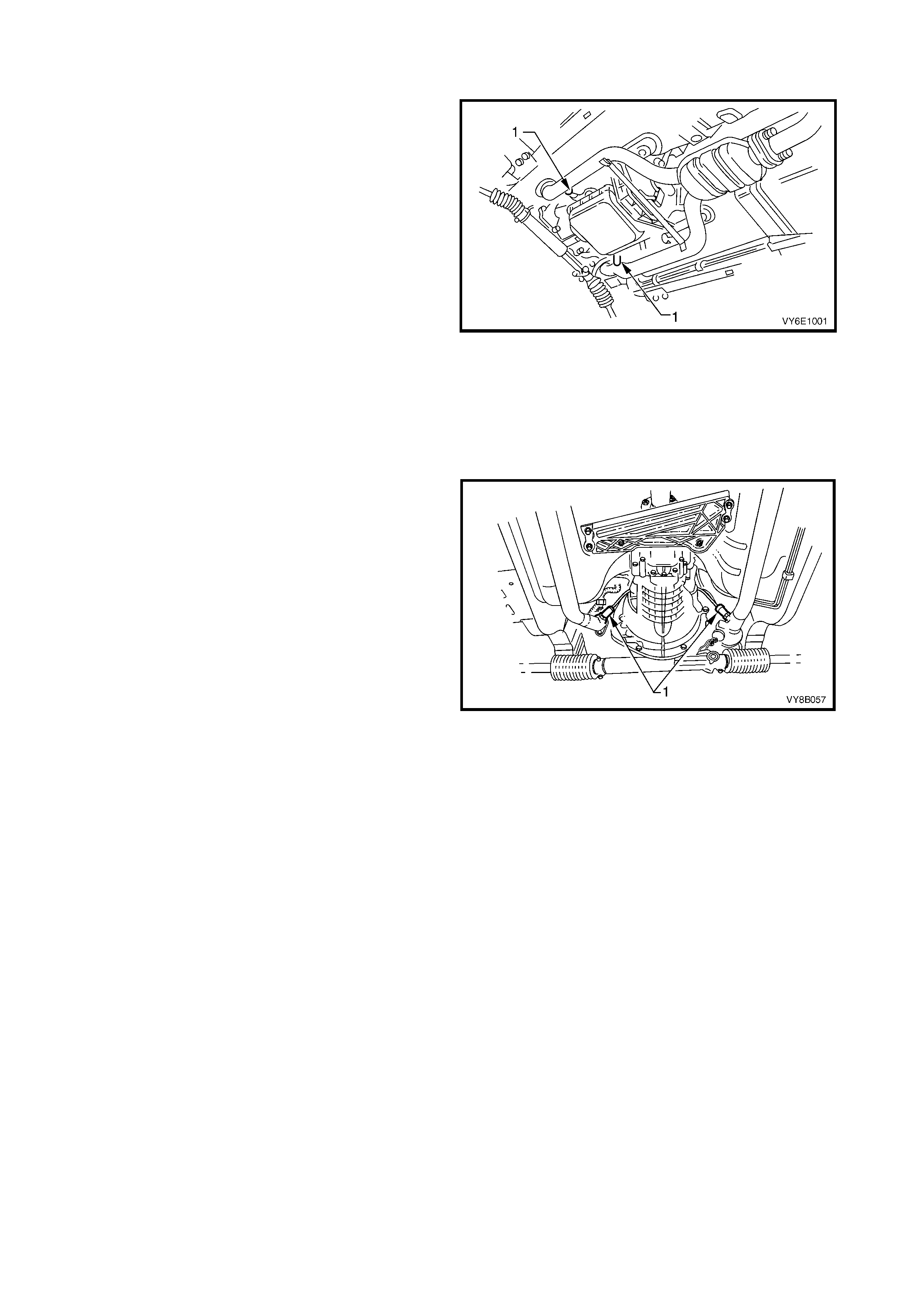
Refer to Figure 6E1-4 for the position of oxygen
sensors on vehicles fitted with an automatic
transmission.
Figure 6E1-4
Refer to Figure 6E1-5 for the position of oxygen
sensors (1) on vehicles fitted with a manual
transmission.
Figure 6E1-5
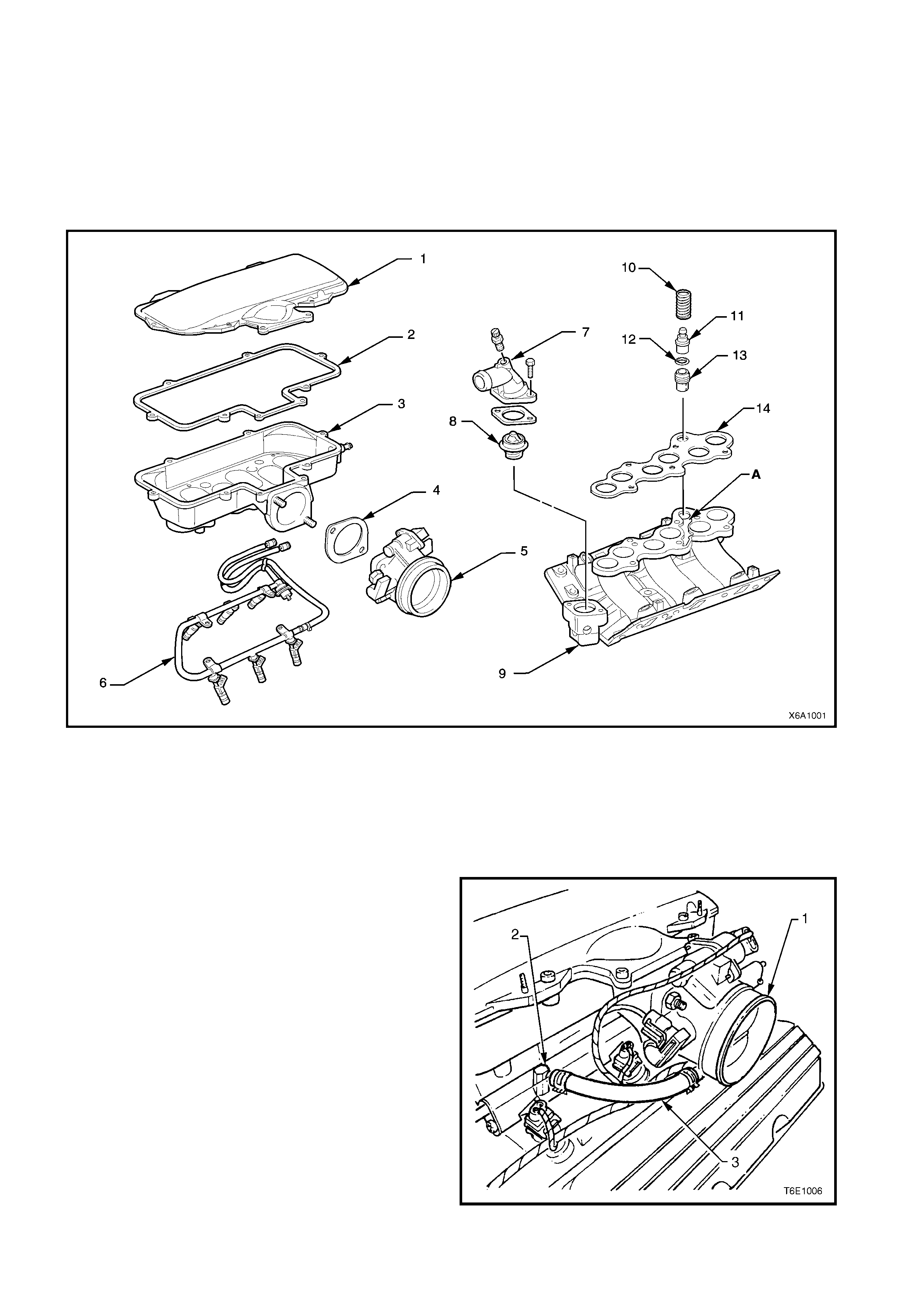
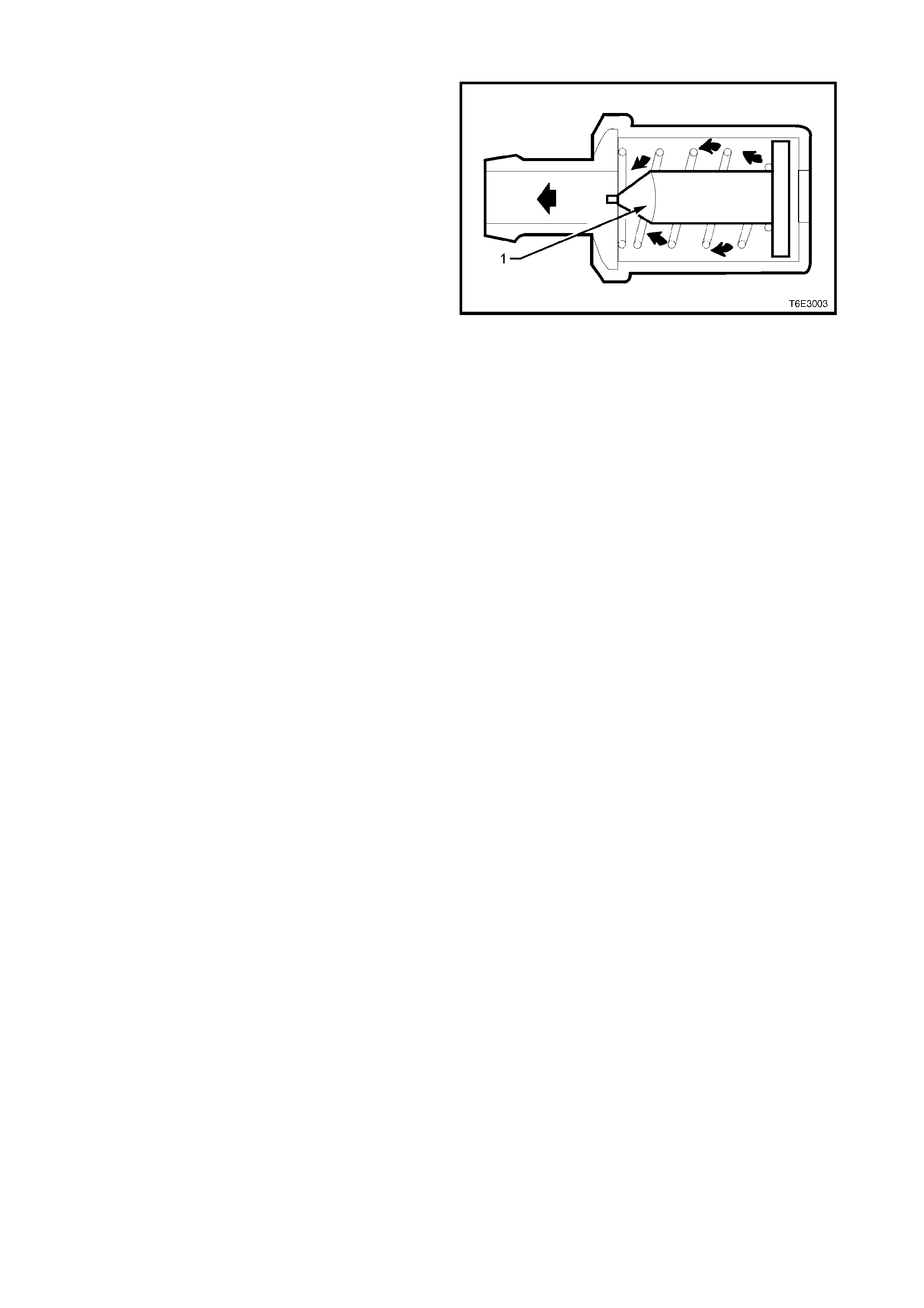
1.3 ENGINE VENTILATION
The engine ventilation s ystem uses a Positive Crank case Ventilation (PCV) valve (11) which is located in the lower
inlet manif old ( 9), refer to Figure 6E1-6. T he channel (A) provides an even distribution of crank case fum es, thereby
impr oving spark plug reliability and a reduction in emis sions. T he PCV valve is a non-servic eable item and must be
replaced if defective.
W hen the upper inlet m anifold is s eparated from the lower half, per form a functional check of the PCV valve. Also,
clean the PCV valve passage in the lower manifold to avoid any possibility of the passage becoming clogged with
condensed engine oil fumes.
Figure 6E1-6
Legend
1. Upper Inlet Manifold Cover 6. Fuel Injector and Rail Assembly 11. PCV Valve
2. Upper Inlet Manifold gasket 7. Thermostat Housing & Bleeder 12. PCV Valve O-Ring Seal
3. Upper Inlet Manifold 8. Thermostat 13. Oil Separation Baffle
4. Throttle Body Gasket 9. Lower Inlet Manifold 14. Upper to Lower Inlet Manifold Gasket
5. Throttle Body 10. Spring – PCV Valve
During normal driving conditions, crankcase vapours
are drawn into the inlet manifold via the PCV valve.
Vapours are then delivered through the inlet manifold
plenum chamber into the combustion chamber, to be
burnt with the air/fuel mixture.
Fresh air is drawn into the crankcase via a breather
hose (3), which is connected between the throttle
body (1) and a port on the inlet manifold (2).
The PCV valve meters the mixture of fresh air and
crankcase vapours into the induction system at a rate
dependant upon manifold vacuum.
To maintain idle quality, the PCV valve restricts the
flow when inlet manifold vacuum is high. If abnormal
manifold conditions arise, the system is designed to
allow excess ive am ounts of crank case vapours to flow
back through the breather hose, into the throttle body
to be consumed by normal combustion.
Figure 6E1-7
RESULTS OF INCORRECT OPERATION
A blocked or partially blocked PCV check valve (1) may
cause:
• Rough idle.
• Stalling or slow idle speed.
• Oil leaks.
• Sludge in engine.
A leaking valve would cause:
• Rough idle.
• Stalling.
• High idle speed.
Figure 6E1-8
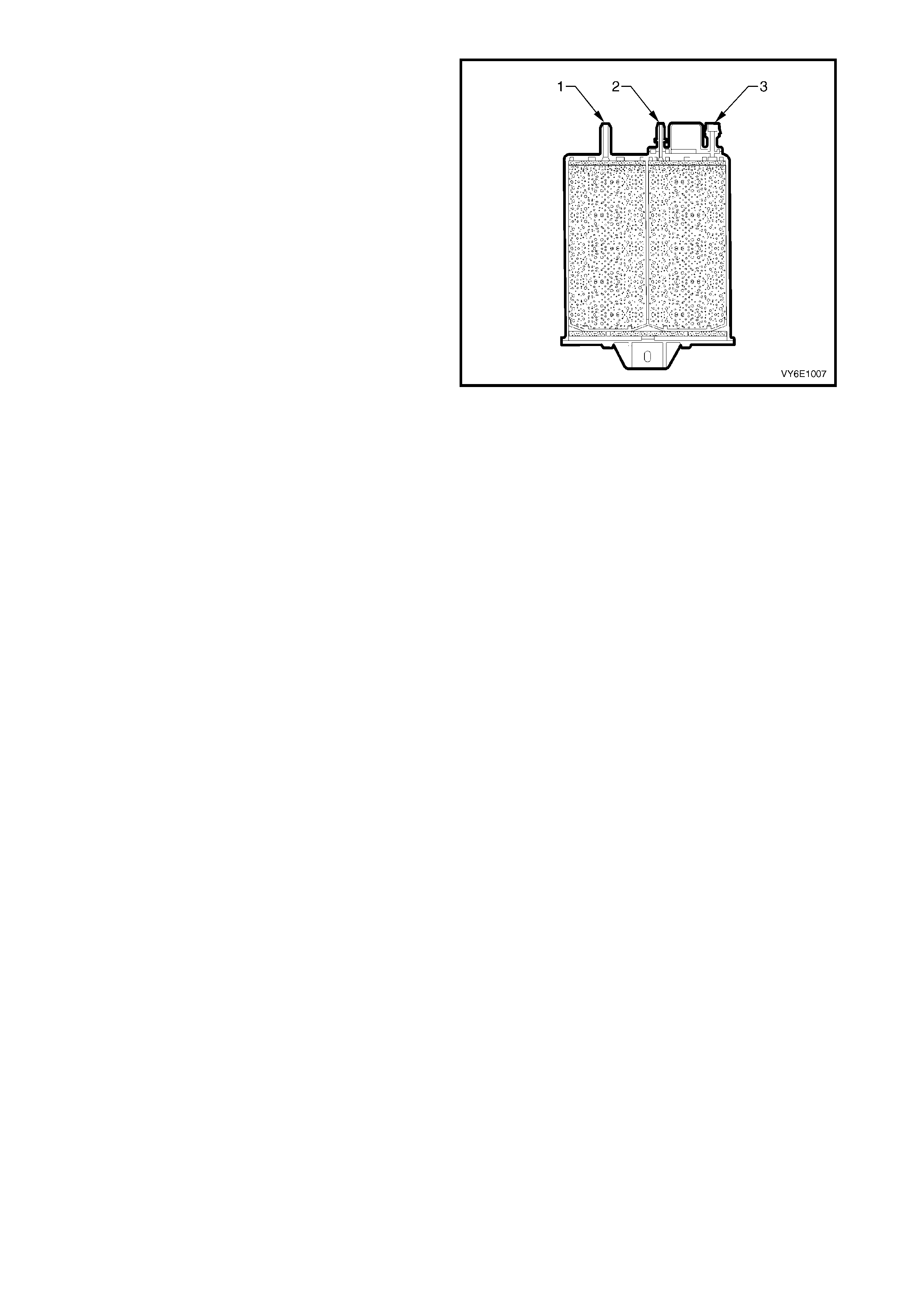
1.4 EVAPORATIVE EMISSION CONTROL
The evaporative emission control system used on this
vehicle is the activated carbon (charcoal) canister
storage method. This fuel vapour canister (4) is a three
port design and is mounted in a bracket underneath
the vehicle, near the fuel filter (5).
The canister cannot be repaired and is serviced only
as an assembly. Periodically check the canister at the
time or distance intervals specified in Section 0B
LUBRICATION AND SERVICE.
The canister is designed to store fuel tank vapour via
the tank vent line (3) and release it to the engine via
the canister purge line (2).
The canister vent line (1) is routed to the fuel filler
neck.
Figure 6E1-9
Figure 6E1-10 shows the canister vent line (A)
attachm ent to the fuel f iller neck on all vehicles except
Utility.
Figure 6E1-10
Figure 6E1-11 shows the canister vent line (1)
attachment to the fuel filler neck on the Utility.
For removal of the f r ont inner s ide panel c over, r ef er to
Section 1B, 2.8 FRONT INNER SIDE PANEL
COVER.
Figure 6E1-11
Fuel vapour from the fuel tank enters the canister via
the tank vent port (3). The fuel vapour is absorbed by
the charcoal within the canister.
W hen the engine is running at or above idle, manifold
vacuum on the canis ter purge port (2) caus es air to be
drawn in from the canister vent port (1). This air flow
purges fuel vapour from the canister which is then
transferred to the throttle body. The fuel vapour is
consumed in the normal combustion process.
The EVAP canister purge valve controls the manifold
vacuum that is applied to the canister. The PCM
energises the EVAP canister purge valve by supplying
an earth signal (purge on). The EVAP canister purge
valve control is Pulse Width Modulated (PWM). (This
means that the canister purge valve is turned on and
off several times a second.)
The PCM c ontrolled PW M output is com manded when
the appropriate conditions have been met, such as:
• Engine coolant temperature is below 20 °C at cold
start up and the engine has been running longer
than 3 minutes and 10 seconds, or
• Engine coolant temperature is above 80 °C and
the engine has been running longer than
5 seconds, or
• Engine is not in decel fuel cutoff mode and the
throttle opening is less than 96%, or
• The engine is in closed loop fuel mode.
Figure 6E1-12
A higher purge rate is used under conditions that are
likely to produce large amounts of vapour, when the
following conditions have been met:
• Intake Air Temperature (IAT) is above 50 °C, or
• Engine Coolant Temperature (ECT) is above
100 °C, or
• The engine has been running for more than
15 minutes.
The EVAP purge PW M duty cycle varies according to
operating conditions determined by mass air flow, fuel
trim and intake air temperature. The EVAP canister
purge valve is re-enabled when throttle position angle
decreases below 96%.
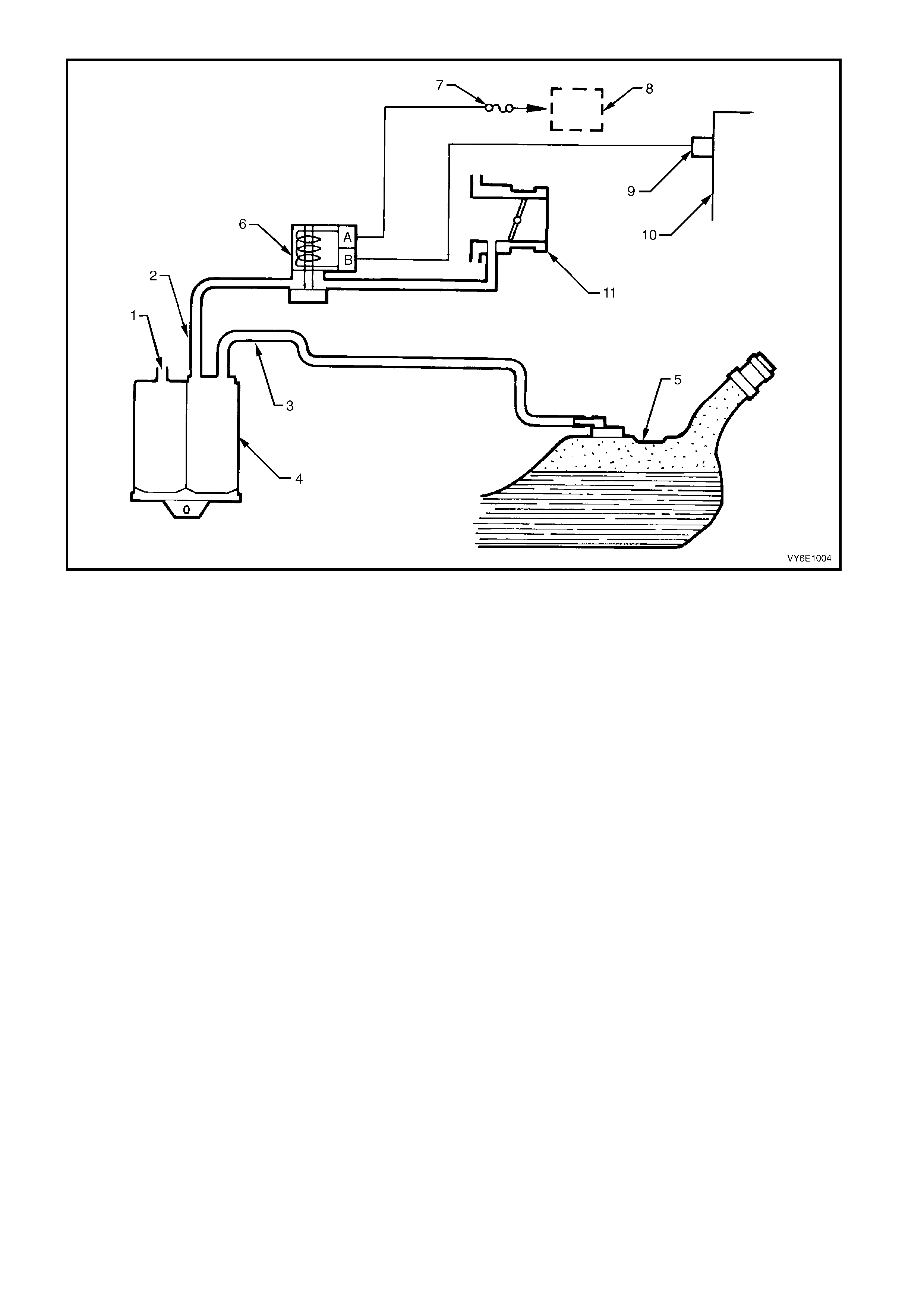
Figure 6E1-13
Legend
1. Canister Vent Port 5. Fuel Tank 9. PCM Terminal X1_A10
2. Canister Purge Line 6. EVAP Canister Purge Valve 10. PCM
3. Tank Vent Line 7. Fuse F33 11. Throttle Body
4. Canister 8. EFI Relay
RESULTS OF INCORRECT OPERATION
Poor idle, stalling and poor driveability can be caused by:
• Inoperative EVAP canister purge valve.
• Damaged canister.
• Hoses split, cracked and/or not connected to the correct locations.
• Throttle body and canister hoses interchanged on the EVAP canister purge valve connections.
NOTE: The canister purge port is marked with CAN.
Evidence of fuel loss or fuel vapour odour can be caused by:
• Liquid fuel leaking from fuel lines.
• Cracked or damaged canister.
• Disconnected, incorrectly routed, kinked, deteriorated or damaged hoses.
If the EVAP canis ter purge valve is s tuc k open, or the contr ol cir cuit is s horted to ear th, the c anis ter will purge to the
intake manif old all the tim e. This can allow extra f uel at idle or during warm -up, which can c ause rough or unstable
idle or a rich fuel operation.
If the canister purge solenoid is always closed, the canister can become overloaded resulting in noticeable fuel
odour.
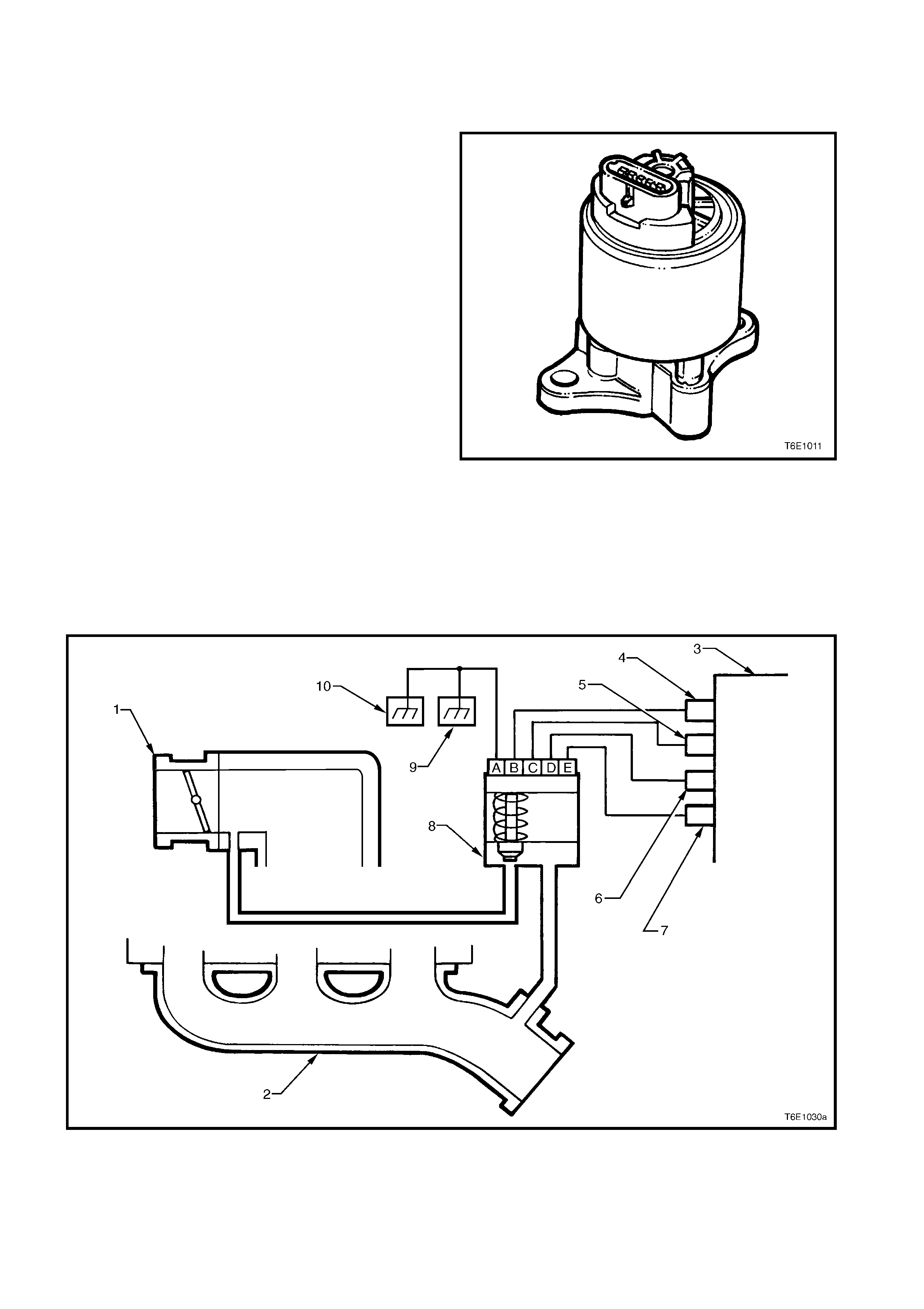
1.5 EXHAUST GAS RECIRCULATION
PRINCIPLES OF OPERATION
The V6 engine is equipped with an Exhaust Gas
Recirculation (EGR) system. T he EGR system is used
to lower Oxides of Nitrogen (NOx) emission levels,
caused by high combustion temperature.
A linear EGR valve feeds small amounts of exhaust
gas back into the combustion chamber. This dilutes
the air/fuel mixture and combustion temperatures are
reduced.
The linear EGR valve is designed to accurately supply
exhaust gas to the engine independent of the intake
manif old vacuum. T he valve contr ols gas f low from the
exhaust to the intak e m anif old through an orif ice with a
PCM controlled pintle. During operation, the PCM
controls pintle pos ition by m onitoring the pintle position
feedback signal.
The linear EGR valve is usually activated under the
following conditions:
• Warm engine operation.
• Above idle speed.
The PCM monitors actual EGR position and adjusts
the pintle ac cordingly. The PCM us es inform ation fr om
the following sensors to control pintle position:
• Engine Coolant Temperature (ECT) sensor.
• Throttle Position (TP) sensor.
• Mass Air Flow (MAF) sensor.
• Engine RPM.
Figure 6E1-14
Figure 6E1-15
Legend
1. Throttle Body 5. PCM Terminal X2_C8 9. Ground Point, Front Right Hand of Engine Block
2. Exhaust Manifold 6. PCM Terminal X2_B5 10. Ground Point, Rear Left Hand of Engine Block
3. PCM 7. PCM Terminal X3_E12
4. PCM Terminal X2_C16 8. Linear EGR Valve
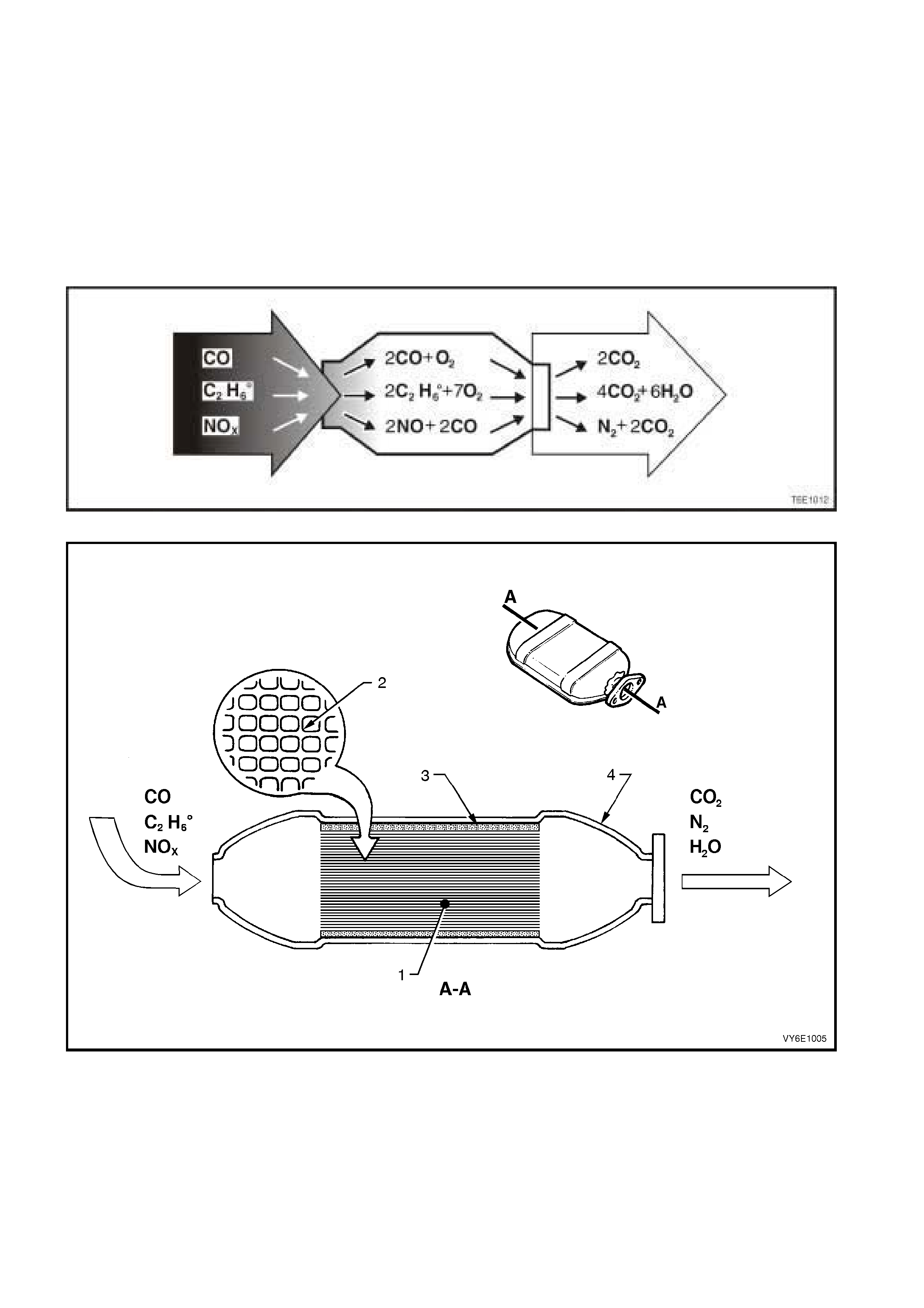
1.6 THREE-WAY CATALYTIC CONVERTER
PRINCIPLES OF OPERATION
The catalytic converter consists of a stainless steel housing that encloses a ceramic monolith. The monolith is an
extruded high temperature ceramic with approximately 62 cells/sq.cm in cross section. This gives the monolith a
large surface area for its mass. Distributed over the monolith surface is a catalyst that consists of platinum and
rhodium. A catalyst is a substance that accelerates a chemical reaction without itself being changed.
Engine exhaust gases contain carbon m onoxide (CO), hydrocarbons (HC) and oxides of nitrogen (NOX). When the
exhaust gases flow through the monolith, reactions with the catalyst occur. CO and HC are converted by oxidation
with oxygen (O2) in the exhaust gas es to produce carbon diox ide (CO2) and water vapour (H2O). NOX is conver ted
by reduction with CO to produce nitrogen (N2) and CO2. The converter is called a three-way type because it
simultaneously converts three components of exhaust gas (CO, HC and NOX) to harmless natural gases.
Figure 6E1-16
Figure 6E1-17
Legend
1. Ceramic Monolith 3. Ceramic Mat Securing Monolith
2. Cross Section of Ceramic Monolith 4. Stainless Steel Shell

The catalytic converter can only reduce exhaust emissions if:
a. The engine is designed for use with a catalytic converter and unleaded petrol, since lead contaminates the
catalytic coating and prevents it from functioning.
b. It is integrated in the exhaust system in such a way that the exhaust emission conversion occurs in the most
effective temperature range – in the vicinity of 600 degrees Celsius.
c. The catalysts function ef fectively within certain air/fuel ratios only. As a c onsequence, the air/fuel r atio supplied
to the engine mu st be controlled within strict lim its for emission c onversion and long converter lif e. This contr ol
is off ered by oper ating under a closed loop mix ture control system with dual oxygen sensors. F or details of the
oxygen sensors refer to Section 6C1-3, 2.6 OXYGEN SENSORS.
The catalytic converter can be damaged, or rendered ineffective:
a. If operated outside the limits of the closed loop mixture control system, or
b. If the engine burns excessive amounts of oil, or
c. If the exhaust temperature at the converter is too high (above 850 degrees Celsius).
SERVICE NOTES
1. Do not operate the vehicle with leaded petrol. Lead will contaminate the ceramic monolith.
2. Do not drop the catalytic converter as it will damage the ceramic monolith.
3. Replace the catalytic converter if it is damaged.
4. Do not allow water, oil or fuel to enter the converter as the ceramic monolith will be contaminated.
5. Do not use engine additives. Many additives contain phosphorous that will contaminate the ceramic monolith.
6. In order to prevent the catalytic converter from overheating, the following sequence must be followed when
carrying out a cylinder balance test:
a. Maximum time each cylinder may be switched off is 8 seconds.
b. Pause for at least 8 seconds between each switch off.
c. If repeating a cylinder balance test, allow the engine to idle for a least 60 seconds before retesting.
7. T he vehicle m ust not be s tarted by pushing or towing, as unburned f uel could reach the c atalytic c onverter and
destroy the ceramic monolith. Always use jumper leads to start a vehicle that has a flat or defective battery.
8. When carrying out a compression test, remove fuse F34 from the engine compartment relay housing, refer to
Section 6A1-1, 2.6 COMPRESSION TEST. This prevents fuel injection and ignition during engine cranking.
9. Do not drive the vehicle with the engine misfiring or with the spark plug leads disconnected as the catalytic
converter will overheat.
10. Do not coast downhill with the engine misfiring or with the spark plug leads disconnected.
11. T he catalytic converter is integrated with the exhaust system. For removal and installation instructions, refer to
Section 8B EXHAUST SYSTEM.
2. SERVICE OPERATIONS
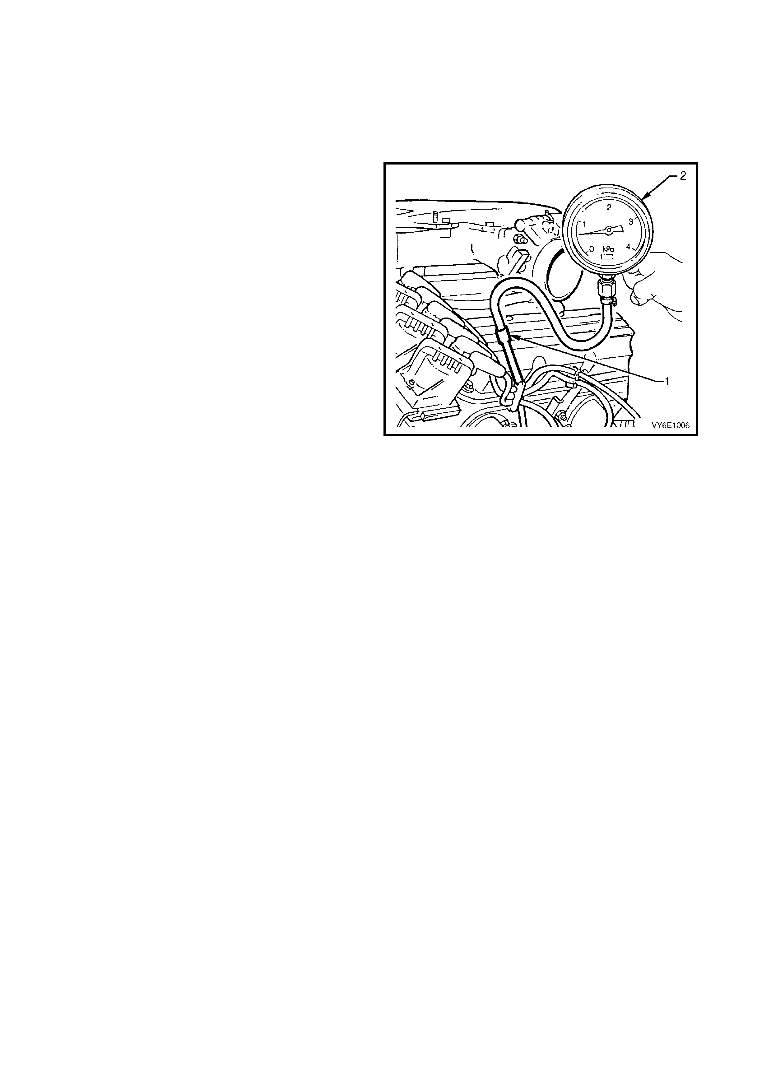
2.1 POS I TIVE CRANKCASE VENTILATION VALVE
LT Section No. – 00-249
REPLACEMENT AND FUNCTIONAL CHECK
1. Remove the engine oil dipstick.
2. Connect a commercially available vacuum
gauge (2) with a scale of approx imately 0 to -4 kPa
to the engine oil dipstick tube (1), ensuring a tight
seal.
3. Allow the engine to idle and read the vacuum
gauge. If a vacuum of approximately -0.2 to -1.00
kPa is present, the PCV valve and PCV system
are functioning correctly.
If no vacuum or a possible positive pressure is
registered, this can indicate one or more faults:
• The engine may not be sealed and/or is drawing
outside air. Check engine crankcase, valve cover,
oil pan gasket, etc. for leaks.
• The engine may be badly worn causing excessive
engine blow-by.
• The PCV valve may be blocked and requires
further investigation using the following procedure.
1. Remove the PCV valve from inlet manifold, refer to
Section 6A1-1, 2.11 LOWER INLET MANIFOLD.
2. Shake the PCV valve and listen for a rattle of the
check valve inside the valve housing. If valve does
not rattle, discard and install new PCV valve and
O-ring.
3. Reinstall the PCV valve with O-ring, refer to
Section 6A1-1, 2.11 LOWER INLET MANIFOLD.
NOTE: It is possible (and normal) to have a positive
pressure reading at the engine oil dipstick tube while
the vehicle is under driving conditions at wide open
throttle.
CAUTION: Do not clamp the PCV valve outlet to
throttle body hose when the engine is running, as this
can cause damage to the engine.
Figure 6E1-18
2.2 EVAPORATIVE EMISSION CONTROL CANISTE R
LT Section No. – 03-165
REMOVE
1. Disconnect the canister purge line (1) by using the
following procedure:
a. Gr asp both sides of the quick -c onnect f itting. Twist
the connector 1/4 turn in each direction in order to
loosen any dirt within the quick-connect fitting.
Caution: Wear safety glasses when using
compressed air.
b. Using compressed air, blow any dirt out of the
quick connect fitting.
c. Gr as p the quick-c onnect f itting and pus h it towards
the canister.
d Squeeze the quick-connect fitting to release the
retaining tabs, then pull back on the connector to
remove the canister purge line from the canister.
Figure 6E1-19
2. Disconnect the tank vent line (1) by using the
following procedure:
a. Gr asp both sides of the quick -c onnect f itting. Twist
the connector 1/4 turn in each direction in order to
loosen any dirt within the quick-connect fitting.
Caution: Wear safety glasses when using
compressed air.
b. Using compressed air, blow any dirt out of the
quick connect fitting.
c. Gr as p the quick-c onnect f itting and pus h it towards
the canister.
d Squeeze the quick-connect fitting to release the
retaining tabs, then pull back on the connector to
remove the tank vent line from the canister.
Figure 6E1-20
3. Rem ove the canis ter vent line (1) from the canister
by twisting and pulling it off.
Figure 6E1-21
4. Remove the canister retaining nut (1).
5. Remove the canister from the retaining stud and
then slide the canister out of the retainer (2).
Figure 6E1-22
REINSTALL
1. Reinstall the canister into the retainer (1) and over
the retaining stud.
2. Reinstall the canister retaining nut (2) and hand
tighten.
3. Push canister toward centre of vehicle and tighten
the canister retaining nut to the specified torque.
CANISTER RETAINING NUT
TORQUE SPECIFICATION 2.0 - 5.0 Nm
Figure 6E1-23
4. Reinstall the canister vent line (1).
5. Align the canister purge line quick connector (2)
with the canister purge line port. Push the
connector firmly onto the port.
6. Align the tank vent line quick connector (3) with the
tank vent port. Push the connector firmly onto the
port.
7. Once installed, pull on each quick connect to
ensure the connections are secure and locked in
position.
Figure 6E1-24
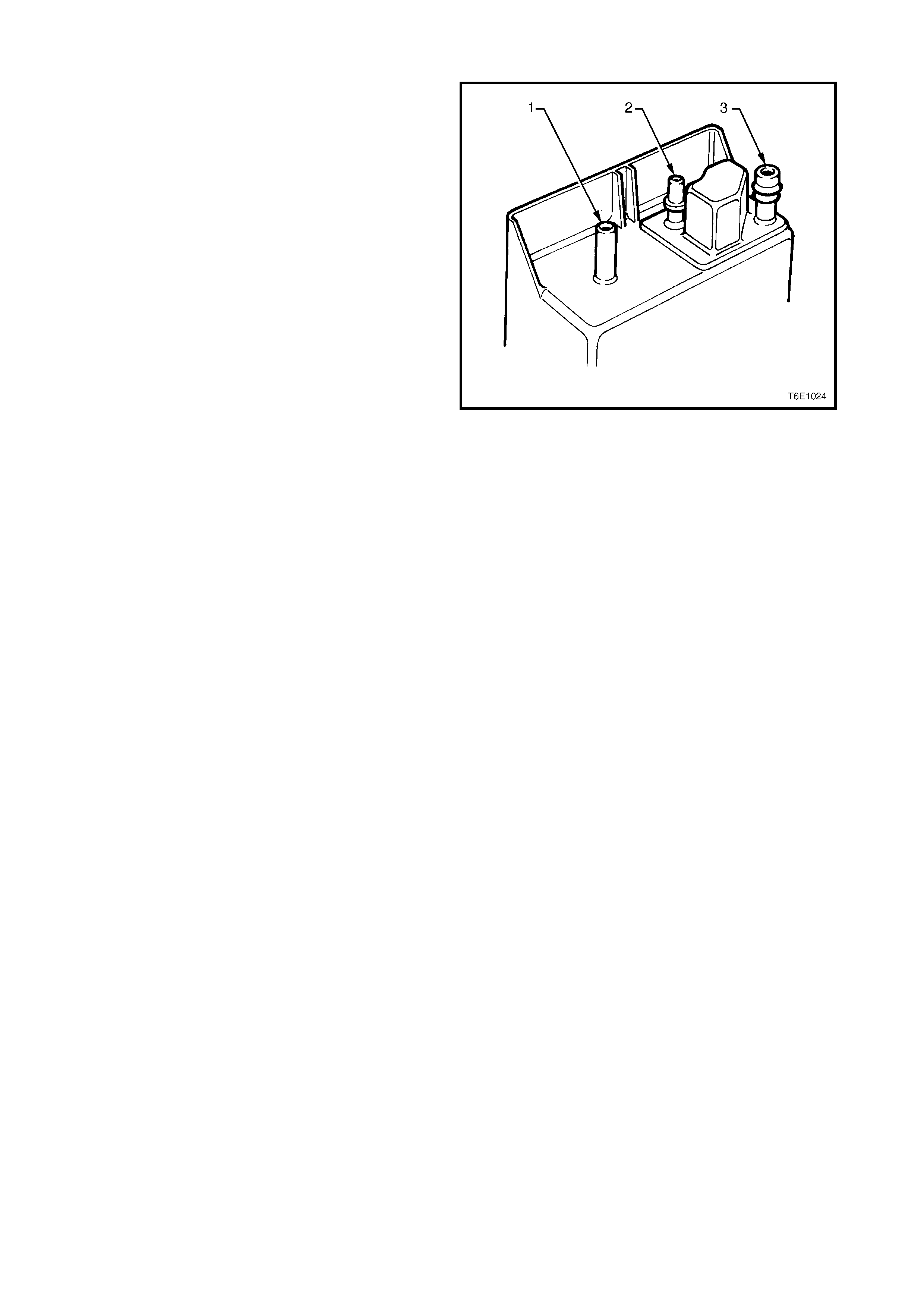
SERVICE CHECKS
1. Remove canister as described in this Section.
2. Shake the canister. There should be no audible
sound of carbon movement.
3. Using low pressure compressed air (20-35 kPa),
blow into the tank vent port (3). Check that air
flows freely from the canister vent port (1). Block
the canister vent port (1) and air should flow from
the canister purge port (2).
4. If airflow through the canister vent port (2) is poor,
clean the atm os pheric f ilter by blocking of f the tank
vent port (3) and blowing compressed air at
approximately 300 kPa through the canister purge
port (2).
5. Check airflow through the filter as in Step 3. If
airflow through the canister vent port (1) is still
poor, replace the canister.
6. Block the canister vent port (1) and the canister
purge port (2). Apply low pressure compressed
air (20-35 kPa) to the tank vent port (3). If any air
leaks from the canister, i.e. around ports or
seams, the canister must be replaced.
Figure 6E1-25
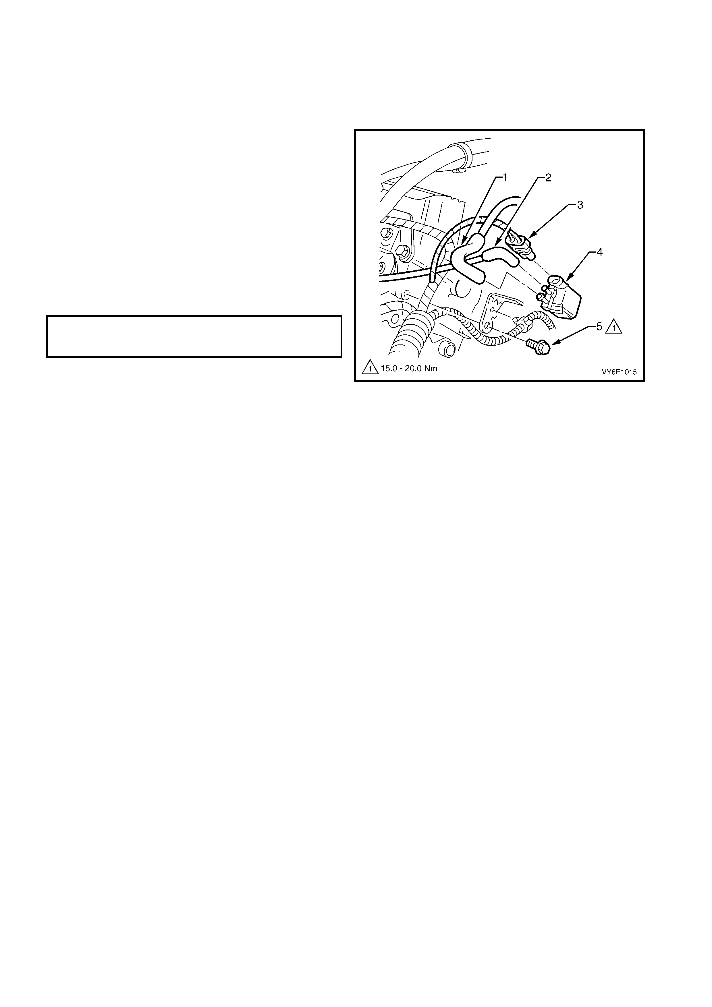
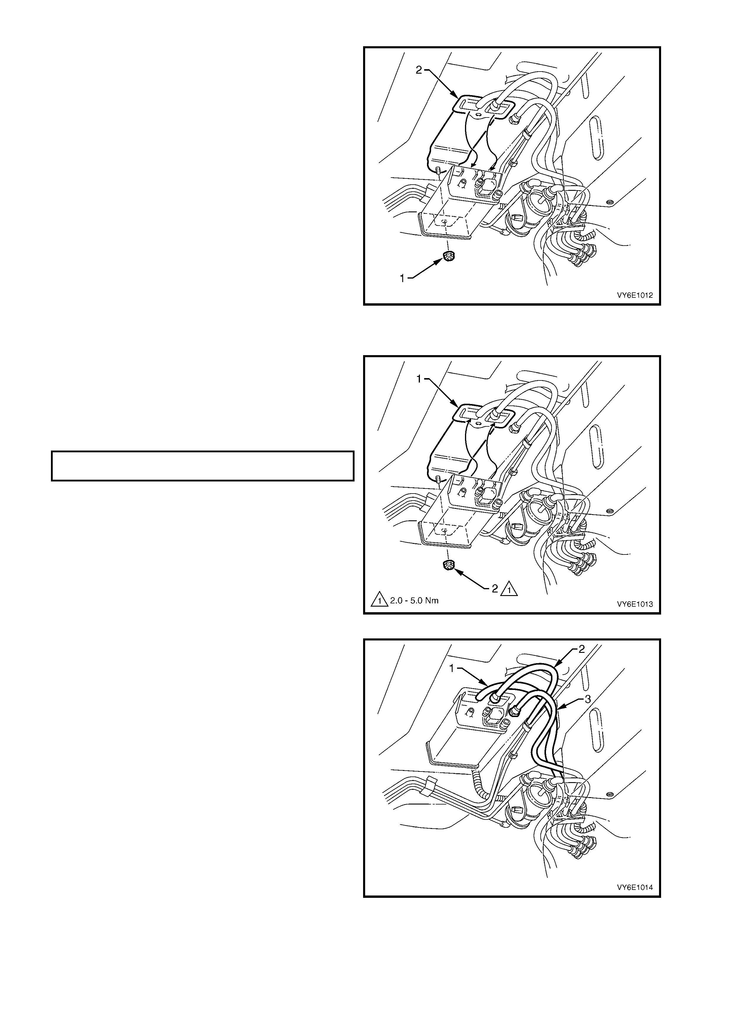
2.3 CANISTER PURGE SOLENOID VALVE
LT Section No. – 03-165
REMOVE
1. Ensure that the ignition switch is off.
2. Mark the hoses on canister purge solenoid
valve (1, to fuel vapour canister and 2, from throttle
body), and remove the hoses from the valve.
3. Remove the wiring harnes s connector (3) from the
solenoid valve (4).
4. Remove the screw from the solenoid valve
bracket.
5. Remove the solenoid valve.
REINSTALL
1. Reinstall the canister purge solenoid valve to the
rear of the cylinder head and install the bracket
screw. Tighten the screw to the specified torque.
CANISTER PURGE SOLENOID VALVE
BRACKET SCREW
TORQUE SPECIFICATION 15.0 – 20.0 Nm
2. Apply Loctite 4210 adhesive to both vacuum
hoses. Connect the vacuum hoses to the purge
solenoid valve ensuring that the connections are
correct.
3. Reconnect the wiring harness connector to the
canister purge solenoid valve.
Figure 6E1-26
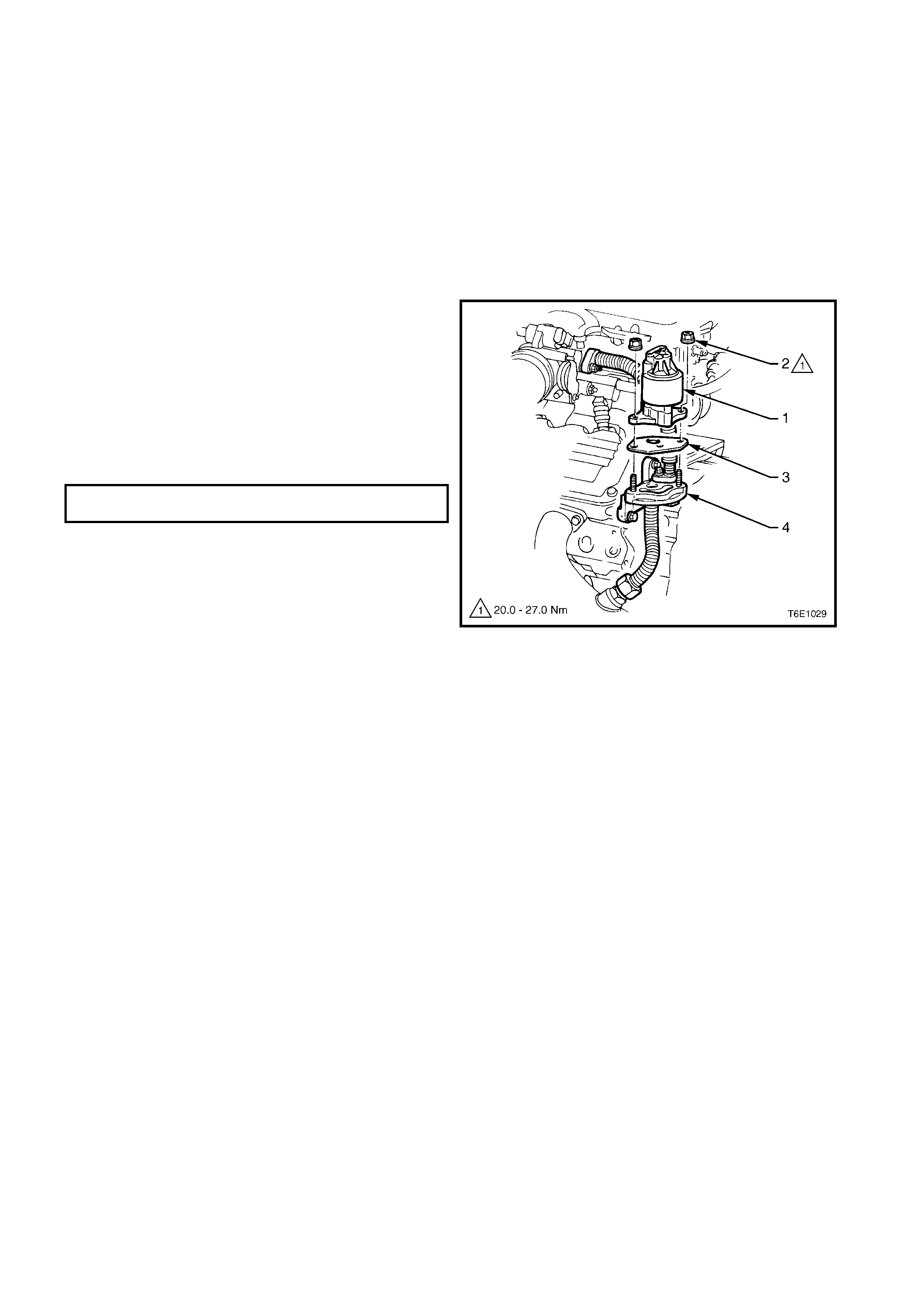
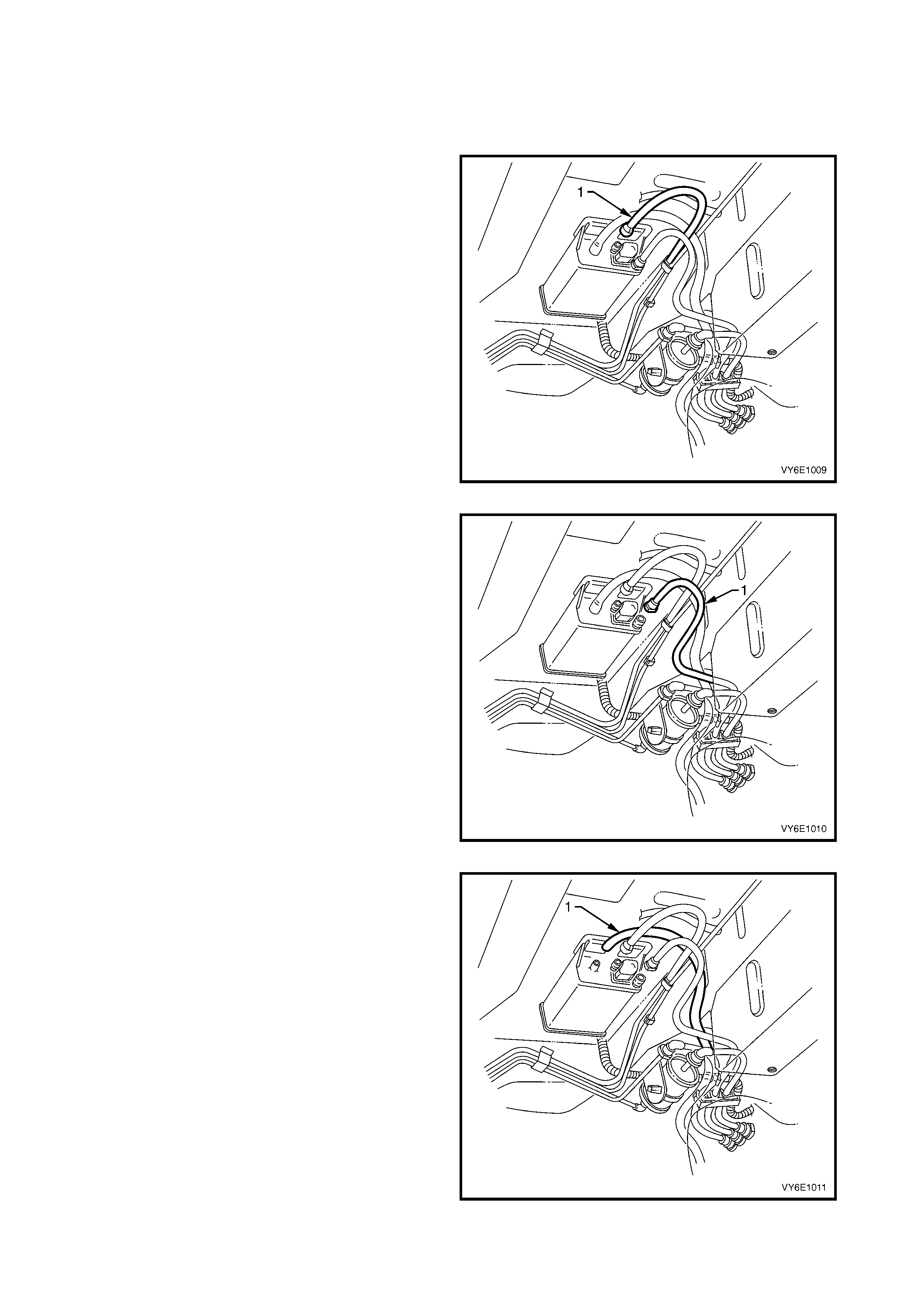
2.4 LINEAR EGR VALVE
LT Section No. – 03-300A
REMOVE
IMPORTANT: Disconnection of the battery affects
certain vehicle electronic systems. Refer to
Section 00, 5. BATTERY DISCONNECTION
PROCEDURES before disconnecting the battery.
1. Disconnect the battery earth lead.
2. Remove the engine dress cover.
3. Disconnect the EGR valve electrical connector.
4. Remove the EGR valve retaining nuts (2).
5. Remove the EGR valve (1) and gasket (3) from
EGR adaptor assembly (4).
REINSTALL
1. Reinstall a new EGR valve gasket.
2. Reinstall the EGR valve and retaining nuts.
3. Tighten the EGR valve retaining nuts to the
specified torque.
EGR VALVE RETAINING NUTS
TORQUE SPECIFICATION 20.0 – 27.0 Nm
4. Reinstall the engine dress cover.
5 Reconnect the battery earth lead.
Figure 6E1-27

3. DIAGNOSIS
3.1 POS ITIVE CRANKCASE VENTILATION
CONDITION PROBABLE CAUSE CORRECTIVE ACTION
Rough, slow idle or stalling 1. PCV valve blocked.
2. Blocked or damaged
ventilation hose.
Clean valve or replace.
Clean or replace hose.
Rough, fast idle or stalling 1. PCV valve stuck in
intermediate position.
2. PCV valve leaking.
Clean valve or replace.
Check valve O-ring, replace if
necessary.
Check valve installation.
Excessive sludging or diluting of
oil Engine is not vented. Check for clogged PCV valve
circuit and clogged ventilation
circuit.

3.2 EVAPORATIVE EMISSION CONTROL
CONDITION PROBABLE CAUSE CORRECTIVE ACTION
Loss of fuel from filler cap 1. Unsatisfactory sealing
between cap and filler neck.
2. Malfunction of filler cap relief
valve.
Replace filler cap.
Replace filler neck if damaged.
Replace filler cap.
Loss of fuel from fuel lines 1. Loose line connection.
2. Faulty connector.
3. Split or cracked fuel line.
Secure connection.
Replace fuel line.
Replace fuel line.
Loss of fuel from canister 1. Fuel tank overfilled. When the
fuel temperature increases,
excess fuel is discharged into
the canister, flooding it.
2. Kinked hoses at filler neck or
canister.
3. Blocked, damaged or
disconnected purge valve.
Avoid overfilling of tank.
Replace damaged hoses. Ensure
that the hoses are installed
correctly.
Check purge valve operation.
Collapsed fuel tank or pressure in
tank 1. Faulty fuel filler cap. In high
temperature operating
conditions some pressure in
the fuel tank is a normal
condition.
2. Blocked or kinked hoses at
filler neck or canister.
3. Defective canister (usually
internal blocked).
4. Purge solenoid valve is closed
causing canister to become
overloaded.
Replace filler cap.
Replace damaged hoses. Ensure
that the hoses are installed
correctly
Replace canister.
Refer to 6C1 POWERTRAIN
MANAGEMENT – V6 ENGINE.
Rough idle 1. Improperly routed or
disconnected purge line.
2. Purge solenoid valve is open
or not receiving power.
Check purge line.
Refer to 6C1 POWERTRAIN
MANAGEMENT – V6 ENGINE.
For diagnosis of faults pertaining to vehicle performance, refer to Section 6C1 POWERTRAIN MANAGEMENT –
V6 ENGINE.
4. SPECIAL TOOLS
TOOL NUMBER ILLUSTRATION DESCRIPTION TOOL
CLASSIFICATION
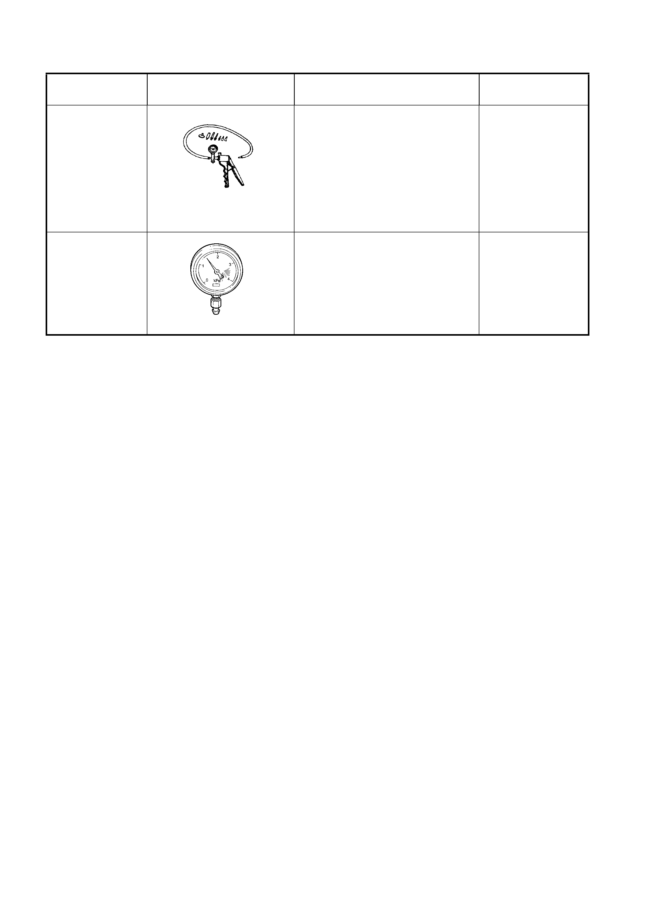
J23738-A
VACUUM PUMP (20 IN. HG
MINIMUM)
Used for many applications,
including engine, automatic
transmission, steering gear,
diagnostic checks.
Previously released.
Mandatory
N/A
VACUUM GAUGE
Vacuum gauge with scale of 0 to
-4kPa. Used for checking P.C.V.
valve operation and function.
Previously released.
Mandatory

5. TORQUE WRENCH SPECIFICATIONS
Canister retaining nut............................................................2.0 – 5.0 Nm
Canister purge solenoid valve bracket screw .......................15.0 – 20.0 Nm
EGR valve retaining nuts ......................................................20.0 – 27.0 Nm