
SECTION 6E3 - EMISSION CONTROL –
V8 ENGINE
IMPORTANT:
Before perfo rming any Service Operation or other procedu re described in this Section , refer to Section 00
CAUTIONS AND NOTES for correct workshop practices with regard to safety and/or property damage.
CONTENTS
1. GENERAL INFORMATION
1.1 VEHICLE EMISSION CONTROL
INFORMATION LABEL
1.2 EMISSIONS MANAGEMENT
1.3 ENGINE VENTILATION
RESULTS OF INCORRECT OPERATION
1.4 EVAPORATIVE EMISSION CONTROL
RESULTS OF INCORRECT OPERATION
1.5 EXHAUST EMISSION CONTROL SYSTEM
1.6 THREE-WAY CATALYTIC CONVERTER
PRINCIPLES OF OPERATION
SERVICE NOTES
2. SERVICE OPERATIONS
2.1 POSITIVE CRANKCASE VENTILATION VALVE
TEST
REMOVE
REINSTALL
2.2 EVAPORATIVE EMISSION CONTROL
CANISTER
REMOVE
REINSTALL
SERVICE CHECKS
2.3 CANISTER PURGE SOLENOID VALVE
REMOVE
REINSTALL
3. DIAGNOSIS
3.1 POSITIVE CRANKCASE VENTILATION
3.2 EVAPORATIVE EMISSION CONTROL
4. SPECIAL TOOLS
5. TORQUE WRENCH SPECIFICATIONS
1. GENERAL INFORM ATION
An emission control system is installed on MY 2003 VY Series and V2 Series II vehicles fitted with GEN III V8
engines. These vehicles feature electronically controlled fuel injection and ignition systems and are designed to
comply the requirements of Australian Design Rule, ADR 37/01 and ECE R83.00 level B emission compliance.
In order to meet these specifications, the vehicles operate on unleaded petrol and are fitted with the following
emission control systems:
• Engine ventilation
• Evaporative emission control
• Three-way catalytic converter
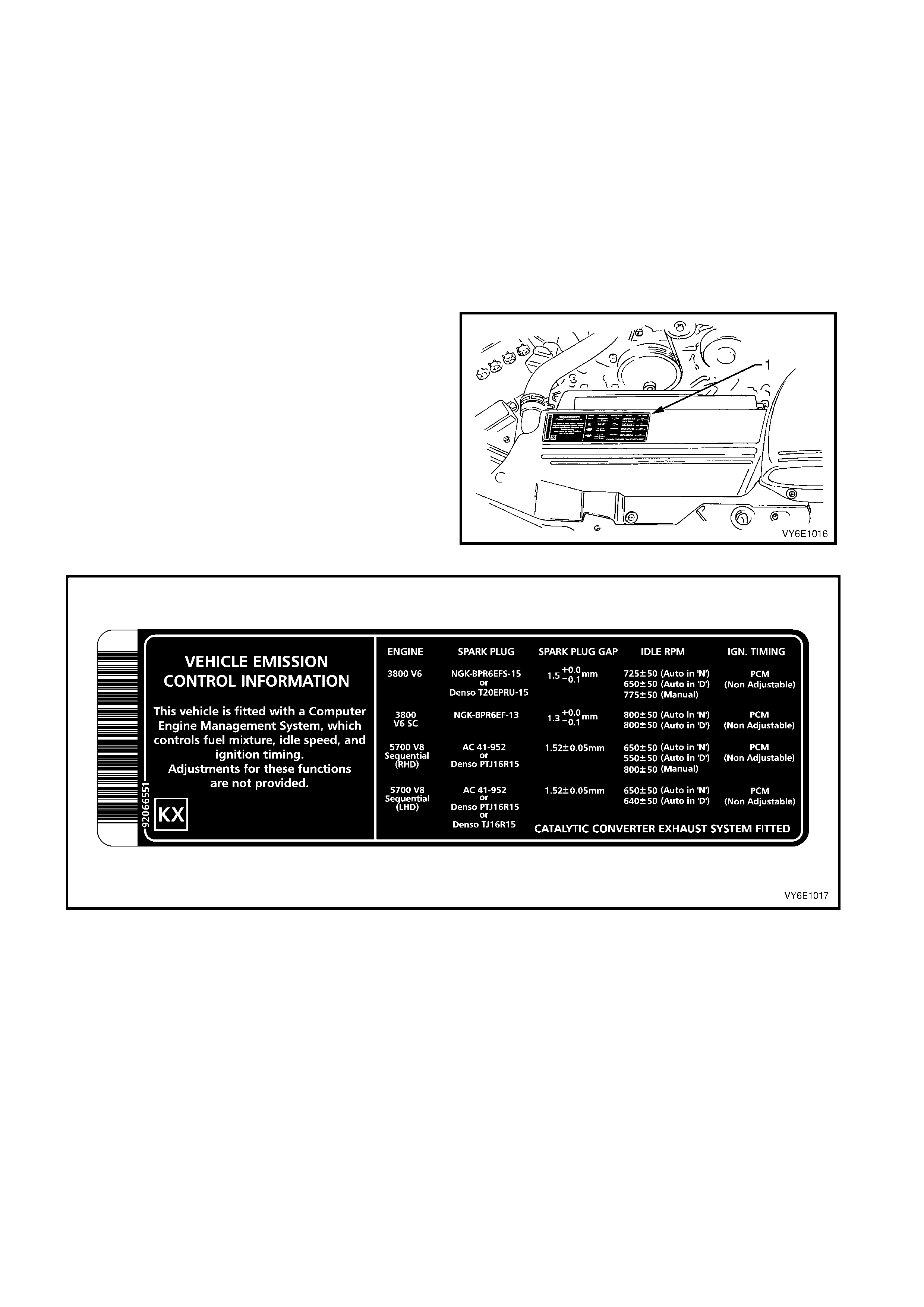
1.1 VEHICLE EMISSION CONTROL INFORMATION LABEL
The vehicle emission control information label is
located in the engine compartment.
The label contains im portant engine tune conditions to
achieve the correct emission levels, and should be
referred to before making any adjustments, refer to
Figure 6E3-2.
Figure 6E3-1
Figure 6E3-2
1.2 EMISSIONS MANAGEMENT
All aspects of engine air/f uel ratio and spark tim ing are
controlled by the Powertrain Control Module (PCM).
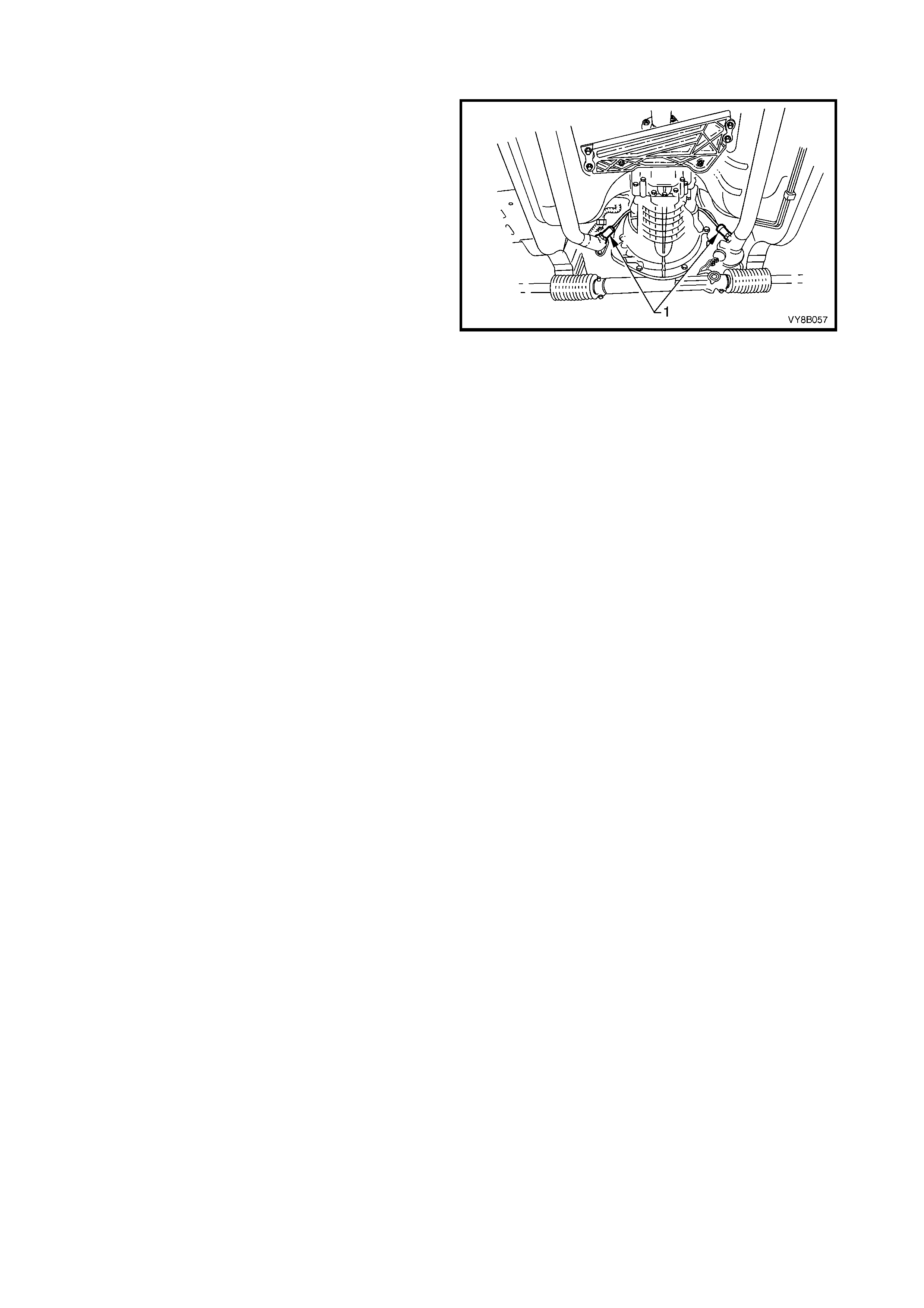
The mixture control is a closed loop system that
incorporates dual oxygen sensors (1), located in the
exhaust system engine pipes, f orward of eac h catalytic
converter.
While the engine ventilation system requires no
outside control, the operation of the evaporative
emission control system is controlled by the PCM via
an EVAP canister purge valve, mounted on the engine
intake manifold.
The PCM and associated systems are described in
Section 6C3 POWERTRAIN MANAGEMENT – V8
ENGINE.
Refer to Figure 6E3-3 for the position of oxygen
sensors on vehicles fitted with a manual transmission.
The position of oxygen sensors on vehicles fitted with
an automatic transmission is similar.
Figure 6E3-3
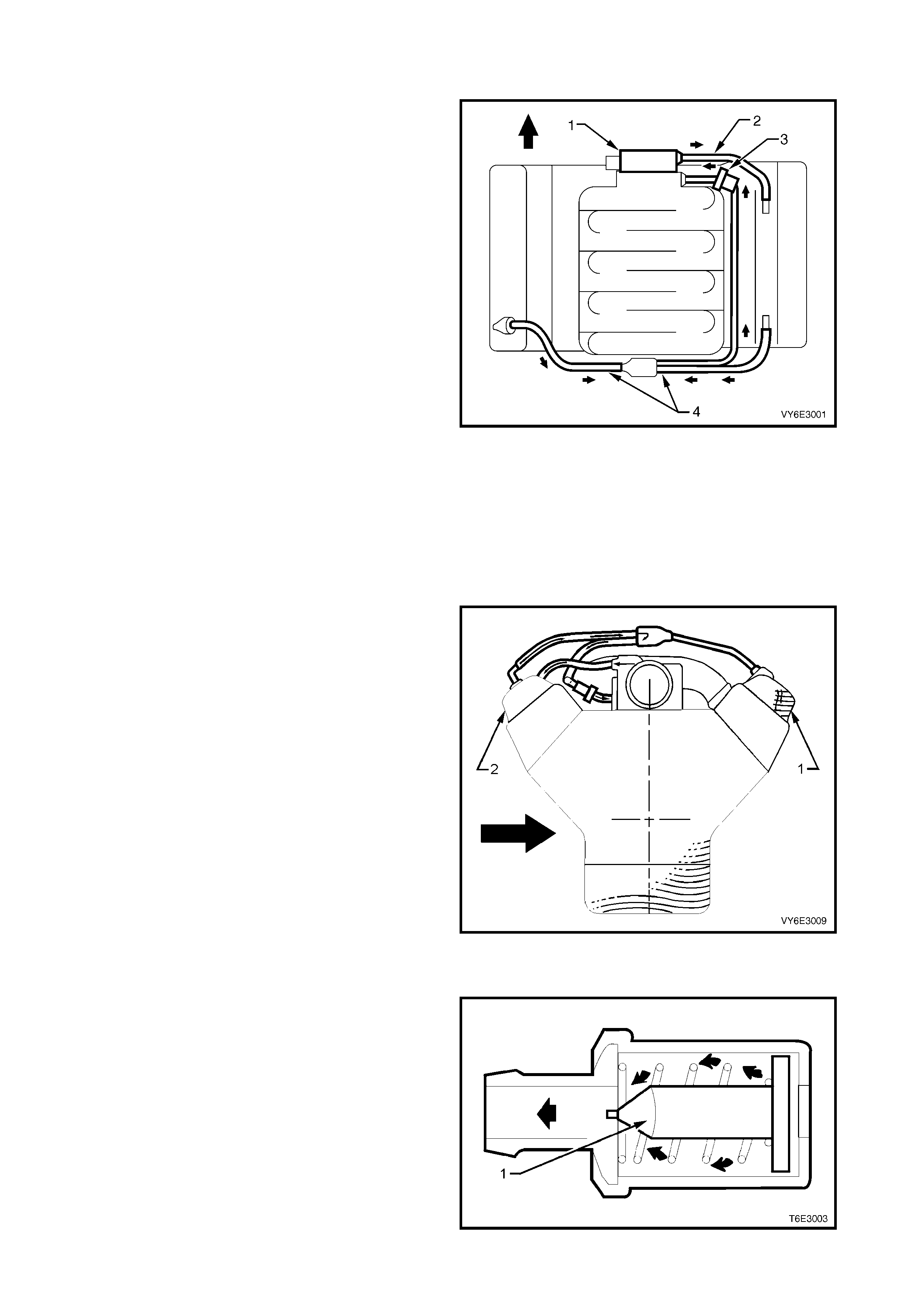
1. 3 ENGINE VENTILATION
A closed crankcase ventilation system is used to
provide complete scavenging of crankcase vapours.
Fresh air from the throttle body (1) is supplied to the
crank cas e, m ixed with blow-by gases and then passed
through a Positive Crankcase Ventilation (PCV)
valve (3) into the intake manifold.
The engine ventilation system minimises oil
consumption and ensures that oil ingestion does not
occur during severe vehicle handling manoeuvres.
Filtered fresh air is r outed f r om upstream of the thr ottle
blade to the front of the right roc ker cover via a f orm ed
rubber hose (2).
To reduce the potential of oil pullover into the throttle
bore area due to back flow of the ventilation system,
the fitting in the right side rocker cover is located in a
‘quiet’ area located between, and shielded from, the
rocker arms.
Crankcase blow-by gases are routed from the rear of
both rocker covers, through moulded nylon lines to a
tee fitting, located on the c entreline of the engine at the
rear of the intake manifold (4). From there, a single
hose carries crankcase vapours through an externally
mounted, horizontal PCV valve (3) and enters the
intake manifold behind the throttle body (1).
The hos es are foam insulated and the PCV valve (3) is
conduction-heated from the c ylinder block by a braided
cable.
Figure 6E3-4
This dual draw system was developed to m eet high ‘g’
forces incurred during severe cornering manoeuvres.
During sustained maximum lateral accelerations, the
outboard rocker cover (1) may fill with oil.
The dual draw system passively s witches, allowing the
PCV valve to draw on the rocker cover with the least
resistance. This results in the system drawing on the
air f illed, or inboard, roc ker c over ( 2) and elim inates oil
pullover that would result from drawing on the oil filled
outboard rocker cover.
Sectioned view shown is looking rearward from the
engine front.
Figure 6E3-5
RESULTS OF INCORRECT OPERATION
A blocked or partially blocked PCV check valve (1) may
cause:
• Rough idle.
• Stalling or slow idle speed.
• Oil leaks.
• Sludge in engine.
A leaking valve would cause:
• Rough idle.
• Stalling.
• High idle speed.
Figure 6E3-6
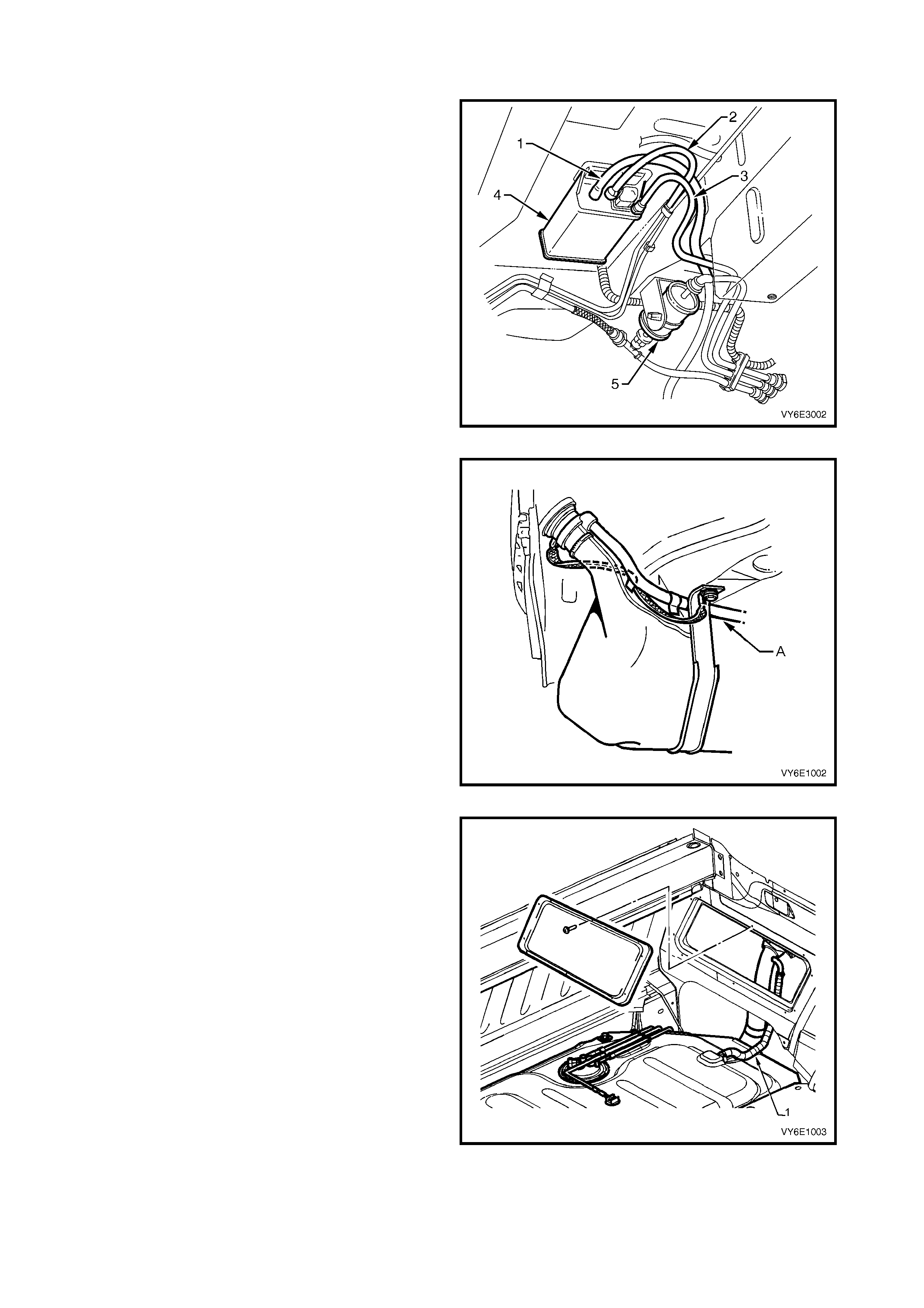
1.4 EVAPORATIVE EMISSION CONTROL
The evaporative emission control system used on this
vehicle is the activated carbon (charcoal) canister
storage method. This fuel vapour canister (4) is a three
port design and is mounted in a bracket underneath
the vehicle, near the fuel filter (5).
The canister cannot be repaired and is serviced only
as an assembly. Periodically check the canister at the
time or distance intervals specified in Section 0B
LUBRICATION AND SERVICE.
The canister is designed to store fuel tank vapour via
the tank vent line (3) and release it to the engine via
the canister purge line (2).
The canister vent line (1) is routed to the fuel filler
neck.
Figure 6E3-7
Figure 6E3-8 shows the canister vent line (A)
attachm ent to the fuel f iller neck on all vehicles except
Utility.
Figure 6E3-8
Figure 6E3-9 shows the canister vent line (1)
attachment to the fuel filler neck on the Utility.
For removal of the f r ont inner s ide panel c over, r ef er to
Section 1B, 2.8 FRONT INNER SIDE PANEL
COVER.
Figure 6E3-9
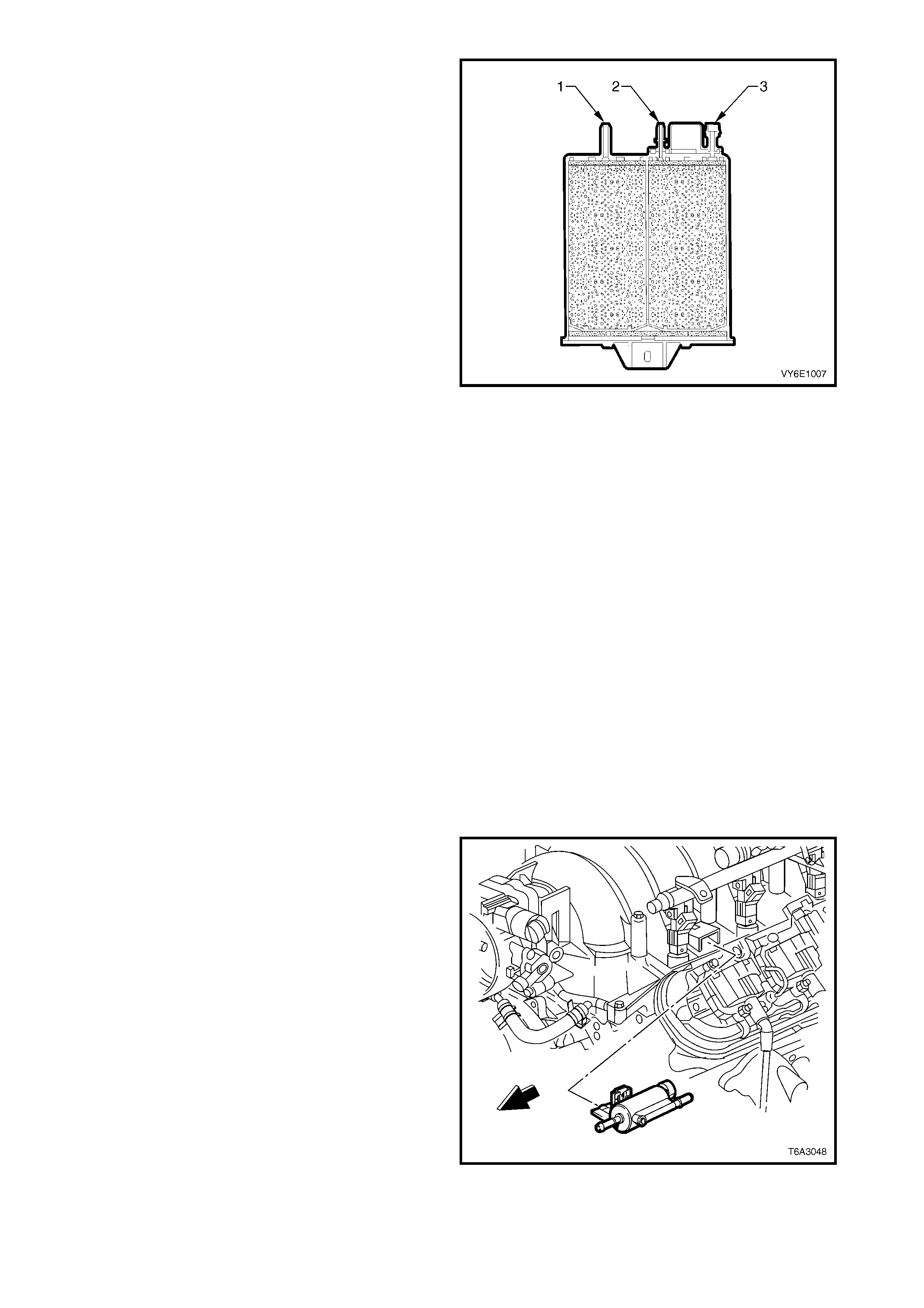
Fuel vapour from the fuel tank enters the canister via
the tank vent port (3). The fuel vapour is absorbed by
the charcoal within the canister.
W hen the engine is running at or above idle, manifold
vacuum on the canis ter purge port (2) caus es air to be
drawn in from the canister vent port (1). This air flow
purges fuel vapour from the canister which is then
transferred to the throttle body. The fuel vapour is
consumed in the normal combustion process.
The EVAP canister purge valve controls the manifold
vacuum that is applied to the canister. The PCM
energises the EVAP canister purge valve by supplying
an earth signal (purge on). The EVAP canister purge
valve control is Pulse Width Modulated (PWM). (This
means that the canister purge valve is turned on and
off several times a second.)
The PCM c ontrolled PW M output is com manded when
the appropriate conditions have been met, such as:
• Engine coolant temperature is below 20 °C at cold
start up and the engine has been running longer
than 3 minutes and 10 seconds, or
• Engine coolant temperature is above 80 °C and
the engine has been running longer than
5 seconds, or
• Engine is not in decel fuel cutoff mode and the
throttle opening is less than 96%, or
• The engine is in closed loop fuel mode.
Figure 6E3-10
A higher purge rate is used under conditions that are
likely to produce large amounts of vapour, when the
following conditions have been met:
• Intake Air Temperature (IAT) is above 50 °C, or
• Engine Coolant Temperature (ECT) is above
100 °C, or
• The engine has been running for more than
15 minutes.
The EVAP purge PW M duty cycle varies according to
operating conditions determined by mass air flow, fuel
trim and intake air temperature. The EVAP canister
purge valve is re-enabled when throttle position angle
decreases below 96%.
The EVAP purge PW M duty cycle varies according to
operating c onditions, determ ined by m ass air flow, fuel
trim and intake air temperature. The EVAP canister
purge valve is re-enabled when TP angle decreases
below 96%.
Figure 6E3-11
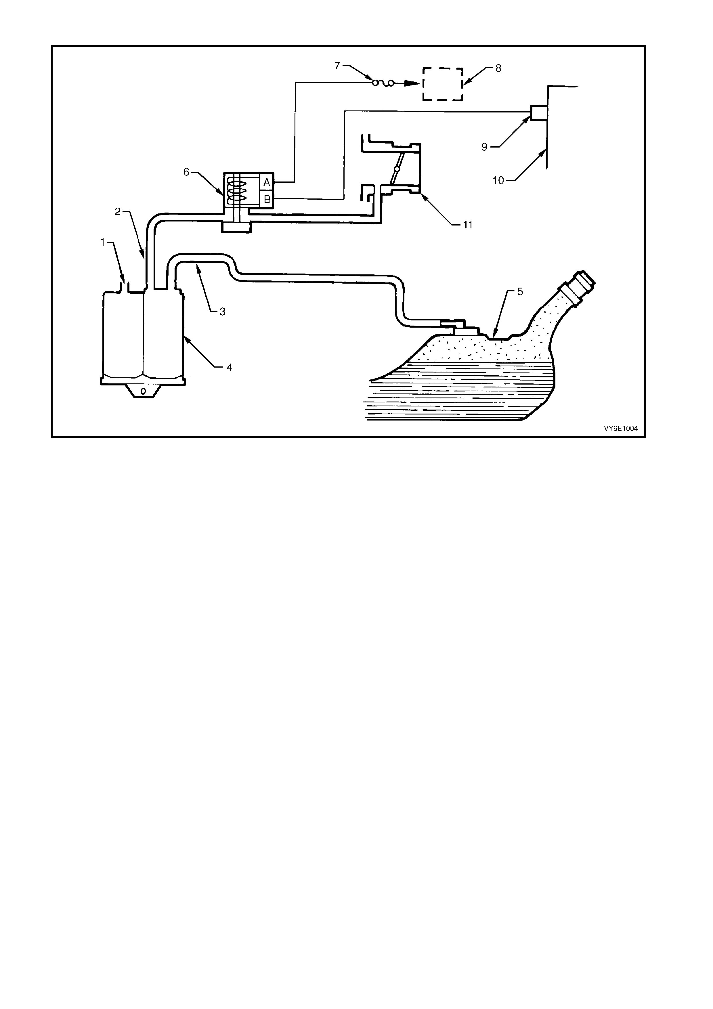
Legend
1. Canister Vent Port 5. Fuel Tank 9. PCM Terminal X2_34
2. Canister Purge Line 6. EVAP Canister Purge Valve 10. PCM
3. Tank Vent Line 7. Fuse F33 11. Throttle Body
4. Canister 8. EFI Relay Figure 6E3-12
RESULTS OF INCORRECT OPERATION
Poor idle, stalling and poor driveability can be caused by:
• Inoperative EVAP canister purge valve.
• Damaged canister.
• Hoses split, cracked and/or not connected to the correct locations.
• Throttle body and canister hoses interchanged on the EVAP canister purge valve connections.
NOTE: The canister purge port is marked with CAN.
Evidence of fuel loss or fuel vapour odour can be caused by:
• Liquid fuel leaking from fuel lines.
• Cracked or damaged canister.
• Disconnected, incorrectly routed, kinked, deteriorated or damaged hoses.
If the EVAP canis ter purge valve is s tuc k open, or the contro l cir cuit is s horted to ear th, the c anist er will purge to the
intake manif old all the tim e. This can allow extra f uel at idle or during warm -up, which can c ause rough or unstable
idle or a rich fuel operation.
If the canister purge solenoid is always closed, the canister can become overloaded resulting in noticeable fuel
odour.

1. 5 EXHAUST EMISSION CONTROL SYSTEM
No exhaust gas recirculation (EGR) system is required for the GEN III V8 engine to meet legislated exhaust
emission control limits.
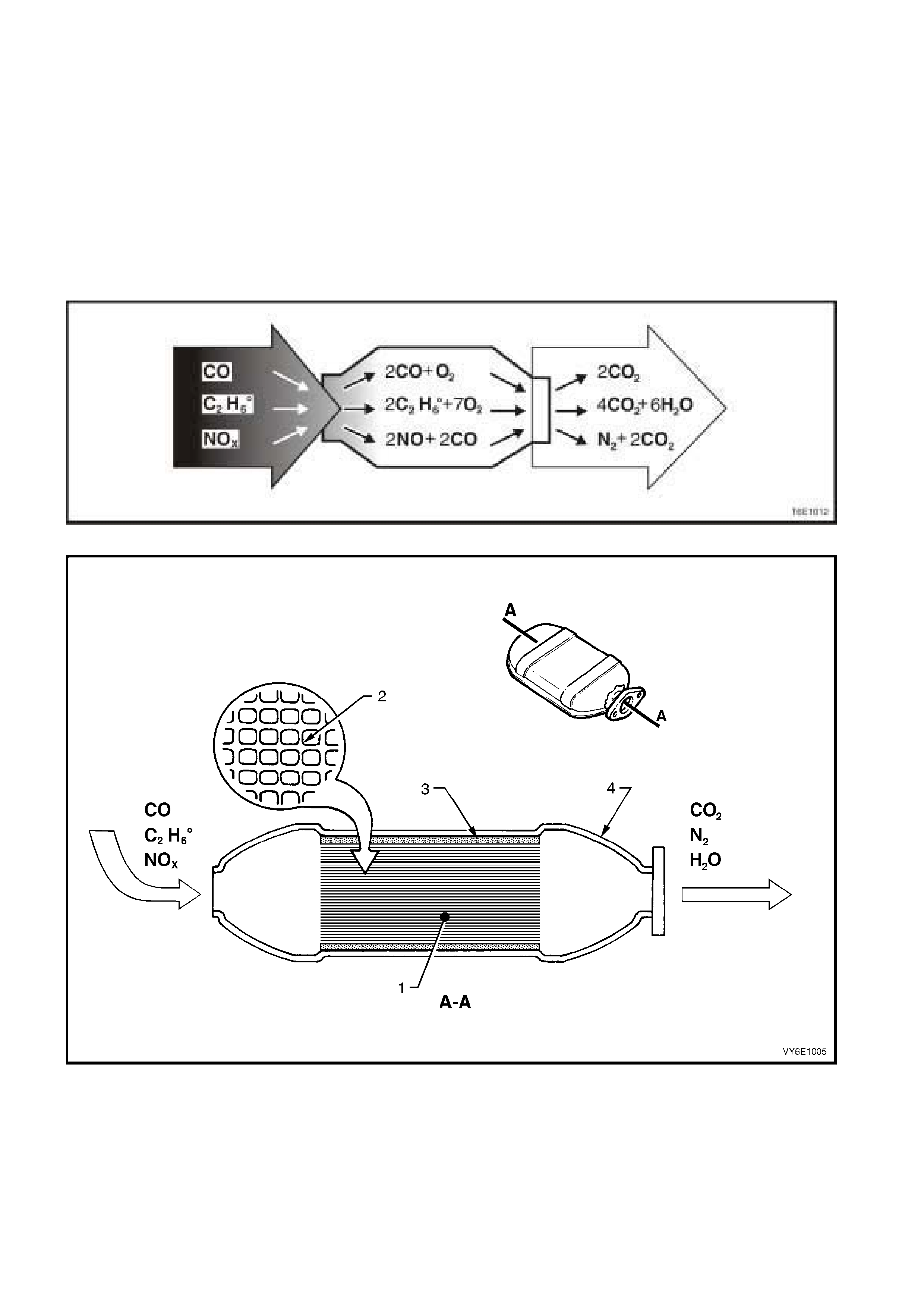
1.6 THREE-WAY CATALYTIC CONVERTER
PRINCIPLES OF OPERATION
The catalytic converter consists of a stainless steel housing that encloses a ceramic monolith. The monolith is an
extruded high temperature ceramic with approximately 62 cells/sq.cm in cross section. This gives the monolith a
large surface area for its mass. Distributed over the monolith surface is a catalyst that consists of platinum and
rhodium. A catalyst is a substance that accelerates a chemical reaction without itself being changed.
Engine exhaust gases contain carbon m onoxide (CO), hydrocarbons (HC) and oxides of nitrogen (NOX). When the
exhaust gases flow through the monolith, reactions with the catalyst occur. CO and HC are converted by oxidation
with oxygen (O2) in the exhaust gas es to produce carbon diox ide (CO2) and water vapour (H2O). NOX is conver ted
by reduction with CO to produce nitrogen (N2) and CO2. The converter is called a three-way type because it
simultaneously converts three components of exhaust gas (CO, HC and NOX) to harmless natural gases.
Figure 6E3-13
Figure 6E3-14
Legend
1. Ceramic Monolith 3. Ceramic Mat securing Monolith
2. Cross Section of Ceramic Monolith 4. Stainless Steel Shell

The catalytic converter can only reduce exhaust emissions if:
a. The engine is designed for use with a catalytic converter and unleaded petrol, since lead contaminates the
catalytic coating and prevents it from functioning.
b. It is integrated in the exhaust system in such a way that the exhaust emission conversion occurs in the most
effective temperature range – in the vicinity of 600 degrees Celsius.
c. The c atalysts function eff ectively within cert ain air/fuel ratios only. As a consequenc e, the air/fuel ratio supplied
to the engine mu st be controlled within strict lim its for emission c onversion and long converter lif e. This contr ol
is off ered by oper ating under a closed loop m ixture control system with dual oxygen sensors. F or details of the
oxygen sensors refer to Section 6C3-3, 2.8 HEATED OXYGEN SENSORS.
The catalytic converter can be damaged, or rendered ineffective:
a. If operated outside the limits of the closed loop mixture control system, or
b. If the engine burns excessive amounts of oil, or
c. If the exhaust temperature at the converter is too high (above 850 degrees Celsius).
SERVICE NOTES
1. Do not operate the vehicle with leaded petrol. Lead will contaminate the ceramic monolith.
2. Do not drop the catalytic converter as it will damage the ceramic monolith.
3. Replace the catalytic converter if it is damaged.
4. Do not allow water, oil or fuel to enter the converter as the ceramic monolith will be contaminated.
5. Do not use engine additives. Many additives contain phosphorous that will contaminate the ceramic monolith.
6. In order to prevent the catalytic converter from overheating, the following sequence must be followed when
carrying out a cylinder balance test:
a. Maximum time each cylinder may be switched off is 8 seconds.
b. Pause for at least 8 seconds between each switch off.
c. If repeating a cylinder balance test, allow the engine to idle for a least 60 seconds before retesting.
7. The vehicle m ust not be star ted by pushing or towing, as unburned fuel c ould reach the catalytic converter and
destroy the ceramic monolith. Always use jumper leads to start a vehicle that has a flat or defective battery.
8. When c ar rying out a compress ion test, r emove fus es F34 and F 35 f rom the engine compartment relay housing,
refer to Section 6A3-3, 2.5 COMPRESSION TEST. This prevents fuel injection and ignition during engine
cranking.
9. Do not drive the vehicle with the engine misfiring or with the spark plug leads disconnected as the catalytic
converter will overheat.
10. Do not coast downhill with the engine misfiring or with the spark plug leads disconnected.
11. The catalytic converter is integrated with the exhaust system. For removal and installation instructions refer to
Section 8B EXHAUST SYSTEM.

2. SERVICE OPERATIONS
2.1 POS I TIVE CRANKCASE VENTILATION VALVE
LT Section No. – 00-249
TEST
1. Remove the engine dress cover.
2. Start the engine and allow to idle.
3. Disconnect the rocker cover PCV hose (1) from
the PCV valve (2).
4. Place a finger over the end of the PCV valve, and
check f or vacuum . If there is no vacuum , check for
plugged hoses or inoperative PCV valve.
5. Switch ignition off. Remove PCV valve from the
hoses. Shake the valve and listen for the rattle of
the valve within. Replace the valve if it does not
rattle.
REMOVE
1. Remove the engine dress cover.
2. Remove the nut (3) securing the PCV valve heat-
conducting strap (4) from the front right hand
vapour pipe screw (5).
3. Disconnect the PCV valve from the rocker cover
PCV hose and the throttle body PCV hose (6).
REINSTALL
1. Reconnect the PCV valve to the roc ker c over PCV
hose and the throttle body PCV hose.
2. Reinstall the heat-conducting strap to the right
hand vapour pipe screw and tighten the nut to the
correct torque.
PCV VALVE HEAT-CONDUCTING
STRAP NUT TORQUE SPECIFICATION 12.0 Nm
3. Reinstall the engine dress cover.
Figure 6E3-15
2.2 EVAPORATIVE EMISSION CONTROL CANISTER
LT Section No. – 03-165
REMOVE
1. Disconnect the canister purge line (1) by using the
following procedure:
a. Grasp both s ides of the quic k -connec t fitting. T wist
the connector 1/4 turn in each direction in order to
loosen any dirt within the quick-connect fitting.
Caution: Wear safety glasses when using
compressed air.
b. Using compressed air, blow any dirt out of the
quick connect fitting.
c. Grasp the quic k-connec t f itting and push it towards
the canister.
d Squeeze the quick-connect fitting to release the
retaining tabs, then pull back on the connector to
remove the canister purge line from the canister.
Figure 6E3-16
2. Disconnect the tank vent line (1) by using the
following procedure:
a. Grasp both s ides of the quic k -connec t fitting. T wist
the connector 1/4 turn in each direction in order to
loosen any dirt within the quick-connect fitting.
Caution: Wear safety glasses when using
compressed air.
b. Using compressed air, blow any dirt out of the
quick connect fitting.
c. Grasp the quic k-connec t f itting and push it towards
the canister.
d Squeeze the quick-connect fitting to release the
retaining tabs, then pull back on the connector to
remove the tank vent line from the canister.
Figure 6E3-17
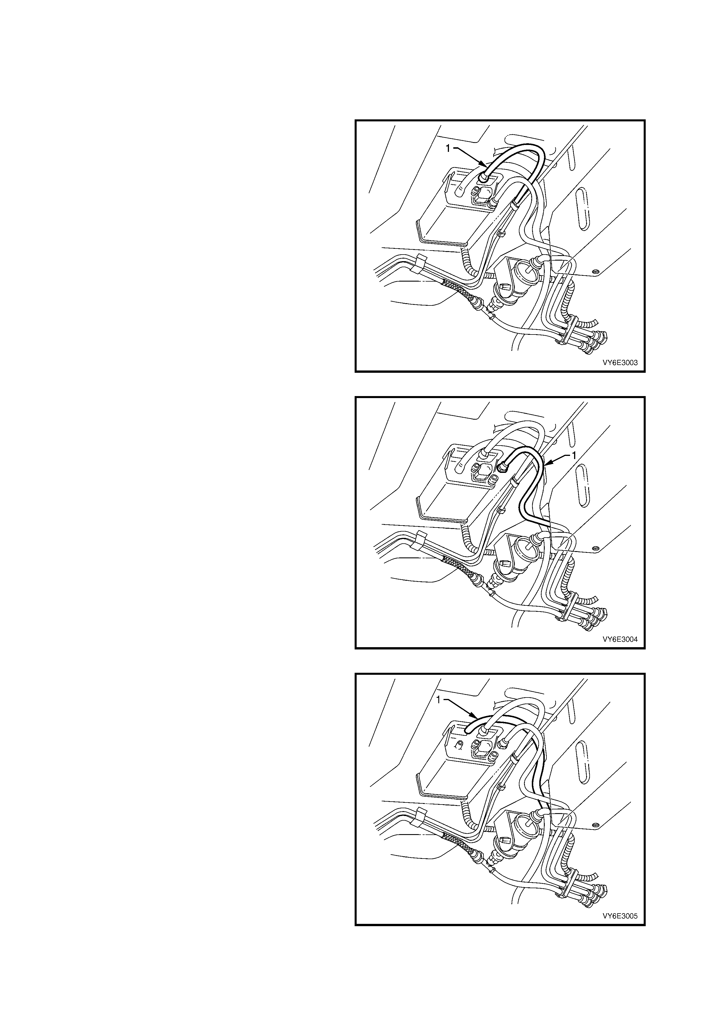
3. Remove the c anister vent line (1) from the canister
by twisting and pulling it off.
Figure 6E3-18
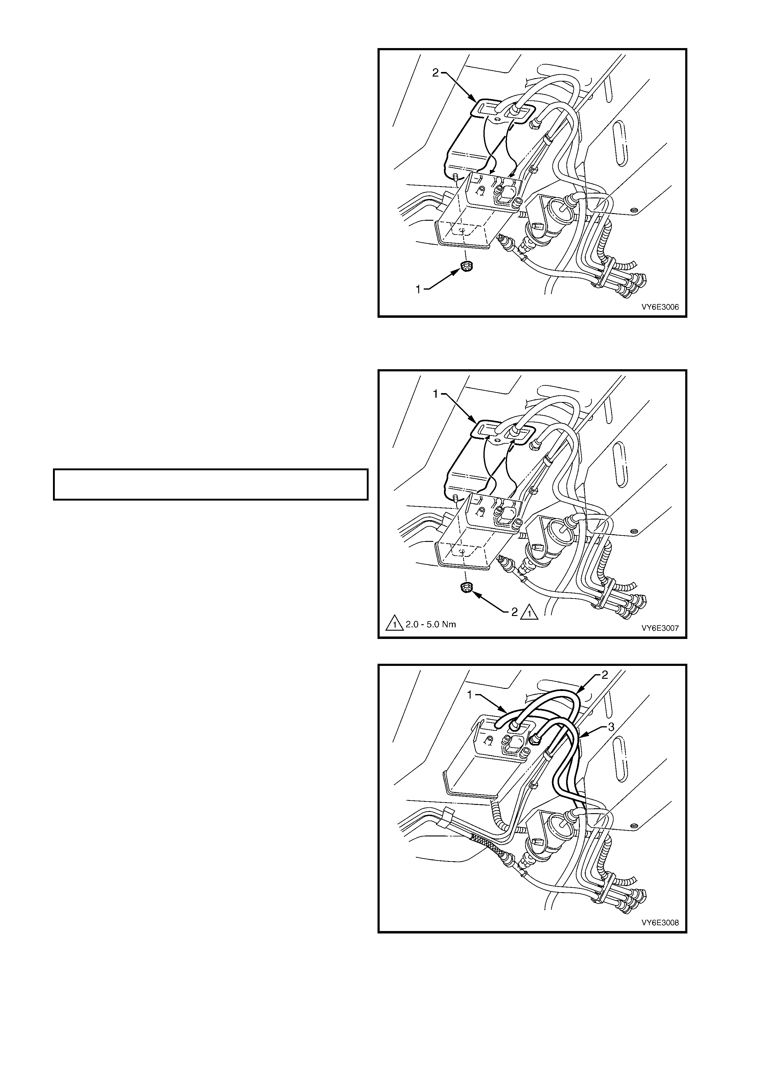
4. Remove the canister retaining nut (1).
5. Remove the canister from the retaining stud and
then slide the canister out of the retainer (2).
Figure 6E3-19
REINSTALL
1. Reinstall the canister into the retainer (1) and over
the retaining stud.
2. Reinstall the canister retaining nut (2) and hand
tighten.
3. Push canister toward centre of vehicle and tighten
the canister retaining nut to the specified torque.
CANISTER RETAINING NUT
TORQUE SPECIFICATION 2.0 - 5.0 Nm
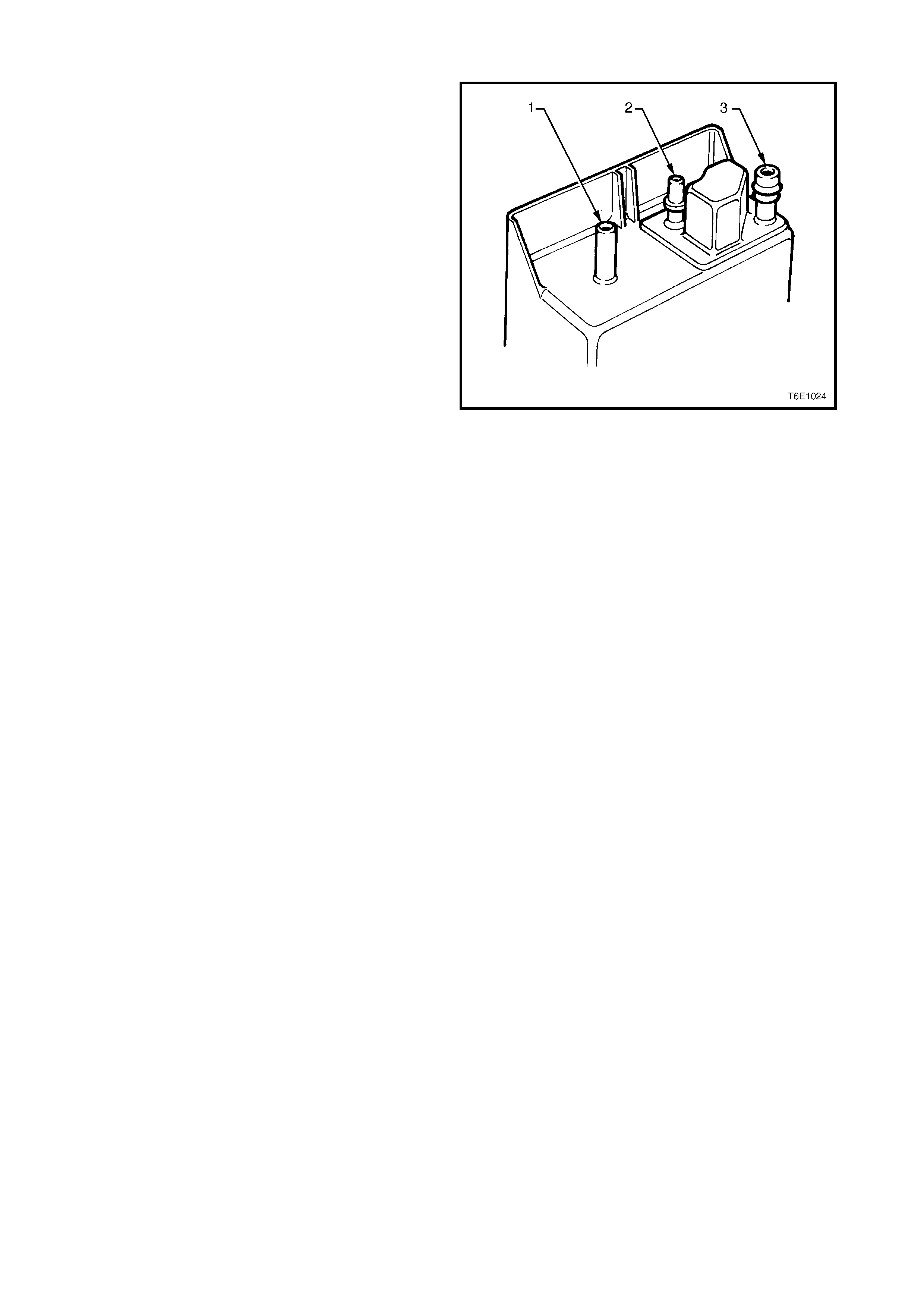
Figure 6E3-20
4. Reinstall the canister vent line (1).
5. Align the canister purge line quick connector (2)
with the canister purge line port. Push the
connector firmly onto the port.
6. Align the tank vent line quick connector (3) with the
tank vent port. Push the connector firmly onto the
port.
7. Once installed, pull on each quick connect to
ensure the connections are secure and locked in
position.
Figure 6E3-21
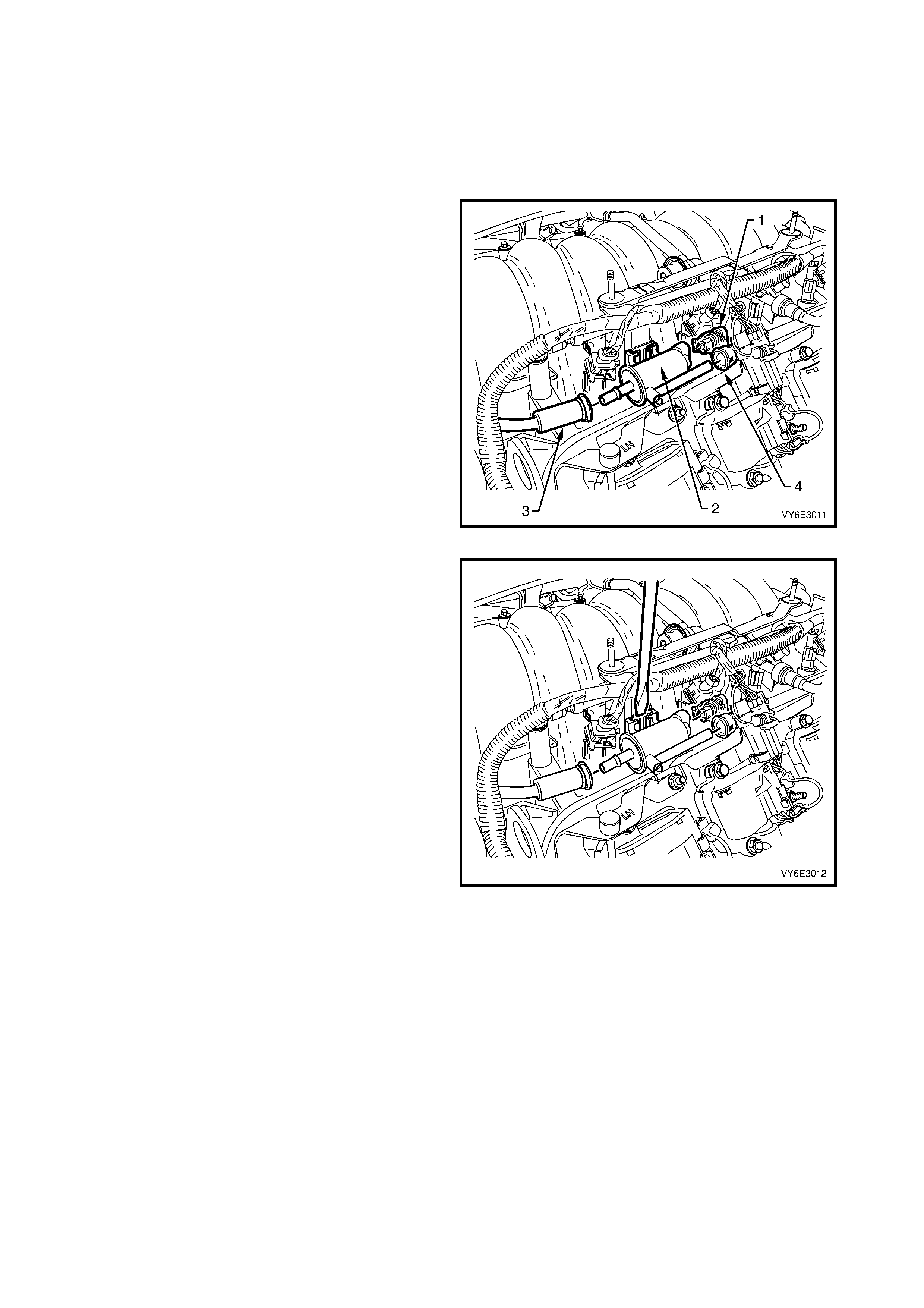
SERVICE CHECKS
1. Remove canister as described in this Section.
2. Shake the canister. There should be no audible
sound of carbon movement.
3. Using low pressure compressed air (20-35 kPa),
blow into the tank vent port (3). Check that air
flows freely from the canister vent port (1). Block
the canister vent port (1) and air should flow from
the canister purge port (2).
4. If airflow through the canister vent port (2) is poor,
clean the atmospheric f ilter by blocking of f the tank
vent port (3) and blowing compressed air at
approximately 300 kPa through the canister purge
port (2).
5. Check airflow through the filter as in Step 3. If
airflow through the canister vent port (1) is still
poor, replace the canister.
6. Block the canister vent port (1) and the canister
purge port (2). Apply low pressure compressed
air (20-35 kPa) to the tank vent port (3). If any air
leaks from the canister, i.e. around ports or seams,
the canister must be replaced.
Figure 6E3-22
2.3 CANISTER PURGE SOLENOID VALVE
LT Section No. – 03-165
REMOVE
1. Ensure that the ignition switch is off.
2. Remove the engine dress cover.
3. Disconnect the electrical connector (1) from the
canister purge solenoid valve (2).
4. Disconnect the throttle body hose (3) by pressing
the locking retainer and pull the hose from the
canister purge solenoid valve.
5. Disconnect the canister purge line (4) from the
canister purge solenoid valve using tool AU533.
Refer to Section 8A1, 2.10 QUICK-CONNECT
FITTINGS.
Figure 6E3-23
6. Insert a thin blade screwdriver between the
solenoid valve and the solenoid brack et to release
the retaining clip.
7. Remove the solenoid valve f rom the solenoid valve
bracket.
REINSTALL
1. Reinstall the canister purge solenoid valve onto the
solenoid br acket and push down over the retaining
clip.
NOTE: Ensure that the retaining clip locks into place.
2. Reconnect both hoses and the electric al connector
to the canister purge solenoid valve.
3. Reinstall the engine dress covers.
Figure 6E3-24

3. DIAGNOSIS
3.1 POS ITIVE CRANKCASE VENTILATION
CONDITION PROBABLE CAUSE CORRECTIVE ACTION
Rough, slow idle or stalling 1. PCV valve blocked.
2. Blocked or damaged
ventilation hose.
Clean valve or replace.
Clean or replace hose.
Rough, fast idle or stalling 1. PCV valve stuck in
intermediate position.
2. PCV valve leaking.
Clean valve or replace.
Check valve O-ring, replace if
necessary.
Check valve installation.
Excessive sludging or diluting of
oil Engine is not vented. Check for clogged PCV valve
circuit and clogged ventilation
circuit.

3.2 EVAPORATIVE EMISSION CONTROL
CONDITION PROBABLE CAUSE CORRECTIVE ACTION
Loss of fuel from filler cap 1. Unsatisfactory sealing
between cap and filler neck.
2. Malfunction of filler cap relief
valve.
Replace filler cap.
Replace filler neck if damaged.
Replace filler cap.
Loss of fuel from fuel lines 1. Loose line connection.
2. Faulty connector.
3. Split or cracked fuel line.
Secure connection.
Replace fuel line.
Replace fuel line.
Loss of fuel from canister 1. Fuel tank overfilled. When the
fuel temperature increases,
excess fuel is discharged into
the canister, flooding it.
2. Kinked hoses at filler neck or
canister.
3. Blocked, damaged or
disconnected purge valve.
Avoid overfilling of tank.
Replace damaged hoses. Ensure
that the hoses are installed
correctly.
Check purge valve operation.
Collapsed fuel tank or pressure in
tank 1. Faulty fuel filler cap. In high
temperature operating
conditions some pressure in
the fuel tank is a normal
condition.
2. Blocked or kinked hoses at
filler neck or canister.
3. Defective canister (usually
internal blocked).
4. Purge solenoid valve is closed
causing canister to become
overloaded.
Replace filler cap.
Replace damaged hoses. Ensure
that the hoses are installed
correctly
Replace canister.
Refer to 6C3 POWERTRAIN
MANAGEMENT – GEN III V8
ENGINE.
Rough idle 1. Improperly routed or
disconnected purge line.
2. Purge solenoid valve is open
or not receiving power.
Check purge line.
Refer to 6C3 POWERTRAIN
MANAGEMENT – GEN III V8
ENGINE.
For diagnosis of faults pertaining to vehicle performance, refer to Section 6C2 POWERTRAIN MANAGEMENT –
V8 ENGINE.
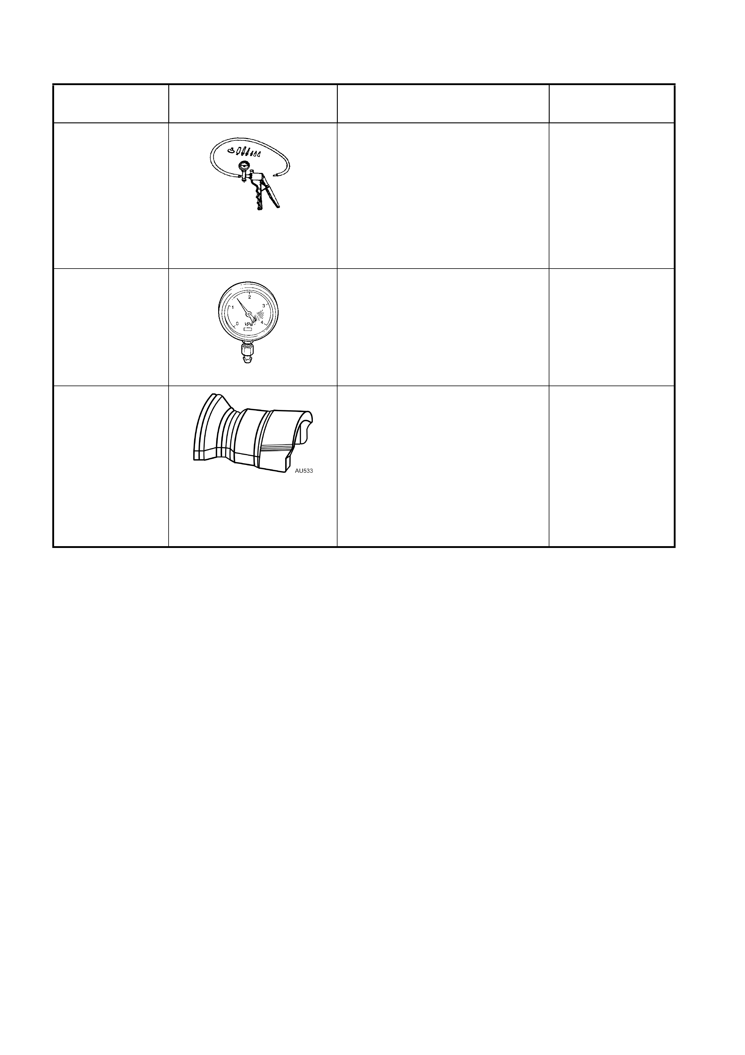
4. SPECIAL TOOLS
TOOL NUMBER ILLUSTRATION DESCRIPTION TOOL
CLASSIFICATION
J23738-A
VACUUM PUMP (20 IN. HG
MINIMUM)
Used for many applications,
including engine, automatic
transmission, steering gear,
diagnostic checks.
Previously released.
Mandatory
N/A
VACUUM GAUGE
Vacuum gauge with scale of 0 to
-4kPa. Used for checking P.C.V.
valve operation and function.
Previously released.
Mandatory
AU533
QUICK CONNECT FITTING
RELEASE TOOL
Released in two sizes; Red for
5/16” fittings and Blue for 3/8”
fittings.
Also available commercially.
Previously released.
Desirable

5. TORQUE WRENCH SPECIFICATIONS
Canister retaining nut............................................................2.0 – 5.0 Nm