
SECTION 6F3 - ENGINE TUNE –
GEN III V8 ENGINE
IMPORTANT
Before performing any Service Operation or other procedure described in this Section, refer to Section 00
CAUTIONS AND NOTES for correct workshop practices with regard to safety and/or property damage.
CONTENTS
1. GENERAL INFORMATION
1.1 VEHICLE EMISSION CONTROL INFORMATION
2. ENGINE TUNE RECOMMENDATIONS
3. ENGINE TUNING DATA
3.1 TUNING SERVICE NOTES
3.2 CYLINDER BALANCE CHECK
IGNITION
FUEL
MECHANICAL
4. SPECIAL TOOLS
1. GENERAL INFORMATION
Engine tuning, although simplified by electronic control of the air/fuel mixture and ignition timing, is of great
importance due to the susceptibility of the catalytic converter to damage caused by rich air/fuel mixture. The
Powertrain Control Module (PCM) controls the air/fuel ratio to near optimum condition. A rich mixture can be
induced by faulty spark plugs or leads or a fault in the engine management system, refer to
Section 6C3, POWERTRAIN MANAGEMENT – GEN III V8 ENGINE.
The PCM will set a Diagnostic Trouble Code (DTC) and the words “Check Engine” together with an icon will be
displayed in the instrument cluster multi-function display, in the event of the mixture continuing to operate outside
the specified limits. Prolonged operation with a rich mixture may damage the catalytic converter, refer to
Section 6E3, 1.6 THREE-WAY CATALYTIC CONVERTER.
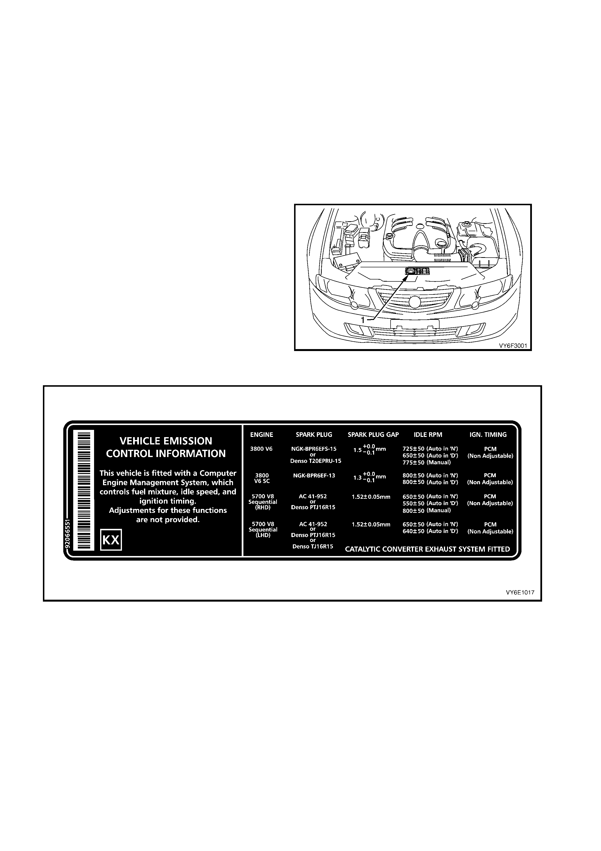
1.1 VEHICLE EMISSION CONTROL INFORMATION
Engine tune specifications necessary to achieve
the correct emission levels are located on the
vehicle emission control information label; located
in the engine compartment. Refer to the label
before adjusting the engine.
To maintain the performance and emission control
levels specified for the vehicle, it is necessary for
regular maintenance to be performed in
accordance with the schedule set out in the VY
Series Owner's Handbook.
Figure 6F3-1
Figure 6F3-2
The following engine tune recommendation chart lists the items that require attention when tuning the engine.
Cross-references to the appropriate section in the VY service manual are also provided.
There is no provision for ignition timing, idle speed and idle mixture adjustments on the VY Series Models with a
GEN III V8 engine, refer to Section 6C3, POWERTRAIN MANAGEMENT – GEN III V8 ENGINE.
The Engine Tune Data Chart provides condensed engine tuning data.
NOTE: The use of unleaded petrol will result in black tail pipe deposits rather than the familiar grey colour.
Therefore, the black colour does not indicate a poor state of engine tune.
2. ENGINE TUNE RECOMMENDATI ONS
ENGINE TUNE RECOMMENDATIONS VY SERVICE MANUAL
REFERENCE SE CTIO N
ENGINE COMPRESSIO N TEST SECTION 6A 3, 2.5 COMPRESSION
CHECK. ALSO REF ER TO 3.1 TUNI NG
SERVICE NOTES.
ENGINE DRIVE BELT CHECK SECTION 6A 3, 2.6 ENGINE DRI V E
BELTS.
COOLING SYSTEM CHECK FOR LEAKS SECTION 6B 3, 2.3 DRAINING A ND
FILLING COOLING SYSTEM.
VALVE LASH ADJUSTMENT NON-ADJUST ABLE HYDRAULIC
LIFTERS
IDLE SP EED NON-ADJUST A BLE
IDLE MIXTURE NON-ADJUST A BLE
AIR CLEANER CHECK OR REPLACE, TEST FOR LEAKS SECTION 6C3-3, 5.5 AIR CLEA NE R
ASSEMBLY.
FUEL FILTER CHECK AND REP LA CE SECTION 6C3-3 11 FUEL FI LTER.
SPARK PLUGS CLEAN, ADJUST OR REPLACE SECTION 6C3-3, 3.11 SPARK PLUGS.
SPARK PLUG LEADS TEST FOR CONTINUITY SECTION 6C3-3, 4.4 SPARK PLUG
LEADS.
IGNITION TIMING NON-ADJUST A BLE
EXHAUST SYSTEM CHECK FOR EXCESSIVE BACK
PRESSURE, GENERAL CONDITION AND
OXYGEN SENSOR OPERATION
SECTION 8B, EXHAUST SYSTEM AND
SECTION 6C3-3, 2.8 OXYGEN SENSOR
ENGINE VENTILATION CHECK SECTION 6E 3, 1.3 ENGINE
VENTILATION.
EVAPORATIVE EMISSION CONTROL CHECK LINES, HOSES AND CANISTER SECTION 6E3, 1.4 EVAPORATIVE
EMISSION CONTROL.
BATTERY AND CABLES CHECK SECTION 12A, BATTERY AND CABLES.
3. ENGINE TUNI NG DATA
SPARK PLUGS
ENGINE TYPE TRANSMISSION IDLE SPEED
(RPM) IG N ITION TI MING TYPE GAP (mm)
MANUAL 800 ± 50
650 ± 50
(IN NEUTRAL)
5.7 LITRE P.F.I.
GEN III V8 AUTOMATIC
TRANSMISSION 550 ± 50
(IN DRIV E )
PCM
CONTROLLED
(NON –
ADJUSTABLE)
TYPE AC 41-952
Alternat i ve S e rvi ce
Replacement
DENSO PT J16R15
1.52 ± 0.05 mm
650 ± 50
(IN NEUTRAL)
5.7 LITRE P.F.I.
GEN III V8
(MIDDLE EAST)
AUTOMATIC
TRANSMISSION 640 ± 50
(IN DRIV E )
PCM
CONTROLLED
(NON –
ADJUSTABLE)
TYPE AC 41-952
OR
DENSO PT J16R15
OR
DENSO TJ16R15
1.52 ± 0.05 mm
NOTE: Idle speed is controlled by the PCM and varies with: – Battery voltage
– Engine temperature
– Air conditioning request
– Park/Neutral Switch Signal (Automatic only)
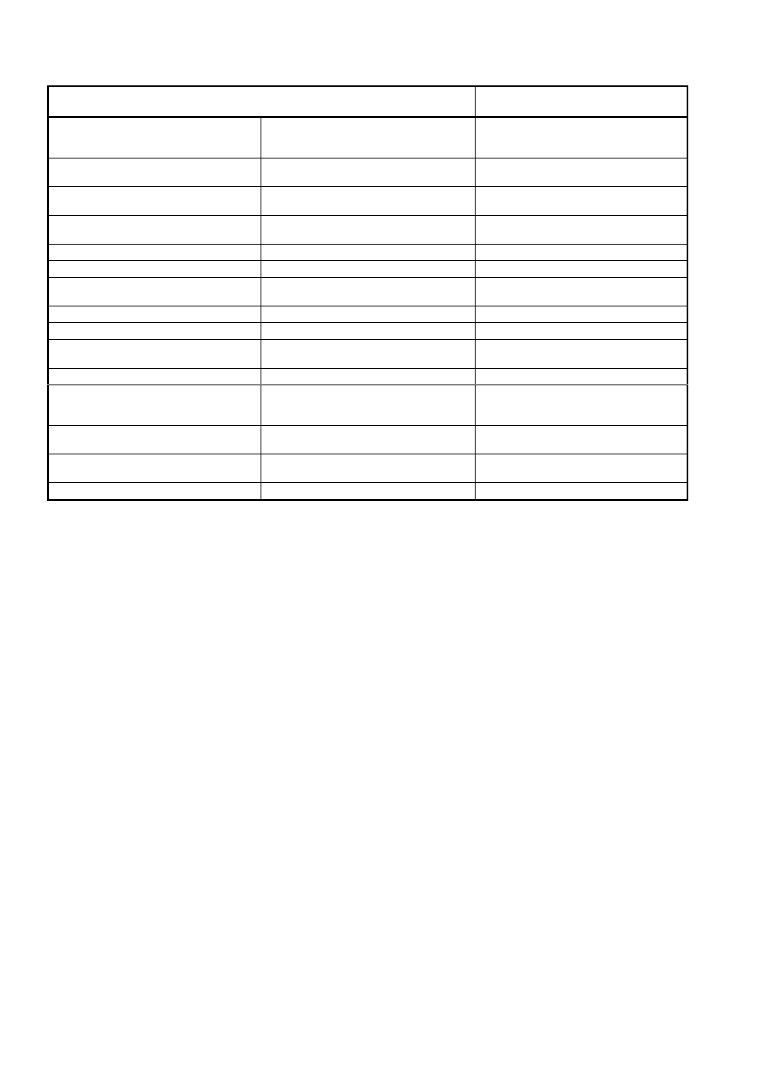
3.1 TUNING SERVI CE NOTES
CAUTION: To prevent fuel being injected into
the cylinders and the ignition during cranking,
remove the EFI relay (1) when performing a
compression test. This will avoid damaging the
catalytic converter with unburned fuel.
For compression testing procedure and
specifications, refer to
Section 6A3, 2.5 COMPRESSION CHECK.
1. Do not oper ate the engine with any spark plugs
or spark plug leads disconnected as:
a. The ignition system or PCM may be damaged.
b. The resultant mixture could damage the
catalytic converter.
2. Make all engine checks with engine coolant
and oil at normal operating temperatures,
preferably those temperatures reached while
driving.
3. Ensure the air conditioning, where fitted, is
switched OFF.
4. Verify that the words “Check Engine” and
accompanying icon are not displayed in the
instrument cluster multi-function display when
the engine is running.
Figure 6F2-3
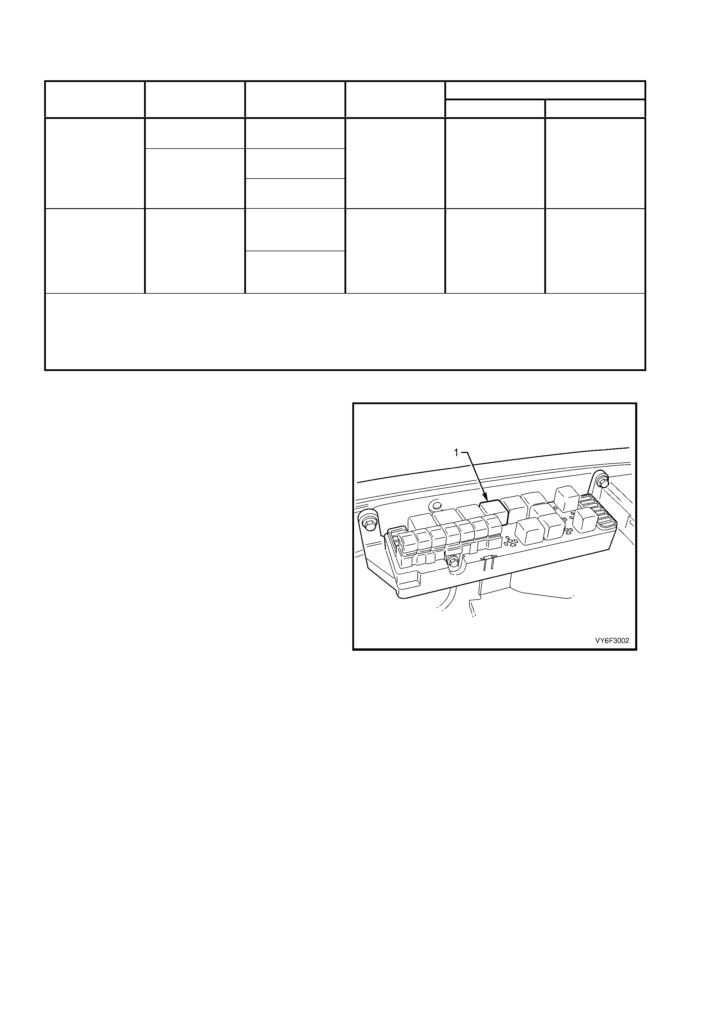
3.2 CYLINDER BALANCE CHECK
1. Connect the Tech 2 (4) to the Data Link
Connector (DLC) (1) via the DLC Adaptor (2)
and DLC Cable (3).
2. Select VY Commodore / Engine / Functional
Tests / Power Balance.
3. Perform power balance as directed by the
Diagnostic Scan Tool.
NOTE 1: RPM readings displayed on the
Diagnostic Scan Tool should be within 50 RPM of
the idle engine speed for all cylinders
NOTE 2: Any cylinder that does not caus e a drop in
engine idle speed is misfiring.
NOTE 3: For further information on the usage of
Tech 2, refer to Section 0C, TECH 2.
Once the problematic cylinder has been identified,
the cause of the problem will still need to be
determined. Reasons for the fault include fuel,
spark or engine mechanical problems.
The following checks are to assist in isolating the
cause of the engine misfire. For additional
diagnostic information, refer to
Section 6C3, POWERTRAIN MANAGEMENT –
GEN III V8 ENGINE.
Figure 6F2-4
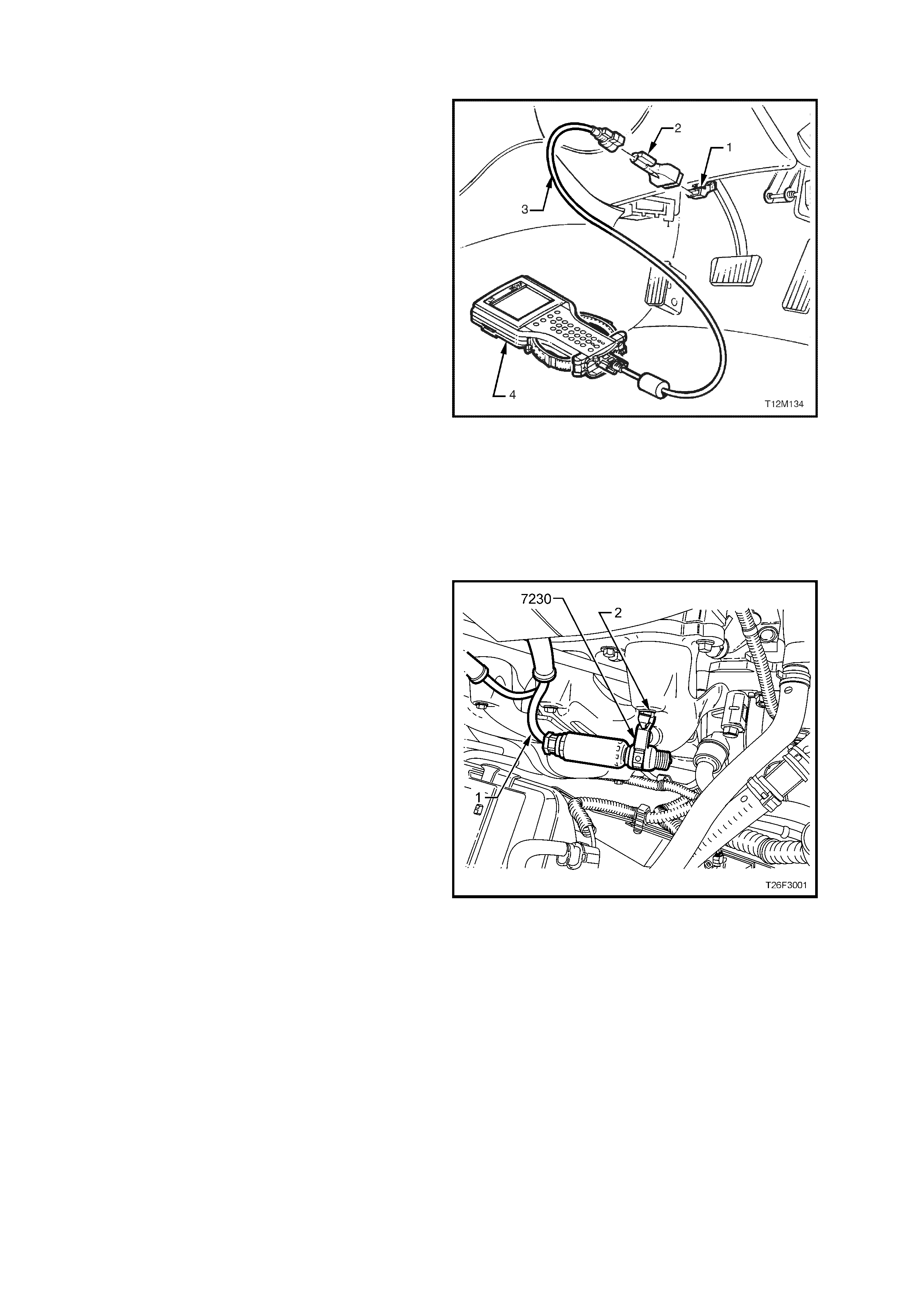
IGNITION
1. Remove the spark plug lead (1) from the plug
and the engine harness connector from the
injector of the misfiring cylinder.
2. Install the test plug, tool No. 7230 and connect
it to an engine earth point (2).
NOTE 1: Failure to properly earth the may result in
damage to the ignition system components due to
excessive secondary voltages required to fire it.
NOTE 2: Avoid placing the test plug near sensors,
modules or other electronic equipment that m ay be
affected by electromagnetic interference.
3. Disconnect the spark plug wire and the engine
wiring harness from the injector of the
corres ponding cylinder. Connect the spark plug
lead directly to the engine earth.
4. Start and run the engine. If the tester shows a
good spark, check for faulty spark plug.
5. If there is a weak spark or no spark at all,
check the spark plug lead for a short circuit to
the earth, or open or very high resistance
NOTE: If any lead is open circuited, recheck coil
secondary resistance, it may have been damaged
by high voltage produced by open circuit.
Figure 6F2-5
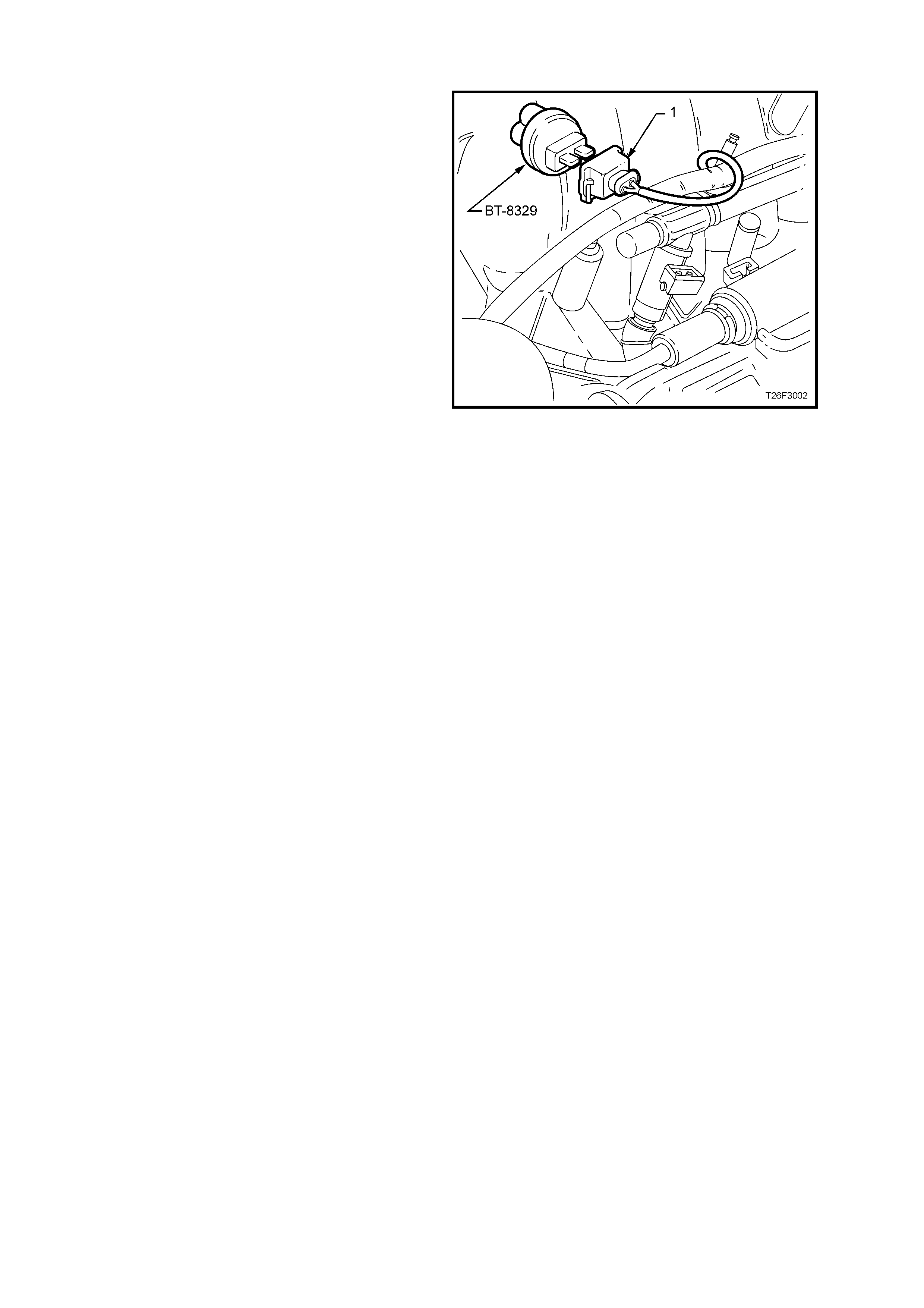
FUEL
1. Disconnect the engine harness connector from
the injector of the cylinder that is misfiring.
2. Install injector node light tester (1), tool No.
J34730-2C into the connector (2) and start the
engine.
3. Check tester for light flashing.
a. If the injector node light does not flash or
flashes erratically, check the engine harness
between connector and PCM.
b. If the injec tor node light test er flashes regularly,
check for blocked or faulty injector, refer to
Section 6C3, POWERTRAIN MANAGEMENT
– GEN III V8 ENGINE.
Figure 6F2-6
MECHANICAL
Perform compression test refer to Section 6A3,
2.5 COMPRESSION CHECK.
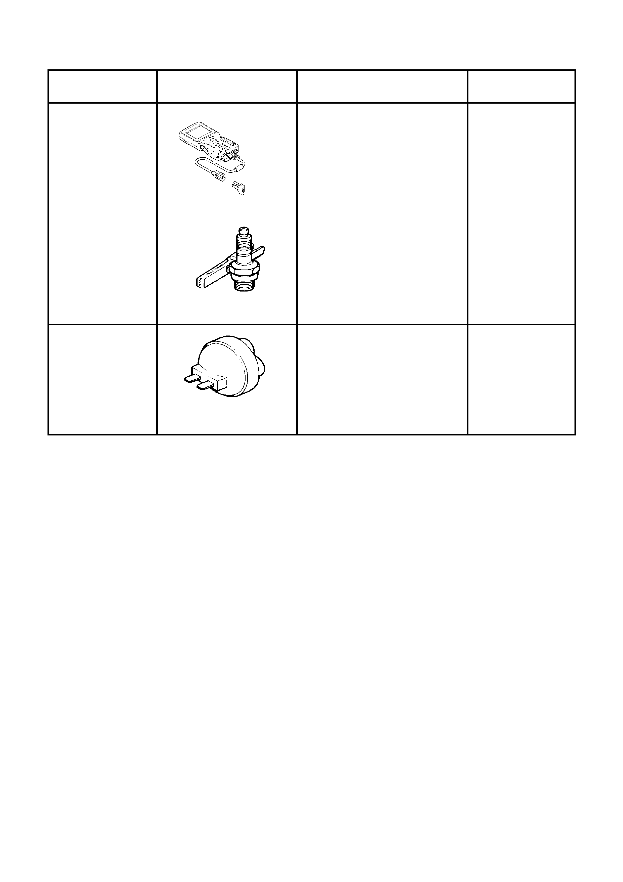
4. SPECIAL TOOLS
TOOL NUMBER ILLUSTRATION DESCRIPTION TOOL
CLASSIFICATION
7000086I
TECH 2
DIAGNOSTIC SCAN TOOL
Used for diagnosis of vehicle
electrical system.
Previously released.
Mandatory
7230
(ST-125)
HEI TESTER
(TEST PLUG)
Used in diagnostic checks with
engine management system.
Previously released.
Mandatory
J34730-2C
(BT-8329)
INJECTOR NODE LIGHT
TESTER
Used when carrying out engine
management electrical
diagnostic checks.
Previously released.
Mandatory