
SECTION 7A1 - CLUTCH – V6 ENGINE
IMPORTANT
Before performing any Service Operation or other procedure described in this Section, refer to Section
00 CAUTIONS AND NOTES for correct workshop practices with regard to safety and/or property damage.
CONTENTS
1. GENERAL INFORMATION
2. GENERAL DESCRIPTION
2.1 DUAL MASS FLYWHEEL
SERVICE IMPLICATIONS
2.2 CLUTCH CONTROL
ARRANGEMENT
2.3 CLUTCH MASTER CYLINDER/ACTUATING
CYLINDER OPERATION
CLUTCH RELEASED
CLUTCH APPLIED
3. SERVICE OPERATIONS
3.1 SERVICE NOTES
3.2 FLUID LEVEL CHECK
3.3 CLUTCH HYDRAULIC SYSTEM, BLEED
3.4 CLUTCH FLUID – CHANGE
3.5 CLUTCH MASTER CYLINDER
REMOVE
DISASSEMBLE
CLEAN AND INSPECT
REASSEMBLE
REINSTALL
3.6 CLUTCH ACTUATING CYLINDER
REMOVE
DISASSEMBLE
CLEAN AND INSPECT
REASSEMBLE
REINSTALL
3.7 CLUTCH PEDAL ASSEMBLY
REMOVE
DISASSEMBLE
REASSEMBLE
REINSTALL
3.8 CLUTCH PEDAL SWITCH
REPLACE
3.9 CLUTCH DRIVEN PLATE, PRESSURE
PLATE AND/OR THROWOUT BEARING
REMOVE
INSPECT
REINSTALL
3.10 DUAL MASS FLYWHEEL
REPLACE
3.11 CRANKSHAFT SPIGOT BUSH
REPLACE
4. DIAGNOSIS
5. SPECIFICATIONS
6. TORQUE WRENCH SPECIFICATIONS
7. SPECIAL TOOLS
Techline

1. GENERAL INFORMA TION
The clutch system used with the Type 260 manual transmission, is an hydraulically controlled, diaphragm spring
clutch pressure plate and dual mass engine flywheel.
NOTE: The information provided in this Section is to be used for both left and right-hand drive vehicles. Although
the information shown is primarily right-hand drive, views need to be mirrored for left-hand drive vehicles unless
otherwise specified.
2. GENERAL DESCRIPTION
2.1 DUAL MASS FLYWHEEL
Most engine vibrations caused by the igniting fuel air mixture are absorbed by the engine flywheel and clutch
assembly. However, vibrations that are not absorbed, can travel via the transmission bearings, as far as the
propeller shaft and the vehicle body. Using a dual mass flywheel makes it possible for even these secondary
vibrations to be absorbed at that point.
The f l ywheel is d i vid ed in to t wo parts t hat ar e j oin ed r a dia lly by spr in gs . The firs t h alf is b olt ed dir ec t l y to th e e ngi ne
crankshaft. A torsion damper consisting of springs and dampening friction systems forms the intermediary
components, while the clutch is bolted to the second half of the flywheel. The single, dry clutch driven plate is no
longer fitted with torque reaction springs.
The eff ectiveness of the dual mass flywheel is due to the division of the moments of inertia. The m oment of iner tia
of the f lywheel half on the eng ine side is reduce d and c orresponding ly increase d on th e transm ission side f lywheel
half.
As a r esult of th is system , critic al vibratio ns are onl y dis cernible at engine spe eds belo w idle spe ed. This prevents
body noises and allows smooth gear changing, especially at low temperatures.
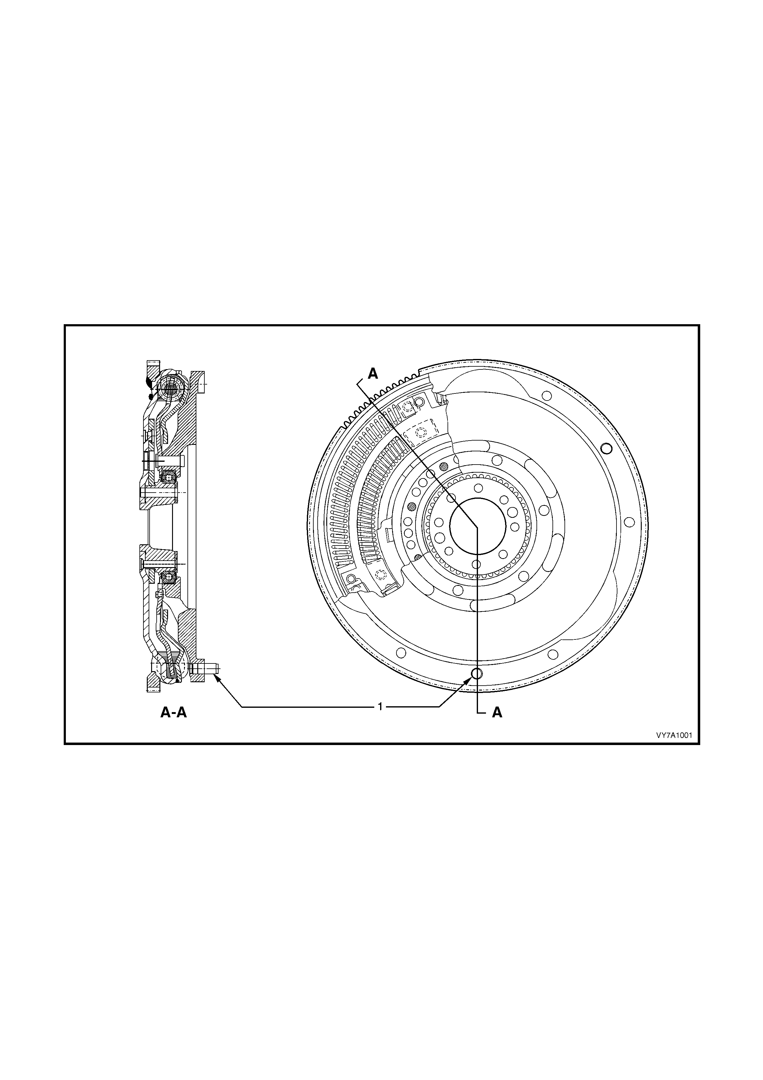
Figure 7A1 – 1 Dual Mass Flywheel Assembly
Legend: 1. Locating Pin
SERVICE IMPLICATIONS
Re-surfacing of the clutch driven plate surface, is not possible for the following reasons:
1. As both flywheel masses are able to move independently to each other, it is not possible to effectively clamp
the assembly without the possibility of misalignment.
2. A speci al balancing pr ocedure is f ollowed at m anufacture tha t involves rot ating the f lywheel to 6,0 00 rpm f or a
minimum amount of time prior to undertaking balancing at normal speeds.
Because t he ring gear is welded to th e crank shaf t side of the f lywheel, rin g gear replacem ent is not possi ble, as re-
welding could cause distortion and possible burning of the grease used to lubricate the springs.
2.2 CLUTCH CONTROL
Hydraulic actuation for the clutch has been adopted for a number of beneficial reasons;
• Noise reduction.
• Automatic adjustment.
• Constant pedal position.
• Constant efficiency factor.
• Constant pedal path.
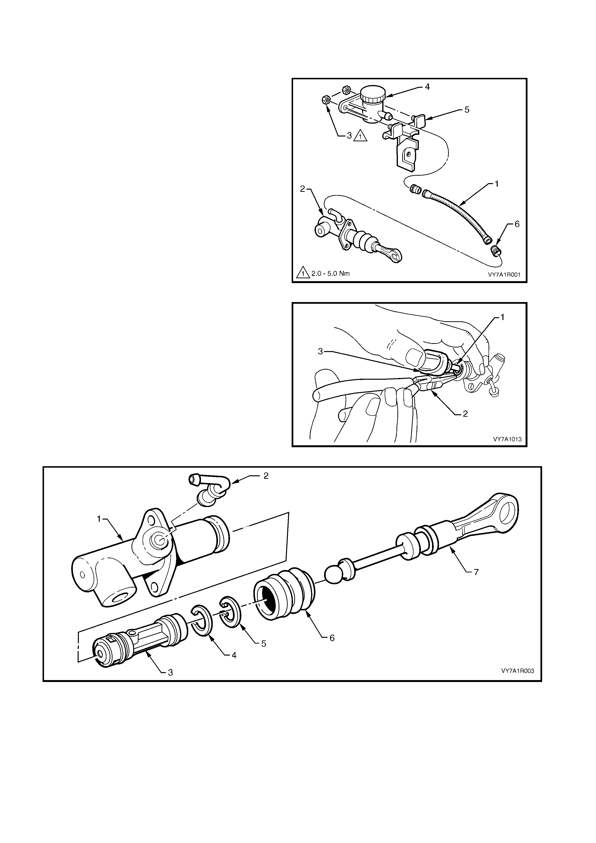
ARRANGEMENT
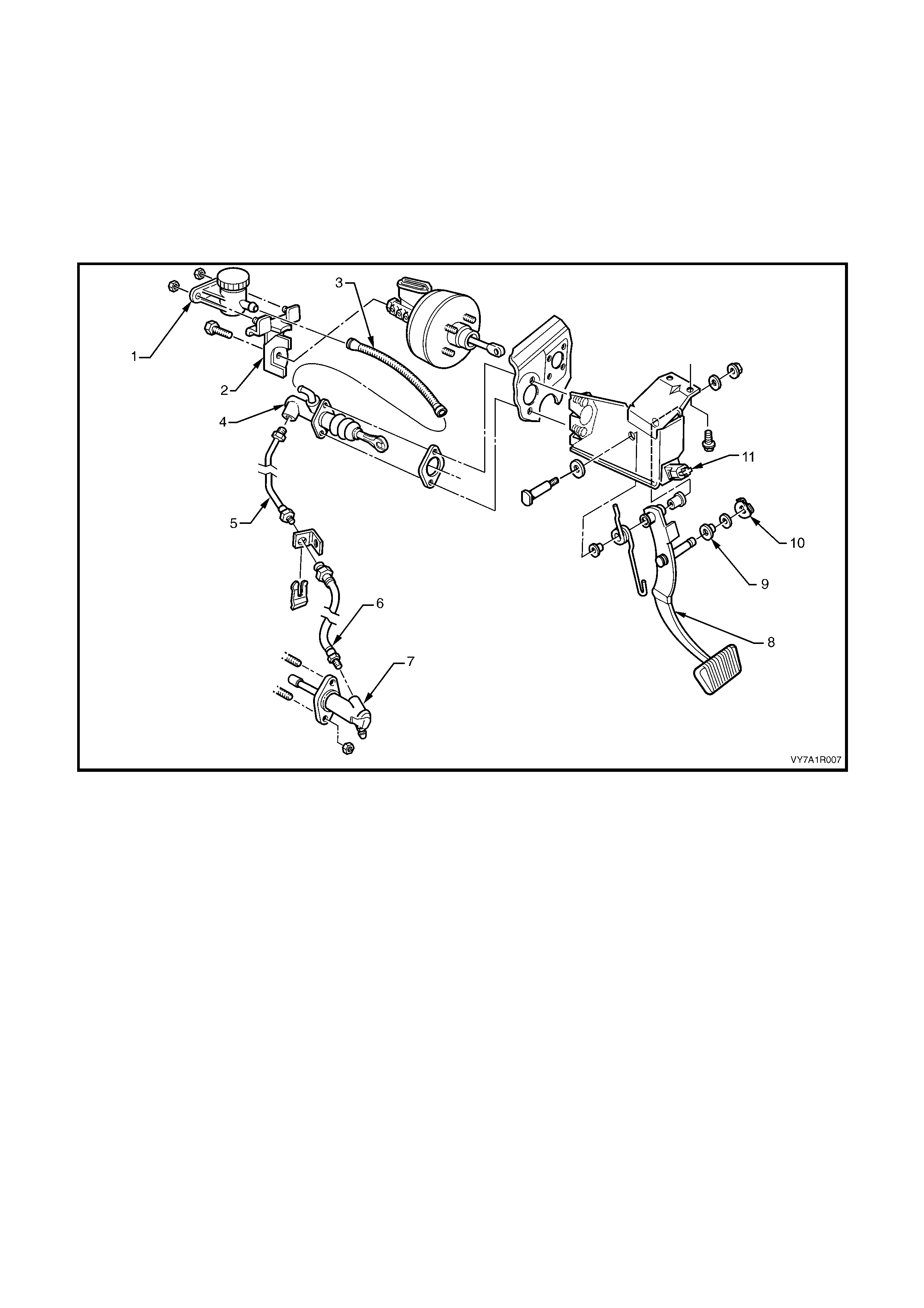
Figure 7A1 – 2 Clutch Control Layout – RHD
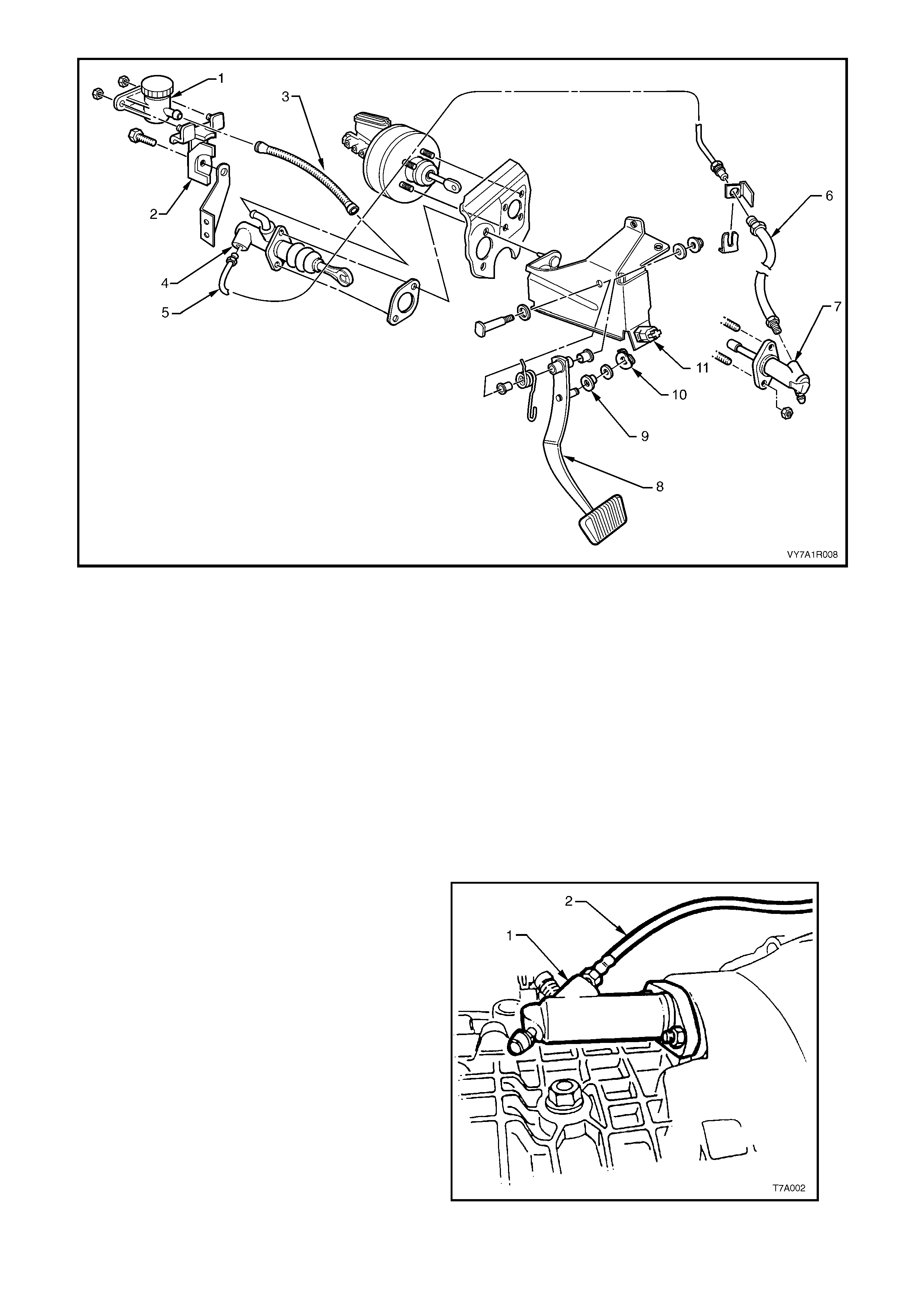
Figure 7A1 – 3 Clutch Control Layout – LHD
Legend (For Both Right and Left-Hand Drive Vehicles):
1. Reservoir – Clutc h Fluid
2. Bracket – Clutch Fluid Reservoir
3. Hose – Reservoir t o Mast er Cyl i nder
4. Master Cylinder
5. Pipe – Master Cylinder to Flexible Hose
6. Flexible Hose to Actuating Cylinder
7. Actuati ng Cylinder – Cl utc h
8. Pedal – Clutch
9. Bush
10. Spring Clip - Quick Connect
11. Switch – Clutch Pedal
Brake fluid is fed to the clutch master cylinder from a remote reservoir mounted to a bracket, bolted to the end of
the brak e m aster cylinder. A flexible line (fitte d with push/pu ll quick connect fittings at each end) connects the t wo
components.
The master cylinder is attached to the firewall in the engine compartment.
The clutch pedal is mounted in the clutch/brake pedal support bracket, bolted to the dash panel.
The c lutch master c ylinder piston is connecte d to the clutch pe dal by a push r od, with a quic k connec t fitting that is
retained on the clutch pedal pin by a groove. No clutch adjustments are required.
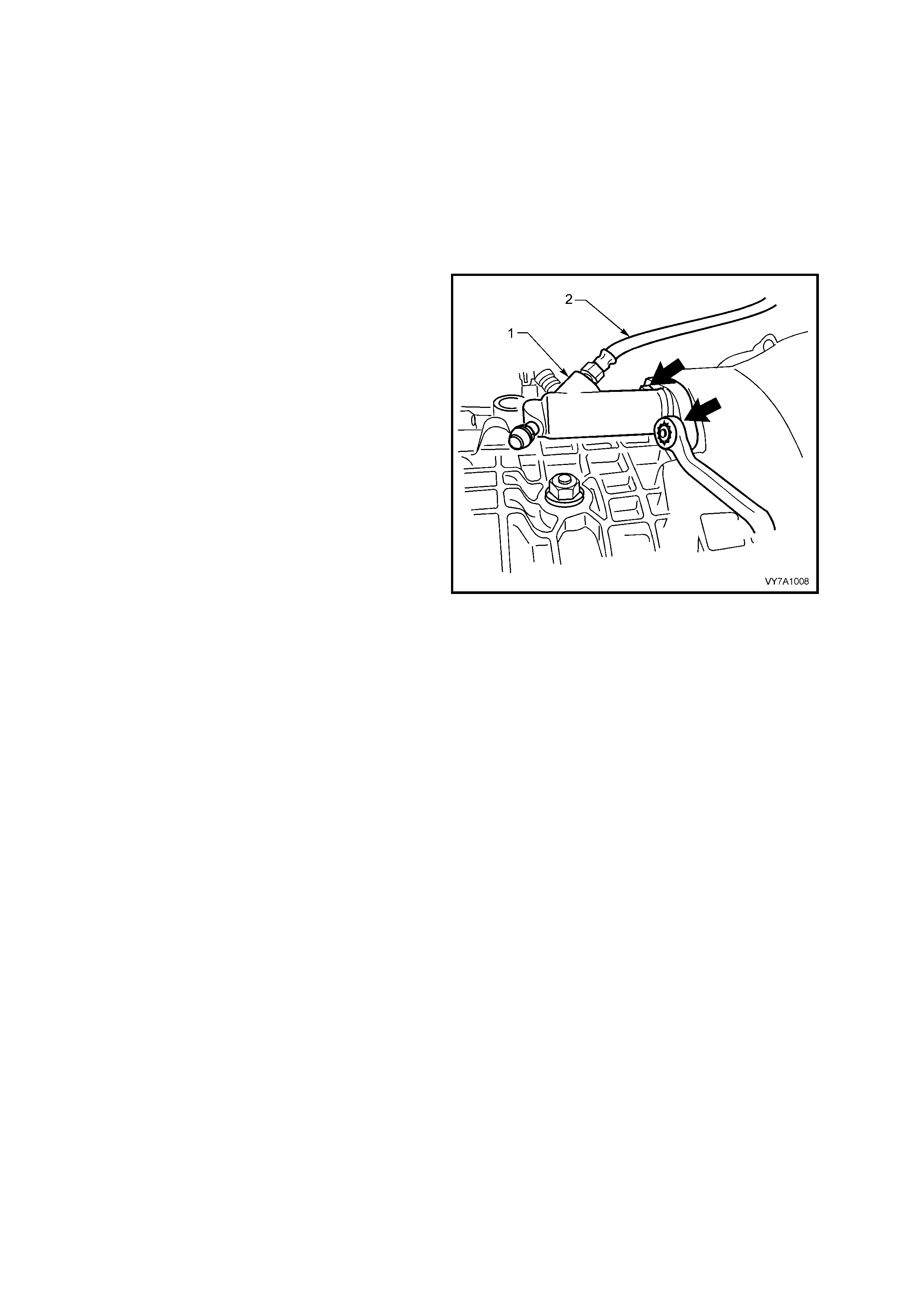
Stroking of the clutch throwout bearing is ach ieved
by using an hydraulic clutch actuating cylinder (1)
mounted on the right- hand s ide of the trans miss ion
clutch housing.
Hydraulic connect ion to the m aster cylinder is b y a
flexible hose (2) and steel piping.
The ac tuating c ylinder is fitt ed with a bleed valv e to
assist in removal of air from the hydraulic system.
Figure 7A1 – 4

The clutch throwout bearing (1) is a sealed-for-life,
ball race type, that is in constant contact with the
clutch pressure plate diaphragm spring.
The throwout bearing is actuated by a pressed
steel cl utch throwout le ver (2), that is retaine d by a
spring c lip a nd pivots at on e e nd, while th e s tr oking
of the clutch actuating cylinder piston and push
rod, moves it at the other.
Figure 7A1 – 5
2.3 CLUTCH M ASTER CYLINDER/ACTUATING CYLINDER OPERATION
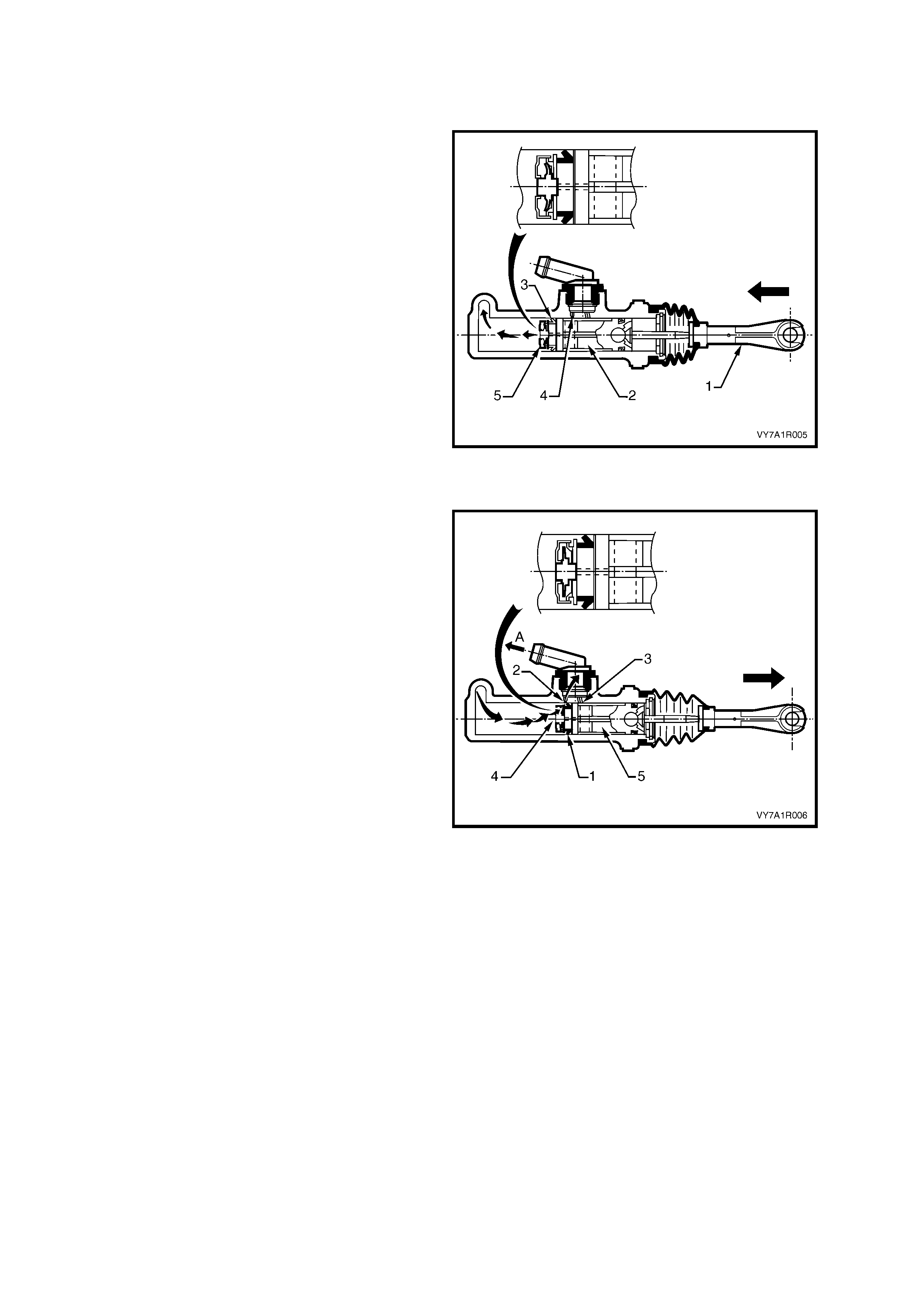
CLUTCH RELEASED
As the clutch pedal is depressed, force is
transm itted via the clutch p edal push r od (1), to the
clutch master cylinder piston (2), moving it down
the cylinder bore. When the piston starts to move,
the primary seal (3) covers the compensating port
(4) and the res ultant b uild- up in press ure, seats the
relief valve (5) in the end of the piston.
As hydraulic pressure develops, the fluid is
displaced and moves the piston in the clutch
actuating cylinder against the return spring and
clutch pressure plate diaphragm spring forces, to
stroke the actuating cylinder push rod. In turn, this
action moves the clutch throwout lever and
bearing, releasing the clutch pressure plate.
Figure 7A1 – 6
CLUTCH APPLIED
As the depressed clutch pedal is raised, the clutch
pressure plate diaphragm spring force, moves the
fluid back through hydraulic system, to the master
cylinder. As the clutch pedal is lifted to the point
where the pedal is fully released, the master
cylinder, primary piston seal (1) uncovers the
compensating port (2). Once this occurs, excess,
pressurised fluid (arrows) returns to the fluid
reservoir, via ‘A’.
If the clutch pedal is released very quickly, the
combined forces of the clutch pressure plate
diaphragm s pring, the re turn s pring in th e actuat ing
cylinder and the clutch pedal return spring, return
both pisto ns quick er than the f luid can ret urn to the
reservoir through the relat ively sm all compensating
port (2).
This creates a par tia l vacu um c onditio n that c aus es
atmospheric pressure acting on the reservoir fluid,
to force fluid through the recuperating port (3),
unseating the relief valve (4) in the end of the
master cylinder piston and equalising fluid
pressure. Should any excess fluid build up in front
of the master cylinder piston (5), it can then return
to the reservoir via the compensating port (2).
Figure 7A1 – 7

3. SERVICE OPERATIONS
3.1 SERVICE NOTES
IMPORTANT ITEMS
1. W hile GM’s clutch parts are not asbes tos based in th eir m ater ial com position, a danger exists that replac em ent
non-genuine parts may contain asbestos.
Not only is it in the interests of personal safety but also the safe and reliable operation of the clutch system, that
only genuine parts are used for replacement purposes.
Even so, when ser vicing c lutch par ts, do not c rea te dust by grind ing or s anding the c lutch pla te, or cl ean cl utch
parts with a dry brush or with compressed air. Breathing in dust that may contain asbestos fibres can cause
serious bodily harm over a protracted period of time.
A water dampened cloth or water based solution should be used to remove any dust on clutch parts.
Equipment is commercially available to perform this washing function. These wet methods prevent clutch
component fibres from becoming airborne.
2. The polyglycol brake fluid used in the MY 2003 VY and V2 Series vehicles is hygroscopic and absorbs
moisture from the air through the flexible clutch hose etc. Therefore, for maximum clutch effectiveness, a two
yearly change of brake fluid is mandatory, refer to 3.4 CLUTCH FLUID - CHANGE.
To prevent the absorption of moisture from the air or other contamination, it is recommended that the brake
fluid be stored in small (500 ml) containers and that any surplus fluid remaining in a container after use be
discarded.
NOTE: The only approved brake fluid is DOT 4 Plus or Super DOT 4 Plus and is available in 250 and 500 ml
containers . If pr es sur e bl ee din g eq uipment is us ed, it must be of an a ppro ved t yp e with a dia phr agm separ at ing t he
brake fluid from the air.
CAUTION: Brake fluid is extremely damaging to paint. If fluid should accidentally come into contact with a
painted surface, immediately wash the fluid from the paint and clean the painted surface.
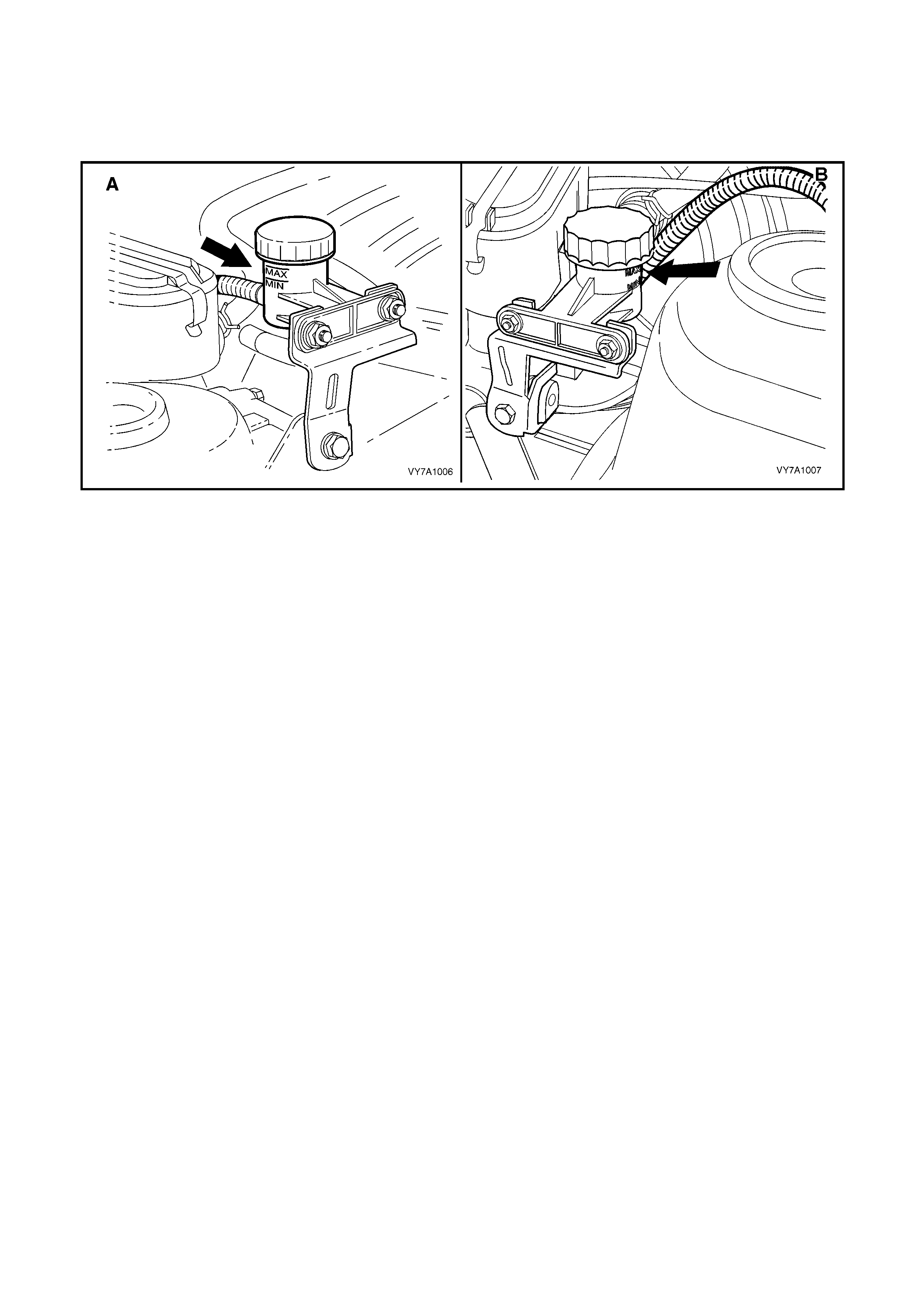
3.2 FLUID LEVEL CHECK
Check that the flu id le vel is bet ween the t wo gui delin es on the trans lucent r eser voir housin g. Should the ad dition of
fluid be required, remove the reservoir cap and use heavy duty brake fluid (DOT 4 Plus or Super DOT 4).
NOTE: View ‘A’ shows the RHD arrangement while view ‘B’ shows that for LHD vehicles.
Figure 7A1 – 8
3.3 CLUTCH HYDRAULIC SYSTEM, BLEED
The c lutch hydraulic s ystem must be bled when ever the h ydr aulic lin e has been disc onnected, or when a leak has
allowed air to enter the system. Air trapped in the system can prevent full disengagement of the clutch.
During bleeding operations, the master cylinder reservoir must be kept at least half full with hydraulic brake fluid.
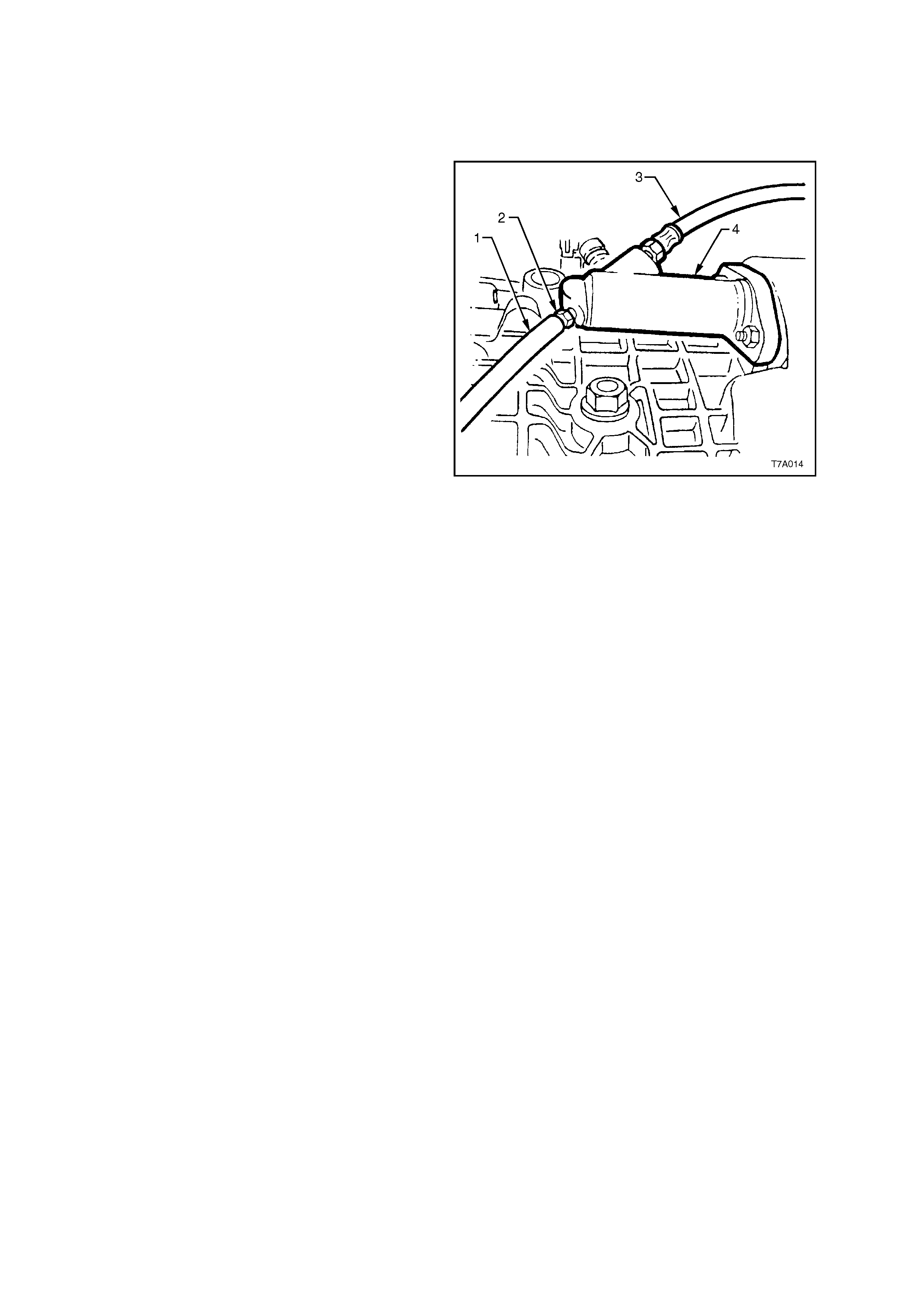
1. Carefully clean any dirt from around the
reservoir cap.
2. Remove the filler cap and top up reservoir as
required, with heavy duty hydraulic brake fluid
(DOT 4 Plus or Super DOT 4).
3. Slip the end of a bleeder hose (1) over the
bleeder screw (2) on the clutch actuating
cylinder (4) and insert the other end into a
clean glass container such as a jar, that has
been partially filled with new brake fluid.
Ensure that the end of the hose always
remains submerged in the brake fluid during
bleeding oper at io ns .
4. Loosen the bleeder screw 1/2 to 3/4 turn.
5. Fully depress the clutch pedal by hand, then
allow it to return slowly. Continue this slow
pumping motion, forcing fluid and air through
the hydraulic system until all bubbles cease to
appear at the end of the bleeder hose.
6. W hile depr es sing the pe dal , tig hte n th e b le eder
screw, then remove the bleeder hose from the
actuating cylinder bleeder screw.
7. Once all bleeding operations have been
completed, ensure that the fluid level in the
reservoir is correct.
NOTE: An alternative bleeding method is to use a
commercially available pressure bleeding system,
using a universal reservoir sealing cap
arrangement.
Figure 7A1 – 9

3.4 CLUTCH FLUID – CHANGE
At the int erval spec ified in the O wners Han dbo ok, the c lutch f luid mus t be change d. Discol ourat ion of the f lui d is no
reason for fluid replacement. The recommended method is to use a commercially available pressure bleeder,
together with an appropriate fluid reservoir cap. Follow the manufacturer’s instructions in the use of the pressure
bleeding equipment and continue allowing fluid to flow through the system until the fluid runs clear in the bleeder
hose attached to the clutch actuating cylinder bleeder screw.
Follo wing t he f lu id c han ge oper at ion , e ns ur e t hat the fluid le ve l in the r es ervo ir is c or re ct and that th e s la ve cyli nd er
bleeder screw is tightened to the correct torque specification.
CLUTCH ACTUATING
CYLINDER BLEEDER SCREW
TORQUE SPECIFICATION 8 Nm
3.5 CLUTCH M ASTER CYLINDER
REMOVE
CAUTION: Disable the SRS (Air Bag). Refer to
'DISABLING THE SRS’, in Section 12M,
OCCUPANT PROTECTION SYSTEM.
1. Disconnect the batt ery ground cable.
2. Remove ignition keys from ignition switch.
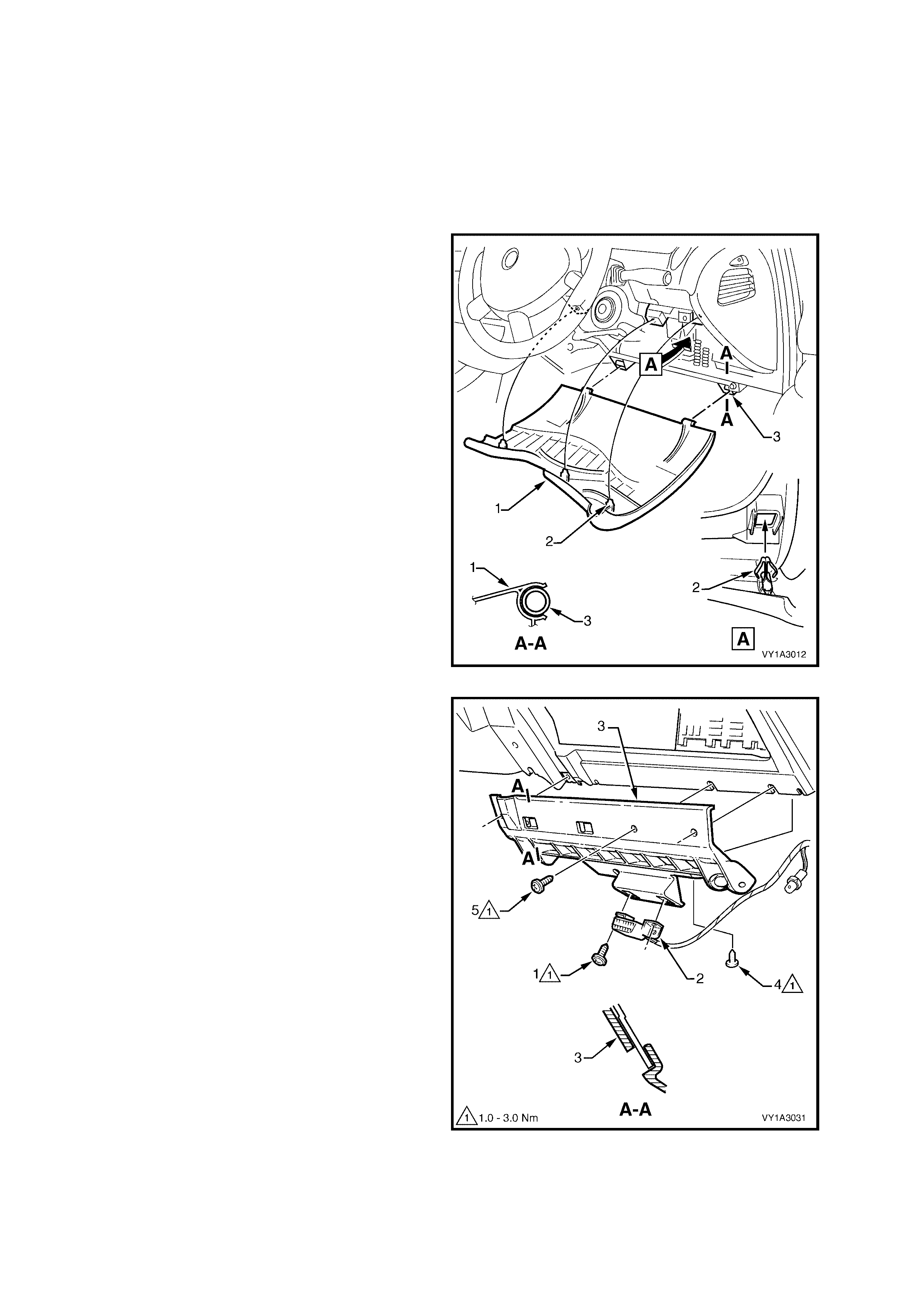
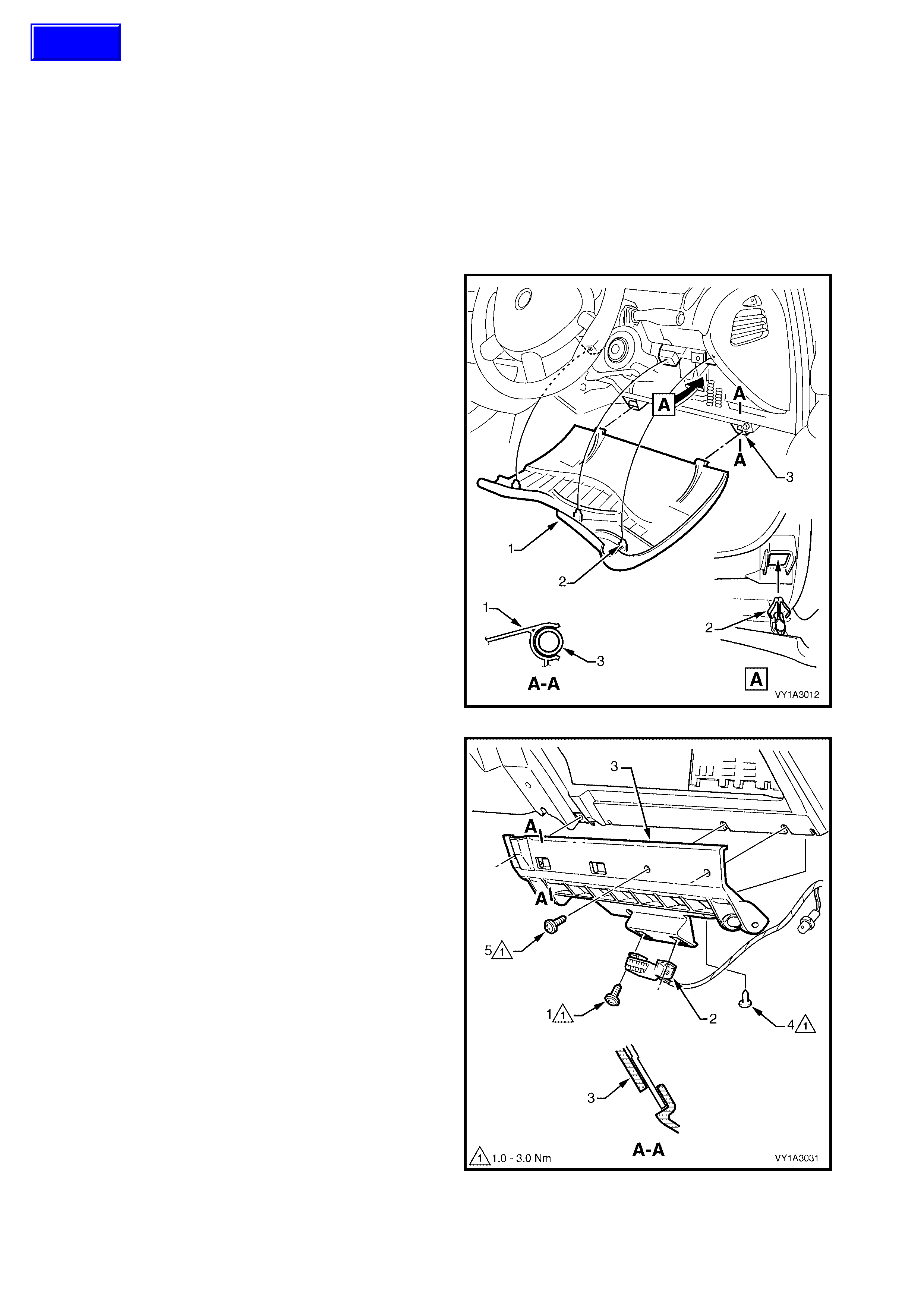
3. Lower the instrument panel lower fuse panel
cover assembly (1) by grasping the top edge
on each side of the steering column with the
finger tips and pulling the top edge out, to free
the retaining lugs (2) from the clips (3).
Figure 7A1 – 10
4. Remove the screw (1), two places, attaching
the Data Link Connector (2) to the instrument
panel lower trim panel retainer (3).
5. Rem ove the screw (4) a ttaching the retainer to
the air duct.
6. Remove the screw (5), three places, attaching
the retainer to the instrument panel assembly
and instrument panel.
7. Slide the retainer downwards to disengage the
two lugs from the instrument panel assembly
and remove the retainer.
Figure 7A1 – 11
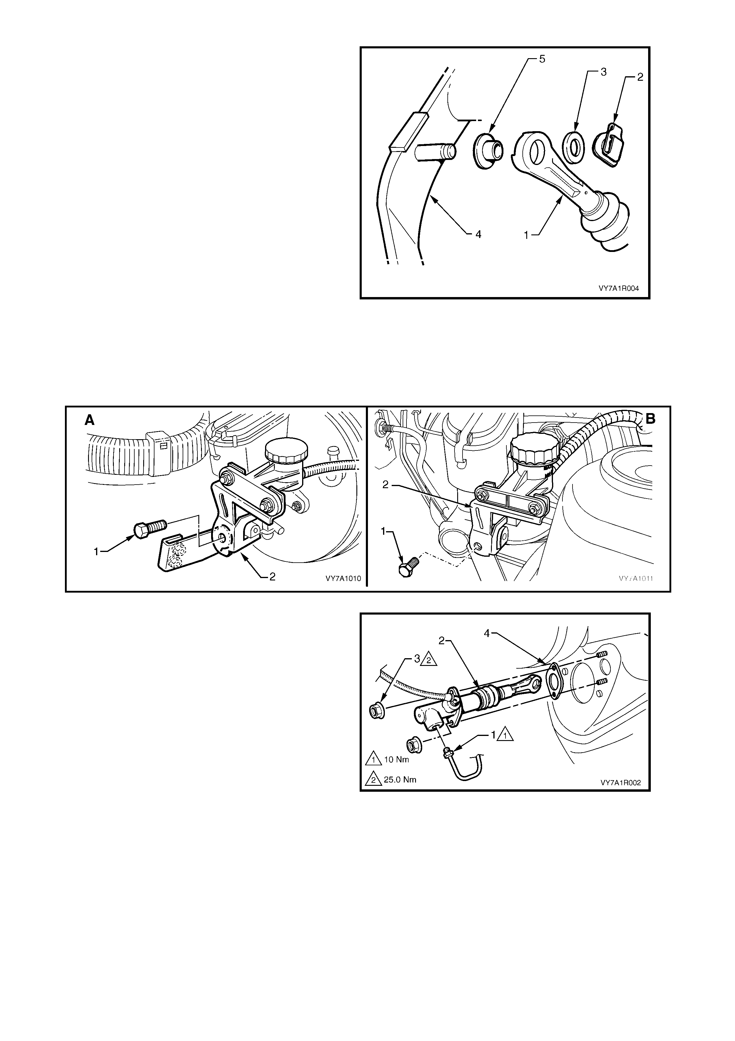
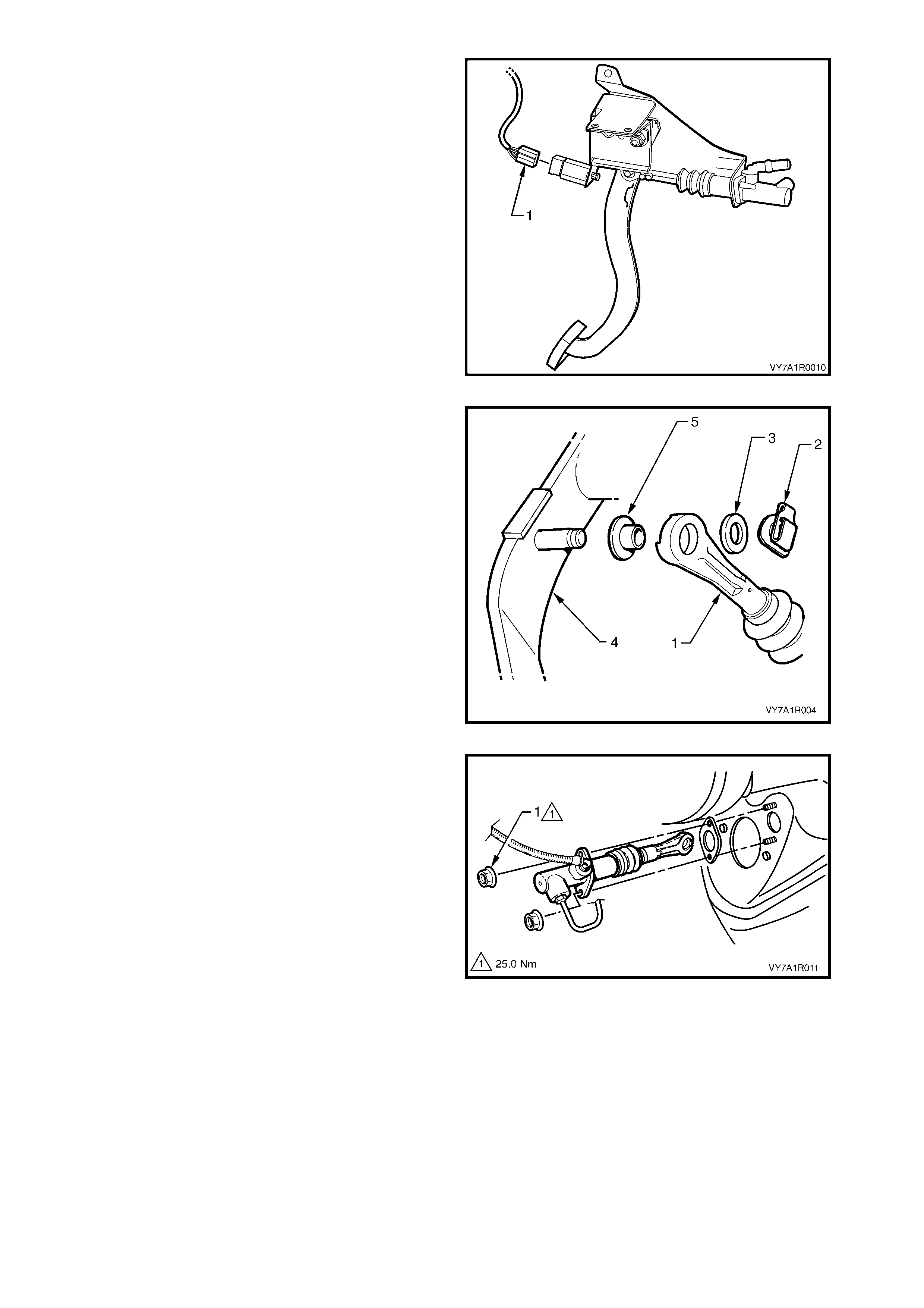
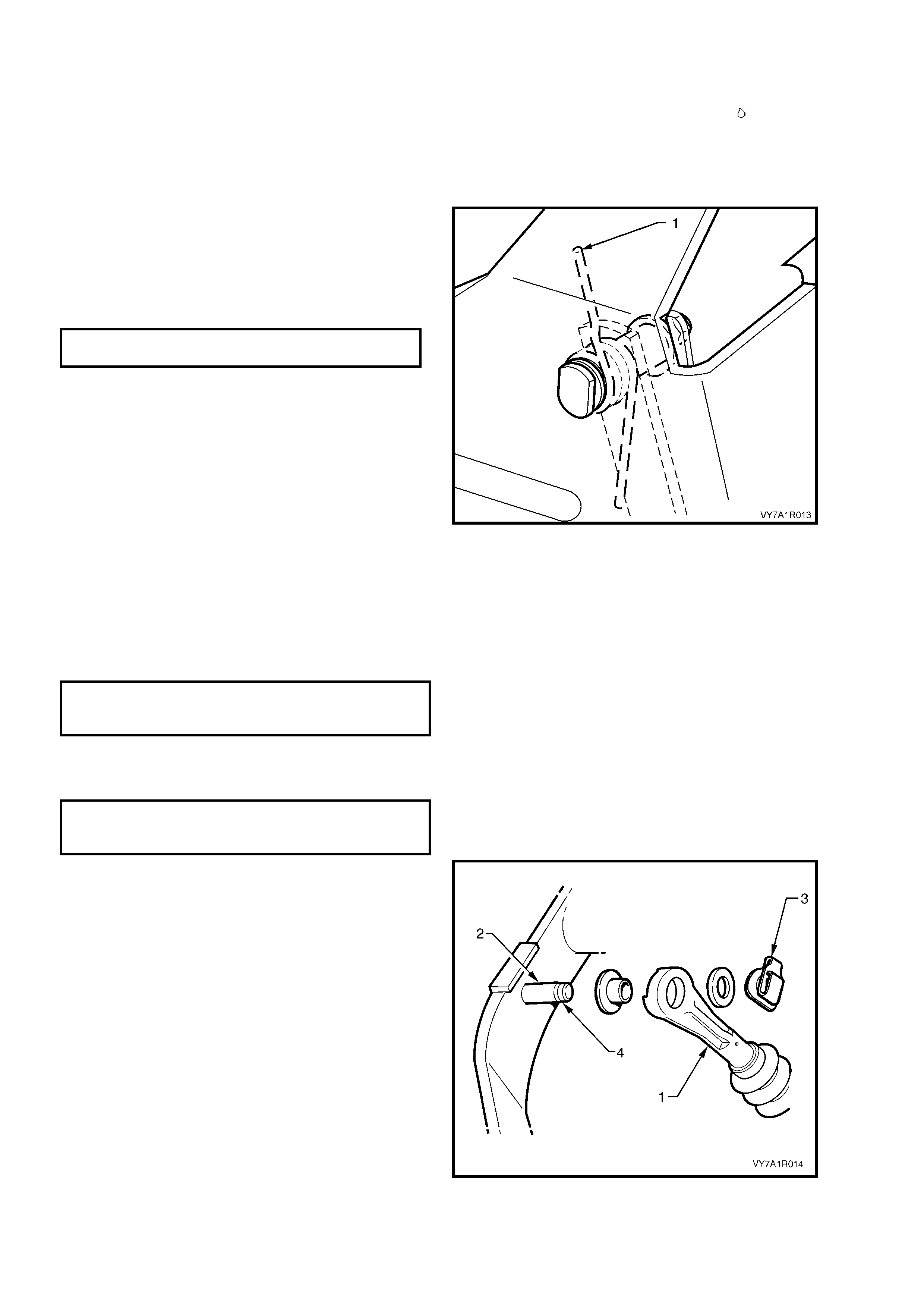
8. Disconnect th e clutch m aster cylinder push rod
(1) by removing the spring clip (2) and metal
washer (3) f rom the p in on the c lutch pedal (4).
Disconnect the master cylinder push rod from
the inner bush (5).
Figure 7A1 – 12
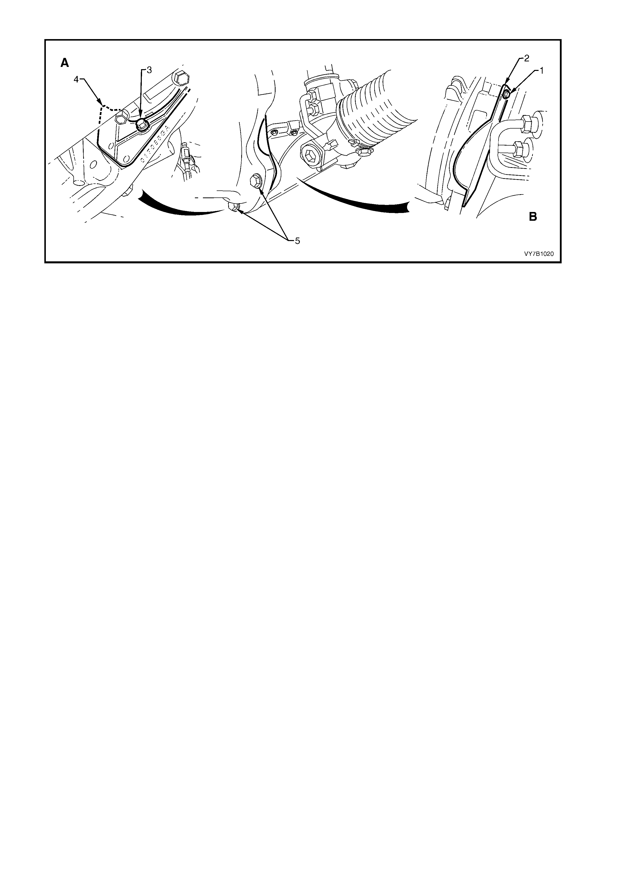
9. Remo ve the c lutc h master cylinder flu id res ervoir and br ac k e t (2) as an as s embly by rem ovi ng t he bolt f r om the
end of the brake master cylinder end brace (1). Support the clutch reservoir to prevent fluid spillage. Refer to
Figure 7A1 – 13.
NOTE: View ‘A’ shows the RHD arrangement while view ‘B’ shows that for LHD vehicles.
Figure 7A1 – 13
10. Remove the hydraulic steel pipe (1) from the
clutch master cylinder (2), then plug both the
open pipe end and the m aster c ylinder open ing
to prevent dirt entry and fluid loss.
11. Remove the two clutch master cylinder
retaining nuts (3) from the engine bay side of
the cockpit module and remove the master
cylinder and reservoir assembly from the
vehicle. Also remove the gasket (4).
Figure 7A1 – 14
DISASSEMBLE
1. Drain the brake fluid from the reservoir into a
suitable container. Discard the collected fluid.
2. Disconnect the flexible hose (1) from the
master cylinder (2) b y pulling on the end of the
hose at the master cylinder.
3. If required, remove the nuts (3) attaching the
reservoir (4) to the clutch master cylinder
bracket (5).
NOTE: When the hose is disconnected, a rubber
seal (6) normally located in the end of the flexible
hose may become dislodged. Push the seal back
into the flexible hose should this happen.
4. Rem ove the boot from the c ylinder groove and
pull back over the end of the push rod.
Figure 7A1 – 15
5. Using the master cylinder push rod (3),
depress the m aster cylinder piston sufficient to
relieve pressure on the circlip (1). Then, using
suitable circlip pliers (2), remove the circlip
from the master cylinder body.
6. As the pus h rod is s ecure d to the pis ton, ge ntl y
pulling on the push rod will remove the piston
assembly and retaining washer from the
master cylinder bore.
7. As the repair kit supplies all of the removed
components as a complete assembly, no
further dismantling is required.
Figure 7A1 – 16
Figure 7A1 – 17
Legend
1. Clutch Mast er Cyl i nder
2. Clutch Master Cyl i nder Elbow
3. Piston, Val ve and Seals Assembly
4. Retaining Washer
5. Circlip
6. Boot
7. Push Rod Assembly

CLEAN AND INSPECT
IMPORTANT: Do not wash hands in petrol or oil before cleaning or handling master cylinder parts; always use a
soap and water based hand cleaning product.
Hands must be clean before hydraulic components are handled and washed, as the slightest trace of mineral
based grease or oil in the cylinder or on components, can cause excessive swelling and/or destroy rubber based
parts.
1. Wash all parts in clean alcohol or methylated spirits and blow dry with compressed air.
2. Ins pect the m ast er c ylinder bore f or sc ores, deep s cratc hes or c orrosion. If cons idered to be uns ervicea ble , the
complete master cylinder assembly must be replaced.
NOTE: The master cylinder bore must not be honed.
3. Carefully inspect the p is ton to ens ure th at it is f r ee from bur r s and/or s harp edg e s , whic h may cause damage to
the master cylinder wall.
4. Check that the breather cap ventilation system on the reservoir is intact and functional.
5. Replace all internal components supplied in the clutch master cylinder overhaul kit.
REASSEMBLE
1. Dip piston seals and the piston in clean brake fluid.
2. After lu bricating the mast er cylinder b ore with cle an brake f luid, install th e piston, push rod a nd boot assem bly
into the cylinder.
NOTE: Ensure that neither of the piston seals get caught or damaged during the installation process.
3. Reinstall the washer (4) and retaining circlip (5). Refer to Figure 7A1 – 17.
4. Reinstal l th e f lan ge of th e b oot ( 6) o ver the en d of the master cylinder (1), ens uri n g tha t th e b oot fits complet el y
into the groove provided.
5. Reinstall master cylinder reservoir hose to the master cylinder fitting, by pushing it onto the master cylinder
fitting.
6. Plug the mas ter cylinder o u tlet f itt in g to pr ev ent the ent ry of for eign matter in to t he cylinder, during re inst a llati on
operations.
7. If previously removed, refit the master cylinder reservoir to the clutch master cylinder bracket. Tighten to the
correct torque specification.
MASTER CYLINDER RESERVOIR TO
CLUTCH MASTER CYLINDER BRACKET
TORQUE SPECIFICATION 2 - 5 Nm
REINST ALL
Installation is the reverse of removal operations except for the following points:
1. Reinstall master cylinder over studs, fit retaining nuts and washers and tighten to the correct torque
specification.
CLUTCH MASTER CYLINDER NUT
TORQUE SPECIFICATION 25 Nm
2. Reinstall and tighten hydraulic pipe flare nut to master cylinder to the correct torque specification.
HYDRAULIC PIPE FLARE NUT
TO MASTER CYLINDER
TORQUE SPECIFICATION 10 Nm
3. Reinstall the clutch master cylinder fluid reservoir bracket to the brake master cylinder end brace. Tighten to
the correct torque specification.
CLUTCH MASTER CYLINDER RESERVOIR
BRACKET TO BRAKE MAS TER
CYLINDER END BRACE
TORQUE SPECIFICATION 8 - 11 Nm
4. Bleed the clutch hydraulic system, as detailed in 3.3 CLUTCH HYDRAULIC SYSTEM, BLEED, in this Section.
5. Following bleeding operations, check that the hydraulic fluid level is correct, as detailed in 3.2 FLUID LEVEL
CHECK, in this Section.
6. Check clutch operation.
IMPORTANT: Enable the SRS (Air Bag). Refer to 'ENABLING THE SRS’, in Section 12M, OCCUPANT
PROTECTION SYSTEM.
3.6 CLUTCH ACTUATING CYLINDER
REMOVE
1. Raise the vehicle and place on safety stands. Refer to Section 0A GENERAL INFORMATION, for location of
jacking and support points.
2. Place a suitable, clean container under the clutch actuating cylinder (1), then disconnect the hydraulic pipe
from the hydraulic hose (2), at the bracket attached to the vehicle sub-frame (not shown in Figure 7A1 – 18).
Plug the end of the pipe to block the flow of brake fluid from the clutch master cylinder and reservoir.
Also plug the hose opening to prevent the entry of foreign matter during removal operations.
3. Remove the hose retaining clip with combination pliers and remove the hose from the bracket.
4. Remove the two clutch actuating cylinder
mounting nuts (arrows), then remove cylinder
from the vehicle.
NOTE: As spring force from the actuating cylinder
piston positioning spring will push the cylinder out
from the transm ission hous ing, ho ld the c ylinder in,
against this force while removing the mounting
nuts.
Figure 7A1 – 18
DISASSEMBLE
1. While holding the piston inwards against spring force, prise the retainer (9) from the end of the actuating
cylinder (2).
2. Rele ase the h oldin g for ce and rem ove the r etainer, boot ( 7) and push r od ass embl y (8), piston ( 5) a nd seal ( 4),
and the spr ing (3) fr om the c ylinder (2) . It m ay be neces sar y to tap the open en d of the c ylinder against a b lock
of wood to dislodge the piston assembly and spring. Refer to Figure 7A1 – 19.
3. Remove the bleeder screw (1) from the cylinder.
4. Prise the seal from the piston and discard.
CLEAN AND INSPECT
IMPORTANT: Do n ot was h han ds in petrol or oil bef or e clea ning or handl ing ac tuatin g cylinder par ts; a lwa ys use a
soap and water based hand cleaning product.
Hands must be clean before hydraulic components are handled and washed, as the slightest trace of mineral
based grease or oil in the cylinder or on components, can cause excessive swelling and/or destroy rubber based
parts.
1. Wash all parts in clean alcohol or methylated spirits and blow dry with compressed air.
2. Inspect the actuating cylinder bore for scores, deep scratches or corrosion. If considered to be unserviceable,
the complete cylinder assembly must be replaced.
NOTE: The actuating cylinder bore must not be honed.
3. Carefully inspect the p is ton to ens ure th at it is f r ee from bur r s and/or s harp edg e s , whic h may cause damage to
the cylinder wall.
4. Check that the bleeder screw thread is undamaged and that the drilled passage is clear of debris.
5. Replace all rubber seals and the dust boot.
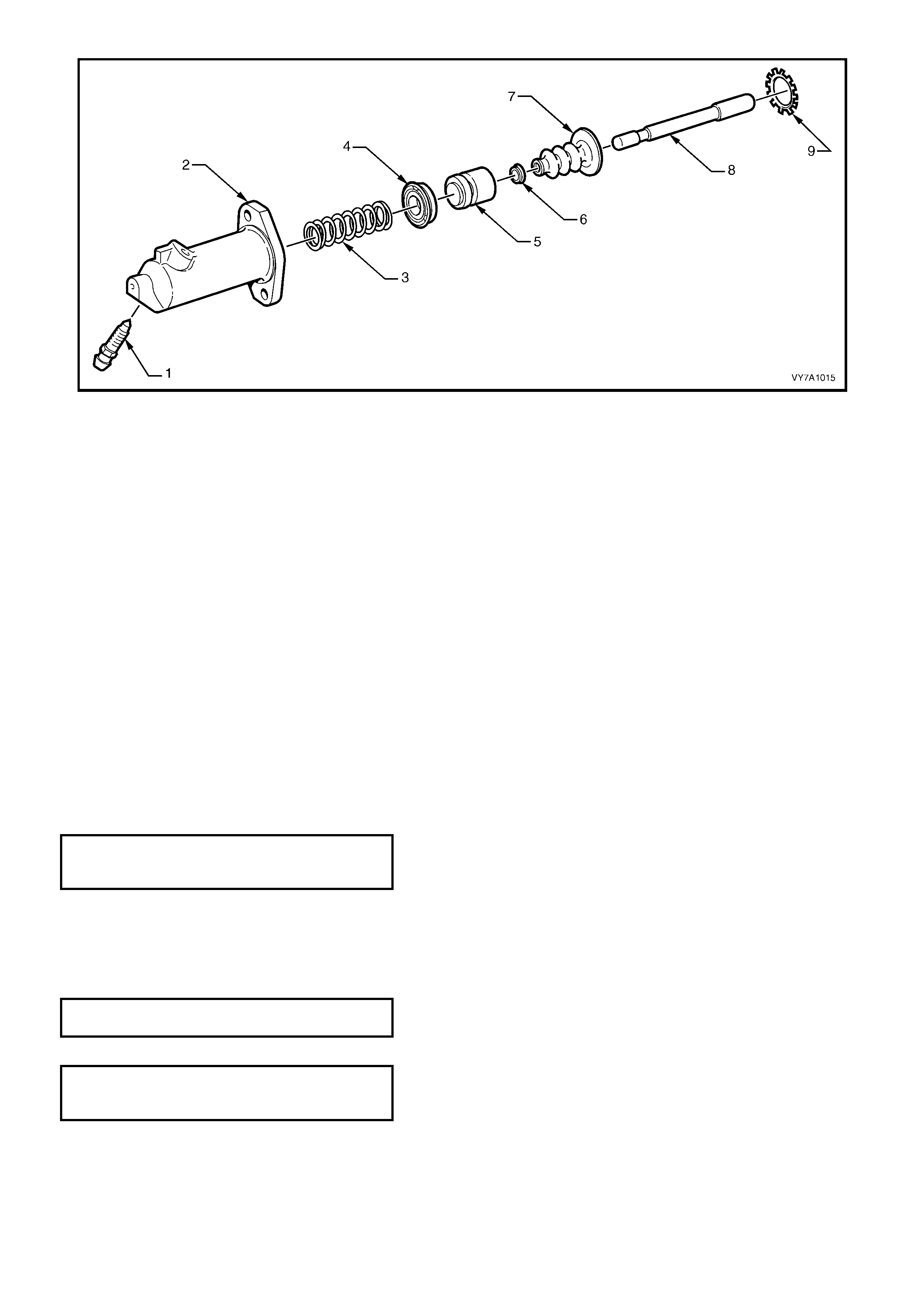
Figure 7A1 – 19
Legend
1. Bleeder Screw
2. Clutch Actuating Cylinder
3. Piston Positioning Spring
4. Seal
5. Piston
6. Boot Retainer
7. Boot
8. Push Rod
9. Retainer
REASSEMBLE
1. Dip piston seal and the piston in clean brake fluid, then install seal over piston land, with the lip facing away
from the push rod end.
2. After lubricating the actuating cylinder bore with clean brake fluid, install the spring and piston assembly into
the cylinder.
3. Reinstall the push rod, boot and retaining washer, into the cylinder.
4. Using a suitable sleeve such as a deep socket, install a new retainer into the end of the cylinder.
5. Reinstall the bleeder screw and tighten finger tight only, at this time.
6. Plug the actu ati ng cylinder outlet fitting to prev ent th e entry of foreign matter into the cylinder, dur in g installation
operations.
REINST ALL
Installation is the reverse of removal operations except for the following points:
1. Reinstall hydraulic hose to clutch actuating cylinder and tighten to the correct torque specification.
HYDRAULIC HOSE TO CLU TCH
ACTUATING CYLINDER
TORQUE SPECIFICATION 11 Nm
2. Reinstall actuating cylinder over the housing studs and fit retaining nuts and washers.
NOTE: During installation, ensure that the actuating cylinder push rod is correctly located in the clutch lever. If
installed out of position, the push rod and piston will be pumped out of the cylinder during bleeding operations,
damaging the piston seal.
3. Tighten fasteners to the correct torque specification.
CLUTCH ACTUATING CYLIN DER
NUT TORQUE SPECIFICATION 22 Nm
4. Reinstall and tighten hydraulic pipe flare nut to actuating cylinder to the correct torque specification.
HYDRAULIC PIPE FLARE NUT
TO FLEXIBLE HOSE
TORQUE SPECIFICATION 10 Nm
5. Bleed the clutch hydraulic system, as detailed in 3.3 CLUTCH HYDRAULIC SYSTEM, BLEED, in this Section.
6. Following bleeding operations, check that the hydraulic fluid level is correct, as detailed in 3.2 FLUID LEVEL
CHECK, in this Section.
7. Lower vehicle and road test vehicle, to check clutch operation.
3.7 CLUTCH P EDAL ASSEMBLY
REMOVE
CAUTION: Disable the SRS (Air Bag). Refer to 'DISABLING THE SRS’, in Section 12M, OCCUPANT
PROTECTION SYSTEM.
NOTE 1: To remove the clutch pedal on LHD vehicles, it may not be necessary to remove the clutch pedal box
assembly. This is dependent on whether there is enough clearance to fully extract the clutch pedal pivot bolt.
NOTE 2: Where only right-hand drive views are shown, left-hand drive are the same but views will be mirror
reversed.
1. Disconnect the batt ery ground cable.
2. Grasp the upper edge of the instrument panel
lower tr im panel as sem bl y (1) and pu ll out wards to
disengage the three retaining clips (2).
3. Swing the panel assembly open.
4. Holding each side of the panel assembly, pull
rearwards to disengage it from the instrument
panel lower trim panel retainer (3), two places.
Figure 7A1 – 20
5. Remove the screw (1), two places, attaching the
data link connector (2) to the instrument panel
lower trim panel retainer (3).
6. Rem ove the screw (4) attaching th e retainer to t he
air duct.
7. Rem ove the screw (5), three places, attaching the
retainer to the instrument panel assembly and
instrument panel.
8. Slide the r e tai ner d o wnw ards to d is eng age the t wo
lugs from the instrument panel assembly and
remove the retainer.
Figure 7A1 – 21
Techline
9. Disconnect the wiring harness connector from the
clutch pedal switch (1).
Figure 7A1 – 22
10. Disconnect the clutch m aster cylinder pus h rod (1)
by removing the spring clip (2) and metal washer
(3) from the pin on the clutch pedal (4). Disconnect
the master cylinder push rod from the inner
bush (5).
Figure 7A1 – 23
11. Remove the clutch master cylinder retaining nuts
(1), two places, from the engine bay side of the
cockpit module. Allow the master cylinder to
remain in place.
Figure 7A1 – 24
12. Remove the bolts (1), three places LHD (A), two
places R HD ( B), s ec urin g t he c lu tch p edal brac ket
to the steering column bracket. Refer to Figure
7A1 – 25.
13. Lower the clutch pedal bracket assembly from
under the instrument panel.

NOTE: View ‘A’ is for LHD vehicles while view ‘B’ is for RHD.
Figure 7A1 – 25
DISASSEMBLE
1. Remove the nut (1) an d wa s her (2) sec ur ing the c lutch pedal pi vot bo lt ( 3) t o t he p edal supp ort br acket, ref er to
Figure 7A1 – 26.
2. Carefully withdraw the clutch pedal pivot bolt and washer (4) from the pedal support assembly.
3. Withdraw the clutch pedal (5) and return spring assembly.
4. Release the end of the return spring (6) from the clutch pedal.
5. Remove the return spring and the two bushes (7) from the pedal.
NOTE: View ‘A’ is for LHD vehicles while view ‘B’ is for RHD.
Figure 7A1 – 26
REASSEMBLE
Installation is the reverse of the removal procedure except for the following points:
1. Lubricat e all bush sur faces with Mo lybdenum Disulphide gre ase, as indic ated by the s ym bol . Ref er to Figure
7A1 – 26.
2. Reinstall the two pedal bushes into the pedal pivot bore.
3. Assemble the clutch pedal return spring to the clutch pedal and then install the pedal to the clutch pedal
support bracket. Reinstall the clutch pedal pivot bolt (3) and washers (2 and 4).
NOTE: When the return spring is installed to the
clutch pe dal pivo t pin, pos it ion the u pper e nd of the
spring (1) as shown.
4. Install and tighten the nut (1) to the correct
torque specification. Refer to Figure 7A1 – 26.
CLUTCH PEDAL PIVOT BOLT
TORQUE SPECIFICATION 15 Nm
Figure 7A1 – 27
REINST ALL
1. Reinstall the clutch pedal bracket assembly,
taking care to align the clutch master cylinder
mounting studs with the master cylinder.
Tighten the bolts, three places to the correct
torque specification. Refer to Figure 7A1 – 25.
CLUTCH PEDAL BRACKET TO
STEERING COLUMN BRACKET
TORQUE SPECIFICATION 20 – 30 Nm
2. Reinstal l the mast er cylinde r r etain ing nuts , t wo
places, and tighten to their correct torque
specification.
CLUTCH MASTER CYLINDER NUT
TO DASHPANEL
TORQUE SPECIFICATION 25 Nm
3. Reinstall the clutch master cylinder push rod
(1) to the ped al pin (2), ensuring that the quick
connect fitting (3) fully engages the groove (4)
in the pedal pin.
4. Reinstall all removed instrument panel
components in the reverse to removal
operations.
5. Road test vehicle to check clutch operat ion.
IMPORTANT: Enable the SRS (Air Bag). Refer to
'ENABLING THE SRS’, in Section 12M, Occupant
Protect ion S ystem.
Figure 7A1 – 28

3.9 CLUTCH DRIVEN PLATE, PRESSURE PL ATE AND/OR THROWOUT BEARING
REMOVE
CAUTION: Disable the SRS (Air Bag). Refer to
'DISABLING THE SRS’, in 12M, OCCUPANT
PROTECTION SYSTEM.
1. Remove transmission assembly. Refer to
Section 7B1 MANUAL TRANSMISSION - V6
ENGINE.
Figure 7A1 – 29
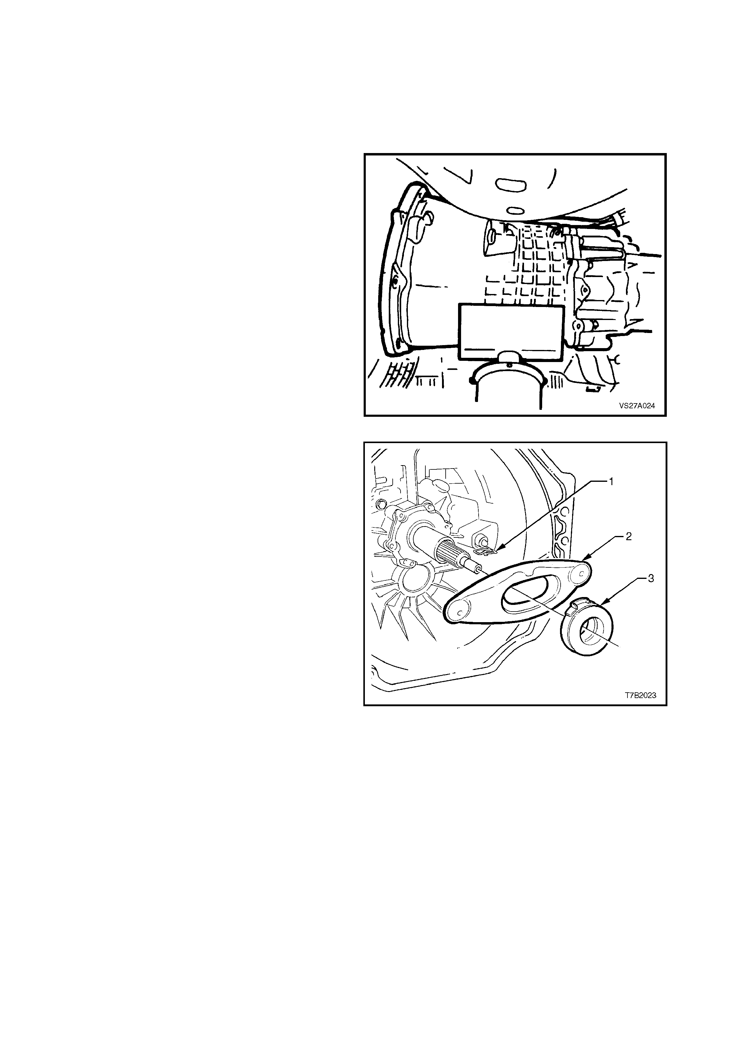
2. Release the clutch throwout lever (2) from the
retaining wire clip (1), then remove the lever
and bearing assembly (3) from the
transmission housing.
Figure 7A1 – 30
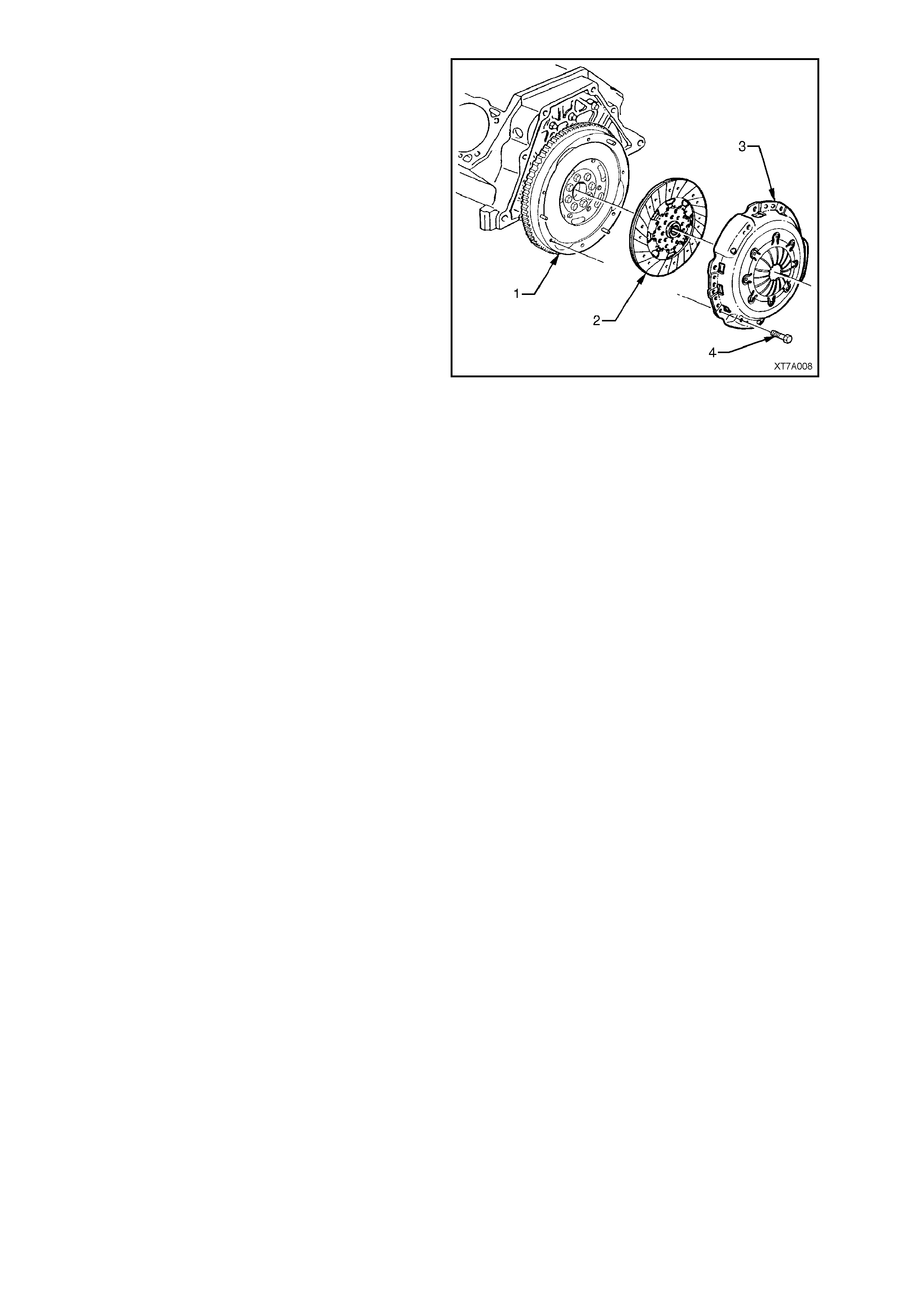
3. Mark the relationship of the clutch pressure
plate to the flywheel, to maintain the correct
balance condition on reassembly.
4. Initia lly loosen a ll pressur e plate ret aining bo lts
(4), working from opposite sides, to avoid
distortion of the cover (3).
5. Continue loosening bolts from opposite sides,
until all are removed, then lift the clutch driven
plate (2) and pressure plate (3) assemblies
from the flywheel (1).
Figure 7A1 – 31
INSPECT
1. Use a water dampened cloth or water based solution to wipe the pressure plate, flywheel surfaces.
NOTE 1: Do not wash the pressure plate with liquid petroleum based products or use compressed air.
NOTE 2: Do not soak the throw out bearing in cleaning solvent as this will destroy the bearing lubricant.
2. Inspect maindrive gear shaft spigot bush for wear. If necessary, replace the bush as detailed in
3.11 CRANKSHAFT SPIGOT BUSH, in this Section.
NOTE: Do not remove the bush unless inspection reveals that it is unserviceable.
3. Inspect clutch lever pivot socket and stud for wear. Replace as required. Check lever retaining spring for
damage or distortion. Spring tension should be sufficient to hold lever in position on the stud. Check clutch
lever for cracks or wear.
4. Check throwout bearing for roughness of operation or signs of wear. Replace if necessary.
5. Examine bearing hub bore for burrs. Any burrs should be removed. If burrs are found, inspect transmission
ma indrive ge ar be arin g retain er f or s coring. If s coring is sli ght, r em ove usin g f ine em er y cloth. Rep lace retain er
if scoring is excessive, refer Section 7B1 MA NUAL TRANSMISSION - V6 ENGINE.
6. Inspect flywheel and clutch pressure plate friction surfaces for burn marks scoring or roughness. Slight
roughnes s ma y b e smooth ed with f ine emer y c loth. Sc oring of fl ywheel or press ure plate sur faces however will
require replacement of damaged component/s.
7. Inspect clutch driven plate for lining wear or other damage, such as tearing, scoring, oil or fluid contamination.
NOTE: If oil or fluid is foun d on the clutch linings, locate and correct th e cause of the leak before proceeding with
the clutch repairs.
8. If installing a new clutch driven plate, check clutch hub for a free sliding fit on maindrive gear clutch shaft
splines.
REINST ALL
1. If the crankshaft spigot bush has been replaced, sparingly lubricate the crankshaft spigot bush with a small
amount of synthetic oil.
IMPORTANT: If excess lubricant is applied, it will be thrown onto the driven plate linings, causing clutch slippage.
Note 1: Do not lubricate the input shaft spigot .
2. Reassemble clutch driven plate, together with cover and pressure plate assembly and insert a suitable clutch
centering tool (either fabricated or commercially available) into spigot bearing, through driven plate.
IMPORTANT: The V6 clutc h dr iven p lat e is ins t al led with the offs et end of the s pl ined h ub facing for war d. T he wor d
“Getriebeseite” (Gearbox Side) is also stamped on the inner surface on the short hub side.
3. Line up m arks on pressu re plate cover and flywheel, m ade during disassem bly, and install pr essure plate over
the locating do wel pins . Lo os ely install pressure pla te to fl ywhee l bolts.
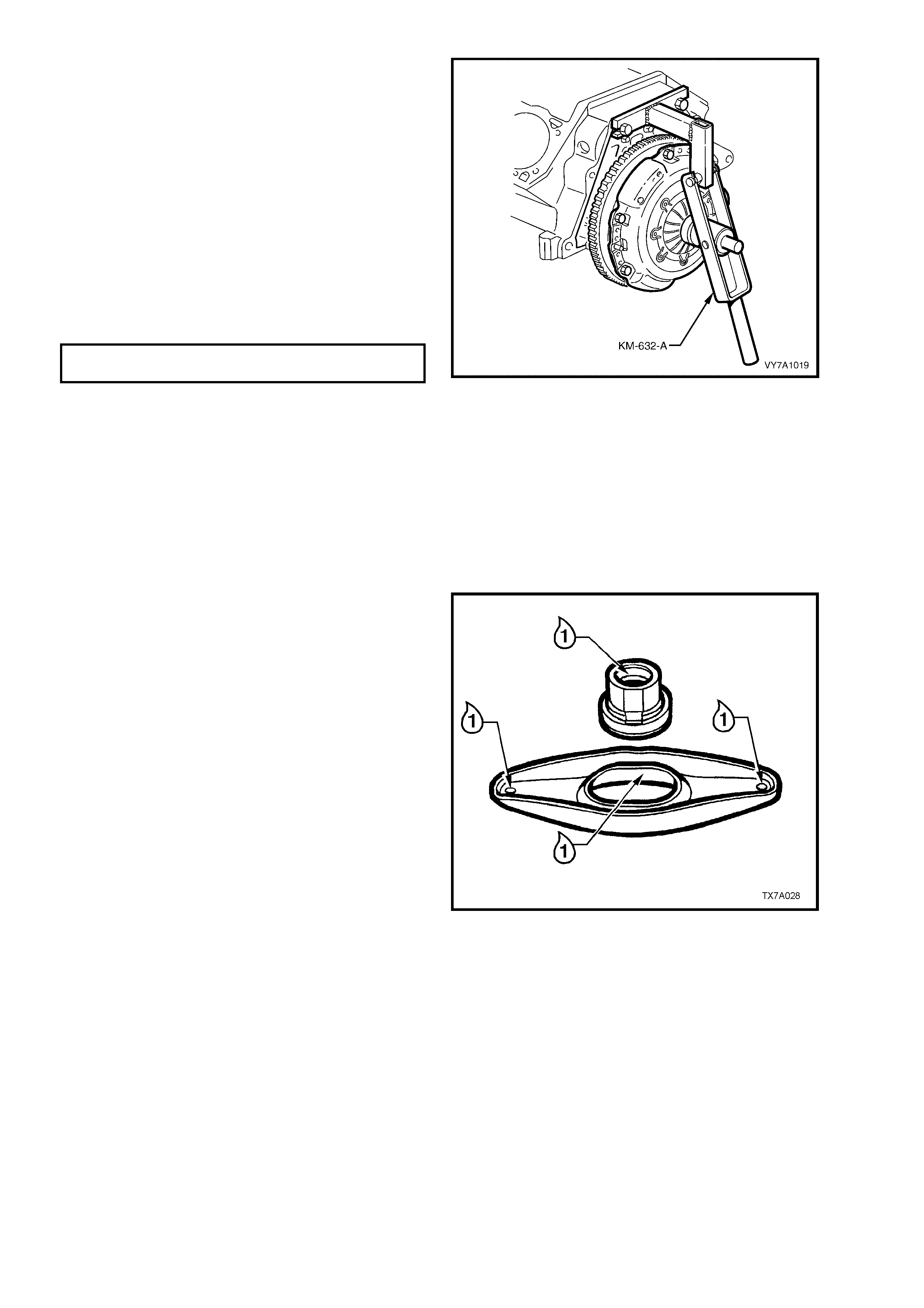
4. Instal l the br acket of Tool KM-63 2-A, to the top
two gearbox mounting holes, using two of the
gearbox bolts, each with a nut and a flat
washer.
NOTE: The thread for the nut is 12 mm x 1.75
pitch.
5. Hook the arm of Tool KM- 632-A under the lugs
of the br ack et as s hown, a nd app ly forc e to the
arm, depressing the pressure plate by 18 mm,
fully r eleasing the c lamping force on t he driven
plate.
6. With the pressure plate loaded in this manner,
tighten the pressure plate bolts to the correct
torque specification, working from opposite
sides.
CLUTCH PRESSURE PLATE BOLT
TORQUE SPECIFICATION 32 Nm
IMPORTANT: It is critical that the loading tool is
used to depress the pressure plate diaphragm
spring, while the bolts are tightened. If not used,
then the pressure plate cover will be permanently
distorted, resulting in an uneven force being
applied to the driven plate and the bolt torque
figures will also be inadequate.
7. Rele ase th e for ce on t he le ver of Tool K M-63 2-
A, when all bolts have been tightened to the
correct specification. Remove Tool KM632-A
and the bracket.
Figure 7A1 – 32
8. Remove the clutch plate centring tool.
9. Lubricate the clutch throwout lever at each of
the points indicated, using an NLGI No. 2 Cla y
Thickened Grease, suitable for high
temperature conditions (similar to wheel
bearing grease).
Use the same lubricant and apply it to the
groove on the inner surface of the throwout
bearing sleeve as shown.
IMPORTANT: If excess lubricant is applied, it will
be thrown onto the driven plate linings, causing
clutch slippage and premature clutch failure may
result.
10. Reassemble the clutch throwout be aring to the
sleeve, then ins tall the lever and bearing to the
throwout bearing guide in the transmission.
Secure the pivot end of the lever with the wire
clip and push the actuating cylinder end
inwards, to secure the position of the bearing
to the lever.
Figure 7A1 – 33
11. Reinstall the transmission assembly. Refer to Section 7B1 MANUAL TRANSMISSION, V6 ENG IN E.
NOTE: W hen installing th e tr ans mission, do not al lo w it to ‘han g’ o n the maindriv e gear s plin es, as the c lutch dr iv en
plate will be damaged.
12. Reinstall the two front close-out covers (2 and 4) and secure with a screw (1 and 3) in each. Refer to Figure
7A1 – 34.
NOTE: W hile Figure 7A1 – 34 shows the right-h and drive ar rangem ent, the proc edure for lef t-hand drive vehicles
is similar. View ‘A’ shows the left side close-out cover, while view ‘B’ shows the right side.

3.10 DUAL MASS FLYWHEEL
REPLACE
NOTE 1: As this operation is included with other engine mechanical items, refer to 3.4 Flywheel/Flexplate,
in Section 6A1 ENGINE MECHANICAL – V6 ENGINE, for details regarding this service operation.
NOTE 2: The ring gear is welded to the flywheel and, as such is not replaceable. If ring gear damage is evident,
then the complete flywheel assembly must be replaced.


4. DIAGNOSIS
CONDITION PROBABLE CAUSE CORRECTIVE ACTION
SLIPPING Worn or oil-soaked lining.
Grease on linings from excessive
application to the input shaft
splines.
Driven plate sticking on main drive
gear splines.
Weak or broken diaphragm spring.
Master or actuating cylinder
defective
Replace driven plate, correct oil
leak.
Replace driven plate, remove
excess lubrication.
Clean spli nes and check clutch hub
for a free sliding fit.
Replace pressure plate and
diaphragm assembly. Refer
3.9 Clutch Driven Plate, Pressure
Plate and/or Throwout Bearing,
in this Section.
Overhaul defective cylinder as
detailed in 3.5 Master Cylinder or
3.6 Clutch Actuating Cylinder, in
this Section.
DRAG OR FAILURE TO
RELEASE Air trapped in hydraulic system.
Leak In hydraulic system.
Clutch master or actuating cylinder
defective.
Cracked or oil-soaked linings.
Excess ive dri ven pl ate run- out or
distorted.
Driven plate sticking on splines.
Main drive gear spigot partially
seized in crankshaft spigot bush.
Bleed system as outlined under
3.3 Clutch H ydraulic S ystem Bleed,
in this Section.
Correct leak and bleed hydraulic
system .
Overhaul defective cylinder as
outlined under 3.5 Master Cylinder
or 3.6 Clutch Actuating Cylinder, in
this Section.
Replace clutch driven plate. Refer
3.9 Clutch Driven Plate, Pressure
Plate and/or Throwout Bearing, in
this Section.
Replace driven plate. Refer
Operation 3.9 Clutch Driven Plate,
Pressure Plate and/or Throwout
Bearing, in this Section.
Clean spli nes and check clutch hub
for a free sliding fit.
Remove clutch, replace bush.
Refer 3.11 Cr ank shaf t Spig ot Bush,
in this Section.
GRAB OR CHATTER Oil on linings.
Worn main drive gear splines.
Rough, or grooved, flywheel or
pressure plate.
Loose engine m ountings .
Loose or worn prope ll er sh af t
coupling/s or damaged pinion
flange.
Defective clutch dr i ven plat e.
Defective dual mass flywheel.
Replace driven plate, correct oil
leak.
Replace main drive gear.
Replace flywheel or replace both
flywheel and pr ess ur e plate.
Tighten or replace mountings.
Tighten or replace propeller shaft
coupling/s and/or pinion flange.
Replace clutch driven plate. Refer
3.9 Clutch Driven Plate, Pressure
Plate and/or Throwout Bearing, in
this Section.
Replace dual mass flywheel. Refer
3.10 Dual Mass Flywheel, in this
Section.

HARD OR STIFF CLUTCH
ACTION Clutch pedal bush seized or tight
on pedal shaft.
Blockage in fluid hydraulic pipe.
Replace bushes as detailed in
3.7 Clutch Pedal in this Section.
Clean lines and bleed hydraulic
system. Refer 3.3 Clutch Hydraulic
System Bleed in this Sec ti o n.
CLUTCH ENGAGEMENT TOO
SLOW Blockage in fluid hydraulic pipe.
Clutch master or actuating cylinder
defective.
Incorrect brake fluid used.
Clean lines and bleed hydraulic
system. Refer 3.3 Clutch Hydraulic
System Bleed in this Sec ti o n.
Overhaul defective cylinder as
outlined under 3.5 Master Cylinder
or 3.6 Clutch Actuating Cylinder, in
this Section.
Flush and bleed hydraulic system.
Refer 3.3 Clutch Hydraulic System
Bleed in this Sec ti on.

5. SPECIFICATIONS
MASTER CYLINDER:
Type ........................................................................ Compensating port.
Bore Size................................................................. 19.05 mm
Nominal Stroke........................................................ 30 mm
CLUTCH ACTUATING CYLINDER:
Type ........................................................................ Flange mounted with side port delivery and end bleed.
Bore Size................................................................. 22.2 mm
Available Stroke ...................................................... 25.6 mm
BRAKE FLUID:
Type ........................................................................ Either DOT 4 Plus or Super DOT 4
CLUTCH DRIVEN PLATE:
Type ........................................................................ Single plate dry disc.
Disc Facing:
Outside Diameter............................................... 240 ± 1.0 mm
Inside Diameter.................................................. 155 ± 1.5 mm
Thickness of disc assembly with 7,000 N load ....... 8.4 ± 0.2 mm
CLUTCH PRESSURE PLATE:
Type ........................................................................ Recessed, with a pressed steel cover plate and a
Belleville diaphragm spring.
CLUTCH THROWOUT BEARING:
Type ........................................................................ Ball race.
Lubrication............................................................... Sealed with grease for life.
DUAL MASS FLYWHEEL:
Type ........................................................................ Spring dampened internally; the transmission side is
recessed to accommodate the clutch assembly.
Rotational freeplay maximum, including
length tolerances and heat setting losses:
Degrees.............................................................. 11°
Distance............................................................. 27 mm at the outside diameter (281.3 mm) of the
secondary side of the flywheel assembly.
Serviceability........................................................... None. Starter motor ring gear is not replaceable and
machining of the clutch facing surface is not permitted.
LUBRICANT
Clutch throwout lever ................................................. NLGI No. 2 clay thick ened greas e.
Clutch throwout bearing sleeve.................................. NLGI No. 2 clay thickened grease.
Transmission input shaft spigot.................................. Synthetic oil.
Clutch pedal bushes................................................... Molybdenum disulphide greas e

6. TORQUE WRENCH SPECIFIC ATIONS Nm
Clutch actuating cylinder bleeder screw............................................................................. 8
Clutch actuating cylinder mounting nut............................................................................... 22
Clutch master cylinder nut to engine firewall...................................................................... 25
Clutch master cylinder reservoir bracket to brake mastercylinder end brace bolt.............. 8 - 11
Clutch pedal bracket to steering column bracket bolt......................................................... 20 - 30
Clutch pedal pivot bolt......................................................................................................... 15
Clutch pressure plate to flywheel bolt................................................................................. 32
Hydraulic flexible hose to clutch actuating cylinder ............................................................ 11
Hydraulic pipe flare nut to master cylinder.......................................................................... 10
Hydraulic pipe flare nut to flexible hose.............................................................................. 10
Master cylinder reservoir to clutch master cylinder bracket nut.......................................... 2 - 5
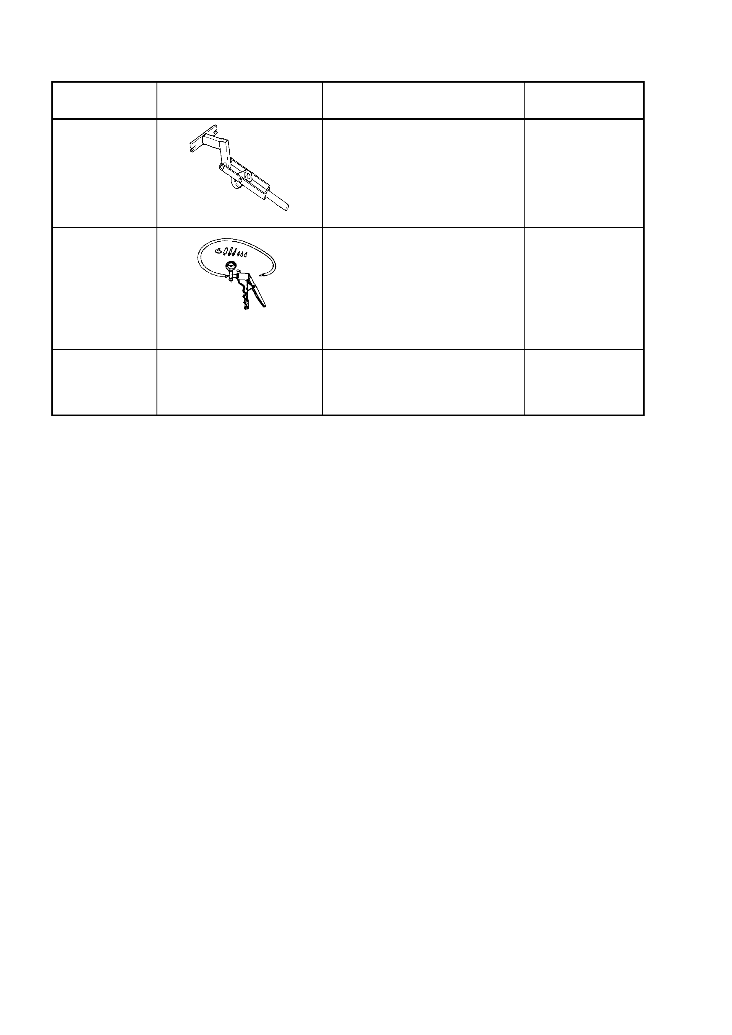
7. SPECIAL TOOLS
TOOL
NUMBER ILLUSTRATION DESCRIPTION CLASSIFICATION
KM-632-A
CLUTCH PRESSURE PLATE
LOADING TOOL
Used to ‘load’ the pressure plate
on V6 engined vehicles, while
tightening the retaining bolts.
Previously released
Desirable
J23738-A
HAND VACUUM PUMP
Used for many applications,
including diagnostic checks or
anywhere that an appli ed v acuum
would be useful.
Previously released and
comm er c ially available
Mandatory
N/A CLUTCH CENTERING TOOL
Commercially available
Available