
SECTION 7A2 - CLUTCH – GEN III V8 ENGINE
IMPORTANT
Before performing any Service Operation or other procedure described in this Section, refer to Section
00 CAUTIONS AND NOTES for correct workshop practices with regard to safety and/or property damage.
CONTENTS
1. GENERAL INFORMATION
1.1 SELF-ADJUSTING CLUTCH PRESSURE PLATE
1.2 CLUTCH CONTROL
ARRANGEMENT
OPERATION
2. SERVICE OPERATIONS
2.1 SERVICE NOTES
2.2 FLUID LEVEL CHECK
2.3 CLUTCH HYDRAULIC SYSTEM, BLEED
2.4 CLUTCH FLUID – CHANGE
2.5 CLUTCH MASTER CYLINDER
2.6 CLUTCH SLAVE CYLINDER
REMOVE
DISASSEMBLE
CLEAN AND INSPECT
REINSTALL
2.7 CLUTCH THROWOUT BEARING
REMOVE
CLEAN AND INSPECT
REINSTALL
2.8 CLUTCH PEDAL ASSEMBLY
2.9 CLUTCH PEDAL SWITCH
REMOVE
REINSTALL
2.10 CLUTCH AND PRESSURE PLATES
REMOVE
INSPECT
CLUTCH PRESSURE PLATE ADJUSTMENT
REINSTALL
2.11 ENGINE FLYWHEEL
REPLACE
2.12 RING GEAR
REPLACE
2.13 CRANKSHAFT SPIGOT BEARING
REPLACE
3. DIAGNOSIS
4. SPECIFICATIONS
5. TORQUE WRENCH SPECIFICATIONS
6. SPECIAL TOOLS
Techline
Techline
Techline
Techline
Techline
Techline
Techline
1. GENERAL INFORMA TION
1.1 SELF-ADJUSTING CLUTCH PRESSURE PLATE
The self-adjusting feature for the clutch pressure plate fitted to the GEN III V8 engine and the six speed manual
transmission, has been retained, that achieves several advantages:
a. The clutch pedal loading is maintained at a consistent level throughout the life of the assembly, as the
diaphragm spring leverage over the pivot rings remains the same.
b. This also results in the fact that the clutch ‘take-up’ re mains at a c onstant poi nt, with the clutc h pedal f eel also
remaining constant.
c. No maintenance adjustments are required.
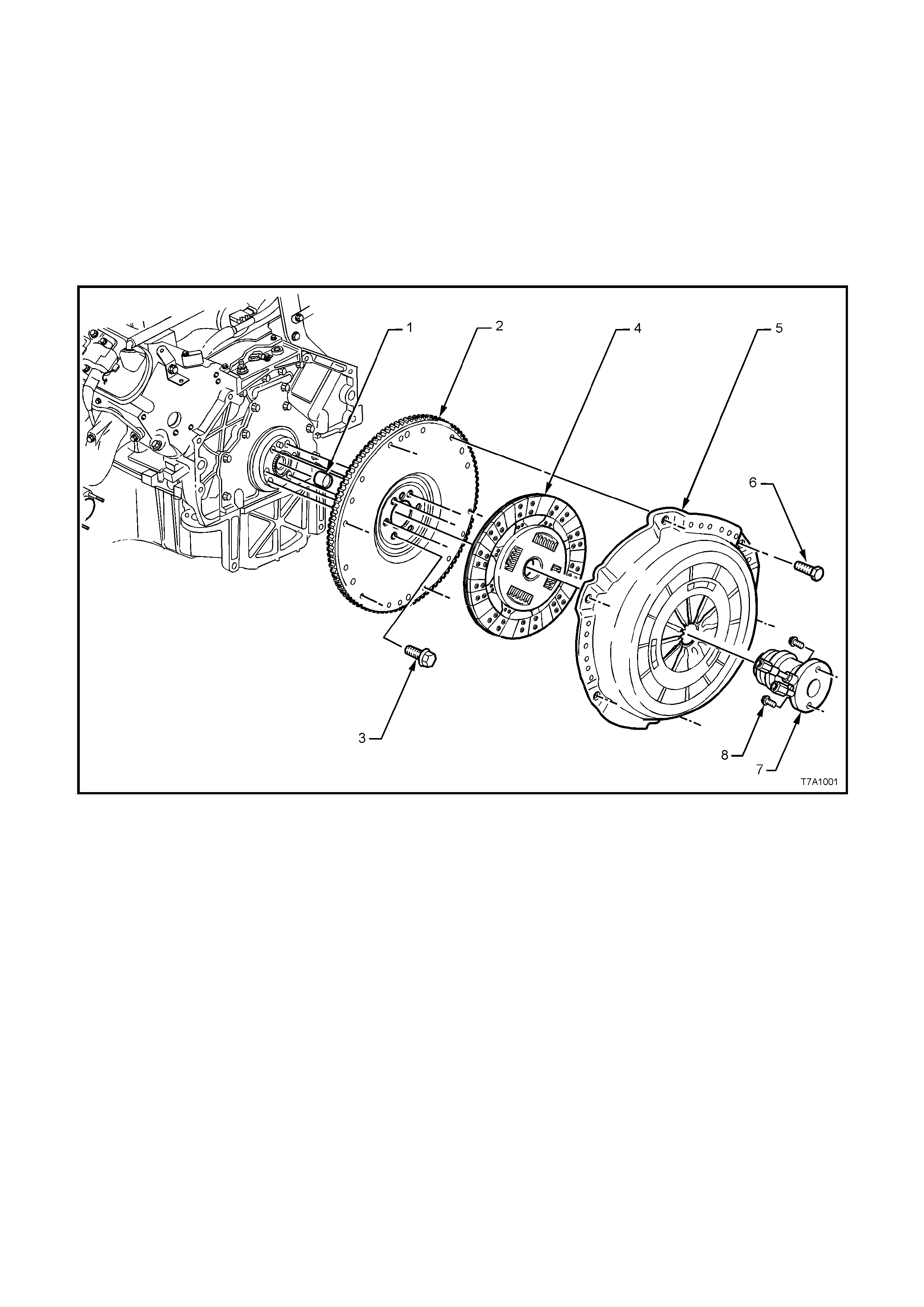
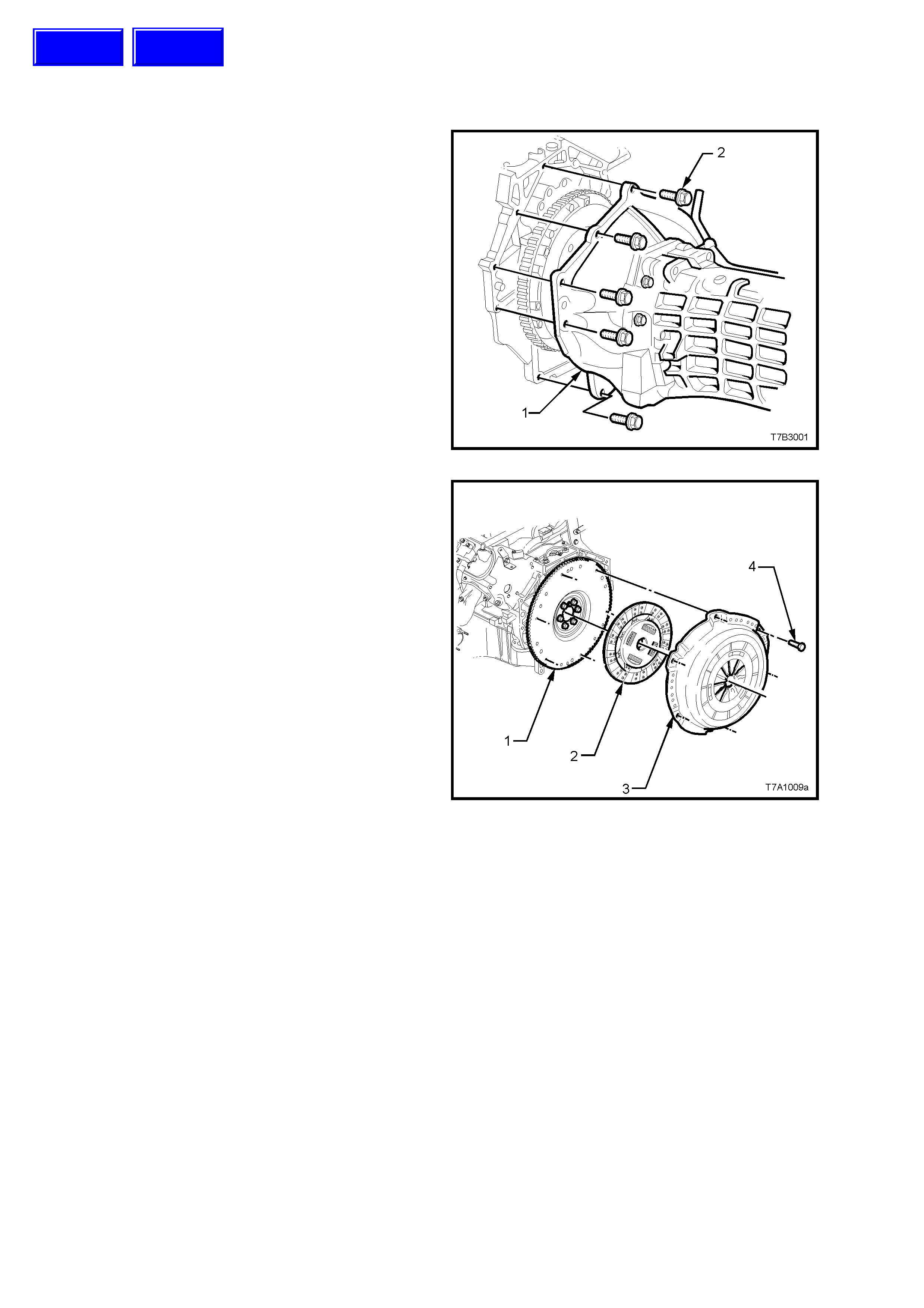
Figure 7A2 – 1 Clutch Components
Legend
1. Bearing - Clutc h Pil ot
2. Flywheel - Engine
3. Bolt - Flywheel (6 places)
4. Plate - Clutch Dri ven
5. Plat e - Clutch Press ure
6. Bolt - P ressu re P lat e (6 places)
7. Assem bl y - Clutch Slave
8. Bolt - Slave Cylinder (2 places)
1.2 CLUTCH CONTROL
Hydraulic actuation for the clutch has been retained for the GEN III V8 engine application in MY 2003 VY and V2
Series vehicles and uses some common components with the V6 engined vehicle. For example, apart from the
changed orientation of the outlet fitting, the clutch master cylinder remains unchanged.
The clutch pedal is also common, except for those vehicles fitted with cruise control, when a small bracket is
welded to the pedal for clutch switch control.
Clutch control component changes that are unique for the GEN III V8 engine are:
• Hydraul ic piping from the flexible hose t o the centra l clutch slave c ylinder , routed acr oss the top of the m anual
transmission.
• An integrated clutch throwout bearing and concentric slave cylinder, mounted to the front of the transmission
adaptor plate.
ARRANGEMENT
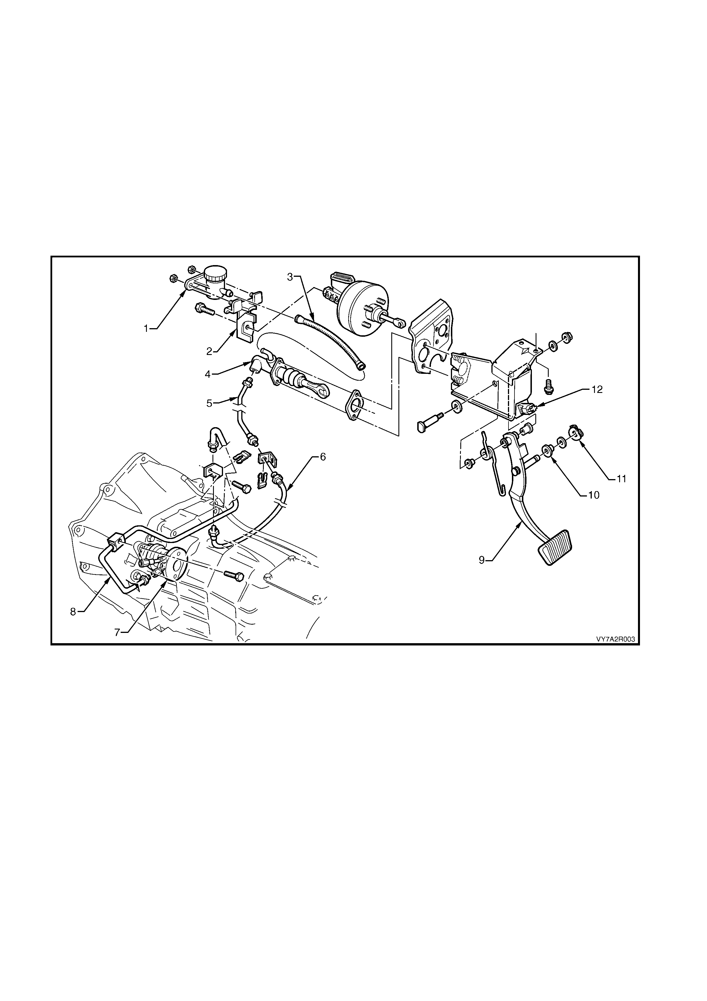
Figure 7A2 – 2 Clutch Control Layout
Legend:
1. Reservoir – Clutch Fluid
2. Bracket – Clutch Fluid Reservoir
3. Hose – Reservoir to Master Cylinder
4. Master Cylinder
5. Pipe – Master Cylinder to Flexible Hose
6. Hose – Master Cyli nder Pipe to Slave Cylinder Pipe
7. Assem bl y – Slave Cylinder and Bearing
8. Pipe – Hose to Slave Cylinder
9. Pedal – Clutch
10. Bush – Master Cylinder Push Rod
11. Retainer – Push Rod Bush
12. Switch – Clutch (Cruise Control only)
OPERATION
Brak e fluid is fed to the cl utch mas ter cylinder fr om
a remote reservoir mounted to a bracket, bolted to
the end of the brake mas ter cylinder. A flexi ble line
connects the two components.
The m aster cylinder and vacuum booster assem bly
is attached to the firewall in the engine
compartment.
The clutch pedal is mounted in the clutch/brake
pedal support bracket, bolted to the dash panel.
The clutch master cylinder piston is connected to
the clutch pedal by a quick connect fitting on the
end of the push rod, that clips onto a grooved pin
attached to the clutch pedal.
No clutch adjustments are required.
Stroking of the clutch throwout bearing is achieved
by using a concentric hydraulic clutch slave
cylinder (2) mounted to the front of the
transmission adaptor plate housing.
Hydraulic connection to the master cylinder is by
steel piping from the master cylinder, flexible hose
to the transmission and steel pipe again from the
flexible hose to the slave cylinder (1) (Also see
Figure 7A2-2) .
The slave cylinder is fitted with a bleed valve to
assist in removal of air from the hydraulic system.
Apart fr om the thro wout be ar ing ass embly and l oad
spring, there are no other serviceable parts in the
slave cylinder and, if found to be faulty, the
assembly must be replaced.
Figure 7A2 – 3
CLUTCH MASTER CYLINDER OPERATION
As the oper ation of the clutc h mas ter cylinder fitted
to GEN III V8 engined vehicles is the same as for
all manual tr ansm iss ion equip ped MY 200 3 VY and
V2 Series vehicles, refer to the description in
Section 7A1 CLUTCH.
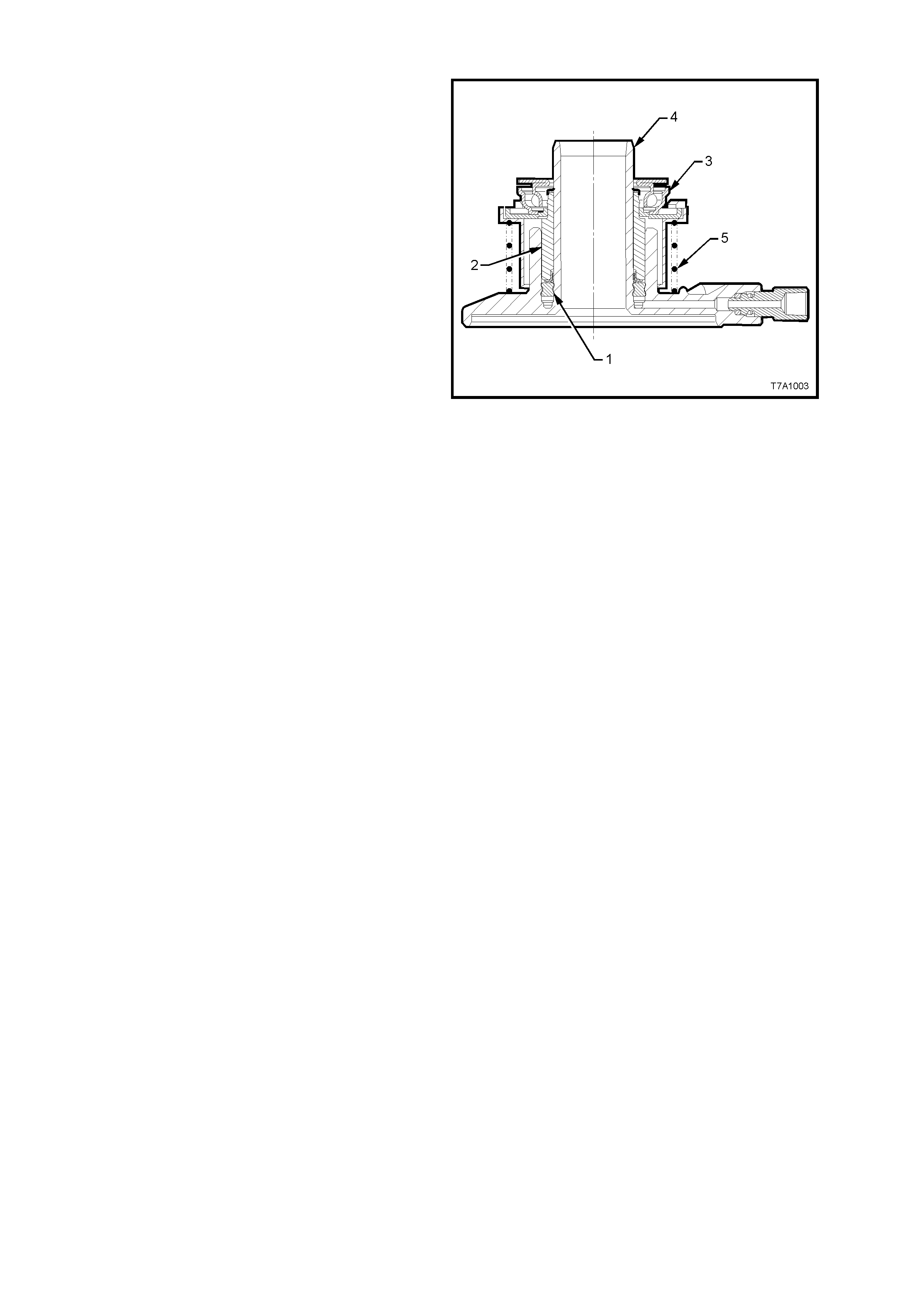
CLUTCH SLAVE CYLINDER OPERATION
When pressurised fluid from the clutch master
cylinder acts upon the seal (1), the seal moves,
stroking the sleeve (2) before it. As the throwout
bearing assembly (3) is attached to the sleeve (2),
the throwout bearing als o moves with the sleev e, to
forc e the dia phra gm fingers of the pr ess ur e p lat e to
move against its in-built spring force.
As the slave cylinder sleeve (2) continues to be
moved along th e guide of the cylinder bod y (4), the
force applied to the pressure plate diaphragm
spring causes the spring to pivot, thus releasing
the applied force on the clutch driven plate,
allowing it to spin. When this situation occurs, the
frictional link between the engine flywheel and the
transmission input shaft is broken and gear
changing c a n th en s af ely take place, witho ut u ndu e
stress being placed upon the transmission
synchromesh assemblies.
When the clutch pedal is released, the pressure
plate diaphragm spring force, moves the throwout
bearing (3) and slave cylinder sleeve (2), back
along the slave cylinder body guide (4), returning
displaced fluid back to the master cylinder
reservoir.
Coil spring (5) acts to maintain constant contact of
the throwout bearing with the pressure plate
diaphragm spring fingers, thereby reducing pedal
travel to begin initial movement by compensating
for any slight finger height variation in the
diaphragm spring.
Figure 7A2 – 4
As the clutch pressure plate is self-adjusting, the ‘at
rest’ position of the throwout bearing and clutch
slave cylinder sleeve (2), remains relatively
constant throughout the life of the assembly,
compared to other clutch control systems.

2. SERVICE OPERATIONS
2.1 SERVICE NOTES
Important Items
1. W hile GM’s clutch parts are not asbes tos based in th eir m ater ial com position, a danger exists that replac em ent
non-genuine parts may contain asbestos.
Not only is it in the interests of personal safety but also the safe and reliable operation of the clutch sy stem, that
only genuine parts are used for replacement purposes.
Even so, when ser vicing c lutch par ts, do not c rea te dust by grind ing or s anding the c lutch pla te, or cl ean cl utch
parts with a dry brush or with compressed air. Breathing in dust that may contain asbestos fibres can cause
serious bodily harm over a protracted period of time.
A water dampened cloth or water based solution should be used to remove any dust on clutch parts.
Equipment is commercially available to perform this washing function. These wet methods prevent clutch
component fibres from becoming airborne.
2. The polyglycol brake fluid used in the MY 2003 VY and V2 Series vehicles is hygroscopic and absorbs
moisture from the air through the flexible clutch hose etc. Therefore, for maximum clutch effectiveness, a two
yearly change of brake fluid is mandatory, refer to 2.4 CLUTCH FLUID - CHANGE.
To prevent the absorption of moisture from the air or other contamination, it is recommended that the brake
fluid be stored in small (500 ml) containers and that any surplus fluid remaining in a container after use be
discarded.
NOTE: The only approved brake fluid is DOT 4 Plus or Super DOT 4 Plus and is available in 250 and 500 ml
containers . If pr es sur e bl ee din g eq uipment is us ed, it must be of an a pproved t yp e with a dia phragm s eparating the
brake fluid from the air.
CAUTION: Brake fluid is extremely damaging to paint. If fluid should accidentally come into contact with a
painted surface, immediately wash the fluid from the paint and clean the painted surface.

2.2 FLUID LEVEL CHECK
Check that the fluid level is between the two
guidelines on the translucent reservoir housing.
Should the add it ion of fluid be required , remove the
reservoir cap and use heavy duty brake f luid, such
as DOT 4 Plus or Super DOT 4 Plus.
Figure 7A2 – 5
2.3 CLUTCH HYDRAULIC SYSTEM, BLEED
The c lutch hydraulic s ystem must be bled when ever the h ydraulic line has been disconnected, or when a le ak has
allowed air to enter the system. Air trapped in the system can prevent full disengagement of the clutch.
During bleeding operations, the master cylinder reservoir must be kept at least half full with hydraulic brake fluid.
1. Carefully clean any dirt from around the fluid reservoir cap.
2. Remove the filler cap and top up reservoir as required, with heavy duty hydraulic brake fluid, such as DOT 4
Plus or Super DOT 4 Plus.
3. Using an 11 mm, 3/8 drive socket, short
extension and socket bar, loosen the slave
cylinder bleeder, located in the upper aperture
of the transmission adaptor plate/clutch
housing, on the left hand side.
4. Then, using just the socket and extension,
tighten the bleeder, using light finger force
only.
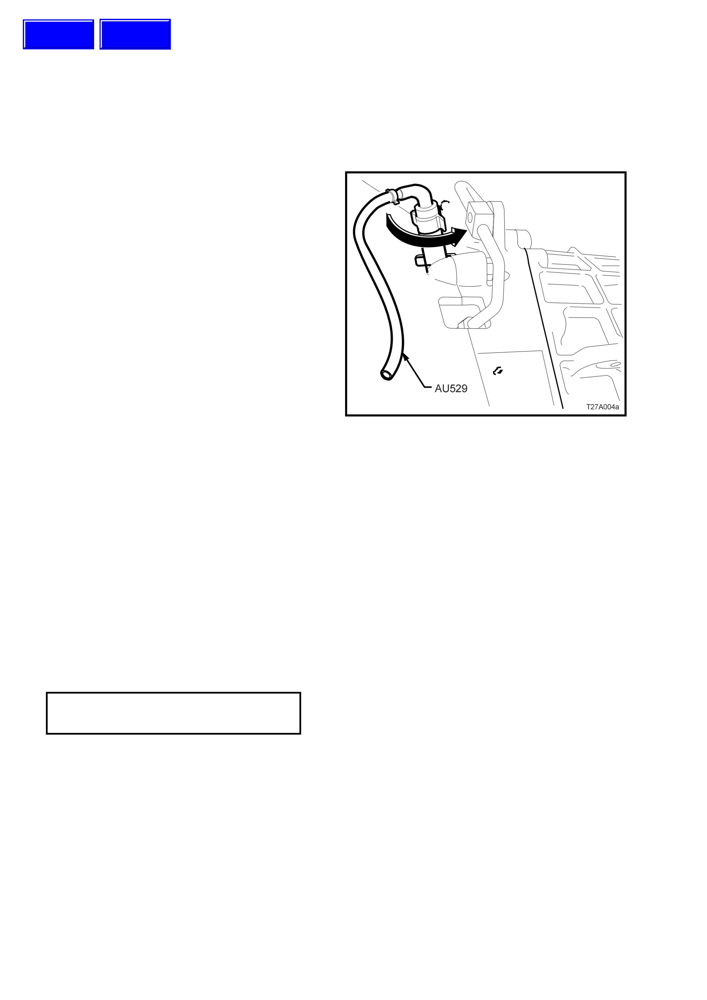
5. Insert the end of the rubber tube of Tool AU529
over the e nd of the ble eder, posit ioned at the 9
o’clock position.
6. With the other end of the bleeder tool inserted
into a clean glass container such as a jar, that
has been partially filled with new brake fluid,
open the bleeder 1/4 turn, using the rubber on
the bleeder tool to provide the required grip.
Ensure that the end of the hose always
remains submerged in the brake fluid during
bleeding oper at io ns .
7. Using an assistant, slowly depress the clutch
pedal by hand, one single time and, while
holding the pe dal depresse d, close the bleeder
using T ool AU529. Once the b leeder is closed,
the clutch pedal can be allowed to slowly
release. Ensure that the pedal fully returns to
the 'UP' position – lift by hand, if required.
Repeat this process until all bubbles cease to
appear at the end of the bleeder hose.
NOTE: Do not pump the clutch pedal repeatedly
during bleeding operations, as entrapped air will
cause the fluid to foam, making air removal
extremely difficult.
Figure 7A2 – 6
Also, as the hydraulic steel piping is routed over the top of the transmission housing, air can be trapped in that
section.
8. When all air has been removed, close off the bleeder and remove Tool AU529. With the clutch pedal still
depressed, tighten the bleeder screw to the correct torque specification.
CLUTCH SLAVE CYLINDER
BLEEDER SCREW
TORQUE SPECIFICATION 18 Nm
9. Once all bleeding operations have been completed, ensure that the fluid level in the reservoir is correct.
NOTE: Alternative methods of bleeding would be to use either a pressure bleeder, with a commercially available
reservoir cap or use the vacuum method, with the assistance of a ha nd operated vacuum pump such as Tool No.
J23738-A (also commercially available as a ‘MityVac’™) and an air tight, glass container.
Techline
Techline

2.4 CLUTCH FLUID - CHANGE
At the int erval spec ified in the O wners Han dbo ok, the c lutch f luid mus t be change d. Discol ourat ion of the f lui d is no
reason for fluid replacement. The recommended method is to use a commercially available pressure bleeder,
together with an appropriate fluid reservoir cap. Follow the manufacturer’s instructions regarding the use of the
pressure bleeding equipment.
1. Fit bleeder adaptor AU529 to the slave cylinder bleeder as described in 2.3 CLUTCH HYDRAULIC SYSTEM,
BLEED, in this Section, then use the pressure bleeder to force fluid through the hydraulic system.
2. Continue allowing fluid to flow through the system until the fluid runs clear in the bleeder hose , immersed in
clean glass container .
3. Following the fluid change operation, ensure that the fluid level in the reservoir is correct and that the slave
cylinder bleeder screw is tightened to the correct torque specification.
CLUTCH SLAVE CYLINDER
BLEEDER SCREW
TORQUE SPECIFICATION 18 Nm
NOTE: An alternati ve method wou ld be to us e t he vacuum method, with th e as s is tanc e of a han d op er ated vac uum
pump such as Tool No. J23738-A (also commercially available as a ‘MityVac’™) and an air tight, glass container.

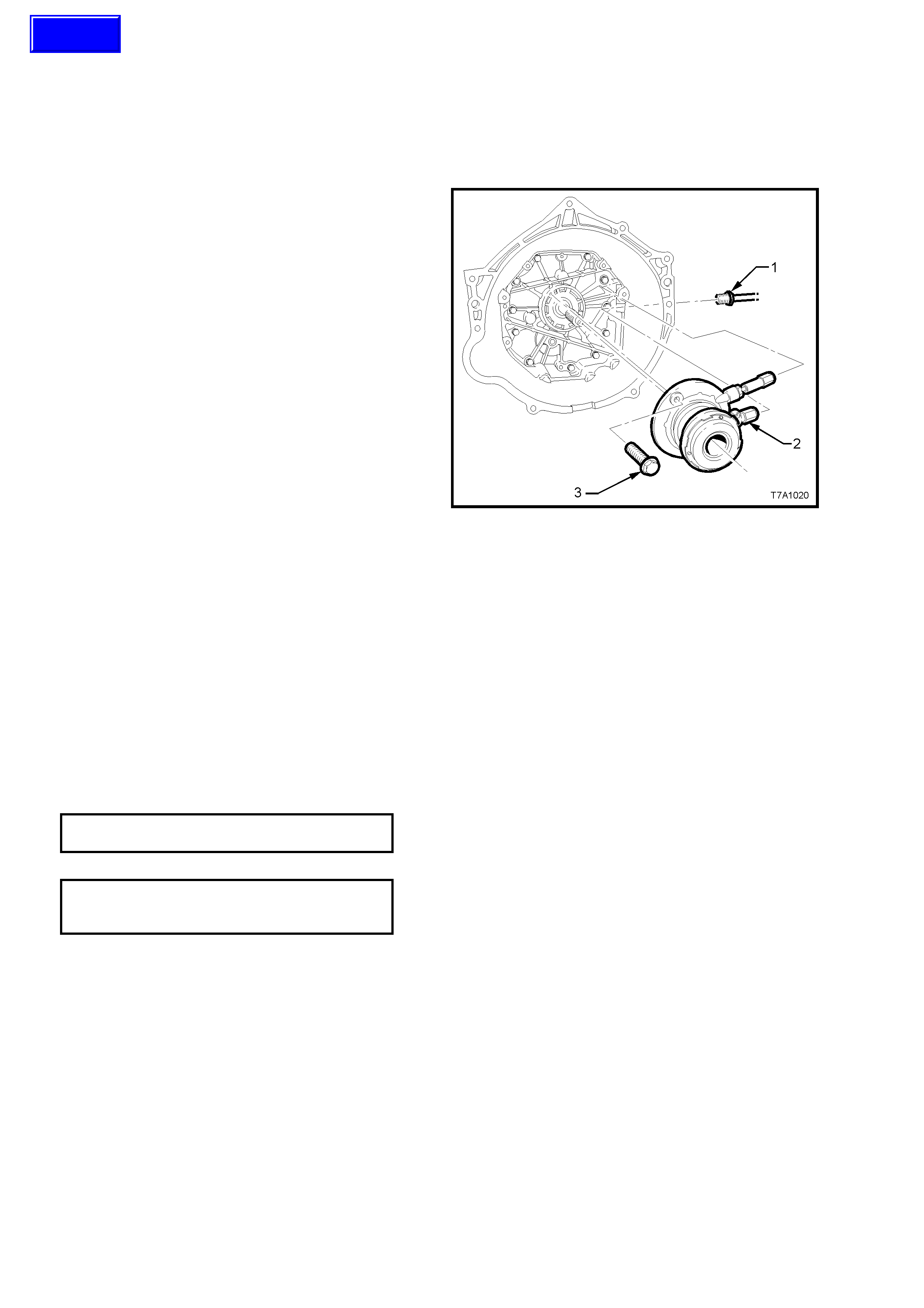
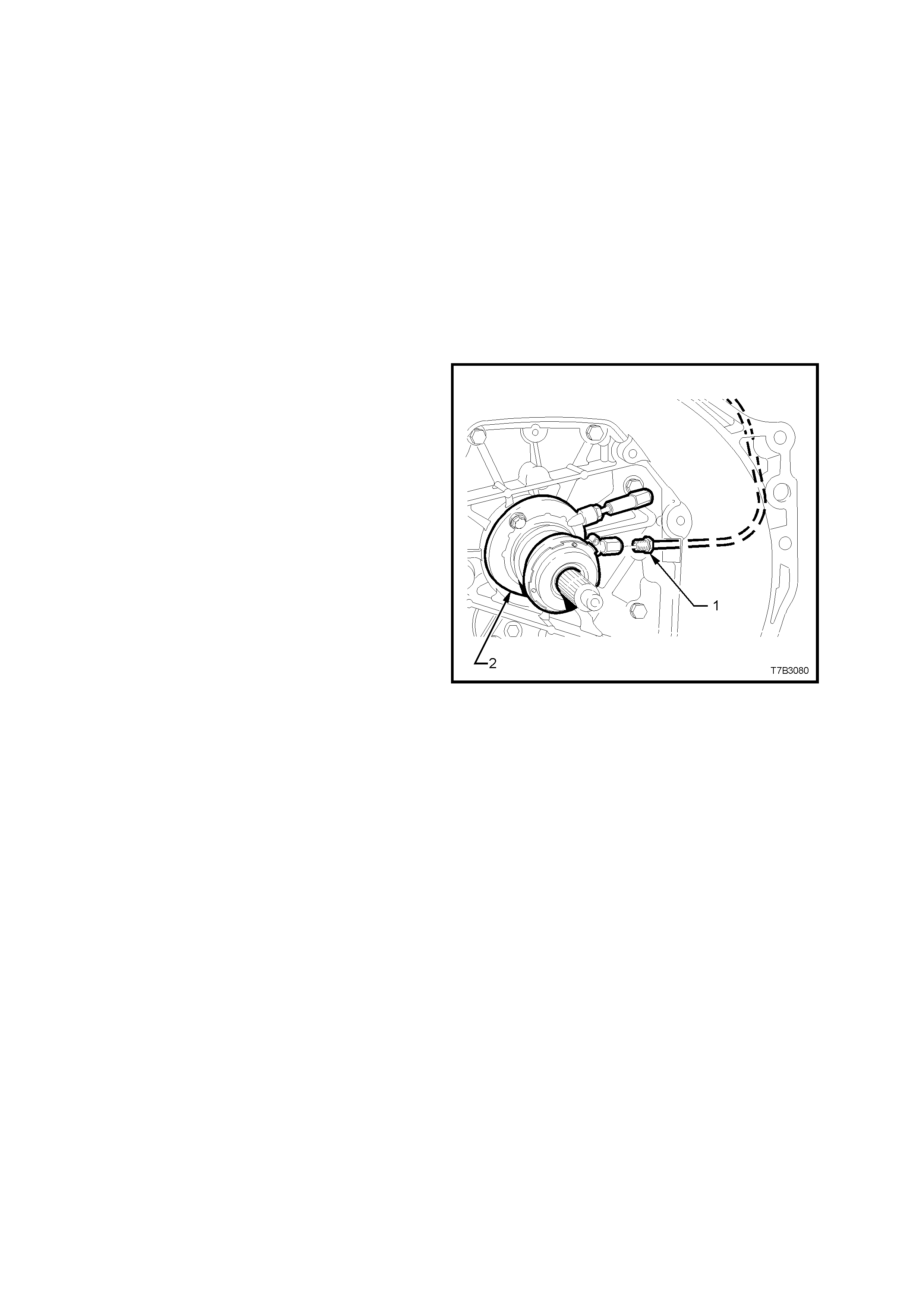
2.6 CLUTCH SLAVE CYLINDER
REMOVE
1. Remove the transmission from the vehicle.
Refer to Section 7B2, 4.2 TRANSMISSION
ASSEMBLY, Remove.
2. Unscrew the pipe fitting (1) from the clutch
slave cylinder (2).
3. Remove the two bolts (3) securing the clutch
slave cylinder assembly to the transmission
adaptor plate, then remove the slave cylinder.
DISASSEMBLE
If required, remove the throwout bearing. Refer to
2.7 CLUTCH THROWOUT BEARING.
NOTE: Apart from this bearing and the spring
behind it, there are no other serviceable parts in
the clutch slave cylinder assembly.
CLEAN AND INSPECT
IMPORTANT: Do not wash hands in petrol or oil
before cleaning or handling clutch slave cylinder
parts. Always use a soap and water based hand
cleaning product.
1. Inspect the slave cylinder for any evidence of
fluid leakage. If found, replace the assembly.
2. Remove the bleeder screw and inspect the
slave cylinder threaded apertures for damage.
Replace the slave cylinder assembly as
necessary.
3. Check that the bleeder screw thread is
undamaged and that the drilled passage is
clear of debris.
4. Inspect the throwout bearing. Refer to
2.7 CLUTCH THROWOUT BEARING.
Figure 7A2 – 7
REINST ALL
Installation is the reverse of removal operations except for the following points:
1. Install slave cylinder and the 2 retaining bolts, then tighten the bolts to the correct torque specification.
CLUTCH SLAVE CYLINDER BOLT
TORQUE SPECIFICATION 10 Nm
2. Install and tighten hydraulic pipe flare nut to the slave cylinder, tightening to the correct torque specification.
HYDRAULIC PIPE FLARE NUT TO
SLAVE CYLINDER
TORQUE SPECIFICATION 13 Nm
3. Reinstall the transmission. Refer to Section 7B2, 4.2 TRANSMISSION ASSEMBLY, Reinstall.
4. Bleed the clutch hydraulic system, as detailed in 2.3 CLUTCH HYDRAULIC SYSTEM, BLEED.
5. Following bleeding operations, check that the hydraulic fluid level is correct, as detailed in
2.2 FLUID LEVEL CHECK.
6. Road test the vehicle and check for correct clutch and transmission operation.
Techline
2.7 CLUTCH THROWOUT BEARING
REMOVE
1. Remove the transmission. Refer to
Section 7B2, 4.2 TRANSMISSION
ASSEMBLY, Remove.
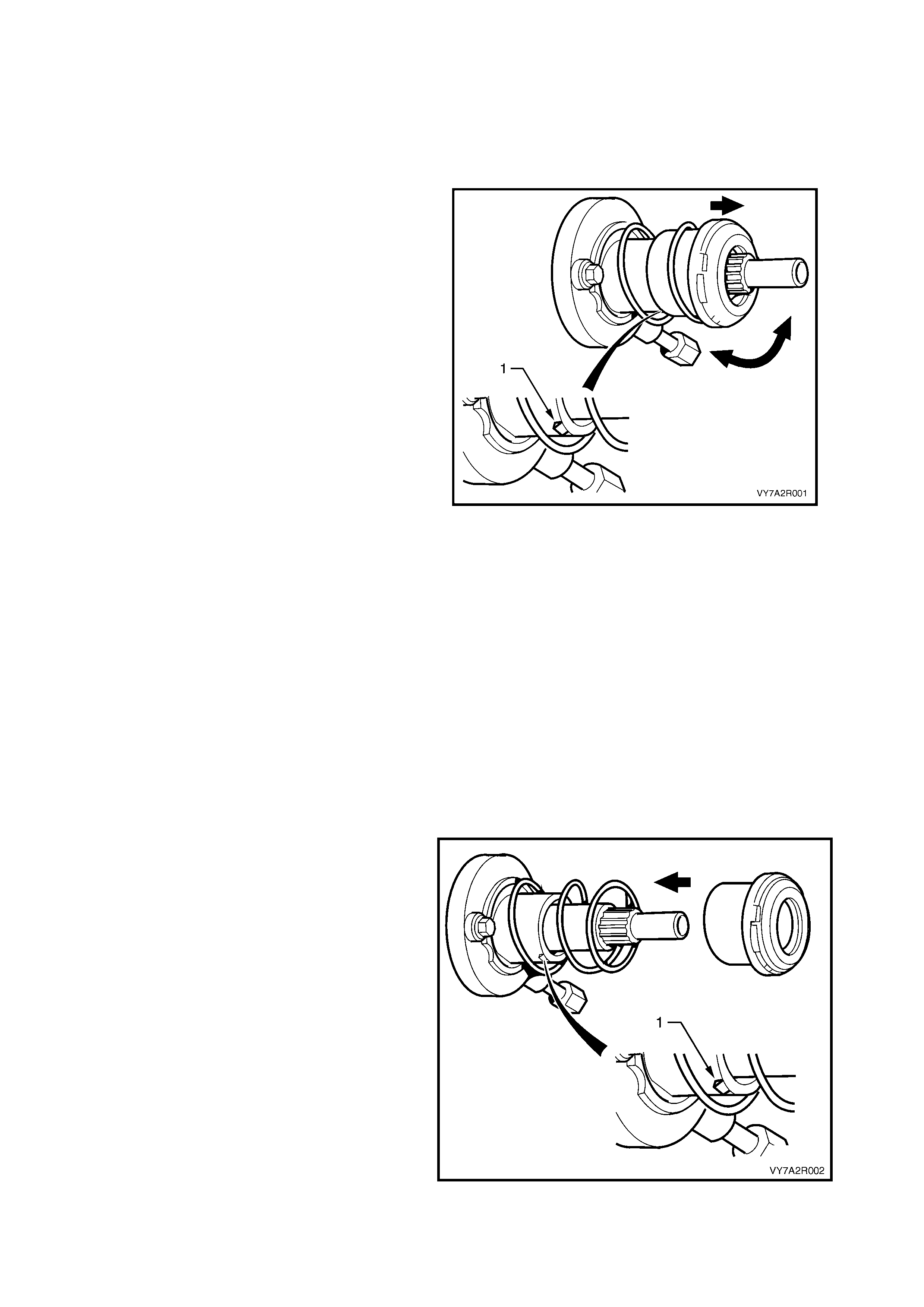
2. W hilst grasping the thro wout beari ng, twist and
pull the bearing to release the slave cylinder
guide sleeve retaining tab (1) from the throwout
bearing guide sleeve.
Figure 7A2 – 8
CLEAN AND INSPECT
IMPORTANT: Do not use cleaners or chemicals on the bearing guide sleeve.
1. Ins pect the thro wout bear ing for any signs of r oughnes s or drynes s by rotating the beari ng when a light loa d is
applied. If either of these conditions are evident, replace the throwout bearing.
2. Examine the bearing guide sleeve for signs of damage, abrasion or scuffing. Renew the throwout bearing if
either of these conditions exist.
NOTE: The throwout bearing guide is not serviceable and is supplied complete with the throwout bearing.
3. Inspect the slave cylinder. Refer to 2.6 CLUTCH SLAVE CYLINDER.
4. Use a water dampened cloth or water based solution to wipe the slave cylinder clean.
REINST ALL
1. Using a clean dry rag, wipe the exposed portion of the throwout bearing guide sleeve.
2. Apply molybdenum disulphide grease to the slave cylinder guide sleeve.
NOTE: If replacing the throwout bearing, grease may have been applied to the new clutch throwout bearing.
3. Install the clutch throwout bearing to the guide
sleeve, b y firm ly pushing the new bearing on to
the sleeve, until it snaps into place over the
retaining tab (1).
4. Install the transmission. Refer to Section 7B2,
4.2 TRANSMISSION ASSEMBLY, Reinstall.
5. Road test the vehicle and check for correct
clutch and transmission operation.
Figure 7A2 – 9

2.9 CLUTCH PE DAL SWITCH
REMOVE
CAUTION: Disable the SRS (Air Bag). Refer 'DISABLING THE SRS’, in Section 12M, OCCUPANT
PROTECTION SYSTEM.
1. Disconnect batt ery ground lead.
IMPORTANT: Disconnection of the battery affects certain vehicle electronic systems. Refer to
Section 00 CAUTIONS, 5. Battery Disconnection Procedures before disconnecting the battery.
2. Remove ignition keys from ignition switch.
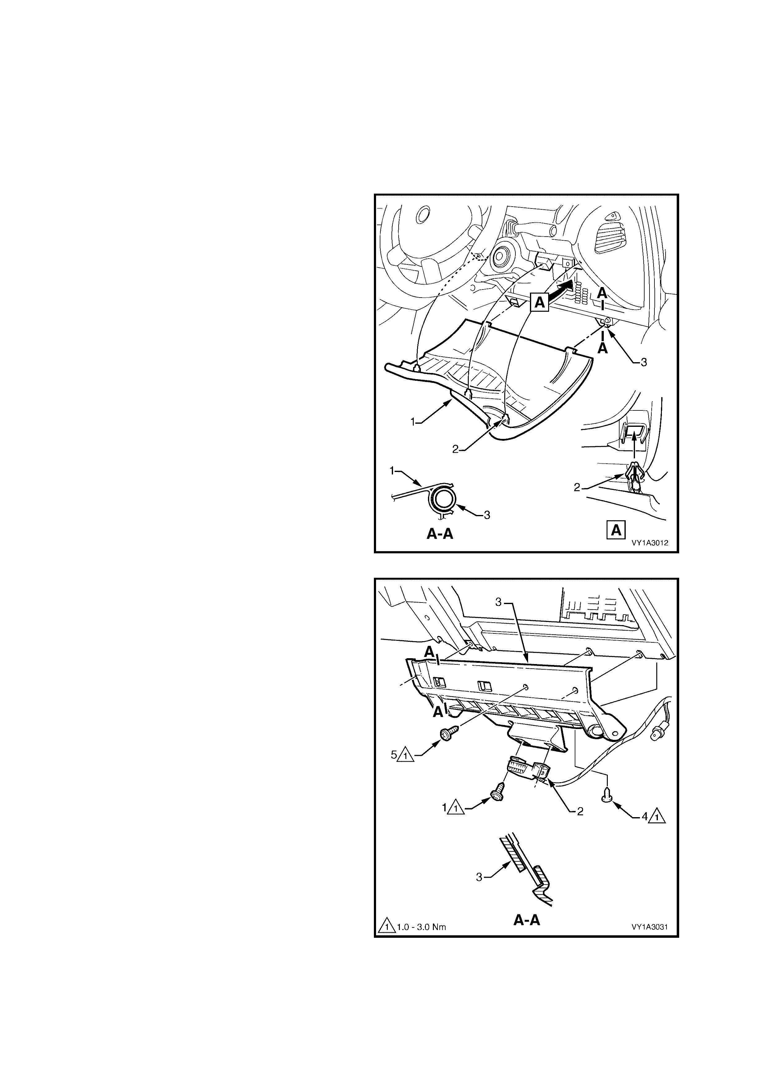
3. Lower the instrument panel lower fuse panel
cover assembly (1) by grasping the top edge
on each side of the steering column with the
finger tips and pulling the top edge out, to free
the retaining lugs (2) from the clips (3).
4. Release the steering column tilt/reach clamp
lever, lower the column and lock the clamp
lever in this position.
Figure 7A2 – 10
5. Remove the screw (1), two places, attaching
the Data Link Connector (2) to the instrument
panel lower trim panel retainer (3).
6. Rem ove the screw (4) a ttaching the retainer to
the air duct.
7. Remove the screw (5), three places, attaching
the retainer to the instrument panel assembly
and instrument panel.
8. Slide the retainer downwards to disengage the
two lugs from the instrument panel assembly
and remove the retainer.
Figure 7A2 – 11

9. Remove the clutch switch wiring harness
connector (1), then remove the clutch switch
(2) by rotating counter-clockwise (to the left)
1/4 turn, then pull to free the switch bayonet
lugs.
Figure 7A2 – 12
REINST ALL
1. Reinstall the switch and rotate 1/4 turn clockwise to lock the switch bayonet lugs, then reinstall the wiring
harness connector.
2. Reinstall all removed instrument panel components in the reverse to removal operations.
3. Road test vehicle to check clutch switch operation. Refer Section 12E CRUISE CONTROL.
IMPORTANT: Enable the SRS (Air Bag). Refer 'ENABLING THE SRS’, in 12M OCCUPANT PROTECTION
SYSTEM.
2.10 CLUTCH AND PRESSURE PLATES
REMOVE
1. Remove transmission assembly (1). Refer
Section 7B2 MANUAL TRANSMISSION -
GEN III ENGINE.
Figure 7A2 – 13
2. Initia lly loosen a ll pressur e plate ret aining bo lts
(4), working from opposite sides, to avoid
distortion of the cover (3).
3. Continue loosening bolts from opposite sides,
until all are removed, then lift the clutch driven
plate (2) and pressure plate (3) assemblies
from the flywheel (1).
NOTE: The two locating dowel pins in the flywheel
are set 170° apart, which means that marking the
pressure plate relationship to the flywheel is not
required.
Figure 7A2 – 14
INSPECT
1. Use a water dampened cloth or water based solution to wipe the pressure plate and flywheel surfaces.
NOTE: Do not wash the pressure plate with liquid petroleum based products or use compressed air.
2. Inspect and clean the slave cylinder. Refer to 2.6 CLUTCH SLAVE CYLINDER.
NOTE: Do not attempt to clean the slave cylinder and throwout bearing with any fluid solvents or compressed air.
3. Inspec t the cranks haft spigot bearing f or wear. If neces sary, replace the bear ing. Refer to 2.13 CRANKSH AFT
SPIGOT BEARING.
4. Inspect flywheel and clutch pressure plate friction surfaces for burn marks scoring or roughness. Slight
roughness may be smoothed with fine emery cloth. Scoring of flywheel or pressure plate surfaces will require
replacement of the damaged component/s.
5. Inspect clutch driven plate for lining wear or other damage, such as oil or fluid contamination.
NOTE: If oil or fluid is found on the clutch linings, locate and correct the cause of the leak before proce eding with
any clutch repairs.
6. Before installing the clutch driven plate, check clutch hub for a free sliding fit on maindrive gear clutch shaft
splines.
Techline
Techline
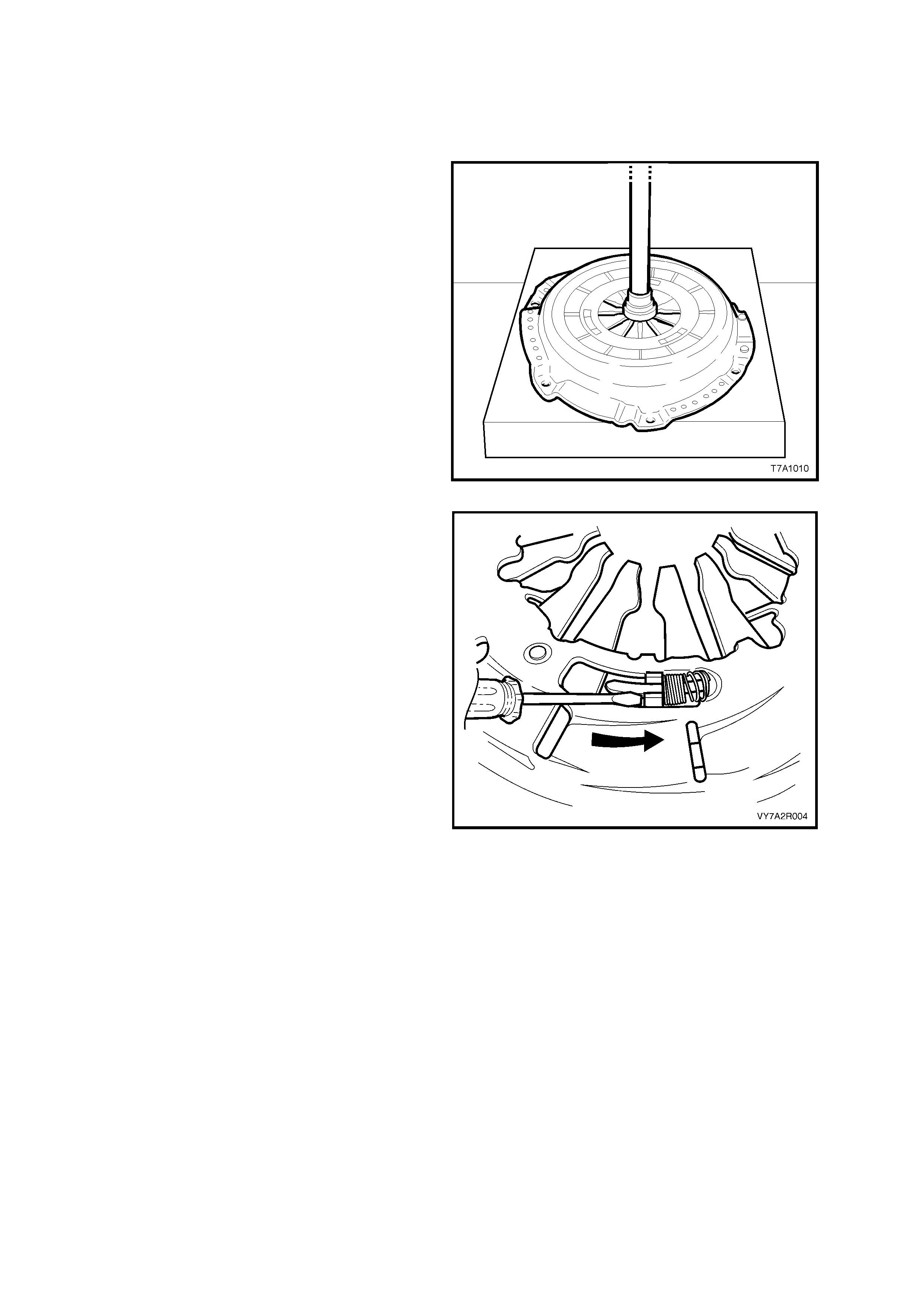
CLUTCH PRESSU RE PLAT E ADJUSTMENT
IMPORTANT: Prior to the installation of the
pressure plate, the self-adjusting feature must be
pre-set. If not carried out before installation, then
probable failure of the pressure plate will result.
1. Place the flat side of the clutch plate
downwards on flat press plates, then place the
pressur e plate ass embly over it.
2. Using a hydraulic press, compress the
pressur e plate d iap hr agm spring un til tens i on is
released from the clutch driven plate.
NOTE: Care mus t be exercised when com pressing
the pressure plate diaphragm spring. If the
diaphragm spring is compressed to far, damage to
the pressure plate may result.
Figure 7A2 – 15
3. Hold a screwdriver (1) or other suitable tool,
against the stepped adjusting ring tension
spring stop (2) in front of the adjusting ring
tension spring (3)
4. Using the screwdriver, rotate the stepped
adjusting ring, counter-clockwise (arrow), fully
compressing the tension springs.
NOTE 1: Minimal effort is required to rotate the
adjustment ring. If difficulty is experienced in
rotating the adjustment ring check that the
diaphragm spring has been adequately
compressed.
NOTE 2: Do not force the adjustment ring as
damage to the pressure plate may result.
5. While holding the tension springs in the fully
loaded position, release the force on the
diaphragm spring. This will then retain the
springs in the fully loaded position.
6. Remove the pressure plate and clutch driven
plate from the press.
Figure 7A2 – 16
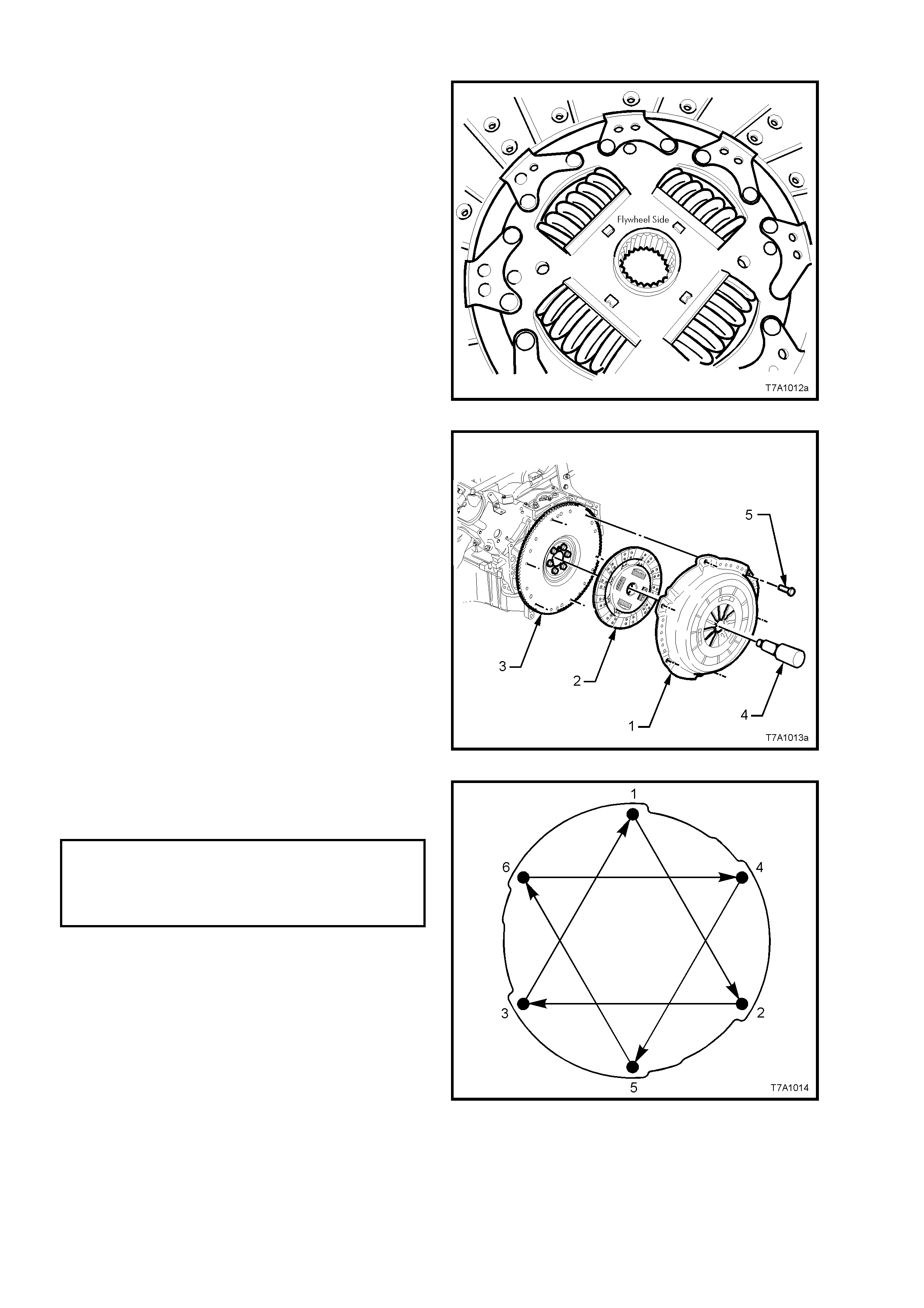
REINST ALL
1. While holding the clutch driven plate up to the
engine flywheel, insert a suitable clutch
centring tool (commercially available) into the
spigot bearing, through the driven plate.
NOTE: The clutch driven plate is installed with the
flat side of the hub, facing forward to the flywheel.
The word ‘Flywheel Side’ is also stamped on the
inner surface, as shown.
Figure 7A2 – 17
2. Reinstall the pressure plate assembly (1) over
the alignment tool (4) and clutch driven plate
(2), aligning the offset dowel pins in the
flywheel (3) with the mating holes in the
pressure plate cover (1).
3. Loosely install the six pressure plate to
flywheel bol ts (5).
Figure 7A2 – 18
4. Tighten the 6 pressure plate retaining bolts in
sequence and evenly over 4 stages until the
correct torque specification is reached.
CLUTCH PRESSURE PLATE
BOLT TORQUE SPECIFICATION Stage 1: 15 Nm
Stage 2: 35 Nm
Stage 3: 55 Nm
Stage 4: 70 Nm
IMPORTANT: Tightening to the torque settings,
stages and in the sequence listed are all
necessary, to avoid permanent distortion of the
pressure plate cover.
Figure 7A2 – 19

IMPORTANT: Under no circumstances should a
lubricant be applied to the bearing face off the
clutch throwout bearing, the gearbox input shaft
splines or the input shaft spigot. Should a lubr icant
be applied, premature clutch failure may result.
5. Reinstall the transmission assembly. Refer to
Section 7B2 MANUAL TRANSMISSION,
GEN III V8 ENGINE.
NOTE: When installing the transmission, do not
allow it to ‘hang’ on the maindrive gear splines, as
the clutch driven plate will be damaged.
6. Bleed the hydraulic clutch actuating system.
Refer to 2.3 CLUTCH HYDRAULIC SYSTEM,
BLEED.
7. Depr ess the c lutch pedal s evera l tim es to all ow
the self- adjusting functi on of the pressure plate
to take effect.
8. Start engine, and check for exhaust leaks
before road testing the vehicle for satisfactory
clutch operation.
Figure 7A2 – 20


3. DIAGNOSIS
CONDITION PROBABLE CAUSE CORRECTIVE ACTION
SLIPPING Worn or oil-soaked lining.
Grease on linings from excessive
use of grease on splines.
Driven plate sticking on
transmission input shaft splines.
Weak or broken diaphragm spring.
Master or slave cylinder defective.
Replace driven plate, correct oil
leak.
Replace driven plate, remove
excess lubrication.
Clean spli nes and check clutch hub
for a free sliding fit.
Replace pressure plate assembly.
Refer to 2.10 Clutch and Pressure
Plates.
Overhaul defective cylinder as
outlined under 2.5 Mas ter Cylinder
or 2.6 Clutch Slave Cylinder.
DRAG OR FAILURE TO
RELEASE Air trapped in hydraulic system.
Leak In hydraulic system.
Clutch master or slave cylinder
defective.
Cracked or oil-soaked linings.
Excess ive dri ven pl ate run- out or
distorted.
Driven plate sticking on splines.
Transmission input shaft spigot
partially seized in crankshaft spigot
bearing.
Bleed system as outlined under
2.3 Clutch Hydraulic System,
Bleed.
Correct leak and bleed hydraulic
system .
Replace defective cylinder as
outlined under 2.5 Master Cylinder
or 2.6 Clutch Slave Cylinder.
Replace driven plate. Refer to
2.10 Clutch and Pressure Plates.
Replace driven plate. Refer to
2.10 Clutch and Pressure Plates.
Clean splines and check clutch hub
for a free sliding fit.
Remove clutch, replace bush.
Refer to 2.13 Crankshaft Spigot
Bearing.
GRAB OR CHATTER Oil on linings.
Worn transmission input shaft
splines.
Rough, or grooved, flywheel or
pressure plate.
Loose engine m ountings .
Loose or worn prope ll er sh af t
couplings or rear universal joint
flange.
Defective clutch dr i ven plat e.
Replace driven plate, correct oil
leak.
Replace transmission input shaft.
Refer to Section 7B2, Manual
Transmission – GEN III V8 Engine.
Replace flywheel or replace both
flywheel and pressure plate. Refer
to 2.10 Clutch and Pressure Plates
or 2.11 Engine Flywheel.
Tighten or replace mountings.
Refer Section 6A3 Engine
Mechanic al GEN III V8 Engine.
Tighten or replace universal
coupling/s and/or pinion flange.
Refer Section 4C Propeller Shaft
And Universa l Joi nts .
Replace clutch driven plate. Refer
to 2.10 Clutch and Pressure Plates.
HARD OR STIFF CLUTCH
ACTION Clutch pedal bush seized or tight
on pedal shaft.
Blockage in fluid hydraulic pipe.
Replace bushes as detailed in
2.8 Clutch Pedal Assembly.
Clean lines and bleed hydraulic
system. Refer to 2.3 Clutch
Hydraulic System, Bleed.

CONDITION PROBABLE CAUSE CORRECTIVE ACTION
CLUTCH ENGAGEMENT TOO
SLOW Blockage in fluid hydraulic pipe.
Clutch master or slave cylinder
defective.
Incorrect brake fluid used.
Clean lines and bleed hydraulic
system. Refer 2.3 Clutch Hydraulic
System, Bleed.
Replace defective cylinder as
outlined under 2.5 Mas ter Cylinder
or 2.6 Clutch Slave Cylinder.
Flush and bleed hydraulic system.
Refer to 2.3 Clutch Hydraulic
System, Bleed.

4. SPECIFICATIONS
Note: Only th ose specif ications relat ing specif icall y to this sec tion ar e quoted her e. for al l rem aining spec ific ations,
refer to Section 7A1 CLUTCH.
MASTER CYLINDER:
.................................................................................... All Engines
Type .................................................................................... Compensating port.
Bore Size............................................................................... 19.05 mm
Nominal Stroke...................................................................... 30 mm
CLUTCH SLAVE CYLINDER:
Type .................................................................................... Concentric hydraulic slave cylinder with side feed
.................................................................................... and ble ed ports
Bore Size............................................................................... I.D. 36 mm/O.D 47.6 mm (nominal)
Available Stroke .................................................................... 22.8 mm (nominal)
BRAKE FLUID:
Type .................................................................................... DOT 4 Plus or Super DOT 4 Plus.
CLUTCH DRIVEN PLATE:
Type .................................................................................... Single plate dry disc.
Disc Facing:
Outside Diameter ............................................................... 297 mm
Inside Diameter.................................................................. 198 mm
Thickness of disc assembly with 10,000 N load applied.... 8.7 ± 0.35 mm
CLUTCH PRESSURE PLATE:
T ype .................................................................................... Self-adjusting with a press ed steel cover plat e and
a multi- f ingered Be ll ev il le dia phr ag m spring.
CLUTCH THROWOUT BEARING:
Type .................................................................................... Ball race.
Lubrication............................................................................. Sealed with grease for life.
LUBRICANT:
Slave cylinder guide sleeve................................................... Molybdenum disulphide grease.

5. TORQUE WRENCH SPECIFIC ATIONS
Note: only those torque specifications referred to in this section are quoted here. for all remaining torque
specifications, refer to Section 7A1 CLUTCH. Nm
Clutch pressure plate bolt to flywheel Stage 1........................................ 15
Stage 2........................................ 35
Stage 3........................................ 55
Stage 4........................................ 70
Clutch slave cylinder bleed screw .................................................... 18
Clutch slave cylinder mounting bolt .................................................... 10
Flywheel to crankshaft mounting bolts Stage 1........................................ 20
Stage 2........................................ 50
Stage 3........................................100
Hydraulic pipe flare nut to slave cylinder and flexible hose......................... 13
Master cylinder hydraulic pipe to flexible hose flare nut.............................. 13
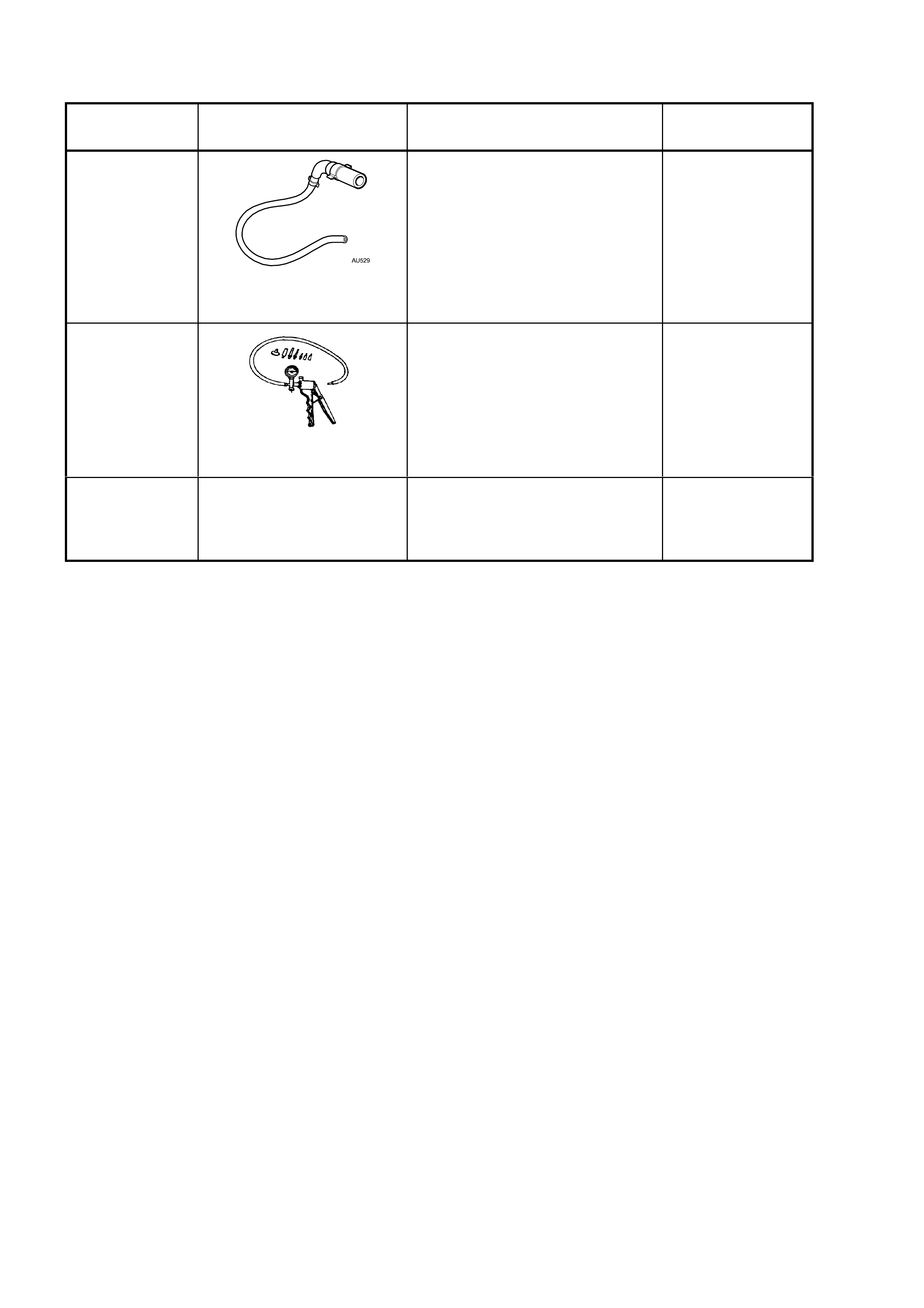
6. SPECIAL TOOLS
TOOL
NUMBER ILLUSTRATION DESCRIPTION CLASSIFICATION
AU529
CLUTCH SLAVE CYLINDER
BLEED TOOL
Used to bleed air from the Central
Slave Cylinder (CSC) fitted to the
T56, 6 speed manual transmission
available for the GEN III V8
engine.
Previo us ly Releas e d
Desirable
J23738-A
HAND VACUUM PUMP
Used for many applications,
including diagnostic checks or
anywhere that an appli ed v acuum
would be useful.
Previously released and
comm er c ially available
Available
N/A CLUTCH CENTRING TOOL
Commercially available.