
SECTION 7B1 - MANUAL TRANSMISSION –
V6 ENGINE
IMPORTANT
Before performing any Service Operation or other procedure described in this Section, refer to Section 00
CAUTIONS AND NOTES for correct workshop practices with regard to safety and/or property damage.
CONTENTS
1. GENERAL INFORMATION
1.1 GENERAL DESCRIPTION
SYNCHRONISER ASSEMBLIES
REVERSE GEAR
BEARING SUPPORT
LUBRICATION
SELECTOR MECHANISM
1.2 POWER FLOWS
1.3 TRANSMISSION SERIAL NUMBER
2. SERVICING INFORMATION
2.1 RECOMMENDED LUBRICANT
2.2 CHECKING TRANSMISSION LUBRICANT
LEVEL
2.3 DRAINING AND REFILLING TRANSMISSION
3. MINOR SERVICE OPERATIONS
3.1 BACK-UP LAMP SWITCH
REMOVE
REINSTALL
3.2 SPEED SENSOR AND/OR BRACKET
REPLACE
3.3 GEARSHIFT LEVER KNOB AND BOOT
ASSEMBLY
REMOVE
REINSTALL
3.4 GEARSHIFT LEVER
REMOVE
DISASSEMBLE
REASSEMBLE
REINSTALL
ADJUST
3.5 SHIFT LINKAGE BRACE, RUBBER MOUNTING
AND/OR BUSH
REPLACE
4. MAJOR SERVICE OPERATIONS
4.1 SPEED SENSOR TOOTHED RING OR
TRANSMISSION CASE REAR SEAL
REMOVE
SPEED SENSOR TOOTHED RING - REPLACE
REINSTALL
4.2 TRANSMISSION ASSEMBLY
REMOVE
REINSTALL
4.3 TRANSMISSION DISASSEMBLE
4.4 TRANSMISSION SUB-ASSEMBLIES
DISASSEMBLE
INSPECT COMPONENTS
SYNCHROMESH ASSEMBLIES
REASSEMBLE
TRANSMISSION CASE, REAR SECTION
TRANSMISSION CASE, FRONT SECTION
CLUSTER GEAR END PLAY ADJUSTMENT
CLUTCH THROWOUT BEARING GUIDE
4.5 TRANSMISSION REASSEMBLE
5. DIAGNOSIS
6. SPECIFICATIONS
7. TORQUE WRENCH SPECIFICATIONS
8. SPECIAL TOOLS
1. GENERAL INFORMATION
With the introduction of the MY 2003 VY and V2 Series range of vehicles, the manual transmission available for
fitment to the V6 engine, is an upgraded five speed, Getrag, Type 260 (production option M35).
Whether this manual transmission is standard equipment, optional or not available, will depend upon specific
vehicle specifications for various markets.
The ‘260’ manual transmission is a fully synchronised unit, including reverse gear, with baulk ring type
synchronisers. The transmission primarily consists of a two piece transmission case, with the clutch housing
integrated with the front case section. During disassembly, the gear train and shift mechanism remain in the
transmission case rear section. The transmission for MY 2003 vehicles (where fitted), has had a number of
changes made, that result in the modifications not being compatible with earlier build transmissions. Therefore,
always check the current release of PartFinder® for the correct parts to be fitted to this transmission.
In summary, the changes are:
• Modified gear tooth profiles.
• Increased tension crossover springs in the Neutral gate/Reverse selection.
• Re-designed transmission end housing to accommodate the changed design rear support mounting.
• Selective fit first gear to the mainshaft.
1.1 GENERAL DESCRIPTION
SYNCHRONISER ASSEMBLIES
Each of the three synchroniser hubs are an interference fit, splined to the mainshaft and fixed by selective snap
rings to accommodate manufacturing tolerances. Sintered, double cone blocking rings are fitted to 1st and 2nd
gears, while thos e f or 3rd, 4th, 5th and r evers e gears ar e brass, with a m olybden um coating on the ir inner s ur face.
The purpose of the synchroniser assemblies is to permit clutching to the required gear, that is in constant mesh
with the cluster gear.
Synchroniser Action
During s ync hron is er o peration, the synchronis er sle eve is moved into engagement by the appropria te f or k, car r ying
with it three synchroniser inserts and spring loaded balls, located in slots in the synchroniser hub.
The s ynchronis er sleeve, toget her with the ins erts, is m oved along the hu b, placing a load on the three lugs of the
blocking ring.
This initial force is sufficient to seat the b locking ring and s tart pre-s ynchronis ation because of the friction b etween
the cone on the constant mesh gear and the blocking ring/s.
At this s tage, gear engag em ent is prevented as long as there is a dif fer ence in speed between t he m ating s urf aces
of the blocking ring and cone of the constant mesh gear. As the speeds between the blocking ring and the gear
cone become synchronised, the teeth on the blocking ring and gear cone line up with the internal splines of the
sleeve, allowing the sleeve to engage the teeth on the mainshaft gear, completing gear selection.
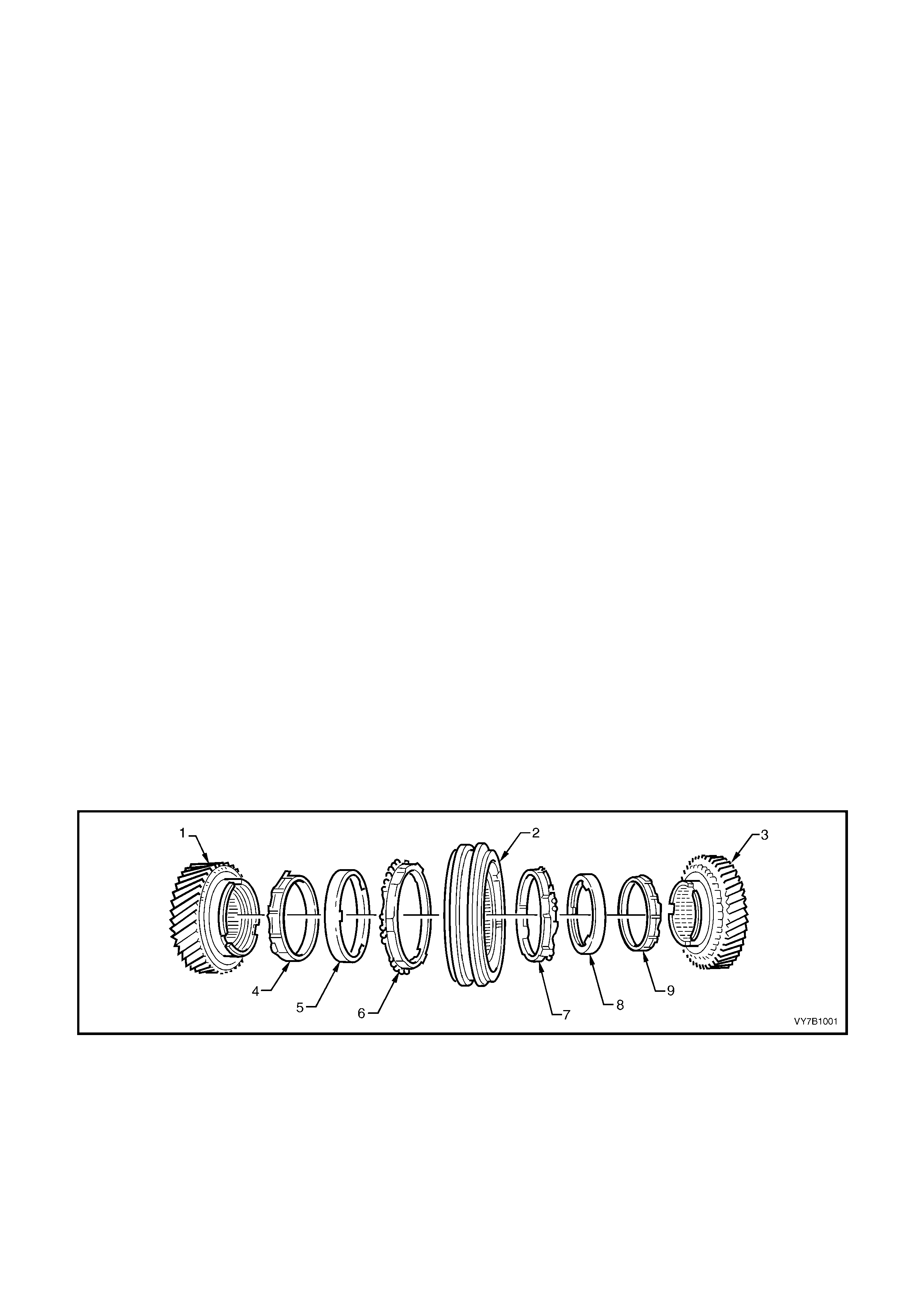
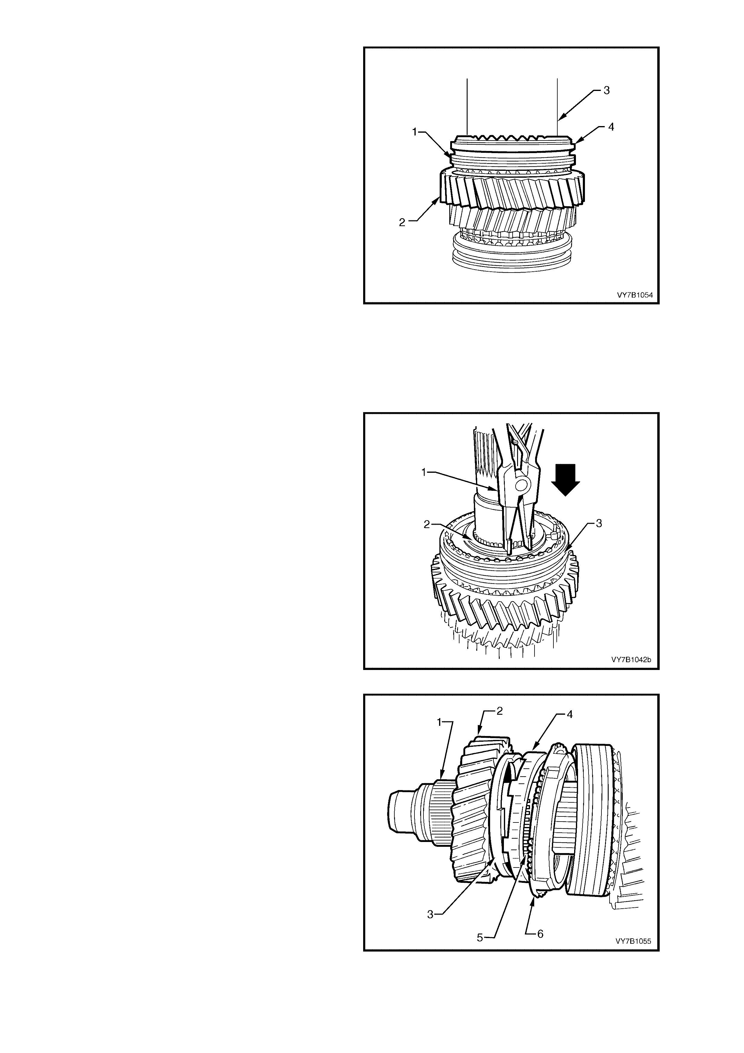
Figure 7B1-1 shows an exploded view of the three piece synchromesh unit, used for 1st and 2nd gears.
Figure 7B1-1
Legend
1. 2nd Speed Gear
2. 1st/2nd Speed Synchroniser, Hub and Sleeve
3. 1st Speed Gear
4. 2nd Inner Synchroniser Ring
5. 2nd Intermediate Synchroniser Ring
6. 2nd Outer Synchroniser Ri ng
7. 1st Outer Synchroniser Ring
8. 1st Intermediate Synchroniser Ring
9. 1st Inner Synchroniser Ring
REVERSE GEAR
The reverse idler gear is in constant mesh with the cluster gear and the reverse gear that is mounted on the
mainshaft. When reverse gear is engaged, the 5th/reverse synchromesh sleeve engages the reverse constant
mesh gear, completing the selection.
BEARING SUPPO RT
The maindrive gear runs on a single row ball race in the front of the transmission case and supports the front end of
the mains haft via a caged need le roller bear ing. The m ainshaft runs on a s ingle row ball race, m ounted in the rear
transmission case.
The maindrive gear and mainshaft bearings are located in their respective housings by an interference fit and the
use of snap rings or a bolted plate. Shims are used to accommodate manufacturing tolerances in each bearing
bore.
The cluster gear runs on two parallel roller bearings, one at each end, with end float being controlled by a shim
located between the cluster gear front bearing cup and the front circlip.
Each of the mainshaft constant mesh gears run on caged needle roller bearings, while the reverse idler gear is
supported by two caged needle roller bearings running on the idler gear shaft.
LUBRICATION
Lubrication of all internal components is by splash feed, provided by the rotating cluster gear assembly.
SELECTOR MECHANISM
The floor mounted, gearshift control lever operates a single rail mechanism which extends into the rear
transmission case. The first/second, third/fourth and fifth/reverse shift forks are all supported at each end, in the
two transmission cases.
A shift i nter loc k s ystem , preven ts eng agement of more than one gear at a time. T he system c onsis ts of an int er lock
pin locat ed in the third/fourth selector shaft and two interlock balls, that locate in a neu tral position groove in each
of the rem aining t wo rails . T hese com ponents, tog ether with th e shif t detent balls and s prings are all l ocated in th e
end of rear transmission housing.
When either the first/second or fifth/reverse selector shaft is moved to engage a gear, one of the interlock balls is
moved across, displacing the interlock pin, effectively locking the remaining two shafts. Moving the third/fourth
selector shaft, moves each of the two balls firmly into their respective shafts, allowing a third/fourth shift to take
place, with the interlock pin being carried with the shaft.
See Figure 7B1-2 f or a section ed vie w of the type ‘26 0’ transm ission (produc tion option M 35). Figur e 7B1-3 s hows
an explo ded view of the two cas e halves and se lector c omponents, while f igure 7B1-4 shows an exp loded vi ew of
the gear train components.
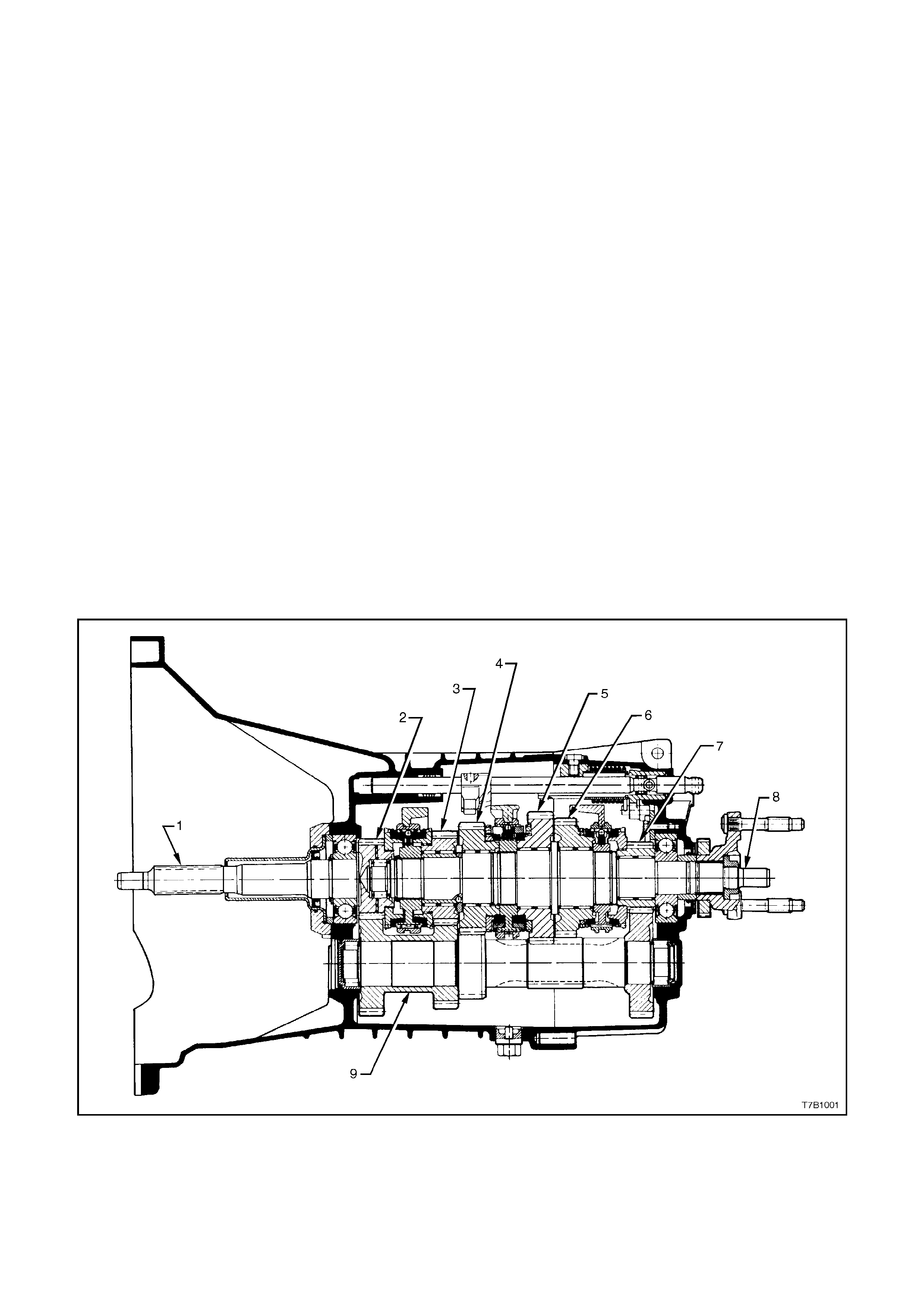
Figure 7B1-2 – Type ‘260’ Transmission, Sectioned View
Legend
1. Input Shaft
2. Maindrive Gear
3. Third Speed Gear
4. Second Speed Gear
5. First Speed Gear
6. Reverse Gear
7. Fifth Speed Gear
8. Mainshaft
9. Cluster Gear
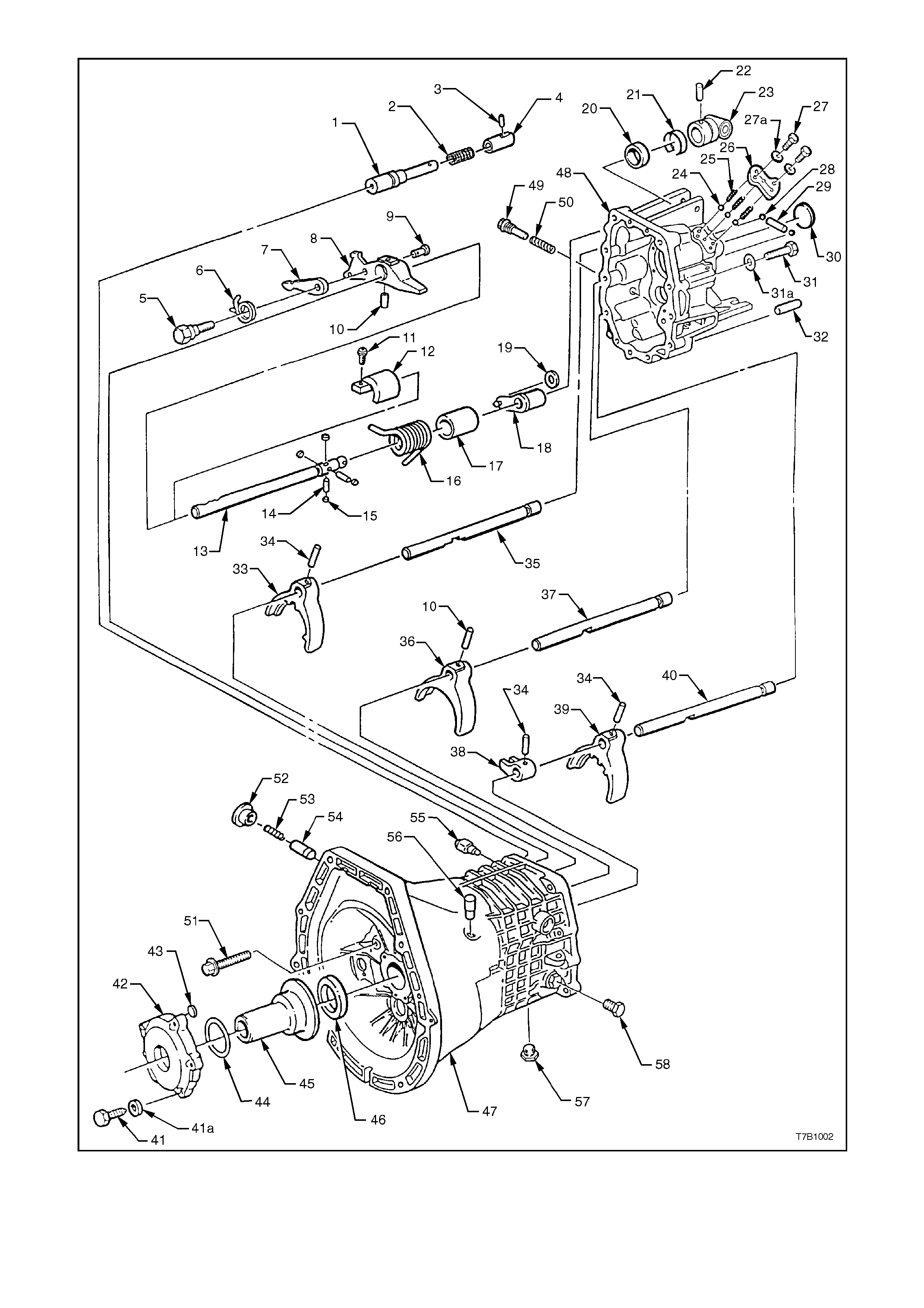
Figure 7B1-3 – Transmission Shift Mechanism and Case Components

Legend
1. Reverse blocker pin
2. Helical compressi on sprin g
3. Reverse blocker bushing, retainer pin
4. Reverse blocker bushing
5. Cap bolt
6. Cylindrical torsion spring
7. Reverse lock plate
8. Shift finger
9. Pin
10. Roll pin
11. Allen key head cap scr ew
12. Shift shaft support
13. Selector rod shift shaft
14. Dowel pin
15. Roller
16. Cylindrical torsion spring
17. Bushing
18. Select lever
19. Roller
20. Oil seal – shift shaft
21. Spring retaining clip
22. Selector rod trunnion pin
23. Selector rod trunnion
24. Detent ball - 3 places
25. Helical compression spring - 3 places
26. Cover plate
27. Bolt
27a. Wave washer
28. Interlock ball - 2 places
29. Interlock pin
30. Welsh plug
31. Bolt
31a. Wave washer
32. Dowel pin
33. Shift fork, 5th/Reverse
34. Roll pin
35. Selector shaft, 5th/Reverse
36. Shift fork, 3rd/4th
37. Selector shaft, 3rd/4th
38. Shift yoke, 1st/2nd
39. Shift fork, 1st/2nd
40. Selector shaft, 1st/2nd
41. Bolt
41a. Wave washer
42. Front housing cover
43. Disc
44. O-ring
45. Clutch throwout bearing guide
46. Oil seal
47. Front transmission housing
48. Rear transmission housing
49. Plug
50. Spring
51. Reverse blocker pin bolt
52. Plug
53. Spring
54. Detent plunger assembly
55. Back-Up lamp switch
56. Breather plug
57. Drain plug with magnet
58. Filler plug
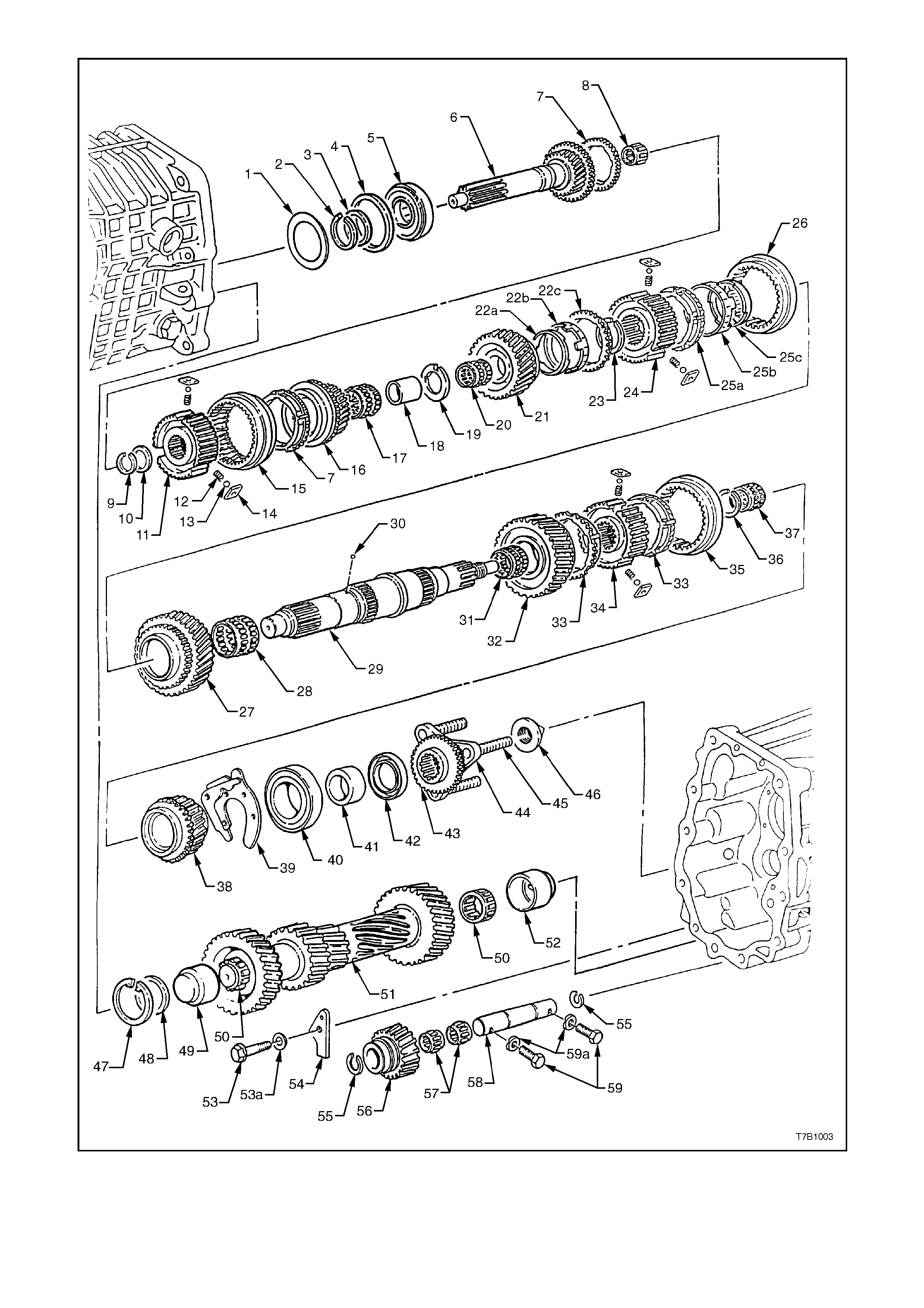
Figure 7B1-4 - Transmission Gear Components

Legend
1. Selective spacer washer
2. Snap ring
3. Selective spacer washer
4. Front bearing spacer ring
5. Front bearing
6. Input shaft and maindrive gear
7. Synchromesh ring
8. Caged, spigot needle rolle r bearing
9. Snap ring
10. Selective spacer washer
11. Synchromesh hub
12. Spring
13. Ball
14. Sliding key
15. Synchromesh outer sleeve
16. 3rd speed gear
17. Caged, needle roller bearing
18. Needle roller inner sleeve
19. Thrust washer
20. 2nd gear, needle roller bearing
21. 2nd speed gear
22a. Cone ring
22b. Friction ring
22c. Synchromesh ring
23. Snap ring
24. 1st/2nd speed synchromesh hub
25a. Synchromesh ring
25b. Friction ring
25c. Cone ring
26. Synchromesh outer sleeve
27. 1st speed gear
28. 1st speed, needle roller bearing
29. Mainshaft
30. Locating ball
31. Reverse gear, needle roller bearing
32. Reverse gear
33. Synchromesh ring
34. 5th/Reverse speed synchromesh hub
35. Synchromesh outer sleeve
36. Selective snap ring
37. 5th speed, needle roller bearing
38. 5th speed gear
39. Rear mainshaft bearing retainer plate
40. Rear mainshaft bearing
41. Spacer
42. Oil seal
43. Speed sens or toothed ring
44. Output flange
45. Knurled stud
46. Flanged retaining nut
47. Circlip
48. Support washer
49. Front cluster gear needle roll er bearing cup
50. Cluster gear needle roller bearing
51. Cluster gear
52. Rear cluster gear needle roller bearing cup
53. Bolt
53a. Wave washer
54. Thrust plate
55. Snap ring
56. Reverse idler gear
57. Caged needle roller bearings
58. Reverse idler gear shaft
59. Bolt
59a. Wave washer

1.2 POWER FLOWS
The maindrive gear, fifth, third, second, first speed and reverse gears are in constant mesh with the cluster gear.
Therefore, when the engine is running with the clutch engaged, torque is imparted to the maindrive gear and
through the cluster gear to the fifth, third, second, first speed and reverse gears at all times.
Refer to Figure 7B1-6 for illustrations relating to the following descriptions:
NEUTRAL
In neutral, with the clutch engaged, the maindrive gear turns the cluster gear. The cluster gear turns the constant
mesh gear s becaus e no s ynchr oniser as sem blies ar e enga ged. As all cons tant m esh gear s are s upporte d on r oller
bearings, they will also rotate with the cluster gear.
FIRST GEAR
In first gear , the firs t/secon d speed synchro niser sleev e is m oved rear ward to e ngage t he f irst speed g ear, which is
being turned by the cluster gear. Because the first/second speed synchroniser hub is splined to the mainshaft,
torque is imparted to the mainshaft from the first speed gear through the synchroniser sleeve and hub.
SECOND GEAR
In second gear, the first/second speed synchroniser sleeve is moved forward to engage the second speed gear,
which is being turned by the cluster gear. Because the first/second speed synchroniser hub is splined to the
mainshaft, torque is imparted to the mainshaft from the second speed gear through the synchroniser sleeve and
hub.
THIRD GEAR
In third gear, the first/second speed synchroniser sleeve assumes a neutral position. The third/fourth speed
synchroniser sleeve is moved rearward to engage the third speed gear, which is being turned by the cluster gear.
The engagement of the sleeve with the third speed gear, imparts torque to the mainshaft because the third/fourth
speed synchroniser hub is splined to the mainshaft.
FOURTH GEAR
In fourth gear, the third/fourth speed synchroniser sleeve is moved forward to engage the maindrive gear. This
engagement of the maindrive gear with the third/fourth synchroniser sleeve and hub assembly, imparts torque
directly to the mainshaft. While the cluster gear is still rotating, it does not impart torque to any component but
continues to lubricate the internal transmission components by the ‘splash’ method.
FIFTH GEAR
In fifth or overdrive gear, the first/second and third/fourth speed synchroniser sleeves assume neutral positions.
The fifth speed/reverse synchroniser sleeve is moved rearward to engage the fifth speed constant mesh gear,
supported on the mainshaft by a caged needle roller bearing. This engagement of the sleeve with the fifth speed
constant mesh gear, imparts torque from the cluster gear to the mainshaft, via the splined synchromesh hub.
REVERSE GEAR
In reverse gear, the fifth speed/reverse synchroniser sleeve is moved forward to engage the mainshaft reverse
gear and the cluster reverse gear, via the reverse idler gear. This imparts torque from the cluster reverse gear
through the idler gear (reversing direction of rotation) to the mainshaft reverse gear. Because the fifth
speed/reverse synchromesh hub is splined to the mainshaft, this causes the mainshaft to rotate in the opposite
direction to the maindrive gear.
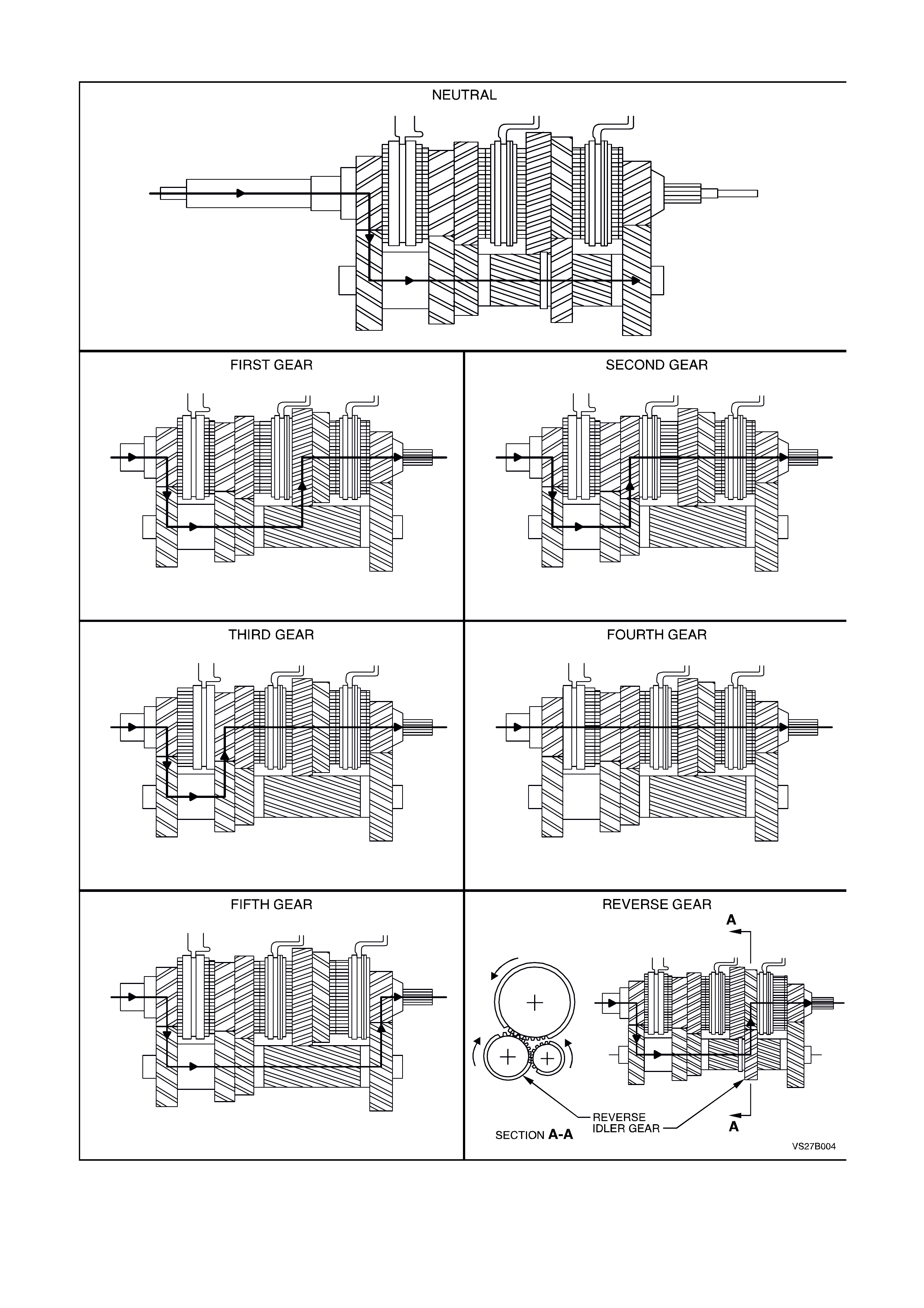
MA NUAL TRANSMISSION POWER FLOWS
Figure 7B1-5

1.3 TRANSMISSION SERIAL NUMBER
The transmission serial number is located on a
self-adhesive decal attached to the left side of the
transmission front housing.
This number provides coded information which is
significant to parts interpretation and should be
referred to when ordering replacement parts. For
example, the transmission part number has
changed to that shown.
Figure 7B1-6

2. SERVICING INFORM ATION
2.1 RECOMMENDED LUBRICANT
The recommended lubricant for the ‘260’ manual transmission is an 80W gear oil, such as Castrol VMX80W or
equivalent.
The transmission lubricant capacity is approximately 1.2 litres.
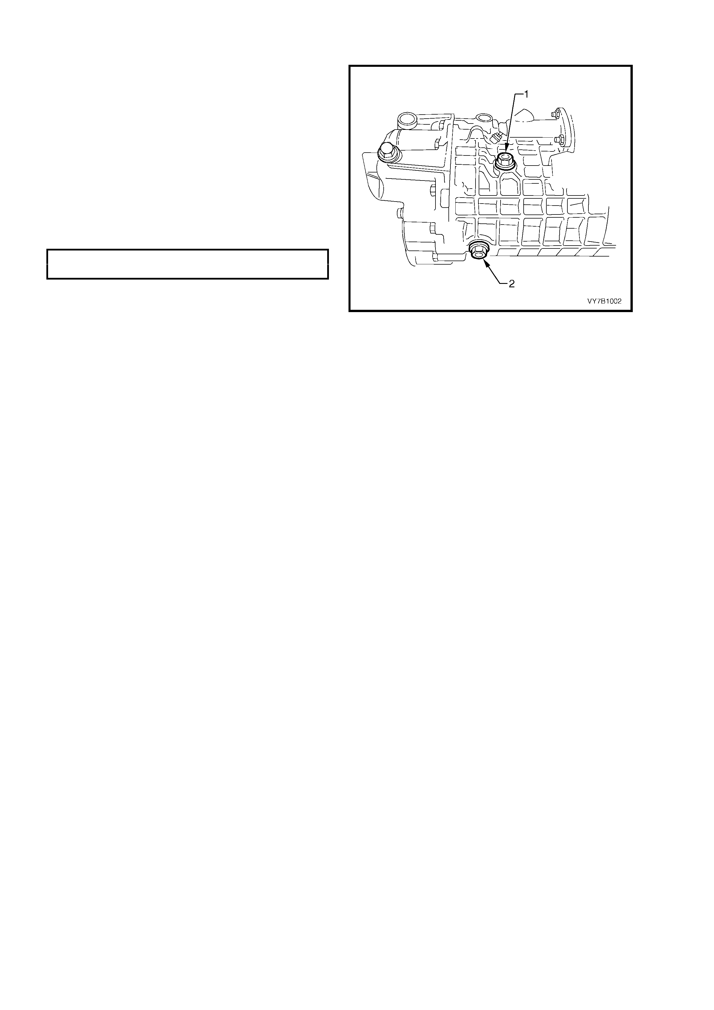
2.2 CHECKING TRANSMISSION LUBRICANT LEVEL
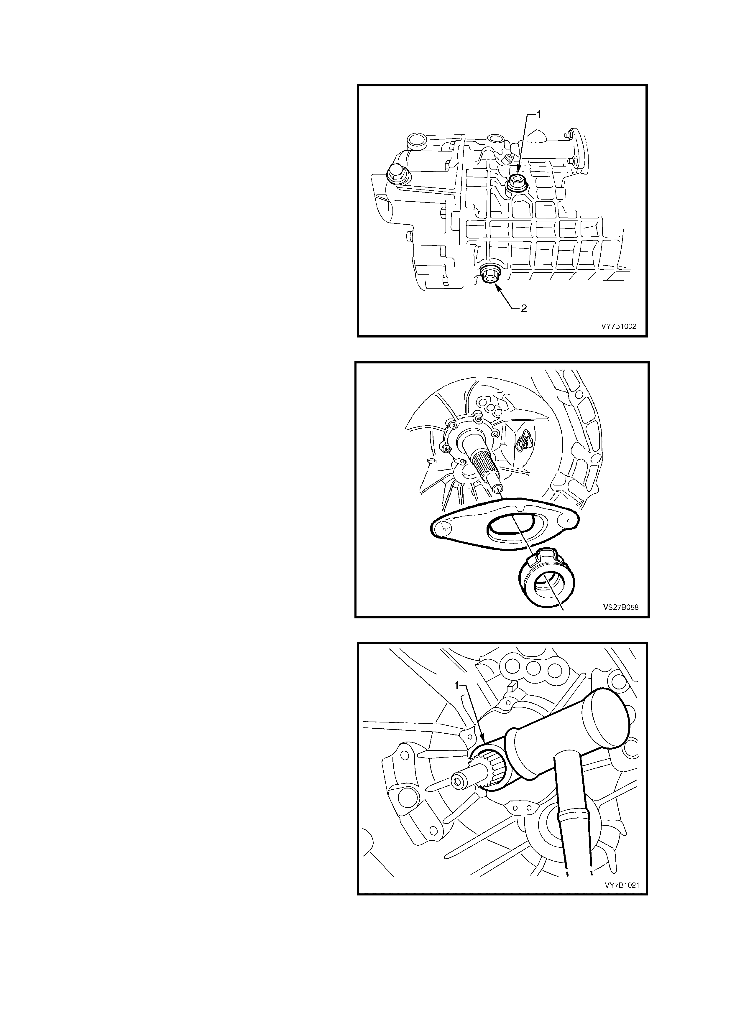
To check transmission lubricant level, remove
transmission filler plug (1), using a 17 mm ring
spanner, from right hand side of transmission case.
The level is correct when lubricant is level with the
filler plug threads.
NOTE: Ensure that the vehicle is on level ground
and transmission is cold.
If necessary, add lubricant to bring to the correct
level.
Reinstall filler plug (1) and tighten to the correct
torque s pecif icat ion. D o not ap ply thr ead s eala nt or
tape to the plug threads.
TRANSMISSION FILLER PLUG
TORQUE SPECIFICATION 50 Nm
Lubricant level is to be checked at the time or
distance intervals detailed in the MY 2003 VY and
V2 Series Owner's Handbook.
Figure 7B1-7

2.3 DRAINING AND REFILLING TRANSMISSION
W h ile the init ia l f ill of tr ans mission lubric ant is s pec if ie d as a ‘fill f or lif e’, s hou ld a lubr icant change be r eq uir e d, the n
the following pr ocedure should be ado pted .
1. To drain transmission, jack up vehicle front and rear and support on safety stands. Refer to
Section 0A GENERAL INFORM ATION, in the MY 20 0 3 V Y and V 2 Ser ies Ser vice Info rm ation, f or the loc a ti on
of jacking points.
2. Place a drain tray beneath transmission and remove filler plug and then drain plug using a 17 mm ring spanner.
3. When transmission has fully drained, insert drain plug and tighten to the correct torque specification. Do not
apply thread sealant or tape to the plug threads.
TRANSMISSION DRAIN PLUG
TORQUE SPECIFICATION 50 Nm
4. Refill transmission to correct level, refer 2.2 CHECKING TRANSMISSION LUBRICANT LEVEL in this Sec ti o n.

3. MINOR SERVICE OPERATIONS
3.1 BACK-UP LAMP SWITCH
LT SECTION NO. – 04M-075
REMOVE
1. Raise front of vehicle and support on safety
stands.
Refer to Section 0A GENERAL
INFORMATION, in the MY 2003 VY and V2
Series Service Information, for the location of
jacking points.
2. Remove wiring harnes s connector f rom switch,
located on the right hand side of the
transmission case.
3. Loosen, then remove switch from the
transmission case.
Figure 7B1-8
REINST ALL
1. Ensure that the switch threads are clean.
2. Reinstall switch to transmission case and
tighten to the correct torque specification.
BACK-UP LAMP SWITCH
TORQUE SPECIFICATION 20 Nm
3. Reinstall wiring harness connector to switch.
4. Remove safety stands and lower vehicle to
ground.
5. Check back-up lamp operation.
Figure 7B1-9
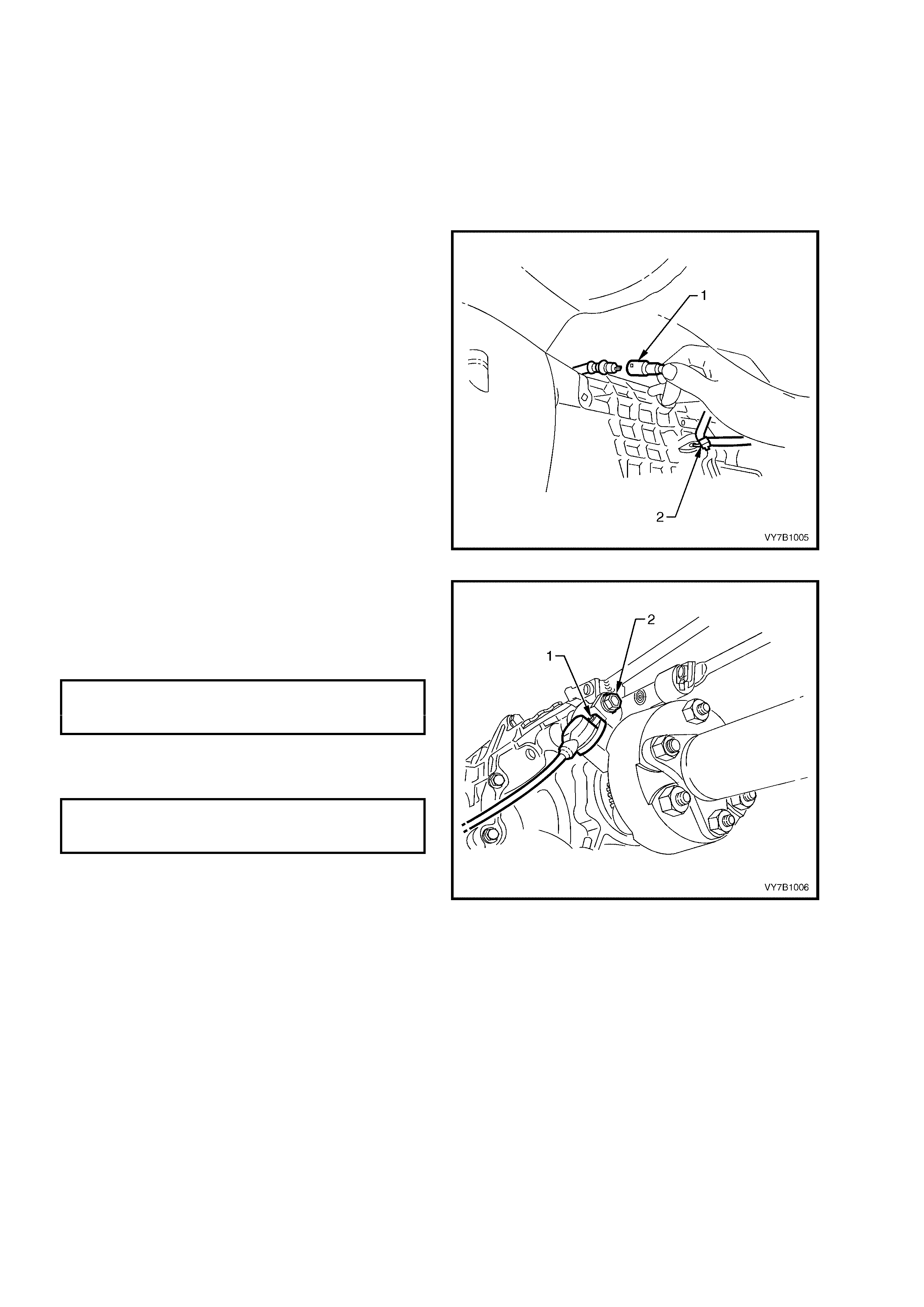
3.2 SPEED SENSOR AND/OR BRA CK ET
LT SECTION NO. – 04M-075
REPLACE
1. Jack up vehicle front and rear and support on
safet y st ands. Refer to Section 0A G ENER AL
INFORMATION, in the MY 2003 VY and V2
Series Service Information, for the location of
jacking points.
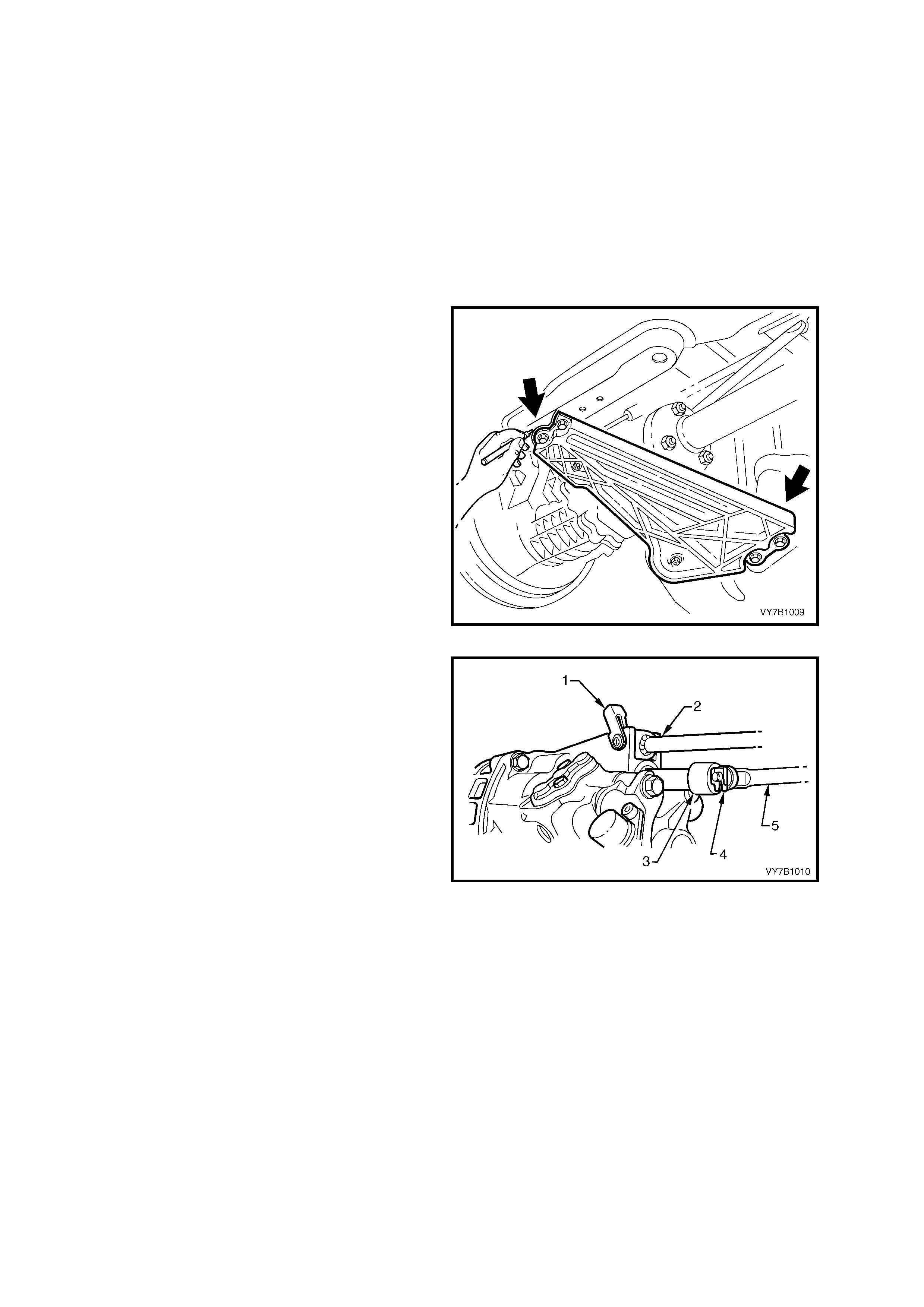
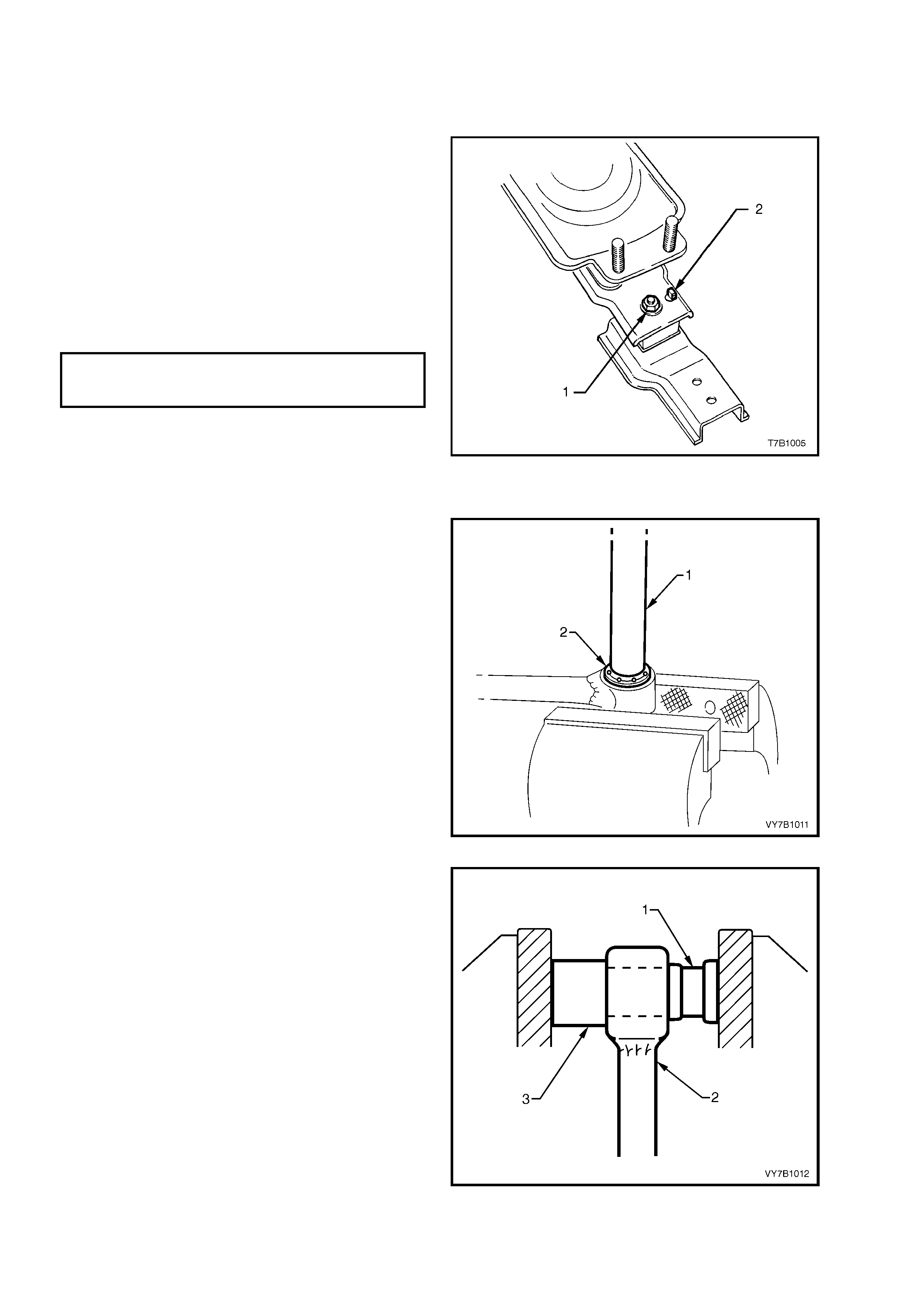
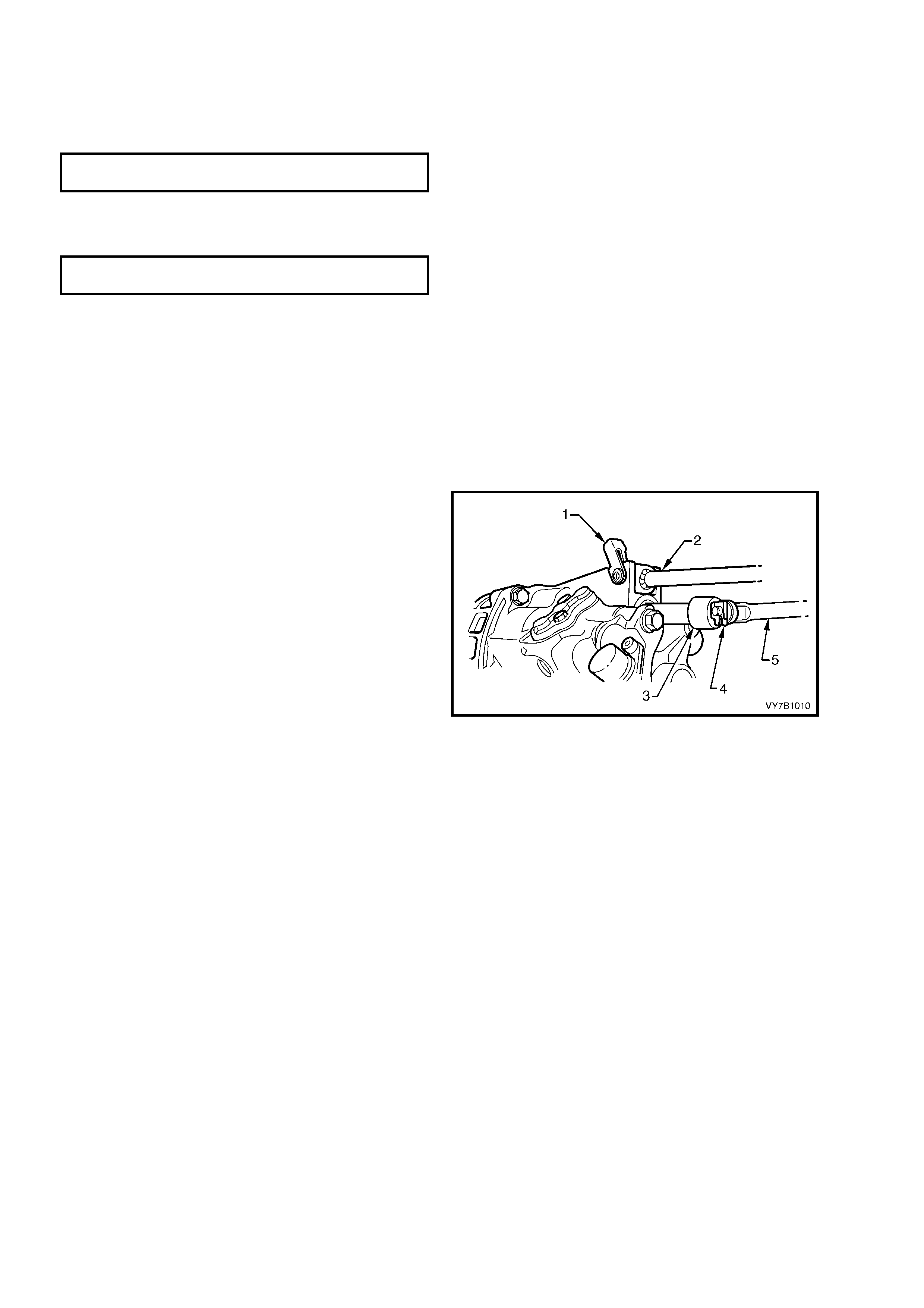
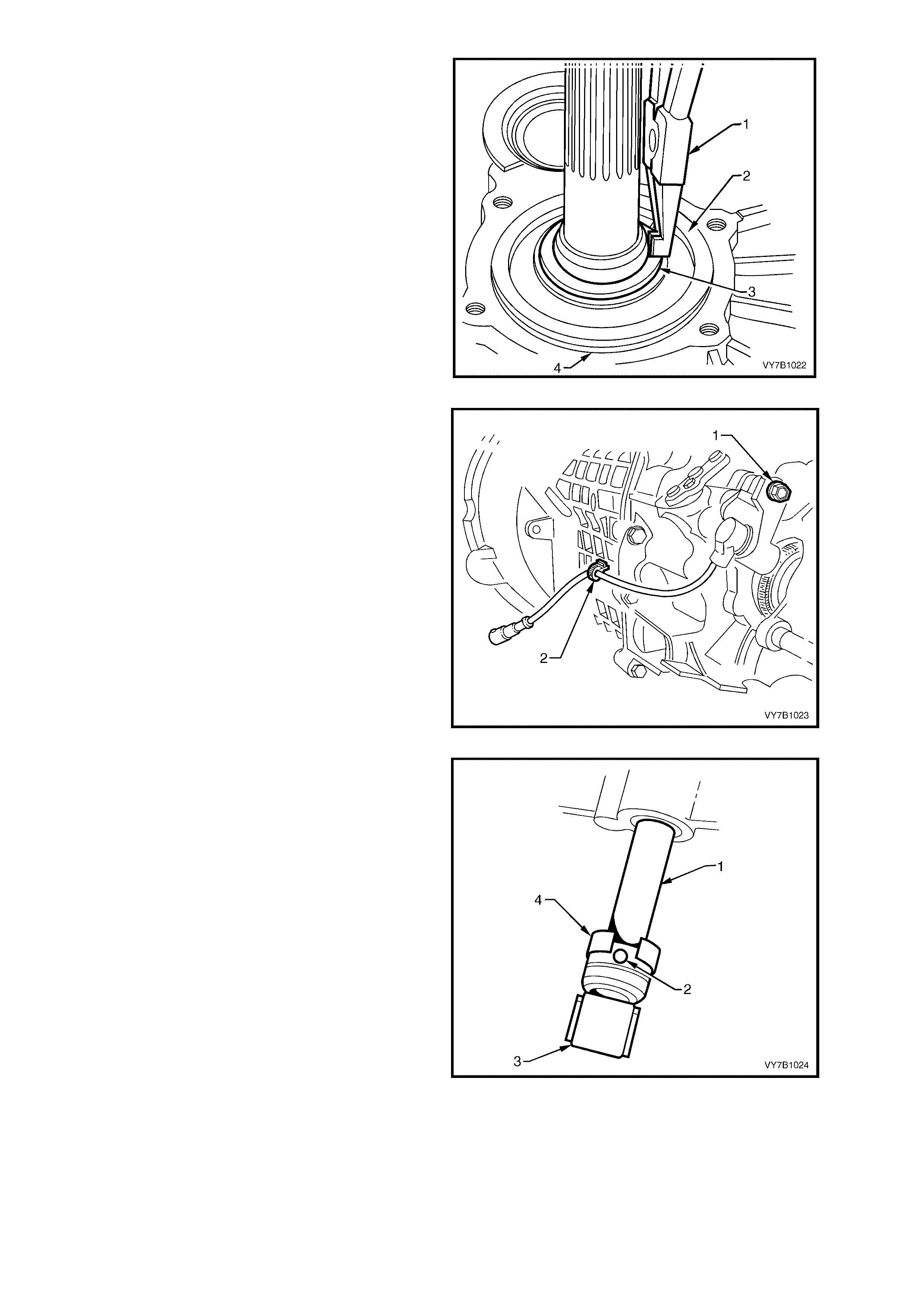
2. Disconnect speed sensor wiring harness
connector (1).
3. Cut the speed sensor wiring harness strap (2)
from the lug on the transmission case.
4. Remove speed sensor mounting bracket bolt
from the rear of the transmission housing.
5. Remove the brac k et and s ens or as s em bly from
the rear transmission housing.
6. Remove the s ens or to brac ket m ounting s cr ew,
then disconnect the sensor by a twisting and
pulling motion to free the O-ring seal from the
bracket
Figure 7B1-10
7. Reinstallation is the reverse of removal except
for the following points;
a. Tighten the speed sensor to mounting
bracket retaining screw (1) to the correct
torque specification.
SPEED SENSOR
TO BRACKET SCREW
TORQUE SPECIFICATION 10 Nm
b. Tighten the sensor brack et to transmission
housing mounting bolt (2) to the correct
torque specification.
SPEED SENSOR BRACKET TO
TRANSMISSION HOUSING BOLT
TORQUE SPECIFICATION 18 Nm
c. Connect the speed sensor lead to the
wiring harnes s c onnec t or, e nsur ing th at the
connection is posi tive and secur e.
d. Sec ure the spee d sensor wiring harness to
the lug on t he transm ission using a ne w tie
strap.
Figure 7B1-11
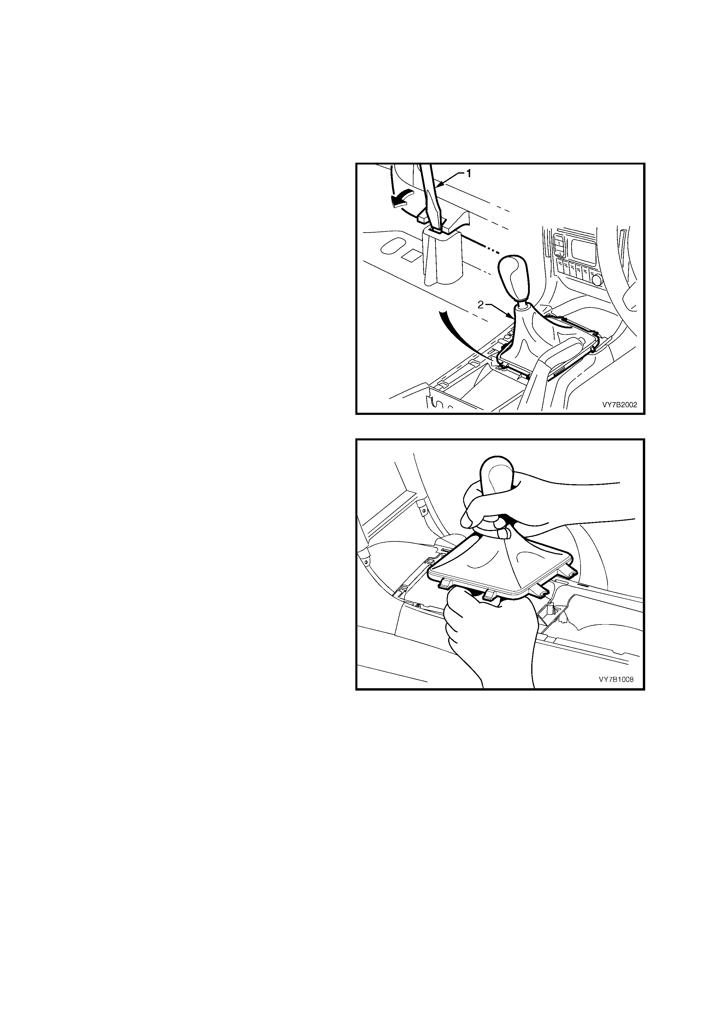
3.3 GEARSHIFT LEVER KNOB AND BOOT ASSEMBLY
LT SECTION NO. – 04M-060
NOTE: The gearshift lever knob and gearshift boot are manufactured as a single component. Do not attempt to
separate t he gearshif t lever knob from the boot. The knob and bo ot assem bly can however , be replac ed, using th e
follo wing proc ed ur e.
REMOVE
1. Remove the floor console cover assembly.
Refer 2.1 FLOOR CONSOLE COVER
ASSEMBLY, in Section 1A3 INSTRUMENT
PANEL & CONSOLE, in the MY 2003 VY and
V2 Series Service Information.
2. Using a fine bladed screwdriver, release each
locking tab, while exerting an upward force on
the boot carrier. Lift the gearshift boot retainer
free from the floor console.
Figure 7B2-12
3. Lift the ge arshift lever boot enough to e nable a
firm grasp to be made on the gearshift lever
with the left hand, then grasp the gearshift
knob with the right.
4. While rocking the knob sideways, and with an
upward force applied, dislodge the knob
retaining claws from the lever.
5. Remove the gearshift lever knob and boot
assembly, from the gearshift lever.
Figure 7B1-13
REINST ALL
1. Reinstall the k nob and boot assembly over the
gearshift lever, align the knob in the correct
attitude and then bump the knob onto the
gearshift lever until the reta ining claws engage
with the groove in the le ver .
2. Align the boot retaining clips with the hole in
the console cap, then carefully seat the boot
retainers into the console cap until each clip
engages correctly.
3.4 GEARSHIFT LEVER
LT SECTION NO. – 04M-060
REMOVE
1. Remove the gearshift lever knob and boot
assembly, from the gearshift lever. Refer
3.3 GEARSHIFT LEVER KNOB AND BOOT
ASSEMBLY, for the necessary procedure.
2. Raise vehicle front and rear and support on
safet y st ands. Refer to Section 0A G ENER AL
INFORMATION, in the MY 2003 VY and V2
Series Service Information, for the location of
jacking points.
3. Scribe around each of the rear engine
mounting crossmember mounting points to the
vehicle underbody, to provide an alignment
reference for reassembly.
IMPORTANT: This step is critical to the correct
powertrain alignment on reassembly. If not carried
out, then vehicle vibration and/or handling
problems may result!
NOTE: For c larity, the exhaus t system is sho wn as
having already been removed.
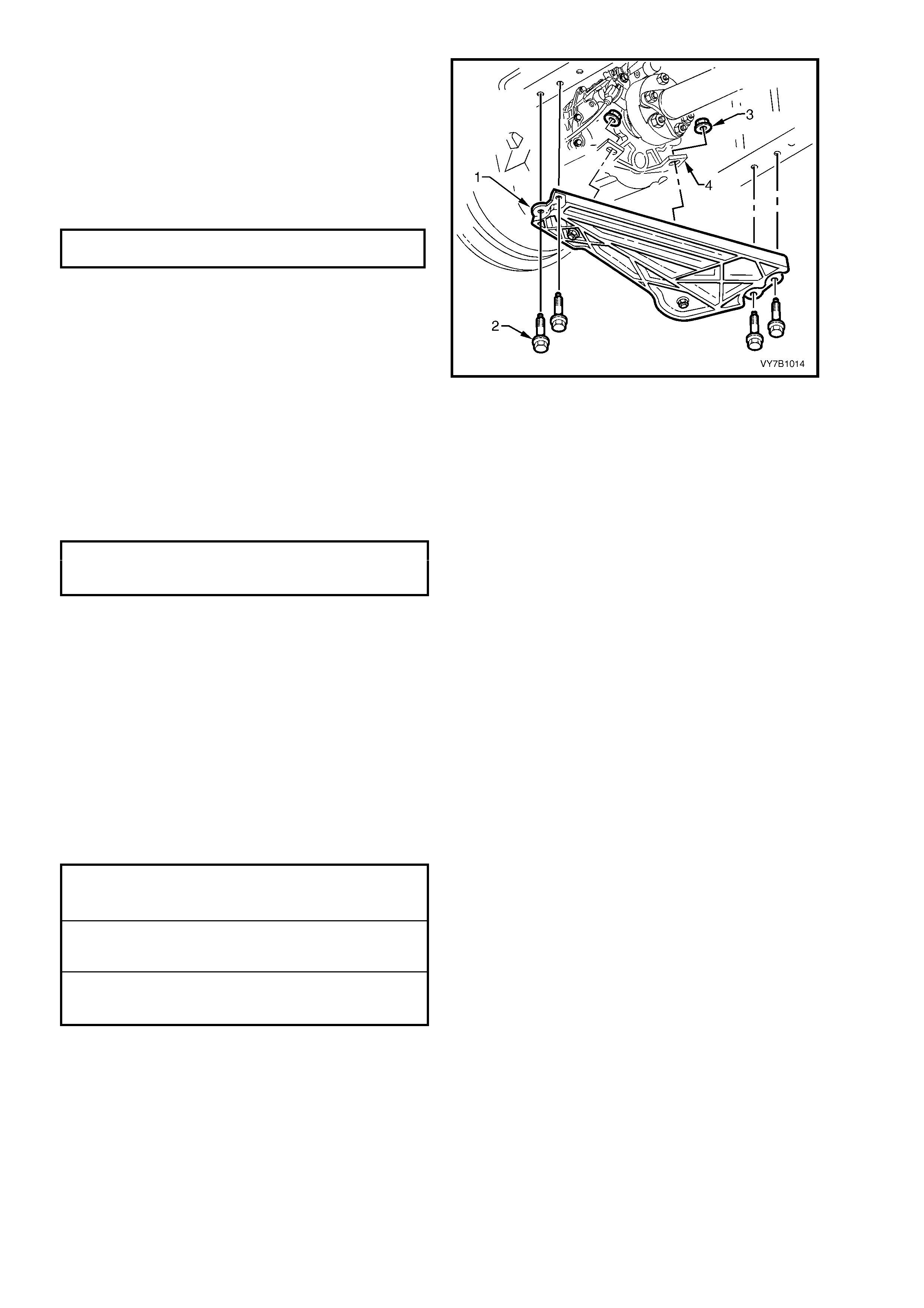
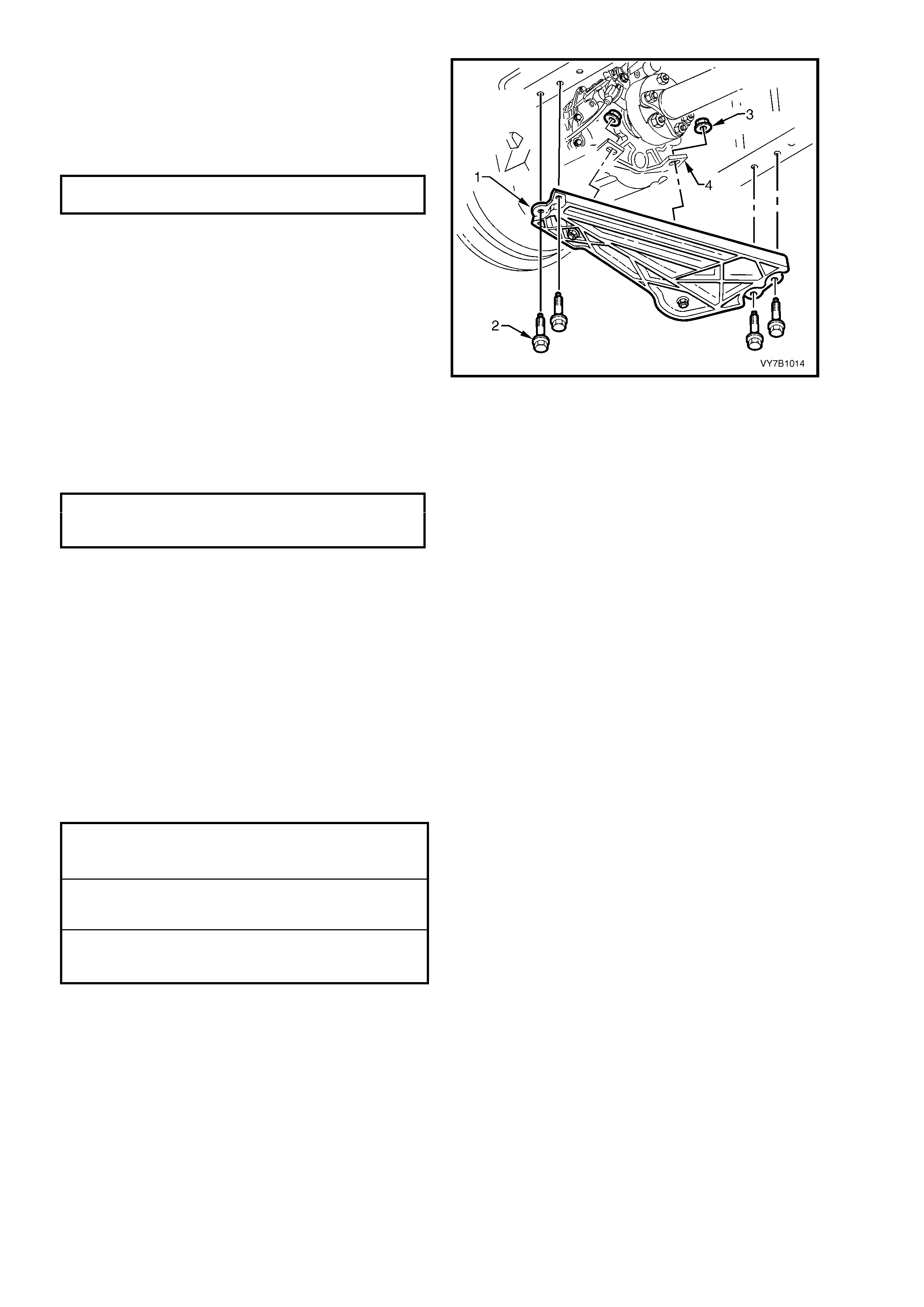
4. Support the rear of the transmission with a
floor jack, then remove the four rear engine
mounting crossmember bolts.
Figure 7B1-14
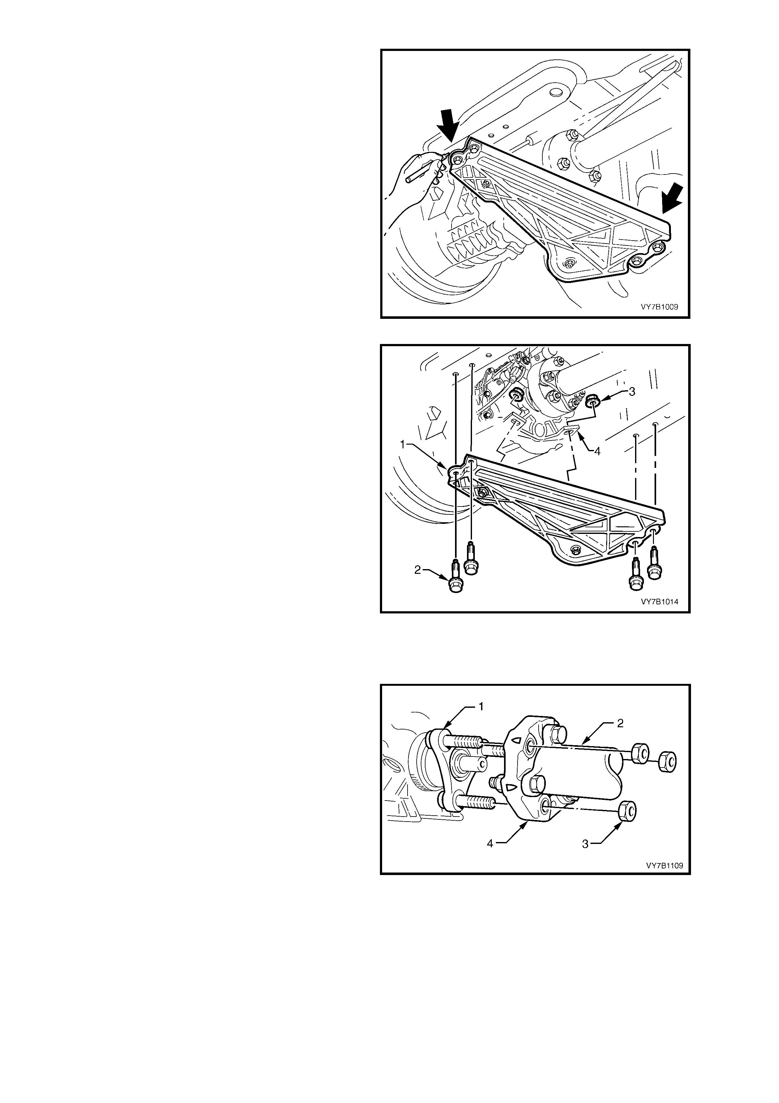
5. Lower t he rear of the trans mission, s ufficient to
gain acces s to th e front end of th e shif t linkage
brace (2).
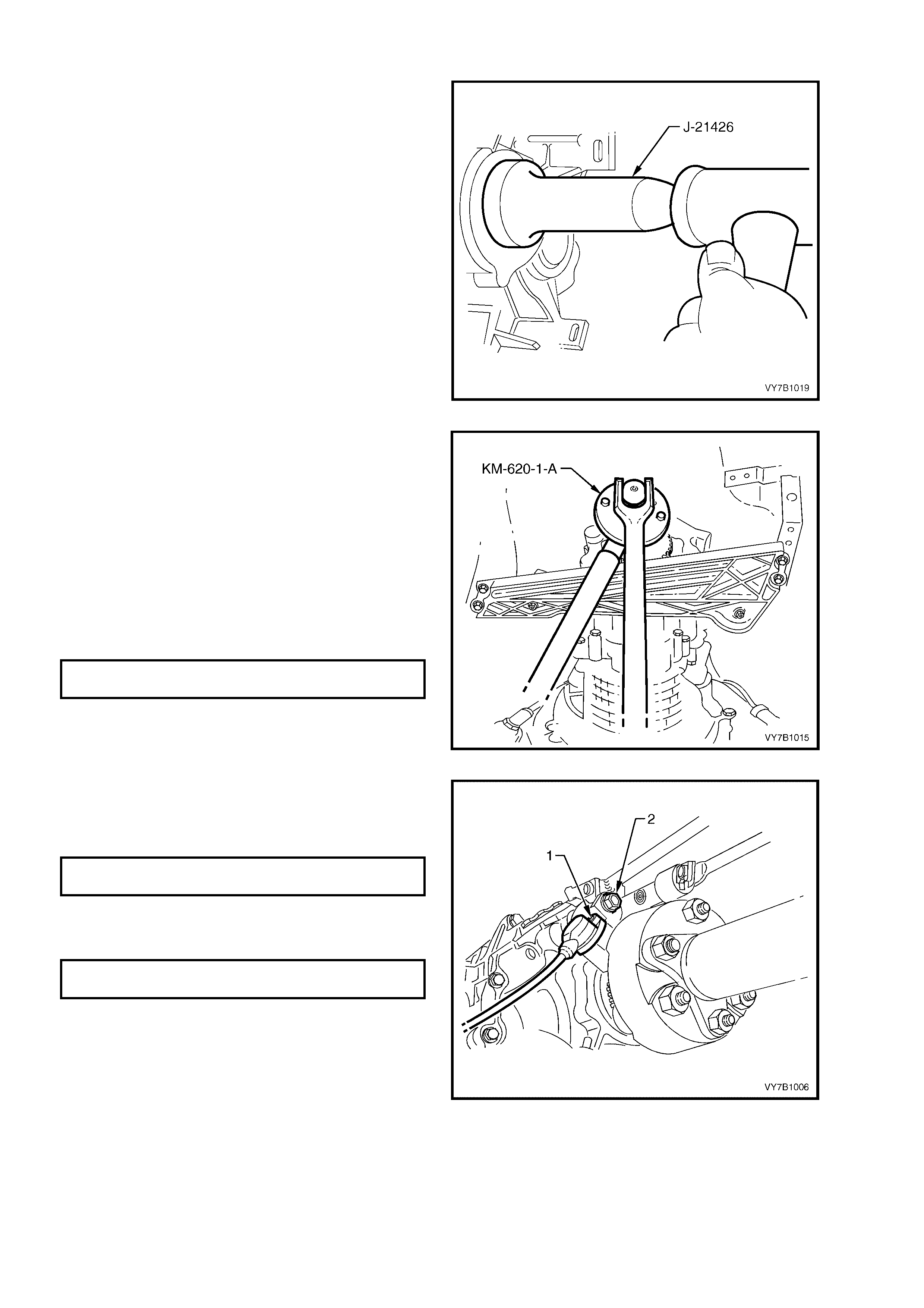
6. From under vehicle, prise the shift linkage
brace retainer (1) loose, at the transmission
end, using a screwdriver or suitable lever.
7. Remove the retainer and pin (1) from the
transmission case lugs.
NOTE: While the shift rod can be removed at this
time, by removing the clip (4) and a flat washer
before sliding the shift rod from the trunnion (3), it
is pref err ed that th e s hif t r o d be removed i n st ep 1 1
of this procedure.
Figure 7B1-15
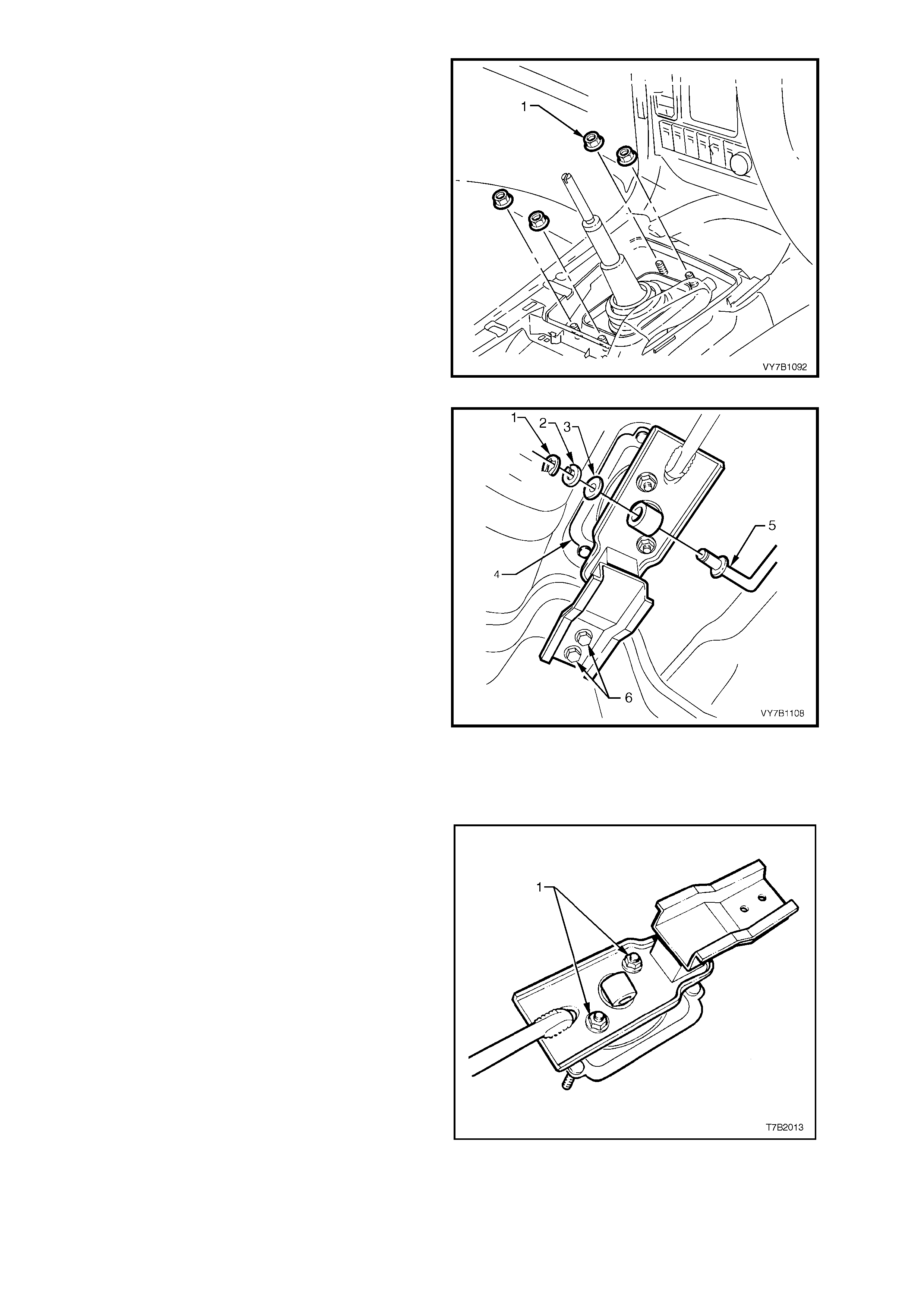
8. Remove the four gearshift lever bracket,
mounting nuts (1 from inside the vehicle.
Figure 7B1-16
9. Remove the retaining C-clip (1), then the
spring and flat washers (2 and 3) from the
transmission shift rod coupling (5), at the
gearshift lever end.
CAUTION: to prevent possible eye damage
when removing the C-clip, wear suitable eye
protection.
10. Remove two gearshift lever support mounting
bolts (6) from underfloor bracket.
11. Remove gear sh ift le ver bra cke t (4), with ru bber
boot and the complete brace assembly, from
below the vehicle.
NOTE 1: If the s hift rod was disconnecte d from the
transmission end and removed from the vehicle,
take particular note of the rod’s orientation for
correct installati on.
NOTE 2: While the illustration shows the propeller
shaft and exhaust removed for clarity, removal of
the brace assembly from the vehicle, is possible
without first removing these items.
Figure 7B1-17
DISASSEMBLE
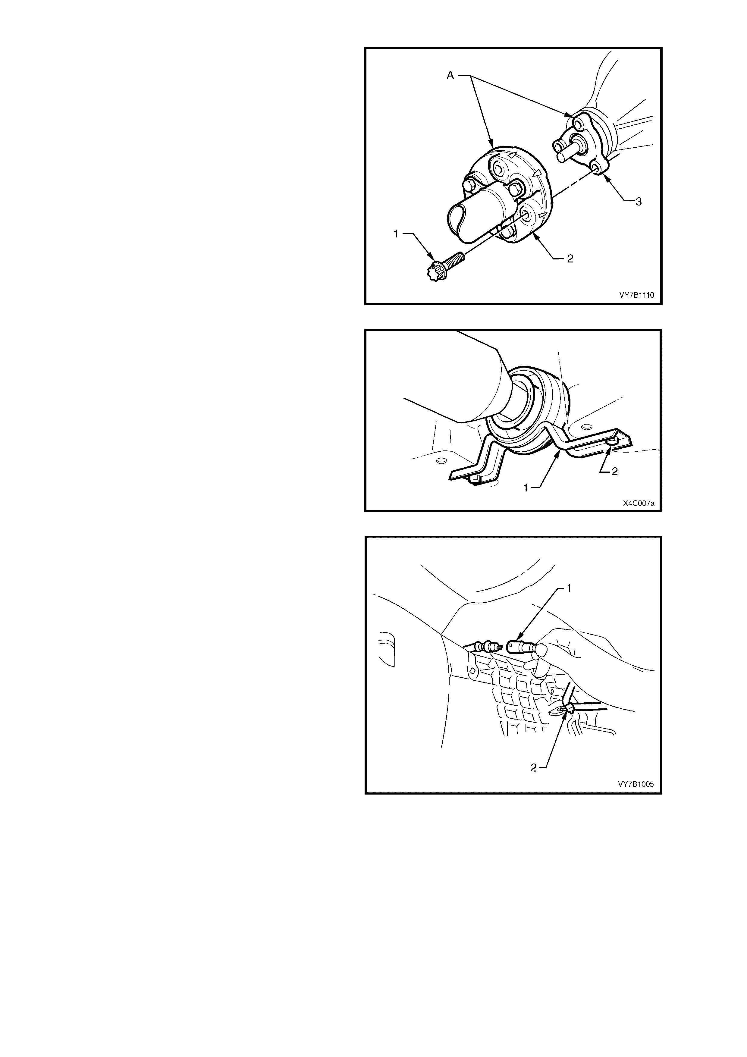
1. Remove both nuts (1) securing the gearshift
lever ball socket retainer, to the mounting
brace.
2. Remove retainer and gearshift lever assembly
from the brace.
Figure 7B1-18
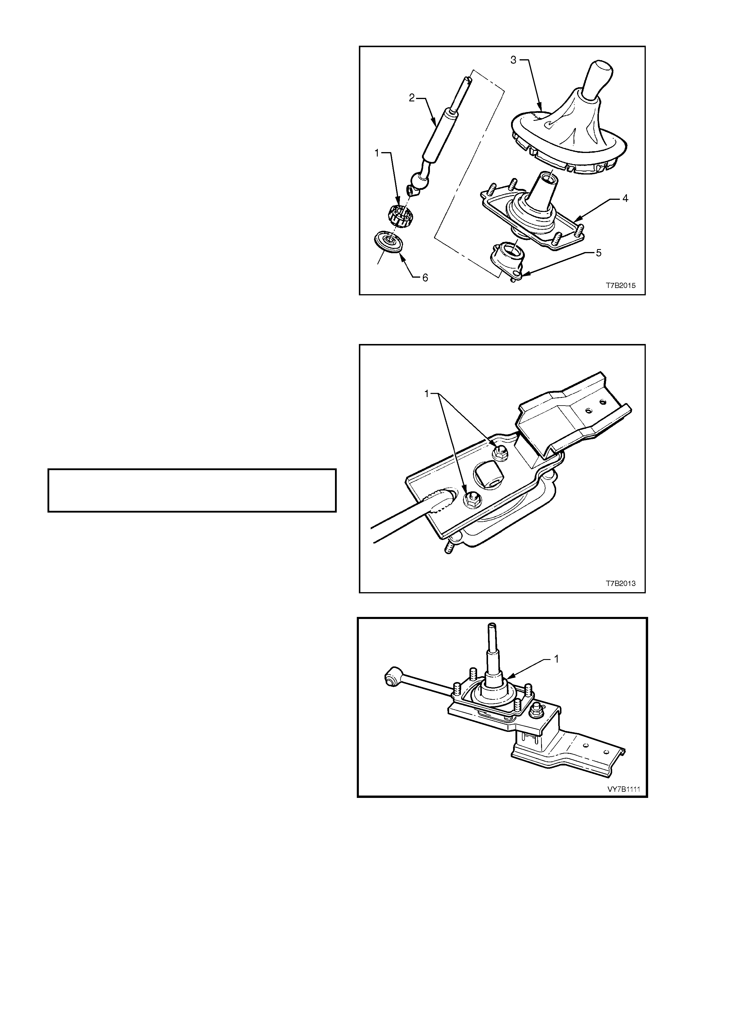
3. Remove the boot and mounting bracket
assembly (4), from the gearshift lever (2).
4. Separate the assembly by holding the bearing
cover (5) and gently bump the end of the
gearshif t lever (2) , to dis place the end plat e (6)
and bearing (1) from the ball of the gearshift
lever.
5. Inspect all components for wear and/or
damage, replacing parts as required.
Figure 7B1-19
REASSEMBLE
Reassembly operations are the reverse of
disassembly, except for the following items.
1. Lubricate the gearshift lever ball and socket
with Lithium grease NLGI No. 4 EP.
2. Reinstall the gearshift lever ball and socket
retainer to the brace, fit the two retaining nuts
(1) and tighten to the correct torque
specification.
GEARSHIFT BALL SOCKET
RETAINER PLATE NUTS
TORQUE SPECIFICATION 10 Nm
Figure 7B1-20
3. Reinstall the rubber gearshift boot (1) over the
gearshift lever as shown.
Figure 7B1-21
REINST ALL
1. Reinstall gearshift lever assembly (1) into
position, aligning studs with the holes in the
floor pan and the bolt holes in the rubber
mounting, with the captive nuts on the
underbody.
2. Reinstal l gearshif t lever brac e rubber mount ing
bolts (2) and tighten to the correct torque
specification.
GEARSHIFT LEVER BRACE, RUBBER
MOUNTING BRACKET BOLT
TORQUE SPECIFICATION 10 Nm
3. From inside the vehicle, install and tighten the
four, brace (1) to underfloor retaining nuts,
tightening to the correct torque specification.
GEARSHIFT LEVER BRACKET TO
UNDERFLOOR RETAINING NUT
TORQUE SPECIFICATION 10 Nm
Figure 7B1-22
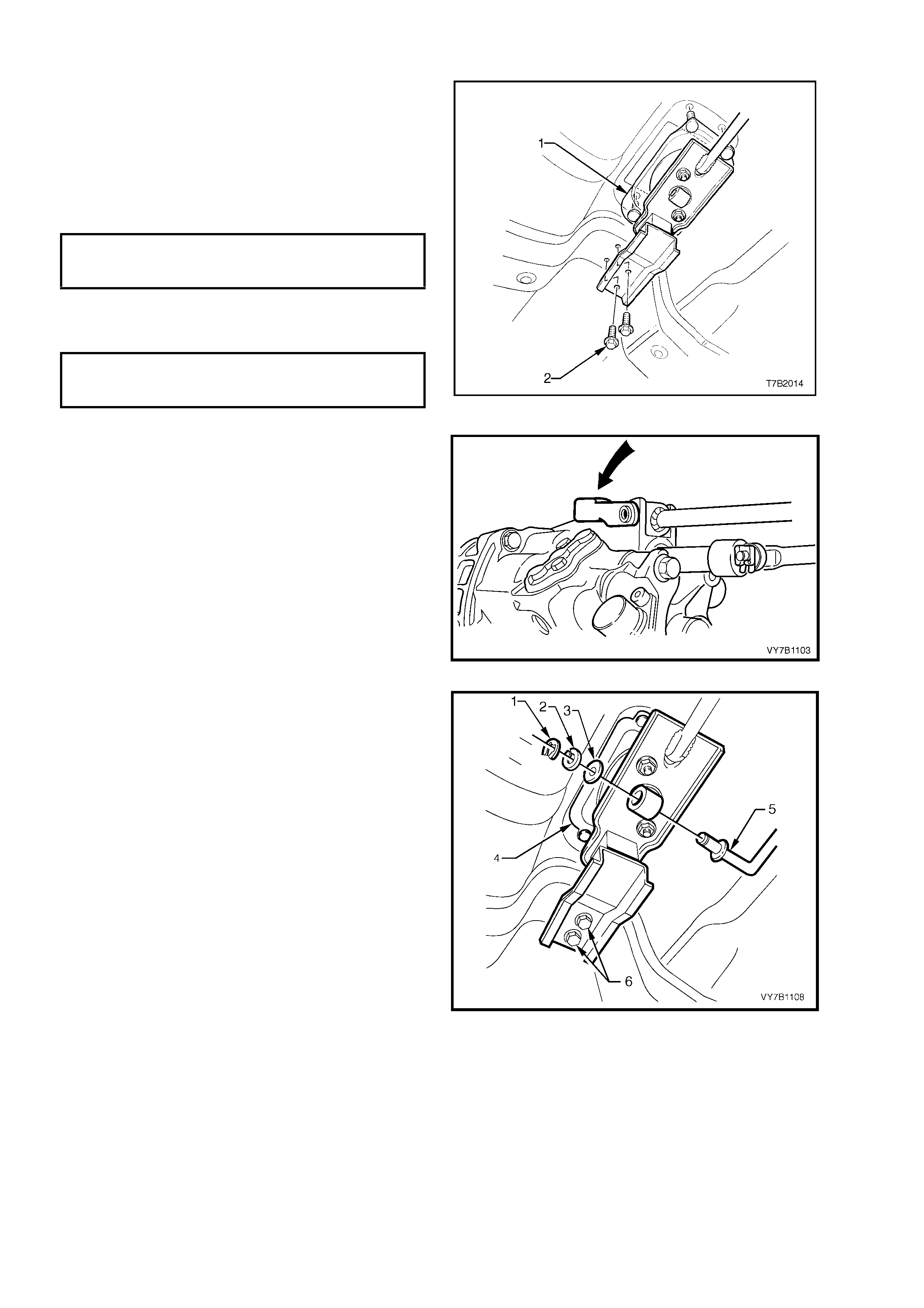
4. Install gearshift brace pin and retainer to the
transmission end, ens uri ng that t he s ec ur ity lug
is firmly in place.
Figure 7B1-23
5. Reinstall gearshift linkage (5) to the lower end
of the gearshift lever, then install the flat
washer (3), spring washer (2) and C-clip (1).
NOTE: Ensure that the linkage is only assembled
in the attitude shown. If fitted in the reverse
directi on, the li nkage m ay foul, r esultin g in d ifficu lty
with 2nd gear selection that can cause damage to
the transmission.
6. Remove safety stands and lower vehicle to
ground.
7. Reinstall gearshift lever knob/boot assembly.
Refer to 3.3 GEARSHIFT LEVER KNOB AND
BOOT ASSEMBLY in this Section, for specific
details.
8. Road test vehicle to check gears hif t operat ion.
Figure 7B1-24
ADJUST
No adjustment of the gearshift linkage is required.
3.5 SHIFT LINKAGE BRACE RUBBER MOUNTING AND/OR BUSH
LT SECTION NO. – 04M-060
REPLACE
1. Remove the gearshift lever and brace
assembly from the vehicle, as detailed in
3.4 GEARSHIFT LEVER in this Section.
Brace Mount in g
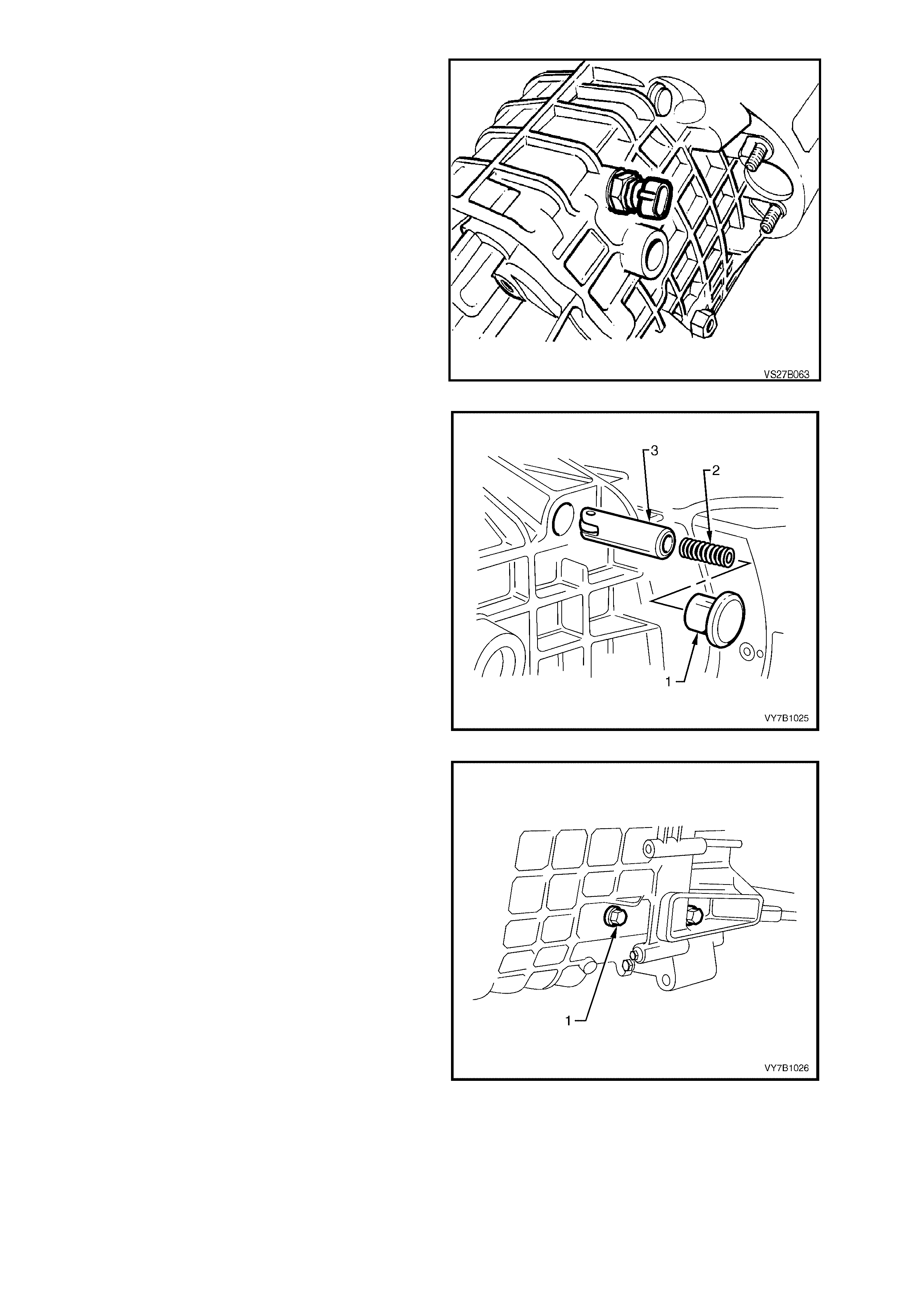
2. Remove the rubber mounting from the rear of
the gearshift lever support after removing the
retaining nut (1).
3. F it the rear m ounting to th e br ace, ins erting t he
locating tang (2) in the hole provided. Install
the retaining nut (1) and tighten to the correct
torque specification.
REAR GEARSHIFT LINKAGE
RUBBER MOUNTING NUT
TORQUE SPECIFICATION 22 Nm
Figure 7B1-25
Brace Bush
4. Using a suitable sized pin punch (1) and
hammer, remove the rubber bushing (2) from
the transmission end of the brace assembly,
clamping the eye of the brace between
protected vice jaws.
Figure 7B1-26
5. Using a suitable sized piece of tubing (2) (or
socket), over the end of th e brace eye (2), use
the clamping effect of a bench vice to install
the replacement rubber bush (1).
NOTE: Dip the replacement bushing (1) in a soap
solution to assis t in the ins t all ation pr oc ess .
6. Reinstal l the brace and gear shift assem bly into
the vehicle, as detailed in 3.4 GEARSHIFT
LEVER in this Section.
Figure 7B1-27
4. MAJOR SERVICE OPERATIONS
4.1 SPEED SENSOR TOOTHED RING OR TRANSMISSION CASE REAR SEAL
LT SECTION NO. – 04M-100
REMOVE
1. Disconnect battery ground lead.
IMPORTANT: Disconnection of the battery affects
certain vehicle electronic systems. Refer to
Section 00 CAUTIONS, 5. Battery Disconnection
Procedures before disconnecting the battery.
2. Raise front and rear of vehicle, supporting on
safet y st ands. Refer to Section 0A G ENER AL
INFORMATION in the MY 2003 VY and V2
Series Service Information, for the location of
jacking and support points.
3. Disconnect wiring harness connectors from
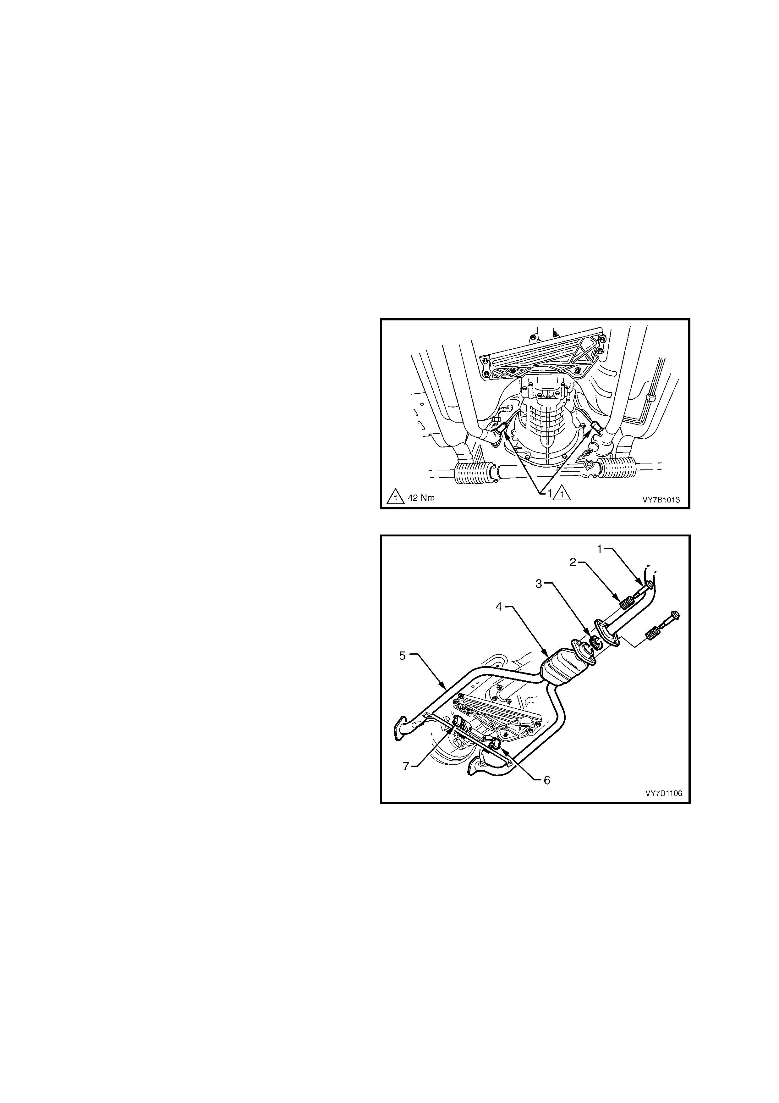
each of the two oxygen sensors (1).
Figure 7B1-28
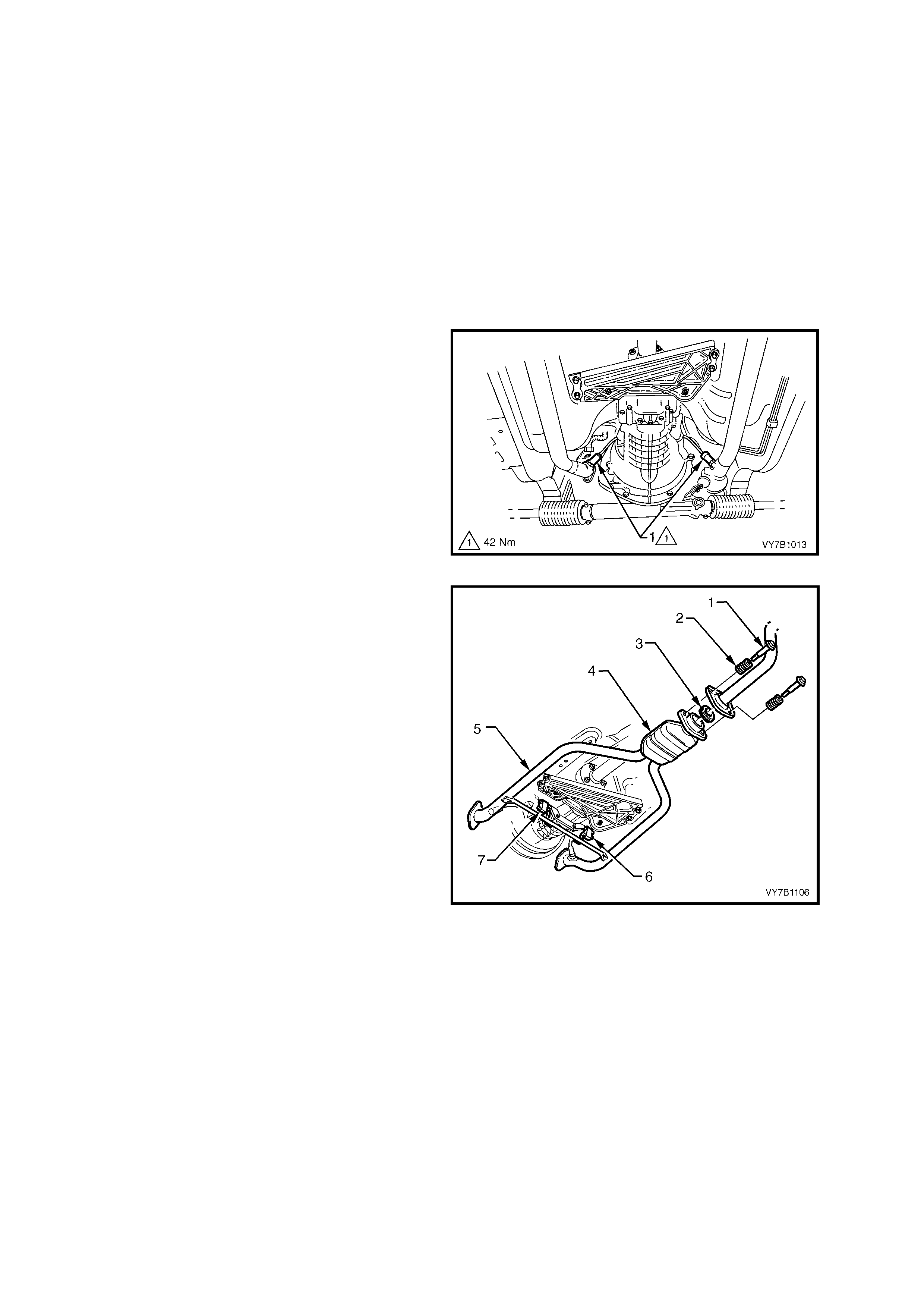
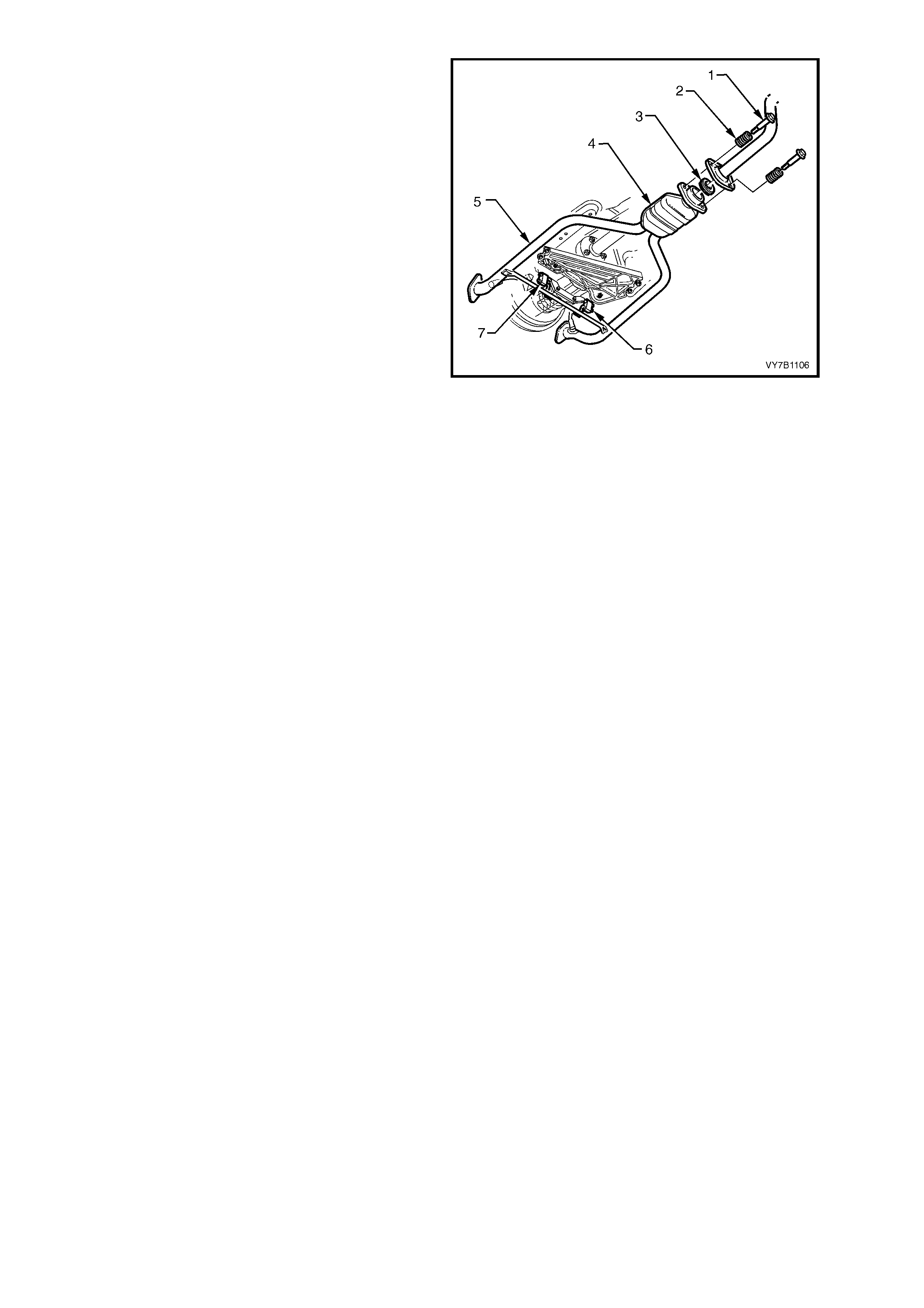
4. Remove the intermediate pipe to catalytic
convert er bolts (1), s prings (2) and sealing r ing
(3).
5. Remove the exhaust pipe flange to exhaust
manifold nuts from each side (not shown in
Figure 7B1-29) .
6. While supporting the twin exhaust pipes (5)
and catalytic converter assembly (4), remove
the support rubbers (6 and 7) from the rear of
the transmission.
7. Carefully lower and remove the exhaust pipes
from the veh icle, tak ing car e not to dam age the
exhaust gas oxygen sensors, in the process.
Figure 7B1-29
8. Scribe around each of the rear engine
mounting crossmember mounting points to the
vehicle underbody, to provide an alignment
reference for reassembly.
IMPORTANT: This step is critical to the correct
powertrain alignment on reassembly. If not carried
out, then vehicle vibration and/or handling
problems could result.
Figure 7B1-30
9. Support weight of transmission assembly on a
suitable jack.
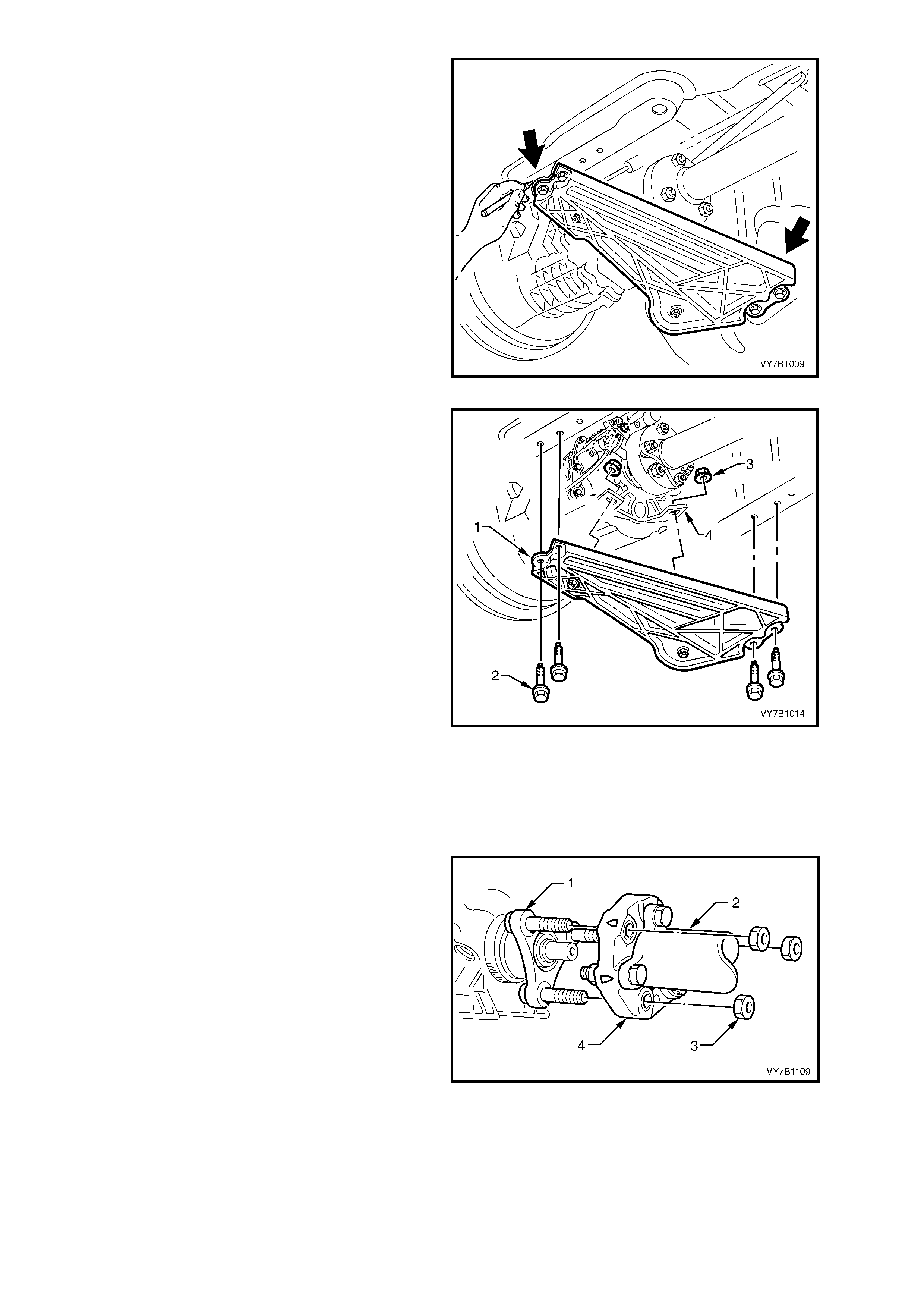
10. Remove engine rear crossmember to side
frame attaching bolts (2).
11. Lower the rear of the transmission assembly,
enough to gain access to the two mount to
transmission case lug, nuts (3). Before
loosening the nuts scribe an alignment mark, to
ensure that the mounts are reinstalled in the
same position.
IMPORTANT: Failure to take note of the mount
positions before loosening the retaining nuts (3),
could cause driveline vibration problems, once the
vehicle is placed back in service.
12. Rem ove th e re ar m ount att achin g nuts ( 3) fr om
the transmission rear case mounting lugs (4),
then remove the crossmember and mount
assemblies (1) from the vehicle.
NOTE: Illustrat ion does not sho w trans m ission jac k
in position, for clarity of the crossmember
orientati on.
Figure 7B1-31
13. Remove propeller shaft (2) flexible rubber
coupling (4) to mainshaft flange (1) attaching
nuts (3).
Figure 7B1-32
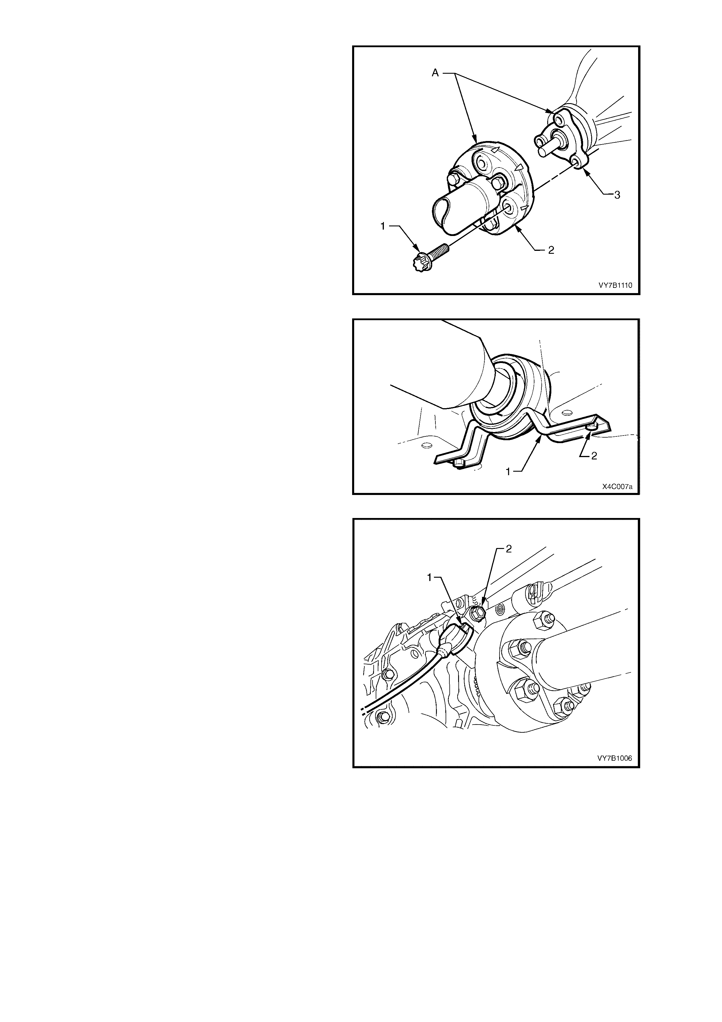
14. W ith the transm ission in first gear and the park
brake firmly applied, use Torx socket
K04425E20 or a commercially available E20
Torx socket to loosen the three Torx headed
bolts (1) securing the propeller shaft rear
rubber coupling (2) to the pinion flange (3).
15. Release the park brake and select neutral, to
relieve any torque loading on the rubber
coupling, then remove the three Torx headed
bolts (1)
NOTE: To enable the propell er shaft to be install ed
in the original position relative to the pinion flange,
use a felt tipped pen or similar to identify the
relationsh ip (‘A’) of the t wo components before bo lt
removal.
Figure 7B1-33
16. Remove the two centre bearing carrier (1) to
underbody reinforcement bolts (2).
17. While supporting the centre bearing section,
lower the c entre b earing an d slide t he pro peller
shaft assembly forward to disengage from the
final drive pinion support pin.
18. Lower the assembly at the rear, sliding
rearward to remove from the rear of the
transmission.
Figure 7B1-34
19. Remove the speed sensor bracket retaining
bolt (2) from the rear of the transmission,
remove the sensor (1) and bracket and secure
to the underbody with a piece of tie wire.
Figure 7B1-35
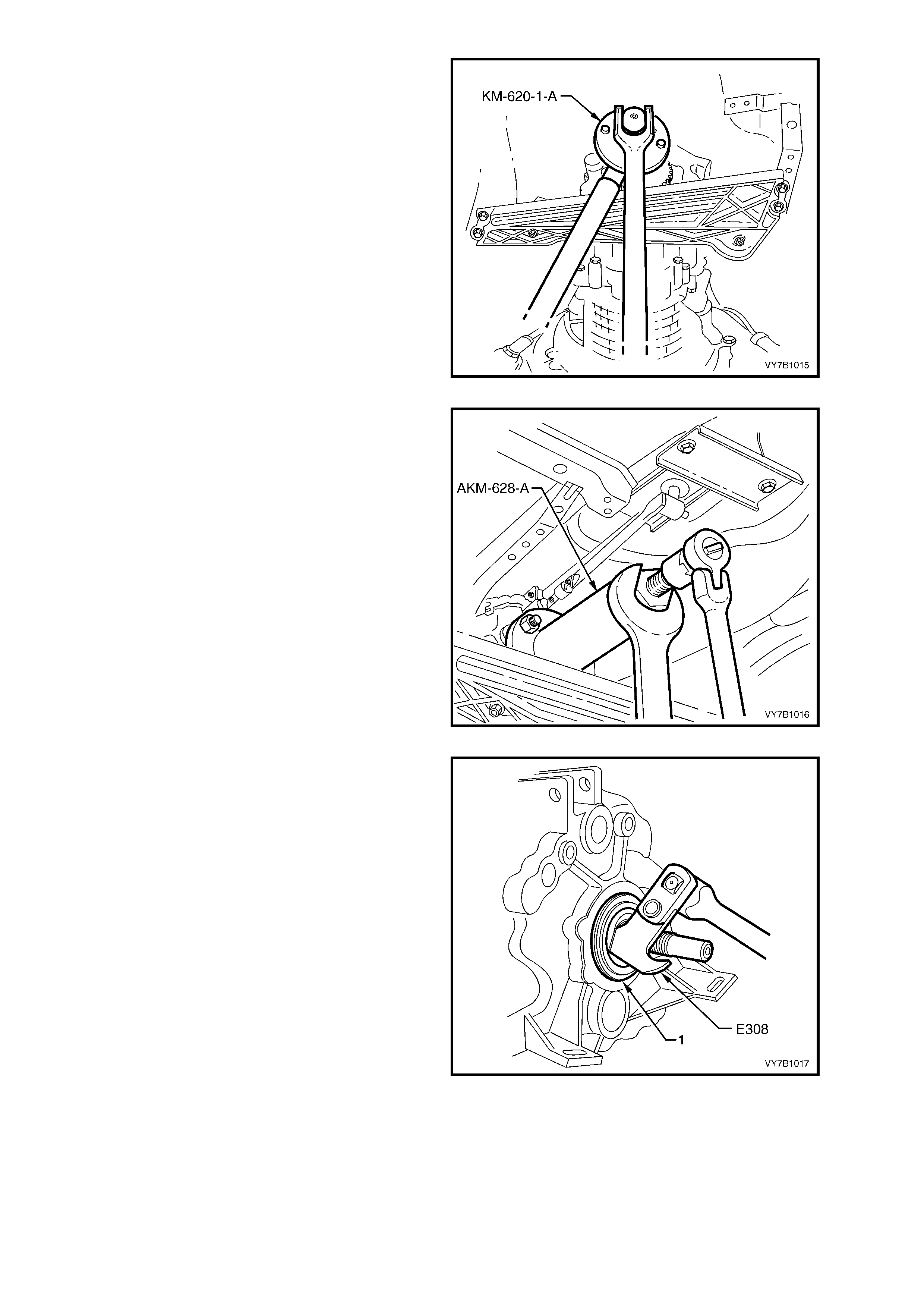
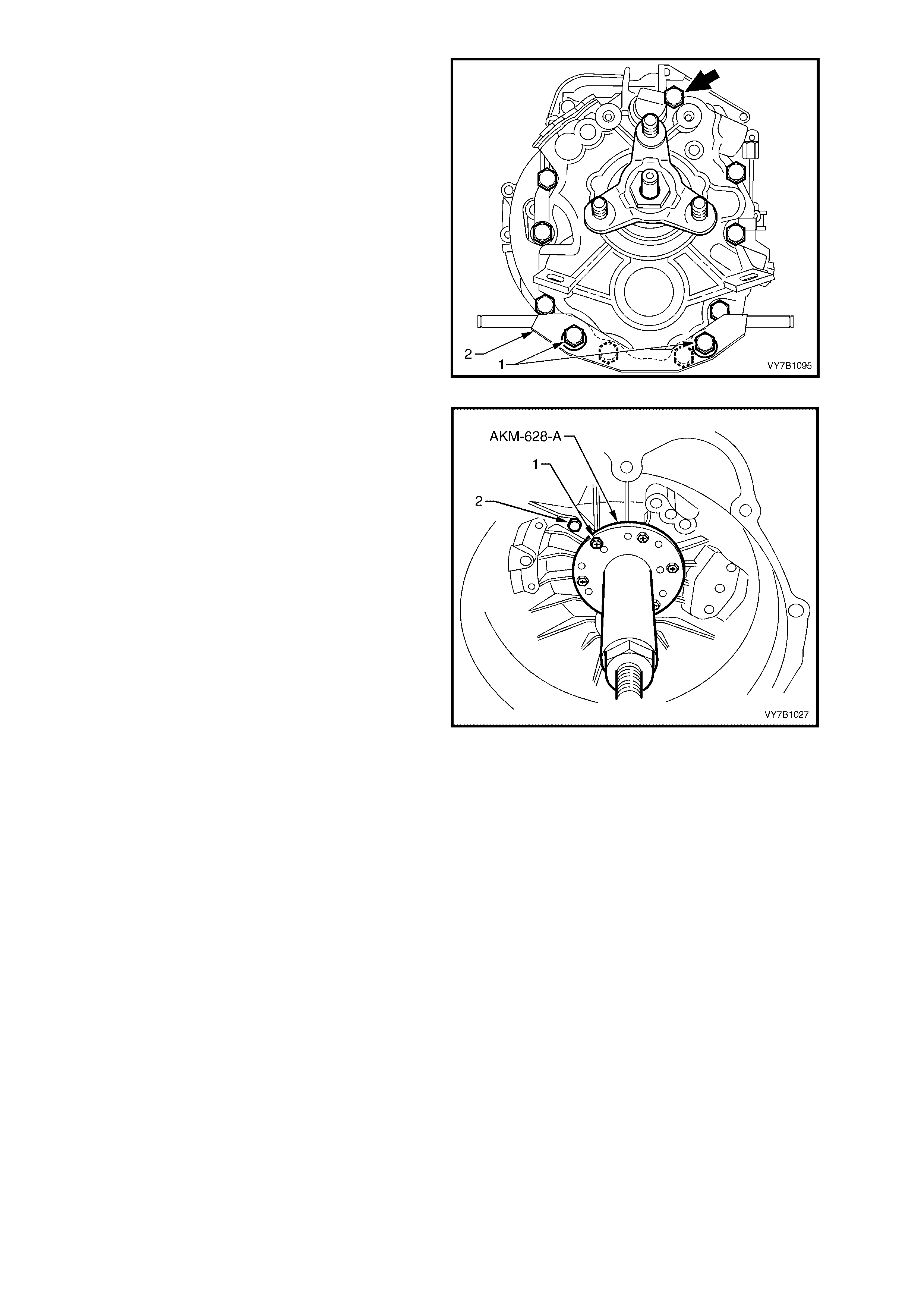
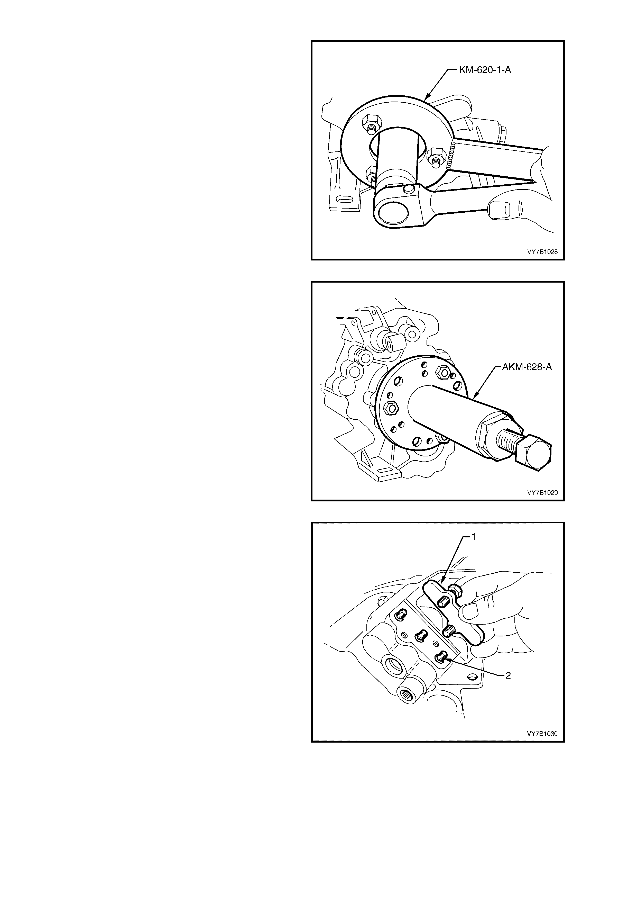
20. To use the previously released, Tool No. KM-
620-1-A to hold the flange, it must first be
modified by redrilling the three holes stamped
‘B’ (on the Tool) to 13 mm.
Fasten th e m odified to ol to the flan ge using the
three discarded nuts. Then, using a suitable
length of pipe on the tool, loosen and remove
flange nut, using a commercially available, 30
mm deep socket.
Figure 7B1-36
21. Place a drain tray beneath transmission.
22. Install ex tractor, Tool No. A KM-628-A to outpu t
shaft flange.
23. Tighten extractor forcing bolt and remove
flange and speed sensor toothed ring, from
output shaft.
24. Inspect the sealing surface of the flange for
damage. Replace as necessary.
NOTE: Take care that no tooth damage takes
place to the speed sensor toothed ring while the
flange is removed.
Figure 7B1-37
25. Using a seal remover such as Tool No. E308
or a suitable lever, remove the seal (1) from
the transmission case.
Figure 7B1-38
SPEED SENSOR TOOTHED RING – REPLACE
The speed sensor toothed ring is not serviced separately from the output shaft flange. Therefore, if found to be
damaged, then the complete flange assembly must be replaced.
REINST ALL
1. Lubricate seal surface of spacer with
transmission lubricant and install over the
mainshaft.
2. After lubricating the seal lip with transmission
lubricant, use Tool No. J-21426 (previously
released) or similar, to fit a new seal over the
sleeve and into the transmission rear case
housing.
Figure 7B1-39
3. Reinstall flange and toothed ring onto
mainshaft, using the original flange nut to pull
the assembly fully into place. Use Tool No.
KM-620-1-A to hold the flange during this
process.
4. Remove the original nut and replace with a
new nut that has had thread sealant such as
Loctite 242 or 243 (or equivalent) applied to the
threads.
5. Again using modified Tool No. KM-620-1-A to
hold flange, tighten the new flange nut to the
correct torque specification.
MAINSHAFT FLANGE NUT
TORQUE SPECIFICATION 100 Nm
Figure 7B1-40
6. If separated from the mounting bracket,
reinstall the speed sensor to the mounting
bracket and secure with the screw (1),
tightening to the correct torque specification.
SPEED SENSOR TO BRACKET
SCREW TORQUE SPECIFICATION 10 Nm
7. Reinstall speed sensor and bracket assembly,
tightening the retaining bolt (2) to the correct
torque specification.
SPEED SENSOR BRACKET MOUNTING
BOLT TORQUE SPECIFICATION 18 Nm
Figure 7B1-41
8. Lower the jack supporting the transmission
assembly, enough to gain access to the two
rear mount to transmission lugs (4).
9. Reinstall the rear crossmember and mounts to
the two transmission case lugs (4), then
reinstall the two retaining nuts (3).
10. Align the s cribed m arks made prior to remova l,
then tighten the two retaining nuts (3) to the
correct torque specification.
REAR MOUNT TO TRANSMISSION LUG
NUT TORQUE SPECIFICATION 25 Nm
11. Raise the support jack, then loosely reinstall
rear crossmember to side frame member bolts.
12. Carefull y align the scribe d m arks made prior to
removal, then tighten the four crossmember to
side frame bolts.
IMPORTANT: This step is critical to the correct
powertrain alignment. If not carried out, then
vehicle vibration and/or handling problems may
result.
13. Remove jack supporting the transmission.
14. After checking to see that the crossmember
position has not changed, tighten the four
crossm ember to s ide frame bo lts to the c orrect
torque specification.
Figure 7B1-42
REAR CROSSMEMBER TO SIDE
FRAME MEMBER BOLT
TORQUE SPECIFICATION 58 Nm
15. Reinstall propeller shaft rubber coupling to
transmission mainshaft flange and loosely
install NEW attaching nuts.
16. Lift propeller shaft upward and install centre
bearing carrier to underbody reinforcement,
ensuring that any spacers are placed in the
same positions, noted on removal. Install
retaining bolts.
17. Assemble propeller shaft rear universal joint
flange to pinion flange, aligning marks made
before removal and reinstall attaching bolts
and nuts.
18. T ighten a ll prop eller shaft a ttachi ng bolts to the
correct torque specification.
PROPELLER SHAFT RUBBER COUPLING
TO TRANSMISSION OUTPUT FLANGE
NUT TORQUE SPECIFICATION 78 Nm
CENTRE BEARING CARRIER TO
UNDERBODY REINFORCEMENT
BOLT, TORQUE SPECIFICATION 23 Nm
PROPELLER SHAFT REAR UNIVERSAL
JOINT FLANGE TO PINION FLANGE
BOLT TORQUE SPECIFICATION 58 Nm
19. Reinstall exhaust system, tightening fasteners
as detaile d in Sect ion 8B EXH AUST SYST EM
in the MY 2003 VY and V2 Series Service
Information.
20. Check transmission lubricant level and top up
as necessary, refer 2.1 CHECKING
TRANSMISSION LUBRICANT LEVEL in this
Section.
21. Rem ove safe ty stands and lo wer vehicle t o the
ground
22. Reconnec t batter y ground l ead.
4.2 TRANSMISSION ASSEMBLY
LT SECTION NO. – 04M-090
REMOVE
1. Disconnect battery ground lead.
IMPORTANT: Disconnection of the battery affects
certain vehicle electronic systems. Refer to
Section 00 CAUTIONS, 5. Battery Disconnection
Procedures before disconnecting the battery.
2. Raise vehicle front and rear and support on
safet y st ands. Refer to Section 0A G ENER AL
INFORMATION in the MY 2003 VY and V2
Series Service Information for the location of
jacking and support points.
3. Disconnect wiring harness connectors from
each of the two oxygen sensors (1).
Figure 7B1-43
4. Remove the intermediate pipe to catalytic
convert er bolts (1), s prings (2) and sealing r ing
(3).
5. Remove the exhaust pipe flange to exhaust
manifold nuts from each side (not shown in
Figure 7B1-44) .
6. While supporting the twin exhaust pipes (5)
and catalytic converter assembly (4), remove
the support rubbers (6 and 7) from the rear of
the transmission.
7. Carefully lower and remove the exhaust pipes
from the veh icle, tak ing car e not to dam age the
exhaust gas oxygen sensors, in the process.
Figure 4C-44
8. Scribe around each of the rear engine
mounting crossmember mounting points to the
vehicle underbody, to provide an alignment
reference for reassembly.
IMPORTANT: This step is critical to the correct
powertrain alignment on reassembly. If not carried
out, then vehicle vibration and/or handling
problems could result.
Figure 7B1-45
9. Support weight of transmission assembly on a
suitable jack.
10. Remove engine rear crossmember to side
frame attaching bolts (2).
11. Lower the rear of the transmission assembly,
enough to gain access to the two mount to
transmission case lug, nuts (3). Before
loosening the nuts scribe an alignment mark, to
ensure that the mounts are reinstalled in the
same position.
IMPORTANT: Failure to take note of the mount
positions before loosening the retaining nuts (3),
could cause driveline vibration problems, once the
vehicle is placed back in service.
12. Rem ove th e re ar m ount att achin g nuts ( 3) fr om
the transmission rear case mounting lugs (4),
then remove the crossmember and mount
assemblies (1) from the vehicle.
NOTE: Illustrat ion does not sho w trans m ission jac k
in position, for clarity of the crossmember
orientati on.
Figure 7B1-46
13. Remove propeller shaft (2) flexible rubber
coupling (4) to mainshaft flange (1) attaching
nuts (3).
Figure 7B1-47
14. W ith the transm ission in first gear and the park
brake firmly applied, use Torx socket
K04425E20 or a commercially available E20
Torx socket to loosen the three Torx headed
bolts (1) securing the propeller shaft rear
rubber coupling (2) to the pinion flange (3).
15. Release the park brake and select neutral, to
relieve any torque loading on the rubber
coupling, then remove the three Torx headed
bolts (1)
NOTE: T o enable the propeller shaft to be installed
in the original position relative to the pinion flange,
use a felt tipped pen or similar to identify the
relationsh ip (‘A’) of the t wo components before bo lt
removal.
Figure 7B1-48
16. Remove the two centre bearing carrier (1) to
underbody reinforcement bolts (2).
17. While supporting the centre bearing section,
lower the c entre b earing an d slide t he pro peller
shaft assembly forward to disengage from the
final drive pinion support pin.
18. Lower the assembly at the rear, sliding
rearward to remove from the rear of the
transmission.
Figure 7B1-49
19. Disconnect the speed sensor wiring harness
connector (1) on the left hand side of the
transmission. Cut the tie strap (2) securing the
wiring harness to the transmission.
Figure 7B1-50
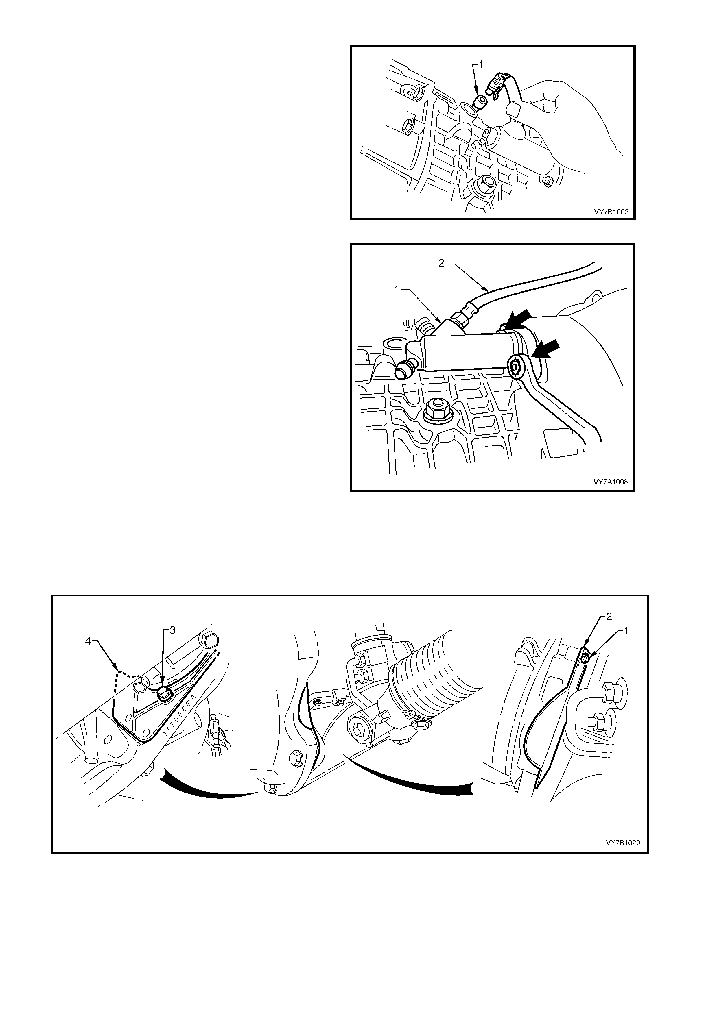
20. Disconnect wiring harness connector from
back up lamp switch (1).
Figure 7B1-51
21. Rem ove clutc h ac tuat ing cylinder r eta ini ng nuts
(arrows) , then rem ove the cylinder ( 1) from the
transmission case. Secure to one side with tie
wire or similar.
Figure 7B1-52
22. Remove the two screws (1 and 3) securing the two front close-out covers (2 and 4). Remove each of the
covers.
23. Remove the two transmission to engine attaching bolts (5) from the clutch housing side.
NOTE: While Figure 7B1- 53 shows the right hand drive arrangem ent, the procedure for left hand drive vehicles is
similar. View ‘A’ shows the left hand close-out cover, while view ‘B’ shows the right side.
Figure 7B1-53
24. Lower transmission slowly on jack, still supporting weight of transmission.
25. Disconnect wir i ng harnes s f rom two reta in ing s tra ps ; o ne o n to p of the tr ans mission c ase, the other on t he right
hand side.
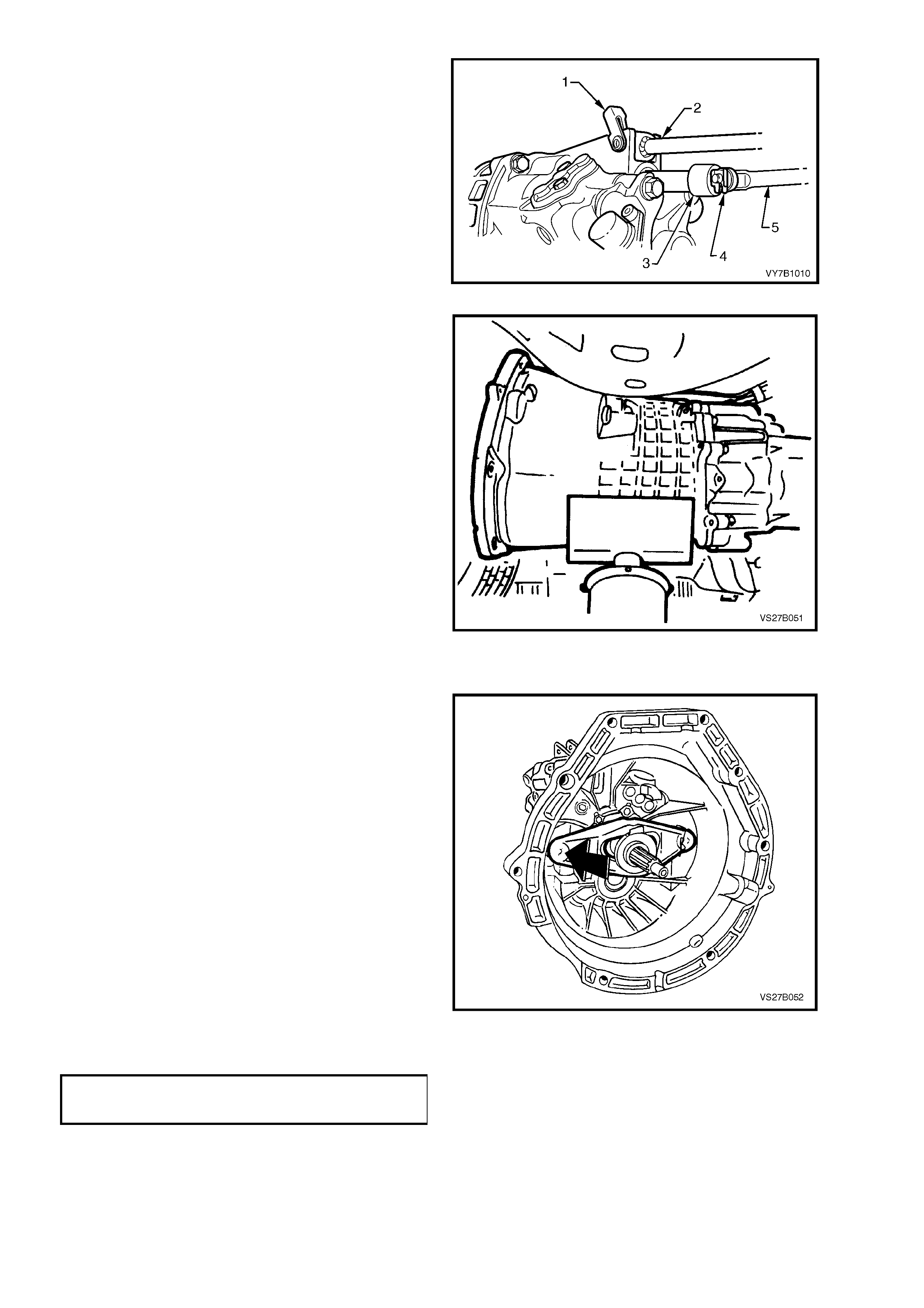
26. Us ing a scr ewdriver, pr ise t he retainer ( 1) up to
clear the transmission case, then remove to
free the shift rod (2) at the transmission end.
27. Using a suitable tool, remove the shift rod
retaining clip (4).
CAUTION: to prevent possible eye damage
when removing the clip, wear suitable eye
protection.
28. Remove a flat washer from the shift rod pin,
then remove the shift rod (5) and a second flat
washer from the transmission shift trunnion (3).
Figure 7B1-54
29. Remove transmission case to engine block
attaching bo lts .
30. Withdraw transmission from the engine block
and clutch driven plate.
NOTE: Keep th e transm ission ass embly supporte d
so that it does not tilt in relatio n to the engin e, until
the maindrive gear splines are clear of the clutch
driven plate. If the transmission is allowed to hang
on the splines, the clutch driven plate will be
damaged.
Figure 7B1-55
REINST ALL
1. Put transmission into 4th gear.
2. Sparingly apply a thin coating of short fibre,
high temperature grease to maindrive gear
splines. Push the clutch throwout bearing into
the fully released position (toward the
transm iss ion), ensuring tha t placem ent with the
throwout fork, is correct.
3. Apply a thin coating of 10% molybdenum
disulph ide grease, suc h as Molybond G A 10 or
equivalent, to the transmission input shaft
spigot.
4. Raise transmission on jack and install
maindrive gear into splines of clutch driven
plate and push transmission toward engine
block. It ma y be necessary to rotate the output
flange to assist in spline alignment.
5. Reinstall and tighten clutch housing to engine
block attaching bolts and nut. Also install the
two clutch housing to engine oil pan bolts,
tightening all to the correct torque specification.
CLUTCH HOUSING TO ENGINE
BLOCK AN D O IL PAN BOLT
TORQUE SPECIFICATION 85 Nm
Figure 7B1-56
6. Reinstall the two close-out covers, ensuring
that the locating lug on the RHS one is
installed before securing the cover with the
screw. Reinstall the cover retaining screws and
tighten to the correct torque specification.
FLYWHEEL CLOSE-OUT COVER
SCREW TORQUE SPECIFICATION 10 Nm
7. Reinstall clutch actuating cylinder to
transmission case, install the nuts and tighten
to the correct torque specification.
CLUTCH ACTUATING CYLINDER
NUT TORQUE SPECIFICATION 22 Nm
NOTE:When the actuating cylinder is engaged with
the mounti ng s tuds, the int ernal sprin g will hold the
flange out from the fully installed position, by
approximately 25 mm. Hold the cylinder in against
this spring force, to start the retaining nuts.
8. Using transmission jack, support transmission
in a lower than installed position.
9. Reinstall wiring harness retaining straps.
10. Reinstall wiring harness connector to back up
lamp switch and to the speed sensor.
11. Align the shift linkage brace/bush and the
transmission lug holes. Install the pin (1) from
the left hand side, then rotate, to engage the
retaining clip with the transmission lug. Tap
with a hamm er to fully engage the clip with the
lug.
12. Fit a washer to the inner end of the shift
linkage (5) pin, apply a small amount of
Molybden um Disulph id e grease to th e p in, the n
install into the transmission shift rod trunnion
(3). Insta ll a second washer to the shif t linkage
pin, then secure with the retaining clip (4).
Figure 7B1-57
13. Reinstall the rear crossmember and mounts to
the two transmission case lugs (4), then
reinstall the two retaining nuts (3).
14. Align the scribed alignment marks made prior
to removal, then tighten the two retaining nuts
(3) to the correct torque specification.
REAR MOUNT TO TRANSMISSION LUG
NUT TORQUE SPECIFICATION 25 Nm
15. Raise the support jack, then loosely reinstall
rear crossmember to side frame member bolts.
16. Carefull y align the scribe d m arks made prior to
removal, then tighten the four crossmember to
side frame bolts.
IMPORTANT: This step is critical to the correct
powertrain alignment. If not carried out, then
vehicle vibration and/or handling problems may
result.
17. Remove jack supporting the transmission.
18. After checking to see that the crossmember
position has not changed, tighten the four
crossm ember to s ide frame bo lts to the c orrect
torque specification.
REAR CROSSMEMBER TO SIDE
FRAME MEMBER BOLT
TORQUE SPECIFICATION 58 Nm
Figure 7B1-58
19. Reinstall propeller shaft rubber coupling to
transmission mainshaft flange and loosely
install NEW attaching nuts.
20. Lift propeller shaft upward and install centre
bearing carrier to underbody reinforcement,
ensuring that any spacers are placed in the
same positions, noted on removal. Install
retaining bolts.
21. Assemble propeller shaft rear universal joint
flange to pinion flange, aligning marks made
before removal and reinstall attaching bolts
and nuts.
22. T ighten a ll prop eller shaft a ttachi ng bolts to the
correct torque specification.
PROPELLER SHAFT RUBBER COUPLING
TO TRANSMISSION OUTPUT FLANGE
NUT TORQUE SPECIFICATION 78 Nm
CENTRE BEARING CARRIER TO
UNDERBODY REINFORCEMENT
BOLT, TORQUE SPECIFICATION 23 Nm
PROPELLER SHAFT REAR UNIVERSAL
JOINT FLANGE TO PINION FLANGE
BOLT TORQUE SPECIFICATION 58 Nm
23. Inspect catalytic converter to intermediate
exhaust pipe seal ring (3) for deterioration or
damage, replacing if required.
24. Reinstall exhaust system components. Refer
Section 8B EXHAUST SYSTEM, in the MY
2003 VY and V2 Series Service Information,
for the necessary procedures and clearances.
Tighten all fasteners to the correct torque
specifications, as detailed in that Section.
25. If transmission fluid was drained during
the removal operation, then refill, as
described in 2.3 DRAINING AND REFILLING
TRANSMISSION in this Se c tion.
26. Remove safety stands and lower vehicle.
27. Reconnec t batter y ground l ead.
28. Road test vehicle and check transmission,
clutch and gearshift operations.
Figure 7B1-59
4.3 TRANSMISSION DISASSEMBLE
LT Section No. – 04M-125
1. If not carried out during the transmission
removal procedure, use a 17 mm ring spanner
and remove transmission filler plug (1) from
right hand side of transmission case.
2. Remove transmission drain plug (2), also with
a 17 mm ring spanner and allow transmission
lubricant to drain into a suitable clean, drain
tray.
NOTE: At this tim e, carefull y inspec t the drain pl ug
magnet and the drained fluid for foreign matter
such as metal particles, etc.
Figure 7B1-60
3. Release clutch release lever from the wire clip
and remove lever from transmission case,
together with the thrust bearing.
Figure 7B-61
4. Remove bo lts attac h in g throwout b ear ing gu ide
assembly (1). Gently tap sideways with a soft
faced hammer to break the seal, then remove
the assembly from the transmission maindrive
gear shaft.
Figure 7B1-62
5. Remove shim washer (2) and distance spacer
ring from the f ront b earing. Using s uitabl e sn ap
ring pliers (1), remove the snap ring (3) and
spacer washer (4) from maindrive gear.
Figure 7B1-63
6. Remove the speed sensor bracket retaining
bolt (1) from the rear transmission case. Cut
the wiring harness retaining strap (2) from the
transmission case lug and remove the sensor
and brack et assem bl y.
Figure 7B1-64
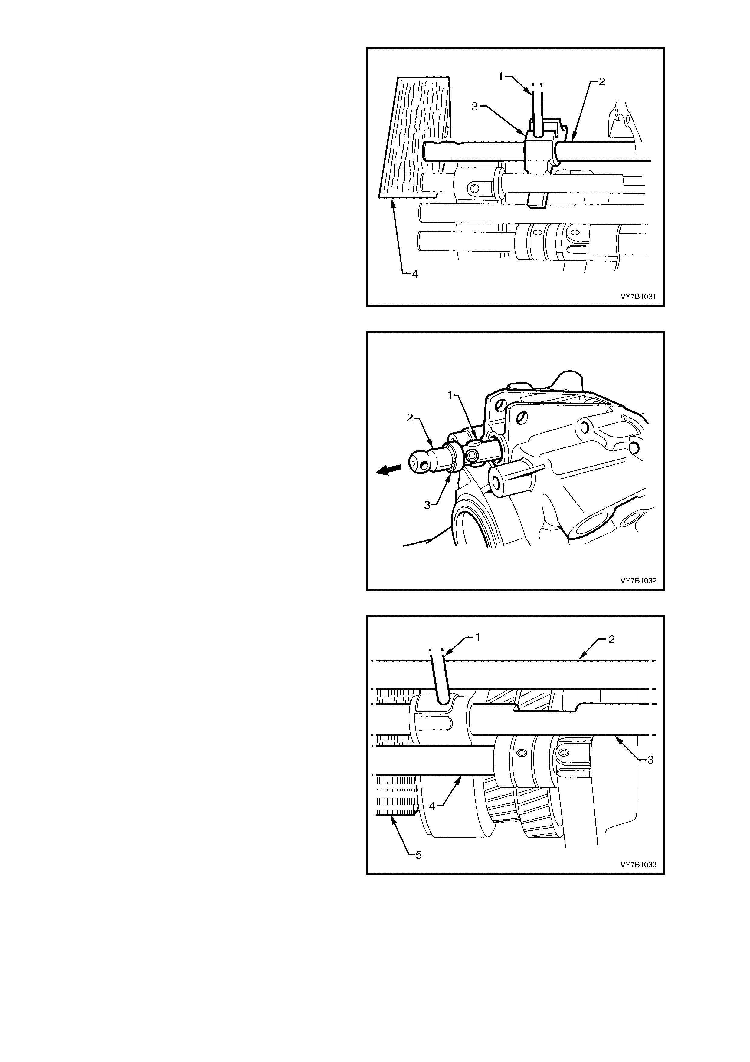
7. Lever the sprin g steel reta ining r ing (4) f orward
from selector rod trunnion (3), to expose the
connecting pin (2).
8. While pushing the trunnion in to the
transmission, use a suitable punch and push
the pin from the trunnion. Remove trunnion and
retaining ring from the selector rod (1).
Figure 7B1-65
9. Remove back-up lamp switch and spacer
washer.
Figure 7B1-66
10. Using suitable lever, remove detent plug (1)
from front section of transmission case.
11. Rem ove de tent pin ( 3), pre ssur e spring (2) a nd
plug (1).
Figure 7B1-67
12. Remove front bolt (1) fastening the reverse
idler gear shaft to the left side of transmission
case.
Figure 7B1-68
13. Remove transmission case attaching bolts
from c ase rear sec tion. Take note of the l onger
bolt (60 mm) position (bold arrow) for
reassembly.
14. Drive the upp er locating do wel p in int o the f r ont
transmission case.
Figure 7B1-69
15. Install extractor, Tool No. AKM-628-A, to front
of transmission case using all six of the clutch
throwout bearing guide bolts (1). It is not
necessary to remove the reverse block shaft
bolt (2).
16. Tighten extractor forcing bolt to separate the
two transmission case sections.
NOTE: While the forcing bolt of Tool AKM-628-A
has torque applied, it may be necessary to use a
suitable block of wood and hammer at the two lug
locations provided on the rear transmission case,
to assist in the initial separation process.
17. Carefully remove the front transmission case
section and pl ace to one si de.
NOTE 1: The maindrive gear bearing and cluster
gear front bearing cup remain in the transmission
case front section. Take care that the cluster gear
roller bearing does not fall out of the front case
immediately after splitting the cases. The
remainder of the transmission assembly is
removed with the transmission case rear section.
NOTE 2: W hen the transmission cases have been
separated, do not manipulate the position of the
transmission rear section by using the maindrive
gear as a lever or handle. If this is done, then the
mainshaft spigot bearing will suffer brinelling and
be permanently damaged.
Figure 7B1-70
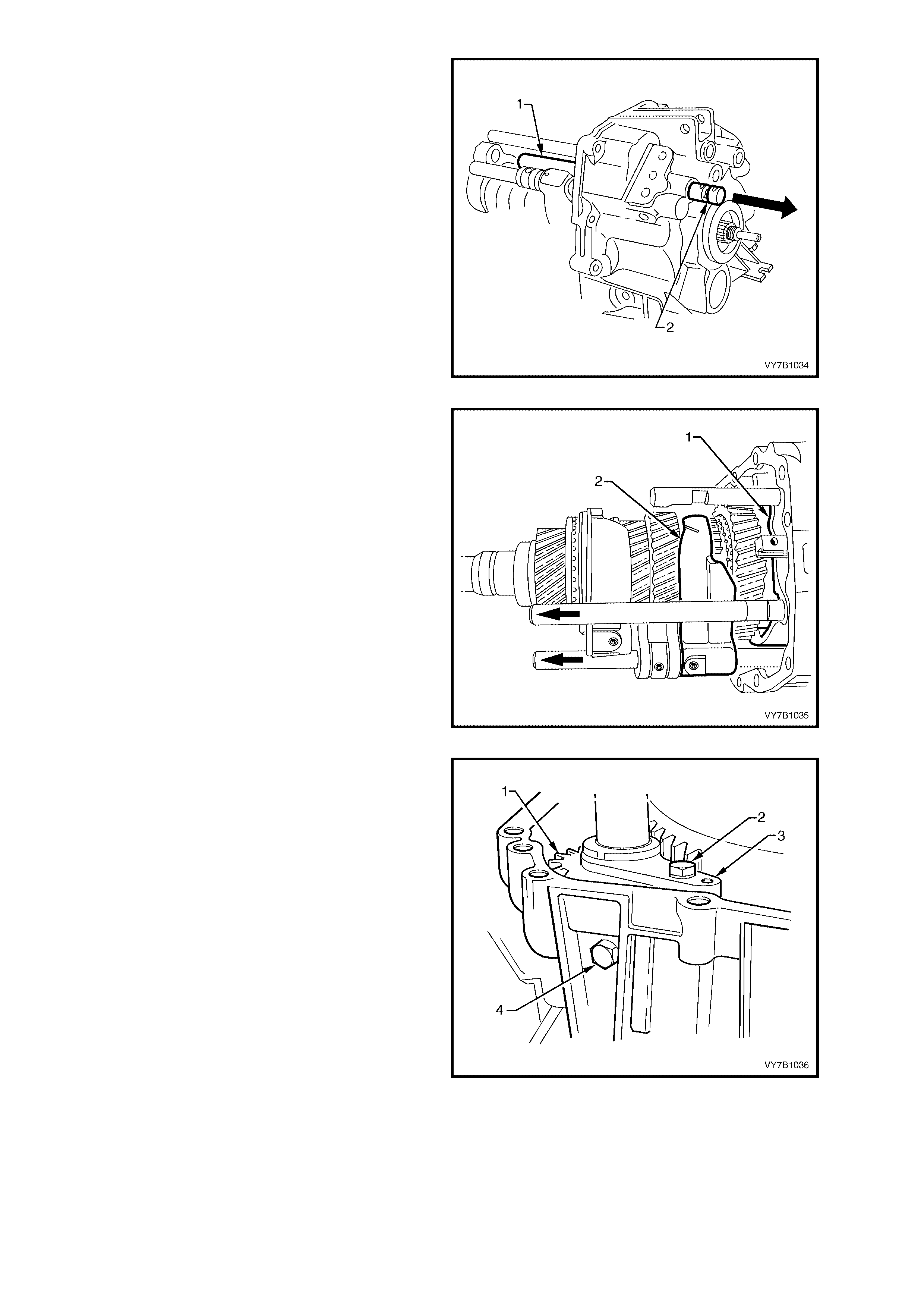
18. Before using the previously released, Tool No.
KM-620-1-A to hold the flange, it must first be
modified by redrilling the three holes stamped
‘B’ (on the Tool) to 13 mm.
19. F asten th e m odified to ol to the flan ge using the
three discarded nuts. Then, using a suitable
length of pipe on the tool handle, loosen and
remove flange nut, using a commercially
available, 30 mm deep socket.
Figure 7B1-71
20. Install extractor, Tool No. AKM-628-A to
mainshaft output flange studs. Use the
removed nuts to secure the extractor tool to the
flange.
21. Tighten extractor forcing bolt to remove flange
from mainshaft.
Figure 7B1-72
22. Remove bolts attaching pressure spring cover
plate (1) to transmission case rear section.
23. Remove three detent ball springs (2).
24. Using a pencil magnet, remove three detent
balls from under the springs.
Figure 7B1-73
25. Select 4 th gear, s upport the s hift selec tor shaft
(2) with a wooden wedge (4), then remove the
roll pin from the gearshift selector arm (3),
using a suitable sized pin punch (1) and
hammer. When in 4th gear, the roll pin will not
foul on gear teeth during the removal process.
Figure 7B1-74
26. Using a soft faced hammer, tap the shift shaft
(2) rearwards through the bearing support,
removing the seal (3) in the same operation.
Discard the removed seal (3) as it will be
damaged in the removal process.
NOTE: As the shif t shaft is rem oved, there are f our
rollers (1) that can be dislodged from the pins in
the shaft. Take care not to lose them.
Figure 7B1-75
27. While supporting the 3rd/4th selector shaft (3)
with a suitable wedge of wood (5), drive the
selector fork roll pin out, just sufficient to
enable the shaft (3) to be removed.
Legend:
1. Pin Punch
2. 5th/Reverse Selector Shaft
3. 3rd/4th Selector Shaft
4. 1st/2nd Selector Shaft
5. Wooden Wedge
Figure 7B1-76
28. While supporting the 3rd/4th shift fork, use a
soft faced hammer to gently tap the shaft (1)
rearward, displacing the expansion plug in the
rear transmission housing. This will also allow
removal of the interlock pin (2) and the shaft
from the rear, which overcomes the risk of the
interlock pin becoming dislodged and jamming
the shaft.
Figure 7B1-77
29. Move the 5th/Reverse synchromesh fork (1)
forward, into the Reverse position and the
1st/2nd synchromesh fork (2) forward into the
2nd gear posit ion .
Figure 7B1-78
30. Remove the rear bolt (4) securing the reverse
idler gear (1) to the transmission case and the
bolt (2) securing the thrust plate (3). Remove
the reverse idler gear shaft and roller bearing
from the rear case section. Remove the idler
gear.
Figure 7B1-79
31. To remove mainshaft (1) and cluster gear
assemblies, together with the selector shafts
and forks from rear transmission case (2),
support th e case on suitable pr ess plates, then
press the mainshaft (1) from the rear
mainshaft, sealed ball race.
IMPORTANT: Take care when the gear
assemblies come free from the ball race, as they
are heavy. Do not allow them to drop to the floor
when gear tooth damage could occur.
NOTE: Do not lose any of the selector interlock
balls that will come away when the shafts are
removed. There are two of them, both of equal
size.
Once free, the cluster gear assembly and
selector shafts and forks can be easily
separated from the mainshaft assembly.
Figure 7B1-80
4.4 TRANSMISSION SUB-ASSEMBLIES
LT Section No. – 04M-125
DISASSEMBLE
Mainshaft
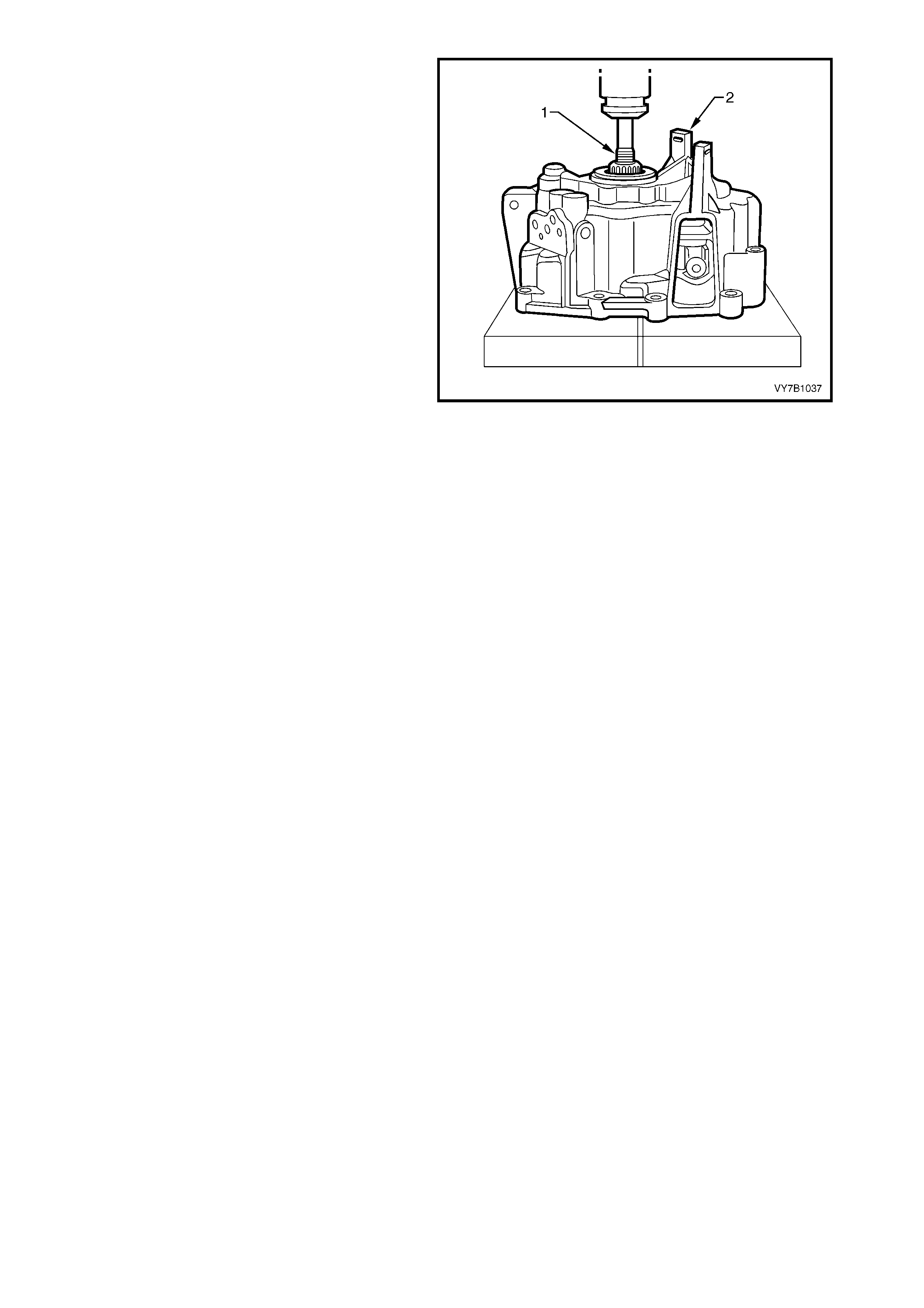
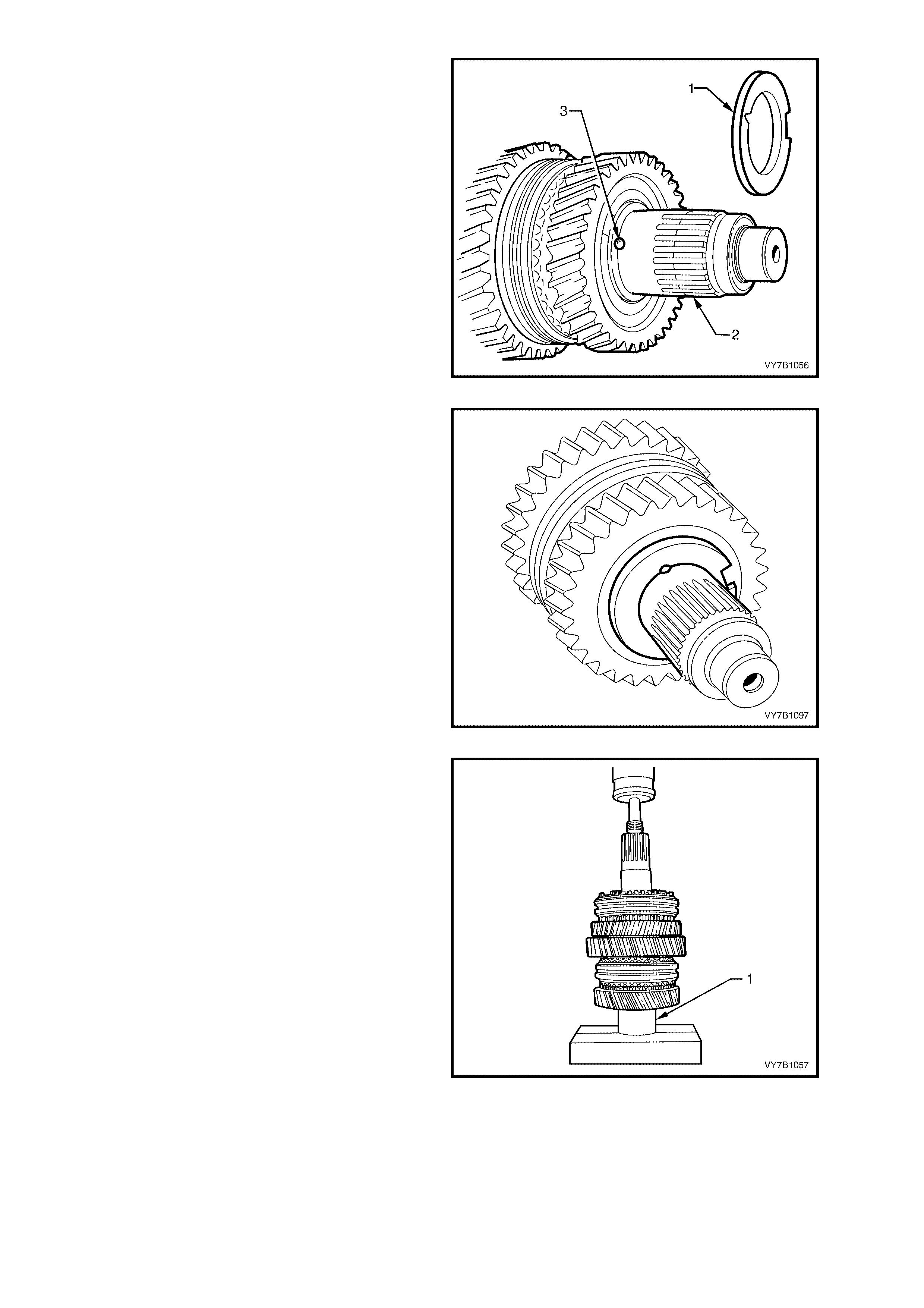
1. Remove the 5th s p eed c on s tant mesh gear ( 1) ,
synchromesh ring (2) and caged needle roller
bearing (3) from the rear of the mainshaft.
Figure 7B1-81
2. Remove m aindrive gear and four th speed gear
synchromesh ring from mainshaft.
3. Remove snap ring (1) and washer from front
end of mainshaft, using suitable snap ring
pliers (2).
Figure 7B1-82
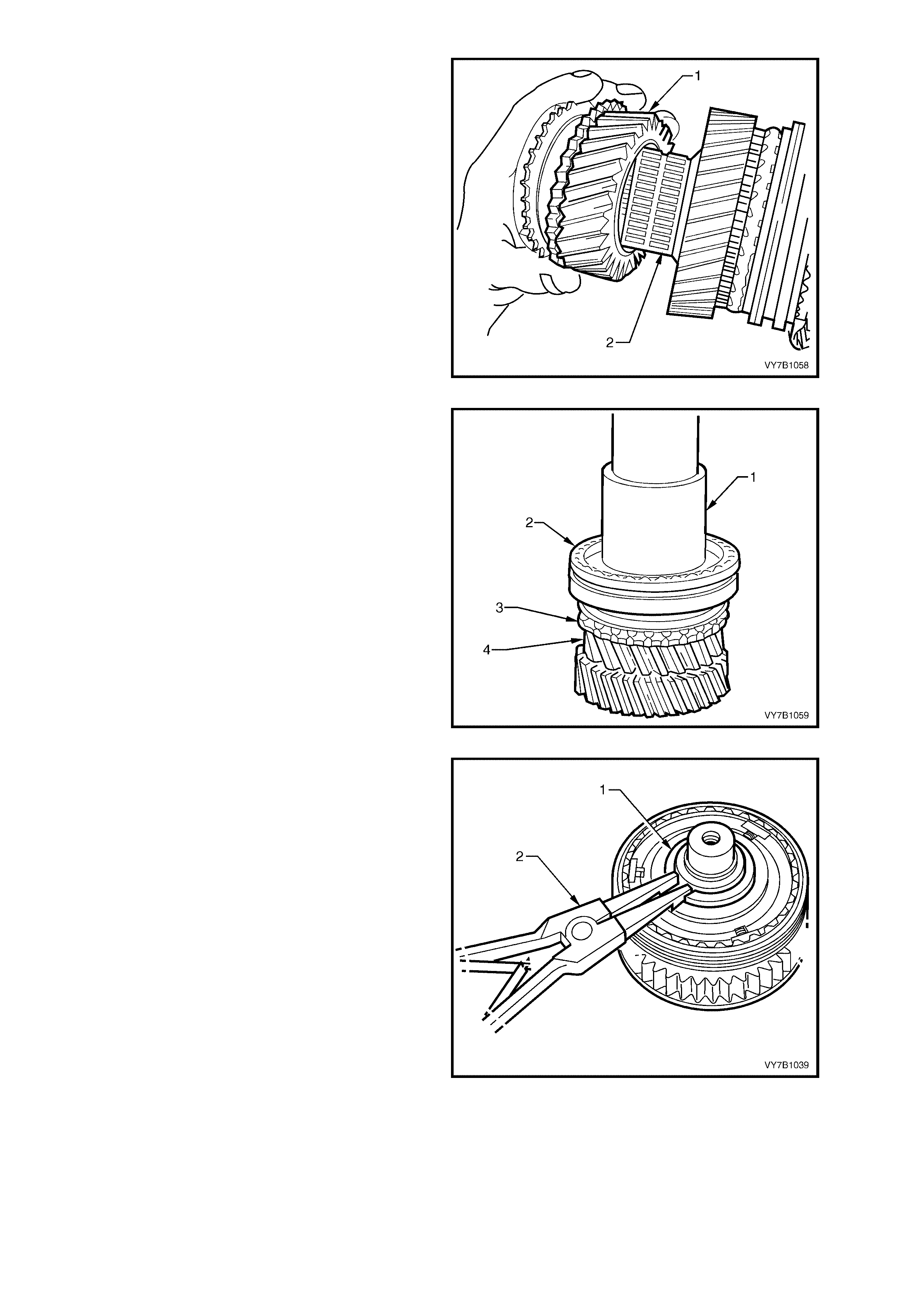
4. Insert each half of Tool No. AU454 under the
dog clutch teeth of 2nd speed gear, ensuring
that both halves are fully installed.
NOTE: Only one half of Tool No. AU454 is shown,
to more clearly show the installation position.
Figure 7B1-83
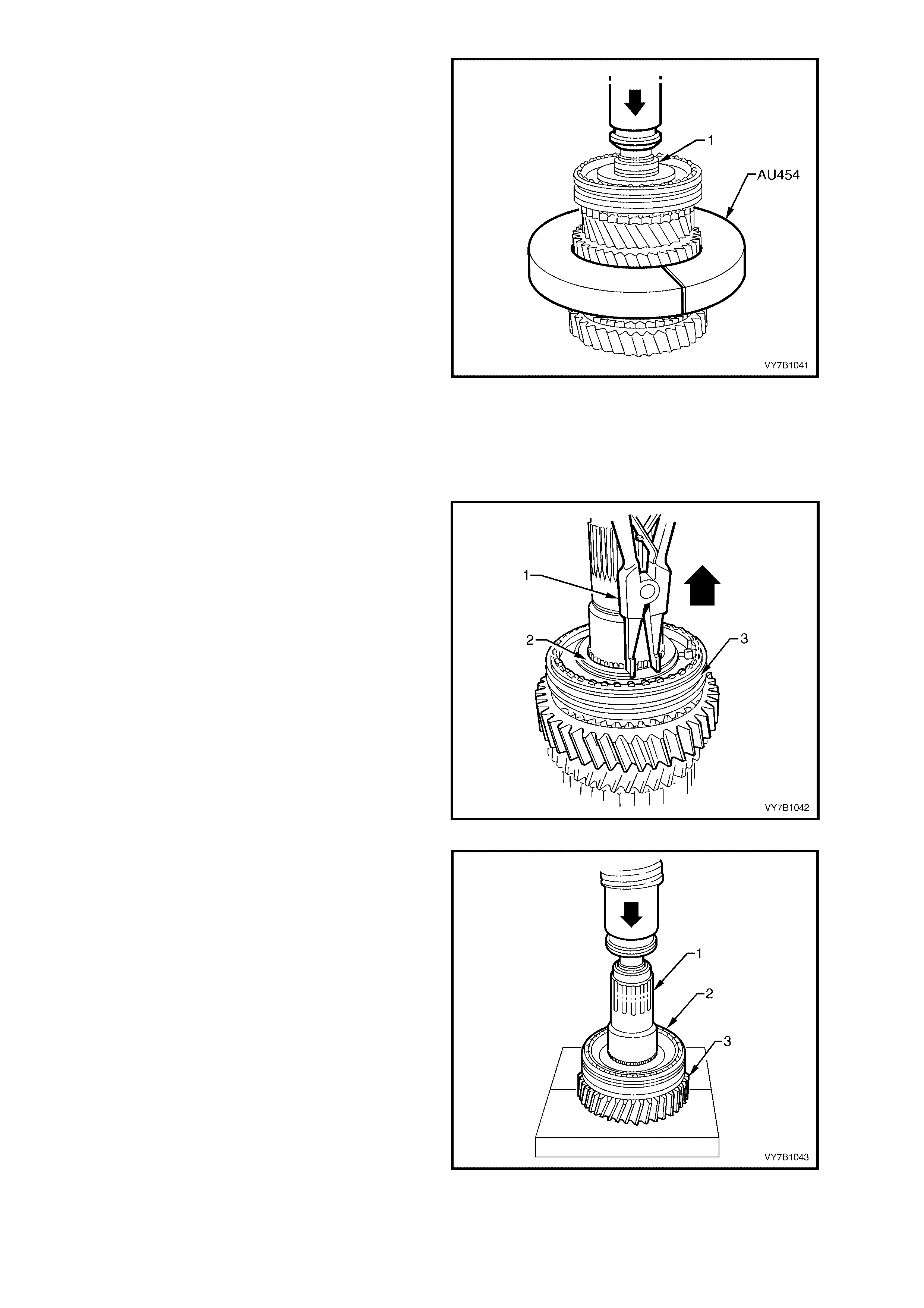
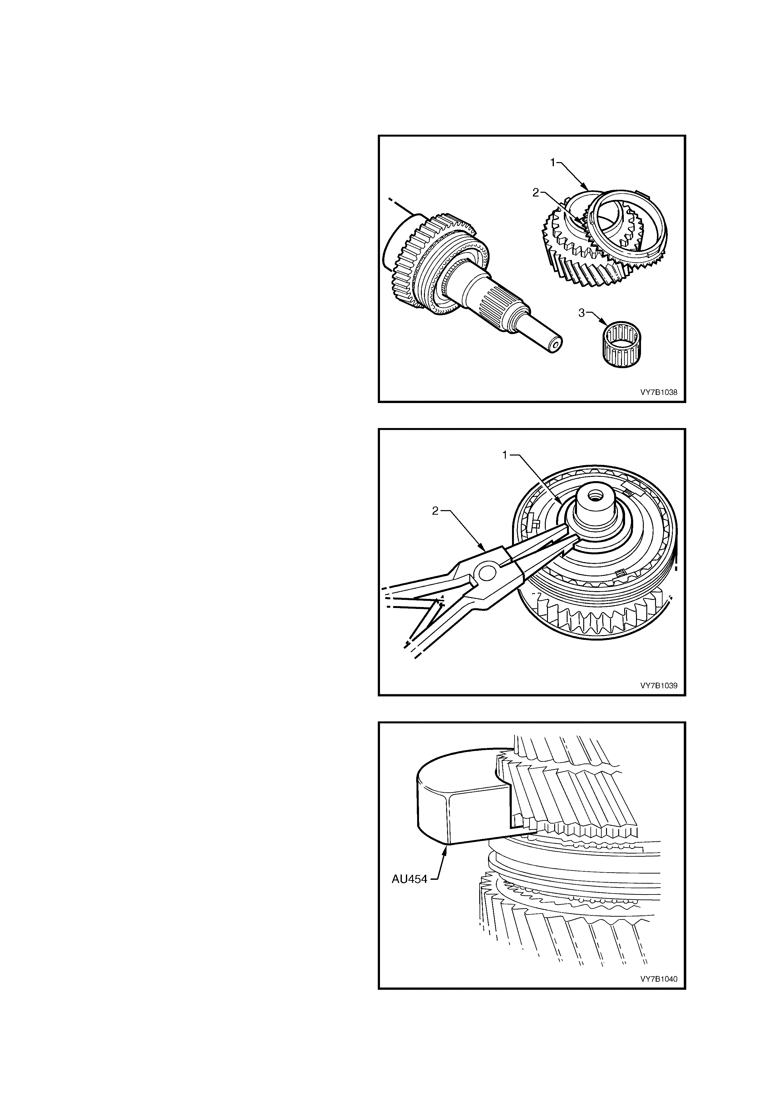
5. Support both halves of Tool No. AU454 under
suitable press plates and press the mainshaft
(1) from the following components;
• 3rd/4th gear synchromesh assembly.
• 3rd speed gear and synchromesh ring.
• 3rd speed gear, caged needle roller
bearing.
• 3rd speed gear, roller bearing sleeve.
• 2nd speed gear thrus t washer .
• Thrust washer locating ball.
• 2nd speed gear.
• 2nd speed gear, caged needle roller
bearing.
NOTE: As the s ynchrom esh hub and roller bearing
sleeve are both interference fits on the mainshaft,
some force will be required to remove these
components. Also, take care not to lose the thrust
washer locating ball, as it may fall out during the
pressing oper at io n.
6. Remove the thr e e p ar t s yn c hromes h rings f rom
the 1st/2nd synchromesh assembly.
Figure 7B1-84
7. Remove snap ring (2) from the 1st/2nd gear
synchromesh hub (3), using suitable snap ring
pliers (1).
Figure 7B1-85
8. Using s uitable pres s plates , position ed with the
flat side under first speed gear (3), press
mains haft ( 1) from 1st/2nd speed s ynchrom es h
assembly (2), 1st speed synchromesh ring,
cone ring, friction ring, first speed gear (3) and
needle roller bearing.
Figure 7B1-86
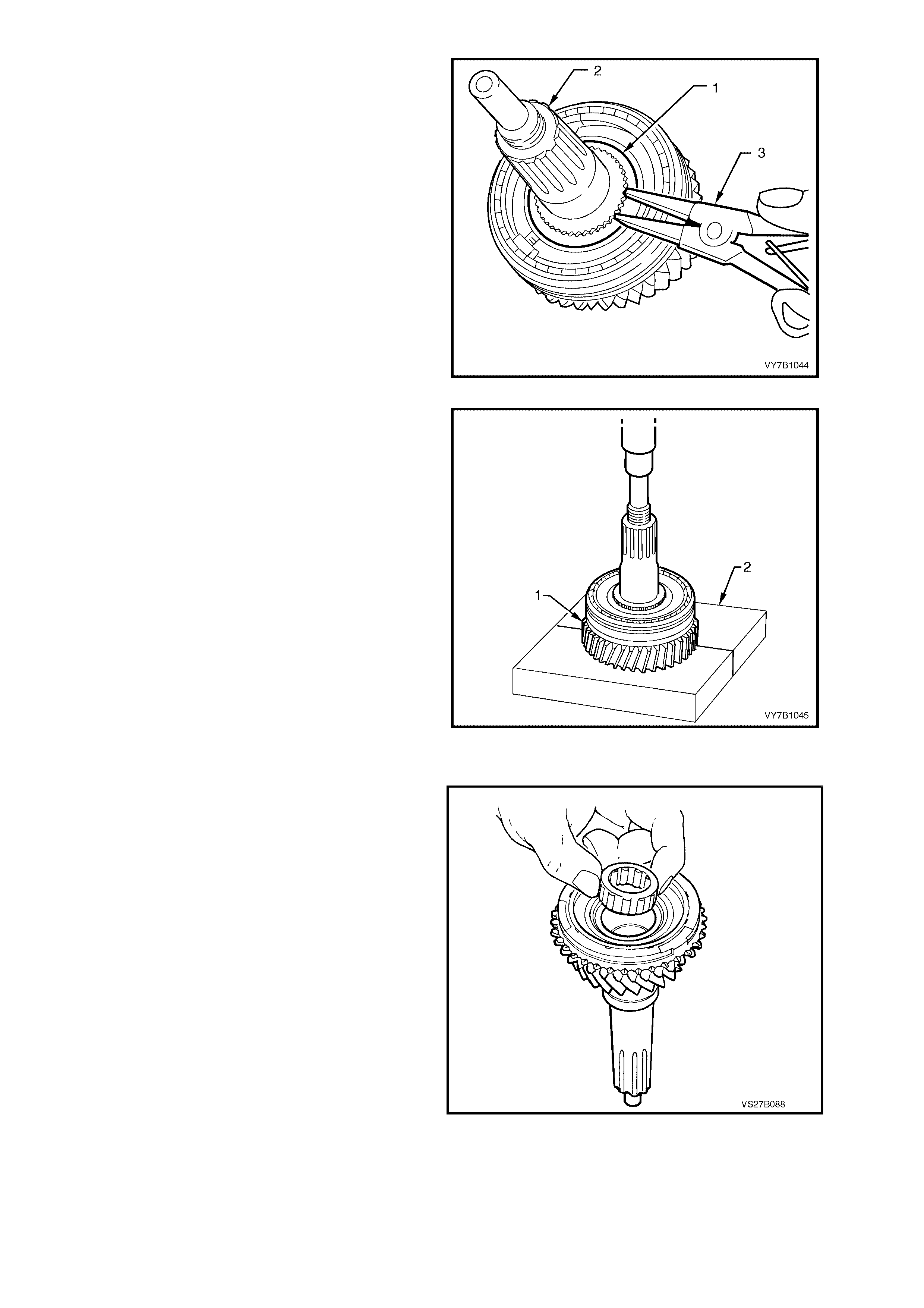
9. Remove 5th/Reverse speed synchromesh hub
snap ring (1) from mains haft (2), using s uitable
snap ring pliers (3).
Figure 7B1-87
10. Press mainshaft from 5th/Reverse speed
synchromesh assembly, reverse synchromesh
ring and reverse constant mesh gear, using
suitable press plates (2), with the flat side
positioned under Reverse speed gear (1).
11. Remove reverse speed gear and selective,
caged needle roller bearing from mainshaft.
Figure 7B1-88
Maindrive Gear
1. Remove the caged needle roller bearing from
the maindrive gear.
Figure 7B-89
Cluster Gear
While the cluster gear is made up from three
separate components, it is only serviced as a
complete assembly. It should therefore, not be
dismantled. The assembly of the components is
precise and cannot be duplicated without the use
of specialised jigs.
Reverse Idler Gear Shaft
When removing the two snap rings securing the
two caged needle roller bearings to the idler shaft,
take particular note of the orientation of each snap
ring to the bearings.
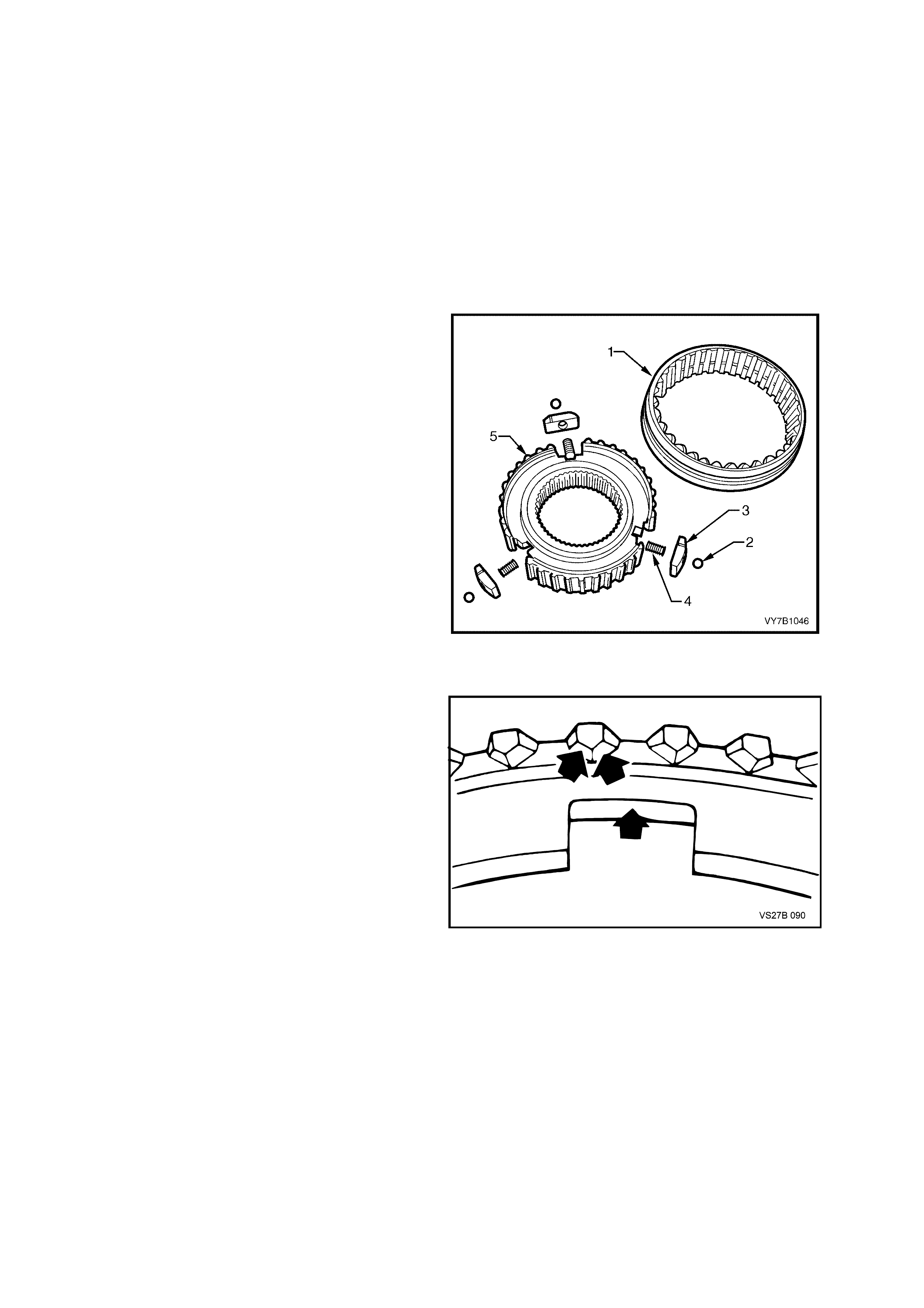
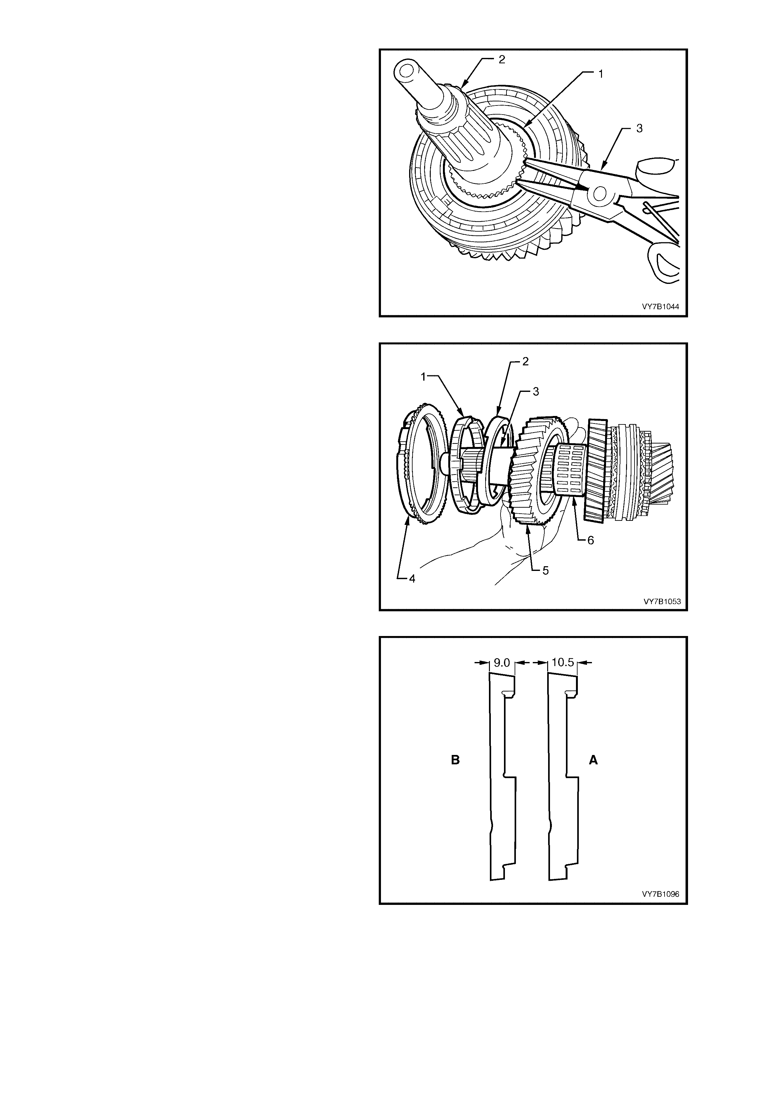
Synchromesh Assemblies
With the index finger and thumb of the left hand
circling the synchromesh hub (5), slide the outer
sleeve (1) from the assem bly, usi ng the rig ht hand.
Be careful that the pressure springs (4) do not
cause any of the three balls (2) to be ejected and
lost. Note th e relati onship o f the outer sleeve to t he
synchrom es h hub an d the c orrec t orientat ion of th e
sliding keys (3).
NOTE: W hile the synchrom esh assembly shown is
for the 1st/2nd speed ranges, the disassembly
process is the same for each of the remaining two
assemblies.
Figure 7B1-90
INSPECT COMPONENTS
1. Check synchromesh rings for cracks and for
deformation. Inspect rings for excessive wear
in the areas shown.
2. Check synchromesh hubs, outer sleeves,
sliding blocks and synchromesh springs for
damage.
Figure 7B-91
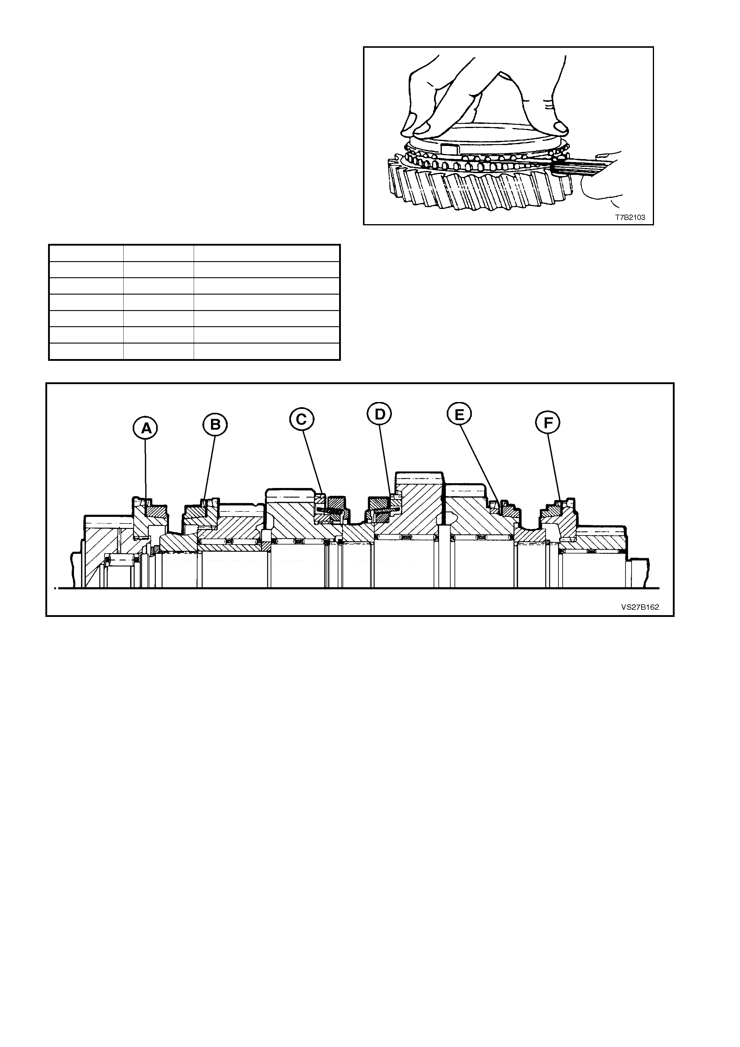
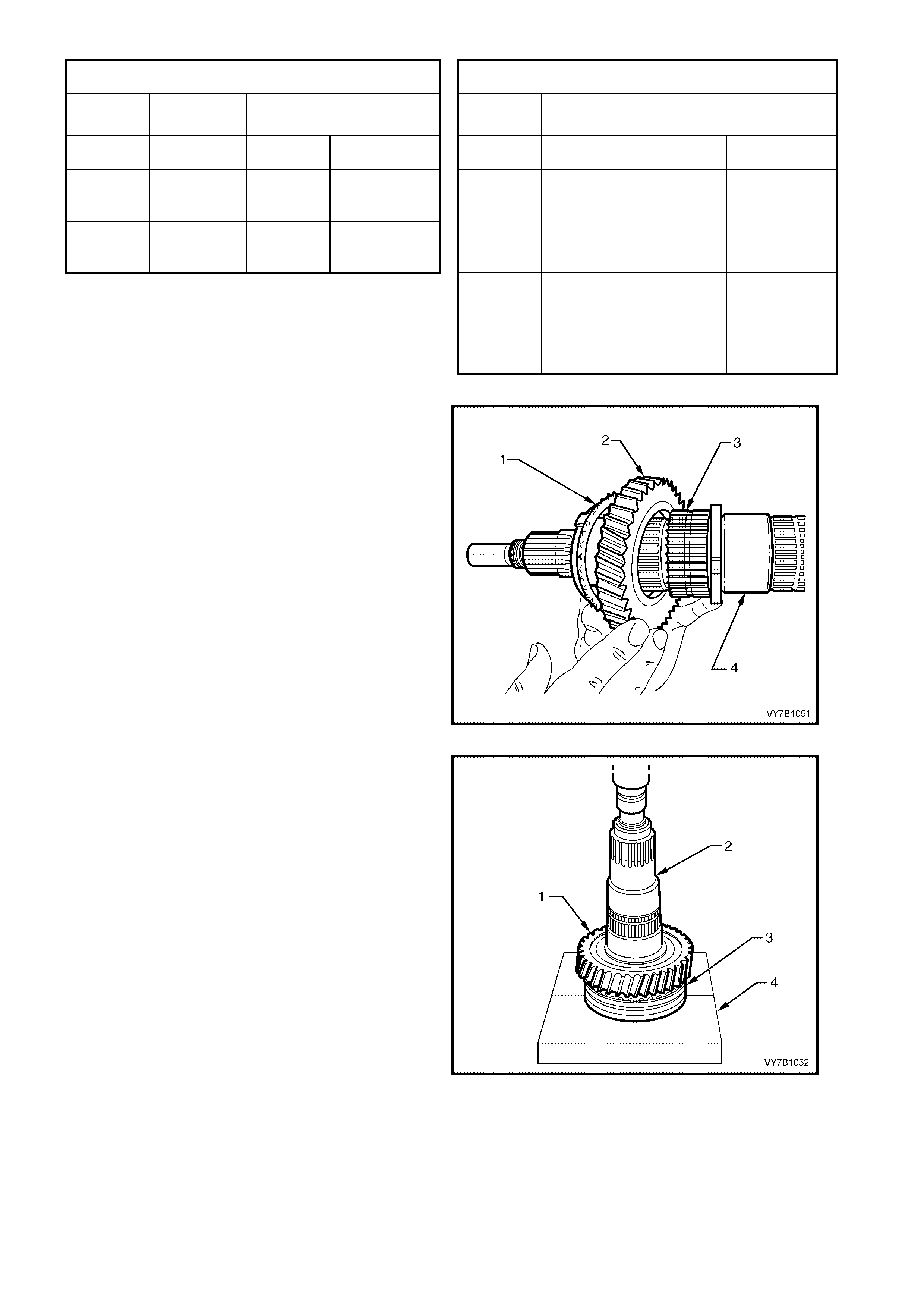
3. Check each synchromesh ring for wear by
mounting the ring on the respective gear and
measuring the gap, as indicated.
NOTE: To obtain an accurate measurement, the
synchromesh ring must be held squarely and fully
installed on its gear, as shown. Then, using feeler
gauges, measure the gap in at least three places
around the circumference. Average the readings
and use this figure to ass ess the s ynchrom esh ring
wear.
Specifications for each synchromesh ring are as
follows and correspond to the synchromesh
assemblies indicated in the se ctioned view.
Position Gear Serviceable Wear Limit
(A) 4th 0.82 - 1.35 mm
(B) 3rd 0.82 - 1.35 mm
(C) 2nd 0.85 - 2.25 mm
(D) 1st 0.95 - 2.35 mm
(E) Reverse 0.5 - 0.98 mm
(F) 5th 0.82 - 1.35 mm
Figure 7B-92
Figure 7B-93
4. Inspect all gears, sleeves, hubs, rings and shaf ts for wear, scoring, pitting, chips , nicks or burrs. Slig ht scores
or burrs may be honed off with a fine stone, however if a gear is chipped or unduly worn it must be replaced.
5. Inspect all needle roller bearings for wear or damage.
NOTE: As needle roller wear can be difficult to see, it is good practice to replace all roller bearings where a
substantial distance has been covered by the transmission.
6. Inspect the mainshaft surfaces, roller bearing inner sleeves and internal surfaces of the gears where the needle
bearings come into contact.
NOTE: The needle roller bearing assembly used with the mainshaft Reverse gear, is a selective fit. Should any
component associated with this gear and/or the mainshaft need to be replaced, then the procedure detailed in
REAS SEMBLE, Mainshaft, must be adopted, to ensure that the correct replacement part/s are fitted.
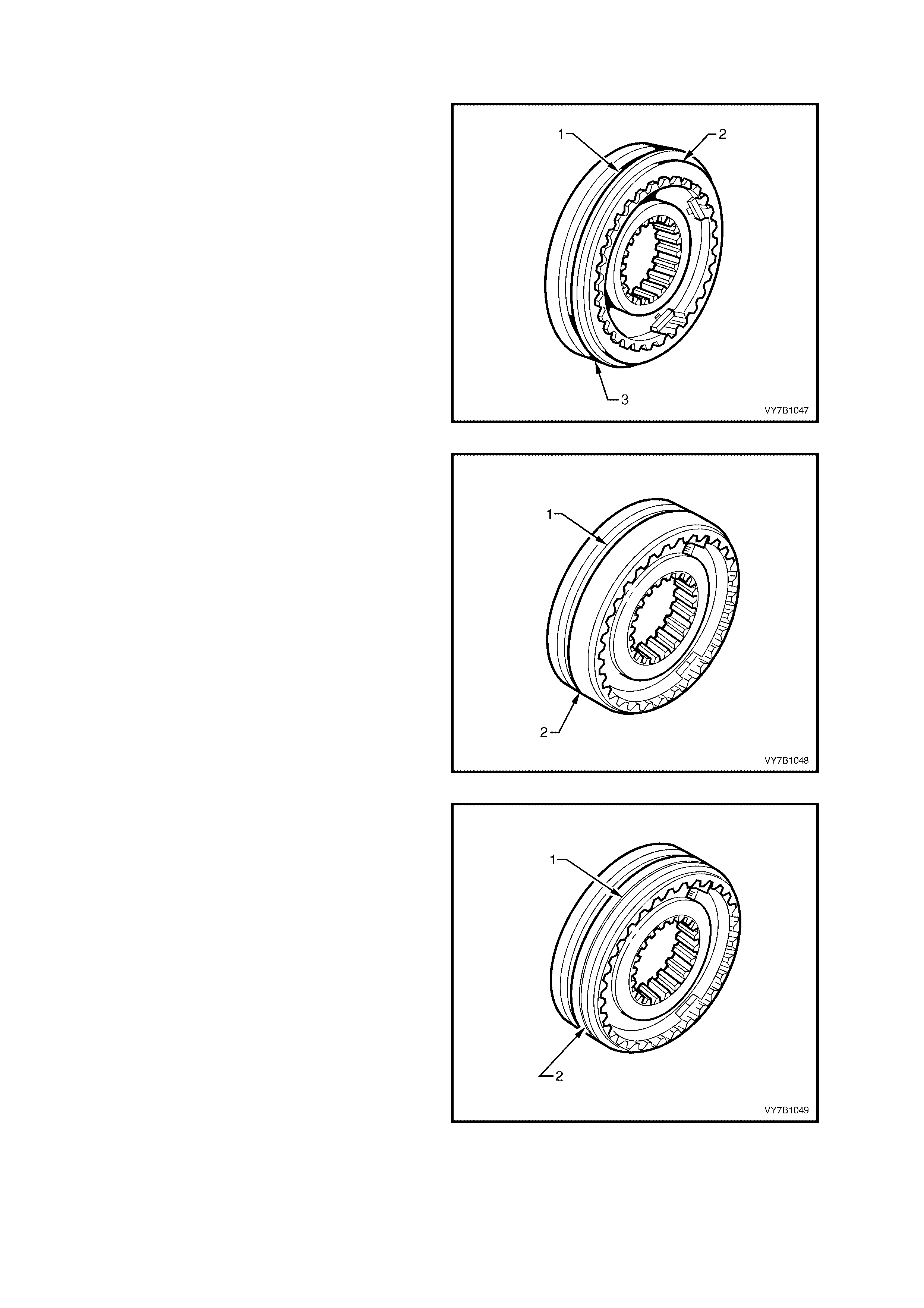
SYNCHROM ESH ASSEMBLIES
Identification
1. The 1st/2nd speed synchromesh assembly (3)
can be recognised by the larger diameter
splined hole in the hub, when com pared to the
3rd/4th synchromesh assembly.
T he s teppe d e dge ( 2) o n the ou ter s leeve ( 3) is
another identification feature, as is the offset
groove (1).
Figure 7B1-94
2. Identification of 3rd/4th speed synchromesh
assem bly ( 2) is by the off set selec tor slot (1) in
the outer sleeve and smaller diameter splined
hole in the hub.
Figure 7B1-95
3. Identification of the 5th/Reverse synchromesh
assembly (2) is by a single groove (1) on the
outer sleeve and the larger diameter splined
hole in the hub, when compared to the 3rd/4th
speed synchromesh assembly.
Figure 7B1-96
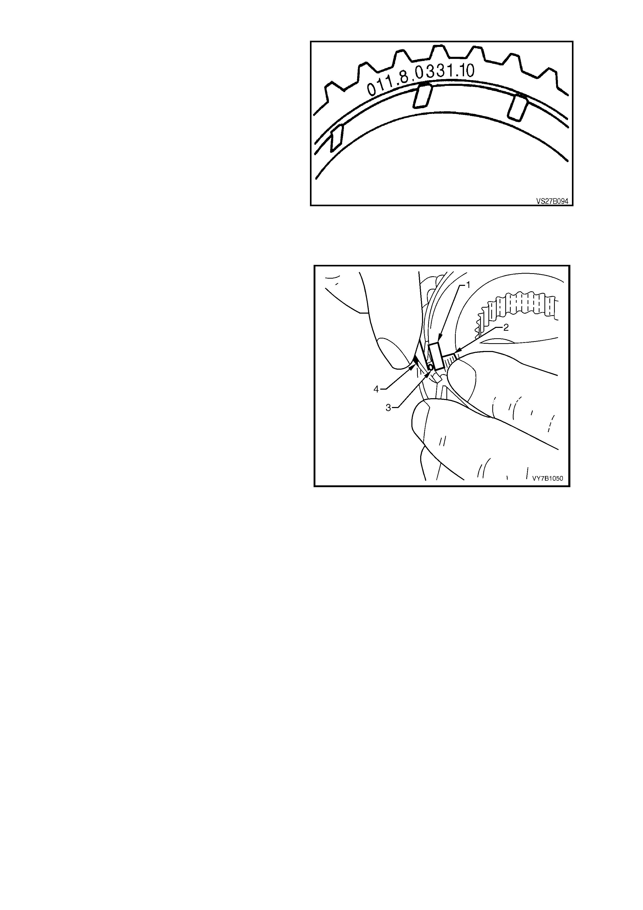
The synchromesh rings can be identified by the
number stamped on the flat face of each one.
Applications are as follows;
1st/2nd .................... 040.8.0001.00
3rd/4th..................... 002.8.0301.00
5th/Reverse............. 011.8.0331.10
(optional)............ 011.8.0331.11
Figure 7B-97
REASSEMBLE
Synchromesh Assemblies
The respective synchromesh assemblies are to be
assembled before pressing onto the mainshaft.
Only one synchromesh assembly is described in
the following operations, since reassembly is
similar for all units.
1. Support the synchromesh hub over a suitable
disc to raise it from the bench surface and
install the outer sleeve over the synchromesh
hub.
2. Insert sliding key s (1) (with the chamfered ends
facing outwards) and the pressure springs (2),
into each of the locations in the synchromesh
hub. Use petroleum jelly to hold parts in place.
3. Using a small screwdriver (4), prise each key
(1)upwards, just sufficient to enable a ball (3)
to be inserted. While holding the ball inwards,
push the key down to capture the ball. Repeat
for the remaining two key/spring combinations.
Assembly Notes:
a. The thicker boss of the 3rd/4th synchromesh
hub faces 3rd gear. The offset of the 3rd/4th
selector fork groove faces 4th gear.
b. The offset groove and the step in the outer
sleeve of the 1st/2nd gear synchromesh
assembly, faces 1st gear.
c. The single groove on the outer sleeve of the
5th/Reverse synchromesh outer sleeve, faces
5th gear.
Figure 7B1-98
Mainshaft
First and Reverse Gear Needle Roller Bearings
NOTE: Both the mainshaft first and reverse gears, caged needle roller bearing is a selective fit, with the various
sizes identified by different colour needle roller bearing cages.
Both the mainshaft and first/reverse gears are accurately measured during manufacture and the size recorded by
using different colour paint daubs on each component.
Depending on the combination of the two different colours (and therefore, sizes), the correct needle roller bearing
can then be selected, also by a colour coding of the cage.
Examples of the selection process, using the next two sets of tables, are;
a. With a white paint daub on the mainshaft and a green daub on the reverse gear, the correct needle roller
selection would be one that had a red cage.
b. A yellow daub on the mainshaft (forward of the gear) with a blue daub on the first gear, indicates the correct
needle roller selection as being one with a grey/white cage.
Relationship of the Mainshaft, First Gear and First
Gear Needle Roller Bearing Relationship of the Mainshaft, Reverse Gear and
Reverse Gear Needle Roller Bearing
Mainshaft First Gear Needle Roller Bearing Mainshaft Reverse
Gear Needle Roller Bearing
Paint Daub
Colour Paint Daub
Colour Cage
Colour Undersize
Dimension Paint Daub
Colour Paint Daub
Colour Cage
Colour Undersize
Dimension
White
White
White
Blue
Orange
Yellow
Green
Grey/White
Blue
–0.5 to –0.7 µm
–0.3 to –0.5 µm
–0.1 to –0.3 µm
White
White
White
Yellow
White
Green
Green
Grey/White
Red
–0.5 to –0.7 µm
–0.3 to –0.5 µm
0 to –0.2 µm
Yellow
Yellow
✹ Yellow
Blue
Orange
Yellow
Grey/White
Blue
Red
–0.3 to –0.5 µm
–0.1 to –0.3 µm
0 to –0.2 µm
Yellow
Yellow
Yellow
Orange
Yellow
White
Green
Grey/White
Blue
–0.5 to –0.7 µm
–0.3 to –0.5 µm
–0.1 to –0.3 µm
✹ Yellow Green Red 0 t o –0.2 µm
NOTE: Those selections marked ‘✹’ are non-preferred
combinations. If possible, an alternative mainshaft
or first/reverse gear colour would be preferred.
However, if this is not possible, then the choices as
listed, can be used.
Orange
Orange
Orange
✹ Orange
Blue
Orange
Yellow
White
Green
Grey/White
Blue
Red
–0.5 to –0.7 µm
–0.3 to –0.5 µm
–0.1 to –0.3 µm
0 to –0.2 µm
Table 1
1. Coat mainshaft (4), all gear bores and needle
bearings (3) with transmission lubricant.
2. Reassemble the colour coded, selective
Reverse gear needle bearing (3), gear (2) and
synchromesh ring (1) to mainshaft (4).
3. Heat assembled 5th/Reverse speed
synchromesh hub to approximately 100° C on
an electric hotplate.
NOTE: Use Faber Castel l Therm ochr om 2815/10 0°
C to indicate temperature. Apply Thermochrom
around synchromesh hub.
IMPORTANT: Do not exceed a temperature of
100° C
Figure 7B1-99
4. Using a heat proof glove, position
synchromesh assembly (3) onto mainshaft (2),
with the groove in the outer sleeve facing 5th
gear and aligning mainshaft and hub splines.
5. Using suitable sleeve and press plates (4),
press mainshaft (2) into synchromesh hub (3),
ensurin g that synchrom esh ring slots align with
sliding keys in the synchromesh assembly.
6. Remove mainshaft from press, and if
necessary, lever up the Reverse synchromesh
ring with a screwdriver so that it is not jammed
on the gear cone.
Figure 7B1-100
7. Reinstall synchromesh assembly selective
snap ring (1) onto mainshaft (2), ensuring that
no gap exists between the synchromesh hub
and the installed snap ring (1). Make sure the
snap ring is seated correctly in groove. Do not
over-stretch the snap ring with the pliers (3)
during installation.
Snap rings are available in thicknesses of 1.8,
1.85, 1.9, 1.95 and 2 mm.
Figure 7B1-101
8. Assemble the colour coded, selective 1st
speed gear, caged needle roller bearing (6),
1st speed gear (5), friction ring (1), cone ring
(2) and synchromesh ring (4) onto mainshaft
(3).
NOTE: The 1st and 2nd gear synchromesh cone
rings have different dimensions. Refer Figure 7B1-
103.
Figure 7B1-102
IMPORTANT: Ensure that the correct cone ring is
fitted. The cone rings for 1st and 2nd gears have
different dimensions, as shown. Further
identif ication can be made from the m anufacturer ’s
number on each ring, which is as follows;
1st gear cone ring (A) 040.8.0069.00
2nd gear cone ring (B) 040.8.0059.00
Figure 7B1-103
9. Heat assembled 1st/2nd speed synchromesh
hub on a hot plate to approximately 100° C on
an electric hotplate.
NOTE: Use Faber Castel l Therm ochr om 2815/10 0°
C to indicate temperature. Apply Thermochrom
around synchromesh hub.
IMPORTANT: Do not exceed a temperature of
100° C.
10. Using a heat proof glove, position
synchromesh assembly (4) onto mainshaft,
aligning mainshaft and hub splines.
NOTE: The side with t he sm aller outer s urface and
the step (1), faces 1st gear (2).
11. Using a suitable sleeve (3), press
synchromesh hub onto mainshaft, ensuring
that synchromesh ring slots align with sliding
keys.
12. Remove mainshaft from press, and if
necessary, lever up 1st speed synchromesh
ring with a screwdriver so that it is not jammed
on the gear cone.
Figure 7B1-104
13. Mount rear end of mainshaft in vice with soft
metal jaws.
14. Reinstall synchromesh assembly (3), selective
snap ring (2) onto mainshaft, ensuring that
snap ring (2) is correctly seated in groove,
without an y end clear ance. Do not ov er-stretch
the snap ring (2) with the snap ring pliers (1),
during installation.
NOTE: Selective fit snap rings are available in
thicknesses of 1.8, 1.85, 1.9, 1.95 and 2 mm.
Figure 7B1-105
15. Reinstal l 2n d s pe ed g ear (2 ) with caged nee dl e
roller bearing (5), friction cone (4), cone ring (3)
and synchromesh ring (6) onto mainshaft (1),
ensuring that the friction ring (4), cone ring (3)
and synchromesh ring (6) are correctly located
in the synchromesh assembly.
NOTE: Ensure that the correct synchromesh cone
ring is fitted. Refer to Figure 7B1-103 for correct
identif icat ion det ai ls .
Figure 7B1-106
16. Reinstall small, locating ball (3) in mainshaft
(2), securing with petroleum jelly.
Figure 7B1-107
17. Install thrust washer over locating ball.
Figure 7B1-108
18. Heat 3rd speed gear roller bearing sleeve (1)
on a hot plate to approximately 80° C.
NOTE: Use Faber Castell Thermochrom 2815/80°
C to indicate tem peratur e.
IMPORTANT: Do not exce ed a temperatur e of 80°
C.
19. Using a heat proof glove, position bearing
sleeve onto mainshaft and press home using
suitable pr ess pla tes . When pres s ing mainshaf t
into the sleeve, ensure that the thrust washer
(‘1’ in Figure 7B1-107) remains in place over
the retaining ball.
Figure 7B1-109
20. Reinstall caged needle roller bearing (2), 3rd
speed constant mesh gear (1) and
synchromesh ring, onto mainshaft.
21. Heat the assembled 3rd/4th speed
synchromesh assembly on a hot plate to
approximately 100° C.
NOTE: Use Faber Castel l Therm ochr om 2815/10 0°
C around synchromesh hub, to indicate
temperature.
22. Using a heat proof glove, position
synchromesh assembly onto mainshaft,
aligning mainshaft and hub splines.
NOTE: The 3rd/4th selector fork offset in the outer
sleeve faces away from 3rd gear.
Figure 7B1-110
23. Using suitable sleeve (1), press synchromesh
hub assem bly (2) o nto m ainshaf t, ensur ing that
synchromesh ring slots align with sliding keys.
24. Remove mainshaft from press, and if
necessary, lever up 3rd speed synchromesh
ring (3) with a screwdriver so that it is not
jammed on the 3rd speed gear cone (4).
Figure 7B1-111
25. Reinstall washer and selective snap ring (1) to
mainshaft, using suitable snap ring pliers (2).
Ensure that the snap ring (1) is correctly
seated in groove with no clearance between
the snap ring and the washer.
Snap rings are available in thicknesses of 2.0,
2.1, 2.2, 2.3, 2.4 and 2.5 mm .
Figure 7B1-112

26. Reinstall a pre-lubricated 5th speed caged
needle roller bearing (3) onto mainshaft. Then
install the synchromesh ring (2), engaging ring
slots with sliding blocks of the synchromesh
assembly and finally, the 5th speed gear (1).
Figure 7B1-113
Maindrive Gear
1. Coat maindrive gear needle bearing with
petroleum jelly.
2. Insert bearing assembly into the maindrive
gear.
Figure 7B-118
Reverse Idler Gear Shaft
1. Lubricate the reverse idler gear shaft with
clean transmission fluid, then install the two
caged needle roller bearings.
2. Locate the roller bearings by installing new
snap rings to each groove on the reverse idler
gear shaft.
IMPORTANT: Snap r ings (1) must be insta ll ed with
the curved out portion of each snap ring end,
AWAY from the roller bearing as shown.
As the reverse idler gear is in constant mesh with
the cluster gear, if the snap rings are not installed
as shown, then a transmission noise will be
created.
Figure 7B1-119
TRANSMISSION CASE, REAR SECTION
Disassemble
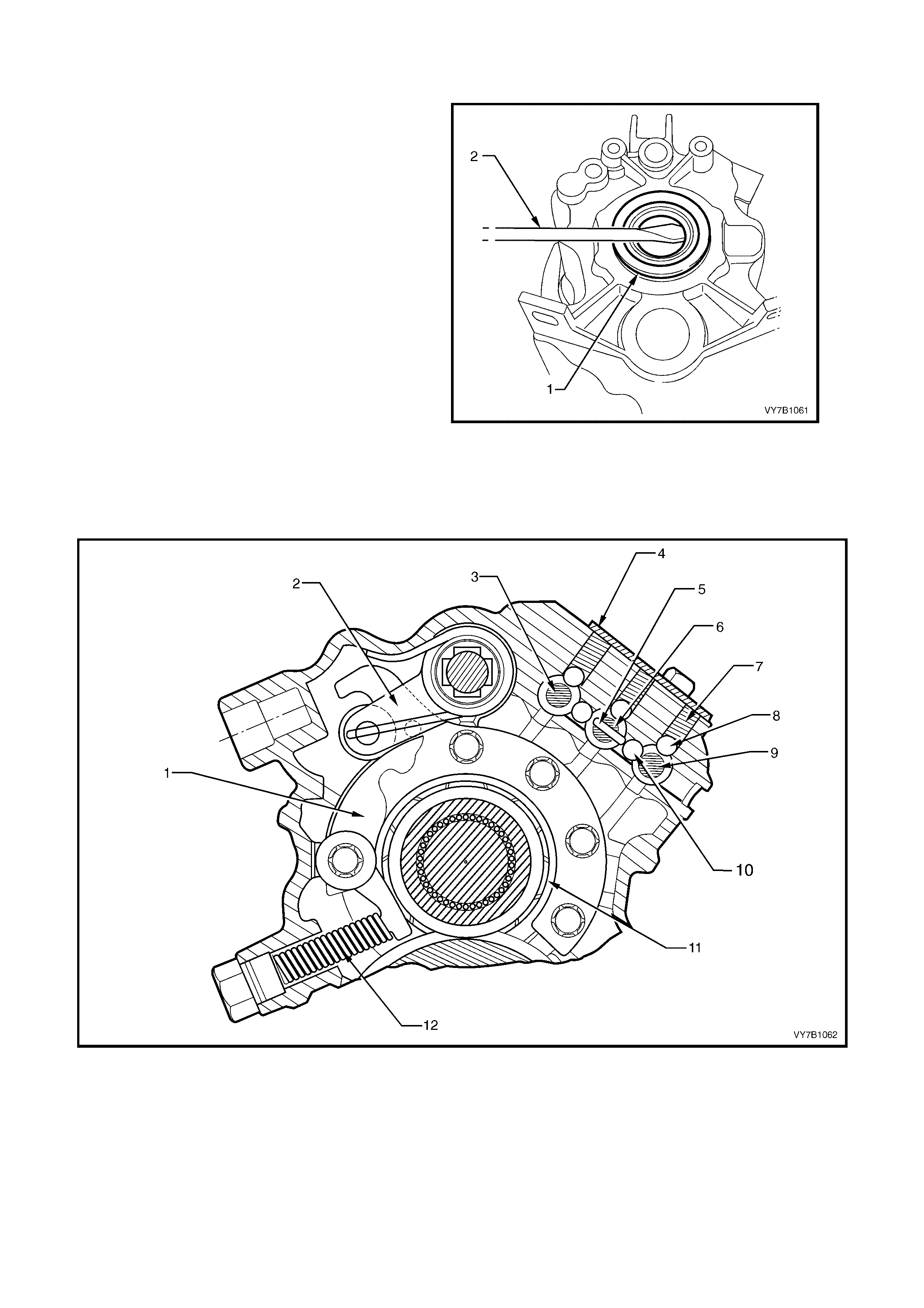
1. To remove the rear oil seal, use the distance
spacer r ing (1) from the f ront m ains haf t bear ing
to protect the transmission rear housing, then
use a suitable lever such as a screwdriver (2)
to lever o ut the seal from the rear transm ission
case.
NOTE: Take extreme care not to scratch the seal
surface in the rear transmission case. If damaged,
a subsequent fluid leak may occur.
Figure 7B1-120
2. Remove th e loc king le ver scr ew plug f rom the rear ho using, using a 19 m m ring spanner , no ting t hat se alan t is
applied to the threads.
CAUTION: Take care that the plug does not fly out under spring force, when the plug is unscrewed.
3. Remove the spring from the rear housing.
Figure 7B-121
Legend
1. Locking Lever
2. Selector Arm
3. 5th/Reverse Selector Shaft
4. Cover Plate
5. Interlock Pin
6. 3rd/4th Selector Shaft
7. Detent Ball Spring
8. Detent Ball
9. 1st/2nd Selector Shaft
10. Interlock Ball
11. Mainshaft Bearing
12. Locking Lever Spring, Plunger and Cap
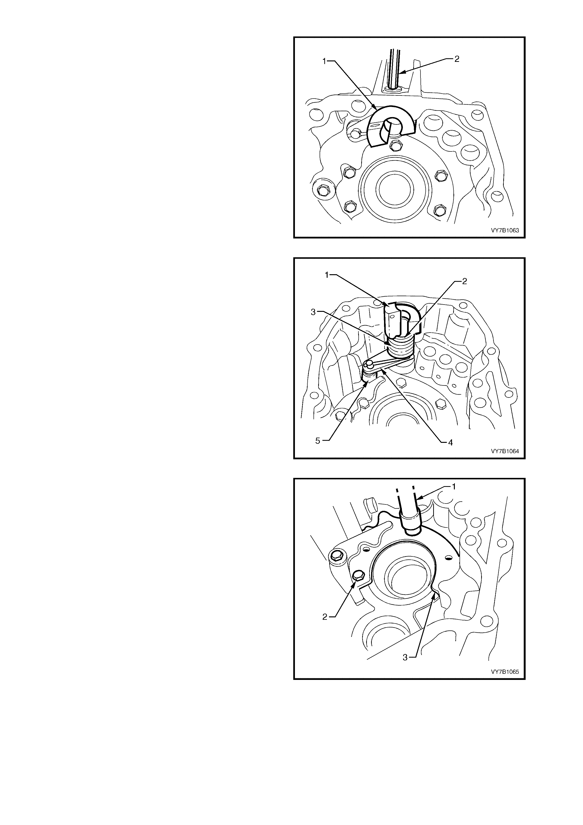
13. Using a 6 mm, Allen key socket (2), remove
the gearshift selector rod bush (1) lock bolt
from the rear case section.
NOTE 1: The lock bolt has sealant applied to the
thread and will be difficult to remove, if a hot air
gun is not used to soften the sealant prior to bolt
removal.
NOTE 2: As the Allen key screw is removed,
support the gearshift selector rod bush against
rotational spring force.
Figure 7B1-122
14. From inside case, remove the spring (3), spring
guide (2) and selector arm (4) with roller (5)
and gear selector rod bush (1). Be careful as
spring force can easily eject these parts,
uncontrolled.
Figure 7B1-123
15. Remove the five bolts (2) holding the rear
bearing plate and locking lever support (3)
using suitable socket equipment (1), then
remove the plate and locking lever as an
assembly.
16. If required, remove the locking lever pivot bolt
and nut from the rear bearing retaining plate.
Figure 7B1-124
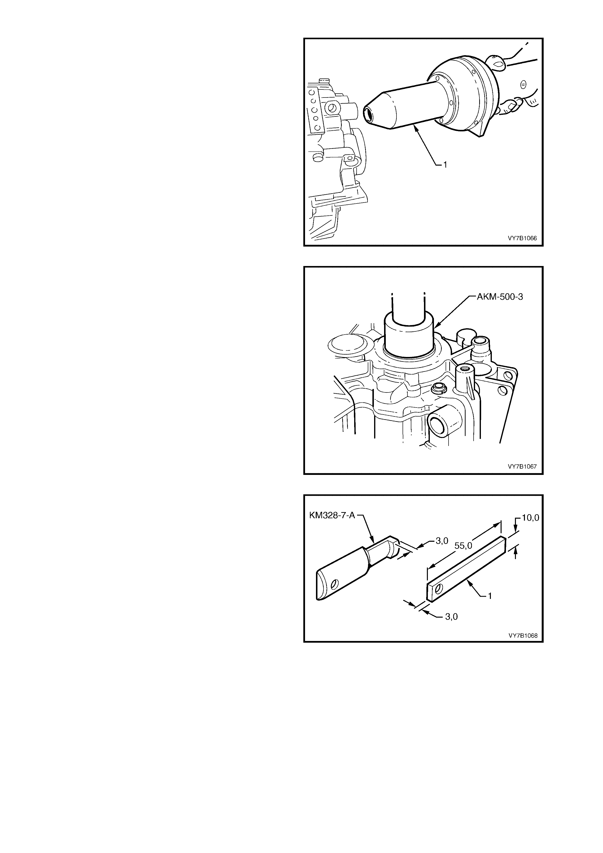
NOTE: Unless the rear mainshaft bearing is to be
replaced, there is no need for this next operation.
17. Preheat the transmission housing in the rear
bearing area, to approximately 80° C using a
comm er c ially availab le hot air blow er.
NOTE: Use Faber Castell Thermochrom 2815/80°
C, to ensure that an excessive temperature is not
reached.
Figure 7B1-125
18. Use a suitable sleeve such as AKM-500-3 and
press the mainshaft rear bearing from the
transmission housing.
IMPORTANT: Because of ball brinelling, the
bearing MUST be replaced, after removal.
Figure 7B1-126
19. To remove the rear cluster gear bearing cup,
use the following method;
a. Grind the legs of Tool KM-328-7-A down to
approximately 3 mm, sufficient to insert under
the bearing cup.
b. Fabricate a spacer (1) as shown, to insert
between the two legs, using 3 mm thickness,
mild steel stock.
Figure 7B1-127
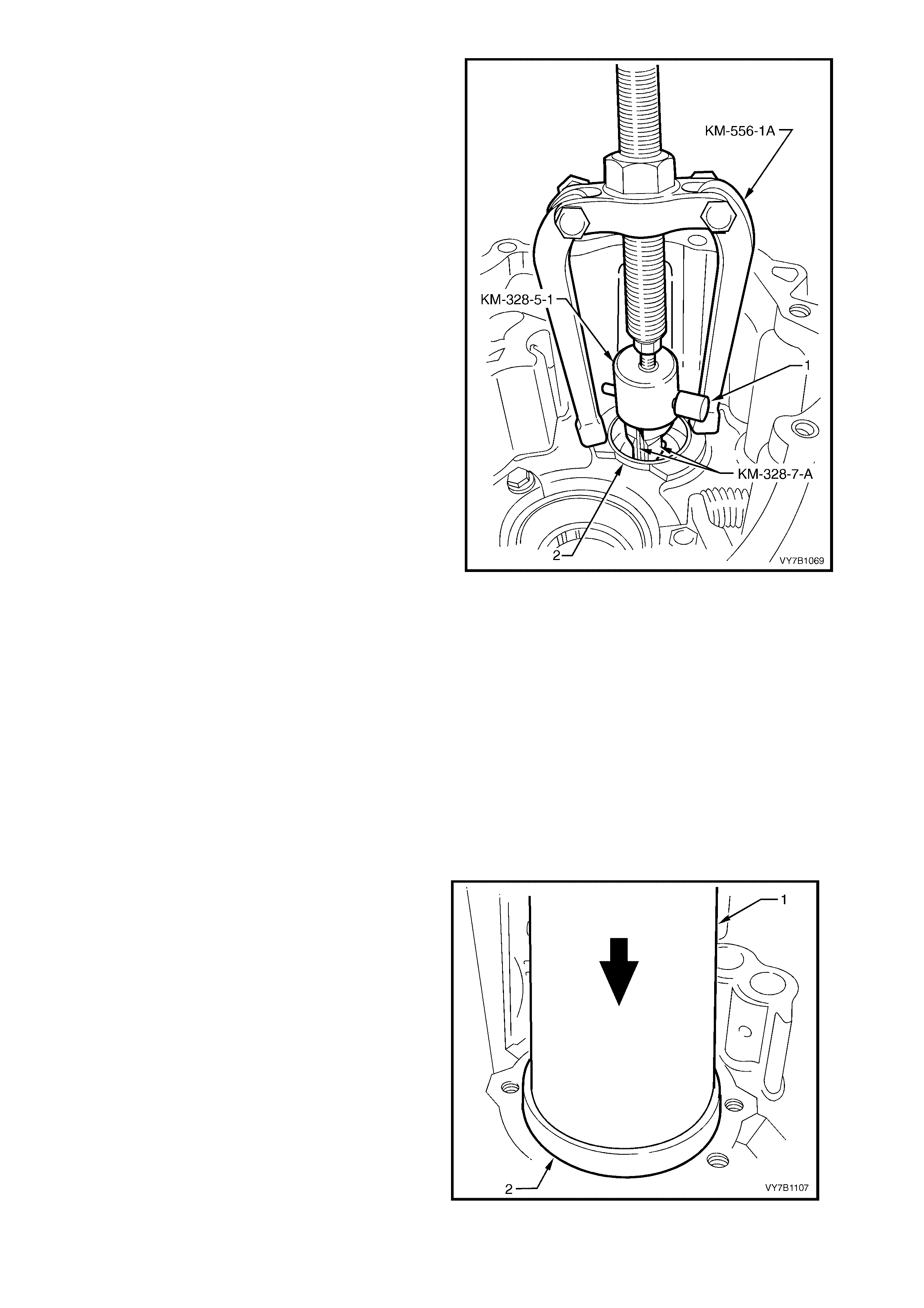
c. Install each of the modified legs of Tool KM-
328-7-A under the bearing cup, then insert the
fabricated spacer in between them.
d. Us e the cup, T ool KM-3 28-5- A and pin (1) from
slide hammer, Tool KM-328-B to secure the
legs and spacer assembly.
e. Scr ew threade d adaptor int o cup (2) a nd instal l
puller KM-556-1A.
f. Use the puller to extract the bearing cup from
the rear transmission case.
NOTE: To aid in removal of bearing, it will be
necessary to preheat case area of bearing to 80°
C, using a commercially available, hot air blower.
Use Faber Castell Thermochrom 2815/80° C, to
ensure that an excessive temperature is not
reached.
Figure 7B1-128
Inspect
1. Inspect rear transmission case for any defects
or cracks that may cause oil leaks.
2. Check all machined surfaces for burrs, and if
present, dress them off with a fine cut file.
3. Check bearing bores for damage or scoring.
4. Inspect all shift control component contact
surfaces and sliding surfaces for wear,
scratches, projections or other damage.
5. Check all springs for damage or distortion.
6. Check the selector inter-lock pin and balls for
damage.
Reassemble
1. Using a suitable length and diameter pipe (1),
press a new, sealed ball race (2) into the rear
transmission case, ensuring that force is only
applied to the outer bearing ring.
NOTE 1: To ass is t in t he in s tall ation of the be ar in g,
heat the rear transmission housing with a
comm erc ially availa ble hot air gun to appr ox im ately
80° C.
Use Faber Castell Thermochrom 2815/80° C, to
ensure that an excessive temperature is not
reached.
NOTE 2: The offset on the inner bearing cone
faces the rear of the transmission.
Figure 7B1-129
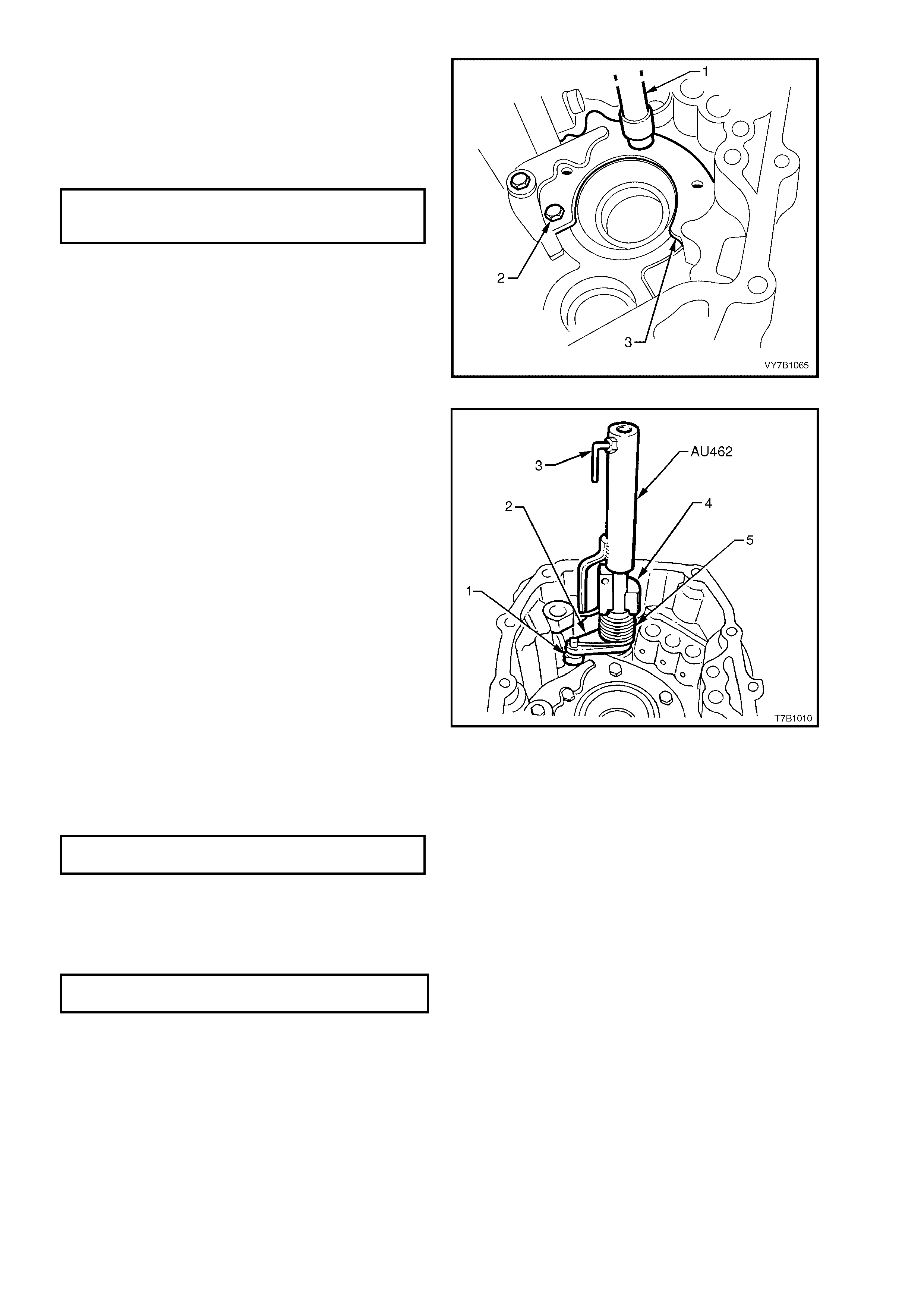
2. Apply thread sealant such as Loctite 242 or
243 (or equivalent) to the cleaned threads of
the rear be aring plate reta ining bolts ( 2). Install
the rear bearing plate (1) and tighten the bolts
to the correct torque specification, using
suitable socket equipment (1) and a torque
wrench.
REAR BEARING PLATE AND
LOCKING LEVER BOLT
TORQUE SPECIFICATION 10 Nm
Figure 7B1-130
3. Pre-assemble the selector arm, spring, bush
and sleeve, by first inserting the shaft of Tool
AU462 into the rear of the selector arm,
engaging the lugs with those in the arm (2).
Then, install the straight end of the spring (5)
into the selector arm pin hole and insert the
sleeve and bush (4) over the shaft. Insert the
sleeve of Tool AU462 over the protruding shaf t
and engage the leg with the free end of the
spring.
While holding the selector lever (2) in one
hand, rotate the sleeve of the holding Tool
AU462 counter-clockwise, loading the spring.
Tighten the locking screw (3) to retain the
assem bl y in the loaded stat e.
4. Use petroleum jelly to secure the selector arm
roller (1), to the pin, then install the assembly
into the rear transmission case.
5. Reinstall the bush locating screw, after
applying se alant suc h as Loctite 242 or 243 (or
equivalent) to the cleaned screw threads.
Tighten with an All en key h eaded sock et to the
correct torque specification.
GEARSHIFT SELECTOR ROD BUSH
SCREW TORQUE SPECIFICATION 20 Nm
6. Apply thread sealant such as Loctite 242 or
243 (or equivalent) to the cleaned threads of
the locking lever screw plug. Install the spring
and plug, tightening to the correct torque
specification.
Figure 7B1-131
LOCKING LEVER SCREW PLUG
TORQUE SPECIFICATION 48 Nm
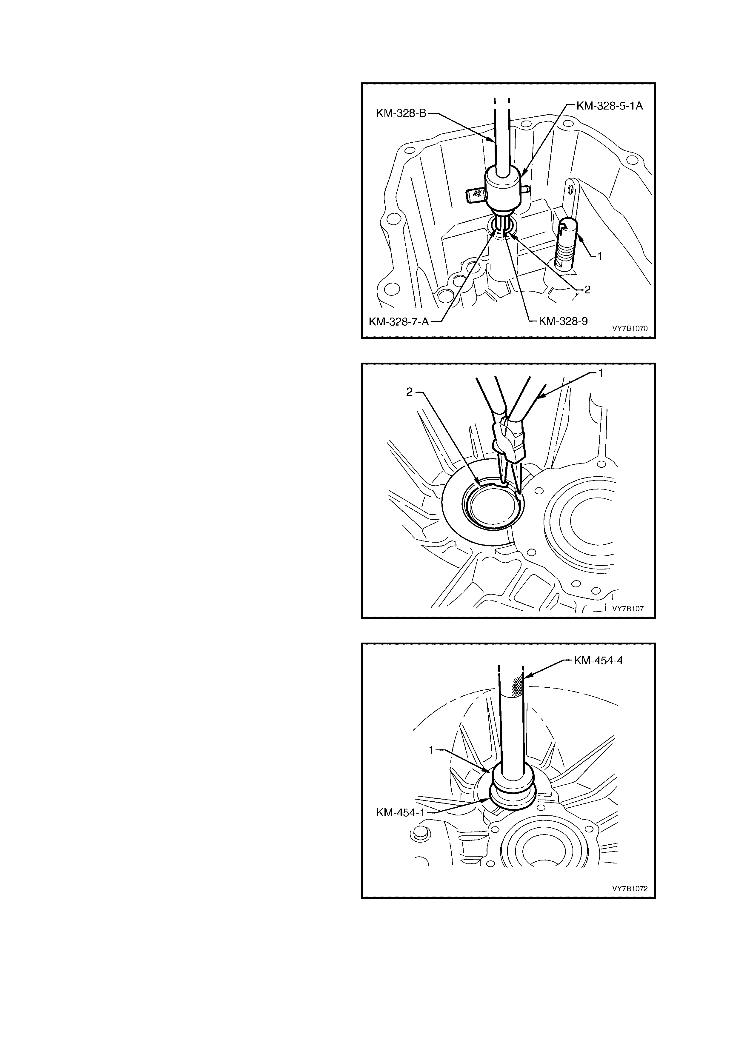
TRANSMISSION CASE, FRONT SECTION
Disassemble
1. Insert the legs of Tool KM328-7-A into the
bearing (2) and hold in position with spacer,
Tool KM-3 28-9. S lip the cu p of T ool KM-328-5-
1A over the legs and secure with the pin.
2. Screw the thread of slide hammer, Tool No.
KM-328-B into the cup and remove the
gearshift selector rod front bearing from case.
NOTE: When carrying out this operation, the
bearing will be damaged and must be replaced.
3. From inside the transmission bell housing,
remove the bolt securing the reverse block
assembly (1). To remove the reverse block
shaft, temporarily reinstall the bolt for a few
threads and gently tap the shaft free from the
transmission front case.
Figure 7B1-132
NOTE: Normally this next operation would only be
considered necessary if replacement of the front
cluster gear, bearing and/or transmission front
case was required.
4. Remove cluster gear front bearing snap ring
(2) from front tr ansmission cas e, using suitab le
circlip pliers (1) and remove any end float
adjusting shims.
NOTE: If necessary, press bearing inward slightly
so that snap ring can be removed. Use the
adaptor, Tool KM-4 54-1 and mandr el T ool KM- 4 54-
4, with a flat washer.
Figure 7B1-133
5. Use the adaptor, Tool KM 454-1 and mandrel
Tool K M-454-4, with a f lat washer (1) (or us e a
sleeve of 43 mm diameter), press the bearing
cup into the transmissi on case.
Figure 7B1-134
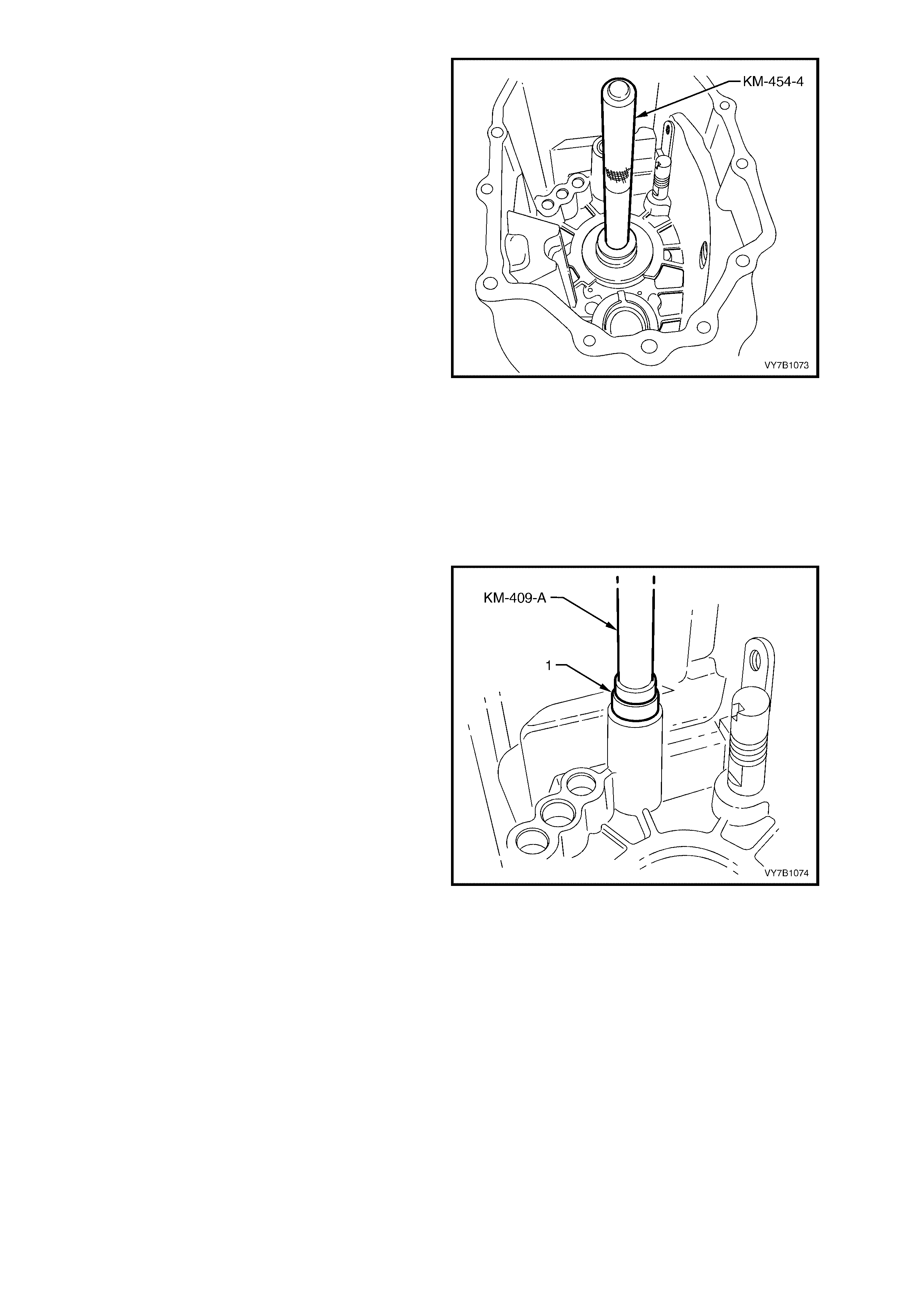
6. Using a suitable adaptor (or sleeve), press on
the outer ring of the maindrive gear bearing
from inside the transmission case, to remove it.
Figure 7B1-135
Inspect
1. Inspect transmission case for any defects or
cracks that may cause oil leaks.
2. Check all machined surfaces for burrs, and if
present, dress them off with a fine cut file.
3. Check bearing bores for damage or scoring.
Reassemble
1. Lubricate a new gearshift lever shaft guide
bearing (1) with transmission fluid. Install,
using Tool No. KM-409-A or equivalent.
Figure 7B1-136
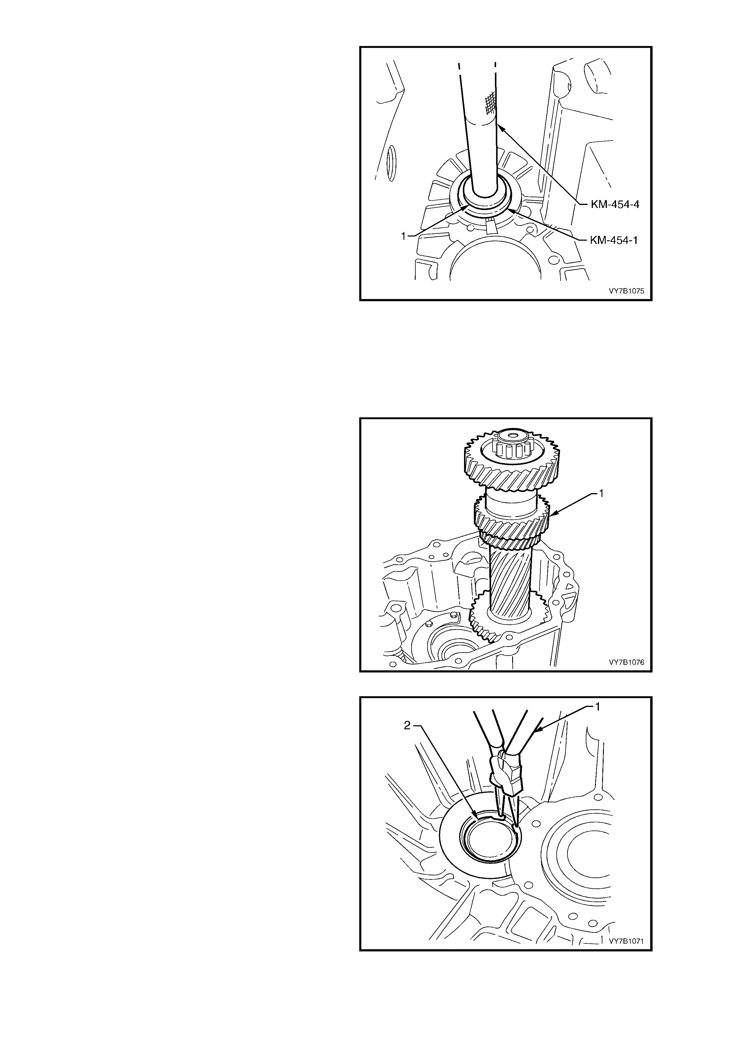
2. Reins tal l com pens ating shi m /s and a new s nap
ring to the bore of the front cluster gear
bearing.
3. Reinstall cluster gear front bearing, using
adaptor, Tool KM-454-1, flat washer (1) and
mandrel KM-454-4 (or a suitable sized tube),
pressing from the inside of the front
transmission housing, outward.
NOTE 1: If a new transmission case front section
and/or new cluster gear is to be installed, the end
play must be measured.
Refer to the Sub-Assembly heading ‘Cluster Gear
End Play Adjustment', next in this Section.
NOTE 2: If the maindrive bearing was removed
and a replacement is to be installed, then
compensating shim thickness will need to be
calculated, after installation. As bearing
replacement would normally be carried out
during transmission reassembly, this operation
will be detailed at that time. In any case, if
cluster gear end play adjustment is to be
carried out, then the bearing would need to be
removed for this operation.
Figure 7B1-137
CLUSTER GEAR END PLAY ADJUSTMENT
This operation is only necessary when replacing
the front transmission case and/or the cluster gear.
1. Reinstall cluster gear (1) into transmission
case rear section.
Figure 7B1-138
2. Remove front cluster bearing circlip (2) from
transmission case using suitable circlip pliers
(1) front section, then remove compensating
shim/s.
NOTE: If necessary, press bearing cup inward
slightly to enable removal of snap ring.
Figure 7B1-139
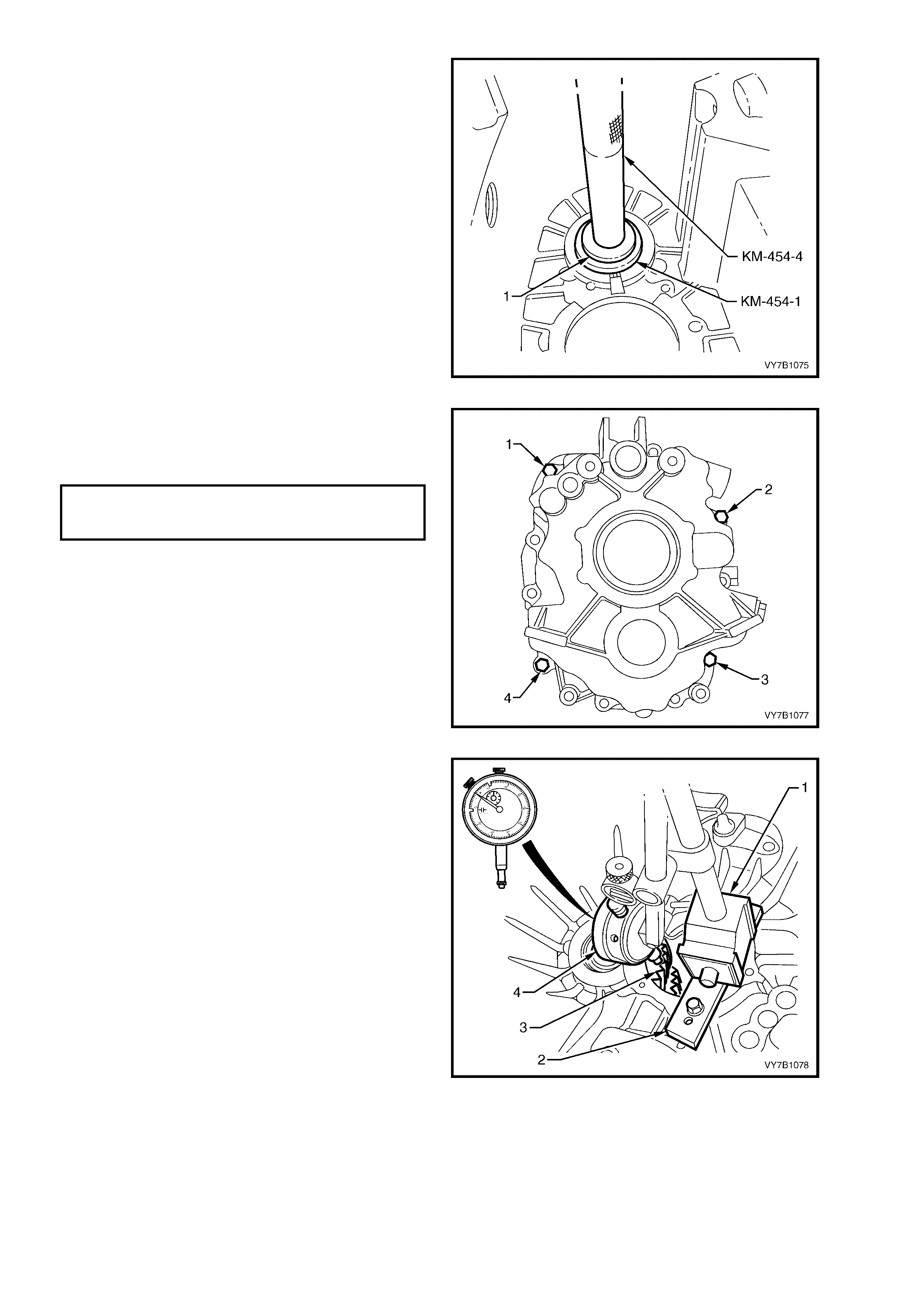
3. Reinstall cluster gear front bearing circlip,
without shim/s.
4. Using adaptor, Tool KM-454-1 and mandrel
KM-454-4, together with a flat washer (1) (or
use a suitable tube), press bearing into case
bore until it contacts snap ring.
Figure 7B1-140
5. Place tr ansm ission cas e front sectio n onto rear
section and install four case attaching bolts (1
to 4). Tighten bolts to the correct torque
specification.
TRANSMISSION REAR CASE
ATTACHING BOLTS
TORQUE SPECIFICATION 25 Nm
Figure 7B1-141
6. Secure a piece of flat steel (2) (approximately
20 x 5 mm) with two bolts, to the front
machined surface of the clutch throwout
bearing guide fla nge.
7. Mount a dial indicator (4) and magnetic stand
(1) to the flat steel (2), ensuring that the stylus
of dial indicator (4) rests on front of cluster gear
(3), as shown. Zero the dial in dicator.
Figure 7B1-142

8. Using a screwdriver (1) through filler plug
opening, raise and lower cluster gear to obtain
the total end float dimension. Record this
reading.
Axial play should be to the following
specification:
CLUSTER GEAR AXIAL PLAY 0.13 - 0.23 mm
9. Subtract this axial play figure from the
measurement taken to determine the required
shim stack.
e.g. Total Axial Play Recorded = 3.96 mm
Subtract Axial Play Specification = 0.18 mm
Required Shim Thickness = 3.78 mm
Shims are available in 1.0, 1.7 mm, 1.8 mm,
2.0 mm, 2.1 mm, 2.2 mm and 2.3 mm
thicknesses. In the above example, a shim
combination of 1.8 and 2.0 mm would be
required.
10. Reinstall selected shim/s, refer to Transmission
Case Front Section-Disassemble and
Reassemble in this Sec t ion .
11. Recheck axial play as described previously.
12. Once axial play has been adjusted, separate
the two transmission cases and remove the
cluster gear.
Figure 7B1-143
CLUTCH THROWOUT BEARING GUIDE
Input Shaft Se al, Rep lace
1. Remove the maindrive bearing compensation
shim/s (1) if fitted, from the throwout bearing
guide and set to one side. If the maindrive
bearing is not replaced, then this same shim
stack will need to be reinstalled, on
reassembly.
2. Using a screwdriver (2), drive the seal ring (3)
from thrust bearing guide sleeve, as shown.
Take c ar e not to sc ratc h th e s ea l sur f ace of the
throwout bearing guide during seal removal.
Figure 7B1-144
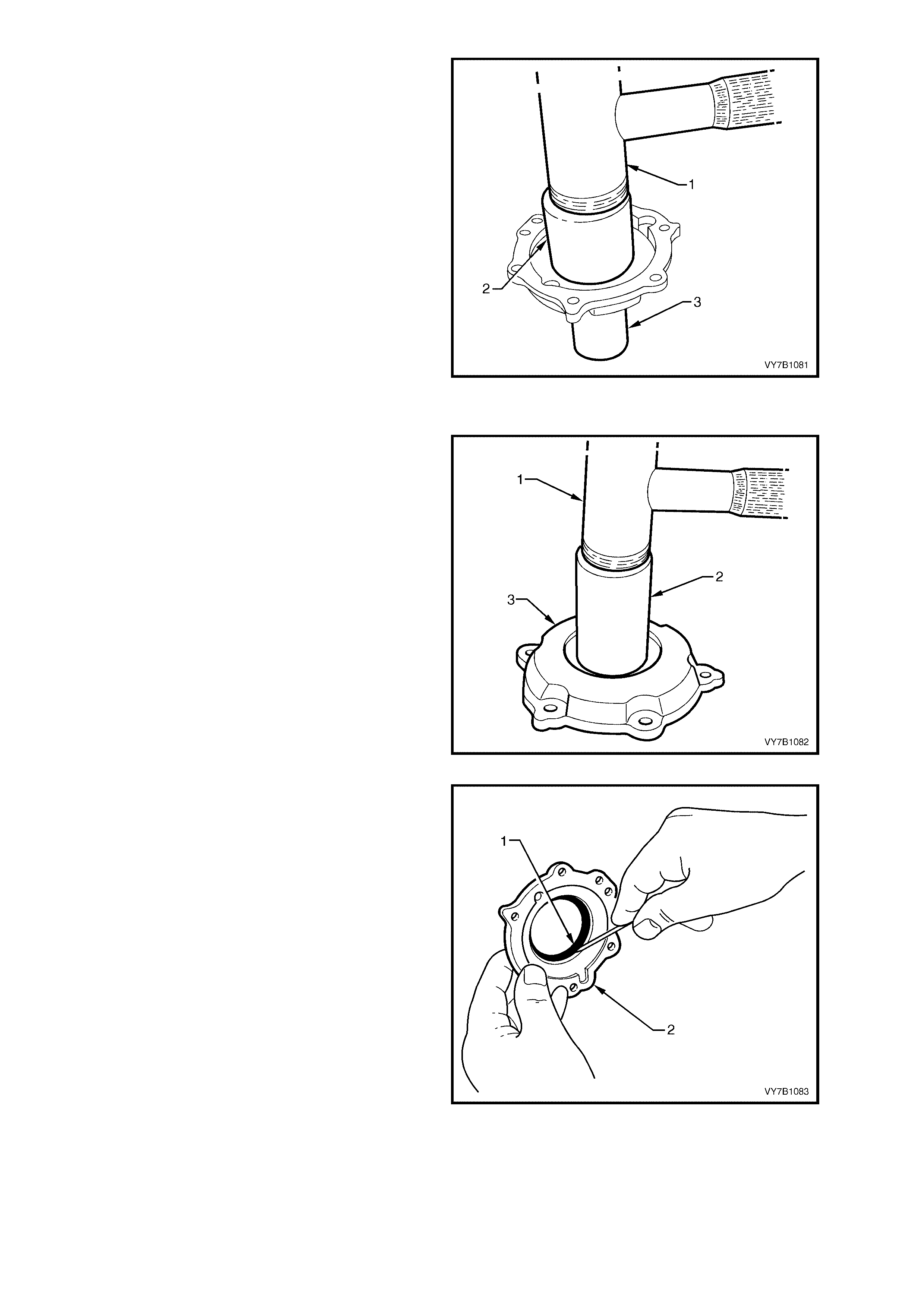
3. Using a suitable size sleeve (2), use a soft
faced ham mer (1) to insta ll new seal i nto guide
sleeve (3).
Figure 7B1-145
O-Ring, Replace
1. While holding the flange (3) against a flat
surface, use a plastic faced hammer (1) and
tap the throwout bearing guide (2) from the
mounting flange.
NOTE: Do not lose the small locating disc.
Figure 7B1-146
2. Remove the O-ring seal (1) from the mounting
flange (2), using a small screwdriver.
3. Clea n all c om ponents and inspec t for wear an d
damage. Replace as required.
4. Install new O-ring into the flange, lubricating
with petrole um jell y.
5. Align the locating disc, semi-circular cut-outs of
the flange and guide and assemble, taking
care to keep both parts square to each other.
6. Reinstall the locating disc, securing with a
small amount of petroleum jelly.
Figure 7B1-147
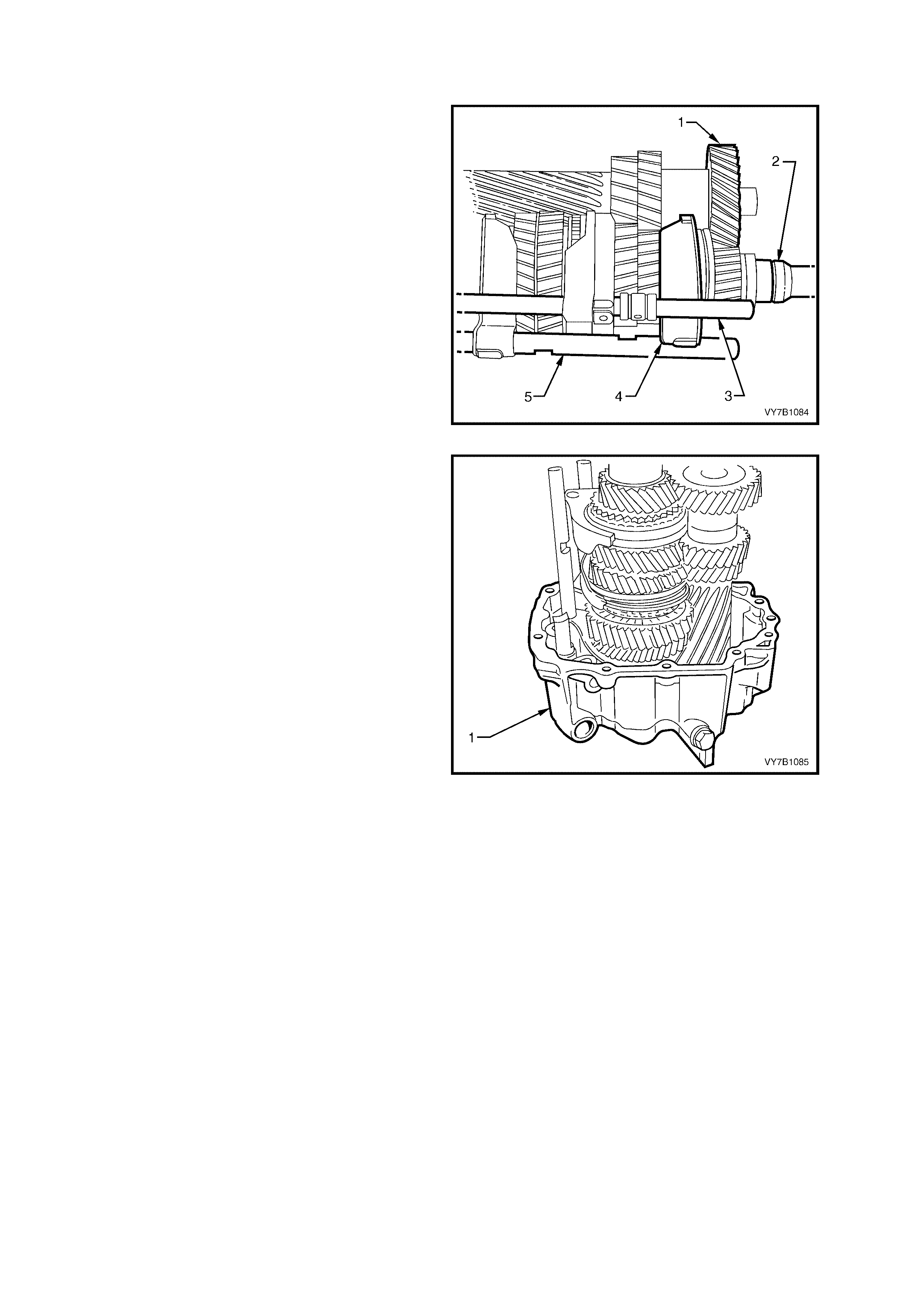
4.5 TRANSMISSION REASSEMBLE
LT SECTION NO. – 04M-125
1. Carefully move the respective synchromesh
rings into Reverse and 2nd gear positions.
2. Reinstall all shift forks to their respective
synchromesh rings - the 5th/Reverse (5) and
1st/2nd (3), with their shafts, both with new roll
pins fitted.
NOTE:The 3rd/4th shift shaft will be fitted later in
the assembly process.
3. Reass emble the m aindrive gear (2) and cl uster
gear (1) to the mainshaft assembly, holding
everything together as a single assembly.
4. Pre-heat the inner race of the sealed rear ball
race to 80° C, using a commercially available
hot air blower.
NOTE: Use Faber Castell Thermochrom 2815/80°
C to indicate the temperature of the inner race.
Figure 7B1-148
5. With the transmission case rear section (1)
supported in an upright position, carefully
install the gear and shift fork/rail assemblies
into the case, aligning the two shift rails with
their respective bores.
Figure 7B1-149
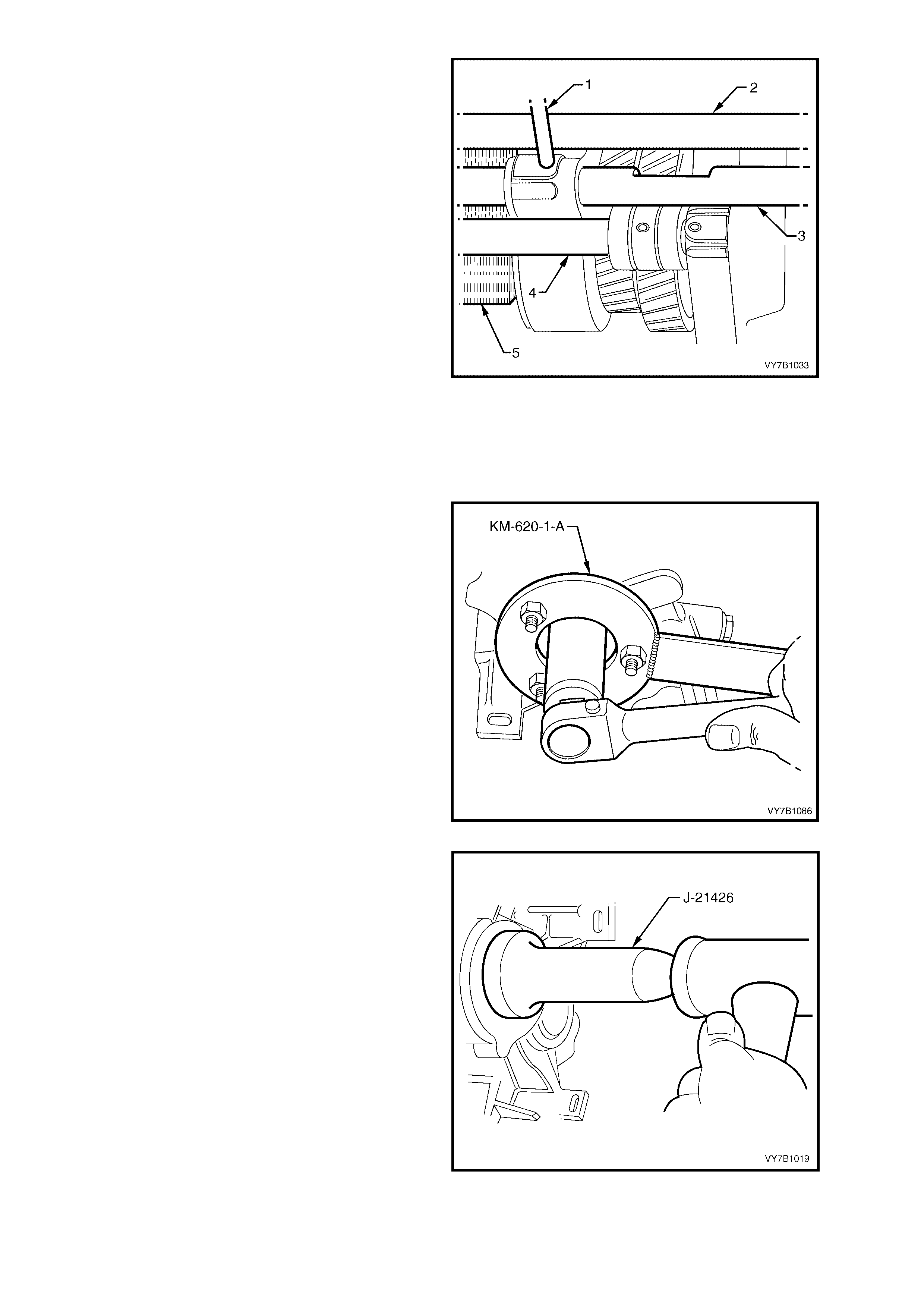
6. Carefully move the 5th/Reverse (2) and
1st/2nd gear synchromesh rings (4) into the
Neutral position.
7. Reinstall both interlock balls to the interlock
bore, securi ng in plac e with petro leum jelly.
8. With the transmission rear case in an upright,
horizontal position, install the lower interlock
ball.
9. Insert th e 3rd/4th se lector shaf t (3) through the
3rd/4th shift fork and install partially into the
bore in the rear case. Then, using a small
screwdriver, insert the second interlock ball
into position from the rear, fully installing with
the 3rd/4th selector shaft.
10. Pus h the 3r d/4th selec tor shaft thr ough and o ut
the rear of the case, insert the interlock pin,
then move the selector shaft forward, lining up
the roll pin hole with the selector fork.
NOTE: Ensure that the detent ball grooves in the
selector shaft face uppermost.
11. While supporting the shaft with a suitable
wooden wedge (5), install a new roll pin (1) to
the fork and shaft (3).
Figure 7B1-150
12. Fully install the mainshaft to the sealed rear
bearing, using the following method:
a. Temporarily install the mainshaft sleeve and
the output f lange and to othed ring assem bly to
the mainshaft.
b. While hold ing the f la nge with Tool No. K M-620-
1-A and a suitable length of pipe, tighten the
flange nut using a commercially available, 30
mm socket, pulling the inner bearing fully into
place.
c. Rem ove the fla nge nut, f lange and s leeve f rom
the mainshaft.
Figure 7B1-151
13. With the transmission in a horizontal position,
install a new seal into transmission case rear
section us ing Tool No. J-2 1426 or sim ilar, after
coating the seal lip with transmission lubricant.
14. Also lubricate the seal surface of mainshaft
sleeve with transmission lubricant and install
over the mainshaft.
Figure 7B1-152
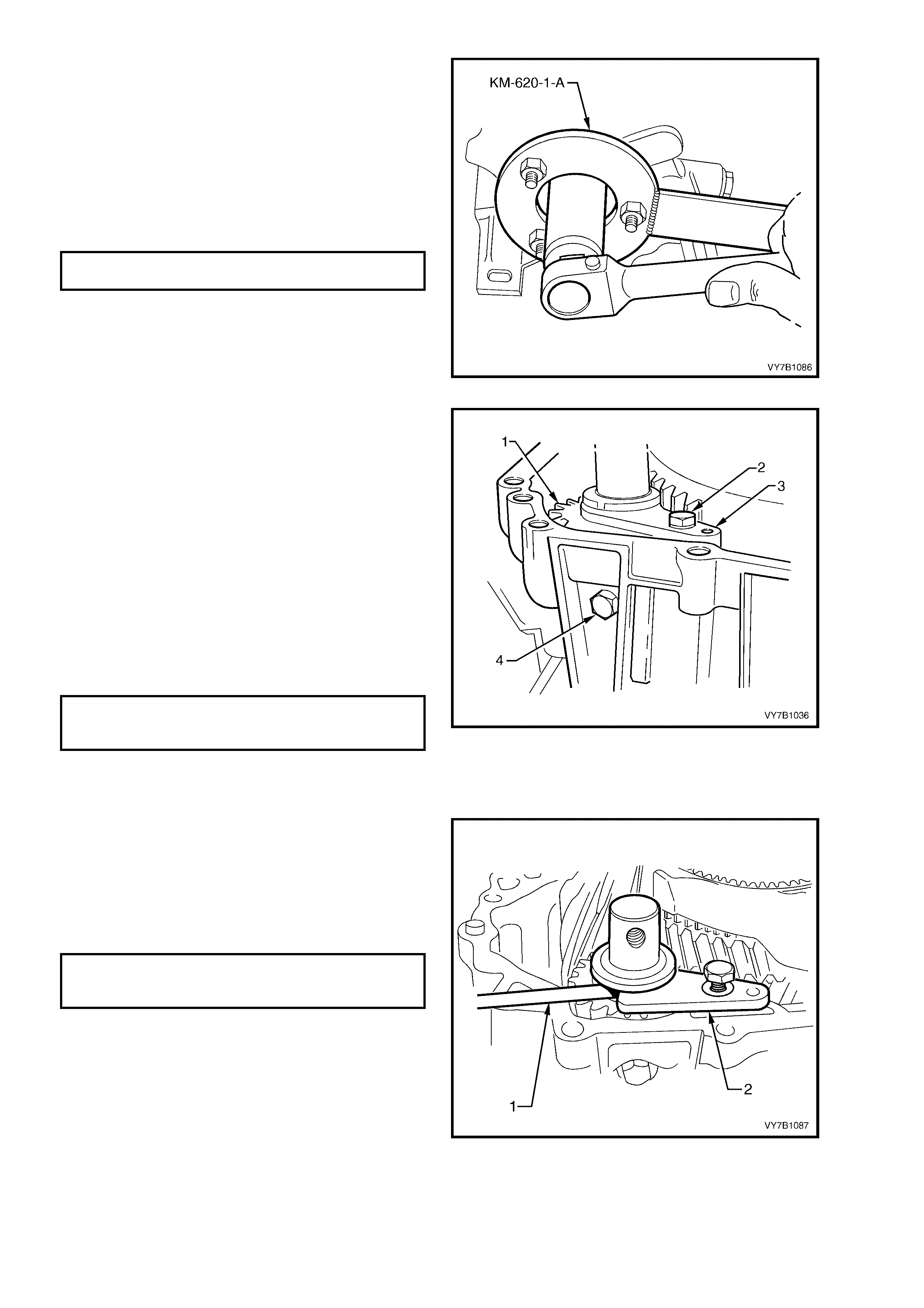
15. Reinstall mainshaft flange and toothed ring
assembly to the mainshaft.
16. Apply Loctite 242 or 243 or equivalent, to the
splines of the mainshaft flange a nd t he c l ean ed
threads of the flange nut. Install the flange to
the mainshaft.
17. W hile hold ing the f la nge with Tool No. K M-620-
1-A, tighten the nut to fully install the output
flange and then tighten the flange nut to the
correct torque specification.
MAINSHAFT FLANGE NUT
TORQUE SPECIFICATION 100 Nm
Figure 7B1-153
18. Apply a smear of sealant such as Loctite 574
(or equivalent) to the section of the rear case
that supports the reverse idler shaft.
19. Reinstall reverse idler gear (1) into position,
with the groove fac ing for war d.
20. Lubricate the reverse idler gear shaft needle
roller bearings with tr ansmis sion lubrica nt, then
insert the shaft through the gear and into the
rear case, aligning the threaded hole with the
locating bolt hole in the rear transmission case.
21. Apply sealant such as Loctite 242 or 243 or
equivalent, to the under-head portion of the
reverse idler gear shaft fastening bolt (4),
install and tighten to the correct torque
specification.
REVERSE IDLER GEAR SHAFT
REAR LOCATING BOLT
TORQUE SPECIFICATION 25 Nm
NOTE: Do not tighten the thrust plate (3) retaining
bolt (2) at this time.
Figure 7B1-154
22. Reduc e the width of a piec e of f eeler gaug e (1)
0.040 mm thick, sufficient to fit between the
reverse idler gear and the retainer (2).
23. Insert the feeler gauge (1) and, while holding
the retainer (2) against the feeler gauge,
tighten the retaining bolt to the correct torque
specification.
REVERSE IDLER GEAR THRUST
PLATE RETAINING BOLT
TORQUE SPECIFICATION 25 Nm
NOTE: This operation is necessary to centre the
retaining plate with the reverse idler gear. Failure
to carr y out this operat ion wil l result i n transm is sion
noise.
Figure 7B1-155
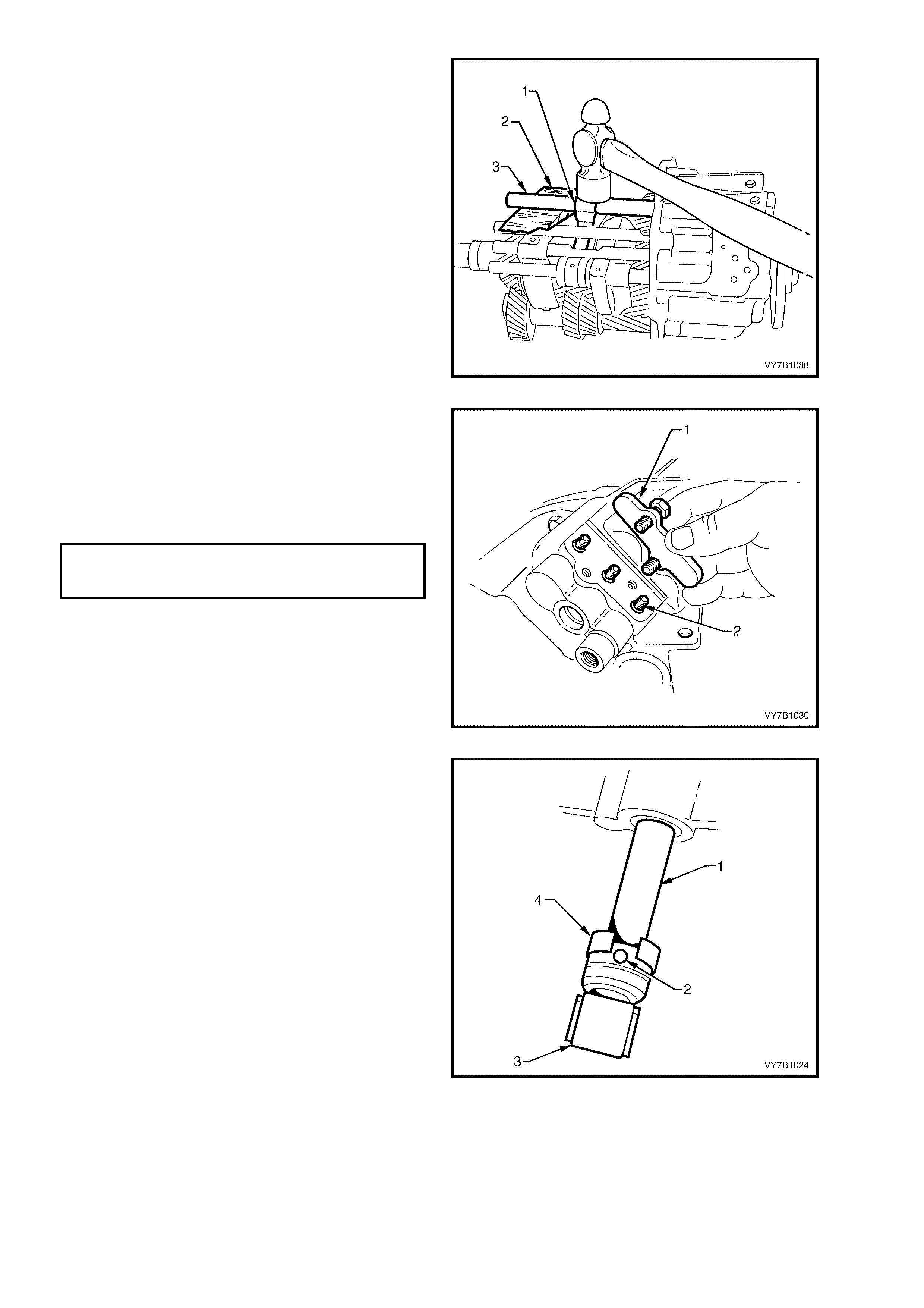
24. Apply a thin coating of petroleum jelly to
gearshift operating shaft rollers, then install
shaft (3) into the rear of the transmission
housing, aligning the rollers with the internal
selector arm and the shaft with the selector
arm (1).
25. Align the selector arm (1) roll pin hole with the
operating shaft hole, support the shaft (3) with
a suitable size wooden wedge (2), then install
a new roll pin to the arm and shaft.
Figure 7B1-156
26. Insert the three detent balls and pressure
springs (2) into transmission case.
27. Apply thread sealant such as Loctite 242 or
243 or equ ivale nt, to the c l eane d thre ads of the
attaching bolts, then install pressure spring
cover (1) and t ighten bolts t o the c orrec t torqu e
specification.
SHIFT DETENT SPRING
COVER BOLT
TORQUE SPECIFICATION 10 Nm
Figure 7B1-157
28. Lubricate gearshift shaft seal lips with
transmission fluid, then install the seal into the
rear transmission housing, using a suitable
length and size of tubing, until the seal is flush
against the rear transmission housing.
29. Reinstall gearshift trunnion (3) to the gearshift
selector rod shaft (1) and secure with the
retaining pin (2).
30. Lever the spring steel retaining ring (4) over
the pin (2), then rotate to completely cover the
pin.
31. Select 4th gear and check that all remaining
synchronisers are loosely seated against their
respective gear cones. If necessary, loosen
firmly seated ring/s from gear cone/s.
Figure 7B1-158
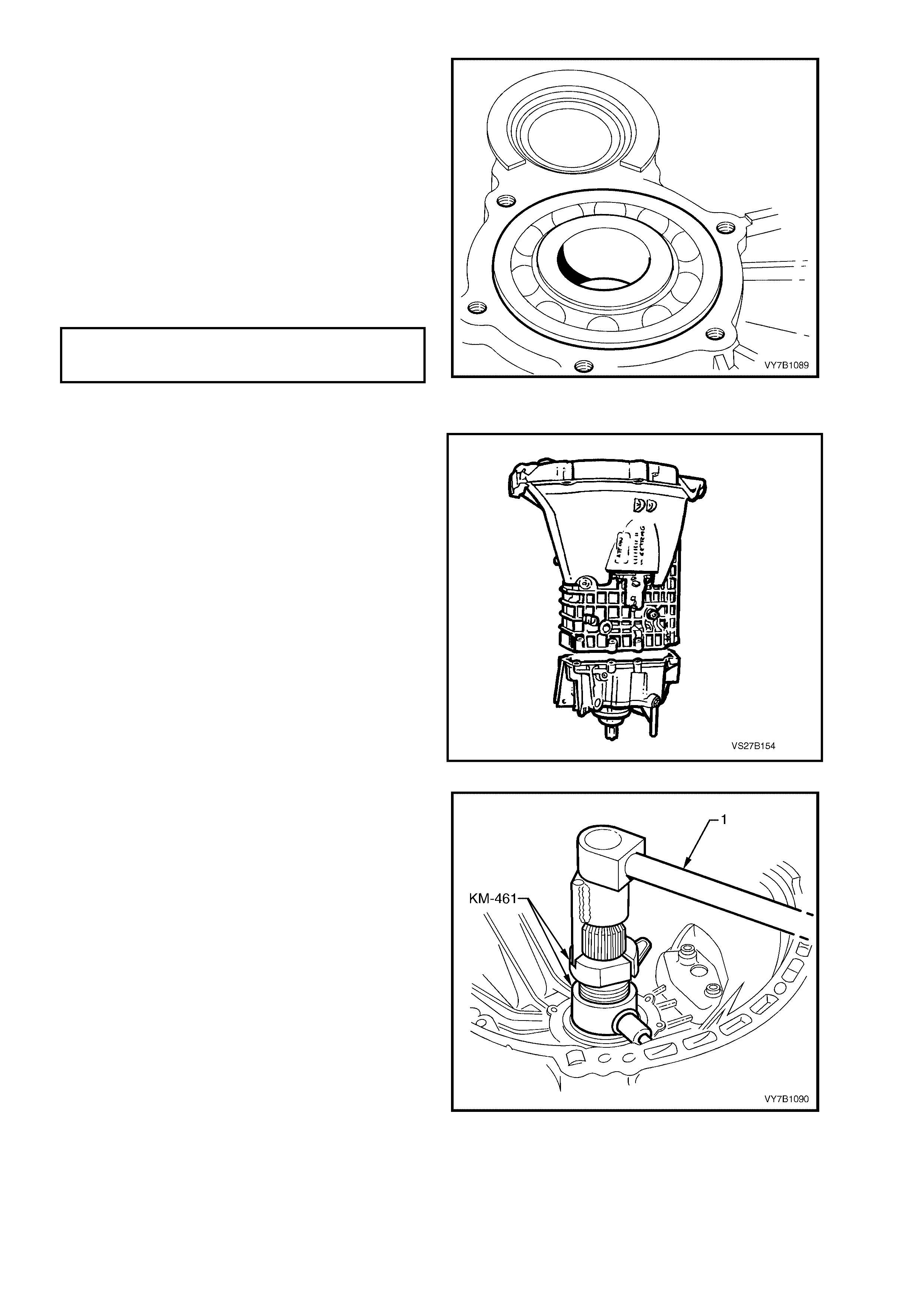
32. Pr eheat tr ansmiss ion case fr ont section i n are a
of maindrive bearing to approximately 80° C
using a commerc ially avai la ble hot air blo w er.
NOTE: Apply Faber Castell Thermochrom
2815/80° C around bearing area of transmission
case to indicate temperature. .
33. Using a suitable sleeve acting on the outer
bearing ring, press bearing fully home to the
flange in transmission case front section.
34. Reinstall reverse block assembly to the
transmission case, by using a plastic faced
hammer. Apply Loctite 574 or equivalent, to the
sealing surface of the retaining bolt. Tighten to
the correct torque specification.
REVERSE BLOCK BOLT TO
TRANSMISSION FRONT CASE
TORQUE SPECIFICATION 10 Nm
Figure 7B1-159
35. Apply a bead of Loctite 574 sealant or
equivalent, to sealing surface of transmission
case an d the fr ont bolt hole of the rev erse idl er
shaft.
36. Position f r ont sec ti on of tr a nsmiss ion cas e o nto
rear section, aligning shift rods with front
section bore hol es .
Figure 7B-160
37. Install Tool No. KM-461 as shown and draw
the input shaft into the front bearing, using a
socket bar (1).
38. Remove Tool No. KM-461 and install selective
washer and retaining ring to maindrive gear.
Selective washers are available in thicknesses
of 2.1 mm, 2.2 mm, 2.3 mm, 2.4 mm and 2.5
mm.
NOTE: The specified clearance between the
selective washer and the front bearing hub is from
0.00 - 0.09 mm.
39. Place transmission into neutral position and
rotate maindrive gear to check that no
synchroniser rings have become jammed on
gear cones.
Figure 7B1-161
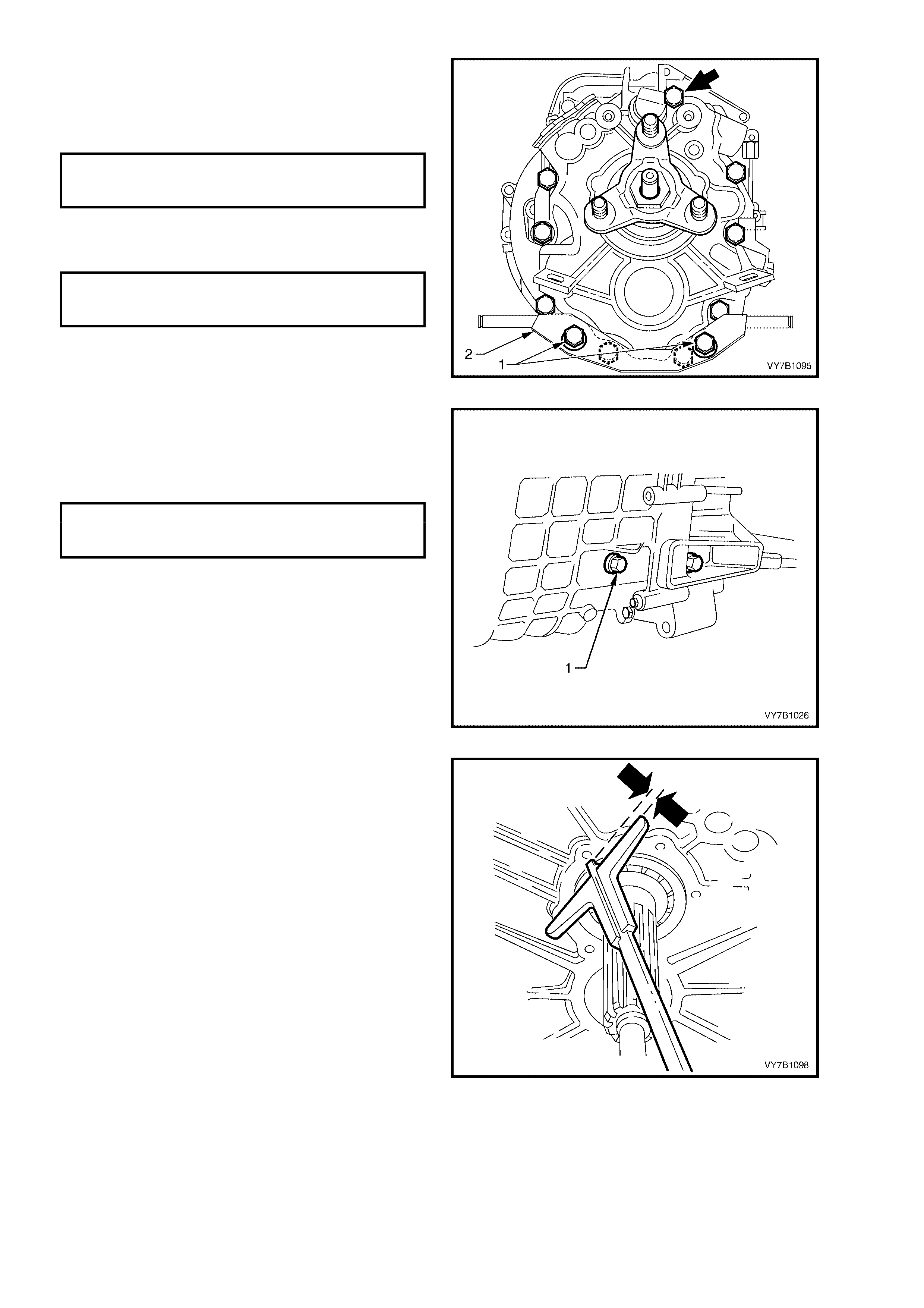
40. Install new dowel pins to align the front and
rear transmission cases, prior to installing and
tightening the attaching bolts to the correct
torque specification. Note the location of the
longest bolt (bold arrow).
TRANSMISSION REAR CASE
TO FRONT CASE BOLT
TORQUE SPECIFICATION 25 Nm
41. Reinstall the exhaust pipe support bracket (2),
securing with two bolts (1), tightened to the
correct torque specification.
EXHAUST PIPE SUPPORT
BRACKET BOLT
TORQUE SPECIFICATION 25 Nm
Figure 7B1-162
42. Apply sealant such as Loctite 242 or 243 (or
equivalent) to the under-head portion of the
reverse idler gear s haf t, f ront fas tening bolt ( 1),
reinstall and tighten to the correct torque
specification.
REVERSE IDLER GEAR SHAFT
FRO NT LOCATING BOLT
TORQUE SPECIFICATION 25 Nm
Figure 7B1-163
43. Prior to installing the clutch throwout bearing
guide, the compensating shim thickness must
be determined, as follows:
a. With the front bearing distance ring installed,
use a depth gauge to measure the distance
between the front edge of the b earing dista nce
ring and the transmission case, noting the
measurement.
Figure 7B1-164
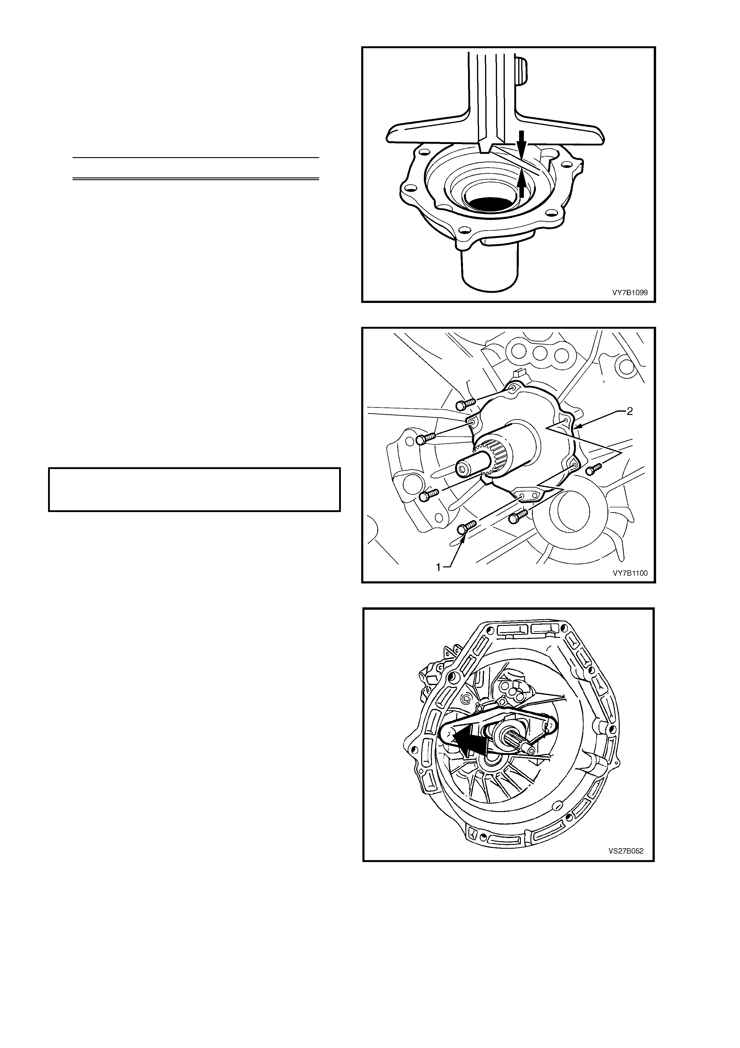
b. After removing any shims, measure the depth
of the counterbore in the clutch throwout
bearing guide, not ing the measurement.
c. Subtr act m easurem ent ‘a’ from ‘b’ to determ ine
the compensating shim stack required.
e.g. Front Bearing Ring Protrusion = 5.5 mm
Throwout Counterbore Depth = 6.0 mm
Shim thickness = 0.5 mm
Selective shims are available in thicknesses of
0.3 mm, 0.4 mm and 0.5 mm.
Figure 7B1-165
44. Apply a thin coating of Loctite 574 (or
equivalent), to the mounting face of the clutch
throwout bearing retaining plate.
45. Lubricate seal with transmission fluid, then
install throwout bearing guide assembly (2).
46. Apply sealant such as Loctite 574 or
equivalent, to the cleaned threads of the
fastening bolts (1) to the correct torque
specification.
THROWOUT BEARING GUIDE
RETAINING BOLT
TORQUE SPECIFICATION 10 Nm
NOTE: The bearing guide assembly can only be
installed in the one correct position.
Figure 7B1-166
47. Lubricate throwout bearing guide sleeve,
maindrive gear teeth, release lever,
throwout bearing and ball headed pin
with high temperature grease. Refer to
Section 7A1 CLUTCH in the MY 2003 VY
and V2 Series Ser v ice Infor mation.
48. Reinstall clutch throwout bearing to the clutch
release lever, then install the bearing/lever
assembly, securing to the pivot ball with the
spring clip.
49. Push the bearing fully in, to maintain position
on the lever, until the transmission is installed
and the slave cylinder is reinstalled.
Figure 7B-167
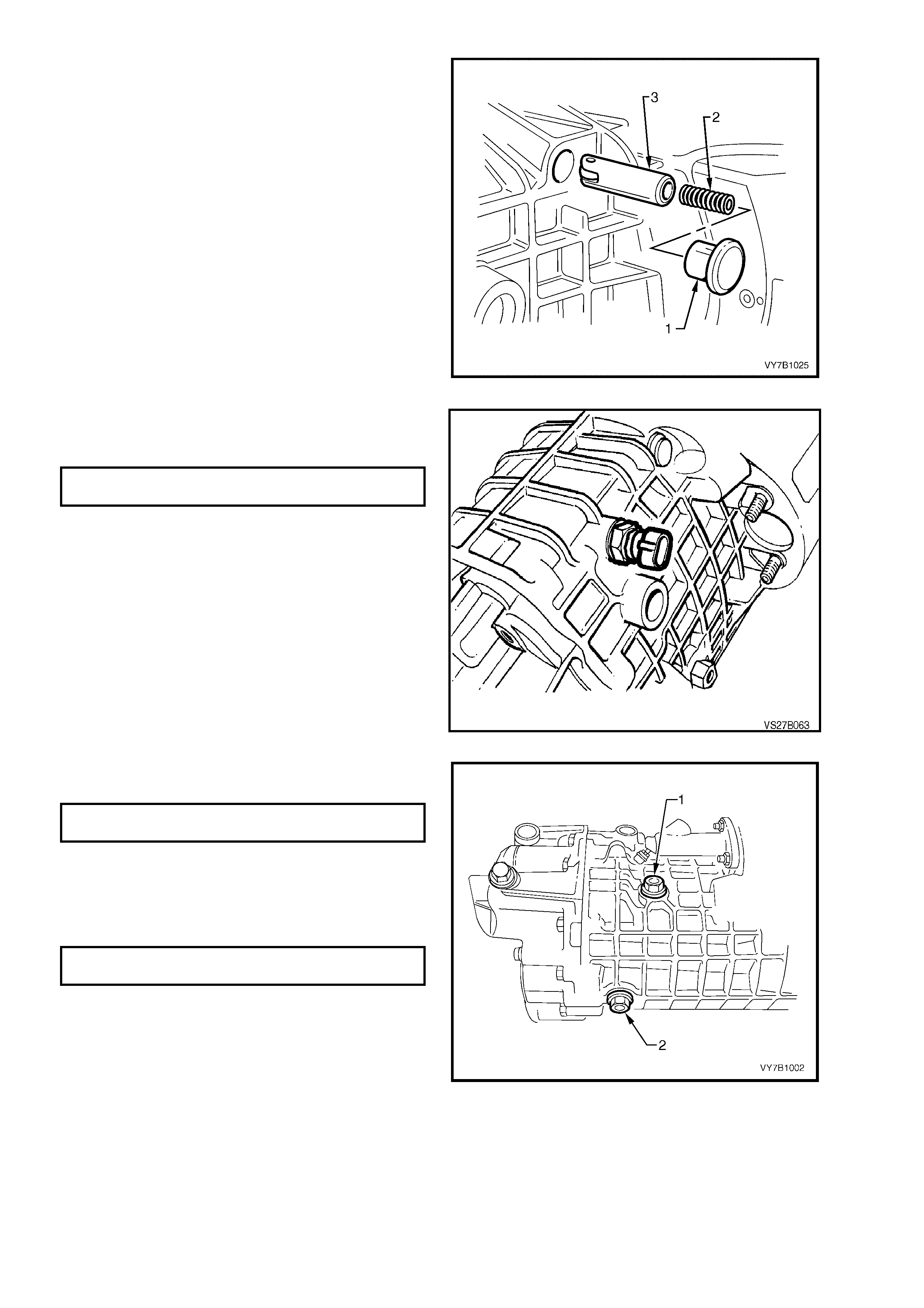
50. Insert detent pin and pressure spring into
transmission case.
NOTE: Ensure that detent pin is ins t al led wit h r ol ler
in a horizontal position, as shown.
51. Reinstall detent spring closure plug, after
coating with sealant such as Loctite 574 (or
equivalent).
Figure 7B1-168
52. Reinstall back-up lamp switch to transmission
case and tighten to the correct torque
specification.
BACK-UP LAMP SWITCH
TORQUE SPECIFICATION 20 Nm
Figure 7B1-169
53. Install drain plug (2) and tighten to the correct
torque specification.
TRANSMISSION DRAIN PLUG
TORQUE SPECIFICATION 50 Nm
54. F ill transm is sion with appr oximatel y 1.2 litres of
80W gear oil, such as Castrol VMX80W or
equivalent.
55. Reinstal l fil ler plu g (1) an d tight en to the cor rec t
torque specification.
TRANSMISSION FILLER PLUG
TORQUE SPECIFICATION 50 Nm
Figure 7B1-170
56. Reinstall transmission into vehicle. Refer to
4.2 TRANSMISSION ASSEMBLY in this
Section.

5. DIAGNOSIS
CONDITION PROBABLE CAUSE CORRECTION
TRANSMISSION SHIFT
HARD/HEAVY Clutch pedal high effort.
Shifter shaft binding.
Internal bind in transmission caused
by shift forks, selector shafts or
synchromes h assemblies.
Incorrect lubr ica nt.
Lubricate or replace as required.
Check for mispositioned shift fork roll
pin/s, loose bolts, worn shifter shaft or
shaft bores or distorted oil seal.
Repair as necessary.
Remove, disa ss em ble and ins pect
transmission. Replac e worn or
damaged components as necessary.
Drain and refill transmission.
GEAR CLASH WHEN SHIFTING
FROM ONE GEAR TO ANOTHER Lubricant level low or incorrect
lubricant.
Gearshift components or
synchromesh assemblies worn or
damaged.
Drain and refill transmission and
check for lubricant leaks if level was
low. Repair as necessary.
Remove, disa ss em ble and ins pect
transmission. Replac e worn or
damaged components as necessary.
TRANSMISSION NOISY Lubricant level low or incorrect
lubricant has been used.
Transmission housing to engine
attaching.
Gearshift mechanism, transmission
gears or bearing components worn or
damaged.
Drain and refill transmission. If
lubricant was low, check for leaks and
repair as necessary .
Check and correct bolt torque settings
as necessary.
Remove, disa ss em ble and ins pect
transmission. Replac e worn or
damaged components as necessary.
JUMPS OUT OF GEAR Gearshift mechanism, shift forks,
selector shafts, interlock pin, detent
balls/springs, worn or damaged.
Gear teeth worn or tapered,
synchromesh assemblies worn or
damaged.
Remove, disa ss em ble and ins pect
transmission assembly. Replace worn
or damaged components as
necessary.
Remove, disa ss em ble and ins pect
transmission. Replace all worn or
damaged components as necessary.
WILL NOT SHIFT INTO ONE GEAR Gearshift selector shaft/s, interlock pin
or selector arm, worn, damaged or
incorrectly assembled.
Synchromesh sleeves or hubs, worn
or damaged.
Remove, disa ss em ble and ins pect
transmi ssi on sel ector assembl ies.
Repair or replace components as
necessary.
Remove, disa ss em ble and ins pect
transmission. Replac e worn or
damaged co mpo nent s.
LOCKED IN ONE GEAR -
CANNOT BE SHIFTED OUT Shift shaft/s worn or damaged,
selector fork bent or broken.
Gearshift mechanism worn, damaged
or broken. Worn or damaged gear
train components.
Inspect and replace worn or damaged
components.
Disassemble transmission. Replace
damaged part s or assemble c orrect ly .
TRANSMISSION WILL NOT SHIFT
INTO REVERSE (ALL OTHERS OK) Worn or damaged internal
components.
Reverse block mechanism jammed
Remove transmission. Check for
damaged reverse gear trai n
components.
Dismantle transmission, inspect and
replace components as necessary.

6. SPECIFICATIONS
TRA NSMISSION:
V6 Powered Vehicles.............................................. Getrag, Type 260 - 5 Speed Manual Transmission,
Overdrive 5th Sp eed , Pro d uc tion Option M35
TRANSMISSION RATIOS:
1st ...................................................................... 3.829:1
2nd..................................................................... 2.199:1
3rd...................................................................... 1.401:1
4th...................................................................... 1.000:1
5th...................................................................... 0.809:1
Reverse.............................................................. 3.456:1
NUMBER OF TEETH:
Maindrive Input Gear............................................... 26
Mainshaft Gear
1st ...................................................................... 41
2nd..................................................................... 37
3rd...................................................................... 30
5th...................................................................... 26
Reverse.............................................................. 37
Reverse Idler Gear.................................................. 21
Cluster Gear Input................................................... 34
Cluster Gear
1st/Reverse........................................................ 14
2nd..................................................................... 22
3rd...................................................................... 28
5th...................................................................... 42
SYNCHROM ESH ASSEMBLIES:
Synchromesh Ring Wear
New Clearance .................................................. 1.0 - 1.3 mm
Replacement Clearance .................................... less than 1.0 mm
Synchromesh Ring identification
1st, 2nd .............................................................. 040.8.0001.00
3rd, 4th............................................................... 002.8.0301.00
5th/Reverse........................................................ 011.8.0331.10
011.8.0331.11 (optional)
END FLOAT CLEARANCES:
Maindrive Gear........................................................ 0.00 - 0.09 mm
Cluster Gear............................................................ 0.13 - 0.23 mm
SELECTIVE SNAP RING THICKNESSES:
3rd/4th Synchromesh Assembly............................. 2.0, 2.1, 2.2, 2.3, 2.4, 2.5 mm
1st/2nd Synchromesh Assembly............................. 1.8, 1.85, 1.9, 1.95, 2.0 mm
5th/Reverse Synchromesh Assembly..................... 1.8, 1.85, 1.9, 1.95, 2.0 mm
SELECT IVE SHIM/WASHER THICKNESSE S:
Throwout Bearing Guide to Input Shaft Bearing..... 0.3, 0.4, 0.5 mm
Input Shaft Bearing ................................................. 2.1, 2.2, 2.3, 2.4, 2.5 mm
Cluster Gear End Float Adjusting ........................... 1.0, 1.7, 1.8, 2.0, 2.1, 2.2, 2.3 mm
LUBRICANT:
Type ........................................................................ 80W Gear Oil, such as Castrol VMX80W or equivalent.
Capacity (Nominal).................................................. 1.2 litres
SEALANTS:
Thread Sealant in nominated locations................... Loctite 242 or 243 or equivalent.
Transmission Case Mat in g Sur f ac es, Clutch
Throwout Guide Sleeve to Front Case and
other nominated locations.................................. Loctite 574 or equivalent.

7. TORQUE WRENCH SPECIFIC ATIONS
Nm
Backup Lamp Switch ........................................................................................ 20
Centre Bearing Carrier to Underbody Reinforcement Bolt ............................... 23
Clutch Housing to Engine Block and Oil Pan Bolt ............................................ 85
Clutch Actuating Cylinder Retaining Nut........................................................... 22
Exhaust Pipe Su ppor t Brack et Bolt.............................................................. 25
Flywheel Close-out Cover Attaching Screw................................................. 10
Gearshift Ball Socket Retainer Plate Nuts .................................................. 10
Gearshift Brace Rear Rubber Mount to Underfloor Bolt.............................. 10
Gearshift Lever Bracket to Underfloor......................................................... 10
Gearshift Linkage Rear Rubber Mounting Nut ............................................ 22
Gearshift Selector Rod Bush Securing Screw............................................. 20
Locking Lever Screw Plug ........................................................................... 48
Mainshaft Flange Nut .................................................................................. 100
Propeller Shaft Rubber Coupling to Transmission Output Flange Nut........ 78
Propeller Shaft Rear Universal Joint Flange to Pinion Flange Bolt............. 58
Rear Mount to Transmission Lug Nut ......................................................... 25
Rear Mount to Crossmember Nut................................................................ 25
Rear Crossmember to Side Frame Member Bolt ........................................ 58
Rear Bearing Plate and Locking Lever Bolt................................................. 10
Reverse Block, Retaining Bolt ..................................................................... 10
Reverse Idler Gear Shaft Locating Bolt (Front or Rear) .............................. 25
Reverse Idler Gear Thrust Plate Retaining Bolt .......................................... 25
Shift Detent Spring Cover Bolt .................................................................... 10
Speed Sensor to Bracket Screw ................................................................. 10
Speed Sensor Bracket to Transmission Housing Bolt................................. 18
Throwout Bearing Guide Assembly Bolt...................................................... 10
Transmission Drain Plug ............................................................................. 50
Transmission Filler Plug .............................................................................. 50
Transmission Rear Case to Front Case Attaching Bolt............................... 25
Transmission Rear Mounting to Case Nuts................................................. 25
Transmission Rear Mounting to Rear Crossmember.................................. 58
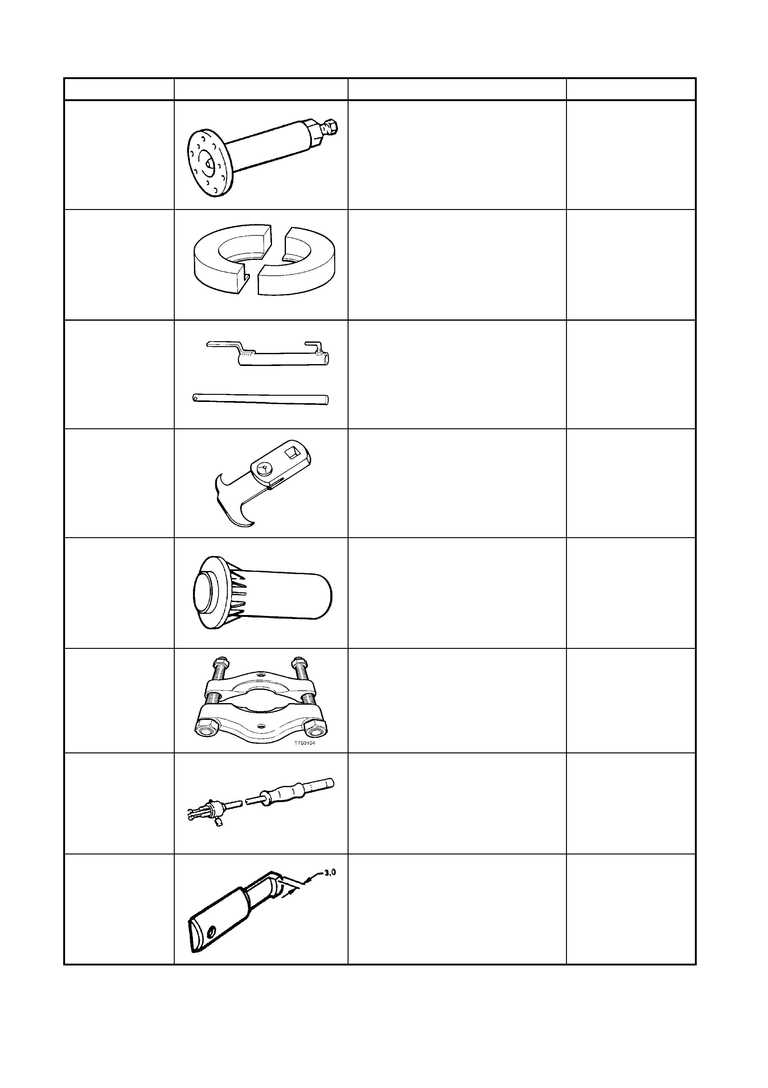
8. SPECIAL TOOLS
TOOL NUMBER ILLUSTRATION DESCRIPTION CLASSIFICATION
AKM-628-A EX TR A CTOR TOO L
Used to remove the mainshaft
flange and to separate the two
transmission housings on
disassembly.
Unique
AU454
GEAR REMOV ER PLAT ES
Used to remove 3rd/4th
synchromesh assembly, 3rd speed
gear, 2nd speed gear and related
components from the mainshaft.
Unique
AU462
SELECT LEVER SPRING AND
BUSH INSTALLER
Used to load the select lever spring
and components for reassembly
into transmission rear housing.
Previously released
Unique
E308
SEAL REMOVER
Used as a universal seal remover.
Also previo us l y releas ed as 56750.
Desirable
J-21426 SEAL INSTALLER
Previously released for 4L60-E
automatic transmission.
Unique
J-22912-01
PRESS PLATES
Also previousl y released as E6673. Desirable
KM-328-B
SLIDE HAMMER
Includes Cup KM-328-5-A and pin.
Previously released.
Unique
KM-328-7-A PULLER LEG S
Modify as detailed. Use with spacer
KM-328-9 and slide hammer KM-
328-B to remove bearings from the
transmission case.
Previously released.
Unique
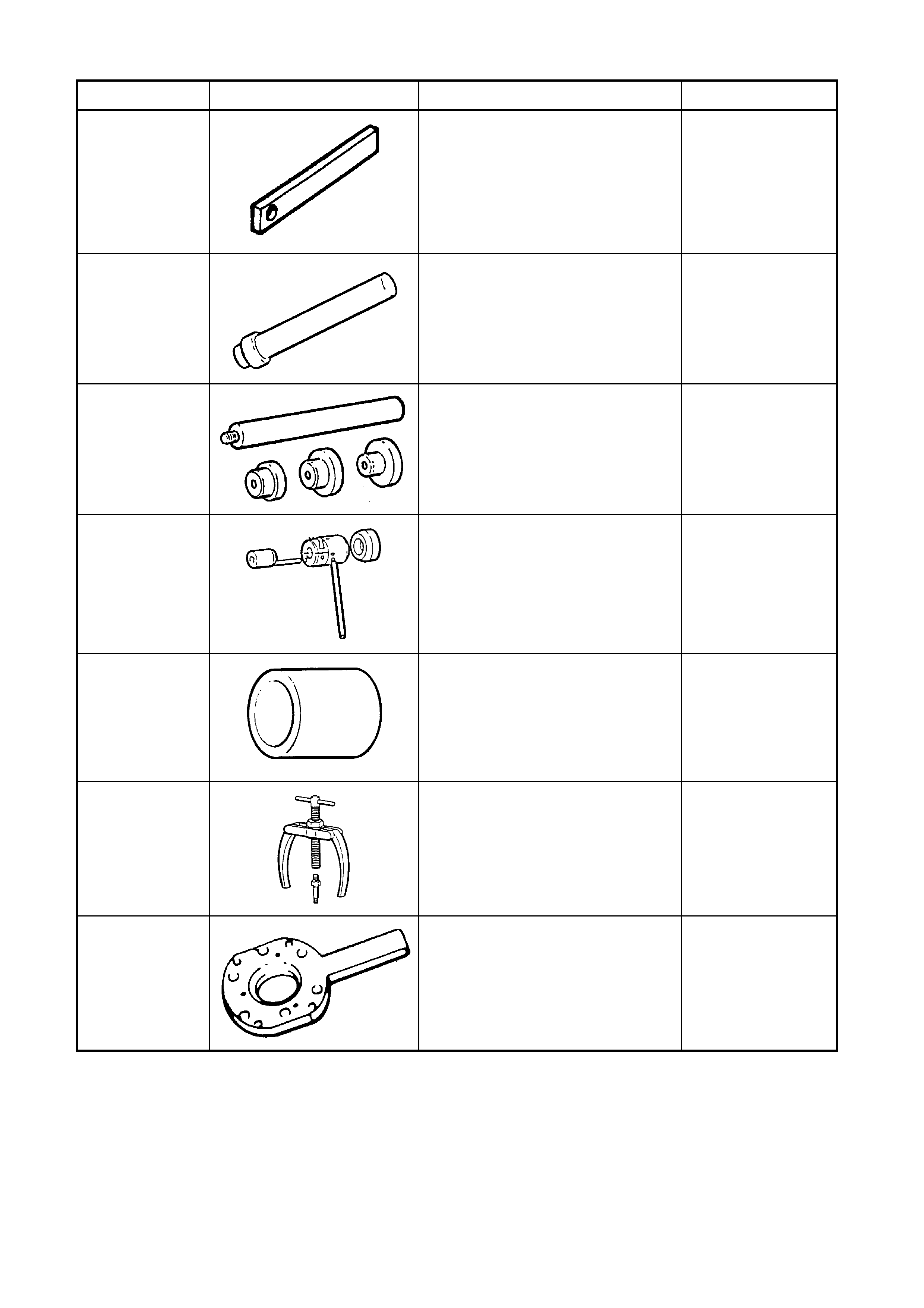
8. SPECIAL TOOLS (Continued)
TOOL NUMBER ILLUSTRATION DESCRIPTION CLASSIFICATION
KM-328-9
SPACER
Used with legs KM-3 28- 7-A and
slide hammer KM-328-B.
Previously released
Unique
KM-409-A
INSTALLER
Used to install the shift rod bearing
into the front transmission housing.
Previously released
Unique
KM-454-A REMOVER/INSTALLER
Used to remove and install cluster
gear bearing cups.
Previously released
Unique
KM-461-C
INSTALLER
Used to assemble the two
transmission housings on
reassembly.
Previously released
Unique
KM-500-3
SLEEVE
Previously released.
Used for various pressing
operations as described in the text.
Previously released
Unique
KM-556-1-A
PULLER
Part of Puller Kit KM-556-A.
Previously released
Unique
KM-620-1-A FLANGE HOLDING TOOL
Modified from the previously
released tool as detailed in the text.
Unique