
SECTION 7B2 - MANUAL TRANSMISSION –
GEN III V8 ENGINE
IMPORTANT
Before performing any Service Operation or other procedure described in this Section, refer to Section 00
CAUTIONS AND NOTES for correct workshop practices with regard to safety and/or property damage.
CONTENTS
1. GENERAL INFORMATION
1.1 GENERAL DESCRIPTION
SYNCHRONISER ASSEMBLIES
REVERSE GEAR
BEARING SUPPORT
LUBRICATION
SELECTOR MECHANISM
REVERSE LOCKOUT MECHANISM
SHIFT PATTERN
POWER FLOWS
1.2 TRANSMISSION SERIAL NUMBER
2. SERVICING INFORMATION
2.1 RECOMMENDED LUBRICANT
2.2 CHECKING TRANSMISSION LUBRICANT
LEVEL
PROCEDURE
2.3 DRAINING AND REFILLING TRANSMISSION
3. MINOR SERVICE OPERATIONS
3.1 BACK-UP LAMP SWITCH
REPLACE
3.2 SPEED SENSOR
REPLACE
3.3 TRANSMISSION SUPPORT MOUNT
REPLACE
3.4 REVERSE LOCKOUT SOLENOID ASSEMBLY
REMOVE
DISASSEMBLE
REASSEMBLE
REINSTALL
3.5 CONTROL LEVER KNOB, BOOT & CONTROL
LEVER ASSEMBLY
REMOVE
REINSTALL
3.6 CONTROL LEVER BOOT
REPLACE
3.7 REMOTE SHIFT LEVER BOOT
REMOVE
REINSTALL
4. MAJOR SERVICE OPERATIONS
4.1 TRANSMISSION OUTPUT SHAFT SEAL
AND BOOT
REMOVE
REINSTALL
4.2 TRANSMISSION ASSEMBLY
REMOVE
REINSTALL
4.3 TRANSMISSION DISASSEMBLE
CLUTCH HOUSING AND SLAVE CYLINDER
EXTENSION HOUSING
SPEEDOMETER PULSE RING
REVERSE AND 5TH/6TH DRIVEN GEAR
COUNTERSHAFT EXTENSION ASSEMBLY
TRANSMISSION CASE
GEAR TRAINS AND SHIF T RAI LS
4.4 REMOTE CONTROL SHIFT MECHANISM
DISASSEMBLE
CLEAN AND INSPECT
REASSEMBLE
4.5 TRANSMISSION SUB-ASSEMBLIES
DISASSEMBLE
CLEAN AND INSPECT COMPONENTS
REASSEMBLE
4.6 BEARING SHIMMING PROC EDURES
INPUT SHAFT/MAINSHAFT &
COUNTERSHAFT
COUNTERSHAFT EXTENSION
4.7 TRANSMISSION REASSEMBLE
GEAR TRAINS AND SHIF T RAI LS
TRANSMISSION CASE
COUNTERSHAFT EXTENSION ASSEMBLY
5TH/6TH DRIVEN GEAR
REVERSE SYNCHROMESH ASSEMBLY
REVERSE SPEED GEAR
SPEEDOMETER PULSE RING
EXTENSION HOUSING
CLUTCH HOUSING AND SLAVE CYLINDER
5. DIAGNOSIS
5.1 TRANSMISSION SHIFTS HARD
5.2 TRANSMISSION HARD TO SHIFT INTO
REVERSE
5.3 GEAR CLASH WHEN SHIFTING GEARS
5.4 TRANSMISSION NOISY
5.5 TRANSMISSION JUMPS OUT OF GEAR
5.6 TRANSMISSION DOES NOT SHIFT INTO
ONE GEAR
5.7 TRANSMISSION LOCKED IN ONE GEAR
6. SPECIFICATIONS
7. TORQUE WRENCH SPECIFICATIONS
8. SPECIAL TOOLS
Techline
Techline
Techline
Techline
Techline
Techline

1. GENERAL INFORMAT ION
Dependent on vehicle specifications for specific markets, this manual transmission is available for fitment to the
GEN III V8 engine and is a six speed, Type T56 (production option MM6).
The ‘T56’ manual transmission is a fully synchronised unit, including reverse gear, with blocking ring type
synchronisers.
The transmission primarily consists of a four piece construction comprising a clutch housing bolted to a front
adaptor plate, transmission case and extension housing. During disassembly, the major number of gear train
components and shift mechanism remain on the transmission front adaptor plate.
1.1 GENERAL DESCRIPTION
SYNCHRONISER ASSEMBLIES
Each of the four synchroniser hubs are splined to their respective shafts and secured by a snap ring. All
synchromesh blocking rings have a carbon fibre frictional material and are brass, except for 1st and 2nd gears.
The blocking rings used on 1st and 2nd gears are of a double cone construction, with carbon fibre frictional material
on each side of the inner member. The purpose of the synchroniser assemblies is to permit clutching to the
required gear.
Synchroniser Action
During synchroniser operation, the synchroniser ring is moved into engagement by the appropriate fork, carrying
with it, three spring loaded synchroniser inserts, located in slots in the synchroniser hub.
The synchroniser ring, together with the inserts, is moved along the hub, placing a load on the three lugs of the
blocking ring.
This initial force is sufficient to seat the b locking ring and s tart pre-s ynchronis ation because of the friction b etween
the cone on the constant mesh gear and the blocking ring.
At this s tage, gear engag em ent is prevented as long as there is a dif fer ence in speed between t he m ating s urf aces
of the blocking ring and cone of the constant mesh gear. As the speeds between the blocking ring and the gear
cone become synchronised, the teeth on the blocking ring and gear cone line up with the internal splines of the
ring, allowing the ring to engage the teeth on the gear being engaged, completing gear selection.
REVERSE GEAR
The reverse idler gear is in constant mesh with the counter gear extension and the reverse gear, splined to the
mainshaft. When reverse gear is engaged, the reverse synchromesh ring engages the reverse constant mesh gear,
completing the selection.
BEARING SUPPO RT
All shafts in the transmission are supported by taper roller bearings, except for a parallel roller bearing at the rear of
the mainshaft.
The input shaft gear, front countershaft g ear and rear countershaft gear extension bearing cups are a sliding fit in
their respective housings. Selective shims are located under each of the bearing cups to control bearing pre-load or
end float (for the countershaft extension).
Each of the constant mesh gears is supported by caged needle roller bearings, except for the reverse idler gear
that has a twin, caged needle roller bearing running on the reverse idler gear shaft.
LUBRICATION
Lubrication of all internal components is by splash feed, provided by the rotating countershaft gear assembly.
SELECTOR MECHANISM
The floor mounted, gearshift control lever operates through a remote lever arrangement onto a single rail
mechanism which extends into the transmission rear case. The 1st/2nd, 3rd/4th, 5th/6th and reverse shift shaft rails
are all supported at each end, in the adaptor plate, transmission case or extension housing.
A shift interlock system, prevents engagem ent of more than one gear at a time. T he system consists of a selector
pin and interlock plate mounted on the 1st/2nd and 3rd/4th selector shaft rail.
W hen any gear is s elec t ed, the s elec tor pi n is al ign ed with th e par tic u lar s hift fork link or shift lever, with 5 th/6 th and
reverse gears. As this selector pin slides within the interlock plate, only the gear selected can be engaged.
REVERSE LOCKOUT MECHANISM
The transmis sion is als o f itt ed with a reverse loc kout sole noi d as s embly that prevents the se lec t ion of revers e gear,
above road speeds of 8 km/h. Above this speed, the Powertrain Control Module (PCM), causes the solenoid
plunger (1) to block the movement of the spring loaded, reverse lockout plunger (2) (See view ‘B, next).
When activated, the rear offset lever (3) is blocked from rotating to the reverse selection position.
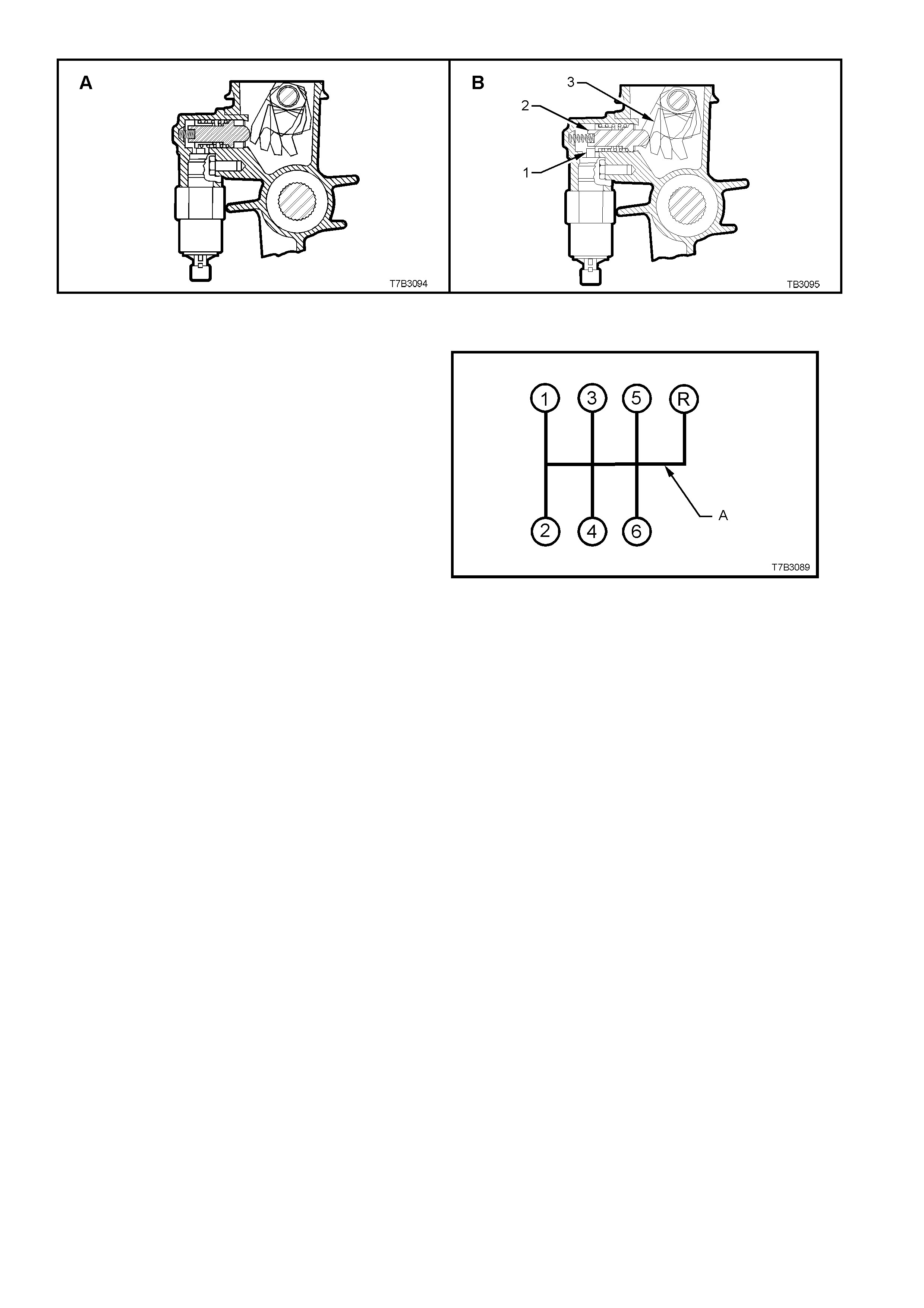
Figure 7B2-1 - Reverse Lockout Mechanism
SHIFT PATTERN
The s hif t pattern is as s ho wn in Figure 7B2- 2. P oi nt
‘A’ indicates that reverse gear can be inhibited by
the reverse lockout solenoid assembly, just
described.
Figure 7B2-2 - Transmission Shift Pattern
Refer Figure 7B2-3 for a sectioned view of the type T56 transmission (production option MM6) and Figure 7B2-4 for
an exploded view of the transmission components.
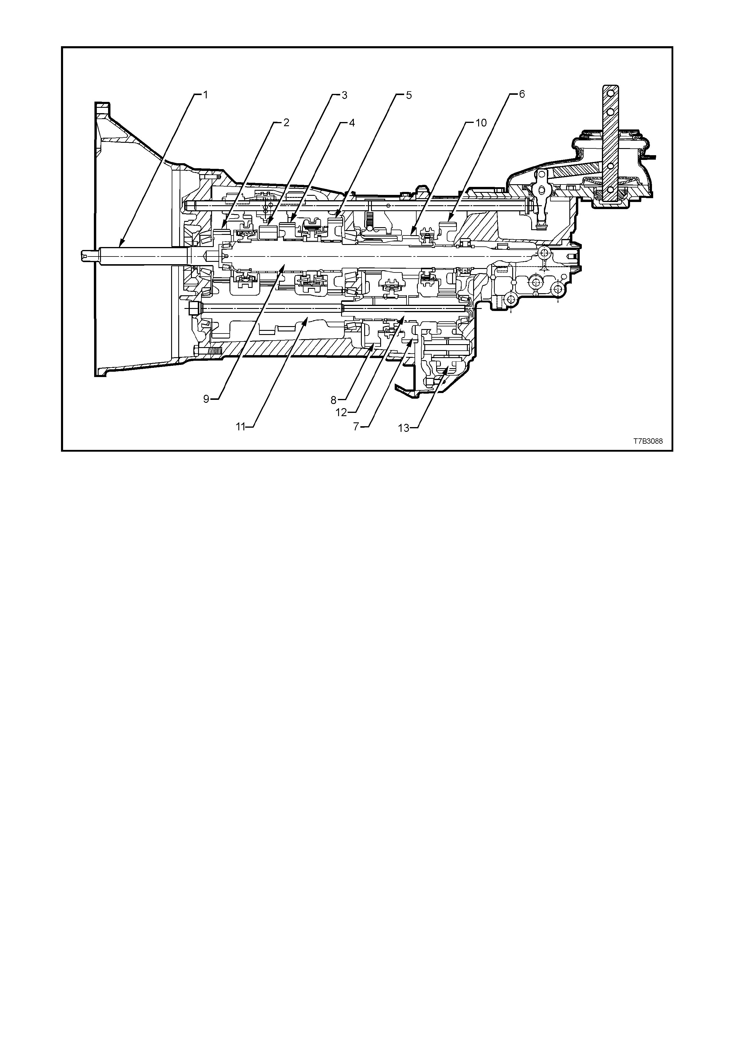
Figure 7B2-3 - Type ‘T56’ Transmission, Sectioned View
Legend
1. Input Shaft
2. Input Shaft Drive Gear
3. Third Speed Driven Gear
4. Second Speed Driven Gear
5. First Speed Driven Gear
6. Reverse Driven Gear
7. Fifth Speed Drive Gear
8. Sixth Speed Drive Gear
9. Mainshaft
10. 5th/6th Speed Compound Gear
11. Countershaft Gear
12. Countershaft Gear Extension
13. Reverse Idler Gear
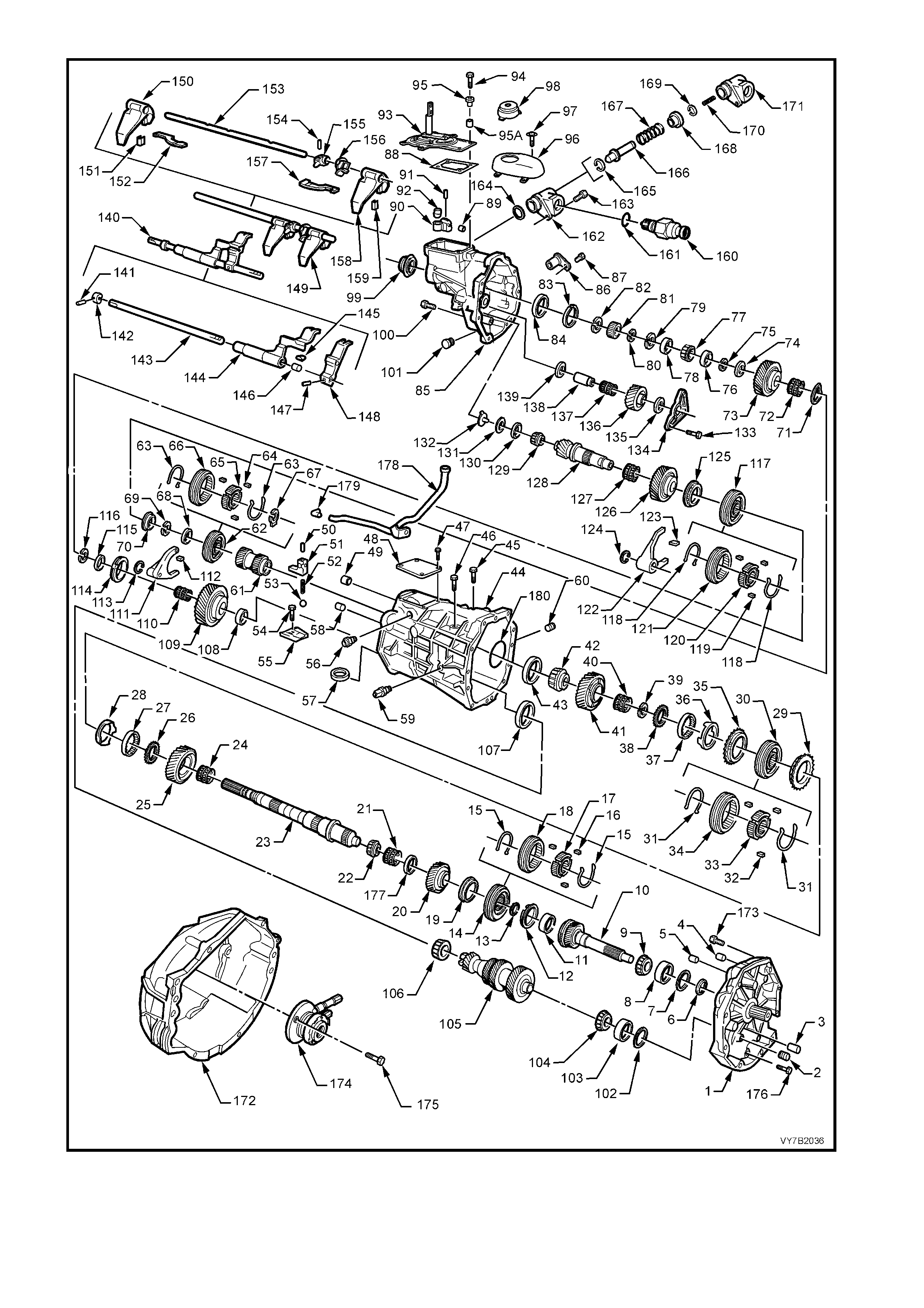
Figure 7B2-4 - Transmission Components
REF
No. PART NAME REF
No. PART NAME REF
No. PART NAME
1.
2.
3.
4.
5.
6.
7.
8.
9.
10.
11.
12.
13.
14.
15.
16.
17.
18.
19.
20.
21.
22.
23.
24
25.
26.
27.
28.
29.
30.
31.
32.
33.
34.
35.
36.
37.
38.
39.
40.
41.
42.
43.
44.
45.
46.
47.
48.
49.
50.
51.
52.
53.
54.
55.
56.
57.
58.
59.
60.
61.
62.
63.
Plate, Transmissi on Adaptor
Plug
Pin, Dowel (2 places)
Pin, Dowel (2 places)
Bushing , Sh if t Rail
Seal, Input Shaft
Shim, Input Shaft
Cup, Input Shaft Bearing
Bearing, Input Shaft Tapered
Shaft, Input
Cup, Input Shaft Bearing
Blocker Ri ng, 4t h Gear
Ring, Snap
Synchroniser Assembly, 3rd/4th
Spring, 3rd/ 4th Synchroni ser
Key, 3rd/4th Synchroni ser
Hub, 3rd/4th Sync hroniser
Ring, 3rd/4t h Synchroniser
Blocker Ri ng, 3rd Gear
Gear, 3rd Speed
Bearing, 3rd Gear Needle
Bearing, Mainshaft Sm all Tapered
Mainshaft
Bearing, 2nd Gear Needle
Gear, 2nd Speed
Washer, Thrust
Cone, Inner
Cone, Friction
Blocker Ri ng, 2nd Gear
Synchroniser Assembly, 1st/2nd
Spring, 1st/2nd Synchroni ser
Key, 1st/2nd S ynchroniser
Hub, 1st/2nd Sync hroniser
Ring, 1st/ 2nd Sync hronis er
Blocker Ri ng, 1st Gear
Cone, Friction
Cone, Inner
Washer, Thrust
Ring, Snap
Bearing, 1st Gear Needle
Gear, 1st Speed
Bearing, Mains haft Large Tapered
Cup, Mainshaft Bearing
Case, Transmission
Bolt, Shift Lever Guide
Bolt, Shift Lever Guide
Bolt, Shift Detent Cove r
Cover, Shift Detent
Bushing , Sh if t Rail
Pin, Front Offset Lever Roll
Lever, Front Offset
Spring, Shift Detent
Ball, Shift Detent
Bolt, Shift Guide Plate
Plate, Shift Guide
Enhancer, Shift
Magnet (2 places)
Pin, Dowel (2 places)
Switch, Back-Up Lamp
Plug, Fill
Gear, 5th/6th Driven
Synchroniser Assembly, Reverse
Spring, Reverse Synchroniser
64.
65.
66.
67.
68.
69.
70.
71.
72.
73.
74.
75.
76.
77.
78.
79.
80.
81.
82.
83.
84.
85.
86.
87.
88.
89.
90.
91.
92.
93.
94.
95.
95a.
96.
97.
98.
99.
100.
101.
102.
103.
104.
105.
106.
107.
108.
109.
110.
111.
112.
113.
114.
115.
116.
117.
118.
119.
120.
121.
122.
Key, Revers e Sync hroni ser
Hub, Reverse S ynchroniser
Ring, Reverse Sync hroni ser
Retainer, Reverse Synchroniser
Key
Washer, Thrust
Ring, Snap
Blocker Ri ng, Reverse Gear
Wa s her , Wa v e
Bearing, Revers e Gear Needle
Gear, Reverse
Washer, Thrust
Ring, Snap
Spacer
Bearing, Rear Mains haft Tapered
Spacer
Ring, Snap
Ring, Snap
Ring, Speedom eter Puls e
Ring, Snap
Ring, Snap
Cup, Mainshaft Bearing Rear
Housing, Transmission Extension
Sensor, Elect ronic Speed
Bolt, Speed Sensor
Gasket, Shifter Assembly Cover
Bushing , Sh if t Rail
Lever, Rear Offset Shift
Pin, Rear Offset Shift Lever Rol l
Cup, Isolat or
Shifter Assembly
Bolt, Shifter As sembly
Sleeve, Insulating
Distance Pie ce, Shift Cover Bo l t
Cover, Shift er Ass embly
Screw, Shifter Assembly Cover
Boot, Shift er
Seal and Boot, Rear Output
Bolt, Transmissi on Extension
Housing
Plug, Drain
Shim, Countershaf t
Cup, Counters haft Bearing
Bearing, Count ershaf t Tapered
Countershaft
Bearing, Count ershaf t Tapered
Cup, Counters haft Bearing
Washer, Thrust
Gear, 6th Drive
Bearing, 6th Gear Needle
Fork, Revers e Shift
Pad, Revers e Shift F o rk
Circlip
Blocker Ri ng, 6t h Gear
Spacer
Ring, Snap
Synchroniser Assembly, 5th/6th
Spring, 5th/6th Synchroniser
Key, 5th/6t h Sync hronis er
Hub, 5th/6th Synchroni ser
Ring, 5th/6th Sync hroniser
Fork, 5th/6th Shift
123.
124.
125.
126.
127.
128.
129.
130.
131.
132.
133.
134.
135.
136.
137.
138.
139.
140.
141.
142.
143.
144.
145.
146.
147.
148.
149.
150.
151.
152.
153.
154.
155.
156.
157.
158.
159.
160.
161.
162.
163.
164.
165.
166.
167.
168.
169.
170.
171.
172.
173.
174.
175.
176.
177.
178.
179.
180.
Pad, 5th/6th Shift Fork
Circlip
Blocker Ri ng, 5t h Gear
Gear, 5th Drive
Bearing, 5th Gear Needle
Extension, Count ershaf t
Bearing, Count ershaf t E xtensi on
Tapered
Cup, Counters haft Extensi on
Bearing
Shim, Countershaf t Extens i on
Funnel, Oil
Bolt, Reverse Idler Shaft Bracket
Bracket, Reverse Idler Shaft
Washer, Reverse Idler Gear Thrust
Gear, Reverse I dler
Bearing, Revers e Idl er Gear Roller
Shaft, Revers e Idl er Gear
Washer, Reverse Idler Gear Thrust
Rail Assembly, 5t h/ 6th, Revers e
Shift
Pin, Roll
Collar
Rail, Shif t
Lever, 5th/6th Shift Rail
Pad, 5th/6th Shift Rai l Lever
Bushing, 5t h/6t h Shift Rail Lever
Pin, Roll
Lever, Reverse S hift Rail
Rail Assembly, 1st/2nd, 3rd/4th
Shift
Fork, 1st/2nd Shift
Pad, 1st/2nd Shift Fork
Link, Shift
Rail, 1st/2nd 3rd/ 4th Shift
Pin, Roll
Pin, Selector
Plate, Interlock
Link, Shift
Fork, 3rd/4th Shift
Pad, 3rd/4th Shift Fork
Solenoid, Reverse Lockout
O-Ring, Reverse Lockout Solenoid
Body Assembly, Reverse Lockout
Bolt, Reverse Lockout Assembly
O-Ring, Reverse Lockout Asm
Circlip
Plunger, Reverse Lockout
Spring, Reverse Lockout Outer
Collar, Revers e Lockout
‘C’ Clip
Spring, Reverse Lockout Inner
Body, Revers e Lock o ut
Housing, Cl utc h
Bolt, Clutch Housing to Adaptor
Assembl y, Clutc h Slave Cyl i nder
Bolt, Clutch Slave Cylinder
Bolt, Transmission Adaptor Plate
Spacer
Tube, Vent
Fitting, Vent Tube
O-Ring, Mainshaft
Legend - Transmission Components

POWER FLOWS
The inp ut shaft dr ive gear , third, s econd an d first spee d gears are in co nstant m esh wit h the counter shaft g ear. As
the counter shaft gear extension is spl ined to the en d of the counters haft gear, r everse dr ive gear at the end of this
extensio n, rotates with the c ounters haf t gear .
Theref ore, when the e ng ine is r unn ing with the clutc h enga ged, e ngine torq ue is t rans fer red to the input shaf t dri ve
gear and through the countershaft gear to the third, second, first speed and reverse gears at all times.
The schematics in Figure 7B2-5 relate to the following descriptions:
Neutral
In neutral, with the clutch engaged, the input shaft drive gear turns the countershaft gear and countershaft
extension. The countershaft gear turns the constant mesh gears of 3rd, 2nd, 1st and reverse gears because no
synchroniser assemblies are engaged. As these constant mesh gears are supported on roller bearings, they will
also rotate with the countershaft gear.
As the 5th/6th compound gear is splined to the mainshaft, these constant mesh gears, mounted on the
countershaft extension, will remain stationery while the vehicle is stopped.
First Gear
In first gear, the first/second speed synchroniser ring is moved rearward to engage the first speed gear, which is
being turned by the countershaft gear. Because the first/second speed synchroniser hub is splined to the
mains haf t, tor que is trans f e r red to the mainshaft fr om the firs t s peed g ear thr o ugh the synchronis er ri ng a nd h ub, a t
a speed reduction of 2.66:1.
Second Gear
In second gear, the first/second speed synchroniser ring is moved forward to engage the second speed gear, which
is being turned by the countershaft gear. Because the first/second speed synchroniser hub is splined to the
mainshaft, torque is transferred to the mainshaft from the second speed gear through the synchroniser ring and
hub, at a speed reduction of 1.78:1.
Third Gear
In selecting third gear, the first/second speed synchroniser ring moves to the neutral position and the third/fourth
speed synchroniser ring is moved rearward to engage the third speed gear. As this gear is being turned by the
countershaft gear, the engagement of the ring with the third speed gear, torque is transferred to the mainshaft
because the third/fourth speed synchroniser hub is splined to the mainshaft. The mainshaft the turns at a speed
reduction of 1.30:1
Fourth Gear
In fourth gear, the third/fourth speed synchroniser ring is moved forward to engage the input shaft drive gear.
This engagement of the input shaft drive gear with the third/fourth synchroniser ring and hub assembly, transfers
torque direct l y to the mainshaft.
While the countershaft gear and countershaft extension is still rotating, no torque transfer takes place but the
spinning g ear con t in ues to l ubr icate th e inter nal trans miss ion compone nts by the ‘ s plas h’ method. As t he mai nshaft
is effectively joined to the input shaft, the drive is direct with a ratio of 1.00:1.
Fifth Gear
In fifth gear, which is the first of the overdrive ratios , the first/second and third/fourth speed synchroniser rings must
be in the n eutral posit ion. T he f ifth/s ixth s peed s ynchr onis er ri ng is m oved rear war d to e ngage the f ifth s peed drive
gear, supported on the countershaft extension by a caged need le roller bearin g. This engagement of the ring with
the fifth speed constant mesh gear, allows torque to be transferred from the countershaft gear extension to the
mainshaft, via the splined synchromesh hub and the splined fifth/sixth speed compound driven gear. This speed
generates an overdrive ratio of 0.74:1.
Sixth Gear
In sixth gear, the fifth/sixth speed synchroniser ring is moved forward to engage the sixth speed drive gear,
supported on the countershaft extension by a caged needle roller bearing. This engagement of the ring with the
sixth speed constant mesh gear, allows torque to be transferred from the countershaft gear extension to the
mainshaft, via the splined synchromesh hub and the splined fifth/sixth speed compound driven gear. This speed
generates an overdrive ratio of 0.50:1.
Reverse Gear
In reverse ge ar, the rev erse s ynchron iser r ing is m oved rear ward to engag e the m ains haft m ounted, revers e dr iven
gear. This allows torque to be transferred from the countershaft extension gear through the reverse idler gear
(revers ing d irecti on of rotation) to th e m ainshaf t rever se dri ven g ear. As the re ver se s ynchrom esh hub is s pli ned t o
the mains haft, this causes the m ainshaft to rotate in the op posite direction to the i nput shaf t drive ge ar, at a speed
reduction of 2.90:1.
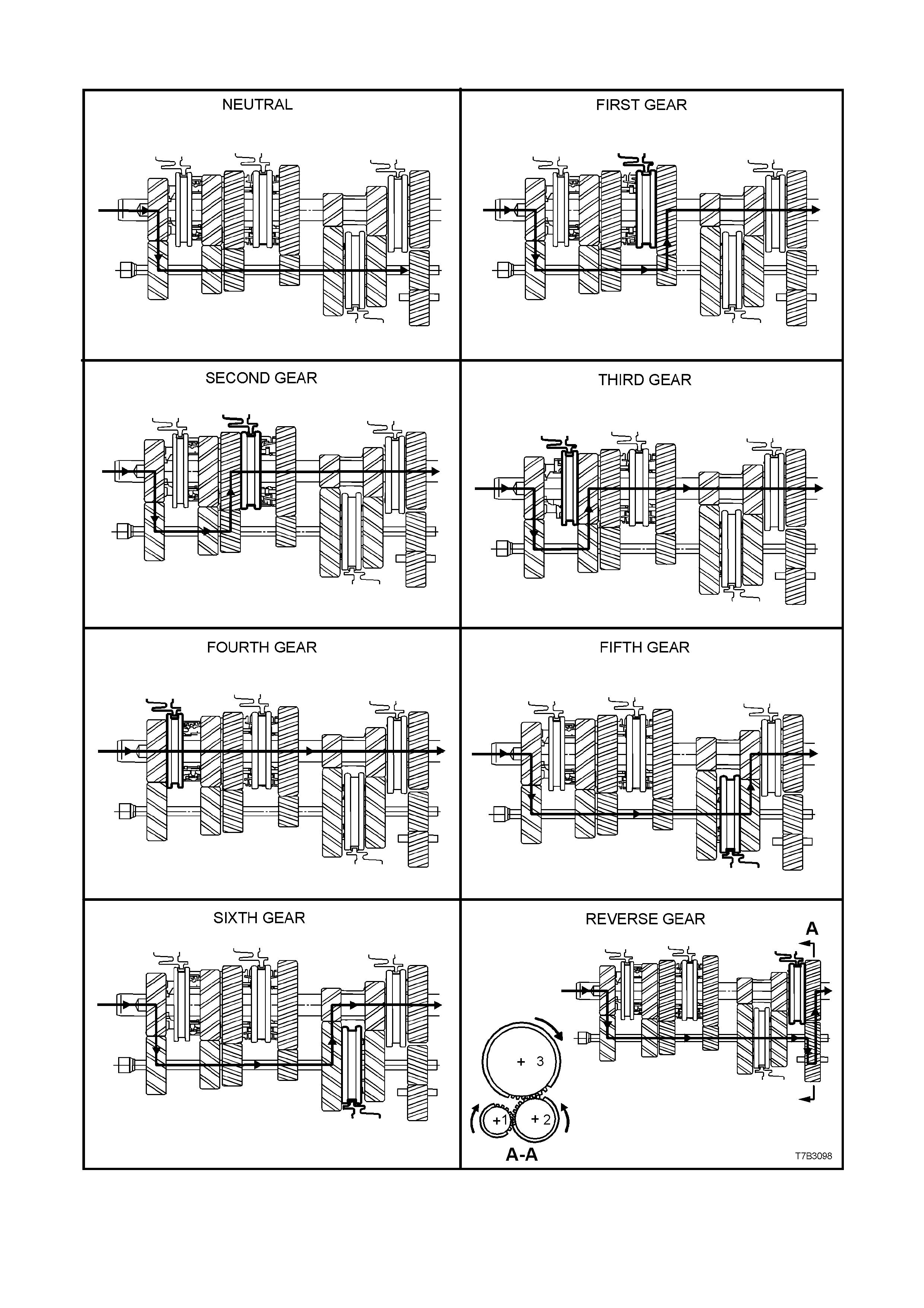
MANUAL TRANSMISSION POWER FLOWS
Figure 7B2-5 – Power Flow Schematics
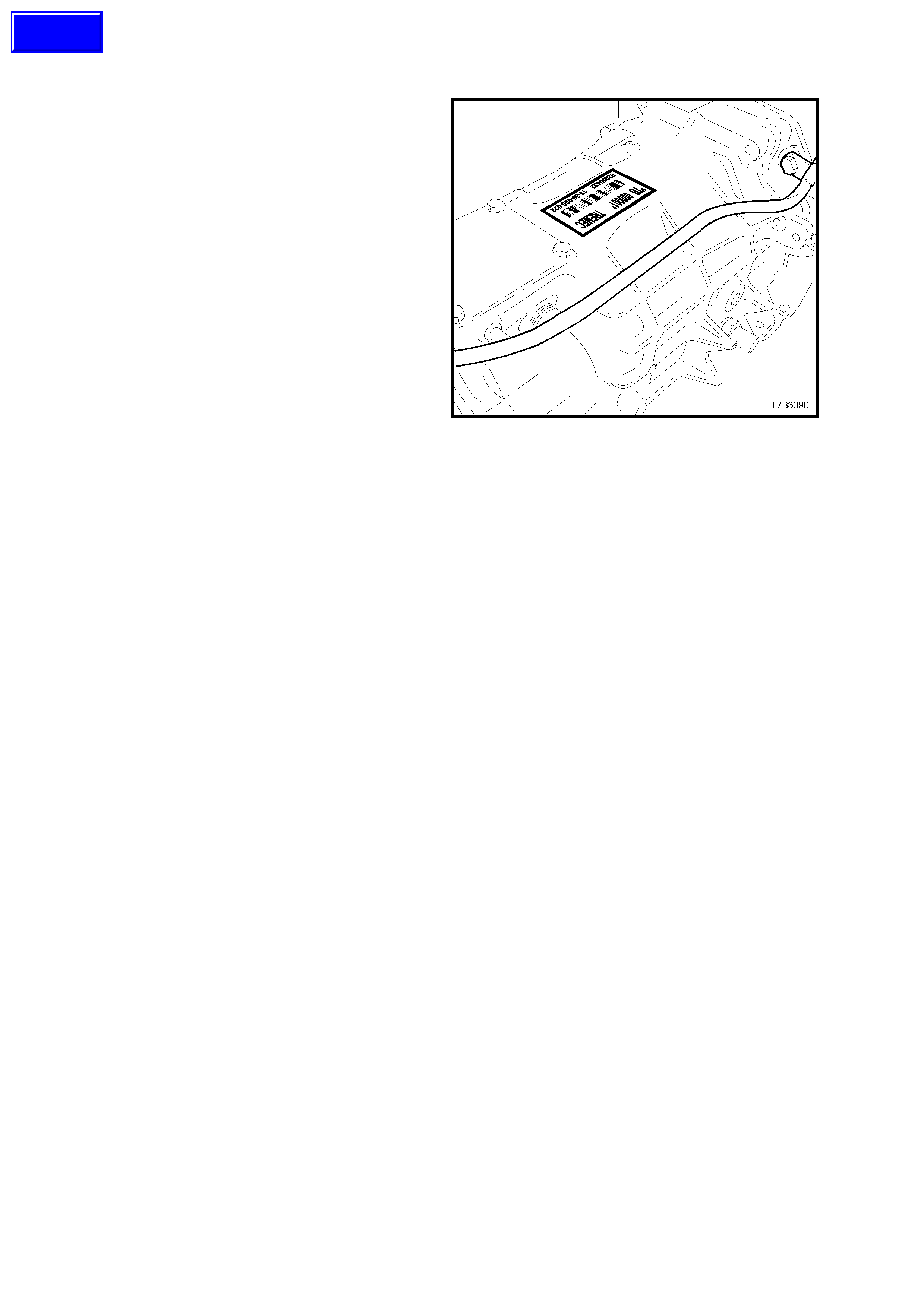
1.2 TRANSMISSION SERIAL NUMBER
The transmission serial number is located on a
self-adhesive decal attached to the top of the
transmission case.
This number provides coded information which
could be significant to parts interpretation and
should be referred to when ordering replacement
parts.
In addition, an identification tag is attached to the
transmission under an extension housing bolt, on
the right hand side. Refer Figure 7B2-8.
Figure 7B2-6
Techline

2. SERVICING INFORM ATION
2.1 RECOMMENDED LUBRICANT
The recommended lubricant for the ‘T56’ manual transmission is Dexron III® automatic transmission fluid.
The transmission lubricant capacity is approximately 4.4 litres.
2.2 CHECKING TRANSMISSION LUBRICANT LEVEL
IMPORTANT: T his transm ission is class ified as be ing a “Fill f or Life” trans mission and ch ecking the lubricant le vel
is not recommended.
The only time that fluid level checking would be appropriate, would be after correction of a fluid leak that did not
require the transmission to be fully drained and/or removed from the vehicle.
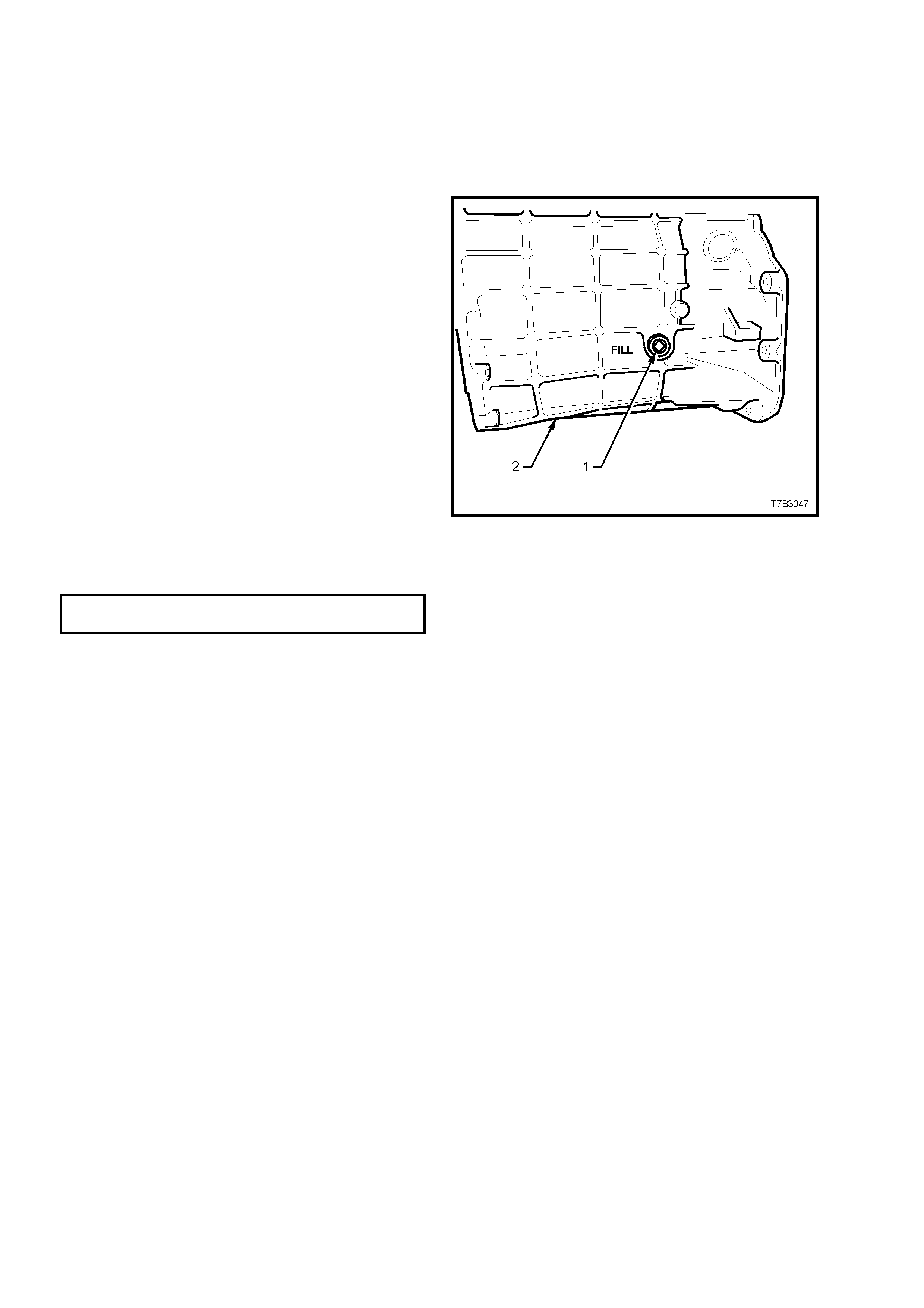
PROCEDURE
1. Raise the veh icle fr ont and rear and support o n
safety stands, ens ur i ng t hat the veh ic le is l ev el.
Refer to Section 0A GENERAL
INFORMATION in the MY 2003 VY and V2
Series Service Information, for the location of
jacking and support points.
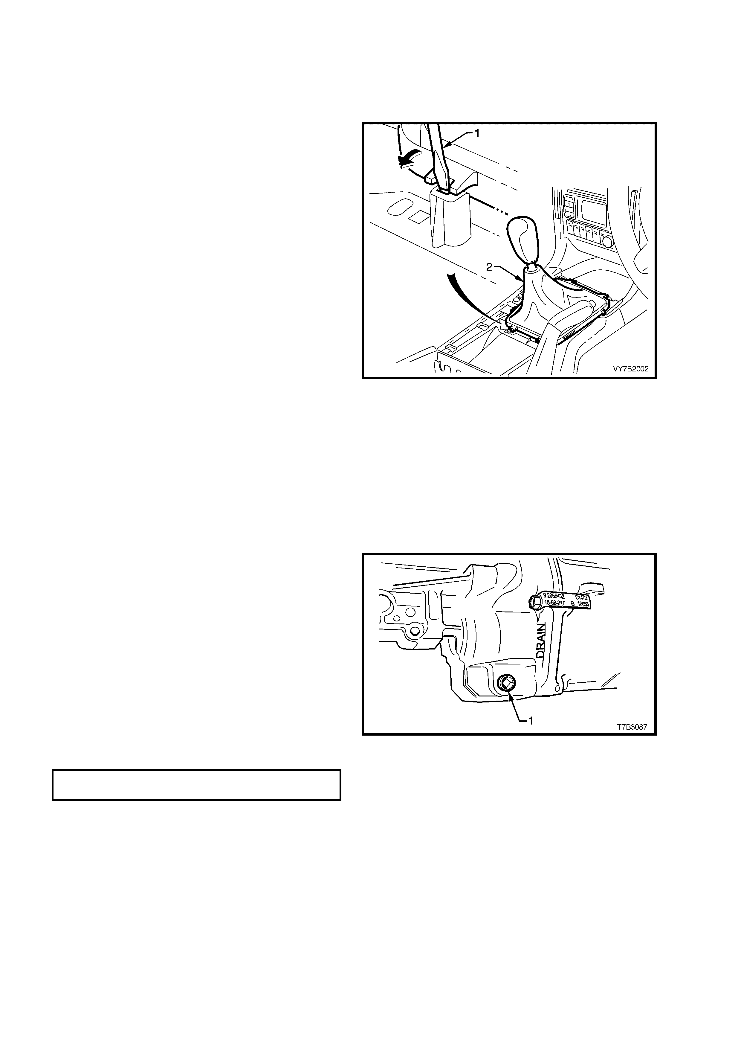
2. Place a drain tray beneath transmission and
remove transmission filler plug (1) from left
hand side of transmission case (2), using a
3/8” drive socket bar.
NOTE: Depending on the severity of the loss, fluid
will prob ably flow fr om the f iller plug ho le, following
removal.
3. Allow excess fluid to drain until flow stops. If
required, top up fluid level until it does flow out.
4. Clean the threads of the filler plug, apply
thread sealant such as Loctite 565 or
equivalent (GM P/N 12346004), then reinstall
filler plug, tightening to the correct torque
specification. Do not apply Teflon thread tape
to the plug threads.
TRANSMISSION FILLER PLUG
TORQUE SPECIFICATION 28 Nm
Figure 7B2-7
5. Remove the back-up lamp switch. Refer to 3.1 BACK-UP L AMP SWIT CH, Replace in this Section.
6. Using commercially available fluid dispensing equipment, add a measured, 0.5 litres of the recommended
lubricant to the transmission, via the back-up lamp switch threaded hole in the transmission case.
7. Reinstal l the bac k- up lam p switch. Ref er to 3. 1 B ACK-UP L AMP SW ITCH, Repla ce in this Secti on, then lower
the vehicle to the ground.
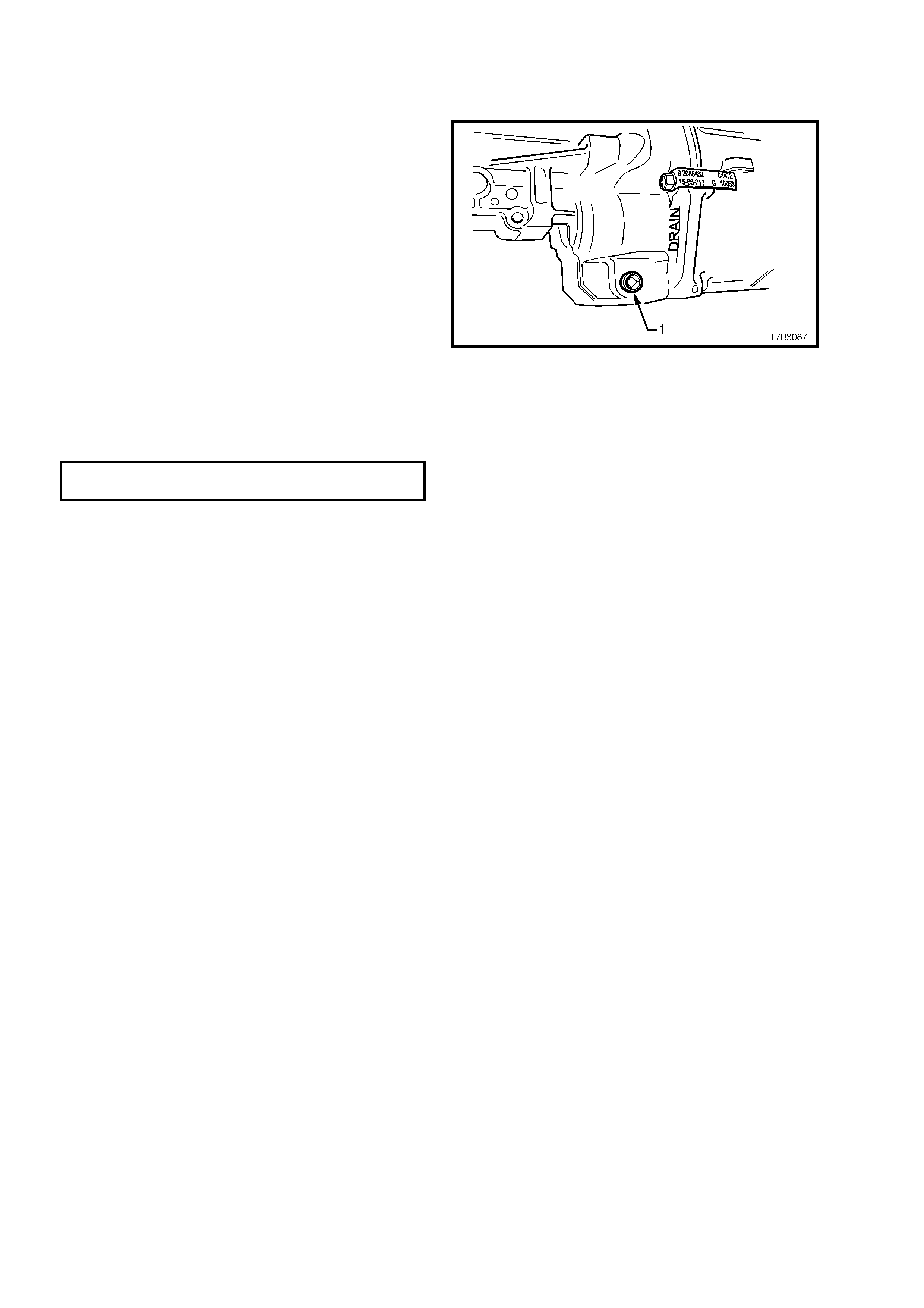
2.3 DRAINING AND REFILLING TRANSMISSION
Should a lubricant change be required, then the following procedure should be adopted.
1. T o drain tr ans mission, j ac k up veh icle f r ont and
rear and support on safety stands. Refer to
Section 0A GENERAL INFORMATION in the
MY 2003 VY and V2 Series Service
Information, for the location of jacking and
support points.
2. Place a drain tray beneath transmission and
rem ove filler plug (‘1’ i n Fig ure 7B2-7) and the n
the drain plug from the transmission extension
housing (‘ 1’ in F igur e 7B2- 8), us ing a 3/8” dr ive
socket bar.
3. After draining, clean the threads of the drain
plug, apply thread sealant such as Loctite 565
or equivalent (GM P/N 12346004) then
reinstall, tightening to the correct torque
specification.
NOTE: Do not apply Tef lon thread ta pe to the plug
threads.
TRANSMISSION DRAIN PLUG
TORQUE SPECIFICATION 28 Nm
4. Refill transmission to correct level, refer to
2.2 CHECKING TRANSMISSION
LUBRICANT LEVEL in this Section.
Figure 7B2-8
3. MINOR SERVICE OPERATIONS
3.1 BACK-UP LAMP SWITCH
LT Section NO. – 04-075
REPLACE
1. Raise front of vehicle and support on safety
stands. Refer to Section 0A GENERAL
INFORMATION in the MY 2003 VY and V2
Series Service Information, for the location of
jacking and support points.
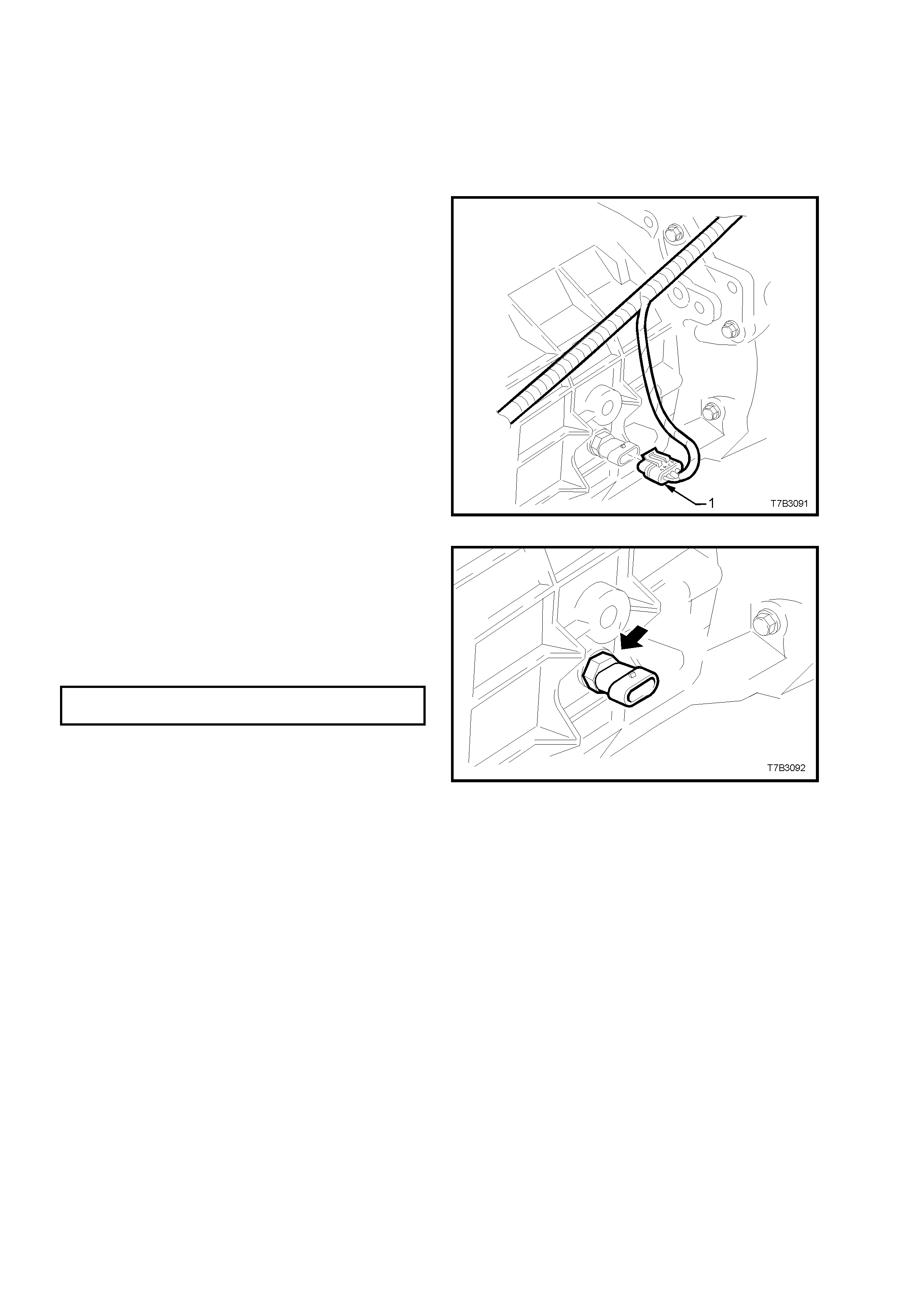
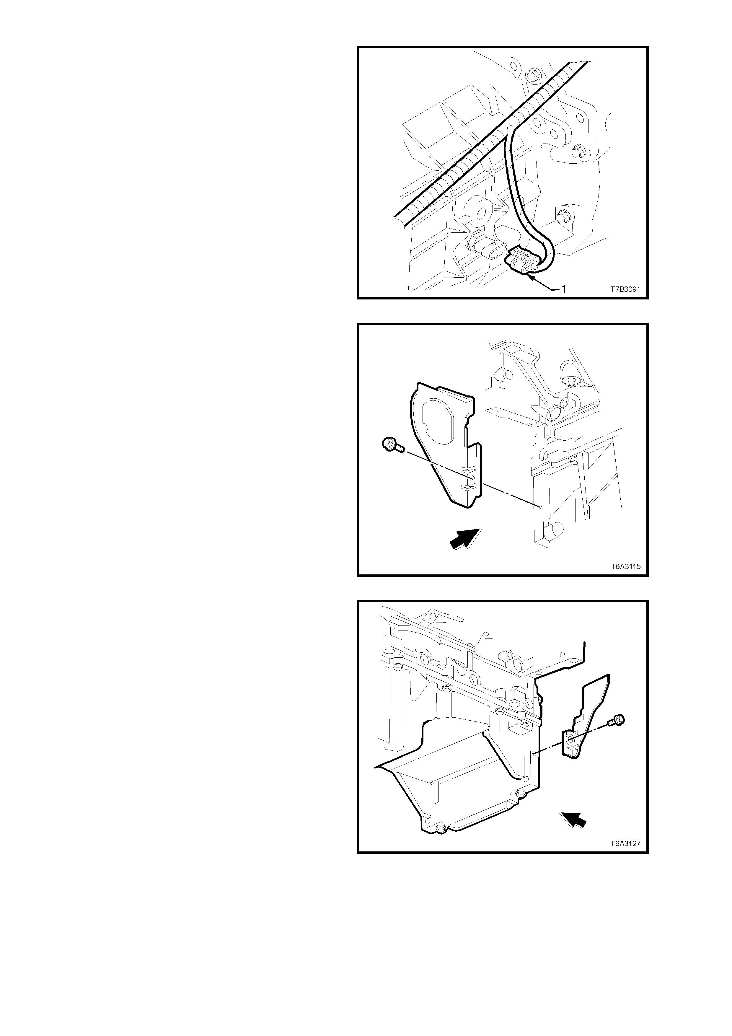
2. Remove wiring harness connector (1) from
switch, located on the right hand side of the
transmission case.
Figure 7B2-9
3. Loosen, then remove switch (arrow) from the
transmission case.
4. Apply Loctite 565 or equivalent (GM P/N
12346004) , to the clean ed threads of the back -
up lamp switch.
5. Install switch to transmission case and tighten
to the correct torque specification.
BACK-UP LAMP SWITCH
TORQUE SPECIFICATION 28 Nm
6. Install wiring harness connector to switch.
7. Remove safety stands and lower vehicle to
ground.
8. Check back-up lamp operation.
Figure 7B2-10
3.2 SPEED SENSOR
LT Section No. – 04-075
REPLACE
1. Raise front of vehicle and support on safety
stands. Refer to Section 0A GENERAL
INFORMATION in the MY 2003 VY and V2
Series Service Information, for the location of
jacking and support points.
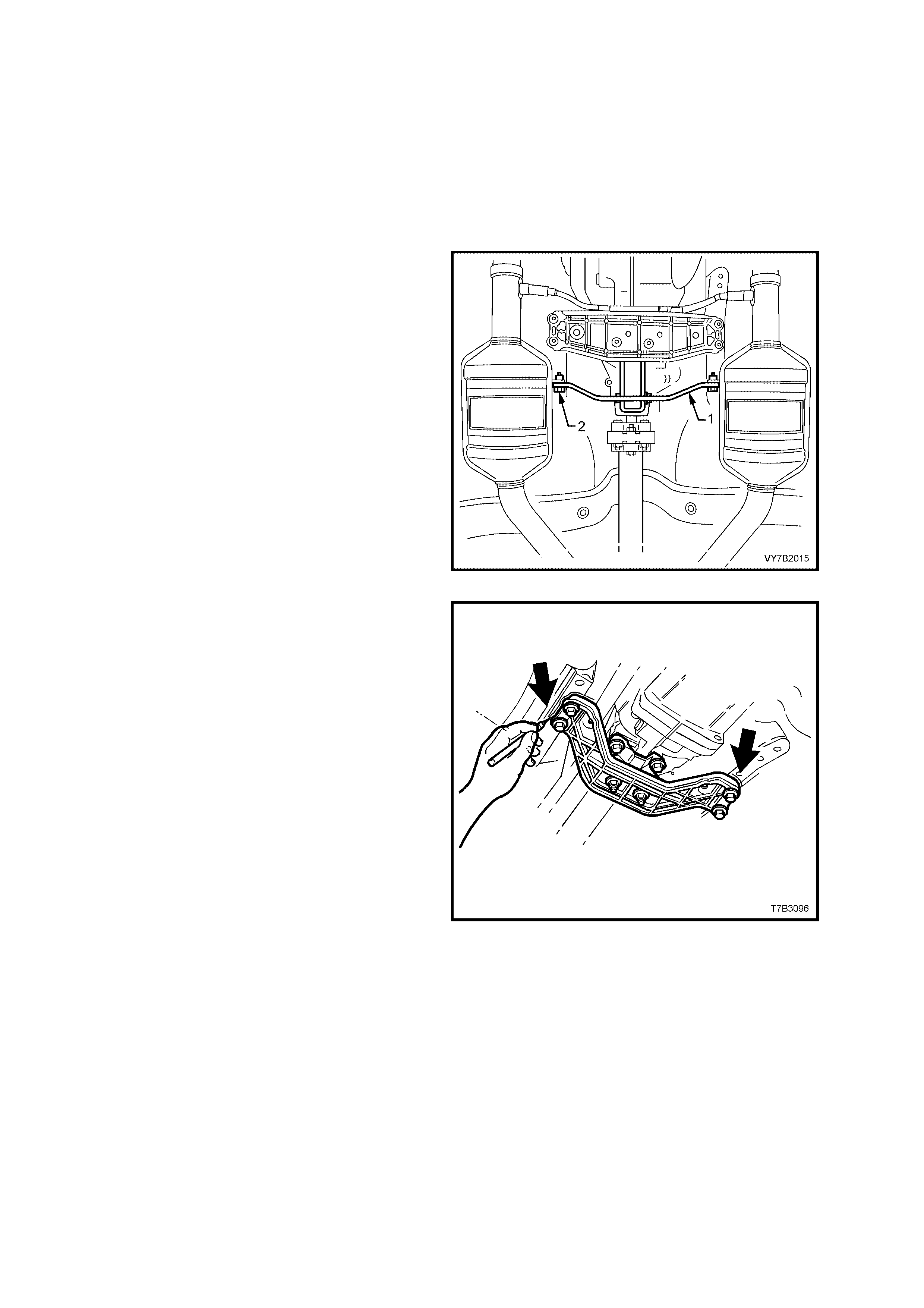
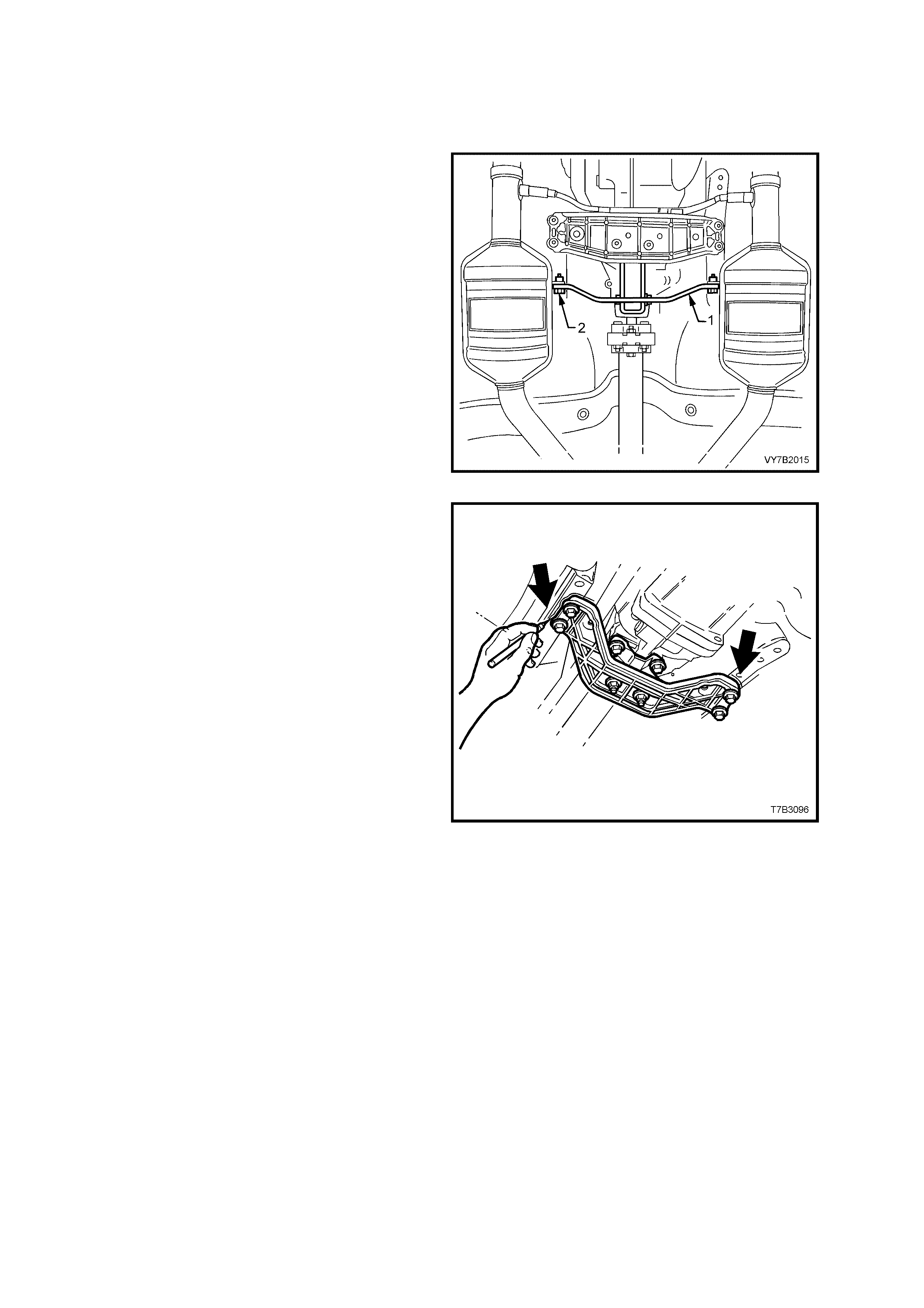
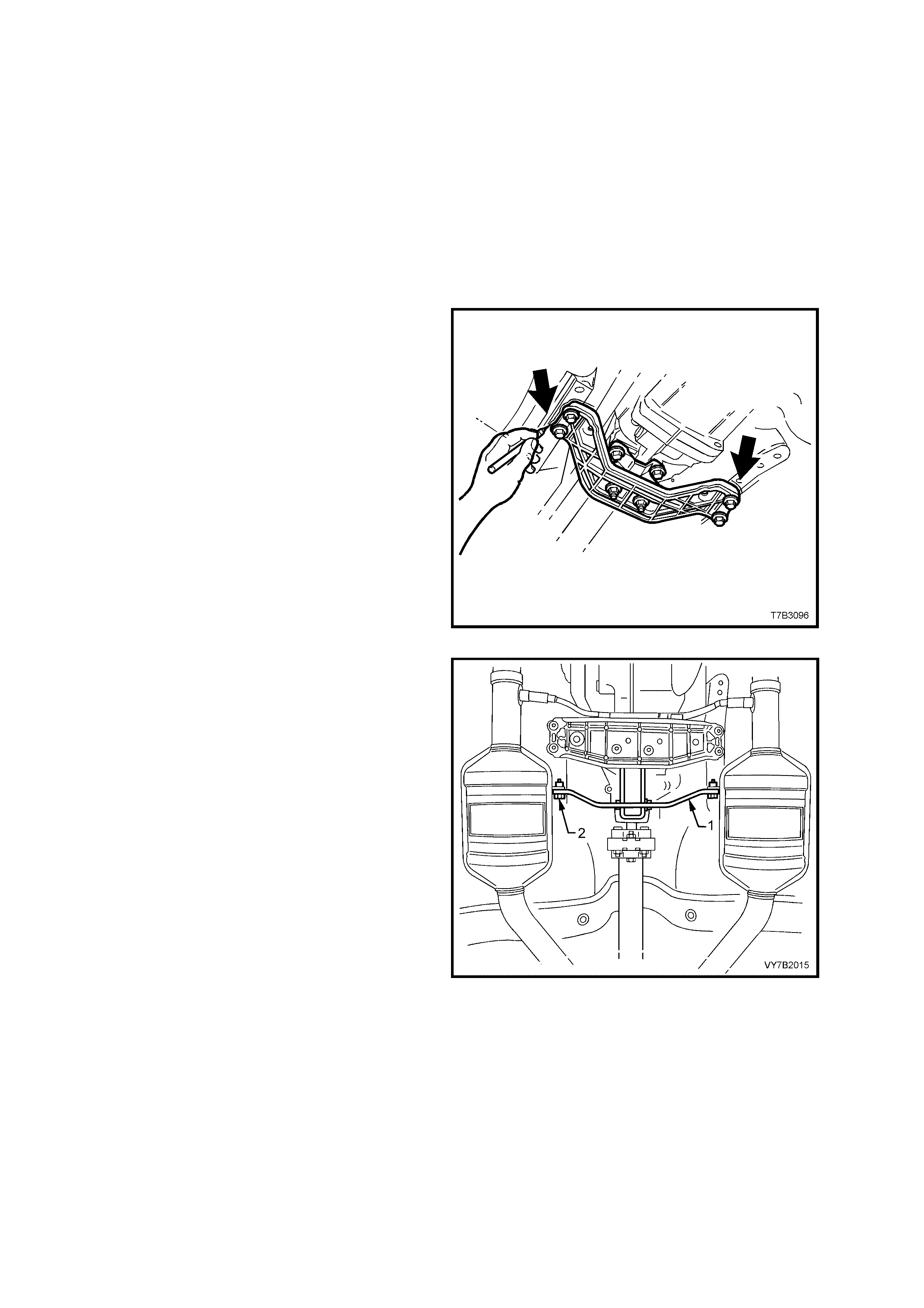
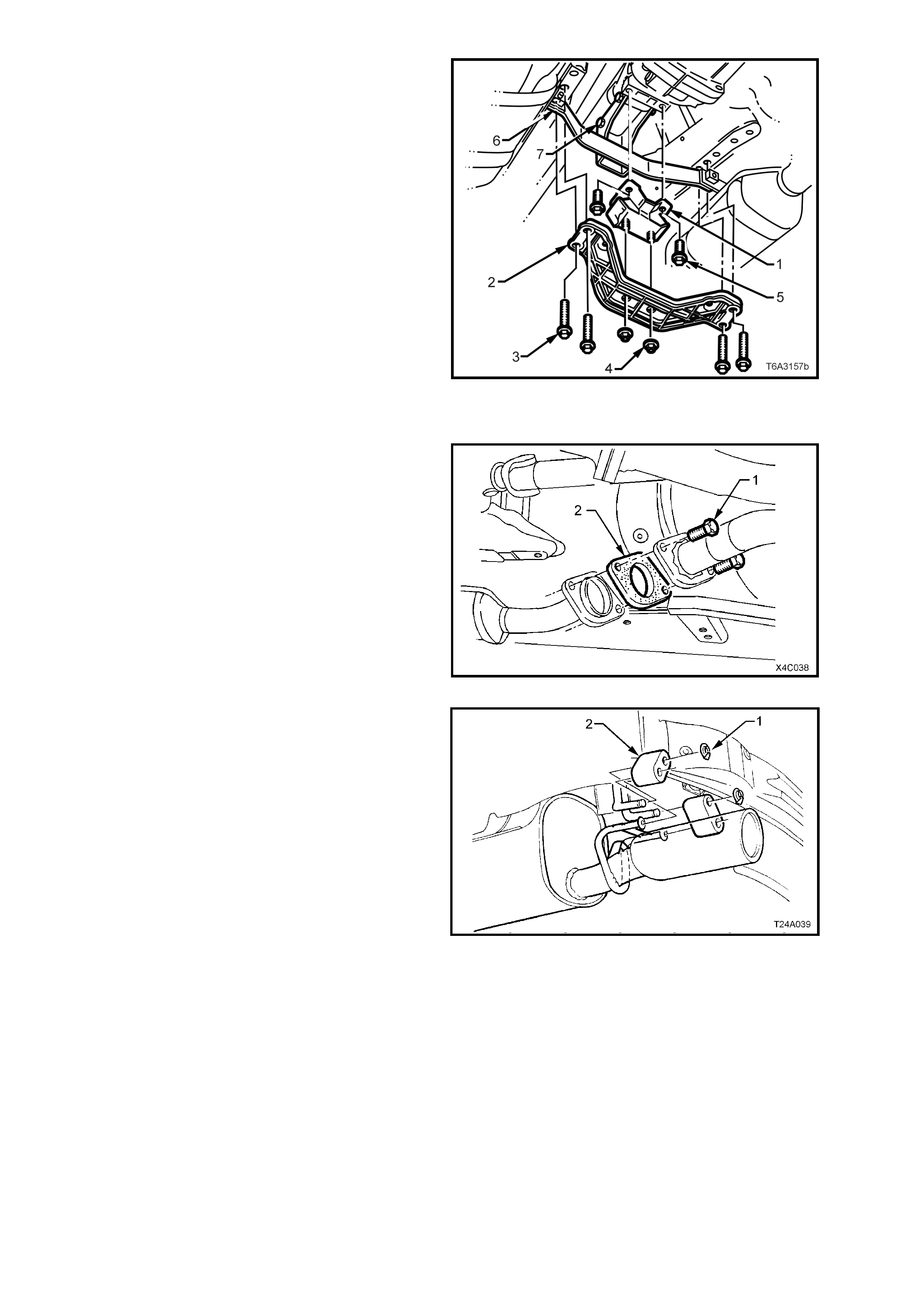
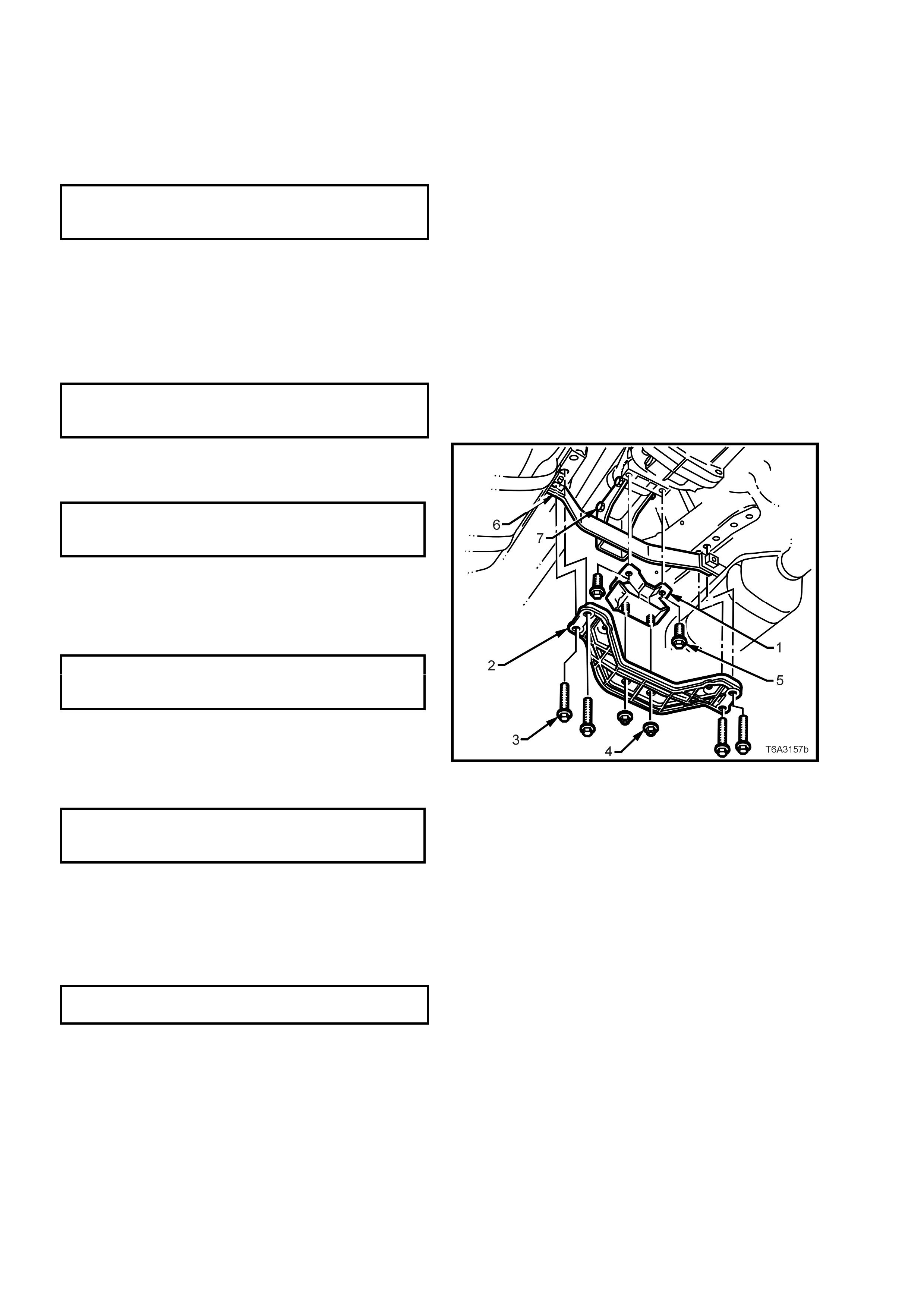
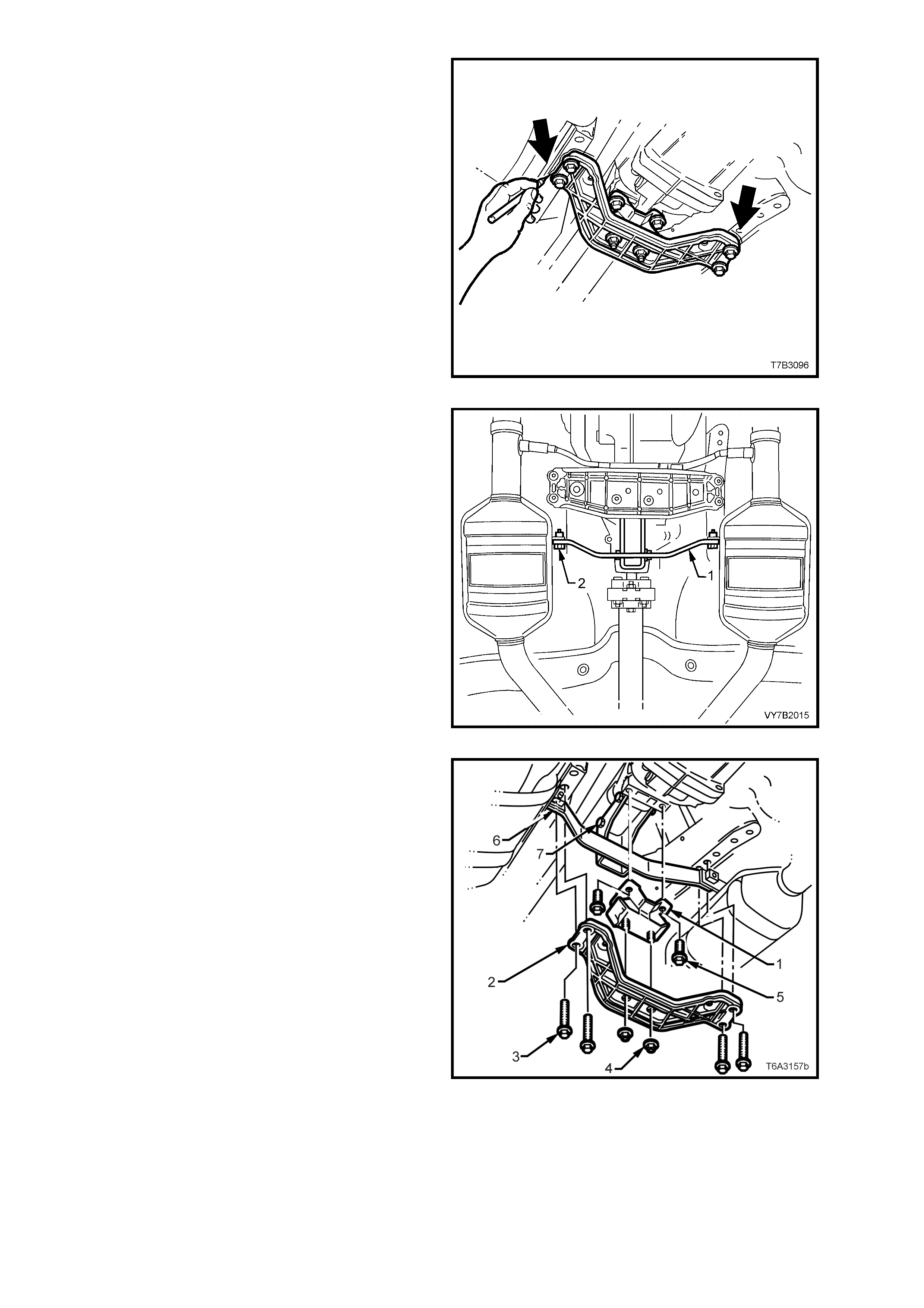
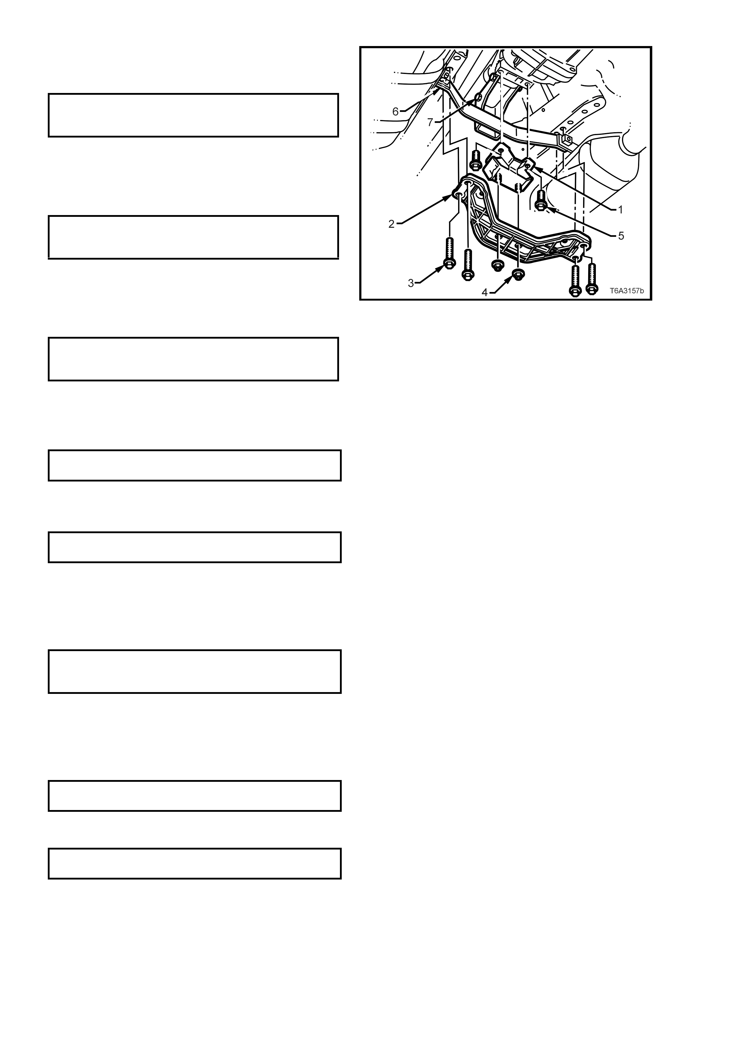
2. Remove the t wo bolts ( 2) securing the catal ytic
converter bracket (1) to the catalytic
converters.
NOTE: Spacers may be located between the
bracket and the catalytic converter/s. If so, the
number and location must be noted for correct
reassembly.
Figure 7B2-11
3. Scribe around each of the transmission support
crossmember mounting points to the vehicle
underbody, to provide an alignment reference
for reassembly.
NOTE: This s tep is c ritical to the c orr ect po wertra in
alignment on reassembly. If not carried out, then
vehicle vibration and/or handling problems may
result.
4. Support the transmission with a suitable lifting
device, then remove the four crossmember
bolts, followed by the two rear mount to
crossmember nuts. Set the crossmember to
one side.
5. Lower the rear of the transmission enough to
gain clear access to the sensor.
Figure 7B2-12
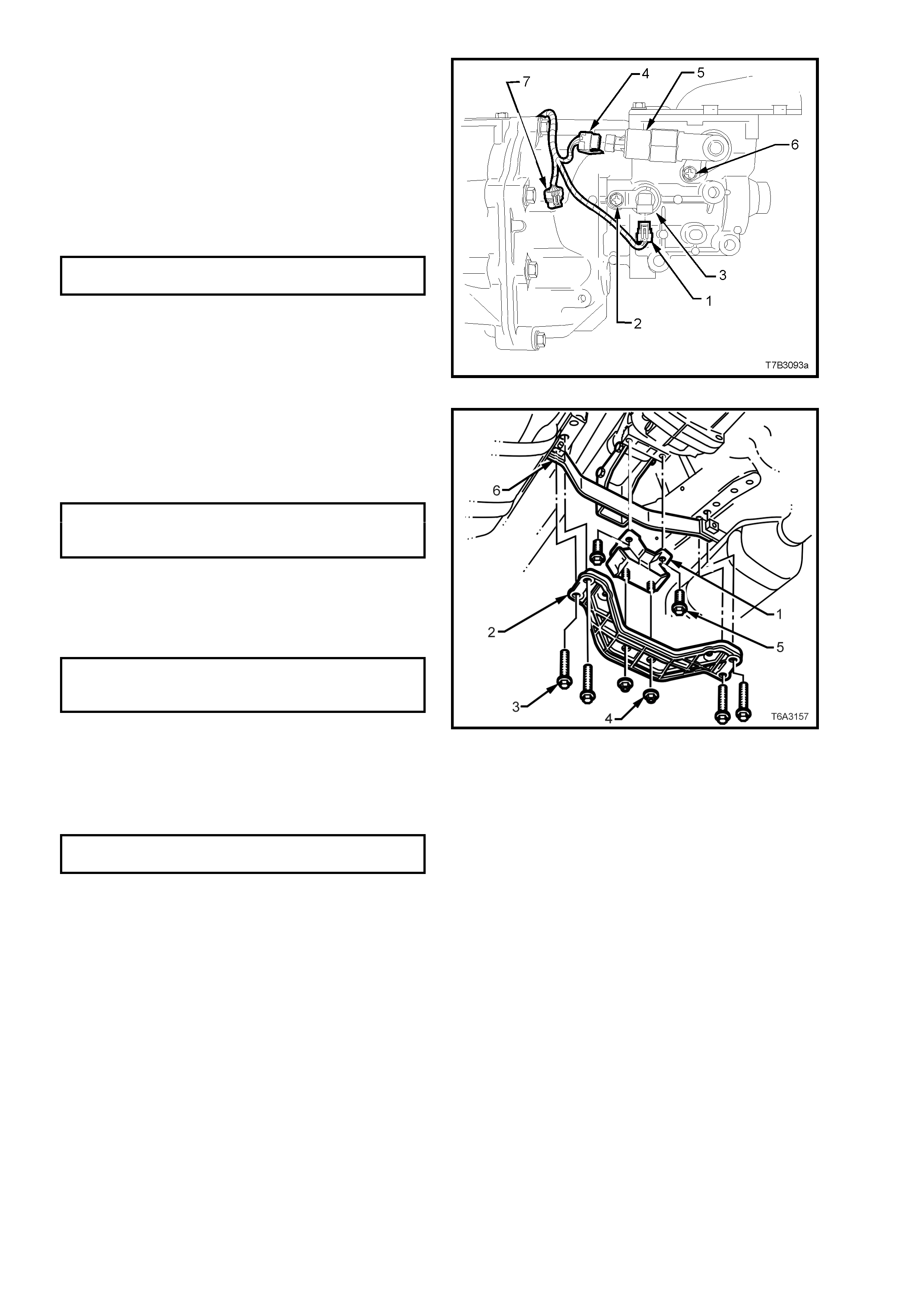
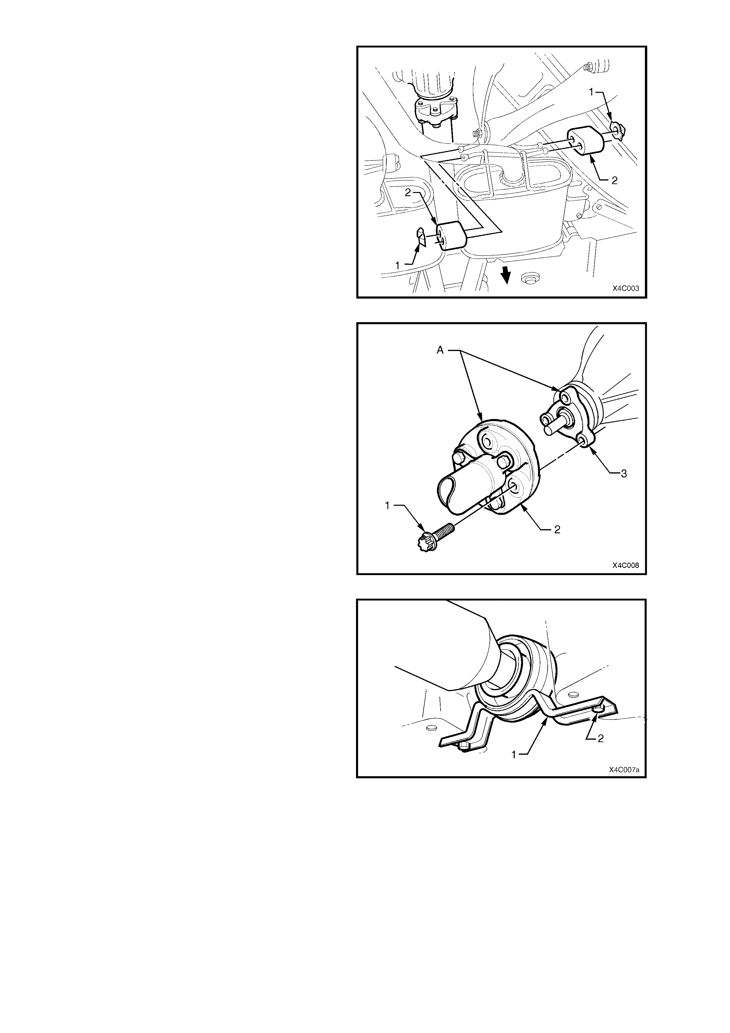
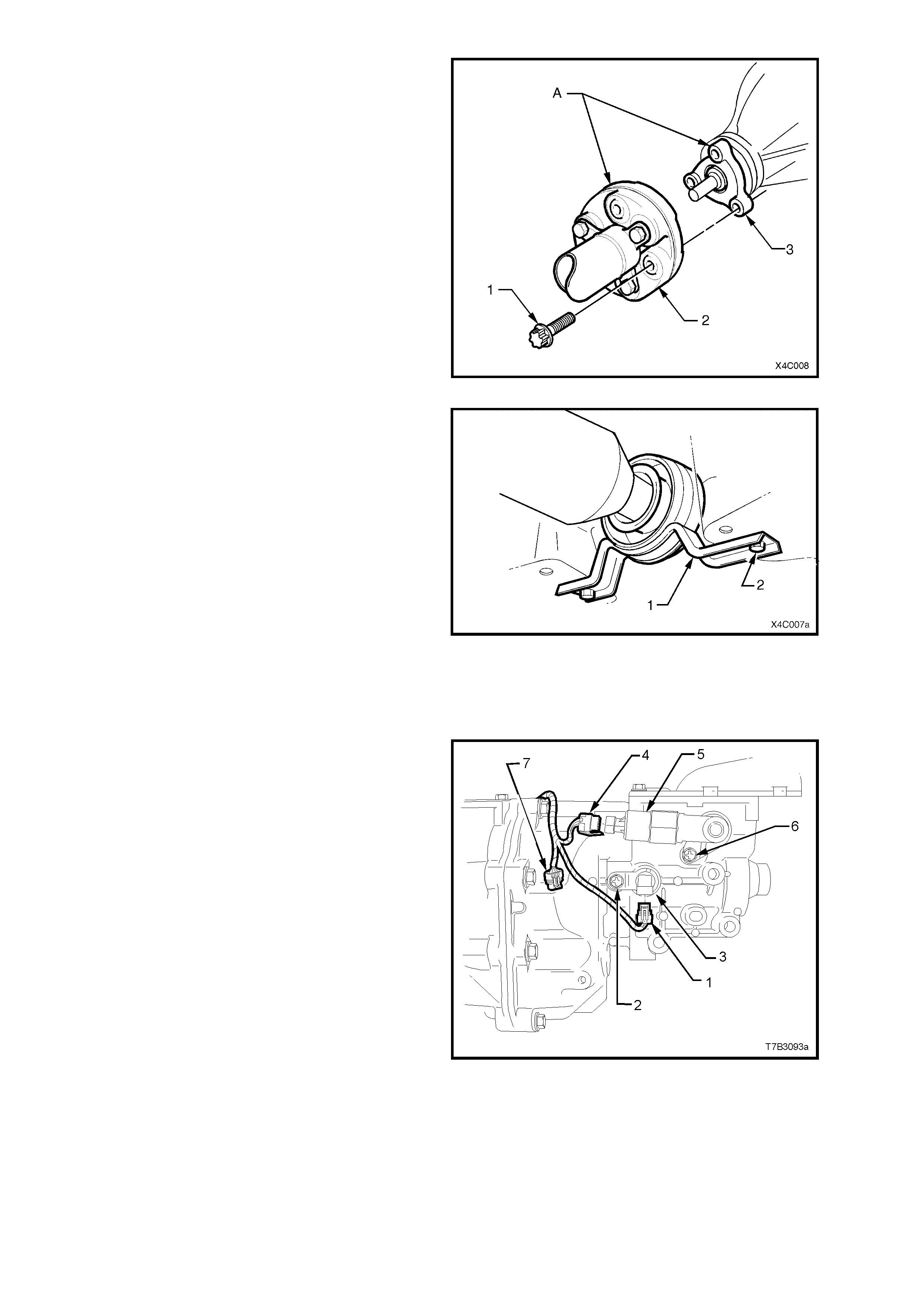
6. Remove the speed sensor wiring harness
connector (1) from the sensor (3).
7. Remove s peed s ensor m ounting brack et sc rew
(2) from the transmission extension housing,
then remove the sensor (3).
8. Installation is the reverse o f removal exc ept for
the following points;
a. Tighten the speed sensor to mounting
bracket retaining screw (2) to the correct
torque specification.
SPEED SENSOR BRACKET
SCREW TORQUE SPECIFICATION 12 Nm
b. Connect the speed sensor lead connector (1)
to the sensor.
Figure 7B2-13
9. Raise the transmission, then install the four
crossmember to side frame bolts (3), aligning
the crossmember (2) with the scribed lines
made prior to disassembly. Tighten the bolts
(3) to the correct torque specification.
REAR CROSSMEMBER TO
SIDE FRAME MEMBER BOLT
TORQUE SPECIFICATION 58 Nm
10. Remove the lifting device from the
transmission, c entralis e the r ear m ount s tuds in
the crossmember holes, then reinstall the nuts
(4), tightening to the correct torque
specification.
REAR CROSSMEMBER TO
TRANSMI SS I ON MOUNT NU T
TORQUE SPECIFICATION 25 Nm
11. Reinstal l the two catal ytic converter bracket (6)
bolts, tightening to the correct torque
specification.
NOTE: If any spacers were removed on
disassembly, then these must be fitted in the
original format.
CATALYTIC CONVERTER BRACKET
BOLT TORQUE SPECIFICATION 25 Nm
12. Lower the vehicle and road test to check
speedometer operation.
Figure 7B2-14
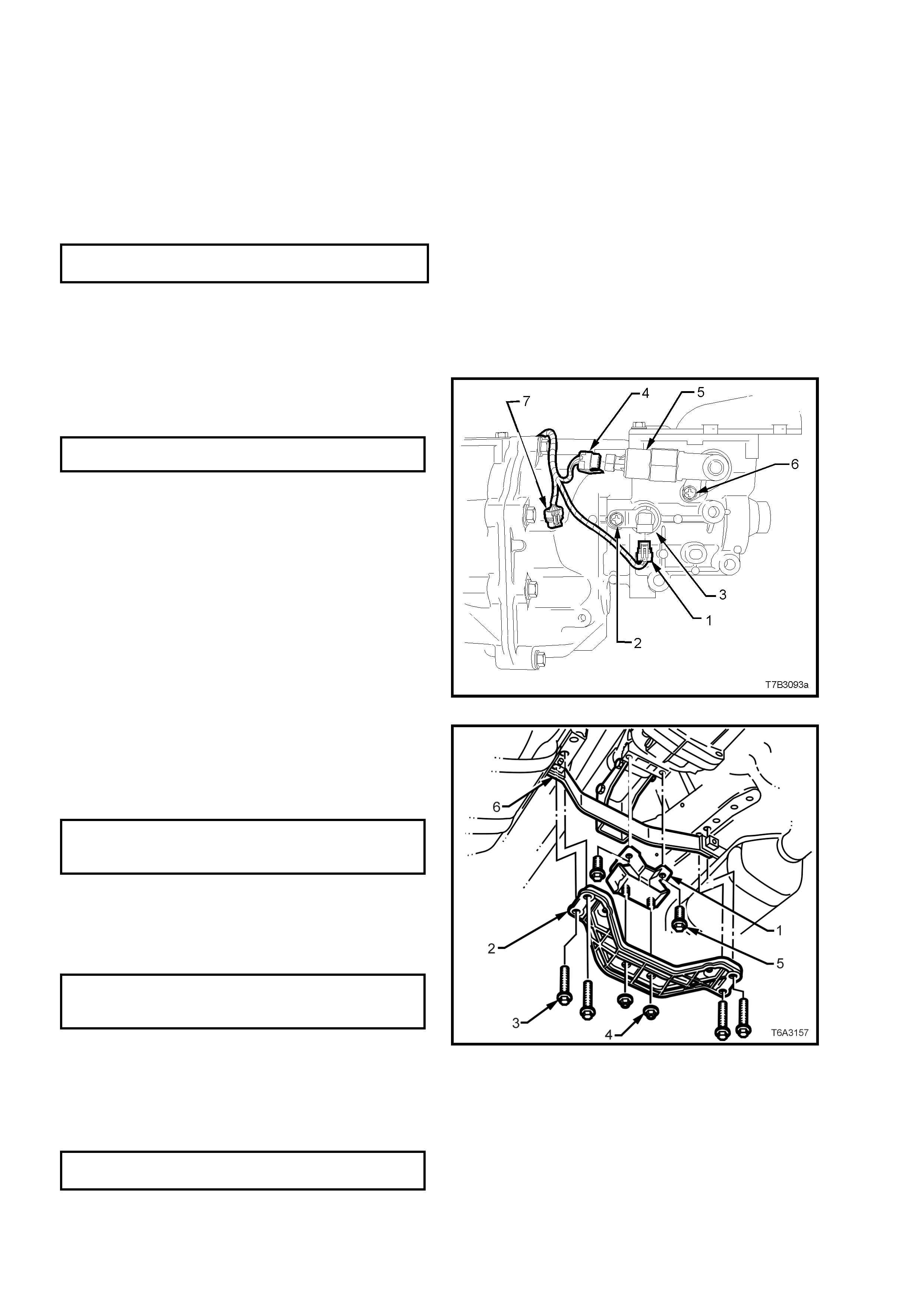
3.3 TRANSMISSION SUPPORT MOUNT
LT Section No. – 04-020
REPLACE
1. Raise front of vehicle and support on safety
stands. Refer to Section 0A GENERAL
INFORMATION in the MY 2003 VY and V2
Series Service Information, for the location of
jacking and support points.
2. Remove the t wo bolts ( 2) securing the catal ytic
converter bracket (1) to the catalytic
converters.
NOTE: Spacers may be located between the
bracket and the catalytic converter/s. If so, the
number and location must be noted for correct
reassembly.
Figure 7B2-15
3. Scribe around each of the transmission support
crossmember mounting points to the vehicle
underbody, to provide an alignment reference
for reassembly.
NOTE: This s tep is c ritical to the c orr ect po wertra in
alignment on reassembly. If not carried out, then
vehicle vibration and/or handling problems may
result.
4. Support the transmission with a suitable lifting
device, then remove the four engine mounting
crossmember bolts.
5. Lower the transmission slightly, then remove
the two rear mount to crossmember nuts. Set
the crossmember to one side.
Figure 7B2-16
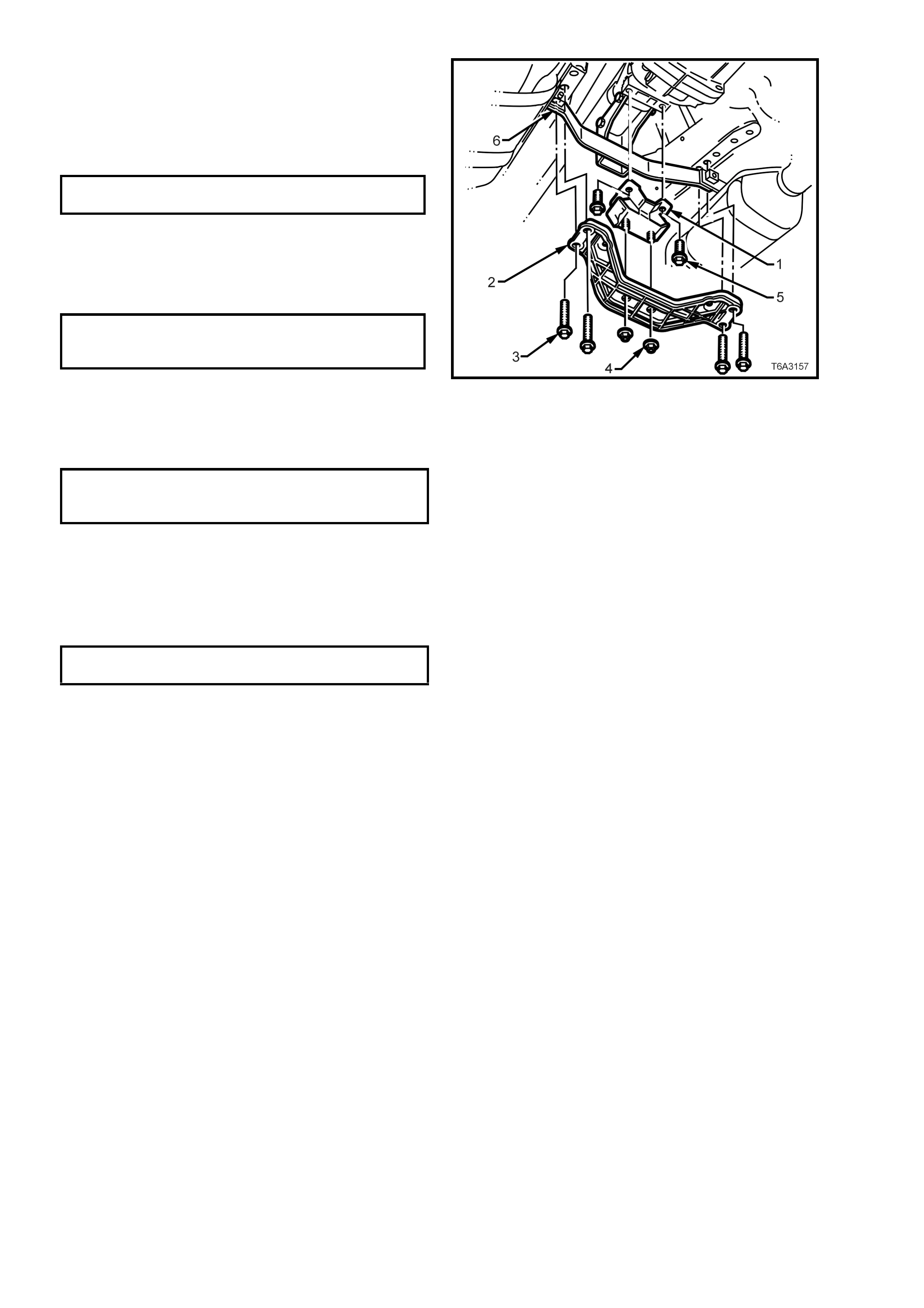
6. Remove the two bolts (5) securing the mount
(1) to the trans mission exte nsion housing, the n
remove the mount from the vehicle.
7. Reinstall the mount (1) to the transmission
extension housing, install the two bolts (5) and
tighten to the correct torque specification.
TRANSMISSION SUPPORT MOUNT
BOLT TORQUE SPECIFICATION 25 Nm
8. Raise the transmission slightly, then reinstall
the four crossmember to side frame bolts (3),
aligning the crossmember (2) with the scribed
lines made prior to disassembly. Tighten the
bolts (3) to the correct torque specification.
REAR CROSSMEMBER TO
SIDE FRAME MEMBER BOLT
TORQUE SPECIFICATION 58 Nm
9. Remove the lifting device from the
transmission, c entralis e the r ear m ount s tuds in
the crossmember holes, then reinstall the nuts
(4), tightening to the correct torque
specification.
Figure 7B2-17
REAR CROSSMEMBER TO
TRANSMI SS I ON MOUNT NU T
TORQUE SPECIFICATION 25 Nm
10. Reins tal l the t wo ca tal ytic c onverter brac k et (6)
bolts, tightening to the correct torque
specification.
NOTE: If any spacers were removed on
disassembly, then these must be fitted in the
original format.
CATALYTIC CONVERTER BRACKET
BOLT TORQUE SPECIFICATION 25 Nm
11. Lower the vehicle and road test to check
speedometer operation.

3.4 REVERSE LOCKOUT SOLENOID ASSEMBLY
LT Section No. – 04-090
REMOVE
1. Raise front of vehicle and support on safety
stands. Refer to Section 0A GENERAL
INFORMATION in the MY 2003 VY and V2
Series Service Information, for the location of
jacking and support points.
2. Remove the t wo bolts ( 2) securing the catal ytic
converter bracket (1) to the catalytic
converters.
NOTE: Spacers may be located between the
bracket and the catalytic converter/s. If so, the
number and location must be noted for correct
reassembly.
Figure 7B2-18
3. Scribe around each of the transmission support
crossmember mounting points to the vehicle
underbody, to provide an alignment reference
for reassembly.
NOTE: This s tep is c ritical to the c orr ect po wertra in
alignment on reassembly. If not carried out, then
vehicle vibration and/or handling problems may
result.
4. Support the transmission with a suitable lifting
device, then remove the four engine mounting
crossmember bolts.
5. Lower the transmission slightly, then remove
the two rear mount to crossmember nuts. Set
the crossmember to one side.
Figure 7B2-19
6. Lower the transmission sufficient to gain
access to the reverse lockout solenoid
assembly (5).
7. Remove wiring harness connector (4) from the
reverse lockout solenoid (5), after depressing
the lock ing tab.
8. Remove the revers e l oc k out s oleno id as s embly
mounting s crew (6), t hen rem ove the assem bly
from the transmission extension housing by
rotating back and forth while pulling on the
assembly.
Figure 7B2-20
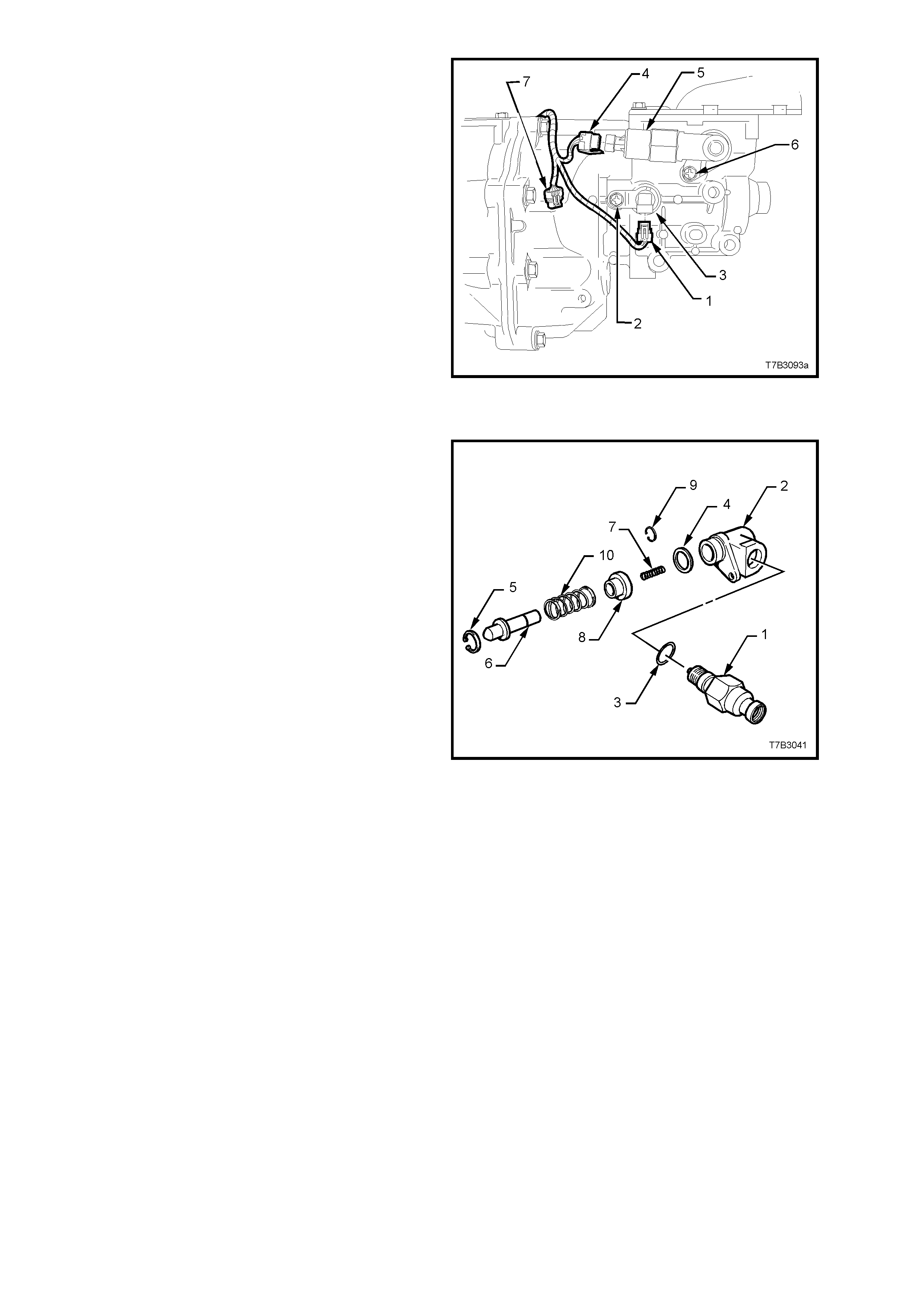
DISASSEMBLE
1. While holding the lockout body (2) in a vice
fitted with soft jaws, unscrew the reverse
lockout solenoid (1) from the body (2), then
remove the O-ring seal (3). If the O-ring seal
(3) is undamaged, it can be re-used.
2. Remove the O -ring (4) from the bod y (2). If th e
O-ring seal is undamaged it can also be re-
used.
3. Remove circlip (5), using suitable pliers, from
the body (2).
4. Rem ove lock out plunger assem bly (6) from the
body (2), then remove the inner spring (7).
5. Compress the reverse lockout plunger (6) and
collar (8) in a bench vice, then remove the ‘C’
clip (9).
CAUTION: The reverse lockout assembly is
under a strong spring force. Exercise care
when removing ‘C’ clip (9), as injury could
result.
6. Release the vice and disassemble the collar
(8) and spring (10) from the plunger (6).
7. Clean all parts in a suitable solvent and blow
dry with compressed air.
CAUTION: Wear safety glasses to avoid eye
injury.
8. Inspect all parts for damage or wear and
springs for broken or damaged coils.
Figure 7B2-21
9. For solenoid testing procedure, refer to
Section 6C3 POWERTRAIN MANAGEMENT
- GEN III V8 ENGINE, in the MY 2003 VY and
V2 Series Service Information..
REASSEMBLE
NOTE: Refer Figure 7B2-21 for component identification.
1. Compress the reverse lockout plunger (6), spring (10) and collar (8) in a bench vice, then install the ‘C’ clip (9).
CAUTION: Wear safety glasses to avoid eye injury.
2. Install the inner spring (7) into the end of the lockout plunger assembly (6), then install the assembly into the
reverse lockout body (2).
3. Install circlip (5), using suitable pliers, to retain the lockout plunger assembly (6).
4. Install the reverse lockout solenoid (1) and a new O-ring, tightening to the correct torque specification.
REVERSE LOCKOUT SOLENOID
TORQUE SPECIFICATION 40 Nm
5. Install a new O-ring (4) to the body (2).
REINST ALL
The r einstal lation pr oces s is the rever s e of re moval
operations except for the following:
1. After reinstalling the reverse lockout assembly
(5), inst all the reta ining s cre w (6) and tig hten to
the correct torque specification.
REVERSE LOCKOUT ASSEMBLY
BOLT TORQUE SPECIFICATION 18 Nm
2. Reinstall the wiring harness connector (4) to
the reverse lockout solenoid.
Figure 7B2-22
3. Raise the transmission slightly, then reinstall
the four crossmember to side frame bolts (3),
aligning the crossmember (2) with the scribed
lines made prior to disassembly. Tighten the
bolts (3) to the correct torque specification.
REAR CROSSMEMBER TO
SIDE FRAME MEMBER BOLT
TORQUE SPECIFICATION 50 - 65 Nm
4. Remove the lifting device from the
transmission, c entralis e the r ear m ount s tuds in
the crossmember holes, then reinstall the nuts
(4), tightening to the correct torque
specification.
REAR CROSSMEMBER TO
TRANSMI SS I ON MOUNT NU T
TORQUE SPECIFICATION 25 Nm
5. Reins tall the two cat alytic converter bracket (6)
bolts, tightening to the correct torque
specification.
NOTE: If any spacers were removed on
disassembly, then these must be fitted in the
original format.
CATALYTIC CONVERTER BRACKET
BOLT TORQUE SPECIFICATION 25 Nm
6. Lower the vehicle and road test to check
speedometer operation.
Figure 7B2-23
3.5 CONTROL LEVER KNOB, BOOT & CONTROL LEVER ASSEMBLY
LT Section No. – 04-060
IMPORTANT: The gearshift lever knob and
gearshift lever are permanently bonded together
during manufacture and are not serviced
separately. Therefore, do not attempt to separate
these two components.
REMOVE
1. Remove the floor console cover assembly.
Refer 2.1 FLOOR CONSOLE COVER
ASSEMBLY, in Section 1A3 INSTRUMENT
PANEL & CONSOLE, in the MY 2003 VY and
V2 Series Service Information.
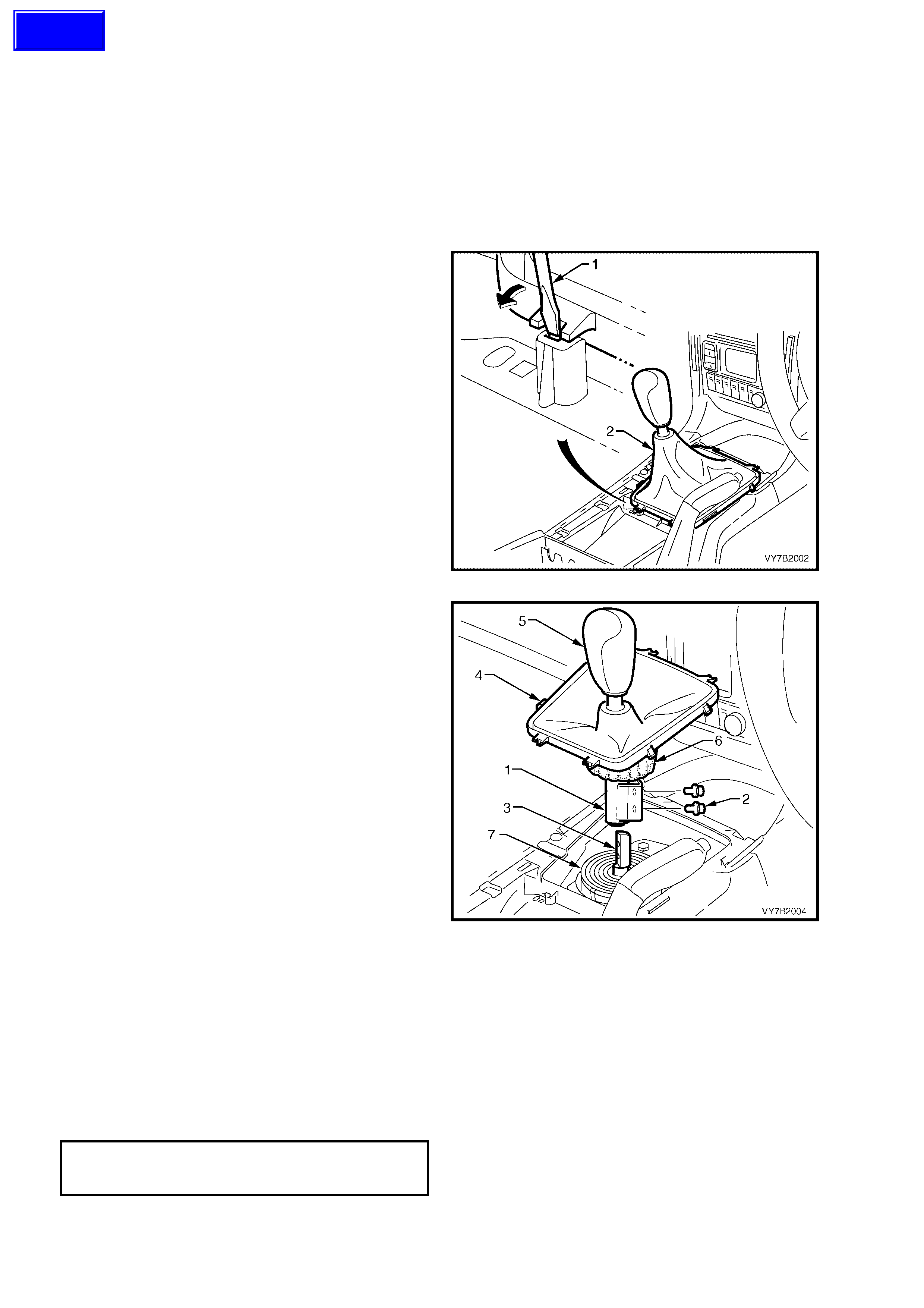
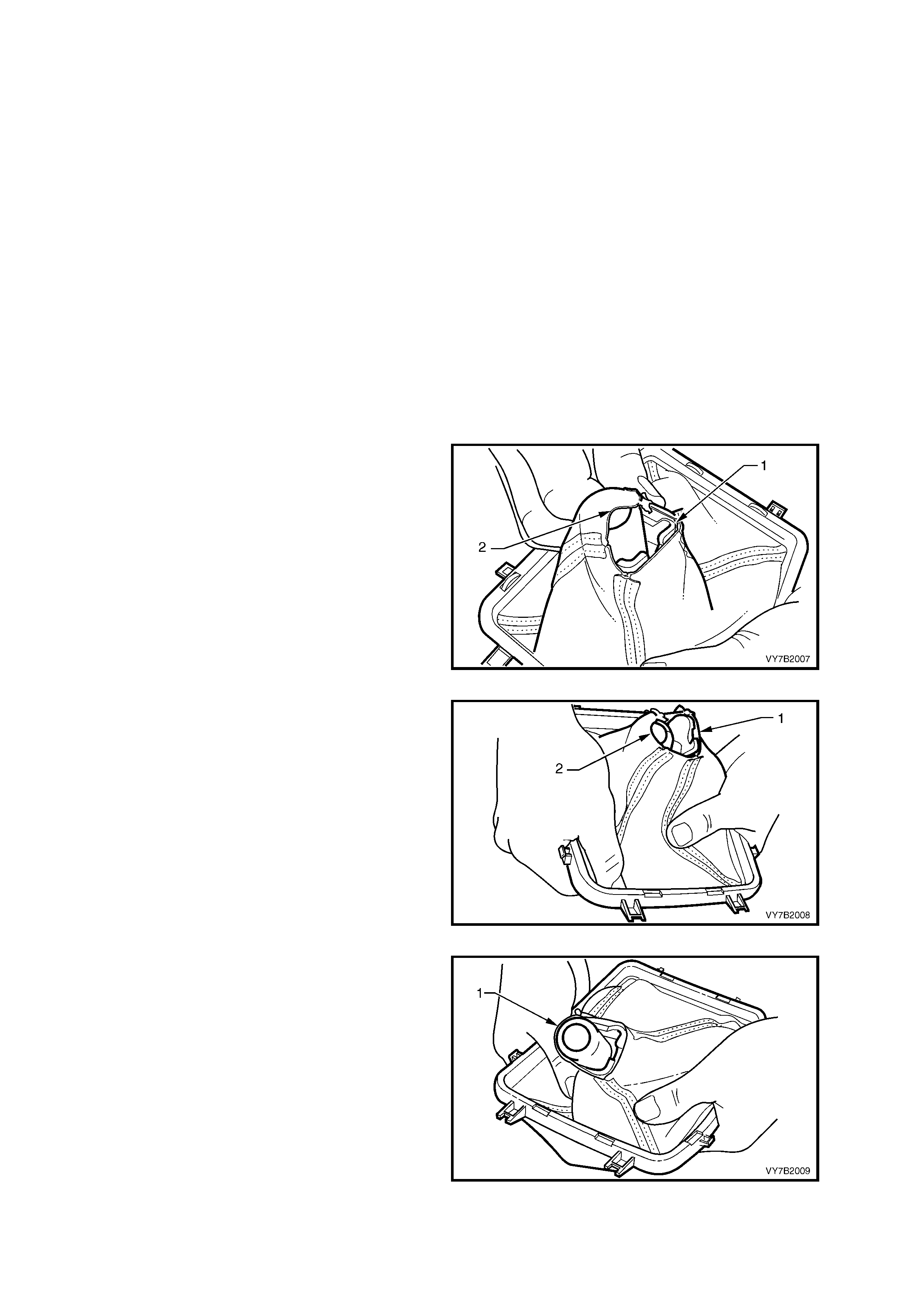
2. Using a fine bladed screwdriver, release each
locking tab, while exerting an upward force on
the boot carrier. Lift the gearshift boot retainer
free from the floor console.
Figure 7B2-24
IMPORTANT: T he gearshift k nob (5) and gearshift
lever (1) are now permanently glued together and
are not to be separated. The boot (4) however, is
replaceable. Refer 3.6 CONTROL LEVER BOOT,
Replace, in this Section.
3. Lif t the gear shift le ver boot (4) up and o ver the
gearshift knob (5), then turn the insulator (6)
back on itself, enough to gain access to the
gearshift remote shift lever shaft screws (2).
4. Using a 10 m m s ocket, rem ove the tw o scre ws
(2) securing the control lever (1) to the
gearshift remote shift lever shaft (3), then lift
the control lever (1), gearshift knob (5) and
boot (4), free.
5. Clean old thread sealant from the bolt threads.
Figure 7B2-25
REINST ALL
IMPORTANT: Before reinstalling the control lever assembly, ensure that the gearshift remote lever boot (7) is
located correctly in the groove provided in the remote gearshift lever (3). Also refer Figure 7B2-31. If the boot is not
located correctly, the durability of the boot will be severely diminished, once the vehicle is put back into service.
1. Apply thread sealant such as Loctite 242 or equivalent, to the cleaned threads of the control lever retaining
bolts (2).
2. With the control lever boot still pulled up over the gearshift knob and the insulator installed over the control
lever, (and also folded back on itself), reinstall the assembly to the gearshift remote shift lever shaft, reinstall
the two bolts and tighten to the correct torque specification.
GEARSHIFT LEVER TO REMOTE
SHIFT LEVER SHAFT BOLT
TORQUE SPECIFICATION 25 Nm
Techline

3. Unfold the insulator sock, ensuring that it is pulled down over the lower part of the control lever assembly,
covering the mounting bracket and attaching screws, then pull the boot (4) down.
NOTE: The cor rect pos ition of the ins ulat ing soc k is for the lo wer edg e to jus t cont act the rem ote s hift le ver, r ubber
boot (6).
4. Align the boot carrier locking tabs with the locations in the floor console, then c arefully seat th e boot retainers
until each tab engages correctly.
5. Reinstal l the floor c onsole cover as sem bl y. Refer 2.1 FLOOR CONSOLE COVER ASSEMBLY , in Section 1A3
INSTRUMENT PANEL & CONSOLE, in the MY 2003 VY and V2 Series Service Information.
3.6 CONTROL LEVE R BOOT
LT Section No. 04-060
REPLACE
1. Remove the control lever knob, boot and
control lever assembly. Refer 3.5 CONTROL
LEVER KNOB, BOOT & CONTROL LEVER,
in this Section.
2. Carefully remove the insulator sock and
inspect for tears or rub marks. Replace as
required.
3. Turn the boot inside out and pull up over the
control lever knob. Cut the tie strap and
remove the boot from the knob and control
lever assembly. Discard both the boot and the
tie strap.
IMPORTANT: To install a new boot, a specific
procedure is required, to ensure that damage to
the new boot does not occur .
4. With the new boot (1) turned inside out, begin
installation by locating the lever attaching lug
(1), inside and against one of the long sides of
the boot assembly, as shown.
IMPORTANT: During the installation process,
apply a firm but constant force and ease the boot
over the le ver attach ing lug to minimis e the chance
of the boot stitching being ruptured.
Figure 7B2-26
5. Gradually ease the boot opening over the
rounded section of the lever assembly, taking
care not to rupture the boot stitching in the
process.
Figure 7B2-27
6. Continue to apply a constant force to the boot,
easing the boot over the lever end. When fully
stretched over the lever end, pull the boot
down, to install past the mounting flange.
Figure 7B2-28
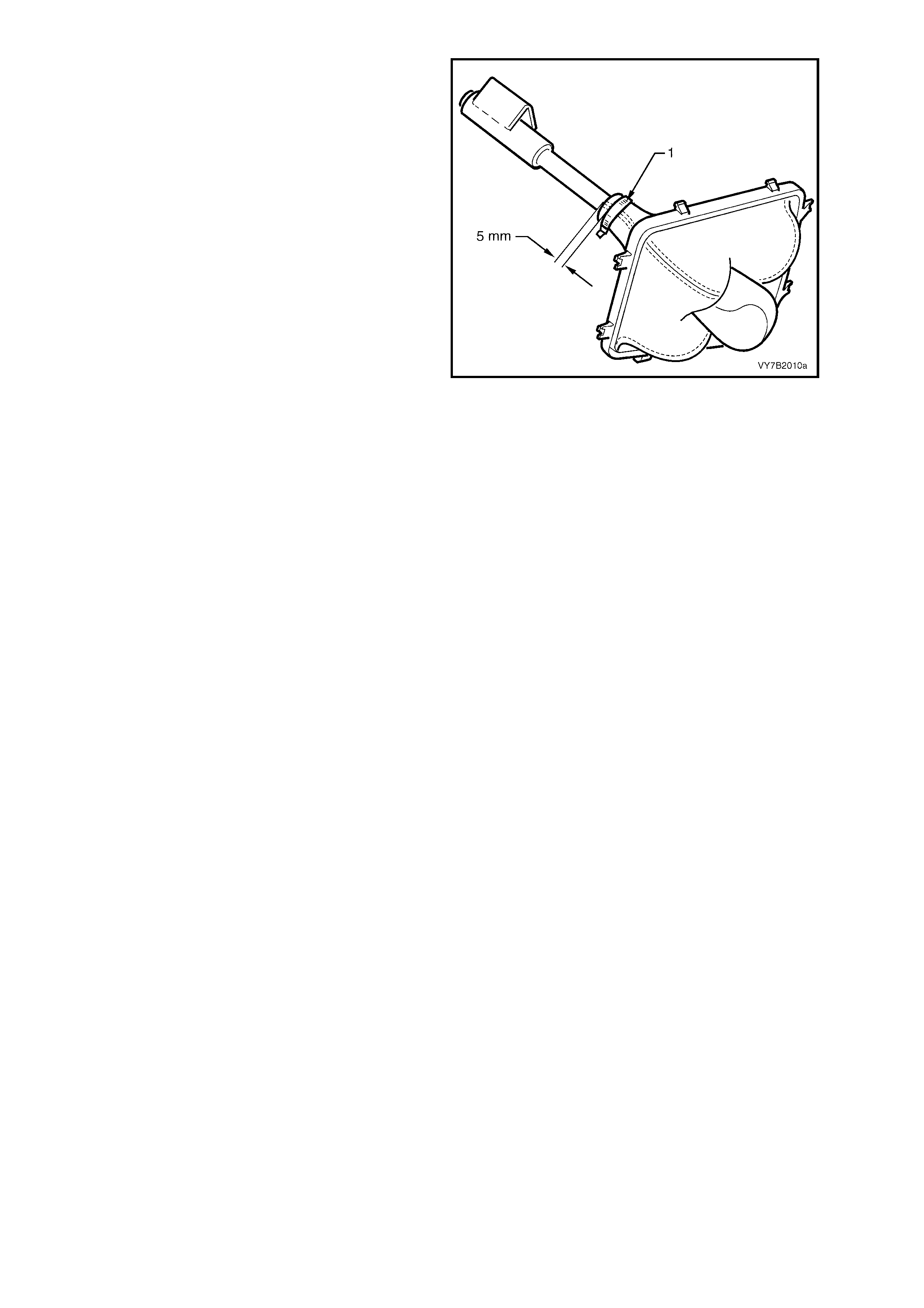
7. Slide the b oot into place over the gro ove in the
gearshift knob.
8. Install a new retaining tie strap around the
boot, ensuring that;
a. 5 mm of the boot extends out from the tie
strap.
b. The tie strap is locate d in t he knob groove,
with the catch located at the rear of the
shift lever. This will be in a position on the
opposite side to the lever mounting flange.
c. Fully tighten the tie strap to secure the
boot in place. Cut the excess strap and
discard.
9. If the insulator sock is in a serviceable
condition, reinstall it over the mounting flange,
then roll t he s oc k back, to ex pose the mounti ng
flange bolt holes .
10. After installing the insulator to the control lever
and with the boot still inside out, reinstall the
control lever knob, boot and control lever
assembly. Refer 3.5 CONTROL LEVER
KNOB, BOOT & CONTROL LEVER, in this
Section.
Figure 7B2-29
3.7 REMOTE SHIFT LEVER BOOT
LT Section No. – 04-060
REMOVE
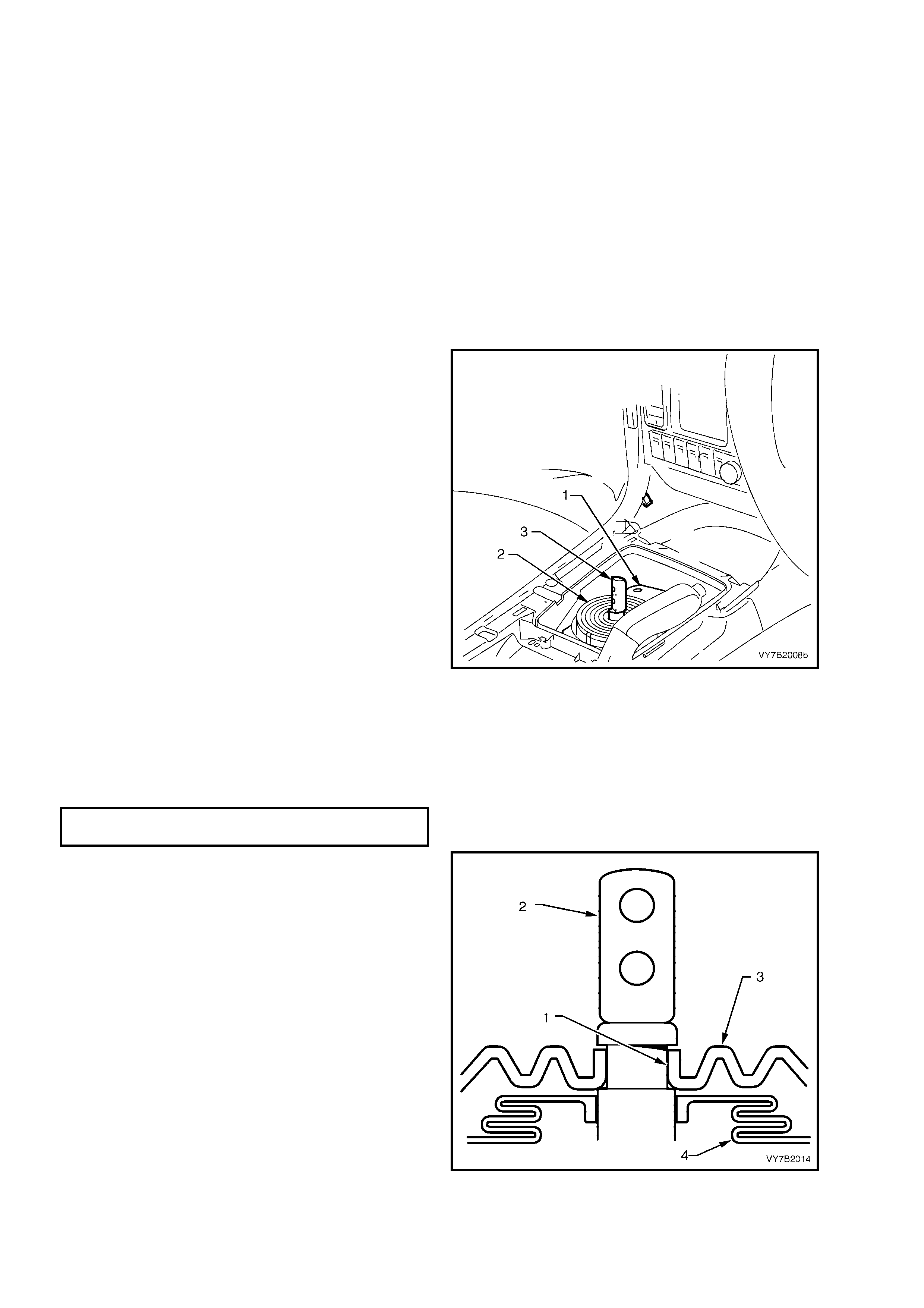
1. Disc onnect the batter y ground lead.
2. Remove the gearshift control lever knob, boot
and control lever assembly from the gearshift
remote shift lever. Refer to 3.5 CONTROL
LEVER KNOB AND BOOT AS SEMBLY in this
Section, for the necessary procedure.
3. Raise the vehicle and support on safety
stands. Refer to Section 0A GENERAL
INFORMATION in the MY 2003 VY and V2
Series Service Information, for the location of
jacking and support points.
4. From under the vehicle, remove the four nuts
securing the shift lever boot retaining plate (1)
to the floor pan, then remove the boot (2) and
retaining plate (1) assembly.
IMPORTANT: Do not tear the boot (2) when
releasing from the groove in the gearshift remote
shift lever shaft (3).
5. Ins pect the gearshif t remote s hift lever boot (3)
for tears or other damage, replacing as
required.
Figure 7B2-30
REINST ALL
1. Reinstall the gearshift remote lever boot (4)
and plate (6) and secure to the floor pan, with
the four nuts, tightening to the correct torque
specification.
GEARSHIFT REMOTE LEVER BOOT
PLATE NUT TORQUE SPECIFICATION 15 Nm
2. Fit the neck of the boot (3) into the recess (1)
in the remote shift lever (3).
IMPORTANT: Ensure that the boot (3) engages
fully with the gr oo ve ( 1) i n t he ge ar s hif t r emote shif t
lever shaft (2). If full engagement does not occur,
then the boot will rip prematurely, resulting in
transmission and road noise becoming audible.
3. Reinstall the gearshift control lever knob, boot
and control lever assembly. Refer to
3.5 CONTROL LEVER KNOB AND BOOT
ASSEMBLY in this Section, for the necessary
procedure.
4. Reinstall the floor console cover assembly.
Refer 2.1 FLOOR CONSOLE COVER
ASSEMBLY, in Section 1A3 INSTRUMENT
PANEL & CONSOLE, in the MY 2003 VY and
V2 Series Service Information.
5. Reconn ec t batter y ground l ead.
6. Road test vehicle and check for correct
gearshift operation.
Figure 7B2-31
4. MAJOR SERVICE OPERATIONS
4.1 TRANSMISSION OUTPUT SHAFT SEAL AND BOOT
LT Section No. – 04-090
REMOVE
1. Disc onnect batter y ground lead.
2. Raise front of vehicle and support on safety
stands. Refer to Section 0A GENERAL
INFORMATION in the MY 2003 VY and V2
Series Service Information, for the location of
jacking and support points.
3. Scribe around each of the transmission support
crossmember mounting points to the vehicle
underbody, to provide an alignment reference
for reassembly.
NOTE: This s tep is c ritical to the c orr ect po wertra in
alignment on reassembly. If not carried out, then
vehicle vibration and/or handling problems may
result.
Figure 7B2-32
4. Remove the t wo bolts ( 2) securing the catal ytic
converter bracket (1) to the catalytic
converters.
NOTE: Spacers may be located between the
bracket and the catalytic converter/s. If so, the
number and location must be noted for correct
reassembly.
Figure 7B2-33
5. Support the transmission with a suitable lifting
device, then remove the four engine rear
crossmember to side frame attaching bolts (3).
6. Lower the transmission slightly, then remove
the two transmission mount to crossmember
nuts (4). Set the crossmember (2) to one side.
7. Remove the two bolts (5) securing the
transmission mount (1) to the transmission
extension, then remove the mount (1) and
bracket (6) from the vehicle.
NOTE: Illustrat ion does not sho w trans m ission jac k
in position, for clarity of the crossmember
orientati on.
8. Remove the nuts from the two bolts (7)
securing the catalytic converter bracket (6) to
the transmission extension, remove the bolts
and bracket and set to one side.
9. Lower the transmission enough to provide
clearance for the propeller shaft rubber
coupling when the propeller shaft is removed.
Figure 7B2-34
NOTE: To gain access to the propeller shaft
fasteners, it will be necessary to remove the
intermediate and rear sections of the exhaust
system.
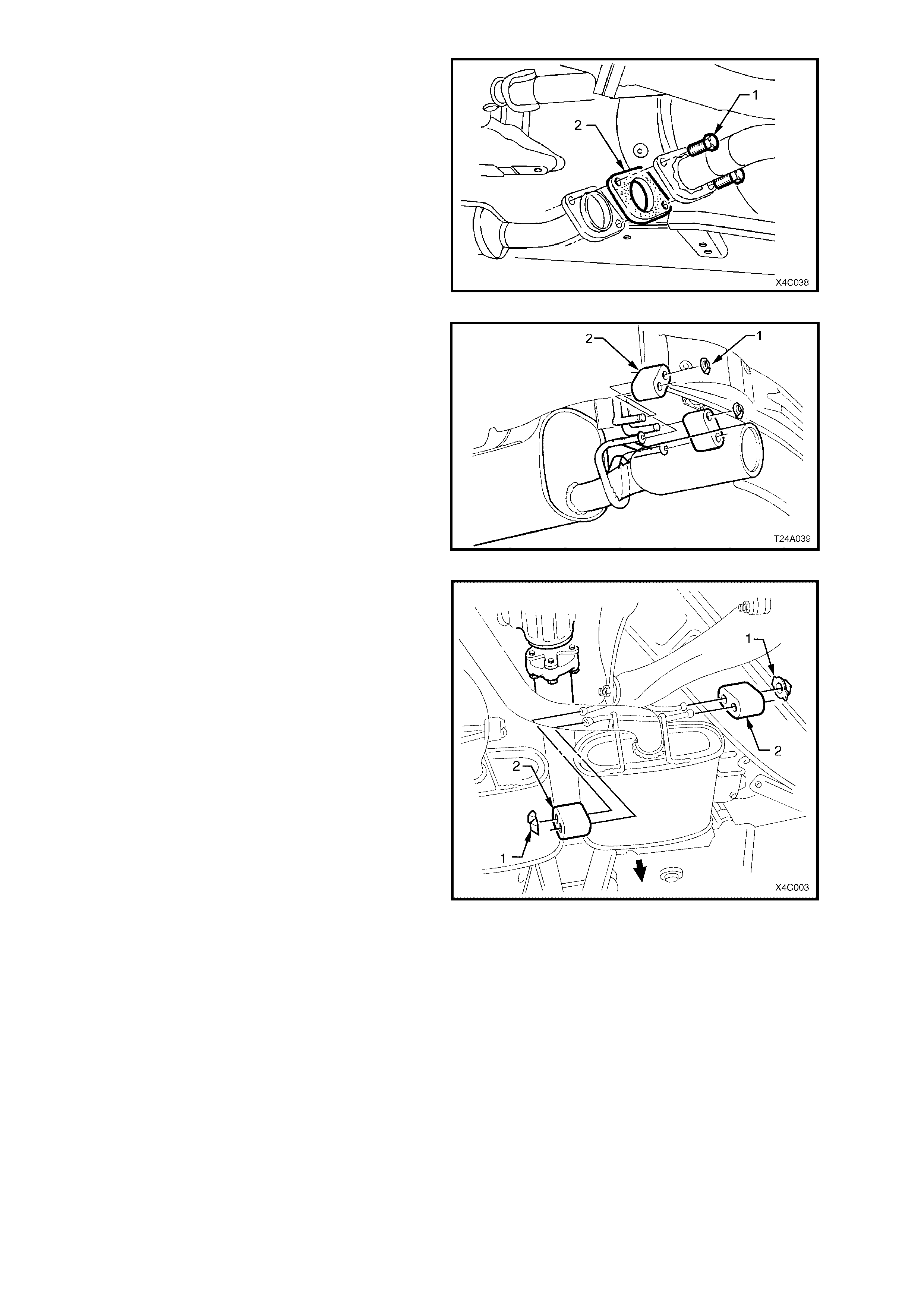
10. Disconnect the intermediate exhaust pipe to
catalytic converter bolts (1) from the rear of
each catalytic converter. Discard the flange
gaskets (2).
NOTE: Only one side of the exhaust system is
shown.
Figure 7B2-35
11. Remove the two retainers (1) from the top
support posts and discard.
12. Disconnect exhaust system support rings (2)
from rear hanger of the rear muffler.
Figure 7B2-36
13. Remove the four muffler support to rear
crossmember retainers (1).
14. While supporting the intermediate section of
the exhaust system, remove the four
intermediate muffler support rubbers (2).
15. Remove the intermediate and rear sections of
the exhaust system from the vehicle.
Figure 7B2-37
16. W ith the transm ission in first gear and the park
brake firmly applied, use a commercially
available E20 Torx socket to loosen the three
Torx headed bolts (1) securing the propeller
shaft rear rubber coupling (2) to the pinion
flange (3).
17. Release the park brake to relieve any torque
loading on the rubber coupling, then remove
the three Torx headed bolts (1).
NOTE: T o enable the propeller shaft to be installed
in the original position relative to the pinion flange,
use a felt tipped pen or similar to identify the
relationsh ip (‘A’) of the t wo components before bo lt
removal.
Figure 7B2-38
18. Remove the two centre bearing carrier (1) to
underbody reinforcement bolts (2).
19. Place a drain tray beneath transmission.
20. While supporting the centre bearing section,
slide the propeller shaft assembly forward to
disengage from the final drive pinion support
pin, then lo wer th e as s embly at t he rear , sliding
rearward to remove from the vehicle.
NOTE 1: Take car e to pro t ec t th e o uter diameter of
the front yoke. Nicks or abrasions will damage the
transm iss ion extension s eal durin g reass em bly and
result in subsequent lubricant leakage from this
area.
NOTE 2: Insert a suitable plug in the end of the
transmission rear extension to prevent loss of
transmission lubricant.
Figure 7B2-39
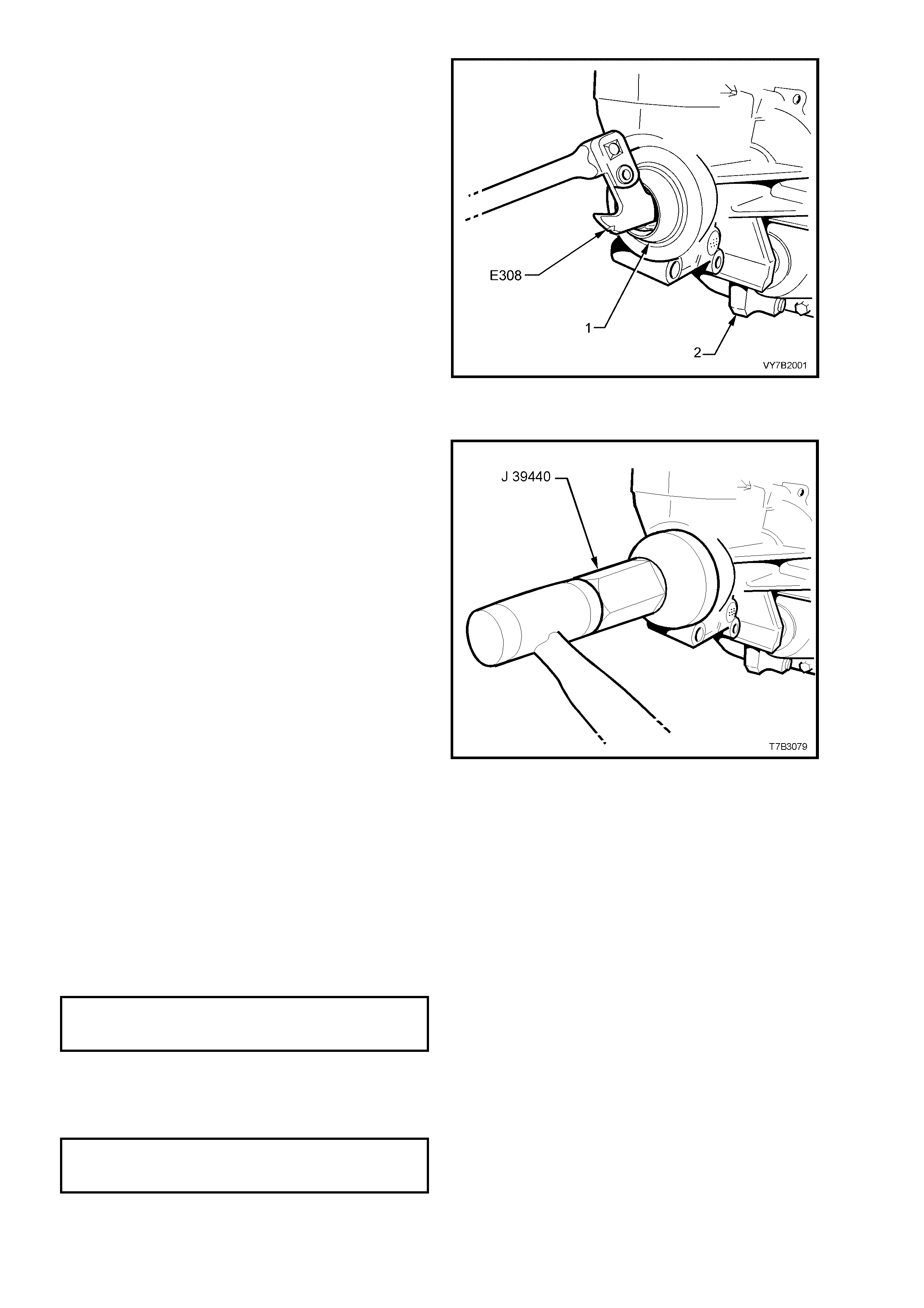
21. Using a seal remover such as Tool No. E308
(also released as 56750), remove the seal (1)
from the transmission extension housing (2).
NOTE: Should Tool No. E308 not be available,
then it will be necessary to remove the seal by
prisin g it from the extens ion hous ing with a suita ble
lever s uch as a screwdriv er. If this m ethod is used,
take care not to scratch the bore of the extension
housing during the removal process.
Figure 7B2-40
REINST ALL
1. After lubricating the seal lip with transmission
lubricant, use seal installer J 39440 and install
the new seal into the rear of the extension
housing.
Figure 7B2-41
2. Lubricate the final drive pinion spigot with 10% Molybdenum Disulphide grease, such as Molybond GA 10 (or
equivalent).
3. Clean threads of centre bearing carrier to underbody reinforcement bolts and underbody weld nuts.
4. Remove any foreign matter that may have adhered to the front universal joint yoke and lubricate with
transmission lubricant. Insert yoke onto transmission mainshaft, indexing the splines.
5. Reinstall the front of the propeller shaft assembly first, supporting the centre and rear sections.
6. W hile still supporting the centre bear ing area, slide the propeller shaft assem bly forward to allow engagem ent
of the rear spigot, then slide rearward to fully engage with the final drive pinion spigot.
7. Raise the centre bearing assembly and reinstall the bolts and washers to secure to the underbody
reinforcement. Tighten both bolts to the correct torque specification.
CENTRE BEARING CARRIER TO
UNDERBODY REINFORCEMENT
BOLT TORQUE SPECIFICATION 22 Nm
8. Before reinstalling the attaching b olts and washers to the propeller shaft rear coupling and pinion flange, align
marks on pinion flange and rear coupling (or marks made on removal), refer to Figure 7B2-38.
9. Provided no thread damage is evident, reinstall the original rear propeller shaft coupling to final drive pinion
flange bolts and washers, tightening to the correct torque specification.
PROPELLER SHAFT REAR
COUPLING TO PINION FLANGE
BOLT TORQUE SPECIFICATION 115 Nm
10. Reinstall the exhaust system as follows;
a. Ensure the catalytic converter flange is clean and free from any gasket material.
b. Reinstall exhaust system, using a new gasket at the catalytic converter and new hanger retainers for the
muffler supports to rear crossmember.
b. Reinstall the catalytic converter to intermediate exhaust pipe bolts and tighten to the correct torque
specification.
INTERMEDIATE EXHAUST PIPE
TO CATALYTIC CONVERTER
BOLT TORQUE SPECIFICATION 45 Nm
c. Check exhaust clearances as detailed in Section 8B EXHAUST SYSTEM in the MY 2003 VY and V2
Series Service Information.
11. If transmis sion lubricant le ak ed from the rear of the transmis sion when the pro peller shaf t was rem oved, check
transm ission lubrica nt level and t op up as neces sary. Refer to 2.2 CHECKING TRANSM ISSION LUBRICANT
LEVEL, in this Section.
12. Reinstall the catalytic converter bracket (6) to the transmission extension, install the bolts (7) and nuts, then
tighten to the correct torque specification.
CATALYTIC CONVERTER BRACKET
TO TRAN S M I SS I ON EX TE NSI ON
BOLT TORQUE SPECIFICATION 50 Nm
13. Reinstall the transmission mount (1) to the
transm ission extension, install th e two bolts (5)
and tighten to the correct torque specification.
TRANSMISSION MOUNT TO
EXTENSION HOUSING BOLT
TORQUE SPECIFICATION 25 Nm
14. Raise the transmission slightly, then reinstall
the four crossmember to side frame bolts (3),
aligning the crossmember (2) with the scribed
lines made prior to disassembly. Tighten the
bolts (3) to the correct torque specification.
REAR CROSSMEMBER TO
SIDE FRAME MEMBER BOLT
TORQUE SPECIFICATION 58 Nm
15. Remove the lifting device from the
transmission, c entralis e the r ear m ount s tuds in
the crossmember holes, then reinstall the nuts
(4), tightening to the correct torque
specification.
REAR CROSSMEMBER TO
TRANSMI SS I ON MOUNT NU T
TORQUE SPECIFICATION 25 Nm
16. Reinstal l the two catal ytic converter bracket (6)
bolts, tightening to the correct torque
specification.
Figure 7B2-42
NOTE: If any spacers were removed on
disassembly, then these must be fitted in the
original format.
CATALYTIC CONVERTER BRACKET
BOLT TORQUE SPECIFICATION 25 Nm
17. Check the transmission fluid level. Refer to
2.2 CHECKING TRANSMISSION
LUBRICANT LEVEL in this Section. Correct
fluid level as required.
18. Lower the vehicle reconnect battery ground
lead.
19. Lower the vehicle and road test to check
vehicle operation.
4.2 TRANSMISSION ASSEMBLY
REMOVE
1. Disc onnect batter y ground l ead.
2. Remove the floor console cover assembly.
Refer 2.1 FLOOR CONSOLE COVER
ASSEMBLY, in Section 1A3 INSTRUMENT
PANEL & CONSOLE, in the MY 2003 VY and
V2 Series Service Information.
3. Using a fine bladed screwdriver, release each
locking tab, while exerting an upward force on
the boot carrier. Lift the gearshift boot retainer
free from the floor console.
4. Remove the gearshift knob, boot and gearshift
lever. Refer 3.5 CONTROL LEVER KNOB,
BOOT & CONTROL LEVER ASSEMBLY, in
this Section.
5. Remove the gearshift remote shift lever boot.
Refer 3.6 GEARSHIFT REMOTE SHIFT
LEVER BOOT, in this Section.
6. Select third gear to allow the remote shifter
lever to clear the opening in the floor pan,
when the transmission is lowered for removal.
Figure 7B2-43
7. Raise vehicle, preferably on a ‘drive-on’ hoist
or a four post hoist. This preference is based
on the fact that the transmission is very heavy
and the use of a transmission jack will be
require d for eff ective tr ans m ission rem oval a nd
installation.
8. Disconnect wiring harness connectors from
each of the two oxygen sensors.
9. Depending on the reason for removal, it might
be appropriate to drain the transmission
lubricant into a clean container.
Place a drain tray beneath transmission and
remove the drain plug (1) using a 3/8” drive
socket bar.
W hen transm ission has f ully dra ined, clean t he
threads of the drain plug, apply thread sealant
such as Loctite 565 or equivalent (GM P/N
12346004), then reinstall, tightening to the
correct torque specification, using a 3/8” drive
adaptor and a torque wrench.
NOTE: Do not appl y Tef lon thread tape to t he plug
threads.
DRAIN PLUG
TORQUE SPECIFICATION 28 Nm
Figure 7B2-44
10. Scribe around each of the transmission support
crossmember mounting points to the vehicle
underbody, to provide an alignment reference
for reassembly.
NOTE: This s tep is c ritical to the c orr ect po wertra in
alignment on reassembly. If not carried out, then
vehicle vibration and/or handling problems may
result.
Figure 7B2-45
11. Rem ove the t wo bolts (2) s ecuring the ca talytic
converter bracket (1) to the catalytic
converters.
Figure 7B2-46
12. Support the transmission with a suitable lifting
device, then remove the four engine rear
crossmember to side frame attaching bolts (3).
13. Lower the transmission slightly, then remove
the two rear mount to crossmember nuts (4).
Set the crossmember (2) to one side.
14. Remove the two bolts (5) securing the rear
mount (1) to the transmission extension, then
set the mount to one side.
15. Remove the two nuts and bolts (7) securing the
catalytic converter bracket (6) to the
transmission extension, then remove the
bracket (6) from the vehicle.
NOTE: Illustrat ion does not sho w trans m ission jac k
in position, for clarity of the crossmember
orientati on.
Figure 7B2-47
NOTE: To gain access to the propeller shaft
fasteners, it will be necessary to remove the
intermediate and rear sections of the exhaust
system.
16. Disconnect the intermediate exhaust pipe to
catalytic converter bolts (1) from the rear of
each catalytic converter. Discard the flange
gaskets (2).
NOTE: Only one side of the exhaust system is
shown.
Figure 7B2-48
17. Remove the two retainers (1) from the top
support posts and discard.
18. Disconnect exhaust system support rings (2)
from rear hanger of the rear muffler.
Figure 7B2-49
19. Remove the four muffler support to rear
crossmember retainers (1).
20. While supporting the intermediate section of
the exhaust system, remove the four
intermediate muffler support rubbers (2).
21. Remove the intermediate and rear sections of
the exhaust system from the vehicle.
Figure 7B2-50
22. W ith the transm ission in first gear and the park
brake firmly applied, use a commercially
available E20 Torx socket to loosen the three
Torx headed bolts (1) securing the propeller
shaft rear rubber coupling (2) to the pinion
flange (3).
23. Release the park brake to relieve any torque
loading on the rubber coupling, then remove
the three Torx headed bolts (1).
NOTE: T o enable the propeller shaft to be installed
in the original position relative to the pinion flange,
use a felt tipped pen or similar to identify the
relationsh ip (‘A’) of the t wo components before bo lt
removal.
Figure 7B2-51
24. Remove the two centre bearing carrier (1) to
underbody reinforcement bolts (2).
25. Place a drain tray beneath transmission.
26. While supporting the centre bearing section,
slide the propeller shaft assembly forward to
disengage from the final drive pinion support
pin, then lo wer th e as s embly at t he rear , sliding
rearward to remove from the vehicle.
NOTE 1: Take car e to pro t ec t th e o uter diameter of
the front yoke. Nicks or abrasions will damage the
transm iss ion extension s eal durin g reass em bly and
result in subsequent lubricant leakage from this
area.
NOTE 2: Insert a suitable plug in the end of the
transmission rear extension to prevent loss of
transmission lubricant.
Figure 7B2-52
27. Remove the speed sensor wiring harness
connector (1) and the connector (4) from the
reverse lockout sole noid. (5).
Figure 7B2-53
28. Remove the wiring harness c onnector from the
back -up lamp switch , located o n the right h and
side of the transmission.
29. Cut the tie strap securing the powertrain
harness to the breather pipe (not shown),
remove the harness from the clip under the
right hand top extension housing bolt and
secure to one side.
Figure 7B2-54
30. Remove the starter motor. Refer to
Section 6D3-2, ST ARTIN G SY STEM - GEN III
V8 ENGINE, in t he M Y 200 3 VY and V2 Seri es
Service Information, for the necessary
procedure.
31. Remove the right close-out cover and screw.
Figure 7B2-55
32. Remove the left close-out cover and screw.
Figure 7B2-56
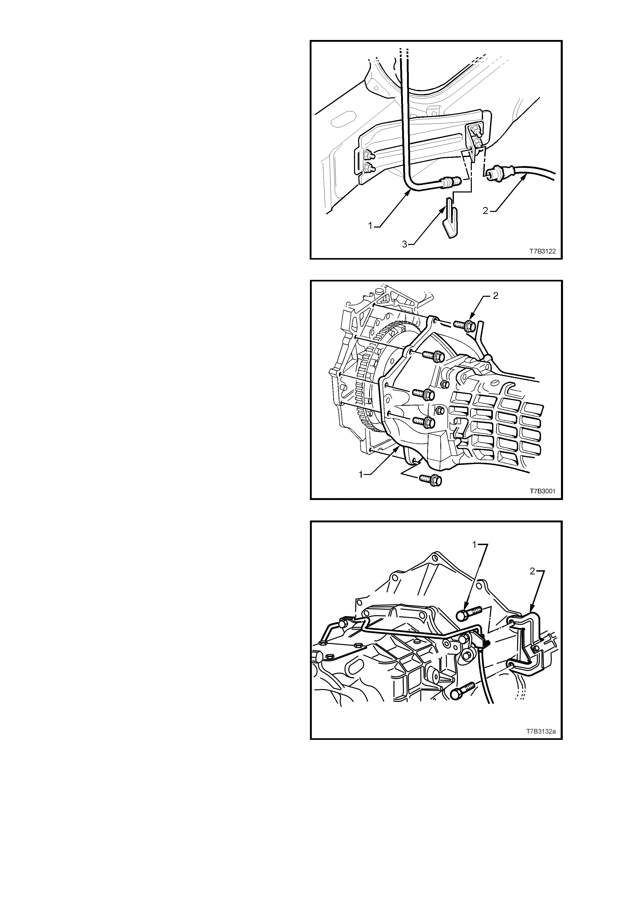
33. Place a suitable container under the clutch
hydraulic hose area, then disconnect the
hydraulic pipe (1) from the hydraulic hose (2),
at the bracket attached to the vehicle sub-
frame.
NOTE: Use a back-up spanner on the hydraulic
hose (2) when loosening the pipe fitting.
34. Remove the hose retaining clip (3) using
combination pliers, then remove the hose from
the bracket.
NOTE: Plug the hydraulic hose (2) and master
cylinder pipe (1) open ends to stop fluid loss and
dirt entry.
Figure 7B2-57
35. Lower the transm ission enough to gain access
to the bol ts (2) fast ening the clutc h housing (1)
to the rear of the engine.
36. Progressively loosen then remove six of the
eight clutch housing to engine bolts (2).
Figure 7B2-58
37. After removing the two remaining bolts (1) that
also secure the starter motor heat shield (2),
unclip the heat shield from the starter motor
and set to one side.
38. Pull the transmission rearward, just enough to
clear the locating dowels, then rotate the
transmission through 90° to the right to gain
clearance at the floor pan.
39. With the transmission supported by a
transmission jack, continue to withdraw the
transmission, taking care not to place any
loading on the clutch driven plate centre
splines that could cause driven plate distortion.
NOTE: It is most important that distortion of the
driven plate is prevented, because replacement
would then be required.
40. When the transmission input shaft is clear of
the clutch pressure plate, the transm ission can
be lowered and removed from the vehicle.
NOTE: Take particular care when lowering the
transmission, that damage to the oxygen sensors
does not occur.
Figure 7B2-59

REINST ALL
1. Select 3rd gear.
2. If rem oved, i ns ta ll t he c l utc h sla ve cylind er pi pe
(1) to the slave cylinder (2), and tighten to the
correct torque specification.
CLUTCH HYDRAULIC PIPE FITTING
TO SLAVE CYLINDER
TORQUE SPECIFICATION 13 Nm
3. Sparingly apply 10% molybdenum disulphide
grease, such as Molybond GA 10 (or
equivalent) to the bearing face of the clutch
throwout bearing, mounted to the slave
cylinder (2), the splines and spigot of the input
shaft.
4. With the transmission on its side, with the top
surface facing the right hand side of the
vehicle, use a transmission jack to raise the
transmission and install input shaft into the
splines of clutch driven plate.
5. Push transmission in toward engine block. It
may be nec essary to rotate the mainshaf t after
temporarily installing the propeller shaft, to
assist in spline alignment.
Figure 7B2-60
6. When installed up to the locating dowel pins,
rotate the transmission counter-clockwise 90°,
then push full y home.
7. Clip the heat shield (2) onto the starter motor,
then install two clutch housing to engine block
bolts (1), to retain.
Figure 7B2-61
8. Reinstall the remaining six clutch housing to
engine block/oil pan bolts and tighten all bolts
in the sequence shown, to the specified torque.
CLUTCH HOUSING TO
ENGINE BLOCK BOLT
TORQUE SPECIFICATION 50 Nm
Figure 7B2-62

9. Reinstall wiring harness connectors to the back up lamp switch, reverse lockout solenoid, speed sensor and
each of the oxygen sensors.
10. Secure the powertrain wiring harness to the transmission vent pipe, using a cable tie.
11. Lubricate the final drive pinion spigot with 10% Molybdenum Disulphide grease, such as Molybond GA 10 (or
equivalent).
12. Clean threads of centre bearing carrier to underbody reinforcement bolts and underbody weld nuts.
13. Remove any foreign matter that may have adhered to the front universal joint yoke and lubricate with
transmission lubricant. Insert yoke onto transmission mainshaft, indexing the splines.
14. Reinstall the front of the propeller shaft assembly first, supporting the centre and rear sections.
15. W hile still supporting t he centre bearing are a, slide the propeller shaft assem bly forward to allow engagement
of the rear spigot, then slide rearward to fully engage with the final drive pinion spigot.
16. Raise the centre bearing assembly and reinstall the bolts and washers to secure to the underbody
reinforcement. Tighten both bolts to the correct torque specification.
CENTRE BEARING CARRIER TO
UNDERBODY REINFORCEMENT
BOLT TORQUE SPECIFICATION 22 Nm
17. Before reinstalling the attaching b olts and washers to the propeller shaft rear coupling and pinion flange, a lign
marks on pinion flange and rear coupling (or marks made on removal), refer to Figure 7B2-51.
18. Provided no thread damage is evident, reinstall the original rear propeller shaft coupling to final drive pinion
flange bolts and washers, tightening to the correct torque specification.
PROPELLER SHAFT REAR
COUPLING TO PINION FLANGE
BOLT TORQUE SPECIFICATION 115 Nm
19. Reinstall the exhaust system as follows;
a. Ensure the catalytic converter flange is clean and free from any gasket material.
b. Reinstall exhaust system, using a new gasket at the catalytic converter and new hanger retainers for the
muffler supports to rear crossmember.
d. Reinstall the catalytic converter to intermediate exhaust pipe bolts and tighten to the correct torque
specification.
INTERMEDIATE EXHAUST PIPE
TO CATALYTIC CONVERTER
BOLT TORQUE SPECIFICATION 45 Nm
e. Check exhaust clearances as detailed in Section 8B EXHAUST SYSTEM in the MY 2003 VY and V2
Series Service Information.
20. Reinstall the catalytic converter bracket (6) to the transmission extension, install the bolts (7) and nuts, then
tighten to the correct torque specification.
CONVERTER BRACKET TO
TRANSMISSION EXTENSION BOLT
TORQUE SPECIFICATION 50 Nm
21. Reinstall the transmission mount (1) to the
transm ission extension, install th e two bolts (5)
and tighten to the correct torque specification.
TRANSMISSION MOUNT TO
EXTENSION HOUSING BOLT
TORQUE SPECIFICATION 25 Nm
22. Raise the transmission slightly, then reinstall
the four crossmember to side frame bolts (3),
aligning the crossmember (2) with the scribed
lines made prior to disassembly. Tighten the
bolts (3) to the correct torque specification.
REAR CROSSMEMBER TO
SIDE FRAME MEMBER BOLT
TORQUE SPECIFICATION 58 Nm
23. Remove the lifting device from the
transmission, c entralis e the r ear m ount s tuds in
the crossmember holes, then reinstall the nuts
(4), tightening to the correct torque
specification.
REAR CROSSMEMBER TO
TRANSMI SS I ON MOUNT NU T
TORQUE SPECIFICATION 25 Nm
24. Reinstal l the two catal ytic converter bracket (6)
bolts, tightening to the correct torque
specification.
Figure 7B2-63
NOTE: If any spacers were removed on disassembly, then these must be fitted in the original arrangement.
CONVERTER BRACKET TO CONVERTER
BOLT TORQUE SPECIFICATION 25 Nm
25. Remove the p lugs from the ends of the dis connected c lutch hydraulic hos e and pipe. Re install the h ose to the
sub-frame bracket, then reinstall the pipe flare fitting, tightening to the correct specification. Use a back-up
spanner on the hydraulic hose fitting during the tightening process.
CLUTCH HYDRAULIC PIPE TO HOSE
TORQUE SPECIFICATION 13 Nm
26. Reinstall the horseshoe clip to retaining the clutch hydraulic hose to the sub-frame bracket.
27. If transm ission fluid was drained d uring the rem oval oper ation, then ref ill, as des cribed in 2.3 DR AINING AND
REFILLING TRANSMISSION, in this Section.
28. Reinstall the right and left close-out covers, secure with a screw in each and tighten to the correct torque
specification.
ENGINE TO TRANSMISSION CLOSE-OUT
COVER SCREW (EACH SIDE)
TORQUE SPECIFICATION 12 Nm
29. Reinstall the starter motor. Refer to Section 6D3-2, STARTING SYSTEM - GEN III V8 ENGINE in the MY
2003 VY and V2 Series Service Information, for the necessary procedure.
30. Lower vehicl e to the grou n d.
31. Reins tal l the rem ote shif t lever boo t and ret ainer, c heck ing that the boot en gages with the groo ve in the remote
shift lever shaft. Install the four bolts and tighten to the correct torque specification.
REMOTE SHIFT LEVER BOOT PLATE
BOLT TORQUE SPECIFICATION 10 Nm
32. Reinstall the gearshift control lever, boot and gearshift knob assembly to the remote shift lever. Secure with
bolts that have Loctite 242 or equivalent applied to cleaned threads. Tighten to the correct torque specification.
GEARSHIFT CONTROL LEVER BOLT
TORQUE SPECIFICATION 25 Nm
33. Pull the b oot and insu lator do wn into place, alig n the gears hift boot retain ing clips with the holes in the conso le
cap, then carefully seat the boot retainers into the console cap until each clip engages correctly.
34. Reinstall c entr e c onsole c o ver . Ref er to Section 1 A3, INSTRUMENT P ANEL AND CONSOLE, in the M Y 2003
VY and V2 Series Service Information for the necessary procedure.
35. Reconnect battery ground lead.
36. Road test vehicle and check transmission, clutch and gearshift operations.
4.3 TRANSMISSION DISASSEMBLE
1. Remove transmission assembly from vehicle.
Refer 4.2 TRANSMISSION ASSEMBLY –
REMOVE, in this Section.
CLUTCH HOUSING AND SLAVE CYLINDER
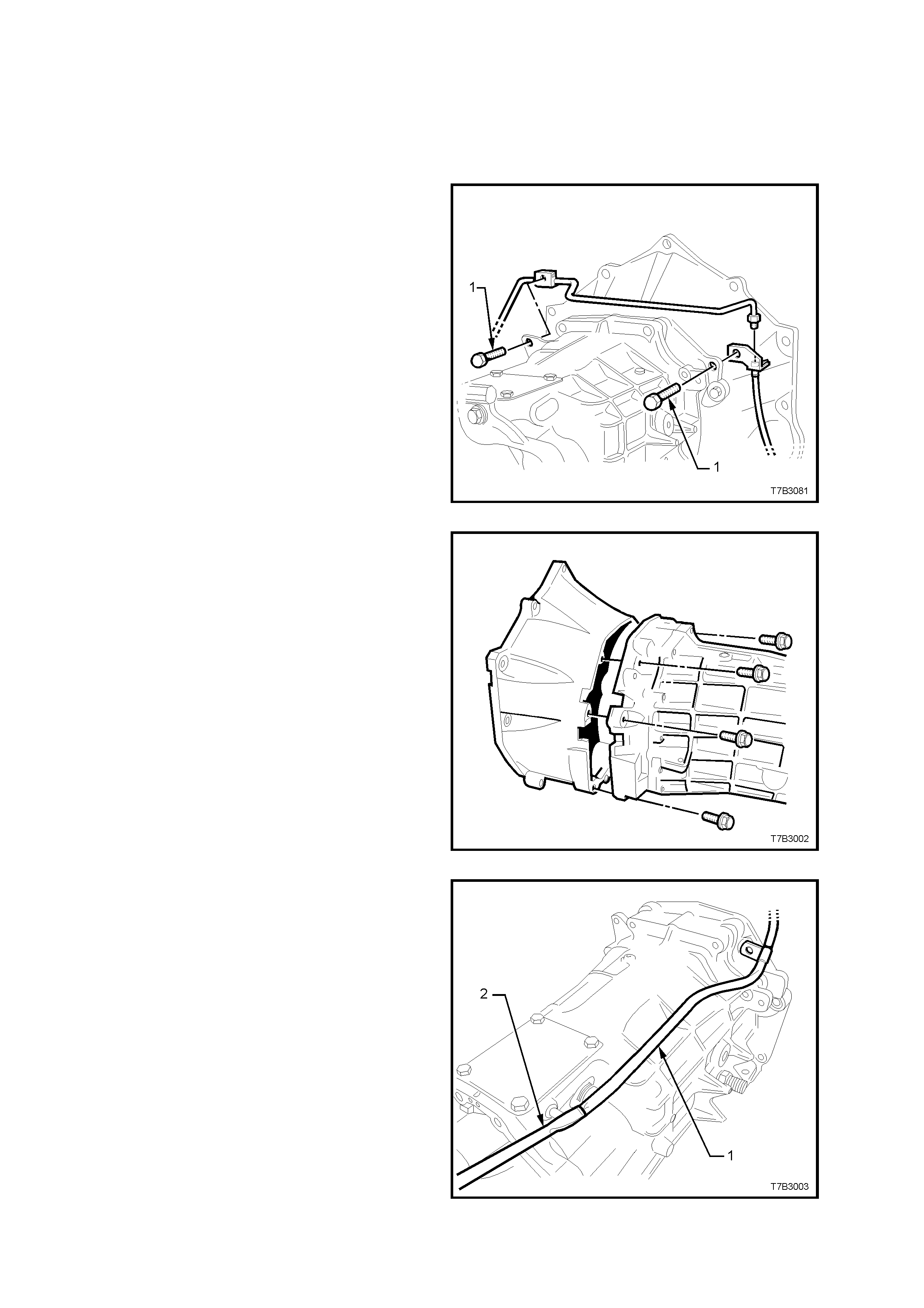
2. Remove the two bolts (1) securing the clutch
slave cylinder pipe to the transmission,
unscrew the fitting from the slave cylinder and
remove the pipe and brackets from the
transmission.
Figure 7B2-64
3. Remove the 8 bolts holding the clutch housing
to the transmission, then remove the housing.
Figure 7B2-65
4. Remove the plastic vent tube (1), by pushing
on the end of the tube with the flat blade of a
screwdriver (2), to slide the tube from the vent
tube fitting, then set the pipe to one side.
Figure 7B2-66
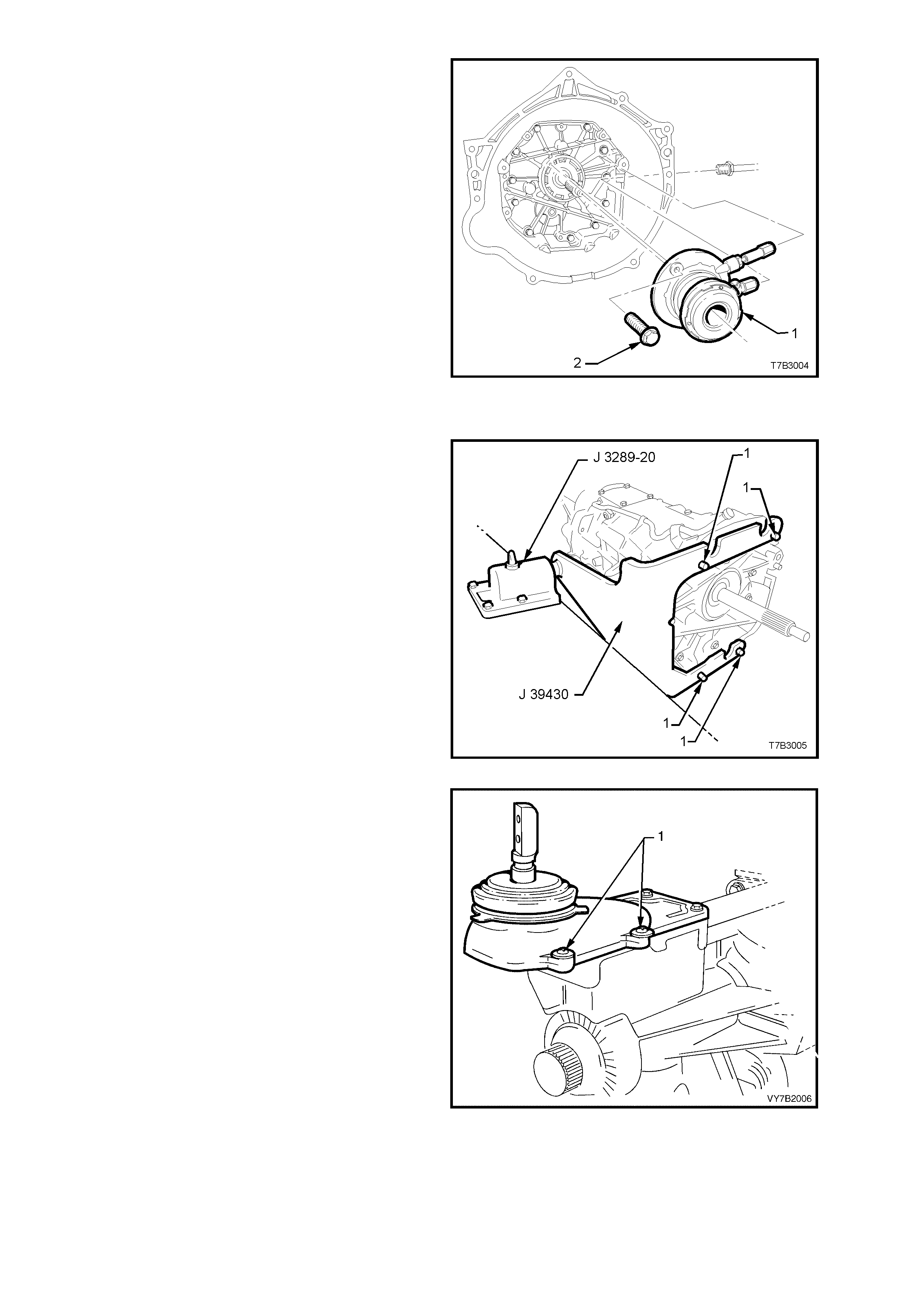
5. Remove the 2 bolts (2) securing the clutch
slave cylinder (1) to the transmission adaptor
plate, then set the slave cylinder assembly (1)
to one side.
Figure 7B2-67
EXTENSION HOUSING
1. Install holding tool J 39430 to the front of the
transmission, using 4 of the clutch housing
bolts (1).
2. Install holding tool J 39430 into the bench
holding fixture J 3289-20.
Figure 7B2-68
3. With the transmission in a horizontal position
with the shift lever up, drain the transmission
fluid (if not carried out previously).
4. Remove the four screws (1) securing the shift
lever cover, prise the cover loose, then
remove.
Figure 7B2-69
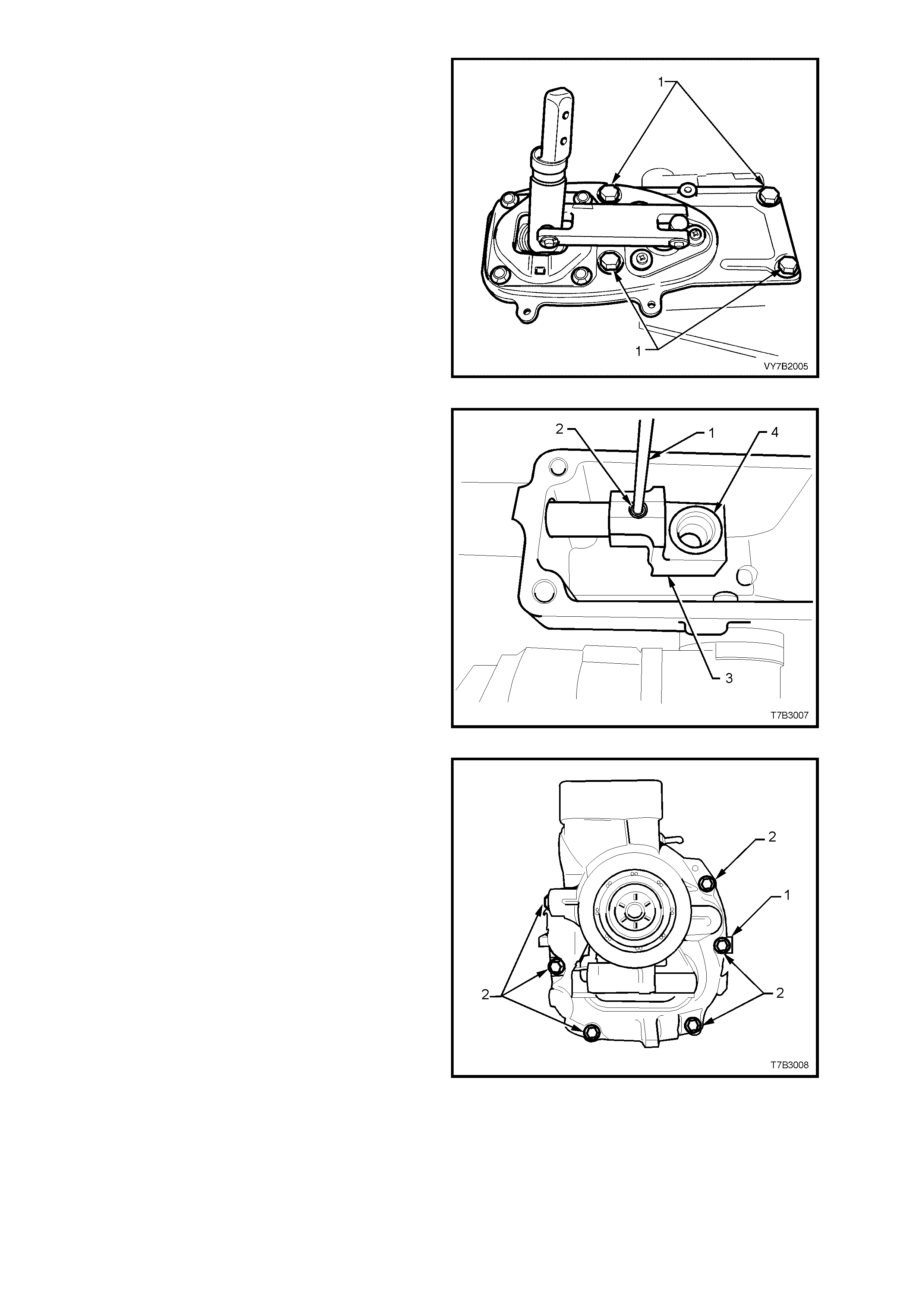
5. Select either 2nd or 4th gear.
6. Remove the 4 bolts (1) holding the shifter
assembly to the extension housing. If required,
tap with a rubber or plastic hammer to break
the seal, t hen remove the a s s em bl y and rub ber
seal from the extension housing.
Figure 7B2-70
7. Select either 2nd or 4th gear. Then, using a
suitable pin punch (1), remove the rear offset
lever roll pin (2).
NOTE: Selecting either gear, shortens the shift rail
overhang, providing more support during the roll
pin removal.
8. Rem ove the r e ar of f s et lever (3) and c heck that
the isolator cup (4) is secure in the lever. If
loose, discard both the isolator cup and the
rear offset lever.
Figure 7B2-71
9. Remove the 8 bolts (2) holding the extension
housing, n oting the posit ion of the identif ication
tag (1).
NOTE: The two top bolts ( not sh own) have s ealant
applied to the threads.
Figure 7B2-72
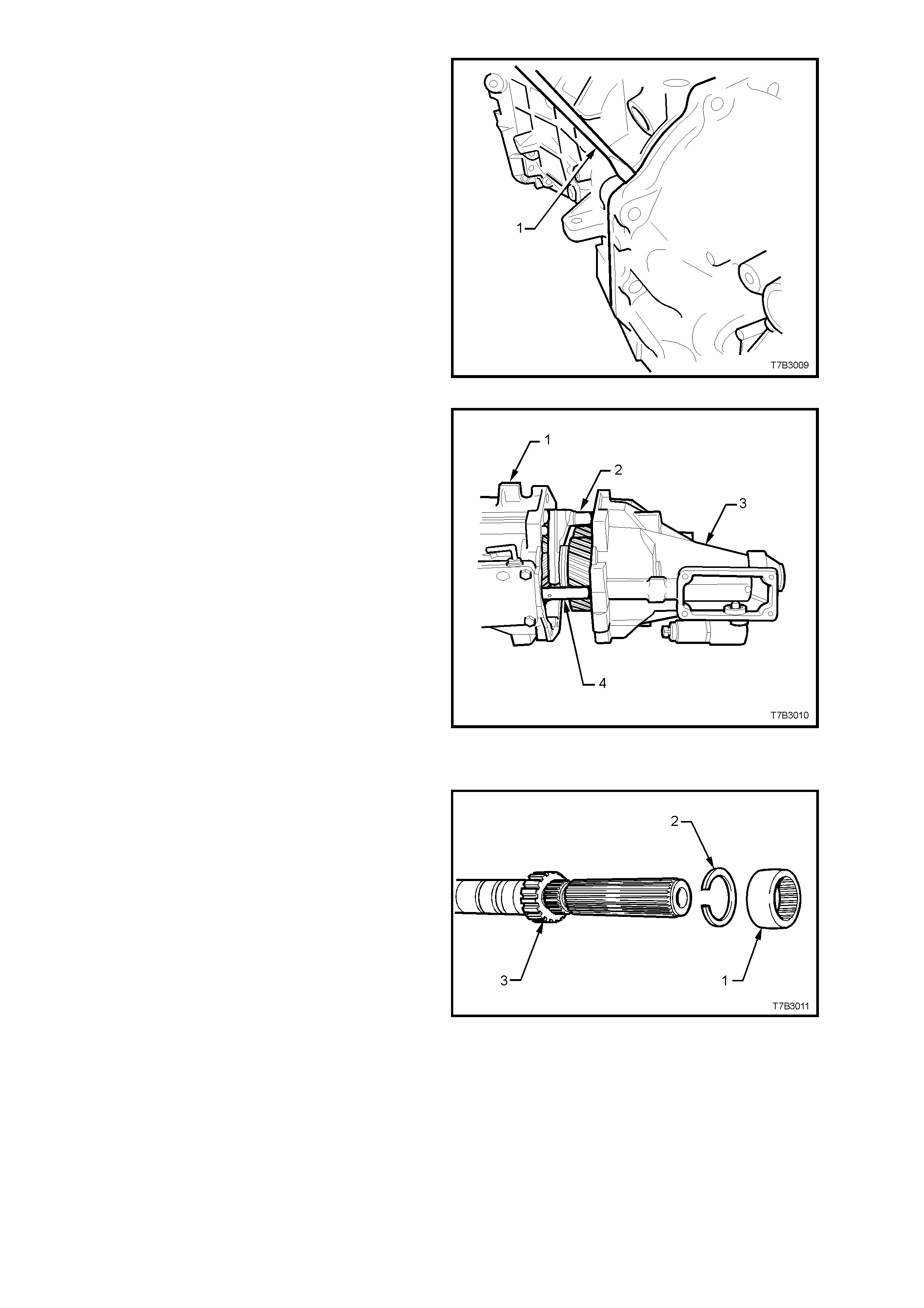
10. With the transmission in a horizontal position,
break the sealant seal by levering in the point
provided, using a flat bladed screwdriver (1).
11. Tap the extension housing rearward, using a
plastic or rubber hammer to remove the
housing from the 2 locating dowel pins.
Figure 7B2-73
12. Slide t he housing (3) from the shift rails (2 and
4) and remove from the transmission case (1).
13. Remove both circular magnets located in the
recess in the rear of the tr ansmiss ion case and
set to one side.
Figure 7B2-74
SPEEDOMETER PULSE RING
1. Slide the rubber shipping ring (1) from the
mainshaft and discard.
NOTE: This rubber ring (1) splined to the
mainshaft, is only required for shipping from the
manufacturer. It serves no functional purpose and
reinstallation on transmission assembly, is not
required. This part is not serviced.
2. Using suitable snap ring pliers, remove the
snap ring (2) from the speedometer pulse ring
(3).
Figure 7B2-75
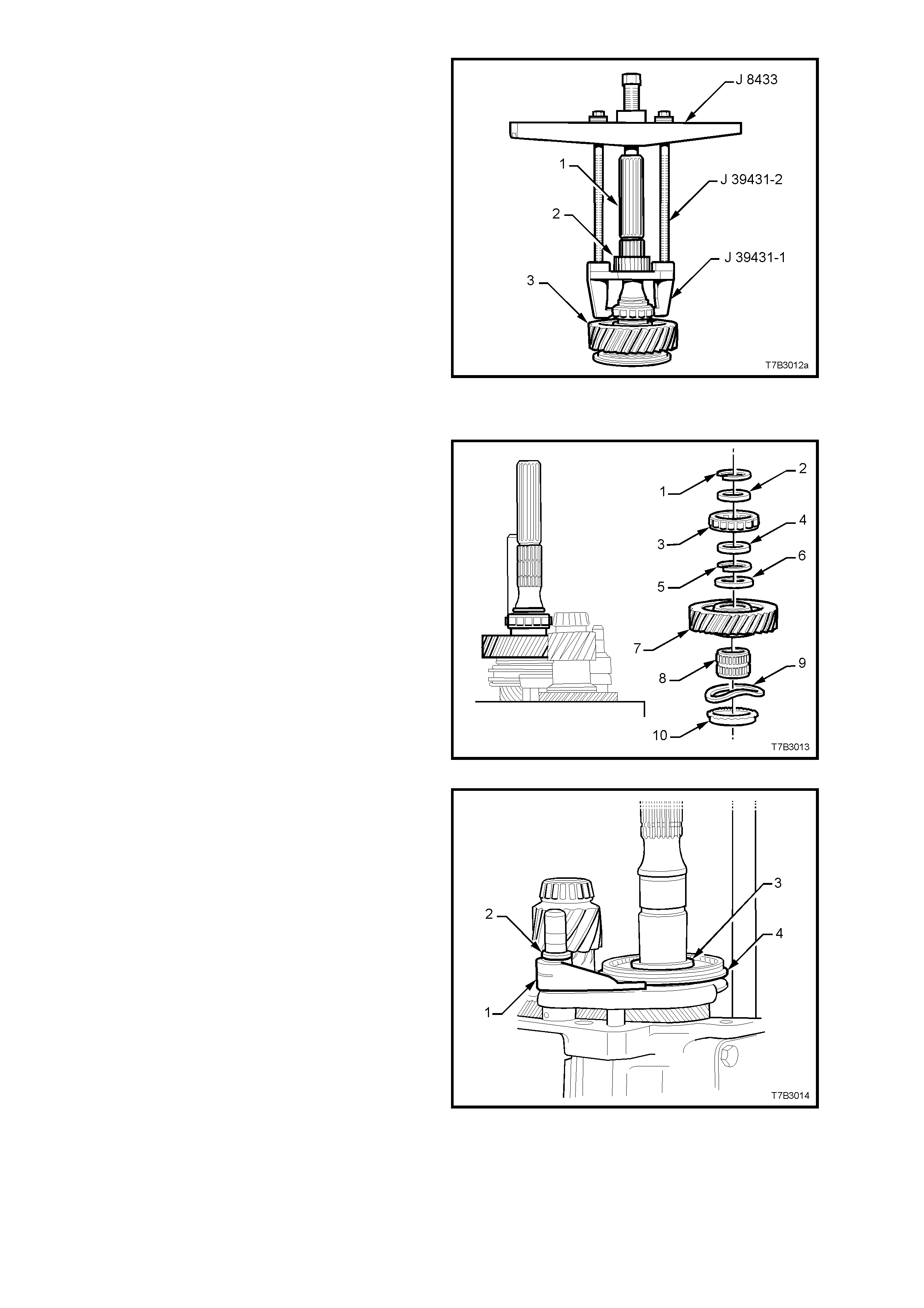
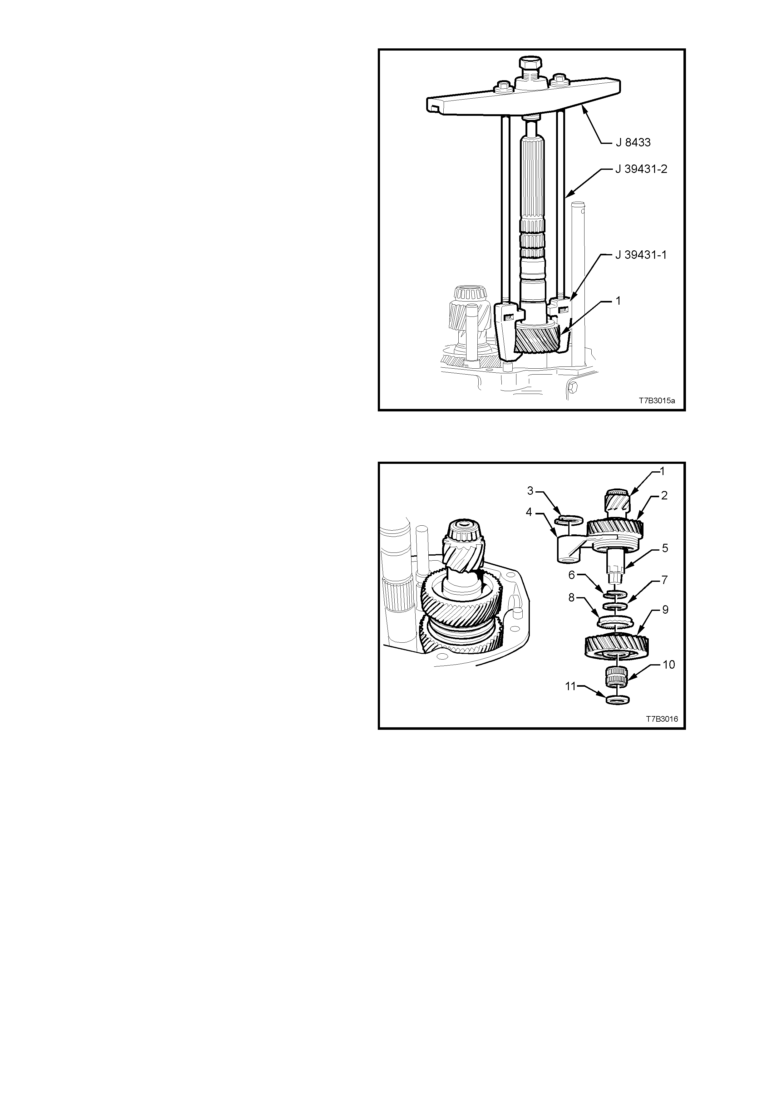
3. Assemble universal bridge puller J 8433 and
puller J 39431-1 using bolts J 39431-2, as
shown.
4. Remove the speedometer pulse ring (2) from
the mainshaft (1), then disassemble the tools.
5. Remove the second speedometer pulse ring
snap ring, using suitable snap ring pliers.
Figure 7B2-76
REVERSE AND 5th/6th DRIVEN GEAR
1. Remove the following components from the
mainshaft:
1. Snap ring.
2. Spacer.
3. Rear mainshaft roller race.
4. Spacer.
5. Snap ring.
6. Thrust washer.
7. Reverse gear.
8. Reverse gear, caged roller bearing.
9. Wave washer.
10. Reverse gear blocker ring.
Figure 7B2-77
2. Remove reverse synchromesh assembly snap
ring (3), using fine nosed circlip pliers.
3. Remove circlip (2) from the reverse shift rail
and discard.
4. Remove the reverse synchromesh assembly
(4), thrust washer (not shown) and reverse shift
fork (1), as an assembly.
NOTE: The synchromesh hub (4) is a sliding fit to
the mainshaft splines.
Figure 7B2-78
5. Assemble universal bridge puller J 8433 and
puller ada ptor J 394 31- 1 using bo lts J 3943 1-2,
as shown.
6. Rem ove 5th/6th dr i ven g ea r (1) , then d is mantle
tools.
Figure 7B2-79
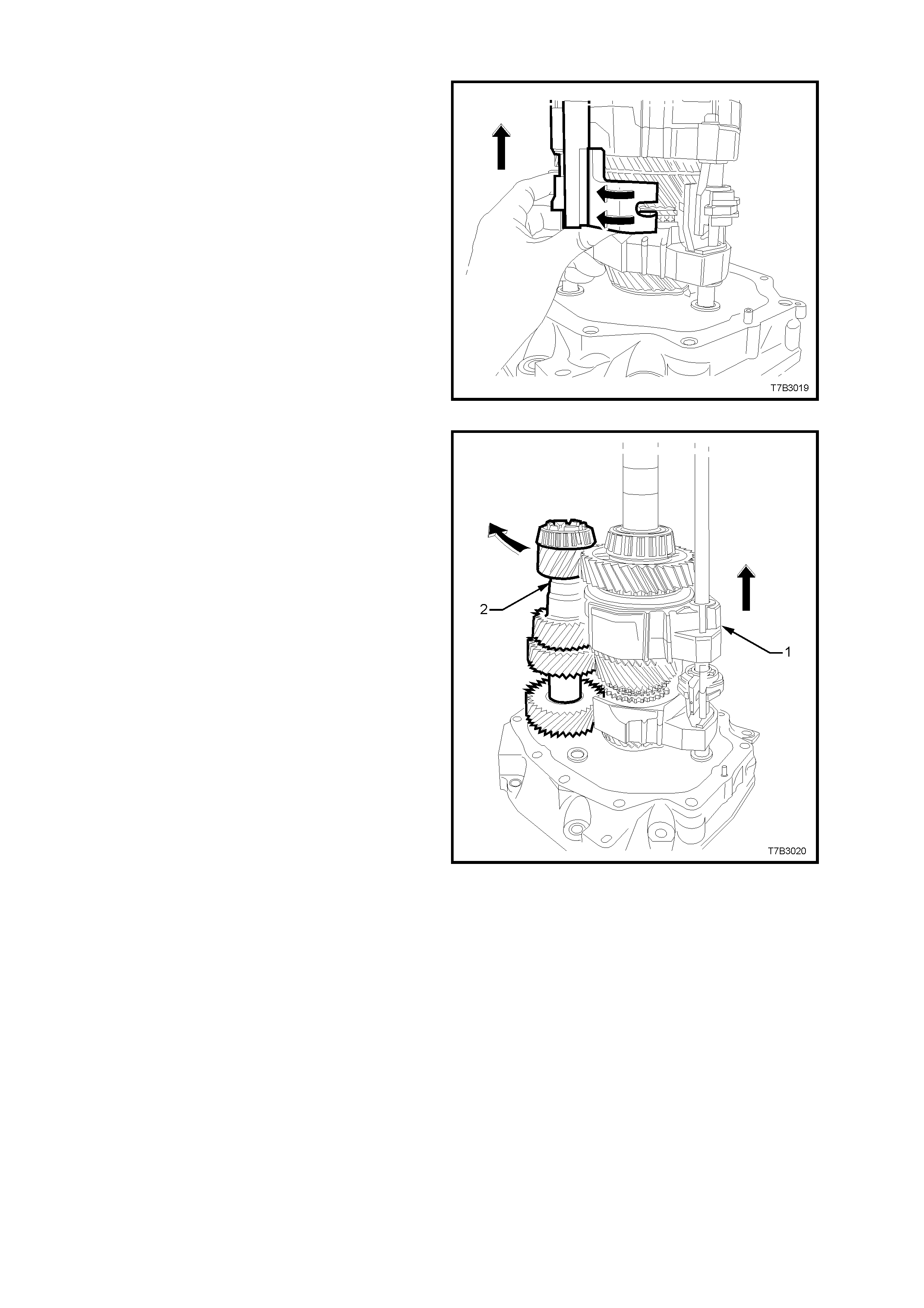
COUNTERSHAFT EXTENSION ASSEMBLY
1. Remove the circlip (3) from the 5th/6th shift
rail, then remove the following components as
an assembly; countershaft extension (1) with
the 5th drive gear (2), selector fork (4) and
synchromesh assembly (2), all secured by the
snap ring (6).
2. Remove the following components;
7. Spacer.
8. 6th gear, blocker ring.
9. 6th drive gear.
10. 6th drive gear, caged needle roller bearing.
11. Thrust washer.
Figure 7B2-80
3. Remove the 4 bolts securing the guide plate
cover to the transmission case. Use a flat
bladed screwdriver and plastic hammer to
dislodge the cover sealant, then remove the
cover.
NOTE: Be careful not to bend the cover when
breaking the sealant grip.
4. Remove the shift enhancer (4) from the
transmission case using a suitable sized
socket.
5. Using a suitable sized pin punch, remove the
roll pin (3), from the front offset lever (2).
Figure 7B2-81
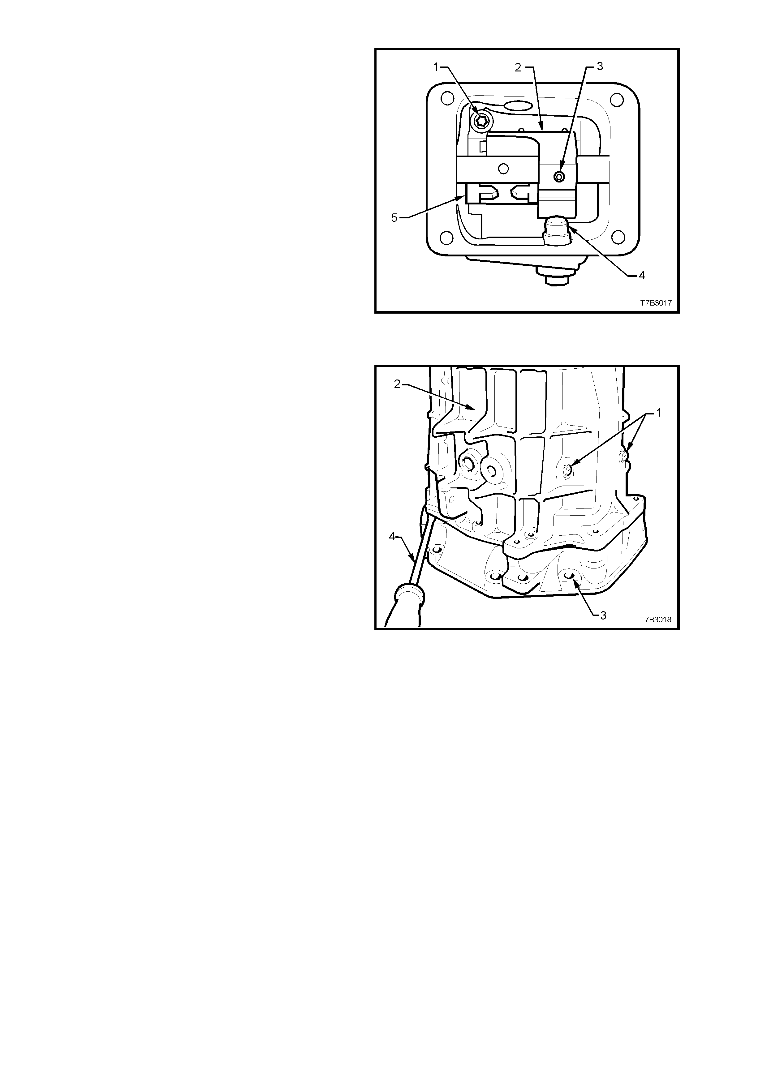
TRANSMISSION CASE
1. Remove the two T40 Torx bit screws securing
the shift lever guides (1).
NOTE: Both of these screws have thread sealant
applied and will be extremely difficult to remove
unless a hot air gun is used to soften the thread
sealant prior to loosening and during removal.
2. Rem ove the reverse lam p switch from the side
of the transmission case.
3. Remove the 10 adaptor plate to transmission
case bolts from the front of the transmission
(not shown).
4. Carefully rotate the transmission into a vertical
position, then lever the transmission case (2)
from the adaptor plate (3), using a flat bladed
screwdriver (4) in the spaces provided, to
break the sealant se al and clear t he two do wel
pins.
5. Lift the transmission case upward from the
gear train and shift rail components, while
supporting the front offset lever during the
process.
NOTE: Holding the front offset lever against the
guide plate during case removal, will reduce the
possibility of the detent ball and spring from being
dislodged.
6. Referring to Figur e 7B2-81, use a T40 T orx bit,
to remove the 2 screws (1) from the guide plate
(5).
NOTE: In Figure 7B2-81, the front offset lever (2)
covers the second guide plate screw.
7. Remove the guide plate (5) from the
transmission case.
Figure 7B2-82
GEAR TRAINS AND SHIFT RAILS
1. Rotate the 5th/6th and Reverse shift levers
from the interlock plate (curved arrows), then
lift both shift rail assemblies from the adaptor
plate.
Figure 7B2-83
2. Lift the mainshaft and shift forks (1) to allow
counter gear (2) removal.
3. Carefully lift the mainshaft assembly with the
shift f orks in place , from the input shaf t and set
to one side.
4. Lift the input shaft from the adaptor plate and
set to one side.
Figure 7B2-84
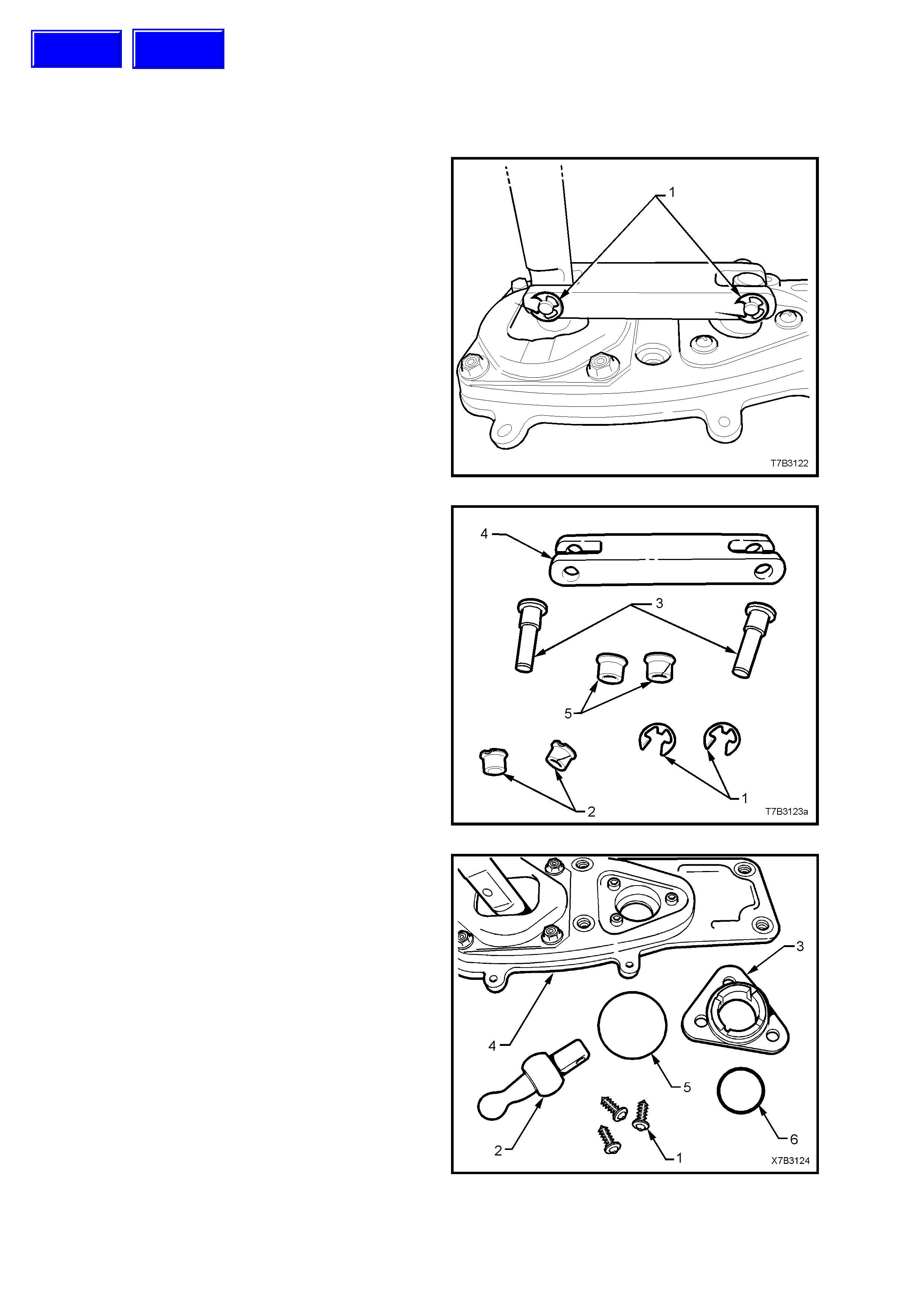
4.4 REMOTE CONTROL SHIFT MECHANISM
LT Section No. – 04-100
DISASSEMBLE
CAUTION: Wear safety glasses to avoid
possible e ye injury.
1. With the boot and dust cover removed, use a
small screwdriver to remove both ‘E’ clips (1).
Figure 7B2-85
2. Tap the two pins (3) free from the bridging
piece (4). These t wo pi ns a re an i nter f erenc e f it
into each of the two pivot pieces and must be
replaced after removal.
3. Remove both the smaller (2) and larger (5)
bushes from the bridging piece (4).
Figure 7B2-86
4. To disassemble the front pivot assembly,
unscrew the three self tapping screws (1),
using a Phillips No. 2 screwdriver.
5. By grasping the remote selector pivot (2), pull
the pivot (2) and seat assembly (3) from the
baseplate (4).
6. Remove the O-ring seals (5 and 2) from the
seat (3).
7. Separate the selector pivot (2) from the seat
assembly (3) by supporting the seat assembly
over the open jaws of a vice assembly, then
tap the ball end of the selector pivot (2) free
from the seat (3).
Figure 7B2-87
Techline
Techline
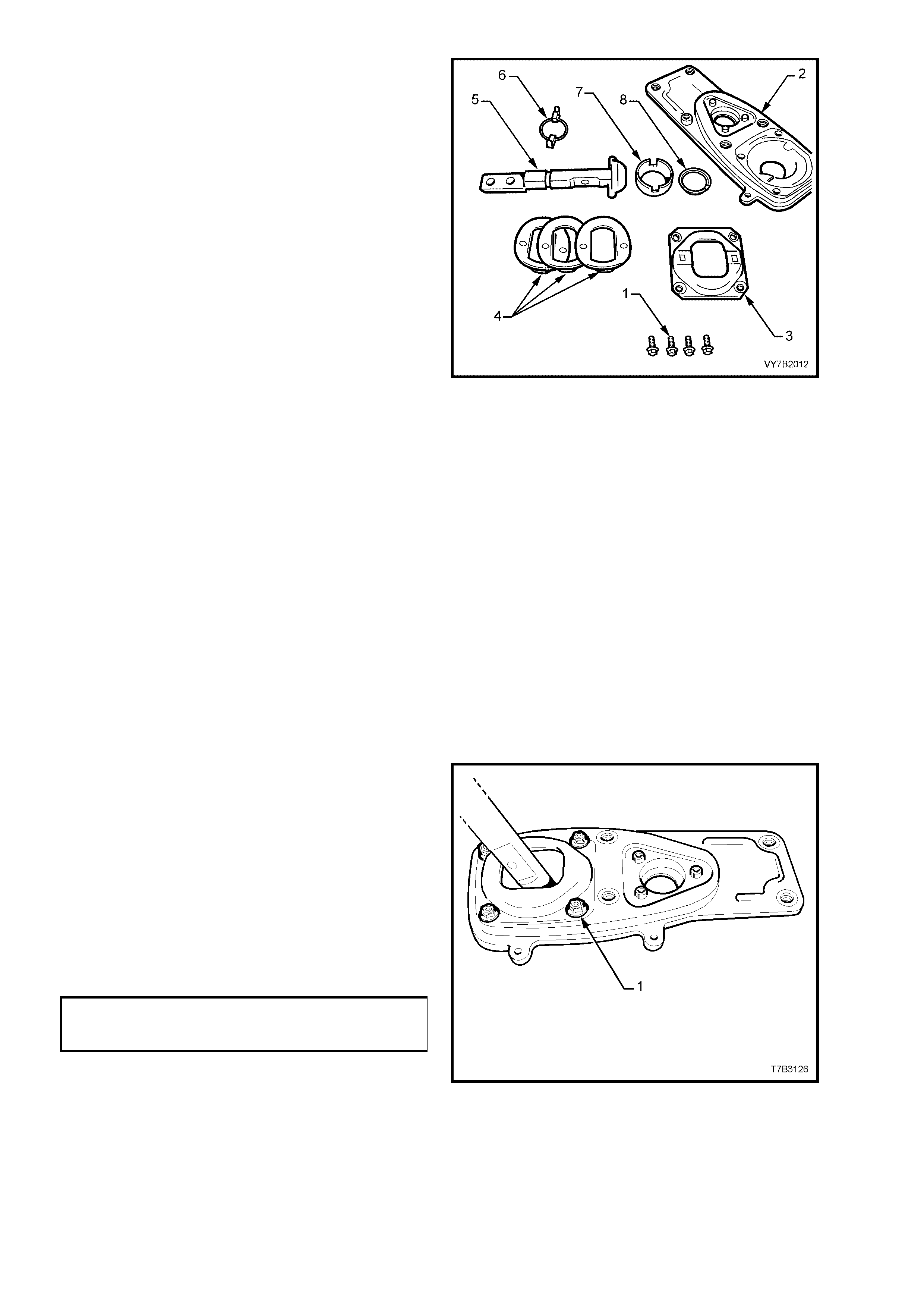
8. The rear remote shifter assembly can be
disassembled by first removing the four plate
(3) retaining bolts (1) from the baseplate (2).
9. Remove the wave springs (4), remote shifter
shaft (5) and guide (6), from the base plate (2).
10. Finally, remove the ball seat (7) and seat
support ring (8) from the base plate (2).
Figure 7B2-88
CLEAN AND INSPECT
Clean
After removing rubber insulating bushes and seal
to the extension housing, thoroughly wash all
components in a suitable c leaning solvent. Dr y all
parts with clean, dry compressed air.
CAUTION: Wear safety glasses to avoid eye
injury.
Inspect
1. Inspect pins, bushes, ball seats and other
components for wear or damage, replacing as
required.
2. Inspect the O-ring seal at the front pivot
assembly, the cover plate insulating rubber
bushes and seal to the extension housing, for
deterioration or damage, replacing as required.
REASSEMBLE
While reassembly is the reverse to disassembly
operations. there some specific procedures such
as;
1. Apply 10% molybdenum disulphide grease
such as Molybond GA 10 or equivalent to all
moving parts in the rear remote shifter
assembly.
2. Reassemble all parts in the reverse order of
disassembly.
3. Reinstall th e four b olts (1) s ecuring the plate to
baseplate, tightening to the correct torque
specification.
REAR REMOTE SHIFT
LEVER COVER BOLT
TORQUE SPECIFICATION 10 - 12 Nm
Figure 7B2-89
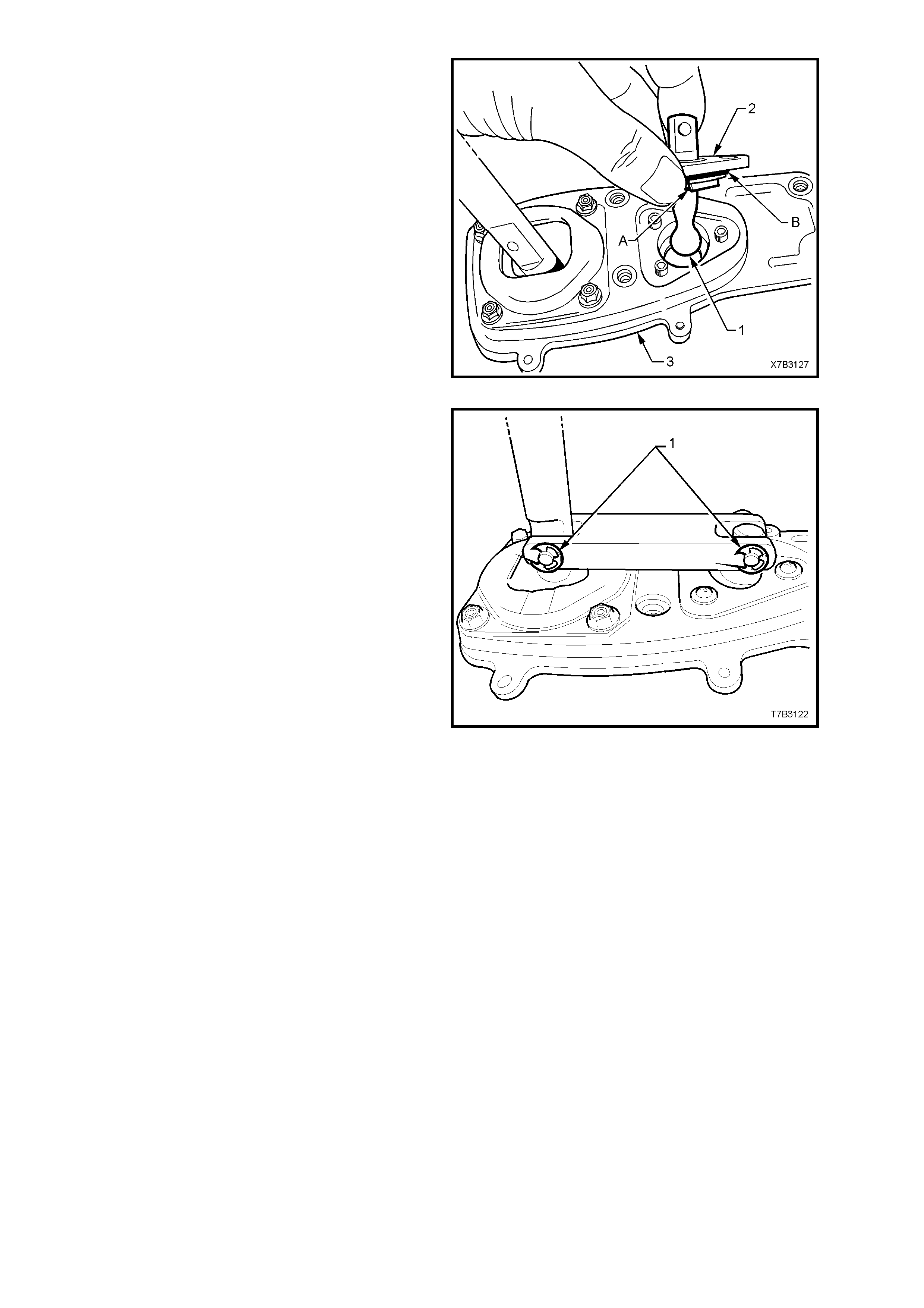
4. Apply NLGI No. 4 EP grease to the ball socket
of the front selector pivot (2), then reassemble
by tapping the front selector pivot (1) into the
plastic ball socket (2).
5. Install the O-ring seals ‘A’ and ‘B’ to the ball
socket (2), replacing with new parts if the
originals are damaged.
6. Reinstall the front selector pivot assembly to
the baseplate (3), install the three retaining
screws and tighten securely.
Figure 7B2-90
7. Install the bridging piece to the two remove
lever assemblies.
8. Install new bushes to the bridging piece after
lubric ating with NLG I No . 4 EP grease.
9. Install new pivot pins to each location and tap
home with a hammer.
NOTE: These pins are designed to be an
interference fit to the front and rear remote shifter
levers and not be free floating.
10. Fit new ‘E’ clips (1) to secure each pin.
CAUTION: Wear safety glasses to avoid eye
injury.
NOTE: the dust cover and boot assembly will be
installed after the remote shifter assembly is
installed to the transmission extension housing.
Figure 7B2-91
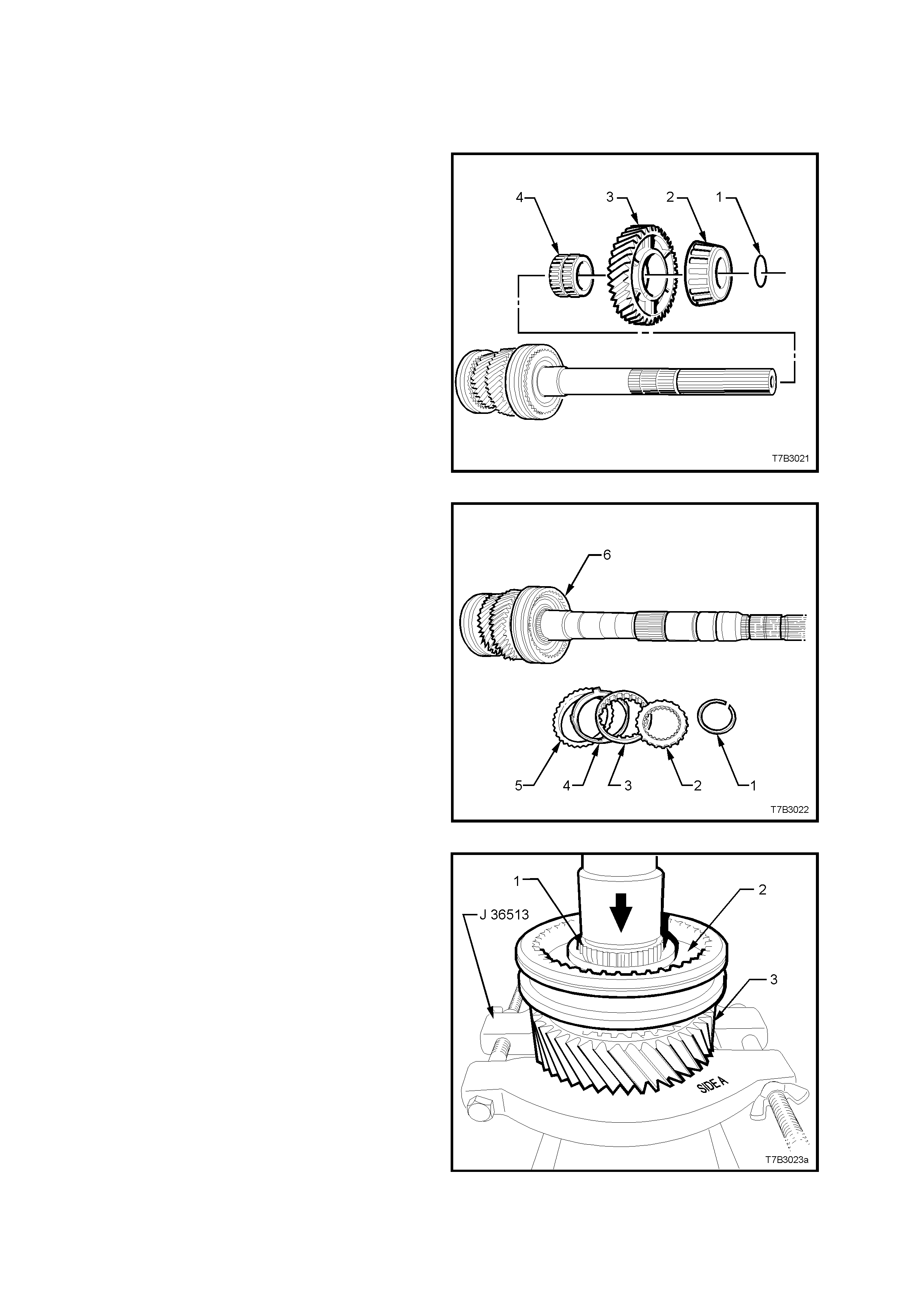
4.5 TRANSMISSION SUB-ASSEMBLIES
DISASSEMBLE
Mainshaft
NOTE: Do not m ix any s ynchrom esh block er rings,
or any synchromesh components.
1. Remove the O-ring (1) behind the rear
mainshaft bearing (2).
NOTE: The O-ring (1) is only used by the
manufacturer to assist in the assembly process. It
serves no other purpose and can be discarded
after removal. This O-ring is not serviced.
2. Grasp the 1st speed gear (3) and slide from
the mainshaft, removing the rear tapered roller
bearing (2) in the process. This rear bearing is
a sliding fit on the mainshaft.
3. Remove the 1st speed gear, caged needle
roller bearing (4) from the mainshaft.
Figure 7B2-92
4. Rem ove the snap ring (1) securing the 1st/2nd
synchromesh assembly (6).
5. Remove the thrust washer (2), inner cone (3),
friction cone (4), and blocker ring (5) from the
1st/2nd synchromesh assembly (6).
Figure 7B2-93
6. Install split press plates J 36513, with the flat
side (side A) against the 2nd speed constant
mesh gear (3).
7. Press the mainshaft (1) from the 2nd speed
constant mesh gear (3) and synchromesh
assembly (2). The components of the 2nd
speed synchromesh unit (2nd speed blocker
ring, friction cone, 2nd speed inner cone and
thrust washer), will also be removed in this
operation.
IMPORTANT: Be careful not to let the mainshaft
drop free to the floor, after pressing operations.
8. Remove the 2nd speed gear caged needle
roller bearing from the mainshaft.
Figure 7B2-94
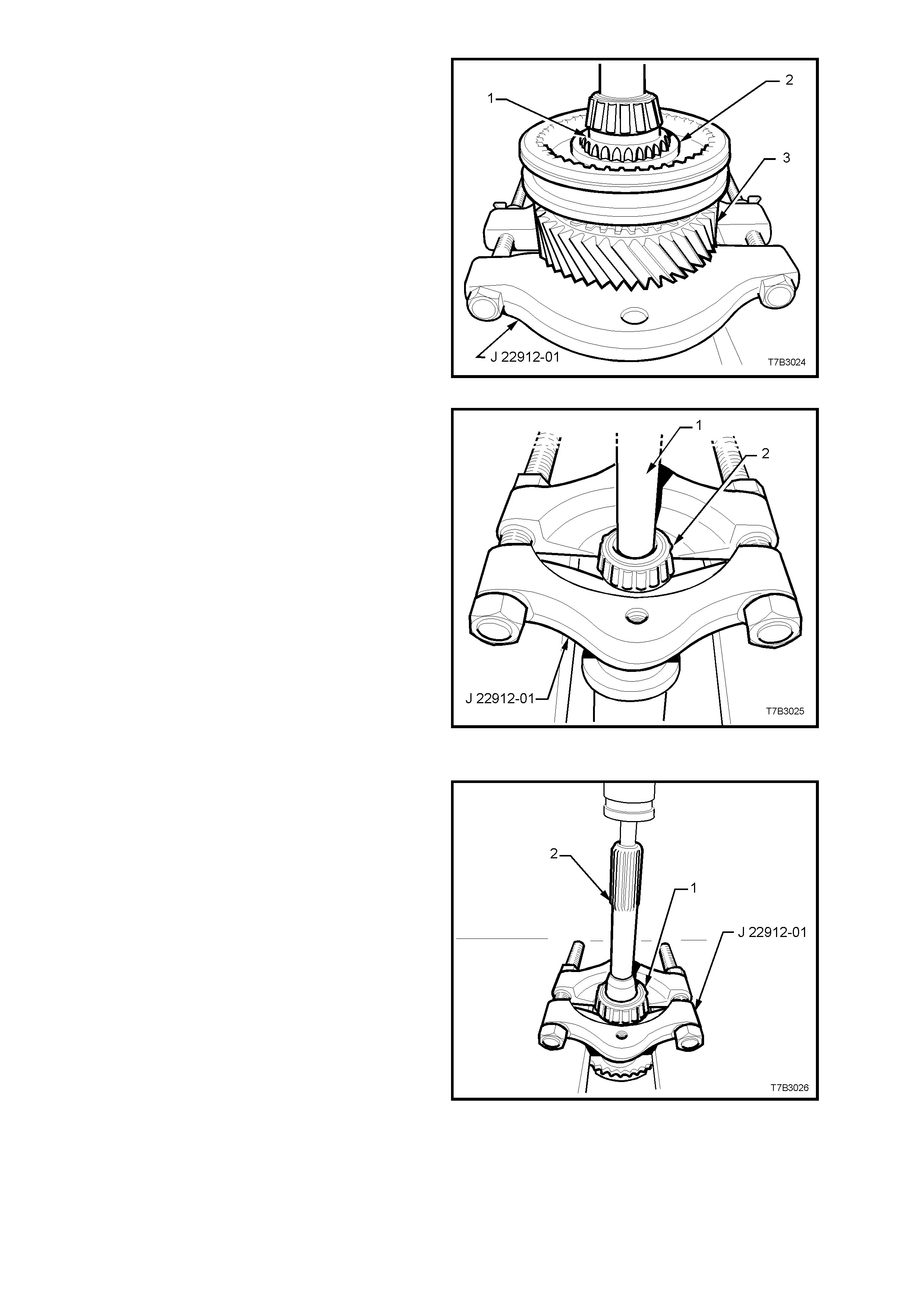
9. Remove the snap ring securing the 3rd/4th
synchromesh assembly.
10. Install split press plates J 22912-01 with the flat
side aga inst the 3rd spee d c onstant m esh ge ar
(3). Press the mainshaft (1) from the 3rd/4th
synchrom esh assem bly (2). In the proc ess, the
3rd speed constant mesh gear (3), 3rd speed
blocker ring, friction cone, inner cone and
thrust washer wi ll als o be r emoved.
IMPORTANT: Be careful not to let the mainshaft
drop free to the floor, after pressing operations.
11. Remove the 3rd speed gear caged needle
roller bearing from the mainshaft.
Figure 7B2-95
12. Install split press plates J 22912-01 under the
pilot bearing (2) installed on the nose of the
ma inshaft, tightenin g the b olts to secure . Press
the bearing (2) from the mainshaft, using a
suitable sized drift (1) (or socket extension).
Discard the bearing.
NOTE: Only remove this bearing if it is to be
replaced, as damage to the bearing during the
removal process will most likely occur.
Figure 7B2-96
Input Shaft
NOTE: Only remove the input shaft bearing or the
pilot bearing cup, if these components are to be
replaced.
1. Install split press plates J 22912-01 under the
input shaft bearing (1), tightening the bolts to
secure.
2. Press the bearing (1) from the input shaft (2).
3. Discard the removed bearing (1).
Figure 7B2-97
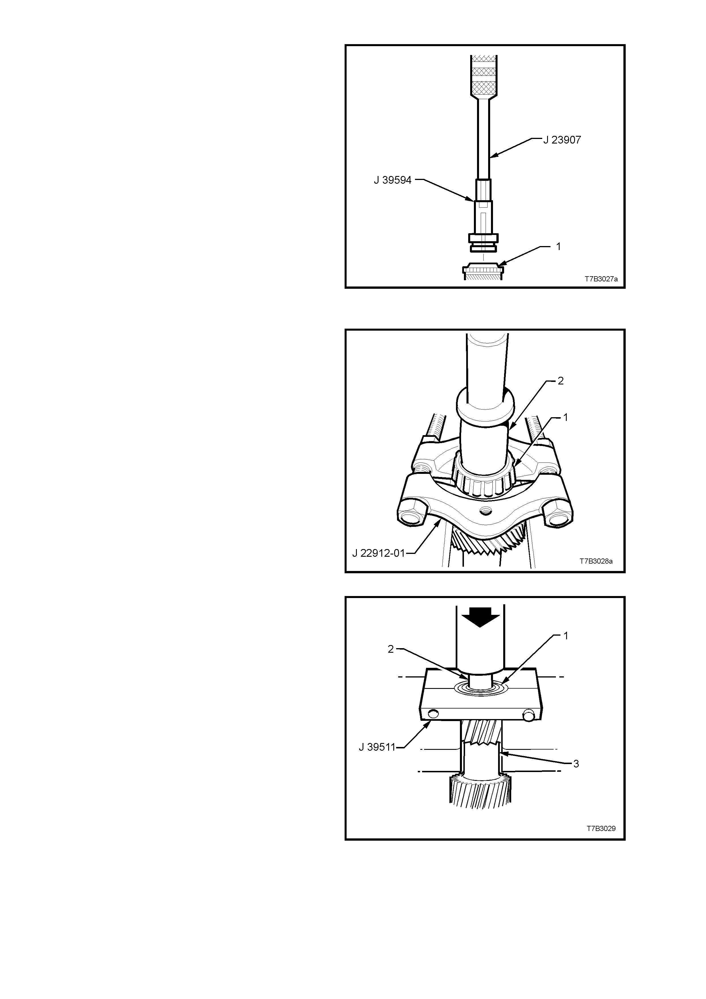
4. After assembling bearing remover J 39594 to
slide hammer J 23907, remove the front
mainshaft bearing cup from the input shaft (1).
Discard the removed bearing cup.
Figure 7B2-98
Countersha ft Gear
NOTE: Only remove either or both of the
countershaft bearing/s if replacement is required,
as damage will result from the removal procedure.
1. For the rear taper roller bearing (1);
a. Install press plates J 22912-01 under the
taper roller bearing (1), tightening the bolts
to secure.
b. Press the bearing (1) from the countershaft
gear, using a suitable size drift (2) (or
socket).
c. Discard the removed bearing.
Figure 7B2-99
2. For the front taper roller bearing;
a. Install split press plates J 39511 under the
front countershaft gear bearing (1),
tightening the bolts to secure.
b. Press the bearing (1) from the countershaft
gear (3), using a suitable size drift (2) (or
socket).
c. Discard the removed bearing.
Figure 7B2-100

Countersha ft Extension
1. Remove the following components from the
countershaft gear extension (7):
1. 5th/6th gear shift fork.
2. Thrust washer (may be retained on
countershaft gear).
3. 6th speed drive gear.
4. Synchromesh blocking ring.
5. Caged needle roller bearing.
6. Spacer.
Figure 7B2-101
2. Remove 5th/6th gear synchromesh assembly
snap ring.
3. With the flat sides of press plates J 22912-01
under the 5th speed drive gear (1), press the
gear and synchromesh assembly (2) from the
countershaft extension shaft (3), using a
suitable size drift.
Figure 7B2-102
4. Install split press plates J 22912-01 under the
tapered roller bearing (2), tightening the bolts
to secure.
5. Press the bearing (2) from the countershaft
extension, using a suitable sized drift (1) (or
socket extension). Discard the removed
bearing.
NOTE: Only remove this bearing if it is to be
replaced, as damage to the bearing during the
rem o val proces s will oc c ur.
Figure 7B2-103
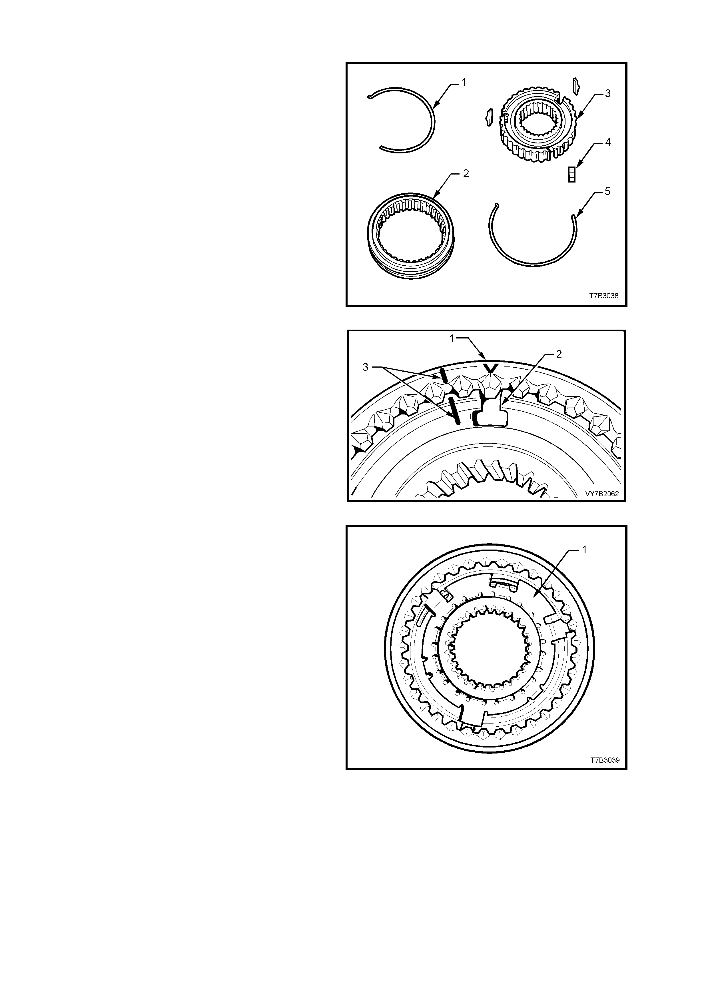
Synchromesh Assemblies
NOTE: This oper ation is not rec ommended, unles s
considered to be absolutely necessary. If
disassembly is required, then extreme care must
be taken to identify each component and it’s exact
location, using liquid paper or a felt tipped pen for
the purpose.
All Assemblies Except Reverse Gear
1. Using a small screwdriver, remove the
synchroniser springs (1 and 5).
CAUTION: Wear safety glasses to avoid eye
injury.
Figure 7B2-104
2. Note the location of the synchromesh
assembly ring ‘V’ mark (1) to the key location in
the hub (2), then slide the ring from the hub.
NOTE: If no 'V' mark can be found, then mark the
relationship (3) between the ring and the hub,
using correction fluid ('Whiteout').
Figure 7B2-105
Reverse Gear Synchromesh Assembly
1. Using a small screwdriver, remove the
synchroniser spring from the reverse gear side.
CAUTION: Wear safety glasses to avoid eye
injury.
2. Note the location of the synchromesh
assembly ring mark (‘V’) to the key location in
the hub, then slide the ring from the hub.
3. Remove the three keys.
4. Remove the synchromesh key retainer (1),
using a pin punch through the hub key slots.
Discard the retainer.
5. Remove the s econd s ynchroniser spring, using
a small bladed screwdriver.
Figure 7B2-106
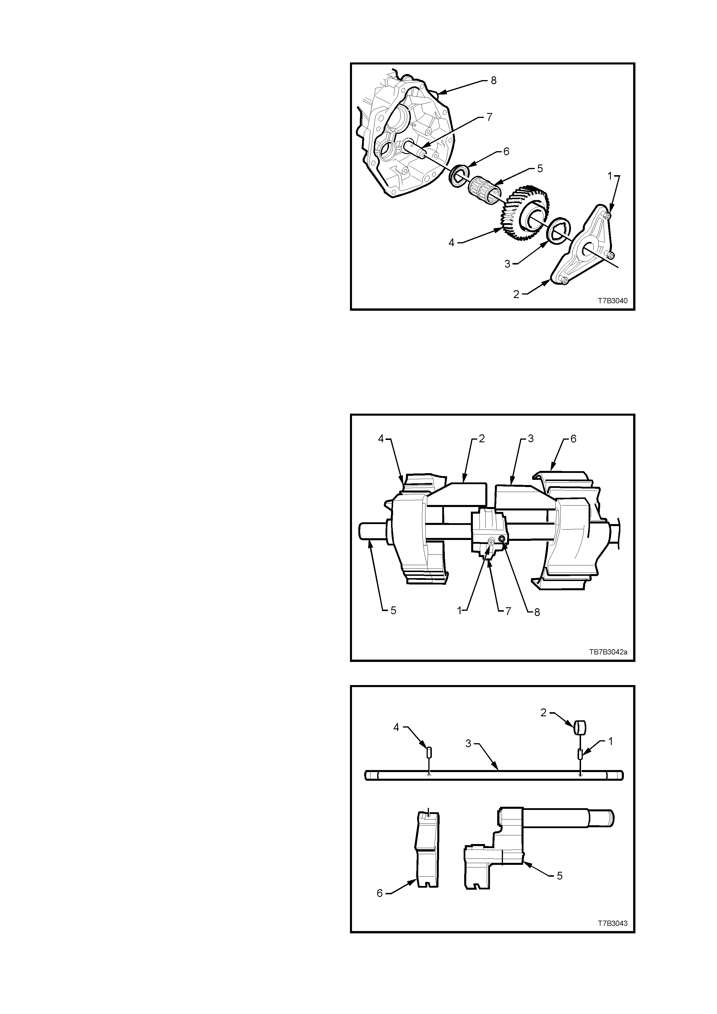
Reverse Idler Gear
1. Using Torx bit T40, remove the three screws
(1) securing the reverse idler gear shaft
support plate (2).
2. Remove the support plate (2), reverse idler
gear thrust washer (3), reverse idler gear (4),
caged needle roller bearing (5), the second
reverse idler gear thrust washer (6), and idler
gear shaft (7) from the extension housing (8).
Figure 7B2-107
Reverse Lockout Solenoid A ssembly
Refer to 3.4 REVERSE LOCKOUT SOLENOID
ASSEM BLY, Disassembl e, in th is Sec tion, f or this
procedure.
Shift Rail and Fork Assemblies
1st/2nd and 3rd/4th Shift Rail Assembly
1. Rotate the selector pin (1) until the interlock
plate (7) clears both shift plate links (2 and 3).
2. Slide the 3rd/4th shift fork (4) and link (2) from
the shift rail (5).
3. Slide the 1st/2nd shift f ork (6) and link (3) from
the shift rail (5).
4. Slide the interlock plate (7) from the shift rail
(5).
5. Using a suitable size pin punch and hammer,
remove the roll pin (8) from the selector pin (1).
NOTE: W hile bot h s h if t fork links ar e the s ame, it is
good practice to keep each link with its respective
fork.
Figure 7B2-108
5th/6th and Reverse Shift Rail Assembly
6. Remove the roll pin (1) from the collar (2) and
shift rail (3), using a suitable size pin punch
and hammer.
7. Slide the 5th/6th shift rail lever (5) from the shift
rail (3).
NOTE 1: Only remove the bushes from the 5th/6th
shift rail if they are worn or damaged and require
replacement.
NOTE 2: While the s le ev e can b e pr es sed fr om the
5th/6th shift rail lever (after removing the retaining
circlip), this operation is not recommended unless
parts are to be replaced.
8. Using a suitable size pin punch and hammer,
rem ove the roll pin (4) ho lding the re verse shif t
rail lever (6) to the shift rail (3). Slide the
reverse shift rail lever (6) from the shi ft rail (3).
Figure 7B2-109
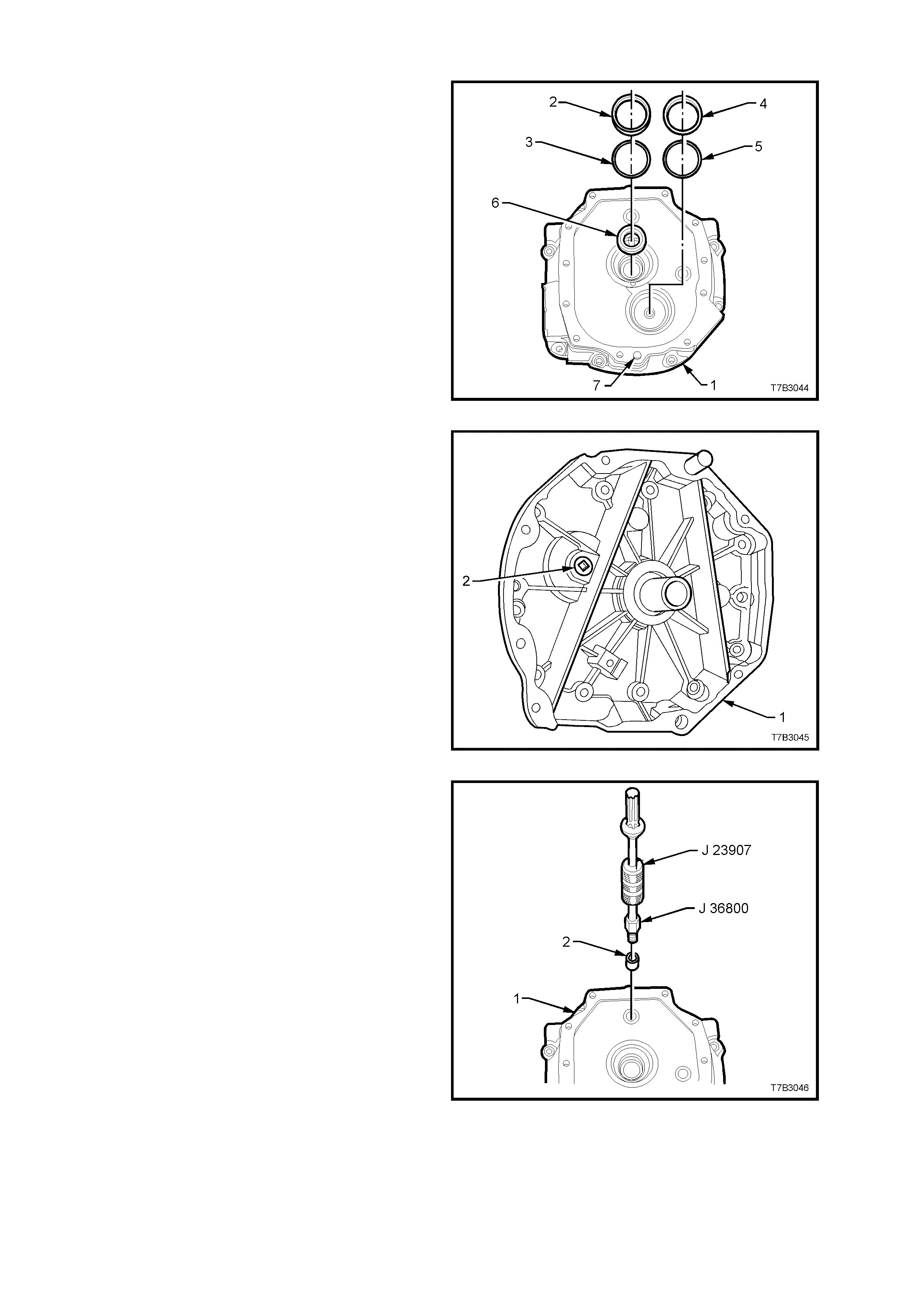
Transmissio n Adaptor Plate
1. Slide t he input shaf t be ar in g c up (2) an d s him/s
(3) by pulling with the finger tips of each hand.
NOTE: Rotating the cup back and forth while
pulling, will reduce the problem of the bearing cup
cocking and jamming in the adaptor plate bore.
2. Repeat th is pr oces s with th e counter shaf t front
bearing cup (4) and shim/s (5).
3. Prise the input shaft oil seal (6) from the
adaptor plate (1).
4. O nly remove the do wel pins ( 7), if replacem ent
is required.
Figure 7B2-110
5. Using a 3/8” drive socket bar, remove the
adaptor plate plug (2) from the front of the
adaptor plate (1).
Figure 7B2-111
6. If worn or damaged, remove the 1st/2nd and
3rd/4th shift rail bushing (2), using the following
procedure;
a. Screw bushing remover J 36800 into the
shift rail bushing (2).
b. Screw slide hammer J 23907 into the
bushing remover J 36800 and remove the
bushing (2) from the adaptor plate (1).
Figure 7B2-112
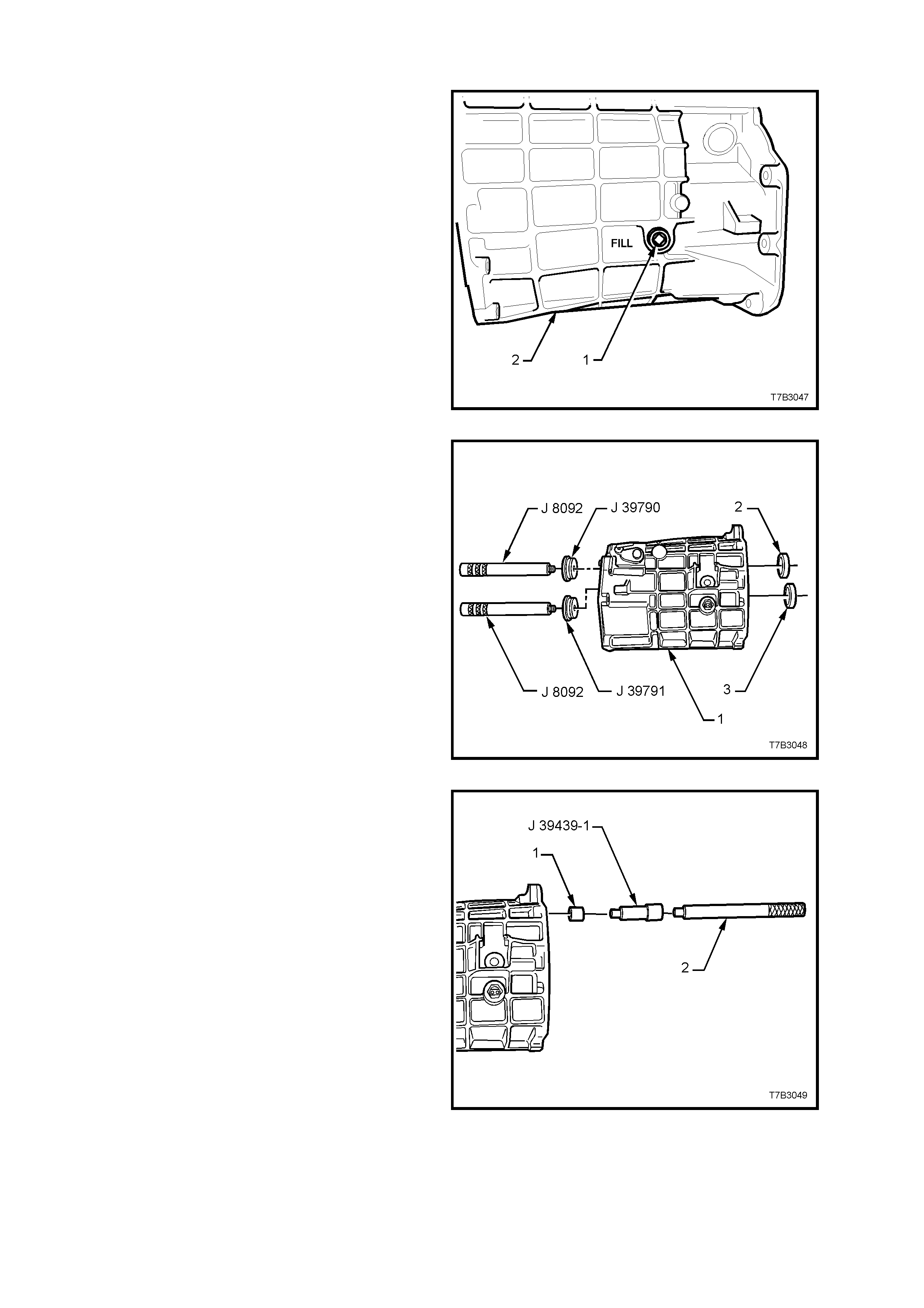
Transmission Case
1. Using a 3/8” drive socket bar, remove the filler
plug (1) from the transmission case (2).
Figure 7B2-113
NOTE: Only remove the rear mainshaft bearing
cup (2) and/or rear countershaft gear bearing cup
(3) if these components are to be replaced.
2. Press the mainshaft bearing rear cup (2) from
the transmission case (1), using remover J
39790 and driver handle J 8092.
3. Press the countershaft gear rear bearing cup
(3) from the transmission case (1), using
remover J 39791 and driver handle J 8092.
4. Discard removed bearing cup/s.
Figure 7B2-114
5. If worn or damaged, remove the shift rail
bushes (1), using bushing remover J 39439-1
and a suitable driver handle (2). Discard the
removed bushes (1).
Figure 7B2-115
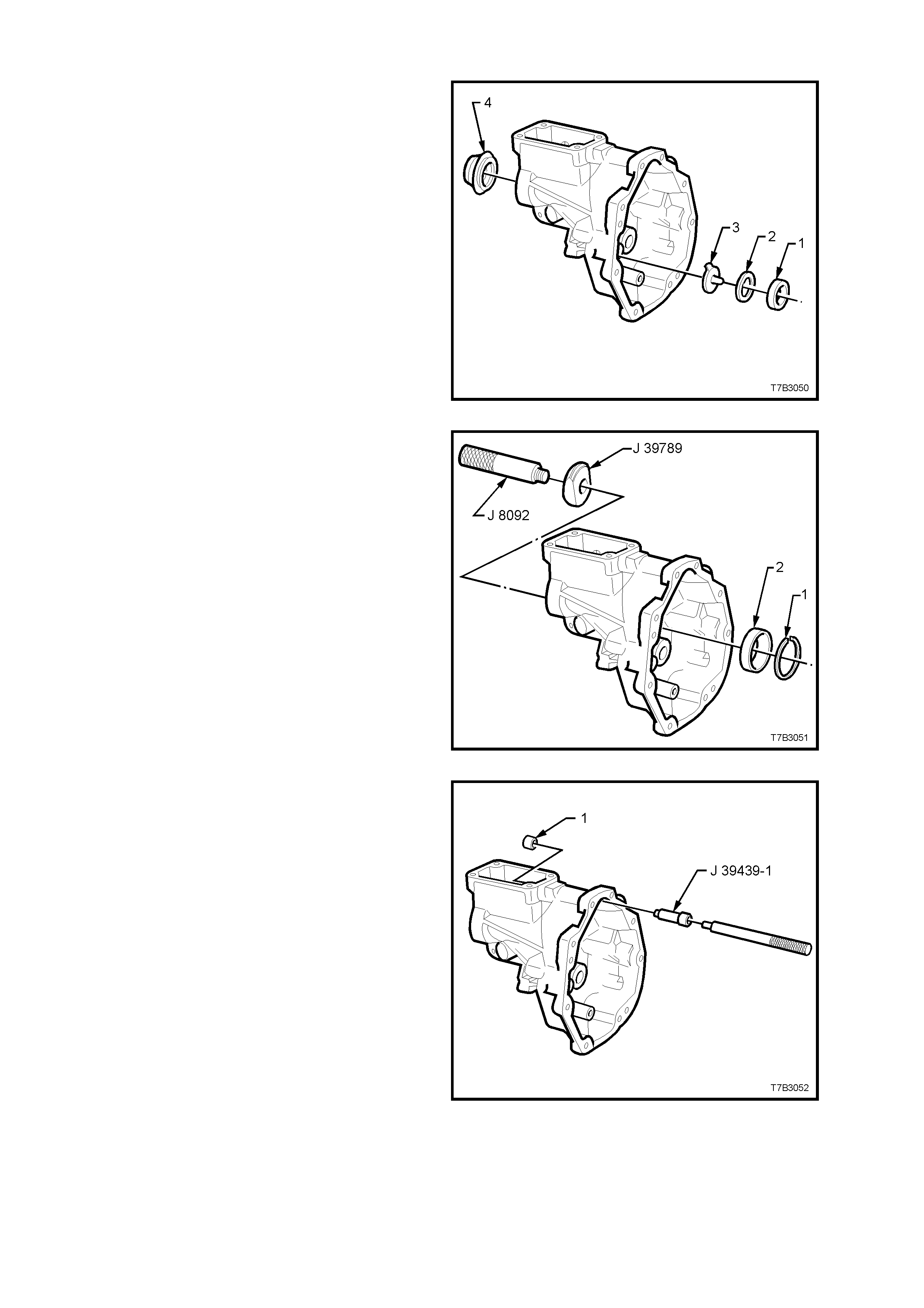
EXTENSION HOUSING
NOTE: If not removed during the transmission
disassembly process, remove the following
components;
a. Drain Plug.
b. Reverse lockout solenoid and body assembly.
c. Vehicle speed sensor.
d. Reverse idler gear assembly.
1. Slide the countershaft gear extension, rear
bearing cu p (1) , s him /s (2) and oil f un nel (3) b y
pulling with the finger tips of each hand.
NOTE: Rotating the rear bearing cup (1) back and
forth while pulling with the finger tips, will reduce
the problem of the bearing cup cocking and
jamming in the extension housing bore.
2. Prise the rear seal (4) from the extension
housing, using a suitable lever. Discard the
removed seal.
Figure 7B2-116
NOTE: Only remove the mainshaft rear roller
bearing cup if the bearing assembly is to be
replaced.
3. Remove the mainshaft rear roller bearing cup
retaining snap ring (1) using suitable pliers.
4. Press the mainshaft rear bearing cup (2) from
the extension housing, using remover J 39789
and driver handle J 8092.
Figure 7B2-117
5. If worn or damaged, remove the shift rail
bushing (1), using bushing remover J 39439-1
and a suitable driver handle. Discard the
removed bushing.
NOTE: The propeller shaft slip yoke bush is not
serviced separately. If excessive wear is detected,
then the extension housing assembly must be
replaced.
Figure 7B2-118
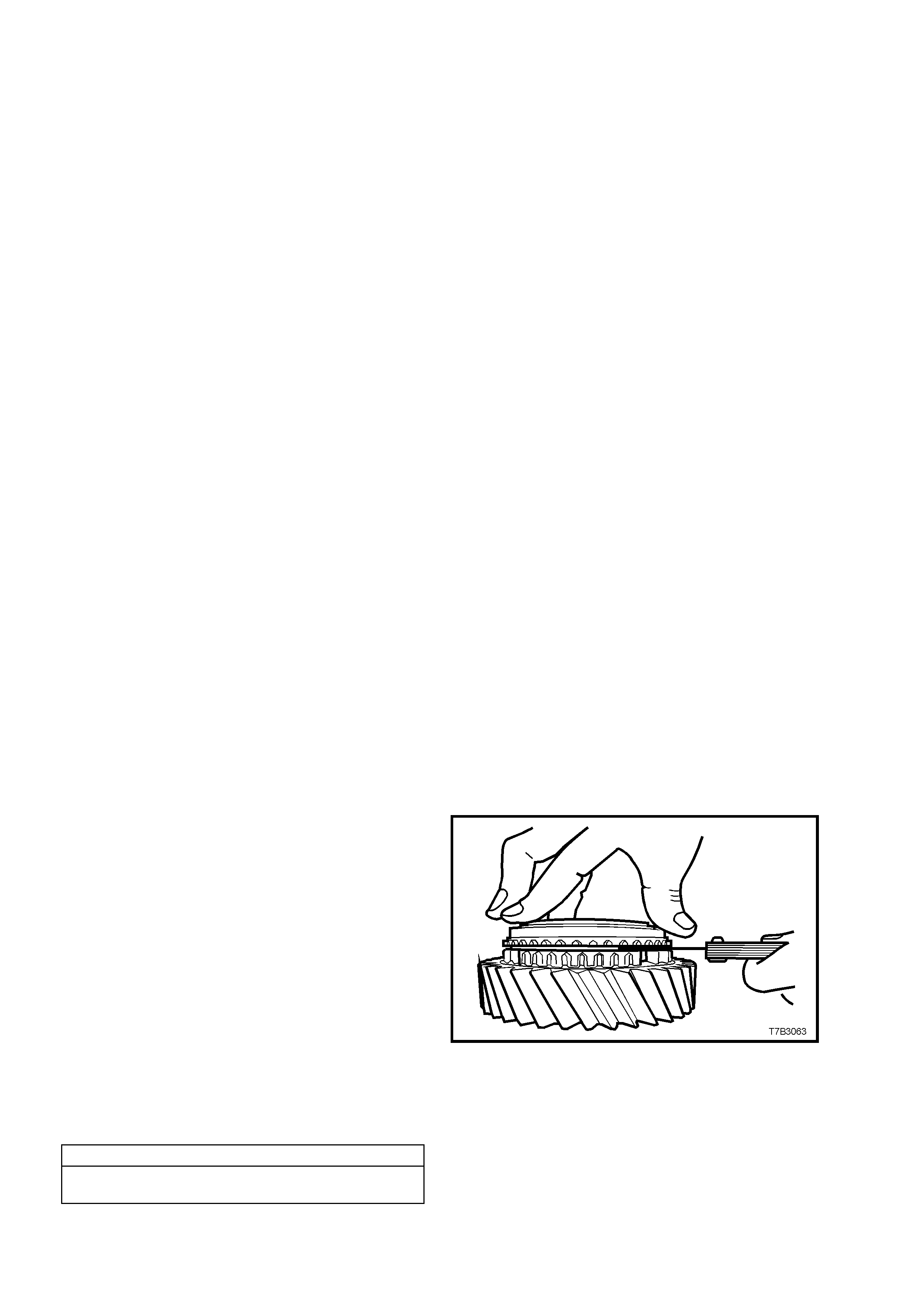
CLEAN AND INSPECT COMPONENTS
Clean
Thoroughly wash all components in a suitable cleaning solvent. Dry all parts with clean, dry compressed air.
CAUTION: Wear safety glasses to avoid eye injury.
Use a wire brush or thread taps to clean thread sealant from all fasteners that are to be re-used.
Inspect
1. Inspect transmission case, rear extension, adaptor plate and clutch housings for any cracks or defects that may
cause lubricant leakage.
2. Ensure that there is no dam age to or sealant on, the f ront face of transm ission adaptor plate that could cause
misalignment between case and clutch housing.
3. Check all m achined f aces for burrs and trac es of sealant. If s craping of theses sur faces is required, on ly use a
plastic scraper to av oid dam aging finely m achined allo y surfac es. If burrs ar e found, dres s them of f with a fine
mill file.
4. Al l roller and need le bearin g assemblies should be ins pected closel y and replace d if there is an y sign of wear.
Inspect mainshaft and internal surfaces of all gears where needle bearings come in contact.
For diagnosis of tapered roller bearing failures, refer to 4.2, 'DIFFERENTIAL AND REAR AXLE BEARING
DIAGNOSIS' in Section 4B, FINAL DRIVE AND DRIVESHAFTS, in the MY 2003 VY and V2 Series Service
Information.
NOTE 1: If the countershaft gear bearings are worn or damaged, refer to 4.5 TRANSMISSION SUB-
ASSEMBLIES, Disassemble, Countershaft Gear, in this Section. If either bearing is removed, it must be
replaced with a new part as damage will occur during the removal operation.
NOTE 2: If the input shaft bearing is worn or damaged, refer to 4.5 TRANSMISSION SUB-ASSEMBLIES,
Disassemble, Input Shaft, in this Section.
NOTE 3: As n eed le rol ler wear can be d iff icult to se e, it is g ood pr act ice to r epla ce all nee dle rol ler bear ing s wher e
the vehicle has travell ed a s ubstantial dist ance.
5. Inspect all gears, sleeves, hubs, rings and shafts for wear, scoring, pitting, chips , nicks or burrs. Slig ht scores
or burrs may be honed off with a fine stone but, if a gear is chipped or unduly worn, it must be replaced.
6. Check synchroniser teeth on blocking rings and gears. Replace any component that is worn or damaged.
7. Inspect synchroniser hubs, outer rings, inserts and springs for damage or wear. Check that the synchroniser
rings slide freely on their hubs. Replace any worn component.
NOTE: Even though the synchromesh blocking rings are the same, it is sound practice to keep each ring with its
respective gear, to preserve wear patterns.
8. Inspect reverse idler gear shaft, replacing if worn.
9. Check all thrust washers, replace any that are worn.
10. Inspect all shift control component, both contact and sliding surfaces for wear, scratches, projections or other
damage.
11. Inspect breather tube to ensure that it is not blocked.
IMPORTANT: If any constant mesh gear end float
is considered to be excessive, then careful
attention must be paid to measuring blocker ring
wear. If within the specifications provided, replace
parts as required to reduce end float, as no shim
adjustment is provided.
12. Measure the wear of all blocker rings as
follows:
a. Place the three blocking ring components onto
the appropriate gear cone i.e. fifth gear
blocking ring assembly onto fifth speed drive
gear.
b. Hold rings square on the gear’s cone surface
and hold firmly in the seated position.
c. Measure clearances in the location shown.
d. Discard any blocker ring that measures less
than the minimum prescribed clearance.
BLOCKER RING ASSEMBLY TO GEAR CLEARANCE
1st to 6th GEARS INCLUSIVE 0.38 mm Minimum
REVERSE 0.75 mm Minimum
Figure 7B2-119
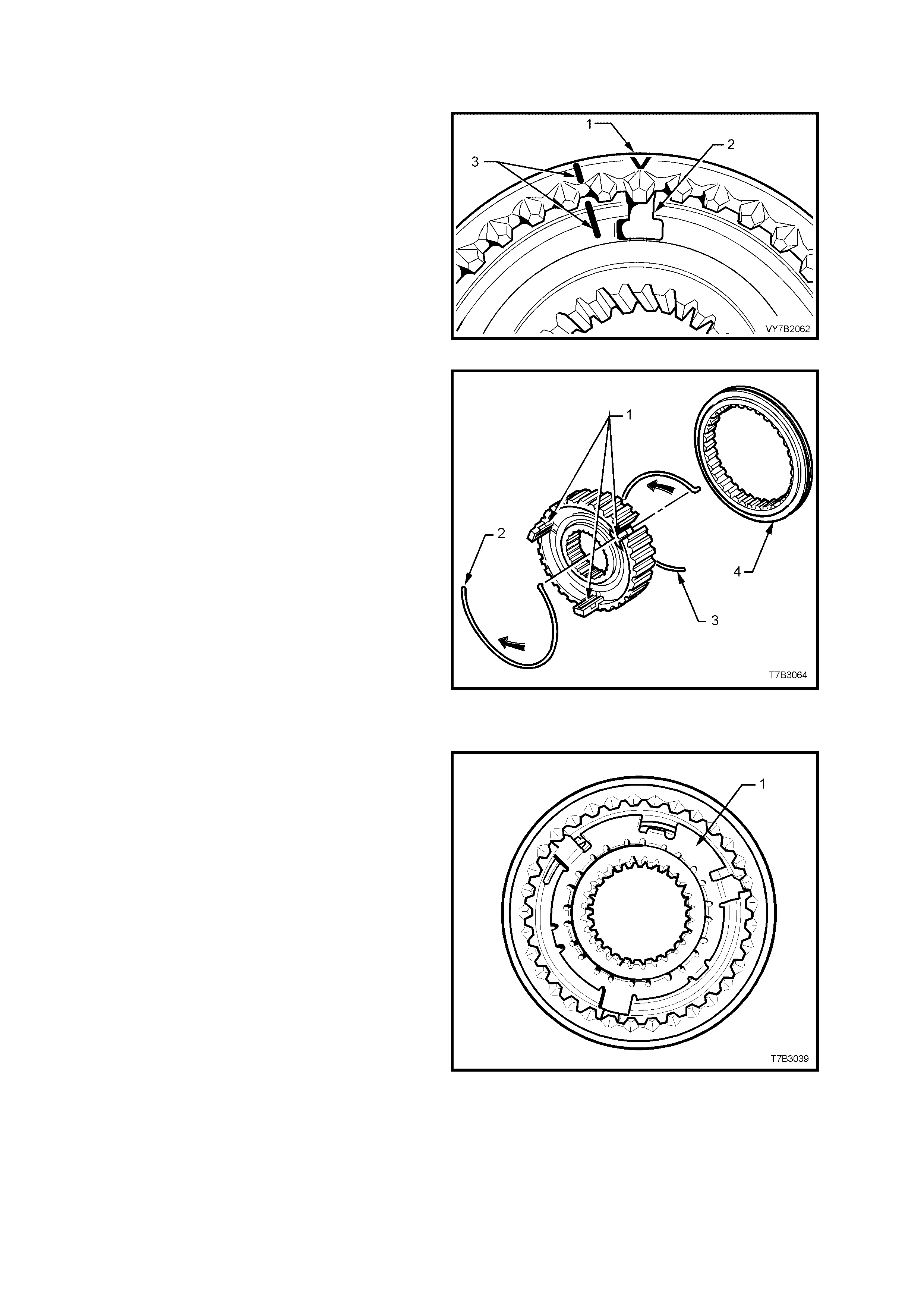
REASSEMBLE
Synchromesh Assemblies – All
1. Install the synchromesh ring over the hub,
aligning the ‘V’ on t he edge of the ring (1) with
one of the previously marked, hub key
openings (2) or, align the marks (3) made
before disassembly.
NOTE: While none of the hubs has an offset, the
orientation of the outer synchroniser ring is
specific, depending on the application.
Figure 7B2-120
2. Install the three keys (1) with the protrusions
facing outward.
3. Ins tall one s ynchroniser s pring (2), l ocating the
spring tang in one of the synchroniser keys,
using a small screwdriver to assist.
CAUTION: Wear safety glasses to avoid eye
injury.
4. Turn the assembly over, then install the second
synchron iser s pring ( 3), locatin g t he tan g in the
same key as before but in the opposite
direction to the first. Again use a small
screwdriver to assist.
NOTE: The s ync hromesh as sembly is sho wn in an
exploded state to more clearly show the
synchroniser spring arrangement.
Figure 7B2-121
Reverse Synch rom e sh Assembl y Onl y
1. Following the assembly of the synchromesh
assembly, as detailed in steps 1 to 4 above,
install a new synchromesh key retainer (1),
locating the tan gs over the s ynchromesh ke ys.
2. Using a suitable size sleeve such as Tool No.
E1891-6 (or tube I.D. 50 mm, wall thickness 5
mm maximum) and a hammer, install the key
retainer, securing it to the synchromesh hub
centre.
Figure 7B2-122
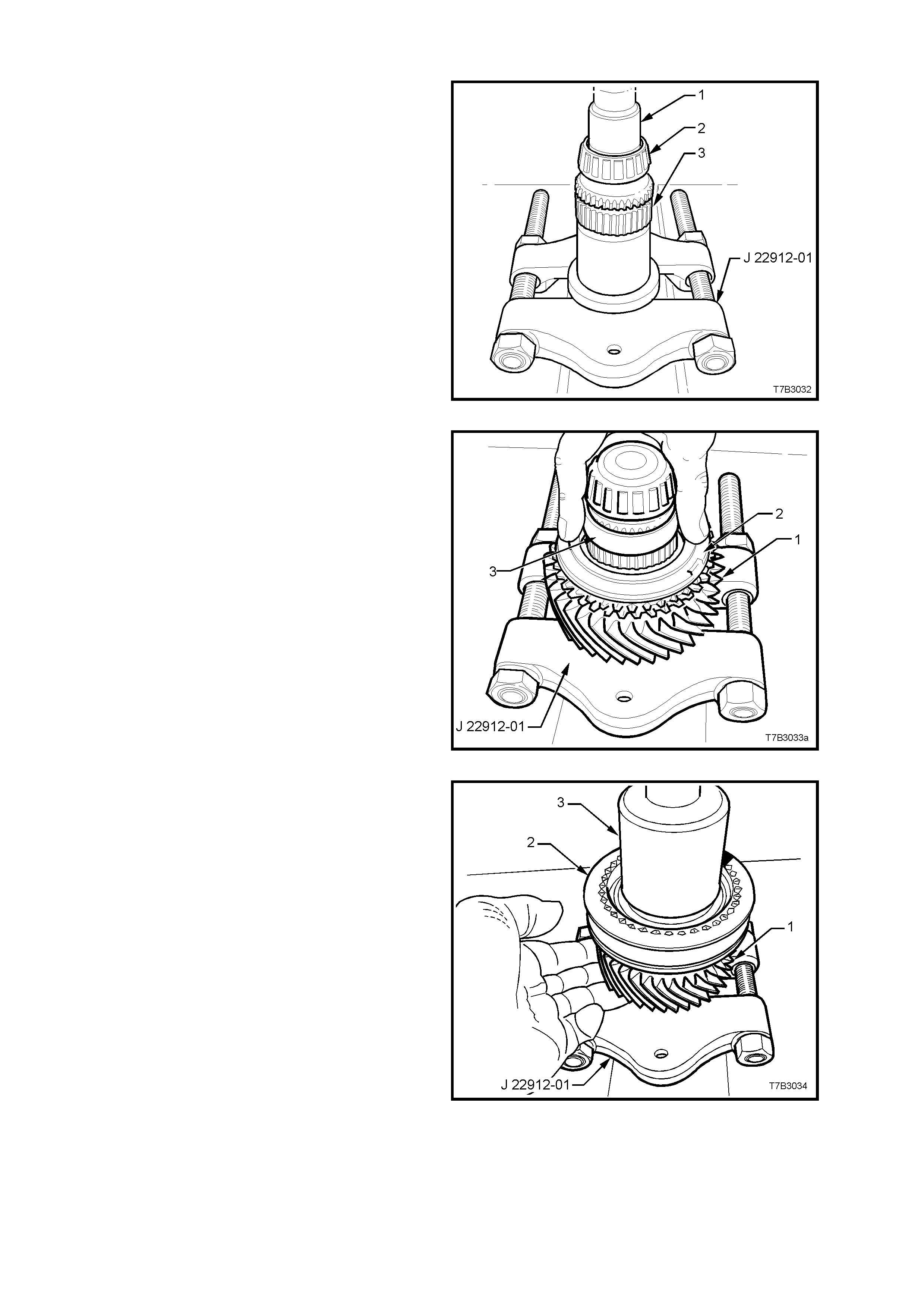
Mainshaft
1. With press plates J 22919-01 installed under
the mainshaft flange as shown, press a NEW
spigot taper roller bearing (2) onto the
mainshaft (3), using a suitable sleeve (1) (e.g.
21 mm socket).
Figure 7B2-123
2. With press plates J 22912-01, still installed
under the mainshaf t flange, insta ll the 3rd g ear
caged needle roller race, 3rd gear (1) and the
blocker ring (2).
3. Install plastic sleeve (3) over the mainshaft.
Figure 7B2-124
4. Install 3rd/4th synchromesh assembly (2) to
the mains haft splines, n oting that the groo ve in
the outer ring faces forward (to 4th gear).
5. Press 3rd/4th synchromesh assembly to the
mainshaft, using a suitable size sleeve (3) (47
mm ID, minimum length 25 mm and wall
thickness 5 mm).
6. During the pressing process, hold the 3rd gear
(1) and blocker ring into place against the
synchromesh assembly (2) to ensure correct
location of the locating dogs on the blocker
ring, with the synchromesh keys.
Figure 7B2-125
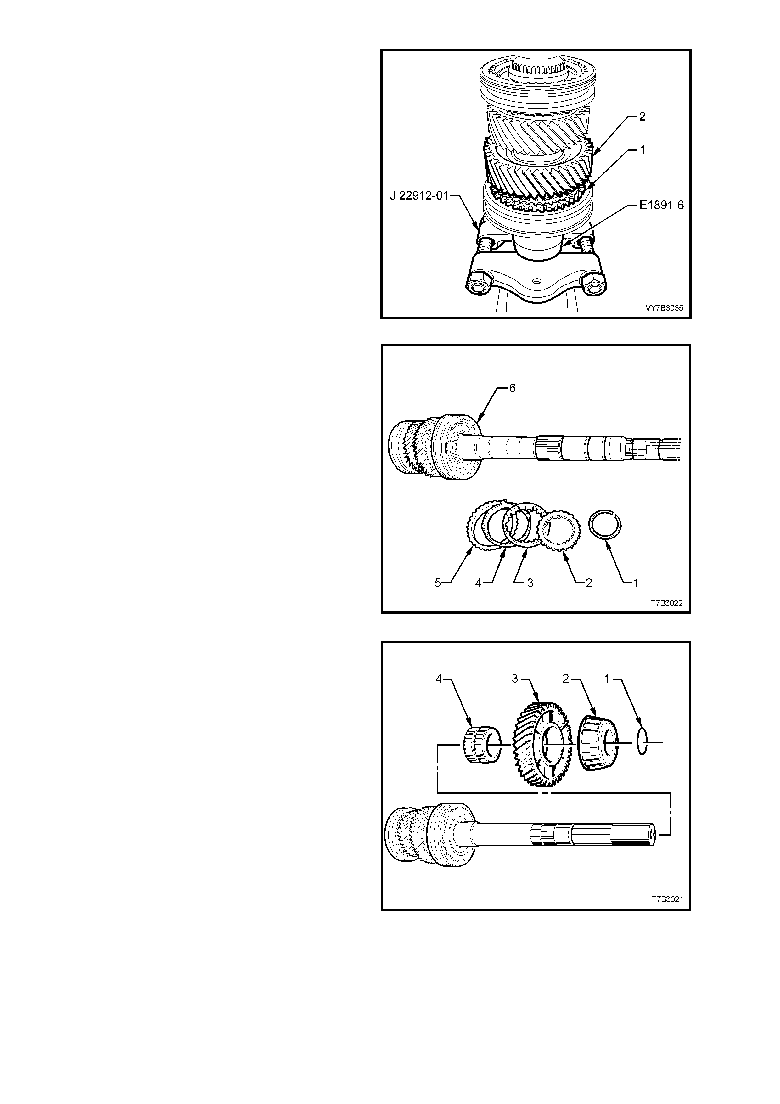
7. Install 2nd speed gear (3) and caged needle
roller bearing, the blocking ring and 1st/2nd
speed synchromesh assembly (2) to the
mainshaft, noting that the groove in the outer
ring of the synchromesh assembly faces
rearward (to 1st gear).
8. Using a suitable sleeve such as Tool E1891-6
(or I.D. 50 mm, wall thickness 5 mm),
supported by press plates J 22912-01 as
shown, press the mainshaft into the 1st/2nd
speed synchromesh assembly (2).
NOTE: The locating dogs of the 2nd speed
blocking ring should be aligned with the
synchromesh keys during the pressing process,
allowing the 2nd speed g ear (3) weight to keep the
assem bl y in place .
Figure 7B2-126
9. Reinstall the blocker ring (5), friction cone (4),
inner cone (3) and the thrust washer (2) to
engage with the mainshaft splines and the
1st/2nd speed synchromesh assembly teeth.
10. Using suitable snap ring pliers, install a new
snap ring, securing these components.
Figure 7B2-127
11. After lubricating the 1st speed constant mesh
gear needle roller bearing with new
transmission fluid, install the bearing and the
1st speed constant mesh gear, engaging the
lugs on the friction ring with the cut-outs in the
gear.
12. Slide the taper roller bearing cone along the
mainshaft. If present and serviceable the
bearing can be retained by reinstalling the O-
ring (1).
NOTE: As noted in the disassembly process, this
O-ring (1) is only used to assist in the assembly
process and can be discarded. If not fitted
however, c are m ust be tak en to n ot ensur e that th e
roller bearing does not slide from the mainshaft
and suff er c age dam age from dr opping ont o a har d
surface.
Figure 7B2-128
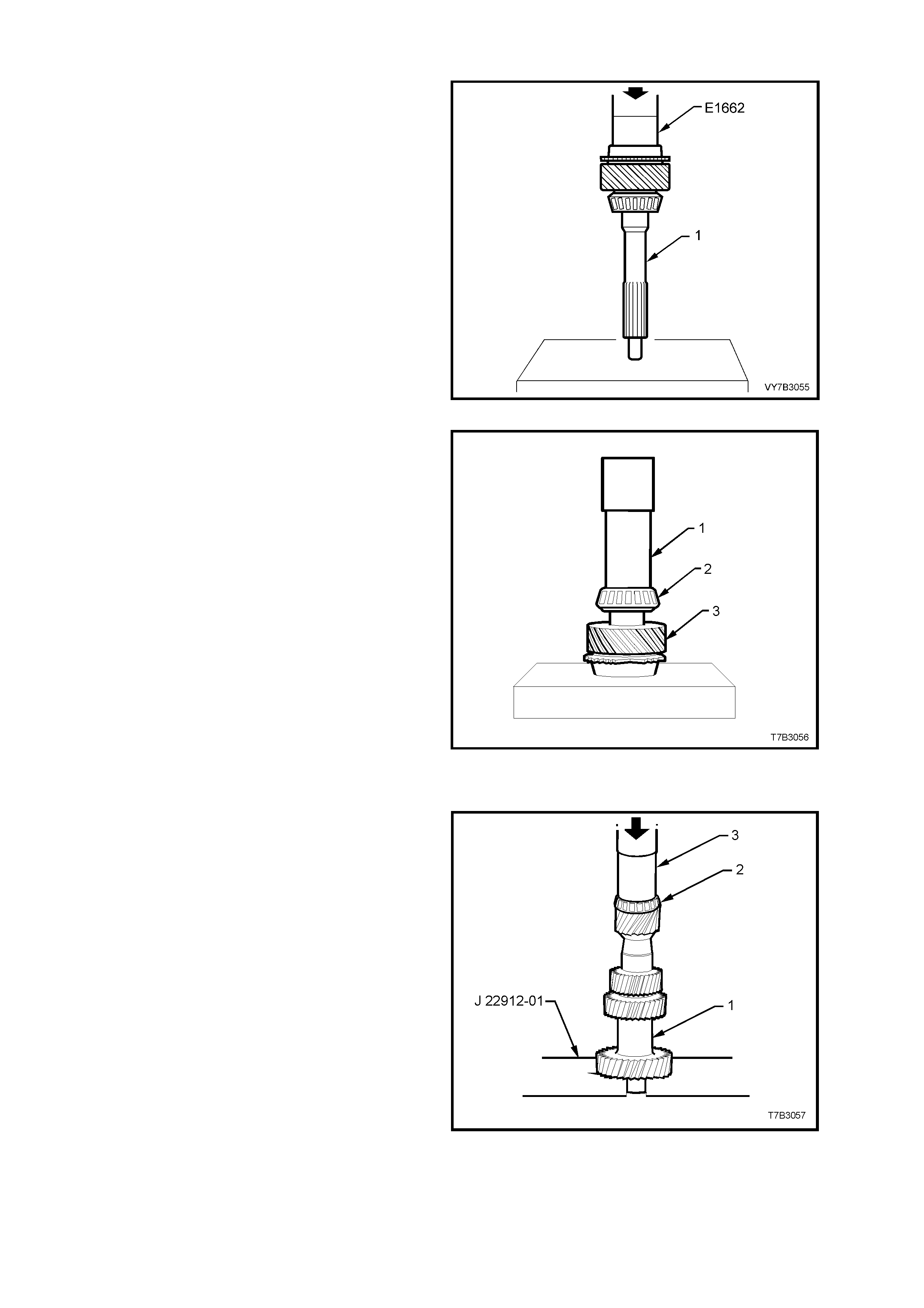
Input Shaft
1. Using tube E1662 or equivalent size (O.D. 47
mm, length approximately 40 mm) and an
hydraulic press, install a new input shaft
bearing cup into the counter bore of the input
shaft (1).
Figure 7B2-129
2. Using a suita ble size tu be (1) (I.D. 32 m m, wall
thickness 5 mm maximum and length 200
mm), and an hydraulic press, install a new
tapered roller bearing (2) to the input shaft (3).
Figure 7B2-130
Countersha ft Gear
1. Using press plates J 22912-01, support the
input gear of the countershaft gear (1).
2. Install a ne w beari ng (2) to the sm all end of the
countershaft gear (1), using a suitable size
sleeve (3) (I.D. 40 mm, wall thickness 4 mm
maximum) and an hydraulic press.
Figure 7B2-131
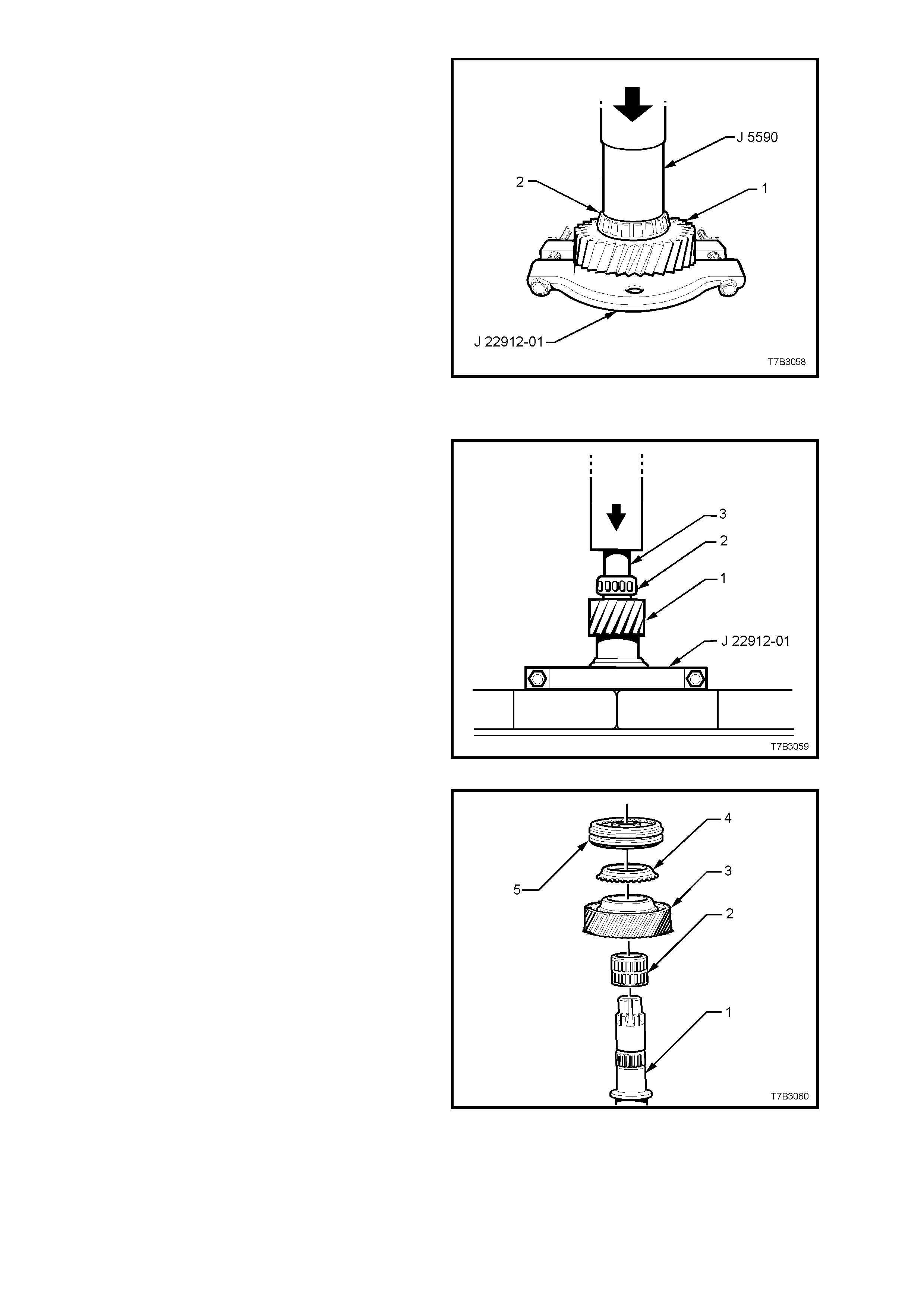
3. Using press plates J 22912-01, support the
input gear of the countershaft gear (1) as
shown.
4. Install a new bear ing (2) to the larg e end of the
countershaft gear (1), using installer J 5590 or
a suitable sleeve (I.D. 36 mm, wall thickness 4
mm maximum) and an hydraulic press.
Figure 7B2-132
Countersha ft Extension Gear
1. With press plates J 22912-01 installed under
the countershaft extension flange (1) as
shown, press a new taper roller bearing (2)
onto the extension (1), using a suitable sleeve
(3) (e.g. 21 mm socket).
Figure 7B2-133
2. Install the following components to the
countershaft extension (1):
2. 5th gear caged needle roller bearing.
3. 5th speed drive gear.
4. 5th speed synchromesh blocking ring.
5. 5th/6th speed synchromesh assembly.
Figure 7B2-134
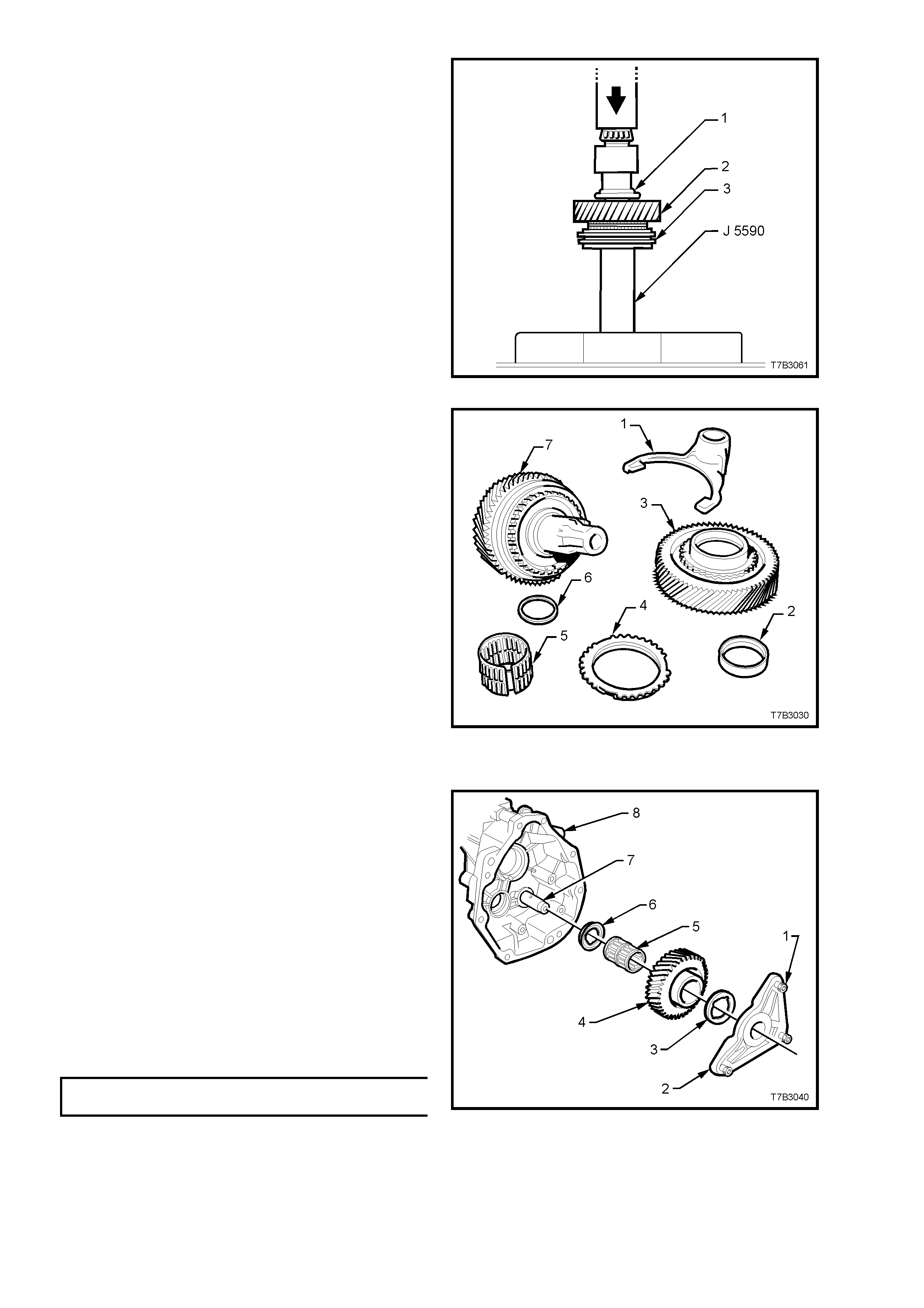
3. With the assembly arranged as shown, press
the countershaft extension into the
synchromesh assembly hub, using tube
J 5590.
NOTE: Index the blocking ring assembly with the
synchromesh keys before pressing operations.
4. Fit a new snap ring to the countershaft
extension to secure the synchromesh
assembly.
Illustration Key:
1. Countershaft gear extension.
2. 5th speed drive gear.
3. 5th/6th speed synchromesh assembly.
Figure 7B2-135
5. Install the spacer washer (6), caged needle
roller bearing (5), 6th speed blocking ring (4),
6th speed dr ive gear (3), a nd thrust washer ( 2)
with the recessed side facing the countershaft
gear.
6. Install the 5th/6th shift fork (1) to the
synchromesh ring, in preparation for
installation.
Figure 7B2-136
Reverse Idler Gear
1. Install the reverse idler gear shaft (7) and
thrust washer (6) to the transm ission extensi on
housing (8).
2. Lubricate the reverse idler gear (4) and caged
needle roller bearing (5) with clean
transmission fluid, then install both over the
idler gear shaft (7).
3. Install the outer thrust washer (3) and reverse
idler shaft retaining bracket (2).
4. After cleaning any thread sealant residue from
the threads of the three, Torx headed bracket
screws (1), apply thread sealant such as
Loctite 24 2 or equi valent, to the s crew t hreads.
Reinstall and tighten the screws to the correct
torque specification.
REVERSE IDLE GEAR SHAFT BRACKET
SCREW TORQUE SPECIFICATION 25 Nm
Figure 7B2-137
Reverse Lockout Assembly
Refer to 3.4 REVERSE LOCKOUT SOLENOID
ASSEMBLY, in this Section, for the reassembly
description.
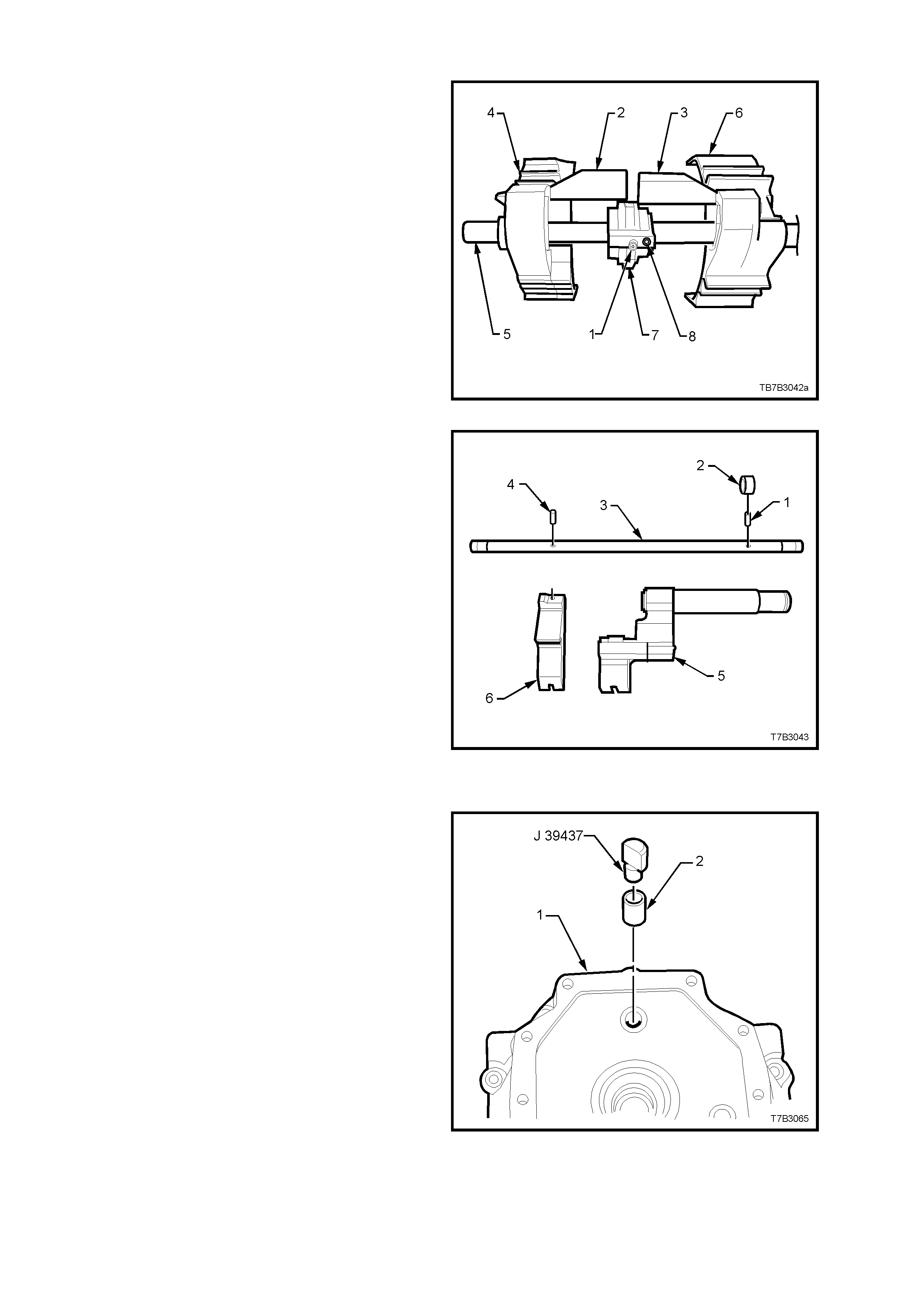
Shift Rail and Fork Assemblies
1st/2nd and 3rd/4t h Sh ift Rail Assembly
1. If removed, slide the selector pin (1) over the
shift rail (5) and secure with a new roll pin (8).
2. Install the interlock plate (7) over the selector
pin (1), then slide the 1st/2nd shift fork (6) and
link (3) over shift rail (5), rotating the interlock
plate to allow installation of the link (3).
3. Repe at step 2 f or the 3rd/4 th shift f ork and li nk
(2).
4. Rotate the interlock plate (7) to engage both
shift fork links (2 and 3).
Figure 7B2-138
5th/6th and Reverse Shift Rail Assembly
1. Using a suitable size pin punch and hammer,
install a NEW roll pin (4) to secure the reverse
shift rail lever (6) to the shift rail (3).
2. Slide the 5th/6th shift rail lever assembly (5)
onto the shift rail (3).
3. Using a suitable size pin punch and hammer,
install a new roll pin (1) to secure the collar (2).
Figure 7B2-139
Transmissio n Adaptor Plate
1. If removed, install a new shift rail bush (2) to
the adaptor plate (1) , usin g insta ller J 39 437 or
equivalent stepped driver.
Figure 7B2-140
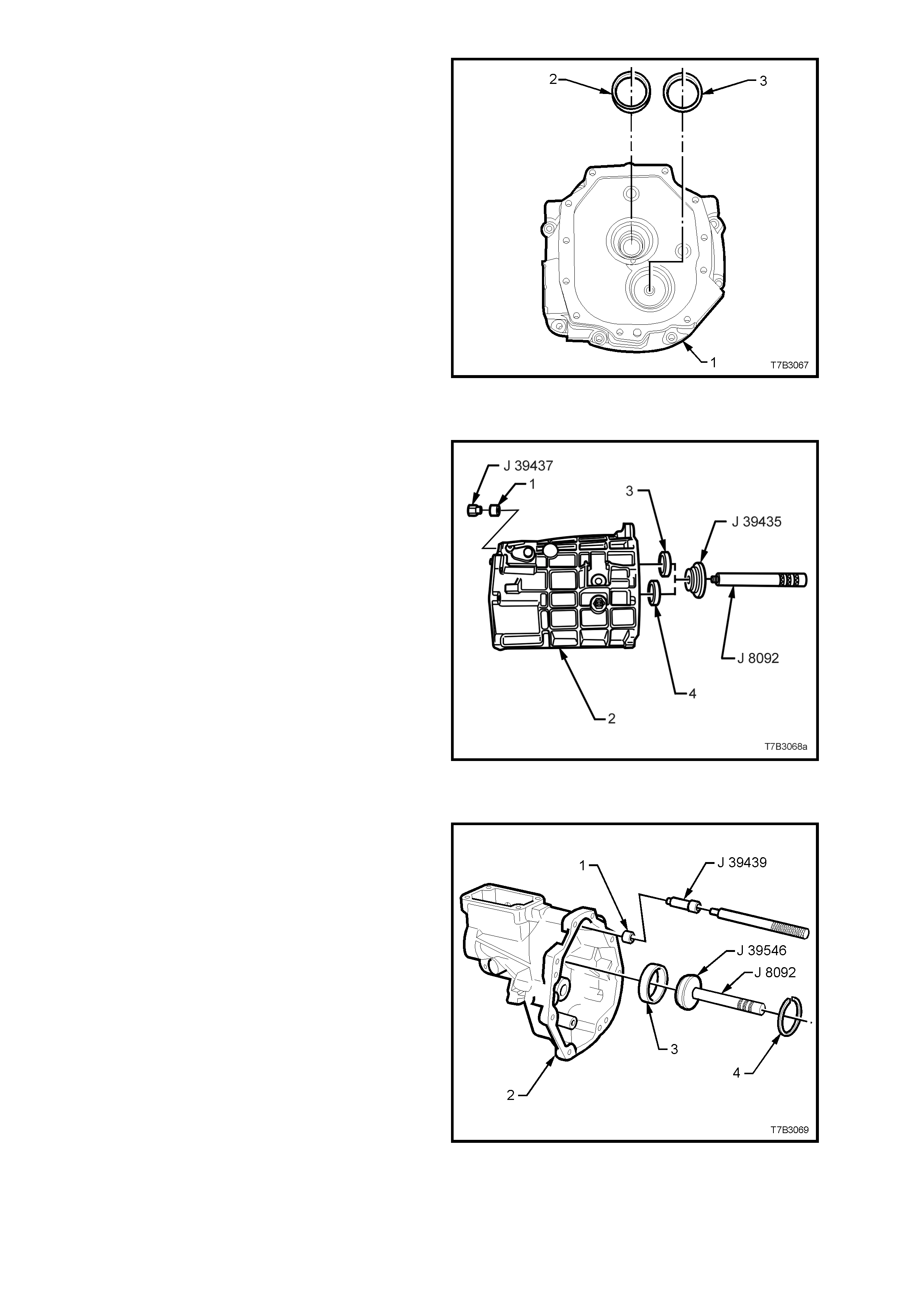
2. Install both the input shaft and front
countershaft bearing cups (2 and 3
respectively) to the adaptor plate (1),
WITHOUT any shims. The correct shim
thickness will be fitted during the assembly
operations, when shaft end floats are
determined.
Figure 7B2-141
Transmission Case
1. If removed, install new shift rail bushes (1) to
the transmission case (2), using installer J
39437 or equivalent stepped driver.
2. Install mainshaft bearing cup (3) and
countershaft bearing cup (4), using installer
J39435 and driver handle J 8092.
3. If removed, ins ta ll new dowel pins.
4. Loosely install filler plug.
Figure 7B2-142
Extension Housing
1. If removed, install new shift rail bushing (1) to
the extension housing (2), using tool J 39439
or equivalent stepped driver.
2. Install mainshaft roller bearing cup (3), using
installer J39546 and driver handle J 8092.
3. Install roller bearing cup circlip (4), using
suitable pl ier s.
Figure 7B2-143
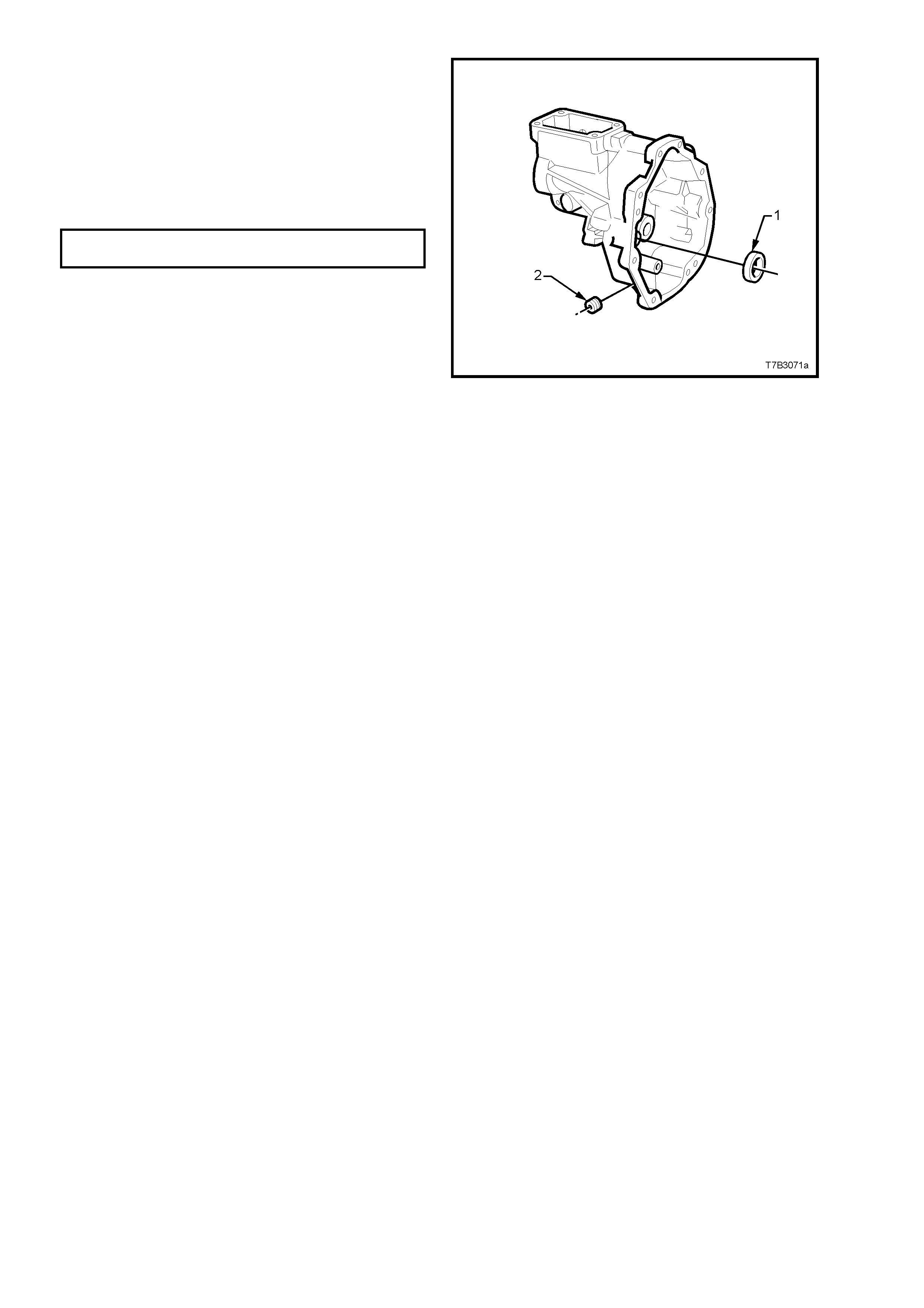
4. Temporarily install the countershaft extension
bearing cup (1) WITHOUT any shims. Shim
selection will be determined during the end
float measuring procedure detailed in
4.6 BEARING SHIMMING PROCEDURES.
5. Appl y s ealant s uc h as Loc t i te 56 5 or e qui va le nt
(GM P/N 12346004), to the cleaned threads of
the transmission drain plug (2) and install,
tightening to the correct torque specification.
DRAIN PLUG
TORQUE SPECIFICATION 28 Nm
Figure 7B2-144
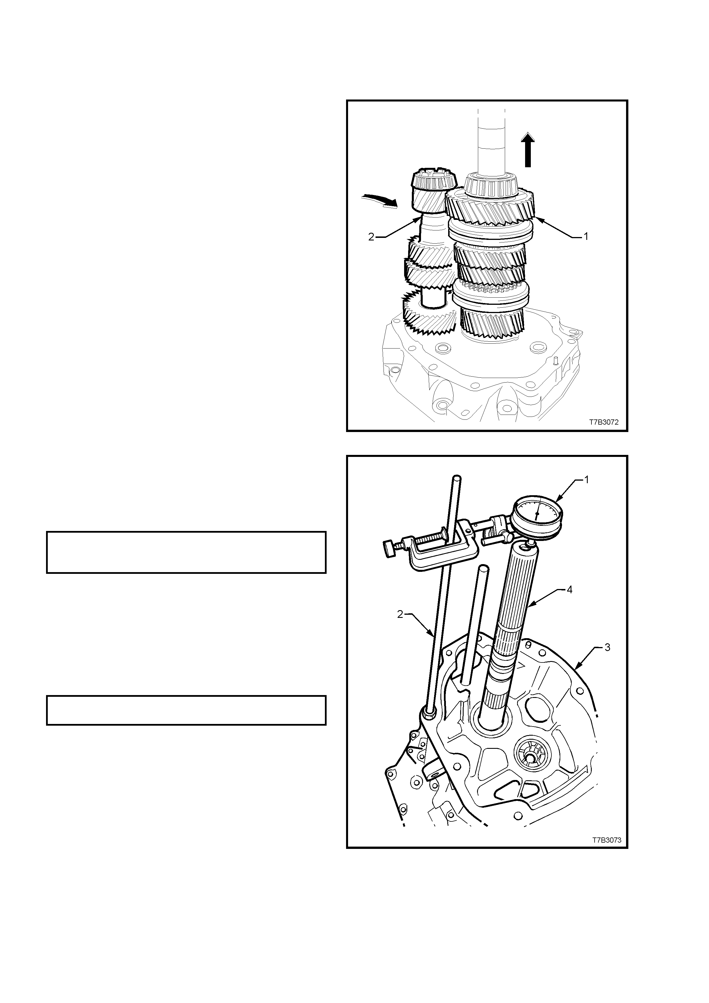
4.6 BEARING SHIMMING PROCEDURES
INPUT SHAFT/MAINSHAFT & COUNTERSHAFT
1. With the adaptor plate mounted to the
transmission holding fixture J 39430 that in
turn, is installed into bench fixture J 3289-20,
rotate to the vertical with the rear of the
adaptor plate facing up.
2. Install the input shaft, 4th speed blocking ring
and mainshaft into the front bearing cup.
Check that the blocker ring is correctly aligned
with the synchromesh assembly keys.
3. While slightly lifting the mainshaft, install the
countershaft to its front bearing.
Figure 7B2-145
4. Install the transmission case to the adaptor
plate a nd reins tall t he t en a daptor pl ate to c ase
bolts.
5. Tighten the ten bolts to the correct torque
specification.
ADAPTOR PLATE TO
TRANSMISSION CASE
TORQUE SPECIFICATION 35 Nm
6. Rotate the assembly through 180° and mount a
commercially available dial indicator (1) and
stand (2) to the end of the transmission case
(3), as shown. Zero the dial indicator, then lift
the mainshaft (4) up and down to obtain the
end play.
7. Select a shim pack to achieve the correct
bearing pre- lo ad spec ificati on.
INPUT SHAFT/MAINSHAFT
PRE-LOAD SPECIFICATION 0.00 - 0.05 mm
NOTE: There are 37 shim selections available,
ranging from 0.559 – 1.372 mm.
8. Remove the dial indic at or ass em bl y.
Figure 7B2-146
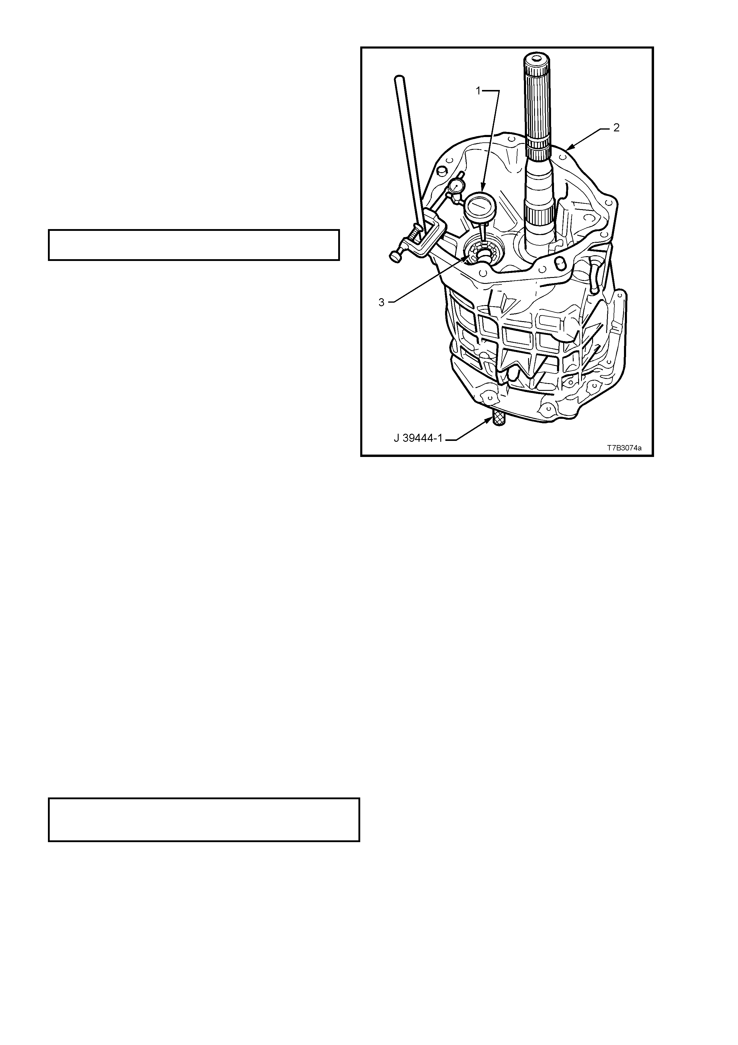
9. With the transmission assembly remaining in
the vertical position, mount a commercially
available dial indicator (1) to the transmission
case (2) , with the probe se nsing the end of the
countershaft (3). Zero the dial indicator.
10. Ins ert cou ntershaf t e nd pla y rod J 3944 4-1 (n ot
shown) into the adaptor plate plug hole (at the
front of the p lat e) , th en use the r o d t o move th e
countershaft up and down, enabling an end
play measurement to be taken.
11. Select a shim pack to achieve the correct
bearing pre- lo ad spec ificati on.
COUNTERSHAFT PRE-LOAD
SPECIFICATION 0.00 - 0.05 mm
NOTE: There are 33 shim selections available,
ranging from 0.356 - 1.372 mm.
12. Remove the dial in dic at or as s em bl y.
Figure 7B2-147
COUNTERSHAFT EXTENSION
IMPORTANT: This procedure is not to be undertaken until the correct shim stack has been installed under the
countershaft front bearing cup.
1. Loosen then remove the adaptor plate to transmission case bolts.
2. Lift the transmission case clear of the mainshaft and countershaft.
3. Lift the mainshaft slightly to allow countershaft removal.
4. Remove the mainshaft assembly, then lift the input shaft and blocking rings from the adaptor plate.
5. Remove the input shaft bearing cup, by pulling with the finger tips of each hand.
NOTE: Rotating the bearing cup back and forth while pulling, will reduce the problem of the bearing cup cocking
and jamming in the adaptor plate bore.
6. Repeat this process with the counter shaft front bearing cup.
7. Install the calculated shim stack for the input shaft/mainshaft and countershaft, previously determined.
8. Reinstall the input shaft and countershaft bearing cups.
9. Reinstall the input shaft, 4th speed blocking rings and mainshaft, to the adaptor plate, ensuring that the
blocking rings engage correctly with the synchromesh assembly keys.
10. Reinstall the countershaft to the adaptor plate, using the same procedure detailed previously.
11. Reinstall the transmission case over the mainshaft, reinstall the ten adaptor to transmission case bolts and
tighten to the correct torque specification.
ADAPTOR PLATE TO
TRANSMISSION CASE BOLT
TORQUE SPECIFICATION 35 Nm
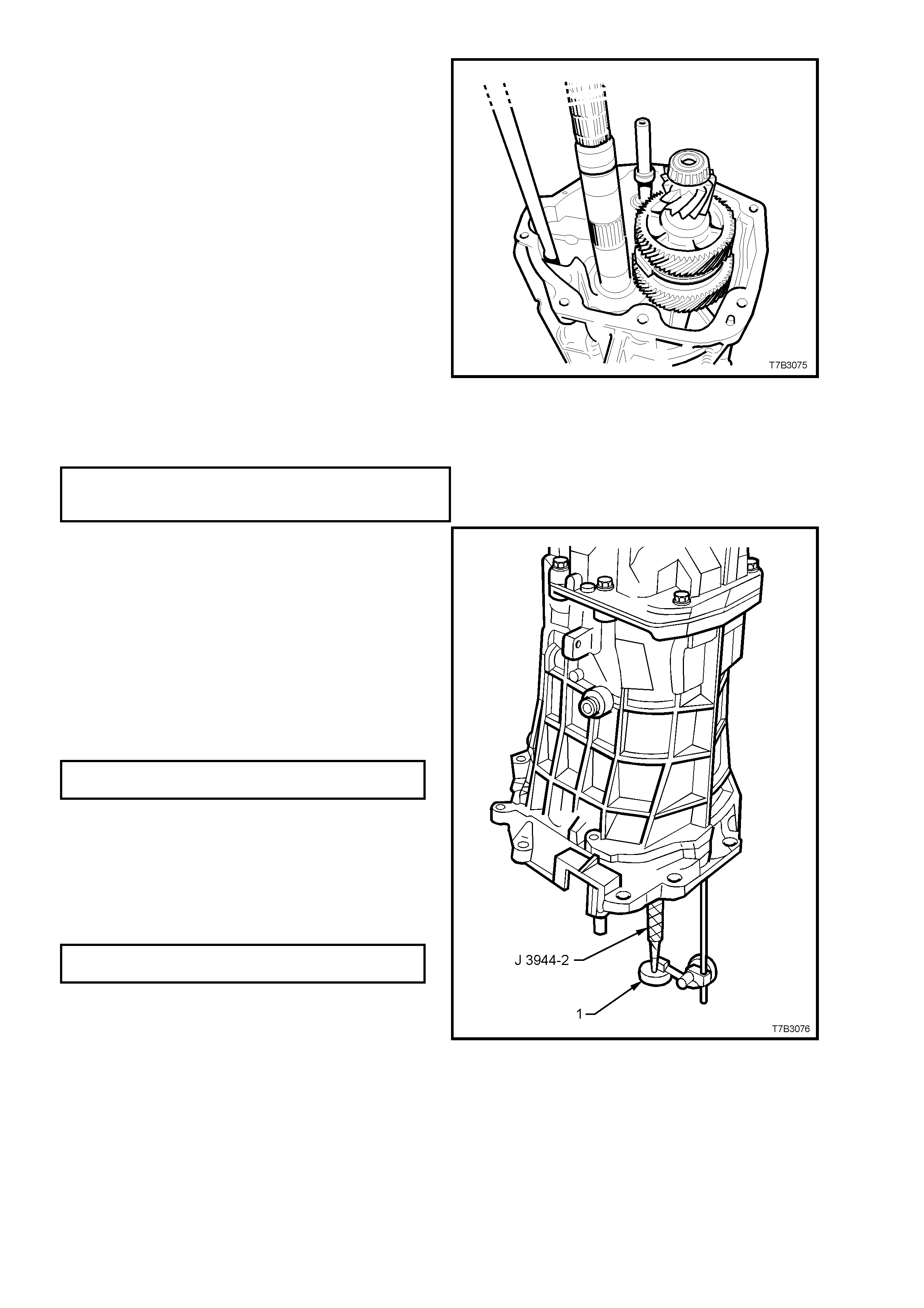
12. With the transmission in a vertical position,
install the cou nter s haf t exte ns ion, e ns ur ing th at
the recessed side of the thrust washer faces
toward the countershaft and that the dogs on
the extension fully engage with those on the
countershaft.
Figure 7B2-148
13. Install the extension housing over the
countershaft extension, install the eight bolts
and tighten to the correct torque specification.
EXTENSION HOUSING TO
TRANSMISSION CASE BOLT
TORQUE SPECIFICATION 35 Nm
14. Insert countershaft extension, end play rod
J 39444-2 through the adaptor plate plug hole
and hollow countershaft, then screw the rod
into the threaded end of the countershaft
extension.
15. Mount a commerc ially ava ilabl e dia l in dic at or to
the adaptor plate, with the probe sensing the
end of the end play rod. Zero the dial indicator.
16. Lift the end pla y rod J 3944 4-2 up and down to
determine the countershaft extension end play.
17. Select a shim pack to achieve the correct end
play specification.
COUNTERSHAFT EXTENSION
END PLAY SPECIFICATION 0.05 - 0.13 mm
NOTE: There are 33 shim selections available,
ranging from 0.559 - 1.372 mm.
18. Remove the dial indicator and end play rod.
19. Apply seal ant s uch as Loc t i te 56 5 or e quivalent
(GM P/N 12346004), to the cleaned threads of
the adaptor plug, install the plug and tighte n to
the correct torque specification.
ADAPTOR PLATE PLUG
TORQUE SPECIFICATION 28 Nm
20. Loosen then remove the eight extension
housing to transmission case bolts, then
remove the extension housing.
Figure 7B2-149
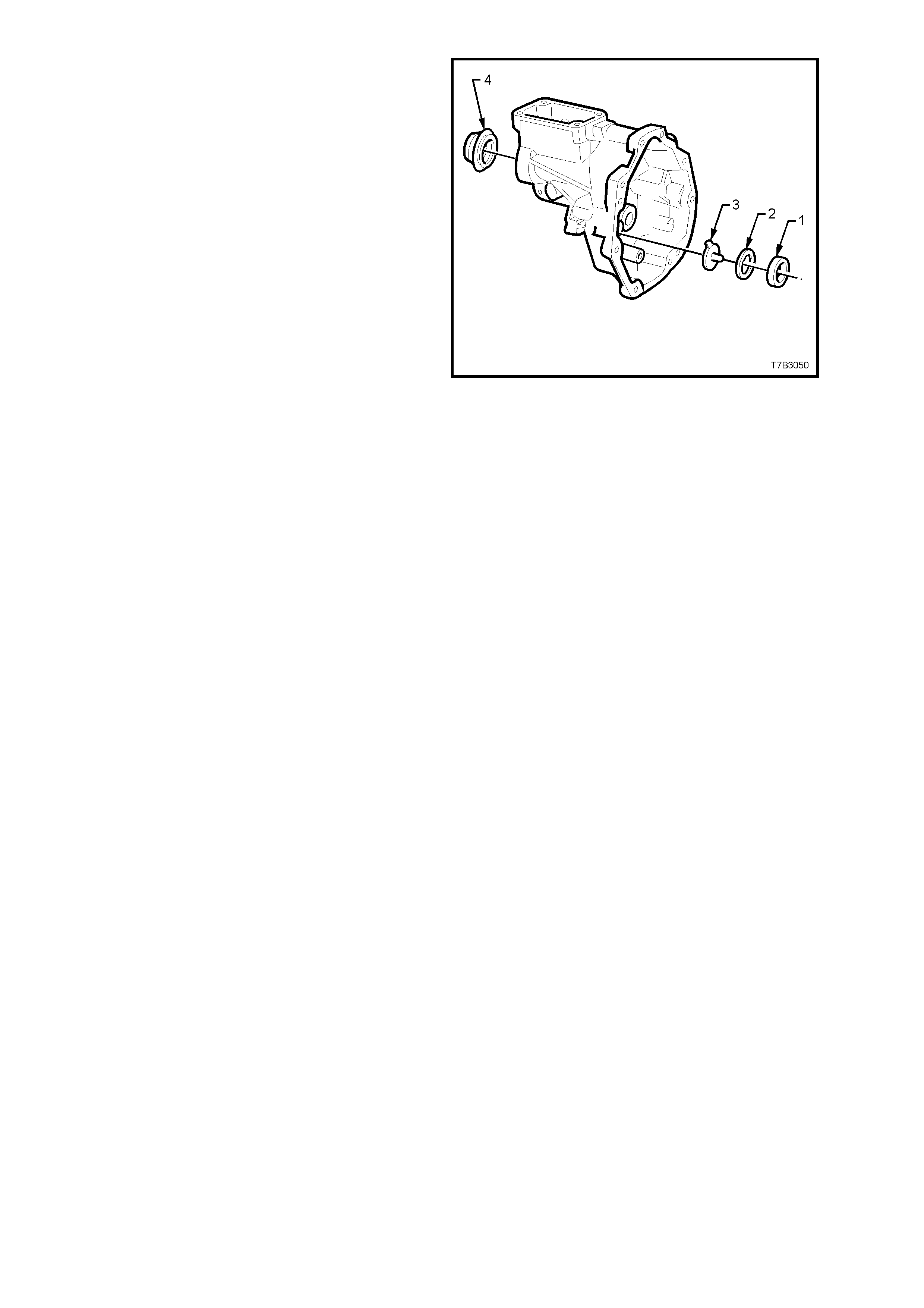
21. Slide the countershaft gear extension, rear
bearing cup (1) from the extension housing.
NOTE: Rotating the cup back and forth while
pulling with the finger tips, will reduce the problem
of the bearing cup cocking and jamming in the
extension housing bore.
22. Install the oil funnel (3), the shim pack (2)
determined from the end play check, then
reinstall the countershaft extension rear
bearing cup (1).
Figure 7B2-150
23. Loosen then remove the ten adaptor plate to
transmission case bolts, then remove the
transmission case.
24. Lift the mainshaft assembly slightly to allow
countershaft removal, then remove the
mainshaft assembly and input shaft and
blocker rings.
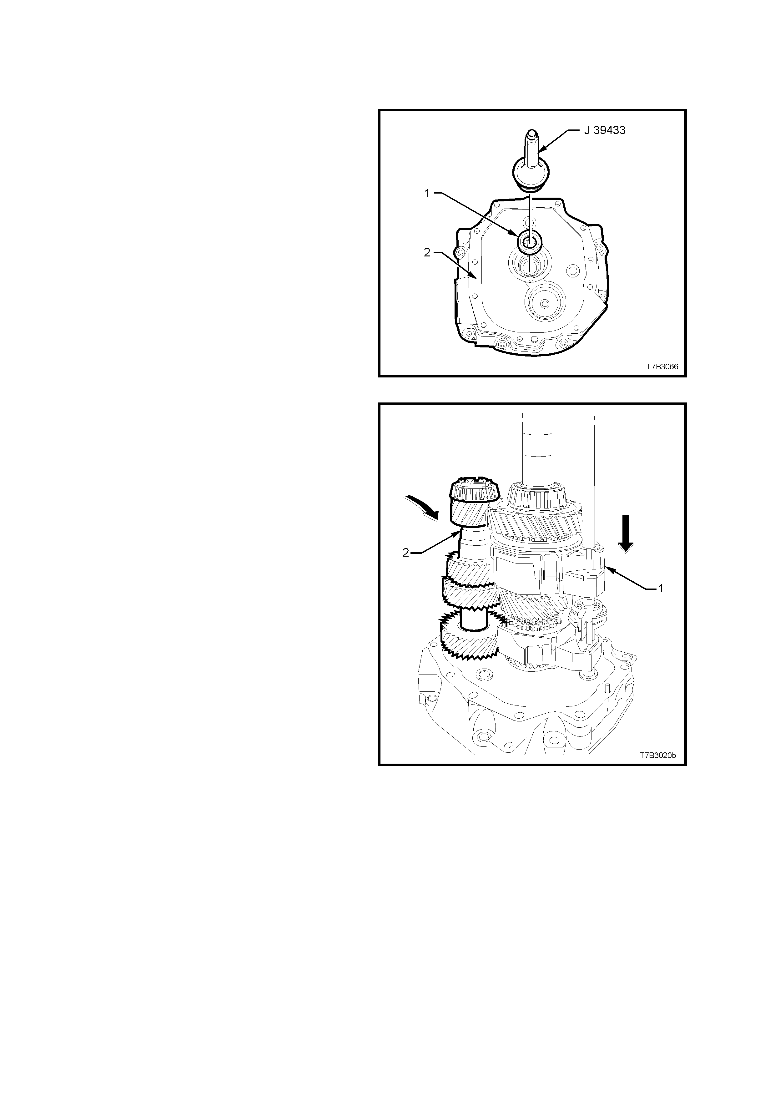
4.7 TRANSMISSION REASSEMBLE
GEAR TRAINS AND SHIFT RAILS
1. Using seal installer J 39433, install a new oil
seal (1) to the adaptor plate (2).
2. Lubricate the input shaft, taper roller bearing
and seal contact area of the input shaft with
clean transm ission fluid, th en reinstall t he input
shaft to the adaptor plate.
3. Install the blocker rings to the input shaft gear.
Figure 7B2-151
4. Reinstall the mainshaft, together with the
1st/2nd, 3rd/4th shift shaft and forks (1) after
lubricating the spigot taper roller bearing and
shift shaft bush with clean transmission fluid.
Take care that the 4th speed blocker rings are
correctly engaged with the synchromesh
assembly keys.
5. Lubr icate the c ountershaf t, front and r ear taper
roller bearings with clean transmission fluid,
then reinstall the countershaft (2) to the
adaptor plate, after lifting the mainshaft
assembly (1) slightly, to allow installation
access.
Figure 7B2-152
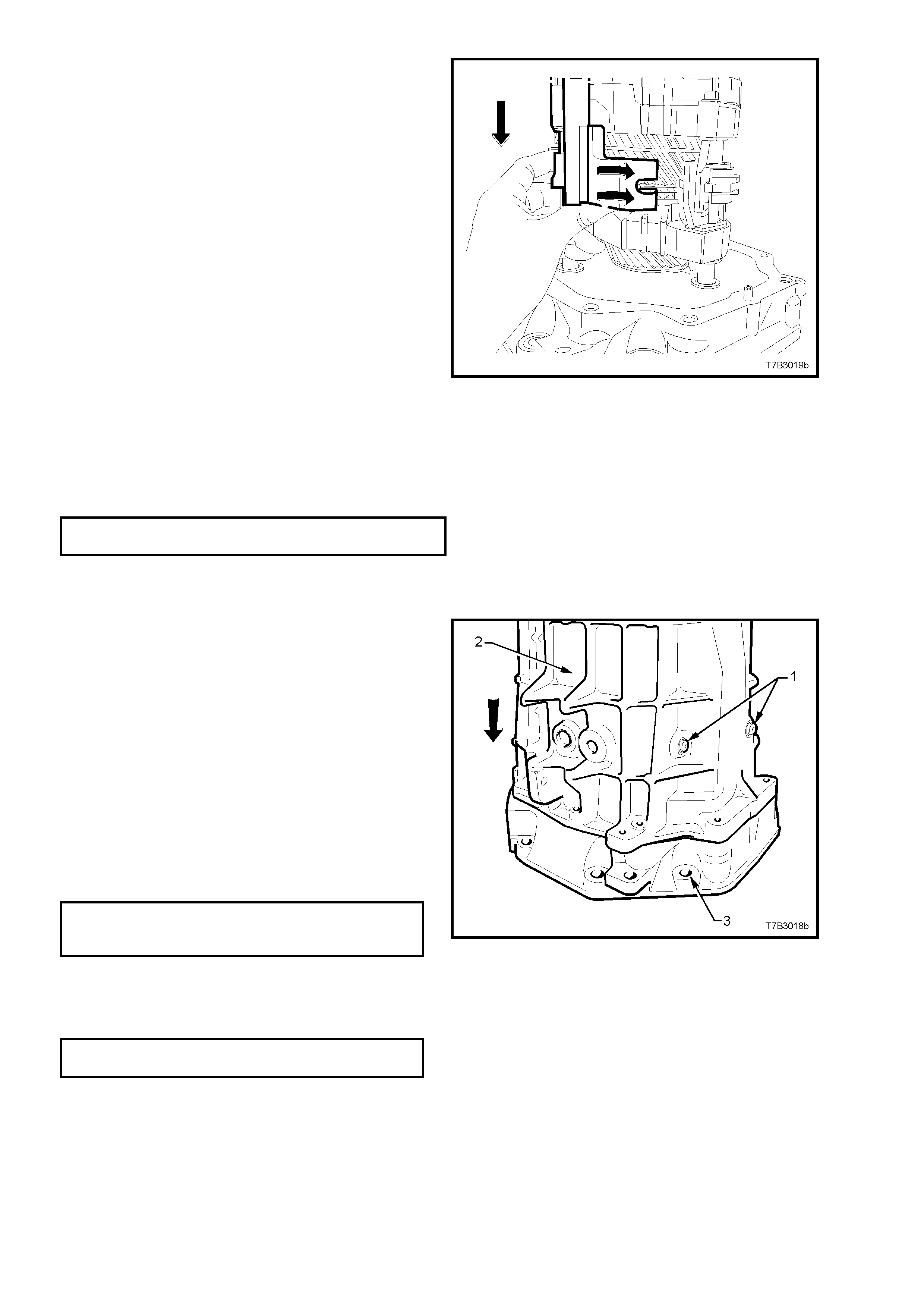
6. Install the 5th/6th and Reverse shift shaft
assembly, then align the slots in the shift rail
levers with the interlock plate and selector pin.
Figure 7B2-153
TRANSMISSION CASE
1. Install the front offset lever guide plate to the
transmission case, install the two Torx headed
screws and tighten to the correct torque
specification, using a T40 Torx bit and adaptor.
SHIFT GUIDE PLATE SCREW
TORQUE SPECIFICATION 22 Nm
NOTE: The ‘H+’ pattern in the guide plate must
face the rear of the transmission. i.e. to the
extension housing.
2. Apply a single bead of sealant such as Loctite
“Ultrablack” 598 or equivalent (GM P/N
12345739), to the cleaned, transmission case
to adaptor plate mating surface.
3. Reinstall the transmission case (2) over the
mainshaft and shift shaft. As the case is
installe d, push the fr ont offset lever aga inst the
detent ball and spring, holding the detent ball
against the guide plate, in the neutral plane
position, to align the front offset lever with the
shift shaft.
4. When the case is fully installed over the two
adaptor plate dowel pins, install the ten adaptor
to transmission case bolts and tighten to the
correct torque specification.
ADAPTOR PLATE TO
TRANSMISSION CASE
TORQUE SPECIFICATION 35 Nm
5. Apply thread sealant such as Loctite 242 or
equivalent, to the cleaned threads of the shift
lever guide bolts (1), install and tighten to the
correct torque specification.
SHIFT LEVER GUIDE BOLT
TORQUE SPECIFICATION 28 Nm
NOTE: It might be necessary to pull up on the
5th/6th and Reverse shift shaft to align the slot of
the interlock plate with the guide bolt hole.
IMPORTANT: to maintain the shift rails in the
correct position during the remainder of the
assembly process, it is vital that these two guide
bolts are installed at this time.
Figure 7B2-154
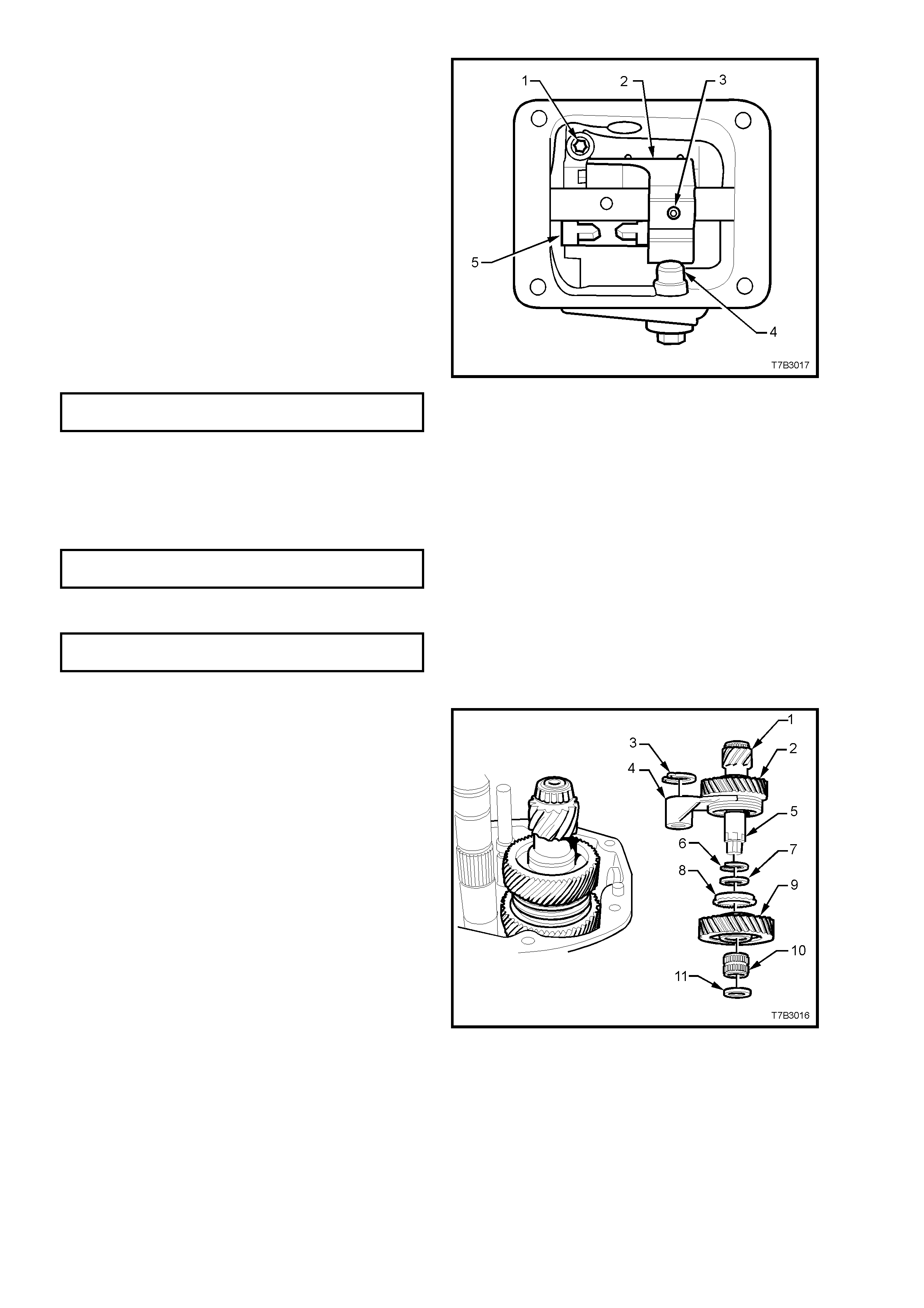
6. Align the front offset lever (2) with the hole in
the shift shaft, then install a new roll pin (3) to
secure, using a suitable size pin punch and
hammer.
NOTE: Insert a pin punch of suitable size into the
rear offset lever roll pin hole in the shift shaft and
check that the shif t shaf t is able to be rot ated f reel y
through each of the detent ball positions. This will
ensure that the shift selector forks, interlock plate
and associated parts are all aligned correctly. If
difficulty is experienced in rotating the shift shaft,
then the transmission case must be removed and
the problem rectified before proceeding.
7. Apply thread sealant such as Loctite 242 or
equivalent, to the cleaned threads of the shift
enhancer (4), then, using a 24 mm socket,
install and tighten to the correct torque
specification.
SHIFT ENHANCER
TORQUE SPECIFICATION 40 Nm
8. Apply a continuous bead of sealant such as
Loctite “Ultrablack” 598 or equivalent (GM P/N
12345739), to the mating surface of the cover
plate, then install to the transmission case.
9. Install the four cover bolts and tighten to the
correct torque specification.
FRONT OFFSET LEVER COVER
BOLT TORQUE SPECIFICATION 20 Nm
10. Install the back-up lamp switch and tighten to
the correct torque specification.
BACK-UP LAMP SWITCH
TORQUE SPECIFICATION 28 Nm
Figure 7B2-155
COUNTERSHAFT EXTENSION ASSEMBLY
1. Install the following components to the
countershaft extension (5);
7. Spacer.
8. 6th gear, blocker ring.
9. 6th drive gear.
10. 6th drive gear, caged needle roller bearing.
11. Thrust washer.
NOTE 1: Ensure that the recessed side of the
thrust washer (11) faces the countershaft.
NOTE 2: Snap ring (6) was installed when the
5th/6th synchrom esh assembly (2) was installed to
the countershaft extension (1). Refer to Step 4,
page 7B2-60.
2. With the 5th/6th shift fork (4) positioned as
shown, install the countershaft extension
assembly onto the rear of the countershaft,
guiding the 5th/6th shift fork (4) over the
5th/6th shift rail lever sleeve.
3. Rotate the countershaft extension back and
forth to ensure that the dog teeth on the
countershaft extension mate with the
corresponding dogs on the end of the
countershaft.
4. Install a new circlip (3) to the groove in the
5th/6th shift rail lever sleeve to secure the shift
fork.
Figure 7B2-156
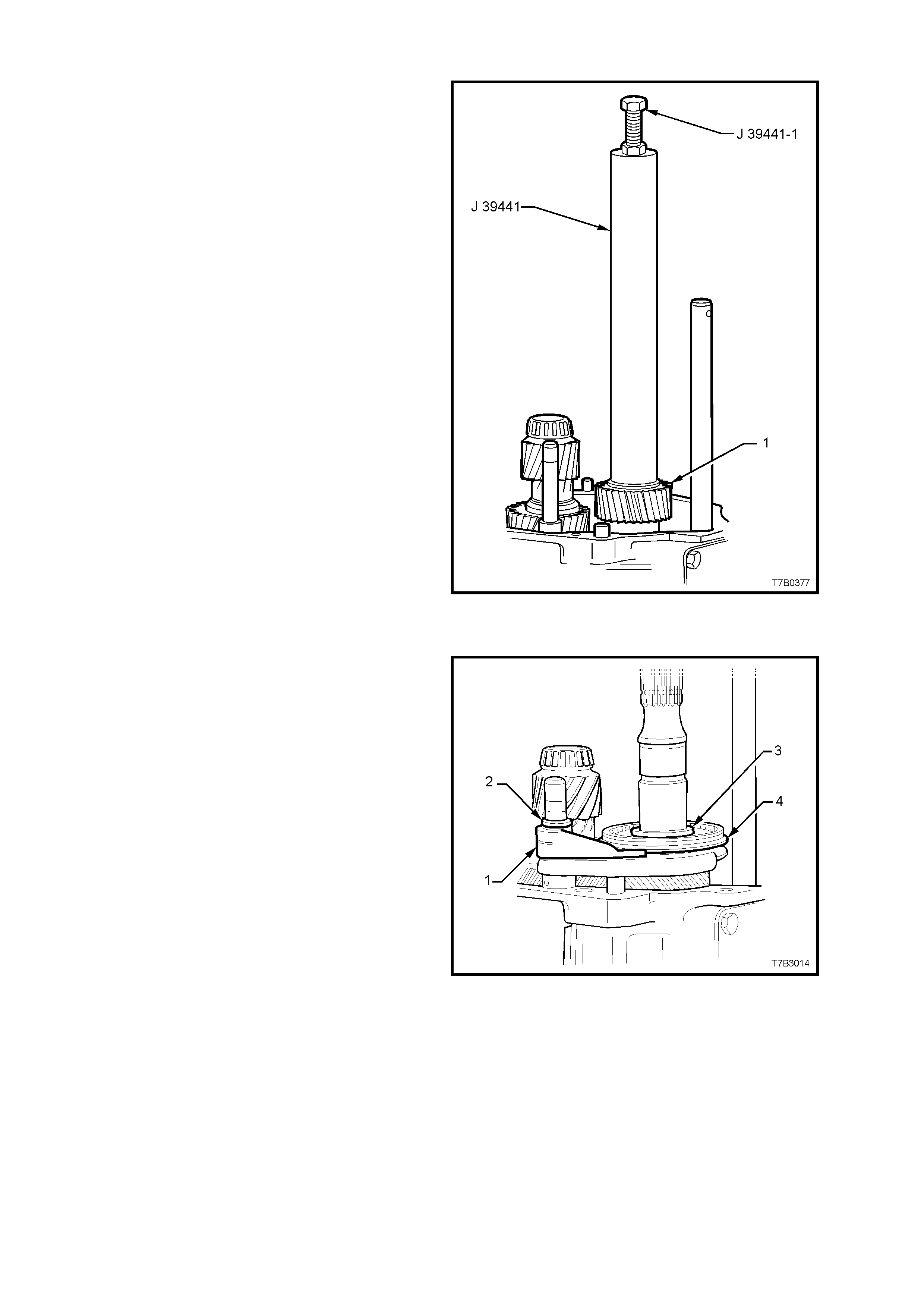
5th/6th DRIVEN GEAR
1. Install the 5th/6th speed driven gear (1) over
the mainshaft with the smaller gear facing
inward.
2. Engage the inner gear splines with those on
the mainshaft and install, using installer J
39441 and bolt/nut J 39441-1.
NOTE: It may be necessary to rotate the 5th and
6th drive gears on the countershaft extension to
assist in gear meshing with the driven gear (1),
prior to the gear installation process.
Figure 7B2-157
REVERSE SY NCHROMESH ASSEM BLY
1. With the reverse shift lever (1) positioned as
shown, reinstall the reverse synchromesh
assembly (4) and shift lever (1) to the
mainshaft and shift shaft, ensuring that the
reverse synchromesh key retainer faces the
end of the 6th speed driven gear.
2. Fit a new circlip (2) to retain the shift fork (1)
and a new snap ring (3) to secure the reverse
synchromesh assembly (4).
Figure 7B2-158
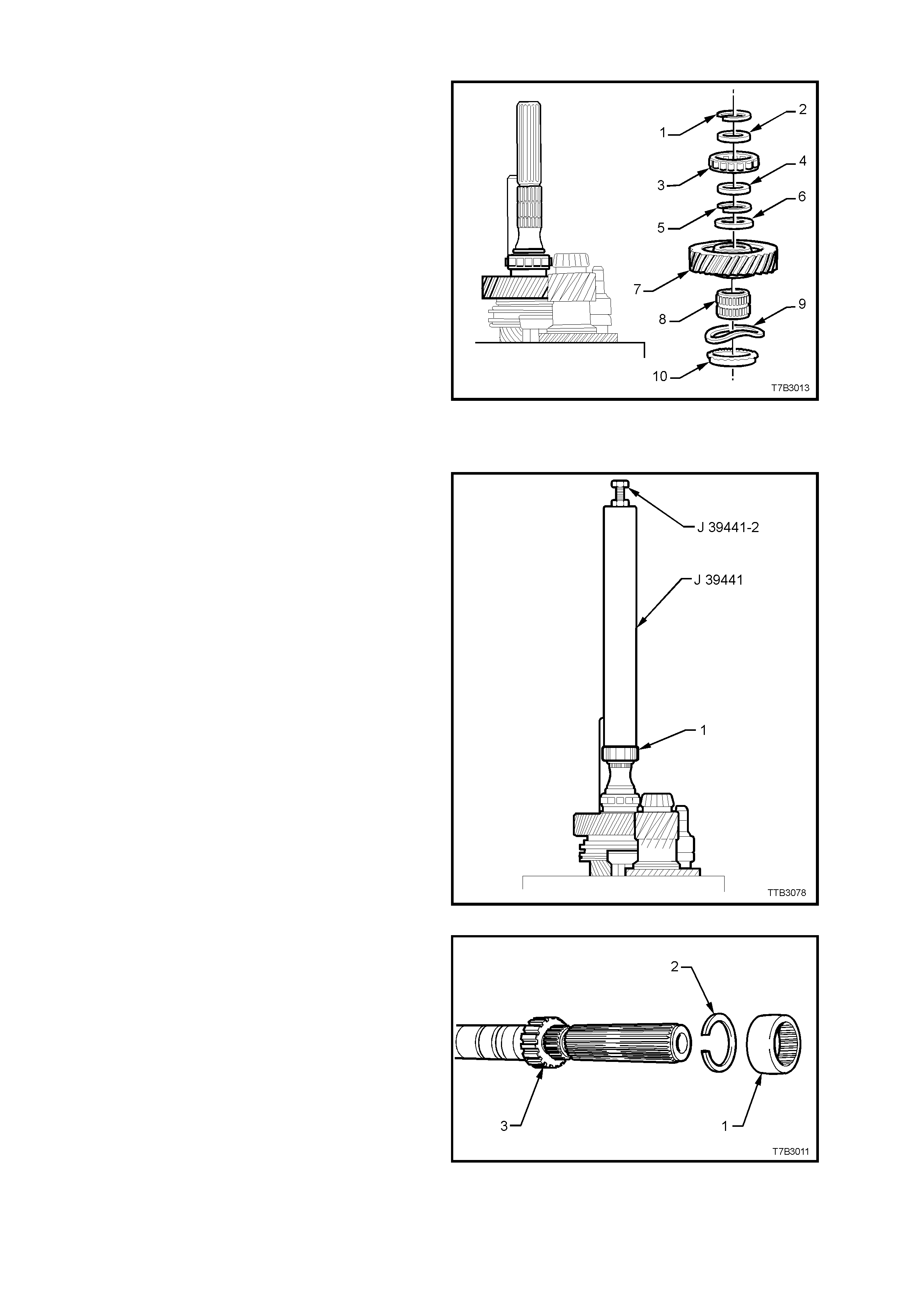
REVERSE SPEED GEAR
1. Install the following components onto the
mainshaft, aligning the blocker rings with the
synchromesh ke ys, in the proces s ;
10. Reverse gear blocker ring.
9. Wave washer.
8. Reverse gear, caged roller bearing.
7. Reverse gear.
6. Thrust washer.
2. Fit a new snap ring (5) to secure the reverse
driven gear (7).
3. Continue to install the components of the rear
mainshaft roller bearing, as follows;
4. Spacer.
3. Rear mainshaft roller race.
2. Spacer.
4. Secure these components with a new snap
ring (1).
Figure 7B2-159
SPEEDOMETER PULSE RING
1. Install a new, inner snap ring to the
speedometer pulse ring groove in the
mainshaft.
2. Install the speedometer pulse ring to the
mainshaft, using Installer J 39441 and bolt/nut
J 39441-2.
3. T ighten th e nut of J 39441- 2 until the pu ls e rin g
bottoms against the snap ring.
4. Remove the tools.
Figure 7B2-160
5. Install a new snap ring (2) to the outer
speedometer pulse ring (3) groove in the
mainshaft.
6. If in a ser v iceable co nd iti on , the r u bber, s p li ned
packing ring (1) may be reinstalled. Otherwise
discard, as it serves no other functional
purpose.
Figure 7B2-161
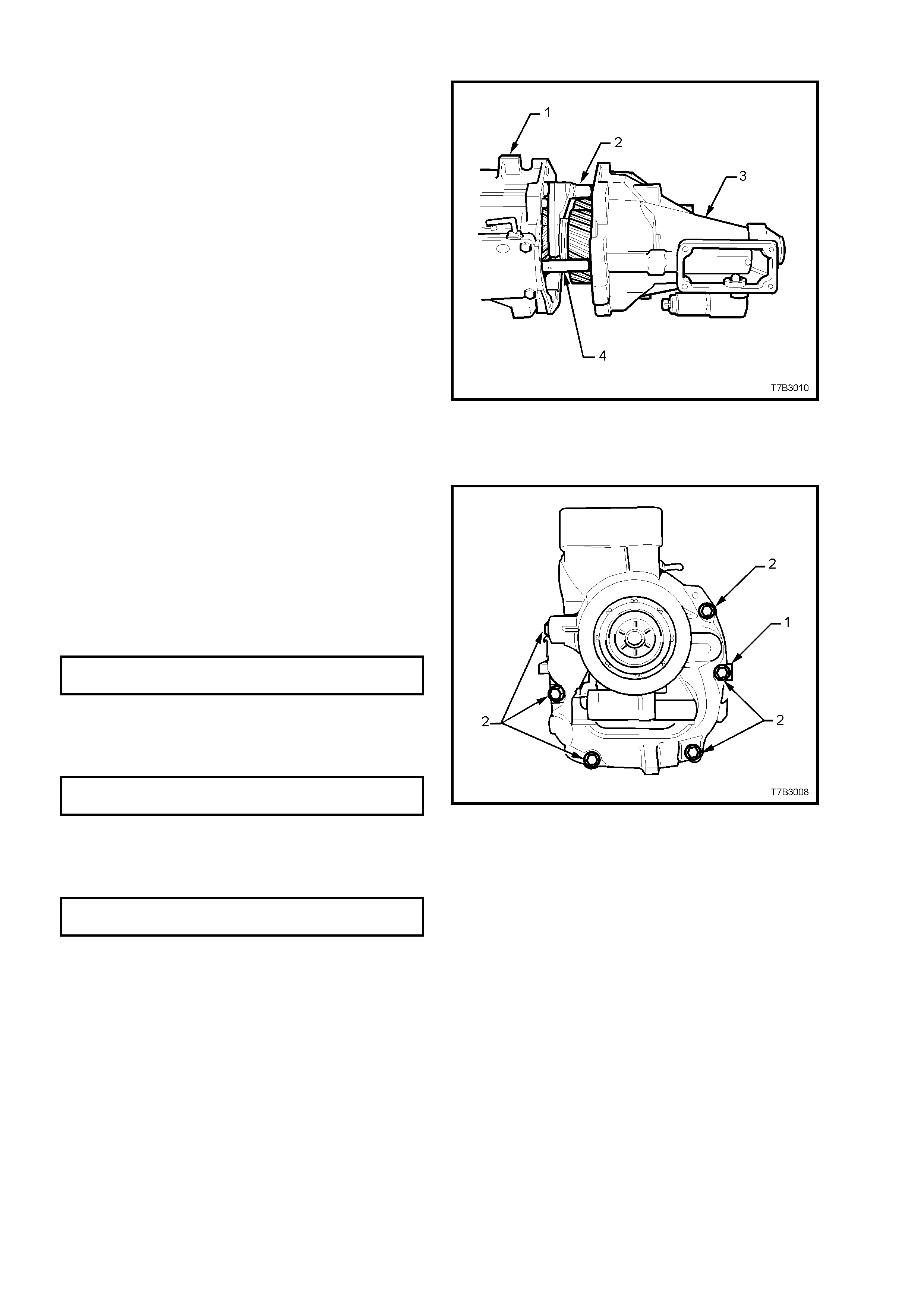
EXTENSION HOUSING
1. Rotate the transmission through 90° into the
horizontal position, then move the shift rail (4)
into the 2nd or 4th gear position to shorten the
shift rail length.
2. Lubricate the countershaft extension taper
roller bearing with clean transmission fluid.
3. Install the two circular magnets into the
grooved space in the transmission case.
4. Apply a continuous bead of sealant such as
Loctite “Ultrablack” 598 or equivalent (GM P/N
12345739), to the extension housing to
transmission case mating surface.
5. Install the extension housing (3) over the
mains haft, aligning the shif t rails (4 and 2) with
the extension housing bushes.
NOTE: Because the 5th/6th and Reverse shift
shaft (2) is unsupported at this point, it will need to
be manipulated to align the end of the shaft with
the corresponding bore in the extension housing.
Do not tr y and f orc e the ex t ens io n ho using ov er the
dowel pins.
Figure 7B2-162
6. Install all but the two upper extension housing
bolts. (not shown). Apply thread sealant such
as Loctite 565 or equivalent (GM P/N
12346004), to the cleaned threads of the two
upper bolts. Note that a wiring harness clip is
under the right hand upper bolt and also, the
position of the identification tag (1).
7. Tighten all 8 bolts (2) to the correct torque
specification.
EXTENSION HOUSING BOLT
TORQUE SPECIFICATION 35 Nm
8. Install the O-ring to the reverse lockout
solenoid assembly, then install the assembly
and retaining bolt to the extension housing,
tightening to the correct torque specification.
REVERSE LOCKOUT SOLENOID
SCREW TORQUE SPECIFICATION 18 Nm
9. Install the O-ring seal to the vehicle speed
sensor, th en install th e sensor to t he extension
housing, retaining with a screw, tightened to
the correct torque specification.
SPEED SENSOR RETAINING
SCREW TORQUE SPECIFICATION 12 Nm
Figure 7B2-163
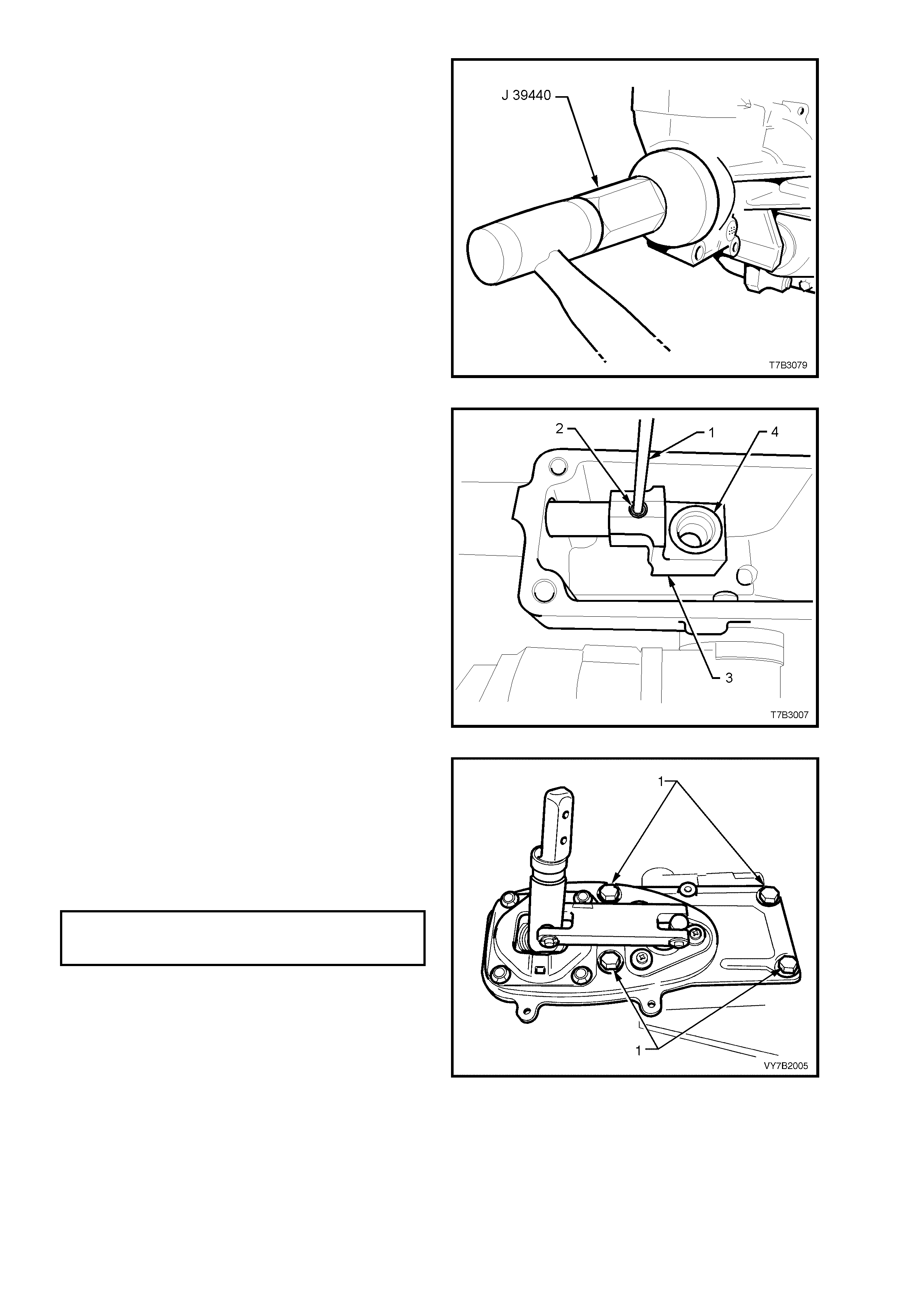
10. Us ing sea l insta ller J 3944 0, insta ll a NEW rear
seal to the extension housing.
Figure 7B2-164
11. Slide the rear offset lever (3) over the shift rail
and secure with a ne w roll pin (2), ins ta lle d with
a suitable pin pinch (1) and hammer.
12. Apply Lithium grease NLGI No. 4 EP to the
isolator cup (4) in the rear offset shift lever (3).
Figure 7B2-165
13. If the remote shifter assembly, rubber seal is
undamaged, then it may be re-used.
Otherwise, fit a new seal to the extension
housing.
14. Install the remote shifter assembly to the
extension housing, install the insulating
grommets and four retaining bolts (1), then
tighten to the correct torque specification.
REMOTE SHIFTER
RETAINING BOLT
TORQUE SPECIFICATION 20 Nm
Figure 7B2-166
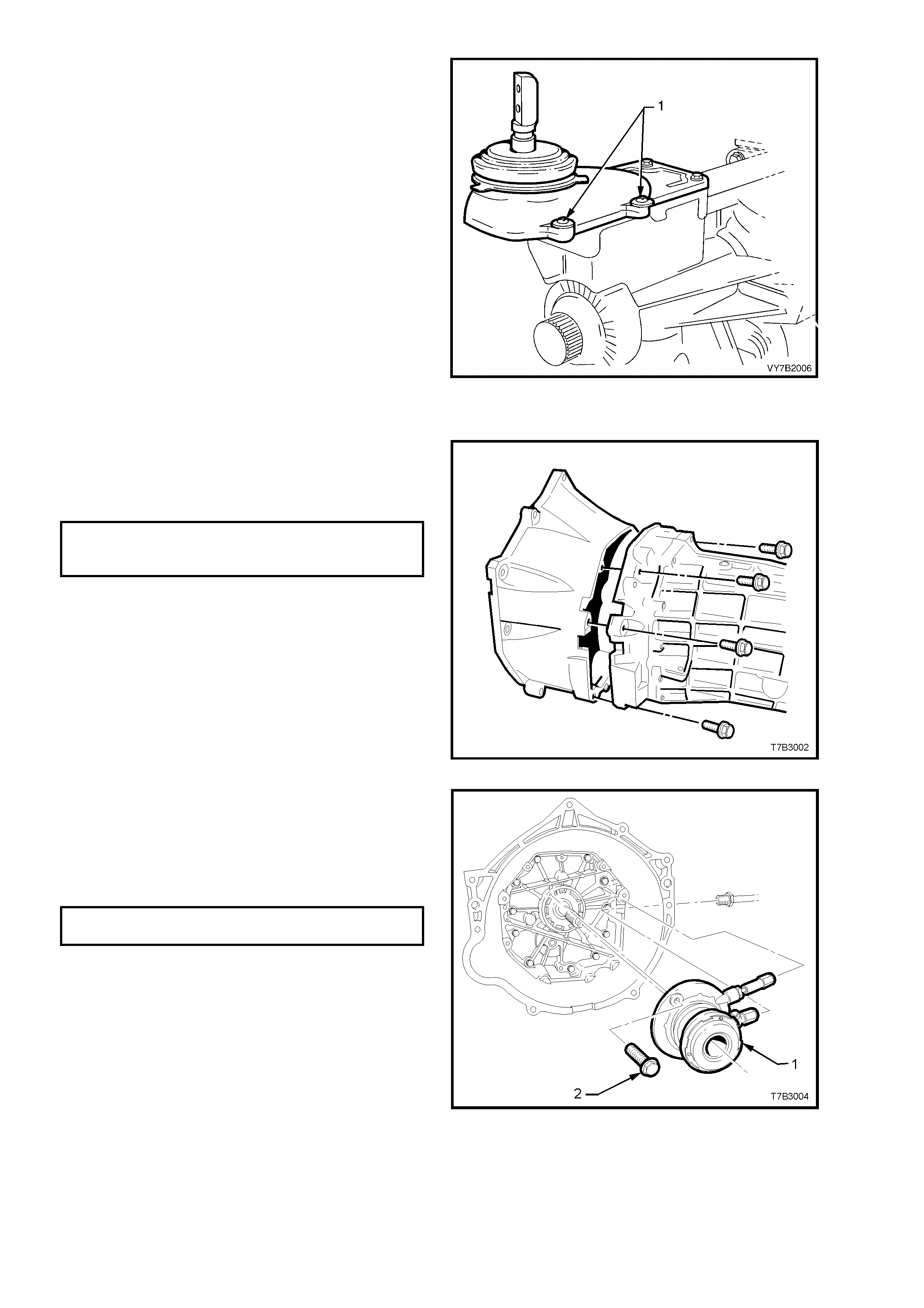
15. Install the cover over the remote shifter
assem bly and secure with the 4 scr ews (1). Do
not over-tighten.
Figure 7B2-167
CLUTCH HOUSING AND SLAVE CYLINDER
1. Remove the transmission from the
transmission holding fixture J 39430.
2. Reinstall the clutch housing and eight bolts,
tightening to the correct torque specification.
CLUTCH HOUSING TO
ADAPTOR PLATE BOLT
TORQUE SPECIFICATION 35 Nm
Figure 7B2-168
3. Install the clutch slave cylinder (1) over the
input shaft.
4. Apply thread sealant such as Loctite 242 or
equivalent, to the two slave cylinder retaining
bolts (2), install and tighten to the correct
torque specification.
CLUTCH SLAVE CYLINDER BOLT
TORQUE SPECIFICATION 10 Nm
IMPORTANT: Before tightening the two retaining
bolts, ce ntralise t he slave c ylinder bleeder s crew in
the transmission adaptor plate/clutch housing
aperture. T his is neces sar y to ensure acces s to the
bleeder, after the transmission has been installed.
5. Sparingly apply 10% molybdenum disulphide
grease, such as Molybond GA 10 to the clutch
throwout bearing contact face, the splines and
spigot of the input shaft.
Figure 7B2-169
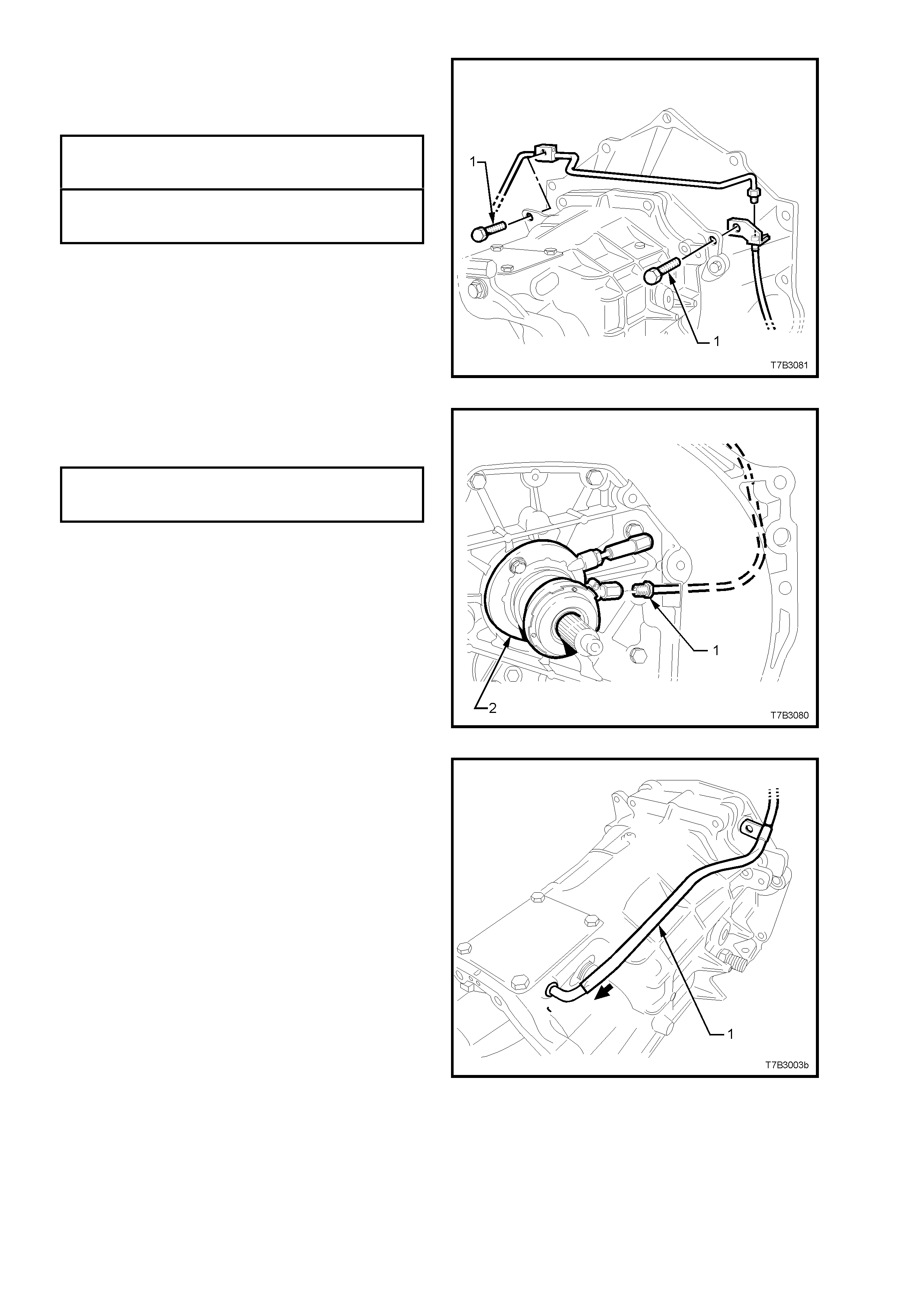
6. Route the clutch fluid pipe around the
transmission housing, install the bracket
fasteners (1) and tighten to the correct torque
specification.
CLUTCH PIPE BRACKET SCREW
TO LEFT HAND SIDE
TORQUE SPECIFICATION 5.0 Nm
CLUTCH PIPE BRACKET SCREW
TO RIGHT HAND SIDE
TORQUE SPECIFICATION 10 Nm
Figure 7B2-170
7. Install the clutch fluid pipe fitting (1) to the
slave cylinder (2) and tighten to the correct
torque specification.
CLUTCH HYDRAULIC PIPE FITTING
TO SLAVE CYLINDER
TORQUE SPECIFICATION 13 Nm
Figure 7B2-171
8. Install the transmission vent tube (1), sliding it
over the pipe located at the front offset lever.
Figure 7B2-172

9. If removed, reinstall the rear engine mount to transmission extension bolts, tightening to the correct torque
specification.
TRANSMISSION MOUNT
TO EXTENSION HOUSING
BOLT TORQUE SPECIFICATION 25 Nm
10. Fit a suitable plug to the rear oil seal to prevent dirt/dust entry.
11. Reinstall transmission into the vehicle. Refer to 4.2 TRANSMISSION ASSEMBLY, in this Section.
12. Fill transmission with 4.4 litres of Dexron III® fluid. Refer to 2.2 CHECKING TRANSMISSION LUBRICANT
LEVEL.
13. Apply sealant such as Loctite 565 or equivalent (GM P/N 12346004), to the cleaned threads of the filler plug
and tighten to the correct torque specification.
FILLER PLUG
TORQUE SPECIFICATION 28 Nm
NOTE: Under no circumstances is Teflon thread tape to be used on the filler, drain or adaptor plate plugs.

5. DIA GNOSIS
5.1 TRANSMISSION SHIFTS HARD
DEFINITION: The transmission does not shift smoothly or without difficulty into another gear.
Step Action Value(s) Yes No
1 Check the transmission for improper lubricant. Refer to
2.1 Recommended Lubricant.
Is the recommended lubricant being used?
−
Go to Step 2
Go to Step 3
2 Check the transmission for loose shift lever housing
bolts.
Are the bolts loose?
−
Go to Step 4
Go to Step 5
3 Drain and refill the transmission with the recommended
lubricant. Refer to 2.3 DRAINING AND REFILLING
TRANSMISSION.
Does the transmission shift smoothly?
−
System OK
Go to Step 5
4 Align the component parts and tighten the fasteners.
Refer to 7. TORQUE SPECIFICATIONS.
Does the transmission shift smoothly?
−
System OK
Go to Step 5
5 Check for proper clutch operation.
Was the clutch the cause of hard shifting? −
System OK
Go to Step 6
6
1. Remove the transmission. Refer to
4.2 TRANSMISSION ASSEMBLY, Remove, in this
Section.
2. Disassemble the transmission. Re fer to
4.3 TRANSMISSION DISASSEMBLE.
3. Look for the following list of causes:
• Binding shift rail.
• Mispositioned shift selector arm roll pin.
• Worn shift rail bores.
• Distorted oil seal.
4. Replace all worn or damaged parts.
−
−
−

5.2 TRANSMISSION HARD TO SHIFT INTO REVERSE
DEFINITION: The transmission does not shift smoothly into reverse gear or will not shift into reverse gear.
Step Action Value(s) Yes No
1 1. Turn the ignition switch to the ON position.
2. Check for voltage at the reverse lockout solenoid
electrical connector.
Is there voltage at the connector.
12 volts
Go to Step 2
Go to Step 5
2
1. Remove the reverse lockout solenoid assembly from
the reverse lockout assembly. Refer to
3.4 REVERSE LOCKOUT SOLENOID, Remove.
2. Apply 12 volts to the solenoid electrical connector.
Is the solenoid plunger extended?
−
Go to Step 3
Go to Step 6
3
Remove the reverse lockout assembly from the
transmission. Refer to 3.4 REV ER SE LO CKOUT
SOLENOID ASSEMBLY, Remove.
Can you easily depress the reverse lockout plunger with
your thumb?
−
Go to Step 4
Go to Step 7
4
1. Remove the transmission. Refer to
4.2 TRANSMISSION ASSEMBLY, Remove.
2. Disassemble the transmission. Re fer to
4.3 TRANSMISSION DISASSEMBLE, in this
Section.
3. Look for the following list of causes:
• Worn or broken shift linkage parts.
• A worn or damaged synchroniser ring or hub.
4. Replace all worn or damaged parts.
−
−
−
5 Repair the reverse lockout solenoid electrical circuit.
Is the circuit OK? −
Go to Step 1 −
6 Replace the solenoid.
Does the transmission shift OK now? −
System OK −
7 Repair or replace the reverse lockout assembly. Refer
to 3.4 REVERSE LOCKOUT SOLENOID ASSEMBLY,
Reinstall.
Does the transmission shift OK now?
−
System OK
−

5.3 GEAR CLASH WHEN SHIFTING GEARS
DEFINITION: The transmission gears clash when shifting from one gear into another.
Step Action Value(s) Yes No
1 Check for low oil level in the transmission. Refer to
2.2 CHECKING TRANSMISSION LUBRICANT LEVEL.
Is the oil level OK?
−
Go to Step 2
Go to Step 3
2 Check the transmission for improper lubricant. Refer to
2.1 RECOMMENDED LUBRICANT.
Is the recommended lubricant being used?
−
Go to Step 5
Go to Step 4
3 Replenish the oil to the level of the oil fill plug. − − −
4 Drain and ref ill the trans mission with the r ec om mended
lubric ant. Ref er to 2.3 DRAINING AND REFILLING
TRANSMISSION. − − −
5 Check for proper clutch operation.
Is the clutch operating properly? −
Go to Step 6 −
6
1. Remove the transmission. Refer to
4.2 TRANSMISSION ASSEMBLY, Remove.
2. Disassemble the transmission. Re fer to
4.3 TRANSMISSION DISASSEMBLE.
3. Look for the following list of causes:
3.1 Gearshift components are worn or damaged.
3.2 Synchroniser assemblies worn or damaged.
4. Replace all worn or damaged parts.
−
−
−

5.4 TRANSMISSION NOISY
DEFINITION: Transmission gear noise in evident in the passenger compartment.
Step Action Value(s) Yes No
1 Check for low oil level in the transmission. Refer to
2.2 CHECKING TRANSMISSION LUBRICANT LEVEL.
Is the oil level OK?
−
Go to Step 2
Go to Step 3
2 Check the transmission for improper lubricant. Refer to
2.1 RECOMMENDED LUBRICANT.
Is the recommended lubricant being used?
−
Go to Step 5
Go to Step 4
3 Replenish the oil to the level of the oil fill plug. − − −
4 Drain and refill the transmission with the recommended
lubricant. Refer to 2.3 DRAINING AND REFILLING
TRANSMISSION.
− − −
5 Check for loose clutch housing bolts. Refer to
7. TORQUE WRENCH SPECIFICATIONS.
Are the bolts tightened to specifications?
−
Go to Step 6
Go to Step 7
6
1. Remove the transmission. Refer to
4.2 TRANSMISSION ASSEMBLY, Remove.
2. Disassemble the transmission. Re fer to
4.3 TRANSMISSION DISASSEMBLE.
3. Look for the following list of causes:
3.1 Gearshift components are worn or damaged.
3.2 Transmission gears are worn or damaged.
3.3 Bearing components are worn or damaged.
4. Replace all worn or damaged parts.
−
−
−
7 Tighten the clutch housing bolts to the specified torque. − − −

5.5 TRANSMISSION JUMPS OUT OF GEAR
DEFINITION: Transmission selects Neutral without any driver action.
Step Action Value(s) Yes No
1 Check for loose clutch housing bolts. Refer to
7. TORQUE WRENCH SPECIFICATIONS.
Are the bolts tightened to specifications?
−
Go to Step 2
Go to Step 3
2 Tighten the clutch housing bolts to the specified torque. − − −
3
1. Remove the transmission. Refer to
4.2 TRANSMISSION ASSEMBLY, Remove.
2. Disassemble the transmission. Re fer to
4.3 TRANSMISSION DISASSEMBLE.
3. Look for the following list of causes:
3.1 Gearshift components worn or damaged.
3.2 Gear teeth worn or tapered.
3.3 Synchroniser assemblies worn or damaged.
3.4 Exc ess ive end pla y in components.
3.5 Bearing components are worn or damaged.
4. Replace all worn or damaged parts.
−
−
−

5.6 TRANSMISSION DOES NOT SHIFT INTO ONE GEAR
DEFINITION: The transmission does not shift into one gear.
Step Action Value(s) Yes No
1 Remove the tra nsmis sion. Ref er to 4.2 T R ANS MI SSI O N
ASSEMBLY, Remove.
Check for worn or damaged gearshift components.
Are the gearshift components OK?
−
Go to Step 2
Go to Step 3
2 Disa ssemble the transmission. Refer to
4.3 TRANSMISSION DISASSEMBLE.
Look for worn or damaged synchroniser assemblies.
Replace all worn or damaged parts.
−
−
−
3 Replace the worn or damaged gearshift components.
Refer to Transmissi on Disassemble.
Will the transmission shift gears?
−
System OK
Go to Step 2

5.7 TRANSMISSION LOCKED IN ONE GEAR
DEFINITION: The transmission cannot be shifted out of gear.
Step Action Value(s) Yes No
1 Remove the transm is sion. Ref er to 4.2 TRANSMISSION
ASSEMBLY, Remove.
Are the gearshift components properly assembled?
−
Go to Step 2
Go to Step 3
2 Are the gearshift components worn, bent or broken? − Go to Step 4 Go to Step 5
3 Disassemble the gearshift components. Properly
assemble the gearshift components. Refer to
4.3 TRANSMISSION DISASSEMBLE.
Will the transmission shift gears?
−
System OK
Go to Step 5
4 Replace the worn or damaged parts. Refer to
4.3 TRANSMISSION DISASSEMBLE.
Will the transmission shift gears?
−
System OK
Go to Step 5
5 Disassemble the transmission geartrain. Refer to
4.3 TRANSMISSION DISASSEMBLE.
Look for worn, broken, or, damaged components.
Replace all worn, broken, or damaged components.
−
−
−

6. SPECIFICATIONS
TRA NSMISSION:
GEN III, V8 Powered Vehicles................................ Type T56 Manual Transmission.
Overdrive 5th and 6th Speed, Production Option MM6.
TRANSMISSION RATIOS:
1st ...................................................................... 2.66:1
2nd..................................................................... 1.78:1
3rd...................................................................... 1.30:1
4th...................................................................... 1.00:1
5th...................................................................... 0.74:1
6th...................................................................... 0.50:1
Reverse.............................................................. 2.90:1
NUMBER OF TEETH:
Input Gear ............................................................... 31
Mainshaft Gear
1st ...................................................................... 39
2nd..................................................................... 43
3rd...................................................................... 37
5th...................................................................... 37
6th...................................................................... 29
Reverse.............................................................. 35
Reverse Idler Gear.................................................. 23
Countershaft Gear Input.......................................... 36
Countershaft Gear
1st ...................................................................... 17
2nd..................................................................... 28
3rd...................................................................... 33
Countershaft Gear Extension
5th...................................................................... 58
6th...................................................................... 67
Reverse.............................................................. 14
SYNCHROM ESH ASSEMBLIES:
Synchromesh Ring Wear
Replacement Clearance - All forward gears ..... less than 0.38 mm
- Reverse Gear.......... less than 0.75 mm
BEARING PRE-LO AD/END FLOAT:
Input Shaft/Mainshaft.............................................. 0.00 - 0.05 mm pre-load
Countershaft Gear................................................... 0.00 - 0.05 mm pre-load
Countershaft Gear Extension.................................. 0.05 - 0.13 mm end float
SELECTIVE SHIM WASHER THICKNESSES:
Input Shaft Bearing ................................................. 0.559 - 1.372 mm
Countershaft Gear................................................... 0.356 - 1.372 mm
Countershaft Gear Extension.................................. 0.559 - 1.372 mm
LUBRICANTS:
Transmission........................................................... Dexron III® fluid.
Capacity (Nominal).................................................. 4.4 litres
Rear Offset Lever Isolating Cup.............................. NLGI No. 4 EP grease
Clutch Throwout Bearing Contact Face.................. 10% molybdenum disulphide grease
SEALANTS:
Thread Sealant in nominated locations................... Loctite 242 or equivalent (GM P/N 12345382)
Sealing Plugs and Bumper Bolt Threads................ Loctite 565 or equivalent (GM P/N 12346004)
Adaptor Plate and Extension Housing to Case....... Loctite 598HB “Ultrablack” or equivalent
(GM P/N 12345739)

7. TORQUE WRENCH SPECIFIC ATIONS
Nm
Adaptor Plate Pl ug..................................................................... 28
Adaptor Plate to T ransmission Case Bo lts................................ 35
Backup Lamp Switch ................................................................. 28
Catalytic Converter Bracket Bolt to Catalytic Converter............ 25
Catalytic Converter Bracket Bolt to Transmission Extension .... 50
Centre Bearing Carrier to Underbody Reinforcement Bolt........ 22
Clutch Housing to Ada ptor Pla te Bo lt ........................................ 35
Clutch Housing to Engine Block Bolt......................................... 50
Clutch Hydraulic Pipe Bracket Bolt (LHS) ................................. 5
Clutch Hydraulic Pipe Bracket Bolt (RHS)................................. 10
Clutch Hydraulic Pipe Fitting to Slave Cylinder ......................... 13
Clutch Hydraulic Pipe Fitting to Flexible Hose........................... 13
Clutch Slave Cylinder Bolt ......................................................... 10
Drain Plug.................................................................................. 28
Engine to Transmission Close-out Cover Screws (Each Side) . 12
Extension Housing to Transmission Case Bolts........................ 35
Filler Plug................................................................................... 28
Front Offset Lever Cover Bolts.................................................. 25
Gearshift Control Lever to Remote Shift Lever Bolt .................. 25
Intermediate Exhaust Pipe to Catalytic Converter Bolt ............. 45
Propeller Shaft Rear Coupling to Pinion Flange Bolt................. 115
Rear Crossmember to Transmission Support Mount Nut ........ 25
Rear Crossmember to Side Frame Member Bolt ...................... 58
Rear Remote Shift Lever to Extension Housing Screw............. 12
Remote Shift Lever Cover Bolts ................................................ 20
Remote Shift Lever Boot Plate Bolt........................................... 10
Reverse Idler Shaft Bracket Screw............................................ 25
Reverse Lockout Assembly Retaining Screw............................ 18
Reverse Lockout Solenoid......................................................... 40
Shift Enhanc er Assembly........................................................... 40
Shift Lever Guide Plate Bolts..................................................... 22
Shift Guide Plate Screw............................................................. 22
Speed Sensor Bracket to Extension Housing Bolt .................... 12
Transmission Support Mount to Extension Housing Bolt .......... 25
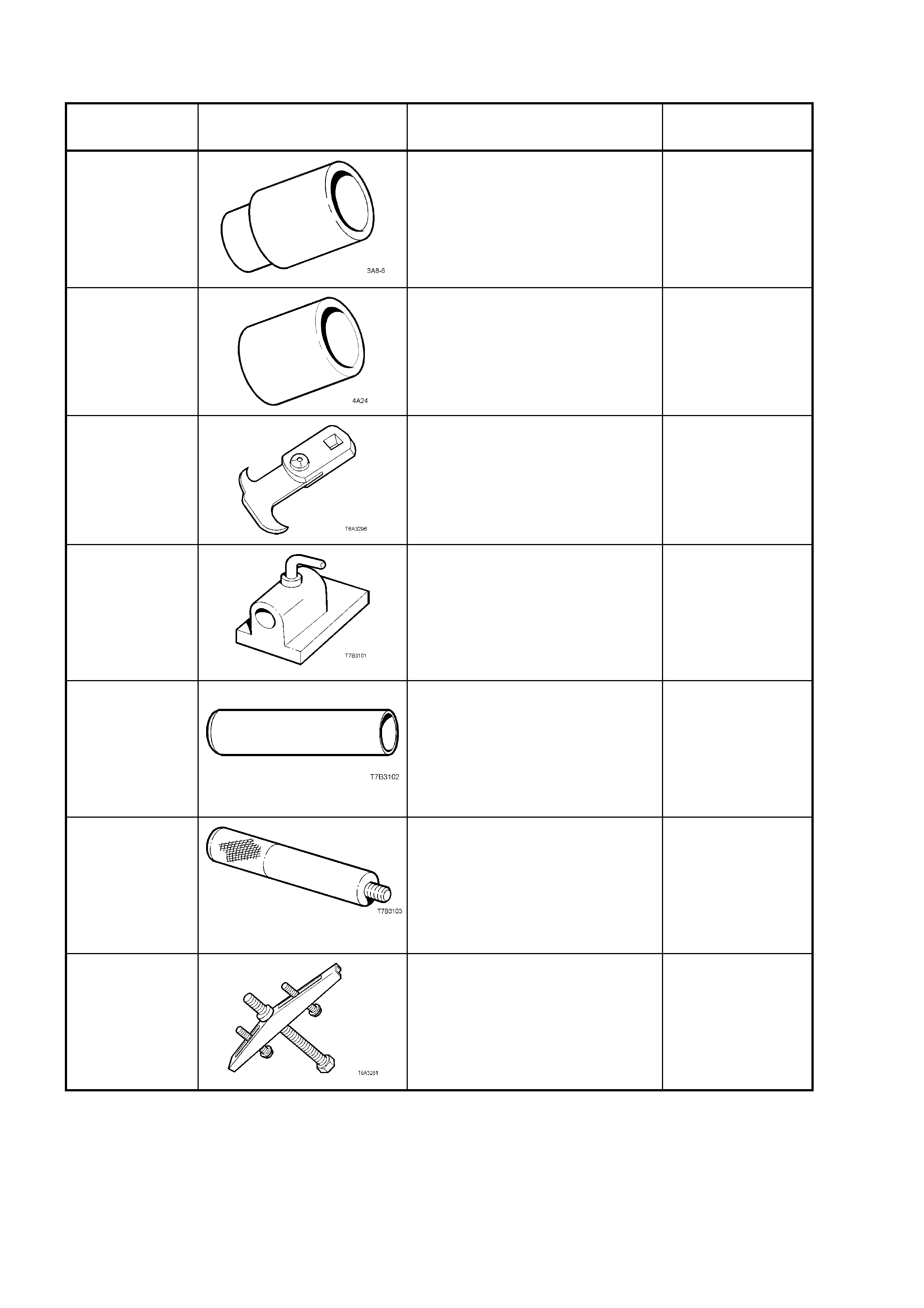
8. SPECIAL TOOLS
TOOL
NUMBER ILLUSTRATION DESCRIPTION CLASSIFICATION
E1891-6
SLEEVE
Used to install the 1st/2nd gear
synchromesh hub to the
mainshaft.
Also previousl y released as 3A8-
6.
Unique
E1662
SLEEVE
Used to install the bearing cup into
the input shaft gear.
Also previo us l y releas ed as 4A2 4.
Unique
E308
SEAL REMOVER
Used to remove the rear oil seal
from the extension housing.
Also previousl y released as E308
and 49V01200 1.
Desirable
J 3289-20
BENCH HOLDING FIXTURE
Used as a bench fixture to support
a transmission. Used in
conjunc tio n with Tr ans mission
Holding Fixture, J 39430.
Previously released.
Unique
J 5590 PRESS TUBE
Used to install various
components, using an hydraulic
press.
Previously released for 4L60-E
automatic transmission.
Unique
J 8092 UNIVERSAL DRIVER HANDLE
Used in conjunction with various
other tools for removal and
installation of various bearing cups
in the transmission.
Previously released.
Unique
J 8433
UNIVERSAL BRIDGE PULLER
Used in conjunction with J 39431-
1 & 2 to remove the speedometer
pulse ring and the 5th/6th speed,
compound dr iven ge ar .
Unique
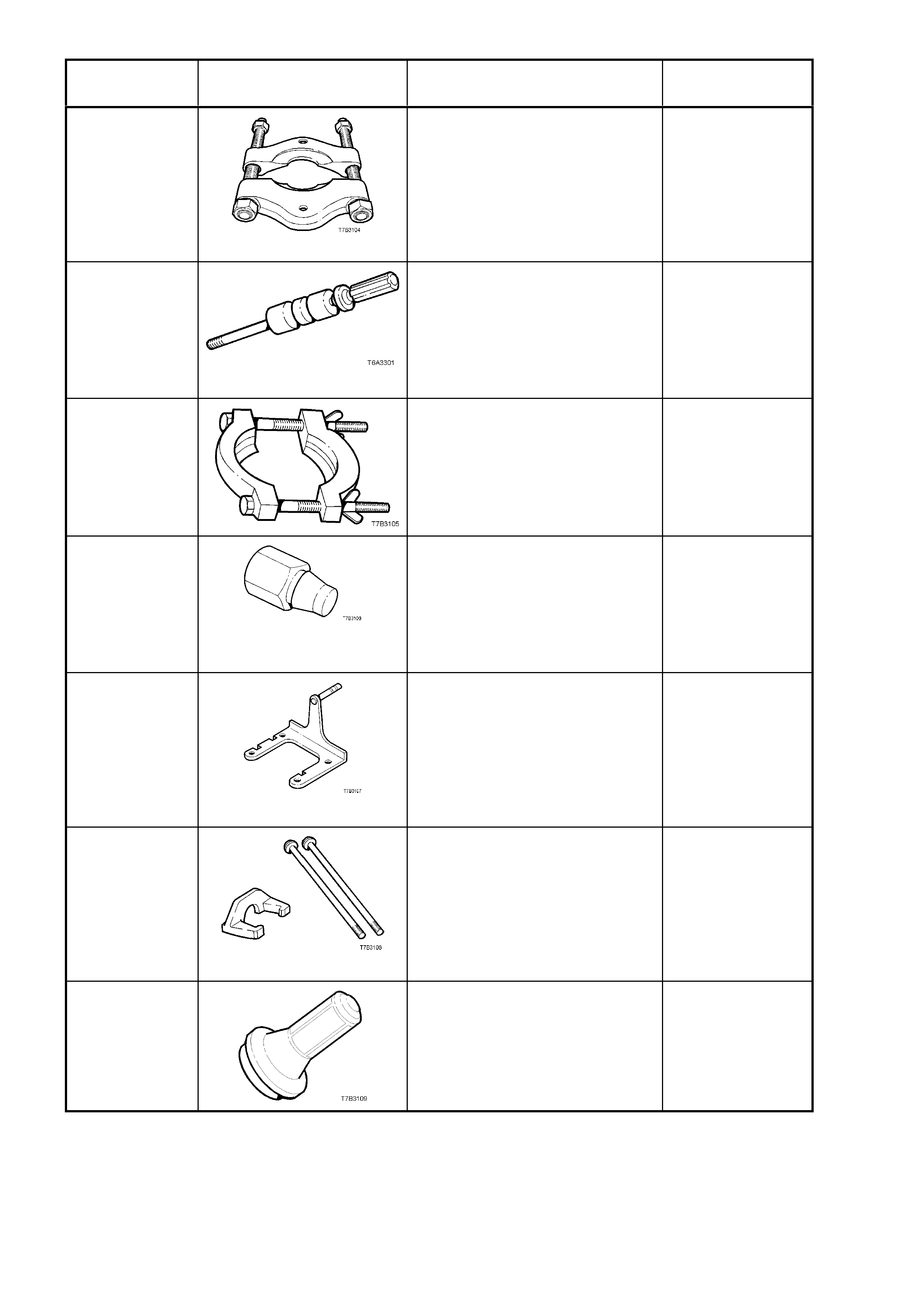
TOOL
NUMBER ILLUSTRATION DESCRIPTION CLASSIFICATION
J 22912-01
PRESS PLATES
Used in a number of different
applicat ions in removi ng be arings
and other transmiss ion
components when pressin g
operations are required.
Previously released.
Desirable
J 23907 SLIDE HAMMER
Used in conjunction with a number
of different pullers to remove
bushes and bearing cups in the
transmission
Unique
J 36513 PRESS PLATES
Used to press 1st/2nd speed
synchromesh assembly and 2nd
gear from the mainshaft.
Unique
J 36800
BUSHING REMO VER
Used to remove the shift rail
bushes in the adaptor plate and
extension housing, in conjunction
with slide hammer J 23907.
Previously released.
Unique
J 39430
TRANSMISSION HOLDING
FIXTURE
Used in conjunction with Bench
Fixture J 3289-20 to mount the
transmission to the bench for unit
repair opera tio ns .
Previously released.
Unique
J 39431-1 & 2
REMOVER AND BOLTS
Used to remove the speedometer
pulse ring and the 5th/6th speed,
compound dr iven ge ar , in
conjunction with universal bridge
puller J 8433.
Unique
J 39433
SEAL INSTALLER
Used to install the input shaft oil
seal.
Previously released.
Desirable
TOOL
NUMBER ILLUSTRATION DESCRIPTION CLASSIFICATION
J 39435
BEARING CUP INSTALLER
Used to install the rear mainshaft
and rear countershaft bearing cup,
in conjunction with driver handle J
8092.
Previously released
Unique
J 39437
BUSHING INSTALLER
Used to install the selector shaft
bushes in the adaptor plate, and
transmission case.
Previously released
Unique
J 39439-1
BUSHING
REMOVER/INSTALLER
Used to remove shift shaft bushes
from the transmission case and
extension housing.
Previously released
Unique
J 39440
REAR SEAL AND BOOT
INSTALLER
Used to install the rear extension
seal.
Desirable
J 39441
GEAR INSTALLER
Used to install the 5th/6th
compound dr iven ge ar and the
speedometer pulse ring.
Unique
J 39444-1 & 2
END PLAY RODS
Used to check the end float of the
countershaft gear (J 39444-1) and
countershaft gear extension (J
39444-2).
Unique
J 39511
SPLIT PLATE
Used to remove the front
countershaft gear bearing.
Previously released
Unique
J 39546 BEARING CUP INSTALLER
Used to install the rear mainshaft
roller bear ing cup, in co nj unction
with driver handle J 8092.
Previously released
Unique
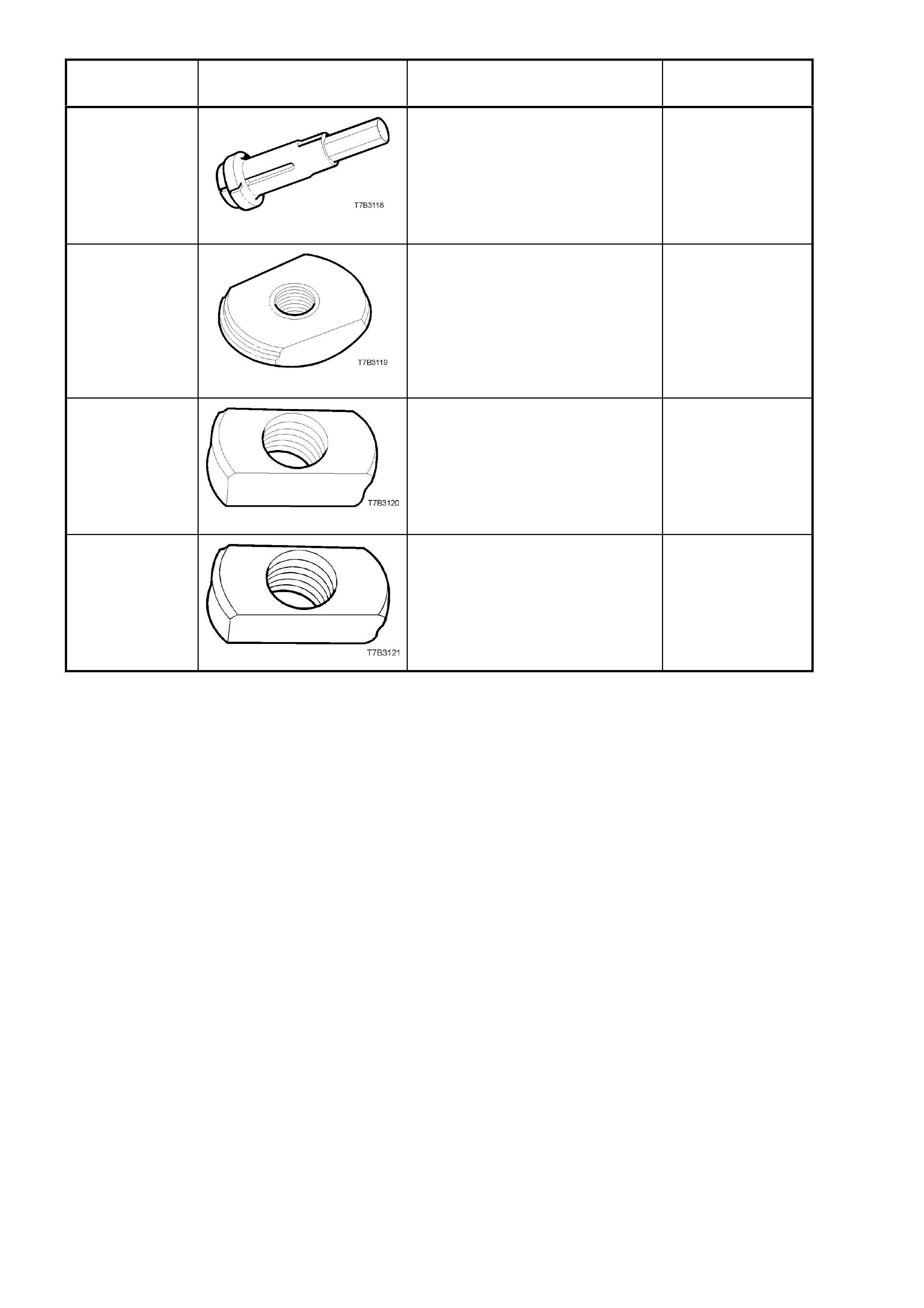
TOOL
NUMBER ILLUSTRATION DESCRIPTION CLASSIFICATION
J 39594
BEARING CUP REMOVER
Used in conjunction with slide
hammer J 23907 to remove the
mainshaft pilot bearing cup in the
input shaft gear.
Previously released
Unique
J 39789
BEARING CUP REMOVER
Used to press out the rear
mainshaft roller bearing cup from
the extension housing, in
conjunction with driver handle J
8092.
Unique
J 39790 BEARING CUP REMOVER
Used to press out the rear
mainshaft bearing cup from the
transmission case, in conjunction
with driver handle J 8092.
Unique
J 39791 BEARING CUP REMOVER
Used to press out the rear
countershaft bearing cup from the
transmission case, in conjunction
with driver handle J 8092.
Previously released
Unique