
SECTION 7C1 - HYDRA-MATIC 4L60-E AUTOMATIC
TRANSMISSION: GENERAL INFORMATION
IMPORTANT
Before perfo rming any Service Operat ion or oth er procedure described in this Section , refer to Section 00
CAUTIONS AND NOTES for correct workshop practices with regard to safety and/or property damage.
CONTENTS
1. SECTION DESCRIPTIONS
2. TRANSMISSION CHANGES FOR MY2003
2.1 ‘HAD’ MODEL TRANSMISSION
3-4 CLUTCH
2.2 ALL MY2003 TRANSMISSIONS
PRESSURE CONTROL SOLENOID (PCS)
BOOST VALVE BUSHING
2.3 BRAKE TRANSMISSION SHIFT
INTERLOCK (BTSI)
MANUAL OVERRIDE
OPERATION
3. TRANSMISSION OPERATION -OVERVIEW
3.1 GENERAL DESCRIPTION
TRANSMISSION COMPONENT SUMMARY
MATCHING ENGINE TORQUE AND
LINE PRESSURE
ECONOMY, POWER & CRUISE MODES
ADAPTIVE CONTROLS
ENGINE TORQUE MANAGEMENT
SYSTEM PROTECTIVE DEVICES
SELF DIAGNOSIS
PCM SENSORS AND ACTUATORS
TRANSMISSION IDENTIFICATION
TRANSMISSION SPEED RANGES
RANGE REFERENCE CHART
3.2 PULSE WIDTH MODULATED TCC SOLENOID
DUTY CYCLE
TCC PWM SOLENOID OPERATION
3.3 TORQUE CONVERTER CLUTCH
GENERAL DESCRIPTION
TORQUE CONVERTER CLUTCH –
RELEASED
TORQUE CONVERTER CLUTCH – APPLIED
3.4 3-2 DOWNSHIFT CONTROL SOLENOID
GENERAL DESCRIPTION
3-2 CONTROL SOLENOID OPERATION
4. TRANSMISSION DEFINITIONS AND
ABBREVIATIONS
4.1 DEFINITIONS
4.2 ABBREVIATIONS
5. SERVICE NOTES
5.1 FASTENERS
5.2 GENERAL WORKSHOP PRACTICE
Techline
Techline

1. SECTION DESCRIPTIONS
A multi-section approach to the Hydra-matic 4L60-E Automatic Transmission has been adopted for MY2003
vehicles.
7C1: HYDRA-MATIC AUTOMATIC TRANSMISSION: GENERAL INFORMATION
The purpos e of this s ection is to provide an over view of the autom atic transm ission, by brief ly describing what each
of the various sub-sections contains.
In addition, an overview of the transmission features is provided, that includes;
• A general description of the transmission, its operation and control, as well as transmission identification
information.
• A brief description of some salient sy stems such as torque converter clutch and 3-2 downshift controls.
• A glossary of generic terms that are used.
• Some notes that address safe workshop practices.
• Service notes relating to fasteners and consumable items used at various stages throughout this section.
7C2 HYDRA-MATIC AUTOMATIC TRANSMISSION:- ELECTRICAL DIAGNOSIS
As the electrical systems and diagnosis for this transmission are controlled by the Powertrain Control
Module (PCM), for the V6 and V6 Supercharged engines or the PCM/Powertrain Interface Module (PIM) for the
GEN III V8 engine, this material has now been included in the appropriate sections relating to the PCM; namely
Section 6C1 POWERTRAIN MANAGEMENT – V6 ENGINE, Section 6C2 POWERTRAIN MANAGEMENT – V6
SUPERCHARGED ENGINE and Section 6C3 POWERTRAIN MANAGEMENT – GEN III V8 ENGINE.
7C3 HYDRA-MATIC AUTOMATIC TRANSMISSION:- HYDRAULIC/MECHANICA L DIAGNOSIS
As distinct from the previous section, 7C3 contains information that will assist in the diagnosis of the mechanical
and hydraulic components in the 4L60-E automatic transmission, with the unit installed in the vehicle.
Examples of the type of diagnostic information contained within this section are; transmission functional test, fluid
checking procedure, shift speed and line pressure information. Other material contained in this section refers to
some fluid flow and hydraulic circuit descriptions, plus fluid passage identification diagrams relating to the
transmission.
7C4 HYDRA -MATIC AUTOMATIC TRANSMISSION:- ON-VEHICLE SERVICING
Inform ation in this s ection c overs tr ansm iss ion fluid level c heck ing and diagnosis, as well as spec ific infor m ation for
servicing some components while the transmission remains installed in the vehicle.
This section also contains the necessary procedures for the removal and installation of the transmission.
7C5 HYDRA-MATIC AUTOMATIC TRANSMISSION:- UNIT REPAIR
This section contains the procedures necessary for the disassembly, inspection, overhaul and reassembly
operations of the mechanical components, once the transmission is removed from the vehicle. Also included is
information relating to the measurement of certain clearances, the correct use of special tools and torque
specifications required for assembly.
2. TRANSMISSION CHANGES FOR MY2003
Apart from some minor changes detailed here, the transm ission carries over f rom MY2002. One change however,
has not been detailed previously and is now included here for general information.
SPACER PLATE AND GASKETS
Effective from a Julian build date (refer Figure 7C1-4), of “1HXD002 X XXXXXXX”, the Torque Converter Clutch
(TCC) Regulator Valve exhaust port was reduced in size. This change has meant that, not only has the control valve
body changed but the spacer plate and both gaskets have also been modified. The early and later gaskets and
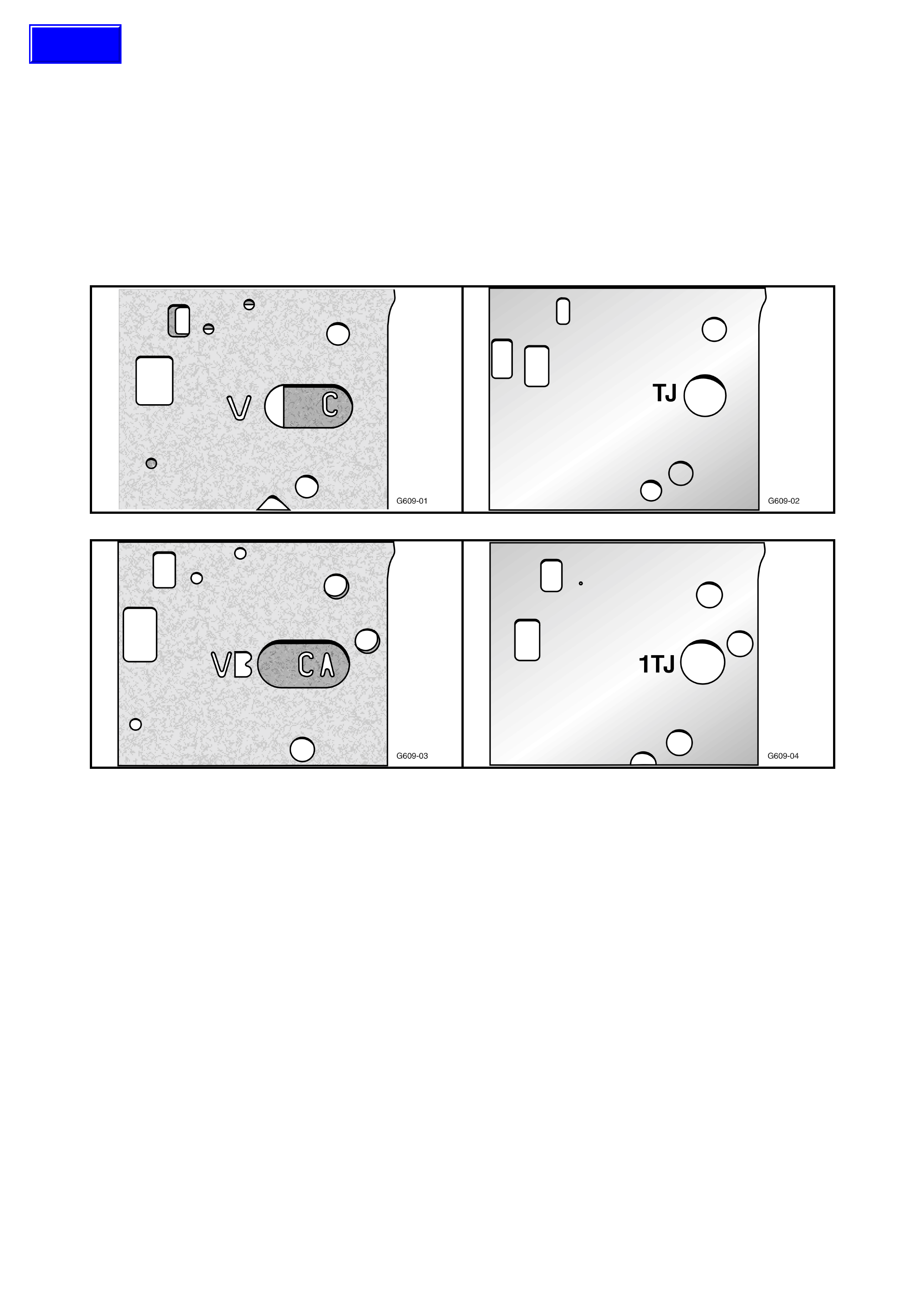
spacer plates can be physically identified as shown next.
Control Valve Body Gaskets Control Valve Body Spacer Plate
A B
C D
Figure 7C1-1
Legend
A. Pre-Change Gaskets – ‘V’ = Valve body side, ‘C’ =
Case Gasket
B. Pre-Change Spacer Plate – Identification is embossed
‘TJ’
C. Post-Change Gaskets – ‘VB’ is the Valve body side, ‘CA’
is the Case Gasket
D. Post-Change Spacer Plate – Identification in an
embossed ‘1TJ’
Techline

2.1 ‘HAD’ MODEL TRANSMISSION
To increase durability of the 4L60-E automatic transmission fitted to the GEN III V8 engine, a change to the
3-4 clutch pack has been effected for the 2003MY transmission release. Resulting from these changes the
transmission prefix has been changed from ‘HPD’ to ‘HAD’.
3-4 CLUTCH
The number of plates in the 3-4 clutch pack has been increased from six to seven plates. To achieve this result
without undergoing major internal com ponent changes, the plates are thinner. This means that the same selective
plates can be used to achieve the same end float specification.
Apart from the change in part number, the HAD clutch plates can be physically identified by;
Composition plates – Thickness of new plates (1.62 ± 0.10 mm) and by one or more lightly coloured stripes
across the friction surfaces.
Steel plates – Thickness of new plates (2.42 +0.08 –0.07 mm).
2.2 ALL MY2003 TRANSMISSIONS
PRESSURE CONTROL SOLENOID (PCS)
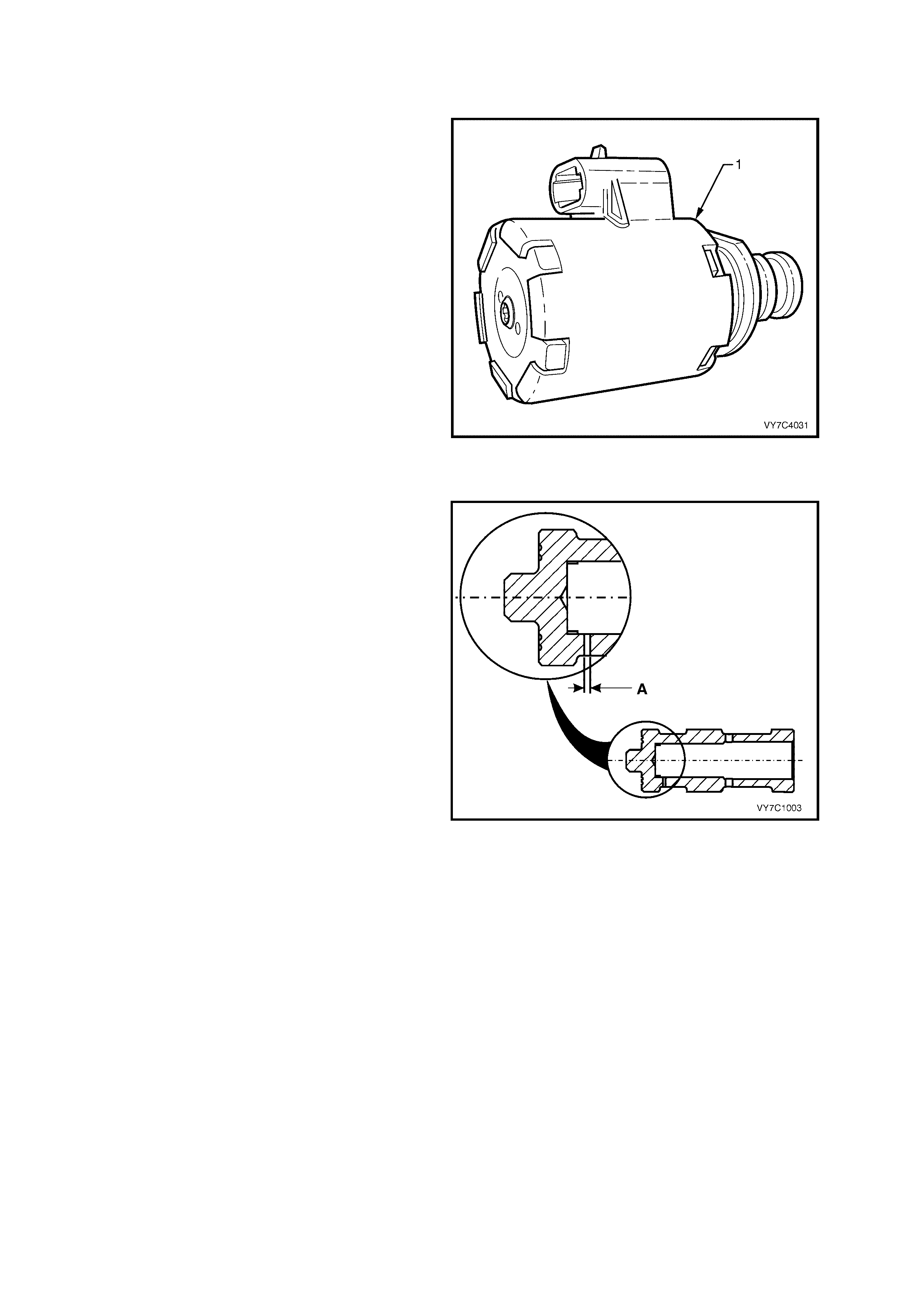
The Pressure Control Solenoid (PCS) (1) is a new
design and, as the design of the terminal
connection is also new, the internal transmission
wiring harness also changes.
With the change in the PCS, the line pressure has
been affected and that results in a change in the
pressure checking procedure and results. Refer to
2.4 LINE PRESSURE CHECK in Section 7C3,
HYDRAULIC/ MECHANICAL DIAGNOSIS, for
specific details.
Figure 7C1-2
BOOST VALVE BUSHING
The orifice size (‘A’) in the boost valve sleeve,
(mounted in the oil pump housing) has been
reduced from a nominal 1.08 mm to 0.89 mm
(+0.07 mm/–0.06 mm), which affects the ATF
pressure boost characteristics of the valve.
Apart from this changed dimension, the bushing
has a new part number and has yellow dye applied
to it, for identification purposes.
Figure 7C1-3
2.3 BRAKE TRANSMISSION SHIFT INTERLOCK (BTSI)
Dependent on vehicle specifications for different markets, the gearshift selector mechanism for MY 2003 VY and V2
Series vehicles, may be fitted with a Brake Transmission Selector Interlock (BTSI) device.
The selector lever cannot be moved from the Park position, unless the ignition switch is turned to the ON position
and the f oot brak e is applied. Because the foot br ake mu st be applied to release the m echanism, this device then,
assists in preventing the selection of Reverse when the vehicle is at rest say, when stationary at traffic lights.
Should the vehicle battery power be lost for some reason, then a manual override is provided, to allow shift lever
movement. This override will also be necessary, should the selector mechanism require disassembly, when
removed from the vehicle. Refer to Section 7C4 ON-VEHICLE SERVICING for these disassembly procedures.
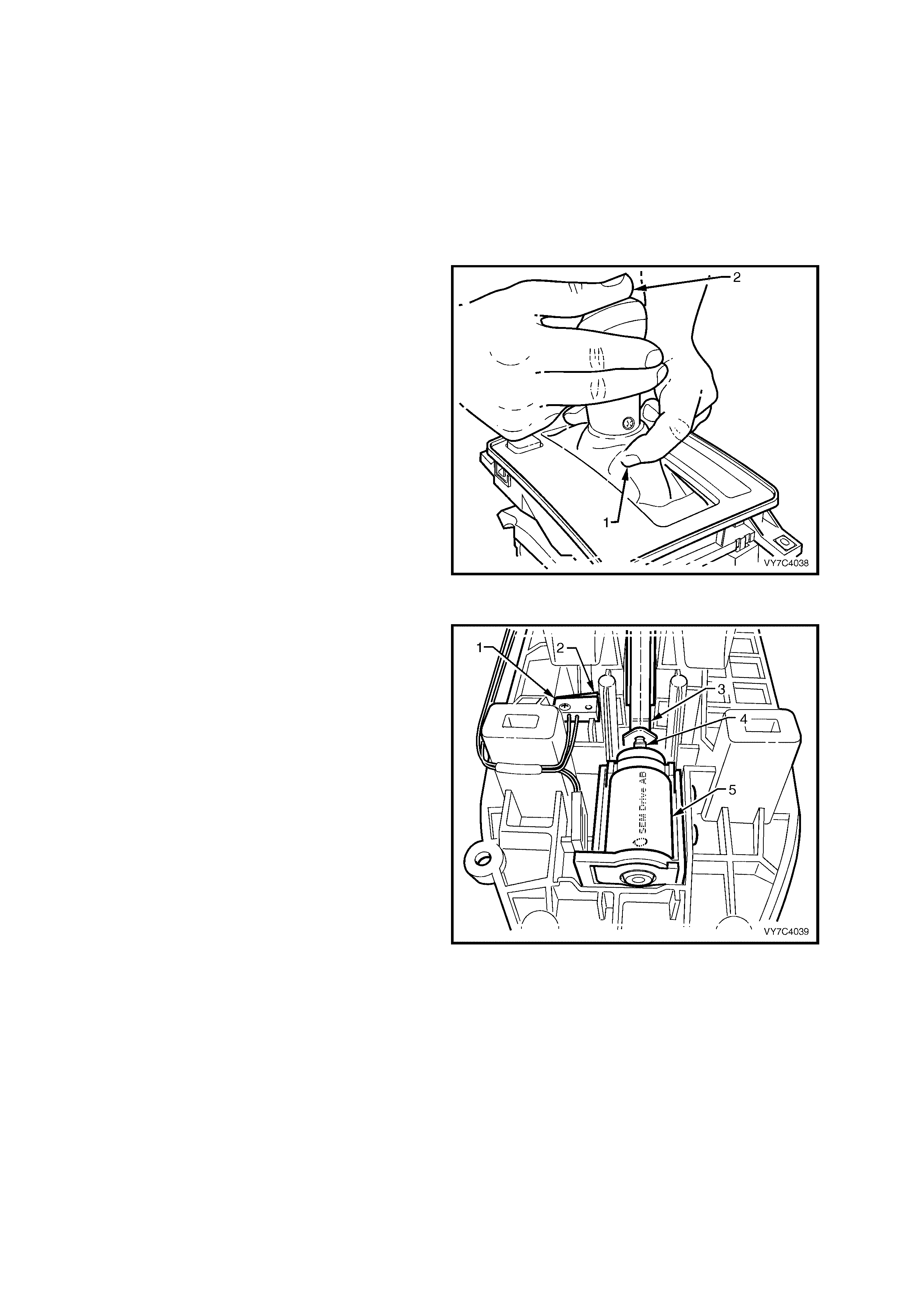
MANUAL OVERRIDE
To release the selector lever manually (no battery
power available);
a. First, press inwards on the boot, at the front of
the selector lever and just below the gearshift
knob, as shown (1).
b. Then, while still pressing inward (1), depress
the selector knob with the other hand (2) and
move the lever from the Park position.
NOTE: While the illustration shows the shift lever
assem bly rem oved from the vehicle, the procedure
is exactly the same for an in-car situation.
Figure 7C1-4 – Releasing Interlock
OPERATION
When the shift lever is in the Park position (as
shown), the interlock lever (3) is pushed rearward
by the spring loaded solenoid plunger (4), against
the lever’s spring force. This causes a step on the
interlock lever to be positioned in such a away that
downward movement of the handle button is
blocked.
NOTE: It is this interlock lever that is manually
pressed at the top end (through the shift lever
boot), that frees the button pushrod movement.
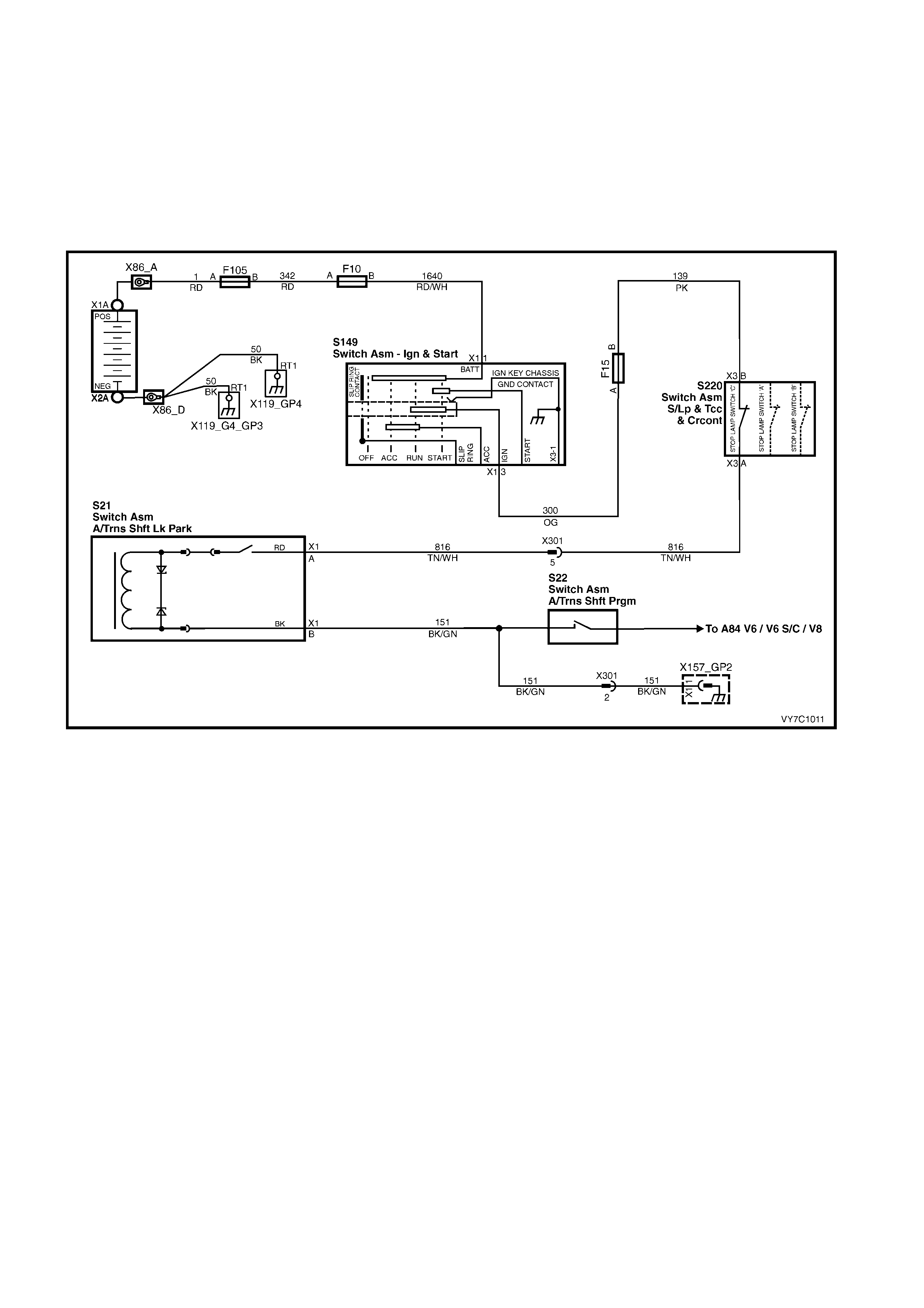
With the selector lever in this position (Park) and
the ignition switch in the ON position (with the foot
brake applied), current flows from the stop lamp
switch ‘C’, thr ough the now closed m icro s witch (1),
the solenoid (5) and ground, through the same
circuit used for the transmission Power/Economy
switch circuit. This activates the solenoid (5). Also
refer to the electrical circuit shown in Figure 7C1-6.
With the solenoid activated, the plunger (4) is
retracted, allowing the spring loaded isolating lever
(3) to move f orward at the s olenoid end. This action
positions the lever stop to clear the selector lever
button rod. The selector button can now be
depressed, and the selector lever to be moved
from the Park position.
Figure 7C1-5 – BTSI Components
Once the selector lever is moved from the Park
position, the released tension on the micro switch
spring lever (2), opens the electrical circuit,
isolating the solenoid (5).
This condition remains until the Park position is
selected once again.
NOTE: The insulating foam has been removed
from this view to mo re clearly show the mec hanism
arrangement.
Figure 7C1-6 – BTSI Electrical Circuit
3. TRANSMISSION OPERATION - OVERVIEW
3.1 GENERAL DESCRIPTION
The Hydra-matic 4L60-E is a fully automatic, four speed, rear wheel drive transmission. It consists primarily of a four
element torque converter, two planetary gear sets, various clutches, an oil pump and a control valve body.
The four element torque converter contains a pump, a turbine, a pressure plate splined to the turbine and a stator
assembly. The torque converter acts as a fluid coupling to transmit power smoothly from the engine to the
transm ission. It also hydraulically pr ovides additional torque multiplic ation when required. The press ure plate, when
applied, provides a mechanical 'direct drive' coupling of the engine to the transmission.
The two planetary gear sets provide the four forward gear ratios and reverse. Changing of the gear ratios is fully
automatic and is accomplished through the use of various electronic sensors that provide input signals to the
Powertrain Control Module (PCM). The PCM inter prets thes e signals to send c urrent to the var ious solenoids inside
the transmission.
By using electronics, the PCM controls shift points, shift feel and torque converter clutch apply and release, to
provide proper gear ranges for maximum fuel economy and vehicle performance.
Five m ultiple-dis c clutc hes, one roller clutch, a s prag clutch and a brak e band provide the f riction elem ents required
to obtain the various ratios with the planetary gear sets.
An hydraulic system (including the control valve body), pressurised by a vane type pump, provides the working
pressure needed to operate the friction elements and automatic controls.
The general arrangement of both the majority of mechanical and hydraulic components is as shown next.
With traditional, hydraulically controlled transmissions, the gear shifts are controlled by the opposing pressures of
hydraulic fluid in a complex system of spring-loaded valves. In this electronically controlled Hydra-matic 4L60-E
transmission, gear shift points and shift feel are determined by electrical signals sent from the Powertrain Control
Module (PCM).
The PCM proc ess es data every 25 millisec onds f rom various sensor s, such as throttle position, vehicle speed, gear
range, temperature, engine load and other inputs. Using this data, a signal is transmitted to the valve body shift
solenoids, which ac tivate the shift valves f or precise shif t control. Shift points ar e therefore prec isely controlled and
are identical from vehicle to vehicle.
Shift feel is also elec tronica lly controlled by the PCM, by signals sent to the Var iable Force Solenoid, which c ontrols
fluid line pres sur e and it is this pres s ure that prec is ely determines how the shif ts will feel. In this way, the Powertrain
Control Module (PCM) electronically synchronises the engine and transmission into a single, integrated powertrain
system, for optimum performance, shift timing, fuel efficiency and emission control.
NOTE: While the Variable Force Solenoid (also referred to as the Pressure Control Solenoid – ‘PCS’), is now a
different design for the HAD transmission fitted to the GEN III V8 engine, the purpose and operation are the same.
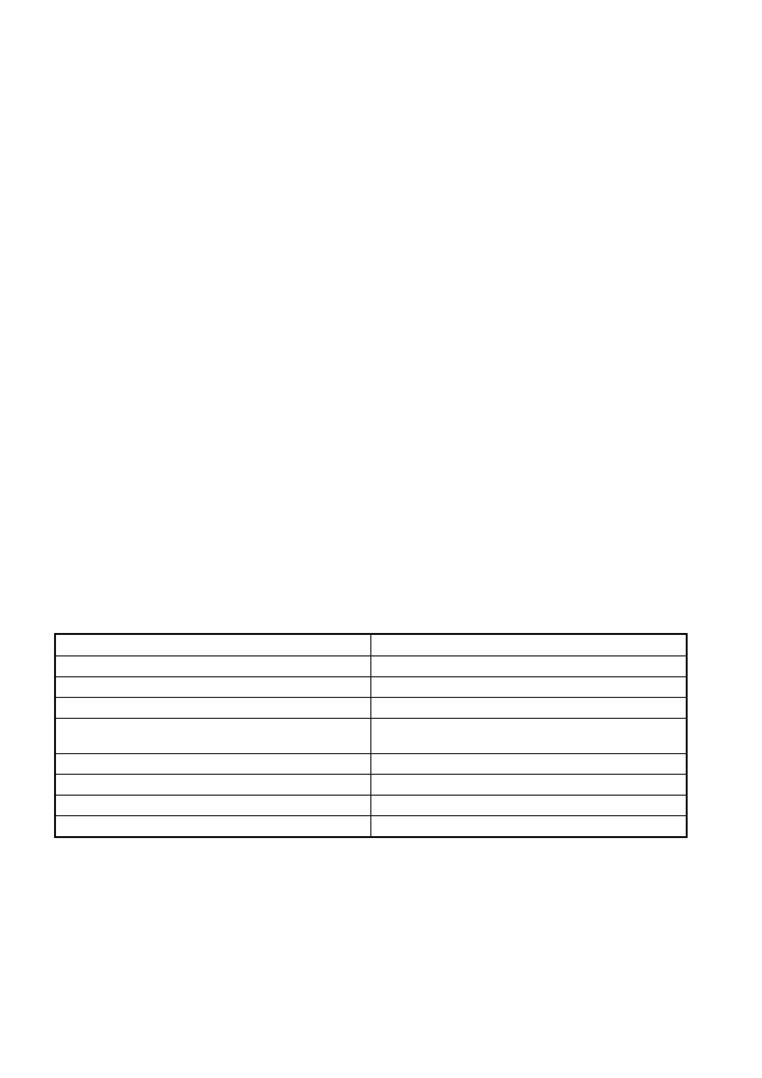
TRANSMISSION COMPONENT SUMMARY
Mechanical/Hydraulic Electrical
Torque Converter with Converter Clutch Two Shift Solenoids
13 Vane, Variable Displacement Oil Pump. Effectively, an ON/OFF, 3-2 Downshift Solenoid
Five Multiple Disc Clutch Packs A Pressure Control Solenoid (PCS) or ‘Force Motor’
A 2-4 Band Assembly An ON/OFF, Torque Converter Clutch (TCC)
Solenoid
Two Planetary Gear Sets One Pulse Width Modulated (PWM) TCC Solenoid
One Sprag Clutch Transmission Fluid Temperature Sensor
One Roller Clutch Fluid Pressure Switch Assembly
A Control Valve Body Assembly Vehicle Speed Sensor
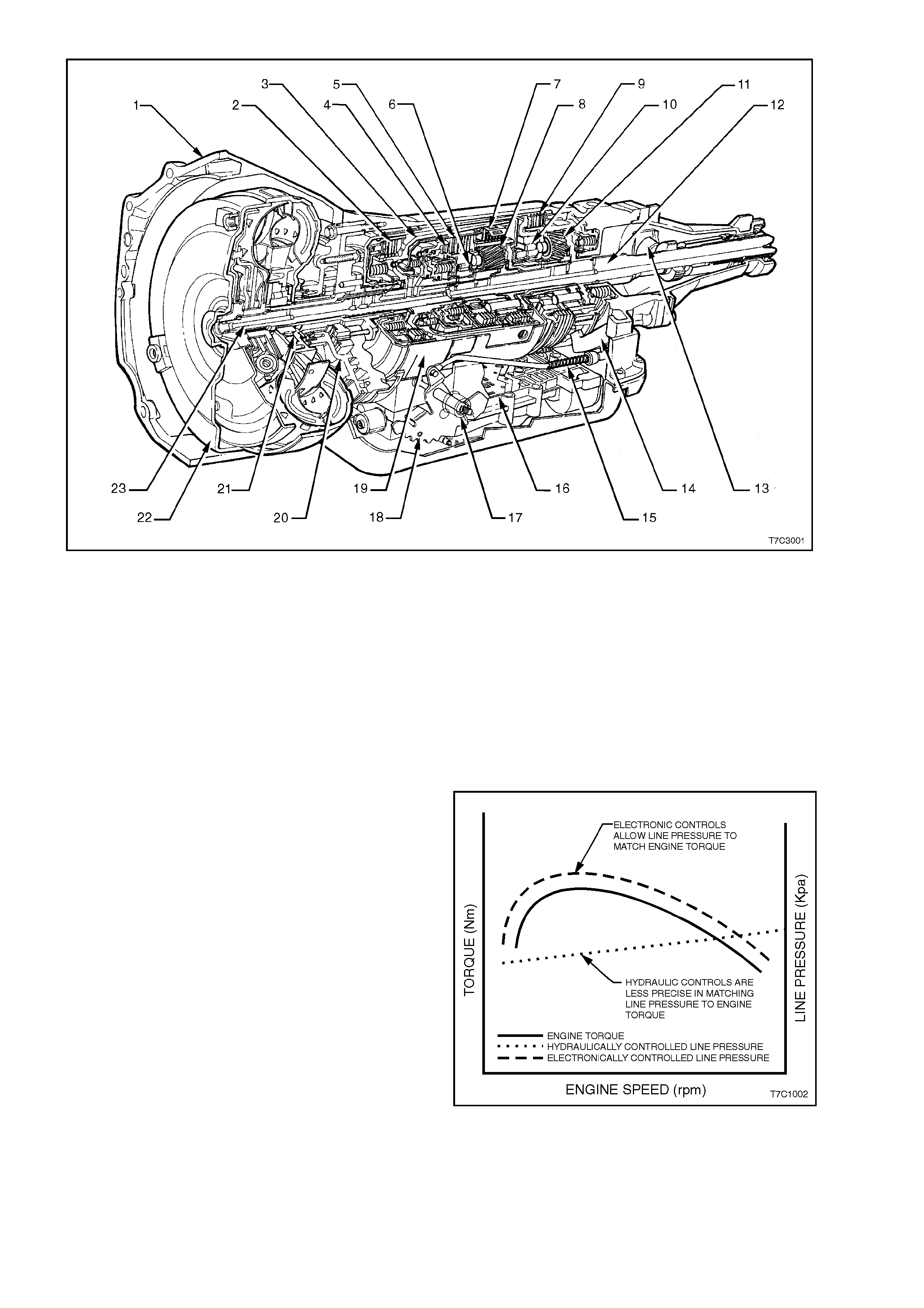
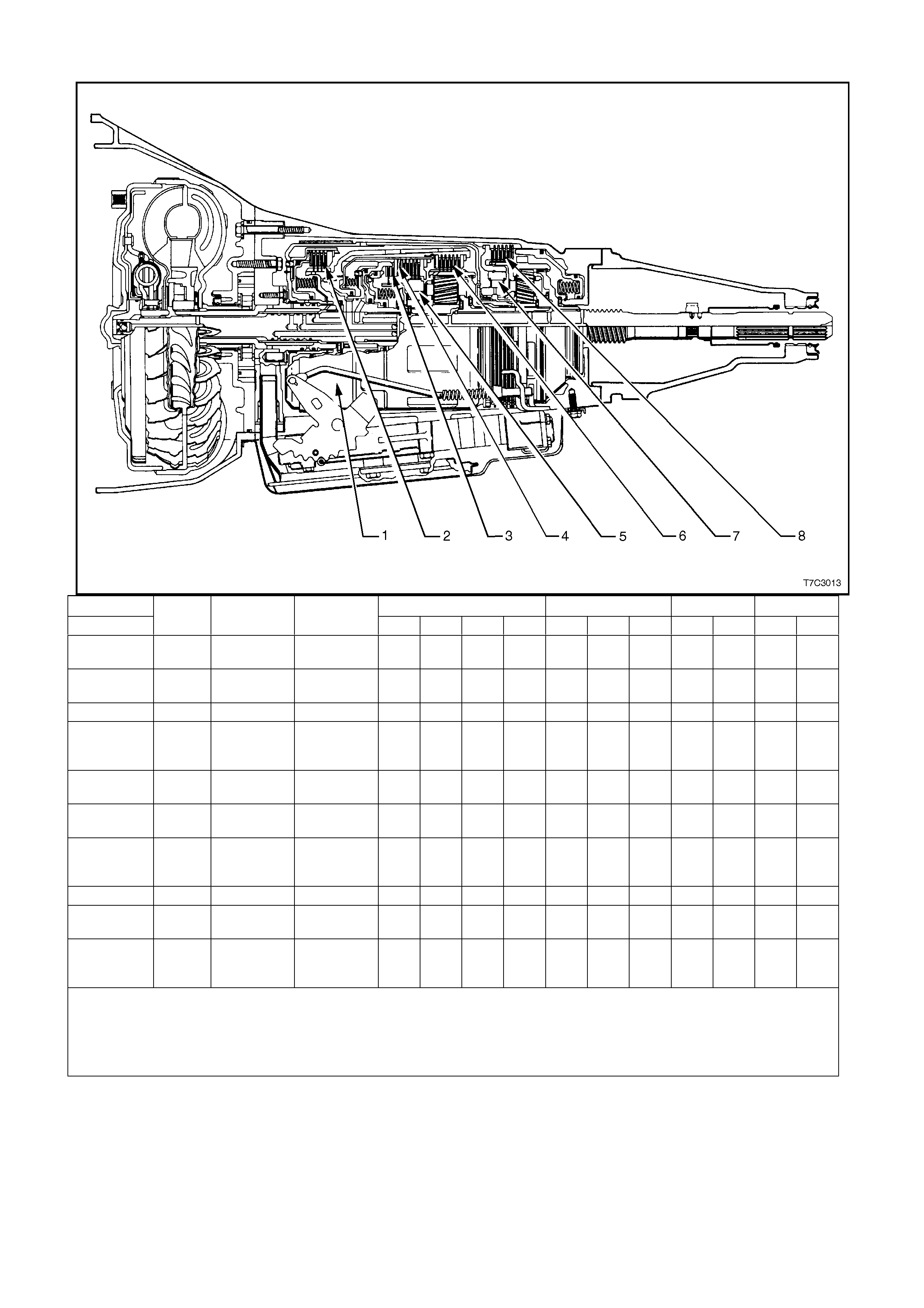
Figure 7C1-7
Legend
1. Case Assembly
2. Reverse Input Clutch
3. Input Clutch Housing
4. Overrun Clutch
5. Forward Clutch
6. Forward Clutch Sprag Assembly
7. 3–4 Clutch
8. Input Planetary Gear Set
9. Low and Reverse Clutch
10. Low Roller Clutch Assembly
11. Reaction Planetary Gear Set
12. Output Shaft
13. Speed Sensor
14. Parking Pawl
15. Parking Lock Actuator Assembly
16. Control Valve Assembly
17. Manual Shaft
18. Inside Detent Lever
19. 2–4 Band Assembly
20. Pump Assembly
21. Stator Roller Clutch
22. Torque Converter Assembly
23. Turbine Shaft
MATCHING ENGINE TORQUE AND LINE PRESSURE
The torque output f rom an engine varies in relation
to engine speed, in an inconsistent manner that
results in the typical curve, as shown. By using
springs and hydraulic pressure to control fluid line
pressure in an automatic transmission, control is
purely linear (indicated by the dotted line) and this
does not provide an ideal match to engine output.
With the Hydra-matic 4L60-E automatic
transm ission, the use of electronic control over line
pressure means that a much more precise, match
with engine performance is possible and the ‘shift
feel' more closely approximates engine output.
Figure 7C1-8
ECONOMY, POWER & CRUISE MODES
The programming in the Powertrain Control Module (PWM) provides for these different shift patterns which are
driver c ontr ollable, through the us e of the Ec onomy/Power button, located in the centre cons ole or the c r uis e contr ol
lever (where fitted).
Economy Mode
The calibration for this mode is for maximum comfort, with minimal intrusion of engine noise and smooth shifts
under all driving conditions. When additional power is required for acceleration, full throttle upshifts are similar to
those calibrated for the Power Mode.
Power Mode
When activated, the PCM modifies the transmission calibration in the following way s:
1. When the throttle is less than 80% open, later upshift points are provided.
2. Shift time is reduced.
3. The Torque Converter Clutch (TCC) will be applied in both third and fourth speed ranges.
Cruise Mode
When the driver activates the cruis e control ( where fitted), the ‘Power’ icon in the Instr um ent, Multi-Function Display
(MFD) will be deactivated (provided the vehicle was operating in ‘Power’ m ode) and the transmission shift pattern
will switch to the cruise control pattern. When in this mode, the PCM modifies the shift pattern so that earlier
downshift and later upshift points are provided.
Through the electronic programming of the logic processes contained in the Powertrain Control Module, the
frequenc y of gear shifting and tor que converter clutc h application and release is minim ised. The end result of these
logic processes, is that transmission 'busyness' (a quick series of upshifts and downshifts; e.g. a '4-3-4' shift
pattern) is minimised.
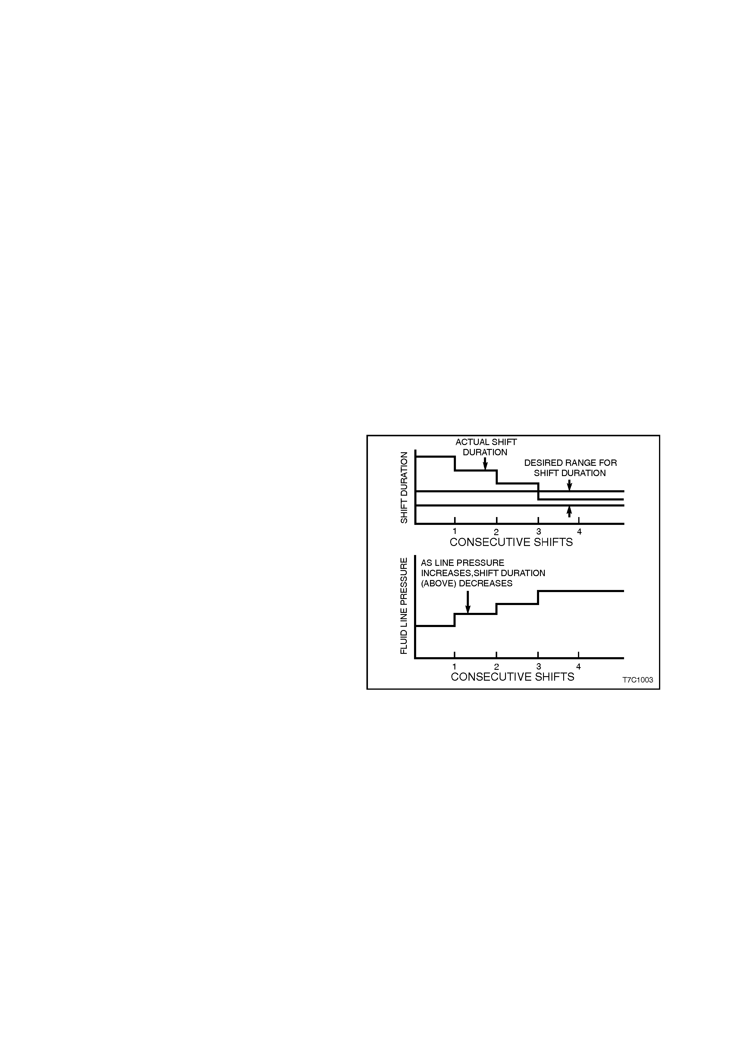
ADAPTIVE CONTROLS
As a normal part of its operation, the PCM
continually monitors the transmission's shift time
(duration) for the 1-2 upshift and compares this with
it's pre-programmed information. As normal
transmission wear occurs, such as with friction
material and spring tensions, the time that is taken
for this shift to occur, will change.
When the PCM finds that the time is outside it's
programmed limits, the transmission fluid line
pressure is modified via the pressure control
solenoid and this 'adapts' the change time to
maintain the c orrec t shif t feel. Line pres sure can be
adapted to values ranging from 35 kPa below, to 70
kPa above normal line pressure. This 'learning'
feature is similar to what is used for fuel control.
Figure 7C1-9

ENGINE TORQUE MANAGEMENT
W hen the GEN III V8 engine is fitted with the 4L60-E transmission, Torque Management is a function of the PCM
that reduces engine power under certain conditions, included in which, is the transmission upshifts and downshifts.
Torque Management is performed for the following reasons:
1. To prevent overstress of the powertrain components.
2. To prevent damage to the vehicle during certain abusive manoeuvres.
3. To reduce engine speed when the IAC is out of the normal operating range.
The PCM monitors the following sensors and engine parameters to calculate engine output torque;
• Air/Fuel ratio
• Mass Air Flow
• Manifold Absolute P ressure
• Intake Air Temperature
• Spark Advance
• Engine Speed
• Engine Coolant Temperature
• A/C Clutch Status
The PCM monitors the torque converter status, the transmission gear ratio, and the engine speed in order to
determ ine if torque r educ tion is r equir ed. T he PCM r etards the s park as appr opriate to r educ e engine torque output
if torque reduction is required. T he PCM. also shuts off the fuel to certain injectors to reduce the engine power In
the case of an abusive manoeuvres.
Instances when engine power reduction is likely to be experienced, are:
a. During transmission upshifts and downshifts.
b. Heavy acceleration from a standing start.
c. The IAC is out of the normal operating range.
d. W hen the driver is performing stress-inducing (abusive) manoeuvres such as shifting into gear at high throttle
angles or shifting the transmission from reverse to drive to create, a rocking motion.
The driver is unlikely to notice the torque management actions in the first two instances. The engine power output
will be moderate at full throttle in the other two cases.
The PCM c alculates the am ount of spark retard nec essary to reduce the engine power by the desir ed amount. For
example the PCM disables the fuel injectors for cylinders 1, 4, 6, and 7 in the case of an abusive manoeuvres.
SYSTEM PROTECTION DEVICES
a. Should 1st gear be selected and left in that range, the PCM will protect the engine from an over-speeding
condition by upshifting to 2nd speed at a pre-determined point. Similarly, the PCM provides high speed,
downshift protection by preventing a manual shift into 1st gear above pre-determined engine speeds.
b. Under severe operating conditions such as towing in high ambient temperatures, fluid temperatures rise to the
point where lubr ication break down c an occur. W ith the VR range of vehicles, in addition to having an oil cooler
fitted, the 4L60-E transmission is also fitted with a transmission fluid temperature sensor located in the
Transmission Range (TR) Pressure Switch Assembly (PSA).
When fluid temperatures in excess of 135° C are sensed, the Torque Converter Clutch is applied as
programmed, in 3rd or 4th gear.
This action reduces further fluid temperatures that could arise in normal operation of the torque converter.
W hile these high f luid temper atures are sens ed, Torque Conver ter Clutch apply is not available however, when
the throttle opening is above 50%.
Similarly , when the fluid temperature is below 29° C, the PCM prevents Torque Converter Clutch apply.
c. Should a condition occ ur that prevents electr onic control of the transm ission's functions, a "Fail Safe" mode will
default the transmission to 3rd gear (when either Drive 'D' or '3' is selected) and also apply maximum line
pressure. While in this mode, the vehicle operator can still manually select '2', '1', Reverse, Park or Neutral,
should the need arise.
SELF DIAGNOSIS
Should any transmission operation controlled by the PCM begin to operate outside pre-set parameters, the PCM
has the ability to store a range of diagnostic codes that can be accessed by the servicing Technician, thereby
localising the problem circuit.
PCM SENSORS AND ACTUATORS
As indicated earlier, there are a number of sensors and switches that provide input information for the PCM
programming that will allow the PCM to make decisions about such things as; shift pattern, shift feel and torque
converter clutch operation.
The PCM does this by comparing this input information with its ‘Look up' tables on Shift Pattern, Fluid Pressure
maps, Shift Duration parameters, Extreme Heat Protection programming and Adaptive Controls.
In addition, each input signal and output actuator operation is also m onitored and, if outside pre-set parameters, a
diagnostic code is logged for future reference by the servicing Technician.
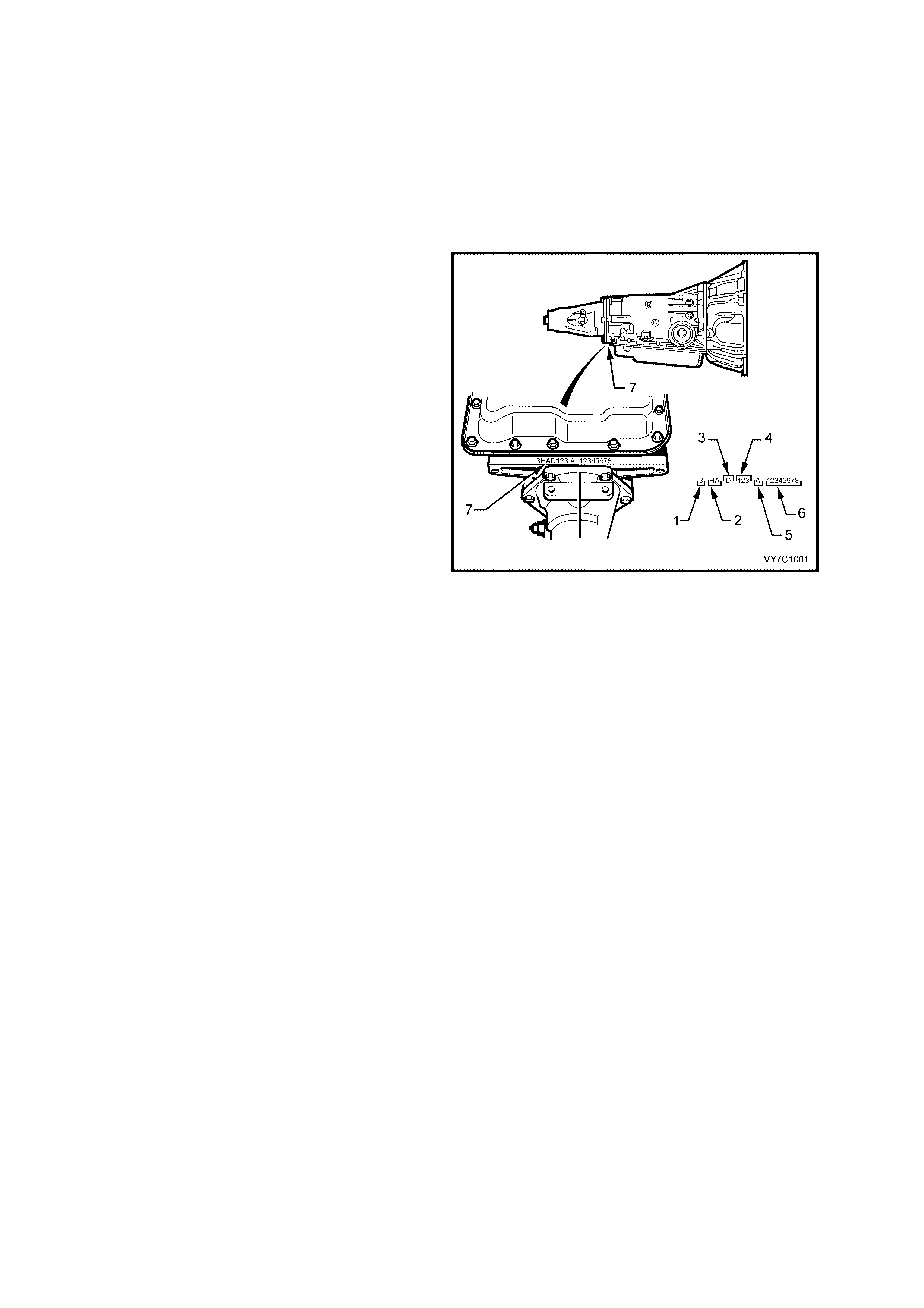
TRANSMISSION IDENTIFICATION
The 4L60-E automatic transm is sion application and
identification can be determined from the stamping
in the rear of the transmission case at the rear, in
the location shown (7).
The coded number can be interpreted from the
following breakdown;
1. Model Year (‘3’ = 2003)
2. Model:
3.8 litre V6 (LN3).................. HF
3.8 litre V6 S/C (L67)............ HN
5.7 litre GEN III V8 (LS1) ..... HA
3. Transmission Model Identifier (‘D’ = 4L60-E)
4. Julian Date (Day of the Year)
5. Shift Build ‘A’, ‘B’, ‘J’ = First Shift;
‘C’, ‘H’, ‘W’ = Second Shift
6. Individual Transmission Serial Number
Figure 7C1-10
TRANSMISSION SPEED RANGES
The Hydra-matic 4L60-E transmission can be operated in any one of the following seven modes:
P Park position enables the engine to be started while preventing the vehicle from rolling either forward or
backward. For safety reasons, the parking brake should be used in addition to the park position. Since the
output shaft is mechanically locked to the case through the parking pawl and reaction internal gear, 'Park'
position should not be selected until the vehicle has come to a complete stop.
R Reverse allows the vehicle to be operated in a rearward direction.
N Neutral allows the engine to be started and operated without driving the vehicle. If necessary, this position
should be selected to re-start the engine while the vehicle is moving.
D Drive range should be used for all normal driving conditions for maximum efficiency and fuel economy. This
range provides four gear ratios plus converter clutch operation. Downshifts are available for safe passing by
depressing the accelerator or by manually selecting a lower gear with the shift selector.
NOTE: W hen towing, if 4 - 3 - 4 shifts occur, then it is recommended that the ‘3 Drive’ mode of operation be
selected.
3 Drive position is used for city traffic and hilly terrain. It provides three gear ranges. Again, downshifts are
available for safe passing by depressing the accelerator.
2 Manual second is used to provide acceleration, engine braking, or greater traction from a stopped situation.
When manual second is selected, the vehicle will start off and remain in second gear. This range maybe
selected at any vehicle speed.
1 Manual first is used to provide maximum engine braking. This range may also be selected at any speed,
however the transmission will not shift into first gear until the vehicle speed is below approximately 48 to 56
km/h. Above this speed the transmission will remain in second gear. Manual first is particularly useful for
maintaining maximum engine braking while descending steep grades.
Referenc e to Figu re 7C1-7, shows the application of the various com ponents that are applied in each of the speed
ranges.
RANGE REFERENCE CHART
RANGE D 3 2 1
GEAR PARK REVERSE NEUTRAL 1st 2nd 3rd 4th 1st 2nd 3rd 1st 2nd 1st 2nd
1-2 Shift
Solenoid ON* ON* ON* ON* OFF OFF ON* ON* OFF OFF ON* OFF ON* OFF
2-3 Shift
Solenoid ON* ON* ON* ON* ON* ON* OFF ON* ON* OFF ON* ON* ON* ON*
2-4 Band – – – – A – A – A – – A – A
Reverse
Input
Clutch – A – – – – – – – – – – – –
Overrun
Clutch – – – – – – – – – A A A A A
Forward
Clutch – – – A A A A A A A A A A A
Forward
Sprag
Clutch – – – H H H – H – H – – – –
3-4 Clutch – – – – – A A – – A – – – –
Low Roller
Clutch – – – H – – – – H – H – H –
Low/
Reverse
Clutch A A – – – – – – – – – – A –
A = Applied H = Holding
ON = The Solenoid is E nergi sed OFF = The Solenoid is De-energi sed
* Shift Solenoid state is a func t i on of vehicl e speed and may change if t he vehi cle speed increases suffi cientl y in Park, Reverse or
Neutral. However this odes not affect the operation of he t ransm i ssion.
** In Manual First , Second gear i s only available above approximately 70 k m/h to prevent engine over-s peedi ng.
Figure 7C1-11
3.2 PULSE WIDTH MODULATED TCC SOLENOID
A Torque Converter Clutch Pulse Width Modulated (TCC PWM) solenoid is used in conjunction with the Torque
Converter Clutch ( TCC) solenoid to contr ol torque converter clutc h apply and release. This control is accom plished
by the Powertrain Control Module (PCM) varying the solenoid's duty cycle percent time energised, according to
various PCM input signals. This feature is in addition to the ON/OFF control of the TCC solenoid.
DUTY CYCLE
The TCC PWM solenoid operates on a negative
duty c ycle, which m eans that the earth (negative or
low) side of the solenoid circuit is controlled by the
PCM.
Therefore, the TCC PWM solenoid is constantly fed
approximately 12 volts to the high (positive) side
and the PCM controls the length of time the
electrical circuit path to earth is closed (i.e. duty
cycle).
When the PCM closes the solenoid earth circuit,
current flows through the TCC PW M solenoid, and
the earth circuit (or negative side) is at a low
voltage state (0 volts and solenoid energised).
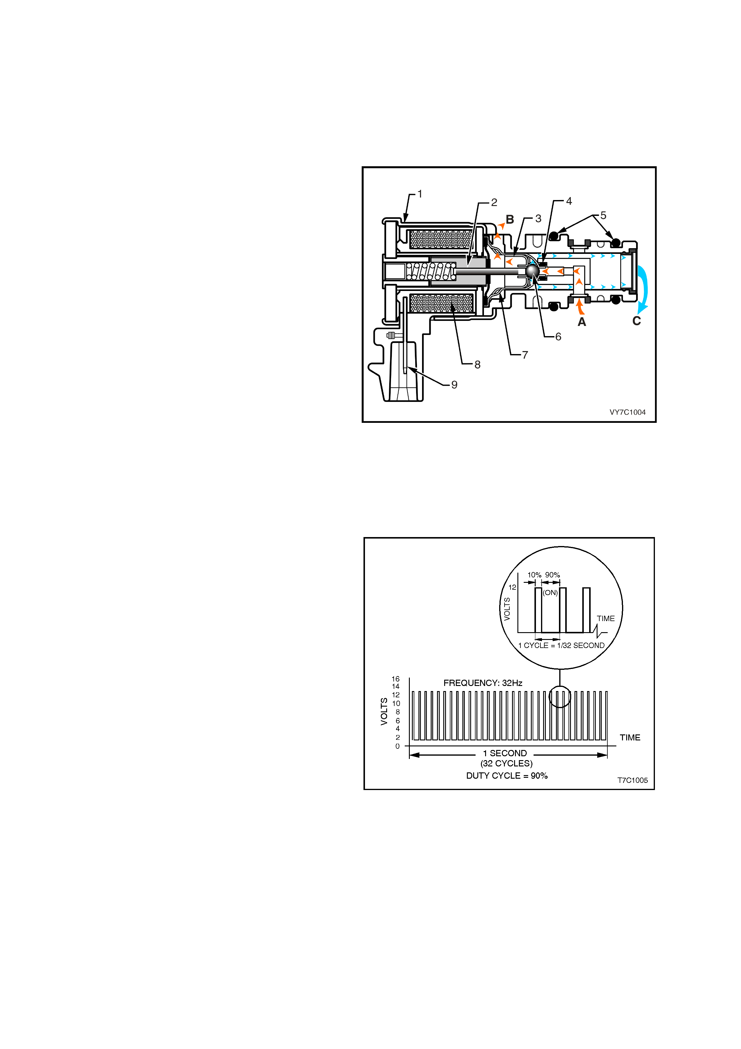
Legend:
1 Housing
2 Armature
3 Exhaust Seat
4 Internal O-Ring
5 O-Rings
6 Metering Ball
7 Inlet Seat
8 Coil Assembly
9 Connector Terminal
A Actuat or Feed Li mit (A FL) Fl ui d
B Exhaust
C Converter Clutch Signal (CC S IGNAL) Fluid
Figure 7C1-12
Shown is an example of the TCC PWM solenoid
operating with a 90% negative duty cycle at a
constant operating frequency of 32 Hz (cycles per
second). The frequency means that the solenoid is
pulsed (energised) with current from the PCM 32
times per second. The 90% negative duty cycle
means that during each of these 32 cycles the
solenoid is energis ed (ON) and 0 volts is m easur ed
on the low (negative) side of the circuit, 90% of the
time.
At road speeds below approximately 13 km/h, the
negative duty cycle will be 0%, which means that
no current will flow through the TCC PWM
solenoid, deactivating it. When in this condition,
spring force will move the plunger (refer
Figure 7C1-9), seating the metering ball and
blocking the filtered Actuator Feed Lim it (AFL) fluid
from entering the Converter Clutch Signal (CC
SIGNAL) circuit. This action opens the Converter
Clutch Signal fluid circuit to exhaust through the
solenoid.
Above road speeds of approximately 13 km/h, the
TCC PWM solenoid will be operating at about a
90% duty cycle. T his action will cause the metering
ball to close off the path to exhaust, most of the
time and allow AFL fluid to flow past the metering
ball and into the CC SIGNAL circuit, in readiness
for the apply of the torque converter clutch.
Figure 7C1-13
When the PCM signals TCC apply, the TCC PWM solenoid operates with a variable, negative duty cycle, ranging
from 90% to 0%, with an operating f requency of 32 Hz. This allows the PCM to control the cur rent flow through the
solenoid coil according to the duty cycle it sets. This has the effect of creating a variable magnetic field, that
magnetis es the s olenoid core, attrac ting the m etering ball to seat agains t spring force. A high percentage duty cyc le
keeps the metering ball will be seated more often, thereby creating higher TCC signal fluid pressures.
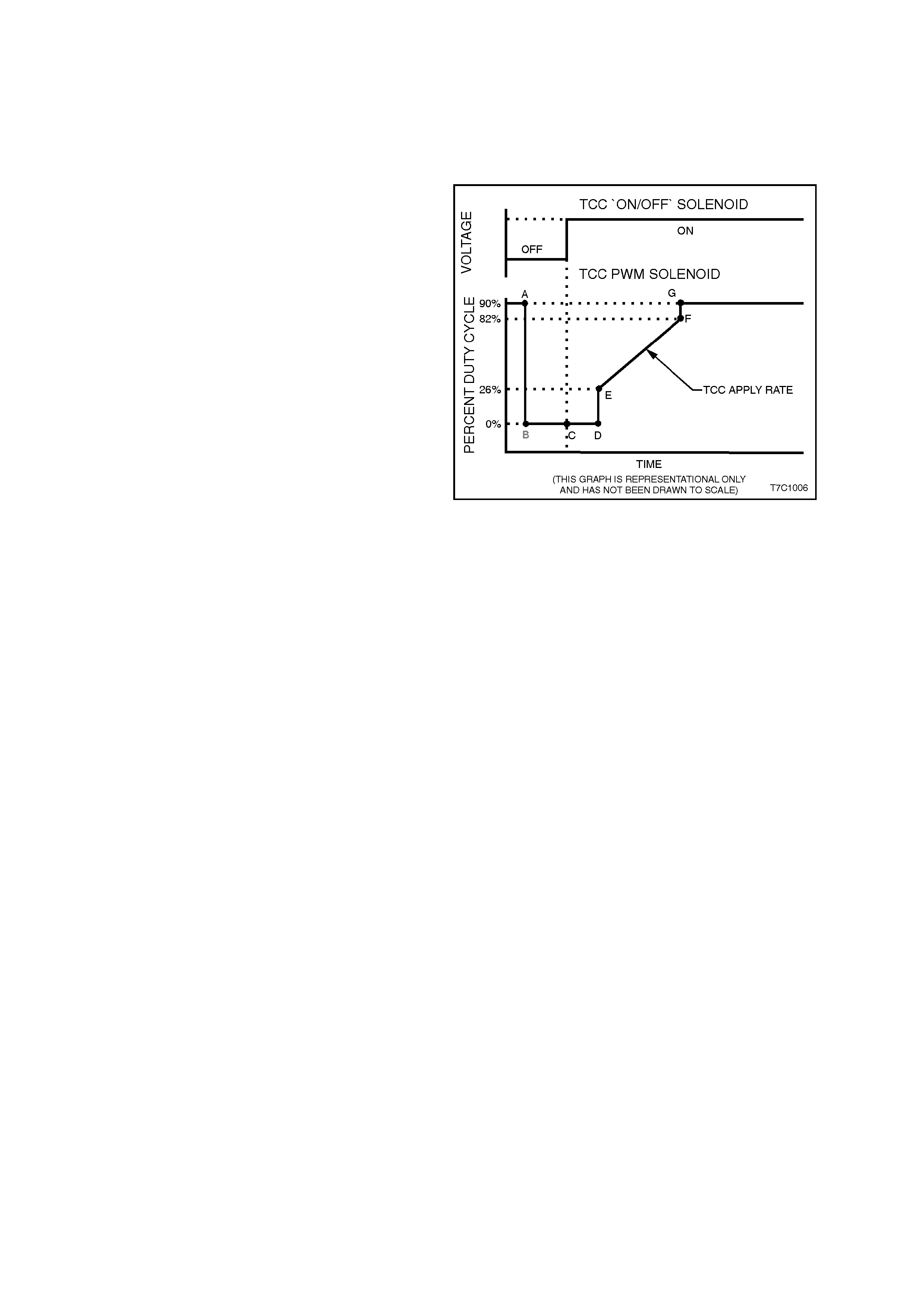
TCC PWM SOLENOID OPERATION
When vehicle road speed rises above about 13
km/h, the PCM causes the TCC PWM solenoid
duty cycle to change from 0% to 90% (point 'A'), in
readiness for an apply of the torque converter
clutch.
To apply the torque converter clutch, the process
the PCM adopts, is as follows;
• The duty cycle is dropped to 0% (point 'B') and
a m easurable am ount of tim e is allowed for the
'ON/OFF' TCC solenoid to turn on. This is
shown as the time between points 'B' and 'C', in
Figure 7C1-8. Note that, at point 'C', the TCC
'ON/OFF' solenoid is activated.
• The time from point 'C' to 'D' is used to allow
converter feed (CONV FD) fluid to build in
pressur e and move the Converter Clutc h Valve
into the apply position.
• At this point, with the TCC 'ON/OFF' solenoid
applied, the PCM then increases the duty cycle
to about 26% (point 'E'). From this point, the
duty cycle is 'ramped' to around the 82% point
('E' to 'F'). The rate at which the duty cycle is
increased over this period of time, determines
how quickly the value of the regulated apply
fluid increases and therefore, how quickly the
torque converter clutch is applied.
Figure 7C1-14
This rate of change also affects the converter
clutch apply 'feel'.
• As soon as the duty cycle reaches the 82%
value, it is then immediately increased to the
ma ximum of 90%, to ac hieve f ull apply pressure
in the regulated apply fluid circuit (point 'G').
NOTE: Both the duty cycle and apply pressure will
continually vary, depending on vehicle specific ation
and operating conditions.

3.3 TORQUE CONVERTER CLUTCH
GENERAL DESCRIPTION
W hile the Powertrain Control Module (PCM) continues to control the apply/releas e of the Torque Conver ter Clutch,
via the use of the T orque Conver ter Clutch s olenoid (as it does in earlier tr ansm issions ), the use of the Pulse Width
Modulated Torque Conver ter Clutch, ( T CC PWM) s olenoid (r ef er Figure 7C1-9), provides the ability of being able to
control more precisely, the rate of Torque Converter Clutch (TCC) apply and release.
Essentially the TCC PW M solenoid changes actuator feed limit (AFL) f luid to converter clutch signal (CC SIGNAL)
fluid, that is dir ected to the base of the Is olator Valve. Depending on the PCM controlled duty cycle, the T CC PW M
solenoid determines the value of the CC SIGNAL fluid pressure.
By having an electronically controllable, variable fluid pressure acting on the end of the Isolator Valve, the force
controlling the position of the REGULATED APPLY (REG APPLY) Valve is also variable.
This means that the Regulated Apply Valve can now vary the REGULATED APPLY (REG APPLY) fluid pressure
that is directed to the Converter Clutch Valve.
TORQUE CONVERTER CLUTCH – RELEASED
With the TCC 'ON/O FF ' s olenoid de-ac tivated (as deter mined by the PCM), the spring for ce acting on the end of the
Converter Clutch Valve positions the valve so that the torque converter hydraulic circuits function as follows:
• REGULATED APPLY fluid rests at the Converter Clutch Valve.
• Converter f eed (CONV FEED) fluid fr om the Pres sure Regulator Valve, (c onverted from LINE fluid) both passes
through an orifice at the base of the Converter Clutch Valve, to exhaust at the Normally Open (N.O.) TCC
'ON/OFF' solenoid and is directed through the Converter Clutch Valve to become RELEASE fluid.
• This circuit feeds RELEASE fluid to the front of the torque converter, past the torque converter pressure plate,
circulating through the torque converter to exit as APPLY fluid.
• After passing through the Converter Clutch Valve, APPLY fluid becomes COOLER fluid. Then, after it flows
through the cooler, it is used in the transmission LUBE circuits.
TORQUE CONVERTER CLUTCH – APPLIED
When the PCM determines that the torque converter clutch should be applied, the TCC 'ON/OFF' solenoid is
activated, closing off the exhaust port at the base of the Converter Clutch Valve. As previously explained, during this
period the TCC PWM solenoid duty cycle is dropped to zero.
This action causes the following hydraulic/electronic circuit changes to take place:
• Converter feed (CONV FEED) fluid pressure rapidly builds at the base of the Converter Clutch Valve, m oving it
upwards against spring force.
• Depending on the duty cyc le selected by the PCM, the rate of torque conver ter clutc h apply, is directly c ontrolled
by the TCC PWM solenoid. As previously stated, this occurs because the CC SIGNAL f luid acting on the end of
the Isolator Valve, changes the value of the spring force, that dictates the position of the Regulator Apply Valve.
Through this electronic control then, variable regulator apply (REGULATED APPLY) fluid now becomes
converter APPLY fluid, af ter it pass es through the Conver ter Clutch Valve. Theref or e, the r ate of apply, is direc tly
related to the value of this fluid pressure.
• Converter RELEASE fluid passes through to exhaust at the spring end of the Converter Clutch Valve. This action
allows the torque converter pressure plate to be for ced against the front face of the torque converter, creating a
frictional grip between the Impeller and the Turbine, effectively locking the assembly.
• Converter feed (CONV FEED) fluid now flows through the Converter Clutch Valve to become COOLER and
provide fluid flow through the cooler and supply LUBE fluid for various transmission components.
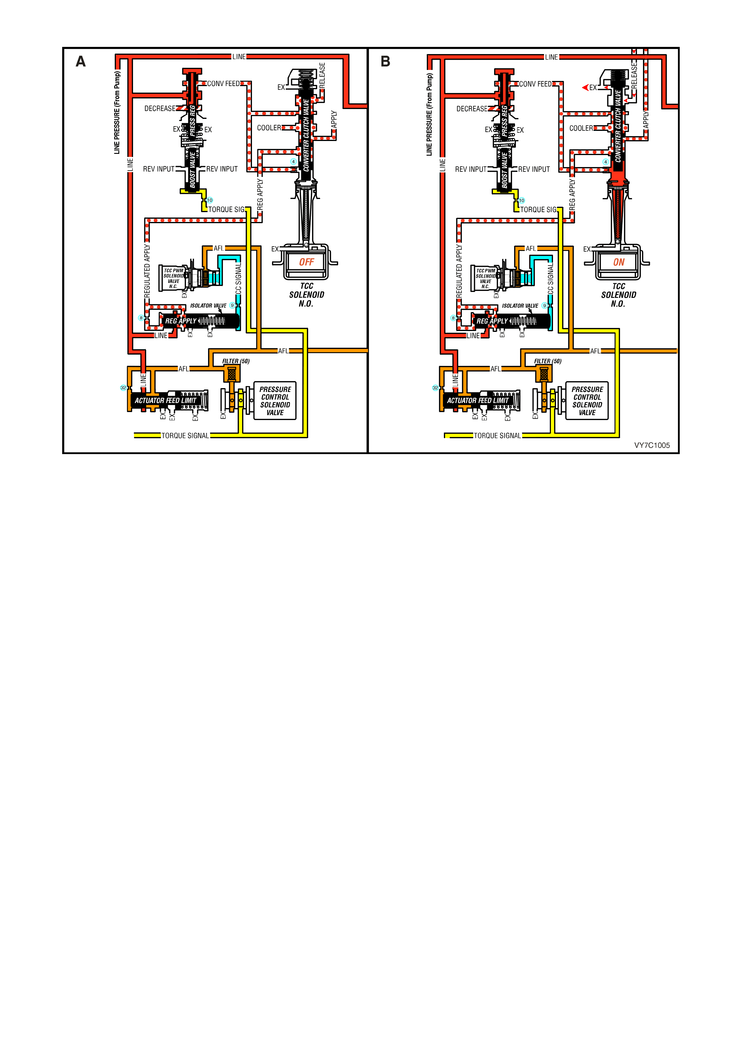
Figure 7C1-15 – Torque Converter Clutch – Released (‘A’) and Applied (‘B’)
3.4 3-2 DOW NS HIFT CONTROL SO LENOID
GENERAL DESCRIPTION
The 3-2 downshift control solenoid is a normally
closed solenoid and is used to control the 3-2
downshift.
During a 3-2 downshift, the 2-4 band is applied as
the 3-4 c lutch r eleases . The tim ing between the 3-4
clutch release and the 2-4 band apply not only must
be timed but it also must be varied, depending on
vehicle speed and throttle.
The PCM will turn the 3-2 control solenoid either
ON or OFF to control 3rd accumulator (3RD
ACCUM) pressure so that the release of the 3-4
clutch and the apply of the 2-4 band is such that a
bind-up or flair does not occur.
The normally closed 3-2 control solenoid is ON in
all drive gear s, ex c ept dur ing a 3-2 downshif t, when
the solenoid is turned O FF. T he am ount of tim e the
solenoid is ON, is determined by throttle position,
vehicle speed and the commanded gear.
Legend
1 Housing
2 Metering Ball
3 O-Ring
4 Fluid Screen
5 Plunger
6 Coil Assembly
7 Connector Terminals
8 Spring
A Pressure Apply (A FL)
B Exhaust
C Pressure Control (3-2 S i gnal )
Figure 7C1-16
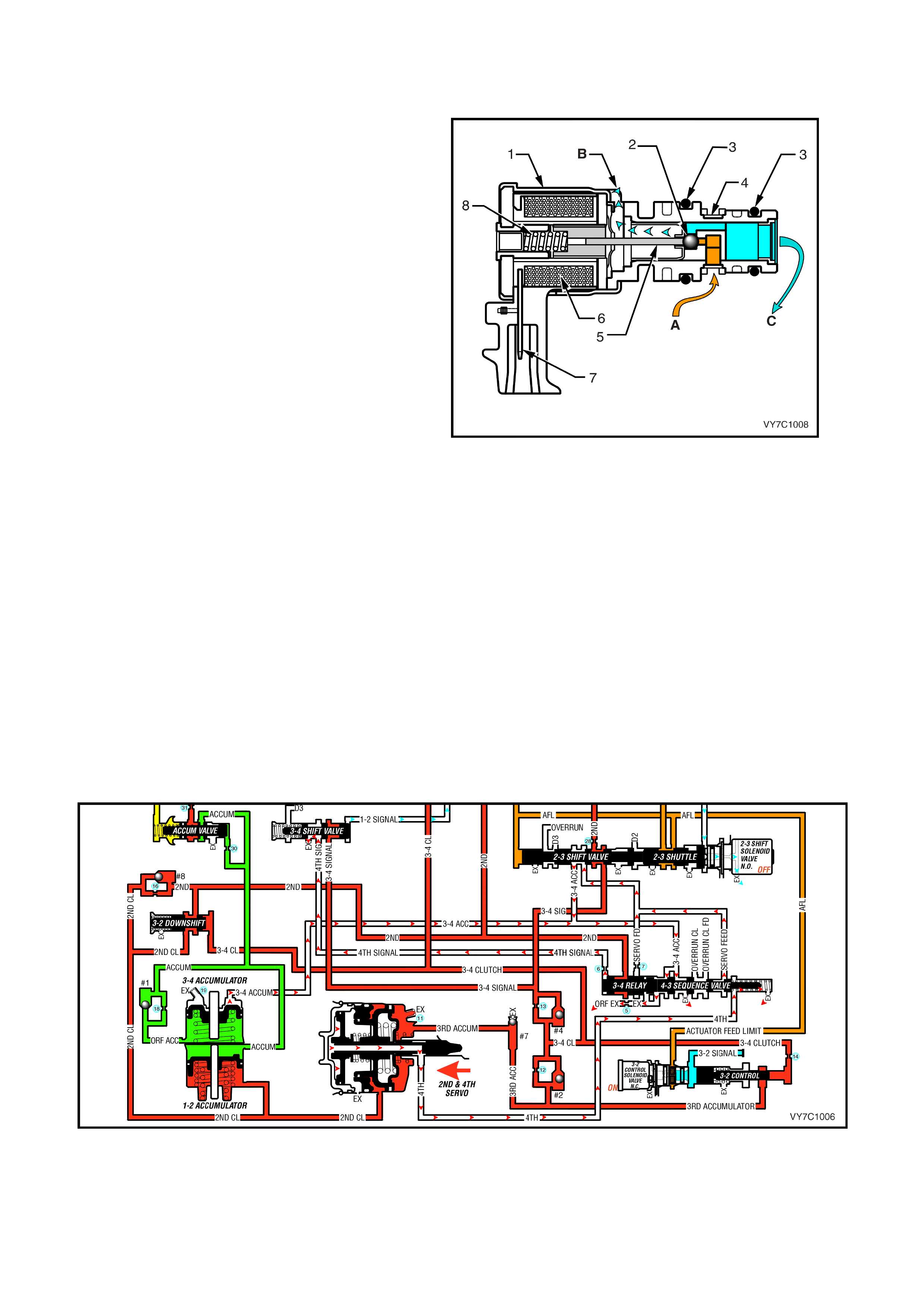
3-2 CONTROL SOLENOID OPERATION
Solenoid ON
W hen the solenoid is activated by the PCM, current flows through the solenoid coil, creating a magnetic field that
magnetises the solenoid core. This attracts the metering ball, moving the ball and plunger against spring force to
block the internal exhaust port, opening the valve and allowing ACTUATOR FEED LIMIT (AFL) fluid to act on the
end of the 3-2 c ontrol valve. When the f luid pressu re increas es enough, the valve will m ove away from the s olenoid
against spring force, closing the 3-2 control valve.
Figure 7C1-17 – 3-2 Downshift Control Solenoid ON
Solenoid OFF
W hen the solenoid is OFF, no current flows to the solenoid coil. A spring inside the solenoid, holds a plunger and
ball against the fluid inlet port that blocks ACTUATOR FEED LIMIT (AFL) fluid from acting on the large end of the 3-
2 control valve. This allows the 3-2 control valve spring force to push the valve to the solenoid, holding the 3-2
Control Valve open, exhausting any residual fluid through the solenoid.
Figure 7C1-18 – 3-2 Downshift Control Solenoid OFF
3-2 Downshift Timing
At higher vehicle speeds, the apply of the 2-4 band must be delayed to allow engine speed to increase suff iciently
for a smooth transfer of engine load to the 2-4 band. This is achieved by delaying the exhaust of 3rd
ACCUMULATOR (3RD ACCUM) fluid. Under these conditions (see Figure 7C1-14), the 3-2 control solenoid is
commanded ON, moving the 3-2 control valve away from the solenoid (closing the 3-2 Control Valve) during the
shift. This causes the exhausting 3-4 clutch fluid (3-4 CL) to seat check ball #4 and flow through orifice #13 to
exhaust at the 2-3 shift valve, via the 3-4 Signal (3-4 SIG) circuit.
While this 3-4 clutch exhaust is in process, the apply rate of the 2-4 band is governed by the exhausting 3rd
accumulator (3RD ACC) fluid. The initial fluid flow seats check ball #7 and, with the 3-2 control valve closed, 3rd
accumulator (3RD ACC) fluid also seats check ball #2. Fluid then must pass through both orifice #12 and #13 to
exhaust through the 3-4 signal (3-4 SIG) passage. This action delays the apply of the 2-4 band to effect a sm ooth
downshift.
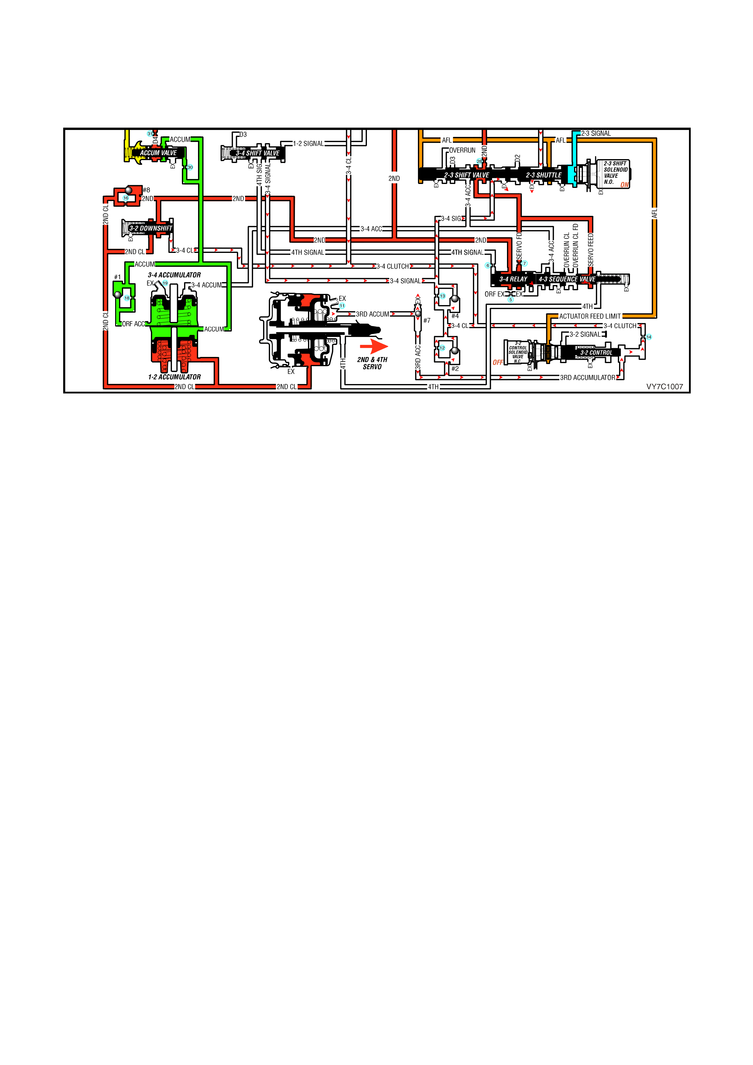
At lower vehicle speeds (see Figure 7C1-15), when the band must be applied more quickly, the PCM commands
the 3-2 control solenoid OFF, allowing spring force to move the control valve to the solenoid (opening the valve).
This now opens another circuit, allowing 3rd accum ulator (3RD ACC) fluid to f low thr ough both orifice #12 and #14
to exhaust with the 3-4 clutch fluid. This allows the 2-4 band to be applied more quickly for the correct shift timing
under these operating conditions.

4. TRANSMISSI ON DEFINITIONS AND ABBREVIATIONS
The following definitions and abbreviations are provided to establish a common language and assist the user in
describing transmission related conditions. The use of these terms and/or conditions can be found in the various
parts of the automatic transmission sections of the MY2003 Service Information, but more particularly, in
Section 7C3 HYDRAULIC/MECHANICAL DIAGNOSIS.
4.1 DEFINITIONS
The following definitions have been arranged in alphabetical order and are intended to assist the user with an
explanation of their meaning, in order to gain the maximum benefit from those Sections of the MY2003 Service
Inform ation that deal with the Hydra-matic 4L60-E, Autom atic T rans m ission. T here are additional, unique def initions
in Section 7C3 HYDRAULIC/MECHANICAL DIAGNOSIS that should also be refer red to when using that partic ular
information.
Accumulator - A component of the transmission that absorbs hydraulic pressure during the apply of a clutch or
band. Accumulators are designed to control the quality of a shift from one gear range to anther. within
Adaptive Learning - Programming within the PCM that automatically adjusts hydraulic pressures in order to
compensate for changes in the transmission (i.e. component wear).
Applied - An 'Applied Com ponent' is one that is holding another com ponent to which it is splined or as sembled to.
Also referred to as "engaged".
Apply Components - Hydraulically operated clutches, servo’s, bands and mechanical one-way roller or sprag
clutches that drive or hold members of a planetary gear set.
Apply Plate - A steel clutch plate in a clutch pack, located next to the (apply) piston.
Backing Plate - A steel plate in a c lutch pack that is usually the last plate in that clutch ass em bly (furthest f rom the
clutch piston).
Band - An apply component that cons ists of a flex ible strip of steel and f riction mater ial that wraps around a drum.
When applied, it tightens around the drum and prevents the drum from rotating.
Brake Switch - An electrical device that provides signals to the Powertrain Control Module (PCM), based on the
position of the brake pedal. The PCM uses this information to apply or release the torque converter clutch (TCC).
Centrifugal Force - A force that is imparted on an object (due to rotation) that increases as that object moves
further away from a centre-point of rotation.
Checkball - A spherical, hydraulically controlled component (usually of steel) that either seals or opens fluid circuits.
It is also referred to as a check valve.
Clutch Pack - An assembly of components generally consisting of clutch plates, an apply plate and a backing plate.
Clutch Plate - An hydraulically activated component that has two basic designs : ( 1) all s teel, or (2 ) a s teel c ore with
friction material bonded to one or two sides of the plate.
Control Valve Body - A machined metal casting that contains valve trains and other hydraulically controlled
components that shift the transmission.
Coupling Speed - The speed at which a vehicle is travelling and no longer requires torque multiplication through
the torque converter. At this point, the stator 'free wheels' to allow fluid leaving the turbine to flow directly to the
pump. (Also see Torque Converter).
De-energise(d) - To interrupt the electrical current that flows to an electronically controlled device, making it
electrically inoperable.
Direct Drive - A condition in a gears set where the input speed and input torque equals the output speed and output
torque. The gear ratio through the gear set is 1:1.
Downshift - A change in a gear ratio where both input speed and torque increases.
Duty Cycle - In reference to an electronically controlled solenoid, it is the amount of time (expressed as a
percentage) that current flows through the solenoid coil.
Energise(d) - To supply a current to an electronically controlled device, enabling it to perform its designed function.
Engine Compression Braking - A condition where com pression from the engine is used with the transm ission to
decrease vehicle speed.
Exhaust - The release of fluid pressure from a hydraulic circuit. (The words 'exhausts' and 'exhausting' are also
used and have the same intended meaning.)
Fail-Safe Mode - A condition whereby a component (i.e. engine or transmission) will partially function even if its
electrical circuit is disabled.
Fluid - In this Section of the Service Manual, 'fluid' refers primarily to Automatic Transmission Fluid (or ATF) and,
for the Hydra-matic 4L60-E transmission, the only recommended fluid is Dexron III®.
Fluid Pressure - A pressure that is consistent throughout a given fluid circuit.
Force - A measurable effort that is exerted on an object (component).

Freewheeling - A condition where power is lost through a driving or holding device (i.e. roller or sprag clutches).
Friction Material - A heat and wear resistant fibrous material, bonded to clutch plates and bands.
Gear - A round, toothed device that is used for transmitting torque through other components.
Gear Range - A specific speed to torque ratio at which the transmission is operating (i.e. 1st gear, 2nd gear etc.).
Gear Ratio - Revolutions of an input gear as compared to the revolutions of an output gear. It can also be
expressed as the number of teeth on a gear as compared to the number of teeth on a gear that it is in mesh with.
Hydraulic Circuit - A fluid passage which often includes the mechanical components in that circuit designed to
perform a specific function.
Input - A starting point for torque, revolutions or energy into another component of the transmission.
Internal Gear - The outer m ost m em ber of a gear s et that has gear teeth in c onstant m esh with the planetary pinion
gears of the gear set.
Land (Valve Land) - The larger diameters of a spool valve that contact the valve bore or bushing.
Line Pressure - The main fluid pressure in a hydraulic system created by the pump and pressure regulator valve.
Manual Valv e - A spool valve that distributes fluid to various hydraulic circuits and is mechanically linked to the gear
sele ctor lever.
Orifice - A restricting device (usually a hole in the spacer plate) for controlling pressure build up into another circuit.
Overdrive - An operating condition in the gear set allowing output speed to be higher than input speed and output
torque to be lower than input torque.
Overrunning - The function of a one-way mechanical clutch that allows the clutch to freewheel during certain
operating conditions of the transmission.
Pinion Gears - Pinion gears ( housed in a car rier) that ar e in constant m es h with a circum f erential internal gear and
centralised sun gear.
Planetary Gear Set - An ass em bly of gears that consis ts of an internal gear, planet pinion gears with a carrier, and
a sun gear.
Powertrain Control Module (PCM) - An electronic device that manages the vehicle's engine and automatic
transmission functions.
Pressure - A measurable force that is exerted on an area and expressed as kilopascals (kPa).
Pulse Width Modulated (PWM) - An electronic signal that continuously cycles the ON and OFF time of a device
(such as a solenoid) while varying the amount of ON time.
Race (Inner or Outer) - A highly polished steel surface that contacts bearings or sprag or roller elements.
Reduction (Gear Reduction) - An oper ating condition in the gear set allowing output speed to be lower than input
speed and output torque to be higher than input torque.
Residual Fluid Pressure - Excess pressure contained within an area after the supply pressure has been
terminated.
Roller Clutch - A mechanical clutch (holding device) consisting of roller bearings assembled between inner and
outer races.
Servo - A spring loaded device consisting of a piston in a bore that is operated (stroked) by hydraulic pressure to
apply or release a band.
Spool Valve - A round hydraulic control valve often containing a variety of land and valley diameters.
Sprag Clutch - A mechanical clutch (holding device consisting of "figure eight" like elements assembled between
inner and outer races.
Throttle Position - The travel of the throttle plate that is expressed in percentages and measured by the Throttle
Position Sensor (TP Sensor).
Torque - A measurable twisting force expressed in terms of Newton metres (Nm).
Torque Converter - A component of an automatic transmission, (attached to the engine flexplate) that transfers
torque from the engine to the transmission through a fluid coupling.
Variable Capacity Pump - The device that provides fluid for operating the hydraulic circuits in the transmission.
The amount of fluid supplied varies depending on vehicle operating conditions.

4.2 ABBREVIATIONS
2WD – Two Wheel Drive.
AC – Alternating Current
A/C – Air Conditioning
AFL – Actuator Feed Limit
DC – Direct Current
D.C. – Duty Cycle
DLC – Diagnostic Link Connector
DTC – Diagnostic Trouble Code
ECT Sensor – Engine Coolant Temperature Sensor.
N.C. – Normally Closed
N.O. – Normally Open
PCM – Powertrain Control Module.
PCS – Pressure Control Solenoid (or Force Motor)
PIM – Powertrain Interface Module (GEN III V8 Engine Only )
PWM – Pulse Width Modulated
RWD – Rear Wheel Drive.
TCC – Torque Converter Clutch.
TFP Switch – Transmission Fluid Pressure Manual Valve Position Switch
TFT – Transmission Fluid Temperature Sensor.
TP Sensor – Throttle Position Sensor.
VS Sensor – Vehicle Speed Sensor.

5. SERVICE NOTES
In the interests of safety to personnel, equipm ent and to the vehicle and its com ponents, the following notes should
be read and adhered to whenever servicing operations are to be carried out on the Hydra-matic 4L60-E autom atic
transmiss ion. In addition, s ome of this inf or mation also r ef er s to the adher enc e to sound workshop pr ac tices and, to
achieve the design life of affected components, it is also recommended that these points are taken into account.
5.1 FASTENERS
• Always reinstall fasteners in the same locations as they were removed.
• If a f astener requires replacem ent, always use a par t of the correc t part num ber or of equal s ize and st rength or
stronger.
• Tighten fasteners to correct torque value when required. Torque values are specified for dry, unlubricated
fastener threads.

5.2 GENERAL WORKSHOP PRACTICE
• Keep work area and tools clean.
• To avoid unnecessary contamination, always clean the exterior of the transmission before removing any parts.
• Do not use wiping cloths or rags because of the risk of lint being trapped in the transmission.
• Do not use solvents on:
− neoprene seals.
− composition faced clutch plates.
− thrust washers.
• Always wear eye protection when using compressed air on components.
• Blow out all passages with compressed air. Only probe small passages with soft, thin wire.
• Handle parts with care to avoid nicks and scratches.
• Do not remove Teflon oil seal rings unless damaged or performing a complete overhaul.
• Expand internal snap rings and compress external snap rings to maximise retention and security.
• Lubricate all internal parts with transmission fluid (Only use Dexron® III), as they are being installed.
• When installing cap screws into aluminium castings:
− always use a torque wrench.
− always dip screw threads in transmission fluid (Only use Dexron® III).
− Stripped or damaged threads in aluminium castings may be reconditioned by using commercially available
thread inserts.
• Once removed, replace all gaskets, seals and O-rings with new parts and:
− always use seal protectors where indicated and do not use gasket cement or sealant on any joined face
unless specified to do so.