
SECTION 7C3 - HYD RA-MATIC 4L60-E AUTOM ATIC
TRANSMISSION – HYDRAULIC / MECHANICAL
DIAGNOSIS
IMPORTANT:
Before performing any Service Operation or other procedure described in this Section, refer to Section
00 CAUTIONS AND NOTES for correct workshop practices with regard to safety and/or property damage.
CONTENTS
1. GENERAL INFORMATION
1.1 HOW TO USE THIS SECTION2
1.2 TRANSMISSION GENERAL DESCRIPTION
1.3 TRANSMISSION DEFINITIONS AND
ABBREVIATIONS
THROTTLE POSITIONS
SHIFT CONDITIONS
NOISE CONDITIONS
ABBREVIATIONS
2. DIAGNOSIS
2.1 BASIC KNOWLEDGE REQUIRED
SPECIAL TOOLS
2.2 FUNCTIONAL TEST PROCEDURE
2.3 TRANSMISSION FLUID CHECKING PROCEDURE
2.4 LINE PRESSURE CHECK
PRELIMINARY INFORMATION
PROCEDURE
2.5 ROAD TEST PROCEDURE
PRELIMINARY INFORMATION
ELECTRICAL FUNCTION CHECK
UPSHIFT CONTROL AND TORQUE
CONVERTER CLUTCH (TCC) APPLY
PART THROTTLE DETENT DOWNSHIFTS
FULL THROTTLE DETENT DOWNSHIFT
MANUAL DOWNSHIFTS
COASTING DOWNSHIFTS
MANUAL GEAR RANGE SELECTION
2.6 TORQUE CONVERTER DIAGNOSIS
PROCEDURE
TORQUE CONVERTER STATOR
NOISE
TORQUE CONVERTER CLUTCH SHUDDER
2.7 TORQUE CONVERTER/FLEXPLATE VIBRATION
TEST
EVALUATION
RECTIFICATION
2.8 NOISE AND VIBRATION ANALYSIS
2.9 CLUTCH PLATE DIAGNOSIS
COMPOSITION PLATES
STEEL PLATES
2.10 ENGINE COOLANT IN TRANSMISSION
2.11 FLUID LEAK DIAGNOSIS AND REPAIR
METHODS FOR LOCATING LEAKS
REPAIRING THE LEAK
POSSIBLE POINTS OF FLUID LEAKS
CASE POROSITY REPAIR
2.12 SHIFT SOLENOID LEAK TEST
2.13 SYMPTOM DIAGNOSIS
SYMPTOM DIAGNOSIS TABLE
2.14 DIAGNOSTIC TABLES
OIL PRESSURE HIGH OR LOW
HARSH SHIFTS
INACCURATE SHIFT POINTS
FIRST GEAR RANGE ONLY – NO UPSHIFT
SLIPS IN FIRST GEAR
SLIPPING OR ROUGH 1-2 SHIFT
NO 2-3 SHIFT OR SHIFT SLIPS, ROUGH OR
HUNTING
2ND/3RD GEAR ONLY OR 1ST/4TH GEARS ONLY
THIRD GE AR ONLY
3-2 FLARE OR TIE-UP
NO 3-4 SHIFT, SLIPS OR ROUGH 3-4 SHIFT
NO REVERSE OR SLIPS IN REVERSE
NO PART THROTTLE OR DELAYED DOWNSHIFTS
HARSH GARAGE SHIFT
NO OVERRUN BRAKING – MANUAL 3-2-1
NO TORQUE CONVERTER CLUTCH APPLY
TORQUE CONVERTER CLUTCH SHUDDER
NO TORQUE CONVERTER CLUTCH RELEASE
DRIVES IN NEUTRAL
2ND GEAR START
NO PARK
OIL OUT THE VENT
VIBRATION IN REVERSE AND WHINING NOISE
IN PARK
RATCHETING NOISE
NO DRIVE IN ALL RANGES
NO DRIVE IN DRIVE RANGE
FRONT OIL LEAK
DELAY IN DRIVE AND REVERSE
2.15 RANGE REFERENCE CHAR T
3. MY2003 4L60-E SHIFT SPEED CHARTS
3.1 INTRODUCTION
3.2 V6 ENGINE – ALL
3.3 V6 SUPERCHARGED ENGINE
3.4 GEN III V8 ENGINE – HIGH/LOW OUTPUT
4. FLUID FLOW AND CIRCUIT DESCRIPTIONS
4.1 PARK – ENGINE RUNNING
4.2 NEUTRAL – ENGINE RUNNI NG
4.3 DRIVE (OVERDRIVE) RANGE, FIRST GEAR
4.4 DRIVE (OVERDRIVE) RANGE, SECOND GEAR
4.5 DRIVE (OVERDRIVE) RANGE, THIRD GEAR
(TCC APPLIED)
4.6 DRIVE (OVERDRIVE) RANGE, FOURTH GE AR
(TCC APPLIED)
4.7 DRIVE (OVERDRIVE) RANGE, 4-3 DOWNSHIFT
4.8 DRIVE (OVERDRIVE) RANGE, 3-2 DOWNSHIFT
4.9 MANUAL THIRD – TCC APPLIED
4.10 MANUAL SECOND GEAR
4.11 MANUAL FIRST GEAR
4.12 REVERSE
5. HYDRAULIC PATHS IN TRANSMISSION
COMPONENTS
6. SPECIAL TOOLS
Techline
Techline

1. GENERAL INFORMATION
1.1 HOW TO USE THIS SECTION
This Section contains a description of the HYDRA-MATIC 4L60-E procedures for diagnosing the
hydraulic/mechanical aspects of this transmission. However, before diagnosing any 4L60-E HYDRA-MATIC
transmission, ALWAYS begin with the FUNCT ION AL T EST PROCEDURE detailed in this Section.
After the cause of a condition has been determined, refer to Section 7C4 ON-VEHICLE SERVICING or
Section 7C5 UNIT REPAIR, for the necessary procedures.
Alternatively, if the condition is considered to be electrical/electronic in nature, then refer to either ,
Section 6C1 POWERTRAIN MANAGEMENT – V6 ENGINE, Section 6C2 POWERTRAIN MANAGEMENT – V6
SUPERCHARGED ENGINE or Section 6C3 POWERTRAIN MANAGEMENT – GEN III V8 ENGINE, depending
on the engine fitted to the vehicle.
1.2 TRANSMISSION GENERAL DESCRIPTION
The Hydra-Matic 4L60-E is a fully automatic, four speed, rear wheel drive transmission. It consists primarily of a
four element torque converter, two planetary gear sets, various clutches, an oil pump and a control valve body.
The four element torque converter contains a pump, a turbine, a pressure plate splined to the turbine a nd a stator
assembly. The torque converter acts as a fluid coupling to transmit power smoothly from the engine to the
transm ission. It also provid es additional h ydraulic torque multiplication when required. When applied, the pressure
plate provides a mechanical direct drive (or ‘locked’) coupling of the engine to the transmission.
The two planetary gear sets provide the four forward gear ratios and reverse. Changing of the gear ratios is fully
automatic and is accomplished through the use of various electronic sensors that provide input signals to the
Powertrain Control Module (PCM).
The PCM interprets these signals to send current to the various solenoids inside the transmission. By using
electronics, the PCM controls shift points, shift feel and torque converter clutch apply and release, to provide proper
gear ranges for maximum fuel economy and vehicle performance.
Five m ulti ple- dis c c lutc h es, one r o ll er c lutc h, a sp rag c l utch an d a br ake band pro v ide t he f r ic tio n el ements requir e d
to obtain the various ratios with the planetary gear sets.
An hydraulic system (the control valve body), pressurised by a vane type pump, provides the working pressure
needed to operate the clutch pistons, band servos and automatic controls.
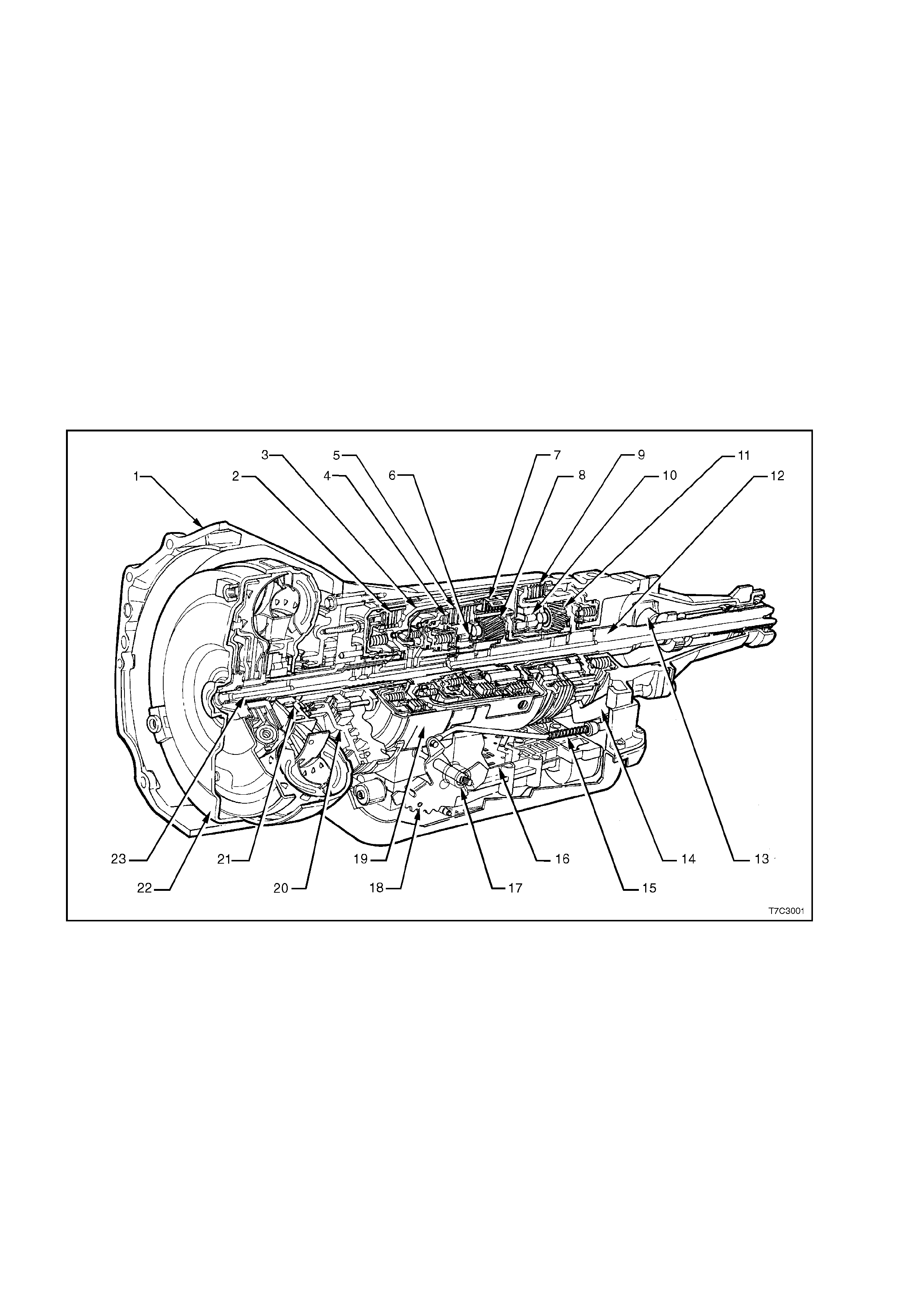
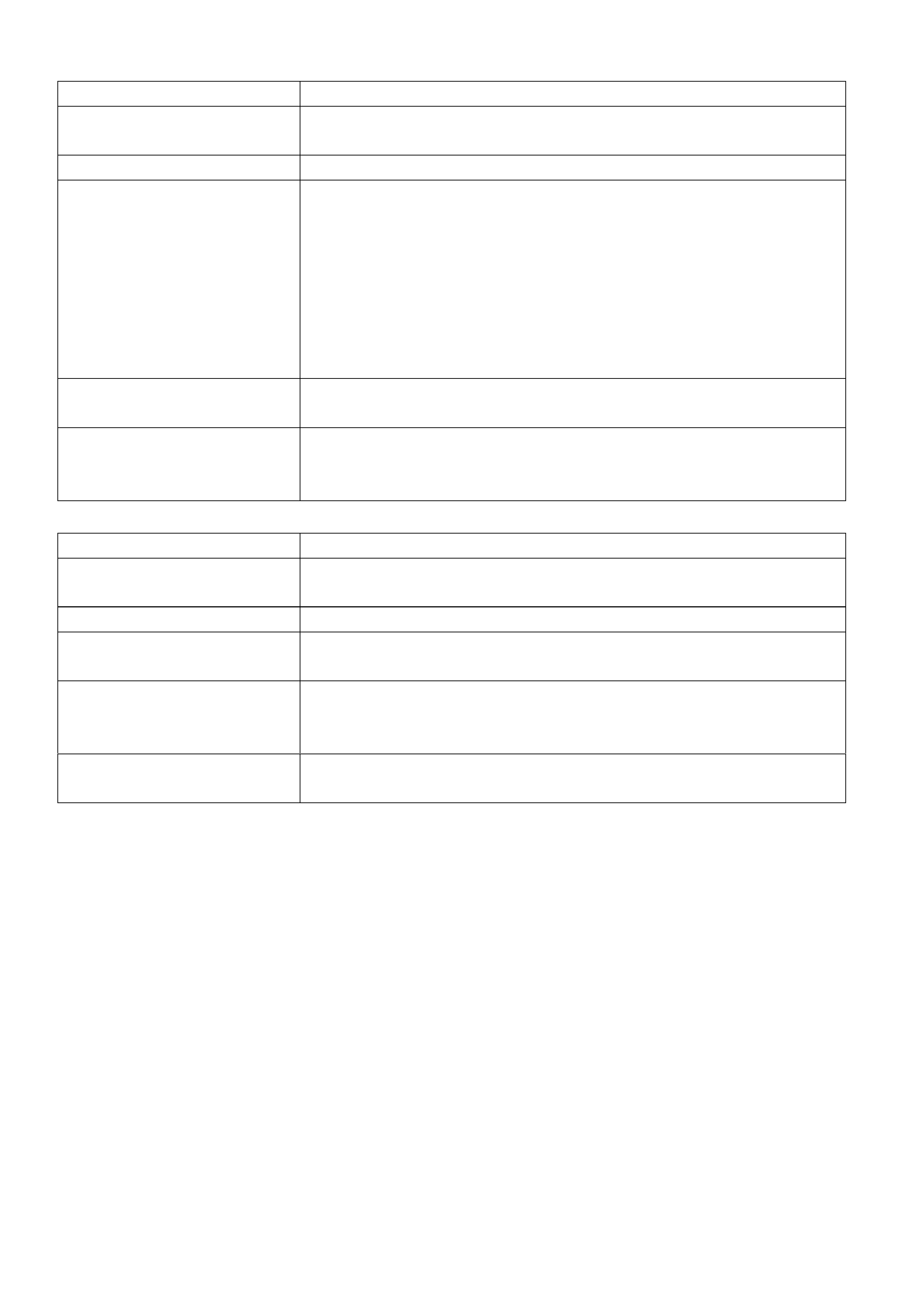
The general arrangement and location for the majority of mechanical and hydraulic components is as shown.
Figure 7C3-1
Legend
1. Case Assembly
2. Reverse Input Clutch
3. Input Clutch Housing
4. Overrun Clutch
5. Forward Clutch
6. Forward Clutch Sprag Assembly
7. 3 – 4 Clutch
8. Input Planetary Gear Set
9. Low and Reverse Clutch
10. Low Roller Clutch Assembly
11. Reaction Planetary Gear Set
12. Output Shaft
13. Speed Sensor
14. Parking Pawl
15. Parking Lock Actuator Assembly
16. Control Valve Assembly
17. Manual Shaft
18. Inside Detent Lever
19. 2 – 4 Band Assembly
20. Pump Assembly
21. Stator Roller Clutch
22. Torque Converter Assembly
23. Turbine Shaft

1.3 TRANSMISSION DEFINITIONS AND ABBREVIATIONS
The following Definitions and Abbreviations are provided to establish a common language for describing
transmission related conditions. Taking the few minutes required to read this information may easily overcome
unnecessary waste of time by being familiar with the terminology used within this Diagnosis Section.
THROTTLE POSITIONS
Minimum Throttle – the least amount of throttle opening required for an upshift.
Light Throttle – approximately 1/4 of accelerator pedal travel (25% Throttle Position).
Medium Throttle – approximately 1/2 of accelerator pedal travel (50% Throttle Position).
Heavy Throttle – approximately 3/4 of accelerator pedal travel (75% Throttle Position).
Wide Open Throttle (WOT) – full travel of the accelerator pedal ( 100% Throttle Position).
Full Throttle Detent Downshift – a quick apply of the accelerator pedal to its full travel, forcing a downshift.
Zero Throttle Coastdown – a full release of the accelerator pedal while the car is in motion and in drive range.
Engine Braking – a condition where the engine is used to slow the car by manually downshifting during a zero
throttle coastdown.
SHIFT CONDITIONS
Bump – a sudden and forceful apply of a clutch or band.
Chuggle – a bucking or jerk ing ma y be most noticeab le when th e conv erter clutc h is engaged; sim ilar to the f eel of
towing a trailer.
Delayed – a condit ion where a s hift is expected but does not occur for a period of time. Exam ples of this could be
described as clutch or band engagement that does n ot occur as quickly as expected during a part throt tle or wide
open throttle appl y of the accelerator or, when manua lly downshiftin g to a lower r ange. Also defined as “ LATE” or
“EXTENDED”.
Double Bump (Double Feel) – two sudden and forceful applications of a clutch or band.
Early – a condition where the shift occurs before the car has reached proper speed. Tends to labour the engine
after the upshift.
End Bump – a firm er feel at the en d of a shift, com pared to the f eel at the star t of the shift. A lso defined a s “END
FEEL” or “SLI P BUM P”.
Firm – a noticeably quick apply of a clutch or band that is considered normal with a medium to heavy throttle.
Should not be confused with “HARSH” or “ROUGH”.
Flare – a quick inc rease i n eng ine rpm alon g with a mom entar y loss of torque. T his m ost generall y occur s dur ing a
shift. Also defined as ‘SLIPPING’’.
Harsh (Rough) – a more noticeable apply of a clutch or band as compared with “FIRM”. This condition is
considere d undesirable at an y throttle pos it io n.
Hunting – a repeating quick series of upshifts and downshifts that causes a noticeable change in engine rpm. An
example could be described as a 4-3-4 shift pattern. Also defined as “BUSYNESS”.
Initial Feel – a distinct firmer feel at the start of a shift as compared to the finish of the shift.
Late – a shift that occurs when the engine is at a higher than normal rpm for a given amount of throttle.
Shudder – a repeating jerking condition sim ilar to “CHUGGLE” but more severe and rap id. This condition may be
most noticeable during certain ranges of car speed.
Slipping – a noticeable increase in engine rpm without a car speed increase. A s lip usually occurs during or after
initial clutch or band apply.
Soft – a slow, almost unnoticeable clutch or band apply with very little shift feel.
Surge – a repeating engine related condition of acceleration and deceleration that is less intense than
“CHUGGLE”.
Tie-Up – a condition where t wo opposin g clutches a nd/or bands ar e attem pting to appl y at the sam e time c ausing
the engine to labour with a notic e ab le loss of engine rp m.
NOISE CONDITIONS
Planetary Gear Noise – a whine related to car speed most noticeable in first gear or reverse. Becomes less
noticeable after an upshift.
Pump Noise – a high pitch whine that inc reas es with eng ine rpm.

ABBREVIATIONS
PCM - Powertrain Control Module.
TCC - Torque Converter Clutch.
TP Sensor – Throttle Position Sensor.
ECT Sensor – Engine Coolant Temperature Sensor
VS Senso r – Vehicle Speed Sensor.
TFP VAL. POSITION SW. – Tr ansmission Fluid Pres s ur e Manual Val ve Posit io n Swit c h
PSA - Transmission Range (TR) Pressure Switch Assembly.
TTS – Transmission Fluid Temperature Sensor.

2. DIAGNOSIS
2.1 BASIC KNOWLEDGE REQUIRED
You must be familiar with some basic electronics to use this section of the Service Manual. They will help you to
follow diagnostic procedures.
NOTE: A lack of basic knowledge of this powertrain when performing diagnostic procedures, could result in
incorrec t diagnostic p erform ance or damage to po wertrain com ponents. Do n ot, under an y circum stances, attem pt
to diagnose a powertrain problem without this basic knowledge.
SPECIAL TOOLS
You shou ld be abl e to use a break out b ox, a Dig ital Mult i Meter (D MM), a cir cuit tester, j umper wires or lea ds and
a line pressure gauge set. Having access to and the ability to use Tech 2 would also be a distinct advantage, as
many aspects of transmission diagnosis requires the use of this instrument.
The Functional Test Procedure detailed next, is designed to verify the correct operation of components in the
transmission and to identify whether a condition is electrical in nature, or not. This will eliminate the unnecessary
removal of transmission components and time loss in rectification.

2.2 FUNCTIONAL TEST PROCEDURE
When diagnosing any HYDRA-MATIC – 4L60-E related condition, ALWAYS begin with this Functional Test
Procedure. This procedure will indicate the proper path of diagnosing the transmission, by describing the basic
checks and then referencing the locations of specific checks.
The Func tional Tes t Procedure is th e first step in d iagnosin g mechanic al or hydraulic transm ission conditions . The
Functional Test provides procedures and references to the Symptom Diagnosis table for specific diagnostic
information.
STEP ACTION YES NO
1. IMPORTANT: Engine performance can greatly affect transmission
performance. Ensure that the complaint is not the result of poor
engine performance before continuing.
1. Verify the customer complaint.
Has the customer complaint been verified?
Go to Step 2
–
2. Has the Powertrain On Board Diagnostic (OBD) System Check been
performed?
IMPORTANT: If a DTC fault is detected, the transmission may
activate default actions that could be interpreted as being a
transmissi on concern.
Go to Step 3
Go to PCM – On
Board Diagnostic
(OBD) System
Check in
6C1-2A (V6),
6C2-2A (V6 S/C)
or 6C3-2A
(GEN III V8)
3. 1. Perform a visual inspection. Look for the following conditions:
– Vehicle damage.
– Transmi ssi on oil pan dam age.
Refer to 7C4 ON-VEHICLE SERVICE OPERATIONS
2. Worn or damaged suspension parts. Refer to 3. FRONT
SUSPENSION.
3. Worn or damaged steering parts. Refer to 9 STEERING.
4. Transmission range selector linkage damaged or out of
adjustment. Refer to Selector Linkage Adjustment in 7C4 ON-
VEHICLE SERVICING.
5. Loose, worn, damaged or missing:
− Mounts or struts
− Brackets
− Mounting hardware
Refer to Transmission Assembly Remove in 7C4 ON-VEHICLE
SERVICING.
6. Transmission cooler or cooler line restrictions. Refer to
Transmission Cooler Reverse Flush and Flow Rate Check in 7C4
ON-VEHICLE SERVICING.
7. Fluid leaks. Refer to 2.11 FLUID LEAK DIAGNOSIS AND
REPAIR in this Section.
Was an item identified that needs service?
Go to the
Appropriate
Repair or
Diagnosis Section
Go to Step 4
4. 1. Perform the Transmission Fluid Checking Procedure in this
Section.
Is the procedure complete?
Go to Step 5
Go to 2.3
Transmission
Fluid Checking
Procedure in this
Section.
5. 1. Perform the Road Test Procedure detailed in this Section.
Did the vehicle exhibit any objectionable condition?
Go to Step 6
System OK
6. Did the vehicle exhibit objectionable torque converter operation? Go to Step 15 Go to Step 7
7. Did the vehicle exhibit a noise condition? Go to 2.13
SYMPTOM
DIAGNOSIS
(Noise and
Vibration
Diagnosis) in this
Section.
Go to Step 8
8. Did the vehicle exhibit a vibration condition? Go to Step 9 Go to Step 10

STEP ACTION YES NO
9. Did the vibration occur only during TCC apply or release?
Go to Step 15
Go to 2.13
SYMPTOM
DIAGNOSIS
(Noise
and Vibration
Diagnosis)
in this Section.
10 1. Did the vehicle exhibit a shift speed condition such as low or high
shift speeds?
Go to 2.13
SYMPTOM
DIAGNOSIS (Shift
Speed Diagnosis)
in this Section.
Go to Step 11
11. 1. Check for any if the following shift quality (feel) conditions:
• Harsh, soft, delayed or no engagement.
• Harsh, soft or delayed shifts.
• Shift shudder, flare or tie-up.
Were any of these conditions evident?
Go to Step 12
Go to Step 13
12. 1. Perform the Line Pressure Check Procedure, detailed in this
Section.
Is the line pressure within specification?
Go to Step 13
Go to
2.4 LINE
PRESSURE
CHECK, in this
Section.
13. 1. Road test to check for any of the following shift pattern conditions:
• No upshift or downshift
• Only one or two forward gears
• No First gear, no Second gear, no Third gear or no Fourth gear
• Slipping
• Non-first gear start
Were any of these conditions evident?
Go to 2.13
SYSTEM
DIAGNOSIS (Shift
Quality (Feel)
Diagnosis), in this
Section.
Go to Step 14
14. 1. Check for any of the following range performance conditions:
• No PARK, REVERSE or DRIVE
• No engine braking
• No gear selection
• Incorrect gear se lect ion
Were any of the above conditions evident?
Go to 2.13
SYSTEM
DIAGNOSIS
(Range
Performance
Diagnosis), in this
Section.
System OK
15. 1. Refer to 2.6 TORQUE CONVERTER DIAGNOSIS PROCE DURE,
in this Section to check whether the vehicle exhibits any of the
following TCC conditions:
• Stuck ON or OFF
• Early or late engagement
• Incorrect apply or release
• Soft or harsh apply
• Clunk or shudder
• No torque multiplication
• Excessive slip
• Poor acceleration
• Engine stalls
Were any of the above TCC conditions evident?
Go to the
Appropriate
Repair or
Diagnosis Section
recommended in
2.6 TORQUE
CONVERTER
DIAGNOSIS
PROCEDURE.
System OK
2.3 TRANSMISSION FLUID CHECKING PROCEDURE
1. Start engine and drive vehicle for a distance of 24 km, or until transmission normal operating temperature is
reached.
NOTE: As temperature greatly affects transmission fluid levels, this operation must only be carried out with the
transmission at normal operating temperature (82° – 94° C). If the vehicle is not at normal operating temperature,
and the proper checking procedures are not followed, the result could be a false reading of the fluid level on the
dipstick.
2. Park vehicle on a level surface.
3. With the engin e id ling and t he f oot brak e f irm ly appli ed, m ove th e gear se lect or le ver t hrou gh each gear ran ge,
pausing for about 3 seconds in each selected range. Finally, select the 'PARK' position.
4. Apply park brake.
5. Let engine idle for 3 minutes with accessories turned off.
6. Lift the locking lever on the red coloured dipstick indicator, remove dipstick, wipe clean, then reinsert into the
indicator tu be. W ait 3 seconds, then remove the lever once again. Check the level of fluid on each side of the
indicator. The fluid level should be between the cross hatched, 'HOT' indicator section.
7. If the fluid level is low, add only enough Dexron® III to bring the level into the “HOT” area.
IMPORTANT: Inacc urate fl uid leve l readin gs will resu lt if check ed immediatel y after the vehicle has been o perated
under any or all of the following conditions:
a. In high ambient temperatures above 32° C.
b. At sustained high speeds.
c. In heavy city traffic during hot weather.
d. Towing.
e. In commercial use (e.g. taxi).
If the vehicle has been operated under the above conditions, switch the engine off and allow the vehicle to
'cool' for approxim atel y thirty m inutes. Af ter the cool- down per iod, re- start the v ehic le and contin ue f rom s tep 2,
above.
4L60-E TRANSMISSION FLUID CHECKING PROCEDURE
STEP ACTION YES NO
1. 1. Check the fluid colo ur.
Is the fluid colour red? Go to Step 5 Go to Step 2
2. Is the fluid a non-transparent pink in colour? Go to Step 13 Go to Step 3
3. NOTE: Fluid may turn a dark brown from normal use. This colour does
not always indicate an oxidation or a contamination concern.
Is the fluid a light brown in colour?
Go to Step 6 Go to Step 4
4. Is the fluid black in colour and/or have a "burnt" smell? Go to Step 15 Go to Step 5
5. Does the fluid appear to be 'foamy' or full of bubbles on the dipstick
indicator? Go to Step 13 Go to Step 6
6. 1. Check the fluid level as detailed in Steps 1 to 6 above.
Is the fluid level satisfactory? Fluid Check is
Complete Go to Step 7
7. Is the fluid level high on the dipstick indicator? Go to Step 12 Go to Step 8
8. Is the fluid level low on the dipstick indicator? Go to Step 9 –
9. 1. Check for any external leak or leaks. Refer to 2.11 Fluid Leak
Diagnosis and Repair, in this Section.
Were any external leak or leaks found?
Go to Step 10 Go to Step 11
10. 1. Correct any leak or leaks, as required?
Is the action complete? Go to Step 11 Go to Step 9
11. 1. Add Dexron® III transmission fluid until the level is in the middle of
the cross-hatched area on the dipstick indicator.
Is the level OK?
Fluid Check is
Complete –
12. 1. Remove excess fluid via the dipstick tube, using commercially
available pumping equipment.
Is the level now correct?
Go to Step 20 –

STEP ACTION YES NO
13. 1. With both transmission cooler pipes disconnected at the radiator,
pressure test the engine cooling system, refer to ENGINE
COOLING (6B1 – V6, 6B2–- V6 S/C, 6B3 – GEN III V8).
2. Check if engine coolant lea ks f rom the fluid co oler pip e fitt ing s.
Does engine coolant leak from the cooler pipe fittings?
Go to Step 14 Go to Step 17
14. 1. Replace the radiator (transmission cooler is not serviced
separately).
2. Refer to information contained in 2.10 Engine Coolant in
Transmission, in this Section.
Are the actions complete?
Go to Step 16 –
15. IMPORTANT: A small amount of friction material in the oil pan is a
'normal' condition but large pieces and/or metal particles indicate that a
co mplete transmission overhaul is requi red.
1. Remove transmission oil pan, drain fluid and inspect oil pan residue
and magnet.
Is there a sign or signs of internal transmission damage found in the
bottom of the oil pan?
Go to Step 18 Go to Step 16
16. 1. Reverse flush the oil cooler and lines. Refer to 2.2 Transmission
Reverse Flush and Flow Rate Check All, in 7C4 A/T ON-VEHICLE
SERVICING.
Is action complete?
Go to Step 17 –
17. 1. Replace the transmission fluid filter and fluid.
Is the replacement complete? Go to Step 20 –
18. 1. Overhaul the transmission or fit a SRTA unit. Refer to 7C5 UNIT
REPAIR and/or 3.14 Transmission Assembly, Remove/Reinstall in
7C4 A/T ON-VEHICLE SERVICING..
Is action complete?
Go to Step 19 –
19. 1. Add new Dexron® transmission fluid.
Is action complete? Go to Step 20 –
20. 1. Is the fluid level satisfactory? If not, correct as necessary.
Is action complete? Fluid Check is
Complete –
2.4 LINE PRESSURE CHECK
PRELIMINARY INFORMATION
Line pressures are calibrated for two sets of gear ranges – Drive/Park/Neutral and Reverse. This allows the
transmission line pressure to be appropriate for two different pressure needs in different gear ranges:
Gear Range Line Pressure Range
Drive, Park or Neutral...... 380 – 1,300 kPa
Reverse........................... 440 – 2,235 kPa
Before performing a line pressure check, verify that the pressure control (PC) solenoid is receiving the correct
electrical signal from the PCM, as follows:
1. Install Tech 2. Refer to Section 0C TECH 2, for the necessary procedure.
2. Start the engine and firmly apply the park brak e.
3. Check for stored diagnostic trouble code/s (DTC) and in particular, for a pressure control solenoid DTC.
4. Rectify as necessary.
NOTE: The transmission may experience harsh, soft or mushy shifts for up to two days after this procedure.
PROCEDURE
1. Check engine and transmission fluid levels.
2. Check manual linkage for correct adjustment
and wear.
3. If not previously carried out, install Tech 2 to
the vehicle. Refer to Section 0C TECH 2, for
the necessary procedure.
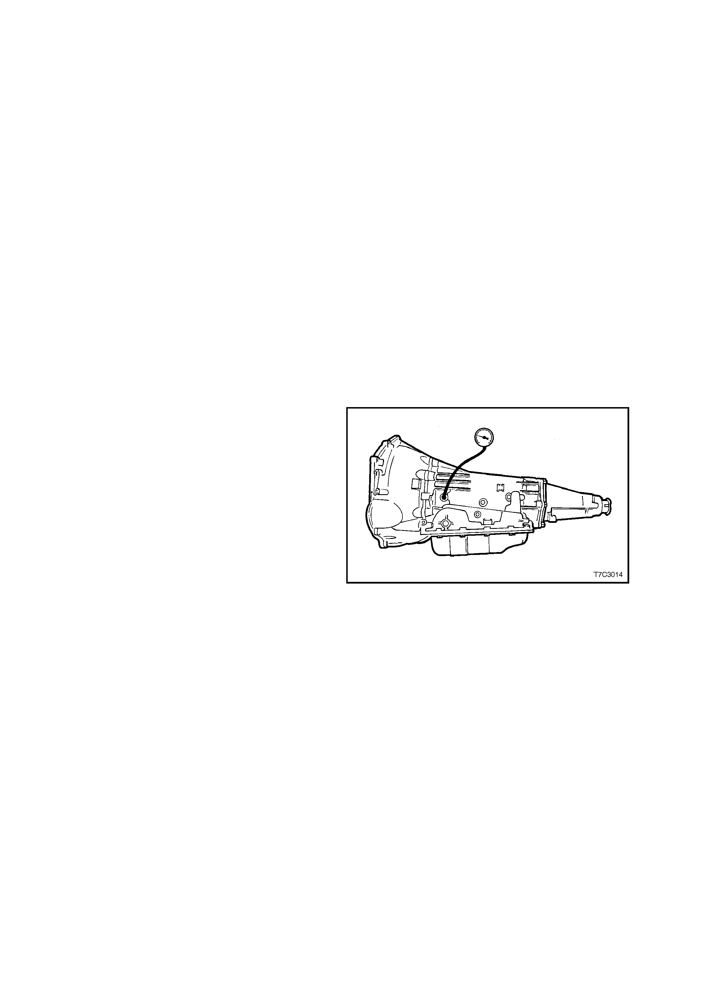
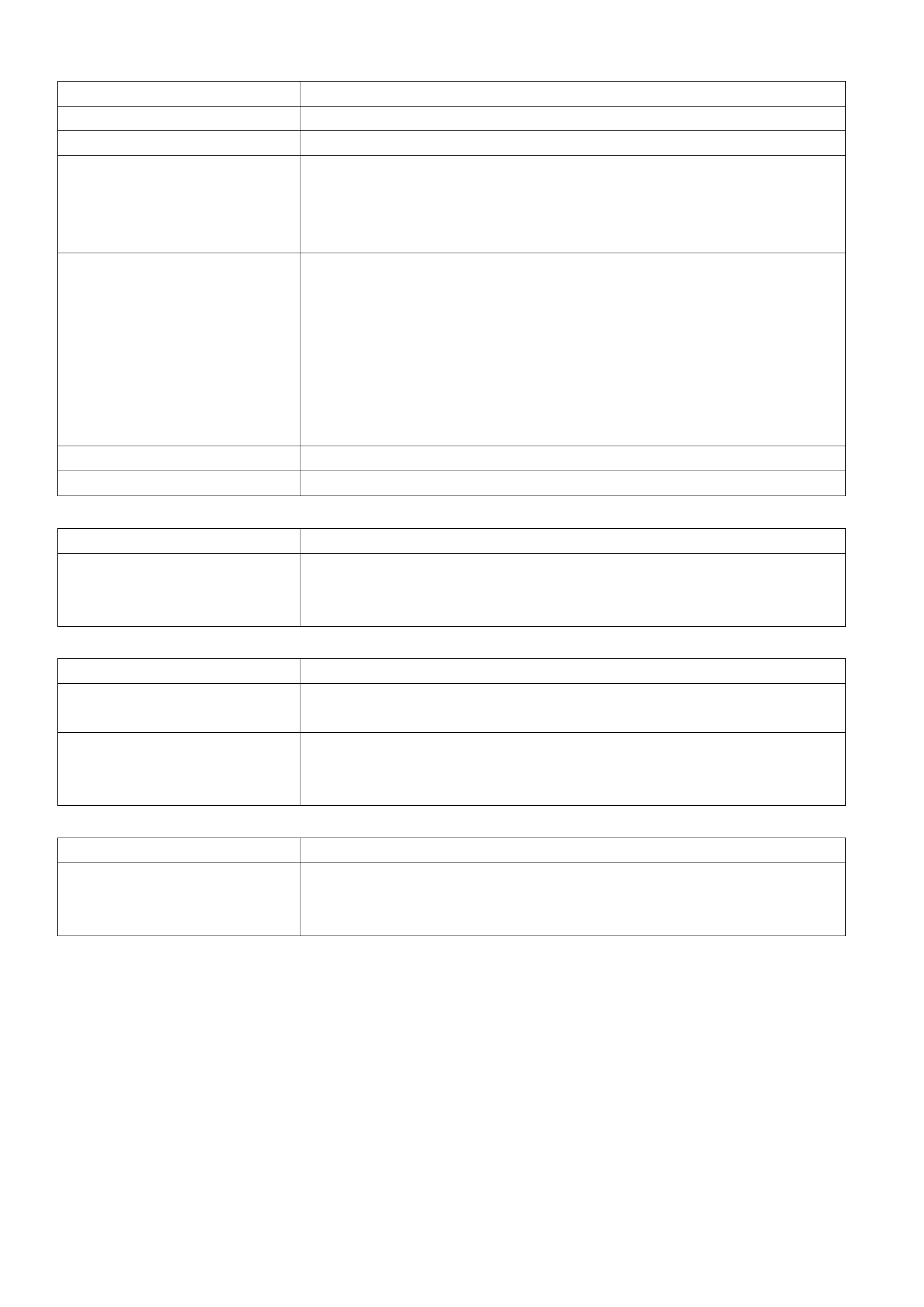
4. Install an oil pressure gauge such as Tool
J21867 or commercial equivalent, to the line
pressure tapping point on the transmission, as
shown.
5. Select ‘P’ (Park) range and firmly apply the
park brake.
6. Start the engine and allow to warm up, at idle.
7. Access ‘Miscellaneous Tests’ on Tech 2, then
the “PCS CONTROL” test.
8. Increase “ACTUAL PCS” in 0.1 Amp
increments on Tech 2 and read the
corresponding line pressure reading on the
fluid pressure gauge. (Allow the pressure to
stabilise for 5 seconds after each current
change.
9. Compare the pressure readings against the
charts shown next.
IMPORTANT: Total test running time should not
exceed 2 minutes or transmission damage could
occur.
Figure 7C3-2
NOTE 1: Pressures are to be taken at an engine
speed of 1,500 rpm and a temperature of 66° C.
Line pressure drops as temperature increases.
NOTE 2: If pressure readings differ greatly from
the line pressure chart, refer to the Diagnostic
Section in:
Section 6C1 POWERTRAIN MANAGEMENT –
V6 ENGINE,
Section 6C2 POWERTRAIN MANAGEMENT –
V6 SUPERCHARGED ENGINE,
Section 6C3 POWERTRAIN MANAGEMENT –
GEN III V8 ENGINE.
NOTE 3: Tec h 2 is only able to c ontrol th e PC s ol eno i d in Park, and Neutral, with the vehic l e st oppe d. T his protec ts
the clutch packs from extremely high or low pressures in Drive or Reverse ranges.
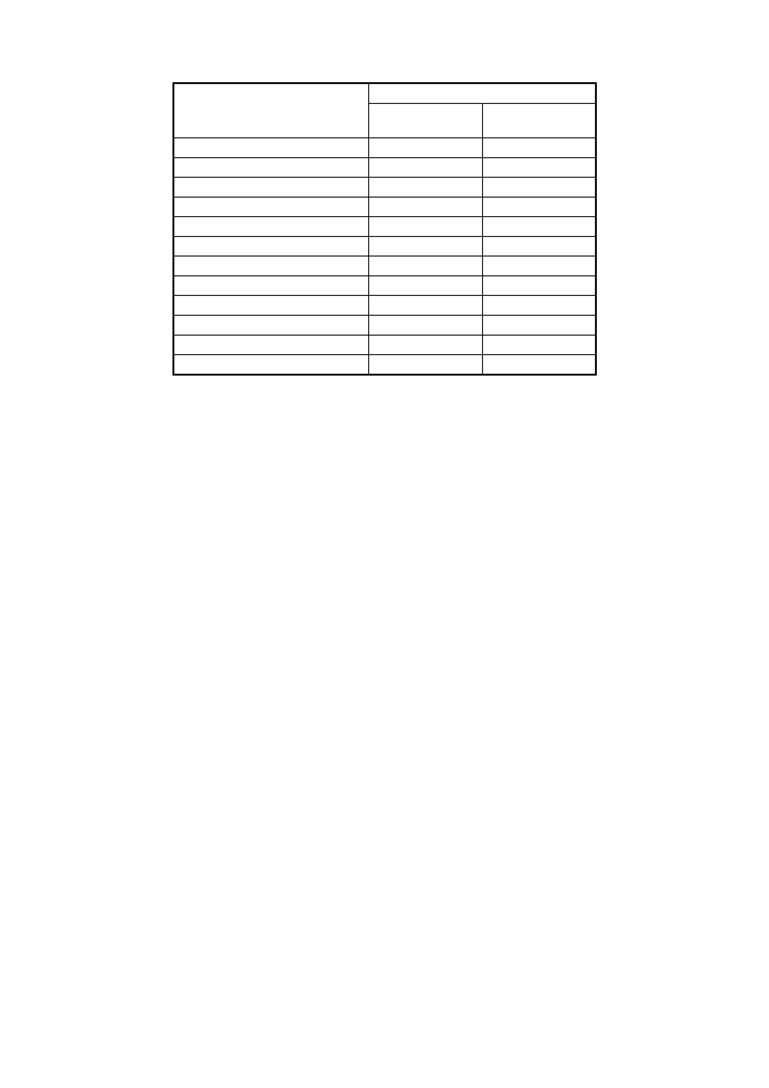
Pressure Control Solenoid Line Pressure (kPa)
Current (Amp) V6 Engine GEN III V8
Engine
0.00 1,261 – 1,399 1,369 – 1,507
0.10 1,257 – 1,395 1,356 – 1,494
0.20 1,233 – 1,371 1,334 – 1,472
0.30 1,201 – 1,339 1,299 – 1,437
0.40 1,139 – 1,277 1,229 – 1,367
0.50 1,055 – 1,193 1,143 – 1,281
0.60 921 – 1,059 1,016 – 1,154
0.70 818 – 956 868 – 1,006
0.80 649 – 787 693 – 831
0.90 439 – 577 481 – 619
1.00 379 – 517 333 – 471
1.10 339 – 477 —
Table 7C3-1

2.5 ROAD TEST PROCEDURE
PRELIMINARY INFORMATION
IMPORTANT: T he Road Test Pr ocedure s hould be p erf orm ed only as part of the F unctio nal T est Proc edure. Refer
to 2.2 FUNCTIONAL TEST PROCEDURE, in this Section.
The following test provides a method of evaluating the condition of the automatic transmission. The test is
structured so that most driving conditions would be achieved. The test is divided into the following parts:
1. Electrical Function Check
2. Upshift Control and Torque Converter Clutch (TCC) Apply Part Throttle Detent Downshifts
3. Full Throttle Detent Downshifts Manual Downshifts
4. Coasting Downshifts
5. Manual Gear Range Selection
− REVERSE
− Manual FIRST
− Manual SECOND
− Manual THIRD
IMPORTANT: Complete the test in the sequence given. Incomplete testing cannot guarantee an accurate
evaluation.
• Before the road test, ensure the following:
– The engine is performing properly.
– Tr ansmission flui d level is correct. Ref er to 2.3 T RANSM ISSION FLUID CH ECKING PROCEDUR E in this
Section.
– Tyre pressures are correct.
• During the road test:
– Perform the test only when traffic conditions permit.
– Operate the vehicle in a controlled, safe manner.
– Observe all traffic regulations.
– Take an assistant to view the Tech 2 data while conducting this test.
– Observe any unusual sounds or smells.
• After the road test, check the following:
– Transmission fluid level. Refer to the 2.3 TRANSMISSION FLUID CHECKING PROCEDURE, in this
Section.
– Diagnostic Trouble Codes (DTC’s) that may have set during the testing. Refer to the applicable DTC, in
Section 6C1 POWERTRAIN MANAGEMENT – V6 ENGINE, Section 6C2 POWERTRAIN
MANAGEMENT – V6 SUPERCHARGED ENGINE, or Section 6C3 POWERTRAIN MANAGEMENT –
GEN III V8 ENGINE.
– Tech 2 data for any abnormal readings or information.

ELECTRICAL FUNCTION CHECK
Perform this check f irst, in order to ensure the electronic transm ission components are connected and functioning
properly. If these components are not checked, a simple electrical condition could be mis-diagnosed.
1. Connect Tech 2.
2. Ensure the gear selector is in PARK and set the parking brake.
3. Start the engine.
4. Verify that the follo wing Tech 2 data can be obtained and is f unc ti on ing properl y. Data th at is questiona bl e may
indicate a concern. Refer to Transmission Scan Tool Data Values, in Section 6C1 POWERTRAIN
MANAGEMENT – V6 ENGINE, Section 6C2 POWERTRAIN MANAGEMENT – V6 SUPERCHARGED
ENGINE, or Section 6C3 POWERTRAIN MANAGEMENT – GEN III V8 ENGINE.
• Engine Speed
• Transmission output speed
• Vehicle speed
• T F P manual va lv e pos ition s wit ch
• Transmission range (engine list)
• Commanded gear (current gear)
• PC solenoid reference current
• PC solenoid actual current
• PC solenoid duty cycle
• Brake switch
• Engine coolant temperature
• Transmission fluid temperature
• Throttle angle
• Ignitio n vol tag e
• 1-2 shift solenoid (A)
• 2-3 shift solenoid (B)
• TCC solenoid duty cycle
• TCC slip speed
5. Monitor the brake switch signal while depressing and releasing the brake pedal. Tech 2 should display:
• Closed when the brake pedal is released.
• Open when the br ak e pedal is depr ess ed.
6. Check the garage shifts.
• Apply the brake pedal and ensure that the parking brake is set.
• Move the gear selector through the following ranges:
− PARK to REVERSE
− REVER SE to NEUTRAL
− NEUTRAL to DRIVE
• Pause two to three seconds in each gear position.
• Verify the gear engagements are immediate and not harsh.
NOTE: Harsh engagement may be caused by any of the following conditions:
• High idle speed. Compare engine idle speed to desired idle speed.
• Commanded low PC solenoid current. Compare PC solenoid reference current to PC solenoid actual
current.
• A default condition caused by certain DTC’s that result in maximum line pressure to prevent slippage.
NOTE: Soft or delayed engagement may be caused by any of the following conditions:
• Low idle speed. Compare engine idle speed to desired idle speed.
• Low fluid level.
• Commanded high PC solenoid current. Compare PC solenoid reference.
• Current to PC solenoid actual current.
• Cold transmission fluid. Check for low transmission fluid temperature.

7. Monitor transmission range on Tech 2 (engine list).
• Apply the brake pedal and ensure the parking brake is set.
• Move the gear selector through all ranges.
• Pause two to three seconds in each range.
• Return gear selector to PARK.
• Verify that all selector positions match display on Tech 2.
8. Check throttle angle in put.
• Apply the brake pedal and ensure that the parking brake is set.
• Ensure the gear selector is in PARK.
• Monitor throttle angle while increasing and decreasing engine speed with the throttle pedal. The Tech 2
throttle angle display should increase and decrease with engine speed.
If any of the above checks do not perform properly, record the result for reference after completion of the road test.
UPSHIFT CONTROL AND TORQUE CONVERTER CLUTCH (TCC) APPLY
The PCM calculates the upshift points based primarily on two inputs: throttle angle and vehicle speed. When the
PCM determines that co ndi tions are met f or a s hif t to oc cur , the PCM c om mands the shif t by closing or op eni ng the
earth circuit for the appropriate solenoid.
Perform the following steps:
1. Refer to the 3. MY2003 4L60-E SHIFT SPEED CHARTS in this Section for the appropriate shift pattern and
engine configuration.
2. Monitor the following Tech 2 parameters:
• Throttle angle
• Vehicle speed
• Engine speed
• Output shaft speed
• Commanded gear
• Slip speed
• Solenoid states
3. Place the gear selector in the OVERDRIVE position.
4. Accelerate the vehicle using the chosen throttle angle. Hold the throttle steady.
5. As the tr ansm ission u pshif ts, note the vehicle spee d when the s hift occ urs f or eac h gear c hange. T here shou ld
be a noticeable shift feel or engine speed change within one to two seconds of the commanded gear change.
6. Compare the shift speeds to the Shift Speed Chart. Shift speeds may vary slightly due to transmission fluid
temperature or hydraulic delays in responding to electronic controls.
Note any harsh, soft or delayed shifts or slipping and any noise or vibration.
7. Repeat steps 1 through 6 to complete all shift patterns.
IMPORTANT: The TCC will not engage until the engine is in closed loop operation and the vehicle speed is as
shown in the Shif t Speed table, in this Sec tion. T he vehicle m ust be in a n ear-cruis e condition ( not acceler ating or
coasting) and on a level road surface.
8. Check for TCC apply in THIRD and FOURTH gear.
• Note the TCC apply point. When the TCC applies, there should be a noticeable drop in engine speed and a
drop in slip speed to below 100 RPM. If the TCC apply can not be detected:
– Check for DTC’s.
– Refer to 2.6 TORQUE CONVERTER DIAGNOSIS PROCEDURE, in this Section.
– Refer to the 3. MY2003 4L60-E SHIFT SPEED CHARTS in this Section for the correct apply speeds.
– Lightly tap and release the brake pedal. The TCC will release on most applications.
PART THROTTLE DETENT DOWNSHIFT
1. Place the gear selector in the OVERDRIVE position.
2. Accelerate the vehicle to 64-88 km/h in FOURTH gear.
3. Quickly increase throttle angle to greater than 50%.
4. Verify the following:
• The TCC releases.
• The transmission downshifts immediately to THIRD gear.

FULL THROTTLE DETENT DOWNSHIFT
1. Place the gear selector in the OVERDRIVE position. Accelerate the vehicle to speeds of 64-88 km/h in
FOURTH gear.
2. Quic kly increase thrott le an gle to 100% (WOT).
3. Verify the following:
• The TCC releases.
• The transmission downshifts immediately to SECOND gear.
MANUAL DOWNSHIFTS
The shift solenoid valves do not control the initial downshift for the 4-3 or the 3-2 manual downshifts as these are
hydraulic.
The 2-1 manual downshift however, is electronic. The solenoid states should change during or shortly after a
manual downshift is selected.
Manual 4-3 Downshift
1. Place the gear selector in the OVERDRIVE position.
2. Accelerate the vehicle to 64-88 km/h in FOURTH gear.
3. Release the throttle while moving the gear selector to THIRD.
4. Verify the following:
• The TCC releases.
• The transmission downshifts immediately to THIRD gear.
• The engine slows the vehicle.
Manual 4-2 Downshift
1. Place the gear selector in the OVERDRIVE position.
2. Accelerate the vehicle to 64-72 km/h.
3. Release the throttle while moving the gear selector to SECOND. Verify the following:
• The TCC releases.
• The transmission downshifts immediately to SECOND gear.
• The engine slows the vehicle.
Manual 4-1 Downshift
1. Place the gear selector in the OVERDRIVE position.
2. Accelerate the vehicle to 48 km/h.
3. Release the throttle while moving the gear selector to FIRST.
4. Verify the following:
• The TCC releases.
• The transmission downshifts immediately to FIRST gear.
• The engine slows the vehicle.
COASTING DOWNSHIFTS
1. Place the gear selector in the OVERDRIVE position.
2. Accelerate the vehicle to FOURTH gear with the TCC applied. Release the throttle and lightly apply the brakes.
3. Verify the following:
• The TCC releases.
• Downshifts occur at speeds shown in the Shift Speed table, in this Section.

MANUAL GEAR RANGE SELECTION
The shift solenoids control the upshifts in the manual gear ranges.
Perform the following tests using 10 to 15% throttle angle.
Reverse
1. With the vehicle stopped, move the gear selector to REVERSE.
2. Slowly accelerate the vehicle.
3. Verify that there is no noticeable slip, noise or vibration.
Manual First
1. With the vehicle stopped, move the gear selector to FIRST.
2. Accelerate the vehicle to 32 km/h.
3. Verify the following:
• No upshifts occur.
• The TCC does not apply.
• There is no noticeable slip, noise, or vibration.
Manual Second
1. With the vehicle stopped, move the gear selector to SECOND.
2. Accelerate the vehicle to 57 km/h.
3. Verify the following:
• The 1-2 shift occurs.
• The 2-3 shift does not occur.
• There is no noticeable slip, noise or vibration.
Manual Third
1. With the vehicle stopped, move the gear selector to THIRD.
2. Accelerate the vehicle to 64 km/h.
3. Verify the following:
• The 1-2 shift occurs.
• The 2-3 shift occurs.
• There is no noticeable slip, noise or vibration.

2.6 TORQUE CONVERTE R DIAGNOSIS PROCEDURE
The Tor que Converter Clutc h (TCC) is applied b y fluid pres sure, which is c ontrolled b y a PW M solenoid val ve. T his
solenoid valve is loc ated inside of the automatic trans mission ass embly and is contr olled throu gh a combinatio n of
computer controlled switches and sensors.
TORQUE CONVERTER STATOR
The torque converter stator roller clutch can have two different malfunctions:
• The stator assembly freewheels in both directions.
• The stator assembly remains locked up at all times.
Poor Acceleration at Low Speed
If the stator is freewheeling at all times, the car tends to have poor acceleration from a standstill but at speeds
above 50-55 km/h, the car may act normally.
For poor ac celeration, you should f irst determine that t he exhaust s ystem is not blocked, and the trans mis sion is in
first gear when starting out.
If the engine freely accelerates to high RPM in NEUTRAL, you can assume that the engine and the exhaust system
are norm al. Check for poor perf ormance in DRIV E and REVER SE to help d eterm ine if the s tator is fr eewheeling at
all times.
Poor Acceleration at High Speed
If the stator is locked up at all times, performance is normal when accelerating from a standstill but engine RPM
and car spe ed are l imited or restricted at high spe eds. Visua l examinat ion of the conver ter ma y rev eal a blue color
from overheating.
If the conver t er has be en r e moved fr om the transmiss ion, you c an ch ec k the stator r oller c lu tc h by inserting a f inger
into the splined inner race of the roller clutch and trying to turn the race in both directions. You should be able to
freel y turn the inner race c loc kwise, but you sho uld ha ve dif fic ulty in m oving the inner r ace count erc lock wise or you
may be unable to move the race at all.
NOISE
IMPORTANT: Do not confuse this noise with pump whine noise, which is usually noticeable in PARK, NEUTRAL
and all other gear ranges. Pump whine will vary with line pressure.
You may notice a torque converter whine when the vehicle is stopped and the transmission is in DRIVE or
REVERSE. This noise will increase as you increase the engine RPM. The noise will stop when the vehicle is
moving or when the torque converter clutch is applied, because both halves of the converter are turning at the
same speed.
Perform a stall test to make sure the noise is actually coming from the converter:
1. Place your foot on the brake.
2. Put the gear selector in DRIVE.
3. Depress the accelerator to approximately 1,200 RPM for no more than six seconds.
NOTE: You may damage the transmission if you depress the accelerator for more than six seconds.
A torque converter noise will increase under this load.
TORQUE CONVERTER CLUTCH SHUDDER
The key to diagnosing Torque Converter Clutch (TCC) shudder is to note when it happens and under what
conditions.
TCC shudder which is caused by the transmission should only occur during the apply or the release of the
converter clutch. Shudder should never occur after the TCC plate is fully applied.
If Shudder Occurs During TCC Apply or Release
If the shudder occurs while the TCC is applying, the problem can be within the transmission or the torque
converter. Something is causing one of the following conditions to occur:
• Something is not allowing the clutch to become fully engaged.
• Something is not allowing the clutch to release.
• The clutch is releasing and applying at the same time.
One of the following conditions may be causing the problem to occur:
• Leaking turbine shaft seals.
• A restricted release orifice.
• A distorted clutch or housing surface due to long converter bolts.
• Defective friction material on the TCC plate.

If Shudder Occurs After TCC has Applied
If shudder occurs after the TCC has applied, most of the time there is nothing wrong with the transmission!
The T CC is not likel y to slip af ter the T CC has b een ap pli ed. En gi ne pr o bl ems m ay go unnot ic ed u nd er li ght t hr ottle
and load, but they become not iceable after the TCC apply when going up a hill or accelerating. This is due to the
mechanic a l coup ling between the engine and the tr ansm ission.
Once TCC is applied, there is no torque converter (fluid coupling) assistance. Engine or driveline vibrations could
be unnoticeable before TCC engagement.
Inspect the f ollowing com ponents in order to a void misdiag nosis of T CC shudder . An inspection will also av oid the
unnecessary disassembly of a transmission or the unnecessary replacement of a torque converter.
• Spa rk plugs – Inspect for cracks, high resistance or a broken insulator.
• Plug wires – Look in each end. If there is red dust (ozone) or a black substance (carbon) present, then the
wires are bad. Also look for a white discoloration of the wire. This indicates arcing during hard acceleration.
• Coils – Look for a black discoloration on the bottom of each coil. This indicates arcing while the engine is
misfiring.
• Fuel injectors – A filter may be plugged.
• Vacuum leak – The eng ine will n ot g et a c or rec t amount of f uel. The m ixt ure may run rich or le an dep end in g on
where the leak occurs.
• EGR valve (V6 engines only) – The valve may let in too much or too little unburnable exhaust gas and could
cause the engine to run rich or lean.
• MAP/MAF sensor – Like a vacuum leak, the engine will not get the correct amount of fuel for proper engine
operation.
• Carbon on the intake valves – Carbon restricts the proper flow of air/fuel mixture into the cylinders.
• Flat cam – Valves do not open enough to let the proper fuel/air mixture into the cylinders.
• Oxy gen sensor – This sensor may command the engine too rich or too lean for too long.
• Fuel pressure – This may be too low.
• Engine mounts – Vibration of the mounts can be multiplied by TCC engagement.
• Propeller shaft and driveshaft/s – Check for vibration.
• TP Sensor – The TCC app ly and releas e depends on the TP Sensor in many engin es. If the TP Se nsor is out
of specification, TCC may remain applied during initial engine loading.
• Cylinder balance – Bad piston rings or poorly sealing valves can cause low power in a cylinder.
• Fuel contamination – This causes poor engine performance.
Replace the torque converter if any of the following conditions exist:
• External leaks appear in the hub weld area.
• The converter hub is scored or damaged.
• The converter pilot is broken, damaged, or fits poorly into the crankshaft.
• You discover steel particles after flushing the cooler and the cooler lines.
• The pum p is dam aged, or you disco ver s teel p ar tic l es in the c onv erter . The vehicl e has T CC shudder an d/or no
TCC appl y. Rep lace the t or que c on verter o nly after all h ydraul ic and e lectr ic a l dia gnos es ha ve b een made. The
converter clutch material may be glazed.
• The converter has an imbalance which cannot be corrected. Refer to 2.7 TORQUE CONVERTER/
FLEXPLATE VIBRATION T EST , in this Section.
• The converter is contaminated with engine coolant which contains antifreeze.
• An internal failure occurs in the stator roller clutch.
• You notice excessive end play.
• Overheati ng produc es hea v y debris in the clutch .
• You disc o ver ste e l part ic les or c lutch l ini ng material in t he f lui d f ilt er or on the m agnet, whe n no i ntern al parts in
the unit are worn or damaged. This condition indicates that lining material came from the converter.
NOTE: For torque converter replacement procedures, refer to Section 7C4 ON-VEHICLE SERVICING, for all
engines.

Do Not Replace the Torque Converter if you discover any of the following symptoms:
• The oil has an odour or the oil is discolored, even though metal or clutch facing particles are not present.
• The threads in one or more of the converter bolt holds are damaged. Correct the condition with a new thread
insert.
• Transmission failure did not display evidence of dam aged or worn internal parts, steel particles or clutch plate
lining material in the unit and inside the fluid filter.
• The vehicle has been exposed to high mileage only. An exception may exist where the lining of the torque
converter clutch dampener plate has seen excess wear by vehicles operated in heavy and/or constant traffic,
such as taxi, delivery, or police use.
2.7 TORQUE CONVERTER/FLEXPLATE VIBRATION TEST
Should an imbalance condition with either of these two components be suspected, then the following procedures
should be followed.
NOTE: This procedure covers all engines.
EVALUATION
1. Start the engine and run until normal operating temperature is reached.
2. With the engine at idle speed and the transmission in "PARK" or "NEUTRAL", observe the vibration condition.
3. Stop the engine.
RECTIFICATION
1. Disc onnect the battery ground con necti on.
IMPORTANT: Disconnection of the battery affects certain vehicle electronic systems. Refer to Section 00
CAUTIONS, 5. Battery Disconnection Procedures before disconnecting the battery.
2. Raise the vehicle and support on safety stands. Refer to Section 0A GENERAL INFORMATION in the MY
2003 VY and V2 Series Service Information, for the location of jacking and support points.
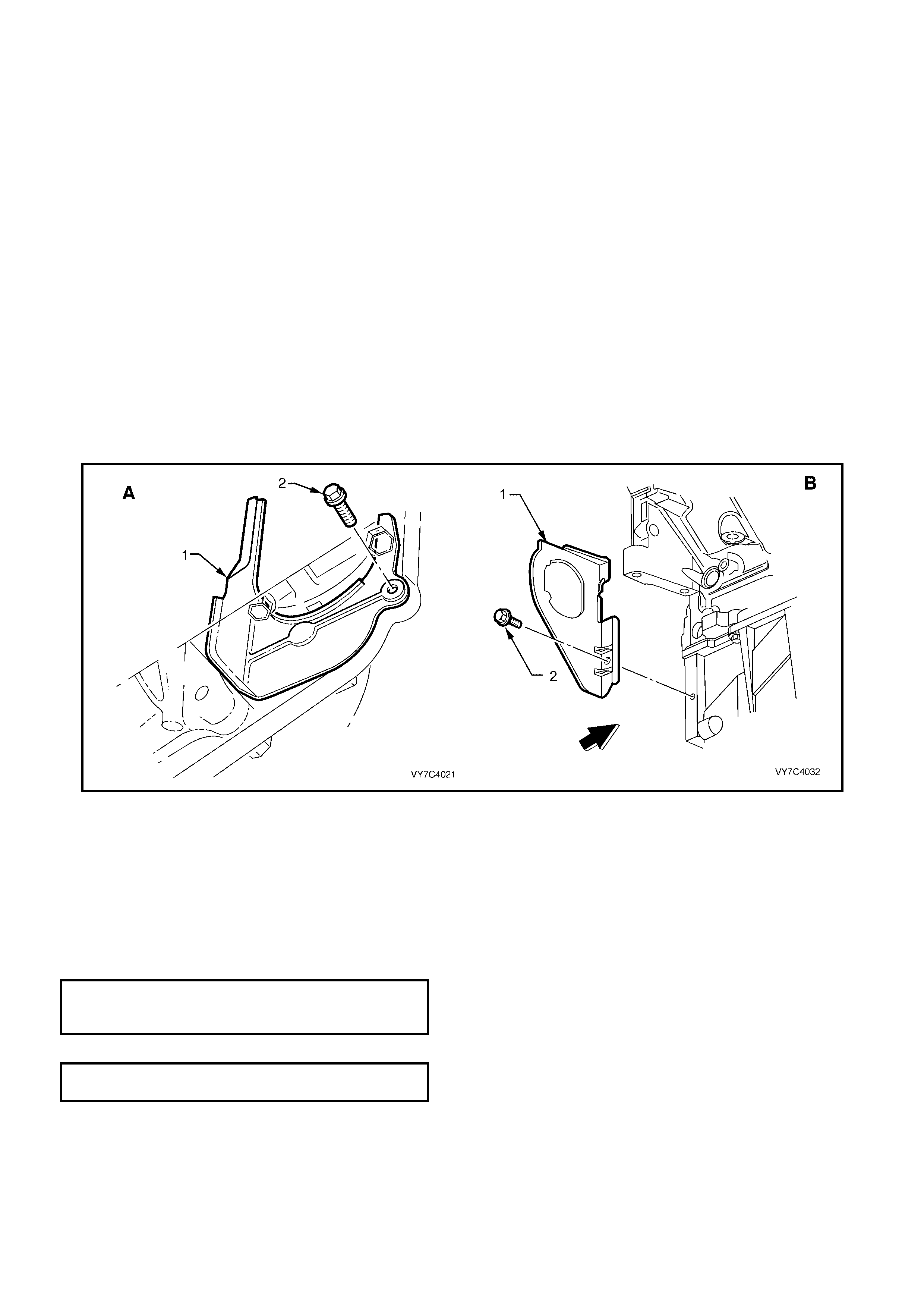
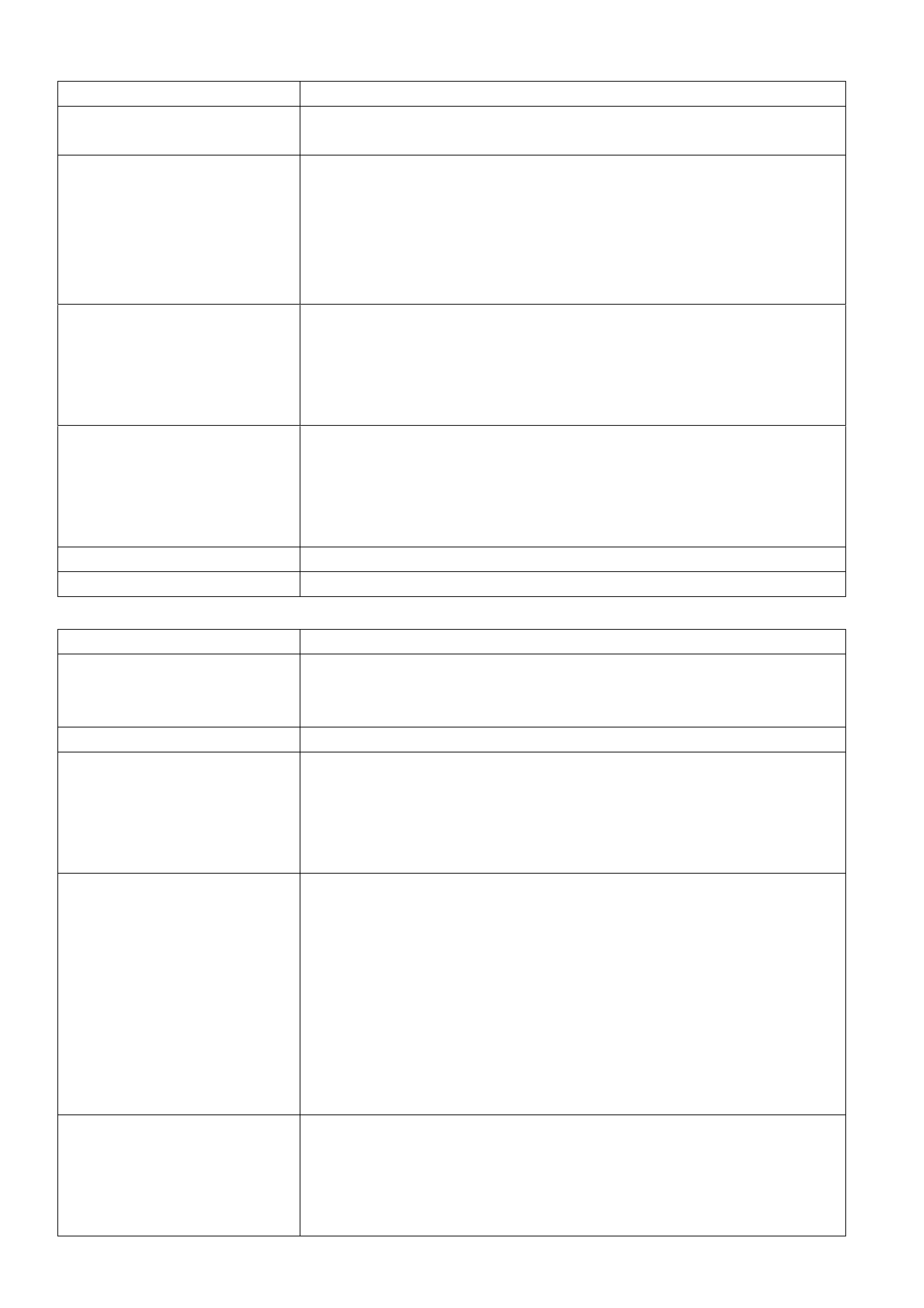
3. Remove the starter motor, refer to; Section 6D1-2 STARTING SYSTEM (V6), Section 6D2-2 (V6
Supercharged) or Section 6D3-2 (GEN III V8), for the necessary procedure. Remove close-out cover screw
(2). View ‘A’ shows the V6 arrangement, while view ‘B’ shows the GEN III V8 arrangement.
NOTE: Removing the close-out cover on the Starter motor side provides more space for converter bolt access.
Figure 7C4-3
4. Rotate the flexplate by hand, using a suitable lever in the ring gear teeth, until a torque converter to engine
flexplate bolt becomes accessible.
5. While locking the flexplate by inserting a screwdriver blade or similar into the ring gear teeth, remove the
exposed torque converter to engine flexplate bolt.
6. Rotat e the flexpl ate b y one third of a turn, then repeat s tep 6, until the thr ee bo lts hav e been r emoved.
7. Rotate the torque converter through 1/3 turn and reinstall the attaching bolts but only after having cleaned the
threads and applying a thread sealant such as Loctite 242 or equivalent to the threads. Tighten bolts to the
correct torque specification, while locking the flexplate from turning.
TORQUE CONVERTER TO
FLEXPLATE BOLT
TORQUE SPECIFICATION 65 Nm
8. Reinstall the close-out cover and screw, then tighten to the correct torque specification.
CLOSE-OUT COVER SCREW
TORQUE SPECIFICATION 12 Nm
9. Reinstall the starter motor, Refer to; Section 6D1-2 STARTING SYSTEM (V6), Section 6D2-2 (V6
Supercharged) or S ectio n 6D3- 2 (GEN III V8), for the necessary procedure.
10. Start the engine and check for vibration. Repeat the above procedure until the best possible balance is
obtained.

2.8 NOISE AND VIBRATION ANALYSIS
A noise or vibration that is noticeable when the vehicle is in motion MAY NOT be the result of the transmission.
If noise or vibration is noticeable in PARK and NEUTRAL with the engine at idle, but is less noticeable as RPM
increases, the cause may be from poor engine performance.
• Inspect the tyres for the following:
− Une ven wear.
− Imbalance.
− Mixed sizes.
− Mixed radial tyre tread pattern. Refer to Section 10 WHEELS AND TYRES.
• Inspect the suspension components for the following:
− Alignment and wear.
− Loose fasteners. Refer to Section 3 FRONT SUSPENSION and/or Section 4A REAR SUSPENSION.
• Inspect the engine and transmission mounts for damage and loose bolts.
• Inspect the transmission case mounting holes for the following:
− Missing bolts, nuts, and studs.
− Stripped threads.
− Cracks.
• Inspect the flexplate for the following:
− Missing or loose bolts.
− Cracks.
− Imbalance.
• Inspect the torque converter for the following:
− Missing or loose bolts or lugs.
− Missing or loose balance weights.
− Imbalance.

2.9 CLUTCH PLATE DIAGNOSIS
COMPOSITION PLATES
Dry the plates and inspect each, for the following conditions:
• Pitting
• Flaking
• Wear
• Glazing
• Cracking
• Charring
• Chips or metal particles embedded in the lining
Replace the set, if any composition plate shows any of the above conditions.
STEEL PLATES
IMPORTANT: If the clutch shows evidence of extreme heat or burning, replace the release springs.
Wipe the plates dry and check the plates for heat discoloration. If the surfaces are smooth, even if color smear is
indicate d, you can reuse th e plate. If the plate is discolored with heat spots or if the surface is scuffed, replace the
plate.
Causes of Burned Clutch Plates
The following conditions can result in a burned clutch plate:
• Incorrect usage of clutch plates
• Low line press ur e
• Valve body conditions, such as:
− The valve body face is not flat
− Por os ity between channels
− The valve bushing clips are improperly installed
− The checkballs are misplaced
• The Teflon® seal rings are worn or damaged.
• Engine coolant in the transmission fluid
• A cracked clutch piston
• Damaged or missing seals

2.10 ENGINE COOLANT IN TRANSMISSION
NOTE: The antifreeze in the engine coolant will cause both the Viton O-ring seals and the glue that bonds the
clutch material to the pressure plate, to deteriorate. Both conditions may cause damage to the transmission.
If the transmission oil cooler has de veloped a leak , allowing engine coolant to enter the transmission, perform the
follo wing oper ati ons :
1. Disassemble the transmission.
2. Replace all of the rubber type seals. (The coolant will attack the seal material which will cause leakage.)
3. Replace the composition-faced clutch plate assemblies. (The facing material may separate from the steel
center portion.)
4. Replace all of the nylon parts (washers).
5. Replace the torque converter.
6. Thoroughly clean and rebuild the transmission, using new gaskets and oil filter.
7. Flush the cooler lines after the transmission cooler has been properly repaired or replaced.

2.11 FLUID LEAK DIAGNOSIS AND REP AIR
The cause of most external leaks can usually be located and repaired with the transmission installed in the vehicle.
METHODS FOR LOCATING LEAKS
Genera l Method
1. Verify that the leak is in fact, transmission fluid.
2. Thoroughly clean the suspected leak area.
3. Operate the vehicle for about 24 km or until normal operating temperatures are reached.
4. Park the vehicle over clean paper or cardboard.
5. Switch the engine off and look for fluid spots on the paper.
6. Make necessary repairs.
Powder Method
1. Thoroughly clean the suspected leak area with a suitable cleaning agent.
2. Apply an aerosol ty pe powder (eg foot powder) to the suspected leak area.
3. Operate the vehicle for about 24 km or until normal operating temperatures are reached.
4. Switch the engine off.
5. Inspect the suspected leak area and trace the leak path through the powder to find the source.
6. Make necessary repairs.
Dye and Black Light Method
While the following can be used as a guide, always follow the manufacturer’s recommendations for use of this
equipment.
1. Pour the manufacturer's recommended amount of dye (such as J28431-B) into the transmission.
2. Road test the vehicle under normal operating conditions.
3. Direct the black light (Tool No. J42220) to the suspect area. Any fluid leak will appear as a brightly coloured
path, leading to the source.
NOTE: The colour of the dyed fluid can be checked on the transmission dipstick.
4. Make the necessary repairs, then re-check that the leak has been rectified.
REPAIRING THE LEAK
NOTE 1: Once the leak has been located and traced back to its source, the CAUSE of the leak must be
determined, for the repair to be satisfactory.
NOTE 2: If a gasket is replaced, but the sealing flange is distorted or bent (eg oil pan flange), the new gasket will
not stop t he leak . Obvio us dam age such as this m ust be rec tified before f itting ne w gaskets , if a sat isfactor y repair
is to be expected.
Before attempting to repair a leaking seal and/or gasket, check to make sure that the following conditions do not
apply:
Gaskets:
• Fluid level or pressure is too high.
• Blocked or partially blocked vent or drain back holes.
• Incorrectly torqued fasteners or dirty/damaged threads.
• Warped/bent flanges or sealing surface.
• Scratches, burrs or other damage to the sealing surface.
• Damaged or worn gasket.
• Cracking or porosity of the component or adjacent part.
• Improper sealant used (where applicable).
Seals:
• Fluid level or pressure is too high.
• Blocked or partially blocked vent or drain back holes.
• Damaged seal bore (Scratched burred or nicked).
• Damaged or worn seal.
• Incorrect previous installation.
• Cracks in the component.
• Manual or output shaft is scratched, nicked or worn.
• Loose or worn bear ing, cau s ing exces s seal wear.

POSSIBLE POINTS OF FLUID LEAKS
1. Transmission and Oil Pan:
• Attaching bolts not torqued correctly.
• Improperly installed or damaged gasket.
2. Case Leak:
• Filler tube multi-lip seal damaged or missing.
• Filler tube bracket misaligned.
• Speed sensor seal damaged.
• Manual shaft seal worn or damaged.
• Oil cooler connector fittings loose or damaged.
• Propeller shaft oil seal worn or damaged.
• Line pressure plug loose or thread damage has occurred.
• Porous casting.
3. Leak at End of Converter:
• Converter seal damaged.
– Seal lip cut (Check converter hub for damage).
– Bushing has moved forward and/or is damaged.
– Garter spring is missing from seal.
• Converter leak in the weld area.
• Porous casting (case or pump).
4. Fluid Comes from Vent or Fill Tube:
• Overfilled.
• Water or coolant in fluid (milky/pink fluid colour).
• Case porous.
• Incorrect fluid level indicator.
• Blocked or partially blocked vent.
• Drain back holes blocked.
• The alignment of the oil pump to case gasket is incorrect.
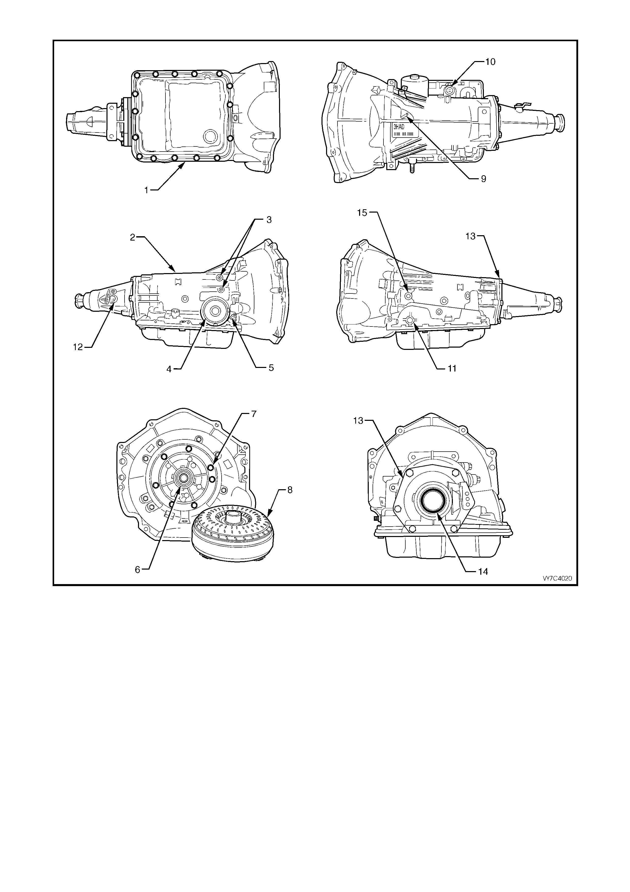
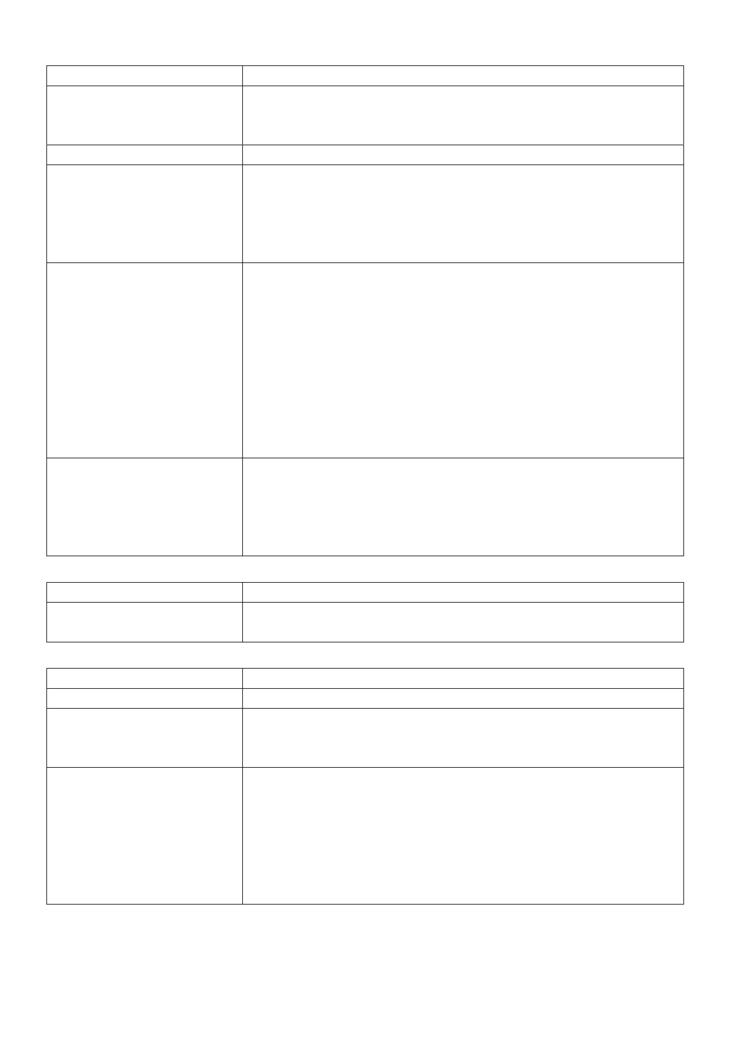
Figure 7C4-4
Legend:
1. Oil Pan Gasket
2. Transmission Main Case
3. Cooler Connections
4. 2-4 Servo Cover Seal
5. Oil Filler Tube Seal
6. Oil Pump Seal Assembly
7. Oil Pump to Case Seal
8. Torque Converter
9. Transmission Vent
10. Pass-through Connector O-ring
11. Manual Shaft Oil Seal
12. Vehicle Speed Sensor O-ring
13. Extension Housing to Case Seal
14. Extension Housing Oil Seal Assembly
15. Line Pressure Plug
CASE POROSITY REPAIR
1. Clean the area with epoxy manufacturer's recommended solvent and air dry.
CAUTION: Epoxy adhesives may cause skin irritations and eye damage. Read and follow all
information on the product label, as provided by the manufacturer.
2. Mix sufficient amount of epoxy adhesive ('Araldite'™ or an equivalent product), following the manufacturer's
recommendations.
3. While the transmission case is hot, apply epoxy adhesive with a clean, dry stiff brush.
4. Allow the a dhesiv e to dr y for the recomm ended tim e befor e starting the eng ine and check ing the resu lts of the
repair.
5. Repeat the fluid leak diagnosis procedure previously detailed.
2.12 SHIFT SOLENOID LEAK TEST
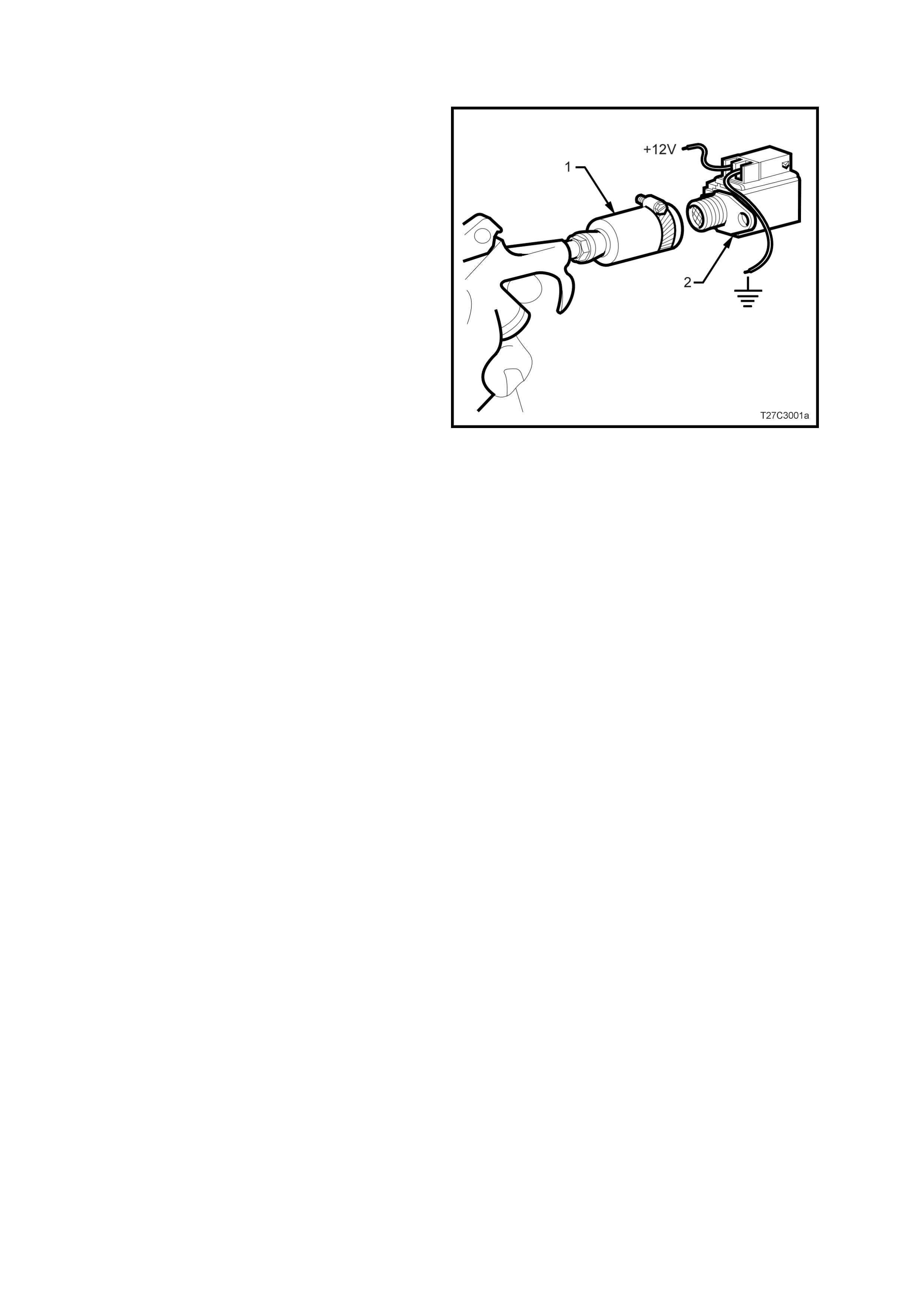
Should a shift solenoid be suspected of leaking, perform the following test.
1. Clamp a piece of 12 mm I.D. rubber hose (1)
over the fluid inlet end of the solenoid (2).
2. Connect a wire from one of the solenoid
terminals to the negative terminal (ground) of
the battery.
3. Apply compressed air to the rubber hose. Do
not use air pressure in excess of 825 kPa.
Excessive pressure will not allow the solenoid
ball check valve to seat properly.
4. Connect a wire from the other solenoid
terminal to the positive terminal (12 volts) of
the battery.
5. Observe air f low through the s olenoid. Rep lace
the solenoid if there is an air leak when the
solenoid is energised.
Figure 7C3-5

2.13 SYMPTOM DIAGNOSIS
The following table consists of seven diagnostic categories that are located in the left-hand column. Using this
column, choose the appropriate category based on the operating conditions of the vehicle or transmission. After
selecting a category, use the right-hand column to locate the specific symptom diagnostic information. Unless
otherwise stated, this specific information refers to the tables in 2.14 DIAGNOSTIC TABLES, in this Section.
The tables that follow, provide more specific information relating to each of the symptoms listed.
NOTE: The Func tional Tes t Procedure sho uld be perf ormed bef ore beginning an y diag nosis. If this procedu re has
not already been performed, refer to 2.2 FUNCTIONAL TEST PROCEDURE, in this Section.
SYMPTOM DIAGNOSIS TABLE
Diagnostic Category Diagnostic Information
Fluid Diagnosis
This category contains the following topics:
• Fluid condition (appearance, contaminants, smell,
overheating)
• Line pressure (high or low)
• Fluid leaks
• Refer to 2.3 Transmission Fluid Checking
Procedure, in this Section.
• Refer to Oil Pressure High or Low.
• Refer to Fluid Leak Diagno s is (procedure).
• Refer to Oil Out the Vent .
• Refer to Front Oil Leak.
Noise and Vibration Diagnosis
This category contains the following topics:
• Ratcheting noise
• Noise (drive gear, final drive, whine, growl, rattle,
buzz, poppi ng)
• Vibration
• Refer to Ratcheting Noise.
• Refer to Vibration in Reverse and Whining Noise in
Park.
Range Performance Diagnosis
This category contains the following topics: Drives in
Neutral
• No Park
• No Reverse
• No Drive
• No engine braking
• Refer to Drives in Neutral.
• Refer to No Park.
• Refer to No Reverse or Slips in Reverse.
• Refer to No Drive in All Ranges.
• Refer to No Drive in Drive Range.
• Refer to No Overrun Braking - Manual 3-2-1.
Shift Quality (Feel) Diagnosis
This category contains the following topic:
• Harsh, soft or slipping shifts
• Harsh, soft or delayed engagement
• Shift shudder, flare or tie-up
• Refer to Harsh Shifts.
• Refer to Slipping or Rough 1-2 Shif t.
• Refer to No 2-3 Shift or 2-3 Shift Slips, Rough or
Hunting.
• Refer to No 3-4 Shift, Slips or Rough 3-4 Shift.
• Refer to Harsh Garage Shift.
• Refer to Delay in Drive and Reverse.
• Refer to 3-2 Flare or Tie-Up.
Shift Pattern
This category contains the following topics:
• One forward gear only
• Two forward gears only gear missing or slipping
• No upshift or slipping upshift
• No downshifts
• Non-First gear start
• Refer to 1st Gear Range Only - No Upshift.
• Refer to Third Gear Only.
• Refer to 2nd/3rd Gear Only or 1st/4th Gears Only.
• Refer to Slips in 1st Gear.
• Refer to Slipping or Rough 1-2 Shif t.
• Refer to No 2-3 Shift or 2-3 Shift Slips, Rough or
Hunting.
• Refer to No 3-4 Shift, Slips or Rough 3-4 Shift.
• Refer to No Part Throttle or Delayed Downshifts.
• Refer to 2nd Gear Start.
Shift Speed Diagnosis
This category contains the following topic:
• Inaccurate or inconsistent shift points
• Refer to Inaccurate Shift Points.
Torque Converter Diagnosis
This category contains the following topics:
• Torque converter diagnosis
• TCC does not apply
• TCC does not release
• TCC apply/release quality
• Refer to Torque Conv er ter Diag nos is Proc ed ur e.
• Refer to No TCC Apply.
• Refer to No TCC Release.
• Refer to Torque Conv erter Clutc h Sh udd er.
2.14 DIAGNOSTIC TABLES
OIL PRESS URE HIGH OR LOW
Checks Causes
Oil Pump Assembly • Pressure regulator valve stuck
• Pressure regulator valve spring
• Rotor guide omitted or misassembled
• Rotor cracked or broken
• Reverse boost valve or sleeve stuck, damaged or incorrectly assembled
• Orifice hole in pressure regulator valve plugged
• Sticking slide or excessive rotor clearance
• Pressure relief ball not seated or damaged
• Porosity in pump cover or body
• Wrong pump cover
• Pump faces not flat
• Excessive rotor clearance
Oil Filter • Intake pipe restricted by casting flash
• Cracks in filter body or intake p ipe
• O-ring seal missing, cut or damaged
• Wrong grease used on rebuild
Control Valve Body • Manual v al ve scored or damaged
• Spacer plate or gaskets incorrect, misassembled or damaged
• Face not flat
• 2-3 Shift valve stuck
• Checkballs omitted or misassembled
Pressu re Contr ol So le noi d • Damage to pins
Transmission Fluid Pressure
Manual Va lve Pos it io n Swit c h • Contamination
• Damaged seals
Case • Case to control valve body face not flat
System Voltage • 12 volts not supplied to transmission
• Electrical short (pinched solenoid wire)
• Solenoid not grounded
HARSH SHIFTS
Checks Causes
Throttle Position Sensor • Open or shorted circuit
Vehicle Speed Sensor • Open or shorted circuit
Pressure Switch Assembly • Contamination
• Damaged seals
Trans Fluid Temperature Sensor • Open or shorted circuit
Engine Coolant Temperature
Sensor • Open or shorted circuit
Pressu re Contr ol So le noi d • Damage to pins
• Contamination
IN ACCURATE SHIFT POINT S
Checks Causes
Oil Pump Assembly • Stuck pressure regulator valve
• Sticking pump slide
Valve Body Assembly • Spacer plate or gaskets misassembled, damaged or incorrect
Case • Porous or dam aged va lv e bod y pad
• 2-4 Servo Assembly
− 2-4 accumulator porosity
− Damaged servo piston seals
− Apply pin damaged or improper length
• 2-4 Band Assembly
− Burned
− Anchor pin not engaged
Throttle Position Sensor • Disconnected
• Damage
Vehicle Speed Sensor • Disconnected
• Damaged
• Bolt not tightened
FIRST GEAR RANGE ONLY – NO UPSHIFT
Checks Causes
Control Valve Body • The 1-2 shift valve is sticking
• The spacer plate or gaskets are mispositioned or damaged
Case • The case to valve body face is damaged or is not flat
Shift Solenoid Valves • Stuck or damaged
• Faulty electrical connection
2-4 Servo Assembly • The apply passage case is restricted or blocked
• Nicks or burrs on the servo pin or on the pin bore in the case
• Fourth servo piston is installed backwards
2-4 Band Assembly • The 2-4 band is worn or damaged
• The band anchor pin is not engaged

SLIPS IN FIRST GEAR
Checks Causes
Forward Clutch Assembly • Clutch plates wor n
• Porosity or damage in forward clutch piston
• Forward clutch piston inner and outer seals missing, cut or damaged
• Damaged forward clutch housing
• Forward clutch housing retainer and ball assembly not sealing or
damaged
Forward Clutch Accumulator • Piston seal missing, cut or damaged
• Piston out of its bore
• Poros ity in the pis to n or va l ve body
• Stuck abuse valve
Input Housing and Shaft
Assembly • Turbine shaft seals missing, cut or damaged
Valve Body • 1-2 Accumulator valve stuck
• Face not flat, damaged lands or interconnected passages
• Spacer plate or gaskets incorrect, mispositioned or damaged
Low Roller Clutch • Damage to lugs to inner ramps
• Rollers not free moving Inadequate spring tension Damage to inner
splines Lube passage plugged
Torque Converter • Stator roller clutch not holding
1-2 Accumulator Assembly • Porosity in piston or 1-2 Accumulator cover and pin assembly
• Damaged ring grooves on piston
• Piston seal missing, cut or damaged
• Valve body to spacer plate gasket at 1-2 Accumulator cover, missing or
damaged
• Leak between piston and pin
• Broken 1-2 Accumulator spring
Line Pressure • Refer to Oil Pressure High or Low, in this Sect ion.
2-4 Servo Assembly • 4th Servo pis ton in bac k wa rds
SLIPPING OR ROUGH 1 – 2 SHIFT
Checks Causes
Valve Body Assembly • 1-2 Shift valve train stuck
• Gaskets or spacer plate incorrect, mispositioned or damaged
• 1-2 Accumulator valve stuck
• Face not flat
2-4 Servo Assembly • Apply pin too long or too short
• 2nd servo apply piston seal missing, cut or damaged
• Restricted or missing oil passages
• Servo bore in case damaged
2nd Accumulator • Porosity in 1-2 accum ulator housing or piston
• Piston seal or groove damaged
• Nicks or burrs in 1-2 accumulator housing
• Missing or restricted oil passage
2-4 Band • Worn or mispositioned
Oil Pump Assembly or Case • Faces not flat
NO 2–3 SHIFT OR SHIFT SLIPS, ROUGH OR HUNTING
Checks Causes
Converter • Internal damage
Oil Pump • Stator shaft sleeve scored or off location
Valve Body Assembly • 2-3 Shift valve train stuck
• Gaskets or spacer plate incorrect, mispositioned or damaged
• 2-3 Accumulator valve stuck
• Face not flat
Input Housing Assembly • 3-4 clutch or forward clutch plates worn
• Excessive clutch plate travel
• Cut or damaged 3-4 clutch or forward clutch piston seals
• Porosity in input clutch housing or piston
• 3-4 clutch piston checkball stuck, damaged or not sealing
• Restricted apply passages
• Forward clutch piston retainer and ball assembly not seating
• Sealing balls loose or missing
Case • 3rd accumulator retainer and ball assembly not seating
2-4 Servo Assembly • 2nd apply piston seals missing, cut or damaged
2ND/3RD GEAR ONLY OR 1ST/4TH GEARS ONLY
Checks Causes
Shift Solenoid Valves • Sediment is in the valves
• The electrical connection is faulty
• Damaged seal
THIRD GEAR ONLY
Checks Causes
System Voltage • 12 volts not supplied to transmission
• Electrical short (pinched solenoid wire) Solenoid not grounded
3-2 Control Solenoid • Shorted or damaged
• Contamination
• Damaged Seal
3-2 FLARE OR TIE-UP
Checks Causes
3-2 Control Solenoid Shorted or damaged
Contamination
Damaged Seal
NO 3-4 SHIFT, SLIPS OR ROUGH 3-4 SHIFT
Checks Causes
Oil Pump Assembly • Pump cover retainer and ball assembly omitted or damaged
• Faces not flat
Valve Body Assembly • Valves stuck
− 2-3 Shift valve train
− Accumulator valve
− 1-2 Shift valve train
− 3-2 Control valve
• Spacer plate or gaskets incorrect, mispositioned or damaged
2-4 Servo Assembly • Incorrect band apply pin
• Missing or damaged servo seals
• Porosity in piston, cover or case
• Damaged piston seal grooves
• Plugged or missing orifice cup plug
Case • 3rd Accumulator retainer and ball assembly leaking
• Porosity in 3-4 accumulator piston or bore
• 3-4 Accumulator piston seal or seal grooves damaged
• Plugged or missing orifice cup plug
• Restr icted oi l pas sage
Input Housing Assembly • Refer to Sli ppi ng 2-3 Shif t , in this Section
2-4 Band Assembly • Worn or misassembled
NO REVERSE OR SLIPS IN REVERSE
Checks Causes
Input Housing Assembly • 3-4 Apply ring stuck in applied position
• Forward clutch not releasing
• Turbine shaft seals missing, cut or damaged
Manual Va lve Link • Disconnected
Valve Body Assembly • 2-3 Shift valve stuck
• Manual linkage not adjusted
• Spacer plate and gaskets incorrect, mispositioned or damaged
• Low overrun valve stuck
• Orificed cup plug restricted, missing or damaged
Reverse Input Clutch Assembly • Clutch plate wor n
• Reverse input housing and drum assembly cracked at weld
• Clutch plate retaining ring out of groove
• Return spring assembly retaining ring out of groove
• Seals cut or damaged
• Restric ted app ly passag e
• Porosity in piston
• Belleville plate installed incorrectly
• Excessive clutch plate travel
• Overs i zed hous ing
Low and Reverse Clutch • Clutch plates wor n
• Porosity in piston
• Seals damaged
• Return spring assembly retaining ring mispositioned
• Restric ted app ly passag e
NO PART THROTTLE OR DELAYED DOWNSHIFTS
Checks Causes
Input Housing Assembly • 3-4 Apply ring stuck in applied position
• Forward clutch not releasing
• Turbine shaft seals missing, cut or damaged
Manual Va lve Link • Disconnected
Valve Body Assembly • 2-3 Shift valve stuck
• Manual linkage not adjusted
• Spacer plate and gaskets incorrect, mispositioned or damaged
• Low overrun valve stuck
• Orificed cup plug restricted, missing or damaged
Reverse Input Clutch Assembly • Clutch plate wor n
• Reverse input housing and drum assembly cracked at weld
• Clutch plate retaining ring out of groove
• Return spring assembly retaining ring out of groove
• Seals cut or damaged
• Restric ted app ly passag e
• Porosity in piston
• Belleville plate installed incorrectly
• Excessive clutch plate travel
• Overs i zed hous ing
Low and Reverse Clutch • Clutch plates wor n
• Porosity in piston
• Seals damaged
• Return spring assembly retaining ring mispositioned
• Restric ted app ly passag e
HARSH GARAGE SHIFT
Checks Causes
Valve Body Assembly • Orifice cup plug missing
• Checkball missing
NO OVERRUN BRAKING - MANUAL 3-2-1
Checks Causes
External Linkage • Not adjusted properly
Valve Body Assembly • 4-3 Sequence valve stuck
• Checkball mispositioned
• Spacer plate and gaskets incorrect, damaged or mispositioned
Input Clutch Assembly • Turbine shaft oil passages plugged or not drilled
• Turbine shaft seal rings damaged
• Turbine shaft sealing balls loose or missing
• Turbine shaft sealing balls loose or missing
• Porosity in forward or overrun clutch piston
• Overrun piston seals cut or damaged
• Overrun piston checkball not sealing
NO TORQUE CONVERTER CLUTCH APPLY
Checks Causes
Electrical • 12 volts not supplied to transmission
• Outside electrical connector damaged
• Inside electrical connector, wiring harness or solenoid damaged
• Electrical short (pinched solenoid wire)
• Solenoid not grounded
Torque Converter Clutch • Internal damage
Oil Pump Assembly • Converter clutch valve stuck or assembled backwards
• Converter clutch valve retaining ring mispositioned
• Pump to case gasket mispositioned
• Orifice cup plug restricted or damaged
• Solenoid O-ring seal cut or damaged
• High or uneven bolt torque (pump body to cover)
Input Housing and Shaft • Turbine shaft O-ring seal cut or damaged
• Incorrect O-ring fitted (e.g. 300 mm torque converter O-ring on 258 mm
converter)
• Turbine shaft retainer and ball assembly restricted or damaged
Transmission Fluid Pressure
Manual Va lve Pos it io n Swit c h • Contamination
• Damaged seals
Control Val ve Bo d y Assem bly • TCC signal valve stuck
• Solenoid O-ring leaking
Solenoid Screen • Blocked
TCC Solenoid Valve • Internal damage
Engine Speed Sensor • Internal damage
Engine Coolant Temperature
Sensor • Internal damage
Automatic Transmission Fluid
Temperature Sensor • Internal damage
Brake Switch • Internal damage
TORQUE CONVERTER CLUTCH SHUDDER
Checks Causes
Electrical • 12 volts not supplied to transmission
• Outside electrical connector damaged
• Inside electrical connector, wiring harness or solenoid damaged
• Electrical short (pinched solenoid wire)
• Solenoid not grounded
Converter • Internal damage
Oil Pump Assembly • Converter clutch valve stuck or assembled backwards
• Converter clutch valve retaining ring mispositioned
• Pump to case gasket mispositioned
• Orifice cup plug restricted or damaged
• Solenoid O-ring seal cut or damaged
• High or uneven bolt torque (pump body to cover)
Input Housing and Shaft • Turbine shaft O-ring seal cut or damaged
• Turbine shaft retainer and ball assembly restricted or damaged
Pressure Switch Assembly • Contamination
• Damaged seals
Valve Body Assembly • TCC signal valve stuck Solenoid O-ring leaking
Solenoid Screen • Blocked
NO TORQUE CONVERTER CLUTCH RELEASE
Checks Causes
TCC Solenoid Valve • External ground
• Clogged exhaust orifice
Converter • Internal damage
Valve Body Assembly • The converter clutch apply valve is stuck in the apply position
Oil Pump Assembly • The converter clutch valve is stuck
PCM • External ground
DRIVES IN NEUTR AL
Checks Causes
Forward Clutch • The clutch does not release
Manual Va lve Link • Disconnected
Case • The face is not flat
• Interna l leak age ex is ts
2ND GEAR START
Checks Causes
Forward Clutch Sprag Assembly • The sprag assembly is installed backwards
NO PARK
Checks Causes
Parking Linkage • Actuator rod assembly bent or damaged
• Actuator rod spring binding or improperly crimped
• Actuator rod not attached to inside detent lever
• Parking lock bracket damaged or not torqued properly
• Inside detent le ver not to rq ued pr oper l y
• Park ing pa wl bin ding or damaged
OIL OUT THE VENT
Checks Causes
Oil Pump • Chamber in pump body rotor pocket porous
Miscellaneous • Fluid level-overfilled
VIBRATION IN REVERSE AND WHINING NOISE IN PARK
Checks Causes
Oil Pump • Chamber in pump body rotor pocket porous
Miscellaneous • Fluid level-overfilled
RATCHETING NOISE
Checks Causes
Parking Pawl • The parking pawl return spring is weak, damaged, or misassembled
NO DRIVE IN ALL RANGES
Checks Causes
Torque Converter • The converter to flex plate bolts are missing
NO DRIVE IN DRIVE RANGE
Checks Causes
Torque Converter • The stator roller clutch is not holding
• The converter is not bolted to the flexplate

FRONT OIL LEAK
Checks Causes
Torque Converter • The welded seam is leaking
• The converter hub is damaged
Torque Converter Seal • The seal assembly is damaged
• The garter spring is missing
DELAY IN DRIVE AND REVERSE
Checks Causes
Torque Converter • Converter drainback
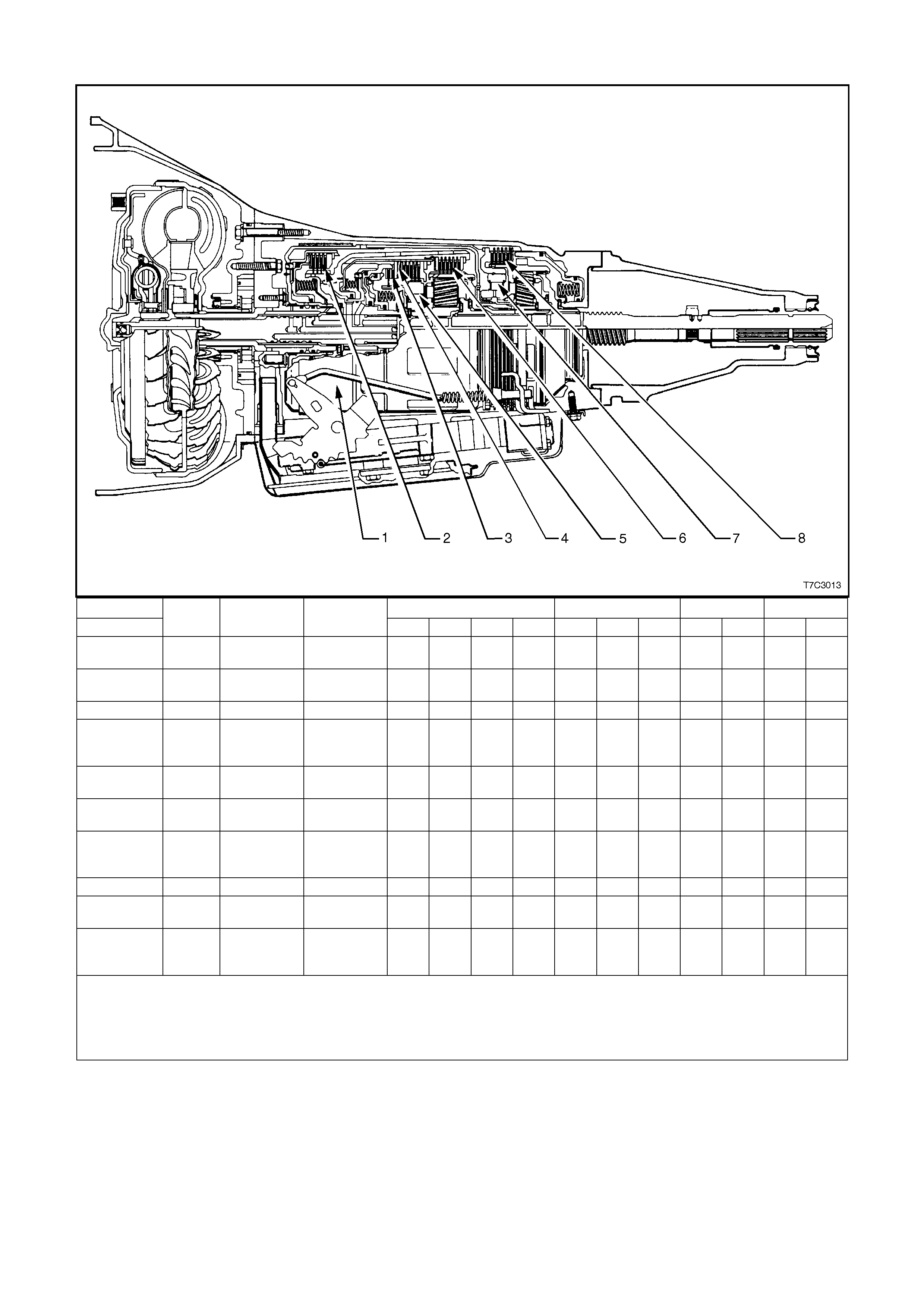
2.15 RANGE REFERENCE CHART
RANGE D 3 2 1
GEAR PARK REVERSE NEUTRAL 1st 2nd 3rd 4th 1st 2nd 3rd 1st 2nd 1st 2nd
1-2 Shift
Solenoid ON* ON* ON* ON* OFF OFF ON* ON* OFF OFF ON* OFF ON* OFF
2-3 Shift
Solenoid ON* ON* ON* ON* ON* ON* OFF ON* ON* OFF ON* ON* ON* ON*
2-4 Band – – – – A – A – A – – A – A
Reverse
Input
Clutch – A – – – – – – – – – – – –
Overrun
Clutch – – – – – – – – – A A A A A
Forward
Clutch – – – A A A A A A A A A A A
Forward
Sprag
Clutch – – – H H H – H – H – – – –
3-4 Clutch – – – – – A A – – A – – – –
Low Roller
Clutch – – – H – – – – H – H – H –
Low/
Reverse
Clutch A A – – – – – – – – – – A –
A = Applied H = Holding
ON = The Solenoid is Energised OFF = The Solenoid is De-energised
* Shift Solenoid state is a function of vehicle speed and may change if the vehicle speed increases sufficiently in Park, Reverse or
Neutral. However this odes not affect the operation of he transmission.
** In Manual First, Second gear is only available above approximat el y 70 km/h to prevent engi ne over-speeding.
Figure 7C3-6

3. MY2003 – 4L60-E SHIFT SPEED CHARTS
3.1 INTRODUCTION
NOTE: To assist in the interpretation of the following charts, the following criteria have been applied:
1. All upshifts have a solid blue line – 1- 2 has red f illed triangle plot points, 2-3 has red filled, c ircular plot points
and 3-4 has red filled square plot points.
2. All downshif ts have a das hed, red l ine – 2-1 has yellow filled tri angular p lot point s, 3-2 has ye llow f illed circular
plot points and 4-3 has yellow filled triangular plot points.
3. Tor que converter c lutc h appl y points (‘3r d App ’ and ‘4t h App’) ha ve a so lid gr een line – ‘3rd A pp’ has bl ue fil led
triangular plot points and ‘4th App’ has blue filled, square plot points.
4. Torque converter clutch release points (‘3rd Rel’ and ‘4th Rel’) have a dashed pink line – ‘3rd Rel’ has white
filled diamond plot points and ‘4th Rel’ has white filled, square plot points.
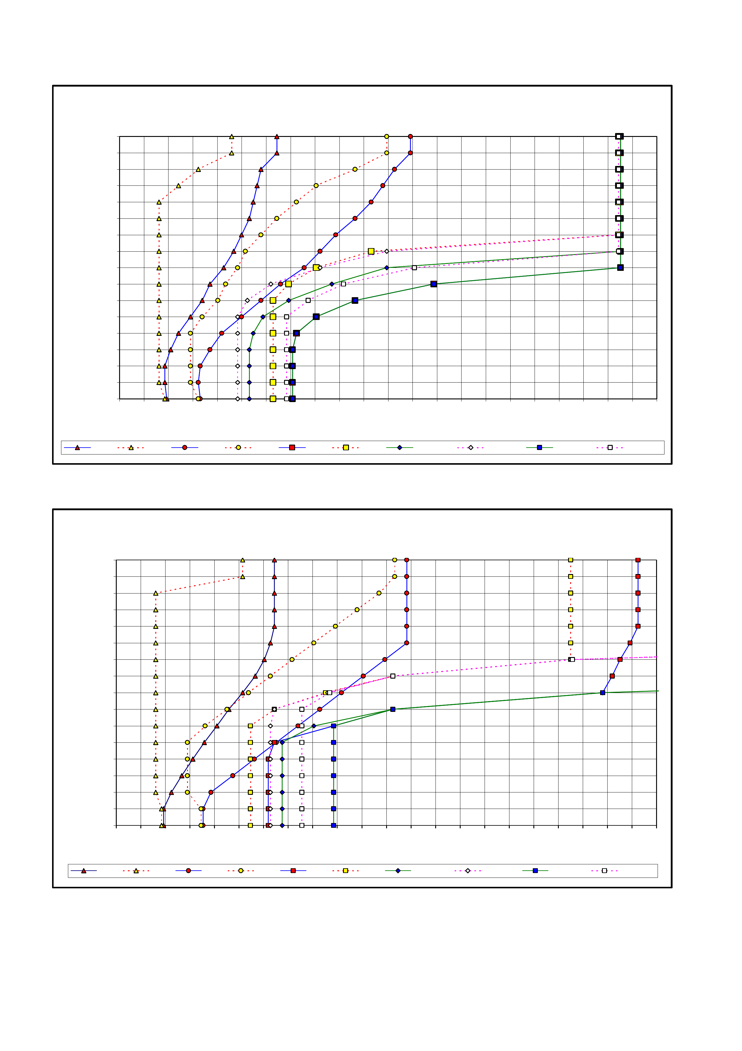
3.2 V6 ENGINE – ALL
Figure 7C3-7 – V6 Engine – All – Normal Mode Shift Pattern
Figure 7C3-8 – V6 Engine - All – Power Mode Shift Mode
VY - V6 - ALL - NORMAL MOD E SHIFT PATTERN
0.00%
6.25%
12.50%
18.75%
25.00%
31.25%
37.50%
43.75%
50.00%
56.25%
62.50%
68.75%
75.00%
81.25%
87.50%
93.75%
100.00%
0 10 20 30 40 50 60 70 80 90 100 110 120 130 140 150 160 170 180 190 200 210 220
Road Speed (km/h)
Throttle Opening (%)
N 1-2 N 2-1 N 2 - 3 N 3-2 N 3-4 N 4-3 N 3rd App N 3rd Rel N 4th App N 4th Re l
VY - V6 - ALL - POW ER MOD E SH IFT PAT TE RN
0.00%
6.25%
12.50%
18.75%
25.00%
31.25%
37.50%
43.75%
50.00%
56.25%
62.50%
68.75%
75.00%
81.25%
87.50%
93.75%
100.00%
0 10 20 30 40 50 60 70 80 90 100 110 120 130 140 150 160 170 180 190 200 210 220
Road Speed (km/h)
Throttle Opening (%)
P 1-2 P 2-1 P 2-3 P 3-2 P 3-4 P 4-3 P 3rd App P 3rd Rel P 4th App P 4th Rel
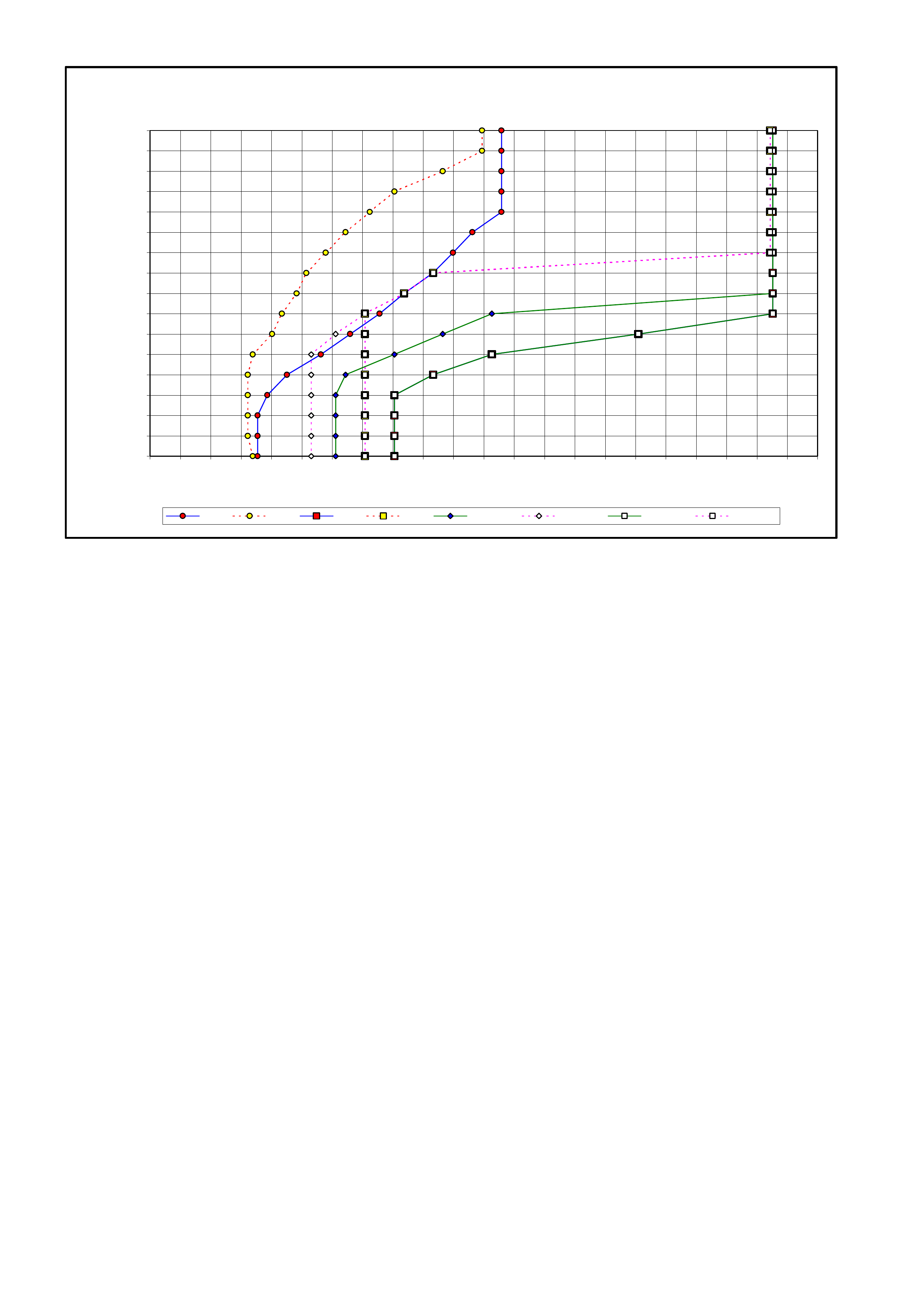
Figure 7C3-9 – V6 Engine – All – Cruise Mode Shift Pattern
VY - V6 -A LL - CR UI SE MOD E SH IF T PATTE RN
0.00%
6.25%
12.50%
18.75%
25.00%
31.25%
37.50%
43.75%
50.00%
56.25%
62.50%
68.75%
75.00%
81.25%
87.50%
93.75%
100.00%
0 10 20 30 40 50 60 70 80 90 100 110 120 130 140 150 160 170 180 190 200 210 220
Roads Speed (km/h)
Throttle Opening (%)
C 2-3 C 3-2 C 3-4 C 4-3 C 3rd App C 3rd Rel C 4th App C 4th Re l
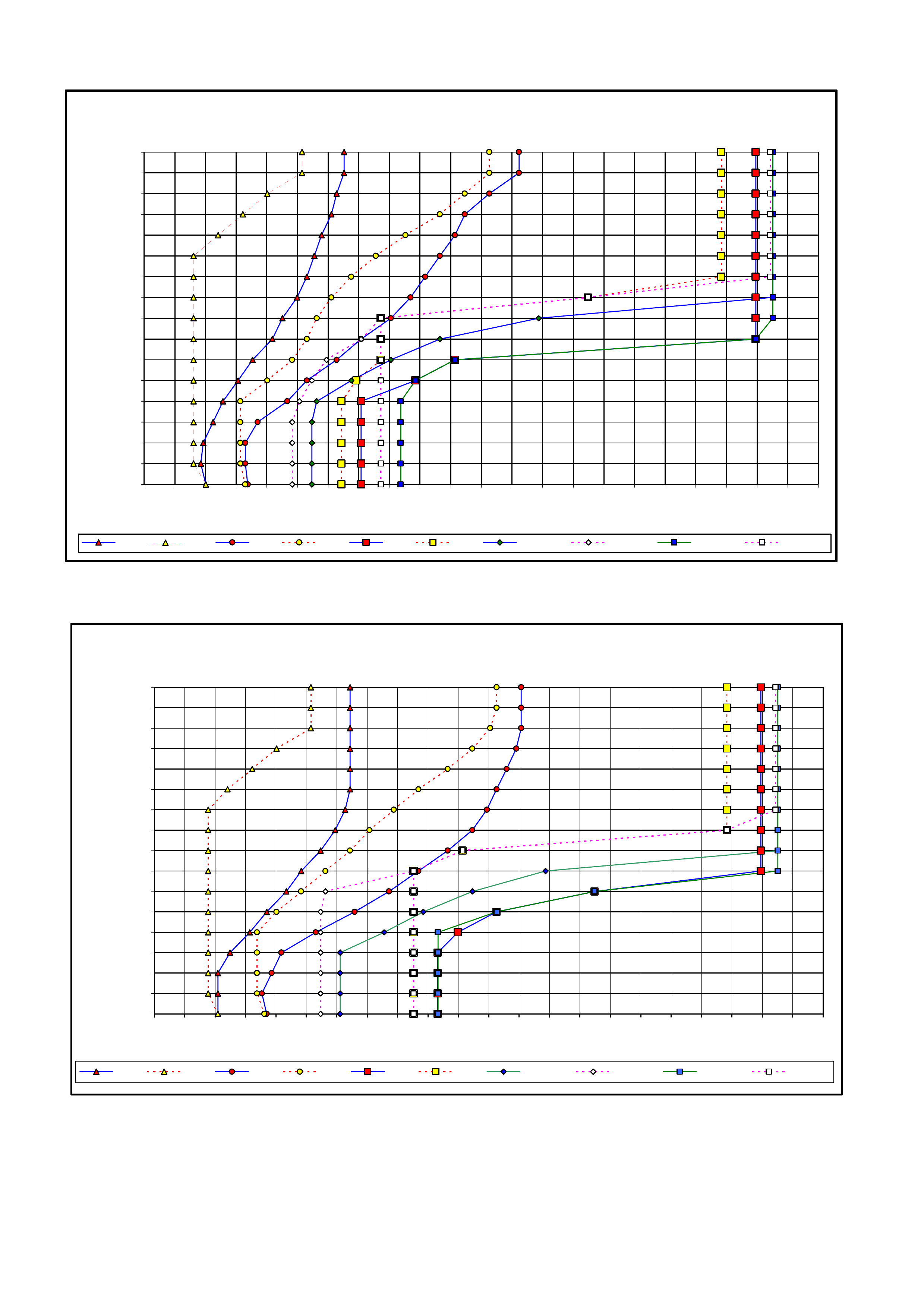
3.3 V6 SUPERCHA RGED ENGINE
Figure 7C3-10 – V6 Supercharged Engine – Normal Mode Shift Pattern
Figure 7C3-11 – V6 Supe rcharged Engine – Performance Mode Shift Pattern
VY - V6 S/C ENGI N E - PE RFOR MA NCE MOD E SH IF T PATTE RN
0.00%
6.25%
12.50%
18.75%
25.00%
31.25%
37.50%
43.75%
50.00%
56.25%
62.50%
68.75%
75.00%
81.25%
87.50%
93.75%
100.00%
0 10 20 30 40 50 60 70 80 90 100 110 120 130 140 150 160 170 180 190 200 210 220
Road Speed (km/h)
Throttle Opening (%)
P 1-2 P 2-1 P 2-3 P 3-2 P 3- 4 P 4-3 P 3rd App P 3rd Rel P 4th App P 4th Rel
VY - V6 S/C ENGINE - NORMAL MODE SHIFT PATTERN
0.00%
6.25%
12.50%
18.75%
25.00%
31.25%
37.50%
43.75%
50.00%
56.25%
62.50%
68.75%
75.00%
81.25%
87.50%
93.75%
100.00%
0 10 20 30 40 50 60 70 80 90 100 110 120 130 140 150 160 170 180 190 200 210 220
Road Speed (km/h)
Throttle Opening (%)
N 1-2 N 2-1 N 2-3 N 3-2 N 3-4 N 4-3 N 3rd App N 3rd Rel N 4th App N 4th Rel
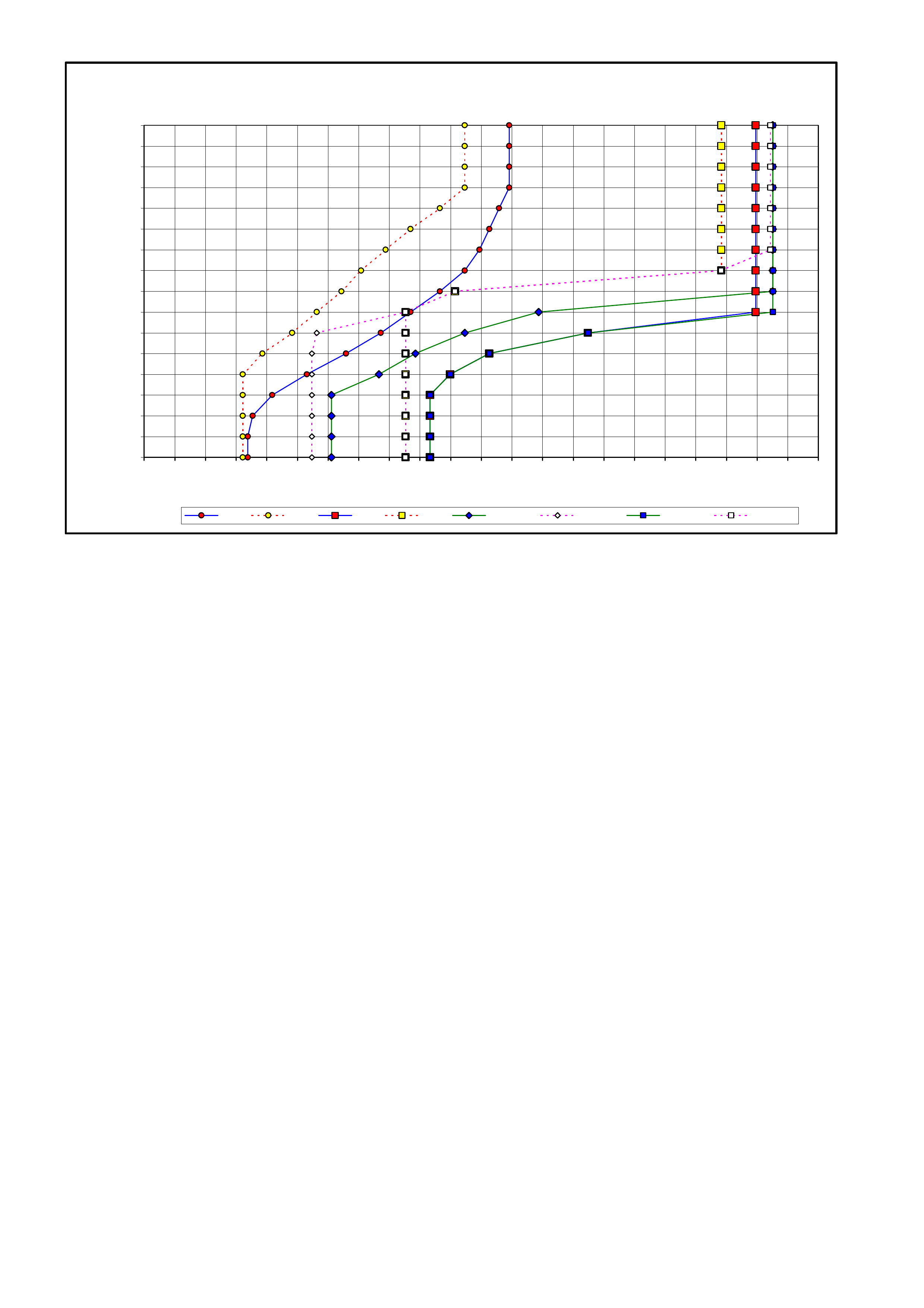
Figure 7C3-12 – V6 Supercharged Engine – Cruise Mode Shift Pattern
VY - V6 S/C ENGINE - CRUISE MODE SH IFT PATTERN
0.00%
6.25%
12.50%
18.75%
25.00%
31.25%
37.50%
43.75%
50.00%
56.25%
62.50%
68.75%
75.00%
81.25%
87.50%
93.75%
100.00%
0 10 20 30 40 50 60 70 80 90 100 110 120 130 140 150 160 170 180 190 200 210 220
Road Speed (km/h)
Throttle Opening (%)
C 2-3 C 3-2 C 3-4 C 4-3 C 3rd App C 3rd Rel C 4th App C 4th Rel
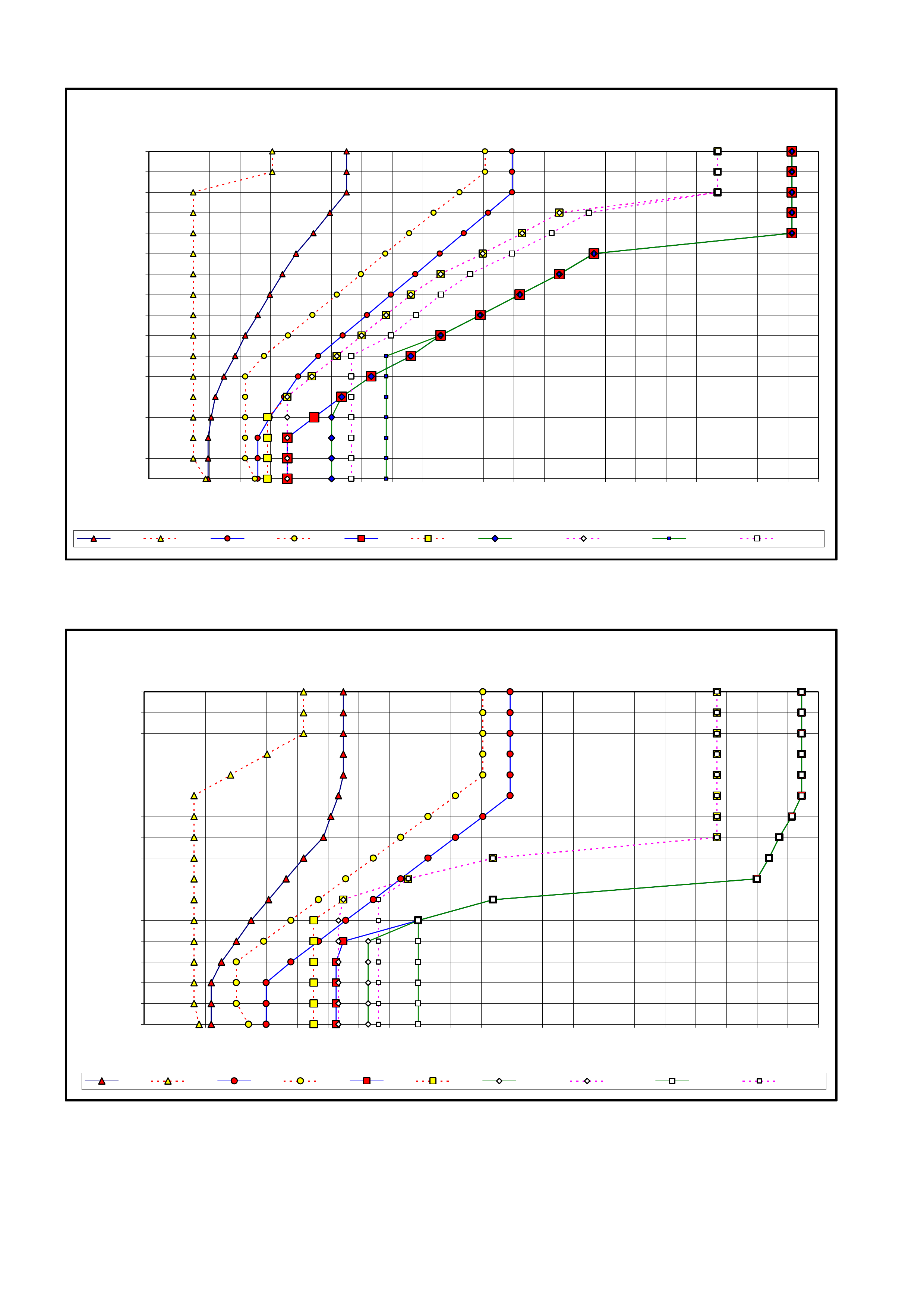
3.4 GEN III V8 ENGINE – HIGH/LOW OUTPUT
Figure 7C3-13 – GEN III V8 Engine – Normal Mode Shift Pattern
Figure 7C3-14 – GEN III V8 Engine – Power Mode Shift Pattern
VY - GEN III V8 - HIGH/LOW OUTPUT - POWER MODE SHIFT PATTERN
0.00%
6.25%
12.50%
18.75%
25.00%
31.25%
37.50%
43.75%
50.00%
56.25%
62.50%
68.75%
75.00%
81.25%
87.50%
93.75%
100.00%
0 10 20 30 40 50 60 70 80 90 100 110 120 130 140 150 160 170 180 190 200 210 220
Road Speed (km/h)
Throttle Opening (%)
P 1-2 P 2-1 P 2-3 P 3- 2 P 3-4 P 4-3 P 3rd Ap p P 3rd Rel P 4th App P 4th Rel
VY - GEN III V8 - HIGH/LOW OUTPUT - NORMAL MODE SHIFT PATTERN
0.00%
6.25%
12.50%
18.75%
25.00%
31.25%
37.50%
43.75%
50.00%
56.25%
62.50%
68.75%
75.00%
81.25%
87.50%
93.75%
100.00%
0 10 20 30 40 50 60 70 80 90 100 110 120 130 140 150 160 170 180 190 200 210 220
Road Speed (km/h)
Throttle Opening (%)
N 1-2 N 2-1 N 2-3 N 3-2 N 3-4 N 4-3 N 3rd App N 3rd Rel N 4th App N 4th Rel
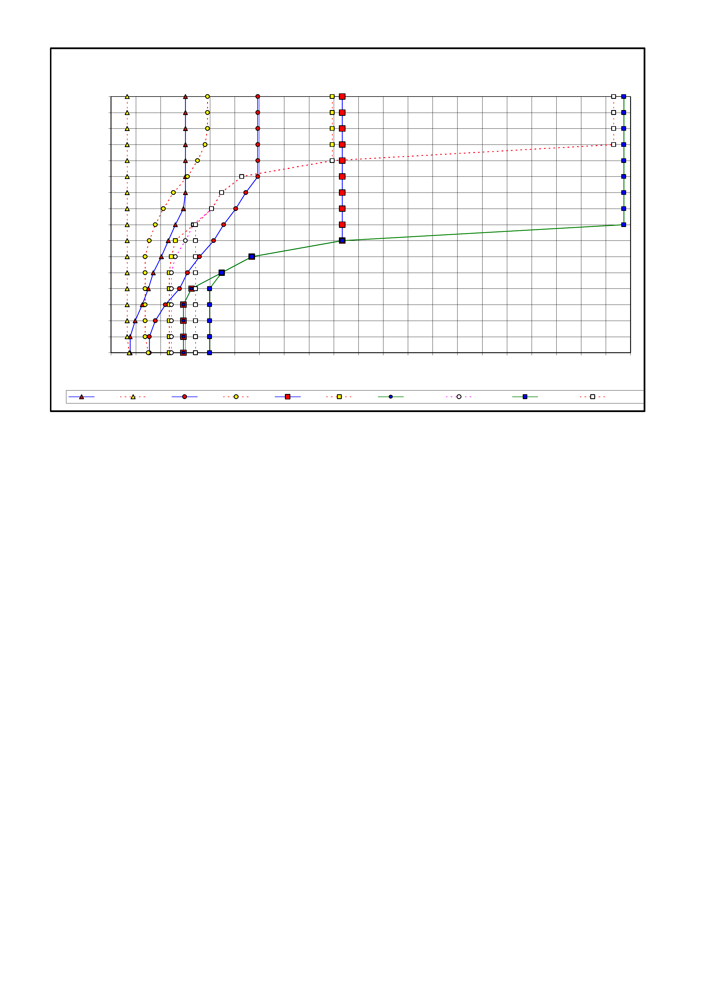
Figure 7C3-15 – GEN III V8 Engine – Cruise Mode Shift Pattern
VY - GEN III V8 ENGINE - HIGH/LOW OUTPUT - C RUISE MODE SHIFT P ATTERN
0.00%
6.25%
12.50%
18.75%
25.00%
31.25%
37.50%
43.75%
50.00%
56.25%
62.50%
68.75%
75.00%
81.25%
87.50%
93.75%
100.00%
0 20 40 60 80 100 120 140 160 180 200 220 240 260 280 300 320 340 360 380 400 420
Road Speed (km/h)
Throttle Opening (%)
C 1-2 C 2-1 C 2-3 C 3-2 C 3-4 C 4-3 C 3rd App C 3rd Rel C 4th App C 4th Rel
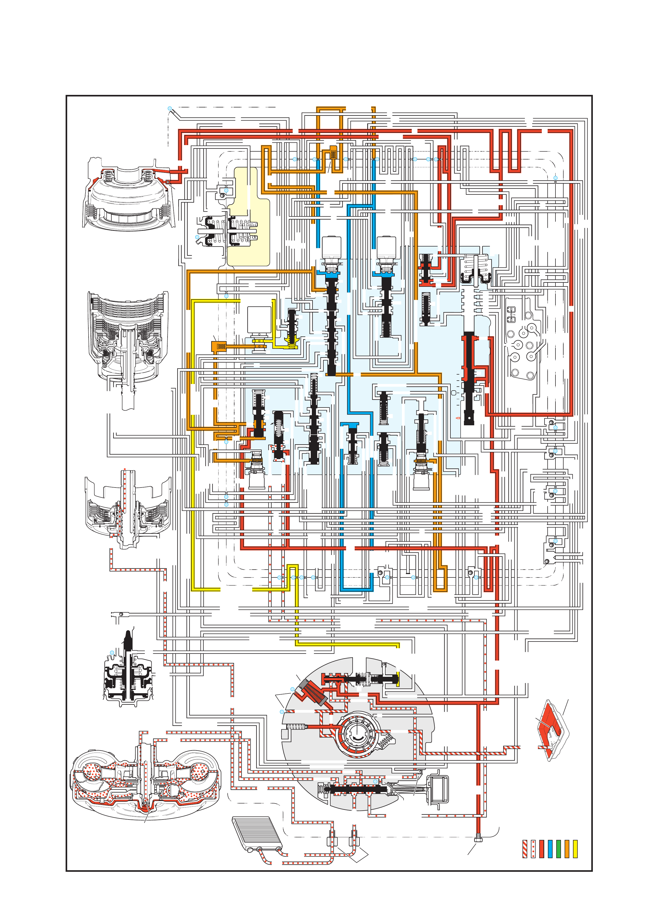
Figure 7C3-16 - Park - Engine Running
4. FLUID FLOW AND CIRCUIT DESCRIPTIONS
PARK
(Engine Running)
INPUT CLUTCH
HOUSING ASSEMBLY
24
REAR LUBE
FILTER
(49)
RELEASE
APPLY
LO/REVERSE
PR
BOOST VALVE PRESS REG
BOTTOM
PAN
(SUMP)
(75)
FILTER
(72)
REVERSE INPUT
REV INPUT
DECREASE
LINE
EX
FILTER
(232)
AIR
BLEED
(240)
1
SUCTION
LINE
EX
PRESSURE
RELIEF
VALV E
PUMP
ASSEMBLY
(4)
4
TCC
SOLENOID
(66)
N.O.
COOLER
LUBE
COOLER
SUCTION
CONVERTER & LUBE
MAINLINE
SOLENOID SIGNAL
ACCUMULATOR
ACTUATOR FEED LIMIT
TORQUE SIGNAL
FLUID PRESSURES
REVERSE INPUT
FORWARD CLUTCH FEED
#1
ACCUMULATOR
ORF ACC
2ND CLUTCH
3-4 ACCUMULATOR
1-2 ACCUMULATOR
19 3-4 ACCUM
ACCUM
EX
ORIFICED ACCUM
3-4 ACCUMULATOR
3-4 ACCUM
2ND CLUTCH
2ND CLUTCH
D3
REVERSE INPUT
D2-N.C.
REV-N.O.
D3-N.C.
LO-N.O.
D4-N.O.
LO
TEMP
SENSOR
TFP
SWITCH
ASSEMBLY
D2
D4
D3
D3
D3
EX
FORWARD ABUSE
FWD CL FD
3RD ACCUMULATOR EX
#7
11
3RD ACCUM
4TH
EX
EX
4TH
2ND & 4TH
SERVO
REV ABUSE
EX
REVERSE
REVERSE INPUT
#12
D4
22
D4
D4
#4
13
3-4 SIGNAL
3-4 CL
3-4 CLUTCH
#2
12
3-4 CLUTCH
3RD ACCUM
3-4 CL
#8
16
2ND
2ND CL
2ND CL
2ND CL
2ND CL
2ND CLUTCH2ND CLUTCH
TORQUE SIG
FORWARD CLUTCH FEED
FORWARD
CLUTCH
ACCUMULATOR
EX
PR
LO
LO
LO
FORWARD CLUTCH FEED
FORWARD CLUTCH FEED
FWD CL FEED
D3
D3
D3
14
3-4 CLUTCH
3RD ACCUMULATOR
3RD ACCUM
EX
AFL
3-2 SIGNAL
2ND
2ND
LINE
REGULATED APPLY
8
REG APPLY
1-2 SHIFT VALVE
26
LO
D4
O’ EX
D4-3-2 2ND
25
1-2 SIGNAL
LO/1ST
27
1-2 SIGNAL
EX
ORIFICED EX
ORIFICED EX
EX
LO/1ST D4-3-2
D4
D4
2
EX
CONV FD
EX
EX
EX
LINE LINE
LINE
PRESSURE
TAP
(39)
REGULATED APPLY
LUBE
LUBE
LUBE
LUBE
CASE (8)
CASE (8)
GASKET (47)
SPACER PLATE (48)
GASKET (52)
VALVE BODY (60)
SUCTION
LINE
LINE
3a
3b
3c
D3
EX
3-4 SIGNAL
1-2 SIGNAL
4TH SIGNAL
3-4 SHIFT VALVE
1-2 SIGNAL
3-4 CLUTCH
OVERRUN CLUTCH
OVERRUN CLUTCH
OVERRUN CLUTCH
OVERRUN CLUTCH
OVERRUN CLUTCH
OVERRUN CLUTCH
12a
12b
12c
12d
12e
EX
EX
EX
32
AFL
AFL
30
D4
EX
31
ACCUMULATOR
ACCUMULATOR
EX
TORQUE SIGNAL
FILTERED AFL
D4
AFLAFL
FILTER
(50)
10
43a
43b 44
11b
11c
11a
14b
14a
14c
LO OVERRUN
23
PR
LO/REV
LO/1ST
LO/REVERSE
LO/REVERSE
PR PR
EX
22 10c
23 10b
9n
9o
22b
22a
10a
10 9k
9g
9m
44a
43c 44
41a
41b
41c
41d
42b
42a
13a
13b
OIL
COOLER
PIPE
CONNECTOR
(10)
18a
18b
18c
18 17a
18 17b
20b
48b
48a
REGULATED APPLY
30a
30b
32a
37a
9b
9e
10 9d
9c
9a
9f
9h
31a
31b
31c
OVERRUN CLUTCH FEED
3-4 ACCUM
SERVO FEED
SERVO FEED
6
7
4TH4TH
OVERRUN CL
4TH SIGNAL
2ND
EX
EX
3-4 RELAY 4-3 SEQUENCE VALVE
5
EX
SERVO FD
ORF EX
CASE (8)
REV INPUT
EX
(237)
17d
17c
17e
17f
17
g
21
21
20d
20e
21a
20a
20c
1-2 ACCUMULATOR COVER (57)
25g
33c
33a
33b
27d
27c
27b
29
29
27a
28a
29b
29a
29d
40
29c
29e
29g28
28
29f
24a
24b
24c
24d
24e
24f
24
g
24h
25a
25b
25d
25e
25f
25
25
24m
24k
REVERSE INPUT
#3
17
REVERSE INPUT
15c
15b
16
16
REVERSE
REVERSE INPUT
16a
15d
15a
REVERSE
34f
34e
34d
34c
34a
34b
#6
OVERRUN CL FD
21
ORIFICED D2
#5
OVERRUN
OVERRUN OVERRUN
OVERRUN
36
36
35e
35d
39
35b
35c
36a
35a
38d
38e39
38c
38b
38a
EX
TORQUE SIGNAL
2ND CL
20
18
2-3 SHUTTLE2-3 SHIFT VALVE
28
29
EX
EX
EX
EX
D2
OVERRUN
D3
D3
2ND
3-4 SIGNAL
EX
D4-3-2
2-3 SIGNAL
ACTUATOR FEED LIMIT
AFL
SERVO FD
3-4 ACC
FILTERED AFL
AFL
ACTUATOR FEED LIMIT
ACTUATOR FEED LIMIT
AFL
D2
2ND
2ND
2ND
2ND
D2
D2
D2
D2
ORIFICED D2
D2
D2
D2
VALVE BODY (60)
3-4 SIGNAL
2ND
D4
PR
3-4 ACCUMULATOR
D4
EX
D4-3-2
LO
D4
2ND CLUTCH
D3
D3
FORWARD CLUTCH FEED ACTUATOR FEED LIMIT
TORQUE SIGNAL
SERVO FEED
OVERRUN CLUTCH
LINE
9p
26a
PR
OFF
CONVERTER CLUTCH VALVE
COOLER
RELEASE
APPLY
EX
EX
CONV FD
REGULATED APPLY
3-2 CONTROL
EX
EX
CC SIGNAL
CC SIGNAL
ACTUATOR FEED LIMIT
9
26b
TCC PWM
SOLENOID
VALVE
N.C.
1-2 SIGNAL
2ND
4TH SIGNAL
3-2
CONTROL
SOLENOID
VALVE
N.C.
OFF
#10
LOW AND REVERSE
CLUTCH ASSEMBLY
REVERSE INPUT
CLUTCH ASSEMBLY
TORQUE
CONVERTER
ASSEMBLY
#9
(237)
(238)
EX
2ND CLUTCH
3-4 CLUTCH
2ND
PRESSURE
CONTROL
SOLENOID
VALV E
2-3 SHIFT
SOLENOID
VALV E
N.O. ON
EX
1-2 SHIFT
SOLENOID
VALV E
N.O. ON
ACCUM VALVE
PRND321
D4
D4
REVERSE
D3
D2
LO
EX
EX
LINE
MANUAL VALVE
PR
EXEX
3-2 DOWNSHIFT
ISOLATOR VALVE
REG APPLY
4.1 PARK - ENGINE RUNNING

With the gear selector lever in the PARK (P) position and the engine running, the line pressure from the oil pump
assembly is directed to various components in the valve body and the oil pump.
PRESSURE REGULATOR
Pressure Regulator Valve
The pres sure regulator v alve regulates the oil pum p output (line pr essure) in r esponse to the s ignal fluid pr essure,
the spr ing forc e and the line pres sure ac ting on the end of the val ve. T he line pr essure is r outed t hrough t he valve
and into both the converter feed and the decrease fluid circuits. Regulated line pressure is also directed to the
manual valve, the converter clutch signal valve and the actuator feed limit valve.
Pressure Relief Valve
Controlled by spring force, this checkball limits the maximum value of the line pressure. When the line pressure
reaches this limiting value, fluid is exhausted past the ball and returns to the sump.
Line Pressure Tap
The line pressure tap provides a location to measure the line pressure with a fluid pressure gauge.
Actuator Feed Limit Valve
Biased by spring force and orificed AFL fluid, it limits the maximum value of line pressure entering the AFL fluid
circuit. Below this limiting value, the AFL fluid pressure equals the line pressure. The AFL fluid is routed to the
pressure control solenoid, the 3-2 control solenoid, the 1-2 and 2-3 shift solenoids, and the 2-3 shift valve train.
Pressure Control Solenoid
Controlled by the Powertrain Control Module (PCM) the pressure control solenoid regulates the filtered AFL fluid
into the torque signal fluid pressure. The PCM controls this regulation by varying the current value to the solenoid in
relation to the throttle position and other vehicle operating conditions.
TORQUE CONVERTER CLUTCH (TCC)
Torque Converter Clutch Signal Valve
The val ve may be in a p os it ion to al lo w the l ine pr es sur e to ent er the c on verter c lut c h ( CC) s ign al f lu id c irc uit. If this
occurs with the 2nd c lutch fluid c ircuit em pty, the CC signa l fluid press ure orif iced to the end of the CC s igna l va lve
will close th e valve and bl ock line pressure. A ny fluid in the CC s ignal fluid c ircuit will exhaust thr ough the n ormall y
open TCC solenoid.
Converter Clutch Apply Valve
Held in the release position by spring force, it directs converter feed fluid into the release fluid circuit. Also, fluid
returning from the converter in the apply fluid circuit is routed through the valve and into the cooler fluid circuit.
Torque Converter
Release f luid pr ess ur e uns eats the TCC apply checkball (# 9), keeps the pres s ure plate r e le as ed f rom the c onver t er
cover and fills the converter with fluid. Fluid exits the converter between the converter hub and the stator shaft in
the apply fluid circuit.
Cooler and Lubrication System
Cooler fluid from the converter clutch apply valve is routed through the transmission fluid cooler and into the
lubrication fluid circuits.
MANUAL VALVE
Controlled by the selector lever and the manual shaft, the manual valve is in the Park (P) position and directs the
line pressure into the PR (Park/Reverse) fluid circuit. Line pressure is blocked from entering any other fluid circuit at
the manual valve.
LOW AND REVERSE CLUTCH APPLIES
Low and Reverse Clutch Piston
The PR fluid seats the low and reverse clutch checkball (#10) and is orificed to the outer area of the piston.
Orificing the PR fluid around the #10 checkball helps control the low and reverse clutch appl y. Also, Low/Reverse
fluid pressure from the low overrun valve acts on the inner area of the low and reverse clutch piston in order to
increase the clutch holding capacity.
Low Overrun Valve
The PR fluid pressure moves the valve against the spring force and fills the low/reverse fluid circuit. Low/Re verse
fluid is orificed (323) back to the low overrun valve in order to assist the PR fluid in moving the valve against the
spring force. The spring force provides a time delay for the PR fluid filling the Low/Reverse fluid circuit. The
Low/Reverse fluid is routed to the inner area of the low and reverse clutch piston in order to increase the holding
capacity of the clutch.

TRANSMISSION FLUID PRESSURE (TFP) MANUAL VALVE POSITION SWITCH ASSEMBLY
The T FP Pos ition S witch. c onsists of f ive flu id pres sure s witches : D2 a nd D3 ar e norm ally clos ed and D4, Lo w and
Rev are nor mally open. All fluid circuits r outed to the assem bly are em pty and the TFP Positi on Switch signa ls the
PCM that the transmission is in either Park or Neutral.
Shift Solenoids (1-2 and 2-3)
Both shift solenoids, which are normally open, are energised by the PCM and block fluid from exhausting. This
maintains the signal A fluid pressure at the 1-2 shift solenoid and signal B fluid pressure at the 2-3 shift solenoid.
Shift Valves (1-2, 2-3 and 3-4)
Signal A fluid pressure holds the 1-2 shift valve in the downshift posit ion and the 3-4 valve in the upshift (first and
fourth gear ) positi on. The s ignal B f luid press ure fr om the 2-3 sh ift soleno id ho lds the 2- 3 shif t train in the do wnshif t
position.
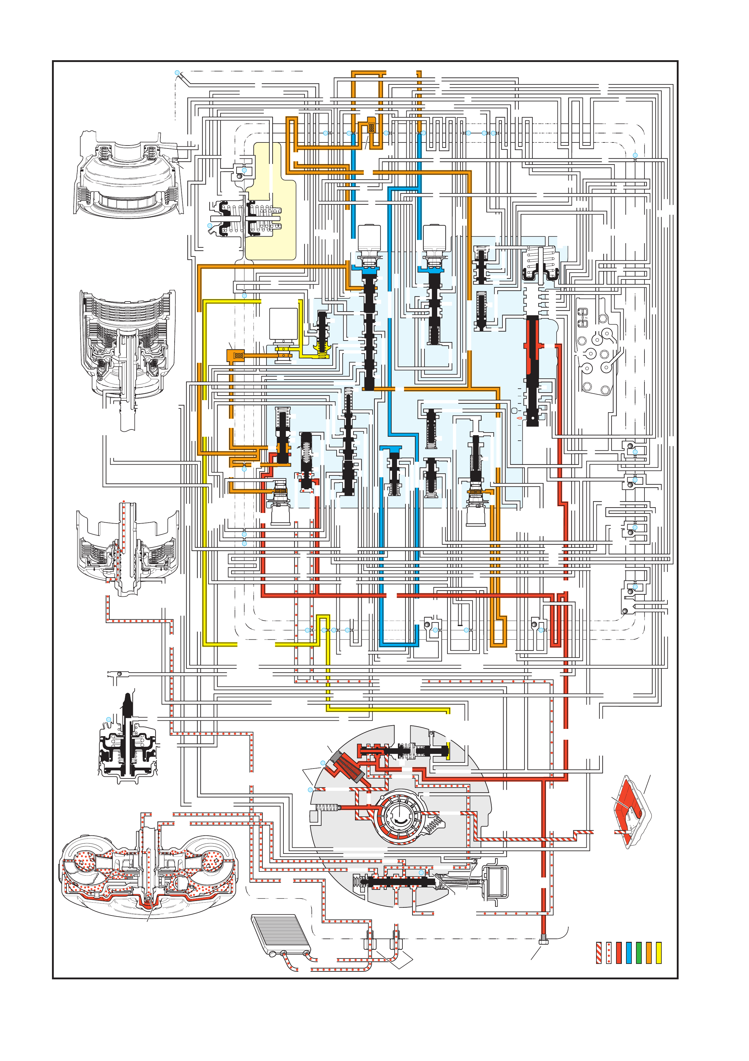
Figure 7C3-17 - Neutral - Engine running
4.2 NEUTRAL - ENGINE RUNNING
NEUTRAL
(Engine Running)
INPUT CLUTCH
HOUSING ASSEMBLY
24
REAR LUBE
FILTER
(49)
RELEASE
APPLY
LO/REVERSE
PR
BOOST VALVE PRESS REG
BOTTOM
PAN
(SUMP)
(75)
FILTER
(72)
REVERSE INPUT
REV INPUT
DECREASE
LINE
EX
FILTER
(232)
AIR
BLEED
(240)
1
SUCTION
LINE
EX
PRESSURE
RELIEF
VALV E
PUMP
ASSEMBLY
(4)
4
TCC
SOLENOID
(66)
N.O.
COOLER
LUBE
COOLER
SUCTION
CONVERTER & LUBE
MAINLINE
SOLENOID SIGNAL
ACCUMULATOR
ACTUATOR FEED LIMIT
TORQUE SIGNAL
FLUID PRESSURES
REVERSE INPUT
FORWARD CLUTCH FEED
#1
ACCUMULATOR
ORF ACC
2ND CLUTCH
3-4 ACCUMULATOR
1-2 ACCUMULATOR
19
3-4 ACCUM
ACCUM
EX
ORIFICED ACCUM
3-4 ACCUMULATOR
3-4 ACCUM
2ND CLUTCH
2ND CLUTCH
D3
REVERSE INPUT
D2-N.C.
REV-N.O.
D3-N.C.
LO-N.O.
D4-N.O.
LO
TEMP
SENSOR
TFP
SWITCH
ASSEMBLY
D2
D4
D3
D3
D3
EX
FORWARD ABUSE
FWD CL FD
3RD ACCUMULATOR EX
#7
11
3RD ACCUM
4TH
EX
EX
4TH
2ND & 4TH
SERVO
REV ABUSE
EX
REVERSE
REVERSE INPUT
#12
D4
22
D4
D4
#4
13
3-4 SIGNAL
3-4 CL
3-4 CLUTCH
#2
12
3-4 CLUTCH
3RD ACCUM
3-4 CL
#8
16
2ND
2ND CL
2ND CL
2ND CL
2ND CL
2ND CLUTCH2ND CLUTCH
TORQUE SIG
FORWARD CLUTCH FEED
FORWARD
CLUTCH
ACCUMULATOR
EX
PR
LO
LO
LO
FORWARD CLUTCH FEED
FORWARD CLUTCH FEED
FWD CL FEED
D3
D3
D3
14
3-4 CLUTCH
3RD ACCUMULATOR
3RD ACCUM
EX
AFL
3-2 SIGNAL
2ND
2ND
LINE
REGULATED APPLY
8
REG APPLY
1-2 SHIFT VALVE
26
LO
D4
O’ EX
D4-3-2 2ND
25
1-2 SIGNAL
LO/1ST
27
1-2 SIGNAL
EX
ORIFICED EX
ORIFICED EX
EX
LO/1ST D4-3-2
D4
D4
2
EX
CONV FD
EX
EX
EX
LINE LINE
LINE
PRESSURE
TAP
(39)
REGULATED APPLY
LUBE
LUBE
LUBE
LUBE
CASE (8)
CASE (8)
GASKET (47)
SPACER PLATE (48)
GASKET (52)
VALVE BODY (60)
SUCTION
LINE
LINE
3a
3b
3c
D3
EX
3-4 SIGNAL
1-2 SIGNAL
4TH SIGNAL
3-4 SHIFT VALVE
1-2 SIGNAL
3-4 CLUTCH
OVERRUN CLUTCH
OVERRUN CLUTCH
OVERRUN CLUTCH
OVERRUN CLUTCH
OVERRUN CLUTCH
OVERRUN CLUTCH
12a
12b
12c
12d
12e
EX
EX
EX
32
AFL
AFL
30
D4
EX
31
ACCUMULATOR
ACCUMULATOR
EX
TORQUE SIGNAL
FILTERED AFL
D4
AFLAFL
FILTER
(50)
10
43a
43b 44
11b
11c
11a
14b
14a
14c
LO OVERRUN
23
PR
LO/REV
LO/1ST
LO/REVERSE
LO/REVERSE
PR PR
EX
22 10c
23 10b
9n
9o
22b
22a
10a
10 9k
9g
9m
44a
43c 44
41a
41b
41c
41d
42b
42a
13a
13b
OIL
COOLER
PIPE
CONNECTOR
(10)
18a
18b
18c
18 17a
18 17b
20b
48b
48a
REGULATED APPLY
30a
30b
32a
37a
9b
9e
10 9d
9c
9a
9f
9h
31a
31b
31c
OVERRUN CLUTCH FEED
3-4 ACCUM
SERVO FEED
SERVO FEED
6
7
4TH4TH
OVERRUN CL
4TH SIGNAL
2ND
EX
EX
3-4 RELAY 4-3 SEQUENCE VALVE
5
EX
SERVO FD
ORF EX
CASE (8)
REV INPUT
EX
(237)
17d
17c
17e
17f
17g
21
21
20d
20e
21a
20a
20c
1-2 ACCUMULATOR COVER (57)
25g
33c
33a
33b
27d
27c
27b
29
29
27a
28a
29b
29a
29d
40
29c
29e
29g28
28
29f
24a
24b
24c
24d
24e
24f
24
g
24h
25a
25b
25d
25e
25f
25
25
24m
24k
REVERSE INPUT
#3
17
REVERSE INPUT
15c
15b
16
16
REVERSE
REVERSE INPUT
16a
15d
15a
REVERSE
34f
34e
34d
34c
34a
34b
#6
OVERRUN CL FD
21
ORIFICED D2
#5
OVERRUN
OVERRUN OVERRUN
OVERRUN
36
36
35e
35d
39
35b
35c
36a
35a
38d
38e39
38c
38b
38a
EX
TORQUE SIGNAL
2ND CL
20
18
2-3 SHUTTLE2-3 SHIFT VALVE
28
29
EX
EX
EX
EX
D2
OVERRUN
D3
D3
2ND
3-4 SIGNAL
EX
D4-3-2
2-3 SIGNAL
ACTUATOR FEED LIMIT
AFL
SERVO FD
3-4 ACC
FILTERED AFL
AFL
ACTUATOR FEED LIMIT
ACTUATOR FEED LIMIT
AFL
D2
2ND
2ND
2ND
2ND
D2
D2
D2
D2
ORIFICED D2
D2
D2
D2
VALVE BODY (60)
3-4 SIGNAL
2ND
D4
PR
3-4 ACCUMULATOR
D4
EX
D4-3-2
LO
D4
2ND CLUTCH
D3
D3
FORWARD CLUTCH FEED ACTUATOR FEED LIMIT
TORQUE SIGNAL
SERVO FEED
OVERRUN CLUTCH
LINE
9p
26a
PR
OFF
CONVERTER CLUTCH VALVE
COOLER
RELEASE
APPLY
EX
EX
CONV FD
REGULATED APPLY
3-2 CONTROL
EX
EX
CC SIGNAL
CC SIGNAL
ACTUATOR FEED LIMIT
9
26b
TCC PWM
SOLENOID
VALVE
N.C.
1-2 SIGNAL
2ND
4TH SIGNAL
3-2
CONTROL
SOLENOID
VALVE
N.C.
OFF
#10
LOW AND REVERSE
CLUTCH ASSEMBLY
REVERSE INPUT
CLUTCH ASSEMBLY
TORQUE
CONVERTER
ASSEMBLY
#9
(237)
(238)
EX
2ND CLUTCH
3-4 CLUTCH
2ND
PRESSURE
CONTROL
SOLENOID
VALV E
2-3 SHIFT
SOLENOID
VALV E
N.O.
ON
EX
1-2 SHIFT
SOLENOID
VALV E
N.O.
ON
ACCUM VALVE
PRND321
D4
D4
REVERSE
D3
D2
LO
EX
EX
LINE
MANUAL VALVE
PR
EX
EX
3-2 DOWNSHIFT
ISOLATOR VALVE
REG APPLY

W hen the gear s elec tor le ver is m oved t o the N eutra l ( N) posit ion f rom the Rever s e positi on, the f ollo win g changes
occur to the transmission hydraulic and electrical systems.
MANUAL VALVE
In the Neutral position, the manual valve blocks the line pressure from entering any other fluid circuits. Reverse and
PR fluids exhaust past the manual valve.
LOW AND REVERSE CLUTCH RELEASES
Low and Reverse Clutch Piston
PR and Low/Reverse fluids exhaust from the piston, thereby releasing the low and reverse clutch plates.
Exhausting PR fluid unseats the low and reverse clutch checkball (#10) for a quick exhaust.
LOW OVERRUN VALVE
Spring force closes the valve when the PR fluid pressure exhausts. Low/reverse fluid exhausts through the valve,
into the Low/1st fluid circuit, past the 1-2 shift valve, into the Low fluid circuit and through an exhaust port at the
manual valve.
REVERSE INPUT CLUTCH RELEA SES
Reverse Input Clutch Piston
Reverse input fluid pressure exhausts from the piston, through the boost valve, past the #3 checkball and to the
manual valve. With the reverse input fluid exhausted, the reverse input clutch plates are released and the
transmission is in Neutral.
REVER SE ABUSE V ALVE
Reverse fluid pressure exhausts and spring force closes the valve.
BO OST VALVE
Reverse input fluid pressure exhausts and line pressure returns to the norm al operating range as in the Park and
Overdri ve posit ions.
REVERSE INPUT CHECKBALL (#3)
Exhausting reverse input fluid unseats the ball for a quick exhaust through the reverse fluid circuit and past the
manual valve.
TRANSMISSION FLUID PRESSURE (TFP) MANUAL VALVE POSITION SWITCH ASSEMBLY
IMPORTANT: In Park , Reverse and Neutral the shif t solenoids are shown energised. This is the normal operating
state when the vehicle is stationary or at low vehicle speeds. However, the PCM will change the shift solenoid
states depending on the vehicle speed.
For example, if Neutral is selected when the transmission is operating in Second Gear, the shift solenoids will
rem ain in a S econd Gear s tate. Howev er, with t he m anua l valve block ing line pre ssur e, the sh ift sole noid s tates do
not affect transmission operation in Park, Reverse and Neutral.
Reverse inp ut fluid ex hausts fr om the TFP Switc h. W ith no other fluid rou ted to it, the T FP Switch sig nals the PCM
that the transmission is operating in either Park or Neutral.
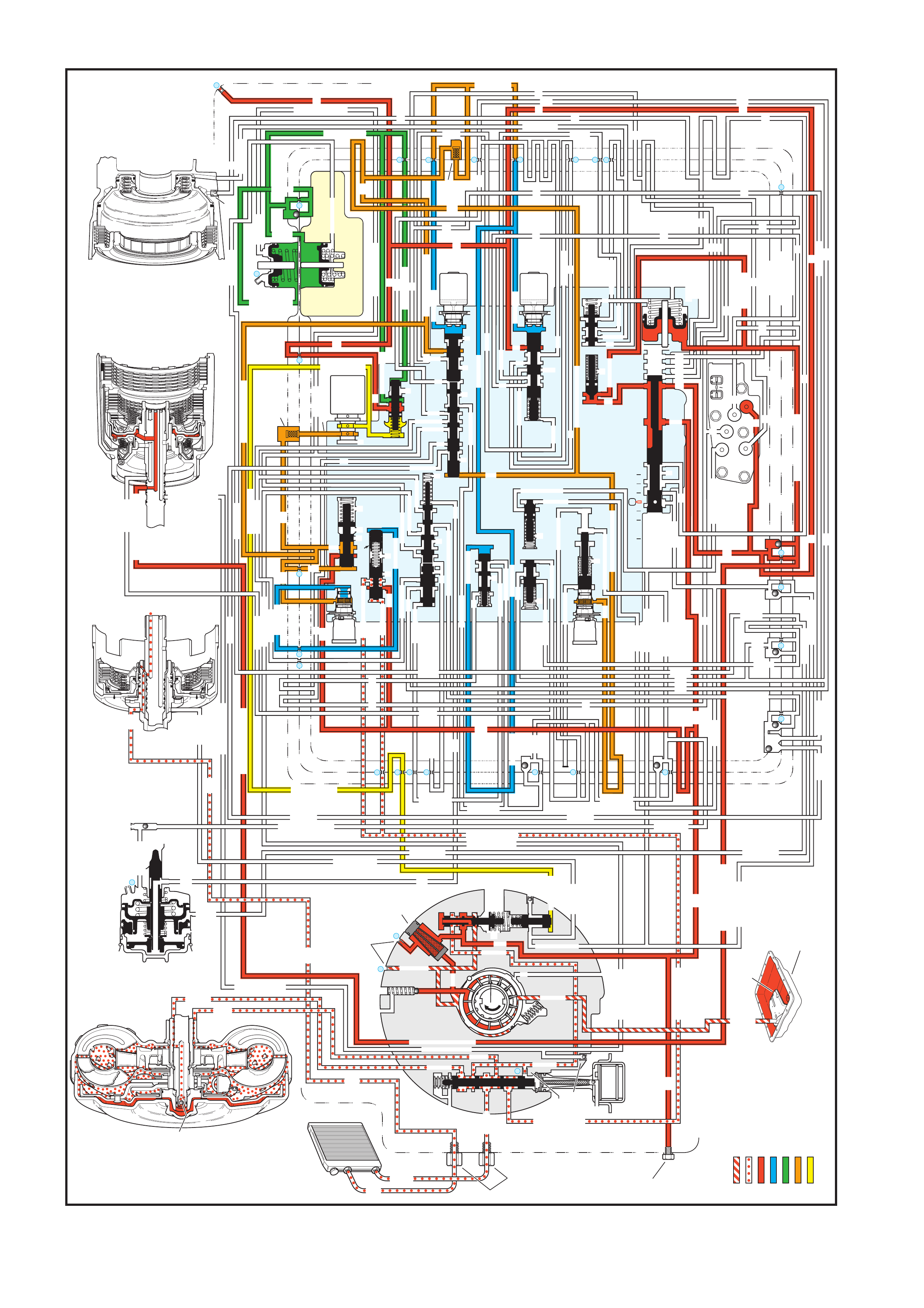
Figure 7C3-18 - Drive (Overdrive) Range - First Gear
4.3 DRIVE (OVERDRIVE) RANGE, FIRST GEAR
OVERDRIVE RANGE – FIRST GEAR
INPUT CLUTCH
HOUSING ASSEMBLY
24
REAR LUBE
FILTER
(49)
RELEASE
APPLY
LO/REVERSE
PR
BOOST VALVE PRESS REG
BOTTOM
PAN
(SUMP)
(75)
FILTER
(72)
REVERSE INPUT
REV INPUT
DECREASE
LINE
EX
FILTER
(232)
AIR
BLEED
(240)
1
SUCTION
LINE
EX
PRESSURE
RELIEF
VALV E
PUMP
ASSEMBLY
(4)
4
TCC
SOLENOID
(66)
N.O.
COOLER
LUBE
COOLER
SUCTION
CONVERTER & LUBE
MAINLINE
SOLENOID SIGNAL
ACCUMULATOR
ACTUATOR FEED LIMIT
TORQUE SIGNAL
FLUID PRESSURES
REVERSE INPUT
FORWARD CLUTCH FEED
#1
ACCUMULATOR
ORF ACC
2ND CLUTCH
3-4 ACCUMULATOR
1-2 ACCUMULATOR
19 3-4 ACCUM
ACCUM
EX
ORIFICED ACCUM
3-4 ACCUMULATOR
3-4 ACCUM
2ND CLUTCH
2ND CLUTCH
D3
REVERSE INPUT
D2-N.C.
REV-N.O.
D3-N.C.
LO-N.O.
D4-N.O.
LO
TEMP
SENSOR
TFP
SWITCH
ASSEMBLY
D2
D4
D3
D3
D3
EX
FORWARD ABUSE
FWD CL FD
3RD ACCUMULATOR EX
#7
11
3RD ACCUM
4TH
EX
EX
4TH
2ND & 4TH
SERVO
REV ABUSE
EX
REVERSE
REVERSE INPUT
#12
D4
22
D4
D4
#4
13
3-4 SIGNAL
3-4 CL
3-4 CLUTCH
#2
12
3-4 CLUTCH
3RD ACCUM
3-4 CL
#8
16
2ND
2ND CL
2ND CL
2ND CL
2ND CL
2ND CLUTCH2ND CLUTCH
TORQUE SIG
FORWARD CLUTCH FEED
FORWARD
CLUTCH
ACCUMULATOR
EX
PR
LO
LO
LO
FORWARD CLUTCH FEED
FORWARD CLUTCH FEED
FWD CL FEED
D3
D3
D3
14
3-4 CLUTCH
3RD ACCUMULATOR
3RD ACCUM
EX
AFL
3-2 SIGNAL
2ND
2ND
LINE
REGULATED APPLY
8
REG APPLY
1-2 SHIFT VALVE
26
LO
D4
O’ EX
D4-3-2 2ND
25
1-2 SIGNAL
LO/1ST
27
1-2 SIGNAL
EX
ORIFICED EX
ORIFICED EX
EX
LO/1ST D4-3-2
D4
D4
2
EX
CONV FD
EX
EX
EX
LINE LINE
LINE
PRESSURE
TAP
(39)
REGULATED APPLY
LUBE
LUBE
LUBE
LUBE
CASE (8)
CASE (8)
GASKET (47)
SPACER PLATE (48)
GASKET (52)
VALVE BODY (60)
SUCTION
LINE
LINE
3a
3b
3c
D3
EX
3-4 SIGNAL
1-2 SIGNAL
4TH SIGNAL
3-4 SHIFT VALVE
1-2 SIGNAL
3-4 CLUTCH
OVERRUN CLUTCH
OVERRUN CLUTCH
OVERRUN CLUTCH
OVERRUN CLUTCH
OVERRUN CLUTCH
OVERRUN CLUTCH
12a
12b
12c
12d
12e
EX
EX
EX
32
AFL
AFL
30
D4
EX
31
ACCUMULATOR
ACCUMULATOR
EX
TORQUE SIGNAL
FILTERED AFL
D4
AFLAFL
FILTER
(50)
10
43a
43b 44
11b
11c
11a
14b
14a
14c
LO OVERRUN
23
PR
LO/REV
LO/1ST
LO/REVERSE
LO/REVERSE
PR PR
EX
22 10c
23 10b
9n
9o
22b
22a
10a
10 9k
9g
9m
44a
43c 44
41a
41b
41c
41d
42b
42a
13a
13b
OIL
COOLER
PIPE
CONNECTOR
(10)
18a
18b
18c
18 17a
18 17b
20b
48b
48a
REGULATED APPLY
30a
30b
32a
37a
9b
9e
10 9d
9c
9a
9f
9h
31a
31b
31c
OVERRUN CLUTCH FEED
3-4 ACCUM
SERVO FEED
SERVO FEED
6
7
4TH4TH
OVERRUN CL
4TH SIGNAL
2ND
EX
EX
3-4 RELAY 4-3 SEQUENCE VALVE
5
EX
SERVO FD
ORF EX
CASE (8)
REV INPUT
EX
(237)
17d
17c
17e
17f
17
g
21
21
20d
20e
21a
20a
20c
1-2 ACCUMULATOR COVER (57)
25g
33c
33a
33b
27d
27c
27b
29
29
27a
28a
29b
29a
29d
40
29c
29e
29g28
28
29f
24a
24b
24c
24d
24e
24f
24
g
24h
25a
25b
25d
25e
25f
25
25
24m
24k
REVERSE INPUT
#3
17
REVERSE INPUT
15c
15b
16
16
REVERSE
REVERSE INPUT
16a
15d
15a REVERSE
34f
34e
34d
34c
34a
34b
#6
OVERRUN CL FD
21
ORIFICED D2
#5
OVERRUN
OVERRUN OVERRUN
OVERRUN
36
36
35e
35d
39
35b
35c
36a
35a
38d
38e39
38c
38b
38a
EX
TORQUE SIGNAL
2ND CL
20
18
2-3 SHUTTLE2-3 SHIFT VALVE
28
29
EX
EX
EX
EX
D2
OVERRUN
D3
D3
2ND
3-4 SIGNAL
EX
D4-3-2
2-3 SIGNAL
ACTUATOR FEED LIMIT
AFL
SERVO FD
3-4 ACC
FILTERED AFL
AFL
ACTUATOR FEED LIMIT
ACTUATOR FEED LIMIT
AFL
D2
2ND
2ND
2ND
2ND
D2
D2
D2
D2
ORIFICED D2
D2
D2
D2
VALVE BODY (60)
3-4 SIGNAL
2ND
D4
PR
3-4 ACCUMULATOR
D4
EX
D4-3-2
LO
D4
2ND CLUTCH
D3
D3
FORWARD CLUTCH FEED ACTUATOR FEED LIMIT
TORQUE SIGNAL
SERVO FEED
OVERRUN CLUTCH
LINE
9p
26a
PR
OFF
CONVERTER CLUTCH VALVE
COOLER
RELEASE
APPLY
EX
EX
CONV FD
REGULATED APPLY
3-2 CONTROL
EX
EX
CC SIGNAL
CC SIGNAL
ACTUATOR FEED LIMIT
9
26b
TCC PWM
SOLENOID
VALVE
N.C.
1-2 SIGNAL
2ND
4TH SIGNAL
3-2
CONTROL
SOLENOID
VALVE
N.C.
OFF
#10
LOW AND REVERSE
CLUTCH ASSEMBLY
REVERSE INPUT
CLUTCH ASSEMBLY
TORQUE
CONVERTER
ASSEMBLY
#9
(237)
(238)
EX
2ND CLUTCH
3-4 CLUTCH
2ND
PRESSURE
CONTROL
SOLENOID
VALV E
2-3 SHIFT
SOLENOID
VALV E
N.O.
ON
EX
1-2 SHIFT
SOLENOID
VALV E
N.O.
ON
ACCUM VALVE
PRND321
D4
D4
REVERSE
D3
D2
LO
EX
EX
LINE
MANUAL VALVE
PR
EX
EX
3-2 DOWNSHIFT
ISOLATOR VALVE
REG APPLY

When the gear selector lever is moved to the “D” (Overdrive) position from the Neutral position, the following
changes occur to the transmission’s hydraulic and electrical systems:
MANUAL VALVE
Line pres sure flows t hrough the m anual valve and fills the D4 f luid circ uit. All other f luid circuits remain em pty with
the manual valve in the Overdrive position.
FORWARD CLUTCH APPLIES
Forward Clutch Accumulator Checkball (#12)
D4 fluid pr es sur e s eats the chec kball and is or ificed (# 22) into the f orw ard c l utc h feed flu id c irc uit . This orif ic e he lps
control the forward clutch apply rate.
Forward Clutch Accumulator Piston
Forward clutch feed fluid pressure moves the piston against spring force. This action absorbs some of the initial
increase of forward clutch feed fluid pressure to cushion the forward clutch apply.
Forward Clutch Abuse Valve
D4 fluid pressure acts on the valve opposite of spring force. At engine speeds gr eater than idle, D4 fluid pr essure
increases and moves the valve against spring force (as shown). D4 fluid can then quickly fill the forward clutch
feed fluid circuit, thereby bypassing the control of orifice #22 and providing a faster apply of the forward clutch.
Otherwise, with increased throttle opening and engine torque, the clutch may slip during apply.
TRANSMISSION FLUID PRESSURE (TFP) MANUAL VALVE POSITION SWITCH ASSEMBLY
D4 fluid pr essure is routed to the TFP Switch and closes the normally open D4 fluid pressure s witch. T his signals
the PCM that the transmission is operating in Overdrive range.
1-2 SHIFT SOLENOID
Energised (ON) as in Neutral, the normally open solenoid is closed and blocks signal A fluid from exhausting
through the solenoid. This maintains pressure in the signal A fluid circuit.
2-3 SHIFT SOLENOID
Energised (ON) as in Neutral, the normally open solenoid is closed and blocks signal B fluid from exhausting
through the solenoid. This maintains signal B fluid pressure at the solenoid end of the 2-3 shift valve.
2-3 Shift Valve Train
Signal B fluid pressure at the solenoid end of the 2-3 shift valve holds the valve train in the downshifted position
against AF L fluid pres sure acting on th e 2-3 shift val ve. In this posit ion, the 2-3 s huttle valve block s AFL flui d from
entering the D432 fluid circuit. The D432 fluid circuit is open to an exhaust port past the valve.
1-2 Shift Valve
Signal A fluid pressure holds the valve in the downshifted position against spring force. In the First gear position,
the valve blocks D4 fluid from entering the 2nd fluid circuit.
ACCUMULATOR VALVE
Biased b y torque s ignal fluid pr essure, spring f orce and orific ed accumu lator fluid pressur e at the end of the valve,
the accum ulator valve reg ulates D4 f luid into ac cum ulator f luid press ure. Ac cum ulator f luid is route d to both the 1- 2
and 3-4 accumulator assemblies in preparation for the 1-2 and 3-4 upshifts respectively.
REAR LUBE
D4 fluid is routed through an orifice cup plug (#24) in the rear of the transmission case to feed the rear lube fluid
circuit.
PRESSURE CONTROL SOLENOID
Remember that the pressure control solenoid continually varies torque signal fluid pressure in relation to throttle
position and vehicle operating conditions. This provides a precise control of line pressure.
3-2 CONTROL SOLENOID
The PCM keeps the solenoid OFF in First gear and the normally closed solenoid blocks filtered AFL fluid from
entering the 3-2 signal fluid circuit.
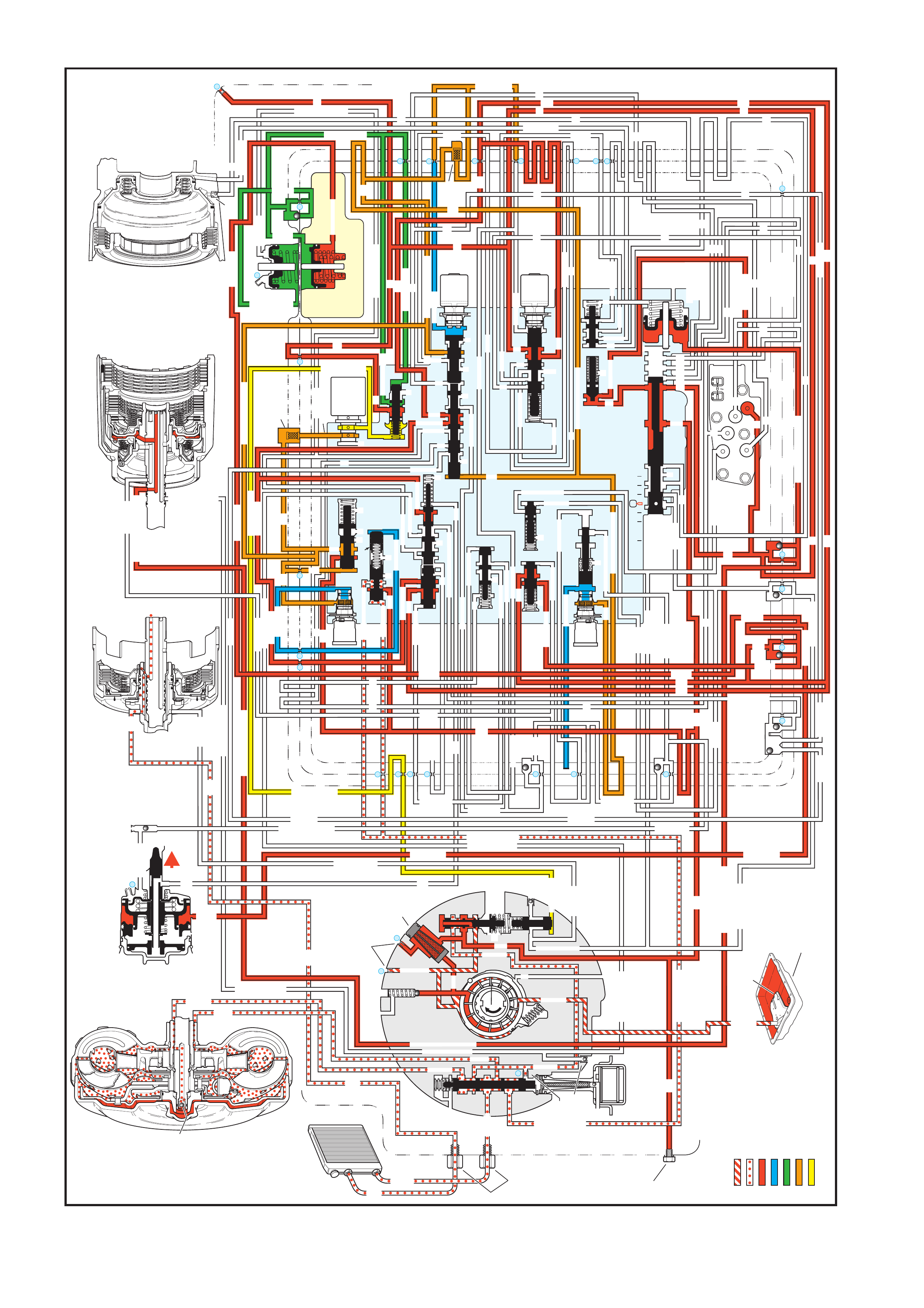
Figure 7C3-19 - Drive (Overdrive) Range - Second Gear
4.4 DRIVE (OVERDRIVE) RANGE, SECOND GEAR
OVERDRIVE RANGE – SECOND GEAR
INPUT CLUTCH
HOUSING ASSEMBLY
24
REAR LUBE
FILTER
(49)
RELEASE
APPLY
LO/REVERSE
PR
BOOST VALVE PRESS REG
BOTTOM
PAN
(SUMP)
(75)
FILTER
(72)
REVERSE INPUT
REV INPUT
DECREASE
LINE
EX
FILTER
(232)
AIR
BLEED
(240)
1
SUCTION
LINE
EX
PRESSURE
RELIEF
VALV E
PUMP
ASSEMBLY
(4)
4
TCC
SOLENOID
(66)
N.O.
COOLER
LUBE
COOLER
SUCTION
CONVERTER & LUBE
MAINLINE
SOLENOID SIGNAL
ACCUMULATOR
ACTUATOR FEED LIMIT
TORQUE SIGNAL
FLUID PRESSURES
REVERSE INPUT
FORWARD CLUTCH FEED
#1
ACCUMULATOR
ORF ACC
2ND CLUTCH
3-4 ACCUMULATOR
1-2 ACCUMULATOR
19
3-4 ACCUM
ACCUM
EX
ORIFICED ACCUM
3-4 ACCUMULATOR
3-4 ACCUM
2ND CLUTCH
2ND CLUTCH
D3
REVERSE INPUT
D2-N.C.
REV-N.O.
D3-N.C.
LO-N.O.
D4-N.O.
LO
TEMP
SENSOR
TFP
SWITCH
ASSEMBLY
D2
D4
D3
D3
D3
EX
FORWARD ABUSE
FWD CL FD
3RD ACCUMULATOR EX
#7
11
3RD ACCUM
4TH
2ND & 4TH
SERVO
REV ABUSE
EX
REVERSE
REVERSE INPUT
#12
D4
22
D4
D4
#4
13
3-4 SIGNAL
3-4 CL
3-4 CLUTCH
#2
12
3-4 CLUTCH
3RD ACCUM
3-4 CL
#8
16
2ND
2ND CL
2ND CL
2ND CL
2ND CL
2ND CLUTCH2ND CLUTCH
TORQUE SIG
FORWARD CLUTCH FEED
FORWARD
CLUTCH
ACCUMULATOR
EX
PR
LO
LO
LO
FORWARD CLUTCH FEED
FORWARD CLUTCH FEED
FWD CL FEED
D3
D3
D3
14
3-4 CLUTCH
3RD ACCUMULATOR
3RD ACCUM
EX
AFL
3-2 SIGNAL
2ND
2ND
LINE
REGULATED APPLY
8
REG APPLY
1-2 SHIFT VALVE
26
LO
D4
O’ EX
D4-3-2 2ND
25
1-2 SIGNAL
LO/1ST
27
1-2 SIGNAL
EX
ORIFICED EX
ORIFICED EX
EX
LO/1ST D4-3-2
D4
D4
2
EX
CONV FD
EX
EX
EX
LINE LINE
LINE
PRESSURE
TAP
(39)
REGULATED APPLY
LUBE
LUBE
LUBE
LUBE
CASE (8)
CASE (8)
GASKET (47)
SPACER PLATE (48)
GASKET (52)
VALVE BODY (60)
SUCTION
LINE
LINE
3a
3b
3c
D3
EX
3-4 SIGNAL
1-2 SIGNAL
4TH SIGNAL
3-4 SHIFT VALVE
1-2 SIGNAL
3-4 CLUTCH
OVERRUN CLUTCH
OVERRUN CLUTCH
OVERRUN CLUTCH
OVERRUN CLUTCH
OVERRUN CLUTCH
OVERRUN CLUTCH
12a
12b
12c
12d
12e
EX
EX
EX
32
AFL
AFL
30
D4
EX
31
ACCUMULATOR
ACCUMULATOR
EX
TORQUE SIGNAL
FILTERED AFL
D4
AFLAFL
FILTER
(50)
10
43a
43b 44
11b
11c
11a
14b
14a
14c
LO OVERRUN
23
PR
LO/REV
LO/1ST
LO/REVERSE
LO/REVERSE
PR PR
EX
22 10c
23 10b
9n
9o
22b
22a
10a
10 9k
9g
9m
44a
43c 44
41a
41b
41c
41d
42b
42a
13a
13b
OIL
COOLER
PIPE
CONNECTOR
(10)
18a
18b
18c
18 17a
18 17b
20b
48b
48a
REGULATED APPLY
30a
30b
32a
37a
9b
9e
10 9d
9c
9a
9f
9h
31a
31b
31c
OVERRUN CLUTCH FEED
3-4 ACCUM
SERVO FEED
SERVO FEED
6
7
4TH4TH
OVERRUN CL
4TH SIGNAL
2ND
EX
EX
3-4 RELAY 4-3 SEQUENCE VALVE
5
EX
SERVO FD
ORF EX
CASE (8)
REV INPUT
EX
(237)
17d
17c
17e
17f
17g
21
21
20d
20e
21a
20a
20c
1-2 ACCUMULATOR COVER (57)
25g
33c
33a
33b
27d
27c
27b
29
29
27a
28a
29b
29a
29d
40
29c
29e
29g28
28
29f
24a
24b
24c
24d
24e
24f
24
g
24h
25a
25b
25d
25e
25f
25
25
24m
24k
REVERSE INPUT
#3
17
REVERSE INPUT
15c
15b
16
16
REVERSE
REVERSE INPUT
16a
15d
15a
REVERSE
34f
34e
34d
34c
34a
34b
#6
OVERRUN CL FD
21
ORIFICED D2
#5
OVERRUN
OVERRUN OVERRUN
OVERRUN
36
36
35e
35d
39
35b
35c
36a
35a
38d
38e39
38c
38b
38a
EX
TORQUE SIGNAL
2ND CL
20
18
2-3 SHUTTLE2-3 SHIFT VALVE
28
29
EX
EX
EX
EX
D2
OVERRUN
D3
D3
2ND
3-4 SIGNAL
EX
D4-3-2
2-3 SIGNAL
ACTUATOR FEED LIMIT
AFL
SERVO FD
3-4 ACC
FILTERED AFL
AFL
ACTUATOR FEED LIMIT
ACTUATOR FEED LIMIT
AFL
D2
2ND
2ND
2ND
2ND
D2
D2
D2
D2
ORIFICED D2
D2
D2
D2
VALVE BODY (60)
3-4 SIGNAL
2ND
D4
PR
3-4 ACCUMULATOR
D4
EX
D4-3-2
LO
D4
2ND CLUTCH
D3
D3
FORWARD CLUTCH FEED ACTUATOR FEED LIMIT
TORQUE SIGNAL
SERVO FEED
OVERRUN CLUTCH
LINE
9p
26a
PR
OFF
CONVERTER CLUTCH VALVE
COOLER
RELEASE
APPLY
EX
EX
CONV FD
REGULATED APPLY
EX
EX
CC SIGNAL
CC SIGNAL
ACTUATOR FEED LIMIT
9
26b
TCC PWM
SOLENOID
VALVE
N.C.
1-2 SIGNAL
2ND
4TH SIGNAL
#10
LOW AND REVERSE
CLUTCH ASSEMBLY
REVERSE INPUT
CLUTCH ASSEMBLY
TORQUE
CONVERTER
ASSEMBLY
#9
(237)
(238)
EX
2ND CLUTCH
3-4 CLUTCH
2ND
PRESSURE
CONTROL
SOLENOID
VALV E
2-3 SHIFT
SOLENOID
VALV E
N.O.
ON
EX
1-2 SHIFT
SOLENOID
VALV E
N.O.
OFF
PRND321
D4
D4
REVERSE
D3
D2
LO
EX
EX
LINE
MANUAL VALVE
PR
11
4TH
EX
EX
ACCUM VALVE
EX
EX
3-2 DOWNSHIFT
3-2 CONTROL
3-2
CONTROL
SOLENOID
VALVE
N.C.
ON
ISOLATOR VALVE
REG APPLY

As vehicle speed increases and other operating conditions are appropriate, the PCM de-energises the 1-2 shift
solenoid in order to shift the transmission to second gear.
1-2 SHIFT SOLENOID
De-energis ed (t urned O FF) by th e PCM, the n orm all y open sol enoid opens and s ignal A flu id exha usts throu gh t he
solenoid.
2-3 SHIFT SOLENOID
IMPORTANT: The actuator feed limit (AFL) fluid continues to feed the signal A fluid circuit through orifice #25.
However, the ex haust port thr ough the solenoid is larger than orif ice #25 in order to prevent a pressure bu ild-up in
the signal A fluid circuit. Exhausting signal A fluid is represented by the blue arrows.
Energised (ON) as in first gear, the 2-3 shift solenoid blocks signal B fluid from exhausting through the solenoid.
This maintains signal B fluid pressure at the solenoid end of the 2-3 shift valve.
1-2 SHIFT VALVE
W ithout signal A f luid press ure, spr ing forc e moves the val ve into the ups hif t position. D4 f luid is r outed thr ough the
valve and fills the 2nd fluid circuit.
1-2 SHIFT CHECKBALL (#8)
The 2nd fluid pressure seats the #8 checkball, flows through orifice #16, and fills the 2nd clutch fluid circuit. This
orifice helps control the 2-4 band apply rate.
2-4 SERVO ASSEMBLY
The 2nd c lutch fluid pres sure moves the #8 c heck ball, flows thro ugh orif ice #16 a nd fills th e 2nd clutch f luid c ircuit.
This orifice helps to control the 2-4 band apply rate.
1-2 ACCUMULATOR
The 2nd c lutch fluid pres sure also m oves the 1-2 acc umulator pis ton against t he spring for ce and the acc umulator
fluid pressure. This action absorbs the initial 2nd clutch fluid pressure in order to cushion the 2-4 band apply rate.
Also, the m ovem ent of the 1-2 ac cum ulator piston for ces som e accumulator fluid out of the accum ulator ass embly.
This accumulator fluid is routed back to the accumulator valve.
ACCUMULATOR VALVE
The accumulator fluid forced out of the 1-2 accum ulator is orificed (#30) to the end of the accumulator valve. This
pressure moves the valve against the spring force and the torque signal fluid pressure in order to regulate the
exhaust of excess accumulator fluid. This regulation provides additional control for the 2-4 band apply rate. The
fluid circuit shows the exhaust of the accumulator fluid during the shift by the arrow directions in the accumulator
fluid circuit.
2-3 SHIFT VALVE TRAIN
The s ignal B fluid pr essure f rom the 2-3 shif t solenoid holds the val ve train in the downshif t position. T he 2nd fluid
is routed through the 2-3 shuttle valve and fills the servo feed fluid circuit.
3-4 RELAY VALVE AND 4-3 SEQUENCE VALVE
Spring force holds these valves in the downshift position (first, second and third gear positions). The 2nd fluid is
blocked by the 3-4 relay valve and the servo feed fluid is blocked by both valves in preparation for a 3-4 upshift.
3-2 DOWNSHIFT VALVE
Spring force holds the valve closed, blocking the 2nd fluid and the 2nd clutch fluid. This valve is used in order to
help control the 3-2 downshift.
3-4 SHIFT VALVE
Signal A fluid pressure exhausts and spring force moves the valve into the downshift position (second and third
gear positions).
CONVERTER CLUTCH SIGNAL VALVE
The 2nd clutch fluid pressure opens the valve and the line pressure feeds the converter clutch (CC) signal fluid
circuit. The TCC signal fluid is orificed (#8) to the end of the CC signal valve and opposes the 2nd clutch fluid
pressure. The TCC signal fluid is routed through a filter and orificed (#4) to the TCC solenoid.
TCC SOLENOID
IMPORTANT: The orifice cup plug (#4) in the CC signal fluid circuit is smaller than the exhaust through the TCC
solenoid. Therefore, fluid pressure does not build up at the end of the converter clutch apply valve.
Under norm al operating condit ions in second gear, the PCM k eeps the normally open TCC solenoid de-energised
(OFF) . CC signal fluid exh austs through the o pen solenoi d and spring f orce k eeps the converter clutch app ly valve
in the release position.
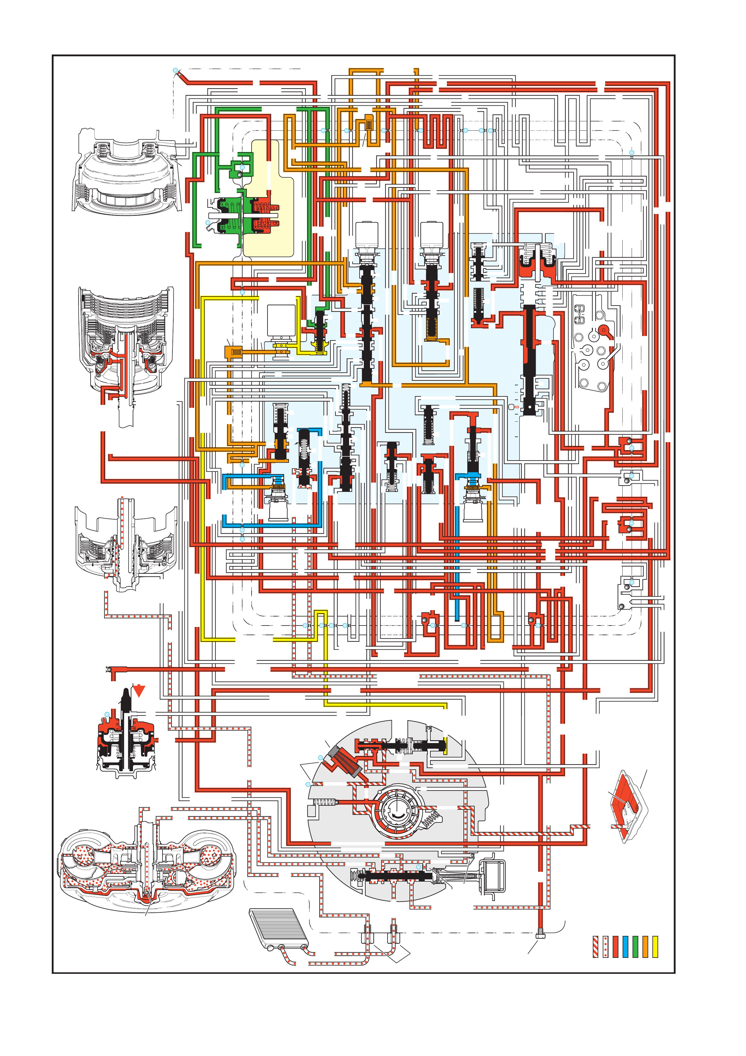
Figure 7C3-20 - Drive (Overdrive) Range - Third Gear
4.5 DRIVE (OVERDRIVE) RANGE - THIRD GEAR
OVERDRIVE RANGE – THIRD GEAR
INPUT CLUTCH
HOUSING ASSEMBLY
24
REAR LUBE
FILTER
(49)
RELEASE
APPLY
LO/REVERSE
PR
BOOST VALVE PRESS REG
BOTTOM
PAN
(SUMP)
(75)
FILTER
(72)
REVERSE INPUT
REV INPUT
DECREASE
LINE
EX
FILTER
(232)
AIR
BLEED
(240)
1
SUCTION
LINE
EX
PRESSURE
RELIEF
VALV E
PUMP
ASSEMBLY
(4)
4
TCC
SOLENOID
(66)
N.O.
COOLER
LUBE
COOLER
SUCTION
CONVERTER & LUBE
MAINLINE
SOLENOID SIGNAL
ACCUMULATOR
ACTUATOR FEED LIMIT
TORQUE SIGNAL
FLUID PRESSURES
REVERSE INPUT
FORWARD CLUTCH FEED
#1
ACCUMULATOR
ORF ACC
2ND CLUTCH
3-4 ACCUMULATOR
1-2 ACCUMULATOR
19
3-4 ACCUM
ACCUM
EX
ORIFICED ACCUM
3-4 ACCUMULATOR
3-4 ACCUM
2ND CLUTCH
2ND CLUTCH
D3
REVERSE INPUT
D2-N.C.
REV-N.O.
D3-N.C.
LO-N.O.
D4-N.O.
LO
TEMP
SENSOR
TFP
SWITCH
ASSEMBLY
D2
D4
D3
D3
D3
EX
FORWARD ABUSE
FWD CL FD
3RD ACCUMULATOR EX
#7
11
3RD ACCUM
4TH
2ND & 4TH
SERVO
REV ABUSE
EX
REVERSE
REVERSE INPUT
#12
D4
22
D4
D4
#4
13
3-4 SIGNAL
3-4 CL
3-4 CLUTCH
#2
12
3-4 CLUTCH
3RD ACCUM
3-4 CL
#8
16
2ND
2ND CL
2ND CL
2ND CL
2ND CL
2ND CLUTCH2ND CLUTCH
TORQUE SIG
FORWARD CLUTCH FEED
FORWARD
CLUTCH
ACCUMULATOR
EX
PR
LO
LO
LO
FORWARD CLUTCH FEED
FORWARD CLUTCH FEED
FWD CL FEED
D3
D3
D3
14
3-4 CLUTCH
3RD ACCUMULATOR
3RD ACCUM
EX
AFL
3-2 SIGNAL
2ND
2ND
LINE
REGULATED APPLY
8
REG APPLY
1-2 SHIFT VALVE
26
LO
D4
O’ EX
D4-3-2 2ND
25
1-2 SIGNAL
LO/1ST
27
1-2 SIGNAL
EX
ORIFICED EX
ORIFICED EX
EX
LO/1ST D4-3-2
D4
D4
2
EX
CONV FD
EX
EX
EX
LINE LINE
LINE
PRESSURE
TAP
(39)
REGULATED APPLY
LUBE
LUBE
LUBE
LUBE
CASE (8)
CASE (8)
GASKET (47)
SPACER PLATE (48)
GASKET (52)
VALVE BODY (60)
SUCTION
LINE
LINE
3a
3b
3c
D3
EX
3-4 SIGNAL
1-2 SIGNAL
4TH SIGNAL
3-4 SHIFT VALVE
1-2 SIGNAL
3-4 CLUTCH
OVERRUN CLUTCH
OVERRUN CLUTCH
OVERRUN CLUTCH
OVERRUN CLUTCH
OVERRUN CLUTCH
OVERRUN CLUTCH
12a
12b
12c
12d
12e
EX
EX
EX
32
AFL
AFL
30
D4
EX
31
ACCUMULATOR
ACCUMULATOR
EX
TORQUE SIGNAL
FILTERED AFL
D4
AFLAFL
FILTER
(50)
10
43a
43b 44
11b
11c
11a
14b
14a
14c
LO OVERRUN
23
PR
LO/REV
LO/1ST
LO/REVERSE
LO/REVERSE
PR PR
EX
22 10c
23 10b
9n
9o
22b
22a
10a
10 9k
9g
9m
44a
43c 44
41a
41b
41c
41d
42b
42a
13a
13b
OIL
COOLER
PIPE
CONNECTOR
(10)
18a
18b
18c
18 17a
18 17b
20b
48b
48a
REGULATED APPLY
30a
30b
32a
37a
9b
9e
10 9d
9c
9a
9f
9h
31a
31b
31c
OVERRUN CLUTCH FEED
3-4 ACCUM
SERVO FEED
SERVO FEED
6
7
4TH4TH
OVERRUN CL
4TH SIGNAL
2ND
EX
EX
3-4 RELAY 4-3 SEQUENCE VALVE
5
EX
SERVO FD
ORF EX
CASE (8)
REV INPUT
EX
(237)
17d
17c
17e
17f
17g
21
21
20d
20e
21a
20a
20c
1-2 ACCUMULATOR COVER (57)
25g
33c
33a
33b
27d
27c
27b
29
29
27a
28a
29b
29a
29d
40
29c
29e
29g28
28
29f
24a
24b
24c
24d
24e
24f
24
g
24h
25a
25b
25d
25e
25f
25
25
24m
24k
REVERSE INPUT
#3
17
REVERSE INPUT
15c
15b
16
16
REVERSE
REVERSE INPUT
16a
15d
15a
REVERSE
34f
34e
34d
34c
34a
34b
#6
OVERRUN CL FD
21
ORIFICED D2
#5
OVERRUN
OVERRUN OVERRUN
OVERRUN
36
36
35e
35d
39
35b
35c
36a
35a
38d
38e39
38c
38b
38a
EX
TORQUE SIGNAL
2ND CL
20
18
2-3 SHUTTLE2-3 SHIFT VALVE
28
29
EX
EX
EX
EX
D2
OVERRUN
D3
D3
2ND
3-4 SIGNAL
EX
D4-3-2
2-3 SIGNAL
ACTUATOR FEED LIMIT
AFL
SERVO FD
3-4 ACC
FILTERED AFL
AFL
ACTUATOR FEED LIMIT
ACTUATOR FEED LIMIT
AFL
D2
2ND
2ND
2ND
2ND
D2
D2
D2
D2
ORIFICED D2
D2
D2
D2
VALVE BODY (60)
3-4 SIGNAL
2ND
D4
PR
3-4 ACCUMULATOR
D4
EX
D4-3-2
LO
D4
2ND CLUTCH
D3
D3
FORWARD CLUTCH FEED ACTUATOR FEED LIMIT
TORQUE SIGNAL
SERVO FEED
OVERRUN CLUTCH
LINE
9p
26a
PR
OFF
CONVERTER CLUTCH VALVE
COOLER
RELEASE
APPLY
EX
EX
CONV FD
REGULATED APPLY
EX
EX
CC SIGNAL
CC SIGNAL
ACTUATOR FEED LIMIT
9
26b
TCC PWM
SOLENOID
VALVE
N.C.
1-2 SIGNAL
2ND
4TH SIGNAL
#10
LOW AND REVERSE
CLUTCH ASSEMBLY
REVERSE INPUT
CLUTCH ASSEMBLY
TORQUE
CONVERTER
ASSEMBLY
#9
(237)
(238)
EX
2ND CLUTCH
3-4 CLUTCH
2ND
PRESSURE
CONTROL
SOLENOID
VALV E
2-3 SHIFT
SOLENOID
VALV E
N.O.
OFF
EX
1-2 SHIFT
SOLENOID
VALV E
N.O.
OFF
PRND321
D4
D4
REVERSE
D3
D2
LO
EX
EX
LINE
MANUAL VALVE
PR
11
4TH
EX
EX
EX
EX
3-2 DOWNSHIFT
3-2 CONTROL
3-2
CONTROL
SOLENOID
VALVE
N.C.
ON
ACCUM VALVE
ISOLATOR VALVE
REG APPLY

As vehicle speed increases further and other vehicle operating conditions are appropriate, the PCM de-energises
the normally open 2-3 shift solenoid in order to shift the transmission into Third gear.
2-3 SHIFT SOLENOID
De-energis ed (turned O FF) by the PCM, th e solenoi d opens and actuat or feed li mit signal B f luid exhausts through
the solenoid. Note: AFL fluid continues to feed signal B fluid to the solenoid through orifice #29. However, the
exhaust port through the solenoid is larger than orifice #29 to prevent a build-up of pressure in the signal B fluid
circuit a t the so lenoid e nd of the 2-3 s hift va lve. Exha usting sig nal B f luid is represente d b y the arrows t hrough the
solenoid.
2-3 SHIFT VALVE TRAIN
AFL fluid pressure at the 2-3 shift valve moves the valve train toward the solenoid. In the upshifted position, the
following changes occur:
AFL fluid is routed through the 2-3 shift valve and fills the D432 fluid circuit.
2nd fluid is blocked from entering the servo feed fluid circuit and is orificed (#28) into the 3-4 signal fluid circuit. This
orifice helps control the 3-4 clutch apply rate.
Servo feed fluid exhausts past the valve into the 3-4 accumulator fluid circuit and through an exhaust port at the 3-4
relay valve.
3-4 CLUTCH EXHAUST CHECKBALL (#4)
3-4 signal fluid unseats the ball and enters the 3-4 clutch fluid circuit.
3-4 CLUTCH PISTON
3-4 clutch fluid pressure moves the piston to apply the 3-4 clutch plates and obtain 3rd gear. However, the 2-4
band must release as the 3-4 clutch applies.
3RD ACCUMULATOR CHECKBALL (#2)
3-4 clutch fluid pressure unseats the ball and fills the 3rd accumulator fluid circuit.
3RD ACCUMULATOR EXHAUST CHECKBALL (#7)
3rd accum ulator f luid seats the ball aga inst the or ificed ex haust and is routed to t he released s ide of the 2nd appl y
piston. Before the #7 checkball seats air in the 3rd accumulator fluid circuit is exhausted through the orifice.
2-4 SERVO ASSEMBLY
3rd accumulator fluid pressure acts on the release side of the 2nd apply piston and assists servo return spring
force. The surface area on the release side of the piston is greater than the surface area on the apply side.
Therefore, 3rd accumulator fluid pressure and servo return spring force move the 2nd apply piston against 2nd
clutch fluid pressure. This action serves two functions:
1. Move the apply pin to release the 2-4 band.
2. Act as an accum ulator by absor bing initial 3- 4 clutch f luid to cushio n the 3-4 clut ch apply rate. R emember that
the 3rd accumulator fluid circuit is fed by 3-4 clutch fluid.
3-2 DOWNSHIFT VALVE
3-4 clutch f luid pr ess ur e m oves th e va lv e aga inst spr i ng f or ce. T his opens the v a lv e and a llows 2nd fluid to f eed th e
2nd clutch fluid circuit through the valve.
1-2 SHIFT SOLENOID AND 1-2 SHIFT VALVE
The 1-2 s hift soleno id remains d e-energis ed and sign al A fluid is exhausted through the s olenoid. Also, D432 f luid
pressure from the 2-3 shift valve assists spring force to hold the 1-2 shift valve in the upshifted position.
3-4 SHIFT VALVE
Spring force holds the valve in the downshifted position, blocking 3-4 clutch fluid in preparation for a 3-4 upshift.
TORQUE CONVERTER CLUTCH
TCC Solenoid
Under normal operating conditions in Overdrive Range-Third Gear, the PCM keeps the normally open TCC
solenoid de-energised. CC signal fluid exhausts through the open solenoid and spring force keeps the converter
clutch apply valve in the release position. However, at speeds above approximately 121 km/h, the PCM will
command TCC apply in Third gear.
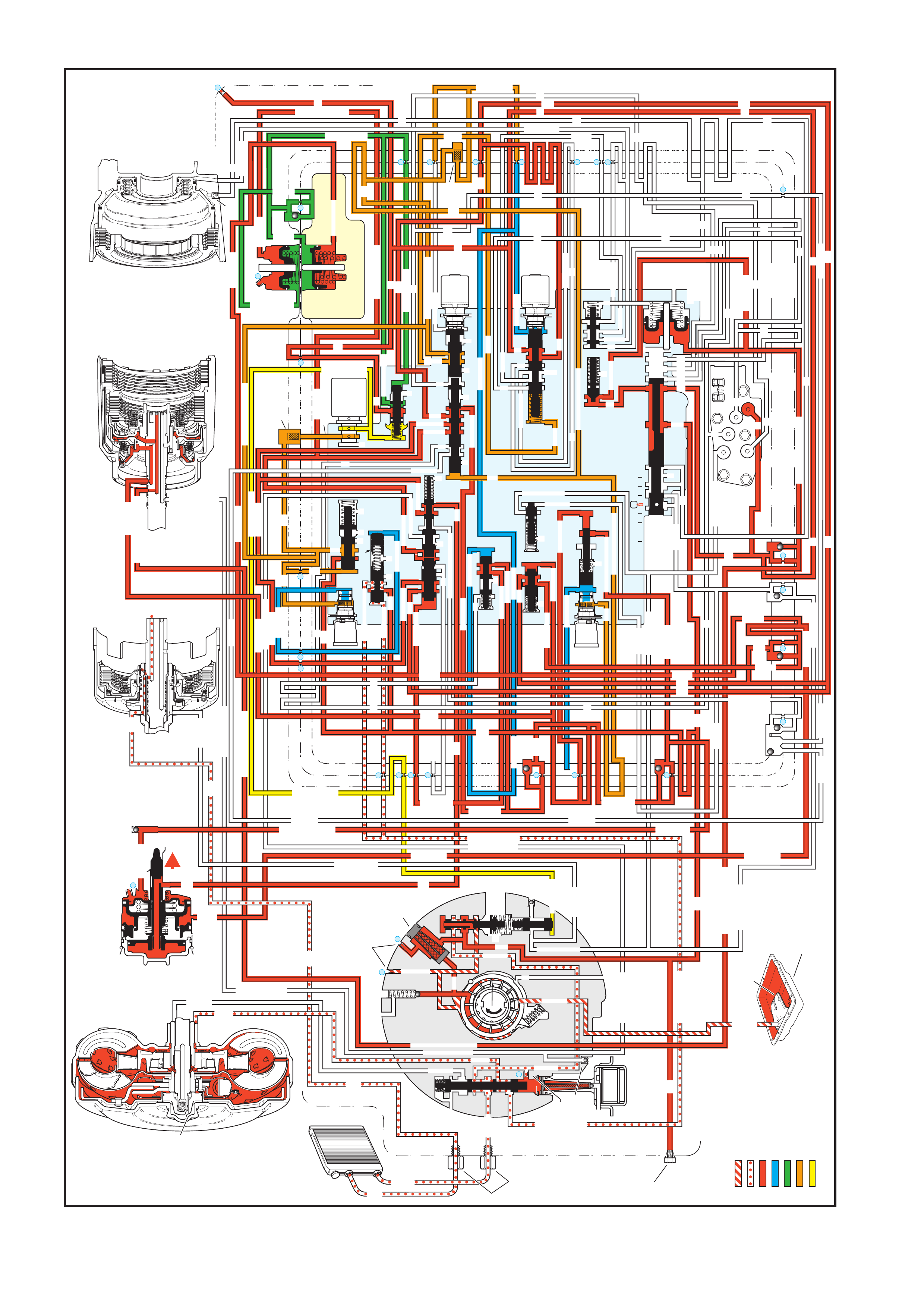
Figure 7C3-21 - Drive (Overdrive) Range - Fourth Gear (TCC Applied)
4.6 DRIVE (OVERDRIVE) RANGE - FOURTH GEAR (TCC APPLIED)
OVERDRIVE RANGE – FOURTH GEAR
(Torque Converter Clutch Applied)
INPUT CLUTCH
HOUSING ASSEMBLY
24
REAR LUBE
FILTER
(49)
RELEASE
APPLY
LO/REVERSE
PR
BOOST VALVE PRESS REG
BOTTOM
PAN
(SUMP)
(75)
FILTER
(72)
REVERSE INPUT
REV INPUT
DECREASE
LINE
EX
FILTER
(232)
AIR
BLEED
(240)
1
SUCTION
LINE
EX
PRESSURE
RELIEF
VALV E
PUMP
ASSEMBLY
(4)
4
TCC
SOLENOID
(66)
N.O.
COOLER
LUBE
COOLER
SUCTION
CONVERTER & LUBE
MAINLINE
SOLENOID SIGNAL
ACCUMULATOR
ACTUATOR FEED LIMIT
TORQUE SIGNAL
FLUID PRESSURES
REVERSE INPUT
FORWARD CLUTCH FEED
#1
ACCUMULATOR
ORF ACC
2ND CLUTCH
3-4 ACCUMULATOR
1-2 ACCUMULATOR
19
3-4 ACCUM
ACCUM
EX
ORIFICED ACCUM
3-4 ACCUMULATOR
3-4 ACCUM
2ND CLUTCH
2ND CLUTCH
D3
REVERSE INPUT
D2-N.C.
REV-N.O.
D3-N.C.
LO-N.O.
D4-N.O.
LO
TEMP
SENSOR
TFP
SWITCH
ASSEMBLY
D2
D4
D3
D3
D3
EX
FORWARD ABUSE
FWD CL FD
3RD ACCUMULATOR EX
#7
11
3RD ACCUM
4TH
2ND & 4TH
SERVO
REV ABUSE
EX
REVERSE
REVERSE INPUT
#12
D4
22
D4
D4
#4
13
3-4 SIGNAL
3-4 CL
3-4 CLUTCH
#2
12
3-4 CLUTCH
3RD ACCUM
3-4 CL
#8
16
2ND
2ND CL
2ND CL
2ND CL
2ND CL
2ND CLUTCH2ND CLUTCH
TORQUE SIG
FORWARD CLUTCH FEED
FORWARD
CLUTCH
ACCUMULATOR
EX
PR
LO
LO
LO
FORWARD CLUTCH FEED
FORWARD CLUTCH FEED
FWD CL FEED
D3
D3
D3
14
3-4 CLUTCH
3RD ACCUMULATOR
3RD ACCUM
EX
AFL
3-2 SIGNAL
2ND
2ND
LINE
REGULATED APPLY
8
REG APPLY
1-2 SHIFT VALVE
26
LO
D4
O’ EX
D4-3-2 2ND
25
1-2 SIGNAL
LO/1ST
27
1-2 SIGNAL
EX
ORIFICED EX
ORIFICED EX
EX
LO/1ST D4-3-2
D4
D4
2
EX
CONV FD
EX
EX
EX
LINE LINE
LINE
PRESSURE
TAP
(39)
REGULATED APPLY
LUBE
LUBE
LUBE
LUBE
CASE (8)
CASE (8)
GASKET (47)
SPACER PLATE (48)
GASKET (52)
VALVE BODY (60)
SUCTION
LINE
LINE
3a
3b
3c
D3
EX
3-4 SIGNAL
1-2 SIGNAL
4TH SIGNAL
1-2 SIGNAL
3-4 CLUTCH
OVERRUN CLUTCH
OVERRUN CLUTCH
OVERRUN CLUTCH
OVERRUN CLUTCH
OVERRUN CLUTCH
OVERRUN CLUTCH
12a
12b
12c
12d
12e
EX
EX
EX
32
AFL
AFL
30
D4
EX
31
ACCUMULATOR
ACCUMULATOR
EX
TORQUE SIGNAL
FILTERED AFL
D4
AFLAFL
FILTER
(50)
10
43a
43b 44
11b
11c
11a
14b
14a
14c
LO OVERRUN
23
PR
LO/REV
LO/1ST
LO/REVERSE
LO/REVERSE
PR PR
EX
22 10c
23 10b
9n
9o
22b
22a
10a
10 9k
9g
9m
44a
43c 44
41a
41b
41c
41d
42b
42a
13a
13b
OIL
COOLER
PIPE
CONNECTOR
(10)
18a
18b
18c
18 17a
18 17b
20b
48b
48a
REGULATED APPLY
30a
30b
32a
37a
9b
9e
10 9d
9c
9a
9f
9h
31a
31b
31c
OVERRUN CLUTCH FEED
3-4 ACCUM
SERVO FEED
SERVO FEED
6
7
4TH4TH
OVERRUN CL
4TH SIGNAL
2ND
EX
EX
3-4 RELAY 4-3 SEQUENCE VALVE
5
EX
SERVO FD
ORF EX
CASE (8)
REV INPUT
EX
(237)
17d
17c
17e
17f
17g
21
21
20d
20e
21a
20a
20c
1-2 ACCUMULATOR COVER (57)
25g
33c
33a
33b
27d
27c
27b
29
29
27a
28a
29b
29a
29d
40
29c
29e
29g28
28
29f
24a
24b
24c
24d
24e
24f
24
g
24h
25a
25b
25d
25e
25f
25
25
24m
24k
REVERSE INPUT
#3
17
REVERSE INPUT
15c
15b
16
16
REVERSE
REVERSE INPUT
16a
15d
15a
REVERSE
34f
34e
34d
34c
34a
34b
#6
OVERRUN CL FD
21
ORIFICED D2
#5
OVERRUN
OVERRUN OVERRUN
OVERRUN
36
36
35e
35d
39
35b
35c
36a
35a
38d
38e39
38c
38b
38a
EX
TORQUE SIGNAL
2ND CL
20
18
2-3 SHUTTLE2-3 SHIFT VALVE
28
29
EX
EX
EX
EX
D2
OVERRUN
D3
D3
2ND
3-4 SIGNAL
EX
D4-3-2
2-3 SIGNAL
ACTUATOR FEED LIMIT
AFL
SERVO FD
3-4 ACC
FILTERED AFL
AFL
ACTUATOR FEED LIMIT
ACTUATOR FEED LIMIT
AFL
D2
2ND
2ND
2ND
2ND
D2
D2
D2
D2
ORIFICED D2
D2
D2
D2
VALVE BODY (60)
3-4 SIGNAL
2ND
D4
PR
3-4 ACCUMULATOR
D4
EX
D4-3-2
LO
D4
2ND CLUTCH
D3
D3
FORWARD CLUTCH FEED ACTUATOR FEED LIMIT
TORQUE SIGNAL
SERVO FEED
OVERRUN CLUTCH
LINE
9p
26a
PR
ON
COOLER
RELEASE
APPLY
EX
EX
CONV FD
REGULATED APPLY
EX
EX
CC SIGNAL
CC SIGNAL
ACTUATOR FEED LIMIT
9
26b
TCC PWM
SOLENOID
VALVE
N.C.
1-2 SIGNAL
2ND
4TH SIGNAL
#10
LOW AND REVERSE
CLUTCH ASSEMBLY
REVERSE INPUT
CLUTCH ASSEMBLY
TORQUE
CONVERTER
ASSEMBLY
#9
(237)
(238)
EX
2ND CLUTCH
3-4 CLUTCH
2ND
PRESSURE
CONTROL
SOLENOID
VALV E
2-3 SHIFT
SOLENOID
VALV E
N.O.
OFF
EX
1-2 SHIFT
SOLENOID
VALV E
N.O.
ON
PRND321
D4
D4
REVERSE
D3
D2
LO
EX
EX
LINE
MANUAL VALVE
PR
11
4TH
EX
EX
CONVERTER CLUTCH VALVE
3-4 SHIFT VALVE
ACCUM VALVE
EX
EX
3-2 DOWNSHIFT
3-2 CONTROL
3-2
CONTROL
SOLENOID
VALVE
N.C.
ON
ISOLATOR VALVE
REG APPLY

At higher vehicle speeds, t he Hydra-m atic 4L60-E transm ission uses an overdrive gear ratio (fourth gear ) in order
to increase fuel economy and in order to maximise engine performance. When vehicle operating conditions are
appropriate, the PCM energises the 1-2 shift solenoid to shift the transmission into fourth gear.
1-2 SHIFT SOLENOID
Energised (turned ON) by the PCM, the normally open solenoid closes and blocks signal A fluid from exhausting
through the solenoid. This creates pressure in the signal A fluid circuit.
2-3 SHIFT SOLENOID
De-energised (OFF) as in third gear, the 2-3 shift solenoid exhausts signal B fluid through the solenoid.
1-2 SHIFT VALVE
D432 fluid pressure from the 2-3 shift valve and spring force hold the valve in the upshift position against signal A
fluid pressure.
3-4 SHIFT VALVE
Signa l A fluid pressur e moves the valve into the ups hift positi on against the spr ing force. In this position, the va lve
routes 3-4 signal fluid into the 4th signal fluid circuit.
3-4 RELAY VALVE AND 4-3 SEQUENCE VALVE
4th signa l fluid pres sure moves both va lves into th e upshif t (four th gear) pos ition agains t the spr ing forc e acting on
the 4-3 sequence valve. This causes the following changes:
• Orificed (#7) 2nd fluid is routed through the 3-4 relay valve and into the servo feed fluid circuit.
• Servo feed fluid is routed through the 4-3 sequence valve and into the 4th fluid circuit.
• 3-4 accumulator fluid routed from the 2-3 shuttle valve is blocked by both valves.
2-4 SERVO ASSEMBLY
4th fluid is routed through the center of the servo apply pin and acts on the apply side of the 4th app ly piston. 4th
fluid pressure moves the 4th apply piston against the apply pin spring force acting on the release side of the 4th
apply piston. This action moves the apply pin and applies the 2-4 band in order to obtain fourth gear.
2-4 BAND APP LY ACCUMULATION
2-3 Shift V alve Train: The valve tra in remains in the ups hift position with the AF L fluid press ure acting on t he 2-3
shift val ve. In ad dition t o its operat ion third g ear, th e 2- 3 shift val ve dir ects s ervo feed f luid in to the 3- 4 accu m ulator
fluid circuit.
3-4 ACCUMULATOR AS SEM BLY
3-4 accumulator fluid pressure moves the 3-4 accumulator piston against spring force and orificed accumulator fluid
pressure, This action absorbs initial 4th clutch apply fluid pressure in order to cushion the 2-4 band apply.
Remember that both of the 3-4 accumulator and 4th fluid circuits are fed by servo feed fluid.
As 3-4 accumulator fluid fills the accumulator, any air in the system will exhaust through orifice #19. This piston
movement forces some orificed accumulator fluid out of the 3-4 accumulator assembly.
3-4 ACCUMULATOR CHECKBALL (#1)
The accumulator fluid forced from the accumulator unseats the #1 checkball and enters the accumulator fluid
circuit. This fluid is routed to the accumulator valve. This is shown by the arrow directions in the fluid circuit.
ACCUMULATOR VALVE
Accumulator fluid forced from the 3-4 accumulator is orificed to the end of the accumulator valve. This fluid
pressure, in addition to spring force and torque signal fluid pressure, regulates the exhaust of excess accumulator
fluid pressure through the middle of the valve. This regulation helps control the 2-4 band apply feel.
TORQUE CONVERTER CLUTCH APPLIES
TCC Solenoid: When operating conditions are appropriate, the PCM energises the normally open TCC solenoid.
This closes the solenoid, blocks the converter clutch signal fluid from exhausting and creates pressure in the
converter clutch signal fluid circuit.
CONVERTER CLUTCH APPLY VALVE
Converter clutch signal fluid pressure moves the valve against spring force and into the apply position. In this
position, r elease f luid is open to an exhaust p ort and conver ter feed f luid fills the apply fluid c ircuit. Con verter feed
fluid also feeds the cooler fluid circuit through orifice #3.

TORQUE CONVERTER
Release fluid from behind the pressure plate exhausts through the end of the turbine shaft. Appl y fluid pressure is
routed between the converter hub and stator shaft where it enters the torque converter. This fluid applies the
converter clutch against the converter cover and keeps the converter filled with fluid.
TCC APPLY CHECKBALL (#9)
Release fluid, exhaust ing from the converter, seats the #9 checkball located in t he end of the turbine shaft, and is
orificed around the ball. Orificing the exhausting release fluid controls the converter clutch apply rate.

Figure 7C3-22 - Drive (Overdrive) Range - 4-3 Downshift
4.7 DRIVE (OVERDRIVE) RANGE, 4-3 DOWNSHIFT
OVERDRIVE RANGE – 4-3 DOWNSHIFT (Torque Converter Clutch Released)
INPUT CLUTCH
HOUSING ASSEMBLY
24
REAR LUBE
FILTER
(49)
RELEASE
APPLY
LO/REVERSE
PR
BOOST VALVE PRESS REG
BOTTOM
PAN
(SUMP)
(75)
FILTER
(72)
REVERSE INPUT
REV INPUT
DECREASE
LINE
EX
FILTER
(232)
AIR
BLEED
(240)
1
SUCTION
LINE
EX
PRESSURE
RELIEF
VALV E
PUMP
ASSEMBLY
(4)
4
TCC
SOLENOID
(66)
N.O.
COOLER
LUBE
COOLER
SUCTION
CONVERTER & LUBE
MAINLINE
SOLENOID SIGNAL
ACCUMULATOR
ACTUATOR FEED LIMIT
TORQUE SIGNAL
FLUID PRESSURES
REVERSE INPUT
FORWARD CLUTCH FEED
#1
ACCUMULATOR
ORF ACC
2ND CLUTCH
3-4 ACCUMULATOR
1-2 ACCUMULATOR
19
3-4 ACCUM
ACCUM
EX
ORIFICED ACCUM
3-4 ACCUMULATOR
3-4 ACCUM
2ND CLUTCH
2ND CLUTCH
D3
REVERSE INPUT
D2-N.C.
REV-N.O.
D3-N.C.
LO-N.O.
D4-N.O.
LO
TEMP
SENSOR
TFP
SWITCH
ASSEMBLY
D2
D4
D3
D3
D3
EX
FORWARD ABUSE
FWD CL FD
3RD ACCUMULATOR EX
#7
11
3RD ACCUM
4TH
2ND & 4TH
SERVO
REV ABUSE
EX
REVERSE
REVERSE INPUT
#12
D4
22
D4
D4
#4
13
3-4 SIGNAL
3-4 CL
3-4 CLUTCH
#2
12
3-4 CLUTCH
3RD ACCUM
3-4 CL
#8
16
2ND
2ND CL
2ND CL
2ND CL
2ND CL
2ND CLUTCH2ND CLUTCH
TORQUE SIG
FORWARD CLUTCH FEED
FORWARD
CLUTCH
ACCUMULATOR
EX
PR
LO
LO
LO
FORWARD CLUTCH FEED
FORWARD CLUTCH FEED
FWD CL FEED
D3
D3
D3
14
3-4 CLUTCH
3RD ACCUMULATOR
3RD ACCUM
EX
AFL
3-2 SIGNAL
2ND
2ND
LINE
REGULATED APPLY
8
REG APPLY
1-2 SHIFT VALVE
26
LO
D4
O’ EX
D4-3-2 2ND
25
1-2 SIGNAL
LO/1ST
27
1-2 SIGNAL
EX
ORIFICED EX
ORIFICED EX
EX
LO/1ST D4-3-2
D4
D4
2
EX
CONV FD
EX
EX
EX
LINE LINE
LINE
PRESSURE
TAP
(39)
REGULATED APPLY
LUBE
LUBE
LUBE
LUBE
CASE (8)
CASE (8)
GASKET (47)
SPACER PLATE (48)
GASKET (52)
VALVE BODY (60)
SUCTION
LINE
LINE
3a
3b
3c
D3
EX
3-4 SIGNAL
1-2 SIGNAL
4TH SIGNAL
3-4 SHIFT VALVE
1-2 SIGNAL
3-4 CLUTCH
OVERRUN CLUTCH
OVERRUN CLUTCH
OVERRUN CLUTCH
OVERRUN CLUTCH
OVERRUN CLUTCH
OVERRUN CLUTCH
12a
12b
12c
12d
12e
EX
EX
EX
32
AFL
AFL
30
D4
EX
31
ACCUMULATOR
ACCUMULATOR
EX
TORQUE SIGNAL
FILTERED AFL
D4
AFLAFL
FILTER
(50)
10
43a
43b 44
11b
11c
11a
14b
14a
14c
LO OVERRUN
23
PR
LO/REV
LO/1ST
LO/REVERSE
LO/REVERSE
PR PR
EX
22 10c
23 10b
9n
9o
22b
22a
10a
10 9k
9g
9m
44a
43c 44
41a
41b
41c
41d
42b
42a
13a
13b
OIL
COOLER
PIPE
CONNECTOR
(10)
18a
18b
18c
18 17a
18 17b
20b
48b
48a
REGULATED APPLY
30a
30b
32a
37a
9b
9e
10 9d
9c
9a
9f
9h
31a
31b
31c
OVERRUN CLUTCH FEED
3-4 ACCUM
SERVO FEED
SERVO FEED
6
7
4TH4TH
OVERRUN CL
4TH SIGNAL
2ND
EX
EX
3-4 RELAY 4-3 SEQUENCE VALVE
5
EX
SERVO FD
ORF EX
CASE (8)
REV INPUT
EX
(237)
17d
17c
17e
17f
17g
21
21
20d
20e
21a
20a
20c
1-2 ACCUMULATOR COVER (57)
25g
33c
33a
33b
27d
27c
27b
29
29
27a
28a
29b
29a
29d
40
29c
29e
29g28
28
29f
24a
24b
24c
24d
24e
24f
24
g
24h
25a
25b
25d
25e
25f
25
25
24m
24k
REVERSE INPUT
#3
17
REVERSE INPUT
15c
15b
16
16
REVERSE
REVERSE INPUT
16a
15d
15a
REVERSE
34f
34e
34d
34c
34a
34b
#6
OVERRUN CL FD
21
ORIFICED D2
#5
OVERRUN
OVERRUN OVERRUN
OVERRUN
36
36
35e
35d
39
35b
35c
36a
35a
38d
38e39
38c
38b
38a
EX
TORQUE SIGNAL
2ND CL
20
18
2-3 SHUTTLE2-3 SHIFT VALVE
28
29
EX
EX
EX
EX
D2
OVERRUN
D3
D3
2ND
3-4 SIGNAL
EX
D4-3-2
2-3 SIGNAL
ACTUATOR FEED LIMIT
AFL
SERVO FD
3-4 ACC
FILTERED AFL
AFL
ACTUATOR FEED LIMIT
ACTUATOR FEED LIMIT
AFL
D2
2ND
2ND
2ND
2ND
D2
D2
D2
D2
ORIFICED D2
D2
D2
D2
VALVE BODY (60)
3-4 SIGNAL
2ND
D4
PR
3-4 ACCUMULATOR
D4
EX
D4-3-2
LO
D4
2ND CLUTCH
D3
D3
FORWARD CLUTCH FEED ACTUATOR FEED LIMIT
TORQUE SIGNAL
SERVO FEED
OVERRUN CLUTCH
LINE
9p
26a
PR
OFF
CONVERTER CLUTCH VALVE
COOLER
RELEASE
APPLY
EX
EX
CONV FD
REGULATED APPLY
EX
EX
CC SIGNAL
CC SIGNAL
ACTUATOR FEED LIMIT
9
26b
TCC PWM
SOLENOID
VALVE
N.C.
1-2 SIGNAL
2ND
4TH SIGNAL
#10
LOW AND REVERSE
CLUTCH ASSEMBLY
REVERSE INPUT
CLUTCH ASSEMBLY
TORQUE
CONVERTER
ASSEMBLY
#9
(237)
(238)
EX
2ND CLUTCH
3-4 CLUTCH
2ND
PRESSURE
CONTROL
SOLENOID
VALV E
2-3 SHIFT
SOLENOID
VALV E
N.O.
OFF
EX
1-2 SHIFT
SOLENOID
VALV E
N.O.
OFF
PRND321
D4
D4
REVERSE
D3
D2
LO
EX
EX
LINE
MANUAL VALVE
PR
11
4TH
EX
EX
EX
EX
3-2 DOWNSHIFT
3-2 CONTROL
3-2
CONTROL
SOLENOID
VALVE
N.C.
ON
ACCUM VALVE
ISOLATOR VALVE
REG APPLY

W hen the transm ission is operati ng in fourth ge ar, a for ced 4-3 downs hift occur s if there is a signif icant incre ase in
throttle p osition. At minim um throttle, th e vehic le speed dec reases graduall y (co astdo wn) and the PCM comm ands
a 4-3 downshift.
The PCM also initiates a forced 4-3 downshift when the throttle position remains constant but engine load is
increased, such as driving up a steep incline. To achieve a 4-3 downshift, the PCM de-energises the 1-2 shift
solenoid and the following changes occur to the transmission's electrical and hydraulic systems:
1-2 SHIFT SOLENOID
De-energised by the PCM, the normally open solenoid opens and signal A fluid exhausts through the solenoid.
1-2 SHIFT VALVE
As in Fourth gear, D432 fluid pressure and spring force hold the valve in the upshift position.
2-4 BAND RELEASES
3-4 Shift Valve: With the signal A fluid pressure exhausted, the spring force moves the valve into the downshift
position. In this position, the valve blocks the 3-4 signal fluid and the 4th signal fluid exhausts past the valve.
3-4 RELAY VALVE AND 4-3 SEQUENCE VALVE
These valves control the timing of the 2-4 band release. With the 4th signal fluid pressure exhausted, the 3-4
accumulator fluid pressure moves the 3-4 relay valve into the third gear position. This opens the 3-4 accumulator
fluid to an orif ic ed ex haus t (#5) pas t th e 3-4 rela y va lv e (s ho wn b y red ar ro ws) . B ec aus e th e ex h aust is orific ed, th e
3-4 accumulator fluid pressure momentarily holds the 4-3 sequence valve against spring force before completely
exhausting.
When the exhausting 3-4 accumulator fluid pressure decreases sufficiently, the spring force moves the 4-3
sequence v alve int o th e th ird gear position as s ho wn. This opens b oth t he 3-4 ac cumulator and t he 4th fluid c irc uits
to a quick exhaust past the 4-3 sequence valve. In this position the valve blocks the 2nd fluid from entering the
servo feed fluid circuit.
2-4 SERVO ASSEMBLY
The 4th fluid exhausts from the 4th apply piston in the servo assembly. The apply pin spring moves the 4th apply
piston and the apply pin in order to release the band from the reverse input drum and shift the transmission into
third gear.
3-4 ACCUMULATOR AS SEM BLY
The 3-4 accumulator fluid exhausts from the 3-4 accumulator piston. The orificed accumulator fluid pressure and
the spring force move the piston into a third gear position.
3-4 ACCUMULATOR CHECKBALL (#1)
As the accumulator fluid fills the 3-4 accumulator, it seats the #1 checkball and is forced through orifice #18. This
orifice controls the rate at which accumulator fluid pr essure fills the 3-4 accumulator and the 3-4 accumulator fluid
exhausts from the accumulator assembly.
ACCUMULATOR VALVE
Biased by torque signal fluid pressure and spring force, the accumulator valve regulates the drive fluid into the
accumulator fluid circuit.
2-3 SHIFT SOLENOID
This solenoid remains de-energised as in fourth gear and the signal B fluid exhausts through the solenoid.
2-3 SHIFT VALVE TRAIN
The AFL f luid pres sure at the 2- 3 shif t valve holds the va lves in the upsh ift pos ition. T his allo ws the ser vo fee d fluid
to exhaust through the valve, into the 3-4 accumulator fluid circuit and past the 4-3 sequence valve.
TORQUE CONVERTER CLUTCH
The PCM r eleases th e converter c lutch prior to initiating t he 4-3 do wnshif t. However, if the vehicle s peed is abo ve
approximately 121 km/h, the PCM commands the TCC to apply in third gear.
Pressure Control Solenoid
Remember that the pressure control solenoid continually adjusts the torque signal fluid pressure in relation to the
various PCM input signals (mainly the throttle position).
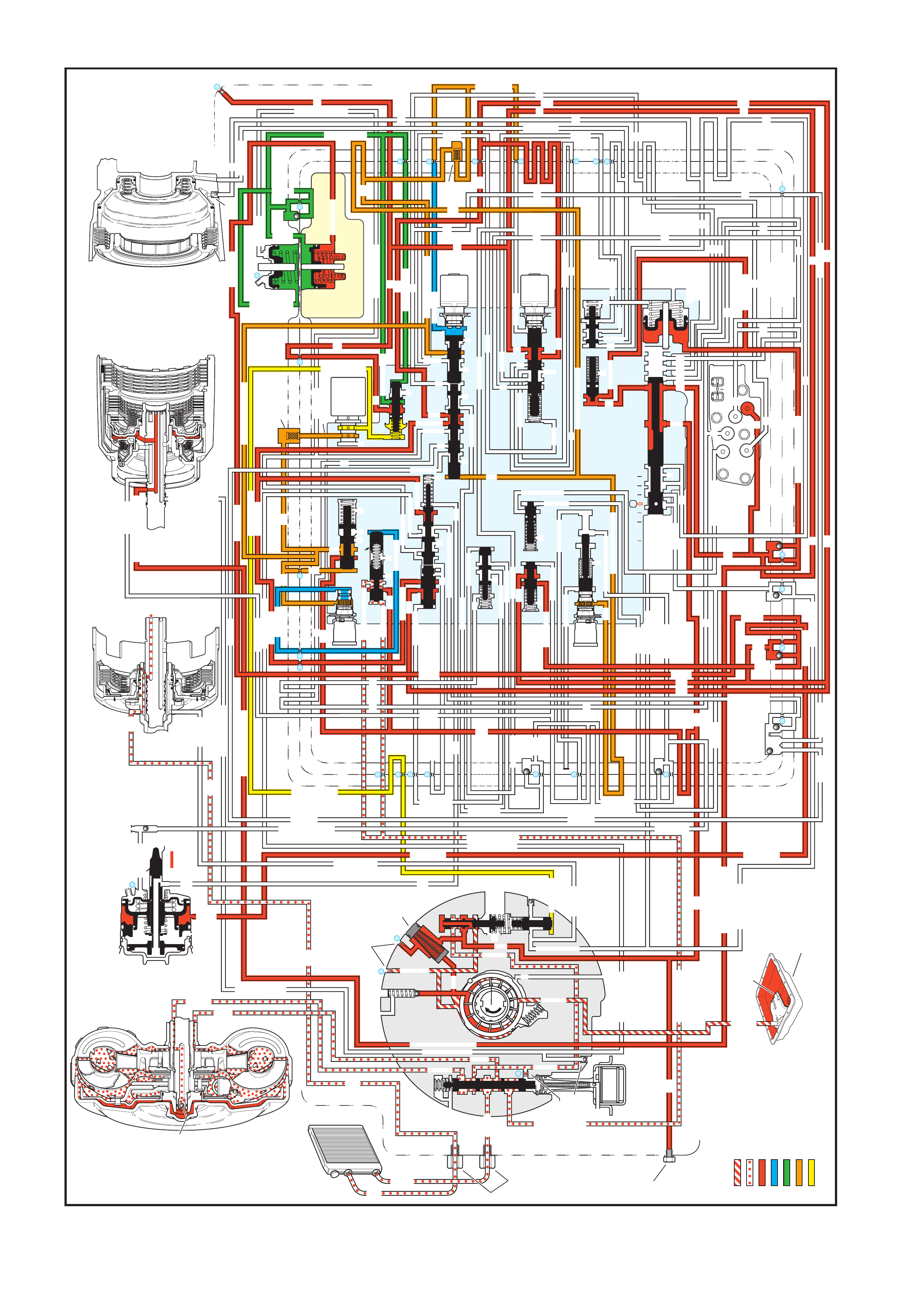
Figure 7C3-23 - Drive (Overdrive) Range - 3-2 Downshift
4.8 DRIVE (OVERDRIVE) RANGE, 3-2 DOWNSHIFT
OVERDRIVE RANGE – 3-2 DOWNSHIFT
INPUT CLUTCH
HOUSING ASSEMBLY
24
REAR LUBE
FILTER
(49)
RELEASE
APPLY
LO/REVERSE
PR
BOOST VALVE PRESS REG
BOTTOM
PAN
(SUMP)
(75)
FILTER
(72)
REVERSE INPUT
REV INPUT
DECREASE
LINE
EX
FILTER
(232)
AIR
BLEED
(240)
1
SUCTION
LINE
EX
PRESSURE
RELIEF
VALV E
PUMP
ASSEMBLY
(4)
4
TCC
SOLENOID
(66)
N.O.
COOLER
LUBE
COOLER
SUCTION
CONVERTER & LUBE
MAINLINE
SOLENOID SIGNAL
ACCUMULATOR
ACTUATOR FEED LIMIT
TORQUE SIGNAL
FLUID PRESSURES
REVERSE INPUT
FORWARD CLUTCH FEED
#1
ACCUMULATOR
ORF ACC
2ND CLUTCH
3-4 ACCUMULATOR
1-2 ACCUMULATOR
19
3-4 ACCUM
ACCUM
EX
ORIFICED ACCUM
3-4 ACCUMULATOR
3-4 ACCUM
2ND CLUTCH
2ND CLUTCH
D3
REVERSE INPUT
D2-N.C.
REV-N.O.
D3-N.C.
LO-N.O.
D4-N.O.
LO
TEMP
SENSOR
TFP
SWITCH
ASSEMBLY
D2
D4
D3
D3
D3
EX
FORWARD ABUSE
FWD CL FD
3RD ACCUMULATOR EX
#7
11
3RD ACCUM
4TH
2ND & 4TH
SERVO
REV ABUSE
EX
REVERSE
REVERSE INPUT
#12
D4
22
D4
D4
#4
13
3-4 SIGNAL
3-4 CL
3-4 CLUTCH
#2
12
3-4 CLUTCH
3RD ACCUM
3-4 CL
#8
16
2ND
2ND CL
2ND CL
2ND CL
2ND CL
2ND CLUTCH2ND CLUTCH
TORQUE SIG
FORWARD CLUTCH FEED
FORWARD
CLUTCH
ACCUMULATOR
EX
PR
LO
LO
LO
FORWARD CLUTCH FEED
FORWARD CLUTCH FEED
FWD CL FEED
D3
D3
D3
14
3-4 CLUTCH
3RD ACCUMULATOR
3RD ACCUM
EX
AFL
3-2 SIGNAL
2ND
2ND
LINE
REGULATED APPLY
8
REG APPLY
1-2 SHIFT VALVE
26
LO
D4
O’ EX
D4-3-2 2ND
25
1-2 SIGNAL
LO/1ST
27
1-2 SIGNAL
EX
ORIFICED EX
ORIFICED EX
EX
LO/1ST D4-3-2
D4
D4
2
EX
CONV FD
EX
EX
EX
LINE LINE
LINE
PRESSURE
TAP
(39)
REGULATED APPLY
LUBE
LUBE
LUBE
LUBE
CASE (8)
CASE (8)
GASKET (47)
SPACER PLATE (48)
GASKET (52)
VALVE BODY (60)
SUCTION
LINE
LINE
3a
3b
3c
D3
EX
3-4 SIGNAL
1-2 SIGNAL
4TH SIGNAL
3-4 SHIFT VALVE
1-2 SIGNAL
3-4 CLUTCH
OVERRUN CLUTCH
OVERRUN CLUTCH
OVERRUN CLUTCH
OVERRUN CLUTCH
OVERRUN CLUTCH
OVERRUN CLUTCH
12a
12b
12c
12d
12e
EX
EX
EX
32
AFL
AFL
30
D4
EX
31
ACCUMULATOR
ACCUMULATOR
EX
TORQUE SIGNAL
FILTERED AFL
D4
AFLAFL
FILTER
(50)
10
43a
43b 44
11b
11c
11a
14b
14a
14c
LO OVERRUN
23
PR
LO/REV
LO/1ST
LO/REVERSE
LO/REVERSE
PR PR
EX
22 10c
23 10b
9n
9o
22b
22a
10a
10 9k
9g
9m
44a
43c 44
41a
41b
41c
41d
42b
42a
13a
13b
OIL
COOLER
PIPE
CONNECTOR
(10)
18a
18b
18c
18 17a
18 17b
20b
48b
48a
REGULATED APPLY
30a
30b
32a
37a
9b
9e
10 9d
9c
9a
9f
9h
31a
31b
31c
OVERRUN CLUTCH FEED
3-4 ACCUM
SERVO FEED
SERVO FEED
6
7
4TH4TH
OVERRUN CL
4TH SIGNAL
2ND
EX
EX
3-4 RELAY 4-3 SEQUENCE VALVE
5
EX
SERVO FD
ORF EX
CASE (8)
REV INPUT
EX
(237)
17d
17c
17e
17f
17g
21
21
20d
20e
21a
20a
20c
1-2 ACCUMULATOR COVER (57)
25g
33c
33a
33b
27d
27c
27b
29
29
27a
28a
29b
29a
29d
40
29c
29e
29g28
28
29f
24a
24b
24c
24d
24e
24f
24
g
24h
25a
25b
25d
25e
25f
25
25
24m
24k
REVERSE INPUT
#3
17
REVERSE INPUT
15c
15b
16
16
REVERSE
REVERSE INPUT
16a
15d
15a
REVERSE
34f
34e
34d
34c
34a
34b
#6
OVERRUN CL FD
21
ORIFICED D2
#5
OVERRUN
OVERRUN OVERRUN
OVERRUN
36
36
35e
35d
39
35b
35c
36a
35a
38d
38e39
38c
38b
38a
EX
TORQUE SIGNAL
2ND CL
20
18
2-3 SHUTTLE2-3 SHIFT VALVE
28
29
EX
EX
EX
EX
D2
OVERRUN
D3
D3
2ND
3-4 SIGNAL
EX
D4-3-2
2-3 SIGNAL
ACTUATOR FEED LIMIT
AFL
SERVO FD
3-4 ACC
FILTERED AFL
AFL
ACTUATOR FEED LIMIT
ACTUATOR FEED LIMIT
AFL
D2
2ND
2ND
2ND
2ND
D2
D2
D2
D2
ORIFICED D2
D2
D2
D2
VALVE BODY (60)
3-4 SIGNAL
2ND
D4
PR
3-4 ACCUMULATOR
D4
EX
D4-3-2
LO
D4
2ND CLUTCH
D3
D3
FORWARD CLUTCH FEED ACTUATOR FEED LIMIT
TORQUE SIGNAL
SERVO FEED
OVERRUN CLUTCH
LINE
9p
26a
PR
OFF
CONVERTER CLUTCH VALVE
COOLER
RELEASE
APPLY
EX
EX
CONV FD
REGULATED APPLY
EX
EX
CC SIGNAL
CC SIGNAL
ACTUATOR FEED LIMIT
9
26b
TCC PWM
SOLENOID
VALVE
N.C.
1-2 SIGNAL
2ND
4TH SIGNAL
#10
LOW AND REVERSE
CLUTCH ASSEMBLY
REVERSE INPUT
CLUTCH ASSEMBLY
TORQUE
CONVERTER
ASSEMBLY
#9
(237)
(238)
EX
2ND CLUTCH
3-4 CLUTCH
2ND
PRESSURE
CONTROL
SOLENOID
VALV E
2-3 SHIFT
SOLENOID
VALV E
N.O.
ON
EX
1-2 SHIFT
SOLENOID
VALV E
N.O.
OFF
PRND321
D4
D4
REVERSE
D3
D2
LO
EX
EX
LINE
MANUAL VALVE
PR
11
4TH
EX
EX
ACCUM VALVE
3-2 CONTROL
3-2
CONTROL
SOLENOID
VALVE
N.C.
OFF
EX
EX
3-2 DOWNSHIFT
ISOLATOR VALVE
REG APPLY

Similar to a forced 4-3 downshift, a forced 3-2 downshift can occur because of minimum throttle (coastdown
conditio ns), hea v y throttle or increas ed en gine load. I n order t o ach ieve a f orced 3-2 downs hift, th e PCM ener gises
the 2-3 shift solenoid and the following changes occur:
Energised by the PCM, the normally open solenoid closes and blocks the signal B fluid from exhausting through the
solenoid. This creates pressure in the signal B fluid circuit at the solenoid end of the 2-3 shift valve.
2-3 SHIFT VALVE TRAIN
The signal B fluid pressure from the shift solenoid moves both valves to the downshift position against AFL fluid
pressure acting on the 2-3 shift valve. This causes the following changes:
• The AFL fluid is blocked from the D432 fluid circuit and the D432 fluid exhausts past the 2-3 shuttle valve.
• The 2nd fluid is blocked from feeding the 3-4 signal fluid circuit and the 2nd fluid is routed into the servo feed
fluid circuit.
• The 3-4 signal fluid is exhausted p ast the valve. T he 3-4 clutch fluid and the 3rd accumulator fluid, which were
fed by the 3-4 signal fluid, also exhaust.
3-4 CLUTCH RELEASES AND 2-4 BAND APPLIES
3-4 Clutch Piston: The 3-4 clutch fluid exhausts from the piston and the 3-4 clutch plates are released.
3-4 Clutch Exhaust Checkball (#4): Exhausting the 3-4 clutch fluid seats the #4 checkball and is forced through
orifice #13. This orifice controls the 3-4 clutch fluid exhaust and the 3-4 clutch release rate.
2-4 SERVO ASSEMBLY
The 3rd accumulator fluid exhausts from the servo assembly. The 2nd clutch fluid pressure moves the 2nd apply
piston against the servo return spring force in order to move the apply pin and apply the 2-4 band.
3-2 DOWNSHIFT VA LVE AND 1-2 UPSHIFT CHECKBALL (#8)
The 3-2 clutch fluid exhausts from the valve and the spring force moves the valve into the second gear position.
However, before the spring force overcomes exhausting the 3-4 clutch fluid pressure, the 2nd fluid feeds the 2nd
clutch fluid circuit through the valve. This bypasses the control of orifice #16 at the #8 checkball and provides a
faster 2-4 b and ap ply. Rem em ber that the #8 c heck ball a nd or ific e #16 are us ed t o help contr ol the 2-4 band appl y
during a 1-2 upshift.
DOWNSHIFT TIMING AND CONTROL
At higher vehicle speeds, the 2-4 band apply must be delayed to allow the engine speed RPM to increase
sufficiently for a smooth transfer of engine load to the 2-4 band. Therefore, exhaust of the 3rd accumulator fluid
must be delayed. However, at lower speeds the band must be applied quickly. In order to provide for the varying
requirements for the 2-4 band apply rate, the exhausting 3rd accumulator fluid is routed to both the 3rd accumulator
checkball (#2) and the 3-2 control valve.
3RD ACCUMULATOR CHECKBALL (#2)
The exhausting 3rd accumulator fluid seats the #2 check ball and is forced throu gh orifice #12. This fluid exhausts
through the 3-4 clutch a nd the 3-4 sig nal fluid circ uits and pas t the 2-3 sh ift valve. O rifice #12 s lows the exh aust of
the 3rd accumulator fluid and delays the 2-4 band apply rate.
3-2 CONTROL SOLENOID AND 3-2 CONTROL VALVE
These components are used to increase the exhaust rate of 3rd accumulator fluid, as needed, depending on the
vehicle speed.
The 3-2 control solenoid is a normally closed On/Off solenoid controlled by the PCM. The PCM controls the
solenoid state during a 3-2 downshift according to vehicle speed.
Low Speed: At lower vehicle speeds, the PCM operates the 3-2 control solenoid in the Off position.
• In the Off position the solenoid blocks actuator feed limit fluid pressure from the 3-2 control valve.
• With no actuator feed limit fluid pressure, the 3-2 control valve spring force keeps the valve open to allow a
faster exhaust of 3rd accumulator fluid through orifice #14 into the 3-4 clutch fluid circuit.
• A faster exhaust of the 3rd accumulator exhaust fluid provides a faster apply of the 2-4 band, as needed at
lower ve hic l e spe eds .
High Speed: At hig h ve hic l e s pe ed, the P CM operates the 3- 2 contr o l s o le noi d in the On pos it ion a llo win g ac tuator
feed limit fluid to pass through the solenoid. This pushes the 3-2 control valve Into the closed position.
• This ac tion perm its a slow apply of the 2- 4 band b y blocking off 3rd accum ulator exhaust f luid from entering the
3-4 clutch fluid circuit through orifice #14.
• This allows the engine speed to easily come up to the necessary RPM before the 2-4 band is applied.

3RD ACCUMULATOR EXHAUST CHECKBALL (#7)
After the downs hift is com plete d, the #7 ch eck ball uns eats an d allo ws the r esidua l f luid in th e 3r d accum ulat or f luid
circuit to exhaust.
PRESSURE CONTROL SOLENOID
Remember that the pressure control solenoid continually adjusts torque signal fluid in relation to the various PCM
input signals (mainly the throttle position).
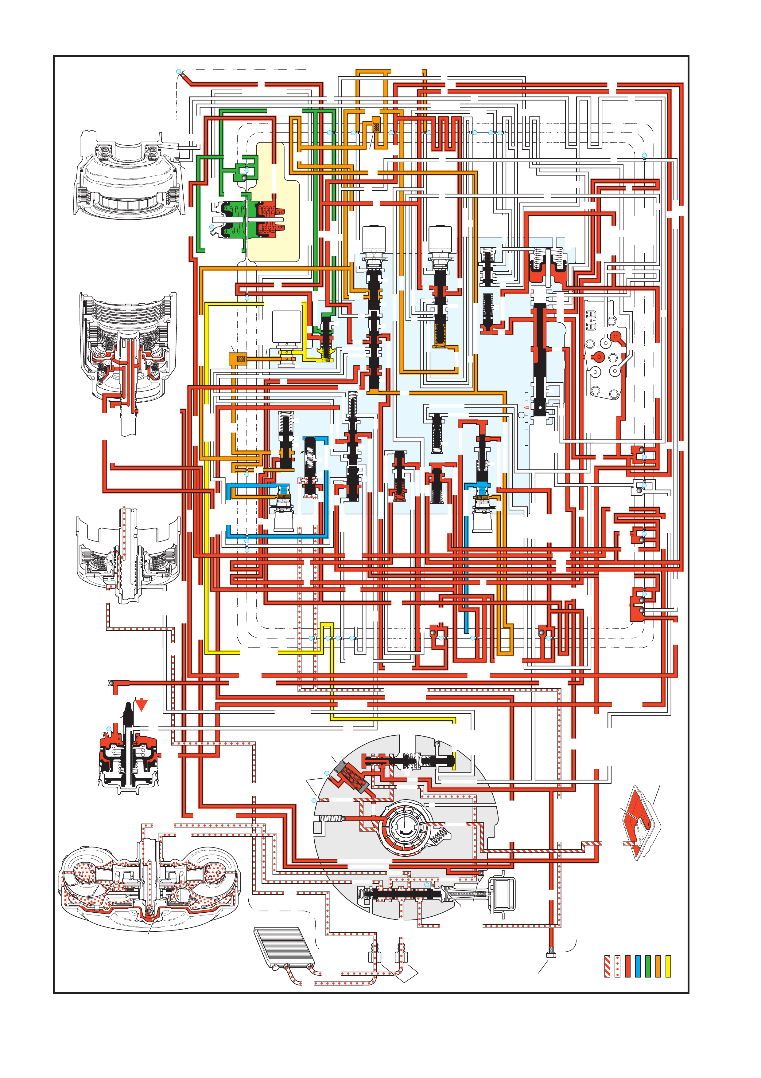
Figure 7C3-24 - Manual Third Gear
4.9 MANUAL THIRD GEAR - TCC APPLIED
MANUAL THIRD – THIRD GEAR
(from Overdrive Range – Fourth Gear)
INPUT CLUTCH
HOUSING ASSEMBLY
24
REAR LUBE
FILTER
(49)
RELEASE
APPLY
LO/REVERSE
PR
BOOST VALVE PRESS REG
BOTTOM
PAN
(SUMP)
(75)
FILTER
(72)
REVERSE INPUT
REV INPUT
DECREASE
LINE
EX
FILTER
(232)
AIR
BLEED
(240)
1
SUCTION
LINE
EX
PRESSURE
RELIEF
VALV E
PUMP
ASSEMBLY
(4)
4
TCC
SOLENOID
(66)
N.O.
COOLER
LUBE
COOLER
SUCTION
CONVERTER & LUBE
MAINLINE
SOLENOID SIGNAL
ACCUMULATOR
ACTUATOR FEED LIMIT
TORQUE SIGNAL
FLUID PRESSURES
REVERSE INPUT
FORWARD CLUTCH FEED
#1
ACCUMULATOR
ORF ACC
2ND CLUTCH
3-4 ACCUMULATOR
1-2 ACCUMULATOR
19 3-4 ACCUM
ACCUM
EX
ORIFICED ACCUM
3-4 ACCUMULATOR
3-4 ACCUM
2ND CLUTCH
2ND CLUTCH
D3
REVERSE INPUT
D2-N.C.
REV-N.O.
D3-N.C.
LO-N.O.
D4-N.O.
LO
TEMP
SENSOR
TFP
SWITCH
ASSEMBLY
D2
D4
D3
D3
D3
EX
FORWARD ABUSE
FWD CL FD
3RD ACCUMULATOR EX
#7
11
3RD ACCUM
4TH
2ND & 4TH
SERVO
REV ABUSE
EX
REVERSE
REVERSE INPUT
#12
D4
22
D4
D4
#4
13
3-4 SIGNAL
3-4 CL
3-4 CLUTCH
#2
12
3-4 CLUTCH
3RD ACCUM
3-4 CL
#8
16
2ND
2ND CL
2ND CL
2ND CL
2ND CL
2ND CLUTCH2ND CLUTCH
TORQUE SIG
FORWARD CLUTCH FEED
FORWARD
CLUTCH
ACCUMULATOR
EX
PR
LO
LO
LO
FORWARD CLUTCH FEED
FORWARD CLUTCH FEED
FWD CL FEED
D3
D3
D3
14
3-4 CLUTCH
3RD ACCUMULATOR
3RD ACCUM
EX
AFL
3-2 SIGNAL
2ND
2ND
LINE
REGULATED APPLY
8
REG APPLY
1-2 SHIFT VALVE
26
LO
D4
O’ EX
D4-3-2 2ND
25
1-2 SIGNAL
LO/1ST
27
1-2 SIGNAL
EX
ORIFICED EX
ORIFICED EX
EX
LO/1ST D4-3-2
D4
D4
2
EX
CONV FD
EX
EX
EX
LINE LINE
LINE
PRESSURE
TAP
(39)
REGULATED APPLY
LUBE
LUBE
LUBE
LUBE
CASE (8)
CASE (8)
GASKET (47)
SPACER PLATE (48)
GASKET (52)
VALVE BODY (60)
SUCTION
LINE
LINE
3a
3b
3c
D3
EX
3-4 SIGNAL
1-2 SIGNAL
4TH SIGNAL
3-4 SHIFT VALVE
1-2 SIGNAL
3-4 CLUTCH
OVERRUN CLUTCH
OVERRUN CLUTCH
OVERRUN CLUTCH
OVERRUN CLUTCH
OVERRUN CLUTCH
OVERRUN CLUTCH
12a
12b
12c
12d
12e
EX
EX
EX
32
AFL
AFL
30
D4
EX
31
ACCUMULATOR
ACCUMULATOR
EX
TORQUE SIGNAL
FILTERED AFL
D4
AFLAFL
FILTER
(50)
10
43a
43b 44
11b
11c
11a
14b
14a
14c
LO OVERRUN
23
PR
LO/REV
LO/1ST
LO/REVERSE
LO/REVERSE
PR PR
EX
22 10c
23 10b
9n
9o
22b
22a
10a
10 9k
9g
9m
44a
43c 44
41a
41b
41c
41d
42b
42a
13a
13b
OIL
COOLER
PIPE
CONNECTOR
(10)
18a
18b
18c
18 17a
18 17b
20b
48b
48a
REGULATED APPLY
30a
30b
32a
37a
9b
9e
10 9d
9c
9a
9f
9h
31a
31b
31c
OVERRUN CLUTCH FEED
3-4 ACCUM
SERVO FEED
SERVO FEED
6
7
4TH4TH
OVERRUN CL
4TH SIGNAL
2ND
EX
EX
3-4 RELAY 4-3 SEQUENCE VALVE
5
EX
SERVO FD
ORF EX
CASE (8)
REV INPUT
EX
(237)
17d
17c
17e
17f
17g
21
21
20d
20e
21a
20a
20c
1-2 ACCUMULATOR COVER (57)
25g
33c
33a
33b
27d
27c
27b
29
29
27a
28a
29b
29a
29d
40
29c
29e
29g28
28
29f
24a
24b
24c
24d
24e
24f
24
g
24h
25a
25b
25d
25e
25f
25
25
24m
24k
REVERSE INPUT
#3
17
REVERSE INPUT
15c
15b
16
16
REVERSE
REVERSE INPUT
16a
15d
15a
REVERSE
34f
34e
34d
34c
34a
34b
#6
OVERRUN CL FD
21
ORIFICED D2
#5
OVERRUN
OVERRUN OVERRUN
OVERRUN
36
36
35e
35d
39
35b
35c
36a
35a
38d
38e39
38c
38b
38a
EX
TORQUE SIGNAL
2ND CL
20
18
2-3 SHUTTLE2-3 SHIFT VALVE
28
29
EX
EX
EX
EX
D2
OVERRUN
D3
D3
2ND
3-4 SIGNAL
EX
D4-3-2
2-3 SIGNAL
ACTUATOR FEED LIMIT
AFL
SERVO FD
3-4 ACC
FILTERED AFL
AFL
ACTUATOR FEED LIMIT
ACTUATOR FEED LIMIT
AFL
D2
2ND
2ND
2ND
2ND
D2
D2
D2
D2
ORIFICED D2
D2
D2
D2
VALVE BODY (60)
3-4 SIGNAL
2ND
D4
PR
3-4 ACCUMULATOR
D4
EX
D4-3-2
LO
D4
2ND CLUTCH
D3
D3
FORWARD CLUTCH FEED ACTUATOR FEED LIMIT
TORQUE SIGNAL
SERVO FEED
OVERRUN CLUTCH
LINE
9p
26a
PR
OFF
CONVERTER CLUTCH VALVE
COOLER
RELEASE
APPLY
EX
EX
CONV FD
REGULATED APPLY
EX
EX
CC SIGNAL
CC SIGNAL
ACTUATOR FEED LIMIT
9
26b
TCC PWM
SOLENOID
VALVE
N.C.
1-2 SIGNAL
2ND
4TH SIGNAL
#10
LOW AND REVERSE
CLUTCH ASSEMBLY
REVERSE INPUT
CLUTCH ASSEMBLY
TORQUE
CONVERTER
ASSEMBLY
#9
(237)
(238)
EX
2ND CLUTCH
3-4 CLUTCH
2ND
PRESSURE
CONTROL
SOLENOID
VALV E
2-3 SHIFT
SOLENOID
VALV E
N.O. OFF
EX
1-2 SHIFT
SOLENOID
VALV E
N.O. OFF
PRND321
D4
D4
REVERSE
D3
D2
LO
EX
EX
LINE
MANUAL VALVE
PR
11
4TH
EX
EX
EX
EX
3-2 DOWNSHIFT
3-2 CONTROL
3-2
CONTROL
SOLENOID
VALVE
N.C.
ON
ACCUM VALVE
ISOLATOR VALVE
REG APPLY

A manual 4-3 downshift is available to increase vehicle performance when the use of only three gear ratios is
desired. Manual Third gear range also provides engine braking in Third gear when the throttle is released. A
m anual 4-3 downs hif t is acc omplishe d by m oving th e selec tor le ver int o the Manual Third ( D) posit ion. T his moves
the manual valve and immediately downshifts the transmission into Third gear. Refer to Overdrive Range, 4-3
Downshift, in this Section for a complete description of a 4-3 downshift. In Manual Third, the transmission is
prevented, both hydraulically and electronically, from shifting into Fourth gear. The following information explains
the additional changes during a manual 4-3 downshift as compared to a forced 4-3 downshift.
MANUAL VALVE
The selector lever moves the manual shaft and manual valve into the Manual Third position (D). This allows line
pressure to enter the D3 fluid circuit.
TRANSMISSION FLUID PRESSURE (TFP) MANUAL VALVE POSITION SWITCH ASSEMBLY
D3 fluid is routed to the TFP Switch and opens the normally closed D3 fluid pressure switch. The combination of
the opened D3 switch and the closed D4 switch signals the PCM that the transmission is operating in Manual Third.
1-2 SHIFT SOLENOID
When Manual Third is selected, the PCM de-energises the 1-2 shift solenoid to immediately downshift the
transmission into Third gear. This electronically prevents Fourth gear.
3-4 SHIFT VALVE
D3 fluid pr essur e assis ts s pring f orce to k eep the va lve in the do wnshif ted pos itio n agains t the s ign al A f luid c ircuit.
In this position, the valve blocks 3-4 signal fluid and the 4th signal fluid circuit is open to an exhaust port past the
valve. Therefore, with D3 fluid pressure assisting spring force, Fourth gear is hydraulically prevented.
2-3 SHIFT VALVE TRAIN
W ith the 2-3 sh if t solenoi d de- energis ed a nd ope n, ac tuator f eed l imit ( AFL) f luid ac ting on the 2- 3 s hift valv e hold s
both valves in the upshifted position. This allows D3 fluid to feed the overrun fluid circuit through the 2-3 shift valve.
OVERRUN CLUTCH FEED CHECKBALL (#5)
Overrun fluid pressure seats the ball against the empty D2 fluid circuit.
OVERRUN CLUTCH CONTROL CHECKBALL (#6)
Overrun fluid pressure seats the #6 checkball and is orificed (#20) to fill the overrun clutch feed fluid circuit. This
orifice controls the overrun clutch apply rate.
3-4 RELAY VALVE AND 4-3 SEQUENCE VALVE
4th signa l f lui d pres s ure is ex haus te d f r om the en d of t he 3- 4 r e lay valve. O ver run c lutc h f eed f lu id pres s ure as s ist s
spring force and closes both valves. This allows overrun clutch feed fluid to flow through the 4-3 sequence valve
and fill the overrun clutch fluid circuit.
OVERRUN CLUTCH PISTON
Overrun clutch fluid pres s ur e moves the pis ton t o app ly the overrun c lutch plates. The overrun clutc h p lat es p r ovi de
engine compression braking in Manual Third - Third Gear.
OVERRUN CLUTCH AIR BLEED CHECKBALL
This ball and capsule is located in the overrun clutch fluid circuit in the oil pump. It allows air to exhaust from the
circuit as fluid pressure increases and also allows air into the circuit to displace the fluid when the clutch releases.
TORQUE CONVERTER CLUTCH
The PCM de-energises the TCC solenoid to release the converter clutch prior to downshifting (assuming the
convert er clutc h is app lied in O verdr ive R ange-F ourth Gear when M anu al T hird is selec ted) . T he PCM will re -appl y
the converter clutch in Manual Third-Third Gear only when vehicle speed is above approximately 121 km/h.
PRESSURE CONTROL SOLENOID
The pres sure contr ol solenoid operates in the sam e manner as Overdr ive Range, regulating in respons e to thr ottle
position and other vehicle operating conditions.
MANUAL THIRD-FIRST AND SECOND GEARS
Overrun Clutch Released: In Manual Third, the transmission upshifts and downshifts normally between First,
Second and T hird gears. However, in First and Second gears, the 2-3 shift solenoid is energised and the 2-3 shif t
valve train is in the downshifted position. The 2-3 shift valve blocks D3 fluid from entering the overrun fluid circuit
and opens the overrun fluid circuit to an exhaust port at the valve. This prevents overrun clutch apply and engine
compression braking in Manual Third-First and Second Gears.
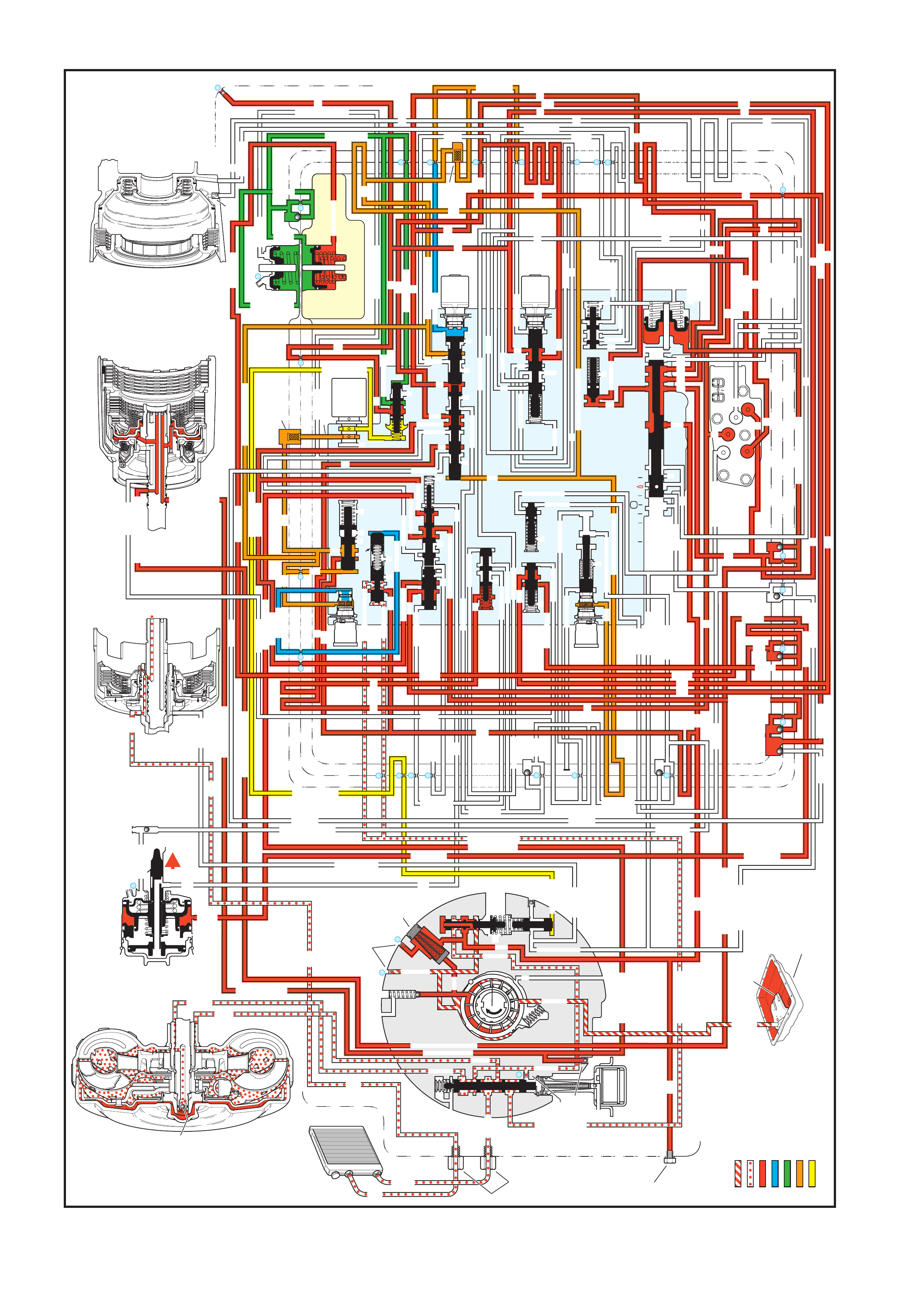
Figure 7C3-25 - Manual Second Gear
4.10 MANUAL SECOND GEAR
MANUAL SECOND – SECOND GEAR
(from Manual Third – Third Gear)
INPUT CLUTCH
HOUSING ASSEMBLY
24
REAR LUBE
FILTER
(49)
RELEASE
APPLY
LO/REVERSE
PR
BOOST VALVE PRESS REG
BOTTOM
PAN
(SUMP)
(75)
FILTER
(72)
REVERSE INPUT
REV INPUT
DECREASE
LINE
EX
FILTER
(232)
AIR
BLEED
(240)
1
SUCTION
LINE
EX
PRESSURE
RELIEF
VALV E
PUMP
ASSEMBLY
(4)
4
TCC
SOLENOID
(66)
N.O.
COOLER
LUBE
COOLER
SUCTION
CONVERTER & LUBE
MAINLINE
SOLENOID SIGNAL
ACCUMULATOR
ACTUATOR FEED LIMIT
TORQUE SIGNAL
FLUID PRESSURES
REVERSE INPUT
FORWARD CLUTCH FEED
#1
ACCUMULATOR
ORF ACC
2ND CLUTCH
3-4 ACCUMULATOR
1-2 ACCUMULATOR
19
3-4 ACCUM
ACCUM
EX
ORIFICED ACCUM
3-4 ACCUMULATOR
3-4 ACCUM
2ND CLUTCH
2ND CLUTCH
D3
REVERSE INPUT
D2-N.C.
REV-N.O.
D3-N.C.
LO-N.O.
D4-N.O.
LO
TEMP
SENSOR
TFP
SWITCH
ASSEMBLY
D2
D4
D3
D3
D3
EX
FORWARD ABUSE
FWD CL FD
3RD ACCUMULATOR EX
#7
11
3RD ACCUM
4TH
2ND & 4TH
SERVO
REV ABUSE
EX
REVERSE
REVERSE INPUT
#12
D4
22
D4
D4
#4
13
3-4 SIGNAL
3-4 CL
3-4 CLUTCH
#2
12
3-4 CLUTCH
3RD ACCUM
3-4 CL
#8
16
2ND
2ND CL
2ND CL
2ND CL
2ND CL
2ND CLUTCH2ND CLUTCH
TORQUE SIG
FORWARD CLUTCH FEED
FORWARD
CLUTCH
ACCUMULATOR
EX
PR
LO
LO
LO
FORWARD CLUTCH FEED
FORWARD CLUTCH FEED
FWD CL FEED
D3
D3
D3
14
3-4 CLUTCH
3RD ACCUMULATOR
3RD ACCUM
EX
AFL
3-2 SIGNAL
2ND
2ND
LINE
REGULATED APPLY
8
REG APPLY
1-2 SHIFT VALVE
26
LO
D4
O’ EX
D4-3-2 2ND
25
1-2 SIGNAL
LO/1ST
27
1-2 SIGNAL
EX
ORIFICED EX
ORIFICED EX
EX
LO/1ST D4-3-2
D4
D4
2
EX
CONV FD
EX
EX
EX
LINE LINE
LINE
PRESSURE
TAP
(39)
REGULATED APPLY
LUBE
LUBE
LUBE
LUBE
CASE (8)
CASE (8)
GASKET (47)
SPACER PLATE (48)
GASKET (52)
VALVE BODY (60)
SUCTION
LINE
LINE
3a
3b
3c
D3
EX
3-4 SIGNAL
1-2 SIGNAL
4TH SIGNAL
3-4 SHIFT VALVE
1-2 SIGNAL
3-4 CLUTCH
OVERRUN CLUTCH
OVERRUN CLUTCH
OVERRUN CLUTCH
OVERRUN CLUTCH
OVERRUN CLUTCH
OVERRUN CLUTCH
12a
12b
12c
12d
12e
EX
EX
EX
32
AFL
AFL
30
D4
EX
31
ACCUMULATOR
ACCUMULATOR
EX
TORQUE SIGNAL
FILTERED AFL
D4
AFLAFL
FILTER
(50)
10
43a
43b 44
11b
11c
11a
14b
14a
14c
LO OVERRUN
23
PR
LO/REV
LO/1ST
LO/REVERSE
LO/REVERSE
PR PR
EX
22 10c
23 10b
9n
9o
22b
22a
10a
10 9k
9g
9m
44a
43c 44
41a
41b
41c
41d
42b
42a
13a
13b
OIL
COOLER
PIPE
CONNECTOR
(10)
18a
18b
18c
18 17a
18 17b
20b
48b
48a
REGULATED APPLY
30a
30b
32a
37a
9b
9e
10 9d
9c
9a
9f
9h
31a
31b
31c
OVERRUN CLUTCH FEED
3-4 ACCUM
SERVO FEED
SERVO FEED
6
7
4TH4TH
OVERRUN CL
4TH SIGNAL
2ND
EX
EX
3-4 RELAY 4-3 SEQUENCE VALVE
5
EX
SERVO FD
ORF EX
CASE (8)
REV INPUT
EX
(237)
17d
17c
17e
17f
17g
21
21
20d
20e
21a
20a
20c
1-2 ACCUMULATOR COVER (57)
25g
33c
33a
33b
27d
27c
27b
29
29
27a
28a
29b
29a
29d
40
29c
29e
29g28
28
29f
24a
24b
24c
24d
24e
24f
24
g
24h
25a
25b
25d
25e
25f
25
25
24m
24k
REVERSE INPUT
#3
17
REVERSE INPUT
15c
15b
16
16
REVERSE
REVERSE INPUT
16a
15d
15a
REVERSE
34f
34e
34d
34c
34a
34b
#6
OVERRUN CL FD
21
ORIFICED D2
#5
OVERRUN
OVERRUN OVERRUN
OVERRUN
36
36
35e
35d
39
35b
35c
36a
35a
38d
38e39
38c
38b
38a
EX
TORQUE SIGNAL
2ND CL
20
18
2-3 SHUTTLE2-3 SHIFT VALVE
28
29
EX
EX
EX
EX
D2
OVERRUN
D3
D3
2ND
3-4 SIGNAL
EX
D4-3-2
2-3 SIGNAL
ACTUATOR FEED LIMIT
AFL
SERVO FD
3-4 ACC
FILTERED AFL
AFL
ACTUATOR FEED LIMIT
ACTUATOR FEED LIMIT
AFL
D2
2ND
2ND
2ND
2ND
D2
D2
D2
D2
ORIFICED D2
D2
D2
D2
VALVE BODY (60)
3-4 SIGNAL
2ND
D4
PR
3-4 ACCUMULATOR
D4
EX
D4-3-2
LO
D4
2ND CLUTCH
D3
D3
FORWARD CLUTCH FEED ACTUATOR FEED LIMIT
TORQUE SIGNAL
SERVO FEED
OVERRUN CLUTCH
LINE
9p
26a
PR
OFF
CONVERTER CLUTCH VALVE
COOLER
RELEASE
APPLY
EX
EX
CONV FD
REGULATED APPLY
EX
EX
CC SIGNAL
CC SIGNAL
ACTUATOR FEED LIMIT
9
26b
TCC PWM
SOLENOID
VALVE
N.C.
1-2 SIGNAL
2ND
4TH SIGNAL
#10
LOW AND REVERSE
CLUTCH ASSEMBLY
REVERSE INPUT
CLUTCH ASSEMBLY
TORQUE
CONVERTER
ASSEMBLY
#9
(237)
(238)
EX
2ND CLUTCH
3-4 CLUTCH
2ND
PRESSURE
CONTROL
SOLENOID
VALV E
2-3 SHIFT
SOLENOID
VALV E
N.O.
ON
EX
1-2 SHIFT
SOLENOID
VALV E
N.O.
OFF
PRND321
D4
D4
REVERSE
D3
D2
LO
EX
EX
LINE
PR
11
4TH
EX
EX
ACCUM VALVE
MANUAL VALVE
3-2 CONTROL
3-2
CONTROL
SOLENOID
VALVE
N.C.
OFF
EX
EX
3-2 DOWNSHIFT
ISOLATOR VALVE
REG APPLY

A manual 3-2 downshift can be accomplished by moving the gear selector lever into the Manual.
Second (2) position when the transmission is operating in third gear. This causes the transmission to shift
immediately into second gear regardless of vehicle operating conditions. Also, the transmission is prevented from
operatin g in an y other gear , first, third or four th. The follo wing inf orm ation explains the additio nal changes during a
manual 3-2 downshift, as compared to a forced 3-2 downshift.
MANUAL VALVE
The selector lever moves the manual shaft and the manua l valve into t he manual second (2) position. This allows
the line pressure to enter the D2 fluid circuit.
TRANSMISSION FLUID PRESSURE (TFP) MANUAL VALVE POSITION SWITCH ASSEMBLY
The D2 f luid is routed to the T FP Switch wher e it opens the normall y closed D2 fluid pr essure switch. W ith the D2
and the D3 pressure switches closed and the D4 pressure switch open, the TFP Switch signals the PCM that the
transmission is operating in manual second.
THIRD AND FOURTH GEARS PREVENTED
2-3 Shift Solenoid: The PCM ener gises the 2-3 sh ift solenoid and t he AFL flui d pressure holds the 2-3 shift val ve
in the downshift position. This electronically prevents operation of the third and fourth gears.
2-3 Shift Valve Train: The D2 fluid is routed between the 2-3 shuttle and the 2-3 shift valves and causes the
following:
• Regardless of the operating conditions, t he D2 fluid pressure holds the 2-3 shift valve in the downshift position
against the AFL fluid pressure.
• The 2nd fluid is blocked from entering the 3-4 signal fluid circuit and the 3-4 signal fluid circuit is open to an
exhaust port at the valve.
• The 3-4 clutch cannot apply with the 3-4 signal fluid exhausted. Therefore, third and fourth gears are
hydraulically prevented.
• The 2nd fluid feeds the servo feed fluid circuit, but the 2nd fluid circuit has no function in manual second.
• The AFL fluid is blocked by the 2-3 shift valve and the D432 fluid circuit is exhausted through the valve.
• The overrun fluid is exhausted through the 2-3 shuttle valve.
1-2 SHIFT VALVE
The 1-2 solenoid is OFF, the signal A fluid exhausts through the solenoid and the spring force holds the valve in the
upshifted pos ition.
FIRST GEAR PREVENTED
The prevent ion of first gear is controlled electronicall y by the PCM through the 1- 2 shift solenoid. T he PCM keeps
the 1-2 s hift solenoid de-ener gised, rega rdless of th e vehicle o perating c onditions when the TF P Val. Positio n Sw.
signals manual second gear range. This keeps signal A fluid exhausted and the spring force holds the 1-2 shift
valve in the upshift position.
OVERRUN CLUTCH REMAINS APPLIED
Overrun Clut ch F eed Checkball (# 5) : O rificed D2 flu i d pr ess ur e seats t he # 5 c h ec kball against the empty overrun
clutch f lu id c irc uit. This is d one sim ultane ous ly with the o ver run c lu tc h f lu id ex ha usting s o that there is a c o ntin uous
fluid supply to the overrun clutch feed fluid circuit.
Overrun Clutch Piston: A continuous suppl y of fluid pressure is routed to the piston in order to keep the o verrun
clutch plates applied.
TORQUE CONVERTER CLUTCH
The converter clutch is released prior to downshifting into manual second-second gear. Under normal operating
conditions, the TCC will not apply in second gear.
PRESSURE CONTROL SOLENOID
The PCM output signal to the pressure control solenoid increases the operating range of torque signal fluid
pressur e in m anual sec ond. T his pr ovides the inc reas ed line pr essur e for the add itional tor que r equirem ents durin g
the engine compression braking and increased engine loads.
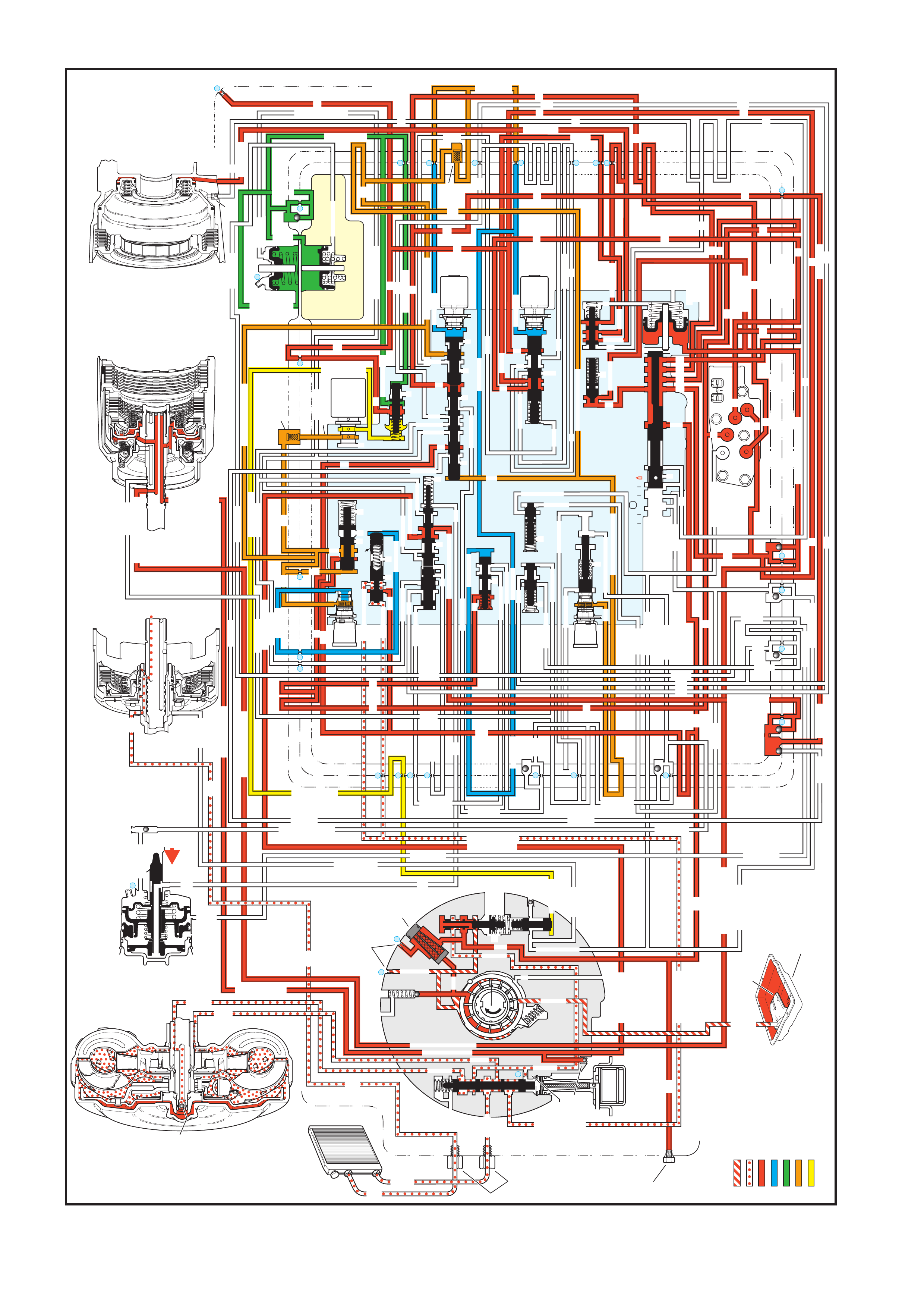
Figure 7C3-26 - Manual First Gear
4.11 MANUAL FIRST GEAR
MANUAL FIRST – FIRST GEAR (from Manual Second – Second Gear)
INPUT CLUTCH
HOUSING ASSEMBLY
24
REAR LUBE
FILTER
(49)
RELEASE
APPLY
LO/REVERSE
PR
BOOST VALVE PRESS REG
BOTTOM
PAN
(SUMP)
(75)
FILTER
(72)
REVERSE INPUT
REV INPUT
DECREASE
LINE
EX
FILTER
(232)
AIR
BLEED
(240)
1
SUCTION
LINE
EX
PRESSURE
RELIEF
VALV E
PUMP
ASSEMBLY
(4)
4
TCC
SOLENOID
(66)
N.O.
COOLER
LUBE
COOLER
SUCTION
CONVERTER & LUBE
MAINLINE
SOLENOID SIGNAL
ACCUMULATOR
ACTUATOR FEED LIMIT
TORQUE SIGNAL
FLUID PRESSURES
REVERSE INPUT
FORWARD CLUTCH FEED
#1
ACCUMULATOR
ORF ACC
2ND CLUTCH
3-4 ACCUMULATOR
1-2 ACCUMULATOR
19
3-4 ACCUM
ACCUM
EX
ORIFICED ACCUM
3-4 ACCUMULATOR
3-4 ACCUM
2ND CLUTCH
2ND CLUTCH
D3
REVERSE INPUT
D2-N.C.
REV-N.O.
D3-N.C.
LO-N.O.
D4-N.O.
LO
TEMP
SENSOR
TFP
SWITCH
ASSEMBLY
D2
D4
D3
D3
D3
EX
FORWARD ABUSE
FWD CL FD
3RD ACCUMULATOR EX
#7
11
3RD ACCUM
4TH
EX
EX
4TH
2ND & 4TH
SERVO
REV ABUSE
EX
REVERSE
REVERSE INPUT
#12
D4
22
D4
D4
#4
13
3-4 SIGNAL
3-4 CL
3-4 CLUTCH
#2
12
3-4 CLUTCH
3RD ACCUM
3-4 CL
#8
16
2ND
2ND CL
2ND CL
2ND CL
2ND CL
2ND CLUTCH2ND CLUTCH
TORQUE SIG
FORWARD CLUTCH FEED
FORWARD
CLUTCH
ACCUMULATOR
EX
PR
LO
LO
LO
FORWARD CLUTCH FEED
FORWARD CLUTCH FEED
FWD CL FEED
D3
D3
D3
14
3-4 CLUTCH
3RD ACCUMULATOR
3RD ACCUM
EX
AFL
3-2 SIGNAL
2ND
2ND
LINE
REGULATED APPLY
8
REG APPLY
1-2 SHIFT VALVE
26
LO
D4
O’ EX
D4-3-2 2ND
25
1-2 SIGNAL
LO/1ST
27
1-2 SIGNAL
EX
ORIFICED EX
ORIFICED EX
EX
LO/1ST D4-3-2
D4
D4
2
EX
CONV FD
EX
EX
EX
LINE LINE
LINE
PRESSURE
TAP
(39)
REGULATED APPLY
LUBE
LUBE
LUBE
LUBE
CASE (8)
CASE (8)
GASKET (47)
SPACER PLATE (48)
GASKET (52)
VALVE BODY (60)
SUCTION
LINE
LINE
3a
3b
3c
D3
EX
3-4 SIGNAL
1-2 SIGNAL
4TH SIGNAL
3-4 SHIFT VALVE
1-2 SIGNAL
3-4 CLUTCH
OVERRUN CLUTCH
OVERRUN CLUTCH
OVERRUN CLUTCH
OVERRUN CLUTCH
OVERRUN CLUTCH
OVERRUN CLUTCH
12a
12b
12c
12d
12e
EX
EX
EX
32
AFL
AFL
30
D4
EX
31
ACCUMULATOR
ACCUMULATOR
EX
TORQUE SIGNAL
FILTERED AFL
D4
AFLAFL
FILTER
(50)
10
43a
43b 44
11b
11c
11a
14b
14a
14c
LO OVERRUN
23
PR
LO/REV
LO/1ST
LO/REVERSE
LO/REVERSE
PR PR
EX
22 10c
23 10b
9n
9o
22b
22a
10a
10 9k
9g
9m
44a
43c 44
41a
41b
41c
41d
42b
42a
13a
13b
OIL
COOLER
PIPE
CONNECTOR
(10)
18a
18b
18c
18 17a
18 17b
20b
48b
48a
REGULATED APPLY
30a
30b
32a
37a
9b
9e
10 9d
9c
9a
9f
9h
31a
31b
31c
OVERRUN CLUTCH FEED
3-4 ACCUM
SERVO FEED
SERVO FEED
6
7
4TH4TH
OVERRUN CL
4TH SIGNAL
2ND
EX
EX
3-4 RELAY 4-3 SEQUENCE VALVE
5
EX
SERVO FD
ORF EX
CASE (8)
REV INPUT
EX
(237)
17d
17c
17e
17f
17g
21
21
20d
20e
21a
20a
20c
1-2 ACCUMULATOR COVER (57)
25g
33c
33a
33b
27d
27c
27b
29
29
27a
28a
29b
29a
29d
40
29c
29e
29g28
28
29f
24a
24b
24c
24d
24e
24f
24
g
24h
25a
25b
25d
25e
25f
25
25
24m
24k
REVERSE INPUT
#3
17
REVERSE INPUT
15c
15b
16
16
REVERSE
REVERSE INPUT
16a
15d
15a
REVERSE
34f
34e
34d
34c
34a
34b
#6
OVERRUN CL FD
21
ORIFICED D2
#5
OVERRUN
OVERRUN OVERRUN
OVERRUN
36
36
35e
35d
39
35b
35c
36a
35a
38d
38e39
38c
38b
38a
EX
TORQUE SIGNAL
2ND CL
20
18
2-3 SHUTTLE2-3 SHIFT VALVE
28
29
EX
EX
EX
EX
D2
OVERRUN
D3
D3
2ND
3-4 SIGNAL
EX
D4-3-2
2-3 SIGNAL
ACTUATOR FEED LIMIT
AFL
SERVO FD
3-4 ACC
FILTERED AFL
AFL
ACTUATOR FEED LIMIT
ACTUATOR FEED LIMIT
AFL
D2
2ND
2ND
2ND
2ND
D2
D2
D2
D2
ORIFICED D2
D2
D2
D2
VALVE BODY (60)
3-4 SIGNAL
2ND
D4
PR
3-4 ACCUMULATOR
D4
EX
D4-3-2
LO
D4
2ND CLUTCH
D3
D3
FORWARD CLUTCH FEED ACTUATOR FEED LIMIT
TORQUE SIGNAL
SERVO FEED
OVERRUN CLUTCH
LINE
9p
26a
PR
OFF
CONVERTER CLUTCH VALVE
COOLER
RELEASE
APPLY
EX
EX
CONV FD
REGULATED APPLY
3-2 CONTROL
EX
EX
CC SIGNAL
CC SIGNAL
ACTUATOR FEED LIMIT
9
26b
TCC PWM
SOLENOID
VALVE
N.C.
1-2 SIGNAL
2ND
4TH SIGNAL
3-2
CONTROL
SOLENOID
VALVE
N.C.
OFF
#10
LOW AND REVERSE
CLUTCH ASSEMBLY
REVERSE INPUT
CLUTCH ASSEMBLY
TORQUE
CONVERTER
ASSEMBLY
#9
(237)
(238)
EX
2ND CLUTCH
3-4 CLUTCH
2ND
PRESSURE
CONTROL
SOLENOID
VALV E
2-3 SHIFT
SOLENOID
VALV E
N.O.
ON
EX
1-2 SHIFT
SOLENOID
VALV E
N.O.
ON
ACCUM VALVE
PRND321
D4
D4
REVERSE
D3
D2
LO
EX
EX
LINE
PR
MANUAL VALVE
EX
EX
3-2 DOWNSHIFT
ISOLATOR VALVE
REG APPLY

A manual 2-1 downshift can be accomplished by moving the gear selector lever into the manual first (1) position
when the transmission is operating in second gear. The downshift to first gear is controlled electronically by the
PCM. The PCM will not energise the 1-2 shift solenoid to initiate the downshift until the vehicle speed is below
approxim atel y 48 to 56 km /h. Abov e this s peed, t he transmiss ion operates in a m anual f irst- second gear state . T he
following text explains the manual 2-1 downshift.
MANUAL VALVE
The selector lever m oves the manual shaf t and the manual valve into the manual first (1) position. This allows the
line pressure to enter the Low fluid circuit.
TRANSMISSION FLUID PRESSURE (TFP) MANUAL VALVE POSITION SWITCH ASSEMBLY
Low fluid is routed to the TFP Switch where it closes the normally open Low pressure switch. The addition of the
low pressure switch being closed signals to the PCM that manual first is selected.
2-3 SHIFT SOLENOID
In both first and second gears, this solenoid is energis ed and maintains the signal B fluid pressure at the solenoid
end of the 2-3 shift valve train.
2-3 SHIFT VALVE TRAIN
Held in the downshift position by the signal B fluid pressure from the solenoid, the valve train blocks the AFL f luid
from entering the D432 fluid circuit. The D432 fluid circuit is open to exhaust past the valve.
1-2 SHIFT SOLENOID
Below appr oxim atel y 48 to 56 km /h ( 30 to 35 m ph) the PCM energis es th e norm all y open s olenoid. T his bloc ks the
signal A fluid pressure from exhausting through the solenoid and creates the pressure in the signal A fluid circuit.
Above this speed, the PC M keeps the s olenoid de-en ergis ed and the transm ission operat es in m anual first- second
gear.
1-2 SHIFT VALVE
Signal A fluid pressure moves the valve against the spring force and into the downshift position. In this position,
Low fluid f rom the m anual valv e is rout ed into t he Lo w/1s t fluid cir cuit an d D4 flu id is block ed f rom entering the 2n d
fluid circ uit. T he 2nd fluid e xhaus ts throug h an orif ice and an a nnulus ex haus t por t past the va lve. T his orif ice ( #26)
helps control the 2-4 band release during a 2-1 downshift.
2-4 BAND RELEASES
2-4 Servo Assembly: The 2nd clutch fluid, which was fed by the 2nd fluid, exhausts from the servo. This allows
the spring force from the servo cushion and the servo return springs to move the 2nd apply piston and apply the pin
to release the 2-4 band. These spring forces help control the 2-4 band release.
1-2 ACCUMULATOR AS SEM BLY
The 2nd c lutch fluid also exhaus ts from the 1- 2 accum ulator assem bly. The spri ng force and th e accum ulator fluid
pressure move the accumulator piston to assist the 2nd clutch fluid exhaust.
ACCUMULATOR VALVE
As the accumulator fluid is filling the 1-2 accumulator assembly, the accumulator valve regulates the D4 fluid into
the accumulator fluid circuit. This regulation biased by torque signal fluid pressure and spring force, helps control
the movement of the 1-2 accumulator piston. The 2nd clutch fluid exhaust, and the 2-4 band release.
1-2 UPSHIFT CHECKBALL (#8)
Exhausting the 2nd clutch fluid pressure unseats the ball and is routed through the 2nd fluid circuit.
CONVERTER CLUTCH SIGNAL VALVE
The 2nd fluid exhausts from the converter clutch signal valve. Refer to Park – Engine Running, in this Section,
range for a description of the TCC signal valve operation in first gear.
LOW AND REVERSE CLUTCH APPLIES
Low Overrun Valve: The Low/1st fluid is regulated through the low overrun valve and into the Low/reverse fluid
circuit in order to control the Low and reverse clutch apply.
LOW AND REVERSE PISTON
The Low/re verse fluid press ure ac ts on the inner ar e a of the pis ton in or d er to move the piston a nd in or der to apply
the low and revers e clutch plat es .
OVERRUN CLUTCH APPLIED
The overrun clutch remains applied in manual first in order to provide engine compression braking.

PRESSURE CONTROL SOLENOID
Similar to manual s econd, t he PCM output s ignal to the press ure contro l soleno id increas es the opera ting ra nge of
the torque signal fluid pressure. This provides the increased line pressure for the additional torque requirements
during the engine compression braking and the increased engine loads.
3-2 DOWNSHIFT CONTROL SOLENOID AND THE 3-2 CONTROL VALVE
In first gear the solenoid is OFF, the AF L fluid is bloc ked by the sole noid, and the 3-2 signal flu id exhausts through
the solenoid and the spring force opens the 3-2 control valve.
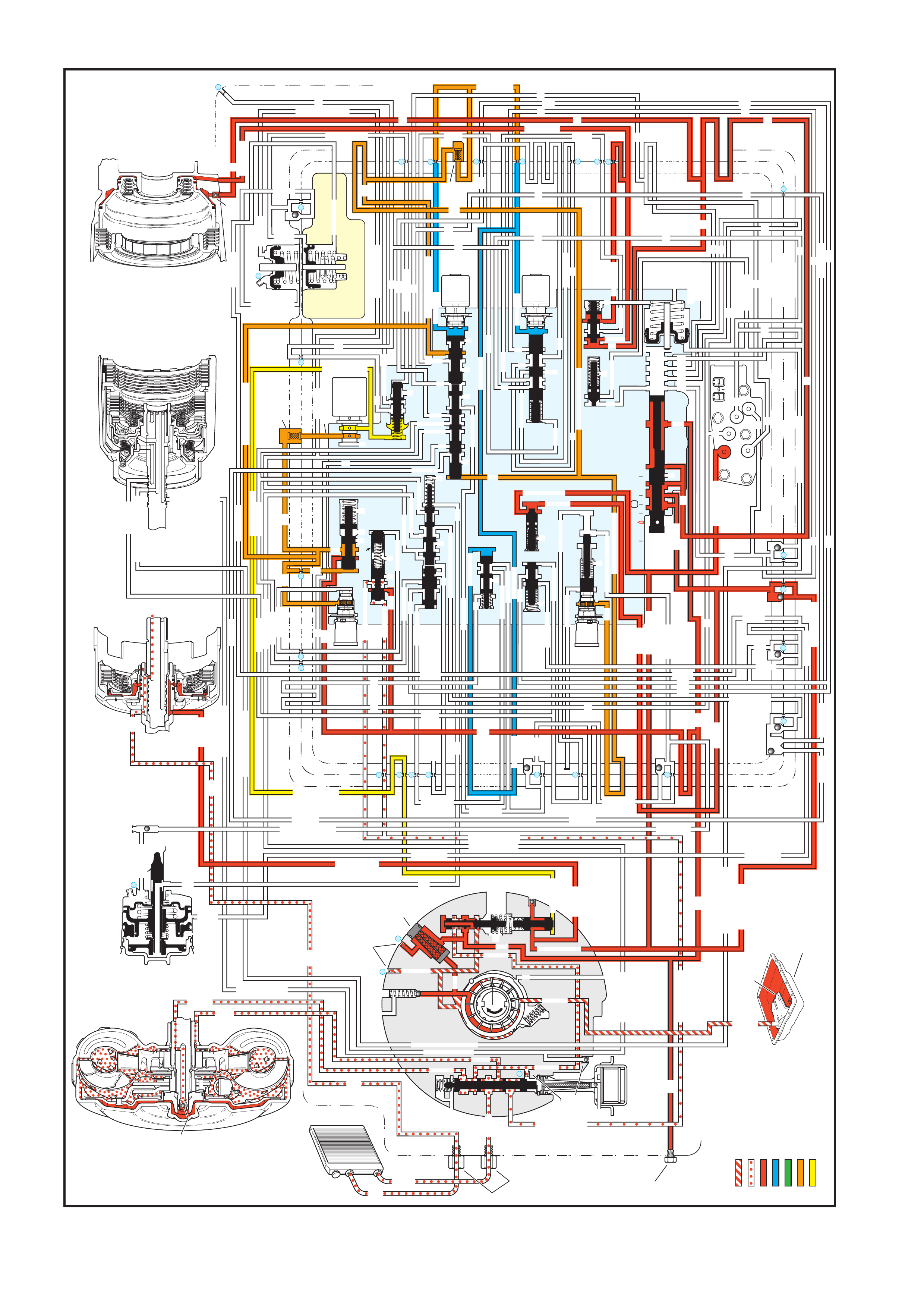
Figure 7C3-27 - Reverse
4.12 REVERSE
REVERSE
INPUT CLUTCH
HOUSING ASSEMBLY
24
REAR LUBE
FILTER
(49)
RELEASE
APPLY
LO/REVERSE
PR
BOOST VALVE PRESS REG
BOTTOM
PAN
(SUMP)
(75)
FILTER
(72)
REVERSE INPUT
REV INPUT
DECREASE
LINE
EX
FILTER
(232)
AIR
BLEED
(240)
1
SUCTION
LINE
EX
PRESSURE
RELIEF
VALV E
PUMP
ASSEMBLY
(4)
4
TCC
SOLENOID
(66)
N.O.
COOLER
LUBE
COOLER
SUCTION
CONVERTER & LUBE
MAINLINE
SOLENOID SIGNAL
ACCUMULATOR
ACTUATOR FEED LIMIT
TORQUE SIGNAL
FLUID PRESSURES
REVERSE INPUT
FORWARD CLUTCH FEED
#1
ACCUMULATOR
ORF ACC
2ND CLUTCH
3-4 ACCUMULATOR
1-2 ACCUMULATOR
19
3-4 ACCUM
ACCUM
EX
ORIFICED ACCUM
3-4 ACCUMULATOR
3-4 ACCUM
2ND CLUTCH
2ND CLUTCH
D3
REVERSE INPUT
D2-N.C.
REV-N.O.
D3-N.C.
LO-N.O.
D4-N.O.
LO
TEMP
SENSOR
TFP
SWITCH
ASSEMBLY
D2
D4
D3
D3
D3
EX
FORWARD ABUSE
FWD CL FD
3RD ACCUMULATOR EX
#7
11
3RD ACCUM
4TH
EX
EX
4TH
2ND & 4TH
SERVO
REV ABUSE
EX
REVERSE
REVERSE INPUT
#12
D4
22
D4
D4
#4
13
3-4 SIGNAL
3-4 CL
3-4 CLUTCH
#2
12
3-4 CLUTCH
3RD ACCUM
3-4 CL
#8
16
2ND
2ND CL
2ND CL
2ND CL
2ND CL
2ND CLUTCH2ND CLUTCH
TORQUE SIG
FORWARD CLUTCH FEED
FORWARD
CLUTCH
ACCUMULATOR
EX
PR
LO
LO
LO
FORWARD CLUTCH FEED
FORWARD CLUTCH FEED
FWD CL FEED
D3
D3
D3
14
3-4 CLUTCH
3RD ACCUMULATOR
3RD ACCUM
EX
AFL
3-2 SIGNAL
2ND
2ND
LINE
REGULATED APPLY
8
REG APPLY
1-2 SHIFT VALVE
26
LO
D4
O’ EX
D4-3-2 2ND
25
1-2 SIGNAL
LO/1ST
27
1-2 SIGNAL
EX
ORIFICED EX
ORIFICED EX
EX
LO/1ST D4-3-2
D4
D4
2
EX
CONV FD
EX
EX
EX
LINE LINE
LINE
PRESSURE
TAP
(39)
REGULATED APPLY
LUBE
LUBE
LUBE
LUBE
CASE (8)
CASE (8)
GASKET (47)
SPACER PLATE (48)
GASKET (52)
VALVE BODY (60)
SUCTION
LINE
LINE
3a
3b
3c
D3
EX
3-4 SIGNAL
1-2 SIGNAL
4TH SIGNAL
3-4 SHIFT VALVE
1-2 SIGNAL
3-4 CLUTCH
OVERRUN CLUTCH
OVERRUN CLUTCH
OVERRUN CLUTCH
OVERRUN CLUTCH
OVERRUN CLUTCH
OVERRUN CLUTCH
12a
12b
12c
12d
12e
EX
EX
EX
32
AFL
AFL
30
D4
EX
31
ACCUMULATOR
ACCUMULATOR
EX
TORQUE SIGNAL
FILTERED AFL
D4
AFLAFL
FILTER
(50)
10
43a
43b 44
11b
11c
11a
14b
14a
14c
LO OVERRUN
23
PR
LO/REV
LO/1ST
LO/REVERSE
LO/REVERSE
PR PR
EX
22 10c
23 10b
9n
9o
22b
22a
10a
10 9k
9g
9m
44a
43c 44
41a
41b
41c
41d
42b
42a
13a
13b
OIL
COOLER
PIPE
CONNECTOR
(10)
18a
18b
18c
18 17a
18 17b
20b
48b
48a
REGULATED APPLY
30a
30b
32a
37a
9b
9e
10 9d
9c
9a
9f
9h
31a
31b
31c
OVERRUN CLUTCH FEED
3-4 ACCUM
SERVO FEED
SERVO FEED
6
7
4TH4TH
OVERRUN CL
4TH SIGNAL
2ND
EX
EX
3-4 RELAY 4-3 SEQUENCE VALVE
5
EX
SERVO FD
ORF EX
CASE (8)
REV INPUT
EX
(237)
17d
17c
17e
17f
17g
21
21
20d
20e
21a
20a
20c
1-2 ACCUMULATOR COVER (57)
25g
33c
33a
33b
27d
27c
27b
29
29
27a
28a
29b
29a
29d
40
29c
29e
29g28
28
29f
24a
24b
24c
24d
24e
24f
24
g
24h
25a
25b
25d
25e
25f
25
25
24m
24k
REVERSE INPUT
#3
17
REVERSE INPUT
15c
15b
16
16
REVERSE
REVERSE INPUT
16a
15d
15a
REVERSE
34f
34e
34d
34c
34a
34b
#6
OVERRUN CL FD
21
ORIFICED D2
#5
OVERRUN
OVERRUN OVERRUN
OVERRUN
36
36
35e
35d
39
35b
35c
36a
35a
38d
38e39
38c
38b
38a
EX
TORQUE SIGNAL
2ND CL
20
18
2-3 SHUTTLE2-3 SHIFT VALVE
28
29
EX
EX
EX
EX
D2
OVERRUN
D3
D3
2ND
3-4 SIGNAL
EX
D4-3-2
2-3 SIGNAL
ACTUATOR FEED LIMIT
AFL
SERVO FD
3-4 ACC
FILTERED AFL
AFL
ACTUATOR FEED LIMIT
ACTUATOR FEED LIMIT
AFL
D2
2ND
2ND
2ND
2ND
D2
D2
D2
D2
ORIFICED D2
D2
D2
D2
VALVE BODY (60)
3-4 SIGNAL
2ND
D4
PR
3-4 ACCUMULATOR
D4
EX
D4-3-2
LO
D4
2ND CLUTCH
D3
D3
FORWARD CLUTCH FEED ACTUATOR FEED LIMIT
TORQUE SIGNAL
SERVO FEED
OVERRUN CLUTCH
LINE
9p
26a
PR
OFF
CONVERTER CLUTCH VALVE
COOLER
RELEASE
APPLY
EX
EX
CONV FD
REGULATED APPLY
3-2 CONTROL
EX
EX
CC SIGNAL
CC SIGNAL
ACTUATOR FEED LIMIT
9
26b
TCC PWM
SOLENOID
VALVE
N.C.
1-2 SIGNAL
2ND
4TH SIGNAL
3-2
CONTROL
SOLENOID
VALVE
N.C.
OFF
#10
LOW AND REVERSE
CLUTCH ASSEMBLY
REVERSE INPUT
CLUTCH ASSEMBLY
TORQUE
CONVERTER
ASSEMBLY
#9
(237)
(238)
EX
2ND CLUTCH
3-4 CLUTCH
2ND
PRESSURE
CONTROL
SOLENOID
VALV E
2-3 SHIFT
SOLENOID
VALV E
N.O.
ON
EX
1-2 SHIFT
SOLENOID
VALV E
N.O.
ON
ACCUM VALVE
PRND321
D4
D4
REVERSE
D3
D2
LO
EX
EX
LINE
MANUAL VALVE
PR
EX
EX
3-2 DOWNSHIFT
ISOLATOR VALVE
REG APPLY

W hen the gear selector lever is moved to the Reverse (R) position (from the Park position), the follo wing changes
occur to the transmissions hydraulic and electrical systems:
MANUAL VALVE
The m anual valve m oves to the Reverse pos ition and lin e pressure enter s the rever se fluid cir cuit. As in Park, line
pressure also fills the PR (Park/Reverse) fluid circuit. All other fluid circuits are blocked by the manual valve.
LOW AND REVERSE CLUTCH
As in Park, PR fluid pressure acts on the outer area of the low and reverse clutch piston to apply the low and
reverse clutch. Also, Low/reverse fluid from the low overrun valve acts on the inner area of the piston to increase
the holding capacity of the clutch (see Note below).
REVERSE INPUT CHECKBALL (#3)
Reverse f luid pres sure seat s the #3 chec kball, f lows through orific e #17 and f ills the r everse i nput fluid c ircuit. T his
orifice helps control the reverse input clutch apply rate when engine speed is at idle.
REVER SE ABUSE V ALVE
Reverse f luid pressure acts on the end of the valve opposite of spring f orce. At engine spee ds above id le, reverse
fluid pressure, which is fed by line pressure, increases and moves the valve against spring force (as shown).
Reverse f luid can then fill t he revers e input f luid cir cuit throu gh the rev erse abus e valve. T his bypas ses the control
of orifice #17 and provides a faster clutch apply.
BO OST VALVE
Reverse in put f luid pr essur e m oves the b oost val ve a gainst the pres sure reg ula tor va lve s pring. T he spr ing acts on
the pressure regulator valve to increase the operating range of line pressure in Reverse. Reverse input fluid also
flows through the valve and to the reverse input clutch piston. Remember that torque signal fluid pressure
continually acts on the boost valve to control line pressure in response to vehicle operating conditions.
REVERSE INPUT CLUTCH PISTON
Reverse input fluid pressure moves the piston to apply the reverse input clutch plates and obtain Reverse.
REVERSE INPUT AIR BLEED CHECKBALL
This ball and capsule is located in the reverse input fluid circuit in th e oil pump to provide an air escape when the
fluid pressure increases. It also allows air into the circuit to displace the fluid when the clutch releases.
TRANSMISSION FLUID PRESSURE (TFP) MANUAL VALVE POSITION SWITCH ASSEMBLY
Reverse inp ut fluid press ure closes the n ormally open reverse switch i n the TFP Switch T his signals th e PCM that
the manual valve is in the Reverse (R) position.
SHIFT SOLENOIDS (1-2 AND 2-3)
Both solenoids are energised as in the Park range. Signal A and signal B fluids are blocked from exhausting
through the shift solenoids to maintain fluid pressure in these circuits at the end of the shift valves.
SHIFT VALVES (1-2, 2-3 AND 3-4)
Signal A fluid pressure holds the 1-2 shift valve in t he downshifted position and the 3-4 shift valve in the upshif ted
(Firs t and Fourth gear) p osition. Sig nal B fluid press ure fr om the 2- 3 solenoid sh ift holds the 2- 3 shift valve t rain in
the downshifted position.
PRESSURE CONTROL SOLENOID
The pres sure contr ol solenoid cont inues to r egulate A FL fluid int o torque sign al fluid press ure. The PCM varies the
current at the s olenoid to regu late torque s ignal fluid press ure in response to thr ottle posit ion and other PC M input
signals. Torque signal fluid pressure is used to control line pressure at the boost and pressure regulator valves.
NOTE: The explanation in each gear range is, for the most part, limited.
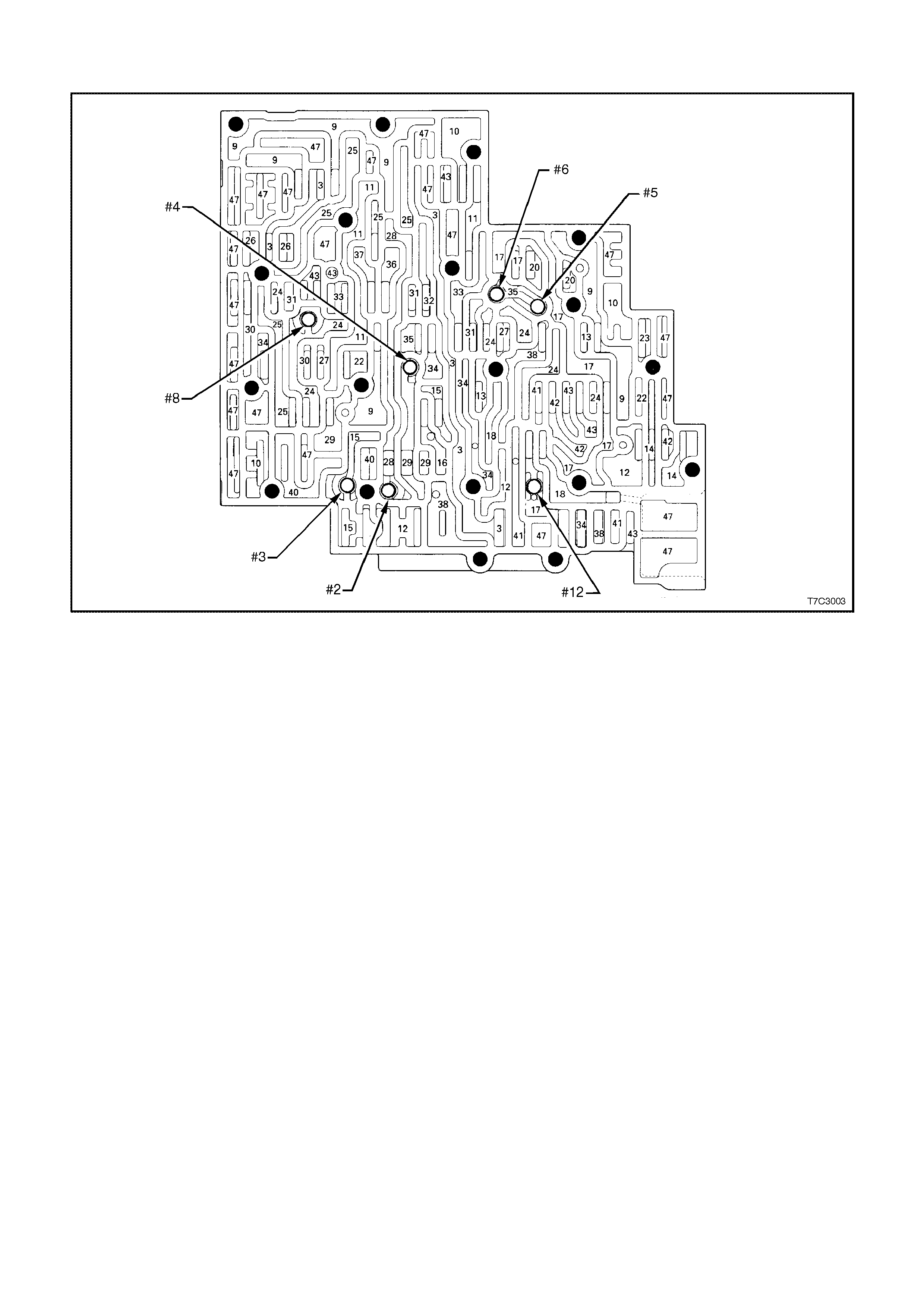
5. HYDRAULIC PATHS IN TRANSMISSION COMPONENTS
Figure 7C3-28 – Control Valve Body Passages and Checkball Locations
Legend
#2 Checkball (61)
#3 Checkball (61)
#4 Checkball (61)
#5 Checkball (61)
#6 Checkball (61)
#8 Checkball (61)
#12 Checkball (61)
3. Line
9. Actuator Feed Limit
10. Filtered Actuator Feed
11. Torque Signal
12. PR
13. D4 - 3 - 2
14. Low/Reverse
15. Reverse
16. Reverse Input (Rev. Cl.)
17. D4
18. Forward Clutch Feed
20. Accumulator
22. Signal A
23. Signal B
24. 2nd
25. 2nd Clutch
26. CC Signal
27. 3 - 4 Signal
28. 3rd Accumulator
29. 3 - 4 Clutch
30. 4th Signal
31. Servo Feed
32. 4th
33. 3- 4 Accumulator
34. D3
35. Overrun
36. Overrun Clutch Feed
37. Overrun Clutch
38. D2
40. 3 - 2 Signal
41. Low
42. Low/1st
43. Exhaust
47. Void
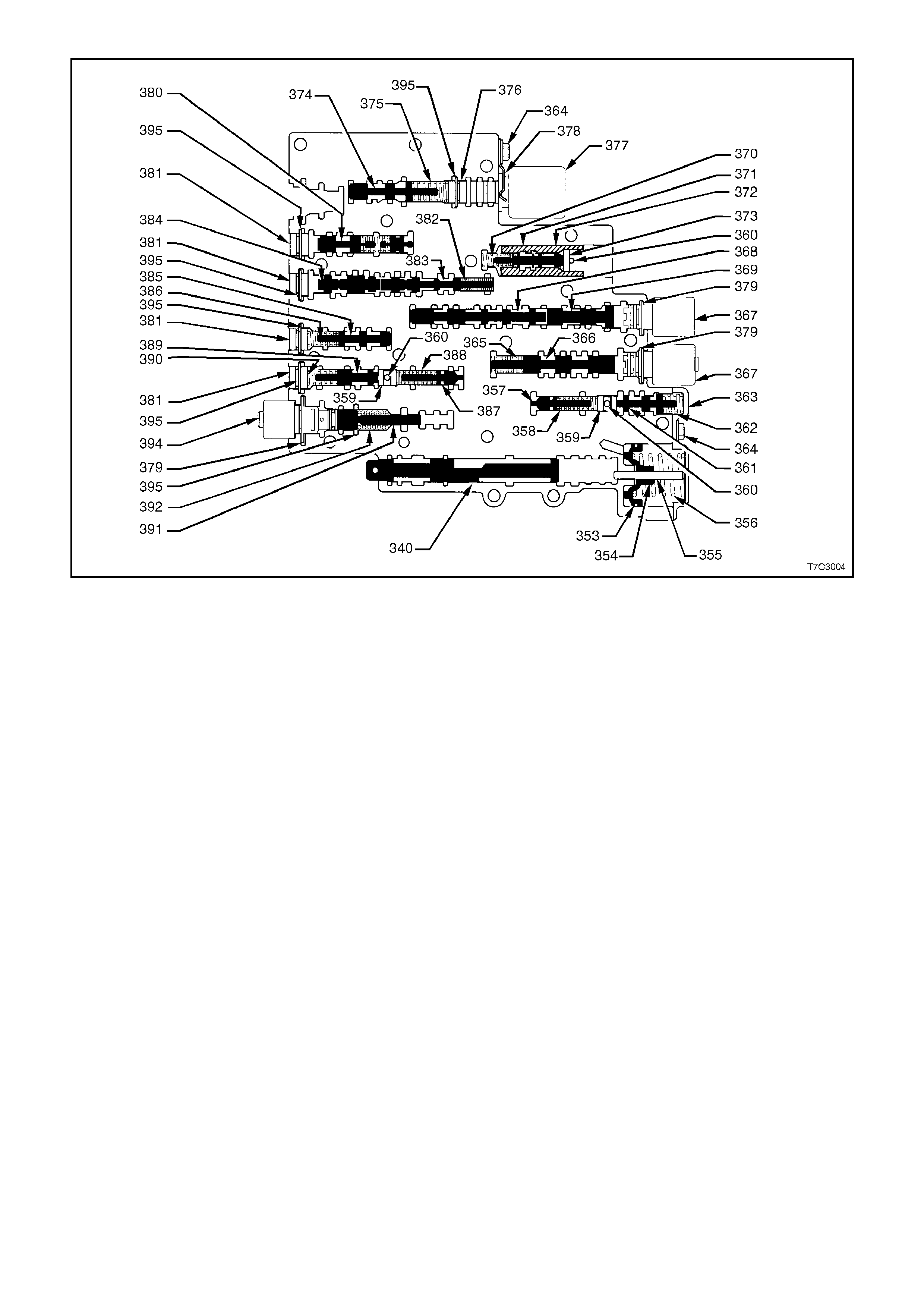
Figure 7C3-29 – Control Valve Body Valve Trains
Legend
340. Valve, Manual
353. Seal, Forward Accumulator Oil
354. Piston, Forward Accumulator
355. Pin, Forward Accumulator
356. Spring, Forward Accumulator
357. Valve, Forward Abuse
358. Spring, Forward Abuse Valve
359. Plug, Bore
360. Pin, Coiled Spring
361. Valve, Low Overrun
362. Spring, Low Overrun Valve
363. Cover, Forward Accumulator
364. Bolt, Forward Accumulator Cover
365. Spring, 1-2 Shift Valve
366. Valve, 1-2 Shift
367. 2-3 Shift Solenoid
368. Valve, 2-3 Shift
369. Valve, 2-3 Shuttle
370. Spring, 1-2 Accumulator Valve
371. Valve, 1-2 Accumulato r
372. Sleeve, 1-2 Accumulator Valve
374. Valve, Actuator Feed Limit
375. Spring, Actuator Feed Limit Valve
376. Plug, Bore
377. Pressure Control Solenoid
378. Retainer, Pressure Control Solenoid
379. Retainer, Solenoid
380. Valve, Converter Clutch Signal
381. Plug, Bore
382. Spring, 4-3 Sequence Valve
383. Valve, 4-3 Sequence
384. Valve, 3-4 Relay
385. Valve, 3-4 Shift
386. Spring, 3-4 Shift Valve
387. Valve, Reverse Abuse
388. Spring, Reverse Abuse Valve
389. Valve, 3-2 Downshift
390. Spring, 3-2 Downshift Valve
391. Valve, 3-2 Control
392. Spring, 3-2 Control Valve
394. 3-2 Control Solenoid
395. Retainer, Bore Plug
397. Spring
398. Valve
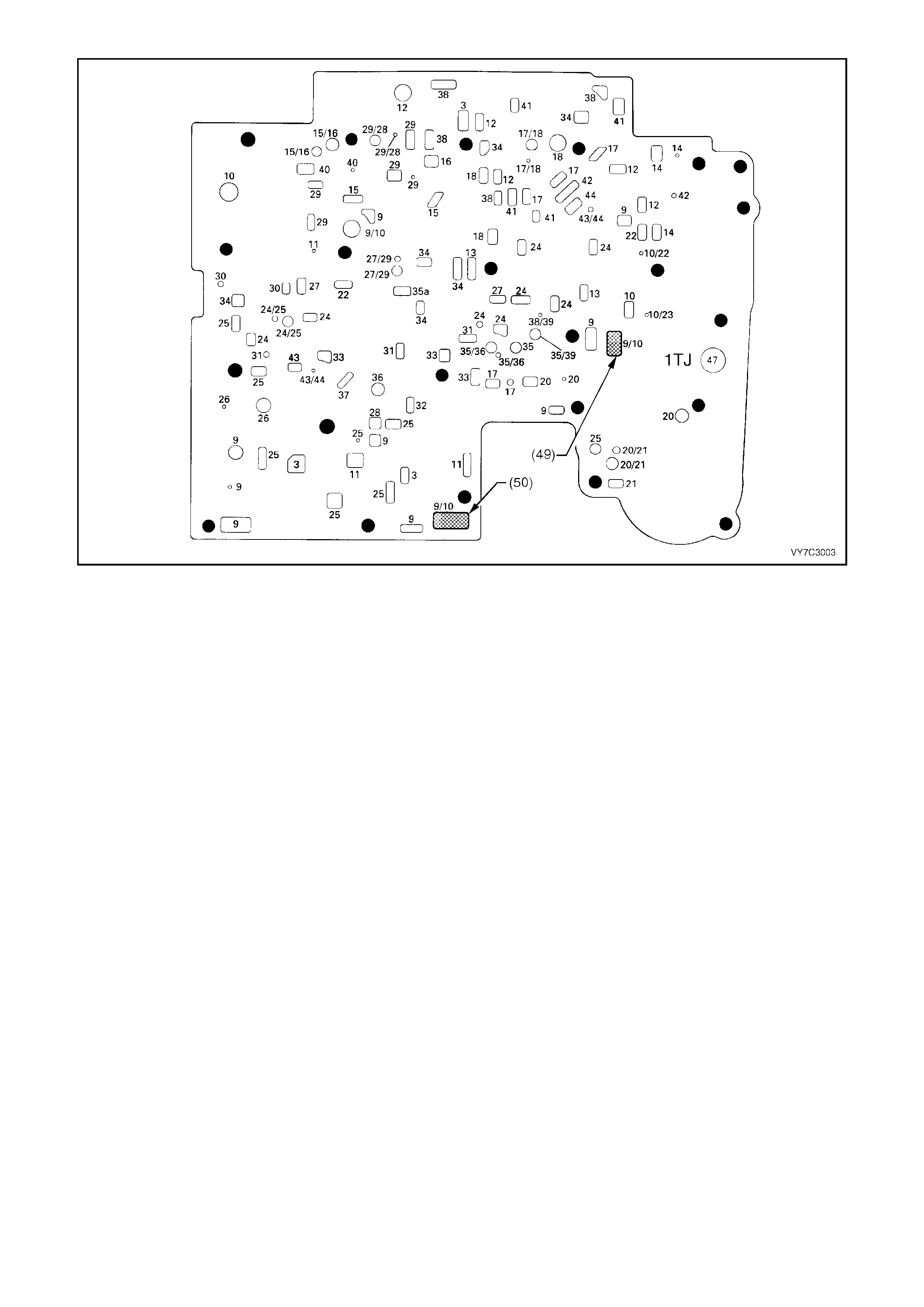
Figure 7C3-30 – Spacer Plate Passages
Legend
(49) Screen, Shift Solenoids
(50) Screen, Pressure Control Solenoid
3. Line
9. Actuator Feed Limit
9/10. Actuator Feed Limit/Filtered Actuator
Feed
10. Filtered Actuator Feed
10/22. Filtered Actuator Feed/Signal A
10/23. Filtered Actuator Feed/Signal B
11. Torque Signal
12. PR
13. D4 - 3 - 2
14. Low/Reverse
15. Reverse
15/16. Reverse/Reverse Input (Rev. Cl.)
16. Reverse Input (Rev. Cl.)
17. D4
17/18. D4
18. Forward Clutch Feed
20. Accumulator
20/21. Accumulator/Orificed
Accumulator
21. Orificed Accumulator
22. Signal A
24. 2nd
24/25. 2nd/2nd Clutch
25. 2nd Clutch
26. CC Signal
27. 3 - 4 Signal
27/29. 3 - 4 Signal
28. 3rd Accumulator
29/28. 3 - 4 Clutch/3rd Accumulator
29. 3 - 4 Clutch
30. 4th Signal
31. Servo Feed
32. 4th
33. 3 - 4 Accumulator
34. D3
35a. Overrun
35. Overrun
35/36. Overrun/Overrun Clutch Feed
35/39. Overrun/Orificed D2
36. Overrun Clutch Feed
37. Overrun Clutch
38. D2
38/39. D2/Orificed D2
40. 3 - 2 Signal
41. Low
42. Low/1st
43. Exhaust
43/44. Exhaust/Orificed Exhaust
44. Orificed Exhaust
47. Void
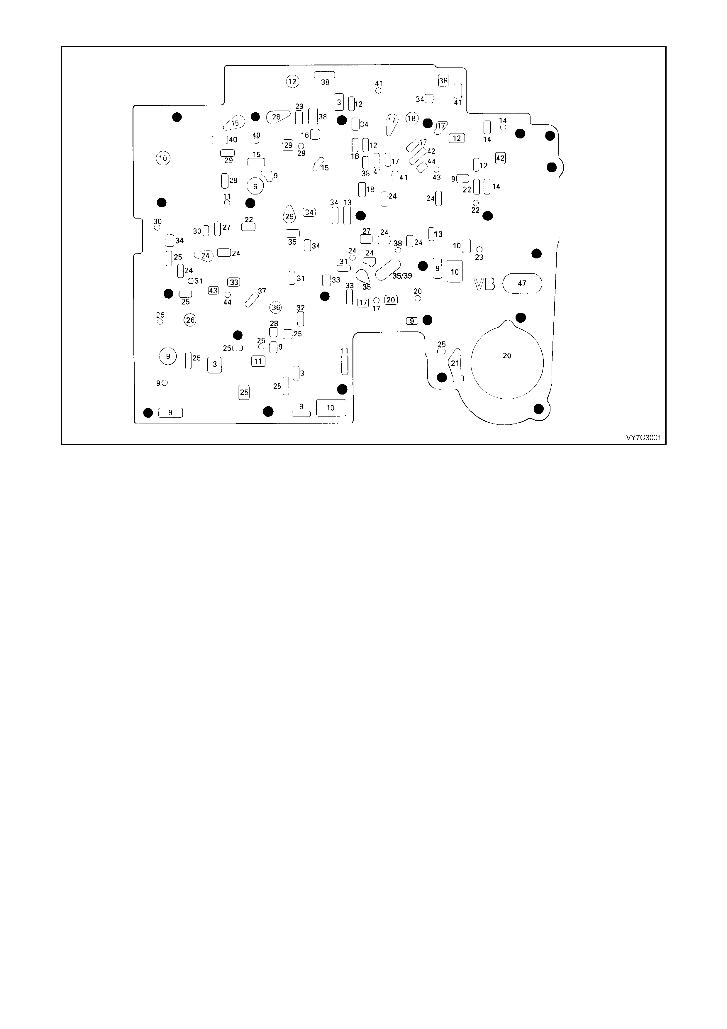
Figure 7C3-31 – Spacer Plate to Control Valve Body Gasket
Legend
3. Line
9. Actuator Feed Limit
10. Filtered Actuator Feed
11. Torque Signal
12. PR
13. D4 - 3 - 2
14. Low/Reverse
15. Reverse
16. Reverse Input (Rev. Cl.)
17. D4
18. Forward Clutch Feed
20. Accumulator
21. Orificed Accumulator
22. Signal A
23. Signal B
24. 2nd
25. 2nd Clutch
26. CC Signal
27. 3 - 4 Signal
28. 3rd Accumulator
29. 3 - 4 Clutch
30. 4th Signal
31. Servo Feed
32. 4th
33. 3 - 4 Accumulator
34. D3
35. Overrun
35/39. Overrun/Orificed D2
36. Overrun Clutch Feed
37. Overrun Clutch
38. D2
40. 3 - 2 Signal
41. Low
42. Low/1st
43. Exhaust
44. Orificed Exhaust
47. Void
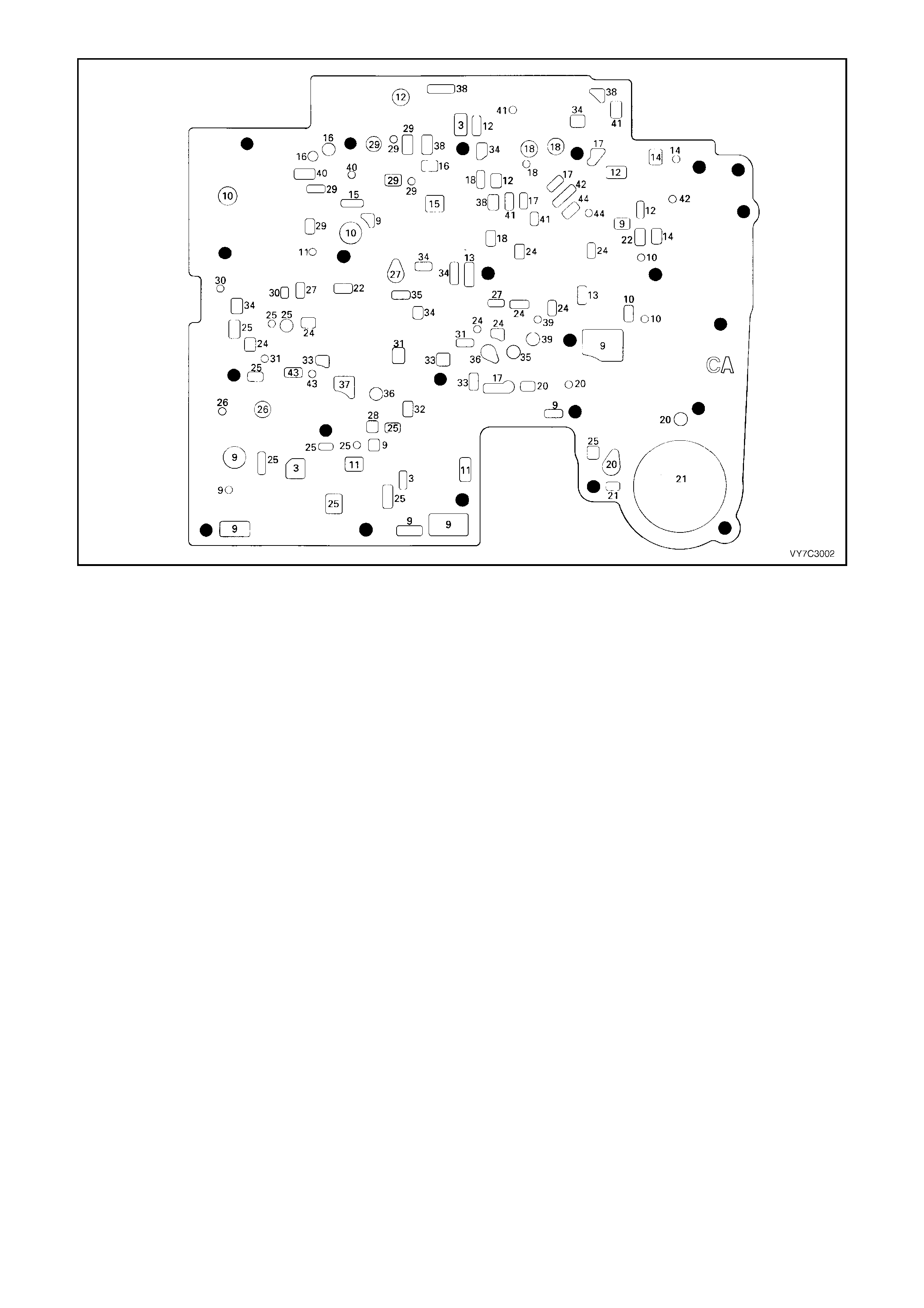
Figure 7C3-32 – Spacer Plate to Transmission Case Gasket
Legend
2. Line
9. Actuator Feed Limit
10. Filtered Actuator Feed
11. Torque Signal
12. PR
13. D4 - 3 - 2
14. Low/Reverse
15. Reverse
16. Reverse Input (Rev. Cl.)
17. D4
18. Forward Clutch Feed
20. Accumulator
21. Orificed Accumulator
22. Signal A
24. 2nd
25. 2nd Clutch
26. CC Signal
27. 3 - 4 Signal
28. 3rd Accumulator
29. 3 - 4 Clutch
30. 4th Signal
31. Servo Feed
32. 4th
33. 3 - 4 Accumulator
34. D3
35. Overrun
36. Overrun Clutch Feed
37. Overrun Clutch
38. D2
39. Orificed D2
40. 3 - 2 Signal
41. Low
42. Low/1st
43. Exhaust
44. Orificed Exhaust
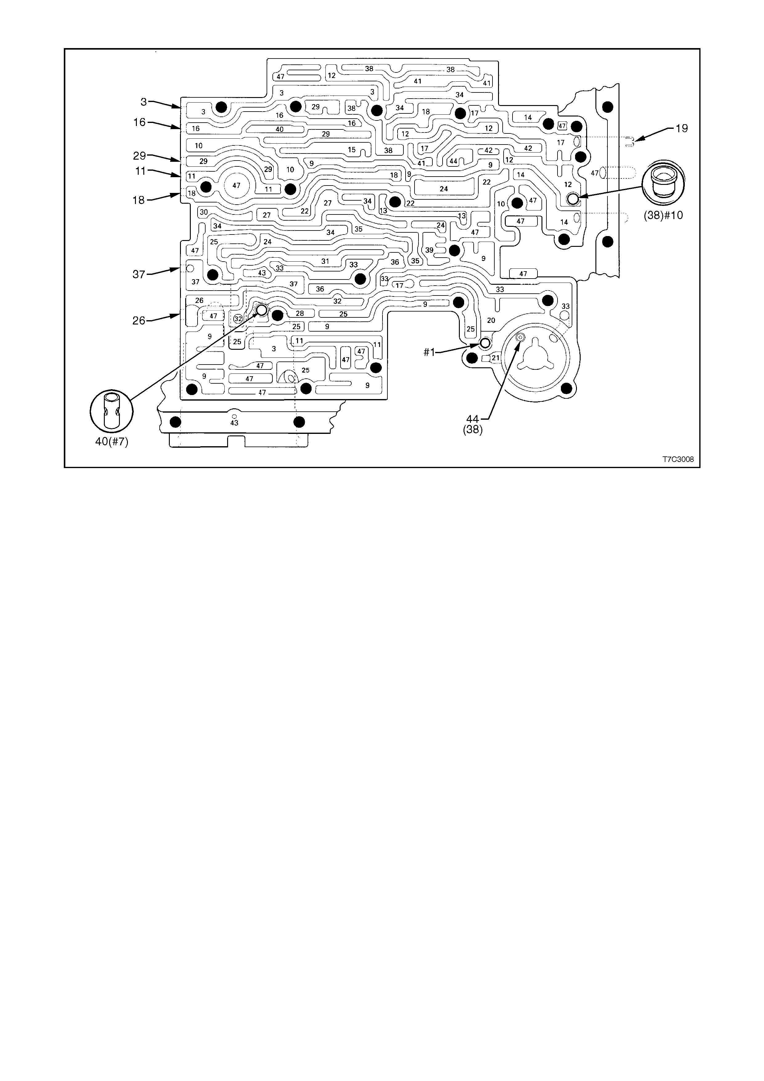
Figure 7C3-33 – Transmission Case Fluid Passages and Checkball Locations
Legend
#1 Checkball (61)
#7 3rd Accumulator Retainer & Ball Asm (40)
#10 Checkball (42)
44 Accumulator Bleed Plug (38)
3. Line
9. Actuator Feed Limit
10. Filtered Actuator Feed
11. Torque Signal
12. PR
13. D4 - 3 - 2
14. Low/Reverse
15. Reverse
16. Reverse Input (Rev. Cl.)
17. D4
18. Forward Clutch Feed
19. Rear Lube
20. Accumulator
21. Orificed Accumulator
22. Signal A
24. 2nd
25. 2nd Clutch
26. CC Signal
27. 3 - 4 Signal
28. 3rd Accumulator
29. 3 - 4 Clutch
30. 4th Signal
31. Servo Feed
32. 4th
33. 3 - 4 Accumulator
34. D3
35. Overrun
36. Overrun Clutch Feed
37. Overrun Clutch
38. D2
39. Orificed D2
40. 3 - 2 Signal
41. Low
42. Low/1st
43. Exhaust
44. Orificed Exhaust
47. Void
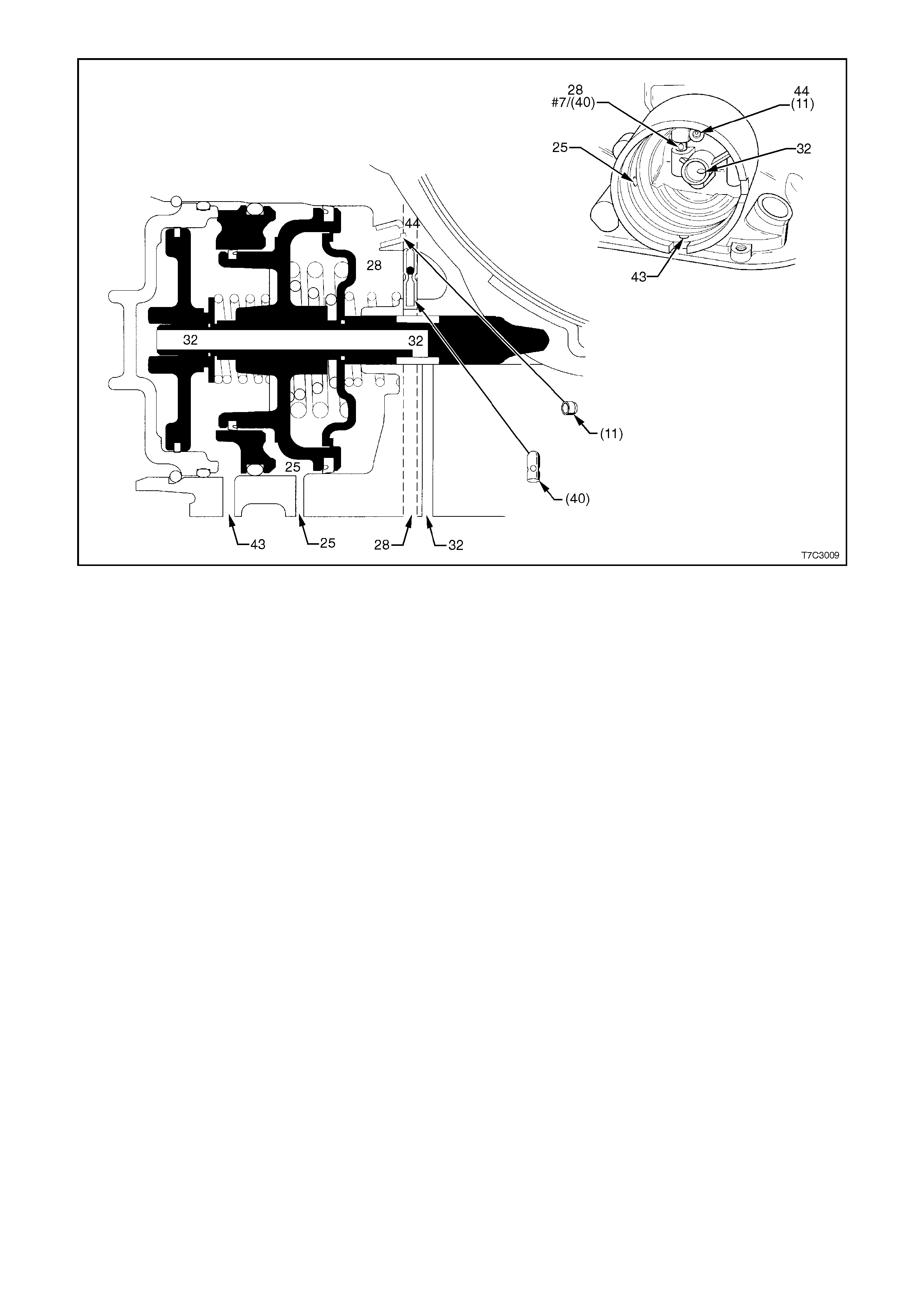
Figure 7C3-34 – 2-4 Servo Passages
Legend
11. Case Servo Orificed Plug
25. 2nd Clutch Apply
28. 3rd Accumulator Passage
32. 4th Band Apply
37 3rd Accumulator Retainer & Ball Asm (40)
40. 3rd Accumulator Retainer & Ball Asm (#7)
43. Exhaust Passage
44. Orificed Exhaust (#11)
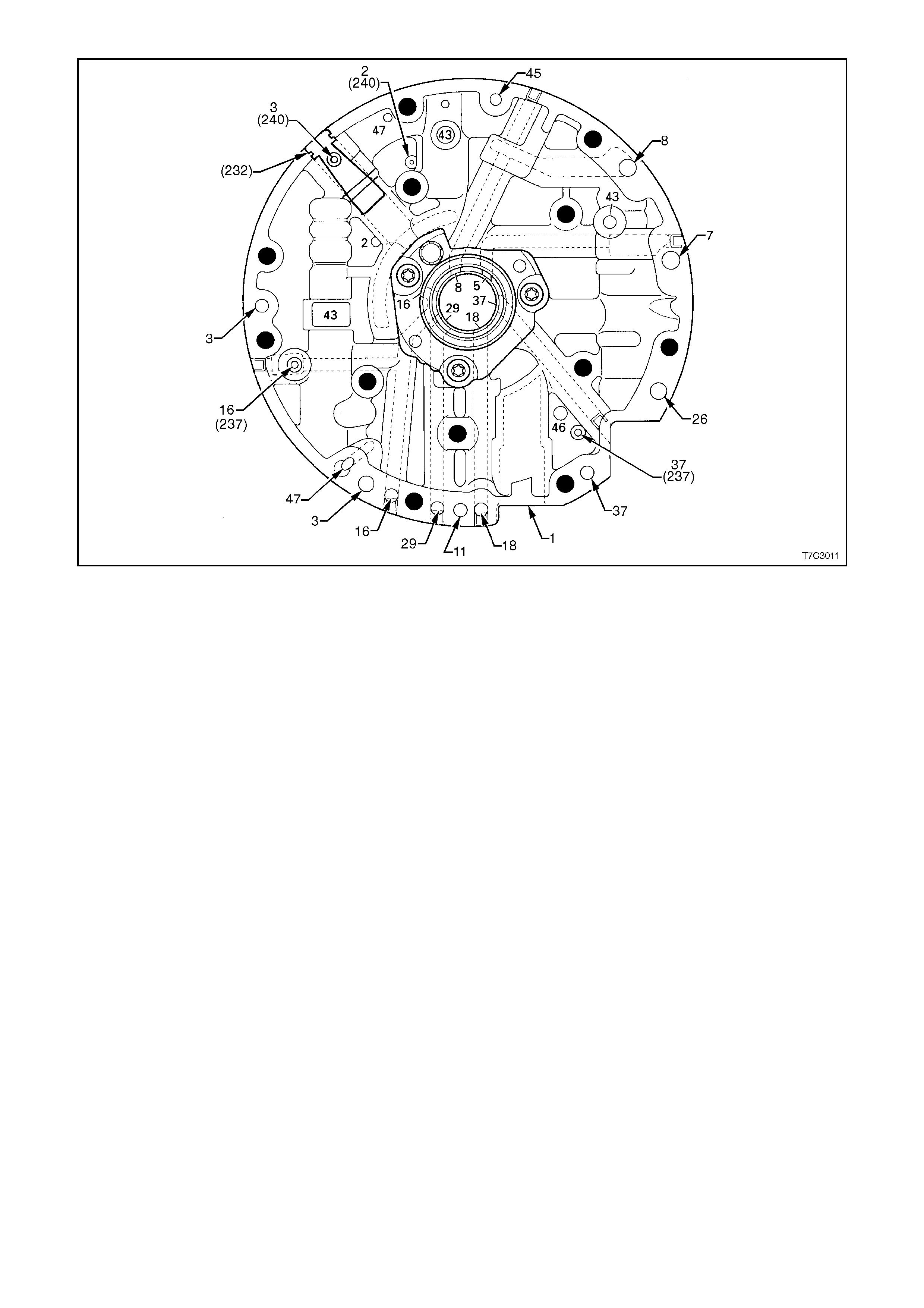
Figure 7C3-35 – Oil Pump Cover Fluid Passages (Transmission Case Side)
Legend
232. Oil Pump Cover Screen
237. Check Valve Retainer & Ball As m
240. Orificed Cup Plug
1. Suction (Intake)
2. Decrease
3. Line
5. Release
7. To Cooler
8. Lube from Cooler
11. Torque Signal
16. Reverse Input (Rev. Cl.)
18. Forward Clutch Feed
26. CC Clutch
29. 3 - 4 Clutch
37. Overrun Clutch
43. Exhaust
45. Vent
46. Seal Drain
47. Void

Figure 7C3-36 – Oil Pump Cover Fluid Passages
Legend
1. Suction (Intake)
2. Decrease
3. Line
4. Converter Feed
5. Release
7. To Cooler
8. Lube from Cooler
11. Torque Signal
16. Reverse Input
18. Forward Clutch Feed
26. CC Clutch
29. 3 - 4 Clutch
37. Overrun Clutch
43. Exhaust
45. Vent
46. Seal Drain
47. Void
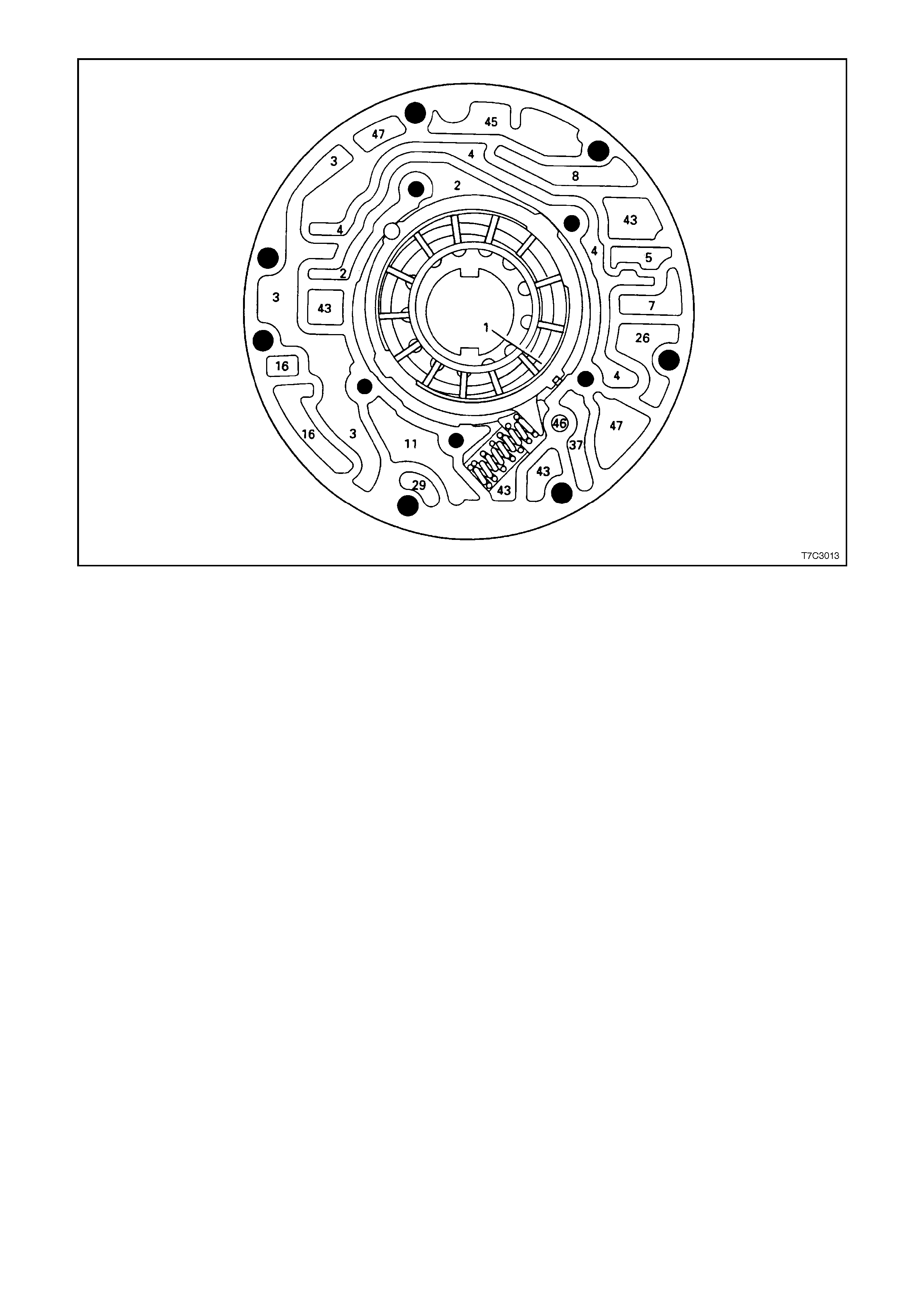
Figure 7C3-37 – Oil Pump Body Fluid Passages
Legend
1. Suction (Intake)
2. Decrease
3. Line
4. Converter Feed
5. Release
7. To Cooler
8. Lube from Cooler
11. Torque Signal
16. Reverse Input
26. CC Clutch
29. 3 - 4 Clutch
37. Overrun Clutch
43. Exhaust
45. Vent
46. Seal Drain
47. Void
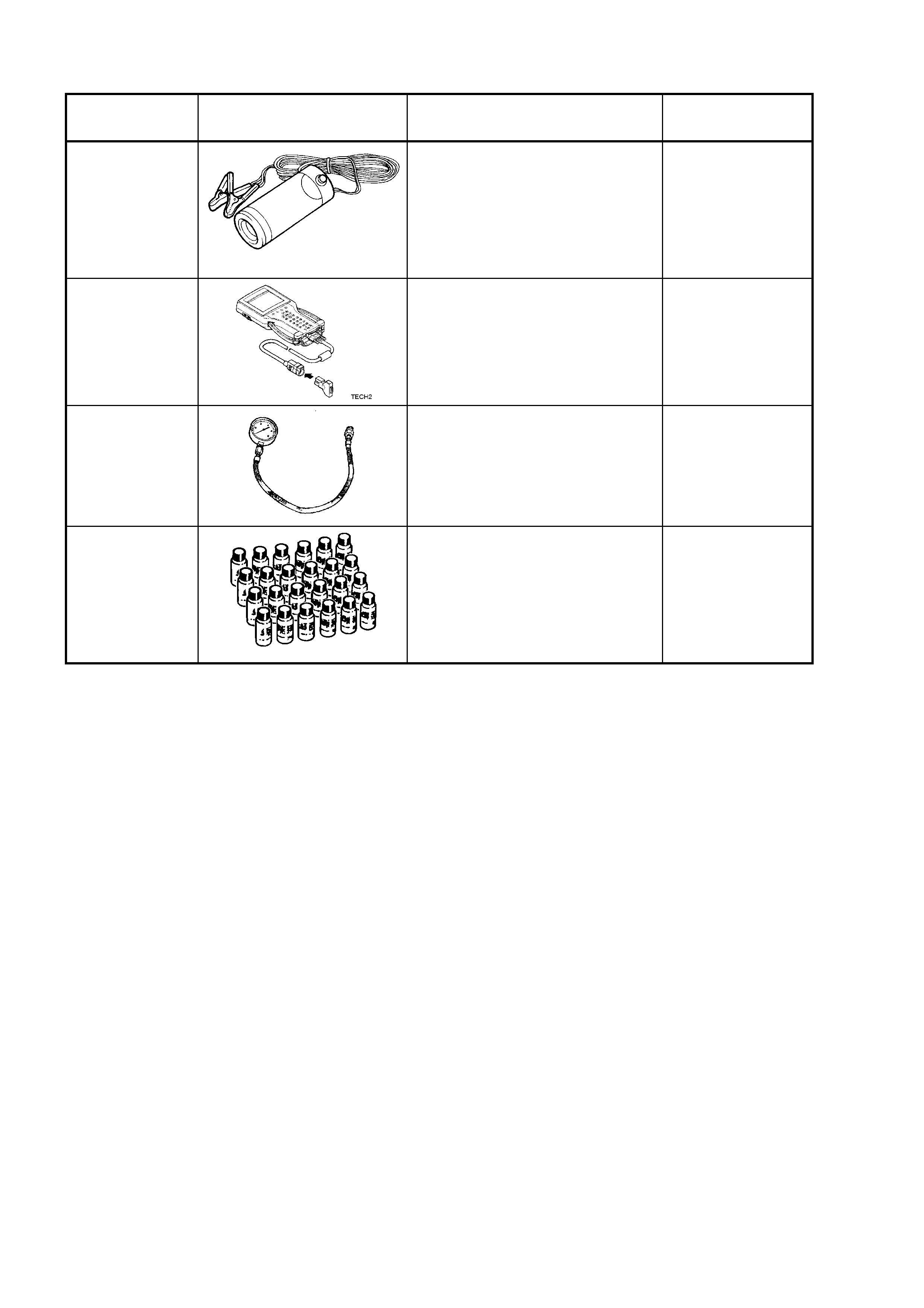
6. SPECIAL TOOLS
TOOL
NUMBER ILLUSTRATION DESCRIPTION CLASSIFICATION
16296 12 VOLT BLACK LIGHT
Used with special, fluorescent
dyes for tracing a variety of fluid
leaks.
Also previously releas ed as
J42220.
Desirable
70000861
TECH 2 DIAGNOSTIC TOOL
Previously released.
Mandatory
J21867
PRESSURE GAUGE AND HOSE
ASSEMBLY
Previously released.
Mandatory
J28431-B
FLUORESCENT OIL DYE
Supplied in packs of 24, 1 oz
bottles. Suitable for black light
tracing of engine, transmission
and power steering fluid leaks.
Previously released.
Desirable