
SECTION 7C4 - HYD RA-MATIC 4L60-E AUTOM ATIC
TRANSMISSION – ON-VEHICLE SERVICING
IMPORTANT
Before performing any Service Operation or other procedure descri bed in this Section, refer to Section 00
CAUTIONS AND NOTES for correct workshop practices with regard to safety and/or property damage.
CONTENTS
1. GENERAL INFORMATION
1.1 GENERAL SERVICE PRECAUTIONS
RECOMMENDATIONS
OIL COOLER PIPES
2. MAINTENANCE AND GENERAL INFORMATION
2.1 FLUID LEVEL CHECK
GENERAL INFORMATION
TRANSMISSION FLUID COLOUR
TRANSMISSION FLUID CHECKING
PROCEDURE
2.2 TRANSMISSION COOLER REVERSE FLUSH
AND FLOW RATE CHECK – ALL
REVERSE FLUSH
FLOW RATE CHECK
3. ON-VEHICLE SERVICE OPERATIONS
3.1 FLUID CHANGE & FILTER REPLACE
3.2 SELECTOR LINKAGE
REMOVE
INSPECT
REINSTALL
ADJUST
3.3 SELECTOR CONTROL LEVER ASSEMBLY
REMOVE
DISASSEMBLE
REASSEMBLE
REINSTALL
3.4 NEUTRAL START AND BACK-UP LAMP SWITCH
REMOVE
REINSTALL
ADJUST
3.5 VEHICLE SPEED SENSOR
REMOVE
REINSTALL
3.6 MANUAL SHAFT OIL SEAL
REPLACE
3.7 CASE EXTENSION OIL SEAL
REPLACE
3.8 EXTENSION HOUSING AND/OR BUSH
REPLACE
3.9 1–2 ACCUMULATOR ASSEMBLY
REMOVE
CLEAN AND INSPECT
REINSTALL
3.10 CONTROL VALVE BODY WIRING HARNESS
REMOVE
REINSTALL
3.11 CONTROL VALVE BODY
REMOVE
DISASSEMBLE, CLEAN, INSPECT AND
REASSEMBLE
REINSTALL
3.12 SPACER PLATE, CHECK BALLS, FILTER
SCREENS AND 3-4 ACCUMULATOR
REMOVE
CLEAN AND INSPECT
REINSTALL
3.13 FILLER TUBE
REPLACE
3.14 TRANSMISSION ASSEMBLY
REMOVE
REINSTALL
3.15 TRANSMISSION COOLER PIPES
V6 ENGINES – REMOVE
V6 ENGINES – REINSTALL
GEN III V8 ENGINE – REMOVE
GEN III V8 ENGINE – REINSTALL
4. SPECIFICATIONS
5. TORQUE WRENCH SPECIFICATIONS
6. SPECIAL TOOLS
Techline
Techline
Techline

1. GENERAL INFORMATION
As detailed in 7C1, material contained within this Section, details service operations that can be carried out on a
transmission while it is still installed in the vehicle. In addition, the procedures required to remove and reinstall the
transmission assembly from/to the vehicle are also detailed.
General servicing information is also included in this Section and it is recommended that this material be read and
followed, whenever servicing operations are to be carried out on this transmission.
Dependent on vehicle specifications for different markets, the gearshift selector mechanism may be fitted with a
Brake Transmission Selector Interlock (BTSI) device that is colloquially referred to as “Bitsi”. Refer to
Section 7C1 GENERAL INFORMATION for a description of this device and its operation. Within this Section, the
service procedures for both selector types are described.
1.1 GENERAL SERVICE PRECAUTIONS
RECOMMENDATIONS
When servicing the transmission, all parts should be cleaned and inspected as outlined under 'Clean and Inspect',
in these recommendations. Individual units should be reassembled before disassembly of other units to avoid
confusion and interchanging of parts.
1. Thoroughly clean the transmission exterior before removal of any component.
2. Disassembly and reassembly must be made on a clean work bench. Cleanliness is of the utmost importance.
The bench tools, and parts must be kept clean at all times.
3. Before installing screws and other fasteners into aluminium parts, DIP SCREWS INTO TRANSMISSION FLUID
(Only use Dexron III) to prevent galling aluminium threads and to prevent screws from seizing.
4. To prevent thread stripping, always use a torque wrench when installing screws.
5. If threads in aluminium parts are stripped or damaged, the part can be made serviceable by the use of
commercially available, thread inserts.
6. Protective tools must be used when assembling seals to prevent damage. The slightest flaw in the sealing
surface of the seal can cause an oil leak.
7. Aluminium castings and valve parts are very susceptible to nicks, burrs, etc., and should be handled with care.
8. Internal snap rings should be expanded and external snap rings compressed if they are to be re-used. This will
ensure proper seating when reinstalled.
9. O-rings, gaskets and oil seals that are removed should not be re-used.
10. Teflon oil seal rings should not be removed unless damaged.
11. During assembly of each unit, all internal moving parts must be lubricated with transmission fluid.
OIL COOLER PIPES
Should any transmission fluid cooling pipe suffer accidental damage, then a genuine replacement pipe must be
fitted. Refer to the current release of PartFinder® to determine the correct part number for the particular engine
and pipe involved. Reworking of damaged pipes or hand made replacements are not permitted.
Clean And Inspect
After complete disassembly of a component, wash all metal parts in a clean solvent and dry with compressed air.
Blow oil passages out and check to make sure they are not obstructed. Small passages should be checked with tag
wire. All parts should be inspected to determine which parts are to be replaced.
Pay particular attention to the following:
1. Inspect linkage and pivot points for excessive wear.
2. Bearing and thrust surfaces of all parts should be checked for excessive wear and scoring.
3. Check for broken seal rings, damaged ring lands and damaged threads.
4. Inspect seal and O-rings.
5. Mating surf aces of cas tings should be chec ked for burrs . Irregularities m ay be rem oved by lapp ing the surf ace
with emery paper. The emery paper is laid on a flat surface, such as a piece of plate glass.
6. Castings should be checked for cracks and porosity.
NOTE: Do not use solvents on neoprene seals, composition faced clutch plates or thrust washers as damage to
parts may occur.

2. MAINTENANCE AND GENERAL INFORMATION
2.1 FLUID LEVEL CHECK
GENERAL INFORMATION
W hen adding or c ha ng ing t he tr ansmiss ion f luid, use o nly Dexron® III a utomatic trans miss ion fluid. Ref er to t he M Y
2003 VY and V2 Series Owner's Handbook for servicing intervals.
Because th is transm ission flui d changes c olour and de velops an o dour ver y earl y in its life, thes e indicat ors shou ld
not necessarily be relied upon to diagnose either transmission internal condition nor fluid deterioration.
If, when following the Fluid Checking Procedure, a dark brown fluid colour is observed, coupled with a reported
delayed shift pattern, this may only indicate that the fluid requires replacement and alone, is not a definite indication
of a potential transmission failure.
NOTE: Do not o verfill th e trans miss ion. Overfillin g will cause f oaming of the fluid, loss of fluid, s hift com plaints and
possible damage to the transmission.
TRANSMISSION FLUID COLOUR
Transmission fluid colour when new and unused, is red. A red dye is added so that it can be distinguished from
other oils and lubricants. The red dye is not an indicator of fluid quality and is not permanent. As the vehicle is
driven, the transmission fluid will quickly begin to look darker in colour. The colour will then appear light brown. A
DARK brown colour with a distinctively burnt odour MAY indicate fluid deterioration and a need for the fluid to be
changed.
TRANSMISSION FLUID CHECKING PROCEDURE
1. Start engine and drive vehicle for a distance of 24 km, or until transmission normal operating temperature is
reached.
NOTE: As temperature greatly affects transmission fluid levels, this operation must only be carried out with the
transmission at normal operating temperature (82° – 94° C). If the vehicle is not at normal operating temperature,
and the proper checking procedures are not followed, the result could be a false reading of the fluid level on the
dipstick.
2. Park vehicle on a level surface.
3. With the engine idlin g and t he foot brak e f irml y applied , m ove th e gear s elec tor l ever thr ough each gear r ang e,
pausing for about 3 seconds in each selected range. Finally, select the 'PARK' position.
4. Apply park brake.
5. Let engine idle for 3 minutes with accessories turned off.
6. Lift the locking lever on the red coloured dipstick indicator, remove dipstick, wipe clean, then reinsert into the
indicator tu be. W ait 3 seconds, then remove the le ver once again. Check the level of fluid on each side of the
indicator. The fluid level should be between the cross hatched, 'HOT' indicator section.
7. If the fluid level is low, add only enough Dexron® III to bring the level into the “HOT” area.
IMPORTANT: Inac curate f luid le vel readin gs will r esult if check ed imm ediately aft er the vehic le has been o perated
under any or all of the following conditions:
a. In high ambient temperatures above 32° C.
b. At sustained high speeds.
c. In heavy city traffic during hot weather.
d. Towing.
e. In commercial use (e.g. taxi).
If the vehicle has been operated under the above conditions, switch the engine off and allow the vehicle to
'cool' for approxim atel y thirty m inutes. Af ter the cool- down per iod, re- start the v ehic le and contin ue f rom s tep 2,
above.

4L60-E TRANSMISSION FLUID CHECKING PROCEDURE
STEP ACTION YES NO
1. 1. Check the fluid colo ur.
Is the fluid colour red? Go to Step 5 Go to Step 2
2. Is the fluid a non-transparent pink in colour? Go to Step 13 Go to Step 3
3. NOTE: Fluid may turn a dark brown from normal use. This colour does
not always indicate an oxidation or a contamination concern.
Is the fluid a light brown in colour?
Go to Step 6 Go to Step 4
4. Is the fluid black in colour and/or have a "burnt" smell? Go to Step 15 Go to Step 5
5. Does the fluid appear to be 'foamy' or full of bubbles on the dipstick
indicator? Go to Step 13 Go to Step 6
6. 1. Check the fluid level as detailed in Steps 1 to 6 above.
Is the fluid level satisfactory? Fluid Check is
Complete Go to Step 7
7. Is the fluid level high on the dipstick indicator? Go to Step 12 Go to Step 8
8. Is the fluid level low on the dipstick indicator? Go to Step 9 –
9. 1. Check for any external leak or leaks. Refer to 2.11 Fluid Leak
Diagnosis and Repair, in 7C3 A/T HYDRAULIC/MECHANICAL
DIAGNOSIS.
Were any external leak or leaks found?
Go to Step 10 Go to Step 11
10. 1. Correct any leak or leaks, as required?
Is the action complete? Go to Step 11 Go to Step 9
11. 1. Add Dexron® III transmission fluid until the level is in the middle of
the cross-hatched area on the dipstick indicator.
Is the level OK?
Fluid Check is
Complete –
12. 1. Remove excess fluid via the dipstick tube, using commercially
available pumping equipment.
Is the level now correct?
Go to Step 20 –
13. 1. With both transmission cooler pipes disconnected at the radiator,
pressure test the engine cooling system (refer to ENGINE
COOLING (6B1 – V6, 6B2–- V6 S/C, 6B3 – GEN III V8).
2. Check if engine coolant lea ks f rom the fluid co oler pip e fitt ing s.
Does engine coolant leak from the cooler pipe fittings?
Go to Step 14 Go to Step 17
14. 1. Replace the radiator (transmission cooler is not serviced
separately).
2. Refer to information contained in 2.10 Engine Coolant in
Transmission, in 7C3 A/T HYDRAULIC/MECHANICAL
DIAGNOSIS.
Are the actions complete?
Go to Step 16 –
15. IMPORTANT: A small amount of friction material in the oil pan is a
'normal' condition but large pieces and/or metal particles indicate that a
co mplete transmission overhaul is requi red.
1. Remove transmission oil pan, drain fluid and inspect oil pan residue
and magnet.
Is there a sign or signs of internal transmission damage found in the
bottom of the oil pan?
Go to Step 18 Go to Step 16
16. 1. Reverse flush the oil cooler and lines. Refer to 2.2 Transmission
Reverse Flush and Flow Rate Check, in this Section.
Is action complete?
Go to Step 17 –
17. 1. Replace the transmission fluid filter and fluid.
Is the replacement complete? Go to Step 20 –
18. 1. Overhaul the transmission or fit a SRTA unit. Refer to 7C5 UNIT
REPAIR and/or 3.14 Transmission Assembly, Remove/Reinstall in
this Section.
Is action complete?
Go to Step 19 –
19. 1. Add new Dexron® transmission fluid.
Is action complete? Go to Step 20 –
20. 1. Is the fluid level satisfactory? If not, correct as necessary.
Is action complete? Fluid Check is
Complete –

2.2 TRANSMISSION COOLER REVERSE FLUSH AND FLOW RATE CHECK – ALL
LT SECTION NO. – 04A-200
IMPORTANT: It is essential that a reverse flush and oil cooler flow rate check is performed, after ANY of the
following situations:
• Transmission is replaced.
• Fluid contamination is suspected.
• Whenever the oil pump and/or torque converter is replaced.
NOTE: The reverse flush must be completed prior to conducting a flow rate check.
REVERSE FLUSH
The recommended procedure for reverse flushing the transmission cooler and lines, particularly after an
overhauled or replaced transmission has been installed into the vehicle, is as follows:
1. Dis connect both c ool er lin es at t he transm iss ion and at th e radiat or coo ler en d. R efer to 3 .15 TR ANSM ISSI ON
COOLER PIPES/HOSES, in this Section. Do not lose the pipe to fitting sealing washer, when the pipe is
removed.
2. Car efull y check the coo ler inlet f ittin g (lo wer) to s ee whether an y material is evi dent at this point. If s o, dislo dge
and remove with a suitable tool and/or compressed air blown in the reverse direction through the cooler.
3. Using a commercially available pressure spray gun and clean solvent, such as white spirit:
a. Back flush through both cooler lines.
b. Back flush through the cooler, including an external cooler (if fitted).
c. Blow compressed air through return and inlet pipes to remove solvent.
d. Flush pipes with transmission fluid.
4. Check the cooler pipe to cooler fitting, sealing washers for damage, replacing as required.
5. Reconnect cooler lines to the transmission and cooler but leave the cooler return line to transmission
connection ope n.
6. Conduct a flow rate test as described below, to ensure that any restriction has been cleared.
7. If flow rate is satisfactory, reconnect the return line to the transmission quick connect fitting.
8. Tighten the cooler pipe flange buts at the cooler end (V6 engines only) to the specified torque. Refer to
3.15 TRANSMISSION COOLER PIPES/HOSES, Reinstall for the correct procedure.
OIL COOLER PIPE TO
RADIATOR FITTING
TORQUE SPECIFICATION V6 Engines 25 Nm
9. Lower vehicle and check fluid level as detailed in 2.1 FLUID LEVEL CHECK, in this Section.
FLOW RATE CHECK
IMPORTANT: Do not run e ngine an y longer th an abso lutely nec essar y, as too low a fluid le vel can cause aeration
and foaming.
1. When installing the transmission assembly, leave the cooler return line disconnected from the transmission
(upper fitting).
2. Ensure that the fluid level is to the recommended level, as detailed in 2.1 FLUID LEVEL CHECK, in this
Section.
3. Place a container underneath the disconnected cooler line.
4. With the selector lever in the Neutral position, start the engine and observe the fluid flow into the container,
after all air bubbles have ceased and a steady flow is evident. Measure the flow rate.
Result: The fluid flow rate should be approximately 0.7 litre in a 20 second period, with cold automatic transmission
fluid (ATF). With ATF at normal operating temperature (86 – 93° C), the flow rate will increase and should be
approximately 1.2 litres in a 20 second period.
If the f low rate is l ess than this specif icati on, the s ourc e of the r estric tion m us t be locate d and r ectif ied. Pos sibil ities
are either radiator tank cooler, faulty flexible hoses and/or external cooler (if fitted).
5. Reinstall the cooler return line to the transmission quick connect. Refer to 3.15 TRANSMISSION COOLER
PIPES/HOSES, Reinstall for the correct procedure.
Techline
3. ON-VEHICLE SERVICE OPERATIONS
3.1 FLUID CHANGE & FILTER REPLACE
LT Section No. – 04A-220
CAUTION: To avoid personal injury from
accidental hot oil spillage, perform fluid change
only when transmission fluid is cold.
1. Raise front of vehicle and support on safety
stands. Refer to Section 0A GENERAL
INFORMATION in the MY 2003 VY and V2
Series Service Information, for the location of
jacking and support points.
2. Clean all dirt from around oil pan and
transmission case.
3. Place drain tray under transmission.
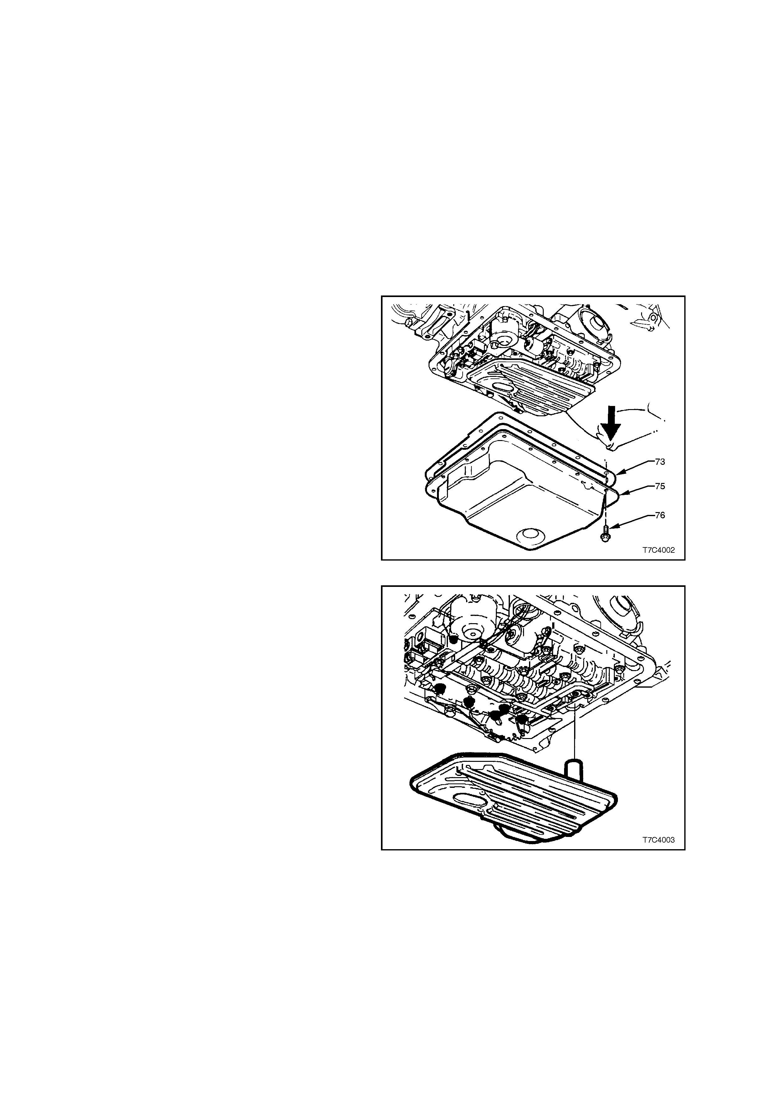
4. Hold oil pan in place and, remove the oil pan
bolts from the front and both sides.
5. Loosen the rear oil pan bolts by about 4 turns
each and, while still supporting the oil pan,
lightly tap the sides with a rubber hammer to
break the gasket seal.
6. Lower the fr ont of the oil p a n and dr a in t he f lui d
into a suitable container, then remove the oil
pan from the transmission.
Figure 7C4-1
7. At the same time, pull down and twist the filter
to remove it from the transmission case.
8. Open the filter by prying the metal crimping
away from the top of the filter and pull apart.
Inspect the filter material for particles that m ay
indicate evidence of a potential transmission
problem. Examples of the type of material to
look for, are;
– Clutch friction material.
– Bronze slivers , ind icating bush wear .
– Steel particles.
Figure 7C4-2
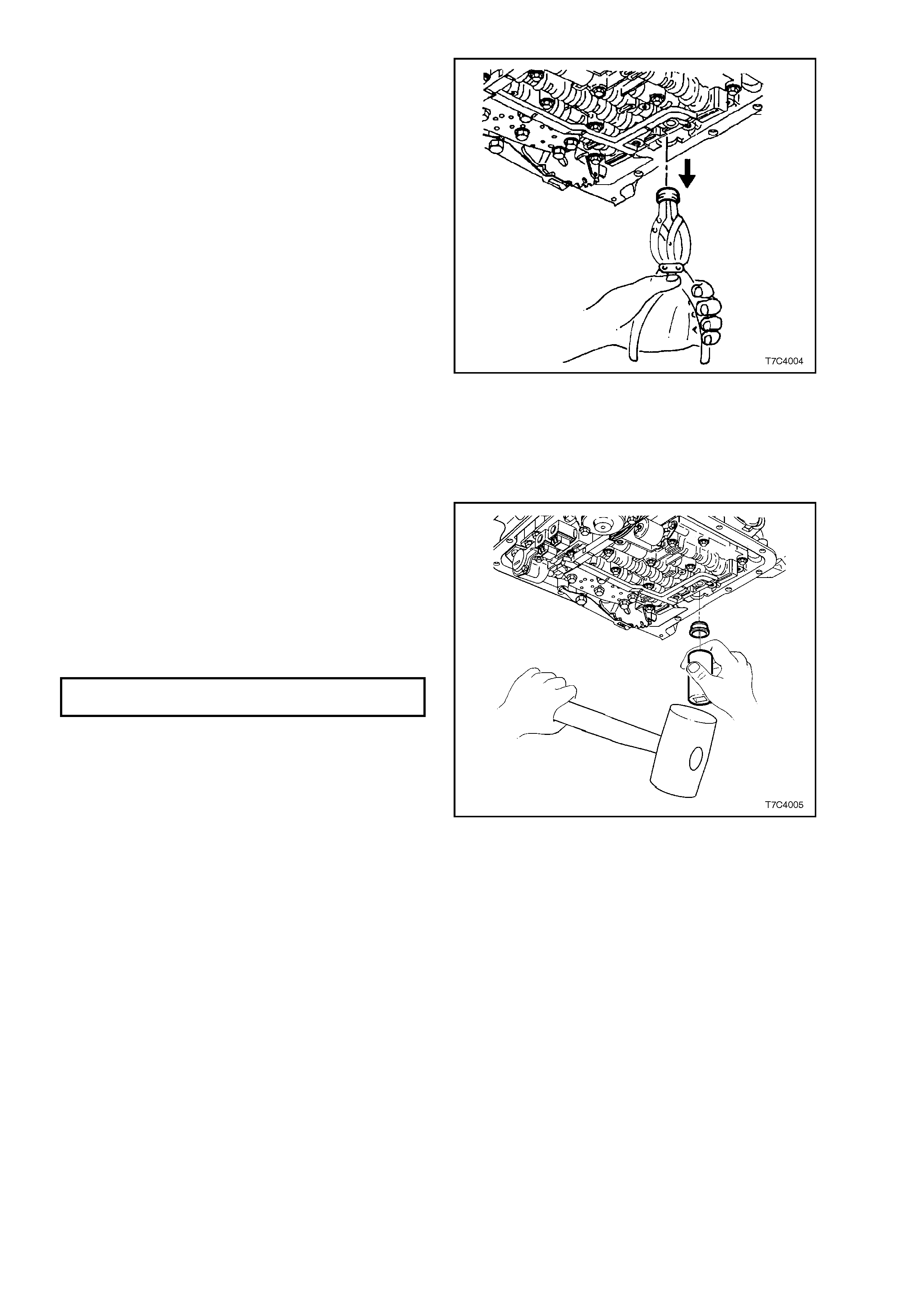
9. Using suitable circlip pliers or a two legged
puller and s lide ham m er, r em ove the f ilter s eal.
Take care not to scratch the oil pump bore
during the process.
NOTE: If the seal bore is scratched, fluid leakage
could occur from this point, once the vehicle has
been put back into service.
Figure 7C4-3
9. Remove old oil pan gasket and discard.
10. Clean the transmission case, oil pan and oil
pan gasket surface, drying with compressed
air. Ensur e that all traces of the old gasket are
removed.
11. Lubricate a new filter seal with petroleum jelly
(Vaseline™ or equivalent) and install into the
oil pum p bore, using a suit able sized sock et or
piece of tubing.
12. Install a new filter into the transmission case.
13. Check that the magnet is functional and
located in the designated position in the oil
pan. Install new gasket and reinstall oil pan.
Tighten bolts to specified torque.
OIL PAN BOLT
TORQUE SPECIFICATION 12 Nm
14. Lower vehicle and add approximately 4.8 litres
(V6 engine) or 5.0 litres (GEN III V8 engine) of
Dexron III automatic transmission fluid.
15. Operate the vehicle for about 24 km or until
normal operating temperatures are reached.
Check that there are no fluid leaks from the oil
pan area.
16. Check tr ansmission f luid leve l, refer 2.1 F LUID
LEVEL CHECK in this Section.
Figure 7C4-4

3.2 SELECTOR LINKAGE
LT Section No. – 04A-170
REMOVE
1. Set transmission selector lever to the 'PARK'
position.
2. Raise front of vehicle and place on safety
stands Refer to Section 0A GENERAL
INFORMATION in the MY 2003 VY and V2
Series Service Information for the location of
the recommended jacking and support points.
3. Remove locking b olt ( 1), dis hed wash er ( 2) , f lat
washer (3), insulator (4) and sleeve (5) from
lower end of selector lever (9).
4. Slide trunnion (6) from selector rod (7).
5. While holding the transmission selector lever
with an adjustable wrench, remove retaining
nut (8), rod and lever assembly (7) from
transmission manual shaft.
INSPECT
Check all items for wear and/or damage, replace
all worn or dam aged items.
REINST ALL
Reinstallation is the reverse of the removal
procedure, except for:
1. Tighten the selector lever retaining nut (8) and
the selector lever locking bolt (1), to the
specified torque settings.
MANUAL SHAFT LEVER NUT
TORQUE SPECIFICATION 25 Nm
SELECTOR LEVER
LOCKING BOLT
TORQUE SPECIFICATION 25 Nm
2. Adjust linkage as described below.
Figure 7C4-5
ADJUST
Refer to Figure 7C4-5.
1. Loosen locking bolt (1) at selector lever (9).
2. Position transmission selector lever in the
'PARK' position.
3. Position gearshift lever in the 'PARK' position,
then tighten the locking bolt at the selector
lever, to the specified torque.
SELECTOR LEVER
LOCKING BOLT
TORQUE SPECIFICATION 25 Nm
4. Lower vehicle and test that the vehicle
operates correctly.
5. Ensure that engine can be started only in
'PARK' and 'NEUTRAL'. If required, adjust the
Neutral Start and Back-Up Lamp switch. Refer
3.4 NEUTRAL START AND BACK-UP LAMP
SWITCH, in this Section.
3.3 SELECTOR CONTROL LEVER ASSEMBLY
LT Section No. – 04A-190
REMOVE
1. Raise vehicle and place on safety stands.
Refer Section 0A GENERAL INFORMATION
in the MY 2003 VY and V2 Series Service
Information for the location of recommended
jacking and support points.
2. Remove floor console cover, lower extension
side trim panels and the floor console
assembly. Refer Section 1A3 INSTRUMENT
PANEL & CONSOLE, in the MY 2003 VY and
V2 Series Service Information.
3. Disconnect the wiring harness connector from
the selector patch harness.
4. From beneath the vehicle, disconnect the
selector rod and trunnion from the selector
lever. Refer 3.2 SELECTOR LINKAGE, in this
Section.
5. Remove the four nuts securing the selector
lever assembly to the floor pan.
6. From inside the vehicle, lift the selector lever
assembly from the floor pan.
Figure 7C4-6
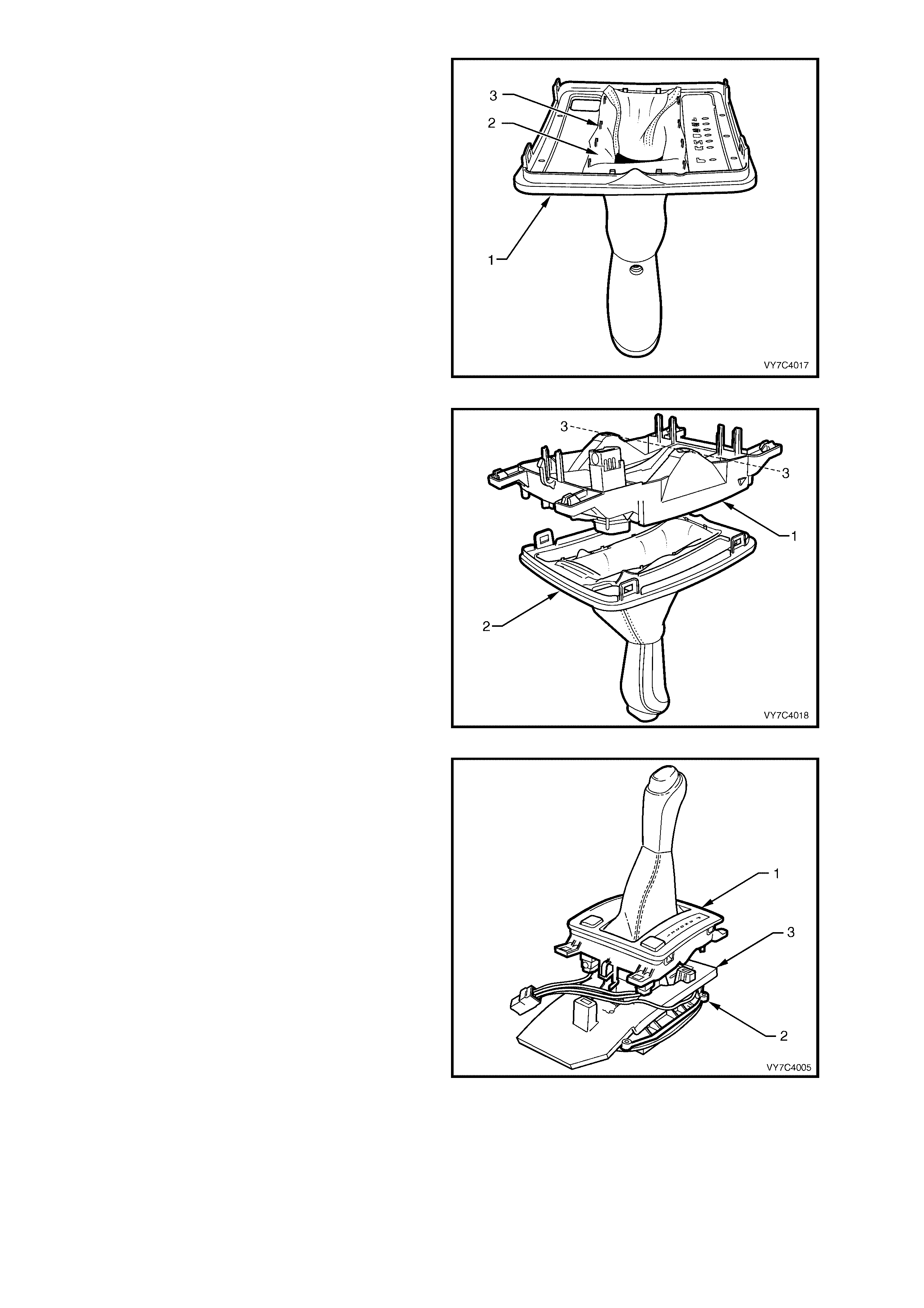
DISASSEMBLE
NOTE 1: Unless specifically noted, the following
procedures can be used for either design of
selector lever assembly.
NOTE 2: W hile most views show the RHD version
of the selector control lever assembly, LHD
procedures can be assumed to be the same
unless otherwise noted.
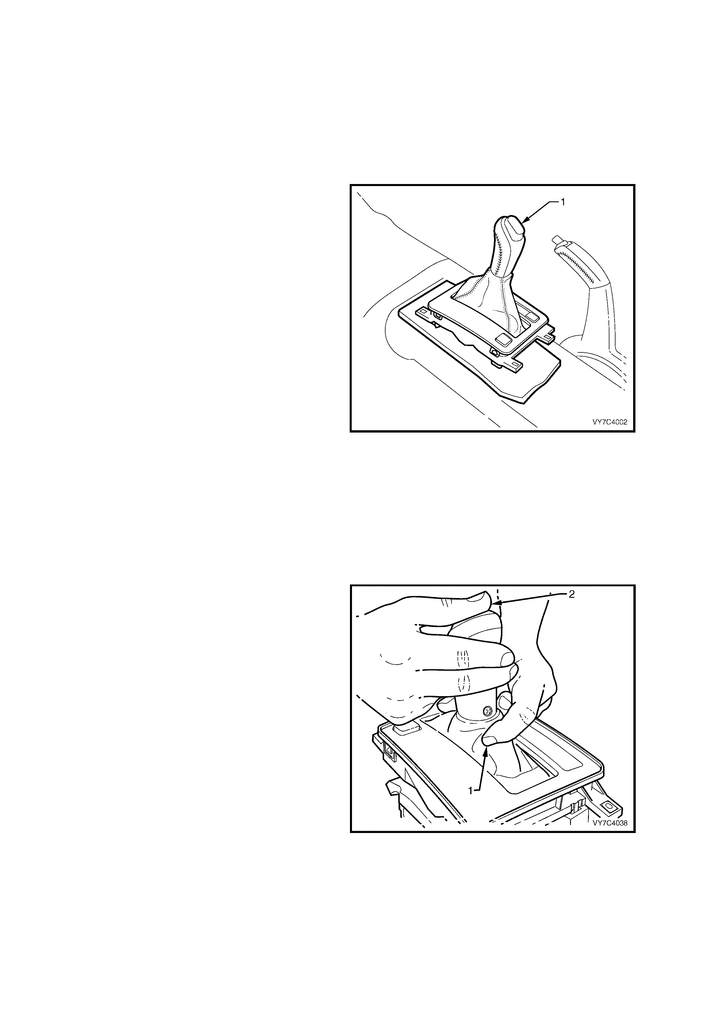
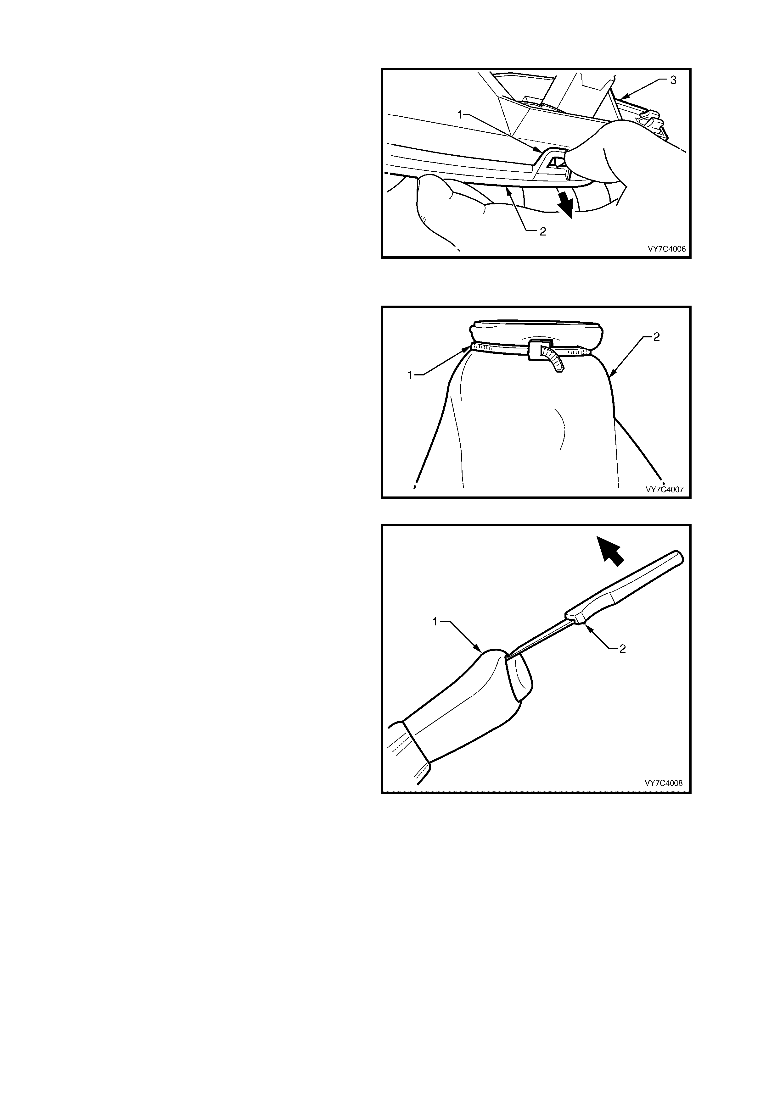
1. If the selector control lever assembly is of the
BTSI design, manually release the interlock
mechanism, as follows:
a. First, press inwards at the front of the
selector le ver, jus t be low th e gear shif t k nob, as
shown (1).
b. Then, while still pressing inward (1), depress
the selector knob with the other hand (2) and
move the lever from the Park position and into
‘D’ Driv e.
NOTE: This is the recommended reassembly
position.
Figure 7C4-7
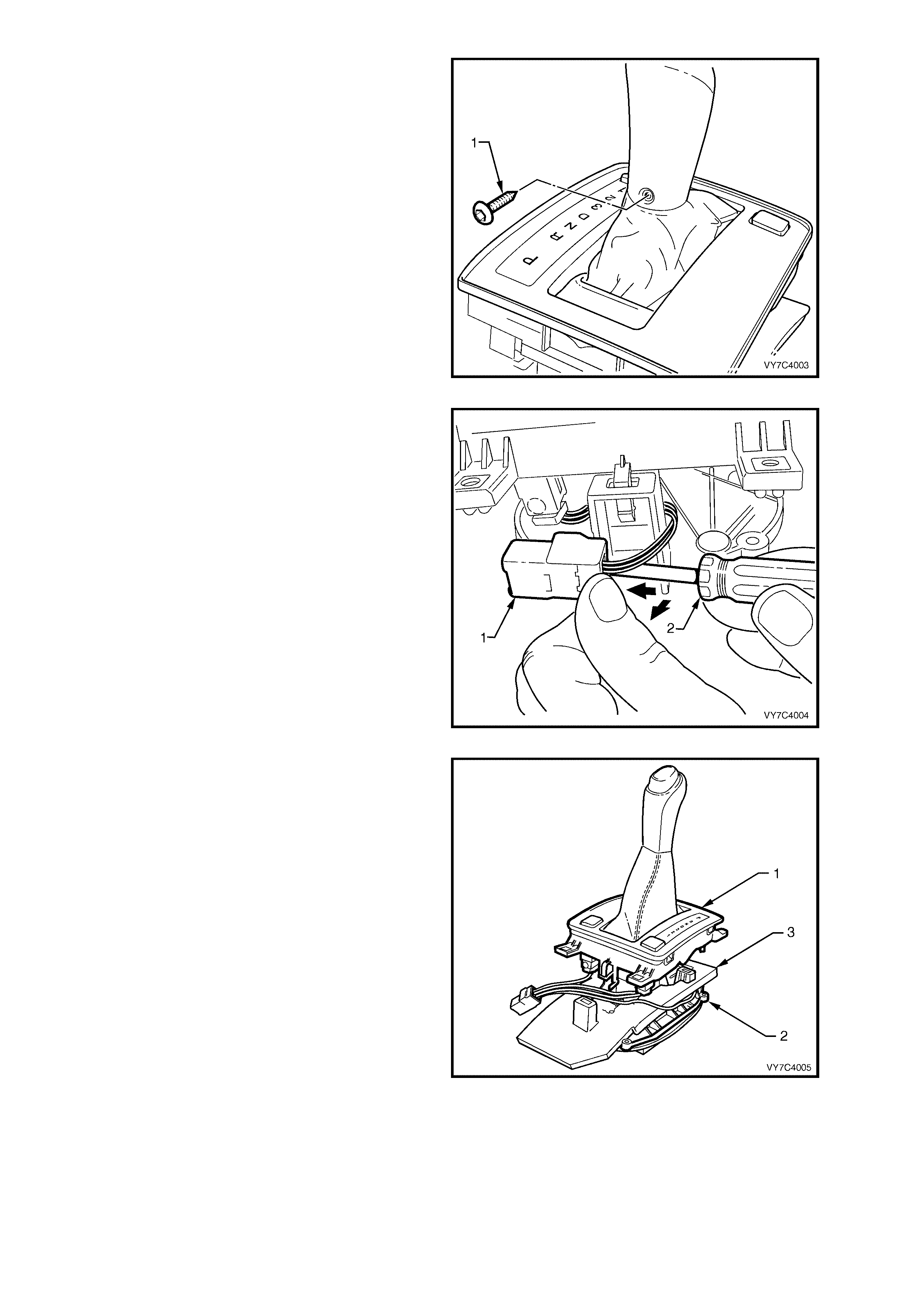
2. Using a commercially available Torx Plus
(TX20) and suitable equipment, remove the
self tapping screw (1). Select ‘D’ Drive.
Figure 7C4-8
3. Using a sm all screwdr iver (2), pris e the locking
tab on the wiring harness connector (1) at the
rear of the shift selector assembly, while
pushing away from the lower housing, as
shown.
NOTE: This operation is optional with the BTSI
shifter, as:
a. The patch harness can be disconnected at the
micro switch and the solenoid (in which case,
step 3 is required).
OR
b. Following separation of the lower housing and
the base (see step 4), the wiring harness
connectors could be removed from the ‘PWR’
and ‘T/C’ (if fitted) switches, leaving the
harness with the base (step 3 not being
required).
Figure 7C4-9
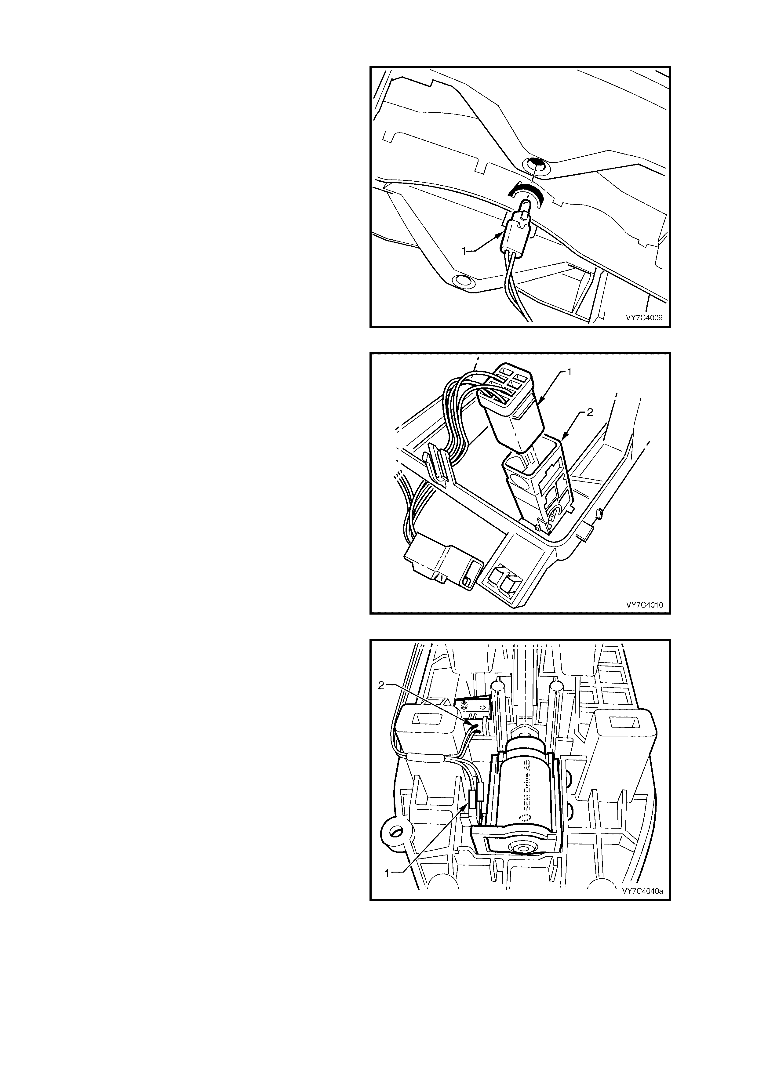
4. With the wiring harness connector free,
disconn ect the lower hous ing f rom the base (1)
by pressing the tangs on each of the retaining
legs (two front, one rear).
5. Lift the lower housing (1) from the base (2),
together with the switch/es, patch wiring
harness, boot and shift lever knob. Set the
assembly to one side.
NOTE: With the BTSI shifter, when the patch
harness is left behind (choice ‘b’ in step 3), the
removed components will be; the lower housing
(1), together with the s witc h/es, boot and s hift l ever
knob.
6. As required, lift the insulator (3) from the base
(2) and set to one side.
Figure 7C4-10
NOTE: With the shift lever assembly now
separate d, selec t fr om the follo wing choic es f or the
service operation/s required.
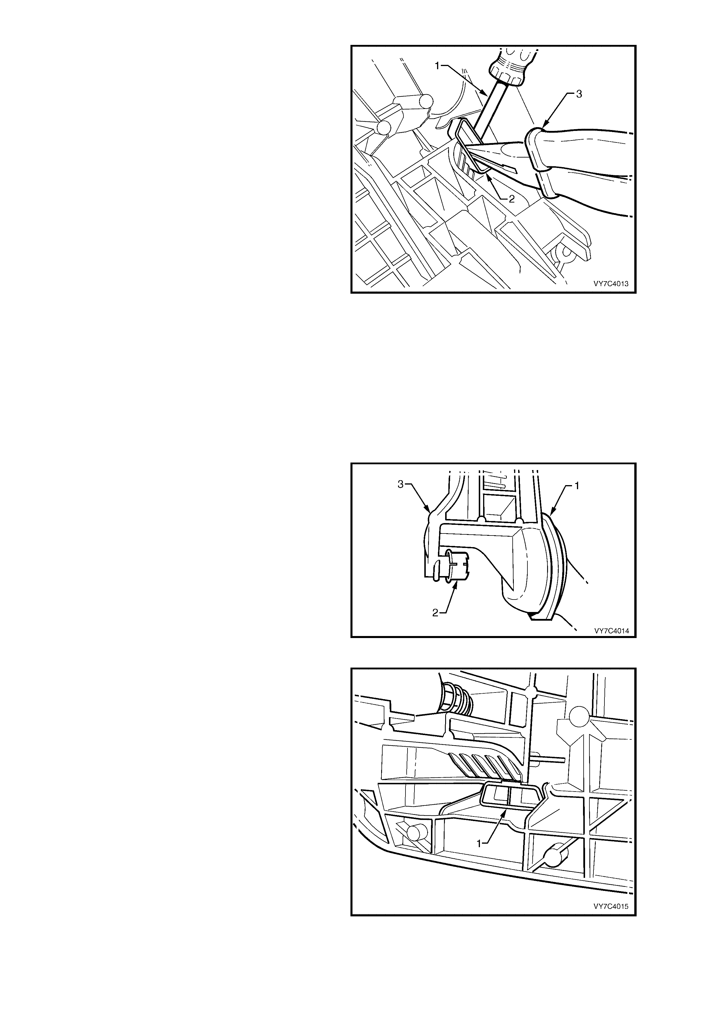
Boot, Shift Lever Knob Remove
7. W hile holding the lower housing in an inverted
position, gently prise each of the four securing
lugs (1) to free the cover (2) from the lower
housing (3). Lift the lower housing (3) from the
gearshift selector knob, boot and upper cover
assembly (2) and set to one side.
NOTE: If the lower housing assembly is not
inverted before separation, then the boot will
probabl y becom e dis lodged from the locati ng tangs
in the upper cover.
8. If boot replacement is required, free the boot
from the upper cov er loc at i ng ta ngs an d set th e
cover t o one si de, being caref ul not to dis lodge
nor damage the PRNDL indicator lens in the
process.
Figure 7C4-11
9. Turn the boot (2) inside out, over the gearshift
selector knob, then cut the plastic tie (1)
securing the boot to the knob. Remove the
boot from the gearshift lever knob and discard.
NOTE: The plastic tie is a unique design and is
markedly different from the usual cable tie.
Figure 7C4-12
10. If the gearshift knob needs to be dismantled,
use a small knife (2) or similar to free the lugs
securing the control rod button from the
gearshift knob (1).
IMPORTANT: The knob is spring loaded and may
fly free once dislodged.
11. Remove the two Phillips head self tapping
screws, (located under the control rod button),
then separate the knob components.
Figure 7C4-13
Patch Harness Removal
12. Remove th e selector indicator lam p and holder
from the switch housing by turning the lamp
holder 90° to the left (counter-clockwise), then
pull.
Figure 7C4-14
13. If not removed previously (step 3), release the
switch connector retaining lug/s, then remove
the connector/s.
NOTE: W hile each s witch patch h arness conn ector
is the same colour (white), the Traction Control
(“T/C”) switch (when fitted) connector wiring is
taped to the PRNDL indicator lamp wiring, as this
switch will always be on the same side as this
lamp. This situation remains the same for both
RHD and LHD vehicles.
Figure 7C4-15
14. If the shift lever assembly is of the BTSI
design, remove the patch harness wiring
connectors from the soleno id (1) and the m icro
switch (2), taking note of the patch harness
routing, for correct reinstallation.
15. Remove the patch harness and set to one side.
Figure 7C4-16
Switch Removal
NOTE: For this operation, the cover must be split
from the lower housing. Refer to Step 4 in this
procedure.
16. To remove the PWR and/or T/C switch (if
fitted), use a small bladed screwdriver and
lever one of the switch retaining tangs from
under the lower housing to free the particular
switch, cock to one side, release the second
tang and then remove the switch from above.
IMPORTANT: Take note of the locating lug on the
switch body that ensures the correct orientation of
the switch when reinstalled.
Figure 7C4-17
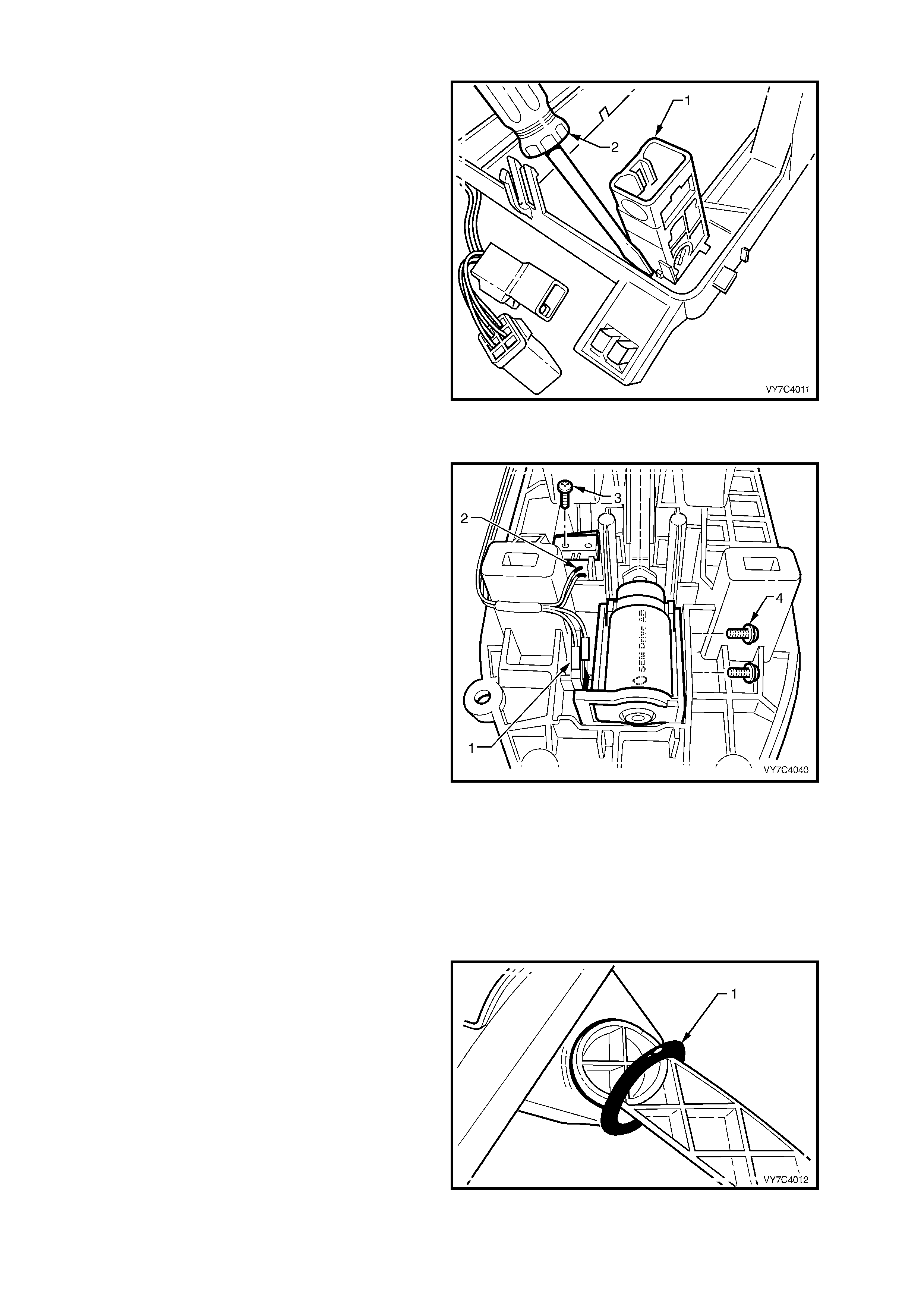
BTSI Solenoid and/or Micro Switch
17. With the lower cover separated from the base,
lift the insulator back and over the shift lever.
18. With the patch harness connectors (2 and 1)
removed from the solenoid, remove the two
Phillips headed screws (4) securing the
solenoid or the single self tapping screw (3)
from the micro switch.
19. Remove the solenoid and/or micro switch from
the BTSI base.
Figure 7C4-18
Base Disassemb l y
20. If not rem oved previousl y, rem ove the shif t rod
trunnion bolt from the lower end of the shift
lever arm. Slide the trunnion from the arm,
then remove the ins u lat in g grom met.
NOTE: This is necessary to provide clearance for
the lever to be removed from the lower housing.
21. Remove the external seal (1) from the lever
arm and set to one side.
Figure 7C4-19
22. To rem ove the le ver lock ing piece, use a sm all
screwdriver (1) to lever the locking tang free
while pulling on the locking piece (2) with long
nosed pliers (3).
23. Push the lever assembly inwards to release the
inner support pin and bush
NOTE: The bush will probably remain in the lower
housing.
24. Lift the shift lever from the lower housing.
NOTE: W hile it will be nec es sar y to manoeuvr e the
lever somewhat, sufficient space is provided to
overcome any need to apply force to the lever
assembly.
Figure 7C4-20
Lever Disassembly
Regardless of the shift lever type, further
disassembly is not recommended, as there is a very
real possibility that, during reinstallation of the roll
pin, the shift lever will be cracked, unless
sophisticated jigs are used. For this reason, the shift
lever is only serviced as an assembly.
REASSEMBLE
Base Reassembly
1. Inspect the ext ernal lever, inner bushing (1) f or
damage, replacing as required. Lubricate with
a multi-purpose chassis grease such as NLGI
No. 1 Lithium grease.
2. Reinstall the split inner support bush (2) to the
selector lever pin, aligning the split in the bush
with the k ey on the selector lever pin. Lubr icat e
the external bush surface with a multi-purpose
chassis grease such as NLGI No. 1 Lithium
grease.
3. Reinstall the selector lever assembly (3), into
the base. Align the small bush with the
aperture in the base then push across to fully
install the lever.
Figure 7C4-21
4. Reinstal l the lever lock ing piece (1) , using long
nosed pliers. Correct reinstallation will have
occurred when an audible click is heard,
indicating that the tang on the locking piece
has been installed correctly.
NOTE: While a standard shift lever is shown, the
reinstallation is the same for the BTSI design.
Figure 7C4-22
5. Appl y a sm ear of multi-pur pose chassis grease
such as NLGI No. 1 Lithium grease to the
outer, lipped seal (1), then reinstall over the
external lever.
Figure 7C4-23
BTSI Sole noi d and/or Micr o Switc h
6. Reinstall the solenoid and/or micro switch to
the base, securing with two screws (4) for the
solenoid and/or single self tapping screw (3) for
the micro switch. Do not over-tighten the
screws.
7. Reinstall the patch wiring harness connectors
to the micro switch (2) and/or solenoid (1).
8. Reposition the insulating foam into position.
NOTE: No adjustment is required for the BTSI
solenoid.
Figure 7C4-24
Lower Housing
9. If removed, reinstall the switch/es to the lower
housing, ensuring that the locating lug on the
switch body engages with the slot in the lower
housing. If the vehicl e is equipped with tract ion
control, the c orrec t loc ation fo r this s witc h, is in
the right hand aperture for RHD vehicles (the
opposite side for LHD vehicles). This will
always be behind the PRNDL indicator lens.
10. Reinstall the patch wiring harness, ensuring
that the switch connector/s connection is
correct. Also reinstall the PRNDL lamp and
holder, by inserting and turning the holder a
quarter turn to the left (counter-clockwise).
If of the BTSI design, it is recommended that
the patch harness be reinstalled to the
solenoid and micro switch first, then to the
PWR and/or T/C switch (if fitted), prior to
reassembling the lower housing assembly to
the base (refer to Figure 7C4-28). In this
instance, the wiring harness connector should
also be installed to the bracket on the base, at
this time.
11. If a new selector lever boot is to be installed,
use the tie strap included with the new boot to
firmly secure the boot to the gearshift selector
knob. Trim excess length and discard.
12. With the upper cover (1) inverted, locate the
boot (2) over each of the cover locating tangs
(3), working gradually around until every tang
is covered.
NOTE: The weight of the selector knob will be
sufficient to keep the boot engaged with the tangs.
Figure 7C4-25
13. To reduce the possibility of the boot from
becoming dislodged from the upper cover
retaining tangs, reinstall the lower housing (1)
to the cover (2), working in an inverted
position, as shown.
NOTE: Before reassem bling the lower cover to the
base, chec k that the colour ed indictor is in line with
the two PRN DL displa y la mp holes (3). T his will be
the approximate position for correct reassembly.
14. Engage each of the tabs on the upper cover
with the retaining lugs on the lower housing.
When all four tabs have been engaged, the
boot will be clamped and can no longer
become disengaged.
Figure 7C4-26
15. Ensure that the PRNDL indicator slide in the
lower housing, is at the “D” position (the red
colour will sho w oppos ite t he “D ” in the PRN DL
lens).
16. After checking that the insulator (3) is
undamaged, reinstall to the base (2).
17. After checking that the selector lever is also in
the Drive position, reinstall the lower housing
(1) over the shift lever and engage each of the
three legs with the base apertures. Check that
the PRNDL indicator slide pin is engaged with
the slot in the selector lever.
Figure 7C4-27
NOTE: If the shifter is of the BTSI design, before
reassembling to the base, reinstall the patch
harness connector/s (1) to the PWR and/or T/C
switch (if fitted).
18. Reinst all the selec tor indica tor lam p and holder
(2) by inserting, then turn to the right
(clockwise), to secure.
19. Re-engage the selector lever knob with the
selector lever, aligning the control rod with the
hole in the selector knob.
NOTE: Correct engagement of the PRNDL
indicator can be easily checked by moving the
selector lever. Should the coloured portion not
move with the le ver, then engagem ent is incorrect.
Separate the lower housing and base and repeat
steps 13 to 15 above.
IMPORTANT: If the shifter is of the BTSI design,
do not engage the Park position during this testing
process. If this does occur, the interlock will need
to be manually released again (refer to Step 1 of
the Disassemble process).
Figure 7C4-28
20. Reinstall the selector knob retaining screw,
using a TX20 Torx bit and suitable equipment,
being caref ul not to over-tighten.
21. Reinstall the selector lever knob and spring,
pushing down until the two locking tangs
engage.
NOTE: If the selector lever knob and spring have
not been removed, then re-engagement with the
selector lever can still be achieved but some
manoevering may be necessary.
22. If removed, reinstall the wiring harness
connector t o the br ack et at the e nd of the bas e
and push until the looking tang engages.
REINST ALL
1. Clean m ating surf aces of floor pan and ins pect
the base seal for damage, replacing if
necessary.
2. Reinstall selector lever assembly to the floor
pan, install the four retaining nuts (1) and
tighten to the correct torque specification.
SELECTOR BASE RETAINING
NUT TORQUE SPECIFICATION 15 Nm
3. The remainder of the reinstallation is the
reverse of the rem oval pro cedure. As r equired,
refer to Section 1 A3 INSTRUM ENT PANEL &
CONSOLE for the reinstallation procedures of
the floor console assembly, lower extension
side trim panels and floor console cover.
4. Adjust shift linkage as detailed in
3.2 SELECTOR LINKAGE in this Section,
tightening the selector rod locking bolt to the
correct torque specification.
SELECTOR LEVER LOCKING
BOLT TORQUE SPECIFICATION 25 Nm
Figure 7C4-29
3.4 NEUTRAL START AND BACK-UP LAMP SWITCH
LT Section No. – 04A-170
REMOVE
1. Raise front of vehicle and support on safety
stands. Refer to Section 0A GENERAL
INFORMATION in the MY 2003 VY and V2
Series Service Information, for the location of
jacking and support points.
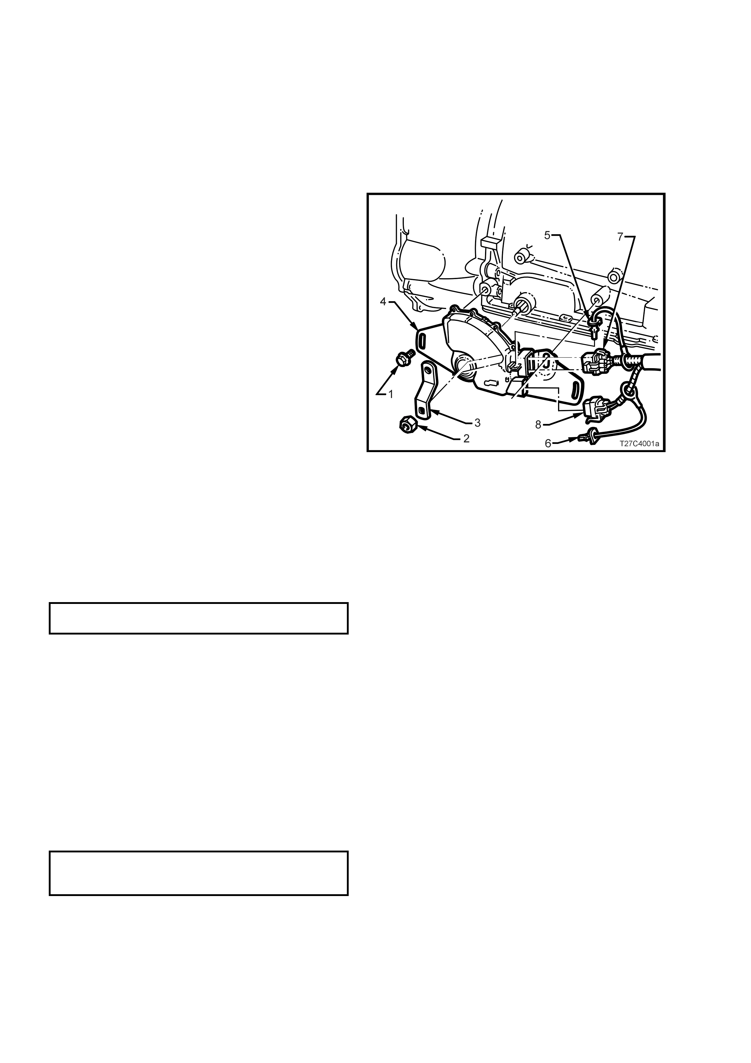
2. While holding the lower selector lever (3) with
an adjustable wrench, remove the retaining
nut (2).
3. Carefully remove the lever (3) from the
transmission manual shaft.
4. Prise the wiring harness connector CPA
(Connector Position Assurance) securing pins
(5 and 6) from the neutral start and back-up
lamp switch (4), taking care not to break the
pins in the process. Disconnect the two wiring
harness connectors (7 and 8) from the switch
assembly (4).
5. Remove the two switch retaining screws (1),
then slide the switch assembly (4) over the
manual shaft and remove from the vehicle.
NOTE: If the GEN III V8 engine is fitted, the front
bolt will also retain the oil cooler pipe support
bracket. If so, carefully bend the bracket clear of
the switch.
Figure 7C4-30
REINST ALL
Reinstallation of the neutral start and back-up lamp switch is the reverse of the removal procedure except for the
following:
1. When reinstalling the two switch securing screws, leave them finger tight, until the adjustment process has
been completed.
2. After reinstalling the selector lever and retaining nut, hold the lever with an adjustable wrench and tighten the
nut to the correct torque specification.
MANUAL SHAFT LEVER NUT
TORQUE SPECIFICATION 25 Nm
3. Reinstall the wiring harness connector/s but do not reinstall the CPA securing pin/s at this stage.
4. Check the selector linkage adjustment. Refer 3.2 SELECT O R LINKAGE, in this Sect ion.
5. On completion of the neutral start and back-up lamp switch adjustment procedure that follows, check that the
engine can only be started when the gearshift lever is either in the ‘P’ (Park) or ‘N’ (Neutral) positions.
ADJUST
1. With the vehicle still raised, rotate the neutral start and back-up lamp switch back and forth until a central
position is attained, then lightly tighten the front bolt to retain.
2. With the ignition switched to the ON position, check that the engine can only be started in both the Park and
Neutral selector positions. A further minor adjustment may be required to achieve this state.
Also check that the Reverse lamps illuminate when Reverse range is selected.
3. After the switch adjustment, tighten the switch retaining screws to the correct torque specification.
NOTE: To gain access to the rear screw, it will be necessary to remove the wiring harness connector, once again.
NEUTRAL START & BACK-UP
LAMP SWITCH RETAINING SCREW
TORQUE SPECIFICATION 25 Nm
4. Following the bolt tightening procedure, reinstall the connector/s and the CPA securing pin/s.
5. Lower the vehicle to the ground and check the operation of the neutral start and back-up lamp switch. The
vehicle should on l y st art i n eith er ‘ P’ ( Park) or ‘N’ (Neutr al) r an ges an d t he r e verse lamps s houl d o nly illum inate
when the ‘R’ (Reverse) range is selected.
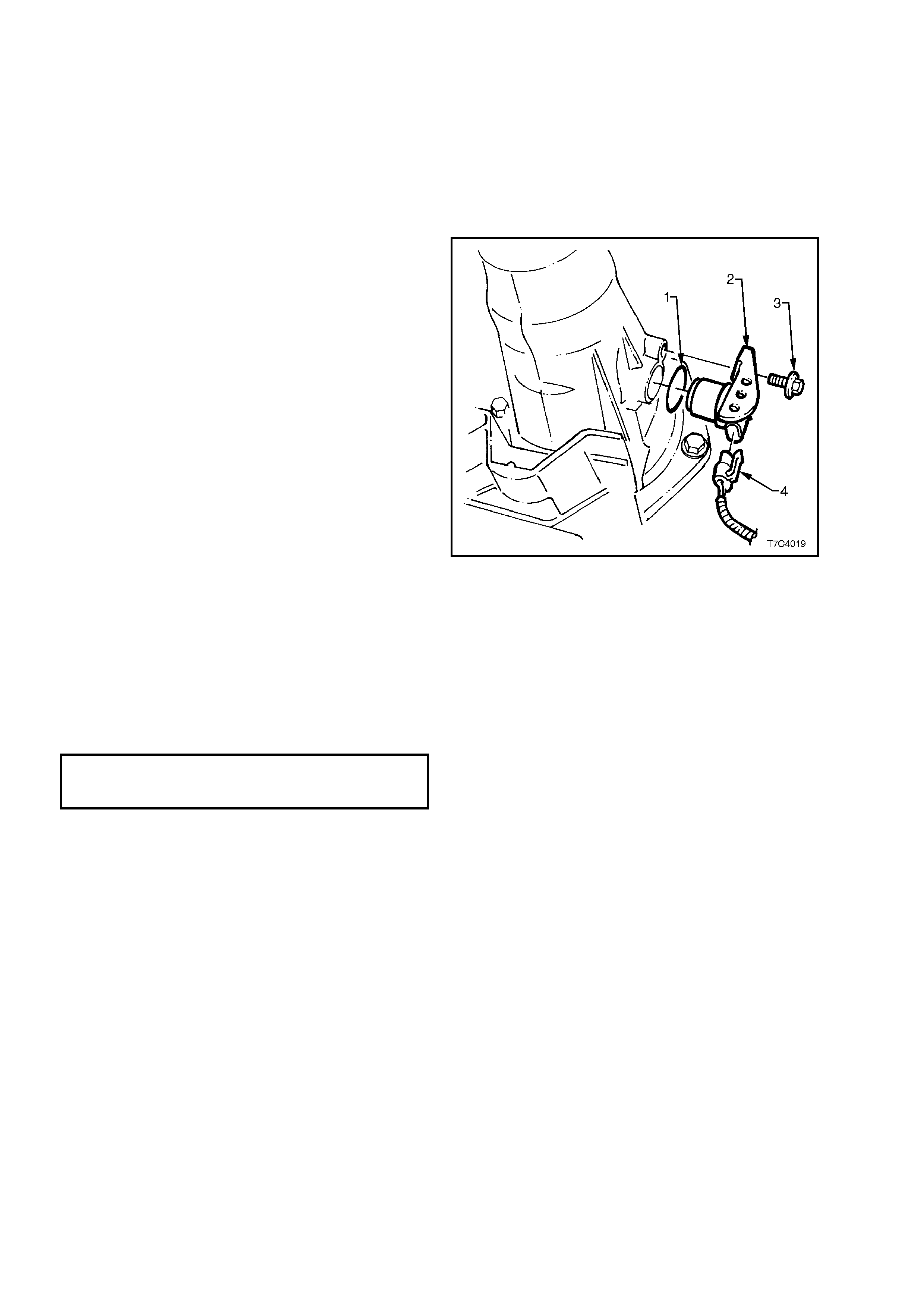
3.5 VEHICLE SPEED SENSOR
LT Section No. – 04A-200
REMOVE
1. Raise rear of vehicle and support on safety
stands. Refer to Section 0A GENERAL
INFORMATION in the MY 2003 VY and V2
Series Service Information, for the location of
jacking and support points.
2. Place drip tray beneath speed sensor.
3. Disconnect electrical connector (4) from the
vehicle speed sensor (2).
4. Unscrew vehicle speed sensor retaining screw
(3).
5. With a pulling/turning motion, remove vehicle
speed s ensor assem bly (2) and O- ring seal (1)
from the transmission extension housing.
Figure 7C4-31
REINSTALL
1. Lubricate a new O-ring seal (1) with p etroleum
jelly (Vaseline™ or equivalent) and install on
the vehicle speed sensor (2).
2. Install the speed sensor (2) into the
transmission extension housing.
3. Reinstall retaining screw (3) and tighten to the
specified torque.
SPEED SENSOR
RETAINING SCREW
TORQUE SPECIFICATION 12 Nm
4. Reinstall the wiring harness connector (4) to
the speed sensor (2).
5. Lower vehicle and check fluid level. Refer
2.1 FLUID LEVEL CHECK in this Section.
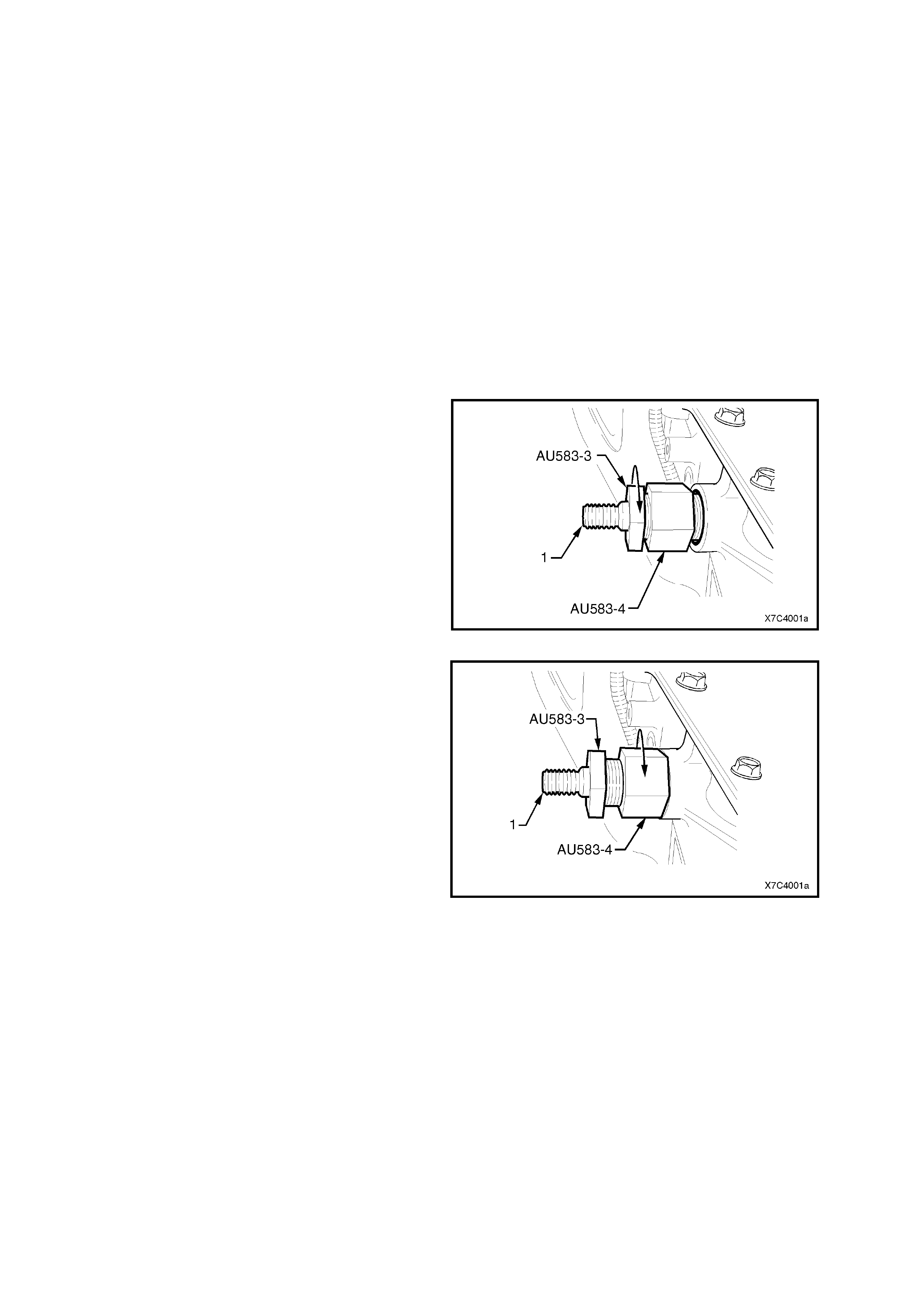
3.6 MANUAL SHAFT OIL SEAL
REPLACE
NOTE: This procedure requires the use of special
tool No. AU583. Should this tool not be available,
the seal can still be replaced but involves the
rem oval of the selector s haft from the transm ission
case. This procedure is detailed in Section 7C5
UNIT REPAIR, in the MY 2003 VY and V2 Series
Service Information.
1. Raise front of vehicle and support on safety
stands. Refer to Section 0A GENERAL
INFORMATION in the MY 2003 VY and V2
Series Service Information, for the location of
jacking and support points.
2. Remove the Neutral Start and Back-Up Lamp
Switch. Refer 3.4 NEUTRAL START AND
BACK-UP LAMP SWITCH in this Section.
3. Assemble the rem over nut (Tool No. AU583-4)
with the threaded section closest to the
hexagonal head of the seal remover AU583-3.
Install the nut up to the hexagonal end.
4. Install the pre-assembled remover (Tool Nos.
AU583-3 and AU583-4) over the manual shaft
(1) and engage the tapered thread end of the
seal remover into the seal. Tighten the seal
remover until the tool thread grips the steel
shell of the seal.
NOTE: Do not overtighten the seal remover in the
seal.
Figure 7C4-32
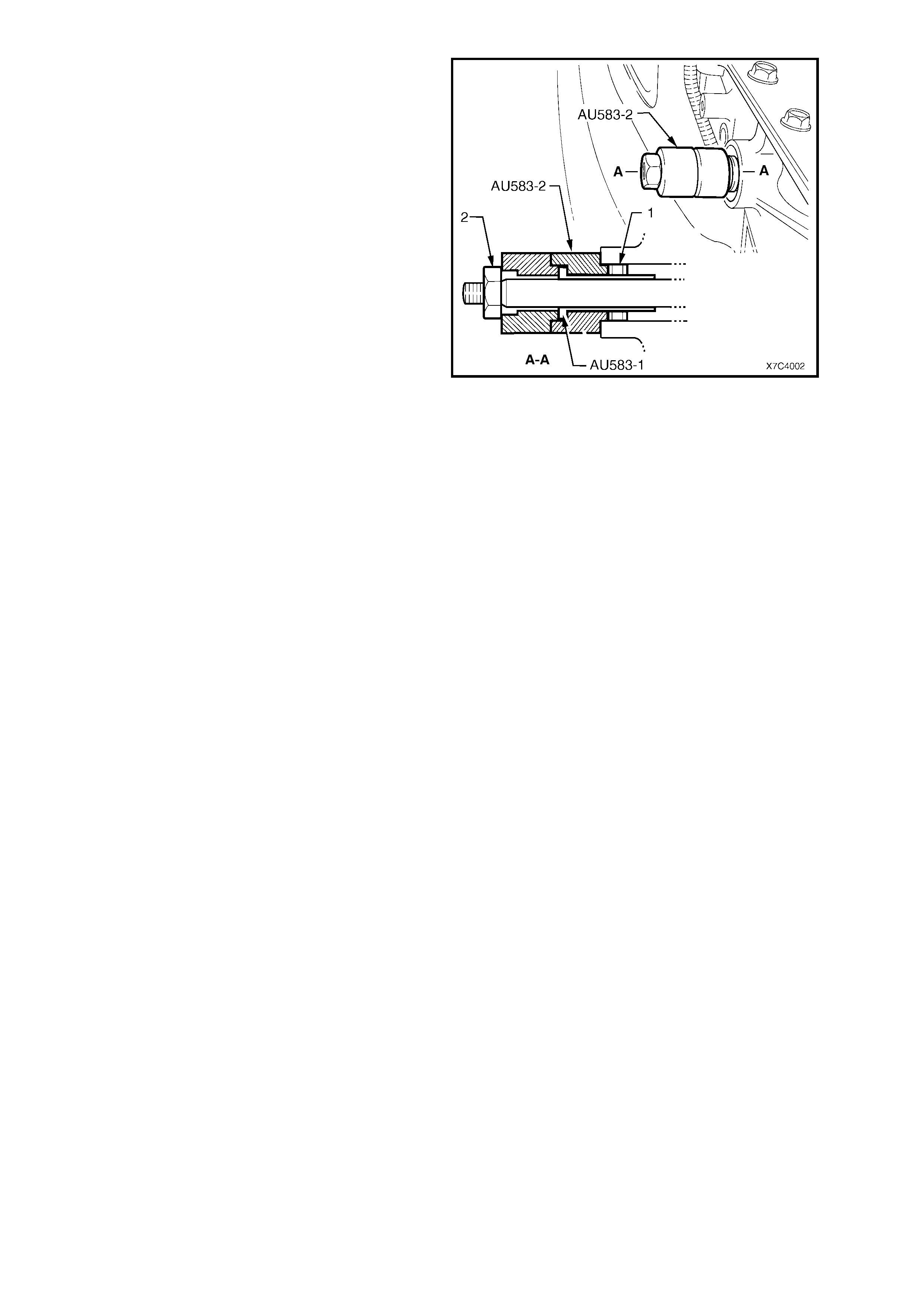
5. While holding the seal remover (AU583-3),
screw the remover nut (AU583-4) up to the
transmission case.
6. Continue tightening the remover nut until the
seal is removed into the remover nut cavity.
7. Discard the removed seal.
Figure 7C4-33
8. Pre-assemble the seal pr ot ec tor ( AU583- 1) into
one of the plastic seal installers (AU583-2), as
shown in the sectioned view.
9. Lubricate the seal lip of a new seal (1) with
Dexron® III automatic transmission fluid, then
install it (with the steel seal casing facing the
installer) over the seal protector sleeve
(AU583-1).
10. Install the seal protector (AU583-1), seal
installer (AU583-2) and seal (1), over the
manual shaft and up to the transmission case.
NOTE: If the sleeve jams on the manual shaft, then
the shaf t wil l be burr ed o ver the f lats that loc ate the
selector l ever. Use a fin e file to rem ove burrs, then
proceed.
11. Install the s econd pl astic seal ins taller over the
manual shaft until it seats against the first
installer.
12. Install the manual shaft lever retaining nut (2)
and tighten it to install the seal fully into place
in the transmission case.
NOTE: Two plastic seal installers (AU583-2) are
required, because of the restricted space between
the end of the manual shaft and the floor pan.
13. Remove installer tools, AU583-2 (two pieces)
and seal protector AU583-1 from the manual
shaft.
Figure 7C4-34
14. Reinstall the Neutral Safety and Back-Up
Lamp Switch and adjust. Refer 3.4 NEUTRAL
START AND BACK-UP LAMP SWITCH, in
this Section.
15. Lo wer the vehic le to t he gr ound, chec k and top
up the automatic transmission fluid level, as
required. Refer 2.1 FLUID LEVEL CHECK, in
this Section.
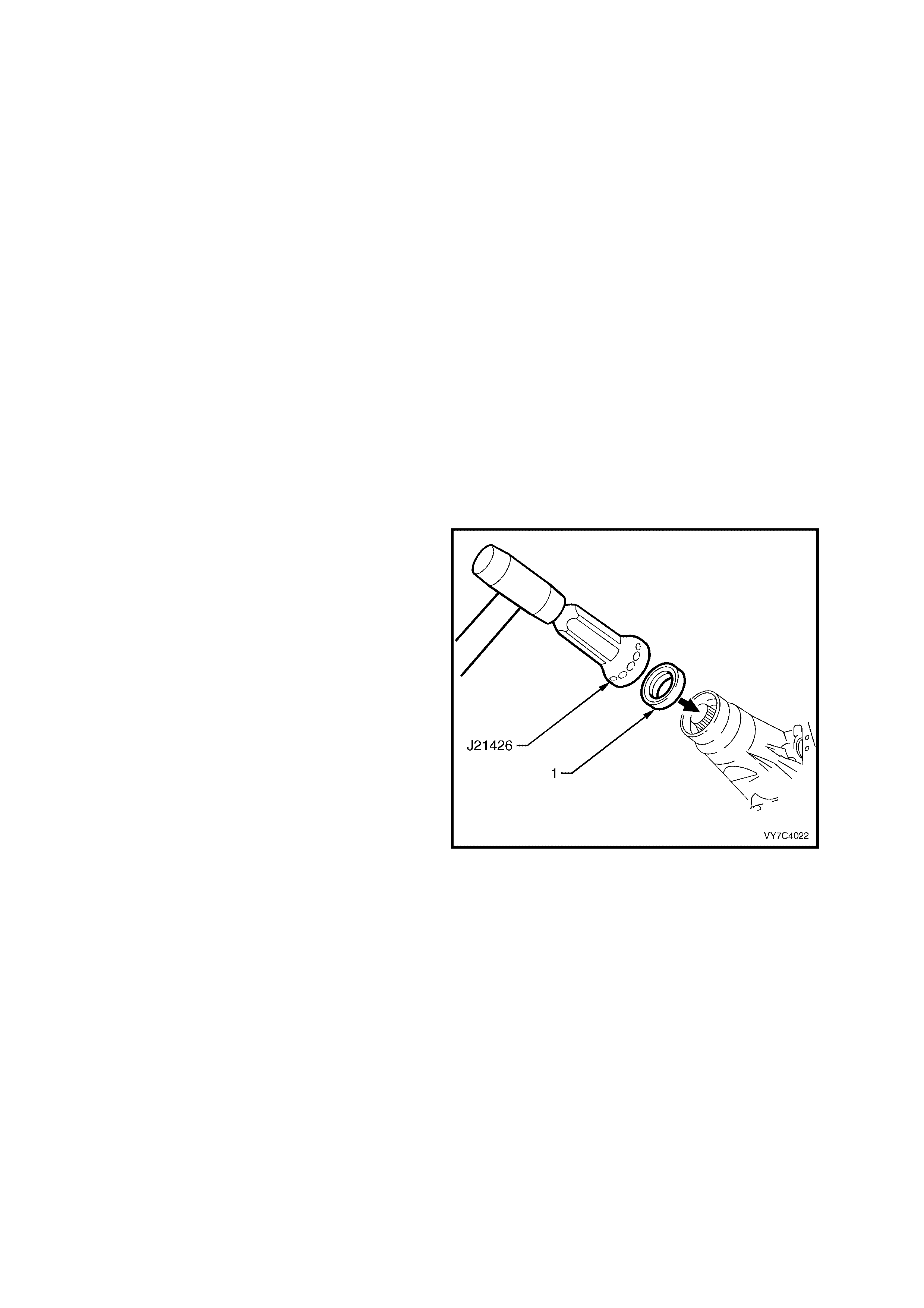
3.7 CASE EXTENSION OIL SEAL
LT Section No. – 04A-200
REPLACE
1. Rais e r ear of t he vehicl e and s uppor t on saf ety
stands. Refer to Section 0A GENERAL
INFORMATION in the MY 2003 VY and V2
Series Service Information, for the location of
jacking and support points.
2. Place a drip tray beneath rear of transmission.
3. Remove propeller shaft assembly, refer to
Section 4C PROPELLER SHAFT AND
UNIVERSAL JOINTS in the MY 2003 VY and
V2 Series Service Information.
4. Using a suitable seal removal tool, such as
E308 or equivalent, pr ise the oil seal f rom rear
of case extension.
IMPORTANT: Take care not to scratch the
machined seal recess in the extension housing as
transmission fluid may weep past the outside of the
installed seal once the vehicle is put back into
service.
5. Thoroughl y clean ar ou nd seal bor e in c ase and
ensure there are no burrs.
6. Tap new seal (1) into place, using Tool No.
J21426 and a soft faced hammer.
7. Reinstall propeller shaft. Refer Section 4C
PROPELLER SHAFT AND UNIVERSAL
JOINTS, in the MY 2003 VY and V2 Series
Service Information.
8. Lower vehic le to the grou n d and c h eck the f luid
level, refer to 2.1 FLUID LEVEL CHECK in this
Section.
Figure 7C4-35

3.8 EXTENSION HOUSING AND/OR BUSH
LT Section No. – 04A-200
REPLACE
1. Raise vehicle and support on safety stands.
Refer to Section 0A GENERAL
INFORMATION in the MY 2003 VY and V2
Series Service Information, for the location of
jacking and support points.
2. With vehicles fitted with the V6 e ngine , rem ove
the twin exhaust pipe and catalytic converter
assembly. For those vehicles fitted with either
the V6 Supercharged or GEN III V8 engines,
remove the exhaust system from the rear of
both catalytic converters rearwards. Refer to
Section 8B EXHAUST SYSTEM in the MY
2003 VY and V2 Series Service Information.
3. Place drip tray beneath case extension.
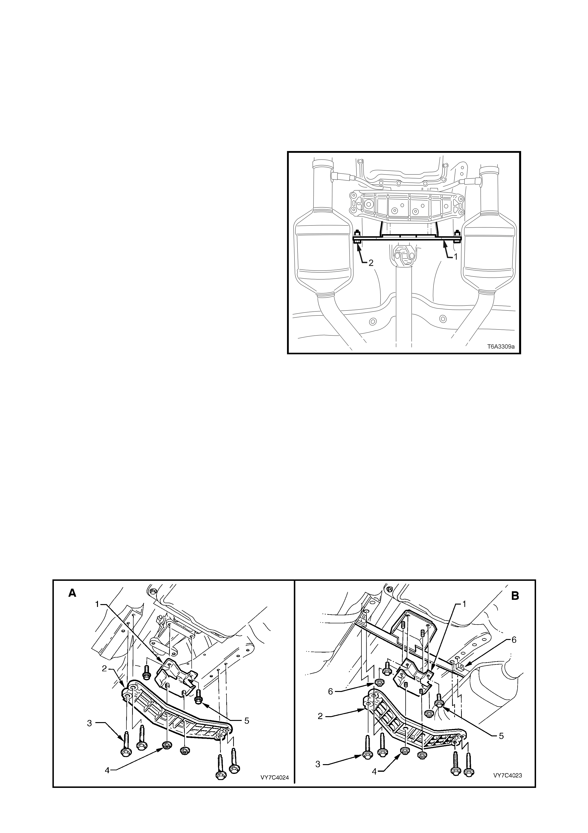
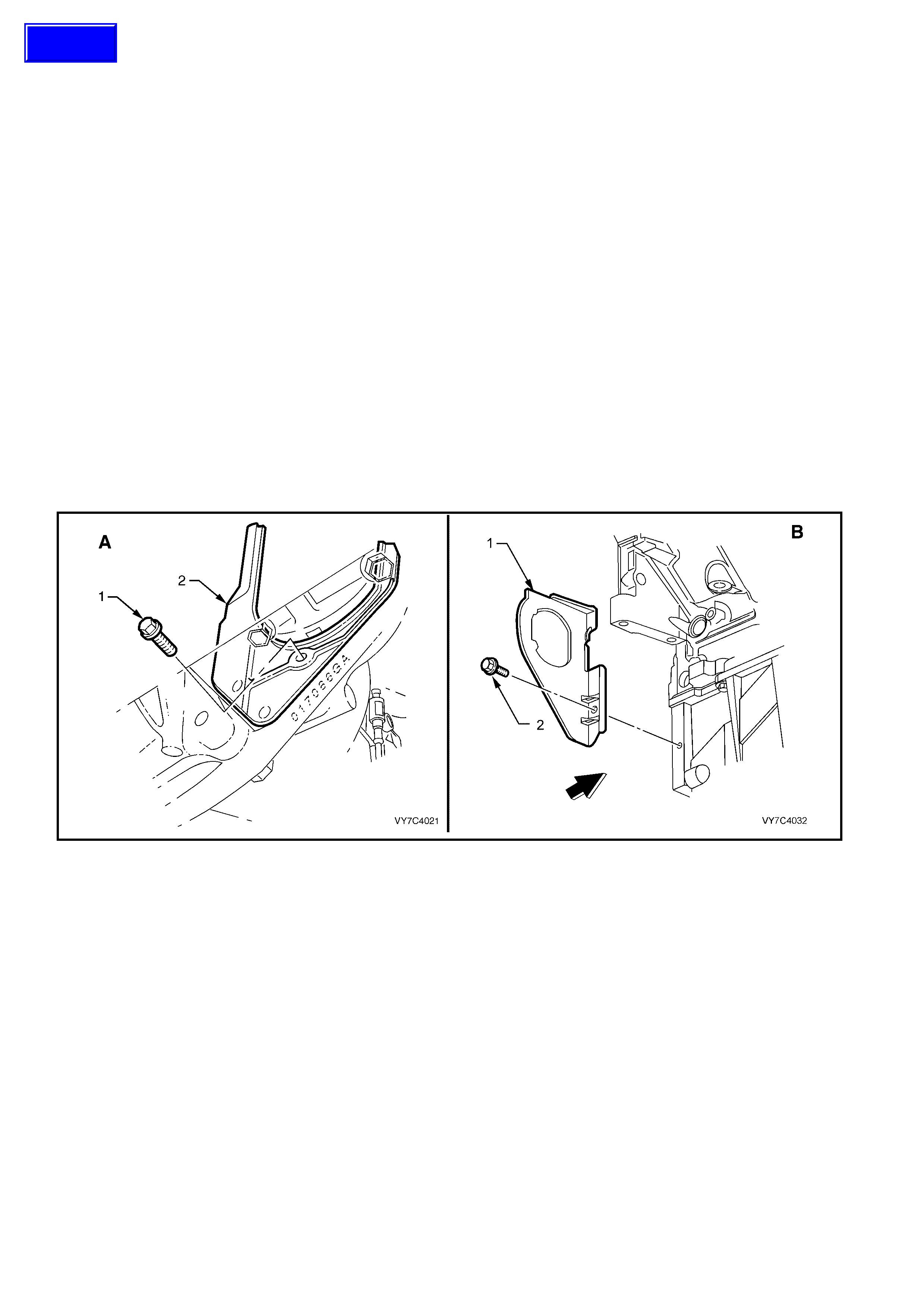
4. For those vehicles fitted with the GEN III V8
engine, remove the two bolts (2) securing the
catalytic converter bracket (1) to each catalytic
converter.
Figure 7C4-36
5. Remove propeller shaft, refer to Section 4C
PROPELLER SHAFT AND UNIVERSAL
JOINTS in the MY 2003 VY and V2 Series
Service Information.
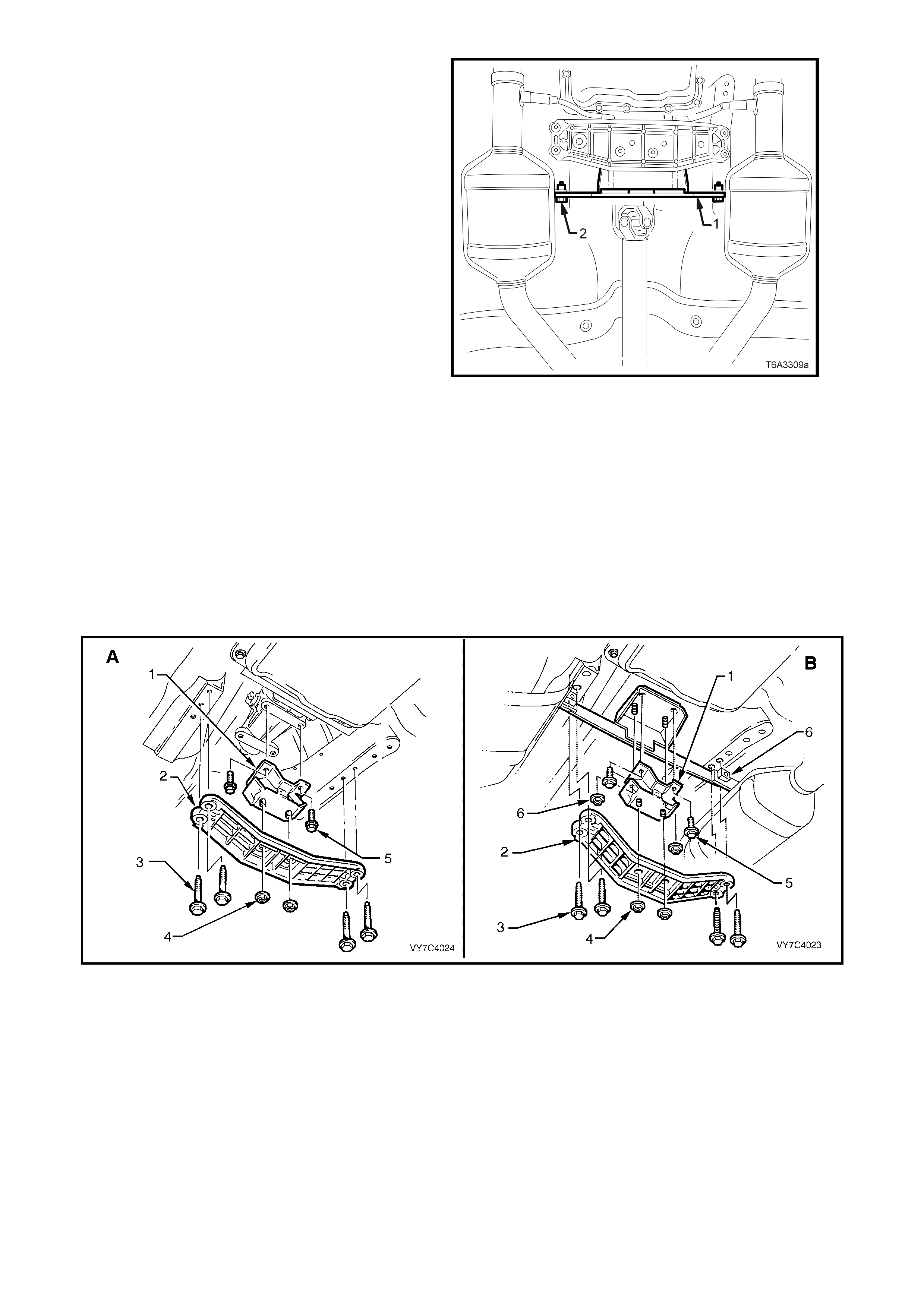
6. Use a sharp scriber to mark the exact location
of the crossmember (2) to the side frame,
before loosening any of the four crossmember
to side frame attaching bolts (3) (refer to
Figure 7C4-37) .
IMPORTANT: This st ep is c r itic al to t he c or rec t
powertrain alignment on reassembly. If not
carried out, then vehicle vibration and/or
handling problems could result!
7. Remove two bolts (5) securing rear engine
mount to transmission.
8. Support transm ission with a jack . Do not place
the support beneath case extension or oil pan.
9. Remove the four crossmember to side frame
bolts (3) and remove crossmember (2) and
rear engine mount (1) from the vehicle.
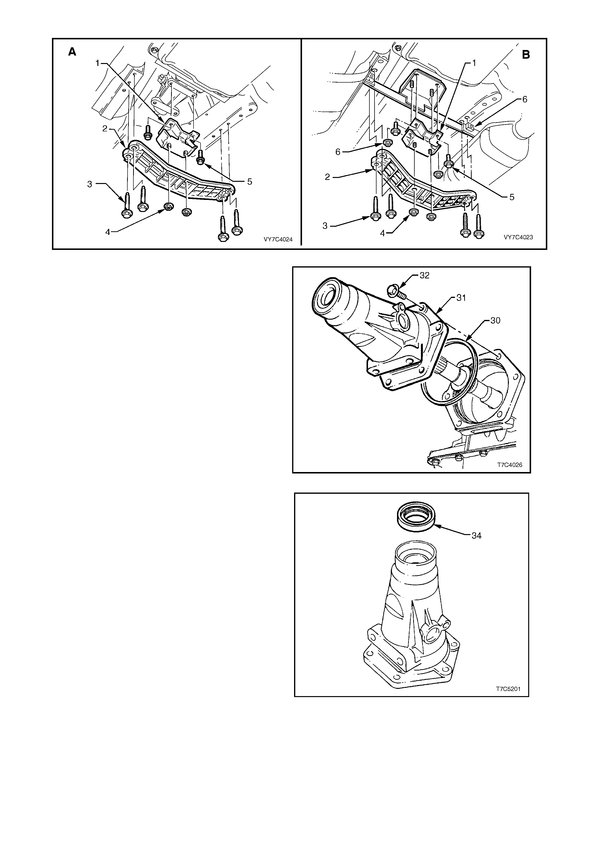
Figure 7C4-37
10. Rem ove vehicle s peed sen sor ass embly wiring
harness connector, then remove the sensor
from the extension housing. Refer to
3.5 VEHICLE SPEED SENSOR in this Section
for details.
11. Remove six bolts securing case extension to
transmission case.
12. Remove case extension (31) and seal
assembly (30) from the rear of the transmission
case.
Figure 7C4-38
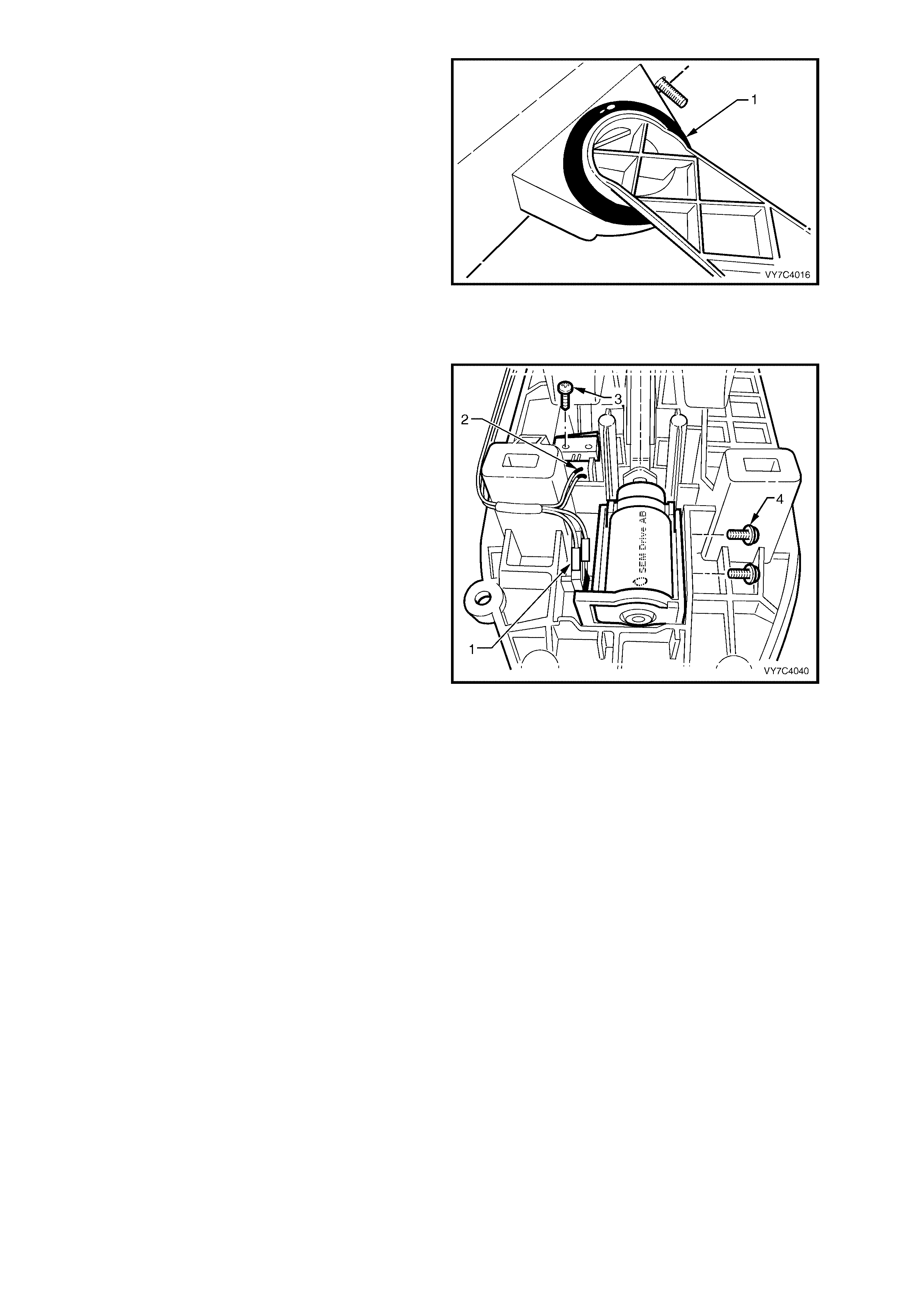
13. If bush is to be replaced, remove the case
extension oil seal (34), using a removing tool
such as Tool E308 or commercial equivalent.
Figure 7C4-39
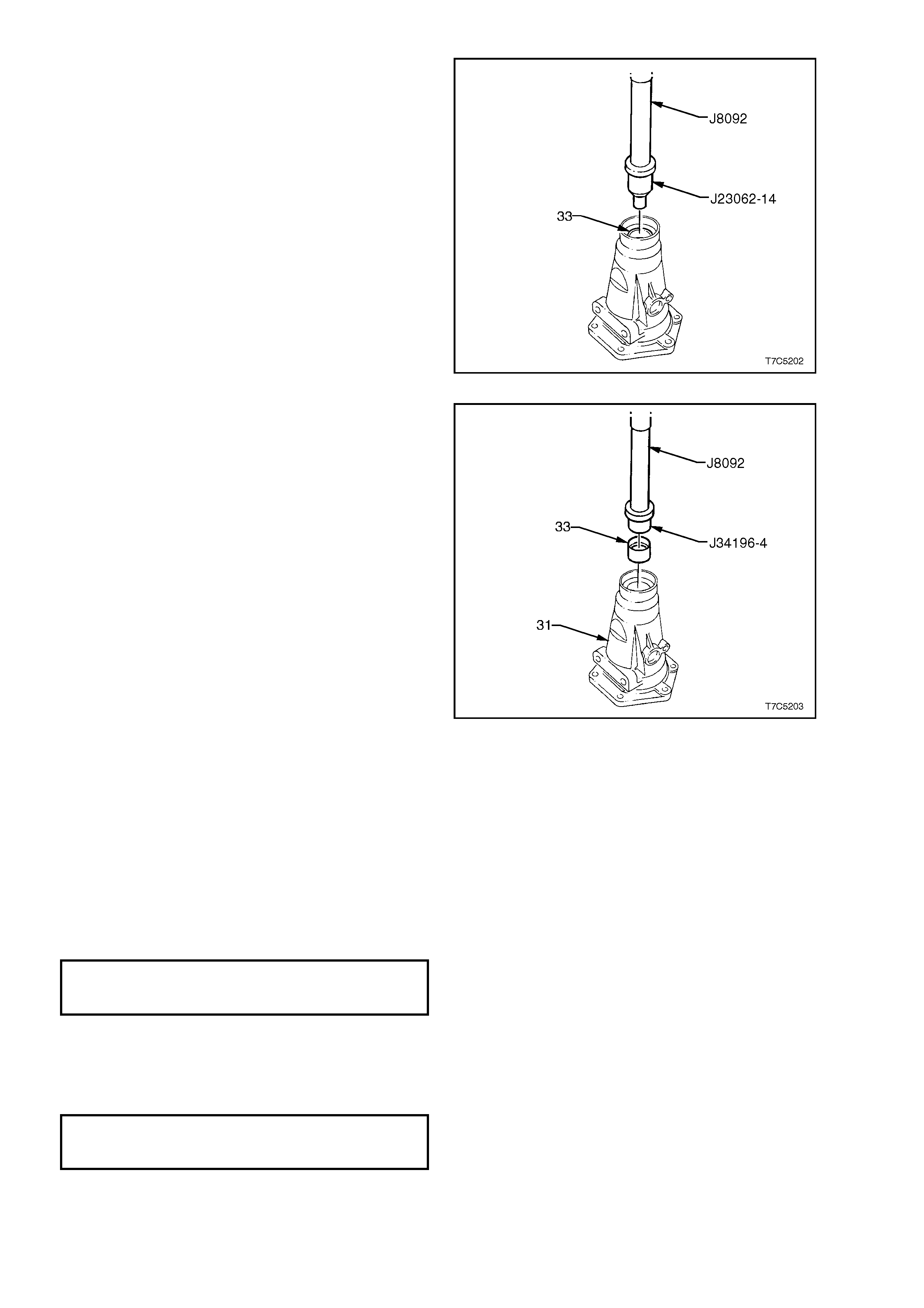
14. Using bush remover, Tool J23062-14 and
driver handle J8092, press the bush (33) from
the extension housing.
NOTE: Take note of the orientation of the split in
the bush for installation purposes.
Figure 7C4-40
15. Lubricate the outside of a new bush with
automatic transmission fluid to reduce the
chance of material pick-up.
16. Install a new bush (33) into the extension
housing (31), using installer J34196-4 and
driver handle J8092, ensuring that the split in
the bush is in the same orientation as the
original.
Figure 7C4-41
Reinstallation of components is in the reverse
order to r emoval (S teps 1 t o 10 abo ve) , taking note
of the following points:
17. Lubric ate t he s eal lips of a ne w case extens ion
oil seal and install, using Tool No. J21426.
18. Lubricate a new extension housing to case
seal ring with automatic transmission fluid,
then install to the extension housing. Reinstall
the housing to the transmission case and
tighten the six bolts to the correct torque
specification.
EXTENSION HOUSING
TO CASE BOLT
TORQUE SPECIFICATION 45 Nm
19. Lubricate a new vehicle speed sensor O-ring
with automatic transmission fluid, then install
to the sensor. Reinstall the sensor to the
extension housing and tighten the retaining
screw to the correct torque specification.
SPEED SENSOR
RETAINING SCREW
TORQUE SPECIFICATION 12 Nm
20. If removed, reinstall the rear engine mounting
to the crossmember, after noting the
orientation of the rear crossmember relative to
the installe d e ngine.
21. Tighten the engine mounting nuts to the correct
torque specification.
REAR ENGINE MOUNTING TO
CROSSMEMBER NUT
TORQUE SPECIFICATION 25 Nm
22. Reinstall the rear crossmember, ensuring that
it is aligned with the scribe lines made prior to
removal, before tightening the attaching bolts
to the correct torque specification.
REAR ENGINE MOUNTING TO
EXTENSION HOUSING BOLT
TORQUE SPECIFICATION 58 Nm
REAR CROSSMEMBER TO SIDE
RAIL ATTACHING BOLT
TORQUE SPECIFICATION 58 Nm
Figure 7C4-42
23. For reinstallation of the exhaust system, refer
to Section 8B EXHAUST SYSTEM in the MY
2003 VY and V2 Series Service Information.
24. Reinstall the propeller shaft. Refer to Section
4C PROPELLER SHAFT AND UNIVERSAL
JOINTS, in the MY 2003 VY and V2 Series
Service Information.
25. Lower vehicle and check transmission fluid
level. Ref er 2.1 FLUID LEVEL CHECK, in this
Section).
3.9 1-2 ACCUMULATOR ASSEMBLY
REMOVE
1. Remove oil pan and filter, refer
3.1 FLUID LEVEL CHANGE AND FILTER
REPLACEMENT in this Section.
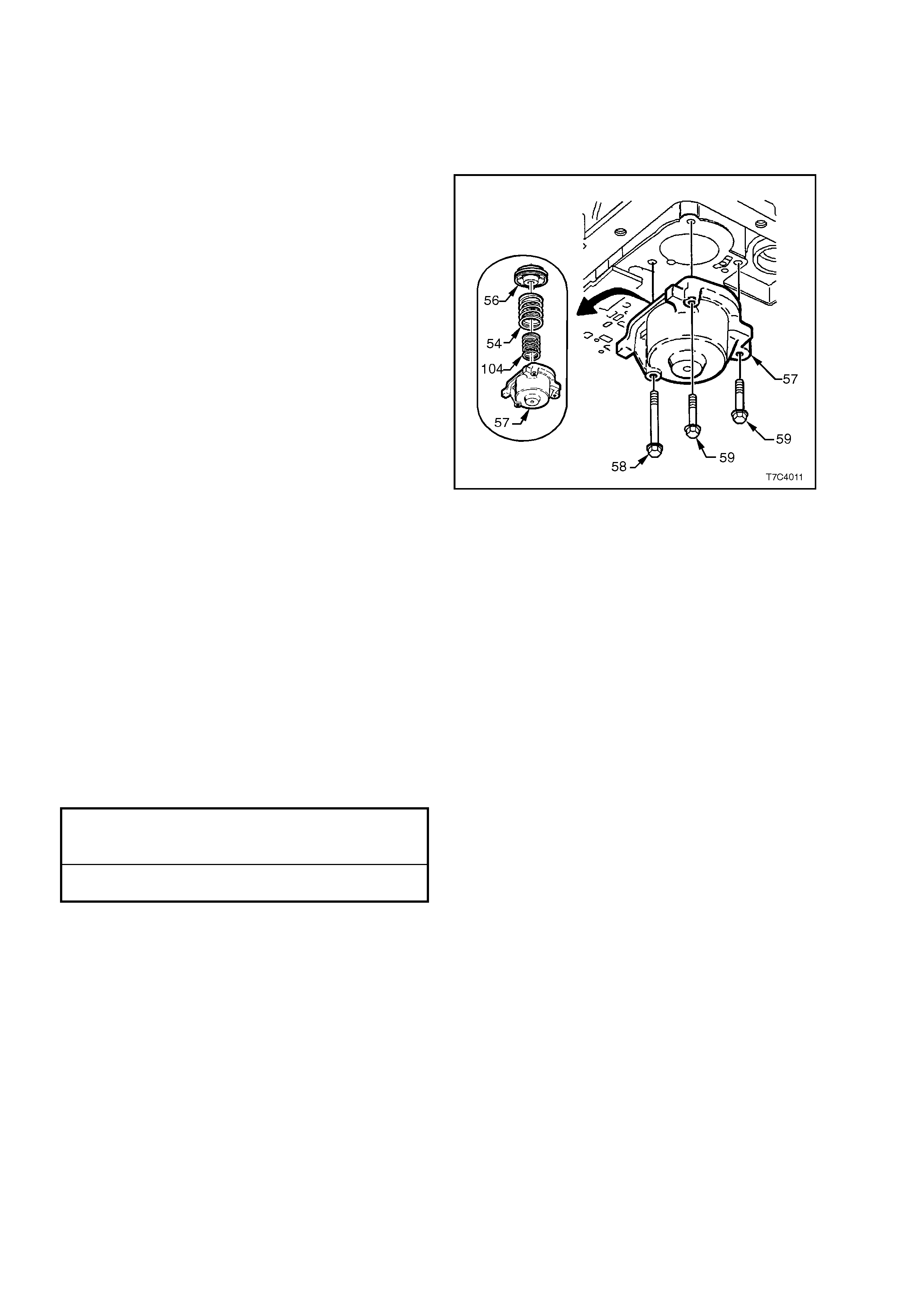
2. Progressively loosen, then remove the three
accum ulator cover bolts (58 an d 59), the cover
(57) and pin assembly, piston and seal
assembly (56) and the two springs (54 and
104), from the control valve body spacer plate.
3. Using LOW press ure air, apply to the dr illing in
the cover to r emove the 1-2 acc umulator pis t on
(56). Remove and discard the piston seal.
4. Remove the two 1-2 accumulator springs (54
and 104).
Figure 7C4-43
CLEAN AND INSPECT
1. Clean components with a suitable solvent and
air dry.
2. Check that springs are not distorted, or broken.
3. Lubricate new seal with petroleum jelly and
install on piston. Check that piston seal does
not bind in the piston groove.
4. Check all machined surfaces for damage or
wear.
REINST ALL
Reinstallation is the reverse of the removal
procedure.
However, use a new oil pan gasket and tighten all
fasteners to the correct torque specification.
1 – 2 ACCUMULATOR
COVER BOLT
TORQUE SPECIFICATION 12 Nm
OIL PAN BOLT
TORQUE SPECIFICATION 12 Nm
3.10 CONTROL VALVE BODY WIRING HARNESS
LT Section No. – 04A-275
REMOVE
1. Raise vehicle and support on safety stands.
Refer to Section 0A GENERAL
INFORMATION in the MY 2003 VY and V2
Series Service Information, for the location of
jacking and support points.
2. For those vehicles fitted with the GEN III V8
engine, remove the two bolts (2) securing the
catalytic converter bracket (1) to each catalytic
converter.
Figure 7C4-44
3. For those vehicles fitted with the V6 engine, remove the twin exhaust pipe and catalytic converter assembly.
For those vehicles fitted with either the V6 Supercharged or GEN III V8 engines, remove the exhaust system
from the rear of both c atalytic converters rearwards . Refer to Section 8B EXH AUST SY STEM in the MY 2003
VY and V2 Series Service Information.
4. Place drip tray beneath case extension.
5. Rem ove pr opel ler shaf t, ref er to Sectio n 4C PRO PEL LER SHAFT AND UNIVER S AL JOINTS in th e MY 20 03
VY and V2 Series Service Information.
6. Use a s harp sc riber to m ark the exact loc ation of the cros smem ber (2) to the s ide fram e, before l oosenin g any
of the four crossmember to side frame attaching bolts (3).
IMPORTANT: This step is critical to the correct powertrain alignment on reassembly. If not carried out, then
vehicle vibration and/or handling problems could result!
7. Remove two bolts (5) (and two nuts for GEN III V8 equipped vehicles) securing rear engine mount to
transmission and to the catalytic converter bracket.
8. Support transmission with a jack. Do not place the support beneath case extension or oil pan.
9. Remove the f our c rossm em ber to side f ram e bolts (3) and rem ove cr ossm em ber (2) and rear engine m ount (1)
from the vehicle.
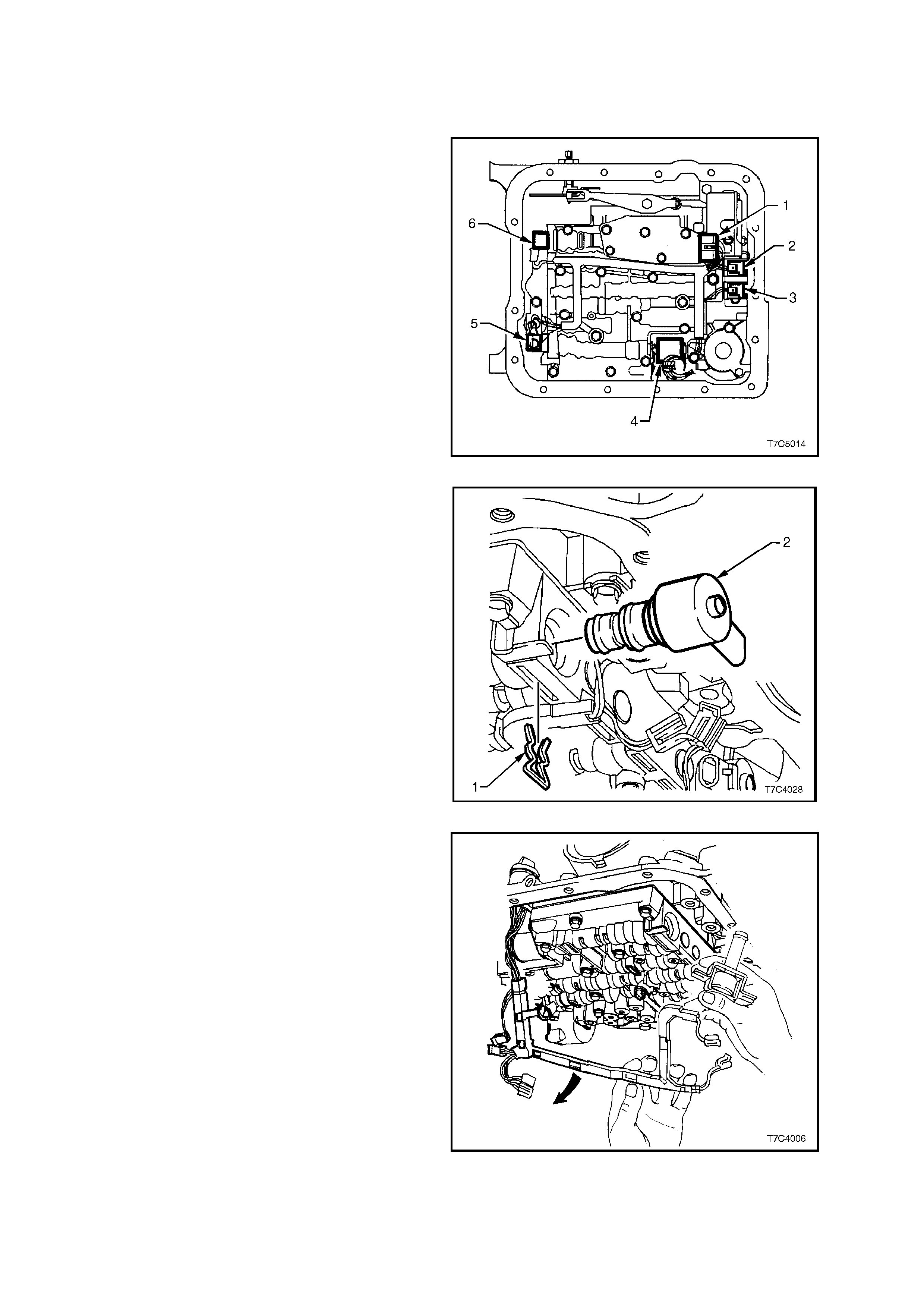
Figure 7C4-45
10. Remove oil pan and filter, refer
3.1 FLUID LEVEL CHANGE AND FILTER
REPLACEMENT in this Section.
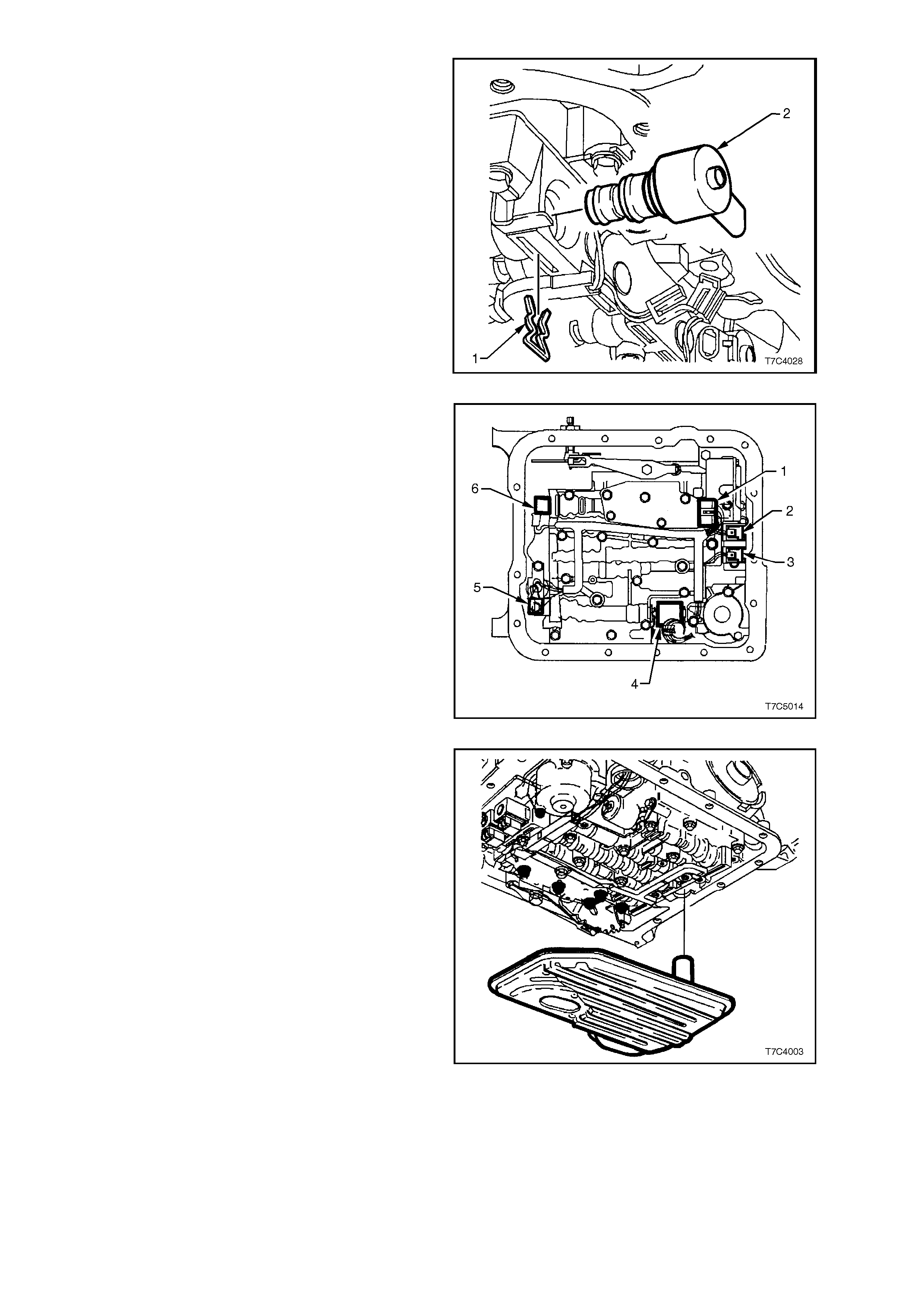
11. Disconnect wiring harness connectors from all
electrical components, except the Torque
Converter Clutch (TCC) Solenoid, that is hard
wired.
NOTE: The connector to the pressure control
solenoid (4) is different for the HAD transmission.
Security and removal however, is the same as for
the TCC PWM solenoid (5).
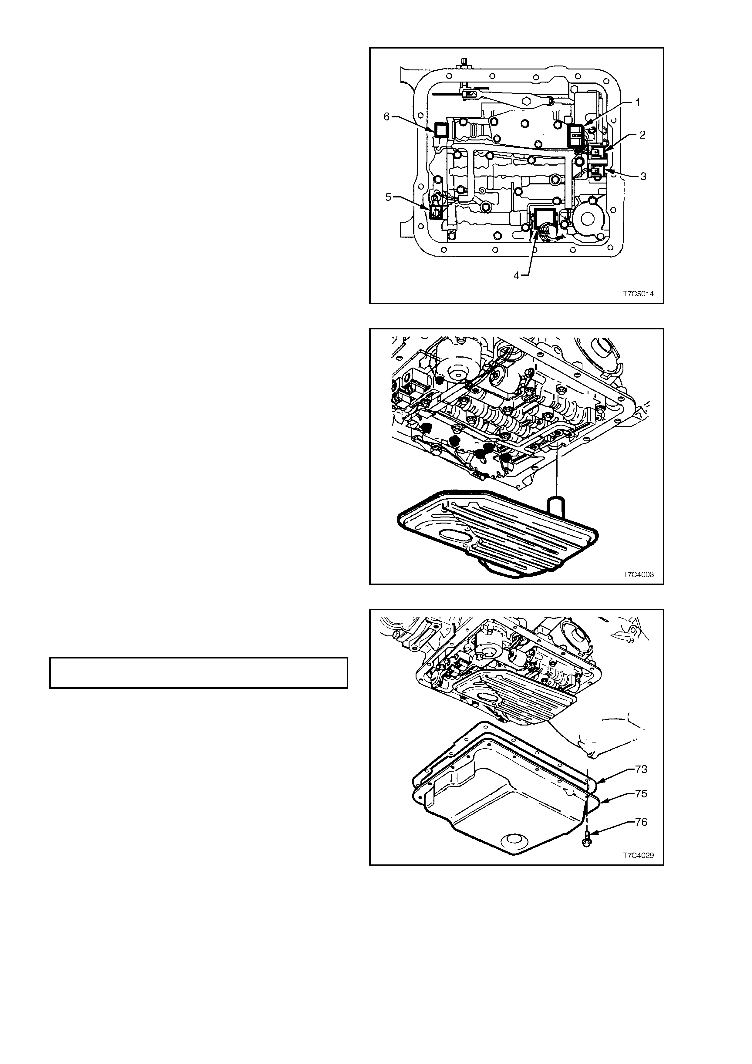
Electrical Connector Identification:
1. TFP Manual Valve Positi on Switch
2. 1-2 Shift Valve Solenoid ‘A’
3. 2-3 Shift Valve Solenoid ‘B’
4. Pressure Control Solenoid (PCS)
5. TCC Pulse Width Modulated (TCC PWM)
Solenoid
6. 3-2 Control Solenoid
Figure 7C4-46
12. Use a hooked piece of wire or a small bladed
screwdriver and prise the TCC PWM solenoid
retaining clip (1) free.
CAUTION: Wear eye protection to prevent
personal injury should the clip fly out
uncontrolled on removal.
13. Remove the TCC PWM solenoid (2) from the
control valve body, with a twisting and pulling
motion.
Figure 7C4-47
14. Remove two bolts securing TCC solenoid
assembly.
15. Withdraw TCC solenoid assembly from pump.
16. Lower the wiring harness and TCC solenoid to
hang from the pass-thru connector.
17. Remove the control valve body. Refer to
3.11 CONTROL VALVE BODY, in this
Section.
NOTE: This is necessary to provide clearance for
the pass-thru connector to be removed.
Figure 7C4-48
18. Lower t he rear of the transm ission ass embl y to
provide space between the floor pan and the
pass-thru connector, located at the right hand
rear of the tr ans m ission cas e. Refer to Step s 5
to 9 inclusive, of 3.8 EXTENSION HOUSING
AND/OR BU SH, in this Sec t ion .
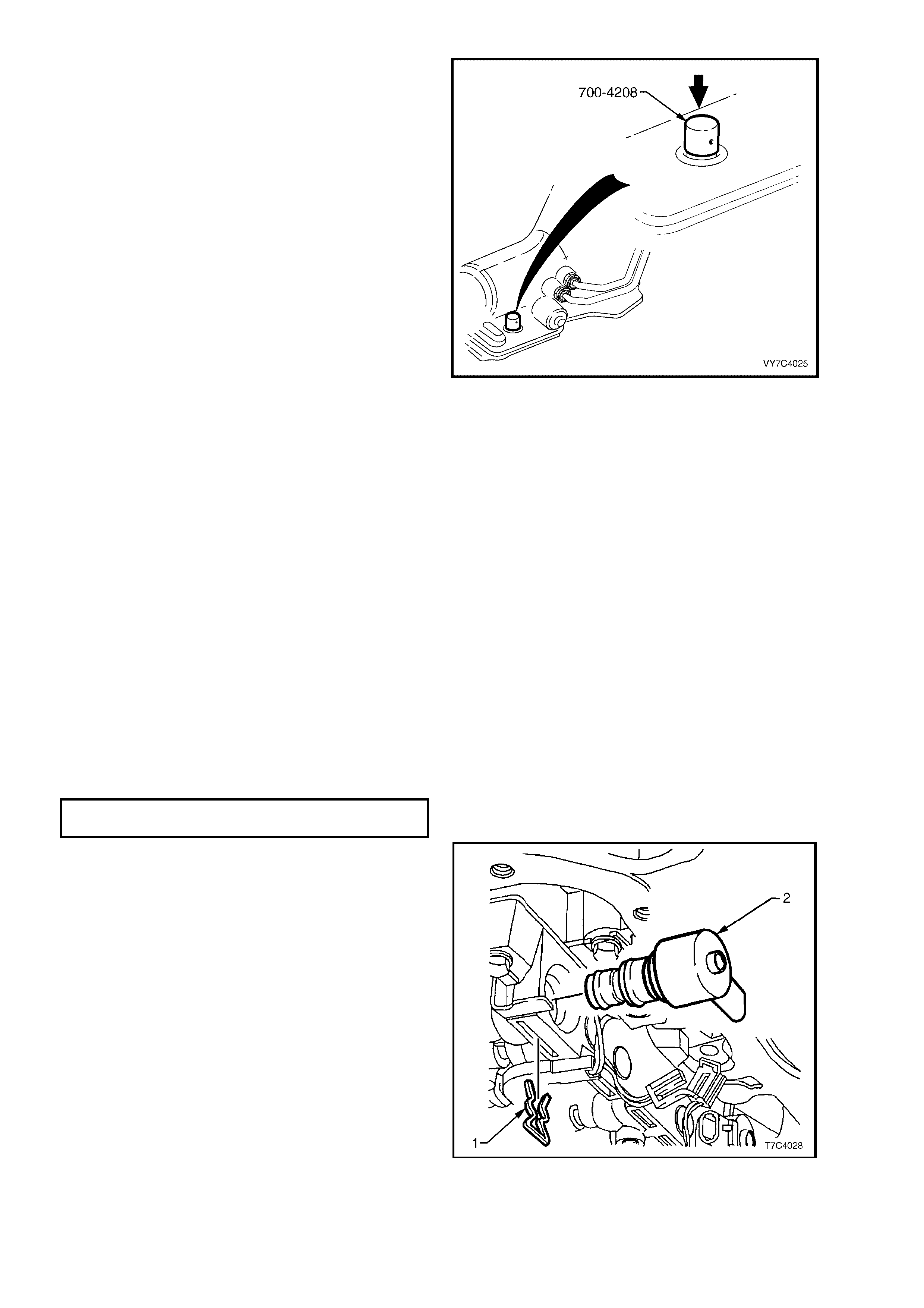
19. Install Tool No. 700-4208 over the pass-thru
connector, t hen use ha nd f orc e to pus h t he t ool
down, compressing the four retaining tangs on
the connector. Pull the pass-thru connector
free from the transmission case, removing the
harness and TCC solenoid assembly from the
transmission.
Figure 7C4-49
REINST ALL
Reinstallation is the reverse of removal operations
except for the items detailed here.
1. Lubricate a new pass-thru connector O-ring
with petroleum jelly such as Vaseline™ or
equivalent, then reinstall the connector up
through the hole in the transmission case and
push until all four of the retaining lugs have
emerged through to the outside of the
transm iss ion case. T ug on the co nnector (NOT
the wiring) to check that full engagement has
take place.
2. Reinstall the control valve body. Refer to
3.11 CONTROL VALVE BODY, in this
Section.
3. Coat a new TCC solenoid O-ring with
petroleum jelly and install on solenoid, then
reinstall TCC solenoid assembly into the oil
pump body. Secure with the two bolts and
tighten to the correct torque specification.
TCC SOLENOID BOLT
TORQUE SPECIFICATION 12 Nm
4. Coat a new TCC PWM solenoid O-ring with
petroleum jelly, install on the solenoid (2). Then
reinstall the solenoid into the control valve
body, securing with retaining clip (1).
Figure 7C4-50
5. Reinstall the wiring harness connectors as
shown, then reinstall the two harness frame
retaining clips over the control valve body
bolts.
Electrical Connector Identification:
1. TFP Manual Valve Positi on Switch
2. 1-2 Shift Valve Solenoid ‘A’
3. 2-3 Shift Valve Solenoid ‘B’
4. Pressure Control Solenoid (PCS)
5. TCC Pulse Width Modulated (TCC PWM)
Solenoid
6. 3-2 Control Solenoid
Figure 7C4-51
6. Reinstall oil filter into the oil filter seal.
Figure 7C4-52
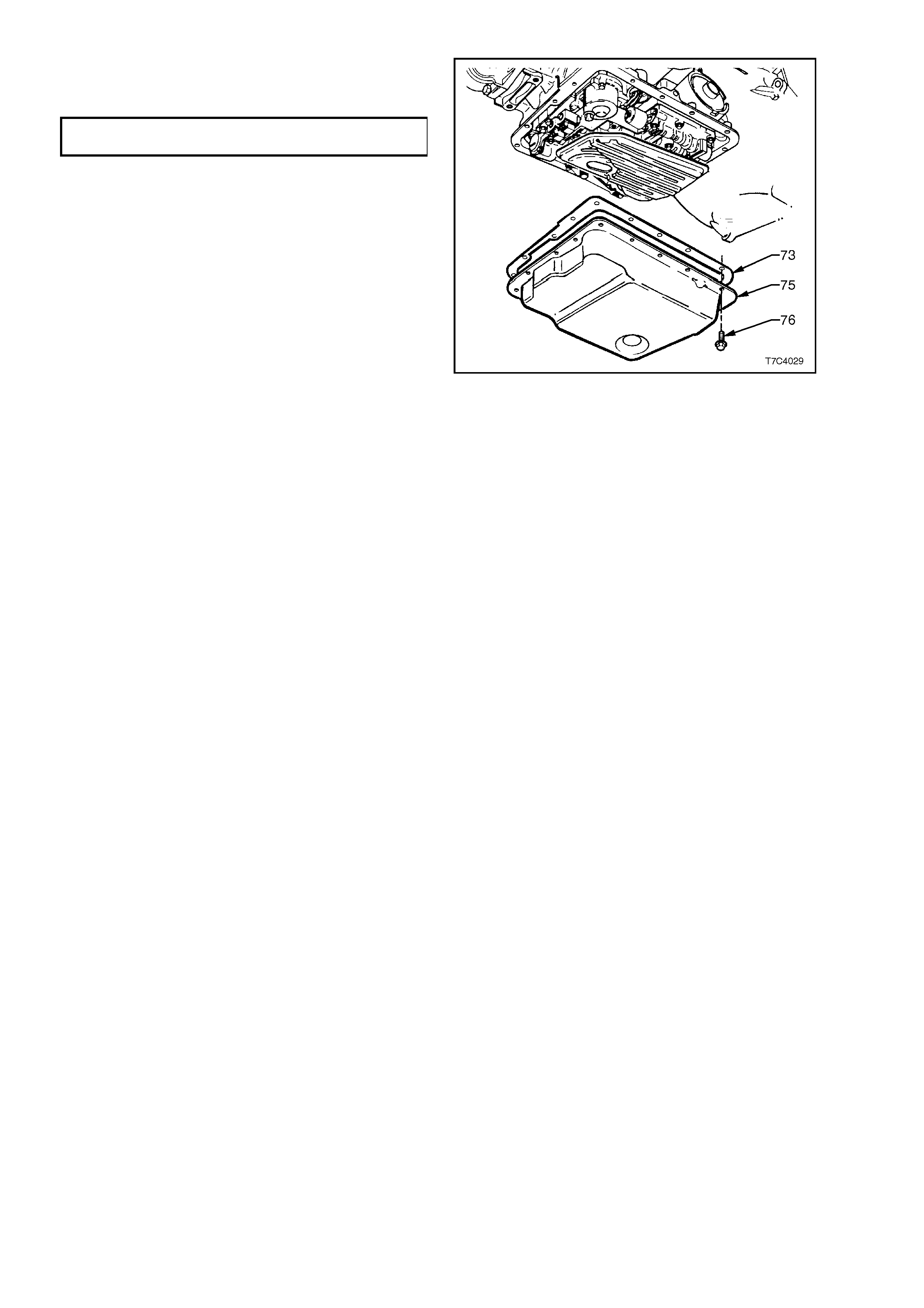
7. Reinstall a new oil pan gasket (73), then
reinstall the oil pan (75), tightening the bolts
(76) to the correct torque specification.
OIL PAN BOLT
TORQUE SPECIFICATION 12 Nm
8. Fill transmission with Dexron III automatic
transmission fluid, as detailed in 3.1 FLUID
CHANGE AND FILTER REPLACEMENT, in
this Section.
9. Lower vehicle and road test until the
transmission has reached operating
temperature.
10. Re-check fluid level (see 2.1 FLUID LEVEL
CHECK, in this Section) and check for fluid
leaks from the oil pan area.
Figure 7C4-53
3.11 CONTROL V ALVE BODY
LT Section No. – 04A-275
REMOVE
1. Refer to 3.10 CONTROL VALVE BODY
WIRING HARNESS, in this Section and
remove the harness to the stage where it is
hanging from the pass-thru connector.
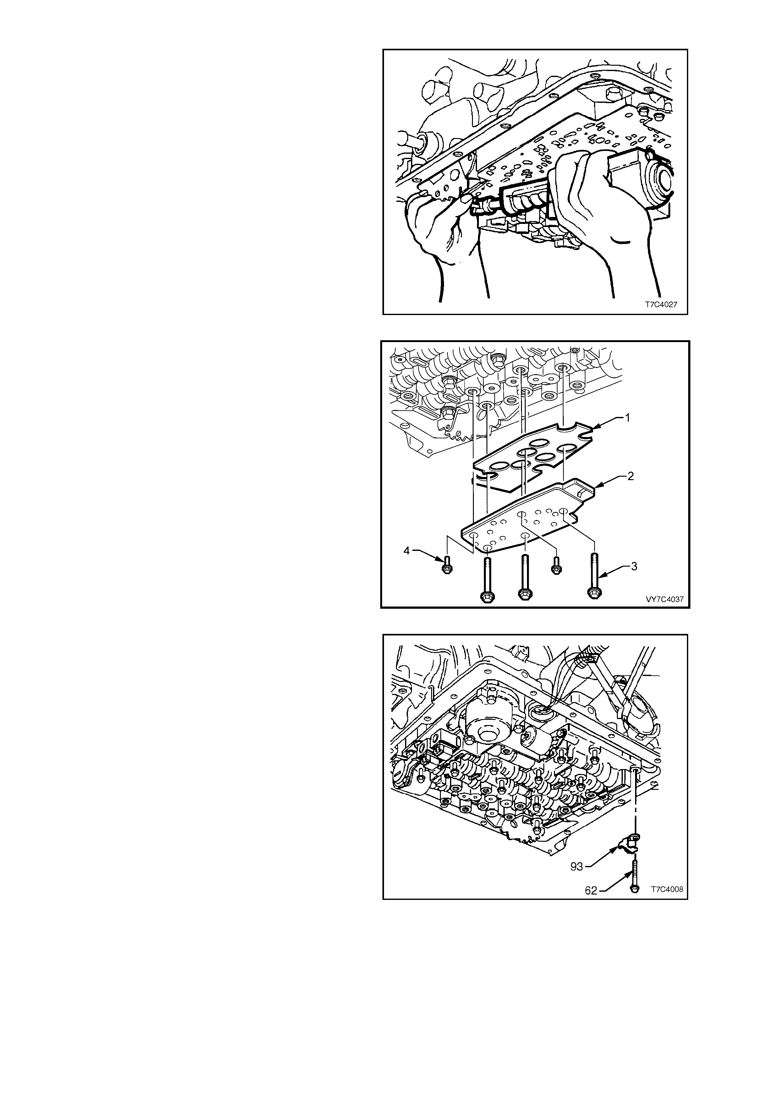
2. Remove the Transmission Fluid Pressure
(T FP) Manua l Va lve Switc h As sem bl y retaini ng
bolts (‘A’ and ‘D’), then remove the shield.
Discard the removed shield.
Figure 7C4-54
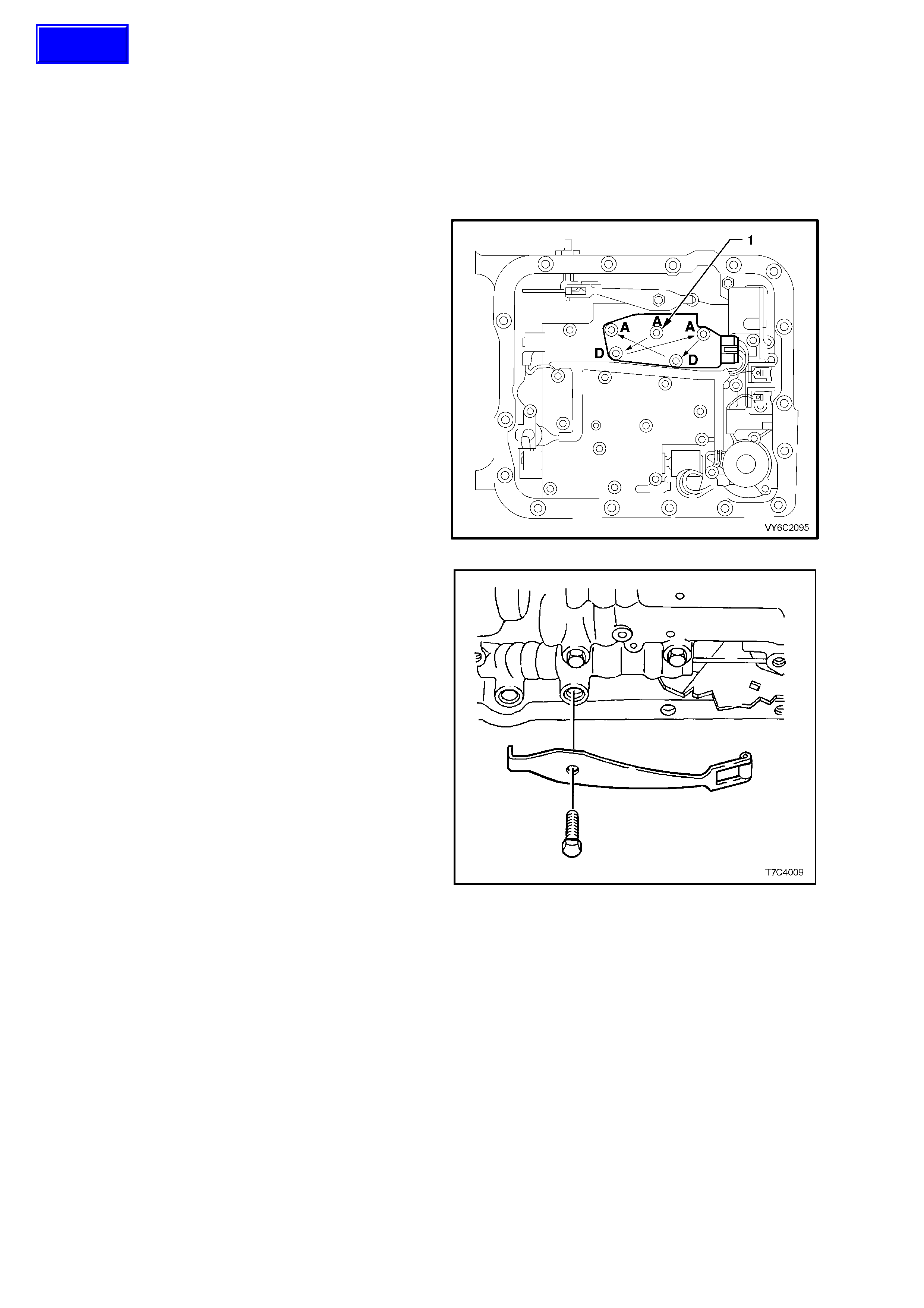
3. Remove the bolt (64) securing the manual
detent spring (63).
Figure 7C4-55
Techline
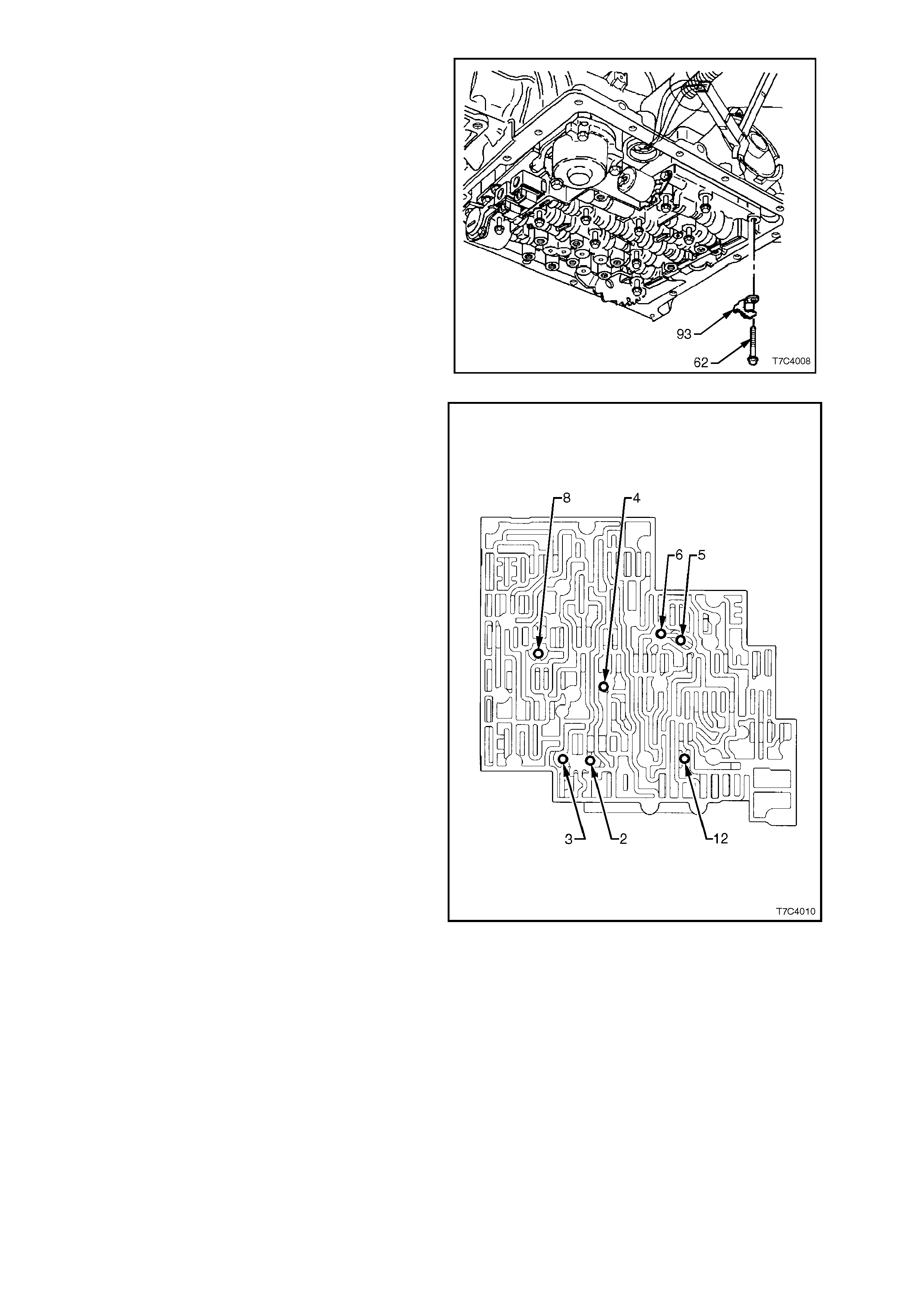
4. Remove the control valve body retaining bolt
(62) securing the dipstick stop bracket (93).
5. Remove remaining control valve body bolts.
6. Remove control valve body assembly by
supporting at the rear with one hand, while
holding the m anual va lve with th e other. As the
valve bod y is being lo wered, rotate it s lightly to
release the manual valve link from the manual
valve.
7. Remove manual valve link from inner detent
lever.
Figure 7C4-56
NOTE: T ake ca re not to lo se the s even c hec k balls
that are located under the control valve body.
Locations for the seven check balls are as shown.
Figure 7C4-57
DISASSEMBLE, CLEAN, INSPECT AND REASSEMBLE
For these operations, refer to 2.16 CONTROL
VALVE BODY in Section 7C5, AUTOMATIC
TRANSMISSION - UNIT REPAIR in the MY 2003
VY and V2 Series Service Information.
REINST ALL
1. Ensure spacer plate gasket is in satisfactory
condition. If gasket needs to be replaced,
refer to 3.12 SPACER PLATE, CHECK
BALLS, FILTER SCREENS AND 3-4
ACCUMULATOR in this Section.
2. Reinstall check balls in control valve body as
shown in Figure 7C4-56 and secure with
petroleum jelly.
3. Reinstall the manual valve link into the inner
detent lever.
4. While supporting the manual valve link in one
hand and the va lve body in the other, rotat e the
valve body slightly and connect the link with
the manual valve. Move the manual valve
forward to retain the link connection and
carefully offer the valve body up, into position.
NOTE: Be careful not to damage the two filter
screens attached to the spacer plate, during this
operation.
Figure 7C4-58
5. Fit a new shield (1) to the Transmission Fluid
Pressure (TFP) Manual Valve Switch
Assembly (2), then reinstall to the control valve
body and r etain with the f ive bolts ( 4 and 5) but
do not tighten at this stage.
Figure 7C4-59
6. Reinstall the dipstick stop bracket (93) and
retaining bolt (62). Do not tighten at this stage.
7. Loosely reinstall the remainder of the control
valve body bolts.
Figure 7C4-60
8. Reinstall the manual detent spring assembly
retaining bolt.
Figure 7C4-61
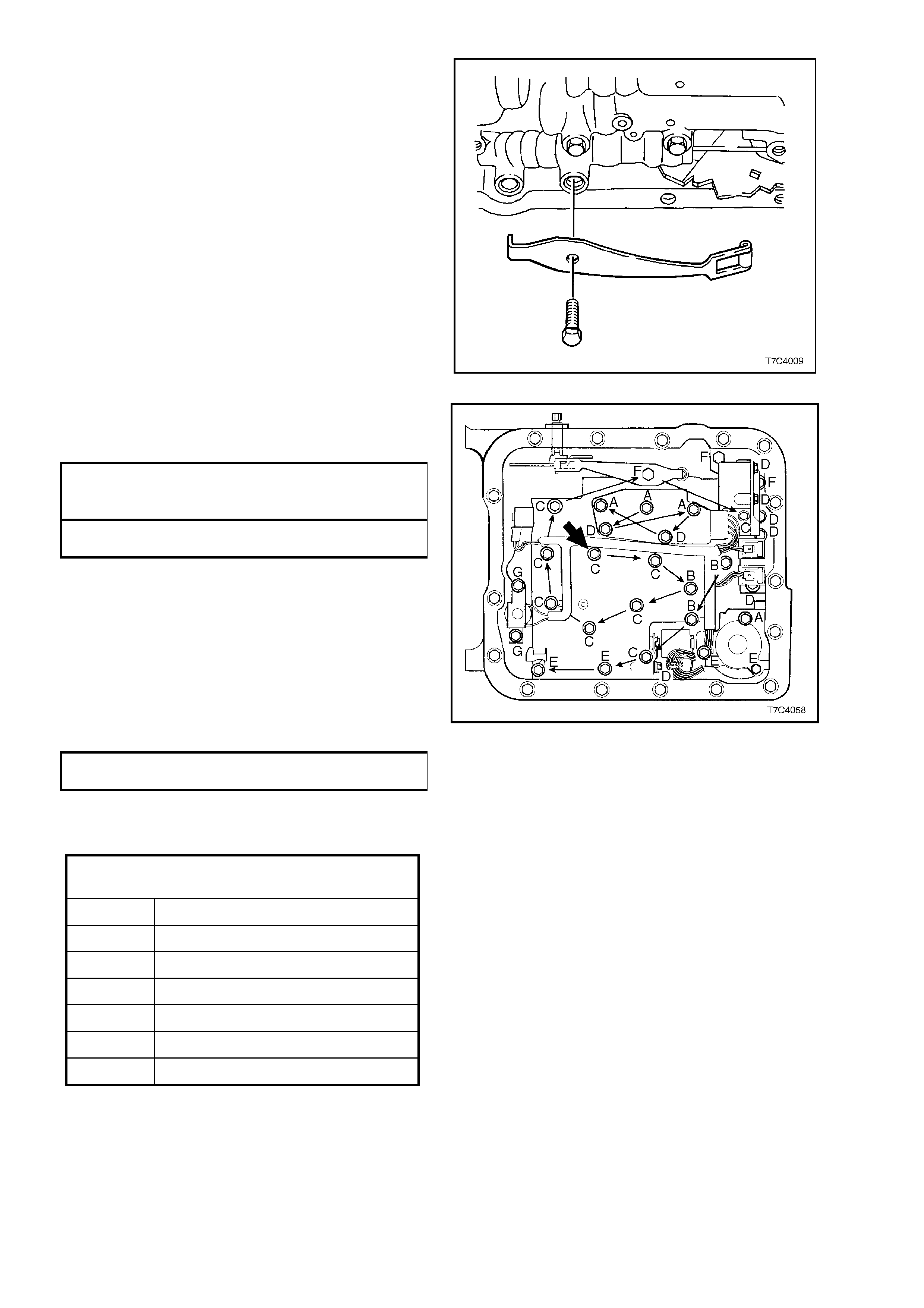
9. T ighten all control valve body retaining bolts to
the specified torque specification, starting from
the centre (bold arrow), in the order shown.
CONTROL VALVE BODY AND TFP
MANUAL VALVE POSITION SWITCH
ASM TORQUE SPECIFICATION 12 Nm
MANUAL DETENT SPRING
BOLT TORQUE SPECIFICATION 23 Nm
IMPORTANT: The control valve body bolts must
be tightened in an outward spiral from the centre
(bold arrow), as shown. Failure to follow this
pattern may distort the valve body, causing valves
to jam in their bores.
10. Coat a new TCC solenoid O-ring with
petroleum jelly and install on solenoid, then
reinstall TCC solenoid assembly into the oil
pump body. Secure with the two bolts and
tighten to the correct torque specification.
TCC SOLENOID BOLT
TORQUE SPECIFICATION 12 Nm
NOTE: There are 7 different bolt sizes used, the
dimensions of which are indicated by the letters
shown.
Figure 7C4-62
CONTROL VALVE BODY FASTENER
SPECIFICATIONS
A M6 x 1.00 x 65.0
B M6 x 1.00 x 54.4
C M6 x 1.00 x 47.5
D M6 x 1.00 x 18.0
E M6 x 1.00 x 35.0
F M8 x 1.25 x 20.0
G M6 x 1.00 x 12.0
11. Coat a new O-ring with petroleum jelly, install
on the solenoid (2). Then reinstall the solenoid
into the control valve body, securing with
retaining clip (1).
Figure 7C4-63
12. Reinstall the wiring harness connectors as
shown, then reinstall the two harness frame
retaining clips over the control valve body
bolts.
Electrical Connector Identification:
1. TFP Manual Valve Positi on Switch
2. 1-2 Shift Valve Solenoid ‘A’
3. 2-3 Shift Valve Solenoid ‘B’
4. Pressure Control Solenoid (PCS)
5. TCC Pulse Width Modulated (TCC PWM)
Solenoid
6. 3-2 Control Solenoid
Figure 7C4-64
13. Reinstall oil filter into the oil filter seal.
Figure 7C4-65
14. Reinstall a new oil pan gasket (73), then
reinstall the oil pan (75), tightening the bolts
(76) to the correct torque specification.
OIL PAN BOLT
TORQUE SPECIFICATION 12 Nm
15. Fill transmission with Dexron III automatic
transmission fluid, as detailed in 3.1 FLUID
CHANGE AND FILTER REPLACEMENT, in
this Section.
16. Lower vehicle and road test until the
transmission has reached operating
temperature.
17. Re-check fluid level (see 2.1 FLUID LEVEL
CHECK, in this Section) and check for fluid
leaks from the oil pan area.
Figure 7C4-66
3.12 SPACE R PLATE, CHECK BALLS, FILTER SCREENS AND 3-4 ACCUMULATOR
LT Section No. – 04A-275
REMOVE
1. Remove control valve body as described in
3.11 CONTROL VALVE BODY AND WIRING
HARNESS in this Section.
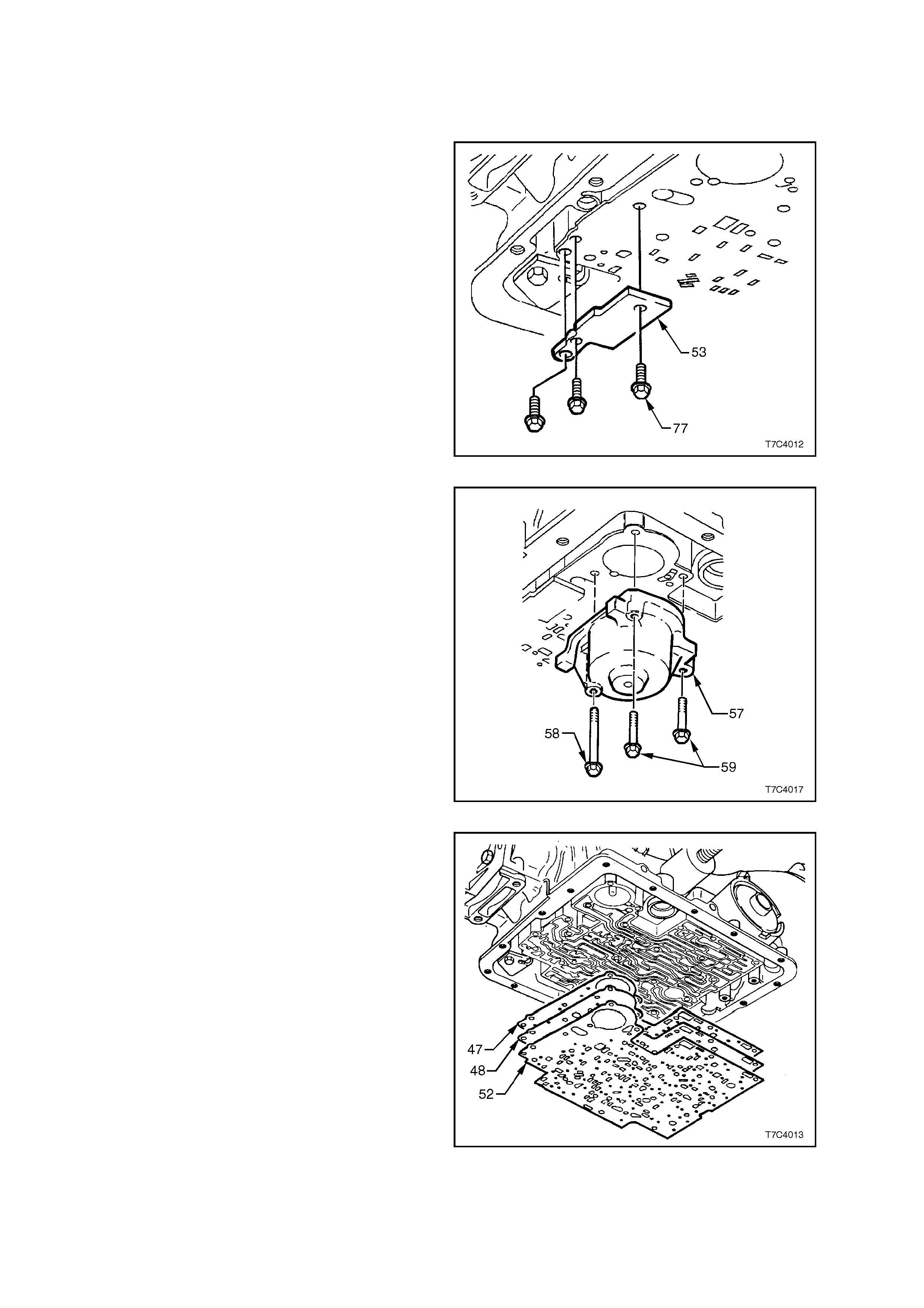
2. Remove the three spacer plate retaining plate
bolts (77) and plate (53).
Figure 7C4-67
3. While supporting the spacer plate, remove the
1-2 accumulator assembly retaining bolts (58
and 59), then carefully lower the accumulator
assem bly (57) f rom the spacer plat e and set to
one side, assuming that removal of the piston
and springs is not required.
NOTE: The 3-4 accumulator spring may push the
spacer plate away from transmission case when
the accumulator cover is removed.
Figure 7C4-68
4. Remove the spacer plate (48) and two spacer
plate gaskets (47 and 52) from the
transmission case.
IMPORTANT: As the spac er plate and gask ets are
lowered from the transmission, a check ball and
the 3-4 accumulator spring will also come away.
Do not lose the check ball.
Figure 7C4-69
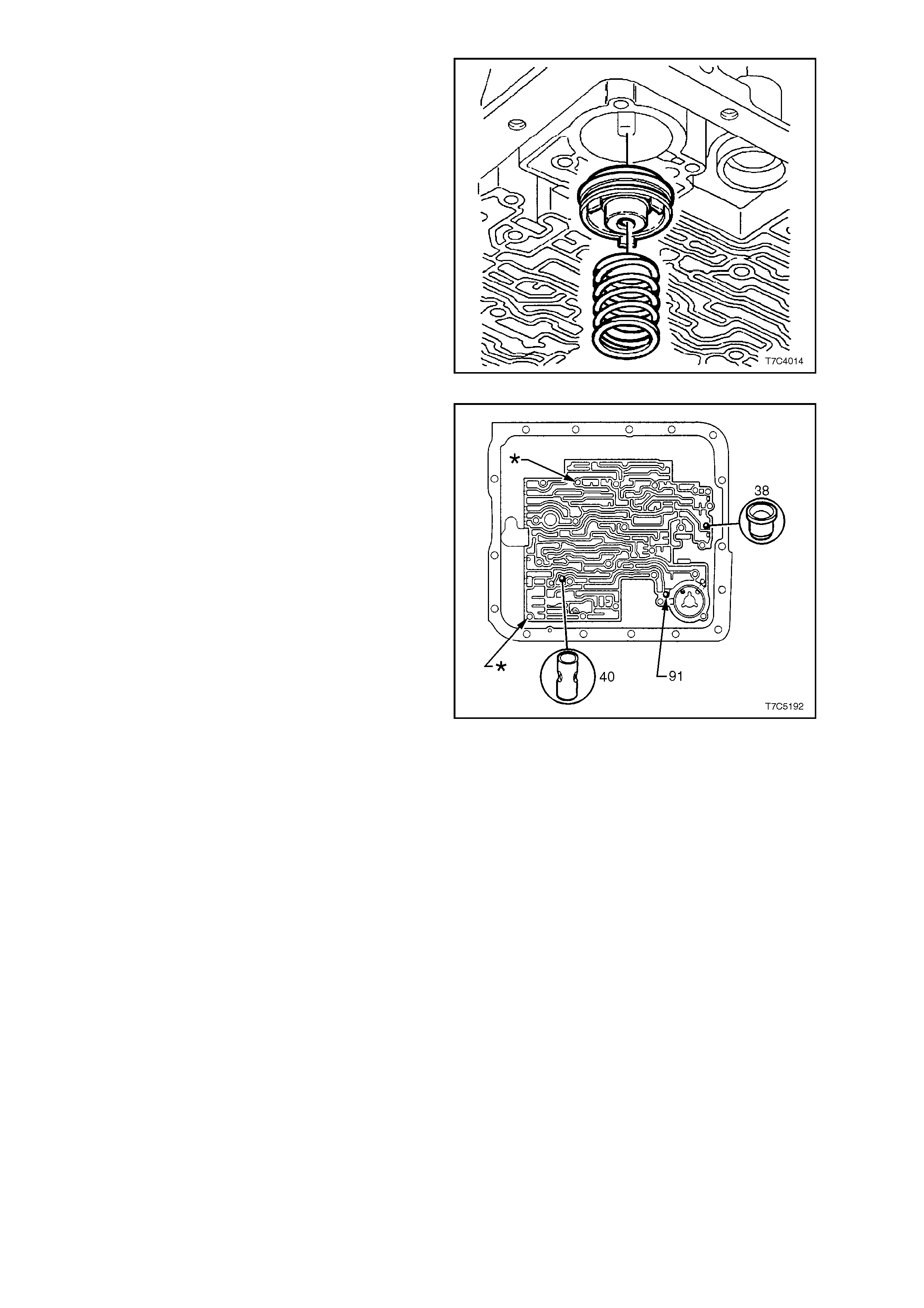
5. If removal of the 3-4 accumulator piston is
required, use snap ring pliers and rotate the
piston while pulling it from the case. Remove
and discard the piston seal.
NOTE: For the HAD trans m ission fitted to t he GEN
III V8 engine, there is no 3-4 accumulator spring
fitted.
Figure 7C4-70
6. The c heckball (91), 3rd accum ulator check ball
assembly (40) and orifice cup plug (38) in the
transmission case, are located, as shown.
NOTE: The locations marked as (,
,,
,) are for two
guide studs to be inserted during reassembly.
Figure 7C4-71
CLEAN AND INSPECT
1. Wash components in clean solvent.
2. Dry with compressed air.
3. Inspect pist on f or por os ity, ring gro ov e damage
or pin hole damage.
4. Check spring for distortion or damage.
5. Inspect accumulator bore for wear or damage.
6. Check spacer plate, filter screens and check
balls for damage.
REINST ALL
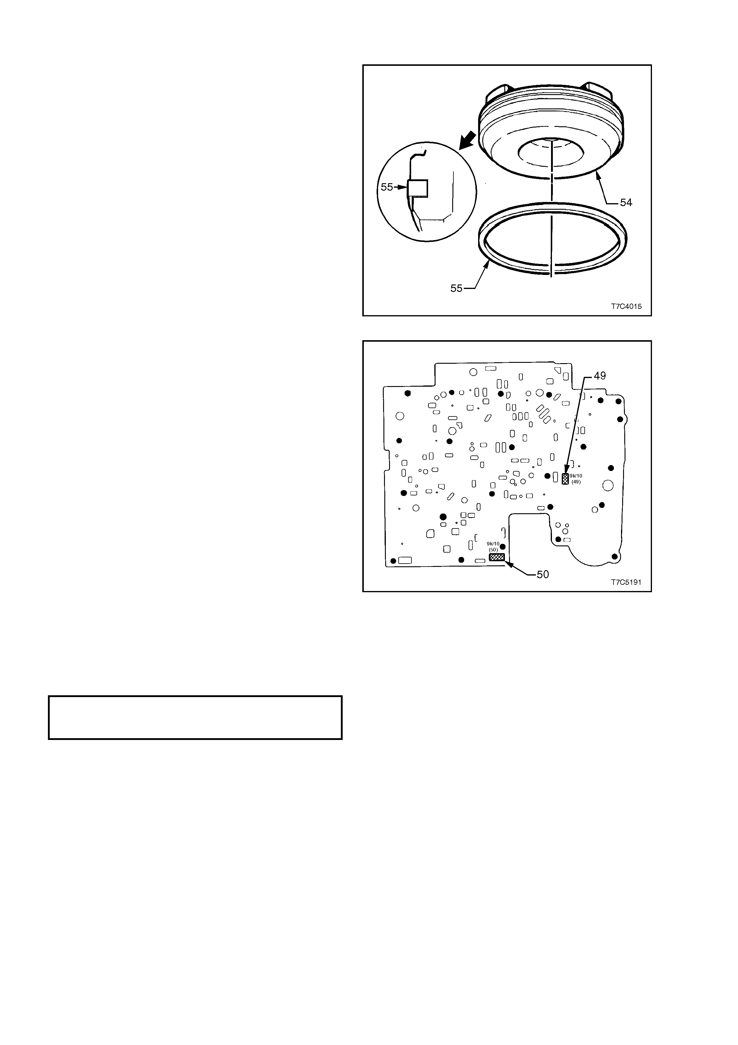
1. Lubricate new seal (55) with petroleum jelly
and install on 3-4 accumulator piston (54).
2. Reinstall pin in case.
3. Reinstal l piston onto p in so that the pisto n side
with three lugs, faces out of bore, as indicated.
4. Install guide pins (J25025-1) into transmission
case in the locations shown (,
,,
,) in Figure 7C4-
70.
NOTE: Ensure that the guide pins are fully installed
so that no thread is visible. Otherwise the spacer
plate gasket could become caught in a thread
during installation, resulting in incorrect alignment.
5. Reinstall the check ball in the transmission
case as shown (Figure 7C4-70) and use
petroleum jelly to hold the ball in place.
6. Reinstall 3-4 accumulator spring (if fitted).
Figure 7C4-72
7. If a new spacer plate is to be install ed, it wil l be
necessary to fit two filter screens (49 and 50)
to the spacer plate before fitment. Locations of
these screens are as shown.
8. Reinstall spacer plate with new gaskets that
have been smeared with petroleum jelly and
hold in place until accumulator is reinstalled.
NOTE: The gasket marked 'CA' is fitted between
spacer plate and transmission case and gasket
marked 'VB' is located between spacer plate and
control valve body. Refer to Spacer Plate and
Gaskets, in 2. TRANSMISSION CHANGES FOR
MY2003, in Section 7C1 - GENERAL
INFORMATION.
Figure 7C4-73
9. Reinstall accumulator. Refer to
3.9 1-2 ACCUMULATOR in this Section.
10. Reinstall spacer plate support plate (53) and
retaining bolt (77), tightening to the correct
torque specification.
SPACER PLATE SUPPORT
PLATE RETAINING BOLT
TORQUE SPECIFICATION 12 Nm
11. Remove guide pins (J25025-1) from the
transmission case.
12. Reinstall control valve body. Refer to
3.11 CONTROL VALVE BODY in this Section.
13. Reinstall filter and oil pan. Refer to 3.1 FLUID
CHANGE AND FILTER REPLACEMENT in
this Section.
3.13 FILLER TUBE
LT Section No. – 04A-010
REPLACE
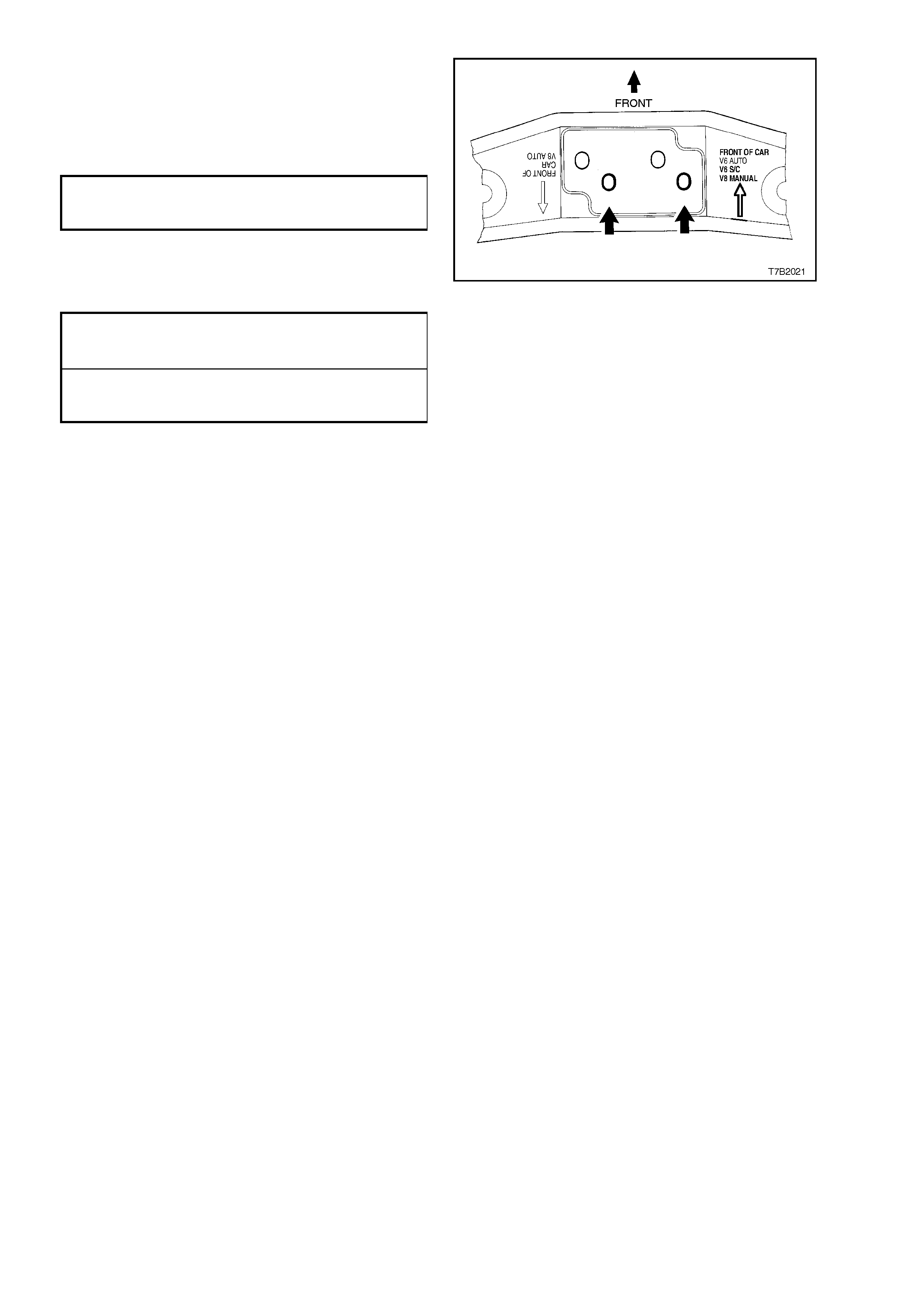
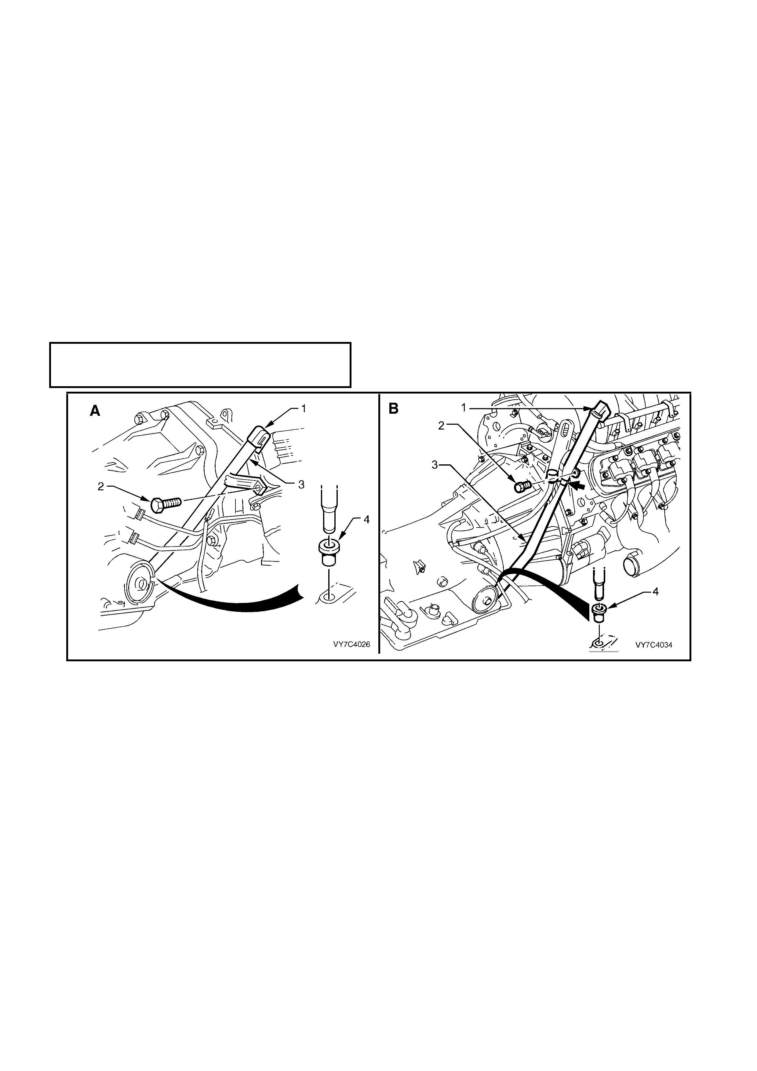
NOTE: In the views shown in Figure 7C4-71, ‘A’ represents the V6 engine, while view ‘B’ shows the GEN III V8
arrangement.
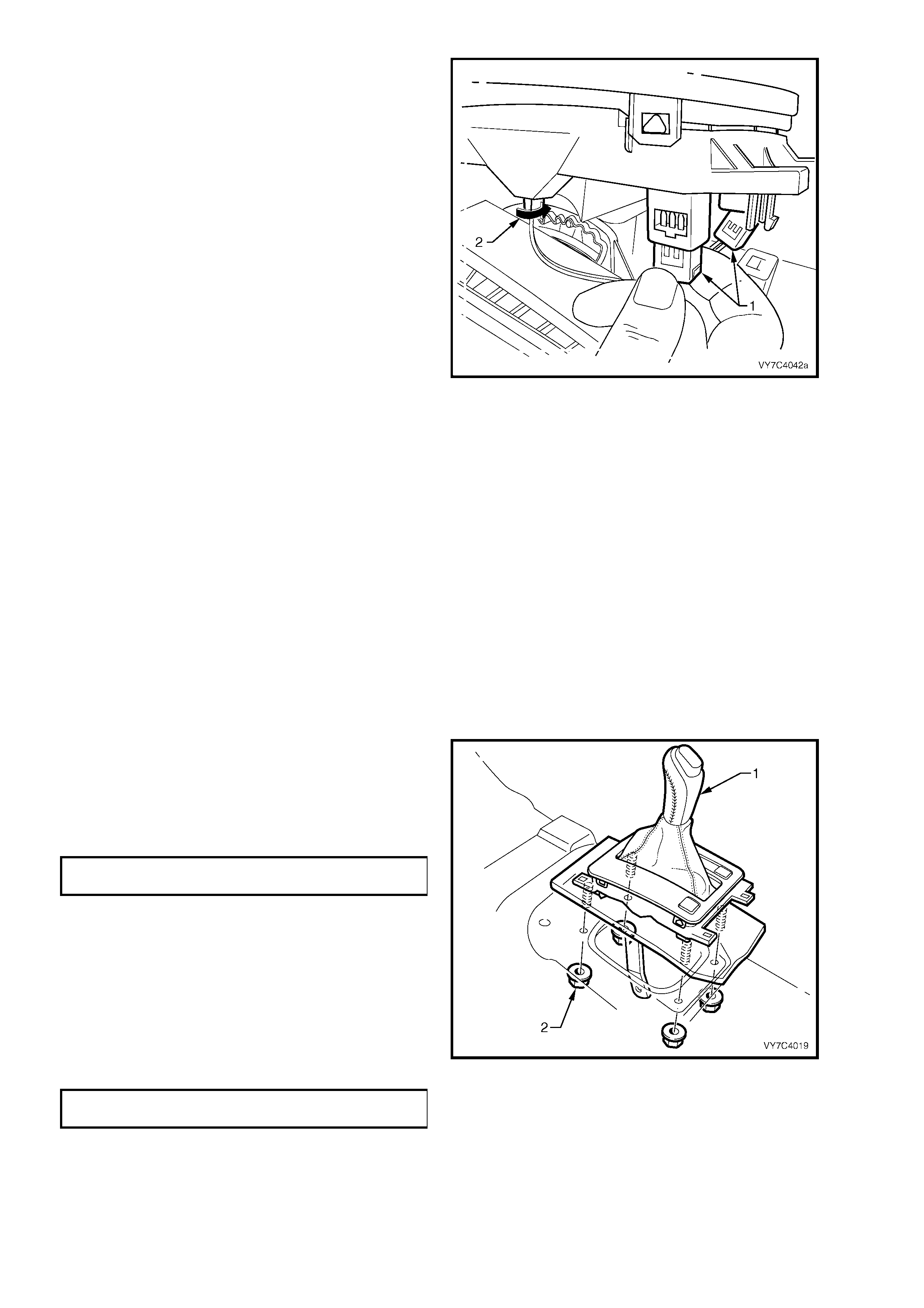
1. Disconnect the battery ground lead.
2. Release the dipstick lock down lever (1) and remove the transmission dipstick.
3. Remove the bolt securing transmission filler tube to the right hand cylinder head.
4. Using a twisting/pu ll in g motion, r emove f iller t ube ( 2) from transmiss ion cas e s ea l ( 4) and with dr a w f rom engine
compartment.
5. Release th e transmis sion breather tube fr om the dipstick bracket ( arrow), after lower ing the d ipstick enough to
gain access.
6. Replace the filler tube seal (4), lubricate with transmission fluid and install into transmission case.
7. Reinstall th e f il ler t ube ( 2 or 6) i n th e r e vers e or der t o removal bu t sec ur e the tran smis s ion breat her hose to the
hole in the filler tube bracket (arrow), before the tube is installed into the transmission case seal (4).
8. Tighten the filler tube bracket retaining bolt (3 or 7) to the correct torque specification.
FILLER TUBE RETAINING
BRACKET BOLT
TORQUE SPECIFICATION All Engines 30 Nm
Figure 7C4-74
3.14 TRANSMISSION ASSEMBLY
LT Section No. – 04A-200
REMOVE
1. Disconnect the battery ground lead.
2. Raise vehicle and support on safety stands. Refer to Section 0A GENERAL INFORMATION in the MY 2003
VY and V2 Series Service Information, for the location of jacking and support points. Place drip tray beneath
transmission.
3. Remove filler tube as detailed above.
4. Plug filler tube hole to prevent dirt entry.
5. Remove propeller shaft assembly: Refer to Section 4C PROPELLER SHAFT AND UNIVERSAL JOINTS, in
the MY 2003 VY and V2 Series Service Information.
6. Disconnect electrical connectors from vehicle speed sensor and oxygen sensors.
7. If not alr eady rem oved in Step 5, remove ex haust pipe s from the ex haust manifol ds to the re ar of the cata lytic
converter (only required for the V6 engine).
8. Hold the transmission selector lever with an adjustable wrench while loosening the retaining nut. Remove the
selector lever from the manual shaft.
9. Remove the starter motor. Refer 6D1-2 (V6), 6D2-2 (V6 S/C) or 6D3-2 (GEN III V8) STARTING SYSTEM, in
the MY 2003 VY and V2 Series Service Information, for the necessary procedure.
10. Remove the close-out cover retaining screw on each side, then remove both covers.
NOTE: Figure 7C4-72 shows the V6 arrangement (‘A’) and GEN III V8 (‘B’) for the starter motor side only. The
procedure for the remaining side is similar.
Figure 7C4-75
11. Mark relative position of torque converter and flexplate, then remove three torque converter to flexplate
attaching bolts. Discard the removed bolts.
Techline
12. For those vehicles fitted with the GEN III V8
engine, remove the two bolts (2) securing the
catalytic converter bracket (1) to each catalytic
converter.
Figure 7C4-76
13. Use a sh arp scriber to m ark the ex act locati on of the crossm ember (2) to the sid e fram e, before loos ening any
of the four crossmember to side frame attaching bolts (3).
IMPORTANT: This s tep is c ritic al t o th e c or rec t po wer t rain alignment on re as sembl y. If not ca rr ied ou t, th en veh icle
vibration and/or handling problems could result!
14. Remove two bolts (5) securing rear engine mount to transmission.
NOTE: For those vehicles fitted with the GEN III V8 engine, also remove the two nuts (6) securing the engine
mount to the catalytic converter brace.
15. Support transmission with a jack. Do not place the support beneath case extension or oil pan.
16. Rem ove the f our cr ossm em ber to side f ram e bolts (3) and r em ove cros sm ember ( 2) and rear eng ine m ount (1)
from the vehicle.
NOTE: View ‘A” shows the V6 arrangement, while view ‘B’ shows the GEN III V8.
Figure 7C4-77
17. Lower rear of transm ission to prov ide suffic ient
clearance, without placing any strain on any
electrical wiring and remove electrical
connector from the transmission as follows:
NOTE: Take care when lowering rear of
transm ission that the inl et m anifold does not hit th e
firewall.
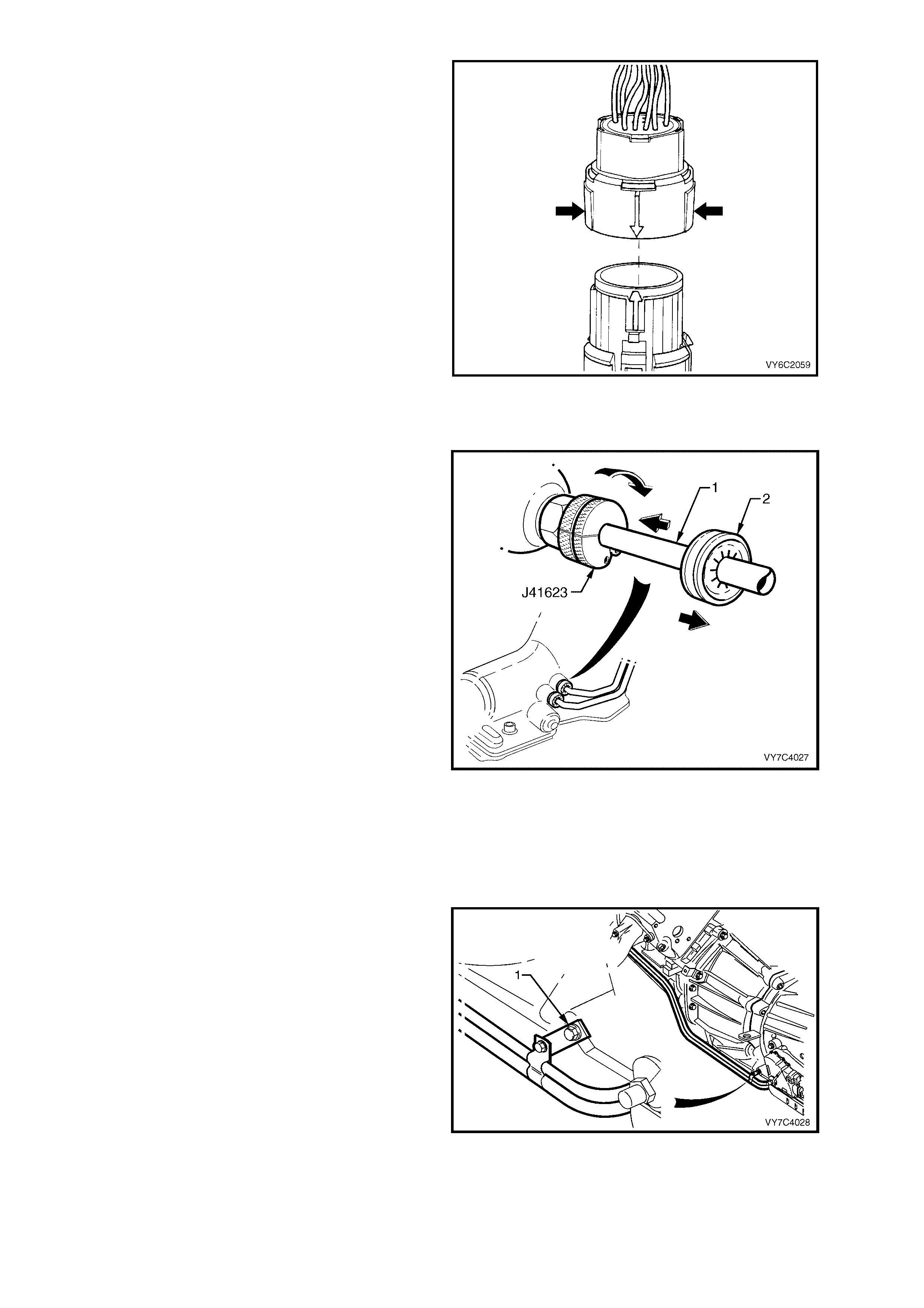
• Roll back the dust boot from the connector, to
gain access to the connector.
• Squeeze the widest side of the connector
inwards (A) and PULL DIRECTLY UPWARD.
IMPORTANT: Do not wriggle the connector
from side to side while removing it! If this
situation occurs, there is a very real possibility
of the connector pins being permanently
damaged.
18. Remove the wiring harness clip retaining
screws from both the right and left sides of the
transmission case.
Figure 7C4-78
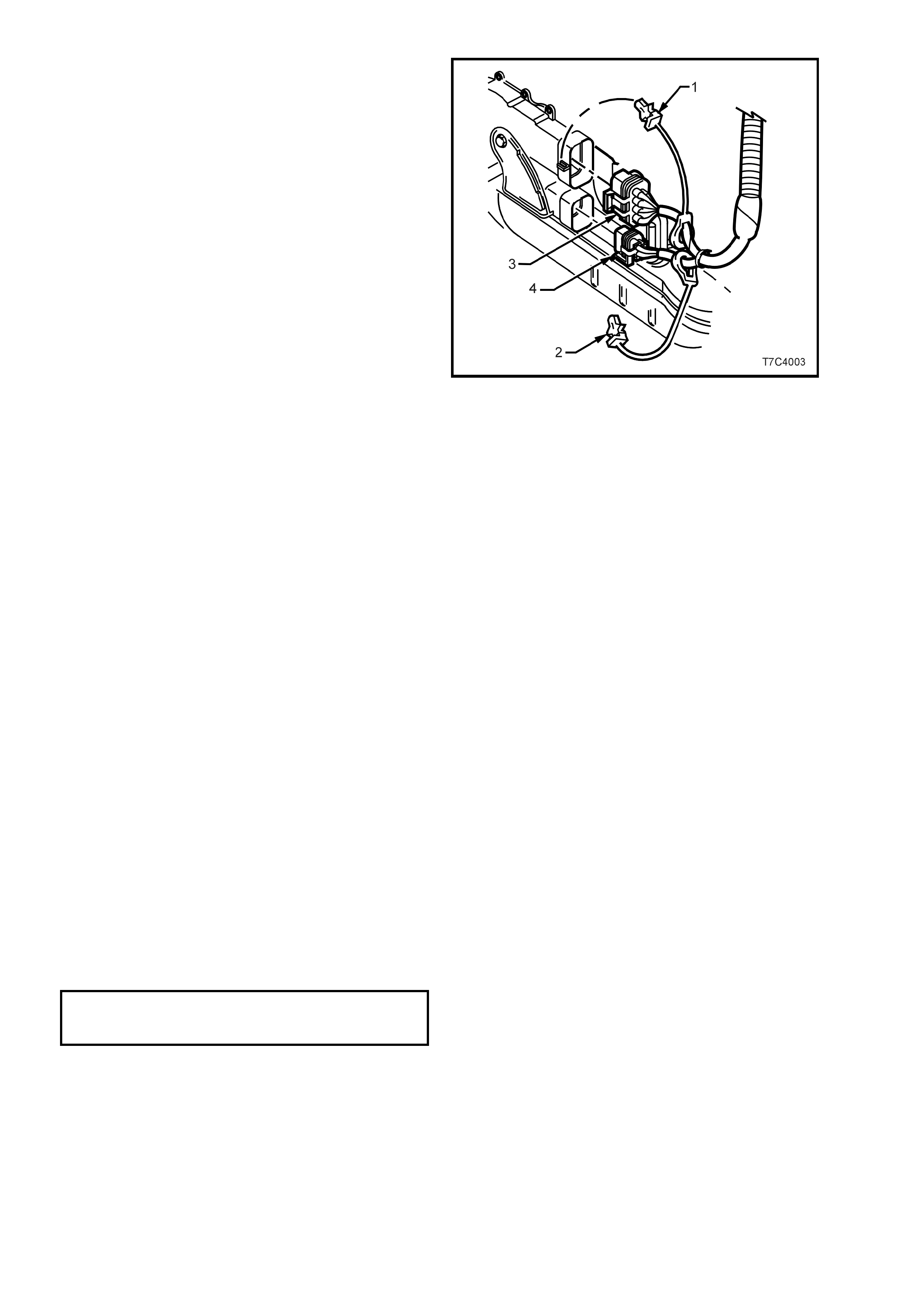
19. While the rear of the transmission is lowered,
disconnect cooler pipes from transmission.
a. Release the verif ier disc (2) by pulling back
with the fingertips, then slide back down
the cooler pipe (1).
b. Open cooler line release Tool J-41623-B
and slip over cooler pipe to be
disconn ected from the transm ission, abo ve
the verifier disc (2), as shown.
c. Slide the release tool along the pipe to
engage with the quick-connect fitting.
d. While pushing inwards, rotate the tool
about one sixth of a turn to release the
spring clip holding the pipe.
e. With the release tool held in this position,
pull back on the cooler pipe to release.
f. Repeat this process with the remaining
pipe and quick-connect fitting.
g. Plug all openings to prevent foreign m atter
entry.
NOTE: Should the spring clip and/or O-ring seal in
the “Jiffy Tite” quick connect fitting be damaged
during the pi pe removal pr o c ess , then the c omplete
fitting must be replaced.
Figure 7C4-79
h. On GEN III V8 engines, remove the front
bolt of the Neutral Safety and Back-Up
Lamp switch (1) that also secures the
cooler pipe bracket.
i. Plug all open pipes and quick-connects to
prevent dirt entry.
Figure 7C4-80
20. Remove the wiring harness CPA (Connector
Position Ass urance) secur ity p in (1 and 2) from
the neutra l start and back -up lamp s witch, then
remove the connectors (3 and 4) from the
switch.
Figure 7C4-81
21. Lower rear of trans miss ion f urther if nec es sary,
to gain access to the converter housing to
engine bolts. Then, using a long socket
extension, a universal joint and a suitable size
socket, remove the remaining converter
housing bolts (and nut, for V6 engine).
22. Support transmission assembly on a suitable
cradle and secure. Also place a suitable
support under engine oil pan rail to support
engine after transmission has been removed.
23. Remove transmission assembly from the
vehicle.
24. Install suitable converter holding tool to
prevent converter becoming dislodged.
REINST ALL
IMPORTANT: If transmission has been replaced, the fluid is contaminated, a converter and/or oil pump has been
replaced, a reverse flush of the cooler lines and a flow rate check MUST be completed. Refer 2.2 TRANSMISSION
COOLER REVERSE FLUSH AND FLOW RATE CHECK in this Section for details.
Reinstallation is the reverse of the removal procedure, noting the following points:
1. Ensure transmission and engine mating surfaces are clean and free of burrs.
2. Lubricate the torque converter spigot with high temperature, wheel bearing grease, prior to installation.
3. Ensure locating dowels completely enter converter housing holes.
4. Prior to reinstalling NEW converter to flexplate bolts, ensure locating marks on converter and flexplate are
aligned.
5. Remove the access ho le cover plate in the lo wer surfac e of the torqu e converter housing an d lever the tor que
converter forward, prior to installing and tightening the torque converter to flexplate attaching bolts. Reinstall
the access hole cover plate.
6. Apply thread s ea lan t s uc h as Loc tit e 24 2 or eq ui va le nt the c le ane d, tor que c o nv erter bol t thre ads . Tighten bo l ts
to the correct torque specification.
TORQUE CONVERTER TO
FLEX PLATE BOLT
TORQUE SPECIFICATION 65 Nm
7. The oil filler tube seal must be installed into transmission before installing filler tube to avoid damage to the
seal.
8. Remove plugs from cooler pipes and quick connect fittings, wipe the pipes clean, then smear with clean
automatic transmission fluid, before pushing each pipe into its respective quick connect fitting. Attempt to pull
the pipe free t o e ns ure c or r ec t en gag ement. S lid e e ach v er if ier d isc up to th e q uick c onnec t f itting . If it en gag es
with the fitting, then the pipe has been correctly installed.
9. The tightening sequence for the transmission to engine block bolts (and nut (4) for V6) is as shown in Figure
7C4-82. View ‘A’ is for the V6 engines and view ‘B’ for the GEN III V8.
NOTE 1: The bolt (2) and nut (4) location is as shown for the V6 transmission, in view ‘A’.
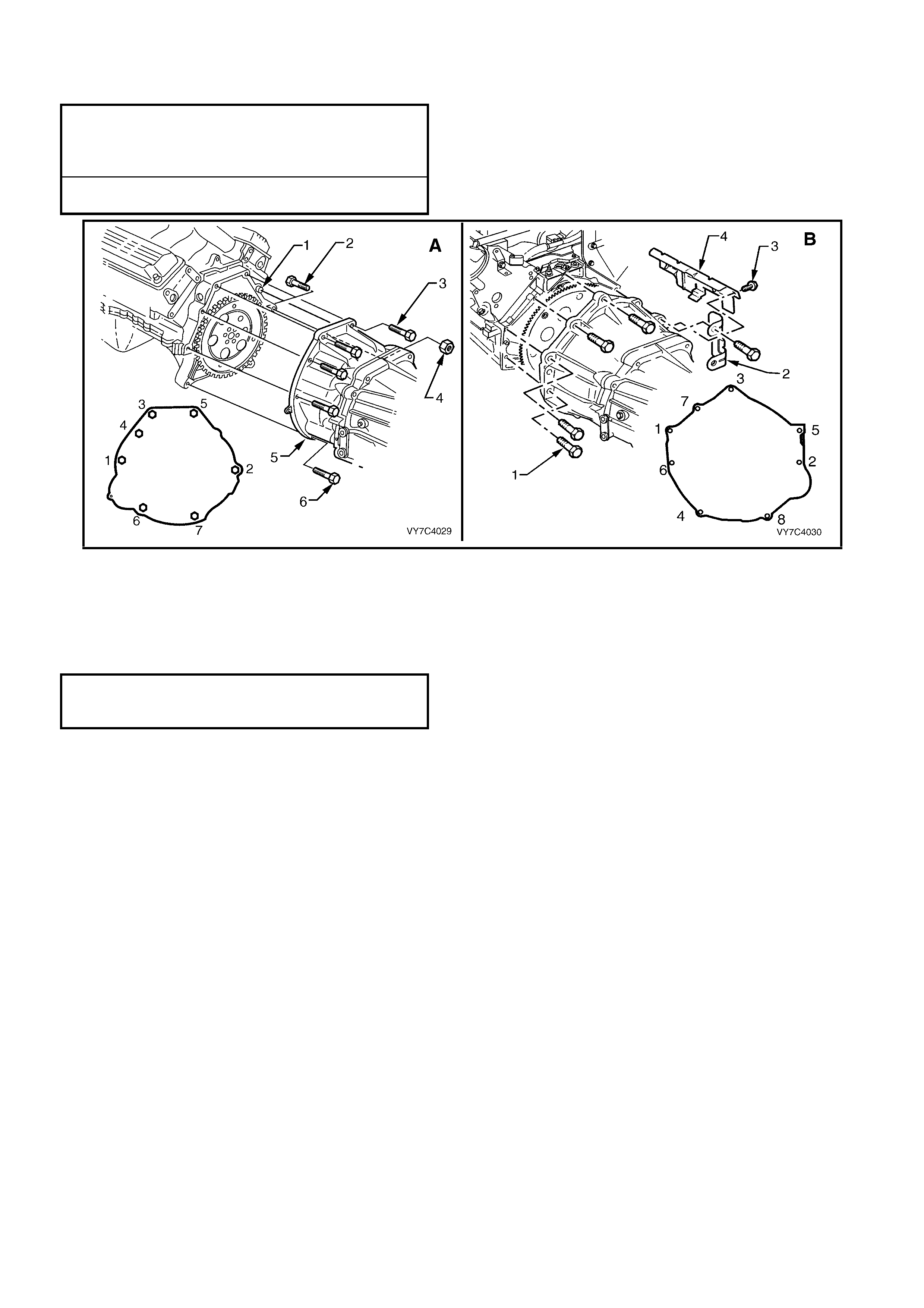
NOTE 2: With the V8 transmission, the bolt (4) also holds the dipstick tube bracket (view ‘B’).
Tighten bolts to the correct torque specification.
TORQUE CONVERTER HOUSING
TO ENGINE BOLT TORQUE
SPECIFICATION V6 Engines 55 Nm
GEN III V8 Engine 38 Nm
CLOSE-OUT COVER SCREW
TORQUE SPECIFICATION 8 Nm
Figure 7C4-82
10. Prior to installing the wiring harness connector to the transmission pass-thru connector, check that all
connector pins and seals are in sound condition. Push down on the connector body until a 'click' is heard.
Reinstall the dust boot, checking that it is not torn and is located correctly.
11. Reinstall the two harness bracket screws to the transmission case lugs, tightening to the correct torque
specification.
TRANSMISSION WIRING HARNESS
RETAINING SCREW
TORQUE SPECIFICATION 10 Nm
12. Tighten all bolts and nuts to the torque settings, as specified in 5. TORQUE SPECIFICATIONS, in this Section.
13. Lower vehicle and check fluid level, refer to 2.1 FLUID LEVEL CHECK, in this Section.
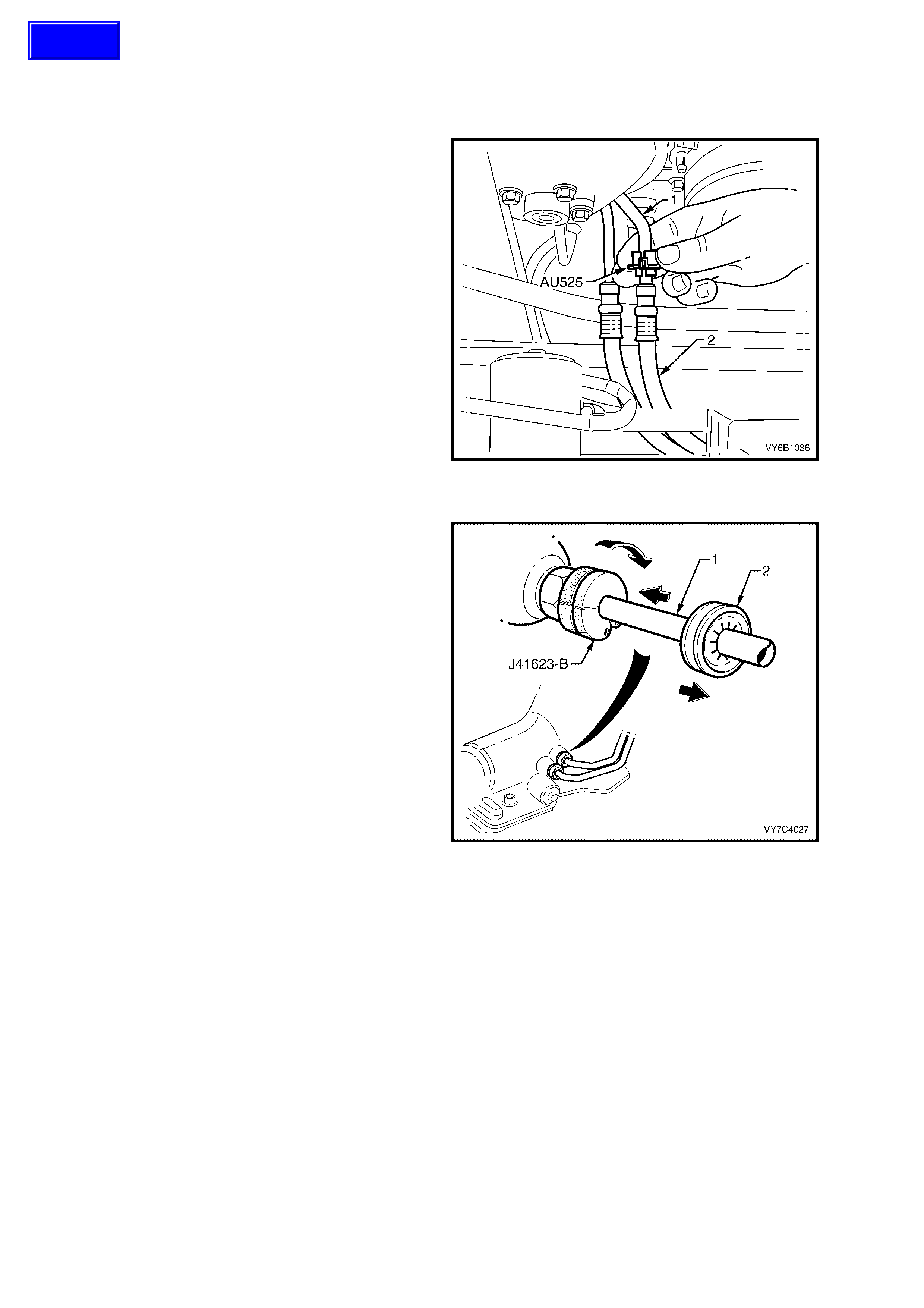
3.15 TRANSMISSION COOLER PIPES/HOSES
LT Section No. – 04A-150
V6 ENGIN ES – REMO VE
1. Disconnect th e transm ission oil cooler hose ( 1)
quick connect fittings, using Tool No. AU525,
as follows:
a. Unlatch the release tool AU525, slip over the
radiator end of the cooler pipe (1) to be
disconn ected, then cl ose and re-latc h the ends
together.
b. Grasp the cooler hose (2) and while pushing
forwards on Tool AU525, push back on the
hose to release the connection, then pull the
pipe rearward, to release. Repeat for the
second hose, as required.
c. Plug hose and oil cooler pipe openings to
prevent foreign matter entry.
NOTE: As the hoses are permanently fitted to the
cooler pipes leading to and from the radiator
cooler, if hose replacement is required, then the
complete pipe/hose combination must be fitted.
Figure 7C4-83
Transmission Oil Cooler Pipes
2. With the rear of the transm ission lo wered (r efer
to Steps 5 to 9 inclusive, of 3.8 EXTENSION
HOUSING AND/OR BUSH, in this Section),
disconnect cooler pipes from transmission.
j. Release the ver ifier dis c (2) by pulling bac k
with the fingertips, then slide back down
the cooler pipe (1).
k. Open cooler line release Tool J-41623-B
and slip over cooler pipe to be
disconn ected from the transm ission, abo ve
the verifier disc (2), as shown.
l. Slide the release tool along the pipe to
engage with the quick-connect fitting.
m. While pushing inwards, rotate the tool
about one sixth of a turn to release the
spring clip holding the pipe.
n. With the release tool held in this position,
pull back on the cooler pipe to release.
o. Repeat this process with the remaining
pipe and quick-connect fitting.
p. Plug all openings to prevent foreign m atter
entry.
3. Carefully remove the cooler pipes from the
vehicle.
Figure 7C4-84
Techline
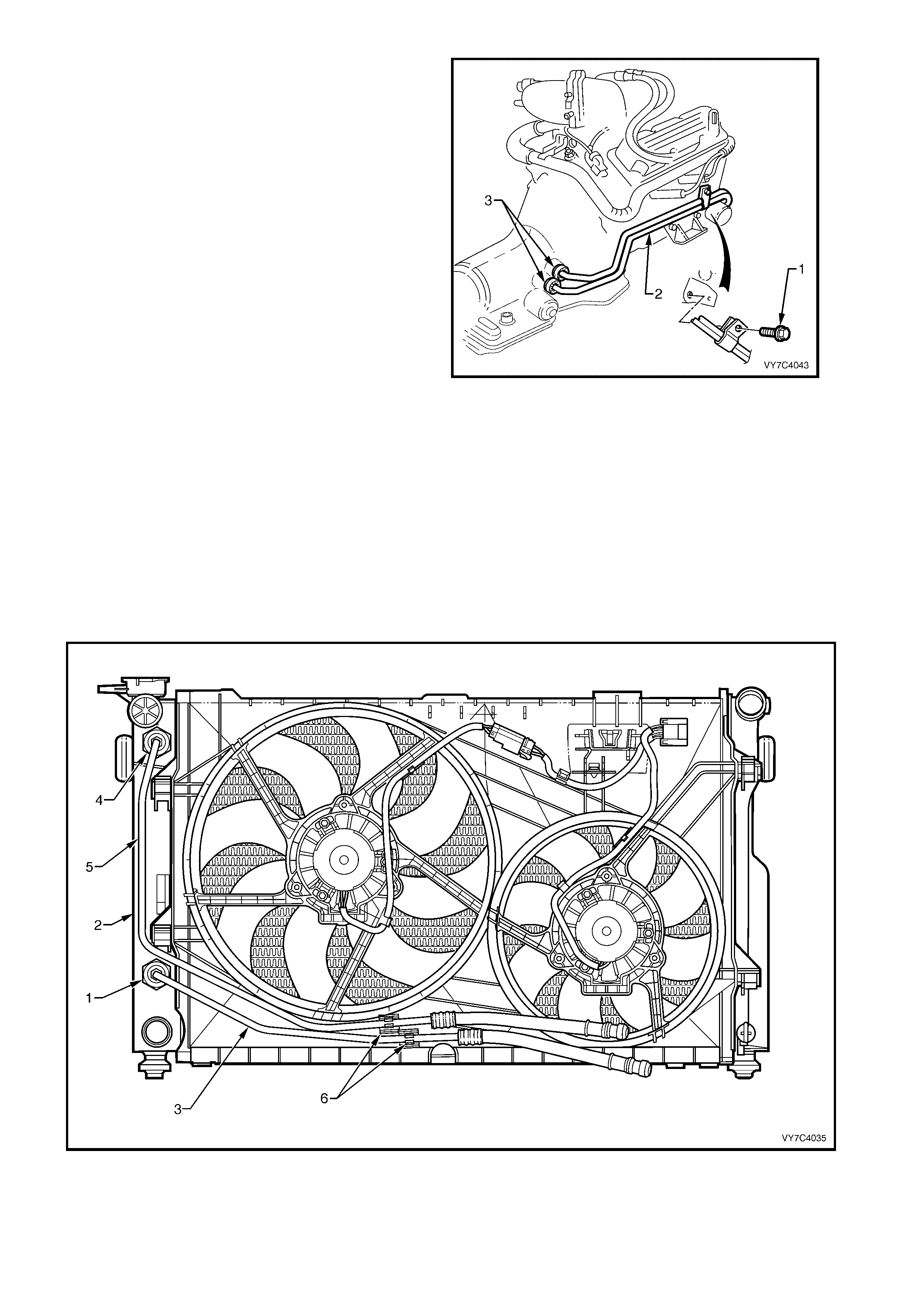
NOTE: Should the spring clip and/or O-ring seal in
the “Jiffy Tite” quick connect fitting be damaged
during the pi pe removal pr o c ess , then the c omplete
fitting must be replaced.
4. Remove the clamp bolt (1) securing the
transmission cooler pipes (2) to the right hand
side of the engine, as shown.
5. Remove the cooler pipes (2) from the vehicle
and separate if required, by removing the pipe
clip.
NOTE: While the V6 Supercharged engine is
shown, the procedure is similar for both V6
engines.
Figure 7C4-85
Radiator Cooler Pipes/Hoses
6. Disconnect the transm ission cooler p ipes from the cooler hoses at the f ront, lower r ight side of th e engine ba y
(refer to Step 1 in this procedure).
7. Referring to Figure 7C4-86, hold the lower fitting (1) at the left radiator tank (2) with a back-up spanner and
disconn ect the oi l coo ler flu id retur n pipe (3) fr om that locatio n. Plu g the op ened c onnec tions t o pre vent f oreign
matter entry.
8. Repeat this procedure for the upper fitting (4) and pipe/hose assembly (5) at the radiator left hand tank (2).
9. Carefully remove the pipes from the clips (6) that form an integral part of the radiator shroud (7). Remove the
radiator cooler pipes/hoses (3 and 5) from the vehicle.
NOTE: While the V6 Standard Fan arrangement is shown in Figure 7C4-86, the fluid cooler line arrangement for
the High Power fan specification, is similar.
Figure 7C4-86 – Oil Cooler Pipe/Hose Layout – V6 Standard Fan
Legend
1. Cooler Pipe Fitting – Lower
2. Radiator End Tank - Left 3. Fluid Cooler Pipe – Fluid Feed Return
4. Cooler Pipe Fitting – Lower 5. Fluid Cooler Pipe – Fluid Feed
6. Cooler Pipe Clips
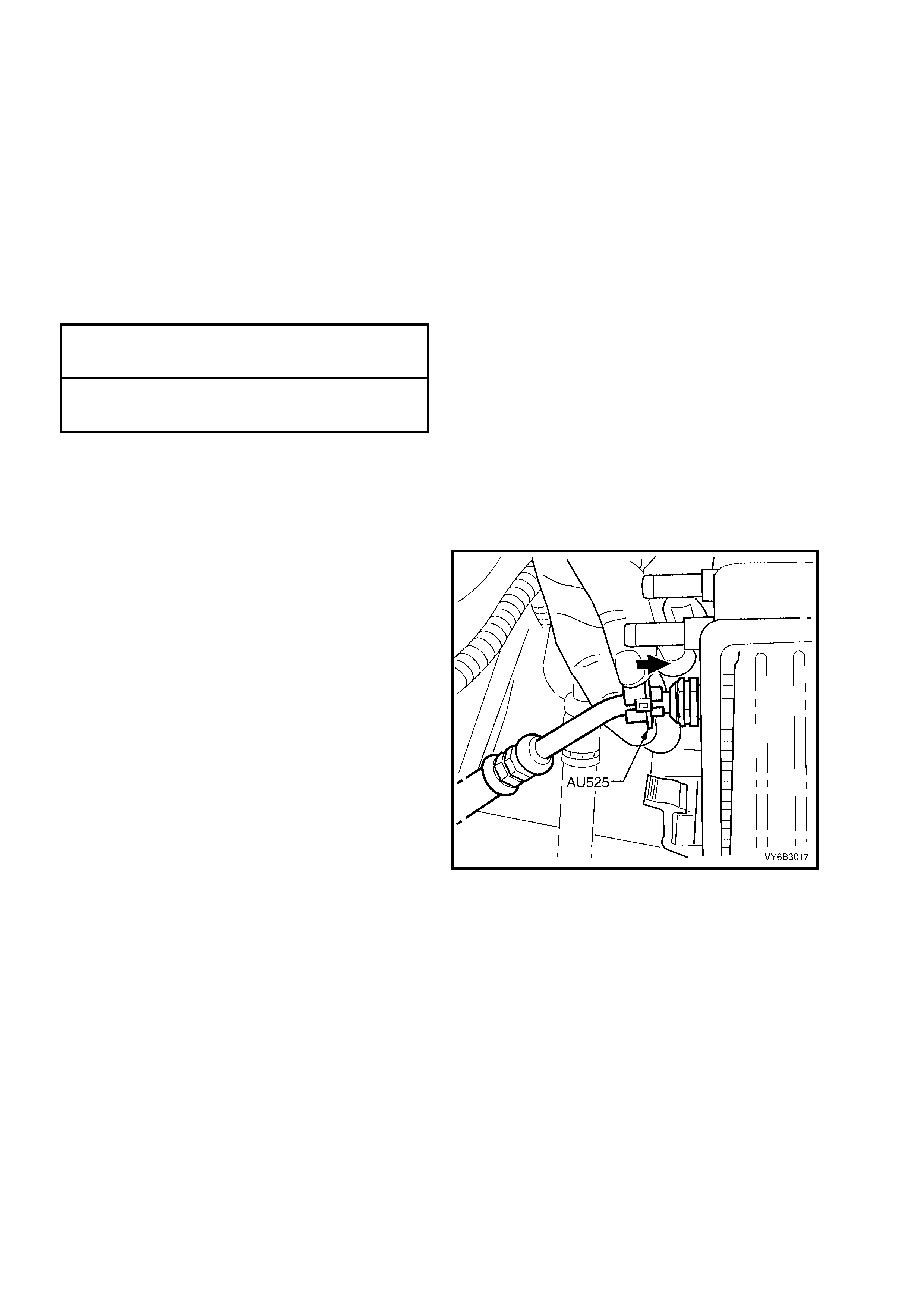
V6 ENGIN ES – REIN STALL
The installation process of the oil cooler pipes/hoses, is the reverse to removal, except for the following:
1. Before reinstalling any quick connect fitting, remove plugs from pipe and hose fittings and wipe all exposed
parts.
2. Smear clean automatic transmission fluid to each cooler pipe end, then push into the flexible hose quick
connect fittings. As a security check, tug on each to ensure correct engagement.
3. At the transmission end, again clean the pipe ends and proceed as detailed in Step 2. As a further security
check, ensure that each verification disc can be pushed into place over the quick connect fitting. If difficulty is
experienced, then the pipe has not been com pletely reinstalled. Rem ove and repeat the reinstallation process
again, until the verification disc can be clipped into place over the transmission quick connect fitting.
4. Ensure that all pipe clamps are reinstalled correctly and that the routing of pipes/hoses are as shown in the
removal illustrations.
5. Ensure that all fasteners and fittings are tightened to the correct torque specifications.
TRANSMISSION OIL COOLER
PIPE BRACKET BOLT
TORQUE SPECIFICATION All Engines 28 Nm
OIL COOLER PIPE
TO RADIATOR FITTING
TORQUE SPECIFICATION V6 Engines 25 Nm
6. Check for leaks and top up transmission fluid
level as required. Refer to 2.1 FLUID LEVEL
CHECK in this Section.
GEN III V8 ENGINE – REMOVE
Transmission Oil Cooler Pipes
1. Disconnect the transmission oil cooler line,
quick connec t f ittin gs at t he r adia tor, us i ng T ool
No. AU525.
a. Open release tool AU525, then close and
clip around the pipe to be disconnected.
b. W hile holding the pipe/flexible hose in with
one hand, push the to ol into c onnection, to
release, then pull back on the pipe.
c. Repeat the above process for the lower
pipe/hose assembly.
Plug all openings in the pipes and oil cooler
quick connect fittings, to prevent transmission
fluid loss and foreign matter entry.
NOTE: As the hoses are permanently fitted to the
cooler pipes leading to and from the transmission,
if hose replacement is required, then the complete
pipe/hose combination must be fitted.
Figure 6B3-87
2. Remove the clamp screw (2) securing the
transm ission cooler pipes to the left ha nd front
of the engine.
3. Remove the clamp screw (3) securing the
transmission cooler pipes to the neutral safety
and back-up lamp switch.
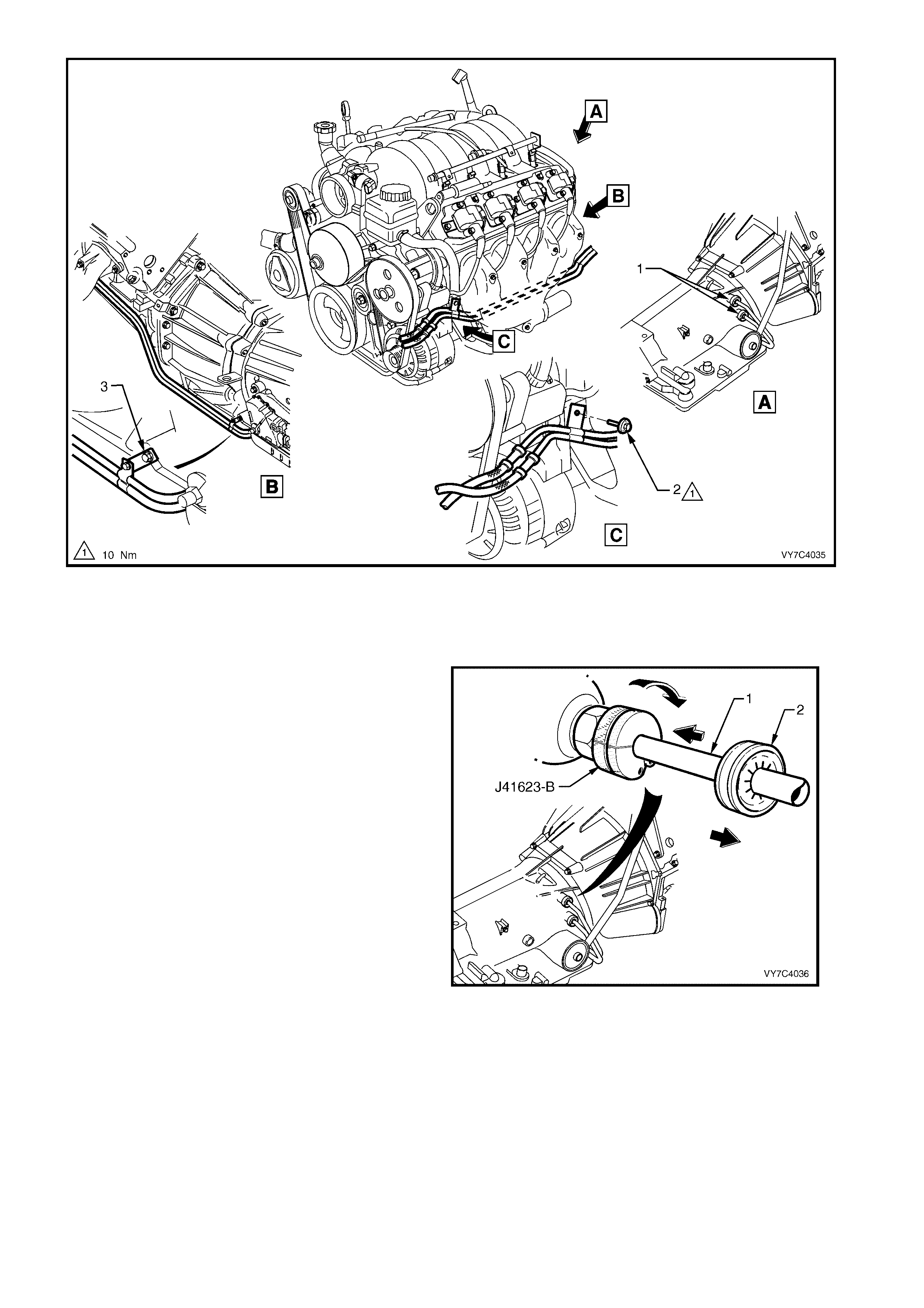
Figure 7C4-88
Legend
1. Quick Connect Fittings 2. Screw – Cooler Pipe Mounting Bracket 3. Bracket – Cooler Pipe to NSBU
Lamp Switch
4. With the rear of the transm ission lo wered (r efer
to Steps 5 to 9 inclusive, of 3.8 EXTENSION
HOUSING AND/OR BUSH, in this Section),
disconnect cooler pipes from transmission.
a. Release the verif ier disc (2) by pulling back
with the fingertips, then slide back down
the cooler pipe (1).
b. Open cooler line release Tool J-41623-B
and slip over cooler pipe to be
disconn ected from the transm ission, abo ve
the verifier disc (2), as shown.
c. Slide the release tool along the pipe to
engage with the quick-connect fitting.
d. While pushing inwards, rotate the tool
about one sixth of a turn to release the
spring clip holding the pipe.
e. With the release tool held in this position,
pull back on the cooler pipe to release.
f. Repeat this process with the remaining
pipe and quick-connect fitting.
g. Plug all openings to prevent foreign m atter
entry.
5. Remove the cooler pipes (4) from the vehicle
and separate if required, by removing the pipe
clip.
Figure 7C4-89
NOTE: Should t he spring clip and/or O -ring sea l in
the “Jiffy Tite” quick connect fitting be damaged
during the pipe removal process, then the
complete fitting must be replaced.
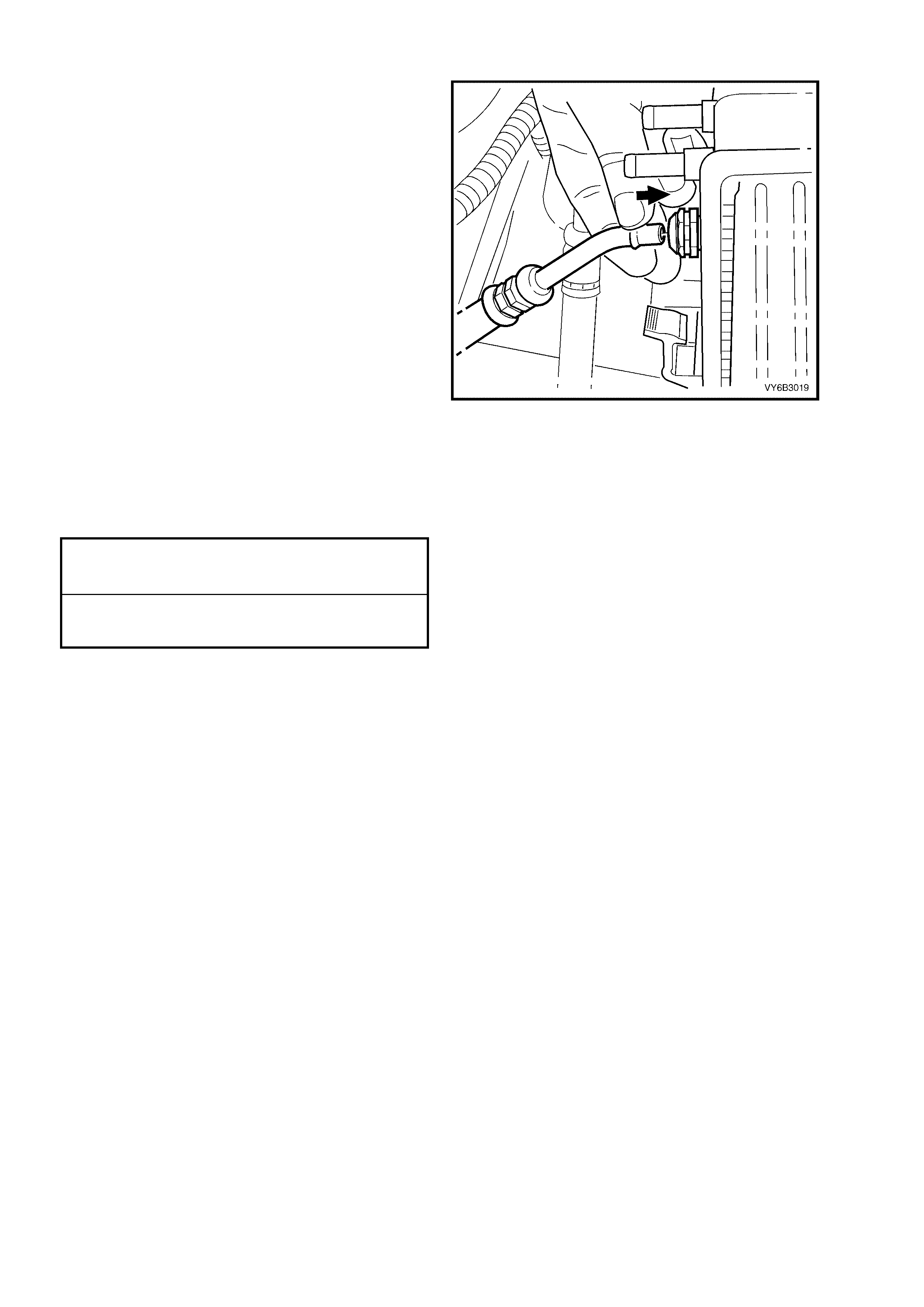
GEN III V8 ENGINE – REINSTALL
1. Remove plugs installed in transmission cooler
pipe and hose openings and wipe all exposed
parts with a clean shop rag.
2. Smear clean automatic transmission fluid to
each cooler pipe end, then push into the
radiator quick connect fittings. As a security
check, tug on each to ensure correct
engagement.
3. At the transmission end, again clean the pipe
ends and proceed as detailed in Step 2. As a
further security check, ensure that each
verification disc can be pushed into place over
the quick connect fitting. If difficulty is
experienced, then the pipe has not been
completely reinstalled. Remove and repeat the
reinstallation process again, until the
verification disc can be clipped into place over
the transmission quick connect fitting.
Figure 7C4-90
4. Ensure that all pipe clamps are fitted correctly
and that pipe/hose are routed as shown in
Figure 7C4-85.
5. Ensure that all fasteners and fittings are
tightened to the correct torque specifications.
TRANSMISSION OIL COOLER PIPE
BRACKET SCREW
TORQUE SPECIFICATION 10 Nm
NEUTRAL START AND BACK-UP
LAMP SWITCH SCREW
TORQUE SPECIFICATION 25 Nm
NOTE: If the neutral st art and back -up lamp switch
position is altered when one of the mounting
screws is removed, then check the switch
adjustment. Refer to 3.4 NEUTRAL START AND
BACK-UP LAMP SWITCH, Adjust, in this Section.
6. Top up transmission fluid level as required,
road test to check vehicle operation, then
check for fluid leaks. Refer to 2.1 FLUID
LEVEL CHECK in this Sec t ion.

4. SPECIFICATIONS
NOTE: For a complete listing of specifications as th ey apply to inter nal components not discussed in this Section,
refer to Section 7C 5 HYDRA-M ATIC 4L60-E AUTOM ATIC T RANSMISSION: UNIT REP AIR, in the MY 2003 VY
and V2 Series Ser v ice Infor mation.
GENERAL:
Type ........................................................................ Hydra-matic 4L60-E
Transmission Code................................................. V6 Engine - 3HFD
V6 Supercharged Engine - 3HND
GEN III V8 Engine - 3HAD
Special Features ..................................................... Electronically controlled shift pattern, feel and torque
converter clutch operation
Selector Location .................................................... Floor mounted console
GEAR RATIOS:
Park (P)................................................................... -
Reverse (R)............................................................. 2.294:1
Neutral (N)............................................................... -
Drive (D).................................................................. 0.696:1
Third (3)................................................................... 1.000:1
Second (2)............................................................... 1.625:1
First (1).................................................................... 3.059:1
SHIFT SPEEDS: ........................................................ Refer to Section 7C3 DIAGNOSIS
OIL PRESSURE: ....................................................... Refer to Section 7C3 DIAGNOSIS
TORQUE CONVERTER:
Number of Elements ............................................... 3 plus torque converter clutch
Maximum Torque Ratio at Stall............................... V6 Engine - 1.63:1 (k=133)
V6 Supercharged Engine - 1.63:1 (k=133)
GEN III V8 Engine - 2.15:1 (k=101)
Nominal Diameter
V6 a nd V6 Su per c harg ed E ngi nes .................... 258 mm
GEN III V8 Engine ............................................. 300 mm
LUBRICANT:
Type Recommended............................................... Dexron III
Capacity (Nominal Only .......................................... Check when transmission is at operating temperature.
Refill ................................................................... V6 Engine - 4.8 litres
GEN III V8 Engine - 5.0 litres
Total (Dry).......................................................... V6 Engine - 7.9 litres
GEN III V8 Engine - 10.6 litres
Fluid Cooling...................................................... Engine coolant to fluid in the left hand radiator tank.
2 – 4 SERVO:
Selective Pin Length
1 Groove ............................................................ 65.82 - 66.12 mm
2 Grooves........................................................... 67.23 - 67.53 mm
No Groove.......................................................... 68.64 - 68.94 mm

5. TORQUE WRENCH SPECIFICATIONS
NOT E: For a complete lis t i ng of tor qu e wrenc h sp ec if ic ations as t hey appl y to int er nal c omponents not dis c u s sed in
this Section, refer to Section 7C5 HYDRA-MATIC 4L60-E AUTOMATIC TRANSMISSION: UNIT REPAIR, in the
MY 2003 VY and V2 Series Service Information. Nm
1–2 Accumulator Cover Bolt.............................................................. 12
Close-Out Cover Securing Screw – All Engines ............................... 8.0
Control Valve Bod y Bolt ..................................................................... 12
Crossmember to Side Rail Attaching Bolt......................................... 58
Extension Housing to Case Bolt........................................................ 45
Oil Pan Screw.................................................................................... 12
Manual Detent Spri ng Reta ini ng Nut................................................. 23
Manual Shaf t Inner Dete nt Lever Nut................................................ 30
Manual Shaft Lever Nut..................................................................... 25
Neutral Start and Back-up Lamp Switch Bolt.................................... 25
Oil Cooler Pipe Fittings to Radiator – V6 Engines ............................ 25
Rear Engine Mounting to Crossmember Nut .................................... 25
Rear Engine Mounting to Transmission Extension Bolt.................... 58
Selector Base Retaining Nut ............................................................. 15
Selector Lever Locking Bolt............................................................... 25
Spacer Plate Su ppor t Plate Bolt........................................................ 12
Speed Sensor Reta in ing Screw ........................................................ 12
Starter Motor Attaching Bolt - All Engines......................................... 50
Starter Motor Brace Bolt - V8 Engine................................................ 15
Torque Converter to Engine Flexplate Attaching Bolt....................... 65
Torque Converter Clutch Solenoid Bolt............................................. 12
Torque Converter Housing to Engine Block Bolt – V6 Engine......... 55
– V8 Engine......... 38
Transmission Filler Tube Bracket Retaining Bolt – All Engines........ 30
Transmission Oil Cooler Pipe Bracket Bolt – V6 Engine................... 28
Transmission Oil Cooler Pipe Bracket Screw – V6 Engines ............ 10
– G EN III V8 Eng ine . 10
Transmission Wiring Harness Bracket Retaining Screw................... 10
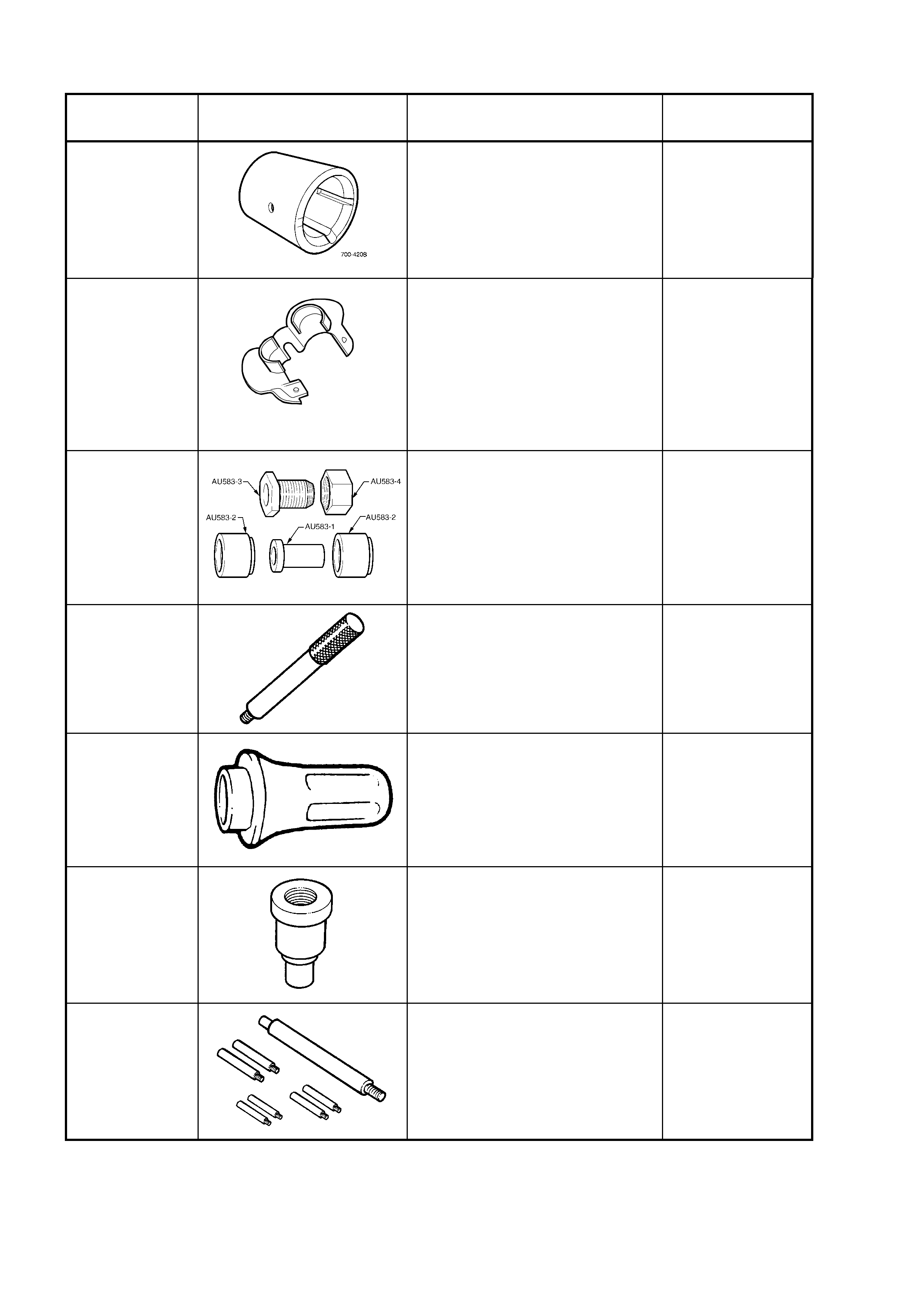
6. SPECIAL TOOLS
TOOL
NUMBER ILLUSTRATION DESCRIPTION CLASSIFICATION
700-4208
PASS-THRU CONNECTOR
RELEASE TOOL
Developed to ease the release of
the pass-thru connector from the
transmission case.
New release.
Unique
AU525
A
U525
QUICK-CONNECT RELEASE
TOOL
Originally released to remove the
fluid cooler lines at the radiator
end on the GEN III V8 engine, this
tool is now used on all engines
with automatic transmission
Previously released.
Mandatory
AU583 SELECTOR SHAFT SEAL
REMOVER/ INSTALLER
Use to remove and install the
manual shaft oil seal, with the
transmission installed in the
vehicle.
Previously released.
Unique
J8092
DRIVER HANDLE
Used in conjunction with Bush
Remover J23062-14.
Previously released.
Unique
J21426 REAR EXTENSION HOUSING
SEAL INSTALLER
Previously released. as 7AT-6.
Unique
J23062-14
BUSH REMOVER
Used in conjunction with driver
handle J8092 to remove and
install extension housing rear
bush.
Previously released.
Unique
J25025-B
DIAL INDICAT OR ST AND AND
GUIDE PIN SET
Used here for the guide pins for
aligning the control valve body
spacer plate
Previously released.
Unique
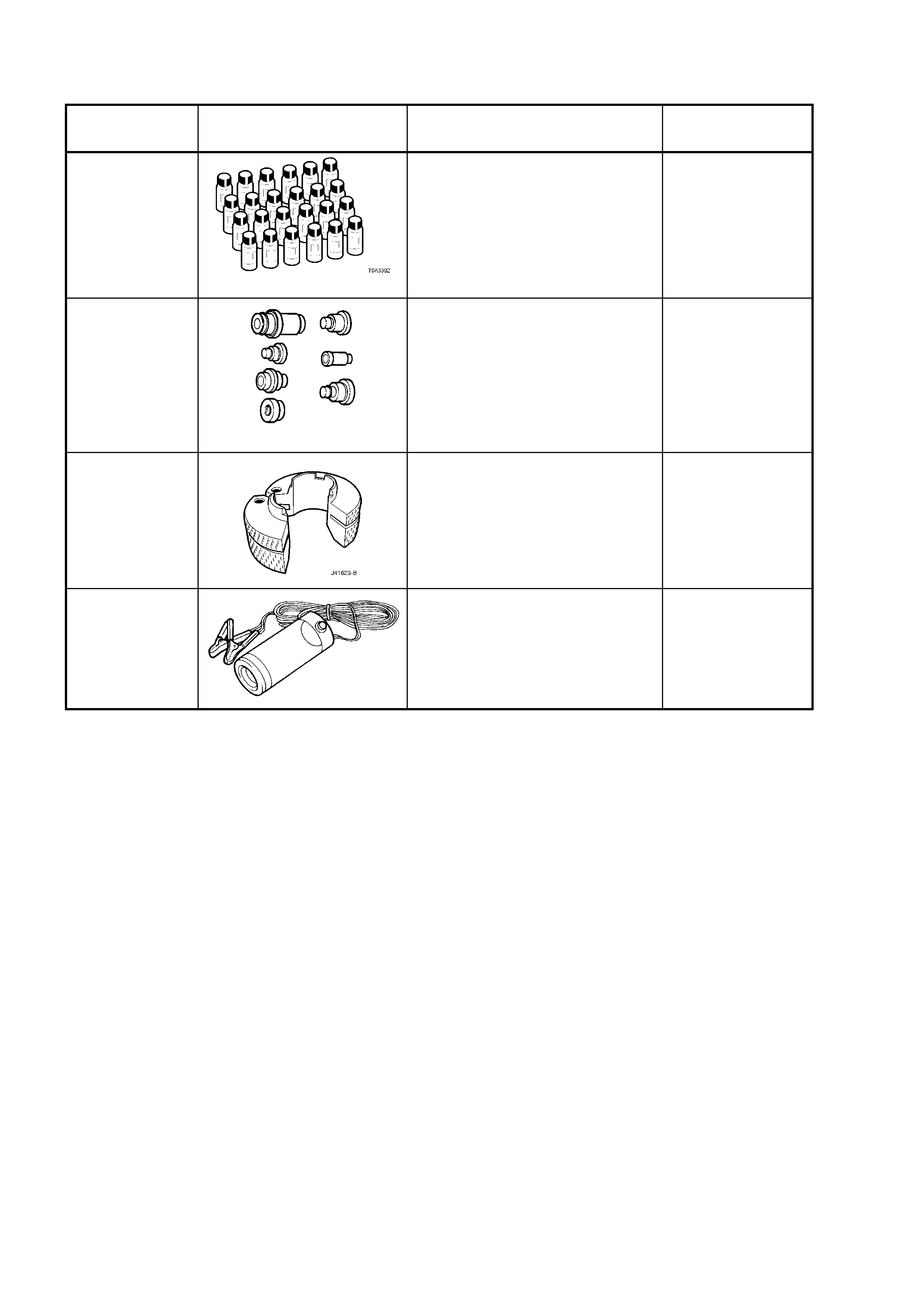
TOOL
NUMBER ILLUSTRATION DESCRIPTION CLASSIFICATION
J28431-B
FLUID DYE
24 x 1 fluid ounce bottles.
Used in conjunction with a black
light such as J42220 to locate
various types of fluid leaks.
Previously released.
Desirable
J34196-B
BUSH REMOVER/INSTALLER
SET
Used to remove / install various
bushings in the automatic
transmission during overhaul
procedures.
Previously released.
Unique
J41623-B
COOLER LINE DISCONNECT
TOOL
Used to disconnect cooler lines at
the transmission end, Quick-
Connects.
New release.
Mandatory
J42220 12 VOLT BLACK LIGHT
Previously released.
Unique