SECTION 8A1 – FUEL TANK
IMPORTANT
Before perfo rming any Service Operat ion or oth er procedure described in this Section , refer to Section 00
CAUTIONS AND NOTES for correct workshop practices with regard to safety and/or property damage.
CONTENTS
1. GENERAL INFORMATION
1.1 MODULAR FUEL PUMP AND SENDER
ASSEMBLY
FUEL PUMP – V6 ENGINE
FUEL PUMP – V6 SUPERCHARGED
ENGINE
FUEL PUMP – GEN III V8 ENGINE
FUEL PUMP – VEHICLES EXPORTED TO
BRAZIL
SINGLE LINE FUEL DELIVERY SYSTEM –
GEN ILL V8 ENGINE
FUEL PRESSURE REGULATOR –
GEN ILL V8 ENGINE
FUEL GAUGE TANK SENDER UNIT
ROLLOVER VALVE – SEDAN, WAGON
AND COUPE
MODULAR FUEL PUMP AND SENDER
ASSEMBLY STRAINERS
1.2 FUEL FILLER CAP
1.3 SYSTEM COMPONENTS
V6 ENGINE
GEN ILL V8 ENGINE
2. SERVICE OPERATIONS
2.1 FUEL TANK – SEDAN AND WAGON
REMOVE
REINSTALL
2.2 FUEL TANK – COUPE
REMOVE
REINSTALL
2.3 FUEL TANK – UTILITY
REMOVE
REINSTALL
2.4 FUEL FILTER – V6 AND V6
SUPERCHARGED ENGINE
REPLACE
2.5 FUEL FILTER – GEN III V8 ENGINE
REPLACE
2.6 MODULAR FUEL PUMP AND SENDER
ASSEMBLY – SEDAN, WAGON AND COUPE
REMOVE
TEST
REINSTALL
2.7 MODULAR FUEL PUMP AND SENDER
ASSEMBLY – UTILITY
REMOVE
TEST
REINSTALL
2.8 FUEL LEVEL SENDER ASSEMBLY –
V6 SUPERCHARGED AND VEHICLES
EXPORTED TO BRAZIL
REMOVE
REINSTALL
2.9 ROLLOVER VALVE – UTILITY
REMOVE
TEST
REINSTALL
2.10 QUICK-CONNECT FITTINGS
SPECIAL TOOL AU533
SPECIAL TOOLS 7370 AND 7371
2.11 FUEL PIPE ARRANGEMENT
V6 AND V6 SUPERCHARGED ENGINES –
SEDAN AND WAGON
V6 AND V6 SUPERCHARGED ENGINE –
COUPE
V6 ENGINE – UTILITY
GEN III V8 ENGINE – SEDAN AND
WAGON
GEN III V8 ENGINE – COUPE
GEN III V8 ENGINE – UTILITY
3. SPECIFICATIONS
4. TORQUE WRENCH SPECIFICATIONS
5. SPECIAL TOOLS
Techline
Techline
Techline
Techline

1. GENERAL INFORMATION
The 75-litre fuel tank fitted to all MY 2003 VY Series Sedan, Wagon and Coupe models is a high-density
polyethylene construction with an integral fuel filler neck. The fuel tank is fitted under the load compartment floor
and is supported by three mounting straps that differ marginally between the different body styles.
The 70-litre fuel tank fitted to all MY 2003 VY Series Utility models is a pressed steel construction, with a separate
fuel f iller neck. T he filler neck is m ade up of a steel pipe lower section which is bolted to the tank, a flexible r ubber
centre section with hose clamps either end and a steel upper pipe that incorporates the filler neck vent fitting and
counter syphon measures. The fuel tank is fitted underneath the load floor front panel assembly and retained by
bolts and washers.
A seal is f itted around the fuel f iller nec k where it protrudes thr ough the vehicle body. The fuel tank is not repairable
on any model and if damaged, must be replaced.
An in-tank, modular fuel pump and sender assembly is used in all fuel tanks. The modular fuel pump and sender
assem bly inc orporates a fuel res ervoir, the fuel sender, j et pump and the electric fuel pum p. In Sedan, W agon and
Coupe models, a rollover valve is also included, whereas in the Utility model it is fitted directly to the tank.
For vehicles fitted with the GEN III V8, the modular fuel pump and sender unit also incorporates a pressure
regulator.
For vehicles f itted with the V6 Supercharged ( and vehic les ex por ted to Brazil), in addition to the complete ass embly,
several c omponents of the modular f uel pump and sender as s embly, including the fuel gauge sender ass embly and
connector kit can be serviced separately.
For V6 (excluding vehicles exported to Brazil) and GEN III V8, the modular f uel pump and sender is serviced as a
complet e assembly only.
Quick connect fuel line fittings are used for all fuel line connections, including the modular fuel pump and sender
assembly, fuel vapour canister, fuel filter and fuel feed/return lines, at both the fuel tank and engine ends.
Servicing details for these and other fuel tank/line related items are covered in this Section.
For additional inf orm ation regar ding the fuel pres sure r egulator and f uel system elec trical diagnostic proc edures not
contained in this Section for MY 2003 VY Series models refer to:
a. Section 6C1 POWERTRAIN — V6 ENGINE
b. Section 6C2 POWERTRAIN — V6 SUPERCHARGED ENGINE
c. Section 6C3 POWERTRAIN — GEN III V8 ENGINE
1.1 MODULAR FUEL PUMP AND SENDER ASSEMBLY
The modular fuel pump and sender assembly is designed to maintain an optimum fuel level in the reservoir. This
ensures a continuous fuel flow under all fuel level conditions and vehicle attitudes. The modular fuel pump and
sender assembly also provides an accurate means of measuring fuel level within the fuel tank.
FUEL PUMP — V6 ENGINE
Single Turbine Fuel Pump
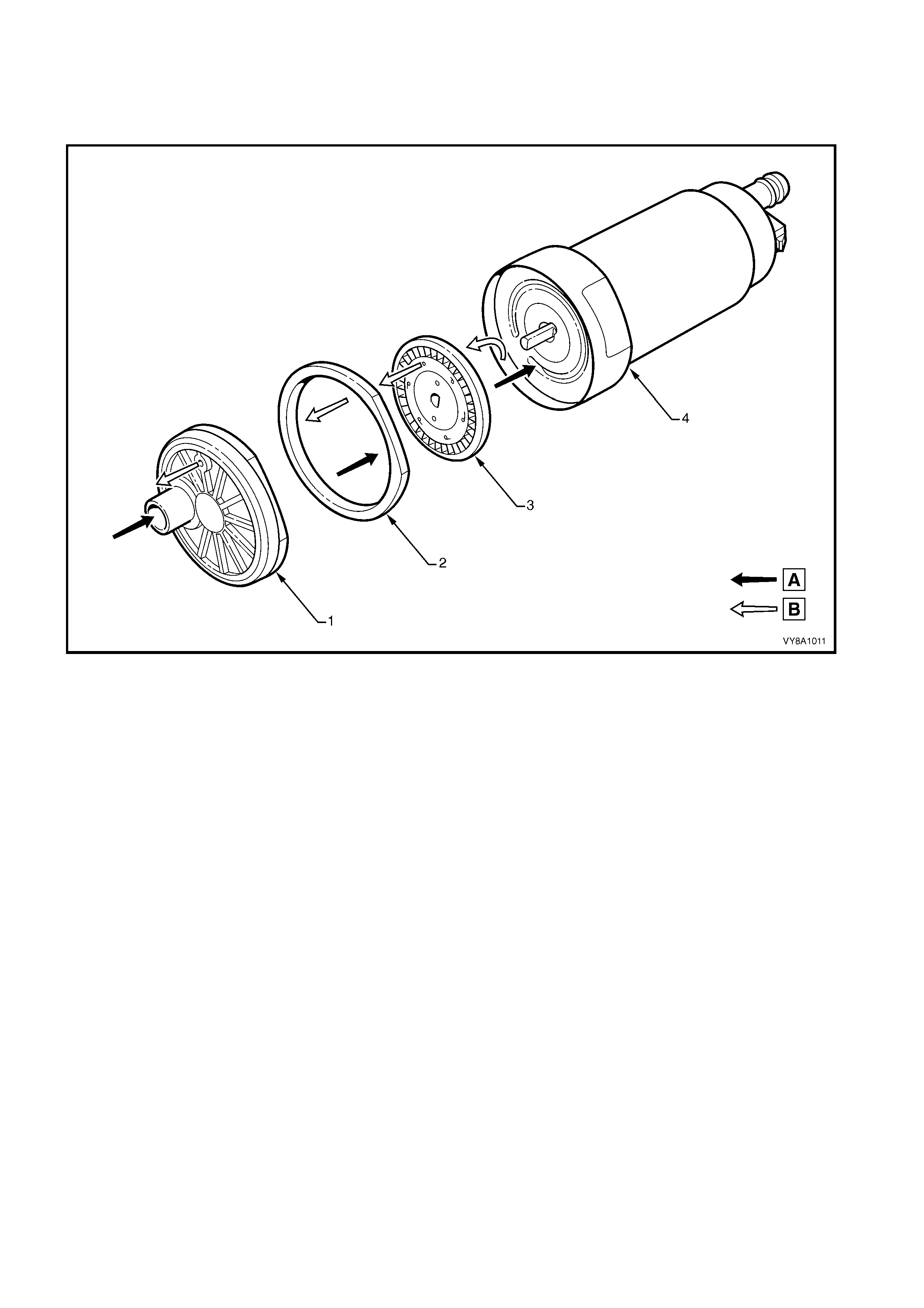
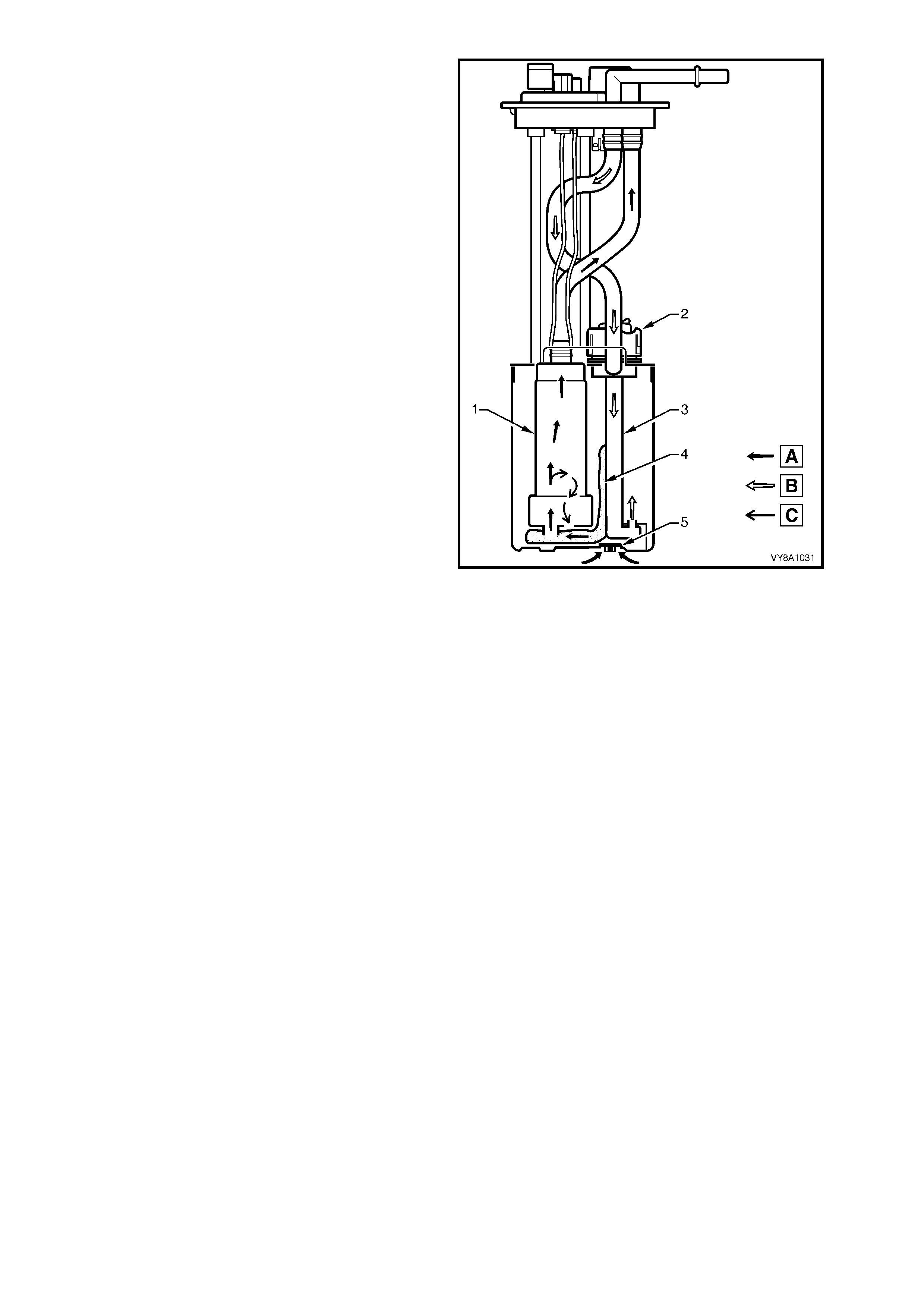
Figure 8A1–1 details fuel f low through the single turbine fuel pum p that is used with the V6 engine, exc ept vehicles
exported to Brazil.
Figure 8A1–1
Legend
A. Fuel
B. Vapour out 1. Inlet Body
2. Impeller Housing
3. Impeller
4. Fuel pump housing

Fuel (A) is drawn into the reservoir of the modular
fuel pump and sender assembly from the fuel tank,
through the primary umbrella valve (4), and into the
fuel pump’s impeller, via the internal strainer (3) at
the fuel pump inlet. At the impeller, vapour (C) is
separated from the fuel. The vapour is ejected from
the fuel pump (1) and into the reservoir via a port
adjacent to the fuel pump’s inlet.
High-pressure fuel then flows through the end cap,
the lower connector and the fuel pump flex pipe.
From the flex pipe, fuel then exits the modular fuel
pump and sender assembly through the fuel feed
fitting and flows on to the externally-mounted fuel
filter and the engine.
Pressure is regulated at the downstream end of the
engine fuel rail and return fuel (B) not used by the
engine is returned to the fuel module via the return
line and the return port of the modular fuel cover. The
return fuel enters the jet pump standpipe (2) of the
reservoir via the return fuel tube.
When the engine is switched off, the reservoir
remains full of fuel, due to of the action of the primary
umbrella valves. At higher fuel levels, fuel from the
tank overflow enters the reservoir over the top of the
reservoir. Fuel levels in the reservoir are also
maintained by returned engine fuel.
Electrical power is supplied to the fuel pump by a
connector that is secured to the cover. An internal
harness assembly completes the connection to the
pump (not shown).
Figure 8A1–2
FUEL PUMP — V6 SUPERCHARGED ENGINE
Roller Vane Fuel Pump
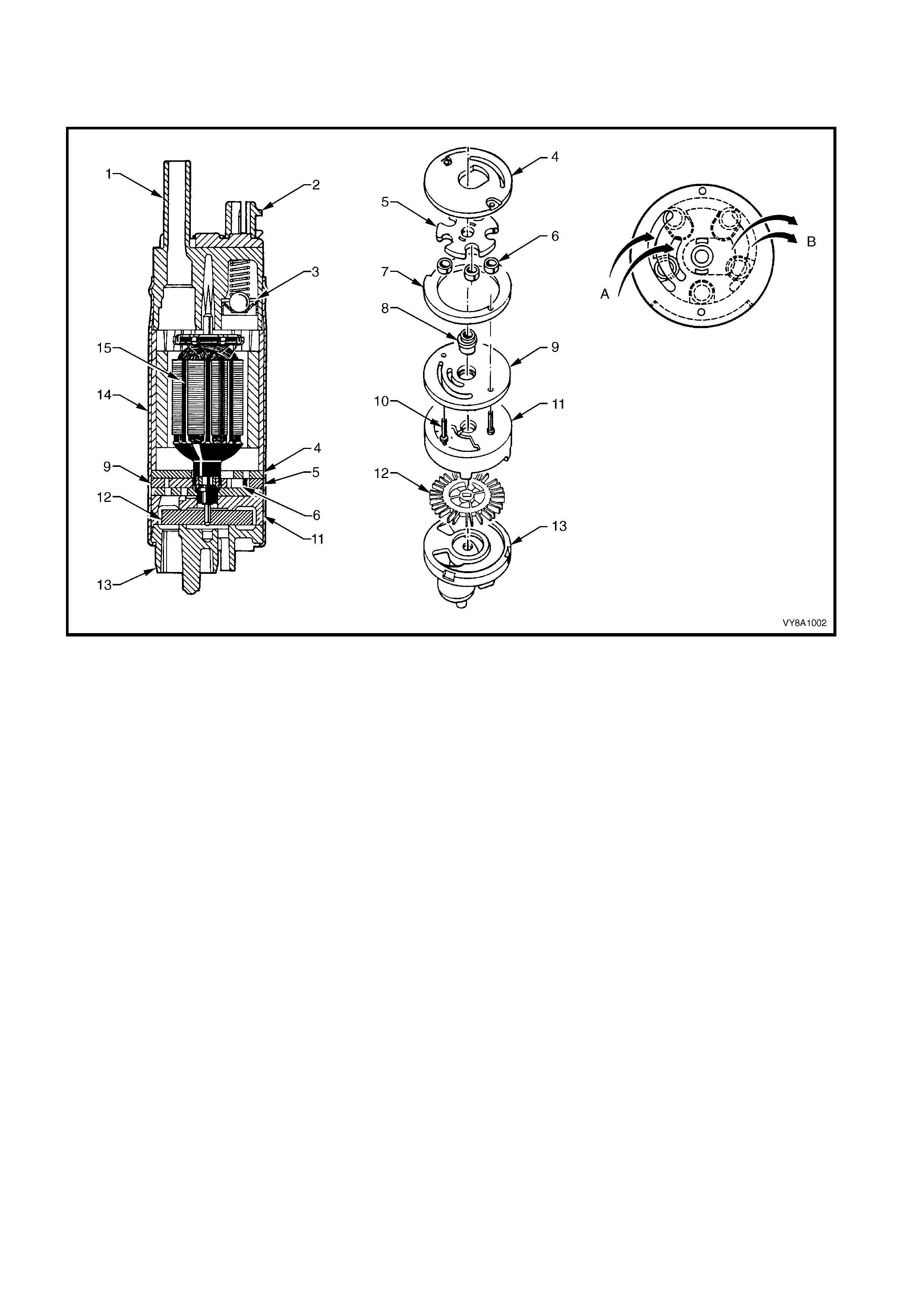
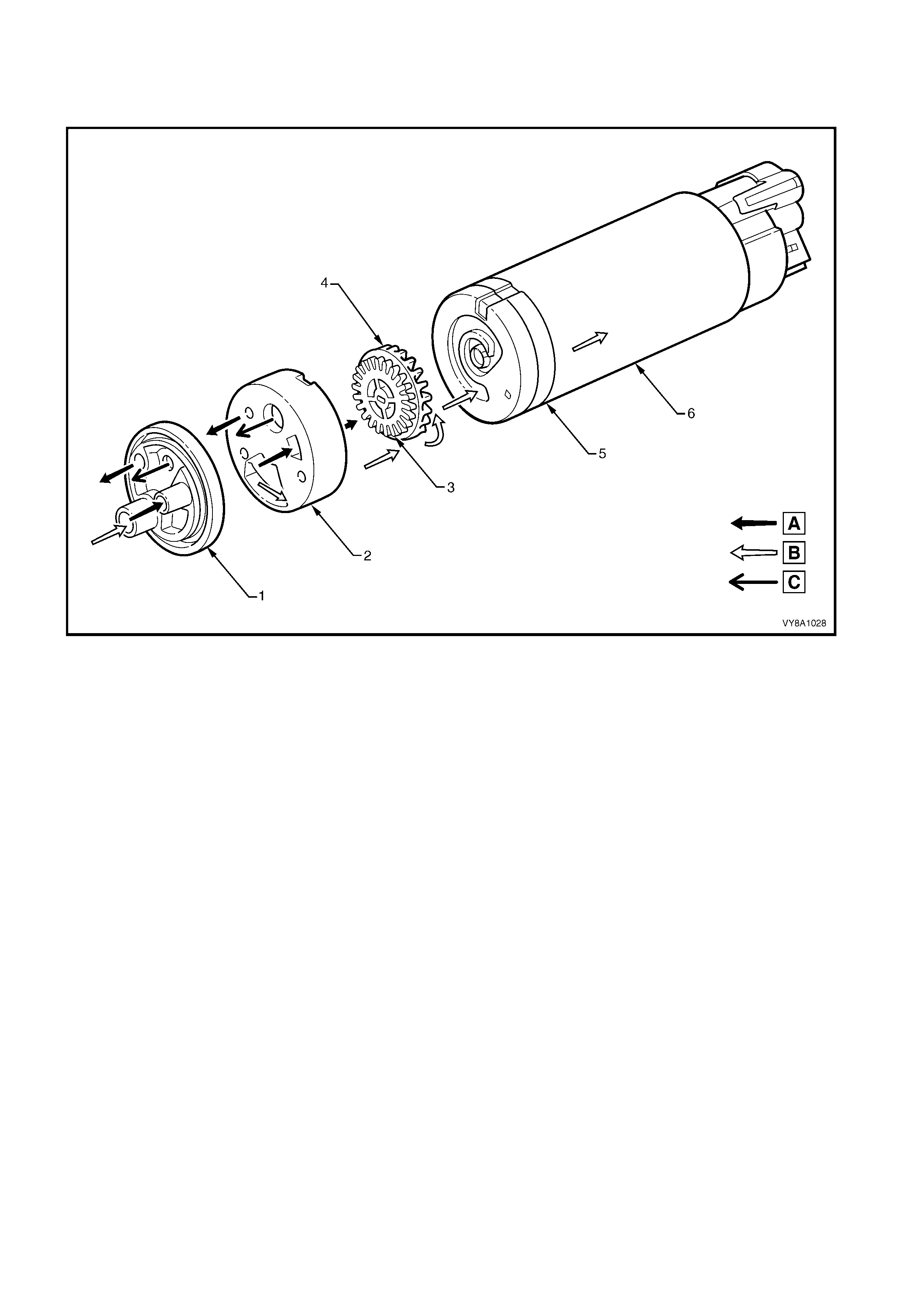
Figure 8A1–3 details fuel flow through the roller vane fuel pump that is used with the V6 Supercharged engine.
Figure 8A1–3
Legend
A. Fuel In
B. Fuel Out 1. End Cap
2. RFI Module
3. Relief Valve
4. Outlet Plate
5. Rotor
6. Rollers
7. Eccentric Ring
8. Bearing
9. Face Plate
10. Rivets
11. Housing
12. Impeller
13. Inlet Body
14. Shell
15. Electric Motor
Fuel (A) enters the roller vane fuel pump via the
two strainers (3 and 5). In the first stage, fuel
vapour (C) is separated from the liquid fuel within
the f uel pum p (6) and is retur ned to the fuel tank at
low pressure and temperature.
The pump then discharges the liquid fuel into the
roller vane sec tion of the pum p. The pum p outlet is
configured to divert the prim ary fuel volum e to flow
into the flex pipe and deliver a por tion of the f low to
the jet pump via an aspirator (1). The remaining
fuel is diverted to an externally mounted fuel filter
and then to the engine.
The diverted fuel from the outlet of the fuel pump
passes through the j et pump filter (2). This c reates
a low pressure area at its base, causing the
umbrella valve to unseat, drawing cooler fuel into
the reservoir area from the fuel tank.
Return fuel (B) not used by the engine is returned
to the fuel module via the fuel return line and the
return port of the modular fuel cover. The return
fuel enters the reservoir via the return fuel tube (7).
When the engine is switched off, the reservoir
rem ains full of fuel, due to the action of the prim ary
and secondary umbrella valves (4). During
refuelling operations, the secondar y um brella valve
unseats, allowing fuel to enter the reservoir up to
the fuel tank level. At higher fuel levels, fuel tank
overflow enters the reservoir over the top of the
assembly.
If the external strainer becomes blocked or restricts
fuel entry, the secondary umbrella valve unseats,
allowing fuel to enter the reservoir area.
Electrical power is supplied to the fuel pump by a
connector that is secured to the cover. An internal
harness assem bly com pletes the connection to the
pump (not shown).
Figure 8A1–4

FUEL PUMP — GEN III V8 ENGINE
Single Turbine Fuel Pump
Figure 8A1–5 details fuel flow through the single turbine fuel pump that is used with the GEN III V8 engine.
Figure 8A1–5
Legend
A. Fuel
B. Vapour out 1. Inlet Body
2. Impeller Housing
3. Impeller
4. Fuel pump housing
Fuel (A) is drawn into the reservoir from the fuel tank,
through the primary umbrella valve (5), and into the
fuel pump’s impeller, via the internal strainer (4) at
the fuel pump (1) inlet. At the impeller, vapour (C) is
separated f rom the fuel. T he vapour is ejec ted out of
the fuel pum p and into the res ervoir via a port nex t to
the fuel pump’s inlet.
High-pressure fuel then flows through the end cap,
the lower connector and the fuel pump flex pipe.
From the flex pipe, fuel then exits the modular fuel
pump and sender assembly through the fuel feed
fitting and flows on to the externally-mounted fuel
filter and the engine.
Pressure is regulated at the downstream end of the
engine fuel rail and return fuel (B) not used by the
engine is returned to the fuel module via the return
fuel line and the retur n port of the m odular fuel cover.
The return fuel enters the jet pump standpipe (3) of
the reservoir via the return fuel tube.
Vehicle line pressure is maintained by a pressure
regulator (2) located within the modular fuel pump
and sender assembly.
When the engine is switched off, the reservoir
remains full of fuel, due to the action of the primary
umbrella valve. At higher fuel levels, fuel from the
tank overflow enters the reservoir over the top of the
reservoir. Fuel levels in the reservoir are also
maintained by returned engine fuel.
Electrical power is supplied to the fuel pump by a
connector secured to the cover. An internal harness
assem bly completes the c onnection to the pump (not
shown).
Figure 8A1–6
FUEL PUMP — VEHICLES EXPORTED TO BRAZIL
Dual Turbine Fuel Pump
Figure 8A1–8 details flow through the dual turbine fuel pump that is fitted to the V6 engine exported to Brazil.
Figure 8A1–7
Legend
A. First Stage Fuel
B. Second and Third Stage Fuel
C. Vapour Out
1. Inlet Body
2. Inlet Housing
3. First Stage Impeller
4. Second Stage Impeller
5. Inlet Plate
6. Third Stage Impeller
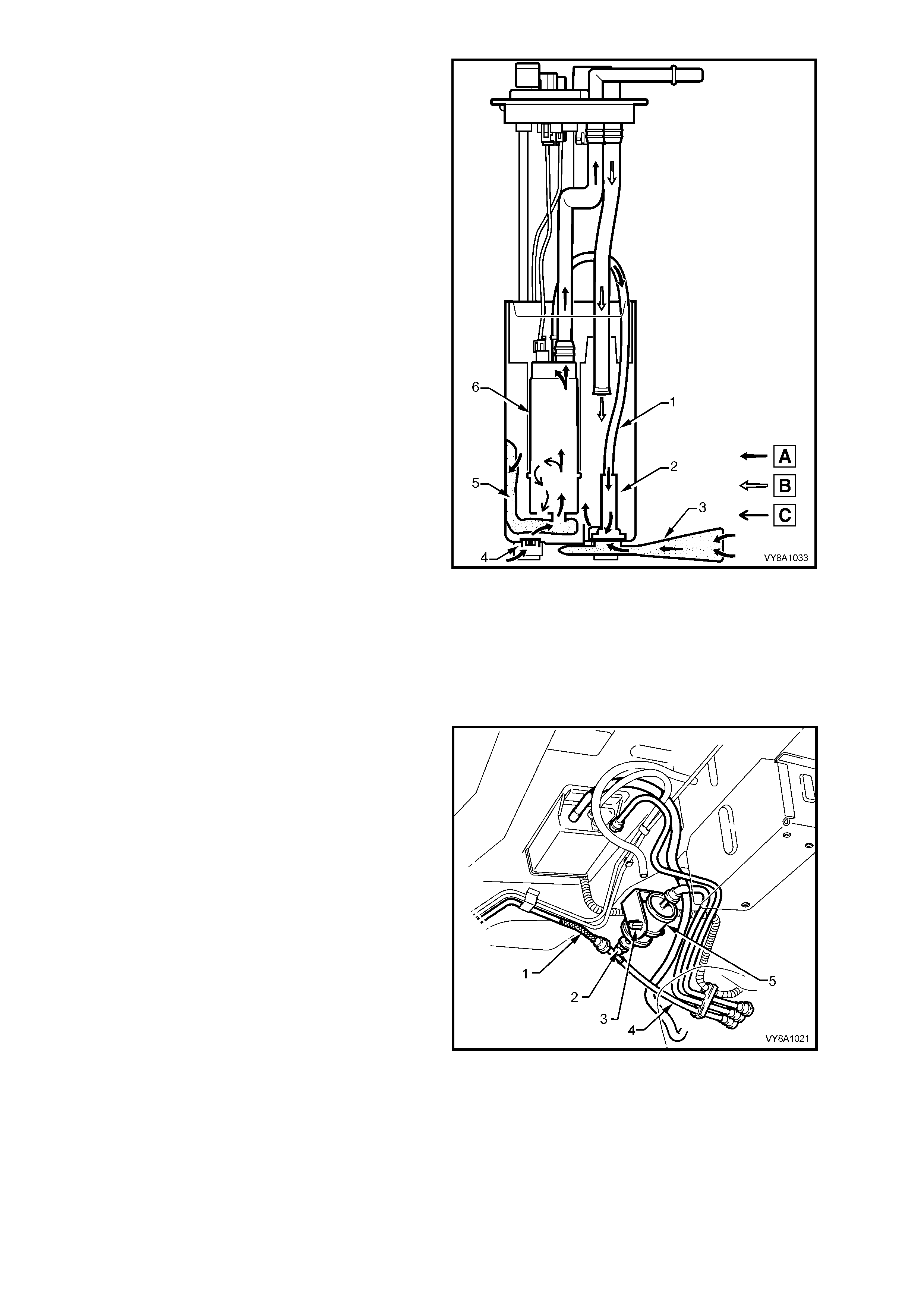
Fuel (A) enters the dual s tage turb ine f uel pum p (6)
via the ex ternal st rainer (3) and of the modular fuel
pump and sender assembly. In the first stage, the
pump separates the vapour (B) from the fuel. First
stage fuel is directed to the reservoir filling the
reservoir bucket.
Fuel levels in the reservoir are also maintained by
return fuel (B) via the return line. Reservoir fuel
flow proceeds through the fuel pump strainer (5),
bypassing the first stage impeller. Fuel then
proceeds to the second impeller and the high-
pressure third stage of the impeller pump.
High-press ure fuel then flows through the end cap.
Attached to the pump outlet is a diver ter that allows
the primary fuel volume to flow into the flex pipe
and deliver a portion of the f low to the jet pump via
an aspirator (1) and the rest to an externally-
mounted fuel filter and the engine.
The diverted fuel from the outlet of the fuel pump
passes through the j et pump filter (2). This c reates
a low pressure area at its base, causing the
umbrella valve (4) to unseat, drawing cooler fuel
into the reservoir area.
When the enigne is switched off, the reservoir
rem ains full of fuel, due to the action of the prim ary
umbrella valves. At higher fuel levels, fuel overflow
enters the reservoir over the top of the reservoir.
If the external strainer becomes blocked or restricts
fuel entry, the secondary umbrella valve (4)
unseats, allowing fuel to enter the reservoir area.
Electrical power is supplied to the fuel pump by a
connector secured to the cover. An internal
harness assem bly com pletes the connection to the
pump (not shown).
Figure 8A1–8
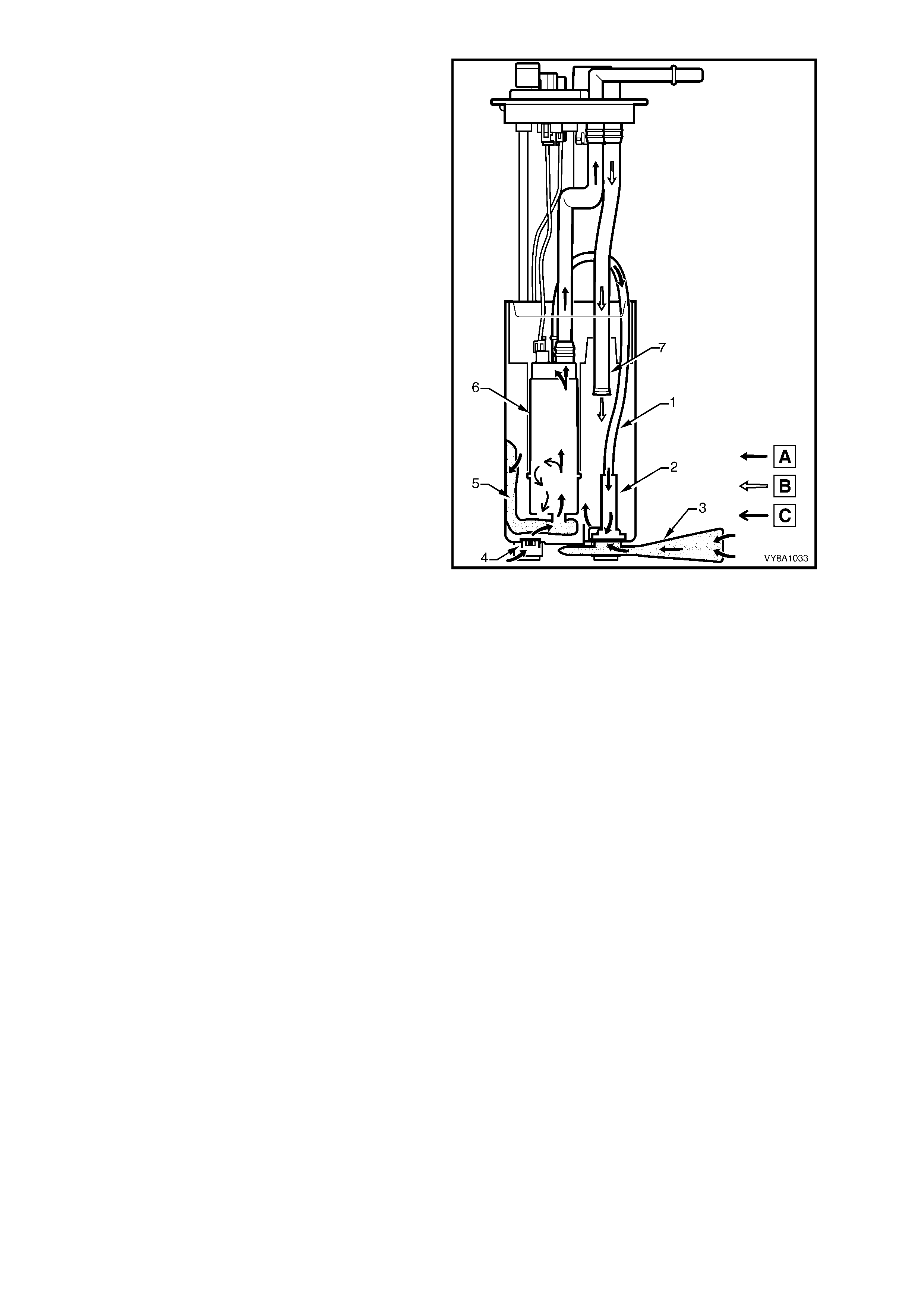
SINGLE LINE FUEL DELIVERY SYSTEM — GEN III V8 ENGINE
Fuel from the single turbine fuel pump is forced
through the fuel pump flex pipe and exits the
assem bly through the fuel feed output fitting on the
cover. Fuel then flows through the fuel filter (5)
mounted to a bracket (3) secured to the floor pan.
From here, fuel is directed through the fuel filter T -
piece (2) and the f lex ible f uel f eed line ( 1) and on to
the engine bay and fuel rail. When fuel line
pressure exceeds the pre-determined value of
410 k Pa, the fuel pressure regulator in the modular
fuel pump and sender assembly opens, allowing
excess system pressure to discharge back to the
module fuel sender assembly reservoir via the
flexible line (4). This process continuously occurs
while the pump is operating.
Figure 8A1–9
FUEL PRESSURE REGULATOR — GEN III V8 ENGINE
The fuel pressure regulator is a diaphragm-
operated relief valve located in the modular fuel
pump and sender assembly of the GEN III V8. On
one side of the diaphragm is fuel pump pressure;
on the other side atmospheric pressure is
combined with mechanical spring pressure. The
fuel pressure regulator maintains a controlled
pressure at the injectors at all times by regulating
the flow into the return line.
NOTE: In vehicles fitted with V6 or V6
Supercharged engines, the fuel pressure regulator
is fitted to the engine fuel rail.
Figure 8A1–10
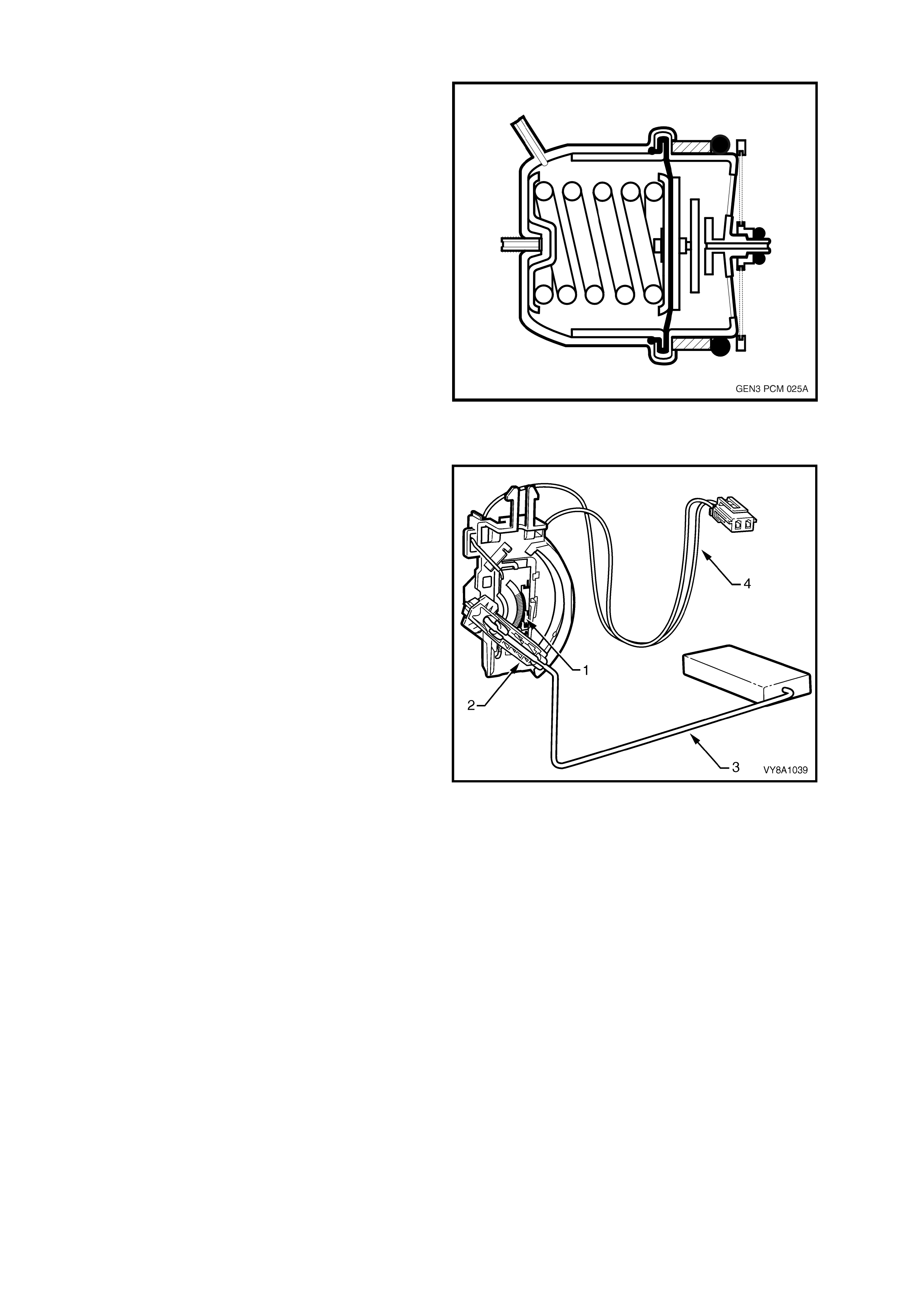
FUEL GAUGE TANK SENDER UNIT
The ceramic resistor card fuel level sensor
assembly consists of a ceramic resistor card (1),
wiper arm (2), float arm assembly (3) and a wiring
harness (4). The action of these components
converts the fuel level in the fuel tank into a
variable electrical signal used to drive the fuel
gauge in the instrument panel.
The assembly mounting is part of the modular fuel
pump and sender assembly moulding on the V6
and GEN III V8 models. On the V6 Supercharged
and vehicles exported to Brazil, the assembly is
attached to the outside surface of the modular fuel
pump and sender assembly, and secured with a
retainer. The wiring harness is attached to the fuel
level sender and the underside of the top of the
unit; it connects the ceramic resistor card to the
vehicle wiring harness.
The function of the ceramic resistor card is to vary
the resistance, dependent upon the float position
and to send that signal via hard wire to the
instrument cluster. This resistance signal changes,
relative to the wiper contact position on the
conductive bars of the ceramic resistor card.
The BCM averages out any slosh variation in the
fuel tank. Therefore, fuel tank baffling is not as
critical to maintaining accurate gauge readings.
NOTE: The fuel gauge tank sender unit is serviced
as a separate component only for vehicles fitted
with the V6 Supercharged engine and vehicles
exported to Brazil.
Figure 8A1–11
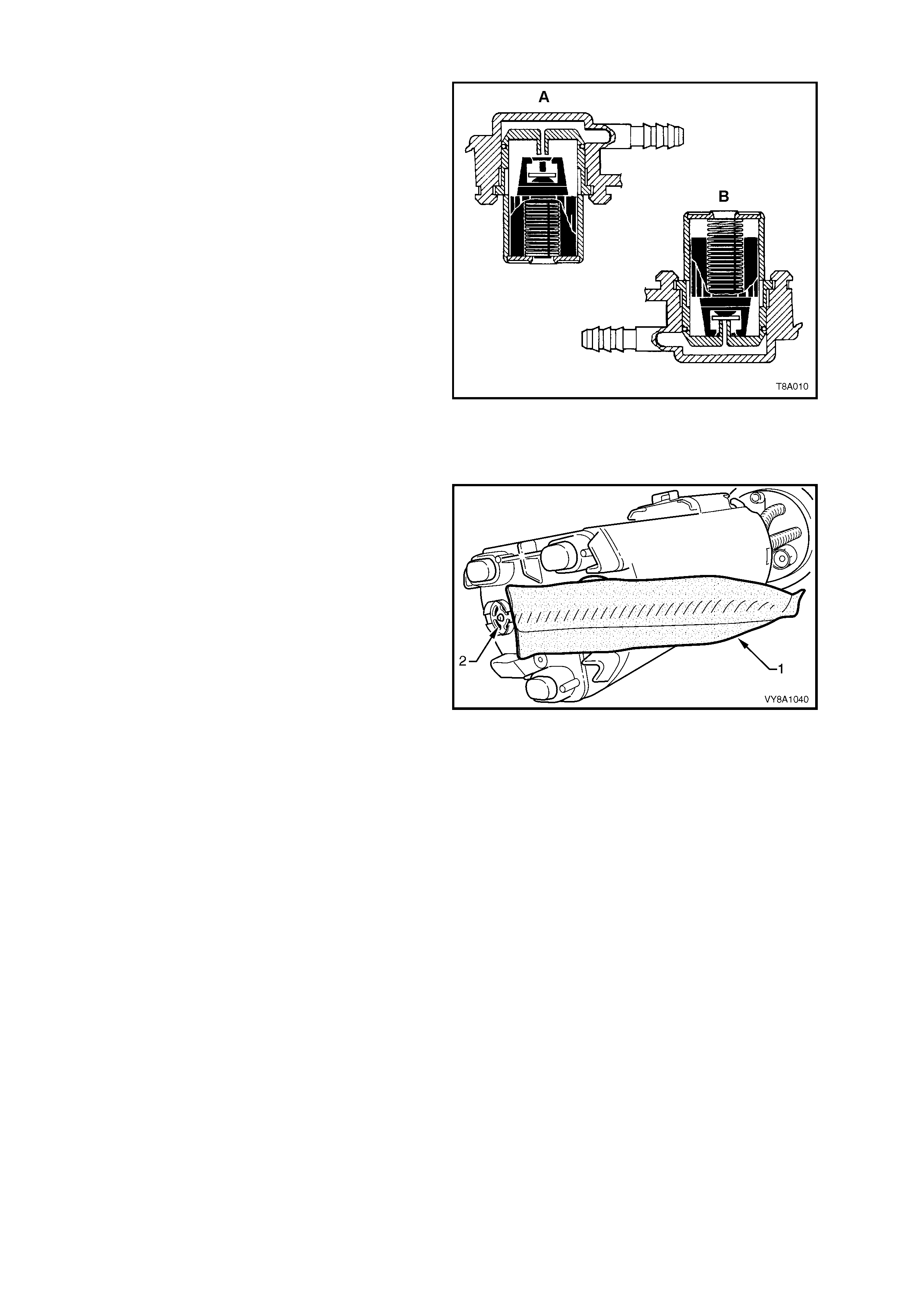
ROLLOVER VALVE — SEDAN, WAGON AND COUPE
The m odular fuel pum p and sender assem bly fitted
to the Sedan, Wagon and Coupe models
incorporate a rollover valve in their design. The
rollover valve limits vapour venting to the canister
using a fixed sized orifice that is normally open
(View A). If the vehic le rolls over (View B), the vent
line to the canister is safely shut off by the rollover
valve, preventing liquid fuel from flooding the
canister.
NOTE 1: The rollover valve in Utility models
operates in the same manner as the rollover valve
fitted to Sedan, Wagon and Coupe models. It is a
similar design, but is fitted directly into the tank.
Consequently, because the vent fitting on the
modular fuel pump and sender assembly is not
required in Utility models, it has been blanked off.
NOTE 2: T he rollover valve f itted to Sedan, Wagon
and Coupe models is not serviceable separately. If
it is faulty, the modular fuel pump and sender
assembly must be replaced.
Figure 8A1–12
MODULAR FUEL PUMP AND SENDER ASSEMBLY STRAINERS
Fuel sender assembly strainers are fitted to the
inlet side of the f uel pump, under neath the modular
fuel pump and sender assembly. The external
strainer (1) separ ates water from fuel and prevents
foreign particles from entering the system. In low
fuel conditions, the strainer fabric also acts as a
wick to draw suf ficient f uel to the electric f uel pump
inlet. An ex ternal st rainer sc reen is only fitted to the
V6 Superc harged and vehic les expor ted to Brazil. If
the external strainer screen becomes blocked or
restricts fuel entry, the secondary umbrella valve
(2) unseats, allowing fuel to enter the reservoir.
Contaminants that pass through the fuel pump are
filtered out by the in-line fuel filter before reaching
the injectors.
Figure 8A1–13
1.2 FUEL FILLER CAP
The fuel filler cap is a 'SCREW ON' type with a
ratcheting feature to prevent over-tightening. W hen
installing the cap, tighten it until a ratcheting
(clicking) sound is audible, indicating the cap is
tightened properly.
IMPORTANT: If a replacement cap is required,
only use the correct all black fuel cap. Using an
incorrect cap causes the emission control system
to malfunction.
NOTE 1: Vehicles using unleaded fuel have
‘UNLEADED FUEL ONLY’ embossed into the top
of the fuel filler cap.
NOTE 2: The fuel filler door and cap arrangement
for the Wagon is shown; the arrangem ent is similar
for the Sedan, Coupe and Utility.
Figure 8A1–14
Techline
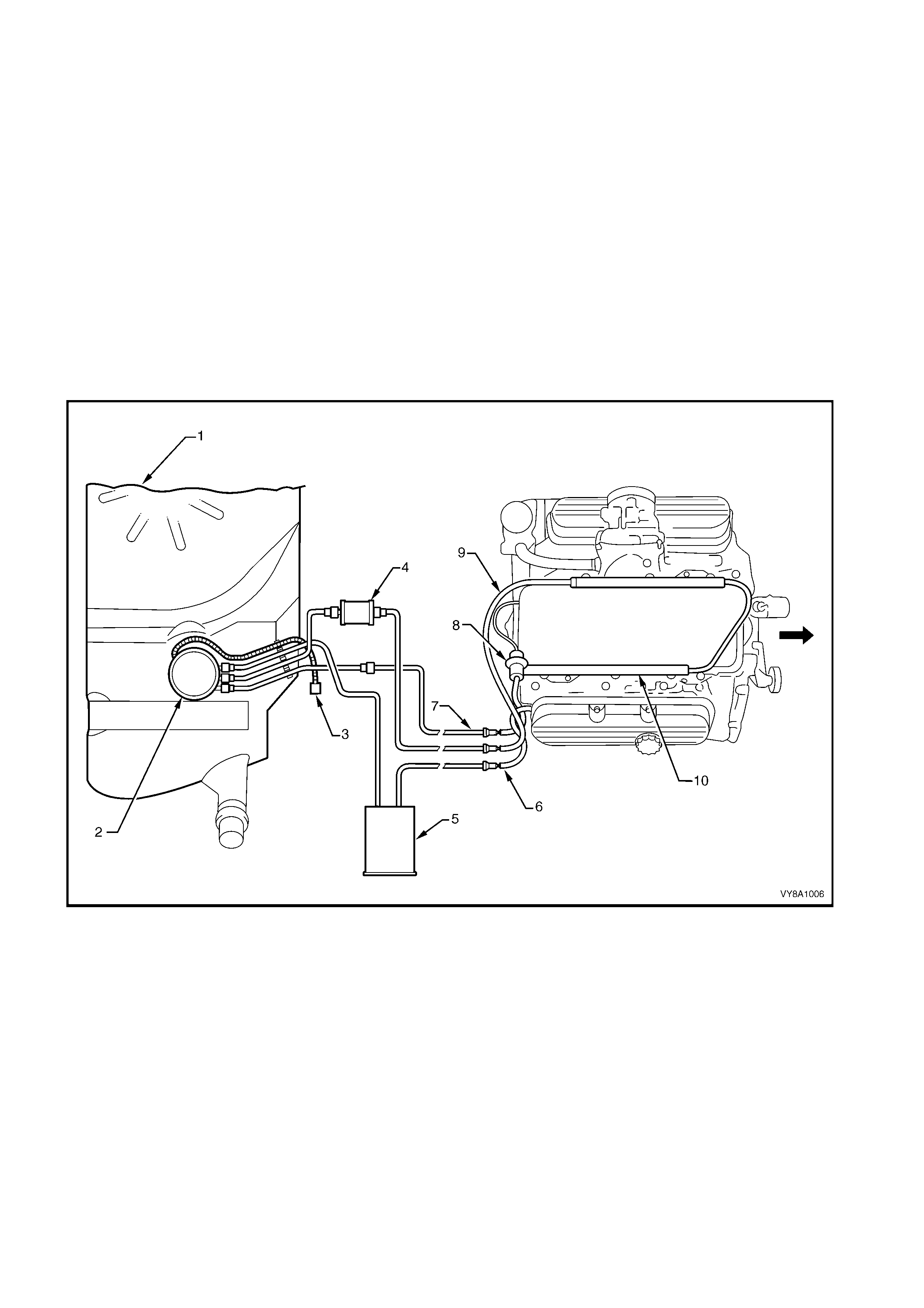
1.3 SYSTEM COMPONENTS
V6 ENGINE
The Fuel Control System consists of the following components. Refer to Figure 8A1–15 for the V6 engine; the
arrangement of the V6 Supercharged engine is similar.
• PCM
• Fuel Tank (1)
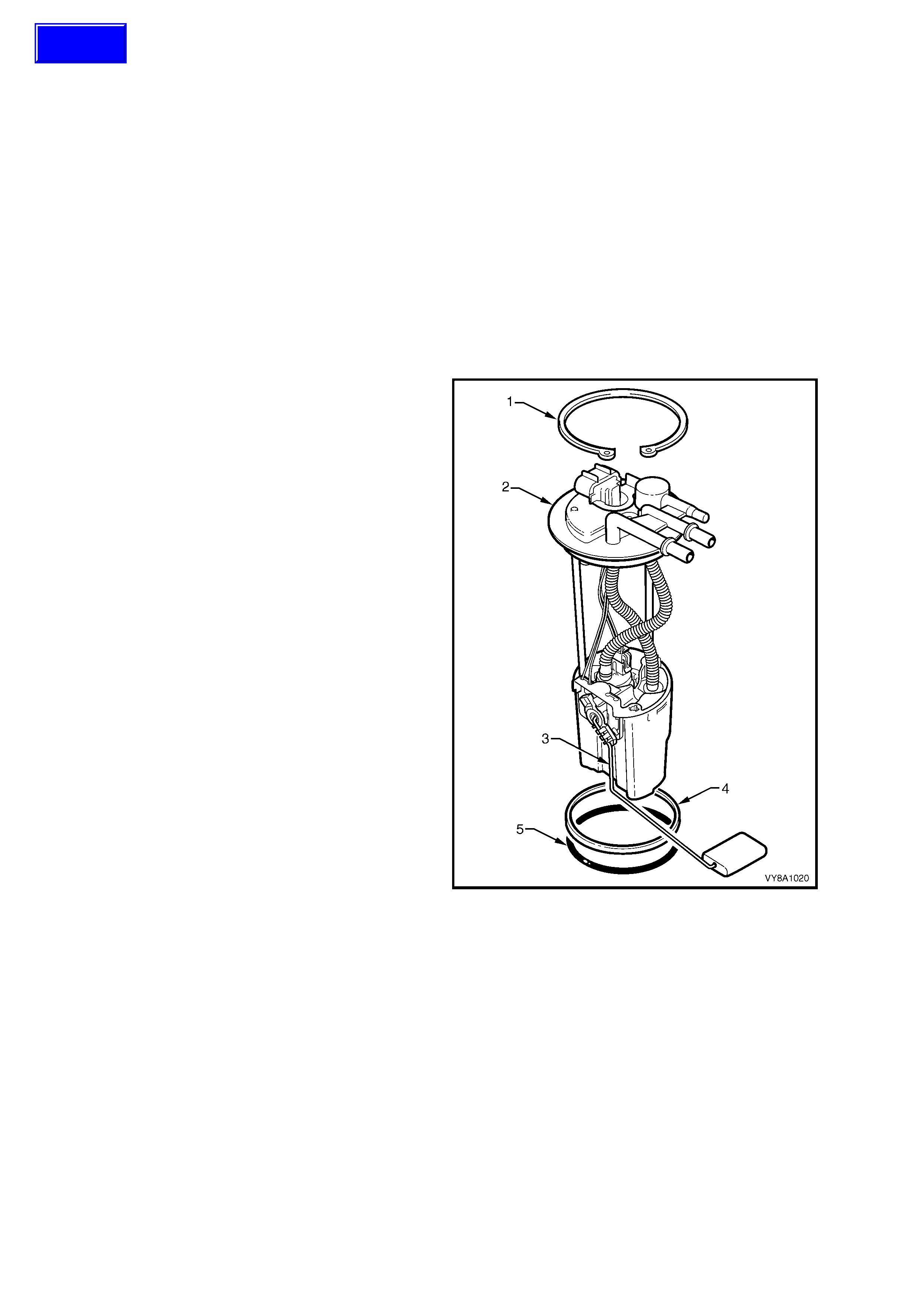
• Modular fuel pump and sender assembly (2), containing:
• Fuel pump assembly
• Jet pump
• Fuel filter (4)
• Fuel pressure supply line (9)
• Fuel pump relay
• Fuel rails (10)
• Injectors
Figure 8A1–15
Legend
1. Fuel Tank
2. Modular Fuel Pump and Sender
Assembly
3. Fuel Pump Electrical Connector
4. Fuel Filter
5. Fuel Vapour Canister
6. Fuel Vapour Tube
7. Fuel Return Line
8. Fuel Pressure Regulator
9. Fuel Delivery Line
10. Fuel Rail
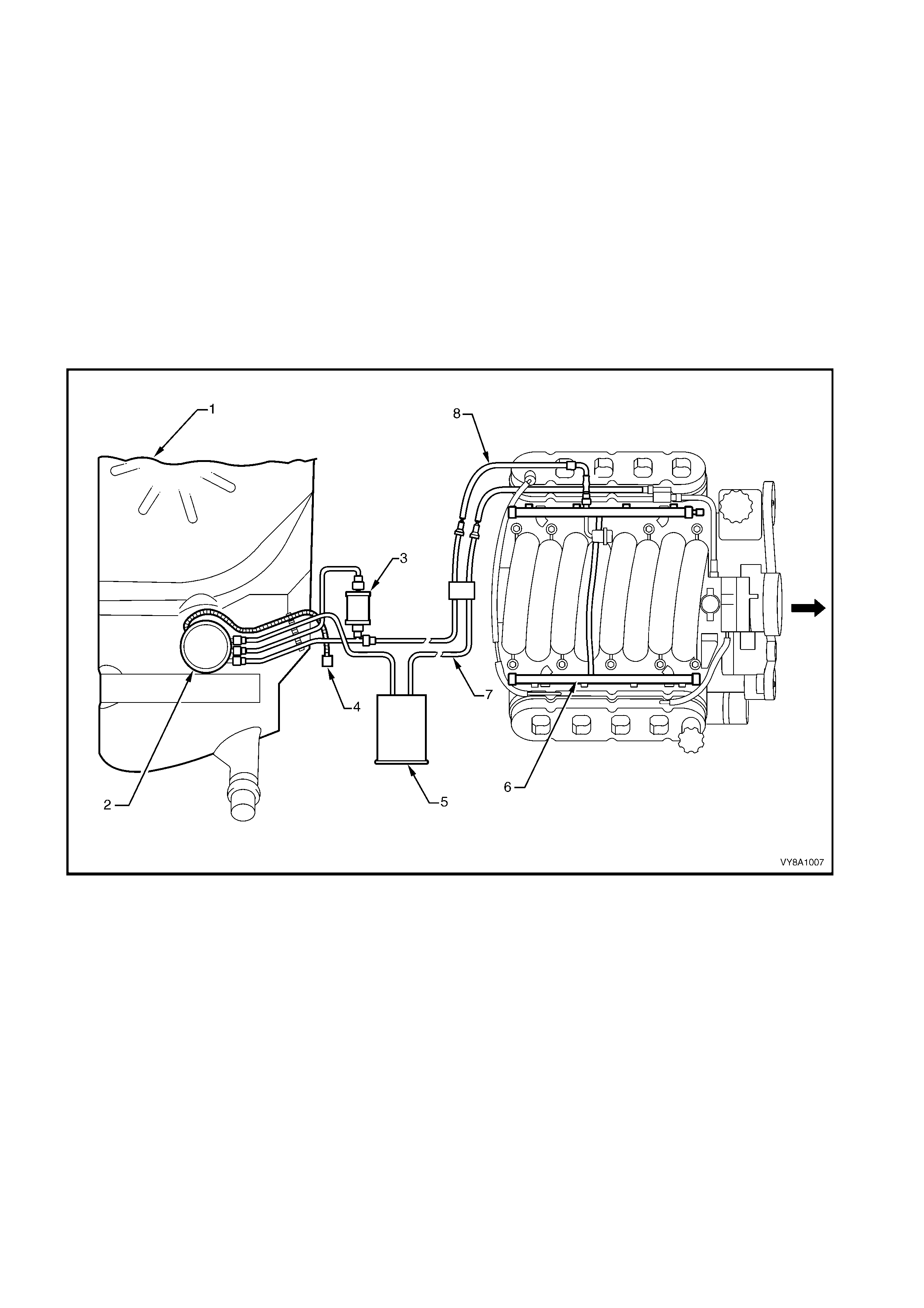
GEN III V8 ENGINE
The Fuel Control System consists of the following components, refer Figure 8A–16:
• PCM
• Fuel Tank (1)
• Modular fuel pump and sender assembly (2), containing:
• Fuel pump assembly
• Fuel pressure regulator
• Jet pump
• Fuel filter (3)
• Fuel pressure supply line (8)
• Fuel pump relay
• Fuel rails (6)
• Injectors
Figure 8A1–16
Legend
1. Fuel Tank
2. Modular Fuel Pump and Sender
Assembly Including Pressure
Regulator
3. Fuel Filter
4. Fuel Pump Electrical Connector
5. Fuel Vapour Canister
6. Fuel Rail
7. Fuel Vapour Tube
8. Fuel Pressure Supply Line
2. SERVICE OPERATIONS
2.1 FUEL TANK — SEDAN AND W AGON
REMOVE
CAUTION: A depressurised fuel system contains fuel in the fuel filter and fuel lines that can be spilled
during service operat ions. Ensure no naked flames o r other ig nition sources are nearby. Ensure all mo bile
phones are switched off.
1. Depressurise the fuel system. Refer to the following sections in this service information:
a. Section 6C1–3, 3.1 FUEL PUMP RELAY for V6.
b. Section 6C2–3, 3.1 FUEL PUMP RELAY for V6 Supercharged.
c. Section 6C3–3, 3.7 FUEL PRESSURE RELIEF PROCEDURE for GEN III V8.
2. Remove the fuel pump relay R16, refer to Section 12O, 1.4 RELAYS.
CAUTION: Never drain or store fuel into an open container, due to the possibility of fire or explosion.
3. Syphon the fuel from the tank, using commercially available equipment.
4. Raise the vehicle, preferably on a hoist, refer to Section 0A, 1.1 HOIST PAD LOCATIONS.
5. Remove the right-hand-rear wheelhouse liner, refer to Section 1A1, 3.2 REAR WHEELHOUSE LINER,
EXCEPT UTILITY.
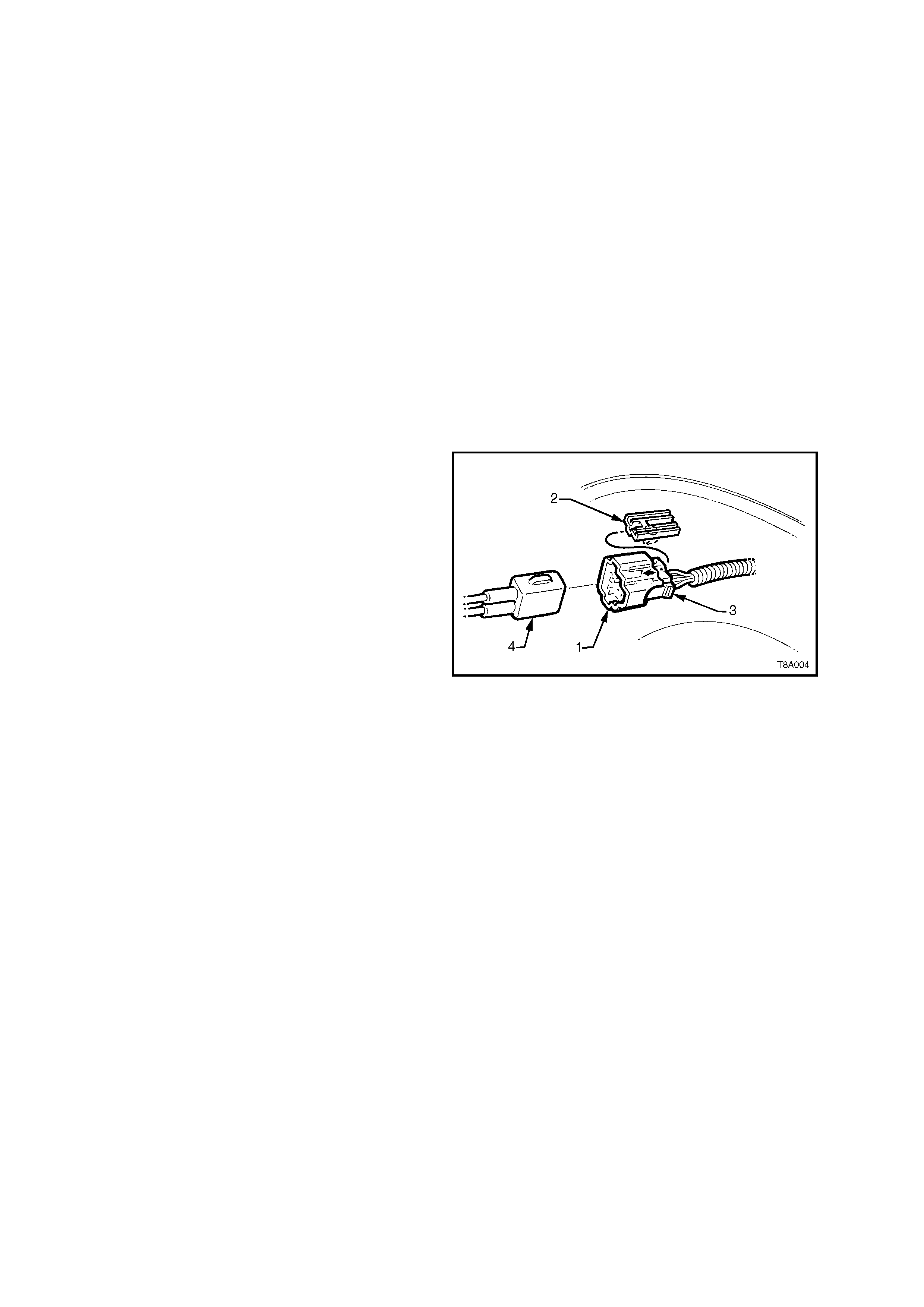
6. Remove the f uel sender electric al connector (1)
from its mounting foot (2) by pulling forward to
dislodge the assembled connector from the
foot. After releasing, press the locking tab (3)
and separate the connector halves (1 and 4).
7. Place a drain tray under the fuel filter area.
CAUTION: Wear safety glasses when using
compressed air.
IMPORTANT: Use compressed air to ensure that
all dirt and foreign materials are removed from all
the fuel connections, before the parts are
disconnected.
Figure 8A1–17
8. For vehicles fitted with V6 and V6 Supercharged engines:
CAUTION: Fuel can spill from the disconnected filter.
a. If required, rem ove the fuel f ilter by dis connecting the fuel f eed line connector (6), then pres s the two barbs on
the mounting strap (7) nipple to remove. Support the fuel filter during the entire process, refer to Figure 8A1–18.
b. Disconnect the quick-connect fittings to the vapour canister (1), return line (3) and fuel filter (4), by pushing
inwards to r elease the s ide tangs of the connector , then pull to dis connec t. Alter natively, use special tool AU533
to assist in pressing the connector locking tangs, refer to 2.10 QUICK-CONNECT FITTINGS. Support the f uel
filter during the entire process.
c. Disconnect the vapour canister breather hose at the canister (2).
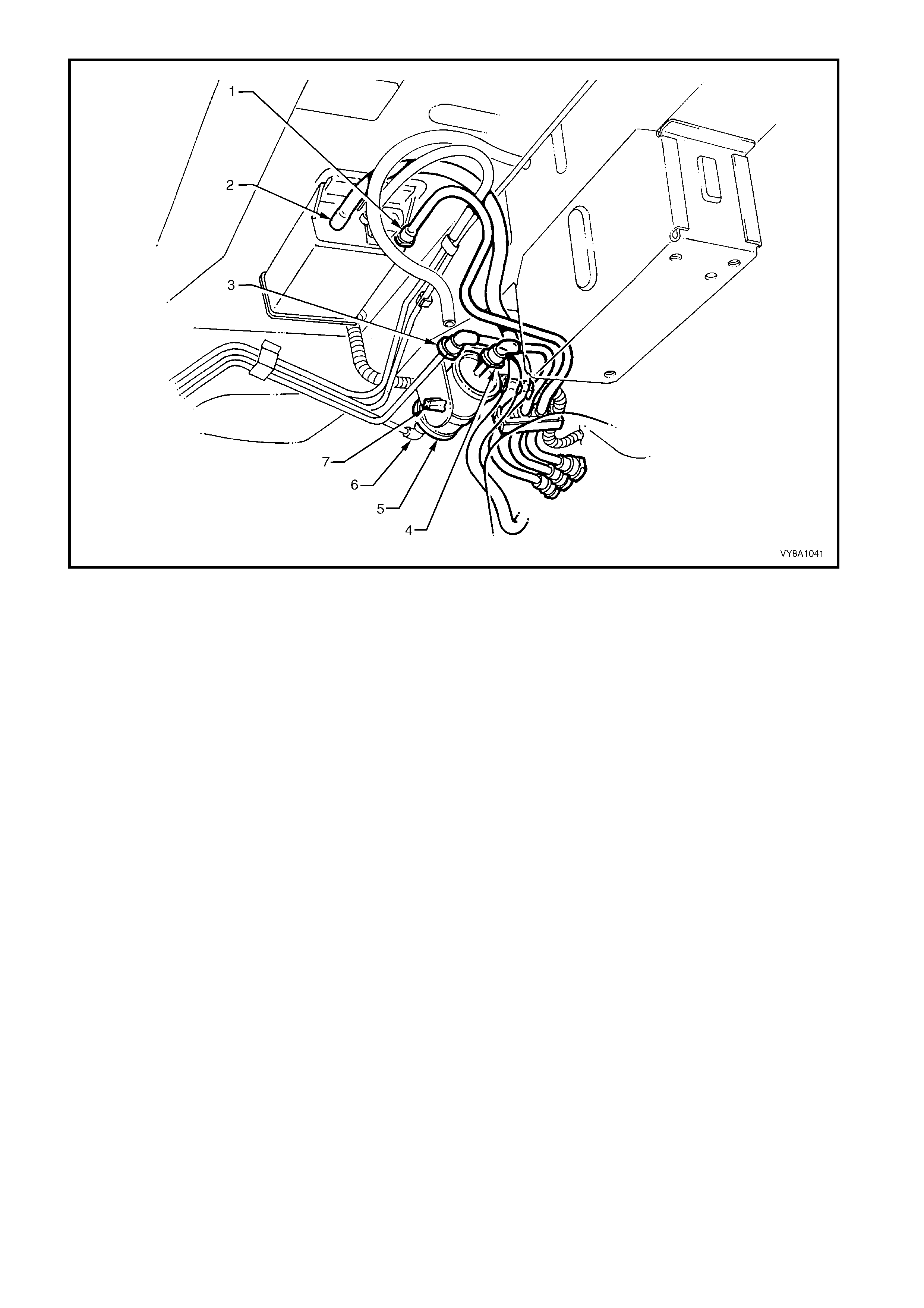
Figure 8A1–18
Legend
1. Fuel Tank Vapour Line to Canister Quick-connect
2. Filler Neck Breather Hose
3. Fuel Return Line Quick-connect
4. Fuel Feed Line Quick-connect
5. Fuel filter
6. Fuel Feed to Filter Quick-connect
7. Fuel Filter Strap Retaining Tangs
9. For vehicles fitted with GEN III V8 engines:
CAUTION: Fuel can spill from the disconnected filter.
a. If required, remove the fuel filter (7) by disconnecting the fuel feed line connector (8). Pess the fuel filter
strap tangs ( 5) on the retainer st rap, and then r emove the fuel f ilter f r om the bracket. Finally, disconnect the
fuel filter T-piece connector (4). Support the fuel filter during the entire process, refer to Figure 8A1–19.
b. Disconnect the quick-connect fittings to the vapour canister (1), by pushing inwards to release the seal
pressure, press the side tangs of the connector, then pull to disconnect. Alternatively, use special tool
AU533 to assist in pressing the connector locking tangs, refer to 2.10 QUICK-CONNECT FITTINGS.
Support the fuel filter during the entire process.
c. Disconnect the filler breather hose from the canister (2).
d. Disconnect the quick-connect fitting (3) at the flexible pipe and filter T-piece, by supporting the quick-
connect fitting while pulling the fuel tank feed line from the fitting.

Figure 8A1–19
Legend
1. Fuel Tank Vapour Line to Canister Quick-connect
2. Filler Neck Breather Hose
3. Fuel Feed to Engine Flexible Line
4. Fuel Filter T-piece Quick-connect
5. Fuel Filter Strap Retaining Tang
6. Fuel Return Line to Fuel Tank
7. Fuel Filter
8. Fuel Feed Line Quick-connect
10. Referr ing to Figure 8A1–20, disconnec t the earth str ap fr om the spade connector (9, in Views A and E), located
under the front right-hand strap-mounting bolt (4, in View A) of the right-hand tank support strap (3, in View A).
11. While supporting the fuel tank in the centre, remove the fuel tank support straps as follows:
a. Remove the centre strap (2, View D) by removing the rear retaining nut (5) and washer, and then unhook
the strap from the front support (View C).
b. Rem ove the bolt at the f ront and unhook the strap f rom the r ear support ( Views A and B). T hen rem ove the
right-hand strap (3).
c. Remove the left-hand strap (1) by unscrewing the nuts and washers from each end of the strap (Views C
and D).
12. Lower the left-hand side of the fuel tank from the vehicle to release the fuel filler neck from the body opening.
Then continue to lower the entire fuel tank.

Figure 8A1–20
Legend
1. Left-hand Fuel Tank Mounting
Strap
2. Centre Fuel Tank Mounting Strap
3. Right-hand Fuel Tank Mounting
Strap
4. Left-hand Strap Front
5. Centre Strap Rear Attaching Bolt
6. Earth Strap Spade Connector
7. Front Support
8. Rear Longitudinal Extension
9. Filler Neck Earth
10. Tank Strap Support Washer
11. Rear Support
12. Fuel Tank Reinforcement Studs
13. Left-hand Strap Rear Attachment
REINSTALL
Reinstallation is the reverse of the removal procedure, noting the following:
1. Check that the insulation has not become dislodged from the top of the tank.
2. Lift the fuel tank into position reinserting the fuel filler neck into the body opening, with the insulator attached.
Raise the remainder of the fuel tank into place.
3. Referring to Figure 8A1–20, fit the support straps in the following order:
a. Loosely reattach the two outer straps (1 and 3).
b. Check that the filler neck seal is correctly located in the body opening.
c. While pushing the fuel tank firmly to the right-hand side, tighten the rear nut of the right-hand strap
(View D).
d. Tighten the right-hand strap front mounting bolt (4, in View A) of the strap (3). Ensure that the earth strap
spade connector is fitted.
e. Hook the centre strap (2) into the front retainer (View C) and replace the nut and washer (5, in View D).
4. Tighten all strap fasteners to the correct torque specification.
FUEL TANK MOUNTING STRAP
NUTS AND BOLTS
TORQUE SPECIFICATION 15.0 – 25.0 Nm
5. Assemble the electrical connector, ensuring that both locking tabs are in place. Then insert the assembled
electrical connector into its mounting foot. Push to engage the locking tabs.
IMPORTANT: Install the fuel filter with the flow arrow on its body pointing in the same direction as the fuel flow to
the front of the vehicle.
6. For vehicles f itted with V6 or V6 Superchar ged engines, ins tall the disconnected f ittings to the fuel filter, canister
and return line. Refer to Figure 8A1–18 for the correct component routeings using the following assembly
sequence:
a. Canister vent hose to canister (2).
b. Fuel vapour return line to canister (1).
c. Fuel tank vent line to canister.
d. Fuel return line to brake and fuel pipe harness assembly (3).
e. Fuel lines (4 and 6) to the fuel filter (5).
f. If it was removed, connect the fuel filter and strap assembly (7) to the filter-mounting bracket.
7. For vehic les fitted with a GEN III V8 engine, install the disconnec ted fittings to the fuel filter, canister and return
line. Refer to Figure 8A1–19 for the correct component routeings using the following assembly sequence:
a. Canister vent hose to canister (2).
b. Fuel tank vent line to canister (1).
c. Fuel feed line to flexible pipe quick-connect (3).
d. Filter to T-piece quick-connect (4), then filter strap retainer (5) to filter bracket.
e. Fuel filter to fuel feed line quick-connect (8).
8. Install the right-hand rear wheelhouse liner, tightening the mounting screws to secure.
9. Before starting the vehicle, perform a fuel system leak test, as detailed in Sections:
a. Section 6C1-3, 3.6 LEAK TESTING for V6.
b. Section 6C2-3, 3.6 FUEL FILTER for V6 Supercharged.
c. Section 6C3-3, 3.20 FUEL SYSTEM LEAK TEST for GEN III V8.

2.2 FUEL TANK – COUPE
REMOVE
CAUTION: A depressurised fuel system contains fuel in the fuel filter and fuel lines that can be spilled
during service operat ions. Ensure no naked flames o r other ig nition sources are nearby. Ensure all mo bile
phones are switched off.
1. Depressurise the fuel system. Refer to:
a. Section 6C1-3, 3.1 FUEL PUMP RELAY for V6.
b. Section 6C2-3, 3.1 FUEL PUMP RELAY for V6 Supercharged.
c. Section 6C3-3, 3.7 FUEL PRESSURE RELIEF PROCEDURE for GEN III V8.
2. Remove relay fuel pump relay R16, refer to Section 12O, 1.4 RELAYS.
CAUTION: Never drain or store fuel into an open container, due to the possibility of fire or explosion.
3. Syphon the fuel from the tank, using commercially available equipment.
4. Raise the vehicle, preferably on a hoist, refer to Section 0A, 1.1 HOIST PAD LOCATIONS.
5. Remove the right-hand rear wheelhouse liner, refer to Section 1A1, 3.2 REAR WHEELHOUSE LINER,
EXCEPT UTILITY.
6. Remove the f uel sender electric al connector (1)
from its mounting foot (2) by pulling forward to
dislodge the assembled connector from the
foot. Once released, press the locking tab (3)
and separate the connector halves (1 and 4).
7. Place a drain tray under the fuel filter area.
CAUTION: Wear safety glasses when using
compressed air.
IMPORTANT: Use compressed air to ensure that
all dirt and foreign materials are removed from all
the fuel connections, before the parts are
disconnected.
Figure 8A1–21
8. For vehicles fitted with V6 and V6 Supercharged engines:
CAUTION: Fuel can spill from the disconnected filter.
a. If requir ed, remove the f uel filter by disconnecting the f uel feed line connector (6), then press the two barbs
on the m ounting str ap (7) nipple to rem ove. Support the fuel filter dur ing the entire process, ref er to Figure
8A1–22.
b. Disconnect the quick -connec t fittings to the vapour canis ter (1), retur n line (3) and fuel f ilter (4), by pushing
inwards to release the side tangs of the connector, then pull to disconnect. Alternatively, use special tool
AU533 to assist in pressing the connector locking tangs, refer to 2.10 QUICK-CONNECT FITTINGS.
Support the fuel filter during the entire process.
c. Disconnect the vapour canister breather hose at the canister (2).
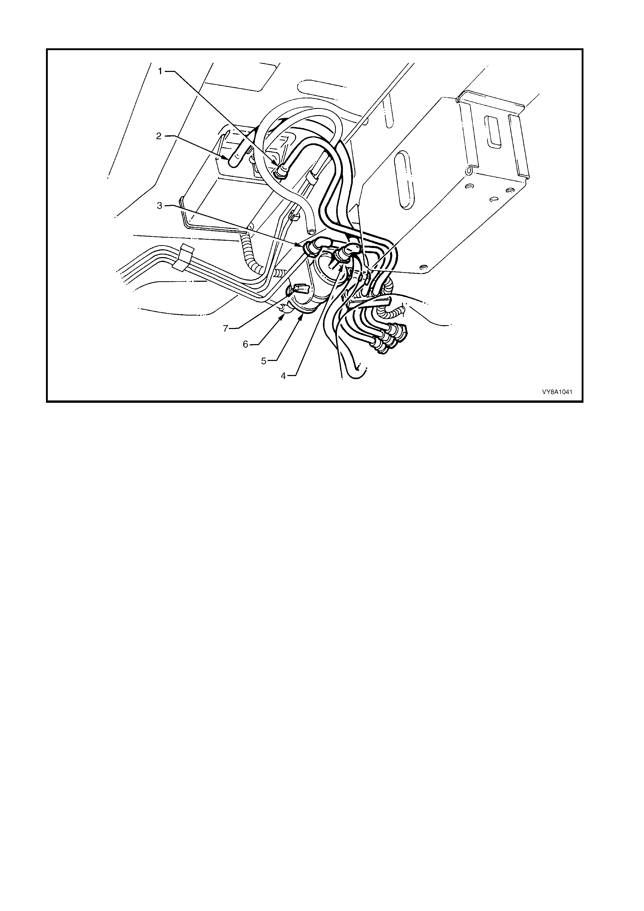
Figure 8A1–22
Legend
1. Fuel Tank Vapour Line to Canister Quick-connect
2. Filler Neck Breather Hose
3. Fuel Return Line Quick-connect
4. Fuel Feed Line Quick-connect
5. Fuel Filter
6. Fuel Feed to Filter Quick-connect
7. Fuel Filter Strap Retaining Tang
9. For vehicles fitted with GEN III V8 engines:
CAUTION: Fuel can spill from the disconnected filter.
a. If required, remove the fuel filter (7) by disconnecting the fuel feed line connector (8). Press the fuel filter
strap tangs ( 5) on the retainer strap, then r em ove the fuel filter from the brack et. Finally, disc onnect the fuel
filter T-piece connector (4). Support the fuel filter during the entire process, refer to Figure 8A1–23.
b. Disconnect the quick-connect fittings to the vapour canister (1), by pushing inwards to release the seal
pressure, press the side tangs of the connector, then pull to disconnect. Alternatively, use special tool
AU533 to assist in pressing the connector locking tangs, refer to 2.10 QUICK-CONNECT FITTINGS.
Support the fuel filter during the entire process.
c. Disconnect the filler breather hose from the canister (2).
d. Disconnect the quick-connect fitting (3) at the flexible pipe and filter T-piece, by supporting the quick-
connect fitting while pulling the fuel tank feed line from the fitting.

Figure 8A1–23
Legend
1. Fuel Tank Vapour Line to Canister Quick-connect
2. Filler Neck Breather Hose
3. Fuel Feed to Engine Flexible Line
4. Fuel Filter T-piece Quick-connect
5. Fuel Filter Strap Retaining Tang
6. Fuel Return Line to Fuel Tank
7. Fuel Filter
8. Fuel Feed Line Quick-connect
10. Referring to Figure 8A1–24, dis connect the earth str ap from the spade connec tor (9, in Views A and E) located
under the right-hand strap-mounting bolt (4, in View A) of the right-hand tank support strap (3, in View A).
11. While supporting the fuel tank in the centre, remove the fuel tank support straps as follows:
a. Remove the centr e s trap ( 2, in View D) by removing the rear r etaining nut (5) and washer ( 10), then unhook
the strap from the front support (View C).
b. Remove the bolts at the front and rear of the right-hand strap (3, in View B). Remove the right-hand strap.
c. Remove the bolts at the front and rear of the left-hand strap (1, in View C). Remove the left-hand strap.
d. Lower the fuel tank from the vehicle, left-hand side first, to release the fuel filler neck from the body
opening.
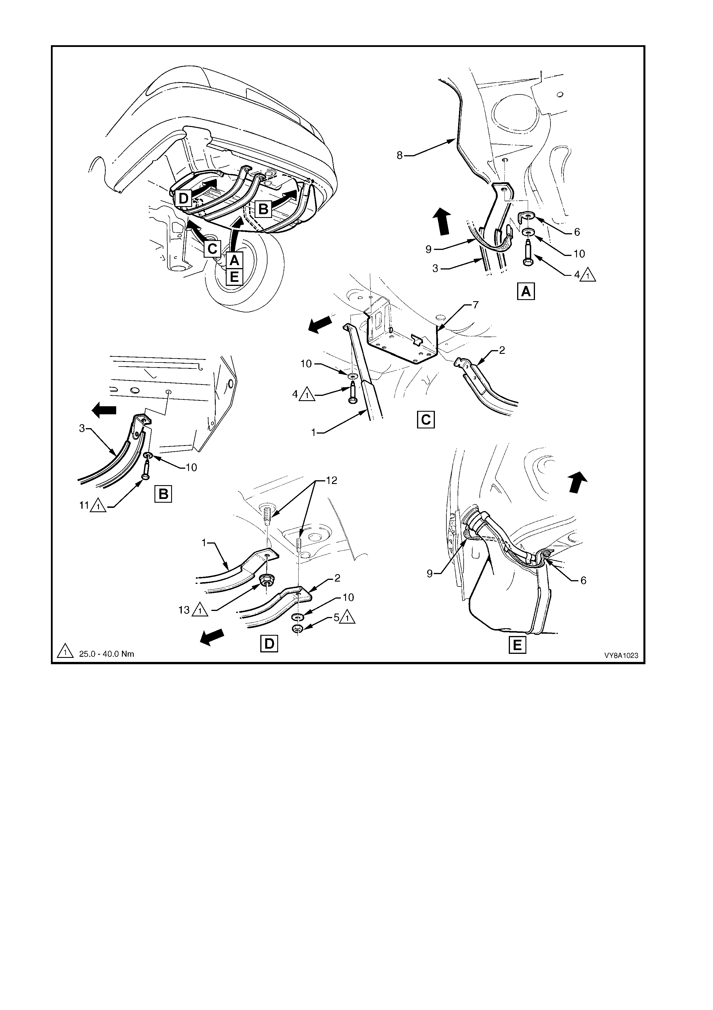
Figure 8A1–24
Legend
1. Left-hand Fuel Tank Mounting
Strap
2. Centre Fuel Tank Mounting Strap
3. Right-hand Fuel Tank Mounting
Strap
4. Left-hand Strap Front Attaching
Bolt
5. Centre Strap Rear Attaching Nut
6. Earth Strap Spade Connector
7. Front Support
8. Right-hand Rear Longitudinal
Extension
9. Filler Neck Earth Strap
10. Fuel Tank Strap Washer
11. Right-hand Strap Rear Attaching
Bolt
12. Fuel Tank Reinforcement Studs
13. Left-hand Strap Rear Attaching
Nut

REINSTALL
Reinstallation is the reverse of the removal procedure noting the following:
1. Check that the insulation has not become dislodged from the top of the tank.
2. Lift the fuel tank into position reinserting the fuel filler neck into the body opening, with the insulator attached.
Then raise the remainder of the fuel tank into place.
3. Referring to Figure 8A1–24, fit the support straps in the following order:
a. Loosely reattach straps 1 and 3.
b. Check that the filler neck seal is correctly located in the body opening.
c. While pus hing the f uel tank firm ly to the right-hand side, tighten the f ront m ounting bolt and rear nut for the
left-hand fuel tank mounting strap.
d. Ensuring that the earth strap spade connector is installed, tighten the front bolt for the right-hand fuel tank
mounting strap.
4. Hook the centre fuel tank mounting strap into the front retainer and install the retaining nut and washer.
5. Tighten all strap fasteners to the correct torque specification.
FUEL TANK MOUNTING STRAP
ATTACHING BOLTS AND NUTS
TORQUE SPECIFICATION 25.0 – 40.0 Nm
6. Assemble the electrical connector, ensuring that both locking tabs are in place. Engage the assembled
connector to its mounting foot and push rearwards to engage the locking tab.
IMPORTANT: Install the fuel filter with the flow arrow on its body pointing in the same direction as the fuel flow to
the front of the vehicle.
7. For vehicles fitted with V6 and V6 Supercharged engines, install the disconnected fittings to the fuel filter,
canister and return line, correctly routeing components as shown in Figure 8A1–22, using the following
assembly sequence:
a. Canister vent hose to canister (2).
b. Fuel vapour return line to canister (1).
c. Fuel tank vent line to canister.
d. Fuel return line to brake and fuel pipe harness assembly (3).
e. Fuel lines (4 and 6) to the fuel filter.
f. Fuel filter (5) and strap assembly (7) to the filter-mounting bracket.
8. For vehicles fitted with the GEN III V8 engine, install the disconnected fittings to the fuel filter, canister and
return line, routeing correctly, as shown in Figure 8A1–23, using the following sequence:
a. Canister vent hose to canister (2).
b. Fuel tank vent line to canister.
c. Fuel feed line to flexible pipe quick-connect (3).
d. Filter to T-piece quick-connect (4), then filter strap retainer (5) to filter bracket.
e. Fuel filter to fuel feed line quick-connect (8).
9. Install the right-hand wheelhouse liner, tightening the mounting screws to secure.
10. Before starting the vehicle, perform a fuel system leak test. To perform the leak test refer to the following
Sections:
a. Section 6C1–3, 3.6 LEAK TESTING for V6.
b. Section 6C2–3, 3.6 FUEL FILTER for V6 Supercharged.
c. Section 6C3–3, 3.20 FUEL SYSTEM LEAK TEST for GEN III V8.

2.3 FUEL TANK – UTILITY
REMOVE
CAUTION: A depressurised fuel system contains fuel in the fuel filter and fuel lines that can be spilled
during service operat ions. Ensure no naked flames o r other ig nition sources are nearby. Ensure all mo bile
phones are switched off.
1. Depressurise the fuel system, refer to:
a. Section 6C1-3, 3.1 FUEL PUMP RELAY for V6.
b. Section 6C3-3, 3.7 FUEL PRESSURE RELIEF PROCEDURE for GEN III V8.
2. Remove the fuel pump relay R16, refer to Section 12O, 1.4 RELAYS.
3. Remove the load floor front panel assembly, refer to Section 1B, 2.7 LOAD FLOOR FRONT PANEL
ASSEMBLY.
4. Rem o ve the screws (2) s ecuring the load c om partm ent side panel inner f ront c over (1), refer to Figure 8A1–25.
If necessary also remove the LPG filler and service lines, refer to Section 8A2 LPG SYSTEM.
5. Disconnect the modular fuel pump and sender harness connector (4).
6. Tag the fuel feed (3) and return (6) line connections located on top of the fuel tank.
NOTE: For identif ication purposes , the fuel return hos e is tagged with a white band near the connector at the top of
the fuel tank.
7. T ag the vent hose (5) on top of the fuel tank and disconnect by pulling the vent hose from the f uel tank rollover
valve vent fitting.
8. Dis engage the fuel r eturn line (6) and the fuel f eed line (3) quick -connect f ittings using special tool AU533, refer
to 2.10 QUICK-CONNECT FITTINGS.
9. Remove the modular fuel pump and sender assembly, refer to 2.7 MODULAR FUEL PUMP AND SENDER
ASSEM BL Y – UT ILIT Y. Drain the entire c ontents of the fuel tank by pumping or syphoning the fuel through the
sender assembly hole in the fuel tank using commercially available equipment.
NOTE: A permanent floodgate restriction in the lower fuel filler neck prevents the fuel tank from being drained
through the filler aperture.
CAUTION: Fuel vapour remains in the tank even when completely empty. Seal all the openings in the fuel
tank u sing a suit able plastic p lug. Ensu re no naked flames or ot her ignit ion sou rces are nearby. Ensure all
mobile phones are switched off.
10. Rem ove the four nuts (7) and rubber isolators (9), then remove the tank by manipulating the filler neck free of
the filler neck grommet and past the inner quarter panel.
Techline
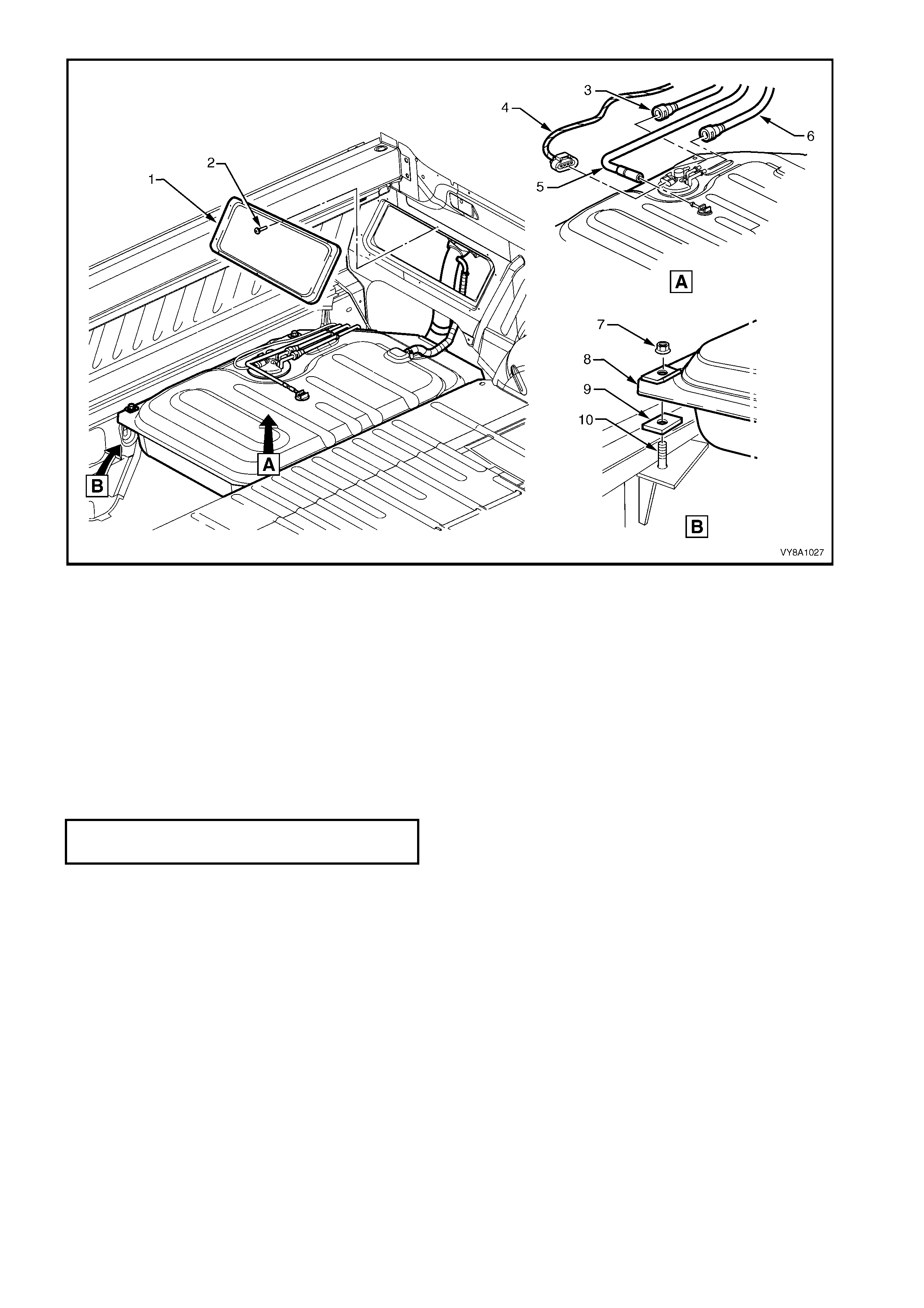
Figure 8A1–25
Legend
1. Side Panel Inner Front Cover
2. Side Panel Screw (10 Places)
3. Fuel Feed Line
4. Fuel Sender Harness Connector
5. Vent Hose
6. Fuel Return Line
7. Nut
8. Fuel Tank
9. Fuel Tank Isolator Rubber
10. Stud
REINSTALL
The installation procedure for the fuel tank is the reverse of the removal procedure, noting the following:
1. The c onnections f or the f uel tank vent hos e ar e shown in View A in Figure 8A1–25. T ighten all mounting nuts to
the correct torque specification.
FUEL TANK MOUNTING NUT
TORQUE SPECIFICATION 25.0 – 30.0 Nm

2.4 FUEL FILTER — V 6 AND V6 SUP ERCHARGED ENGINE
REPLACE
IMPORTANT: This procedure MUST be followed, both in the sequence of removal and installation of a replacement
filter. Failure to observe these instructions will probably result in perm anent dam age to the flexible line, resulting in
unnecessary parts replacement and expense.
NOTE: For details on disconnecting the quick-connect fittings from the fuel filter, refer to 2.10 QUICK-CONNECT
FITTINGS.
CAUTION: A depressurised fuel system contains fuel in the fuel filter and fuel lines that can be spilled
during service operat ions. Ensure no naked flames o r other ig nition sources are nearby. Ensure all mo bile
phones are switched off.
1. Depressurise the fuel system. Refer to:
a. Section 6C1-3, 3.1 FUEL PUMP RELAY for V6.
b. Section 6C2-3, 3.1 FUEL PUMP RELAY for V6 Supercharged.
CAUTION: Wear safety glasses when using compressed air.
2. Use compressed air to ensure that all dirt and foreign materials are removed from all fuel connections before
the parts are disconnected.
3. Push the connector towards the filter and press the retainers together to disconnect the fuel feed flexible line
connector (4) from the fuel filter (5), refer to Figure 8A1–26. Alternatively, use special tool AU533 to assist in
pressing the connector locking tangs. Support the fuel filter during the entire process.
4. Press the fuel filter strap tangs (7) on the retainer strap, then remove the filter from the bracket.
5. Disconnect the fuel feed pipe (6) on the other end of the fuel filter. Alternatively, use special tool AU533 to assist
in pressing the connector locking tangs.
6. Remove the fuel filter from the vehicle.
7. Attach the support strap onto a replacement fuel filter and, while supporting the fuel feed pipe, push the fuel
filter into the quick-connect until fully seated.
8. Install the filter strap retainer to the bracket. Install the quick-connect to the remaining end of the filter.
9. Check each connector by firmly tugging on each one to ensure it is in the locked position.
10. Before starting the vehicle, perform a fuel system leak test, as detailed in:
a. Section 6C1–3, 3.6 LEAK TESTING for V6.
b. Section 6C2–3, 3.6 FUEL FILTER for V6 Supercharged.

Figure 8A1–26
Legend
1. Fuel Tank Vapour Line to Canister Quick-connect
2. Filler Neck Breather Hose
3. Fuel Return Line Quick-connect
4. Fuel Feed Line Quick-connect
5. Fuel Filter
6. Fuel Feed to Filter Quick-connect
7. Fuel Filter Strap Retaining Tang

2.5 FUEL FILTER — GEN III V8 ENGINE
REPLACE
CAUTION: A depressurised fuel system contains fuel in the fuel filter and fuel lines that can be spilled
during service operat ions. Ensure no naked flames o r other ig nition sources are nearby. Ensure all mo bile
phones are switched off.
IMPORTANT: This procedure MUST be followed, both in the sequence of removal and installation of a replacement
filter. Failure to observe these instructions will probably result in perm anent dam age to the flexible line, resulting in
unnecessary parts replacement and expense.
NOTE: For details on disconnecting the quick-connect fittings from the fuel filter refer to 2.10 QUICK-CONNECT
FITTINGS.
1. Depressurise the f uel s ystem r ef er to Section 6C3-3, 3.7 FUEL PRESSURE RELIEF PROCEDURE for GEN III
V8.
CAUTION: Wear safety glasses when using compressed air.
2. Use compressed air to ensure that all dirt and foreign materials are removed from all fuel connections before
the parts are disconnected.
3. Pus h the connector towards the f ilter and press the retainers together to disconnect the fuel feed line connector
(8) from the fuel f ilter (7), ref er to Figure 8A1–27. Alternatively, use special tool AU533 to as sist in pres sing the
connector locking tangs. Support the fuel filter during the entire process.
4. Press the fuel filter strap retaining tangs (5) on the retainer strap, then remove the filter from the bracket.
5. To avoid permanent damage to the flexible line at the T -piece end of the filter, support the T-piece then press
the f ilter into it while releas ing the quick- connect fitting ( 4). Alternatively, fit the special tool num ber AU533 over
the T-piece connector to press the connector locking tangs.
6. Remove the fuel filter from the vehicle.
7. Attach the support strap onto a replacement fuel filter and, while supporting the T-piece, push the fuel filter (7)
into the T-piece quick-connect until fully seated.
8. Install the filter strap retainer to the bracket. Install the quick-connect to the remaining end of the filter.
9. Check each connector by firmly tugging on each one to ensure it is in the locked position.
10. Before s tarting the vehicle, perf orm a f uel system leak test, refer to Section 6C3-3, 3.20 FU EL SY STEM L EAK
TEST for GEN III V8.
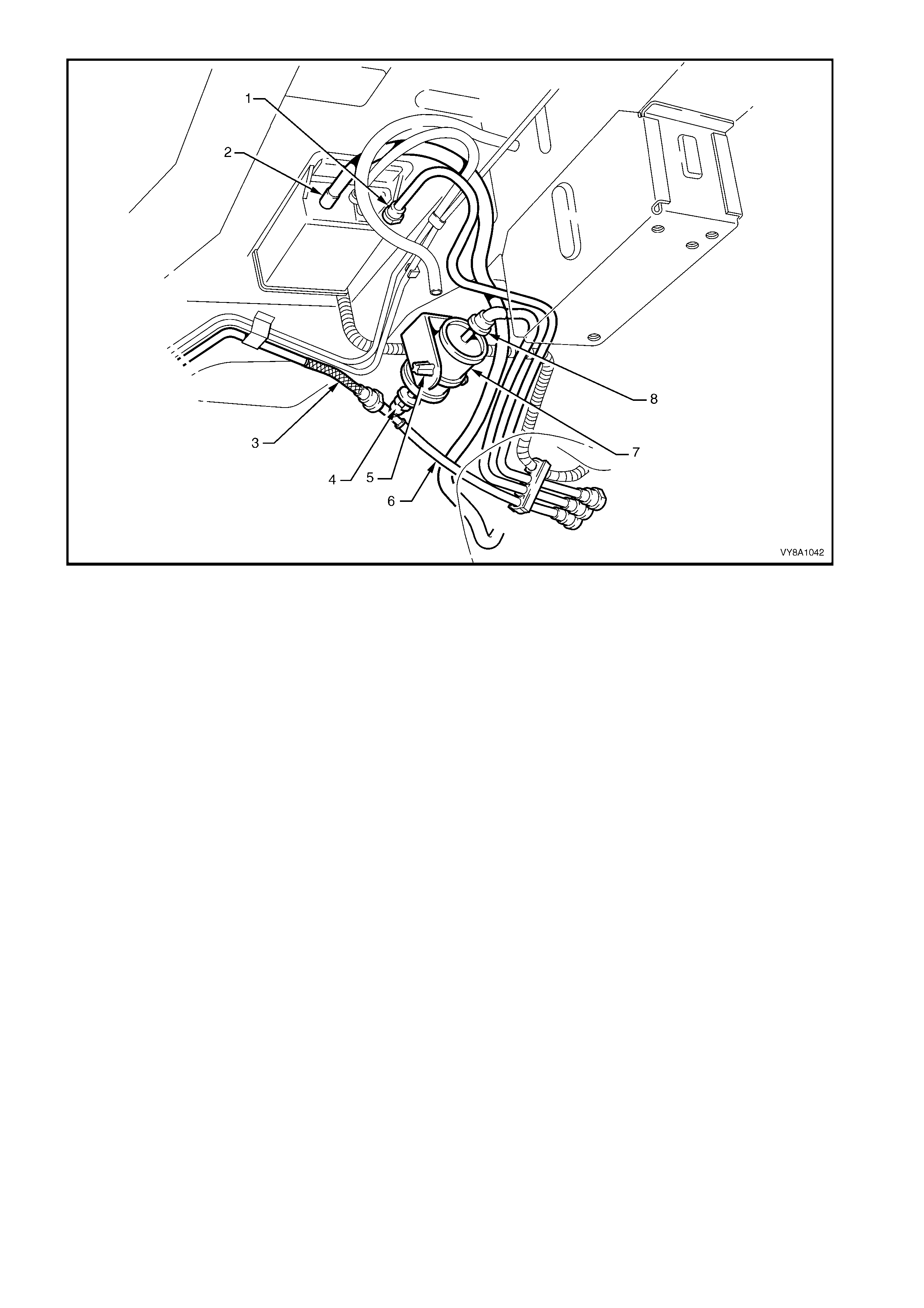
Figure 8A1–27
Legend
1. Fuel Tank Vapour Line to Canister Quick-connect
2. Filler Neck Breather Hose
3. Fuel Feed to Engine Flexible Line
4. Fuel Filter T-piece Quick-connect
5. Fuel Filter Strap Retaining Tang
6. Fuel Return Line to Fuel Tank
7. Fuel Filter
8. Fuel Feed Line Quick-connect
2.6 MODULAR FUEL PUMP AND SENDER ASSEMBLY —
SEDAN, WAGON AND COUPE
REMOVE
CAUTION: Ensure no naked flames or other ignition sources are nearby. Ensure all mobile phones are
switched off.
1. Remove the fuel pump relay R16, refer to Section 12O, 1.4 RELAYS.
2. Remove the fuel tank, refer to 2.1 FUEL TANK — SEDAN AND WAGON or 2.2 FUEL TANK — COUPE.
IMPORTANT: Clean all traces of dirt and other for eign mater ial from the top of the fuel tank , near the m odular fuel
pump and sender assembly, before proceeding.
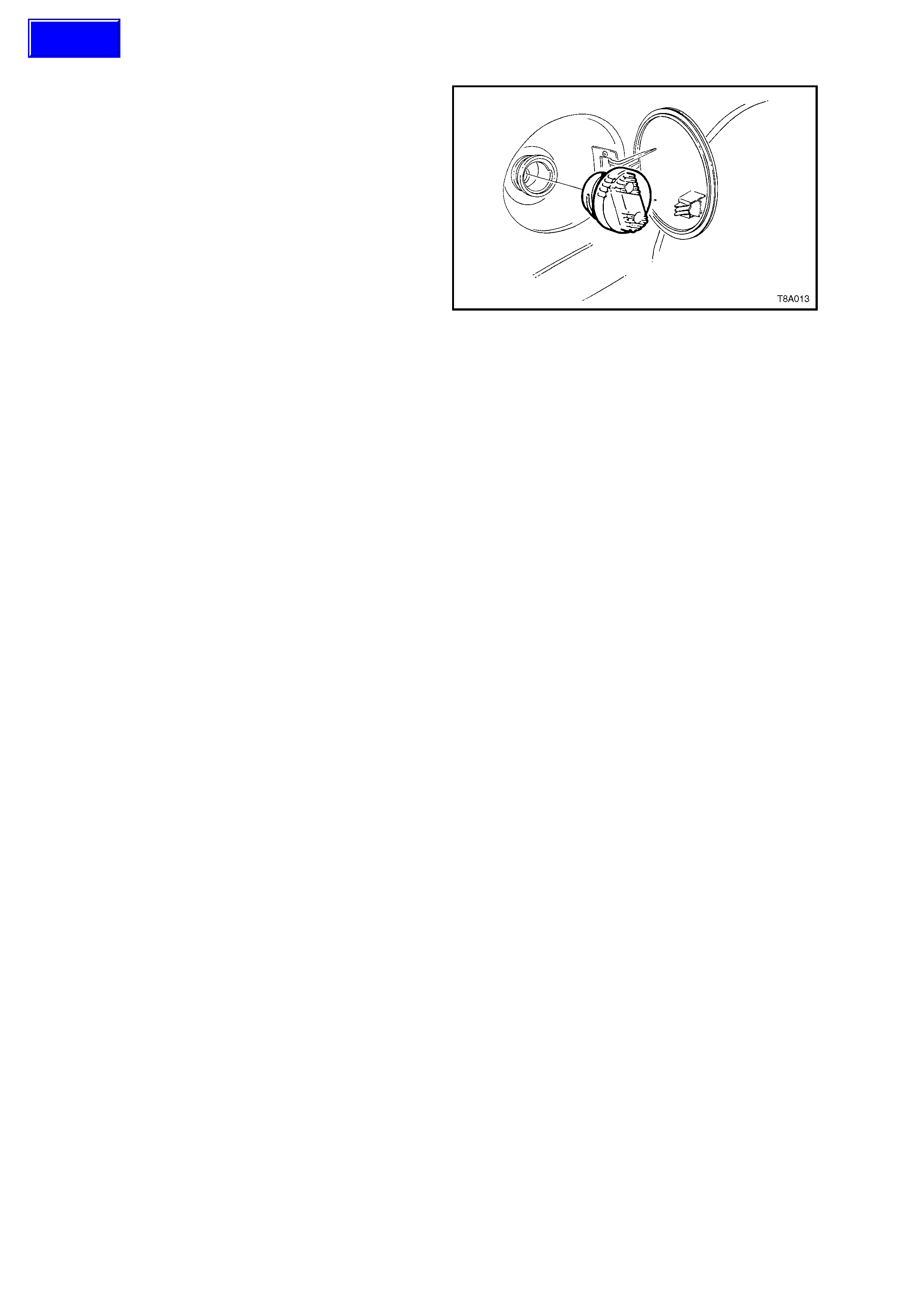
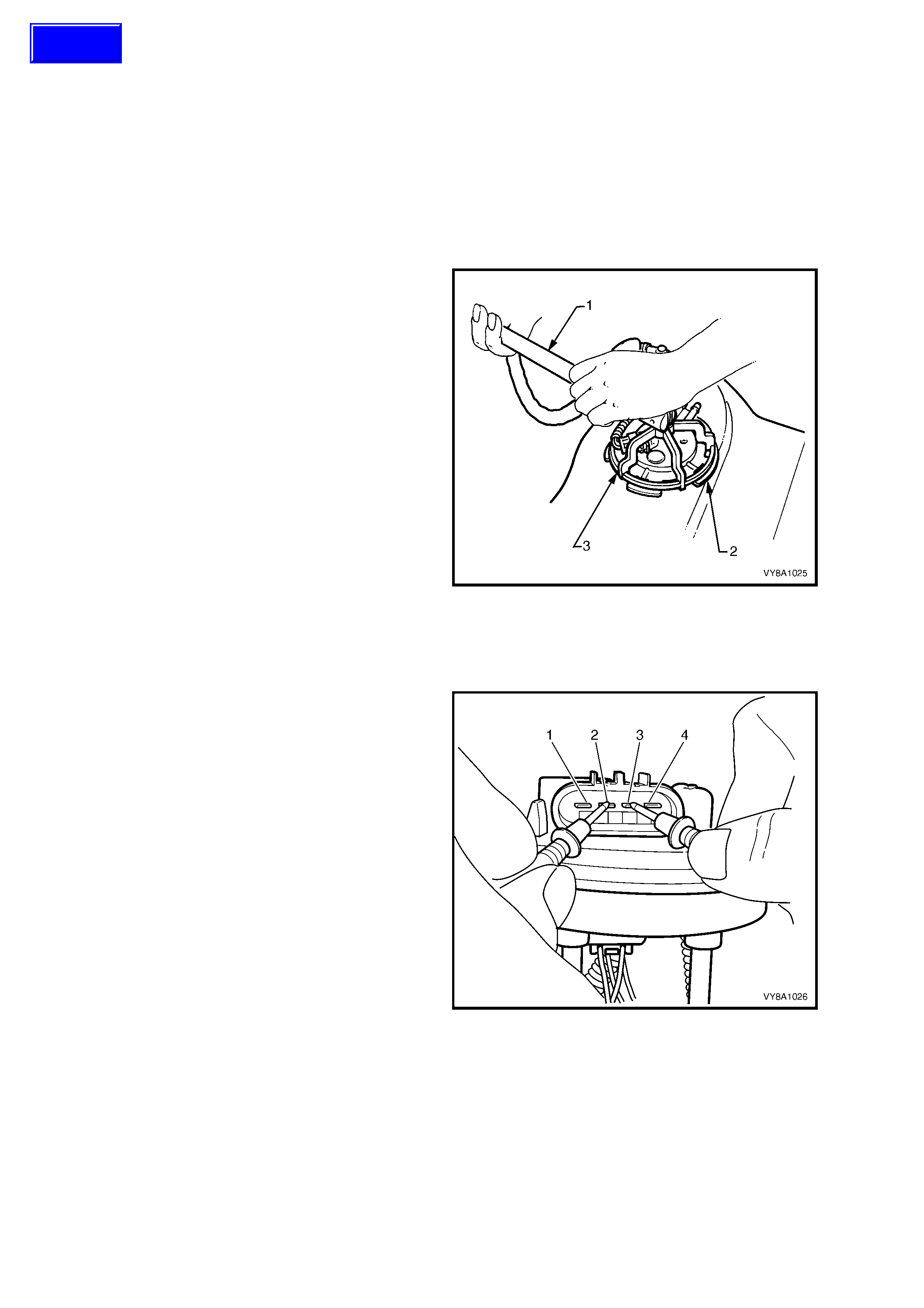
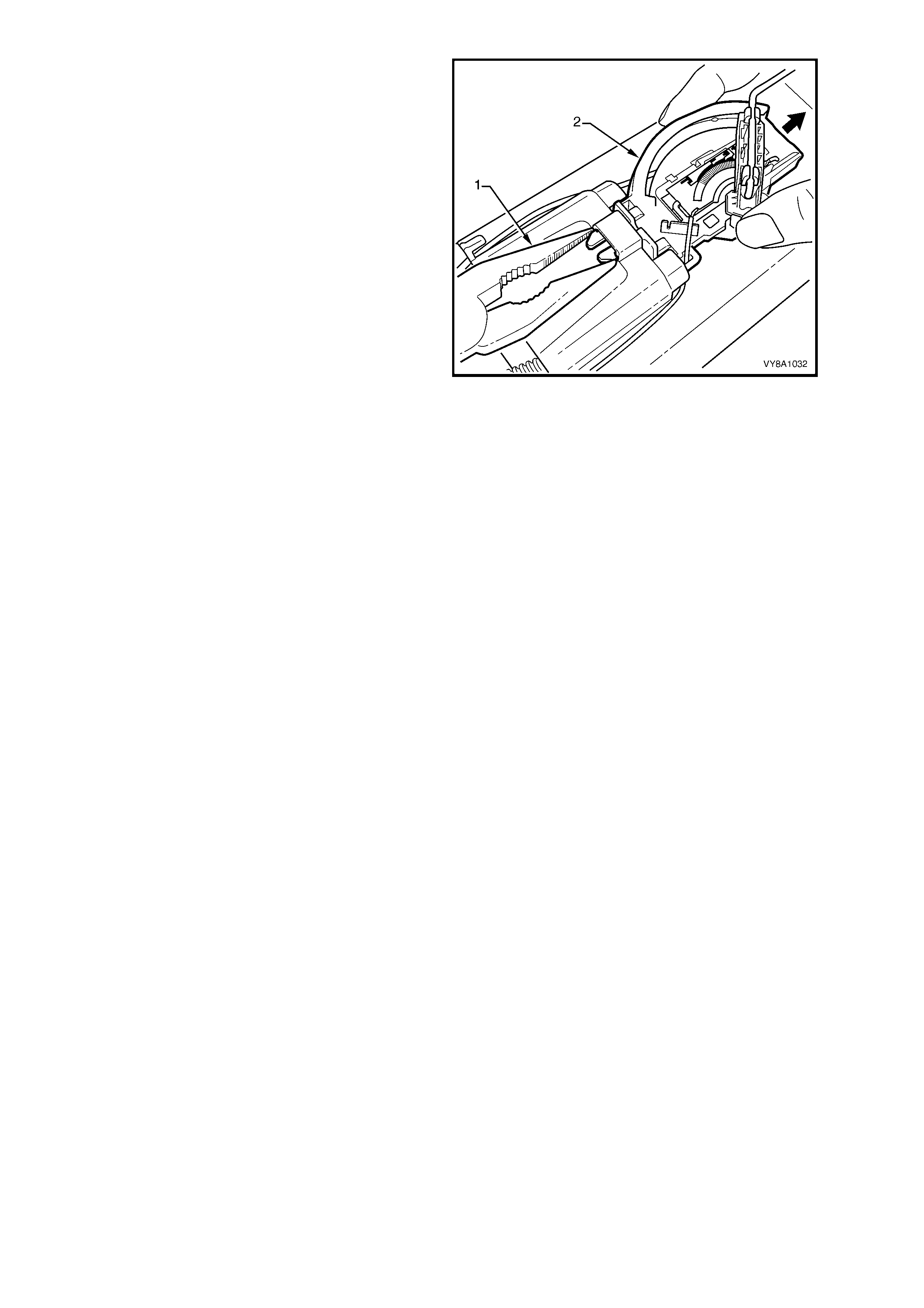
3. Using special tool AU469 (3) and a half-inch
socket bar (1), remove the modular fuel pump
and sender ass em bly circlip (2) by tur ning in an
anti-clockwise direction.
NOTE: The modular fuel pump and sender
assembly springs up when the circlip is removed.
4. Carefully lift the m odular fuel pum p and sender
assembly from the fuel tank, taking care not to
damage the fuel sender float and arm.
IMPORTANT: When the modular fuel pump and
sender assembly is removed from the fuel tank, it
will be full of fuel. Pour any remaining fuel in the
reservoir into a suitable container.
5. Remove and discard the sealing O-ring.
CAUTION: Fuel vapour remains in the tank even
when completely empty. Seal all the openings
in the fuel tank using a suitable plastic plug.
6. Place a clean rag over the opening in the fuel
tank to prevent any foreign matter from
entering the fuel system.
Figure 8A1–28
TEST
1. Measure the resistance acros s terminals 2 and
3 of the fuel pump motor connector. Take the
following measurements:
a. With the float arm assembly in the empty
position, the resistance should be
approximately 40 ohms.
b. With the float arm assembly rotated to the full
position, the resistance should be
approximately 250 ohms.
2. If the fuel level sender assembly is not as
specified, service the fuel level sender
assembly as follows:
a. For vehicles with V6 Supercharged engines
and vehicles exported to Brazil, replace
the fuel level sender assembly. Refer to
2.8 FUEL LEVEL SENDER ASSEMBLY — V6
SUPERCHARGED AND VEHICLES
EXPORTED TO BRAZIL.
b. For vehicles with V6 and GEN III V8 engines
replace the entire modular fuel pump and
sender assembly.
Figure 8A1–29
Techline

REINSTALL
1. Position a new O-ring seal in the fuel tank recess.
2. Install the modular fuel pump and s ender assem bly to the fuel tank , taking care not to dam age the fuel sender
float or arm in the process.
NOTE: T ak e c are not to fold or twist the fuel pick - up strainer during m odule installation. Ens ure the f uel pum p pick -
up strainer does not interfere with the float arm and full travel is still possible.
3. Ensure the locator in the pump cover engages in the slot in the tank opening.
4. Install the circlip over the modular f uel pum p and sender assem bly. Use a half-inch s ocket bar with special tool
AU469 and rotate the circlip in a clockwise direction until the tangs are engaged.
5. Install the fuel tank, refer to 2.1 FUEL TANK — SEDAN AND WAGON or 2.2 FUEL TANK — COUPE.
2.7 MODULAR FUEL PUMP AND SENDER ASSEMBLY — UTILITY
REMOVE
CAUTION: Ensure no naked flames or other ignition sources are nearby. Ensure all mobile phones are
switched off.
1. Remove the fuel pump relay R16, refer to Section 12O, 1.4 RELAYS.
2. Remove the load floor front panel assembly, refer to Section 1B, 2.7 LOAD FLOOR FRONT PANEL
ASSEMBLY, UTILITY.
3. Rem o ve the screws (2) s ecuring the load c om partm ent side panel inner f ront c over (1), refer to Figure 8A1–25.
If necessary also remove the LPG filler and service lines, refer to Section 8A2 LPG SYSTEM.
4. Disconnect the modular fuel pump and sender assembly harness connector, refer to Figure 8A1–25.
5. Tag the fuel feed and return hoses from the connections located on top of the fuel tank, refer to Figure 8A1–25.
6. T ag the vent pipe on top of the fuel tank and disconnec t by pulling the hos e from the fuel tank vent fitting, refer
to Figure 8A1–25.
7. Disengage the fuel return line and the fuel feed line quick-connect fittings using special tool AU533, refer to
2.10 QUICK-CONNECT FITTINGS.
8. Remove the circlip (1) retaining the modular
fuel pump and sender assembly (2).
9. Carefully lift the m odular fuel pum p and sender
assembly from the fuel tank, taking care not to
damage the fuel sender float and arm (3). Do
not spill any fuel remaining in the reservoir.
CAUTION: Never drain or store fuel into an
open container, due to the possibility of fire or
explosion.
IMPORTANT: When the modular fuel pump and
sender assembly is removed from the fuel tank,
pour any fuel remaining in the reservoir into a
suitable container.
NOTE: The fuel sender float arm for the Utility
model is not serviced separately.
10. Remove and discard the sealing O-ring (5).
CAUTION: Fuel vapour remains in the tank even
when completely empty. Seal all the openings
in the fuel tank using a suitable plastic plug.
11. Place a clean rag over the opening in the fuel
tank to prevent any foreign matter from
entering the fuel system.
Figure 8A1–30
TEST
For the test procedure of the m odular fuel pump and sender assembly refer to 2.6 M ODULAR FUEL PUMP AND
SENDER ASSEMBLY — SEDAN, WAGON AND COUPE.
REINSTALL
Reinstallation procedure of the modular fuel pump and sender assembly is the reverse of the removal procedure
noting the following:
1. Ensure that the spacer (4) is fitted to the modular fuel pump sender assembly, refer to Figure 8A1–30.
2. Fit a new O-ring (5) to the modular fuel pump and sender assembly.
3. Ins tall the m odular f uel pum p and sender as sem bly into the fuel tank tak ing c are not to dam age the f uel sender
float or arm in the process.
NOTE: Care should be tak en not to fold or twist the fuel pick -up strainer during module installation. Ensure that the
fuel pump pick-up strainer does not interfere with the float arm and full travel is still possible.
4. Install the modular fuel pump and sender assembly circlip (1).
Techline
2.8 FUEL LEVEL SENDER ASSEMBLY — V6 SUPERCHARGED AND VEHICLES
EXPORTED TO BRAZIL
REMOVE
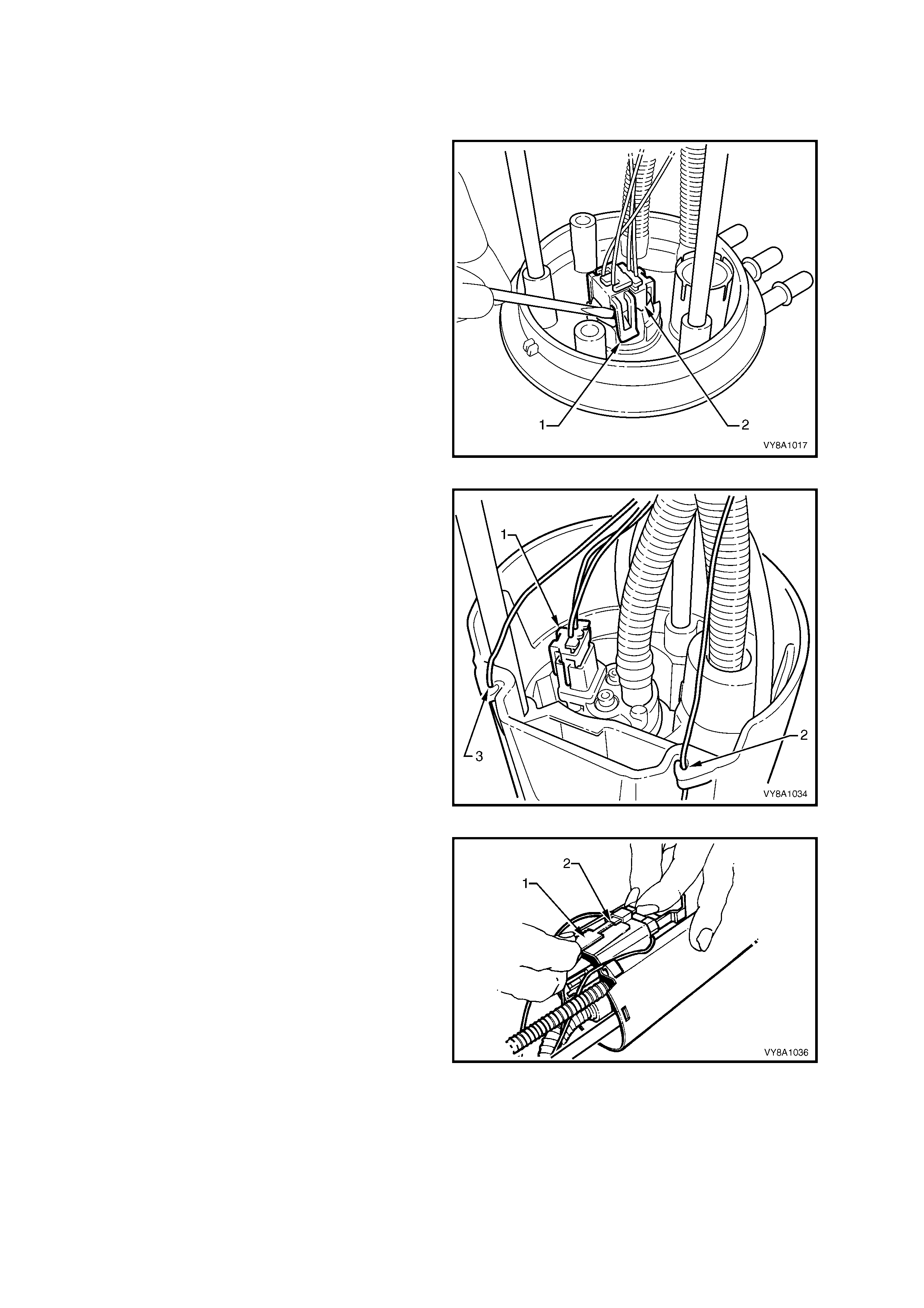
1. Remove the modular fuel pump and sender
assembly refer to 2.5 FUEL FILTER — GEN III
V8 ENGINE.
2. Remove the fuel pump/sender patch harness
connector as follows:
a. Use a small screwdriver to disconnect the fuel
pump har ness c onnector ( 2), then the f uel level
sender harness connector (1) from the
underside of the electrical connector located in
the top of the modular fuel pump and sender
assembly.
Figure 8A1–31
b. Release the locking tabs on the fuel pump
harness connector (1). Remove the connector
from the fuel pump.
c. Release eac h of the two fuel s ender wires f rom
the retainers (2 and 3) on the side of the
modular fuel pump and sender assembly.
Figure 8A1–32
5. Remove the fuel sender Connector Position
Assuranc e (CPA) lock ing tab (2), using a piece
of broken hacksaw blade (1), ground to a
suitable width and push the tab down.
NOTE: Due to the fragile nature of the CPA, it is
recomm ended that a replac ement tab be used after
installation of the fuel level sender assembly.
Figure 8A1–33
6. Use long-nosed pliers (1) to release the fuel
sender CPA locking tabs; push down to remove
the fuel level sender assembly (2).
REINSTALL
Reinstallation of the fuel level sender assembly is
the reverse of the removal procedure.
1. Before installation into the fuel tank, check the
fuel sender float position, as follows:
a. Stand the assembly upright on a flat surface.
b. Measure the distance between the base of the
fuel sender float and the flat surface.
c. If r equir ed, the f loat position s hould be adjusted
to achieve a nominal measurement of 10 mm.
Figure 8A1–34
2.9 ROLLOVER VALVE — UTILITY
REMOVE
1. Remove the load floor front panel assembly,
refer to Section 1B, 2.7 LOAD FLOOR
FRONT PA NEL ASSEMBLY.
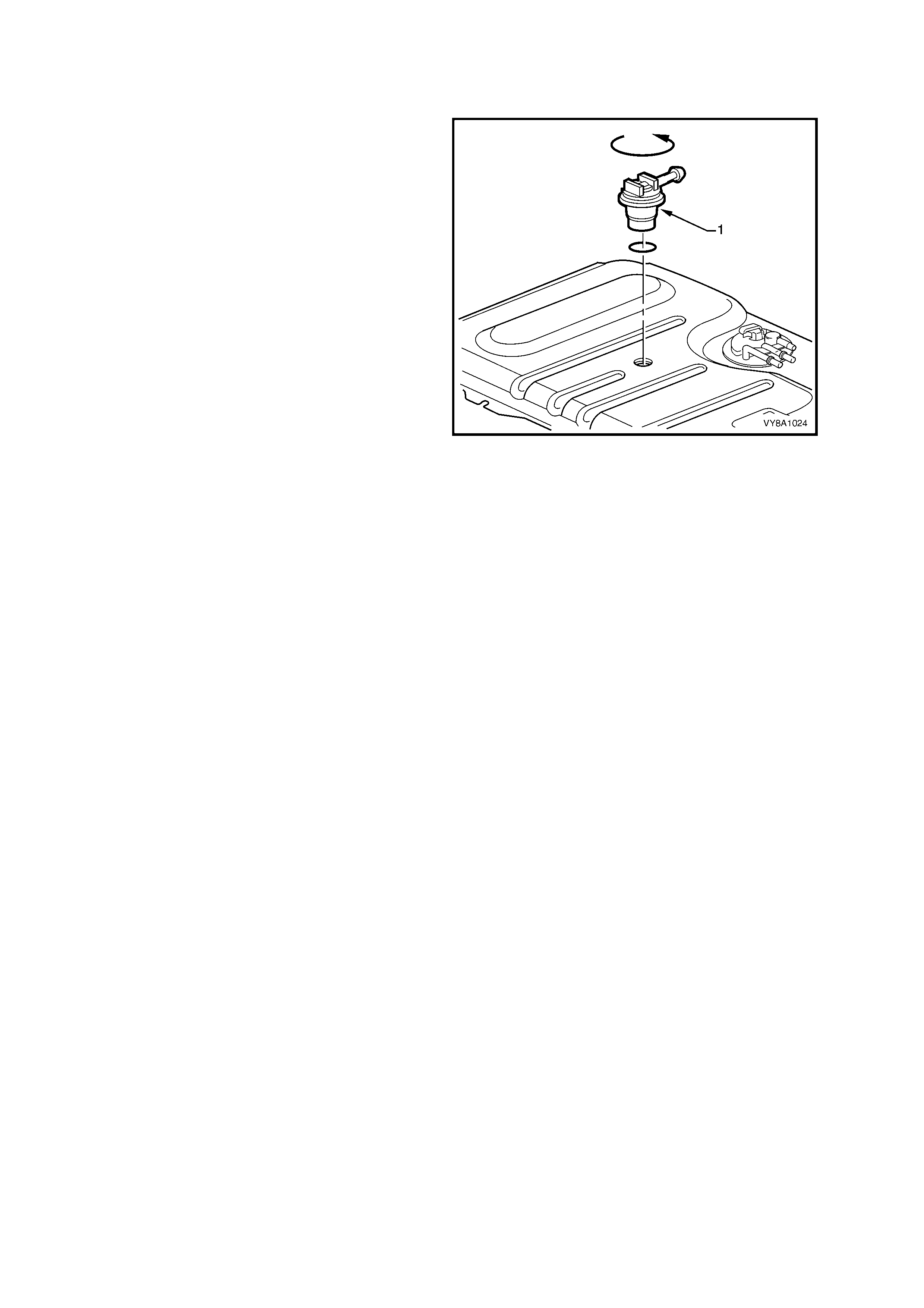
2. Pull the fuel tank vent hose from the rollover
valve (1).
3. Apply a downward pressure on the rollover
valve and rotate it anti-clock wise approximately
30 degrees.
4. Remove the rollover valve from the fuel tank.
5. Place a clean rag into the hole of the fuel tank
to prevent dirt and foreign m atter from entering
the tank.
TEST
1. Remove the rollover valve from the fuel tank.
CAUTION: Wear safety glasses when using
compressed air.
2. Clean the rollover valve with compressed air.
NOTE: Do not us e com pres sed air f or the f ollowing
procedure.
3. W ith the rollover valve upr ight, blow nitrogen at
low pressure into the outlet pipe. The nitrogen
should pass through the valve and out the inlet
holes in the bottom.
4. Continue to blow nitrogen into the outlet pipe
and slowly rotate the rollover valve. At
approximately 90 degrees of rotation, the
internal check valve should operate with an
audible click; nitrogen should then cease to
pass through the valves.
REINSTALL
Reinstallation of the rollover valve is the reverse of
the removal procedure.
Figure 8A1–35
2.10 QUICK-CONNECT FITTINGS
SPECIAL TOOL AU533
This procedure shows the removal of the quick-
connect fittings on the fuel filter using special tool
AU533. The same procedure can also be applied to
other quick-connect fittings.
Remove
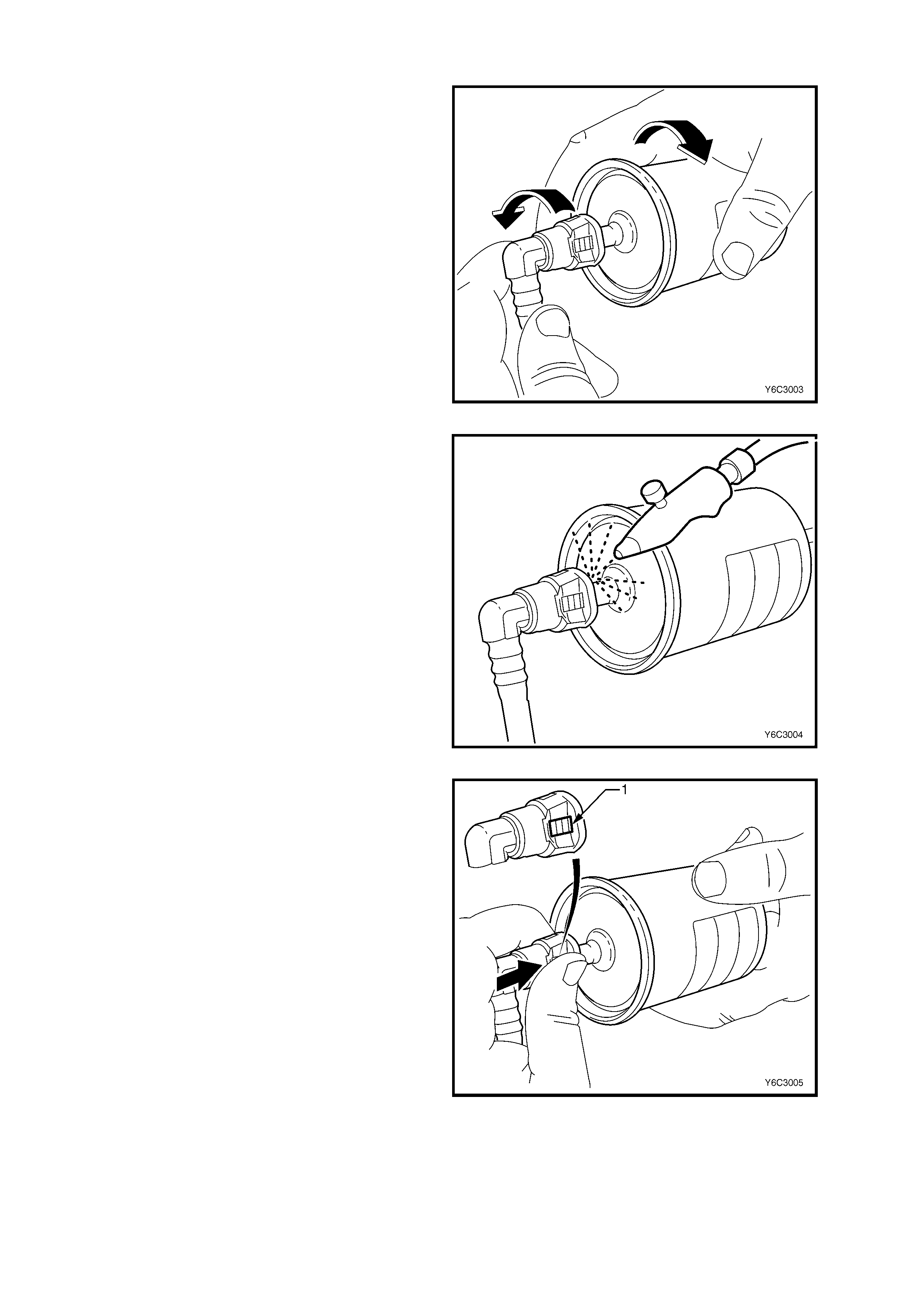
1. Grasp both sides of the quick-connect fitting.
Twist the female connector one quarter of a
turn in each direc tion in order to loosen any dirt
within the fitting.
Figure 8A1–36
CAUTION: Wear safety glasses when using
compressed air.
2. Using compressed air, blow any dirt out of the
quick-connect fitting to aid the release of any
tension or binding on the release tabs.
Figure 8A1–37
3. Grasp the female connector and firmly support
the male connector.
4. Squeeze the plastic retainer releas e tabs (1) on
each side of the fitting while pushing the fitting
firmly inwards to release any tension on the
release tabs.
Figure 8A1–38
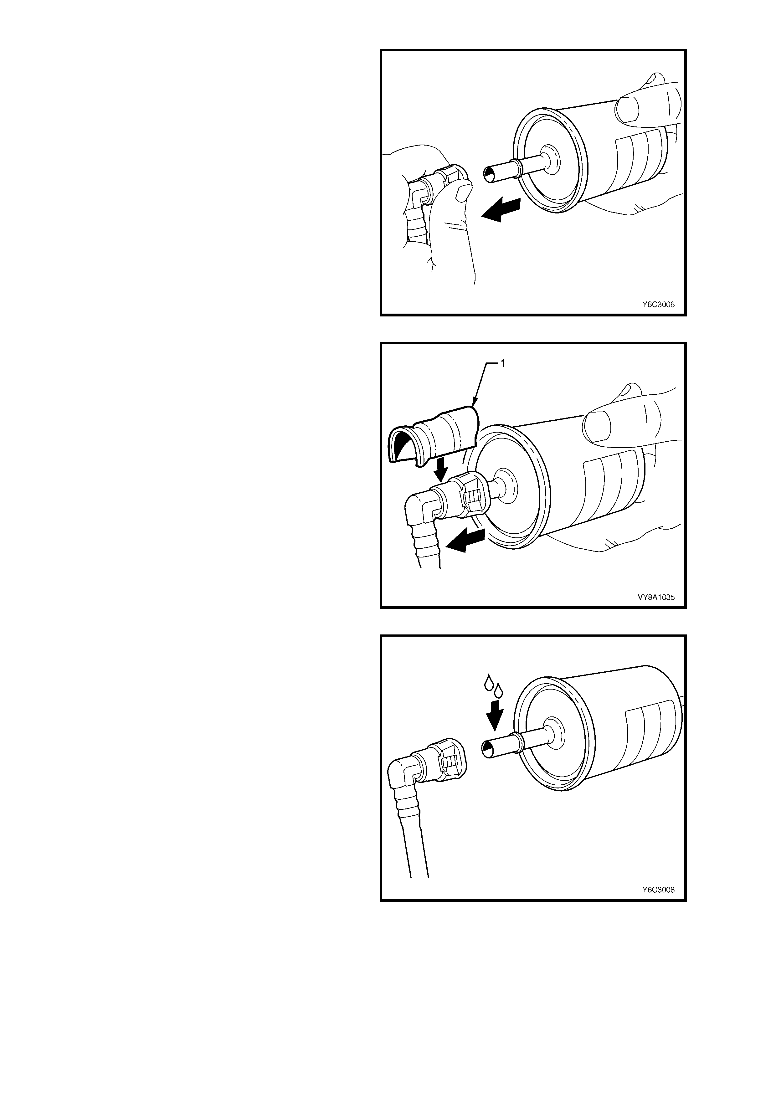
5. With the tension release tabs still pressed pull
the connector apart.
Figure 8A1–39
6. Alternatively, for steps 3 to 5, use special tool
AU533 (1) to squeeze the release tabs and
release the quick-connect fittings.
NOTE: Special tool AU533 will only work with
retainer tabs that sit proud of the connector body.
Some filter connec tors have f lus h retainers that can
only be pressed by hand.
Figure 8A1–40
Reinstall
IMPORTANT: Befor e connecting the quick -c onnect
fittings, always apply a few drops of clean engine oil
to the male connector. This ensures proper
connection and prevents a possible fuel leak.
During normal operation, the O-ring located in the
female connector swells and may prevent proper
reconnection if not lubricated.
1. Apply a few drops of clean engine oil to each
male connector.
Figure 8A1–41
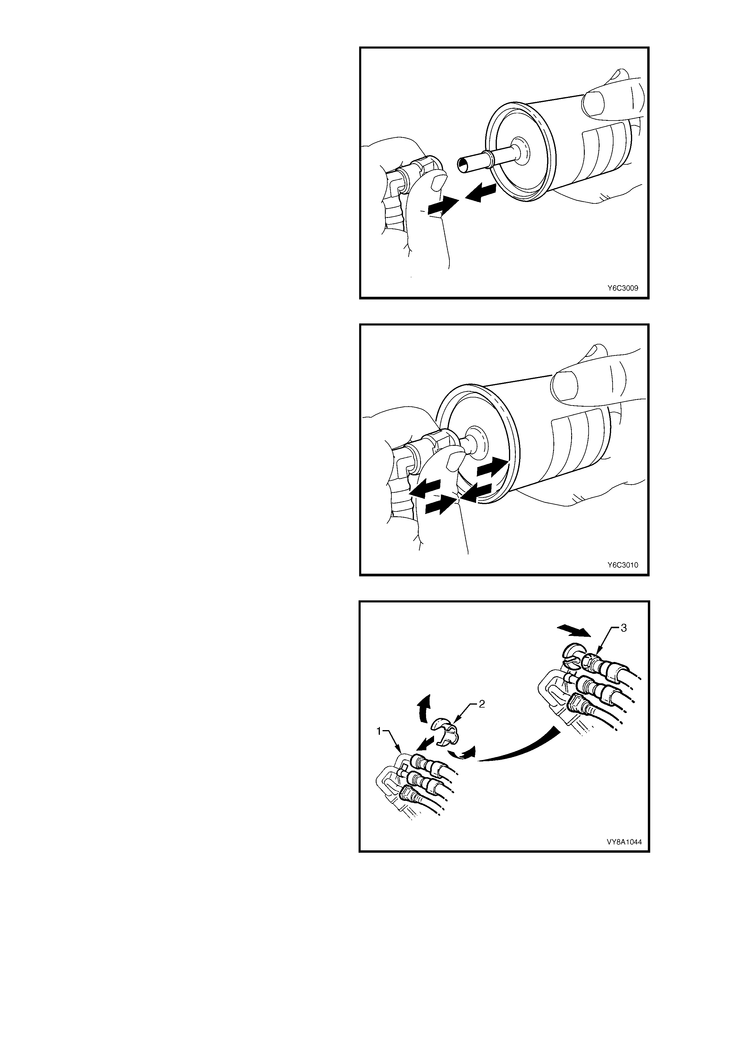
2. Push both quick-connect fittings together so
the retaining tabs snap into place.
Figure 8A1–42
3. After installation, pull and push on the quick-
connect fittings to ensure the connection is
secure.
Figure 8A1–43
SPECIAL TOOLS 7370 AND 7371
Remove
Use special tools 7370 and 7371 to disconnect the
fuel feed and return lines at the engine as follows:
1. Open the quick-connect release tool (2) and
place it over the fuel line (1).
2. Close the tool and pull it into the fuel hose
quick -c onnec t f itting to disc onnec t the fuel hose
from the fuel pipe.
NOTE: Do not attem pt to disconnec t the fuel hoses
at the fuel rail. If the fuel hoses are removed from
the fuel rail the hoses must be replaced.
Reinstall
Reinstallation of the quick-connect fittings
disconnected using special tools 7370 and 7371 is
the same procedure associated with quick-connect
fittings disconnected using special tool AU533.
Refer to SPECIAL TOOL AU533 — Reinstall.
Figure 8A1–44
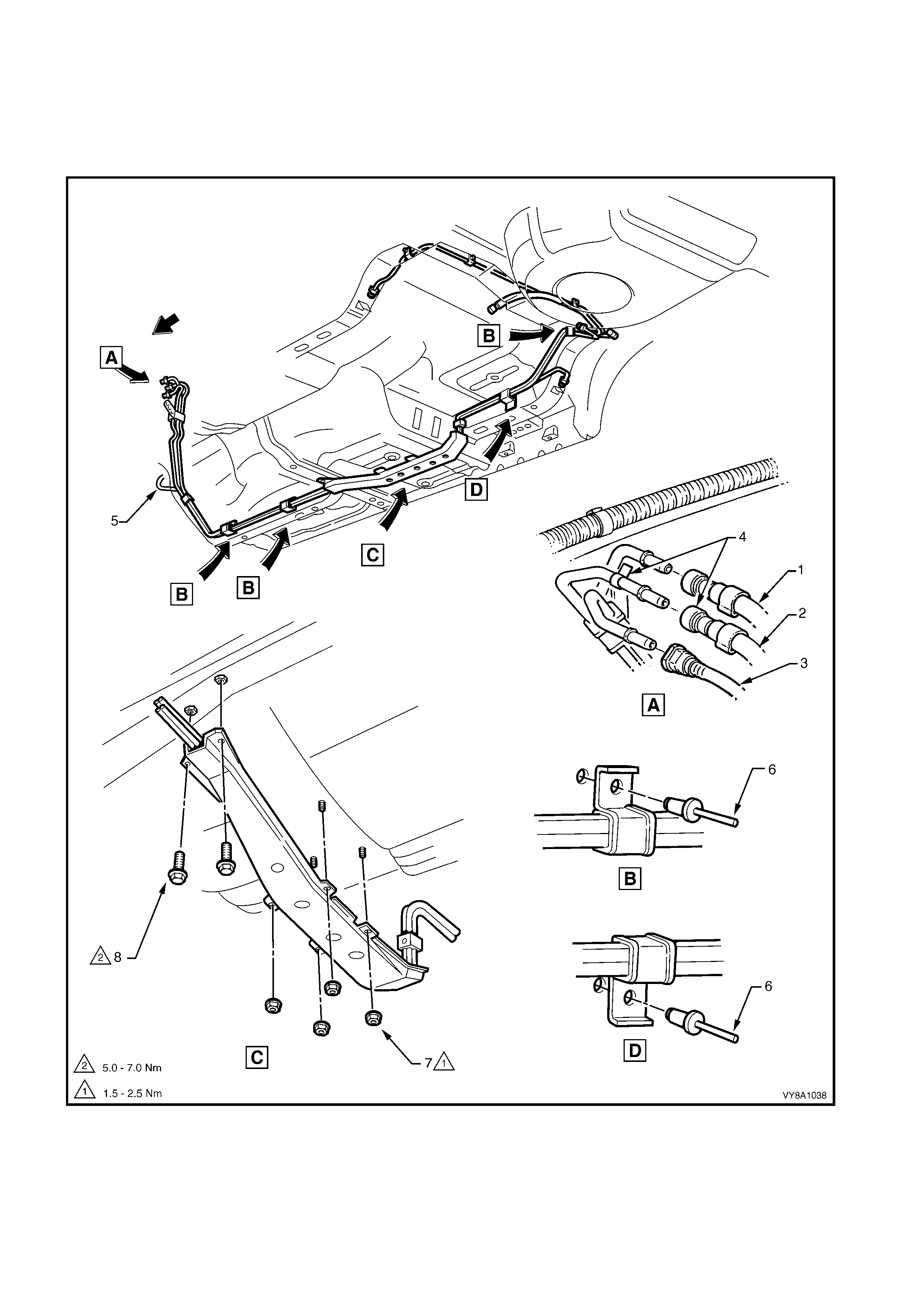
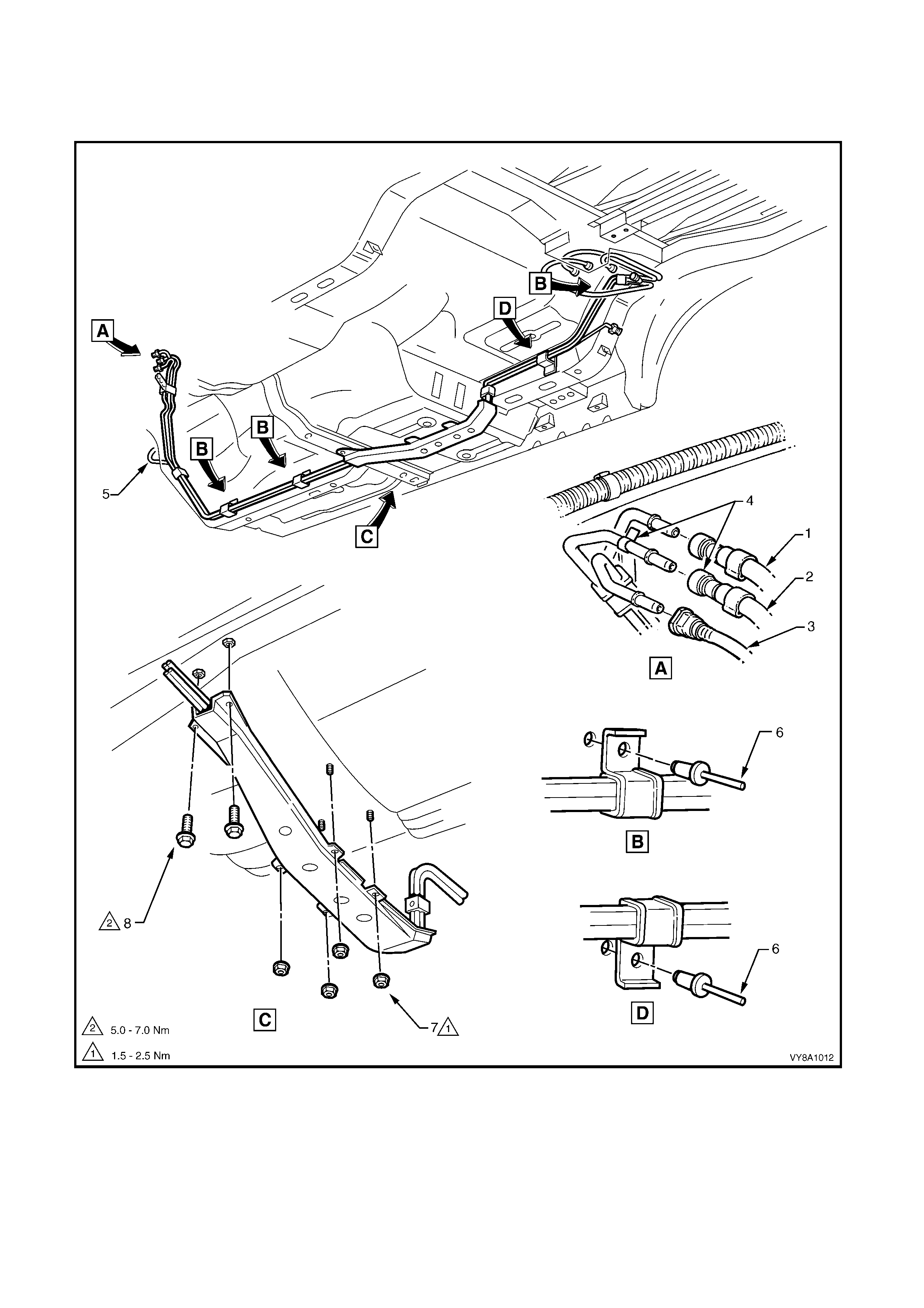
2.11 FUEL PIPE ARRANGEMENT
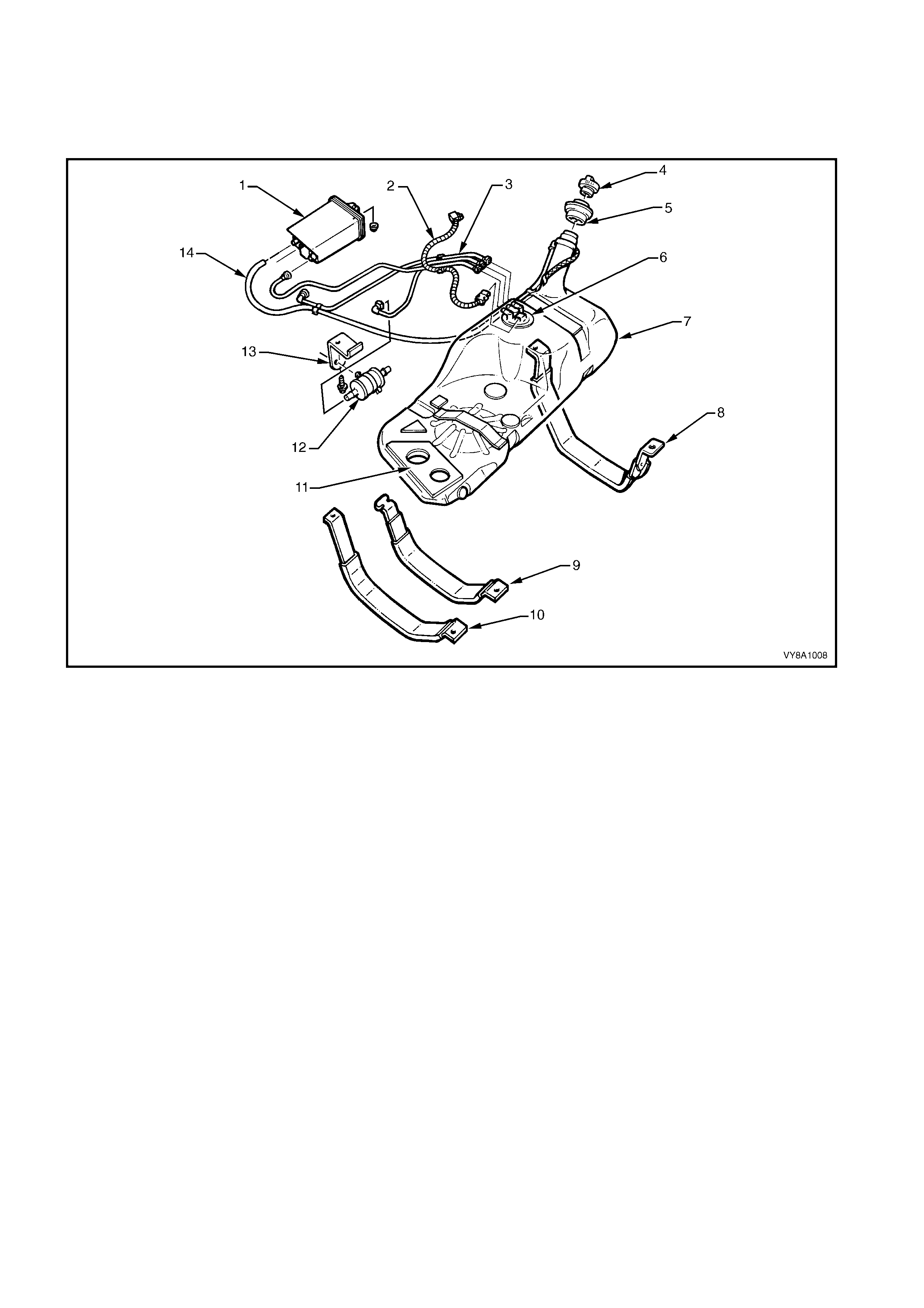
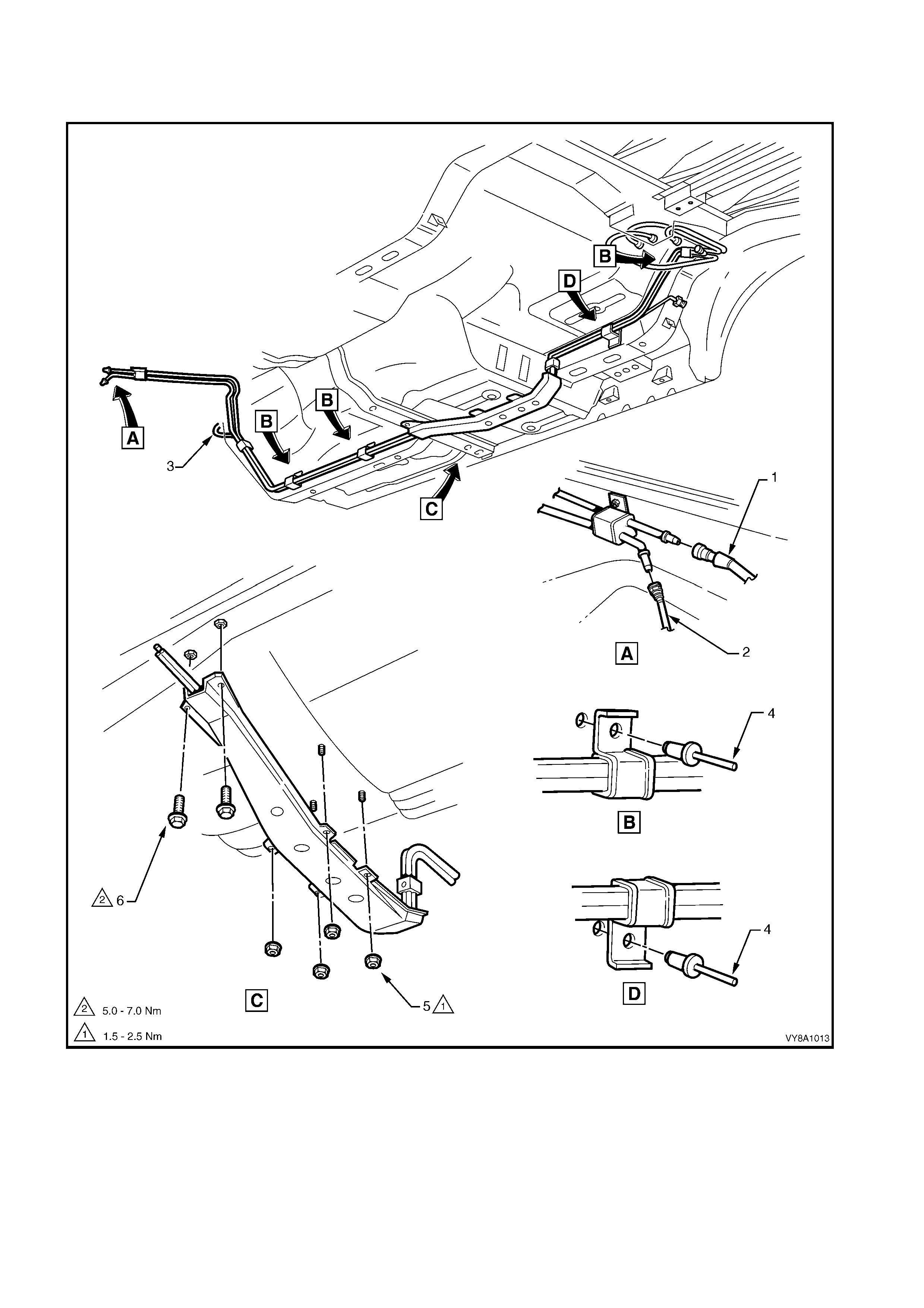
V6 AND V6 SUPERCHARGED ENGINES — SEDAN AND WAGON
Figure 8A1–45 and Figure 8A1–46 illustrate the fuel pipe layout and location of other fuel tank related items in the
Sedan and Wagon with V6 engines. For the f uel pipe arrangement f or vehicles fitted with the LPG system , refer to
Section 8A2 – LPG SYSTEM.
Figure 8A1–45
Legend
1. Fuel Return from Engine Hose
2. Fuel Feed to Engine Hose
3. Fuel Vapour Hose
4. White Identifying Tab
5. Brake Fluid Pipe
6. Fuel Line Bracket Pop Rivet
7. Stone Guard Securing Nut
8. Stone Guard Securing Bolt
SERVICE NOTE: Refer to Figure 8A1–45, for V6 engines, use special tool 7370 to remove the fuel feed hose (2)
and fuel return hose (1) quick -connect fittings. For V6 Supercharged engines, use special tool 7371 to remove the
fuel feed hose (2) quick-connect fitting, and special tool 7370 to remove the fuel return hose (1) quick-connect
fitting. Use special tool AU533 to remove the vapour hose (3), refer to 2.10 QUICK-CONNECT FITTINGS.
Figure 8A1–46
Legend
1. Fuel Vapour Canister
2. Electrical Patch Harness
3. Fuel and Vapour Hoses
4. Fuel Filler Cap
5. Fuel Filler Neck Insulator
6. Modular Fuel Pump and Sender
Assembly
7. Fuel Tank
8. Right-hand Side Fuel Tank
Mounting Strap
9. Centre Fuel Tank Mounting Strap
10. Left-hand Side Fuel Tank
Mounting Strap
11. Fuel Tank to Underbody Insulator
12. Fuel Filter
13. Fuel Filter Mounting Bracket
14. Fuel Tank Vent Hose
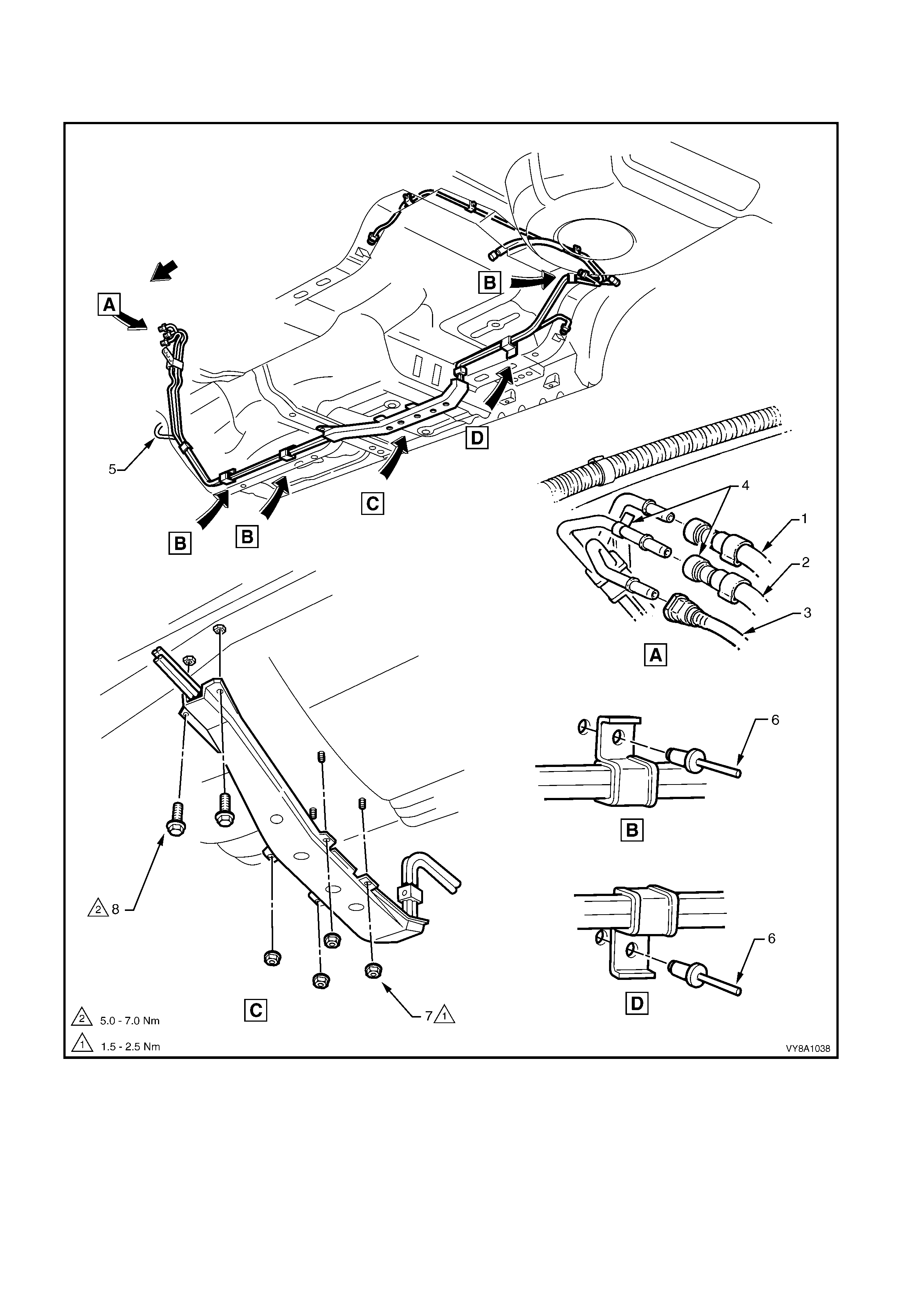
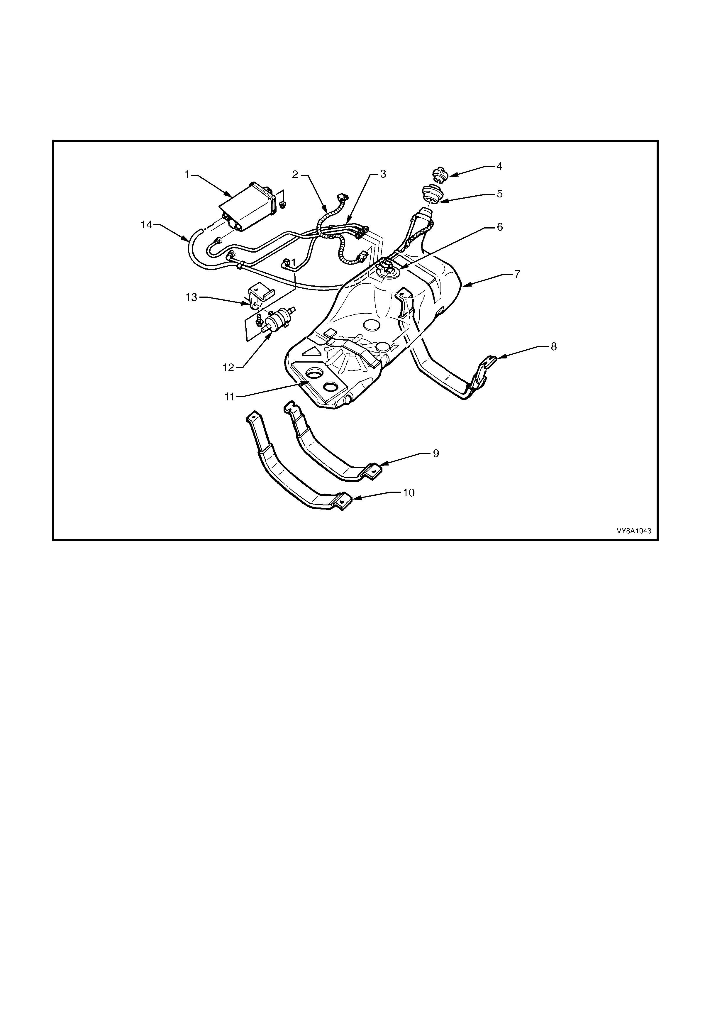
V6 AND V6 SUPERCHARGED ENGINE – COUPE
Figure 8A1–47 and Figure 8A1–48 illustrate the fuel pipe layout and location of other fuel tank related items in the
Coupe with V6 engines.
Figure 8A1–47
Legend
1. Fuel Return from Engine Hose
2. Fuel Feed to Engine Hose
3. Fuel Vapour Hose
4. White Identifying Tab
5. Brake Fluid Pipe
6. Fuel Line Bracket Pop Rivet
7. Stone Guard Securing Nut
8. Stone Guard Securing Bolt
SERVICE NOTE: Refer to Figure 8A1–47, for V6 engines, use special tool 7370 to remove the fuel feed hose (2)
and fuel return hose (1) quick -connect fittings. For V6 Supercharged engines, use special tool 7371 to remove the
fuel feed hose (2) quick-connect fitting, and special tool 7370 to remove the fuel return hose (1) quick-connect
fitting. Use special tool AU533 to remove the vapour hose (3), refer to 2.10 QUICK-CONNECT FITTINGS.
Figure 8A1–48
Legend
1. Fuel Vapour Canister
2. Electrical Patch Harness
3. Fuel and Vapour Hoses
4. Fuel Filler Cap
5. Fuel Filler Neck Insulator
6. Modular Fuel Pump and Sender
Assembly
7. Fuel Tank
8. Right-hand Side Fuel Tank
Mounting Strap
9. Centre Fuel Tank Mounting Strap
10. Left-hand Side Fuel Tank
Mounting Strap
11. Fuel Tank to Underbody Insulator
12. Fuel Filter
13. Fuel Filter Mounting Bracket
14. Fuel Tank Vent Hose
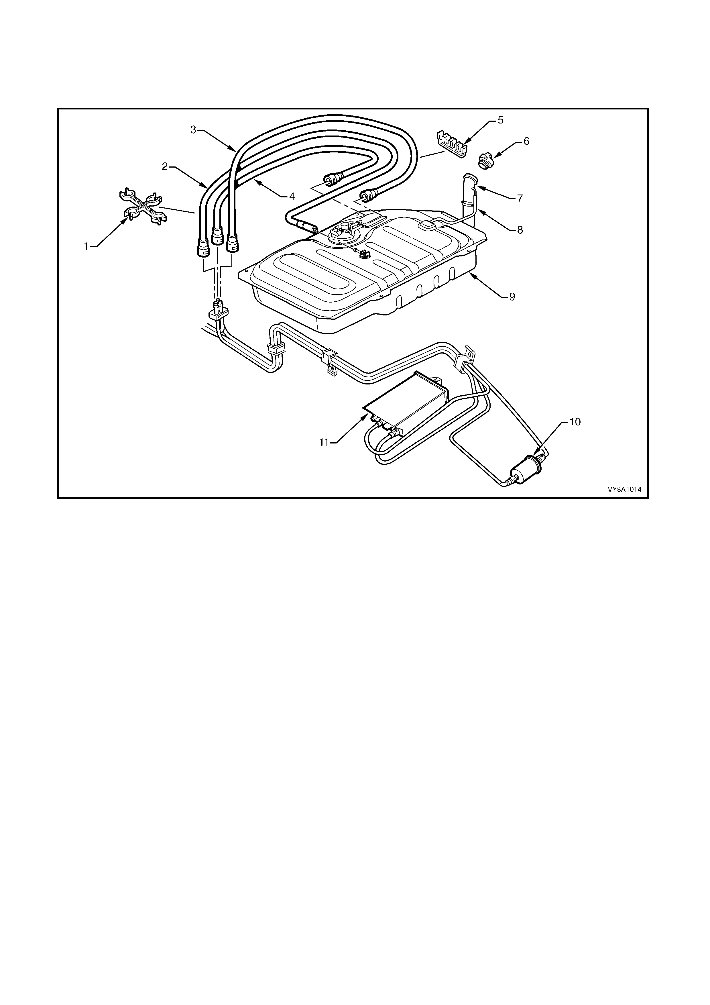
V6 ENGINE — UTILITY
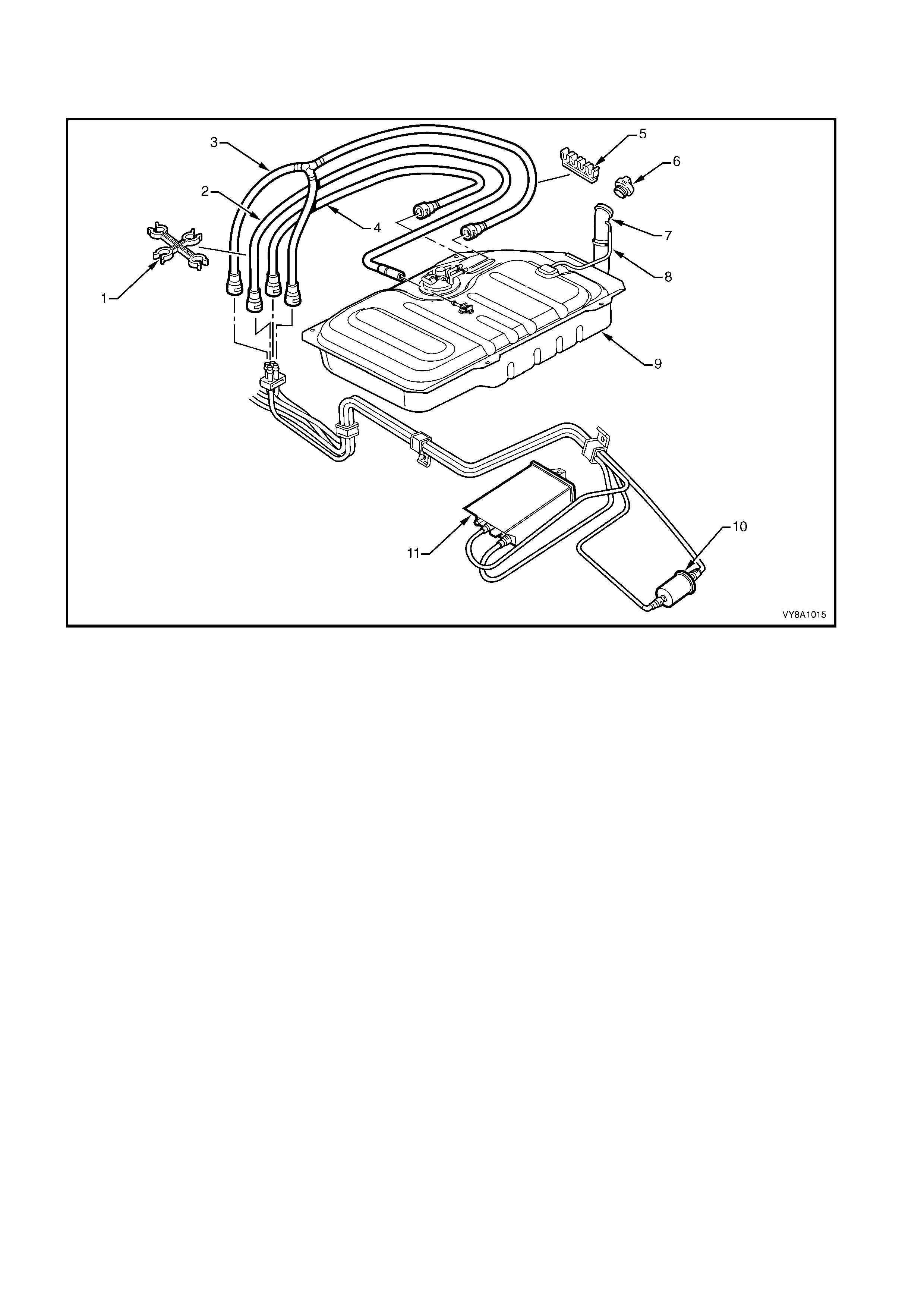
Figure 8A1–49 and Figure 8A1–50 illustrate the fuel pipe layout and location of other fuel tank related items in the
Utility with V6 engines. For the fuel pipe arrangement for vehicles fitted with the LPG system, refer to Section 8A2 –
LPG SYSTEM in this service information.
Figure 8A1–49
Legend
1. Fuel Return from Engine Hose
2. Fuel Feed to Engine Hose
3. Fuel Vapour Hose
4. White Identifying Tab
5. Brake Fluid Pipe
6. Fuel Line Bracket Pop Rivet
7. Stone Guard Securing Nut
8. Stone Guard Securing Bolt
SERVICE NOTE: Refer to Figure 8A1–49, for V6 engines, use special tool 7370 to remove the fuel feed hose (2)
and fuel retur n hose ( 1) quic k-connec t f ittings . Use s pec ial tool AU533 to rem ove the vapour hose (3) quick-c onnec t
fitting, refer to 2.10 QUICK-CONNECT FITTINGS.
Figure 8A1–50
Legend
1. Mounting Clip
2. Fuel Vapour Hose
3. Fuel Return from Engine Hose
4. Fuel Feed to Engine Hose
5. Mounting Clip
6. Fuel Filler Cap
7. Fuel Filler Neck
8. Fuel Tank Vent Hose
9. Fuel Tank
10. Fuel Filter
11. Fuel Vapour Canister
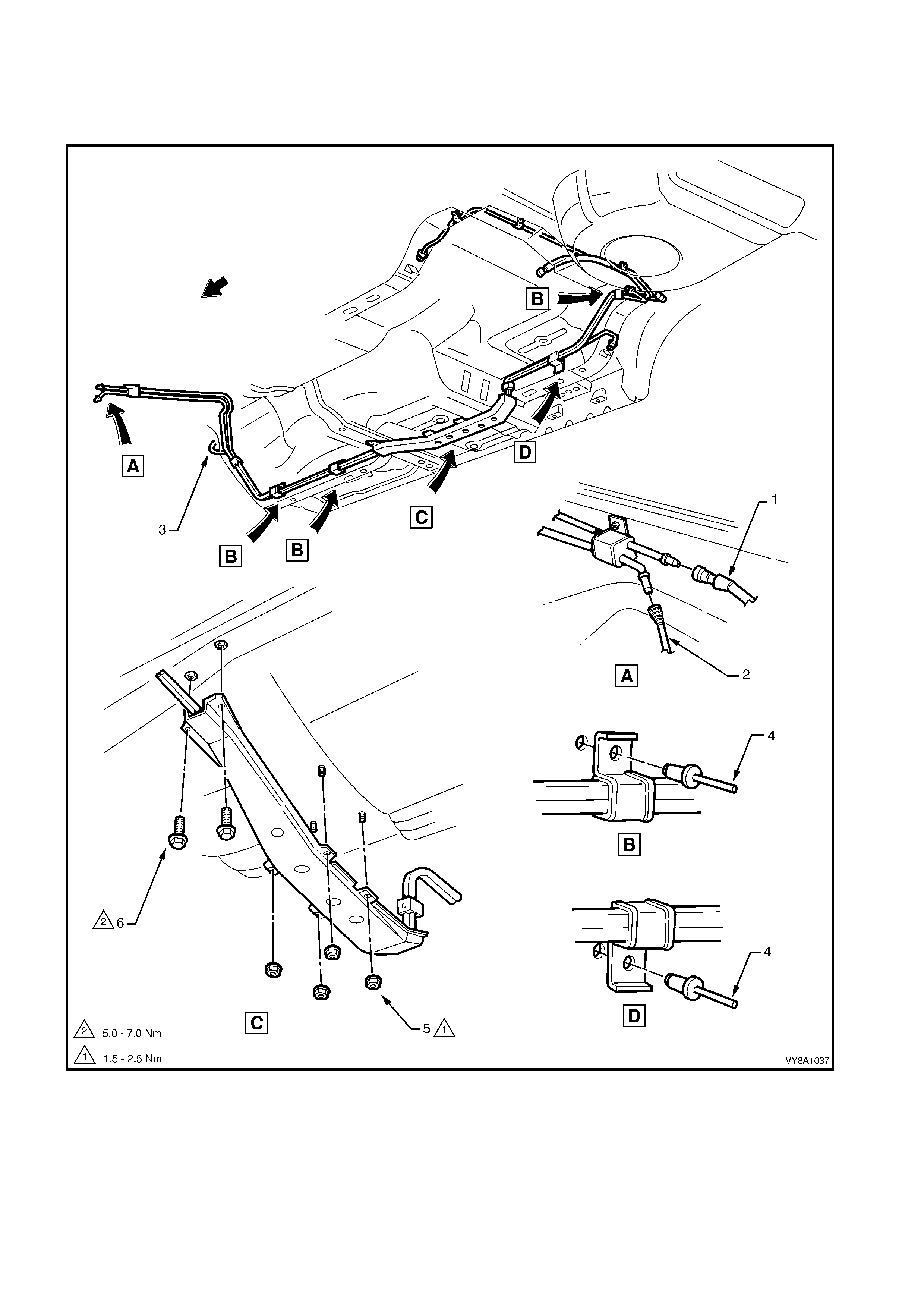
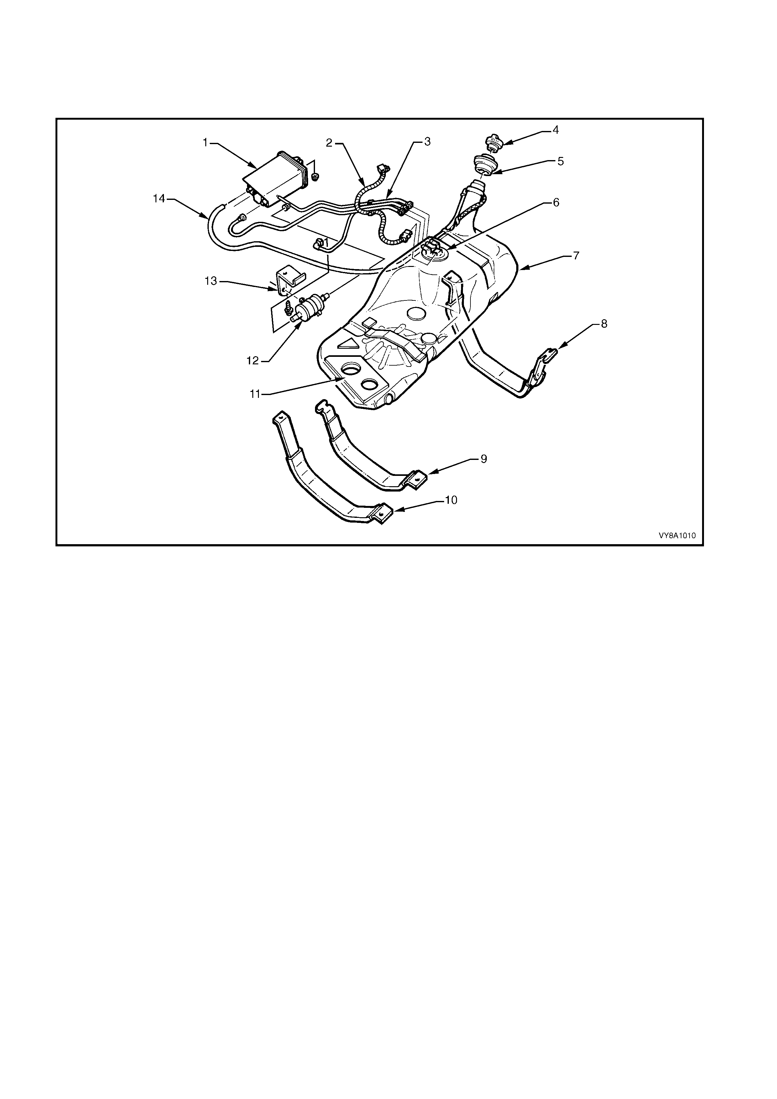
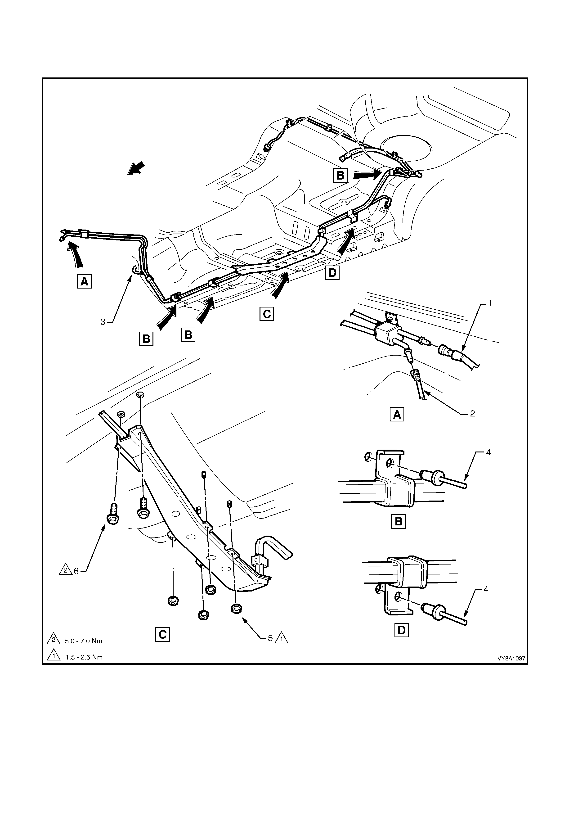
GEN III V8 ENGINE — SEDAN AND WAGON
Figure 8A1–51 and Figure 8A1–52 illustrate the fuel pipe layout and location of other fuel tank related items in the
Sedan and Wagon with a GEN III V8.
Figure 8A1–51
Legend
1. Fuel Feed/Return to Engine
Hose
2. Fuel Vapour Hose
3. Brake Fluid Pipe
4. Fuel Line Bracket Pop Rivet 5. Stone Guard Securing Nut
6. Stone Guard Securing Bolt
SERVICE NOTE: Refer to Figure 8A1–51, for GEN III V8 engines use special tool 7371 to remove the fuel
feed/return to engine hose (1) quick-connect fitting and special tool AU533 to remove the fuel vapour hose (2)
quick-connect fitting, refer to 2.10 QUICK-CONNECT FITTINGS.
Figure 8A1–52
Legend
1. Fuel Vapour Canister
2. Electrical Harness Connector
3. Fuel Return Hose
4. Fuel Filler Cap
5. Fuel Filler Neck Insulator
6. Modular Fuel Pump and Sender
Assembly
7. Fuel Tank
8. Right-hand Side Fuel Tank
Mounting Strap
9. Centre Fuel Tank Mounting Strap
10. Left-hand Side Fuel Tank
Mounting Strap
11. Insulator Kit
12. Fuel Filter
13. Fuel Filter Mounting Bracket
14. Filler Neck Breather Hose
GEN III V8 ENGINE — COUPE
Figure 8A1–53 and Figure 8A1–54 illustrate the fuel pipe layout and location of other fuel tank related items in the
Coupe with a GEN III V8 engine.
Figure 8A1–53
Legend
1. Fuel Feed/Return to Engine Hose
2. Fuel Vapour Hose 3. Brake Fluid Pipe
4. Fuel Line Bracket Pop Rivet 5. Stone Guard Securing Nut
6. Stone Guard Securing Bolt
SERVICE NOTE: Refer to Figure 8A1–53, For GEN III V8 engines use special tool 7371 to remove the fuel
feed/return to engine hose (1) quick-connect fitting and special tool AU533 to remove the fuel vapour hose (2)
quick-connect fitting, refer to 2.10 QUICK-CONNECT FITTINGS.
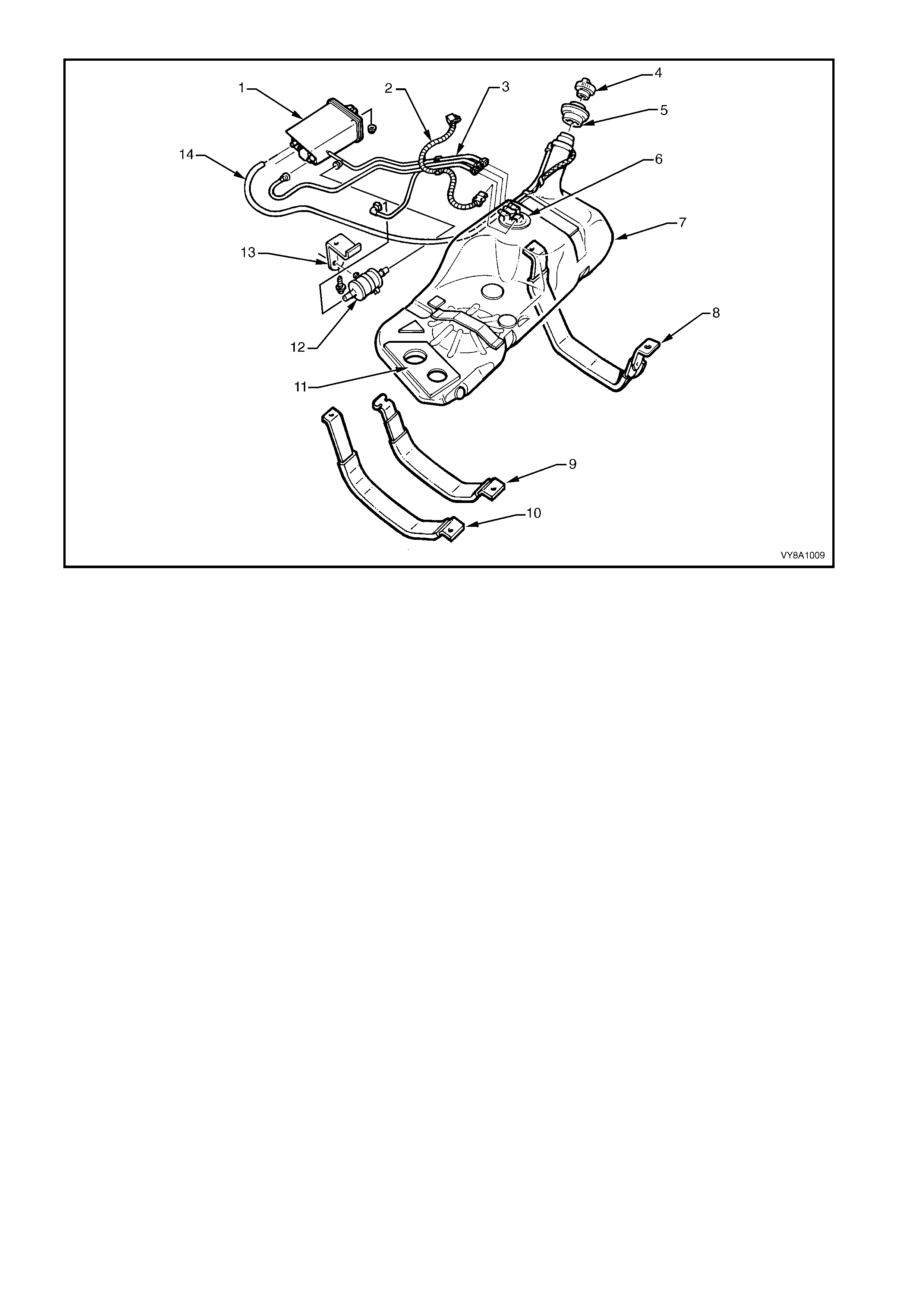
Figure 8A1–54
Legend
1. Fuel Vapour Canister
2. Electrical Patch Harness
3. Fuel Return Hose
4. Fuel Filler cap
5. Fuel Filler Neck Insulator
6. Modular Fuel Pump and Sender
Assembly
7. Fuel Tank
8. Right-hand Side Fuel Tank
Mounting Strap
9. Centre Fuel Tank Mounting Strap
10. Left-hand Side Fuel Tank
Mounting Strap
11. Insulator Kit
12. Fuel Filter
13. Fuel Filter Mounting Bracket
14. Filler Neck Breather Hose
GEN III V8 ENGINE — UTILITY
Figure 8A1–55 and Figure 8A1–56 and Figure 8A1–25 illustrate the fuel pipe layout and location of other f uel tank
related items in the Utility with a GEN III V8 engine.
Figure 8A1–55
Legend
1. Fuel Feed/Return to Engine Hose
2. Fuel Vapour Hose 3. Brake Fluid Pipe
4. Fuel Line Bracket Pop Rivet 5. Stone Guard Securing Nut
6. Stone Guard Securing Bolt
SERVICE NOTE: Refer to Figure 8A1–55, for GEN III V8 engines use special tool 7371 to remove the fuel
feed/return to engine hose (1) quick-connect fitting and special tool AU533 to remove the fuel vapour hose (2)
quick-connect fitting, refer to 2.10 QUICK-CONNECT FITTINGS.
Figure 8A1–56
Legend
1. Mounting Clip
2. Fuel Vapour Hose
3. Fuel Return from Engine Hose
4. Fuel Feed to Engine Hose
5. Mounting Clip
6. Fuel Filler Cap
7. Fuel Filler Neck
8. Fuel Tank Vent Hose
9. Fuel Tank
10. Fuel Filter
11. Fuel Vapour Canister

3. SPECIFICATIONS
Fuel Tank Capacity:
Sedan, Wagon and Coupe...................................... 75 litres
Utility........................................................................ 70 litres
Fuel Tank Material:
Sedan, Wagon and Coupe...................................... High density multi-layer polyethylene
Utility........................................................................ Pressed Steel
Fuel Filler Location:
All Models................................................................ Right-hand rear quarter panel
Fuel Pump Type:
V6 Engine................................................................ Single Turbine
V6 Supercharged Engine........................................ Roller Vane
Gen III V8 Engine.................................................... Single Turbine
Vehicles exported to Brazil...................................... Dual Stage Turbine
Fuel Pump Location:
All Models................................................................ In tank
Fuel Pump Regulated Pressure:
V6 Engine................................................................ 350 kPa
V6 Supercharged Engine........................................ 410 kPa
GEN III V8 Engine................................................... 400 kPa
Vehicles exported to Brazil...................................... 350 kPa
Minimum Fuel Pump Flow Capacity (at Regulated Pressure):
V6 Engine................................................................ 1.7 L/min @ 13.5 volts
V6 Supercharged Engine........................................ 3.2 L/min @ 13.5 volts
GEN III V8 Engine................................................... 2.5 L/min @ 13.5 volts
Vehicles exported to Brazil...................................... 1.7 L/min @ 13.5 volts
Fuel Pump Current Draw (Steady State at Regulated Pressure):
V6 Engine................................................................ 7.4 Amps maximum
V6 Supercharged Engine........................................ 18.0 Amps maximum
GEN III V8 Engine................................................... 9.6 Amps maximum
Vehicles Exported to Brazil ..................................... 12.0 Amps maximum

4. TORQUE WRENCH SPECIFICATIONS
Fuel Tank Strap Nuts/Bolts (Sedan and Wagon) ................. 15.0 – 25.0 Nm
Fuel Tank Mounting Strap Attaching Nuts/Bolts (Coupe)..... 25.0 – 40.0 Nm
Fuel Tank Mounting Nut (Utility) ........................................... 25.0 – 30.0 Nm
Fuel Filter Bracket Screw...................................................... 5.0 – 8.0 Nm
Canister Mounting Nut .......................................................... 2.0 – 5.0 Nm
Stone Guard Securing Nut.................................................... 1.5 – 2.5 Nm
Stone Guard Securing Bolt ................................................... 5.0 – 7.0 Nm
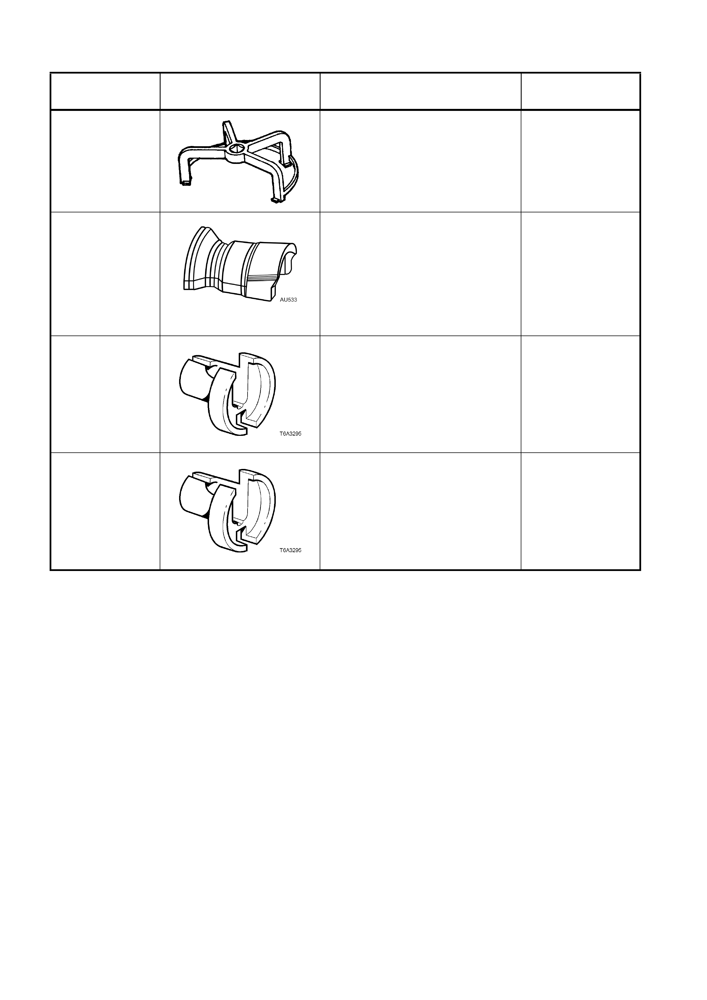
5. SPECIAL TOOLS
TOOL NUMBER ILLUSTRATION DESCRIPTION TOOL
CLASSIFICATION
AU469
(J39765)
MODULAR FUEL PUMP AND
SENDER ASSEMBLY REMOVER /
INSTALLER
Previously released.
Mandatory
AU533
QUICK CONNECT FITTING
RELEASE TOOL
Released in two sizes; Red for
5/16” fittings and Blue for 3/8”
fittings.
Also available commercially.
Previously released.
Desirable
7370
QUICK CONNECT RELEASE
TOOL – 5/16”
Used for releasing fuel hose quick
connects at the dash panel and fuel
rail connections, after the fuel
system has been depressurised.
Previously released.
Mandatory
7371
QUICK CONNECT RELEASE
TOOL – 3/8”
Used for releasing fuel hose quick
connects at the dash panel and fuel
rail connections, after the fuel
system has been depressurised.
Previously released.
Mandatory