
SECTION 8A2 - LPG SYSTEM
IMPORTANT
Before p erforming any Serv ice Operation or other procedu re described in this Section , refer to Section 00
CAUTIONS AND NOTES for correct workshop practices with regard to safety and/or property damage.
CONTENTS
1 GENERAL INFORMATION
1.1 SAFETY PRECAUTIONS7
1.2 IDENTIFICATION PLATES & WARNING
LABELS
2. PRINCIPLES OF OPERATION
2.1 LPG SYSTEM (TYPICAL)
2.2 LPG TANK
SEDAN & UTILITY
WAGON
2.3 FILLER VALVE
2.4 AUTOMATIC FILL LIMITER (AFL)
2.5 PRESSURE RELIEF VALVE
2.6 MANUAL SERVICE VALVE ASSEMBLY
MANUAL SHUT-OFF VALVE
SOLENOID VALVE
EXCESS FLOW VALVE
2.7 SMART UNIT
2.8 TANK FUEL GAUGE ASSEMBLY
2.9 LPG LOCK-OFF
2.10 SERVICE LINE
2.11 CONVERTER
PRIMARY REGULATION
SECONDARY REGULATION
2.12 FUEL CONTROL VALVE
2.13 REGULATOR CHECK VALVE
2.14 MIXER
2.15 FUEL MODE SWITCH
2.16 INSTRUMENT CLUSTER DISPLAY
2.17 TRACTION CONTROL OPERATION
2.18 POWERTRAIN CONTROL MODULE
PETROL MODE
LPG MODE
3. SERVICE OPERATIONS
3.1 SERVICE LINE DRAINING
3.2 LPG TANK UNLOADING
3.3 LEAK TESTING
COMBUSTIBLE GAS DETECTORS
FOAM
LEAK TEST PROCEDURE
3.4 FILLER VALVE & CONNECTOR PIPE
SEDAN
WAGON
UTILITY
3.5 FILLER LINE
SEDAN
WAGON
UTILITY
3.6 LPG TANK
SEDAN
WAGON
UTILITY
3.7 VENT TUBE FLANGE
SEDAN
WAGON
UTILITY
3.8 SMART UNIT & SOLENOID VALVE
REMOVE
REINSTALL
3.9 MANUAL SERVICE VALVE ASSEMBLY
EXCESS FLOW VALVE
REMOVE
REINSTALL
3.10 PICK-UP PIPE & STRAINER
REMOVE
REINSTALL
3.11 AUTOMATIC FILL LIMITER (AFL)
TEST
REMOVE
REINSTALL
3.12 PRESSURE RELIEF VALVE
REMOVE
REINSTALL
3.13 TANK FUEL GAUGE ASSEMBLY
REMOVE
REINSTALL
CONTENTS GAUGE
3.14 FRONT SERVICE LINE
REMOVE
REINSTALL
3.15 REAR SERVICE LINE
SEDAN
WAGON
UTILITY
3.16 INTERMEDIATE SERVICE LINE
REMOVE
REINSTALL
3.17 LPG LOCK-OFF
REMOVE
FILTER ELEMENT REPLACEMENT
TEST
REINSTALL
3.18 CONVERTER
CONVERTER ON-VEHICLE TEST
REMOVE
OVERHAUL
CONVERTER OFF-VEHICLE TEST
REINSTALL
3.19 REGULATOR CHECK VALVE
TEST
REMOVE
REINSTALL
3.20 FUEL CONTROL VALVE
REMOVE
TEST
REINSTALL
3.21 MIXER
TEST
REMOVE
OVERHAUL
REINSTALL
3.22 FUEL MODE SWITCH
REMOVE
TEST
REINSTALL
3.23 COOLANT HOSES
Techline
Techline

3.24 AIR CLEANER ASSEMBLY
REMOVE
REINSTALL
3.25 SPARE WHEEL CARRIER, WAGON
REMOVE
REINSTALL
4. TECH 2 PROCEDURES
4.1 LPG SETUP PROCEDURE
4.2 LPG FCV TEST
4.3 LPG ENABLE TEST
5. AFTER INSTALLATION CHECK
5.1 GENERAL INFORMATION
5.2 UNDERBODY
5.3 REAR COMPARTMENT
5.4 UNDER HOOD
5.5 LEAK CHECK
6. DIAGNOSIS
6.1 PREREQUISITES TO DIAGNOSIS AND
TROUBLESHOOTING
PRELIMINARY SYSTEM REQUIREMENTS
SAFETY REQUIREMENTS
CHECKING EQUIPMENT
6.2 GENERAL INFORMATION
6.3 LPG VEHICLE PRELIMINARY DIAGNOSIS
6.4 DOES NOT OPERATE ON LPG
6.5 FUEL MODE SWITCH DOES NOT OPERATE
6.6 ENGINE DOES NOT CRANK
6.7 ENGINE CRANKS BUT WILL NOT
START ON LPG
TEST 1
TEST 2
TEST 3
6.8 ENGINE BACKFIRES ON LPG
6.9 POOR PERFORMANCE, FLAT
SPOTTING, SLUGGISH OR POOR
FUEL CONSUMPTION WHEN
OPERATING ON LPG
6.10 FUEL CONTROL VALVE DOES NOT
OPERATE
6.11 TECH 2 SCAN TOOL: ENGINE DATA
7. WIRING & CONNECTORS
8. SPECIFICATIONS
9. TORQUE WRENCH SPECIFICATIONS
10. SPECIAL TOOLS

1. GENERAL INFORMATION
Liquefied Petroleum Gas ( LPG) , pr oduction option KL7, is available f or domestic MY2003 VY Series Sedan, Wagon
and Utility vehicles fitted with a V6 engine and automatic transmission.
The LPG system is identical across all vehicles with the exception of the LPG tank and filler assembly, which are
unique for each body style.
Sedan vehicles are fitted with a conventional cylindrical tank mounted in the rear compartment between the rear
wheelhouses, refer to Figure 8A2-1.
W agon vehic les employ a toroidal tank, als o com monly known as a doughnut tank . The tank is fitted into the spar e
wheel-well necessitating relocation of the spare wheel to an upright position in a carrier mounted on the right-hand
side of the rear compartment. Due to the increase in height of the tank compared to the spare wheel, a modified
rear compartment floor carpet is fitted, refer to Figure 8A2-2.
The tank fitted to Utility vehicles is also cylindrical in shape, but is wider and lower in profile to allow installation at
the front of the load compartment, under the rear window. A metal cover is fitted to protect the tank from damage
from objects placed in the load compartment, refer to Figure 8A2-3.
All filler valves are located within the fuel filler pocket above the petrol filler, however due to the tank differences,
routing and installation is unique to each body style.
The rear service lines ar e also unique for each body s tyle as is the rear connection of the interm ediate service line,
which is routed within the fuel and brak e line harness assembly. From this point, each system is com mon with the
intermediate line connecting to the converter via a front service line within the engine compartment. The converter is
incorporated into the cooling system circuit to aid vaporisation of the gas.
The last major component in the system is the mixer. The mixer is fitted in-line of the air inlet ducting and is
responsible for combining the LPG vapour with the inlet air prior to entering the engine.
The LPG system is controlled by the Powertrain Control Module (PCM), which is set to a unique program for LPG
operation. This allows for ease of set-up and provides optimum control of the system. Diagnostic functions and
trouble codes within the PCM support the LPG system.
The driver is able to switch the vehicle to LPG or petrol operation via a fuel mode switch, located in the front floor
console, even while the vehic le is being dr iven. An icon is dis played on the instrum ent c lus ter when LPG is s elec ted
and the standard fuel gauge changes from displaying the contents of the petrol tank to the LPG tank contents.
Further description of the LPG system operation and components is provided in 2. PRINCIPLES OF OPERATION.
All vehicles fitted with the KL7 LPG option are fitted with upgraded springs. For service information, refer to
Section 4A, REAR SUSPENSION.
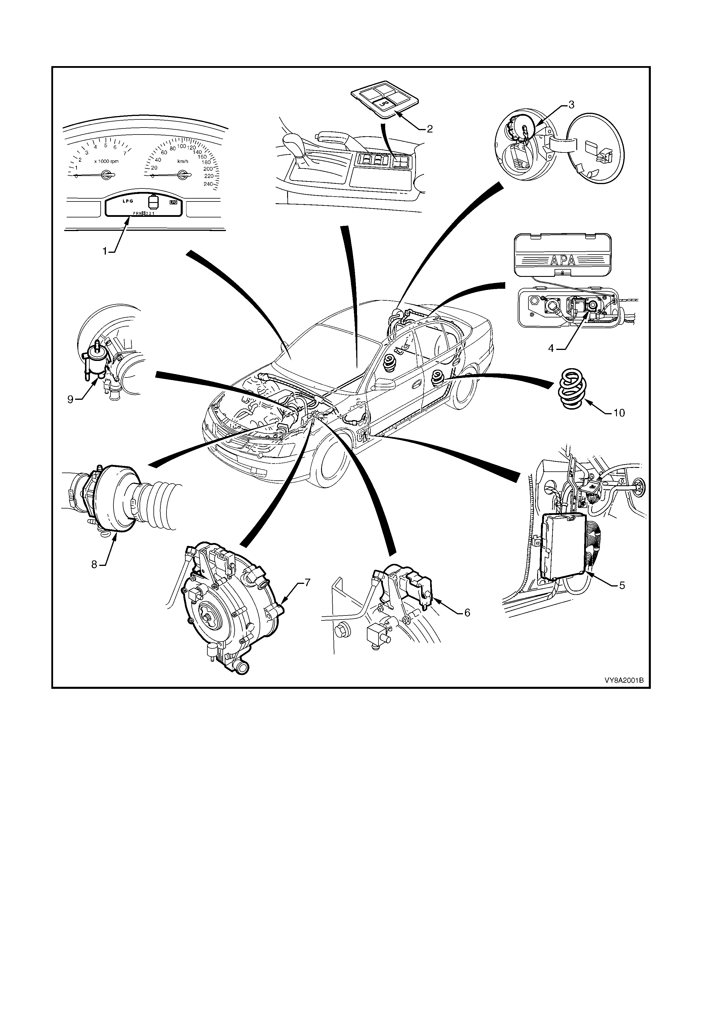
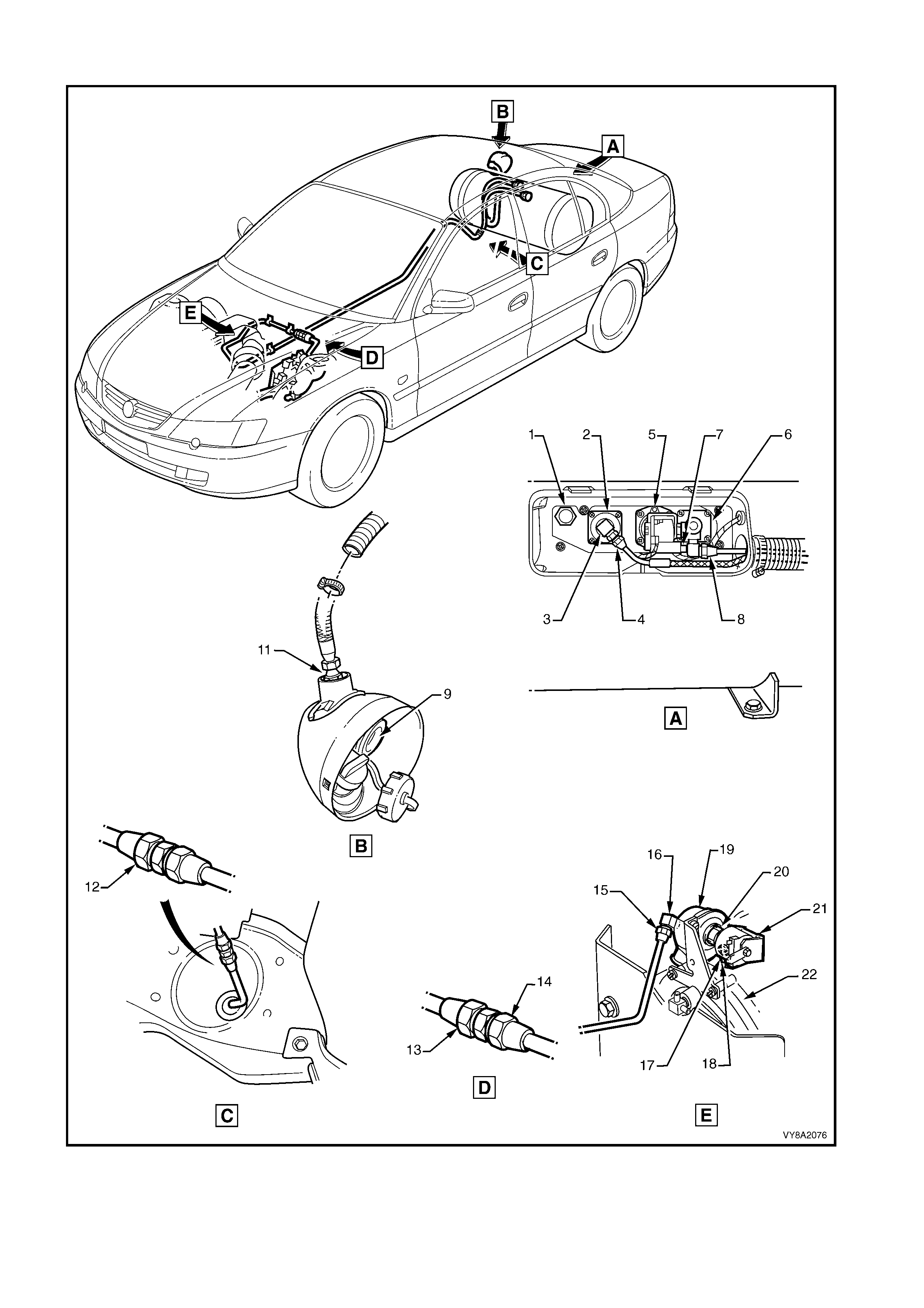
SEDAN
Figure 8A2-1
Legend
1. Instrument Cluster Display LPG Icons 6. LPG Lock-off
2. Fuel Mode Switch 7. Converter
3. LPG Filler Valve 8. Mixer
4. Manual Service Valve Assembly 9. Fuel Control Valve
5. Powertrain Control Module (PCM) 10 Rear Springs
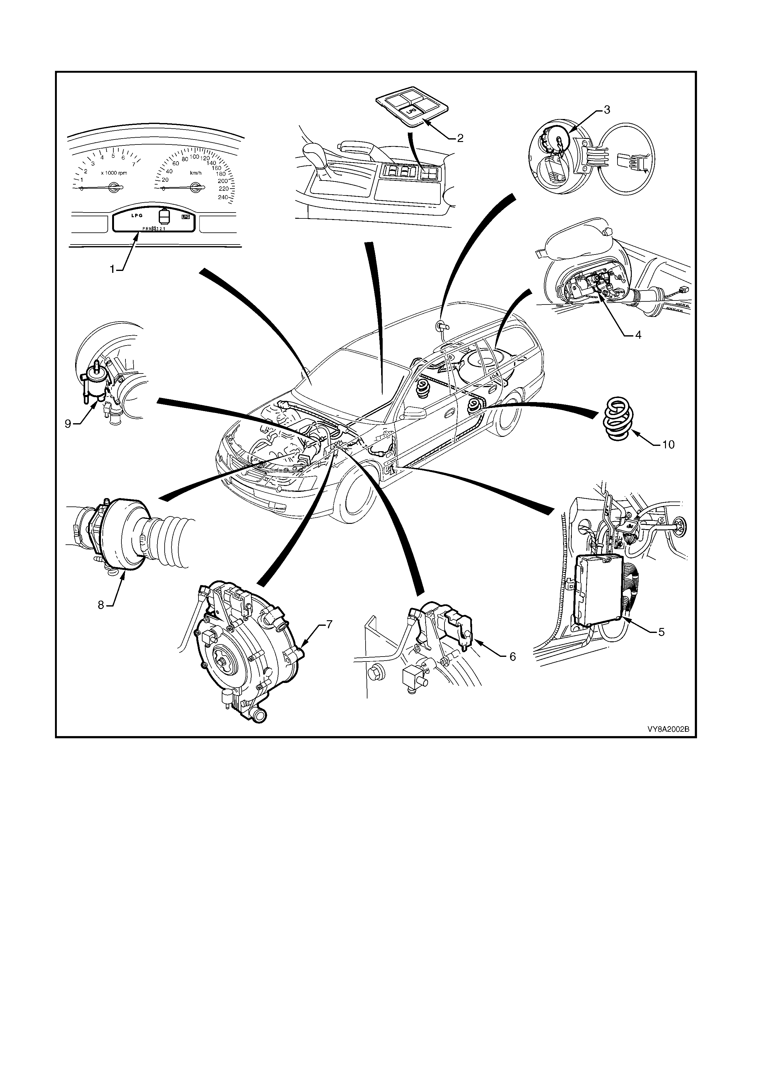
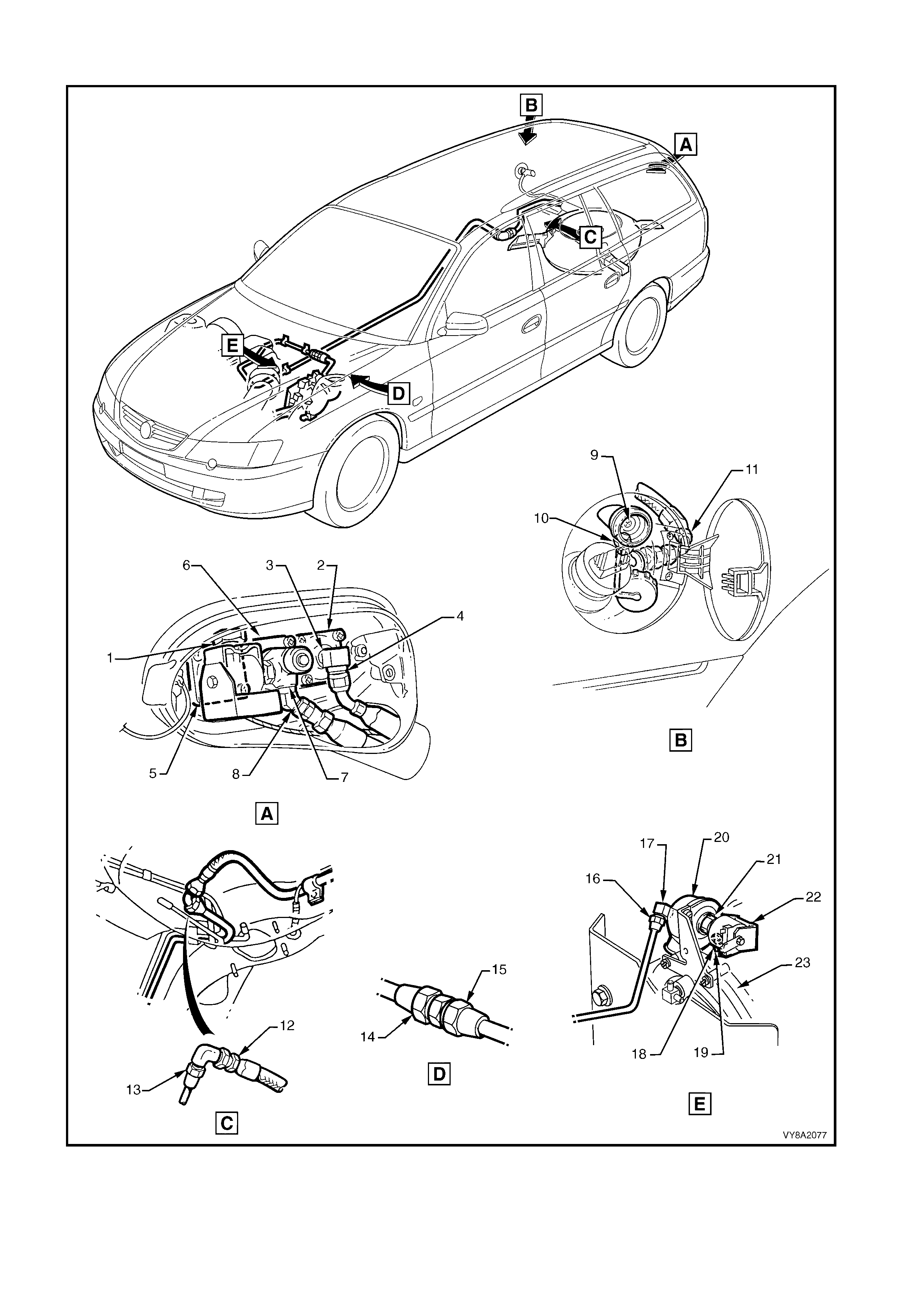
WAGON
Figure 8A2-2
Legend
1. Instrument Cluster Display LPG Icons 2. LPG Lock-off
3. Fuel Mode Switch 4. Converter
5. LPG Filler Valve 6. Mixer
7. Manual Service Valve Assembly 8. Fuel Control Valve
9. Powertrain Control Module (PCM) 10. Rear Springs
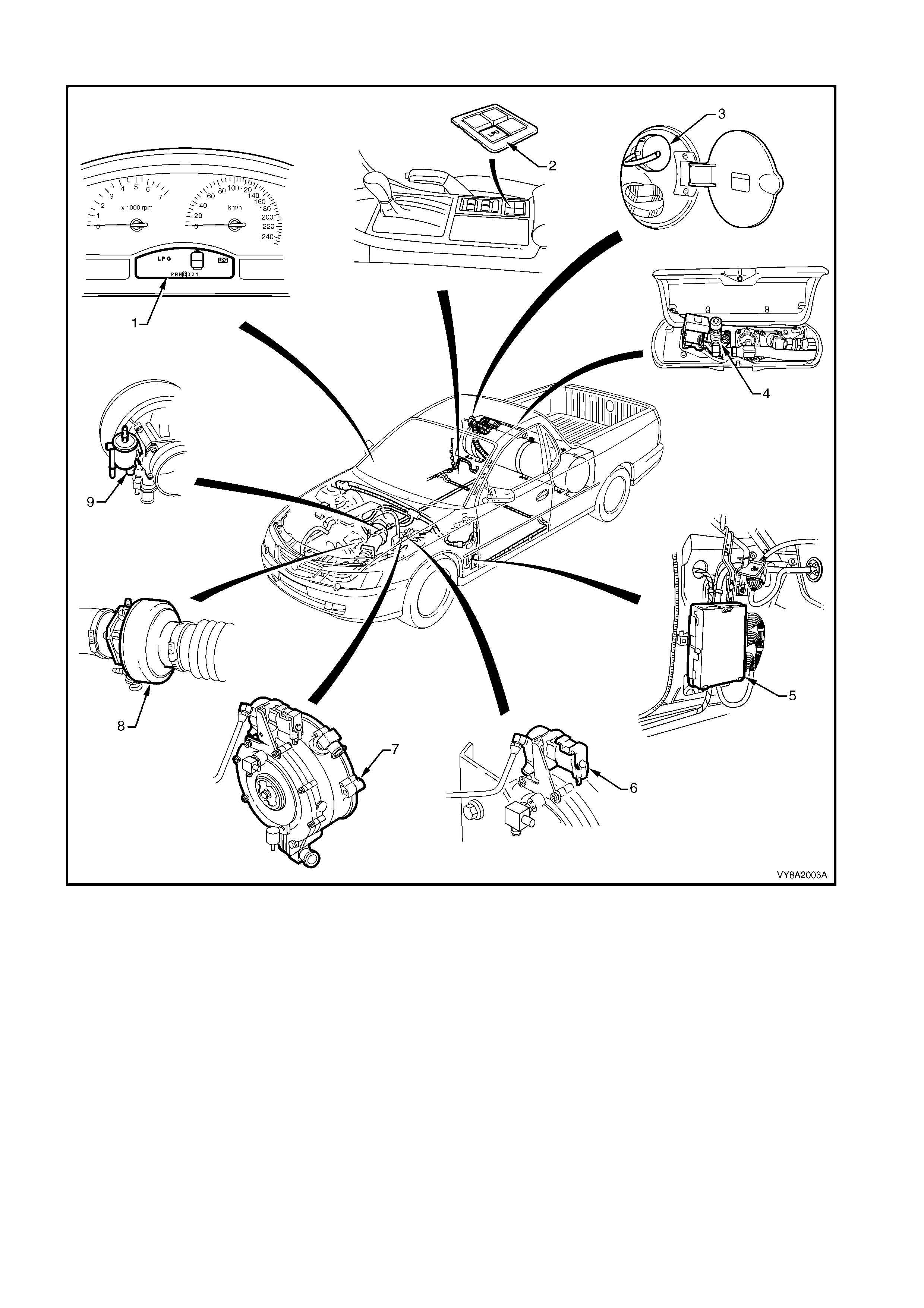
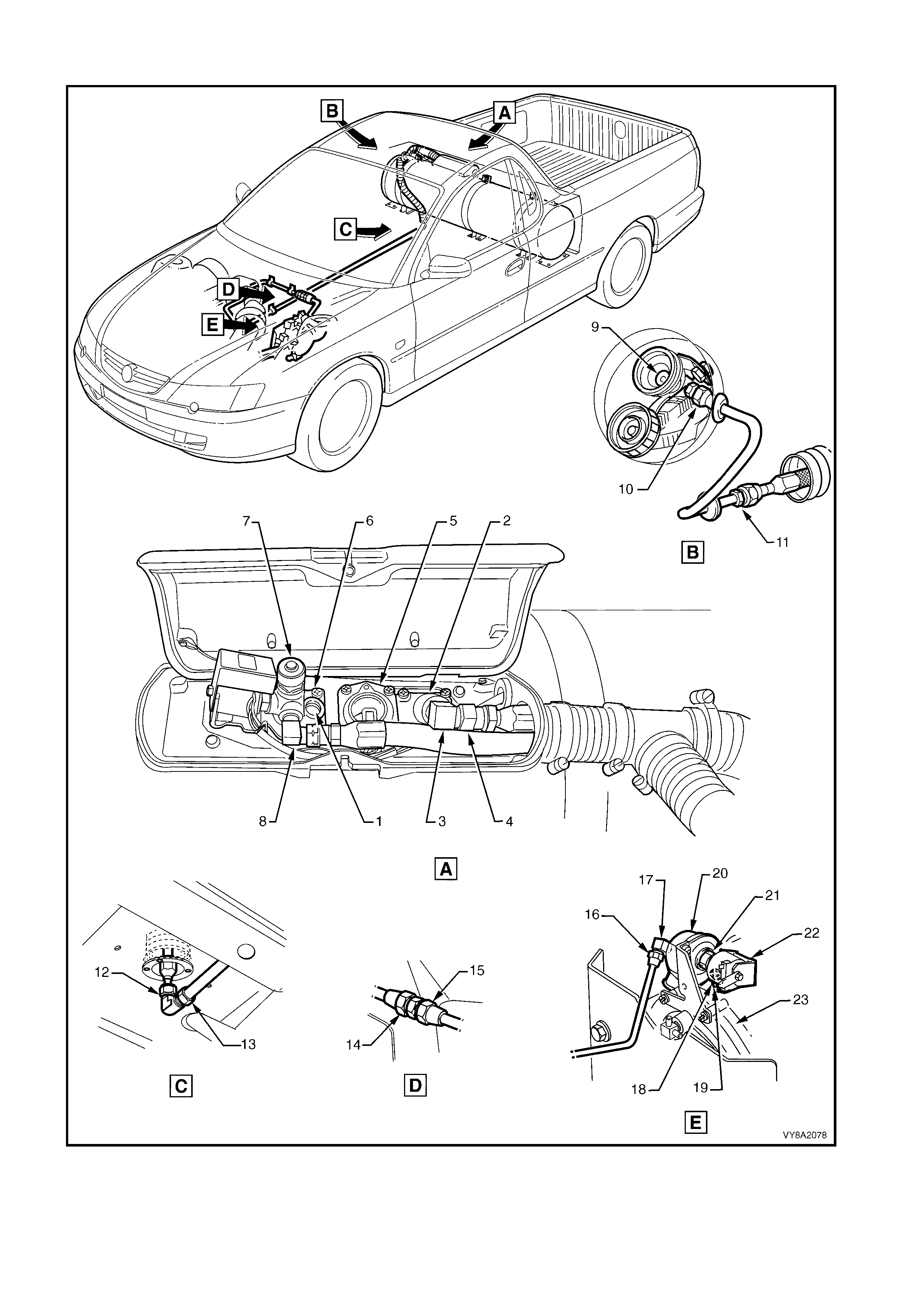
UTILITY
Figure 8A2-3
Legend
1. Instrument Cluster Display LPG Icons 6. LPG Lock-off
2. Fuel Mode Switch 7. Converter
3. LPG Filler Valve 8. Mixer
4. Manual Service Valve Assembly 9. Fuel Control Valve
5. Powertrain Control Module (PCM)

1.1 SAFETY PRECAUTIONS
• Any servicing or testing of the LPG system high pressure area must be performed by trained and/or licensed
LPG installers or fitters, in a Specialist Gas Workshop and in accordance with Australian Standards
AS 2746-1985 and AS 1425-1989.
• Norm al vehicle m aintenance ser vice and any s ervicing of the LPG system not affecting the high- pressure area
(filler line, LPG tank , servic e line, LPG lock - off and converter ) m ay be perform ed by dealership technicians who
are not accredited installers or fitters.
• DO NOT smoke or allow naked flames, or any ignition source near the vehicle.
• LPG m ust never com e in contact with any part of the body as it can caus e severe frostbite. Due to its very low
boiling point, LPG readily absorbs heat from its surroundings or any surface it comes in contact with when
released into the atmosphere.
• When working on the LPG system, suitable protective clothing including gloves and safety goggles must be
worn to prevent personal injury.
• LPG in the vapour form is highly flammable. In the interests of safety, the LPG system should be leak tested
and isolated by turning off the m anual service valve and draining the s ervice lines of LPG prior to c omm encing
any work on the vehicle, refer to 3.1 SERVICE LINE DRAINING.
• During servic ing, the m anual servic e valve m ust r em ain off at all tim es, except when gas is specif ically required
for servicing or testing of the LPG system.
• Whenever any service operation is performed on the high-pressure area of the system (filler line, LPG tank,
service line, LPG lock -off and converter ), a leak test m ust be perf ormed on the com plete LPG system, r efer to
3.3 LEAK TESTING.
• Prior to the removal of any component from the LPG tank, the LPG tank must be emptied of LPG, refer to
3.2 LPG TANK UNLOADING. The LPG tank must then be safety tested in accordance with Australian Standard
AS 2030-1 and according to the laws of the state in which the vehicle is registered. A leak test must be
performed on the complete LPG system before the LPG tank is returned to service in the vehicle.
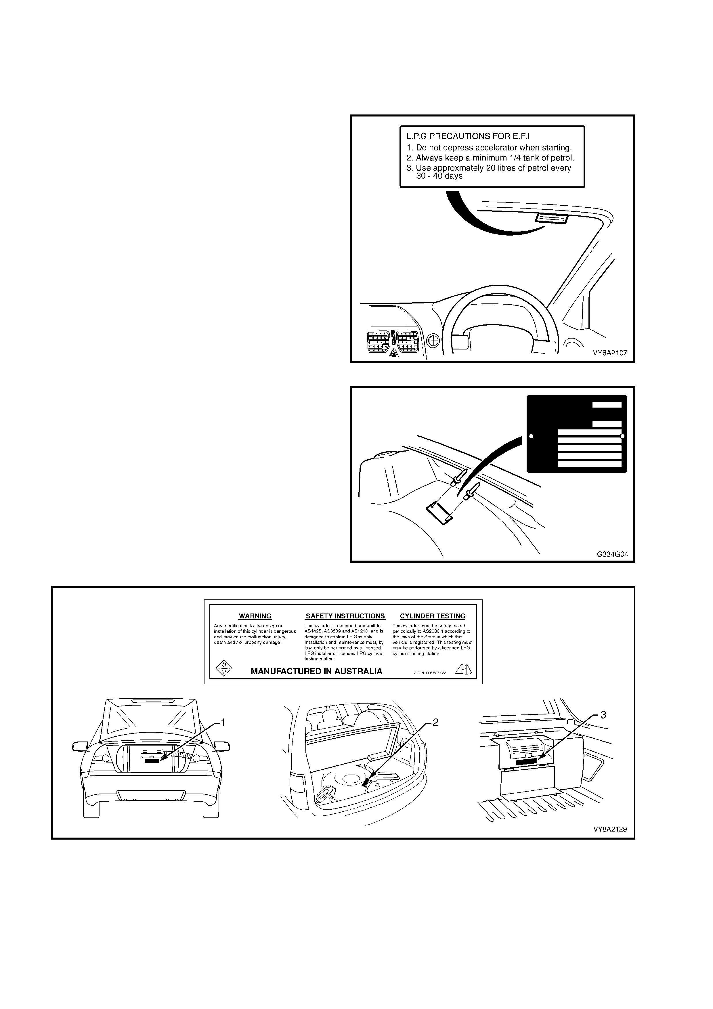
1.2 IDENTIFICATION PLATES & WARNING LABELS
Several identification plates and warning labels are fitted to vehicles with LPG, as shown below .
NOTE: If the vehicle is repaired or the components that the labels / plates are attached to are replaced, the
label or plate must also be replaced.
1. The LPG precaution label, fitted to the
windscreen right-hand upper, provides the driver
with information for operating the vehicle on LPG.
Figure 8A2-4
2. An LPG compliance plate, if required by State
regulations, is riveted to the left-hand front
wheelhouse.
3. A warning label is affixed to the LPG tank (1 –
Sedan, 2 – Wagon, 3 – Utility) and provides
important information regarding the tank
assembly, refer to Figure 8A2-6.
Figure 8A2-5
Figure 8A2-6
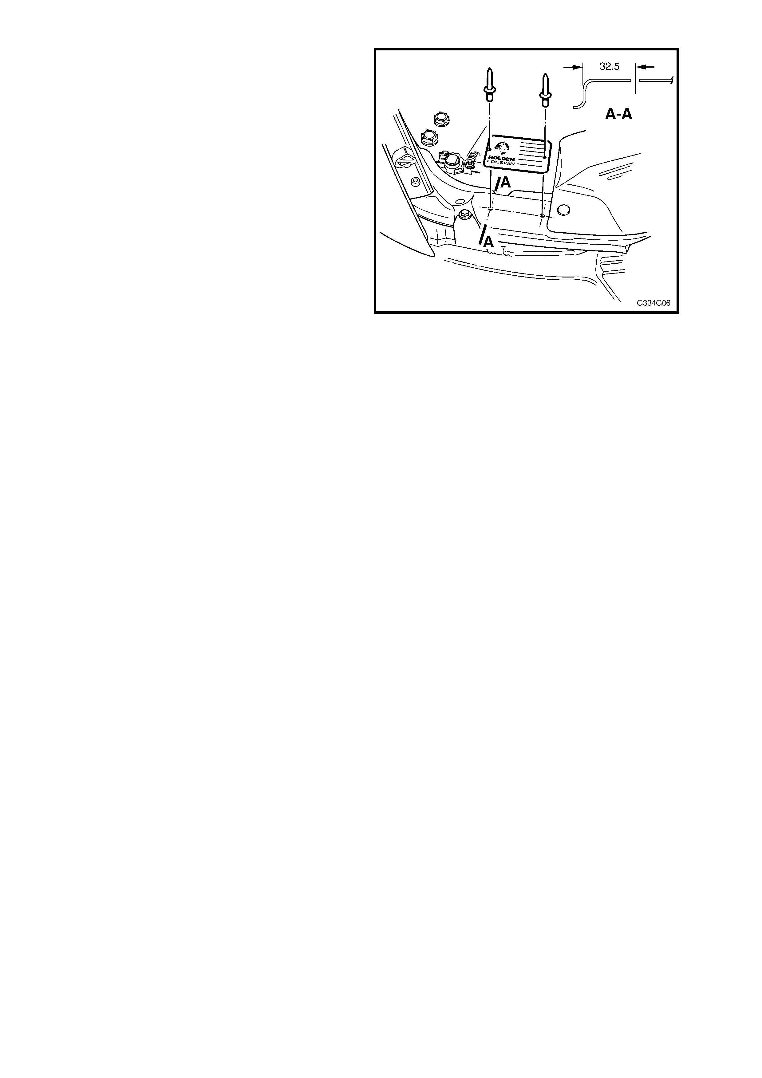
4. A Holden By Design identification plate is riveted
to the front upper panel.
Figure 8A2-7
2. PRINCIPLES OF OPERATION
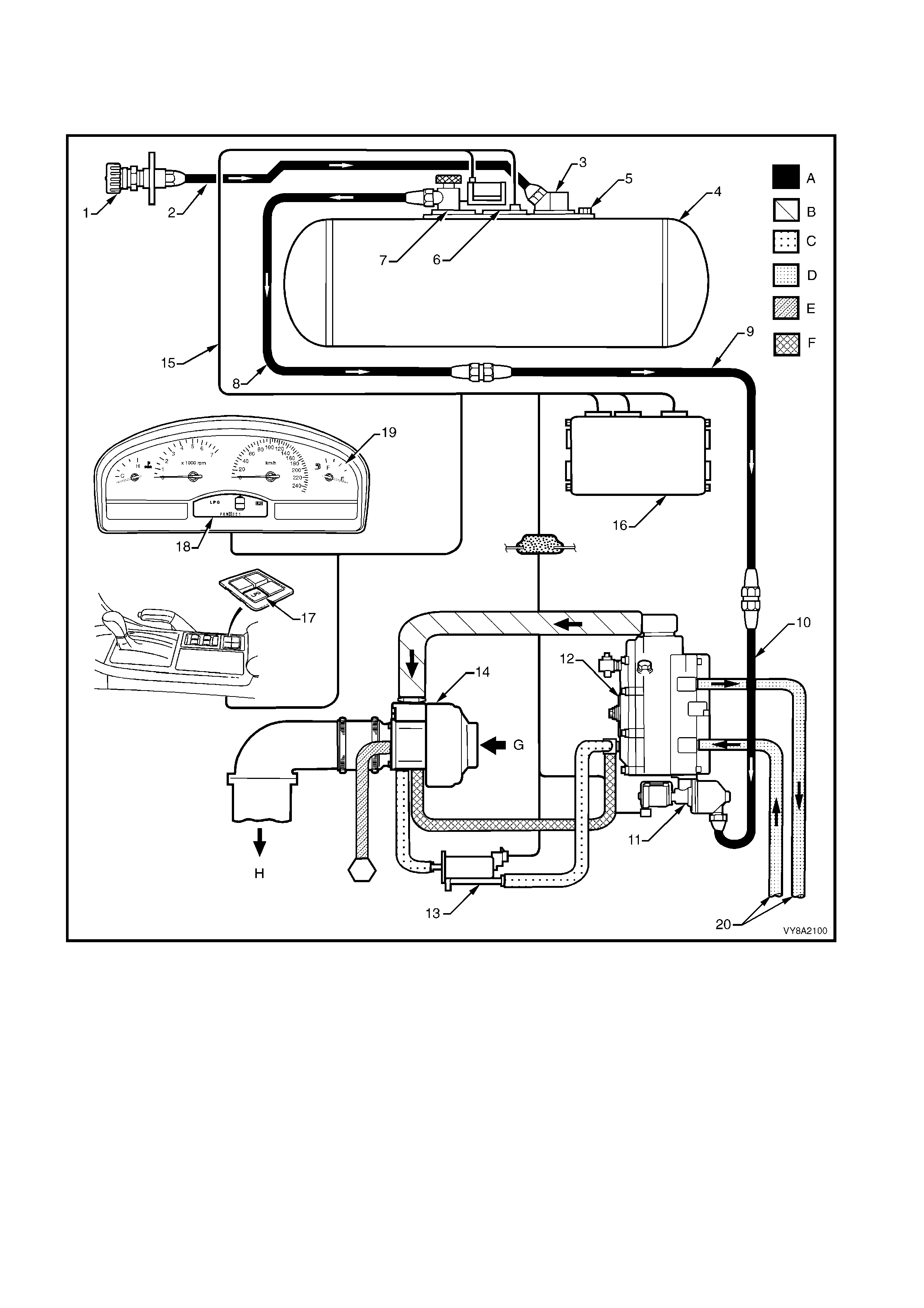
2.1 LPG SYSTEM (TYPICAL)
Figure 8A2-8
Legend
1. LPG Filler Valve 11. LPG Lock-off
2. Filler Line 12. Converter A. Liquid
3. AFL 13. Fuel Control Valve B. Vapour
4. LPG Tank Assembly 14. Mixer C. Vacuum
5. Relief Valve 15. Wiring Harness D. Coolant
6. Fuel Contents Gauge / Sender 16. Powertrain Control Module (PCM) E. Breather
7. Manual Service Valve Assembly 17. Fuel Mode Switch F. Balance / Vacuum
8. Rear Service Line 18. Instrument Cluster Display LPG Icons G. Air Intake
9. Intermediate Service Line 19. Instrument Cluster Fuel Gauge H. To Engine Inlet Manifold
10. Front Service Line 20. Coolant Hoses
2.2 LPG TANK
The LPG Tank is made of carbon steel and is
manufactured to stringent safety standards.
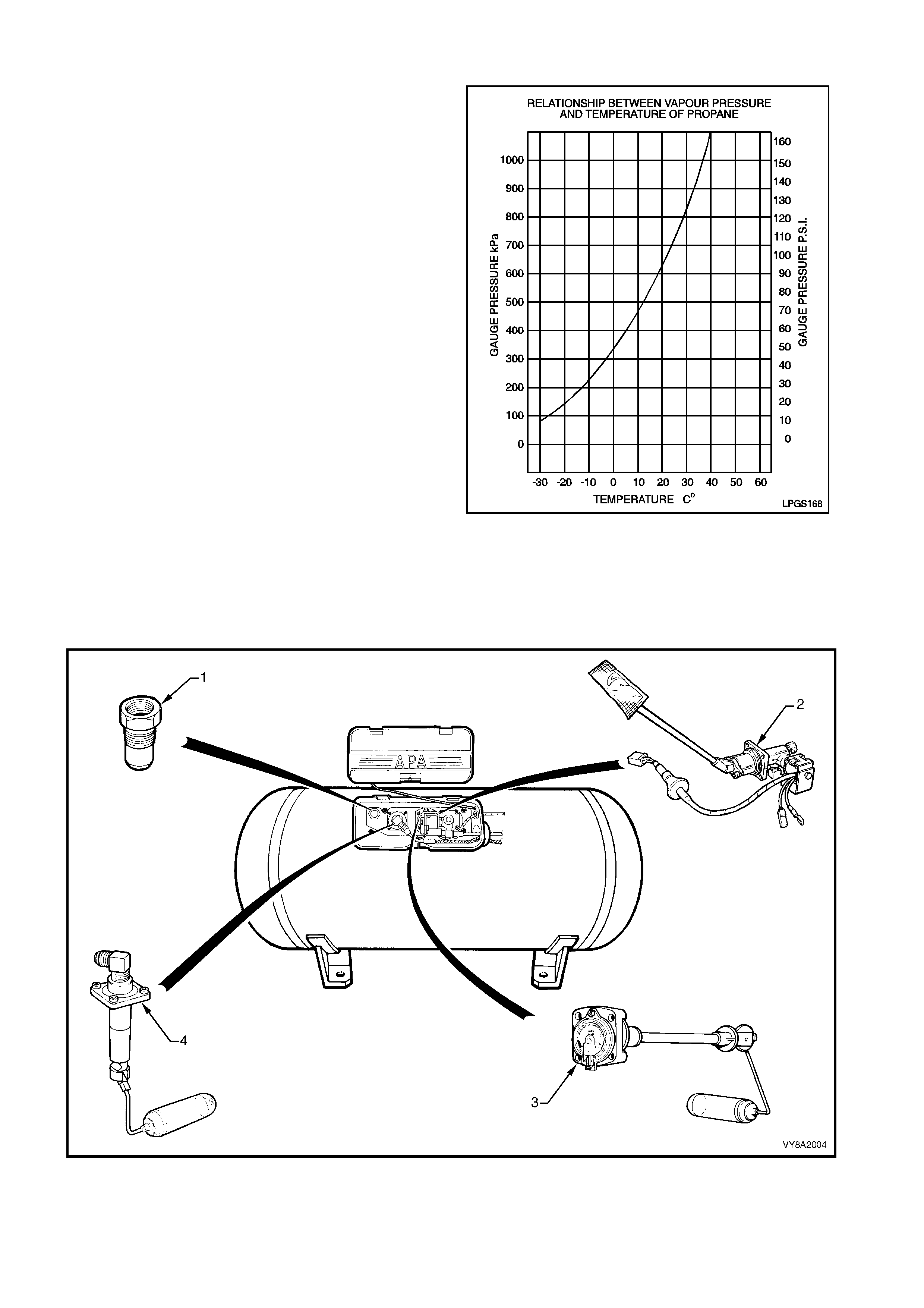
LPG m ust be stored at appr oxim ately 750 k Pa at 20°C
to remain a liquid. The vapour pres s ur e inside the LPG
tank will vary with ambient temperature, as the ambient
temperature rises so does the vapour pressure.
The LPG tank is heat treated during manufacture and
MUST NOT be heated or welded in any way.
SEDAN & UTILITY
For sedan vehicles, the LPG tank is fitted in the rear
compartment, under the rear parcel shelf.
Utility vehicles have the tank mounted at the front of
the load compartment, below the rear window.
The LPG tank incorporates a gas-tight compartment
(valve box) which is vented to atmosphere via a vent
hose and contains the following components, refer to
Figure 8A2-10 (Sedan, Utility is similar):
1. Pressure relief valve,
2. Smart unit, solenoid, manual service valve and
excess flow valve,
3. Tank fuel gauge assembly, and
4. Automatic fill limiter (AFL).
Thes e components are either attached into or onto the
LPG tank. As the LPG tank is loc ated in the luggage or
load compartments, if any of these components were
to leak, or there was an excess pressure discharge,
the LPG would be vented to atmosphere via the vent
hose and will not vent into the vehicle.
Figure 8A2-9
Figure 8A2-10
Legend
1. Pressure Relief Valve 3. Tank Fuel Gauge Assembly
2. Smart Unit, Solenoid, Manual Service Valve and Excess Flow Valve 4. Automatic Fill Limiter (AFL)
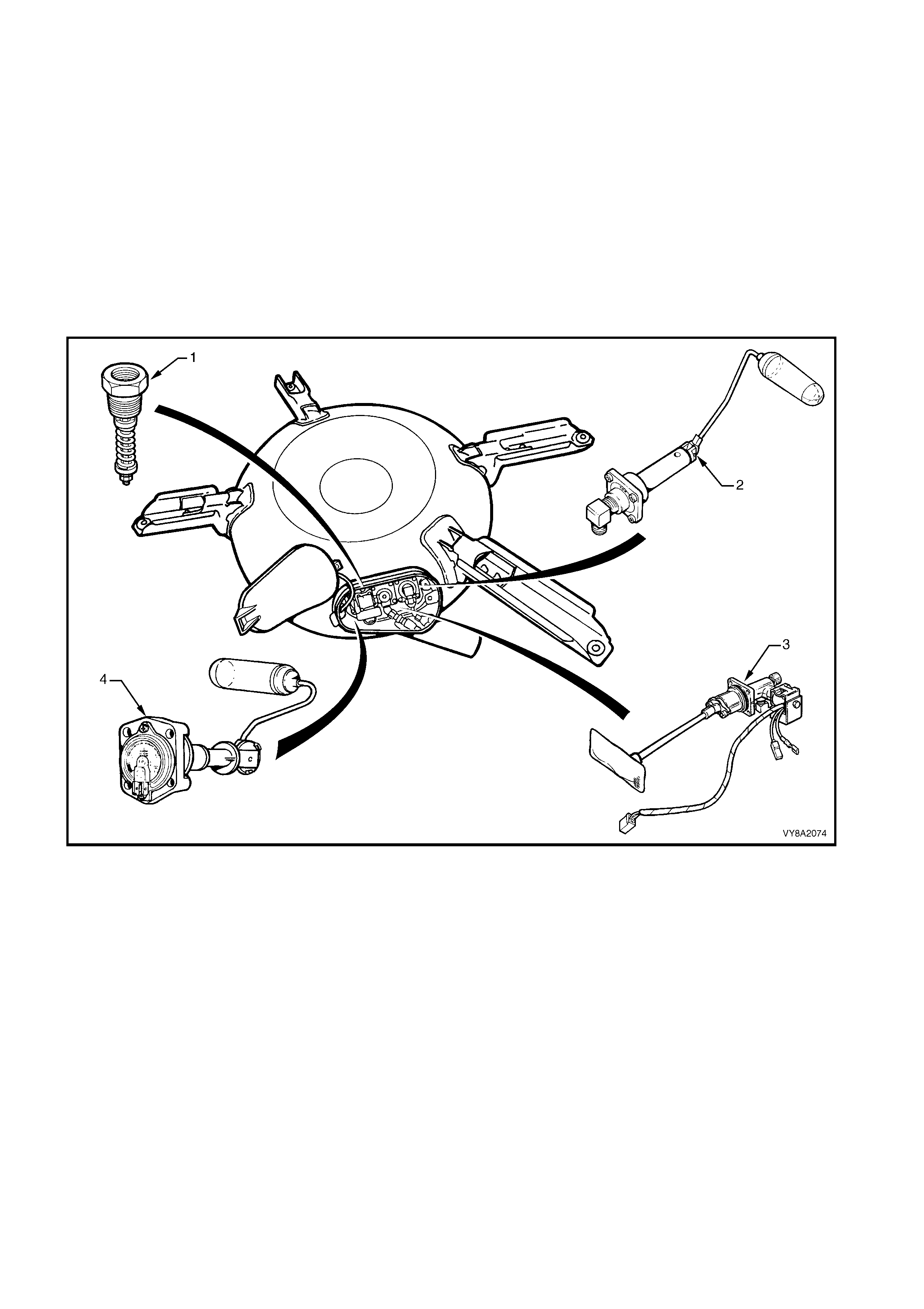
WAGON
Due to s pace lim itations, a toroidal s haped tank is fitted to Wagon vehic les. It is designed to fit within the spare
wheel compartment, necessitating the relocation of the spare wheel to a bracket assembly on the right-hand side
of the luggage compartment.
The LPG tank fitted to Wagon vehicles also has a gas-tight compartment (valve box), which contains the
following components, refer to Figure 8A2-11:
1. Pressure relief valve,
2. Automatic fill limiter (AFL),
3. Smart unit, solenoid and manual service valve assembly, and
4. Tank fuel gauge assembly.
These components are either attached into or onto the LPG tank. As the LPG tank is located in the luggage
compartment, if any of these components were to leak, or there was an excess pressure discharge, the LPG
would be vented to atmosphere via a vent hose and will not vent into the vehicle.
Figure 8A2-11
Legend
1. Pressure Relief Valve 3. Smart Unit, Solenoid, Manual Service Valve and Excess Flow Valve
2. Automatic Fill Limiter (AFL) 4. Tank Fuel Gauge Assembly
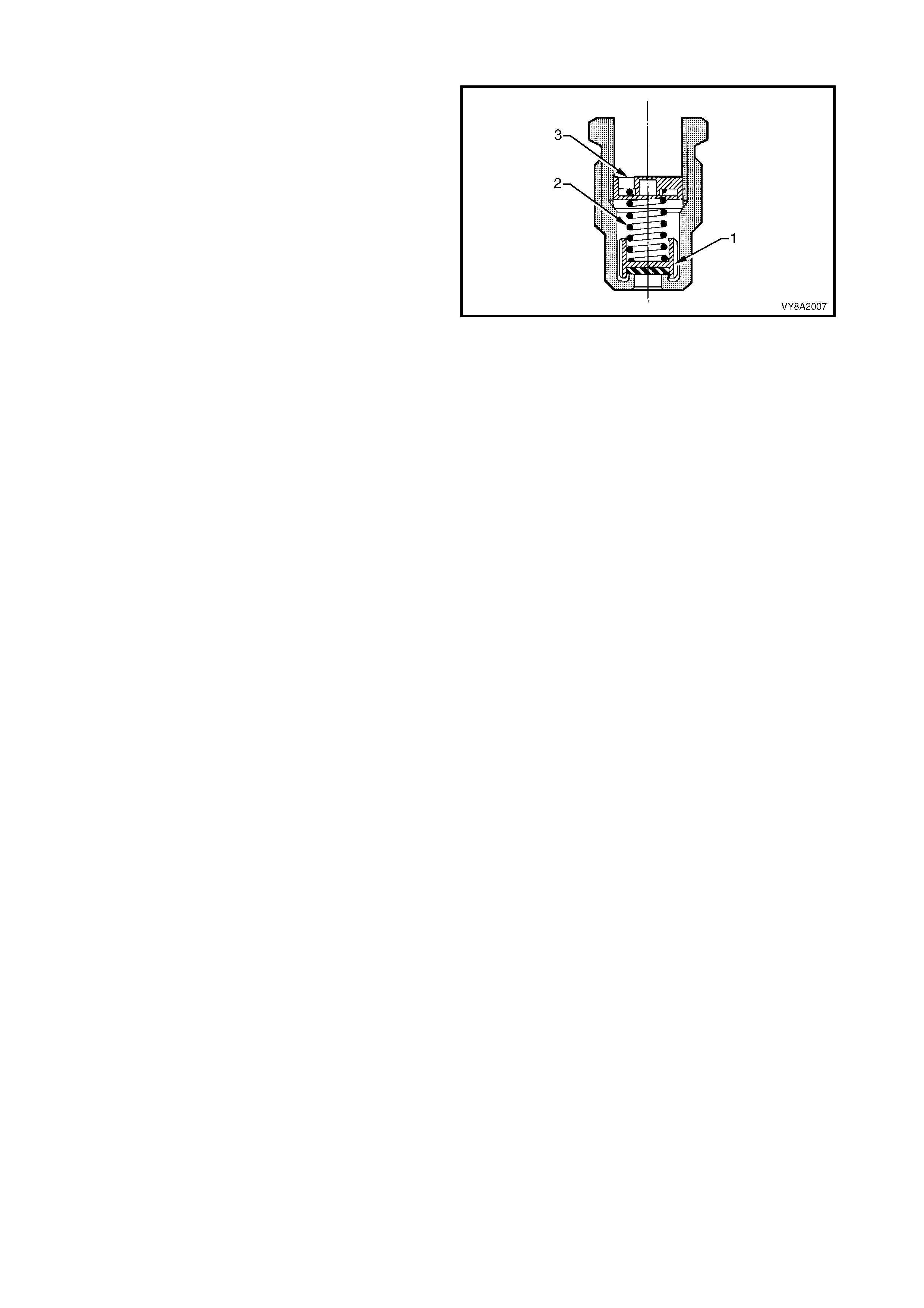
2.3 FILLER VALVE
The filler valve is located in the fuel filler pocket,
adjacent to the petrol filler.
The valve incorporates two spring-loaded non-return
valves (1 & 2) and a sealed cap (3) fitted to the filling
connection (4).
The c onnection is designed to shear off in the event of
the vehicle being driven away with the filler hose
inadvertently attached. In this situation, the lower valve
remains intact, avoiding the LPG discharging.
The filler valve is connected to the LPG tank AFL inlet
elbow by a filler line, which is routed through the LPG
tank vent hose.
Figure 8A2-12
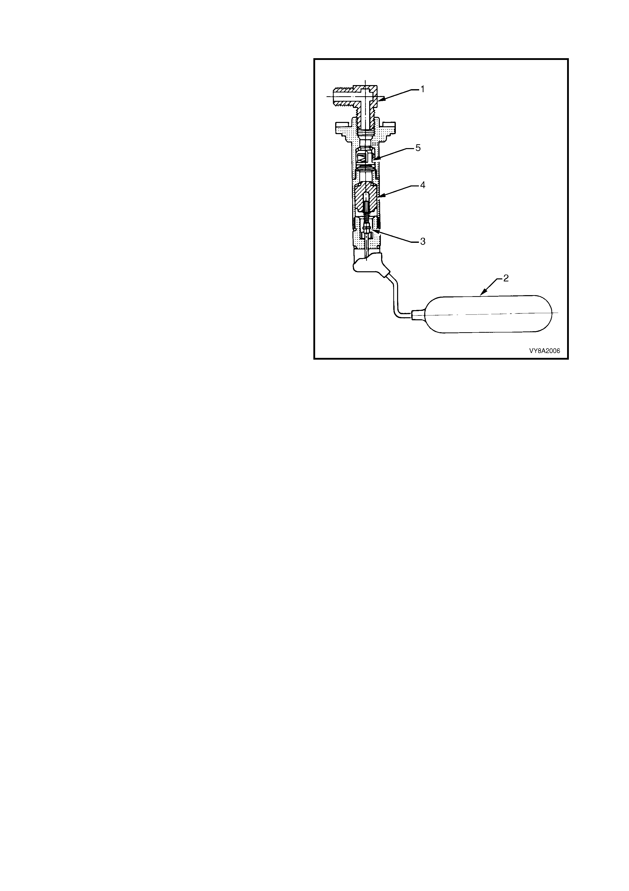
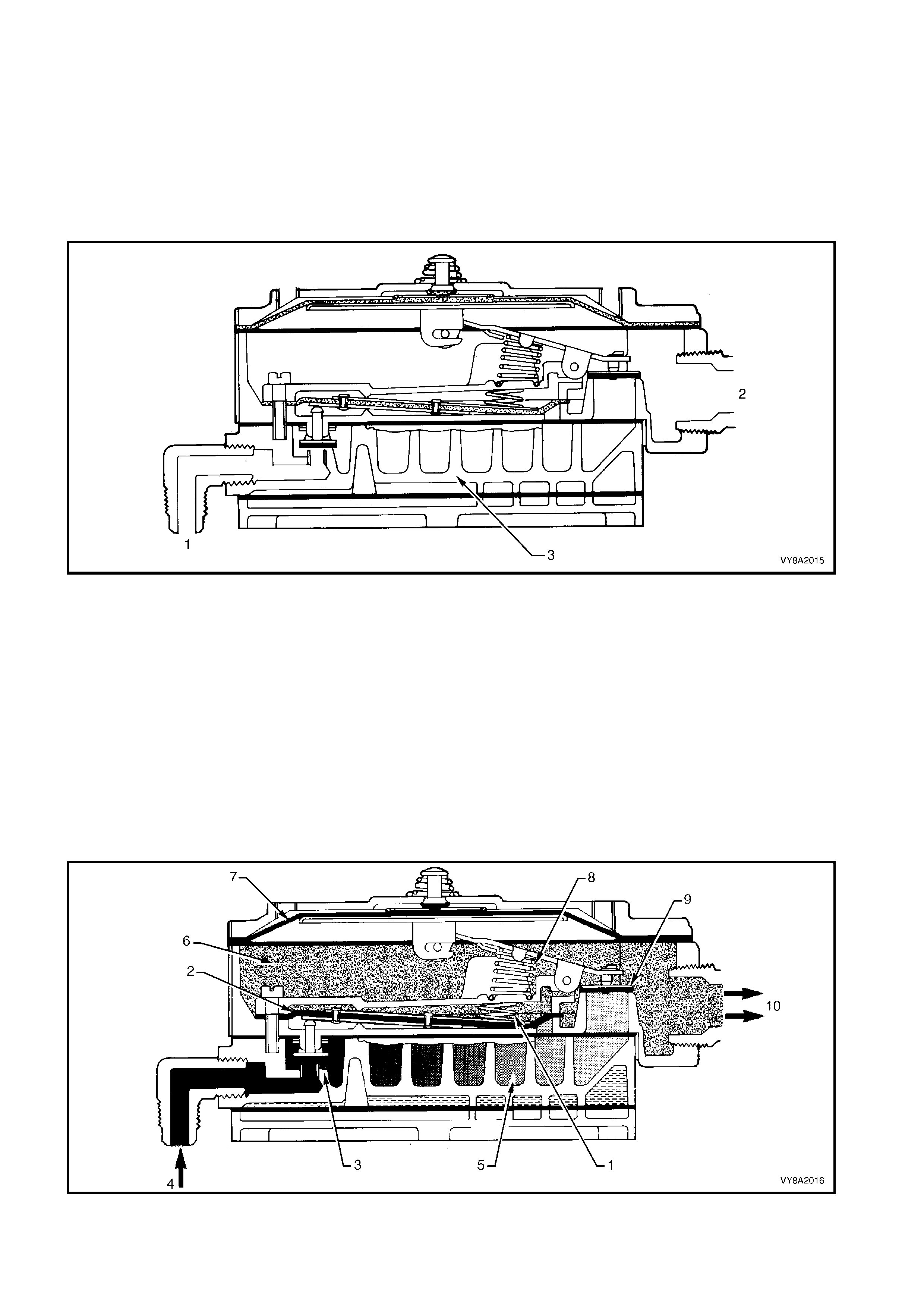
2.4 AUTOMATIC FILL LIMITER (AFL)
The Automatic fill limiter (AFL) is fitted into the LPG
tank. T he inlet elbow (1) connects the to the LPG filler
line.
W hen the tank is being filled with liquid LPG, the AFL
float (2) rises with the liquid within the LPG tank. The
float arm is connected to an actuator (3) that operates
a shut-off piston (4). When the level reaches
approximately 80% full, the piston is in the closed
position, shutting off the flow of LPG into the tank.
The remaining 20% of the tank volume is necessary
vapour space to allow for the expansion of the liquid
that occurs as the temperature of the liquid increases.
The AFL is also fitted with a non-return valve (5) to
prevent the gas escaping.
Figure 8A2-13
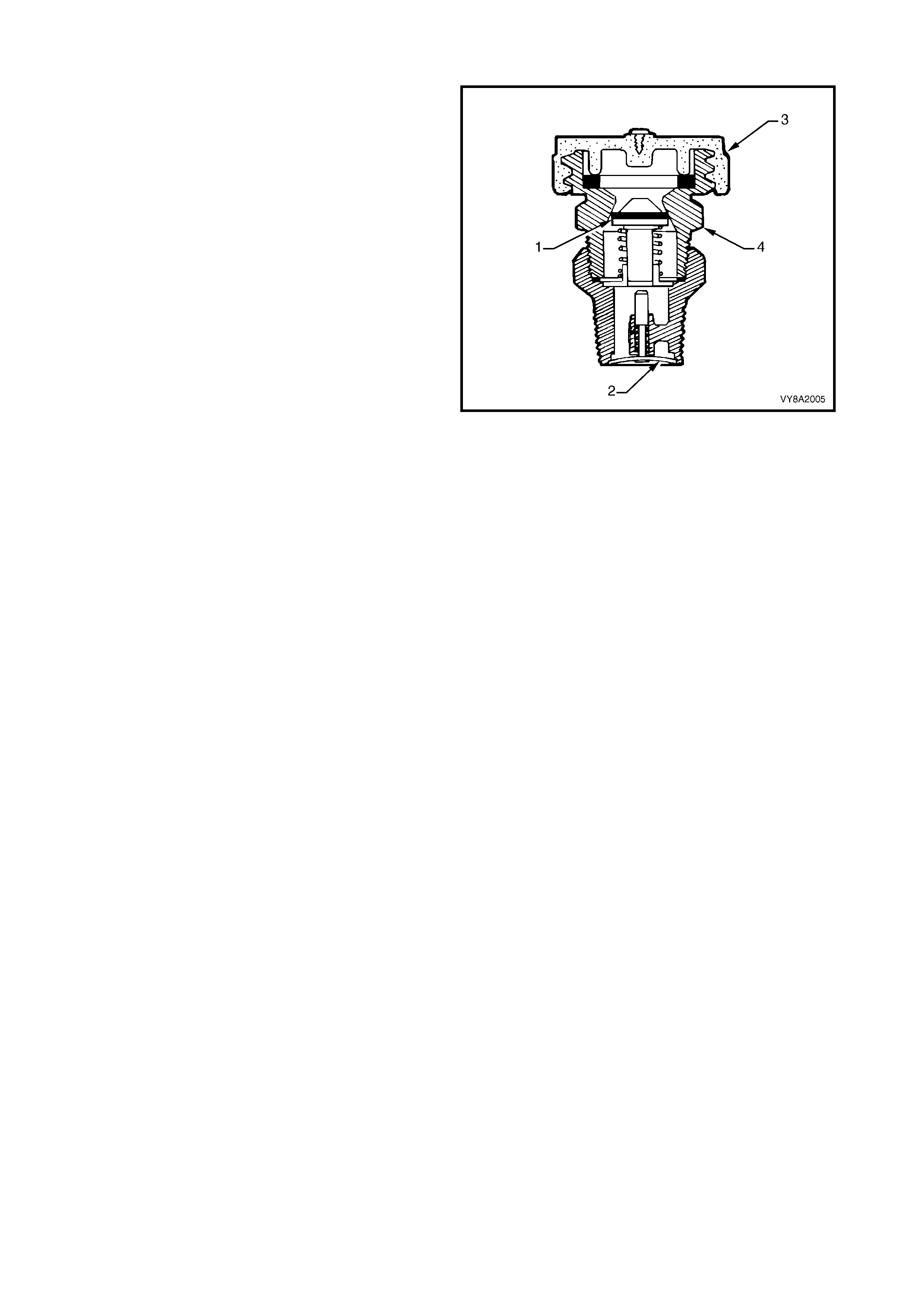
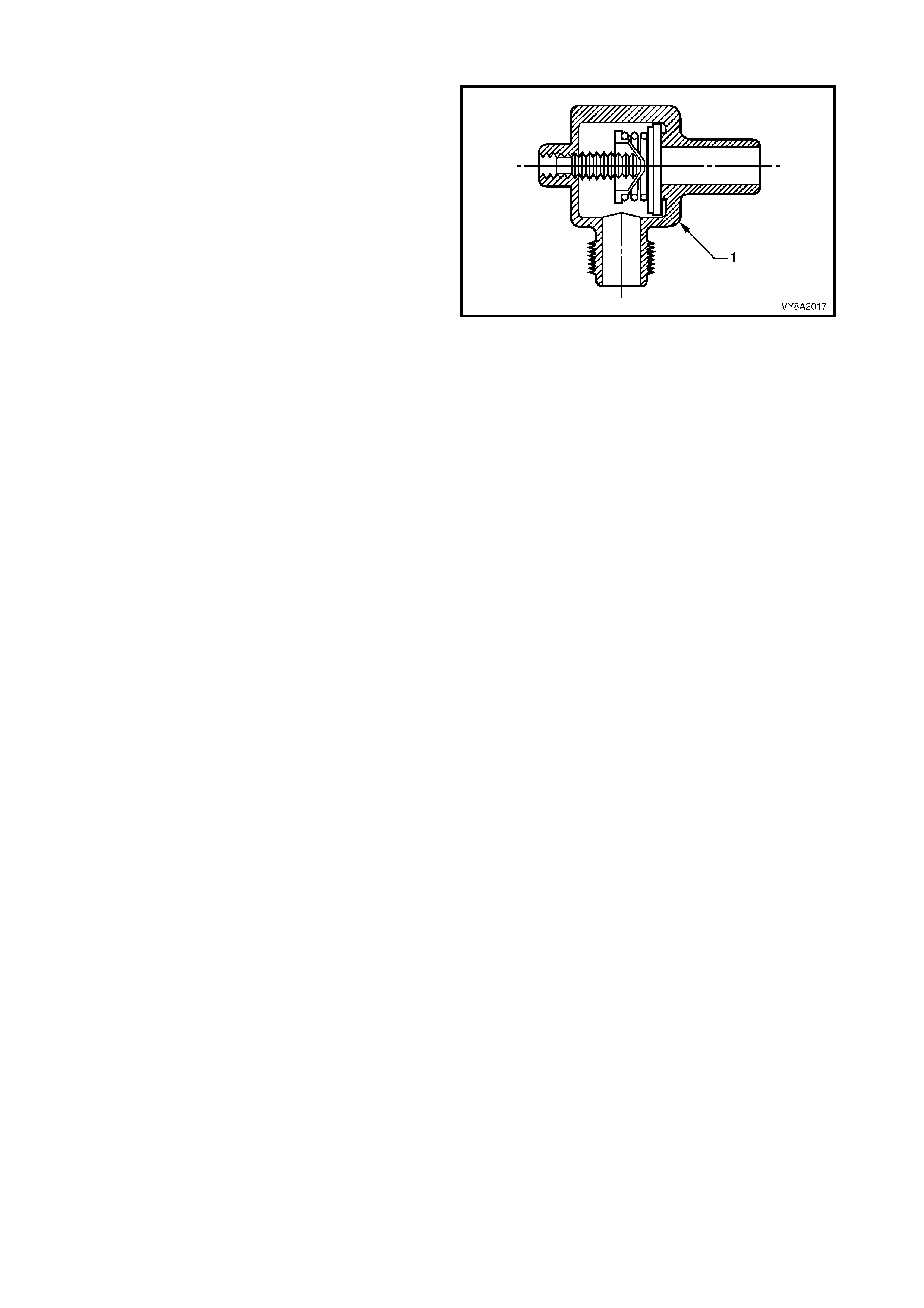
2.5 PRESSURE RELIEF VALVE
The pressure relief valve is housed within the valve
box and attached into the LPG tank.
Pressur e within the LPG tank exceeding approxim ately
2,550 kPa c auses the valve (1) to open by overcom ing
spring tension (2). The excess pressure will then be
vented into the valve box through the orifice (3) and
then to atmosphere via the vent hose.
The valve will continue to vent the LPG tank until the
pressur e drops below 2,550 k Pa and the spring closes
the valve.
During normal operating conditions the pressure relief
valve should not operate.
Figure 8A2-14
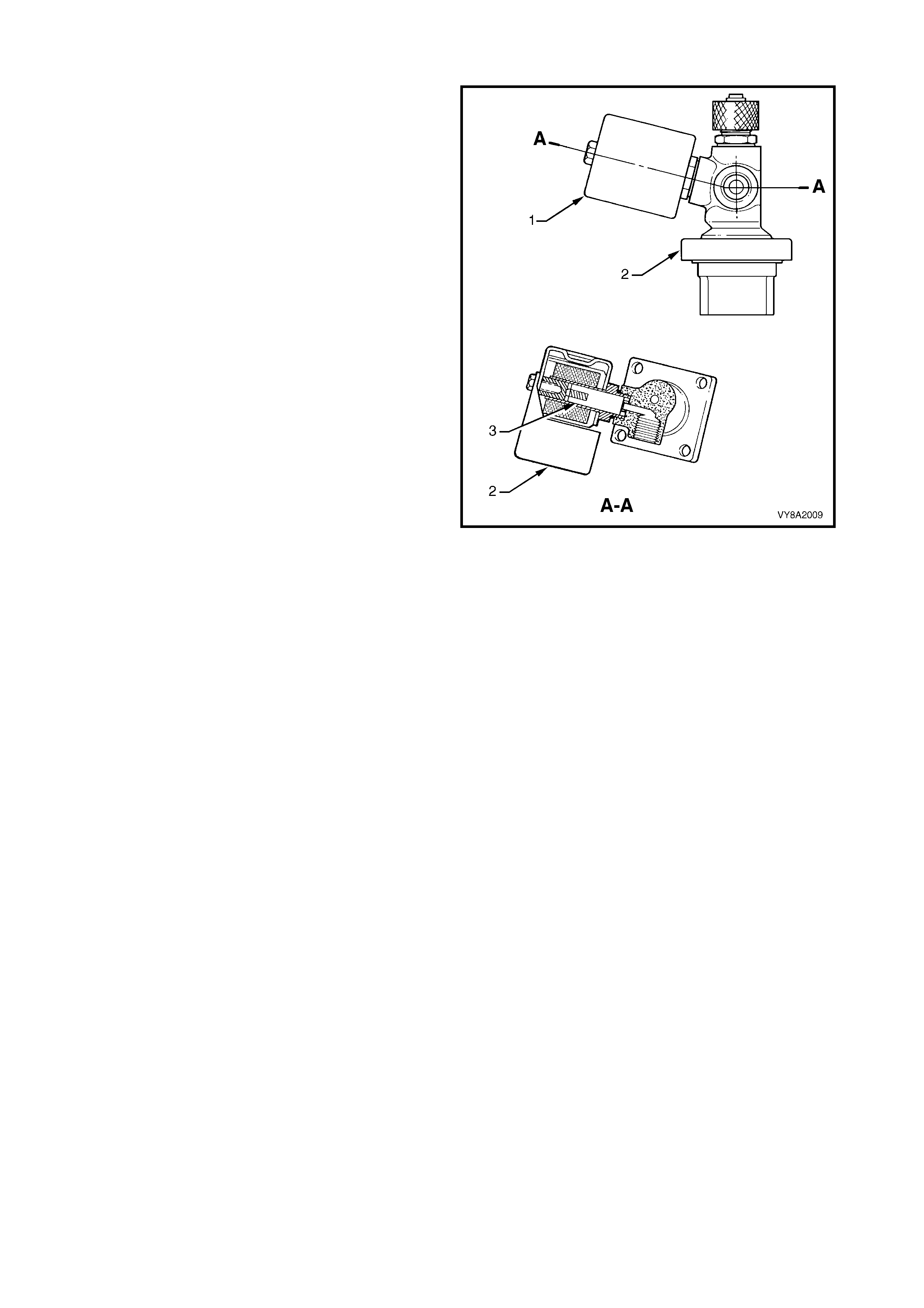
2.6 MANUAL SERVICE VALVE ASSEMBLY
The manual service valve assembly is attached onto
the LPG tank and is three valves in one:
• manual shut off valve,
• electrically operated solenoid valve, and
• excess flow valve.
The manual service valve assembly also incorporates
the smart unit, refer to 2.7 SMART UNIT.
MANUAL SHUT OFF VALVE
The manual s hut of f valve (1) allows the s upply of LPG
to be manually shut off for servicing, if a leak in the
system develops, or in the event of a vehicle accident
by turning the knob (2).
SOLENOID VALVE
The s olenoid valve (3) is an electric ally oper ated valve,
which allows the flow of LPG from the tank into the
service line when energised by the smart unit (4). The
solenoid valve is energis ed f or thr ee seconds when the
ignition key is first turned on, or constantly while the
engine is being cranked or is running.
The solenoid valve will s hut off the LPG f low when the
ignition is switched off and/or the engine stops running.
EXCESS FLOW VALVE
The ex cess f low valve (5) will close autom atically if the
flow of liquid LPG is excessive, shutting off the supply
of liquid LPG. The valve will automatically reopen when
the excess flow condition has ceased.
The ex ces s f low valve is des igned to shut off if the flow
exceeds a specified amount, as would occur if the
service line was severed or opened.
Figure 8A2-15
2.7 SMART UNIT
The smart unit (1) is attached to the manual
service valve (2) and controls the operation of the
solenoid valve (3) and the LPG lock-off, refer to
2.9 LPG LOCK-OFF.
W hen operating in LPG m ode, the PCM will signal the
smart unit to energise the solenoid valve and LPG
lock-off for three seconds when the ignition switch is
first turned on or when the engine is being cranked
and while the engine is running.
If the engine stops running, the PCM signal to the
smart unit will cease and the smart unit will de-
energise the so lenoid valve and LPG lock -of f . The f low
of LPG will then stop.
Figure 8A2-16
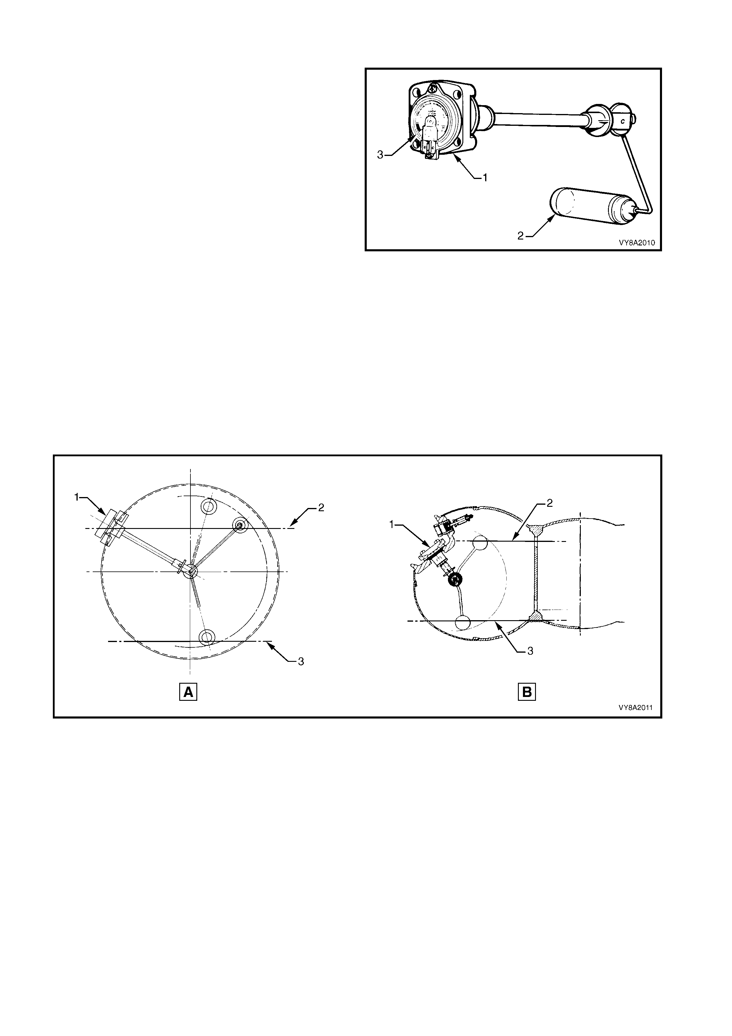
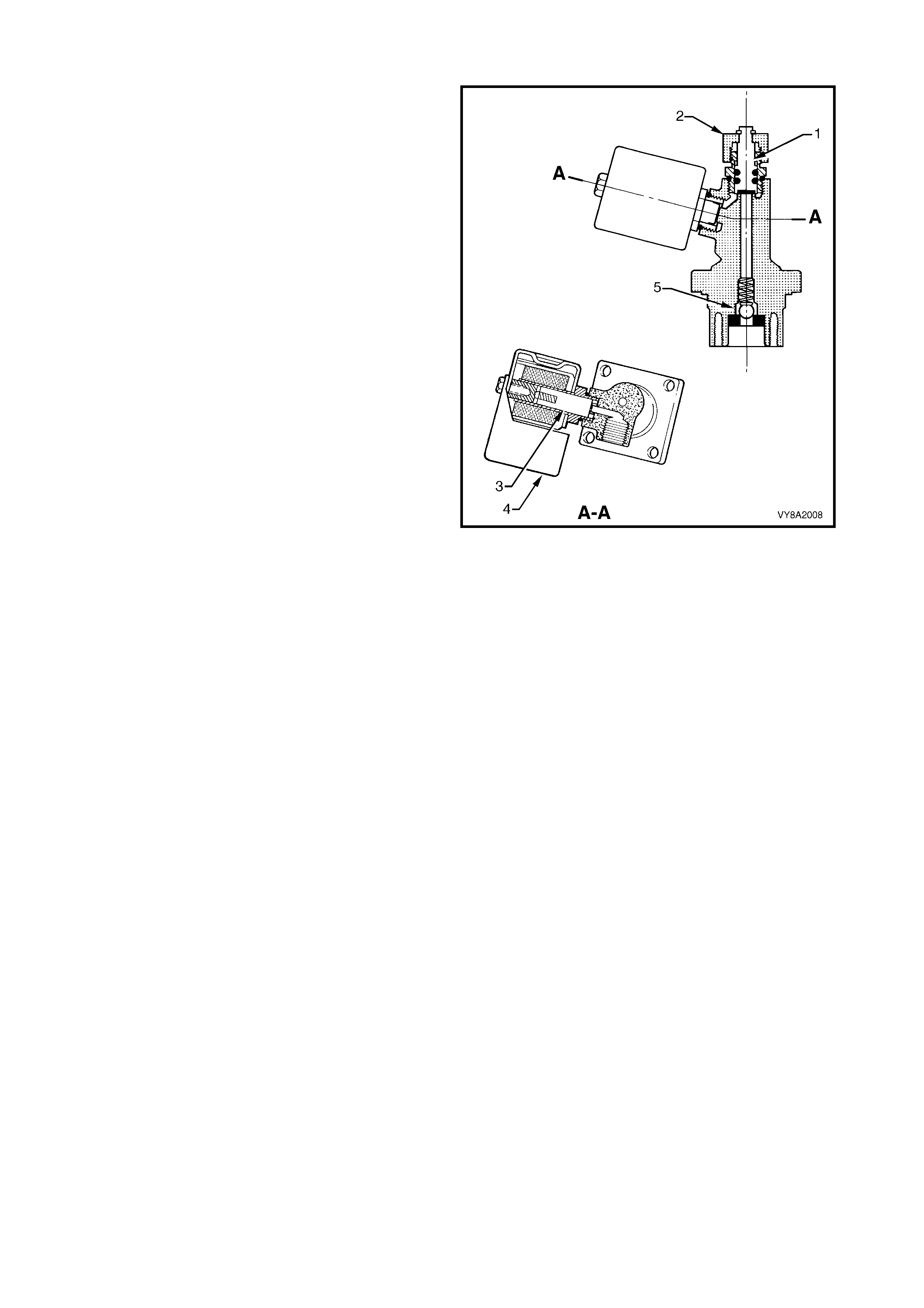
2.8 TANK FUEL GAUGE ASSEMBLY
The tank fuel gauge assembly (1, typical) has a float
(2) similar to a petrol gauge sender unit, and a fuel
contents gauge (3).
As the liquid level in the LPG tank rises, so to does the
float. The float is connected to a magnet within the
assem bly. Any change in the position of the liquid level
is transmitted to the fuel contents gauge via the float
and magnet.
The magnetic field produced by the magnet causes the
fuel contents gauge mounted on the exterior of the
tank to move in relation to the magnet's position.
Referr ing to Figure 8A2- 18, (A) Sedan and Utility or (B)
Wagon, the f uel c ontents gauge (1) will show full when
the liquid level in the tank is at 80% (2). It will show
empty when the tank contents falls to approximately
8.5 litres (3).
The fuel gauge sender unit within the fuel contents
gauge incorporates a variable resistor, which will vary
its resistance from approximately 40 ohms when the
tank is empty to approximately 255 ohms when the
tank is full.
This change in resistance is sensed by the instrument
cluster fuel gauge, which will display the contents of
the LPG tank when the vehicle is operating on LPG. If
the vehicle is switched back to petrol operation, the
contents of the petrol tank will be displayed.
Figure 8A2-17
Figure 8A2-18
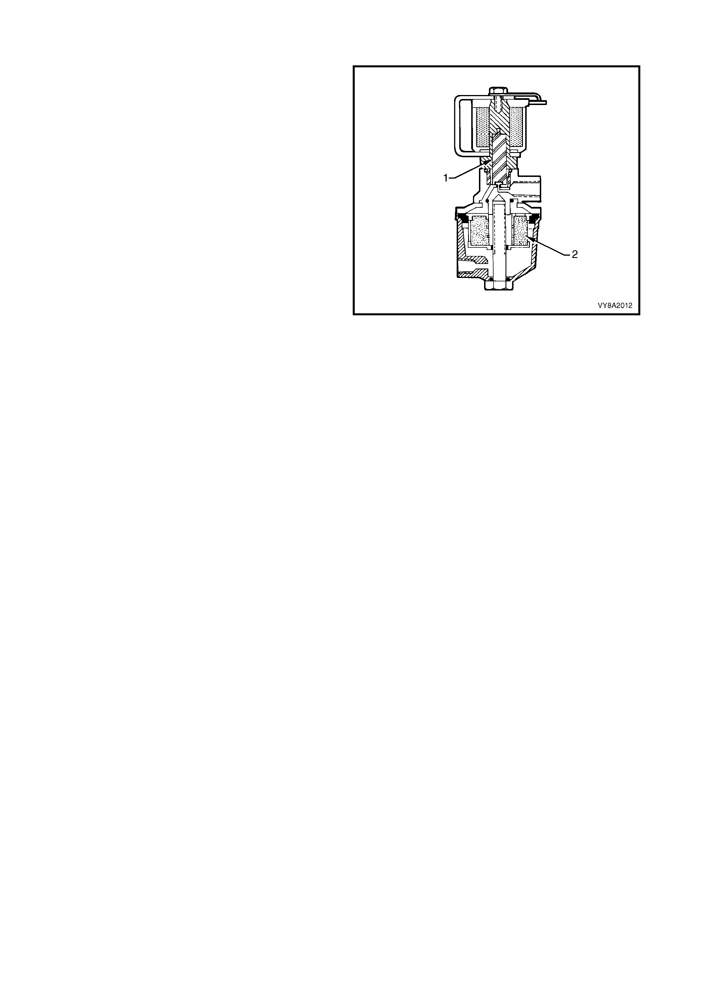
2.9 LPG LOCK-OFF
The LPG lock-off is an electrically operated solenoid
valve, which allows or prevents the flow of LPG to the
converter when energised or de-energised by the
smart unit.
The LPG lock-off is energised for three seconds when
the ignition is turned on, or c onstantly while the engine
is being cranked or is running.
The valve (1) opens and allows LPG from the tank to
flow through a fuel filter (2) and then to the converter.
When the engine stops running, or the ignition is
turned off, the smart unit de-energises the LPG lock-
off and the supply of LPG is shut off.
Figure 8A2-19
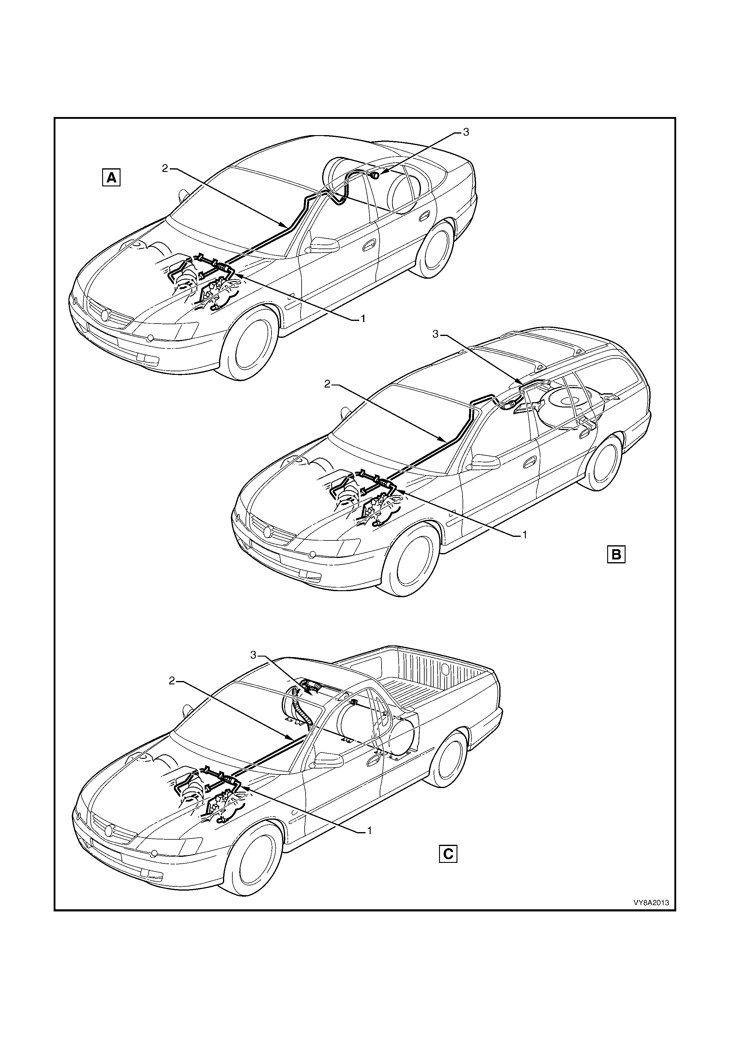
2.10 SERVICE LINE
The service line carries the liquid LPG from the manual service valve to the LPG lock-off. The service line
consists of thr ee major components: the front (1), intermediate (2) and r ear (3) service lines, ref er to Figure 8A2-
20, (A) Sedan, (B) Wagon, (C) Utility.
Figure 8A2-20
Legend
1. Front Service Line A. Sedan
2. Intermediate Service Line B. Wagon
3. Rear Service Line C. Utility
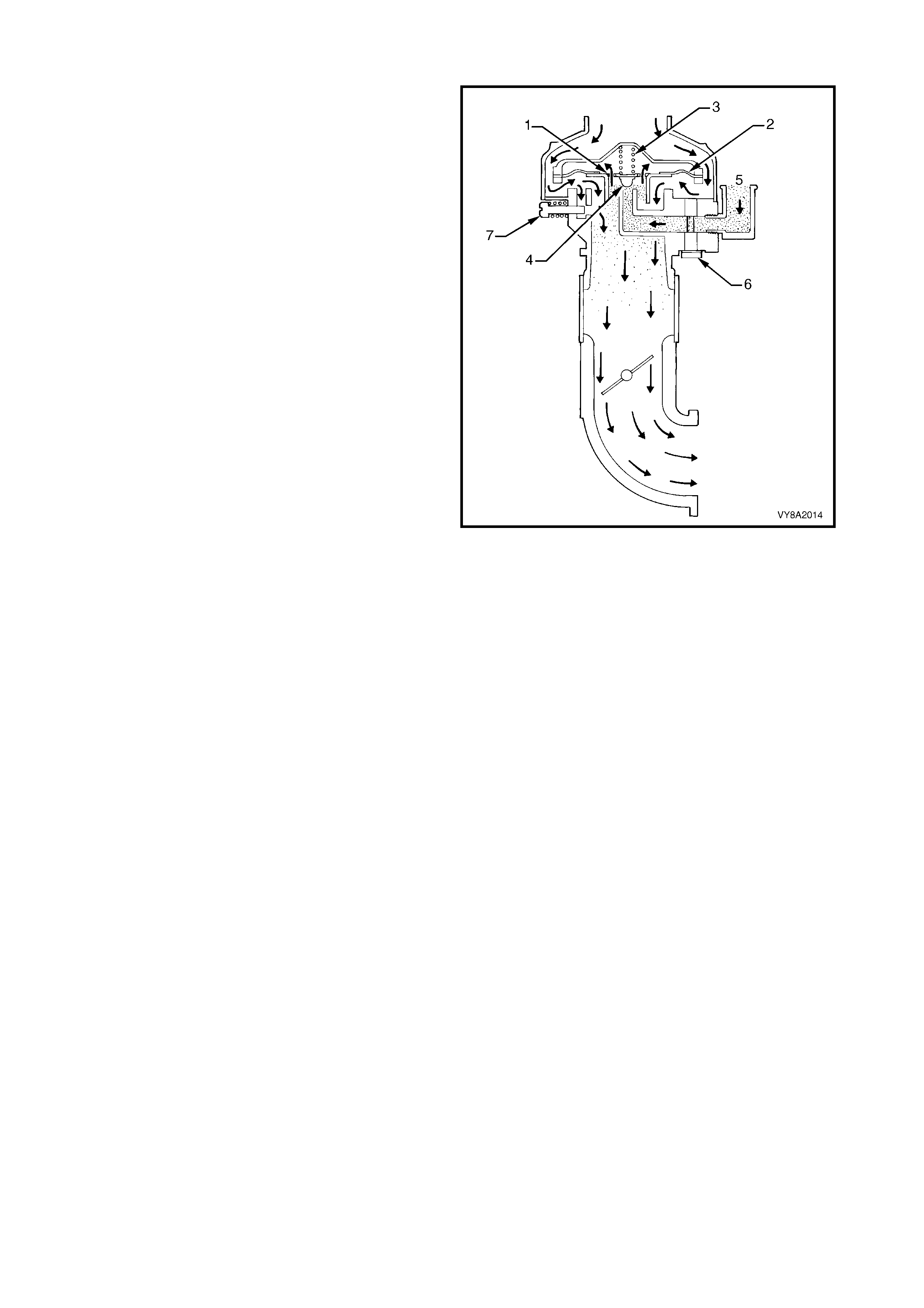
2.11 CONVERTER
The converter is a combined two-stage regulator and vaporiser.
It receives LPG (1) at tank pressure from the LPG lock-off and reduces that pressure in two stages to slightly
less than atmospheric. When the engine is cranked or running, a partial vacuum is created in the vapour line
from the mixer, which opens the converter permitting LPG to flow to the mixer (2), refer to Figure 8A2-21.
In the process of reducing the pressure from approximately 1260 kPa in the tank to atm ospheric pressure, the
LPG expands to become a vapour, causing refrigeration. To compensate for this and to assist in vaporisation,
coolant from the engine cooling system circulates through a heat exchanger (3). The converter seals off LPG
flow when the engine is stopped.
Figure 8A2-21
PRIMARY REGULATION
The primary regulator spring (1), acting on the upper side of the primary diaphragm (2), pushes the primary
diaphragm down. This opens the primary valve (3) and allows LPG to enter the converter (4), which then flows
through the heat exchanger (5) where the LPG changes state from a liquid to a gas.
The pressure of the LPG acting on the underneath side of the primary diaphragm causes the diaphragm to move
upward, closing off the primary valve.
SECONDARY REGULATION
W hen the engine is cranked or running, a vacuum is created by the mixer in the secondary chamber (6). This
vacuum (slightly below atmospheric) acting on the underneath of the secondary diaphragm (7), overcomes the
secondary spring force (8), allowing LPG as a vapour to enter the secondary chamber. This increases the
pressure acting on the underneath side of the diaphragm, overcoming the secondary spring force, causing the
diaphragm to move upward closing off the secondary valve (9). The gas can then flow to the mixer (10).
Figure 8A2-22
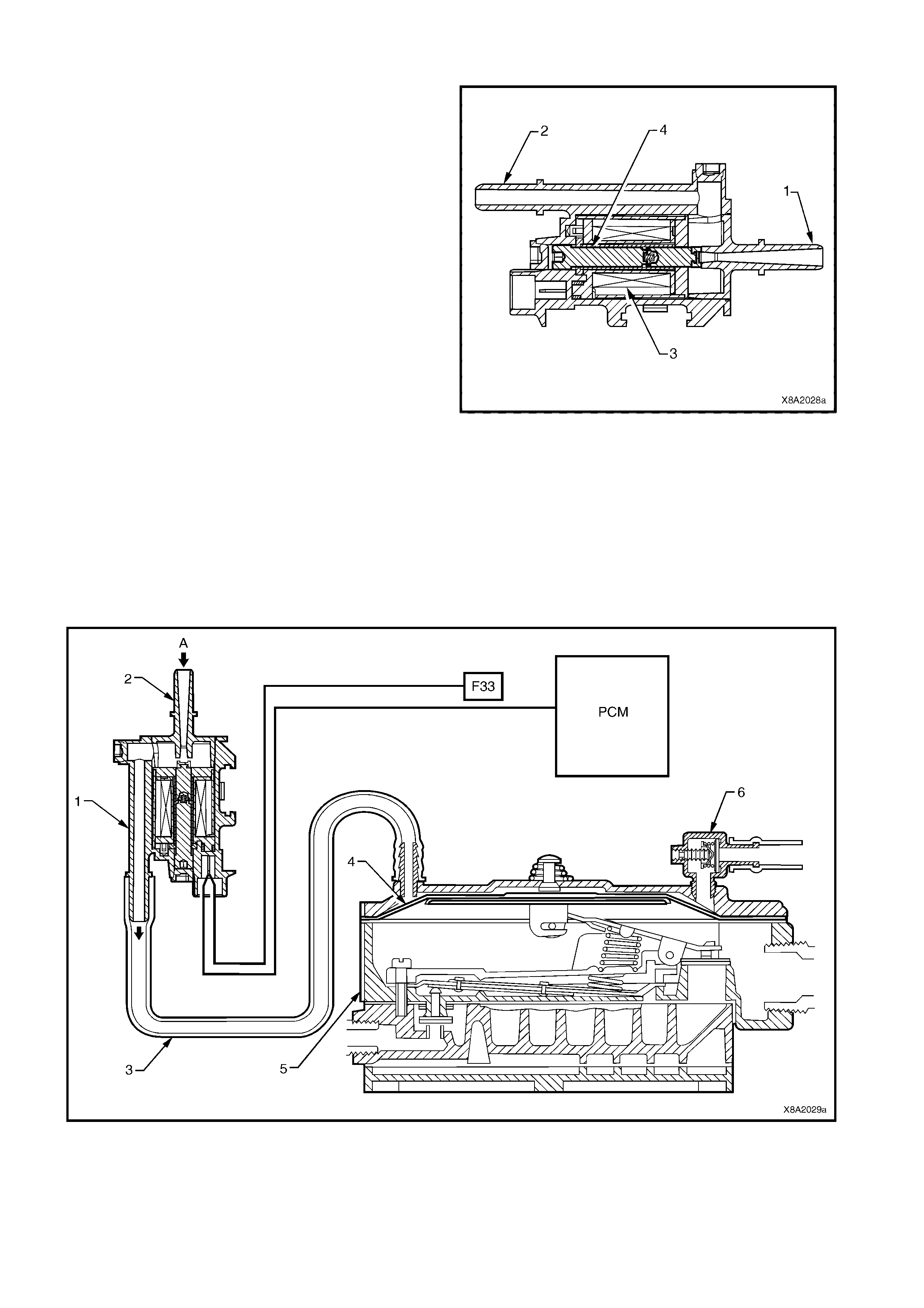
2.12 FUEL CONTROL VALVE
The fuel control valve (FCV) is used to control fuel
delivery.
Because the diaphragm of the converter is very large,
little movement is required to control the amount of
LPG deliver ed. T he f uel contr ol valve is connec ted into
the balance line between the atmospheric vent of the
converter secondary diaphragm (2) and the air valve
venturi of the mixer (1).
This applies a very low vacuum to the atmospheric
side of the converter secondary diaphragm. Any
pressure less than atmospheric results in a reduction
in LPG delivery. This assures extremely accurate LPG
delivery and rapid response time.
With the exhaust gas oxygen sensor at operating
temperature and the powertrain control module (PCM)
operating in closed loop mode, there is a wide range of
control. This permits the PCM to optimise the air/fuel
mixture to varying engine requirements.
The FCV is controlled by the PCM. To open the FCV
and decrease the pressure acting on the secondary
diaphragm of the converter, the PCM pulses the FCV
coil (3) on and off at a frequency of 10 Hz. The ratio
between the on and off time is called the duty cycle.
To open the FCV plunger (4) the PCM increases the
duty cycle, which decreases the pressure applied to
the secondary diaphragm. The amount of time the
FCV is on will determine the pressure acting on the
converter secondary diaphragm. In this way, the PCM
can control the air/fuel ratio.
Figure 8A2-23
Figure 8A2-24
Legend
1. FCV 4. Secondary diaphragm A. Vacuum from mixer
2. Vacuum inlet 5. Converter
3. Balance hose 6. Regulator check valve
2.13 REGULATOR CHECK VALVE
To maintain correct control during normal driving the
pressur e above the s ec ondary diaphragm is inf luenc ed
by the air valve vacuum but is finally controlled by the
FCV.
However, when the accelerator is depressed quickly,
the pressure in the air valve chamber will rise very
quickly, far above its normal working value. This is
because the movement of the mixer diaphragm and
air-gas valve will lag behind the movement of the
throttle valve. This will momentarily subject the air
valve chamber to a high vacuum.
Because the FCV duty cycle has been controlling the
air fuel ratio with a steady vacuum value, this sudden
increase in vacuum will delay the movement of the
converter diaphragm at precisely the time it needs to
move freely. This would cause a lean air/fuel ratio.
Whenever the vacuum above the diaphragm exceeds
16” W C i.e. when the diaphragm needs to m ove down
quickly as the accelerator is suddenly depressed, the
regulator check valve (1) will open and allow
atmospheric pressure to act on the secondary
diaphragm.
Figure 8A2-25
2.14 MIXER
The mixer is installed between the engine intake
manifold and the intake air filter.
When the engine is cranked or running, manifold
vacuum is transm itted through vacuum ports in the air
valve (1) to the upper side of mixer diaphragm (2). As
a result, atmospheric pressure pushing upwards on the
underneath side of the diaphragm, lifts it against the
downward force of the metering valve spring (3).
The pressure applied to the upper side of the
diaphragm varies with engine speed and throttle
position. The pressure difference between
atmos pheric pr essur e acting on the underneath s ide of
the diaphragm and the pressure acting on the upper
side of the diaphragm determines the metering valve
(4) position.
The position and the shape of the metering valve
determines the amount of LPG (5) delivered to the
engine.
Maximum fuel delivery is determined by the power
valve (6), which limits the maximum fuel flow. The
power valve is pre-calibrated in the factory and is not
adjustable in service.
Idle air by-pass adjustment is provided by the
adjustment screw (7).
Figure 8A2-26
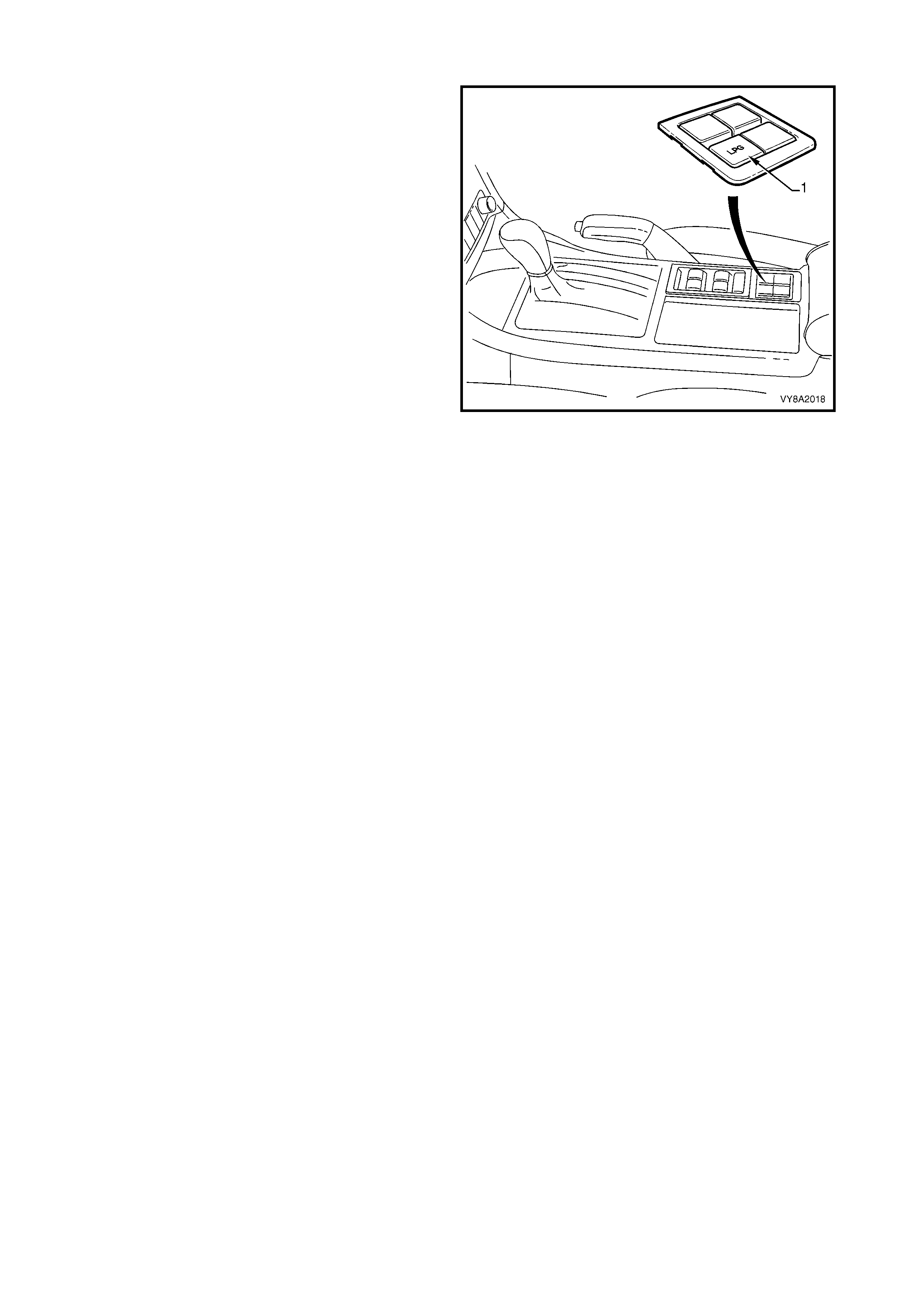
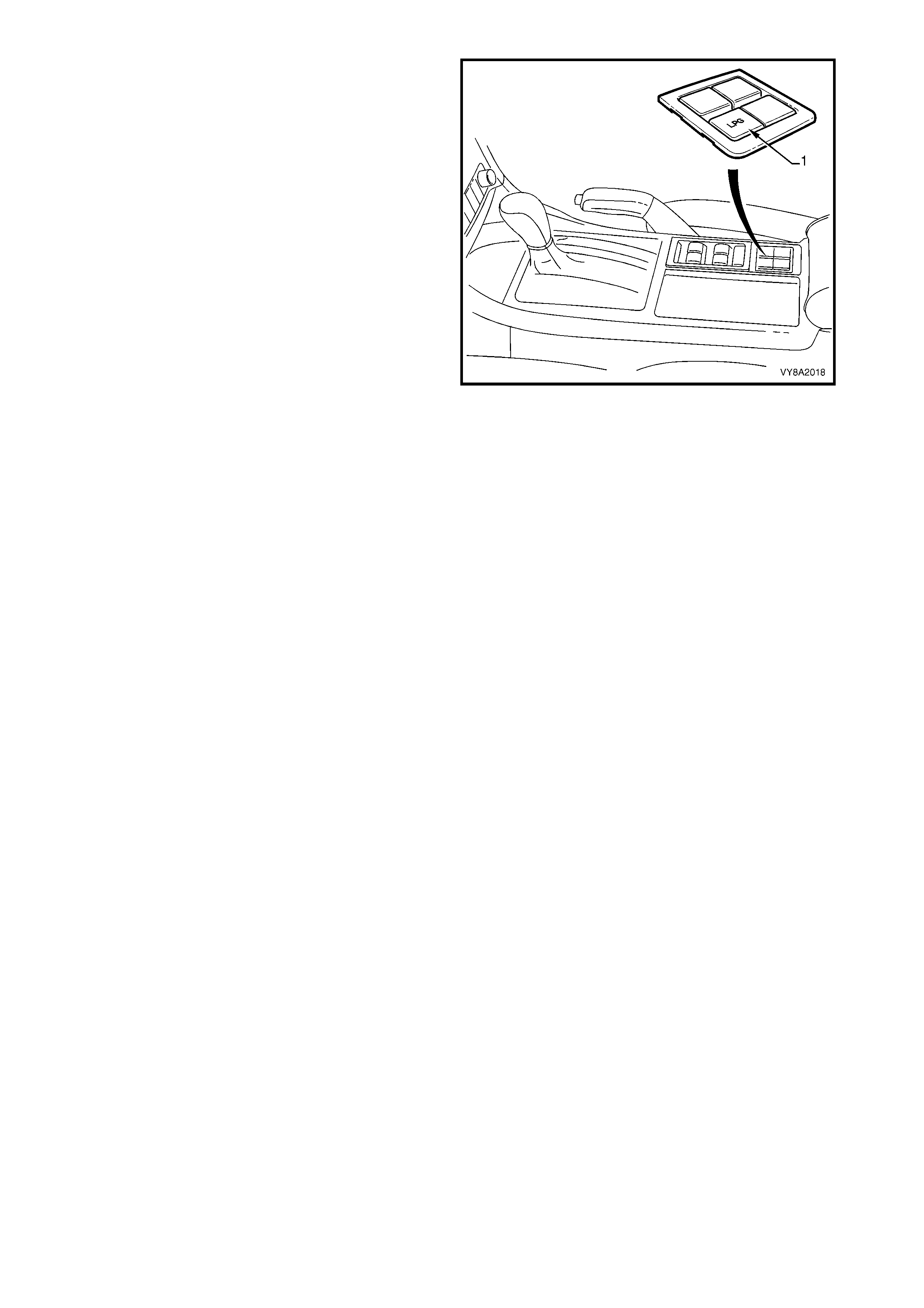
2.15 FUEL MODE SWITCH
On all vehicles f itted with a LPG system, the fuel m ode
switch (1) is mounted in the floor console.
When the fuel mode switch is pressed, the switch
supplies B+ volts to PCM terminal X3-F4. The PCM
sees this voltage as a request to change over from
petrol to LPG or from LPG to petrol.
NOTE: The PCM will only toggle between the petrol
and LPG mode if the ignition is on and the engine is
not running, or if the engine speed is greater that 1500
RPM.
The operational mode that the PCM is in is stored in
the PCM mem or y so that the engine starts in the same
mode on the next ignition cycle.
Figure 8A2-27
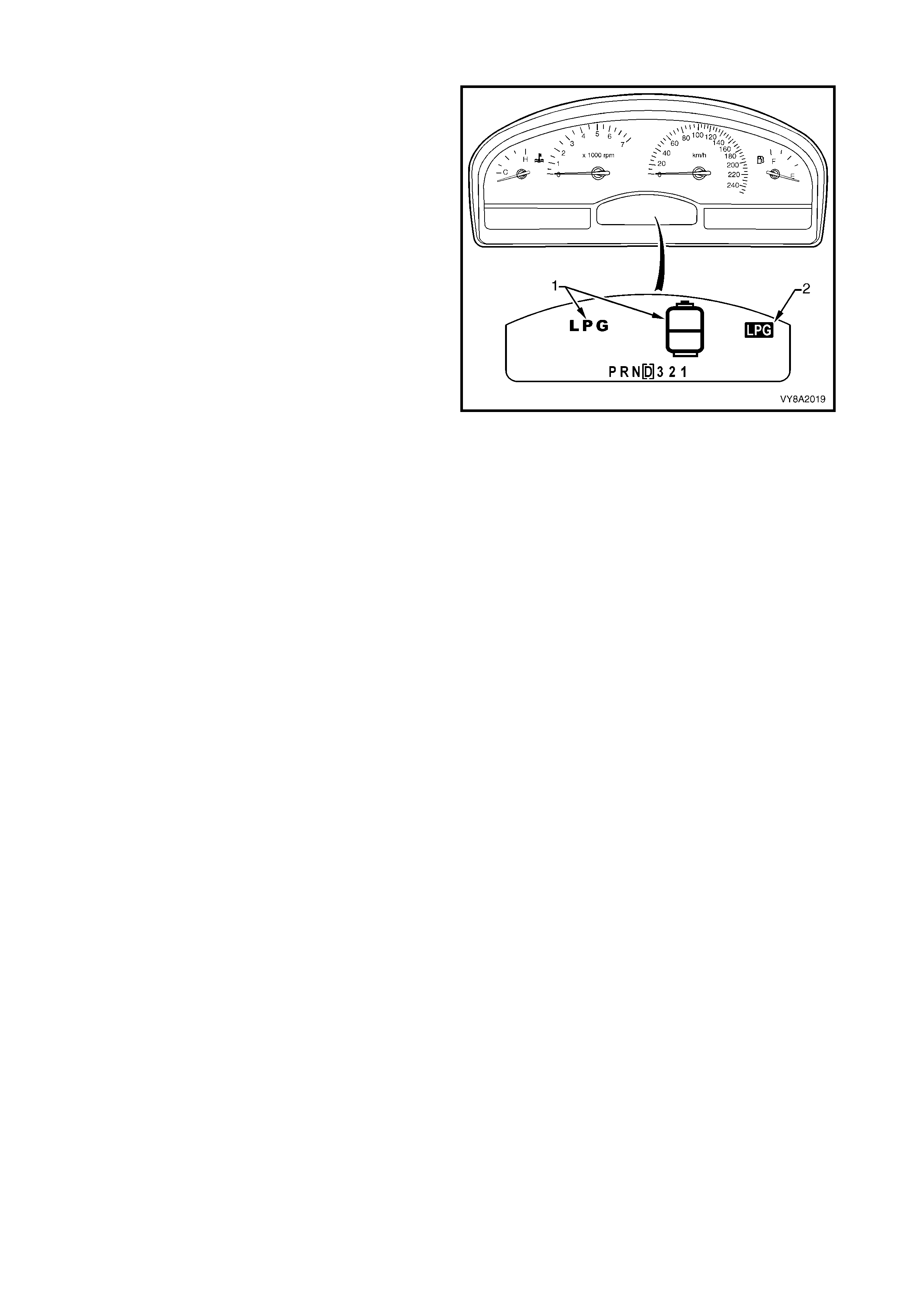
2.16 INSTRUMENT CLUSTER DISPLAY
Whenever the vehicle is switched from petrol to LPG
mode, the LPG tank icon and letters LPG (1) will be
displayed in the instrument cluster multifunction display
(MFD) for two seconds.
In addition, the icon LPG (2) will also be displayed in
the upper right corner of the MFD while the vehicle
remains in LPG mode.
When the vehicle is in LPG mode the fuel gauge
displays the amount of LPG within the tank.
W hen the level falls to a pr edeterm ined point, the LPG
tank icon is displayed with the words Low LPG in tank .
If the level decreases further to second predetermined
point, the icon is displayed again with the words Very
Low LPG in tank. T hese warnings are accom panied by
a warning chime.
NOTE: As the vehicle may continue to use a small
amount of petrol during LPG operation, the level of
the petrol tank is also monitored, refer to
2.18 POWERTRAIN CONTROL MODULE. If the level
falls below predetermined points, similar warnings will
be issued regarding the petrol status, even though the
fuel gauge is displaying LPG tank status.
For further information refer to Section 12C
INSTRUMENT CLUSTER.
Figure 8A2-28
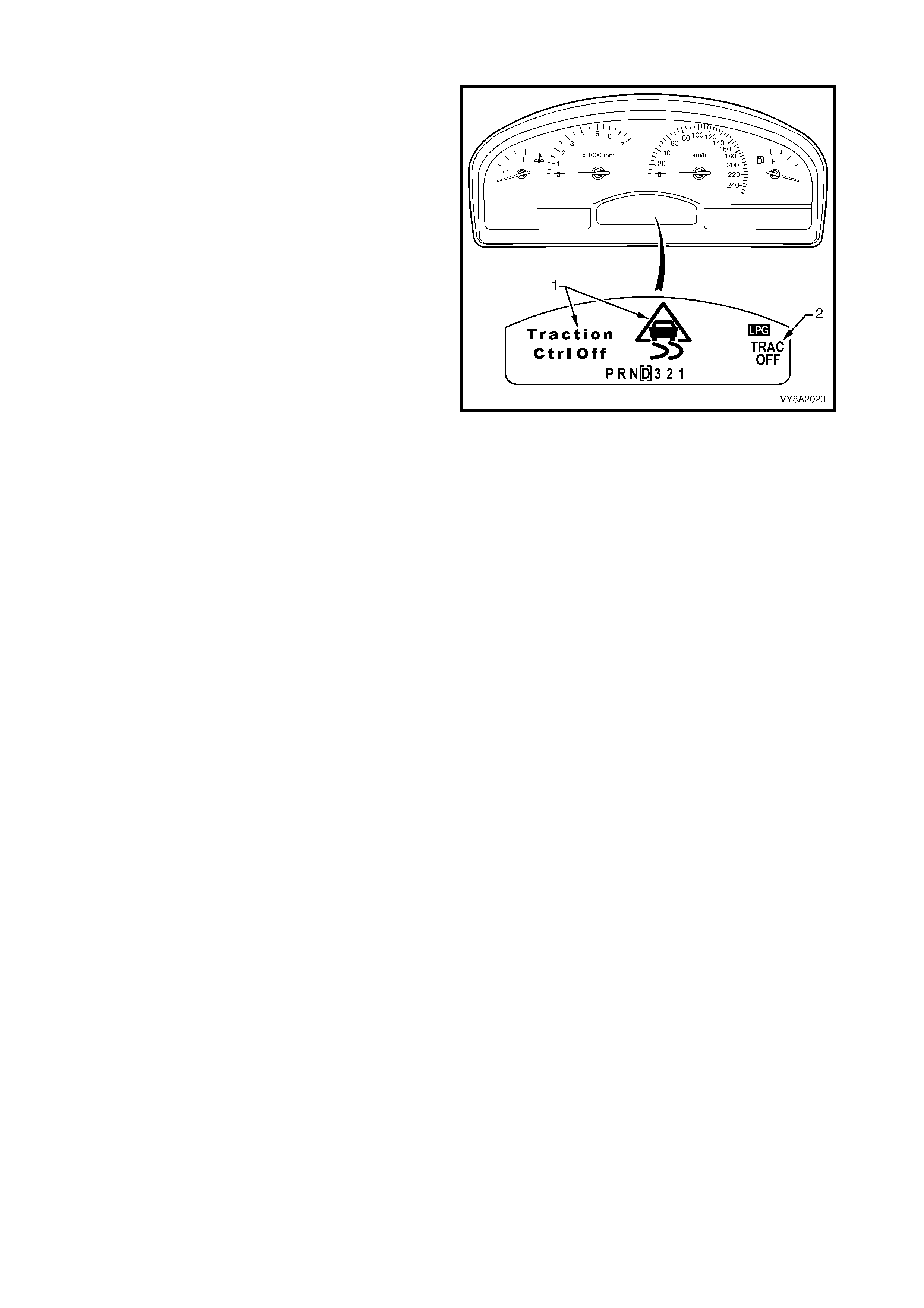
2.17 TRACTION CONTROL OPERATION
Whenever the vehicle is operating in the LPG mode,
the traction control system (if fitted) is disabled. The
traction control off icon (1) and the words Traction Ctrl
Off will be displayed in the instrument cluster
multifunction display (MFD) for two seconds.
In addition, the icon TRAC OFF will also be displayed
on the right-hand side of the MFD while the traction
control system remains disabled.
The traction control system is disabled by the PCM,
which sends a message to the ABS/ETC control
module via the serial data circuit, requesting the
traction control system be switched off.
Figure 8A2-29
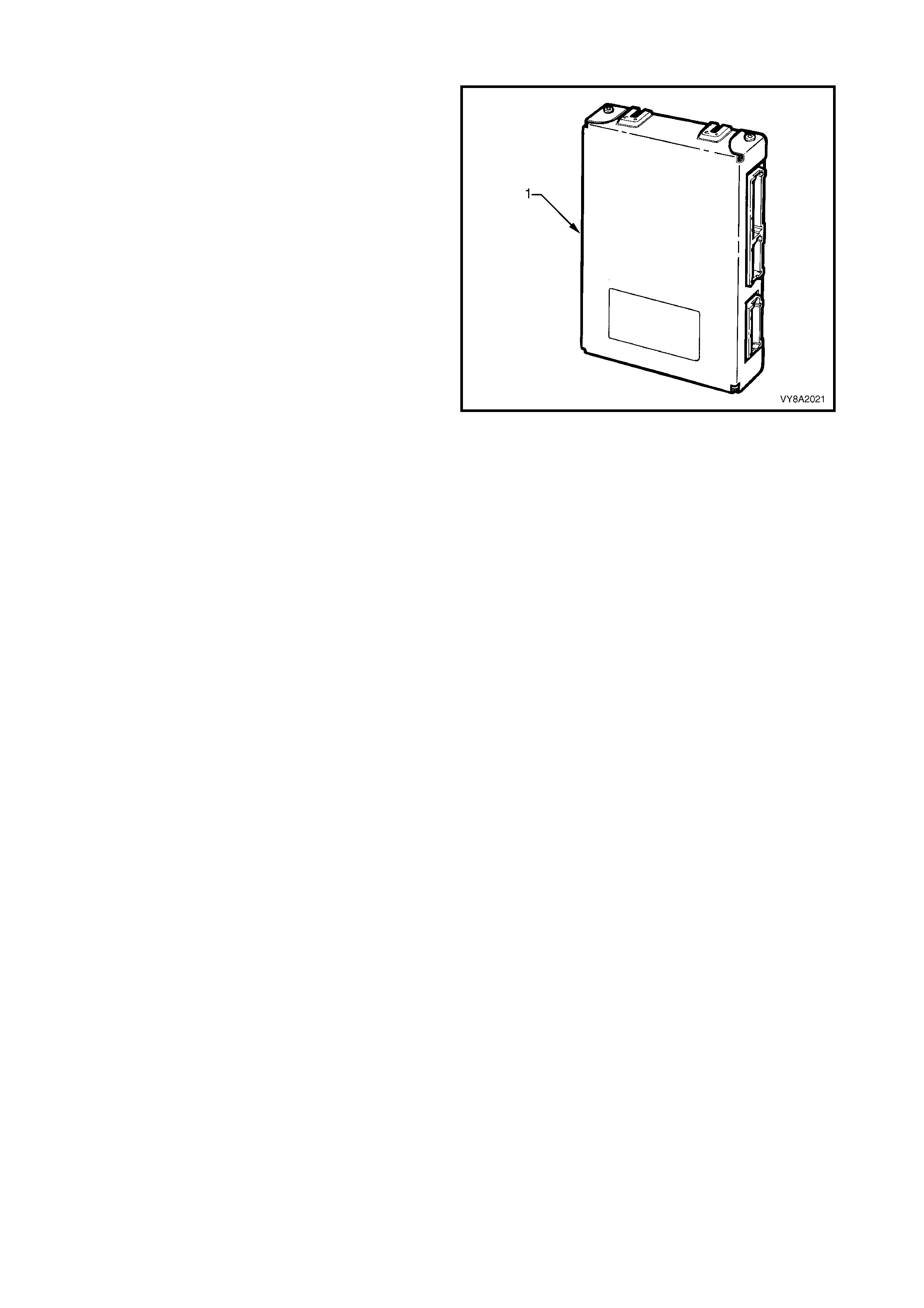
2.18 P O WERTRAIN CONTROL MODULE
When programmed with the correct LPG calibration,
the Powertrain Control Module (PCM) is capable of
operating in either of two operating modes: Petrol or
LPG.
PETROL MODE
When operating in petrol mode, the LPG system is
turned off and the vehicle operates on petrol with full
engine management control in the same manner as a
vehicle not fitted with LPG. In this mode, the
instrument cluster fuel gauge will show the amount of
petrol in the petrol fuel tank.
LPG MODE
When operating in the LPG mode, the engine
management s ystem is switched to LPG mode and the
LPG system is turned on, enabling the vehicle to
operate on LPG. In this mode the LPG lamp will be
illuminated and the instrument cluster fuel gauge will
show the amount of LPG in the LPG tank.
The PCM c ontrols the f low of LPG, by sending a signal
to the smart unit via circuit 2531. On receiving this
signal the sm art unit energise s the solenoid valve. The
smart unit also energises the LPG lock-off valve via
circuit 5620.
To aid engine starting, a small amount of petrol is
injected during engine cranking.
NOTE: In the LPG mode, the following changes have
been made so the engine can operate on LPG. These
changes only effect the operation of the PCM when
operating in LPG mode.
Figure 8A2-30
INJECTOR PULSE WIDTH
The injector pulse width is set to zero in all LPG operating modes, except during engine cranking or, when the
vehicle runs in engine valve recession protection mode.
During engine crank ing the amount of petrol delivered is determ ined by the engine coolant tem perature and the
engine crank time. If the engine stalls, no petrol will be injected during cranking unless the ignition is cycled off
and on.
W hen operating in LPG mode under conditions of prolonged high speed / high load, a sm all amount of petrol is
injected into the engine to cool the valves and catalytic converter.
FUEL PUMP
To provide petrol when starting in the LPG mode, the fuel pump will run for two seconds when the ignition is
turned to the ON position and continue to run when the engine is being cranked, but will be turned off five
seconds after the engine starts.
The fuel pump will also operate under high load conditions. This allows for petrol to be injected into the engine
when the vehicle goes into the engine valve recession protection mode.
To protect the fuel pump, the PCM will switch off the fuel pump and disable the engine valve seat recession
protection mode, if ther e is less than s ix litres of f uel in the petr ol tank. T he PCM monitors the s er ial data normal
mode message to determine the amount of fuel in the petrol tank.
ELECTRONIC SPARK TIMING
The PCM has been programmed with a specific Electronic Spark Timing (EST ) map that provides optimal LPG
operation. If the engine speed drops below 300 RPM, the PCM prevents the spark plugs from firing by setting
the ignition dwell to zero.
FUEL USAGE SIGNAL OUTPUT
The PCM f uel us age output signal is us ed by the trip com puter to deter m ine the fuel c onsum ption display and is
re-calibrated to suit LPG.
ENGINE CRANKING
If the throttle opening is greater than 7% when operating in LPG mode, the PCM will prevent the engine from
cranking by not energising the starter relay.
3. SERVICE OPERATIONS
3.1 SERVICE LINE DRAINING
LT Section –
CAUTION: T he vehicle cannot be operated on LPG in the workshop, unless the workshop is a Specialist
Gas Workshop (in accordance with the current Australian Standards AS 2746-1985) and LPG is
specifically required for testing. Therefore, only at the completion of the following procedure, with the
manual service valve closed, all the LPG in the service lines exhausted and the vehicle running on
petrol, can the vehicle be driven into the workshop.
1. Park the vehicle in a well ventilated area, away from any ignition source when performing this operation.
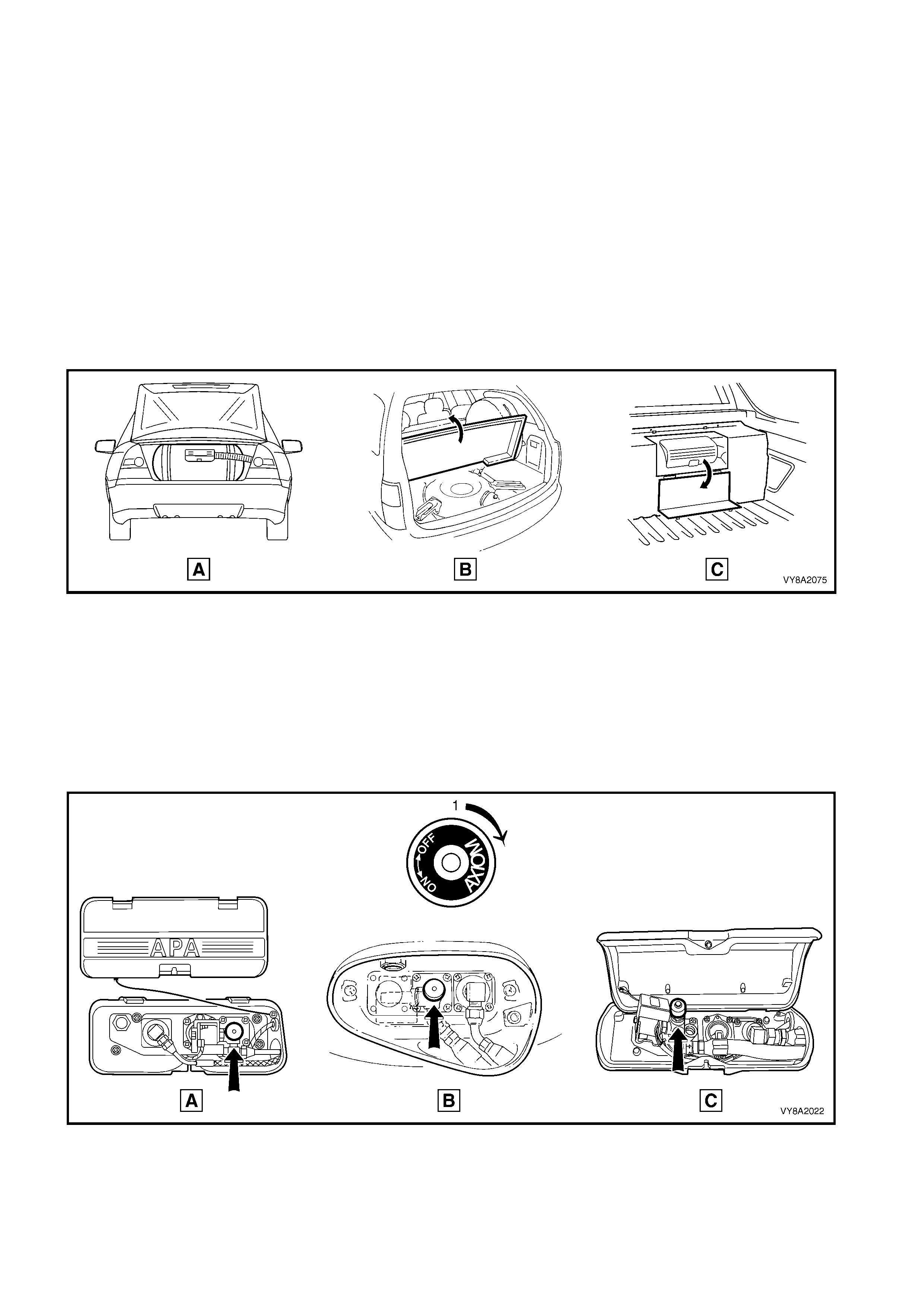
2. For Sedan, open the rear compartment lid (A).
For Wagon, open the liftgate and raise the rear compartment floor carpet (B).
For Utility, open the access cover on the LPG tank cover (C).
Refer to Figure 8A2-31.
Figure 8A2-31
3. Remove or open the LPG tank valve box cover.
4. T urn the manual s ervice valve off in the dir ection shown (1), ref er to Figure 8A2-32, (A) Sedan, ( B) W agon,
(C) Utility.
CAUTION: If at any time the manual service valve becomes stuck, no service operations on the system
will be possible. Should for any reason the valve stick, the tank will have to be returned to the tank
manufacturer (APA) to arrange a replacement tank.
Contact: APA Industries, 190 Colchester Road, Kilsyth, Victoria 3137.
Figure 8A2-32
5. If required, press the f uel m ode switch (1) to place
the vehicle in LPG m ode. With the ignition on, the
LPG icon should be displayed on the instrument
cluster multi-function display.
6. Start the engine and allow to run on LPG until the
engine stalls, then crank the engine several times
to ensure the service lines are empty of LPG.
7. Press the fuel mode switch again to place the
vehicle in petrol mode. With the ignition on, the
LPG icon should not be displayed on the
instrument cluster multi-function display.
8. Disconnect the battery earth lead before
performing any service operations.
NOTE: If it is not possible to start and run the engine
out of LPG, the service lines should be cracked open
to allow them to be em ptied of LPG in accordance with
the current Australian Standards AS 2746 - 1985.
Figure 8A2-33
3.2 LPG TANK UNLOADING
LT Section –
1. Park the vehicle in a well ventilated area, away
from any ignition source.
2. Drain the LPG service lines, refer to
3.1 SERVICE LINE DRAINING.
3. Disconnect the battery earth lead and ensure the
manual service valve is turned off.
4. Disconnect the rear service line from the LPG
tank, refer to 3.15 REAR SERVICE LINE.
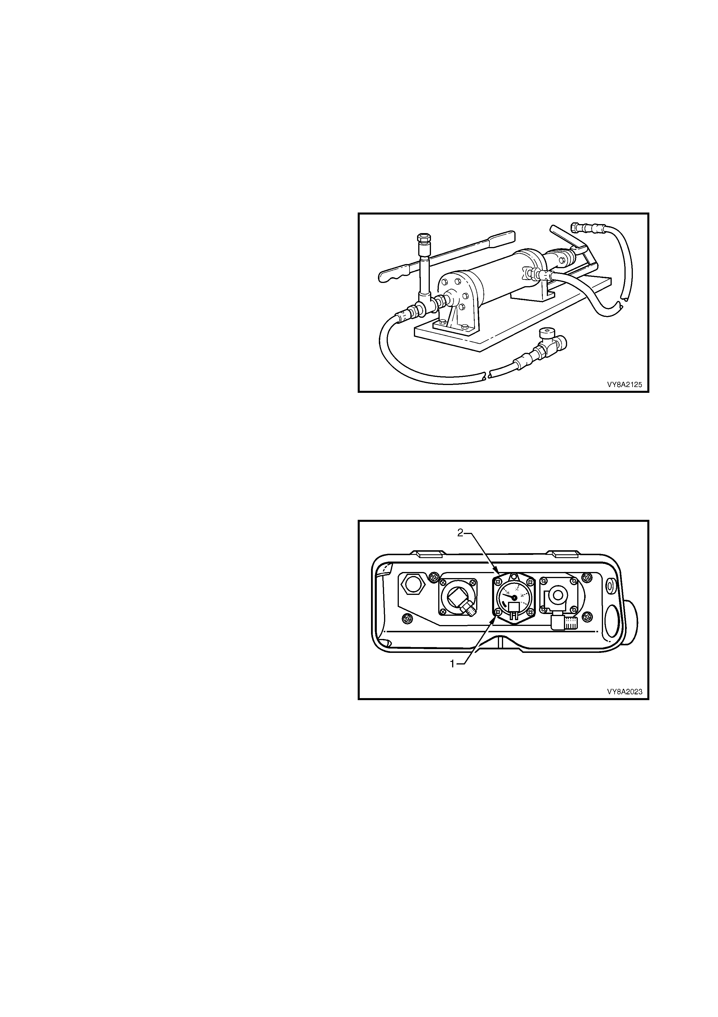
5. Connect an Apollo LPG pum p or equivalent to the
manual service valve assembly connection. Refer
to 10. SPECIAL TOOLS for further pump details.
6. Open the manual service valve and pump-out the
LPG tank, following the instructions provided by
the LPG pump manufacturer for the particular
pump you are using and in accordance with the
current Australian Standards AS 2746-1985.
CAUTION: The LPG tank must be pumped-out until
completely empty.
7. W hen the LPG tank is com pletely empty, close the
manual service valve and disconnect the pump.
8. Carefully open the manual service valve.
9. Remove the wiring connections from the tank fuel
gauge assembly.
10. Remove the smart unit and solenoid valve
from the manual service valve, refer to
3.8 SMART UNIT & SOLENOID VALVE.
11. Remove the filler line from the AFL valve, refer to
the 3.5 FILLER LINE.
Figure 8A2-34
12. Loosen the tank fuel gauge assembly retaining
screw (1), four places, one turn, Sedan shown,
Wagon and Utility similar.
13. Rock the tank fuel gauge assembly to relieve any
residual pressure in the LPG tank.
14. Continue to loosen the tank fuel gauge assembly
screws one turn at a time. Continue rocking the
tank fuel gauge assembly to ensure the LPG tank
has no residual pressure.
15. Completely remove the tank fuel gauge assembly
screws.
16. Remove the tank fuel gauge assembly (2), being
careful not to damage the float.
17. Purge the LPG tank with nitrogen to ensure there
is no residue of LPG in the tank.
CAUTION: After any valve or component has been
removed and reinstalled to the LPG tank, the LPG
tank must be pressure and leak tested in
accordance with the current Australian Standard
AS 2030-1 before the LPG tank is returned to
service.
18. If required, reinstall the tank fuel gauge assembly,
refer to 3.13 TANK FUEL GAUGE ASSEMBLY.
Figure 8A2-35
3.3 LEAK TESTING
LT Section – AA-650Q
The f ollowing leak test procedure is to be perf orm ed on the LPG s ystem high-pr essur e com ponents and is to be
performed at each normal maintenance service.
IMPORTANT: The leak test is to be perform ed in the open air in a well-ventilated area, away from any ignition
source and prior to bringing the vehicle into the workshop.
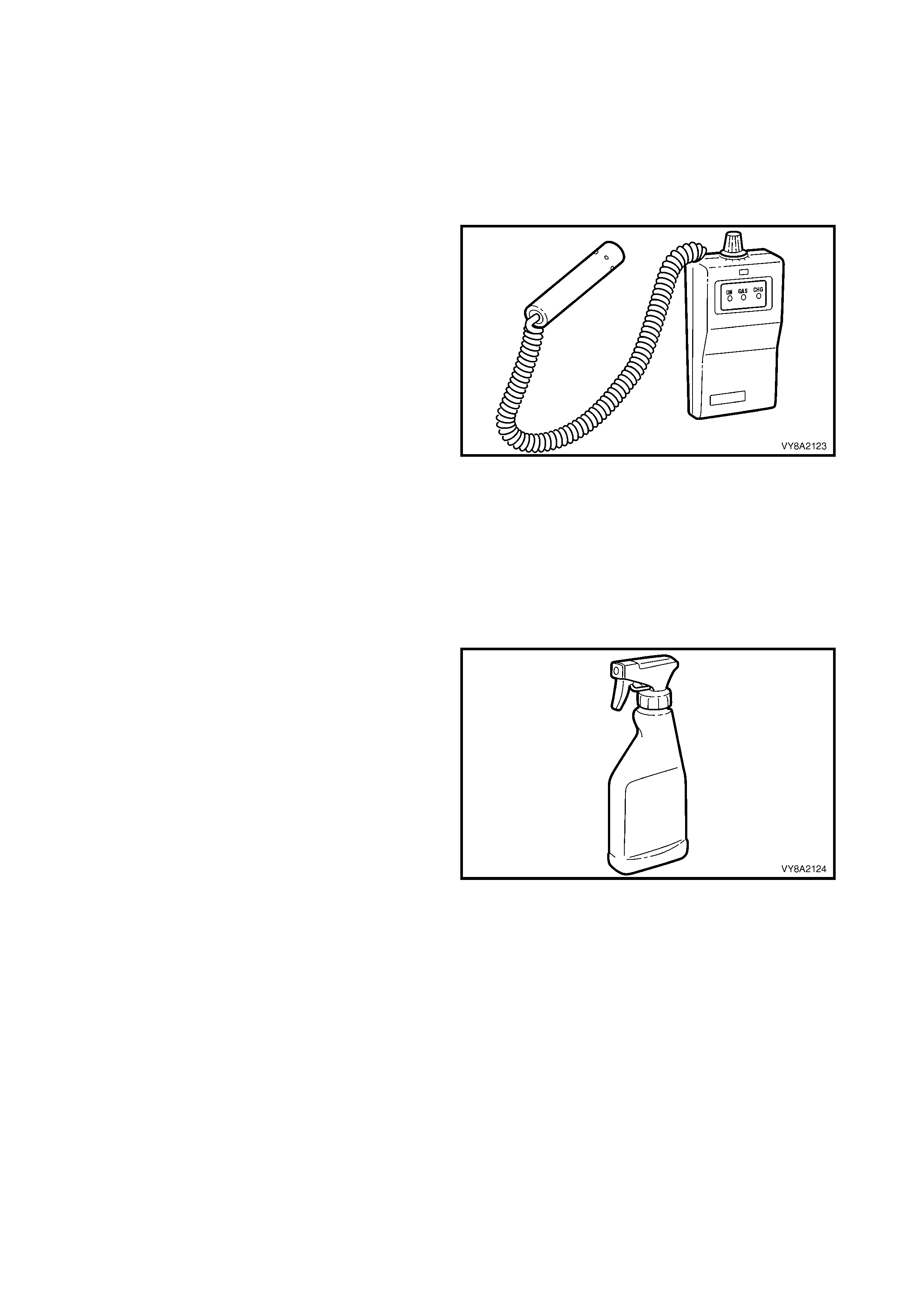
COMBUSTIBLE GAS DETECTORS
If a combustible gas detector is to be used for leak
testing of the LPG system, the combustible gas
detector should be capable of detecting 25 parts per
million (PPM) of LPG in air. A detector such as a LD-
9001 LP Gas Leak Detector or equivalent is
recommended.
Whichever leak detector is used, it is important to
follow the manufacturer's instructions in regard to
adjustment and setting the instrument prior to
conducting the leak test.
Care in interpretation is necess ary, as the detector can
respond to the pres ence of any of several vapours that
are com bus tible, som e of which m ay not be LPG, such
as oil smears, joining compounds, etc. It may also
detect residual LPG vapours that are present for
reasons other than leakage, and which must be
cleared before a valid test for leakage can be made.
If a leak is present, a detector will signal its existence
but not its size, and will indicate its general location,
but may not be able to locate it exactly. A proving or
follow up check with foam is often desirable.
Figure 8A2-36
FOAM
If foam is to be used, the foaming agent should be a
propriety leak test solution, formulated specifically for
the purpose, such as Gameco Leak Check TM or a
similar solution.
The solution should be fr esh and the whole of the ar ea
to be tested should be coated, and time allowed for
bubbles to form. All areas under test must be able to
be observed during the leak test.
Whichever foaming agent is used, it is important to
follow the manufacturer's instructions.
Foam testing is more effective for small leaks. Large
leaks tend to blow the solution away from the leak
without forming a bubble, so care in application is
necessary.
The leak test is performed by directing a spray of
solution at each of the pos sible leak points in the high-
pressure side of the system.
After applying the solution, look carefully for no less
than 15 seconds.
A leak is indicated by the presence of gas bubbles
(foaming) in the solution at the leak source
Figure 8A2-37
NOTE: LPG is heavier than air so test thoroughly below all components and fittings.
If a leak is detected at a joint, the relevant component/s must be removed as described in the appropriate service
operation in this Section. All mating threads must be thoroughly cleaned, then resealed using the specified
sealant and tightened to the specified torque. Once installed, thoroughly leak test the component/s again.
At the completion of each test, dry the leak test area of the foam ing agent with low-pressure com pressed air or
shop cloths and spray the immediate area with a water-dispersing agent such as WD40 or RP7, etc.

LEAK TEST PROCEDURE
With 3 litres of LPG in the LPG tank, leak test the complete LPG system following the instructions.
1. Park the vehicle in a dry, well ventilated area.
CAUTION: Do not smoke or allow naked flames or any ignition source near the vehicle during the testing
operations.
2. Ensure the vehicle is operating on LPG and run the engine for at least 30 seconds to fully pressurise the
system, then stop the engine.
3. Perform the following test sequence, referring to Figure 8A2-38 – Sedan, 8A2-39 – Wagon or 8A2-40 –
Utility:
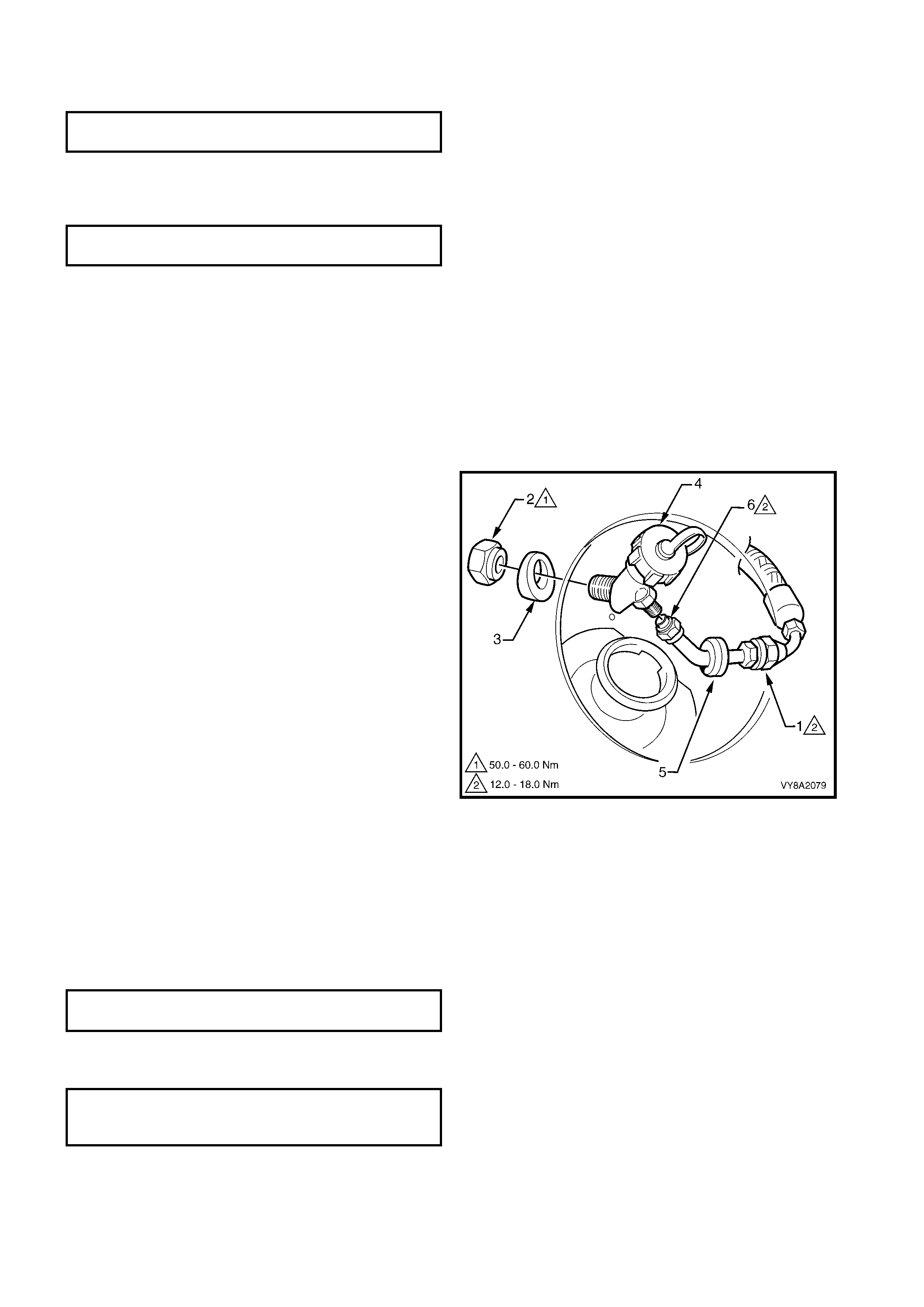
View A
Remove the valve box cover and leak test at and around the:
• Pressure relief valve (1)
• AFL to LPG tank (2)
• AFL inlet elbow to the AFL (3)
• Filler line to the AFL inlet elbow connection (4)
• Tank fuel gauge assembly (5)
• Manual service valve assembly to the LPG tank (6)
• Manual service valve assembly (7)
• Rear service line to the manual service valve assembly elbow connection (8)
View B
Open the fuel filler door and leak test at and around the:
• Filler valve check ball (9)
Wagon & Utility only:
• Leak test at and around the filler valve to filler line connecting pipe (10)
Sedan: Remove the right-hand quarter inner rear side carpet, refer to 2.17 QUART ER INNER REAR SIDE
CARPET in Section 1A8.
W agon: Rem ove the right-hand r ear wheelhouse liner, refer to 3.2 REAR WHEELHOUSE LINER in Section
1A1.
Utility: Remove the lower vent hose clamp at the flange and pull back the hose to expose the filler line
connection.
• Leak test at and around the filler line connecting pipe to the filler line (11)
View C
Raise the rear of the vehicle and support on safety stands, refer to Section 0A GENERAL INFORM ATION
for the location of jacking points. Leak test at around the:
Utility: Remove the connection protector plate, refer to 3.15 REAR SERVICE LINE.
• Rear service line to rear service line joiner or elbow (12)
• Rear service line joiner or elbow to intermediate service line (13)
View D
Leak test in the engine compartment at and around the:
• Intermediate service line to front service line joiner (14)
• Front service line joiner to front service line (15)

View E
Leak test in the engine compartment at and around the:
• Front service line to lock-off inlet connection (16)
• Lock-off inlet connection to lock-off valve (17)
• Lock-off valve to lock-off outlet connection (18)
• Lock-off outlet connection to converter (19)
• Lock-off valve assembly (20, 21, 22)
• Converter mounting faces (23
Sub-compartment
The sub compartment including the vent hoses are incorporated into the system so that in the event any
LPG es c apes from the tank f ittings, press ure r elief valve or the s ervic e line c onnection the LPG is allowed to
vent to the atm osphere and not into the passenger compartm ent of the vehicle. It is im perative that the sub
compartment and hoses are checked at regular intervals in accordance with AS 1425-1999.
A compartment or sub compartment shall be tested to ensure that it is gastight to the vehicle interior by
blowing tracer gas into the compartment or sub compartment and testing the surrounding atmosphere for
gas leak age with a c ombustible gas detec tor. Passages between the compar tment and the outs ide air s uch
as ventilation provisions or an access hatch or door of a permanently inbuilt compartment, shall be sealed
during testing.
If any leakage is detected, the leak shall be rectified and the leak test is to be repeated.
If any leaks are detec ted, at the com pletion of the leak tes t close the m anual service valve, s tart the engine and
run the engine until all the LPG in the service line is exhausted. W ith the engine stopped, switch to petrol and
start the engine. The vehicle can now be driven into the workshop and any leaks rectified by referring to the
appropriate service procedures in 3. SERVICE OPERATIONS.
NOTE: The vehicle cannot be operated on LPG in the workshop unless the workshop is a Specialist Gas
Workshop, refer to Australian Standard AS 2746-1985.
SEDAN
Figure 8A2-38

Legend
1. Pressure Relief Valve 12. Rear Service Line Joiner to Intermediate Service Line
2. Automatic Fill Limiter (AFL) to LPG Tank 13. Intermediate Service Line to Front Service Line Joiner
3. AFL Inlet Elbow to AFL 14. Front Service Line Joiner to Front Service Line
4. Filler Line to AFL Inlet Elbow 15. Front Service Line to Lock-off Inlet Connection
5. LPG Tank Fuel Gauge Assembly 16. Lock-off Inlet Connection to Lock-off Valve
6. Manual Service Valve to LPG Tank 17. Lock-off Valve to Lock-off Outlet Connection
7. Manual Service Valve Assembly 18. Lock-off Outlet Connection to Converter
8. Rear Service Line to Manual Service Valve 19. Lock-off Valve Assembly
9. Filler Valve Check Ball 20. Lock-off Valve Assembly
10. Not Applicable for Sedan 21. Lock-off Valve Assembly
11. Filler Line to Filler Valve 22. Converter Mounting Faces
WAGON
Figure 8A2-39

Legend
1. Pressure Relief Valve 13. Rear Service Line Elbow to Intermediate Service Line
2. Automatic Fill Limiter (AFL) to LPG Tank 14. Intermediate Service Line to Front Service Line Joiner
3. AFL Inlet Elbow to AFL 15. Front Service Line Joiner to Front Service Line
4. Filler Line to AFL Inlet Elbow 16. Front Service Line to Lock-off Inlet Connection
5. LPG Tank Fuel Gauge Assembly 17. Lock-off Inlet Connection to Lock-off Valve
6. Manual Service Valve to LPG Tank 18. Lock-off Valve to Lock-off Outlet Connection
7. Manual Service Valve Assembly 19. Lock-off Outlet Connection to Converter
8. Rear Service Line to Manual Service Valve 20. Lock-off Valve Assembly
9. Filler Valve Check Ball 21. Lock-off Valve Assembly
10. Filler Valve to Filler Line Connecting Pipe 22. Lock-off Valve Assembly
11. Filler Line Connecting Pipe to Filler Line 23. Converter Mounting Faces
12. Rear Service Line to Rear Service Line Elbow
UTILITY
Figure 8A2-40

Legend
1. Pressure Relief Valve 13. Rear Service Line Elbow to Intermediate Service Line
2. Automatic Fill Limiter (AFL) to LPG Tank 14. Intermediate Service Line to Front Service Line Joiner
3. AFL Inlet Elbow to AFL 15. Front Service Line Joiner to Front Service Line
4. Filler Line to AFL Inlet Elbow 16. Front Service Line to Lock-off Inlet Connection
5. LPG Tank Fuel Gauge Assembly 17. Lock-off Inlet Connection to Lock-Off Valve
6. Manual Service Valve to LPG Tank 18. Lock-off Valve to Lock-off Outlet Connection
7. Manual Service Valve Assembly 19. Lock-off Outlet Connection to Converter
8. Rear Service Line to Manual Service Valve 20. Lock-off Valve Assembly
9. Filler Valve Check Ball 21. Lock-off Valve Assembly
10. Filler Valve to Filler Line Connecting Pipe 22. Lock-off Valve Assembly
11. Filler Line Connecting Pipe to Filler Line 23. Converter Mounting Faces
12. Rear Service Line to Rear Service Line Elbow
3.4 FILLER VALVE & CONNECTOR PIPE
LT Section – AA-650R
SEDAN
REMOVE
CAUTION: Ensure that there are no naked flames or other sources of ignition in the vicinity.
1. Drain the service lines of LPG and note all cautions, refer to 3.1 SERVICE LINE DRAINING.
2. Remove the r ight-hand quar ter inner rear s ide carpet, ref er to 2.17 QUARTER INNER REAR SIDE CARPET
in Section 1A8.
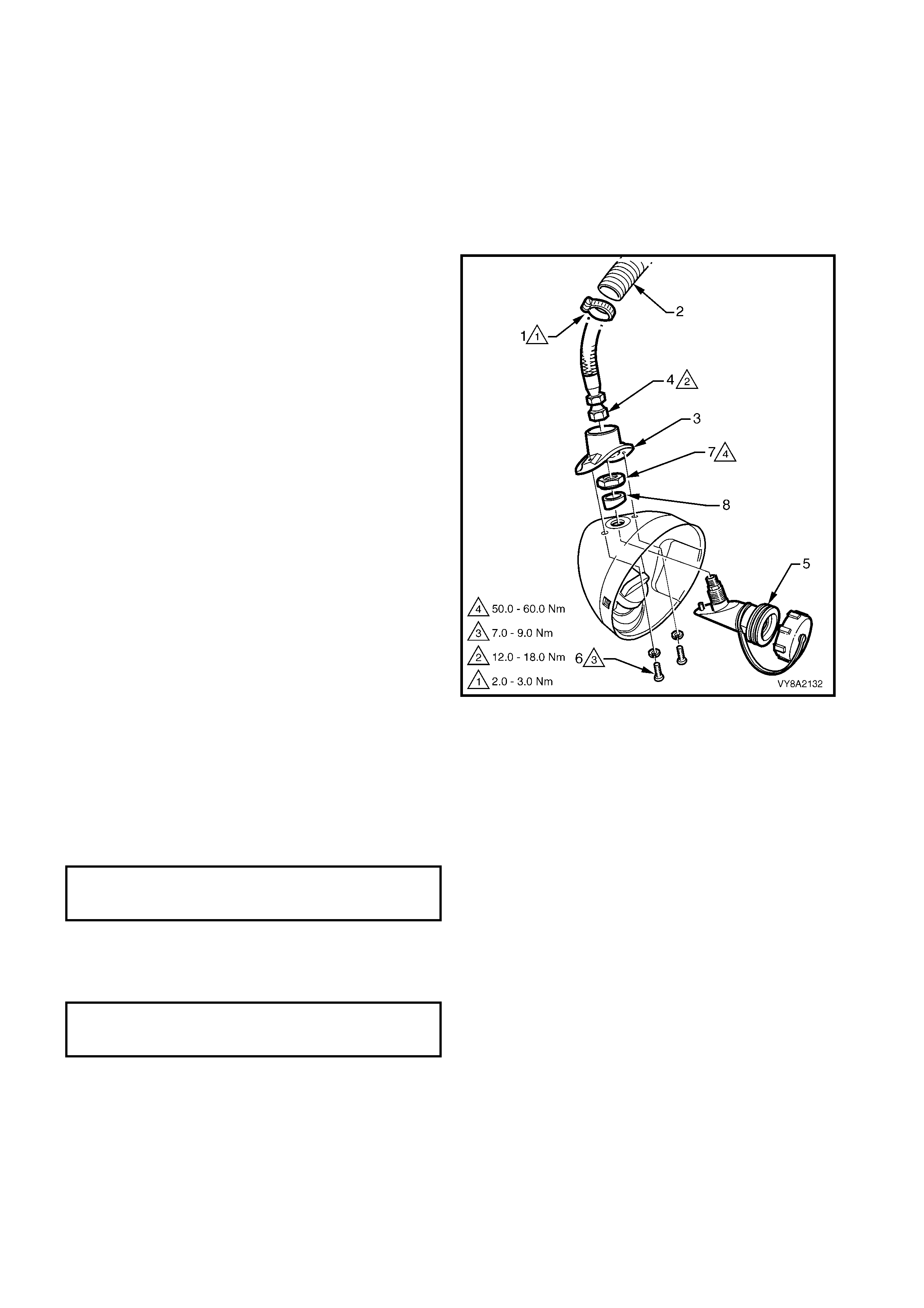
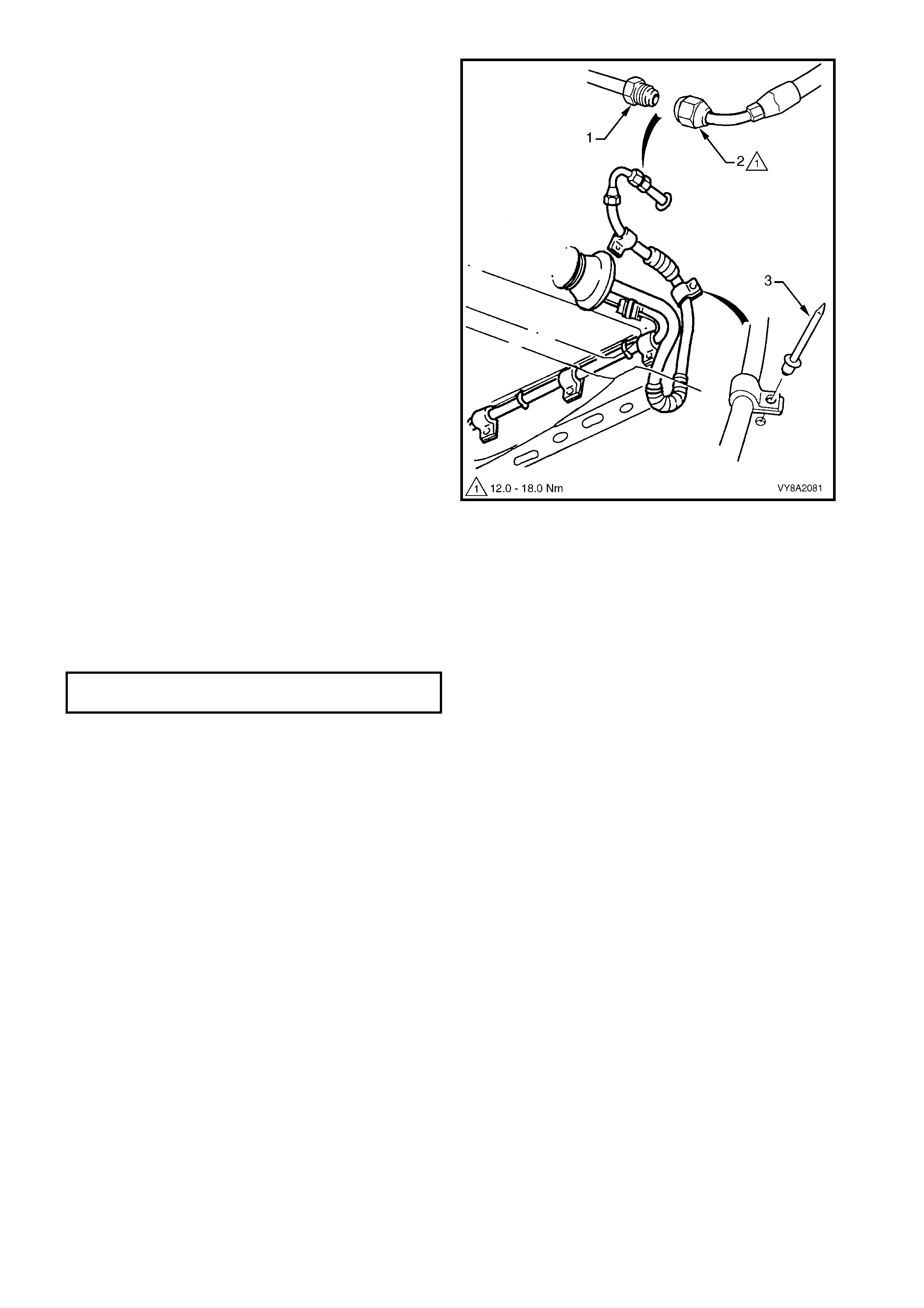
3. From within the rear c om partm ent, loosen the vent
tube clamp (1) and pull the vent tube (2) from the
filler valve flange (3).
4. Crack open the filler line connector (4) from the
filler valve (5) and allow any residual gas to
escape.
CAUTION: The filler line may contain LPG under
pressure.
5. Once the LPG in the line has dispersed, unscrew
the filler line connector completely and move the
filler line and vent tube away from the filler valve
flange.
6. Remove the two screws ( 6) and washers attac hing
the filler valve flange to the fuel filler housing.
7. Us ing a flat-blade screwdriver , prise the filler valve
flange from the fuel filler housing to break the
silicone sealer.
8. Remove the filler valve nut (7) and spacer (8) and
remove the filler valve.
Figure 8A2-41
REINSTALL
Installation if the filler valve is the reverse of the removal procedure, noting the following:
1. If new m ounting holes are r equired, use the tem plate supplied with the new part. Carefully drill the holes and
apply paint to any bare metal.
2. Clean the mating threads on the filler line and filler valve connector pipe.
3. Install the filler valve and tighten the retaining nut to the specified torque.
4. Apply silicone sealer to the mating surface of the filler valve flange.
5. Tighten the filler valve flange screws to the specified torque.
FILLER VALVE
RETAINING NUT
TORQUE SPECIFICATION 50.0 – 60.0 Nm
FILLER VALVE FLANGE
ATTACHING SCREW
TORQUE SPECIFICATION 7.0 – 9.0 Nm
6. Apply Loctite 577 sealant to the filler line and filler valve threads.
7. Tighten the filler line connector to the specified torque.
R
R
R
8. Leak test the LPG system, refer to 3.3 LEAK TESTING.
9. Reinstall the filler line vent tube and tighten the clamp to the specified torque.
WAGON
REMOVE
CAUTION: Ensure that there are no naked flames or other sources of ignition in the vicinity.
1. Drain the service lines of LPG and note all cautions, refer to 3.1 SERVICE LINE DRAINING.
2. Remove the right-hand quarter inner trim panel, refer to Section 1A8, 3.11 QUARTER INNER TRIM
PANEL.
3. Remove the right-hand rear wheelhouse liner, refer to Section 1A1, 3.2 REAR WHEELHOUSE LINER,
EXCEPT UTILITY.
4. From within the wheelhouse, crack open the filler
line connector ( 1) while holding the connector pipe
and allow residual LPG to escape.
CAUTION: The filler line may contain LPG under
pressure.
5. Once all the LPG in the line has dispersed,
unscrew the filler line connector completely.
6. From within the vehicle, remove the nut (2) and
spacer (3) retaining the filler valve (4).
7. Prise the grommet (5) from the filler pocket and
carefully manoeuvre the filler valve and connector
pipe into the fuel filler pocket and remove.
8. If required, disconnect the connector pipe (6) from
the filler valve.
Figure 8A2-42
REINSTALL
Installation if the filler valve and connector pipe is the reverse of the removal procedure, noting the following:
1. If new mounting holes are required, us e the tem plate supplied with the new part. Carefully drill the holes and
apply paint to any bare metal.
2. Clean the mating threads on the filler line, connector pipe and filler valve.
3. Apply Loctite 577 sealant to the filler line, connector pipe and filler valve threads.
4. Tighten the filler valve retaining nut to the specified torque.
5. Tighten the filler line connectors to the specified torque.
6. Leak test the LPG system, refer to 3.3 LEAK TESTING.
FILLER VALVE RETAINING NUT
TORQUE SPECIFICATION 50.0 – 60.0 Nm
CONNECTOR PIPE TO FILLER
LINE & FILLER VALVE
TORQUE SPECIFICATION 12.0 – 18.0 Nm
FILLER LINE TO FILLER VALVE
TORQUE SPECIFICATION 12.0 – 18.0 Nm
VENT TUBE HOSE CLAMP
TORQUE SPECIFICATION 2.0 – 3.0 Nm
UTILITY
REMOVE
CAUTION: Ensure that there are no naked flames
or other sources of ignition in the vicinity.
1. Drain the service lines of LPG and note all
cautions, refer to 3.1 SERVICE LINE DRAINING.
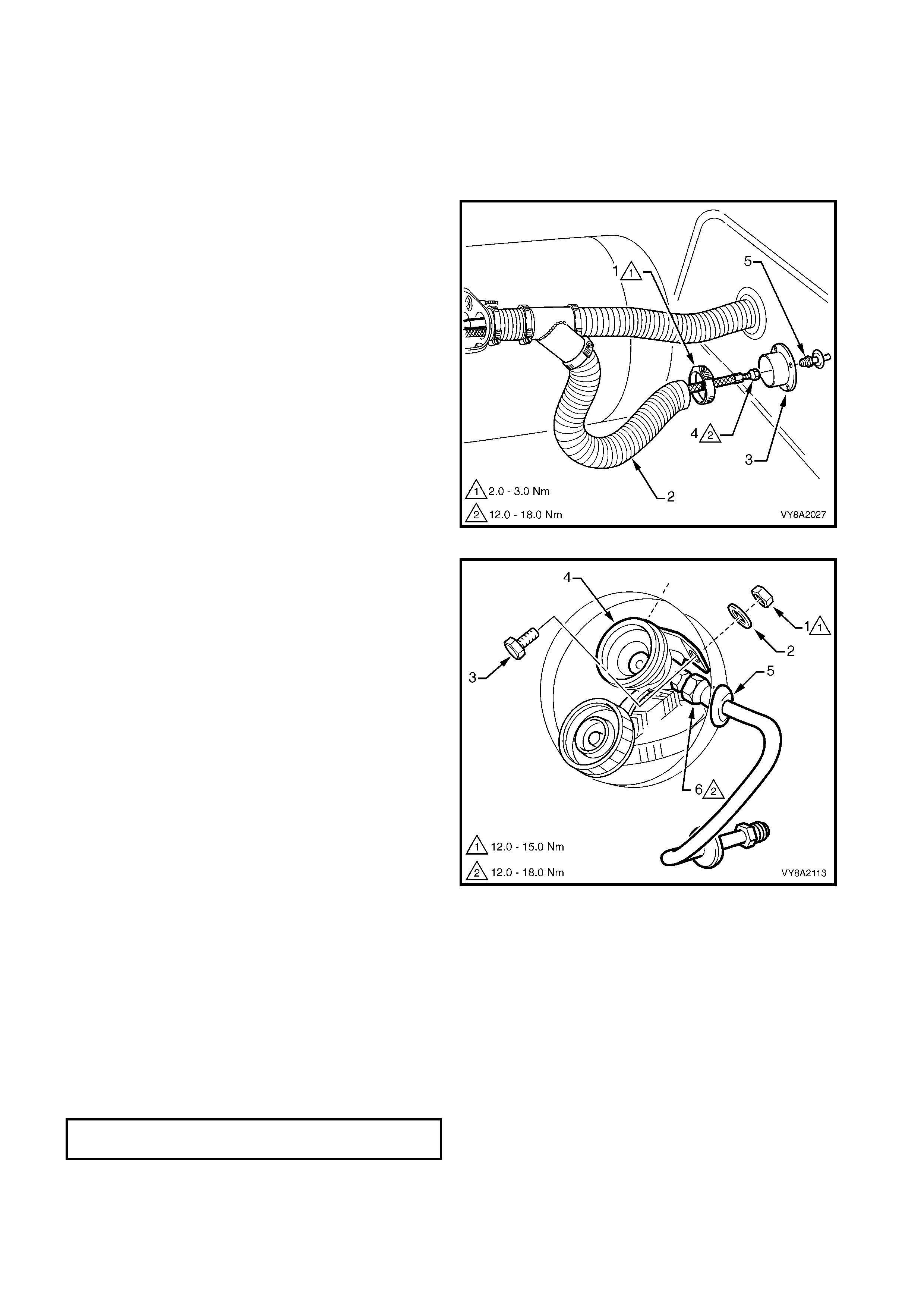
2. Loosen the hose clamp (1) securing the filler line
vent tube (2) to the vent tube flange (3).
3. Crack open the filler line connector (4) while
holding the connector pipe (5) and allow residual
LPG to escape.
CAUTION: The filler line may contain LPG under
pressure.
4. Once all the LPG in the line has dispersed,
unscrew the filler line connector completely.
5. Remove the inner side panel front cover, refer to
Section 1B, 2.8 INNER SIDE PANEL FRONT
COVER.
NOTE: A right-angle screwdriver may be required to
access the front screws.
6. Remove the fuel filler door and the fuel filler pipe
seal retainer, refer to Section 1A1, 4.3 FUEL
FILLER DOOR ASSEMBLY, UTILITY.
Figure 8A2-43
7. From within the vehicle, remove the nut (1) and
washer (2) while an assistant holds the screw (3),
two places, retaining the filler valve (4).
9. As required, fold the fuel filler pipe seal out of the
way and prise the grommet (5) from the filler
pocket.
10. Carefully manoeuvre the filler valve and connector
pipe into the fuel filler pocket and remove.
8. If required, disconnect the connector pipe (6) from
the filler valve.
Figure 8A2-44
REINSTALL
Installation of the filler valve and connector pipe is the reverse of the removal procedure, noting the following:
1. If new m ounting holes are r equired, use the tem plate supplied with the new part. Carefully drill the holes and
apply paint to any bare metal
2. If the filler pocket has been replaced and new mounting holes are required, use the template provided with
the new filler valve assembly. Drill holes as required and coat any bare metal with primer.
3. Clean the mating threads on the filler line, connector pipe and filler valve.
4. Apply Loctite 577 sealant to the filler line, connector pipe and filler valve threads.
5. Tighten the filler valve retaining nut to the specified torque.
FILLER VALVE RETAINING NUT
TORQUE SPECIFICATION 12.0 – 15.0 Nm

6. Tighten the filler line connectors to the specified torque.
7. Leak test the LPG system, refer to 3.3 LEAK TESTING.
8. Reinstall the filler line vent tube and tighten the clamp to the specified torque.
CONNECTOR PIPE TO FILLER
VALVE & FILLER LINE
TORQUE SPECIFICATION 12.0 – 18.0 Nm
VENT TUBE HOSE CLAMP
TORQUE SPECIFICATION 2.0 – 3.0 Nm
3.5 FILLER LINE
LT Section – AA-650R
SEDAN
REMOVE
CAUTION: Ensure that there are no naked flames
or other sources of ignition in the vicinity.
1. Drain the service lines of LPG and note all
cautions, refer to 3.1 SERVICE LINE DRAINING.
2. From within the LPG valve box, crack open the
filler line to AFL elbow connector (1) while holding
the AFL elbow and allow residual LPG to escape.
CAUTION: The filler line will contain LPG under
pressure.
3. Once all the LPG in the line has dispersed,
unscrew the filler line connector completely from
the AFL elbow.
4. Disconnect the filler line from the AFL elbow
connector.
5. Remove the right-hand quarter inner rear side
carpet, refer to 2.17 QUARTER INNER REAR
SIDE CARPET in Section 1A8.
Figure 8A2-45
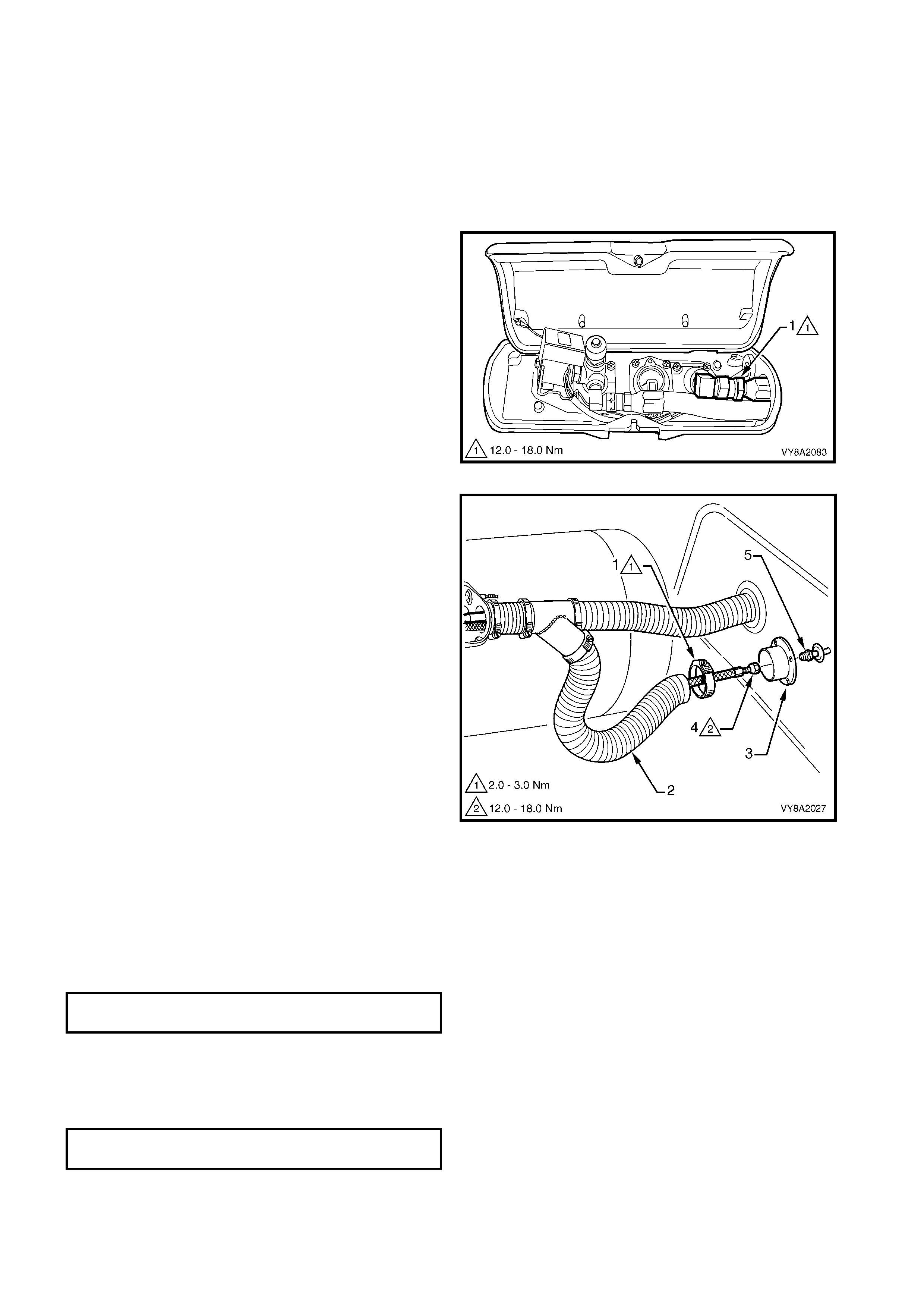
6. From within the rear c om partm ent, loosen the vent
tube clamp (1) and pull the vent tube (2) from the
filler valve flange (3).
7. Unscrew the filler line connector (4) from the filler
valve flange.
Figure 8A2-46
8. Loosen the vent tube clamp (1) and pull the vent
tube (2) from the vent tube joiner (3).
9. Withdraw the filler line through the vent tube and
remove.
Figure 8A2-47
REINSTALL
Reinstallation of the filler line is the reverse of the removal procedure, noting the following:
1. Clean the mating threads on the LPG tank AFL elbow, filler line and filler valve connector pipe.
2. Apply Loctite 577 sealant to the LPG tank AFL elbow and filler pipe connector threads, ensuring that the
flared surfaces are free of sealant and contaminants.
3. Tighten the filler line connections to the specified torque.
4. Leak test the LPG system, refer to 3.3 LEAK TESTING.
5. Reinstall the filler line vent tube and tighten the clamp to the specified torque.
6. Reinstall the LPG tank box cover.
WAGON
REMOVE
CAUTION: Ensure that there are no naked flames
or other sources of ignition in the vicinity.
1. Drain the service lines of LPG and note all
cautions, refer to 3.1 SERVICE LINE DRAINING.
2. De-pressurise the fuel (petrol) system, refer to
Section 6C1 POWERTRAIN MANAGEMENT.
3. Remove the fuel (petrol) tank assembly, refer to
Section 8A FUEL TANK.
4. From within the LPG tank valve box, crack open
the filler line hose to AFL elbow connector (1) while
holding the AFL elbow (2) and allow residual LPG
to escape.
CAUTION: The filler line will contain LPG under
pressure.
5. Once all the LPG in the line has dispersed, remove
the filler line hose connector completely from the
AFL elbow.
Figure 8A2-48
FILLER LINE CONNECTORS
TORQUE SPECIFICATION 12.0 – 18.0 Nm
VENT TUBE HOSE CLAMP
TORQUE SPECIFICATION 2.0 – 3.0 Nm
6. From underneath the vehicle, while holding the
filler valve connecting pipe (1) from turning,
disconnect the filler line hose (2).
7. Us ing a suitable sized drill bit, drill into the head of
the two filler line hose retaining rivets (3) and
remove the filler line hose.
8. Using a suitable size pin-punch and hammer,
knock out remains of the rivets.
Figure 8A2-49
REINSTALL
Reinstallation of the filler line is the reverse of removal, noting the following:
1. Clean the mating threads of the LPG tank AFL elbow, filler line, and filler valve connecting pipe.
2. Apply Loctite 577 sealant to the LPG tank AFL elbow and filler pipe connector threads, ensuring that the
flared surfaces are free of sealant and contaminants.
3. Tighten the filler line connections to the specified torque.
4. Secure the filler line hose using a new rivets, before the fuel (petrol) tank is reinstalled.
5. Before starting the vehicle or opening the manual service valve, perform a fuel (petrol) system leak test,
refer to Section 6C1 POWERTRAIN MANAGEMENT - V6 ENGINE.
6. Leak test LPG system, refer to 3.3 LEAK TESTING.
7. Reinstall the LPG tank valve box cover.
FILLER LINE CONNECTORS
TORQUE SPECIFICATION 12.0 – 18.0 Nm
UTILITY
REMOVE
CAUTION: Ensure that there are no naked flames
or other sources of ignition in the vicinity.
1. Drain the service lines of LPG and note all
cautions, refer to 3.1 SERVICE LINE DRAINING.
2. Remove the LPG tank cover, refer to
3.6 LPG TANK, UTILITY.
3. From within the LPG valve box, crack open the
filler line to AFL elbow connector (1) while holding
AFL elbow and allow residual LPG to escape.
CAUTION: The filler line will contain LPG under
pressure.
4. Once all the LPG in the line has dispersed, remove
the filler line connector completely from the AFL
elbow.
Figure 8A2-50
4. Loosen the hose clamp (1) securing the filler line
vent tube (2) to the vent tube flange (3).
5. Disconnect the filler line (4) from the filler pipe (5)
and remove the LPG filler line from within vent
tube.
Figure 8A2-51
REINSTALL
Reinstallation if the filler line is the reverse of the removal procedure, noting the following:
1. Clean the mating threads of the LPG tank AFL elbow, filler line and filler valve connecting pipe.
2. Apply Loctite 577 sealant to the LPG tank AFL elbow and filler pipe connector threads, ensuring that the
flared surfaces are free of sealant and contaminants.
3. Tighten the filler line connections to the specified torque.
4. Leak test the LPG system, refer to 3.3 LEAK TESTING.
5. Apply a commercially available silicone sealer to the vent tube mating surfaces.
6. Tighten the vent tube clamps to the specified torque.
7. Reinstall the LPG tank box cover.
FILLER LINE CONNECTOR
TORQUE SPECIFICATION 12.0 – 18.0 Nm
VENT TUBE HOSE CLAMP
TORQUE SPECIFICATION 2.0 – 3.0 Nm
3.6 LPG TANK
LT Section – AA-650Q
SEDAN
REMOVE
CAUTION 1: After any valve or component has
been removed and reinstalled to the LPG tank, the
LPG tank must be pressure and leak tested in
accordance with current Australian Standard
AS 2030-1 and / or the laws of the State in which
the vehicle is registered, before the LPG tank is
refitted to the vehicle.
CAUT ION 2: Ensure th at there are no naked flames
or other sources of ignition in the vicinity.
1. Drain the service lines of LPG and note all
cautions, refer to 3.1 SERVICE LINE DRAINING.
2. Unload the LPG tank of LPG, refer to
3.2 LPG TANK UNLOADING.
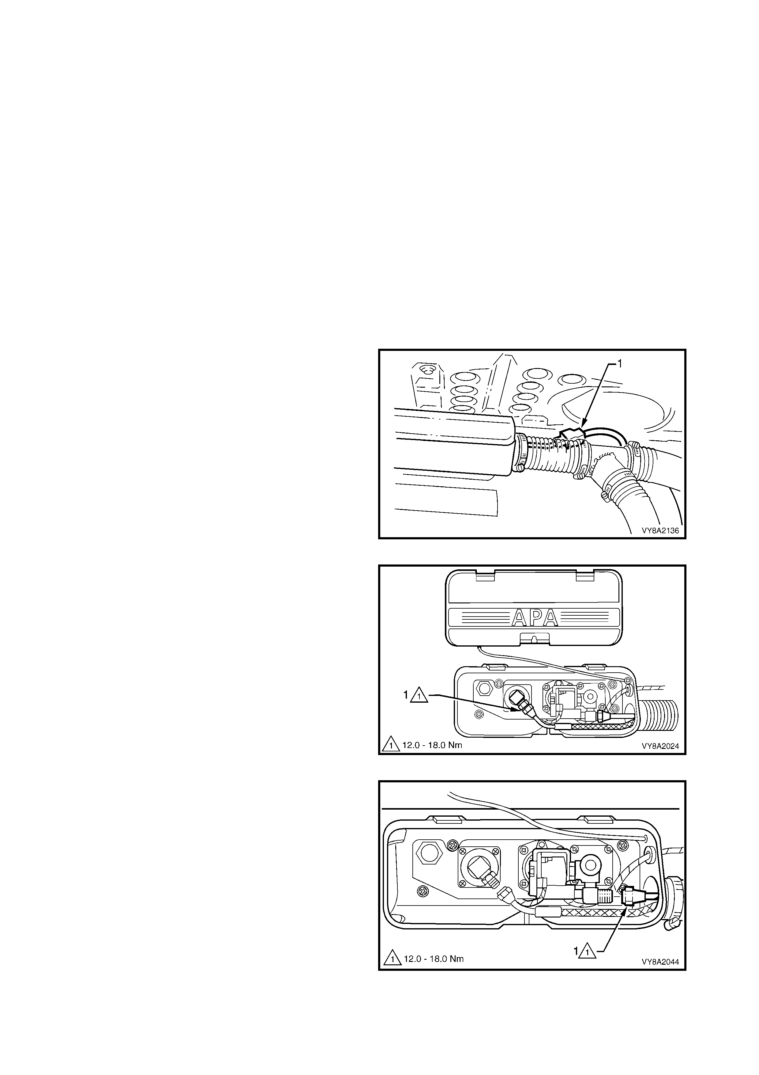
3. Disconnect the LPG body harness connector (1)
from the LPG tank harness connector.
Figure 8A2-52
4. From within the LPG valve box, crack open the
filler line to AFL elbow connector (1) while holding
the AFL elbow and allow residual LPG to escape.
CAUTION: The filler line will contain LPG under
pressure.
5. Once all the LPG in the line has dispersed, remove
the filler line connector completely from the AFL
elbow.
Figure 8A2-53
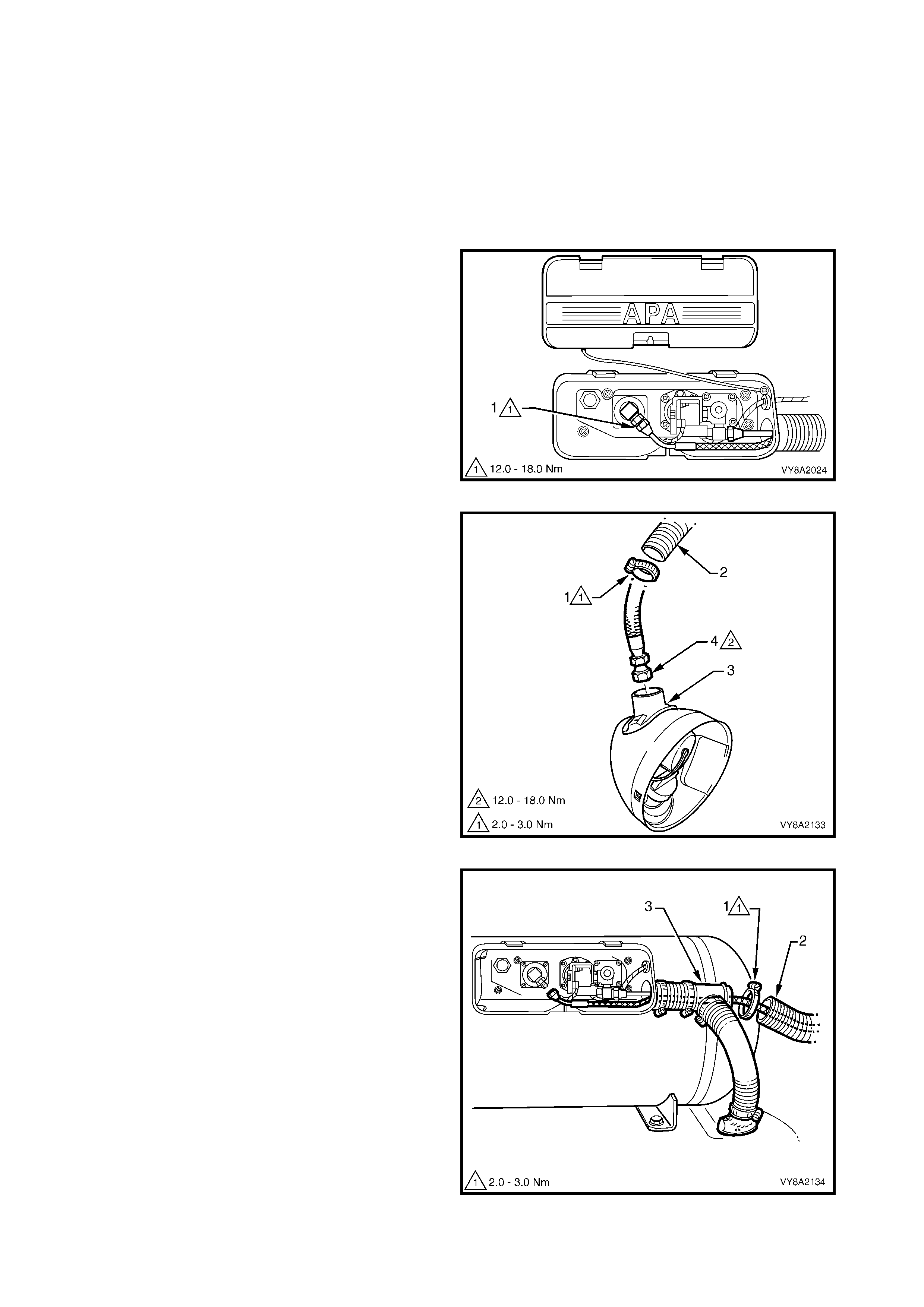
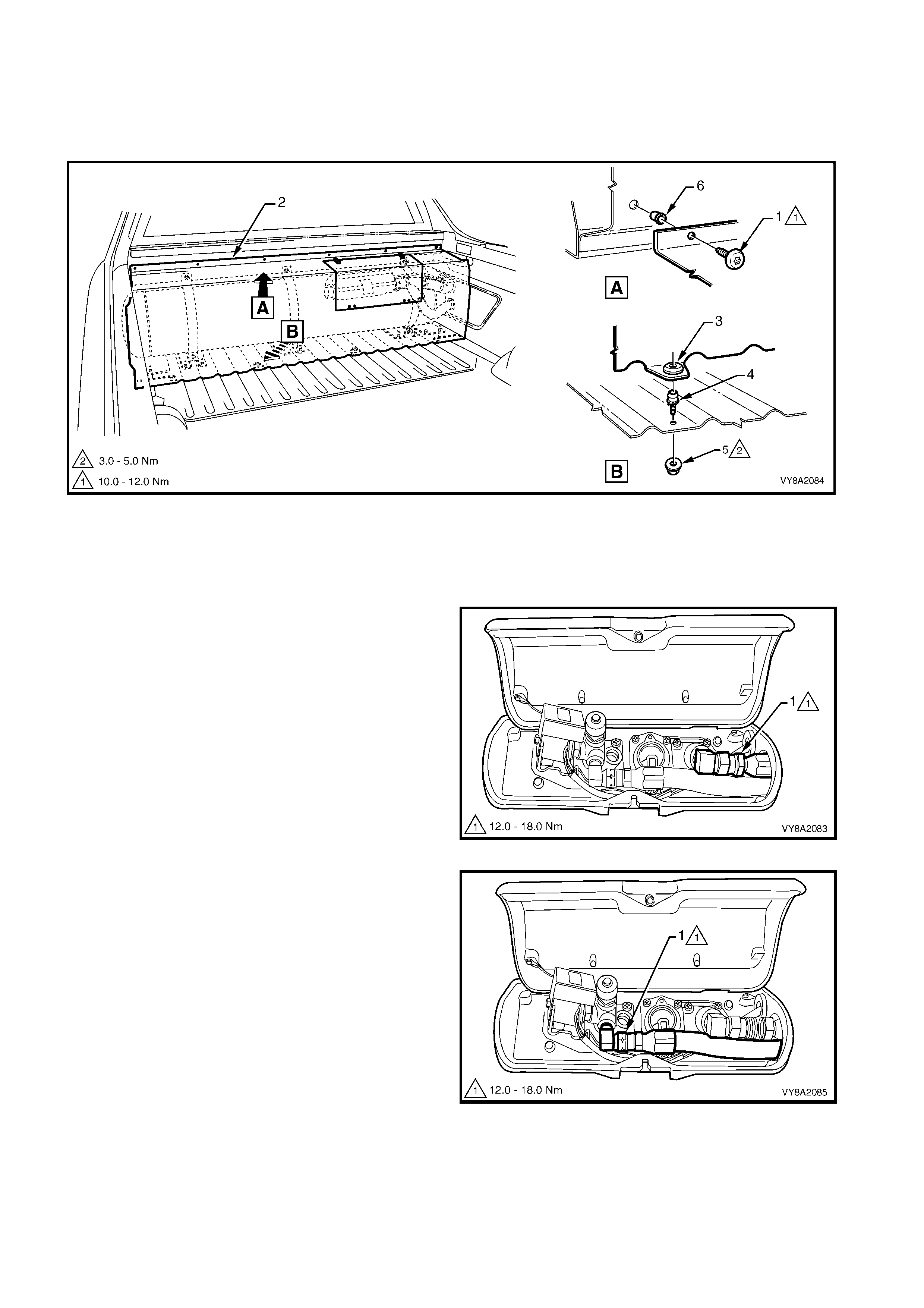
11. From within the LPG tank valve box, unscrew the
rear service line connector (1) from the manual
service valve assembly.
Figure 8A2-54
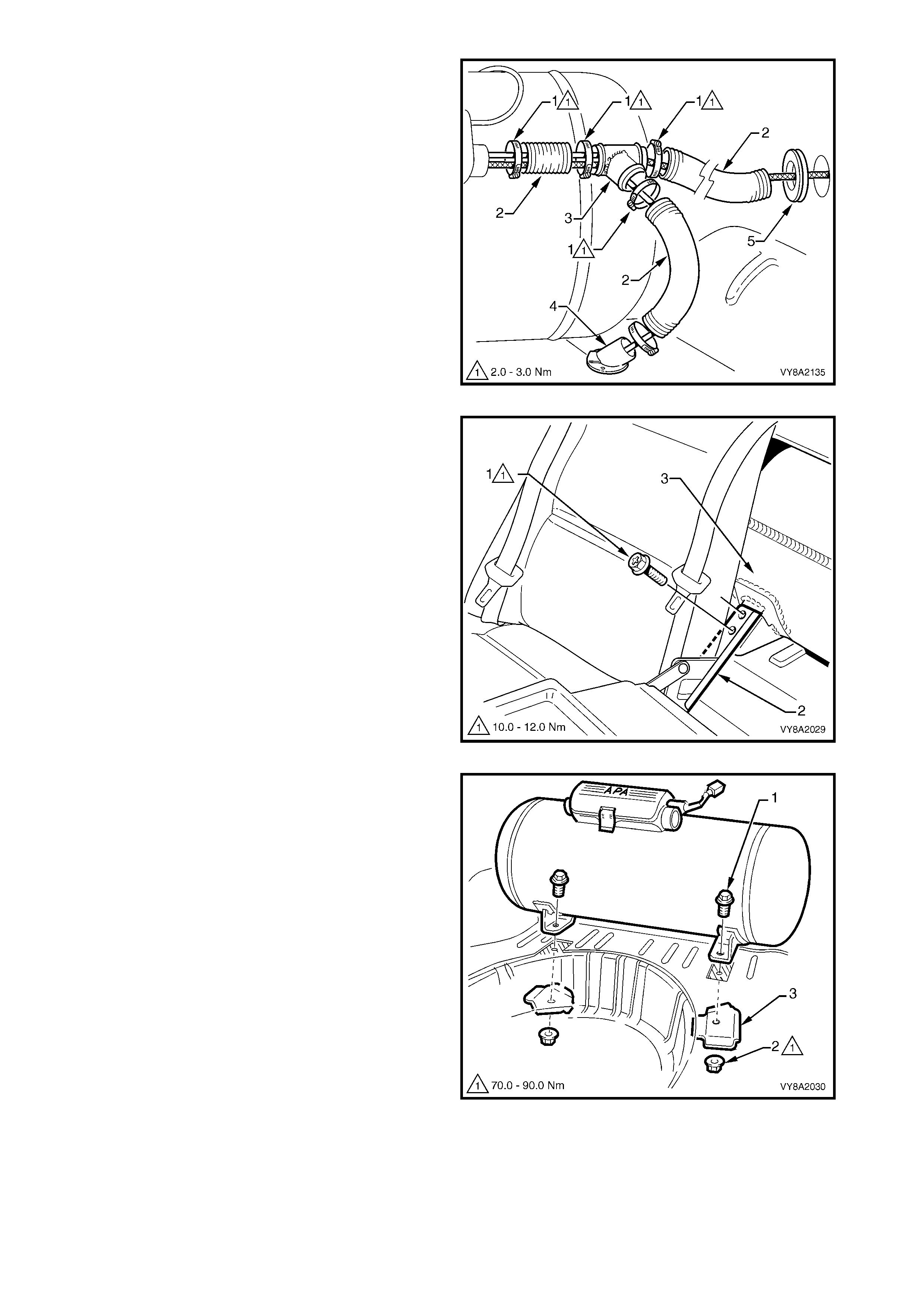
12. As required, rem ove the hose clamps (1) securing
the vent tubes ( 2) to the valve box , vent tube j oiner
(3) or floor flange (4).
13. W ithdr aw the filler and se rvice lines fr om the valve
box.
14. If required withdraw the vent tube from the
grommet (5) and remove.
Figure 8A2-55
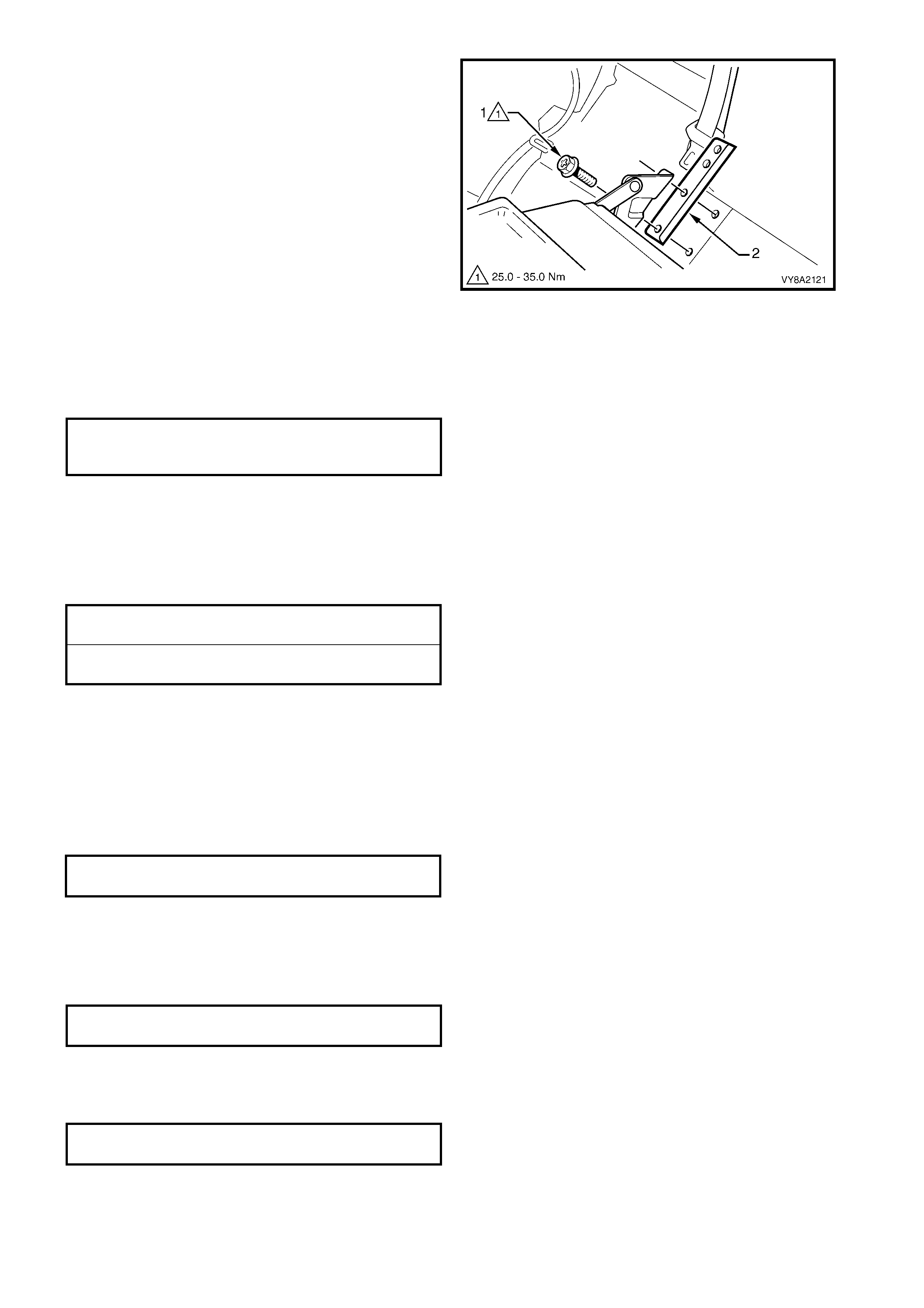
15. Open the rear seat centre back and remove the
top two retaining screws (1) from the LPG tank
retaining bracket (2) on each side of the vehicle.
Figure 8A2-56
16. Fold the rear compartment carpet away from the
LPG tank rear mounting points.
17. With the aid of an assistant to hold the LPG tank
retaining scr ew (1), rem ove the LPG tank retaining
nut (2) and reinforcement plate (3) from beneath
the each side of the vehicle.
18. With help f r om the assis tant, remove the LPG tank
from the rear compartment.
Figure 8A2-57
19. If required, remove the LPG tank retaining bracket:
a. Remove the rear seat back assembly, refer to
Section 1A7, 6.3 REAR SEAT-BACK
ASSEMBLY.
b. Remove the two retaining screws (1) attaching
the rear seat back centre hinge and the LPG
tank retaining bracket (2) to the vehicle and
remove the bracket from behind the hinge.
c. Repeat for the opposite side if required.
Figure 8A2-58
REINSTALL
Installation of the LPG tank is the reverse of the removal procedure, noting the following:
1. If removed, install the front tank mounting brackets and rear seat-back hinges. Tighten the screws to the
specified torque.
2. If the floor panel, etc. has been replaced and new mounting holes are required, seat the tank to the front
mounting brackets and use the tank as a template. Drill holes as required and coat any bare metal with
primer.
3. Ensure the two LPG tank reinforcement plates are installed and all fasteners are tightened to the correct
specified torque.
4. Clean the mating threads on the manual service valve assembly, intermediate to rear service line joiner,
both rear service line connectors, AFL valve and filler line connector.
5. Apply Loctite 577 sealant to the intermediate to rear service line joiner threads, ensuring that the flared
surfaces are free of sealant and contaminants.
6. Assemble the rear service connector to intermediate to rear service line joiner and to the manual service
valve assembly.
7. Tighten both rear service line connectors to the specified torque.
8. Apply Loctite 577 sealant to the LPG tank AFL elbow threads, ensuring that flared surfaces are free of
sealant and contaminants.
9. Install the filler line c onnector to the LPG tank AF L elbow and tighten the filler line c onnector to the s pecif ied
torque.
10. Leak test the LPG system, refer to 3.3 LEAK TESTING.
11. Reinstall the vent tube(s) as required and tighten the clamp(s) to the specified torque.
12. Reinstall the LPG tank box cover
FRO NT LPG TANK R ETAINING
SCREW TORQUE SPECIFICATION 10.0 – 12.0 Nm
REAR LPG TANK RETAINING NUT
TORQUE SPECIFICATION 70.0 – 90.0 Nm
REAR SERVICE LINE CONNECTOR
TORQUE SPECIFICATION 12.0 – 18.0 Nm
FILLER LINE CONNECTOR TO AFL
ELBOW TORQUE SPECIFICATION 12.0 – 18.0 Nm
FRONT LPG TANK MOUNTING
BRACKET RETAINING SCREW
TORQUE SPECIFICATION 25.0 – 35.0 Nm
VENT TUBE HOSE CLAMP
TORQUE SPECIFICATION 2.0 – 3.0 Nm
WAGON
REMOVE
CAUTION 1: After any valve or component has
been removed and reinstalled to the LPG tank, the
LPG tank must be pressure and leak tested in
accordance with current Australian Standard
AS 2030-1 and / or the laws of the State in which
the vehicle is registered, before the LPG tank is
refitted to the vehicle.
CAUT ION 2: Ensure th at there are no naked flames
or other sources of ignition in the vicinity.
1. Remove the rear compartment floor carpet, refer
to Section 1A8, 3.21 REAR COMPARTMENT
FLOOR CARPET ASSEMBLY AND SPARE
WHEEL COVER, WITH LPG.
2. Drain the service lines of LPG and note all
cautions, refer to 3.1 SERVICE LINE DRAINING.
3. Unload the LPG tank of LPG, refer to
3.2 LPG TANK UNLOADING.
NOTE: The service line will be disconnected at this
step.
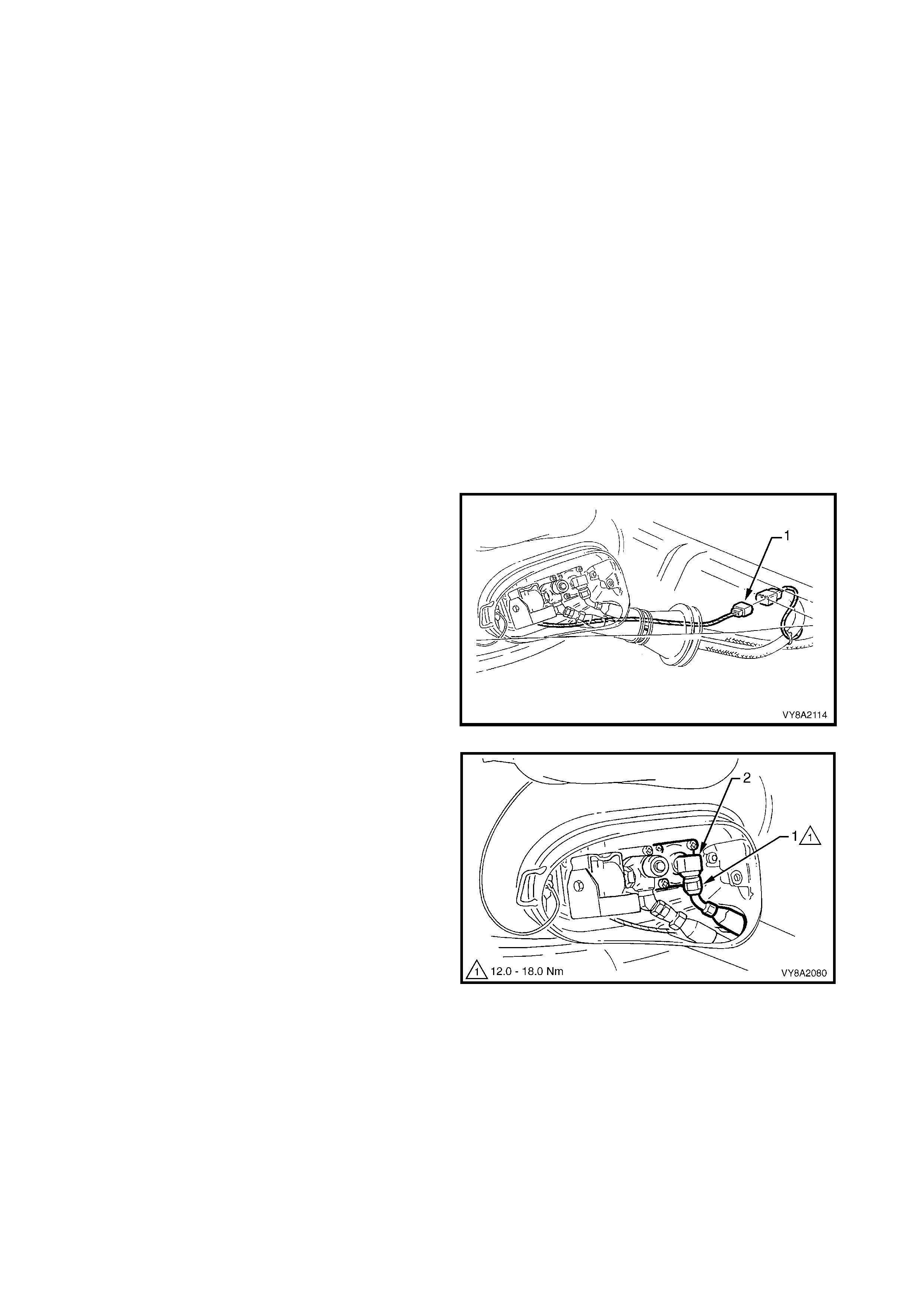
4. Disconnect the LPG tank harness wiring connector
(1) from underneath the vehicle.
Figure 8A2-59
5. From within the LPG valve box, crack open the
filler line to AFL elbow connector (1) while holding
the AFL elbow and allow residual LPG to escape.
CAUTION: The filler line will contain LPG under
pressure.
6. Once all the LPG in the line has dispersed, remove
the filler line connector completely from the AFL
elbow.
Figure 8A2-60
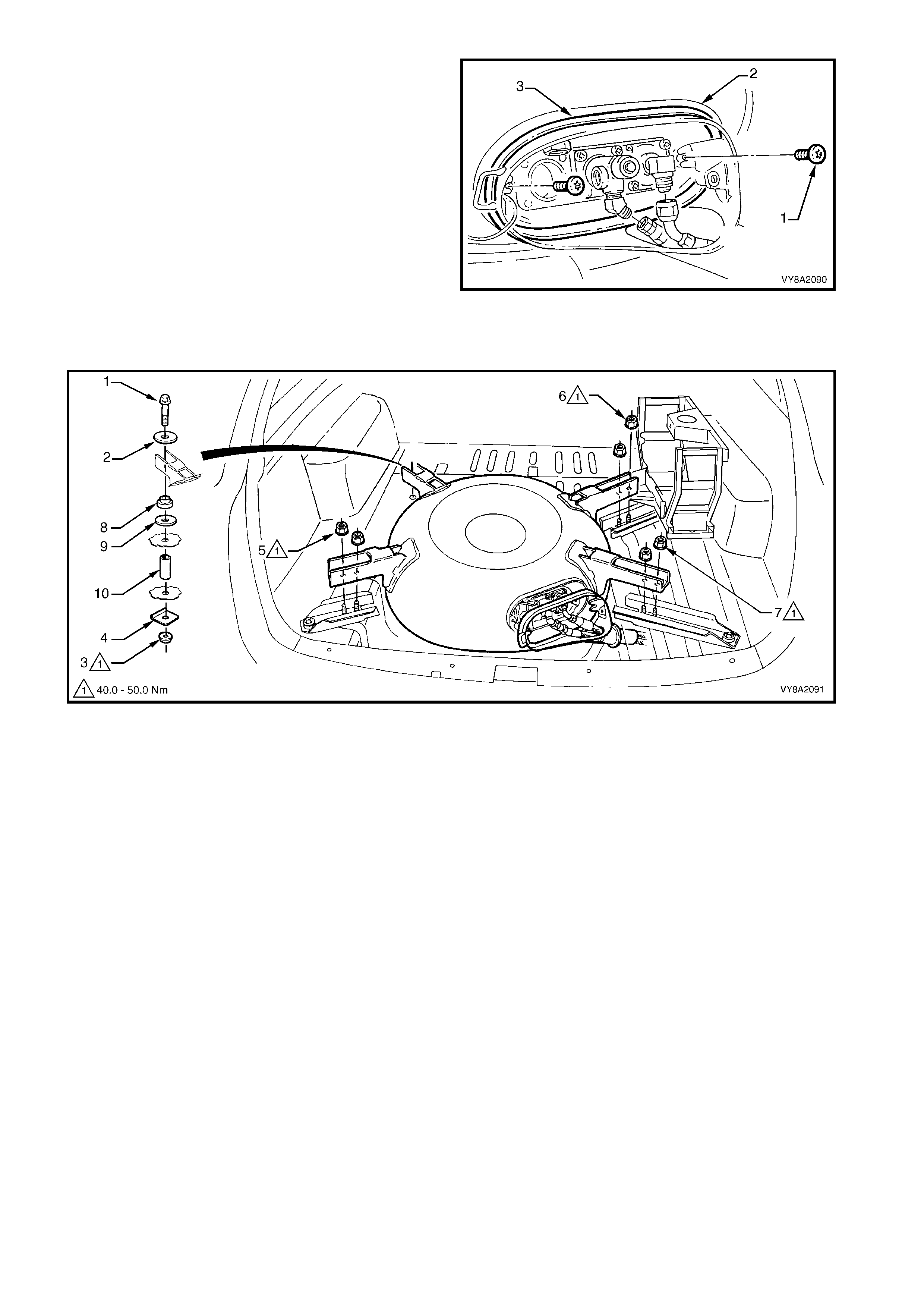
7. Remove the Torx screw (1), two places, attaching
the valve box flange (2) to the LPG tank.
8. Pull the valve box flange and seal (3) away from
the LPG tank so that there is sufficient clearance
to remove the LPG tank.
9. With the aid of an assistant, remove the left-hand
front LPG tank retaining bolt (1), washer (2) and
from underneath the vehicle the nut (3) and plate
(4), refer to Figure 8A2-62.
10. Loosen and remove the two lock-nuts, (5, 6 & 7),
three places, attaching the LPG tank to the LPG
tank brackets.
11. With the aid of an assistant, lift the LPG tank up
and remove from the vehicle.
12. Remove the isolator (8) and washer (9) and if
required the spacer (10).
Figure 8A2-61
Figure 8A2-62
13. As required, with the aid of an ass istant remove the nut, ( 1), plate (2), bolt (3) and washer (4) attaching the
LPG tank mounting brackets (A, B &/or C), refer to Figure 8A2-63.
NOTE: The mounting bracket (A) and its washer (A-4) are seated under the spare wheel carrier (5).
14. Once the bracket(s) are removed, remove the isolator (6), washer (7) and spacer (8) from the floor box-
section.
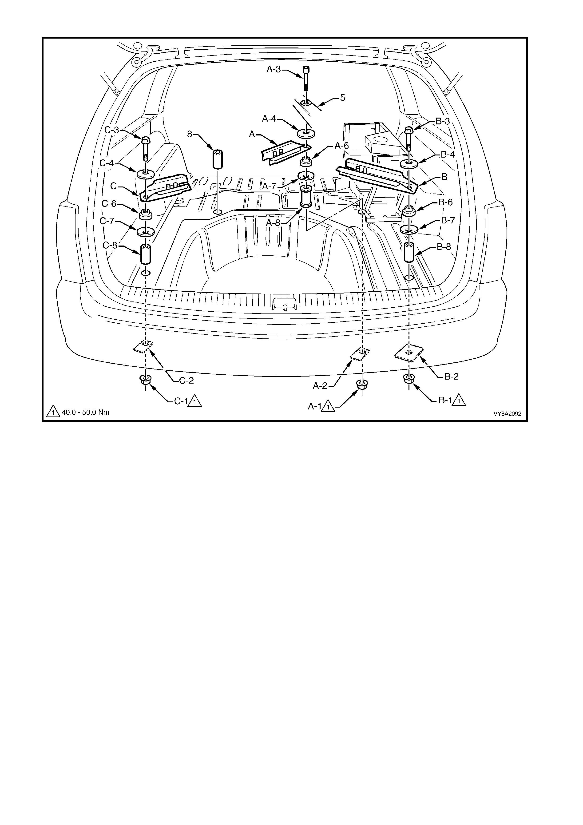
Figure 8A2-63
Legend
A. Right-hand Front LPG Tank Mounting Bracket 4. Washer
B. Right-hand Rear LPG Tank Mounting Bracket 5. Spare Wheel Carrier
C. Left-hand Rear LPG Tank Mounting Bracket 6. Isolator
1. Nut 7. Washer
2. Reinforcement Plate 8. Spacer
3. Bolt
REINSTALL
1. If the floor panel, etc . has been replac ed and new mounting holes are required, align the tank assem bly with
the spare wheel carrier at position A, refer to Figure 8A2-63, seat the tank centrally within the spare wheel-
well, use the tank as a template and ens ure the holes are central within the floor ribs. Drill holes as required
and coat any bare metal with primer.
• Position B, C and D – 12 mm hole through the floor panel and rear chassis rail followed by a 17 mm hole
in the floor panel only.
NOTE: For drilling details of position A and the spare wheel carrier refer to 3.25 SPARE WHEEL CARRIER.
2. If the mounting brackets have been removed, install them as required, referring to Figure 8A2-63. Hand
tighten the nuts at this stage.
3. If required, install the spacer for the left-hand front mount.
4. With the aid of an assistant, place the tank onto the LPG tank bracket studs, six places. Hand tighten the
nuts.
5. W ith the aid of an as sistant, install the lef t-hand f ront retaining bolt, and nut, ens uring the spac ers, is olators,
washers and reinforcement plates are installed correctly, refer to Figure 8A2-62.
6. While holding the retaining bolt, tighten all of the retaining nuts to the specified torque.
7. Install the valve box f lange, ensuring the valve box seal is s eated corr ectly. Tighten the two valve box flange
retaining screws to the specified torque.
8. Clean the mating threads on the manual service valve assembly, intermediate to rear service line joiner,
both rear service line connectors, AFL valve and filler line connector.
9. Apply Loctite 577 sealant to the intermediate to rear service line joiner threads, ensuring that the flared
surfaces are free of sealant and contaminants.
10. Assemble the rear service connectors to the intermediate service line joiner and the manual service valve
assembly.
11. Tighten both rear service line connectors to the specified torque.
12. Apply Loctite 577 sealant to the LPG tank AFL elbow threads, ensuring that flared surfaces are free of
sealant and contaminants.
13. Install the f iller line c onnector to the LPG tank AF L elbow and tighten the filler line c onnector to the s pecif ied
torque.
14. Leak test the LPG system, refer to 3.3 LEAK TESTING.
15. Reinstall the valve box cover.
16. Reinstall the luggage com par tm ent floor c over, ref er to Sect ion 1A8, 3.21 REAR COM PAR TM ENT FL OOR
COMPARTMENT ASSEMBLY & SPARE WHEEL COVER, WITH LPG.
UTILITY
REMOVE
CAUTION 1: After any valve or component has been removed and reinstalled to the LPG tank, the LPG
tank must b e pressure and leak test ed in accordance w ith curren t Au stralian Standard AS 2030-1 befo re
the LPG tank is refitted to the vehicl e.
CAUTION 2: Ensure that there are no naked flames or other sources of ignition in the vicinity.
LPG TANK RETAINING NUT
TORQUE SPECIFICATION 40.0 – 50.0 Nm
VALVE BOX ATTACHING SCREW
TORQUE SPECIFICATION 7.0 Nm
REAR SERVICE LINE CONNECTOR
TORQUE SPECIFICATION 12.0 – 18.0 Nm
FILLER LINE CONNECTOR
TO AFL ELBOW
TORQUE SPECIFICATION 12.0 – 18.0 Nm
1. Rem ove the Tor x sc rew (1), six places, attac hing the LPG tank c over (2) to the vehic le. Pull back the upper
edge of the tank cover slightly, refer to Figure 8A2-64.
2. Lift the tank cover upwards until the lower inner retainer grommet (3) disengages from ball stud (4) at four
places.
3. Remove the cover.
Figure 8A2-64
4. Drain the service lines of LPG and note all
cautions, refer to 3.1 SERVICE LINE DRAINING.
5. Unload the LPG tank of LPG, refer to
3.2 LPG TANK UNLOADING.
6. From within the LPG valve box, while holding the
AFL elbow, crack open the filler line to AFL elbow
connector (1) and allow residual LPG to escape.
CAUTION: The filler line will contain LPG under
pressure.
7. Once all the LPG in the line has dispersed, remove
the filler line connector completely from the AFL
elbow.
Figure 8A2-65
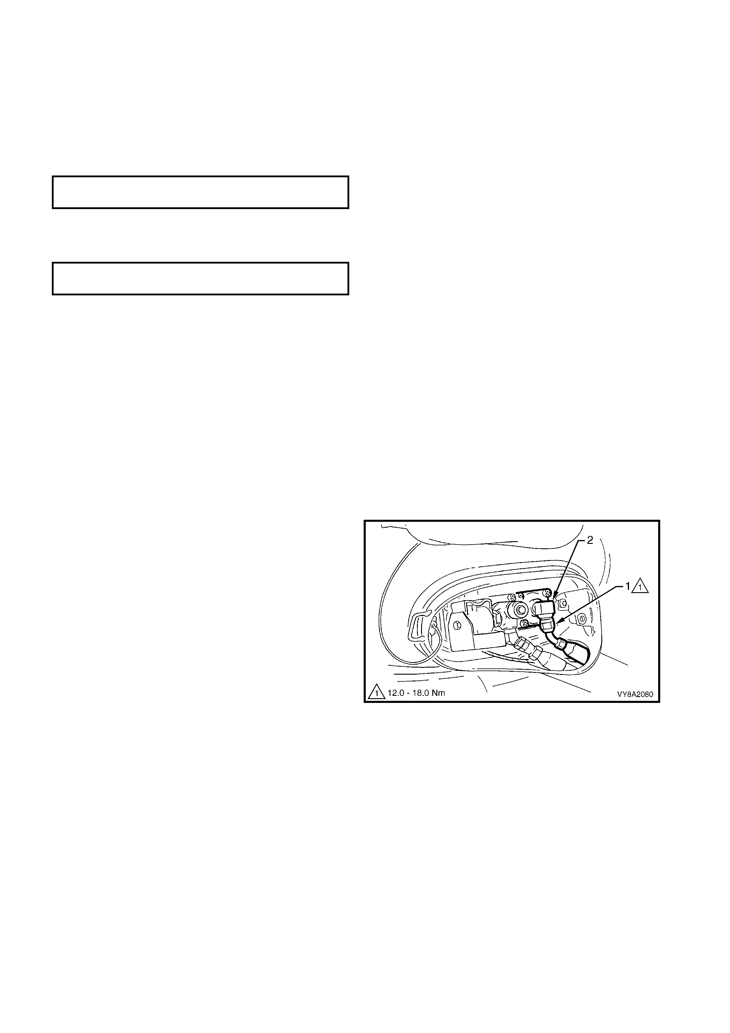
8. From within the LPG valve box, disconnect the
service line connector (1) from the manual service
valve elbow.
Figure 8A2-66
9. Rem ove the hos e clam p (1) securing the vent tube
(2) to the tank valve box.
10. Withdraw the LPG service (3) and filler lines (4)
from the valve box.
11. Disconnect the LPG tank harness connector (5)
from the LPG body wiring harness connector.
Figure 8A2-67
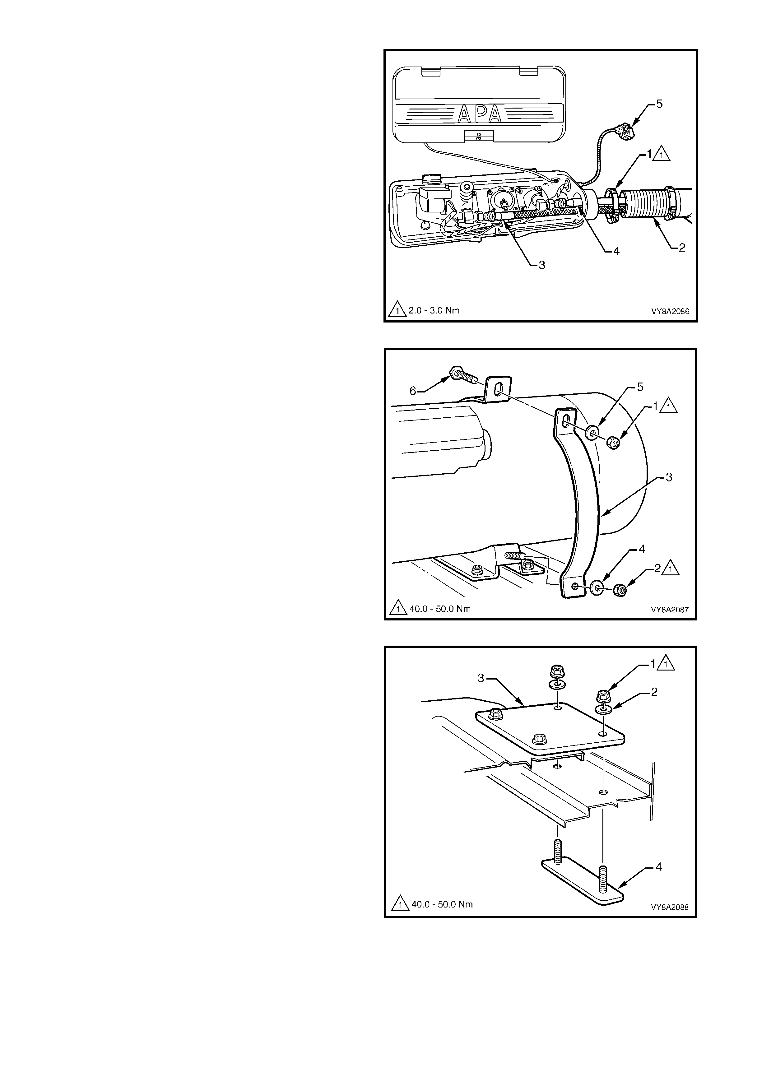
12. Loosen the upper nut (1) and lower nut (2)
securing the LPG tank strap (3).
13. Completely remove the lower nut and washer (4).
14. Remove the upper nut, washer (5) and screw (6)
and remove the strap.
15. Repeat for each LPG tank strap.
16. With the aid of an ass istant, rem ove the LPG tank ,
manoeuvring the left-hand side rearward to
provide clearance for the vent tube.
Figure 8A2-68
17. If required, remove the nut (1) and washer (2)
attaching the upper connecting plate (3) to the
lower connecting bar (4).
18. Remove the load floor front panel assembly,
refer to 2.7 LOAD FLOOR FRONT PANEL
ASSEMBLY, UTILITY in Section 1B.
Figure 8A2-69
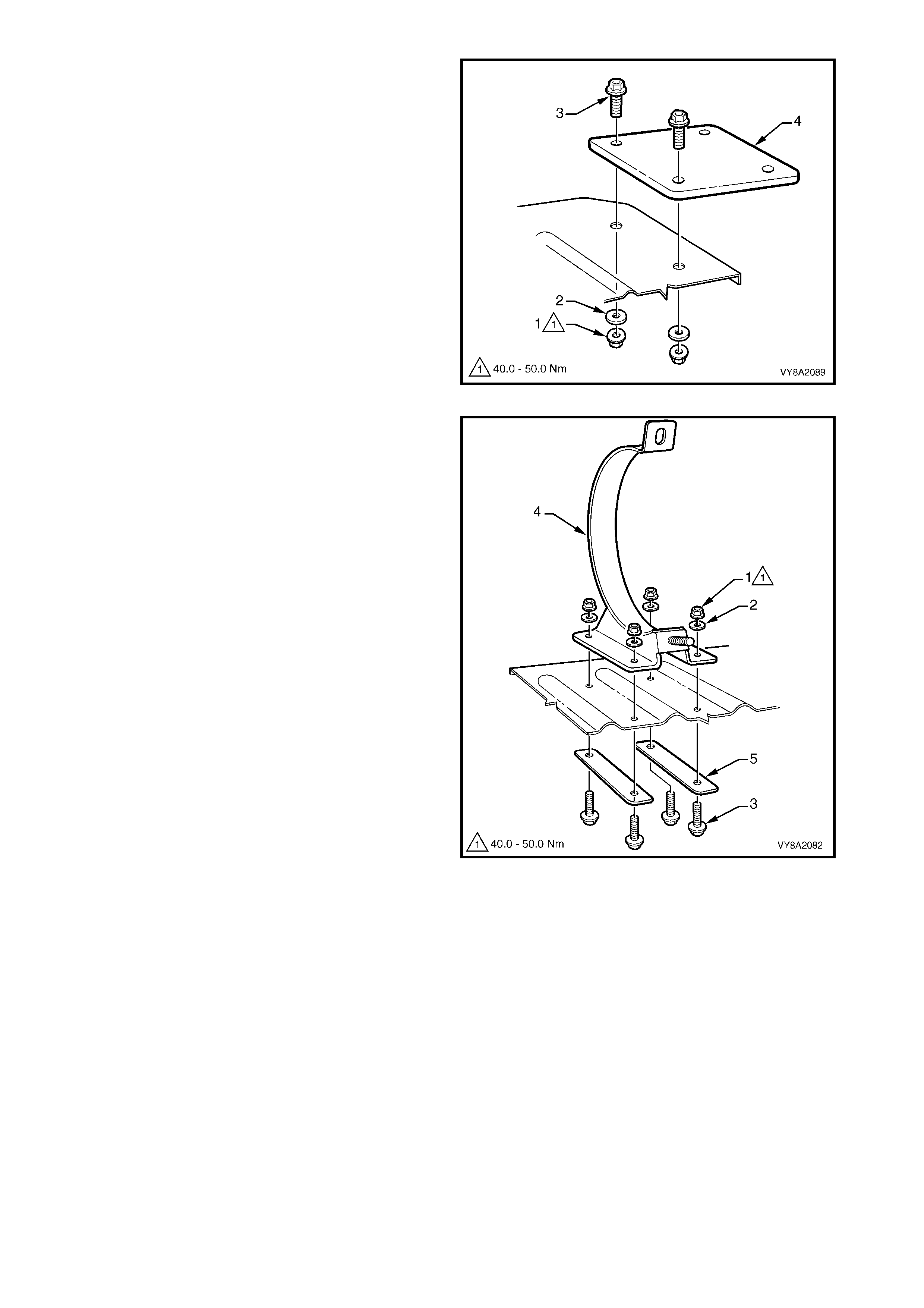
19. Rem ove the nut (1), washer (2) and screw (3), two
places, attaching the upper connecting plate (4) to
the load floor front panel assembly.
20. Remove the plate.
Figure 8A2-70
21. Rem ove the nut (1) , washer ( 2) and s c rew (3), four
places, attaching the tank support bracket (4) and
the backing bar (5), two places, to the load floor
front panel assembly.
22. Remove the support bracket and backing bar.
Repeat as required.
Figure 8A2-71

REINSTALL
Installation of the LPG tank and support assembly is the reverse of the removal procedure, noting the following:
1. If the floor panel, etc. has been replaced and new mounting holes are required, use the old floor as a
reference and the tank as a template. Drill holes as required and coat any bare metal with primer.
2. If removed, reins tall the tank cover ball s tuds (4) , r ef er to Figure 8A2-64. Tighten the nuts (5) to the specif ied
torque.
3. Install the support brackets and connecting plates in the reverse of removal.
4. Tighten the nuts to the specified torque.
5. Install the LPG tank into support brackets. Install the three LPG tank retaining straps, and all retaining
screws, washers and nuts.
6. Tighten to the nuts to the specified torque.
7. Clean the mating threads on the m anual servic e valve assem bly, rear service line connector, AFL valve and
filler line connector.
8. Apply Loctite 577 sealant to the rear service line connector threads, ensuring that the flared surfaces are
free of sealant and contaminants.
9. Assemble the rear service connector to the manual service valve assembly.
10. Tighten the rear service line connector to the specified torque.
11. Apply Loctite 577 sealant to the LPG tank AFL elbow threads, ensuring that flared surfaces are free of
sealant and contaminants.
12. Install the f iller line c onnector to the LPG tank AF L elbow and tighten the filler line c onnector to the s pecif ied
torque.
13. Reconnect the LPG body wiring harness connector to LPG tank connector.
14. Leak test LPG system, refer to 3.3 LEAK TESTING.
15. Apply a commercially available silicone sealant to the vent tube mating surface.
16. Tighten vent tube clamps to specified torque.
17. If required, install new Nutserts (6) with a commercially available Nutsert gun, refer to Figure 8A2-64.
18. Reinstall the LPG tank cover onto the locating studs.
19. Install the LPG tank cover upper retaining screws, six places and tighten to specified torque.
TANK SUPPORT BRACKET AND
UPPER CONNECTING
PLATE RETAINING NUT
TORQUE SPECIFICATION 40.0 – 50.0 Nm
LPG TANK STRAP RETAINING NUT
TORQUE SPECIFICATION 40.0 – 50.0 Nm
REAR SERVICE LINE CONNECTOR
TORQUE SPECIFICATION 12.0 – 18.0 Nm
VENT TUBE HOSE CLAMP
TORQUE SPECIFICATION 2.0 – 3.0 Nm
FILLER LINE CONNECTOR
TORQUE SPECIFICATION 12.0 – 18.0 Nm
LPG TANK COVER UPPER
RETAINING SCREW
TORQUE SPECIFICATION 10.0 – 12.0 Nm
TANK COVER BALL STUD NUT
TORQUE SPECIFICATION 3.0 – 5.0 Nm
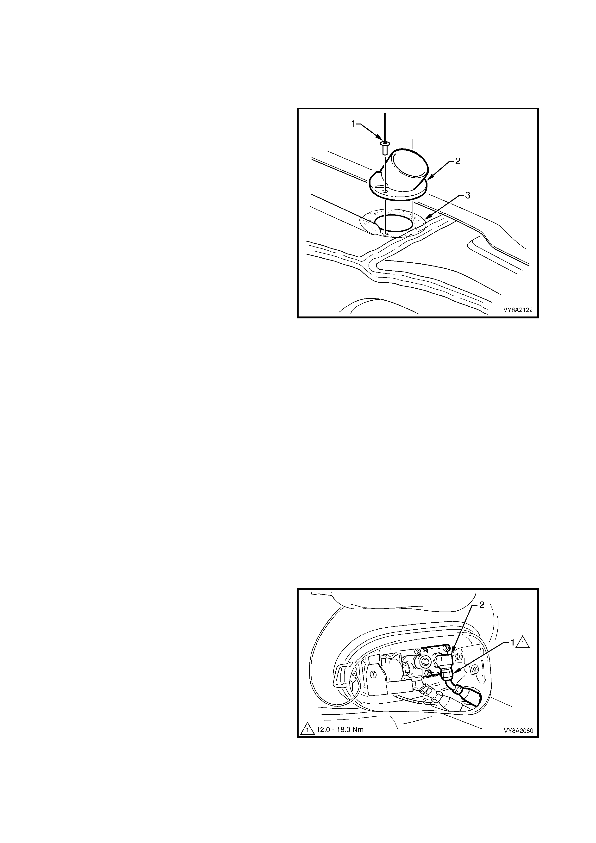
3.7 VENT TUBE FLANGE
LT Section –
SEDAN
REMOVE
1. Remove the LPG tank, refer to 3.6 LPG TANK –
SEDAN.
2. Using a suitable sized drill bit, remove the heads of
the rivet (1) attaching the vent tube flange (2) in
three places.
3. Prise the flange from the floor to break the
sealer (3).
NOTE: On later model vehicles, the vent tube flange
attaches to the floor in the same location but the rib in
the floor pan has been removed.
Figure 8A2-72
REINSTALL
1. If the floor panel has been replaced, align the vent tube flange in the position shown in Figure 8A2-72,
behind the floor join and on the floor rib.
2. Mark the holes and carefully drill three 5 mm holes for the rivets and a 51 mm hole. Clean up all drilling
swarf and prime any bare metal.
NOTE: If the rear side rail assembly has been replaced, also drill a 21 mm in the rail from the underside of the
vehicle, central to the flange hole.
3. Apply silicone sealer to the underside of the flange and install with three new rivets.
WAGON
REMOVE
CAUTION: Ensure that there are no naked flames
or other sources of ignition in the vicinity.
1. Remove the rear compartment floor carpet, refer
to Section 1A8, 3.21 REAR COMPARTMENT
FLOOR CARPET ASSEMBLY AND SPARE
WHEEL COVER, WITH LPG.
2. Drain the service lines of LPG and note all
cautions, refer to 3.1 SERVICE LINE DRAINING.
3. From within the LPG valve box, crack open the
filler line to AFL elbow connector (1) while holding
the AFL elbow and allow residual LPG to escape.
CAUTION: The filler line will contain LPG under
pressure.
4. Once all the LPG in the line has dispersed, remove
the filler line connector completely from the AFL
elbow.
Figure 8A2-73
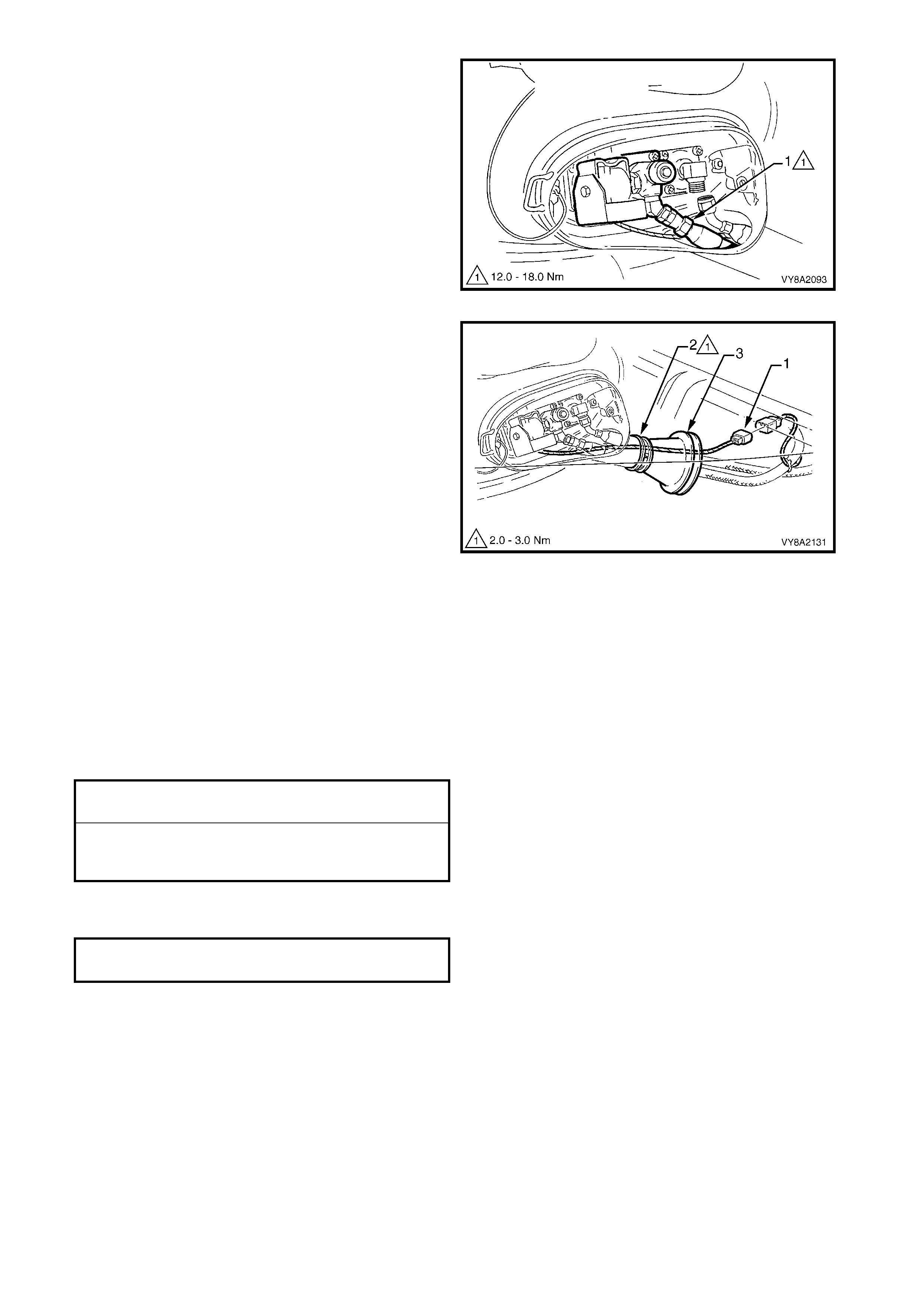
5. From within the LPG tank valve box, unscrew the
rear service line connector (1) from the manual
service valve assembly.
Figure 8A2-74
6. Disconnect the LPG tank harness wiring connector
(1) from underneath the vehicle.
7. Loosen the clamp (2) and prise the flange (3) from
the valve box and vehicle.
8. Withdraw the filler and service lines and remove
the flange.
Figure 8A2-75
REINSTALL
1. If the floor panel has been replaced, align the flange in position.
2. Mark the hole and carefully drill a 70 mm hole. Clean up all drilling swarf and prime any bare metal.
3. Apply silicone sealer to the floor around the flange opening and install the flange.
4. Clean the rear service line mating threads on the manual service valve assembly, the rear service line
connector, AFL valve mating threads and filler line connector.
5. Apply Loctite 577 sealant to the manual service valve assembly threads and AFL valve threads, ensuring
that the flared surfaces are free of sealant and contaminants.
6. Tighten the rear service line and filler line connections to the specified torque.
7. Tighten the vent flange clamp to the specified torque.
8. Leak test the LPG system, refer to 3.3 LEAK TESTING.
REAR SERVICE LINE CONNECTION
TORQUE SPECIFICATION 12.0 – 18.0 Nm
FILLER LINE TO AFL
VALVE CONNECTION
TORQUE SPECIFICATION 12.0 – 18.0 Nm
VENT FLANGE CLAMP
TORQUE SPECIFICATION 2.0 – 3.0 Nm
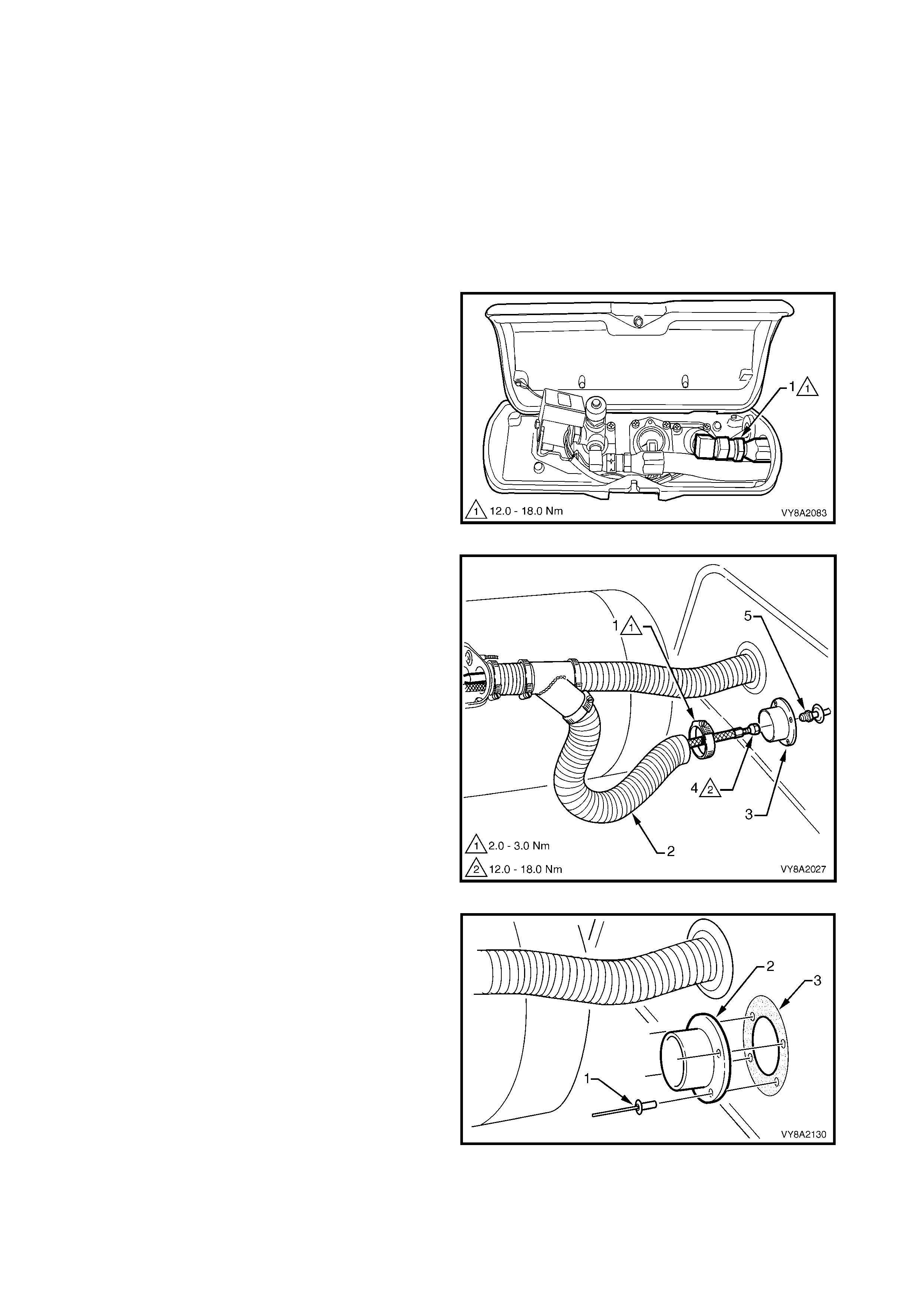
UTILITY
REMOVE
CAUTION: Ensure that there are no naked flames
or other sources of ignition in the vicinity.
NOTE: For r em oval of the s ervice line vent tube flange
(in the floor) refer to 3.14 REAR SERVICE LINE –
UTILITY.
1. Drain the service lines of LPG and note all
cautions, refer to 3.1 SERVICE LINE DRAINING.
2. Remove the LPG tank cover, refer to 3.6 LPG
TANK, UTILITY.
3. From within the LPG valve box, crack open the
filler line to AFL elbow connector (1) while holding
AFL elbow and allow residual LPG to escape.
CAUTION: The filler line will contain LPG under
pressure.
4. Once all the LPG in the line has dispersed, remove
the filler line connector completely from the AFL
elbow.
Figure 8A2-76
6. Loosen the hose clamp (1) securing the filler line
vent tube (2) to the vent tube flange (3).
5. Crack open the filler line connector (4) while
holding the filler pipe and allow residual LPG to
escape.
CAUTION: The filler line will contain LPG under
pressure.
7. Once all the LPG in the line has dispersed,
disconnect the filler line from the filler pipe.
Figure 8A2-77
8. Using a suitable sized drill bit, remove the heads of
the rivet (1) attaching the vent tube flange (2) in
four places.
9. Prise the flange from the front inner side panel
cover to break the sealer (3).
Figure 8A2-78

REINSTALL
1. If the f ront inner s ide panel cover has been r eplac ed, seat the panel cover in position and note the filler valve
connector pipe position. Mark on the panel.
2. Seat the flange on the panel cover central to the mark.
3. Mark the f lange holes on the panel c over and c ar ef ully drill f our 5 m m holes f o r the r ivets and a 22 m m hole.
Clean up all drilling swarf and prime any bare metal.
4. If required, fit the panel cover, refer to Section 1B, 2.8 FRONT INNER SIDE PANEL COVER.
5. Apply silicone sealer to the underside of the flange and install with four new rivets.
6. Clean the mating threads of the filler line and filler valve connecting pipe.
7. Apply Loctite 577 sealant to the filler pipe connector threads, ensuring that the flared surfaces are free of
sealant and contaminants.
8. Tighten the filler line connection to the specified torque.
9. Leak test the LPG system, refer to 3.3 LEAK TESTING.
10. Apply silicone sealer to the vent tube mating surfaces.
11. Tighten the vent tube clamps to the specified torque.
12. Reinstall the LPG tank box cover.
FILLER LINE CONNECTOR
TORQUE SPECIFICATION 12.0 – 18.0 Nm
VENT TUBE HOSE CLAMP
TORQUE SPECIFICATION 2.0 – 3.0 Nm

3.8 SMART UNIT & SOLENOID VALVE
LT Section – AA-650R
REMOVE
10. Park the vehicle in a well ventilated area, away
from any ignition source.
11. Drain the service lines of LPG, refer to
3.1 SERVICE LINE DRAINING.
12. Disconnect the LPG harness connector (1) from
the LPG tank, refer to Figure 8A2-79 A – Sedan
and Utility or B – Wagon.
Figure 8A2-79
13. Remove the screw (1) attaching the smart unit (2)
to the solenoid sleeve (3). Sedan shown, Wagon
and Utility similar.
14. Remove the smart unit from the solenoid sleeve.
15. Remove the solenoid sleeve from the manual
service valve (4), ensuring that the solenoid valve
(5) is also removed.
16. Separate the solenoid valve from the sleeve and
discard the O-ring (6).
17. Disconnect the wiring connectors from the tank
gauge.
NOTE: To aid disconnection of the connectors,
remove the two screws attaching the contents gauge.
If required, refer to 3.13 TANK FUEL GAUGE
ASSEMBLY – CONTENTS GAUGE.
Figure 8A2-80
REINSTALL
Installation of the smart unit & solenoid valve to the manual service valve is the reverse of removal noting the
following:
1. Fit a new O-ring to the solenoid sleeve.
2. Tighten the solenoid sleeve to the specified torque.
3. Once installed, ensure that the smart unit retaining screw is tightened to the specified torque.
4. Leak test LPG system, refer to 3.3 LEAK TESTING.
SOLENOID SLEEVE
TORQUE SPECIFICATION 15.0 – 18.0 Nm
SMART UNIT RETAINING SCREW
TORQUE SPECIFICATION 1.0 – 3.0 Nm
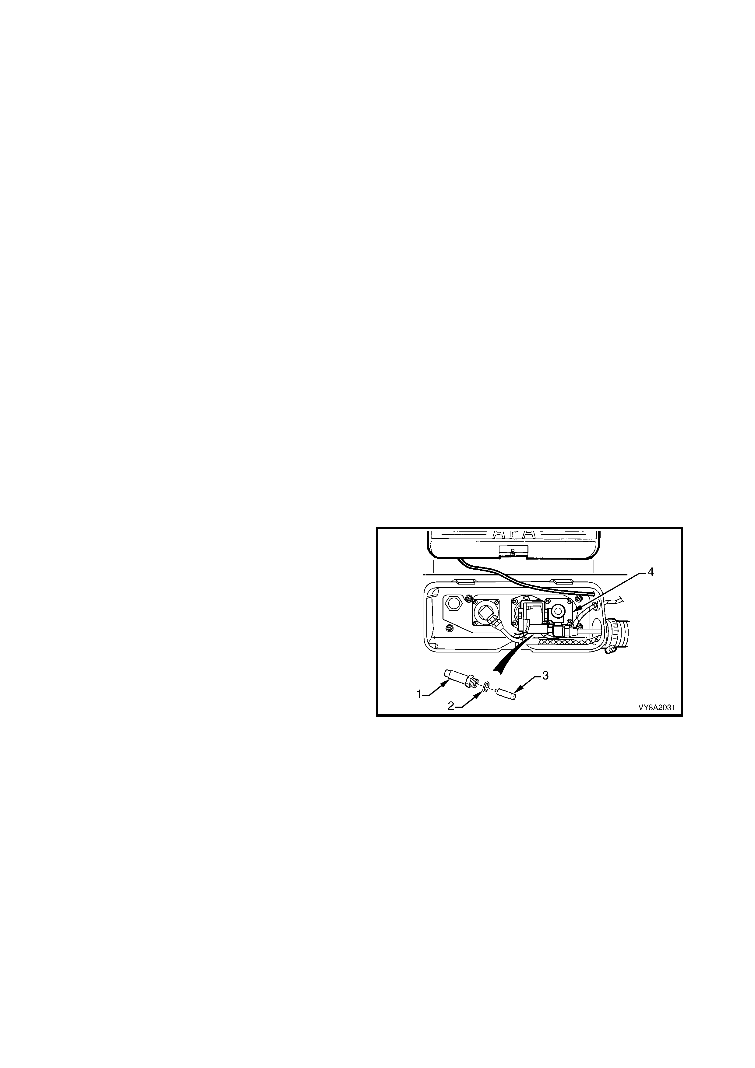
3.9 MANUAL SERVICE VALVE ASSEMBLY
LT Section – AA-650R
CAUTION: If at any time the manual service valve becomes stuck, no service operations on the system
will be possible. Should for any reason the valve stick, the tank should be returned to the tank
manufacturer (APA) to arrange a replacement tank.
Contact: APA Industries
190 Colchester Road
Kilsyth, Victoria. 3137
Phone - (03) 9720 2855
Fax - (03) 9761 4495
Email - [email protected].au
NOTE: The manual service valve is three valves in one. A manual shut off valve, an electrically operated
solenoid valve and an excess flow valve.
EXCESS-FLOW VALVE
TEST
CAUTION: Ensure there are no naked flames or
other sources of ignition in the vicinity.
Ensure all safety precautions listed at the front of
this manual are adhered to while performing this
test.
Do not perform this test on a vehicle with a hot
engine.
1. Drain the service lines of LPG, refer to
3.1 SERVICE LINE DRAINING.
2. Remove the smart unit and solenoid valve
assembly, refer to 3.8 SMART UNIT &
SOLENOID VALVE.
3. Reinstall the solenoid sleeve (1) and O-ring (2),
without the solenoid valve (3), onto the manual
service valve (4).
4. Disconnect the front service line at the lock-off
valve to allow LPG to flow from this line when the
manual service valve is opened, refer to
3.14 FRONT SERVICE LINE.
5. Quickly open the manual service valve and listen
for the sound of the excess-flow valve operating.
6. If the excess flow valve is operating correctly, it
can be heard to click shut when the manual
service valve is opened quickly.
CAUTION: To ensure that the least amount of LPG
escapes into the atmosphere, only open the
manual serv ice v alve for th e minimal time po ssible
to perform this test.
7. Reins tall the front service line to the lock-o ff valve,
refer to the reins tallation pr oc edure in 3.14 FRONT
SERVICE LINE.
Figure 8A2-81
8. Remove the solenoid sleeve from the manual
service valve.
9. Reinstall the solenoid valve, solenoid sleeve and
smart unit, refer to 3.8 SMART UNIT &
SOLENOID VALVE.
10. Leak test the LPG system, refer to 3.3 LEAK
TESTING.
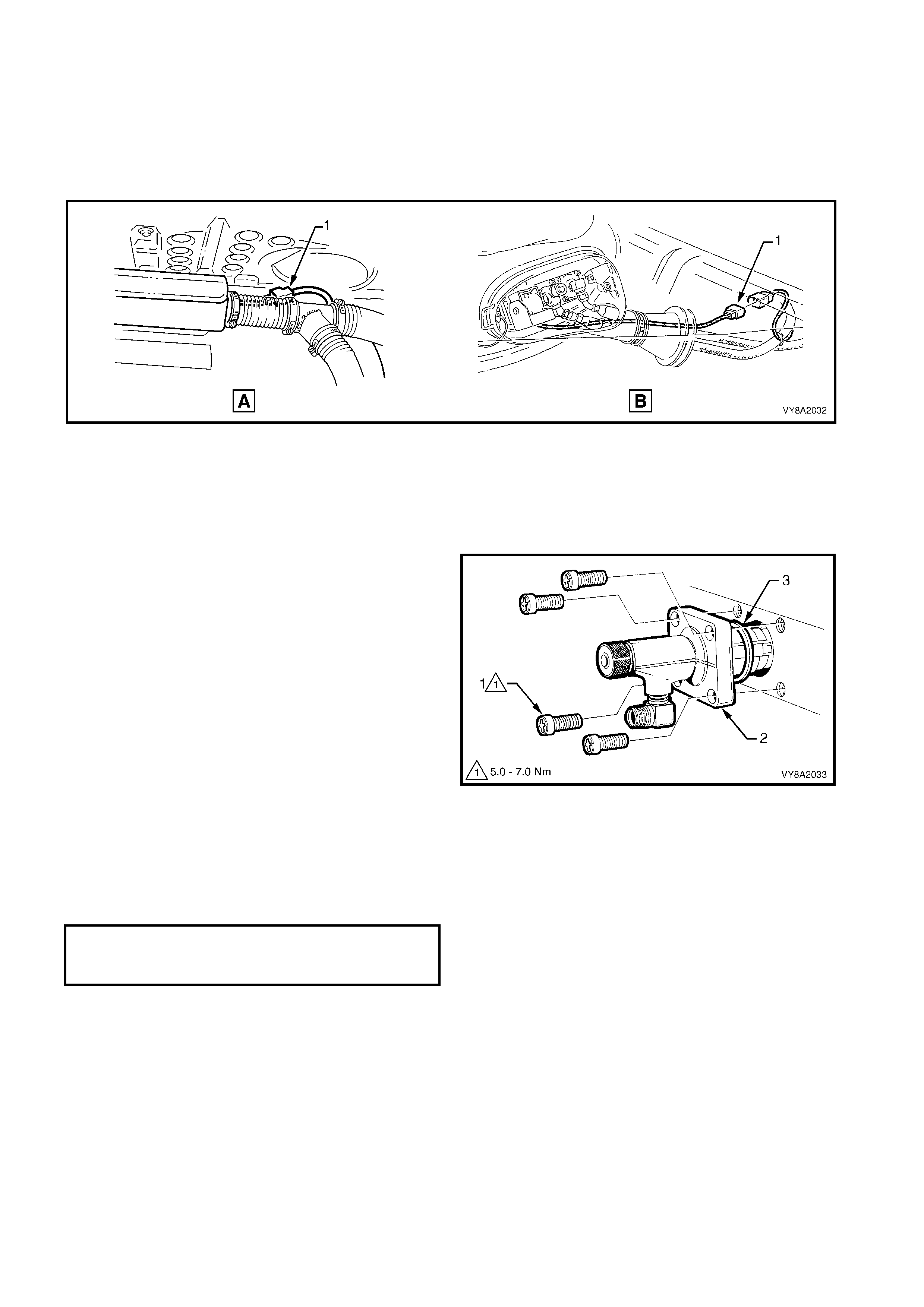
REMOVE
1. Park the vehicle in a well ventilated area, away from any ignition source.
2. Drain the service lines of LPG, refer to 3.1 SERVICE LINE DRAINING.
3. Unload the LPG tank of LPG, refer to 3.2 LPG TANK UNLOADING.
4. Disconnect the LPG harness connector (1) from the LPG tank, refer to Figure 8A2-82 (A) Sedan, Utility
similar or (B) Wagon.
Figure 8A2-82
5. Push the LPG tank harness back into the tank
valve box area.
6. Remove the solenoid assembly from the manual
valve, refer to 3.8 SMART UNIT & SOLENOID
VALVE.
7. Unscrew the four screws (1) attaching the m anual
service valve (2) to the tank and remove the
manual service valve.
NOTE: Typical manual service valve shown.
Figure 8A2-83
REINSTALL
1. Install the new manual service valve ensuring a new sealing ring (3) is fitted.
NOTE: Install the valve so that the service line connection elbow is correctly orientated.
2. Install the manual service valve attaching screws and tighten to the specified torque.
3. Reconnect the LPG body wiring harness connector to LPG tank harness connector and reinstall grommet.
4. Reinstall the rear service line, refer to 3.15 REAR SERVICE LINE.
5. Pressure and leak test the LPG tank in accordance with the current Australian Standard AS 2030-1.
6. Leak test the LPG system, refer to 3.3 LEAK TESTING.
MANUAL SERVICE VALVE
ATTACHING SCREW
TORQUE SPECIFICATION 5.0 – 7.0 Nm
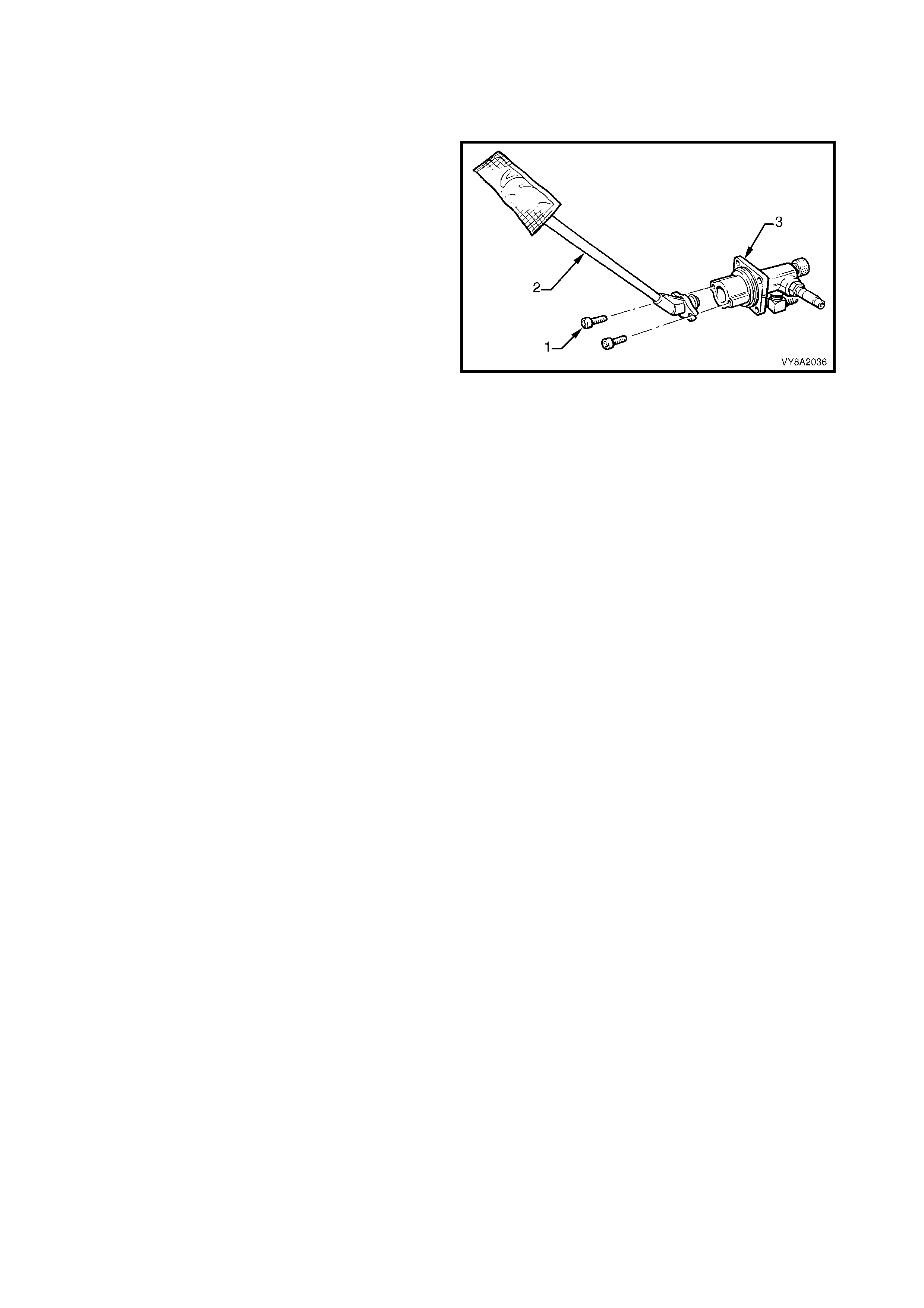
3.10 PICK-UP PIPE & STRAINER
LT Section –
REMOVE
1. Remove the solenoid and manual service valve,
refer to 3.9 MANUAL SERVICE VALVE
ASSEMBLY.
2. Remove the two screws (1) retaining the LPG
pick -up pipe and strainer ( 2) to the m anual service
valve (3).
3. Twist the pick-up pipe out of manual service valve.
REINSTALL
Installation of the LPG pick-up pipe and strainer is the
reverse of removal. Ensure the O-ring on the end of
the pick-up pipe is correctly installed.
Figure 8A2-84
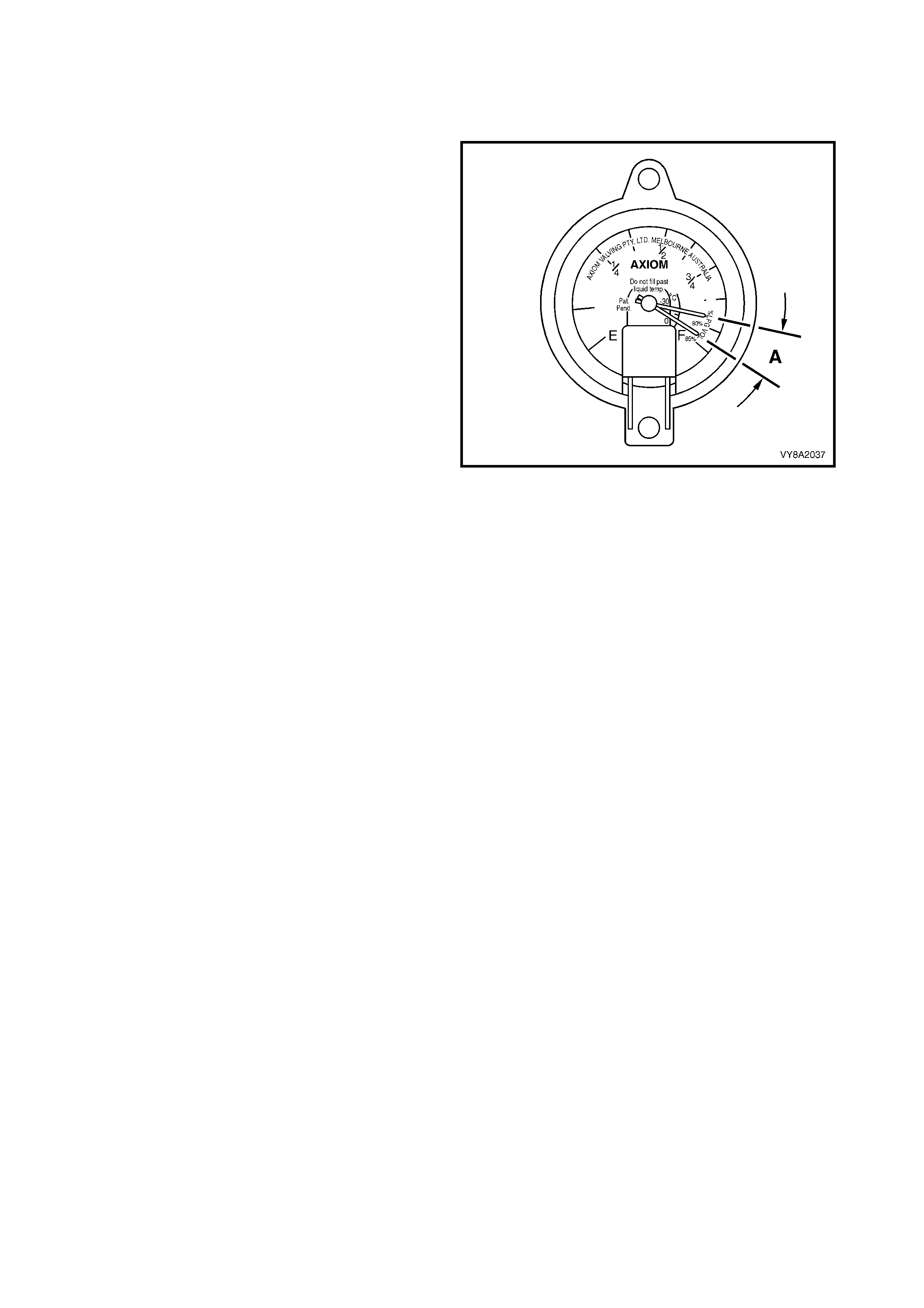
3.11 AUTOMATIC FILL LIMITER (AFL)
LT Section – AA-650Q
TEST
NOTE 1: When performing this test, the vehicle must
be on level ground.
NOTE 2: For Wagon vehicles remove the smart unit,
refer to 3.8 SMART UNIT & SOLENOID VALVE.
1. Fill the LPG tank until the autom atic fill limiter cuts
off.
2. Check the LPG contents gauge at the tank.
• If the gauge reads approximately 80% full ±
3% (A) the automatic fill limiter is operating
correctly.
• If the gauge is reading outside this
specification, the remaining part of this
procedure must be performed.
NOTE: Bounc e the vehicle a couple of tim es to ensur e
accuracy when checking the gauge reading.
3. If the gauge reading was out of specification, the
vehicle must be operated on LPG until the LPG
tank is completely empty.
NOTE 1: Advise the vehicle operator that the vehicle
should be operated on LPG until the LPG tank is
completely empty. Once emptied, the vehicle should
then be returned for inspection on petrol.
NOTE 2: It is not pos s ible to switch the f uel mode f r om
LPG to petrol while the vehicle is moving. Therefore,
the vehicle operator must select a location where
running out of LPG will not present a traffic hazard or
danger.
4. Check the fuel contents gauge on the LPG tank is
displaying empty and the engine will not start with
the vehicle in LPG mode.
5. Fill the LPG tank and note the number of litres
taken. The LPG tank fillable capacity is:
• Sedan – 74 litres ± 2 litres
• Wagon – 60 litres ± 2 litres
• Utility – 70 litres ± 2 litres
Any more indicates a faulty AFL.
Figure 8A2-85
NOTE 1: If the LPG tank is overfilled, the contents of the tank must be reduced to a safe level. This can be
achieved by either running the engine NON-STOP on LPG for sufficient time to consume the excess fuel, or
removing the excess fuel from the LPG tank, refer to 3.2 LPG TANK UNLOADING.
NOTE 2: If the LPG tank fillable capacity is within the specified limits, yet the initial test failed (the gauge was
reading outside the specified parameters), check the calibration of the contents gauge. Refer to 3.13 TANK
FUEL GAUGE ASSEMBLY.
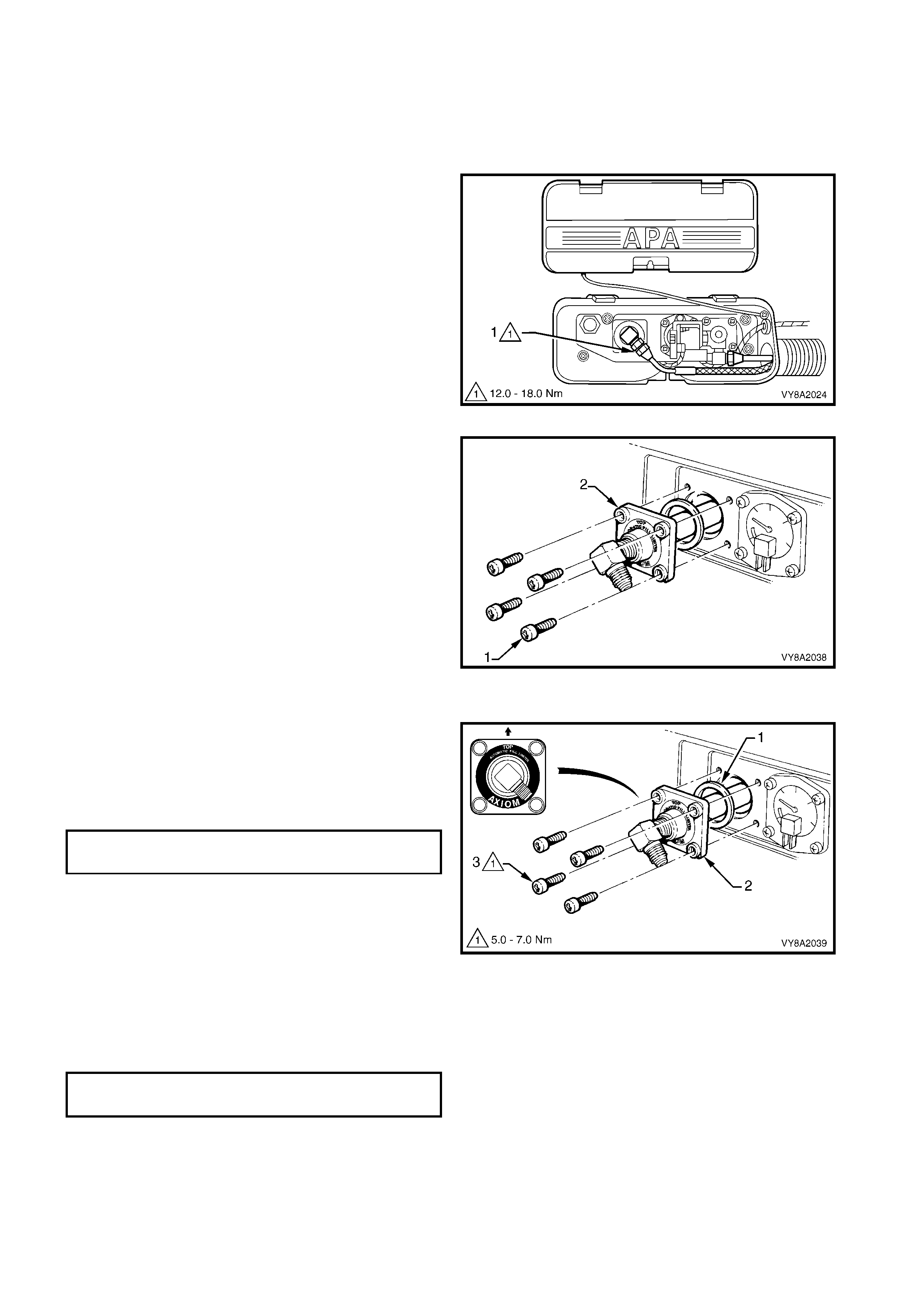
REMOVE
NOTE: The automatic fill limiter should only be replaced if it proves to be faulty.
1. Park the vehicle in a well ventilated area, away from any ignition source.
2. Drain the service lines of LPG, refer to 3.1 SERVICE LINE DRAINING.
3. Unload the LPG tank of LPG, refer to 3.2 LPG TANK UNLOADING.
4. From within the LPG valve box, while holding the
AFL elbow, crack open the filler line to AFL elbow
connector (1) and allow residual LPG to escape.
CAUTION: The filler line will contain LPG under
pressure. Once all the LPG in the line has
dispersed, unscrew the filler line connector
completely from the AFL elbow.
Figure 8A2-86
5. Remove the four screws (1) attaching the AFL (2)
to the tank. Sedan shown, Wagon and Utility
similar.
6. Remove the AFL from the LPG tank.
Figure 8A2-87
REINSTALL
1. Install a new sealing ring (1) onto the AFL (2).
2. Fit the AFL into the tank, ensuring it is correctly
orientated.
3. Install the four screws (3) and tighten to the
specified torque.
4. Reconnect LPG body wiring harness connector to
the LPG tank harness connector and reinstall the
grommet.
5. Reinstall the rear service line, refer to
3.15 REAR SERVICE LINE.
6. Apply Loctite 577 sealant to the f iller line connector
threads, ensuring that the flared surfaces are free
of sealant and c ontam inants. Connec t the filler line
to AFL elbow and tighten to the specified torque.
Figure 8A2-88
7. Pressure and leak test LPG tank in accordance
with the current Australian Standard AS 2030-1.
8. Perform system leak testing, refer to
3.3 LEAK TESTING.
AUTOMATIC FILL LIMITER ATTACHING
SCREW TORQUE SPECIFICATION 5.0 – 7.0 Nm
FILLER LINE CONNECTOR TO AFL
ELBOW TORQUE SPECIFICATION 12.0 – 18.0 Nm
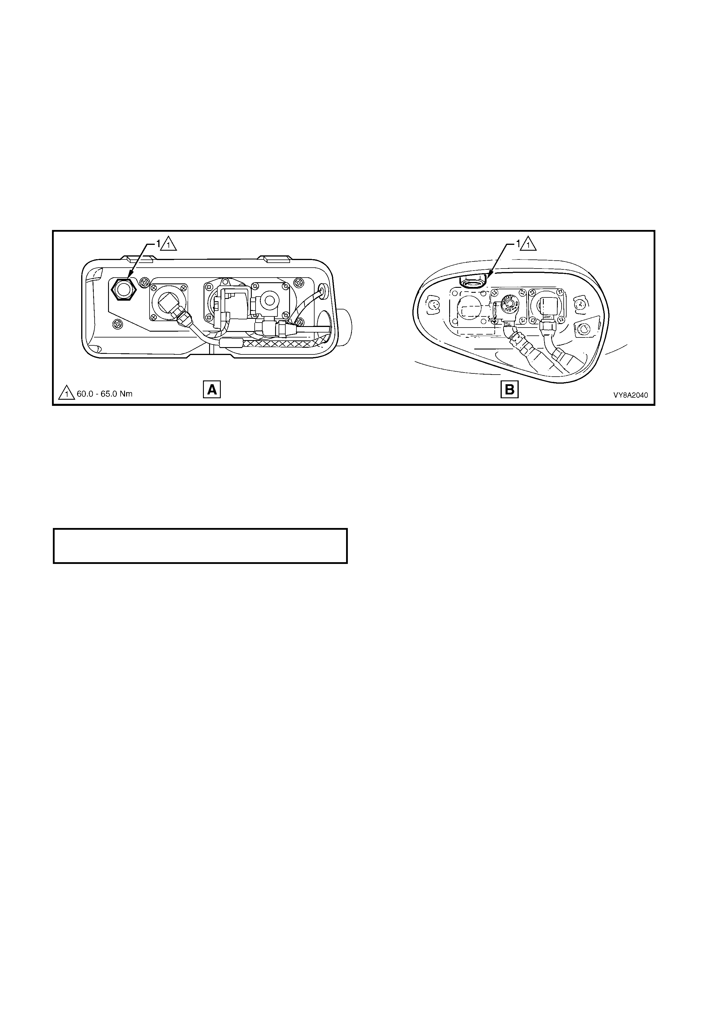
3.12 PRESSURE RELIEF VALVE
LT Section –
REMOVE
NOTE: The pr essure relief valve fitted to Utility vehic les is part of the m anual service valve assem bly and is not
serviced.
1. Park the vehicle in a well ventilated area, away from any ignition source.
2. Drain the service lines of LPG, refer to 3.1 SERVICE LINE DRAINING.
3. Unload the LPG tank of LPG, refer to 3.2 LPG TANK UNLOADING.
4. Remo ve the pres s ure r elief valve ( 1) from the LPG tank valve box, refer to Figure 8A2- 89, A – Sedan, or B –
Wagon.
Figure 8A2-89
REINSTALL
1. Ensure that new relief valve and LPG tank mating threads are clean.
2. Apply an anaerobic s ealant, suc h as Permabond A129 or equivalent to the valve thr ead and a sm all am ount
to the tank mating thread.
3. Tighten the pressure relief valve to the specified torque.
4. Pressure and leak test the LPG tank in accordance with the current Australian Standard AS 2030-1.
5. Leak test the LPG system, refer to 3.3 LEAK TESTING.
PRESSURE RELIEF VALVE
TORQUE SPECIFICATION 60.0 – 65.0 Nm
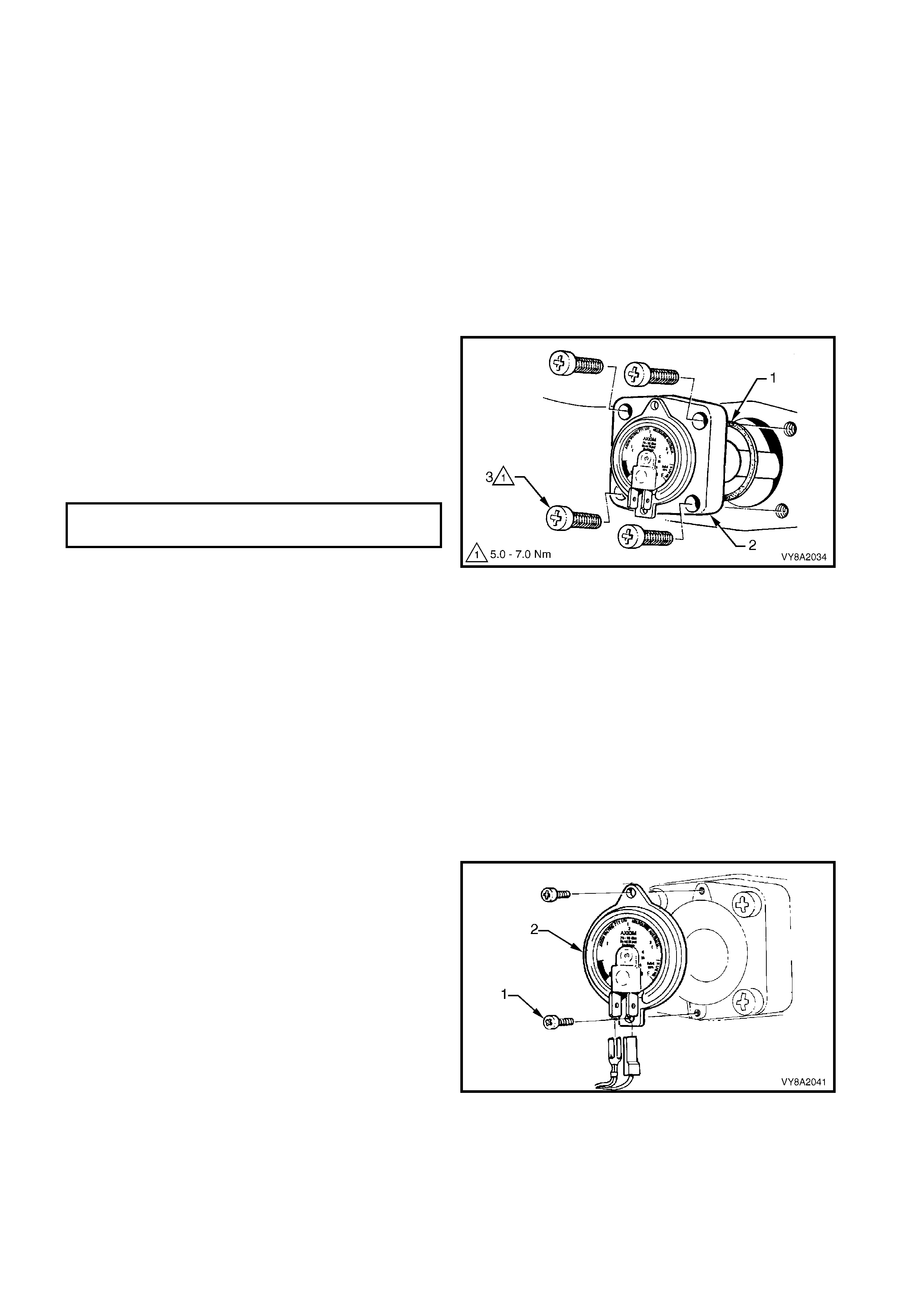
3.13 TANK FUEL GAUGE ASSEMBLY
LT Section – AA-650R
REMOVE
1. Park the vehicle in a well ventilated area, away
from any ignition source.
2. Drain the service lines of LPG, refer to
3.1 SERVICE LINE DRAINING.
3. Unload the LPG tank of LPG, refer to
3.2 LPG TANK UNLOADING.
NOTE: T he tank fuel gauge as sembly will be removed
during this procedure.
REINSTALL
1. Fit a new tank fuel gauge sealing ring (1) and
reinstall the tank fuel gauge assembly (2).
NOTE: Ensure the gauge assembly is correctly
orientated.
2. Connect the wiring harness connectors to gauge
terminals.
3. Install the gauge assembly attaching screws and
tighten to the specified torque.
4. Pressure and leak test the LPG tank in
accordance with the current Australian Standard
AS 2030-1.
5. Leak test the LPG system, refer to
3.3 LEAK TESTING.
Figure 8A2-90
CONTENTS GAUGE
REMOVE
1. Park the vehicle in a well ventilated area, away
from any ignition source.
2. Drain the service lines of LPG, refer to
3.1 SERVICE LINE DRAINING.
3. Remove the smart unit and solenoid valve from
the manual service valve, refer to
3.8 SMART UNIT & SOLENOID VALVE.
4. Disconnect the wiring harnes s c onnec tors f r om the
contents gauge terminals.
5. Remove the two screws attaching the contents
gauge and remove the contents gauge from the
LPG tank gauge assembly.
CAUTION: Do not remove the four screws
retaining the tank fuel gauge assembly to LPG
tank.
Figure 8A2-91
TANK FUEL GAUGE ATTACHING
SCREW TORQUE SPECIFICATION 5.0 – 7.0 Nm
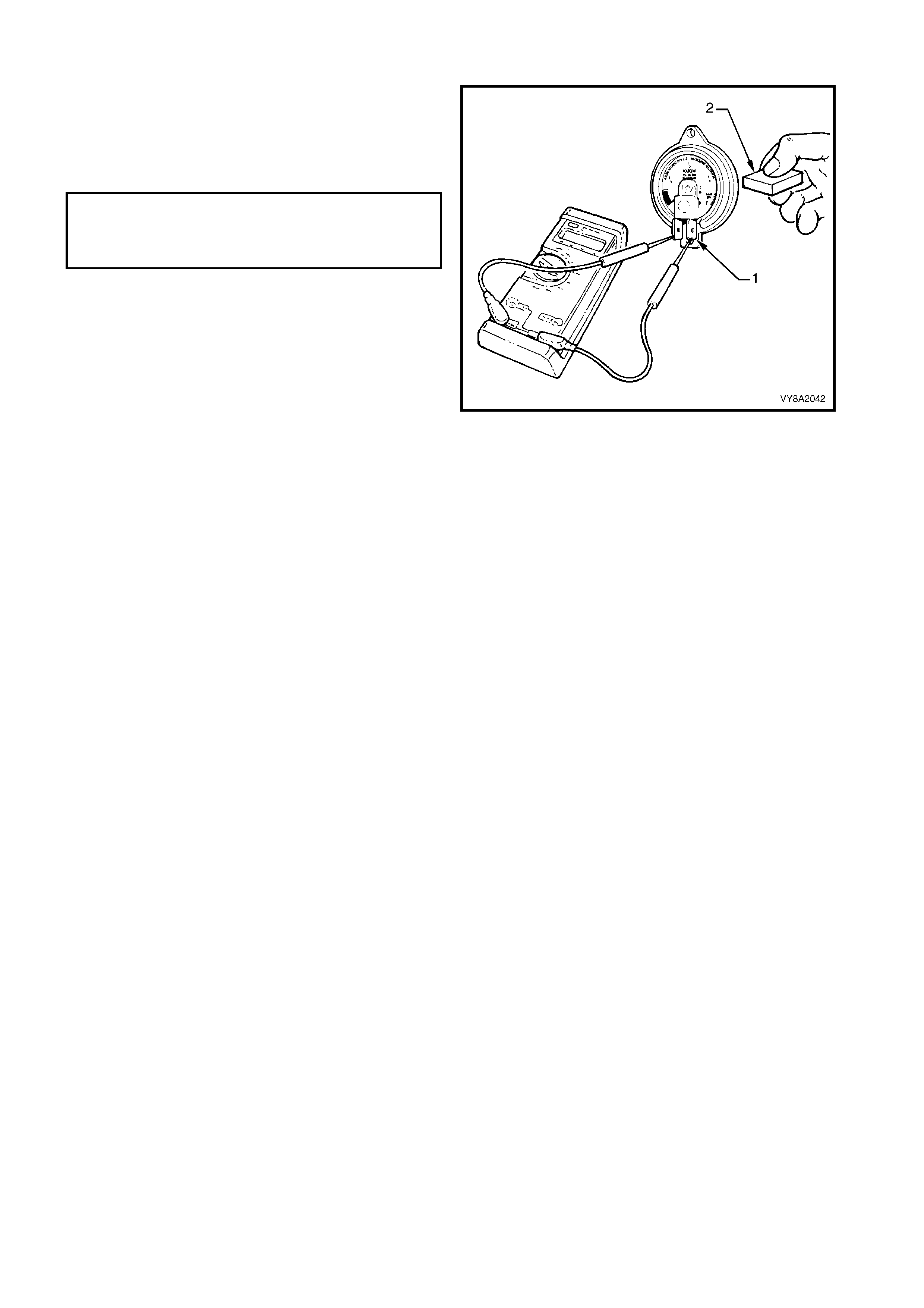
TEST
1. Connect an ohmmeter to the contents gauge
sender unit terminals (1).
2. Place a magnet (2) behind the contents gauge and
rotate the magnet to change the position of the
gauge needle and test for the specified resistance.
3. If the needle does not move in relation to the
movement of the magnet or the resistance does
not meet specification, the contents gauge must
be replaced.
Figure 8A2-92
REINSTALL
1. Install the contents gauge onto the tank fuel gauge assembly and tighten the screws.
2. Connect the wiring harness connectors to the contents gauge terminals.
3. Reinstall the smart unit and solenoid valve on the manual service valve, refer to 3.8 SMART UNIT AND
SOLENOID VALVE.
4. Reconnect the battery earth lead.
TANK CONTENTS GAUGE
RESISTANCE (APPROX.)
EMPTY: 40 OHMS
FULL: 255 OHMS
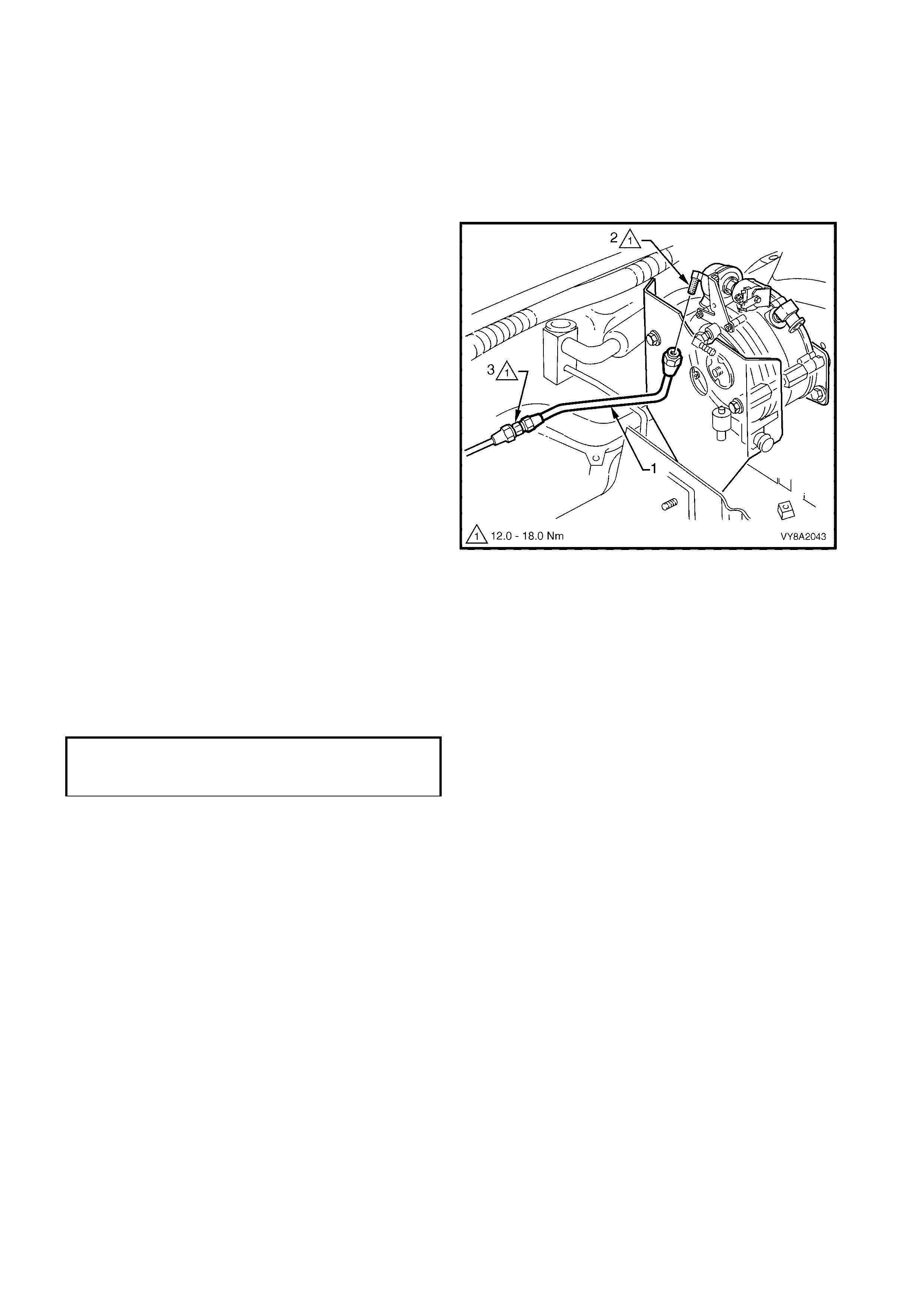
3.14 FRONT SERVICE LINE
LT Section – AA-650Q
REMOVE
1. Park the vehicle in a well ventilated area, away
from any ignition source.
2. Drain the service lines of LPG, refer to
3.1 SERVICE LINE DRAINING.
3. Disconnect the front service line (1) connector
from the LPG lock-off connection (2).
4. W hile holding the front to intermediate service line
joiner (3), disconnect the front service line
connector and remove the front service line.
Figure 8A2-93
REINSTALL
1. Clean the m ating threads of the f ront service line, LPG loc k-off connection and interm ediate to fr ont s ervice
line connector.
2. Apply Loctite 577 sealant or equivalent to the LPG lock-off connection and to the intermediate service line
front connector threads, ensuring that flared surfaces are free of sealant and contaminants.
3. Assemble the front service line connectors to the LPG lock-off connection and intermediate service line
connector and tighten to the specified torque.
NOTE: Ensure the front service line does not chafe or come in contact with the body or other components.
4. Leak test the LPG system, refer to 3.3 LEAK TESTING.
FRONT SERVICE LINE TO LOCK-OFF AND
INTERMEDIATE L I NE CONNECTOR
TORQUE SPECIFICATION 12.0 – 18.0 Nm
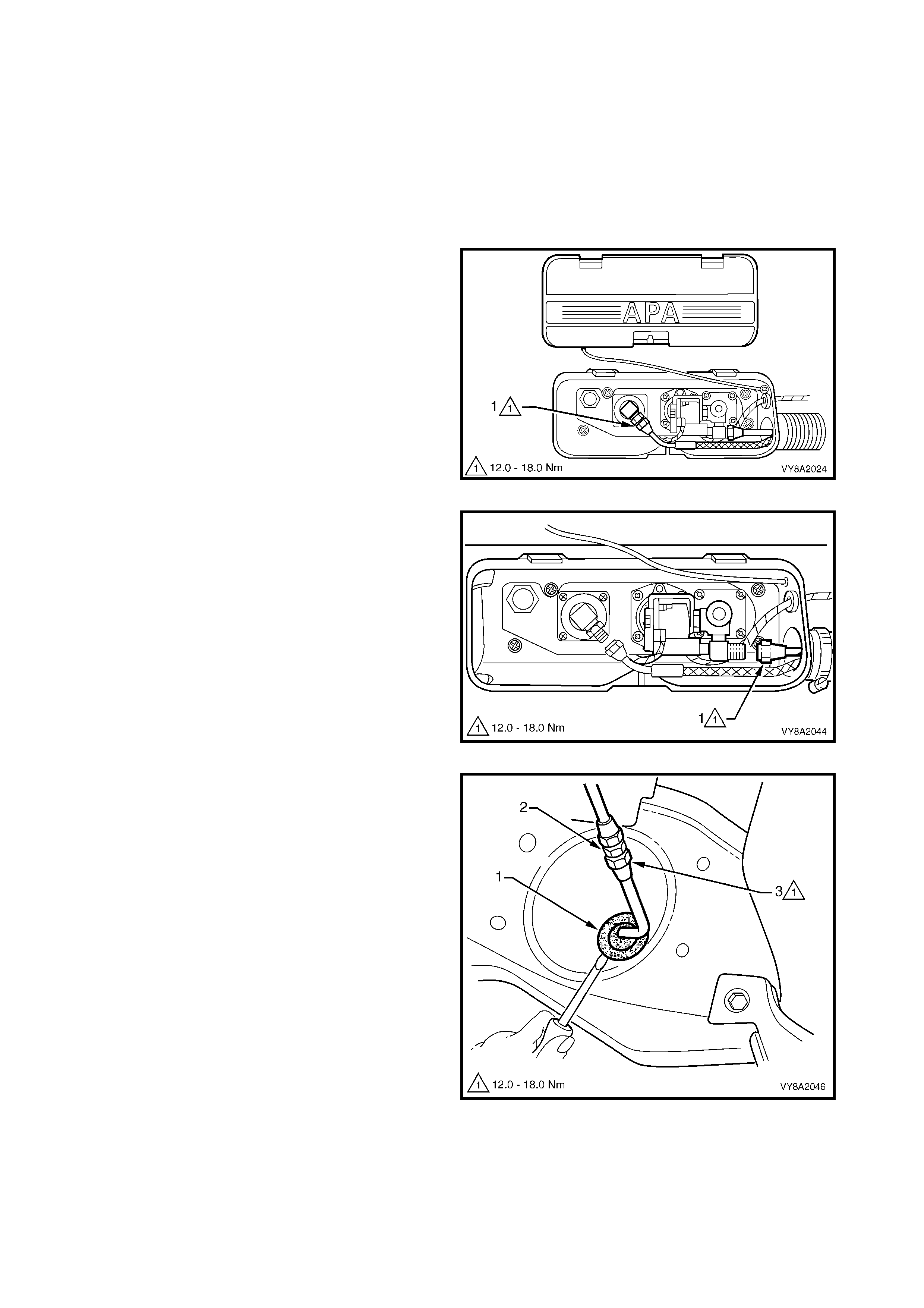
3.15 RE AR SERVICE LINE
LT Section – AA-650Q
SEDAN
REMOVE
1. Park the vehicle in a well ventilated area, away
from any ignition source.
2. Drain the service lines of LPG, refer to
3.1 SERVICE LINE DRAINING.
3. From within the LPG valve box, (while holding the
AFL elbow) crack open the filler line to AFL elbow
connector (1) and allow residual LPG to escape.
CAUTION: The filler line will contain LPG under
pressure. Once all the LPG in the line has
dispersed, unscrew the filler line connector
completely from the AFL elbow.
Figure 8A2-94
4. From within the LPG tank valve box, unscrew the
rear service line connector (1) from the manual
service valve assembly.
5. Jack up rear of the vehicle and support on safety
stands, refer to Section 0A, GENERAL
INFORMATION for jacking point locations.
Figure 8A2-95
6. From underneath the vehicle, remove the rear
service line grommet (1) from the body.
7. W hile holding the intermediate to rear service line
joiner (2) from turning, unscrew the rear service
line connector (3).
8. Remove the rear service line by withdrawing it
through the body.
Figure 8A2-96
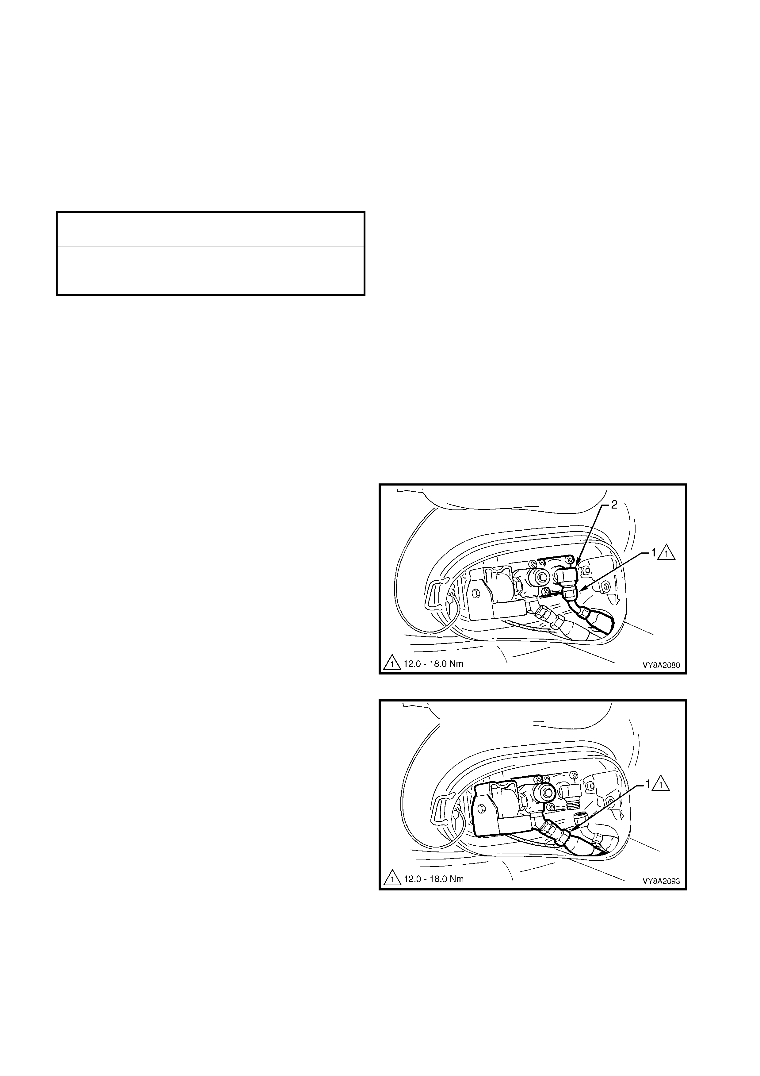
REINSTALL
Installation of the rear service line is the reverse of removal noting the following:
1. Clean the rear service line mating threads on the manual service valve assembly, intermediate to rear
service line joiner, both rear service line connectors, AFL valve mating threads and filler line connector.
2. Reinstall the grommet into the body before installing the vent tubes.
3. Apply Loctite 577 sealant to the intermediate to rear service line joiner threads, manual service valve
assembly threads, and AFL valve threads, ensuring that the flared surfaces are free of sealant and
contaminants.
4. Tighten rear service line and filler line connections to the specified torque.
NOTE: Ensure the rear service line and filler lines do not chafe or come in contact with the body or other
components.
5. Leak test the system, refer to 3.3 LEAK TESTING.
WAGON
REMOVE
9. Park the vehicle in a well ventilated area, away
from any ignition source.
10. Drain the service lines of LPG, refer to
3.1 SERVICE LINE DRAINING.
11. From within the LPG valve box, crack open the
filler line (1) while holding the AFL elbow (2) and
allow residual LPG to escape.
CAUTION: The filler line will contain LPG under
pressure.
12. Once all the LPG in the line has dispersed, remove
the filler line connector completely from the AFL
elbow.
Figure 8A2-97
13. From within the LPG tank valve box, unscrew the
rear service line connector (1) from the manual
service valve assembly.
14. Jack up the rear of vehicle and support on safety
stands, refer to Section 0A, GENERAL
INFORMATION for the jacking point locations.
15. Remove the fuel (petrol) tank, refer to
Section 8A1, 2.1 FUEL TANK – SEDAN &
WAGON.
Figure 8A2-98
REAR SERVICE LINE CONNECTION
TORQUE SPECIFICATION 12.0 – 18.0 Nm
FILLER LINE TO
AFL VALVE CONNECTION
TORQUE SPECIFICATION 12.0 – 18.0 Nm

16. W hile holding the intermediate to rear service line
elbow (1) from turning, unscrew the rear service
line connector (2) from the service line joiner.
17. Using a suitable sized drill bit, remove the heads of
the rivets (3) attaching the rear service line retainer
(4) in three places.
18. Remove the rear service line.
19. Using a suitable size pin-punch and hammer,
knock out the remaining rivets from the chassis
rail.
Figure 8A2-99
REINSTALL
Installation of the rear service line is the reverse of removal noting the following:
18. Clean the rear service line mating threads on the manual service valve assembly, intermediate to rear
service line joiner, both rear service line connectors, AFL valve mating threads and filler line connector.
19. Apply Loctite 577 sealant to the intermediate to rear service line joiner threads, manual service valve
assembly threads, and AFL valve threads, ensuring that the flared surfaces are free of sealant and
contaminants.
20. Tighten the rear service line and filler line connections to the specified torque.
21. Secure the rear service line to the chassis rails with the three clamps and new rivets.
22. Before starting the vehicle or opening the manual service valve, perform a fuel (petrol) system leak test,
refer to Section 6C1 POWERTRAIN MANAGEMENT - V6 ENGINE.
23. Leak test the LPG system, refer to 3.3 LEAK TESTING.
REAR SERVICE LINE CONNECTION
TORQUE SPECIFICATION 12.0 – 18.0 Nm
FILLER LINE TO AFL
VALVE CONNECTION
TORQUE SPECIFICATION 12.0 – 18.0 Nm

UTILITY
REMOVE
1. Park the vehicle in a well ventilated area, away
from any ignition source.
2. Drain the service lines of LPG, refer to
3.1 SERVICE LINE DRAINING.
3. From within the LPG valve box, while holding the
AFL elbow, crack open the filler line to AFL elbow
connector (1) and allow residual LPG to escape.
CAUTION: The filler line will contain LPG under
pressure.
4. Once all the LPG in the line has dispersed, remove
the filler line connector completely from the AFL
elbow.
Figure 8A2-100
5. From within the LPG tank valve box, unscrew the
rear service line connector (1) from the manual
service valve assembly.
6. Jack up the vehicle and support on safety stands,
refer to Section 0A, GENERAL INFORMATION
for the jacking point locations.
Figure 8A2-101
7. Drill-out the rivets (1) securing the service line
connection protector plate (2) and remove the
plate.
8. W hile holding the intermediate to rear service line
elbow (3) from turning, disconnec t the rear service
line connector (4).
9. Disconnect the vent tube at the valve box and
remove the rear service line by pulling up through
the vent tube.
10. If required, remove the lower clamp (5) from the
vent tube (6) within the lower vehicle cavity and
remove the tube.
11. Drill-out the four rivets (7) attaching the vent tube
flange (8) to the vehicle and remove the flange.
Figure 8A2-102
REINSTALL
Installation of the rear service line is the reverse of removal noting the following as required.
1. Install the vent tube flange with new rivets.
2. Apply a commercially available silicone sealant to the vent tube to flange mating surfaces.
3. Tighten the clamp to the specified torque.
4. Clean the rear service line mating threads on the manual service valve assembly, intermediate to rear
service line elbow, both rear service line connectors, AFL valve mating threads and filler line connector.
5. Apply Loctite 577 sealant to the intermediate to rear service line joiner threads, manual service valve
assembly threads, and AFL valve threads, ensuring that the flared surfaces are free of sealant and
contaminants.
6. Tighten the rear service line and filler line connections to the specified torque.
NOTE: Ensure the rear service line and filler lines do not chafe or come in contact with the body or other
components.
7. Leak test the LPG system, refer to 3.3 LEAK TESTING.
8. Fit the protector plate with new rivets.
VENT TUBE HOSE CLAMP
TORQUE SPECIFICATION 2.0 – 3.0 Nm
REAR SERVICE LINE CONNECTION
TORQUE SPECIFICATION 12.0 – 18.0 Nm
FILLER LINE TO AFL
VALVE CONNECTION
TORQUE SPECIFICATION 12.0 – 18.0 Nm
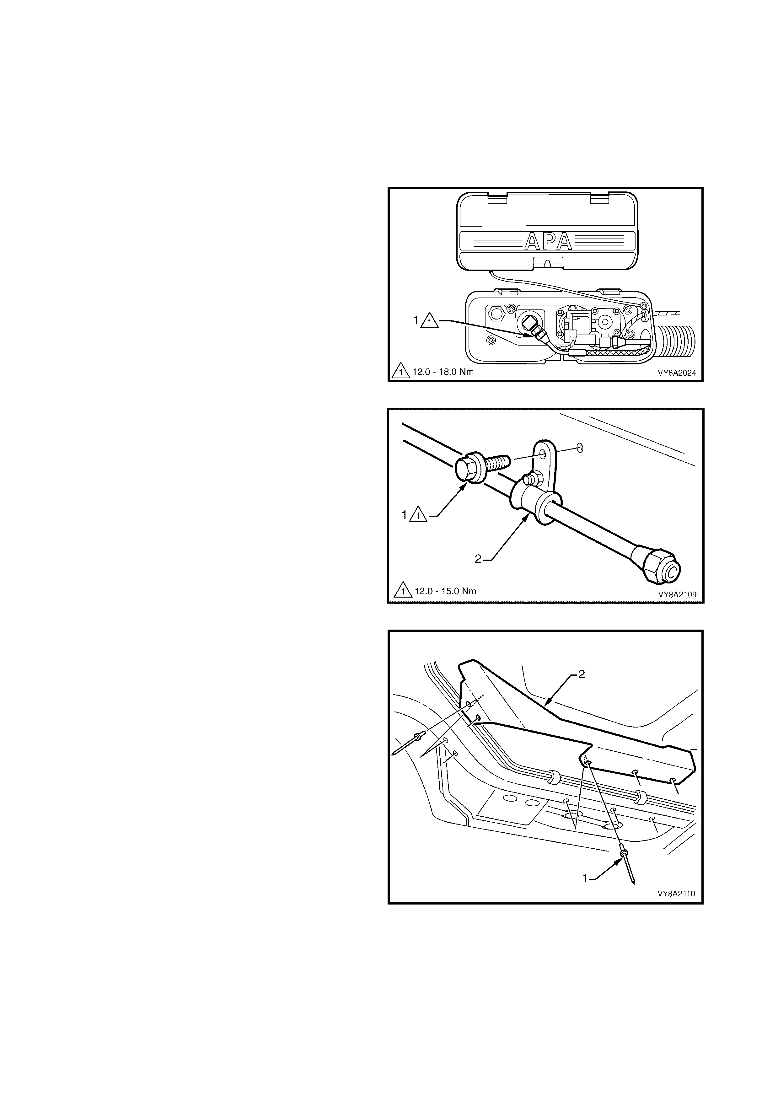
3.16 INTERMEDIATE SERVICE LINE
LT Section – AA-650Q
REMOVE
1. Park the vehicle in a well ventilated area, away
from any ignition source.
2. Drain the service lines of LPG, refer to
3.1 SERVICE LINE DRAINING.
3. From within the LPG valve box, while holding the
AFL elbow, crack open the filler line to AFL elbow
connector (1) and allow residual LPG to escape.
CAUTION: The filler line will contain LPG under
pressure. Once all the LPG in the line has
dispersed, unscrew the filler line connector
completely from the AFL elbow.
4. Disconnect the front and rear service lines as
required, ref er to 3.14 FRONT SERVICE LINE and
3.15 REAR SERVICE LINE.
Figure 8A2-103
5. Remove the screw (1) attaching the fuel line
retainer (2), two places, to the dash panel.
Figure 8A2-104
6. Remove the five rivets (1) attaching the fuel
harness heat shield (2) to the vehicle.
7. Depressurise the fuel (petrol) system, refer to
Section 6C1-3 SERVICE OPERATIONS – V6
ENGINE.
8. Remove the fuel pipe assembly, refer to
Section 8A1, 2.12 FUEL PIPE ARRANGEMENT.
9. Open the retainers and unattach the intermediate
service line (1) from the fuel pipe assembly; A –
Sedan, B – Wagon, C – Utility, refer to Figure
8A2-106.
Figure 8A2-105
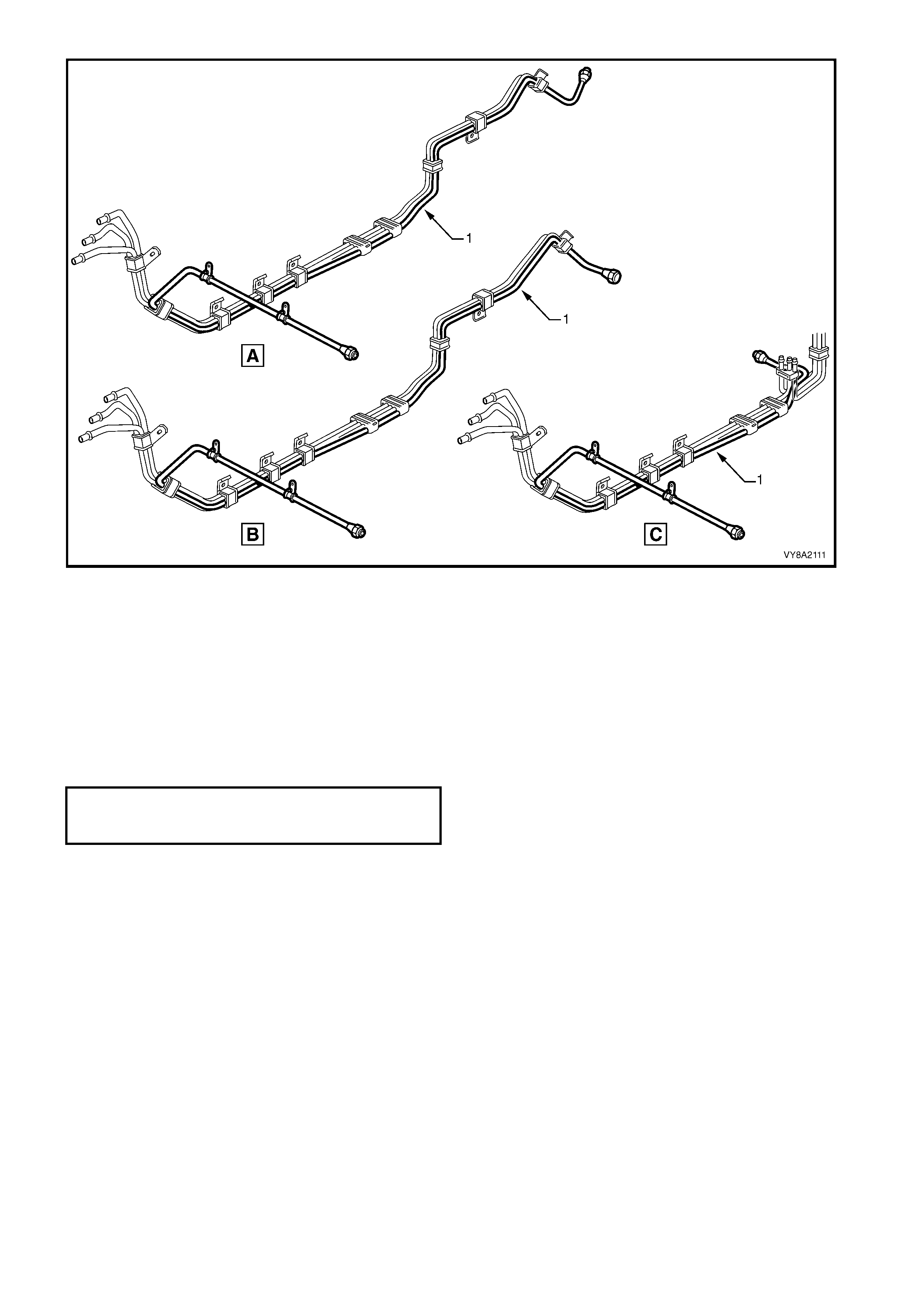
Figure 8A2-106
REINSTALL
Installation of the intermediate service line is the reverse of removal noting the following:
1. Ensure the service line does not chafe or come in contact with the body or other components.
2. Connect the intermediate service line connections to the front and rear service lines, refer to
3.14 FRONT SERVICE LINE and 3.15 REAR SERVICE LINE.
3. Leak test the LPG system, refer to 3.3 LEAK TESTING.
4. Fit the heat shield plate with new rivets.
5. Tighten the retaining clamp screws to the specified torque.
SERVICE LINE RETAINING
CLAMP SCREW
TORQUE SPECIFICATION 12.0 – 15.0 Nm
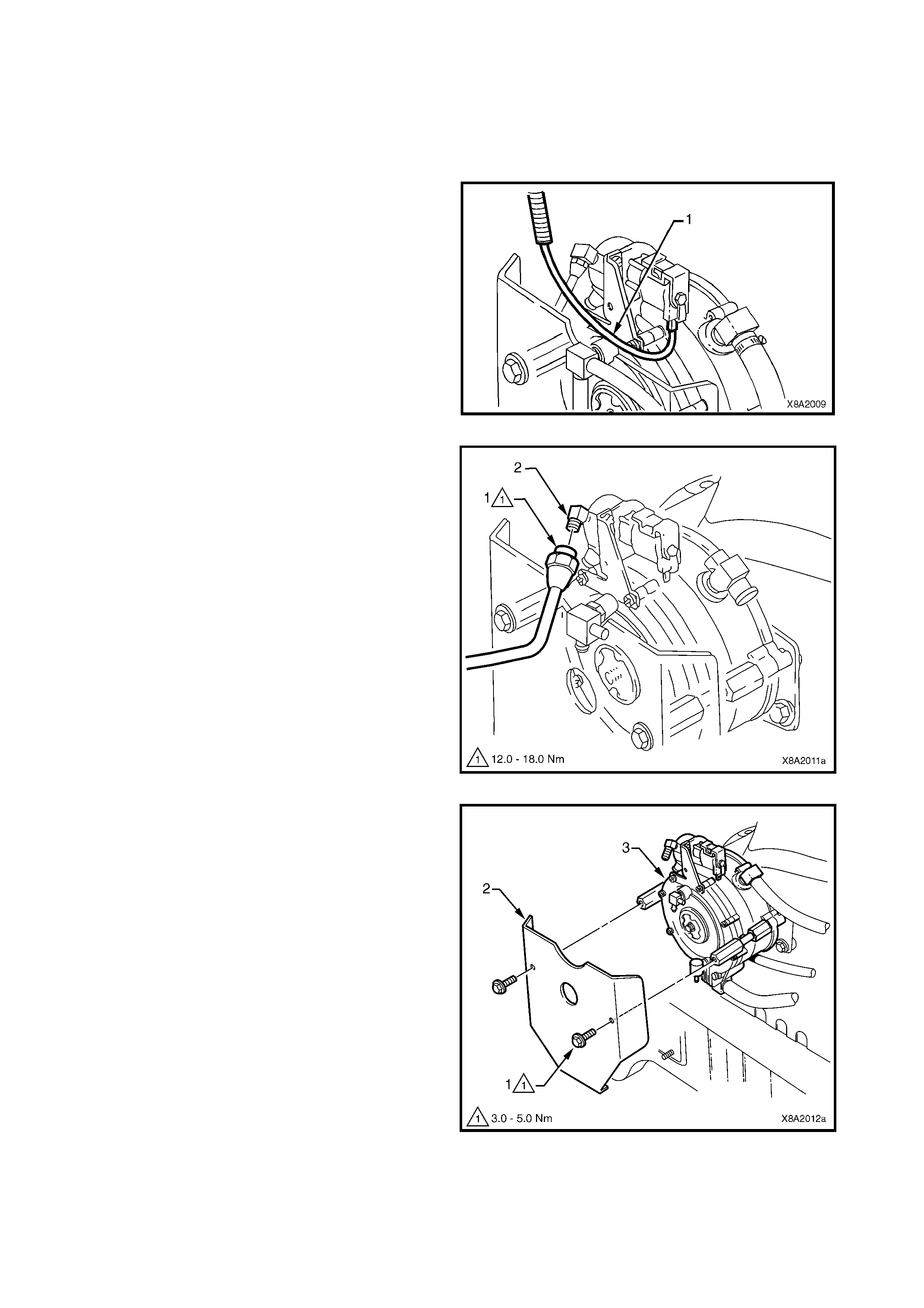
3.17 LPG LOCK-OFF
LT Section –
REMOVE
1. Drain the service lines of LPG, refer to
3.1 SERVICE LINE DRAINING.
2. Disconnect the LPG lock-of f harnes s connec tor (1)
from the LPG lock-off.
Figure 8A2-107
3. Disconnect the front service line (1) from the LPG
lock-off connection (2).
Figure 8A2-108
4. Remove the two screws ( 1) securing the c onverter
heat shield (2) to the c onverter (3) and remove the
heat shield.
Figure 8A2-109

5. Remove the two screws (1) attaching the lock-off
bracket (2) to the converter (3).
6. Remove the two screws and nuts (4) securing the
lock-off bracket to the lock-off (5) and remove the
lock-off bracket.
Figure 8A2-110
7. Loosen the LPG lock-off outlet connection at the
converter.
8. Remove the two heat shield support posts (1) and
the converter retaining screw (2).
9. Lift the converter (3) up as far as possible and
unscrew the LPG lock-off assembly from the
converter.
10. Lower the converter down into its mounting
position and tem porally seat the converter onto the
converter support bracket (4).
Figure 8A2-111
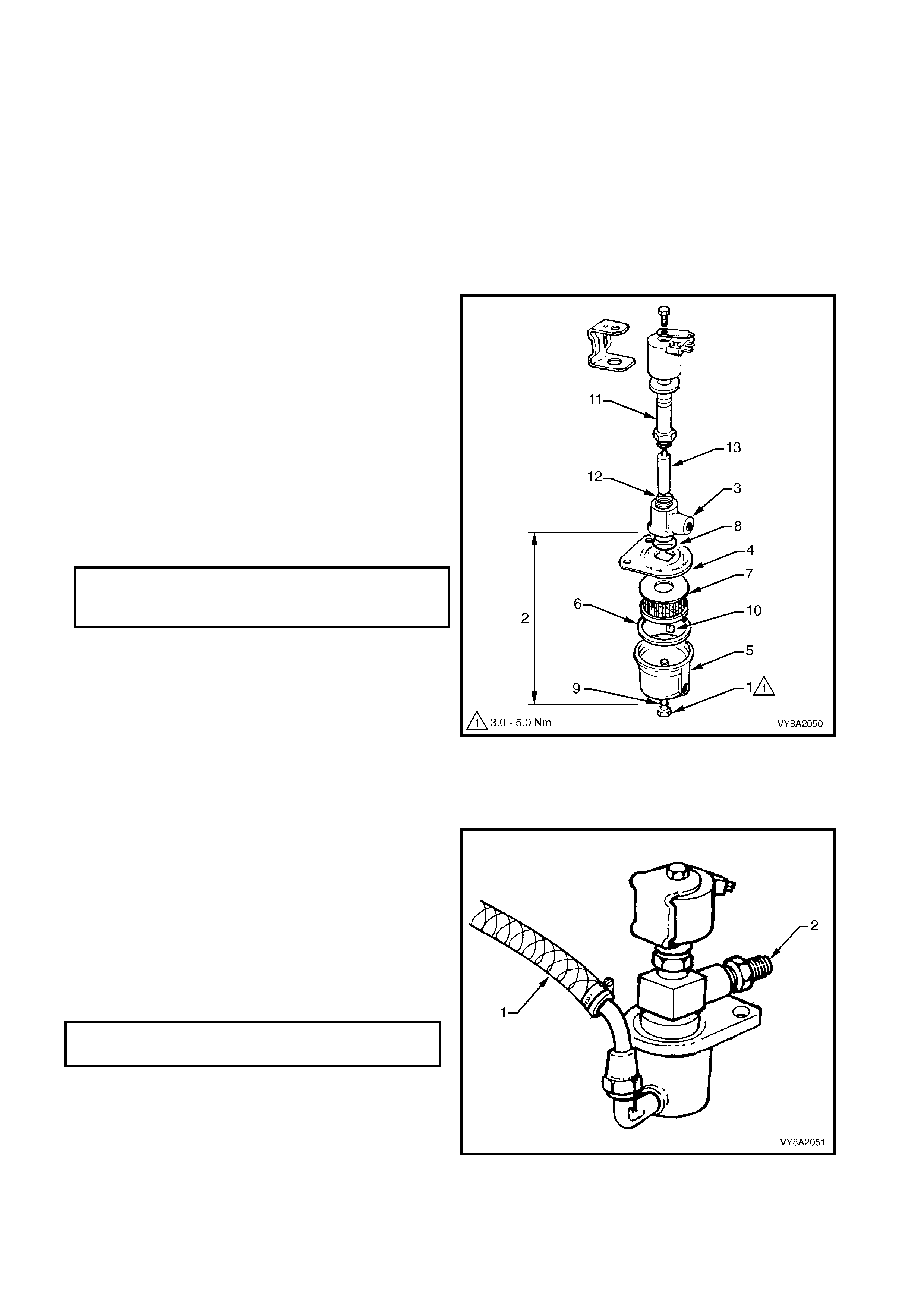
FILTER ELEMENT REPLACEMENT
The following filter element replacement procedure can
be perfor med with or without the LPG lock -off installed
to the converter.
CAUTION: If performing the following procedure
with the LPG lock-off installed, the service
lines must first be drained of LPG, refer to
3.1 SERVICE LINE DRAINING.
1. As required, disconnect the front service line
connector from the LPG lock-off and disconnect
the LPG lock-off wiring connector, refer to
3.17 LPG LOCK-OFF – REMOVE.
2. Rem ove the screw (1) attaching the cup assem bly
(2) to the valve body (3).
3. Separate the cup assembly from the valve body.
4. Remove the cup lid (4) from the cup (5) and
gasket (6), and remove the filter element (7).
5. Remove and discard the cup lid to valve body O-
ring (8) and the cup assembly screw O-ring (9).
6. Replace the filter, O-rings and cup gasket with new
parts.
7. As semble the parts , ensuring that the m agnet ( 10)
is cleaned and located in the cup.
8. Tighten the cup assembly screw to the specified
torque.
NOTE: A filter element replacement kit is available and
contains the following components:
• LPG lock-off cup assembly screw O-ring (9)
• LPG lock-off to valve body gasket (6)
• Filter element (7)
• Cup lid to valve body O-ring (8)
• Bobbin (11) to valve body O-ring (12)
• Coil plunger (13)
Figure 8A2-112
9. Connect the inlet of the LPG lock-off to
pressurised nitrogen (1).
10. Check for any flow of nitrogen from the LPG lock-
off outlet fitting (2).
11. The LPG lock-off should completely stop the flow
of nitrogen up to the specified pressure rating.
12. If the LPG lock-off allows any amount of the
nitrogen to flow, the LPG lock-off should be
replaced.
Figure 8A2-113
LPG LOCK-OFF CUP ASSEMBLY
ATTACHING SCREW
TORQUE SPECIFICATION 3.0 – 5.0 Nm
LPG LOCK-OFF PRESSURE
RATING SPECIFICATION 1200 kPa
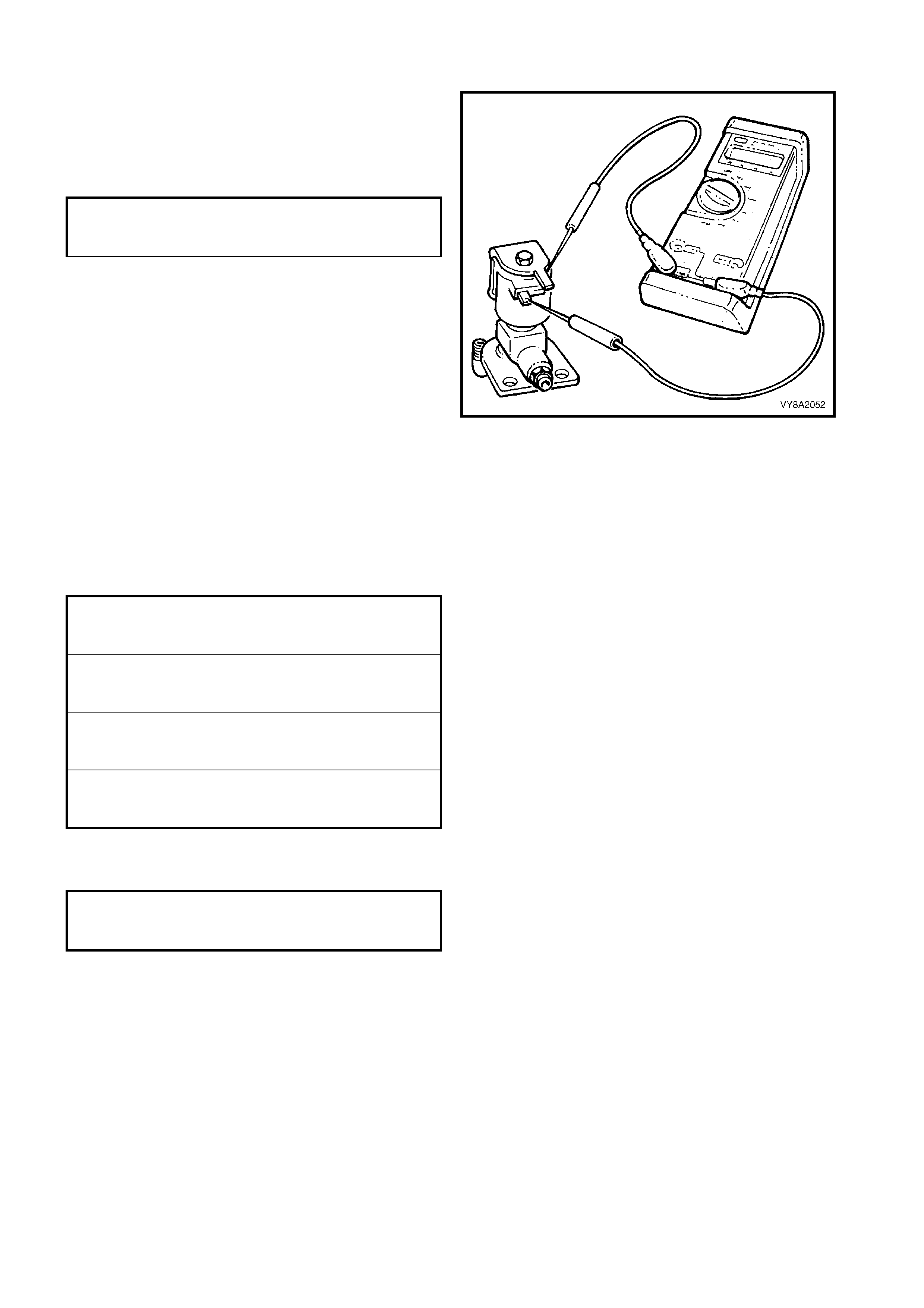
TEST
1. Connect an ohmmeter to the two LPG lock-off
term inals and check for continuity or a short circ uit
of the solenoid coil winding.
2. If the measured resistance is not to specification,
the LPG lock-off should be replaced.
Figure 8A2-114
REINSTALL
Installation of the LPG lock-off is the reverse of removal noting the following:
1. Clean the mating threads of LPG lock-off inlet and outlet connections and the front service line connector.
2. Apply Loctite 577 sealant to the LPG lock-off inlet thread and install the LPG lock-off to the converter and
tighten securely. If necessary, further tighten the lock-off to the converter to align it to the lock-off bracket.
3. Tighten all fasteners to the specified torque.
4. Apply Loctite 577 to the lock-off connector and tighten the connector to the specified torque.
5. Leak test the LPG system, refer to 3.3 LEAK TESTING.
LPG LOCK-OFF
COIL RESISTANCE 17 – 27 OHMS
@ 20° C
LPG LOCK-OFF BRACKET TO
CONVERTOR ATTACHING SCREW
TORQUE SPECIFICATION 3.0 – 5.0 Nm
CONVERTOR TO SUPPORT
BRACKET ATTACHING SCREW
TORQUE SPECIFICATION 10.0 – 12.0 Nm
HEAT SHIELD SUPPORT
POST ATTACHING SCREW
TORQUE SPECIFICATION 10.0 – 12.0 Nm
HEAT SHIELD
ATTACHING SCREW
TORQUE SPECIFICATION 3.0 – 5.0 Nm
FRONT SERVICE LINE TO LPG
LOCK-OFF CONNECTOR
TORQUE SPECIFICATION 12.0 – 18.0 Nm
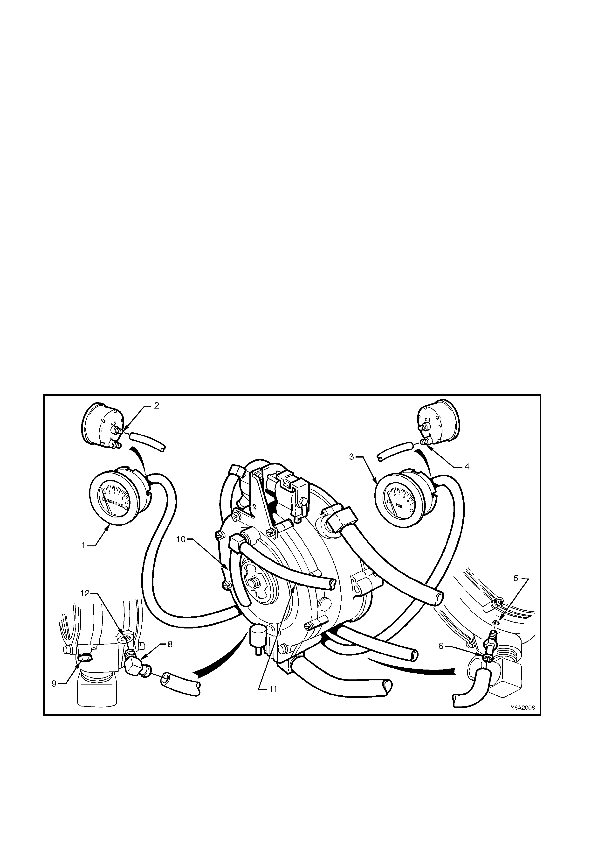
3.18 CONVERTER
LT Section – AA-650Q
CONVERTER ON VEHICLE TEST PROCEDURE
1. Drain the service lines of LPG, refer to 3.1 SERVICE LINE DRAINING.
2. Remove the converter from the vehicle while keeping all lines connected, refer to the procedure in this
Section.
NOTE: To aid accessing the ports, remove the front service line retainers from the dash panel, refer to
3.14 FRONT SERVICE LINE.
Referring to Figure 8A2-115:
3. Remove the plug from the converter primary test port (5) and install a straight test nipple (6) into the
converter primary test port.
4. Connec t the press ure gauge hose to the str aight nipple and to the HI connec tion of the 0 – 5 PSID pr essur e
gauge (3) from the LPG test kit, refer to 10. SPECIAL TOOLS.
5. Remove the plug f rom the conver ter sec ondar y test port (12) and install the test elbow (8) into the sec ondary
test port.
6. Connect the vacuum gauge hose to the secondary test elbow and the LO connection of a 0 – 10 inches
W.C. vacuum gauge (1) from the LPG test kit.
7. Turn the manual service valve on and check the test connections for leaks.
8. With the fuel mode switch in LPG position, start the engine and allow to idle.
NOTE: If the engine will not start, crank the engine and record pressures.
9. Converter primary pressure should be 7 – 10 kPa.
10. Disconnect the FCV to converter balance lines at the converter (10, 11).
11. Secondary converter pressure should be negative 1 – 1.5 inches W.C.
12. Reconnect the balance line and the secondary pressure gauge should fluctuate from 1 – 5 inches W.C.
13. Turn the engine off. The gauges should hold pressure for at least five minutes.
Figure 8A2-115
Legend
1. Inches W.C. Gauge (secondary pressure) 5. Primary Pressure Port 9. Water Drain
2. Low Port 6. Straight Test Nipple 10. Balance Hose (to mixer)
3. PSID Gauge (primary pressure) 7. Vapour Hose 11. Balance Hose (to FCV)
4. High Port 8. Test Elbow 12. Secondary Pressure Port
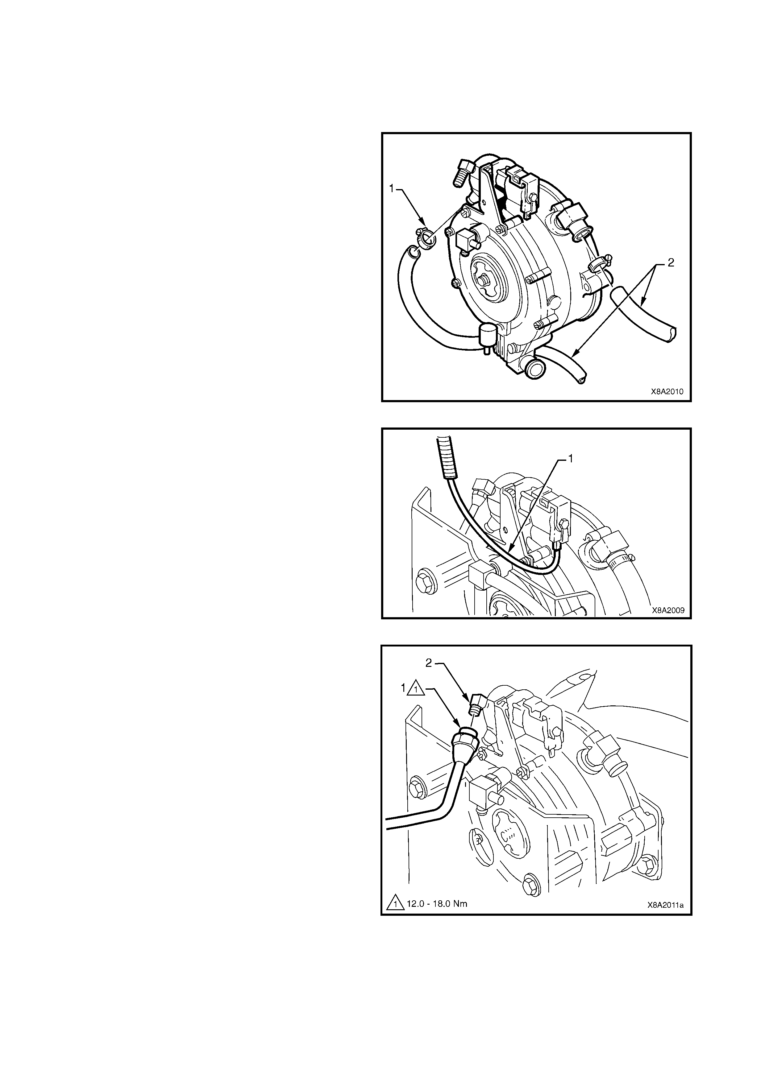
REMOVE
1. Drain the service lines of LPG, refer to 3.1 SERVICE LINE DRAINING.
2. Depressurise the engine cooling system by removing the radiator cap in two stages.
CAUTION: Do not remove radiator cap while the engine coolant is hot as personal injury may result.
3. Plac e a drain tray beneath the vehicle. Loosen the
clamps (1) securing the engine coolant hoses (2)
to the converter coolant inlet and outlet elbows.
Remove the coolant hoses f rom the converter and
lay back away from the converter.
Figure 8A2-116
4. Disconnect the LPG-off harness connector (1)
from the LPG lock-off (2).
Figure 8A2-117
5. Disconnect the front service line (1) from the LPG
lock-off inlet connection (2).
Figure 8A2-118
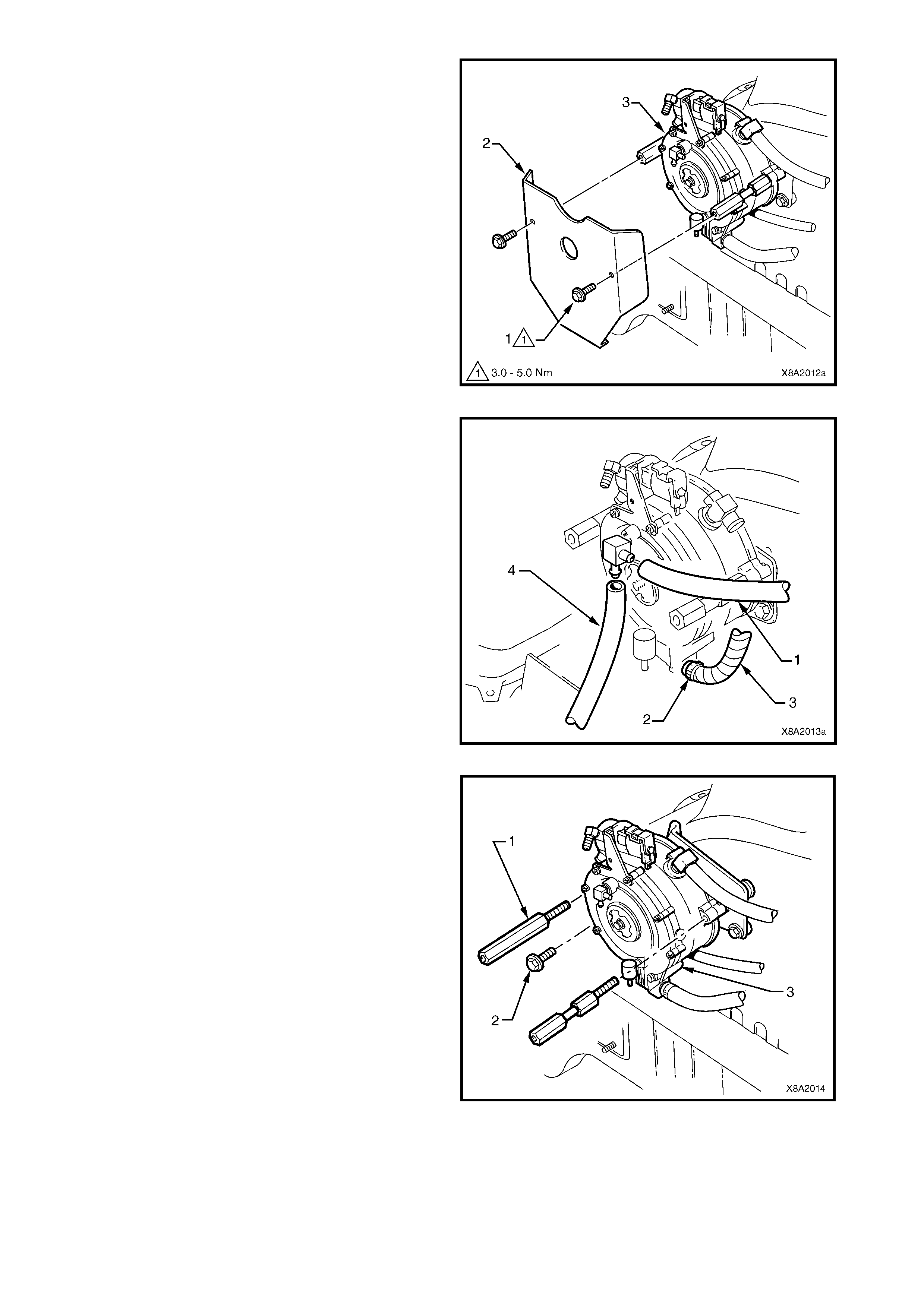
6. Remove the two screws ( 1) securing the c onverter
heat shield (2) to the c onverter (3) and remove the
heat shield.
Figure 8A2-119
7. Remove the FCV balance hose (1) and vacuum
hose (4) from the converter connections.
8. Loosen the mixer to converter vapour hose clamp
(2) at the converter vapour outlet and disconnect
the vapour hose (3) from the converter.
Figure 8A2-120
9. Loosen and remove the two heat shield support
bolts (1), two places, and the converter retaining
bolt (2).
10. Remove the converter assembly (3).
11. Remove the engine coolant inlet and outlet elbows,
vapour outlet, FCV balance hose connection and
lock-off assembly if required.
12. If performing the following overhaul procedure on
the converter assembly, loosen and unscrew the
LPG lock-off to converter connection, remove the
connection and the LPG lock-off from the
converter.
Figure 8A2-121
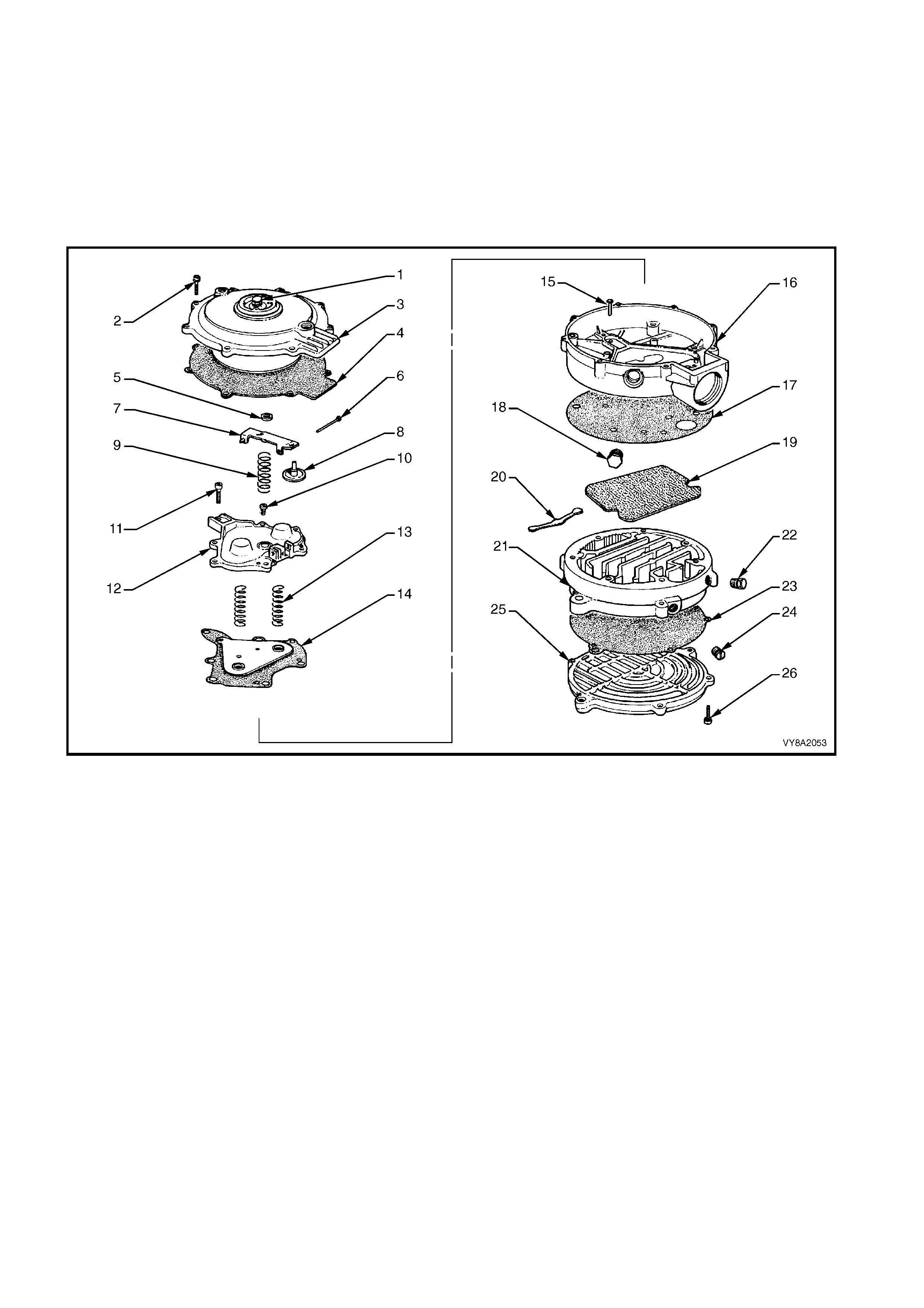
OVERHAUL
Under normal operating conditions, installation of a complete converter repair kit should only be necessary:
• at the time or distance intervals specified in the vehicle owners handbook LPG leaflet, or
• if the converter has been out of service for some time causing the gaskets and diaphragms to deteriorate, or
• after the converter has been stored after being used.
The c onverter repair kit c ontains the components shown in the following diagram m arked # in the Legend, ref er
to Figure 8A2-122.
All other converter components are available separately, refer to spare parts information for details.
Figure 8A2-122
Legend
1. Primer Button 10. Screw 19. Sponge #
2. Screw # 11. Screw # 20. Primary Seat #
3. Diaphragm Cover 12. Primary Diaphragm Cover 21. Heat Exchanger Body
4. Secondary Diaphragm # 13. Primary Diaphragm Spring 22. Plug
5. Hand Primer Washer # 14. Primary Diaphragm # 23. Gasket #
6. Secondary Diaphragm Lever Fulcrum Pin 15. Primary Valve Pin 24. Plug
7. Secondary Diaphragm Lever 16. Regulator Body 25. Heat Exchanger Cover
8. Secondary Seat # 17. Gasket # 26. Screw #
9. Secondary Diaphragm Lever Spring 18. Plug
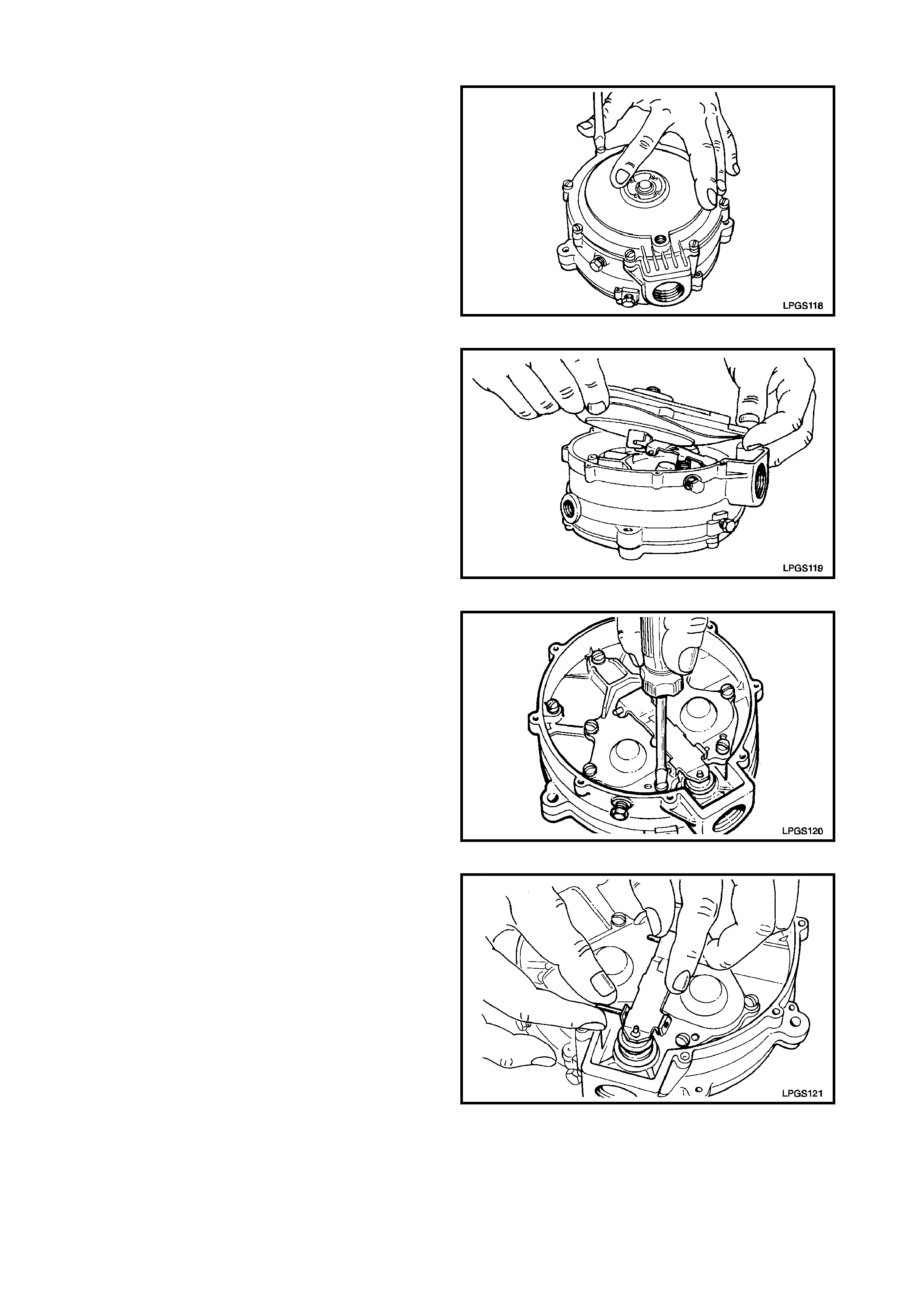
DISASSEMBLE
1. Remove the eight diaphragm cover to regulator
body attaching screws.
Figure 8A2-123
2. Lift up the diaphragm cover and diaphragm from
the regulator body.
3. Move the diaphragm cover and diaphragm away
from the low-pressure outlet by approximately 25
mm to disengage the two prongs of the diaphr agm
link from the secondary diaphragm lever.
4. Remove the diaphragm cover and diaphragm f rom
the regulator body.
Figure 8A2-124
5. Loosen and remove the primary diaphragm cover
to regulator body screw that retains the secondary
diaphragm lever fulcrum pin.
Figure 8A2-125
6. Slide the secondary diaphragm lever fulcrum pin
from the primary diaphragm cover and remove.
Figure 8A2-126
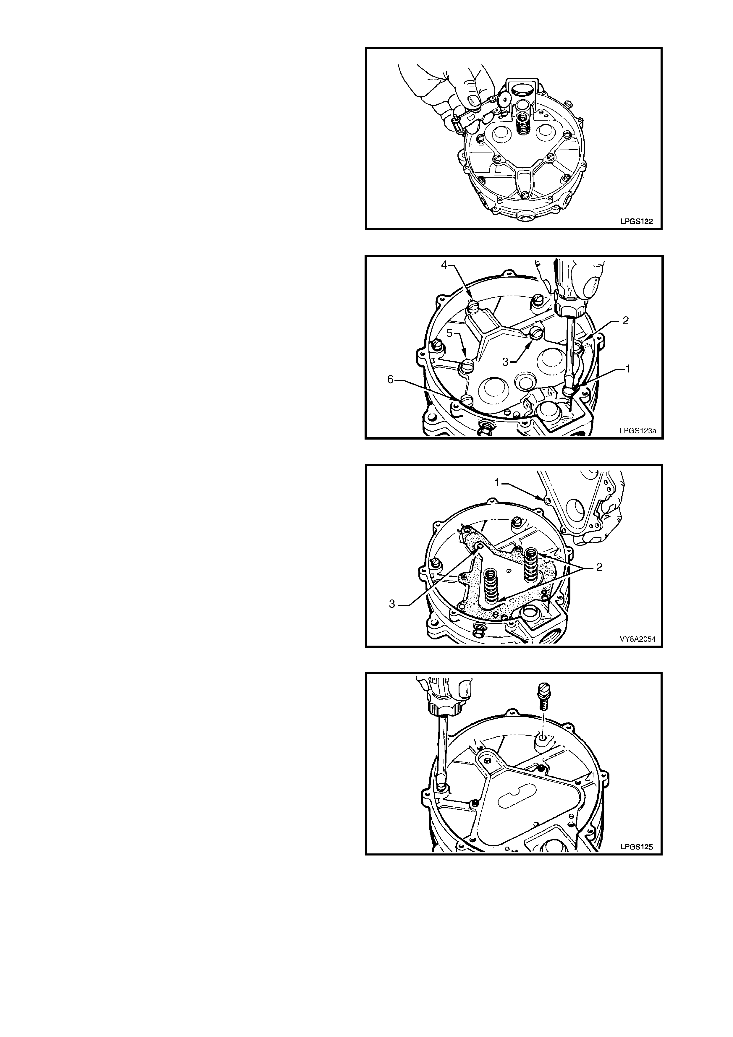
7. Remove the secondary diaphragm lever and
spring from the primary diaphragm cover.
Figure 8A2-127
8. Remove the remaining six primary diaphragm
cover to regulator body retaining screws (1 – 6).
NOTE: Rem oval of these screws releases the primary
diaphragm cover from the regulator body, thereby
allowing the primary diaphragm springs to be released.
Figure 8A2-128
9. Remove the primary diaphragm cover with the
diaphragm (1) and primary diaphragm springs (2)
from the regulator body.
10. Remove the primary valve pin (3) from the
regulator body.
Figure 8A2-129
11. Remove the two remaining regulator body to heat
exchanger body attaching screws.
Figure 8A2-130
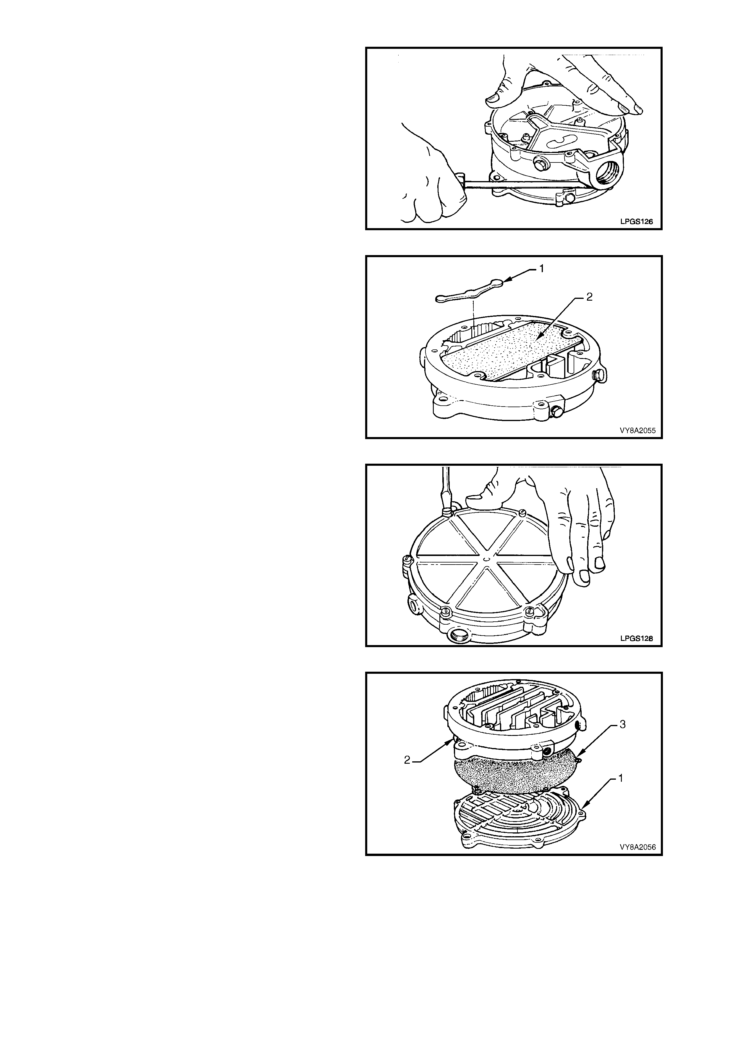
12. Loosen and separate the regulator body from the
heat exchanger body. Discard the gasket.
Figure 8A2-131
13. Remove and discard the primary valve seat (1)
and sponge (2) from the heat exchanger body.
Figure 8A2-132
14. Remove the heat exchanger cover to heat
exchanger body attaching screws.
Figure 8A2-133
15. Separate the heat exchanger cover (1) from the
heat exchanger body (2) and discard the gasket
(3).
Figure 8A2-134
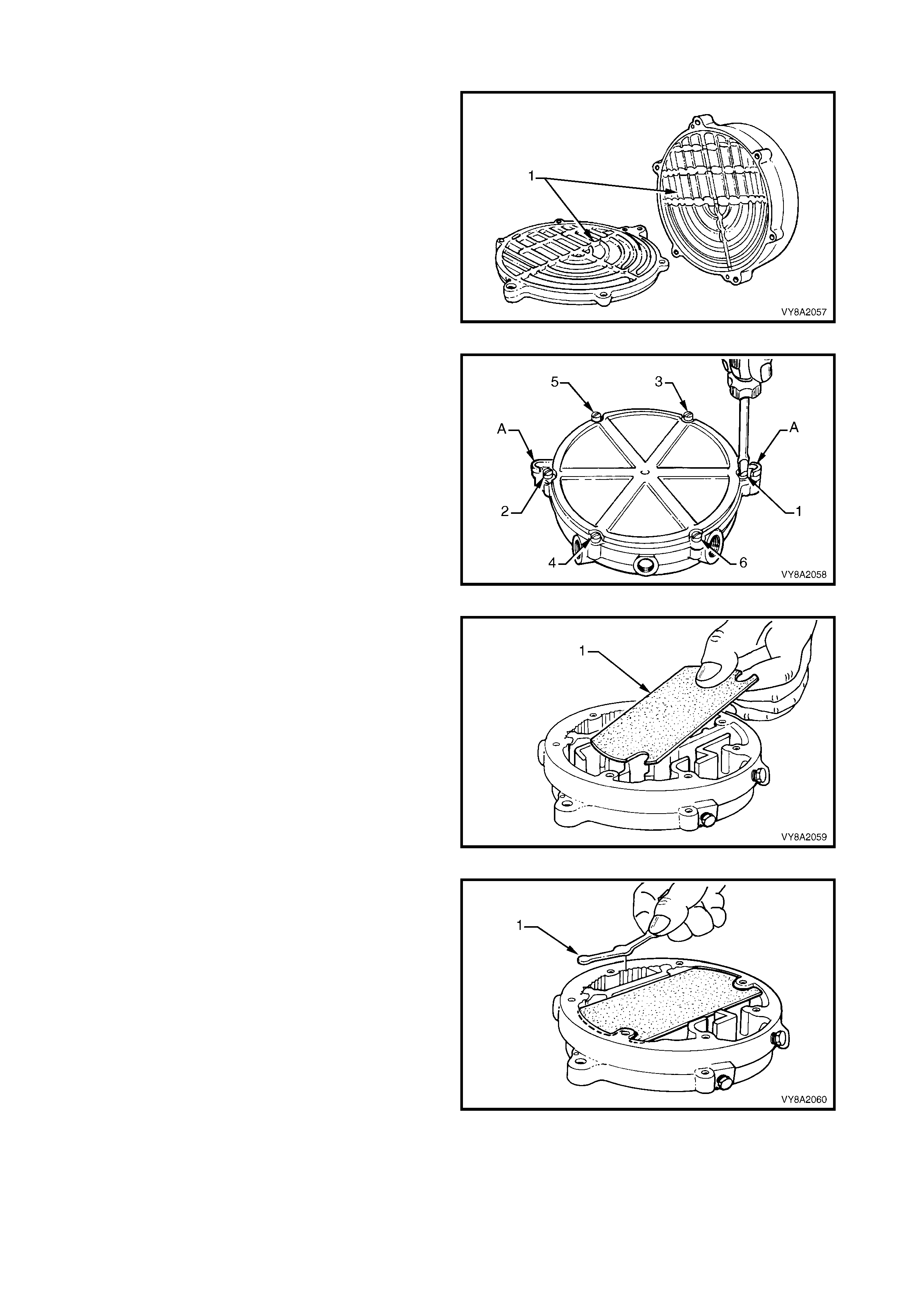
REASSEMBLE
1. Clean all parts in a suitable cleaning solution and
thoroughly dry and inspect all components.
2. Car e should be tak en to clean all depos its (1) from
the heat exchanger body and cover.
Figure 8A2-135
3. Us ing a new gask et, assem ble the heat exchanger
cover to the heat exchanger body, matching the
mounting bosses (A) in the cover with those on the
exchanger body.
4. Ins tall and tighten the attaching screws s ecurely in
the sequence shown.
Figure 8A2-136
5. Place the sponge in the recess in the heat
exchanger body.
NOTE: The sponge must be accurately positioned.
Figure 8A2-137
6. Install a new primary valve seat (1) into the heat
exchanger body.
Figure 8A2-138
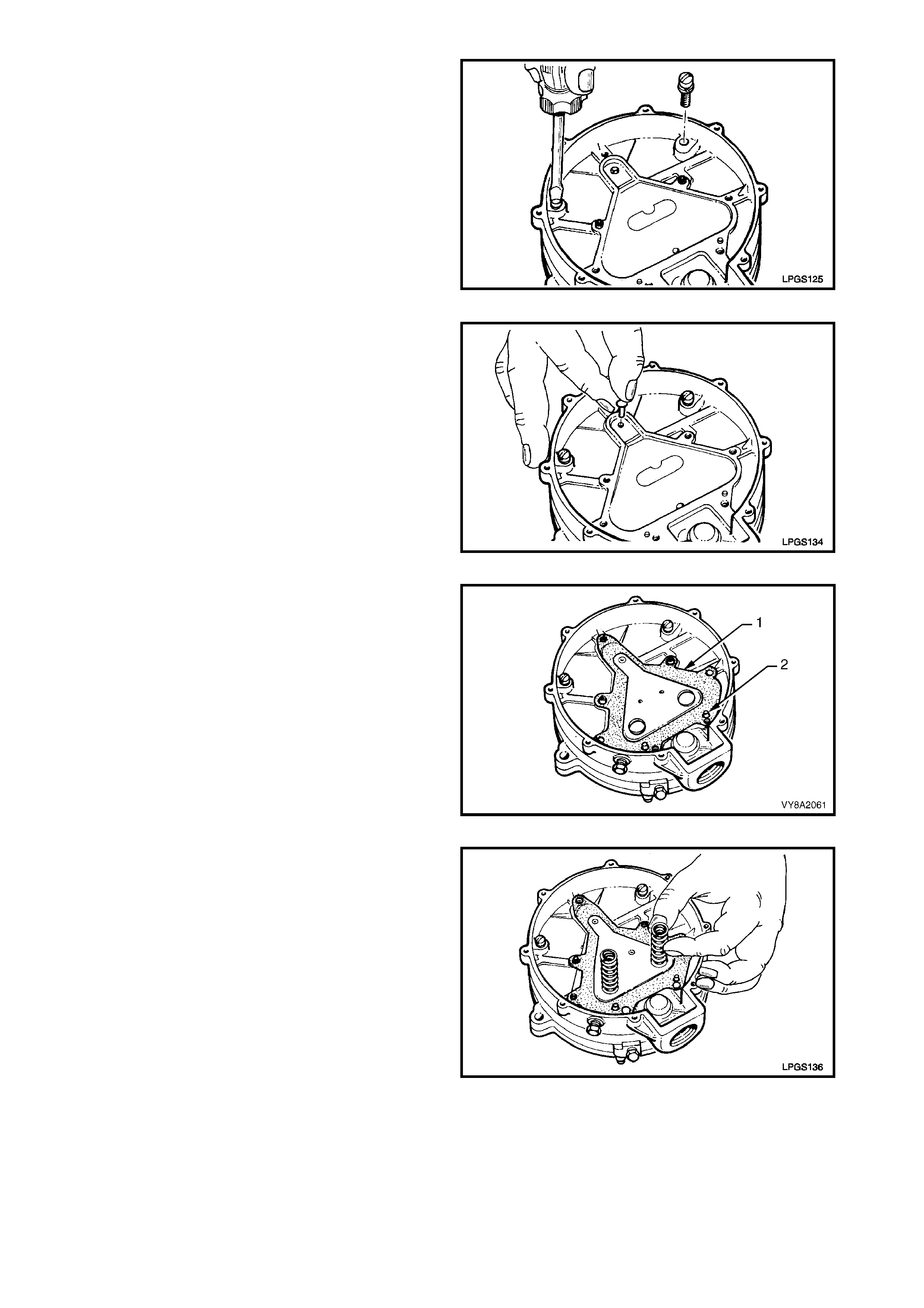
7. Plac e the regulator body to heat exchanger gask et
on the primary pin boss and two locating pins on
the underside of the regulator body .
8. Use the two screws to locate the regulator body
and gasket on the heat exchanger as shown.
9. T ighten the scr ews just until the head engages the
regulator body.
Figure 8A2-139
10. Place the prim ary valve pin into the regulator body
hole.
Figure 8A2-140
11. Install the primary diaphragm (1) over the locating
pins (2) and the screw bosses in the regulator
body. This is essential to ensure proper alignment
and assembly of the primary diaphragm springs
and primary diaphragm cover.
Figure 8A2-141
12. Place the two primary diaphragm springs upon
their locating bosses on the backing plate of the
primary diaphragm assembly.
Figure 8A2-142
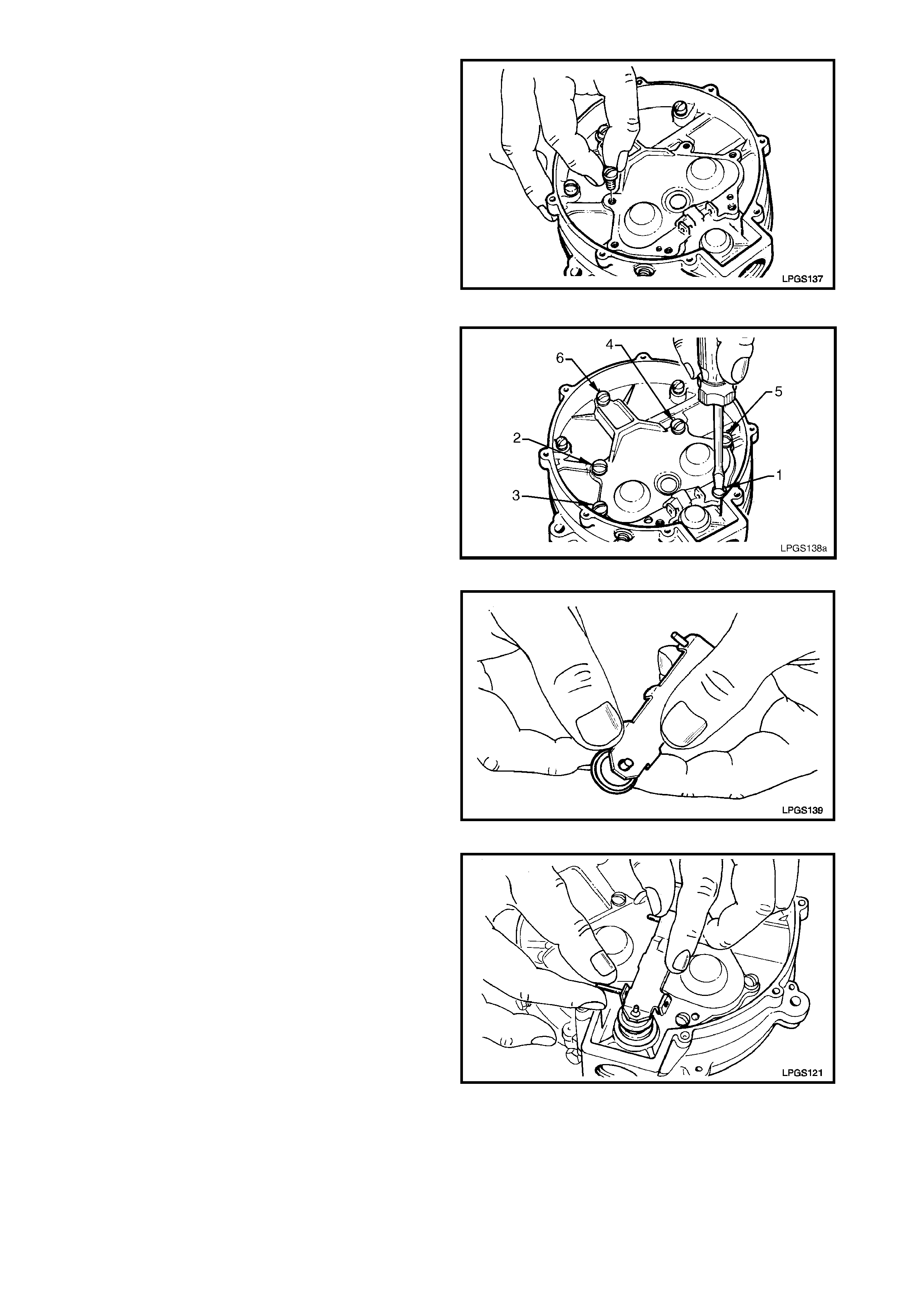
13. Place the primary diaphragm cover over the
primary diaphragm springs and push the cover
down on the springs until it contacts the regulator
body.
NOTE: The springs must locate in the cups in the
primary diaphragm cover.
14. While holding down the primary diaphragm cover,
insert the six c over attaching s crews, ens uring that
the two shallow headed sc rews are installed in the
correct locations, screws (2) and (4) in Figure
8A2-144.
NOTE: Do not install the attaching screw used to
retain the secondary diaphragm lever fulcrum pin at
this stage.
Figure 8A2-143
15. Tighten the primary diaphragm cover screws until
they contact the cover.
16. Tighten the screws securely in the order shown.
Figure 8A2-144
17. Remove the old secondary seat from the
secondary diaphragm lever and r eplac e with a new
seat.
Figure 8A2-145
18. Install the secondary diaphragm lever to the
primary diaphragm cover.
19. Insert the fulcrum pin whilst holding the lever in
place.
Figure 8A2-146
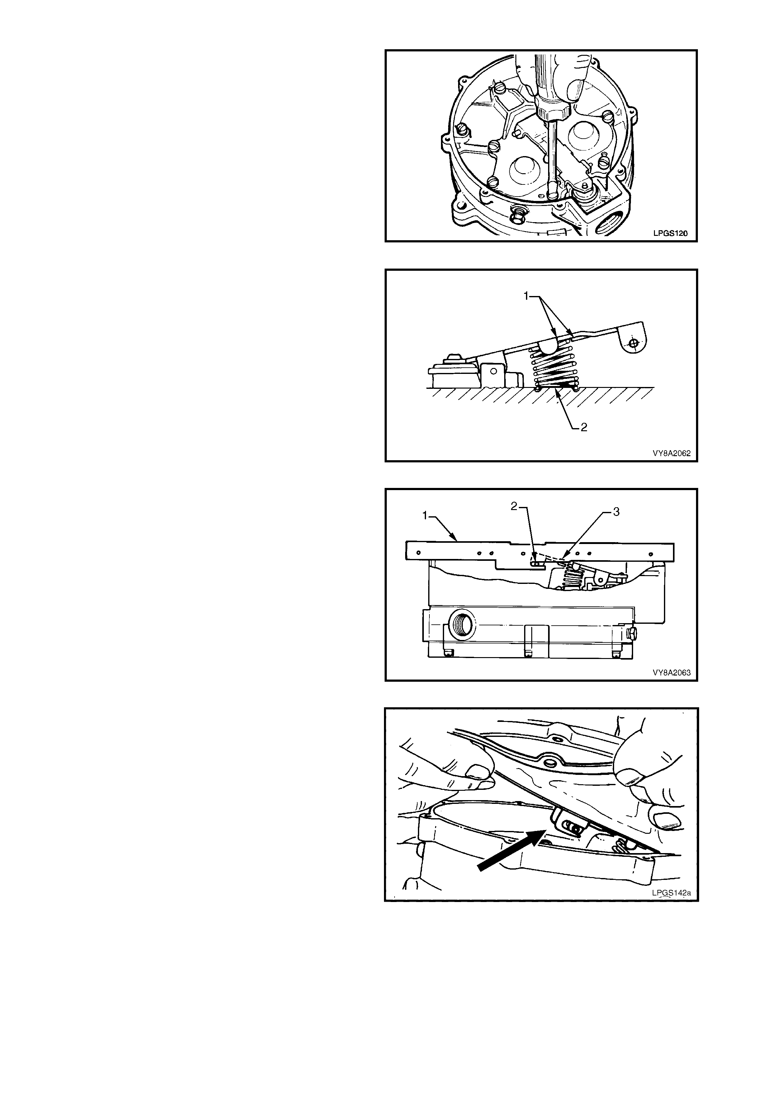
20. Install the remaining primary diaphragm cover
screw also used to retain the fulcrum pin. Tighten
the screw securely.
Figure 8A2-149
21. Install the secondary diaphragm lever spring by
slipping it under the secondary diaphragm lever.
22. Ensure that the s pring is correctly located between
the retaining tabs (1) on the lever and the r etaining
area (2) in the primary diaphragm cover.
Figure 8A2-150
23. Using the secondary diaphragm lever adjustment
gauge, part of LPG Test Kit ITK-1, refer to
10. SPECIAL TOOLS and ensure that the resting
position of the s econdary diaphragm lever is within
specification as shown. The height of the
secondary lever link pin (2) should correspond to
the slot in the measuring gauge.
24. If the height of the secondary diaphragm lever link
pin is not to specification, gently bend the
secondary diaphragm lever at point (3) until the
specified height is achieved.
Figure 8A2-151
25. Assemble the new secondary diaphragm by
attaching the secondary diaphragm slots to the
secondary diaphragm lever link pin.
Figure 8A2-152
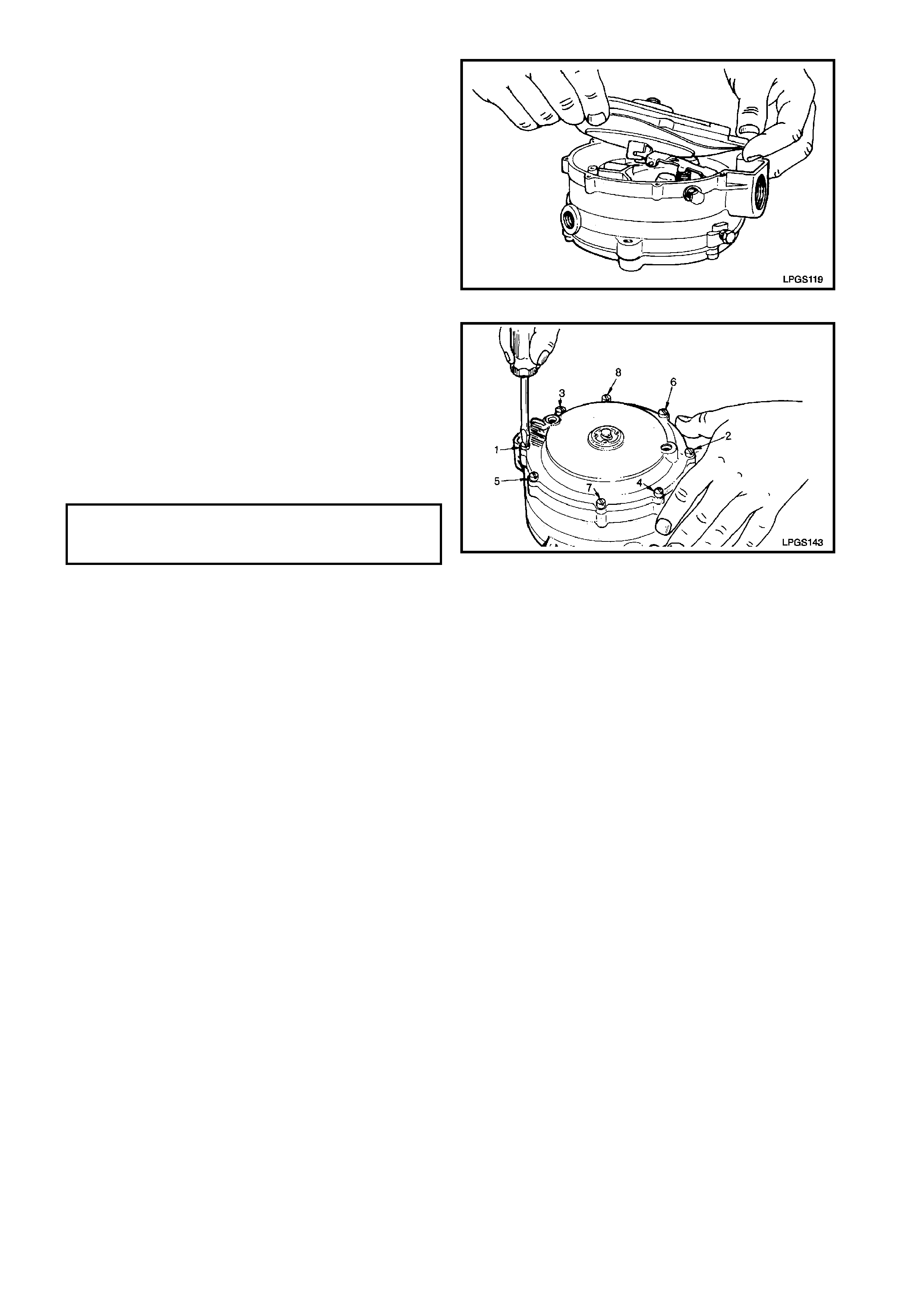
26. Ensure of the c or rec t r elationship of the diaphragm
on the lever link pin.
Figure 8A2-153
27. Install the diaphragm cover onto the regulator
body, ensuring that the secondary diaphragm is
correctly located between the cover and regulator
body.
28. Install the attaching screws and tighten until all
screws contact the cover.
29. Continue to tighten the attaching screws in the
sequence shown until all are seated, then tighten
to the specified torque.
Figure 8A2-154
CONVERTER OFF VEHICLE TEST
1. Remove the converter from the vehicle, refer to REMOVE within this Section.
2. Referring to Figure 8A2-153:
A. Remove the plug from the converter primary test point and install the straight test nipple (1) into the
converter primary test point (2).
B. Connect the pressure gauge hose (3) to the straight test nipple and to the high connection of the
0 - 5 PSID pressure gauge (4), part of the LPG test kit ITK-1.
C. Remove the plug from the converter secondary test point and install the test elbow (5) into the
secondary test point (6).
D. Connect the vacuum gauge hose (7) to the test elbow and the LOW connection of the 0 - 10 inches
W.C. vacuum gauge (8), part of the LPG test kit ITK-1.
E. Remove the converter to LPG lock-off connector (9) from the LPG lock-off and reinstall into the
converter. Tighten the connector securely.
F. Connect an air supply (10) into the converter to LPG lock-off connector and adjust the air supply
pressure to 875 kPa.
G. Note the pressur e reading on the primary pressur e gauge. Primary converter press ure should be 7 - 10
kPa.
H. Disconnect the air supply. The converter should hold primary pressure for at least five minutes.
NOTE: The following step involves the use of a domestic vacuum cleaner as a vacuum source.
I. Reconnect regulated air supply to the converter to LPG lock-off connector. W hile watching the primary
pressur e gauge, bring the vac uum nozzle of the vacuum c leaner ( 11) to the converter vapour outlet (12).
When the primary pressure gauge needle moves (indicating start point of vapour supply out of
secondary), note and record the secondary vacuum gauge reading.
J. The secondary converter pressure should be negative 1 - 1.5 inches W.C.
3. If during this tes t the specified prim ary and/or secondary pressures cannot be ac hieved, the converter m ust
be overhauled.
DIAPHRAGM COVER TO REGULATOR
BODY ATTA CHING SCREW
TORQUE SPECIFICATION 3.0 – 5.0 Nm
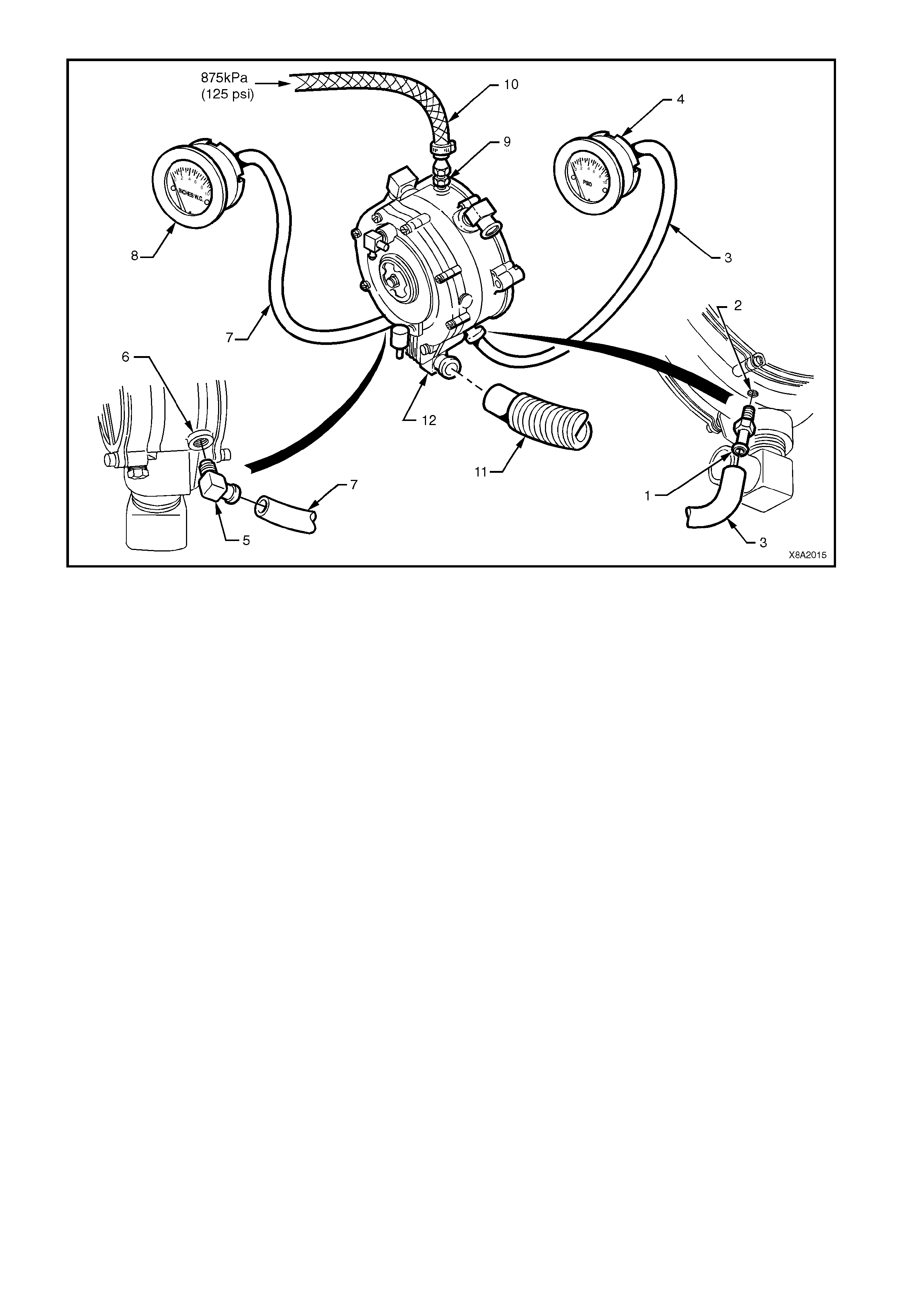
Figure 8A2-155
REINSTALL
Installation of the converter is the reverse of the removal procedure, noting the following points:
1. If removed, ensure that the engine coolant inlet and outlet elbows, vapour outlet, FCV balance hose
connection threads and converter mating threads are clean.
2. Apply Loctite 577 sealant to coolant and vapour elbow threads and tighten these elbows to the positions
shown in Figure 8A2-154.
3. Ensure that the LPG lock-off to converter connector and the front service line to lock-off connector mating
threads are clean.
4. If removed, also clean the LPG lock-off connector and the LPG lock-off mating threads.
5. Apply Loctite 577 sealant to the LPG lock -of f connec tor ensur ing that flared s urf aces ar e free of sealant and
contaminants. Install the LPG lock-off connector to the LPG lock-off and tighten securely.
6. Install the LPG lock-off on to the converter and tighten securely. If necessary, further tighten the lock-off to
align it with the retaining bracket.
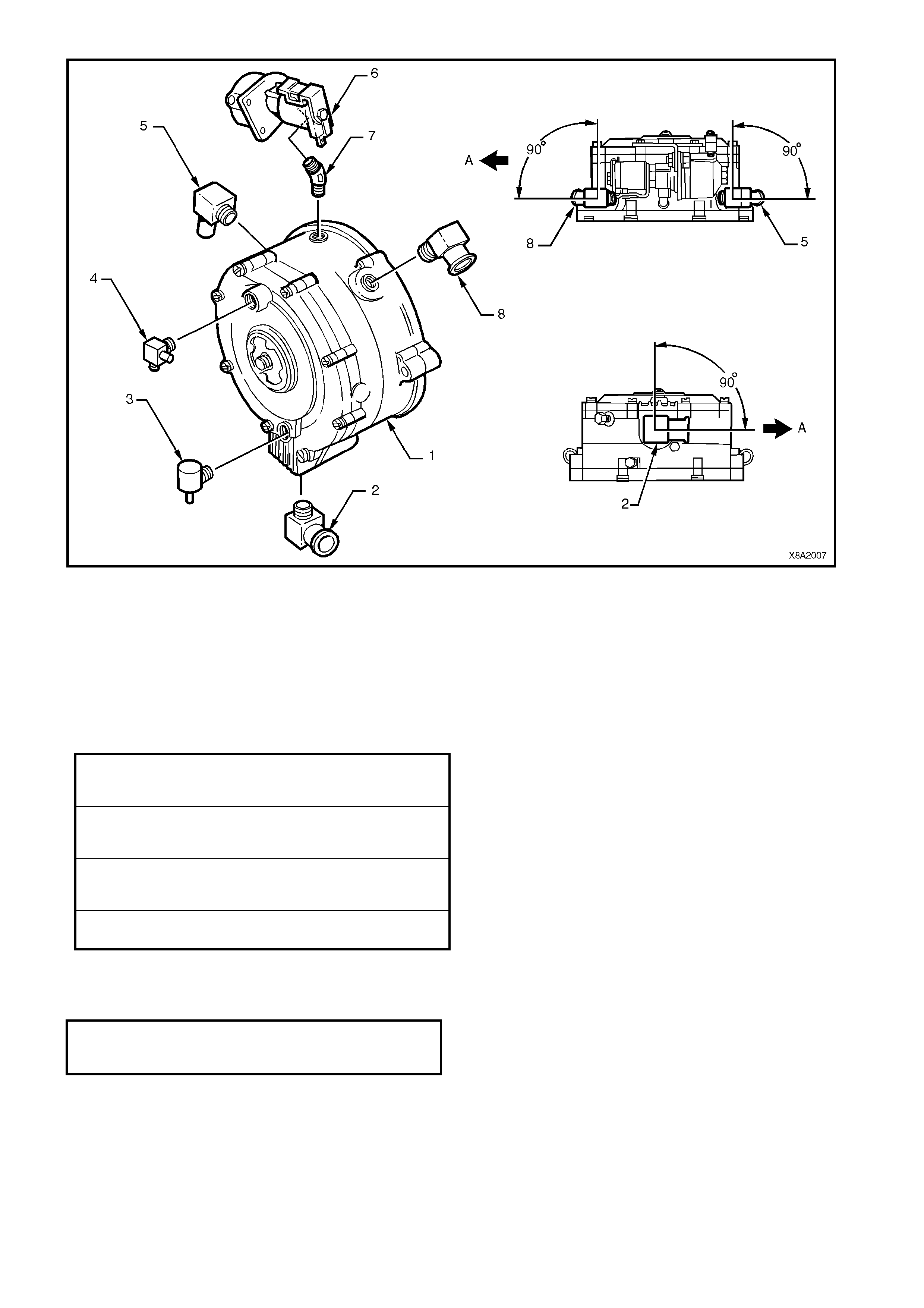
Figure 8A2-156
Legend
1. Converter 5. Coolant Elbow A. Front of Vehicle
2. Vapour Outlet Elbow 6. LPG Lock-off
3. FCV Balance Hose Connector 7. Connector
4. Nipple 8. Coolant Elbow
7. Tighten the fasteners to the specified torque.
8. Apply Loctite 577 to the lock -off connector and tighten the f ront servic e line to LPG lock-of f connector to the
specified torque.
9. Leak test the LPG system, refer to 3.3 LEAK TESTING.
10. Refill the cooling system with coolant to the cor rec t c onc entration level and pr es sur e test the system , ref er to
Section 6B1 ENGINE COOLING – V6 ENGINE.
LOCK-OFF BRACKET TO CONVERTER
ATTACHING SCREW
TORQUE SPECIFICATION 3.0 – 5.0 Nm
CONVERTER TO SUPPORT BRACKET
ATTACHING SCREW
TORQUE SPECIFICATION 10.0 – 12.0 Nm
HEAT SHIELD SUPPORT
POST SCREW
TORQUE SPECIFICATION 10.0 – 12.0 Nm
HEAT SHIELD ATTACHING SCREW
TORQUE SPECIFICATION 3.0 – 5.0 Nm
FRONT SERVICE LINE CONNECTOR
TO LPG LOCK-OFF
TORQUE SPECIFICATION 12.0 – 15.0 Nm
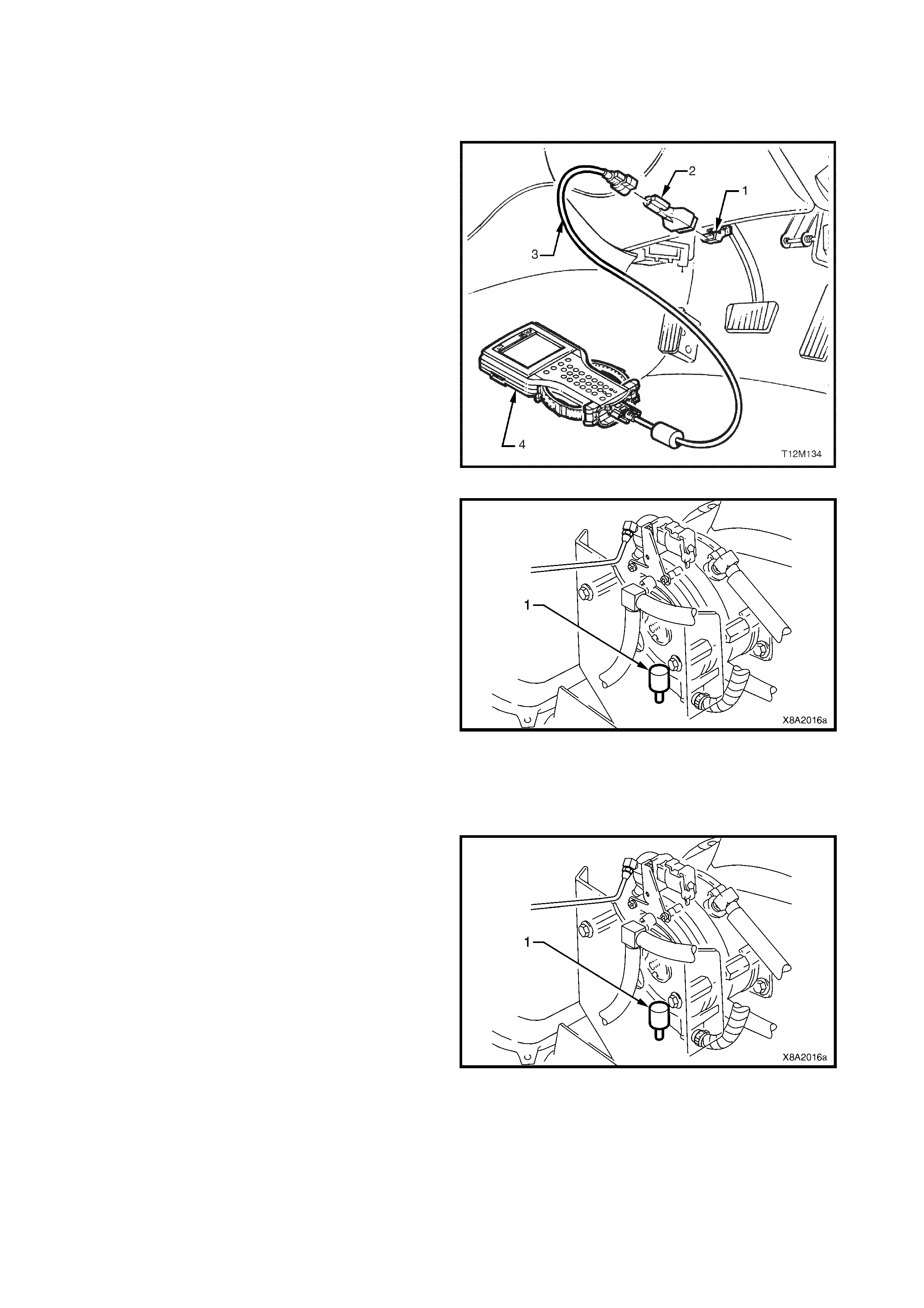
3.19 REGULATOR CHECK VALVE
LT Section –
TEST
1. Connect TECH 2 (4) to the DLC (1) with the cable
(3) and adapter (2).
NOTE: For additional information on connecting and
operating TECH 2, refer to Section 0C TECH 2.
2. Select: Diagnostics / (3) 2003 / VY Commodore /
Engine / V6 / Turn the ignition as instructed by
TECH 2 and confirm the System Identification /
Data Display / All Data.
3. Scroll to Fuel Control Valve.
4. Start the engine and take note of the duty cycles
displayed on the TECH 2 screen for the FCV (%).
Figure 8A2-157
5. Place a finger over the regulator check valve
(RCV) (1) atmospheric port (large opening) and
take note of the FCV duty cycles.
There should be little or no change in the duty
cycle.
6. Place a 3/8” inside diameter hose over the RCV
atmospheric port (large opening). Apply a small
amount of air press ur e to the open end of the hose
(physically blow through hose) and take note of the
duty cycles displayed for the FCV.
7. If duty cycles do not change, it indicates the RCV
is not opening as required and should be replaced.
Figure 8A2-158
REMOVE
1. Drain the service lines of LPG, refer to
3.1 SERVICE LINE DRAINING.
2. If required, remove the two screws securing the
heat shield to the converter heat shield support
bolts and remove heat shield.
3. Unscrew the RCV (1) from the converter.
Figure 8A2-159
REINSTALL
Reinstallation of the RCV is the reverse of the removal procedure, noting the following:
Apply Loctite 577 sealant to RCV threads, install RCV to the converter and tighten securely. If required, further
tighten the RCV to correctly align it.
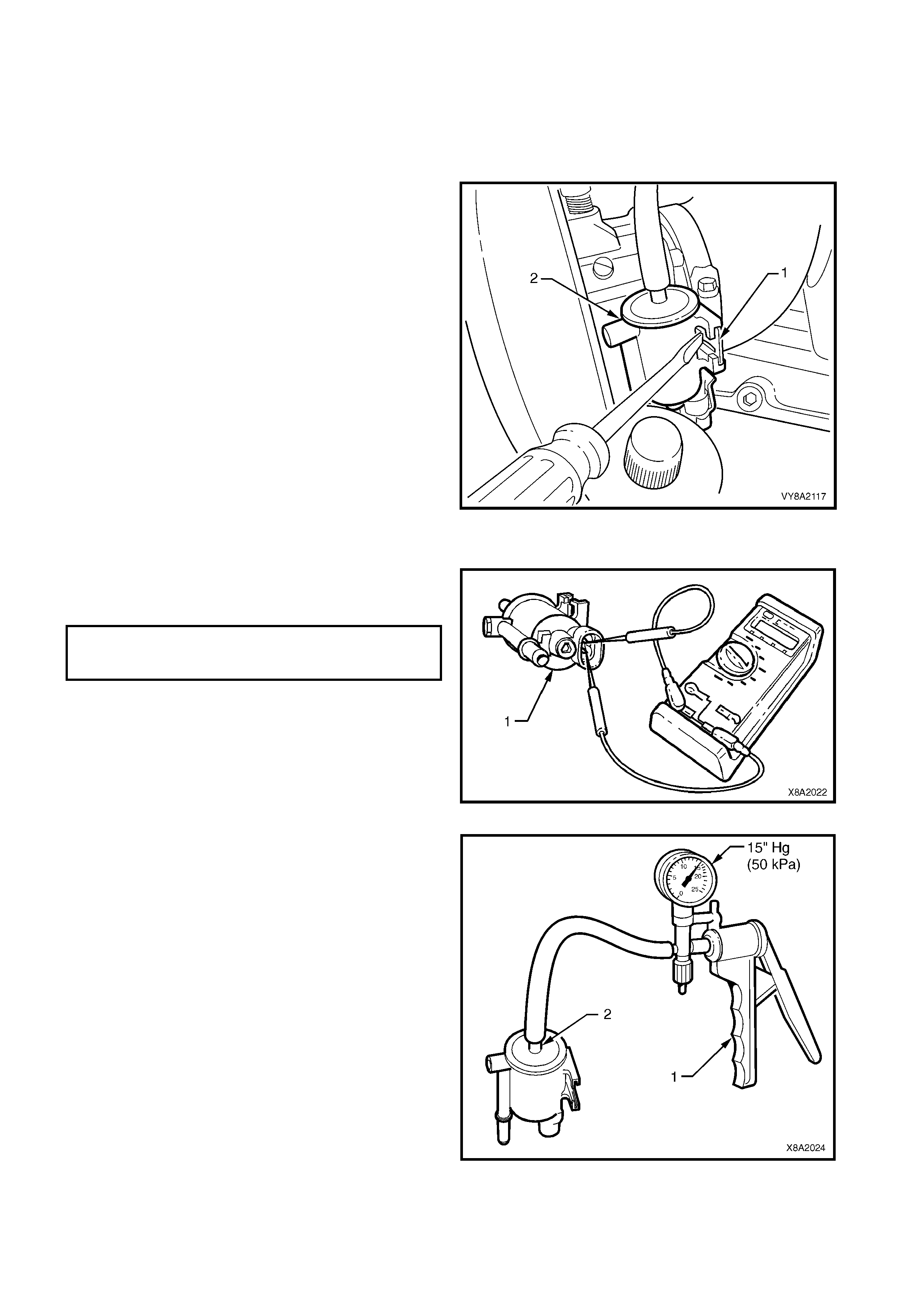
3.20 FUEL CONTROL VALVE
LT Section – AA-650Q
REMOVE
1. Drain the service lines of LPG, refer to
3.1 SERVICE LINE DRAINING.
2. Using a flat bladed screwdriver, gently lever the
retaining tang on the fuel control valve (FCV)
retaining bracket (1) towards the rear of the vehicle
and slide the FCV (2) outwards.
3. W ith the FCV rem oved from the retaining brack et,
disconnect the wiring harness connector, remove
the balance and vacuum hoses and remove the
FCV from the vehicle.
Figure 8A2-160
TEST
1. Connect an ohmmeter to the coil terminals of the
FCV (1) and check the coil resistance.
2. If the res ist ance is not as s pecified, the fuel c ontrol
valve should be replaced.
Figure 8A2-161
3. Connect a vacuum pump (1) such as Tool No.
J23738 A, to the vacuum connector of the FCV
(2).
4. Operate the vacuum pum p until 15 inches Hg. (50
kPa) of vacuum is applied to the FCV
Figure 8A2-162
FUEL CONTROL VALVE COIL
RESISTANCE 19 – 21 ohms
@ 20° C
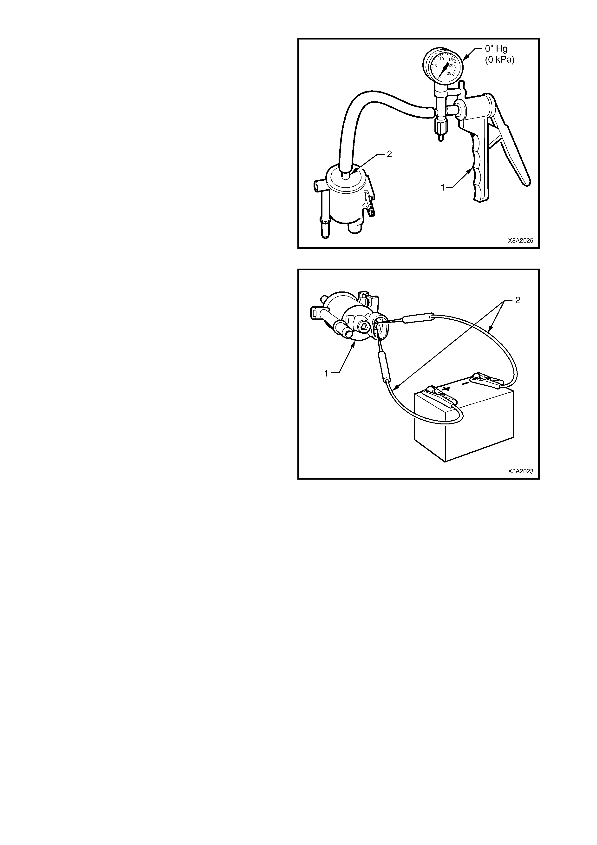
5. Note the time taken for the vacuum to bleed off
through the FCV.
If 15 inches Hg. (50 kPa) of vacuum cannot be
created, or the bleed off time is less than three to
five seconds, then the FCV should be replaced.
Figure 8A2-163
6. Using appropriate test leads (2), such as those
found in KM-609, c onnec t 12 volts ( vehicle batter y)
to the FCV coil terminals (1).
The valve should open (audible click) when 12
volts is applied. Chec k that the valve can be blown
through while open. If the valve does not open and
cannot be blown through, replace the FCV.
Figure 8A2-164

REINSTALL
Installation of the FCV is the reverse of the removal procedure noting the following and referring to Figure
8A2-165:
1. Ensure the FCV balance and vacuum hoses are routed correctly.
2. Connect the LPG wiring harness connector to the FCV, ensuring that it is routed correctly.
Figure 8A2-165
Legend
1. Balance Hose (Atmospheric) 2. Vacuum Hose 4. Breather Hose
1A. Balance Hose (Vacuum) 3. FCV Wiring Harness Connector
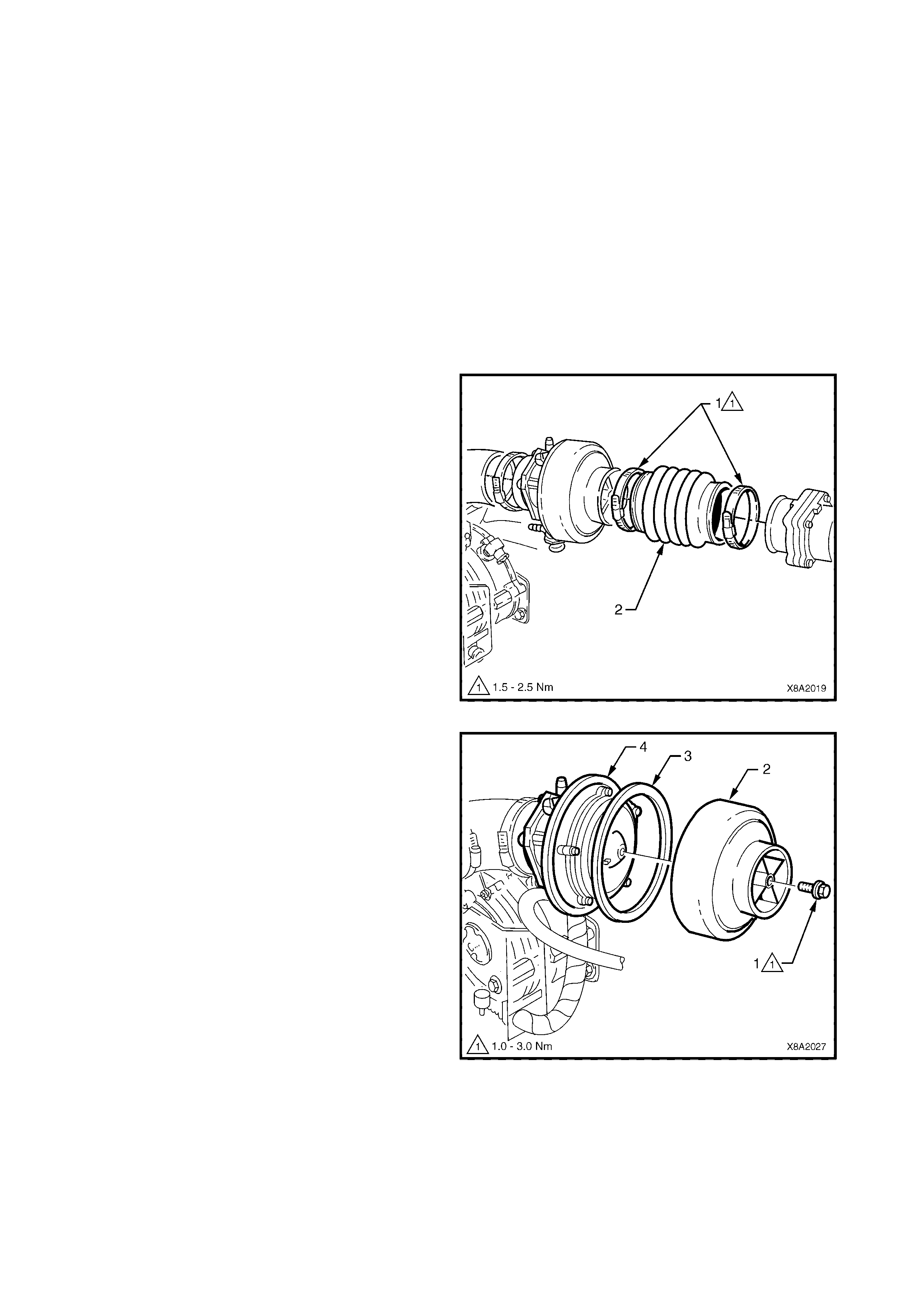
3.21 MIXER
LT Section – AA-650Q
TEST
1. Drain the service lines of LPG, refer to
3.1 SERVICE LINE DRAINING.
2. Disconnect the Mass Air Flow sensor connector.
3. With petrol mode selected via the fuel mode
switch, start the engine and allow to idle until the
Malfunction Indicator Lamp is illuminated, then turn
the engine OFF.
NOTE: Running the engine with the Mass Air Flow
Sensor connec tor disconnected will cause DTC P0101
to set. Setting DT C P0101 will allow the engine to s tart
with the air duct rem oved as des c ribed in Step 6 of this
procedure.
4. Loosen the clamps (1) on either end of air duct
boot (2), between the mixer and the mass air flow
(MAF) sensor. Remove the air duct boot.
Figure 8A2-166
5. Loosen and remove the bell housing to air valve
cover attaching bolt (1) and separate the bell
housing (2) and gasket (3) from the mixer body
(4).
Figure 8A2-167
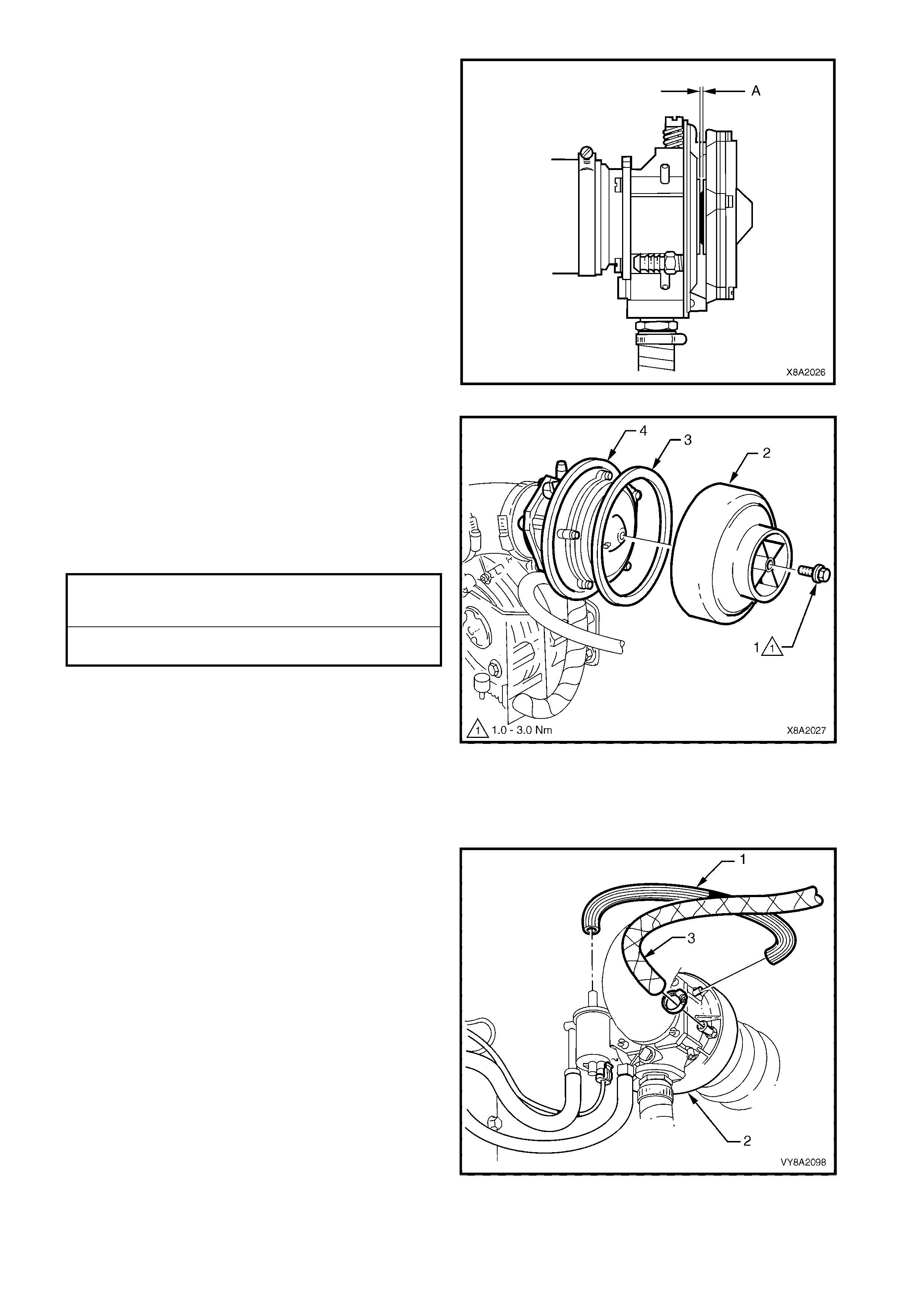
6. With petrol mode selected via the fuel mode
switch, start the engine and allow to idle.
7. Observe the mixer diaphragm position. The
diaphragm should lift slightly (A) as the engine is
cranked. Also, the diaphragm lift should increase
as engine RPM is increased.
8. If the diaphragm does not lift as RPM increases,
check for vacuum leaks between the mixer and
throttle body. If no vacuum leaks are found,
overhaul the mixer, refer to OVERHAUL in this
Section.
Figure 8A2-168
9. Install the bell housing gasket (3), bell housing (2)
and the bell housing to air valve cover attaching
bolt (1) and tighten to the specified torque.
10. Install the air duct and tighten the air duct clamps
to the specified torque.
11. Connect the MAF sensor.
12. Clear all DTCs using Tech 2.
Figure 8A2-169
REMOVE
1. Drain the service lines of LPG, refer to
3.1 SERVICE LINE DRAINING.
2. Remove the FCV vacuum supply hose (1) from the
mixer (2).
3. Disconnect the crankcase breather hose (3) from
the mixer.
Figure 8A2-170
MIXER BELL HOUSING
ATTACHING SCREW
TORQUE SPECIFICATION 1.0 – 3.0 Nm
AIR DUCT CLAMP
TORQUE SPECIFICATION 1.5 – 2.5 Nm
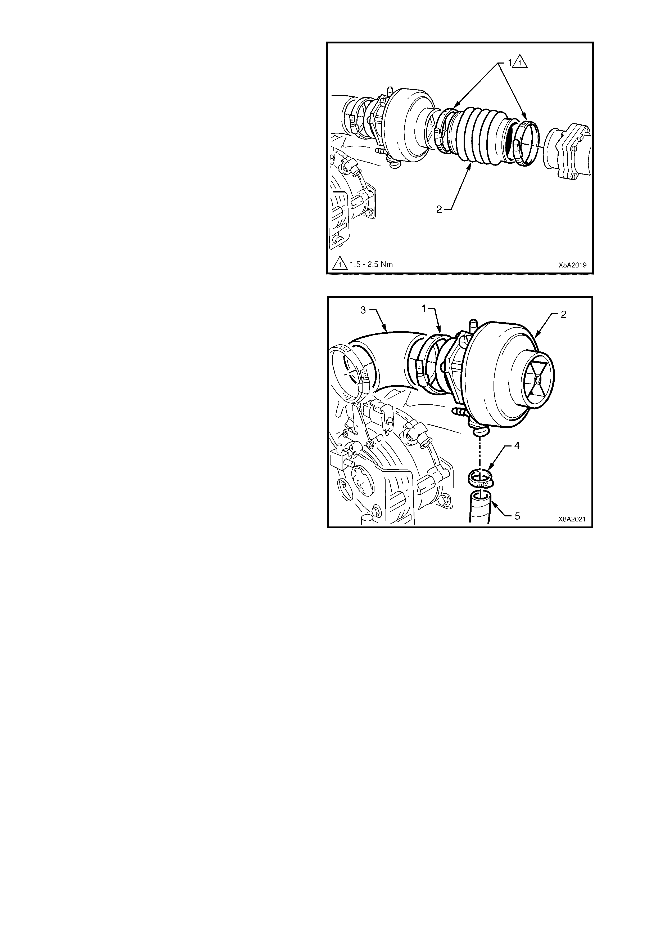
4. Remove the fuel control valve (FCV) from the
mixer, refer to 3.20 FUEL CONTROL VALVE.
5. Loosen the clamps (1) on either end of air duct
boot (2), between the mixer and MAF sensor and
remove the air duct boot.
Figure 8A2-171
6. Loosen the adapter hose clamp (1) at the mixer
end (2).
7. Pull the mixer from the adapter hose (3).
8. Loosen the vapour hose to mixer inlet clamp (4),
disconnect the vapour hose (5) and remove the
mixer.
Figure 8A2-172
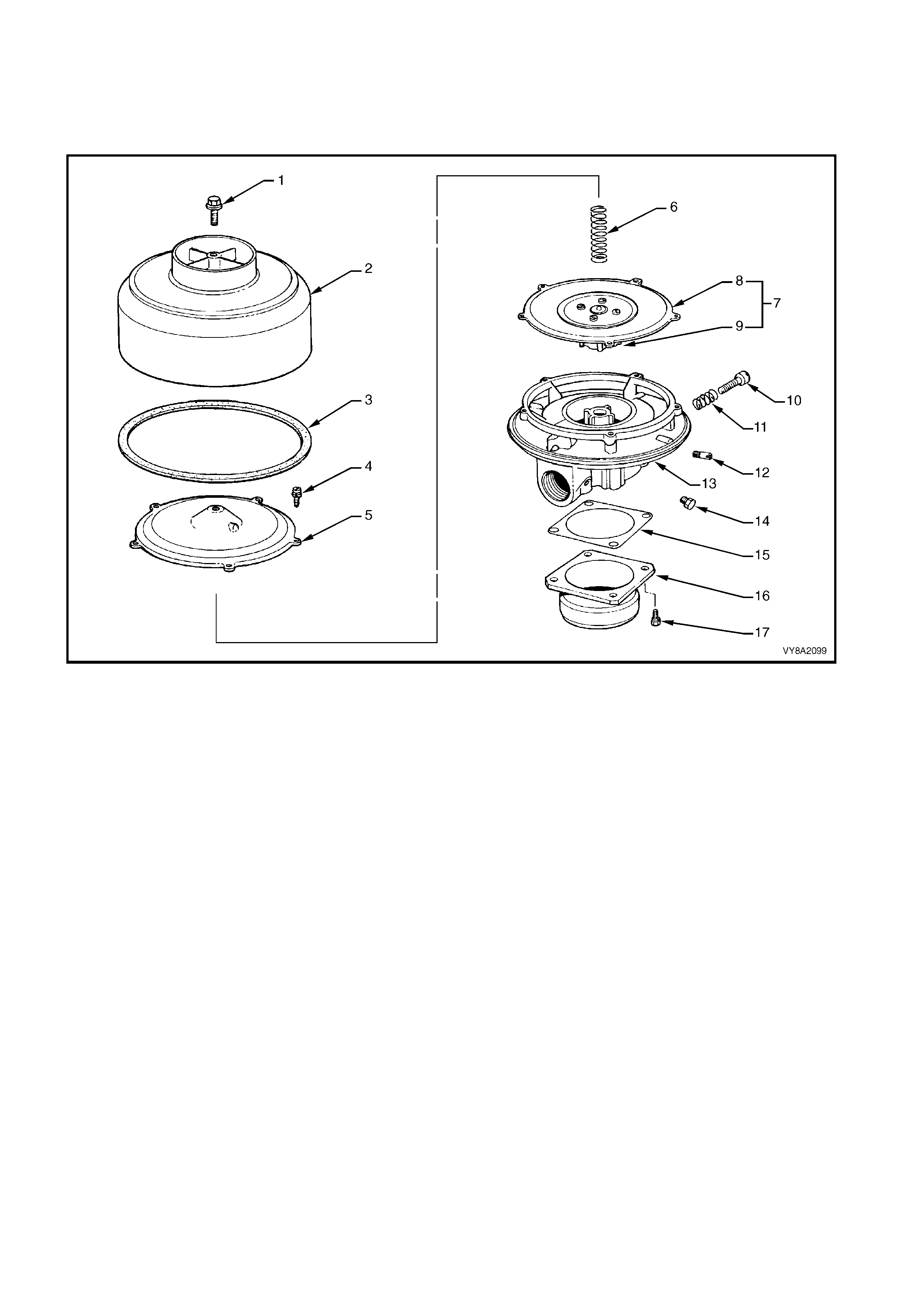
OVERHAUL
For identification of the various parts within the mixer assembly refer to Figure 8A2-173.
NOTE: There is no repair kit available for the mixer overhaul procedure; all mixer components are available
separately.
Figure 8A2-173
Legend
1. Screw 7. Diaphragm Assembly 13. Mixer Body
2. Bell Housing 8. Diaphragm 14. Plug
3. Gasket 9. Air Valve 15. Gasket
4. Screw 10. Idle Screw 16. Adapter
5. Air Valve Cover 11. Spring 17. Screw
6. Spring 12. Screw
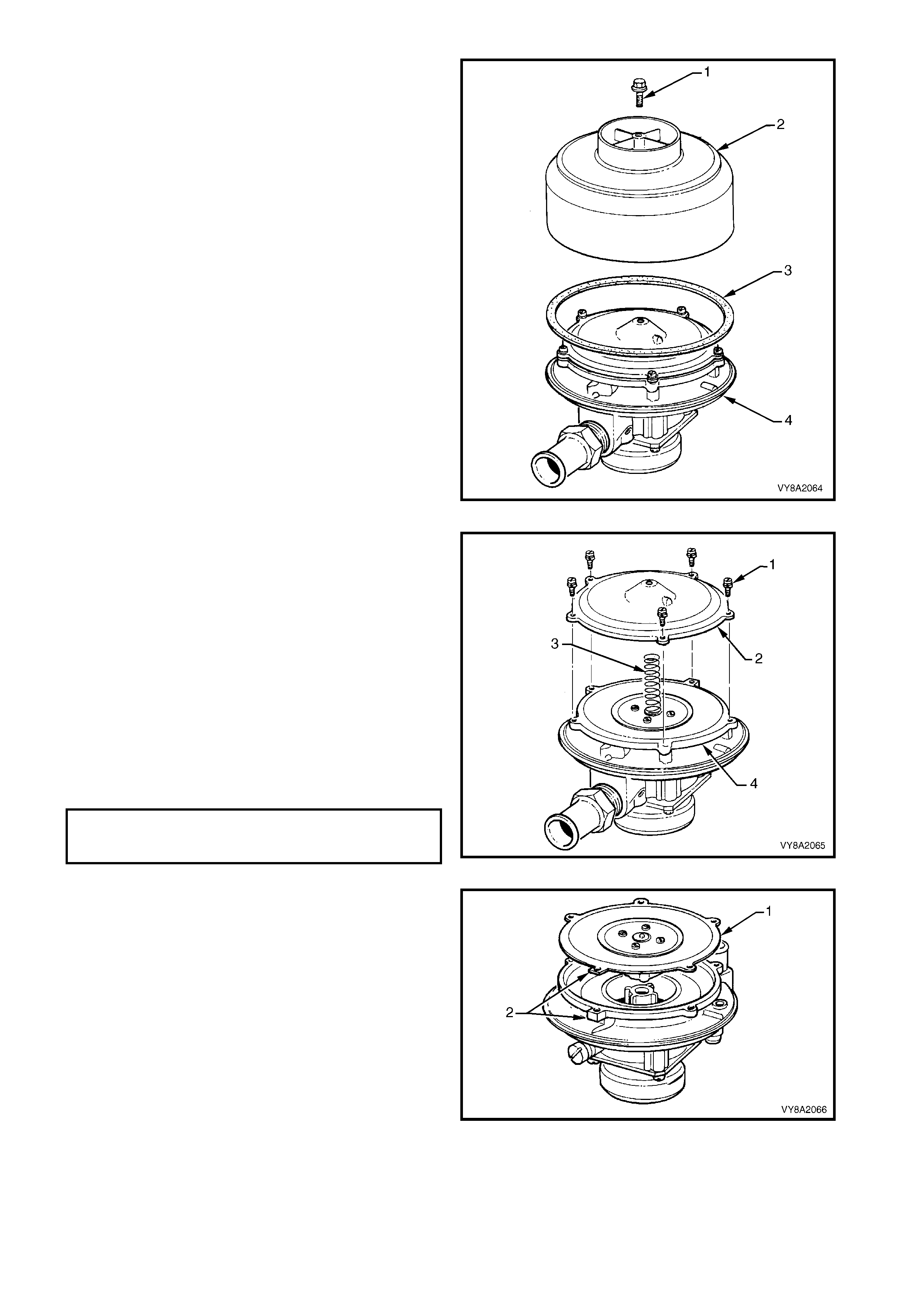
1. Remove the bell housing screw (1) and the
separate the bell housing (2) and gasket (3) from
the mixer body.
Figure 8A2-174
2. Remove the five air valve cover attaching screws
(1) and remove the air valve cover (2) from the
mixer body.
3. Remove the spring (3) and the diaphragm and air
valve assembly (4) from the mixer body.
4. Check the condition of the diaphragm and spring
for wear or damage and replace as required.
5. Clean all parts in a suitable cleaning solution and
inspect their condition.
6. If the air valve was removed from the diaphragm,
or a new part is being installed, fit the air valve on
to the diaphragm ensuring the air valve ring is in
position between the air valve and the diaphragm.
Tighten the screws to the specified torque.
Figure 8A2-175
7. Place the diaphragm and air valve assembly (1)
into the mixer body ensuring that the diaphragm
and mixer body square locating lugs (2) are
aligned.
Figure 8A2-176
AIR VALVE TO DIAPHRAGM
ATTACHING SCREW
TORQUE SPECIFICATION 2.0 – 2.5 Nm
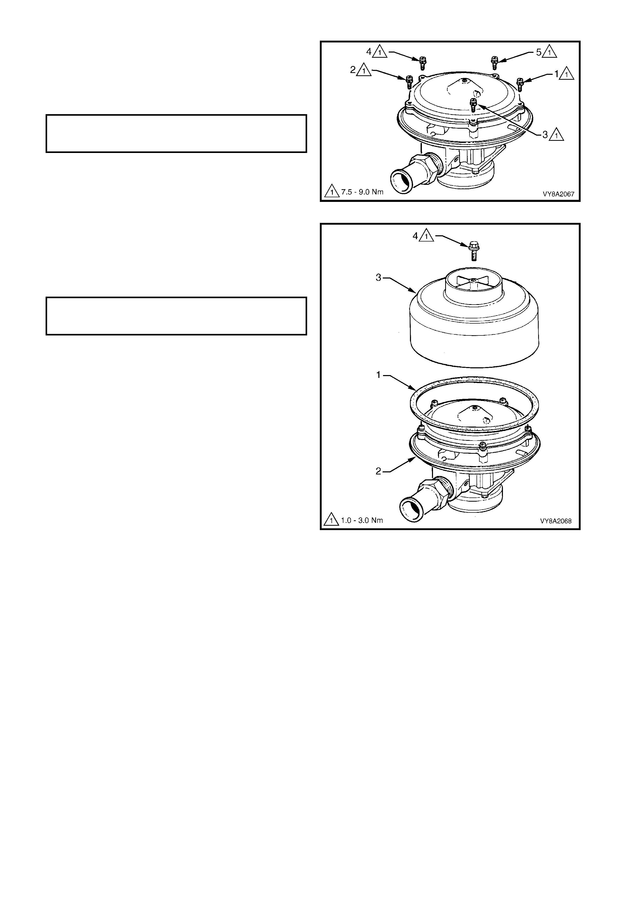
8. Locate the spring onto the diaphragm and install
the air valve cover assembly on to the mixer body.
9. Install the five air valve c over attac hing s c rews and
tighten in the sequence shown to the specified
torque.
Figure 8A2-177
10. Ins tall a new bell housing gas ket (1) onto the m ixer
body (2).
11. Locate the bell housing (3) onto the mixer body
and install the attaching screw (4) and to the
specified torque.
Figure 8A2-178
AIR VALVE COVER
ATTACHING SCREW
TORQUE SPECIFICATION 7.5 – 9.0 Nm
MIXER BELL HOUSING
ATTACHING SCREW
TORQUE SPECIFICATION 1.0 – 3.0 Nm

REINSTALL
Installation of the mixer is the reverse of removal noting the following:
1. Ensure the FCV balance and vacuum hoses are routed correctly, refer to Figure 8A2-179.
2. Connect the LPG wiring harness connector to the FCV, ensuring that it is routed correctly, refer to Figure
8A2-179.
Figure 8A2-179
Legend
1. Balance Hose (atmospheric) 2. Vacuum Hose 4. Breather Hose
1A. Balance Hose (vacuum) 3. FCV Wiring Harness Connector
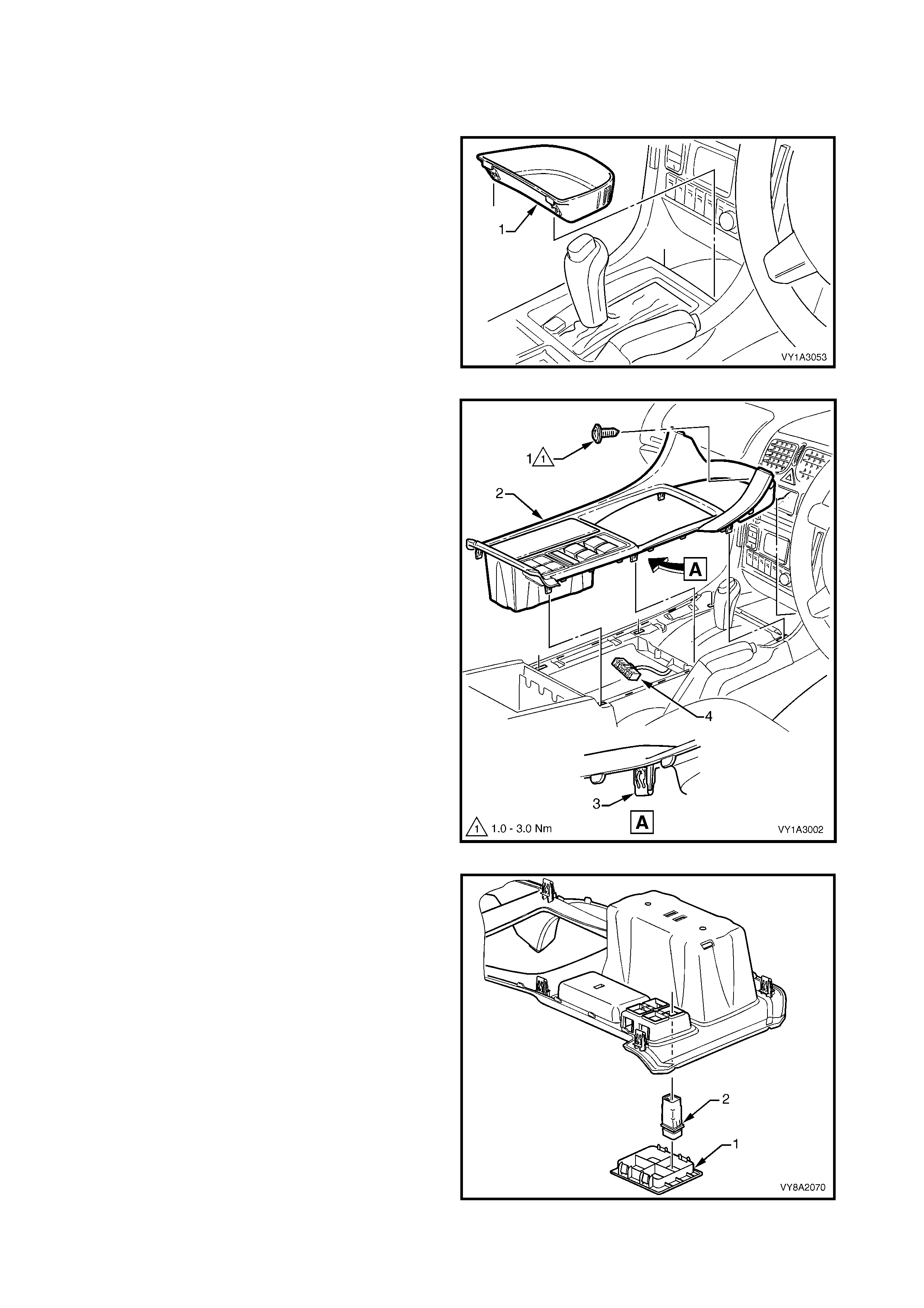
3.22 FUEL MODE SWITCH
LT Section – AA-650Q
REMOVE
1. Remove the floor console front compartment liner
(1) by lifting upwards to disengage the retaining
lugs.
Figure 8A2-180
2. Remove the screw (1) attaching the floor console
cover assembly (2) slightly to the right of centre.
3. Prise the cover assembly from the floor console,
six places (3).
4. Lift the cover assembly up from the rear,
disconnect the wiring connector (4) from the side
window switch assembly and auxiliary switches as
required, and remove the cover assembly.
Figure 8A2-181
5. Depr ess the four tabs s ecuring the auxiliary switch
bezel to the cover assembly and remove.
6. Depress the two tabs securing the fuel mode
switch to the cover assembly and remove the
switch.
Figure 8A2-182
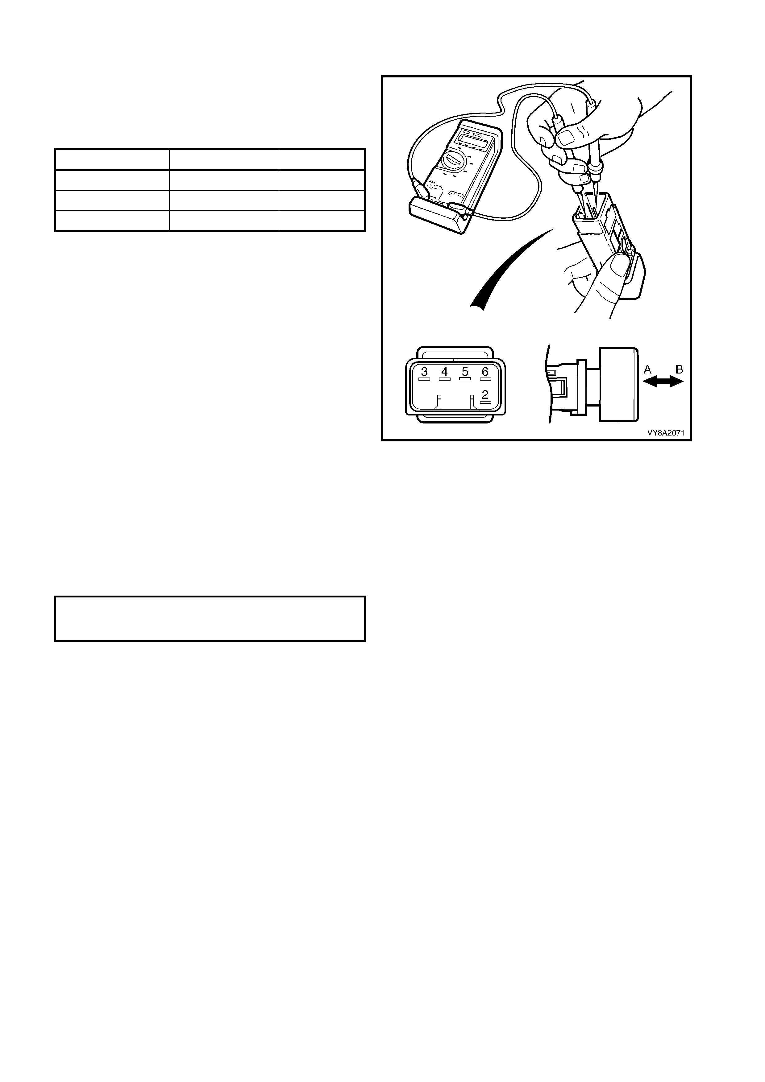
TEST
Connect an ohmmeter to the fuel mode switch
terminals as shown and test for continuity. If the tests
are not as specified, replace the switch or bulb as
required.
NOTE: For further information, refer to
Section 12B, 3.19 SWITCH ILLUMINATION.
Figure 8A2-183
REINSTALL
Installation is the reverse of removal, noting the
following:
1. The fuel mode switch can only fit in the one
location.
2. Tighten the f loor console cover assem bly screw to
the specified torque.
SWITCH POSITION TERMINALS RESULT
ON (A) 3 – 5 Continuit y
OFF (B) 3 – 5 No Continuity
ON or OFF (BULB) 2 – 6 Approx. 30Ω
FLOOR CONSOLE COVER
ASSEMBLY ATTACHING SCREW
TORQUE SPECIFICATION 1.0 – 3.0 Nm
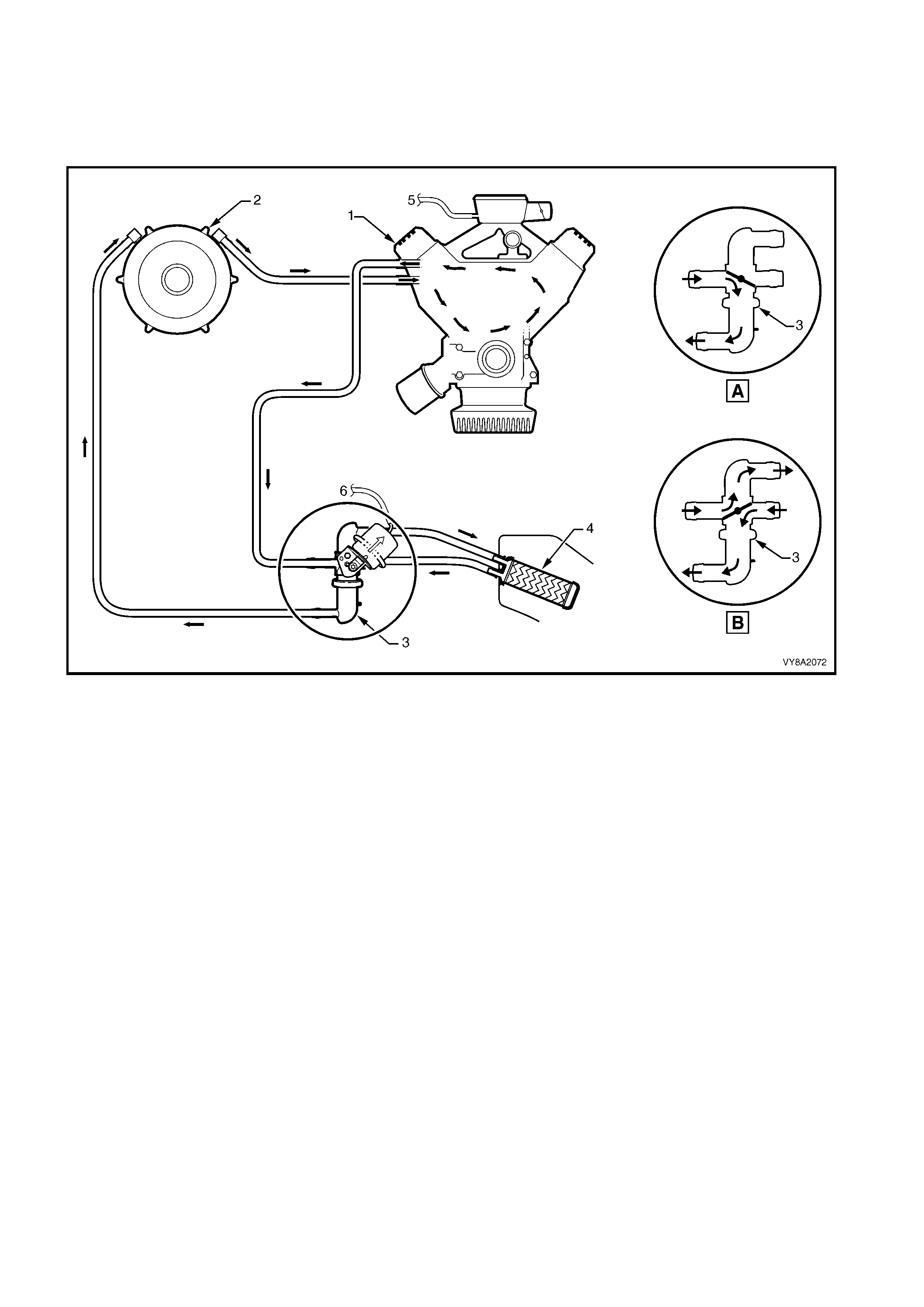
3.23 COOLANT HOSES
LT Section – AA-650Q
The converter is incorporated into the coolant circuit to aid vaporisation of the LPG. The converter is routed
between the heater water valve and the engine, refer to Figure 8A2-184. Note the operation of the water valve
when the heater is in the OFF position (A) or ON position (B).
Figure 8A2-184
Legend
1. Engine 4. Heater Core A. Heater Valve Closed
2. Converter 5. Vacuum Source to Heater Control B. Heater Valve Open
3. Water Valve 6. Vacuum Source from Heater Control
The coolant hoses are installed as shown in the following illustration.
Ensure that the hose connections are thoroughly cleaned before installing any new or existing hoses. When
securing a hose with a retaining clamp, ensure that the vent tube is correctly fitted.
After the hos es are f itted, ref ill the cooling system with the cor rect c oncentration of coolant and pressure test the
cooling system, refer to Section 6B1 ENGINE COOLING - V6 EN GINE.
CAUTION: Always wear pro tect iv e safet y glasses w hen w o rking with sprin g t ype hose clamps. F ailure to
do so could result in eye injury.
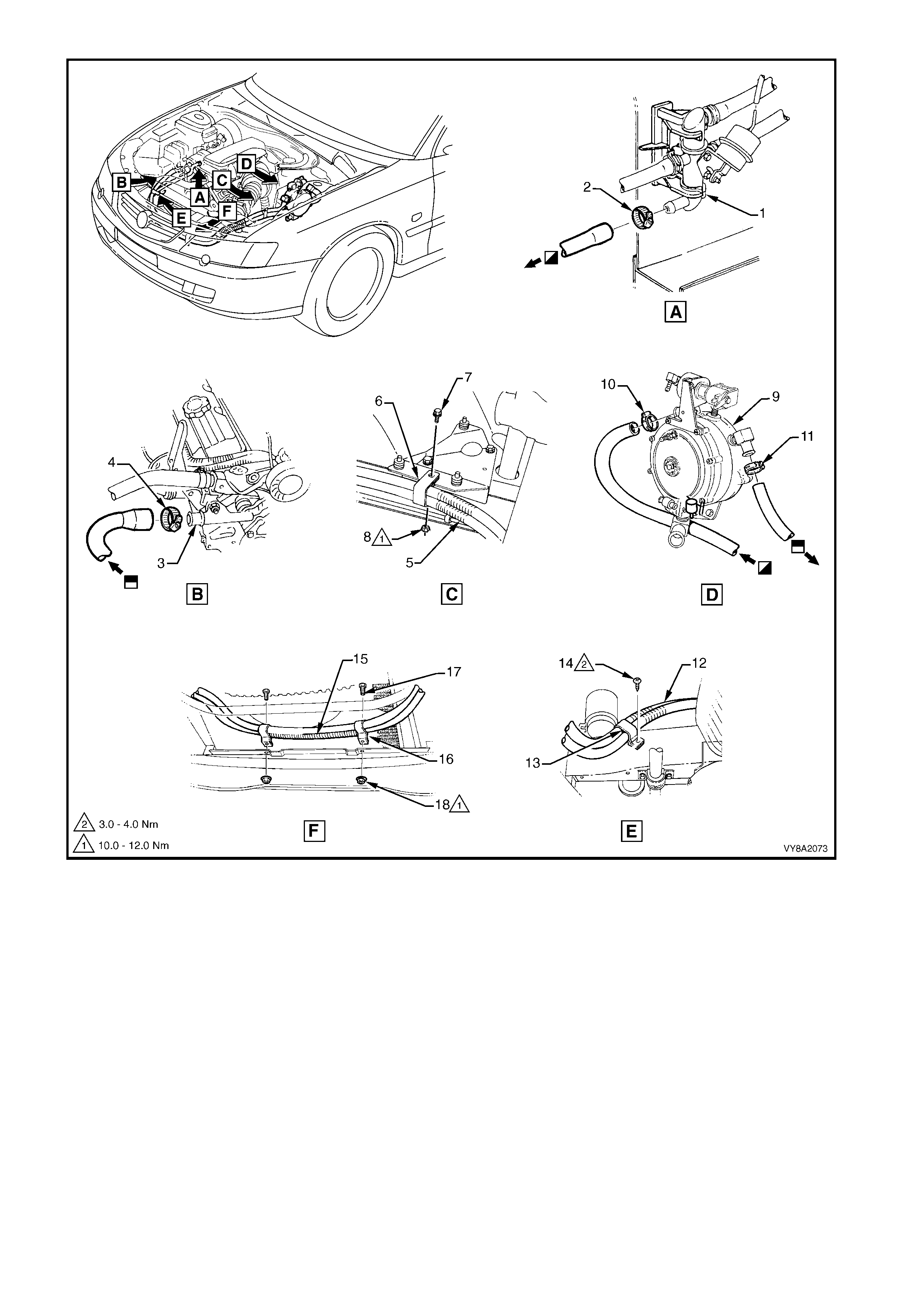
Figure 8A2-185
Legend
1. Water Valve 7. Screw 13. Coolant Hose Retaining Clamp
2. Hose Clamp 8. Nut 14. Screw
3. Engine Coolant Inlet 9. Converter 15. Vent Tube
4. Hose Clamp 10. Hose Clamp 16. Coolant Hose Retaining Clamp (2 places)
5. Vent Tube 11. Hose Clamp 17. Screw (2 places)
6. Coolant Hose Retaining Bracket 12. Vent Tube 18. Nut (2 places)
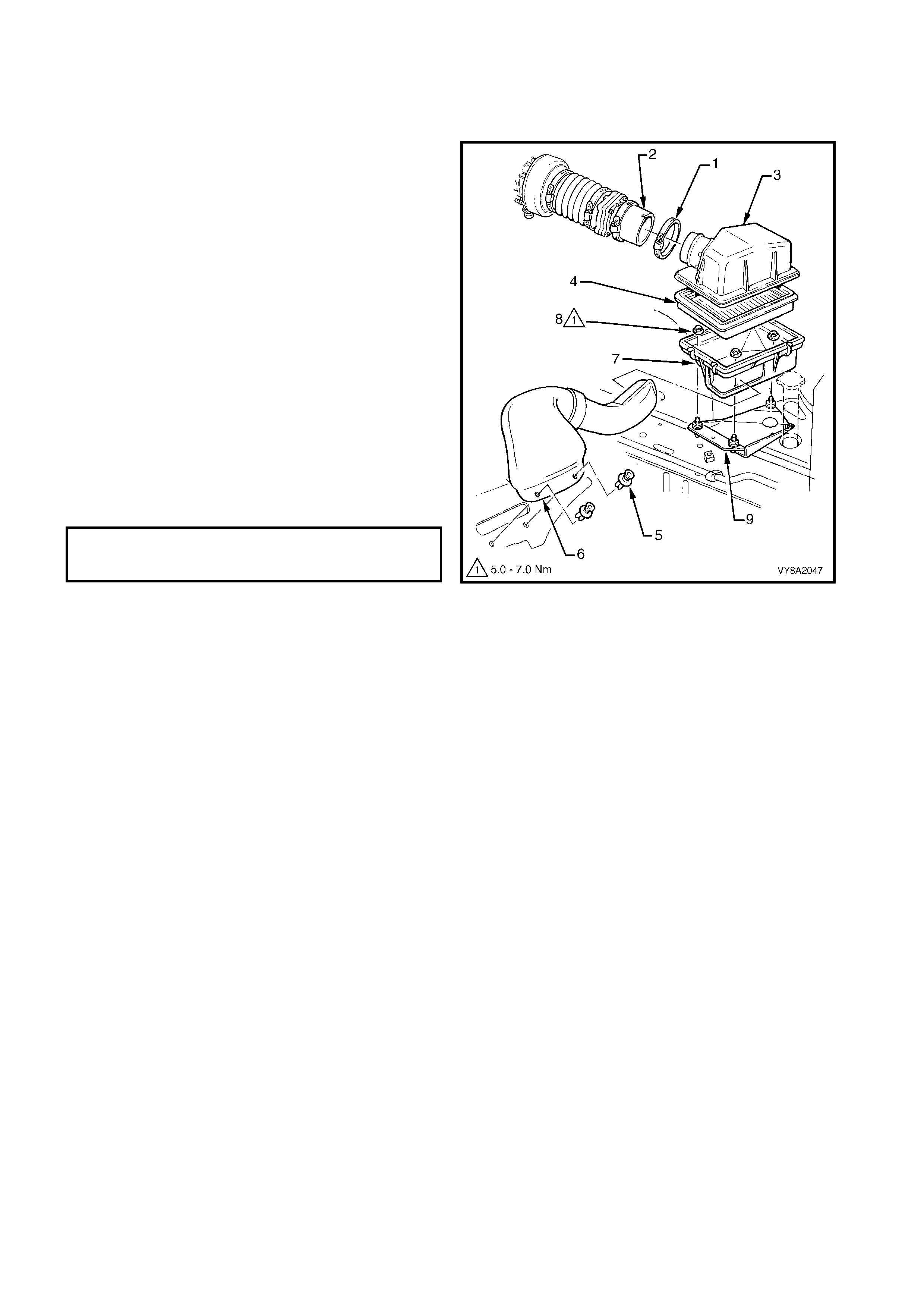
3.24 AIR CLE ANER ASSEMBLY
LT Section – 03-250
REMOVE
1. Loosen the hose clamp (1) attaching air duct
adapter (2) to the air cleaner upper housing (3).
2. Disconnect the air duct from the air cleaner upper
housing.
3. Unclip the clips securing the air cleaner upper
housing in place.
4. Remove the air cleaner upper housing and air
cleaner element (4).
5. Remove the two retainers ( 5) attaching the c old air
intake duct (6) to the front panel. Disengage the
cold air intake duct from the air cleaner lower
housing (7) and remove the cold air intake duct.
6. Remove the three nuts (8) attaching the air cleaner
lower housing to the air cleaner support bracket (9)
and remove the lower housing.
REINSTALL
Installation of the air cleaner assembly is the reverse
of the removal. Tighten the nuts to the specified
torque.
Figure 8A2-186
AIR CLEANER LOWER
HOUSING ATTACHING NUT
TORQUE SPECIFICATION 5.0 – 7.0 Nm
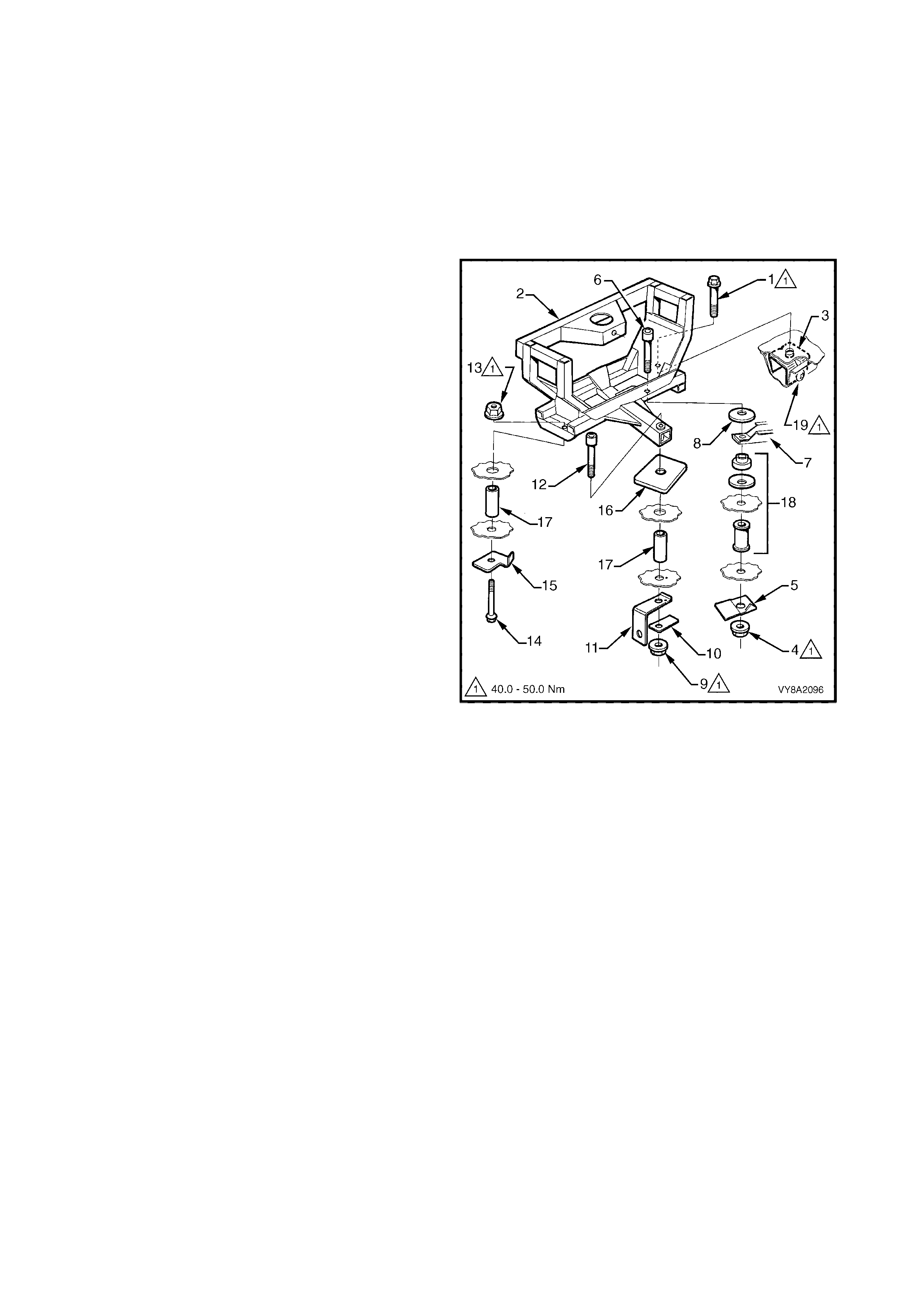
3.25 SPARE WHEEL CARRIER, WAGON
LT Section –
REMOVE
1. Remove the spare wheel cover and the spare
wheel from the carrier.
2. Remove the rear compartment carpet, refer to
Section 1A8, 3.21 REAR COMPARTMENT
FLOOR CARPET ASSEMBLY AND SPARE
WHEEL COVER, WITH LPG.
3. Remove the rear bolt (1) attaching the carrier (2)
to the rear reinforcement bracket (3).
4. With the aid of an assistant, remove the nut (4)
and reinfor cement (5) f rom under neath the vehicle
and remove the bolt (6) attaching the carrier and
tank bracket (7). Slide the washer (8) out from
under the carrier.
5. With the aid of an assistant, remove the nut (9),
reinforcement (10) and fuel filter brack et (11) from
underneath the vehicle and remove the bolt (12)
attaching the carrier.
6. With the aid of an assistant, remove the nut (13)
and remove the bolt (14) and reinforcement (15)
from underneath the vehicle.
7. Remove the carrier from the vehicle.
8. If required, remove the reinforcement plate (16)
and two spacers (17) from the chassis rail cavity.
9. If required, partially remove the tank bracket and
remove the spacer, washer and insulator (18).
10. If required, remove the two screws (19)
securing the reinforcement bracket to the chassis
rail. Remove the right-hand rear shock
absorber mounting plate, refer to
Section 4A REAR SUSPENSION. Manoeuvre the
bracket out of the chassis rail, through the shock
absorber mount plate opening.
Figure 8A2-187
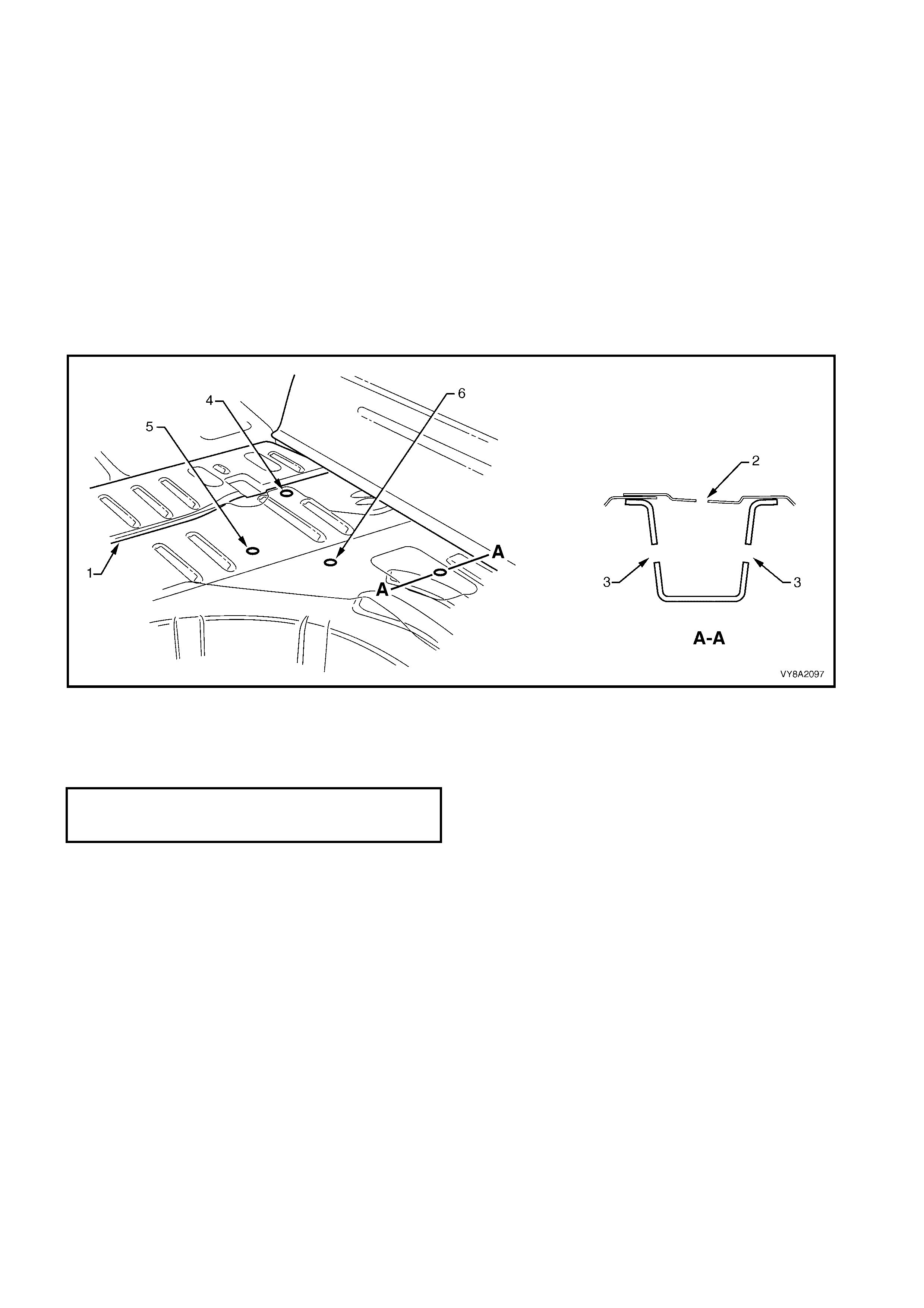
REINSTALL
Installation of the spare wheel carrier is the reverse of removal noting the following:
NOTE: If the f loor panel, chass is rail, etc. has been r eplaced and new mounting holes ar e required, position the
spare wheel carrier ensuring the front edge aligns 50 mm rearward of the floor joint (1) and the rear hole (2)
aligns centrally within the rib in the side to side direction. Use the carrier as a template for the other holes and
mark the floor with their positions. Drill as follows:
• For position (2), drill a 12 mm hole only through the floor panel. If required, drill a 12 mm hole (3) through
each side of the chassis rail for the reinforcement bracket attaching screws.
• For position (4), drill a 12 m m hole com pletely through the floor and rear crossm ember. Drill the hole in the
floor panel only out to 17 mm.
• For position (5), drill a 12 mm hole completely through the floor and rear chassis rail. Drill the hole in the
floor panel only out to 17 mm.
• For position (6) , drill a 12 m m hole c ompletely through the floor and rear chass is rail. T his hole is also us ed
as the right-hand front tank bracket mount.
Figure 8A2-188
1. Install all of the components and hand tighten the nuts and bolts. Ensure the spacers and reinforcement
plates, etc. are assembled in their correct positions.
2. Tighten the bolts and nuts to the specified torque.
SPARE WHEEL CARRIER
ATTACHING NUT AND BOLT
TORQUE SPECIFICATION 40.0 – 50.0 Nm
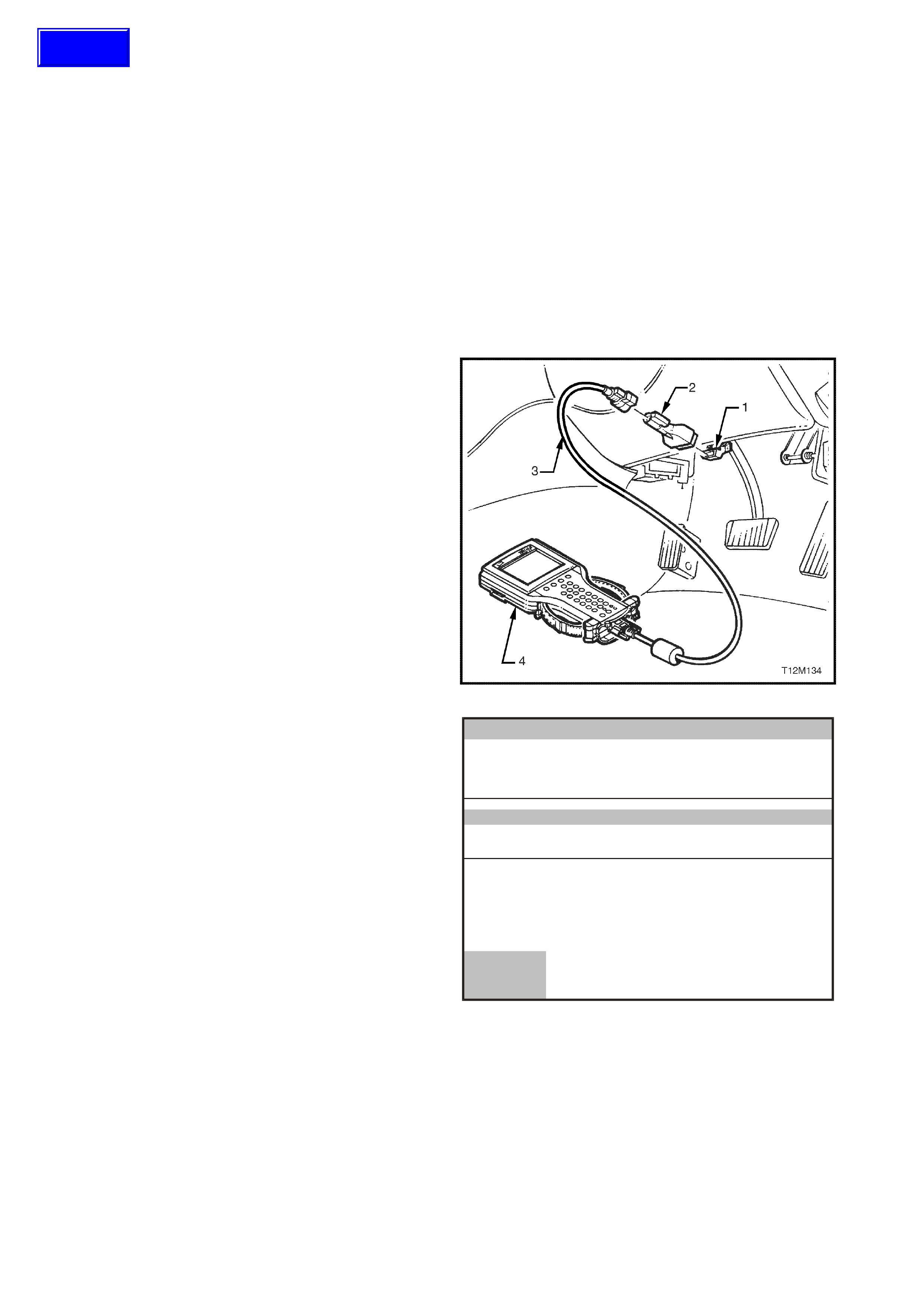
4. TECH 2 PROCEDURES
4.1 LPG SE TUP PROCEDURE
NOTE: The following procedure must be performed
when any LPG system component (mixer, converter,
FCV or PCM) has been replaced, overhauled,
reprogrammed, or when the engine assembly has
been replaced or overhauled.
The LPG Setup proc edure allows the idle mixtur e to be
adjusted under the following controlled conditions:
• Short and Long-Term Fuel Trim Cells set to zero.
• Fixed Spark advance.
• Fixed idle air control valve steps.
• Fuel control valve duty cycle fixed at 40%.
1. Connect TECH 2 (4) to the DLC (1) with the
adapter (2) and cable (3).
NOTE: For further information on Tech 2
connection and operation procedures refer to
Section 0C TECH 2.
2. With the vehicle in LPG mode, start the engine.
3. With no load on the engine, air conditioning off (if
fitted), all electrical consum ers turned off and park
position selected, allow the engine and oxygen
sensor to reach operating temperature.
Figure 8A2-189
4. On TECH 2 select:
F0: Diagnostics / (3) 2003 / VY Series / F0: Engine
/ V6 / F5: Function Tests / F5: LPG Setup.
5. During the setup procedure, Tech 2 ensures the
follow engine operating conditions are met and
maintained:
• Engine Coolant Temperature greater than
91°C,
• Operating in closed loop mode,
• Right hand oxygen sensor is ready,
• The engine cooling fan is off, (engine coolant
temperature less than 104°C).
6. Once all the preconditions have been met, T ech 2
will display the right-hand oxygen sensor voltage
and status.
Engine
LPG Setup
Right O2 Sensor
Right O2 Status 500 mV
Rich
VXLPG001
Confirm
Figure 8A2-190
Techline
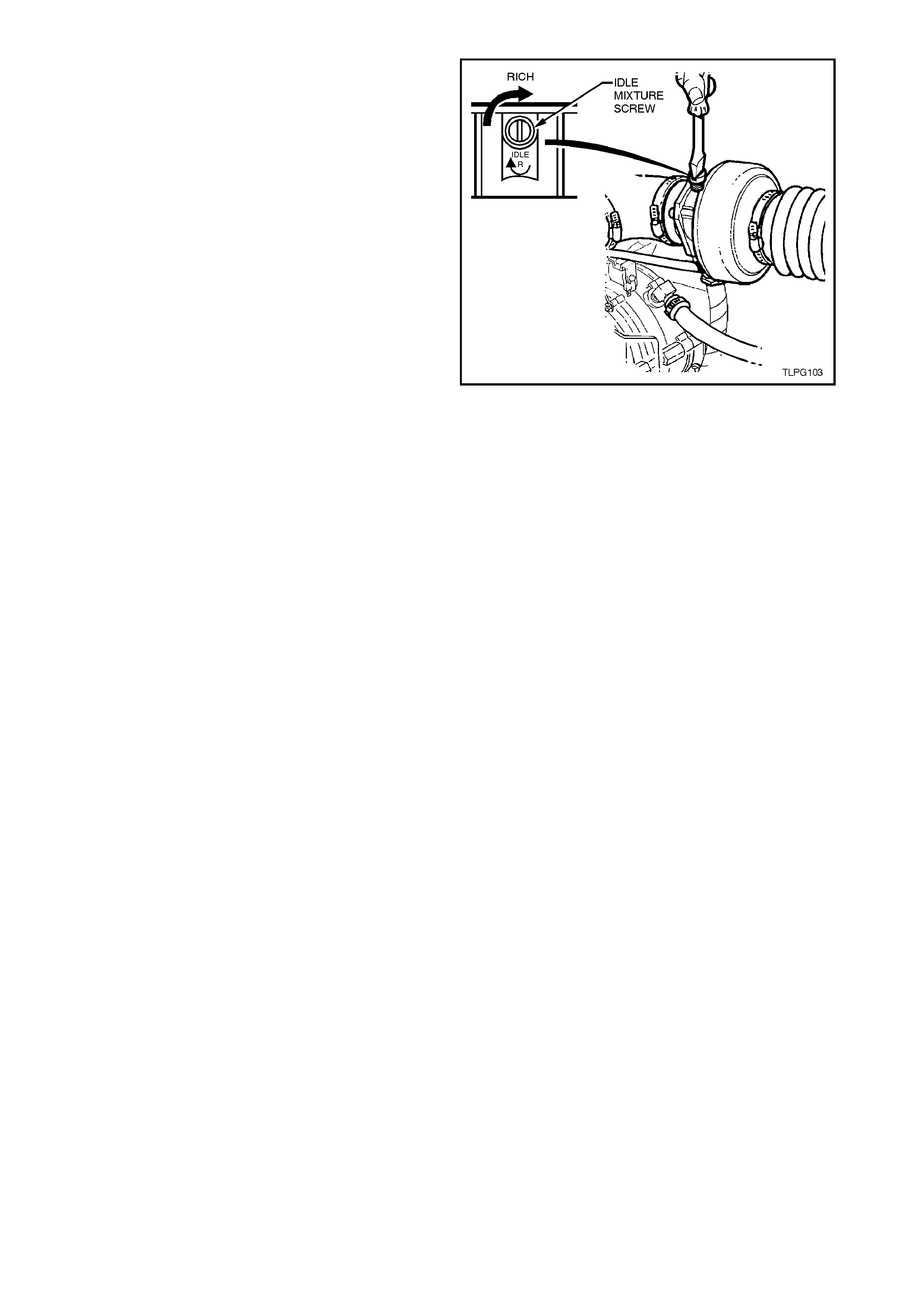
7. Adjust the idle mixture screw until the right-hand
oxygen sensor voltage is as close to 500 mV as
possible and the status of the right oxygen sensor
is constantly toggling between rich and lean.
• An oxygen sensor voltage greater than 500
mV indicates a rich mixture. Turn the idle
mixture screw anti-clockwise to lean-off the
mixture.
• An oxygen s ensor voltage of less than 500 mV
indicates a lean mixture. Turn the idle mixture
screw clockwise to richen the mixture.
NOTE: If the engine coolant temperature exceeds
104°C, the engine cooling fan will operate and Tech 2
will suspend the setup procedure. When the engine
cools, the cooling fan will cease operation and Tech 2
will continue with the setup procedure.
Figure 8A2-191
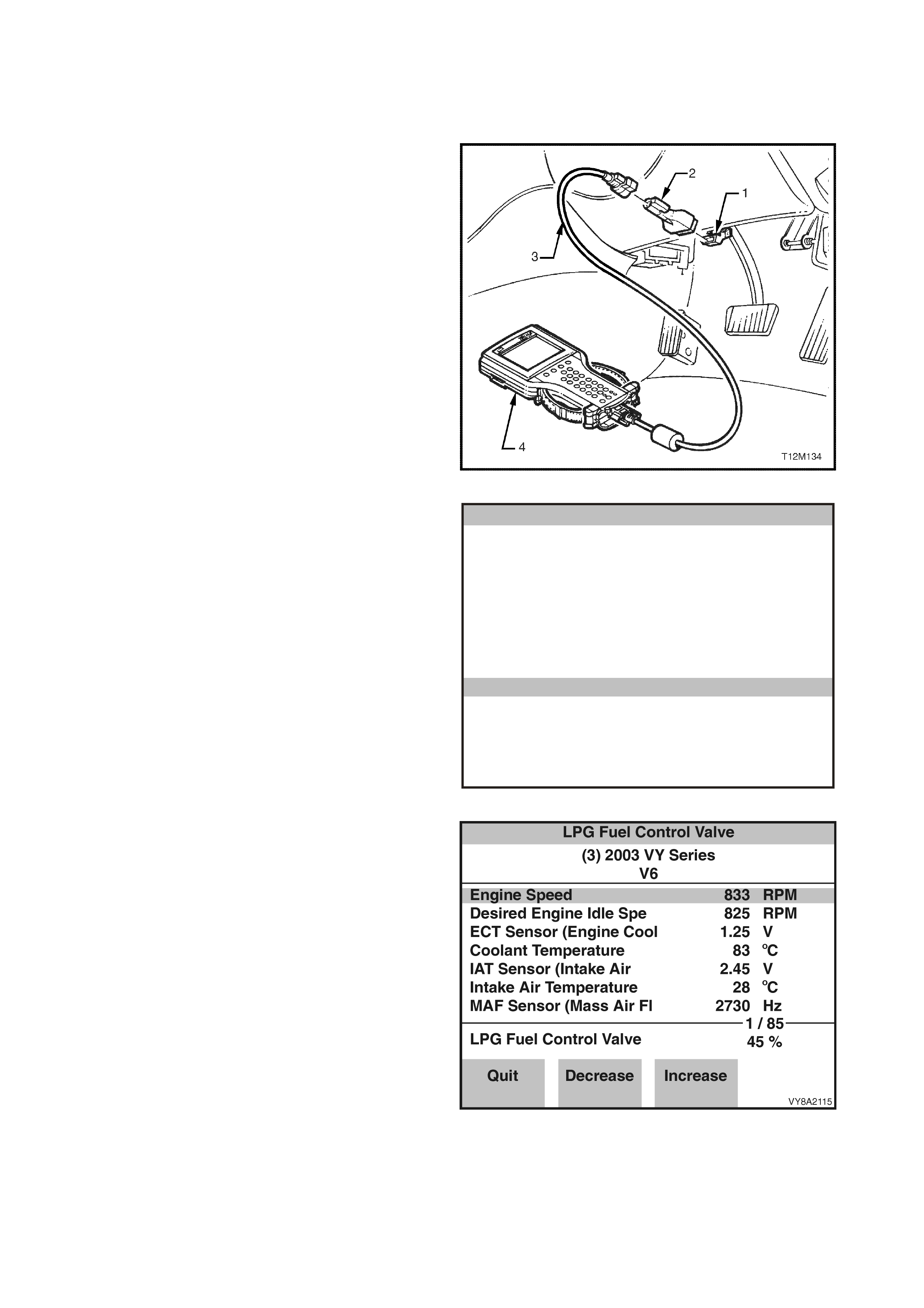
4.2 LPG FUEL CONTROL VALVE TEST
The LPG fuel control valve test is used to command
the LPG fuel control valve from 10% to 90% in
increments of 10%.
1. Connect TECH 2 (4) to the DLC (1) with the
adapter (2) and cable (3).
Figure 8A2-192
2. On TECH 2 select:
F0: Diagnostics / (3) 2003 / VY Series / F0: Engine
/ V6 / F4: Miscellaneous Tests/ F6: LPG Fuel
Control Valve Test.
Miscellaneous Tests
VXLPG005
F0: Output T ests
F1: IAC System
F2: EGR Control
F3: Reset Cells
F4: Bypass Spark
F5: Air Fuel Ratio
F 6: LPG F u el C o n t rol Valve Test
F7: LPG Enable
Figure 8A2-193
3. With the LPG mode select ed, start the engine and
allow the engine to idle.
4. The FCV duty cycle can be increased and
decreased using the decrease or increase soft
keys. Increasing the duty cycle will cause a leaner
air f uel r atio, dec reas ing the duty cycle will cause a
richer air fuel ratio.
NOTE: The F CV c an only be commanded if the engine
is running in the LPG mode.
Figure 8A2-194
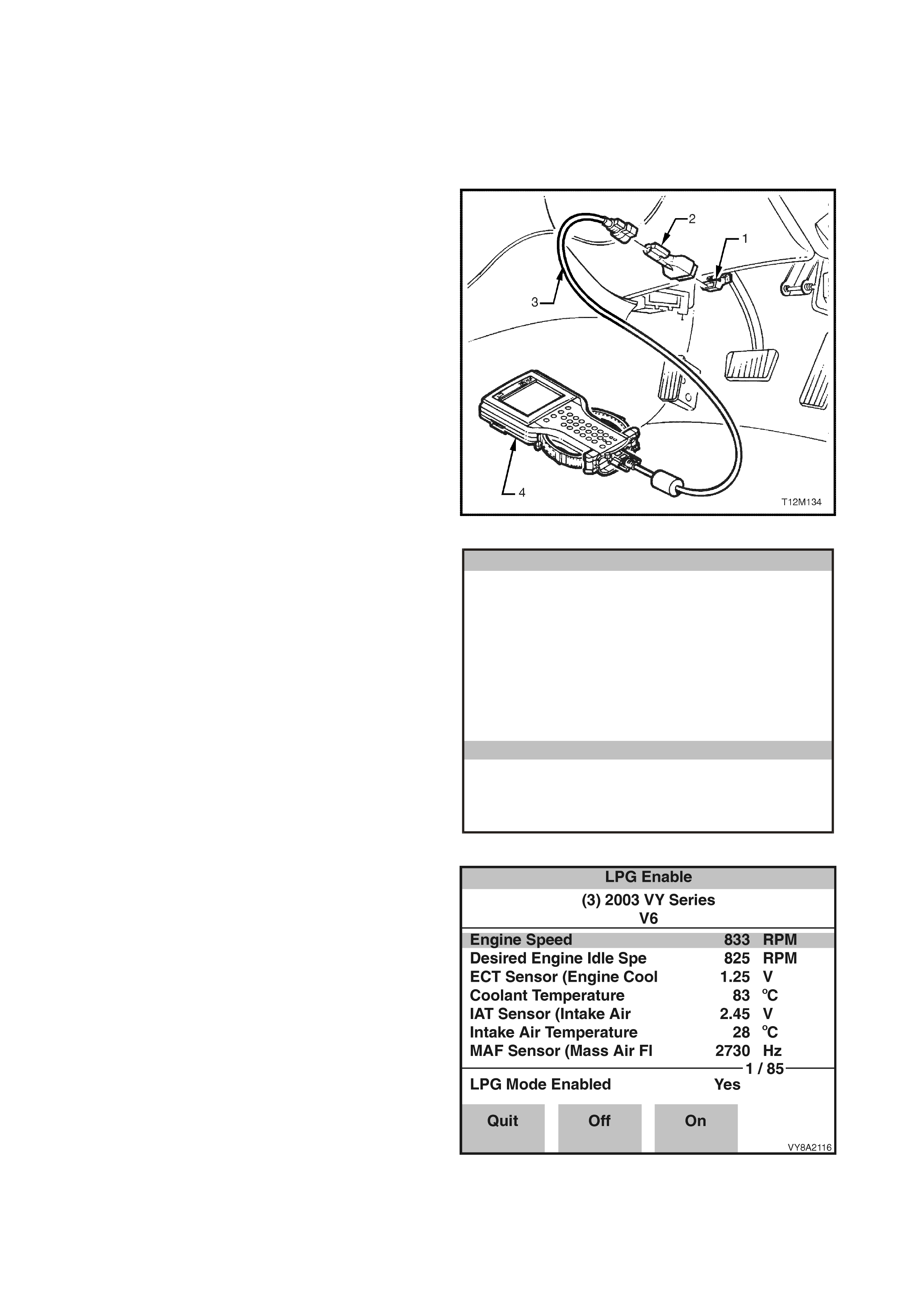
4.3 LPG ENABLE TEST
The LPG enable test is used to enable the vehicle to be plac ed in LPG operating mode. W hen com manded ON,
the PCM will switch to the LPG operating mode.
When commanded OFF, the PCM will switch to petrol operating mode.
NOTE: The PCM will only toggle between the petrol and LPG mode if the ignition is on and the engine is not
running, or if the engine speed is greater that 1300 RPM.
1. Connect TECH 2 (4) to the DLC (1) with the cable
(2) and adapter (3).
Figure 8A2-195
2. On TECH 2 select:
F0: Diagnostics / (3) 2003 / VY Series / F0: Engine
/ V6 / F4: Miscellaneous Tests/ F7: LPG Enable
Test.
Miscellaneous Tests
VXLPG006
F0 : Ou tp ut Tests
F1: IAC System
F2: EGR Control
F3 : Re set C el ls
F4: Bypass Spark
F5: Air Fuel Ratio
F6: LPG Fuel Co n tro l Valve Test
F7: LPG Enable
Figure 8A2-196
3. With the ignition on and the engine not operating
or with the engine operating above 1500 RPM, the
LPG mode can be commanded ON or OFF using
the ON and OFF soft keys.
4. When comm anded ON, the PCM will switch to the
LPG m ode. W hen c omm anded OFF, the PCM will
switch to the petrol mode.
Figure 8A2-197

5. AFTER INSTALLATION CHECK
5.1 GENERAL INFORMATION
At the 1,500 km (or 1 month) service it is a requirement that the following after installation check be performed.
All items in this checklist must be performed to ensure they have been adjusted or installed as outlined in this
Section.

5.2 UNDE RBODY
(Tick the appropriate boxes)
CHECK OK REPAIR
1. The rear service line and interm ediate service line
connectors (under vehicle) are tightened to the
correct torque specification.
! ! !
2. Service lines are correctly routed and retaining
clips installed. ! ! !
3. LPG tank correctly installed and attaching nuts
tightened to the correct torque specification. ! ! !

5.3 REAR COMPARTMENT
(Tick the appropriate boxes)
CHECK OK REPAIR
1. Vent tube flange installed and silicone sealer
applied. Sedan and Utility. ! ! !
2. Service line vent tube installed to vent tube flange
and retaining clamps tightened. Sedan and Utility.
Vent tube grommet installed correctly. Wagon only
! ! !
3. Service line vent tube installed to joiner and
retaining clamp tightened. Utility only. ! ! !
4. Filler line connected to joiner and LPG tank high-
pressure inlet elbow and filler line connectors
tightened to the correct torque specification.
! ! !
5. Filler valve installed correctly and retaining nut
tightened to the correct torque specification. ! ! !
6. Filler door operates without binding and shuts
flush, AFL sticker is affixed to inside of filler door. ! ! !
7. Rear service line connected to manual service
valve assembly and connector tightened to the
correct torque specification.
! ! !
8. LPG tank level sender and smart unit harness
connector is connected to LPG body harness
connector.
! ! !
9. Rear compartment carpet and quarter trim carpet
have been reinstalled and are pos itioned correctly.
Sedan and Wagon
! ! !
10. Check the s pare wheel carrier is correctly installed
and the nuts are tightened to the specified torque.
Wagon only
! ! !
11. Check the spare wheel is correctly fitted and the
retainer is tightened securely by hand. Wagon only ! ! !

5.4 UNDER HOOD
(Tick the appropriate boxes)
CHECK OK REPAIR
1. The vapour line to mixer and vapour line to
converter retaining clamps are installed and
tightened.
! ! !
2. T he vapour line and vacuum hos es are connected
and routed correctly. ! ! !
3. The converter and converter bracket is installed
and retaining bolts are tightened to the correct
torque specification.
! ! !
4. The coolant pipe hose clamps are fitted and
tightened. Coolant and vapour hoses are correctly
routed to avoid contact with engine or body parts.
! ! !
5. The fuel control valve (FCV) is installed and the
retaining bolt tightened to the correct torque
specification.
! ! !
6. The air intake tube is installed, clamps and
mounting screw tightened to the correct torque
specification.
! ! !
7. Air cleaner assembly and MAF sensor installed. ! ! !
8. Intermediate LPG line P-clamps installed on the
dash panel and tightened to the correct torque
specification.
! ! !

5.5 LEAK CHECK
With at least 3 litres of LPG in the tank, leak test the
complete LPG system, refer to 3.3 LEAK TESTING.
The following points must be tested. (Tick the appropriate boxes)
CHECK OK REPAIR
1. Pressure relief valve. ! ! !
2. Manual service valve assembly to LPG tank. ! ! !
3. Solenoid and manual service valve assembly. ! ! !
4. Rear service line to solenoid and manual service
valve assembly connector. ! ! !
5. LPG tank fuel gauge assembly. ! ! !
6. AFL inlet elbow to LPG tank. ! ! !
7. Rear service line to AFL inlet elbow connector. ! ! !
8. AFL to LPG tank. ! ! !
9. Filler valve to filler valve connecting pipe and filler
line. ! ! !
10. Filler valve check ball. ! ! !
11. Rear servic e line to intermediate s ervice line joiner
connection. ! ! !
12. Intermediate service line to rear service line joiner
connection. ! ! !
13. Intermediate s ervice line to front ser vice line joiner
connection. ! ! !
14. F r ont ser vic e line to intermediate ser vice line joiner
connection. ! ! !
15. Front service line to LPG lock-off inlet connection. ! ! !
16. LPG lock-off inlet connection to LPG lock-off. ! ! !
17. LPG lock-off. ! ! !
18. LPG lock-off to LPG lock-off outlet connection. ! ! !
19. LPG lock-off outlet connection to converter. ! ! !

6. DIAGNOSIS
6.1 PREREQUISITES TO DIAGNOSIS AND TROUBLESHOOTING
PRELIMINARY SYSTEM REQUIREMENTS
• Ensure that sound earth connections are provided for all functioning components, particularly at the body
earth connection (fender panel inner stud, adjacent to the battery).
• Ensure the battery is in good condition and adequately charged (above 12.5 volts) before carrying out any
electrical checks.
SAFETY REQUIREMENTS
• Disconnect the battery when carrying out work which involves the risk of an electrical short circuit.
IMPORTANT: Disconnection of the battery affects certain vehicle electronic systems. Refer to
Section 00, 5. BATTERY DISCONNECTION PROCEDURES before disconnecting the battery.
• Do not touc h mechanic al c omponents during function chec ks, to avoid the risk of a hand being caught in the
mechanism.
• All Safety Standards and Regulations pertaining to LPG must be followed at all times.
CHECKING EQUIPMENT
• Tech 2 scan tool.
NOTE: For information on Tech 2 connection and operation procedures refer to Section 0C TECH 2.
• A digital multimeter, with a minimum 10 Mega-ohm impedance must be used when undertaking any
electrical checks on these systems.
• Exercise care when taking readings from wiring harness connectors. It is preferred that the back probing
method with individual connectors is employed wherever possible, to avoid terminal damage and
subsequent connection failure.
• When carrying out wiring checks as directed to by the diagnostic charts, rather than probe terminals and
connectors with incorrect sized multimeter connections, use the adapters contained in connector test
adapter kit KM-609. This will prevent any possibility of spreading or damaging wiring harness terminals.
IMPORTANT: Ensure that the ignition is turned off and the battery earth lead is disconnected before any test
that requires the disconnection or connection of any control module connectors.
• When checking the complete sy stem, the exact order of the test steps should be observed.
• If the required nominal value is not achieved in any stage, then the problem must be rectified before
proceeding further.
• Unless the multim eter being us ed has an auto r anging f unc tion, chec k that the corr ec t range, as specified, is
selected before the test is carried out.
• Testing of the system will involve gaining access to specific wiring harness connectors. For the location of
connectors not detailed in this Section, refer to Section 12O FUSES AND WIRING HARNESSES.

6.2 GENERAL INFORMATION
The procedures outlined in the LPG vehicle preliminary diagnostic chart must be carried out first whenever
diagnosing a problem in a LPG vehicle.
The LPG system is designed to operate in LPG mode when LPG has been selected via the fuel mode switch.
W hen diagnosing the LPG system, unless otherwise directed, ensure that LPG mode has been selected, there is
LPG in the LPG tank and the manual service valve is turned ON.
When LPG has been selected via the fuel mode switch, the PCM will operate in LPG mode if the operating
parameters sensed by the PCM permit the switching to the LPG mode.
Before any diagnostic procedures are carried out on the LPG system you must first confirm that the vehicle
operates on petrol without any problems.
NOTE: For diagnosis of the LPG fuel gauge and the LPG instrument cluster display icons, refer to
Section 12C INSTRUMENT CLUSTER.

6.3 LPG VEHICLE PRELIMINARY DIAGNOSIS
TEST DESCRIPTION
The numbers below refer to step numbers in the following diagnostic chart.
1. Ensures Tech 2 is functioning correctly.
2. Checks if Tech 2 can communicate with the PCM.
3. Checks if any PCM DTCs are present.
4. Checks if the PCM can operate in the LPG mode.
5. Checks if the LPG switch is operating correctly.
6. Checks the operation of the LPG icon.
7. Checks if the engine will operate on petrol.
8. Checks if the engine will crank when LPG has been selected.
9. Checks if the engine will run when LPG has been selected.
STEP ACTION YES NO
1. 1. Turn ignition off, connect Tech 2 to DLC, turn ignition on and
Tech 2 on.
2. Does Tech 2 power-up (screen will illuminate and display
Tech 2)?
Go to Step 2. Refer to Tech 2
DIAGNOSIS in,
Section 0C.
2. 1. With Tech 2 still connected and ignition on, press the ENTER
key then select F0: Diagnostics / (3) 2003 / VY Commodore / F0:
Engine / V6 and then follow the screen instructions.
2. Does Tech 2 display PCM identification information?
Go to Step 3. Refer to ON-
BOARD
DIAGNOSTIC
SYSTEM CHECK
in Section 6C1.
3. 1. At the Tech 2 PCM Identification screen, press the Confirm soft
key. From the Engine menu select F1: Diagnostic Trouble Codes
/ F0: Read Current DTC.
2. Are any DTCs present?
Refer to ON-
BOARD
DIAGNOSTIC
SYSTEM CHECK
in Section 6C1.
Go to Step 4.
4. 1. Return to the Tech 2 Engine menu and select F2: Data Display /
F0: All Data / Scroll to LPG Fuel Enabled.
2. Does Tech 2 display LPG Fuel Enabled YES?
Go to Step 5. Refer to 6.4
DOES NOT
OPERATE ON
LPG.
5. 1. With Tech 2 still connected, scroll to Fuel.
2. Select LPG via the fuel mode switch.
3. Does Tech 2 Data parameter Fuel change from Petrol to LPG?
Go to Step 6. Refer to 6.5 FUEL
MODE SWITCH
DOES NOT
OPERATE.
6. 1. With the LPG Mode selected.
(Tech 2 Data parameter Fuel displaying LPG).
2. Is the LPG icon illuminated in the instrument cluster?
Go to Step 7. Refer to Section
12C
INSTRUMENTS.
7. 1. Select Petrol via the fuel mode switch.
2. Will the engine crank and start immediately the ignition key is
turned from off to start (no delay)?
Go to Step 8. Refer to ON-
BOARD
DIAGNOSTIC
SYSTEM CHECK
in Section 6C1.
8. 1. Select LPG via the fuel mode switch.
2. Will the engine crank immediately the key is turned from off to
start (no delay)?
Go to Step 9. Refer to 6.6
ENGINE DOES
NOT CRANK.
9. 1. Does the engine start and run on LPG? Go to Step 10. Refer to 6.7
ENGINE
CRANKS BUT
WILL NOT
START ON LPG.
10. 1. Does the engine backfire when operated on LPG? Refer to 6.8
ENGINE
BACKFIRES ON
LPG.
Go to Step 11.

STEP ACTION YES NO
11. 1. Does engine lack power, sluggish or have poor performance
when operating on LPG? Refer to 6.9
POOR
PERFORMANCE,
FLAT SPOTTI NG,
SLUGGISH OR
POOR FUEL
CONSUMPTION
WHEN
OPERATING ON
LPG.
Go to step 12.
12. 1. Does fuel gauge operate correctly? LPG Diagnostic
Check completed. Refer to
Section 12C
INSTRUMENTS.
WHEN ALL DIAGNOSIS AND REPAIRS ARE COMPLETE, VERIFY CORRECT OPERATION.
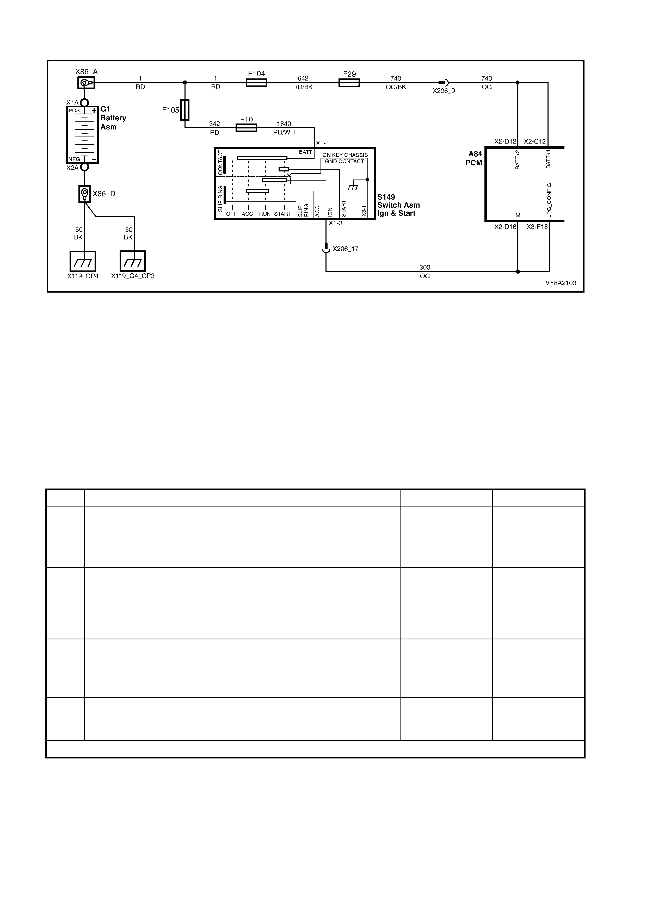
6.4 DOES NOT OPERATE ON LPG
Figure 8A2-198
TEST DESCRIPTION
The numbers below refer to step numbers in the following diagnostic chart.
1. The LPG VEHICLE PRELIMINARY DIAGNOSIS CHECK must be the first step when diagnosing any LPG
system problem.
2. The PCM will not operate in the LPG mode if the PCM has not been programm ed to operate on LPG. Refer
to the latest technical publications for the correct PROM application.
3. W hen the ignition is turned on, battery voltage is applied to terminal X3_F16 of the PCM. This enables the
PCM to operate in either the Petrol or LPG mode. If battery voltage is not applied to PCM terminal X3_F16
the PCM will only operate in the Petrol mode.
4. This test confirms that the PCM connector terminal retention is not causing the problem. The terminal
retention should always be checked before a PCM is replaced.
STEP ACTION YES NO
1. 1. Has the LPG VEHICLE PRELIMINARY DIAGNOSIS CHECK
been performed. Go to step 2 Perform
LPG VEHICLE
PRELIMINARY
DIAGNOSIS
CHECK.
2. 1. Has the PCM been programmed for LPG operation?
Go to step 3. Perform SPS to
program the PCM
for LPG operation.
Refer to SPS in
Section 0C
Tech 2.
3. 1. Ignition on.
2. Measure the voltage at PCM connector A84 terminal X3_F16
circuit 300 (orange/green wire).
3. Is battery voltage present?
Go to step 4. Repair open in
circuit 300.
Verify repair.
4. 1. Check PCM connector terminal retention.
If retention OK replace PCM.
2. Is terminal retention OK?
Replace PCM.
Verify repair. Repair terminals.
Verify repair.
WHEN ALL DIAGNOSIS AND REPAIRS ARE COMPLETE, VERIFY CORRECT OPERATION.
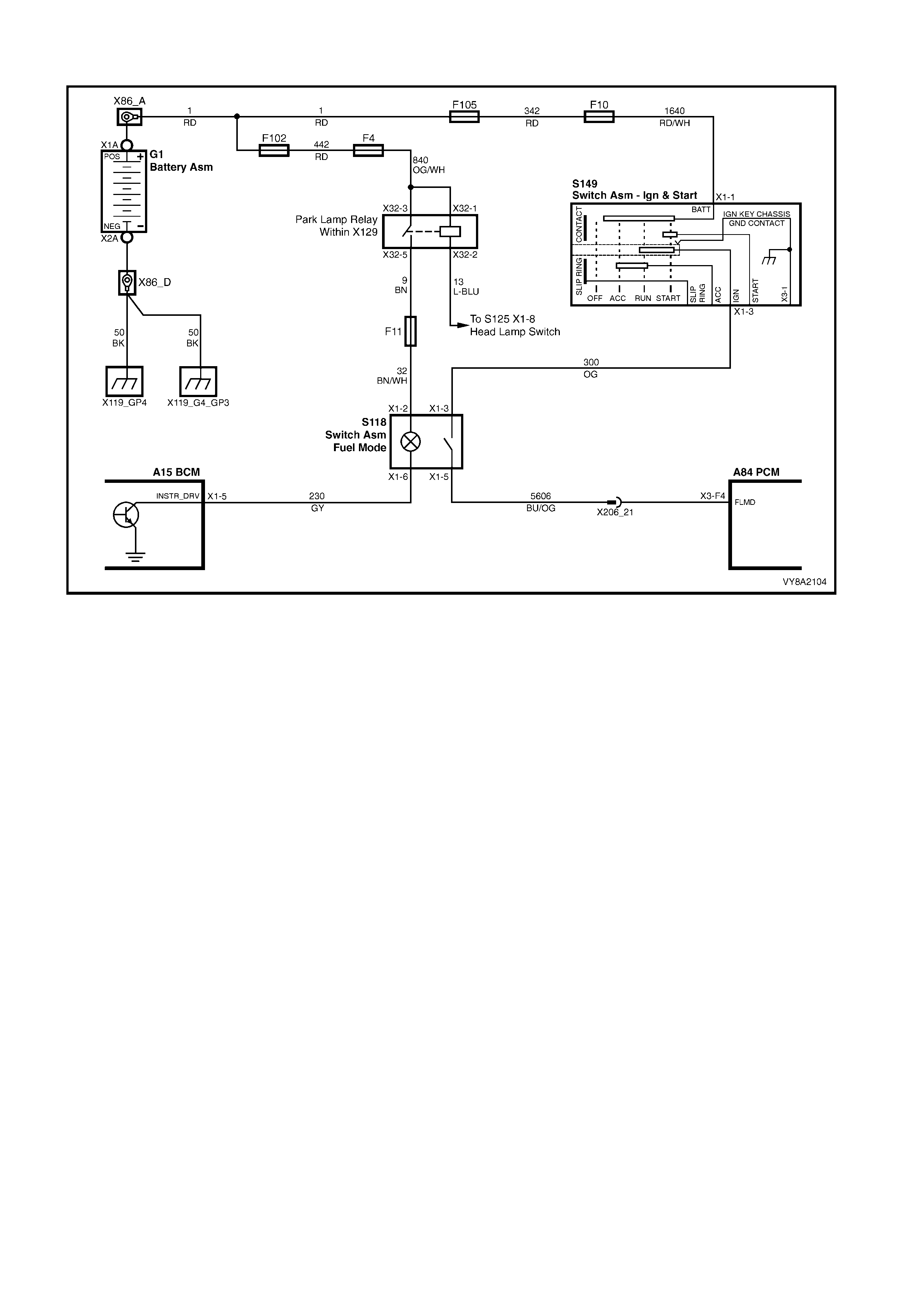
6.5 FUEL MODE SWITCH DOES NOT OPERATE
Figure 8A2-199
TEST DESCRIPTION
The numbers below refer to step numbers in the following diagnostic chart.
1. The LPG VEHICLE PRELIMINARY DIAGNOSIS CHECK must be the first step when diagnosing any LPG
system problem.
2. Checks for battery voltage when the fuel mode switch is activated.
3. Tests operation of fuel mode switch.
4. Checks for voltage at the fuel mode switch. If voltage is not present, circuit 300 is open between the fuel
mode switch and the ignition switch. If voltage is present there is an open circuit between the fuel mode
switch and PCM terminal X3_F4.
5. This test checks for an open in the fuel mode switch circuit 5606 between the fuel mode switch and PCM
terminal X3_F4.
6. This test confirms that the PCM connector terminal retention is not causing the problem. The terminal
retention should always be checked before a PCM is replaced.

STEP ACTION YES NO
1. 1. Has the LPG VEHICLE PRELIMINARY DIAGNOSIS CHECK been
performed. Go to step 2 Perform
LPG VEHICLE
PRELIMINARY
DIAGNOSIS
CHECK.
2. 1. Ignition On
2. Measure the voltage at PCM terminal X3_F4.
3. Is battery voltage present when the fuel mode switch is
depressed?
Go to step 6. Go to step 3.
3. 1. Test the fuel mode switch, refer to 3.22 FUEL MODE SWITCH.
2. Is the fuel mode switch OK? Go to step 4. Replace fuel
mode switch.
Verify repair.
4. 1. Ignition on.
2. Measure the voltage at the fuel mode switch connector S118
circuit 300 (orange wire).
3. Is battery voltage present?
Go to step 5. Repair open in
circuit 300.
Verify repair.
5. 1. Check for open in circuit 5606 (Blue/Orange wire) between fuel
mode switch and PCM terminal X3_F4.
2. Is circuit open?
Repair open in
circuit 5606.
Verify repair.
Go to step 6.
6. 1. Check PCM connector terminal retention.
2. Is terminal retention OK? Replace PCM.
Verify repair. Repair terminals.
Verify repair.
WHEN ALL DIAGNOSIS AND REPAIRS ARE COMPLETE, VERIFY CORRECT OPERATION.

6.6 ENGINE DOE S NOT CRANK
TEST DESCRIPTION
The numbers below refer to step numbers in the following diagnostic chart.
1. The LPG VEHICLE PRELIMINARY DIAGNOSIS CHECK must be the first step when diagnosing any LPG
system problem.
2. The theft deterrent system must be disarmed before the engine will crank. If the Theft Deterrent System
cannot be disarmed, refer to Theft Deterrent Diagnostics in Section 12J BCM.
3. When PETROL is selected, the engine should crank immediately the ignition switch is turned from off to
start. If the engine does not crank immediately, then refer to Section 6C1 ON-BOARD DIAGNOSTIC
SYSTEM CHECK.
4. When LPG is selected, the engine should cr ank imm ediately the ignition switch is turned f rom of f to start. If
the engine cranks immediately system is operating correctly.
5. When LPG is s elected, the PCM will prevent the engine from cranking if the PCM determines the throttle is
open more than 7%. This tests uses Tech 2 to monitor the Throttle Position sensor operation.
STEP ACTION YES NO
1. 1. Has the LPG VEHICLE PRELIMINARY DIAGNOSIS CHECK been
performed. Go to step 2 Perform the
LPG VEHICLE
PRELIMINARY
DIAGNOSIS
CHECK.
2. 1. Ignition on.
2. Is theft deterrent system disarmed?
(Theft deterrent status indicator in the instrument cluster not
flashing or illuminated).
Go to Step 3. Refer to
Section 12J BCM.
3. 1. Ignition on.
2. Select Petrol via the fuel mode switch.
2. Turn ignition switch from OFF to START for a maximum of five
seconds or until engine starts to crank.
3. Does engine crank immediately (less than one second)?
Go to Step 4. Refer to
ON-BOARD
DIAGNOSTIC
SYSTEM CHECK,
Section 6C1.
4. 1. Ignition on.
2. Select LPG via the fuel mode switch.
3. Turn ignition switch from OFF to START for a maximum of five
seconds or until engine starts to crank.
4. Does engine crank immediately (less than one second)?
System operating
correctly.
Check for
intermittent
connections.
Go to Step 5.
5. 1. Turn ignition off.
2. Connect Tech 2 to the DLC.
3. Turn ignition on and then turn Tech 2 on.
4. At the ENGINE menu select F2: Data Display / F0: All Data.
5. Scroll to Throttle Position Sensor.
6. Is Throttle Position sensor displaying 0%?
Refer to
ON-BOARD
DIAGNOSTIC
SYSTEM CHECK,
Section 6C1.
Refer to
TP SENSOR
OUTPUT CHECK
in
Section 6C1-2A.
WHEN ALL DIAGNOSIS AND REPAIRS ARE COMPLETE, VERIFY CORRECT OPERATION.
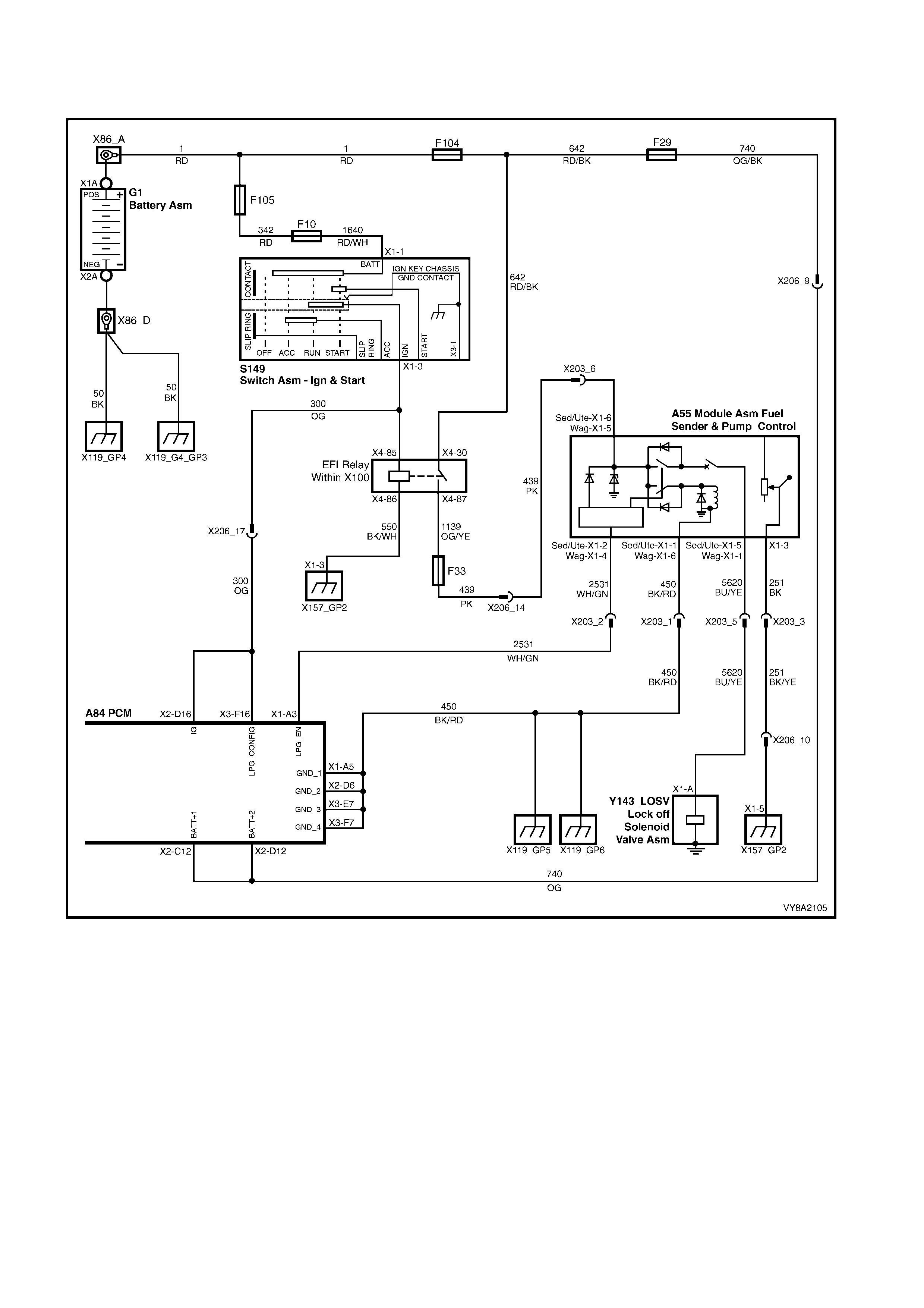
6.7 ENGINE CRANKS BUT WILL NOT START ON LPG
TEST 1
Figure 8A2-200
TEST DESCRIPTION
The numbers below refer to step numbers in the following diagnostic chart.
1. The LPG VEHICLE PRELIMINARY DIAGNOSIS CHECK must be the first step when diagnosing any LPG
system problem.
2. These initial checks are designed to verify that the engine is capable of operating on LPG.
3. Voltage is supplied to the LPG lock-off from the smart unit when the ignition is first turned on and when the
engine is cranking or running. If voltage is not present at these times, the lock-off will not be energised and
LPG will not flow to the converter.
4. This test confirms correct converter operation. Incorrect converter pressures can cause the engine not to
start.
5. This test determines if the PCM is causing the no start condition.

6. Vacuum leaks or blockages can cause a variety of system operating problems. All hoses and vacuum lines
should be checked.
7. This tests confirms correct mixer operation.
8. This tests co nfirms correct PCM LPG set up.
STEP ACTION YES NO
1. 1. Has the LPG VEHICLE PRELIMINARY DIAGNOSIS CHECK been
performed. Go to step 2. Perform the
LPG VEHICLE
PRELIMINARY
DIAGNOSIS
CHECK.
2. INITIAL CHECKS:
1. Has LPG been selected via the fuel mode switch?
2. Has the PCM been programmed to operate on LPG?
3. Is the manual service valve open?
4. Is there any LPG present in the LPG tank, check contents gauge?
If yes to all, go to
Step 3. Repair any faults.
Recheck starting
on LPG.
3. 1. Measure the voltage at LPG lock-off connector Y143 circuit 5620
(Blue/Yellow wire).
2. Is voltage above nine volts for three seconds when the ignition is
first turned on or while the engine is cranking?
Go to Step 4. Go to Diagnostic
Chart ENGINE
CRANKS BUT
WILL NOT
START ON LPG
(Test 2).
4. 1. Test for presence of LPG in the system by checking converter
pressures, refer to 3.18 CONVERTER in this Section.
2. Are converter pressures OK?
Go to Step 5. Go to Diagnostic
Chart ENGINE
CRANKS BUT
WILL NOT
START ON LPG
(Test 3).
5. 1. Ignition on, select Petrol via the fuel mode switch.
2. Start engine and bring to 2000 RPM.
3. Select the LPG mode vi a the fuel mode switch.
4. Does the engine continue to run?
Setup LPG
System. Refer to
4.1 LPG SETUP
PROCEDURE.
Recheck starting
on LPG.
Go to Step 6.
6. 1. Check for vacuum leaks or incorrect routing in the vacuum or
vapour feed lines between the mixer and converter, or a blocked
balance line, FCV or RCV.
2. Are there any leaks, incorrect routing or blockages?
Repair vacuum
leaks or
blockages.
Recheck starting
on LPG.
Go to Step 7.
7. 1. Test mixer operation, refer to 3.21 MIXER in this Section.
2. Is mixer operating correctly? Go to Step 8. Check and repair
any air leaks
between mixer
and throttle body,
if there are no
leaks, overhaul
mixer. Refer to
3.21 MIXER.
Recheck starting
on LPG.
8. 1. Perform the LPG setup procedure, refer to 4.1 LPG SETUP
PROCEDURE and recheck starting on LPG.
2. Does engine start on LPG?
System OK. Go to Diagnostic
Chart ENGINE
CRANKS BUT
WILL NOT
START ON LPG
(Test 2).
WHEN ALL DIAGNOSIS AND REPAIRS ARE COMPLETE, VERIFY CORRECT OPERATION.

TEST 2 – ENGINE CRANKS BUT WILL NOT START ON LPG
Figure 8A2-201
TEST DESCRIPTION
The numbers below refer to step numbers in the following diagnostic chart.
1. This test checks that the smart unit is supplying voltage to circuit 5620.
2. This test checks if circuit 5620 is shorted to earth.
NOTE: T he sm art unit has a current pr otection device on this c ircuit, if cir cuit 5620 is shorted to ear th the sm art
unit will shutdown. The ignition must be cycled from on to off to reset the smart unit.
3. This test checks continuity of the smart unit earth circuit 450.
4. This test checks that voltage is being applied to the smart unit from fuse F33.
5. Ignition voltage should be present at PCM terminal X3_F16 circuit 300 whenever the ignition is on.
6. When oper ating in LPG mode, the PCM puls es the 12 volt pull-up in the s mart unit to earth via c irc uit 2531 at
a 50% duty cycle. Therefor e the voltage at PCM term inal X1_A3 should be approxim ately five volts when the
ignition is first turned on or when the engine is cranking.
7. This test checks the continuity of circuit 2531 (White/Green wire).
8. This test checks if circuit 2531 (White/Green wire) is shorted to earth.

STEP ACTION YES NO
1. 1. Ignition ON, LPG selected.
2. Measure the voltage at the fuel sender & pump control module
(smart unit) connector A55, circuit 5620 (Blue/Yellow wire).
3. Is voltage above nine volts for three seconds when the ignition is
first turned on or while the engine is being cranked?
Repair open in
LPG lock-off
circuit 5620
between smart
unit and lock-off.
Recheck starting
on LPG.
Go to Step 2.
2. 1. Check for short to earth in LPG lock-off circuit 5620 between the
Smart Unit and lock-off.
2. Is circuit 5620 shorted to earth?
Repair short to
earth in LPG lock-
off circuit 5620
between smart
unit and lock-off.
Recheck starting
on LPG.
Go to step 3.
3. 1. Check continuity of smart unit earth circuit 450 (Black/Red wire)
between smart unit connector A55 and a known good earth.
2. Is there continuity?
Go to step 4. Repair open in
circuit 450
(Black/Red wire).
Recheck starting
on LPG.
4. 1. Ignition ON.
2. Measure the voltage at smart unit connector A55 circuit 439 (Pink
wire).
3. Is battery voltage present?
Go to Step 5. Repair open in
circuit 439 (Pink
wire) between
fuse F33 and the
smart unit.
5. 1. Ignition ON.
2. Measure the voltage at PCM connector A84_X3 terminal F16
circuit 300 (Orange wire).
3. Is battery voltage present?
Go to step 6. Repair open in
circuit 300
(Orange wire)
Ignition switch
and PCM.
Recheck starting
on LPG.
6. 1. With LPG selected via the fuel mode switch.
2. Disconnect smart unit connector A55.
3. Measure the voltage at smart unit connector A55 circuit 2531 PCM
side (White/Green wire).
4. Turn the ignition from OFF to ON, is voltage approximately five
volts for three seconds when the ignition is first turned on or when
the engine is cranking?
Check smart unit
connector
terminal retention.
If OK, replace
smart unit.
Verify repair.
Go to step 7.
7. 1. With LPG selected via the fuel mode switch.
2. Measure the voltage at PCM connector A84_X1 terminal A3 circuit
2531 (White/Green wire).
3. Turn the ignition from OFF to ON, is voltage approximately five
volts for three seconds when the ignition is first turned from off to
on or when the engine is cranking?
Go to step 8. Check PCM
connector
terminal retention.
If OK,
replace PCM.
Recheck starting
on LPG.
8. 1. Check continuity of circuit 2531 (White/Green wire) between smart
unit connector A55 and PCM connector A84_X3 terminal A3.
2. Is there continuity?
Go to step 9. Repair open in
circuit 2531
(White/Green
wire).
Verify repair.
9. 1. Check for a short to earth in circuit 2531 (White/Green wire)
between smart unit connector A55 and PCM connector A84_X1
terminal A3.
2. Is there a short to earth?
Repair short to
earth in circuit
2531
(White/Green
wire).
Verify repair.
Check PCM
connector
terminal retention.
If OK,
replace PCM.
Recheck starting
on LPG.
WHEN ALL DIAGNOSIS AND REPAIRS ARE COMPLETE, VERIFY CORRECT OPERATION.

TEST 3 – ENGINE CRANKS BUT WILL NOT START ON LPG
TEST DESCRIPTION
The numbers below refer to step numbers in the following diagnostic chart.
1. Low primary converter pressure can be caused by low supply pressure or a faulty converter.
2. If the primary converter pressure is too high the converter will have to be overhauled.
3. If the primary converter pressure is within specification but the secondary converter pressure is out of
specification the converter will have to be overhauled.
4. This test checks if the solenoid valve is restricting the flow of LPG.
5. This test checks the flow of LPG from the LPG tank to the LPG lock-off.
6. This test determines if the LPG lock-off or the converter is causing the problem.
7. This test chec ks if the servic e line is block ed. If the s ervice line is not bloc ked then the m anual servic e valve
or the LPG cylinder pick up must be blocked.
STEP ACTION YES NO
1. 1. Is primary converter pressure below specification? Go to Step 4. Got to Step 2.
2. 1. Is primary converter pressure above specification? Repair the
converter, refer to
3.18
CONVERTER.
Recheck starting
on LPG.
Go to Step 3.
3. 1. If primary converter pressure is within specification, is the
secondary converter pressure out of specification? Repair converter,
refer to 3.18
CONVERTER.
Recheck starting
on LPG.
Go to step 4.
4. 1. Ignition OFF.
2. Close manual service valve.
3. Remove the solenoid valve from the manual service valve
assembly and reinstall solenoid sleeve, refer to 3.8 SMART UNIT
AND SOLENOID VALVE.
4. Does engine start and run on LPG?
Replace the smart
unit and solenoid
valve.
Recheck starting
on LPG.
Go to Step 5.
5. 1. Ignition OFF.
2. Close manual service valve.
3. With the solenoid valve still removed from the manual service
valve assembly.
4. Disconnect the front service line at the LPG lock-off.
5. In accordance with AS-1425, have a second technician slowly
open the manual service valve so that the excess flow valve
doesn’t shut LPG flow off (if a click is herd at the manual service
valve, the excess flow valve has closed).
6. Does LPG flow from the front service line?
Go to Step 6. Go to Step 7.
6. 1. Test LPG lock-off, refer to 3.17 LPG LOCK-OFF.
2. Is LPG lock-off OK? Repair converter,
refer to 3.18
CONVERTER.
Recheck starting
on LPG.
Repair LPG lock-
off, refer to 3.17
LPG LOCK-OFF.
Recheck starting
on LPG.
7. 1. Disconnect the rear service line at the manual service valve.
2. With front service line still disconnected, blow air through service
line to check for blockages
3. Does air flow through service line?
Check for manual
service valve or
LPG tank fuel
pick-up blockage
or fault. Repair or
replace blocked or
damaged
components.
Recheck starting
on LPG.
Check for
damaged or
blocked service
lines. Repair or
replace blocked or
damaged
components.
Recheck starting
on LPG.
WHEN ALL DIAGNOSIS AND REPAIRS ARE COMPLETE, VERIFY CORRECT OPERATION.

6.8 ENGINE BACKFIRES ON LPG
TEST DESCRIPTION
The numbers below refer to step numbers in the following diagnostic chart.
NOTE: Whenever an engine backfire has occurred, the complete intake system including the mixer should be
checked for damage.
1. The LPG VEHICLE PRELIMINARY DIAGNOSIS CHECK must be the first step when diagnosing any LPG
system problem.
2. An ON BOARD DIAGNOSTIC SYSTEM CHECK should be performed to confirm that a problem with the
powertrain management system is not causing the engine to backfire when operating on LPG?
3-7. An ignition system that is not operating at it’s full potential can cause an engine to backfire when operating
on LPG. Ignition leads that operate quite well when operating on petrol, c an cause problem s when operating
on LPG. Therefore, all ignition system components must be at here optimum when operating on LPG.
8. Vacuum leaks or blocked vacuum lines can cause incorrect system operation, causing engine backfire.
9. Incorrect mixer operation can cause incorrect air/fuel ratios. Incorrect air/fuel ratios can cause engine
backfire.
10. Incorrect LPG set-up can cause incorrect system operation, causing engine backfire.
11. Incorrect converter operation can cause incorrect air/fuel ratios. Incorrect air/fuel ratios can cause engine
backfire.
12. This test confirm correct regulator check valve (RCV) operation, incorrect RCV operation can cause slow
converter response causing engine backfire.
13. Engine mechanical condition can cause engine operating problems that do not effect the engine when
operating on petrol. The engine must be in optimum operating condition to prevent the engine backfiring
when operating on LPG.
STEP ACTION YES NO
1. 1. Has the LPG VEHICLE PRELIMINARY DIAGNOSIS CHECK been
performed. Go to step 2 Perform the
LPG VEHICLE
PRELIMINARY
DIAGNOSIS
CHECK.
2. 1. Has an ON BOARD DIAGNOSTIC SYSTEM CHECK been
performed? Go to Step 3. Perform
ON-BOARD
DIAGNOSTIC
SYSTEM CHECK.
Refer to Section
6C1.
Recheck for
engine backfire.
3. 1. Check spark plug leads for tracking or cracks in insulation and
check their resistance, refer to Section 6D1-3 IGNITION SYSTEM
- V6.
2. Are the spark plugs leads OK?
Go to Step 4. Replace spark
plug leads.
Recheck for
engine backfire.
4. 1. Remove and inspect spark plugs for fouling.
2. Are the spark plugs OK? Go to Step 5. Replace spark
plugs. Recheck
for engine
backfire.
5. 1. Re-gap spark plugs to minimum specification.
2. Have spark plugs been re-gaped to minimum specification? Go to Step 6. Re-gap spark
plugs to minimum
specification
Recheck for
engine backfire.
6. 1. Check ignition coil resistance, refer to Section 6D1-3 IGNITION
SYSTEM - V6.
2. Is the ignition coil resistance within specification?
Go to Step 7. Replace faulty
ignition coil.
Recheck for
engine backfire.
7. 1. Check PCM, DIS and crank angle sensor wiring harness terminal
retention.
2. Is terminal retention OK?
Go to Step 8. Resize terminals.
Recheck for
engine backfire.

STEP ACTION YES NO
8. 1. Check for vacuum leaks in vacuum or vapour feed lines between
mixer and converter, or a blocked balance line, FCV or RCV.
2. Are there any leaks or blockages?
Repair vacuum
leaks or
blockages.
Recheck for
engine backfire.
Go to Step 9.
9. 1. Test mixer operation, refer to 3.21 MIXER.
2. Is the mixer operating correctly? Go to Step 10. Overhaul mixer,
refer to 3.21
MIXER.
Recheck for
engine backfire.
10. 1. Is the LPG setup correct? Go to Step 11. Perform the LPG
setup procedure
refer to 4.1 LPG
SETUP
PROCEDURE.
Recheck for
engine backfire.
11. 1. Test converter pressures.
2. Are the converter pressures OK? Go to Step 12. Overhaul the
converter, refer to
3.18
CONVERTER.
12. 1. Test regulator check valve operation, refer to 3.19 REGULATOR
CHECK VALVE.
2. Is Regulator Check Valve operating correctly?
Go to Step 13. Replace the
regulator check
valve, refer to
3.19
REGULATOR
CHECK VALVE.
Recheck for
engine backfire.
13. 1. Check the engine mechanical condition by checking
compression, valve timing, intake and exhaust valves and manifolds
for casting flash.
2. Is the engine mechanical condition OK?
Check for
incorrectly routed
harnesses,
ignition leads
or non genuine
accessories.
Repair any faults.
Recheck for
engine backfire.
WHEN ALL DIAGNOSIS AND REPAIRS ARE COMPLETE, VERIFY CORRECT OPERATION.

6.9 POOR PERFORMANCE, FLAT SPOTTING, SLUGGISH OR POOR
FUEL CONSUMPTION WHEN OPERATING ON LPG
NOTE: Due to the nature of LPG , a m inim al loss of power m ay be experienced under heavy acceleration, this is
expected and quite normal.
TEST DESCRIPTION
The numbers below refer to step numbers in the following diagnostic chart.
1. The LPG VEHICLE PRELIMINARY DIAGNOSIS CHECK must be the first step when diagnosing any LPG
system problem.
2. An ON BOARD DIAGNOSTIC SYSTEM CHECK should be performed to confirm that a problem with the
powertrain management system is not causing the engine to backfire when operating on LPG?
3. This checks for common causes of engine drivability problems.
4. Incorrect LPG setup can cause incorrect air/fuel ratios.
5. Incorrectly tensioned air valve to diaphragm attaching screws can cause incorrect mixer operation.
6. Correct mixer operation is required so that the correct air/fuel ratio is achieved.
7. A regulator check valve that is blocked or opening at the wrong vacuum can cause incorrect converter
operation.
8. The converter is one of the key components in the control of the delivery of LPG. Incorrect converter
operation can cause rich or lean mixtures.

STEP ACTION YES NO
1. 1. Has the LPG VEHICLE PRELIMINARY DIAGNOSIS CHECK been
performed. Go to step 2 Perform the
LPG VEHICLE
PRELIMINARY
DIAGNOSIS
CHECK.
2. 1. Has an ON BOARD DIAGNOSTIC SYSTEM CHECK been
performed? Go to Step 3. Perform
ON-BOARD
DIAGNOSTIC
SYSTEM CHECK,
refer to
Section 6C1.
Recheck
performance.
3. 1. Perform SYMPTOMS CHECK, refer to Section, 6C1.
2. Are all checks OK? Go to Step 4. Repair any faults.
Recheck
performance.
4. 1. Has the LPG setup procedure been performed? Go to Step 5. Perform the LPG
setup procedure,
refer to
4.1 LPG SETUP
PROCEDURE.
Recheck
performance.
5. 1. Check air valve to diaphragm attaching screws for correct torque.
Refer to 3.21 MIXER.
2. Are the screws tightened to the correct torque?
Go to Step 6. Tighten the
screws to the
correct torque
specification.
Recheck
performance.
6. 1. Test mixer operation, refer to 3.21 MIXER.
2. Is mixer operating correctly? Go to Step 7. Overhaul mixer,
refer to
3.21 MIXER.
Recheck
performance.
7. 1. Test the regulator check valve (RCV) operation, refer to 3.19
REGULATOR CHECK VALVE.
2. Is the RCV operating correctly?
Go to Step 8. Replace the
regulator check
valve.
Recheck
performance.
8. 1. Test converter operation, refer to 3.18 CONVERTER.
2. Is converter operating correctly? Repair the
converter, refer to
3.18
CONVERTER.
Recheck
performance.
WHEN ALL DIAGNOSIS AND REPAIRS ARE COMPLETE, VERIFY CORRECT OPERATION.
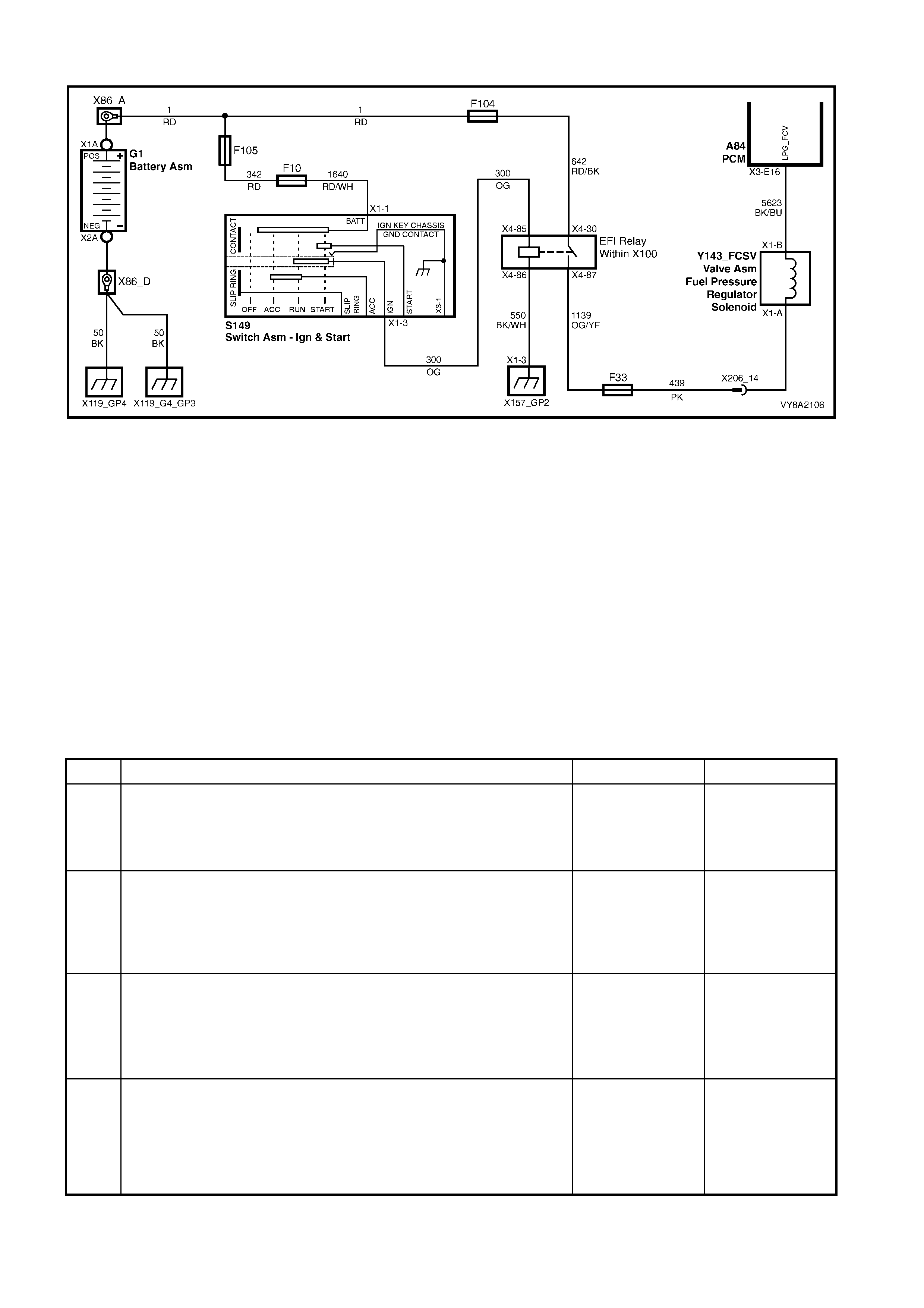
6.10 FUEL CONTROL VALVE DOES NOT OPERATE
Figure 8A2-202
TEST DESCRIPTION
The numbers below refer to step numbers in the following diagnostic chart.
1. The LPG VEHICLE PRELIMINARY DIAGNOSIS CHECK must be the first step when diagnosing any LPG
system problem.
2. This test confirms if the FCV is operating correctly.
3. This test confirms the continuity of the FCV circuit 439 and 5623.
4. This test confirms that the PCM is pulsing the FCV circuit to earth.
5. This test confirms that voltage is being applied to the FCV from fuse F33.
6. This test confirms that circuit 5623 is not open or shorted to battery voltage.
7. This test confirms that circuit 5623 is not shorted to earth.
8. This test checks the operation of the FCV.
9. This test confirms the retention of the PCM terminals. If the terminal retention is OK, the PCM should be
replaced.
STEP ACTION YES NO
1. 1. Has the LPG VEHICLE PRELIMINARY DIAGNOSIS CHECK been
performed? Go to step 2. Perform the
LPG VEHICLE
PRELIMINARY
DIAGNOSIS
CHECK.
2. 1. Perform a fuel control valve test, refer to 3.20 FUEL CONTROL
VALVE.
2. Is the fuel control valve operating correctly?
Fuel control valve
operation is
intermittent.
Check retention of
all FCV circuit
terminals.
Go to Step 3.
3. 1. Ignition OFF, disconnect PCM Connector A84_X3.
2. Ignition ON.
3. Measure the voltage between the PCM connector A84_X3
terminal E16 and earth.
4. Is battery voltage present?
Reconnect PCM
Connector A84
Go to Step 5.
Reconnect PCM
Connector A84
Go to Step 4.
4. 1. Ignition ON, LPG selected.
2. Measure the voltage at PCM connector A84_X3 terminal E16
circuit 5623 (Black/Blue wire) and earth.
3. Turn the ignition from off to on. Is there at least nine volts present
for three seconds when the ignition is first turned on or when the
engine is cranking?
Go to step 8. Go to Step 5.

STEP ACTION YES NO
5. 1. Ignition off.
2. Disconnect FCV connector Y143_FCSV.
3. Ignition on.
4. Measure the voltage at the FCV connector Y143_FCSV circuit 439
(Pink wire) and earth.
5. Is battery voltage present?
Go to step 6. Repair open in
circuit 439 (Pink
wire) between
fuse F33 and
connector
Y143_FCSV.
6. 1. Check for open or short to voltage in circuit 5623 (Black/Blue wire)
between FCV connector Y143_FCSV and the PCM.
2. Is circuit open or shorted to voltage?
Repair open or
short to voltage
circuit 5623
(Black/Blue wire).
Verify repair.
Go to Step 7.
7. 1. Check for a short to earth in circuit 5623 (Black/Blue wire).
2. Is circuit 5623 (Black/Blue wi re) shorted to earth? Repair short to
earth in circuit
5623
(Black/Blue wire).
Verify repair.
Go to step 8.
8. 1. Test operation of the FCV, refer to 3.20 FUEL CONTROL VALVE
in this Section.
2. Is the FCV operating correctly?
Fuel control valve
operation is
intermittent.
Check all FCV
circuit terminal
retention.
Replace FCV.
Verify repair.
9. 1. Check the PCM connector terminal retention.
2. Is PCM terminal retention OK? Replace PCM.
Recheck starting
on LPG.
Repair PCM
terminals.
WHEN ALL DIAGNOSIS AND REPAIRS ARE COMPLETE, VERIFY CORRECT OPERATION.

6.11 TECH 2 SCAN TOOL: ENGINE DATA
The T ECH 2 scan tool engine data listed in the f ollowing table may be used for com paris on when diagnosing faults
on MY 2003 VY Series vehicles operating on LPG:
• After completing the 6.3 LPG VEHICLE PRELIMINARY DIAGNOSIS and the ON-BOARD DIAGNOSTIC
SYSTEM CHECK in Section 6C1.
• Finding the on-board diagnostics are functioning properly and
• No diagnostic DTCs are displayed.
IMPORTANT: The data in the f ollowing table is TYPICAL and as m any of the param eters are var iable according to
operating conditions, should be used as a guide only. For descriptions of the data parameters refer to
Section 6C1-2 DIAGNOSIS – V6 ENGINE.
A Tech 2 scan tool that displays faulty data should not be used, and the problem should be reported to the
manufacturer. The use of a faulty Tech 2 Scan Tool can result in misdiagnosis and unnecessary parts replacement.
TEST DESCRIPTION
The numbers below refer to the bracketed numbers on the diagnostic chart.
1. Scan Position refers to the data that will be displayed when from the Engine menu, F2: Data Display then F0: All
Data is selected. The down arrow can be used to scroll through the data one parameter at a time. After Time
From Start parameter is displayed, pressing the down arrow again w ill display the top of the list again.
2. Units Displayed are the available ways of displaying what each parameter is currently operating in, or a value
that is being sensed or being outputted by the PCM.
3. Typical Data Value is separated into two parts: ignition on and engine running. These displayed values are
typical of a normally operating vehicle. The Ignition ON com parison should be performed first as this may lead
to a quick identification of a f ailure. The engine running data should be compared to the Ignition ON data as a
diagnostic check to make sure the component or system is operating properly.
4. Ignition ON values are the typical values that should be seen on the T ech 2 scan tool with the ignition ON, the
engine stopped and at normal operating temperature.
5. Engine Running values are the typical values that should be seen on the Tech 2 scan tool with the engine
running at normal operating temperature.
NOTE: When operating in the LPG m ode all of the left hand oxygen sensor inf orm ation will be f rozen or invalid, this
is because the PCM only monitors the right hand oxygen sensor when operating on LPG. The values that are frozen
or invalid are shaded in the following table.

TYPICAL DATA VALUE (3)
SCAN POSITION (1) UNITS DISPLAYED
(2) IGNITION ON
(4) ENGINE RUNNING (5)
ENGINE SPEED (IN PARK) RPM 0 RPM ± 100 RPM FROM DESI RED IDLE SPEED
ENGINE SPEED (IN DRIVE) RPM 0 RPM ± 50 RPM FROM DESIRED IDLE SPEED
DESIRED IDLE SPEED
(IN PARK) RPM 0 RPM 737 RPM
(VARIES WITH TEMPERATURE)
DESIRED IDLE SPEED
(IN DRIV E ) RPM 0 RPM 662 RPM
(VARIES WITH TEMPERATURE)
ENG. COOLANT TEMP (ECT) VOLTS VARIES VARIES
COOLANT TEMPERATURE DEGREES C VARIES VARIES
IAT VOLTS VARIES VARIES
INTAKE AIR TEMPERATURE DEGREES C VARIES VARIES
MAF SENSOR FREQUENCY Hz 0 Hz 2200-2500 Hz
MASS AIR FLOW GRAM /SEC 0 g/s 5 - 10 g/s
MASS AIR FLW / CY L Mg/s 0.0 Mg/s 140 to 150 Mg/s
TPS SI GNA L VOLTS 0.51 V 0.51 V
THROTTLE ANGLE 0-100 % 0 % 0 %
RH 02 SENSOR READY YES / NO NO YES
LH 02 SENSOR READY YES / NO NO NO
RH 02 SENSOR Mv 451 Mv 100-1000 Mv AND V A RY ING
LH 02 SENSOR Mv 451 Mv 100-1000 Mv AND VARYING
RH ST FUEL TRIM + 100% TO –100% 0 % +10 % TO –10 %
LH ST FUEL TRIM + 100% TO –100% 0 % +10 % TO –10 %
RIGHT LT FUEL TRIM + 100% to – 100 % 0 % + 10 % to – 10 %
LEFT LT FUEL TRIM + 100% to – 100 % 0 % + 10 % t o – 10 %
LTFT ENABLE YES / NO NO YES
FUELING MODE OP E N / CLOS ED LOOP OPEN LOOP CLOSED LOOP
LTFT CELL CELL # 0 16
RH O2 STAT US RICH / LE AN LEAN RICH
LH O2 STATUS RICH / LEAN LEAN LEAN
RH O2 CROSS CNTS COUNTS 0 1
LH O2 CROSS CNTS COUNTS 0 0
STFT DELTA 0 – 100 % 7 % 7 %
LTFT DELTA 0 – 100 % 2 % 2 %
DECEL FUEL CUTOF F NO / Y ES NO NO
INJ. P ULS E TIME Ms 0.00 Ms 3.55 Ms
INJECTOR V OLTA G E VOLTS 11.9 V 13.8 V
AIR / FUE L RATIO % 14.7 : 1 14.7 : 1
PURGE PWM % 0 % 7 %
EGR POS . COMMANDED % 0% 0 %
EGR POS. FEEDBACK % 0% 0 %
EGR PINTLE SENSOR VOLTS VOLTS 0.8 V 0.8 V
BATTERY VOLTAGE VOLTS 11.9 V 13.4 V
REFERENCE V O LTS VOLTS 5.0 V 5.0 V
3X SIGNAL MISSING / PRESENT MISSING PRESENT
18X SIGNAL MISSING / PRESENT MISSING PRESENT
CAM SIGNAL MISSING / PRESENT MISSING PRESENT
IAC POSITION STEPS 51 STEPS 43 STEPS
LITERS P ER HOUR L/hour 0.00 1 – 2 L/Hour
IDLE RPM VA RIATION RPM 0 RPM 200-268 RPM
SPARK MODE BYPASS / EST BYPASS ELEC. SPARK. TIM.
SPARK ADVANCE DEGREES BTDC 0 ° CA + 20° CA
KNOCK SIGNAL CYLINDER 1 NONE / KNOCK
DETECTED NONE NONE

TYPICAL DATA VALUE (3)
SCAN POSITION (1) UNITS DISPLAYED
(2) IGNITION ON
(4) ENGINE RUNNING (5)
KNOCK SIGNAL CYLINDER 2 NONE / KNOCK
DETECTED NONE NONE
KNOCK SIGNAL CYLINDER 3 NONE / KNOCK
DETECTED NONE NONE
KNOCK SIGNAL CYLINDER 4 NONE / KNOCK
DETECTED NONE NONE
KNOCK SIGNAL CYLINDER 5 NONE / KNOCK
DETECTED NONE NONE
KNOCK SIGNAL CYLINDER 6 NONE / KNOCK
DETECTED NONE NONE
KNOCK SIGNAL ANY
CYLINDER KNOCK / NONE NONE NONE
KNOCK RETARD # OF DEGREES NO NO
KNOCK RET A RD CYLINDER 1 # OF DEGREE S 0 ° CA 0 ° CA
KNOCK RET A RD CYLINDER 2 # OF DEGREE S 0 ° CA 0 ° CA
KNOCK RET A RD CYLINDER 3 # OF DEGREE S 0 ° CA 0 ° CA
KNOCK RET A RD CYLINDER 4 # OF DEGREE S 0 ° CA 0 ° CA
KNOCK RET A RD CYLINDER 5 # OF DEGREE S 0 ° CA 0 ° CA
KNOCK RET A RD CYLINDER 6 # OF DEGREE S 0 ° CA 0 ° CA
TCC SOLENOID ON / OFF OFF OFF
VEHICLE SPEED KM / H 0 KM/H 0 KM/H
A/C REQUEST ON / OFF OFF OFF
A/C CLUTCH ON / OFF OFF OFF
A/C PRESSURE SENSOR VOLTS 1 - 2 V 1 - 2.5 V
A/C PRE S SURE SENS OR kPa 832 kPa 600 - 700 kPa A/C OFF
800 - 1200 kPa A/C ON
HIGH SPEED FAN ON / OFF OFF OFF
LOW SPEED FAN REQUEST ON / OFF OFF OFF
THEFT STATUS NO START/START START START
STARTER RELAY OFF / ON ON OFF
FUEL PUMP RELAY ON / OFF OFF OFF
CRANK TIME SEC 0.0 SEC 0.4 SEC
DTC STA T US NO DTC(s )/ DTC(s) SE T NO DT C NO DT C
TIME FROM START TIME 0:00:00 VARIES
CHECK P OWERTRAIN
LAMP OFF / ON ON OFF
REQUEST E D TORQUE Nm 476 Nm 476 Nm
(Nm will vary depending on the ABS/TCS
control module request ed torque)
ACTUAL TO RQUE Nm 0 Nm 11 Nm
(Nm will closely follow requested torque
during tract i on control)
LOW OIL PRESSURE NO / YES YES NO
LPG SWI TCH " OFF / ON OFF OFF
LPG FUEL ENABLE NO / YES YES YES
FUEL # P E T ROL / LPG LPG LPG
LPG FUEL CONTROL VA LV E 0-100 % 0% 36 %
LPG MODE ENABLED NO / YES YES YES
LPG LOW PET ROL CUT OUT NO / YES NO NO
LPG SMART SOLENOID ON / OFF OFF ON
" Momentary contact switch. Depressing the switch will change the value to ON and revert to OFF when released.
# Fuel ref ers to the mode the vehic le is currently operating in. The m ode can only be switched with the ignition on
and engine not running, or at an engine speed greater than 1500 rpm.
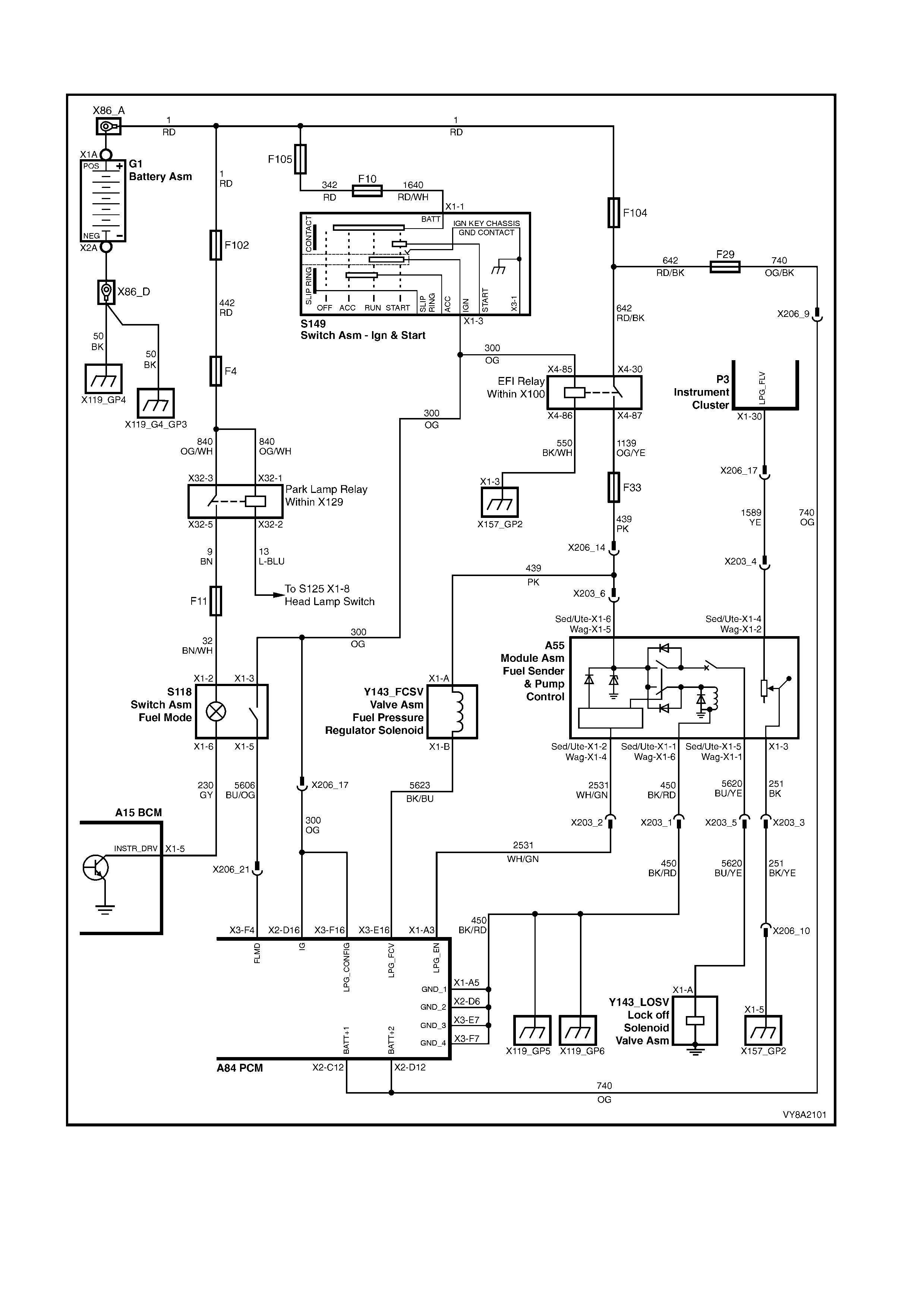
7. WIRI NG & CONNECTORS
Figure 8A2-203
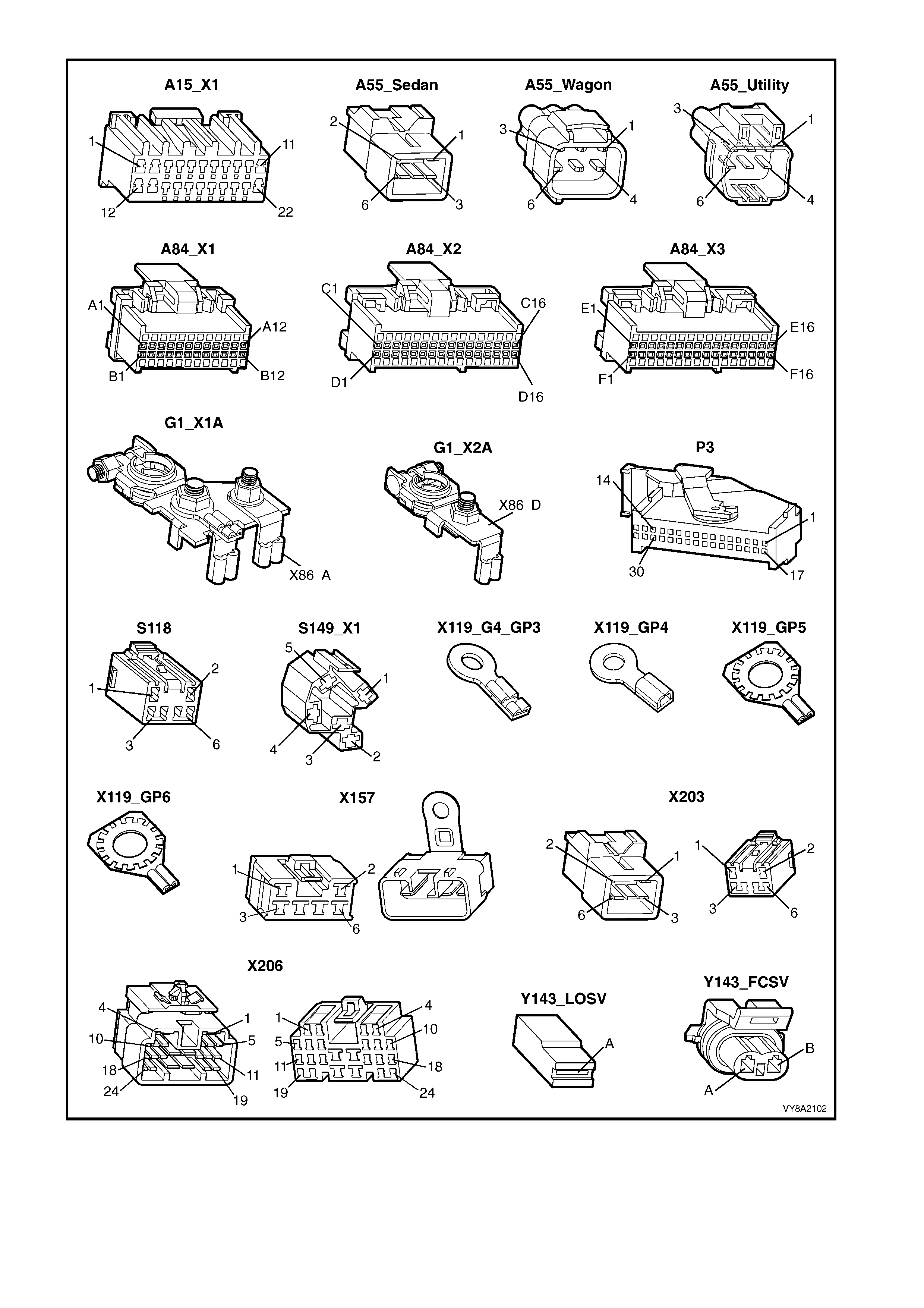
Figure 8A2-204

8. SPECIFICATIONS
LPG tank fillable capacity:
- Sedan......................................................................................... 74 litres ± 2 litres
- Wagon ....................................................................................... 60 litres ± 2 litres
- Utility.......................................................................................... 70 litres ± 2 litres
Converter primary pressure .......................................................... 1 - 1.5 psi (7 - 10 kPa)
Converter secondary pressure ..................................................... Negative 1 - 1.5 inches W.C
(Negative 24 - 38 mm W.C.)
Contents gauge sender unit resistance:
- Empty......................................................................................... 40 Ohms
- Full............................................................................................. 255 Ohms
Fuel Control Valve (FCV) resistance ............................................ 19 - 21 ohms @ 20°C
LPG lock-off coil resistance ......................................................... 17 - 27 ohms @ 20°C
LPG lock-off pressure rating......................................................... 1200 kPa
Spark plug gap.............................................................................. 1.4mm

9. TORQUE WRENCH SPECIFI CATIONS
Nm
Air cleaner lower housing nut................................................ 5.0 – 7.0
Air duct clamp....................................................................... 1.5 – 2.5
Air valve cover screw............................................................ 7.5 – 9.0
Air valve to diaphragm screw................................................ 2.0 – 2.5
Automatic fill limiter screw..................................................... 5.0 – 7.0
Converter to support bracket screw...................................... 10.0 – 12.0
Coolant hose clamp nut........................................................ 10.0 – 12.0
Coolant hose clamp screw.................................................... 3.0 – 4.0
Tank fuel gauge screw.......................................................... 5.0 – 7.0
Diaphragm cover to regulator body screw............................ 3.0 – 5.0
Filler line & connector pipe connectors................................. 12.0 – 18.0
Filler valve nut, Sedan........................................................... 50.0 – 60.0
Filler valve nut, Wagon ......................................................... 50.0 – 60.0
Filler valve nut, Utility............................................................ 12.0 – 15.0
Filler valve flange screw, Sedan ........................................... 7.0 – 9.0
Floor console cover assembly screw.................................... 1.0 – 3.0
Heat shield screw.................................................................. 3.0 –5.0
Heat shield support post screw............................................. 10.0 – 12.0
Lock-off bracket to converter screw...................................... 3.0 – 5.0
Lock-off cup assembly screw................................................ 3.0 – 5.0
Manual service valve screw.................................................. 5.0 – 7.0
Mixer bell housing screw....................................................... 1.0 – 3.0
Pressure relief valve to LPG tank ......................................... 60.0 – 65.0
Service line connectors......................................................... 12.0 – 18.0
Service line retaining clamp screw........................................ 12.0 – 15.0
Smart unit screw................................................................... 1.0 – 3.0
Solenoid sleeve to manual service valve.............................. 15.0 – 18.0
Spare wheel carrier nut and bolt........................................... 40.0 – 50.0
Tank cover ball stud nut, Utility............................................. 3.0 – 5.0
Tank cover upper screw, Utility............................................. 10.0 –12.0
Tank front mounting bracket screw, Sedan.......................... 25.0 – 35.0
Tank screw, front Sedan....................................................... 10.0 – 12.0
Tank nut, rear Sedan............................................................ 70.0 – 90.0
Tank nut, Wagon .................................................................. 40.0 – 50.0
Tank strap nut, Utility............................................................ 40.0 – 50.0
Tank support bracket nut, Utility ........................................... 40.0 – 50.0
Tank support upper connecting plate nut, Utility................... 40.0 – 50.0
Valve box screw, Wagon ...................................................... 7.0
Vent tube hose clamp........................................................... 2.0 – 3.0
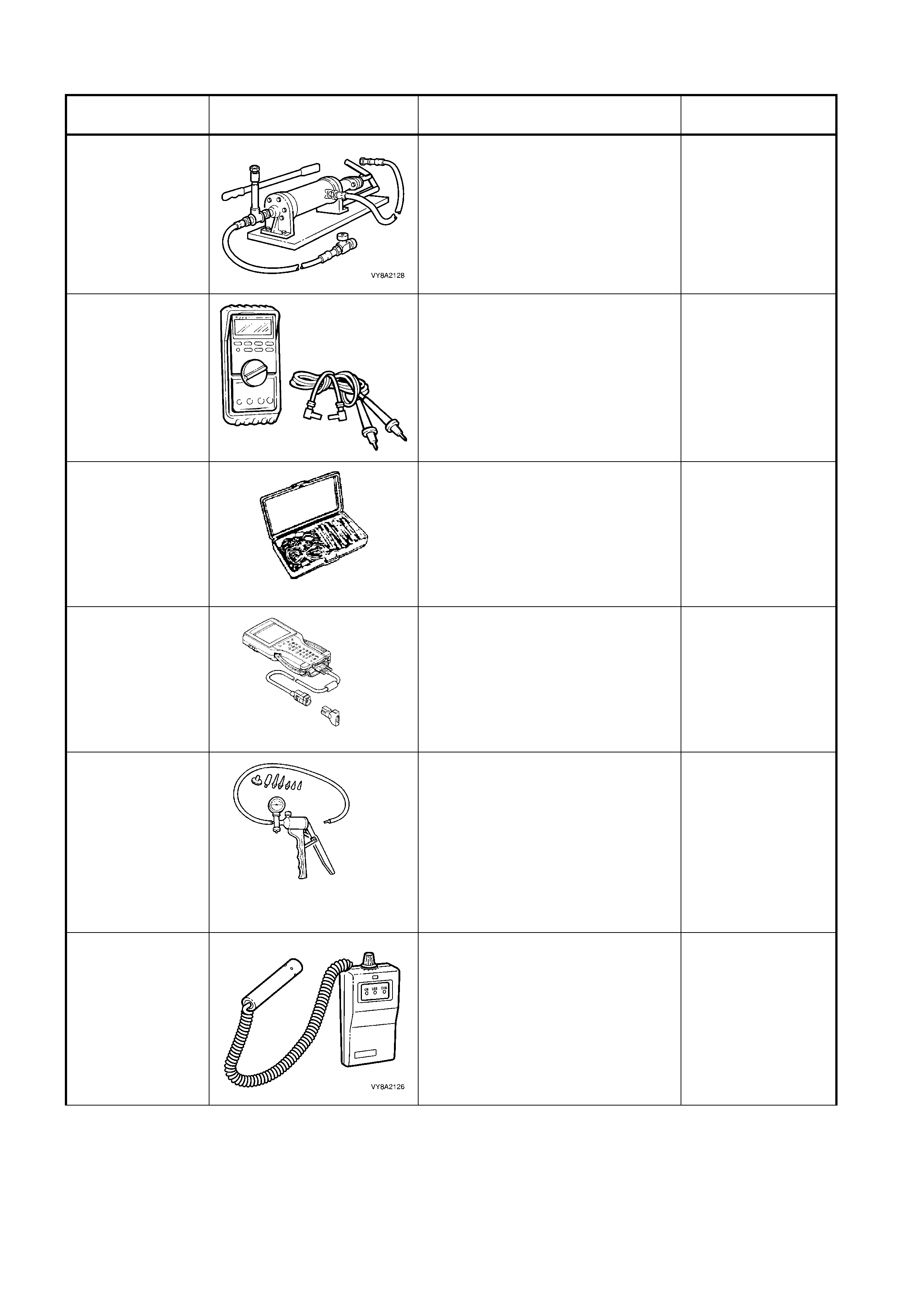
10. SPECIAL TOOLS
TOOL NUMBER ILLUSTRATION DESCRIPTION CLASSIFICATION
N/A
LPG TANK UNLOADING PUMP
Commercially available.
COMMERCIALLY
AVAILABLE
J39200
DIGITAL MULTIMETER
Tool No. J39200 previously
released, or use commercially
available equivalent. Must have 10
meg ohm input impedance.
Available
J35616-A
(KM609)
CONNECTOR TEST ADAPTOR
KIT
Used when carrying out electrical
diagnostic circuit checks.
Previously released.
Desirable
7000086I
TECH 2 DIAGNOSTIC SCAN
TOOL
Used for diagnosis of vehicle
electrical system.
Previously released.
Mandatory
J23738-A
HAND VACUUM PUMP
(20 IN. HG MINIMUM)
Used for applications where a
controlled vacuum is required to be
applied.
Previously released and also
commercially available.
Mandatory
N/A
ELECTRONIC GAS LEAK
DETECT OR
Commercially available
Available
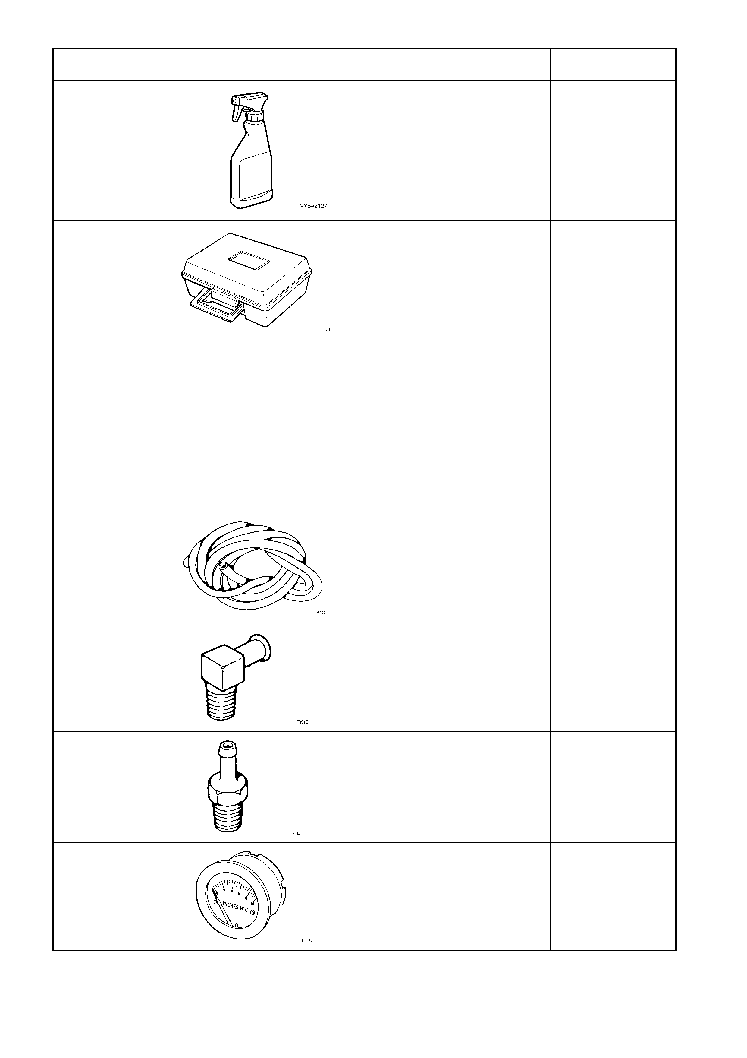
TOOL NUMBER ILLUSTRATION DESCRIPTION CLASSIFICATION
N/A
LEAK TEST FOAMING AGENT
Commercially available
(such as Gameco Leak Checktm)
Available
ITK-1
LPG TEST KIT
AVAILABLE FROM:
IMPCO TECHNOLOGIES
1 - 3 TAUNTON DRIVE
CHELTENHAM VIC. 3192
ALL CORRESPONDENCE TO:
P.O. BOX 45, CHELTENHAM VIC.
3192
TELEPHONE: (03) 9584 5644
FAX: (03) 9583 0696
The LPG test kit contains the
following tools.
Previously released.
Available
ITK-1
(c)
PRESSURE GAUGE HOSE
Part of LPG test kit ITK-1.
Available
ITK-1
(e)
PRESSURE GAUGE HOSE
CONNECTOR FOR INCHES W.C.
PRESSURE GAUGE
Part of LPG test kit ITK-1.
Available
ITK-1
(d)
PRESSURE GAUGE HOSE
CONNECTOR FOR PSID
PRESSURE GAUGE
Part of LPG test kit ITK-1.
Available
ITK-1
(b)
PRESSURE GAUGE INCHES
W.C.
Part of LPG test kit ITK-1.
Available
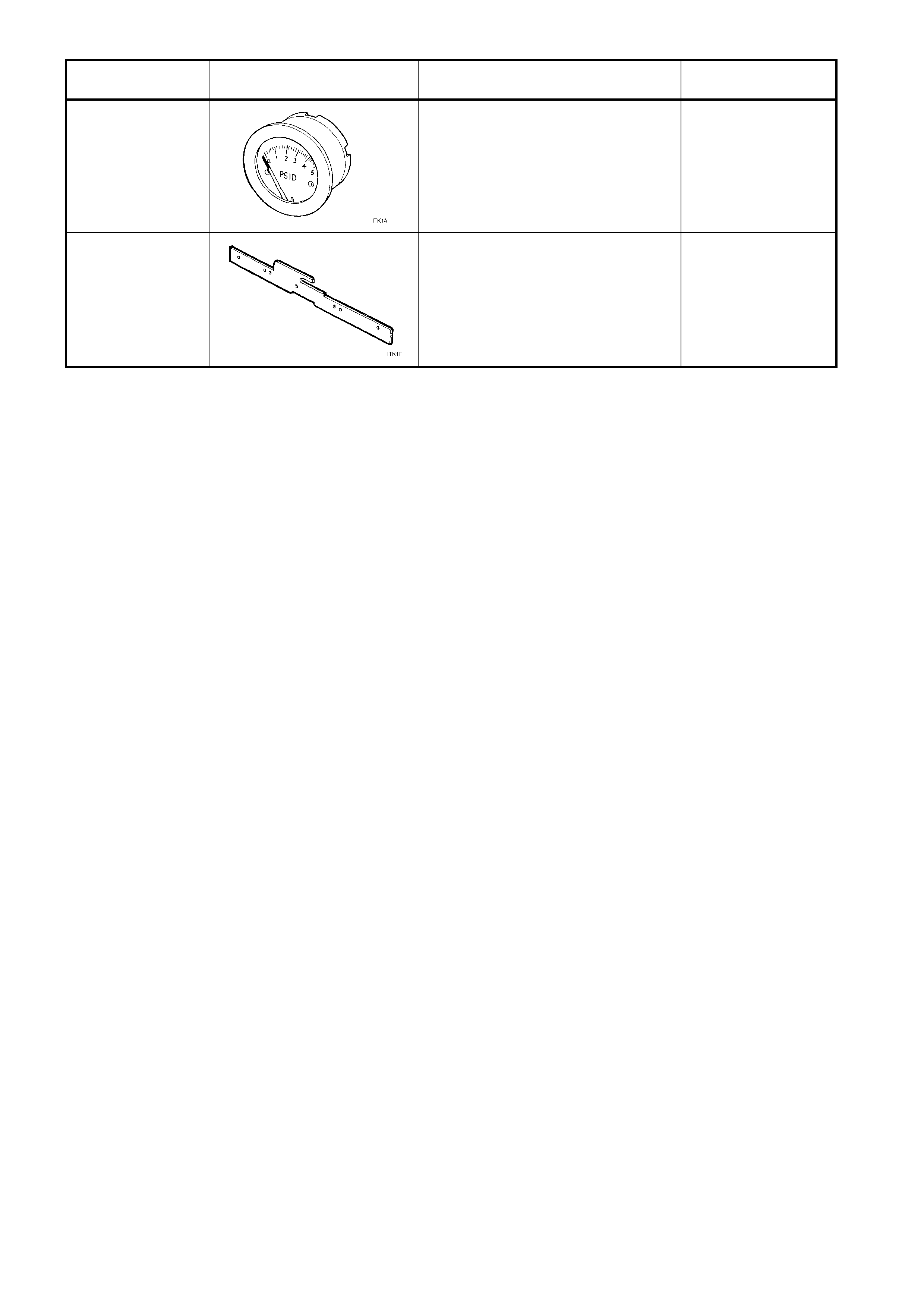
TOOL NUMBER ILLUSTRATION DESCRIPTION CLASSIFICATION
ITK-1
(a)
PSID PRESSURE GAUGE
Part of LPG test kit ITK-1.
Available
ITK-1
(f)
SECONDARY DIAPHRAGM
LEVER ADJUSTMENT GAUGE
Part of LPG test kit ITK-1.
Available