
SECTION 8B - EXHAUST SYSTEM
IMPORTANT
Before perfo rming any Service Operation or other procedu re described in this Section , refer to Section 00
CAUTIONS AND NOTES for correct workshop practices with regard to safety and/or property damage.
CONTENTS
1. GENERAL DESCRIPTION
1.1 EXHAUST SYSTEM CONFIGURATION
V6 ENGINE EXHAUST SYSTEM
V6 ENGINE EXHAUST SYSTEM –
EXPORT FOR INDONESIA
V6 SUPERCHARGED ENGINE
EXHAUST SYSTEM
GEN III V8 ENGINE EXHAUST SYSTEM
1.2 CATALYTIC CONVERTER
2. SERVICE OPERATIONS – V6
2.1 SERVICE NOTES
CATALYTIC CONVERTER
OXYGEN SENSORS
2.2 EXHAUST SYSTEM
COMPLETE EXHAUST SYSTEM
TIGHTENING SEQUENCE
REAR EXHAUST ASSEMBLY
INTERMEDIATE EXHAUST ASSEMBLY
FRONT EXHAUST ASSEMBLY
3. SERVICE OPERATIONS – V6
SUPERCHARGED
3.1 SERVICE NOTES
CATALYTIC CONVERTER
OXYGEN SENSORS
3.2 EXHAUST SYSTEM
COMPLETE EXHAUST SYSTEM
TIGHTENING SEQUENCE
REAR EXHAUST ASSEMBLY
INTERMEDIATE EXHAUST ASSEMBLY
FRONT EXHAUST ASSEMBLY
4. SERVICE OPERATIONS – V8 GEN III
4.1 SERVICE NOTES
CATALYTIC CONVERTER
OXYGEN SENSORS
4.2 EXHAUST SYSTEM
COMPLETE EXHAUST SYSTEM
TIGHTENING SEQUENCE
REAR EXHAUST ASSEMBLY
INTERMEDIATE EXHAUST ASSEMBLY
FRONT EXHAUST ASSEMBLY
5. SERVICE OPERATIONS – EXHAUST
SYSTEM HEAT SHIELDS
5.1 HEAT SHIELDS
HEAT SHIELD – REAR MUFFLER
HEAT SHIELD – INTERMEDIATE MUFFLER
REFLECTIVE FOIL INSULATORS
6. EXHAUST SYSTEM CLEARANCES
6.1 V6 EXHAUST SYSTEM CLEARANCES
6.2 V6 SUPERCHARGED AND V8 GEN III
EXHAUST SYSTEM CLEARANCES
7. EXHAUST SYSTEM DIAGNOSIS
8. SPECIFICATIONS
9. TORQUE WRENCH SPECIFICATIONS
Techline
1. GENERAL DESCRIPTION
Information contained within this section describes the general exhaust system configurations for MY2003 VY and
V2 Series vehicles. The exhaust system f itted to a particular vehicle will depend on series, engine type and model
specifications.
IMPORTANT: All illustrations in this Section represent a right-hand drive vehicle. For left-hand drive vehicles, any
procedure or item that is not a direct mirror of a right-hand drive vehicle in left-hand drive configuration, will be
highlighted and a procedure or illustration produced to accommodate the difference.
1.1 EXHAUST SYSTEM CONFIGURATIONS
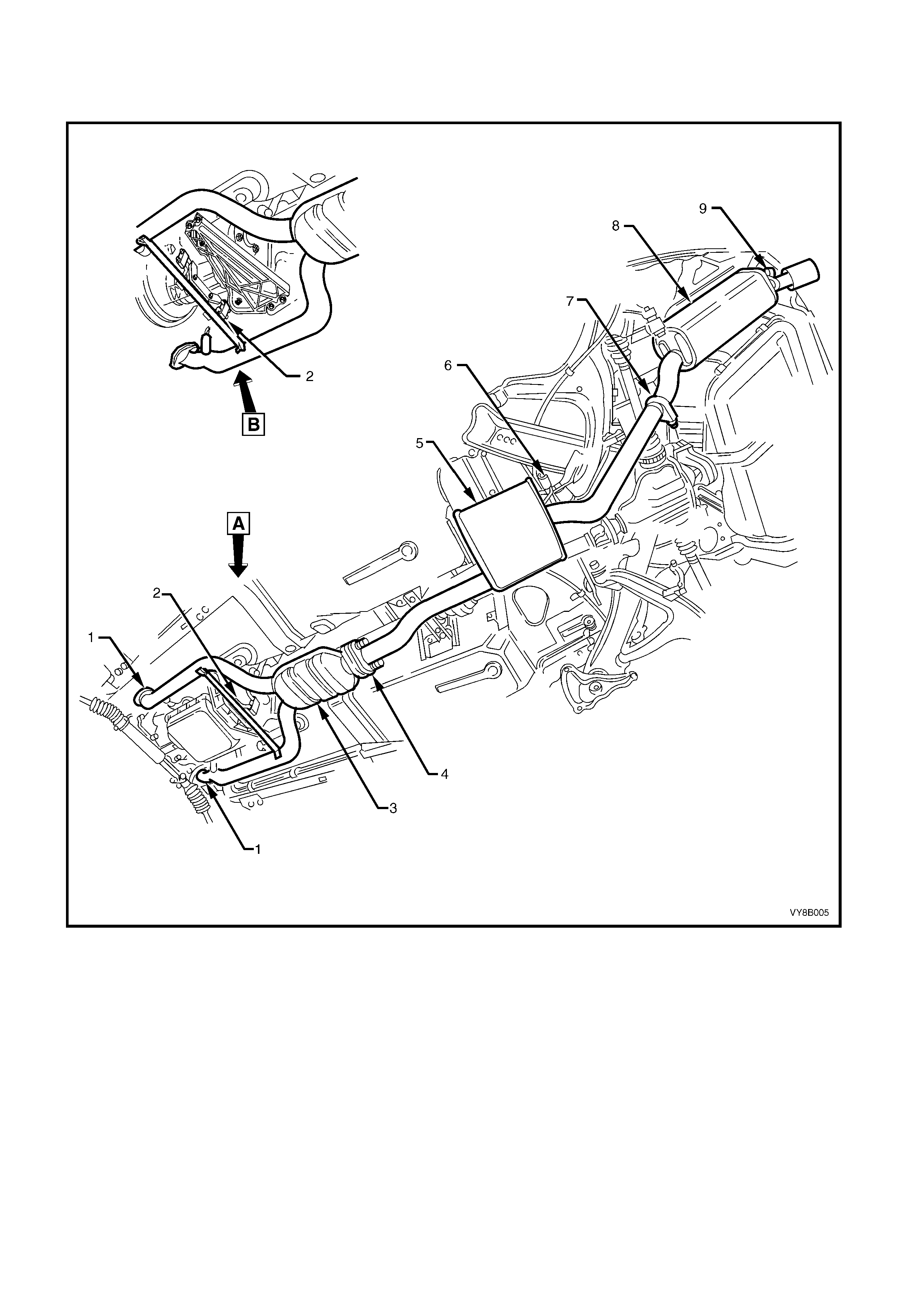
V6 ENGINE EXHAUST SYSTEM
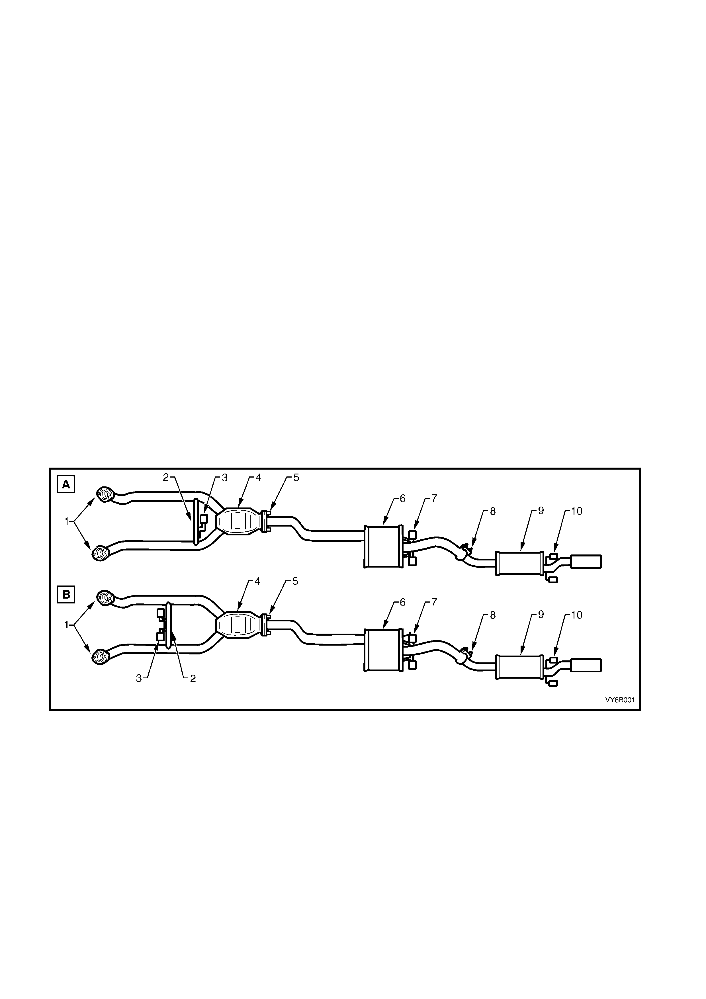
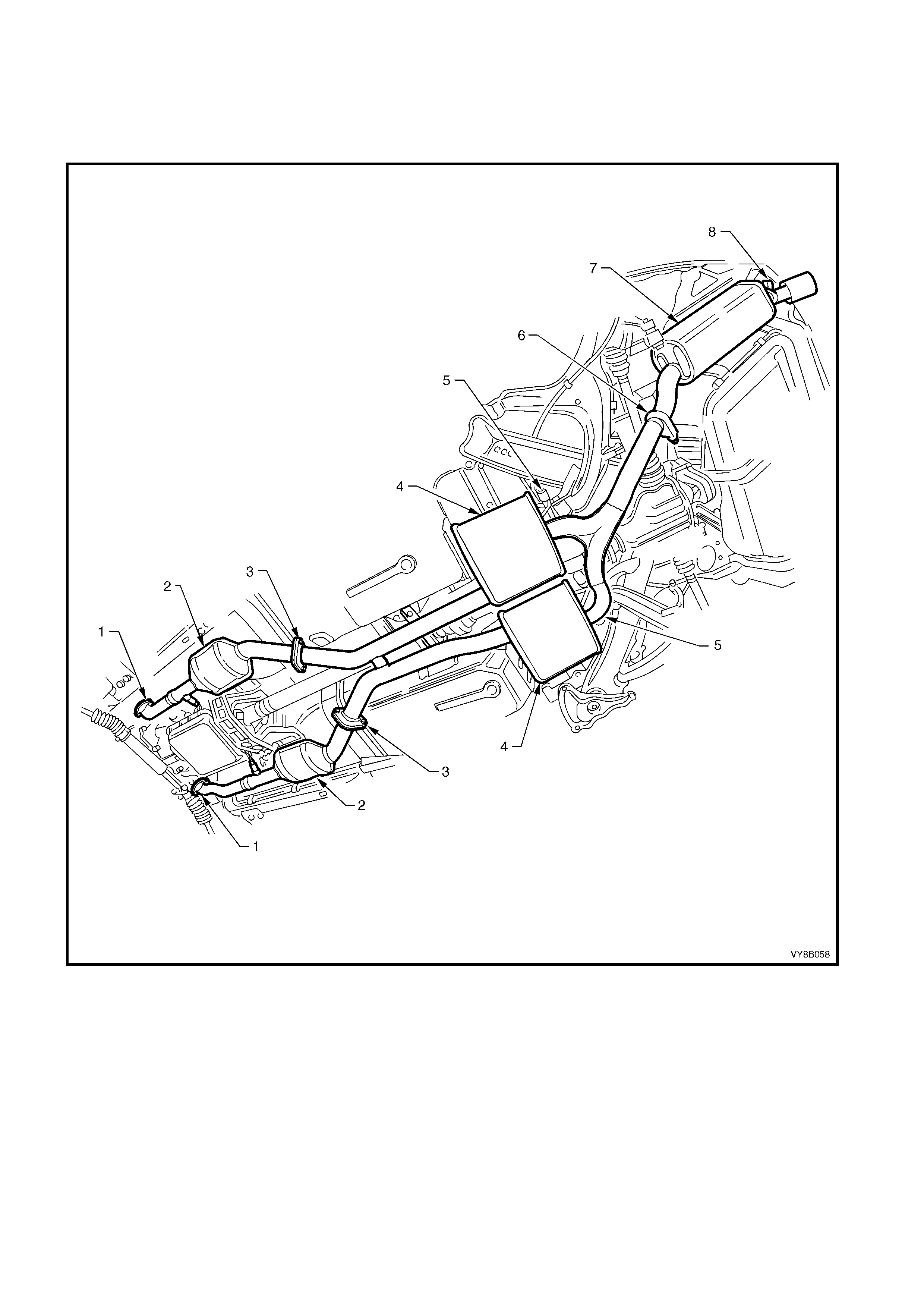
Refer to Figure 8B-1 for the following.
The V6 engine exhaust manifolds are connected to a pair of stainless steel front pipes, by flanged joints (1). The
exhaust system featur es a single, three way catalytic c onverter (4), which f orm s a welded junction point f or each of
the front and intermediate exhaust pipes. A brace (2) and hanger peg assembly is welded across both of the front
engine pipes.
A flanged joint (5) with an internal sealing ring is used to join the catalytic converter to the intermediate exhaust
pipe. The flange mating faces are held together by two spring loaded bolts. The intermediate to rear muffler slip joint
(8) is fastened together with a U-bolt clamp, located behind the rear axle, before the rear muffler (9).
The interm ediate exhaust assem bly is supported by two support rubbers (7) that are attac hed to hangers welded to
the vehicle underbody and to pegs welded to the rear of the inter mediate m uff ler (6). T he rear exhaus t assem bly is
supported by two support rubbers (10) that are attached to hangers welded to the vehicle underbody and to pegs
welded to the rear tail pipe. For autom atic transm ission vehicles ( View A) , the front exhaust ass embly is supported
by a r ubber s upport (3) attached to a hanger c onnected to the transmiss ion extension hous ing and to a peg welded
to the front exhaust pipe brace (2). For manual transmission vehicles (View B), the front exhaust assembly is
supported by two support rubbers (3) attached to hangers bolted to the extension housing and to pegs welded to the
brace (2). The support rubbers are a common part for all locations and are secured by retainer clips at the
intermediate and rear body hangers. Flanged pegs are used at other locations.
Figure 8B-1
Legend
A Configuration – A/T
B Configuration – M/T 1. Manifold to Front Pipe Flange
2. Front Exhaust Brace
3. Front Support Rubber/s
4. Catalyst
5. Catalyst to Intermediate Pipe
Flange Joint
6. Intermediate Muffler
7. Intermediate Muffler Support Rubbers
8. Intermediate to Rear Pipe Slip Joint and
U-bolt clamp
9. Rear Muffler
10. Rear Muffler Support Rubbers
V6 ENGINE EXHAUST SYSTEM – EXPORT FOR INDONESIA
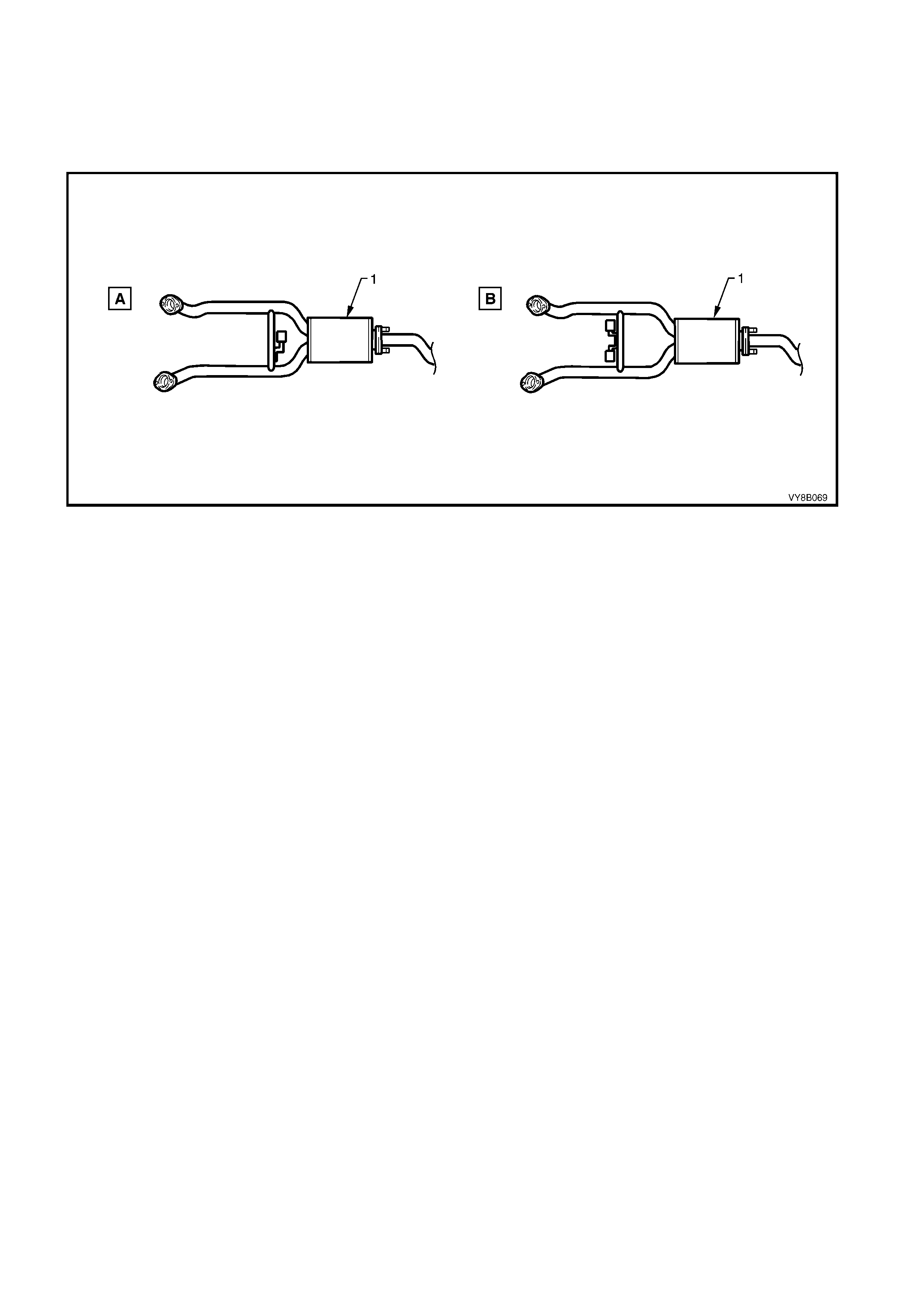
Refer to Figure 8B-2 for the following.
The exhaust system fitted to Indonesian export vehicles is identical to the standard V6 engine exhaust (refer to
V6 ENGINE EXHAUST SYST EM ) ex c ept that the c atalytic conver ter is replac ed with a m uffler ( 1) . View A and view
B show automatic and manual transmission configurations respectively.
Figure 8B-2
Legend
A Configuration – A/T
B Configuration – M/T 1. Muffler
V6 SUPERCHARGED ENGINE EXHAUST SYSTEM
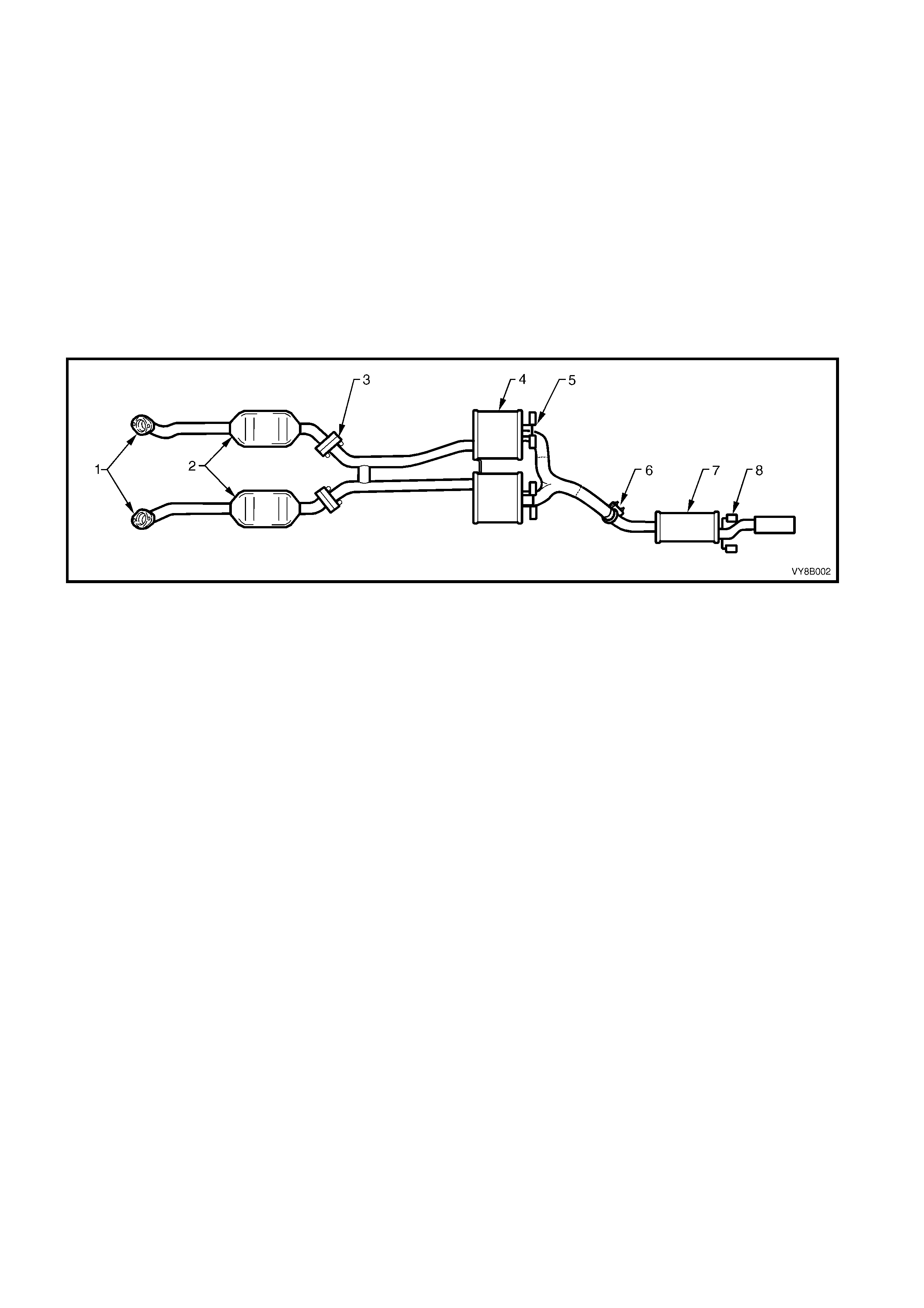
Refer to Figure 8B-3 for the following.
The V6 Supercharged engine exhaust manifolds are connected to a pair of stainless steel front pipes, by flanged
joints (1). The exhaust system features a low backpressure exhaust configuration and maintains a dual exhaust
system back to the rear of the twin intermediate mufflers (4).
The pipes then c onverge into a s ingle pipe that is jo ined to the rear exhaus t as s embly with a s lip j oint (6) and U-bolt
clam p. Coupe vehicles use a gas keted f lange joint at this location. A catalytic converter (2) is welded to each of the
front engine pipes and a flanged, gasketed joint (3) connects each converter to the twin, intermediate exhaust
pipes. The two intermediate exhaust pipes are stiffened by a welded bridging piece at points before the twin
intermediate mufflers. This bridging piece also acts as an exhaust balance pipe.
The intermediate exhaust assembly is supported at each of the intermediate mufflers by a pair of support rubbers
(5) attached to hangers welded to the vehicle underbody. The rear exhaust assembly is supported by two support
rubbers ( 8), which ar e attac hed to hangers welded to the vehicle underbody and to pegs welded to the rear tail pipe,
behind the rear muffler (8). The support rubbers are a common part for all locations and are secured by retainer
clips at both the intermediate and rear body hangers. Flanged pegs are used at other locations.
Figure 8B-3
Legend
1. Manifold to Front Pipe Flange
2. Catalyst
3. Catalyst to Intermediate Pipe Flange Joint
4. Intermediate Muffler
5. Intermediate Muffler Support Rubbers
6. Intermediate to Rear Pipe Slip Joint and U-clamp
7. Rear Muffler
8. Rear Muffler Support Rubbers
GEN III V8 ENGINE EXHAUST SYSTEM
Two exhaust s ystem conf igurations , Standard and Perf orm ance, ar e available for vehic les fitted with the GEN III V8
engine. The type installed will depend on the particular vehicle’s specifications.
Standard:
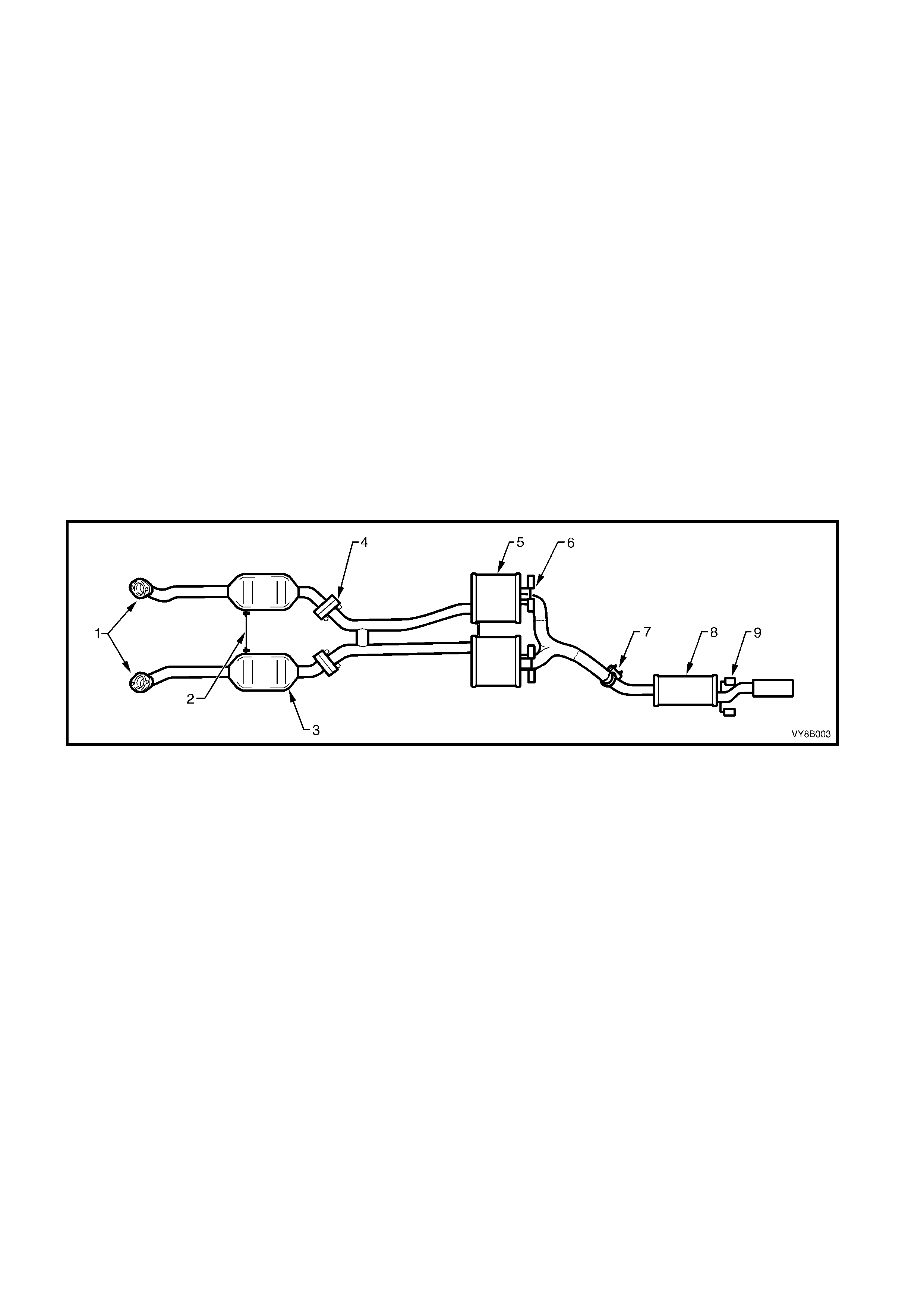
Refer to Figure 8B-4 for the following.
The G EN III V8 engine exhaust m anif olds are c onnected to a pair of stainles s steel f ront pipes by flanged joints (1).
The front exhaust pipes feature a dual wall air gap construction. A dual exhaust system is retained past the twin
intermediate mufflers (5). The pipes then converge into a single pipe that is joined to the rear exhaust assembly with
a slip joint (7) and U-bolt clamp. Coupe vehic les use a gasketed f lange joint at this location. T he rear exhaust pipe
joins to the rear muffler (8), which features a single tail exhaust pipe.
A catalytic converter (3) is welded to each front exhaust pipe, with a flanged, gasketed joint (4) connecting each
converter to the twin, intermediate exhaust pipes. The two intermediate exhaust pipes are stiffened by a welded
bridging piece at points before the twin interm ediate mufflers. This bridging piece also acts as an exhaust balance
pipe.
The intermediate exhaust assembly is supported at each of the intermediate mufflers (5) by a pair of support
rubbers (6) attached to hangers welded to the vehicle underbody. The rear exhaust assembly is supported by two
support rubbers (9) attached to hangers welded to the vehicle underbody and to pegs welded to the rear tail pipe.
For further support, a bracket (2) is bolted between each converter and is fastened to the transmission extension
housing. T his s upport conf iguration is diff erent f or autom atic and m anual transm issions. T he support rubber s are a
common part for all locations and are secured by retainer clips at both the intermediate and rear body hangers.
Flanged pegs are used at other locations.
NOTE: Left-hand drive Sedan, Wagon and Coupe export vehicles use a similar exhaust configuration.
Figure 8B-4
Legend
1. Manifold to Front Pipe Flange
2. Front Exhaust Brace
3. Catalyst
4. Catalyst to Intermediate Pipe Flange Joint
5. Intermediate Muffler
6. Intermediate Muffler Support Rubbers
7. Intermediate to Rear Pipe Slip Joint and U-clamp
8. Rear Muffler
9. Rear Muffler Support Rubbers
Performance:
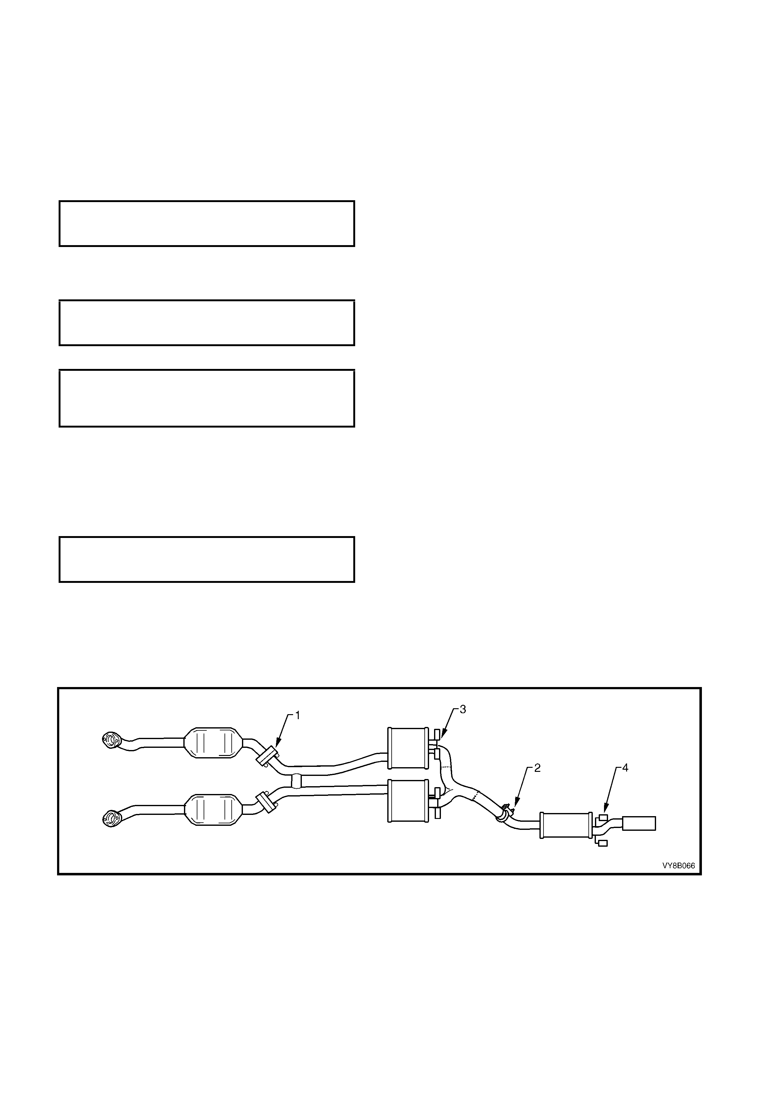
Refer to Figure 8B-5 for the following.
The front exhaust assembly of the Performance exhaust system is identical to the Standard front exhaust assembly,
as shown in Figure 8B-4. The intermediate exhaust assembly incorporates two exhaust balance pipes welded at
points befor e the twin interm ediate m uff lers. T he pipes r unning from the interm ediate m u ff lers are j oined to the rear
exhaust pipes with individual slip j oints and ring clam ps (1). The rear ex haust pipes join to a s ingle rear m uffler ( 2),
which features dual tail exhaust pipes.
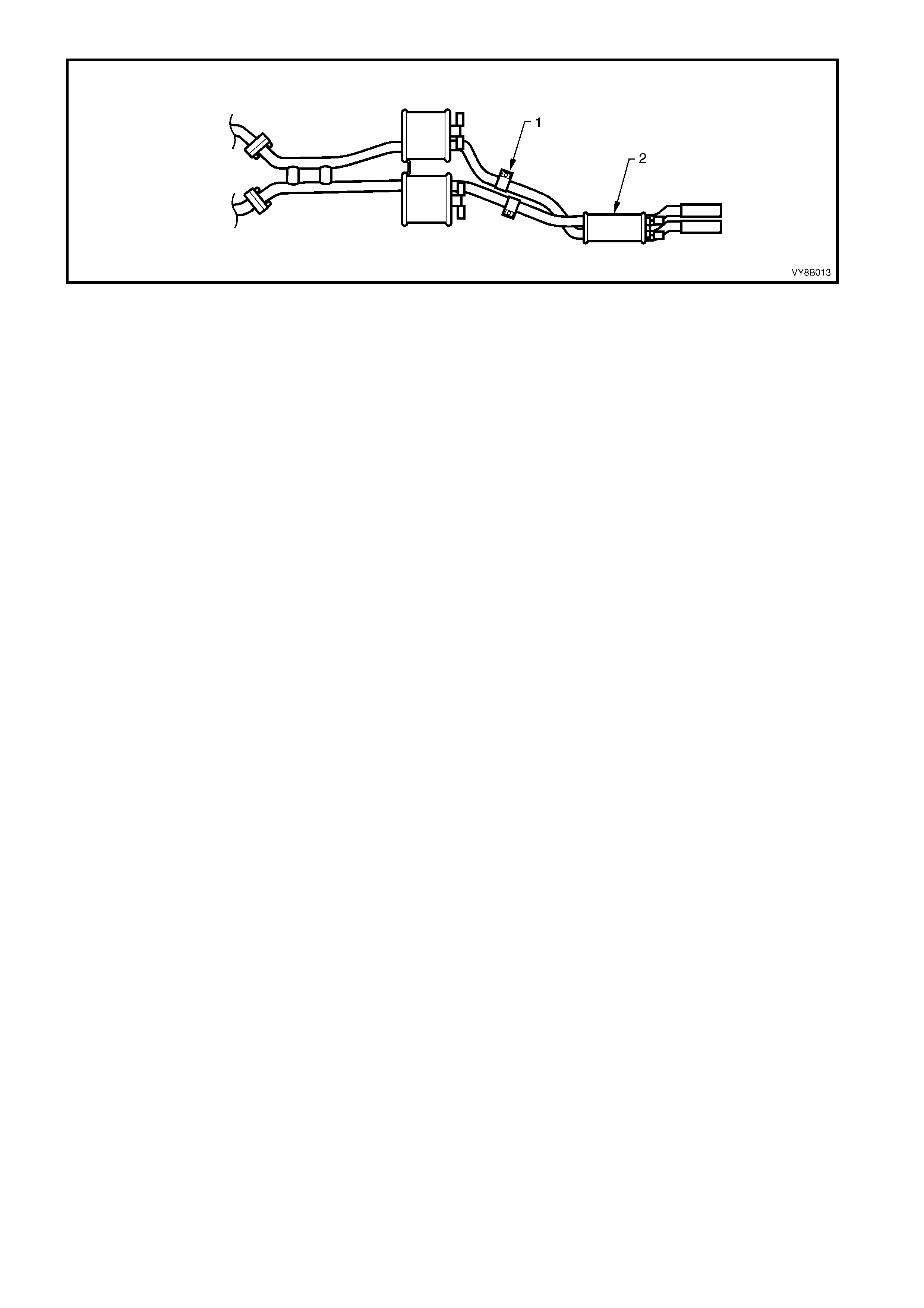
Figure 8B-5
Legend
1. Intermediate to Rear Pipe Slip Joints and Ring Clamps
2. Rear Muffler
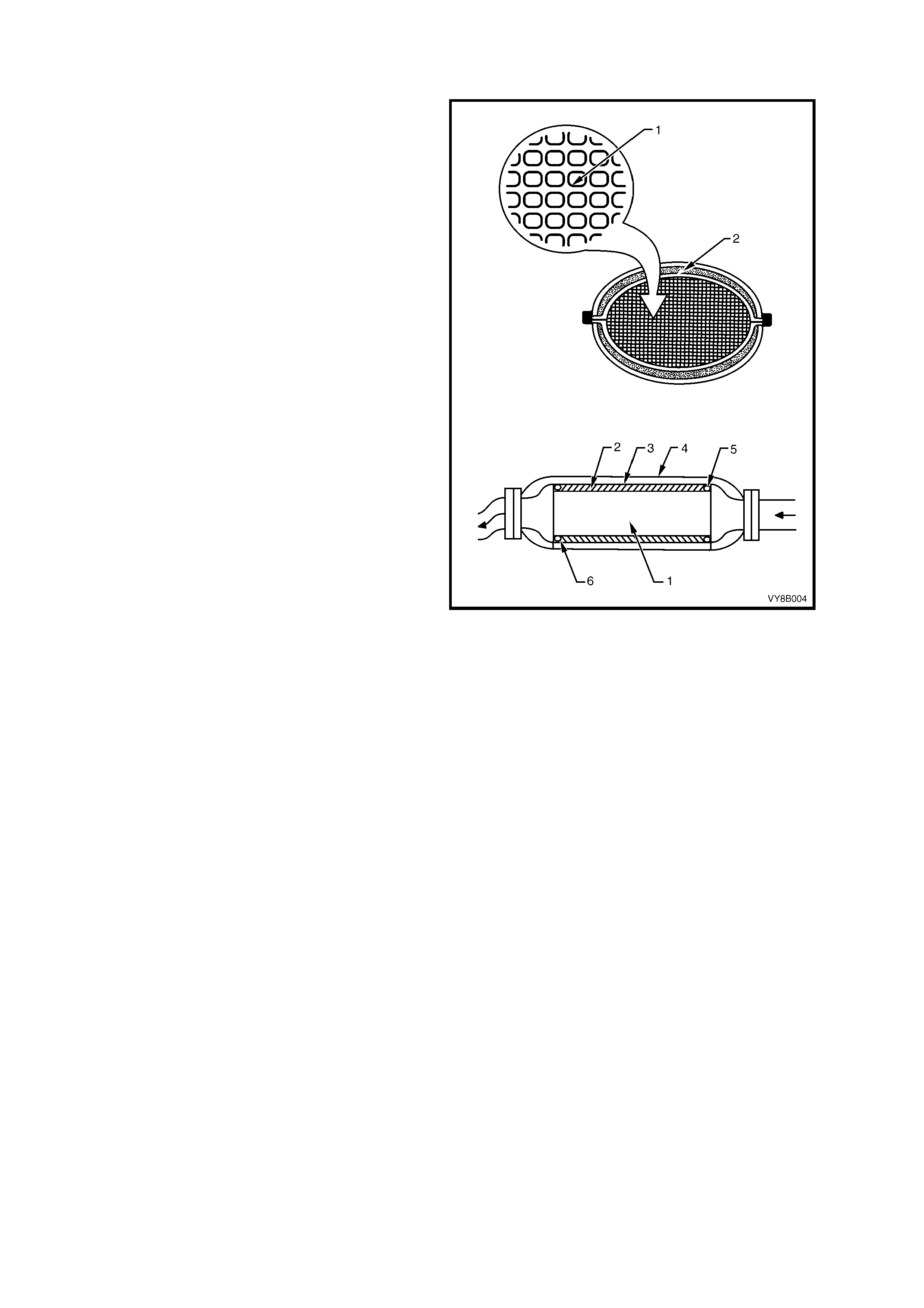
1.2 CATALYTIC CONVERTER
NOTE: Catalytic converters are fitted to all vehicles,
except those exported to Indonesia.
The catalytic converter is similar to a muffler in
appearance however, within the outer stainless
steel shell (4), the there is a ceramic monolith (1)
which is honeycombed in the direction of exhaust
flow, as shown. The ceramic monolith is
surrounded by a mat (2), which has the primary
function of holding the monolith firmly in place to
prevent any contact with the inner shell (3). A mesh
seal (5 and 6) at each end of the converter
prevents exhaust gases from fouling and eroding
the mat.
Surfaces of the ceramic monolith that are exposed
to exhaust gases are coated with a catalytic
material. This material contains rhodium and
platinum, which act to facilitate the chemical
reactions necessary to oxidise carbon monoxide
and hydrocarbons into harmless carbon dioxide.
The c atalytic ma terial is very sensitive to the ef f ec ts
of a rich or lean f uel mixture, which m ay cause the
temperature of the converter to rise rapidly. The
catalytic converter normally operates at
approximately 600° C.
CAUTION: Excessively rich or lean fuel mixture
can cause sudden failure of the catalytic
converter.
The catalytic converter is also sensitive to the use
of leaded petrol. Using leaded fuel can cause
deposits to form in the converter, which restrict
exhaust f low and prevent the catalyst from work ing.
This will result in an increase in exhaust
backpressure and converter temperature.
NOTE: The use of unleaded petrol results in black
tailpipe deposits rather than the grey colour that
some people may normally associate with an
acceptable combustion condition. This blac k colour
resulting from the use of unleaded fuel does not
necessarily indicate a state of poor engine tune.
Refer to Section 6E1, EMISSION CONTROL, for
more information regarding this topic.
Figure 8B-6
2. SERVICE OPERATIONS - V6
2.1 SERVICE NOTES
When installing any exhaust system component, care must be taken to install each component in the correct
relationship to the other. Ensure that correct assembly, installation, tightening sequence, tightening torque and
clearances for the system involved are observed. When exhaust system service work is required, refer to the
various illustrations and instructions provided in this section.
NOTE 1: T he inc or rec t as s embly of exhaust system c omponents c an f r equently be the cause of rattles and ‘booms'
due to incorrec t alignment or clearance of body or suspens ion parts. Ensure that the correc t tightening s equence is
observed upon installation of exhaust system components.
NOTE 2: Catalytic converters and oxygen sensors are fitted to all vehicles, except those exported to Indonesia.
Illustrations within this section represent vehicles with these components fitted. Any significant differences in
service oper ations for vehicles ex ported to Indonesia will be highlighted and a procedure or illus tration produced to
accommodate the difference.
CATALYTIC CONVERTER
The catalytic converter is serviced as a complete assembly only. If removing or replacing the converter, always
check the sealing ring for damage and replace if necessary.
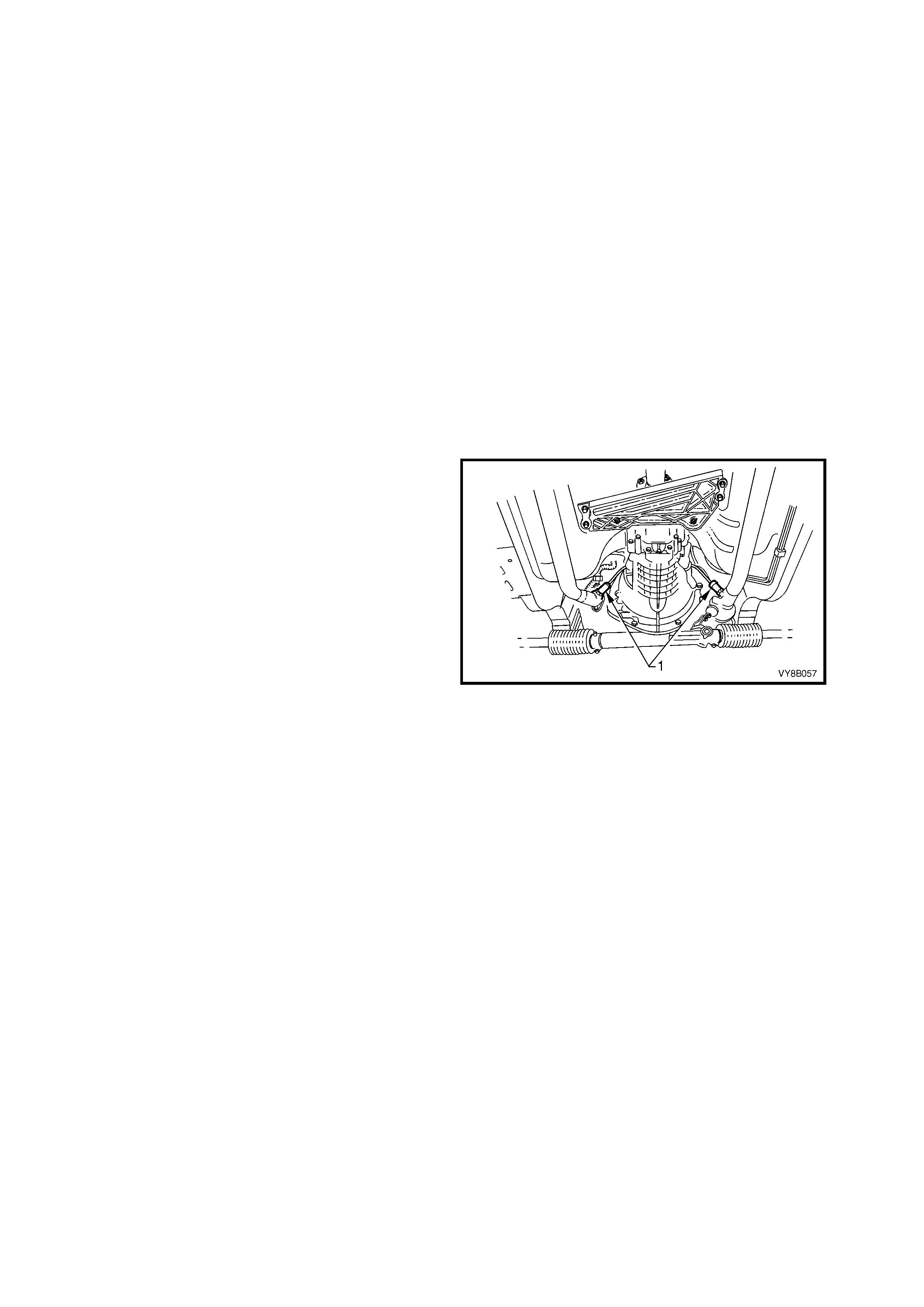
OXYGEN SENSORS
When removing the front exhaust pipes, it
is necessary to disconnect the wiring harness
connectors from each of the two oxygen
sensors (1).
For oxygen sensor replacement, refer to
Section 6C1-3, 2.6 OXYGEN SENSOR.
NOTE: Oxygen sensors are not fitted to Indonesia
vehicles.
Figure 8B-7
2.2 EXHAUST SYSTEM
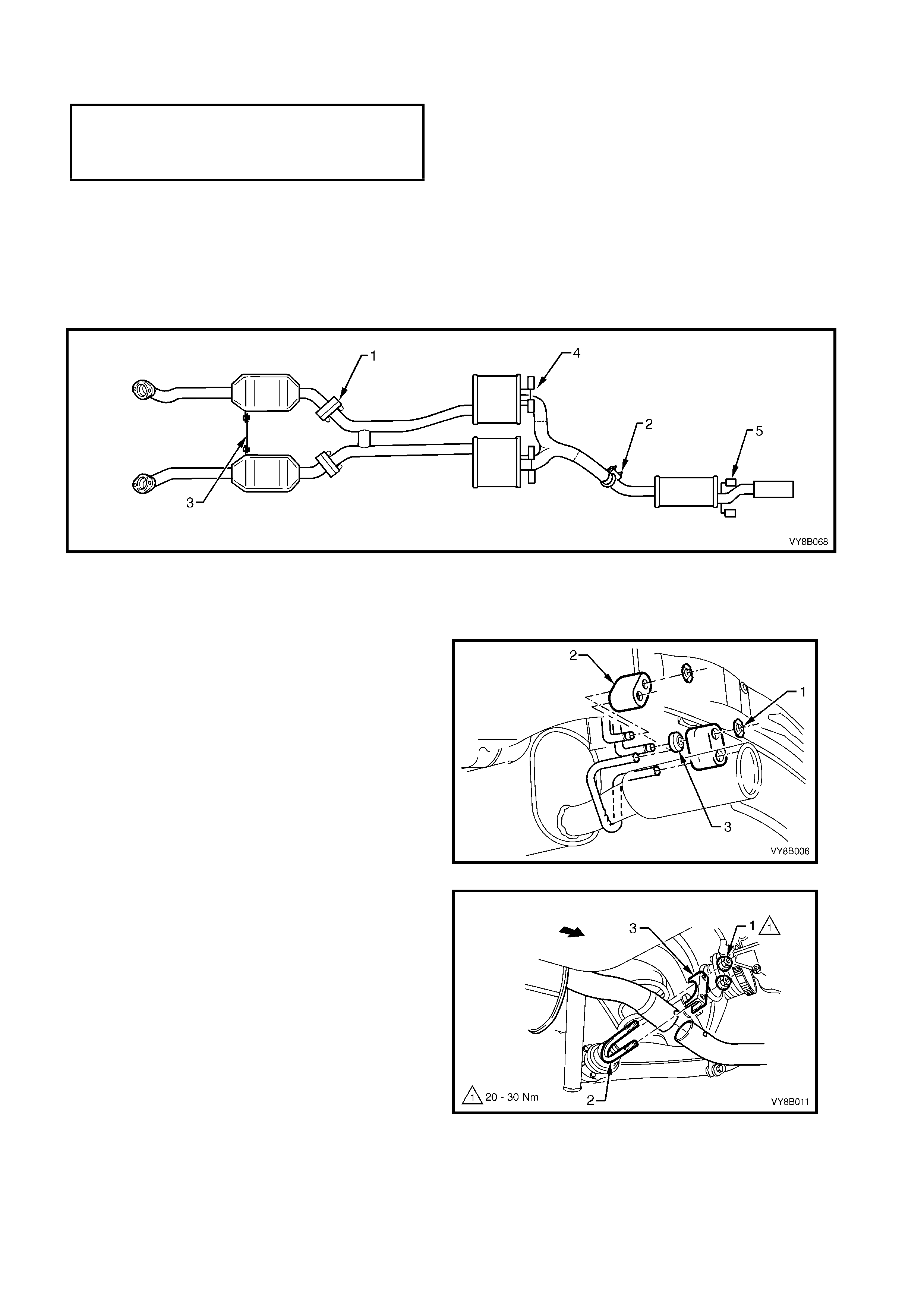
Figure 8B-8 illustrates the exhaust system configuration used with the V6 engine.
Figure 8B-8
Legend
A Configuration – A/T
B Configuration – M/T 1. Manifold to Front Pipe Flange
2. Front Exhaust Brace and Rubber
Support
3. Catalyst (muffler used on Export for
Indonesia vehicles)
4. Flange Joint
5. Intermediate Muffler
6. Intermediate Muffler Support
Rubbers
7. Intermediate to Rear Pipe Slip
Joint and U-clamp
8. Rear Muffler
9. Rear Muffler Support Rubbers
COMPLETE EXHAUST SYSTEM ASSEMBLY
Remove
1. Disconnect the wiring harnes s connectors f rom
each of the two oxygen sensors (1).
NOTE: Oxygen sensors are not fitted to Indonesia
vehicles.
Figure 8B-9
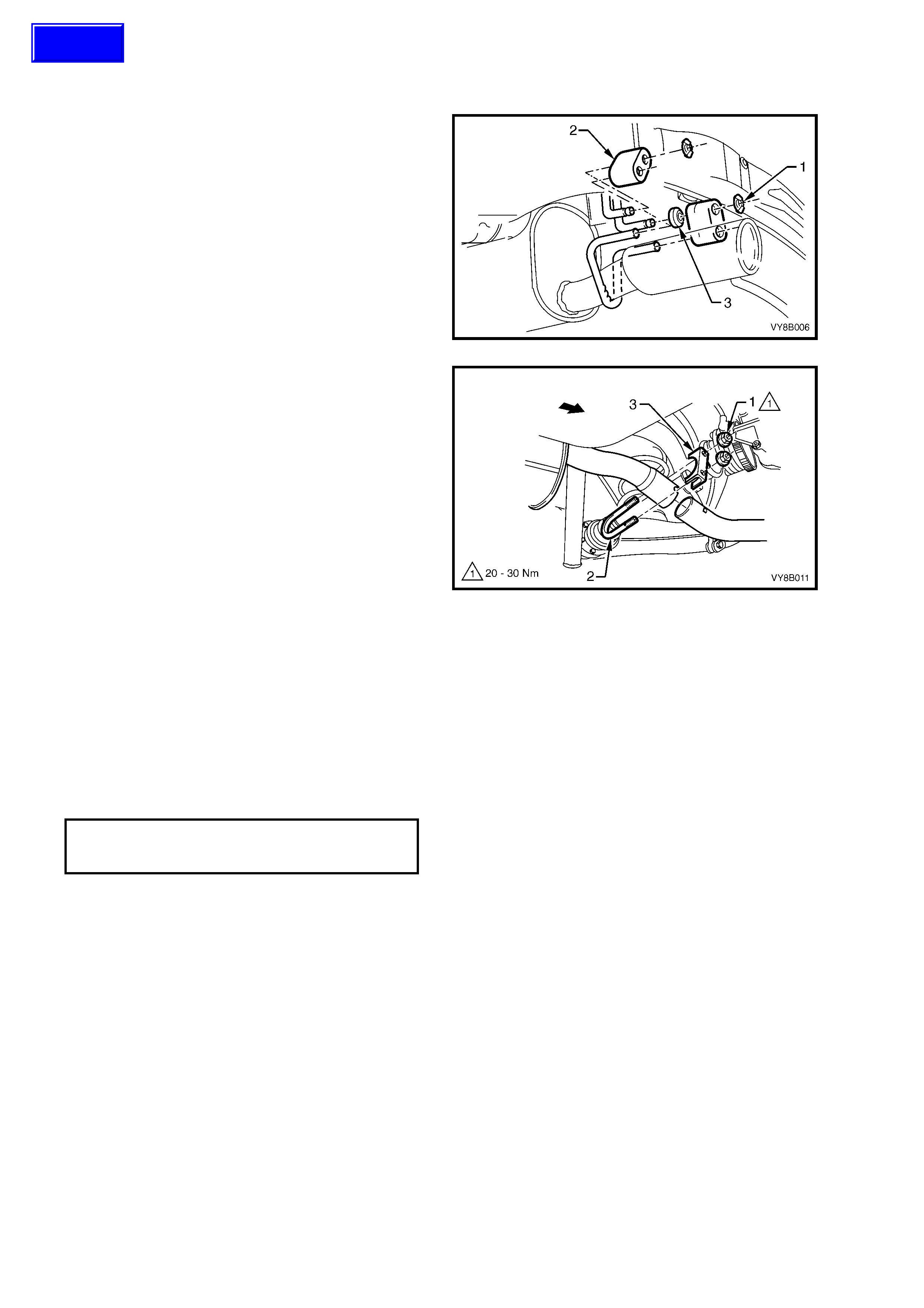
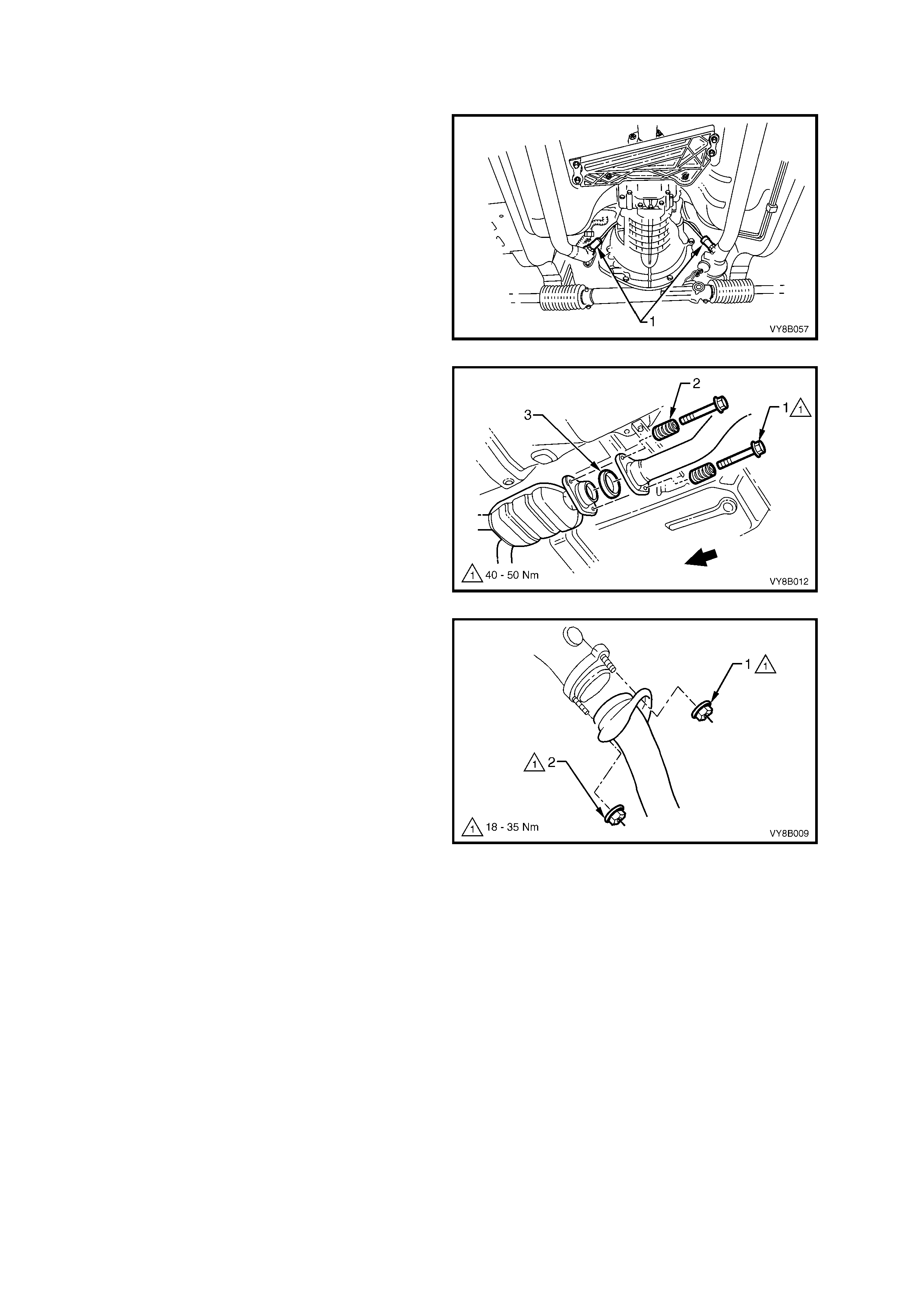
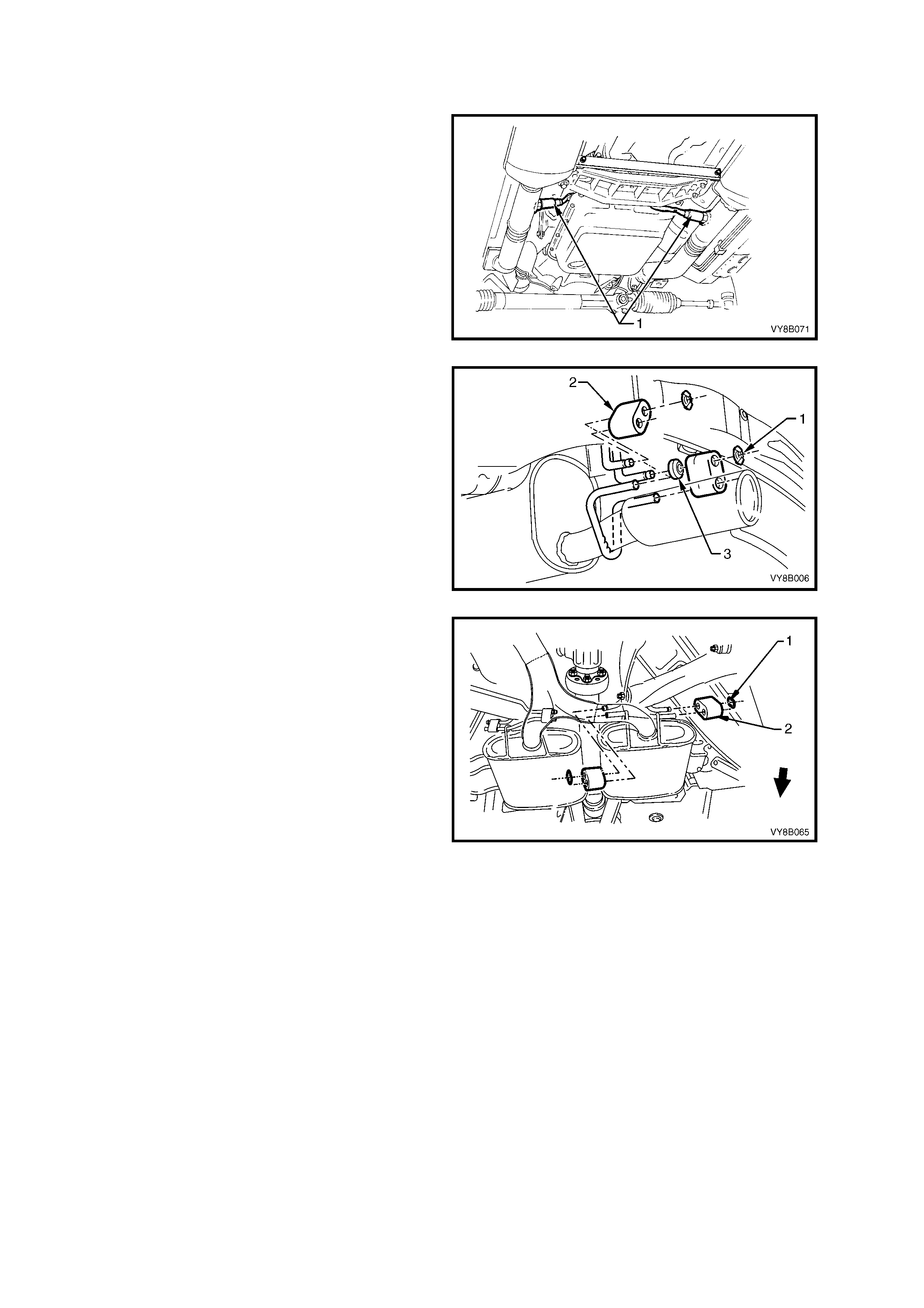
2. Disconnect the rear muffler from the support
hangers by removing the two retainer clips (1)
and two support rubbers (2).
NOTE: The additional bumper washer (3) is fitted
to Utility vehicles only.
Figure 8B-10
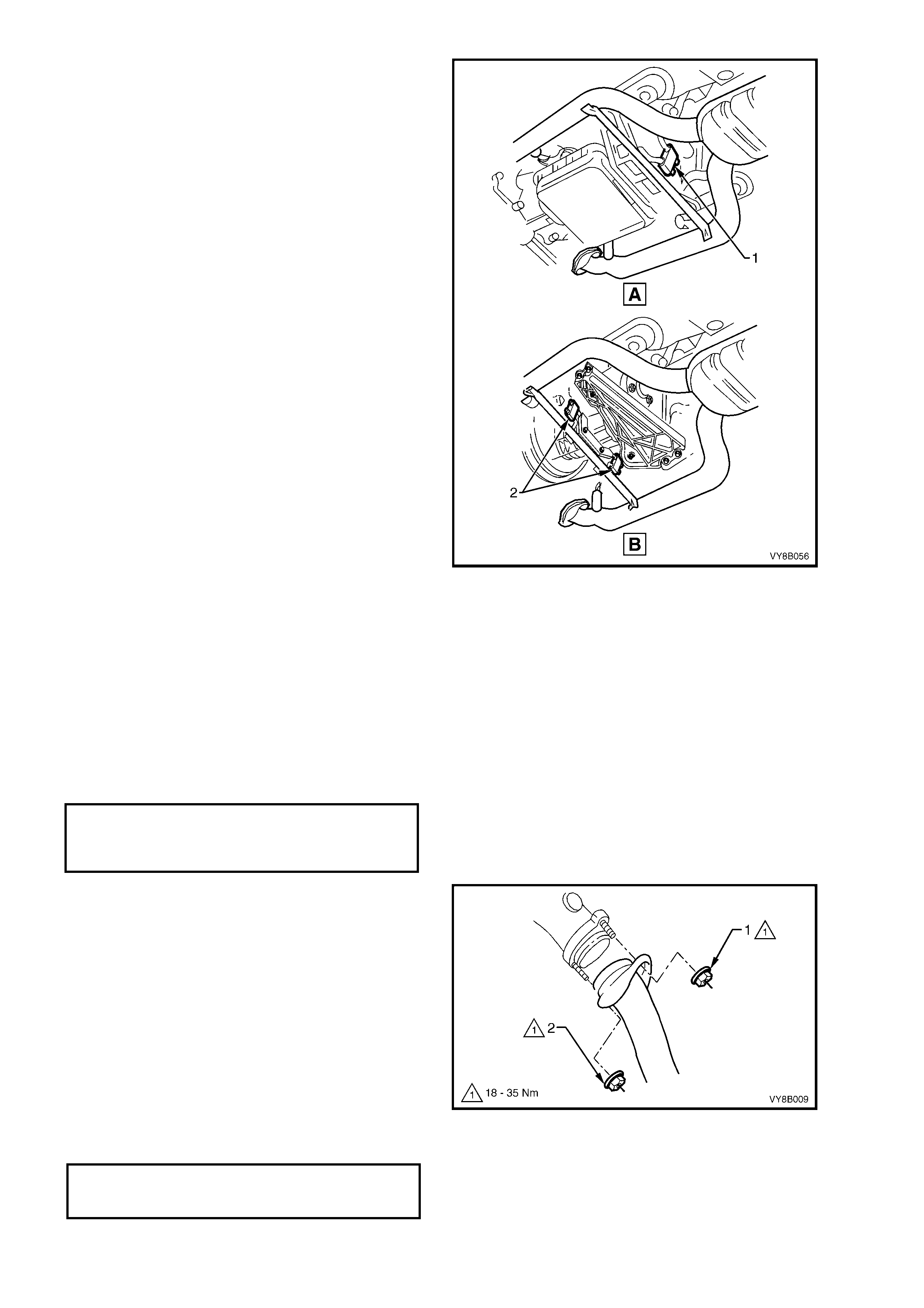
3. Support the exhaust system and disconnect the
intermediate muffler from the support hangers
by removing the two retainer clips (1) and the
two support rubbers (2).
Figure 8B-11
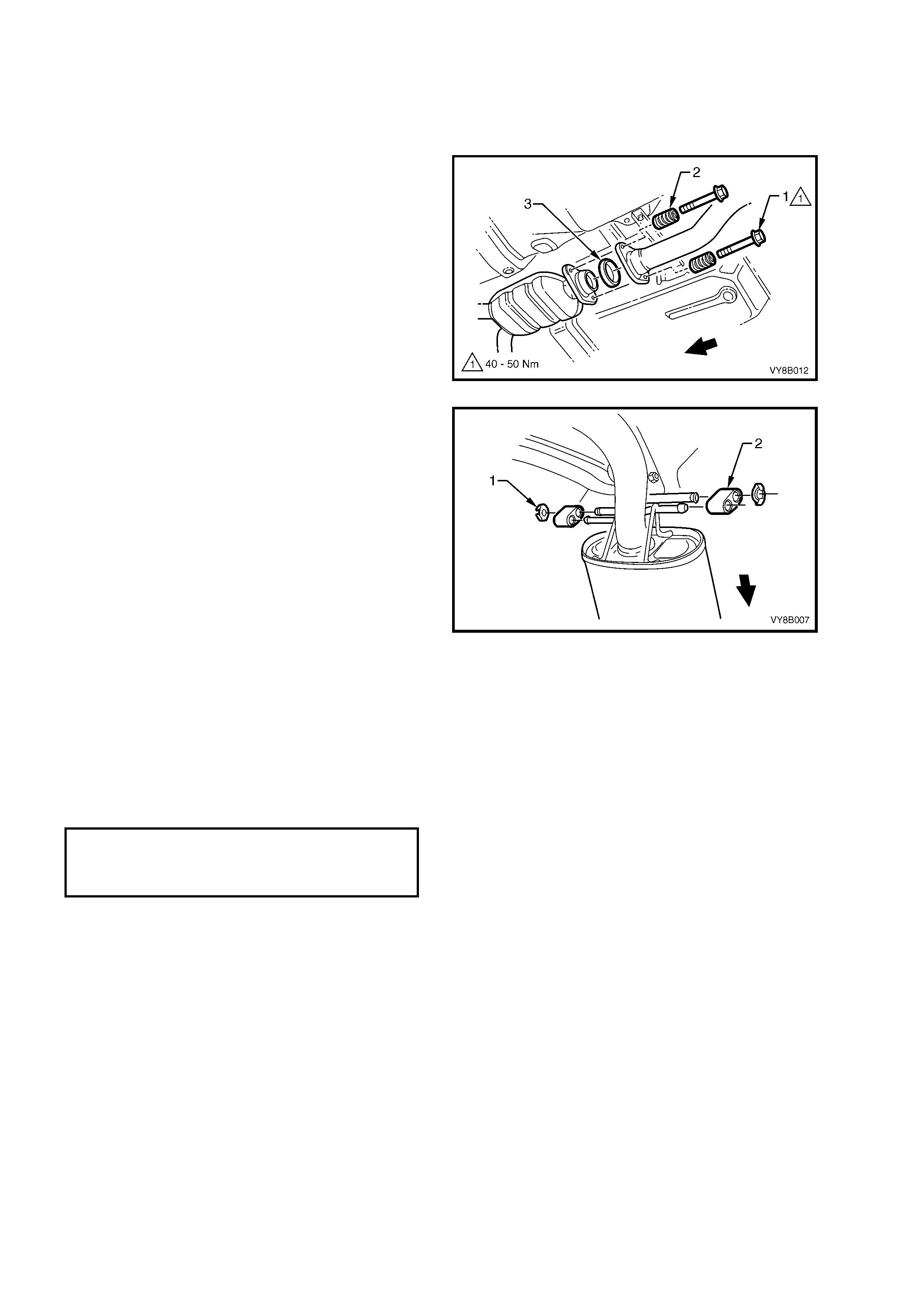
4. Support the exhaust system and remove the
upper (1) and lower (2) fastening nuts from the
exhaust manifold to exhaust pipe flange studs
on both sides.
Figure 8B-12
5. Remove the support rubbers:
a. For automatic transmission vehicles, refer to
View A. Disc onnect the front ex haust assem bly
by disconnecting the support rubber (1) from
the peg welded to the exhaust pipe brace.
b. For manual transmission vehicles, refer to
View B. Disconnect the f ront exhaust asse mbly
by disconnecting the two support rubbers (2)
from either side of the transmission extension
housing.
6. Carefully lower and remove the exhaust
assembly from the vehicle, taking care not to
damage the exhaust gas oxygen sensors.
Figure 8B-13
Reinstall
The installation of complete exhaust system is the
reverse of the removal procedure, noting the
following points:
1. Support the exhaust system at all times.
2. Clean the threads of the manifold to exhaust
pipe flange studs with a suitable cleaning
solvent.
3. Apply a high temperature anti-seize compound
to the exhaust manifold to exhaust pipe flange
studs and align the front pipe flange over the
studs.
4. Install the upper f as tening nut (1) to the s tud on
both sides.
5. Install the lower fas tening nut (2) to the stud on
both sides.
6. Tighten the upper and lower fastening nuts so
that approxim ately equal amounts of thread are
showing.
7. Tighten the exhaust manifold to front pipe
flange attaching nuts (1 and 2) to the specified
torque.
Figure 8B-14
8. Ensure all support rubbers are under load
9. Ensure that correct body clearances are maintained throughout the full exhaust system. Refer to 6.1 V6
EXHAUST SYSTEM CLEARANCES.
NOTE: If steps 8 or 9 are not achieved, refer to TIGHTENING SEQUENCE in this Section.
10. Connect the wiring harness connectors for each of the two oxygen sensors.
EXHAUST MANIFOLD TO FRONT PIPE
FLANGE ATTACHING NUT
TORQUE SPECIFICATION 18 – 35 Nm
TIGHTENING SEQUENCE
This procedure is only to be performed if the exhaust system positioning is not to specification.
Refer to Figure 8B-15 for the following.
IMPORTANT: For all gasketed joints requiring adjustment, ensure that new gaskets are installed.
Ensure that all fasteners mentioned in steps 1 to 6 below are loose before conducting this procedure.
1. Tighten the intermediate exhaust to catalytic converter flange attaching bolts (1) at the rear of the catalytic
converter to the specified torque.
INTERMEDIATE EXH AUST TO
CATALYTIC CONVERTER
FLANGE ATTACHING BOLT
TORQUE SPECIFICATION 40 – 50 Nm
NOTE: A muffler replaces the catalyst for Indonesia vehicles.
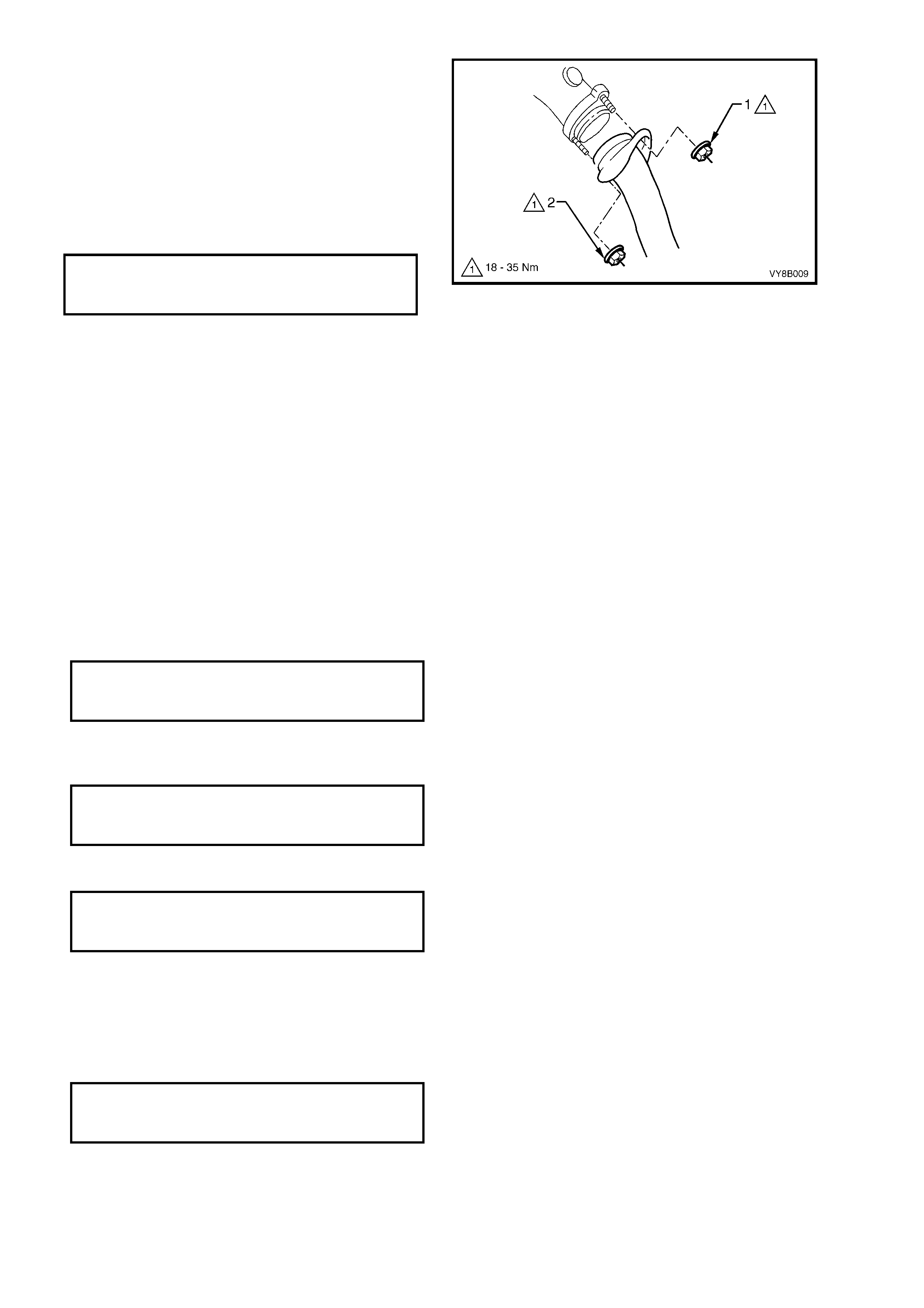
2. Check that the rear exhaust pipe aligning tab is seated within the intermediate exhaust pipe’s end slip joint
groove. Position the U-bolt clamp along the intermediate to rear slip joint and tighten the pair of fastening
nuts (2) to the specified torque.
U-BOLT CLAMP ASSEMBLY
SECURING NUTS
TORQUE SPECIFICATION 20 – 30 Nm
3. Install the upper fastening nut (1) to the stud on both sides, refer to Figure 8B-14.
4. Install the lower fastening nut (2) to the stud on both sides, refer to Figure 8B-14.
5. Tighten the nuts joining the exhaust manifold to the front exhaust pipe flange, so that approximately equal
amounts of thread are showing.
6. Tighten the exhaust m anifold to front exhaus t pipe flange attaching nuts (1 and 2) to the spec ified torque, refer
to Figure 8B-14.
EXHAUST MANIFOLD TO FRONT PIPE
FLANGE ATTACHING NUT
TORQUE SPECIFICATION 18 – 35 Nm
7. Ens ure that all support rubbers (3, 4 and 5) are under load, ref er to Figure 8B-15. If this is not achieved, loos en
the respective joints in the reverse order to steps 1 to 6. Load the hangers and re-tighten in the sequence
described, from steps 1 to 6.
NOTE: The exhaus t s ystem should be s elf- aligning and not require f urther adj ustm ent, provided s tep 7 is ac hieved.
To ensure that correct clearances are maintained throughout the complete exhaust system, refer to
6.1 V6 EXHAUST SYSTEM CLEARANCES for the correct values.
Figure 8B-15
REAR EXHAUST ASSEMBLY
Remove
1. Remove the two support hanger retainer
clips (1) and the two support rubbers (2) from
the support hangers.
NOTE: The additional bumper washer (3) is used
on utility vehicles only.
Figure 8B-16
2. Rem ove the two retaining nuts (1) and the rear
muf fler U-bolt (2) and clam p (3) from along the
intermediate exhaust pipe to rear muffler
exhaust pipe slip joint.
3. Carefully slide the rear exhaust pipe out of the
intermediate exhaust pipe end slip joint and
remove the rear exhaust assembly.
Figure 8B-17
Reinstall
Installation of the rear exhaust assembly is the
reverse of the removal procedure, noting the
following:
1. Ensure that the rear exhaust pipe slides
unobstructed into the intermediate exhaust pipe
slip joint, and that the alignment tab is
positioned in the slip joint groove. Tighten the
U-bolt clamp securing nuts to the specified
torque.
2. Ensure all support rubbers are under load and
all clearances are within the specifications. If
this is not achieved, refer to TIGHTENING
SEQUENCE in this Section.
U-BOLT CLAMP ASSEMBLY
SECURING NUTS
TORQUE SPECIFICATION 20 – 30 Nm
Techline
INTERMEDIATE EXHAUST ASSEMBLY
Remove
1. Remove the rear muffler. Refer to
REAR EXHAUST ASSEMBLY in this Section.
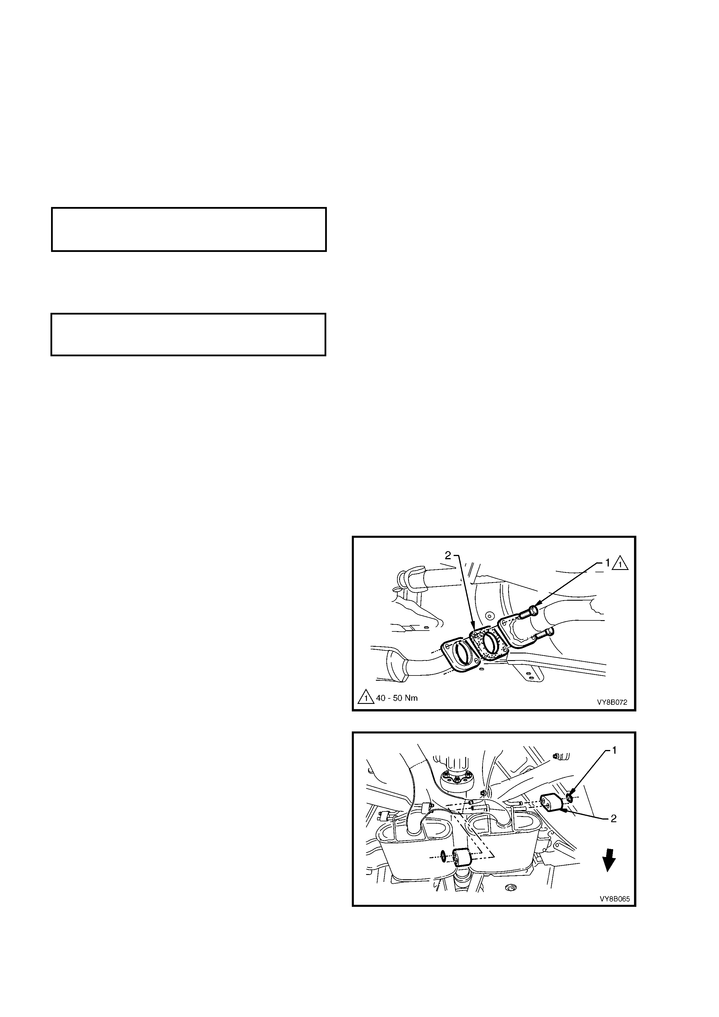
2. Support the intermediate exhaust assembly
and rem ove the two stepped fas tening bolts ( 1)
and springs (2) from the intermediate exhaust
to catalytic converter flange joint.
3. Separate the intermediate exhaust assembly
from the front exhaust assembly and remove
the sealing ring (3) from within the flange joint.
NOTE: A muffler replaces the catalyst for
Indonesia vehicles.
Figure 8B-18
4. Remove the two retainer clips (1) and support
rubbers (2) from the support hangers and
remove the intermediate exhaust assembly.
Figure 8B-19
Reinstall
Installation of the inter mediate exhaust assem bly is
the reverse of the removal procedure, noting the
following:
1. Ensure all support rubbers are under load and
all clearances are within specification. If this is
not achieved, refer to TIGHTENING
SEQUENCE in this Section.
INTERMEDIATE EXH AUST TO
CATALYTIC CONVERTE R FLANGE
ATTACHING BOLT
TORQUE SPECIFICATION 40 – 50 Nm
FRONT EXHA UST ASSEMBLY
Remove
1. Disconnect the wiring harnes s connectors f rom
each of the two oxygen sensors (1).
NOTE: Oxygen sensors are not fitted to Indonesia
vehicles.
Figure 8B-20
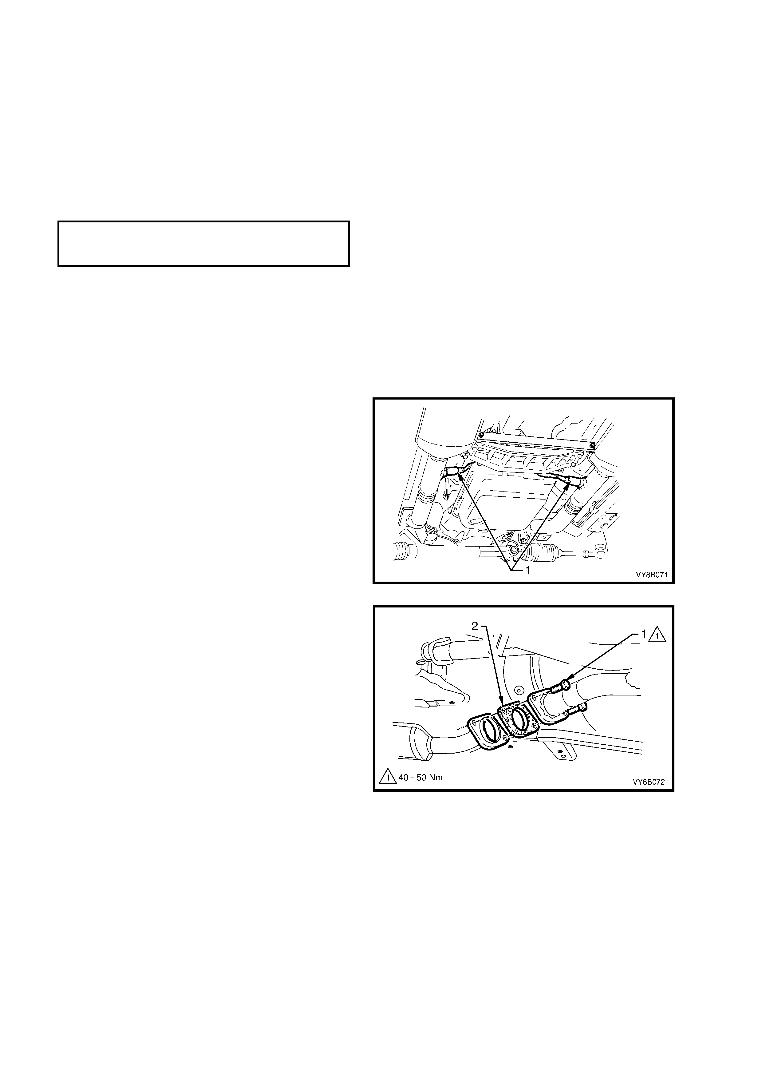
2. Support the intermediate exhaust assembly
and rem ove the two stepped fas tening bolts ( 1)
and springs (2) from the intermediate exhaust
to catalytic converter flange joint.
3. Separate the intermediate exhaust assembly.
Figure 8B-21
4. Support the front exhaust assembly and
remove the upper (1) and lower (2) fastening
nuts f rom the exhaus t manif old to exhaust pipe
flange studs on both sides.
Figure 8B-22
5. Remove the support rubbers:
a. For automatic transmission vehicles, refer to
view A. Disconnect the front exhaust assembly
by disconnecting the support rubber (1) from
the peg welded to the exhaust pipe brace.
b. For manual transmission vehicles, refer to
view B. Disconnect the front exhaust assembly
by disconnecting the two support rubbers (2)
from either side of the transmission extension
housing.
6. Carefully lower and remove the front exhaust
assembly from the vehicle, taking care not to
damage the exhaust gas oxygen sensor.
Figure 8B-23
Reinstall
Installation of the front exhaust assembly is the
reverse of the removal procedure, noting the
following points:
1. Support the exhaust system at all times.
2. Clean threads of all f lange bolts and studs with
a suitable cleaning solvent.
3. Tighten the intermediate exhaust to catalytic
converter f lange attaching bolts to the specified
torque.
4. Apply a high temperature anti-seize compound
to the exhaust manifold to exhaust pipe flange
studs and align the front pipe flange over the
studs.
5. Install the upper f as tening nut (1) to the s tud on
both sides.
6. Install the lower fas tening nut (2) to the stud on
both sides.
7. Tighten the upper and lower fastening nuts so
that approxim ately equal amounts of thread are
showing.
8. Tighten the exhaust manifold to front pipe
flange attaching nuts (1 and 2) to the specified
torque.
Figure 8B-24
INTERMEDIATE EXH AUST TO
CATALYTIC CONVERTE R FLANGE
ATTACHING BOLT
TORQUE SPECIFICATION 40 – 50 Nm
EXHAUST MANIFOLD TO FRONT
PIPE FLANGE ATTACHING NUT
TORQUE SPECIFICATION 18 – 35 Nm

9. Ensure all support rubbers are under load
10. Ensure that correct body clearances are maintained throughout the full exhaust system. Refer to
6.1 V6 EXHAUST SYSTEM CLEARANCES.
NOTE: If steps 9 or 10 are not achieved, refer to TIGHTENING SEQUENCE in this Section.
11. Connect the wiring harness connectors for each of the two oxygen sensors.
3. SERVICE OPERATIONS - V6 SUPERCHARGED
3.1 SERVICE NOTES
When installing any exhaust system component, care must be taken to install each component in the correct
relationship to the other. Ensure that correct assembly, installation, tightening sequence, tightening torque and
clearance for the syst em involved is observed. W hen exhaust s ystem service work is required, ref er to the various
illustrations and instructions provided in this Section.
NOTE: The incorrect assembly of exhaust system components can frequently be the cause of rattles and ‘booms'
due to incorrec t alignment or clearance of body or suspens ion parts. Ensure that the correc t tightening s equence is
observed upon installation of exhaust system components.
CATALYTIC CONVERTER
Catalytic converters are serviced as part of the com plete left or right front exhaust assemblies only. If rem oving or
replacing a front exhaust assembly, always check the flange gaskets for damage and replace if necessary.
OXYGEN SENSORS
When removing the front exhaust pipes, it is
necessary to disconnect the wiring harness
connectors from each of the two oxygen sensors
(1).
For oxygen sensor replacement, refer to
Section 6C2-3, 2.7 OXYGEN SENSORS.
Figure 8B-25
3.2 EXHAUST SYSTEM
The following layout drawing illustrates the exhaust system configuration used on V6 Supercharged Sedan vehicles.
NOTE: For Coupe, a gas keted flange joint and two f astening s tuds are us ed to j oin the inter mediate to rear ex haust
assemblies.
Figure 8B-26
Legend
1. Manifold to Front Pipe Flange
2. Catalyst
3. Catalyst to Intermediate Pipe Flange Joint
4. Intermediate Muffler
5. Intermediate Muffler Support Rubbers
6. Intermediate to Rear Pipe Slip Joint and U-bolt
clamp (Flange Joint for Coupe)
7. Rear Muffler
8. Rear Muffler Support Rubbers
COMPLETE EXHAUST SYSTEM ASSEMBLY
Remove
1. Disconnect the wiring harnes s connectors f rom
each of the two oxygen sensors (1).
Figure 8B-27
2. Disconnect the rear muffler from the support
hangers by removing the two retainer clips (1)
and support rubbers (2).
Figure 8B-28
3. Support the exhaust system and disconnect the
intermediate muffler from the support hangers
by removing each of the retainer clips (1) and
support rubbers (2).
Figure 8B-29
4. Support the exhaust system and remove the
upper (1) and lower (2) fastening nuts from the
exhaust manifold to exhaust pipe flange studs
on both sides.
5. Carefully lower and remove the complete
exhaust system from the vehicle, taking care
not to damage the oxygen sensors in the
process.
Figure 8B-30
Reinstall
The installation of complete exhaust system is the
reverse of the removal procedure, noting the
following points:
1. Support the exhaust system at all times.
2. Clean the threads of the flange and stepped
bolts with a suitable cleaning solvent.
3. Apply a high temperature anti-seize compound
to the exhaust manifold to exhaust pipe flange
studs and align the front pipe flange over the
studs.
4. Install the upper f as tening nut (1) to the s tud on
both sides.
5. Install the lower fas tening nut (2) to the stud on
both sides.
6. Tighten the upper and lower fastening nuts so
that approxim ately equal amounts of thread are
showing.
7. Tighten the exhaust manifold to front pipe
flange attaching nuts (1 and 2) to the specified
torque.
8. Ensure all support rubbers are under load
9. Ensure that correct body clearances are
maintained throughout the full exhaust system.
Refer to 6.2 V6 SUPERCHARGED AND GEN
III V8 EXHAUST SYSTEM CLEARANCES.
NOTE: If steps 8 or 9 are not achieved, refer to
TIGHTENING SEQUENCE in this Section.
10. Connect the wiring harness connectors for
each of the two oxygen sensors.
Figure 8B-31
EXHAUST MANIFOLD TO FRONT PIPE
FLANGE ATTACHING NUT
TORQUE SPECIFICATION 18 – 35 Nm
TIGHTENING SEQUENCE
This procedure is only to be performed if the exhaust system positioning is not to specification.
Refer to Figure 8B-32 for the following.
IMPORTANT: For all gasketed joints requiring adjustment, always check gasket for serviceability and replace
where required.
Ensure that all fasteners mentioned in steps 1 to 6 below are loose before conducting this procedure.
1. T ighten the front pipe to interm ediate pipe flange attaching bolts (1) at the rear of the catalytic converters to the
specified torque.
FRONT PIPE TO INTERMEDIATE PIPE
FLANGE ATTACHING BOLT
TORQUE SPECIFICATION 40 – 50 NM
2. For Sedan, Wagon and Ute, check that the rear exhaust pipe aligning tab is seated within the intermediate
exhaust pipe’s end slip joint groove. Position the U-bolt clamp along the intermediate to rear slip joint and
tighten the pair of fastening nuts (2) to the specified torque.
U-BOLT CLAMP ASSEMBLY
SECURING NUTS
TORQUE SPECIFICATION 20 – 30 NM
3. For Coupe, tighten the pair of intermediate to rear exhaust pipe flange bolts to the correct torque specification.
INTERMEDIATE PIPE TO
REAR PIPE FLANGE JOINT
ASSEMBLY FLANGE BOLTS
TORQUE SPECIFICATION 40 – 50 NM
4. Install the upper fastening nut (1) to the stud on both sides, refer to Figure 8B-31.
5. Install the lower fastening nut (2) to the stud on both sides, refer to Figure 8B-31.
6. Tighten all the nuts joining the exhaust manifold to the front exhaust pipe flange, so that approximately equal
amounts of thread are showing.
7. Tighten the exhaust manifold to front pipe flange attaching nuts (1 and 2) to the specified torque, refer to
Figure 8B-31.
EXHAUST MANIFOLD TO FRONT PIPE
FLANGE ATTACHING NUT
TORQUE SPECIFICATION 18 – 35 NM
8. Ensure that all six suppor t r ubbers (3 and 4) ar e under load, ref er to Figure 8B-32. If this is not achieved, loosen
the respective joints in the reverse order to steps 1 to 7. Load the hangers and re-tighten in the sequence
described, from steps 1 to 7.
NOTE: The exhaust system should be self-aligning and not require further adjustment, provided step 8 is
achieved. To ensure that correct clearances are maintained throughout the full exhaust system, refer to
6.2 V6 SUPERCHARGED AND GEN III V8 EXHAUST SYSTEM CLEARANCES for the correct values.
Figure 8B-32
REAR EXHAUST ASSEMBLY
Remove
1. Remove the two support hanger retainer
clips (1) and the two support rubbers (2) from
the support hangers.
Figure 8B-33
2. For Sedan, Wagon and Ute:
a. Rem ove the two retaining nuts (1) and the rear
muffler U-bolt (2) and clamp plate (3) from
along the intermediate exhaust pipe to rear
muffler exhaust pipe slip joint.
b. Carefully slide the rear exhaust pipe out of the
intermediate exhaust pipe end slip joint.
3. For Coupe:
a. Remove the two bolts from the intermediate to
rear exhaust pipe flange joint. Separate the
intermediate exhaust assemblies and remove
the flange gasket.
NOTE: Sedan, Wagon and Ute slip joint shown,
Coupe uses a gasketed flange joint.
4. Remove the rear exhaust assembly.
Figure 8B-34
Reinstall
Installation of the rear exhaust assembly is the
reverse of the removal procedure, noting the
following:
1. Ensure that the rear exhaust pipe slides
unobstructed into the intermediate exhaust pipe
slip joint, and that the alignment tab is
positioned in the slip joint groove.
2. For Sedan, evenly tighten the U-bolt clamp nuts
to the correct torque specification.
3. For Coupe, tighten the pair of intermediate to
rear exhaust pipe flange bolts to the correct
torque specification.
4. Ensure all support rubbers are under load and
all clearances are within the specifications. If
this is not achieved, refer to TIGHTENING
SEQUENCE in this Section.
INTERMEDIATE PIPE TO
REAR PIPE FLANGE JOINT
ASSEMBLY FLANGE BOLTS
TORQUE SPECIFICATION 40 – 50 Nm
U-BOLT CLAMP ASSEMBLY
ATTACHING SCREW
TORQUE SPECIFICATION 20 – 30 Nm
Techline
INTERMEDIATE EXHAUST ASSEMBLY
Remove
CAUTION: The f ront exhaust assembly must be
supported during and after this procedure.
1. Remove the rear muffler. Refer to
REAR EXHAUST ASSEMBLY in this Section.
2. Support the intermediate and front exhaust
assemblies and remove the two bolts (1) from
each of the two flange joints.
3. Separate the intermediate exhaust assembly
from the front exhaust assembly and remove
each flange gasket from between each of the
flange joints.
Figure 8B-35
4. Remove the pair of retainer clips (1) and
support rubbers (2) from both of the right-hand
side and left-hand side intermediate muffler
support hangers. Remove the intermediate
exhaust assembly.
Figure 8B-36
Reinstall
Installation of the inter mediate exhaust assem bly is
the reverse of the removal procedure, noting the
following:
1. Support the exhaust system at all times.
2. Clean the threads of all flange bolts with a
suitable cleaning solvent.
3. Tighten the front pipe to intermediate pipe
flange attaching bolts at the rear of the catalytic
converters to the specified torque.
4. Ensure all support rubbers are under load
and all clearances are within specification. If
this is not achieved, refer to TIGHTENING
SEQUENCE in this Section.
FRONT PIPE TO INTERMEDIATE PIPE
FLANGE ATTACHING BOLT
TORQUE SPECIFICATION 40 – 50 Nm
FRONT EXHA UST ASSEMBLY
Remove
1. Disconnect the wiring harness connectors from
each of the two oxygen sensors (1).
Figure 8B-37
2. Support the intermediate and front exhaust
assemblies and remove the two bolts (1) from
each of the two flange joints.
3. Separate the intermediate exhaust assembly
from the front exhaust assembly and remove
the flange gasket from between the flange joint.
Figure 8B-38
4. Support the front exhaust assembly and
remove the upper (1) and lower (2) fastening
nuts f rom the exhaust m anifold to exhaust pipe
flange studs on both sides.
5. Carefully lower and remove the front exhaust
assembly from the vehicle, taking care not to
damage the oxygen sensors.
Figure 8B-39
Reinstall
Installation of the front exhaust assembly is the
reverse of the removal procedure, noting the
following points:
1. Support the exhaust system at all times.
2. Clean threads of all f lange bolts and studs with
a suitable cleaning solvent.
3. Apply a high temperature anti-seize compound
to the manifold to front pipe flange studs and
align the front pipe flange over the studs.
4. Install the upper f as tening nut (1) to the s tud on
both sides.
5. Install the lower fas tening nut (2) to the stud on
both sides.
6. Tighten the upper and lower fastening nuts so
that approxim ately equal amounts of thread are
showing.
7. Tighten the exhaust manifold to front pipe
flange attaching nuts (1 and 2) to the specified
torque.
8. Tighten the front pipe to intermediate pipe
flange attaching bolts at the rear of the catalytic
converters to the specified torque.
9. Ensure all exhaust system support rubbers are
under load.
10. Ensure that correct body clearances are
maintained throughout the full exhaust system.
Refer to 6.2 V6 SUPERCHARGED AND GEN
III V8 EXHAUST SYSTEM CLEARANCES.
11. Reconnect the wiring harness connectors for
each of the two oxygen sensors.
NOTE: If steps 9 or 10 are not achieved, refer to
TIGHTENING SEQUENCE in this Section.
Figure 8B-40
EXHAUST MANIFOLD TO FRONT PIPE
FLANGE ATTACHING NUT
TORQUE SPECIFICATION 18 – 35 Nm
FRONT PIPE TO INTERMEDIATE PIPE
FLANGE ATTACHING BOLT
TORQUE SPECIFICATION 40 – 50 Nm
4. SERVICE OPERATIONS – GEN III V8
4.1 SERVICE NOTES
When installing any exhaust system component, care must be taken to install each component in the correct
relationship to the other. Ensure that correct assembly, installation, tightening sequence, tightening torque and
clearance for the syst em involved is observed. W hen exhaust s ystem service work is required, ref er to the various
illustrations and instructions provided in this section.
NOTE: The incorrect assembly of exhaust system components can frequently be the cause of rattles and ‘booms'
due to inc or rec t alignment or c learanc e of body or suspension par ts. Ens ur e that the c orr ect tightening sequenc e is
observed upon installation of exhaust system components.
CATALYTIC CONVERTER
Catalytic converters are serviced as part of the com plete left or right front exhaust assemblies only. If rem oving or
replacing a front exhaust assembly, always check the flange gaskets for damage and replace if necessary.
OXYGEN SENSORS
When removing the front exhaust pipes, it is
necessary to disconnect the wiring harness
connectors from each of the two oxygen sensors
(1).
For oxygen sensor replacement, refer to
Section 6C3-3, 2.8 HEATED OXYGEN
SENSORS.
Figure 8B-41
4.2 EXHAUST SYSTEM
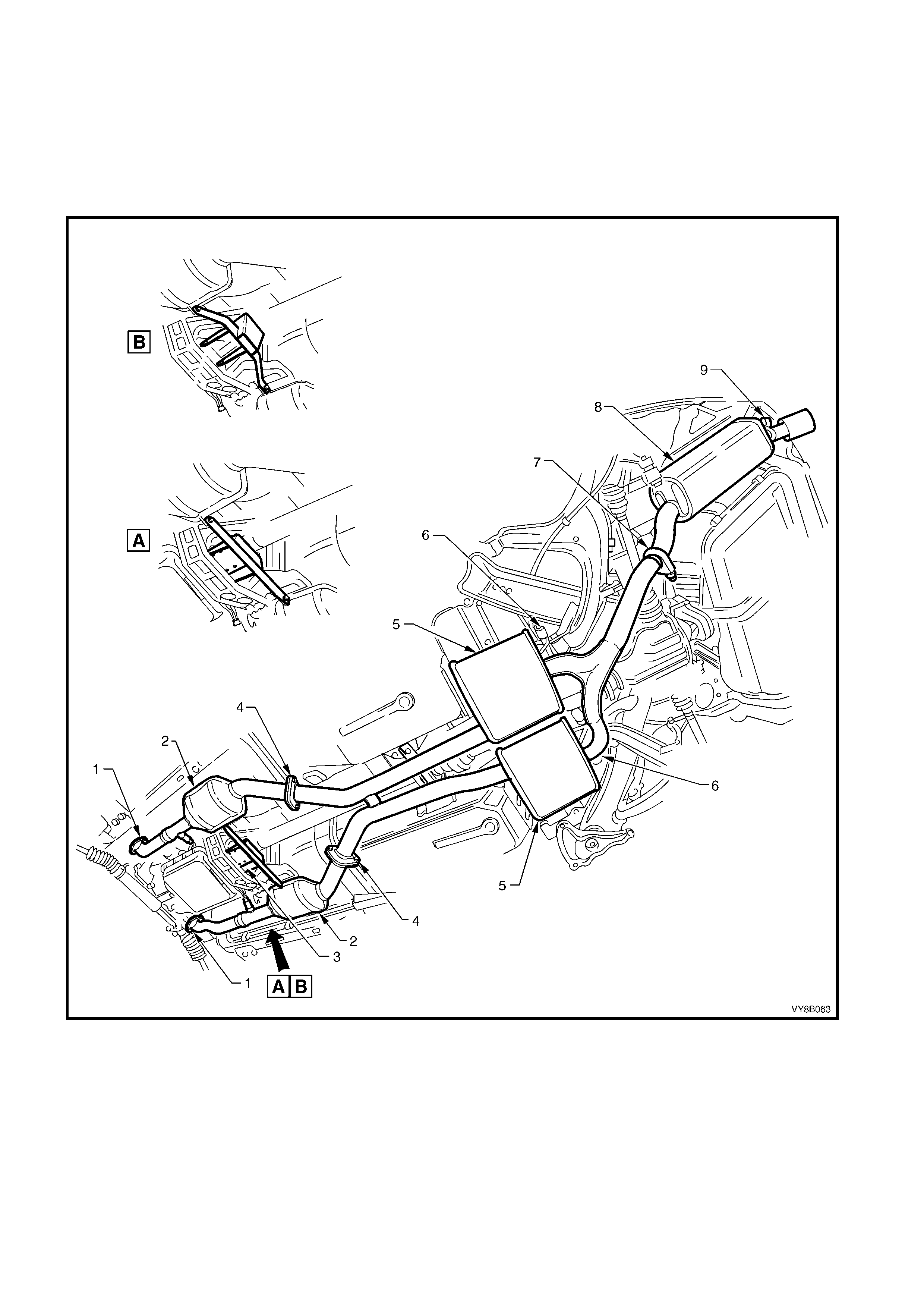
The following removal and installation service operations should be referred to when conducting work on Standard
and Performance exhaust systems, Refer to 1.1 EXHAUST SYSTEM CONFIGURATIONS, Figure 8B-4 and
Figure 8B-5 respectively within this Section. The illustrations provided represent the right-hand drive Standard
exhaust system, however any significant differences in procedure or configuration for left-hand drive or
Performance exhaust systems will be highlighted to accommodate servicing differences.
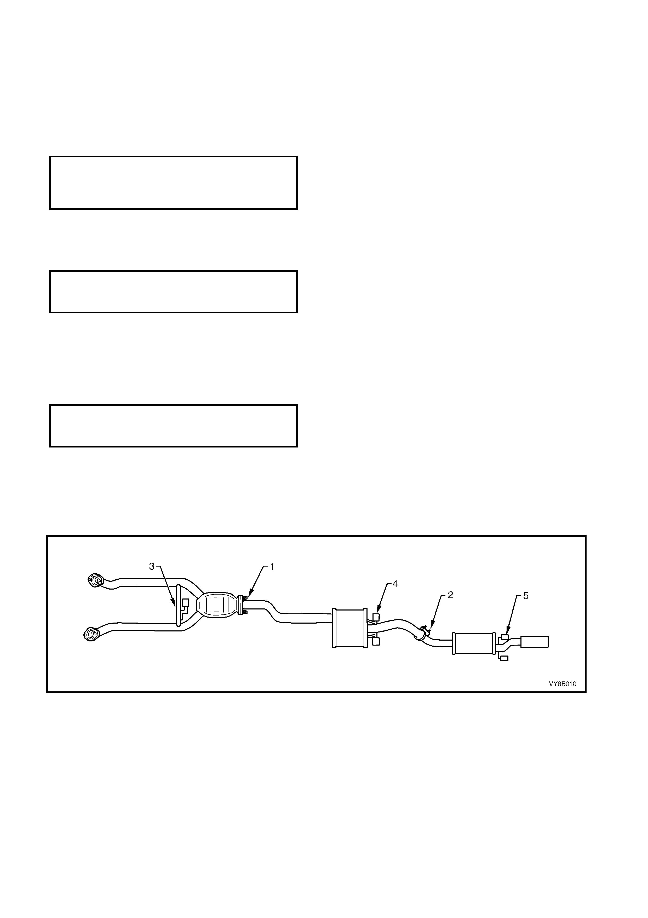
Figure 8B-42 provides a reference to the location of relevant exhaust system removal and installation components.
Figure 8B-42
Legend
A Transmission to Catalyst
Mounting Bracket - A/T
B Transmission to Catalyst
Mounting Bracket - M/T
1. Manifold to Front Pipe Flange Joint
2. Catalyst
3. Transmission to Catalyst Mounting
Bracket
4. Catalyst to Intermediate Pipe Flange
Joint
5. Intermediate Muffler
6. Intermediate Muffler Support
Rubbers
7. Intermediate to Rear Pipe Slip
Joint and Clamp
8. Rear Muffler
9. Rear Muffler Support Rubbers
COMPLETE EXHAUST SYSTEM
Remove
1. Disconnect the wiring harnes s connectors f rom
each of the two oxygen sensors (1).
Figure 8B-43
2. Disconnect the rear muffler from the support
hangers by removing the two retainer clips (1)
and support rubbers (2).
NOTE: The additional bumper washer (3) is used
on utility vehicles only.
Figure 8B-44
3. Support the exhaust system and disconnect
each intermediate muffler from the support
hangers by removing the retainer clips (1) and
the support rubbers (2).
Figure 8B-45

4. Remove the transmission to catalyst mounting
bracket bolts (1).
NOTE: For manual transmission vehicles, refer to
View A. For automatic transmission vehicles, refer
to View B.
Figure 8B-46
5. Support the exhaust system and remove the
upper (1) and lower (2) fastening nuts from the
exhaust manifold to exhaust pipe flange studs
on both sides.
6. Carefully lower and remove the exhaust
assembly from the vehicle, taking care not to
damage the exhaust gas oxygen sensors.
Figure 8B-47
Reinstall
Installation of the f ull exhaust s ys tem is the reverse
of the removal procedure, noting the following
points:
1. Support the exhaust system at all times.
2. Clean threads of flange and fastening bolts with
a suitable cleaning solvent.
3. Apply high temperature anti- seize com pound to
the manifold to fr ont pipe f lange studs and align
the front pipe flange over the studs.
4. Install the upper f as tening nut (1) to the s tud on
both sides.
5. Install the lower fas tening nut (2) to the stud on
both sides.
6. Tighten the upper and lower fastening nuts so
that approxim ately equal amounts of thread are
showing.
7. Tighten the exhaust manifold to front pipe
flange attaching nuts (1 and 2) to the specified
torque.
8. Ensure all support rubbers are under load
9. Ensure that correct body clearances are
maintained throughout the full exhaust system.
Refer to 6.2 V6 SUPERCHARGED AND GEN
III V8 EXHAUST SYSTEM CLEARANCES.
10. Connect the wiring harness connectors for
each of the two oxygen sensors.
NOTE: If steps 8 or 9 are not achieved, refer to
TIGHTENING SEQUENCE in this Section.
Figure 8B-48
TIGHTENING SEQUENCE
This procedure is only to be performed if the exhaust system positioning is not to specification.
Refer to Figure 8B-49 for the following.
IMPORTANT: For all gasketed joints requiring adjustment, always check flange gaskets for serviceability and
replace where required.
1. T ighten the f ront pipe to inter m ediate pipe flange attac hing bolts (1) at the r ear of the catalytic converters to the
specified torque.
FRONT PIPE TO INTERMEDIATE PIPE
FLANGE ATTACHING BOLT
TORQUE SPECIFICATION 40 – 50 Nm
2. For the Standard exhaust system, check that the rear exhaust pipe aligning tab is seated within the intermediate
exhaust pipe’s end slip joint groove. Position the U-bolt clamp along the intermediate to rear slip joint and
tighten the pair of fastening nuts (2) to the specified torque.
U-BOLT CLAMP ASSEMBLY
SECURING NUTS
TORQUE SPECIFICATION 20 – 30 Nm
3. For the Performance exhaust system, check that the rear exhaust pipe aligning tab is seated within the
intermediate exhaust pipe’s end slip joint groove and tighten each fastening bolt to the specified torque.
RING CLAMP ASSEMBLY
FASTENING BOLT
TORQUE SPECIFICATION 37 – 50 Nm
4. Install the upper fastening nut (1) to the stud on both sides, refer to Figure 8B-48.
5. Install the lower fastening nut (2) to the stud on both sides, refer to Figure 8B-48.
6. Tighten all the nuts joining the exhaust manifold to the front exhaust pipe flange, so that approximately equal
amounts of thread are showing.
7. Tighten the exhaust manifold to front pipe flange attaching nuts (1 and 2) to the specified torque, refer to
Figure 8B-48.
EXHAUST MANIFOLD TO FRONT PIPE
FLANGE ATTACHING NUT
TORQUE SPECIFICATION 18 – 35 Nm
EXHAUST MANIFOLD TO FRONT PIPE
FLANGE ATTACHING NUT
TORQUE SPECIFICATION 18 – 35 Nm
8. Tighten the front pipes to transmission extension housing bracket assembly bolts (3) to the specified torque,
refer to Figure 8B-49.
CATALYST TO TRANSMISSION
EXTENSION HOUSING BRACKET
ASSEMBLY BOLTS
TORQUE SPECIFICATION 40 – 50 Nm
9. Ensure that all six support rubbers (4 and 5) are under load. If this is not achieved, loosen the respective
joints in the reverse order to steps 1 to 8. Load the hangers and re-tighten in the sequence described, from
steps 1 to 8.
NOTE: The exhaus t s ystem should be s elf- aligning and not require f urther adj ustm ent, provided s tep 9 is ac hieved.
To ensure that correct clearances are maintained throughout the full exhaust system, refer to
6.2 V6 SUPERCHARGED AND GEN III V8 EXHAUST SYSTEM CLEARANCES for the correct values.
Figure 8B-49
REAR EXHAUST ASSEMBLY
Remove
1. Remove the two support hanger retainer
clips (1) and the two support rubbers (2) from
the support hangers.
NOTE: The additional bumper washer (3) is used
on utility vehicles only.
Figure 8B-50
2. For Standard exhaust:
a. Rem ove the two retaining nuts (1) and the rear
muffler U-bolt (2) and clamp plate (3) from the
intermediate exhaust pipe to rear muffler
exhaust pipe slip joint.
b. Carefully slide the rear exhaust pipe out of the
intermediate exhaust pipe end slip joint.
3. For Performance exhaust:
a. Loosen the two ring clamp fastening bolts.
b. Car efully slide the rear exhaust pipes out of the
intermediate exhaust pipe end slip joints.
4. Remove the rear exhaust assembly.
Figure 8B-51
Reinstall
Installation of the rear exhaust assembly is the
reverse of the removal procedure, noting the
following:
1. Ensure that the rear exhaust pipe slides
unobstructed into the intermediate exhaust pipe
slip joint, and that the alignment tab is
positioned in the slip joint groove.
2. For Standar d exhaust, evenly tighten the U-bolt
clamp nuts to the correct torque specification.
3. For Performance exhaust, tighten each
fastening bolt to the specified torque.
4. Ensure all support rubbers are under load and
all clearances are within the specifications. If
this is not achieved, refer to TIGHTENING
SEQUENCE in this Section.
INTERMEDIATE EXHAUST ASSEMBLY
Remove
1. Remove the rear exhaust assembly. Refer to
REAR EXHAUST ASSEMBLY in this Section.
CAUTION: The f ront exhaust assembly must be
supported during and after this procedure.
2. Support the intermediate and front exhaust
assemblies and remove the two bolts (1) from
each of the two flange joints.
3. Separate the intermediate exhaust assembly
from the front exhaust assembly and remove
each flange gasket (2) from between each of
the flange joints.
Figure 8B-52
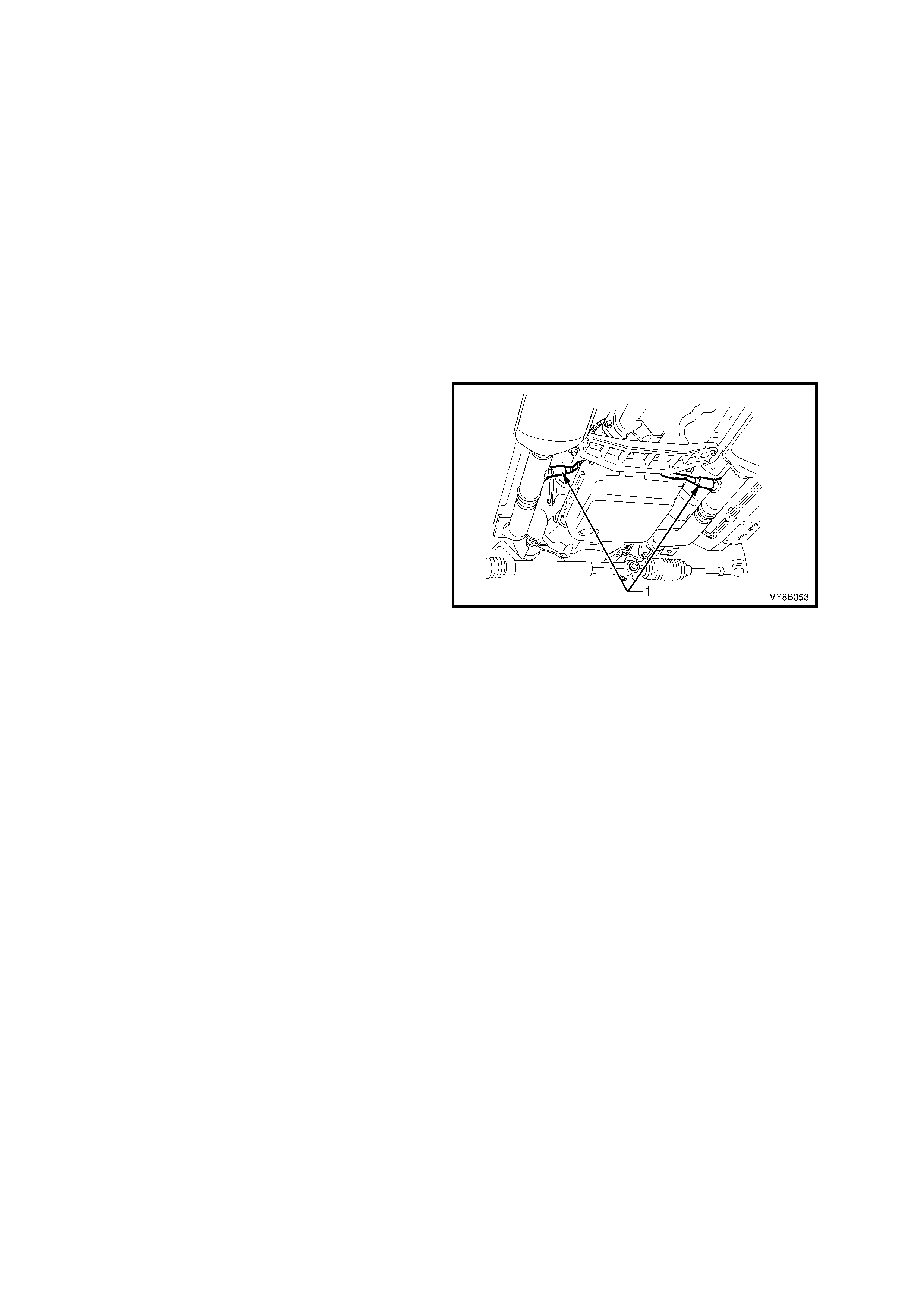
4. Remove the pair of retainer clips (1) and
support rubbers (2) from both of the right-hand
side and left-hand side intermediate muffler
support hangers. Remove the intermediate
exhaust assembly.
Figure 8B-53
RING CLAMP ASSEMBLY
FASTENING BOLTS
TORQUE SPECIFICATION 40 – 50 Nm
U-BOLT CLAMP ASSEMBLY
ATTACHING SCREW
TORQUE SPECIFICATION 20 – 30 Nm
Reinstall
Installation of the inter mediate exhaust assem bly is
the reverse of the removal procedure, noting the
following:
1. Support the exhaust system at all times.
2. Clean the threads of all flange bolts with a
suitable cleaning solvent.
3. Tighten the front pipe to intermediate pipe
flange attaching bolts at the rear of the catalytic
converters to the specified torque.
4. Ensure all support rubbers are under load and
all clearances are within specification. If this is
not achieved, refer to TIGHTENING
SEQUENCE in this Section.
FRONT EXHA UST ASSEMBLY
Remove
1. Disconnect the wiring harnes s connectors f rom
each of the two oxygen sensors (1).
Figure 8B-54
2. Support the intermediate and front exhaust
assemblies and remove the two bolts (1) from
each of the two flange joints.
3. Separate the intermediate exhaust assembly
from the front exhaust assembly and remove
the flange gasket (2) from between the flange
joint.
Figure 8B-55
FRONT PIPE TO INTERMEDIATE PIPE
FLANGE ATTACHING BOLT
TORQUE SPECIFICATION 40 – 50 Nm
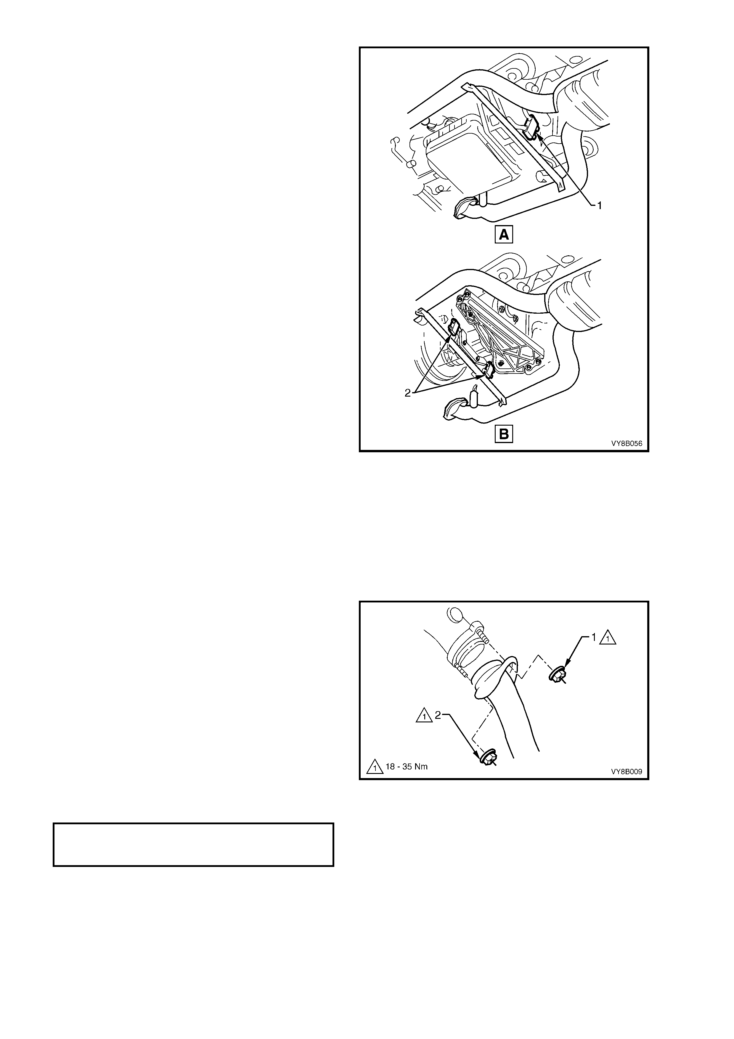
4. Remove the transm ission to catalys t mounting
bracket bolts (1).
NOTE: For manual transmission vehicles, refer to
view A. For automatic transmission vehicles, refer
to view B.
Figure 8B-56
5. Support the front exhaust assembly and
remove the upper (1) and lower (2) fastening
nuts f rom the exhaus t manif old to exhaust pipe
flange studs on both sides.
6. Carefully lower and remove the front exhaust
assembly from the vehicle, taking care not to
damage the oxygen sensors in the process.
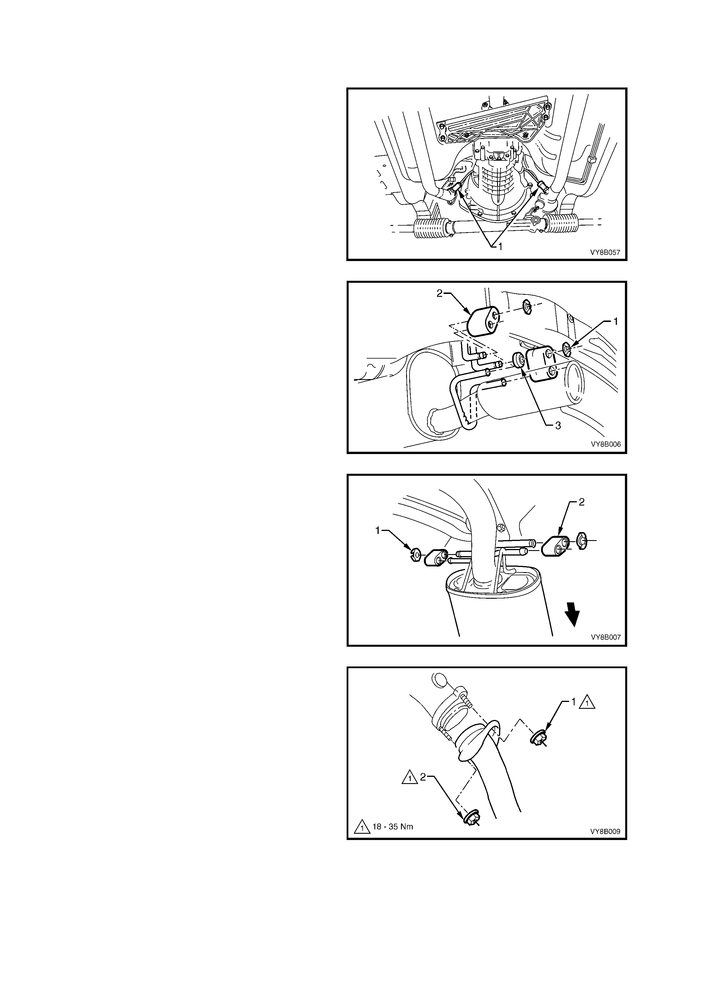
Figure 8B-57
Reinstall
Installation of the front exhaust assembly is the
reverse of the removal procedure, noting the
following points:
1. Support the exhaust system at all times.
2. Clean threads of flange and stepped bolts with
a suitable cleaning solvent.
3. Apply a high temperature anti-seize compound
to the manifold to front pipe flange studs and
align the front pipe flange over the studs.
4. Install the upper f as tening nut (1) to the s tud on
both sides.
5. Install the lower fas tening nut (2) to the stud on
both sides.
6. Tighten the upper and lower fastening nuts so
that approxim ately equal amounts of thread are
showing.
7. Tighten the exhaust manifold to front pipe
flange attaching nuts (1 and 2) to the specified
torque.
8. Tighten the front pipe to intermediate pipe
flange attaching bolts to the specified torque.
9. Ensure all exhaust system support rubbers are
under load.
10. Ensure that correct body clearances are
maintained throughout the full exhaust system.
Refer to 6.2 V6 SUPERCHARGED AND GEN
III V8 EXHAUST SYSTEM CLEARANCES.
11. Connect the wiring harness connectors for
each of the two oxygen sensors.
NOTE: If steps 9 or 10 are not achieved, refer to
TIGHTENING SEQUENCE in this Section.
Figure 8B-58
FRONT PIPE TO INTERMEDIATE PIPE
FLANGE ATTACHING BOLT
TORQUE SPECIFICATION 40 – 50 Nm
EXHAUST MANIFOLD TO FRONT PIPE
FLANGE ATTACHING NUT
TORQUE SPECIFICATION 18 – 35 Nm
5. SERVICE OPERATIONS – EXHAUST SYSTEM HEAT SHIELDS
5.1 HEAT SHIELDS
Should any of the heat shields or reflective foil insulators require replacement, the following procedure is
recommended.
CAUTION: To av oid the possibility of personal injury by burns, allow the exhaust pipe system to cool down
before attempting this operation and wear heat resistant protective gloves when handling heated foil.
NOTE 1: No rear muffler heat shield is fitted to Utility vehicles.
NOTE 2: Do not attempt to re-use a remould reflective foil insulator. Always use a new part.
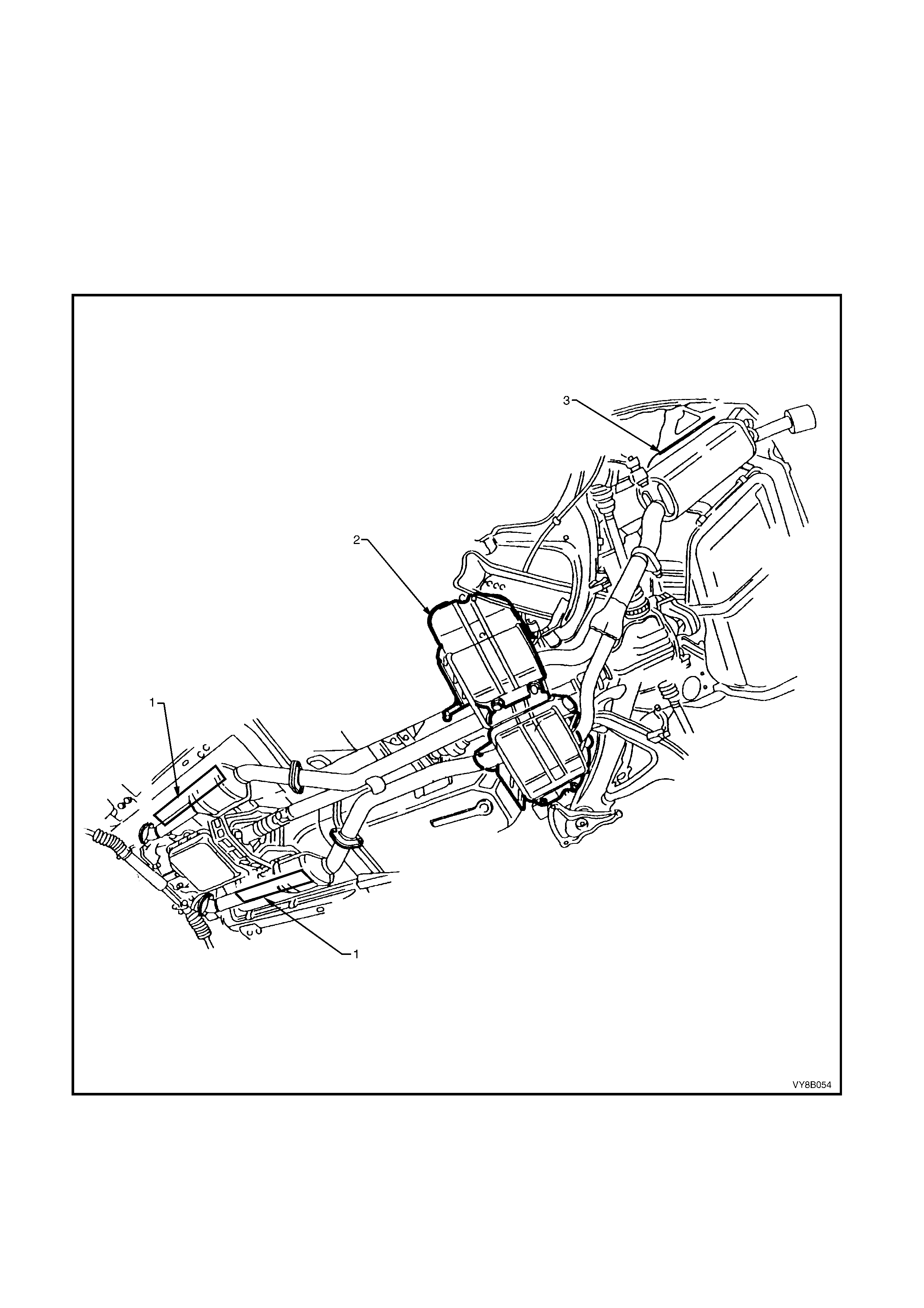
Figure 8B-59 provides a reference to the location of the muffler heat shields and the reflective foil insulators.
Figure 8B-59
Legend
1. Reflective Foil Heat Shield 2. Intermediate Muffler Heat Shield 3. Rear Muffler Heat Shield
HEAT SHIELD – REAR MUFFLER
Remove
1. If required, remove the rear exhaust assem bly,
refer to:
• 2.2 EXHAUST SYSTEM – REAR
EXHAUST ASSEMBLY for V6.
• 3.2 EXHAUST SYSTEM – REAR
EXHAUST ASSEMBLY for V6
Supercharged.
• 4.2 EXHAUST SYSTEM – REAR
EXHAUST ASSEMBLY for GEN III V8.
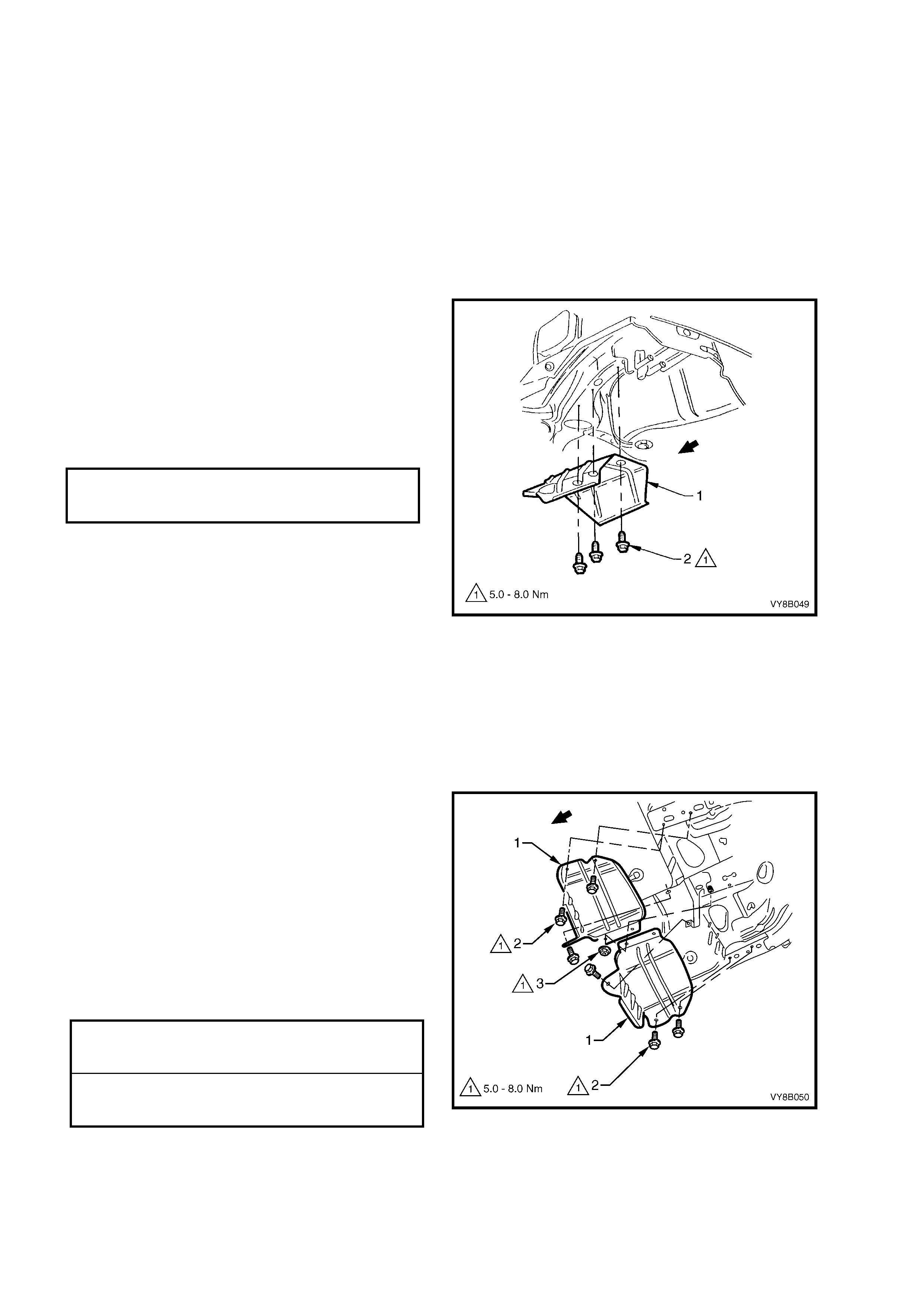
2. Remove the rear muffler heat shield (1) by
removing the three attaching screws (2).
Reinstall
Installation of the rear muffler heat shield is the
reverse of the removal procedure, noting the
following:
1. Tighten the body attaching screws to the
correct torque specification:
Figure 8B-60
HEAT SHIELD – INTERMEDIATE MUFFLER
Remove
1. If required, remove the intermediate exhaust assembly, refer to:
• 2.2 EXHAUST SYSTEM – INTERMEDIATE EXHAUST ASSEMBLY for V6.
• 3.2 EXHAUST SYSTEM – INTERMEDIATE EXHAUST ASSEMBLY for V6 Supercharged.
• 4.2 EXHAUST SYSTEM – INTERMEDIATE EXHAUST ASSEMBLY for GEN III V8.
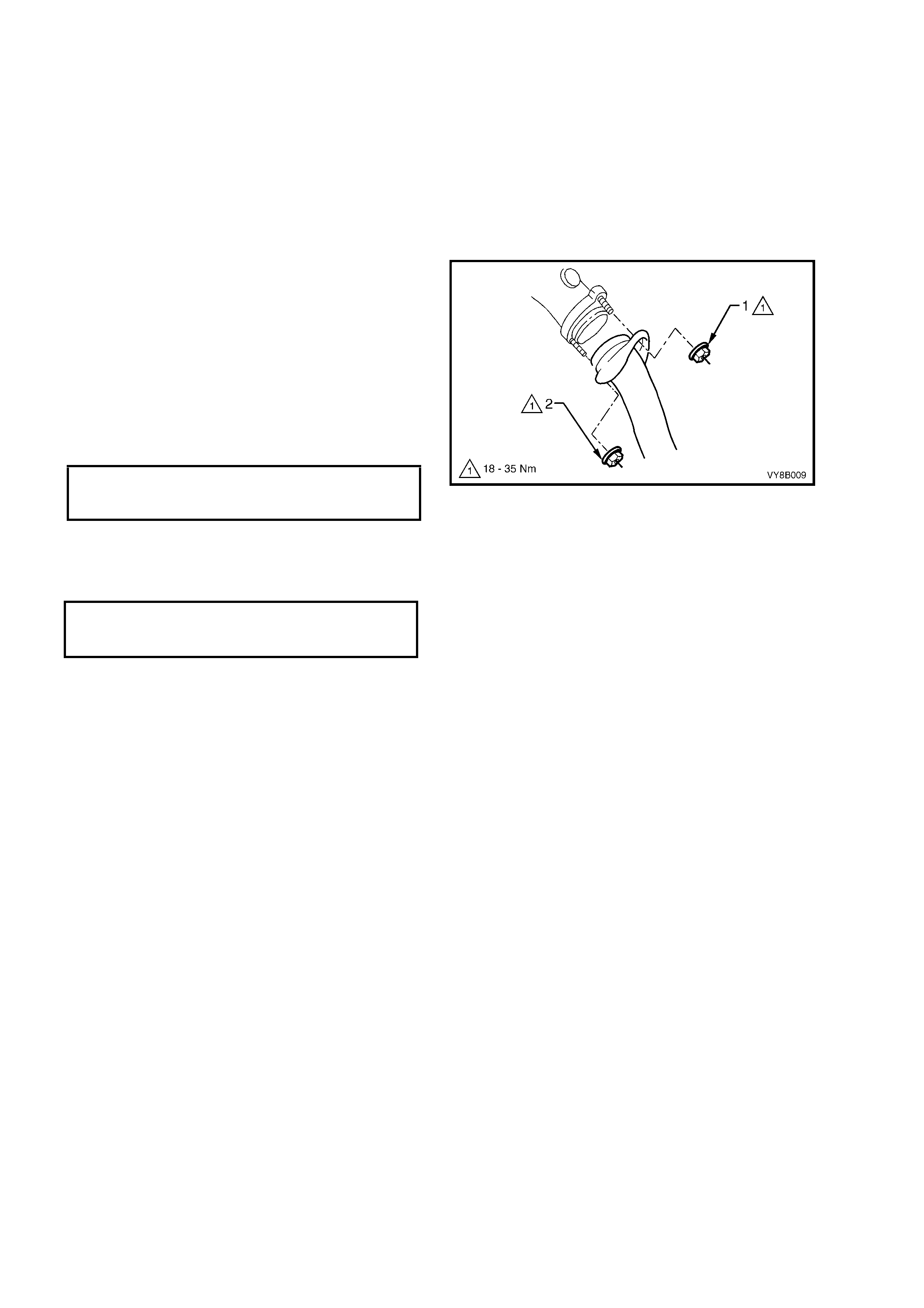
NOTE: For V6 (non-supercharged) vehicles, there
is one intermediate muffler heat shield.
2. Remove the intermediate heat shield/s (1) by
removing the attaching screws (2) and the
single stud nut (3).
Reinstall
Installation of the intermediate heat shield is the
reverse of the removal procedure, noting the
following:
1. T ighten the body attaching screws and stud nut
to the correct torque specification.
Figure 8B-61
REAR MUFFLER HEAT SHIELD
ATTACHING SCREW
TORQUE SPECIFICATION 5.0 – 8.0 Nm
INTERMEDIATE MUFFLER HEAT
SHIELD ATTACHING SCREW
TORQUE SPECIFICATION 5.0 – 8.0 Nm
INTERMEDIATE MUFFLER HEAT
SHIELD STUD ATTACHING NUT
TORQUE SPECIFICATION 5.0 – 8.0 Nm
REFLECTIVE FOIL INSULATORS
Remove
1. If requir ed, rem ove the fr ont exhaust as sem bly,
refer to
• 2.2 EXHAUST SYSTEM – FRONT
EXHAUST ASSEMBLY for V6.
• 3.2 EXHAUST SYSTEM – FRONT
EXHAUST ASSEMBLY for V6
Supercharged.
• 4.2 EXHAUST SYSTEM – FRONT
EXHAUST ASSEMBLY for GEN III V8.
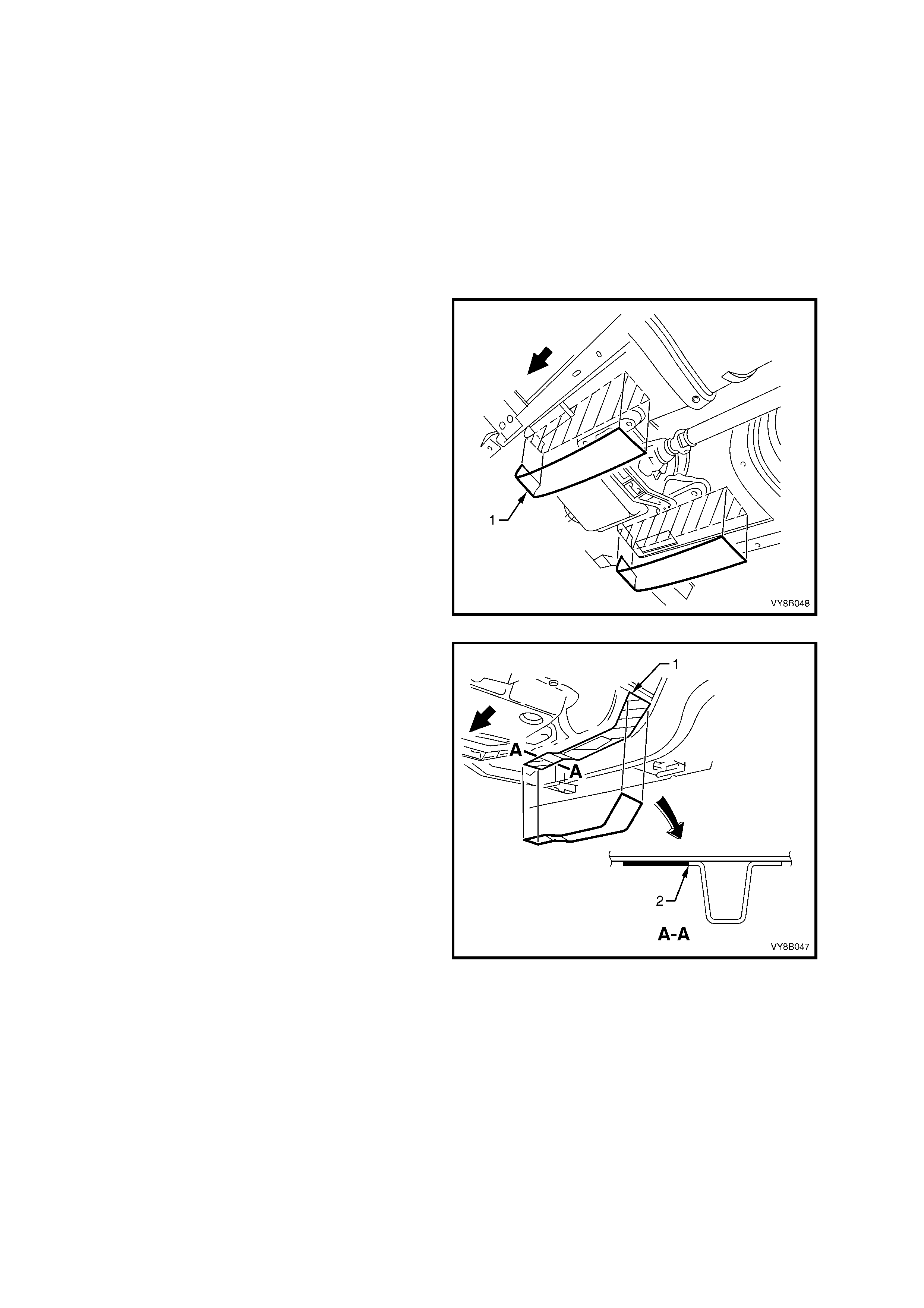
2. Peel the reflective foil insulator/s (1) to be
replaced from the under floor and discard.
3. Use a solvent soaked rag to remove all traces
of the old insulator adhesive, sealer overspray
or paint overspray, should the vehicle have
been repaired.
Reinstall
NOTE: Do not attempt to re-use a removed
reflective foil insulator. Always use a new part.
1. Use a solvent soaked rag to remove all traces
of the old insulator adhesive, sealer overspray
or paint overspray, should the vehicle have
been repaired.
2. Heat a new reflective foil insulator to 40 ± 5° C.
Figure 8B-62
3. Wearing heat resistant protective gloves, peel
the adhesive protective paper from the new
reflective foil heat insulator and apply the
insulator to the cleaned under floor area in the
same position as the removed part. The front
facing end of the foil should start at the join in
the floor (1) and align with the edge of the front
side rail f lange (2). Smooth out any air bubbles
in the process.
Figure 8B-63
6. EXHAUST SYSTEM CLEARANCES
6.1 V6 EXHAUST SYSTEMS CLEARANCES
The following diagrams indicate the exhaust system clearances specified for vehicles fitted with the V6 engine.
Clearances should be checked upon installation of exhaust components to prevent parts interference and ensure
correct alignment. Refer to Figure 8B-8 for the location of exhaust system parts.
CAUTION: To avoid the possibility of personal injury, allow the exhaust system to cool down before
attempting this operation.
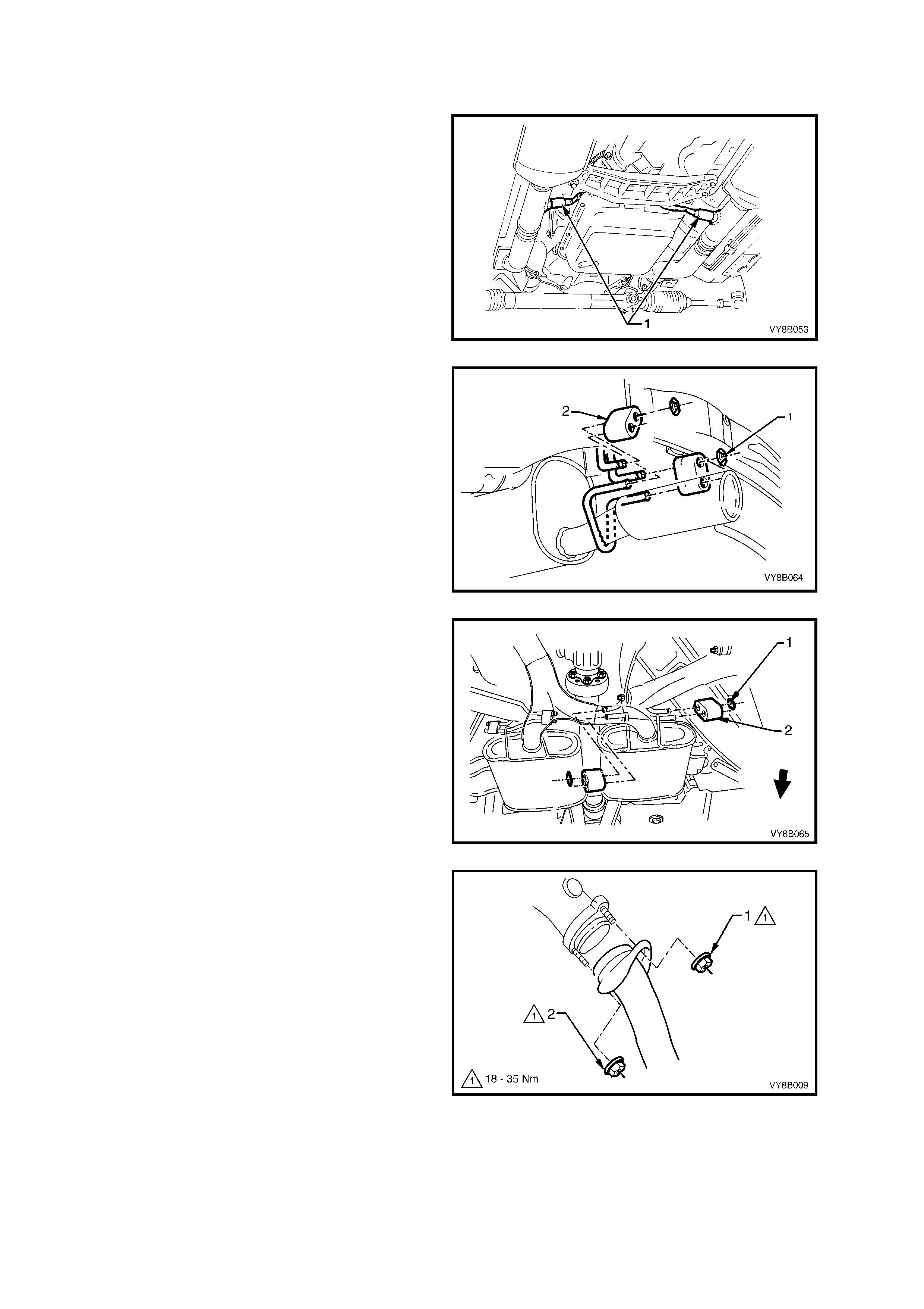
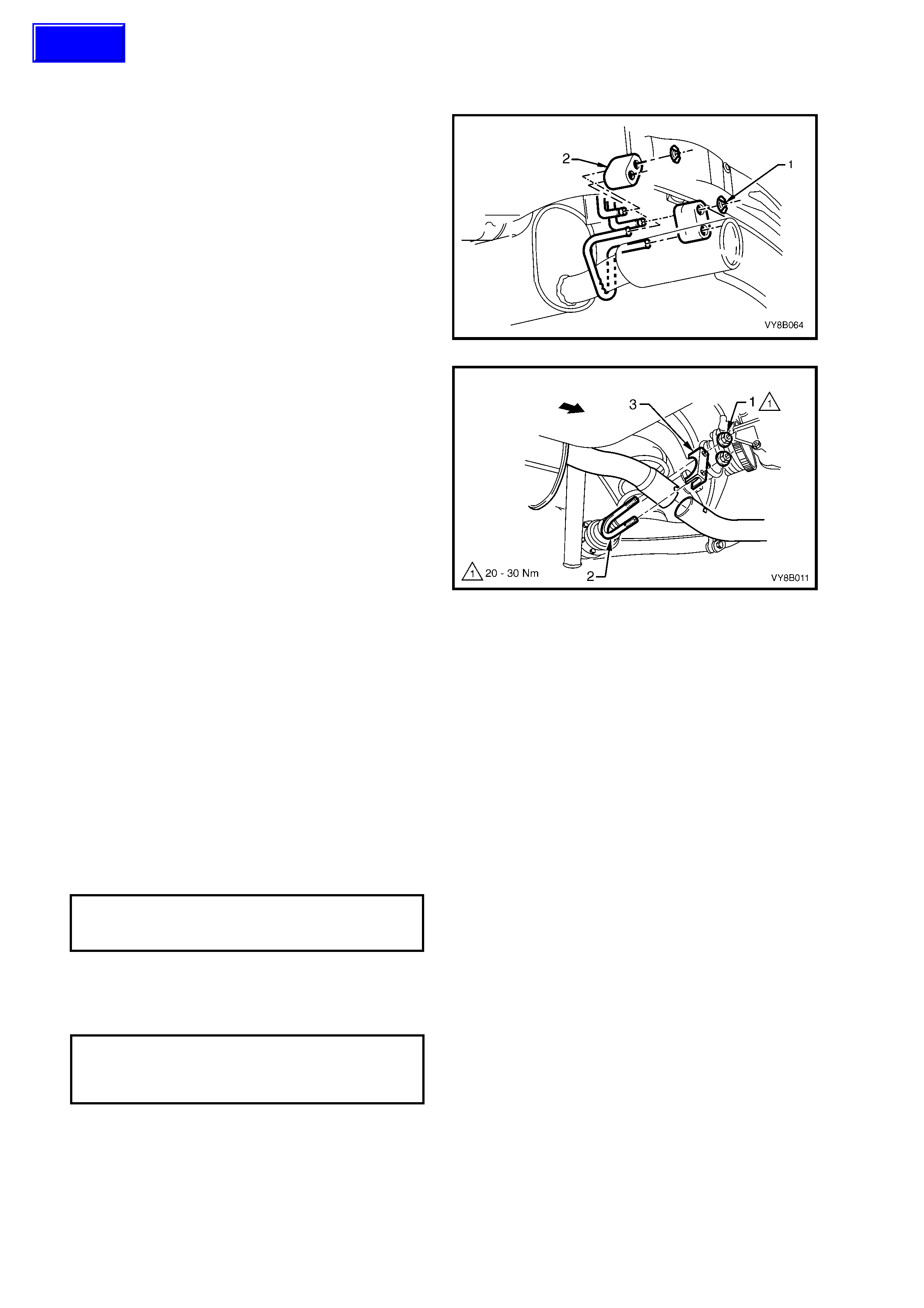
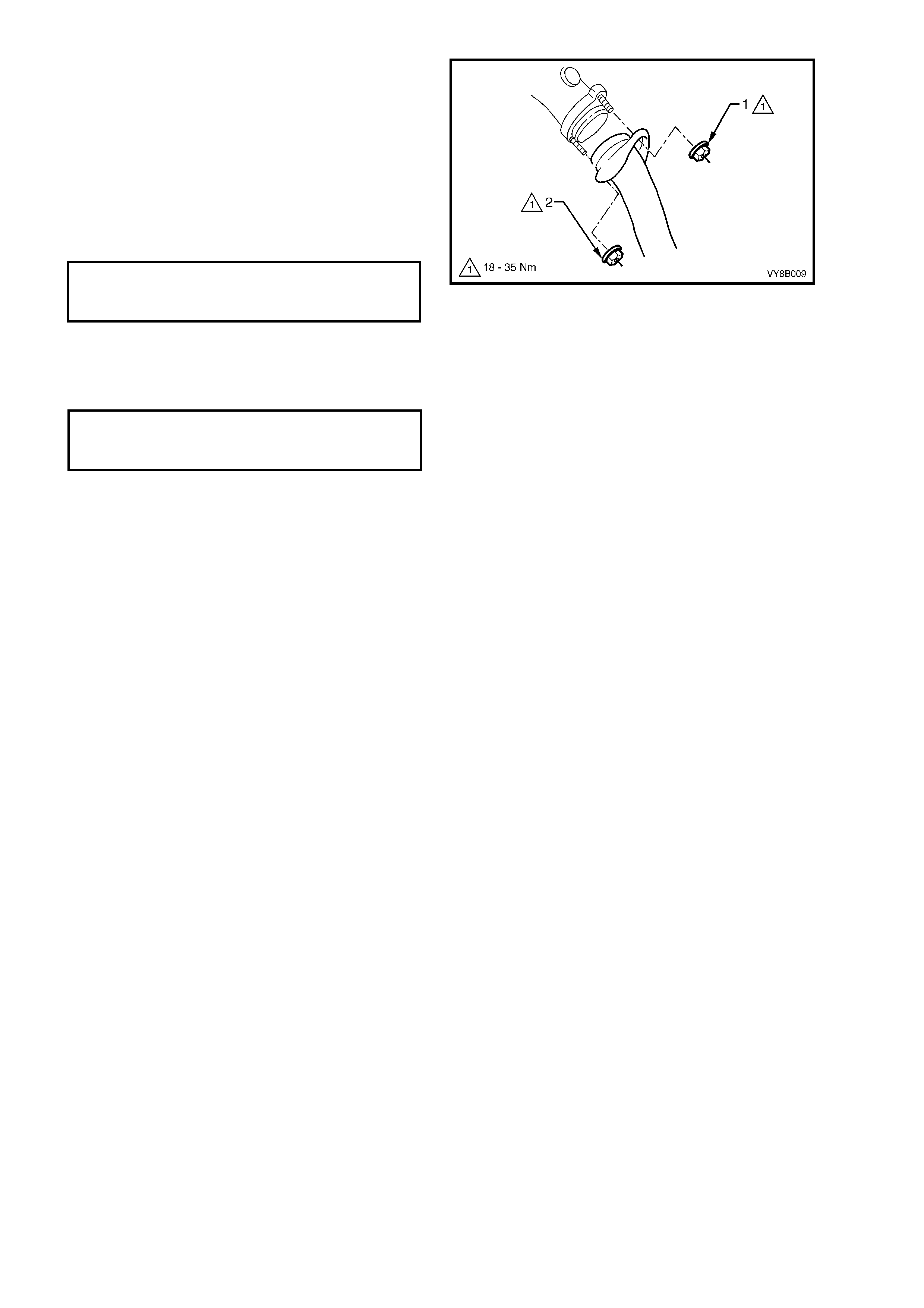
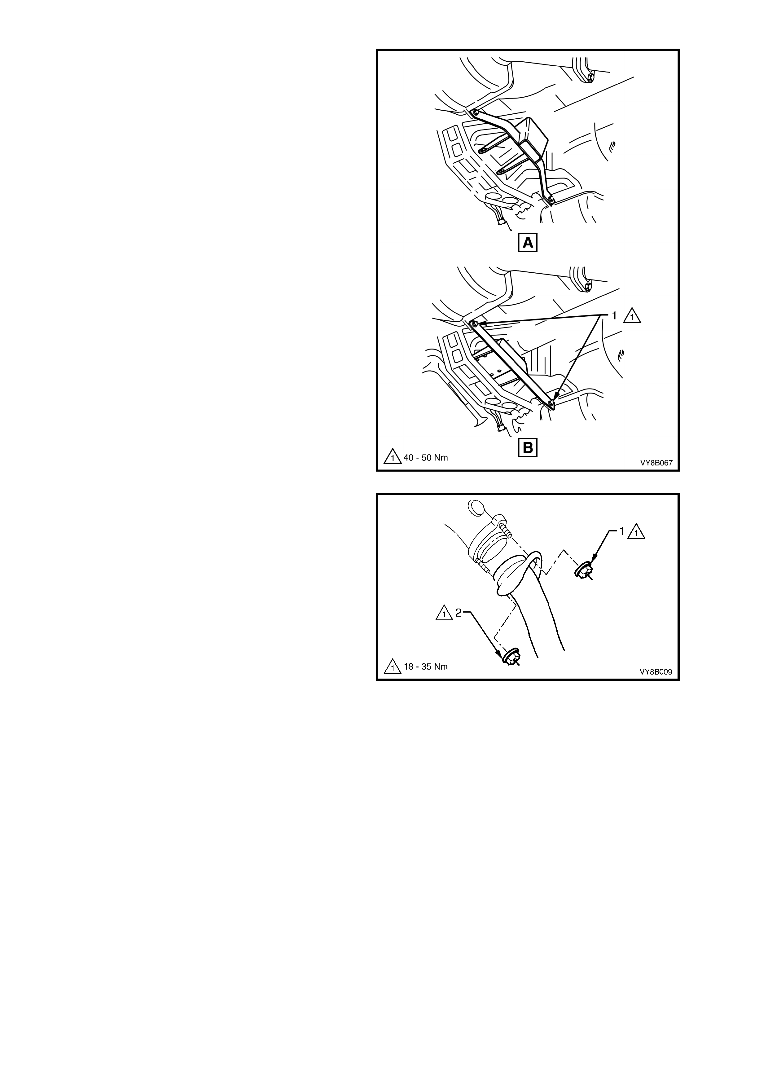
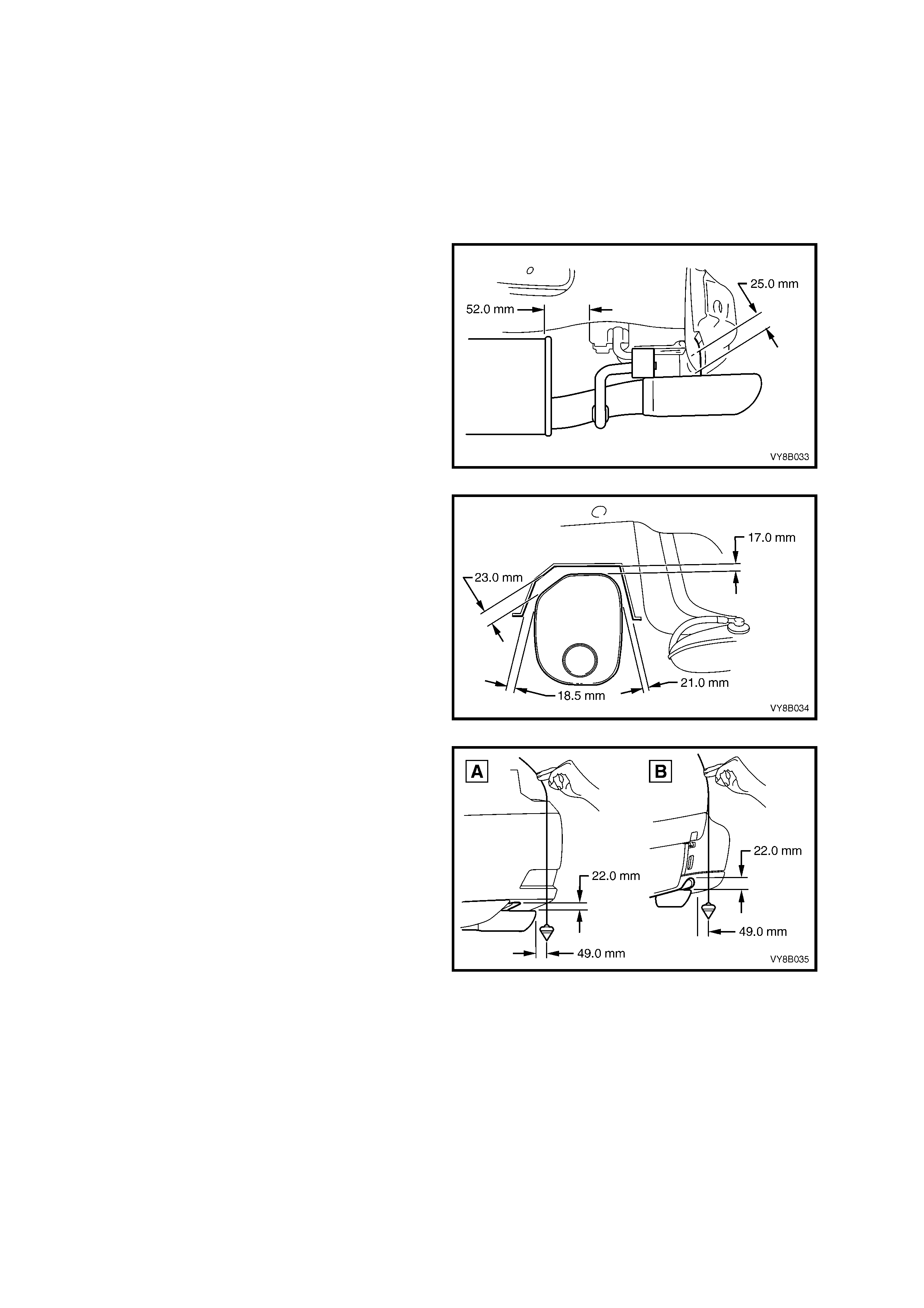
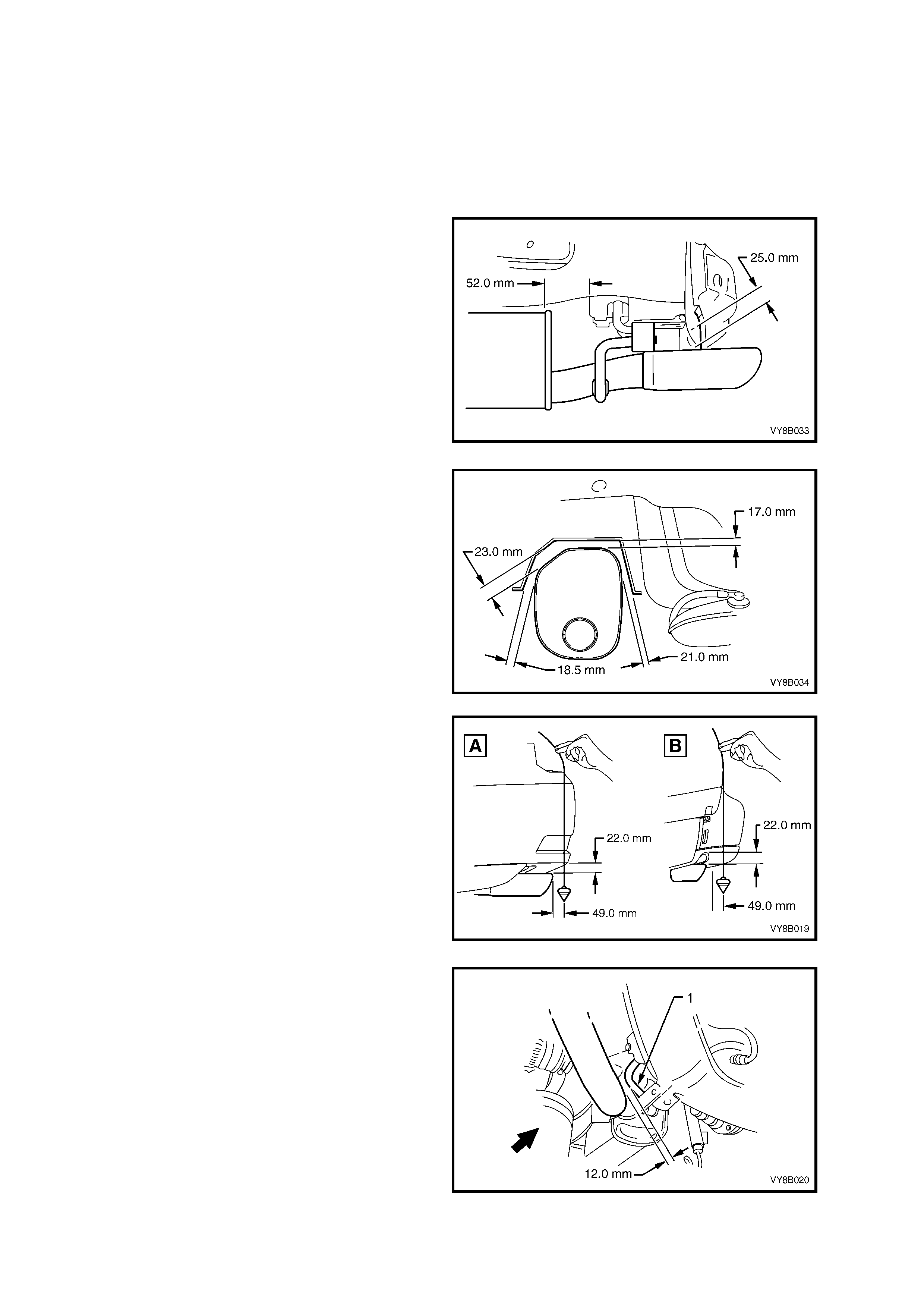
1. Check the rear tail pipe to rear end panel
clearances and rear muffler to tail pipe hanger
mounting clearances.
Figure 8B-64
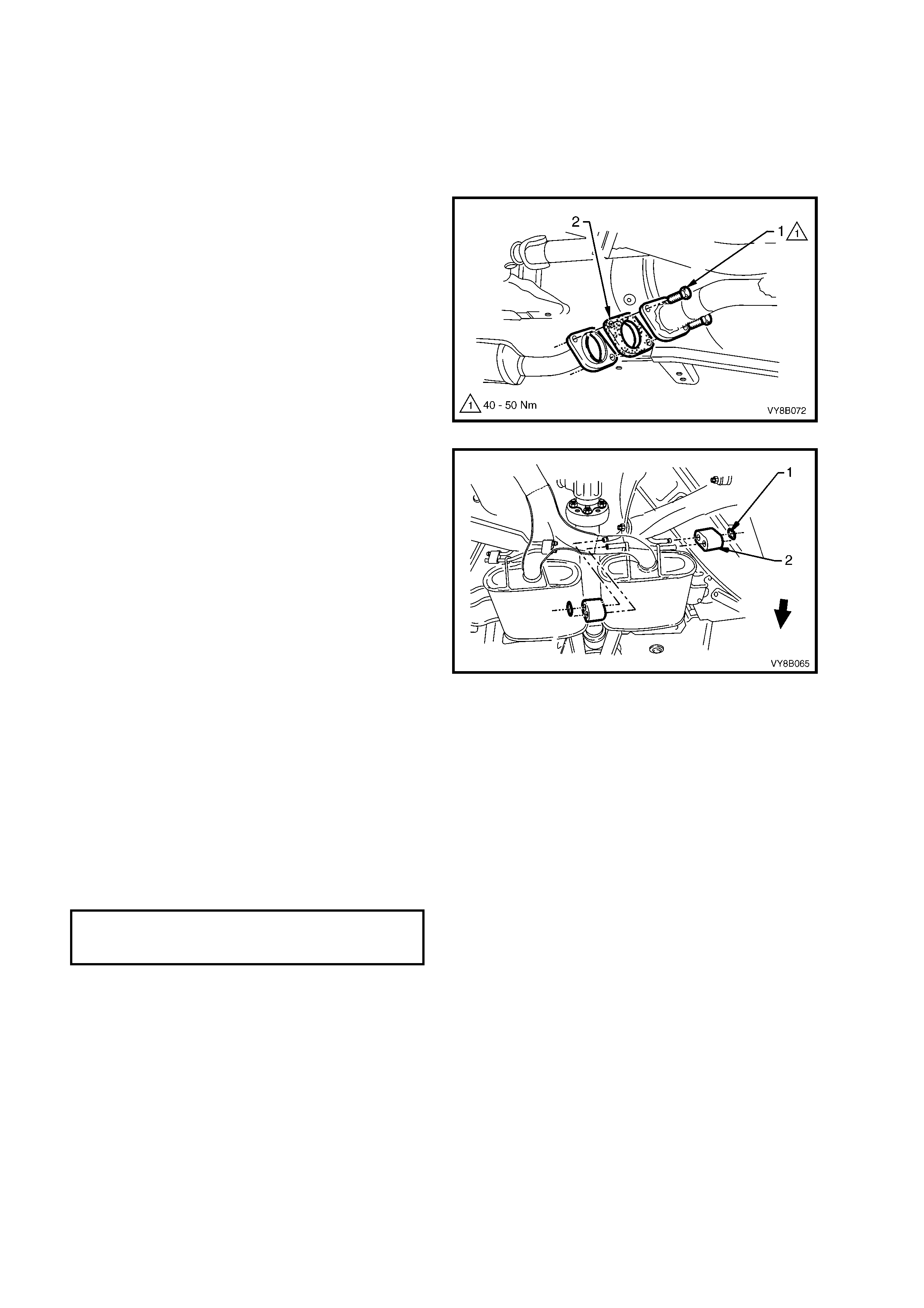
2. Check the rear exhaust muffler to rear heat
shield clearances.
Figure 8B-65
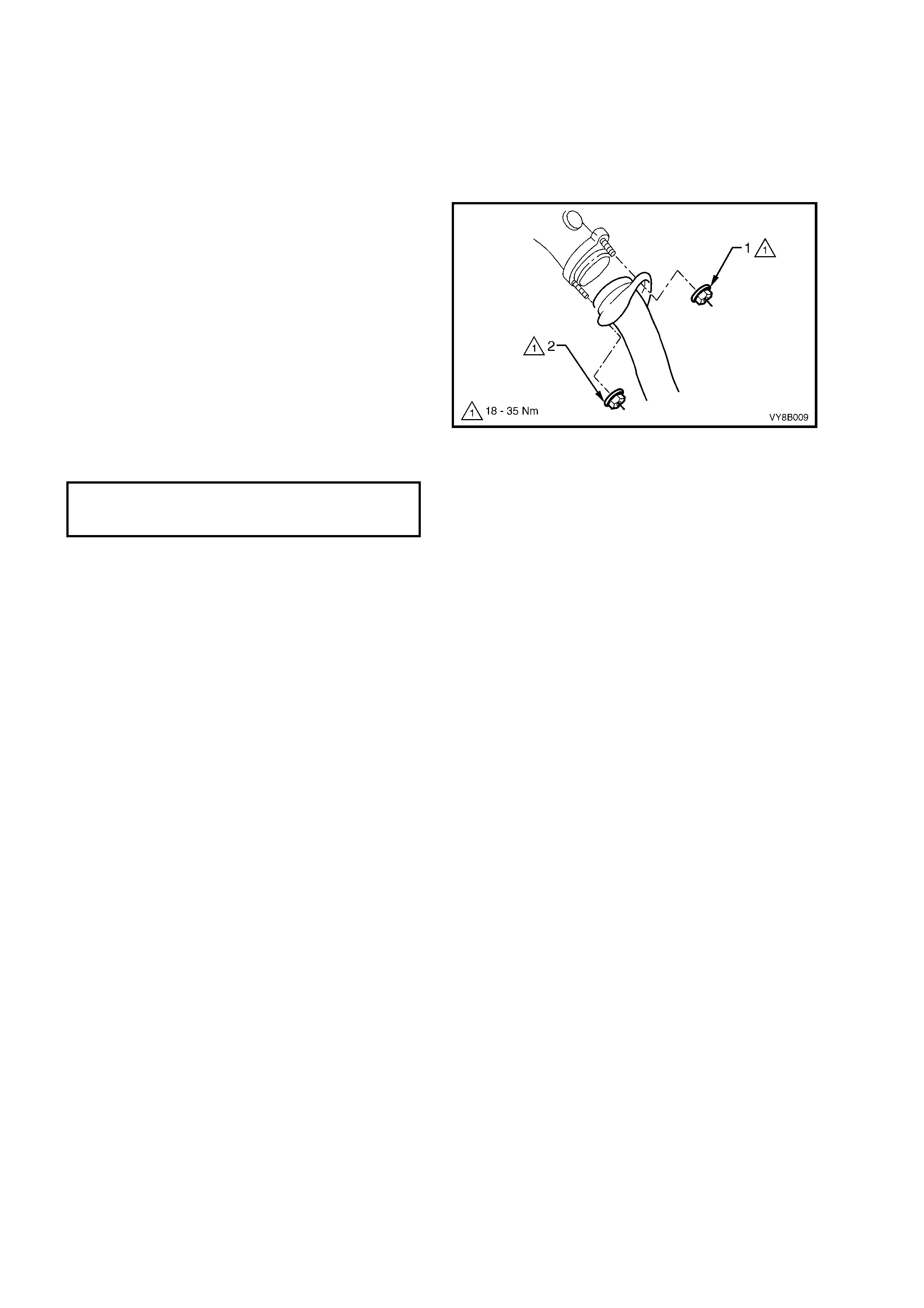
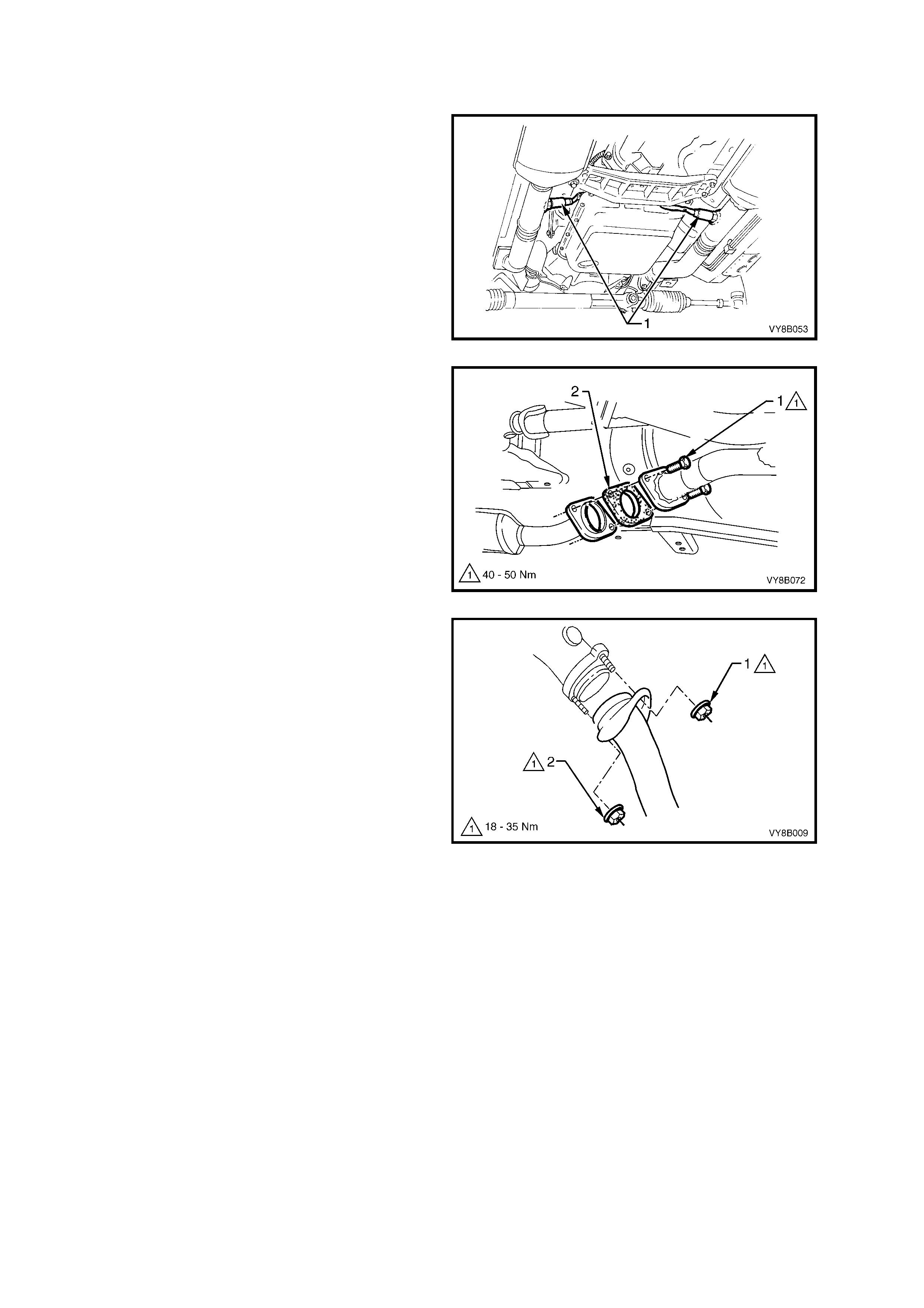
3. Check the clearance between the rear tail pipe
exhaust tip and the underside of the bumper
fascia.
4. Holding a weighted string over the r ear bumper
fascia, in line with the exhaust tip, determine
the horizontal clearance between the exhaust
tip and rear bumper.
NOTE: Refer to View A for Sedan, Wagon and
Coupe. Refer to View B for Utility.
Figure 8B-66
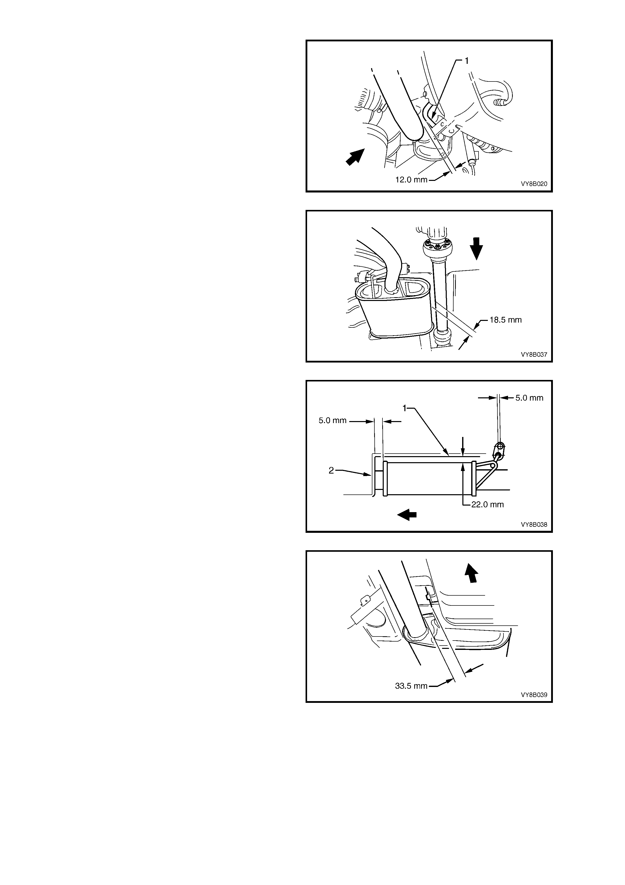
5. Check the intermediate to rear exhaust pipe to
stabiliser bar linkage (1) clearances.
Figure 8B-67
6. Check the intermediate exhaust hanger to
propeller shaft clearances.
Figure 8B-68
7. Check intermediate exhaust muffler to
intermediate heat shield (1) and rear footwell
(2) clearances; nominal clearance provided.
The horizontal clearance provided between the
body hanger and support peg is for reference
only .
Figure 8B-69
8. Check the intermediate exhaust pipe to
intermediate heat shield clearances.
Figure 8B-70
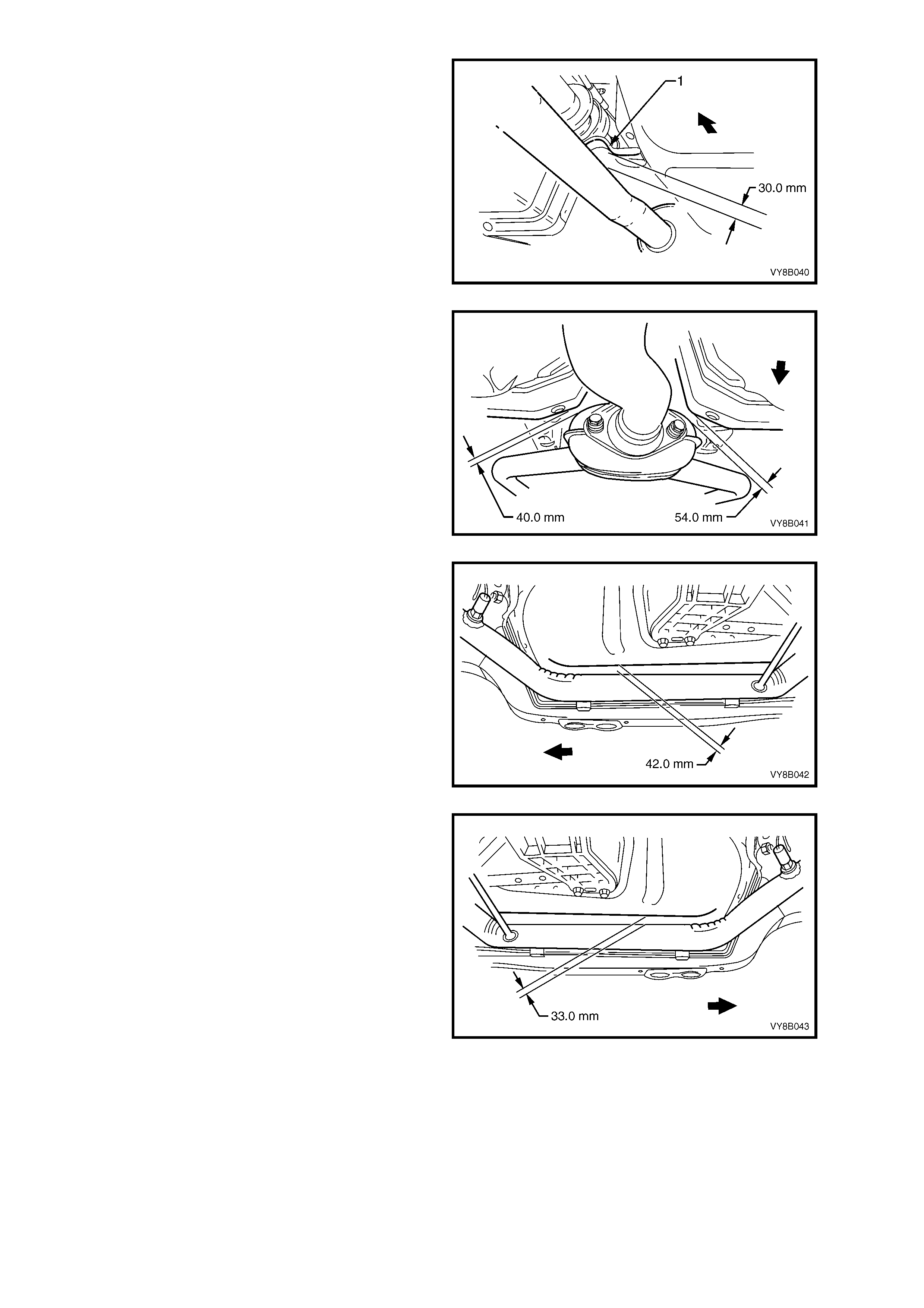
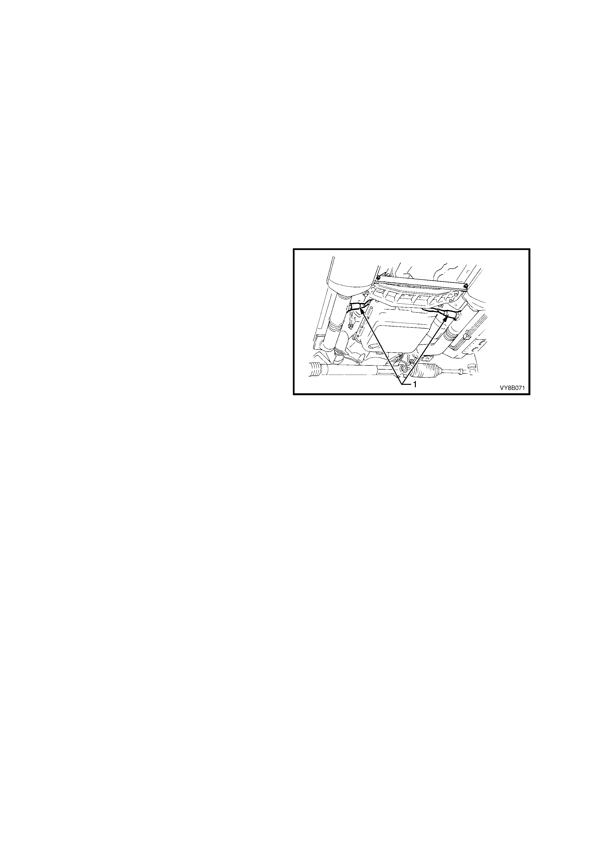
9. Check the intermediate exhaust pipe to centre
bearing carrier (1) clearance.
Figure 8B-71
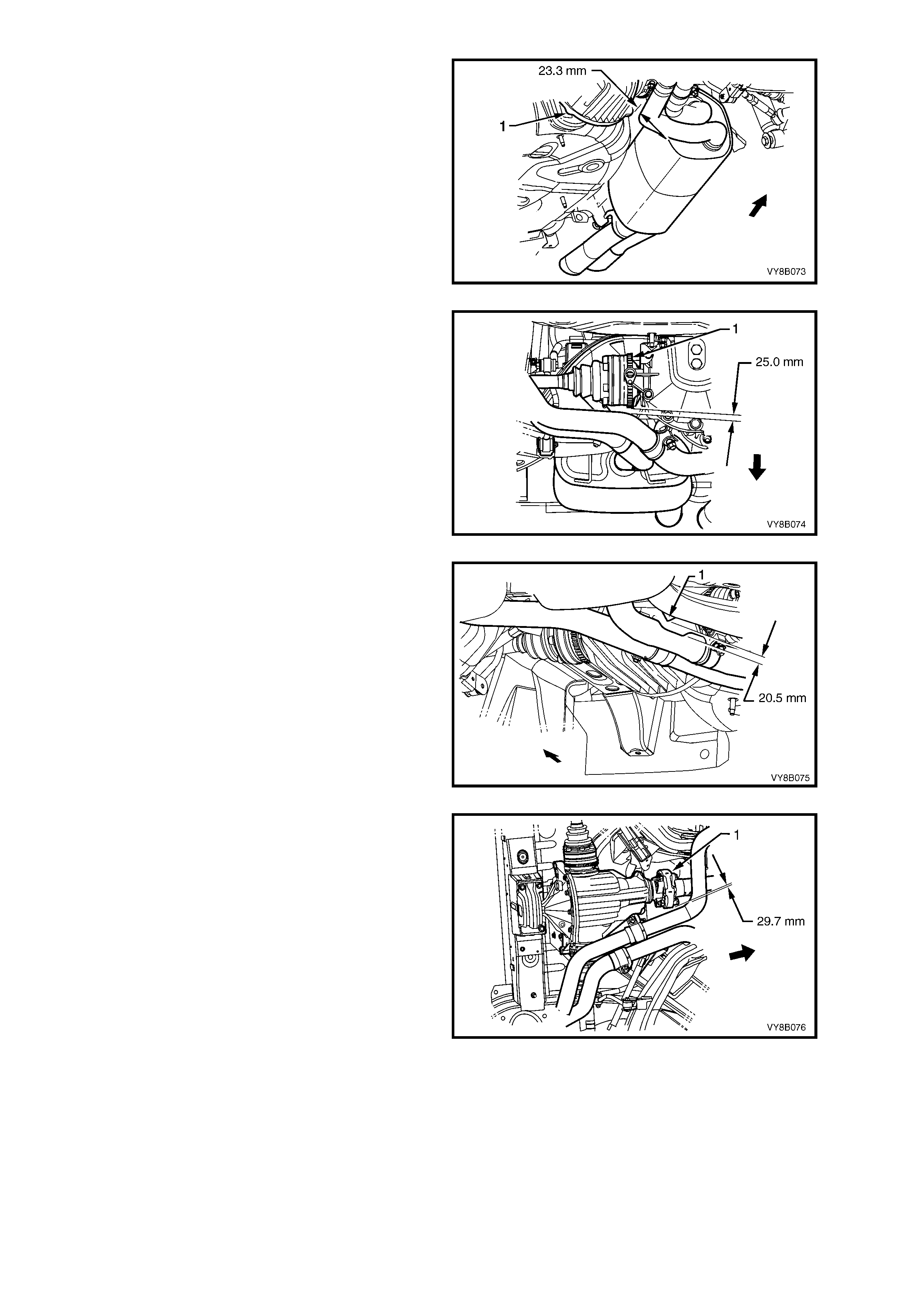
10. Check the catalytic converter to transmission
tunnel roof support clearances. Muffler
clearances for Indonesia vehicles similar.
Figure 8B-72
11. Check the right-hand side f ront exhaust pipe to
underbody foot well clearances. Nominal
clearance provided.
Figure 8B-73
12. Check the left-hand side front exhaust pipe to
underbody foot well clearances. Nominal
clearance provided.
Figure 8B-74

13. Check the front exhaust pipe to the right-hand
side front longitudinal assembly clearances.
Figure 8B-75
14. Check the front left-hand side exhaust pipe to
engine block clearances.
Figure 8B-76
6.2 V6 SUPERCHARGED AND V8 GEN III EXHAUST SYSTEM CLEARANCES
The following diagrams indicate the exhaust system clearances specified for vehicles fitted with either the V6
Supercharged or Gen III V8 Engine. Both standard and performance type exhaust systems are included.
Clearances should be checked upon installation of exhaust components to prevent parts interference and ensure
correct parts alignment. Refer to Figure 8B-26 for V6 Supercharged and Figure 8B-42 GEN III V8 part locations.
CAUTION: To avoid the possibility of personal injury, allow the exhaust system to cool down before
attempting this oper ation.
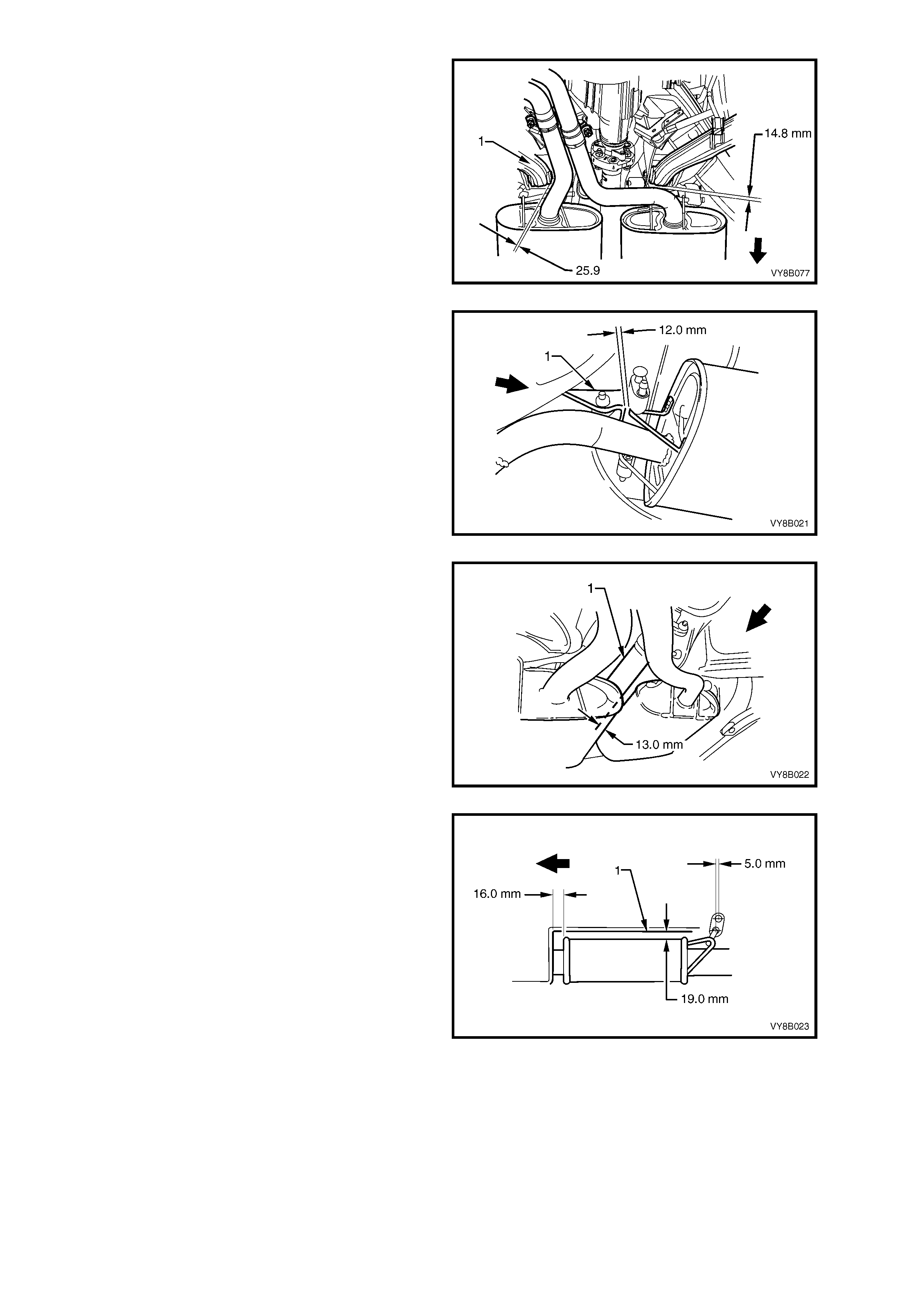
1. Check the rear tail pipe to body panel
clearances and rear muffler to tail pipe hanger
mount clearances.
Figure 8B-77
2. Check the rear exhaust muffler to heat shield
clearances.
Figure 8B-78
3. Check the clearance between the rear tail pipe
exhaust tip and the underside of the bumper
fascia.
4. Holding a weighted string over the r ear bum per
fascia, in line with the exhaust tip, determine
the horizontal clearance between the exhaust
tip and rear bumper.
NOTE: Refer to View A for Sedan, Wagon and
Coupe. Refer to View B for Utility.
Figure 8B-79
1. For V6 Superchar ged and GEN III V8 Standard
exhausts:
a. Check the rear intermediate exhaust pipe to
stabiliser bar linkage (1) clearances.
Figure 8B-80
2. For GEN III V8 Performance exhaust:
a. Check the rear exhaust pipe to differential
carrier (1) clearances.
Figure 8B-81
b. Check the rear exhaust pipe to inner axle
shaft (1) clearances.
Figure 8B-82
c. Check the intermediate exhaust pipe to
suspension member (1) clearances.
Figure 8B-83
d. Check the intermediate exhaust pipe to
rubber coupling (1) clearances.
Figure 8B-84
e. Check the intermediate exhaust pipe to
suspension cross member elbow (1)
clearances.
Figure 8B-85
3. Check the intermediate exhaust hanger to
underbody mounting (1) clearances.
Figure 8B-86
4. Check the intermediate exhaust muffler to
propeller shaft (1) clearances.
Figure 8B-87
5. Check the intermediate exhaust muffler to
intermediate heat shield (1) clearances.
NOTE: The clearance between the intermediate
exhaust muffler and the horizontal section of the
heat shield is nominal.
Figure 8B-88
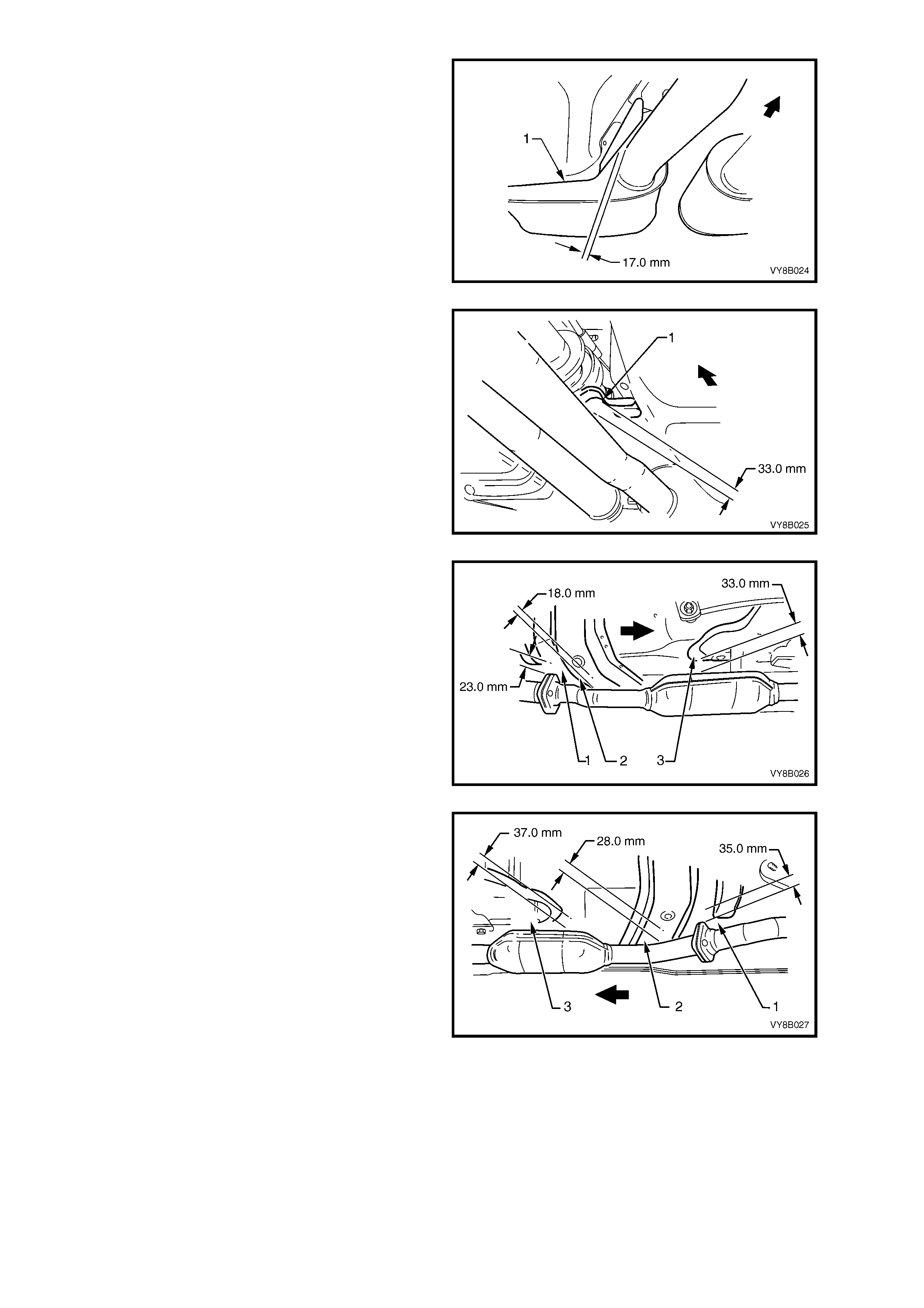
6. Check the intermediate exhaust pipe to
intermediate heat shield clearances.
Figure 8B-89
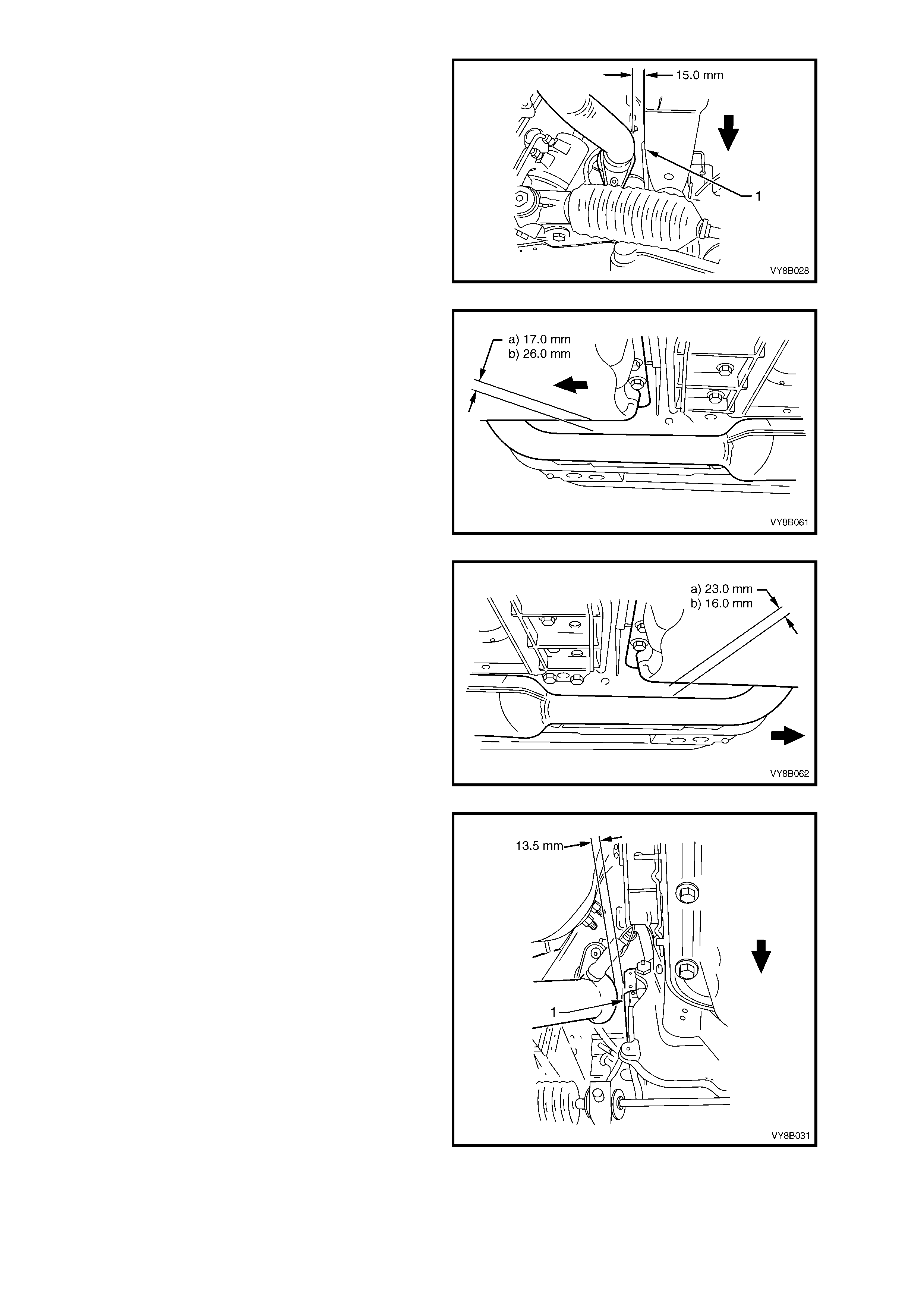
7. Check the intermediate exhaust pipe to centre
bearing carrier (1) clearances.
Figure 8B-90
8. Check the left-hand side intermediate exhaust
pipe flange to underbody panel (1) clearances.
9. Check the left-hand side front exhaust pipe to
transmission tunnel roof support (2) clearance.
10. Check the left-hand side catalyst to
transmission cr oss mem ber suppor t br acket (3)
clearance.
Figure 8B-91
11. Check the right-hand side interm ediate exhaust
pipe flange to underbody panel (1) clearances.
12. Check the right-hand side f ront exhaust pipe to
transmission tunnel roof support (2) clearance.
13. Check the right-hand side catalyst to
transmission cr oss mem ber suppor t br acket (3)
clearance.
Figure 8B-92
14. Check the front exhaust pipe to sub frame
clearances.
Figure 8B-93
15. Check the right-hand side f ront exhaust pipe to
automatic transmission oil pan clearances.
For V6 Supercharged vehicles, refer to
dimension a); for V8 Gen III vehicles, refer to
dimension b).
Figure 8B-94
16. Check the LHS front exhaust pipe to autom atic
transmission oil pan clearances. For V6
Supercharged vehicles, refer to dimension a),
for V8 Gen III vehicles, refer to dimension b).
Figure 8B-95
17. Check the front exhaust pipe to engine block
(1) clearances.
Figure 8B-96

7. EXHAUST SYSTEM DIAGNOSIS
CONDITION PROBABLE CAUSE CORRECTION
Leaks at pipe joints. Tighten U-bolt nuts and joint bolts
to the specified torques.
Damaged or improperly installed
converter sealing ring/gaskets. Replace sealing ring/gasket as
necessary.
Leaking exhaust gases
Burned or rusted out exhaust pipe
or muffler/s. Replace component as necessary.
Leaks at manifold or pipe
connections.
Tighten clamps at leaking
connections to specified torques.
Replace gasket as required.
Burned or blown out pipe or
muffler/s. Replace pipe/muffler assembly as
necessary.
Exhaust manifold/s cracked or
broken. Replace manifold.
Exhaust noises
Leak between manifold/s and
cylinder head/s. Tighten manifold to cylinder head
studs to specified torque.
Clogged catalytic converter (may
result from serious engine
malfunction). Replace catalytic converter.
Loss of engine power, hesitation,
surging, poor fuel economy,
stalling or hard starting Crushed pipe work. Replace pipe work.
Dislodged tubes and/or baffles in
muffler. Replace muffler.
Internal rattling in muffler Catalytic converter monolith has
crumbled and pieces blown into
muffler.
Replace catalytic converter
assembly and affected muffler.
Damaged, worn, missing or
improperly installed support
rubbers. Check and replace as necessary.
Damaged mounting hangers or
pegs. Service / replace hangers or pegs
as necessary.
Check clearances and adjust joint
alignment as necessary.
Improper alignment. Tighten all fasteners according to
tightening sequence and the
specified torques.
Rattling or knocking exhaust
system
Damaged or incorrect exhaust
system components. Replace damaged or incorrect
components as necessary.

8. SPECIFICATIONS
TYPE:
V6............................................................................... Single system
V6 Supercharged ....................................................... Dual system to rear of twin intermediate mufflers with a
single pipe rear muffler/tailpipe arrangement.
GEN III V8: Standard................................................ Dual system to rear of twin intermediate mufflers with a
single pipe rear muffler/tailpipe arrangement.
Performance.......................................... Dual system back to a single rear muffler with dual tail
pipes.
MATERIAL:
Engine Pipes .............................................................. 409 stainless steel
Intermediate Muffler ................................................... 409 stainless steel
Rear Muffler................................................................ 409 stainless steel
CATALYTIC CONVERTER:
Make........................................................................... AC Australia
Type............................................................................ Three way monolith
Outer Steel Shell
Material.................................................................. 409 stainless steel
Inlet Diameter
V6...................................................................... 50.8 mm x 2
V6 Supercharged .............................................. 50.8 mm
Gen III V8 A/T ................................................... 50.8 mm
Gen III V8 M/T................................................... 60.5 mm
Outlet Diameter
V6...................................................................... 60.5 mm
V6 Supercharged .............................................. 50.8 mm
Gen III V8 M/T................................................... 50.8 mm
Gen III V8 A/T ................................................... 60.5 mm
Monolith
Material.................................................................. Extruded Cordierite
Volume
V6 Engine......................................................... 1.8 litres
V6 Supercharged A/T and V8 GEN III A/T....... 1.4 litres each
V8 GEN III M/T................................................. 1.8 litres each
Cells/cm2............................................................... 62

9. TORQUE WRENCH SPECIFICATIONS
Intermediate exhaust to catalytic converter flange
attaching bolt...........................................................................................40 – 50 Nm
U-bolt clamp assembly securing nuts .....................................................20 – 30 Nm
Exhaust manifold to front pipe flange attaching nut................................18 – 35Nm
Intermediate pipe to rear pipe flange joint assembly
flange bolts..............................................................................................40 – 50 Nm
Front pipe to intermediate pipe flange attaching bolt ..............................40 – 50 Nm
Ring clamp assembly fastening bolt........................................................37 – 50 Nm
Catalyst to transmission extension housing
bracket assembly bolts............................................................................40 – 50 Nm
Rear muffler heat shield attaching screw................................................5.0 – 8.0 Nm
Intermediate muffler heat shield attaching screw....................................5.0 – 8.0 Nm
Intermediate muffler heat shield stud attaching nut................................5.0 – 8.0 Nm