
SECTION 9 - STEERING
IMPORTANT
Before performing any Service Operation or other procedure described in this Section, refer to Section 00,
CAUTIONS AND NOTES for correct workshop practices with regard to safety and/or property damage.
CONTENTS
1. GENERAL INFORMATION
1.1 GENERAL DESCRIPTION - POWER
STEERING RACK AND PINION
PRINCIPLES OF OPERATION
POWER STEERING FLUID FLOW
1.2 GENERAL DESCRIPTION - POWER
STEERING PUMP
PUMP CONSTRUCTION
CONSTANT FLOW CONTROL VALVE
OPERATION
DROOP FLOW CONTROL VALVE
OPERATION
1.3 GENERAL DESCRIPTION - STEERING
COLUMN
2. STEERING COLUMN ASSEMBLY
SERVICE OPERATIONS
2.1 STEERING COLUMN ASSEMBLY
SERVICE NOTES AND PRECAUTIONS
CAUTIONARY NOTES
2.2 OCCUPANT PROTECTION SYSTEM
DISABLING AND ENABLING
PROCEDURE
2.3 HORN BAR AND DRIVER’S AIRBAG
2.4 STEERING WHEEL ASSEMBLY
REMOVE
REINSTALL
2.5 IGNITION BARREL LOCK CYLINDER
REMOVE
REINSTAL
2.6 IGNITION SWITCH
REMOVE
TESTING SWITCH
REINSTALL
2.7 STEERING LOCK
2.8 STEERING COLUMN UPPER BEARING
2.9 STEERING COLUMN ASSEMBLY
REMOVE
REINSTALL
CENTRING THE CLOCK SPRING COIL
2.10 CHECKING STEERING COLUMN FOR
ACCIDENT DAMAGE
2.11 TILT/REACH HANDLE
REPLACE
2.12 STEERING COLUMN LOWER BEARING
ASSEMBLY
2.13 STEERING COUPLING
3. POWER STEERING SERVICE
OPERATIONS
3.1 POWER STEERING FLUID LEVEL
CHECK
V6 ENGINE
GEN III V8 ENGINE
3.2 DRIVE BELT ADJUSTMENT
V6 ENGINE
GEN III V8 ENGINE
3.3 HYDRAULIC SYSTEM, BLEEDING/
REFILLING PROCEDURE
CAUTIONARY NOTES
BLEEDING/REFILLING PROCEDURE
3.4 HYDRAULIC SYSTEM, CHECK
PROCEDURE
3.5 TIE ROD SOCKET
REPLACE
3.6 RIGHT-HAND DRIVE POWER STEERING
GEAR
REMOVE
REINSTALL
DISASSEMBLE
CLEAN AND INSPECT
REASSEMBLE
3.7 LEFT-HAND DRIVE POWER STEERING
GEAR
REMOVE
REINSTALL
DISASSEMBLE
CLEAN AND INSPECT
REASSEMBLE
3.8 POWER STEERING FLUID RESERVOIR
- V6 ENGINE
REMOVE
REINSTALL
3.9 POWER STEERING FLUID RESERVOIR -
GEN III V8 ENGINE
REMOVE
REINSTALL
3.10 POWER STEERING PUMP - V6 ENGINE
REMOVE
REINSTALL
DISASSEMBLE
CLEAN AND INSPECT
REASSEMBLE
3.11 POWER STEERING PUMP- GEN III V8
ENGINE
REMOVE
REINSTALL
INSPECTION AND OVERHAUL PROCEDURES
3.12 POWER STEERING PUMP PULLEY
HUB - V6 ENGINE
REPLACE
3.13 POWER STEERING PUMP PULLEY-
GEN III V8 ENGINE – METHOD 1
REPLACE – USING TOOL AU188 & E9239
3.14 POWER STEERING PUMP PULLEY-
GEN III V8 ENGINE – METHOD 2
REPLACE – USING TOOL 7185 & 7005
Techline
Techline
Techline
Techline
Techline
Techline
Techline
Techline
Techline
Techline

3.15 HAND DRIVE POWER RIGHT STEERING
FLUID COOLER AND HOSE/PIPE
ROUTING – V6 ENGINE
ARRANGEMENT
3.16 LEFT-HAND DRIVE POWER STEERING
FLUID COOLER AND HOSE/PIPE
ROUTING – V6 ENGINE
ARRANGEMENT
3.17 RIGHT-HAND DRIVE POWER STEERING
FLUID COOLER AND HOSE/PIPE
ROUTING – GEN III V8 ENGINE
ARRANGEMENT
3.18 LEFT-HAND DRIVE POWER STEERING
FLUID COOLER AND HOSE/PIPE
ROUTING – GEN III V8 ENGINE
ARRANGEMENT
4. DIAGNOSIS
4.1 GENERAL DIAGNOSTIC INFORMATION
4.2 POWER STEERING PUMP
DIAGNOSTIC ITEMS
LEAK DIAGNOSIS
5. SPECIFICATIONS
STEERING GEAR
POWER STEERING PUMP
FRONT WHEEL TOE
LUBRICANTS
SEALANTS
6. TORQUE WRENCH SPECIFICATIONS
STEERING COLUMN ASSEMBLY
POWER STEERING GEAR
V6 POWER STEERING PUMP
GEN III V8 POWER STEERING PUMP
7. SPECIAL TOOLS

1. GENERAL I NFORMATI O N
A power as s isted s teer ing s ystem is f itted as s tandard equipment to all MY 2003 VY and V2 Series Models.
The steering system incorporates;
• A rack and pinion type power steering gear.
• A constant flow vane type power steering pump with remote power steering fluid reservoir for all sedan,
wagon and utility Models.
• A droop flow vane type power steering pump with remote power steering fluid reservoir for all coupe
Models.
• A power steering fluid cooler.
• A four-spoke steering wheel
• An energy absorbing collapsible type steering column incorporating a Tilt/Reach feature, that is
designed to progressively compress under impact from either direction.
The steering Gear used on all right-hand drive vehicles includes a pinion rotary valve housing as a single
piece casting integral with the steering Gear body aluminium casting. The steering Gear used on all left-
hand drive vehicles includes a removable cast iron pinion rotary valve housing that is attached to the
steering Gear body aluminium casting by bolts.
A driver’s airbag is available for all MY 2003 VY and V2 Series Models.
1.1 GENERAL DESCRIPTION - POWER STEERING RACK AND PI NION
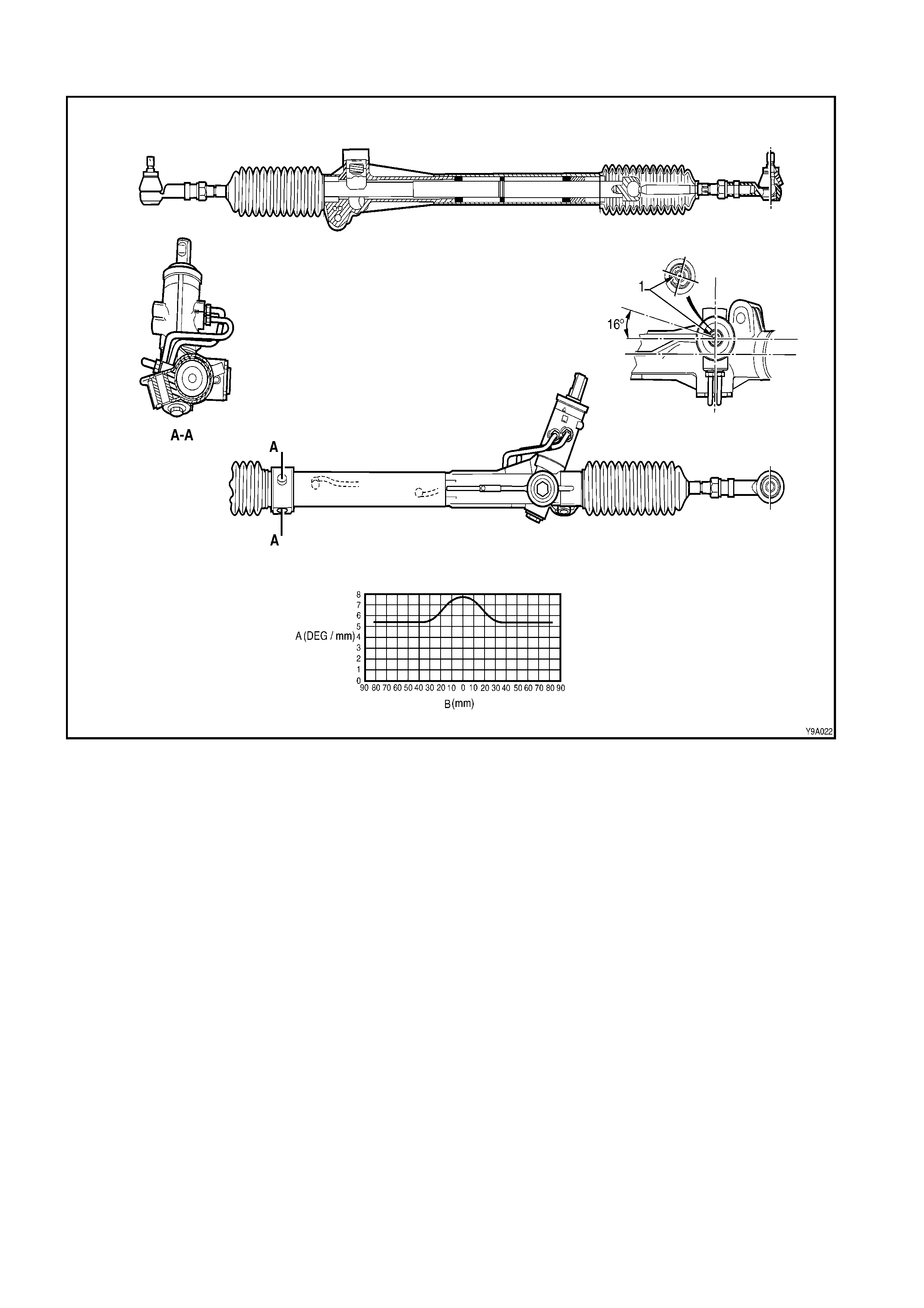
The power steering gear features a variable ratio rack and pinion that is made possible by the unique
design of the r ac k teeth. This means that the effec tive pitc h radius of the pinion is les s in the st raight ahead
position than on turns. This results in less turns being required from lock to lock. For example, 3.5 turns
would be required if the ‘on centre’ ratio was used from lock to lock, whereas only 2.7 turns are required
with this Gear design.
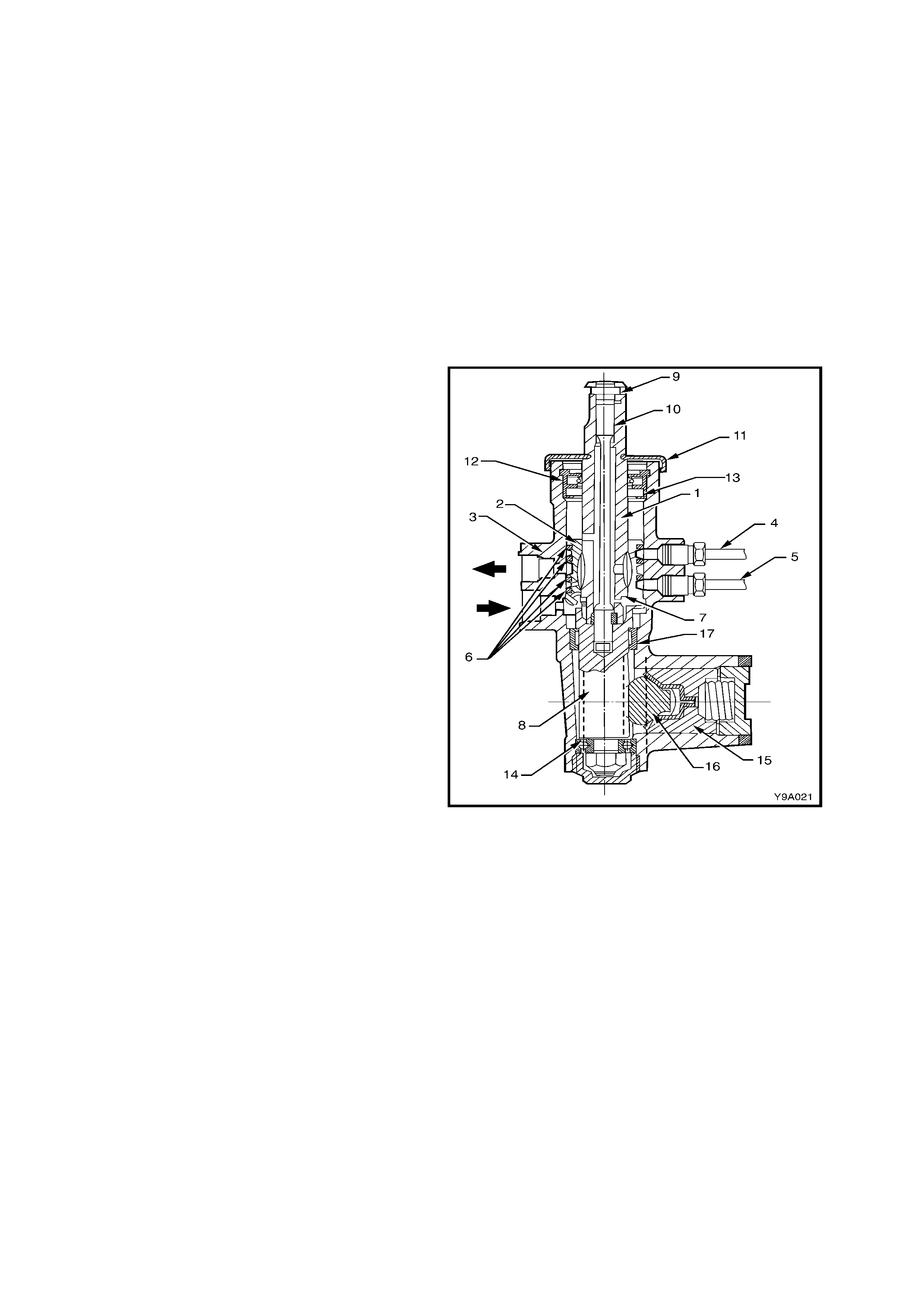
Referring to Figure 9-1, the helical toothed pinion (8) is supported in the steering gear housing (2) by a
needle roller bearing (13) at the upper end, a ball race ( 14) at the lower end and a roller bear ing (17) at the
upper end of the pinion teeth.
The rack (16) operates within the housing and is supported at one end by a rack bearing and at the other
end by the pinion ( 8) and a s pring loaded pad (15), which m aintains slack free adjus tment of the r ack (16)
with the pinion (8).
The tie rods are connec ted to each end of the rack by pre-as sembled soc kets and to the steer ing arms by
sealed for life type tie rod end sockets.
PRINCIPLES OF OPERATION
With the engine running and the steering wheel in
the neutral position (s traight ahead) , power steering
fluid flows continuously from the power steering
pump to the steering gear and back to the pump,
via the power steering fluid reservoir. In this
steering mode, very little pressure is required to
maintain the high power s teering fluid flow rate that
occurs at this time. As a result, little engine power
is required to operate the system.
When turning the steering wheel to either side,
power steering fluid flow from the pump is directed
by a rotary control valve fitted to the steering gear,
to whichever side of the rack piston is appropriate,
as indicated by the steering wheel position. The
power steering fluid pressure then increases as
necessary, to provide the required steering
assistance.
This rotary control valve assembly, is located
between the input shaft (1) and the pinion (8), in the
steering gear.
As shown, the rotary valve assem bly consists of an
inner member (1) which forms part of the input
shaft and a surrounding sleeve member (2). The
whole valve, rotates in the steering gear housing
(3) as the steering wheel is turned, but it is the
slight relative movement of the inner and the sleeve
members that controls and directs the power
steering fluid flow.
Power steering fluid is fed to the valve (➨) and from
there, to the left ( 4) and right (5) sides of the power
piston via circumferential grooves in the outer
sleeve, that are sealed by PTFE seals (6). Excess
power steering fluid is returned to the reservoir.
The outer s leeve is coupled by a s tepped pin (7) to
the rack pinion (8), while the input shaft (1) is
coupled to the rack pinion by a pinned (9), flexible,
torsion bar (10) that provides a mechanical but
flexible link between the two members.
In the straight ahead position, the valve remains
centred. As steering effort requirements increase,
the torsion bar flexes, causing slight relative
rotation between the input shaft and sleeve,
directing power steering fluid and providing power
assistance as needed.
Figure 9-1
POWER STEERING GEAR
Figure 9-2
Legend
A. Rack Grain B. Rack Travel 1. Clamp Bolt Flat
POWER STEERING FLUID FLOW
NEUTRAL POSITION (STRAIGHT AHEAD)
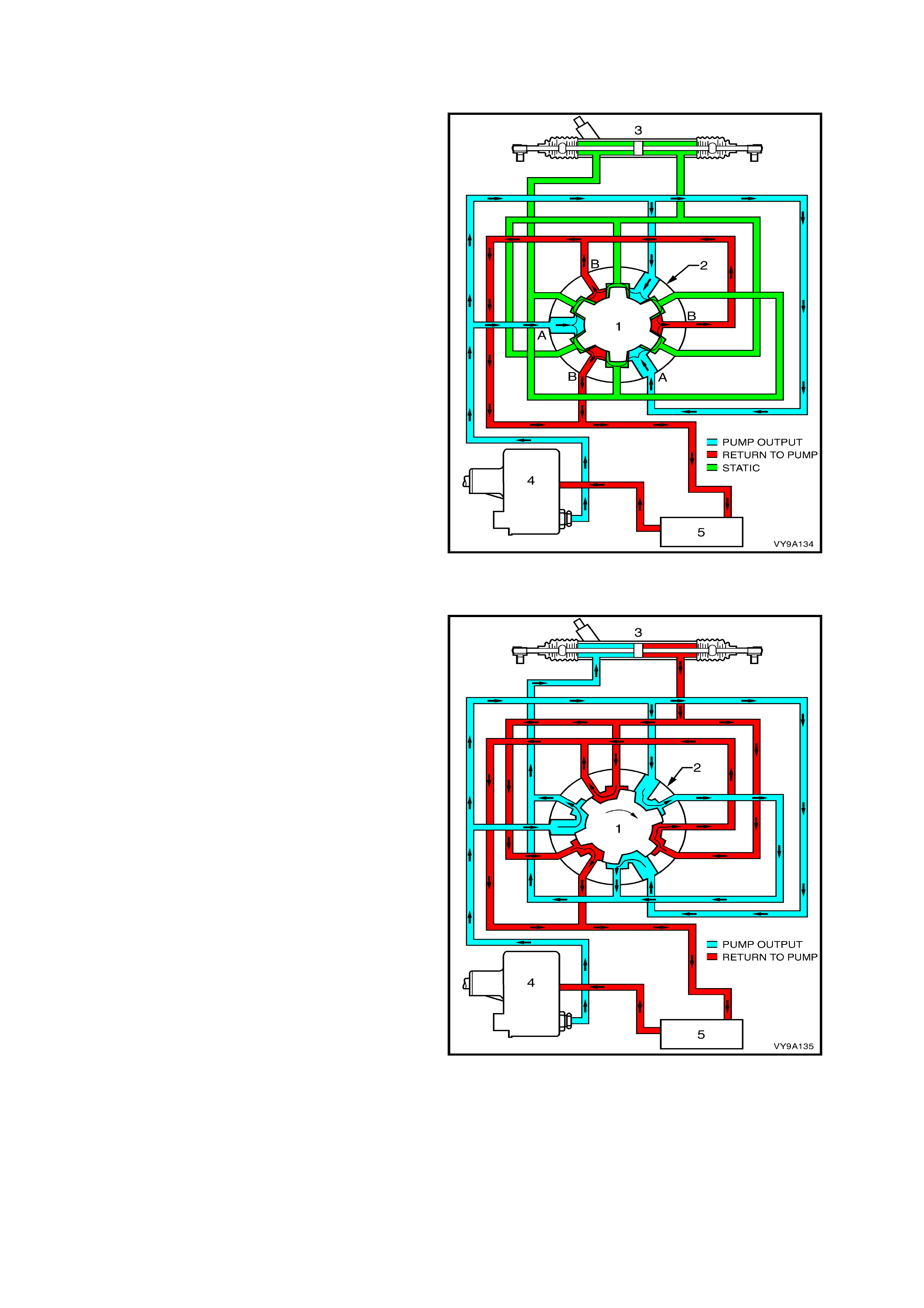
From the s tylised cross - s ect ioned view of the r otary
valve shown in Figure 9-3, it can be seen that in
this attitude, power steering fluid flow from the
pump (4) is directed into the cavities (Shown as
‘A’). of the inner valve assembly (1) and out through
a number of drilled holes in the outer sleeve (2)
(Shown as ‘B’). In this steering position, the inner
valve (1) allows power steer ing fluid to pass equally
to both sides of the rack (3) piston (shown as
'Static' because no power steering fluid actually
flows to and fr om the st eering gear). T he bypass ed
power steering fluid returns to the power steering
fluid reservoir (5) through holes drilled in the
longitudinal grooves of the inner valve. With an
equal pressure applied to both sides of the rack
piston, no power assistance is provided.
Figure 9-3
TURNING RIGHT
When turning to the right, as soon as relative
motion between the inner rotating valve (1) and
outer sleeve (2) occurs, power steering fluid is
restricted in its free return to the pump and is
routed to the right-hand side of the rack piston. At
the sam e time, power s teering fluid on the opposite
side of the piston is directed to the return circuit,
leading to the reservoir (5) and pump (4). This
action is slight at first, providing only a small
amount of driver assistance, but becomes
progressively greater with a higher steering load
that causes the torsion bar in the rotary valve
assembly, to tw ist.
Figure 9-4
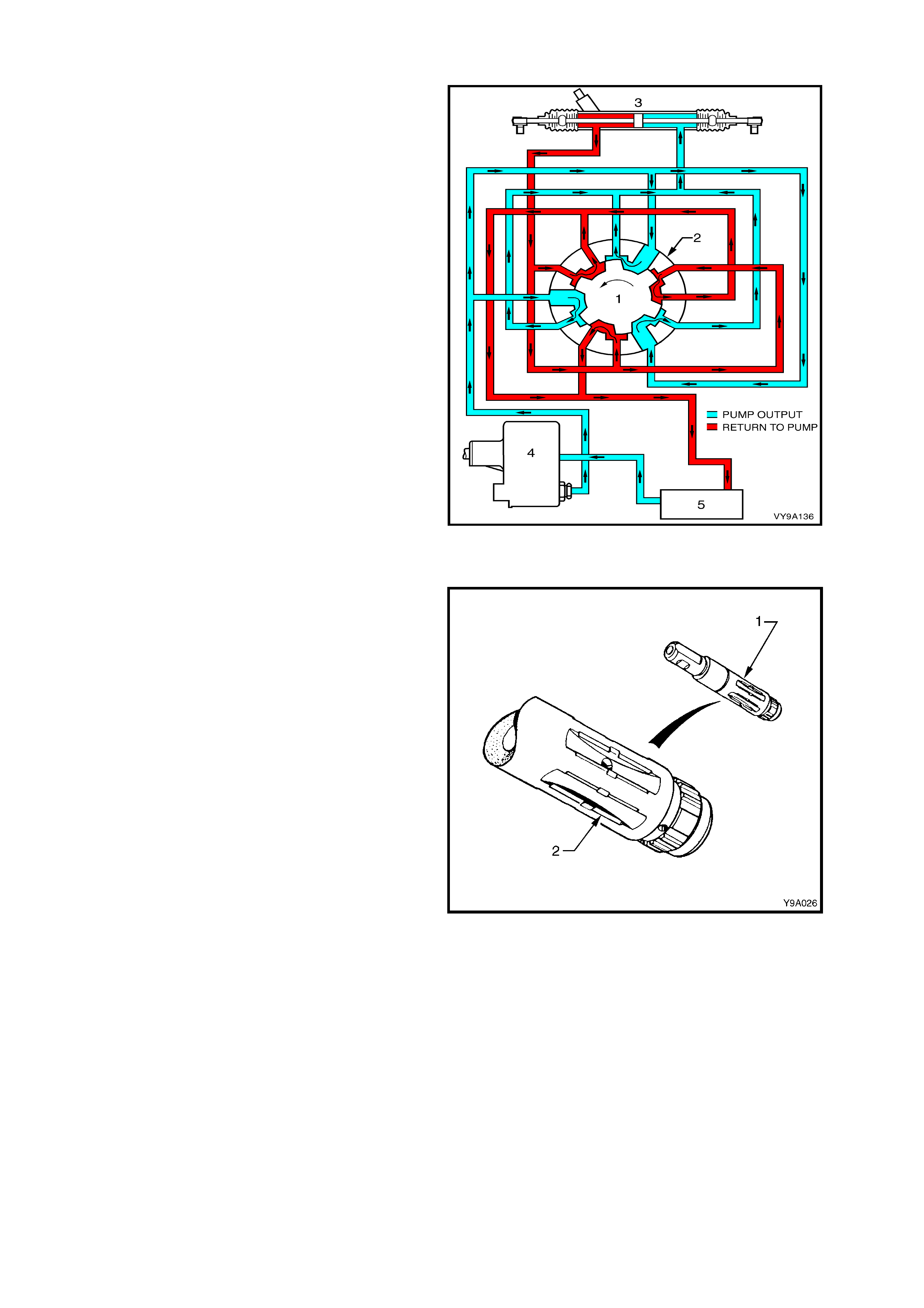
TURNING LEFT
When turning left, the opposite situation occurs.
That is, once the relative m otion between the inner
valve (1) and the outer sleeve (2) causes a return
restriction, power steering fluid is routed to the left-
hand side of the rack piston (3), providing the
required assistance. Also, power steering fluid on
the opposite side of the piston is free to flow back
to the reservoir (5) and the pump (4), through the
return circuit. As before, the amount of assistance
provided by the power steering fluid, is determined
by the restriction caused by the interaction of the
inner valve and outer rotary sleeve. This is
controlled by the twisting of the torsion bar
connected between these two valve members.
Figure 9-5
INNER VALVE MEMBER
W hen parking, more than 90% of the work is done
by the power steering fluid. In order to achieve a
balance between this graduated increase of
assistance and maintain a realistic 'feel' with good
response as the r oad speed inc r eases , the gr ooves
(2) of the inner rotating valve (1) are precisely
shaped to meter the flow of POWER STEERING
FLUID.
Note that under extreme load conditions or when
for any reason, the hydraulic system is inoperative,
the torsion bar is able to deflect suf ficiently to allow
the input shaft to drive the steering pinion directly.
This is achieved by having a loose fitting spline
between the lower end of the input shaft and the
surrounding upper end of the pinion. Under these
operating conditions, steering loads will be high and
a noticeable amount of slack will develop because
of the torsion bar flexing. Therefore, while the
steering gear rem ains entir ely operable, the vehicle
should only be operated in this manner for the
minimum distance needed to reach a point where
the system can be serviced.
Figure 9-6

1.2 GENERAL DESCRIPTION - POWER STEERING PUMP
Hydr aulic pres sure f or the power steer ing system is
provided by a SAGINAW 'N' Series, vane type
pump.
For vehicles fitted with a V6 engine, the power
steering pump (1) is mounted on a retaining
bracket, attached to the right-hand side of the
cylinder block. The remote power steering fluid
reservoir is mounted on a bracket attached to the
radiator.
Figure 9-7
For vehicles fitted with a Gen III V8 engine, the
pump (1) is attached by two bolts (2) to the left-
hand side cylinder head. The remote power
steering fluid reservoir is mounted on a bracket
attached to the engine directly above the power
steering pump.
Figure 9-8
PUMP CONSTRUCTION
In the rear of the pump housing (1), a cavity
contains the following parts: pump ring (2), pump
rotor (3) and vanes (4), splined to the drive shaft (5)
and thrust (6) and pressure plates (7).
A sm aller cavity, below the larger one, contains the
flow control assembly (8), consisting of a control
valve assembly and pump outlet fitting (9) with
control needle and spring.
Figure 9-9
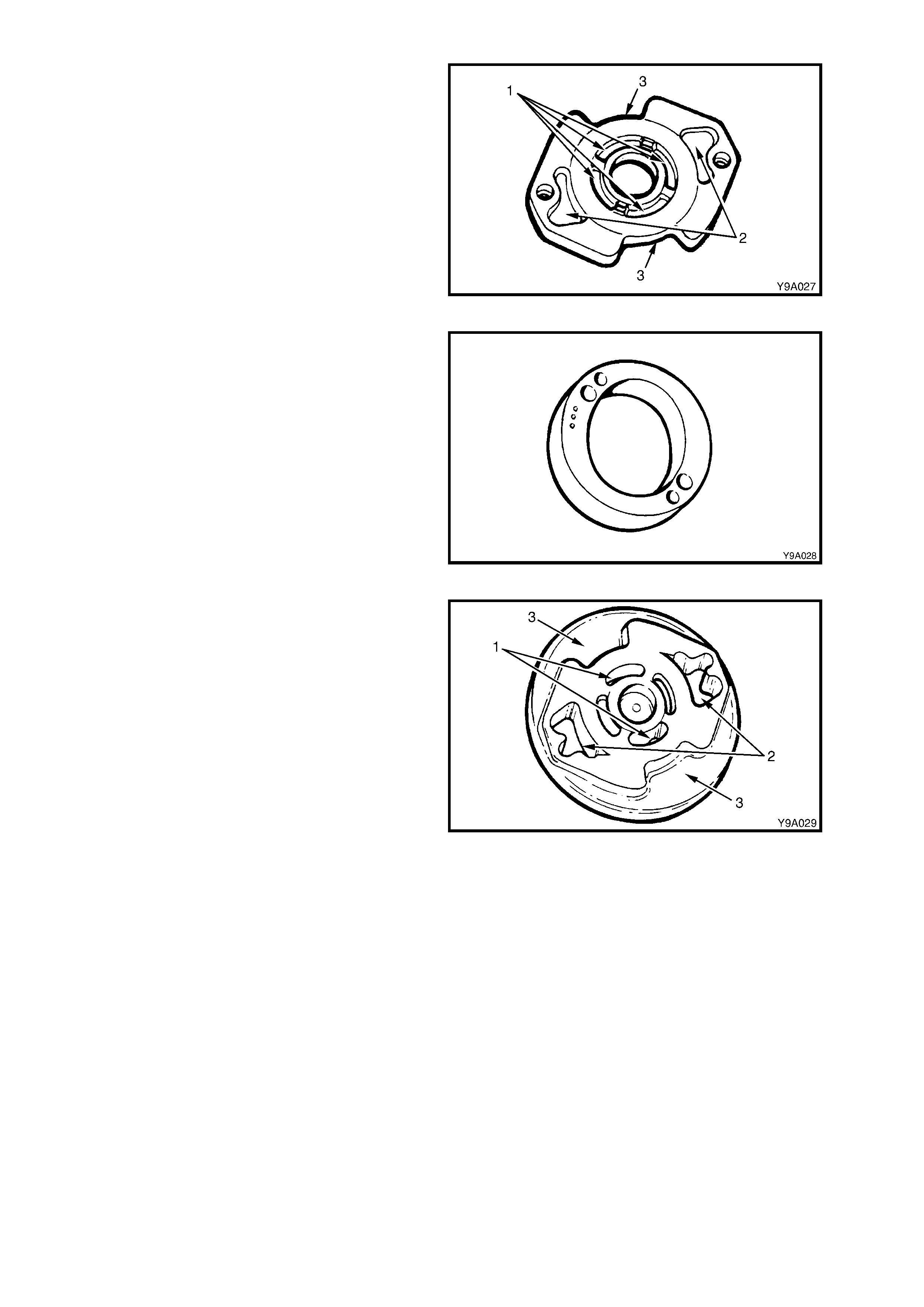
THRUST PLATE
The thrust plate is located on the inner face of the
housing by two dowel pins. This plate has six
cavities; the four central cavities (1) supply under-
vane power steering fluid pressure, and the two
outer cavities ( 2) direct dischar ge pressure through
the cross-over holes in the pump ring, through to
the pres sur e plate and then on to the s teering gear .
The outside slots (3) are for power steering fluid
intake from the suction part of the pump to the
rotor.
Figure 9-10
PUMP RING
The end f aces of the pum p ring are ground flat and
parallel. The centre hole is a two lobed cam in
which the rotor and vanes operate, providing two
cycles per revolution. The r ing is placed next to the
thrust plate and located with the same two dowel
pins used to locate the thrust plate on the inner
face of the housing.
Figure 9-11
PRESSURE PLATE
The pressure plate is fitted against the pump ring
and located with the same two dowel pins used to
locate the thrust plate and pump ring. This plate
has two central ports (1) for under-vane power
steering fluid pressure. The two outer ports (2)
pass power steer ing fluid under discharge pressur e
through the control valve, to the steering gear.
The two outer slots (3) in the press ure plate are for
intake of the power steering fluid from the suction
side of the pump.
Figure 9-12
DRIVE SHAFT AND ROTOR
The drive s haf t is f itted with a belt driven pulley from the engine c rankshaf t. T he pum p rotor is splined to the
drive shaft and is located within the pump ring between the thrust and pressure plates. Ten vanes are
mounted in radial slots around the rotor. The shaft is supported by a bush, pressed into the front of the
pump housing.
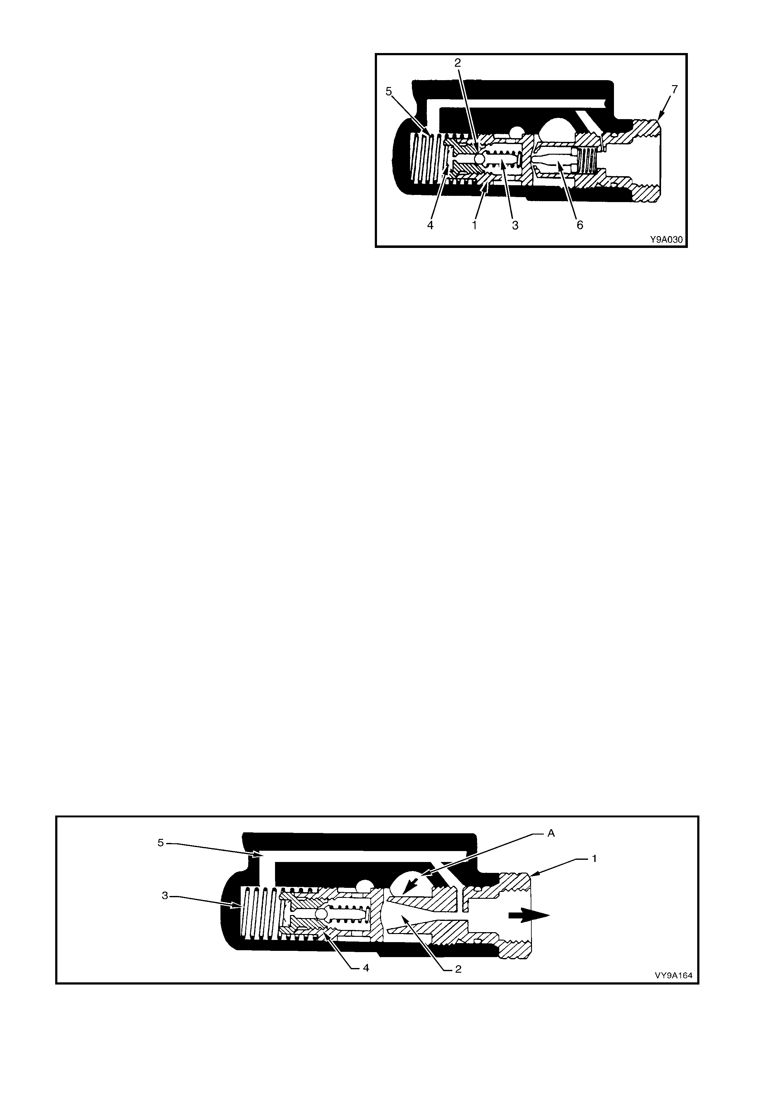
DROOP FLOW CONTROL VALVE ASSEMBLY
The purpose of the control valve assembly fitted to
droop f low des ign pumps, is to var y power steering
system pressure and power steering fluid flow to
the steering gear as required, under various
operating conditions.
The control valve assembly consists of the control
valve plunger (1), an internal pressure relief ball
check (2), ball check guide and ball check guide
spring ( 3). A sc reen (4) in the end of the plunger , is
designed to keep dirt and foreign material out of the
ball check area.
Movement of the control valve assembly under
power steering fluid pressure and spring (5) force,
acts upon a power steer ing fluid control needle and
spring (6), in the pump outlet fitting (7) . T he needle
is tapered and movement within the outlet fitting
orifice hole, changes the am ount of power steering
fluid flow to the steering gear.
Figure 9-13
FILLING THE PUMP
When the pump and power steering gear are completely empty of power steering fluid, adding power
steering fluid to the reservoir will fill the pump housing assembly.
Suction and gravity draw power steering fluid into the intak e section of the pump, caus ing it to flow through
a drilled passage in the housing, leading to the large cavity around the rotor ring. The power steering fluid
fills this area and also the two intake openings on the pressure and thrus t plates, filling the space between
the ring and rotor as sembly. Any air that m ight enter the system is automatically rem oved by the circulating
power steering f luid, from the pum p, thr ough the power steering f luid circuit to the s teering gear and then to
the reservoir, where it vents to atmosphere, via the reservoir cap.
CONSTANT FLOW CONTROL VALVE OPERATION
SLOW CORNERING (FIGURE 9-14)
Pump s peeds during s low cornering or park ing are norm ally low, as are demands for fluid flow volume, due
to slower steering manoeuvres.
With reasonably high relative movement of the inner valve and outer sleeve in the steering Gear control
valve at this tim e, the fluid is pressuris ed to approxim ately 3,400 k Pa to 4,800 kPa and direc ted to the high
pressure cavity behind the pressure plate. Discharge ports direct this fluid to the outlet fitting (1) and then
on to the steering gear.
The discharge fluid pressure from the outlet fitting, is slightly lower in pressure than the internal high
pressure (A), coming from the pump ring.
This drop in pressure, due to venturi action, occurs as the fluid flows through the orifice (2) in the outlet
fitting.
This lower pressure is transmitted to the spring (3) end of the control valve (4) by a fluid passage (5)
connecting the control valve to the outlet fitting.
This results in a pressure unbalance at each end of the control valve, causing it to move away from the
outlet fitting. Owing to the force of the control valve spring, the valve remains closed to the fluid by-pass
hole.
Because sufficient fluid is allowed to circulate through the system, fluid pressure does not build up high
enough to cause the pressure relief ball check in the valve.
Figure 9-14
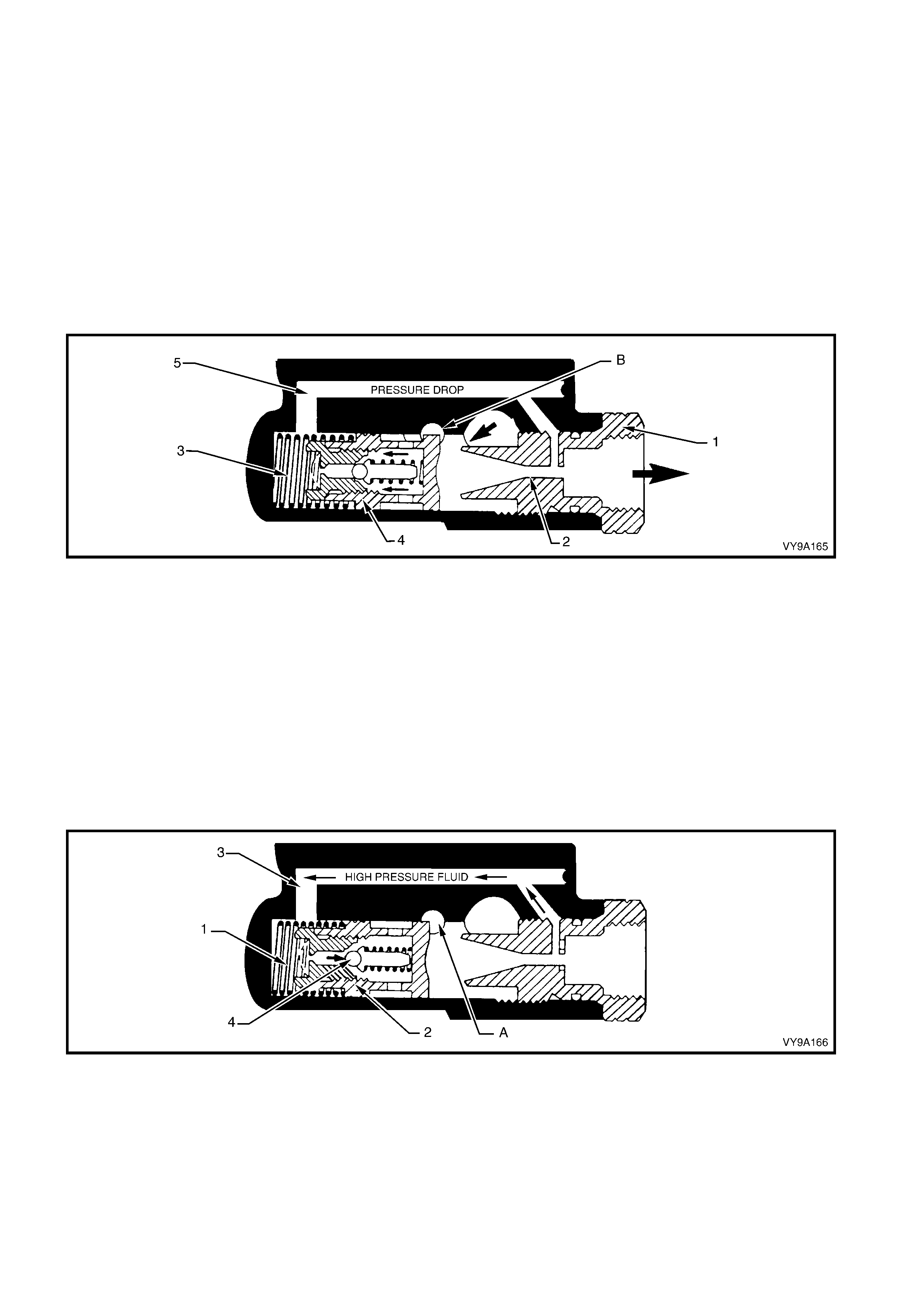
MODERATE TO HIGH SPEED OPERATION (FIGURE 9-15)
System pressure in this mode is normally low (approximately 260 kPa) due to the lack of steering
manoeuvres and high fluid flow rates. When the steering is in the straight ahead position, fluid is discharged
from the high pressure cavity (A), through the outlet fitting (1) to the steering gear and back to the pump
reservoir.
When this flow exceeds a preset level, fluid is by-passed within the pump, as follows:
Fluid passing through the outlet fitting, causes a pressure reduction to occur in the orifice (2) by venturi
action.
This reduced pressure is transmitted to the spring (3) end of the control valve (4), via the fluid by-pass
passage (5) connecting the control valve and the outlet fitting, as shown.
This pressure dif ference on each side of the control valve, causes the valve to move against spring force,
opening the fluid by-pass passage (A) to the pump inlet. Depending on vehicle road speed, pump speed
and the steering requirements needed by the driver, this valve will modulate, controlling the fluid flow rate
through the steering system.
Figure 9-15
CORNERING AGAINST WHEEL STOPS (FIGURE 9-16)
When the steering wheel is turned to full lock and held in that position, the steering rack power piston
chamber becomes fully pressurised and fluid flow stops.
NOTE: Th is full lock condition should not be m aintained f or long periods of time ( in excess of five minutes)
due to excessive fluid temperature rise.
The resulting high pressure is then transmitted to the spring (1) end of the control valve (2) through the
connecting fluid passage (3) from the outlet fitting.
When the pressur e builds up high enough, the relief ball chec k ( 4) within the control valve opens , allowing a
small amount of fluid to pass through the pressure relief orifice, causing a pressure drop that results in a
lower pressure acting on the spring end of the control valve. The control valve then moves against spring
forc e and opens up the f luid by-pas s pas sage (A) s o that fluid is returned to the pump inlet. Pre-determ ined
relief pressure is thus maintained while the steering gear is turned and held on full lock.
Figure 9-16

DROOP FLOW CONTROL VALVE OPERATION
The mode of operation of the power steering pump is based upon the demand of the power steering gear.
The various major modes of operation are:
1. Slow cornering.
2. Moderate to high speed straight ahead driving.
3. Cornering against the wheel stop.
The pump is designed to recognise these conditions and compensate for them internally.
As the pump drive s haf t tur ns the rotor , the vane tips f ollow the inner c am sur f ace of the pum p r ing, moving
outward and inward twice during each revolution. This results in a complete pumping cycle every 180° of
rotation. Power steering fluid is moved in the spaces between the vanes. As the vane tips move outward,
power steering fluid enters the inter-vane spaces through four suction ports in the pressure and thrust
plates. As the vane tips move inwards, the pressure of the power steering fluid is raised and the power
steering fluid is discharged from the pump ring. High pressure fluid discharges into a cavity, behind the
pressure plate. A portion of this power steering fluid is circulated through the central port system in the
pressure plate, forcing the vanes to follow the cam surface of the ring.
Power steering fluid is discharged from the high pressure cavity, through the outlet fitting to the steering
gear. As the power steering fluid passes through the outlet fitting, the power steering fluid pressure drops.
This reduced pressure is transmitted to the spring end of the control valve.
SLOW CORNERING (FIGURE 9-17)
Pump speeds during slow cornering or parking are normally low, as are demands for power steering fluid
flow due to slower steering manoeuvres.
The power steering fluid is pressurised to approximately 3,400 kPa to 4,800 kPa and directed to the high
pressur e cavity behind the pres sure plate (arrow ‘A’). Disc harge ports direct this power steer ing f luid to the
outlet fitting (4) and then to the steering gear.
The discharge power steering fluid pressure from the outlet fitting (4), is slightly lower in pressure than the
internal high pressure coming f rom the pump ring. T his drop in pr essure occ urs as the power steer ing fluid
flow passes the needle (3) and orifice in the outlet fitting.
Figure 9-17
This lower pressure is transmitted to the spring (2) end of the control valve (1) by a power steering fluid
passage (5), connecting the control valve to the outlet fitting (4).
This results in a pressure unbalance on the valve itself.
The control valve ( 1) m oves away from the outlet fitting (4), but due to the f orce of the contr ol valve spring
(2), the valve remains closed to the power steering fluid by-pass hole (B). The movement of the control
valve (1), contr ols the needle valve (3) in the outlet fitting (4 ) and this controls the power st eering fluid flow
to the steering gear.
Because power steer ing f luid pres s ure is not high enough to c aus e the pres s ure r elief ball check to actuate,
the external circuit through the steering gear, allows power steering fluid to recirculate through the entire
system.
MODERATE TO HIGH SPEED OPERATION (FIGURE 9-18)
System pressures in this mode are normally low (approximately 260 kPa) due to the lack of steering
manoeuvres.
Power steering f luid is discharged fr om the high press ure cavity through the outlet fitting (4) to the steering
gear. As power steer ing fluid pass es through the f itting, a pres sure drop oc curs acros s the needle valve (3)
and orific e. This reduced pr essur e is trans m itted to the spring ( 2) end of the control valve (1), via the power
steering fluid passage (5).
This pressure differential, causes the control valve (1) to move and open up the power steering fluid by-
pass passage (B) to the pum p inlet. The movem ent of the control valve (1) also controls the movement of
the flow control needle (3) in the outlet fitting (4). The needle closes in the orifice and power steering fluid
flow to the steering gear is reduced.
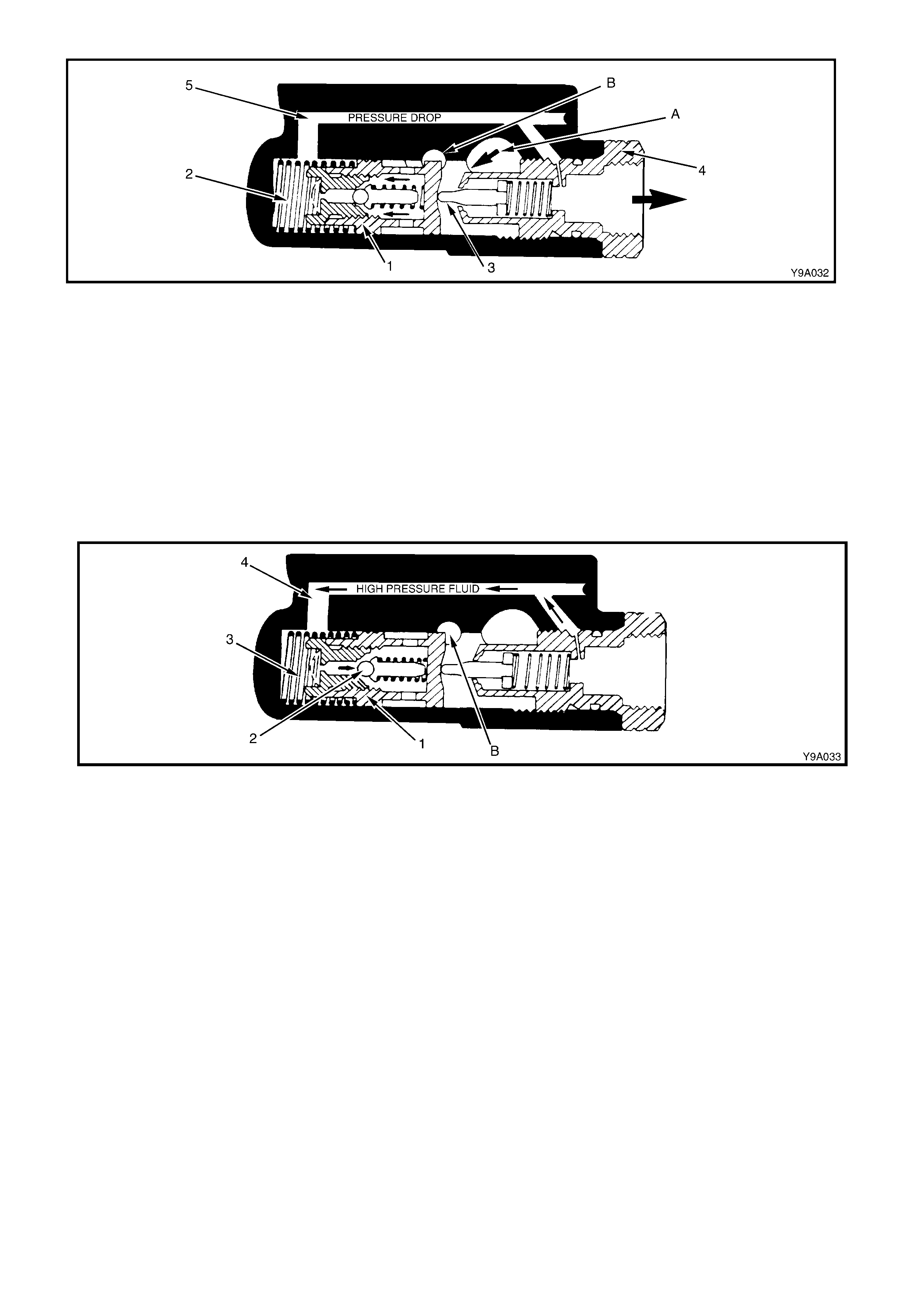
Figure 9-18
CORNERING AGAINST WHEEL STOPS (FIGURE 9-19)
When the steering wheel is turned to full lock and held in that position, the steering Gear power piston chamber
becom es f ully pressuris ed and power steer ing f luid f low stops. The res ulting high pres s ure is then trans mitted to the
spring (5) end of the control valve (1) by connecting power steering fluid passage (8) from the outlet fitting.
When the pressure relief ball check (2) within the control valve opens, a small amount of power steering fluid
passes through the pressure relief orifice, creating a pressure drop, acting on the spring end of the control valve.
The control valve then m oves back against spring for ce (5), opening the power steering f luid by-pass passage (B).
Power steering fluid then returns to the pump inlet. Pre-determined relief pressure is thus maintained while the
steering gear is turned and held on full lock.
NOTE: This condition should not be maintained for long periods of time due to excessive power steering fluid
temperature rise.
Figure 9-19

1.3 GENERAL DESCRIPTION - STEERING COLUMN
The steering colum ns fitted to MY 2003 VY and V2 Series Models include a combination ignition/steering lock, are
of an energy absorbing design and will progressively compress under impact from either direction.
In addition, all steering columns are equipped with a Tilt/Reach feature, as an integral part of their design.
The ignition/steering lock is located to the right of the column assembly. The body of the lock assembly forms an
integral part of the column outer tube and cannot be removed/replaced as a separate component.
The s teering lock is activated when the 'lock ' position is s elected and the lock mechanism is released and engages
into a slot in the steering shaft (when the slot is facing the lock mechanism).
The ignition switch is attached to the left-hand end of the ignition/steering lock housing.
The end of the ignition bar rel ass embly shaf t is stepped and engages with the ignition switch. T he ignition switch is
activated as the lock cylinder is rotated.
Connecting the steering shaft to the steering gear, is an integral steering coupling, which features two universal
joints and a vibration damper.
The following features determine the steering column assembly collapse behaviour in the event of a collision.
A. Upper End of the Steering Column
The upper end of the steering column is fastened to the instrument panel by a bracket with two inserts at the
mounting point, and held in pos ition by two bolts. Under collis ion conditions, should the vehicle operator not be
wearing a seat belt, and sufficient force be exerted by the person against the steering wheel and the deployed
air bag, the bracket is able to move away from the inserts, the amount being controlled by a coiled spring on
each side. This enables the upper end of the steering colum n to move down, within a specified load range, in
this extreme situation.
Collapse load control is achieved primarily by the breaking away of the mounting bracket from the two inserts
and the tension applied by the two control springs.
B. Telescoping Shaft Assembly
The shaft ass embly consists of an upper tube that slides over a lower shaf t, thus allowing the s haft to transm it
torque but still collapse during impact.
C. Steering Wheel Inflatable Restraint (Driver’s Airbag)
This component is designed to supplement the lap/sash seat belt, driver restraint system also fitted to the
vehicle. Under no circumstances is the driver’s airbag expected to replace the need for the driver to
wear a seat belt.
CAUTION: Before any servicing operations are considered, that could in any way impinge on the operation
of the Occupant Protection System (OPS) and/or the personal safety of the individual working on the
vehicle, the cautionary notes detailed under 2.1 STEERING COLUMN ASSEMBLY SERVICE NOTES AND
PRECAUTIONS, must be read and complied with!

Figure 9-20
Legend
1. Steering Column Bracket Assembly
2. Steering Column Upper Trim Cover
3. Steering Column Lower Trim cover
4. Lower Trim Cover To Column Attaching Screw
(1 place)
Steering Column To Upper Mount Attaching Bolt
(2 places)
5. Steering Column To Steering Gear Coupling
7. Steering Gear Assembly
8. Steering Column Coupling Cam Bolt (1 place)
9. Steering Column Coupling Crimp Nut (1 place)
10. Dash Lower Panel
11. Steering Shaft Lower Bearing Support Attaching
Nuts (2 places)

2. STEERING COLUMN ASSEMBLY SERVICE OPERATIONS
2.1 STEERING COLUMN ASSEMBLY SERVICE NOTES AND PRECAUTIONS
CAUTION: Disable the OPS (Air Bag). Refer to Section 12M, 2.2 SYSTEM ENABLING AND DISABLING
PROCEDURE.
CAUTIONARY NOTES:
1. The outer jacket, steering shaft and instrument panel mounting bracket are designed as energy absorbing units.
Because of the des ign of thes e components, it is absolutely vital that the steer ing column ass embly is handled
with care when performing any of the required service operations. Avoid hammering, jarring, dropping or
leaning on any portion of the column.
2. All steering wheel and column fasteners are important parts in that they could affect the performance of other
vital parts and systems.
3. Fasteners must be replaced with those of the same part number or with an equivalent part, if replacement is
required. Do not use a replacement part of lesser quality or substitute design.
4. Torque values must be used where specified during reassembly to assure proper retention of the part.

2.2 OCCUPANT PROTECTION SYSTEM DISABLING AND ENABLING PROCEDURE
IMPORTANT: While sim ply disconnecting the battery earth lead from the batter y terminal is suf f icient to disable the
air bag/s fitted to MY 2003 VY and V2 Series vehicles, this would also m ean losing radio PIN setting (if the battery
were to rem ain disconnec ted for m ore than approx im ately 8 hours) and BCM progr am m ing. The procedure detailed
in 2.2 SYSTEM ENABLING AND DISABLING PROCEDURE in Section 12M, OCCUPANT PROTECTION
SYSTEM, describes an approach that disables the driver’s air bag, rendering it safe to work on steering
com ponents but allowing all pre-sets to rem ain intact. F or detailed inform ation regarding enabling and dis abling the
Occupant Protection System, refer to Section 12M, 2.2 SYSTEM ENABLING AND DISABLING.

2.3 HORN BAR & DRIVER’S AIRBAG ASSEMBLY
LT Section No. – 06-225
All MY 2003 VY and V2 Series Models are fitted with an Occupant Protection System (OPS) that incorporates a
driver’s airbag m ounted into the pad on the front of the steering wheel. The driver’s airbag assem bly also includes
the horn bar . For all the r elevent s ervic e inf ormation r egarding the hor n bar and driver ’s air bag as s embly as fitted to
MY 2003 VY and V2 Series Models, refer to Section 12M, 2.3 HORN BAR AND DRIVER’S AIRBAG ASSEMBLY.
Techline
2.4 STEERING WHEEL ASSEMBLY
LT Section No. – 06-225
REMOVE
CAUTION: Disable the OPS (Air Bag). Refer to Section 12M, 2.2 SYSTEM ENABLING AND DISABLING
PROCEDURE.
1. Remove the steering column upper and lower trim covers, refer to Section 1A3, 3.21 INSTRUMENT PANEL
PAD ASSEMBLY.
2. Rem ove the steering wheel inflatable restraint module, refer to Section 12M, 2.3 HORN BAR AND DRIVER’S
AIRBAG ASSEMBLY.
NOTE: A Special Tool is required to remove the driver’s airbag module.
3. Place the road wheels in the straight-ahead position and lock the steering column.
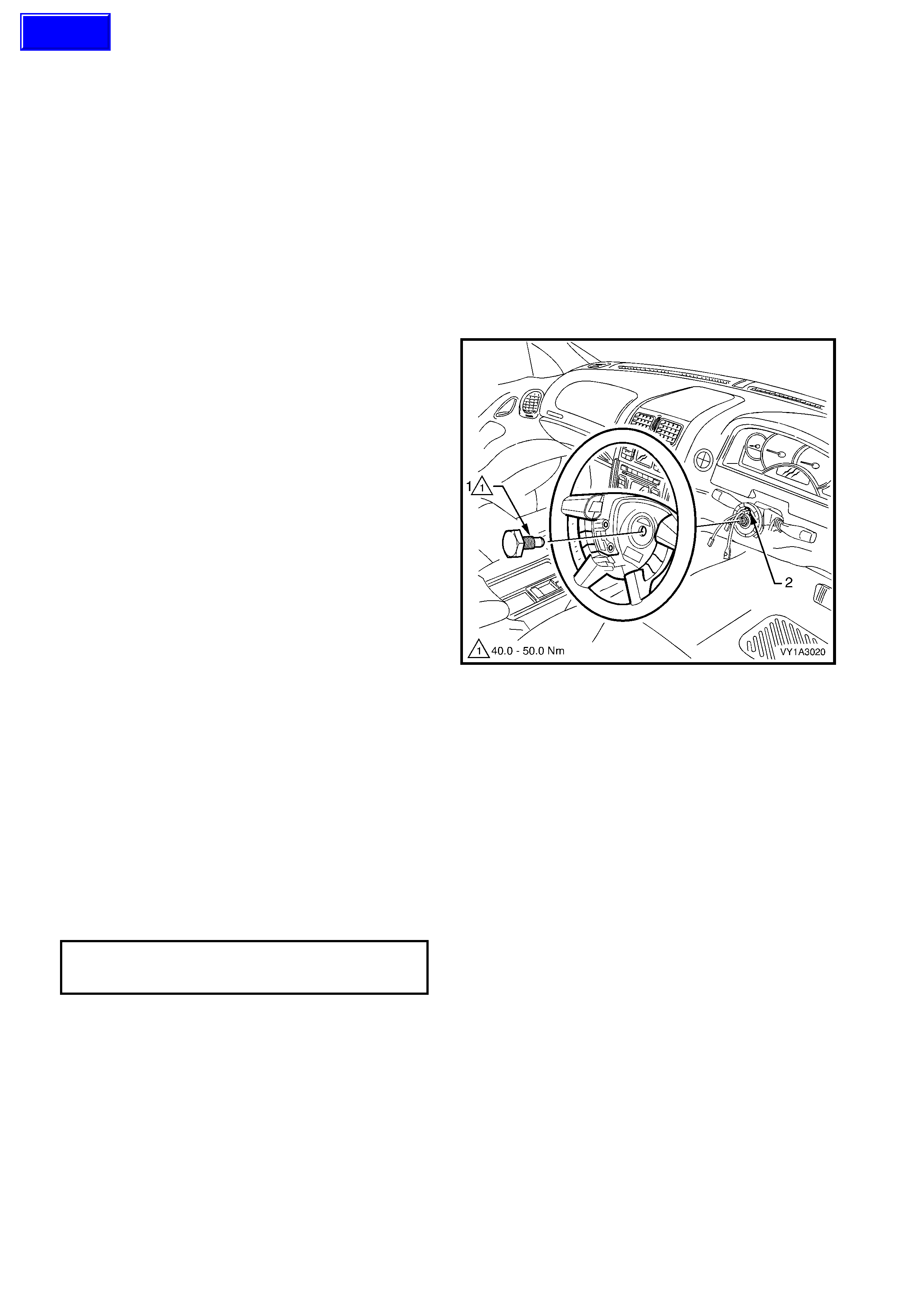
4. Using a suitable socket, remove the screw (1).
5. Remove the steering wheel assembly,
disconnecting and feeding the wires through the
aperture in the wheel assembly as required.
NOTE: A puller should not be required, however, if the
wheel assembly cannot be removed fairly easily, use
puller J1859-A and legs E1408.
6. Check that the green indicator (2) on the coil
assembly - inflatable restraint steering wheel
module has engaged the inner cloc k spr ing to lock
it in the central position.
Figure 9-21
REINSTALL
1. Ensure the road wheels are in the straight-ahead position and the green indictor on the coil assembly - inflatable
restraint steering wheel module is visible.
2. Install the wheel assembly in its correct orientation, feeding the wires through the aperture.
3. Clean the threads of the steering wheel screw and steering shaft and apply Loctite 242 or equivalent to the
screw.
4. Tighten the screw to the specified torque.
5. Connect the wiring connectors as required.
6. Install the driver’s airbag assembly, refer to Section 12M, 2.3 HORN BAR AND DRIVER’S AIRBAG.
7. Install the covers - steering column upper and lower trim, refer to Section 1A3, 3.21 INSTRUMENT PANEL
PAD ASSEMBLY.
STEERING WHEEL
ATTACHING SCREW
TORQUE SPECIFICATION 40 – 50 Nm
8. Enable the OPS (Air Bag). Refer to Section 12M, 2.2 SYSTEM ENA BLING AND DISABLING PROCEDURE.
9. Check horn and turn indicator operation.
Techline
2.5 IGNITION BARREL LOCK CYLINDER
LT Section No. – 06-255
REMOVE
CAUTION: Disable the OPS (Air Bag). Refer to Section 12M, 2.2 SYSTEM ENABLING AND DISABLING
PROCEDURE.
1. Disconnect battery earth lead.
2. Remove the ignition keys from the ignition
switch.
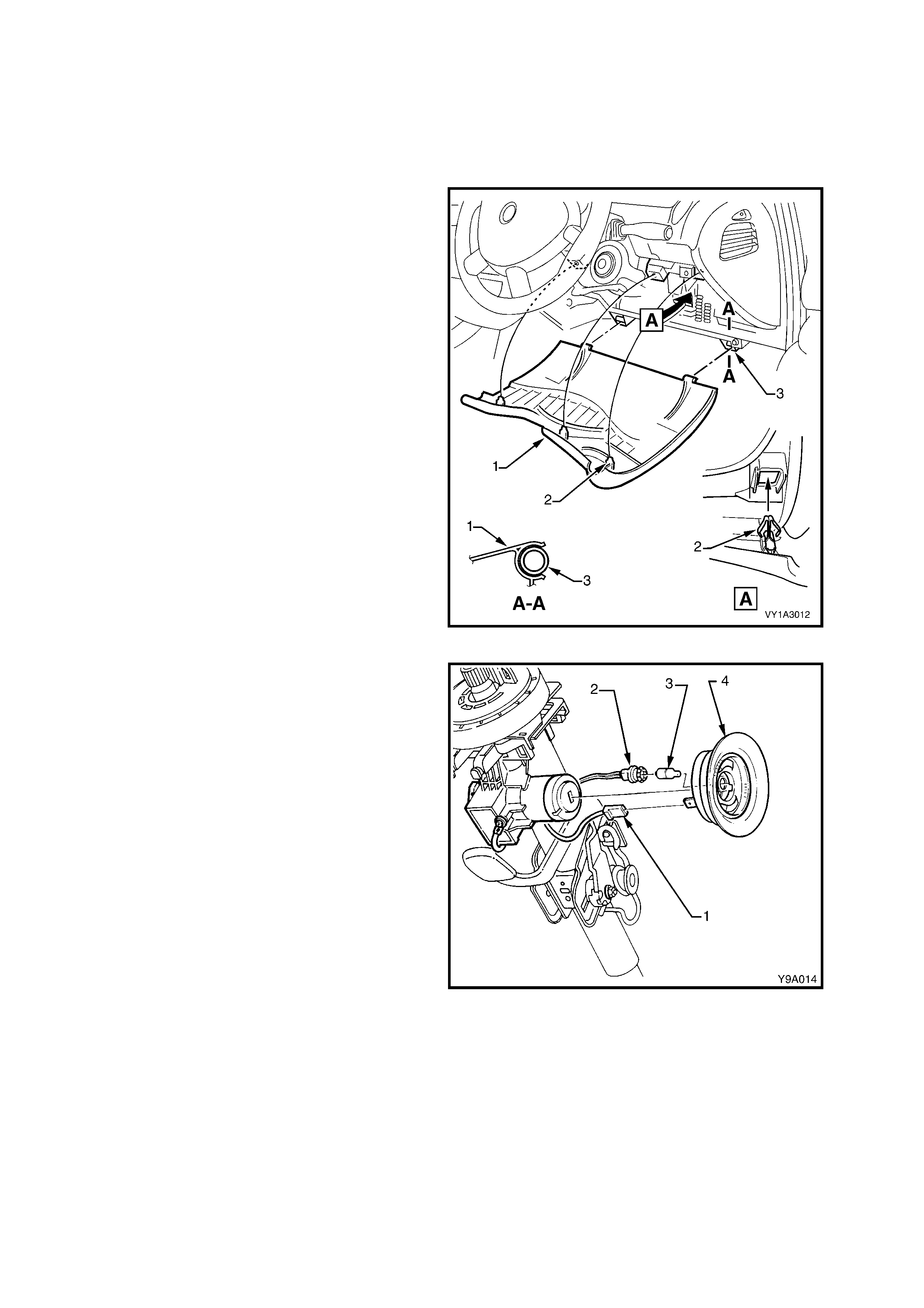
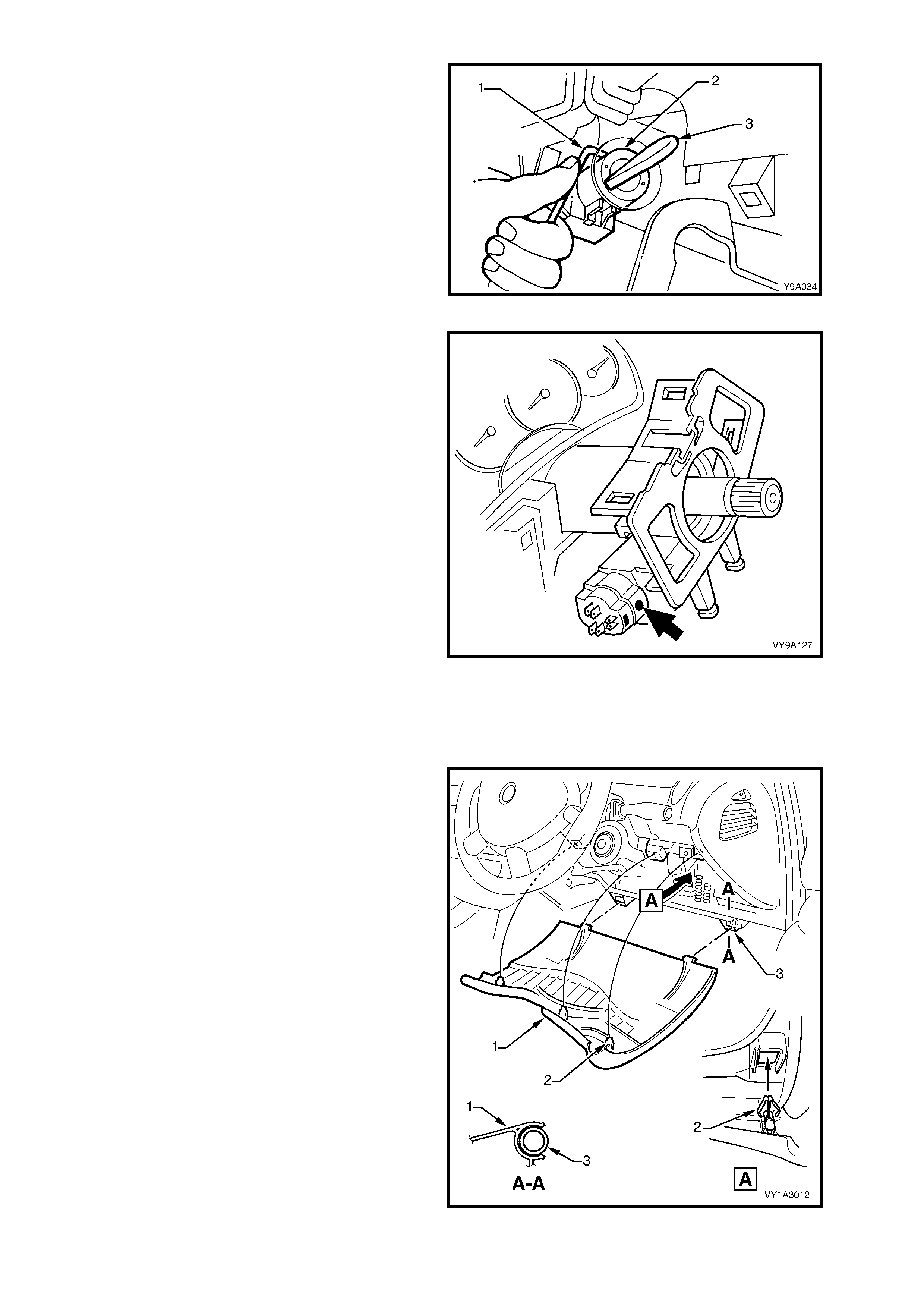
3. Lower the instrument panel lower fuse panel
cover assembly (1) by grasping the top edge on
each side of the steering c olum n with the f inger
tips and pulling the top edge out, to free the
retaining lugs (2) from the clips (3).
4. Release the steering column tilt/reach clamp
lever, lower the column and lock the clamp
lever in this position.
5. Remove the steering column upper and lower
trim covers, refer to Section 1A3, 3.21
INSTRUMENT PANEL PAD ASSEMBLY.
Figure 9-22
6. Disconnect the wiring harness connector (1)
and ignition lock illumination socket (2) and
bulb (3) from the key reader assembly (4).
7. Carefully pull the key reader from the ignition
lock assembly housing.
Figure 9-23
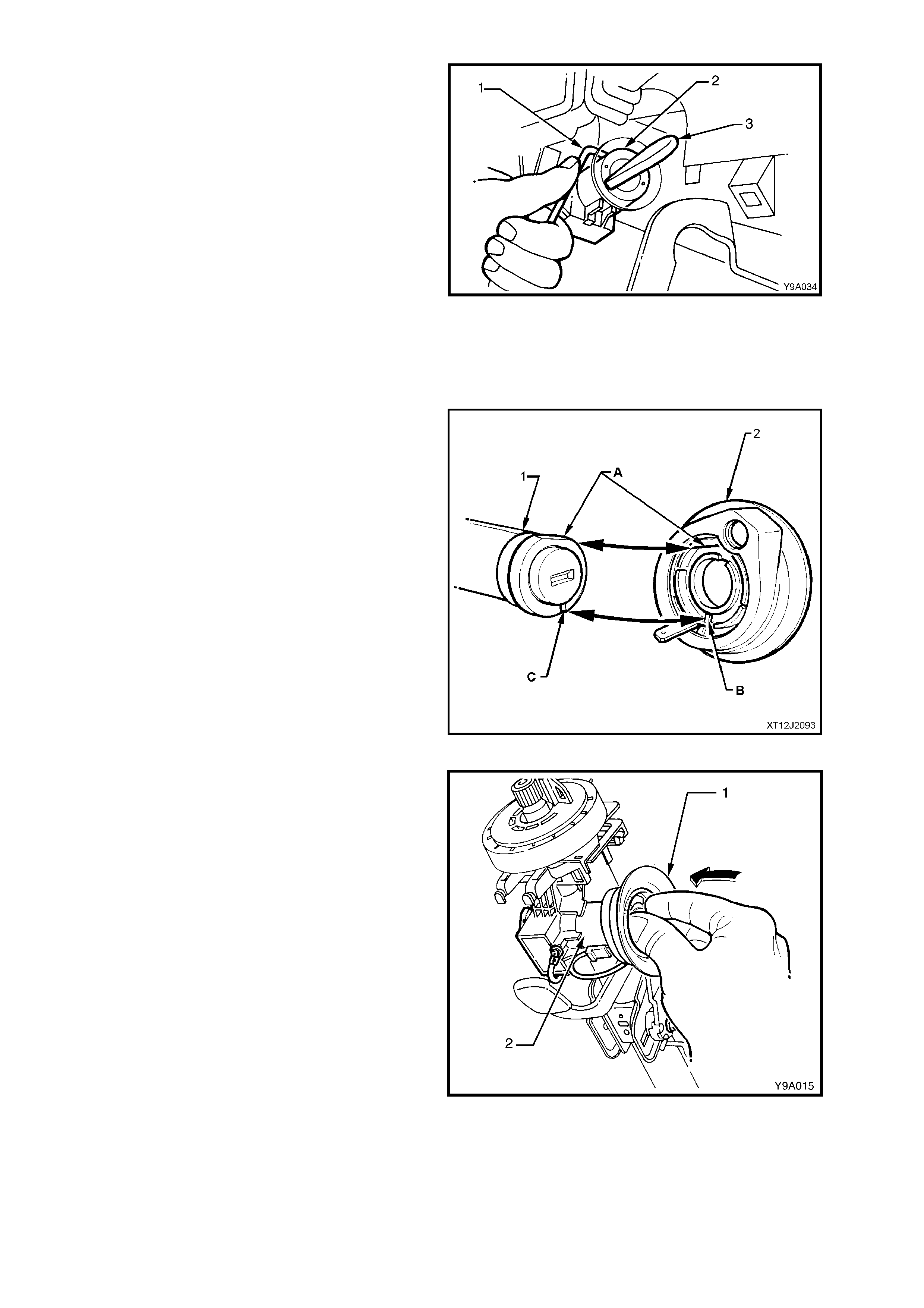
8. Insert ignition key into barrel and turn to the
'ON' position.
9. Insert a 2.5 mm diameter pin (an Allen key is
suitable) (1), into locking pin hole, depress
spring loaded barrel locking latch to release
lock cylinder.
10. Remove pin and pull barrel (2) from lock
housing.
Figure 9-24
REINSTALL
1. Install the key into the ignition barrel and turn the ignition to the 'ON' position.
2. Insert the barrel into the lock housing until the latch locks into the housing.
3. Install the ignition k ey reader (2), align the flats
(A) and indexing lug (B) of the remote key
reader assembly (2), with the mating groove
(C) on the ignition lock assembly (1).
Figure 9-25
4. Gently press the key reader assembly (1) onto
the ignition lock (2) by pushing evenly between
the two key reader seats, until the reader
assembly seats onto the ignition lock.
5. Ensure that the wiring harness connector and
ignition lock illumination bulb and socket are
securely fitted to the key reader assembly.
6. Install the steering column lower cover, by
engaging the two retaining tangs before
pushing the cover towards the instrument
cluster to engage. W hen the holes are aligned,
install the lower cover attaching screw.
7. Install the upper c over in the r evers e manner to
removal.
8. Raise the instrument panel right-hand cover
assem bly and locate each tang in its respective
clip before firmly pushing home to secure.
9. Reconnect the battery earth lead.
10. Insert the ignition k ey and chec k ignition switch
lock and barrel operations.
IMPORTANT: Enable the OPS (Air Bag). Refer to
Section 12M, 2.2 SYSTEM ENABLING AND
DISABLING PROCEDURE.
Figure 9-26

2.6 IGNITION SWITCH
LT Section No. – 06-255
REMOVE
CAUTION: Disable the OPS (Air Bag). Refer to Section 12M, 2.2 SYSTEM ENABLING AND DISABLING
PROCEDURE.
1. Disconnect the battery earth lead.
2. Remove the ignition keys from the ignition
switch.
3. Lower the instrument panel lower fuse panel
cover assembly (1) by grasping the top edge on
each side of the steering c olum n with the f inger
tips and pulling the top edge out, to free the
retaining lugs (2) from the clips (3).
4. Release the steering column tilt/reach clamp
lever, lower the column and lock the clamp
lever in this position.
5. Remove the steering column upper and lower
trim covers, refer to Section 12M, 3.21
INSTRUMENT PANEL PAD ASSEMBLY.
Figure 9-27
6. Disconnect the wiring harness connector (1)
and ignition lock illumination socket (2) and
bulb (3) from the key reader assembly (4).
7. Carefully pull the key reader from the ignition
lock assembly housing.
Figure 9-28
8. Insert the ignition key into the barrel and turn to
the 'ON' position.
9. Insert a 2.5 mm diameter pin (an Allen key is
suitable) (1), into the locking pin hole, depress
the spring loaded barr el lock ing latch to release
the lock cylinder.
10. Rem ove the pin and pull the barrel (2) from the
lock housing.
Figure 9-29
11. Disconnect the wiring harness connector from
the ignition switch.
12. Using a fine bladed screwdriver, remove the
ignition switch to steering lock housing
retaining grub screw (arrow).
13. Pull the switch from the steering lock housing,
disengaging the roll pin from the side opposite
the grub screw.
Figure 9-30
TESTING SWITCH
CAUTION: Disable the OPS (Air Bag). Refer to Section 12M, 2.2 SYSTEM ENABLING AND DISABLING
PROCEDURE.
1. Disconnect the battery earth lead.
2. Lower the instrument panel lower fuse panel
cover assembly (1) by grasping the top edge on
each side of the steering c olum n with the f inger
tips and pulling the top edge out, to free the
retaining lugs (2) from the clips (3).
3. Release the steering column tilt/reach clamp
lever, lower the column and lock the clamp
lever in this position.
4. Remove the steering column upper and lower
trim covers, refer to Section 1A3, 3.21
INSTRUMENT PANEL PAD ASSEMBLY.
Figure 9-31
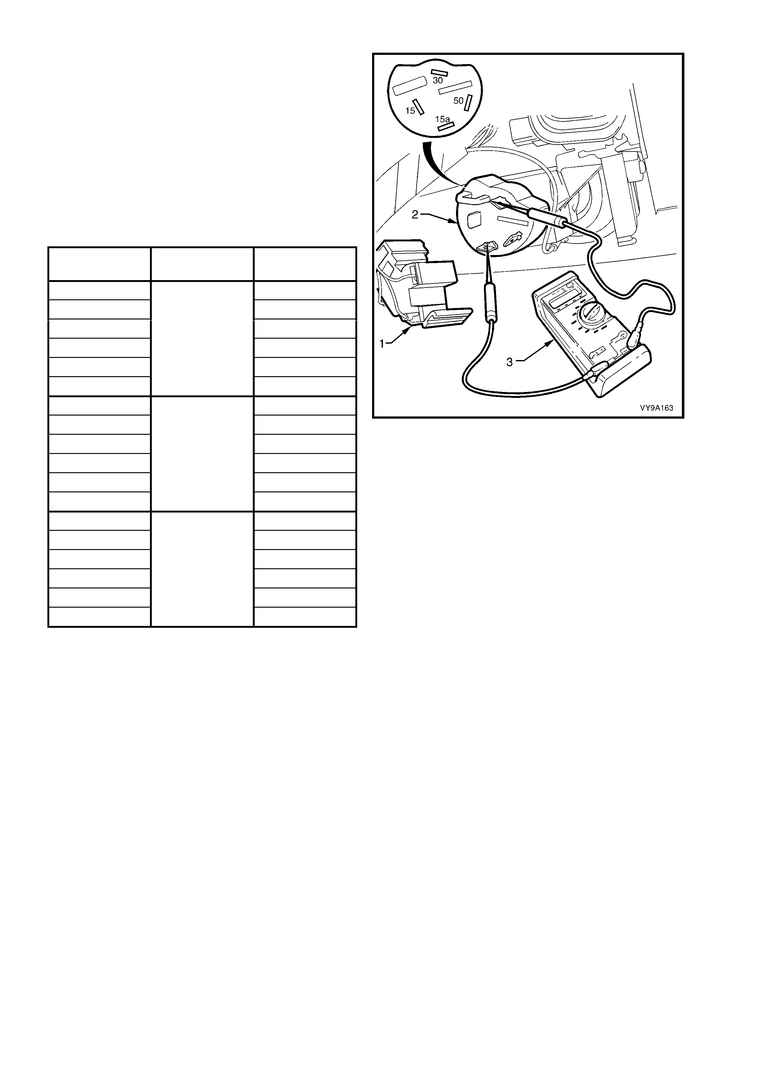
5. Disconnect the wiring harness connector (1)
from the ignition switch (2).
Switch
Terminals Switch
Position Indication if
Okay
30 and 15a Continuity
30 and 15 Open
30 and 50 Open
15a and 15 Open
15a and 50 Open
15 and 50
ACC
Open
30 and 15a Continuity
30 and 15 Continuity
30 and 50 Open
15a and 15 Continuity
15a and 50 Open
15 and 50
IGN
Open
30 and 15a Open
30 and 15 Continuity
30 and 50 Continuity
15a and 15 Open
15a and 50 Open
15 and 50
START
Continuity
Figure 9-32
REINSTALL
Installation of the ignition switch is the reverse of the removal procedure, noting the following points:
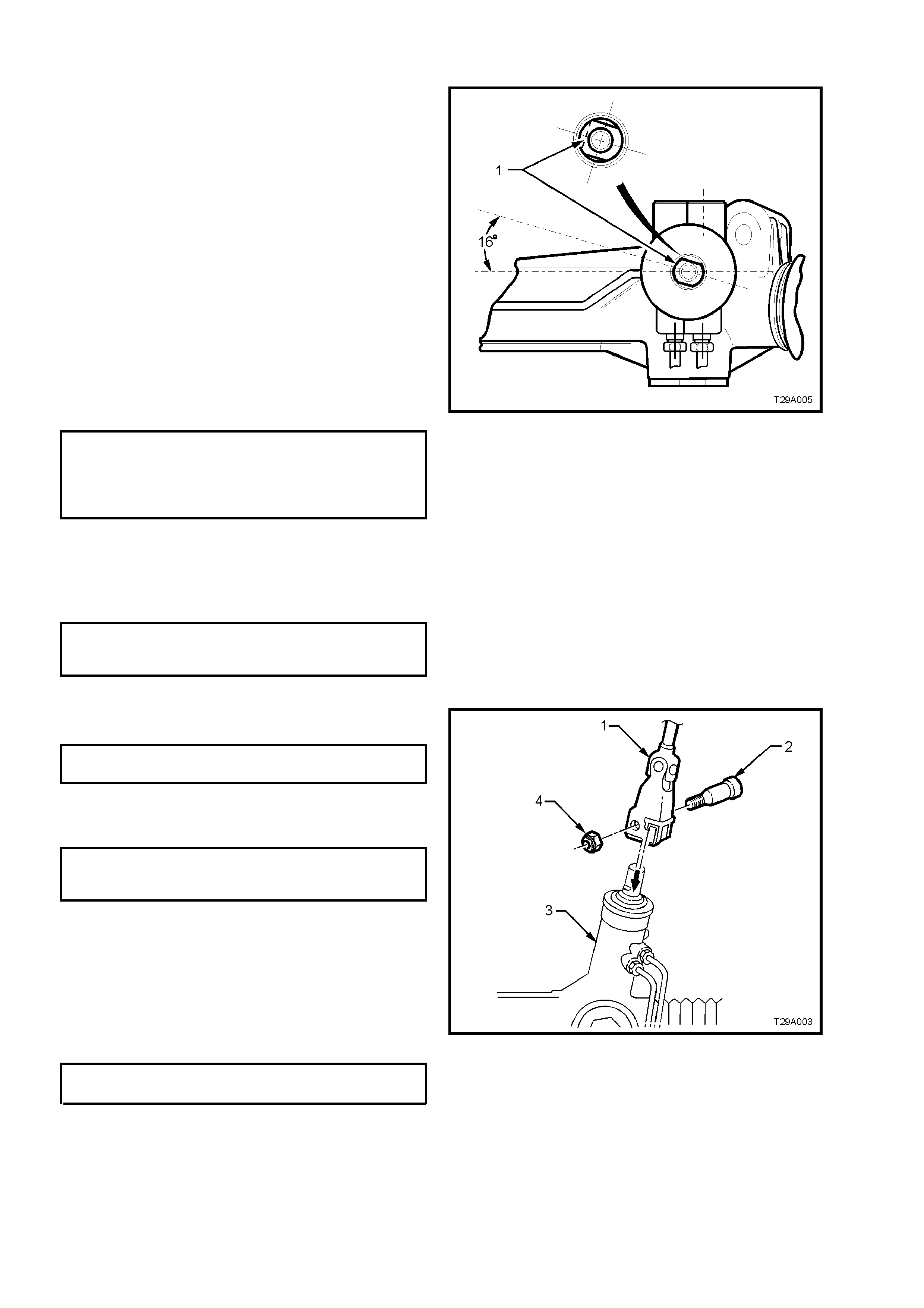
1. When ins talling the ignition switch into the housing, ensure that the s witc h body engages the locating roll pin in
the housing and that the slot in the end of the switch aligns with the stepped end of the ignition barrel shaft.
2. Once fitted, retain the switch by tightening the grub screw.
3. After installing the wiring harness connector to the ignition switch, reconnect the battery earth lead and check
the ignition switch operation.
IMPORTANT: Enable the OPS (Air Bag). Refer to Section 12M, 2.2 SYSTEM ENABLING AND DISABLING
PROCEDURE.

2.7 STEERING LOCK
As the steering lock is an integral part of the steering column assembly, it is not a separately serviceable
component. Should the steering lock be found to be faulty, the entire steering column assembly must be replaced.
For steering column replacement procedures, refer to 2.9 STEERING COLUMN ASSEMBLY in this Section.

2.8 STEERING COLUMN UPPER BEARING
As the steering column upper bearing is an integral part of the steering column assembly, it is not a separately
serviceable c omponent. Should the s teering colum n upper bearing be found to be faulty, the entire steering colum n
assembly must be replaced. For steering column replacement procedures, refer to 2.9 STEERING COLUMN
ASSEMBLY in this Section.
2.9 STEERING COLUMN ASSEMBLY
LT Section No. – 06-253
REMOVE
CAUTION: Disable the OPS (Air Bag). Refer to Section 12M, 2.2 SYSTEM ENABLING AND DISABLING
PROCEDURE.
1. Disconnect the battery earth lead.
2. Remove the instrument panel lower trim panel assembly, refer to Section 1A3, 3.3 INSTRUMENT PANEL
LOWER TRIM PANEL ASSEMBLY.
3. Remove the steering column upper and lower trim covers, refer to Section 1A3, 3.21 INSTRUMENT PANEL
PAD ASSEMBLY.
4. Remove the steering wheel inflatable restraint module, refer to Section 12M, 2.3 STEERING WHEEL
INFLATABLE RESTRAINT in 12M, OCCUPANT PROTECTION SYSTEM.
5. Remove the steering wheel, refer to 2.4 STEERING WHEEL ASSEMBLY in this Section.
6. Remove the clock spring coil, refer to Section 12M, 2.6 CLOCK SPRING COIL.
7. Remove the instrument panel lower trim retainer, refer to Section 1A3, 3.4 INSTRUMENT PANEL LOWER
TRIM PLATE RETAINER.
8. Remove the lower instrument lower trim plate assembly, refer to Section 1A3, 3.1 INSTRUMENT PANEL
LOWER TRIM PLATE ASSEMBLY.
NOTE: For steering column removal, it is not necessary to completely remove the instrument panel lower trim
panel. For this procedur e, leave the Data Link Connector (DLC) attached to the panel, swing the panel to one side
and secure with tie wire or similar.
9. Remove the driver’s side instrument panel outer cover, refer to Section 1A3, 3.19 INSTRUMENT PANEL
OUTER COVER.
10. Remove the driver’s side HVAC unit to driver’s door inner duct, for all MY 2003 VY and V2 Series Models,
regardless of the type of heating and air-conditioning system, refer to Section 2B, 3. HVAC OCCUPANT
CLIMATE CONTROL (MANUAL A/C).
11. Remove the ignition barrel lock cylinder, refer to 2.5 IGNITION BARREL LOCK CYLINDER in this Section.
12. Remove both the turn signal and wiper/washer switch assemblies, refer to Section 1A3, 3.21 INSTRUMENT
PANEL PAD ASSEMBLY, steps 14 and 15.
13. Loosen but do not remove the steering column to instrument panel mounting bolts.
14. Raise the front of the vehic le and plac e on safety s tands. Refer to Section 0A, GENERAL INFORMATION for
location of jacking points.
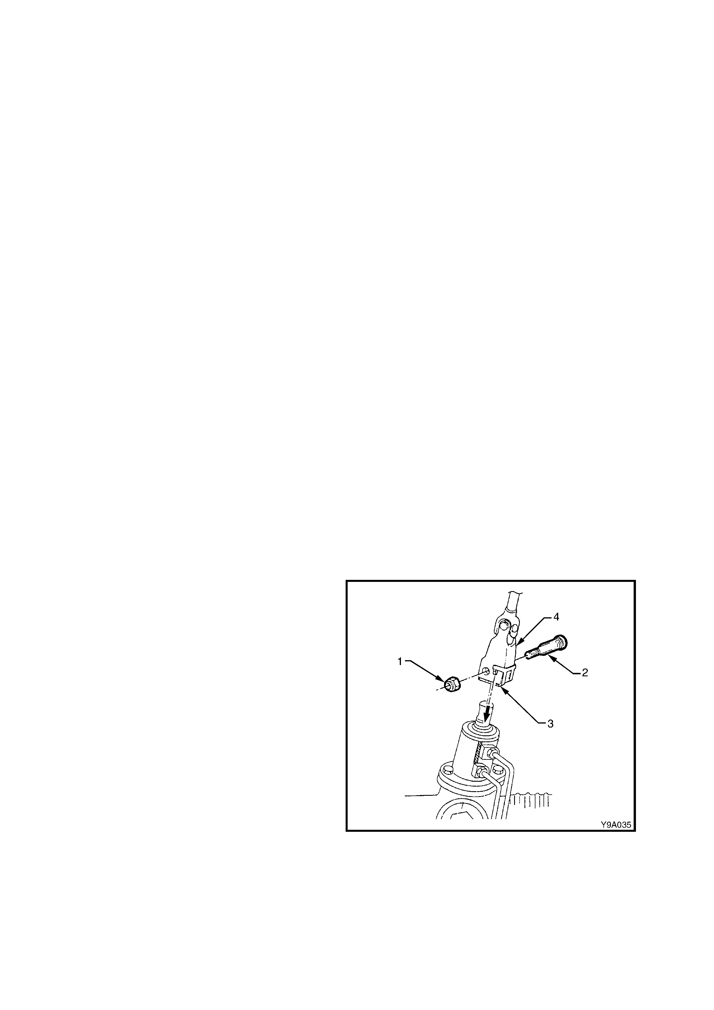
15. Remove steering coupling to steering Gear
pinion shaft cam bolt nut (1). Remove the cam
bolt (2), then disengage the retaining clip (3)
and slide the coupling (4) away from the
steering Gear pinion shaft.
Figure 9-33
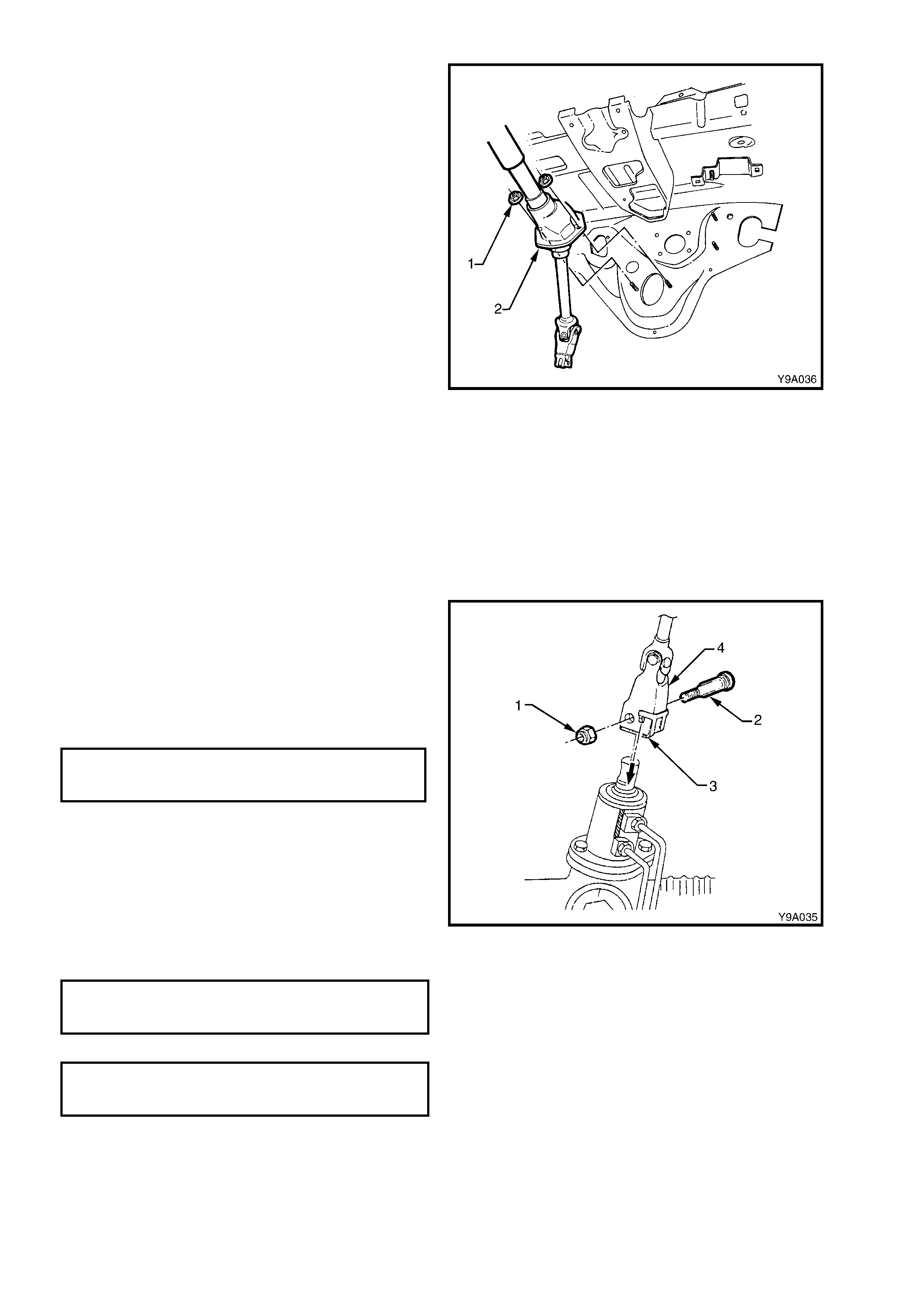
16. From inside the vehicle, remove the two nuts
(1) securing the lower housing assembly (2) to
the floorpan.
17. While supporting the steering column, remove
the previously loosened upper colum n retaining
bolts.
18. Remove the steering column assembly from
the vehicle.
Figure 9-34
REINSTALL
The installation procedure for the steering column assembly is the reverse of the removal procedures, noting the
following points:
1. Inspect the foam seal s tuc k to the lower housing to ensur e it is intac t. If the s ealing ability of the f lattened seal is
suspect, apply a continuous bead of silicone sealant such as RTV 732 or equivalent to the seal material.
2. After installing the steering column coupling through the floor pan, install the two lower housing retaining nuts
but do not tighten at this stage.
3. Lift the column assembly and loosely install the two upper support bracket retaining bolts.
NOTE: Only use bolts that were originally used, or
replace with genuine parts, as these parts are an
inherent part of this vital safety feature of the
vehicle.
4. Engage the lower coupling with the steering
rack input shaft, install the cam bolt and a new
'crim p' nut to the lower coupling and tighten the
nut to the specified torque.
LOWER STEERING COUPLING
TO RACK PINION, CAM BOLT
NUT TORQUE SPECIFICATION 25 – 30 Nm
Figure 9-35
1. Tighten the lower housing retaining nuts from inside the vehicle, to the specified torque.
STEERING COLUMN LOWER
HOUSING RETAINING NUTS
TORQUE SPECIFICATION 15 – 30 Nm
2. Tighten the two upper bracket to instrument panel mounting nuts to the correct torque specification.
UPPER STEERING COLUMN
MOUNT ATTACHING NUTS
TORQUE SPECIFICATION 15 – 30 Nm
3. The rem ainder of the ins tallation proces s is the reverse of the removal steps , with the exception of the following
important points:

4. Install the clock spring assembly as follows:
a. To avoid irreparable damage to the clock spring coil ribbon wire, ensure that the steering gear is in the
centralised pos ition. Refer to either 3.6 RIGHT -HAND DRIVE POWER STEERING GEAR and 3.7 LEFT-HAND
DRIVE POWER STEERING GEAR in this Section for the required details.
b. With the clock spring assembly locked in the centralised position, install the assembly over the steering shaft,
indexing the lower locating pins on the clock spring, with matching holes in the switch housing.
c. Push the clock spring assembly onto the switch housing until the four locking tangs fully engage.
NOTE: If the clock spring assembly was removed without being centred, refer to CENTRING THE CLOCK COIL
below.
5. Install steering wheel, refer to 2.4 STEERING WHEEL ASSEMBLY in this Section.
6. Connect the battery earth lead and check the operation of all affected electrical items.
CENTRING THE CLOCK SPRING COIL
All MY 2003 VY and V2 Series Models are fitted with an Occupant Protection System (OPS) that incorporates a
clock spring c oil as s embly behind the dr iver ’s air bag and hor n bar as s embly. For all the relevent ser vice inf or mation
(including the remove, reinstall and centring procedures) regarding the clock spring coil assembly as fitted to MY
2003 VY and V2 Series Models, refer to Section 12M, 2.6 CLOCK SPRING COIL.

2.10 CHECKING STEERING COLUMN FOR ACCIDENT DAMAGE
IMPORTANT:
When MY 2003 VY and V2 Series vehicles are involved in an accident resulting in major body or sheet metal
damage or where the steering column has been impacted, column damage or misalignment may also have
occurred.
INSPECT:
1. Check visually to s ee that either or both of the two mounting lugs have been dis lodged f rom the column br acket
and that the control springs are undamaged.
2. Visually check for any damage to the column and/or shaft that causes binding or jamming.
Should any component of the steering column assembly show signs that distortion has occurred, then the column
must be replaced as an assembly.
For steering column assembly replacement procedures, refer to 2.9 STEERING COLUMN ASSEMBLY in this
Section.
2.11 TILT/RE ACH HANDLE
LT Section No. – 06-253
REPLACE
NOTE: While replacem ent of this com ponent is not
recommended, the handle is serviced separately.
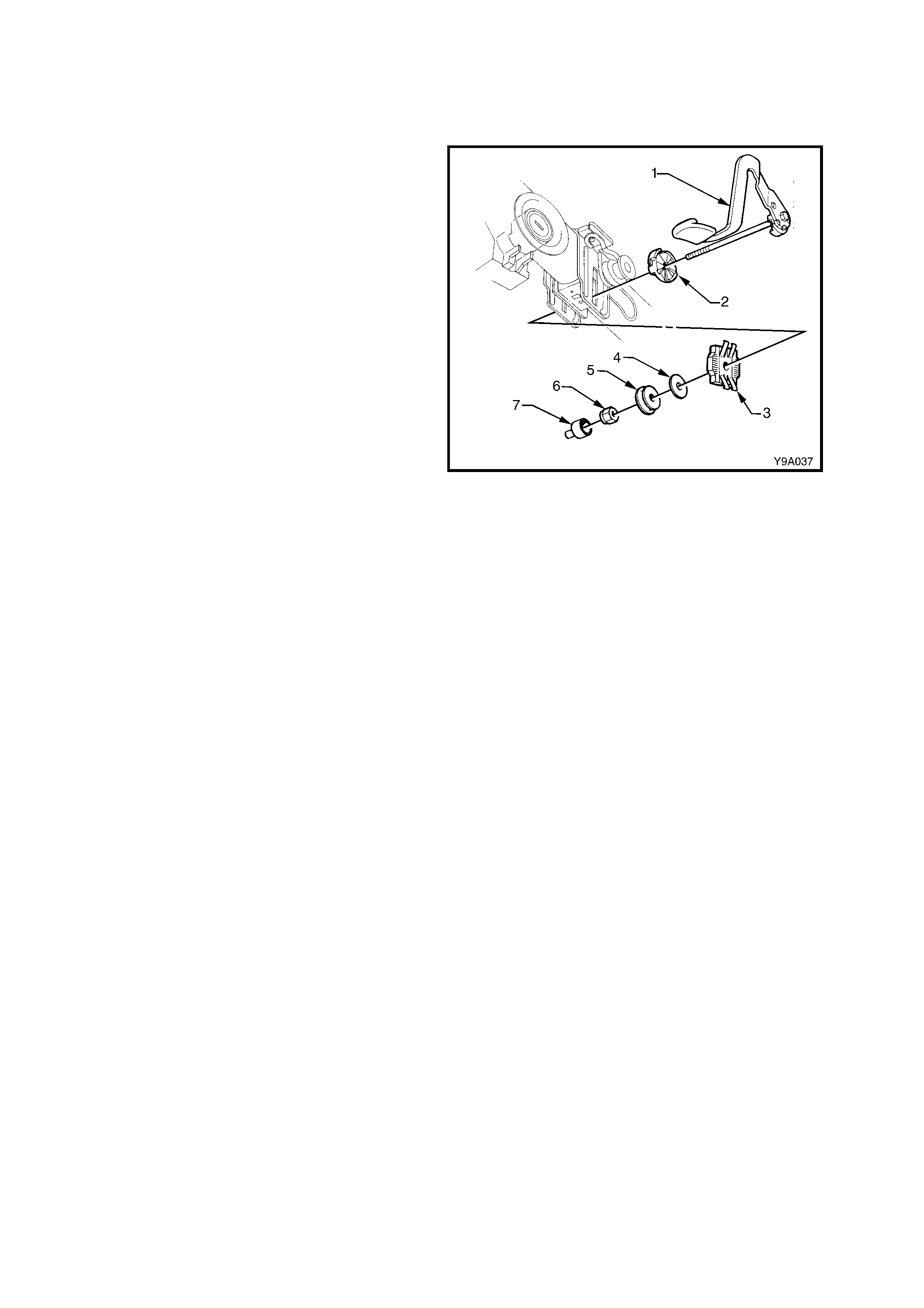
1. Release the tilt/reach handle (1) and, while
supporting it with one hand, remove the
through bolt, nut cover (7) and retaining nut (6).
2. W ithdraw the through bolt and handle (1), inner
cam (2), outer rac k (3) , washer (4) and bearing
(5).
3. Install through bolt and replacem ent handle (1),
through the inner cam (2).
4. Apply Loctite 242 (or equivalent) to the bolt
thread.
5. Install the rem aining c omponents in the reverse
order to removal and install a NEW retaining
nut (6).
IMPORTANT: T he final tension on the through bolt
determines the security of the upper steering
colum n assem bly and the f inal nut tens ion must be
determined by adopting the following procedure.
6. T ighten the nut until a f orce of 80 N is requir ed
to push the lever closed.
7. W ith the lever released, check that the column
is free to slide up and down. If the Gear (3)
grates, loosen the nut just sufficient to allow
free movement of the column.
8. Install the nut cover (7).
Figure 9-36

2.12 STEERING COLUMN LOWER BEARING ASSEMBLY
As the lower bearing is an integral part of the steering column assembly, it is not a separately serviceable
com ponent. Should the lower bearing be found to be f aulty, the entire s teering colum n assem bly must be replaced.
For steering column replacement procedures, refer to 2.9 STEERING COLUMN ASSEMBLY in this Section.

2.13 STEERING COUPLING
As the steering coupling is an integral part of the steering column assembly, it is not a separately serviceable
component. Should the steering coupling be found to be faulty, the entire steering column assembly must be
replaced. For steering column replacement procedures, refer to 2.9 STEERING COLUMN ASSEMBLY in this
Section.
3. POWER STEERING SERVICE OPERATIONS
IMPORTANT
All steering fasteners are important attaching parts as they affect the performance of vital components
and/or cou ld resu lt in major rep air expen se. Wh ere specif ied in this section, fasteners M UST be replaced
with parts of the same part number or a GM approved equivalent. Do not use fasteners of an inferior
quality or substitute design.
Torque values must be used as specified during reassembly to ensure proper retention of all steering
components.
Through-out this section, fastener torque w rench specifications may be accompanied with the following
identification marks:
+
++
+ Fasteners must be replaced after loosening.
&
&&
& Vehicle must be at kerb height before final tightening.
6
66
6 Fasteners either have micro encapsulated sealant applied or incorporate a mechanical thread lock
and
should only be re-used once. If in doubt, replacement is recommended.
If one of these identification marks is present alongside a fastener torque wrench specification, the
recommendation regarding that fastener must be adhered to.
3.1 POWER STEERING FLUID LEVEL CHECK
V6 ENGINE
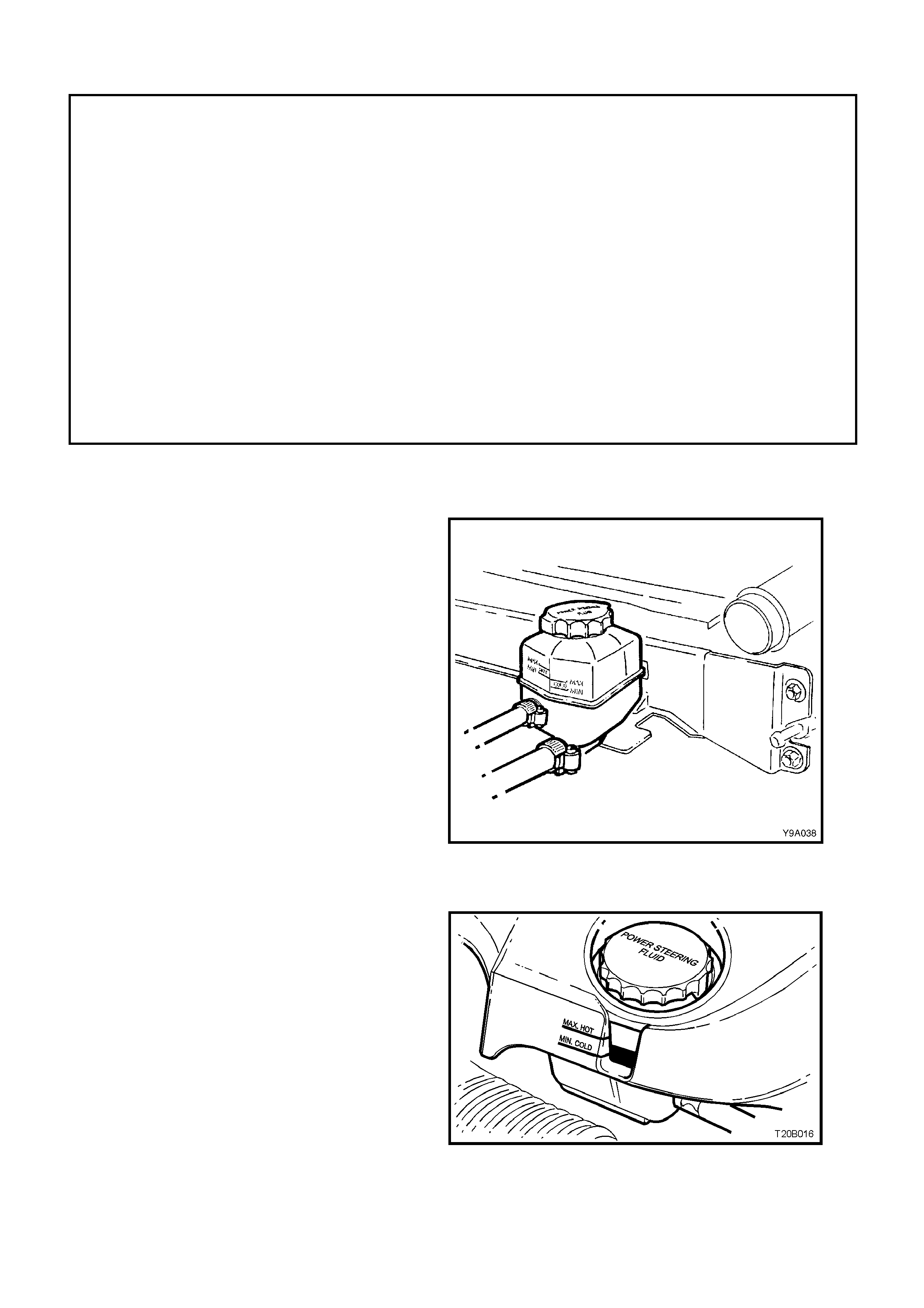
The power steering fluid level can be checked by
viewing the level through the translucent plastic
side of the reservoir.
If the power steering fluid is cold, the level should
be in the ‘COLD’ range. Similarly, if it is hot, the
power steering f luid should be in the ‘HO T ’ r ange. If
the power steering fluid level is at the low side of
either range, new power steering fluid should be
added to bring the level into the correct range and
the system checked for the cause of the leakage
and corrected as necessary.
NOTE: The recommended power steering fluid for
use in all MY 2003 VY and V2 Series vehicles, is
Dexron® III automatic transmission fluid to Holden’s
Specification HN2126.
Figure 9-37
GEN III V8 ENGINE
The power steering fluid level can be checked by
viewing the level through the translucent plastic
side of the reservoir. There is no need to remove
the engine dress cover for this operation.
If the power steering fluid is cold, the level should
be in the ‘COLD’ range. Similarly, if it is hot, the
power steering f luid should be in the ‘HO T ’ r ange. If
the power steering fluid level is at the low side of
either range, new power steering fluid should be
added to bring the level to the corr ect point and the
system checked for the cause of the leakage and
corrected as necessary.
NOTE: The recommended power steering fluid for
use in all MY 2003 VY and V2 Series vehicles, is
Dexron® III automatic transmission fluid to Holden’s
Specification HN2126.
Figure 9-38

3.2 DRIVE BELT ADJUSTMENT
LT Section No. – 01-003
V6 ENGINE
For vehicles with V6 engine, the power steering pump is driven by the engine serpentine dr ive belt. The belt is self
adjusting within tensioner operating limits. For details, refer to Section 6A1, ENGINE MECHANICAL.
GEN III V8 ENGINE
For vehic les with the GEN III V8 engine, the power steer ing pum p is driven by the engine serpentine drive belt. T he
belt is self adjusting within tensioner operating limits. For details, refer to Section 6B3, GEN III V8 ENGINE.
Techline

3.3 HYDRAULIC SYSTE M, BLEE DING/RE FILLING PROCEDURE
LT Section No. – 06-400
CAUTIONARY NOTES:
1. If the power steering fluid level is low in the power steering fluid reservoir, air will be drawn in and mixed with the
power steer ing fluid in small bubbles. If the pump is allowed to continue oper ation, an increasing am ount of air
will be drawn into the s ystem , c ausing the power s teer ing f luid volume to increas e to a point where the r eser voir
will overflow. Sudden releases in pressure that will occur when the steering is suddenly taken off a 'full lock'
condition, will cause dramatic eruptions of power steering fluid from the reservoir. The separation of air
entrapped under these conditions will be extremely difficult to remove and may take several days.
2. If the steering Gear assembly requires replacem ent, a large volume of air will be required to be purged, which
means that the power steering reservoir fluid level will fall rapidly when the engine is started.
3. During bleeding, it is important that the front wheels are clear of the ground and that the steering is not held
forcibly against the steering stops.
BLEEDING/REFILLING PROCEDURE
1. Raise the front of the vehicle and place on safety stands. Refer to Section 0A, GENERAL INFORMATION.
2. W ith the engine not running, add the power steering fluid to reservoir to the maximum mark (or greater, if it is
known that the steering gear is empty).
3. Start the engine and allow to run for only 2-3 seconds. Do not turn the steering wheel at this point.
4. Continue with Steps 2 and 3 until the power steering fluid level remains constant.
5. Start and run the engine at idle speed, turning the steering wheel from lock to lock, without holding at the full
lock positions (this will build up high pressures, atomising any entrapped air). Repeat this procedure from six to
eight times. Stop the engine, check the power steering fluid level and top up to the maximum level, as required.
6. Start and run the engine at idle speed. Again turn the steering wheel from lock to lock but now slowly build up
the pressure levels by holding against the full lock position from 1-2 seconds. Repeat this procedure from four
to six times. Stop the engine and top up the power steering fluid level to the maximum mark, as required.
NOTE: While the majority of entrapped air will be removed by the above process, a small amount may remain,
which can only be removed by alternate circulation and settling of the power steering fluid for a prolonged period.
This is usually achieved automatically after two to three days, with daily driving and settling overnight.
7. Turn the steering wheel to the straight ahead position, lower vehicle to the ground and turn ignition 'OFF'.
3.4 HYDRAULIC SYSTEM, CHECK
The f ollowing procedur es outline methods to identif y and isolate power steering hydraulic circ uit diff ic ulties . This test
is divided into two parts. Test number one provides a means of determining whether the power steering system
hydraulic parts are faulty. If test number one results in readings indicating faulty hydraulic operation, test number
two will identify the faulty part.
Before performing the hydraulic circuit test, carefully check the power steering fluid level, drive belt condition and
tension, idler and driving pulleys for smooth operation.
The engine must be at normal operating temperature and the front tyres inflated to the correct pressure. All tests
are made with engine idling.
To perform the two pressure checks, it is necessary to connect a pressure gauge assembly into the hydraulic line
between the pump and steering gear.
PROCEDURE
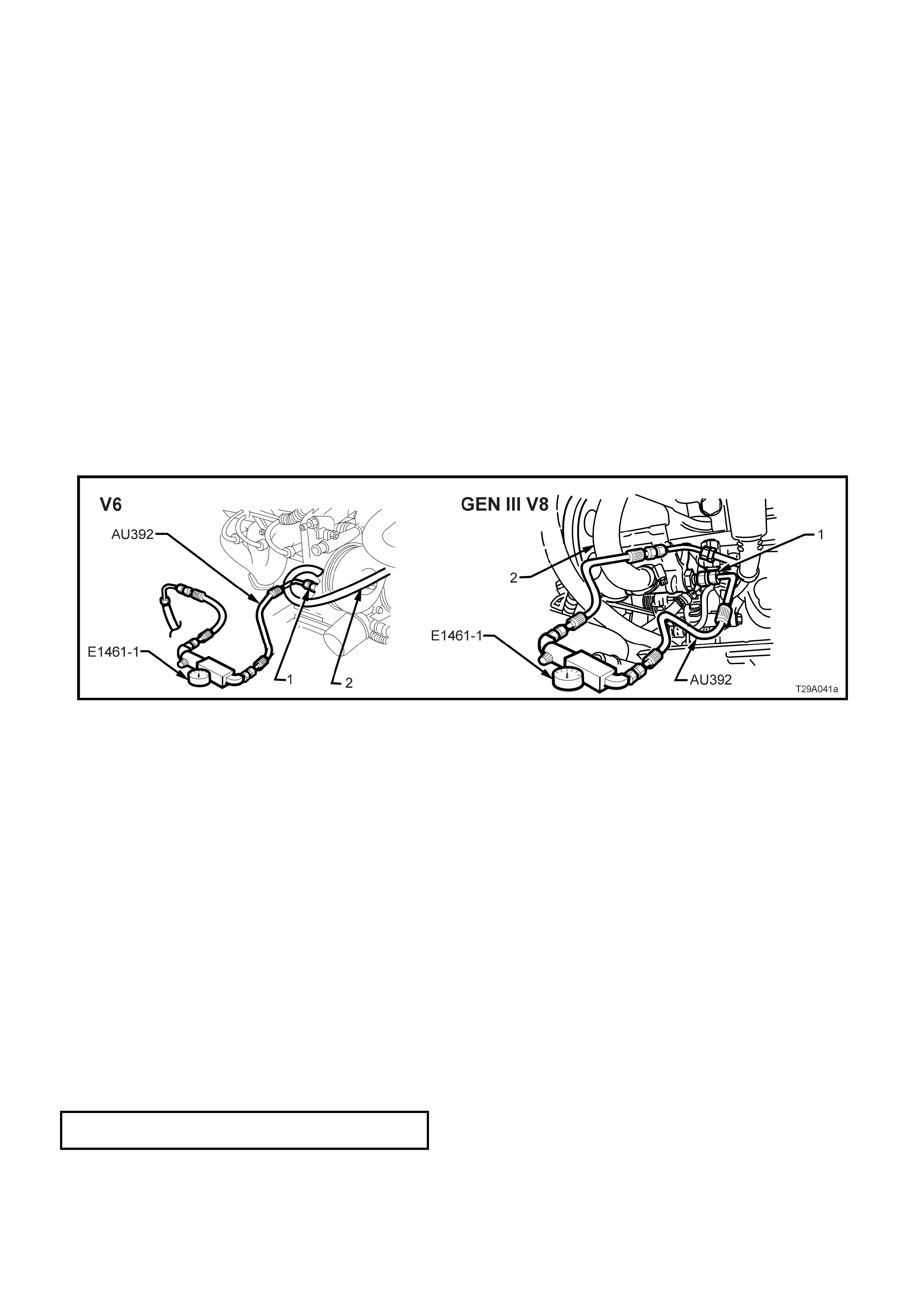
1. Place a drain tray beneath the power steering pump assembly.
2. Loosen and remove the high pressure hydraulic line fitting and O-ring from the power steering pump.
3. Install the press ure gauge assem bly (Hose set AU392 and G auge assem bly E1461-1) between the outlet fitting
of the pump and the high pressure hose fitting (1).
4. Refill the system with power steering fluid to the correct level, refer to 3.1 POWER STEERING FLUID LEVEL
CHECK in this Section. Ensure that there are no leaks at either the hose or gauge connections.
5. Bleed the air from the system, as described in 3.3 HYDRAULIC SYSTEM, BLEEDING / REFILLING
PROCEDURE in this Section.
Figure 9-39
TEST 1 - HYDRA ULIC CIRCUIT OPEN
1. With the valve open, start the engine, allow to idle and with the steering LIGHTLY on full lock, check the
connections for leakage.
2. Insert the thermometer into the reservoir filler opening and move the steering from lock to lock until power
steering fluid reaches 75° Celsius.
3. Turn the steering to full loc k m om entarily, if the pressur e is below 7,580 k Pa (V6 engine) or 8,270 kPa (GEN III
V8 engine), a faulty hydraulic circuit is indicated.
TEST 2 - HYDRA ULIC CIRCUIT CLOSED
1. Slowly turn the valve on Tool E1461-1 to the c losed pos ition, note the pressure, and quickly re-open the valve to
avoid pump damage.
2. If the pressure was less than 7,580 kPa (V6 engine) or 8,270 kPa (GEN III V8 engine), the pump may be
considered to be faulty.
3. If pressure was between 7,580 - 8,270 k Pa (V6 engine) or 8,270 - 8,960 kPa ( GEN III V8 engine), the steer ing
gear, external hoses or connections may be considered faulty.
NOTE: If the pump proves faulty, retest after overhaul to check the repairs and condition of the steering gear.
4. At the completion of the tests, remove the pressure gauge, hoses and connectors.
5. Install the high pressure line and O-ring to the pum p outlet fitting and tighten the flare nut to the correct torque
specification.
HIGH PRESSURE LINE FLARE NUT
TORQUE SPECIFICATION 25 – 35 Nm
6. While LIGHTLY holding the steering wheel on full lock, have an observer check for power steering fluid leaks
from the hose connections.

The following flow chart, details an alternative procedure for checking the power steering hydraulic system.
POWER STEERING HYDRAULIC SYSTEM CHECK
STEP ACTION YES NO
1 • Start engine and allow to idle.
• Is power steering fluid level correct? Go to Step 2. Top up as required
and check for leaks.
Go to Step 2.
2 • Check power steering fluid condition. Is power steering fluid
condition OK? Go to Step 3. Drain, flush system
and refill with power
steering fluid.
Go to Step 3.
3 • With valve on test gauge fully open, check pressure
reading.
• Is the pressure reading for standard power steering
approximately 350 kPa or:
• With speed sensitive power steering, is the pressure
reading approximately 700 kPa?
Go to Step 4. Check hoses/pipes for
restriction. Repair or
replace as necessary.
Go to Step 4.
4 • Is system pressure now to specification? Go to Step 5. Replace steering Gear
valve assembly.
Go to Step 3.
5 • Close then open valve fully three times, noting the highest
pressure reading each time.
NOTE: Do not leave valve closed for more than five seconds,
as pump damage could result.
• Are all readings between 7,580 - 8,270 kPa (V6) or 8,270 -
8,960 kPa (GEN III V8) and within 340 kPa of each other?
Hydraulic system is
operating to
specification.
Go to Step 6.
6 • Are pressures within specified range but not within 340 kPa
of each other? Go to Step 7. Go to Step 9.
7 • Remove flow control valve and remove any burrs with
crocus cloth or fine hone.
• Repeat Step 4. Are pressure readings now OK?
Hydraulic system is
now operating to
specification.
Go to Step 8.
8 • Remove pump, disassemble clean, reassemble and
reinstall.
• Repeat Step 4. Are pressure readings now within 340 kPa
of each other?
Hydraulic system is
now operating to
specification.
Go to Step 10.
9 • Are pressures within 340 kPa of each other but below
specified maximum range? Go to Step 10. Go to Step 5.
10 • Replace flow control valve, then repeat Step 4.
• Are pressure readings now OK? Hydraulic system is
now operating to
specification.
Overhaul or replace
power steering pump.
Go to Step 5.
3.5 TIE ROD SOCKET
LT Section No. – 06-275
REPLACE
Tie rod sockets are serviced as an assembly and must be replaced when excessive up or down movement is
evident, or if any lost motion or end play exists at the ball end of the stud.
1. Raise the front of the vehicle and place on safety stands. Refer to Section 0A, GENERAL INFORMATION.
2. Rem ove the front wheel cover (steel wheels) or
centre caps (alloy wheels)
3. Mark the relationship of each wheel to
hub/brake disc. Remove the road wheel
attaching nuts and remove the wheels.
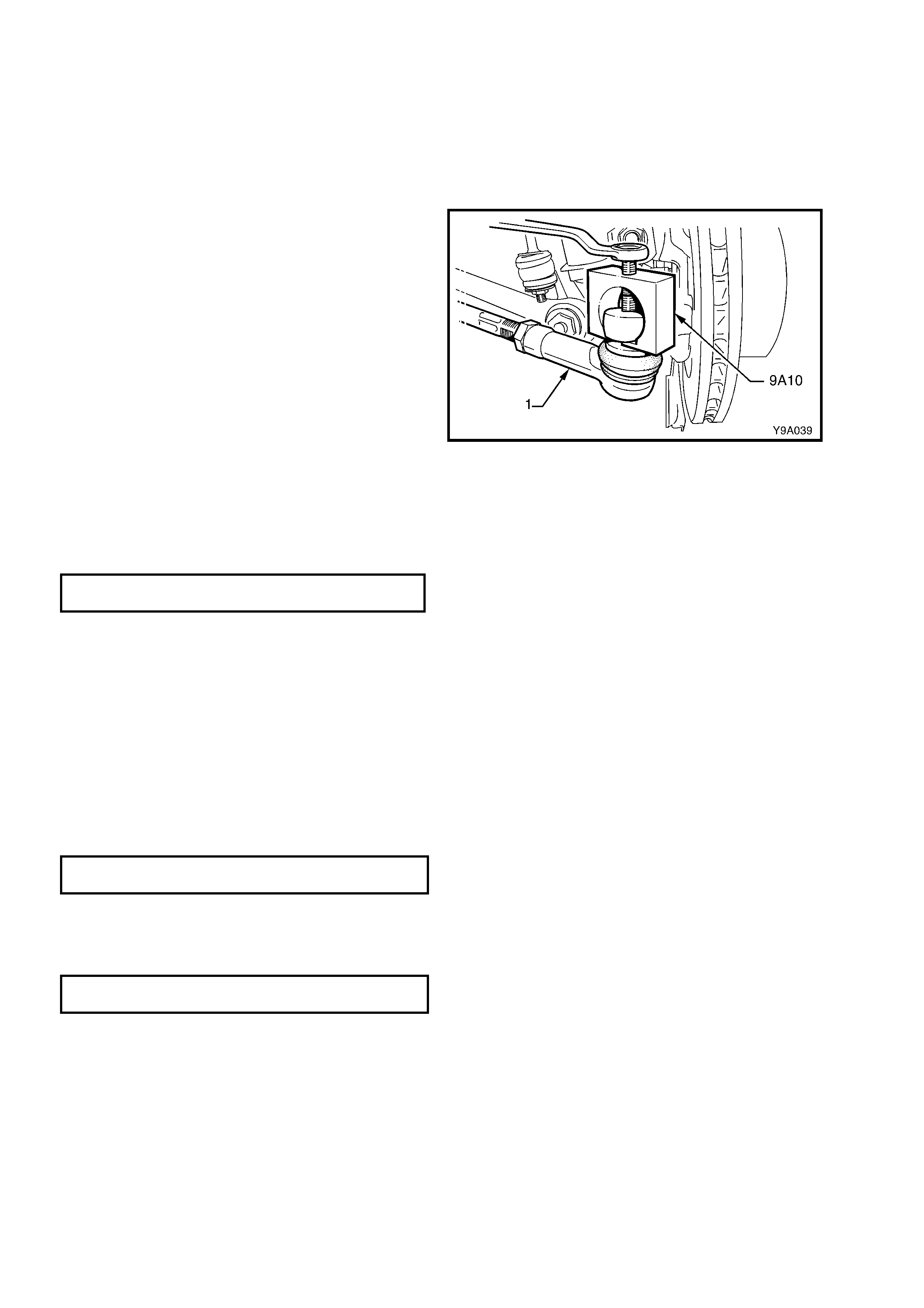
4. Remove the split pin and nut from the tie rod
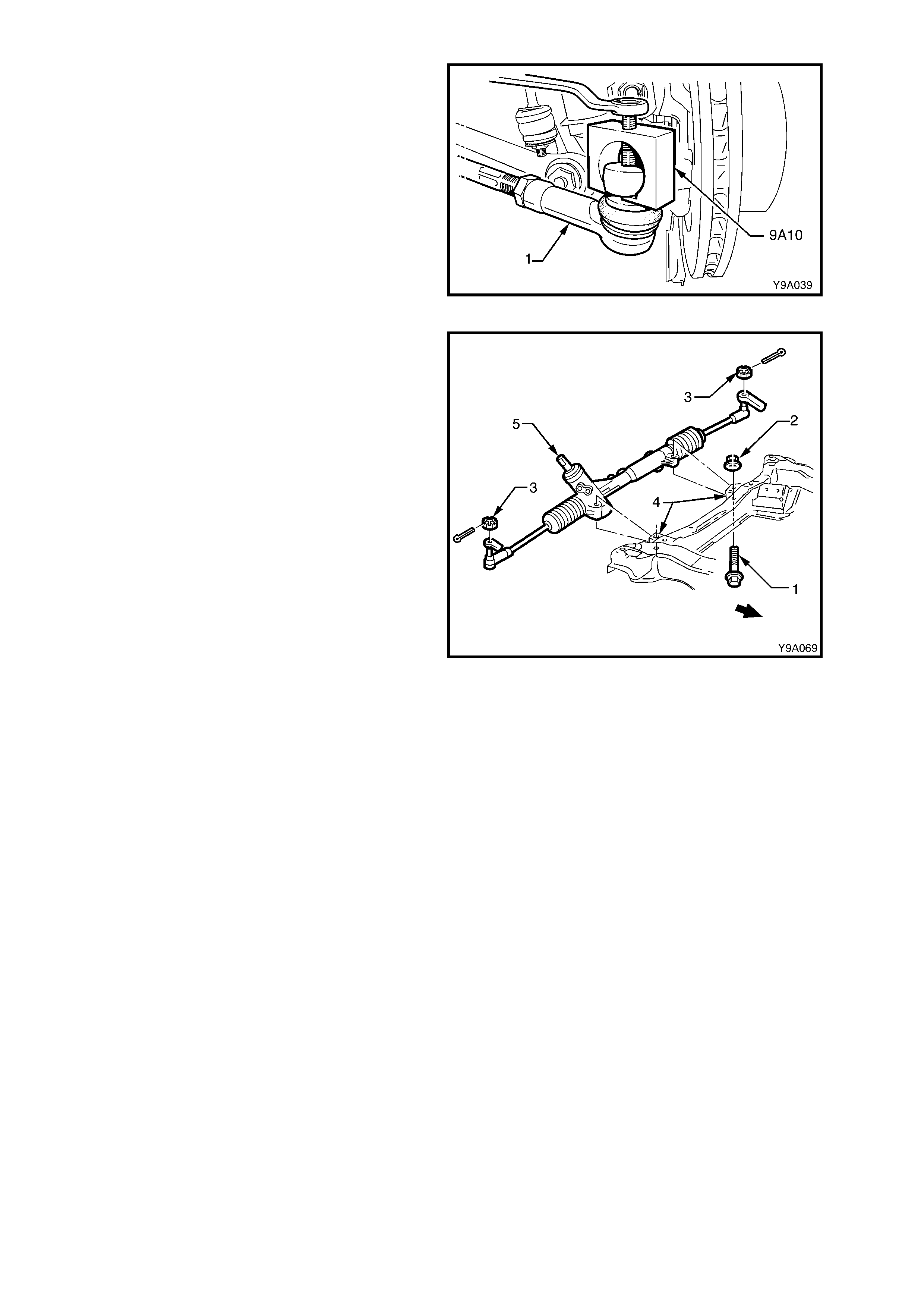
ball stud.
5. Using Tool No. 9A10 or similar, tighten the
centre screw to f orce the stud f rom the taper in
the steering arm.
6. Loosen the tie rod lock nut. Unscrew the socket
(1) from the tie rod, counting the number of
turns to wind the socket from the tie rod.
7. Install the new socket (1) onto the tie rod and
wind the nut on the same num ber of turns as in
Step 3.
8. Ins tall the soc ket to the steer ing arm. Install the
castellated nut and tighten to the corr ect torque
specification.
TIE ROD SOCKET STUD CASTELLATED
NUT TORQUE SPECIFICATION 50 – 85 Nm
NOTE: Ensure that the nylon spacer is positioned
on the tie rod socket stud before installing into the
steering arm.
9. Install a new split pin into the tie rod ball studs.
Figure 9-40
10. Check the front wheel toe. Refer to
Section 3, FRONT SUSPENSION.
NOTE: Ensure the plastic spacers are positioned
on tie rod end ball studs and that they are in good
condition before fitting the studs into the steering
arms. Replace the spacers if damaged.
11. Tighten the tie rod end lock nuts to the corrct
torque specifcation.
TIE ROD SOCKET LOCK NUT
TORQUE SPECIFICATION 50 – 85 Nm
12. Install the wheels, aligning the m arks m ade on
removal. Tighten wheel attaching nuts to the
correct torque specification. Do not over-
tighten!
ROAD WHEEL ATTACHING NUT
TORQUE SPECIFICATION 110 – 140 Nm
13. Lower the vehicle to the ground and reconnect
the battery earth lead.
14. Check the front wheel toe-in setting, refer to
Section 3, FRONT SUSPENSION for details
3.6 RIGHT-HAND DRIVE POWER STEERING GEAR
LT Section No. – 06-275
NOTE: The following fasteners have either micro
encapsulation or incorporate a mechanical thread lock
and should only be used once. If in doubt, r eplacement
is recommended when performing this operation:
♦ Steering gear housing to front suspension
crossmember nuts.
♦ Steering coupling lower cam bolt nut.
NOTE: The following fasteners MUST be replaced
when performing this operation:
+
++
+
Steering gear pinion lower bearing retaining nut
IMPORTANT: Remove t he ignit ion key from the ig nition lock and ensu re that t he steering column is locked.
If this operation is not carried out and the steering wheel is spun while the steering gear is removed from
the vehicle, the clock spring coil in the upper end of the steering column will be destroyed!
REMOVE
1. Disconnect the battery earth lead.
2. Raise the front of the vehicle and place on safety stands. Refer to Section 0A, GENERAL INFORMATION.
3. Remove the front wheel cover (steel wheels) or centre caps (alloy wheels)
4. Mark the relationship of each wheel to the hub/brake disc. Remove the road wheel attaching nuts and rem ove
wheels.
5. Place a drain tray beneath the steering gear.
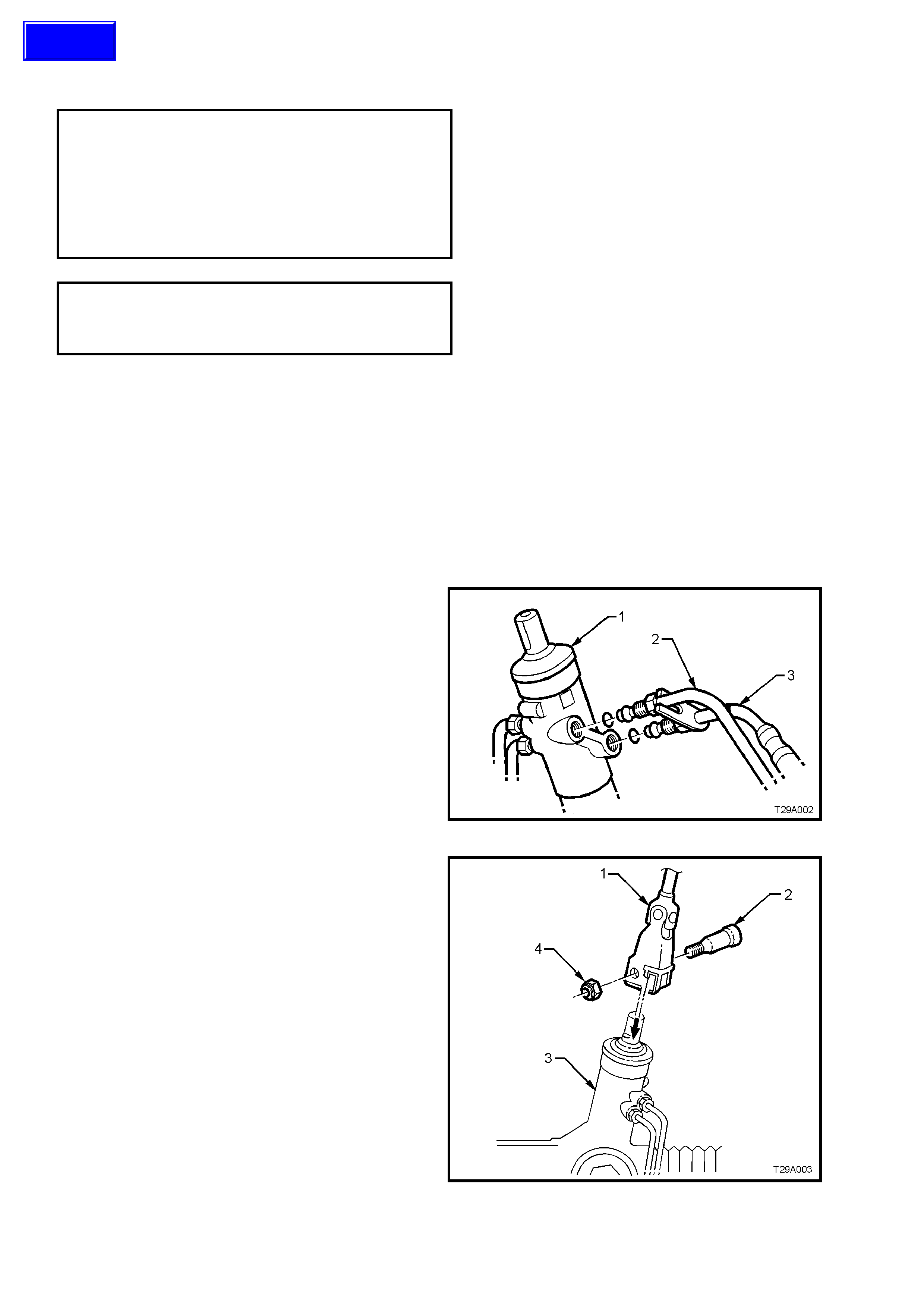
6. Loosen and remove the hydraulic lines (2 and
3) fr om the st eering gear valve housing (1) and
allow the power steering fluid to drain into a
suitable container.
Figure 9-41
7. Remove the steering coupling lower cam bolt
nut (4), then remove the cam bolt (2).
Figure 9-42
Techline
8. Remove the tie rod socket split pins and
castellated nuts (’3’ in Figure 9-58).
9. Separate the tie rod socket (1) studs from the
steering arm tapers using a suitable remover,
such as Tool No. 9A10.
Figure 9-43
10. Remove the steering gear housing to front
suspension crossmember mounting bolts (1)
and nuts (2).
11. Remove the s teering gear by pulling it out from
the front suspension crossmember mounting
(4) and slide pinion (input) shaft (5) from the
steering coupling lower clamp.
Figure 9-44
REINSTALL
NOTE 1: This is achieved by rotating the pinion to
the halfway position of its total lock to lock rotation.
When the G ear is in the s tr aight ahead pos ition, the
pinion (input) shaft will be aligned as shown.
NOTE 2: Alternatively, remove both inner boot
clamps, slide the boots back and measure the
exposed portion of each end of the rack from the
housing. When both measurements are equal, the
rack is centralised.
1. Ensure the steering gear is centralised.
2. Ensure the steering wheel is in the straight
ahead position.
3. Slide the steering gear pinion (input) shaft into
the steering coupling lower flange.
4. Position the steering gear housing into the
crossmember mounting points. Install the
mounting bolts, washers and nuts and tighten
the nuts to the correct torque specification.
(6)STEERING GEAR HOUSING TO
CROSSMEMBER MOUNTING NUT
TORQUE SPECIFICATION 60 Nm, then
40° - 50° turn
angle
5. Inspect the condition of the steering gear
hydraulic line O-rings. Replace as necessary.
6. fit the hydraulic lines to the steering gear valve
housing. Tighten the flare nuts to the correct
torque specification.
HYDRAULIC LINE TO VALVE
HOUSING FLARE NUT
TORQUE SPECIFICATION 30 – 42 Nm
Figure 9-45
7. Install the lower c am bolt (2) and a new nut (4).
Tighten to the correct torque specification.
(6)STEERING COUPLING CAM BOLT
TORQUE SPECIFICATION 25 – 30 Nm
8. Install the tie rod end ball studs into the steering
arms. Install the castellated nuts and tighten to
the correct torque specification.
TIE ROD SOCKET STUD
CASTELLATED NUT
TORQUE SPECIFICATION 50 – 85 Nm
9. Install new split pins.
NOTE: Ensure the plastic spacers are positioned
on the tie rod end ball studs and that they are in
good condition before fitting the studs into the
steering arms. Replace the spacers if damaged.
10. Install the wheels, aligning the marks made on
removal. Tighten the wheel attaching nuts to
the correct torque specification.
ROAD WHEEL ATTACHING NUT
TORQUE SPECIFICATION 110 – 140 Nm
11. Lower the vehicle to ground and reconnect the
battery earth lead.
Figure 9-46
12. Fill and bleed the hydraulic system, refer to 3.3, HYDRAULIC SYSTEM, BLEEDING/REFILLING in this
Section.
13. Check the front wheel toe-in setting, refer to Section 3, FRONT SUSPENSION for details.
DISASSEMBLE
CAUTION: During the manufacturing process, the threaded ends of the steering rack and piston assembly
are staked to the tie rod inner socket housing. Consequently, during disassembly of the power steering
gear, damage t o t he th reads on the end of the t ie rod inner socket and rack and pist on assembly will occur.
Whenever a steering gear is disassembled, the inner tie rods and the rack and piston assembly MUST be
replaced.
For identification of components, refer to Figure 9-51.
1. Clean all dirt and foreign matter from the exterior of the steering gear assembly.
2. Mount the steering gear hous ing (1) by gripping
the right-hand mounting boss in a vice fitted
with soft jaws (2).
3. Place a drain tray beneath the steering gear.
Figure 9-47
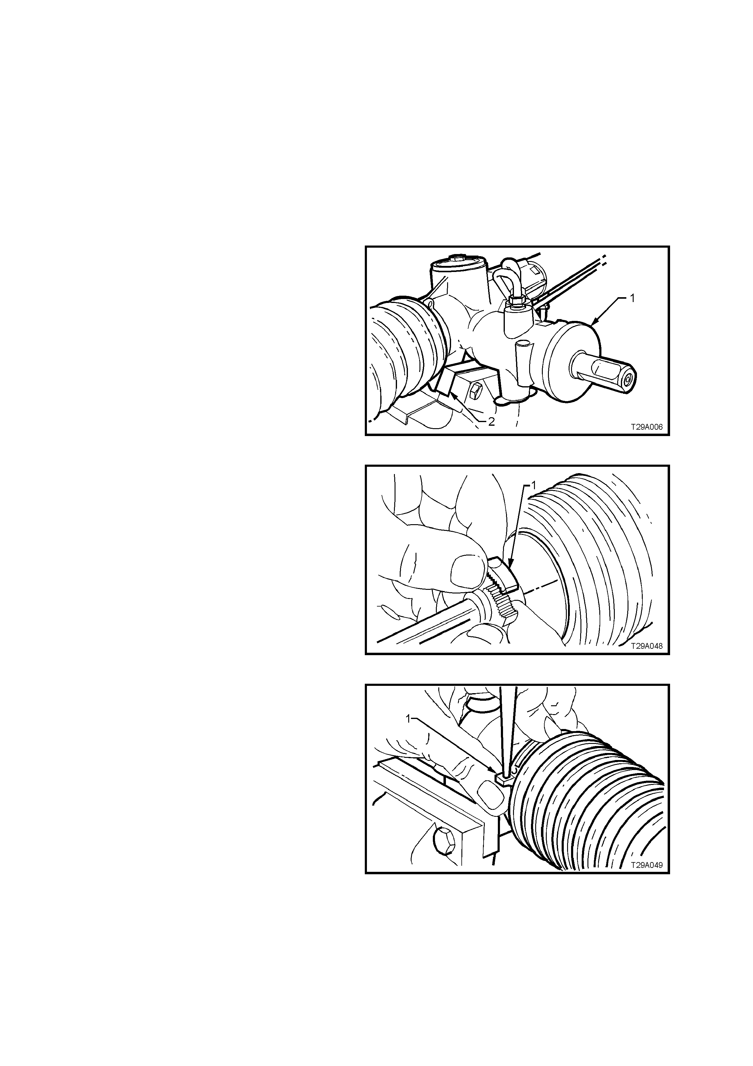
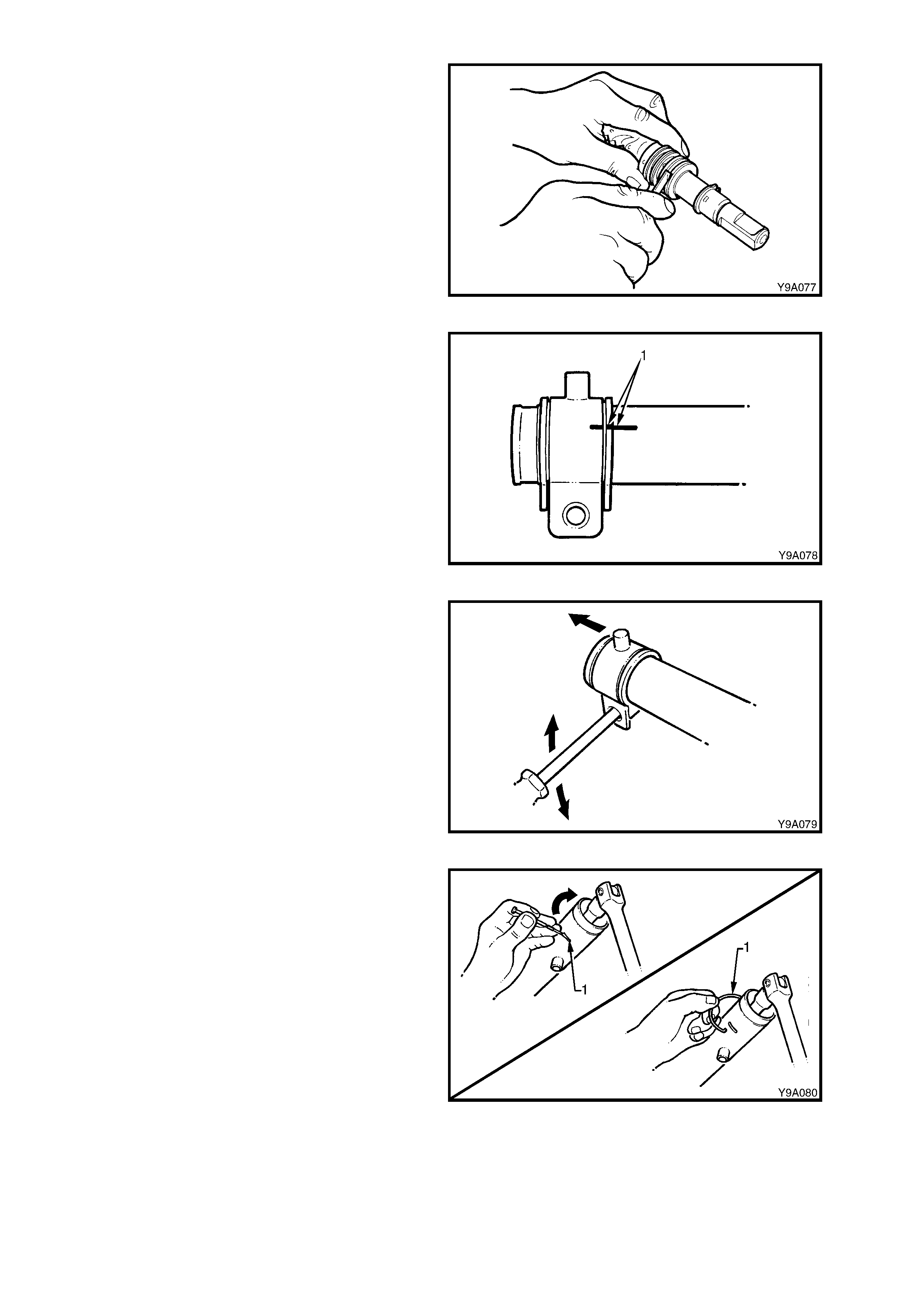
4. Unclip and remove all bellows clips.
a. To remove the outer clips (1): Move the ends of
the clips sideways until they disengage.
Figure 9-48
b. To rem ove the inner clips (1): Push out the pin
retaining the clip ends together using a fine pin
punch.
Figure 9-49
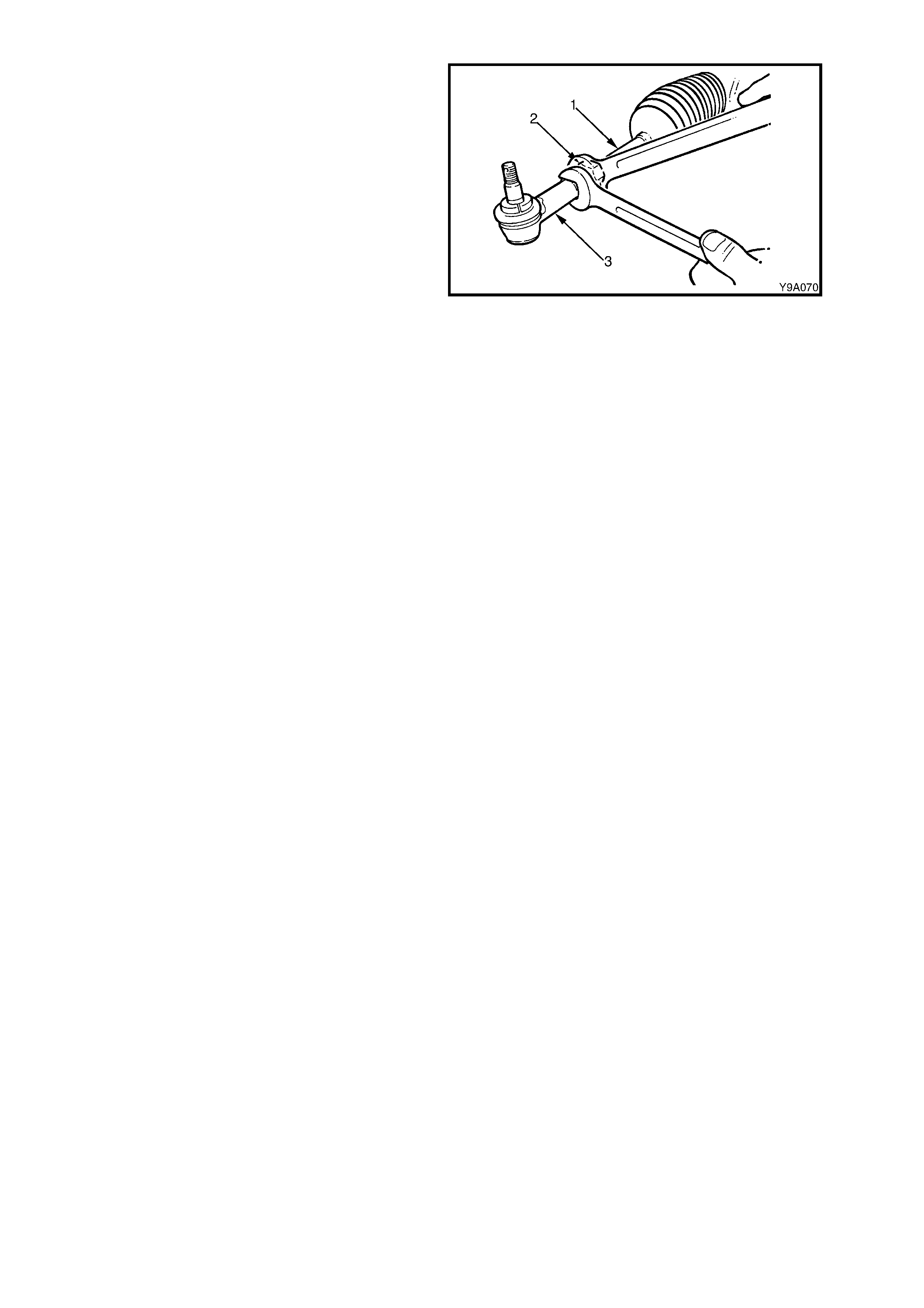
5. Loos en the tie r od lock nuts ( 2) and r emove the
outer tie rod sockets (3) and lock nuts (2) from
the tie rods (1).
6. Slide the bellows from the steering gear
housing and tie rods.
7. Rotate the pinion (input) shaft fully counter-
clockwise (full left lock).
Figure 9-50
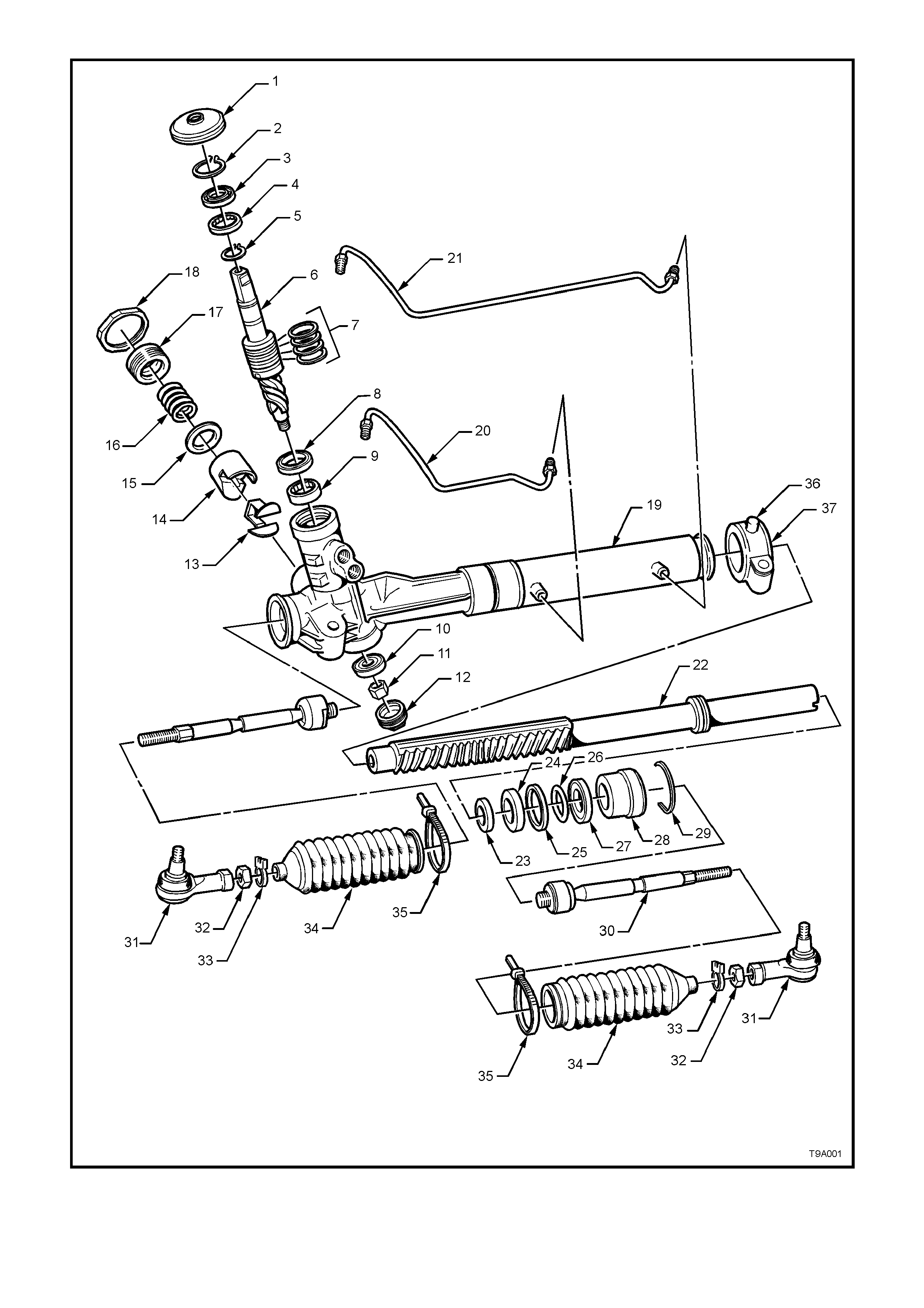
Figure 9-51
Legend
1. Cover, Dust
2. Circlip, Pinion Seal Retaining
3. Seal, Pinion Upper
4. Bearing, Pinion Upper Roller
5. Circlip
6. Valve Assembly, Rotary
7. Sealing Rings, 4 places
8. Seal, Pinion Intermediate
9. Pinion Intermediate Roller Bearing
10. Bearing, Ball
11. Nut, Pinion
12. Plug, Sealing Screw
13. Insert, Rack Pad
14. Pad, Rack
15. Washer, Plastic
16. Spring
17. Plug, Rack Pad
18. Nut, Lock
19. Housing, Steering Gear
20. Pipe, Rack Piston Fluid - Short
21. Pipe, Rack Piston Fluid - Long
22. Rack and Piston Assembly
23. Spacer, Inner Rack Seal
24. Seal, Inner Rack
25. Sealing Ring, Rack Piston
26. O-ring, Rack Piston
27. Sea, Outer Rack
28. Bushing, Rack Outer
29. Wire, Retaining
30. Rod, Tie
31. End, Tie Rod
32. Nut, Lock
33. Clip, Bellows Outer
34. Bellows
35. Strap, Bellows Inner Tie
36. Bracket, Mounting
37. Insulator, Mounting Bracket
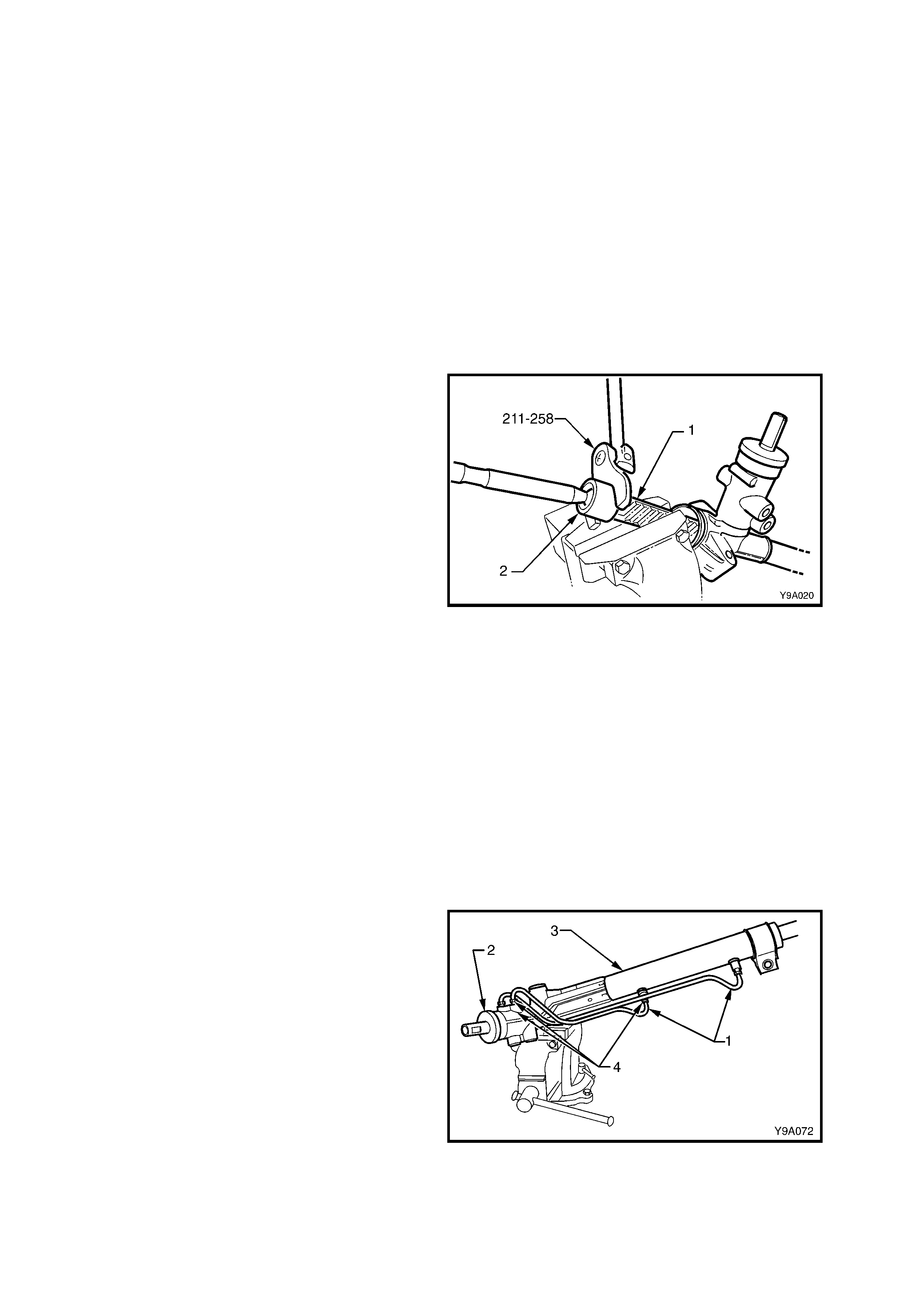
8. Remove steering gear housing from vice and
grip exposed tooth end of rack (1) in vice with
soft jaws.
9. Using Tool No. 211-258, loosen then tighten
the tie rod socket housing (2) to break the
staking, then unscrew the housing from the end
of the rack.
CAUTION: During the manufacturing process,
the threaded ends of the steering rack and
piston assembly are staked to the tie rod inner
socket housing. Consequently, during
disassembly of the power steering gear,
damage to the threads on the end of the tie rod
inner socket and the rack and piston assembly
will occur. Whenever a steering gear is
disassembled, the inner tie rods and the rack
and piston assembly MUST be replaced.
10. Remove the housing assembly from the vice
and ensure that there is no foreign matter on
the rack teeth. Rotate the pinion (input) shaft
clockwise, just enough to expose the left-hand
tie rod socket housing.
11. Remount the steering gear in the vice, again
gripping on the right-hand end of the exposed
teeth of the rack.
12. Remove the left-hand tie rod assembly, using
the same method described in step 9.
Figure 9-52
13. Remount the steering gear housing (3) in the
vice fitted with protective jaws, gripping the
right-hand mounting boss.
14. Disconnect the feed pipes (1 and 4) from the
valve housing (2) and the steering gear tubing
(3).
Figure 9-53
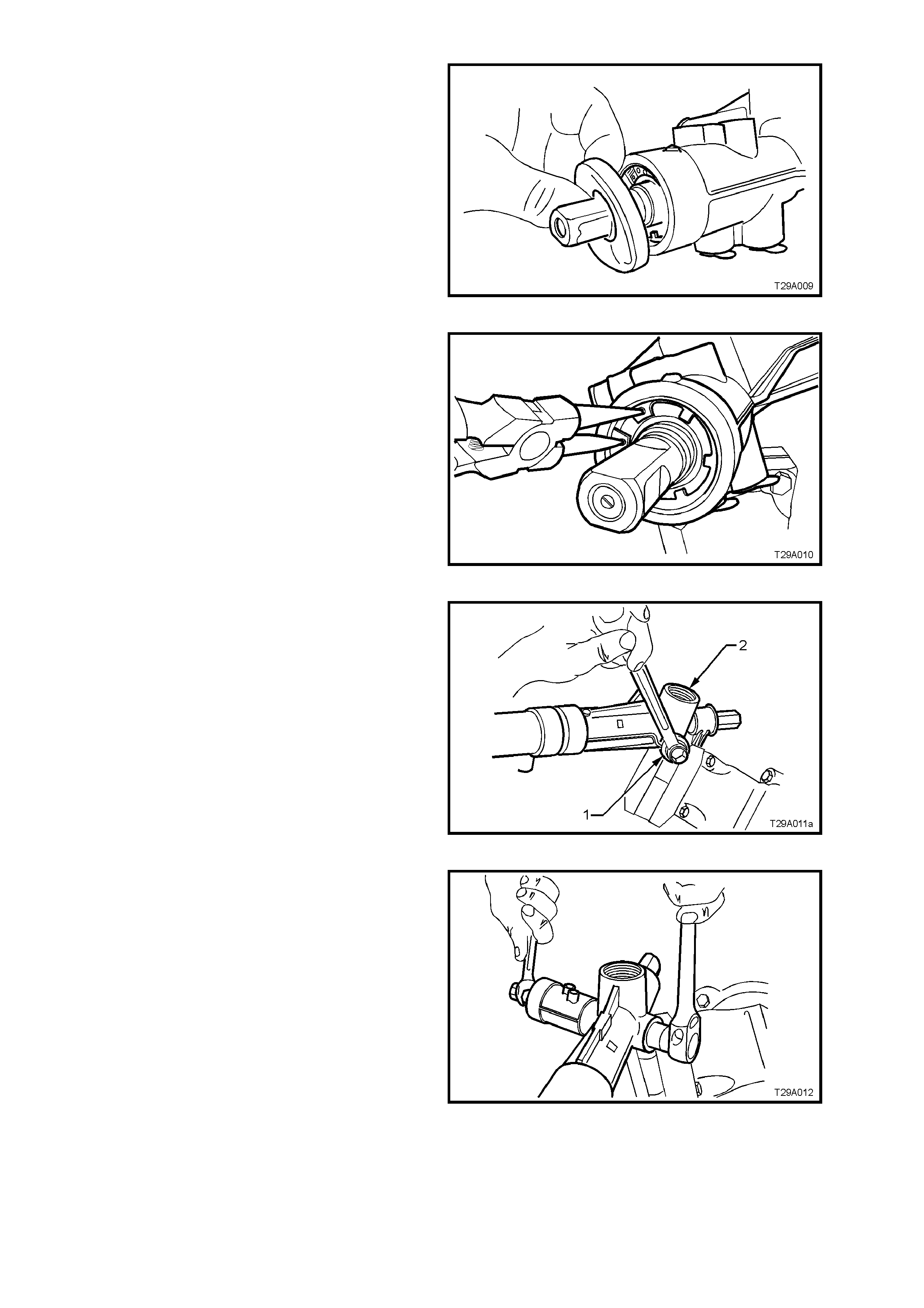
15. Rem ove the dust cover from the valve housing
and input shaft.
Figure 9-54
16. Using suitable circlip pliers, compress and
rem ove the pinion s eal r etaining c irc lip f r om the
top of the housing.
Figure 9-55
17. Remove the pinion lower bearing screw plug
(1) from the housing (2).
Figure 9-56
18. While holding the input pinion with a 15 m m s et
spanner across the flats, remove the pinion
lower bearing retaining nut from the pinion,
using a 17 mm socket and ratchet.
Figure 9-57
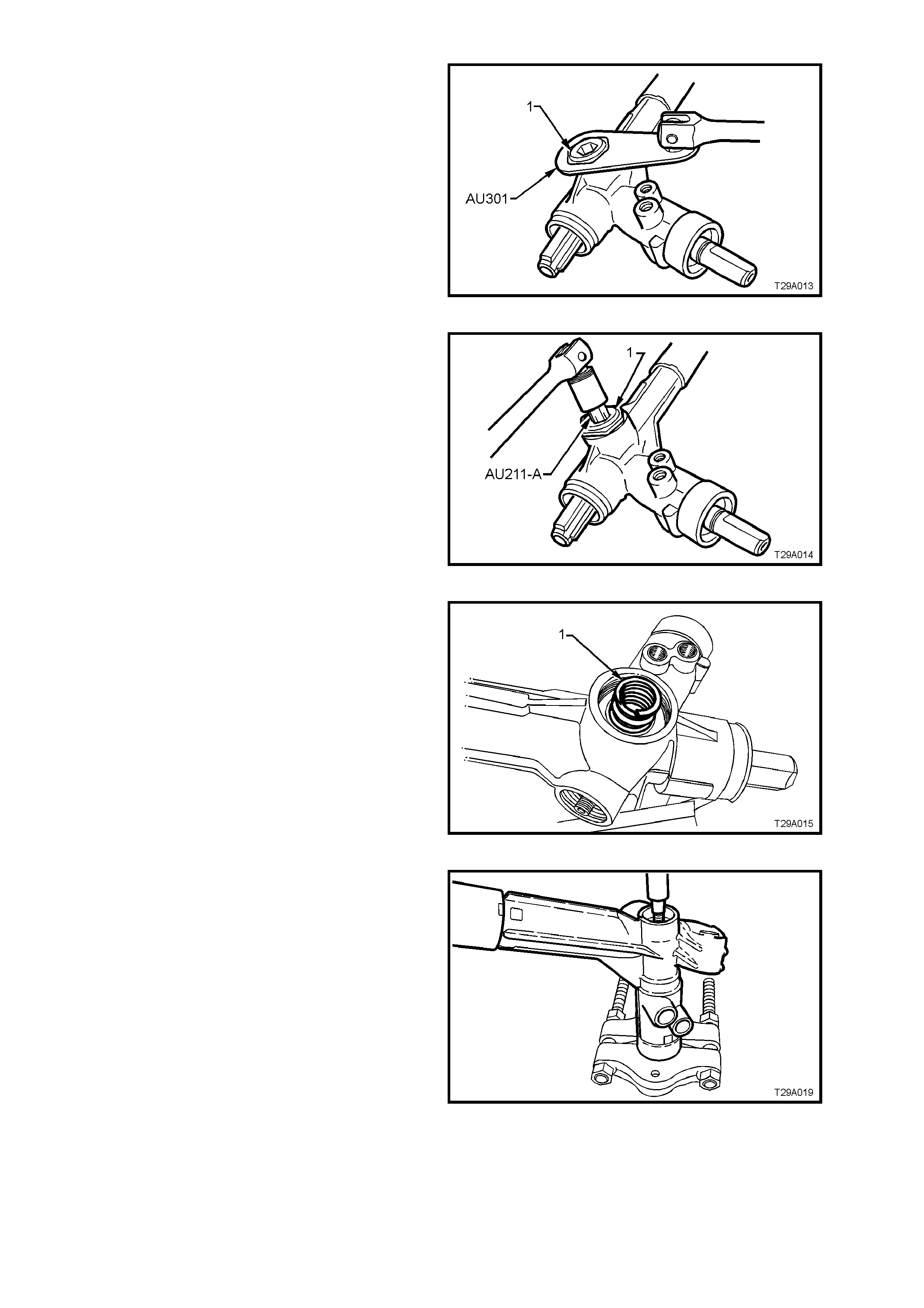
19. Remove the rack pad adjuster lock nut (1)
using Tool No. AU301.
20. Rotate the input shaft fully clockwise (full right
lock).
Figure 9-58
21. Loosen and remove the rack pad adjuster
screw (1), using Tool No. AU211-A.
Figure 9-59
22. Remove the r ack pad spring ( 1), plastic washer
and rack pad assembly from the steering gear
housing.
NOTE: Snap ring pliers can be used to grasp the
rack pad inside the internal flange and twisting
back and forth while pulling to remove.
Alternatively, remove the housing f rom the vic e and
tap gently on a wooden block to dislodge the rack
pad assembly.
Figure 9-60
23. With the steering gear housing supported on
suitable pr ess plates such as E6673 as shown,
use a suitable drift and press on the lower end
of pinion to remove pinion assembly from
housing.
NOTE: While pressing is the preferred method of
removing the pinion assembly from the housing, a
brass drift and hammer could also be use for this
operation. However, considerable f orce will need to
be applied to remove the pinion assem bly from the
lower ball bearing and housing as the upper pinion
seal and roller bearing are also removed in this
operation.
Figure 9-61
24. Remove and discard the PTFE rings from the
rotary valve outer sleeve.
The seals are best removed by cutting
diagonally with a sharp knife, but care must be
taken to avoid scratching the sides of the
grooves otherwise s ubsequent internal leakage
could oc c ur, resulting in a heavy or inconsis tent
steering feel.
NOTE: Because of component matching that is
critical to the s afe oper ation of the sleeve and valve
assembly, THE PINION ASSEMBLY MUST NOT
BE FURTHER DISMANTLED.
Figure 9-62
25. Using a white marker pen or similar, mark the
relative position of the left-hand mounting
bracket and the steering Gear tube (1).
Figure 9-63
26. Remove the left-hand mounting bracket, by
using a round bar inserted through the
mounting holes and rotating the bushing and
bracket, back and forth while pulling at the
same time.
Figure 9-64
27. Remove the rack end bushing retaining wire,
as follows:
a. Using Tool No. E8803-7 with a socket
extension and bar, r otate the rack end bush
anti-clockwise, until the end of the retainer
(1) appears in the slot.
b. Carefully prise the end of the retainer wire
free of the rack tube as shown, then rotate
the end bushing with Tool No, E8803-7, in a
clockwise direction (arrow), winding the
retainer out of the tube.
c. Continue unwinding the retainer until the
end of the retainer (1) appears, then lift it
from the slot in the rack tube.
Figure 9-65
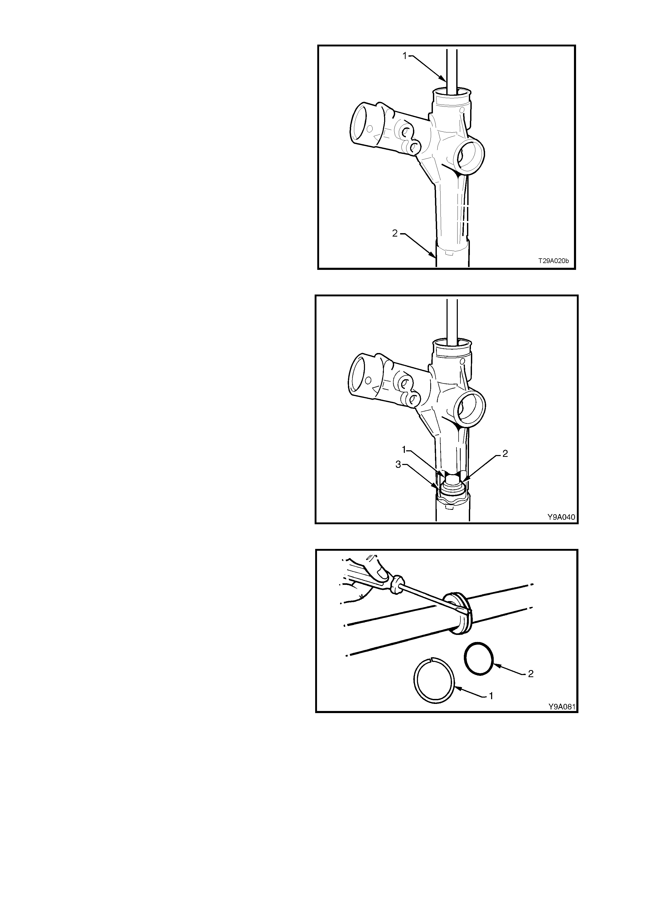
28. Support the tube end of the rack housing (2)
over suitable press plates such as E6673 or
similar, the remove the rack from the housing
by inserting a brass drift (1) into the right
threaded end of the r ack and pressing the rack
from the tube end of the rack housing.
NOTE: While a drift and hammer could also be
used, considerable resistance will be encountered,
as rack removal also removes the rack end bush
and the outer piston rod seal from the steering
tube.
Figure 9-66
29. Insert a suitable length of tubing or mild steel
stock (1), 30 mm in diameter into the housing
from the pinion end, then use a hammer (or
press) to drive the spacer (2) and inner piston
rod seal (3) from the rack housing.
Figure 9-67
30. Remove the rack piston seal (1) and O -ring (2)
from the rack piston.
NOTE: The seal (1) can be more easily removed
by cutting diagonally with a sharp knife, but take
care not to scratch the sides of the seal groove,
during this process.
Figure 9-68
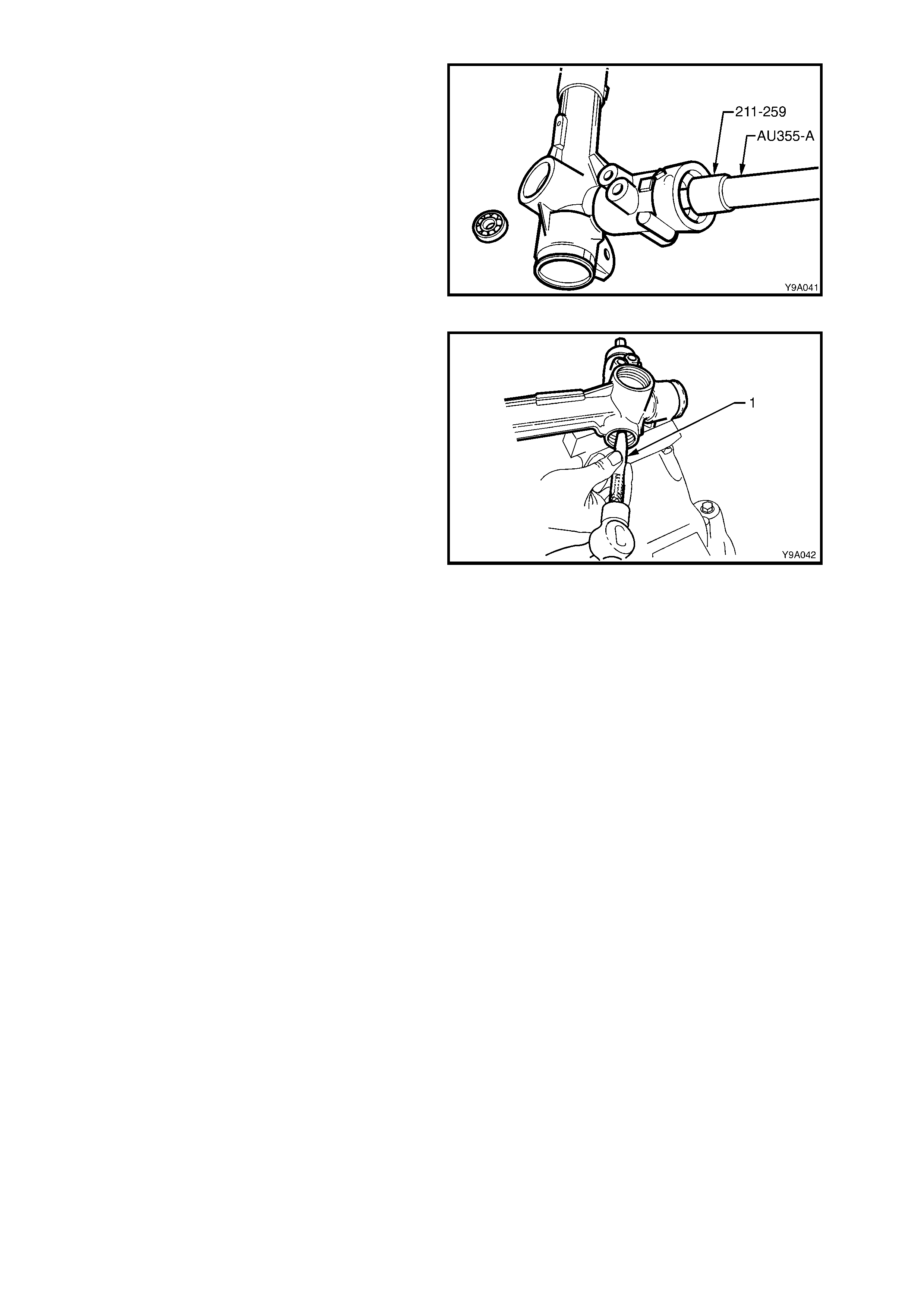
31. Screw Tool 211-259 to driver handle AU355-A,
then insert tool assembly into the rack housing
and tap the lower pinion ball bearing from the
housing.
NOTE: As this oper ation will possibly brinell the ball
race, discard after removal.
Figure 9-69
32. If required, remove the intermediate pinion
roller bearing and s eal by using a pin punch (1)
and hammer, working from opposite sides of
the bearing case until the bearing and seal are
dislodged from the housing
NOTE: As this operation will permanently damage
the roller bearing it must be replaced after removal.
Figure 9-70
CLEAN AND INSPECT
Thoroughly wash all metal parts in cleaning solvent and blow dry with compressed air.
1. Inspect the rubber bellows for damage or deterioration, replace if necessary.
2. Inspect the pinion bearings for signs of brinelling, damage or wear.
NOTE: As the intermediate pinion bearing will have been damaged on removal and the lower ball bearing will
possibly have suffered brinelling damage, both of these bearings must be replaced on reassembly.
3. Inspect the pinion for signs of tooth wear or damage.
4. Inspect the rack for signs of wear or damage to teeth, rack pad faces and rack bearing journal.
NOTE: A light polish on teeth and rack rear face is normal and should not be confused with wear.
5. Inspect the housing for wear or damage in pinion bearing bores, seal bores, rack piston and lock stop faces.
6. Inspect the rack pad for damage or excessive wear.
7. Inspect the major components of pinion assembly (pinion, valve, sleeve and torsion bar) for damage or wear.
NOTE: These parts cannot be serviced individually as they are hydraulically balanced at the pinning stage of
assembly to equalise the steering efforts in right and left directions.
REASSEMBLE
CAUTION: During the manufacturing process, the threaded ends of the steering rack and piston assembly
are staked to the tie rod inner socket housing. Consequently, during disassembly of the power steering
gear, damage to the threads on the end of the tie rod inner socket and the rack and piston assembly will
occur. Whenever a steering gear is disassembled, the inner tie rods and the rack and piston assembly
MUST be replaced.
1. Check that each of the rack seals have a circular, plastic insert ring fitted to each, on the opposite side to the
spring loaded seal lip, with the tapered edge of the inser t facing in toward the seal. Ens ure the tapered ends of
the rings seat correctly.
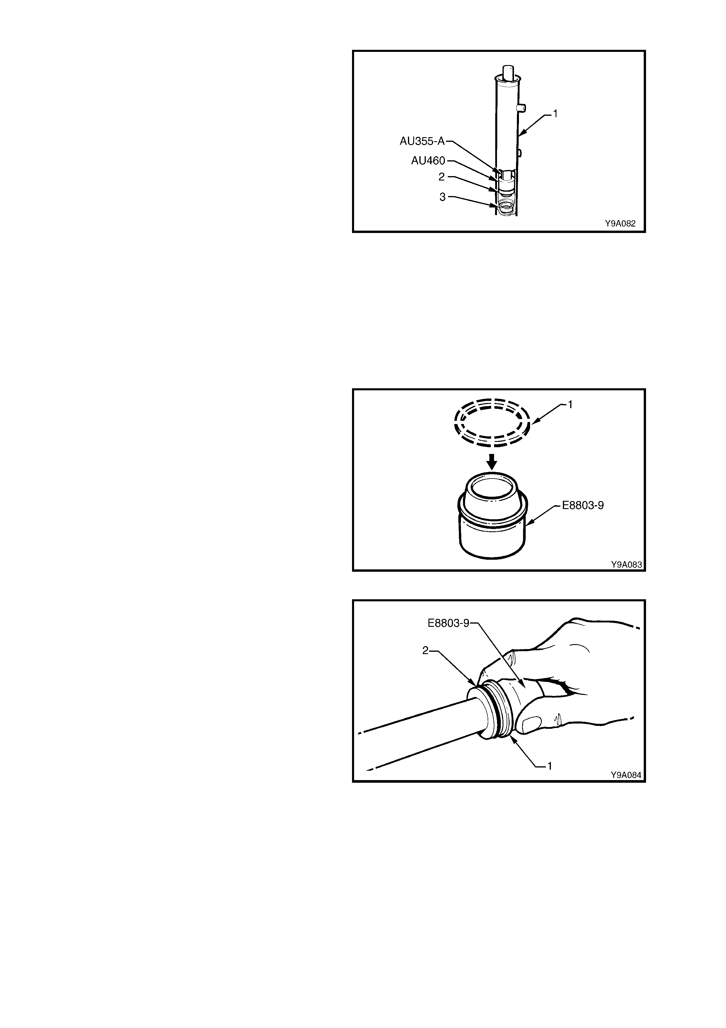
2. Screw Tool No. AU460 onto driver handle T ool
No. AU355-A with the O-ring end facing out.
Install the inner seal spacer (3) onto Tool No.
AU355-A, using the O- ring to hold the s pacer in
place. Insert the tools and spacer into the rack
tube.
3. Using tool combination AU460/AU355-A, press
the seal spacer (3) into the rack housing (1),
until the end of Tool No. AU355-A protrudes
from the rack tube by approximately 53 mm.
This measurement will ensure that the spacer
has been fully installed.
4. Reverse the fitment of Tool No. AU460 to the
driver handle Tool No. AU355-A.
5. Lubricate a new rack inner seal (2) with
Dexron® III automatic transmission fluid. Install
the seal (2) over the spigot of T ool No. AU460,
ensuring that the spring loaded sealing lip is
facing Tool No. AU460.
6. Press the seal into the rack housing (1) on top
of the spac er (3). T he seal will be fully installed
when the end of Tool No. AU355-A protrudes
from the rack tube by approximately 60 mm.
Figure 9-71
7. Install a new O-ring to groove in rack piston.
8. Af ter dipping a new Tef lon seal ring (1 ) in clean
power steering fluid, install the seal ring over
expander Tool No. E8803-9.
Figure 9-72
9. With the seal ring still installed on Tool No.
E8803-9, slide the assembly over the rack and
up to the piston. Slide the seal ring (1) off the
expansion tool and into the piston groove (2),
over the O-ring.
Figure 9-73
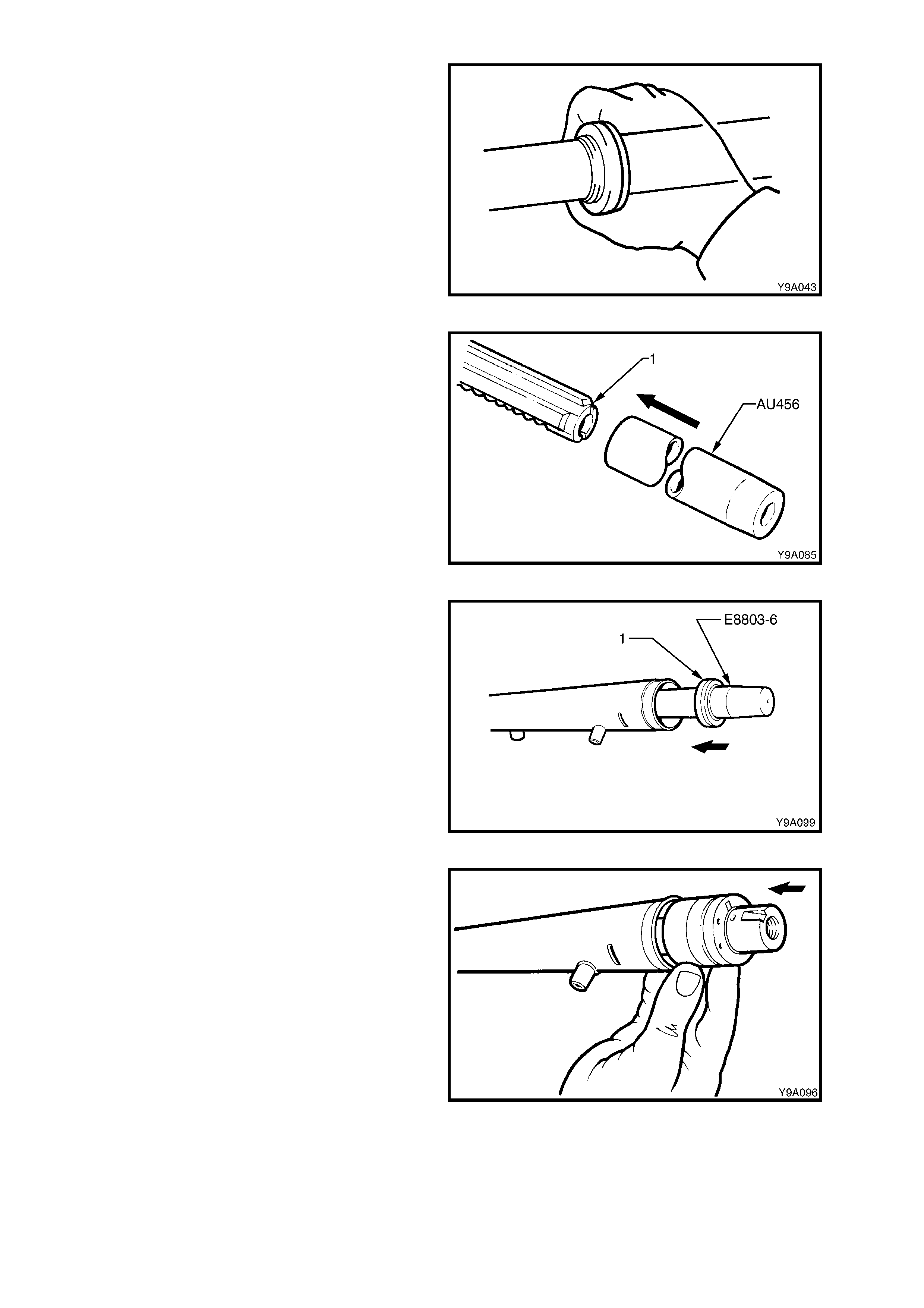
10. Ensure that the seal is seated correctly in the
groove, by wrapping f inger s ar ound the seal, as
shown.
Figure 9-74
11. Install the protector sleeve, Tool No. AU456
over the toothed end of the rack (1) and
liberally apply clean power steering fluid to the
protector’s outer surface.
12. Liberally apply clean power steering fluid to the
inner surf ac e of the r ack tube and over the r ack
piston seal.
13. Carefully install the rack and protector into the
rack housing and through the inner seal,
aligning the rack teeth with the pinion bore.
Continue installation until the rack piston has
entered the smaller, inner tube diameter.
Remove the seal protector, Tool No. AU456
from the toothed end of the rack.
Figure 9-75
14. Install the shorter seal protector E8803-6 over
the end of the rack, at the plain end.
Liberally apply clean power steering fluid to the
lip surface of the outer rack seal (1), then install
over the protector and onto the rack, with the
seal lips facing in towards the rack piston.
Figure 9-76
15. Lubricate the left-hand end bearing (1), inner
surface, with clean power steering fluid, then
install into the rack tube, pushing in against the
outer rack seal.
NOTE: To assist in installation of the bearing
retaining wire, align the hole in the bearing with the
opening in the steering housing tube.
16. Using installer Tool No. E8803-11, install the
outer seal and bearing until the retaining wire
groove is aligned with the slot in the rack
housing tubing.
Figure 9-77
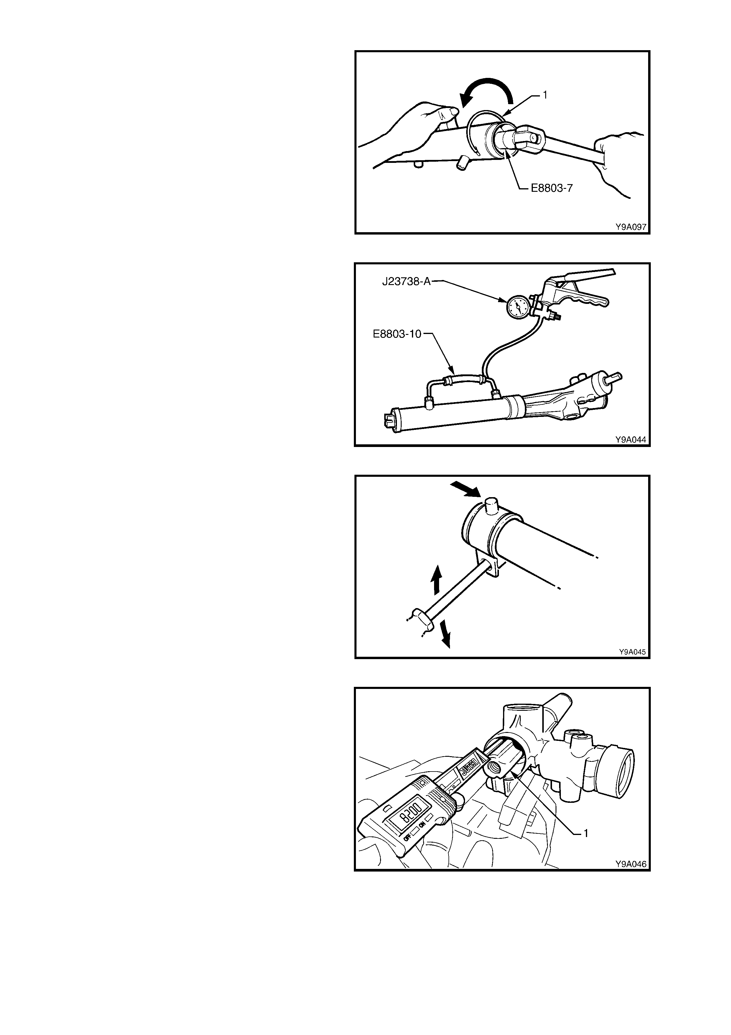
17. If necessary, rotate the end bearing with Tool
No. E8803-7, until the hole in the wire groove
appears in the tube slot.
Install the bent end of the bearing retaining
wire, into the hole then, continuing to use Tool
No. E8803-7, rotate the bearing in an anti-
clockwise direction until the end of the wire
disappears into the rack tubing.
Figure 9-78
18. Install Tool No. E8803-10, to the two cylinder
pipe fittings. Tighten the unions just enough to
effect an air tight seal.
19. Using a hand vacuum pump, such as Tool
No. J- 23738-A, apply a vacuum of 53.3 kPa ( or
40 cm, 15.75 in. Hg), for approximately 30
seconds.
20. Check that no change in the vacuum occurs
during this period. If a c hange does occ ur, then
the reas on m ust be f ound and correc ted befor e
proceeding further.
Figure 9-79
21. Check the mounting bracket insulator for
serviceability. Apply petroleum j elly (Vaseline or
equivalent) to the inner surface, then install
bracket and insulator to the steering tube, in
the reverse manner to removal. Align the
marks made prior to removal.
Figure 9-80
22. Centralise the rack assembly by measuring
82 ± 1mm from the lock stop (flange inside
rack housing) to the end of the toothed rack
(1), as shown.
Figure 9-81
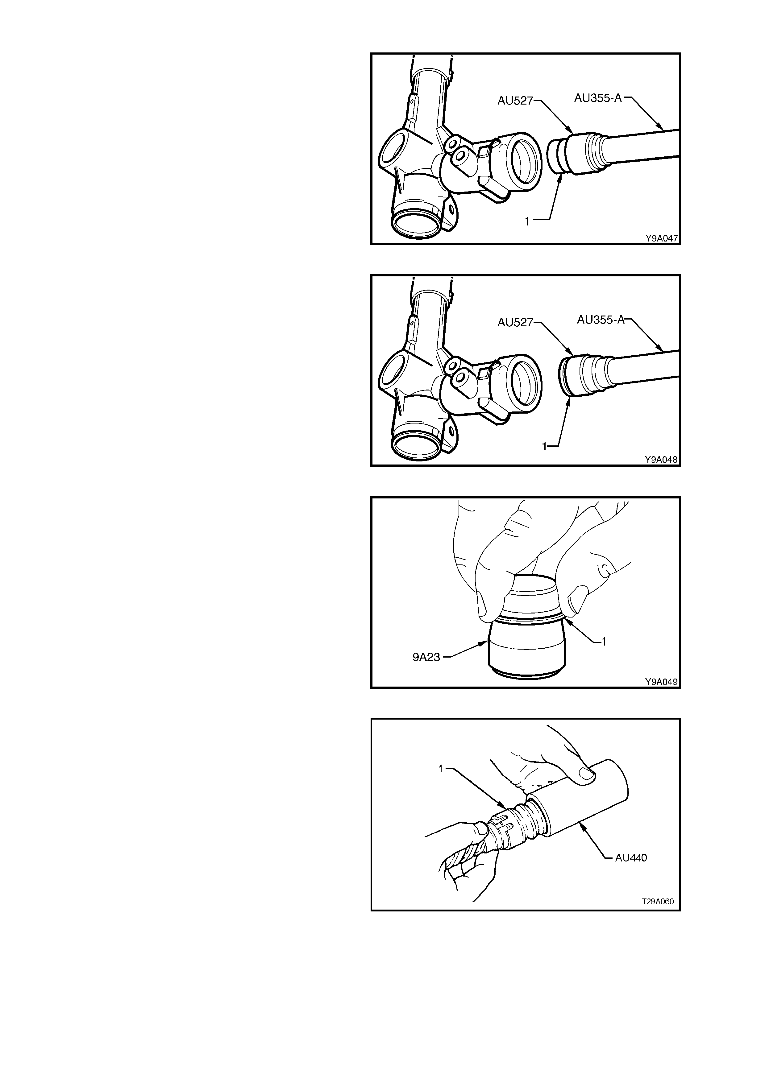
23. Lubricate a new pinion intermediate roller
bearing (1) with Dexronâ III automatic
transmission fluid, then install on the longer
pilot of Tool AU527 that has driver handle
AU355-A attached.
24. Press the bearing (1) into the steering rack
housing until fully seated. Remove the
installation tools.
Figure 9-82
25. Reverse Tool AU527 onto the driver handle
AU355-A, then install a new intermediate seal
(1) onto the shorter pilot, with the seal lips
facing the tool shoulder.
26. Press the seal (1) into the steering Gear
housing until fully seated. Remove the
installation tools.
Figure 9-83
27. To fit new PTFE seal rings (1) to sleeve
grooves, first warm in hot water then install on
the expander, Tool No. 9A23.
Slide the expanding tool with the ring installed,
over the sleeve, then push the s eal off and into
the sleeve groove. Repeat for the remaining
three seals.
Figure 9-84
28. After all seals have been fitted to the sleeve
grooves, push Tool No. AU440 over rings and
valve assembly (1), then leave for 5 to 10
minutes to contract rings back to normal size.
Figure 9-85
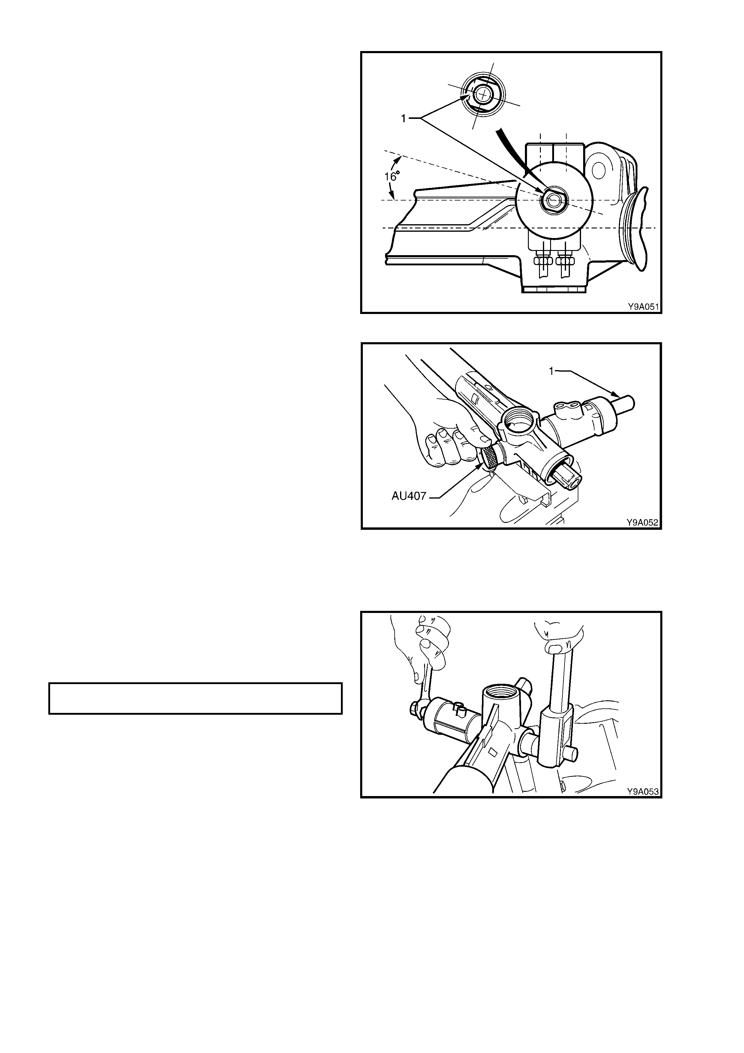
29. Inser t 50 gram s of EP Sem i Fluid Lithium Base
O Grease into the steering gear housing,
through the pinion bore.
30. While maintaining the Gear in the centralised
position, insert the pinion s o that the c lamp bolt
flat of the input shaft is positioned as shown,
when the pinion is fully located in the housing.
Figure 9-86
31. Pack the pinion lower bearing with EP Semi
Fluid Lithium Base Grease.
32. Install pinion lower bearing, using the following
procedure:
a. Install a new, lubricated ball bearing over
the lower end of the pinion, then thread T ool
AU307 onto the pinion end.
b. While holding the knurled section with one
hand as shown, fit a 15 mm set spanner to
the flat section of the pinion (1) and turn
back and forth, advancing the installation
tool until the bearing is fully seated.
c. The bearing will be fully installed when Tool
AU307 cannot be advanced any further.
d. Remove AU307 when the bearing is
installed.
Figure 9-87
33. Install the pinion lower bearing retaining nut
and tighten to the correct torque specification,
using a torque wrench and socket on the nut
and a 15 mm set spanner holding the pinion
input shaft.
(+)PINION LOWER BEARING RETAINING
NUT TORQUE SPECIFICATION 35 – 45 Nm
NOTE: This nut has a deformed thread and may be
reused once only. However, it is strongly
recommended that a new nut is fitted at each
overhaul.
Figure 9-88
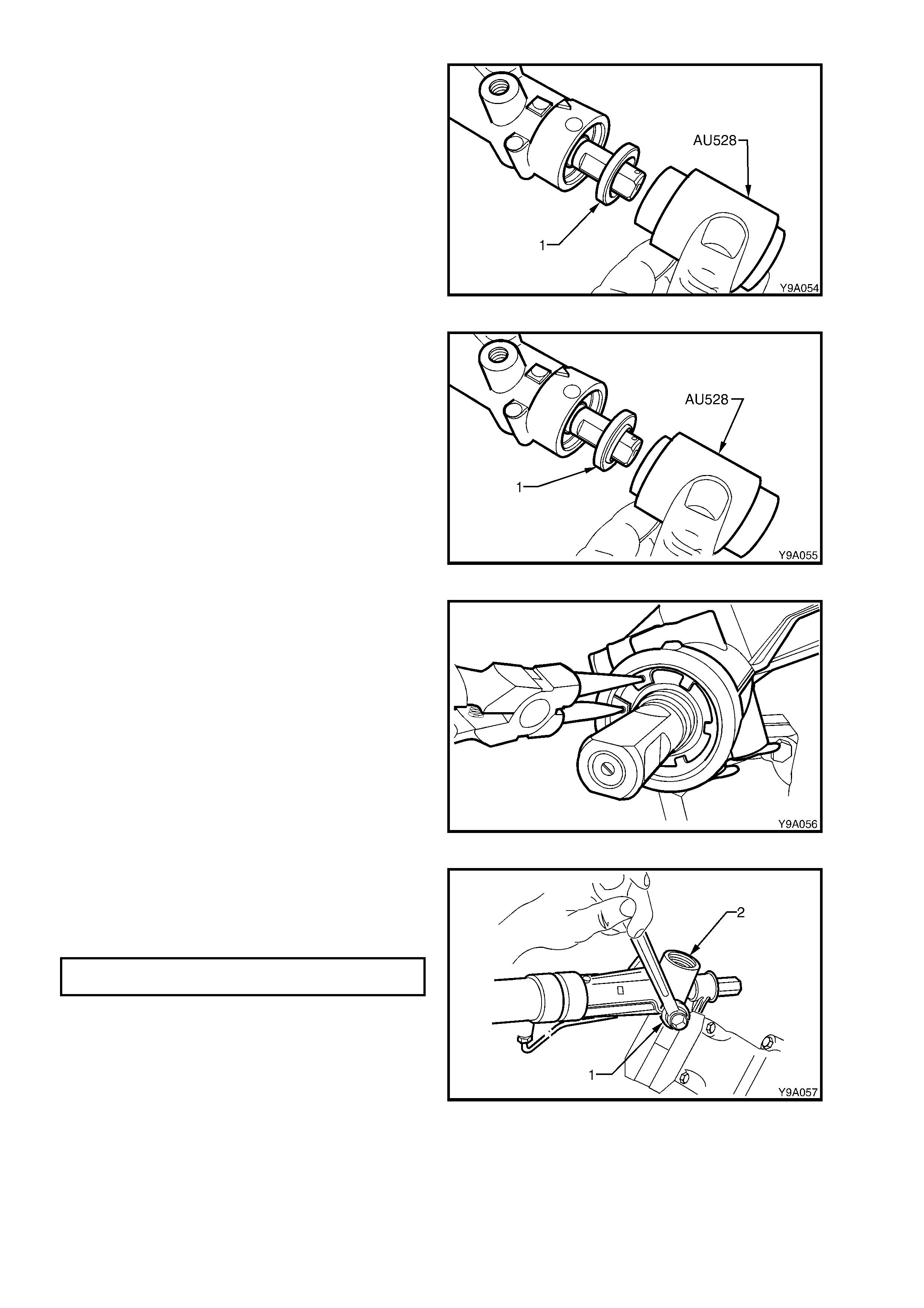
34. Lubricate the upper pinion roller bearing (1)
with Dexronâ III automatic transmission fluid,
then install the bearing over the pinion shaft.
35. Install the upper bearing (1) into the steering
Gear housing, using Tool AU528 and a plastic
hammer.
NOTE: Tool AU528 s hould be used with the longer
shank facing the bearing. When the shoulder
contacts the rack housing, the bearing will have
been installed to the correct depth.
Figure 9-89
36. Lubricate a new pinion shaft upper power
steering fluid seal (1) with Dexronâ III
automatic transmission fluid, then install the
seal over the pinion shaft with the seal lips
facing down.
37. Install the pinion shaft upper power steering
fluid seal (1) into the steering rack housing,
using Tool AU528 and a plastic hammer.
NOTE: Tool AU528 should be used with the shorter
shank facing the power steering fluid seal. When
the shoulder contacts the rack housing, the power
steering fluid seal will have been installed to the
correct depth.
Figure 9-90
38. Using suitable circlip pliers, install the circlip
over the top of the pinion upper power steering
fluid seal, ensuring that the circlip locates
correctly in the housing groove.
Figure 9-91
39. Apply Loctite 242 thread sealant (or equivalent
to Holden’s Specification HN1256) to the
cleaned threads of the pinion lower screw plug
(1), install the plug into the housing (2) and
tighten to the correct torque specification.
PINION LOWER RETAINING SCREW
PLUG TORQUE SPECIFICATION 55 – 60 Nm
Figure 9-92
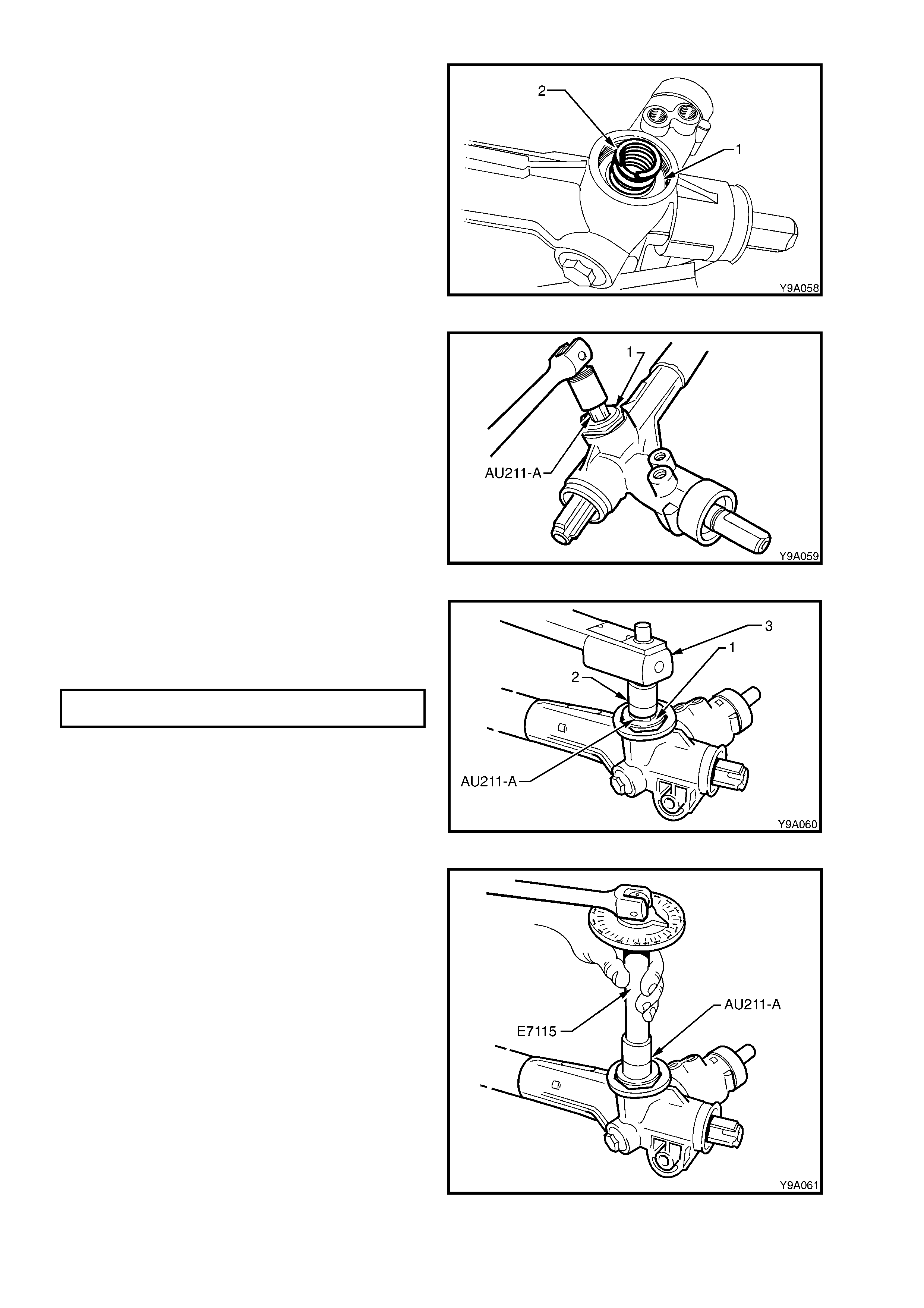
40. Install the rack pad insert to the rack pad (if
removed). Install the rack pad assembly into
the steering gear housing.
41. Install the plastic washer (1) and the rack pad
spring (2).
Figure 9-93
42. Screw the lock nut onto the adjusting screw.
Install the adjusting screw (1) into the steering
gear housing, using Tool AU211-A but leave
the lock nut loose.
Figure 9-94
43. With the steering rack in the centralised
position, tighten the rack pad adjusting screw
(1) to the correct initial torque using Tool No.
AU211-A, a suitable socket (2) and a torque
wrench (3).
RACK PAD ADJUSTING SCREW
INITIAL TORQUE SPECIFICATION 10 – 12 Nm
Figure 9-95
44. Using an angle wrench and special tools E7115
and AU211-A, turn the rack pad adjusting
screw back (anti-clockwise) 20 - 28°.
Figure 9-96
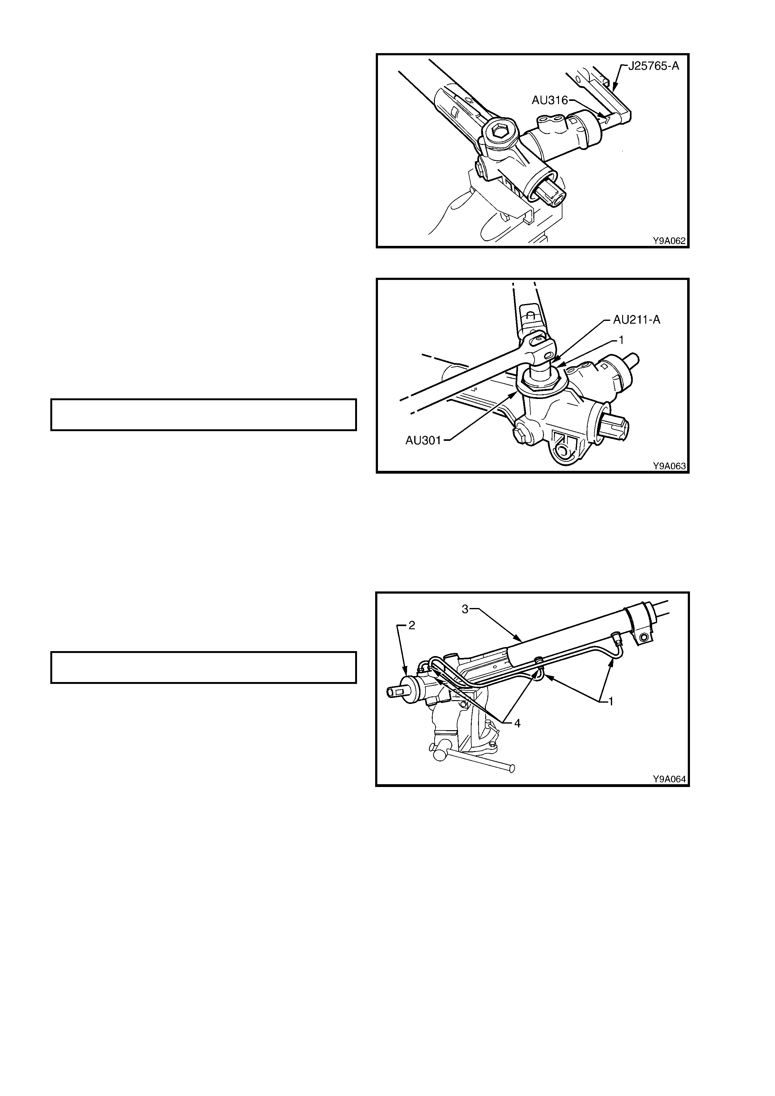
45. Install Tool AU316 to the input shaft and
measure the rotating torque of the input shaft,
using a dial type torque wrench such as
J25765-A, by cycling the steering gear back
and forth. Torque requirements are from 0.8 to
2.5 Nm.
46. As required, m inor variations f rom spec ification
in rotating torque can be corrected by
readjusting the rack pad spring tension.
NOTE: If a large variation from specification in
rotating torque or binding is experienc ed, the cause
must be determined and corrected before
proceeding further.
Figure 9-97
47. Apply Loctite 242 thread sealant (or equivalent)
to the cleaned threads of the rack pad plug lock
nut.
48. While holding the adjusting screw in the
correctly adjusted position with Tool No.
AU211-A and a sock et bar, tighten the lock nut
(1) to the correct torque specification using
Tool No. AU301 and a torque wrench.
RACK PAD ADJUSTING SCREW LOCK
NUT TORQUE SPECIFICATION 55 – 65 Nm
NOTE: Once the r ack pad adjus tment has been set
and the lock nut torqued to specification, the
steering gear must be racked from lock-to-lock to
ensure localised wear has not appreciably affected
the setting. The gear should not bind or appear
tight over any part of the total travel. Should the
gear bind or appear tight, recheck the rack pad
adjustment. If this is not the cause, disassemble
the gear assembly and examine the rack and
pinion for wear. Replace as necessary.
Figure 9-98
49. Reconnect the f eed pipes (1 and 4) to the valve
housing (2) and steering gear tubing (3) and
tighten the pipe flare nuts to the correct torque
specification.
FEED PIPE FLARE NUT
TORQUE SPECIFICATION 15 – 25 Nm
NOTE: The longer of the two pipes (LH lock) is
installed into the upper location on the valve body
housing, while the s horter ( RH lock ) is installed into
the lower.
50. Rotate the pinion shaft fully anti-clockwise (left
lock).
51. Remove the steering gear housing from the
vice, and grip the exposed toothed end of the
rack in the vice with soft jaws.
Figure 9-99
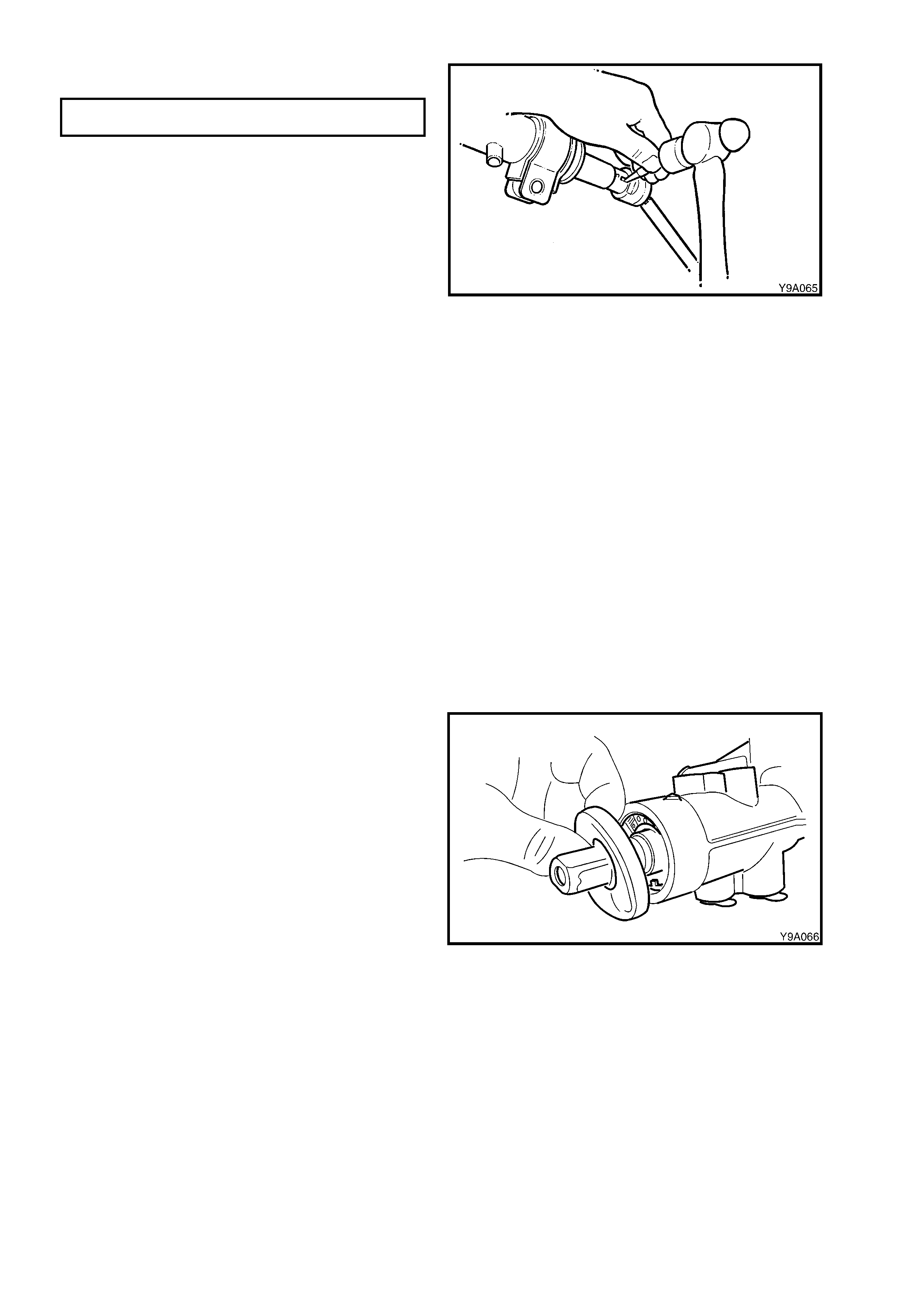
52. Using Tool No. 211-258, tighten the right-hand
tie rod to the correct torque specification.
TIE ROD TO RACK AND PISTON
ASSEMBLY TORQUE SPECIFICATION 90 – 100 Nm
CAUTION: During the manufacturing process,
the threaded ends of the steering rack and
piston assembly are staked to the tie rod inner
socket housing. Consequently, during
disassembly of the power steering gear,
damage to the threads on the end of the tie rod
inner socket and the rack and piston assembly
will occur. Whenever a steering gear is
disassembled, the inner tie rods and the rack
and piston assembly MUST be replaced.
53. Using the centre punch and a large ball-pein
hammer, stake the rack to tie rod socket
housing in two places inside the k ey-way at the
end of the rack.
NOTE: The key-way at either end of the steering
rack has not been hardened, and is the only area
that is suitable f or the stak ing procedure. Ens ure to
stak e the rack in two places as close as possible to
the tie-rod inner socket (either side of key way).
54. Remove the steering gear housing from the
vice and rotate the pinion shaft slightly
clockwise, just enough to expose the left-hand
end of the rack.
55. Tighten the left-hand tie rod as in steps 52 and
53.
56. Relocate the steering gear housing in the vice
by gripping the right-hand mounting boss.
57. Rotate the input shaft to the straight ahead
position.
Figure 9-100
58. Install a new dust cover to the pinion shaft,
ensuring that the cover is engaged with the
groove in the pinion.
Figure 9-101
59. Fit the bellows to the tie rods and steering gear housing. Install the retaining clips.
60. Fit the tie rod socket lock nuts and the tie rod sockets to the tie rods.
NOTE: Do not tighten the lock nuts, as toe adjustment must be performed after steering gear is installed.
61. Install the steering gear assembly into the vehicle, as detailed In 3.6 POWER STEERING GEAR - REINSTA LL.
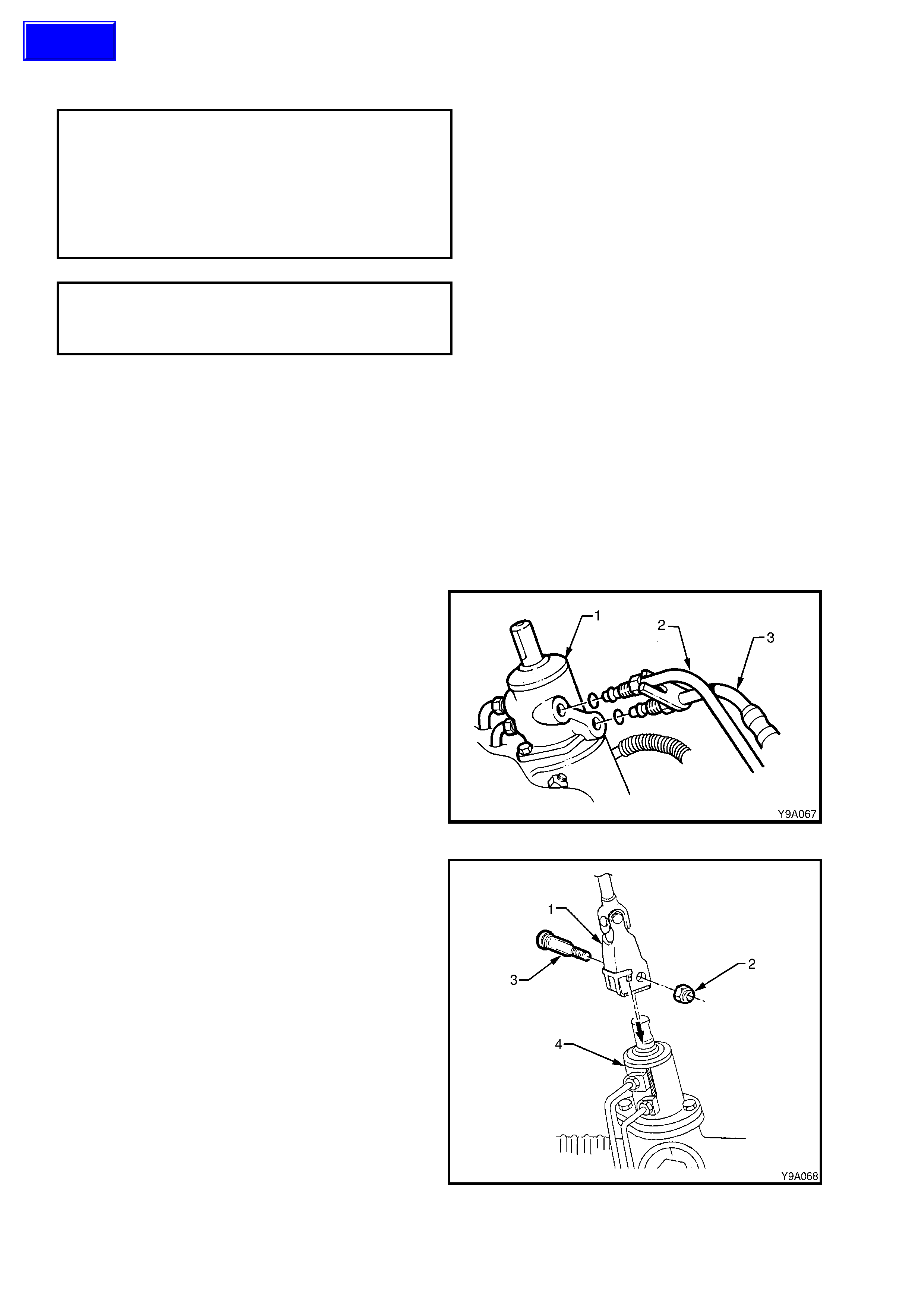
3.7 LEFT-HAND DRIVE POWER STEERING GE AR
LT Section No. – 06-275
NOTE 1: The following fasteners have either micro
encapsulation or incorporate a mechanical thread lock
and should only be used once. If in doubt, r eplacement
is recommended when performing this operation:
♦ Steering gear housing to front suspension
crossmember nuts.
♦ Steering coupling lower cam bolt nut.
NOTE 2: The following fasteners MUST be replaced
when performing this operation:
+
++
+
Steering gear pinion lower bearing retaining nut
IMPORTANT: Remove the ignition key from the ignition lock and ensure that the steering column is locked. If this
operation is not car ried out and the steering wheel is spun while the steering gear is removed f rom the vehicle, the
clock spring coil in the upper end of the steering column will be destroyed!
REMOVE
1. Disconnect the battery earth lead.
2. Raise the front of the vehicle and place on safety stands. Refer to Section 0A, GENERAL INFORMATION.
3. Remove the front wheel cover (steel wheels) or centre caps (alloy wheels)
4. Mark the relationship of each wheel to the hub/brake disc. Remove the road wheel attaching nuts and rem ove
the wheels.
5. Place a drain tray beneath the steering gear.
6. Loosen and remove the hydraulic lines (2 and
3) fr om the st eering gear valve housing (1) and
allow the power steering fluid to drain into a
suitable container.
Figure 9-102
7. Remove the steering coupling (1) lower cam
bolt nut (2), rem ove the cam bolt (3), then s lide
the coupling away from the steering gear (4).
Figure 9-103
Techline

8. Remove the tie rod end split pins and
castellated nuts (’3’ in Figure 9-105).
9. Separate the tie rod end ball studs (1) from
steering arm tapers using a suitable remover,
such as Tool No. 9A10.
Figure 9-104
10. Remove the steering gear housing to front
suspension crossmember mounting bolts (1)
and nuts (2).
11. Remove the s teering gear by pulling it out from
the front suspension crossmember mounting
(4) and slide the pinion (input) shaft (5) from
the steering coupling lower clamp.
Figure 9-105
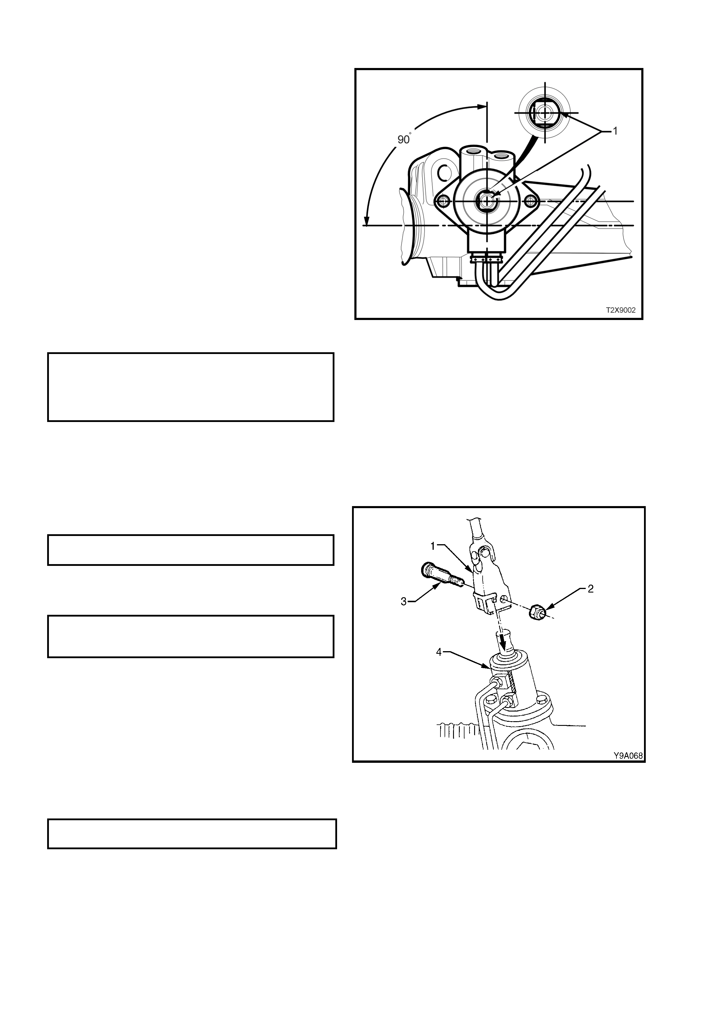
REINSTALL
1. Ensure that the steering gear is centralised.
NOTE: This is achieved by rotating the pinion to the
halfway position of its total lock-to-lock rotation.
W hen the rac k is in the stra ight ahead position, the
flat on the pinion (input) shaft (1) will be aligned as
shown in Figure 9-106.
NOTE: Alternatively, remove both inner boot
clamps, slide the boots back and measure the
exposed portion of each end of the rack from the
housing. When both measurements are equal, the
rack is centralised.
2. Ensure that the st eering wheel is in the straight
ahead position.
3. Slide the steering gear pinion (input) shaft into
the steering coupling lower flange.
4. Position the steering gear housing into the
crossmember mounting points. Install the
mounting bolts, washers and nuts and tighten
the nuts to the correct torque specification.
(6)STEERING GEAR HOUSING TO
CROSSMEMBER MOUNTING NUT
TORQUE SPECIFICATION 60 Nm, then
40° - 50° turn
angle
5. Inspect the condition of the steering gear
hydraulic line O-rings. Replace as necessary.
6. Fit hydraulic lines to the steering gear valve
housing. Tighten the flare nuts to the correct
torque specification.
Figure 9-106
7. Ins tall the lower cam bolt (3) and a new nut (2).
Tighten to the correct torque specification.
(6)STEERING COUPLING CAM BOLT
NUT TORQUE SPECIFICATION 25 – 30 Nm
8. Install the tie rod end ball studs into steering
arms. Install castellated nuts and tighten to the
correct torque specification.
TIE ROD SOCKET STUD
CASTELLATED NUT
TORQUE SPECIFICATION 50 – 85 Nm
9. Install new split pins into the tie rod ball studs.
NOTE: Ensure that the plastic spacers are
positioned on tie rod end ball studs and that they
are in good condition before fitting the studs into
the steering arms. Replace the spacers if
damaged.
Figure 9-107
10. Install the wheels, aligning the m arks m ade on removal. T ighten the wheel attaching nuts to the correct torque
specification.
ROAD WHEEL ATTACHING NUT
TORQUE SPECIFICATION 110 – 140 Nm
11. Lower the vehicle to the ground and reconnect the battery earth lead.
12. Refill and bleed the hydraulic system, refer to 3.3, HYDRAULIC SYSTEM, BLEEDING/REFILLING in this
Section.
13. Check the front wheel toe setting, refer to Section 3, FRONT SUSPENSION.
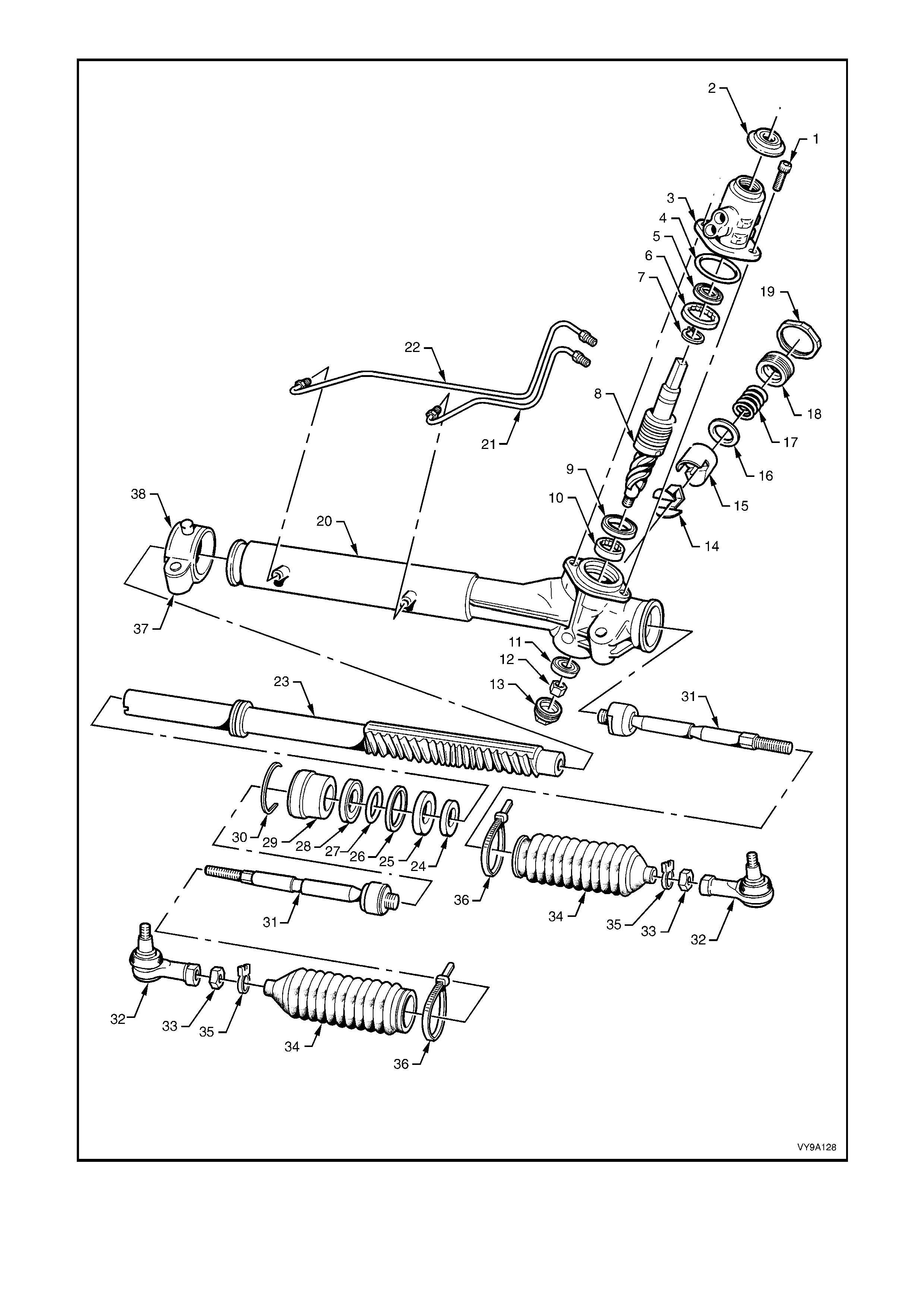
Figure 9-108
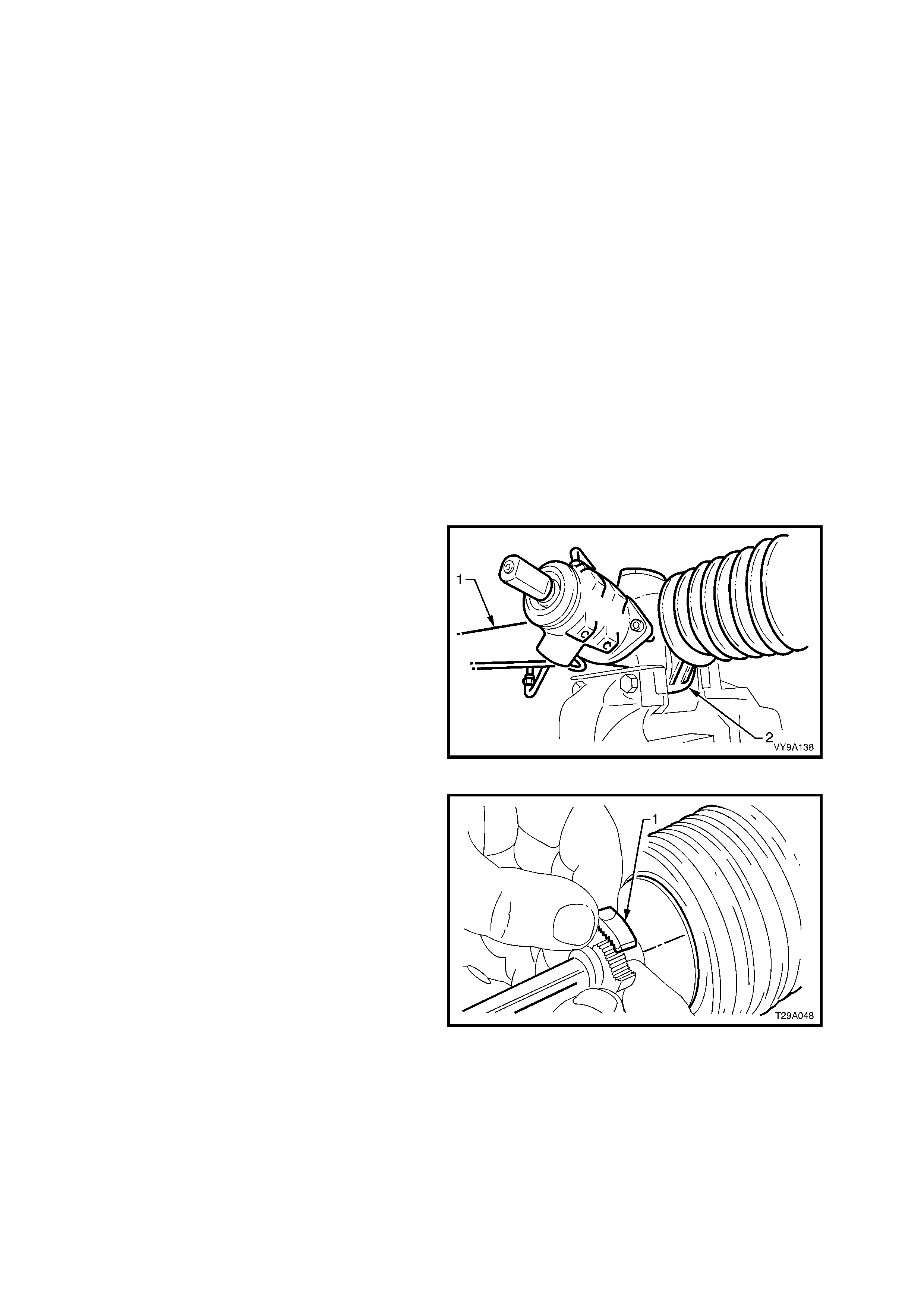
Legend for Figure 9-108
1. Screw, Valve Housing (2 places)
2. Cover, Dust
3. Housing, Valve
4. O-ring
5. Seal
6. Bearing, Roller
7. Circlip
8. Valve Assembly, Rotary
9. Seal
10. Bearing, Roller
11. Bearing, Ball
12. Nut, Pinion
13. Plug, Sealing
14. Insert, Rack Pad
15. Pad, Rack
16. Washer
17. Spring
18. Plug, Rack Pad
19. Nut, Lock
20. Housing, Steering Gear
21. Pipe, Rack Piston Fluid - Short
22. Pipe, Rack Piston Fluid - Long
23. Rack and Piston Assembly
24. Spacer, Inner Rack Seal
25. Seal, Inner Rack
26. Seal, Rack Piston
27. O-ring, Rack Piston
28. Seal, Outer Rack
29. Bushing, Rack Outer
30. Wire, Retaining
31. Rod, Tie
32. End, Tie Rod
33. Nut, Lock
34. Bellows
35. Clip, Bellows Outer
36. Tie Strap, Bellows Inner Tie
37. Bracket, Mounting
38. Insulator, Mounting Bracket
DISASSEMBLE
CAUTION: During the manufacturing process, the threaded ends of the steering rack and piston assembly
are staked to the tie rod inner socket housing. Consequently, during disassembly of the power steering
gear, damage t o t he th reads on the end of the t ie rod inner socket and rack and pist on assembly will occur.
Whenever a steering gear is disassembled, the inner tie rods and the rack and piston assembly MUST be
replaced.
For identification of components, refer to Figure 9-108.
1. Clean all dirt and foreign matter from the exterior of the steering gear assembly.
2. Mount the steering gear hous ing (1) by gripping
the left-hand mounting boss (2) in a vice fitted
with soft jaws.
3. Place a drain tray beneath the steering gear.
Figure 9-109
4. Unclip and remove all bellows clips.
a. To remove the outer clips (1): Move ends of
clips sideways until they disengage.
Figure 9-110
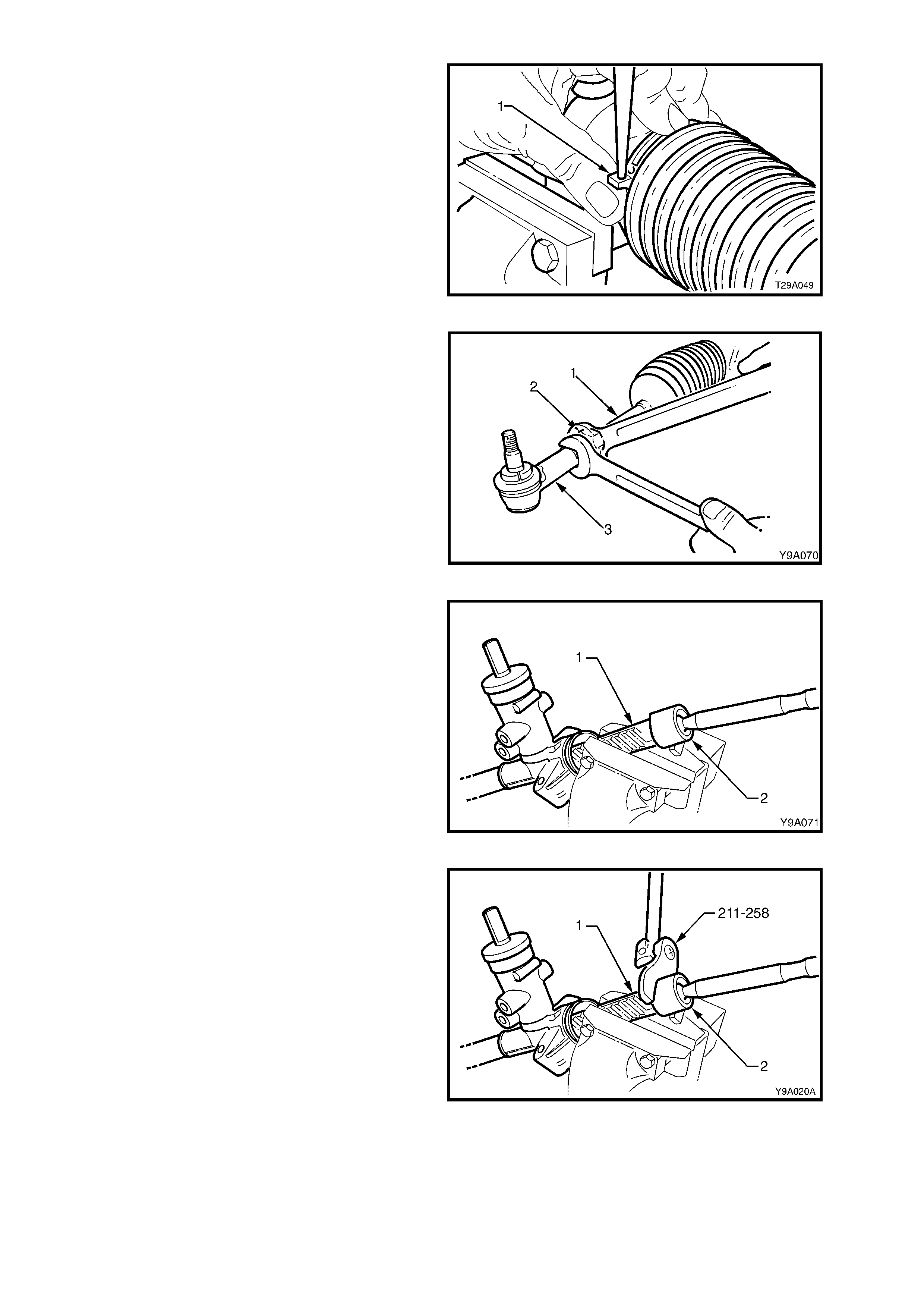
b. T o remove the inner clips (1): Push out the pin
retaining the clip ends together using a fine pin
punch.
Figure 9-111
5. Loosen the tie rod lock nuts (2). Remove the tie
rod sockets (3) and lock nuts (2) from the tie
rods (1).
6. Slide the bellows from the steering gear
housing and tie rods.
7. Rotate the pinion (input) shaft fully clockwise
(full right lock).
Figure 9-112
8. Remove the steering gear housing from the
vice and grip the expos ed tooth end of the rac k
(1) in a vice with soft jaws.
Figure 9-113
9. Using Tool No. 211-258, loosen then tighten
the left-hand tie rod inner socket housing to
break the staking, then unscrew the housing
from the end of the rack.
Figure 9-114
10. Remove the housing assembly from the vice and ensure that there is no foreign matter on the rack teeth.
Rotate the pinion (input) shaft counter-clockwise, (full left lock) to expose the rack and tie rod inner socket
housing.
11. Remount the steering gear in the vice, gripping around the exposed end of the rack.
12. Remove the left-hand tie rod assembly as in step 9.
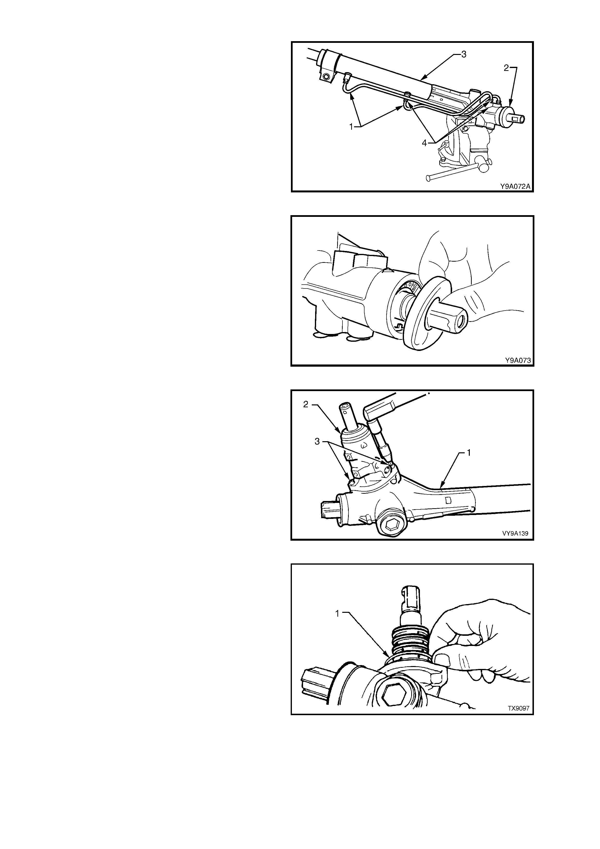
13. Remount the steering gear housing (3) in the
vice fitted with protective jaws, gripping the
right-hand mounting boss.
14. Disconnect the feed pipes (1 and 4) from the
valve housing (2) and the steering gear tubing
(3).
Figure 9-115
15. Rem ove the dust cover from the valve housing
and input shaft.
Figure 9-116
16. Using a 5 mm Allen key, remove the valve
housing attaching screws (3). Withdraw the
valve housing (2) from the input shaft.
Figure 9-117
17. Remove and discard the valve housing to
steering gear housing O-ring (1).
Figure 9-118
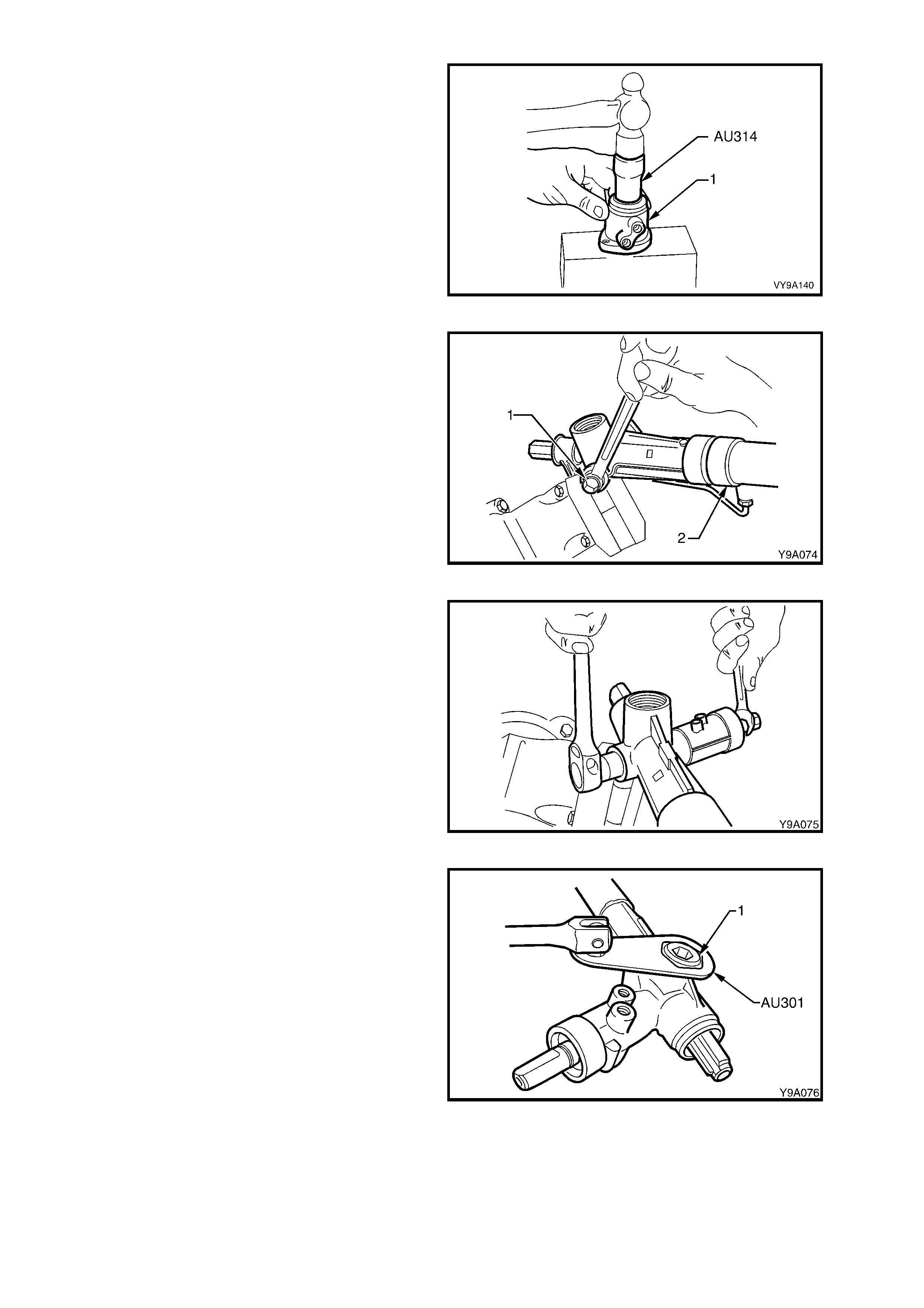
18. Place the flange f ace of the valve housing onto
a wooden block and, using Tool No. AU314,
drive the valve seal and bearing from the valve
housing.
Figure 9-119
19. Remove the pinion lower bearing screw plug
(1) from the housing.
Figure 9-120
20. While holding the input pinion with a set
spanner across the flats, remove the pinion
lower bearing retaining nut from the pinion.
Figure 9-121
21. Remove the rack pad adjuster lock nut (1)
using Tool No. AU301.
22. Rotate the input shaft fully clockwise (full right
lock).
Figure 9-122
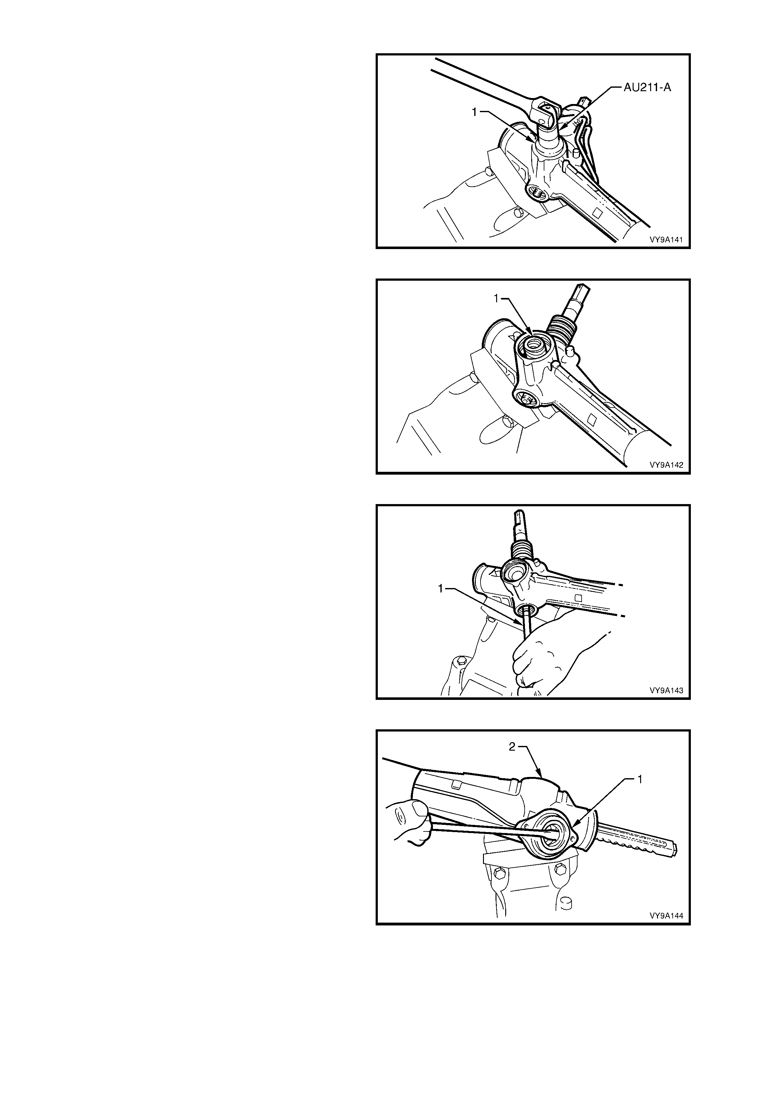
23. Loosen and remove the rack pad adjuster
screw (1), using Tool No. AU211-A.
Figure 9-123
24. Remove the rack pad spring (1) and rack pad
assembly from the steering gear housing.
NOTE: The rack pad assembly may be assisted
from the steering gear housing with a pair of
internal c irclip pliers, however, it may be necessary
to rem ove the housing from the vice and tap gently
on a wooden block to dislodge the rack pad
assembly.
Figure 9-124
25. Using a brass drift (1) and a soft faced
hammer, gently knock on the lower end of the
pinion to remove the pinion assembly from the
housing.
Figure 9-125
26. Using a large screwdriver, lever out the pinion
seal (1) from the housing (2). Discard the seal.
NOTE: Take care not to damage the housing lip.
Figure 9-126

27. Remove and discard the PTFE rings from the
rotary valve outer sleeve.
The seals are best removed by cutting
diagonally with a sharp knife, but care must be
taken to avoid scratching the sides of the
grooves otherwise s ubsequent internal leakage
may occur, resulting in heavy or inconsistent
steering feel.
NOTE: Because of component matching that is
critical to the s afe oper ation of the sleeve and valve
assembly, THE PINION ASSEMBLY MUST NOT
BE FURTHER DISMANTLED.
Figure 9-127
28. Using a white marker pen or similar, mark the
relative position of the left-hand mounting
bracket and the steering rack tube (1).
Figure 9-128
29. Remove the left-hand mounting bracket, by
using a round bar inserted through the
mounting holes and rotating the bushing and
bracket, back and forth while pulling at the
same time.
Figure 9-129
30. Remove the rack end bushing retaining wire,
as follows:
a. Using Tool No. E8803-7 with a socket
extension and bar, rotate the rack end bush
anti-clockwise, until the end of the retainer (1)
appears in the slot.
b. Carefully prise the end of the retainer wire free
of the rack tube as shown, then rotate the end
bushing with Tool No. E8803-7, in a clockwise
direction (ar row), winding the retainer out of the
tube.
c. Continue unwinding the retainer until the end of
the retainer (1) appears , then lif t it fr om the slot
in the rack tube.
Figure 9-130
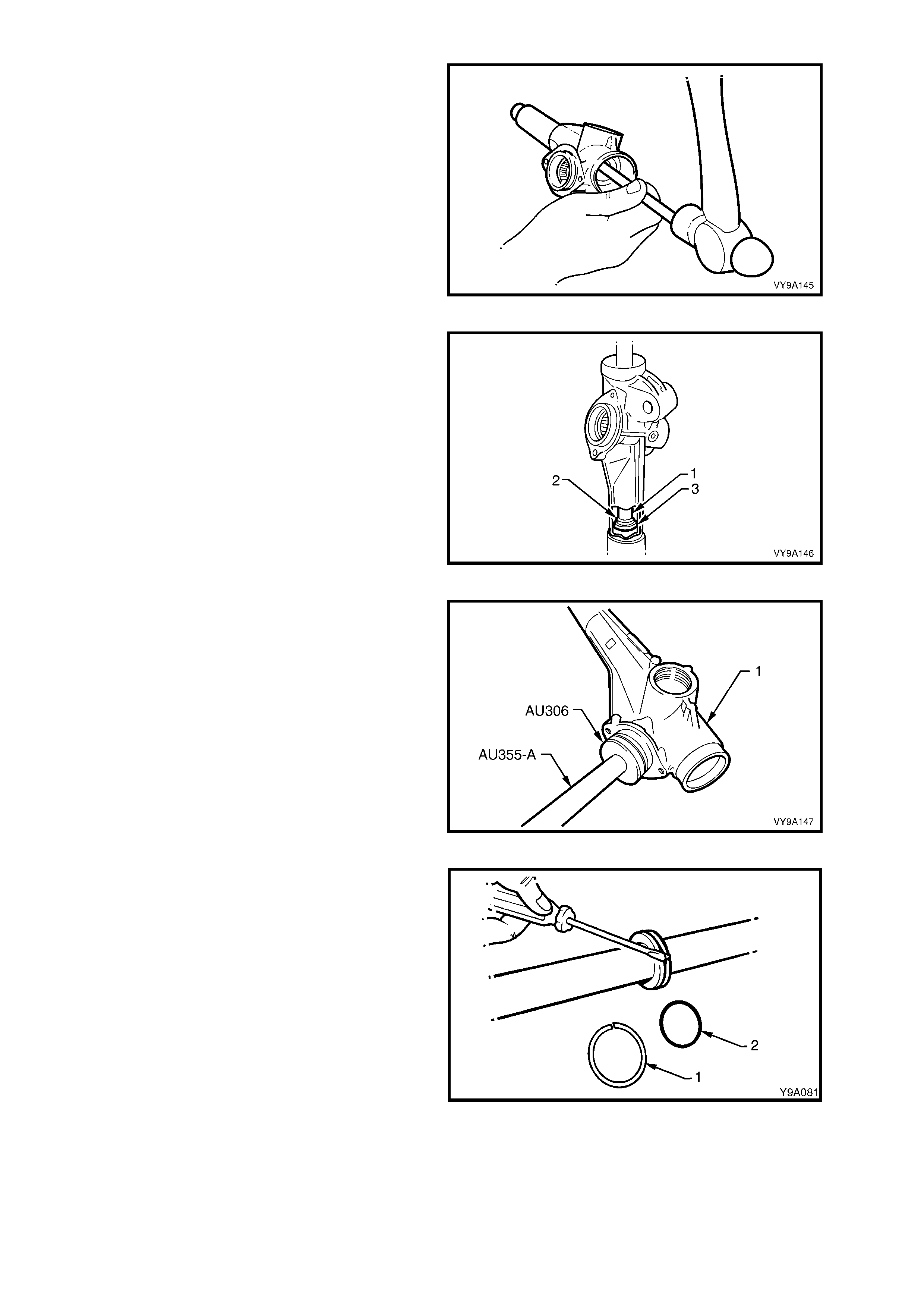
31. Remove the rack from the housing by using a
brass drift on the left-hand end of the rack and
driving the rack out the tube end of the rack
housing.
NOTE: As this action will remove the rack end bush
and the outer piston rod seal from the steering
tube, some resistance will be encountered. If
necessary, a suitable hydraulic press may be used.
Figure 9-131
32. Insert a suitable length of tubing or mild steel
stock (1), 30 mm in diameter into the housing
from the pinion end, then use a hammer to
drive the spacer (2) and inner piston rod seal
(3) and from the rack housing.
Figure 9-132
33. Remove the pinion lower bearing using Tool
No. AU306 and driver handle AU355-A.
NOTE: The pinion upper bearing cannot be
removed from the steering gear housing. If the
upper bearing is found to be damaged or has
failed, then the housing and bearing assembly must
be replaced.
Figure 9-133
34. Remove the rack piston seal (1) and O -ring (2)
from the rack piston.
NOTE: The seal (1) can be more easily removed
by cutting diagonally with a sharp knife, but take
care not to scratch the sides of the seal groove,
during this process.
Figure 9-134
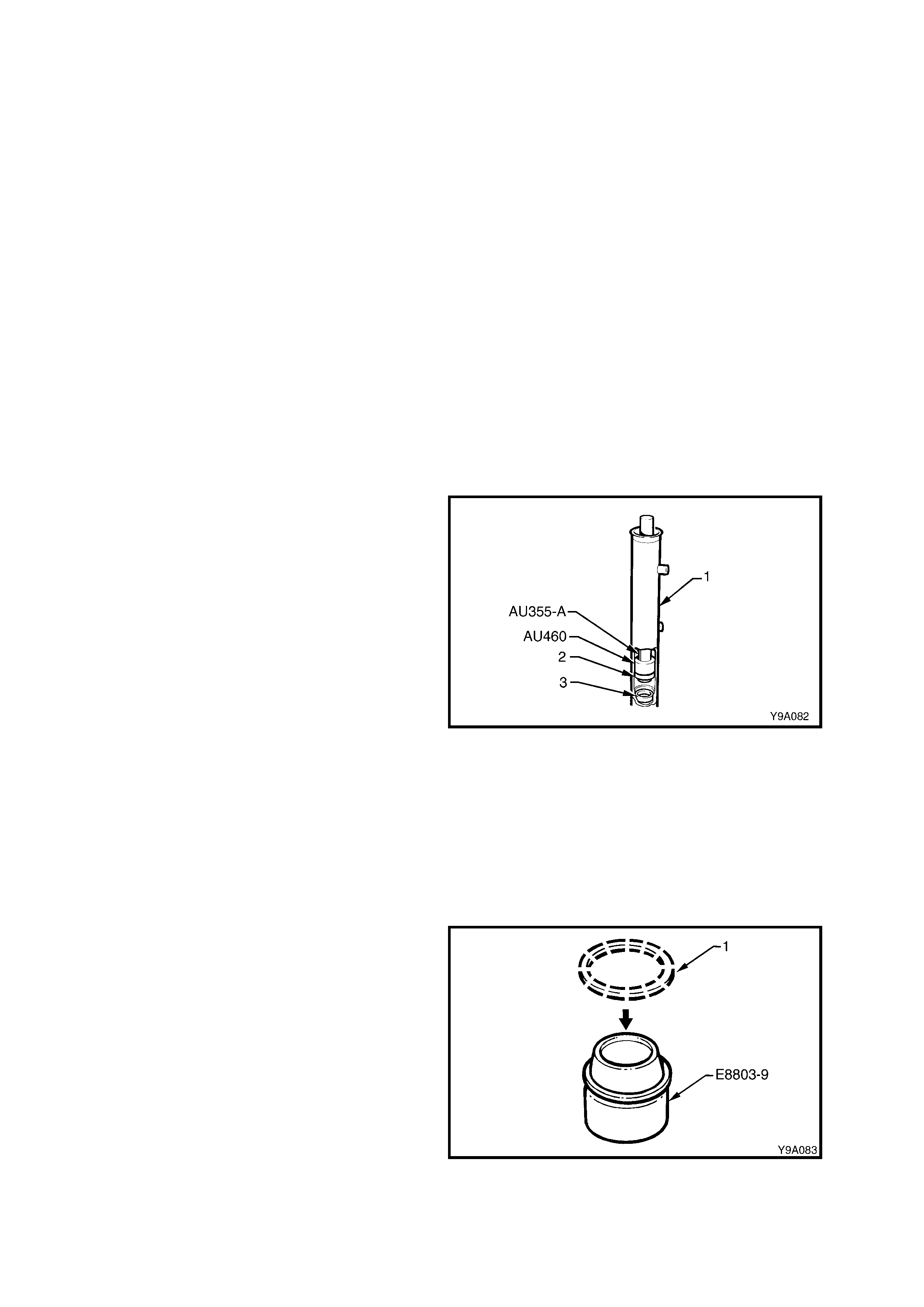
CLEAN AND INSPECT
Thoroughly wash all metal parts in cleaning solvent and blow dry with compressed air.
1. Inspect the rubber bellows for damage or deterioration, replace if necessary.
2. Inspect the pinion bearings for signs of brinelling, damage or wear.
NOTE: The pinion upper bearing cannot be rem oved from the steering gear housing. If the upper bearing is found
to be damaged, replace the housing and pinion upper bearing assembly.
3. Inspect the pinion for signs of tooth wear or damage.
4. Inspect the rack for signs of wear or damage to teeth, rack pad faces and rack bearing journal.
NOTE: A light polish on the teeth and the rack rear face is normal and should not be confused with wear.
5. Ins pec t the hous ing f or wear or damage in the pinion bearing bores , the s eal bores , the r ack piston and the loc k
stop faces.
6. Inspect the rack pad for damage or excessive wear.
7. Inspect the major components of the pinion assembly (pinion, valve, sleeve and torsion bar) for damage or
wear.
NOTE: These parts cannot be serviced individually as they are hydraulically balanced at the pinning stage of
assembly to equalise the steering efforts in right and left directions.
REASSEMBLE
1. Check that each of the rack seals have a circular, plastic insert ring fitted to each, on the opposite side to the
spring loaded seal lip, with the tapered edge of the inser t facing in toward the seal. Ens ure the tapered ends of
the rings seat correctly.
2. Screw Tool No. AU460 onto the driver handle
Tool No. AU355-A with the O-ring end facing
out. Install the inner seal spacer (3) onto Tool
No. AU355-A, using the O-ring to hold the
spacer in plac e. Ins ert the tools and s pac er into
the rack tube.
3. Using tool combination AU460/AU355-A, press
the seal spacer (3) into the rack housing (1),
until the end of Tool No. AU355-A protrudes
from the rack tube by approximately 53 mm.
This measurement will ensure that the spacer
has been fully installed.
4. Reverse the fitment of Tool No. AU460 to the
driver handle Tool No. AU355-A.
5. Lubricate a new rack inner seal (2) with
Dexron® III automatic transmission fluid. Install
the seal (2) over the spigot of T ool No. AU460,
ensuring that the spring loaded sealing lip is
facing Tool No. AU460.
6. Press the seal into the rack housing (1) on top
of the spac er (3). T he seal will be fully installed
when the end of Tool No. AU355-A protrudes
from the rack tube by approximately 60 mm.
Figure 9-135
7. Install a new O-ring to groove in rack piston.
8. Af ter dipping a new Tef lon seal ring (1 ) in clean
power steering fluid, install the seal ring over
expander Tool No. E8803-9.
Figure 9-136
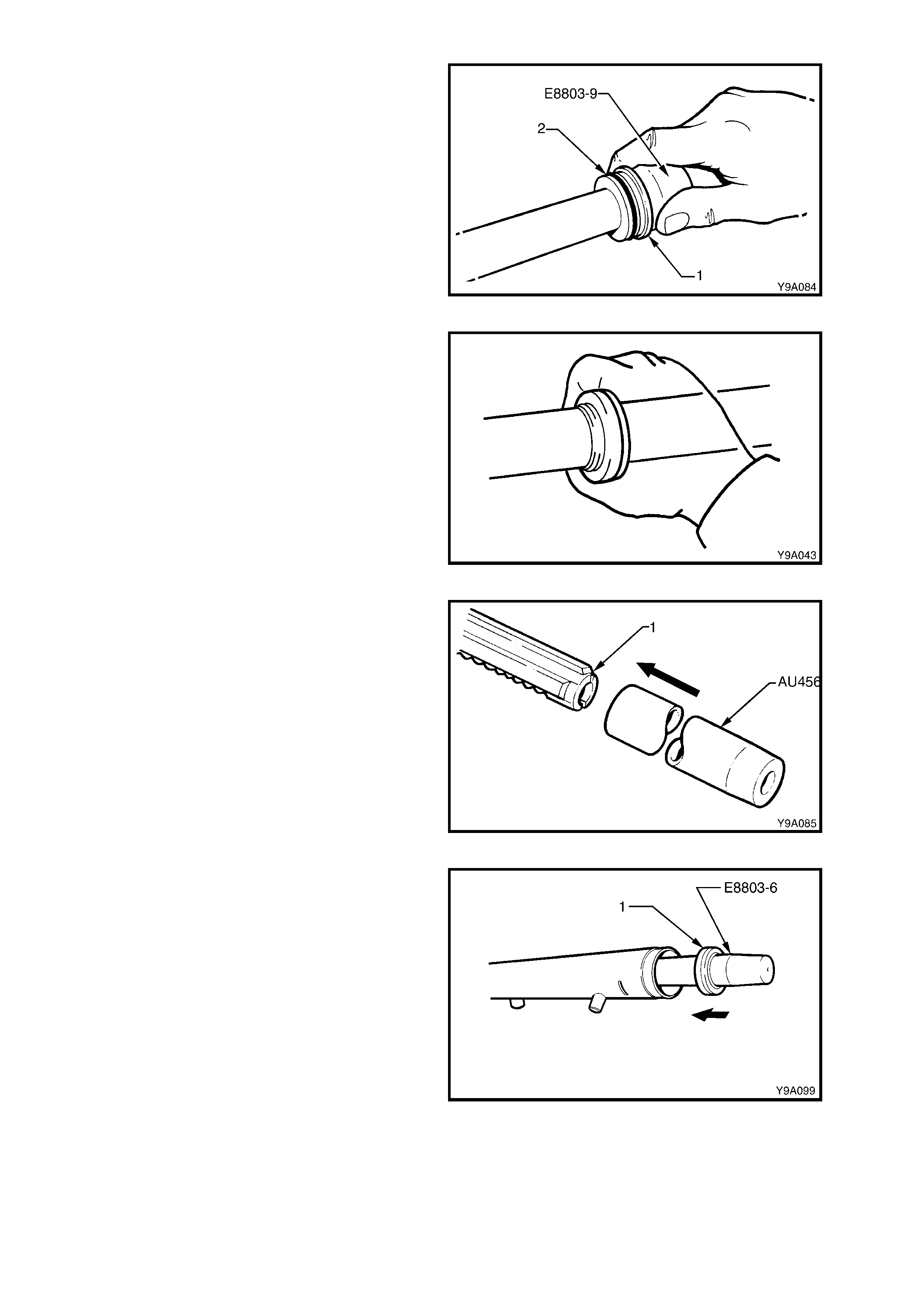
9. With the seal ring still installed on Tool No.
E8803-9, slide the assembly over the rack and
up to the piston. Slide the seal ring (1) off the
expansion tool and into the piston groove (2),
over the O-ring.
Figure 9-137
10. Ensure that the seal is seated correctly in the
groove, by wrapping f inger s ar ound the seal, as
shown.
Figure 9-138
11. Install the protector sleeve, Tool No. AU456
over the toothed end of the rack (1) and
liberally apply clean power steering fluid to the
protector’s outer surface.
12. Liberally apply clean power steering fluid to the
inner surf ac e of the r ack tube and over the r ack
piston seal.
13. Carefully install the rack and protector into the
rack housing and through the inner seal,
aligning the rack teeth with the pinion bore.
Continue installation until the rack piston has
entered the smaller, inner tube diameter.
Remove the seal protector, Tool No. AU456
from the toothed end of the rack.
Figure 9-139
14. Again install seal protector E8803-6 over the
end of the rack at the plain end.
Liberally apply clean power steering fluid to the
lip surface of the outer rack seal, then install
the seal over the protector and onto the rack,
with the seal lips facing in towards the rack
piston.
Figure 9-140
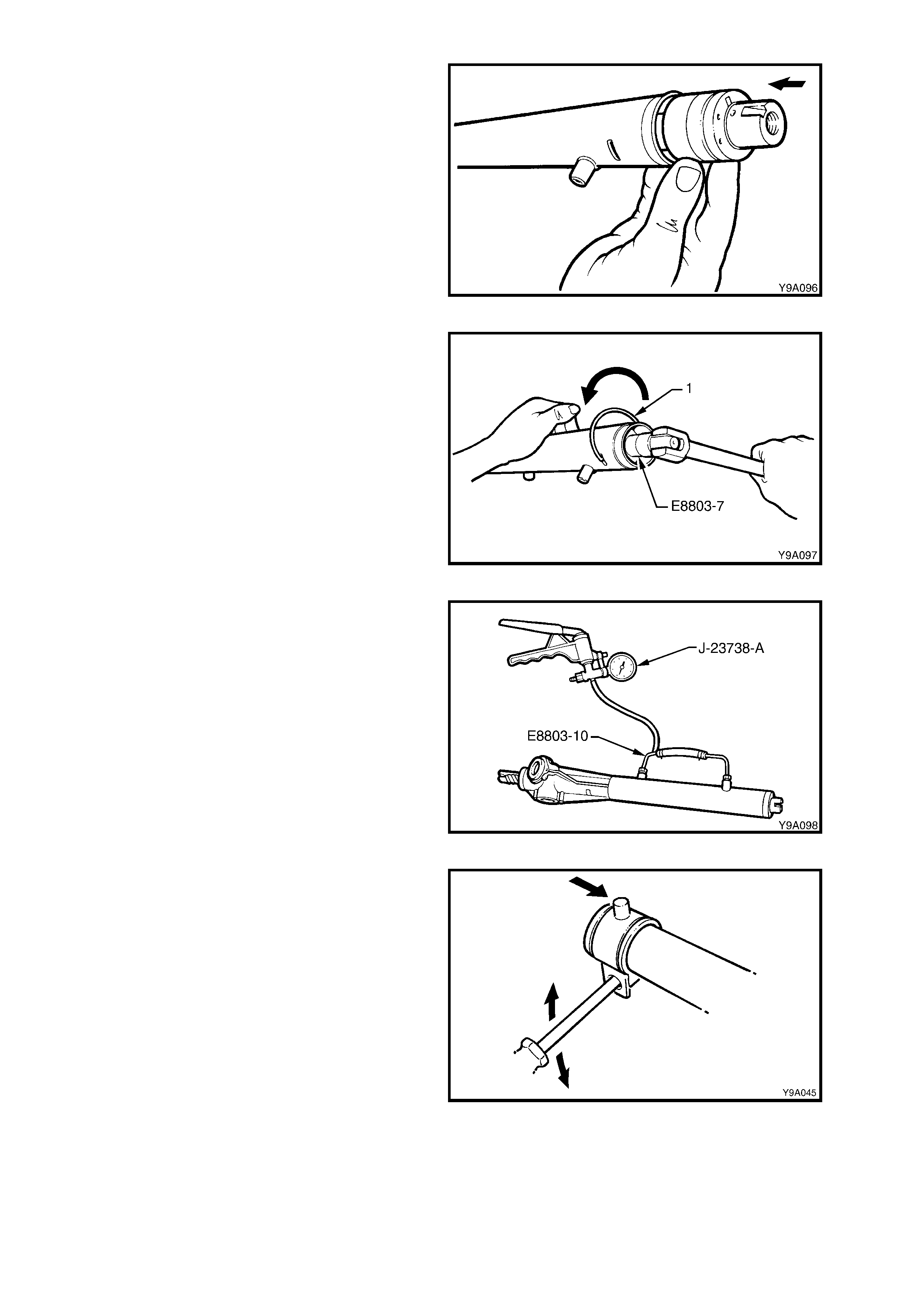
15. Lubricate the left-hand end bearing, inner
surface, with clean power steering fluid, then
install the end bearing into the rack tube,
pushing in against the outer rack seal.
NOTE: To assist with installation of the bearing
retaining wire, align the hole in the bearing with the
opening in the steering housing tube.
16. Using a suitable diameter piece of tubing, tap
the seal and bearing into the rac k tube until the
retaining wire groove in the bearing, is aligned
with the slot in the rack housing tubing.
Figure 9-141
17. If necessary, rotate the end bearing with Tool
No. E8803-7, until the hole in the wire groove
appears in the tube slot.
Install the bent end of the bearing retaining
wire, into the hole then, continuing to use Tool
No. E8803-7, rotate the bearing in an anti-
clockwise direction until the end of the wire
disappears into the rack tubing.
Figure 9-142
18. Install Tool No. E8803-10, on to the two
cylinder pipe fittings. Tighten the unions just
sufficient to effect an air tight seal.
19. Using a hand vacuum pump, such as T ool No.
J-23738-A, apply a vacuum of 53.3 kPa (or 40
cm, 15.75 in. Hg), for approximately 30
seconds.
20. Check that no change in the vacuum occurs
during this period. If a c hange does occ ur, then
the reas on m ust be f ound and correc ted befor e
proceeding further.
Figure 9-143
21. Check the mounting bracket insulator for
serviceability. Apply petroleum j elly (Vaseline or
equivalent) to the inner surf ace, then install the
brack et and insulator on to the steering tube, in
the reverse manner to removal. Align the
marks made prior to removal.
Figure 9-144
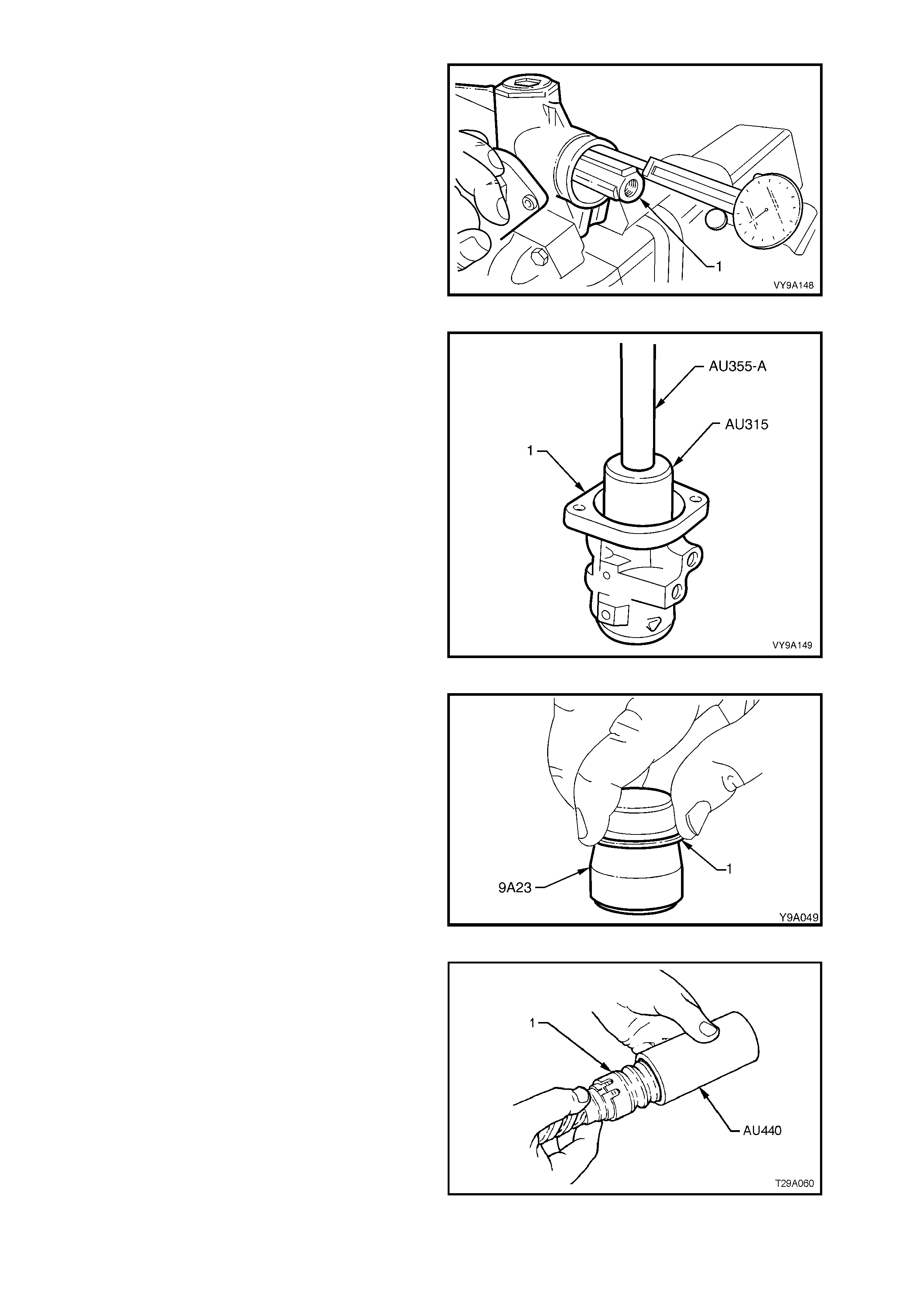
22. Centralise the rack assembly by measuring 82
± 1 mm from the lock stop (flange inside rack
housing) to the end of the toothed rack (1), as
shown.
Figure 9-145
23. Lubricate a new pinion upper seal with Dex ronâ
III automatic transm ission fluid, then f it the seal
to Tool No. AU315, that has driver handle
AU355-A attached. Press seal into place in the
valve housing (1).
24. Lubricate the upper pinion bearing with EP
Semi Fluid Lithium Base O Grease and fit to
Tool No. AU315, that has driver handle AU355-
A attached. Press the bearing into the valve
housing until the bearing is fully seated.
Figure 9-146
25. To fit new PTFE seal rings (1) into the sleeve
grooves, first warm in hot water then install
each s eal ring, in tur n, on to the expander , T ool
No. 9A23.
Slide expanding tool with ring installed, over the
sleeve, then push the seal off and into the
sleeve groove. Repeat for the remaining three
seals.
Figure 9-147
26. After all the seals have been fitted to the sleeve
grooves, push Tool No. AU440 over the rings
and valve assembly (1), then leave for 5-10
minutes to contract rings back to normal size.
Figure 9-148
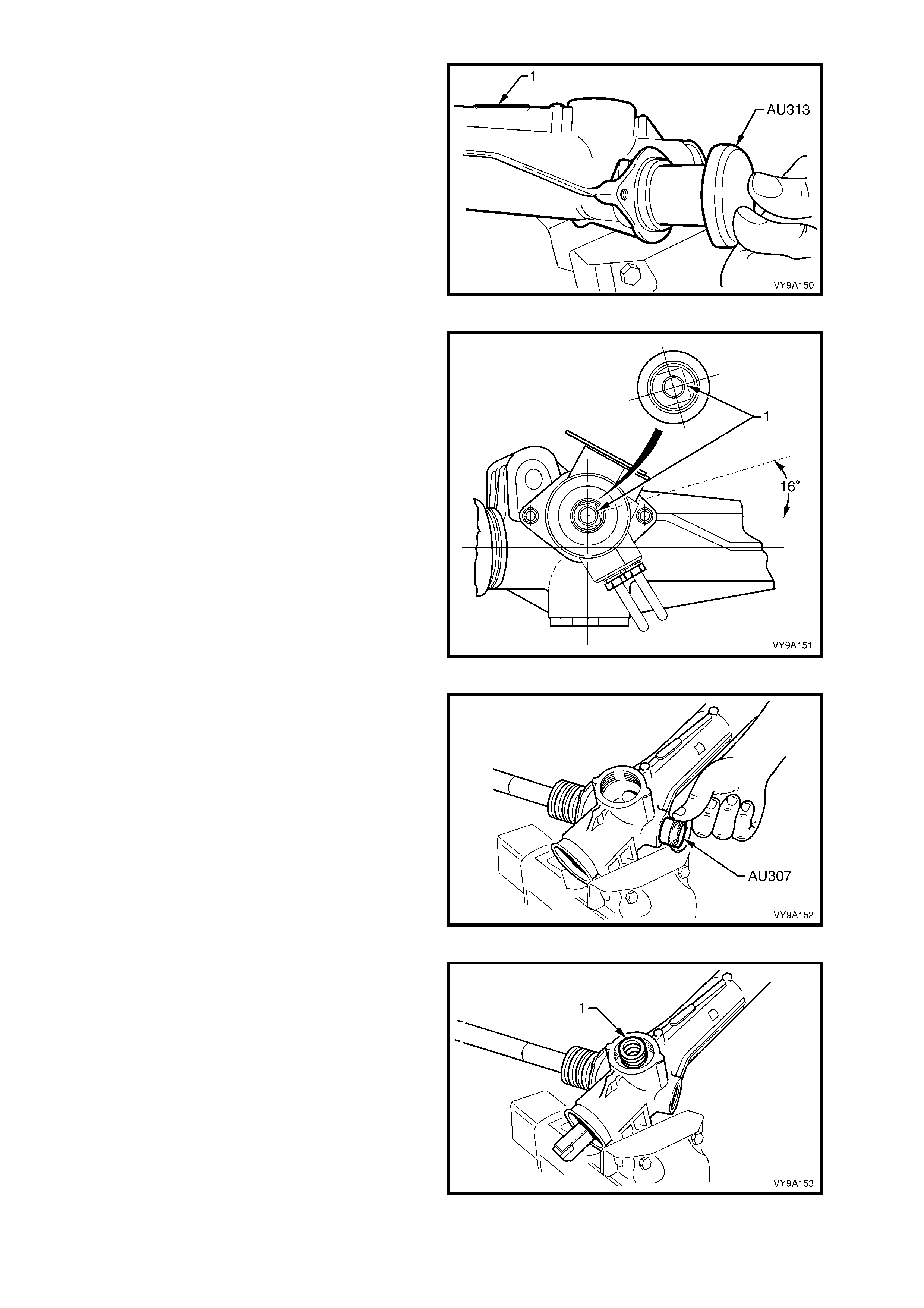
27. Inser t 50 gram s of EP Sem i Fluid Lithium Base
O Grease into the steering gear housing,
through the pinion bore.
28. Using Tool No. AU313, install a new seal into
the steering gear housing (1), fully seating the
seal in its bore.
Figure 9-149
29. While maintaining the rack in the centralised
position, insert the pinion s o that the c lamp bolt
flat (1) of the input shaft is positioned as
shown, when the pinion is fully located in the
housing.
Figure 9-150
30. Pack the pinion lower bearing with EP Semi
Fluid Lithium Base Grease. Install the pinion
lower bearing using Tool No. AU307.
NOTE: Tool No. AU307 screws onto the end of
pinion and pinion lower bearing is fully installed
when Tool No. AU307 cannot be screwed onto the
pinion any further. Remove AU307 once bearing is
installed.
Figure 9-151
31. Install rack pad insert into the rack pad. Install
the rack pad assembly into the steering gear
housing.
32. Install the rack pad spring (1) and the plastic
washer.
Figure 9-152
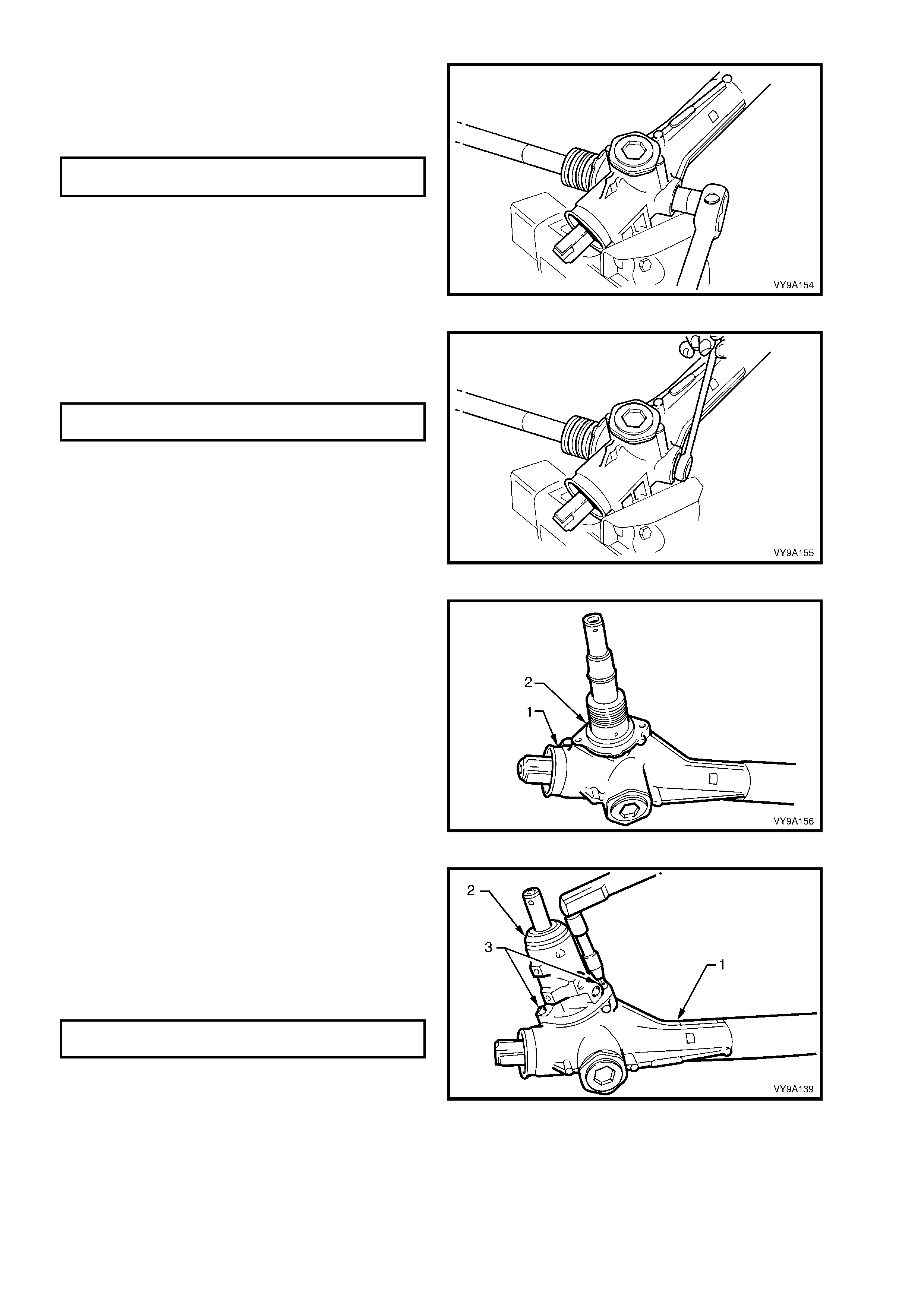
33. Screw the lock nut onto the adjusting screw.
Install the adjusting screw into the steering
gear housing. Leave lock nut loose.
34. Install the pinion lower bearing retaining nut
and tighten to the correct torque specification.
(+)PINION LOWER BEARING RETAINING
NUT TORQUE SPECIFICATION 35 – 45 Nm
NOTE: T his is a def orm ed thread loc k nut and m ay
be reused once only. However, it is recommended
that a new nut is fitted at each overhaul.
Figure 9-153
35. Apply Loctite 242 thread sealant (or equivalent)
to the cleaned threads of the pinion lower
screw plug and tighten to the correct torque
specification.
PINION LOWER RETAINING SCREW
PLUG TORQUE SPECIFICATION 55 – 60 Nm
Figure 9-154
36. Install a new O-ring (2) onto the lip of the
steering gear housing (1).
Figure 9-155
37. Slide the valve housing (2) over the input shaft
and locate the valve housing onto the lip of the
steering gear housing (1).
NOTE: Care must be taken to ensure that the
PTFE sleeve seals and valve seal are not cut or
deformed during this process.
38. Install and tighten the valve housing retaining
screws (3) to the correct torque specification.
VALVE HOUSING RETAINING
SCREW TORQUE SPECIFICATION 5 – 6 Nm
Figure 9-156
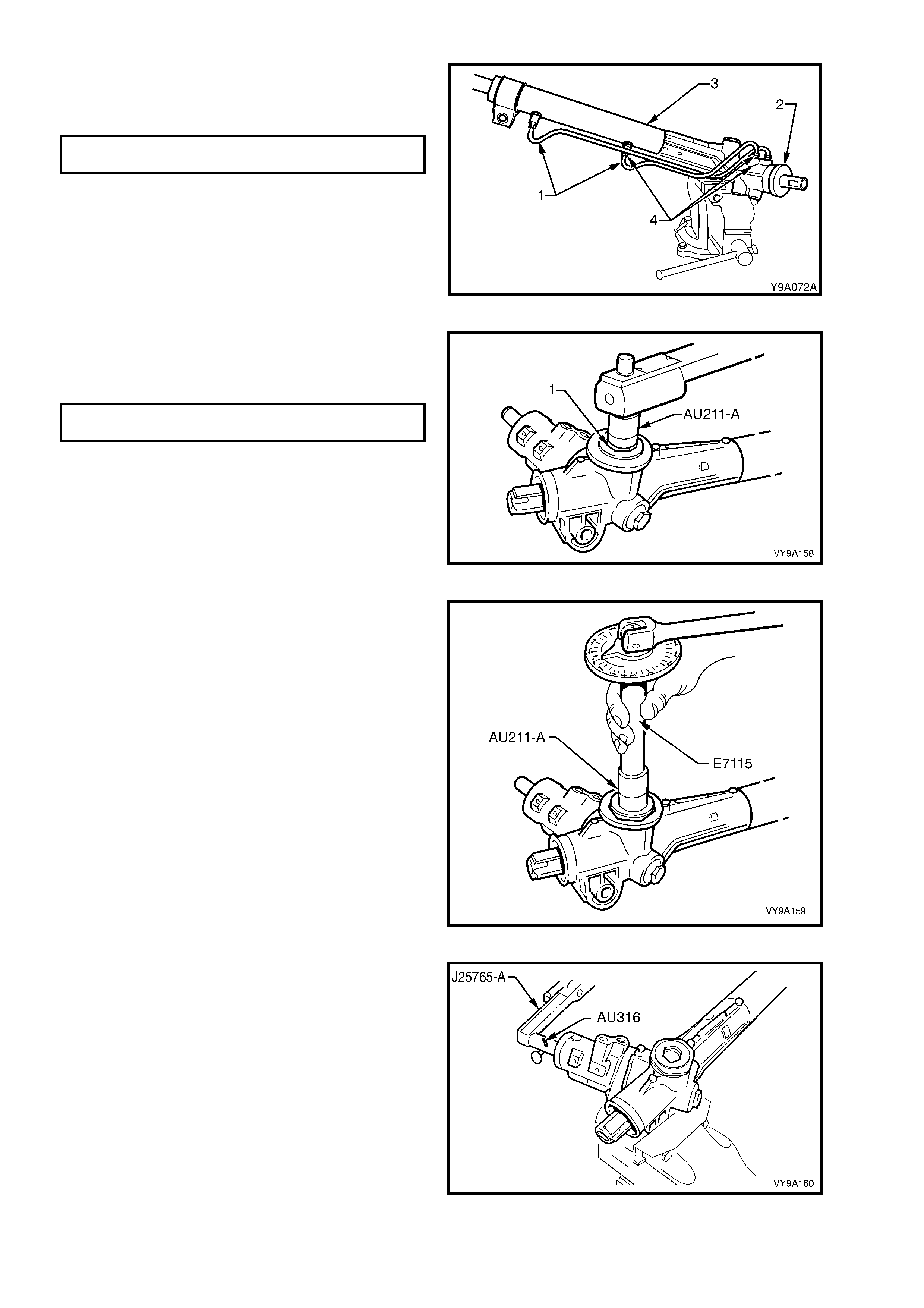
39. Reconnect the f eed pipes (1 and 4) to the valve
housing (2) and steering gear tubing (3) and
tighten the pipe flare nuts to the correct torque
specification.
FEED PIPE FLARE NUT
TORQUE SPECIFICATION 15 – 25 Nm
NOTE: The longer of the two pipes (LH lock) is
installed into the upper location on the valve body
housing, while the s horter ( RH lock ) is installed into
the lower.
Figure 9-157
40. With the steering rack in the centralised
position, tighten the rack pad adjusting screw
(1) using Tool No. AU211-A to the specified
torque.
RACK PAD ADJUSTING SCREW
TORQUE SPECIFICATION 10 – 12 Nm
Figure 9-158
41. Using angle wrench, Tool No. E7115 and
adaptor, T ool AU211-A, tur n rack pad adjus ting
screw back (anti-clockwise) 20 - 28°.
Figure 9-159
42. Install T ool No. AU316 onto the input shaf t and
measure the rotating torque of the input shaft,
using a dial type torque wrench (such as
J25765-A), by cycling the steering gear back
and forth. Torque requirements are from 0.8 to
2.5 Nm.
Figure 9-160
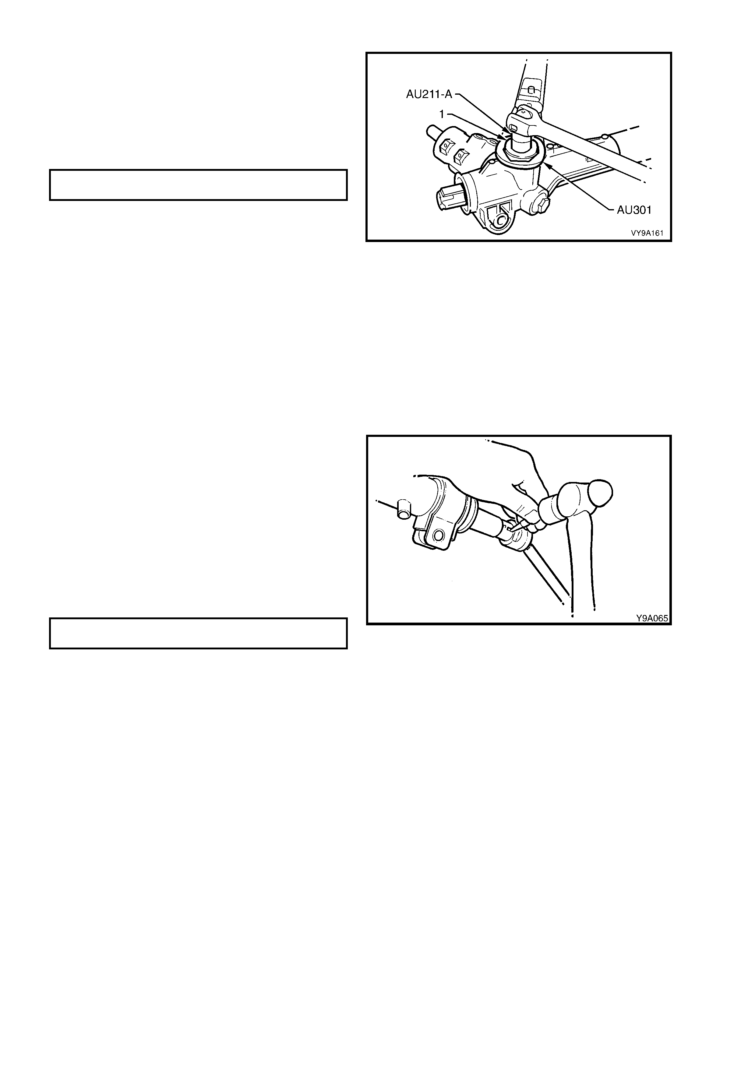
43. Apply Loctite 242 thread sealant (or equivalent)
to the cleaned threads of the rack pad plug lock
nut (1).
44. While holding the adjusting screw in the
position set at step 41 with Tool No. AU211-A
and a socket bar, tighten the lock nut to the
correct torque specification using Tool No.
AU301 and a torque wrench.
RACK PAD ADJUSTING SCREW LOCK
NUT TORQUE SPECIFICATION 55 – 65 Nm
NOTE: Once the r ack pad adjus tment has been set
and the lock nut torqued to specification, the
steering gear must be racked from lock-to-lock to
ensure localised wear has not appreciably affected
the setting. The gear should not bind or appear
tight over any part of the total travel. Should the
gear bind or appear tight, recheck the rack pad
adjustment. If this is not the cause, strip the gear
assembly and examine the rack and pinion for
wear. Replace as necessary.
Figure 9-161
45. Rotate the pinion shaft fully anti-clockwise (left
lock).
46. Remove the steering gear housing from the
vice, and grip the exposed toothed end of the
rack in a vice with soft jaws.
CAUTION: During the manufacturing process,
the threaded ends of the steering rack and
piston assembly are staked to the tie rod inner
socket housing. Consequently, during
disassembly of the power steering gear,
damage to the threads on the end of the tie rod
inner socket and the rack and piston assembly
will occur. Whenever a steering gear is
disassembled, the inner tie rods and the rack
and piston assembly MUST be replaced.
47. Using Tool No. 211-258, tighten the left-hand
tie rod to the correct torque specification.
TIE ROD END HOUSING
TORQUE SPECIFICATION 90 – 100 Nm
48. Using a centre punch and a large ball-pein
hammer, stake the rack to the tie rod socket
housing in two places inside the k ey-way at the
end of the rack.
Figure 9-162
NOTE: The key-way at either end of the steering rack has not been hardened, and is the only area that is
suitable for the st ak ing pr oc edure. Ens ur e to stake the rac k in two places as c los e as poss ible to the tie-rod inner
socket (either side of key way).
49. Remove the s teering gear hous ing from the vic e and rotate the pinion shaf t slightly clockwise, j ust enough to
expose the right-hand end of the rack.
50. Tighten the left-hand tie rod as in steps 47 and 48.
51. Relocate the steering gear housing in the vice by gripping the right-hand mounting boss.
52. Rotate the input shaft to the straight ahead position. Install the dust cover onto the input shaft.
53. Fit bellows to the tie rods and steering gear housing. Install the retaining clips.
54. Fit the tie rod socket lock nuts and the tie rod sockets to the tie rods.
NOTE: Do not tighten the lock nuts, as a toe-in adjustment must be performed when the steering gear is
installed.
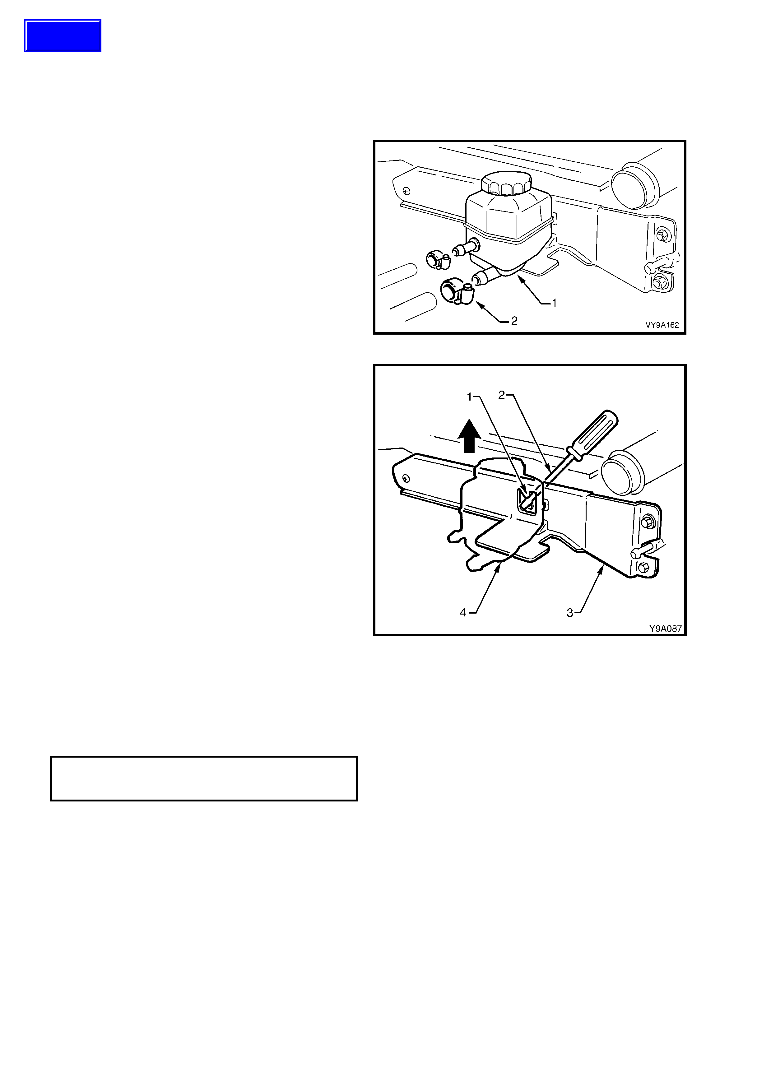
3.8 POWER STEERING FLUID RESERVOIR - V6 ENGINE
LT Section No. – 06-400
REMOVE
1. Place a drain tray beneath the reservoir assembly.
2. Loosen the hose clamps and remove the two
hoses from the reservoir.
NOTE: Cover or tape the hose ends to prevent
foreign matter entry.
Figure 9-163
3. Us ing a s uitable lever (1) s uch as a screwdriver
(2), gently lever locking tang back towards the
radiator and lift the reservoir (4) up and out of
the retaining bracket (3).
4. If required, remove the two hexagon headed
screws and one s elf tapping s c rew securing the
bracket to the radiator, then remove the
bracket.
Figure 9-164
REINSTALL
Installation is the reverse of the removal
operations, noting the following points:
1. Tighten the reservoir retaining bracket screws
to the correct torque specification.
RESERVOIR RETAINING BRACKET
ATTACHING SCREW
TORQUE SPECIFICATION 3 – 7 Nm
2. Refill and bleed the hydraulic system. Refer to
3.3 HYDRAULIC SYSTEM -
BLEEDING/REFILLING in this Section.
3. Start the engine and check for power steering
fluid leaks from the reservoir area.
Techline
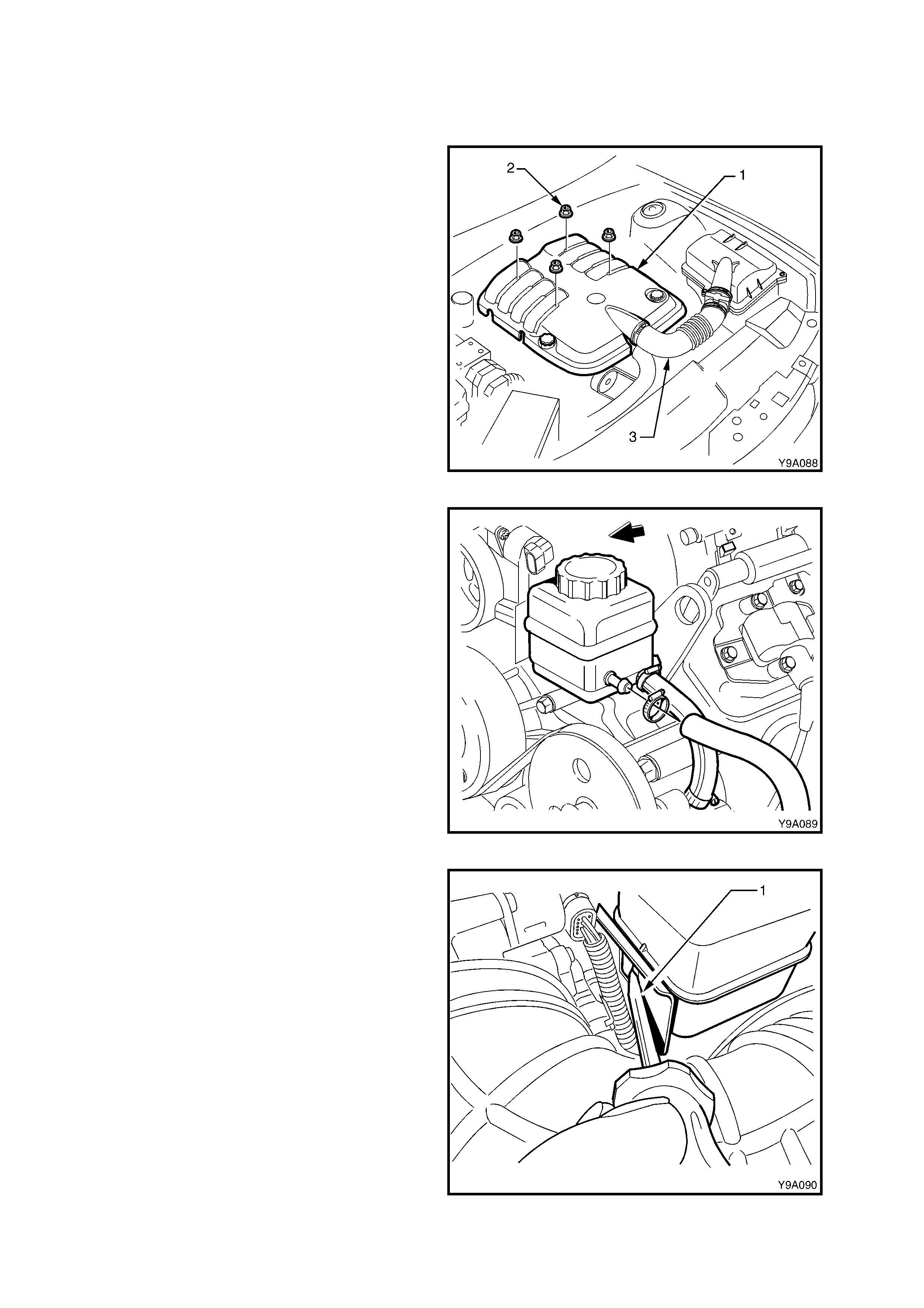
3.9 POWER STEERING FLUID RESERVOIR - GEN III V8 ENGINE
LT Section No. – 06-400
REMOVE
1. Disconnect the battery earth lead from the
battery.
2. Remove the engine trim cover retaining nuts
(2) then remove the cover (1) from the engine.
Figure -165
3. Place a drain tray beneath the reservoir
assembly.
4. Loosen the hose clamps and remove the two
hoses from the reservoir.
NOTE: Cover or tape the hose ends to prevent
foreign matter entry.
Figure 9-166
5. Using a suitable lever such as a screwdriver
(1), gently lever locking tang back to clear the
reservoir tab, then lift the reservoir up and out
of the retaining bracket.
6. Reset the bracket locking tang back into the
original position.
7. If required, remove the two bolts securing the
com bination res ervoir and engine lif ting brack et
from the left-hand cylinder head. Remove the
bracket from the engine.
Figure 9-167

REINSTALL
Installation is the reverse of the removal operations, noting the following:
1. If removed, install the reservoir/engine lift bracket bolts and tighten to the correct torque specification.
RESERVOIR/ENGINE LIFT
BRACKET ATTACHING BOLT
TORQUE SPECIFICATION 50 Nm
2. Tighten the reservoir hose clamps to the correct torque specification.
POWER STEERING RESERVOIR
HOSE CLAMP
TORQUE SPECIFICATION 2.0 – 3.0 Nm
3. Install the engine trim cover, install the retaining nuts and tighten to the correct torque specification.
ENGINE TRIM COVER NUT
TORQUE SPECIFICATION 8 – 12 Nm
4. Refill and bleed the hydraulic system. Refer to 3.3 HYDRAULIC SYSTEM - BLEEDING/REFILLING in this
Section.
5. Start the engine and check for power steering fluid leaks from the reservoir area.
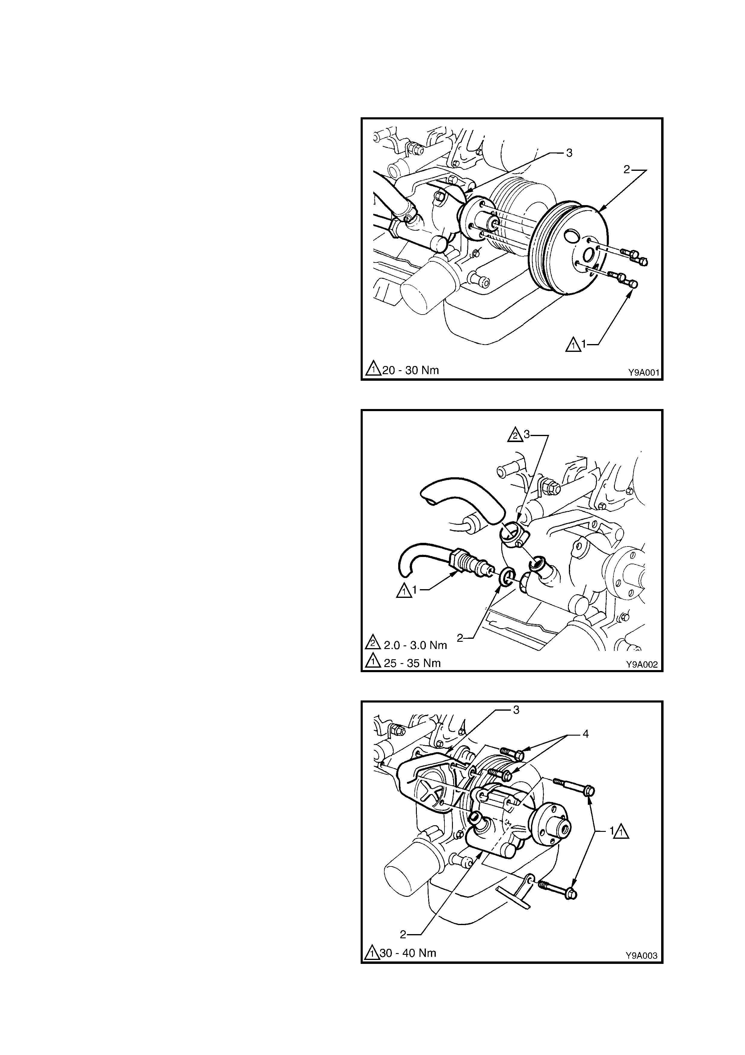
3.10 POWER STEERING PUMP - V6 ENGINE
LT Section No. – 06-400
REMOVE
1. Disconnect the battery earth lead.
2. Loosen the four power steering pump pulley
attaching bolts (Do not remove at this stage).
3. Using a 15 mm ring spanner on the drive belt
tensioner pulley pivot bolt, rotate the tensioner
pulley anti-clockwise and rem ove the drive belt
from the pump pulley. Release the tensioner
pulley.
4. Remove the pump pulley attaching bolts and
the pulley from the pump .
Figure 9-168
6. Place a drain tray beneath the power steering
pump assembly.
7. Loos en and rem ove the high pres sure line f lare
nut (1) and O-ring (2) from the pump outlet
fitting.
8. Loosen the low pressure hose clamp (3) and
remove the hose from the reservoir.
NOTE: Cover or tape the pum p and hose fittings to
prevent foreign matter entry.
Figure 9-169
9. Rem ove the two power steering pum p retaining
bolts (1) and remove the pump assembly (2)
from the retaining bracket (3).
10. If required, remove the two bolts (4) securing
the retaining brack et to the cylinder block , then
remove the bracket.
Figure 9-170

REINSTALL
Installation of the power steering pump is the reverse of removal procedures, noting the following points:
1. Tighten the retaining bracket to cylinder block retaining bolts to the correct torque specification.
PUMP RETAINING BRACKET BOLT
TORQUE SPECIFICATION 30 – 40 Nm
2. Tighten the two pump to retaining bracket attaching bolts to the correct torque specification.
PUMP TO RETAINING BRACKET BOLT
TORQUE SPECIFICATION 30 – 40 Nm
3. Tighten the four pump pulley attaching bolts to the correct torque specification.
PUMP PULLEY BOLT
TORQUE SPECIFICATION 20 – 30 Nm
4. Install the new sealing O -ring on to the high pres sure line connection. Lubricate the sealing ring with Dexron® III
automatic transmission fluid prior to installation.
5. Refill and bleed the hydraulic system, refer to 3.3 HYDRAULIC SYSTEM - BLEEDING/REFILLING in this
Section.
6. Start the engine and check for power steering fluid leaks around the pump and reservoir area.
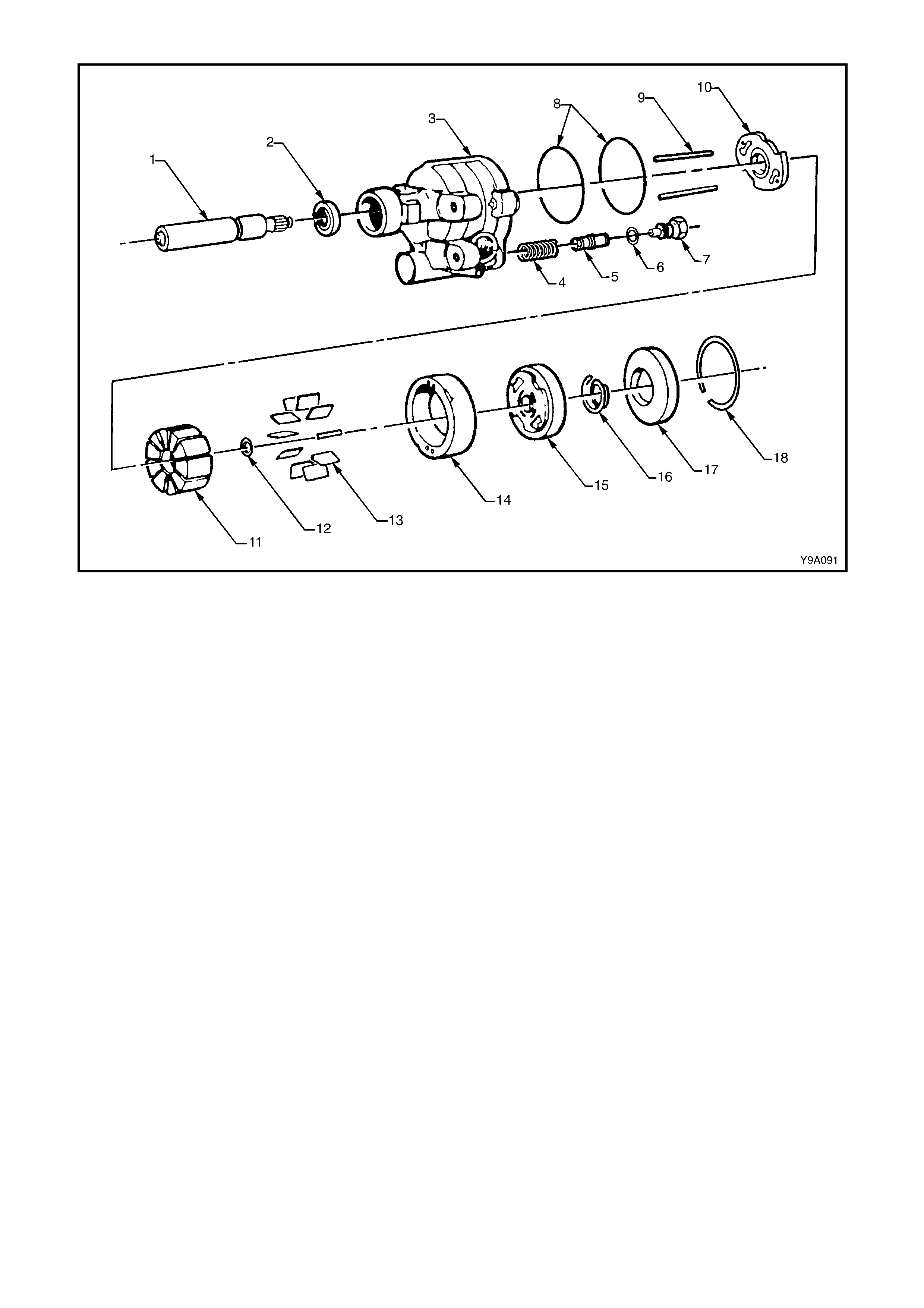
Figure 9-171
Legend
1. Shaft, Pump Drive
2. Seal, Pump Drive Shaft
3. Housing Assembly, Pump
4. Spring, Flow Control Valve
5. Valve, Flow Control
6. O-Ring, Outlet Fitting
7. Fitting, Outlet
8. O-Rings, Pressure and End
Plates
9. Dowel Pins, Pump Ring
10. Plate, Thrust
11. Rotor
12. Ring, Shaft Retaining
13. Vanes, Pump
14. Ring, Pump
15. Plate, Pressure
16. Spring, Pressure Plate
17. Plate, End
18. Ring, End Plate Retaining
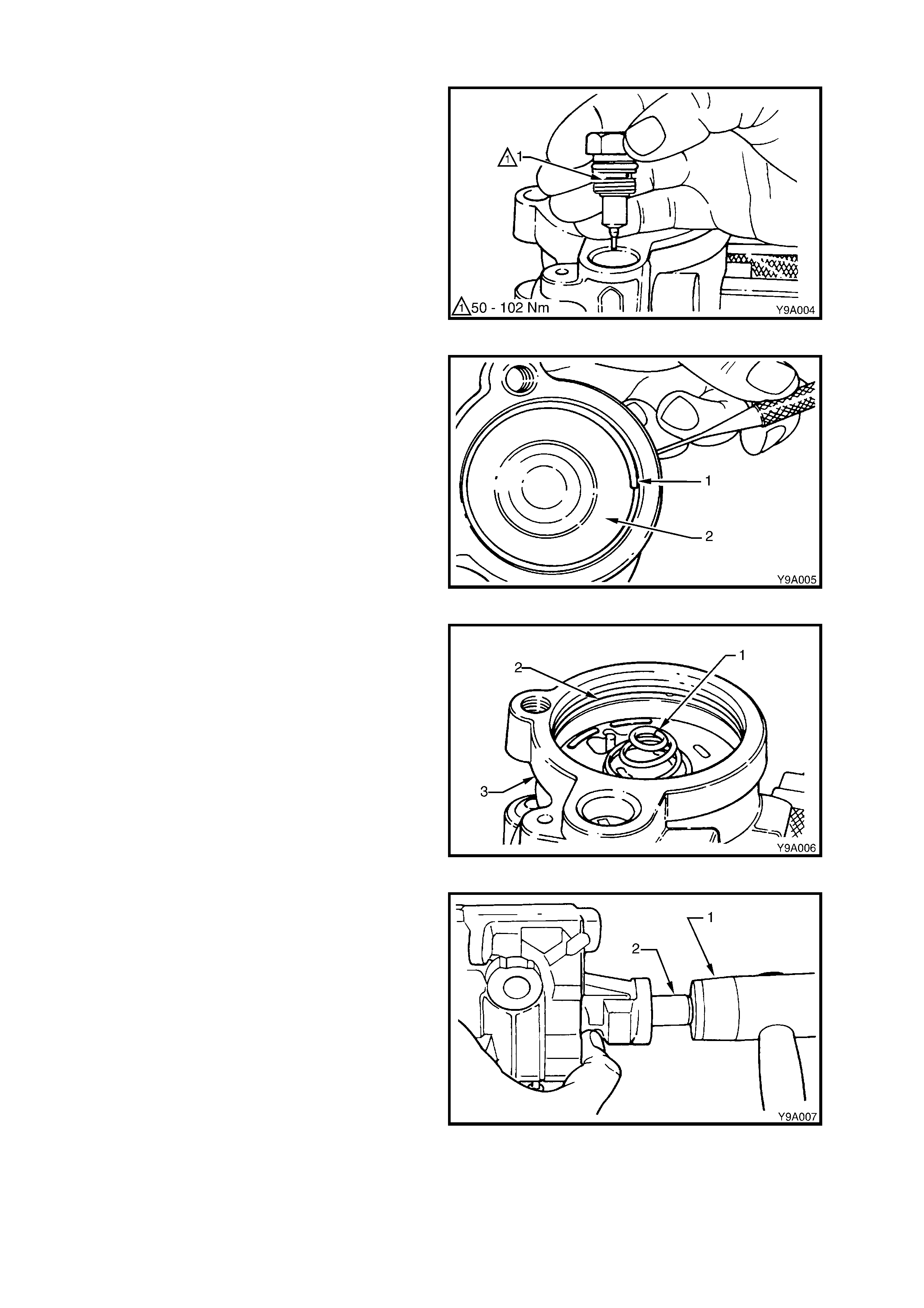
DISASSEMBLE
1. Tilt the pum p assem bly up and allow the power
steering fluid to drain from the pump.
2. Remove the drive belt pulley hub, refer to
3.12, POWER STEERING PUMP PULLEY
HUB - V6 ENGINE in this Section.
3. Clamp the pump, with the rear surface
uppermost, in vice fitted with soft jaws. Do not
use excessive force or the pump body will be
distorted.
4. Remove the outlet f itting ( 1) and the as soc iated
O-ring. Take care as the spring loaded flow
control valve will thrust the outlet fitting from the
pump housing.
Figure 9-172
5. Compress the end plate retaining ring (1) by
pushing with a small punch through the hole in
pump housing, then remove the ring with a
screwdriver, ensuring to hold a hand over ring
as the end plate (2) is spring loaded and may
spring out.
NOTE: It may be necessary to slide the retaining
ring around with a screwdriver, until one end is
close to the access hole.
Figure 9-173
6. Remove the end plate. A slight rocking motion
or light tapping with a soft faced hammer will
force the plate if it should stick.
7. Remove the end plate spring (1).
8. Remove the end plate O-ring (2) from the
pump housing (3) and discard.
9. Remove the pump from the vice and invert to
remove the flow control valve and spring.
10. Clean the exposed end of the drive shaft to
remove any dirt or rust. This will prevent
damage to the shaft bush that might require the
housing to be replaced.
Figure 9-174
11. Us ing a suitable sof t fac ed ham m er (1), tap the
pump shaft (2) very lightly until the shaft,
pressure plate, pump ring, rotor assembly and
thrust plate can be removed as a unit.
12. Disassemble the parts just removed. Refer to
Figure 9-185 for relationship details. Remove
the vanes from the rotor. Remove the rotor
from the shaft after removing retaining ring
from shaft. Discard ring.
Figure 9-175
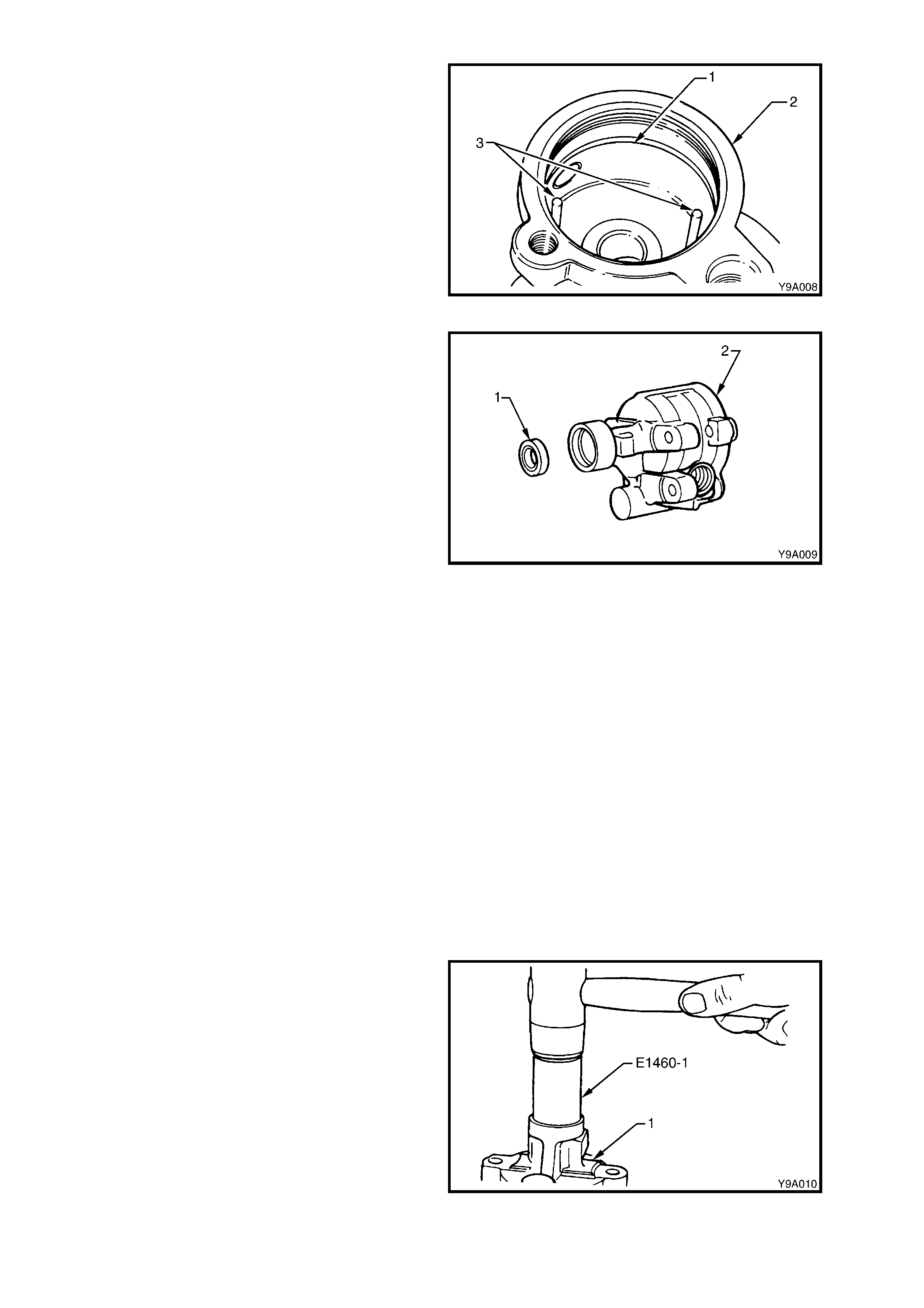
13. Remove the pressure plate O-ring (1) from the
pump housing (2) and discard.
14. Remove the dowel pins (3).
Figure 9-176
15. Prise the shaft seal (1) from the pum p housing
(2) with a screwdriver. Take care not to
damage the housing bore. Discard seal.
Figure 9-177
CLEAN AND INSPECT
Clean all metal parts in solvent, air dry and inspect as follows:
1. The flow control valve must slide freely in the housing bore. If sticking is observed, check for dirt and burrs.
2. Check the cap screw in end of the flow control valve for looseness: if loose, tighten, being careful not to damage
the machined surfaces.
3. Be sure that the pressure plate and thrust plate surfaces are flat and parallel with the pump ring. Check for
cracks and scoring.
NOTE: A high polish is always present on the rotor, pressure plate and thrust plate as a result of norm al wear. Do
not confuse this with scoring.
4. Ensure the vanes move freely in the rotor slots.
5. If the flow control plunger is suspected of being faulty, install a new component. T his part is serviced as a unit
only and is factory calibrated.
6. Check the drive shaft for worn splines, breaks, bush material pick-up, etc.
7. Using a piece of wire, probe through shaft seal relief hole to check for blockage.
8. Always replace all seals and O-rings when the pump is disassembled.
REASSEMBLE
1. Install a new shaft seal (1) in to the pump
housing using Tool No. E1460-1 or 96A1 (2).
Lubricate the seal lips with Dexron® III
automatic transmission fluid.
Figure 9-178
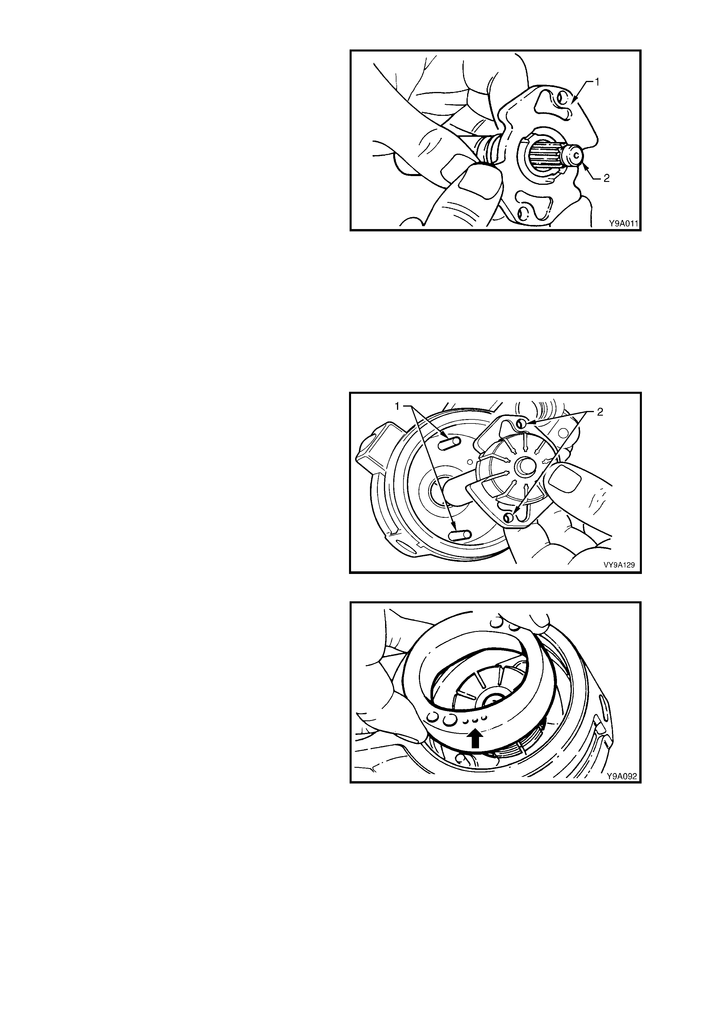
2. Install the thrust plate (1) on to the shaft (2)
with the ported face towards the splined end of
the shaft.
Figure 9-179
3. Install the rotor, which must be free on the shaft splines, with the countersunk side towards the thrust plate.
4. Install a new shaft retaining ring. Place the ring on the end of the shaf t and use a 10 m m s ocket to tap the ring
into place. Ensure the ring is correctly seated in the groove.
I Do not use a C-ring to replace the full circumference clip ring.
5. Install the dowel pins in to the pump housing.
6. Lubr icate the new pressure plate O-r ing with Dexr on® III autom atic trans miss ion fluid and install in to the pum p
housing.
7. Clamp pump housing, cavity uppermost, in a vice with soft jaws. Do not clamp with excessive force.
8. Ins tall the s haf t, thr us t plate and rotor assembly
into the housing, aligning the dowel pins (1)
with the thrust plate holes (2).
Figure 9-180
9. Install the pump ring onto the dowel pins with
the identifying three dots (arrow) facing
uppermost. There are four holes in the pump
ring, the smaller holes are the dowel pin holes.
10. Install the vanes into the rotor slots.
11. Lubricate the outer circum ference and c hamfer
of the pres sure plate with Dexron® III automatic
transmission fluid to prevent damage to the O-
ring. Install the pressure plate on to the dowel
pins with the ported face toward the pump ring
such that the narrow slots engage the dowel
pins.
12. Seat the pressure plate by placing a large
socket on top of the plate and pressing down
by hand. Plate will travel approximately 2 mm
to seat.
13. Install the pressure plate spring on to the
pressure plate.
14. Lubricate the new end plate O-ring with
Dexron® III automatic transmission fluid and
install the O-ring in to the housing groove.
Figure 9-181
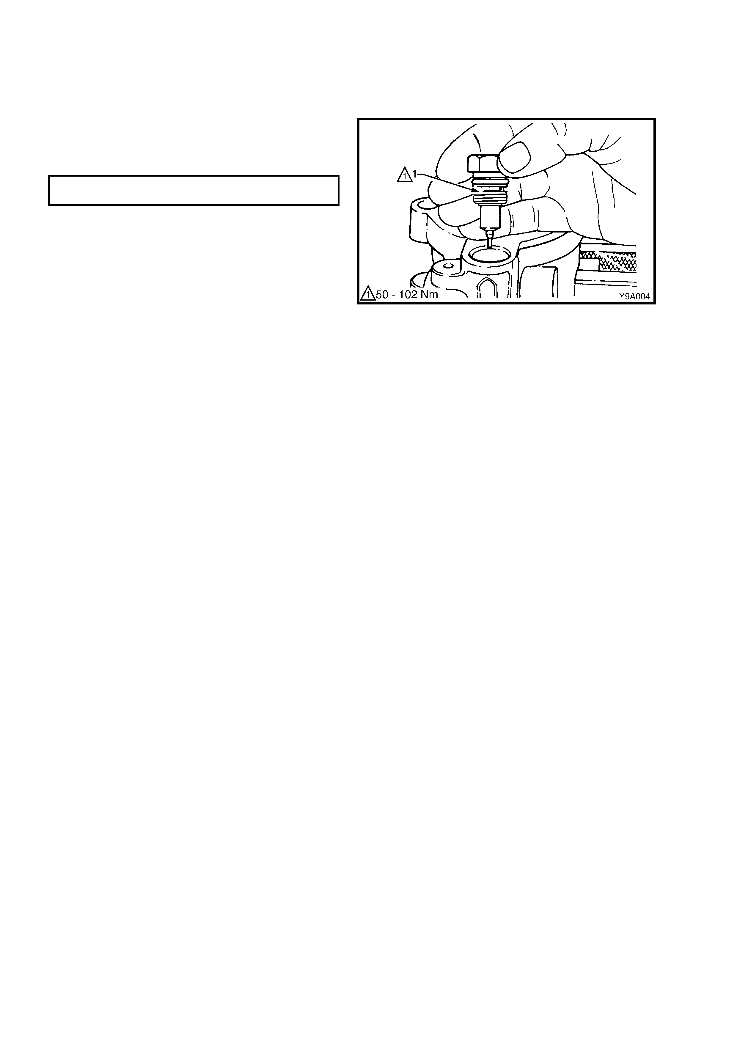
15. Lubr icate the outside circ um fer ence and cham f er of the end plate with transm ission f luid to avoid dam aging the
O-ring and install the end plate.
16. Install the end plate retaining ring. Locate the end of the ring near the hole in the housing.
17. Install the flow control spring and plunger (hex head end first) into the pump housing.
18. Lubricate the outlet fitting O-ring with
transmission fluid, install the O-ring on to the
outlet fitting. Install the outlet fitting and tighten
to the correct torque specification.
POWER STEERING PUMP OUTLET
FITTING TORQUE SPECIFICATION 50 – 102 Nm
19. Install the pump pulley hub, refer to
3.12 POWER STEERING PUMP PULLEY
HUB - V6 ENGINE in this Section.
Figure 9-182
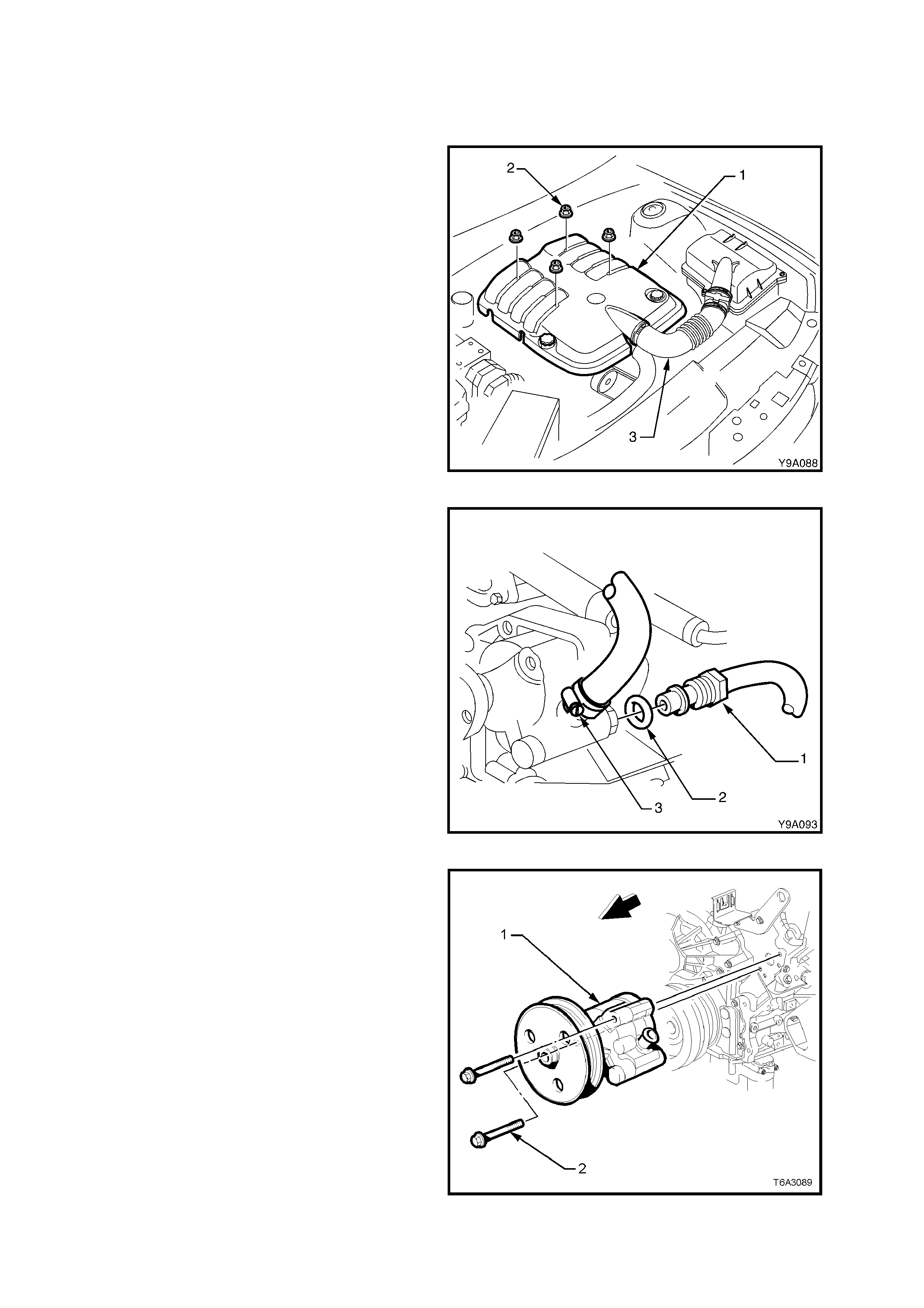
3.11 POWER STEERING PUMP - GEN III V8 ENGINE
LT Section No. – 06-400
REMOVE
1. Loosen the two hose clamps securing the air
intake duc t (3) to the throttle body and Mass Air
Flow (MAF) sensor.
2. Remove the air intake duct from the throttle
body and MAF sensor.
3. Rem ove the engine acc essory drive belt. Refer
to Section 6A3, 2.6 ENGINE DRIVE BELTS.
Figure 9-183
4. Place a drain tray beneath the power steering
pump assembly.
5. Remove the power steering fluid reservoir.
Refer to 3.9 POWER STEERING FLUID
RESERVOIR - GEN III V8 ENGINE in this
Section.
6. Loosen and r em ove the high press ure line f lare
nut (1) and O-ring (2) from the pump outlet
fitting.
7. Loosen the low pressure hose clamp (3) and
remove the hose from the pump inlet fitting.
NOTE: Cover or tape the pum p and hose fittings to
prevent foreign matter entry.
Figure 9-184
8. Rem ove the two power steering pum p retaining
bolts (2) securing the pump to the front of the
left-hand cylinder head. Remove the pump
from the engine.
NOTE: Access to the two bolts can be made
through the pulley holes, using a suitable socket
and extension.
Figure 9-185
REINSTALL
Installation of the power steering pump is the reverse of removal procedures, noting the following points:
1. Tighten the two pump to cylinder head retaining bolts to the correct torque specification.
PUMP TO CYLINDER HEAD BOLT
TORQUE SPECIFICATION 20 – 35 Nm
2. Install a new sealing O-ring to the high pressure line connection. Lubricate the sealing ring with Dexron® III
automatic transmission fluid prior to installation.
3. Tighten the high pressure pipe to pump outlet f itting flare nut, to the correct torque specification, using a back-
up spanner on the outlet fitting.
HIGH PRESSURE LINE FLARE NUT
TORQUE SPECIFICATION 25 – 35 Nm
4. Install and tighten all low pressure hose clamps to the correct torque specification.
LOW PRESSURE HOSE CLAMP
TORQUE SPECIFICATION 2.0 – 3.0 Nm
5. Install the power steering fluid reservoir. Refer to 3.9 POWER STEERING FLUID RESERVOIR - GEN III V8
ENGINE in this Section.
6. Install the engine accessory drive belt. Refer to Section 6A3, 2.6 ENGINE DRIVE BELTS.
1. Ins tall the air intak e duct to the thr ottle body and MAF sensor and tighten the hose clam ps to the correc t torque
specification.
AIR INTAKE DUCT HOSE CLAMP
TORQUE SPECIFICATION 5 – 8 Nm
2. Install the engine trim cover and the retaining nuts and tighten to the correct torque specification.
ENGINE TRIM COVER NUT
TORQUE SPECIFICATION 8 – 12 Nm
9. Refill and bleed the hydraulic system, refer to 3.3 HYDRAULIC SYSTEM - BLEEDING/REFILLING in this
Section.
10. Start the engine and check for power steering fluid leaks around the pump and reservoir area.
INSPECTION AND OVERHAUL PROCEDURES
The disassem ble, clean, inspect and reas semble proc edures for the power steer ing pump as f itted to MY 2003 VY
and V2 Series Models fitted with the GEN III V8 engine are the same as the procedures for the power steering
pump as fitted to vehicles fitted with the V6 engine. For the necessary procedures to disassemble, clean, inspect
and reassemble the power steering pump for vehicles fitted with the GEN III V8 engine, refer to
3.10 POWER STEERING PUMP - V6 ENGINE in this Section.
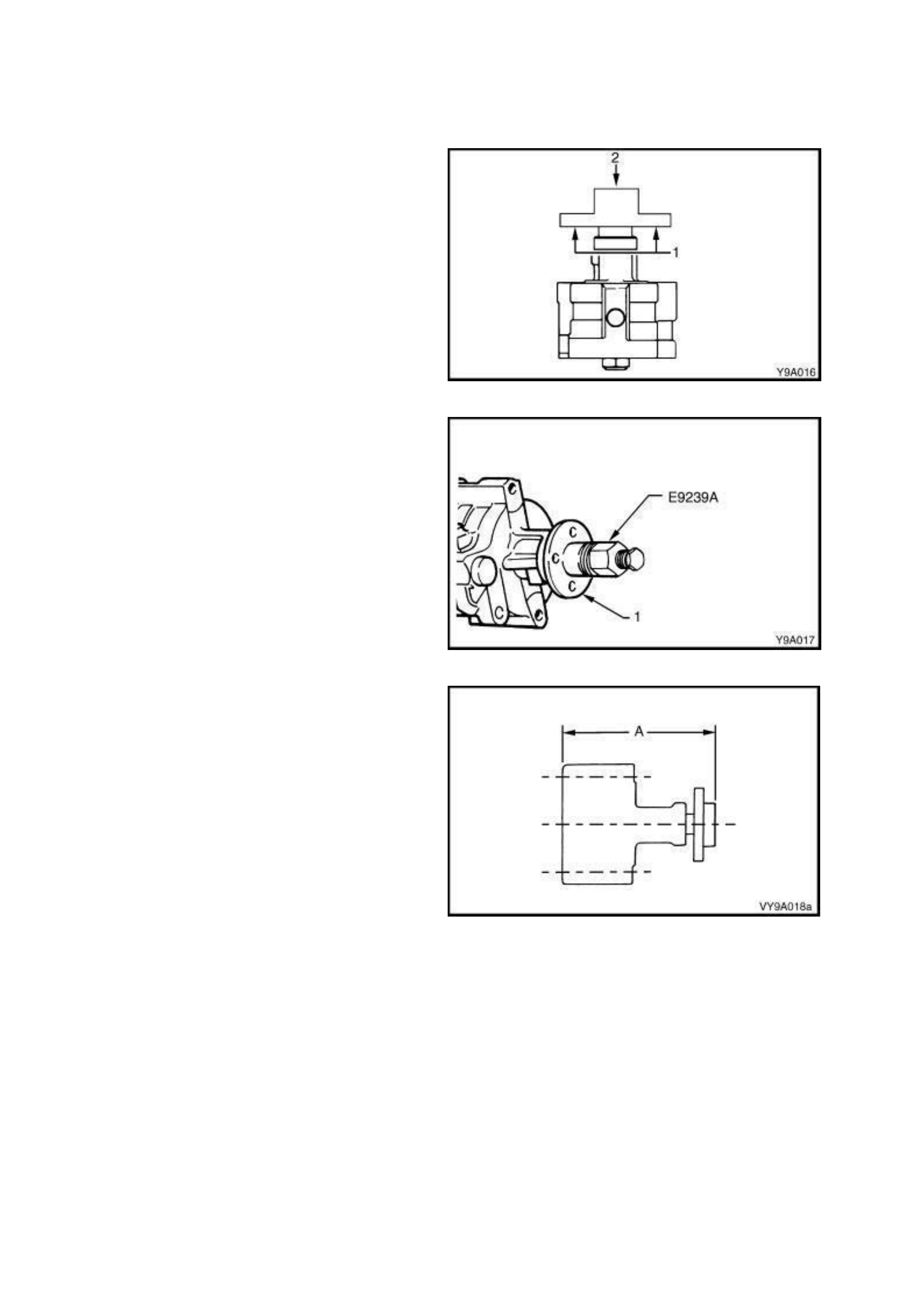
3.12 POWER STEERING PUMP PULLEY HUB - V6 ENGINE
LT Section No. – 06-400
REPLACE
1. Remove the power steering pump, refer to
3.10 POWER STEERING PUMP – V6 ENGINE
in this Section.
2. Using suitable press plates, such as Tool No.
E6673, support the pulley hub (1) and press
down on the pump shaft (2) to remove the pump
assembly from the pulley hub.
Figure 9-186
3. Make sure the pulley hub bore and the pump
shaft are free from burrs. Place pulley hub on
end of pump shaft and install replacer, Tool No.
E9239A, by screwing the bolt fully into the pump
shaft.
Figure 9-187
4. Install the pulley hub by holding the bolt and
turning the large bearing nut clockwise.
Assemble the hub to the pump shaft until
dimension A equals 128.0 ± 0.3 mm.
5. Remove Tool No. E9239.
Figure 9-188
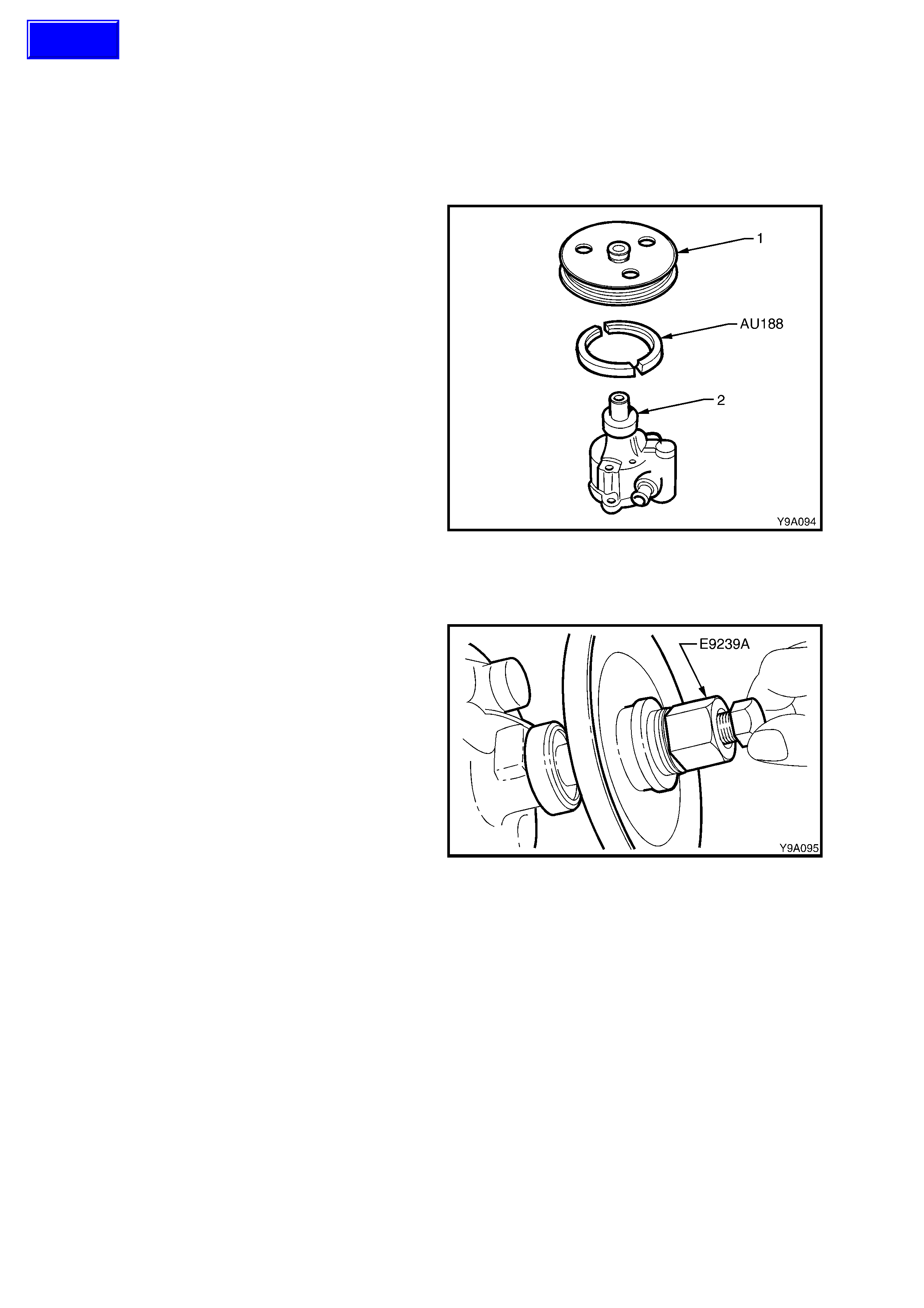
3.13 POWER STEERING PUMP PULLEY - GEN III V8 ENGINE – METHOD 1
LT Section No. – 06-400
REPLACE – USING TOOL A U188 & E9239
1. Remove the power steering pump, refer to
3.11 POWER STEERING PUMP - GEN III V8
ENGINE in this Section.
2. Install suitable press plates, such as E6673
under the power steering pump pulley (1) with
pulley pr ess plates, T ool AU188 in between the
two and pres s the pump ass embly (2) from the
pulley, using a suitable sized drift on the pump
pulley shaft.
NOTE: Do not position the press plates on the
edge of the pulley, as damage to the pulley will
occur.
Figure 9-189
3. Ensure the pulley bore and the pump pulley
shaft are free of burrs, place pulley on end of
pump shaft.
4. Install Tool No. E9239 (or J25033-B) by
screwing the bolt fully into the pump pulley
shaft.
5. Install the pulley by holding the bolt head and
turning the large nut and bearing clockwise
until the pulley is flush with the shaft end.
6. Remove Tool No. E9239 (or J25033-B).
7. Install the power steering pump, refer to
3.11 POWER STEERING PUMP – GEN III V8
ENGINE in this Section.
Figure 9-190
Techline
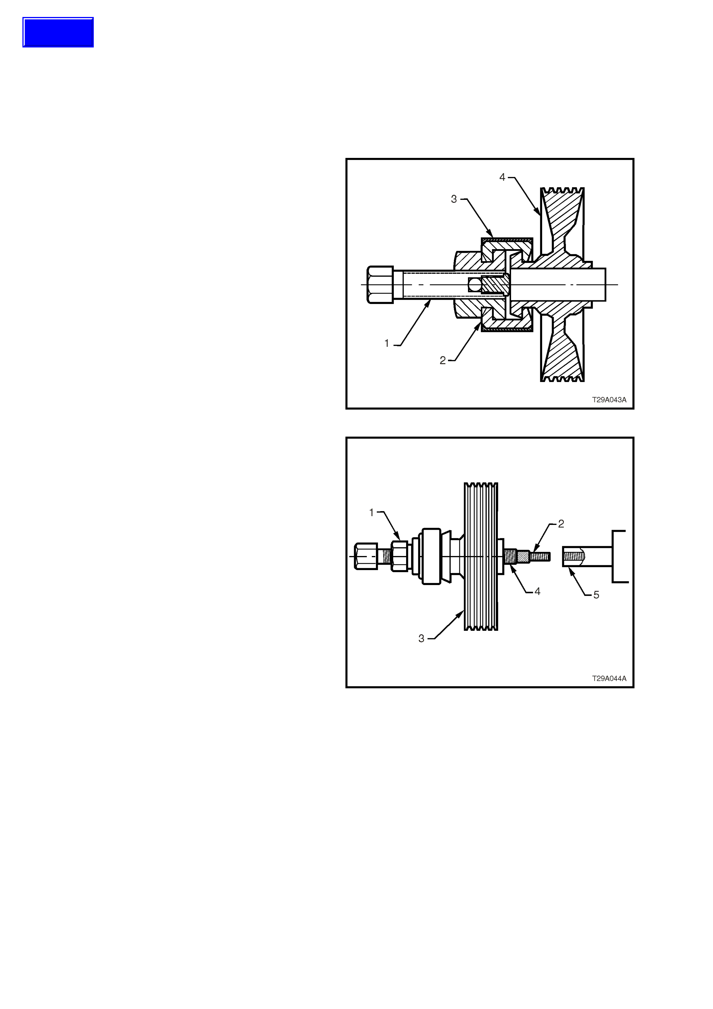
3.14 POWER STEERING PUMP PULLEY - GEN III V8 ENGINE – METHOD 2
LT Section No. – 06-400
REPLACE – USING TOOL 7185 & 7005
1. Remove the power steering pump, refer to
3.11 POWER STEERING PUMP - GEN III V8
ENGINE in this Section.
2. Lubricate the forcing screw (1) of 7185 –
POWER STEERING PULLEY REMOVER and
position the forcing screw against the pulley
shaft.
NOTE: Ensure the full diameter end of the half
jaws (2) are engaged with the pulley (4) and the
larger open end diameter (has chamfer and relief
profile) engages with the pulley flange.
3. Slide the retainer sleeve (3) over the half jaws
and hand tighten the forc ing screw. Ensure that
the forcing screw is aligned with the pump axis.
4. Proceed to remove the pulley.
NOTE: Do not use power tools or exceed a torque
of 90Nm . If the pully cannot be removed within this
torque, replace the complete pump assembly.
Figure 9-191
5. Assemble the drive nut (1), thread insert (2)
onto the forcing screw of 7005 – POWER
STEERING PULLEY REPLACER as shown in
fig 9.198. Ensure that adequate graphite
grease is applied to the forcing screw and nut.
6. Thread the forcing screw assembly, by hand
onto the pump shaft (5) until it bottoms out
against the shoulder. DO NOT USE A
SPANNER FOR THIS OPERATION.
7. Turn the dr ive nut (1) agains t the pulley (3) until
the pulley is at the correct installation depth.
DO NOT ALLOW THE FORCING SCREW TO
TURN DURING THIS OPERATION.
NOTE: Do not use power tools or exceed a torque
of 90Nm. If the pully cannot be installed within this
torque, replace the complete pump assembly.
8. O nce the pulley is installed, r emove the fo rcing
screw from the pump shaft.
9. Install the power steering pump, refer to
3.11 POWER STEERING PUMP – GEN III V8
ENGINE in this Section.
Figure 9-192
Techline

3.15 RIGHT-HAND DRIVE POWER STEERING FLUID COOLE R AND
HOSE/PIPE ROUTING – V6 ENGINE
LT Section No. – 06-400
ARRANGEMENT
Refer to F igure 9-193 f or the general layout of the power steering f luid cooler, hoses and fittings us ed for the power
steering fitted to right-hand drive MY 2003 VY and V2 Series Vehicles fitted with a V6 engine.
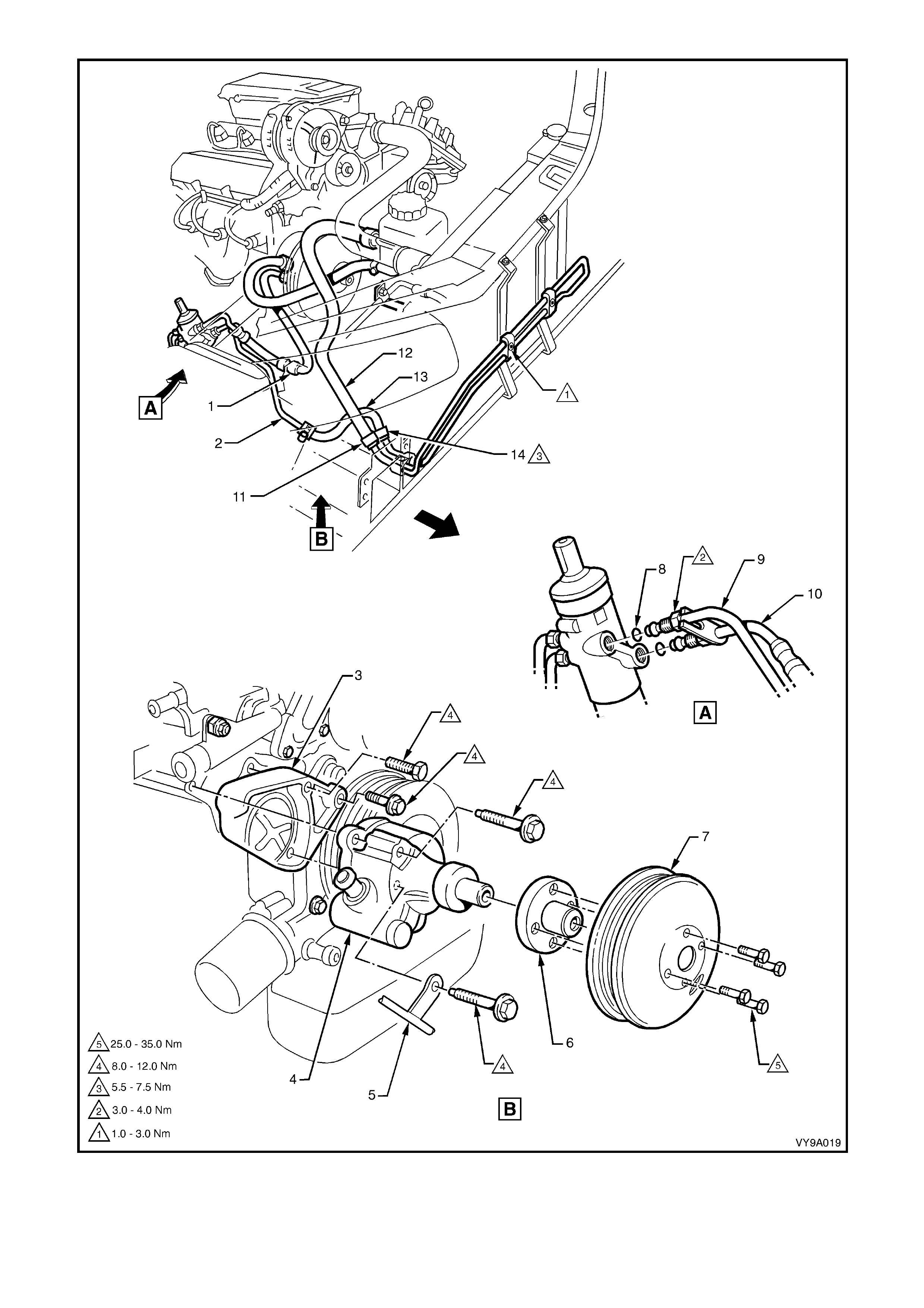
Figure 9-193

Legend
1. High Pressure Hose
2. Fluid Cooler Pipe
3. Pump Mounting Bracket
4. Pump Assembly
5. Pressure Pipe and Hose
6. Pump Hub
7. Pump Pulley
8 O-Ring – Power Steering Pipe
(2 places)
9. Return Pipe
10. Pressure Pipe
11. Hose Clamp (3 places)
12. Low Pressure Hose
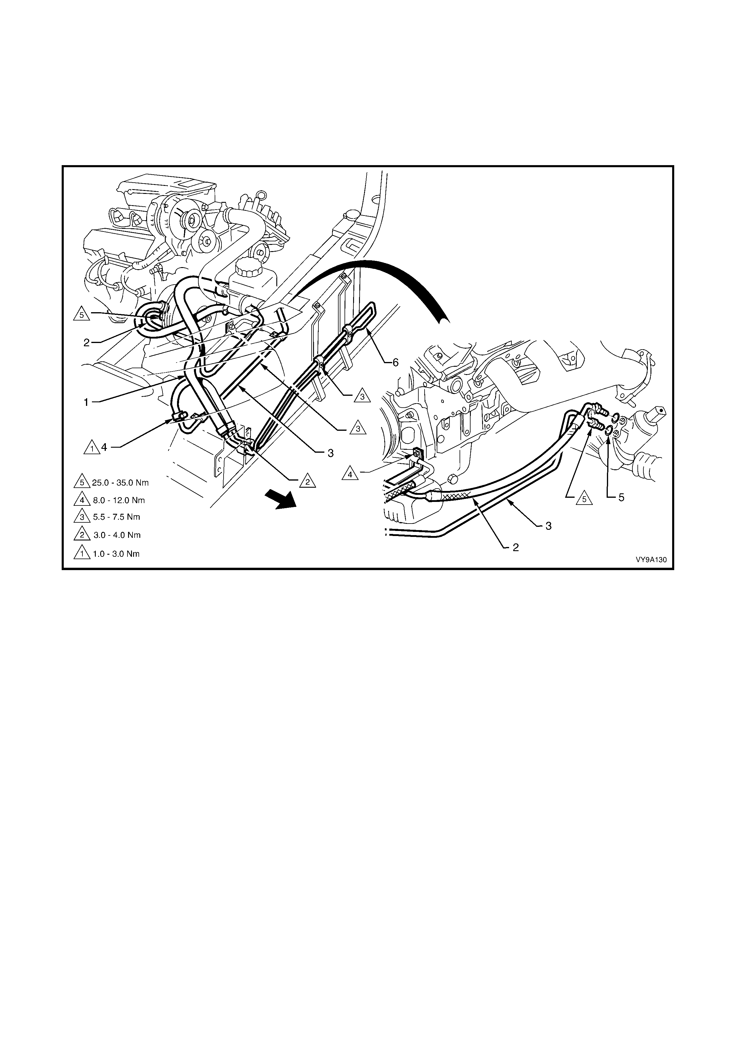
3.16 LEFT-HAND DRIVE POWER STEERING FLUID COOLER AND
HOSE/PIPE ROUTING – V6 ENGINE
LT Section No. – 06-400
ARRANGEMENT
Refer to F igure 9-194 f or the general layout of the power steering f luid cooler, hoses and fittings us ed for the power
steering fitted to left-hand drive MY 2003 VY and V2 Series Vehicles fitted with a V6 engine.
Figure 9-194
Legend
1. Low Pressure Fluid Return Hose, Cooler to Reservoir
2. High Pressure Fluid Feed Pipe Assembly, Pump to
Gear
3. Low Pressure Fluid Return Pipe, Gear to Cooler
4. Clamp, Fluid Cooler Hose to Low Pressure Return Pipe
5. O-Ring, Pipe to Steering Gear (2 places)
6. Cooler, Power Steering Fluid

3.17 RIGHT-HAND DRIVE POWER STEERING FLUID COOLE R AND
HOSE/PIPE ROUTING - GEN III V8 ENGINE
LT Section No. – 06-400
ARRANGEMENT
Refer to Figures 9-195 and 9-196 for the general arrangement of the power steering fluid cooler, hoses, pipes and
fittings used for the power steering system fitted to vehicles with the GEN III V8 engine. Torque specifications are
also provided.
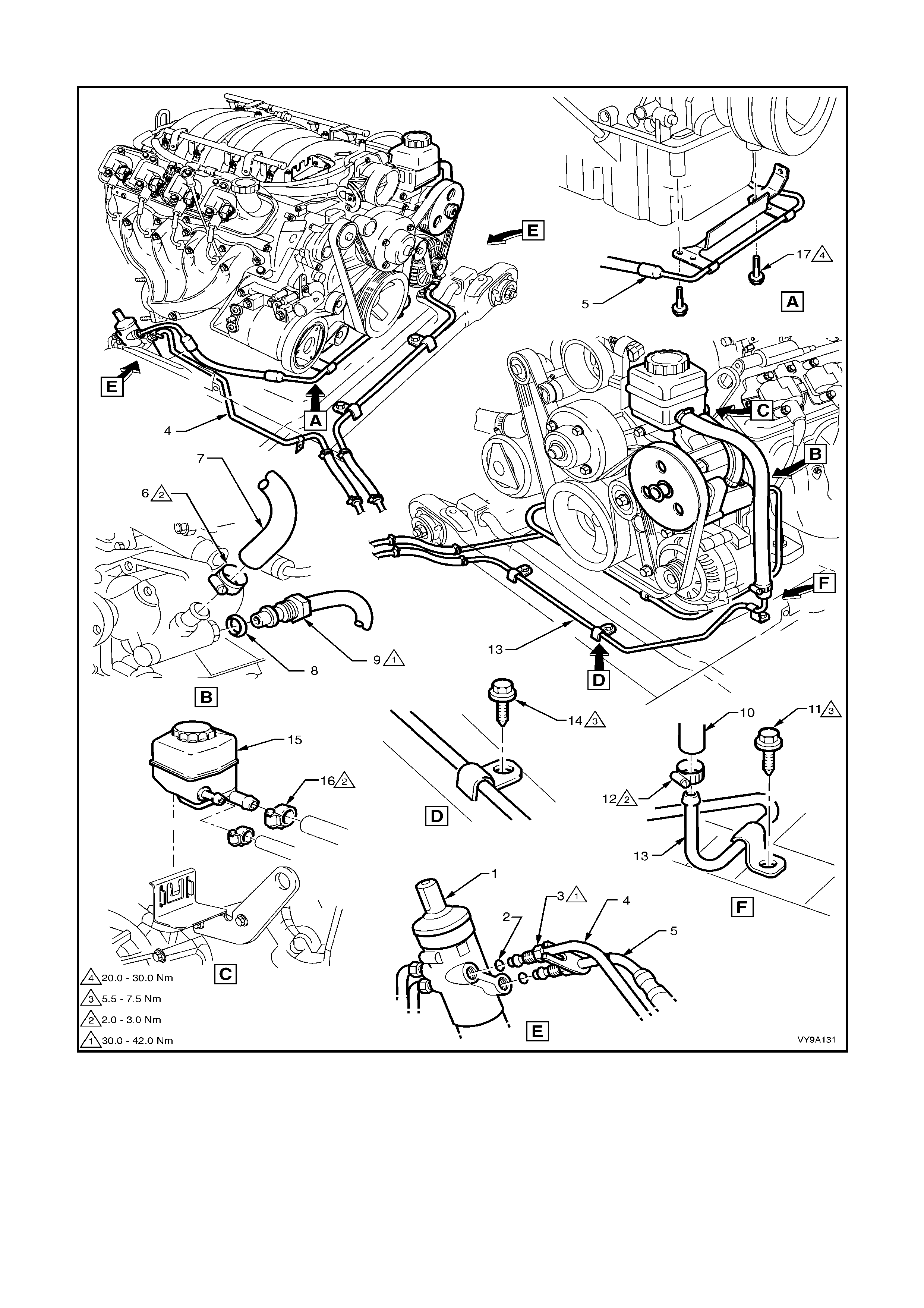
Figure 9-195
Legend
1. Power Steering Rack
2. O-ring, Fluid Pipe to Rack
3. Flare Nut, Fluid Pipe (2 places)
4. Pipe, Steering Rack to Cooler
5. Pipe, Steering Rack to Pump
6. Clamp, Low Pressure Hose
7. Hose, Low Pressure
8. O-ring, Fluid Pipe to Pump
9. Flare Nut, Fluid Pipe
10. Hose, Low Pressure to Reservoir
11. Screw, Low Pressure Pipe
12. Clamp, Low Pressure Hose
13. Pipe, Fluid Cooler to Reservoir
14. Screw, Low Pressure Pipe
15. Reservoir, Fluid
16. Clamp, Low Pressure Hose
17. Bolt, Pipe to Sump Bracket
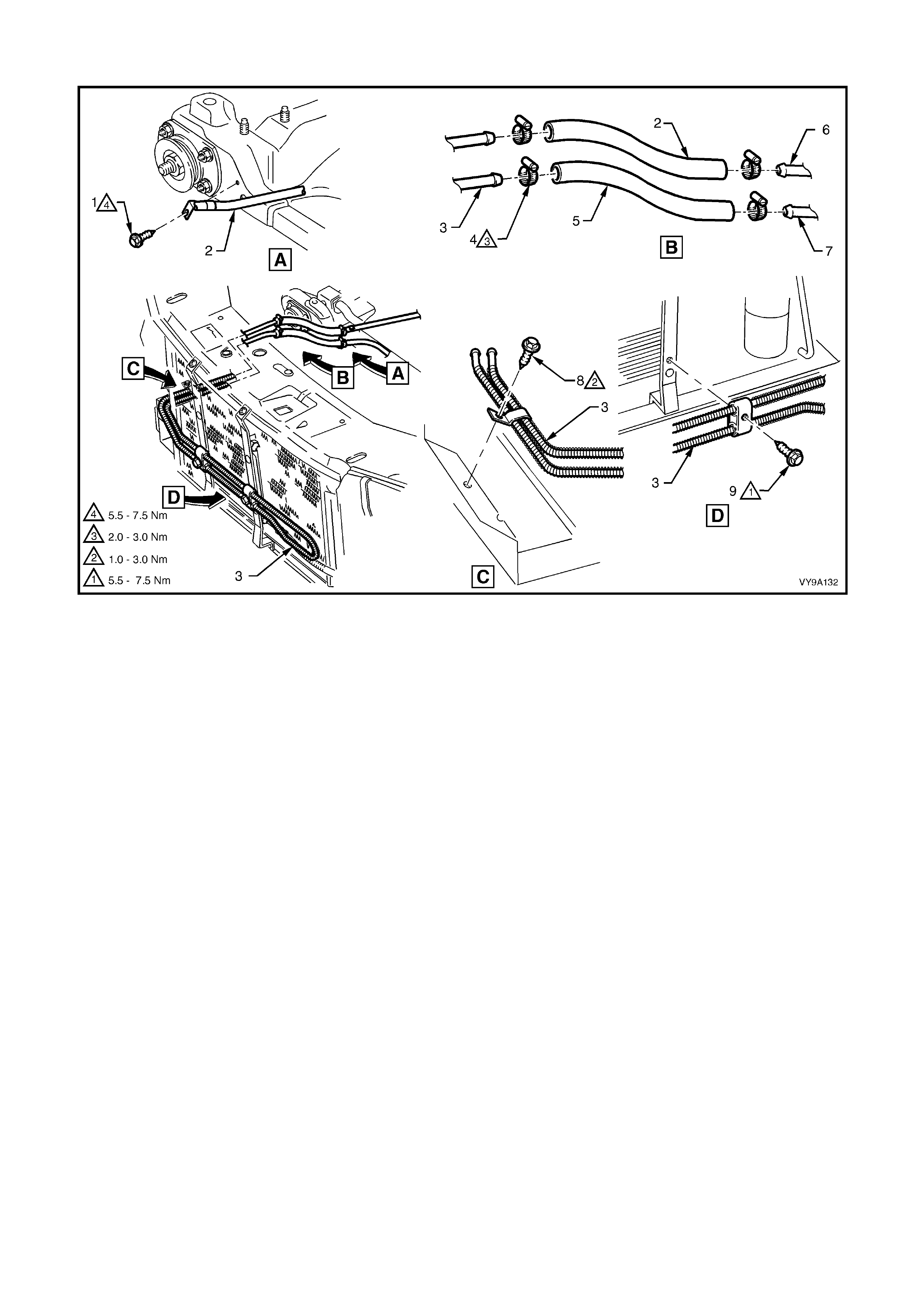
Figure 9-196
Legend
1. Screw, Hose Bracket
2. Hose, Fluid Cooler to Gear
3. Cooler, Fluid
4. Clamp, Hose (4 places)
5. Hose, Fluid Cooler to Reservoir
6. Pipe, Power Steering Rack
7. Pipe, To Fluid Reservoir
8. Screw, Cooler Bracket
9. Screw, Fluid Cooler (2 places)

3.18 LEFT-HAND DRIVE POWER STEERING FLUID COOLER AND
HOSE/PIPE ROUTING - GEN III V8 ENGINE
LT Section No. – 06-400
ARRANGEMENT
Refer to Figures 9-197 and 9-198 for the general arrangement of the power steering fluid cooler, hoses, pipes and
fittings used for the power steering system fitted to vehicles with the GEN III V8 engine. Torque specifications are
also provided.
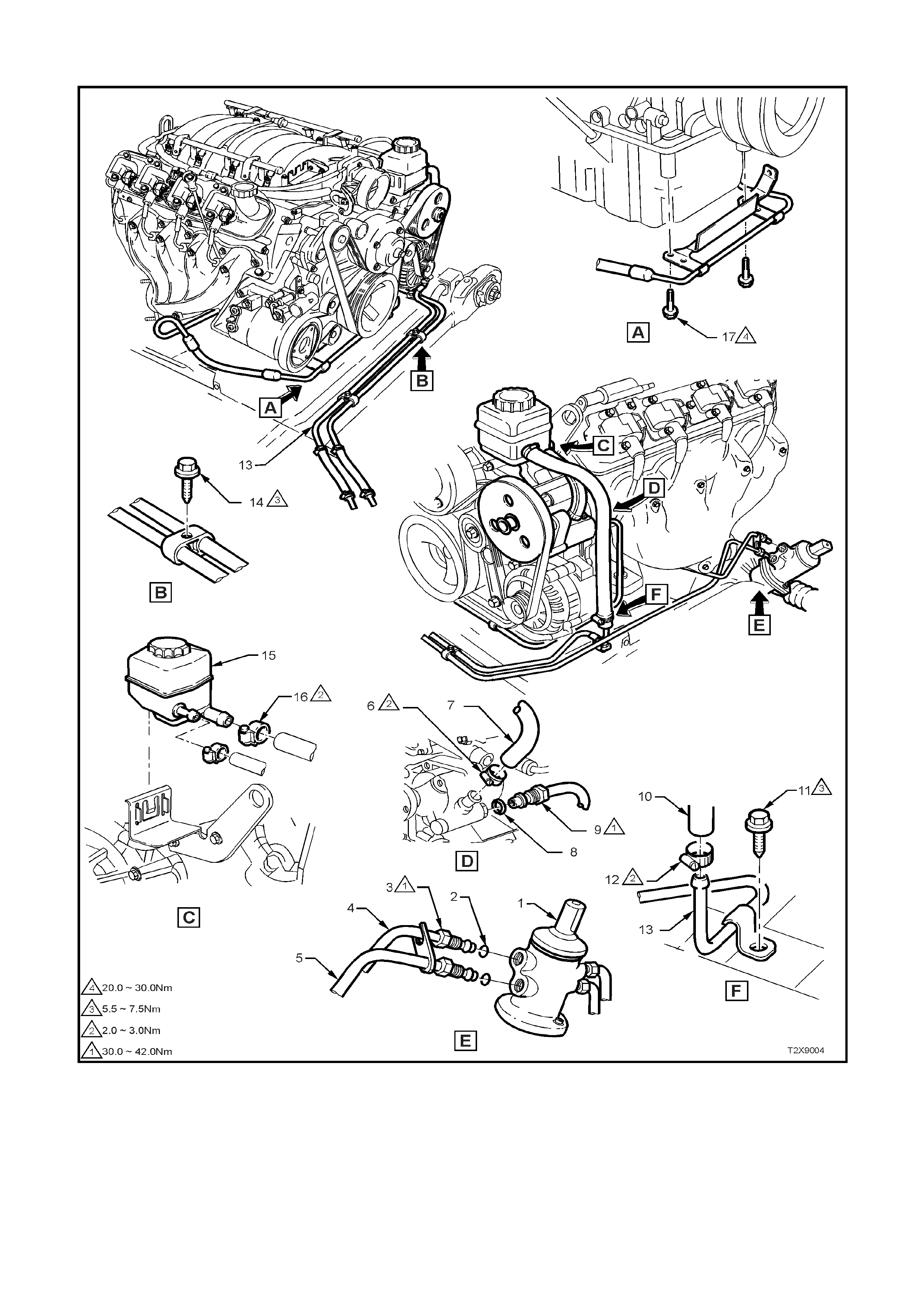
Figure 9-197
Legend
1. Assembly, Steering Rack
2. O-ring, Fluid Pipe to Gear
3. Flare Nut, Fluid Pipe (2 places)
4. Pipe, Steering Gear to Cooler
5. Pipe, Steering Gear to Pump
6. Clamp, Low Pressure Hose
7. Hose, Low Pressure to Reservoir
8. O-ring, Fluid Pipe to Pump
9. Flare Nut, Fluid Pipe
10. Hose, Low Pressure to Reservoir
11. Screw, Low Pressure Pipe
12. Clamp, Low Pressure Hose
13. Pipe, Fluid Cooler to Reservoir
14. Bolt, Pipe to Sump Bracket
15. Reservoir, Fluid
16. Clamp, Low Pressure Hose
17. Bolt, Pipeto Sump Bracket
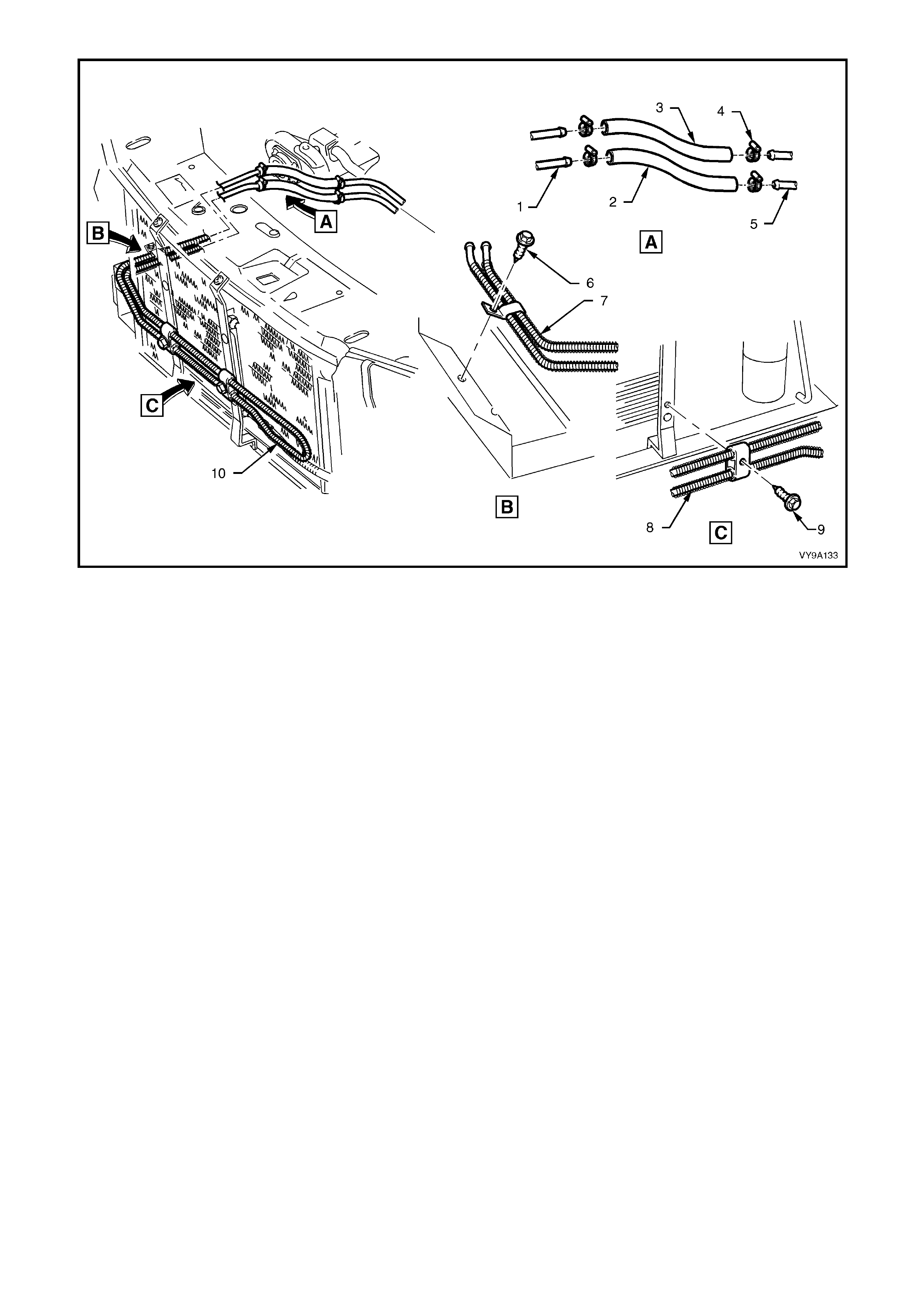
Figure 9-198
Legend
1. Pipe, Cooler to Steering Gear
2. Hose, Cooler to Steering Gear
3. Hose, Cooler to Reservoir
4. Clamp, Hose (4 places)
5. Pipe, Steering Gear
6. Screw, Cooler Bracket
7. Pipe, Fluid Reservoir
8. Cooler, Steering Fluid
9. Screw, Fluid Cooler (2 places)

4. DIAGNOSIS
4.1 GENERAL DIAGNOSTIC INFORMATION
Faulty steering can be caused by problems in areas other than the pump or steering gear. Areas of the steering
system that can be easily checked and quickly corrected without disassembly and overhaul of any major
components, should be attempted first.
Problem s suc h as hard or loose st eering, road shoc k or vibrations are not always due to the steering gear or pump,
but are often related instead to such factors as low tyre pressure or front end alignment. These items should be
checked and corrected before any adjustment or disassembly of the steering gear or pump is attempted.
Other factors that may affect correct operation of the steering system, are:
1. Loose component mountings.
2. Drive belt tension.
3. Power steering fluid level and condition.
These factors must be checked and corrected before making any further diagnosis of the steering system.
After the source of the problem has been located, the cause of the problem can be diagnosed and corrected.
For exam ple, if the power steer ing fluid level in the reservoir is f ound to be low, refill and c heck the entire hydraulic
system for power steering fluid leaks. Refilling the reservoir will not necessarily correct the problem.
Techline

4.2 POWER STEERING PUMP
DIAGNOSTIC ITEMS
Chirp Noise in Steering Pump.
1. Incorrectly tensioned drive belt.
Drive Belt Squeal (Particularly noticeable at full wheel travel and standstill parking).
1. Incorrectly tensioned drive belt.
Growl Noise in Steering Pump.
1. Excessive back-pressure in hoses or steering gear caused by restriction of flow.
Growl Noise in Steering Pump (Particularly noticeable at standstill parking).
1. Scored pressure plate, thrust plate or rotor.
2. Extreme wear of pump ring and vanes.
Groan Noise in Steering Pump.
1. Low power steering fluid level.
2. Air in the power steering fluid. Poor pressure hose connection.
Rattle Noise in Steering Pump.
1. Vanes not installed correctly.
Momentary Increase in Effort when Turning Wheel Fast to Right or Left.
1. Low power steering fluid level.
2. Drive belt slipping.
3. High internal leakage.
Steering Wheel Surges or Jerks when Turning with Engine Running, Especially During Pa rking.
1. Low power steering fluid level.
2. Incorrectly tensioned drive belt.
3. Insufficient pump pressure.
4. Sticky flow control valve.
Hard Steering or Lack of Assist, Especially in Parking.
1. Incorrectly tensioned drive belt.
2. Low power steering fluid level.
3. Steering gear to column misalignment.
4. Tyres not properly inflated.
NOTE: If rectification of checks 1 through 4 does not correct hard steering, follow the Power Steering Test
Procedure as outlined in 3.4 HYDRAULIC SYSTEM CHECK.
Further possible causes could be:
1. Sticky flow control valve.
2. Insufficient pump pressure output.
3. Excessive internal pump leakage.
4. Excessive internal system leakage.
Foaming or Milky Power Steering Fluid, Low Fluid Level and Possible Low Pressure.
1. Air in the power steering fluid, and loss of power steering fluid due to internal pump leakage, causing overflow.
Low Pressure from Steering Pump.
1. Flow control valve stuck or inoperative.
2. Pressure plate not flat against pump ring.
3. Extreme wear of pump ring and vanes.
4. Scored pressure plate, thrust plate or rotor.
5. Vanes not installed correctly.
6. Vanes sticking in rotor slots.
7. Cracked or broken thrust or pressure plate.
8. High internal leakage.

LEAK DIAGNOSIS
General Procedure
1. Wipe suspected area dry.
2. Check for overfilled reservoir.
3. Check for aeration and overflow of foaming power steering fluid.
4. Check hose connections - tighten if necessary to the specified torque.
5. Verify exact point of leakage.
Example: T he location that the power steer ing fluid drips f rom is not necessar ily the leakage point - power steer ing
fluid could be overflowing from the reservoir for example.
6. When service is required:
a. Clean leakage area upon disassembly.
b. Replace leaking seal.
c. Check component sealing surfaces for damage and replace component if necessary.
d. Tighten fastener/s to the specified torque where required.
External Leakage Check
The purpose of this procedure is to pinpoint the location of the leak. In som e cas es, the leak c an easily be located.
Seepage type leaks may be more difficult to isolate. To locate seepage leaks, use the following method.
1. With the engine stopped, wipe the complete power steering system dry (steering gear, pump, hoses and
connections).
2. Check the power steering fluid level in the pump’s reservoir. Add power steering fluid if necessary.
3. Start the engine then turn the steering wheel from stop to stop several times. Do not hold it at a stop for any
length of tim e, as this can dam age the power steering pum p. It is easier if s omeone else operates the steering
wheel while you search for the seepage.
4. Find the exact area of the leak. If the leak is in the steering gear assembly, remove and repair as necessary.
Seal Replacement Recommendations
Lip seals, which s eal rotating shafts , require special tr eatment. T his type of seal is used on the steering gear pinion
shaft and on the dr ive s haf t of the pump. When there is a leak in one of thes e areas , always replace the seal/s af ter
inspecting and thoroughly c leaning the sealing surf aces. Replace the shaf t only if very severe pitting is found. If the
corros ion in the lip seal c ontac t area is s light, clean the s urf ac e of the s haf t with crocus cloth. Replace the shaft only
if the leakage cannot be stopped by first smoothing with crocus cloth.
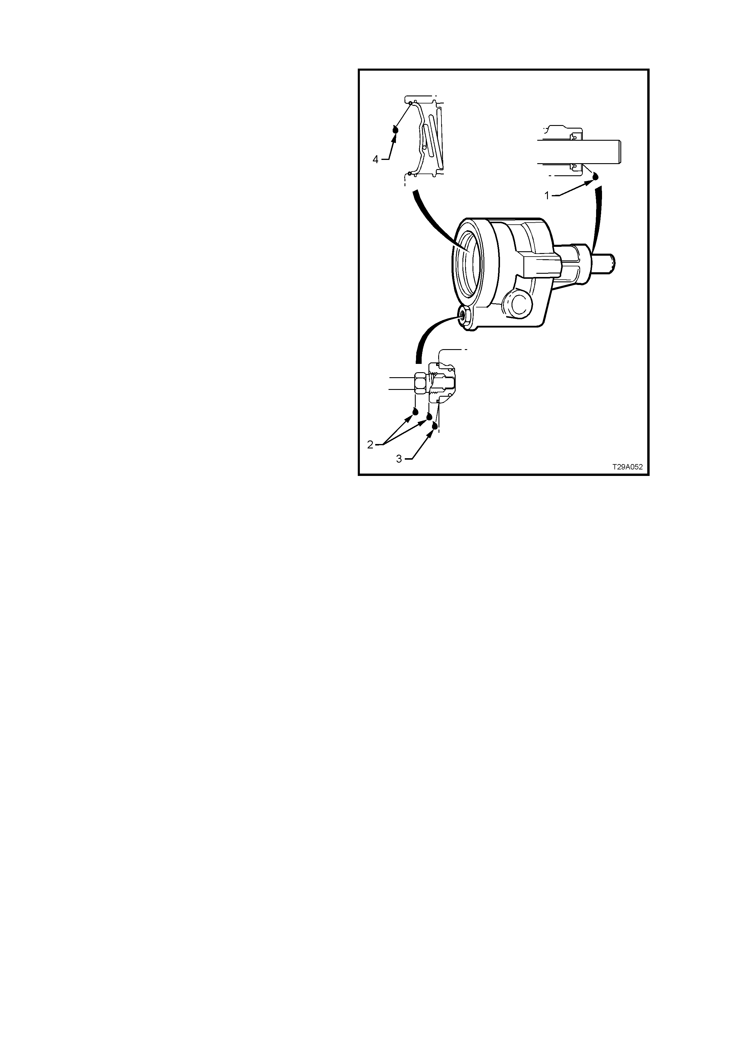
Pump Leak Diagnosis
NOTE: The following explanations relate to the
numbers shown in Figure 9-199.
1. Replace drive shaft seal. Make certain that
drive shaft is clean and free of pitting in seal
area.
2. Torque high pressure pipe flare nut to 25 - 35
Nm. If leakage persists, replace O-ring seal.
3. Torque outlet fitting to 50 - 102 Nm. If leakage
persists, replace O-ring seal.
4. Replace end plate O-ring seal.
Figure 9-199

5. SPECIFICATIONS
STEERING GEAR
Steering Gear Type
Power Steering................................................... Rack and pinion with integral power cylinder and
rotary valve mechanism - variable ratio
Steering Gear Ratio
On-centre........................................................... 17.2:1
Toward Lock....................................................... 11.8:1
No. of Steering Wheel turns Lock to Lock............... 2.7
Nominal Rack Travel Total...................................... 164 mm
POWER STEERING PUMP
Make........................................................................ Saginaw
Type
V6..................................................................... 'N' Series vane type
GEN III V8 Engine............................................ ‘N’ Series vane type
Pressure at 1,000 engine rpm
V6..................................................................... 7,580 - 8,270 kPa
GEN III V8 Engine............................................ 8,270 - 8,960 kPa
Drive........................................................................ Pulley
Lubrication (Power Steering)
Hydraulic ............................................................ Dexron® III Automatic Transmission Fluid
Power Steering Fluid Capacity........................... Approx. 650 ml
Note: Use power steering fluid level indicator as a
final check to ensure correct refill quantity
Drive Belt Tension
V6..................................................................... Belt Self Adjusting
GEN III V8 Engine............................................ Belt Self Adjusting
FRONT WHEEL TOE
Front Toe-in (Degrees Total) ............................. 0° 10’ ± 0° 10’
Front Toe-in (Degrees per Wheel)..................... 0° 5’ ± 0° 5’
LUBRICANTS
Specified Grease................................................ EP Semi Fluid Lithium Base O Grease
Hydraulic Fluid.................................................... Dexron® III Automatic Transmission Fluid
SEALANTS
Specified Locations............................................ Loctite 242 or equivalent
RTV T32 Silicone Sealant

6. TORQUE WRENCH SPECIFICATIONS
Nm
STEERING COLUMN ASSEMBLY
Steering Wheel Retaining Bolt................................................ 40 - 50
Upper Steering Column Mount Attaching NUt........................ 15 - 30
Lower Steering Coupling to Steering Gear Pinion Clamp Nut 23 - 30
Steering Shaft Lower Bearing Support Retaining Nuts........... 15 - 30
♦ Steering Coupling to Gear Pinion Cam Bolt Nut..................... 23 - 30
POWER STEERING GEAR
Hydraulic Pipe to Valve Housing Flare Nut............................. 30 - 42
§ Pinion Lower Bearing Retaining Nut....................................... 35 - 45
Pinion Lower Bearing Screw Plug........................................... 55 - 60
Rack Pad Adjusting Screw...................................................... 10 - 12, then back off 20 - 28°
Rack Pad Adjusting Screw Lock Nut ...................................... 55 - 65
Road Wheel Attaching Nut...................................................... 110 - 140
♦ Steering Gear Housing to Crossmember Mounting Nut......... 60, then 40° - 50° turn angle
Steering Gear Feed Pipe Flare Nut......................................... 15 - 25
Tie Rod Socket Adjustment Lock Nut..................................... 50 - 85
Valve Housing to Gear Housing Attaching Screws................. 5 - 6
Tie Rod Socket Stud Castellated Nut ..................................... 50 - 85
§ Tie Rod to Rack and Piston Assembly.................................... 90 - 100
V6 POWER STEERING PUMP
Reservoir Attaching Screw...................................................... 3.0 - 7.0
Pump Pulley Attaching Bolt..................................................... 20 - 30
Pump to Retaining Bracket Bolt.............................................. 30 - 40
Power Steering Pump Outlet Fitting........................................ 50 - 102
GEN III V8 ENGINE POWER STEERING PUMP
Air Intake Duct Hose Clamp.................................................... 5.0 - 8.0
Engine Dress Cover Nut ......................................................... 8.0 - 12.0
High Pressure Hose Flare Nut................................................ 25 - 35
Low Pressure Hose Clamp - All.............................................. 2.0 - 3.0
Power Steering Pump Outlet Fitting........................................ 50 - 102
Pump to Right-Hand Cylinder Head Bolt................................. 20 - 35
Reservoir BGearet Mounting Bolts.......................................... 50
§
Fasteners must be replaced after loosening.
• Vehicle mus t be at kerb height before final tightening.
♦ Fasteners have micro encapsulated sealant applied and should be replaced after being loosened. If
in doubt, replacement is recommended.

7. SPECIAL TOOLS
TOOL NUMBER ILLUSTRATION DESCRIPTION TOOL
CLASSIFICATION
211-258 TIE ROD WRENCH
Previously released.
Unique
211-259
LOWER PINION BEARING
REMOVER
Previously released.
Used in conjunction with Driver
Handle AU355-A.
Unique
7005 POWER STEERING PUMP
PULLEY INSTALLER
Previously released.
Desirable
7185 POWER STEERING PUMP
PULLEY REMOVER
Previously released.
Desirable
9A10
STEERING LINKAGE BALL STUD
REMOVER
Previously released.
Desirable
9A23 EXPANDER - SLEEVE SEALS
Previously released.
Unique
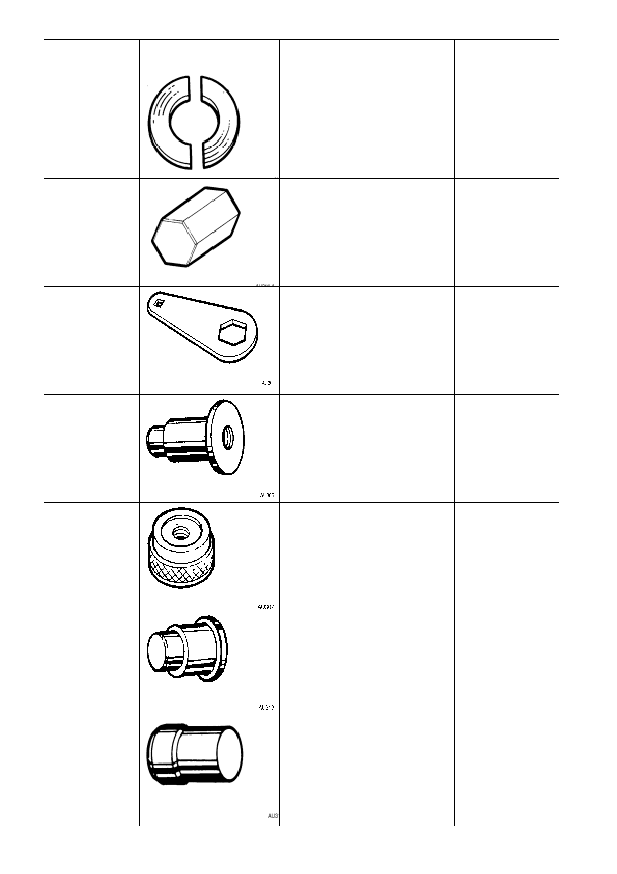
TOOL NUMBER ILLUSTRATION DESCRIPTION TOOL
CLASSIFICATION
AU188 PRESS PLATES
Previously released.
Unique
AU211-A RACK PAD ADJUSTING SCREW
WRENCH
Previously released.
Desirable
AU301 RACK PAD ADJUSTING SCREW
LOCK NUT WRENCH
Previously released.
Desirable
AU306 LOWER PINION BEARING
REMOVER
Previously released.
Unique
AU307 LOWER PINION BEARING
INSTALLER
Previously released.
Unique
AU313 UPPER PINION POWER
STEERING FLUID SEAL
INSTALLER
Previously released.
Used to install valve housing
bearing.
Unique
AU314 VALVE HOUSING SEAL AND
BEARING REMOVER
Previously released.
Unique
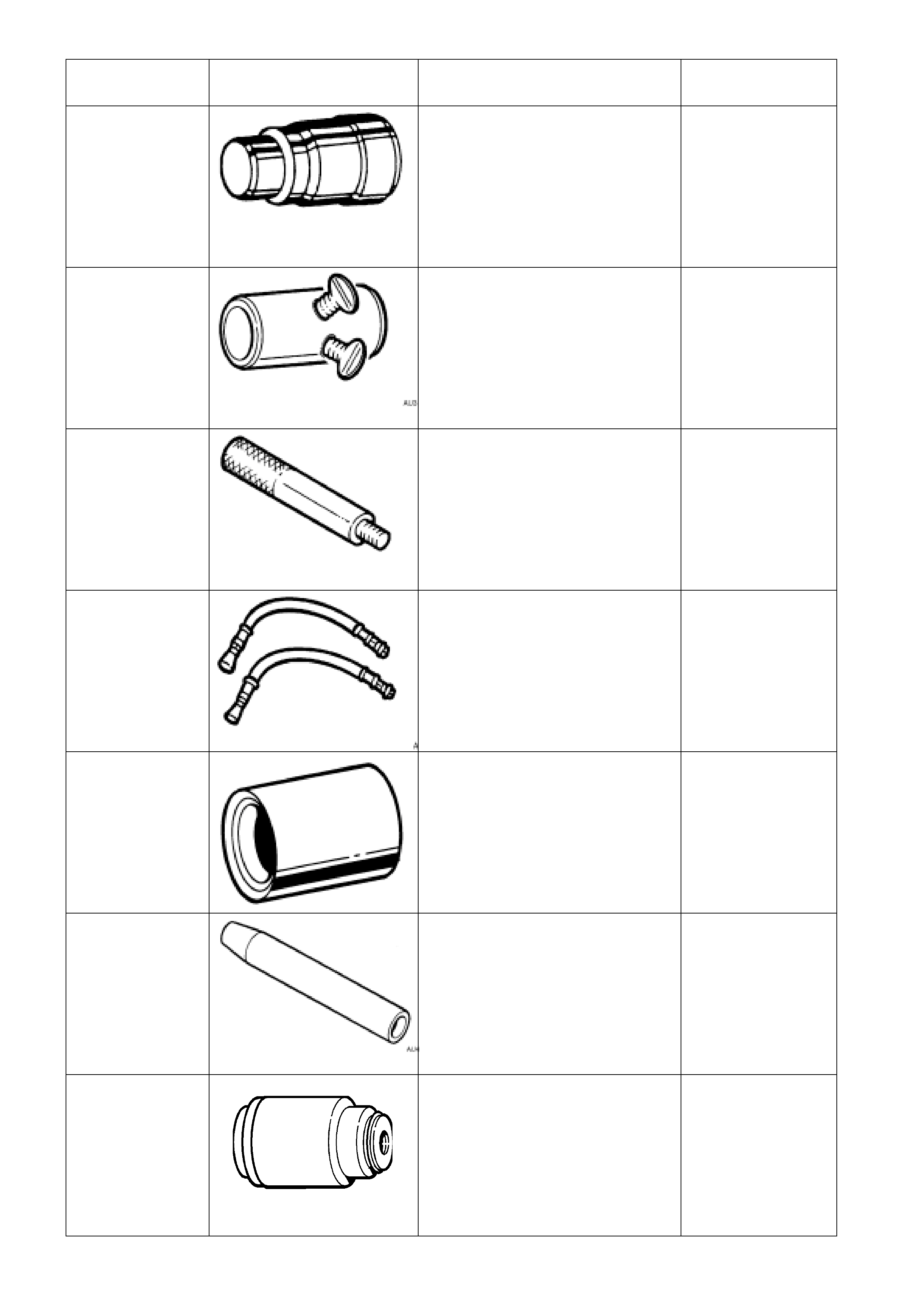
TOOL NUMBER ILLUSTRATION DESCRIPTION TOOL
CLASSIFICATION
AU315 VALVE HOUSING SEAL &
BEARING INSTALLER
Previously released.
Unique
AU316 PRE-LOAD ADAPTOR
Previously released.
Unique
AU355-A DRIVER HANDLE
Previously released as KM523-1.
Used in conjunction with AU306
and AU315.
Unique
AU392 PRESSURE HOSE SET
Previously released.
Comprises:
AU392-1, hose with male end
fitting.
AU392-2, hose with female end
fittin
g
.
Mandatory
AU440 CONTRACTOR - SLEEVE SEALS
Previously released.
Unique
AU456 RACK SEAL PROTECTOR - LONG
Previously released.
Unique
AU460 INSTALLER - INNER RACK SEAL
AND SPACER
Previously released.
Used in conjunction with Driver
Handle AU355-A.
Unique
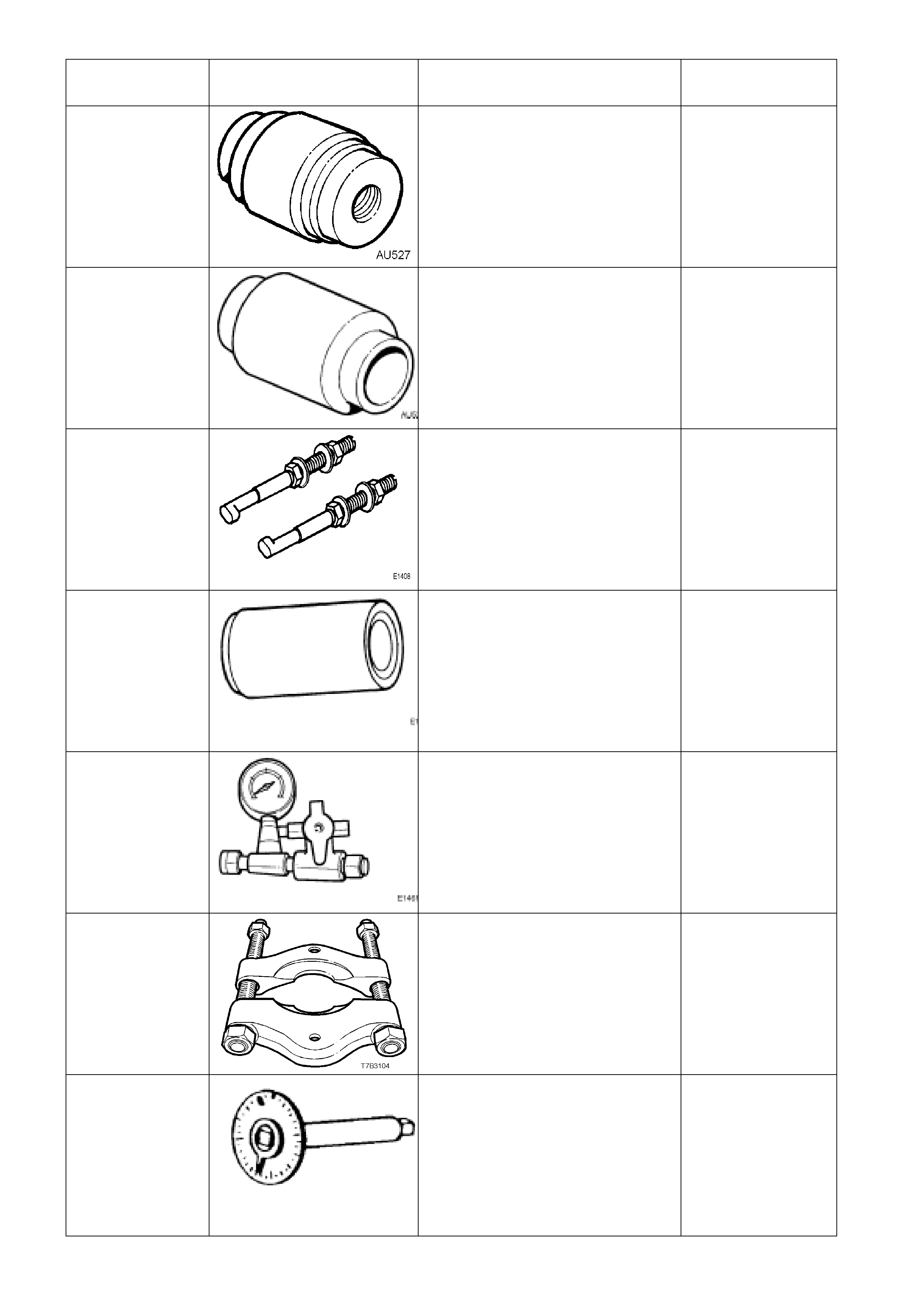
TOOL NUMBER ILLUSTRATION DESCRIPTION TOOL
CLASSIFICATION
AU527 INTERMEDIATE PINION
BEARING AND POWER
STEERING FLUID SEAL
INSTALLER
Previously released.
Used in conjunction with Driver
Handle AU355-
A
.
Unique
AU528 UPPER PINION BEARING AND
POWER STEERING FLUID SEAL
INSTALLER
Previously released.
Unique
E1408 STEERING WHEEL PULLER
LEGS
Previously released.
Desirable
E1460-1 POWER STEERING PUMP
SHAFT SEAL INSTALLER
Previously released as 9A61.
Unique
E1461-1 PRESSURE GAUGE ASSEMBLY
Previously released.
Mandatory
E6673
PRESS RLATES
Previously released as J22912-1
Desirable
E7115 ANGLE WRENCH
Previously released.
Desirable
TOOL NUMBER ILLUSTRATION DESCRIPTION TOOL
CLASSIFICATION
E8803-6 RACK SEAL PROTECTOR -
SHORT
Previously released.
Unique
E8803-7 RACK PISTON TOOL
Previously released.
Used to rotate the end bushing to
remove/install retaining wire clip.
Unique
E8803-9 RACK PISTON SEAL EXPANDER
Previously released.
Used to expand the rack piston seal
prior to installation.
Unique
E8803-10 RACK SEAL TEST ADAPTOR
Previously released.
Used in conjunction with hand
vacuum pump to assess rack seal
serviceability.
Mandatory
E8803-11 RACK END SEAL/BUSH
INSTALLER
Previously released.
Used to install rack end seal and
bush.
Unique
E9239 POWER STEERING PUMP
PULLEY INSTALLER
Previously released as J25033-B.
Desirable
ETX30H TOR X BIT
Previously released.
Also commercially available as a
T30H Torx bit
Mandatory
TOOL NUMBER ILLUSTRATION DESCRIPTION TOOL
CLASSIFICATION
J1859-A STEERING WHEEL PULLER
Previously released.
Unique
J23738-A HAND VACUUM PUMP
Previously released or use
commercially available equivalent.
Mandatory
J25359-8 TORX BIT HOLDER
Previously released or
commercially available.
Used with ETX30H Torx bit.
Mandatory
J25765-A DIAL TYPE TORQUE WRENCH
Previously released or use
commercially available equivalent,
capable of measuring from 0.4 - 6.0
Nm.
Mandatory