
Body Page 1A1–1
02–APR–2003 Page 1A1–1
Section 1A1
Body
ATTENTION
Before performing any Service Operation or other procedure described in this Section, refer to Section 00
WARNINGS, CAUTIONS AND NOTES for correct workshop practices with regard to safety and/or property
damage.
1 General Information...............................................................................................................................2
2 Service Operations.................................................................................................................................3
2.1 Plastic Components .............................................................................................................................................. 3
Plastic Components .............................................................................................................................................. 3
2.2 Inner Rear Body Panel........................................................................................................................................... 6
Remove................................................................................................................................................................... 6
Reinstall.................................................................................................................................................................. 7
3 Torque Wrench Specifications .............................................................................................................8

Body Page 1A1–2
02–APR–2003 Page 1A1–2
1 General Information
With the following exceptions, MY 2003 VY Cab Chassis Series Body information carries over from MY 2003 VY Series
vehicles. For information not contained within this Section, refer to Section 1A1 Body in the MY 2003 VY and V2 Series
Service Information.
• Plastic Components.
• Inner Rear Body Panel
Body Page 1A1–3
02–APR–2003 Page 1A1–3
2 Service Operations
2.1 Plastic Components
Plastic components are used throughout the vehicle. The following chart is included to assist with the identification and
composition of common components unique to MY2003 VY regular cab vehicles.
NOTE
Most components are also identified with the
material code in an inconspicuous place.
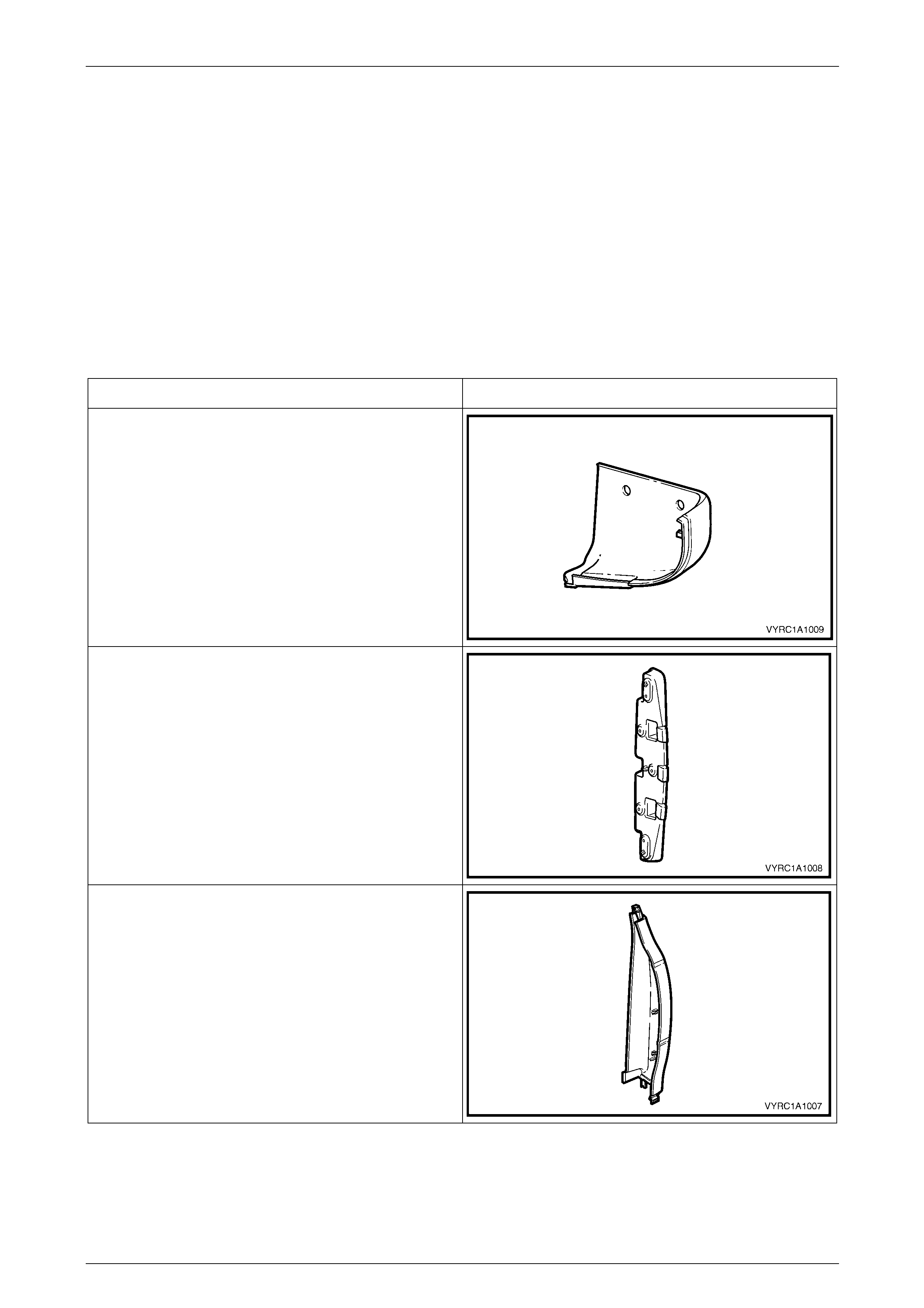
Plastic Components
Component Example
Rocker Panel Rear Moulding Assembly
Material:
PP
Body Side Rear Trim Panel Bracket
Material:
Nylon
30% F/Glass
Body Side Rear Trim Panel
Material:
ABS / PC
Body Page 1A1–4
02–APR–2003 Page 1A1–4
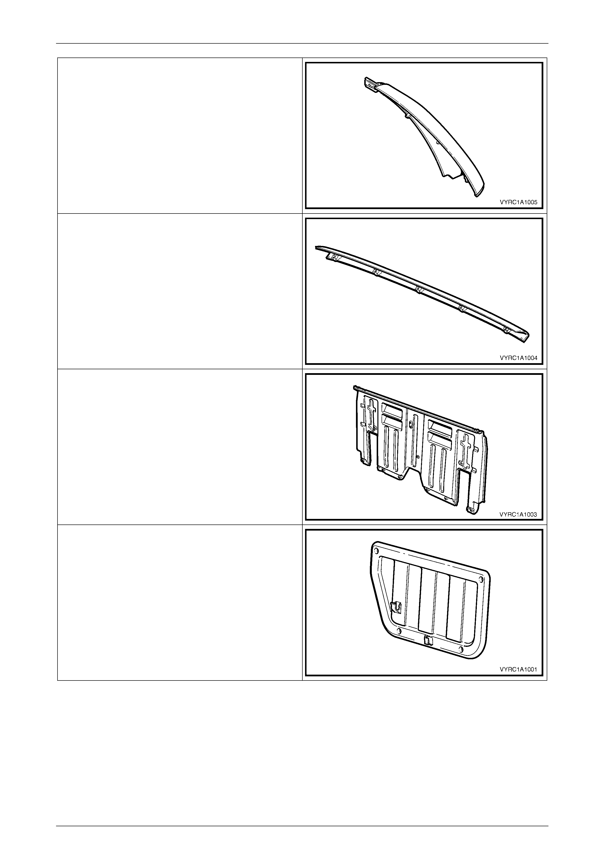
Rear Quarter Window Side Moulding Assembly
Material:
ABS / PC- M6
Rear Quarter Window Upper Moulding Assembly
Material:
ABS / PC- M6
Body Rear Outer Panel Assembly
Material:
10% F/Glass filled PC
Rear Seatback Body Panel Trim Panel Assembly
Material:
PP
Body Page 1A1–5
02–APR–2003 Page 1A1–5
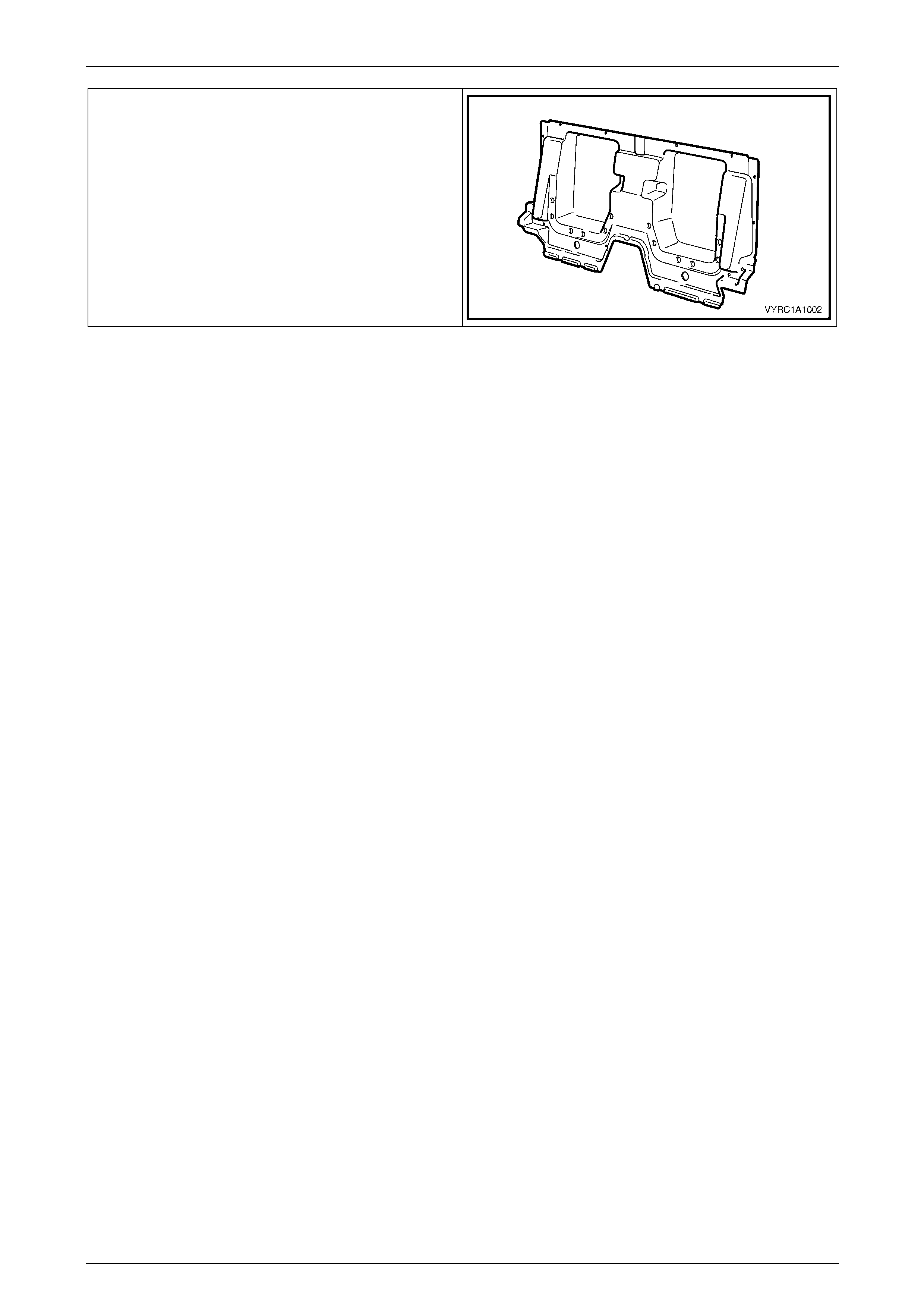
Body Rear Inner Panel
Material:
UP
Body Page 1A1–6
02–APR–2003 Page 1A1–6
2.2 Inner Rear Body Panel
1 Remove the seats or move the seats to the forward position, refer to Section 1A7 Seat Assemblies.
2 As required, first remove the following:
a Remove the floor console, refer to Section 1A3, 2.3 Floor Console Assembly in the MY2003 VY and V2
Series Service Information.
b Remove the centre pillar lower trim, refer to Section 1A8, 5.2 Centre Pillar Lower Trim in the MY2003 VY and
V2 Series Service Information.
c Remove the side sill trim and plate, refer to Section 1A8, 5.4 Side Sill Trim And Plate in the MY2003 VY and
V2 Series Service Information.
e Remove the body lock pillar upper trim, refer to Section 1A8, 5.3 Body Lock Pillar Trim in the MY2003 VY and
V2 Series Service Information.
f Remove the child seat restraint, refer to Section 12M Supplementary Restraint System in the MY2003 VY and
V2 Series Service Information.
g Remove the rear seat back body panel trim assembly, refer to
Section 1A8, 2.1 Rear Seat Back Body Panel Trim Assembly.
Remove
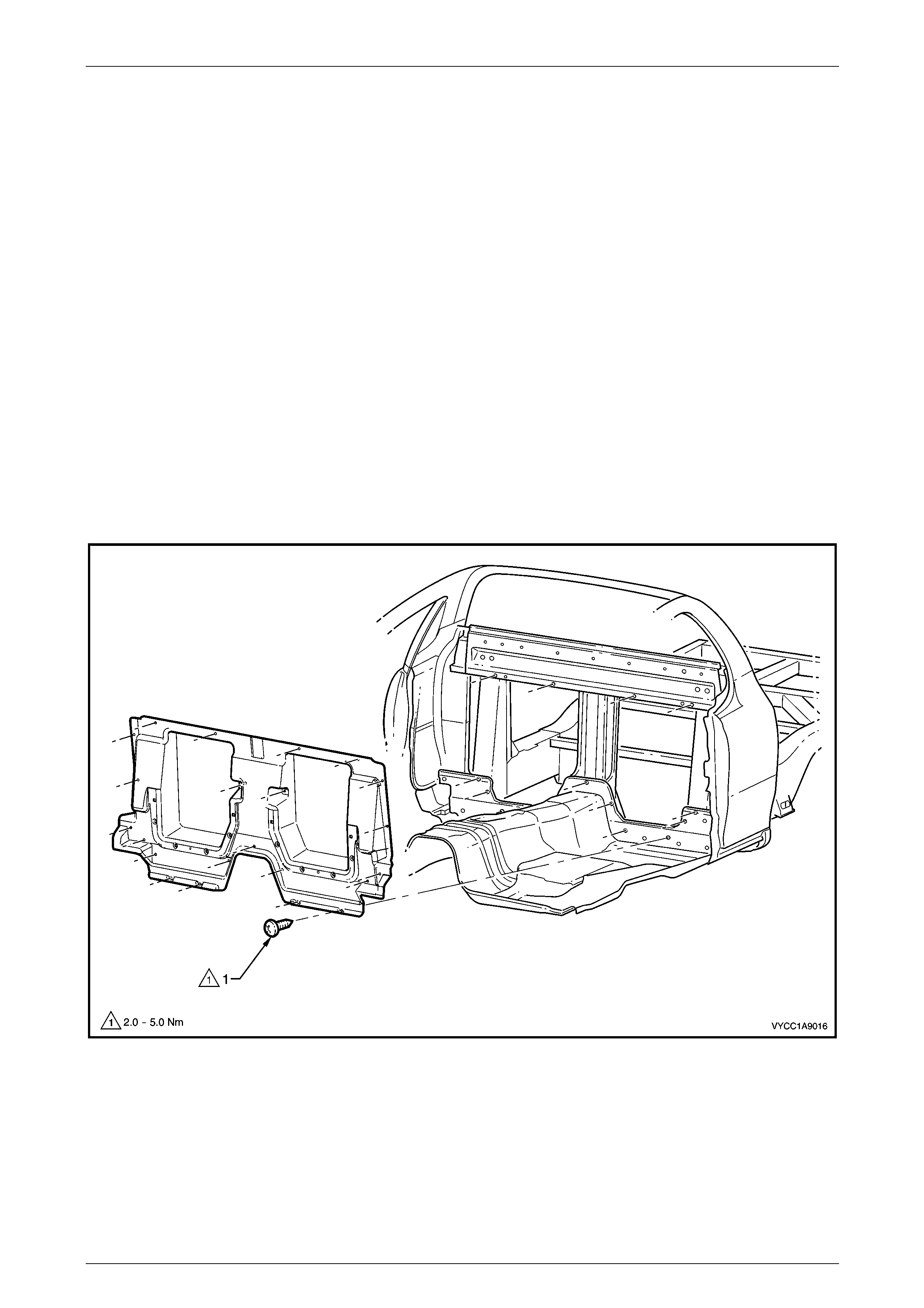
1 Remove the screw (1) 23 places attaching the inner rear body panel to the cab, refer to Figure 1A1 – 1.
Figure 1A1 – 1
2 Using a suitable screwdriver, gently lever the inner rear body panel forward to dislodge the sealer from the body
and remove the panel through the passenger door.
Body Page 1A1–7
02–APR–2003 Page 1A1–7
Reinstall
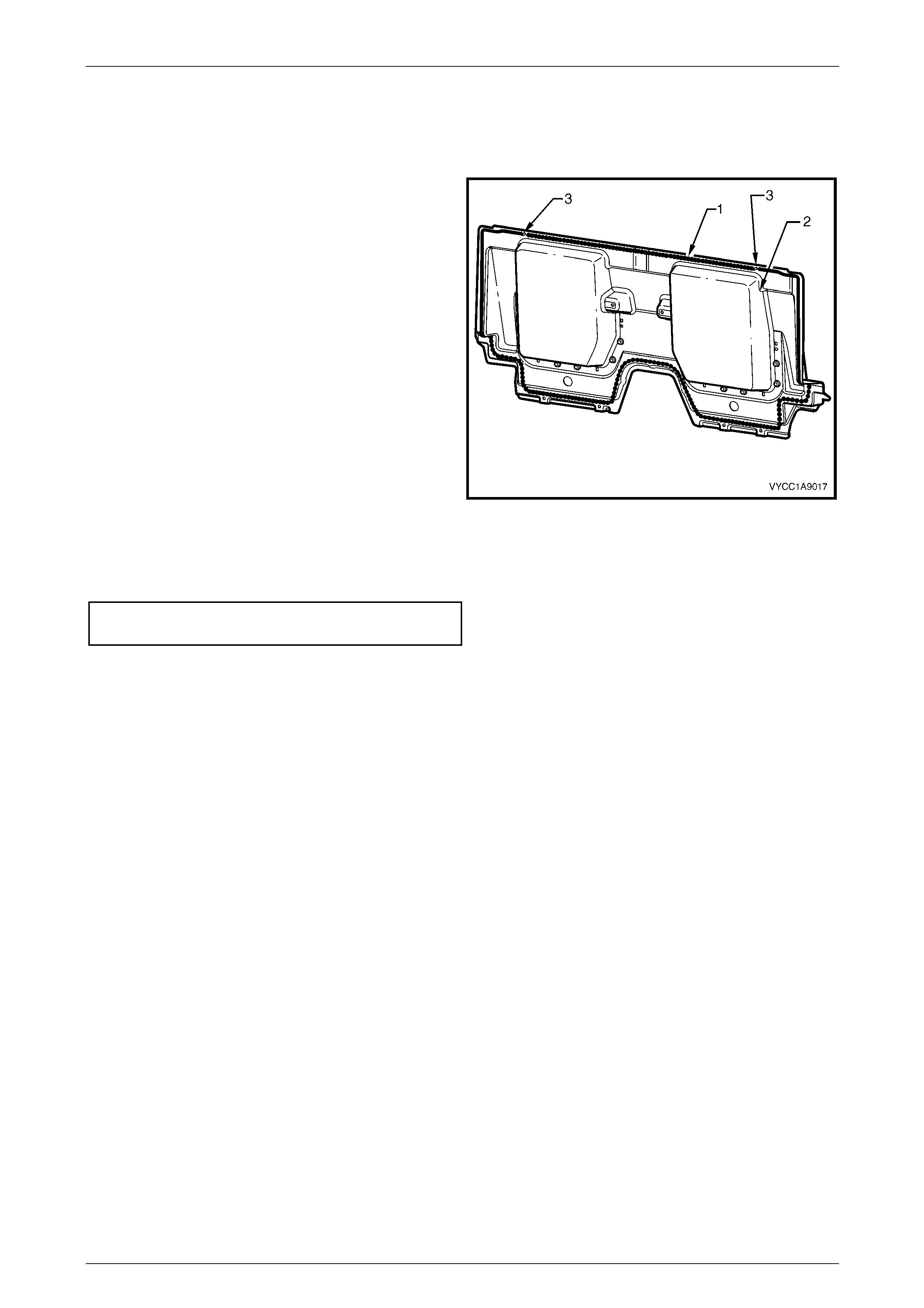
Reinstallation is the reverse of removal noting the following:
1 As required clean off any residual sealer from the surfaces of the inner rear body panel and the body.
2 Apply a bead of sealer (1), mastic or similar around the
edges of the inner rear body panel (2).
3 Using the data pin (3) on the inner rear body panel,
position the panel onto the body.
Figure 1A1 – 2
4 Install the screw (1) 23 places attaching the inner rear body panel, refer to Figure 1A1 – 1.
5 Tighten all screws to the specified torque.
Inner rear body panel
attaching screw..........................................2.0 – 5.0 N.m

Body Page 1A1–8
02–APR–2003 Page 1A1–8
3 Torque Wrench Specifications
Inner Rear Body Panel Screw ....................................................2.0 – 5.0 N.m