
Seat Assemblies Page 1A7–1
Page 1A7–1
Section 1A7
Seat Assemblies
ATTENTION
Before performing any Service Operation or other procedure described in this Section, refer to Section 00
Warnings, Cautions and Notes for correct workshop practices with regard to safety and/or property damage.
1 General Information............................................................................................................................... 3
1.1 Front Seat General Description.............................................................................................................................3
Seat Covers.............................................................................................................................................................3
Electric Seat Operation..........................................................................................................................................3
Raise/Lower Movement......................................................................................................................................4
Four-way Movement Control ..............................................................................................................................4
2 Service Operations................................................................................................................................5
2.1 Front Seat Usage Chart .........................................................................................................................................5
How To Use This Chart..........................................................................................................................................5
Front Seat Type 1...................................................................................................................................................6
Front Seat Type 2...................................................................................................................................................8
2.2 Front Seat Assembly............................................................................................................................................10
Remove .................................................................................................................................................................10
Reinstall ................................................................................................................................................................12
2.3 Front Seat Outer Side Cover Assembly..............................................................................................................13
Remove .................................................................................................................................................................13
Disassemble .........................................................................................................................................................14
Front Seat Adjustment Switch ..........................................................................................................................14
Reinstall ................................................................................................................................................................14
2.4 Front Seat Inner Side Cover................................................................................................................................15
Remove .................................................................................................................................................................15
Reinstall ................................................................................................................................................................15
2.5 Front Seat-back Rear Cover Assembly..............................................................................................................16
Remove .................................................................................................................................................................16
Reinstall ................................................................................................................................................................17
2.6 Dump-latch Mechanism Assembly.....................................................................................................................18
Remove .................................................................................................................................................................18
Reinstall ................................................................................................................................................................19
2.7 Front Seat Head Restraint Assembly .................................................................................................................20
Remove .................................................................................................................................................................20
Disassemble .........................................................................................................................................................20
Reassemble ..........................................................................................................................................................21
Reinstall ................................................................................................................................................................21
2.8 Front Seat Head Restraint Sleeve.......................................................................................................................22
Remove .................................................................................................................................................................22
Reinstall ................................................................................................................................................................22
2.9 Lumbar Support Knob Assembly .......................................................................................................................23
Remove .................................................................................................................................................................23
Reinstall ................................................................................................................................................................23
2.10 Front Seat-back Pad and Cover Assembly ........................................................................................................24
Remove .................................................................................................................................................................24
Reinstall ................................................................................................................................................................24
Techline
Techline
Techline

Seat Assemblies Page 1A7–2
Page 1A7–2
2.11 Front Seat-back Frame Assembly.......................................................................................................................25
Remove .................................................................................................................................................................25
Disassemble .........................................................................................................................................................25
Front Seat Dummy Block Insert Assembly .......................................................................................................25
Lumbar Support Assembly ...............................................................................................................................26
Reinstall ................................................................................................................................................................27
2.12 Track and Height Adjust Assembly....................................................................................................................28
Remove .................................................................................................................................................................28
Reinstall ................................................................................................................................................................28
2.13 Front Seat Cushion Pad and Cover Assembly ..................................................................................................29
Remove .................................................................................................................................................................29
Reinstall ................................................................................................................................................................29
2.14 Front Seat Cushion Frame Assembly.................................................................................................................30
Remove .................................................................................................................................................................30
Disassemble .........................................................................................................................................................30
Reassemble ..........................................................................................................................................................30
Reinstall ................................................................................................................................................................30
2.15 Front Seat Lift Motor Assemblies.......................................................................................................................31
3 Diagnostics – Front Seat..................................................................................................................... 32
3.1 Prerequisites.........................................................................................................................................................32
Safety Requirements............................................................................................................................................32
Equipment.............................................................................................................................................................32
Testing Procedures..............................................................................................................................................32
3.2 Mechanical Diagnosis..........................................................................................................................................33
Lumbar Support Inoperative ...............................................................................................................................33
Introduction.......................................................................................................................................................33
Test Description................................................................................................................................................33
Seat-back Recline Forward and/or Aft Function is Inoperative........................................................................33
Introduction.......................................................................................................................................................33
Test Description................................................................................................................................................33
Seat Fore/Aft Movement Function is Inoperative or is Not Smooth ................................................................34
Introduction.......................................................................................................................................................34
Test Description................................................................................................................................................34
Dump-latch Mechanism is Inoperative...............................................................................................................34
Introduction.......................................................................................................................................................34
Test Description................................................................................................................................................34
3.3 Electrical Diagnosis.............................................................................................................................................36
Wiring Diagram.....................................................................................................................................................36
Connector Chart...................................................................................................................................................37
None of the Driver’s Seat Adjustment Switch Functions Operate...................................................................38
Introduction.......................................................................................................................................................38
Test Description................................................................................................................................................38
Note on Diagnostic Chart..................................................................................................................................38
Front/Rear of the Driver’s Seat Does Not Raise and/or Lower.........................................................................39
Introduction.......................................................................................................................................................39
Test Description................................................................................................................................................39
Note on Diagnostic Chart..................................................................................................................................39
3.4 Front Seat Adjustment Switch Test....................................................................................................................41
Test........................................................................................................................................................................41
4 Torque Wrench Specifications........................................................................................................... 42

Seat Assemblies Page 1A7–3
Page 1A7–3
1 General Information
This Section describes the service and diagnostic procedures for the seat assemblies fitted to MY 2003 VY Regular Cab
vehicles.
1.1 Front Seat General Description
For reasons of personal safety, the vehicle
must only be driven after the driver’s seat has
been adjusted to the correct driving position.
Do not adjust the driver’s seat when the
vehicle is moving as the seat could move
away from the driving position, causing loss
of control.
The front seats fitted to MY 2003 Regular Cab vehicles are summarised as follows:
• Tubular metal seat-back frame type,
• Adjustable lumbar support,
• Four-way electric movement functions for the driver’s seat fitted to S vehicles only,
• Dump-latch assembly for access to the compartment behind the seat.
To identify the front seat type fitted, refer to 2.1 Front Seat Usage Chart.
The front seatbelt buckle and pretensioner assemblies are attached to the front seats. For service operations refer to
Section 12M Occupant Protection System.
Seat Covers
The seat cover construction method used for the front seat assemblies is Surebond type cloth covers. These are not
serviced separately as they are glued to the seat pad.
Electric Seat Operation
The driver’s seat fitted to S vehicles has the following electric movement functions:
• Four-way – Seat cushion front raise/lower and rear raise/lower,
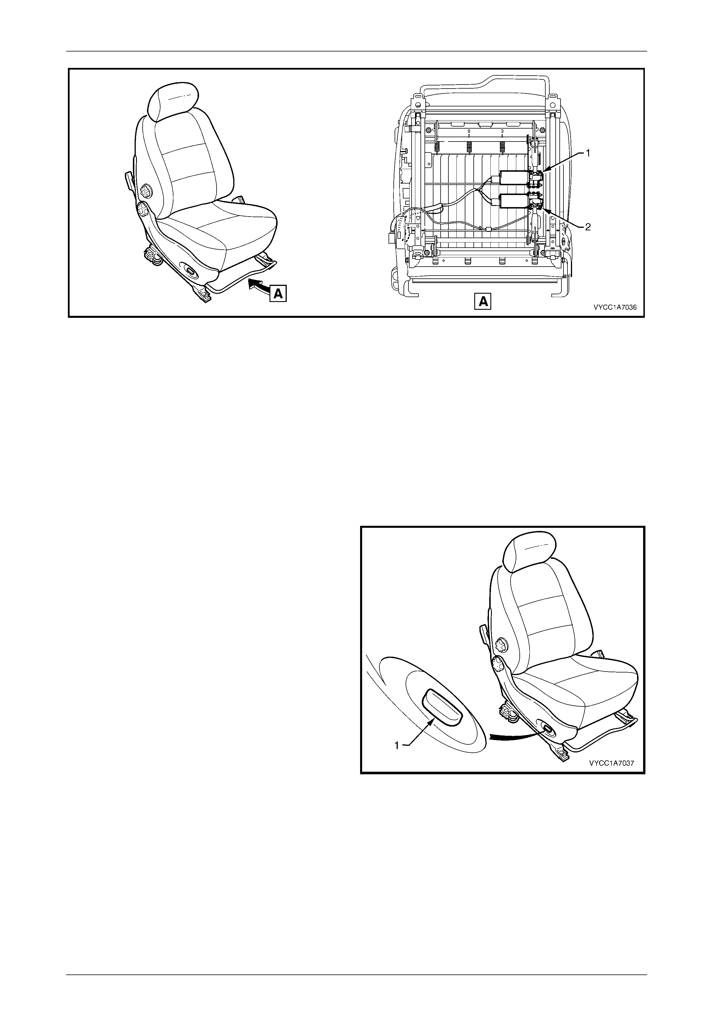
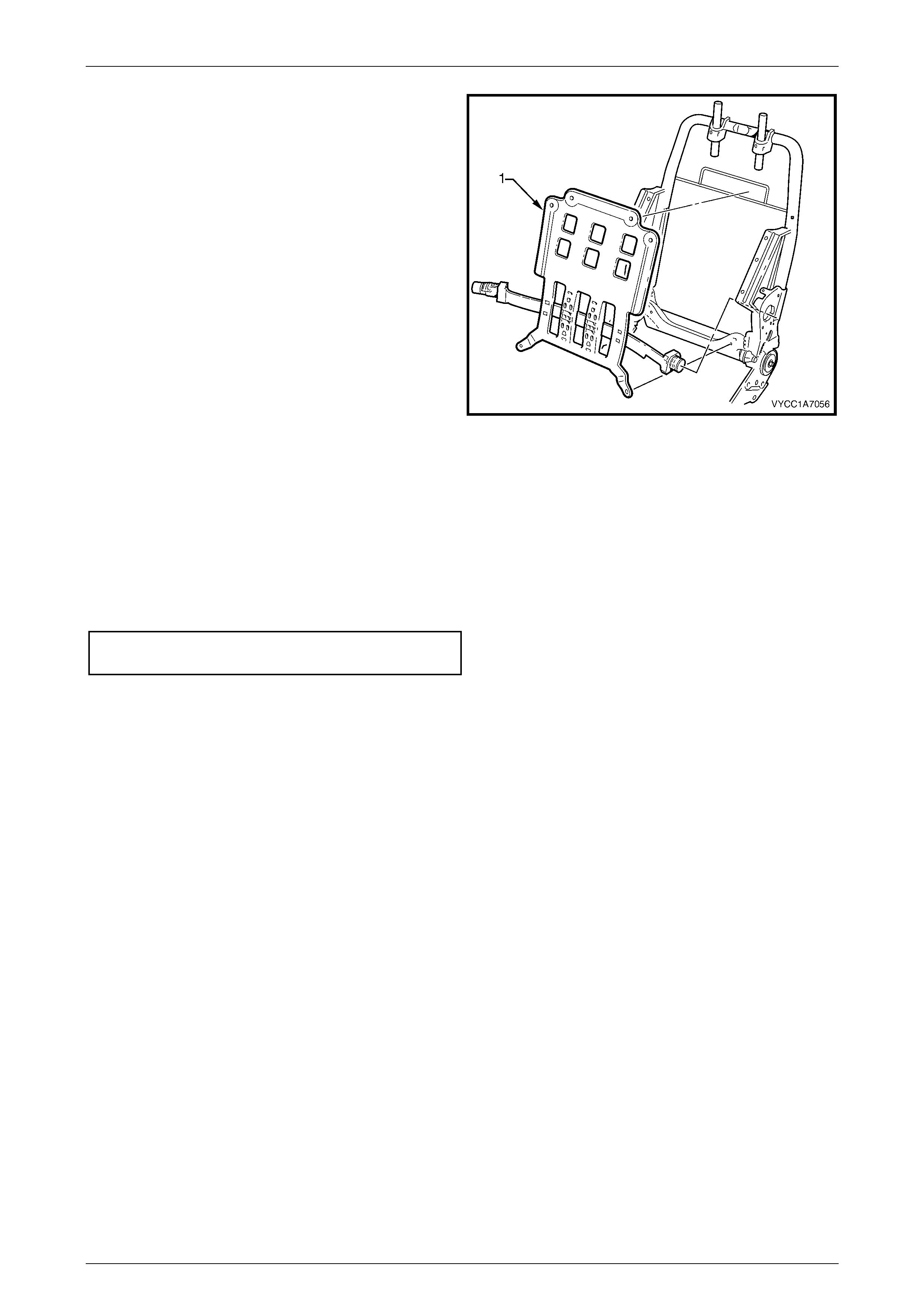
Referring to Figure 1A7 – 1, two electric motor and gearbox assemblies provide the movement of the front seat, one
each for:
• Front raise/lower movement (1),
• Rear raise/lower movement (2),
Seat Assemblies Page 1A7–4
Page 1A7–4
Figure 1A7 – 1
Each function is independently controlled. Alternatively, if desired the front and rear raise/lower movement can be
performed together to raise or lower the complete seat.
Raise/Lower Movement
Two lift motor and gearbox assemblies (1 and 2, refer to Figure 1A7 – 1) are attached to the inboard side of the track and
height adjust assembly; one for front and the other for rear raise/lower movement. When a lift motor is operating, it drives
the gearbox which draws in or extends a mating worm shaft. This in turn operates an arm and cross-shaft.
The cross-shaft is connected to another arm on the opposite side of the track and height adjust assembly and allows the
raising or lowering of that portion (front or rear) of the seat.
Four-way Movement Control
Four-way seat movement is controlled by a front seat
adjustment switch assembly (1), which is fitted to the outer
side of each front seat.
For the four-way seat, the switch provides independent
control of the front and rear raise/lower movements.
To adjust the seat:
• Operate the switch up or down to raise/lower the seat.
• Operate the front of the switch up or down to
raise/lower the front of the seat.
• Operate the rear of the switch up or down to
raise/lower the rear of the seat.
Figure 1A7 – 2

Seat Assemblies Page 1A7–5
Page 1A7–5
2 Service Operations
2.1 Front Seat Usage Chart
How To Use This Chart
Two front seat configurations are fitted. The following usage chart is provided to help determine the seat type fitted to the
vehicle. This is important prior to repairs being performed as the failed/damaged part may not be serviceable.
To determine the seat fitted to the vehicle, obtain the vehicle model, which seat requires attention and the seat cover
fabric. Then establish other features of the seat such as the electric movement functions. Using the chart will lead to the
elimination of all other seat combinations, allowing the identification of the type and the construction of the seat. Finally,
refer to the Figure shown in Front Seat Type for a component breakdown of the front seat assembly.
1 Vehicle – Vehicle model identification. For Model Level definitions refer to Section 0A General Information.
2 Seating – Driver front seat or passenger front seat.
3 Fabric – Cloth or leather seat covers.
4 Movement – Indicates the number of movement functions of the seat:
• Two-way – Seat cushion mechanical fore/aft movement.
• Four-way – As two-way plus seat cushion electric front and rear raise/lower.
5 Memory – Indicates if a seat memory module is fitted.
6 SIAB – If the front seat is fitted with a side impact airbag assembly.
7 Construction – Surebond refers to the seat cover being glued to the seat pad. This type is serviced as a cover and
pad assembly only.
8 Head Restraint – Indicates whether fixed or active head restraints are fitted.
9 Front Seat Type – Identifies the seat type and provides reference to the following illustrations which show a
breakdown of the serviced component for each front seat assembly.
Domestic
Vehicle Seating Fabric Movement Memory SIAB Construction Head
Restraint Front Seat Type
(refer to)
Driver Cloth Two-way No No Surebond Fixed 1
(Figure 1A7 – 3)
Base
Passenger Cloth Two-way No No Surebond Fixed 1
(Figure 1A7 – 3)
Driver Cloth Four-way No No Surebond Fixed 2
(Figure 1A7 – 4)
S
Passenger Cloth Two-way No No Surebond Fixed 1
(Figure 1A7 – 3)
Seat Assemblies Page 1A7–6
Page 1A7–6
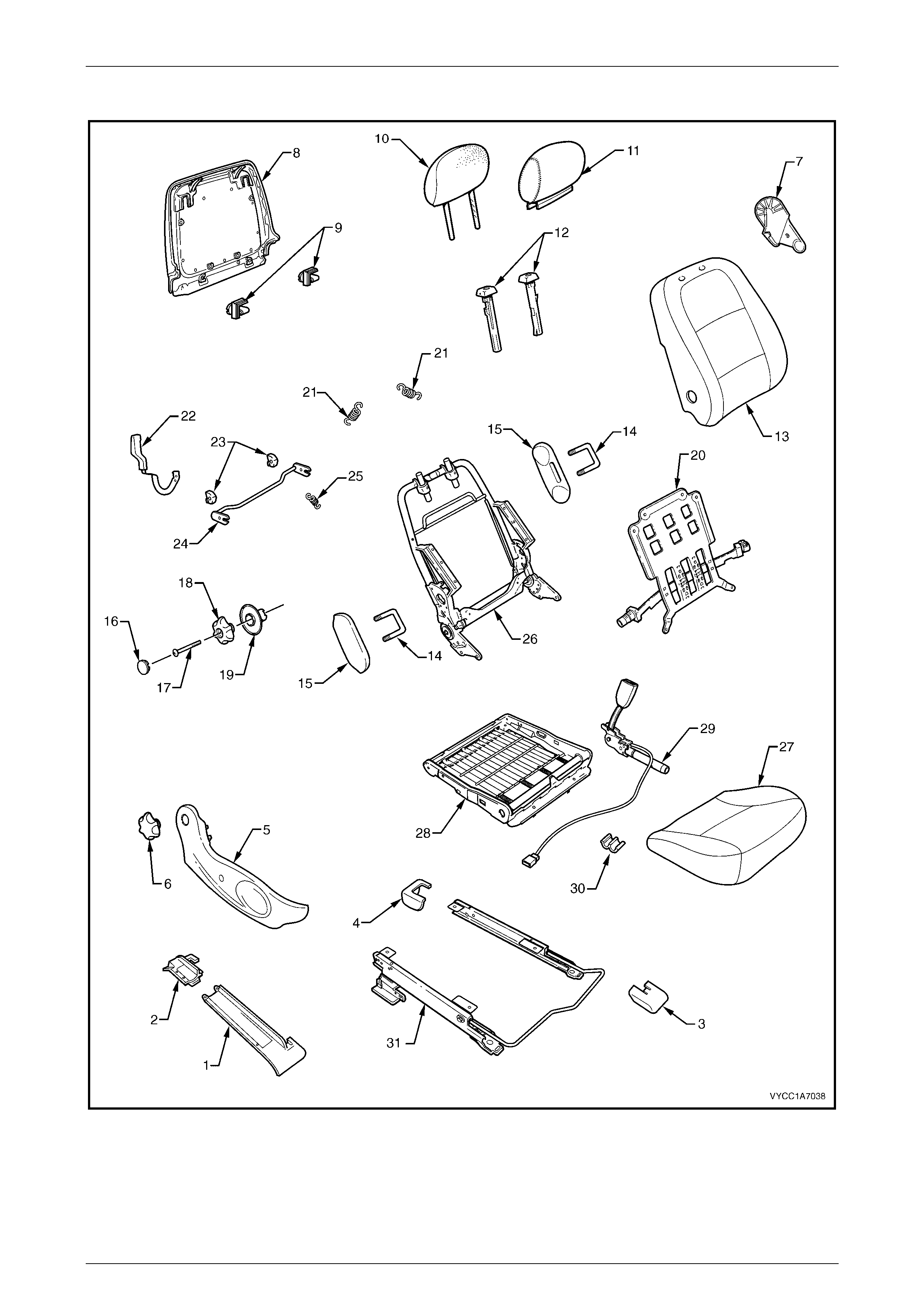
Front Seat Type 1
Figure 1A7 – 3

Seat Assemblies Page 1A7–7
Page 1A7–7
Legend
1 Front Seat Outer Front Cover
2 Front Seat Outer Rear Cover
3 Front Seat Inner Front Cover
4 Front Seat Inner Rear Cover
5 Front Seat Outer Side Cover
6 Recline Adjuster Knob
7 Front Seat Inner Side Cover
8 Front Seat-back Rear Cover
9 Front Seat-back Rear Cover Retaining Clips
10 Front Seat Head Restraint Pad Assembly
11 Front Seat Head Restraint Cover
12 Front Seat Head Restraint Sleeves
13 Front Seat-back Cover and Pad Assembly
14 Front Seat Dummy Block U-bolt
15 Front Seat Dummy Block Insert
16 Lumbar Support Knob Cover
17 Lumbar Support Knob Screw
18 Lumbar Support Knob
19 Lumbar Support Deflector Ring
20 Lumbar Support Assembly
21 Lumbar Support Retaining Spring
22 Dump-latc h Releas e Lever
23 Dump-latc h Releas e Rod Retainer
24 Dump-latc h Releas e Rod
25 Dump-latch Release Spring
26 Front Seat-back Frame Assembly
27 Front Seat Cushion Cover and Pad Assembly
28 Front Seat Cushion Frame Assembly
29 Seatbelt Buckle and Pretensioner Assembly
30 Wiring Harness Retaining Clip
31 Track and Height Adjust Assembl y
NOTE: Right-hand seat shown.

Seat Assemblies Page 1A7–8
Page 1A7–8
Front Seat Type 2
Figure 1A7 – 4

Seat Assemblies Page 1A7–9
Page 1A7–9
Legend
1 Front Seat Outer Front Cover
2 Front Seat Outer Rear Cover
3 Front Seat Inner Front Cover
4 Front Seat Inner Rear Cover
5 Front Seat Outer Side Cover
6 Recline Adjuster Knob
7 Front Sea t Adju stmen t Switch Knob
8 Front Sea t Adju s tment Switch
9 Front Seat Inner Side Cover
10 Front Seat-back Rear Cover
11 Front Seat-back Rear Cover Retaining Clips
12 Front Seat Head Restraint Pad Assembly
13 Front Seat Head Restraint Cover
14 Front Seat Head Restraint Sleeves
15 Front Seat-back Cover and Pad Assembly
16 Front Seat Dummy Block U-bolt
17 Front Seat Dummy Block Insert
18 Lumbar Support Knob Cover
19 Lumbar Support Knob Screw
20 Lumbar Support Knob
21 Lumbar Support Deflector Ring
22 Lumbar Support Assembly
23 Lumbar Support Retaining Spring
24 Dump-latc h Releas e Lever
25 Dump-latc h Releas e Rod Retainer
26 Dump-latc h Releas e Rod
27 Dump-latch Release Spring
28 Front Seat-back Frame Assembly
29 Front Seat Cushion Cover and Pad Assembly
30 Front Seat Cushion Frame Assembly
31 Seatbelt Buckle and Pretensioner Assembly
32 Wiring Harness Retaining Clip
33 Track and Height Adjust Assembl y
34 Wiring Harness Assembly
Seat Assemblies Page 1A7–10
Page 1A7–10
2.2 Front Seat Assembly
LT Section No. – 14-295
NOTE
If the seat assembly is to be disassembled, adjust
the seat assembly to its highest position (if
possible) before disconnecting the power to the
seat.
NOTE
Clean hands are essential when working on the
interior trim.
Remove
Disconnection of the battery affects certain
vehicle electronic systems. Refer to
Section 00, 5 Battery Disconnection
Procedures before disconnecting the battery.
1 Disconnect the battery.
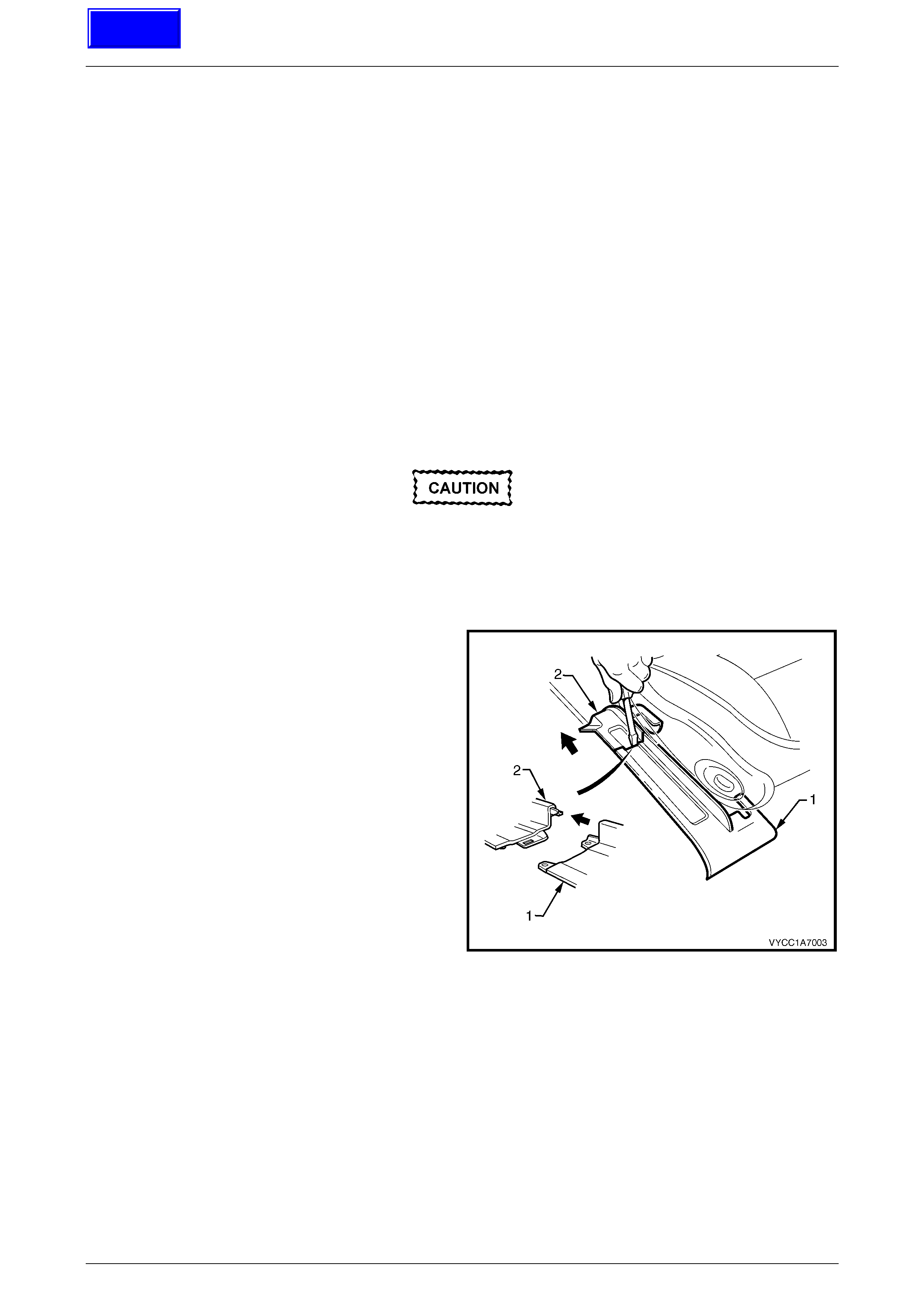
2 Using a small screwdriver, push in the centre of the
join to separate the front seat outer front cov er (1) and
the front seat outer rear cover (2).
3 Unclip the covers from the seat track and disengage
from the side sill trim.
4 Pull the covers apart and remove the rear cover.
Figure 1A7 – 5
Techline
Seat Assemblies Page 1A7–11
Page 1A7–11
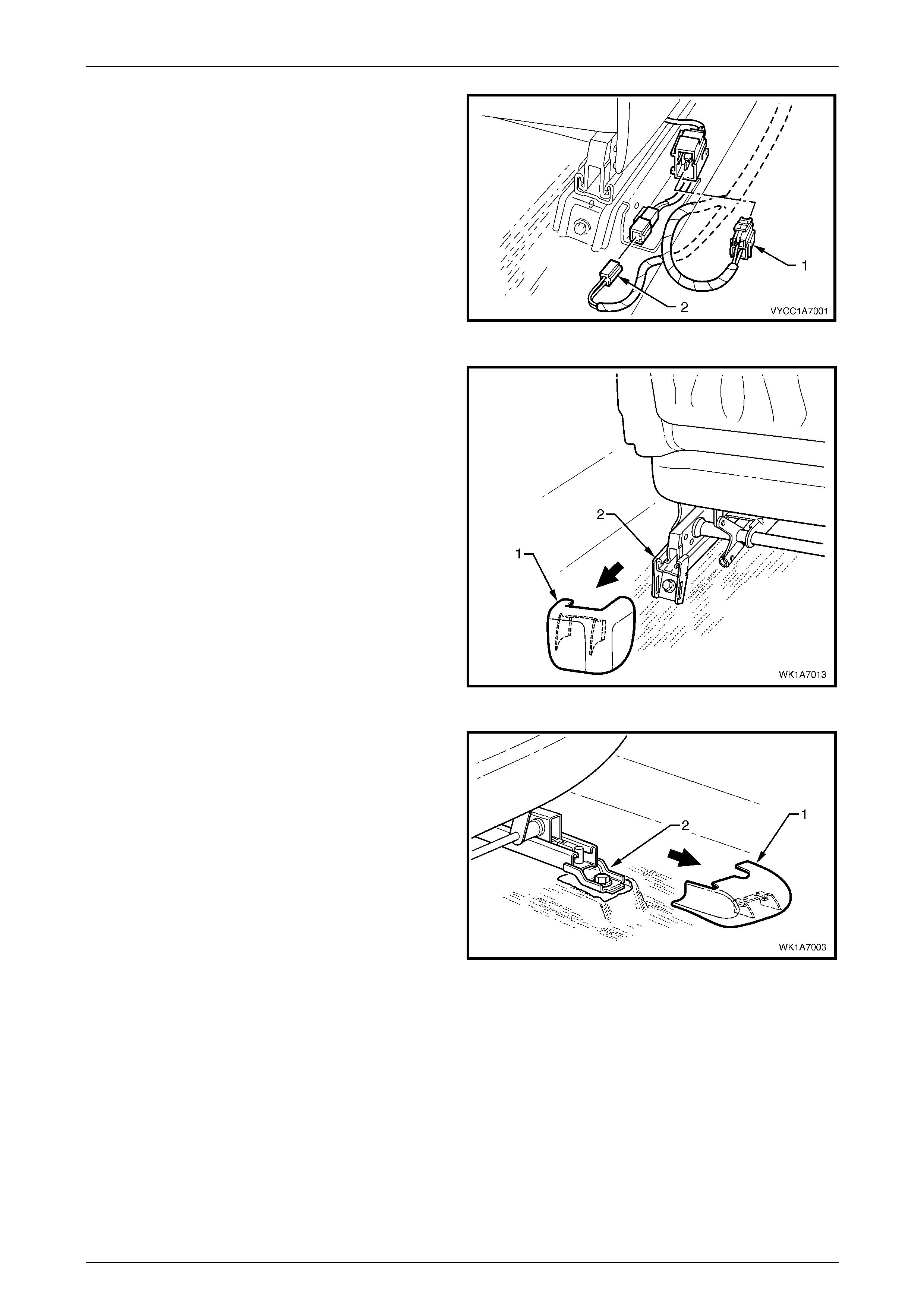
5 Disconnect the body wiring harness connector (1) if
fitted, and the seatbelt pretensioner wiring
connector (2).
Figure 1A7 – 6
6 Unclip the front seat inner rear cover (1) from the seat
track (2).
Figure 1A7 – 7
7 Unclip the front seat inner front cover (1) from the seat
track (2).
Figure 1A7 – 8
Seat Assemblies Page 1A7–12
Page 1A7–12
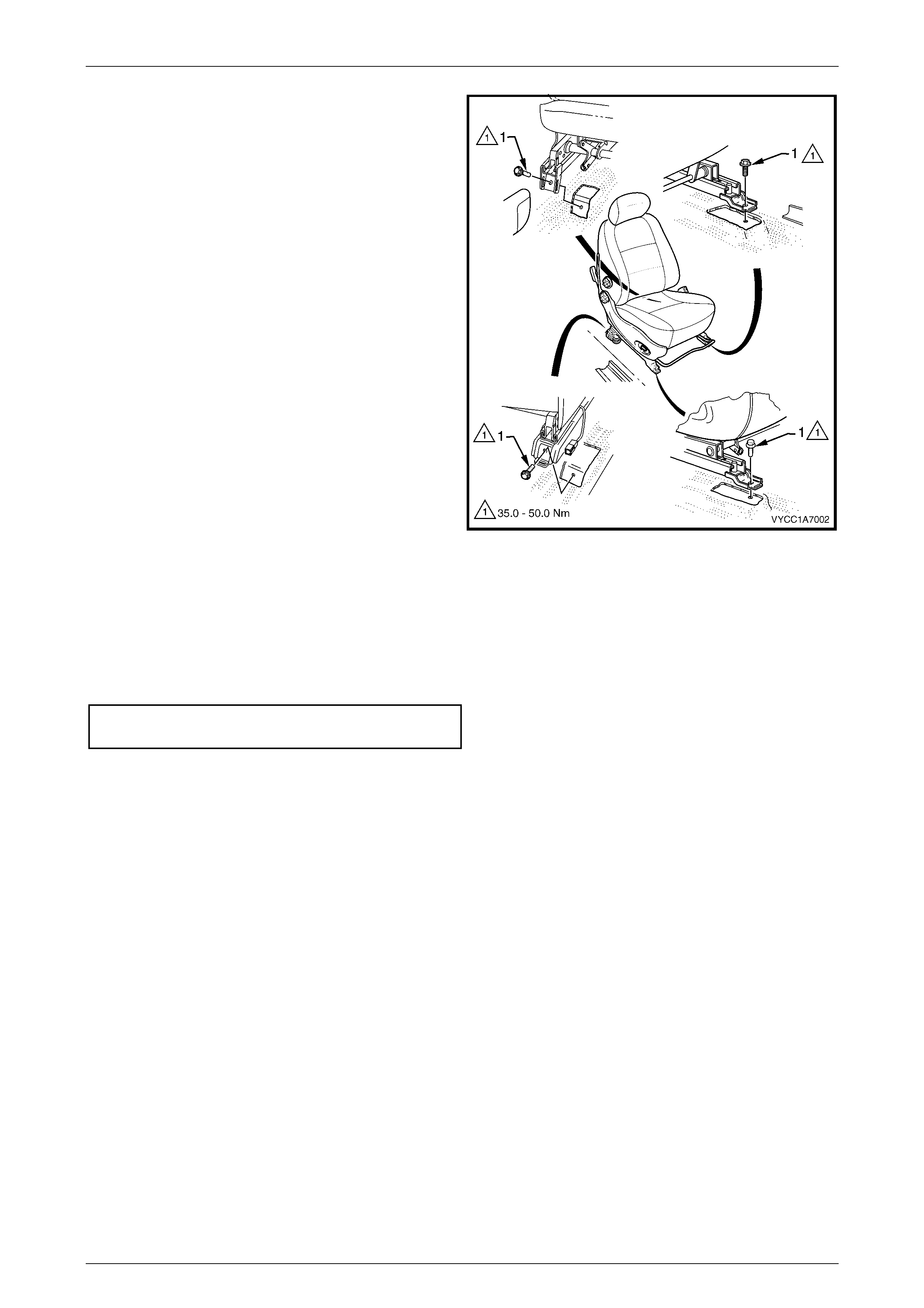
8 Remove the four screws (1) attaching the front seat to
the vehicle.
9 Remove the seat from the vehicle.
Figure 1A7 – 9
Reinstall
1 Position the front seat assembly into the vehicle.
2 Install the four screws securing the front seat.
3 Tighten the attaching screws to the correct torque specification.
Front seat assembly attac hing screw
torque specification ................................ 35.0 – 50.0 Nm
4 Connect the seat wiring harness connector if fitted, and the seatbelt pretensioner harness connector.
5 Align the front seat outer cover’s retaining clips and push firmly to engage.
6 Push the front of the front seat outer cover down to engage the cover with the front of the seat rail.
7 Check the operation of the front seat functions. While checking the seat adjustment/operation, also check that the
seat wiring harnesses do not foul with any of the seat’s moveable components (i.e. seat motor drive shafts, etc.).
Seat Assemblies Page 1A7–13
Page 1A7–13
2.3 Front Seat Outer Side Cover Assembly
LT Section No. – 14-322
Remove
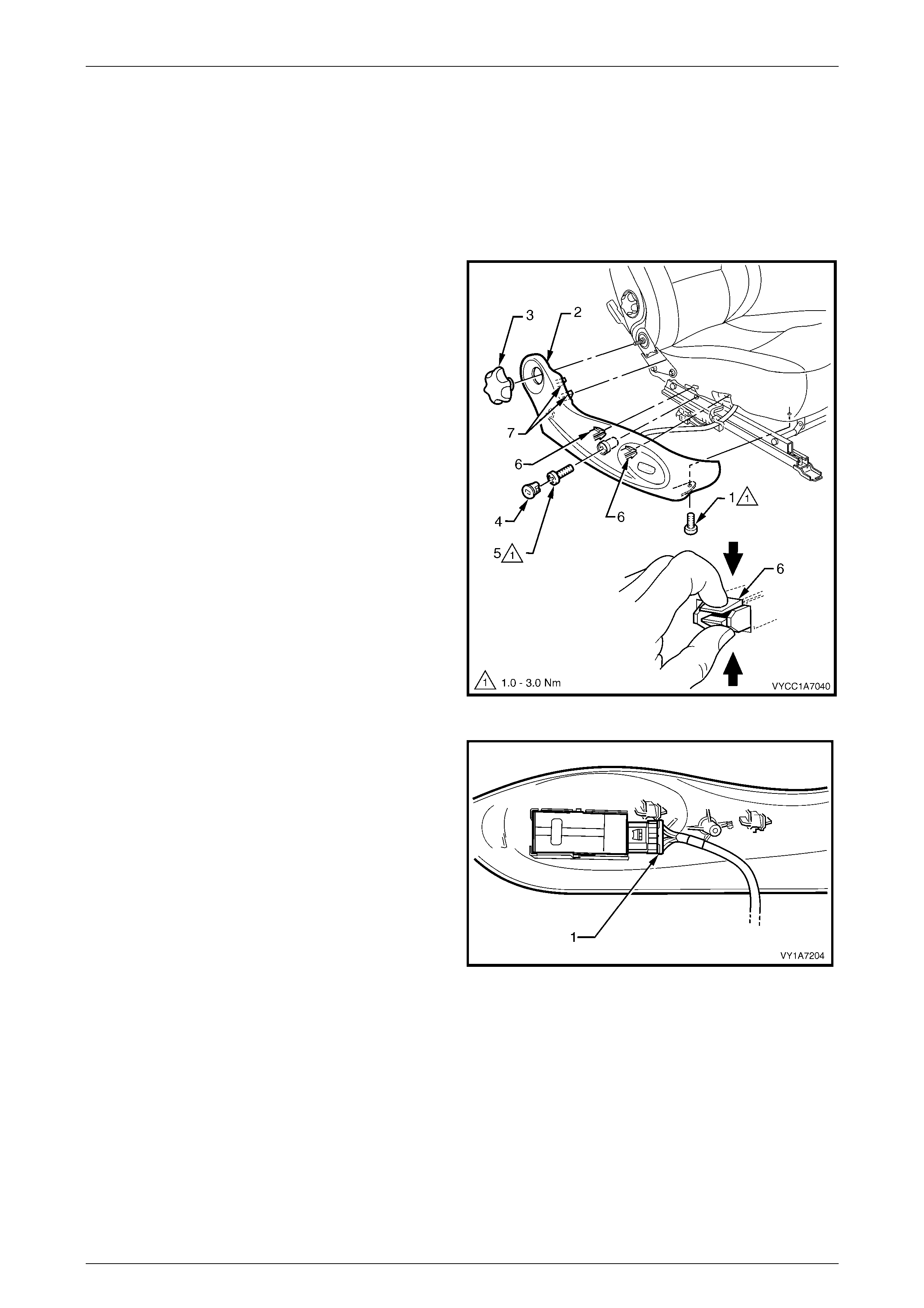
1 Raise the seat to the full-up position, if applicable.
2 Remove the screw (1) attaching the front seat outer
side cover (2).
3 Carefully prise the recliner knob (3) using a flat-blade
screwdriver.
4 Remove the plug (4) by rotating it anti-clockwise, one
quarter of a turn.
5 Remove the screw (5) located behind the plug.
6 Reach up under the seat assembly and squeeze
together the two retaining tangs (6), on the inner side
of the side cover while gently pulling the cover.
7 Gently pull the side cover away from the seat to
disengage the two clips (7) from the seat-back frame
assembly.
NOTE
Only remove the side cover far enough away
from the seat cushion assembly to gain access
to the seat wiring harness connectors, if fitted.
Figure 1A7 – 10
8 For vehicles fitted with the four-way seat assembly,
disconnect the front seat adjustment switch connector
(1) and remove the cover.
Figure 1A7 – 11

Seat Assemblies Page 1A7–14
Page 1A7–14
Disassemble
Front Seat A djustment Switch
Remove
1 Remove the knob (1) from the front seat adjustment
switch (2) by carefully prising it free with a small flat tip
screwdriver wrapped in a clean shop rag (3).
Figure 1A7 – 12
2 Using a flat-blade screwdriver, gently prise the front
seat adjustment switch (1) from the outer side
cover (2).
Figure 1A7 – 13
Reinstall
Reinstall the front seat adjustment switch ensuring it is clipped securely in place. Push the knob in until it clicks in place.
Reinstall
Reinstallation of the front seat outer side cover is the reverse of the removal procedure, noting the following:
1 Tighten the attaching screws to the correct torque specification.
Front seat outer side cover att achi ng
screw torque specification.......................... 1.0 – 3.0 Nm
Seat Assemblies Page 1A7–15
Page 1A7–15
2.4 Front Seat Inner Side Cover
LT Section No. – 14-322
As required, remove the front seat assembly, refer to 2.2 Front Seat Assembly.
Remove
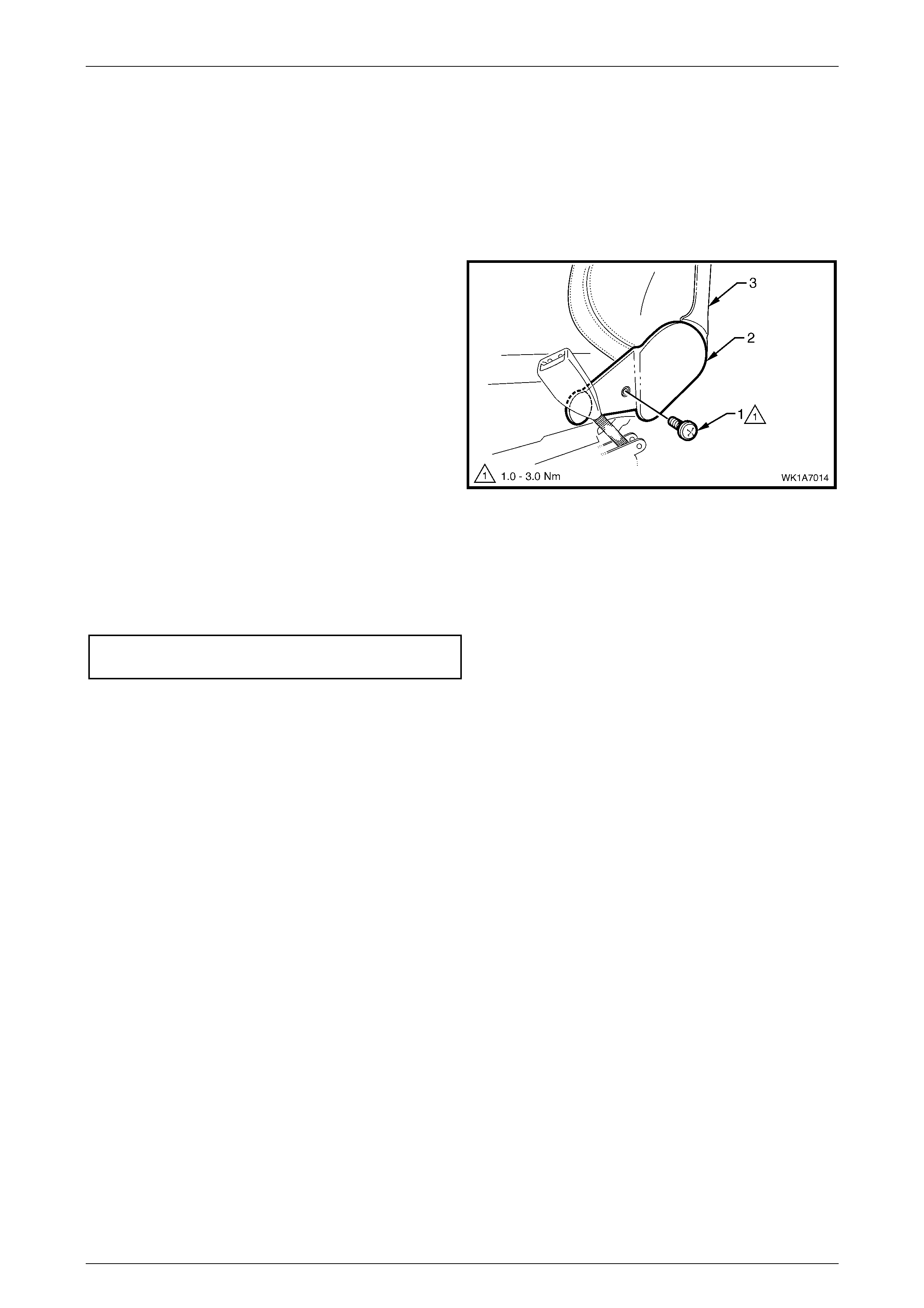
1 Remove the screw (1) attaching the front seat inner
side cover (2) to the seat assembly (3) and remove the
cover.
Figure 1A7 – 14
Reinstall
Reinstallation of the front seat inner side cover is the reverse of the removal procedure, noting the following:
1 Tighten the attaching screw to the correct torque specification.
Front seat inner side cover att achi ng
screw torque specification.......................... 1.0 – 3.0 Nm

Seat Assemblies Page 1A7–16
Page 1A7–16
2.5 Front Seat-back Rear Cover Assembly
LT Section No. – 14-322
Remove
The following component will require
replacement when performing this operation.
• Front seat back rear cover retaining clip,
two places.
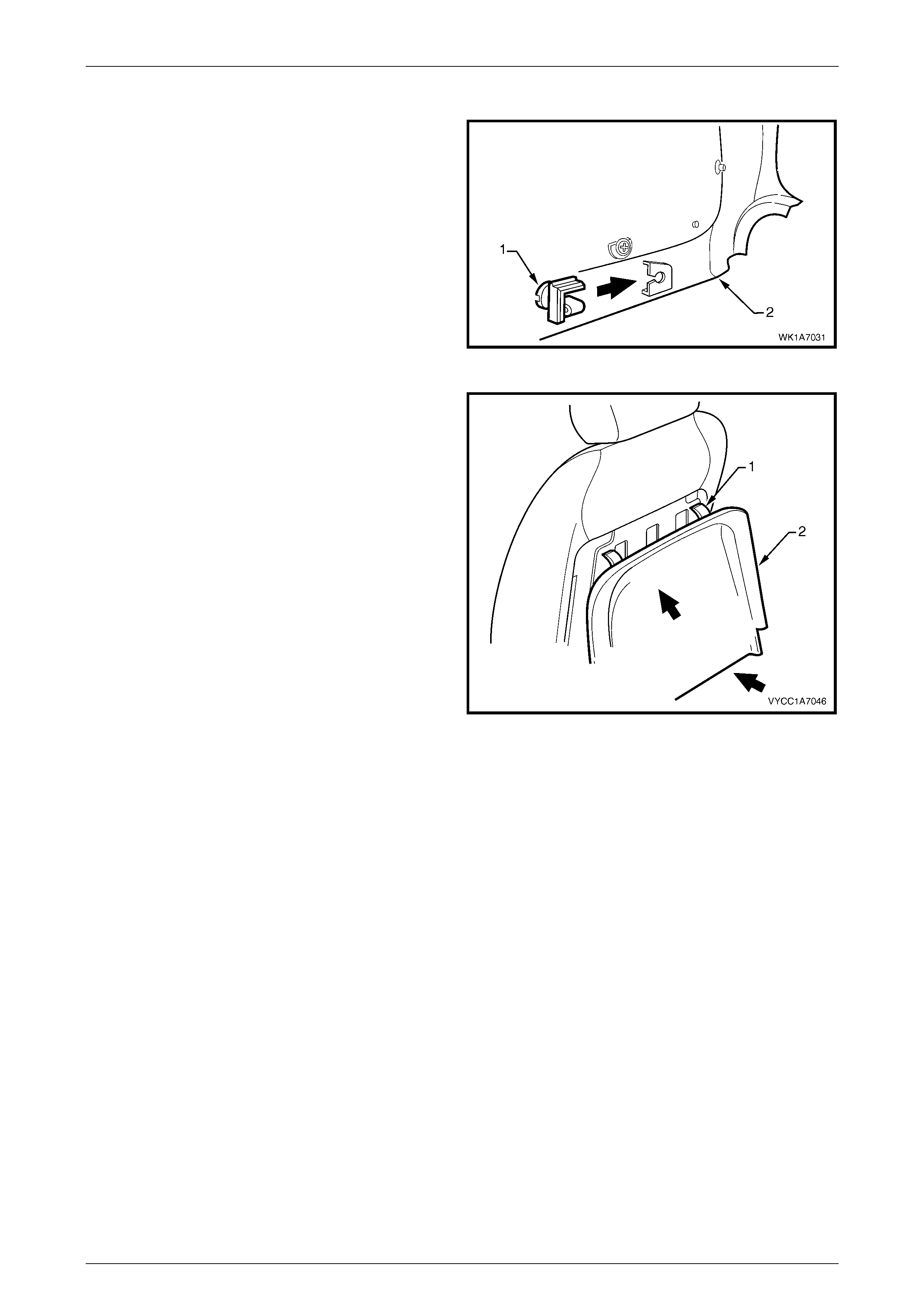
1 Pull the lower corners of the front seat-back rear
cover (1) away from the seat (2), breaking the
retaining clip (3), two places.
Figure 1A7 – 15
2 While holding the lower portion of the front seat-back
rear cover (1) out, pull the cover down to release the
upper retaining lug (2), two places.
3 Remove the cover.
Figure 1A7 – 16
Seat Assemblies Page 1A7–17
Page 1A7–17
Reinstall
1 Replace the damaged retaining clip (1) on the front
seat-back rear cover (2), two places.
Figure 1A7 – 17
2 Locate the upper retaining lug (1), two places, into the
seat-back.
3 Push the front seat-back rear cover (2) up and in at
the lower edge to engage the two lower retaining clips.
Figure 1A7 – 18
Seat Assemblies Page 1A7–18
Page 1A7–18
2.6 Dump-latch Mechanism Assembly
Remove
As required, remove the front seat-back rear cover, refer to 2.5 Front Seat-back Rear Cover Assembly.
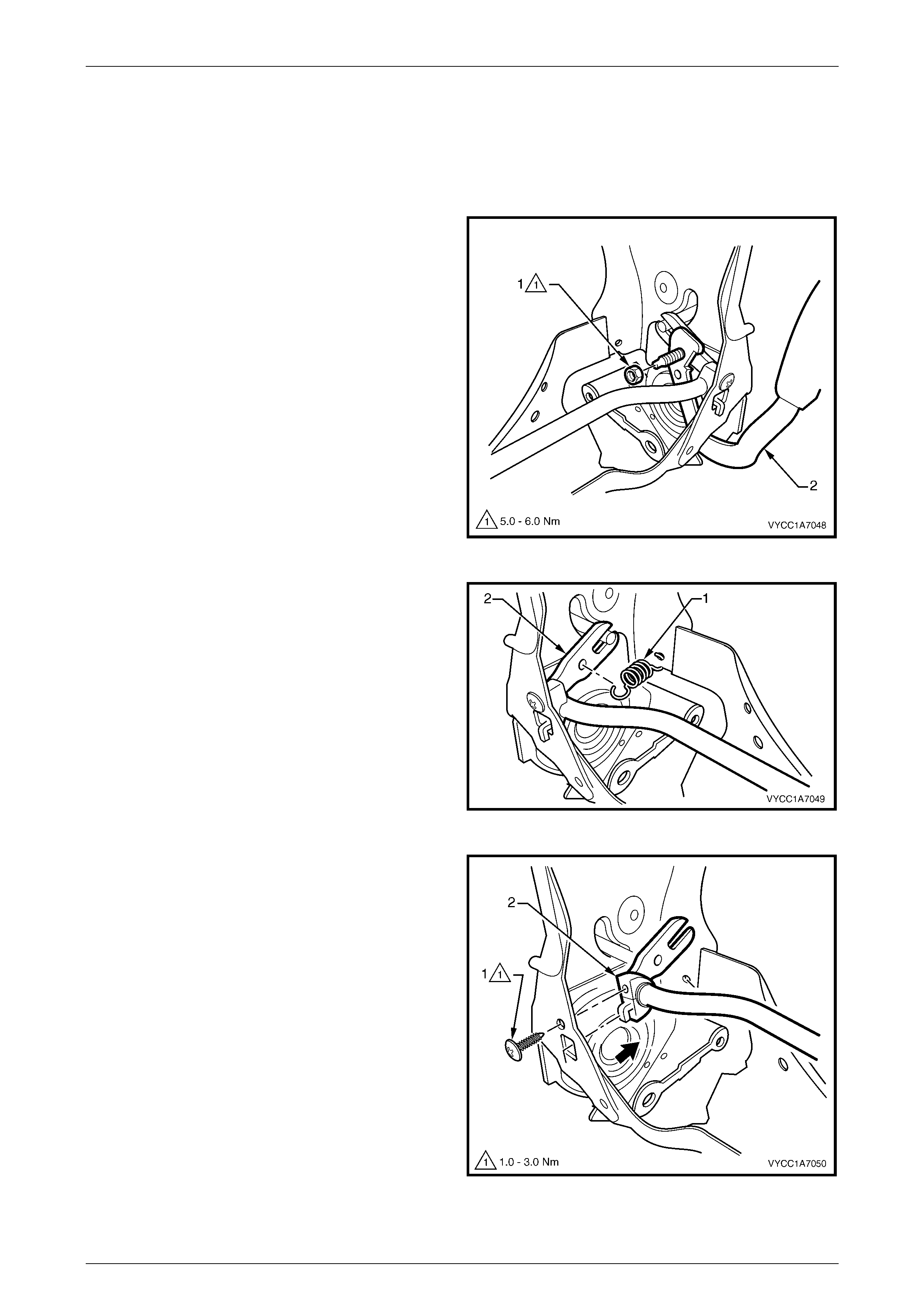
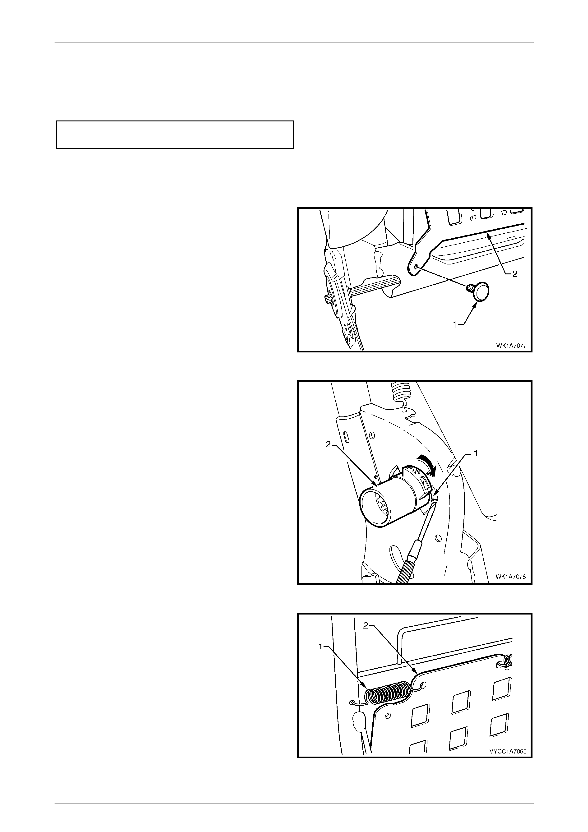
1 Remove the nut (1) attaching the dump-latch release
lever (2) to the seat-back frame and remove the lever.
Figure 1A7 – 19
2 Unhook the spring (1) from the dump-latch release rod
(2) and seat-back frame.
Figure 1A7 – 20
3 Remove the screw (1), attaching the dump-latch
release rod retainer (2) to the seat-back frame.
4 Repeat for the opposite side.
5 From each side of the seat-back frame, unattach the
dump-latch release rod retainer and remove the
release rod and retainers.
6 As required, remove the retainers from the release
rod.
Figure 1A7 – 21

Seat Assemblies Page 1A7–19
Page 1A7–19
Reinstall
Reinstallation of the dump-latch assembly is the reverse of the removal procedure noting the following:
1 Tighten the fasteners to the correct torque specification.
Dump-latch release rod retainer attaching
screw torque specification.......................... 1.0 – 3.0 Nm
Dump-latch release lever attaching
nut torque specification .............................. 5.0 – 6.0 Nm
Seat Assemblies Page 1A7–20
Page 1A7–20
2.7 Front Seat Head Restraint Assembly
LT Section No. – 14-295
Remove
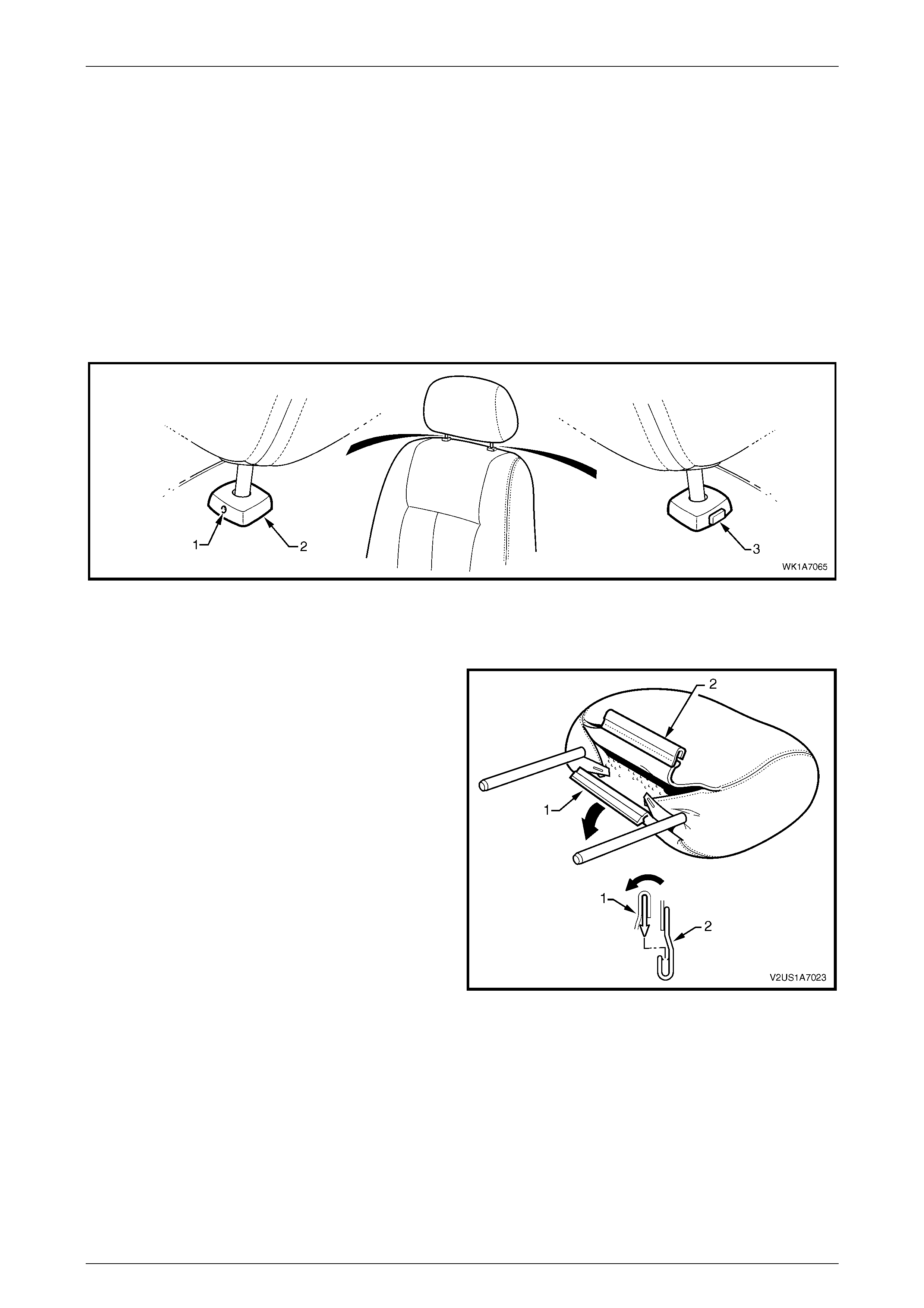
1 Raise the head restraint fully.
2 Insert a suitable size probe into the hole (1) in the right-hand head restraint sleeve (2), refer to Figure 1A7 – 22
3 Push the probe in slightly while applying slight upward pressure on the head restraint. Hold the upward pressure.
4 Depress the head restraint sleeve height adjuster lock (3) on the left-hand head restraint sleeve and remove the
head restraint.
Figure 1A7 – 22
Disassemble
1 Disengage the front head restraint cover J-strip by
pulling the flap (1) back and out of flap (2) in the
direction shown.
Figure 1A7 – 23
Seat Assemblies Page 1A7–21
Page 1A7–21
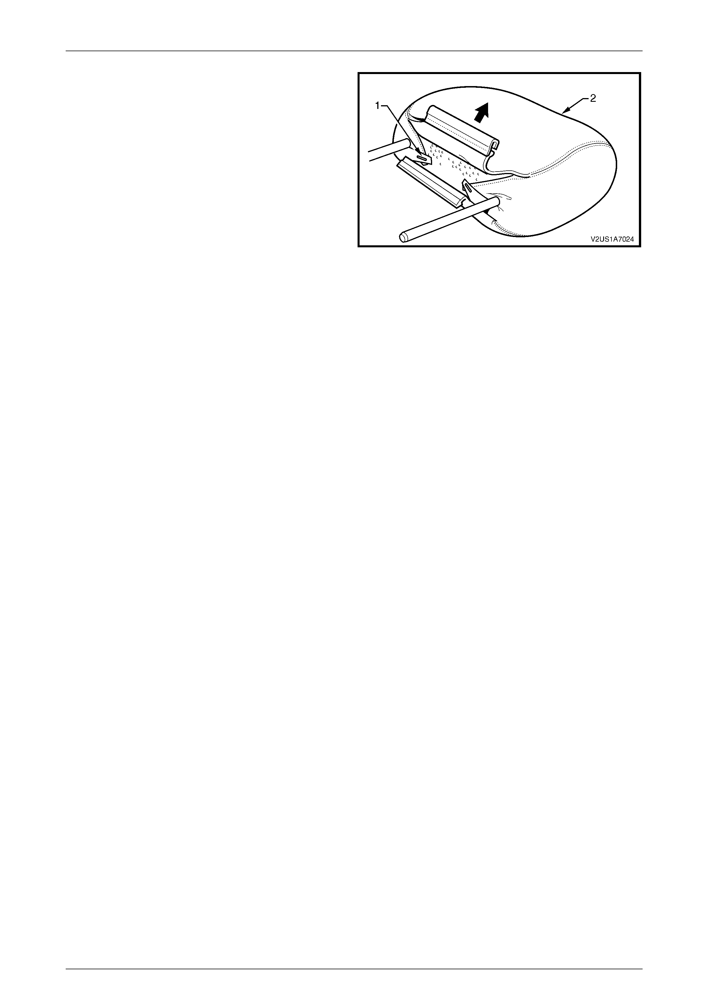
2 Remove the staple (1), two places, retaining the cover
(2) to the head restraint pad assembly.
3 Remove the cover from the pad assembly.
Figure 1A7 – 24
Reassemble
Reassembly of the front seat head restraint assembly is the reverse of the removal procedure. Ensure the head restraint
cover J-clip is fully engaged.
Reinstall
Ensuring correct orientation of the head restraint, fit the head restraint shafts into the sleeves and push the head restraint
down.
Seat Assemblies Page 1A7–22
Page 1A7–22
2.8 Front Seat Head Restraint Sleeve
LT Section No. – 14-275
As required, remove the front seat head restraint assembly, refer to 2.7 Front Seat Head Restraint Assembly.
Remove
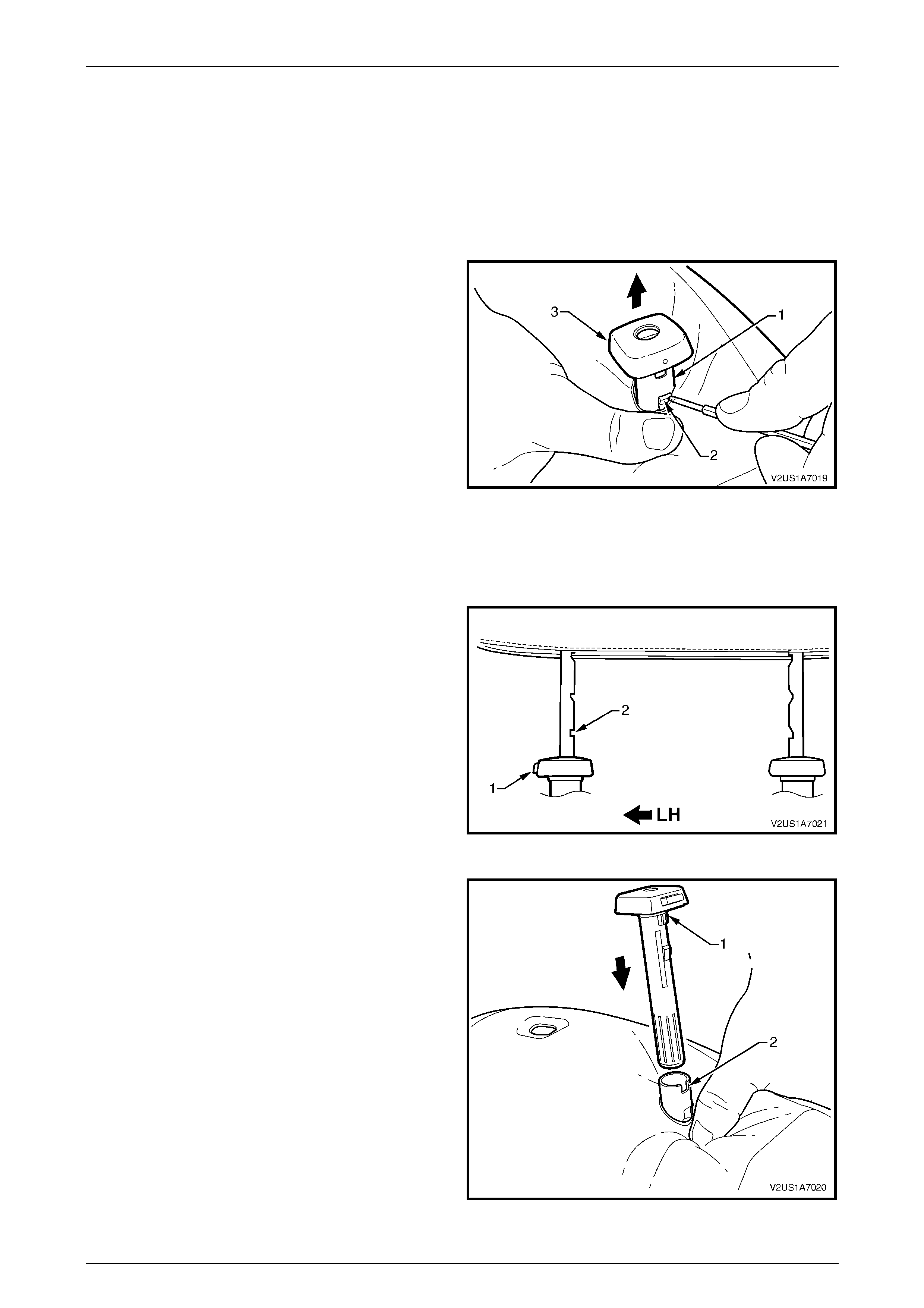
1 Push down on the surrounding seat cover to reveal the
upper portion of the seat-back frame (1).
2 Using a fine flat-blade screwdriver, depress the head
restraint sleeve retaining lug (2) and withdraw the
head restraint sleeve (3) from the frame.
3 Repeat for the remaining sleeve as required.
Figure 1A7 – 25
Reinstall
Reinstallation of the front seat head restraint sleeve is the reverse of the removal procedure, noting the following:
NOTE
Ensure the sleeve with the height adjuster lock
(1) is installed on the left-hand side of the seat;
that is the side that corresponds to the lower
square notch (2) in the head restraint shaft.
Figure 1A7 – 26
1 Align the head restraint sleeve locating ribs (1) with
the notch (2) in the seat-back frame.
2 Insert the sleeve and ensure it clicks into place.
Figure 1A7 – 27
Seat Assemblies Page 1A7–23
Page 1A7–23
2.9 Lumbar Support Knob Assembly
LT Section No. – 14-275
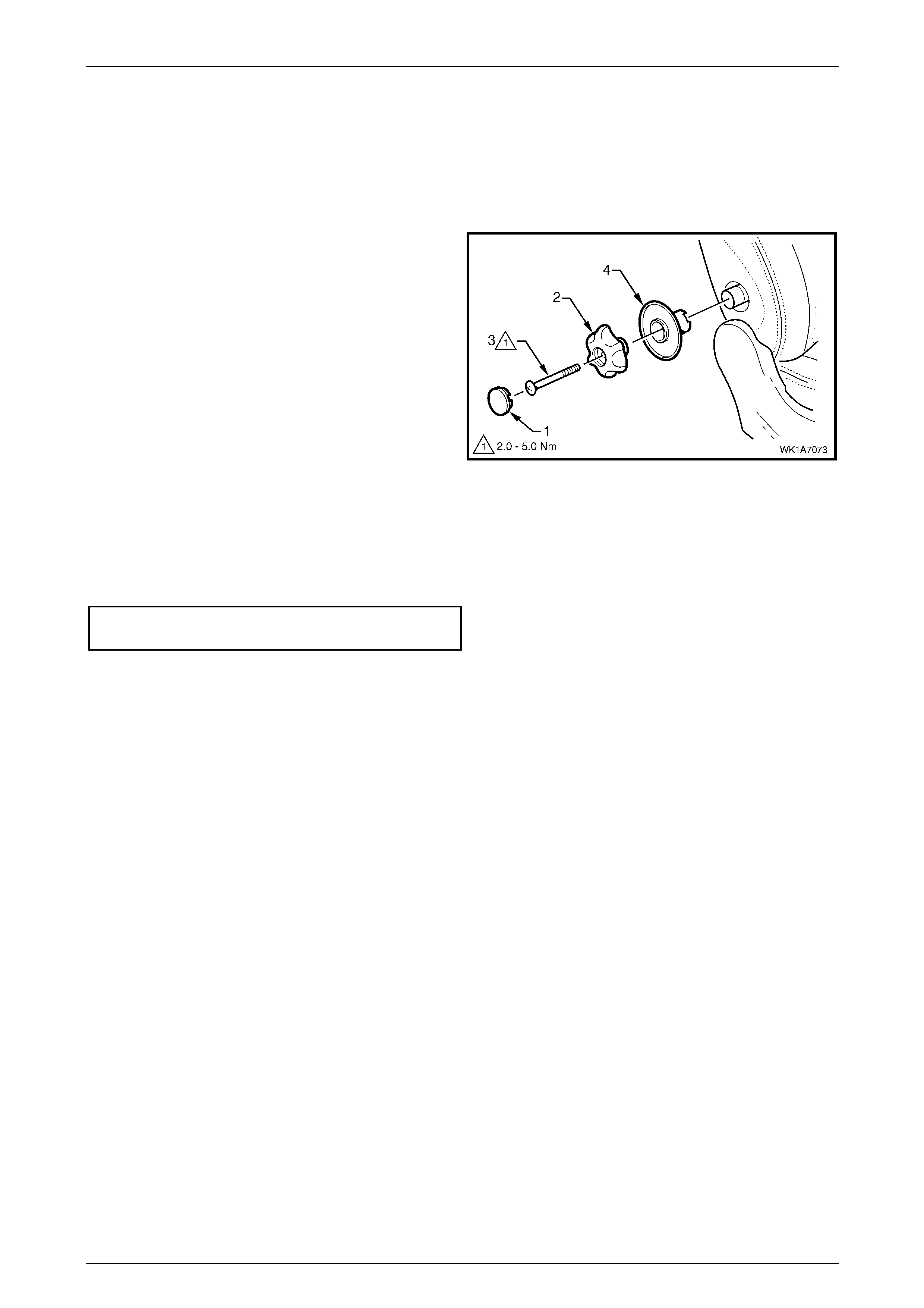
Remove
1 Using a fine flat-blade screw-driver, carefully prise the
cap (1) from the lumbar support knob (2).
2 Remove the screw (3) attaching the knob to the
lumbar support shaft.
3 Pull the knob off the lumbar support shaft and remove
the lumbar support deflector ring (4).
NOTE
The knob is lightly clipped to the lumbar support
shaft and will ‘click-off’.
Figure 1A7 – 28
Reinstall
Reinstallation of the lumbar support knob assembly is the reverse of the removal procedure, noting the following:
1 Tighten the screw to the correct torque specification.
Lumbar support knob attaching
screw torque specification.......................... 2.0 – 5.0 Nm
Seat Assemblies Page 1A7–24
Page 1A7–24
2.10 Front Seat-back Pad and Cover
Assembly
LT Section No. – 14-295
As required, remove the following components:
1 Front seat assembly, refer to 2.2 Front Seat Assembly.
2 Front seat outer side cover, refer to 2.3 Front Seat Outer Side Cover Assembly.
3 Front seat inner side cover, refer to 2.4 Front Seat Inner Side Cover.
4 Front seat-back rear cover assembly, refer to 2.5 Front Seat-back Rear Cover Assembly.
5 Front seat head restraint assembly, refer to 2.7 Front Seat Head Restraint Assembly.
6 Front seat head restraint sleev es, refer to 2.8 Front Seat Head Restraint Sleeve.
7 Lumbar support knob assembly, refer to 2.9 Lumbar Support Knob Assembly .
Remove
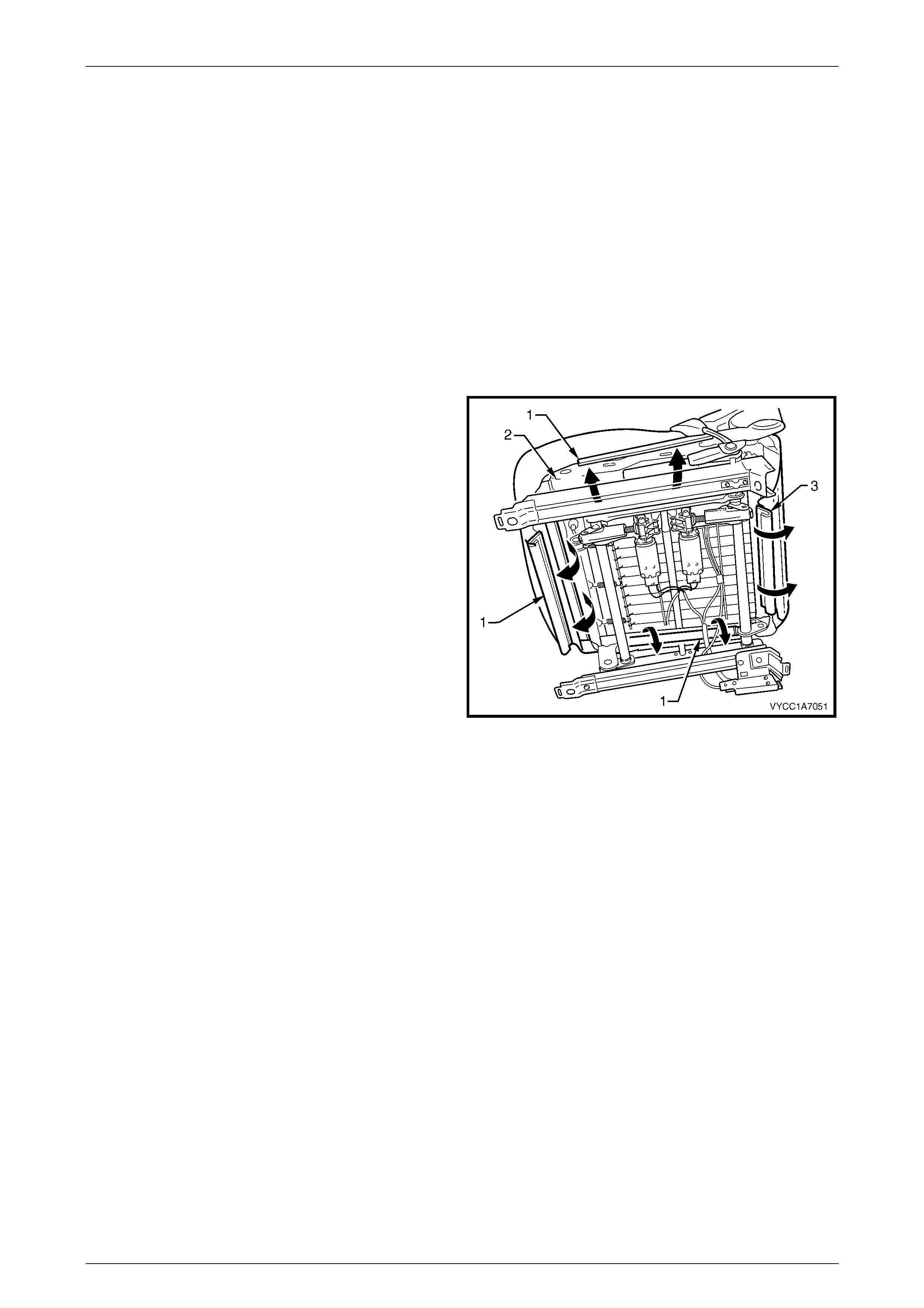
1 Disengage the J-strips from the seat frame.
2 Lift the cover and pad assembly up and away from the
seat-back frame, manoeuvring it over the front seat
dummy block insert assemblies.
Figure 1A7 – 29
Reinstall
Reinstallation of the front seat-back pad and cover assembly is the reverse of the removal procedure.
Seat Assemblies Page 1A7–25
Page 1A7–25
2.11 Front Seat-back Frame Assembly
LT Section No. – 14-275
As required remove the following components:
1 Front seat assembly, refer to 2.2 Front Seat Assembly.
2 Front seat outer side cover, refer to 2.3 Front Seat Outer Side Cover Assembly.
3 Front seat inner side cover, refer to 2.4 Front Seat Inner Side Cover.
Remove
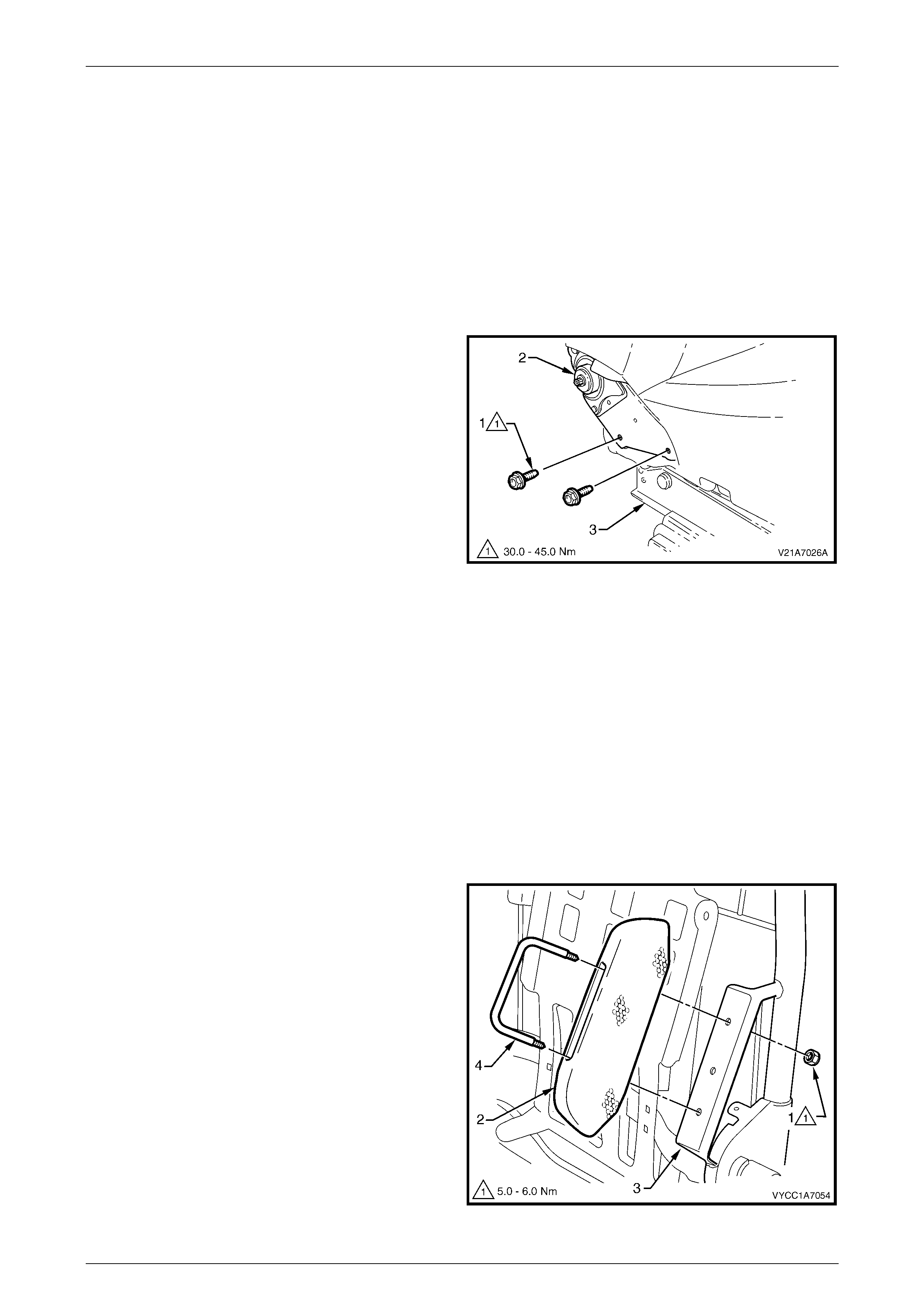
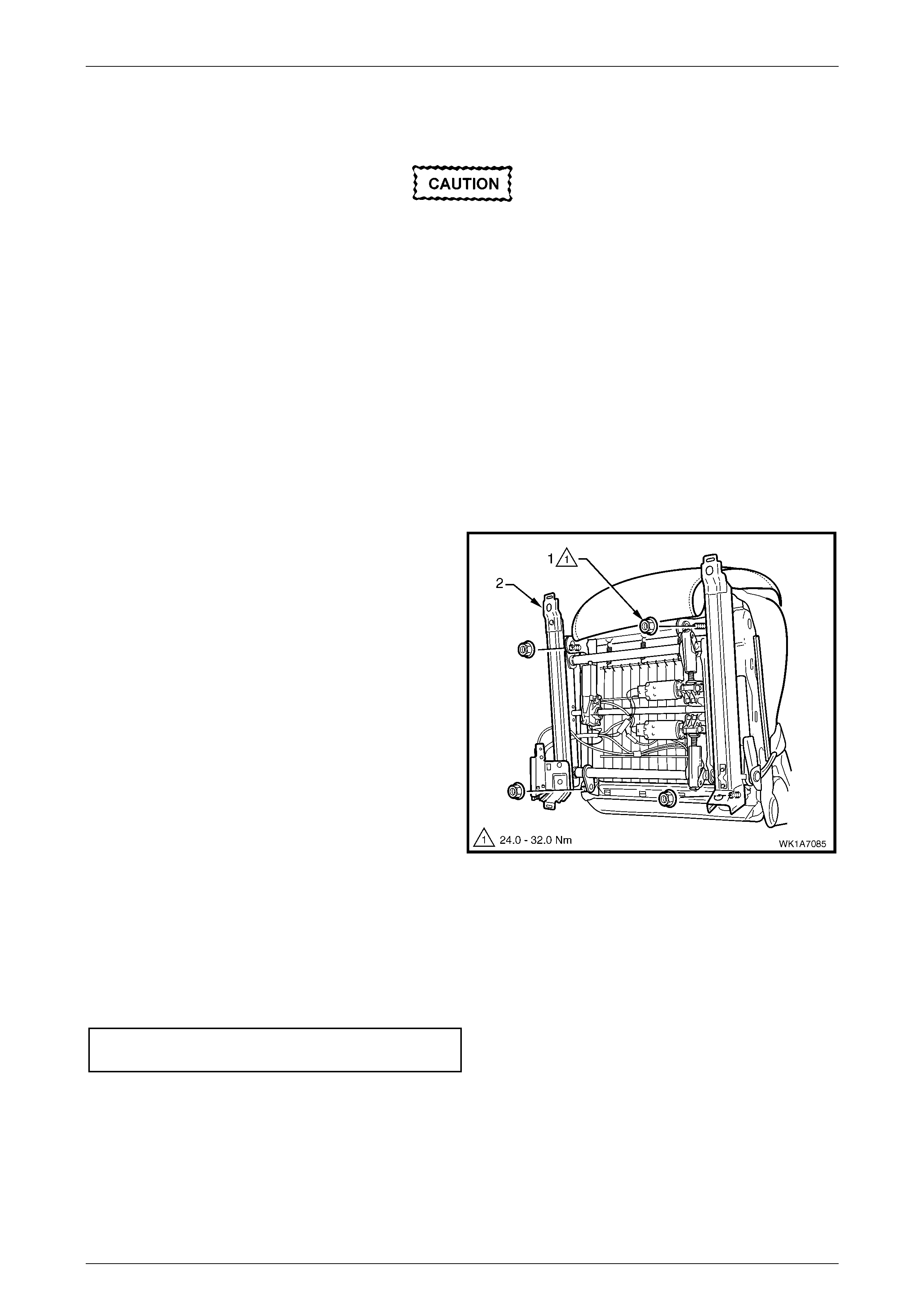
1 From each side of the seat, remove the two screws (1)
attaching the seat-back assembly (2) to the front seat
cushion frame assembly ( 3).
2 Remove the seat-back assembly.
Figure 1A7 – 30
Disassemble
As required, remove the following components:
1 Front seat-back rear cover assembly, refer to 2.5 Front Seat-back Rear Cover Assembly.
2 Front seat head restraint assembly, refer to 2.7 Front Seat Head Restraint Assembly.
3 Front seat head restraint sleev es, refer to 2.8 Front Seat Head Restraint Sleeve.
4 Lumbar support knob assembly, refer to 2.9 Lumbar Support Knob Assembly .
5 Front seat-back pad and cover assembly, refer to 2.10 Front Seat-back Pad and Cover Assembly.
Front Seat Dummy Block Insert Assembly
Remove
1 Remove the lock nut (1), two places, attaching the
front seat dummy block insert (2) to the seat-back
frame (3) and remove the dummy block insert
assembly.
2 If required, remove the dummy block U-bolt (4) from
the dummy block insert.
Figure 1A7 – 31
Seat Assemblies Page 1A7–26
Page 1A7–26
Reinstall
Reinstallation of the front seat dummy block insert assembly is the reverse of the removal procedure, noting the
following:
1 Tighten the nuts to the correct torque specification.
Front seat dummy block insert attaching
nut torque specification .............................. 5.0 – 6.0 Nm
Lumbar Support Assembly
Remove
1 Remove the retainer (1), two places, attaching the
lumbar support assembly (2) to the seat-back frame.
Figure 1A7 – 32
2 Depress the retaining tab (1) and from the inner side
of the seat-back frame, rotate the lumbar support
shaft (2) and withdraw from the seat-back frame.
3 Repeat for the opposite side.
Figure 1A7 – 33
4 Disconnect the spring (1), two places, attaching the
lumbar support assembly (2) to the seat-back frame.
NOTE
To aid spring removal, pull the support assembly
toward the side that the spring is being removed
to relieve spring tension.
Figure 1A7 – 34
Seat Assemblies Page 1A7–27
Page 1A7–27
5 Remove the lumbar support assembly (1).
Figure 1A7 – 35
Reinstall
Reinstallation of the lumbar support assembly is the reverse of the removal procedure.
Reinstall
Reinstallation of the front seat-back frame assembly is the reverse of the removal procedure, noting the following:
1 Tighten the screws to the correct torque specification.
Front seat-back frame assembly
attaching screw torque specification....... 30.0 – 45.0 Nm
2 Check the operation of the front seat-back assembly.
Seat Assemblies Page 1A7–28
Page 1A7–28
2.12 Track and Height Ad just Assembly
The track and height adjust assembly
components are non-serviceable. If the track
and height adjust assembly, drive motors or
drive shafts require replacement, the entire
track and height adjust assembly must be
replaced.
LT Section No. – 14-275
As required, remove the following components:
1 Front seat assembly, refer to 2.2 Front Seat Assembly.
2 Front seat outer side cover, refer to 2.3 Front Seat Outer Side Cover Assembly.
Remove
1 Unattach the seatbelt pretensioner wiring harness from beneath the seat.
2 Remove the four nuts (1) attaching the track and
height adjust assembly (2) to the front seat cushion
frame assembly .
3 Remove the track and height adjust assembly.
4 If required, remove the seatbelt buckle and
pretensioner assembly, refer to Section 12M Occupan t
Protection System.
Figure 1A7 – 36
Reinstall
Reinstallation of the track and height adjust assembly is the reverse of the removal procedure, noting the following:
1 Ensure the connectors are correctly routed and atta che d sec urely .
2 Tighten the nuts to the correct torque specification.
Track and height adjust assembly
attaching nut torque specification........... 24.0 – 32.0 Nm
Seat Assemblies Page 1A7–29
Page 1A7–29
2.13 Front Seat Cushion Pad and Cover
Assembly
LT Section No. – 14-295
As required, remove the following components:
1 Front seat assembly, refer to 2.2 Front Seat Assembly.
2 Front seat outer side cover, refer to 2.3 Front Seat Outer Side Cover Assembly.
3 Front seat inner side cover, refer to 2.4 Front Seat Inner Side Cover.
4 Front seat-back frame assembly, refer to 2.11 Front Sea t-back Frame Assembly.
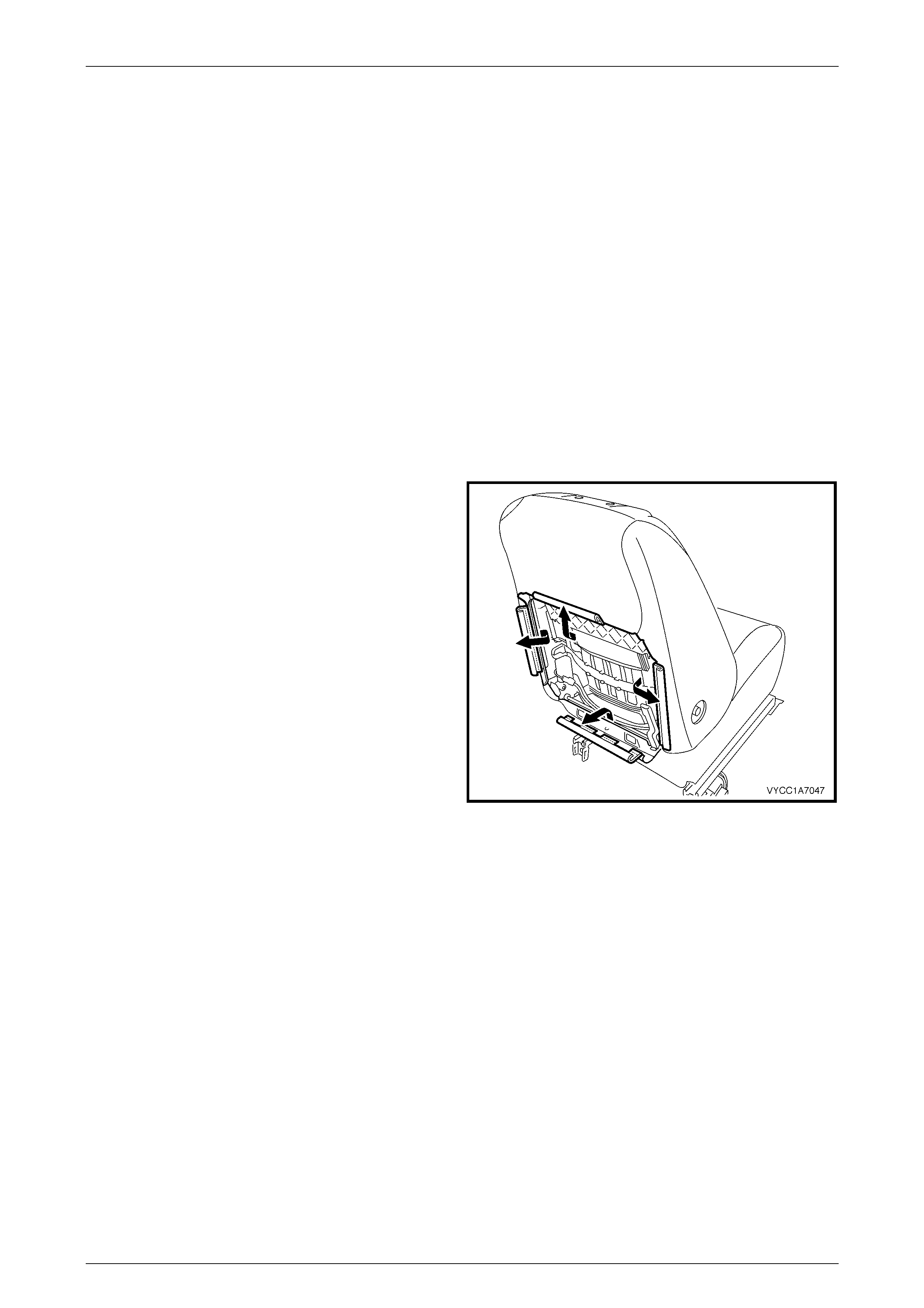
Remove
1 From under the front seat cushion, disengage the front
and side J-strips (1) from the front seat cushion frame
assembly (2).
2 Lift the cover and pad assembly away from the seat
cushion frame and then release the rear J-strip (3).
3 Remove the cover and pad assembly.
Figure 1A7 – 37
Reinstall
Reinstallation of the front seat cushion pad and cover assembly is the reverse of the removal procedure.
Seat Assemblies Page 1A7–30
Page 1A7–30
2.14 Front Seat Cushion Frame Assembly
LT Section No. – 14-275
Remove
As required remove the following components:
1 Front seat assembly, refer to 2.2 Front Seat Assembly.
2 Front seat outer side cover, refer to 2.3 Front Seat Outer Side Cover Assembly.
3 Front seat inner side cover, refer to 2.4 Front Seat Inner Side Cover.
4 Front seat-back frame assembly, refer to 2.11 Front Sea t-back Frame Assembly.
5 Track and height adjust assembly, refer to 2.12 Track and Height Adjust Assembly.
6 Front seat cushion pad and cover assembly, refer to 2.13 Front Seat Cushion Pad and Cover Assembly.
Disassemble
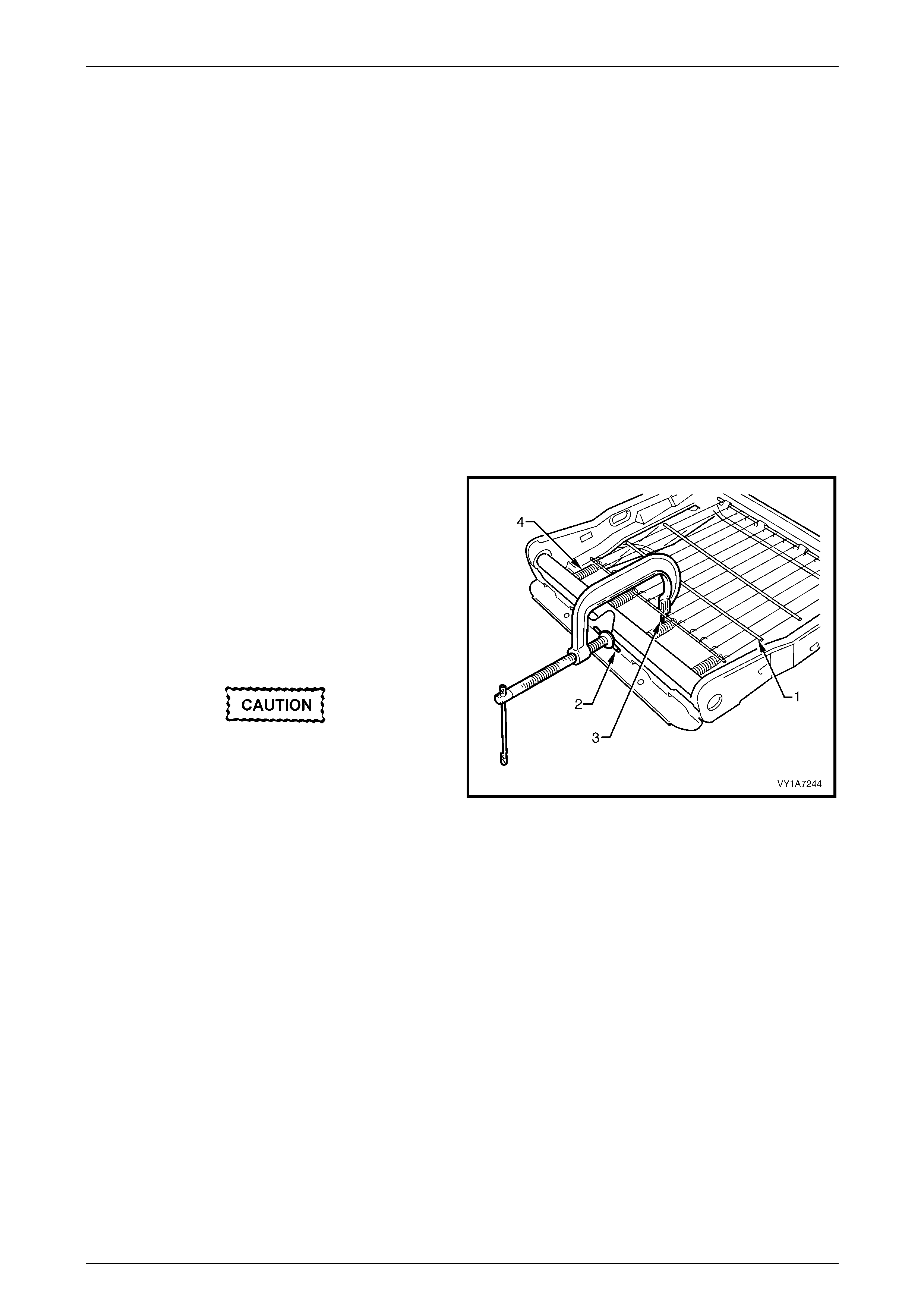
1 To remove the suspension mat (1), modify a G-clamp
with a 5mm diameter metal dowel (2) welded to one
end, approximately 40mm long and with a 2mm
diameter pin (3) approximately 20mm long welded to
the other end.
2 Using the G-clamp, stretch the suspension mat far
enough to allow for the retaining springs (4) to be
removed from the seat cush io n frame.
3 Back the G-clamp load off and remove the suspension
mat.
When using the G-clamp, use existing holes
in the suspension mat to ensure that mat
deformation does not occur.
Figure 1A7 – 38
Reassemble
Reassembly of the suspension mat is the reverse of the disassembly procedure.
Reinstall
Reinstallation of the front seat cushion frame assembly is the reverse of the removal procedure, noting the following:
1 Ensure all wiring is correctly connected and routed, refer to Section 12O Fuses, Relays and W iring Harnesses.
2 Check the mechanical and ele ctri cal opera tion of the front seat.

Seat Assemblies Page 1A7–31
Page 1A7–31
2.15 Front Seat Lift Motor Assemblies
The front seat lift motor assemblies are non-serviceable items.
If a front seat lift motor assembly requires replacement, the track and height adjust assembly must be replaced, refer to
2.12 Track and Height Adjust Assembly.

Seat Assemblies Page 1A7–32
Page 1A7–32
3 Diagnostics – Front Seat
This Section provides charts to assist in the diagnosis and repair of front seats. Refer to 2.1 Front Seat Usage Chart, for
a listing and illustrations of the different types of seats fitted to MY 2003 VY Regular Cab vehicles.
3.1 Prerequisites
Safety Requirements
When operating the seat as part of any of the Steps in the diagnosis charts, ensure that fingers and limbs are clear of
moving parts.
Equipment
The following equipment is required to diagnose the seats:
1 An unpowered test lamp with a current draw of less than 3 A.
2 A digital multimeter with a minimum impedance of 10 MΩ.
Testing Procedures
The following points must be adhered to when performing diagnostic testing on components:
1 Care must be taken when using testing equipment to diagnose wiring harness connectors. It is preferred that the
technician back-probe the connector to avoid terminal damage.
2 When tests are required on connector terminals, utilise the adapters in the connector adaptor kit KM–609 to
prevent damage to the terminals.
3 Unless the multimeter being used has an auto-ranging function, ensure that the correct range is selected.
4 When back-probing connectors, ensure the test lamp ground lead is connected to a suitable ground point on the
vehicle. Ensure that this ground point is not part of the circuit being tested.
NOTE
When following the Steps in the diagnosis charts,
the exact order of Steps should be observed. If
the required nominal value or result is not
achieved at any stage, the problem must be
rectified before proceeding any further.

Seat Assemblies Page 1A7–33
Page 1A7–33
3.2 Mechanical Diagnosis
Lumbar Support Inoperative
Introduction
This test is used by the technician to aid in the diagnosis of the lumbar support assembly.
Test Description
The following numbers refer to the Step numbers in the diagnostic chart.
1 Checks that the lumbar support knob is properly engaging the lumbar support adjuster. Check the knob for cracks
and worn splines.
2 Checks that the lumbar support adjust assembly is not damaged or worn.
3 Checks that there is correct operation of the lumbar support assembly when the lumbar support knob is turned
throughout its range.
Step Action Yes No
1 1 Remove the lumbar support knob, refer to
2.9 Lumbar Support Knob Assembly.
Is the lumbar support knob serviceable? Go to Step 2.
Replace the lumbar support
knob, refer to
2.9 Lumbar Support Knob
Assembly.
2 1 Remove the front seat-back rear cover
assembly, refer to 2.5 Front Seat-back
Rear Cover Assembly.
2 Visually inspect the lumbar support and
strap.
Is the lumbar support assembly serviceable?
Go to Step 3.
Replace the lumbar support
assembly, refer to
2.11 Front Seat-back Frame
Assembly.
3 1 Refit the lumbar support knob and operate
as required.
Does the strap attachment move along the shaft
freely in both directions?
Does the strap tighten and loo sen?
System servic eabl e.
Replace the lumbar support
assembly, refer to
2.11 Front Seat-back Frame
Assembly.
When all diagnosis and repairs are completed, check the system for correct operation.
Seat-back Recline Forward and/or Aft Function is Inoperative
Introduction
This test is used by the technician to aid in the diagnosis of the recline function of the seat assembly.
Test Description
The following numbers refer to the Step numbers in the diagnostic chart.
1 Checks that the recliner knob is properly engaging the recliner shaft. Check the knob for cracks and worn splines.
Step Action Yes No
1 1 Remove the recliner knob, refer to
2.3 Front Seat Outer Side Cover
Assembly.
Is the recliner knob serviceable?
Replace the front seat-back
frame assembly, refer to
2.11 Front Seat-back Frame
Assembly.
Replace the recliner knob,
refer to
2.3 Front Seat Outer Side
Cover Assembly.
When all diagnosis and repairs are completed, check the system for correct operation.

Seat Assemblies Page 1A7–34
Page 1A7–34
Seat Fore/Aft Movement Function is Inoperative or is Not Smooth
Introduction
This test is used by the technician to aid in the diagnosis of the fore/aft movement function of the seat being inoperative
or the action of the seat through the range of movement is not smooth.
Test Description
The following numbers refer to the Step numbers in the diagnostic chart.
1 Checks that there are no items obstructing the guide rails which may stop or hinder the seat movement.
2 Checks that the guide rails have adequate lubricant applied to provide a smooth operation for the seat.
3 Checks that the linkage assembly between the adjustment lever and locking tangs is not worn or damaged. The
locking tangs must disengage from the guide rails before the seat will move.
4 Checks that the guide rails have not been damaged. Any binding between the inner and outer guide rails will result
in poor operation of the fore and aft movement.
Step Action Yes No
1 Are the guide rails free from obstructions? Go to Step 2. Remove the obstructing item.
2 Are the guide rails adequately lubricated?
Go to Step 3.
Apply a small amount of
grease type NLGI No. 1
Lithium Grease (with 9% Zinc
Oxide) to the rails.
3 Do the locking tangs disengage the guide rails
when the seat fore and aft adjustment lever is
raised to its full movement? Go to Step 4.
Replace the track and height
adjust assembly, refer to
2.12 Track and Height
Adjust Assembly.
4 Do the guide rails bind at any point of travel
during the fore and aft movements of the seat? Replace the track and height
adjust assembly, refer to
2.12 Track and Height
Adjust Assembly.
System servic eabl e.
When all diagnosis and repairs are completed, check the system for correct operation.
Dump-latch Mechanism is Inoperative
Introduction
This test is used by the technician to aid in the diagnosis of the front seat dump-latch mechanism being inoperative.
Test Description
The following numbers refer to the Step numbers in the diagnostic chart.
1 Checks that the seat-back frame locks in the upright position.
2 Checks that the front seat-back can be tilted forward once the dump-latch lever is operated.
3 Checks the serviceability of the dump-latch mechanism components.
Step Action Yes No
1 Does the front seat-back lock in the upright
position? Go to Step 2. Go to Step 3.
2 1 Operate the dump-latch release lever.
Can the front seat-back be tilted forward? System serviceable. Go to Step 3.

Seat Assemblies Page 1A7–35
Page 1A7–35
Step Action Yes No
3 1 Remove the front seat-back rear cover,
refer to 2.5 Front Seat-back Rear Cover
Assembly.
2 Check the following components:
• Dump-latch release lever,
• Dump-latch release spring,
• Dump-latch release rod retainer,
• Dump-latch release rod.
Is any component damaged?
Replace the components as
required, refer to
2.6 Dump-latch
Mechanism Assembly.
Replace the seat-back frame
assembly, refer to
2.11 Front Seat-back
Frame Assembly.
When all diagnosis and repairs are completed, check the system for correct operation.
Seat Assemblies Page 1A7–36
Page 1A7–36
3.3 Electrical Diagnosis
The charts in this Section are used by the technician in the aid of diagnosing faults on four-way seat assemblies. To aid
in the use of the diagnosis charts, refer to Wiring Diagram and Connector Chart in this Section.
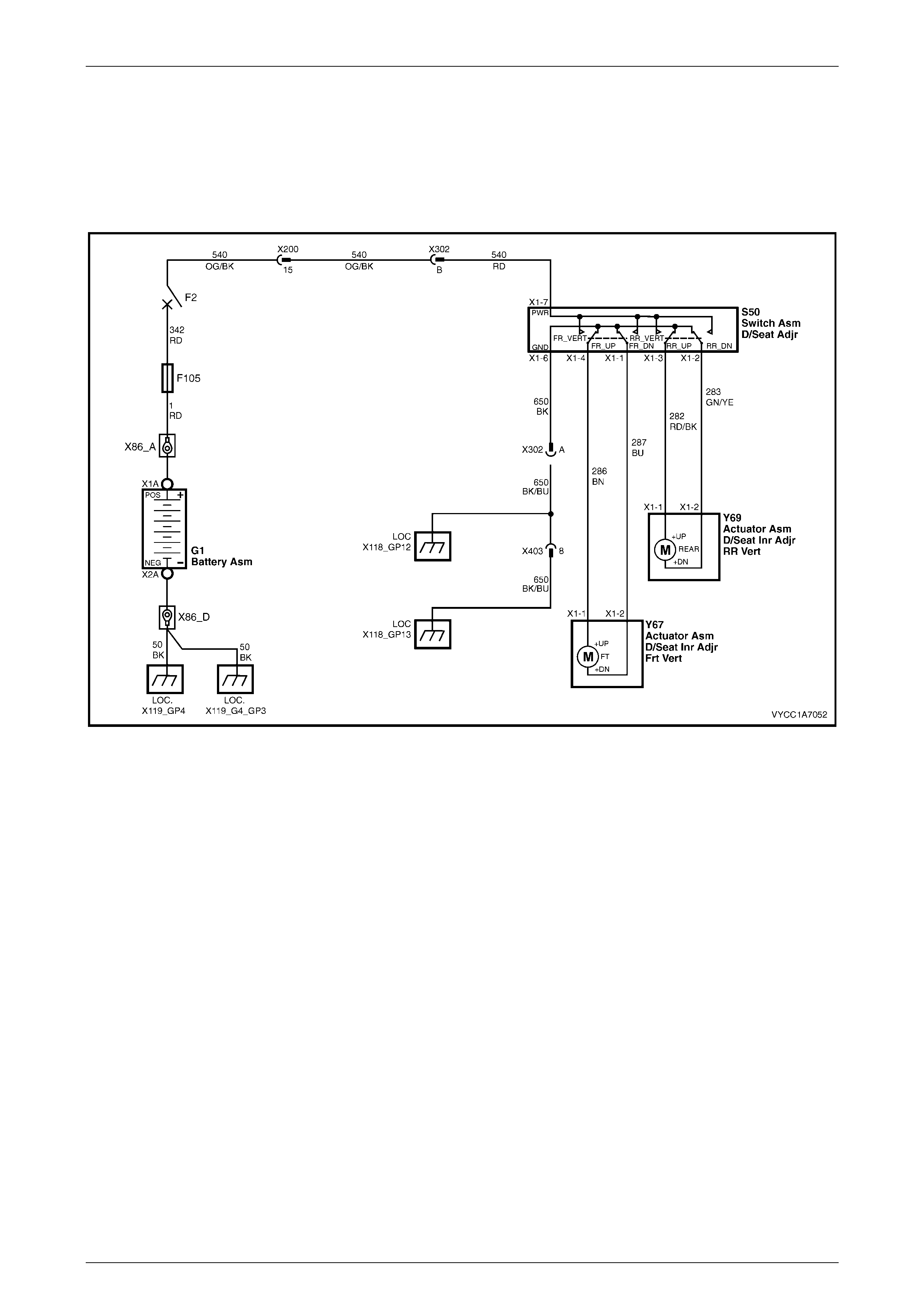
Wiring Diagram
Figure 1A7 – 39
Seat Assemblies Page 1A7–37
Page 1A7–37
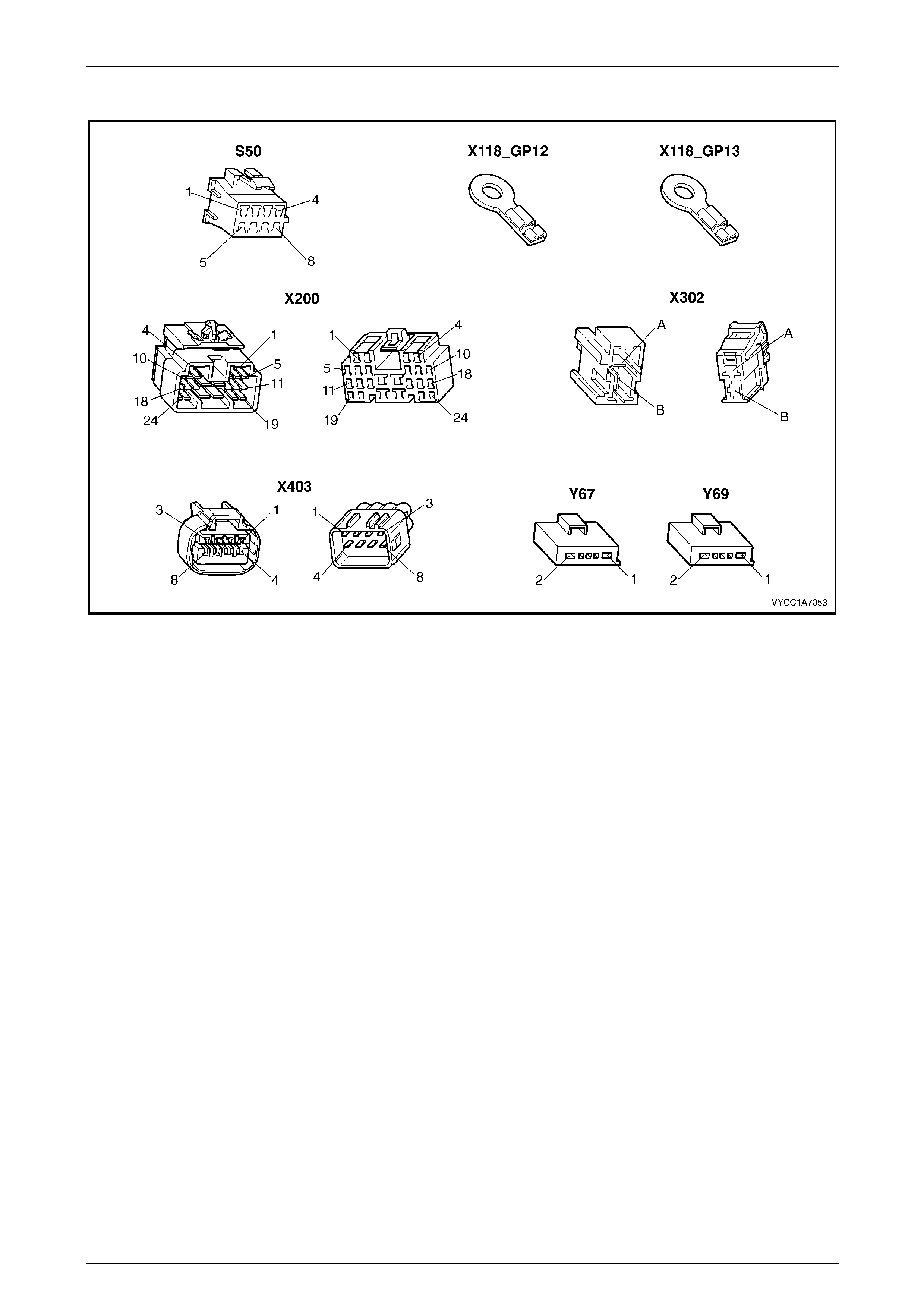
Connector Chart
Figure 1A7 – 40

Seat Assemblies Page 1A7–38
Page 1A7–38
None of the Driver’s Seat Adjustment Switch Functi ons Operate
Introduction
This test is used by the technician to aid in the diagnosis of the driver’s seat adjustment switch when none of the switch
functions operate. The test diagnoses the front seat adjustment switch and associated power and ground circuits.
Test Description
The following numbers refer to the Step numbers in the diagnostic chart.
1 Checks whether there is battery power at connector X302 pin B. Isolates whether there is a fault in circuit 540
between connectors X200 pin 19 and X302 pin B.
2 Checks that all the connectors required for the seat to operate effectively are in place and positively connected.
3 Checks whether there is battery power at connector S50 – X1 pin 7. Isolates whether there is a fault in circuit 540
between connectors S50 – X1 pin 7 and X302 pin B.
4 Checks whether the front seat adju stm ent switch is serviceable.
5 Checks whether there is continuity between connectors S50 – X1 pin 6 and X302 pin A which supplies the ground
circuit for the front seat adjustment switch. Isolates whether there is a fault in circuit 650 between the switch and
connector X302 pin A or between connector X302 pin A and the grounding points.
Note on Diagnostic Chart
1 For all wiring harness fault diagnosis, refer to Section 12P, 3.1 Electrical Fault Diagnosis in the MY 2003 VY and
V2 Service Information.
2 For wiring harness repairs, refer to Section 12P, 5 Wiring Repair Procedures in the MY 2003 VY and V2 Service
Information.
3 Refer to Section 12O Fuses, Relays and Wiring Harnesses for harness routing.
4 If at any time the fault is deemed to be intermittent, refer to Section 12P, 4.7 Detecting Intermittent Faults in the
MY 2003 VY and V2 Service Information.
Step Action Yes No
1 1 Back probe connector X302 pin B with a
test lamp.
Does the test lamp illuminate? Go to Step 3.
There is a fault in circuit 540
between connectors
X200 pin 15 and X302 pin B.
Repair or replace circuit 540
(refer to Note 2).
2 Are the following connectors secure?
• S50
• X302
• Y67
• Y69
Go to Step 4. Ensure that the connectors are
secure.
3 1 Back probe connector S50 – X1 pin 7 with
a test lamp.
Does the test lamp illuminate? Go to Step 5.
There is a fault in circuit 540
between connectors
S50 – X1 pin 7 and
X302 pin B.
Repair or replace circuit 540
(refer to Note 2).
4 1 Remove the front seat adjustment switch
from the seat, refer to 2.3 Front Seat
Outer Side Cover Assembly.
2 Test the front seat adjustment switch, refer
to 3.4 Front Seat Adjustment Switch Test.
Is the front seat adjustment switch serviceable?
Go to Step 6.
Replace the front seat
adjustment switch, refer to
2.3 Front Seat Outer Side
Cover Assembly.

Seat Assemblies Page 1A7–39
Page 1A7–39
Step Action Yes No
5 1 Back probe connector X302 pin A with a
test lamp.
2 Operate the front seat adjustment switch in
any of the available directions.
Does the test lamp illuminate?
There is a fault in circuit 650
between connector X302 pin A
and ground points X118-GP12
and X118–GP13.
Repair or replace circuit 650
(refer to Note 2).
There is a fault in circuit 650
between connectors
S50 – X1 pin 6 and
X302 pin A.
Repair or replace circuit 650
(refer to Note 2).
When all diagnosis and repairs are completed, check the system for correct operation.
Front/Rear of the Driver’s Seat Does Not Raise and/or Lower
Introduction
This test is used by the technician to aid in the diagnosis of the front and/or the rear of the driver’s seat not raising and/or
lowering. The test diagnoses the front seat adjustment switch and the motor circuits.
Test Description
The following numbers refer to the Step numbers in the diagnostic chart.
1 Checks whether the front seat adjustment switch assembly operates the seat in any direction. Isolates whether
there is a battery or ground fault affecting the seat operation.
2 Checks that all the connectors required for the seat to operate effectively are in place and positively connected.
3 Checks whether the front seat adju stm ent switch is serviceable.
4 Confirms whether the rear of the seat raises or lowers. Isolates whether the rear lift motor and circuit of the seat is
the fault.
5 Confirms whether the front of the seat raises or lowers. Isolates whether the front lift motor and circuit of the seat is
the fault.
6 Checks whether there is battery power to the seat rear lift motor at connector Y69 – X1 pin 1. Isolates whether
there is a fault in circuit 282 that supplies battery power to the motor to raise the rear of the seat.
7 Checks whether there is battery power to the seat rear lift motor at connector Y69 – X1 pin 2. Isolates whether the
fault is in circuit 283 that supplies battery power to the motor to lower the rear of the seat or the motor is faulty. As
reversing the polarity changes the direction of the motor, this Step also confirms that the ground circuit from Step 6
is serviceable.
8 Checks whether there is battery power to the seat front lift motor at connector Y67 – X1 pin 1. Isolates whether
there is a fault in circuit 286 that supplies battery power to the motor to raise the front of the seat.
9 Checks whether there is battery power to the seat front lift motor at connector Y67 – X1 pin 2. Isolates whether the
fault is in circuit 287 that supplies battery power to the motor to lower the front of the seat or the motor is faulty. As
reversing the polarity changes the direction of the motor, this Step also confirms that the ground circuit from Step 8
is serviceable.
Note on Diagnostic Chart
1 For all wiring harness fault diagnosis, refer to Section 12P, 3.1 Electrical Fault Diagnosis in the MY 2003 VY and
V2 Service Information.
2 For wiring harness repairs, refer to Section 12P, 5. W iring Repair Procedures in the MY 2003 VY and V2 Service
Information.
3 Refer to Section 12O Fuses, Relays and Wiring Harnesses for harness routing.
4 If at any time the fault is deemed to be intermittent, refer to Section 12P, 4.7 Detecting Intermittent Faults in the
MY 2003 VY and V2 Service Information.

Seat Assemblies Page 1A7–40
Page 1A7–40
Step Action Yes No
1 Does the front seat adjustment switch operate
the seat correctly in any of the four directions? Go to Step 2.
Refer to None of the Driver’s
Seat Adjustment Switch
Functions Operate in this
Section.
2 Are the following connectors secure?
• S50
• Y67
• Y69
Go to Step 3. Ensure that the connectors are
secure.
3 1 Remove the front seat adjustment switch
from the seat, refer to 2.3 Front Seat
Outer Side Cover Assembly.
2 Test the front adjustment switch, refer to
3.4 Front Seat Adjustment Switch Test.
Is the front seat adjustment switch serviceable?
Go to Step 4.
Replace the front seat
adjustment switch, refer to
2.3 Front Seat Outer Side
Cover Assembly.
4 1 Operate the front seat adjustment switch to
raise or lower the rear of the seat.
Does the rear of the seat raise and lower? Go to Step 5. Go to Step 6.
5 1 Operate the front seat adjustment switch to
raise or lower the front of the seat.
Does the front of the seat raise and lower? System serviceable. Go to Step 8.
6 1 Back probe connector Y69 – X1 pin 1 with
a test lamp.
2 Operate the front seat adjustment switch to
raise the rear of the seat.
Does the test lamp illuminate?
Go to Step 7.
There is a fault in circuit 282
between connectors
S50 – X1 pin 3 and
Y69 – X1 pin 1.
Repair or replace circuit 282
(refer to Note 2)..
7 1 Back probe connector Y69 – X1 pin 2 with
a test lamp.
2 Operate the front seat adjustment switch to
lower the rear of the seat.
Does the test lamp illuminate?
The seat rear lift motor is
faulty.
Replace the seat rear lift
motor, refer to
2.15 Front Seat Lift Motor
Assemblies.
Go to Step 5.
There is a fault in circuit 283
between connectors
S50 – X1 pin 2 and
Y69 – X1 pin 2.
Repair or replace circuit 283
(refer to Note 2).
Go to Step 5.
8 1 Back probe connector Y67 – X1 pin 1 with
a test lamp.
2 Operate the front seat adjustment switch to
raise the front of the seat.
Does the test lamp illuminate?
Go to Step 9.
There is a fault in circuit 286
between connectors
S50 – X1 pin 4 and
Y67 – X1 pin 1.
Repair or replace circuit 286
(refer to Note 2).
9 1 Back probe connector Y67 – X1 pin 2 with
a test lamp.
2 Operate the front seat adjustment switch to
lower the front of the seat.
Does the test lamp illuminate?
The seat front lift motor is
faulty.
Replace the seat front lift
motor, refer to
2.15 Front Seat Lift Motor
Assemblies.
There is a fault in circuit 287
between connectors
S50 – X1 pin 1 and
Y67 – X1 pin 2.
Repair or replace circuit 287
(refer to Note 2).
When all diagnosis and repairs are completed, check the system for correct operation.
Seat Assemblies Page 1A7–41
Page 1A7–41
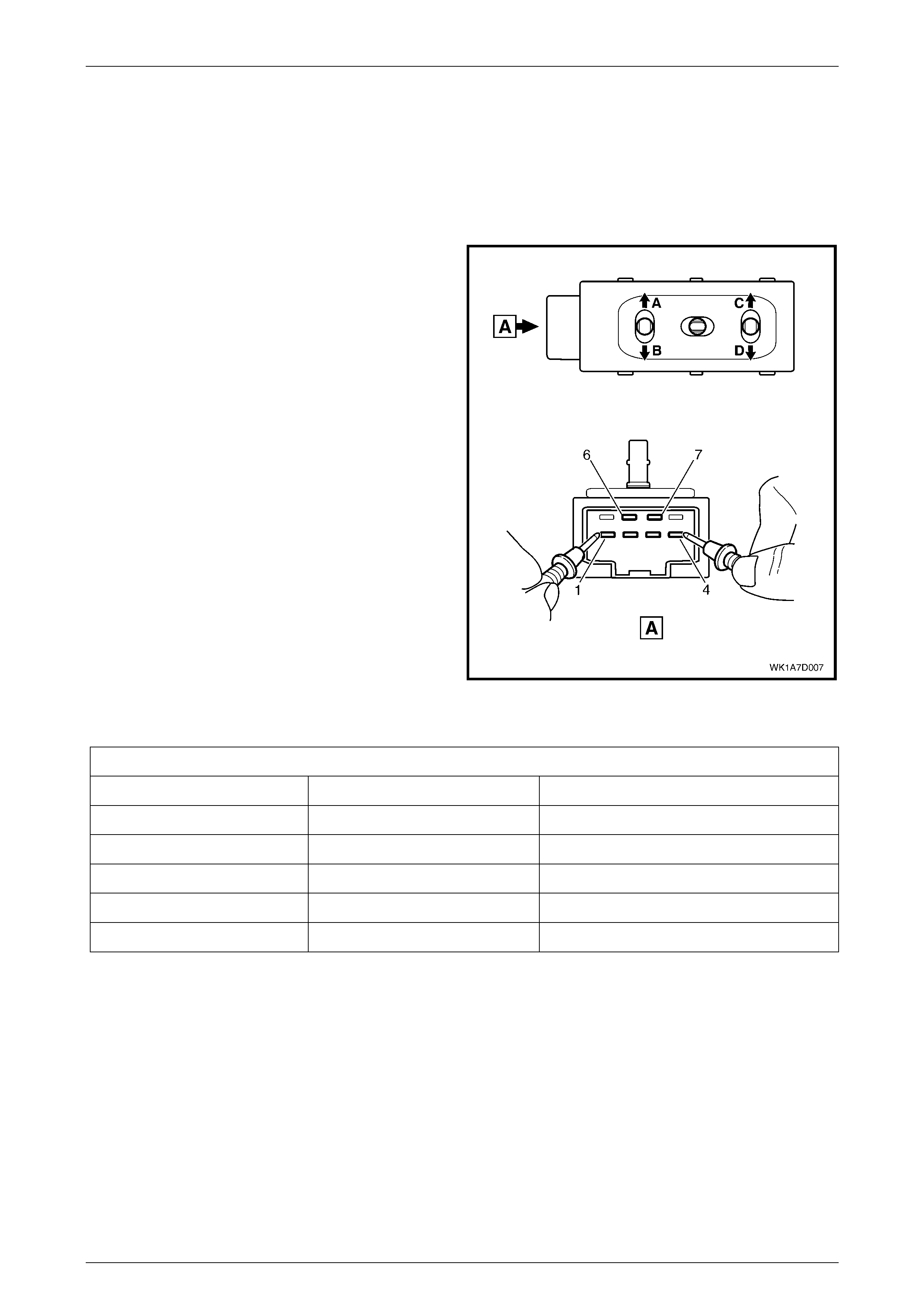
3.4 Front Seat Adjustment Switch Test
The switch is located on the outer side of the seat, attached to the inner side of the front seat outer side cover.
Test
1 Remove the front seat adjustment switch, refer to 2.3 Front Seat Outer Side Cover Assembly.
2 Place the switch in the positions as detailed in the
following char t. Place the prob es of the ohmmet er onto
the terminals listed and take the reading. Compare the
reading to the chart.
3 If the switch fails any part of the test, replace the
switch assembly with a serviceable item.
4 Install the front seat adjustment switch, refer to
2.3 Front Seat Outer Side Cover Assembly.
Figure 1A7 – 41
Front Seat Adjustment Switch
Switch Posi tion Switch Terminals Indication if Switch is Serviceable
Position A 3 and 7 Continuity
Position B 2 and 7 Continuity
Position C 4 and 7 Continuity
Position D 1 and 7 Continuity
Switch in the neutral position 6 and either 1, 2, 3 or 4 Continuity

Seat Assemblies Page 1A7–42
Page 1A7–42
4 Torque Wrench Specifications
Front Seat Assembly Attaching Screw.......................................35.0 – 50.0 Nm
Front Seat Outer Side Cover Attaching Screw...............................1.0 – 3.0 Nm
Front Seat Inner Side Cover Attaching Screw...............................1.0 – 3.0 Nm
Dump-latch Release Rod Retainer Attaching Screw .....................1.0 – 3.0 Nm
Dump-latch Release Lever Attaching Nut......................................5.0 – 6.0 Nm
Lumbar Support Knob Attaching Screw......................................... 2.0 – 5.0 Nm
Front Seat Dummy Block Insert Assembly Attaching Nut..............5.0 – 6.0 Nm
Front Seat-back Frame Attaching Screw...................................30.0 – 45.0 Nm
Track and Height Adjust Assembly Attaching Nut......................24.0 – 32.0 Nm