
Headlining and Int eri or Tri m Page 1A8–1
Page 1A8–1
Section 1A8
Headlining and Interior Trim
ATTENTION
Before performing any Service Operation or other procedure described in this Section, refer to Section 00
WARNINGS, CAUTIONS AND NOTES for correct workshop practices with regard to safety and/or property
damage.
1 General Information............................................................................................................................... 2
2 Service Operations................................................................................................................................ 3
2.1 Pictorial Index .........................................................................................................................................................3
2.2 Seat–back Body Panel Trim Assembly.................................................................................................................4
Remove ...................................................................................................................................................................4
Disassemble.......................................................................................................................................................5
Reassemble .......................................................................................................................................................5
Reinstall..................................................................................................................................................................5
3 Torque Specifications ........................................................................................................................... 6

Headlining and Int eri or Tri m Page 1A8–2
Page 1A8–2
1 General Information
With the following exceptions the MY 2003 VY Regular Cab series headlining and interior trim assemblies carry over
from the MY 2003 VY Series Utility.
• Rear seat back body panel trim assembly
Although some of the interior trim components have been modified or trimmed to suit the Regular Cab vehicle, the
service procedures for these components have carried over from the MY 2003 VY Series Utility.
For information not contained in this section, refer to Section 1A8 Headlining and Interior Trim in the MY 2003 VY and
V2 Series Service Information.
Headlining and Int eri or Tri m Page 1A8–3
Page 1A8–3
2 Service Operations
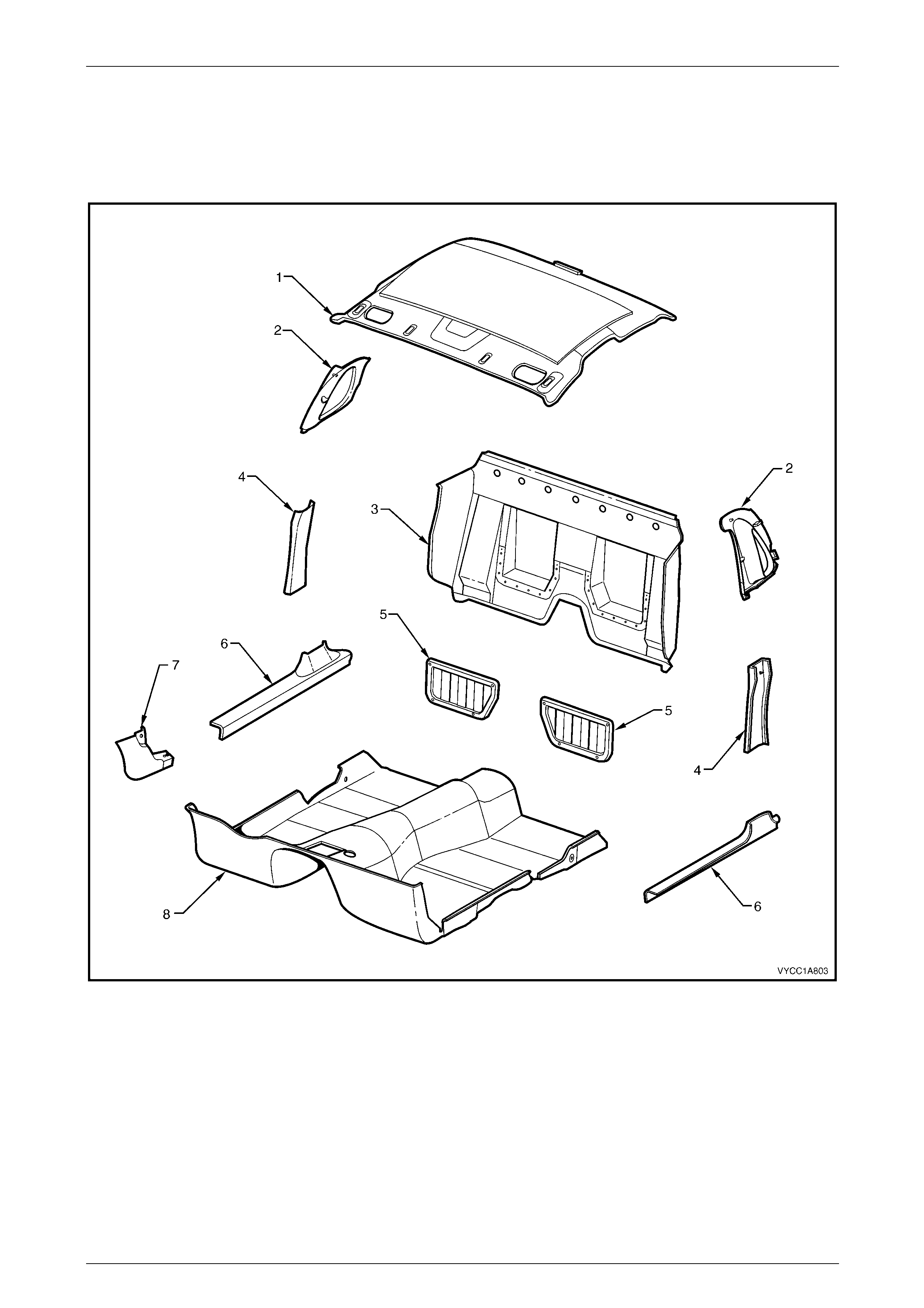
2.1 Pictorial Index
Legend
1 Headlining
2 Body Lock Pillar Upper Trim
3 Seat-back Body Panel Trim
4 Centre Pillar Lower Trim
5 Seat-back Body Panel
6 Side Sill Trim
7 Hinge Pillar Trim
8 Floor Carpet
Headlining and Int eri or Tri m Page 1A8–4
Page 1A8–4
2.2 Seat–back Body Panel Trim Assembly
Remove
1 As required, either slide the seats forward or remove the seats, refer to Section 1A7, 2.2 Front Seat Assembly in
the MY 2003 VY and V2 Series Service Information.
2 Remove the side sill trim, refer to Section 1A8, 5.4 Side Sill Trim and Plate in the MY 2003 VY and V2 Series
Service Information.
3 Remove the centre pillar lower trim, refer to Section 1A8, 5.2 Centre Pillar Lower Trim in the MY 2003 VY and V2
Series Service Information.
4 Remove the body lock pillar upper trim, refer to Section 1A8, 5.3 Body Lock Pillar Upper Trim in the MY 2003 VY
and V2 Series Service Information.
5 If required remove the child restraint fitting, refer to Section 12M Occupant Protection System in the MY 2003 VY
and V2 Series Service Information.
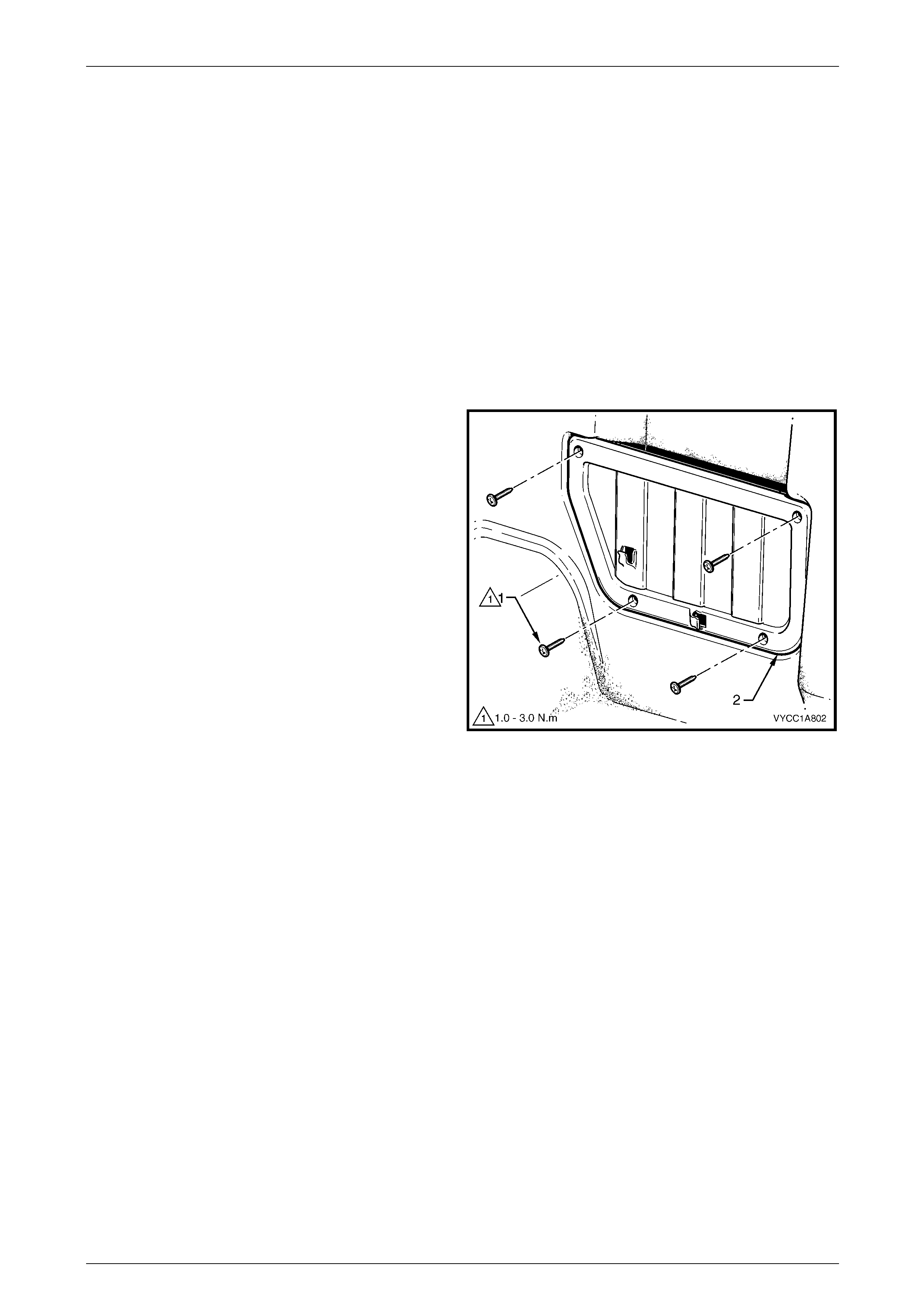
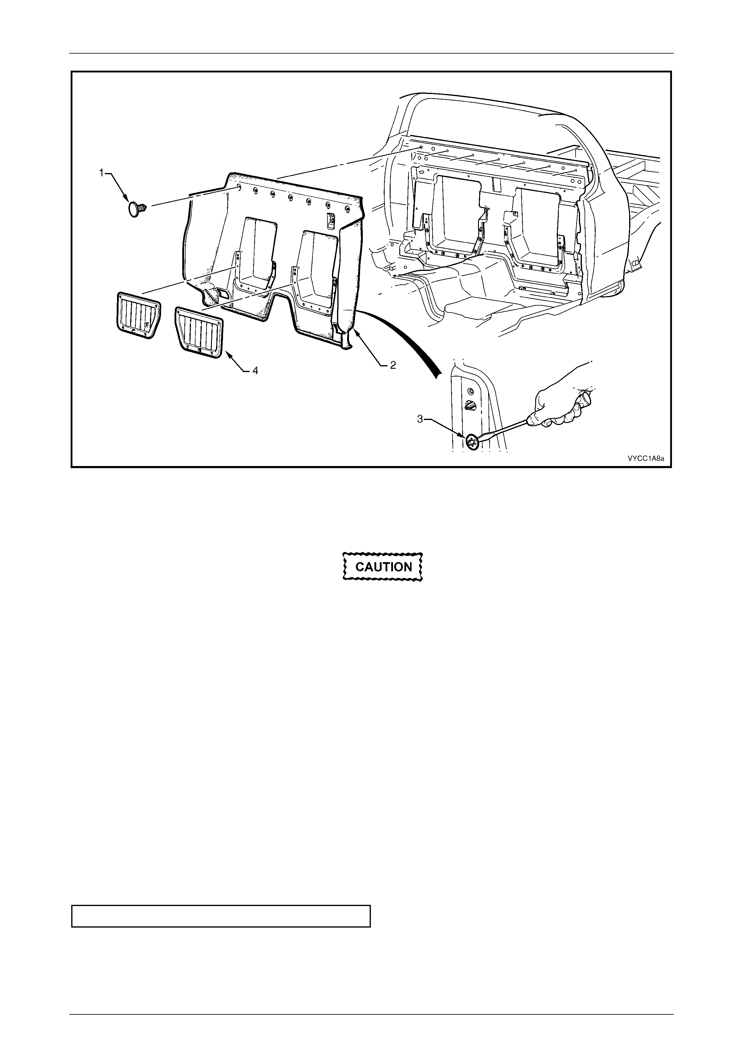
6 Remove the screw (1), four places in each storage
pocket panel (2).
Figure 1A8 – 1
7 Remove the retainer (1), seven places securing the seat back body panel trim assembly (2) to the inner rear body
panel, refer to Figure 1A8 – 2 and remove the trim assembly.
Headlining and Int eri or Tri m Page 1A8–5
Page 1A8–5
Figure 1A8 – 2
Disassemble
Use extreme care when removing the
speed clips from the storage panel
pocket, as the plastic pins can easily be
broken when the clips are being
removed.
1 From the rear of the rear seat-back body panel trim assembly, use a suitable screwdriver and gently prise the
speed clip (3) four places, securing each storage pocket panel (4) to the rear seat back body panel trim assembly,
refer Figure 1A8 – 2.
2 Gently pull the storage pocket panel forward and remove from the rear seat back body panel trim assembly.
Reassemble
1 Position the storage pocket panel to the seat back body panel trim assembly and fit the four speed clips into each
panel, refer Figure 1A8 – 2.
Reinstall
1 Reinstallation of the seat back body panel trim assembly is the reverse of the removal procedure.
2 Tighten the screw (1), 4 places in the storage pocket panel (2) places to the specified torque, refer
Figure 1A8 – 1.
Seat Back Body Panel Trim Screws .........1.0 – 3.0 N.m

Headlining and Int eri or Tri m Page 1A8–6
Page 1A8–6
3 Torque Specifications
Seat-back Body Panel Screws .....................................................1.0 – 3.0 N.m