
Exterior Ornamentation Page 1A9–1
Page 1A9–1
Section 1A9
Exterior Ornamentation
ATTENTION
Before performing any Service Operation or other procedure described in this Section, refer to Section 00
WARNINGS, CAUTIONS AND NOTES for correct workshop practices with regard to safety and/or property
damage.
1 General Information............................................................................................................................... 2
2 Service Operations................................................................................................................................3
2.1 Pictorial Index .........................................................................................................................................................3
Reference Chart......................................................................................................................................................4
2.2 Rocker Panel Moulding End Cap..........................................................................................................................5
Remove ...................................................................................................................................................................5
Reinstall ..................................................................................................................................................................5
2.3 Rear Window Side Moulding.................................................................................................................................6
Remove ...................................................................................................................................................................6
Reinstall ..................................................................................................................................................................6
2.4 Body Side Rear Trim Panel....................................................................................................................................7
Remove ...................................................................................................................................................................7
Reinstall ..................................................................................................................................................................8
2.5 Body Side Rear Trim Bracket................................................................................................................................9
Remove ...................................................................................................................................................................9
Reinstall ..................................................................................................................................................................9
2.6 Rear Quarter Window Moulding..........................................................................................................................10
Remove .................................................................................................................................................................10
Reinstall ................................................................................................................................................................10
2.7 Rear Outer Trim Panel and NVH Foam...............................................................................................................11
Remove .................................................................................................................................................................11
Reinstall ................................................................................................................................................................12
3 Torque Wrench Specifications........................................................................................................... 13
Techline

Exterior Ornamentation Page 1A9–2
Page 1A9–2
1 General Information
With the following exceptions the MY 2003 VY Series Regular Cab exterior ornamentation carries over from the MY 2003
VY Series Utility.
• Rocker Panel End Cap
• Rear Window Side Moulding
• Body Side Rear Trim Panel
• Body Side Rear Trim Bracket
• Rear Quarter Window Moulding
• Quarter Panel Nameplate
• Rear Outer Trim Panel and NVH Foam
Although many of the components are made from different compounds of plastic, some are painted in the vehicles body
colour. The painting procedures are relatively straight forward, providing the correct steps are followed for the
appropriate materials used for the particular component. For information on plastic component materials, refer to
Section 1A1 Body.
The rocker panel moulding has a separate end cap at the rear of the rocker panel moulding.
The body side rear trim panel is attached to the body and also to a bracket that is attached to the rear of the cab. This
bracket is not visible in the following pictorial index.
The MY 2003 VY series regular cab is fitted with NVH foam between the rear of the cab and the rear outer trim panel.
Although the foam is durable it may in service require replacement or removal.
Many of the components are affixed to the vehicle with double-sided tape and or urethane adhesive. It is imperative that
the correct materials as specified in this section are used when reinstalling these parts. Use of materials other than those
specified may lead to premature failure.
To assist in the identification of the exterior ornamentation components and service procedure location, refer to the
following pictorial index diagrams and reference chart on the following pages.
Exterior Ornamentation Page 1A9–3
Page 1A9–3
2 Service Operations
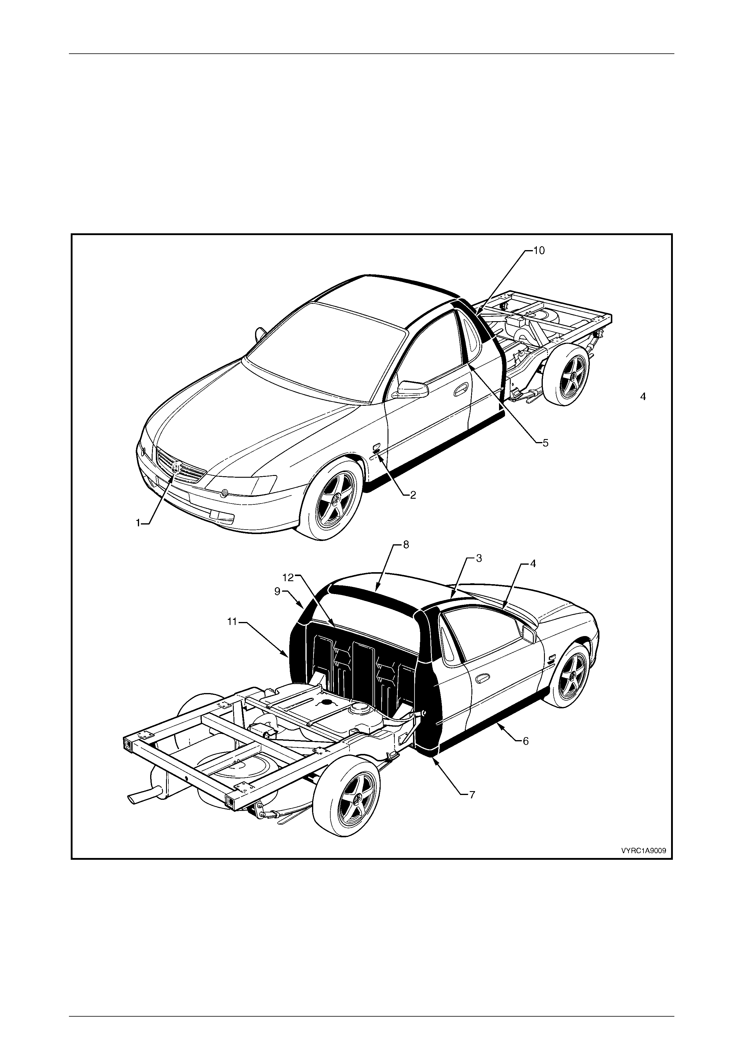
2.1 Pictorial Index
The following diagrams provide a quick reference to the correct service procedures for the exterior ornamentation
components.
Simply locate the component in Figure 1A9 – 1, cross-reference it in the accompanying table below the figure and using
the reference listed, go to the appropriate service procedure.
Figure 1A9 – 1
Exterior Ornamentation Page 1A9–4
Page 1A9–4
Reference Chart
Item Description Refer to
1 Radiator Grille Emblem: Holden Refer to Section 1A9, 4.1 Radiator Grille Emblem in the MY2003 VY
and V2 Series Service Information.
2 Fender Name Plate: V6, V8 Refer to Section 1A9, 4.2 Fender Name Plate in the MY2003 VY and
V2 Series Service Information.
3 Roof Joint Moulding Refer to Section 1A9, 4.6 Roof Joint Moulding in the MY2003 VY and
V2 Series Service Information.
4 Door Opening Moulding Refer to Section 1A9, 4.7 Door Opening Moulding in the MY2003 VY
and V2 Series Service Information.
5 Centre Pillar Upper Finisher
Assembly Refer to Section 1A9, 4.8 Centre Pillar Upper Finisher Assembly in
the MY2003 VY and V2 Series Service Information.
6 Rocker Panel Moulding Assembly Refer to Section 1A9, 4.9 Rocker Panel Moulding Assembly in the
MY2003 VY and V2 Series Service Information.
7 Rocker Panel Moulding End Cap Refer to 2.2 Rocker Panel Moulding End Cap.
8 Rear Window Upper Moulding Refer to Section 1A9, 4.10 Rear Window Upper Moulding in the
MY2003 VY and V2 Series Service Information.
9 Rear Window Side Moulding Refer to 2.3 Rear Window Side Moulding.
10 Quarter Window Moulding Refer to 2.6 Rear Quarter Window Moulding.
11 Body Side Rear Trim Panel and
Bracket Refer to 2.4 Body Side Rear Trim Panel and 2.5 Body Side Rear Trim
Panel Bracket.
12 Rear Outer Trim Panel and NVH
Foam Refer to 2.7 Rear Outer Trim Panel and NVH Foam.
Exterior Ornamentation Page 1A9–5
Page 1A9–5
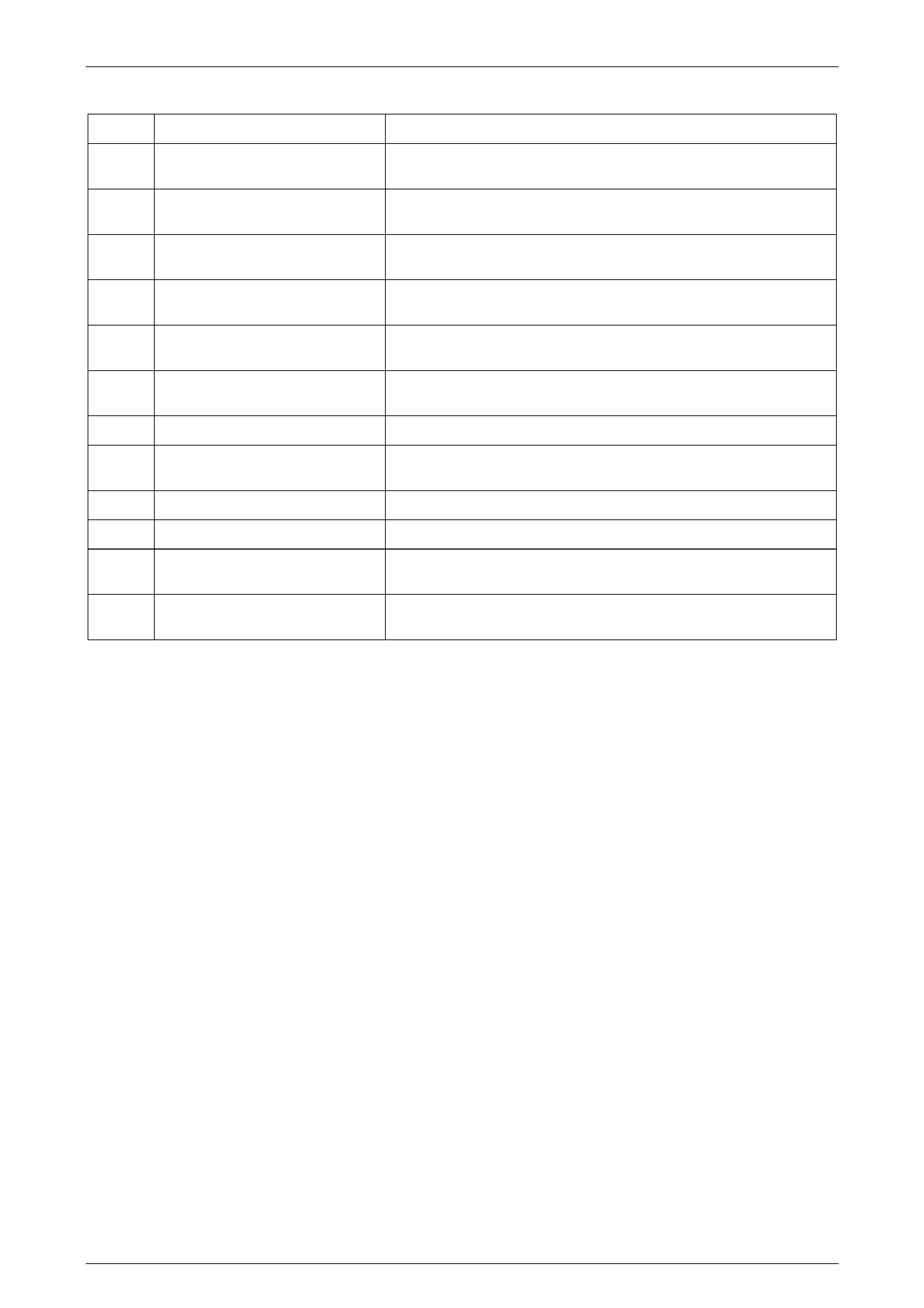
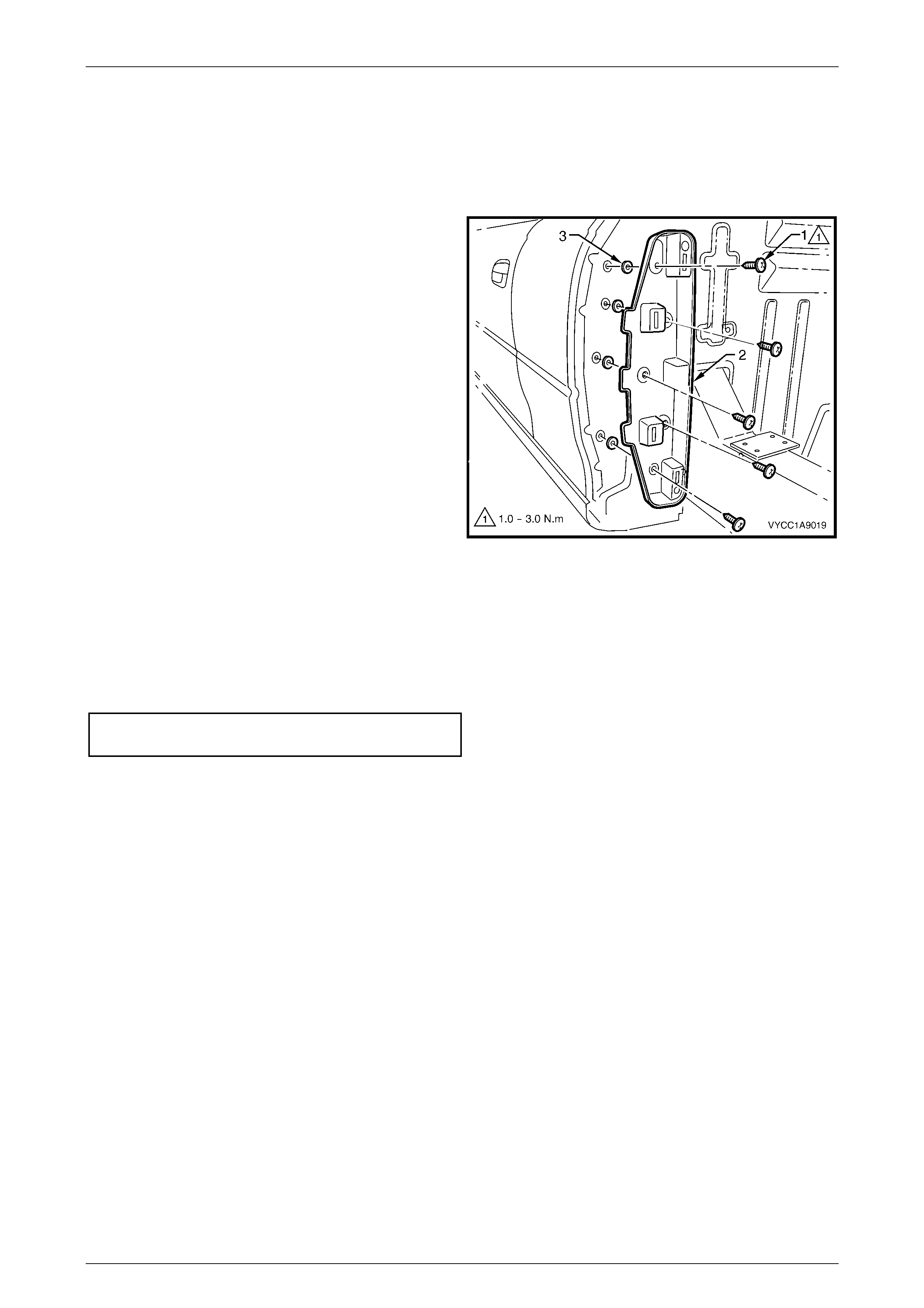
2.2 Rocker Panel Moulding End Cap
Remove
1 Remove the screw (1), three places securing the rear
rocker panel moulding end cap to the body side rear
trim panel and rocker moulding end cap (2).
2 Gently, prise the rocker panel moulding end cap (2)
outward from the body side rear trim panel to release
the retaining clip (3).
Reinstall
Reinstallation is the reverse of removal noting the following:
1 Tighten all screws to the specified torque.
Rocker panel moulding
end cap screw...........................................1.0 – 3.0 N.m
NOTE
Ensure that the clip holding the rear rocker panel
moulding to the rear side trim panel is fastened
correctly and the screws have been located in
the body side rear trim panel correctly. Figure 1A9 – 2

Exterior Ornamentation Page 1A9–6
Page 1A9–6
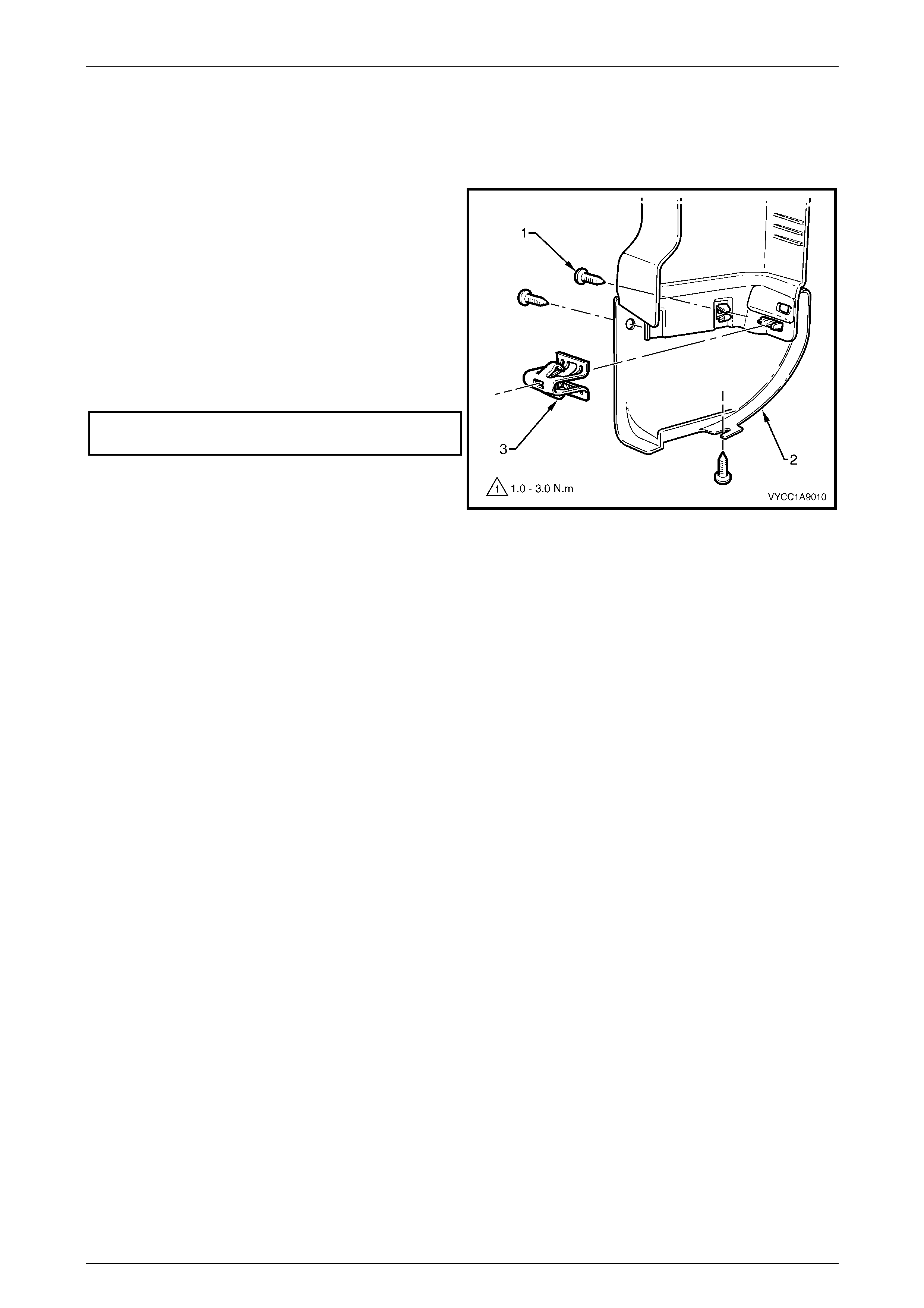
2.3 Rear Window Side Moulding
Remove
1 Remove the rear window upper moulding, refer to Section 1A9, 4.10 Rear Window Upper Moulding in the MY2003
VY and V2 Series Service Information.
2 Remove the retaining screw (1) securing the rear
window side moulding (2) to the body.
3 Rotate the upper edge of the moulding rearward
disengaging the clips at three places.
4 Remove the rear window side moulding taking care to
avoid damage to the paint.
Figure 1A9 – 3
Reinstall
1 Install the lower end of the moulding onto the rear quarter window moulding and behind the body si de rear trim
panel, taking care to avoid paint damage.
2 Locate the lower datum pin, then by rolling the moulding forward, position the three clips into the slots engaging the
lower one first.
3 Push the rear window side moulding firmly on to all three clips.
4 Install the screw (1) retaining the rear window side moulding to the body and tighten to the specified torque, refer to
Figure 1A9 – 3.
Rear window side moulding screw............ 1.0 – 3.0 N.m
5 Install the rear window upper moulding, refer to Section 1A9, 4.10 Rear W indow Upper Moulding in the MY 2003
VY and V2 Series Service Information.
Exterior Ornamentation Page 1A9–7
Page 1A9–7
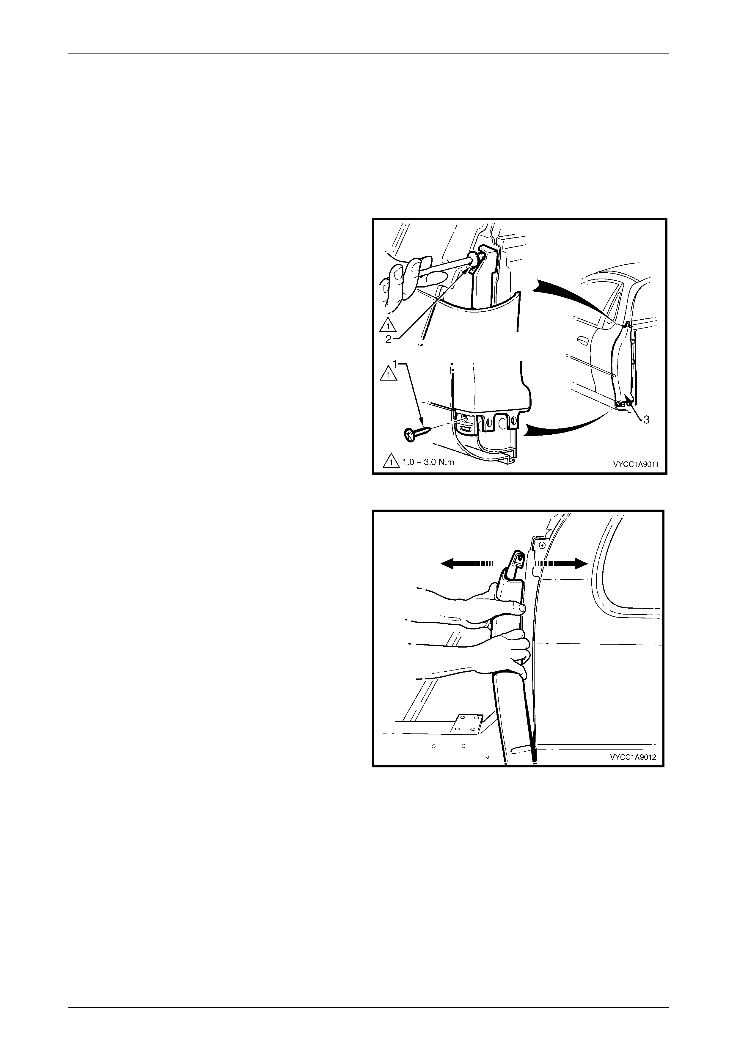
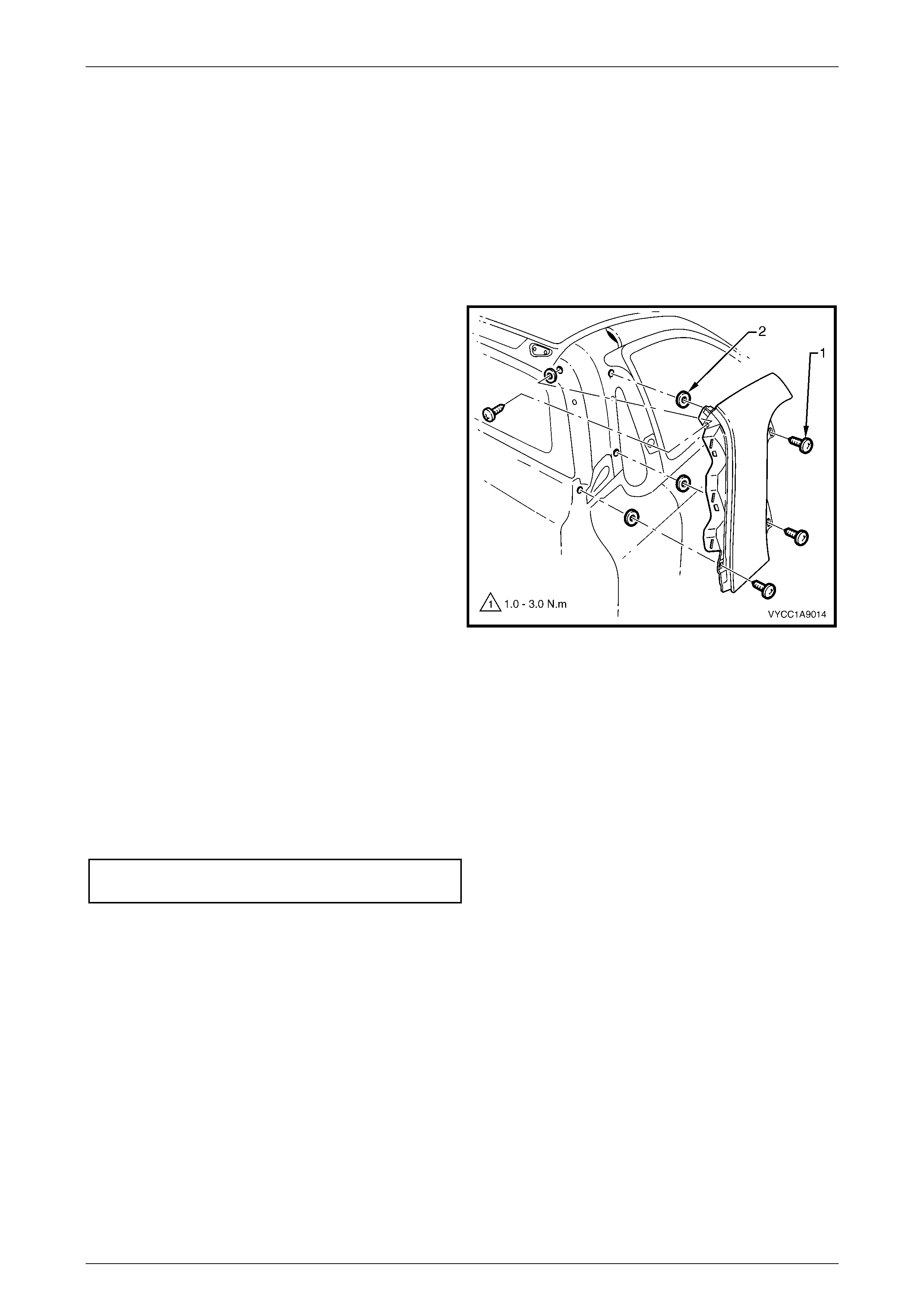
2.4 Body Side Rear Trim Panel
Remove
1 If required, remove the tray to gain the required access, refer to Section 1B1 Tray.
2 Remove the rear rocker panel moulding end cap refer, 2.2 Rear Rocker Panel Moulding.
3 Remove the rear window side moulding refer, 2.3 Rear Window Side Moulding.
4 If required, the front rocker panel moulding may have
to be partially removed to gain access to the lower
screw (1), refer Section 1A9, 4.9 Rocker Panel
Moulding in the MY2003 VY and V2 Series Service
Information.
5 Remove the two retaining screws (1) and (2) attaching
the body side rear trim panel (3).
Figure 1A9 – 4
6 Starting from the top, carefully pull the body side rear
trim panel rearward slightly to disengage the five
retaining clips from the body side rear trim panel
mounting bracket.
Figure 1A9 – 5

Exterior Ornamentation Page 1A9–8
Page 1A9–8
Reinstall
1 Align the body side rear trim panel on to the five mounting bracket retaining clips.
2 Gently push the body side rear trim panel evenly and firmly on to the clips until secured.
3 Refit the two retaining screws (1) attaching the trim panel in place and tighten to the specified torque, refer to
Figure 1A9 – 4.
Body side rear trim panel
retaining scr ew..........................................1.0 – 3.0 N.m
4 If required refit the rocker panel moulding, refer to Section 1A9, 4.9 Rocker Panel Moulding in the MY2003 VY and
V2 Series Service Information.
5 Reinstall the rear rocker panel moulding end cap, refer to, 2.2 Rear Rocker Panel Moulding.
6 Reinstall the rear window side moulding, refer to, 2.3 Rear Window Side Moulding .
7 If required, refit the tray, refer to Section 1B1 Tray.
Exterior Ornamentation Page 1A9–9
Page 1A9–9
2.5 Body Side Rear Trim Bracket
Remove
1 Remove the body side rear trim panel, refer to 2.4 Body Side Rear Trim Panel.
2 Remove the screw (1) five places attaching the
bracket (2) to the body.
3 Remove the bracket and if required remove the foam
seal (3), five places.
Figure 1A9 – 6
Reinstall
Reinstallation of the body side rear trim bracket is the reverse of removal noting the following:
1 Position the foam seal (3), five places over each screw hole in the body, refer to Figure 1A9 – 6.
2 Tighten the screws to the specified torque.
Body side rear trim bracket
mounting screws ....................................... 1.0 – 3.0 N.m
Exterior Ornamentation Page 1A9–10
Page 1A9–10
2.6 Rear Quarter Window Moulding
Remove
1 Remove the quarter window assembly, refer to Section 1A6, 4.2 Quarter Window Assembly in the MY2003 VY and
V2 Series Service Information.
2 Remove the rear window upper moul ding, refer to Section 1A9, 4.10 Rear Window Upper Moulding in the MY2003
VY and V2 Series Service Information.
3 Remove the rear window side moulding, refer to 2.3 Rear Window Side Moulding.
4 Remove the quarter window moulding attaching screw
(1) four places securing the quarter window moulding
to the body.
5 Carefully pull the quarter window moulding rearward
disengaging the front upper edge and remove the
moulding from the vehicle.
6 If required peel the foam seals (2) from the body at
four places.
Figure 1A9 – 7
Reinstall
Reinstallation is the reverse of removal noting the following:
1 Install the foam seal (2), four places over the top of the screw holes.
2 Locate the quarter window moulding to the vehicle.
3 Install the moulding from the rear, inserting the front screws (1) first.
4 Tighten all screws to the specified torque.
Quarter window moulding
attaching screw ......................................... 1.0 – 3.0 N.m
Exterior Ornamentation Page 1A9–11
Page 1A9–11
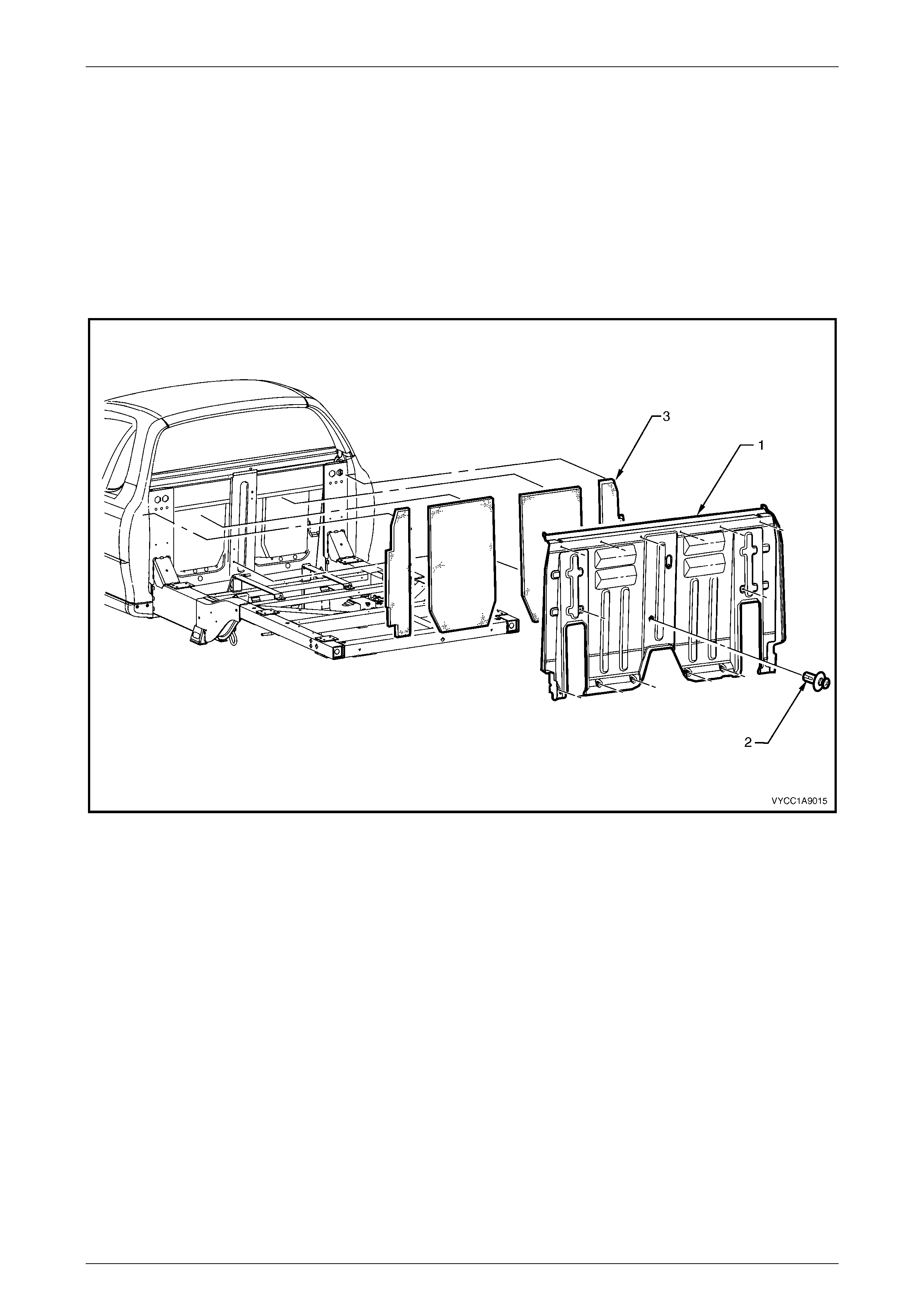
2.7 Rear Outer Trim Panel and NVH Foam
Remove
1 If fitted, remove the tray, refer to Section 1B1 Tray.
2 Remove the body side rear trim panel, refer to 2.4 Body Side Rear Trim Panel.
3 Remove the retainers (2) 16 places securing the rear outer trim panel (1) refer, Figure 1A9 – 8.
4 Carefully tilt the rear outer trim panel (1) backwards then lift it up to clear the body taking care not to dislodge the
NVH foam (3), refer to Figure 1A9 – 8.
Figure 1A9 – 8
5 If required remove the outer section of NVH foam (3), two places refer Figure 1A9 – 8.
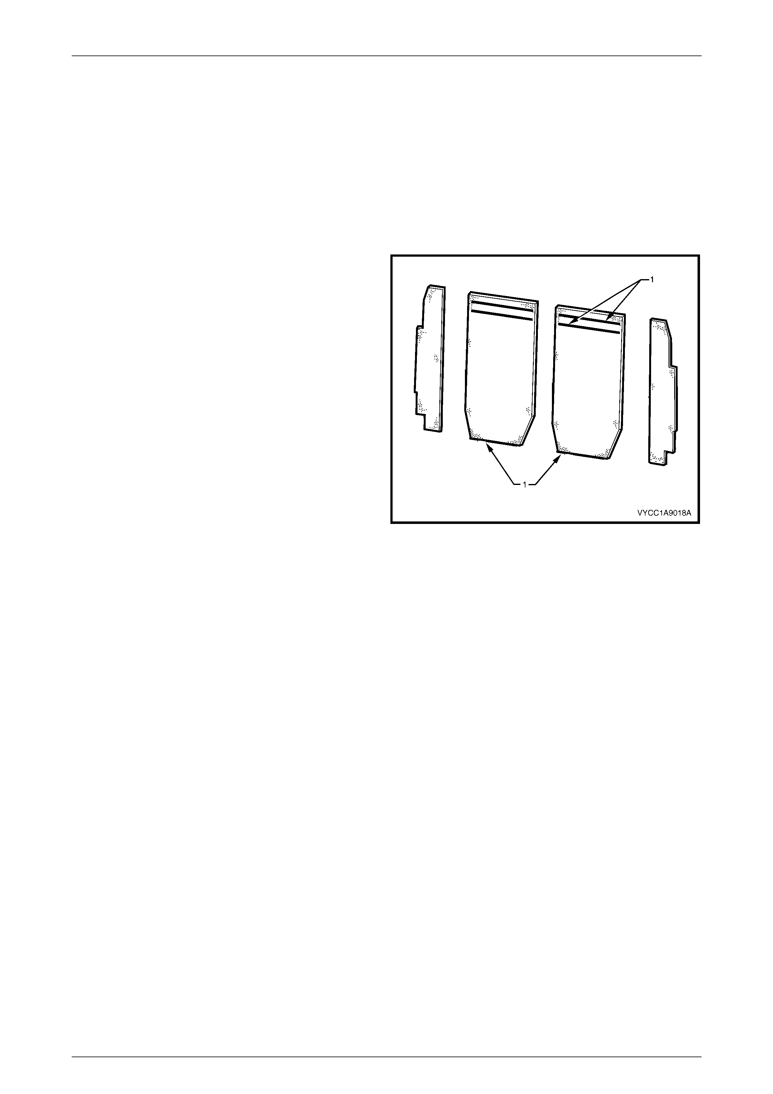
NOTE
The two centre pieces of NVH foam are glued in
place with hot melt adhesive. Care must be taken
not to tear the foam when removing.
6 Carefully pull the centre pieces of NVH foam, two places taking care not to tear the foam at the hot melt locations,
refer Figure 1A9 – 9.
Exterior Ornamentation Page 1A9–12
Page 1A9–12
Reinstall
NOTE
The NVH foam used is mirror cut for use on both
sides of the vehicle. The backing on the foam
used during the production process will only be
visible on one half of the vehicle when fitted
correctly.
1 Position the two outer NVH foam pieces into place, feeding the wiring harness through the slot in the lower corner
of the right-hand piece.
2 Apply two strips of hot melt glue (1) to the NVH foam
centre pieces. (2).
Figure 1A9 – 9
3 Position the centre piece of NVH foam two places to the rear of the cab, refer to Figure 1A9 – 8.
4 Slide the panel down into position and locate the centre datum pin.
5 Install the fasteners (2) 16 places, refer Figure 1A9 – 8.

Exterior Ornamentation Page 1A9–13
Page 1A9–13
3 Torque Wrench Specifications
Rocker Panel Moulding End Cap Screw.......................................1.0 – 3.0 N.m
Rear Window Side Moulding Attaching Screw..............................1.0 – 3.0 N.m
Body Side Rear Trim Panel Screw ...............................................1.0 – 3.0 N.m
Body Side Rear Trim Bracket Screw.............................................1.0 – 3.0 N.m
Rear Quarter Window Moulding Screw.........................................1.0 – 3.0 N.m