
Sheetmetal and Subfram e Page 1B–1
Page 1B–1
Section 1B
Sheetmetal & Subfram e
ATTENTION
Before performing any Service Operation or other procedure described in this Section, refer to Section 00
Warnings, Cautions And Notes for correct workshop practices with regard to safety and/or property damage.
1 General Information............................................................................................................................... 2
2 Service Operations................................................................................................................................3
2.1 Body Structure Replacement Parts......................................................................................................................3
Underbody ..............................................................................................................................................................4
Upperbody ..............................................................................................................................................................6
Body Assembly ......................................................................................................................................................8
2.2 Subframe Assembly.............................................................................................................................................10
Remove .................................................................................................................................................................10
Disassemble .........................................................................................................................................................12
Reassemble ..........................................................................................................................................................12
Reinstall ................................................................................................................................................................12
3 Torque Specifications ......................................................................................................................... 15

Sheetmetal and Subfram e Page 1B–2
Page 1B–2
1 General Information
With the following exception, MY 2003 VY Regular Cab Series sheetmetal information carries over from MY 2003 VY
Series vehicles.
• Body Structure Replacement Parts
• Subframe Assembly
The subframe is a unique design in that it features two forward uprights. In addition to the lower subframe attaching to the
cab, the uprights attach to the cab just below the rear window.
The subframe assembly is attached to the rear of the cab by way of bolts, nuts and stud plates, and although it is a
removable component, it is only serviced as a complete unit and not as individual components.
For information not contained within this Section, refer to Section 1B Sheetmetal in the MY 2003 VY and V2 Series Service
Information.

Sheetmetal and Subfram e Page 1B–3
Page 1B–3
2 Service Operations
2.1 Body Structure Replacement Parts
The following illustrations and tables describe the body structure assemblies and panels that are available for service
replacement.
The purpose of this information is to provide the repairer with a better understanding of available replacement sections.
For further information regarding the body structure, refer to the VY Regular Cab and Crew Cab Service Information
Supplement, Body Structure Repair.
Sheetmetal and Subfram e Page 1B–4
Page 1B–4
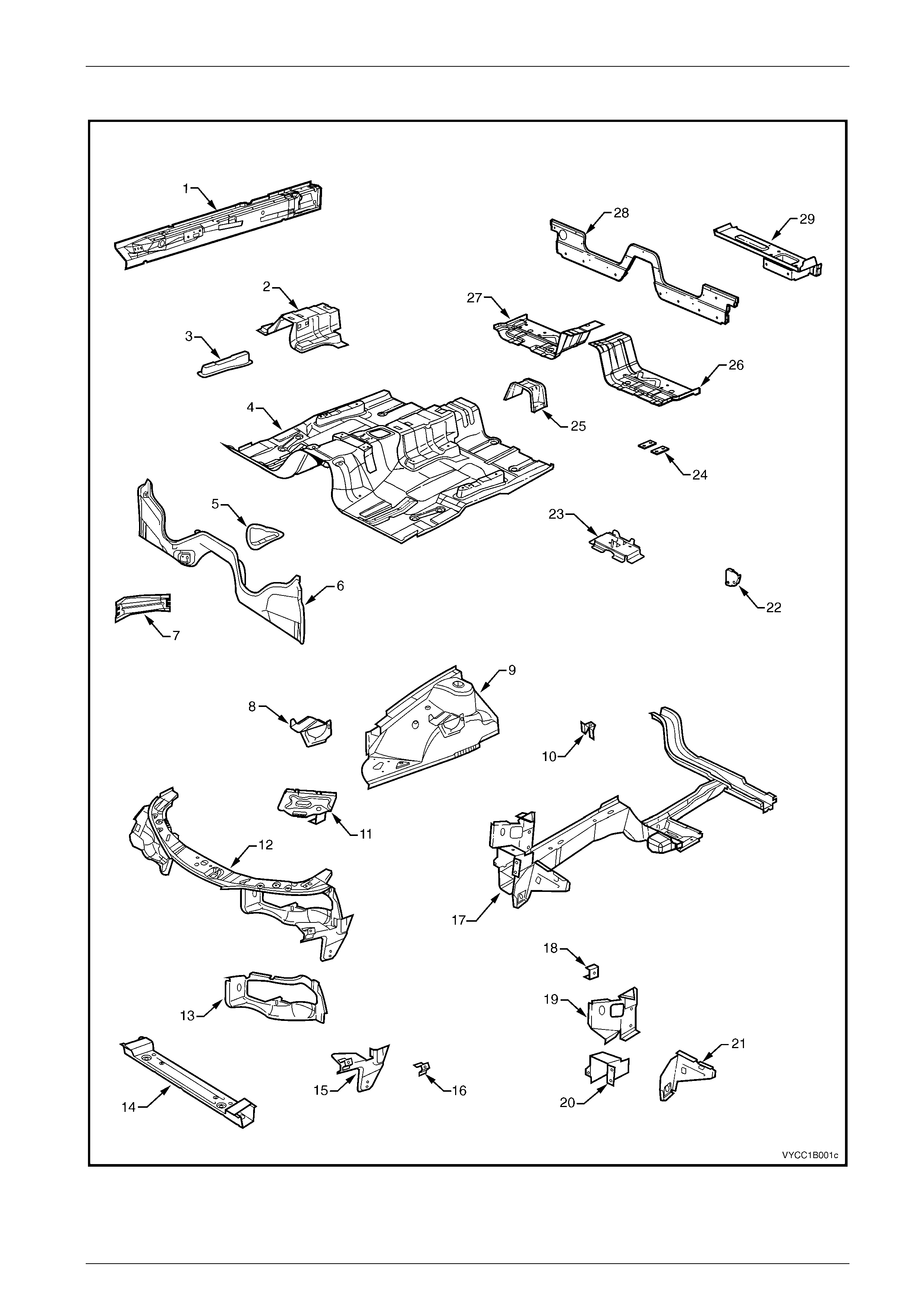
Underbody
Figure 1B – 1

Sheetmetal and Subfram e Page 1B–5
Page 1B–5
Legend
1 Inner Rocker Panel Assem bl y 16 Fender Front Lower Bracket, LH/ RH
2 Seat Inner Bracket Assem bly 17 Front Side Rail Assembly, LH/ RH
3 Seat Outer Bracket Ass embly, RH/ LH 18 Radiator Side Mounting B rack et, LH/ RH
4 Front Floor Panel Assembly 19 Front Wheelhouse Bracket Assembly, LH/ RH
5 Transmission Support Bracket, LH/ RH 20 Front Bumper Impact Bar Bracket, LH/ RH
6 Front Floor Panel Extension 21 Front Wheelhouse Panel Bracket, LH/ RH
7 Front Side Rail Brace, RH/ LH 22 Inner Rocker Panel Filler, LH/ RH
8 ABS Modulator Bracket Assembly 23 Jack Stowage Brack et
9 Front Wheelhouse Panel Assembly 24 Floor Panel Plate Assembly, two each LH/ RH
10 Horn Bracket Assembly 25 Propeller Shaft Hanger Assembly
11 Battery Tray Assembly 26 Front Floor Panel Extension, LH
12 Front End Panel Assembly 27 Front Floor Panel Extension, RH
13 Headlamp Panel, LH/ RH 28 Rear Lower Body Panel
14 Radiator Lower Support Ass embly 29 Rear Lower Body Panel Assem bly, LH/ RH
15 Headlamp & Front Fascia Mount Bracket, LH/ RH
Sheetmetal and Subfram e Page 1B–6
Page 1B–6
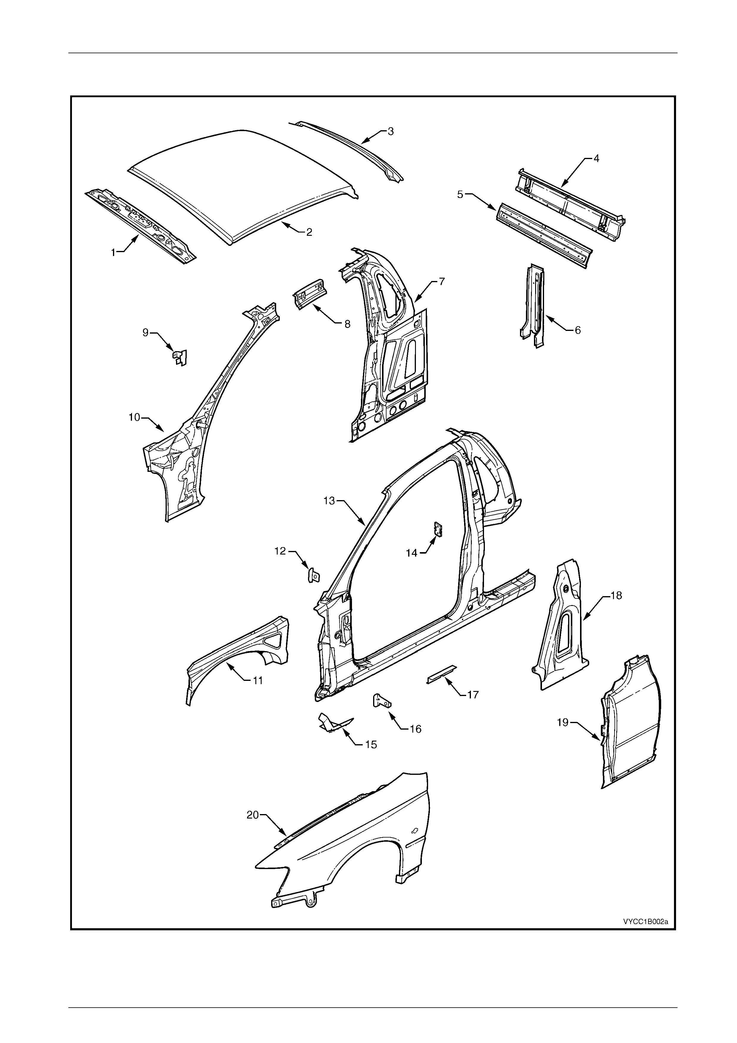
Upperbody
Figure 1B – 2

Sheetmetal and Subfram e Page 1B–7
Page 1B–7
Legend
1 Roof Front Header Panel 11 Front Wheelhouse Panel Upper Side Rail
2 Roof Panel 12 Fender Upper Rear Bracket
3 Roof Rear Header Panel 13 Door Opening Frame Assembly
4 Rear Body Upper Outer Panel Assem b l y 14 Door Striker A nchor Plat e
5 Rear Body Upper Inner Panel Assem bl y 15 Fender Lower Rear Bracket
6 Rear Body Lower Panel 16 Fender Rear Bracket
7 Quarter Panel Inner Assembl y 17 Underbody Jack i ng Locator
8 Quarter Panel Inner Extensi on 18 Quarter Panel Reinforc ement
9 Hinge Pillar Trim Panel Bracket 19 Quarter Panel
10 Hinge Pillar Inner Panel Assembly 20 Front Fender
Sheetmetal and Subfram e Page 1B–8
Page 1B–8
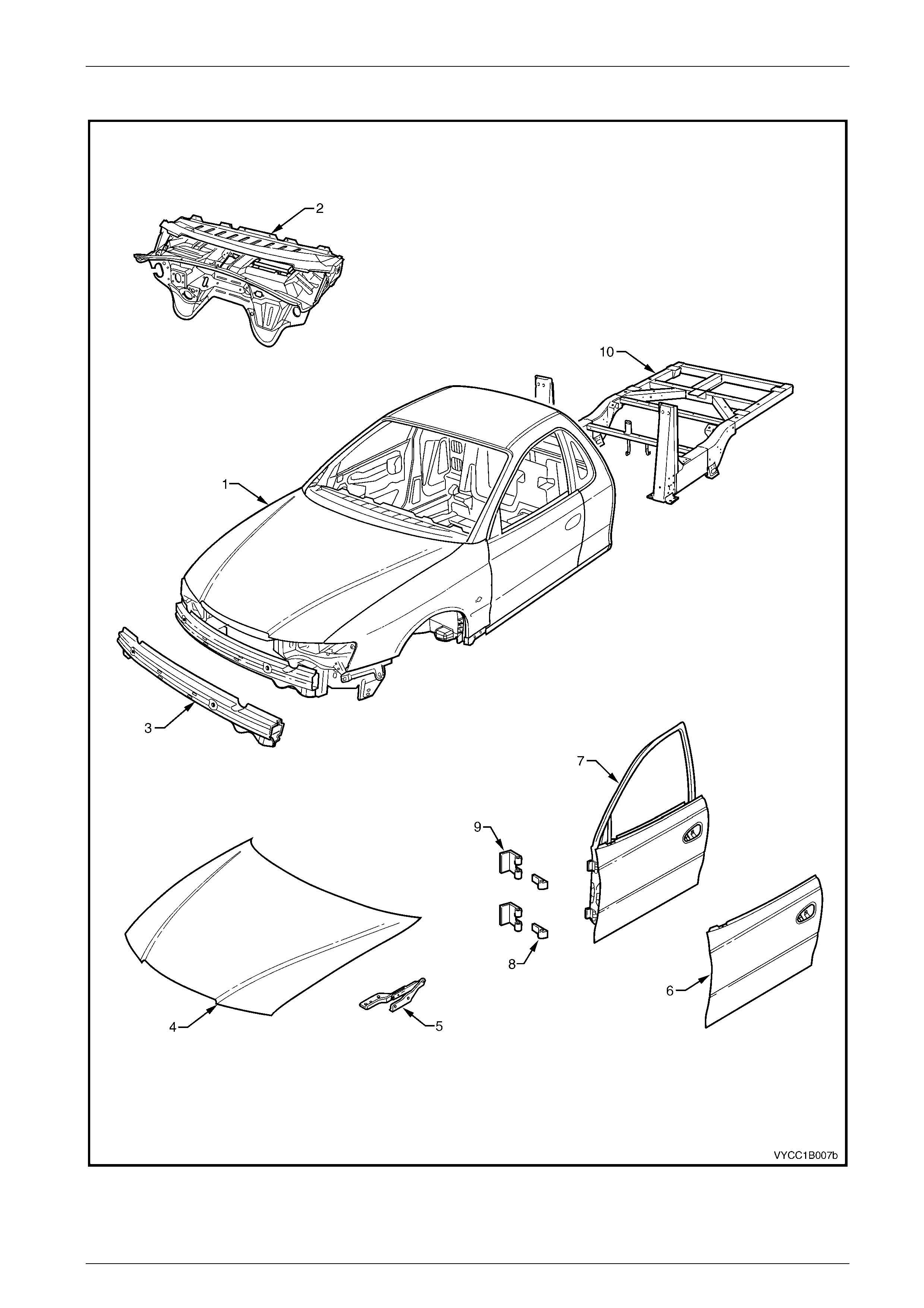
Body Assembly
Figure 1B – 3

Sheetmetal and Subfram e Page 1B–9
Page 1B–9
Legend
1 Body Assembly 6 Front Door Outer Panel
2 Dash Panel Assembly 7 Front Door Assembly
3 Front Bumper Impact Bar Assembly 8 Front Door Hinge (door side)
4 Hood Assembl y 9 Front Door Hinge (body side)
5 Hood Hinge Assembly 10 Subframe Assembly

Sheetmetal and Subfram e Page 1B–10
Page 1B–10
2.2 Subframe Assembly
Any collision that has damaged the subframe to the extent that it needs to be replaced, may have caused some
deformation to the cab structure and a complete thorough inspection and dimension check of the cab bodywork is
recommended.
Where a replacement of the subframe assembly is required, ancillary components will need to be removed from the
subframe. In this case it may be more convenient for the technician to remove these components while the subframe is still
assembled to the vehicle.
The vehicle may become unbalanced on stands
or a hoist once the subframe, rear axle or rear
suspension is removed. Ensure the cab and
subframe are supported sufficiently to avoid
injury or damage before proceeding.
Remove
1 If fitted, remove the tray, refer to Section 1B1 Tray.
2 If required, disconnect the wiring harness connectors for the rear lamps and remove the lamps, refer to Section 12B
Lighting System.
3 Disconnect the rear body wiring harness from the body wiring harness at the right-hand side, forward of the rear axle
and unattach the wiring harnesses as required, refer to Section 12O Fuses, Relays & Wiring Harnesses.
4 Remove the rear seat back body panel trim assembly, refer to Section 1A8 Headlining and Interior Trim.
5 Remove the body side rear trim panel, rear outer trim panel and the inner rear body panel, refer to Section 1A9
Exterior Ornamentation.
6 Disconnect and seal the fuel lines at the connectors located just behind the cab and, if required, remove the fuel
tank, refer to Section 8A1 Fuel Tank.
7 Disconnect the handbrake cable and brake lines, refer to Section 5A Service & Park Braking System.
8 If fitted, disconnect the rear ABS sensor leads, refer to Section 5B ABS.
9 Remove the rear and intermediate exhaust assemblies at the front to intermediate pipe flange joint(s), refer to
Section 8B Exhaust System.
NOTE
Once the propeller shaft has been removed from
the transmission, it may be necessary to fit a
blanking plug into the rear of the transmission to
prevent any loss of transmission fluid.
10 Remove the propeller shaft, refer Section 4C Propeller Shaft and Universal Joint.
NOTE
Removal of the rear suspension and axle
assemblies is not a mandatory requirement for the
removal of the subframe assembly. The rear
suspension and axle assembly may if required, be
removed from the subframe assembly as a
complete unit. If removed, support the subframe
with a suitable jack or lifting crane.
11 If required, remove the rear axle assembly, refer to Section 4B Rear Axle.
12 If required, remove the rear suspension assembly, refer to Section 4A Rear Suspension.
Sheetmetal and Subfram e Page 1B–11
Page 1B–11
13 Remove the noise reduction foam (1), four places from
between the subframe mounts and the cab. For further
information, refer to Section 1A9 Exterior
Ornamentation.
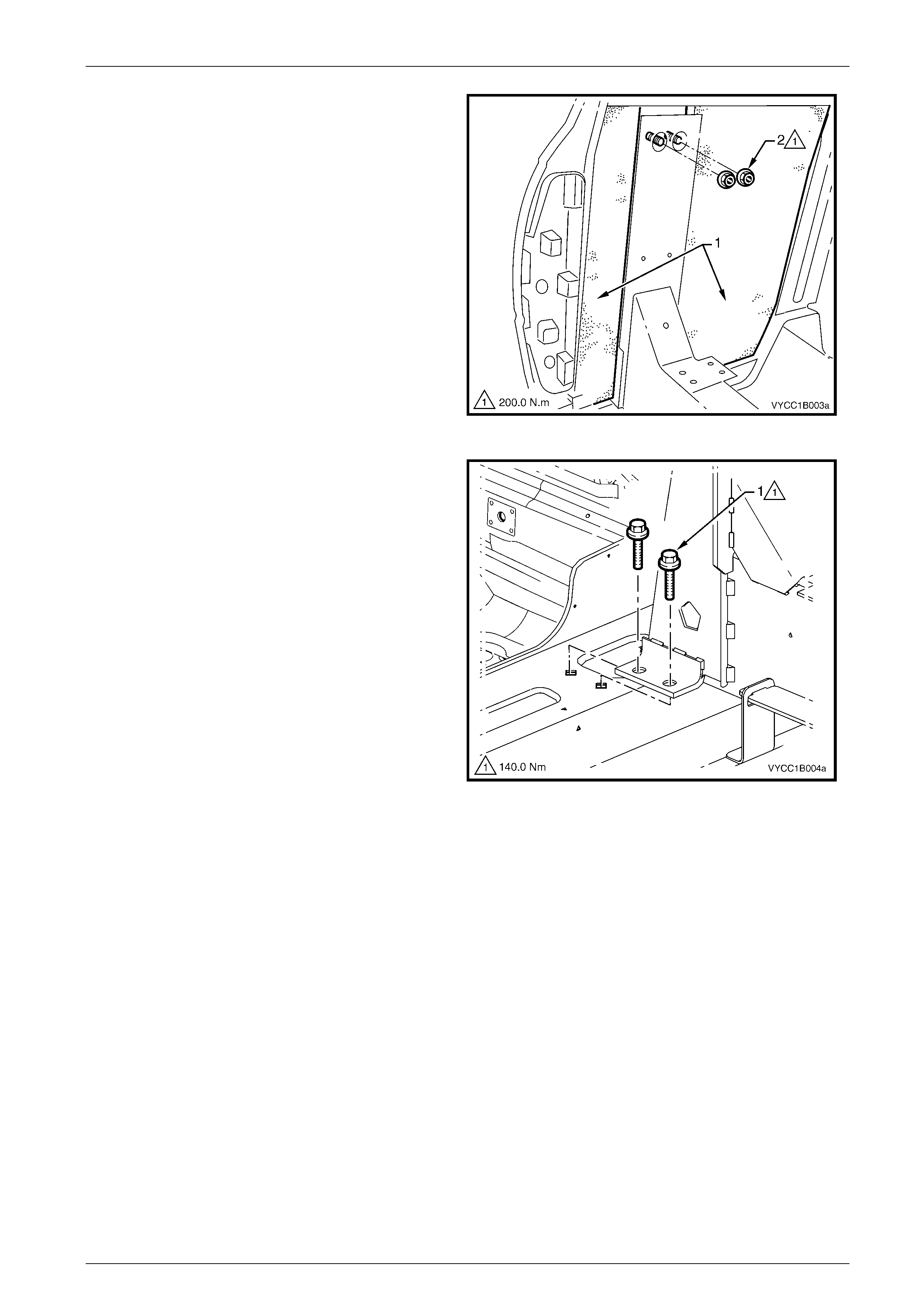
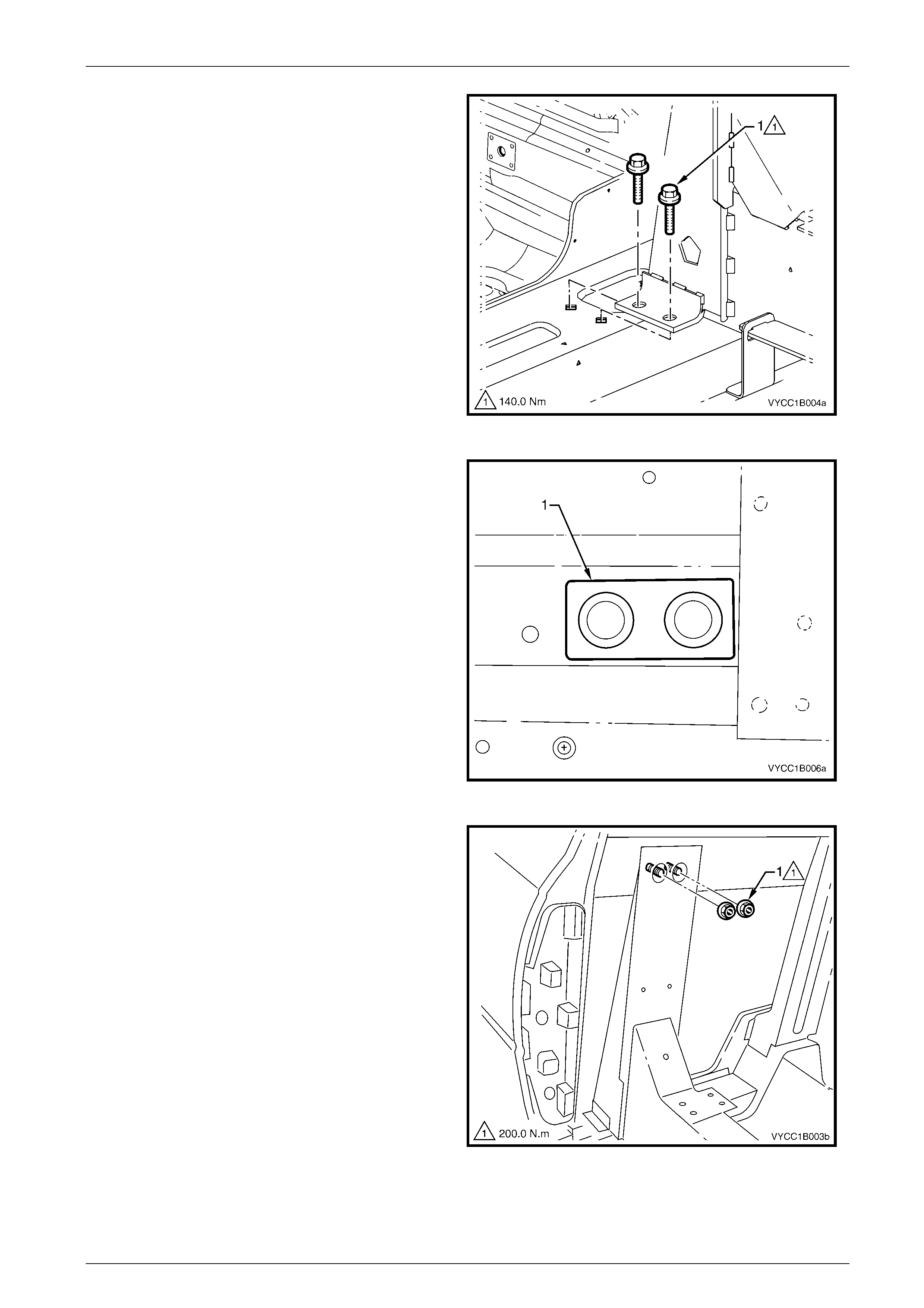
14 Remove the nut (2), two places either side, securing
the top stud plate to the subframe.
Figure 1B – 4
15 Remove the lower bolt (1), four places either side of
the vehicle, securing the subframe to the cab.
Figure 1B – 5
16 With the assistance of another person, remove the subframe from the cab by either lifting or rolling it clear of the cab,
refer to Figure 1B – 6.
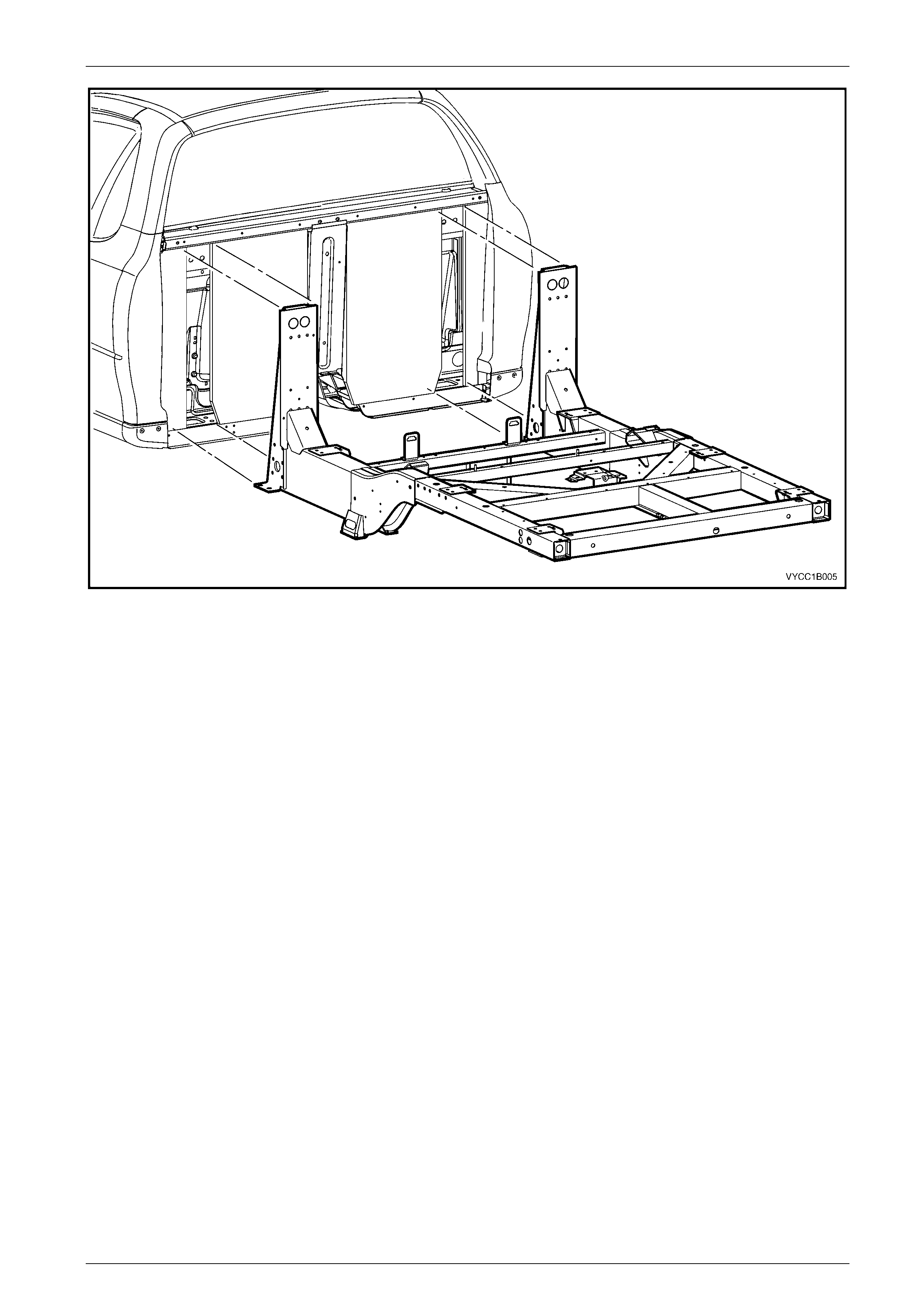
Sheetmetal and Subfram e Page 1B–12
Page 1B–12
Figure 1B – 6
Disassemble
If not already done, as required remove the following.
1 Remove the fuel tank, carbon canister, fuel filler neck, lower fuel tank straps, heat shield and the remaining fuel and
vapour lines attached to the subframe, refer to Section 8A1 Fuel Tank.
2 Remove the brake proportioning valve and the remaining rear brake lines, refer to Section 5A Service & Park Braking
System.
3 Remove the rear axle assembly, refer to Section 4B Final Drive and Drive Shafts.
4 Remove the rear suspension, shock absorbers and bump stops, refer to Section 4A Rear Suspension.
5 Remove the spare wheel winch, refer to Sectio n 10 Wheels & Tyres .
Reassemble
1 Reassemble the subframe components in the reverse order of the disassemble process. Follow the assembly
procedures in the Sections referred to for the relevant components.
Reinstall
1 With the assistance of another person and using a suitable jack or lifting devise, align the subframe assembly
squarely to the cab and position the subframe on to the mating surfaces of the cab lower cross member.
2 Slide the frame forward until the upper face contacts the back of the cab.
NOTE
When installing the mounting nuts and bolts do not
use any sealers or thread locking compounds on
the bolts, nuts or between the joints on the
subframe mounts.
Sheetmetal and Subfram e Page 1B–13
Page 1B–13
3 Insert the lower bolt (1), four places each side of the
vehicle but do not tighten.
Figure 1B – 7
4 From within the cab, install the stud plate (1) one place
each side of the vehicle, through the rear support
panel.
Figure 1B – 8
5 Install the top nut (1), two places each side for the stud
plate.
Figure 1B – 9

Sheetmetal and Subfram e Page 1B–14
Page 1B–14
NOTE
Support the subframe so that the weight does not
hang on the mounting points causing an adverse
effect on the tightening of the bolts.
6 Initially tighten all mounting fixtures to obtain the correct location of the subframe, ensuring there are no gaps at the
mounting points to the body.
7 Tighten the four lower mounting bolts in a diagonal pattern to the specified torque. Repeat for the other side of the
vehicle.
8 Tighten the two top mounting nuts to the specified torque. Repeat for the other side of the vehicle.
Subframe lower attaching bolts.......................140.0 Nm
Subframe top stud plate nuts...........................200.0 Nm
9 To ensure correct alignment of the subframe to the body, it is recommended that a check of the body dimensions is
performed, refer to Section 1A2 Body Dimensions.
10 Reinstall the remaining components in the reverse order to removal, referring to the appropriate Sections.
NOTE
To ensure that the vehicle’s steering and handling
is at its optimum performance, it is recommended
that a wheel alignment be performed after the
subframe assembly has been removed and refitted,
refer to Sec tion 3 Fr ont Suspension.

Sheetmetal and Subfram e Page 1B–15
Page 1B–15
3 Torque Specifications
Subframe lower mounting bolts ..........................................................140.0 Nm
Subframe top stud plate nuts..............................................................200.0 Nm