
Wheels and Tyres Page 10–1
Page 10–1
Section 10
Wheels and Tyres
ATTENTION
Before performing any Service Operation or other procedure described in this Section, refer to Section 00
CAUTIONS AND NOTES for correct workshop practices with regard to safety and/or property damage.
1 General Information............................................................................................................................... 2
1.1 Wheel and Tyre Combinations..............................................................................................................................2
1.2 Tyre Placards..........................................................................................................................................................4
1.3 Tyre Markings.........................................................................................................................................................5
1.4 Spare Wheel and Tool Stowage............................................................................................................................6
Tool Stowage..........................................................................................................................................................6
Spare Wheel Stowage............................................................................................................................................7
2 Service Operations................................................................................................................................ 8
2.1 Spare Wheel Hoist..................................................................................................................................................8
Remove ...................................................................................................................................................................8
Reinstall ..................................................................................................................................................................8
3 Specifications......................................................................................................................................... 9
Steel Wheels...........................................................................................................................................................9
Alloy Wheels...........................................................................................................................................................9
Inflation Pressures.................................................................................................................................................9
4 Torque Wrench Specifications........................................................................................................... 10
Techline
Wheels and Tyres Page 10–2
Page 10–2
1 General Information
With the following exceptions, MY 2003 VY Series Cab Chassis Wheel and Tyre information carries over from MY 2003
VY Series vehicles. For information not covered within this Section, refer to Section 10, Wheels And Tyres in the MY
2003 VY and V2 Series Service Information.
• The spare wheel hoist mounting and access is unique.
• The stowage of the jack, jack/wheel nut wrench and hoist crank handle is unique.
• The steel wheel as fitted to cab chassis base models is unique to accommodate the increased load carrying
requirements.
• The alloy wheel as fitted to cab chassis ‘S’ Pack is unique to accommodate the increased load carrying
requirements.
• The tyres as fitted to all cab chassis models are unique to accommodate the increased load carrying requirements.
1.1 Wheel and Tyre Combinations
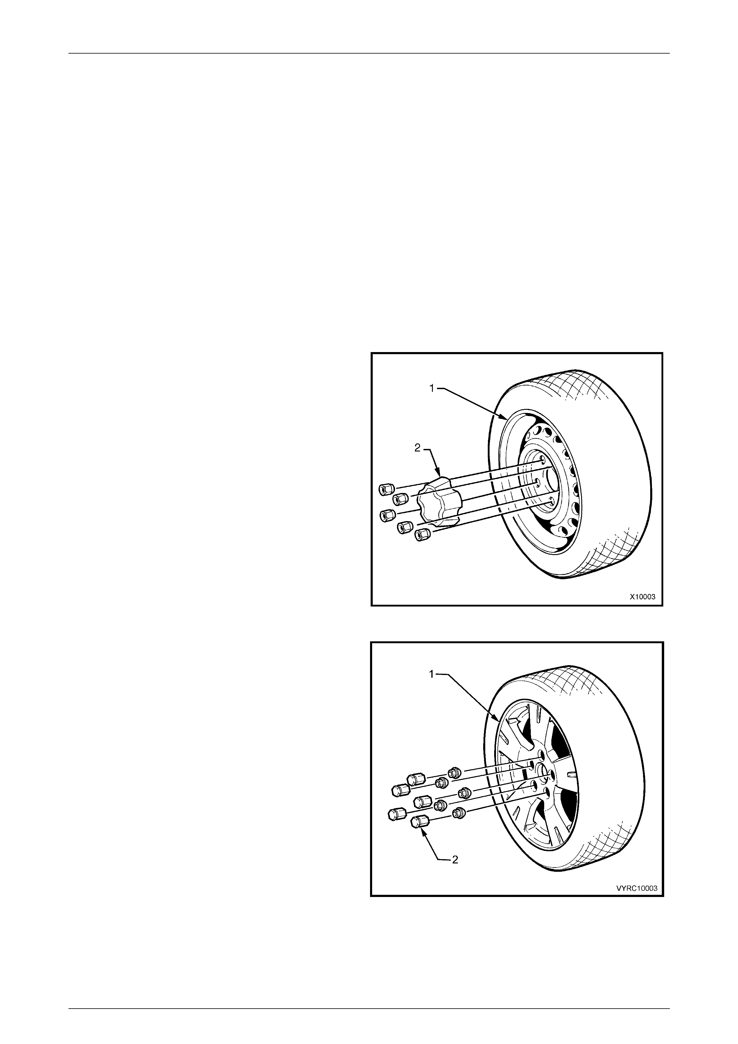
Figure 10-1 illustrates the silver steel wheel (1) and centre
cap (2) fitted as standard equipment to the MY 2003 VY
Series Cab Chassis Base Models.
Road wheels 7J x 15
Tyres 215/65R15C 104R
Figure 10-1
Figure 10-2 illustrates the alloy wheel (1) and centre cap (2)
fitted as standard equipment to MY 2003 VY Series Cab
Chassis ‘S’ Pack.
Road Wheels 7J x 16 alloy
Tyres 215/65R16C 106R
Figure 10-2
Wheels and Tyres Page 10–3
Page 10–3
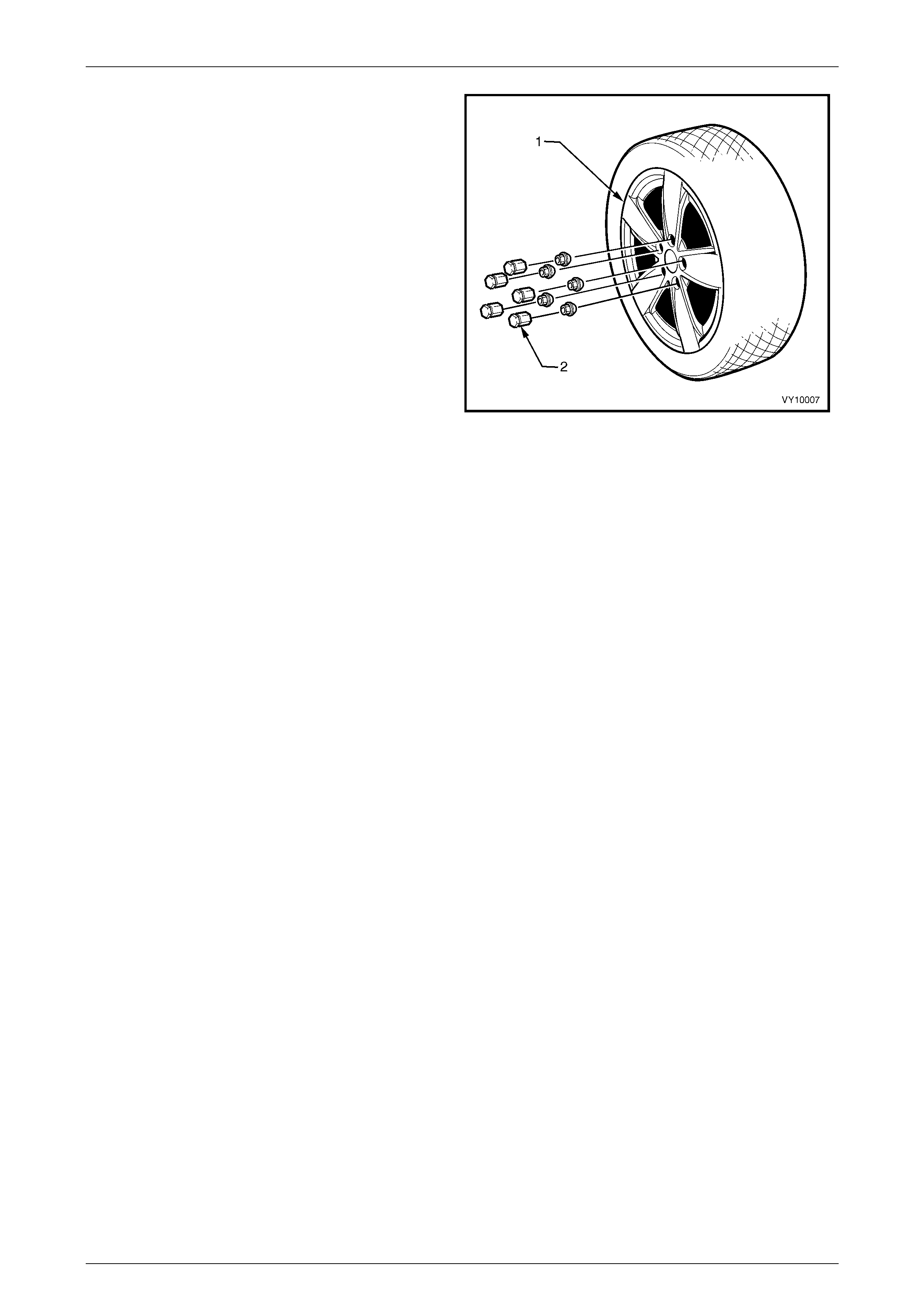
Figure 10-3 illustrates the alloy wheel (1) and centre cap (2)
fitted as standard equipment to the MY 2003 VY Series
Cab Chassis ‘SS’ Pack.
Road Wheels 8J x 17 alloy
Tyres 225/55R17 97H
Figure 10-3
Wheels and Tyres Page 10–4
Page 10–4
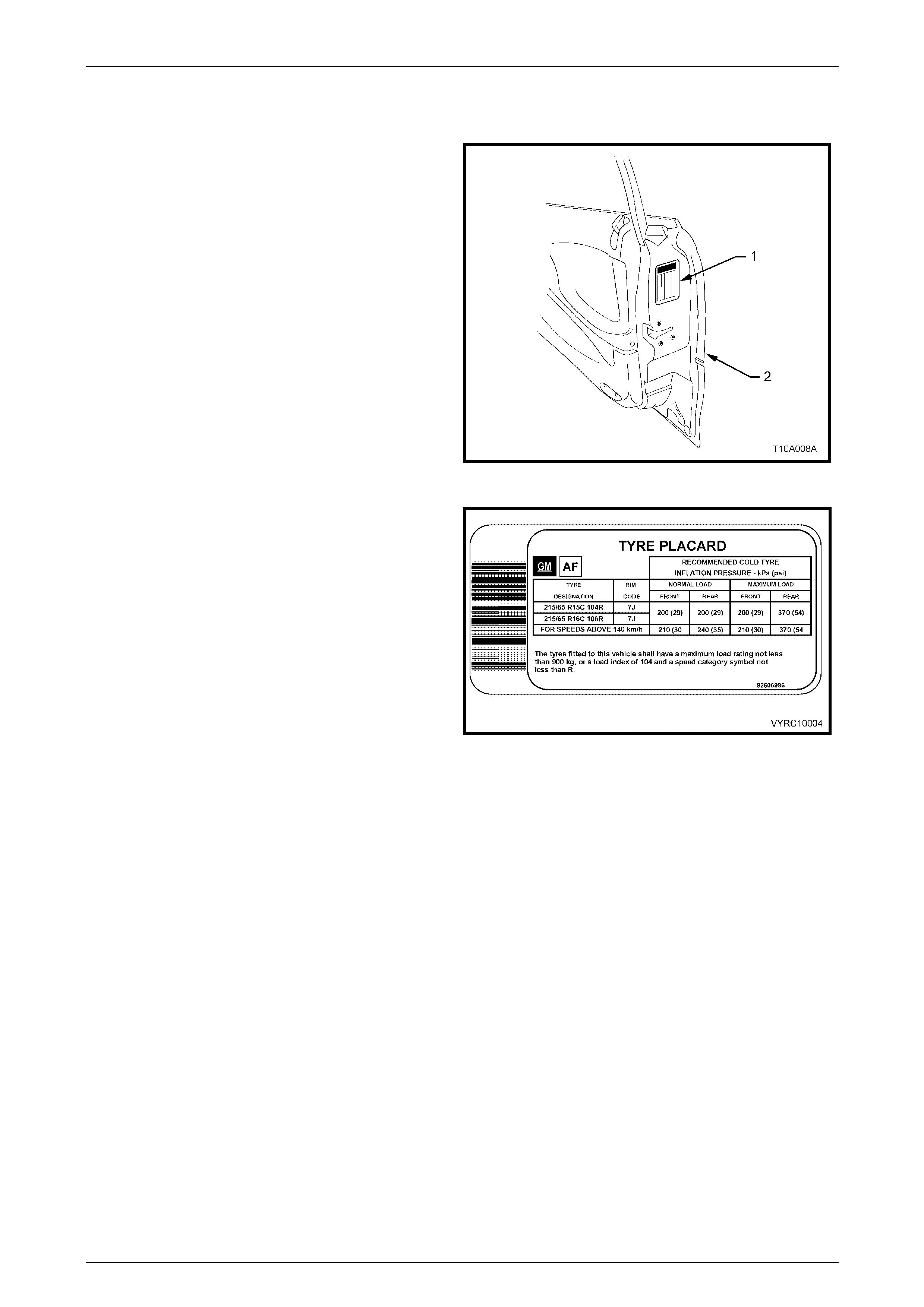
1.2 Tyre Placards
Wheel and tyre sizes, inflation pressures and load capacity
are specified on a tyre placard (1) located on the end
surface of the driver door (2).
Always check tyre pressures, with COLD tyres (after
vehicle has stood for three hours or more, or driven less
than 2 km) and should be checked weekly or before any
extended trip.
When checking ty re pressur e, v isual ly inspect tyres for
excessive wear, sharp objects embedded in the tyre or
damage to the sidewalls.
NOTE
Clean valve exterior, prior to applying air pressure nozzle
when inflating tyre.
NOTE
Always install valve caps to keep out dust and water.
Figure 10-4
The tyre placard shown in Figure 10-5 is typical of those
fitted to MY 2003 VY Series Cab Chassis Models.
Refer to 3. Specifications in this Section or the vehicle
tyre placard for the correct wheel/tyre size and
corresponding tyre inflation pressures.
Figure 10-5
Wheels and Tyres Page 10–5
Page 10–5
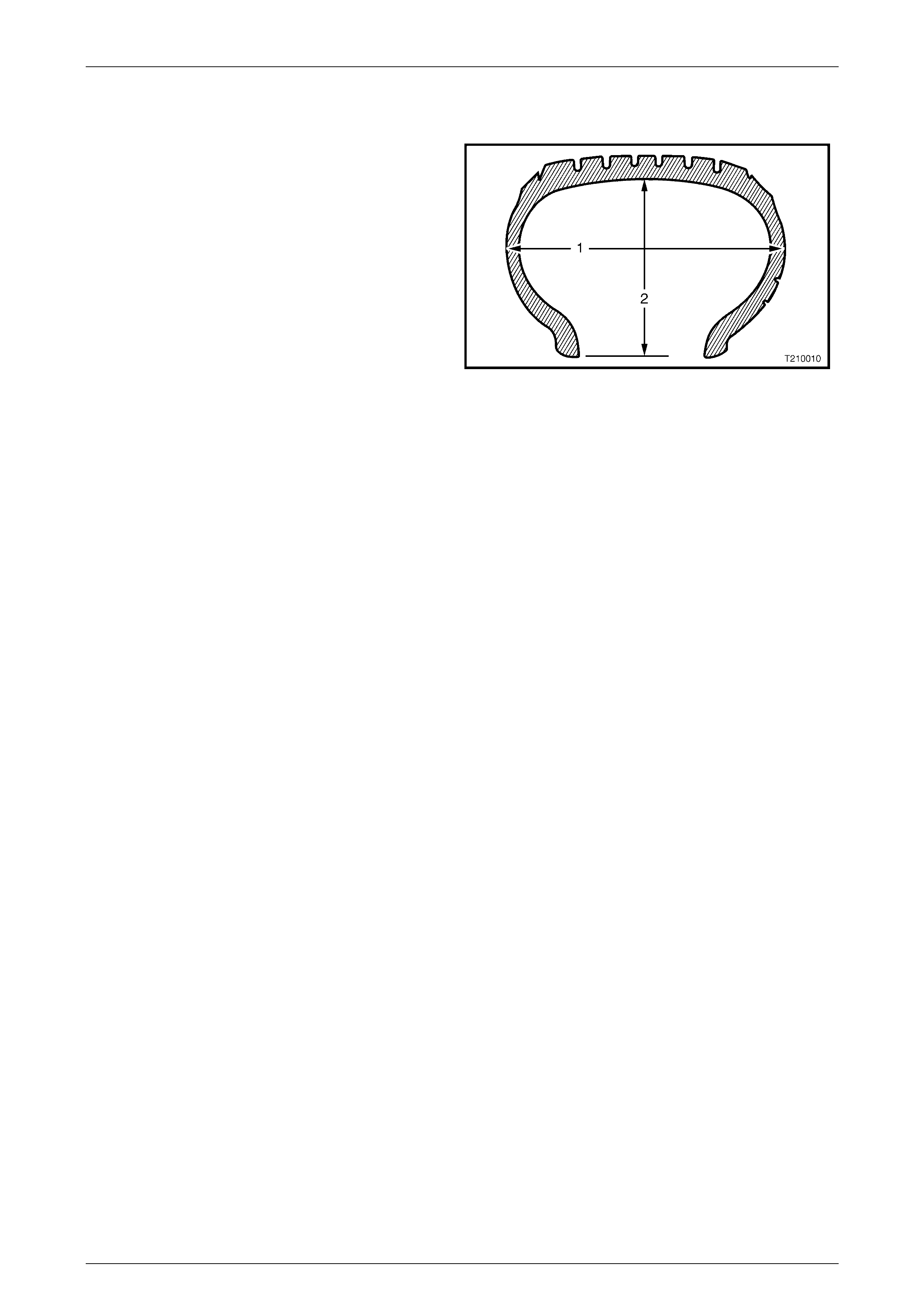
1.3 Tyre Markings
The tyre sidewall has a coded mark ing system, w hich
provides information about the tyre.
Tyre Marking Example:
215 65 R 15 C 104 R
215 = Section Width (1) – mm (215 mm)
65 = Aspect Ratio % i.e.Section Height (2) to
Section Width (1)
(55 = 55%)
(60 = 60%)
(65 = 65%)
R = Tyre Construction
(R = Radial)
15 = Rim Diameter – inches
(15 = 15”)
(16 = 16”)
(17 = 17”)
C = Service Application Code
(C or LT = Light Truck or Multi-purpose
Passenger Vehicle)
NOTE
Some European and Japanese light truck tyres
use C instead of LT for the same purpose.
104 = Load Index – kg @ 250 kPa (36 psi) cold
inflation pressure
(97 = 730 kg max. load)
(104 = 900 kg max. load)
(106 = 950 kg max. load)
R = Speed Rating
(R = 170 km/h)
(H = 210 km/h)
Figure 10-6
Wheels and Tyres Page 10–6
Page 10–6
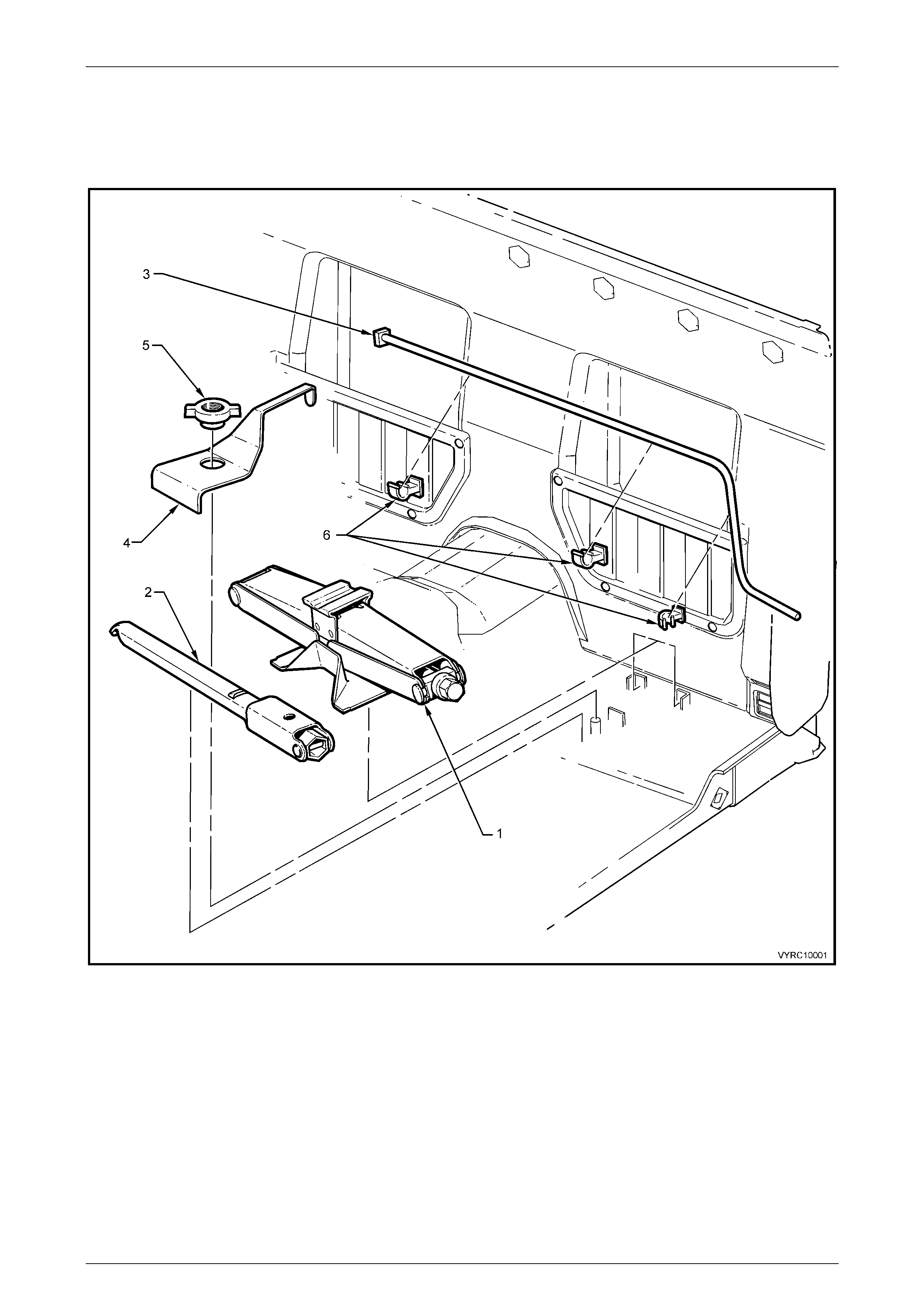
1.4 Spare Wheel and Tool Stowage
Tool Stowage
Figure 10-7
Legend
1 Jack Assembly
2 Jack and Wheel Nut Wrench
3 Spare Wheel Hoist Crank Handle
4 Jack and Handle Trim Cover
5 Trim Cover Retaining Nut
6 Crank Handle Retainers
Wheels and Tyres Page 10–7
Page 10–7
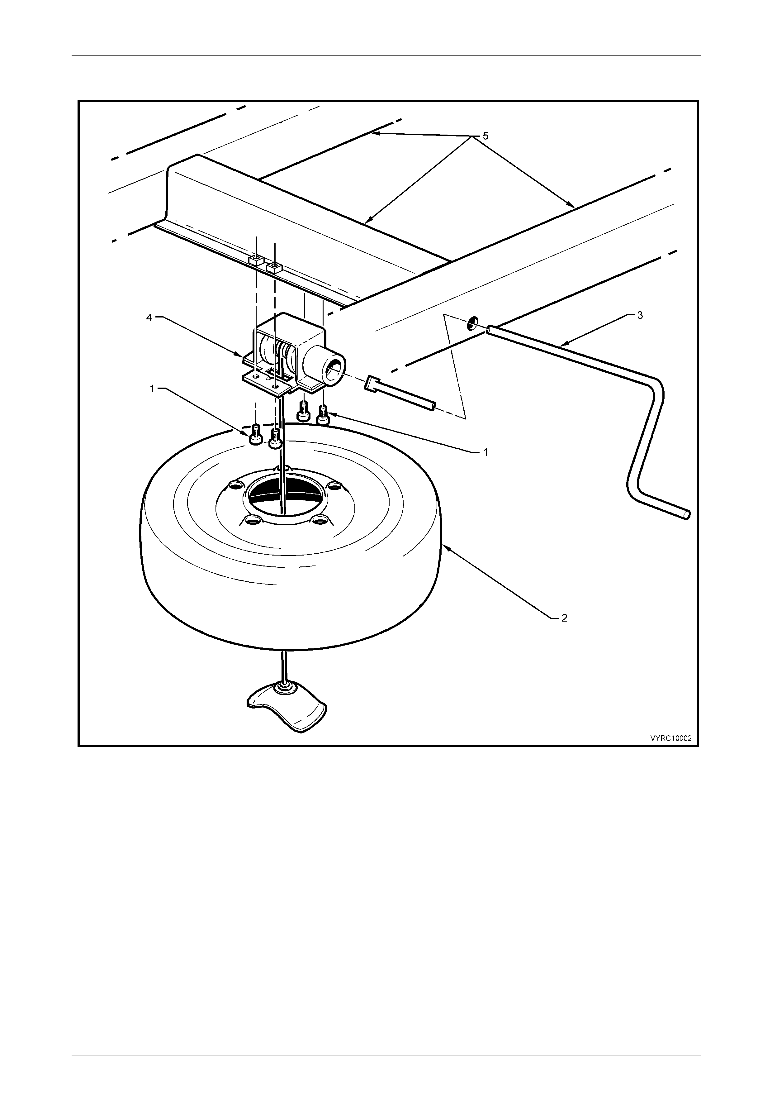
Spare Wheel Stowage
Figure 10-8
1 Spare Wheel Hoist Attaching Bolts (4 places)
2 Spare Wheel
3 Spare Wheel Hoist Crank Handle
4 Spare Wheel Hoist
5 Rear Frame Assembly
Wheels and Tyres Page 10–8
Page 10–8
2 Service Operations
2.1 Spare Wheel Hoist
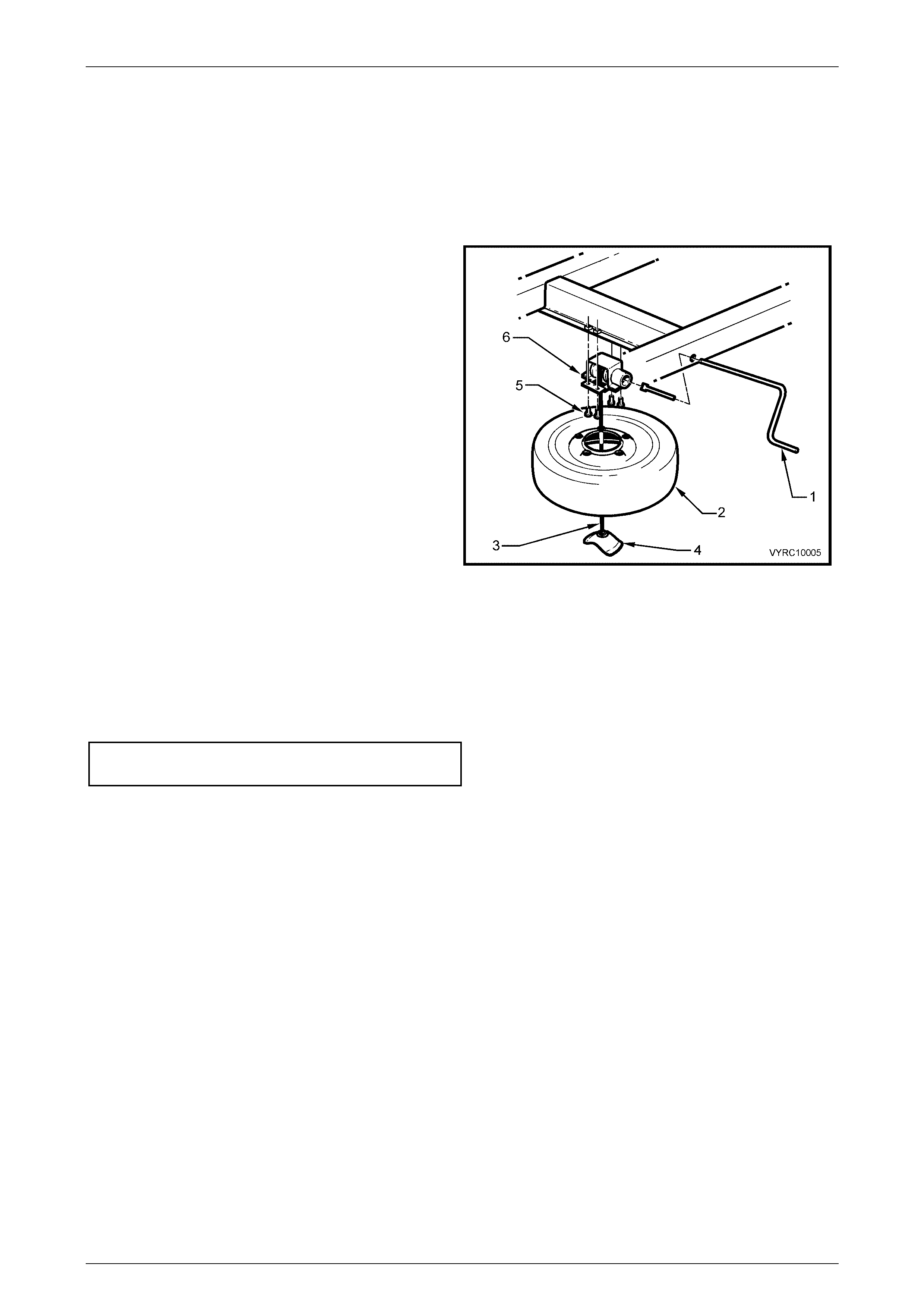
Remove
1 Insert the spare wheel hoist crank handle (1) into the
aperture located at the rear of the vehicle.
2 Rotate the handle in a counter-clockwise direction
until the spare wheel (2) is completely lowered and
some slack exists in the spare wheel hoist
cable (3).
3 Support the spare wheel with one hand, and tilt the
wheel retainer (4) upward, then feed the retainer
through the wheel centre.
4 Remove the spare wheel from below the vehicle.
5 Remove the four screws (5) and lower the hoist
assembly (6) from the vehicle.
Figure 10-9
Reinstall
Installation of the spare wheel hoist is the reverse of the removal procedure, noting the following:.
• Ensure that the hoist is installed with the square coupling towards the rear of the vehicle.
• Tighten the hoist-attaching screws to the correct torque specification.
SPARE WHEEL HOIST ATTACHING
SCREW TORQUE SPECIFIC ATION ...........15 – 35 Nm

Wheels and Tyres Page 10–9
Page 10–9
3 Specifications
Steel Wheels
Rim Width Code
All Steel Wheels....................................................................................................................7J
Diameter Code
All Steel Wheels................................................................................................................... 15
Maximum Permissible Radial Run-out
All Steel Wheels........................................................................................................... 1.5 mm
Maximum Permissible Lateral Run-out
All Steel Wheels........................................................................................................... 1.5 mm
Offset
All Steel Wheels.............................................................................................43 mm (positive)
Al l oy Wheels
Rim Width Code
‘S’ Pack.................................................................................................................................7J
‘SS’ Pack...............................................................................................................................8J
Diameter Code
‘S’ Pack................................................................................................................................ 16
‘SS’ Pack.............................................................................................................................. 17
Maximum Permissible Radial Run-out
All Alloy Wheels........................................................................................................... 1.5 mm
Maximum Permissible Lateral Run-out
All Alloy Wheels........................................................................................................... 1.5 mm
Offset
All Alloy Wheels.............................................................................................48 mm (positive)
Inflation Pressures
RECOMMENDED COLD INFLATION –
kPa
MODEL WHEEL TYRE DESIGNATION
Up to 3
Passengers Up to Max. Load
Front Rear Front Rear
Base 7J x 15 Steel 215/65 R15C 104R 200 200 200 370
‘S’ Pack 7J x 16 Alloy 215/65 R16C 106R 200 200 200 370
‘SS’ Pack 8J x 17 Alloy 235/45 R17 97H 200 200 220 280

Wheels and Tyres Page 10–10
Page 10–10
4 Torque Wrench Specifications
Nm
Spare Wheel Hoist to Frame Attaching Screw.......................................15 – 35
Road Wheel Attaching Nut (All Wheels)............................................110 – 140