
HVAC Climate Control (Manual A/C) – Descri pt i o n and Operation Page 2A–1
Page 2A–1
Section 2A
HVAC Climate Control (Manual A/C)
Description and Operati on
ATTENTION
Before performing any Service Operation or other procedure described in this Section, refer to Section 00
Warnings, Cautions and Notes for correct workshop practices with regard to safety and/or property damage.
1 General Information............................................................................................................................... 2
2 General Description............................................................................................................................... 3
2.1 Cabin Ventilation....................................................................................................................................................3
2.2 Cooling Fans...........................................................................................................................................................4
V6 Models................................................................................................................................................................4
GEN III V8 Models...................................................................................................................................................4
3 Specifications......................................................................................................................................... 5
Cooling Fan System – V6.......................................................................................................................................5
Engine Cooling Fan 1 (LHS)...............................................................................................................................5
Engine Cooling Fan 2 (RHS)..................................................................................................... .........................5
Engine Cooling Fan Motors – Consta nt Current.................................................................................................5
Cooling Fan System – GEN III V8..........................................................................................................................6
Engine Cooling Fan 1 (LHS)...............................................................................................................................6
Engine Cooling Fan 2 (RHS)..................................................................................................... .........................6
Engine Cooling Fan Motors – Constant Current.................................................................................................6
Techline

HVAC Climate Control (Manual A/C) – Descri pt i o n and Operation Page 2A–2
Page 2A–2
1 General Information
The basic HVAC system as fitted to MY 2003 VY Regular Cab vehicles is carried over from previously released MY 2003
VY Series utility vehicles. HVAC Climate Control (Manual A/C) is fitted as a regular available option. Occupant Climate
Control (Auto A/C) is not available. The following design and specification changes have been made to adapt the HVAC
system to Regular Cab model applications:
• The body ventilation outlet installation locations are unique to Regular Cab vehicles.
• All V6 Regular Cab vehicles use the same high power cooling fan system as fitted to left-hand drive VY Series
sedan, wagon and utility models.
• All GEN III V8 Regular Cab vehicles are fitted with a modified cooling fan system. The power rating of the fan
motors has been increased and a different cooling fan operating strategy applies.
Ventilation related modifications are detailed in this Section. For all other information regarding the description and
operation of the heating and ventilation system, refer to Section 2A HVAC Climate Control (Manual A/C) – Description
and Operation in the MY 2003 VY and V2 Series Service Information.
Modifications and specifications relating to the cooling system on GEN III V8 Regular Cab vehicles are highlighted in this
Section. For more comprehensive information relating to the cooling system on GEN III V8 Regular Cab vehicles, refer to
Section 6B3 Engine Cooling.
HVAC Climate Control (Manual A/C) – Descri pt i o n and Operation Page 2A–3
Page 2A–3
2 General Description
2.1 Cabin Ventilation
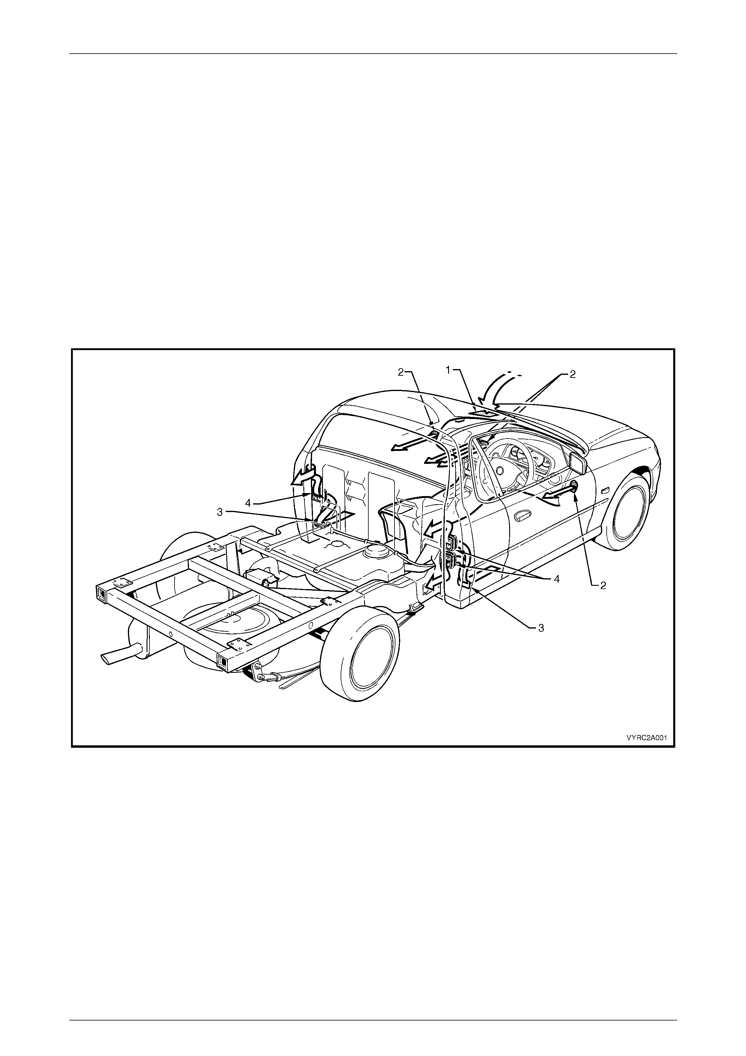
Air enters the heating, ventilation and air conditioning system (HVAC) from under the plenum chamber cover. The air
then passes through the blower motor / fan, evaporator and heater assemblies, to be cooled or heated as required. Air
leaves the HVAC unit and enters the vehicle interior through the centre, side, floor or demist outlets. The cabin outlets
through which the air is emitted is dependent upon the mode selected via the mode control.
When the cabin is sealed, i.e. both movable windows are fully up, air exits the cabin through two rectangular apertures
located in the seat back body panel trim assembly below the body ventilation outlets. These outlets are installed into the
rear inner panel. Two outlets are located on the right-hand side of the cabin and one is located on the left-hand side of
the cabin After passing through the body ventilation outlets, the air enters the cavity between the inner rear body panel
and the rear outer trim panel. It leaves the vehicle via a small air gap located around the entire lower and side perimeters
of the rear outer trim panel. Refer to Figure 2A – 1.
The installation, function and performance of all other HVAC related components (excluding the operation and increased
power rating of the cooling fan system on GEN III V8 models) are identical to MY 2003 VY Series vehicles.
Figure 2A – 1
Legend
1 HVAC Plenum Inlet 3 Airflow Aperture
2 HVAC Cabin Air Outlet 4 HVAC Body Air Outlet
HVAC Climate Control (Manual A/C) – Descri pt i o n and Operation Page 2A–4
Page 2A–4
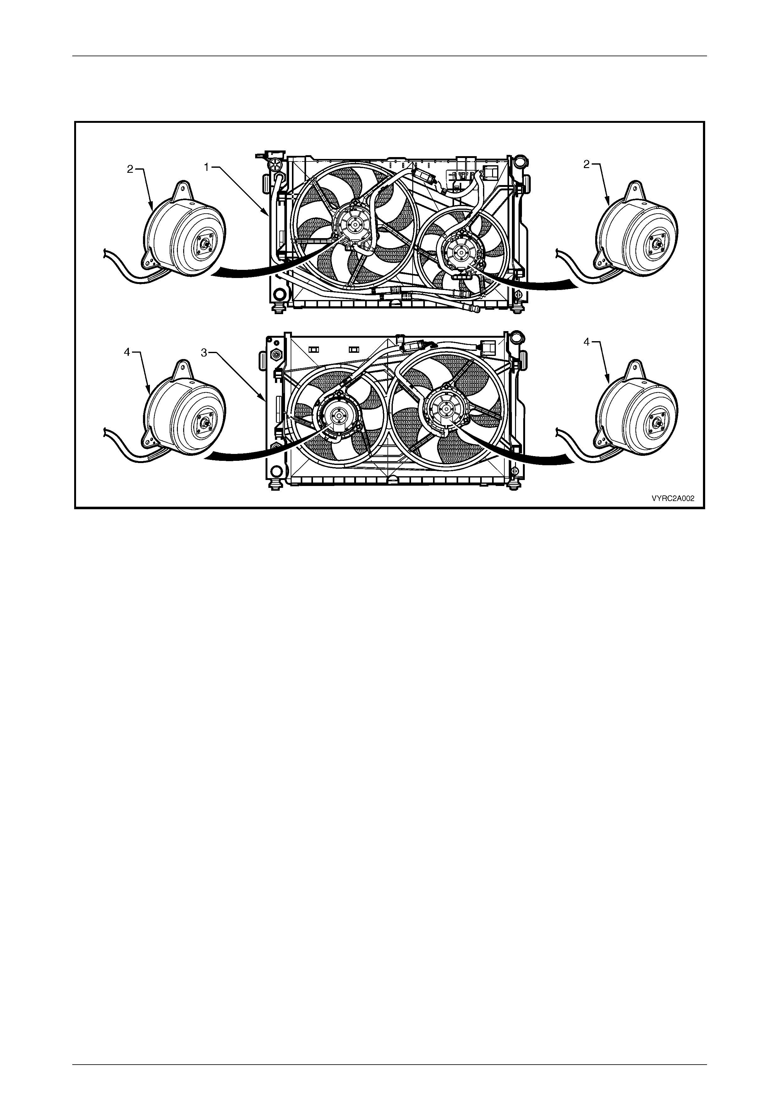
2.2 Cooling Fans
Figure 2A – 2
Legend
1 V6 Radiat or and High Power Cooling Fan System 3 GEN III V8 Radiator and Cooling Fan Syst em
2 V6 High Power Fan Motors – Dual Speed, 400 Watts Total 4 GEN III V8 High Power Fan Motors – Dual Speed, 430 Watts
Total
To accommodate higher in-service performance requirements anticipated for Regular Cab models, the cooling fan
system specifications have been altered as follows:
V6 Models
All V6 Regular Cab models use the same cooling fan system as fitted to V6 LHD VY Series sedan, wagon and utility
models. This system consists of two high power cooling fan motors. The motors are dual speed types and have a
combined power rating of 400 Watts. The cooling system operates as follows:
1st stage – both fans operate at low speed
2nd stage – both fans operate at high speed
For all other information regarding the description and operation this cooling fan system, refer to the V6 High Power
cooling fan system information in Section 2A, 2.9 Cooling Fans in the MY 2003 VY and V2 Series Service Information.
GEN III V8 Models
All GEN III V8 Regular Cab models are fitted with an up rated cooling fan system . This system consists of two high
power cooling fan motors. The motors are dual-speed types and have a combined power rating of 430 Watts. The
cooling fan dimensions remain unaltered. The cooling system operates as follows:
1st stage – both fans operate at low speed (in series)
2nd stage – both fans operate at high speed (in parallel)
For further information relating to the cooling system on GEN III V8 Regular Cab models, refer to Secti on 6B3 Engine
Cooling.
For all other information regarding the description and operation this cooling fan system, refer to the GEN III V8 cooling
fan system information in Section 2A, 2.9 Cooling Fans in the MY 2003 VY and V2 Series Service Information.

HVAC Climate Control (Manual A/C) – Descri pt i o n and Operation Page 2A–5
Page 2A–5
3 Specifications
Cooling Fan System – V6
Engine Cooling Fan 1 (LHS)
Fan
Design......................................................................Symmetric, curved blades with outer ring
Materia...............................................................Polyamide, with zinc coated metal hub insert
Number of blades................................................................................................................... 8
Diameter of blades ..................................................................................................... 365 mm
Diameter of outer ring ................................................................................................. 384 mm
Fan motor
Manufacturer.....................................................................................................................Gate
Model..........................................................................................................................MP8125
Type...............................................................Dual speed, 4 brush and 4 permanent magnets
Housing............................................................Semi-sealed, zinc coated steel with drain hole
Direction of rotation............................................. Anti-clockwise (viewed from fan motor side)
Rotational speed – Stage 1............................................................................2000 ± 150 rpm*
Rotational speed – Stage 2............................................................................2300 ± 150 rpm*
Power......................................................................................................220 Watts (nominal)*
Engine Cooling Fan 2 (RHS)
Fan
Design.....................................................................Symmetric, curved blades, with outer ring
Material..............................................................Polyamide, with zinc coated metal hub insert
Number of blades................................................................................................................... 8
Diameter of blades...................................................................................................... 263 mm
Diameter of outer ring ................................................................................................. 280 mm
Fan motor
Manufacturer.....................................................................................................................Gate
Model..........................................................................................................................MP8120
Type...............................................................Dual speed, 4 brush and 4 permanent magnets
Housing............................................................Semi-sealed, zinc coated steel with drain hole
Direction of rotation............................................. Anti-clockwise (viewed from fan motor side)
Rotational speed – Stage 1............................................................................2350 ± 150 rpm*
Rotational speed – Stage 2............................................................................2700 ± 150 rpm*
Power......................................................................................................180 Watts (nominal)*
Engine Cooling Fan Motors – Constant Current
Stage 1...........................................................................................................25 – 27.5 Amps*
Stage 2..............................................................................................................31 – 34 Amps*

HVAC Climate Control (Manual A/C) – Descri pt i o n and Operation Page 2A–6
Page 2A–6
Cooling Fan System – GEN III V8
Engine Cooling Fan 1 (LHS)
Fan
Design...................................................................Asymmetric, curved blades, with outer ring
Material..............................................................Polyamide, with zinc coated metal hub insert
Number of blades................................................................................................................... 5
Diameter of blades ..................................................................................................... 275 mm
Diameter of outer ring ................................................................................................. 298 mm
Fan motor
Manufacturer.....................................................................................................................Gate
Model..........................................................................................................................MP8120
Type...............................................................Dual speed, 4 brush and 4 permanent magnets
Housing............................................................Semi-sealed, zinc coated steel with drain hole
Direction of rotation............................................. Anti-clockwise (viewed from fan motor side)
Rotational speed – Stage 1............................................................................1700 ± 150 rpm*
Rotational speed – Stage 2............................................................................3000 ± 150 rpm*
Power......................................................................................................215 Watts (nominal)*
Engine Cooling Fan 2 (RHS)
Fan
Design...................................................................Asymmetric, curved blades, with outer ring
Material..............................................................Polyamide, with zinc coated metal hub insert
Number of blades................................................................................................................... 5
Diameter of blades ..................................................................................................... 336 mm
Diameter of outer ring ................................................................................................. 355 mm
Fan motor
Manufacturer.....................................................................................................................Gate
Model..........................................................................................................................MP8125
Type...............................................................Dual speed, 4 brush and 4 permanent magnets
Housing............................................................Semi-sealed, zinc coated steel with drain hole
Direction of rotation............................................. Anti-clockwise (viewed from fan motor side)
Rotational speed – Stage 1............................................................................1200 ± 150 rpm*
Rotational speed – Stage 2............................................................................2400 ± 150 rpm*
Power......................................................................................................215 Watts (nominal)*
Engine Cooling Fan Motors – Constant Current
Stage 1...............................................................................................................7.5 – 9 Amps*
Stage 2..............................................................................................................36 – 39 Amps*
* NOTE: All cooling fan performance specifications are at 12 Volts with the fan and motor assemblies installed to the
radiator / condenser assembly.