
HVAC Climat e Control (Manual A/C) – Servi cing and Diagnosis Page 2C–1
Page 2C–1
Section 2C
HVAC Climate Control (Manual A/C) –
Servicing and Diagnosis
ATTENTION
Before performing any Service Operation or other procedure described in this Section, refer to Section 00
Warnings, Cautions and Notes for correct workshop practices with regard to safety and/or property damage.
1 General Information............................................................................................................................... 2
2 Wiring Diagrams .................................................................................................................................... 3
Connectors: HVAC Climate Control (Manual A/C) System.................................................................................4
Connectors: HVAC Climate Control (Manual A/C) System Continued ..............................................................5
Connectors: HVAC Climate Control (Manual A/C) System Continued ..............................................................6
Wiring Diagram: HVAC Climate Control (Manual A/C) System – V6..................................................................7
Wiring Diagram: HVAC Climate Control (Manual A/C) System – GEN III V8.....................................................8
Techline

HVAC Climat e Control (Manual A/C) – Servi cing and Diagnosis Page 2C–2
Page 2C–2
1 General Information
The basic HVAC system as fitted to MY 2003 VY Regular Cab vehicles is carried over from the MY 2003 VY Series
vehicles. Accordingly, the general servicing and diagnosis procedures of the heating and ventilation system remain the
same as previously published.
HVAC system wiring diagrams, specific to V6 and GEN III V8 model MY 2003 VY Regular Cab vehicles, are included in
this Section.
For all other information regarding the servicing and diagnosis of the heating and ventilation system, refer to Section 2C
HVAC Climate Control (Manual A/C) – Servicing and Diagnosis in the MY 2003 VY and V2 Series Service Information.
HVAC Climat e Control (Manual A/C) – Servi cing and Diagnosis Page 2C–3
Page 2C–3
2 Wiring Diagrams
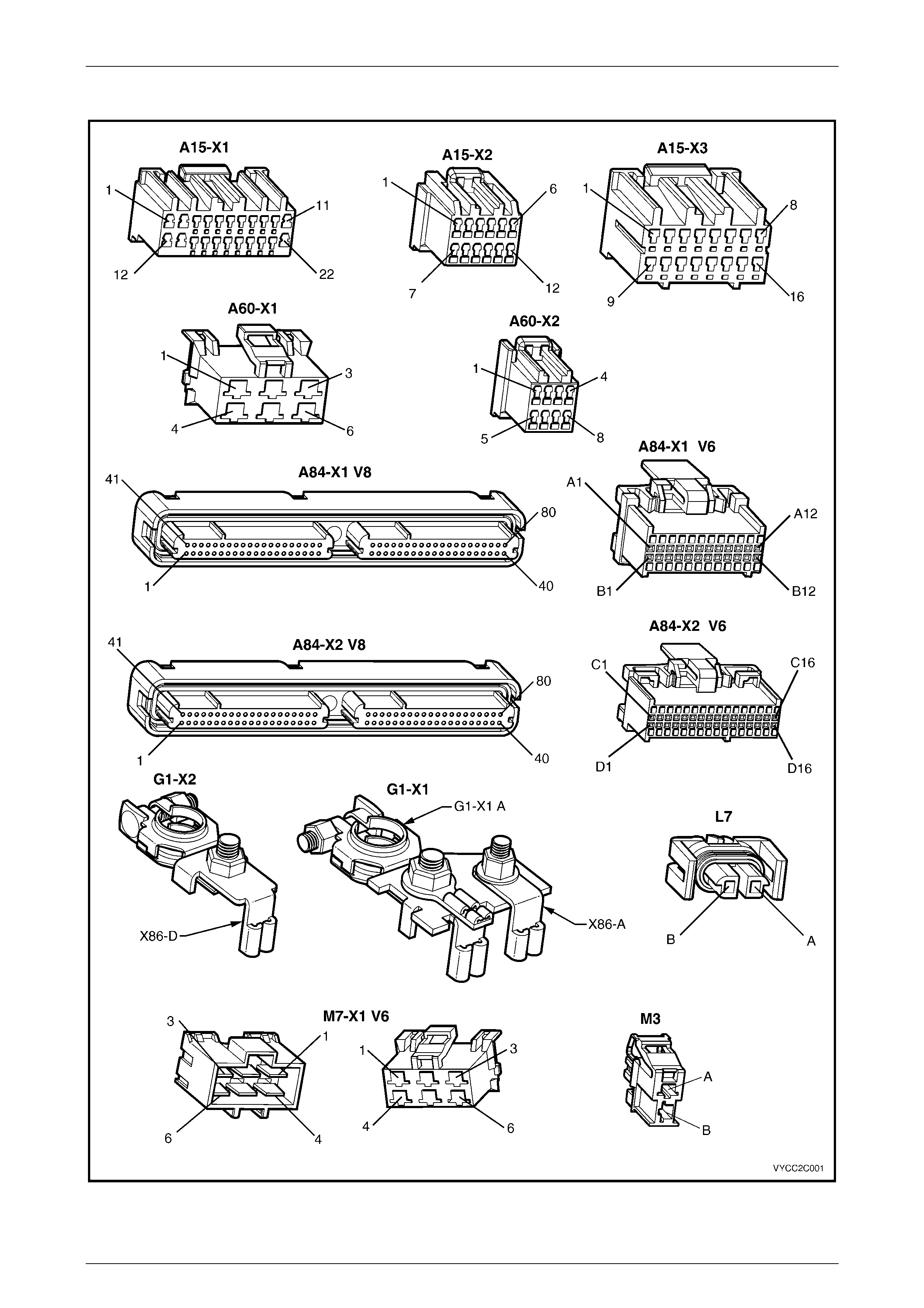
The following figures provide electrical connector diagrams and wiring diagrams applicable to HVAC Climate Control
(Manual A/C) systems as fitted to MY 2003 VY Regular Cab vehicles. These diagrams should be used as an aid to
diagnosing circuit faults. The content of these figures is as follows:
• Electrical connectors (A15 – M7) – refer to Figure 2C – 1
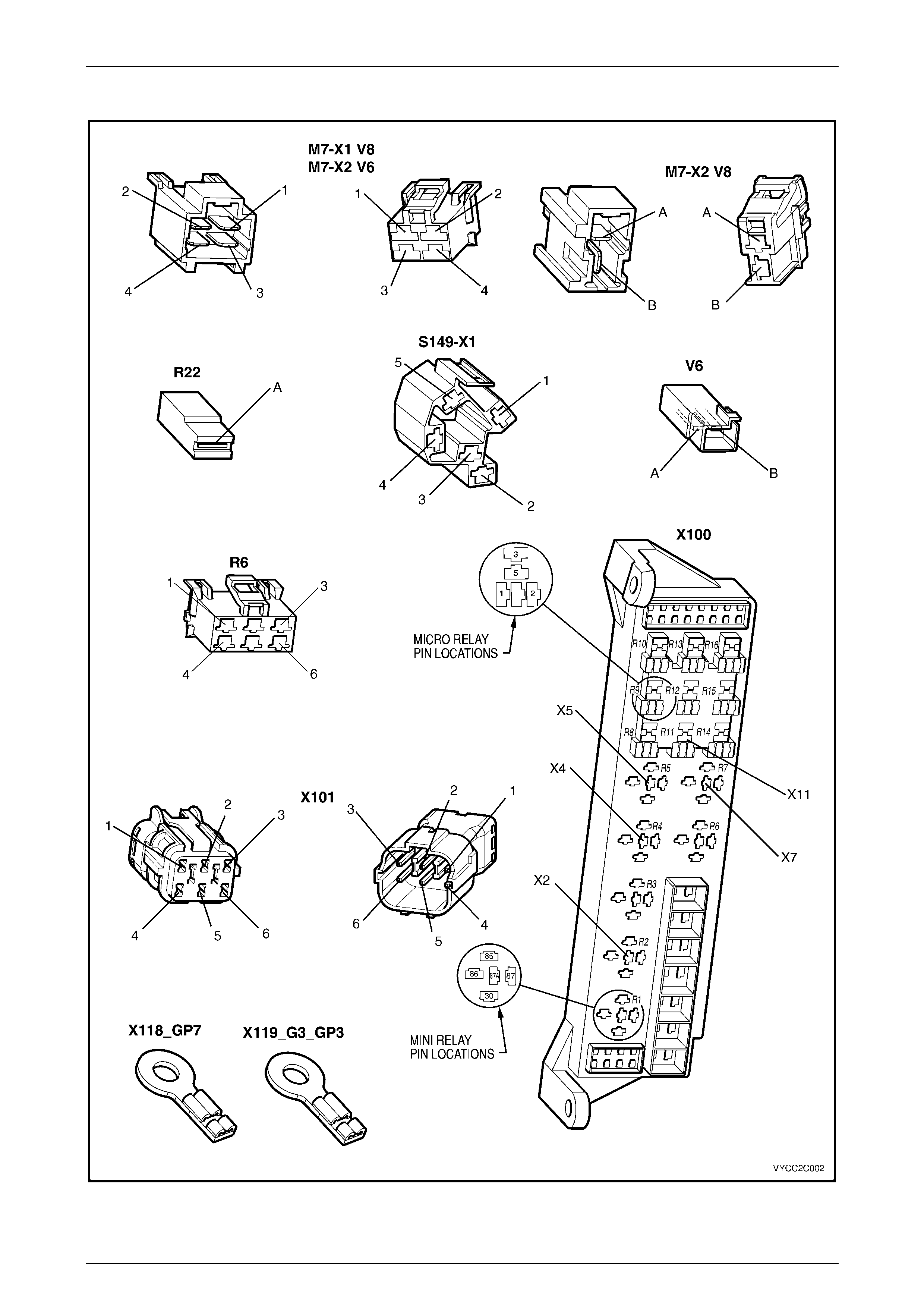
• Electrical connectors continued (M7 – X119) – refer to Figure 2C – 2
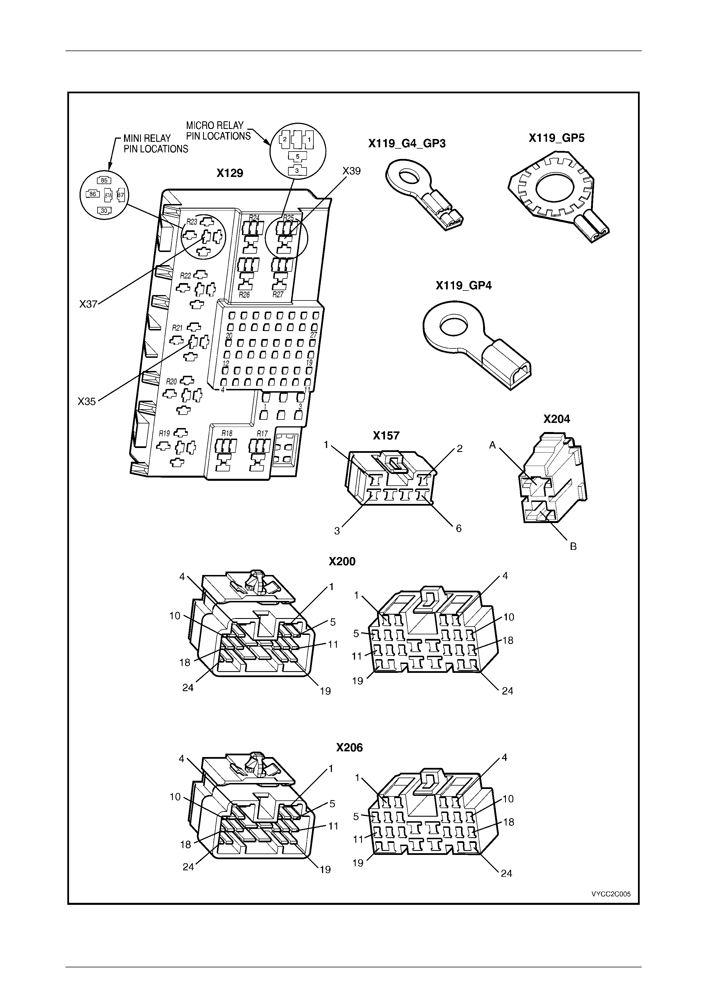
• Electrical connectors continued (X119 – X206) – refer to Figure 2C – 3
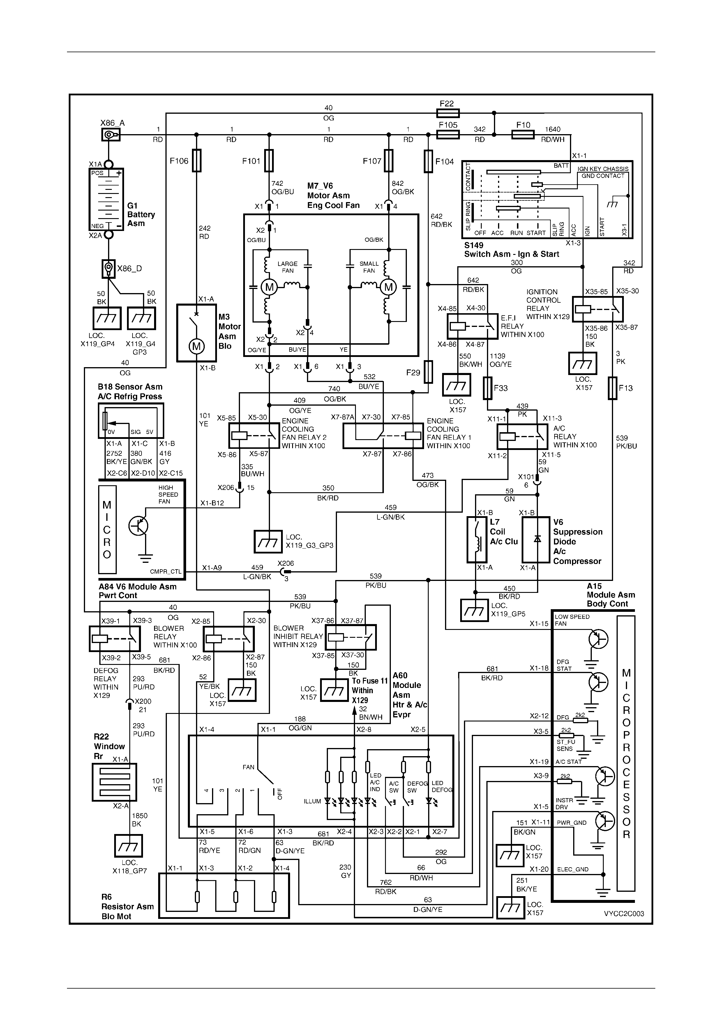
• Wiring diagram: HVAC Climate Control (Manual A/C) system, V6 – refer to Figure 2C – 4
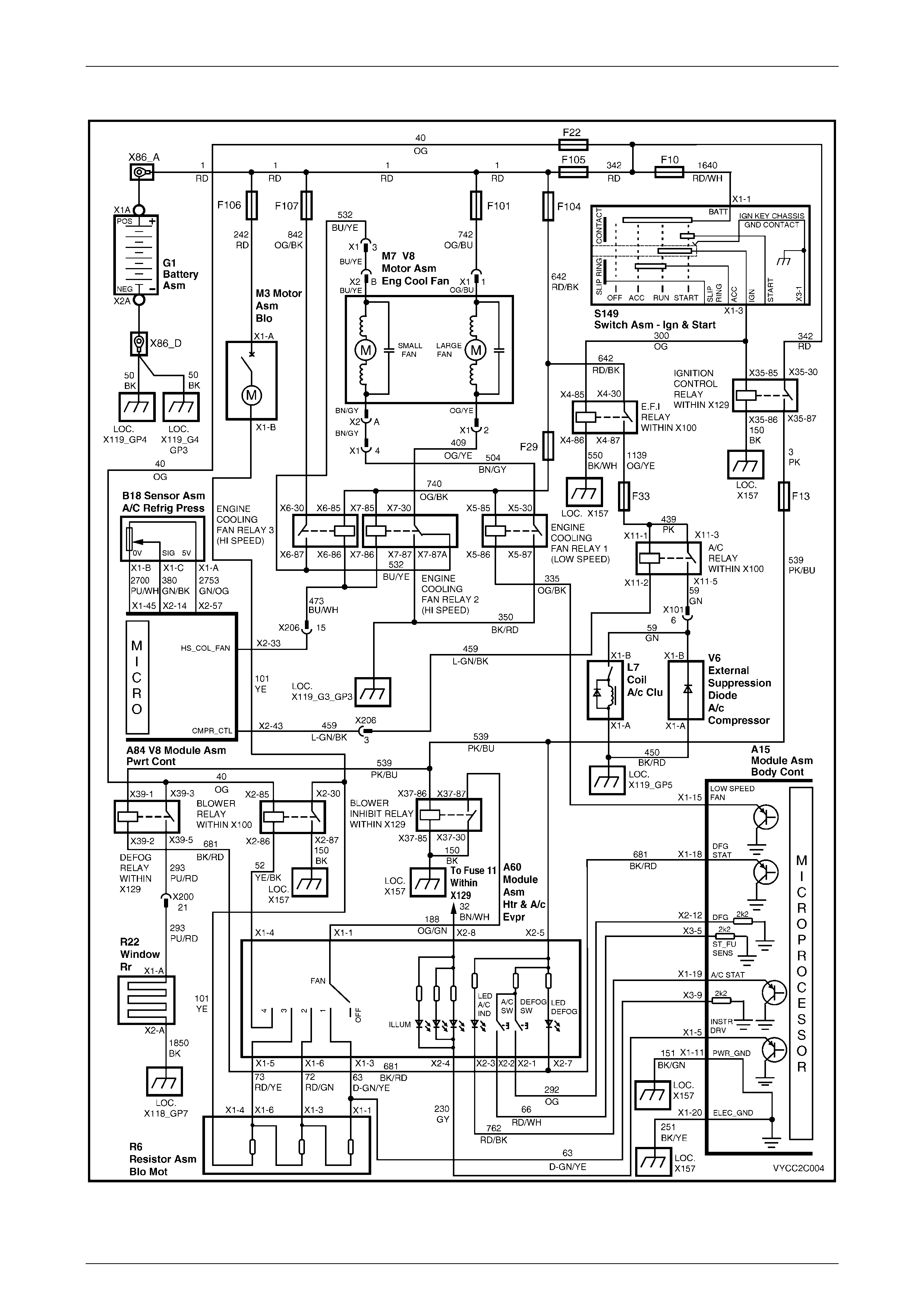
• Wiring diagram: HVAC Climate Control (Manual A/C) system, GEN III V8 – refer to Figure 2C – 5
In the following wiring diagrams (Figure 2C – 4 and Figure 2C – 5) all components are described and displayed in
accordance to the Integrated Vehicle Electrical Design (IVED) standard. To assist in wiring diagram interpretation, refer
to the following table:
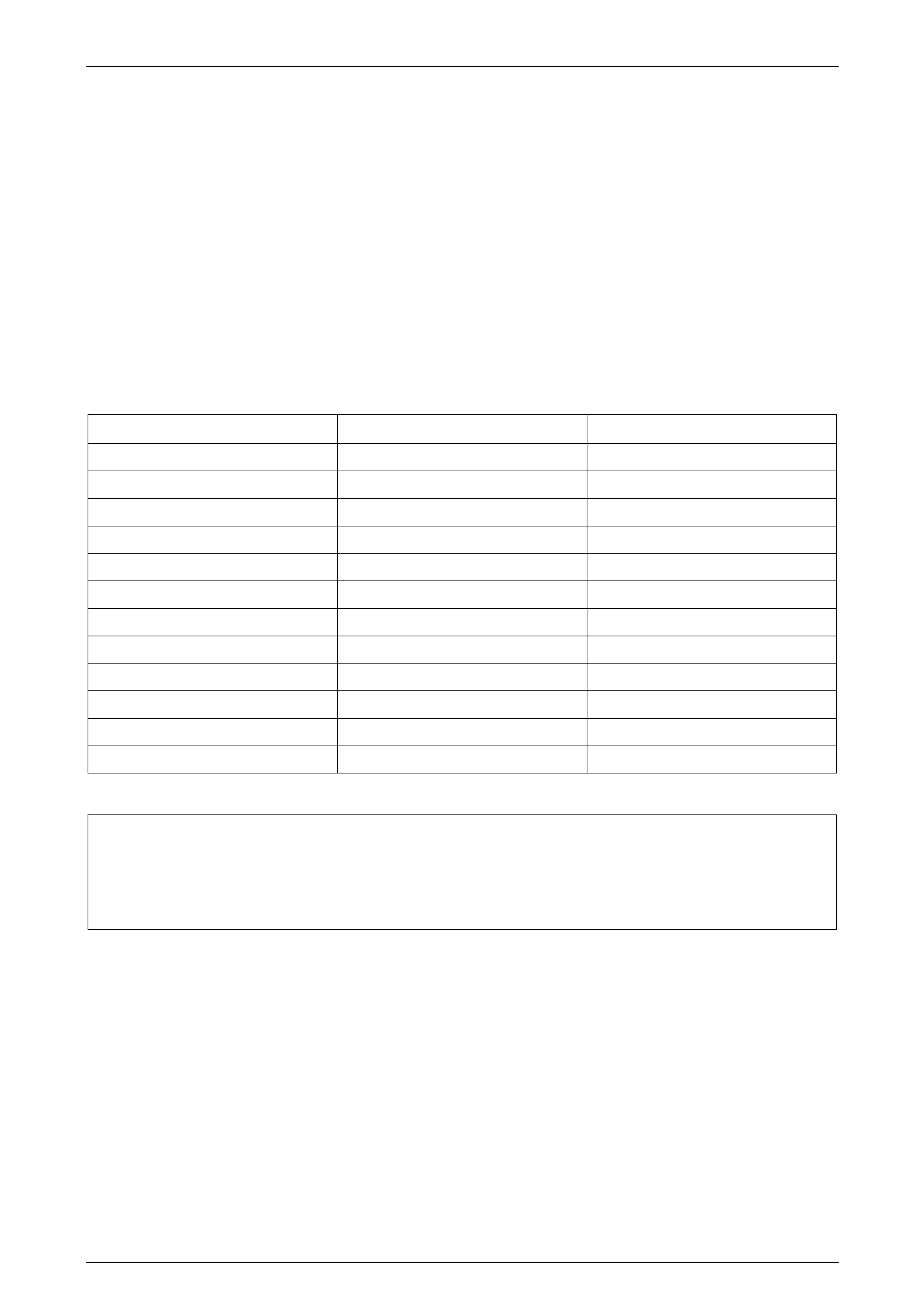
IVED Description IVED Component Identification Common Description
Module Asm Body Cont A15 Body Control Module
Module Asm Htr & A/c Evpr A60 Manual HVAC Control l er
V6 Module Asm Pwrt Cont A84 V6 Powertrain Control Module
V8 Module Asm Pwrt Cont A84 GEN III V8 Powertrain Control Module
Sensor Asm A/C Refrig Press B18 A/C Pressure Transducer
Coil A/c Cl u L7 Compressor Clutch
Motor Asm Blo M3 Blower Motor
Motor Asm Eng Cool Fan M7_V6 V6 Cooling Fan System
Motor Asm Eng Cool Fan M7_V8 GEN III V8 Cooling Fan System
Resistor Asm Bl o Mot R6 Blower Motor Resist or
Window Rear R22 Heated Rear Window
Switch Asm – Ign & Start S149 Ignition Switch
The following table lists the IVED standard wire colour abbreviations:
BK Black D-GN Dark green L-GN Light green RD Red
BU Blue GN Green OG Orange TN Tan
BN Brown GY Grey PK Pink WH White
D-BU Dark blue L-BU Light blue PU Purple YE Yellow
NOTE
For electrical connector locations and additional
wiring diagram information, refer to Section 12P
Wiring Diagrams.
HVAC Climat e Control (Manual A/C) – Servi cing and Diagnosis Page 2C–4
Page 2C–4
Connectors: HVAC Climate Control (Manual A/C) S ystem
Figure 2C – 1
HVAC Climat e Control (Manual A/C) – Servi cing and Diagnosis Page 2C–5
Page 2C–5
Connectors: HVAC Climate Control (Manual A/C) System Continued
Figure 2C – 2
HVAC Climat e Control (Manual A/C) – Servi cing and Diagnosis Page 2C–6
Page 2C–6
Connectors: HVAC Climate Control (Manual A/C) System Continued
Figure 2C – 3
HVAC Climat e Control (Manual A/C) – Servi cing and Diagnosis Page 2C–7
Page 2C–7
Wiring Diagram: HVAC Climate Control (Manual A/C) System – V6
Figure 2C – 4
HVAC Climat e Control (Manual A/C) – Servi cing and Diagnosis Page 2C–8
Page 2C–8
Wiring Diagram: HVAC Climate Control (Manual A/C) System – GEN III V8
Figure 2C – 5