Rear Suspension Page 4A –1
Page 4A–1
Section 4A
Rear Suspension
ATTENTION
Before performing any Service Operation or other procedure described in this Section, refer to Section 00
CAUTIONS AND NOTES for correct workshop practices with regard to safety and/or property damage.
1 General Information............................................................................................................................... 2
2 Service Operations................................................................................................................................4
2.1 Suspension and Trim Height, Check....................................................................................................................4
2.2 Rear Leaf Springs...................................................................................................................................................5
Remove ...................................................................................................................................................................5
Disassemble ...........................................................................................................................................................6
Inspect.....................................................................................................................................................................6
Reassemble ............................................................................................................................................................7
Reinstall ..................................................................................................................................................................7
2.3 Rear Leaf Spring Eye and S hackle Bushes..........................................................................................................9
Remove ...................................................................................................................................................................9
Inspect...................................................................................................................................................................10
Reassemble ..........................................................................................................................................................11
2.4 Rear Shock Absorbers.........................................................................................................................................12
Remove .................................................................................................................................................................12
Inspect...................................................................................................................................................................12
Reinstall ................................................................................................................................................................13
2.5 Rear Stabilizer Bar ...............................................................................................................................................14
Remove .................................................................................................................................................................14
Inspect...................................................................................................................................................................14
Reinstall ................................................................................................................................................................15
2.6 Rear Suspension Bump Stop..............................................................................................................................16
Remove .................................................................................................................................................................16
Inspect...................................................................................................................................................................16
Reinstall ................................................................................................................................................................16
3 Diagnosis.............................................................................................................................................. 17
3.1 Checking and Testing Shock Absorbers ...........................................................................................................17
Preliminary Checks..............................................................................................................................................17
Testing Shock Absorber Action..........................................................................................................................17
5 Specifications....................................................................................................................................... 18
6 Torque Wrench Specifications........................................................................................................... 19
7 Special Tools........................................................................................................................................ 20

Rear Suspension Page 4A –2
Page 4A–2
1 General Information
The rear suspension system for MY2003 VY Series, Cab Chassis Models incorporate two multiple leaf spring assemblies
in conjunction with shock absorbers and a stabilizer bar as standard equipment. The rear suspension system provides
support and control of the movement of the rear axle assembly during vehicle motion, as well as when stationary.
The rear suspension system is mounted to the chassis at four locations via the leaf spring shackle mount brackets, the
spring eye bushing mount brackets and bolts. Two ‘U’ Bolts on each side attach the rear axle assembly to each rear leaf
spring retainer bracket. Torque reaction or the natural resistance or tension of the leaf springs controls wind-up of the
rear axle assembly. Rear axle assembly vertical over-travel is restricted by bump stops mounted to the chassis just
above the rear axle housing tube on each side.
A decoupled stabilizer bar is attached to the rear axle assembly by two mounting brackets and insulati ng bushes, while
at each end of the stabilizer bar a ball joint and connecting rod is attached. Each stabilizer bar connecting rod is then
attached to the chassis via a ball joint.
The rear suspension system dampening is controlled by two double acting shock absorbers mounted between the
chassis frame and the rear leaf spring retainer brackets.
Rear Suspension Page 4A –3
Page 4A–3
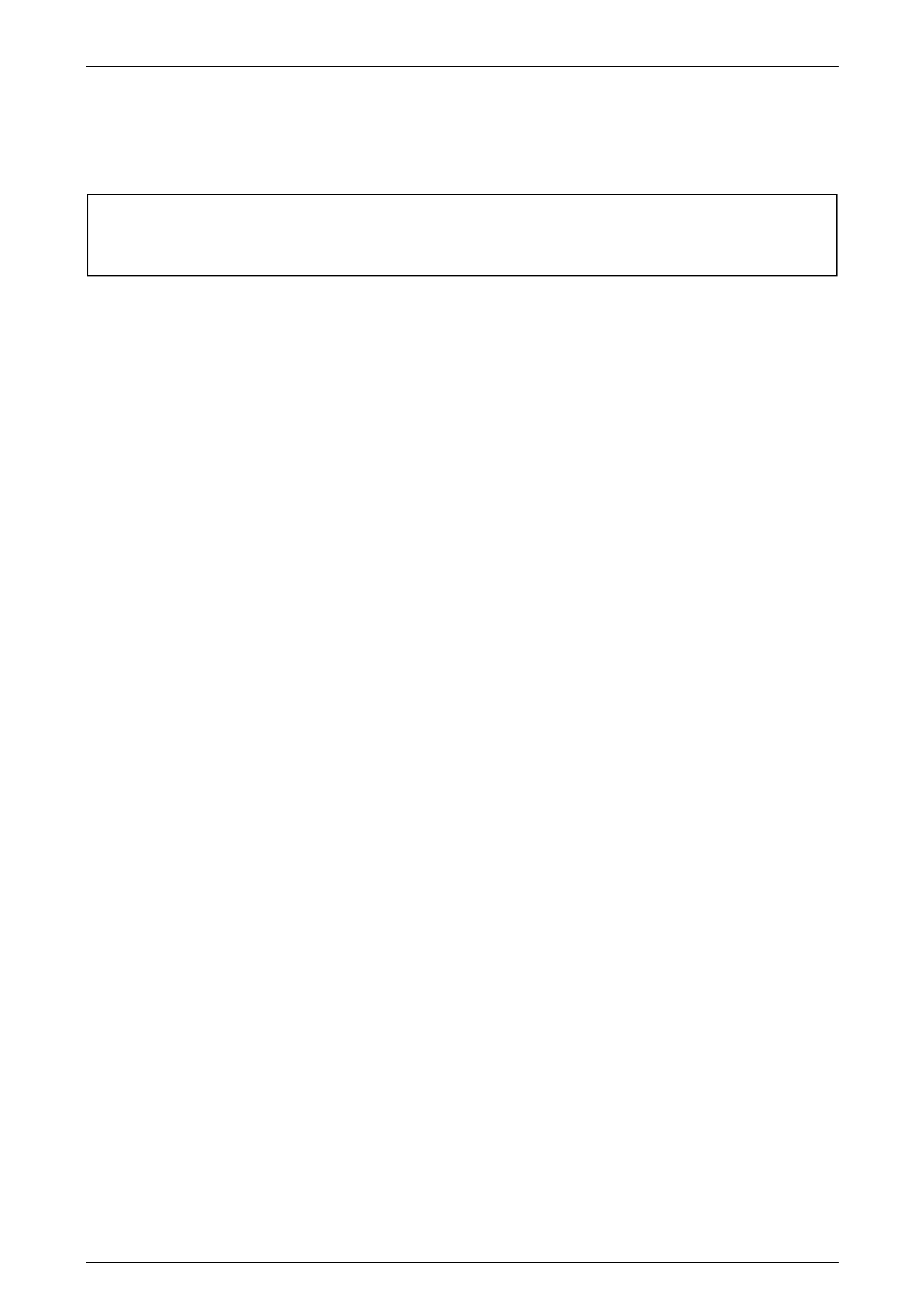
Figure 4A-1
Legend
1 Rear Axle Assembly
2 Rear Leaf Spring Assembly
3 Rear Shock Absorber
4 Rear Suspension Stabilizer
5 Rear Chassis
6 Rear Stabilizer Bar to Chassis Link
7 Rear ABS Sensor

Rear Suspension Page 4A –4
Page 4A–4
2 Service Operations
ATTENTION
All rear axle fasteners are important attaching parts as they affect the performance of vital components
and/or could result in major repair expense. Where specified in this section, fasteners MUST be replaced with
parts of the same part number or a GM approved equivalent. Do not use fasteners of an inferior quality or
substitute design.
Torque values must be used as specified during reassembly to ensure proper retention of all steering
components.
Through out this section, fastener torque wrench specifications may be accompanied with the following
Identification marks:
+
++
+ Fasteners must be replaced after loosening.
!
!!
! Vehicle must be at curb height before final tightening.
6
66
6 Fasteners either have micro encapsulated sealant applied or incorporate a mechanical thread lock and
should only be re-used once. If in doubt, replacement is recommended.
If one of these identification marks is present alongside a fastener torque wrench specification, the
recommendation regarding that fastener must be adhered to.
2.1 Suspension and Trim Height, Check
For suspension and trim height checks and specifications, refer to Section 3, Front Suspension in MY2003 VY Series,
Cab Chassis Service Information.

Rear Suspension Page 4A –5
Page 4A–5
2.2 Rear Leaf Springs
LT Section No: F1000000
ATTENTION
The following fasteners MUST have the ve hicle at curb height before final tightening.
!
!!
! Rear leaf spring shackle attaching nuts.
!
!!
! Rear leaf spring eye attaching bolt and nut.
!
!!
! Rear shock absorber lower mounting attaching bolt.
The following fasteners MUST be replaced when performing this operation:
+ Rear leaf spring shackle attaching nut s.
+ Rear leaf spring eye attaching bolt and nut.
+ Leaf spring centre pin attaching nut.
+ Rear shock absorber lower mounting attaching bolt.
+ Rear leaf spring and retainer plate ‘U’ bolt attaching nuts.
Remove
1 Using a floor jack under the centre of the rear axle
assembly (1), jack up rear of vehicle, then place
safety stands under the rear chassis (2) on both the
left-hand and right-hand sides to support the weight of
the vehicle as shown in Figure 4A-3.
2 With the floor jack still under the centre of the rear
axle assembly, take-up the weight of the rear axle
housing, while observing the leaf springs and
shackles to gain the desired height to relieve any
spring tension. Place further safety stands to support
the rear axle assembly weight at each side and
remove the floor jack.
Figure 4A-2
Rear Suspension Page 4A –6
Page 4A–6
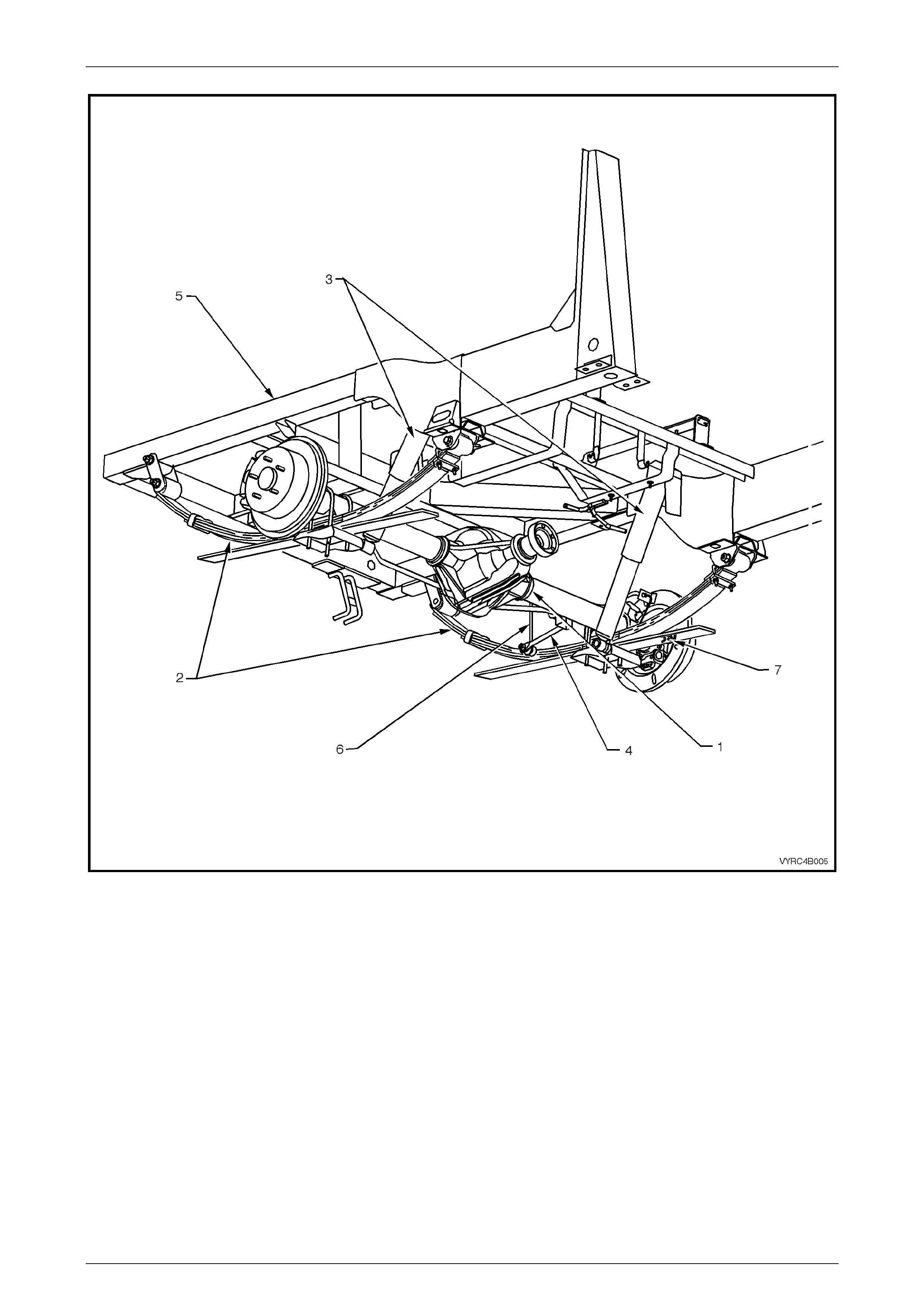
3 Using suitable sockets and bar loosen the following
as shown in Figure 4A-3.
a. Lower shock absorber to leaf spring retainer plate
attaching bolt (1).
b. Front leaf spring eye to mounting bracket bolt (2).
c. Rear leaf spring shackle attaching nuts (3).
d. Rear axle housing to leaf spring retainer plate ‘U’
bolt attaching nuts (4).
4 Remove the lower shock absorber to leaf spring
retainer plate attaching bolt (1).
5 Remove rear axle housing to leaf spring retainer plate
‘U’ bolt attaching nuts (4), leaf spring retainer plate (5)
and ‘U’ bolt’s (6).
6 Remove the front leaf spring eye to mounting bracket
bolt (2).
7 Remove the rear leaf spring shackle and attaching
nuts (3).
8 Remove the leaf spring assembly (7) from the vehicle.
Figure 4A-3
Disassemble
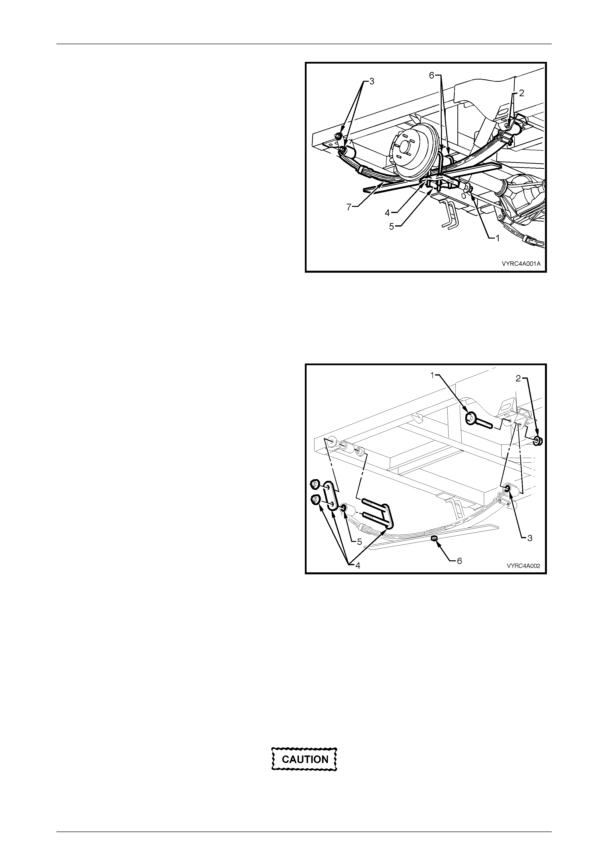
1 Remove the leaf spring eye to mounting bracket
attaching bolt (1) and nut (2). If replacing the leaf
spring eye bush (3) refer to 2.3, Rear Leaf Spring Eye
and Shackle Bushes in this section.
2 Remove the leaf spring shackle to mounting bracket
and shackle to leaf spring attaching nuts (4). If
replacing the leaf spring shackle bushes (5) refer to
2.3, Rear Leaf Spring Eye and Shackle Bushes in this
section.
3 Remove the leaf spring assembly centre pin retaining
nut (6) by using a suitable brass drift to drive the
centre pin from the leaf spring assembly to separate
the spring leaves. Refer to Figure 4A-4.
Figure 4A-4
Inspect
Clean all components using a suitable solvent and inspect the following:
1 The leaf spring eye bush for excessive wear.
2 The leaf spring shackles and bushes for excessive w ear.
3 The general condition of each spring leaf for signs of fatigue or cracking.
4 The interleaf spacers for excessive wear.
5 The centre pin for straightness and excessive wear.
Worn or damaged components must be
replaced.
Rear Suspension Page 4A –7
Page 4A–7
Reassemble
The procedure for reassembly of the leaf spring is the reverse of the disassemble procedure noting the following points:
1 If replacing the leaf spring eye or shackle bushes refer to 2.3, Rear Leaf Spring Eye and Shackle Bushes in this
section.
2 The leaf spring centre pin spindle should be lightly lubricated with Molybdenum Disulphide grease prior to
installation.
3 Ensure all leaves of the spring are aligned prior to tightening the centre pin, attaching nut.
4 Tighten the centre pin, attaching nut to the correct torque.
(+) Leaf spring centre pin
attaching nut
torque specific atio n ..............................................25 Nm
Reinstall
The procedure for reinstallation of the leaf spring assembly is the reverse of the removal procedure noting the following
points:
(+) Leaf spring and retainer
plate ‘u’ bolt attaching nut
torque specific atio n ..............................................90 Nm
NOTE
Preliminary torque of the leaf spring to shackle
attaching nuts is for initial set-up only. A final
torque must be carried out with all four wheels on
the ground and normal vehicle weight applied.
(+) Leaf spring to shackle
attaching nut (preliminary)
torque specific atio n .............................................5.0 Nm
NOTE
Final torque of the leaf spring to shackle
attaching nuts must be carried out with all four
wheels on the ground and normal vehicle weight
applied.
(+ !) Leaf spring to shackle
attaching nut (final)
torque specific atio n ............................................110 Nm
NOTE
Preliminary torque of the leaf spring eye,
attaching bolt and nut is for initial set-up only. A
final torque must be carried out with all four
wheels on the ground and normal vehicle weight
applied.
(+) Leaf spring eye
attaching bolt and nut (preliminary)
torque specific atio n .............................................5.0 Nm
Rear Suspension Page 4A –8
Page 4A–8
NOTE
Final torque of the leaf spring eye, attaching bolt
and nut must be carried out with all four wheels
on the ground and normal vehicle weight applied.
(+ !) Leaf spring eye
attaching bolt and nut (final)
torque specific atio n ............................................130 Nm
NOTE
Preliminary torque of the rear shock absorber
lower mounting, attaching nut is for initial set-up
only. A final torque must be carried out with all
four wheels on the ground and normal vehicle
weight applied.
(+) Rear shock absorber
lower mounting attaching bolt
(preliminary) torque specification.........................5.0 Nm
NOTE
Final torque of the rear shock absorber lower
mounting, attaching nut must be carried out with
all four wheels on the ground and normal vehicle
weight applied.
(+ !) Rear shock absorber
lower mounting attaching bolt
(final) torque specification ..................................110 Nm
Rear Suspension Page 4A –9
Page 4A–9
2.3 Rear Leaf Spring Eye and Shackle
Bushes
LT Section No: F111000
Remove
1 Remove the rear leaf spring assembly; refer to
2.2, Rear Leaf Springs in this sect ion .
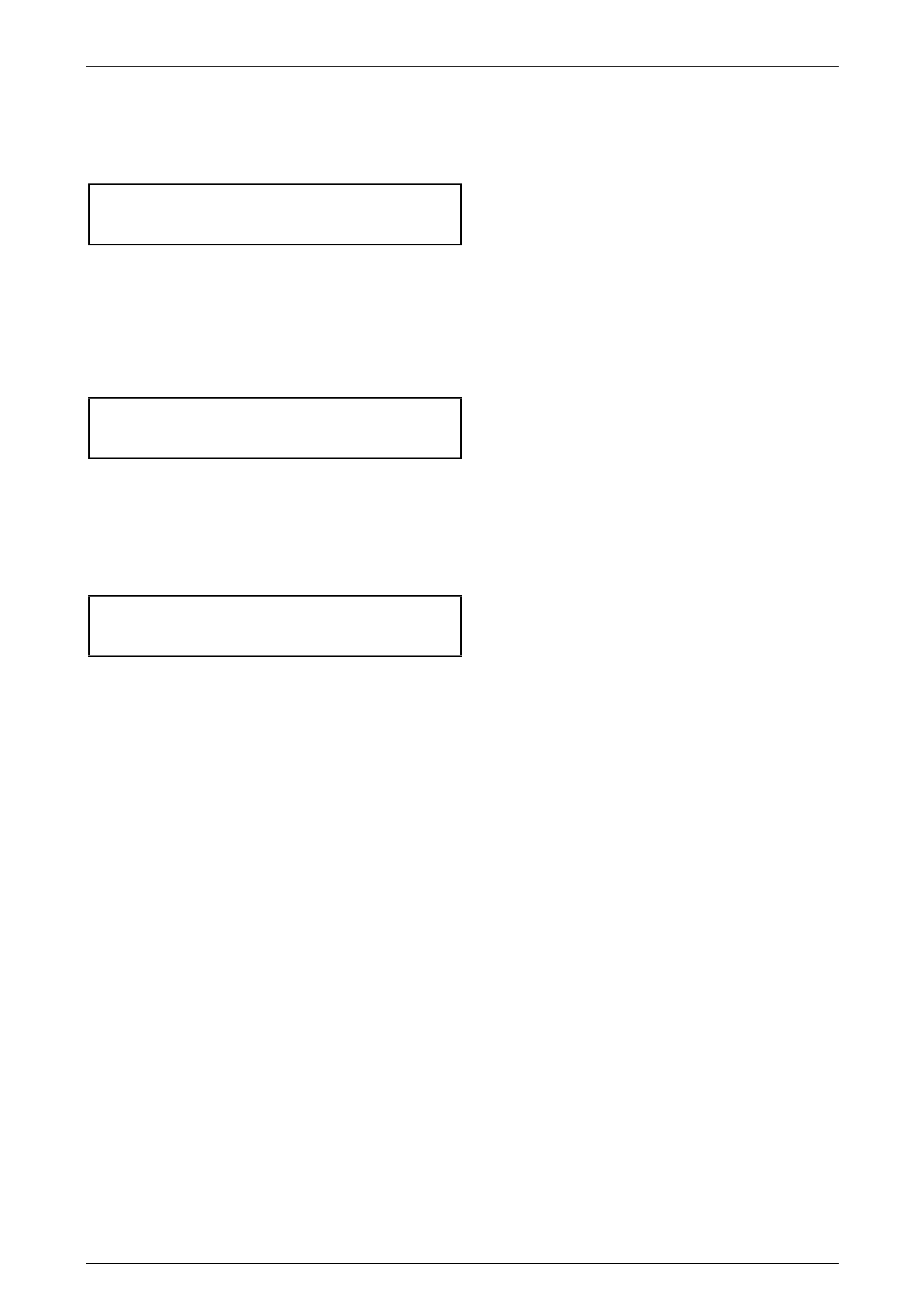
2 Using Tool No’s. AU606-1 (1), AU606-2 (2), AU606-3
(3) and suitable press, place the leaf spring (4) along
with the tools on suitable press plates.
IMPORTANT
When removing the bush from the leaf
spring eye, record the force exerted
during the pressing operation. If the force
exerted is less than 7.5 kN, the leaf spring
must be replaced.
IMPORTANT
The eye bush once removed must be
replaced with new eye bush.
3 Remove the leaf spring eye bush by pressing the
bush with Tool No.AU606-1 (1) along with Tool No.
AU606-2 (2), through the eye of the leaf spring (4)
and into Tool No. AU606-3 (3). Refer to Figure 4A-5.
Leaf spring eye bush
press exertion force.......................................... 7.5 kN
4 Remove the leaf spring shackle; shackle plate and
attaching nuts.
5 Remove the shackle bushes by carefully prying the
bushes from the leaf spring with a suitable probe.
Figure 4A-5
Rear Suspension Page 4A –10
Page 4A–10
Inspect
IMPORTANT
If the eye bush has been removed it must be
replaced with new eye bush.
IMPORTANT
If the eye bush extraction force is less than
7.5 kN the leaf spring must be replaced.
Worn or damaged components must be
replaced.
Clean all components using a suitable solvent and inspect the following:
1 The leaf spring eye for damage or wear.
2 The leaf spring shackles and bushes for excessive w ear.
3 The general condition of the spring leaf for signs of fatigue or cracking.
Rear Suspension Page 4A –11
Page 4A–11
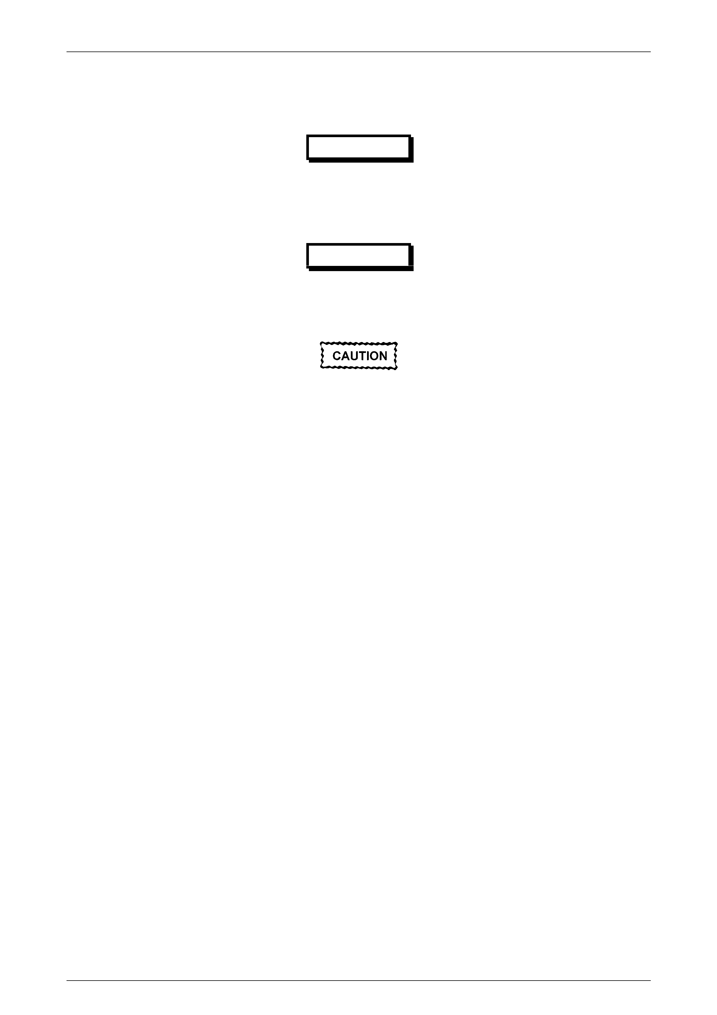
Reassemble
IMPORTANT
When installing the bush into the leaf
spring eye, the force exerted during the
pressing operation should be at least 7.5
kN. If the force exerted is less than 7.5 kN,
the leaf spring must be replaced.
IMPORTANT
A new eye bush must be installed.
1 Using Tool No’s. AU606-1 (1), AU606-4 (2), AU606-3
(3) and suitable press, place the leaf spring (4) along
with the leaf spring eye bush (5) on a suitable press
plate.
2 Install the front leaf spring eye bush by pressing the
bush into the leaf spring eye using Tool No.AU606-1
(1) along with Tool No. AU606-4 (2) and Tool No.
AU606-3 (3) to guide the new bush (4) into the leaf
spring eye (5). Refer to Figure 4A-6.
Leaf spring eye bush
press exertion force.......................................... 7.5 kN
3 Install the rear shackle bushes by hand into the leaf
spring using soapy water to assist installation.
4 Install the shackle, shackle plates and attaching nuts.
5 Tighten the spring to shackle attaching nut to the
correct preliminary torque.
NOTE
Preliminary torque of the leaf spring to shackle
attaching nuts is for initial a set-up only. A final
torque must be carried out with all four wheels
on the ground and normal vehicle weight
applied.
(6) Leaf spring to shackle
attaching nut
(preliminary)
torque specific atio n .........................................5.0 Nm
6 Reinstall the rear leaf spring assembly; refer to
2.2, Rear Leaf Springs in this sect ion .
Figure 4A-6
Rear Suspension Page 4A –12
Page 4A–12
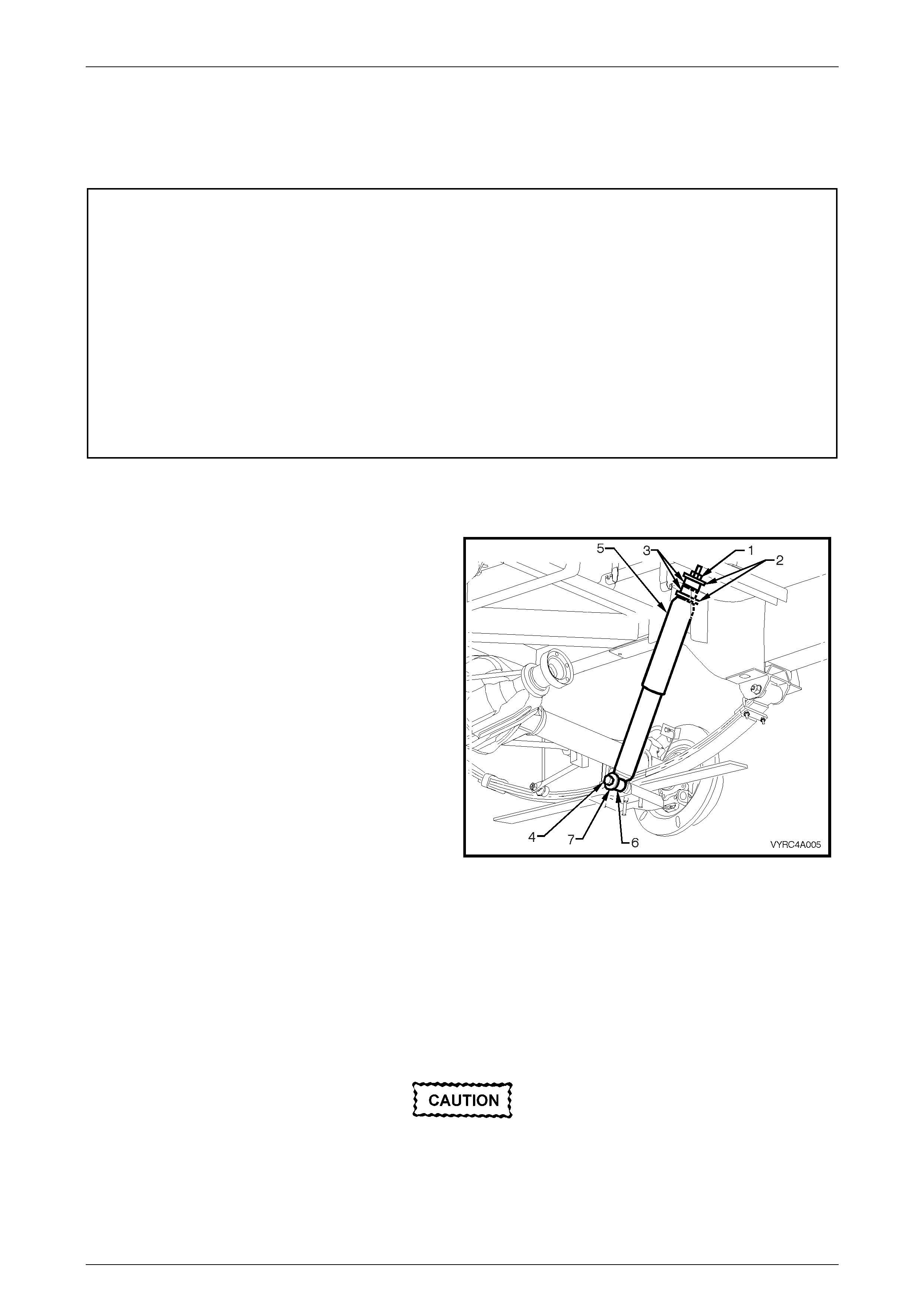
2.4 Rear Shock Absorbers
LT Section No: F120000
ATTENTION
The following fasteners MUST have the ve hicle at curb height before final tightening.
!
!!
! Rear shock absorber lower mounting attaching bolt.
The following fasteners MUST be replaced when performing this operation:
+ Rear shock absorber upper mounting attaching nut.
+ Rear shock absorber lower mounting attaching bolt.
Remove
1 Using a floor jack under the centre of the rear axle
assembly, jack up the rear of the vehicle, then place
safety stands under the chassi s to support the veh icl e
weight
2 Leave the floor jack under the centre of the rear axle
to assist in removing the shock absorber.
3 Using suitable spanners remove the upper shock
absorber attaching nut (1), support washer (2) and
mounting bush (3).
4 Lower the floor jack enough to remove any load on
the shock absorber.
5 Remove the lower shock absorber attaching bolt (4)
and remove the shock absorber (5).
6 Remove the remaining upper mounting bush (6) and
support washer (7) from the shock absorber. Refer to
Figure 4A-7.
Figure 4A-7
Inspect
Clean all components using a suitable solvent and inspect the following:
1 The upper and lower shock absorber bushes for excessive wear.
2 The shock absorber action.
3 The general condition of the shock absorber mounting points of the chassis and rear axle.
Worn or damaged components must be
replaced.
Rear Suspension Page 4A –13
Page 4A–13
Reinstall
The procedure for reinstallation of the shock absorber is the reverse of the removal procedure noting the following points:
(+) Rear shock absorber
upper mounting attaching nut
torque specific atio n ..............................................45 Nm
NOTE
Preliminary torque of rear shock absorber lower
mounting attaching nut is for initial set-up only. A
final torque must be carried out with all four
wheels on the ground and normal vehicle weight
applied.
(+) Rear shock absorber
lower mounting attaching bolt
(preliminary)
torque specific atio n .............................................5.0 Nm
NOTE
Final torque of the rear shock absorber lower
mounting, attaching nut must be carried out with
all four wheels on the ground and normal vehicle
weight applied.
(+ !) Rear shock absorber
lower mounting attaching bolt
(final)
torque specific atio n ............................................110 Nm
Rear Suspension Page 4A –14
Page 4A–14
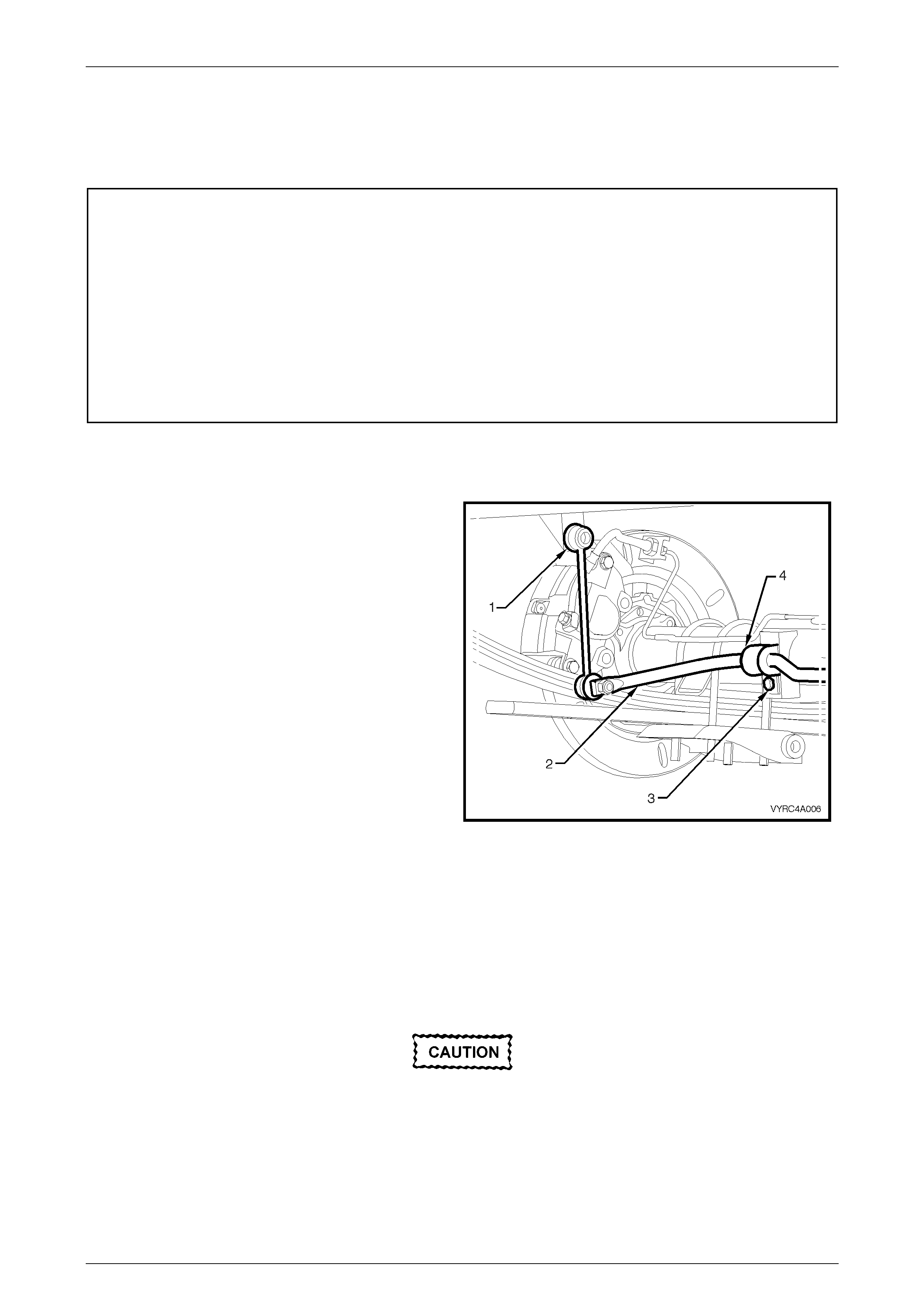
2.5 Rear Stabilizer Bar
LT Section No: F122100
ATTENTION
The following fasteners have either micro encapsulation or incorporate a mechanical thread lock and should
only be used once. If in doubt, replacement is recommended when performing this operation:
6 Rear stabilizer bar drop link upper and lower ball joint to stabilizer bar attaching nut.
The following fasteners MUST be replaced when performing this operation:
+ Rear stabilizer bar mounting to rear axle housing attaching bolt.
Remove
1 Using suitable spanners remove the upper drop link
ball joint (1) for the stabilizer bar (2) from each side of
the chassis.
2 Remove each attaching bolt (3) from the stabilizer bar
mounting’s (4) on the rear axle. Refer to Figure 4A-8.
Figure 4A-8
Inspect
Clean all components using a suitable solvent and inspect the following:
1 The upper and lower upper drop link ball joints for excessive wear.
2 The stabilizer bar mountings and the general condition of the stabilizer mounting points of the chassis and rear
axle.
Worn or damaged components must be
replaced.
Rear Suspension Page 4A –15
Page 4A–15
Reinstall
The procedure for reinstallation of the stabilizer bar is the reverse of the removal procedure noting the following points:
(+) Rear stabilizer bar mounting
to rear axle housing attachi ng
bolt torque specification ........................................ 25 Nm
(6) Rear stabilizer bar drop link
upper and lower ball joint
to stabilizer bar attaching nut
torque specification ...................................... 45 – 55 Nm
Rear Suspension Page 4A –16
Page 4A–16
2.6 Rear Suspension Bump Stop
LT Section No: F109100
ATTENTION
The following fasteners MUST be replaced when performing this operation:
+ Rear suspension bump stop, attaching bolt.
Remove
Using suitable spanners remove the attaching bolts from each side of the bump stop
Inspect
Clean all components using a suitable solvent and inspect the following:
• The general condition of the bump stop and mounting points to the chassis.
Worn or damaged components must be
replaced.
Reinstall
The procedure for reinstallation of the bump stop is the reverse of the removal procedure noting the following point:
(+) Rear suspension bump stop
to chassis frame attaching bolt
torque specific atio n ..............................................25 Nm
Rear Suspension Page 4A –17
Page 4A–17
3 Diagnosis
3.1 Checking and Testing Shock Absorbers
Preliminary Checks
Before proceeding with the removal of shock absorber assemblies, it is good practise to check and make sure the noise
is not emanating from some other source.
Conduct a visual inspection of all shock absorber components along other rear suspensi on relate d comp one nts che ck ing
for anything that may appear unusual.
Check the torque of all attaching fasteners for tightness and check all mounting bushes for alignment. If the bushes are
worn, loose fitting or misaligned, they must be replaced.
Testing Shock Absorber Action
NOTE:
The following test is for non-gas pressurised
shock absorbers.
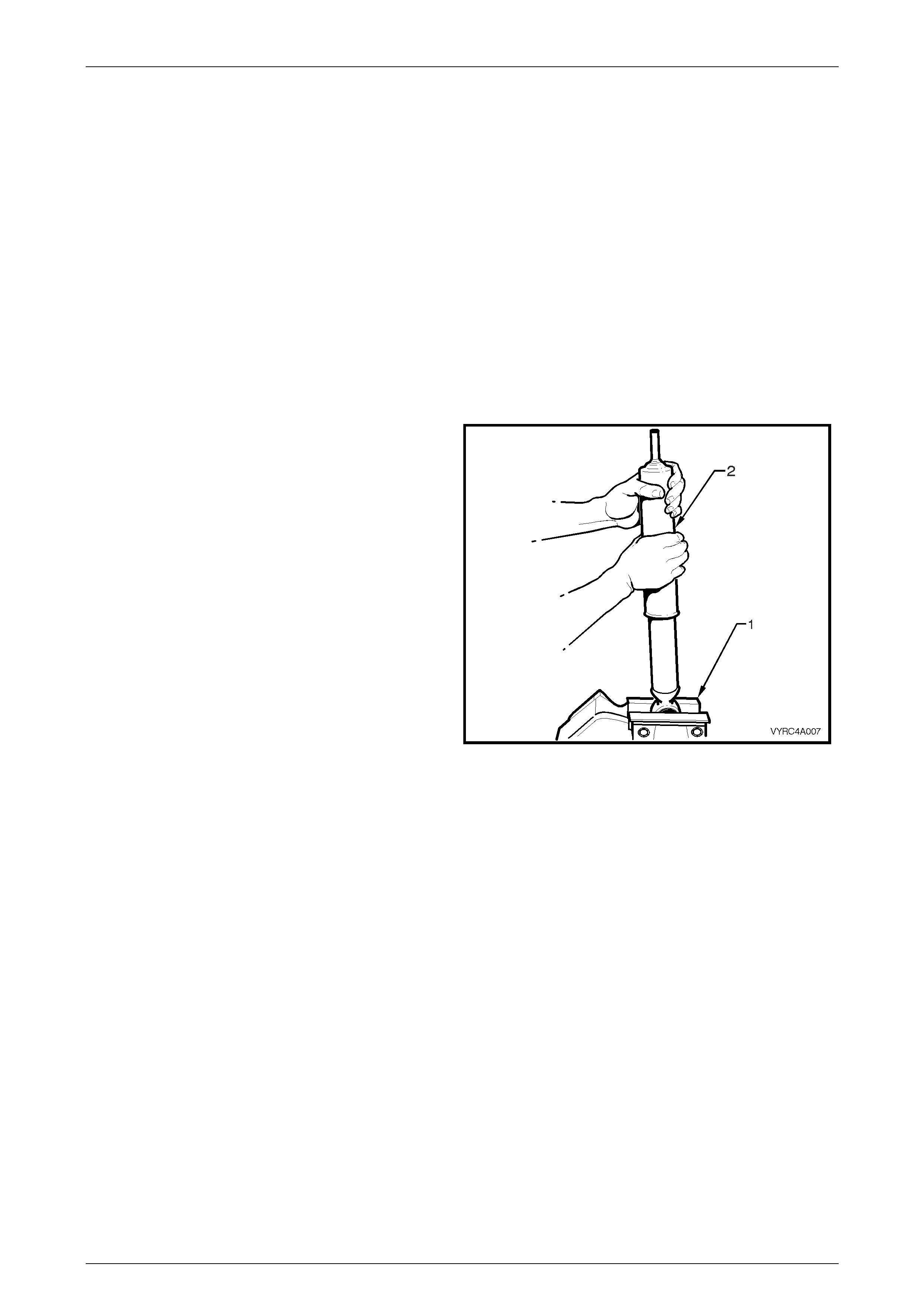
1 Using a suitable vice equipped with soft jaw’s (1),
support the shock absorber (2) by its lower mount.
Refer to Figure 4A-9.
2 Slowly pump the shock absorber up and down its full
stroke at least six times to prime the internal valves of
the shock absorber.
3 Move the shock absorber up and down at various
rates of speed while monitoring the resistance. The
resistance sho uld be consistent through out both
stokes and there shoul d be no slack sp ots. If sla ck
spots are detected this indicates either a lack of oil or
the internal valves are defective.
NOTE:
It is normal for a hissing (orifice swish) noise to
be detected during shock absorber testing.
4 The following conditions are considered outside the
normal function parameters and replacement is
recommended:
a. A skip or lag at reversal of the stroke mid way
through.
b. A seize (except at the extreme end of travel).
c. A noise such as a grunt or squeal after the
completing one ful l str oke in both direct ion s.
d. A clicking noise at fast reversal of the stroke.
e. Fluid leakage.
Figure 4A-9

Rear Suspension Page 4A –18
Page 4A–18
5 Specifications
General
Rear Suspension Assembly.............................................................................................Dana
Type..........................................................................................................................Hotchkiss
...............................................................(Live axle, Stabilizer Bar, Semi elliptical leaf springs)
Number of Primary Leaves .................................................................................................... 3
Number of Secondary Leaves................................................................................................ 1
Shock Absorber
Hydraulic (non-adjustable)................................................................................. Double acting
Stabilizer Bar
Torsional Steel Bar with Drop Link Ball Joint Mounting................................................. 14 mm
Thread Locking Compound
Rear Suspension Fasteners.......................................Loctite 242 or commercial equivalent to
GM Specification 9985283.
Rear Suspension Page 4A –19
Page 4A–19
6 Torque Wrench Specifications
ATTENTION
All Rear Suspension fasteners are important attaching parts as they affect the performance of vital
components and/or could result in major repair expense. Where specified in this section, fasteners MUST be
replaced with parts of the same part number or a GM approved equivalent. Do not use fasteners of an inferior
quality or substitute design.
Torque values must be used as specified during reassembly to ensure proper retention of all steering
components.
Through out this section, fastener torque wrench specifications may be accompanied with the following
Identification marks:
+
++
+ Fasteners must be replaced after loosening.
!
!!
! Vehicle must be at curb height before final tightening.
6
66
6 Fasteners either have micro encapsulated sealant applied or incorporate a mechanical thread lock and
should only be re-used once. If in doubt, replacement is recommended.
If one of these identification marks is present alongside a fastener torque wrench specification, the
recommendation regarding that fastener must be adhered to.
Nm
+ Rear Leaf Spring And Retainer Plate ‘U’ Bolt Attaching Nuts .....................90
+ Leaf Spring Centre Pin Attaching Nut.........................................................25
+ Rear Leaf Spring Shackle Mounting Plate to Chassis Attaching Bolts........90
+ Rear Leaf Spring Shackle Attaching Nuts (Preliminary).............................5.0
+ ! Rear Leaf Spring Shackle Attaching Nuts (Final) ...................................110
+ Rear Leaf Spring Eye Mounting Plate to Chassis Attaching Bolts ..............90
+ Rear Leaf Spring Eye Attaching Bolt And Nut (Preliminary).......................5.0
+ ! Rear Leaf Spring Eye Attaching Bolt And Nut (Final) .............................130
+ Rear Shock Absorber Upper Mounting Attaching Nut ................................45
+ ! Rear Shock Absorber Lower Mounting Attaching Bolt (Preliminary)........5.0
+ ! Rear Shock Absorber Lower Mounting Attaching Bolt (Final).................110
+ Rear Stabilizer Bar Mounting Attaching Bolt...............................................25
6 Rear Stabilizer Bar Drop Link Upper And Lower Ball Joint To
Stabilizer Bar Attaching Nut ..................................................................45 – 55
+ Rear Suspension Stop Bump To Chassis Frame Attaching Bolt.................25
Rear Suspension Page 4A –20
Page 4A–20
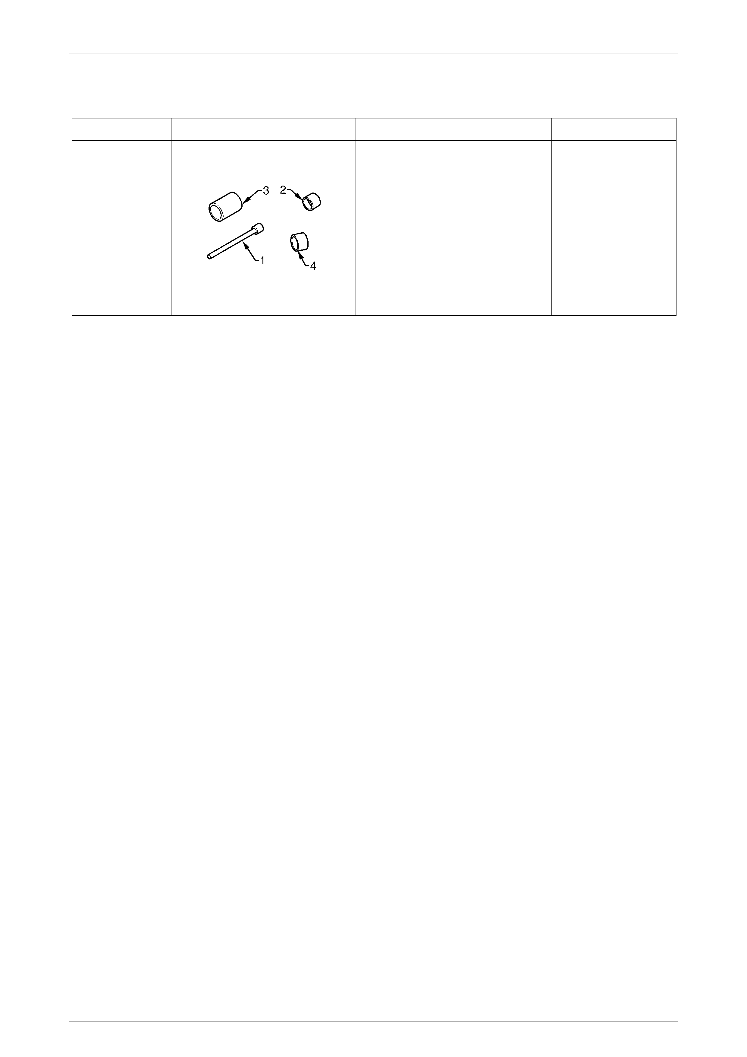
7 Special Tools
TOOL NUMBER ILLUSTRATION DESCRIPTION CLASSIFICATION
AU606
PRESS TOOL
Used to remove/install leaf spring
eye bush.
Consists of:
1. AU606-1 – Centre Spigot
2. AU606-2 – Bush Remover
3. AU606-3 – Bush Catcher
4. AU606-4 – Bush Installer
Unique