Rear Axle Page 4B –1
Page 4B–1
Section 4B
Rear Axle
ATTENTION
Before performing any Service Operation or other procedure described in this Section, refer to Section 00
CAUTIONS AND NOTES for correct workshop practices with regard to safety and/or property damage.
1 General Information............................................................................................................................... 4
1.1 Cone Type Limited Slip Differential – M78 Series ...............................................................................................5
1.2 Multi-Disc Type Limited Slip Differential – M86 series........................................................................................6
1.3 Rear Axle Assembly Identification........................................................................................................................7
1.4 Rear Axle Assembly Maintenance ........................................................................................................................9
Rear Axle Shaft and Bearings ...............................................................................................................................9
Rear Axle Assembly...............................................................................................................................................9
Rear Axle Assembly Breather ...............................................................................................................................9
Limited Slip Differential Precautions..................................................................................................................10
Lubrication............................................................................................................................................................10
2 Minor Service Operations ................................................................................................................... 12
2.1 Service Cautions and Notes................................................................................................................................12
Road Wheel Replacement Caution .....................................................................................................................12
2.2 Checking Rear Axle Lubricant Level ..................................................................................................................13
2.3 Changing/Flushing Rear Axle Lubricant ............................................................................................................ 15
2.4 Rear Axle Shaft Check For Run-Out and End Float ..........................................................................................16
If Run-out and End Float is Within Specification: .............................................................................................19
If the Run-out and End Float Check, Exceeds Specification:...........................................................................19
2.5 Rear Axle Shaft Wheel Studs ..............................................................................................................................20
Replace .................................................................................................................................................................20
2.6 Combined Rear Axle Backlash Check................................................................................................................24
2.7 Limited Slip Differential Torque Check...............................................................................................................25
2.8 Rear Axle Shaft Assembly................................................................................................................................... 28
Remove .................................................................................................................................................................28
Reinstall ................................................................................................................................................................30
2.9 Rear Axle Shaft, ABS Pulse Ring, Oil Seal, Bearing and Retainer Collar........................................................32
Disassemble .........................................................................................................................................................32
Inspect...................................................................................................................................................................34
Axle Shaft, Bearing and Cone ..........................................................................................................................34
Reassemble ..........................................................................................................................................................35
2.10 Pinion Oil Seal ......................................................................................................................................................37
Remove .................................................................................................................................................................37
Inspect...................................................................................................................................................................39
Reassemble ..........................................................................................................................................................39
2.11 Pinion Flange........................................................................................................................................................42
Replace (Using Old Oil Seal) ...............................................................................................................................42
Replace (Using New Oil Seal)..............................................................................................................................45
Theoretical Example .........................................................................................................................................48
3. Major Service Operations ................................................................................................................... 49
3.1 Rear Axle Assembly.............................................................................................................................................49
Preliminary Check ................................................................................................................................................50
Remove .................................................................................................................................................................51
Reinstall ................................................................................................................................................................54
Techline
Techline
Techline
Techline
Techline
Techline
Techline
Techline
Techline
Techline

Rear Axle Page 4B –2
Page 4B–2
3.2 Rear Axle and Differential Housing Assembly...................................................................................................56
Preliminary Check ................................................................................................................................................57
Disassemble .........................................................................................................................................................58
Inspect...................................................................................................................................................................62
Reassemble ..........................................................................................................................................................62
3.3 Differential Assembly – M78 Series (Standard Non LSD) .................................................................................63
Disassemble .........................................................................................................................................................63
Inspect...................................................................................................................................................................66
Differential Case ...............................................................................................................................................66
Differential Side and Pinion Gears....................................................................................................................67
Ring Gear and Pinion Gear ..............................................................................................................................69
Bearings ...........................................................................................................................................................69
Reassemble ..........................................................................................................................................................70
3.4 Differential Assembly – M78 Series (Cone Type Limited Slip) .........................................................................73
Disassemble .........................................................................................................................................................74
Inspect...................................................................................................................................................................76
Differential Case ...............................................................................................................................................76
Differential Side Gears and Pinion Gears.........................................................................................................76
Ring Gear and Pinion .......................................................................................................................................77
Bearings ...........................................................................................................................................................77
Reassemble ..........................................................................................................................................................77
3.5 Differential Assembly – M86 Series (Multi-Disc Type Limited Slip) .................................................................82
Disassemble .........................................................................................................................................................83
Inspect...................................................................................................................................................................87
Differential Case ...............................................................................................................................................87
Differential Side Gears and Pinion Gears.........................................................................................................87
Differential Concentric Grooved Disc’s, Clutch Plates, Retainers and Dished Spacers....................................87
Ring Gear and Pinion .......................................................................................................................................87
Bearings ...........................................................................................................................................................88
Reassemble ..........................................................................................................................................................88
3.6 Differential Assembly Adjustment and Installation Procedures – All Models ................................................92
Differential Side Bearing Preload And Shim Selection .....................................................................................92
Side Bearing Preload Shim Selection Chart .....................................................................................................93
Hypoid Pinion Bearing Preload Shim Selection ................................................................................................96
Hypoid Pinion Shim Selection Table.................................................................................................................99
Hypoid Pinion Bearing Preload Shim Selection Chart ......................................................................................99
Pinion Installation............................................................................................................................................100
Differential Backlash Setting.............................................................................................................................103
Ring Gear and Pinion Contact Pattern .............................................................................................................105
Tooth Marking Terminology ............................................................................................................................105
Ideal Contact.......................................................................................................................................................107
Drive Side .......................................................................................................................................................107
Coast Side ......................................................................................................................................................107
Acceptable Heel Contacts .................................................................................................................................108
Drive Side .......................................................................................................................................................108
Coast Side ......................................................................................................................................................108
Acceptable Toe Contacts...................................................................................................................................109
Drive Side .......................................................................................................................................................109
Coast Side ......................................................................................................................................................109
4. Diagnosis............................................................................................................................................ 110
4.1 General Information ...........................................................................................................................................110
Road Test............................................................................................................................................................110
Tyre Noise...........................................................................................................................................................110
Front Wheel Bearings ........................................................................................................................................110
Transmission Rear Bearing (Manual Transmission).......................................................................................111
Backlash Clunk...................................................................................................................................................111
Drive-Line Snap.................................................................................................................................................. 111
Engine and Other Contributing Factors: .........................................................................................................111
Vehicles with Manual Transmission:...............................................................................................................111

Rear Axle Page 4B –3
Page 4B–3
4.2 Final Drive Assembly Noise ..............................................................................................................................112
Gear Related Noise ............................................................................................................................................112
Ring Gear and Pinion Noise ...........................................................................................................................112
Differential Side Gear and Pinion Noise .........................................................................................................112
Common Causes of Gear Related Noises......................................................................................................112
Bearing Related Noise .......................................................................................................................................112
Differential Pinion Gear Bearings.................................................................................................................... 112
Axle Shaft Bearings ........................................................................................................................................113
Differential Side Bearings ...............................................................................................................................113
Common Causes of Bearing Related Noises .................................................................................................113
4.3 LSD Noise ...........................................................................................................................................................114
4.4 Differential and Rear Axle Bearing Diagnosis .................................................................................................115
Factors When Diagnosing Bearing Condition .................................................................................................115
Bearing Condition Identification.......................................................................................................................116
Abrasive Roller Wear......................................................................................................................................116
Galling ............................................................................................................................................................116
Bent Cage.......................................................................................................................................................116
Abrasive Step Wear........................................................................................................................................117
Etching............................................................................................................................................................117
Bent Cage.......................................................................................................................................................117
Indentations .................................................................................................................................................... 118
Cage Wear .....................................................................................................................................................118
Misalignment ..................................................................................................................................................118
Cracked Inner Race........................................................................................................................................119
Fatigue Spalling..............................................................................................................................................119
Brinelling.........................................................................................................................................................119
Frettage ..........................................................................................................................................................120
Stain Discolouration........................................................................................................................................120
Heat Discolouration ........................................................................................................................................120
Smears ...........................................................................................................................................................121
5. Specifications..................................................................................................................................... 122
6. Torque Wrench Specifications ......................................................................................................... 125
7. Special Tools...................................................................................................................................... 127
Rear Axle Page 4B –4
Page 4B–4
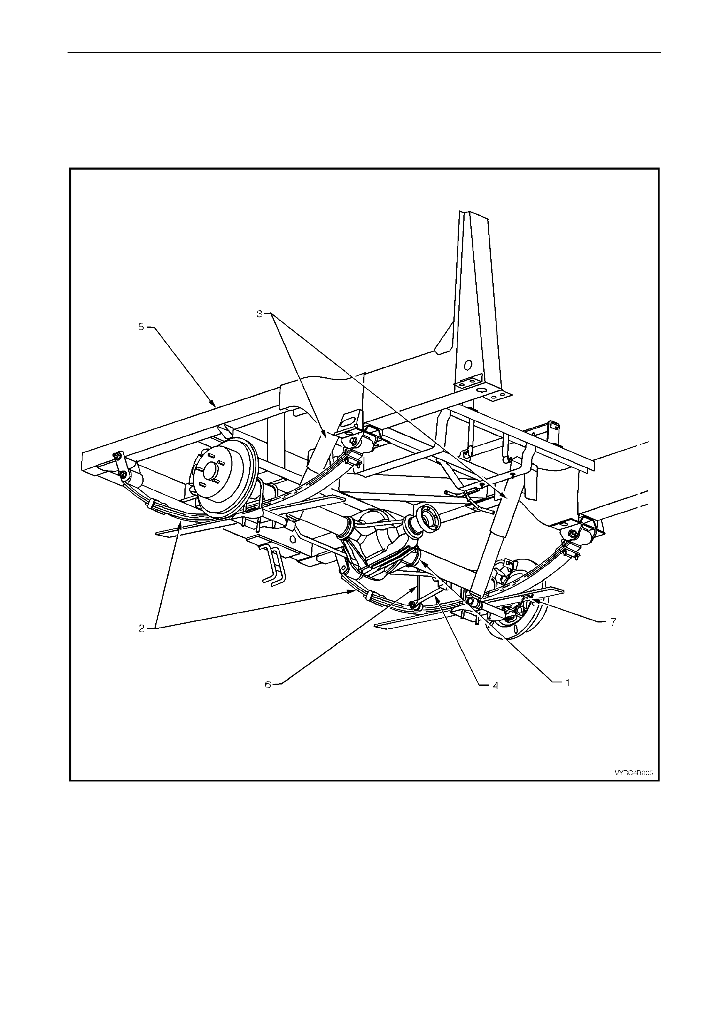
1 General Information
The Rear Axle Assembly as fitted to the MY2003 VY Series Cab Chassis Models is a Salisbury (Unitised carrier) type
rigid live axle, mounted to a leaf spring rear suspension system in conjunction with shock absorbers and stabilizer bar as
standard equipm ent.
Figure 4B-1
Legend
1 Rear Axle Assembly
2 Rear Leaf Spring Assembly
3 Rear Shock Absorber
4 Rear Suspension Stabilizer Bar
5 Chassis Frame
6 Rear Stabilizer Bar to Chassis Link
7 Rear ABS Sensor
Rear Axle Page 4B –5
Page 4B–5
The ring gear diameter varies from 197 mm with a ratio of 3.08:1 (Production option GU4), to 220 mm with a ratio of
3.07:1 (Production option GU4) or 3.46:1 (Production option GS9). The rear axle ratio is dependent on the engine and
transmission fitted to the vehicle while Production option G80, Limited Slip Differential (LSD), (also referred to as Spin
Resistant Differential - SRD) is available on all V6 models and is standard equipment on Gen III V8 models.
The rear axle assembly is mounted to the chassis via leaf springs, ‘U’ bolts, spring shackles and spring eye bushings.
The differential case, hypoid ring and hypoid pinion gears are mounted by opposing tapered roller bearings in the rear
axle housing. Differential side bearing preload adjustment is provided by shims located between the tapered roller
bearing cups and the sides of the rear axle housing. A collapsible spacer and companion flange-retaining nut provide
pinion bearing preload.
Torque is transferred from the propeller shaft to the rear axle assembly via the pinion flange, which is splined to the
hypoid pinion gear. The torque is then transferred from the hypoid pinion gear through the hypoid ring gear, differential
case, differential pinion cross shafts, differential pinion gears, side gears and then via splines on the axle shafts to the
road wheels.
NOTE:
ABS is standard equipment on all models.
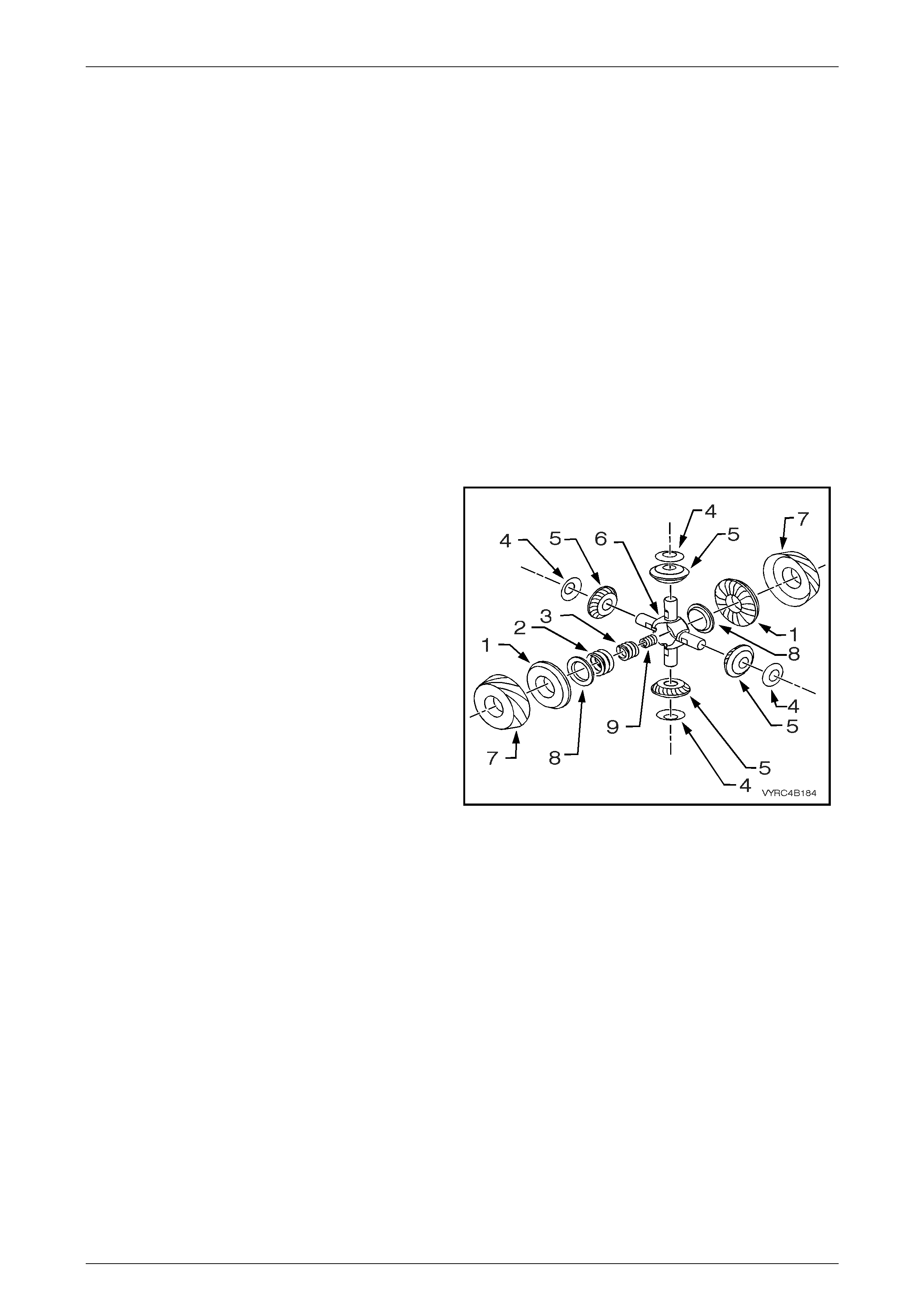
1.1 Cone Type Limited Slip Differential – M78
Series
Legend
1 Gear – Differential Side
2 Spring – Outer, Differential Preload
3 Spring – Intermediate, Differential Preload
4 Washer – Thrust, Differential Pinion Gear
5 Gear – Differential Pinion
6 Block – Thrust, Differential
7 Cone – Clutch
8 Plate – Thrust, Spring
9 Spring – Inner, Differential Preload
Figure 4B-2
The M78 Series Limited Slip Differential (LSD), used with V6 models, performs the same functions as the conventional
type differential but in addition, transfers driving force to the wheel with traction, should the opposite wheel begin to spin.
The differential case houses two cone type clutches behind the side gears that are splined to the inner axle shafts and
their tapered faces contact corresponding faces in the differential case.
On this LSD, the cones form an integral part of the side gears. The four pinion type LSD has three preload springs
enclosed in the centre of the pinion cross shaft. The LSD directs the major driving force to the wheel with the greater
amount of traction, but will not interfere with steering characteristics or differential action. The inherent separating forces
between the side gears and pinions automatically increase the partial locking action, due to the spring load on the cones,
which progressively increases the resistance in the differential as applied torque is increased.
When the rear wheels are under extremely unbalanced conditions, such as a wheel on a dry road and the other in mud
or ice, with the standard differential, wheel spin easily occurs if over-acceleration is attempted. However, with a LSD,
when the tendency for wheel spin occurs, the friction generated inside the case, therefore transfers greater driving force
to the non-spinning wheel. In the event of continued spinning, a whirring sound from the over-running cones is produced
but this condition/sound does not indicate failure of the unit.

Rear Axle Page 4B –6
Page 4B–6
1.2 Multi-Disc Type Limited Slip Differential
– M86 series
Legend
1 Retainer – Clutch Plate
2 Washer – Thrust, Differential Pinion Gear
3 Gear – Differential Pinion
4 Gear – Differential Side
5 Spacer – Dished
6 Disc – Concentric Grooved
7 Clutch Plate
8 Shaft – Differential Pinion Gear, Long
9 Pin – Retaining, Differential Pinion Gear Shaft
Figure 4B-3
The M86 Series Limited Slip Differential (LSD), used with all V8 models, performs the same functions as the M78 type
LSD. Like the M78 Series, the M86 Series differential transfers driving force to the wheel wi th traction should the
opposite wheel begin to spin. The differential case houses four concentric grooved disc plates, four clutch plates, two
clutch plate retainers and a dished spacer behind each side gear. The side gears are splined to match the inner axle
shafts.
On the M86 Series LSD the concentric grooved disc plates are splined to the outer hub face of the side gears while the
clutch plates are supported by retainers that locate in the pockets of the differential hous ing.
As with the M78 Series, the M86 Series LSD directs the major driving force to the wheel with the greater amount of
traction, but will not interfere with steering characteristics or differential action. The partial locking action is due to the
force applied by the dished spacer to the concentric grooved disc plates, which in turn applies force to the clutch plates.
The inherent separating forces between the side gears and pinions automatically increase the force, which progressively
increases the resistance in the differential as applied torque is increased.
When the rear wheels are under extremely unbalanced conditions, such as a wheel on a dry road and the other in mud
or ice, with a standard differential, wheel spin would easily occur if over-acceleration is attempted. However, with the
LSD, when the tendency for wheel spin occurs, the friction generated inside the case, therefore transfers greater force to
the non-spinning wheel
Rear Axle Page 4B –7
Page 4B–7
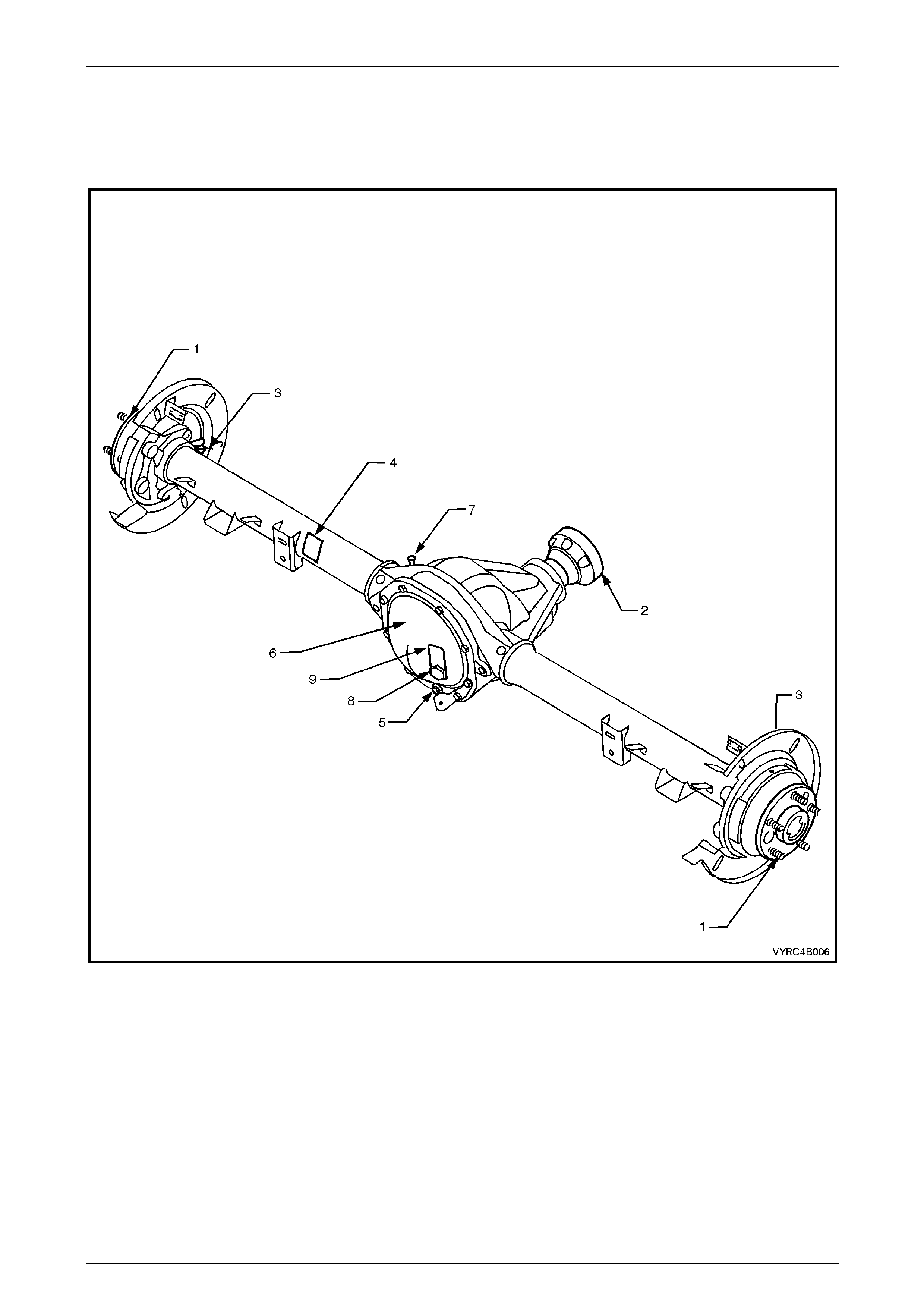
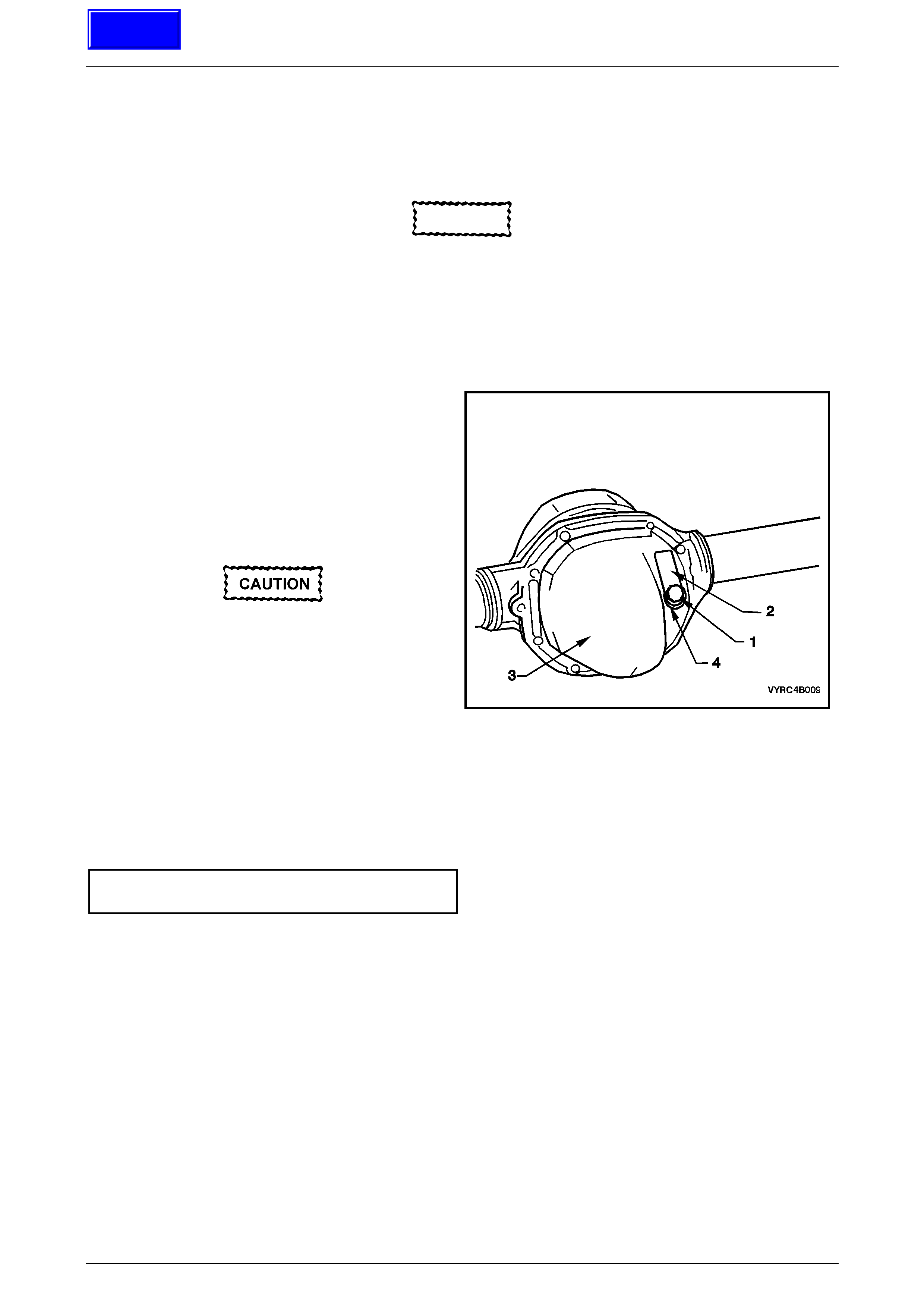
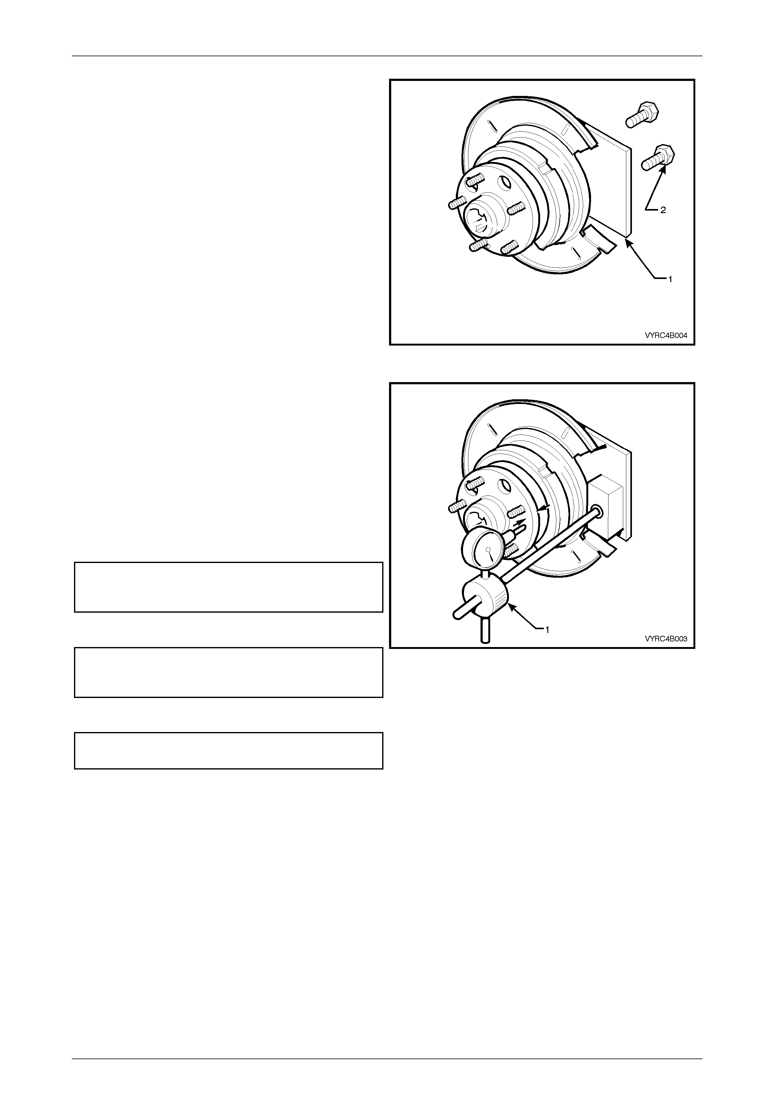
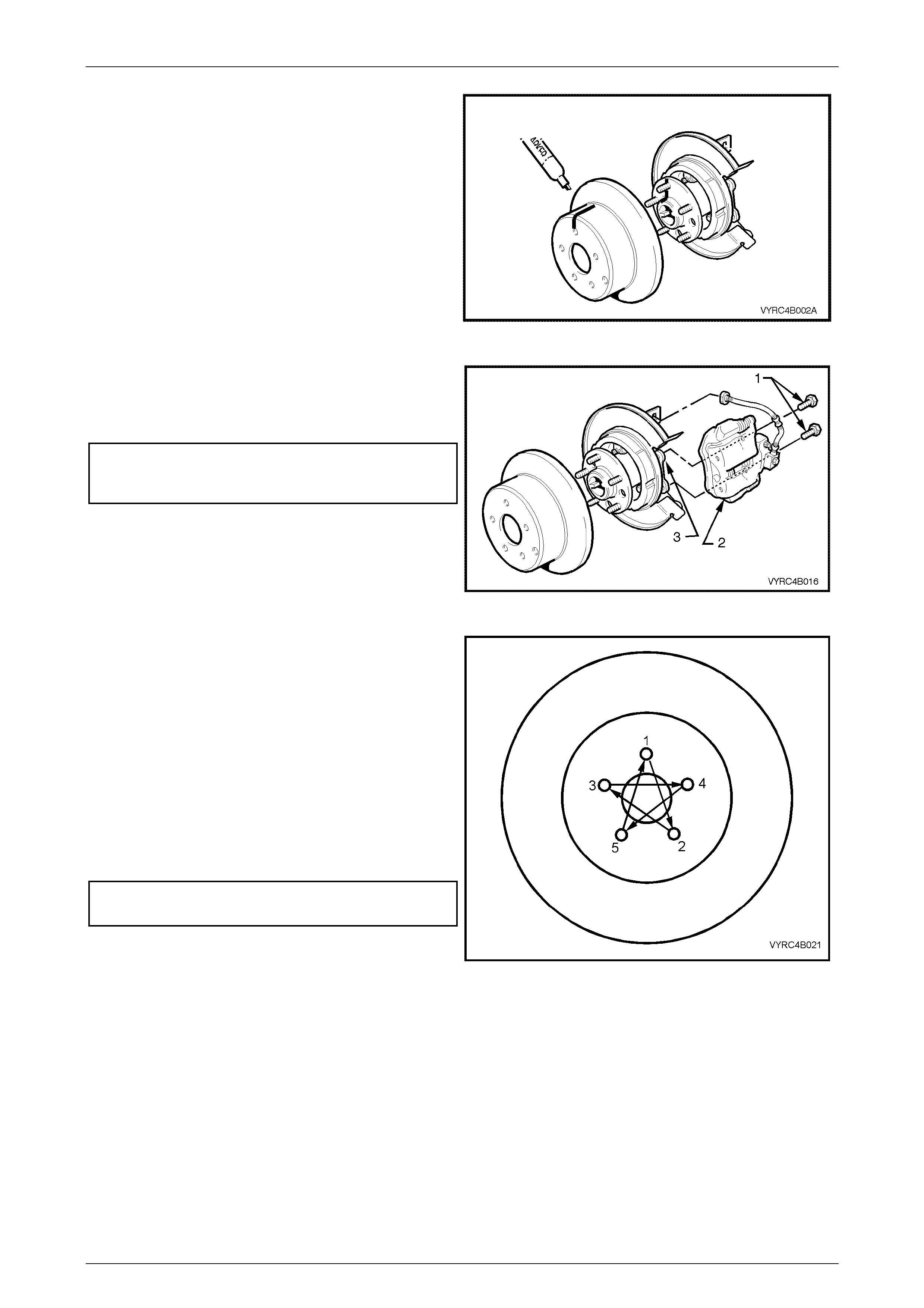
1.3 Rear Axle Assembly Identification
The type of differential fitted to the rear axle assembly can be identified by referring to either the identification label (1)
attached to the LHS of the axle housing and from the lubrication tag (2) under the filler plug (3) on the rear cover.
Figure 4B-4
Legend
1 Rear Axle Shaft
2 Pinion Flange
3 Rear ABS Sensor Mount
4 Identification Label
5 Drain Plug
6 Rear Cover
7 Breather
8 Filler Plug
9 Lubrication Tag

Rear Axle Page 4B –8
Page 4B–8
The locations of the identification label (1) and lubrication tag (2) are as shown in Figure 4B-5.
The identification label (1) carries the rear axle assembly part number, the rear axle ratio, the serial number and the I.D.
code of the assembly.
The code number and bar code is used for production identification of the rear axle assembly.
When fitted, the information on the lubrication tag (2) under the filler plug will be:
1 W ith V6 conventional differential; “HIGH PERFORMANCE. USE APPROVED LUBRICANT ONLY”
2 W ith V6 and GEN III V8 with LSD; “LSD - HIGH PERFORMANCE. USE APPROVED LUBRICANT AND FRICTION
MODIFIER”
USAGE RATIO TYPE I.D. CODE
GEN III V8 with
Manual
Transmission
3.46:1
LSD & ABS
TYW
GEN III V8 with
Automatic
Transmission
3.07:1
LSD & ABS
TYX
ABS (Std)
TYV
V6 with Automatic
Transmission
3.08:1
LSD & ABS
TYU
Figure 4B-5
Rear Axle Page 4B –9
Page 4B–9
1.4 Rear Axle Assembly Maintenance
Rear Axle Shaft and Bearings
The axle shaft outer bearings are lubricated for life and therefore require no periodic maintenance.
If there is any evidence of damage remove the suspect axle shaft. Inspect the axle shaft including the splines, axle
shaft outer bearing and outer axle retaining plate. Refer to 2.4 Rear Axle Shaft Check For Run-Out and End Float,
2.7 Rear Axle Shaft Assembly and 2.9 Rear Axle Shaft, ABS Pulse Ring, Oil Seal, Bearing and Retainer Collar in
this Section.
Rear Axl e Assembly
Check for lubricant leaks at every maintenance service. If there is evidence of leakage, correct leak and add lubricant as
necessary, refer to 2.2 Checking Rear Axle Lubricant Level in this Section.
At the time or distance interval specified in the MY2003 VY Series Cab Chassis Owner's Handbook, check to ensure that
the lubricant level is to the bottom of the filler plug hole.
The rear axle lubricant level MUST be checked
when the rear axle is cold, or overfilling and
oil leaks may occur.
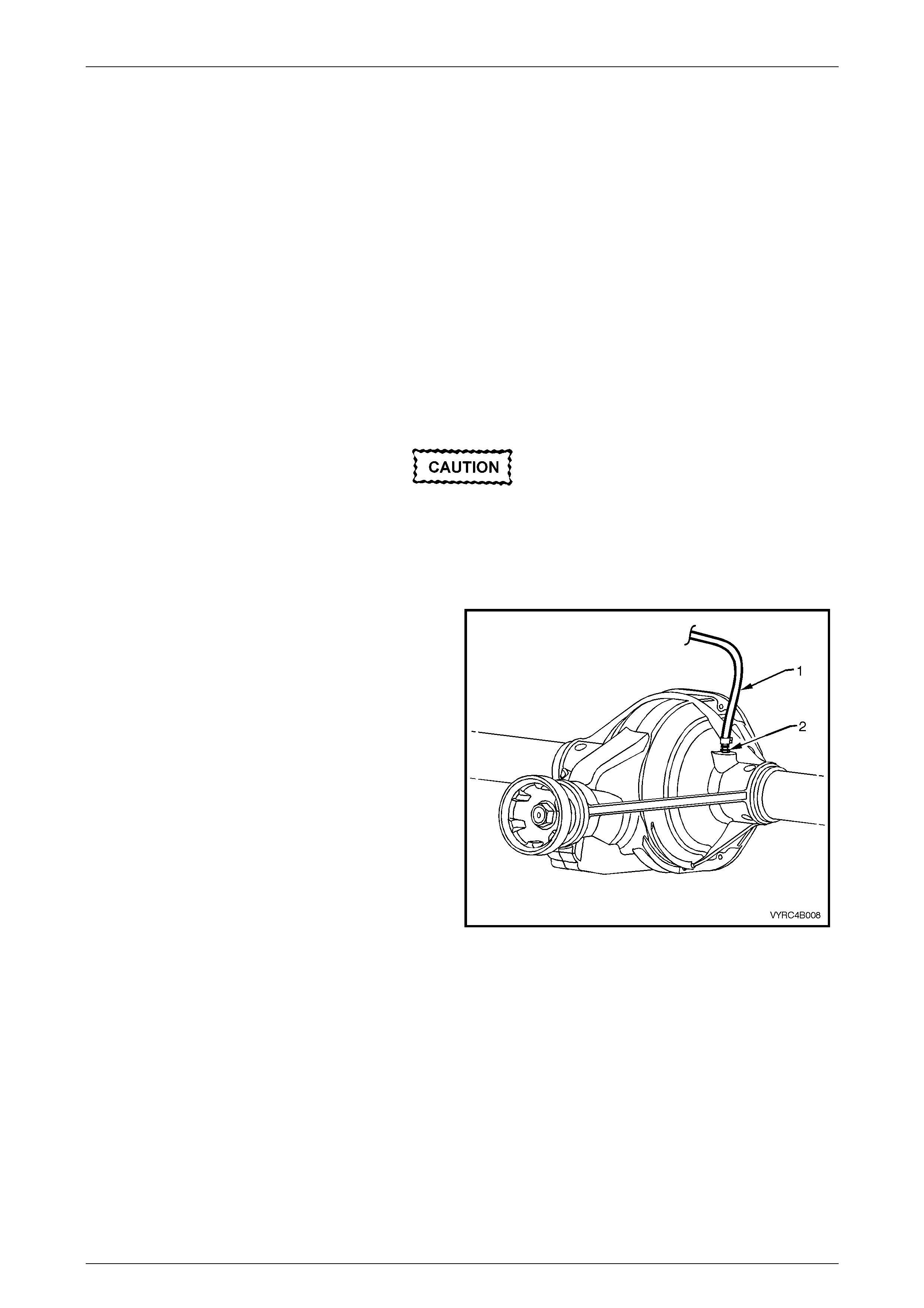
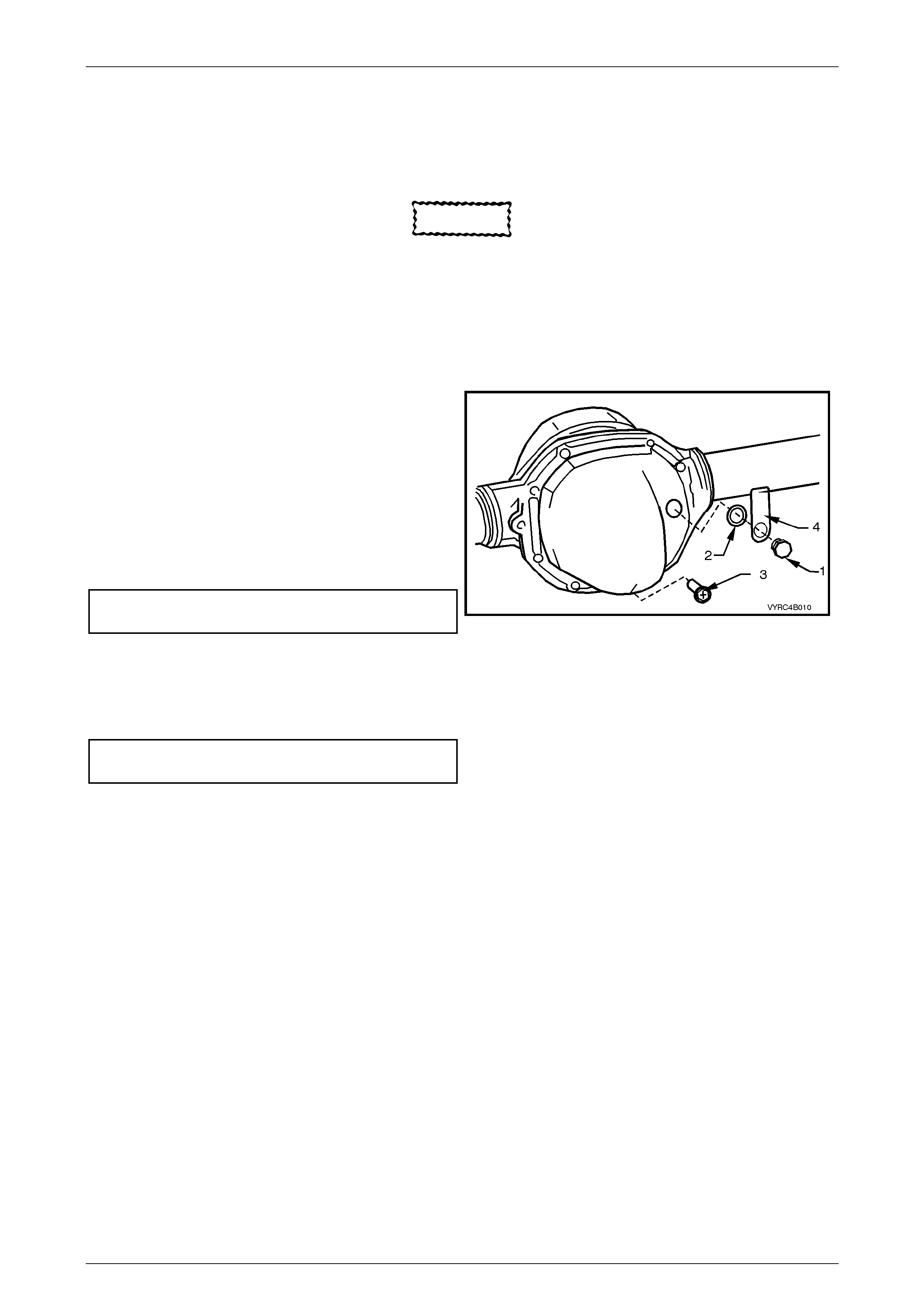
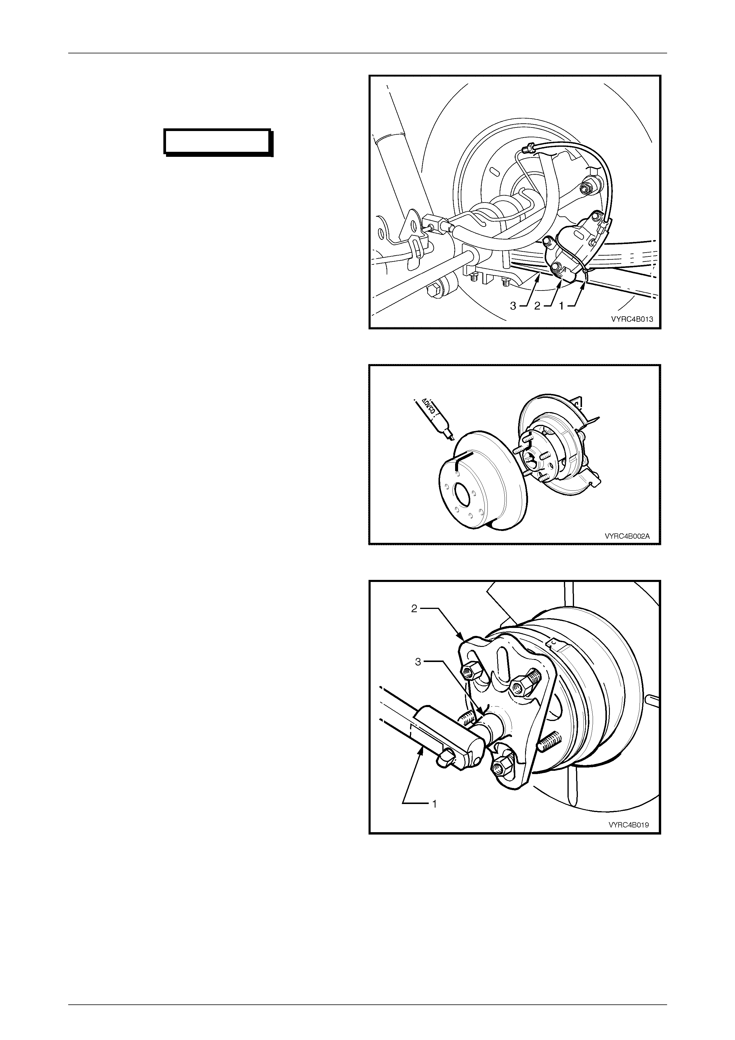
Rear Axl e Assembly Br eat her
1 The breather hose (1) should be checked regularly to
ensure that it is correctly routed and not kinked.
2 The breather fitting (2) should be free from
obstruction.
Figure 4B-6
Rear Axle Page 4B –10
Page 4B–10
Limited Slip Differential Precautions
CAUTION
When servicing a vehicle fitted with a Limited
Slip Differential, never run the engine with the
transmission in gear and one wheel raised.
The driving force to the wheel on the ground
may cause the ve hicle to move.
CAUTION
'On Car' type wheel balancers are not
recommended for use on the rear wheels of
vehicles equipped with a Limited Slip
Differential. One rear wheel will drive if in
contact with the ground when the opposite
wheel is raised and rotated. This type of
balancer may be used, by removing the road
wheel opposite to the one being spun, the
vehicle raised and supported on safety
stands. Refit wheel nuts, reversed, to retain
brake disc.
Lubrication
CAUTION
When servicing either a V6, M78 Series or V8,
M86 Series Rear Axle Assembly fitted with a
Limited Slip Differential, gloves and safety
glasses are recommended when handling the
lubrication additive to prevent any possible
irritation of the skin or eyes
IMPORTANT
The lubricant level should be checked and
topped up (if required), at the time or distance
intervals outlined in the MY2003 VY Series,
Cab Chassis Owner's Handbook with the rear
axle assembly COLD; refer to 2.2 Checking
Rear Axle Lubricant Level in this Section. At
this temperature, the lubricant should be level
with the bottom of the filler plug hole.
Section 4B, 2.2 Checking Rear Axle Lubricant
Level, also details the recommended
lubricants for all rear axle assemblies fitted to
MY 2003 VY, Cab Chassis Series vehicles.
Rear Axle Page 4B –11
Page 4B–11
CAUTION
NEVER USE ANY OTHER THAN THE STATED
AND RECOMMENDED LUBR ICANT.
IMPORTANT
The lubricant for MY2003 VY Series Cab
Chassis Models, is a heavy-duty synthetic
type. Using straight non-LSD type oil in an
LSD rear axle assembly will cause ‘stick-slip’
chatter noise to occur when turning corners.
It must also be noted that, using a mineral
type lubricant in any rear axle assembly fitted
to a GEN III V8 or V6 powered vehicle may
cause gear set and/or bearing damage under
high load driving conditions. The oil seals of
the rear axle assemblies have been specially
formulated to tolerate this synthetic lubricant
along with the LSD lubricant additive. If the
incorrect lubricant is accidentally used in the
rear axle assembly of any MY2003 VY Series
Cab Chassis Model, the rear axle assembly
should be drained, flushed (with the
recommended lubricant) and refilled with the
correct lubricant. For the procedure on this
operation refer to 2.3 Changing/Flushing Rear
Axle Lubricant in this Section.
Rear Axle Page 4B –12
Page 4B–12
2 Minor Service Operations
ATTENTION
All rear axle fasteners are important attaching parts as they affect the performance of vital components
and/or could result in major repair expense. Where specified in this Section, fasteners MUST be replaced with
parts of the same part number or a GM approved equivalent. Do not use fasteners of an inferior quality or
substitute design.
Torque values must be used as specified during reassembly to ensure proper retention of all steering
components.
Through out this Section, fastener torque wrench specifications may be accompanied with the following
Identification marks:
+ Fasteners must be replaced after loosening.
!
!!
! Vehicle must be at kerb height before final tightening.
6
66
6 Fasteners either have micro encapsulated sealant applied or incorporate a mechanical thread lock and
should only be re-used once. If in doubt, replacement is recommended.
If one of these identification marks is present alongside a fastener torque wrench specification, the
recommendation regarding that fastener must be adhered to.
2.1 Service Cautions and Notes
Road Wheel Replacement Caution
1 Whenever a road wheel and/or brake disc is removed
from the vehicle, the relationship of the road wheel
and the disc to the hub MUST be marked with a pen
or similar, in order for those parts to be reinstalled in
their original positi ons. This is critical to maintai n the
brake disc and road wheel runout dimension to a
minimum.
2 When reinstalling road wheels, do not use an impact
gun to tighten wheel nuts unless the impact gun is
fitted with a torque limiter socket (Tool No. AU534 or
a commercial equivalent).
Failure to correctly tighten wheel nuts to the correct torque
specificat ion and in the corre ct order may result in a
distorted brake disc, leading to the development of brake
shudder. For a complete description of the method used to
measure both brake disc and trunnion assembly runout
and correction, refer to Section 5A Standard Brakes,
3.5 Rear Brake Disc – Brake Disc and Hub Indexing
Procedure, in the MY2003 VY Series Service Information.
(!) Road wheel attaching nut
torque specific atio n .................................. 110 – 140 Nm
Figure 4B-7
Rear Axle Page 4B –13
Page 4B–13
2.2 Checking Rear Axle Lubricant Level
LT Section No: 05-400
CAUTION
When servicing either a V6, M78 Series or V8,
M86 Series Rear Axle Assembly fitted with a
Limited Slip Differential, gloves and safety
glasses are recommended when handling the
lubrication additive to prevent any possible
irritation of the skin or eyes
1 Ensure that the vehicle is level.
2 Clean area around filler plug (1).
Refer to Figure 4B-8.
3 Remove filler plug (1) from rear cover (3) (do no t lose
the lubrication tag (2) from the plug, if fitted).
4 The lubricant level is to be maintained at the bottom
edge of the filler plughole.
The rear axle lubricant level MUST be
checked when the rear axle is cold, or
overfilling and oil leaks may occur.
NOTE:
Use only the recommended lubricant.
5 Inspect fill er plug (1) and sealing washer (4) for
damage, if OK, reinstall to the rear cover (3)
(including the lubrication tag (2). If damaged, replace
plug and the sealing w asher.
6 Tighten filler plug (1) to the correct torque
specification.
Rear axle filler plug
torque specification ......................................23 – 31 Nm
Figure 4B-8
Techline
Rear Axle Page 4B –14
Page 4B–14
ENGINE & AXLE TYPE RECOMMENDED LUBRIC ANT
V6 M78 Series
Non LSD
Synthetic Hypoid Gear Oil, such as; MOBIL Mobilube
SHC ID, CASTROL SAF-XA or equivalent lubricant to
Holden's Specification HN2040.
V6 M78 Series LSD
(Cone Type)
CAUTION
When servicing a V6 M78 Series Rear Axle
Assembly fitted with a Limited Slip
Differential, gloves and safety glasses are
recommended when handling the
lubrication additive to prevent any
possible irritation of the skin or eyes
Synthetic Hypoid Gear Oil, such as; MOBIL Mobilube
SHC ID, CASTROL SAF-XA or equivalent lubricant to
Holden's Specification HN2040.
In addition to the synthetic, hypoid gear oil, additive kit (part
number 92145121) must also be used.
The additive kit consists of:
1 LSD Additive – 100 ML special container
2 Material Safety Data Sheet
3 Lubrication ID Tag
GEN III V8
M86 Series LSD
(Multi Disc Type)
Synthetic Hypoid Gear Oil, such as; MOBIL Mobilube
SHC ID, CASTROL SAF-XA or equivalent lubricant to
Holden's Specification HN2040.
Rear Axle Page 4B –15
Page 4B–15
2.3 Changing/Flushing Rear Axle Lubricant
LT Section No: 05-400
CAUTION
When servicing either a V6, M78 Series or V8,
M86 Series Rear Axle Assembly fitted with a
Limited Slip Differential, gloves and safety
glasses are recommended when handling the
lubrication additive to prevent any possible
irritation of the skin or eyes
1 To drain lubricant from rear axle assembly, remove
filler plug (1), the sealing washer (2) and drain plug
(3) refer to Figure 4B-9 and allow (preferably warm)
lubricant to drain into a suitable container.
2 If flushing is required, use an undiluted quantity of the
recommended lubricant for the operation.
3 When the draining (and flushing if required) operation
is complete, apply thread-sealing tape to drain plug
(3) thread. Install and tighten drain plug (3) to the
correct torque specification.
Rear axle drain plug
torque specification ......................................23 – 31 Nm
4 Fill the rear axle assembly with a total of 1.7 litres of
the recommended lubricant (1.6 litres of lubricant plus
100 ML of LSD additive), install the filler pl ug (1)
along with the sealing washer (2) and lubrication tag
(4), then tighten to the correct torque speci fic atio n.
Rear axle filler plug
torque specification ......................................23 – 31 Nm
Figure 4B-9
Rear Axle Page 4B –16
Page 4B–16
2.4 Rear Axle Shaft Check For Run-Out and
End Float
LT Section No: 05-400
ATTENTION
The following fasteners have either micro encapsulation or incorporate a mechanical thread lock and should
only be used once. If in doubt, replacement is recommended when performing this operation:
6
66
6 Rear brake caliper to rear axle anchor plate attaching bolts.
The following fasteners MUST have the ve hicle at curb height before final tightening.
!
!!
! Road Wheel attaching nuts.
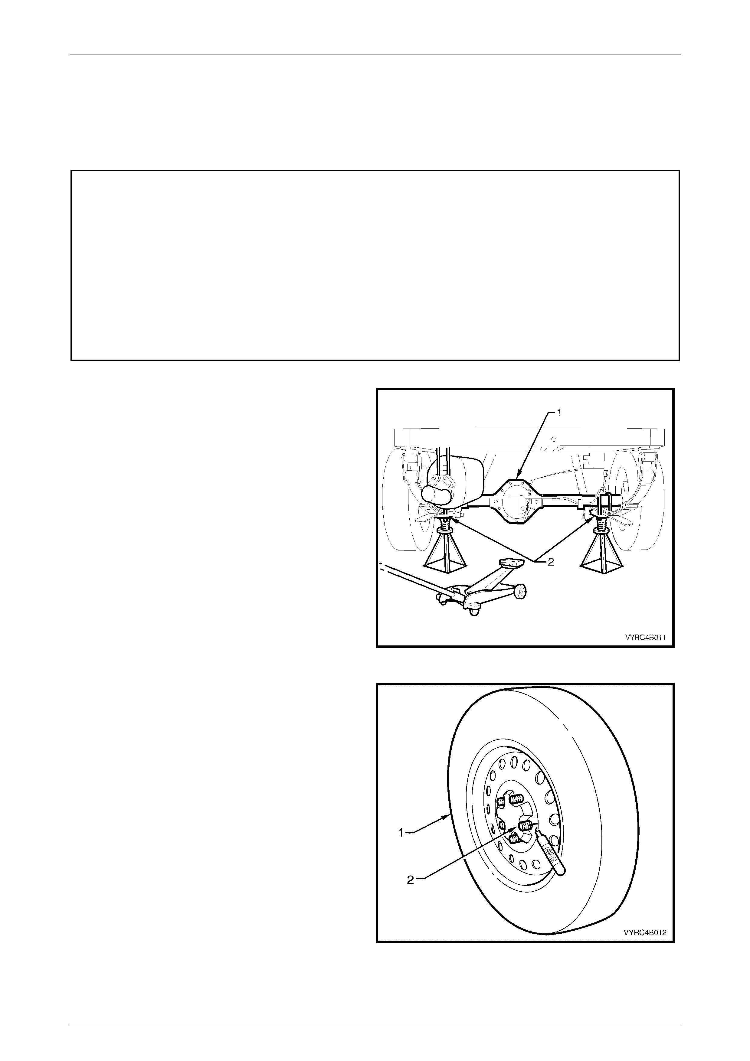
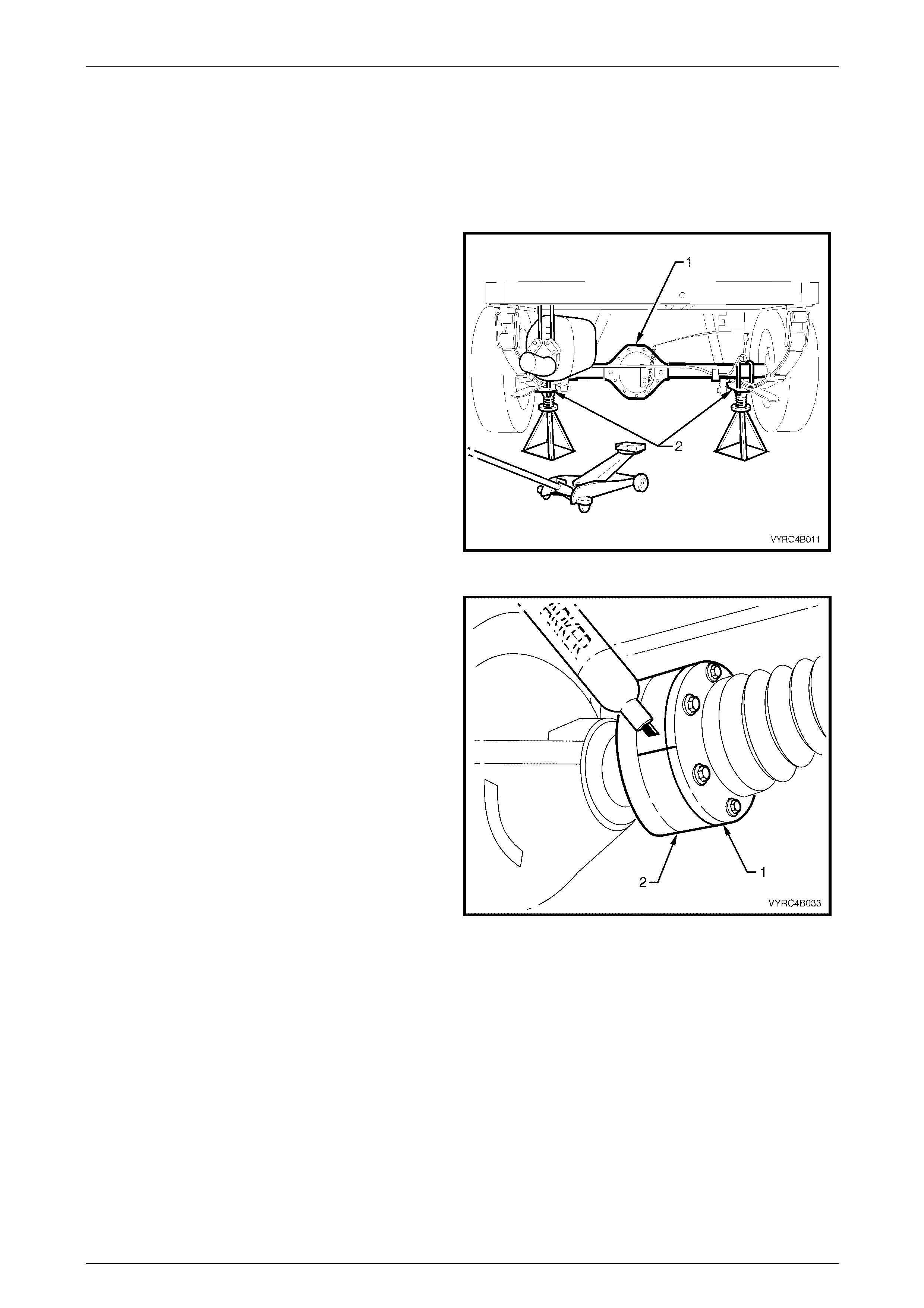
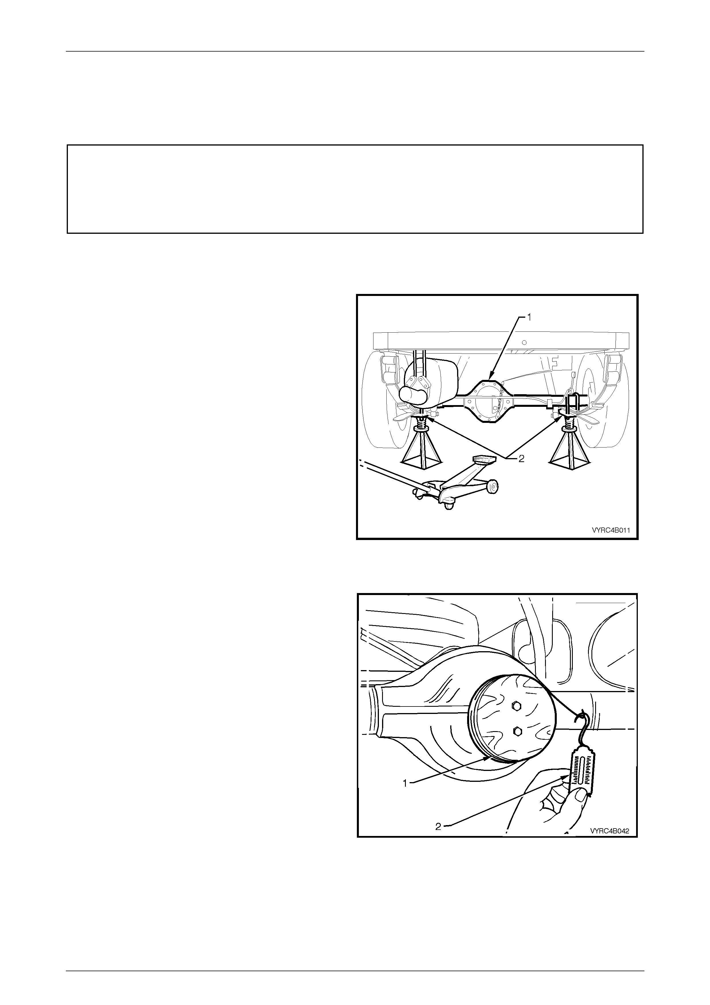
1 Using a floor jack under the centre of the rear axle
assembly (1), jack up the rear of the vehicle, then
place safety stands under the rear leaf spring retainer
plates (2) on both left-hand and right-hand sides to
support the weight of the vehicle.
Refer to Figure 4B-10.
Figure 4B-10
3 Remove the rear wheel cover (steel wheels) or wheel
nut covers (alloy wheels) on the side of the vehicle
where the rear axle is to be checked.
4 With a suitable marking pen, mark the relationship of
the wheel (1) to the rear axle wheel-retaining stud’s
(2) and remove the road wheel.
Refer to Figure 4B-11.
Figure 4B-11
Rear Axle Page 4B –17
Page 4B–17
5 Remove the rear brake caliper to rear axle anchor
plate attaching bolts (1), and then remove the brake
caliper (2) from the disc rotor (3).
Refer to Figure 4B-12.
Figure 4B-12
6 Using tie wire (1), secure the caliper (2) to the top of
the rear leaf spring assembly (3).
Refer to Figure 4B-13.
IMPORTANT
Do not allow caliper to hang by brake
hose, as damage to the brake hose may
occur.
Figure 4B-13
7 With a suitable marking pen, mark the relationship of
the brake disc rotor position to rear axle shaft
assembly, then remove the brake disc rotor from the
rear axle shaft assembly.
Refer to Figure 4B-14.
Figure 4B-14
Rear Axle Page 4B –18
Page 4B–18
8 Clean the rear axle face by rubbing lightly with fine
emery paper.
9 Mount the pre-fabricated mounting plate (1) to the
brake caliper mounting points on the rear trailing arm,
using the caliper mounting bolts (2), as shown in
Figure 4B-15. Refer to 7. Sp ecial Tools in this Section
for details on the pre-fabricated mounting plate.
Figure 4B-15
10 Mount a magnetic based dial indicator stand, install a
dial indicator (1), positioning the pointer against the
axle flange face as shown in Fi gure 4B-16.
11 Move the rear axle in and out by pushing and pulling,
noting the points of maximum and minimum end float.
The difference between these two dimensions is the
total indicated end float.
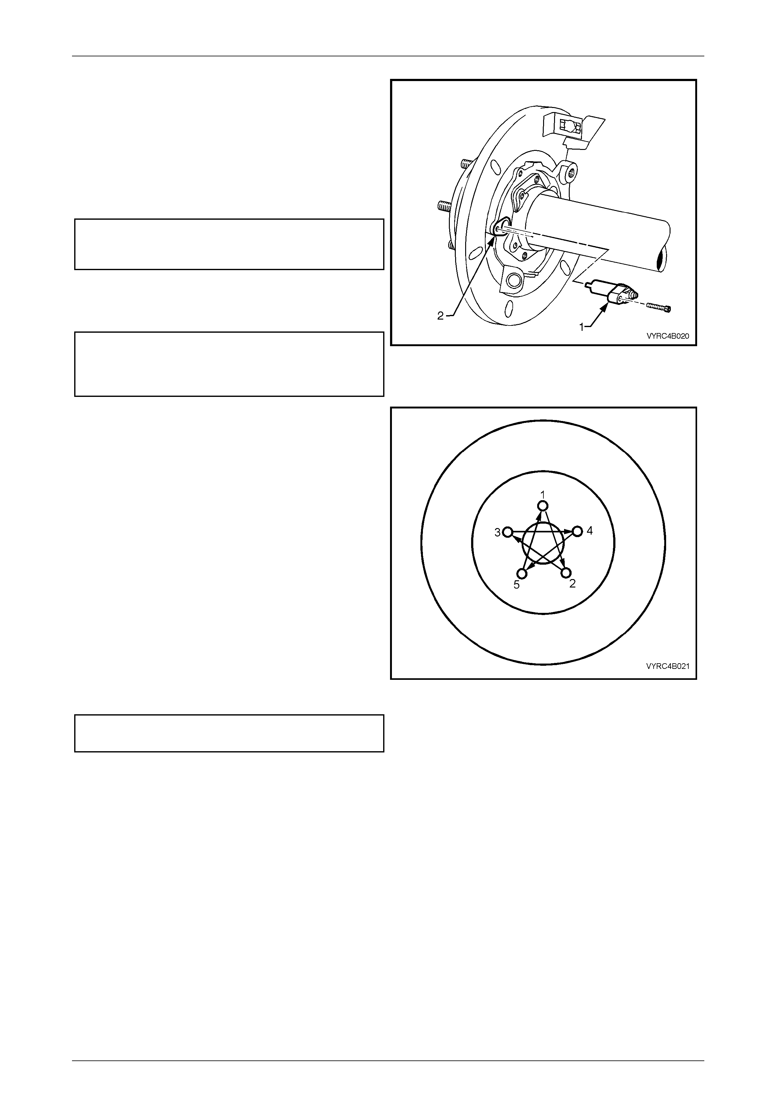
12 Using the wheel studs, carefully rotate the rear axle,
noting the points of maximum and minimum lateral
run-out. The difference between these two
dimensions is the total indicated runout.
Maximum rear axle shaft
with a used bearing
total indicated end floa t .....................................0.75 mm
Rear axle shaft
with a new bearing
total indicated end float ..........................0.02 – 0.30 mm
Maximum rear axle shaft
total indicated run-ou t........................................0.12 mm
Figure 4B-16
Rear Axle Page 4B –19
Page 4B–19
If Run-out and End Float is Within Specification:
1 Reinstall the disc brake rotor over the rear axle wheel
studs, ensuring that the relationship alignment marks
made prior to disassembly are aligned, as shown in
Figure 4B-17.
Figure 4B-17
2 Reinstall the brake caliper (2) to the rear axle anchor
plate, tighten the caliper attaching bolts (1) to the
correct torque specification, as shown in
Figure 4B-18.
3 Reinstall the road wheel, aligning the relationship
marks made prior to removal as shown in Figure 4B-
19.
4 Install and tighten attaching nuts.
5 Remove the safety stand and the lower vehicle.
6 Tighten the road wheel attaching nuts to the correct
torque specification and in the correct sequence, refer
to 2.1 Service Cautions and Notes in this Section.
NOTE:
The vehicle must be at kerb weight and on all
four wheels before this torque is applied.
7 Refit the wheel cover/wheel nut caps.
(6) Brake caliper to rear axle
anchor plate attaching bolt
torque specification .................................. 70 – 100 Nm
Road wheel attaching nut
torque specific atio n .................................. 110 – 140 Nm
Figure 4B-18
Figure 4B-19
If the Run-out and End Float Check, Exceeds Speci fication:
1 The rear axle shaft and or bearing as sembly must be replaced, refer to 2.8 Rear Axle Shaft Assembly also refer to
2.9 Rear Axle Shaft, Oil Seal, ABS Pulse Ring, Bearing and Retainer Collar in this Section.
Rear Axle Page 4B –20
Page 4B–20
2.5 Rear Axle Shaft Wheel Studs
LT Section No: E006600
ATTENTION
The following fasteners have either micro encapsulation or incorporate a mechanical thread lock and should
only be used once. If in doubt, replacement is recommended when performing this operation:
6
66
6 Rear brake caliper to rear axle anchor plate attaching bolts.
The following fasteners MUST have the ve hicle at curb height before final tightening.
!
!!
! Road Wheel attaching nuts.
Replace
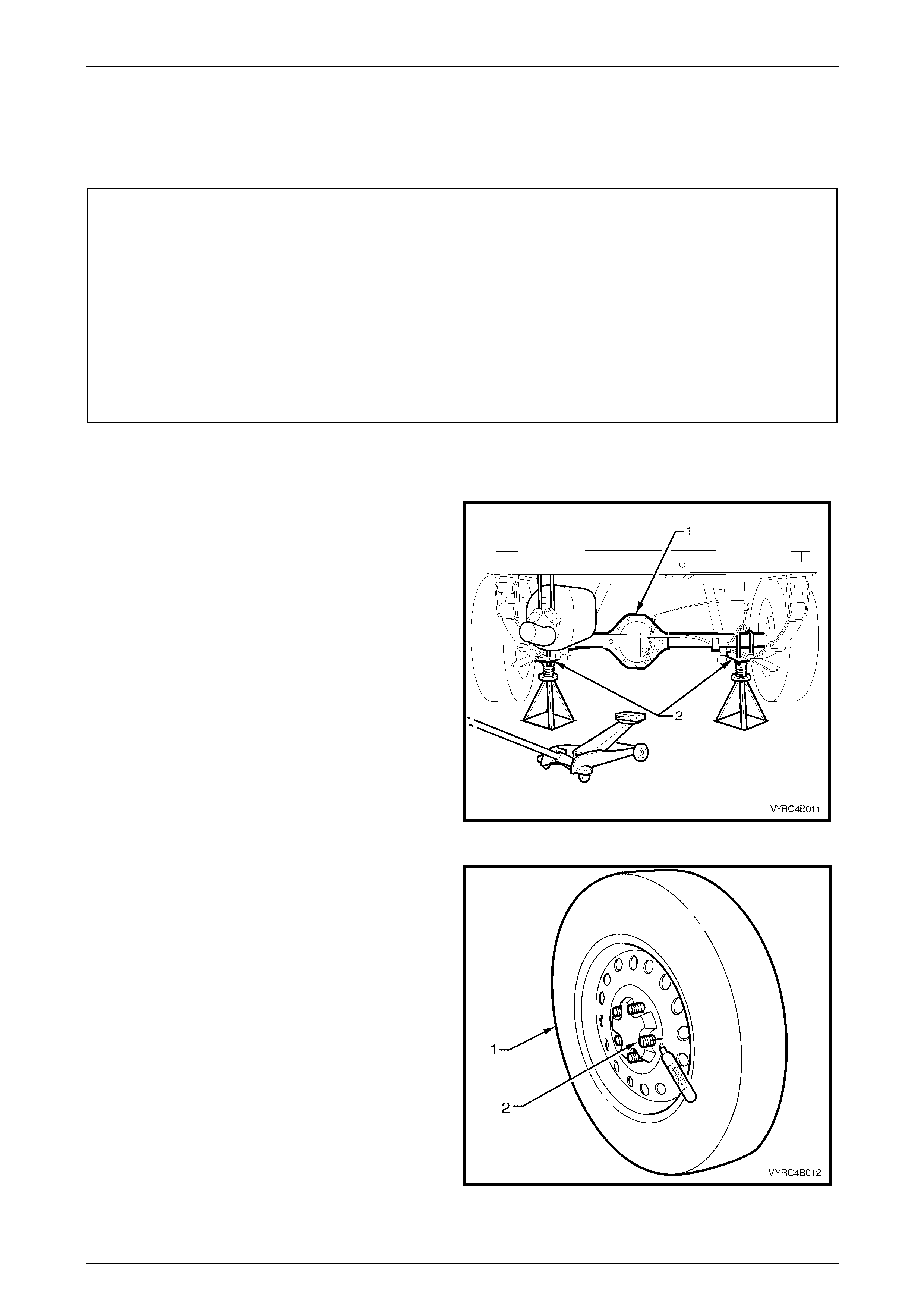
1 Using a floor jack under the centre of the rear axle
assembly (1), jack up rear of vehicle, then place
safety stands under the rear leaf spring retainer
plates (2) on both left-hand and right-hand sides to
support the weight of the vehicle as shown in
Figure 4B-20.
Figure 4B-20
2 Remove the rear wheel cover (steel wheels) or wheel
nut covers (alloy wheels) on that side of the vehicle
where the rear axle is to be checked.
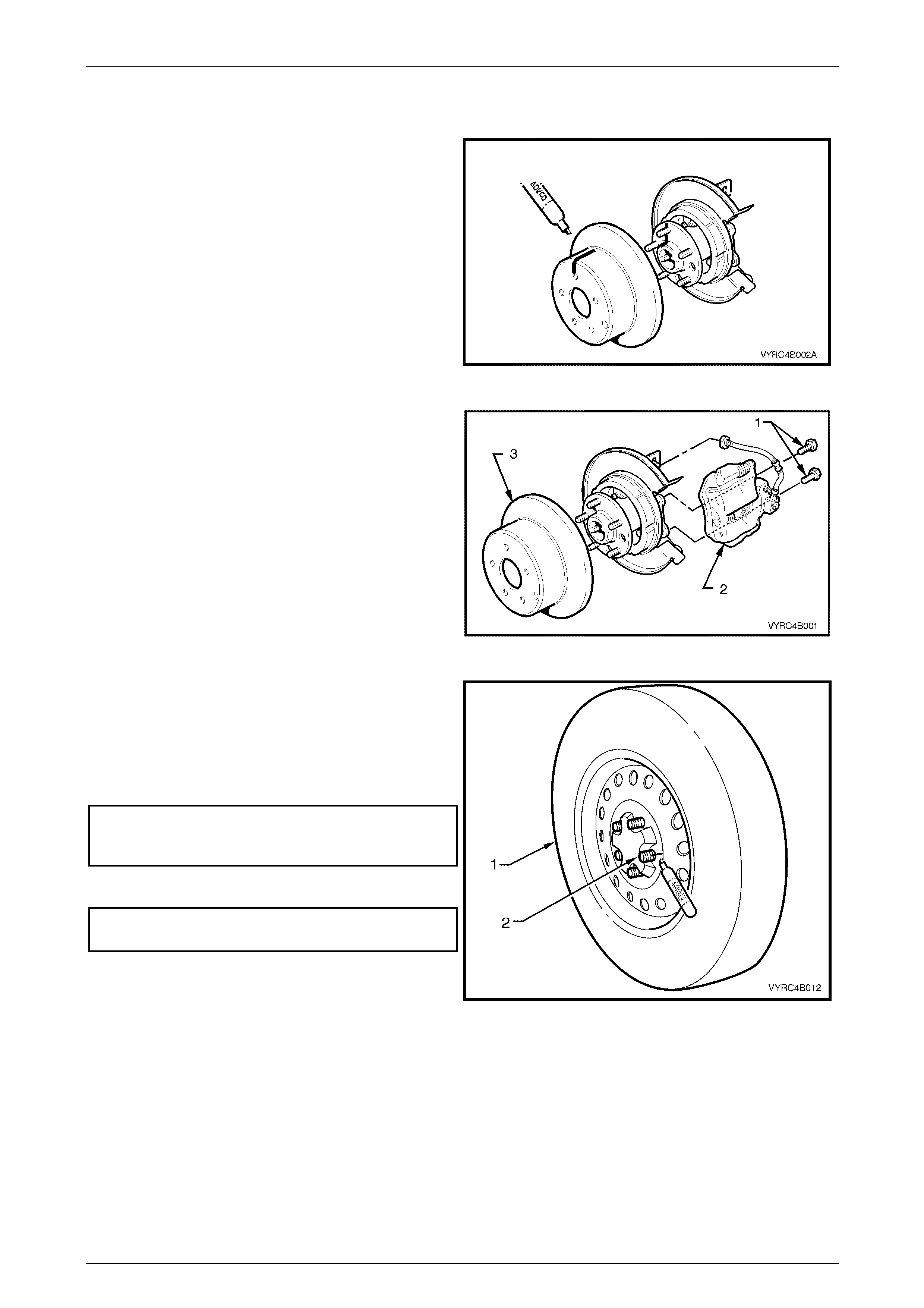
3 With a suitable marking pen, mark the relationship of
wheel (1) to the rear axle wheel reta ining studs (2) as
shown in Figure 4B-21 and remove the road wheel.
Figure 4B-21

Rear Axle Page 4B –21
Page 4B–21
4 Remove rear brake caliper to rear axle anchor plate
attaching bolts (1), remove brake caliper (2) from
the disc rotor (3) as shown in Figure 4B-19.
Figure 4B-22
5 Using suitable tie wire (1), secure the caliper (2) to
the top of the rear leaf spring assembly (3) as shown
in Figure 4B-23.
IMPORTANT
Do not allow the caliper to hang by the
brake hose, as damage to the brake hose
may occur.
Figure 4B-23
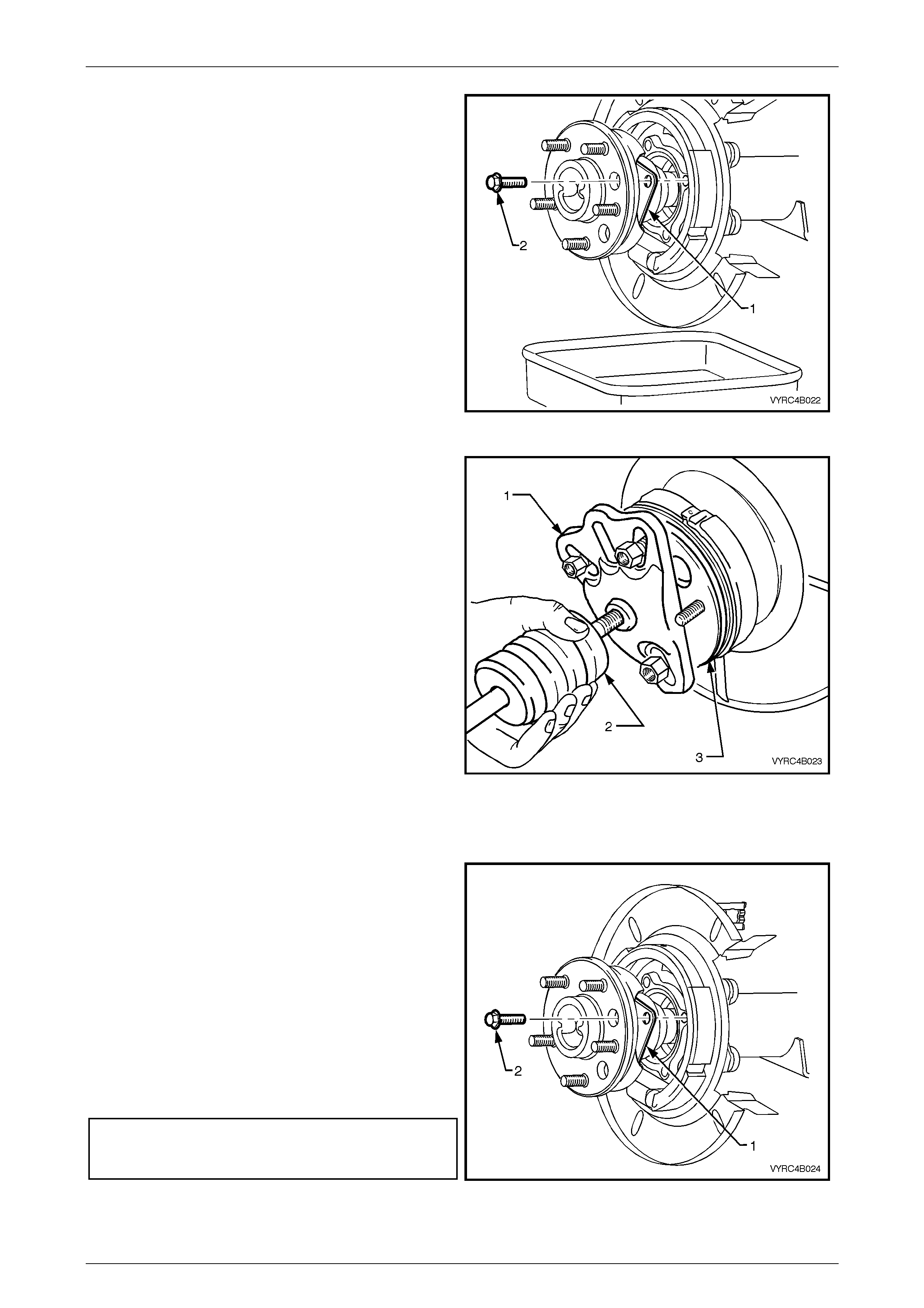
6 With a suitable marking pen, mark the relationship of
the brake disc rotor position to the rear axle shaft
assembly, then remove the brake disc rotor from the
rear axle shaft assembly as shown in Figure 4B-24.
Figure 4B-24
Rear Axle Page 4B –22
Page 4B–22
7 Remove the rear axle shaft assembly; refer to
2.8 Rear Axle Shaft Assembly in this Section.
8 If replacing wheel-attaching studs, remove the rear
axle-bearing race, retaining collar and the ABS
pulse ring before replacing wheel studs. Refer to
2.9, Rear Axle Shaft, ABS Pulse Ring, Oil Seal,
Bearing And Retainer Collar in this Section.
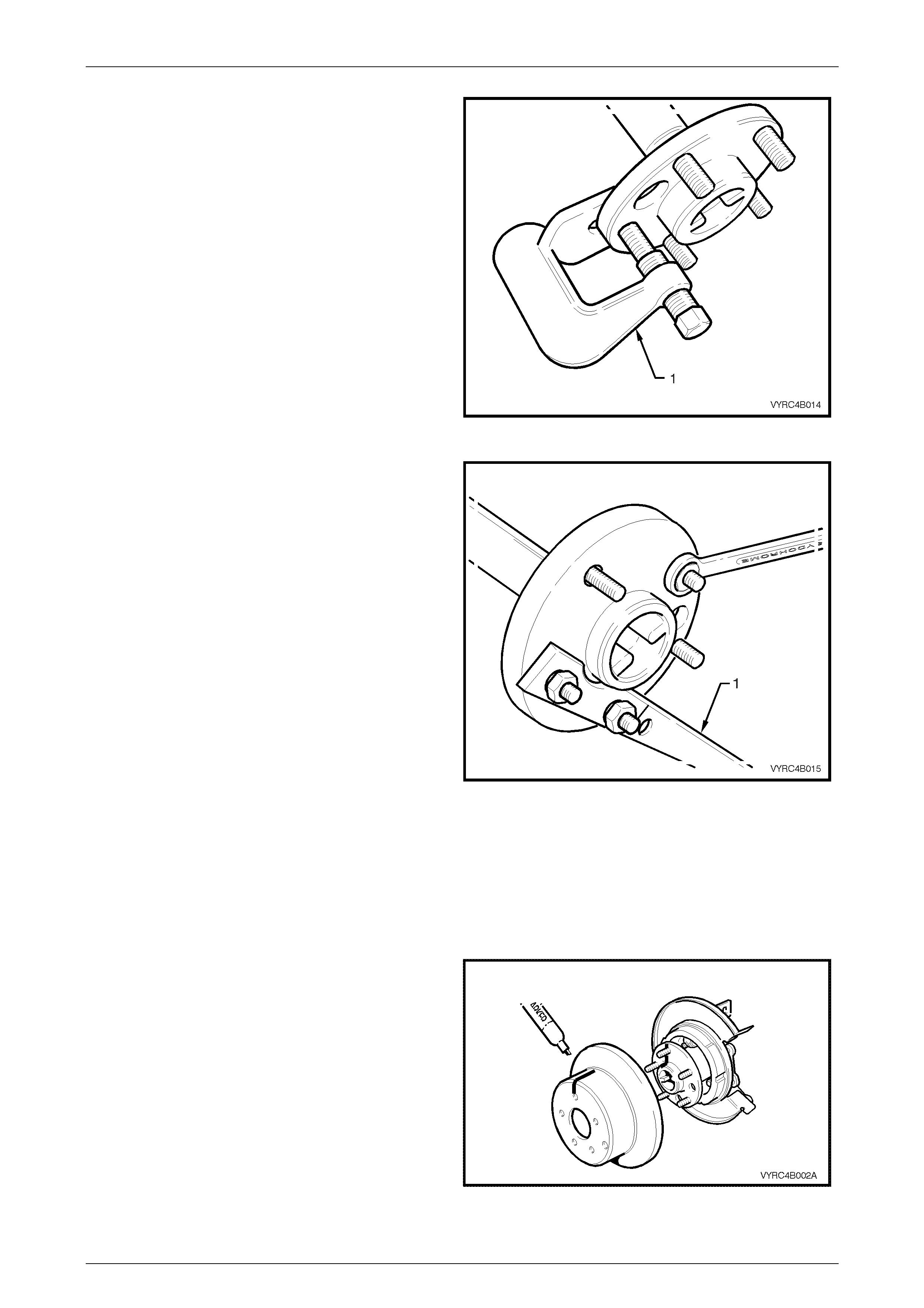
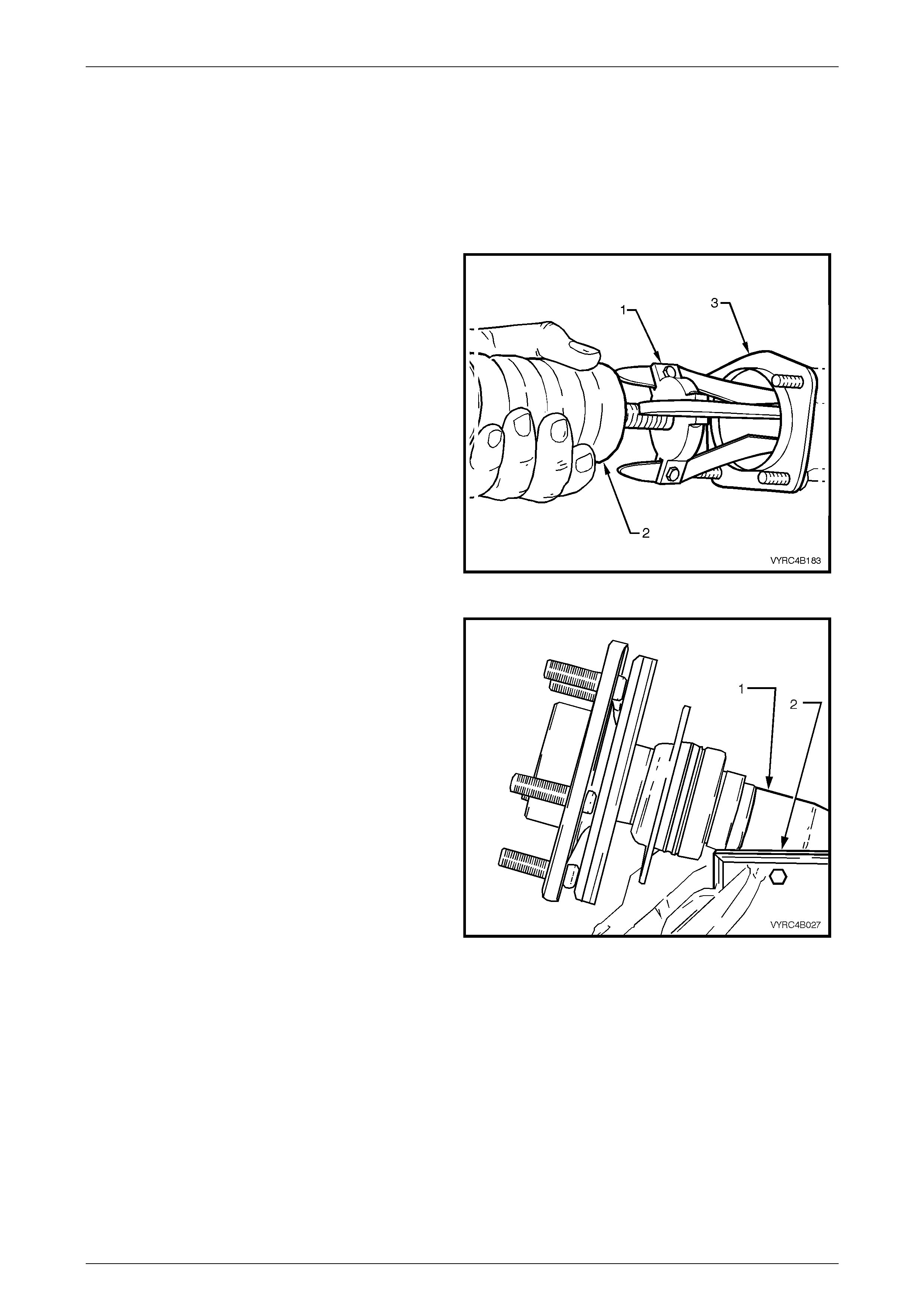
9 Use Tool No. J24292-C (1) or suitable hydraulic press
and support plates to remove the damaged stud from
hub as shown in Figure 4B-25.
10 Remove any remaining studs that require
replacement.
Figure 4B-25
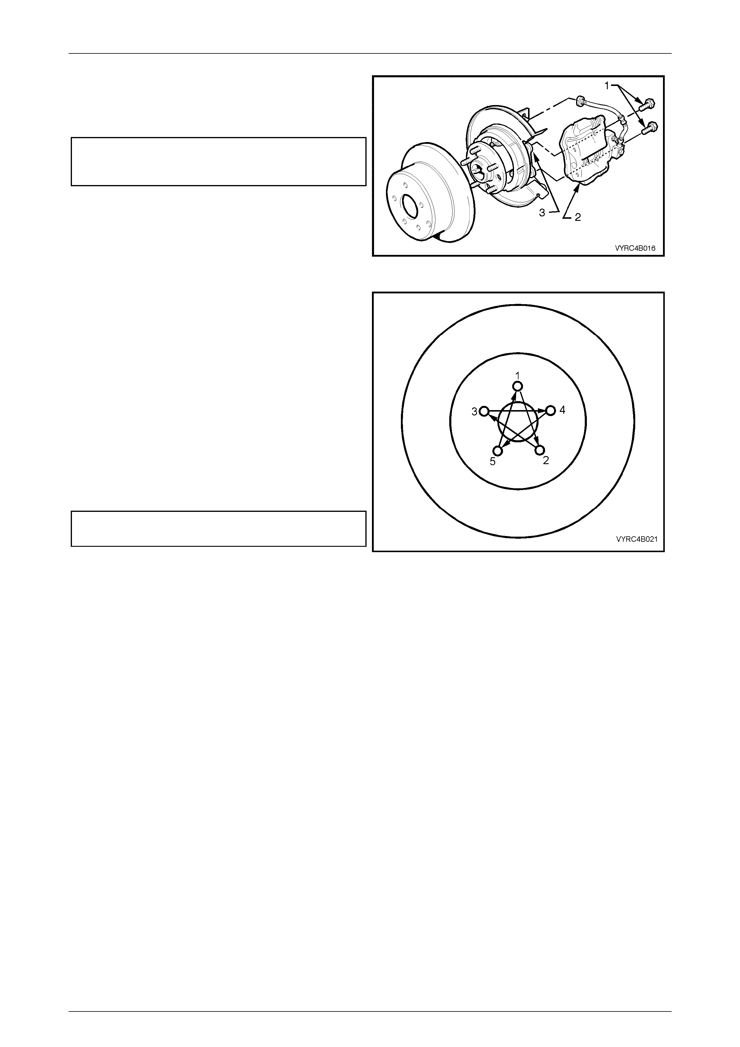
11 Install new studs into the rear axle shaft assembly
using the following method:
a. Install Tool No. KM-468-B holding bar (1), with two
wheel nuts to the rear axle shaft assembly studs.
b. Place the new wheel-attaching stud firmly into the
axle shaft fl ange and rotate the stud to align the
splines.
c. Install a flat washer along with a wheel-attaching
nut to the stud with the tapered side facing
outward or flat face toward the washer.
d. Tighten the wheel-attaching nut with a suitable
spanner to draw in the stud. When the stud is fully
installed, remove wheel nut and washers.
e. Remove Tool No. KM468-B along with the wheel
attaching nuts and washer.
12 An alternative to the method in step 11 is to use a
hydraulic press to install the stud into the rear axle
shaft.
13 Install any remaining studs in the same manner
following steps 11 or 12.
14 Install the rear axle-bearing race, retaining collar,
retaining plate and the ABS pulse ring. Refer to
2.9, Rear Axle Shaft, ABS Pulse Ring, Oil Seal,
Bearing and Retainer Collar in this Section.
Figure 4B-26
15 Reinstall the disc brake rotor over the rear axle wheel
studs, ensuring that the relationship alignment marks
made prior to disassembly are aligned, as shown in
Figure 4B-27.
Figure 4B-27
Rear Axle Page 4B –23
Page 4B–23
16 Reinstall brake caliper (2) to the rear axle anchor
plate (3) and tighten the caliper attaching bolts (1) to
the correct torque specification, as shown in Figure
4B-28.
(6) Brake caliper to rear axle
anchor plate attaching bolt
torque specification .................................... 70 – 100 Nm
Figure 4B-28
17 Reinstall the road wheel, aligning the marks made
prior to removal, install and tighten the wheel
attaching nuts.
18 Remove safety stand and lower vehicle.
19 Tighten road wheel attaching nuts to the correct
torque specification and in the correct sequence, refer
to 2.1 Service Cautions and Notes in this Section.
NOTE:
Vehicle must be at kerb weight and on all four
wheels before this torque is applied.
20 Refit the wheel cover/wheel nut caps.
(!) Road wheel attaching nut
torque specific atio n .................................. 110 – 140 Nm
Figure 4B-29
Rear Axle Page 4B –24
Page 4B–24
2.6 Combined Rear Axle Backlash Check
LT Section No: 05-400
1 Using a the floor jack under centre of the rear axle
assembly (1), jack up the rear of vehicle, then place
safety stands under the rear leaf spring retainer
plates (2) on both left-hand and right-hand sides to
support the weight of the vehicle as shown in
Figure 4B-30.
2 Place the transmission in neutral with the engine
turned OFF.
Figure 4B-30
3 Position a bolt on the pinion drive flange (1) in a
horizontal position to enable a dial indicator (2) to be
positioned for backlash measurement. Refer to
Figure 4B-31.
4 Apply the park brake lever to the fully ON position.
5 Attach a magnetic dial indicator on to the axle carrier
housing.
6 Rotate the propeller shaft by hand, in a clockwise
direction and zero the dial indicator needle.
7 Rotate the propeller shaft by hand, in an
anti-clockwise direction while observing the dial
indicator needle and record the reading.
NOTE:
A torque of approximately 7.0 Nm will need to
be applied in each direction while obtaing the
backlash reading. If the backlash reading is less
than 7.0 mm at the bolt head, then the rear axle
assembly is within acceptable limits.
Figure 4B-31
Techline
Rear Axle Page 4B –25
Page 4B–25
2.7 Limited Slip Differential Torque Check
LT Section No: 05-400
1 Place the transmission in neutral with the engine
turned OFF.
2 Using a floor jack, jack up one rear wheel, leaving the
remaining wheel on the floor and support the vehicle
under the rear axle assembly on raised side with a
safety stand as shown in Figure 4B-32.
Figure 4B-32
3 Remove the rear wheel cover (steel wheel) or wheel
nut cover (alloy wheel) on the raised road wheel.
4 With a suitable marking pen, mark relationship of
wheel (1) to the rear axle wheel reta ining studs (2) as
shown in Figure 4B-33 and remove the road wheel.
5 Release the park brake lever to the fully OFF position
Figure 4B-33
6 Remove the rear brake caliper to rear axle anchor
plate attaching bolts (1), remove the brake caliper (2)
from the disc rotor (3) as shown in Figure 4B-34.
Figure 4B-34
Rear Axle Page 4B –26
Page 4B–26
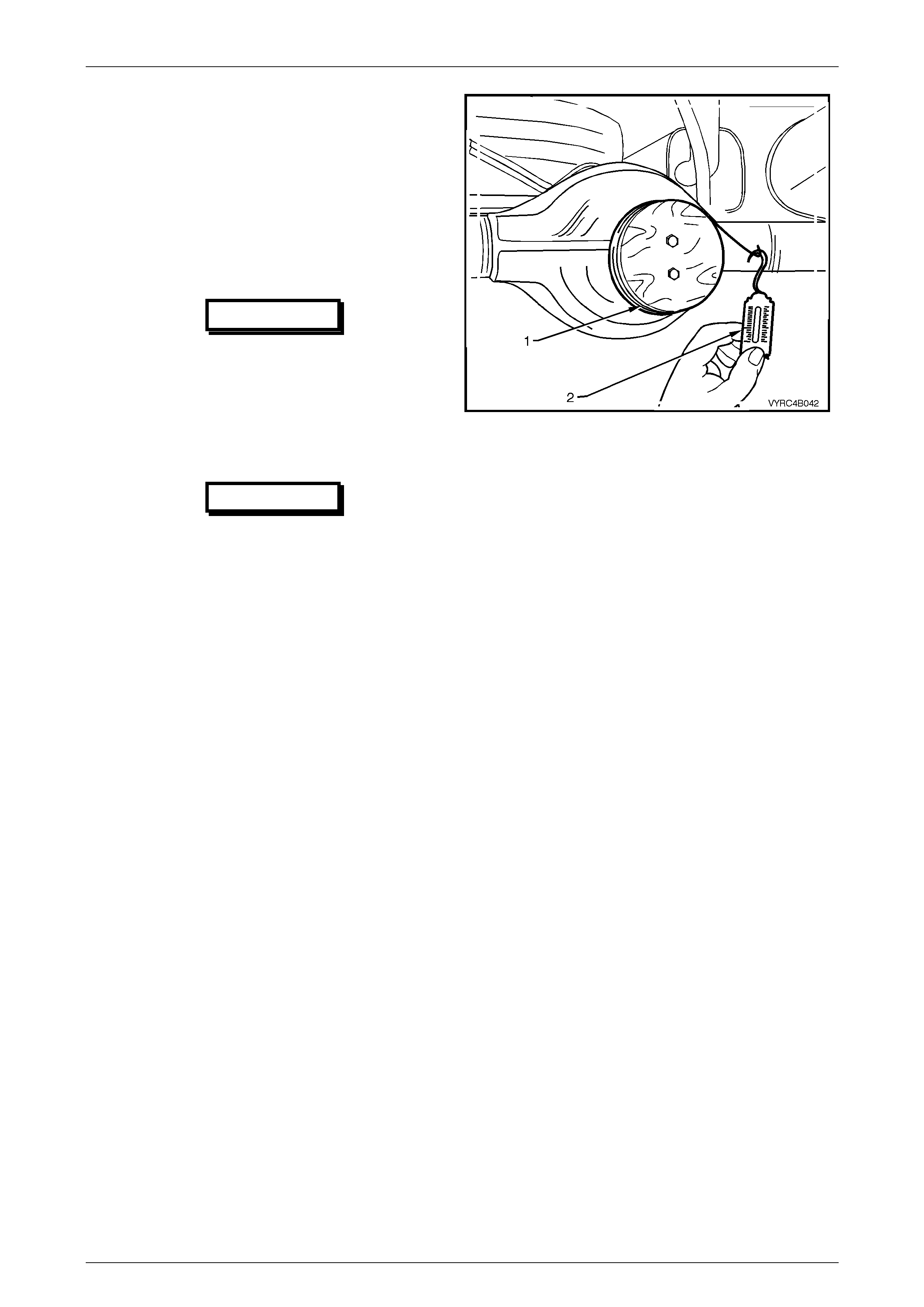
7 Using tie wire (1), secure the caliper (2) to the top of
the rear leaf spring assembly (3) as shown in
Figure 4B-35.
IMPORTANT
Do not allow the caliper to hang by the
brake hose, as damage to the brake hose
may occur.
Figure 4B-35
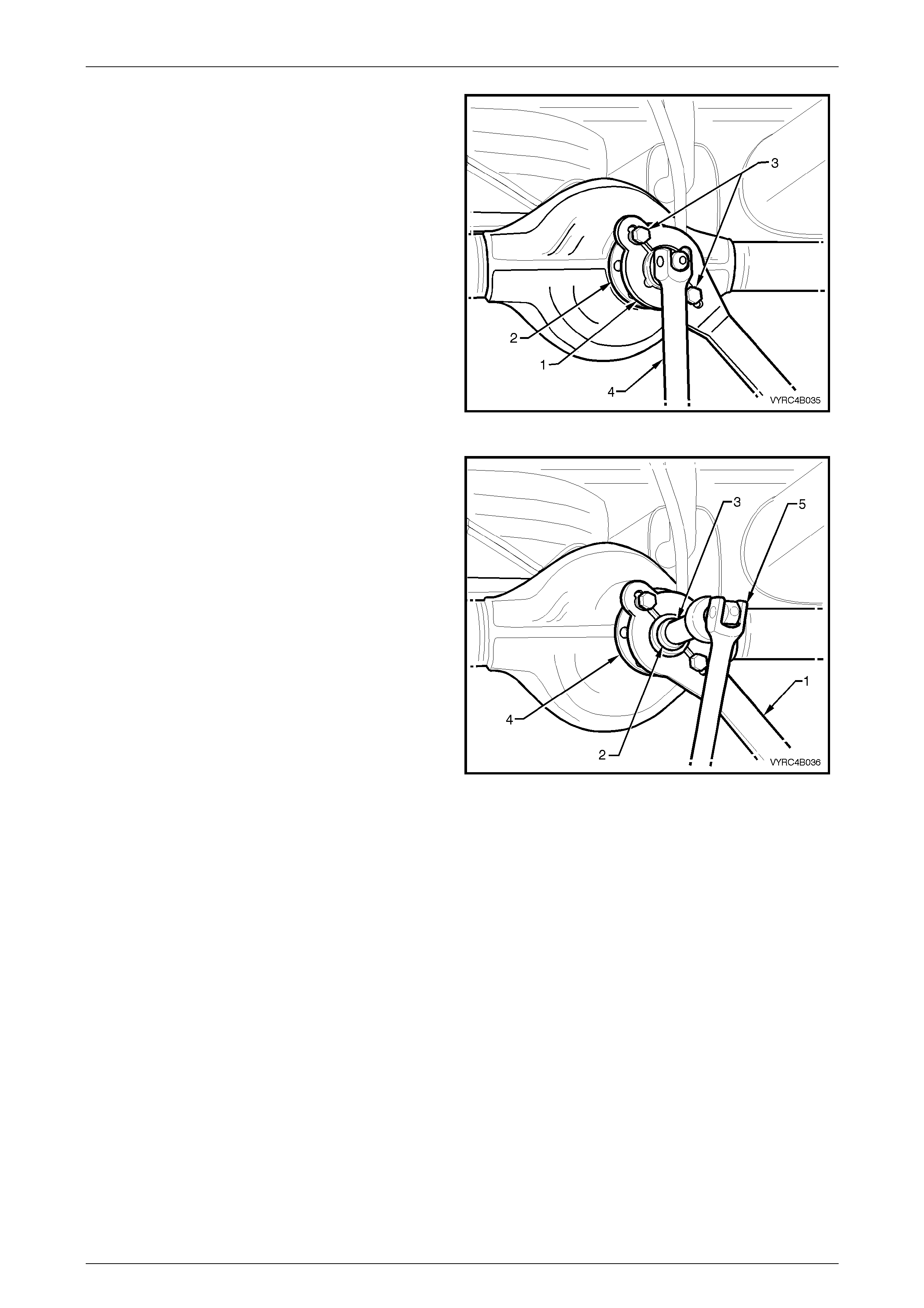
8 With a suitable marking pen, mark the relationship of
the brake disc rotor position to the rear axle shaft
assembly, then remove the brake disc rotor from the
rear axle shaft assembly as shown in Figure 4B-36.
Figure 4B-36
9 Using a torque wrench (1) in conjunction with adaptor,
Tool No. 7372 (2), and torque wrench adaptor
E6662B (3), rotate the rear axle shaft assembly in a
forward direction, as shown in Figure 4B-37.
a. If the unit is operating satisfactorily, a torque
reading of approximately 70 Nm should be
obtained while turning the trunnion assembly, with
the opposite wheel remaining stationary.
b. If a torque reading of less than 35 Nm is obtained,
remove the differential case and inspect case
internal components and repair as necessary,
refer to 3.3 Cone Type Limited Slip Differential –
M78 Series or 3.4 Multi-Disc Type Limited Slip
Differential – M86 Series in this Secti on.
Figure 4B-37
Rear Axle Page 4B –27
Page 4B–27
10 Reinstall the disc brake rotor over the rear axle wheel
studs, ensuring that the relationship alignment marks
made prior to disassembly are aligned, as shown in
Figure 4B-38.
Figure 4B-38
11 Reinstall the brake caliper (2) to the rear axle anchor
plate (3) and tighten the caliper attaching bolts (1) to
the correct torque specification, as shown in
Figure 4B-39.
(6) Brake caliper to rear axle
anchor plate attaching bolt
torque specification .................................... 70 – 100 Nm
Figure 4B-39
12 Reinstall the road wheel, aligning marks made prior to
removal, install and tighten the attaching nuts.
13 Remove the safety stand and the lower vehicle.
14 Tighten the road wheel attaching nuts to the correct
torque specification and in the correct sequence, refer
to 2.1 Service Cautions and Notes in this Section.
NOTE:
Vehicle must be at kerb weight and on all four
wheels before this torque is applied.
15 Refit the wheel cover/wheel nut caps.
(!) Road wheel attaching nut
torque specific atio n .................................. 110 – 140 Nm
Figure 4B-40
Rear Axle Page 4B –28
Page 4B–28
2.8 Rear Axle Shaft Assembly
LT Section No: F504000
ATTENTION
The following fasteners have either micro encapsulation or incorporate a mechanical thread lock and should
only be used once. If in doubt, replacement is recommended when performing this operation:
6
66
6 Rear axle retainer thrust plate attaching bolt.
6
66
6 ABS wheel speed se nsor attaching bolt.
The following fasteners MUST have the ve hicle at curb height before final tightening.
!
!!
! Road Wheel attaching nuts.
Remove
1 Using a floor jack under the centre of the rear axle
assembly (1), jack up the rear of vehicle, then place
safety stands under the rear leaf spring retainer
plates (2) on both the left-hand and right-hand sides
to support the weight of the vehicle as shown in
Figure 4B-41.
2 Remove the rear wheel cover (steel wheels) or wheel
nut covers (alloy wheels) on that side of the vehicle
where the rear axle is to be removed.
Figure 4B-41
3 Remove rear brake caliper to rear axle anchor plate
attaching bolts (1), remove brake caliper (2) from the
disc rotor (3) as shown in Figure 4B-42.
Figure 4B-42
Rear Axle Page 4B –29
Page 4B–29
4 Using tie wire (1), secure the caliper (2) to the top of
the rear leaf spring assembly (3) as shown in Figure
4B-43.
IMPORTANT
Do not allow the caliper to hang by the
brake hose, as damage to the brake hose
may occur.
Figure 4B-43
5 With a suitable marking pen, mark the relationship of
the brake disc rotor position to the rear axle shaft
assembly, then remove the brake disc rotor from the
rear axle shaft assembly as shown in Figure 4B-44.
Figure 4B-44
6 Disconnect and remove the ABS wheel speed sensor
(1) from the rear axle housing ABS sensor aperture
(2) as shown in Figure 4B-45.
Figure 4B-45
Rear Axle Page 4B –30
Page 4B–30
7 Place a suitable container underneath the axle
housing to collect any oil that may leak out during
axle removal.
8 Remove the rear axle retainer thrust plate (1) and
attaching bolts (2) as shown in Figure 4B-46.
Figure 4B-46
9 Using the vehicle wheel attaching nuts, fit Tool No.
7372 (1) and Tool No. 7374 (2) to the rear axle shaft
(3) as shown in Figure 4B-47.
10 Using Tool No. 7372 in conjunction with Tool No.
7374, remove the rear axle from the rear axle
housing, taking care not to damage the ABS pulse
ring.
11 Remove tool No’s. 7372 and 7374 from the rear axle
shaft.
Figure 4B-47
Reinstall
Reinstallation of the axle shaft is the reverse of the removal
procedure noting the following points.
1 Install the rear axle shaft assembly.
2 Ensure the splines on the axle shaft align with the
matching splines located in the differential side gears
and the axle shaft assembly is correctly positioned in
the rear axle housing to allow the retainer thrust plate
and attaching bolts to be installed without obstruction.
3 Install the retainer thrust plate (1) and attaching bolts
(2) to the rear axle housing as shown in Figure 4B-48.
4 Tighten the retainer thrust plate attaching bolts to the
correct torque specification.
(6) Retainer thrust plate
attaching bolt
torque specification ......................................40 – 50 Nm
Figure 4B-48
Rear Axle Page 4B –31
Page 4B–31
5 Reinstall the ABS wheel speed sensor (1) to the rear
axle housing, ABS sensor ape rture (2) as shown in
Figure 4B-49 and re-connect the sensor to the wiring
harness.
6 Install the ABS wheel speed sensor-attaching bolt to
the rear axle housing.
7 Tighten the ABS wheel speed sensor-attaching bolt to
the correct torque specification.
(6) ABS wheel speed sensor
attaching bolt
torque specification ........................................6 – 14 Nm
8 Install and tighten the rear brake caliper anchor plate
to rear axle anchor plate attaching bolts to the correct
torque specif ication.
(6) Rear brake caliper anchor
plate to rear axle anchor plate
attaching bolt
torque specification .................................... 70 – 100 Nm
Figure 4B-49
9 Reinstall the road wheel, aligning the marks made
prior to removal, install and tighten the attaching nuts.
10 Remove the safety stand and the lower vehicle.
11 Tighten the road wheel attaching nuts to the correct
torque specification and in the correct sequence, refer
to 2.1 Service Cautions and Notes in this Section.
NOTE:
Vehicle must be at kerb weight and on all four
wheels before this torque is applied.
12 Refit wheel cover/wheel nut caps.
13 It may be necessary to flush the rear axle assembly
depending on the nature of the repair, refer to
2.3 Changing/Flushing Rear Axle Lubricant in this
Section.
14 Check the lubricant le vel, refer to 2.2 Checking Rear
Axle Lubricant Level in this Section.
(!) Road wheel attaching nut
torque specific atio n .................................. 110 – 140 Nm
Figure 4B-50
Rear Axle Page 4B –32
Page 4B–32
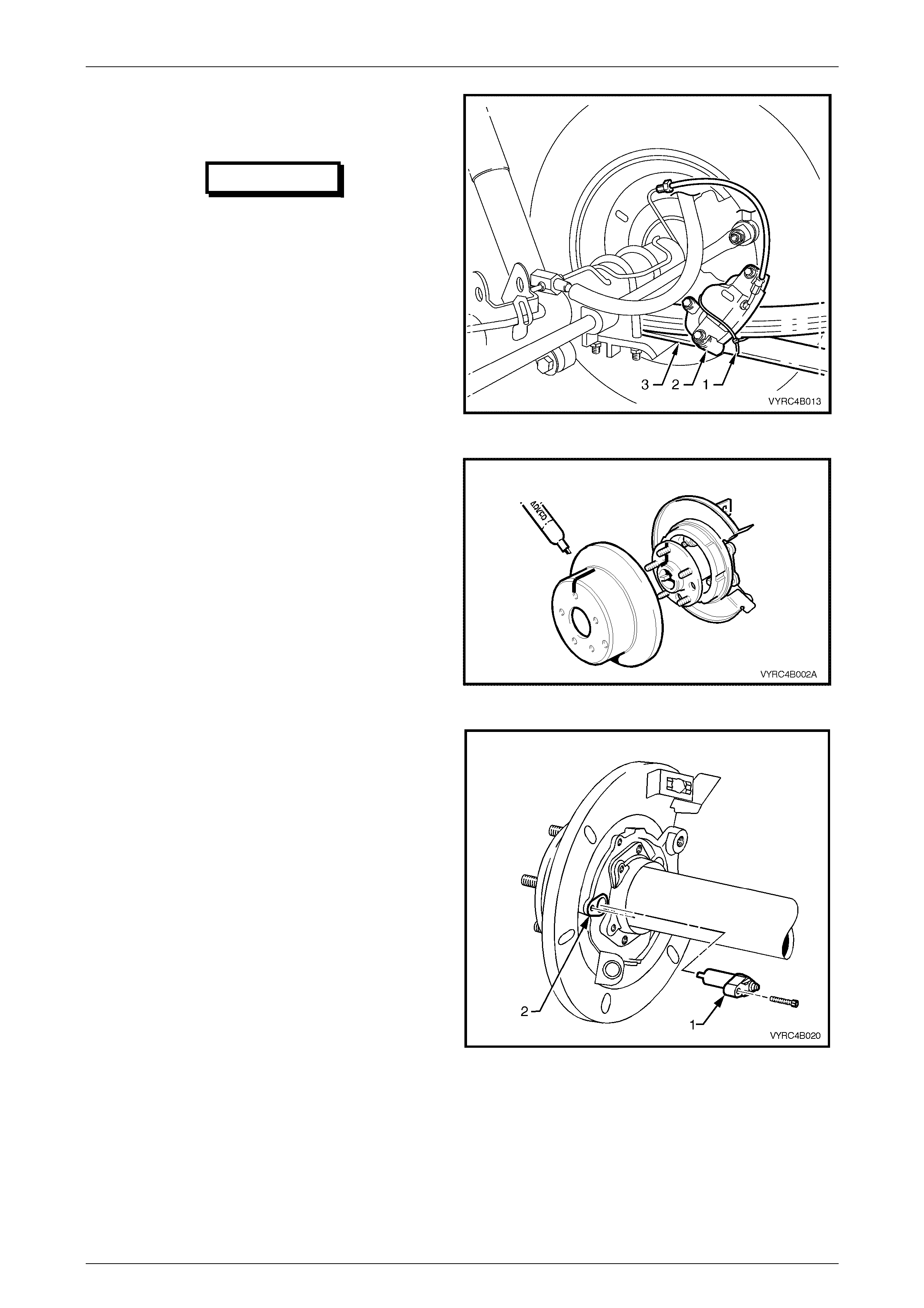
2.9 Rear Axle Shaft, ABS Pulse Ring, Oil
Seal, Bearing and Retainer Collar
LT Section No: F506000
Disassemble
1 Remove the rear axle shaft assembly; refer to
2.8 Rear Axle Shaft Assembly, in this Section.
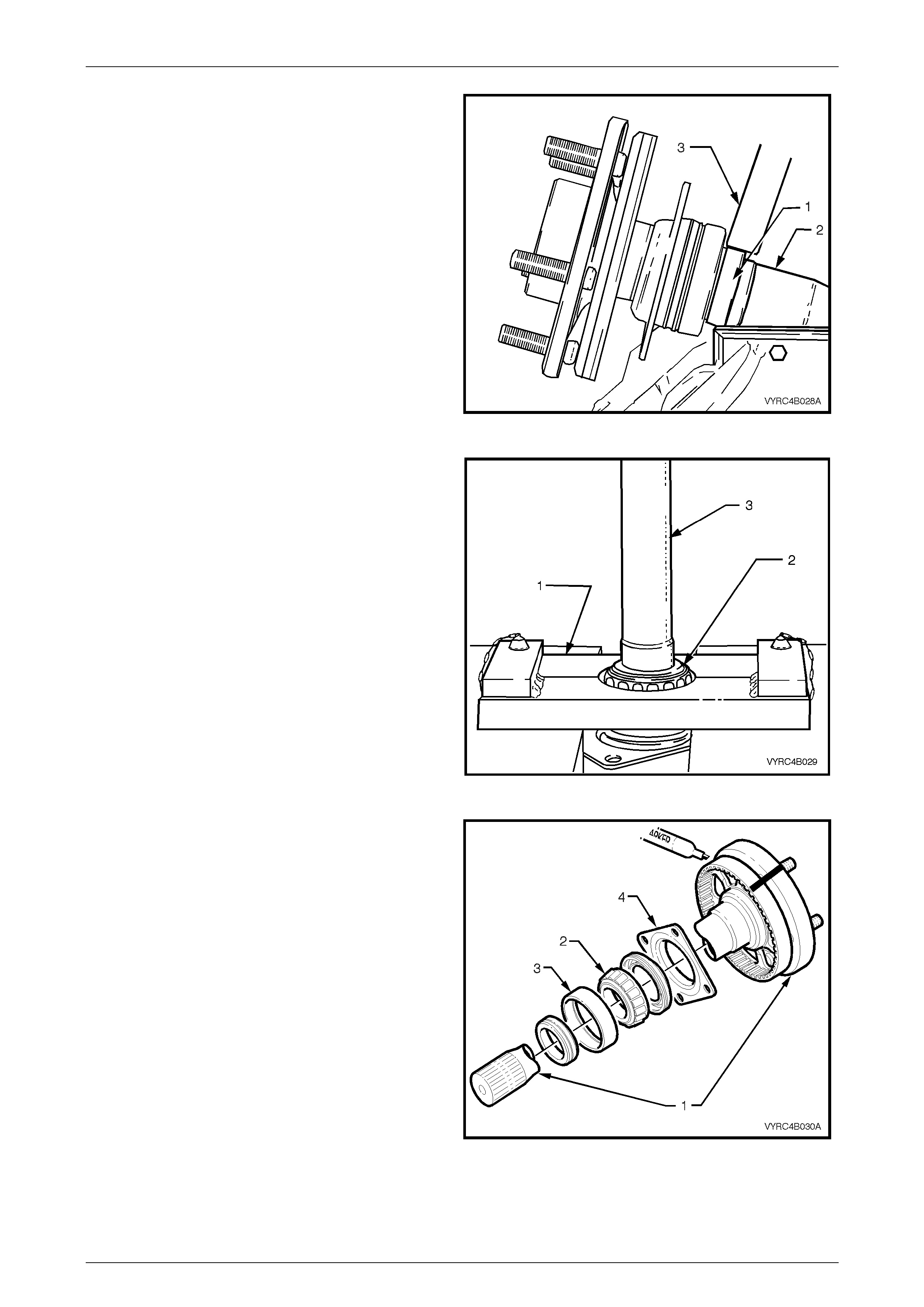
2 Using Tool No. 7136 (1) in conjunction with Tool No.
7374 (2), remove the rear axle bearing cup (3) from
the rear axle housing as shown in Figure 4B-51.
3 Using a suitable solvent, clean the outside of the rear
axle shaft as sembly before disassembly.
Figure 4B-51
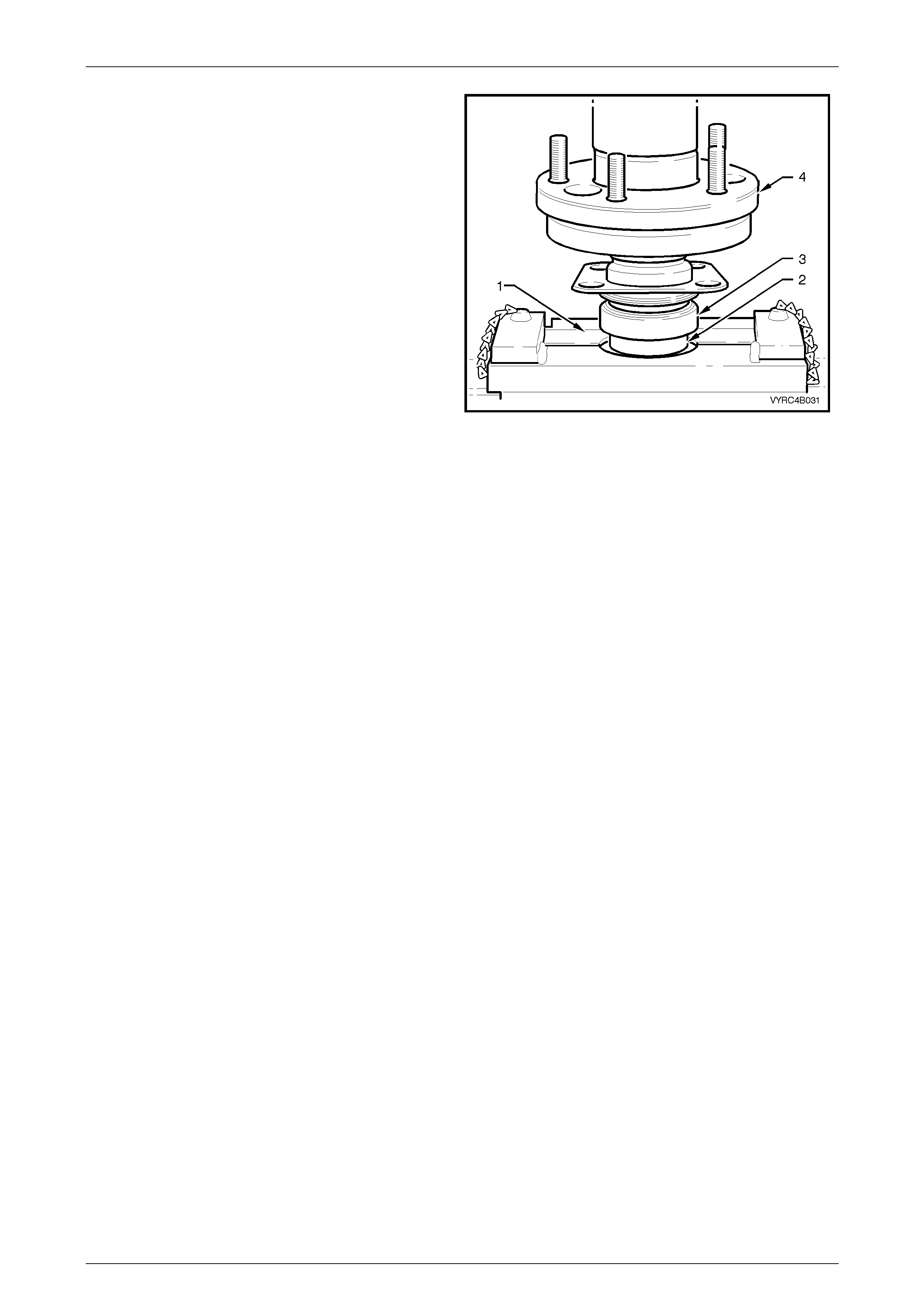
4 Clamp the bearing end of the rear axle shaft (1), in a
vice fitted with soft metal jaws (2), as shown in 4B-52.
Figure 4B-52
Rear Axle Page 4B –33
Page 4B–33
5 Using 6 mm drill bit, drill a hole into the retainer collar
(1) at right angles to the axle shaft, taking care not to
contact the axle shaft (2).
6 Rotate the axle 90°, re-clamp the axle with the vice
and repeat the action at the start of step 5.
7 Using cold chisel (3) and hammer, taking care not to
contact the axle shaft (2), relieve the clamping load
applied to the axle shaft by splitting the bearing
retainer collar (1). It may be necessary to release the
axle from the vice, rotate the axle 90°, re-clamp the
axle with the vice and repeat the spitting action at the
start of this step. Refer to Figure 4B-53.
8 Remove the retaining collar.
Figure 4B-53
9 Using a suitab le press and Tool No. E9298 (1) to
support the inner bearing race (2), press the rear axle
shaft (3) from the inner-bearing race. Refer to
Figure 4B-54.
10 Remove the oil seal and thrust retainer plate from the
axle shaft.
Figure 4B-54
11 Clean the axle shaft (1), inner bearing race (2), and
bearing cup (3) along with the thrust retainer plate (4)
in a suitable cleaning solvent. Refer to Figure 4B-55.
12 If the ABS pulse ring is to be removed use a pen to
scribe relationship marks on the side of both the rear
axle shaft flange and the ABS pulse ring. Refer to
Figure 4B-55.
NOTE:
The relationship marking of the axle shaft flange
and ABS pulse ring is necessary to align the
large hole in the axle shaft flange with an
opening between the webbing of the ABS pulse
ring to facilitate removal of the axle shaft
retainer plate attaching bolts.
Figure 4B-55
Rear Axle Page 4B –34
Page 4B–34
13 Using a suitable press and Tool No. AU607-1 (1) to
support the ABS pulse ring (2), press rear axle s haft
(3) from the ABS pulse ring (2) as shown in
Figure 4B-56.
Figure 4B-56
Inspect
Axle Shaft, Bearing and Cone
1 Inspect the axle shaft for twisting, cracking or excessive spline wear and replace if unserviceable.
2 Inspect the axle shaft-seating surface for the inner bearing and replace if unserviceable.
3 Inspect the inner bearing and cone for pitting, scoring, cracks or uneven wear and replace if unserviceable.
4 Inspect the thrust retainer plate for distortion, scoring, cracks or uneven wear and replace if unserviceable.
5 Inspect the ABS pulse ring for distortion, scoring, cracks or other damage and replace if unserviceable.
6 Discard the retainer collar and replac e with new parts.
IMPORTANT
If removed, the bearing retainer collar can
only be used once and must be replaced.
Rear Axle Page 4B –35
Page 4B–35
Reassemble
Assembly of the ABS pulse ring, thrust retainer plate, oil seal, inner bearing race, and new retaining collar to the axle
shaft is the reversal of the removal procedure noting the following points.
IMPORTANT
If removed, the bearing retainer collar can
only be used once and must be replaced.
NOTE:
Before installation, pre-lubricate the inner seal
lips of the oil seal with Lithium No.2 Grease.
NOTE:
Care must be taken to ensure the bearing race
and retaining collar is fitted squarely during
installation.
NOTE:
Apply sufficient load to ensure the proper seating
of all components.
1. If the ABS pulse ring has been removed, align the
relationship marks on the side of both the rear axle
shaft flange and the ABS pulse ring. Refer to Figure
4B-55.
NOTE:
If installing a new ABS pulse ring, ensure the
relationship mark scribed on the old pulse ring is
transferred to the new pulse ring. The
relationship marking of the axle shaft flange and
ABS pulse ring is necessary to align the large
hole in the axle shaft flange with an opening
between the webbing of the ABS pulse ring to
facilitate removal of the axle shaft retainer plate
attaching bolts.
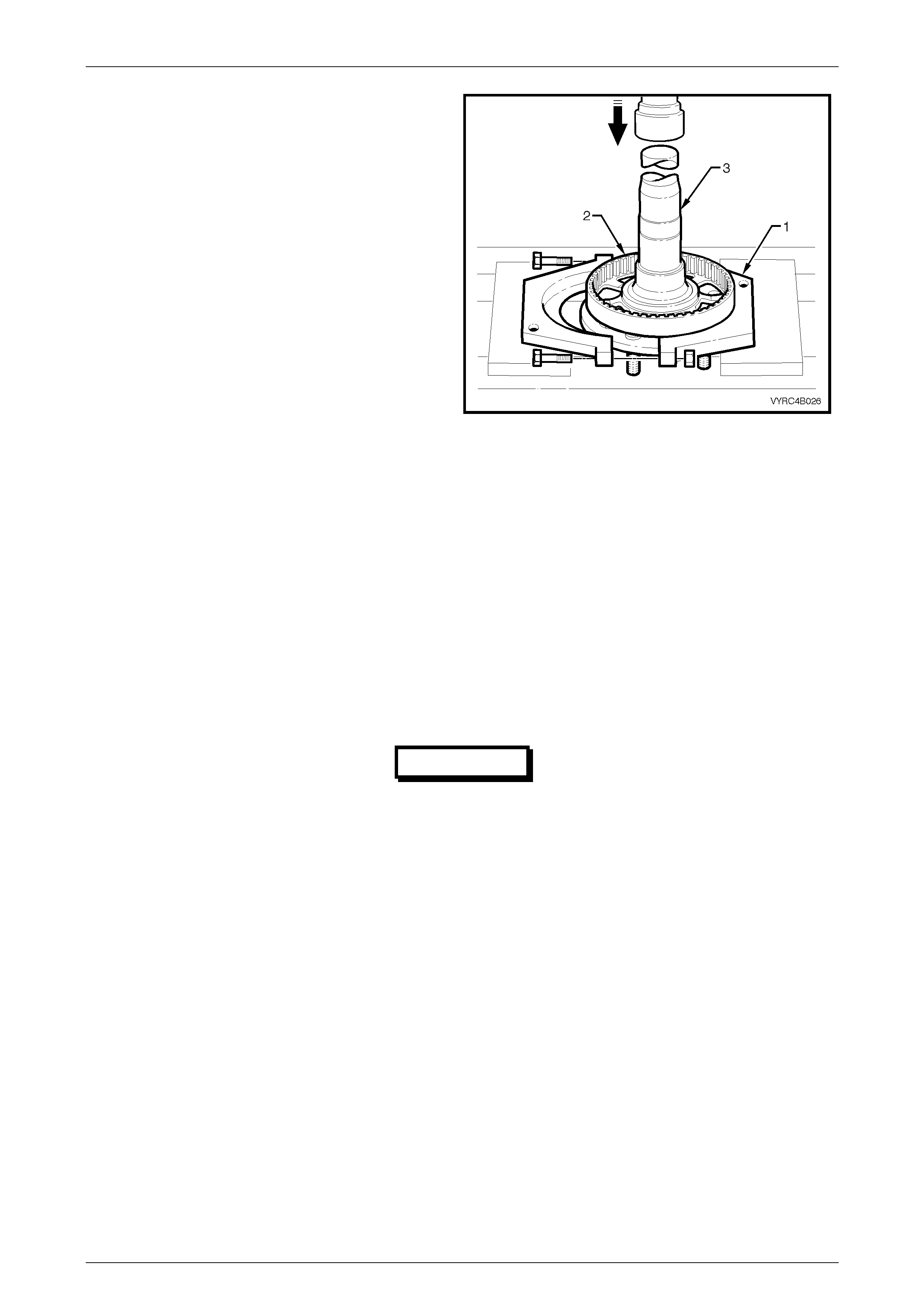
2. Using suitable press and Tool No. AU607-2 (1) to
support the ABS pulse ring (2), press the ABS pulse
ring (2) on to the axle shaft seat (3).
Refer to Figure 4B-57.
3. Check the ABS pulse ring for any damage or distortion.
If damage has occurred during the pressing operation
replace the ABS pulse ring.
Figure 4B-57
Rear Axle Page 4B –36
Page 4B–36
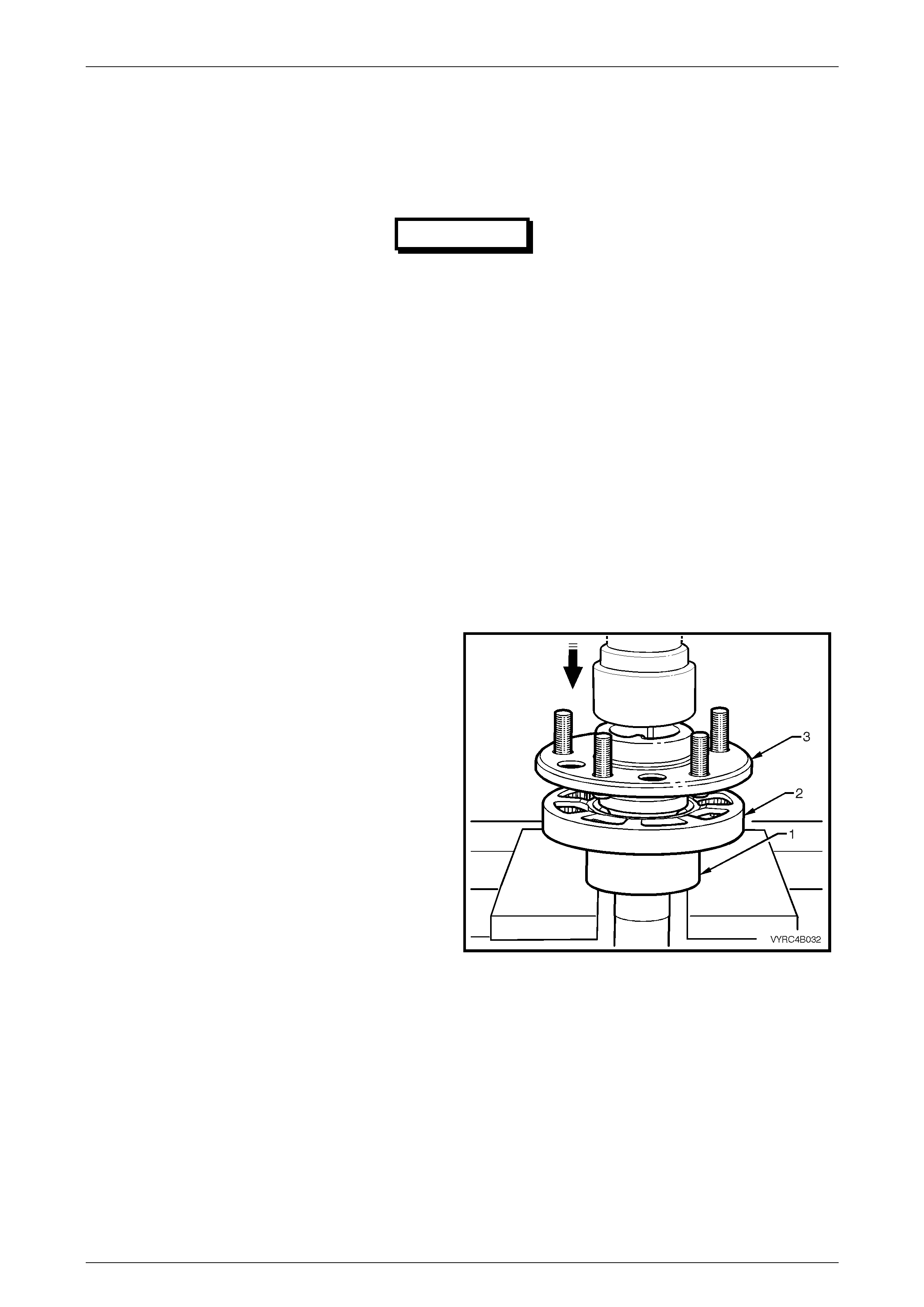
1 Install the thrust retainer plate, oil seal, inner bearing
race and new retaining col lar to the ax le shaft.
2 Using a suitab le press and Tool No. E9298 (1) to
support the retaining collar (2) and inner-bearing race
(3), press the collar and inner-bearing race on to the
axle shaft (4). Refer to Figure 4B-58.
3 Check the inner bearing for binding or cage distortion.
If damage has occurred during the pressing operation
replace the retaining collar, bearing race and cone.
4 Reinstall the rear axle for more detail; refer to
2.8 Rear Axle Shaft Assembly in this Section.
Figure 4B-58
Rear Axle Page 4B –37
Page 4B–37
2.10 Pinion Oil Seal
LT Section No: F502100
Remove
1 Using a floor jack under the centre of the rear axle
assembly (1), jack up the rear of vehicle, then place
safety stands under the rear leaf spring retainer
plates (2) on both the left-hand and right-hand sides
to support the weight of the vehicle as shown in
Figure 4B-59.
Figure 4B-59
2 Mark the relationship position of the propeller shaft
rear coupling (1) to the pinion flange (2), using a pen
or similar, as shown in Figure 4B-60.
3 Remove the propeller shaft, refer to Se cti on 4C
Propeller Shaft and Universal Joints in the MY 2003
VY, Cab Chassis Series Service Information. This
operation may also require partial exhaust system
removal.
Figure 4B-60
Rear Axle Page 4B –38
Page 4B–38
4 Lightly centre-punch alignment marks on the pinion
flange (1), flange nut (2) and pinion end (3) to aid
reassembly as shown in Figure 4B-61.
NOTE:
By reassembling to the original position, the
flange run-out will be minimised and the pinion
bearing preload will be maintained.
Figure 4B-61
5 Attach Tool No. J8614-11 (1) (part of Tool No.
J8614-1) to the pinion flange (2), using two suitable
(M10 x 1.5 pitch) bolts (3) to hold the pinion flange.
6 Remove the pinion flange retaining nut, using a
commercia lly avail abl e sock et and soc ket bar (4) .
Refer to Figure 4B-62.
7 Remove Tool No. J8614-11.
Figure 4B-62
8 Place drain tray beneath the differential carrier.
9 Install Tool No. J8614-11 (1) in conjunction with Tool
No. J8614-2 (2) and Tool No. J8614-3 (3) (part of
Tool No. J8614-1) to the pinion flange (4) using the
same two bolts used to secure the flange holding tool
in steps 5 and 6.
10 While holding the Tool No. J8614-11 (1), us e a
commercially available socket and socket bar (5) to
withdraw the pinion flange by tightening Tool No.
J8614-3 in a clockwise direction.
Refer to Figure 4B-63.
Figure 4B-63
Rear Axle Page 4B –39
Page 4B–39
11 Using Tool No. E308 (1) or a universal seal removing
tool, prise the pinion oil seal (2) from the rear axle
housing, pinion carrier bore. Refer to Figure 4B-64.
Figure 4B-64
Inspect
1 Clean the pinion flange (1), the oil seal seat of the
rear axle housing, the pinion carrier bore (2) and the
threads of the pinion shaft (3) with a suitable cleaning
solvent.
2 Inspect the pinion flange for wear or damage and
replace if unserviceable. Refer to Figure 4B-65.
NOTE:
If the pinion flange is damaged and replacement
is required, refer to 2.11 Pinion Flange, Replace
(Using New Oil Seal) in this Section from this
point on.
3 Discard the pinion oil seal and replace with a new
part.
Figure 4B-65
Reassemble
1 Lubricate the new pinion oil seal lips with the
recommended rear axle lubricant refer to
2.2 Checking Rear Axle Lubricant Level in this
Section.
2 Lightly coat the outside diameter of the oil seal with
non-harden ing ce ment .
3 Start the oil seal (1) into the rear axle housing pinion
carrier bore and drive the seal squarely into position,
for M78 Series use Tool No. E9055 (2) and for M86
Series use Tool No. 205-553. Refer to Figure 4B-66.
NOTE:
Once installed the seal fits flush to 0.25 mm
below the rear axle housing, pinion carrier bore
outer face.
4 Ensure that the pinion shaft is free from burrs and that
the flange oil seal surface is free from damage.
Figure 4B-66
Rear Axle Page 4B –40
Page 4B–40
5 Lubricate the splines and seal surface of the pinion
flange with rear axle lubricant, refer to 2.2 Checking
Rear Axle Lubricant Level or 5 Specifications in this
Section for the recommended lubricant.
6 Ensure that the centre-punch marks are aligned in
relation to the pinion flange (1) and the pinion end (2)
and install flan ge onto the pin i on shaft spl ine s.
Refer to Figure 4B-67.
Figure 4B-67
7 Reinstall Tool No. J8614-11 (1) (part of Tool No.
J8614-1) to the pinion flange (2), using two suitable
bolts (3) to hold the pinion flange.
Refer to figure 4B-68.
Figure 4B-68
IMPORTANT
A thread locking compound such as Loctite
262 or equivalent is required to be applied to
the threads of the pinion flange-retaining nut.
Failure to do this could result in rear axle
failure.
IMPORTANT
The pinion flange is a interference fit on
pinion shaft splines and should only be pulled
into place by tightening the retaining nut.
Do not, under any circumstances, use force
or hammer the flange during installation onto
pinion flange.
Rear Axle Page 4B –41
Page 4B–41
8 Thoroughly clean the threads of the pinion flange
retaining nut and the pinion. A pply a thread-loc ki ng
compound such as Loctite 262 or equivalent, to the
threads of the pinion flange-retaining nut (1), and then
reinstall the nut. Refer to Figure 4B-69.
IMPORTANT
Should the retaining nut be over tightened
and preload exceeded, it will be
necessary to remove the pinion from the
carrier and install a new collapsible
spacer. Under no circumstances must the
retaining nut be backed off to decrease
the preload reading.
9 While supporting the holding tool, tighten the flange-
retaining nut with a commercially available deep
reach socket and socket bar until all centre-punch
marks align. Then carefully tighten the nut to a
position not more than 5° past the aligned setting.
10 Reinstall the propeller shaft rear coupling to the pinion
flange; refer to Section 4C Propeller Shaft and
Universal Joints in MY 2003 VY, Cab Chassis Series
Service Information.
11 Remove the safety stands and lower vehicle.
12 Check the lubricant level and top up as necessary.
Refer to 2.2 Checking Rear Axle Lubricant Level in
this Section.
Figure 4B-69
Rear Axle Page 4B –42
Page 4B–42
2.11 Pinion Flange
LT Section No: F501100
ATTENTION
The following fasteners MUST be replaced when performing this operation:
+
++
+ Pinion flange nut.
Replace (Using Old Oil Seal)
NOTE:
Due to production toleranc es in the length of the
pinion flange, it is essential that the following
method be used when installing a new pinion
flange. A new retaining nut must always be
used when the pinion flange is replaced.
1 Using a floor jack under centre of the rear axle
assembly (1), jack up the rear of vehicle, then place
safety stands under the rear leaf spring retainer
plates (2) on both the left-hand and right-hand sides
to support the weight of the vehicle as shown in
Figure 4B-70.
2 Remove the propeller shaft; refer to Se cti on 4C
Propeller Shaft and Universal Joints in this Service
Information. This operation may also require partial
exhaust system removal.
3 Remove both rear axle shafts; refer to 2.8 Rear Axle
Shaft Assembly in this Section.
Figure 4B-70
NOTE:
For details of the fabricated pulley, refer to
7. Special Tools in this Section.
4 Check and record preload at pinion flange as follows:
a. Fit the pre-fabricated pulley (1) to the pinion
flange, using two bolts and attach a cord around
the pulley and then to a spring balance (2). Refer
to Figure 4B-71.
b. Start rotation of pulley and whilst in motion
(approximately 50-60 rpm) record reading on the
spring balance. This preload reading includes the
pinion bearings, the side bearings, the meshing
effect of gear set and the pinion oil seal.
c. To determine the preload, multiply the reading on
spring balance by the radius of pulley, i.e. With a
pulley diameter of 152 mm, the radius is 76 mm,
which equals 0.076 m. With a spring balance
reading of 25 N, the preload equals 0.076 m x 25
N = 1.9 Nm.
5 Remove the pulley from the pinion flange.
Figure 4B-71
Rear Axle Page 4B –43
Page 4B–43
6 Attach Tool No. J8614-11 (1), part of Tool No. J8614-
1, to the pinion flange (2), using two suitable bolts (3)
to hold pinion flange.
Refer to Figure 4B-72.
7 Remove the pinion flange retaining nut, using a
commercially available socket and socket bar (4).
8 Remove Tool No. J8614-11.
Figure 4B-72
9 Place a drain tray beneath the differential carrier.
10 Install Tool No. J8614-11 (1) in conjunction with Tool
No. J8614-2 (2) and Tool No. J8614-3 (3) to the
pinion flange (4) (part of Tool No. J8614-1) using the
same two bolts used to secure the flange holding tool
in steps 5 and 6.
11 While holding the Tool No. J8614-11 (1), us e a
commercially available socket and socket bar (5) to
withdraw the pinion flange by tightening Tool No.
J8614-3 in a clockwise direction.
Refer to Figure 4B-73.
12 Ensure that the pinion shaft thread is free from burrs,
oil, dirt or grease, and then coat the splines and the
seal surface of the new pinion flange with the
recommended rear axle lubricant.
Refer to 2.2 Checking Rear Axle Lubricant Level or
5 Specifications in this Section for the recommended
lubricant.
13 Install the new pinion flange.
14 Apply a thread-locking compound such as Loctite 262
or equivalent to the threads of the pinion and the new
retaining nut.
15 Install a new pinion flange-retaining nut.
16 Tighten the flange-retaining nut gradually until the
pinion shaft endplay is reduced to approximately
0.50 mm.
Figure 4B-73
Rear Axle Page 4B –44
Page 4B–44
17 Attach the pre-fabcricated pulley (1) to the new pinion
flange then us ing a suitable spring balance (2) check
the preload. Refer to Figure 4B-74.
18 Continue tightening the nut while alternatively turning
the pinion to seat the bearings, until the prel oad figure
recorded previously in Step 4b is reached. Then
further increase the original preload reading by
0.5 Nm.
19 Rotate the pinion an extra 30-40 turns and re-c heck
the preload to ensure that no change has occurred.
IMPORTANT
The pinion flange is an interference fit
onto the pinion shaft splines. The pinion
flange should only be pulled into place by
tightening the retaining nut. Do not, under
any circumstances, use force or hammer
the flange during installation onto pinion
flange.
IMPORTANT
Should the retaining nut be over tightened
and preload exceeded, it will be
necessary to remove the pinion from the
carrier and install a new collapsible
spacer. Under no circumstances must the
retaining nut be backed off to decrease
the preload reading.
20 Reinstall the propeller shaft rear coupling to the
pinion flange; refer to Section 4C Propeller Shaft
and Universal Joints in this Service Information.
21 Remove the safety stands and the lower vehicle.
22 Check the lubricant level and top up as necessary.
Refer to 2.2 Checking Rear Axle Lubricant Level in
this Section.
Figure 4B-74
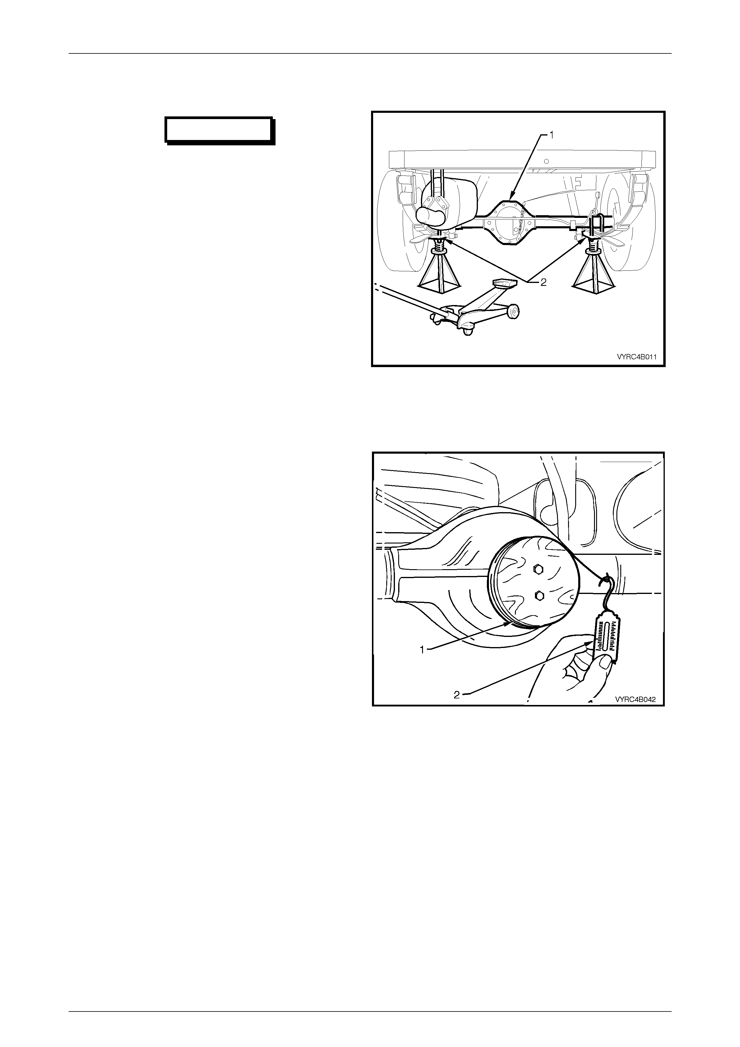
Rear Axle Page 4B –45
Page 4B–45
Replace (Using New Oil Seal)
IMPORTANT
Due to production tolerances in the length
of the pinion flange, it is essential that the
following method be used when installing
a new pinion flange. A new retaining nut
must always be used when a pinion
flange is replaced.
1 Using a floor jack under the centre of the rear axle
assembly (1), jack up the rear of the vehicle, then
place safety stands under the rear leaf spring retainer
plates (2) on both the left-hand and right-hand sides,
to support the weight of the vehicle as shown in
Figure 4B-75.
2 Remove the propeller shaft; refer to Se cti on 4C
Propeller Shaft and Universal Joints in this Service
Information. This operation may also require partial
exhaust system removal.
3 Remove both rear axle shafts; refer 2.8 Rear Axle
Shaft Assembly in this Section.
Figure 4B-75
4 Check and record the preload at the pinion flange as
follows:
a. Fit a pulley (1) to the pinion flange, using two bolts
and attach a cord around the pulley and to a
spring balance (2). Refer to Figure 4B-76.
NOTE:
For details of the fabricated pulley, refer to
7. Special Tools in this Section.
b. Start rotation of the pulley and whilst in motion
(approximately 50-60 rpm) record the reading of
the spring balance. This preload reading includes
the pinion bearings, the side bearings, the
meshing effect of gear set and the pinion oil seal.
c. To determine the preload, multiply reading on the
spring balance by the radius of the pulley, i.e. with
a pulley diameter of 152 mm, the radius is 76 mm,
which equals 0.076 m. With a spring balance
reading of 25 N, the preload equals 0.076 m x 25
N = 1.9 Nm.
5 Remove the pre-fabricated pulley from the pinion
flange.
Figure 4B-76

Rear Axle Page 4B –46
Page 4B–46
6 Attach Tool No. J8614-11 (1) (part of Tool No. J8614-
1) to the pinion flange (2), using two suitable bolts (3)
to hold pinion flange.
Refer to Figure 4B-77.
7 Using a commercially available socket and socket bar
loosen the pinion flange retaining nut until endplay
can be felt in the pinion shaft.
8 Remove Tool No. J8614-11 from the pinion flange.
9 Check the oil seal and differential side bearing
preload using the spring balance and pulley, as
detailed in steps 4a and 4b. Record the oil seal and
side bearing preload for later us e.
10 Reinstall Tool No. J8614-11 to the pinion flange and
completely remove the pinion flange nut.
Figure 4B-77
11 Place a drain tray beneath the differential carrier.
12 Install Tool No. J8614-11 (1) in conjunction with Tool
No. J8614-2 (2) and Tool No. J8614-3 (3) to the
pinion flange (4) using the same two bolts used to
secure the flange-holding tool in steps 6 and 7.
Refer to Figure. 4B-78.
13 While holding the Tool No. J8614-11 (1), us e a
commercially available socket and socket bar (5) to
withdraw the pinion flange by tightening Tool No.
J8614-3 in a clockwise direction.
Refer to Figure 4B-78.
Figure 4B-78
14 Prise the pinion oil seal (2) from the carrier bore using
Tool No. E308 (1) or a universal seal removing tool.
Refer to Figure 4B-79.
15 Lubricate the new pinion oil seal inner and outer lip
diameters with the recommended rear axle lubricant.
Refer to 2.2 Checking Rear Axle Lubricant Level or
5 Specifications in this Section for the recommended
lubricant.
16 Lightly coat the outside diameter of the oil seal with
commercially available non-hardening cement.
Figure 4B-79
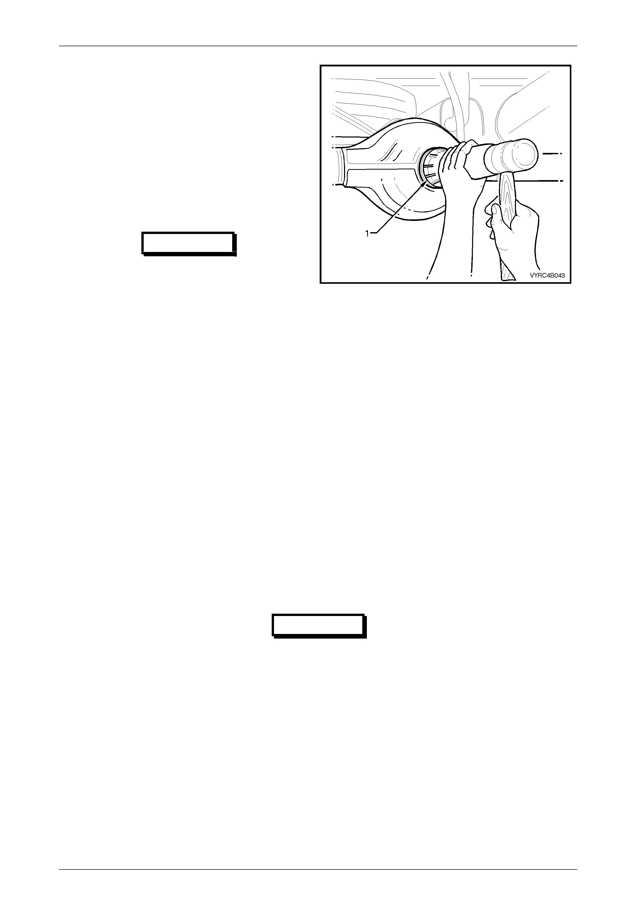
Rear Axle Page 4B –47
Page 4B–47
NOTE:
Once installed the seal fits flush to 0.25 mm
below the rear axle housing, pinion carrier bore
outer face.
17 Start the oil seal into the differential carrier housing
and drive the seal squarely into position, for M78
Series use Tool No. E9055 (1) and for M86 Series
use Tool No. 205-553. Refer to Figure 4B-80.
18 Ensure that the pinion shaft is free from burrs, and
then clean the threads of the pinion shaft, removing
any oil, dirt or grease.
IMPORTANT
The new flange will be a interference fit on
pinion shaft splines and should only be
pulled into place by tightening the
retaining nut. Do not, under any
circumstances, use force or hammer
flange during installation onto pinion
flange.
Figure 4B-80
19 Coat the splines and the seal surface of the pinion flange with differential gear lubricant, then reinstall the flange to
the pinion shaft splines. Refer to 2.2 Checking Rear Axle Lubricant Level or 5 Specifications in this Section for the
recommended lubricant.
20 Install a new flange-retaining nut, and then tighten to draw the pinion flange onto the pinion shaft splines.
21 Continue to tighten the flange retaining nut gradually until pinion shaft endplay is reduced to approximately
0.5 mm.
22 Check the new oil seal and differential assembly preload using a spring balance as previously outlined in steps 4a,
4b and 4c. Record the preload for reassembly.
23 The preload reading for differential assembly obtained in step 9, is subtracted from the preload reading obtained in
step 22. The difference between these figures represents extra lip tension of new seal expressed as a Nm preload
figure. The difference between the preload readings obtained in steps 9 and 22 must be added to preload reading
obtained in step 4b to obtain a total preload reading.
24 Continue tightening the retaining nut while alternately turning the pinion to seat the bearings until the total preload
figure obtained in step 22 is achieved. Then increase this preload reading by 0.11 to 0.34 Nm. Then further rotate
the pinion an extra 30-40 turns and recheck the preload to ensure that no change has occurred.
IMPORTANT
Should the retaining nut be over tightened
and the preload exceeded, it will be necessary
to remove then install a new collapsible
spacer and pinion retaining nut. Under no
circumstances must the retaining nut be
backed off to decrease the preload setting.
NOTE:
It must be realised that the preload readings in
the example are only theoretical. In practice, the
figures could differ greatly, so the readings
obtained when performing the actual operations,
are the ones to use.
Rear Axle Page 4B –48
Page 4B–48
Theoretical Example
STEP SECTION AND ACTION READING/RESULT
From STEP 22 obtain the new oil seal and side bearing
preload setting. 1.47 Nm
From STEP 9 obtain the old oil seal and side bearing
preload reading . 1.02 Nm
Subtract step 9 From step 22. 0.45 Nm
From STEP 4b obtain the complete differential assembly
preload reading . 1.47 Nm
Add the preload readings together, the Combination will be
the sum of: 1.47 Nm plus 0.45 Nm
Which gives a total Preload reading of: - 1.92 Nm
25 Reinstall the propeller shaft rear coupling to the pinion flange, refer to
Section 4C Propeller Shaft and Universal Joints
26 Reinstall the axle shafts; refer to 2.8 Rear Axle Shaft Assembly in this Section.
27 If removed previously, reconnect exhaust system, in the reverse to the removal procedure.
Refer to Section 8B Exhaust System.
28 Remove the safety stands and the lower vehicle.
29 Check the lubricant level and top up as necessary, refer to 2.2 Checking Rear Axle Lubricant Level in this Section.
30 Start the vehicle and check for exhaust leaks
Rear Axle Page 4B –49
Page 4B–49
3. Major Service Operations
ATTENTION
All rear axle fasteners are important attaching parts as they affect the performance of vital components
and/or could result in major repair expense. Where specified in this Section, fasteners MUST be replaced with
parts of the same part number or a GM approved equivalent. Do not use fasteners of an inferior quality or
substitute design.
Torque values must be used as specified during reassembly to ensure proper retention of all steering
components.
Through out this Section, fastener torque wrench specifications may be accompanied with the following
Identification marks:
+
++
+ Fasteners must be replaced after loosening.
!
!!
! Vehicle must be at kerb height before final tightening.
6
66
6 Fasteners either have micro encapsulated sealant applied or incorporate a mechanical thread lock and
should only be re-used once. If in doubt, replacement is recommended.
If one of these identification marks is present alongside a fastener torque wrench specification, the
recommendation regarding that fastener must be adhered to.
3.1 Rear Axle Assembly
LT Section No: F650100
ATTENTION
The following fasteners have either micro encapsulation or incorporate a mechanical thread lock and should
only be used once. If in doubt, replacement is recommended when performing this operation:
6 Rear spring shackle mounting plate to chassis attaching bolt.
6 Rear stabilizer bar mounting to rear axle housing attaching bolt
6 Rear brake load sensing valve linkage to rear axle housing attaching bolt
6 Rear shock absorber lower mounting attaching bolt
The following fasteners MUST be replaced when performing this operation:
+
++
+ Rear spring 'u' bolt and retainer plate attaching nut.
+
++
+ Rear shock absorber upper mounting attaching nut.
+
++
+ Rear stabilizer bar linkage attaching nut.
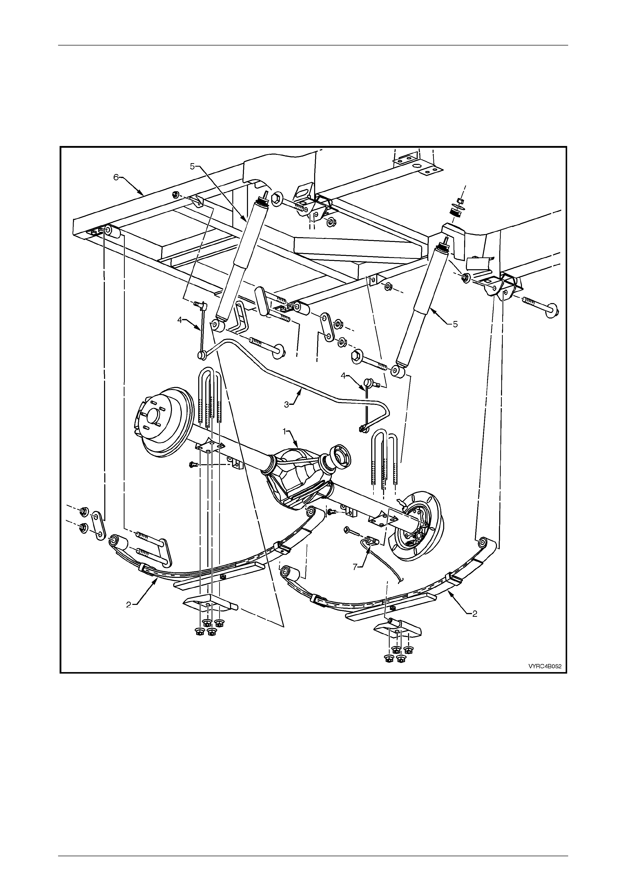
Rear Axle Page 4B –50
Page 4B–50
Preliminary Check
If an overhaul of the rear axle is anticipated, it is recommended that the rear axle shaft check for run-out and end float
procedure be undertaken and the results recorded for future Section, following the removal of the rear axle housing
assembly from the vehicle. Refer to 2.4 Rear Axle Shaft Check For Run-Out And End Float in this Section for the
procedure.
Figure 4B-81
Legend
1 Rear Axle Assembly
2 Rear Leaf Spring Assembly
3 Rear Suspension Stabilizer Bar
4 Rear Stabilizer Bar to Chassis Link
5 Rear Shock Absorber
6 Rear Chassis
7 Rear ABS Sensor
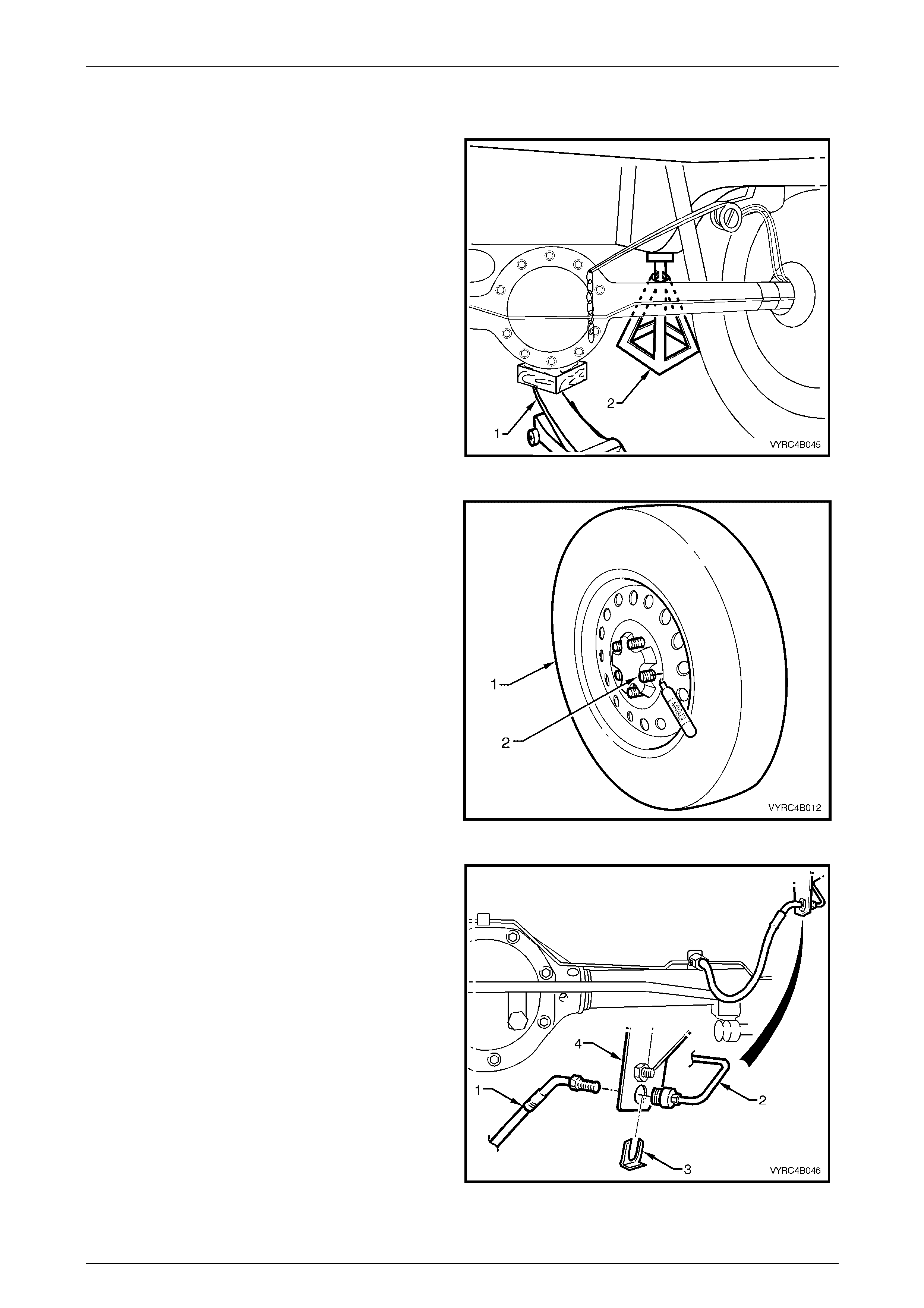
Rear Axle Page 4B –51
Page 4B–51
Remove
1 Using a floor jack under the centre of the rear axle
assembly (1), jack up the rear of the vehicle, then
place safety stands under the rear chassis (2) on both
the left-hand and right-hand sides to support the
weight of the vehicle as shown in Figure 4B-82.
Figure 4B-82
2 Remove both rear wheel covers (steel wheels) or
wheel nut covers (alloy wheels).
3 With a suitable marking pen, mark the relationship of
both road wheels (1) to the rear axle wheel retaining
studs (2) as shown in Figure 4B-83 and remove the
road wheels.
4 Remove the propeller shaft; refer to Se cti on 4C
Propeller Shaft And Universal Joints.
Figure 4B-83
5 Place a suitable drain container under the main rear
brake fluid supply pipe and hose connection.
6 Using a suitable commerci ally av ailable flare nut
spanner, disconnect the main rear axle brake fluid
supply hose (1) from the rear brake fluid, supply pipe
(2), refer to Figure 4B-84.
7 Remove the brak e hose retaining clip (3) from the
hose support bracket (4) and remove the hose from
the bracket.
8 Plug the open ends of the brake pipe and the hose to
prevent fluid loss and forei gn matter entry.
9 Tape the hose to the rear axle housing to prevent
accidental damage to the hose during the rear axle
housing removal procedure.
Figure 4B-84
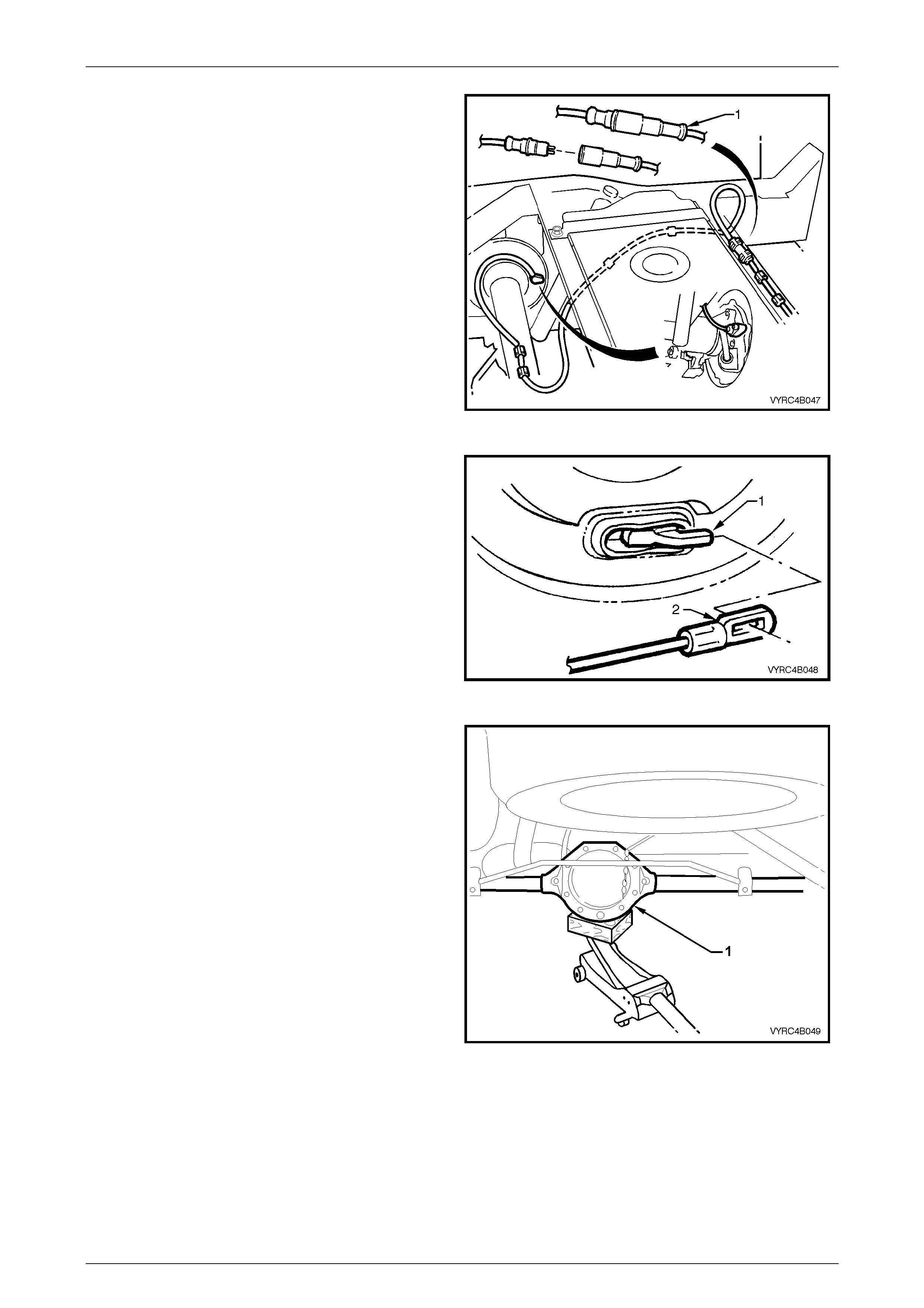
Rear Axle Page 4B –52
Page 4B–52
10 Disconnect the ABS wheel speed sensor body
harness connector (1) Refer to Figure 4B-85.
11 Tape the ABS wheel speed sensor body harness
connector to the chassis to prevent accidental
damage to the connector or harness during the rear
axle housing removal procedure.
12 Tape the ABS wheel speed sensor rear axle harness
connector to the rear axle housing to prevent
accidental damage to the connector or harness during
the rear axle housing removal procedure.
Figure 4B-85
13 Set the park brake to the fully released position.
14 Adjust the park brake to allow the park brake cable to
be disconnected from the rear axle housing
assembly, refer to Section 5A Service and Park
Braking System in this Service Information for the
necessary procedure.
15 Disconnect the park brake cable (2) from the rear
axle, park brake lever (1) and tape it to the chassis to
prevent damage during the rear axle housing removal
procedure. Refer to Figure 4B-86.
Figure 4B-86
16 Position a floor jack with a block of wood, under the
centre of the rear axle housing assembly (1). Refer to
Figure 4B-87.
17 Raise the jack slightly and place safety stands under
rear axle housing tubes to support the weight of the
rear axle housing assembly.
Figure 4B-87
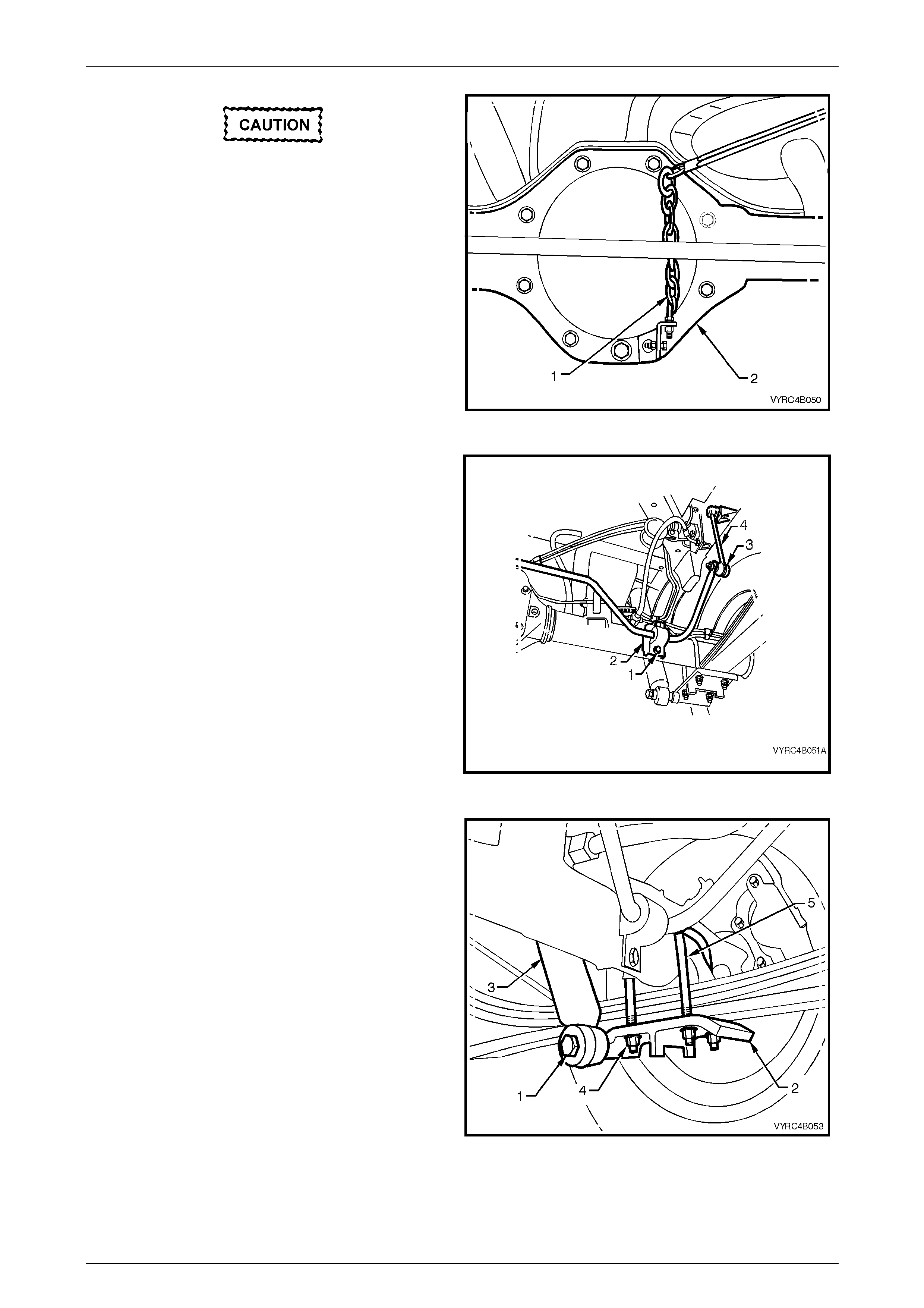
Rear Axle Page 4B –53
Page 4B–53
Under no circumstances is the rear brake
load sensing valve linkage eyebolt or
chain to be disturbed or adjusted. Only
disconnect the bracket from the rear axle
housing cover by removing the bracket
attaching bolts.
18 Disconnect the rear brake load sensing valve linkage
chain and bracket assembly as one unit (1) from the
rear axle housing (2) by removing the bracket to rear
axle cover attaching bolts. Refer to Figure 4B-88.
Figure 4B-88
19 Remove the attaching bolt (1) from each rear
stabilizer bar to rear axle-mounting retainer (2) and
remove the retainers.
20 With the ball joints and linkage (3) still connected,
raise the stabilizer bar (4) by pushing it up and away
from the rear axle assembly.
Refer to Figure 4B-89.
21 Using a suitable tie wire to secure the stabilizer bar to
the chassis.
Figure 4B-89
22 Remove each rear shock absorber lower mounting
retaining bolt (1) from the leaf spring retainer plate
(2), and pull the lower end of shock absorber (3) from
the mounting point on the leaf spring retainer plate.
23 Disconnect all rear leaf spring 'U' Bolt attaching nuts
(4) from the rear springs, then remove the retaining
plates (2) and 'U' Bolts. Refer to Figure 4B-90.
Figure 4B-90
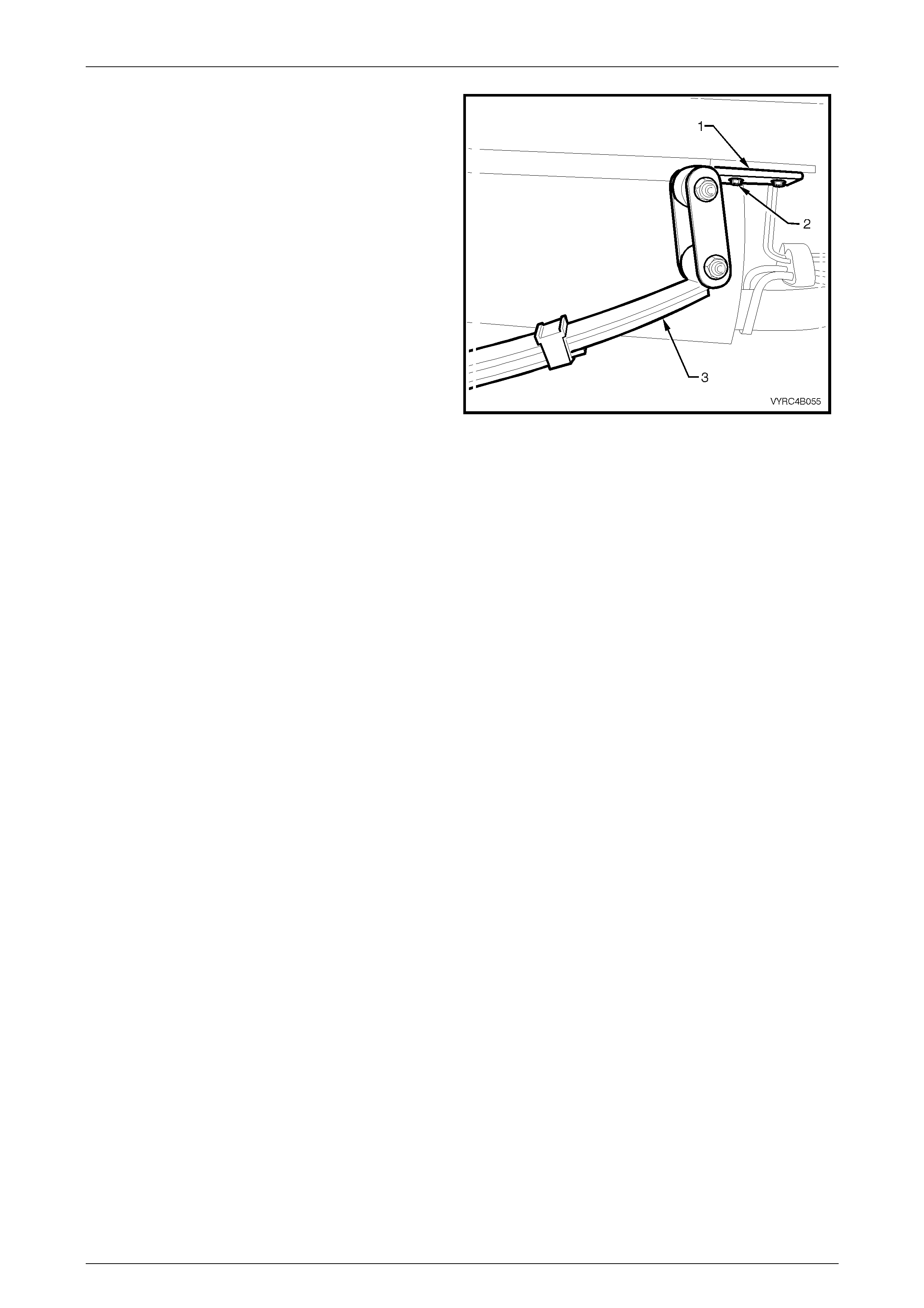
Rear Axle Page 4B –54
Page 4B–54
24 Remove the rear spring shackle mounting plate (1) to
chassis attaching bolts (2) located at the trailing end
of each leaf spring assembly (3). Then carefully lower
the springs to floor level. Refer to Figure 4B-91.
25 With aid of an assistant, remove the safety stands
supporting each side of the rear axle housing, then
gently lower the floor jack to floor level and
manoeuvre the rear axle assembly clear of the
vehicle while supporting its weight on the floor jack.
Figure 4B-91
Reinstall
Reinstallation of the rear axle housing assembly is the reverse of the removal procedure noting the following points:
1 Tighten all attaching nuts to the correct torque specification, refer to Figure 4B-92
2 Check the lubricant level and top up as necessary, refer to 2.2 Checking Rear Axle Lubricant Level.
3 Adjust the parking brake; refer to Section 5A Service and Park Braking System in this Service Information.
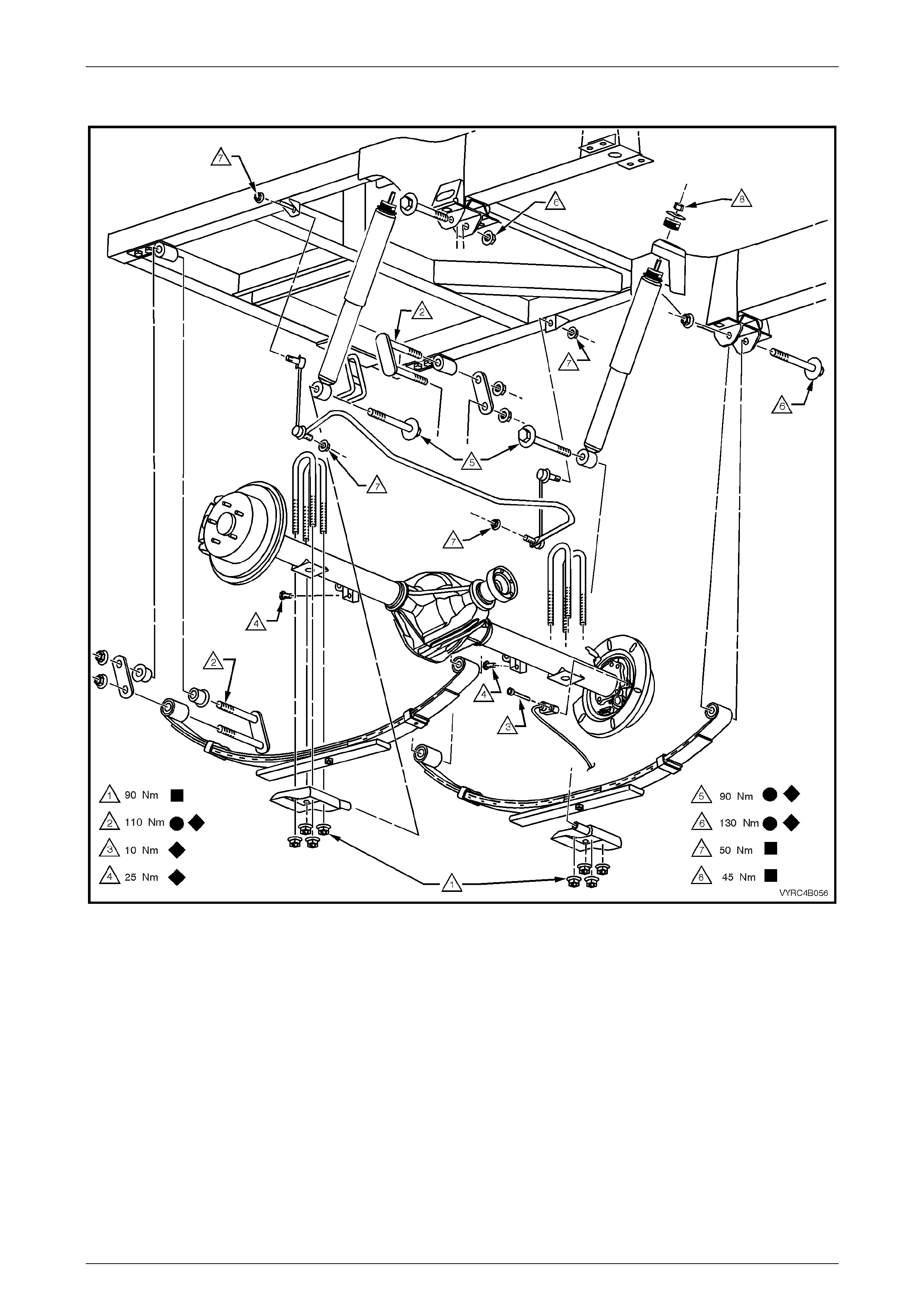
Rear Axle Page 4B –55
Page 4B–55
REAR AXLE ASSEMBLY ATTACHING BOLT AND NUT TORQUE SPECIFICATIONS
Figure 4B-92

Rear Axle Page 4B –56
Page 4B–56
3.2 Rear Ax le and Differential Housing
Assembly
LT Section No: F502600
Figure 4B-93

Rear Axle Page 4B –57
Page 4B–57
Legend
1 Nut – Pinion Flange
Retaining
2 Flange – Pinion
3 Seal – Pinion Oil
4 Bearing Assembly – Pinion
Front
5 Spacer – Collapsible, Pinion
Bearing Pre-Load
6 Shim – Pinion Depth
Adjusting
7 Fitting – Breather Tube
8 Bearing Assembly – Pinion
Rear
9 Ring Gear and Pinion
10 Bearing Assembly – Side,
Differential Case
11 Shim – Side Bearing
Position And Preload
Adjusting
12 Bracket – Load Sensing
Valve Chain
13 Plug – Oil Filler, Rear Axle
14 Gasket – Oil Filler Plug
15 Tag – Lubrication Caution
16 Plug – Oil Drain, Rear Axle
17 Bolt and Washer –
Differential Carrier Cover
Attaching (8 Places)
18 Cover – Differential Carrier
19 Axle Shaft
20 Cap – Side Bearing and
Differential Carrier
21 Bolt – Cap, Side Bearing
and Differential Carrier
22 Case – Differential, M86
Series LSD
23 Shaft – Differential Pinion
Gear, Long
24 Pin – Retaining, Differential
Pinion Gear Shaft
25 W asher – Thrust,
Differential Pinion Gear
26 Gear – Differential Pinion
27 Shaft – Differential Pinion
Gear, Short (M78 Std)
28 W asher – Thrust,
Differential Side Gear
(M78 Std)
29 Gear – Differential Side
30 Spacer – Differential Case
Side Bearing (M86)
31 Block – Thrust, Differential
(M78)
32 Plate – Thrust, Spring
(M78 LSD)
33 Cone – Clutch (M78 LSD)
34 Spring – Outer, Differential
Preload (M78 LSD)
35 Spring – Intermediate,
Differential Preload
(M78 LSD)
36 Spring – Inner, Differential
Preload (M78 LSD)
37 Shaft – Cross, Differential
Pinion (M78 LSD)
38 Bolt – Ring To Differential
Case Attaching (10 Places)
39 Bracket – ABS Sensor and
Park Brake Cable Mounting
40 Plate – Brake Backing
41 Plate – Thrust and
Retaining, Outer Axle
Bearing and Shaft
42 Bolt – Thrust and Retaining
Plate (4 Places per side)
43 Seal – Oil, Rear Axle Shaft
44 Bearing Kit – Rear Axle
Shaft
45 Rear Axle Housing
46 Retainer – Clutch Plate,
(M86 LSD)
47 Clutch Plate (M86 LSD)
48 Disc – Concentric Grooved
(M86 LSD)
49 Spacer – Dished (M86 LSD)
50 Pulse Ring – ABS Sensor
51 Bolt – Differential Case
(M78 LSD)
52 Case – Differential
(M78 Std)
53 Case – Differential
(M78 LSD)
Preliminary Check
If an overhaul of the rear axle is anticipated, it is recommended that a check for rear axle shaft run-out and end float is
undertaken and the results reco rded for future reference, following the removal of the rear axle housing assembly from
the vehicle. Refer to 2.4 Rear Axle Shaft Check For Run-Out and End Float in this Section for the correct procedur e.
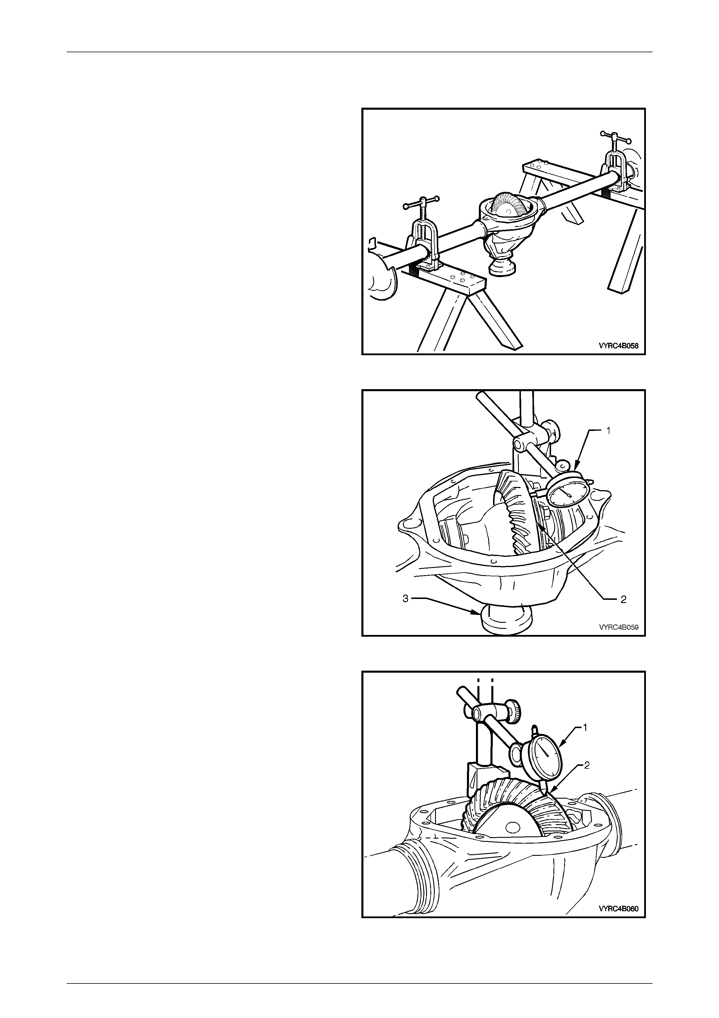
Rear Axle Page 4B –58
Page 4B–58
Disassemble
1 Remove the rear axle assembly and rear road
wheels; refer to 3.1 Rear Axle Assembly in this
Section.
2 Mount the rear axle housing assembly to a suitable
holding fixture to allow the rear axle to be drained of
lubricant. Then drain the lubricant from the rear axle
assembly in to a suitable container by removing the
oil drain plug of the rear axle housing assembly.
3 Rotate the rear axle housing assembly in the holding
fixture to allo w access to the rear cover. Then remove
the cover from the rear axle housing.
Refer to Figure 4B-94.
Figure 4B-94
4 Before removing the differential case assembly
conduct an inspection of the following:
a. Visually inspect all internal moving parts for
damaged, chipped or scuffed surfaces.
b. Check the torque of the ring gear bolts, the
differential carrier bearing cap bolts and the pinion
flange nut.
c. Using a dial indicator (1) against the back face of
the ring gear (2) measure the ring gear run-out
while rotating the pinion flange (3) through several
turns, refer to Figure 4B-95.
d. Leaving the dial indic ator (1) set up as per step 'c'
above, push the ring gear hard to one side, then
push it the opposite way to measure side play.
There should be no side play present.
Figure 4B-95
e. Using a dial indicator on the face of the pinion
flange, check to ensure that there is no pinion
endplay present by pushing and pulling on the
pinion flange.
f. Using a dial indicator (1) against the back face of a
ring gear tooth (2), measure the ring gear
backlash by rocking the ring gear back and forth.
The backlash measurement should be taken at 3
equally spaced positions of the ring gear, refer to
Figure 4B-96.
g. If no obvious faults are found, check the gear tooth
contact pattern of the ring gear and pinion gear.
Refer to 3.6 Rear Axle and Differential Housing
Assembly, Ring Gear and Pinion Contact Pattern
in this Section.
5 Remove the rear axle shafts; refer to 2.8 Rear Axle
Shaft Assembly in this Section.
Figure 4B-96
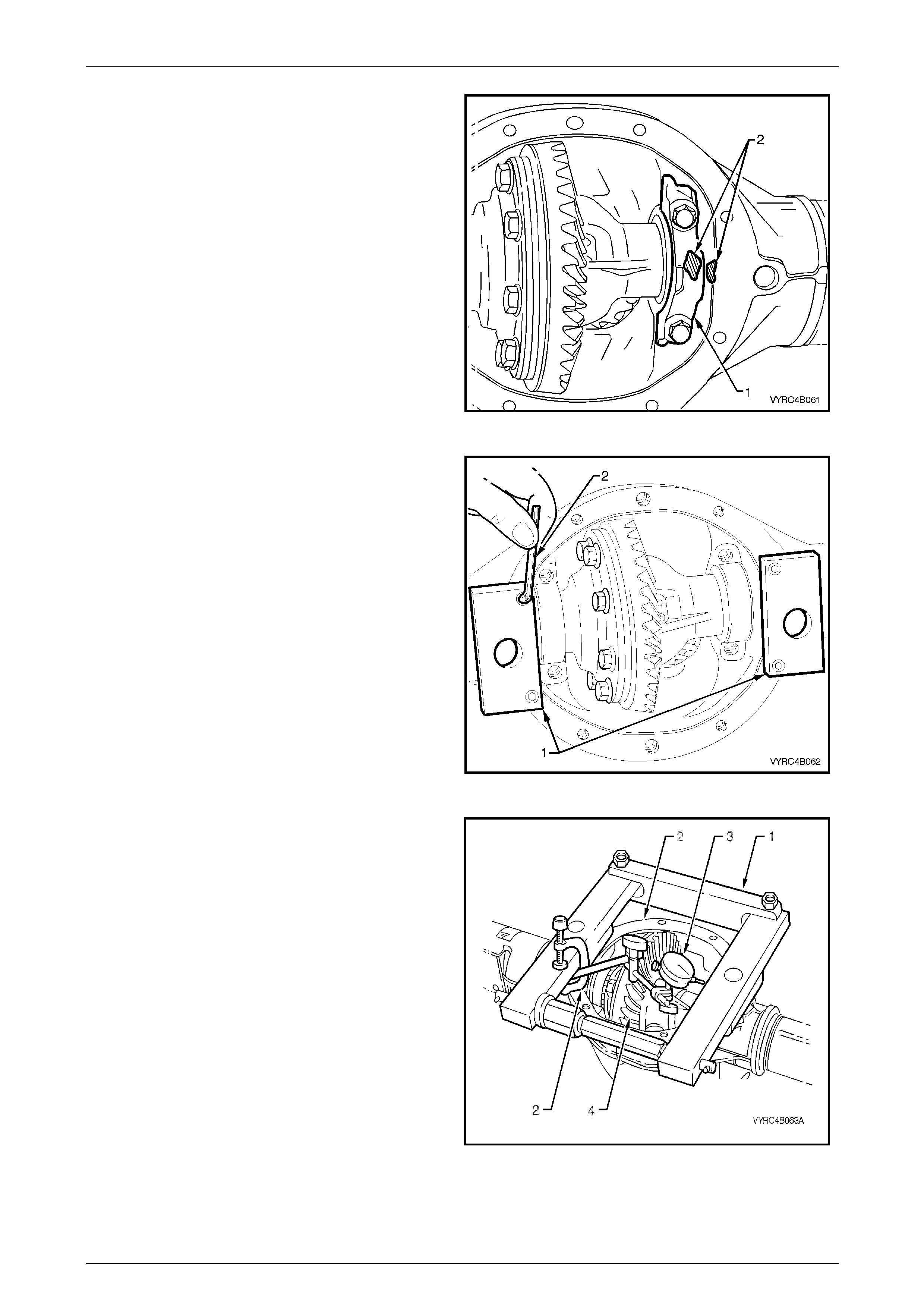
Rear Axle Page 4B –59
Page 4B–59
6 To aid correct reassembly, mark one of the differential
side bearing caps (1) and the adjacent side of the
rear axle housing with a daub of paint (2), refer to
Figure 4B-97
7 Remove the differential side-bearing cap retaining
bolts and side bearing caps.
Figure 4B-97
8 Install the adaptors (1) of the differential spreading
Tool No. E9255 to the differential carrier housing
using a 5mm Allen Key (2), refer to Figure 4B-98
Figure 4B-98
9 Install the differential spreading Tool No. E9255 and
adaptors (1) to the differential carrier housing (2),
refer to Figure 4B-99
10 Install a dial indicator (3) to the differential spreading
Tool No. E9255 and differential carrier housing.
11 Spread the differential carri er hous ing appr oximately
0.1 to 0.2 mm.
NOTE:
Under no circumstances is the differential
carrier to be spread more than 0.5 mm.
12 Remove the differential case assembly (4) along with
the carrier side bearing cups and shims.
13 Take note of which side each bearing cone, bearing
cap and related shim was removed from. Ensure the
original relationship is maintained so they may be
reinstalled in their orig inal location.
14 Release the force exerted by the spreading Tool No.
E9255 and remove the tool along with the adaptor’s
from the differential carrier housing.
Figure 4B-99
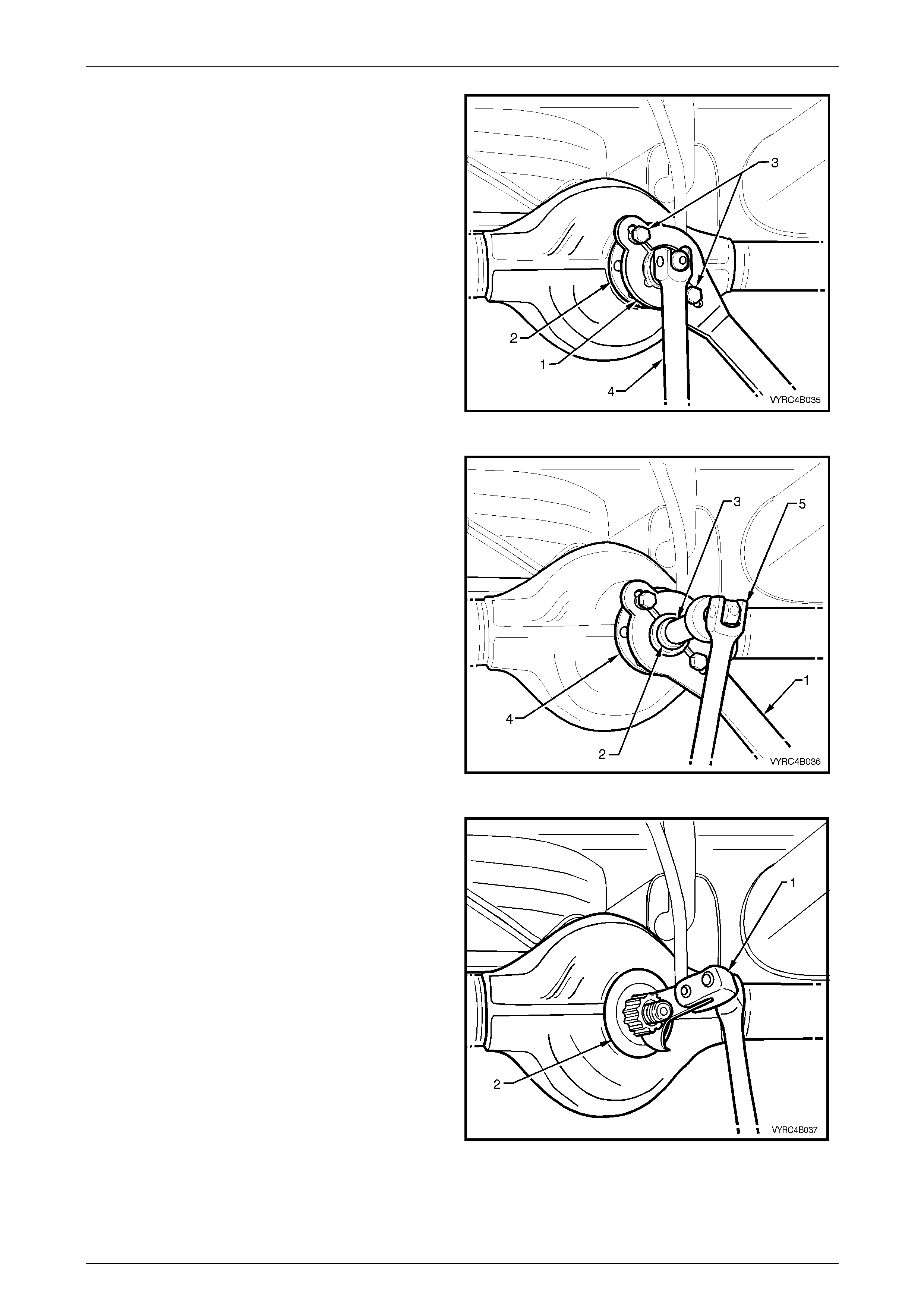
Rear Axle Page 4B –60
Page 4B–60
15 Attach the pinion flange holding fixture Tool No.
J8614-11 (1), part of Tool No. J8614-01, to the pinion
flange (2), using two suitable bolts (3) to hold pinion
flange.
16 Using a suitable socket and bar (4), while holding
Tool No. J8614-11, loosen the pinion flange, retaining
nut and remove it from the pinion.
Refer to Figure 4B-100.
Figure 4B-100
17 Install remover adaptor Tool No. J8614-2 (2) and
forcing screw Tool No. J8614-3 (3) to the pinion
flange holding fixture Tool No J8614-11 (1), part of
Tool No. J8614-01.
18 While holding Tool No. J8614-11 (1), part of Tool No.
J8614-1, use a suitable socket and bar (5) to
withdraw pinion flange (4) by turning the forcing screw
(3) in a clockwise direction. Refer to Figure 4B-101.
Figure 4B-101
19 Prise the pinion oil seal (2) from carrier bore using
Tool No. E308 (1) or a universal seal removing tool.
Refer to Figure 4B-102.
Figure 4B-102
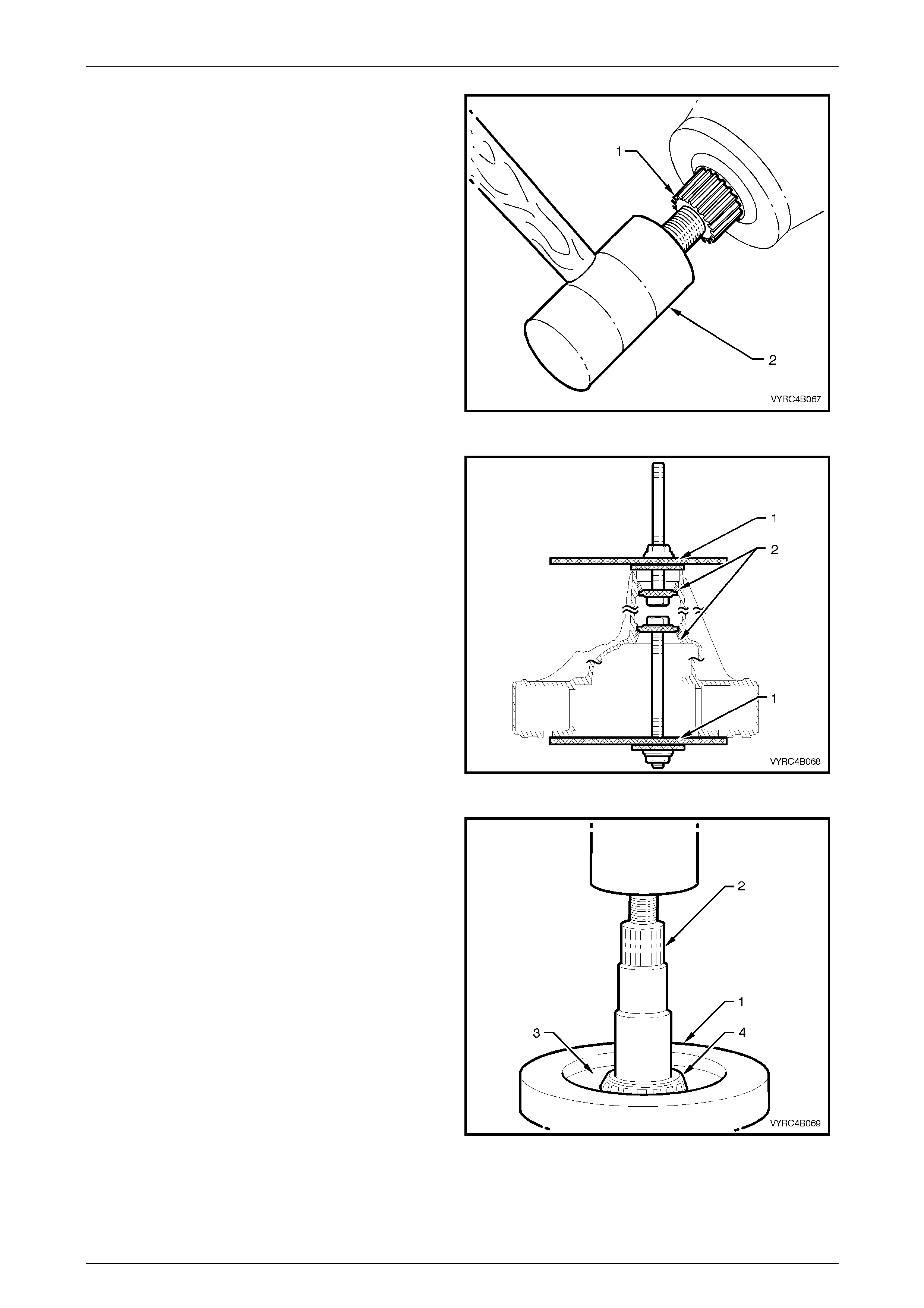
Rear Axle Page 4B –61
Page 4B–61
20 Remove the pinion gear (1) by taping on the front end
with a soft-faced hammer (2). Refer to Figure 4B-103.
21 Remove the front pinion bearing from the carrier bore.
22 Remove and discard the pinion bearing collaps ible
spacer.
Figure 4B-103
23 For M78 Series, if pinion-bearing replacement is
required, use Tool No. E9293 (1) to remove the front
and rear pinion gear bearing cups (2) from the carrier
bore, refer to Figure 4B-104.
For M86 Series, if pinion-bearing replacement is
required, use Tool No. E9293 (1) along with the
adaptors Tool No. 205-551 to remove the front and
rear pinion gear bearing cups (2) from the carrier
bore, refer to Figure 4B-104.
NOTE:
When removing the rear pinion-bearing cup
from the carrier bore ensure the pinion depth
shim is retrieved for future reference or possible
use. The shim is located between the rear
pinion-bearing cup and the bearing cup seat of
the carrier bore.
Figure 4B-104
24 To use Tool No. E1673MT to remove the rear pinion
gear bearing race, first remove the legs from the ring
of the tool.
25 Place the ring of Tool No. E1673MT (1) on suitab le
press plates.
26 Remove and discard the rear pinion gear bearing:
a. For M78 Series, install the pinion gear (2) and
adaptors E1673A15 (3) into the ring (1) and press
the pinion gear (2) from the bearing race (4).
Refer to Figure 4B-105.
b. For M86 Series, install the pinion gear (2) and
adaptors 205-547 (3) into the ring (1) and press
the pinion gear (2) from the bearing race (4). Refer
to Figure 4B-105.
Figure 4B-105
Rear Axle Page 4B –62
Page 4B–62
Inspect
1 Inspect the rear axle tubes and differential housing
casting for all over general so u ndne ss and any signs
of damage.
2 Remove any gasket or sealant material from the
mating surfac es of the differential housing casting (1)
and the rear-cover plate (2). Clean and inspect the
surfaces for damage that may cau se lubri can t
leakage. Refer to Figure 4B-106.
3 Inspect the rear cover bolt holes for damage.
4 Inspect all oil passages, bearing cup seating surfaces
and oil seal seating surfaces (3) for signs of wear,
damage or obstruction.
5 Check the breather is clear of obstruct ion s.
6 Ensure that all surfaces are free from burrs and
foreign matter.
Figure 4B-106
Reassemble
NOTE:
For the differential assembly and pinion
gear reinstallation procedures refer to
3.6 Differential Assembly Adjustment and
Installation Procedures – All Models in this
Section.
1 Install the rear cover and a new gasket to the carrier housing.
2 Install and tighten the rear cover attaching bolts to the correct torque specification.
(6) Rear cover to carrier housing
attaching bolt
torque specification ......................................23 – 31 Nm
3 Reinstall the rear axle assemblies. Refer to 2.8 Rear Axle Shaft Assembly – Reinstall in this Section.
4 Reinstall the rear axle housing assembly. Refer to 3.1 Rear Axle Assembly – Reinstall in this Section.
5 Fill the rear axle housing assemble with the recommended lubricant to the correct level.
Refer to 2.2 Checking Rear Axle Lubricant Level in this Section.
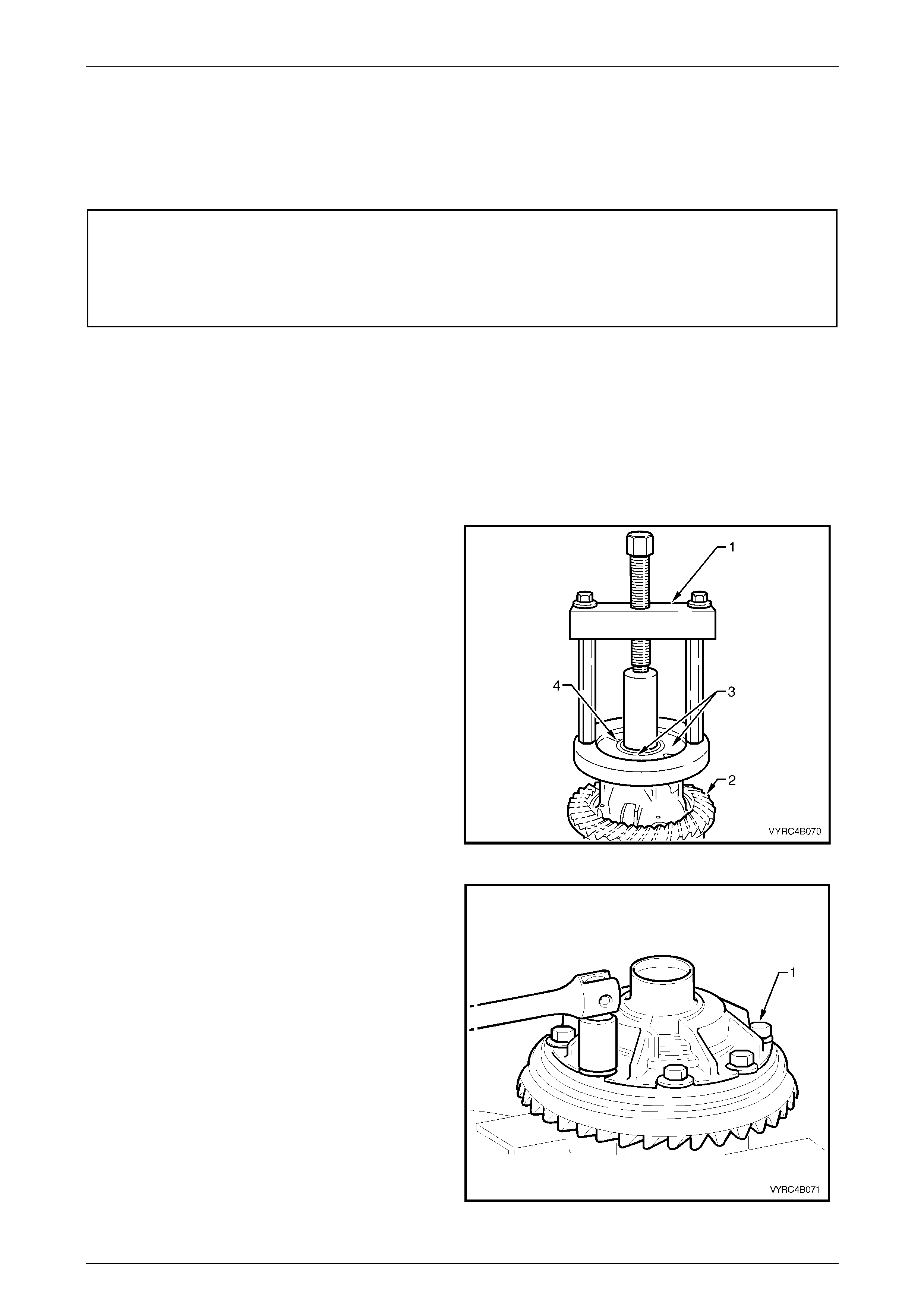
Rear Axle Page 4B –63
Page 4B–63
3.3 Differential Assembly – M78 Series
(Standard Non LSD)
LT Section No: F502600
ATTENTION
The following fasteners MUST be replaced when performing this operation:
+
++
+ Ring gear bolts.
Disassemble
NOTE:
For the differential assembly and pinion gear
removal procedure refer to 3.2 Rear Axle and
Differential Housing Assembly – Disassemble in
this Section.
1. Inspect the side-bearing race on each side of the
differenti al case for any sign s of damag e.
2. If necessary, use Tool No. E1673MT (1), adaptors
E1673N15 (3) and stepped plug E1673B16 to remove
the side bearing race (4) from the differential case and
ring gear assembly (2), refer to Figure 4B-107.
3. Discard the side bearing races once removed.
Figure 4B-107
4. Secure the differential case in a suitable vice equipped
with soft metal jaws.
5. Remove the ring gear attaching bolts (1) and discard
the bolts. Refer to Figure 4B-108.
NOTE:
The ring gear attaching bolts have a left-hand
thread and are identified by an 'L' on the bolt
head.
6. Remove the differential case from the vice.
Figure 4B-108
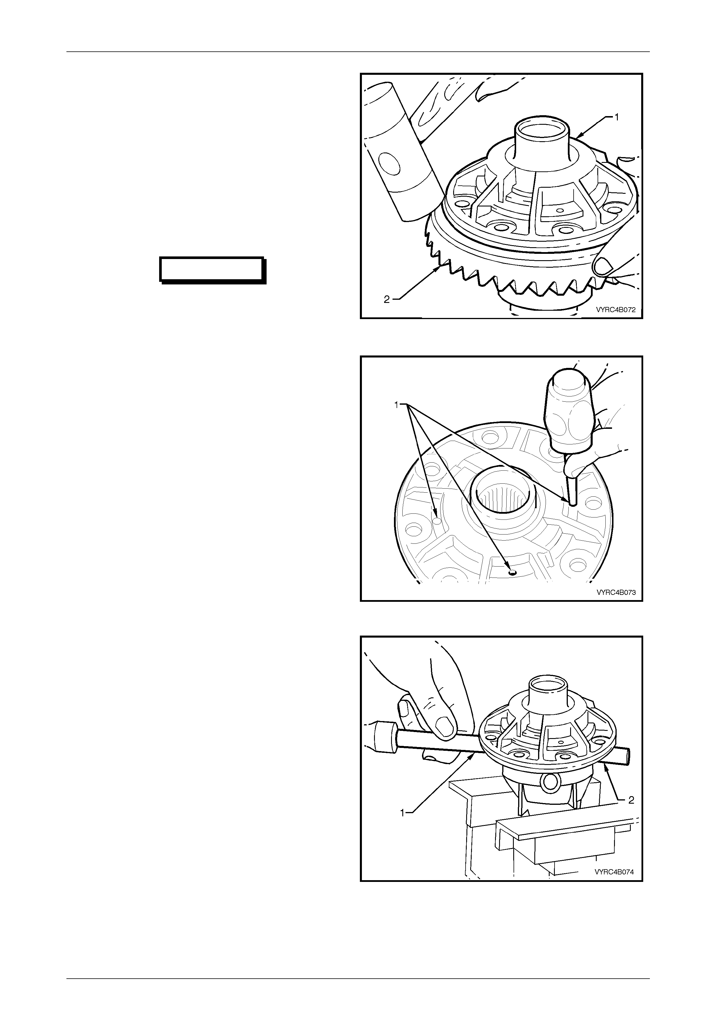
Rear Axle Page 4B –64
Page 4B–64
7. Place a piece of softwood large enough to cover the
over all diameter of the ring gear on top of a suitable
workbench.
8. Place the differential case (1) on top of the piece of
softwood wi th the ring gear attaching bolt holes facing
upward.
9. Using a soft faced hammer, remove the ring gear (2)
from the differential case by tapping down on the ring
gear while simultaneously rotating the differential case
until the ring gear is free from the case. The softwood
will protect the ring gear from damage during this step.
Refer to Figure 4B-109.
IMPORTANT
Do not use a screwdriver or other form of
leverage to pry betw een the ring gear and
the mating face of the differential case, as
damage will occur. Figure 4B-109
10. Re-secure the differential case in a suitable vice
equipped with soft metal jaws.
11. Using suitable a hammer and pin punch drive out the
differential cross shaft and short shaft retaining pins
(1), refer to Figure 4B-110.
Figure 4B-110
12. Using suitable a hammer and brass drift (1) drive-out
the differential cross shaft (2).
Refer to Figure 4B-111.
13. Remove the differential case from the vice.
Figure 4B-111
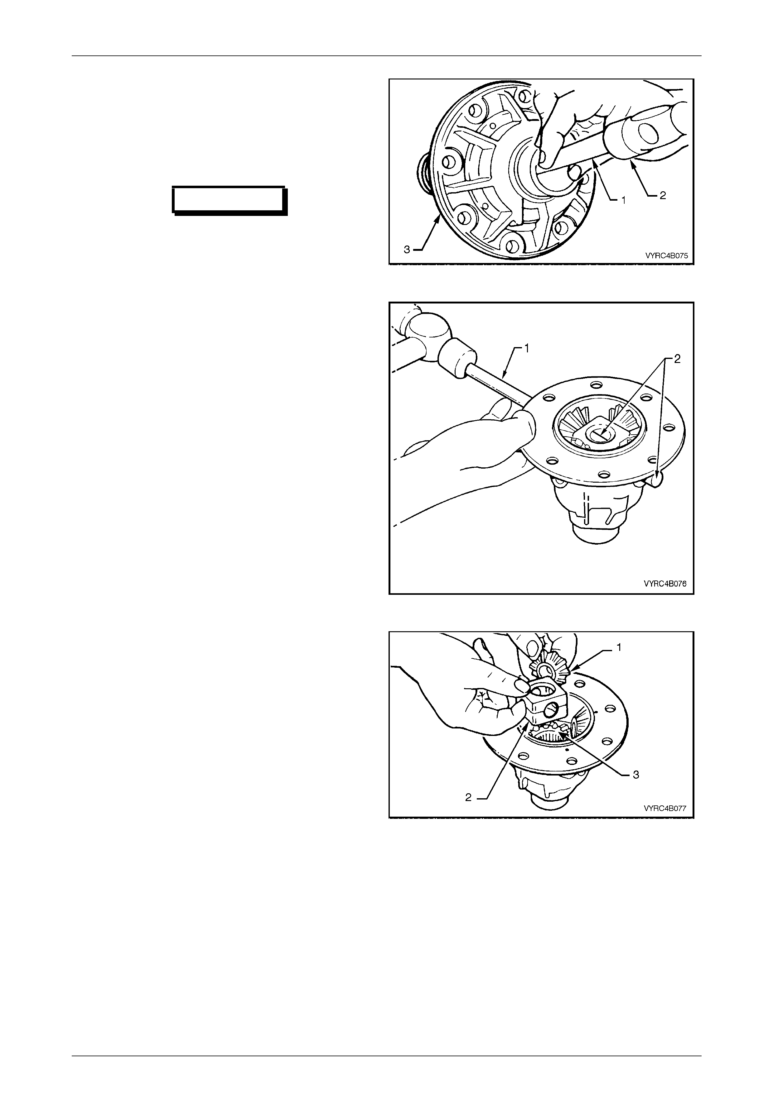
Rear Axle Page 4B –65
Page 4B–65
14. Place the differential case on top of a suitable
workbench wi th the ring gear attaching bolt holes
facing outward.
15. Using a suitable hammer (2) with a brass drift (1), drive
against the thrust block to separate the differential
case halves (3). Refer to Figure 4B-112.
IMPORTANT
Do not use a screwdriver or other form of
leverage to pry the mating faces of the
differential case apart, as damage will
occur.
Figure 4B-112
16. Re-secure the differential case half containing the side
gears, pinion shaft and pinion gears in a suitable vice
equipped with soft metal jaws.
17. Using a suitable hammer with a brass drift (1), drive
out the short pinion shafts (2) from the differential case.
Refer to Figure 4B-113.
Figure 4B-113
18. Lift out the pinion gears (1), respec tive thrust washers
and the thrust block (2).
19. Lift out the side gears (3) and respective thrust
washers. Refer to Figure 4B-114.
NOTE:
Ensure the original relationship of thrust washer
to gear is maintained for both side gear and
pinion gear differential components to the
differential housing so they may be reinstalled in
their original location.
Figure 4B-114
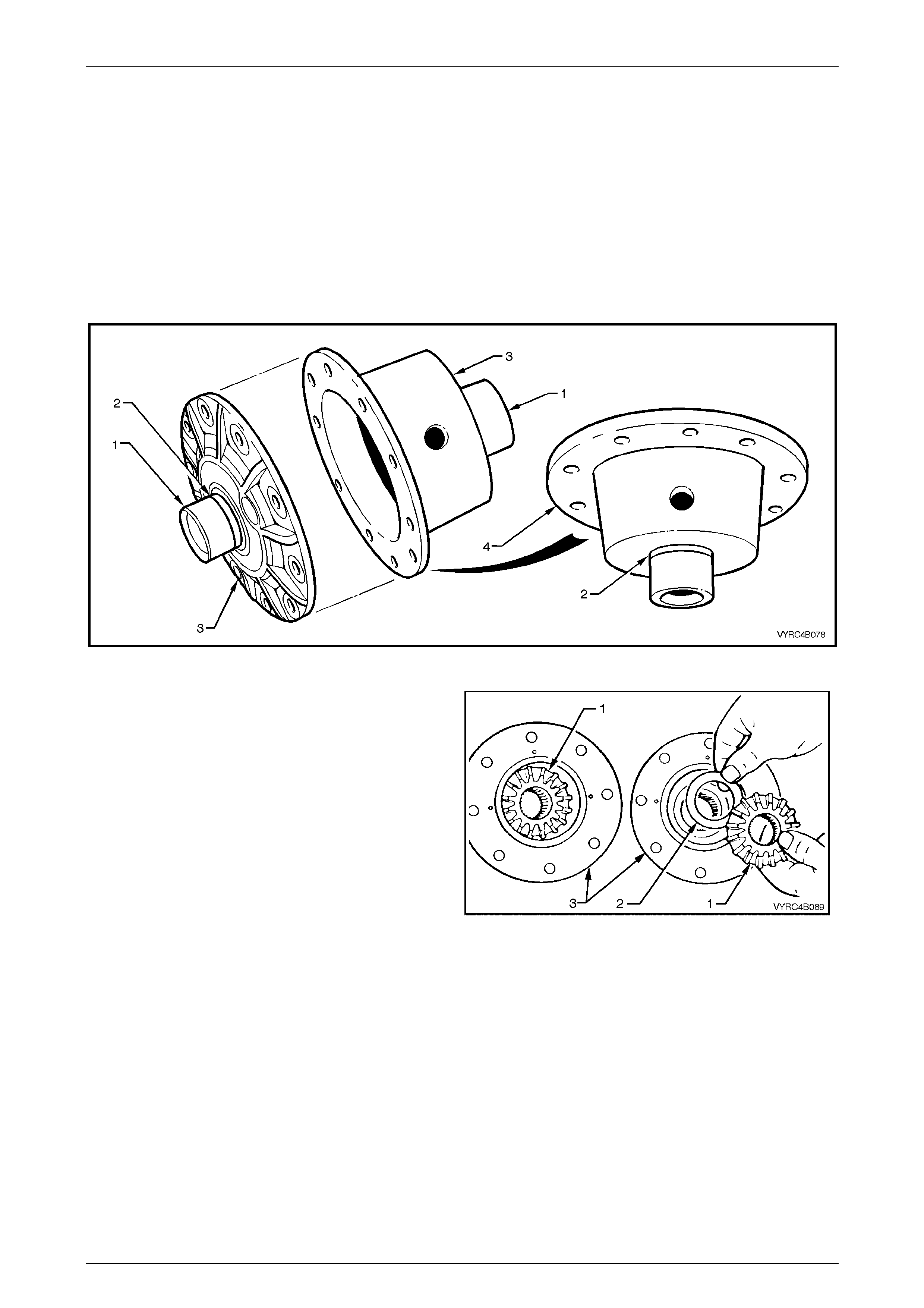
Rear Axle Page 4B –66
Page 4B–66
Inspect
Differential Case
All components of the differential should be cleaned and dried then inspected. Check the differential case for general
condition paying particular attention to the follow points:
1 If the side bearings have been removed from the differential case. Inspect the case side bearing journal (1)
including the bearing seat (2) on each side of the differential case for any signs of damage.
2 Inspect the ring gear spigot and mounting face (4) of the differential case (3) for any signs of damage.
3 Ensure that all surfaces are free from burrs and foreign matter. Refer to Figure 4B-115.
Figure 4B-115
4 Inspect the mating surf ace (3) of the differential case
halves for any signs of damage.
Refer to Figure 4B-116.
5 Inspect the thrust surfaces for the differential side and
pinion gears (1) of the differential case (3) for any
signs of damage or excessive wear.
6 Ensure that all machined surfaces are free from burrs
and foreign matter.
Figure 4B-116
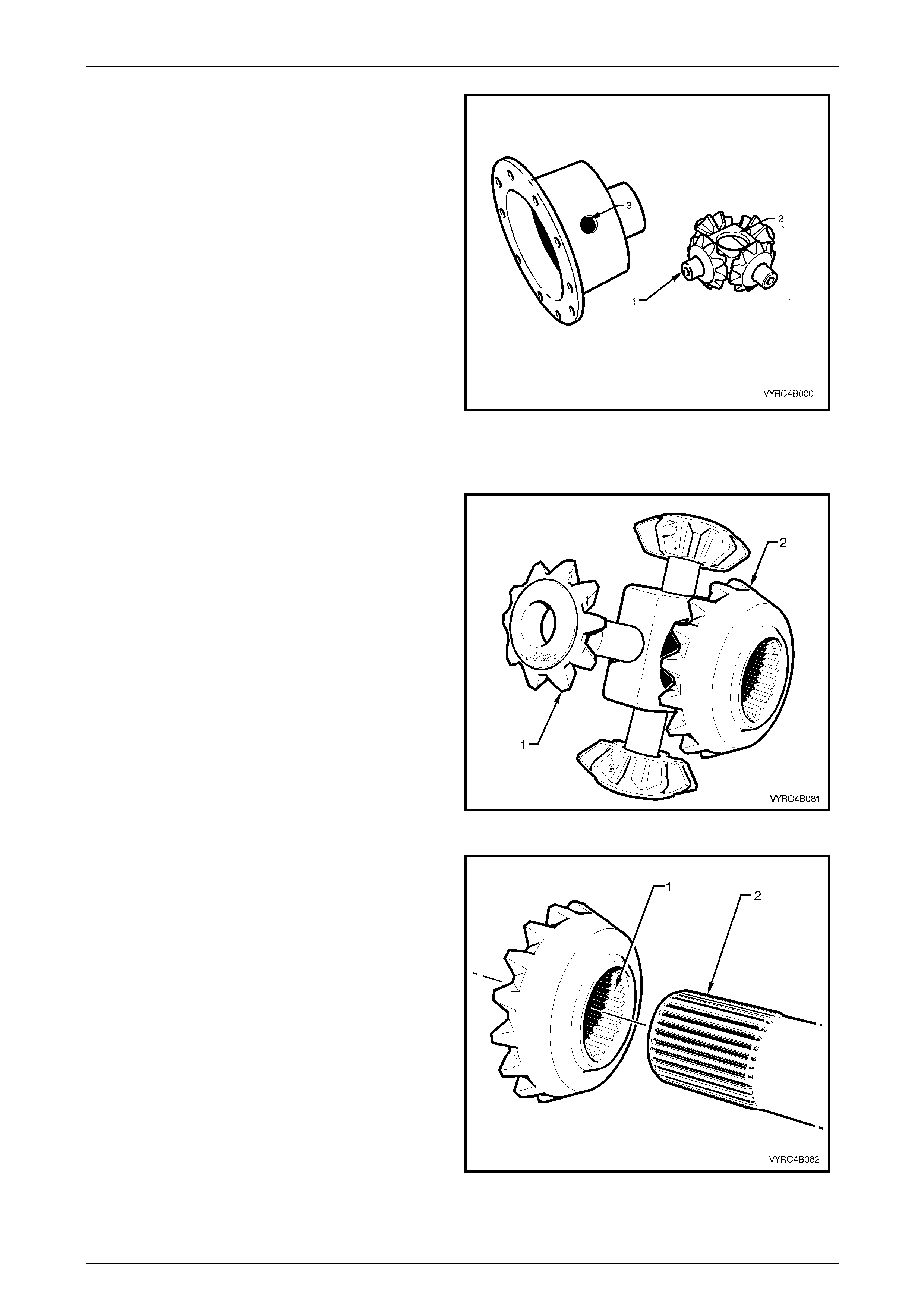
Rear Axle Page 4B –67
Page 4B–67
7 Inspect the different ial pin ion g ear shaft s (1) and
differential case bores (3) for ovality or any signs of
damage. Refer to Figure 4B-117.
8 Inspect the thrust block and bores (2) for ovality or
any signs of damage. Refer to Figure 4B-117.
9 Ensure that all machined surfaces are free from burrs
and foreign matter.
Figure 4B-117
Differential Side and Pinion Gears
1 Inspect the teeth of the differential pinion gears (1)
and side gears (2) for any signs of damage, cracks,
excessive wear or hard contact.
Refer to Figure 4B-118
2 Inspect the thrust faces on the rear of the differential
side and pinion gears for any signs of damage or
scoring.
3 Ensure that all machined surfaces are free from burrs
and foreign matter.
Figure 4B-118
4 Inspect the splines of the differential side gears for
any signs of damage or excessive wear.
5 To check for excessive wear of the side gear spline,
offer the side gear (1) to the splined Section (2) of the
respective axle shaft. The gear should be a snug fi t
with minimal side rotational movement on the axle
spline. Refer to Figure 4B-119.
6 Ensure that all splined surfaces are free from burrs
and foreign matter.
Figure 4B-119
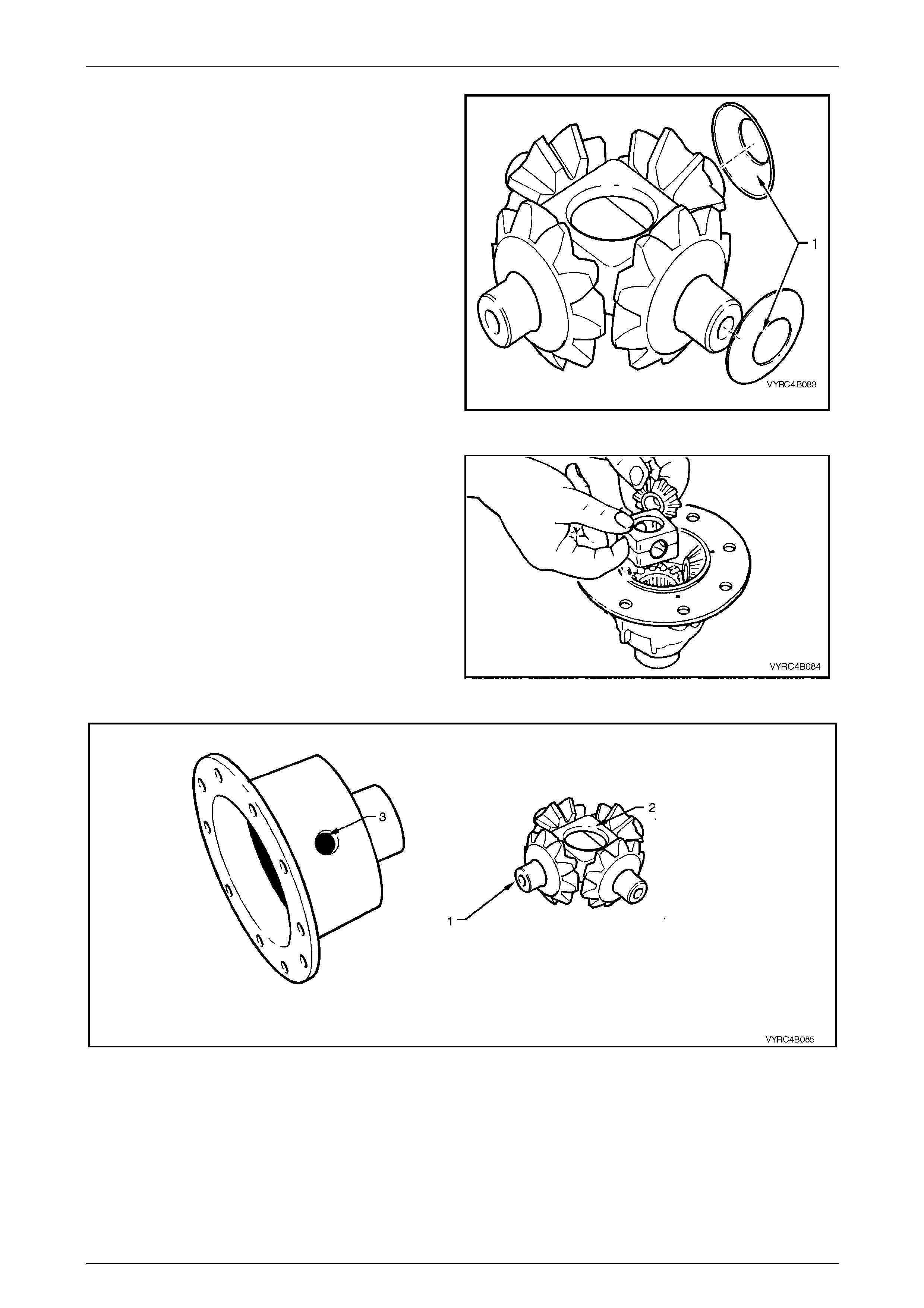
Rear Axle Page 4B –68
Page 4B–68
7 Inspect the thrust washer faces (1) for any signs of
damage or scoring. Refer to Figure 4B-120.
8 Ensure that all thrust washer surfaces are free from
burrs and foreign matter.
Figure 4B-120
9 Check the fit of the differential gears in relation to the
differential case cap and cover. Wear of the side or
pinion gears; hub surfaces or case bores can cause a
'clunking' noise in the rear axle assembly when the
vehicle is driven at low speed.
Refer to Figure 4B-121.
10 Ensure that all surfaces are free of foreign matter.
Figure 4B-121
Figure 4B-122
11 Inspect all pinion gear shaft (1) surfaces for straightness, scoring and wear.
12 Inspect the thrust block (2) and the differential case (3) surfaces for scoring or wear.
13 Ensure that all surfaces are free from burrs and foreign matter. Refer to Figure 4B-122.
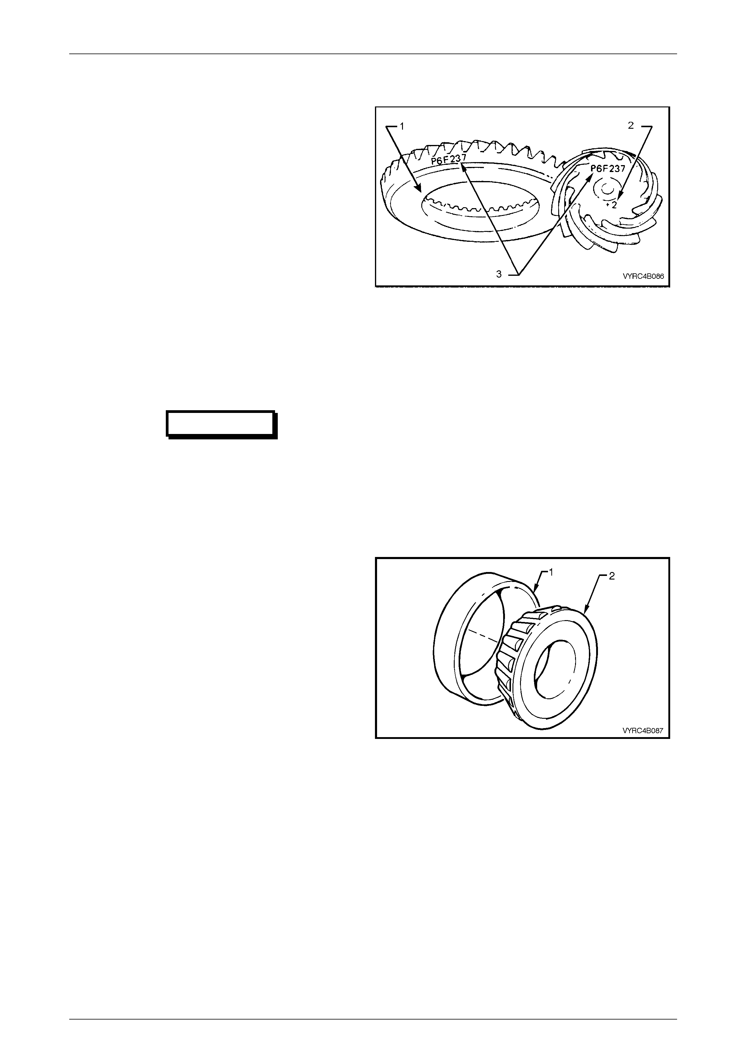
Rear Axle Page 4B –69
Page 4B–69
Ring Gear and Pinion Gear
1 Inspect the teeth of the ring gear (1) and pinion gear
(2) for any signs of damage, scoring, cracks, chips or
excessive wear. Refer to Figure 4B-123.
NOTE:
Excessive shock loading, use of incorrect
lubricant or insufficient ‘run in’ before towing a
heavy load, usually causes scoring of gear
teeth.
2 Inspect the ring gear bore and back faces for any
signs of damage.
3 Inspect the pinion gear bearing seat, spline and
thread surfaces for any signs of damage or evidence
of wear.
4 Ensure that all surfaces are free from burrs and
foreign matter.
5 Ensure that all ring gear attaching bolt 'Durlok'
serration surfaces are clean under each bolt flange.
IMPORTANT
Scored gears must be replaced. If a new
gear set is to be installed, ensure that the
same matching numbers (3) appear on
both the pinion and ring gears.
Refer to Figure 4B-123.
Figure 4B-123
Bearings
NOTE:
All bearings race assemblies and cups should
be kept in the same relationship as when
removed. All bearing race assemblies and cups
should remain as matching sets and should not
be mixed.
1 Inspect all bearing cups (1) for an even wear pattern.
The bearing cups should also be free from flaking or
pitting. Refer to 4.4 Differential and Rear Axle Bearing
Diagnosis in this Section. Refer to Figure 4B-124.
2 Inspect all bearing race asse m blie s (2) for signs of
wear or damage.
3 Inspect the roller cage and bores of the bearing race
assemblies for cracks, flaking, pitting or distortion.
The bearing race assemblies should feel smooth
when turned in their respective cups. Refer to
4.4 Differential and Rear Axle Bearing Diagnosis in
this Section.
4 Ensure that all surfaces are free from burrs and
foreign matter.
Figure 4B-124
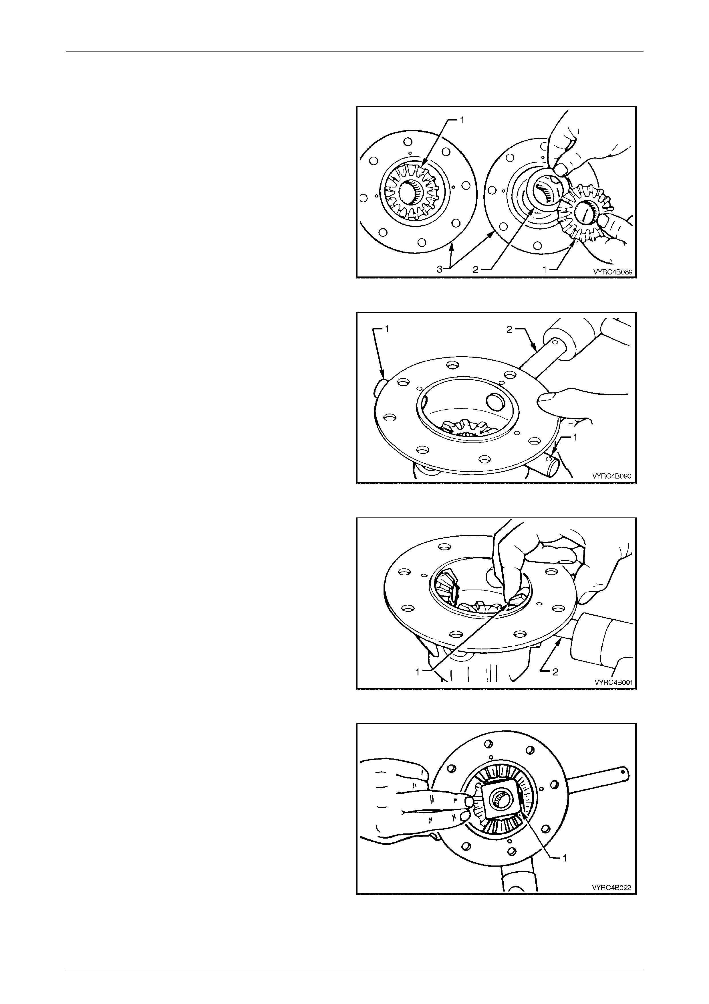
Rear Axle Page 4B –70
Page 4B–70
Reassemble
1 Before reassembly, use the recommended rear axle
lubricant to lubricate the differential pinion gears, side
gears, and side bearings , thrust washers, pinion gear
shafts and thrust block.
2 Install the differential side gears (1) and their related
thrust washer’s (2) into their respective differential
case halves (3). Refer to Figure 4B-125.
Figure 4B-125
3 Using a soft faced hammer, install the short pinion
gear shafts (1) and the long pinion gear shaft (2) into
the differential case, just enough to allow a thrust
washer to sit on the end of each shaft.
Refer to Figure 4B-126.
NOTE:
Ensure that the retaining pin holes in the
differential case and pinion gear shafts are in
alignment with the chamfered edge of the holes
in each shaft facing up.
Figure 4B-126
4 Install one of the pinion gear thrust washers over the
inside end of one of the short pinion shafts.
5 Holding the pinion gear and thrust washer (1) in place
while using a soft faced hammer, gently tap the short
pinion shaft (2) in until it comes through the centre of
the pinion gear. Refer to Figure 4B-127.
6 Repeat steps 4 and 5 for the second pinion gear,
thrust washer and short pinion shaft.
Figure 4B-127
7 Install the thrust block (1) between the two-installed
pinion gears.
8 Holding the thrust block and di fferent ial ca se w hile
using a soft faced hammer ge ntly tap each of the
short pinion shaft in until the retaining pin holes of
each shaft line up with the related holes of the
differential case. Refer to Figure 4B-128.
Figure 4B-128
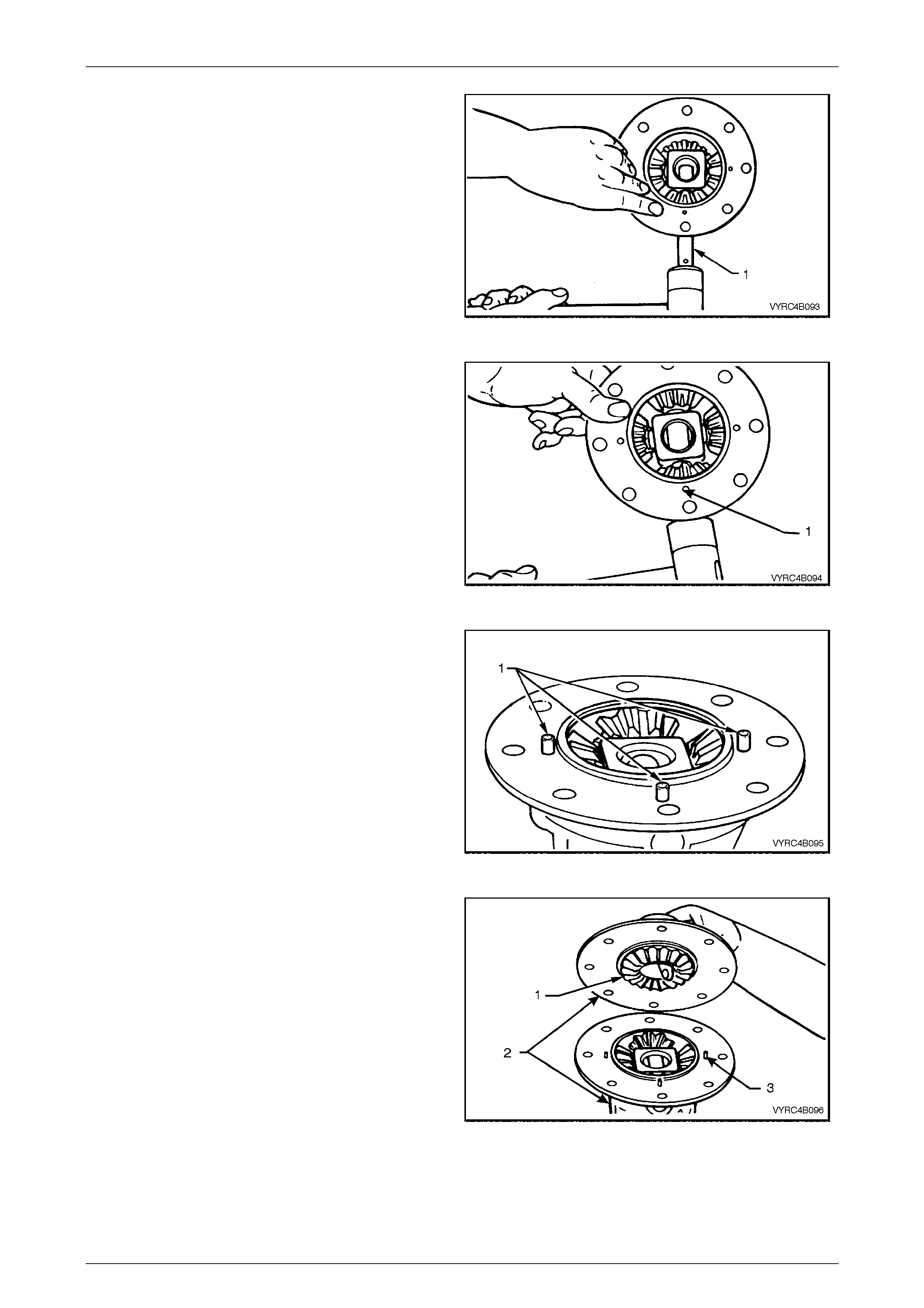
Rear Axle Page 4B –71
Page 4B–71
9 Install the third pinion gear and thrust washer over the
inside end of the long pinion shaft (1).
10 Hold the pinion gear and thrust washer in place. Use
a soft faced hammer to gently tap the long pinion
shaft (1) in until it comes through the centre of the
pinion gear and thrust block just enough to allow the
remaining pinion gear and thrust washer to be
installed. Refer to Figure 4B-129.
Figure 4B-129
11 Install the forth pinion gear and thrust washer over the
inside end of the long pinion shaft.
12 Use a soft faced hammer to gently tap the long pinion
shaft through the centre of the pinion gear, thrust
washer and differential case until the retaining pin
hole of the shaft lines up with the related hole (1) of
the differential case.
Refer to Figure 4B-130.
Figure 4B-130
13 Install the three retaining pins (1) for each pinion shaft
ensuring ea ch pin protrud es 6 mm fr om the mat ing
face of the di fferential case half.
Refer to Figure 4B-131.
Figure 4B-131
14 Ensure that the mating surfaces of each differential
case half are free from burrs and foreign matter.
15 Holding the remaining side gear (1) in position with a
finger through the differential side gear bore, mate the
two halves of the differential case (2) together while
aligning the protruding pinion shaft retaining pins (3)
of the other case half.
Refer to Figure 4B-132.
Figure 4B-132
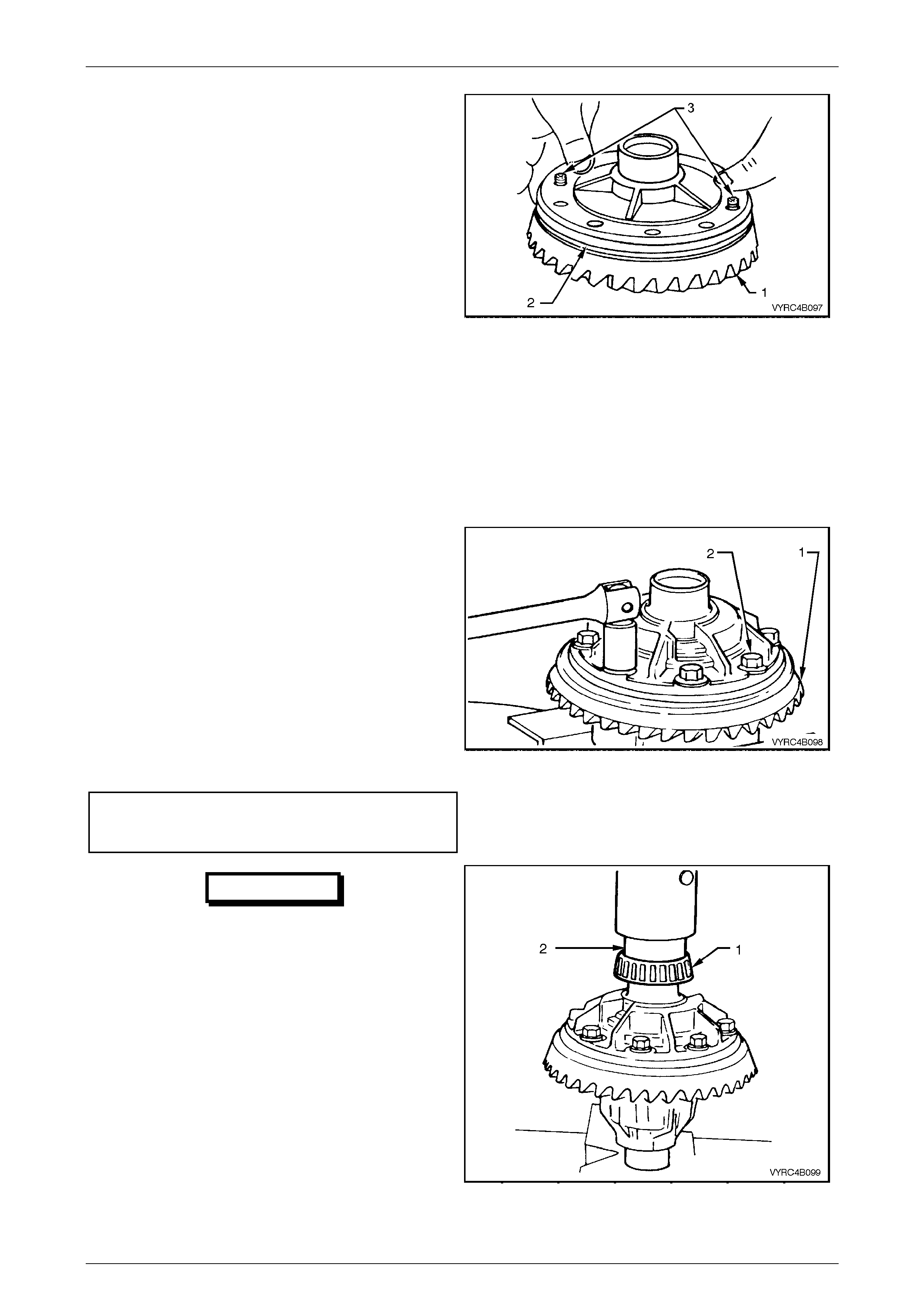
Rear Axle Page 4B –72
Page 4B–72
16 Ensure that all mating surfaces of the ring gear and
differenti al case are free from burrs and forei gn
matter.
NOTE:
To aid assembly, use two left-hand thread guide
pins to pilot the ring gear over the differential
case spigot.
NOTE:
Prior to installation, it may be necessary to heat
the ring gear on a hot plate until it is hot to the
hand.
NOTE:
On no account must a flame be used to heat the
ring gear over the differential c ase spi got.
17 With the aid of two guide pins (3) place the ri ng gear
(1) into position on the differential case (2) and install
the NEW ring gear attaching bolts. Remove the two
guide pins and install the remaining ring gear
attaching bolts Refer to Figure 4B-133.
Figure 4B-133
18 Secure the differential case in a suitable vice
equipped with soft metal jaws. Refer to Figure
4B-134.
19 Using a cross pattern, tighten the ring gear attaching
bolts (2) to seat the ring gear (1) to the differential
case.
NOTE:
The ring gear attaching bolts use a left-hand
thread and are identified by an 'L' on the head of
the bolt.
20 Tighten the ring gear attaching bolts (2) to the correct
torque specif ication.
(+) Ring gear to differential
case attaching bolt
torque specific atio n .................................. 130 – 145 Nm
Figure 4B-134
IMPORTANT
One of two manufacturers, Timken or
Koyo can manufacture the side bearings.
When replacing the differential side
bearings, the two bearings and cups must
be of the same brand. The reason for
matched pairs of bearings is that a
different preload specification is required
for each brand.
21 To install new side bearing race assemblies (1) use
Tool No. 205-545 (2). Use suitable press plates to
support the opposite differential case journal. With
Tool No. 205-545 in plac e, press the bearing race
assembly on to the differential case journal. Refer to
Figure 4B-135.
22 Repeat step 22 to install the remain ing side bearing
race assembly on to the differential case journal
taking care not to damage the previously installed
bearing race. Figure 4B-135
Rear Axle Page 4B –73
Page 4B–73
3.4 Differential Assembly – M78 Series
(Cone Type Limited Slip)
LT Section No: F502600
ATTENTION
The following fasteners MUST be replaced when performing this operation:
+
++
+ Ring gear bolts.
+
++
+ LSD case cap to cover attaching bolts .
The overhaul procedures, ring gear and pinion positioning and tooth ma rkings for the M78 Series limited slip differential
are the same as for the standard type of rear axle assembly, except for the servicing of the internal components of the
limited slip differential assembly.
NOTE:
For the differential assembly and pinion gear
removal procedure refer to 3.2 Rear Axle and
Differential Housing Assembly, Disassemble in
this Section.
NOTE:
The M78 Series, differentials have unique parts
and are not interchangeable with the M86 Series
unit. The general overhaul procedures are also
different for both types.
The unique co mponents for the M78 Series differentials are:
• Differential case.
• Differential pinions.
• Side gears.
• Differential pinion thrust washers.
• Pinion cross shaft.
• Clutch cones.
• Thrust spring plates.
• Differential preload springs.
• Differential case cap to cover attachin g bolts.

Rear Axle Page 4B –74
Page 4B–74
Disassemble
NOTE:
Both side bearings and their cups are matched
parts. If either bearing is to be replaced, its
matching cup must also be replaced.
IMPORTANT:
The side bearings can be manufactured
by one of two manufacturers, Timken or
Koyo. When replacing the differential side
bearings, the two bearings and cups must
be of the same brand. The pinion bearings
may be of a different manufacture but
again; they must be a matched pair. The
reason for matched pairs of bearings is
that a different preload specification is
required for each brand.
1 Before disassembling differential case, inspect
differential side bearings for any signs of damage.
2 If replacing the side bearings (1), use Tool No.
E1673MT (2), adaptor’s Tool No. E1673N15 (3) and
stepped plug Tool No. E1673B16 (4) to remove side
bearings from the differential case. Refer to
Figure 4B-136. Discard side bearings once they are
removed. To remove side-bearing cups, refer to
3.2 Rear Axle And Differential Housing Assembly -
Disassemble, Step 9 in this Section.
Figure 4B-136
3 Using in a suitable vice equipped with soft metal jaws,
secure the differential case, remove the ring gear
attaching bolts (1) and discard the bolts.
Refer to Figure 4B-137.
NOTE:
The ring gear attaching bolts have a left-hand
thread and are identified by an 'L' on the bolt
head.
4 Remove the differential case from the vice.
Figure 4B-137
5 Place a piece of softwood large enough to cover the
over all diameter of the ring gear on top of a suitable
workbench.
6 Place the differential case on top of the piece of
softwood wi th the ring gear attaching bolt holes facing
upward.
7 Remove the ring gear (1) sing a soft faced hammer
(2), from the differential case (3) by tapping down on
the ring gear while simultaneously rotating the
differential case until the ring gear is free from the
case. The softwood will protect the ring gear from
damage during this step. Refer to Figure 4B-138.
IMPORTANT
Do not use a screwdriver or other form of
leverage to pry betw een the ring gear and
the mating face of the differential case, as
damage will occur.
Figure 4B-138
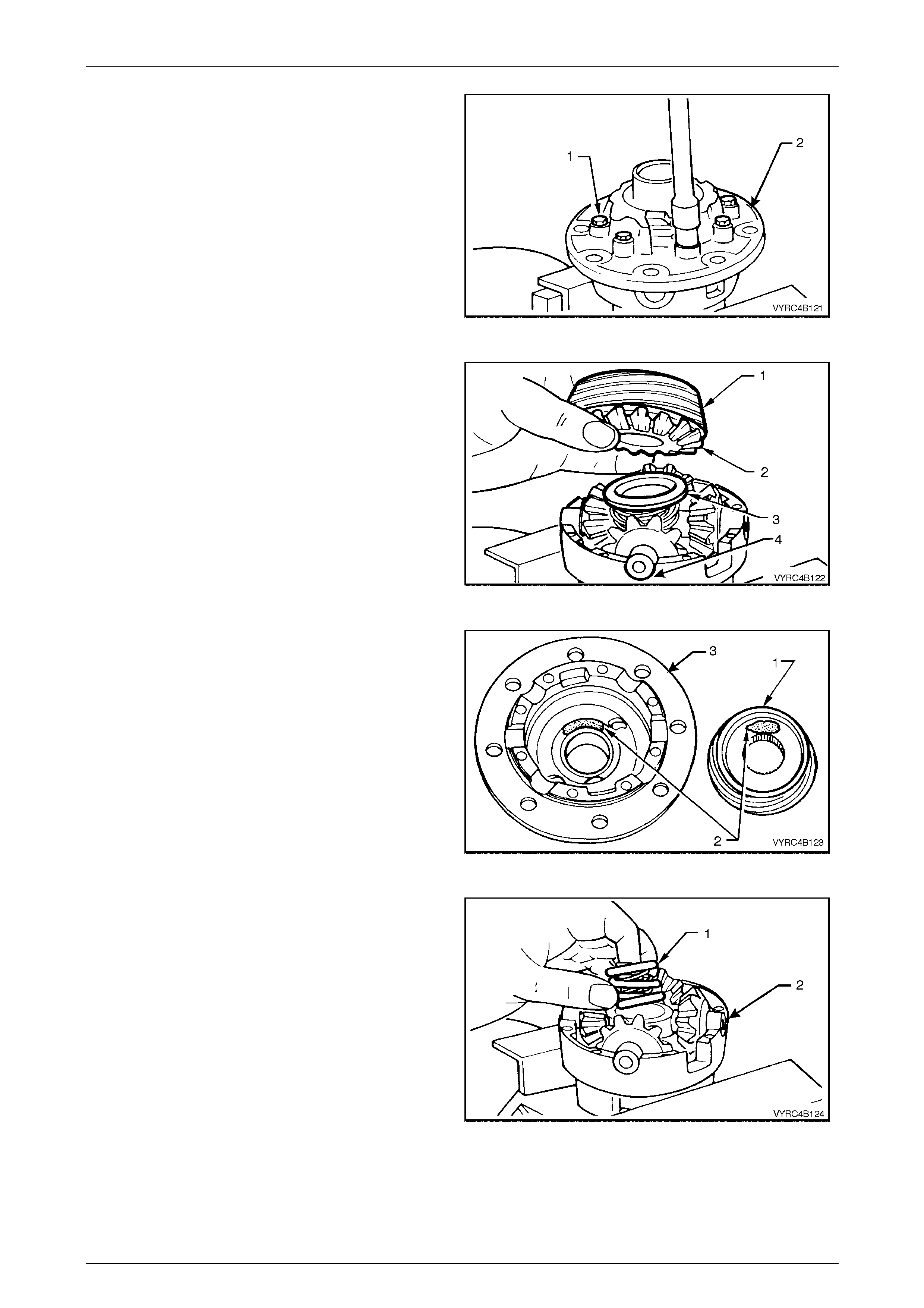
Rear Axle Page 4B –75
Page 4B–75
8 Re-secure the differential case in a suitable vice
equipped with soft metal jaws.
9 Loosen and remove the differential case cap to cover
attaching bolts (1) evenly and discard the bolts.
10 Lift off the differential case cover (2) If necessary;
remove the clutch cone from the cover (sometimes
the cone will remain inside the cover).
Refer to Figure 4B-139.
Figure 4B-139
11 Remove the clutch cone (1), shim (if fitted), side gear
(2) and thrust spring plate (3) from the pinion cross
shaft (4). Refer to Figure 4B-140.
NOTE:
The clutch cones and side gears are an integral
unit and must stay assembled to each other.
Figure 4B-140
NOTE:
To ensure that the clutch cones (1) are not
interchanged during reassembly, mark (2) the
cone and corresponding side of the differential
case (3) with a pen or similar. If shims are
present, they must also be marked so that they
can be reassembled into the correct case half.
Refer to Figure 4B-141.
Figure 4B-141
12 Remove the three concentric differential preload
spring’s (1) from centre of pinion cross shaft (2).
Refer to Figure 4B-142.
Figure 4B-142
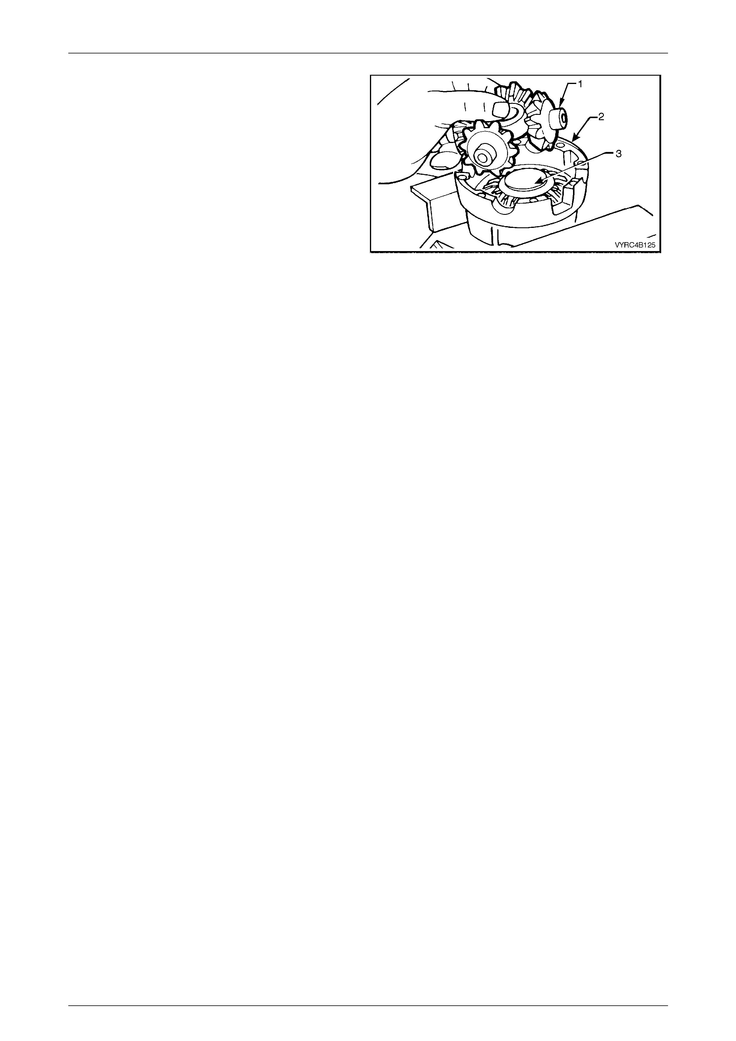
Rear Axle Page 4B –76
Page 4B–76
13 As one unit, lift the pinion cross shaft, pinion gears
and thrust washers (1) from the differential case (2).
Refer to Figure 4B-143.
NOTE:
Keep the pinion gears with their respective
thrust washers in sets so they can be reinstalled
in their original position.
14 Remove the pinion gears and thrust washers from
cross shaft.
15 Remove remaining thrust spring plate, side gear,
shim (if fitted) and clutch con e (3) from differen tia l
case (2). Refer to Figure 4B-143. Figure 4B-143
Inspect
All components should be thoroughly cleaned and dried, then inspected.
NOTE:
Keep the marked components in their respective
sets so they can be reinstalled in their original
position.
Differential Case
Check the following items:
1. The case for general soundness and pay particular attention to the following points:
2. If differential case side bearings have been removed, check case journals for damage and that seating surfaces are
free from dirt and burrs.
3. The ring gear spigot and mounting face should be clean and free from dirt and burrs.
4. The mating surfaces for differential case halves should be clean and free from burrs.
5. The thrust surfaces for the differential pinions should be examined for excessive wear.
6. The clutch cone seats in two housing halves should be smooth and free from any excessive scoring. Slight grooves
and scratches are permissible and normal.
7. The land surface of the heavy spirals on clutch cones will duplicate the housing surface condition. Excessive wear or
damage on the clutch cone surface will require replacement of both clutch cones or the clutch cone/side gear
assemblies (as applicable) and the housing
8. Inspect the axle splines of the clutch cones (where applicable ) for excessive wear.
9. Check the thrust spring plates for excessive wear or damage.
10. If fitted, inspect side gear shims for damage.
11. Inspect the pinion gear cross shaft bores for ovality.
Differential Side Gears and Pinion Ge ars
Check the following items:
1. Examine all gear teeth for cracks or hard conta ct mark s.
2. The differential side gear splines should be checked for excessive wear. Wear on splines can contribute to
excessive driveline backlash.
3. The differential pinion bores and thrust surfaces should be smooth and free from scores. Inspect all thrust washers
for cracks, nicks or burrs. Wear of thrust washers or thrust surfaces on gears can contribute to excessive driveline
backlash.
4. Check that pinion gear cross shaft is not bent and that surfaces on which pinions run, are not scored or worn.
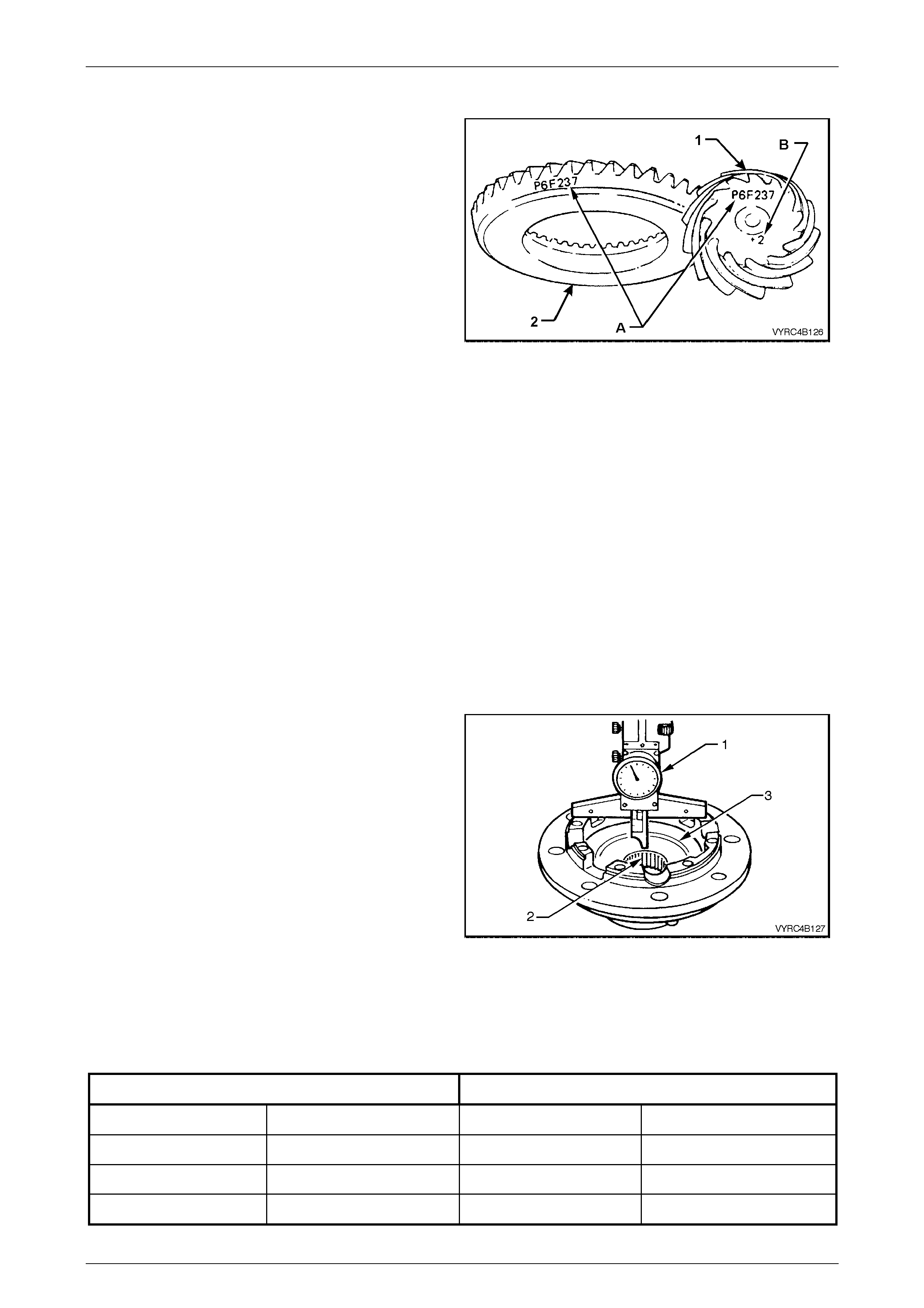
Rear Axle Page 4B –77
Page 4B–77
Ring Gear and Pinion
Check the following items:
1 Inspect the gear teeth for scoring or damage.
Excessive shock loading, use of the incorrect
lubricant or insufficient “run in” before towing a heavy
load, usually causes scoring of the gear teeth. (Refer
to the MY2003 VY Series, Cab Chassis Owner's
Handbook). Scored gears must be replaced.
2 If on reassembly, a new gear set is to be installed,
ensure that the same matching number (A) appears
on both the pinion (1) and ring gear (2).
Refer to Figure 4B-144.
3 The identification number (B) on the pinion end (1) is
used when setting the pinion depth on reassembly.
Refer to Figure 4B-144.
4 On the ring gear bolts clean the serrations under bolt
flanges.
Figure 4B-144
Bearings
Check the following items:
1 Bearing cups should have an even wear pattern and be free from flaking or pitting.
2 Ensure the seating surfaces are clean and free from burrs or raised metal.
3 The bearing assemblies should feel smooth when turned in the cups.
4 The assembly should be free from loose particles.
5 There should be no cracks present in the roller cages and the bores should show no evidence of flaking or pitting.
Refer to 4.4 Differential and Rear Axle Bearing Diagnosis in this Sect ion, for identifi cation related to the diagno sis
of bearing failures.
Reassemble
1 Lubricate all gears, bearings, thrust washers and
pinion gear cross shaft with rear axle lubricant before
assembly. Refer to 2.2 Checking Rear Axle Lubricant
Level in this Section.
2 With the cone type unit separated, reinstall each
respective clutch cone and shim (if fitted) into
differential case halves.
3 To check if shims are required:
a. Using a depth gauge (1), measure the distance
from the case-mating surface (2) to the flat seating
surface for the clutch cone (3). Record this
dimension. Refer to Figure 4B-145.
b. This measurement will indicate what size side
gear positioning shim is required. Each case half
and clutch con e must be mea s ured for its own
respective shi m.
c. With the measurement from "a", above, select the
correct shim size as indicated by the following
chart.
Figure 4B-145
CLUTCH CONE WITHOUT GROOVE CLUTCH CONE WITH GROOVE
Distance Measured Shim Size Required Distance Measured Shim Size Required
29.51 – 29.34 mm No shim required 32.0 – 31.84 mm No shim required
29.64 – 29.54 mm 0.13 mm shim required 32.14 – 32.04 mm 0.13 mm shim required
29.77 – 29.67 mm 0.25 mm shim required 32.27 – 32.17 mm 0.25 mm shim required
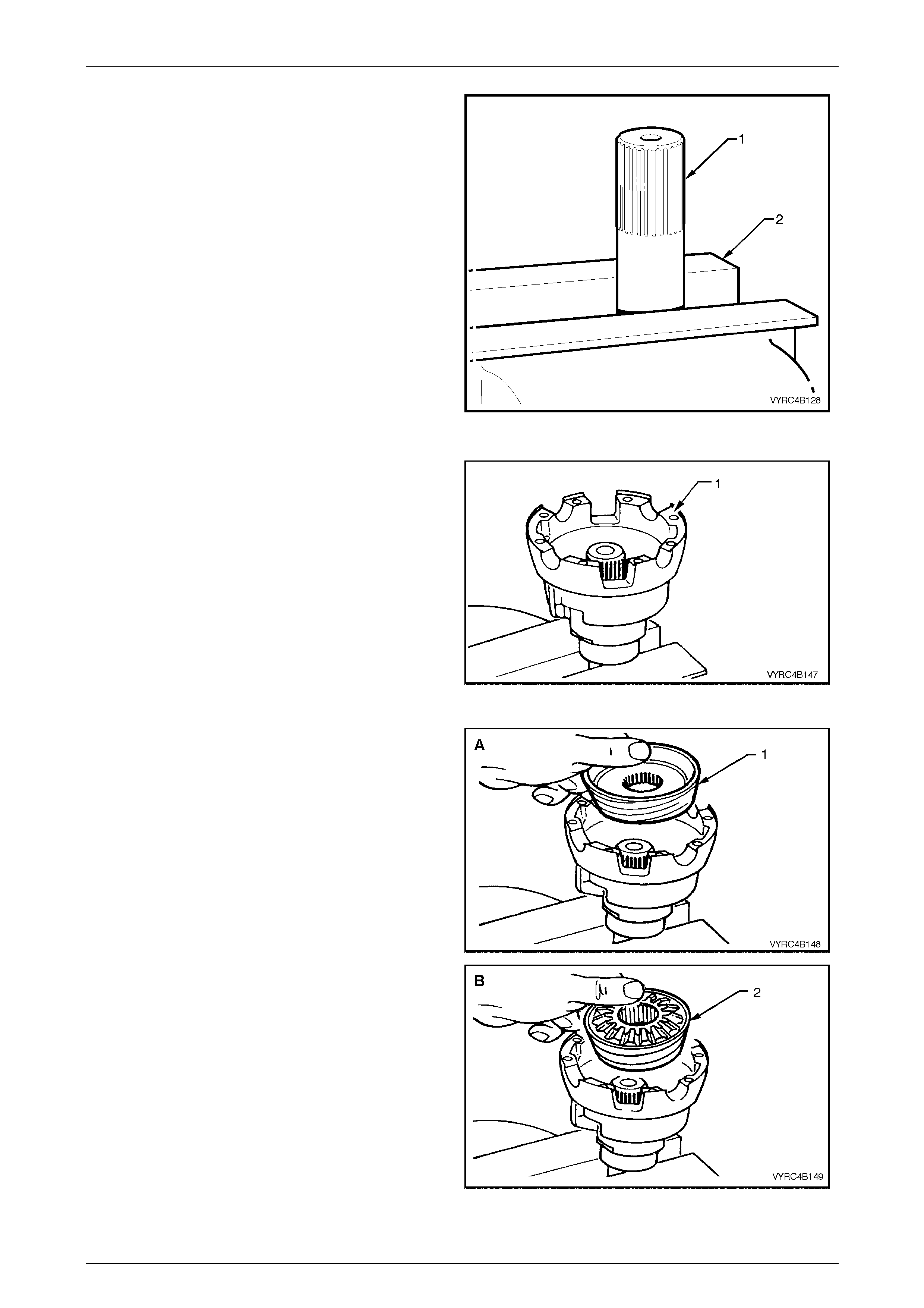
Rear Axle Page 4B –78
Page 4B–78
4 Remove clutch cones and shims from differential
case halves.
NOTE:
There are two types of cone assemblies used in
the M78 Series LSD. For the later type
shimming is not required, as the side gear and
cone are an integrated, single assembly.
5 Clamp the left-hand ax le shaft (1) in a vice equipp ed
with soft jaw’s (2), with at least 85 mm from the
splined end ex posed.
Refer to Figure 4B-146.
NOTE:
The axle shaft is used as a mounting tool with
the separate cone type, to ensure correct side
gear and clutch cone spline alignment. Failure
to follow this procedure will prevent installation
of the axle shafts at final assembly. Figure 4B-146
6 Place differential case cap (1) over axle shaft
mounted in vice (equipped with soft metal jaws) with
interior of the housing facing upwards.
Refer to Figure 4B-147.
7 Paint a mixture of Molybdenum Disulphide grease
and the recommended rear axle lubricant onto the
faces of side gears and the clutch cone surfaces.
Figure 4B-147
8 Install the clutch cone taking note of the following:
a. For separate cone type differentials (view 'A'),
install cl utch cone over axle splines, seating it in
position in housing followed by a shim (if required,
refer Step 3) and side gear.
b. With integral cone type differentials (view 'B'),
install the clutch cone/side gear assembly (2) to
the housing. Refer to Figure 4B-148.
Figure 4B-148
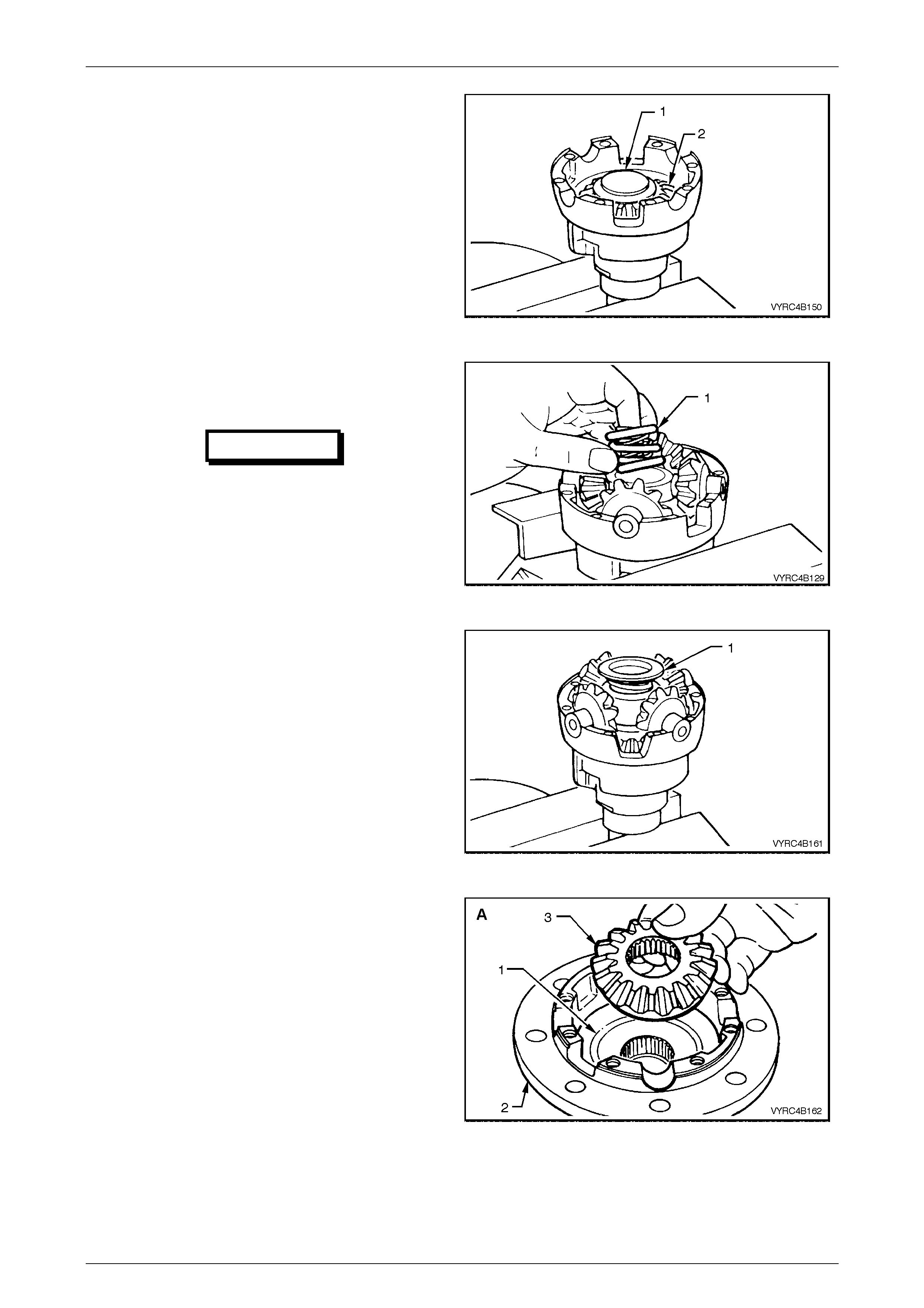
Rear Axle Page 4B –79
Page 4B–79
9 Place a thrust spring plate (1), stepped side up onto
the side gear (2). Refer to Figure 4B-149.
10 Assemble the four pinions and thrust washers onto
pinion cross shaft.
11 Install the pinions and the cross shaft assembly to the
case cap, ensuring that the pinions mesh with the
side gear.
Figure 4B-149
12 Install three new concentr ic dif f erent ial prel oad
springs (1) into the centre of the pinion cross shaft
(2). Refer to Figure 4B-150.
IMPORTANT
NEW preload springs must always be
installed on reassembly, DO NOT RE-USE
OLD SPRINGS.
Figure 4B-150
13 Assemble the second thrust spring plate (1), stepped
side down, onto the preload springs.
Refer to Figure 4B-151.
Figure 4B-151
14 Install the clutch cone taking note of the following:
a. For separate cone type differentials (view 'A'),
install cl utch cone, shi m (if required) and si de gear
(3) to the clutch cone seat (1) in the case cover
(2).
b. For integral cone type differentials (view 'B'), install
the clutch cone/side gear assembly (4) into the
case cover (2). Refe r to Figure 4B-175.
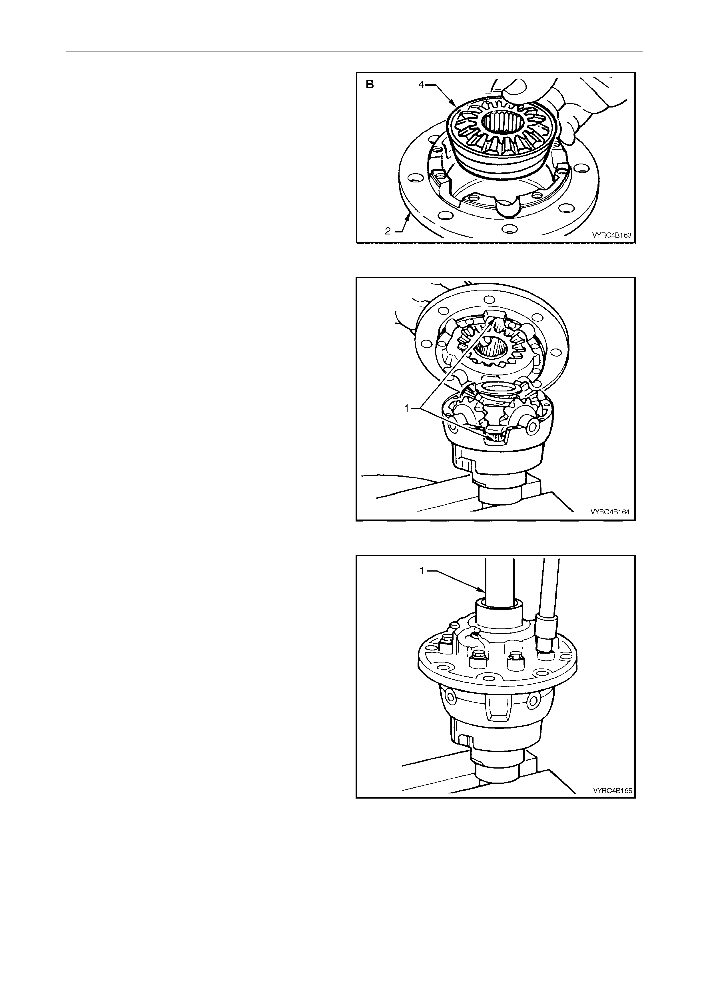
Rear Axle Page 4B –80
Page 4B–80
Figure 4B-152
15 Install the case cover onto the case cap.
NOTE:
Ensure that the cut out (1) on each side of the
case cover and cap align. Refer to Figure 4B-
176.
Figure 4B-153
16 Install two NEW differential case cap-to-cover
attaching bolts in opposite bolt holes and finger
tighten.
17 Install the other inner axle shaft (1) through the case
cover, rotating the axle shaft to engage the clutch
cone splines and then the side gear splines. Leave
the axle shaft in this position. Install the remaining,
(NEW) cap-to-cover attaching bolts and tighten
evenly to the correct torque specification. Refer to
Figure 4B-177.
18 Remove the axle shafts from the differential case
assembly.
NOTE:
If the shafts bind on the clutch cone and side-
gear splines, a light tap with a soft hammer on
the axle shaft flange may be necessary to
remove the axle shafts.
NOTE:
At no time for the separate cone type, must the
side gears and the clutch cones be rotated until
the inner axle shafts are fully installed. Failure to
observe this condition will result in side gear
and clutch cone spline misalignment, thus
preventing inner axle shaft installation.
Figure 4B-154
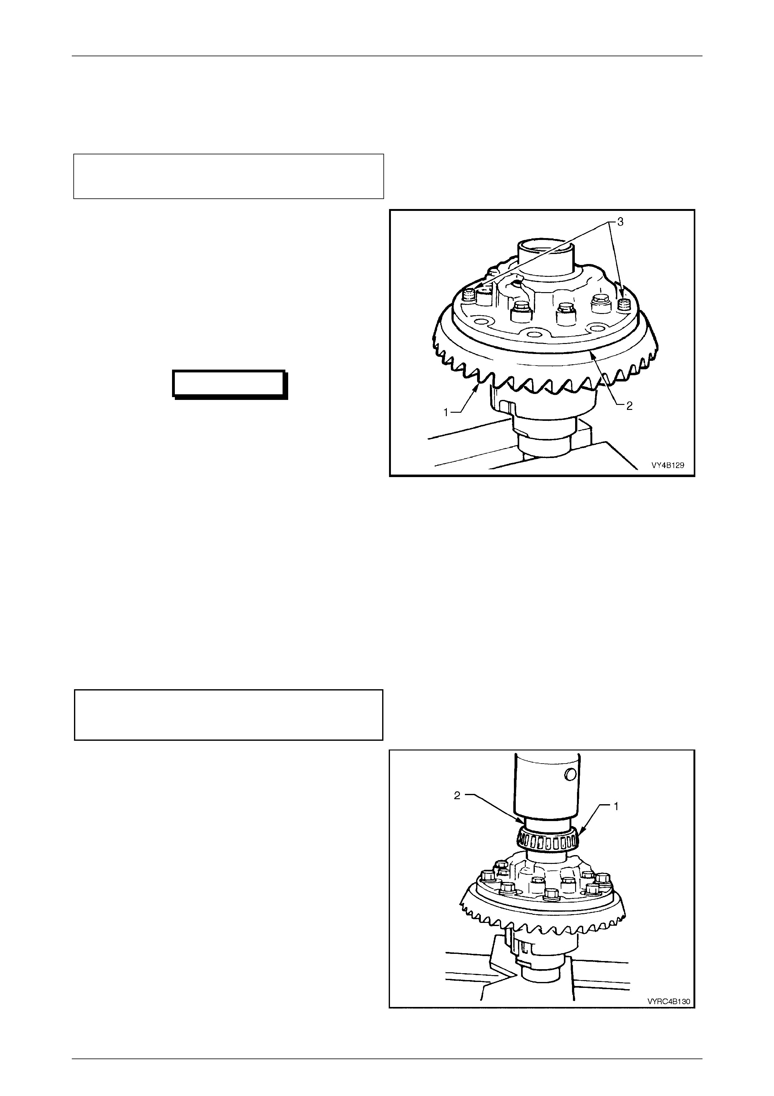
Rear Axle Page 4B –81
Page 4B–81
NOTE:
Should the splines become misaligned, loosen
the case cap to cover bolts and repeat steps 6,
7, 16 and 17.
(+) Differential ca se cap to
to cover attaching bolt
torque specification ......................................35 – 45 Nm
19 Install two left-hand threaded guide pins (3) into two
opposing ring gear bolt holes. Refer to Figure 4B-155.
20 Place the ring gear (1) into position on the differential
case cap (2) and install ring gear attaching bolts.
NOTE:
For ease of assembly, it may be necessary to
heat the ring gear on a hot plate until it is hot to
the hand, prior to installing onto the differential
case cap.
IMPORTANT
On no account must a flame be used to heat
the ring gear.
NOTE:
Use left-hand threaded guide pins (3) to pilot the
ring gear over differential case spigot. Refer to
Figure 4B-155.
NOTE:
Ring gear attaching bolts use a left-hand thread
and are identified by an 'L' on the bolt head.
21 Install the NEW ring gear attaching bolt s even ly until
gear face is flush with differential case spigot.
22 Remove the left-hand threaded guide pins and install
the remaining two NEW ring gear attaching bolts.
23 Tighten all ring gear attaching bolts to the correct
torque specif ication.
(+) Ring gear to differential
case cover attaching bolt
torque specific atio n .................................. 125 – 150 Nm
Figure 4B-155
24 If installing new side bearings (1), use Tool No.
205-545 (2) to press on the new side bearings (1) to
differential case journals. Refer to Figure 4B-182.
25 Continue rear axle assembly, proceeding from
‘Differential Side Bearing Preload And Shim
Selection’, refer to 3.6 Differential Assembly
Adjustment and Installation Procedures – All Models
– Differential Side Bearing Preload And Shim
Selection in this Section.
Figure 4B-156
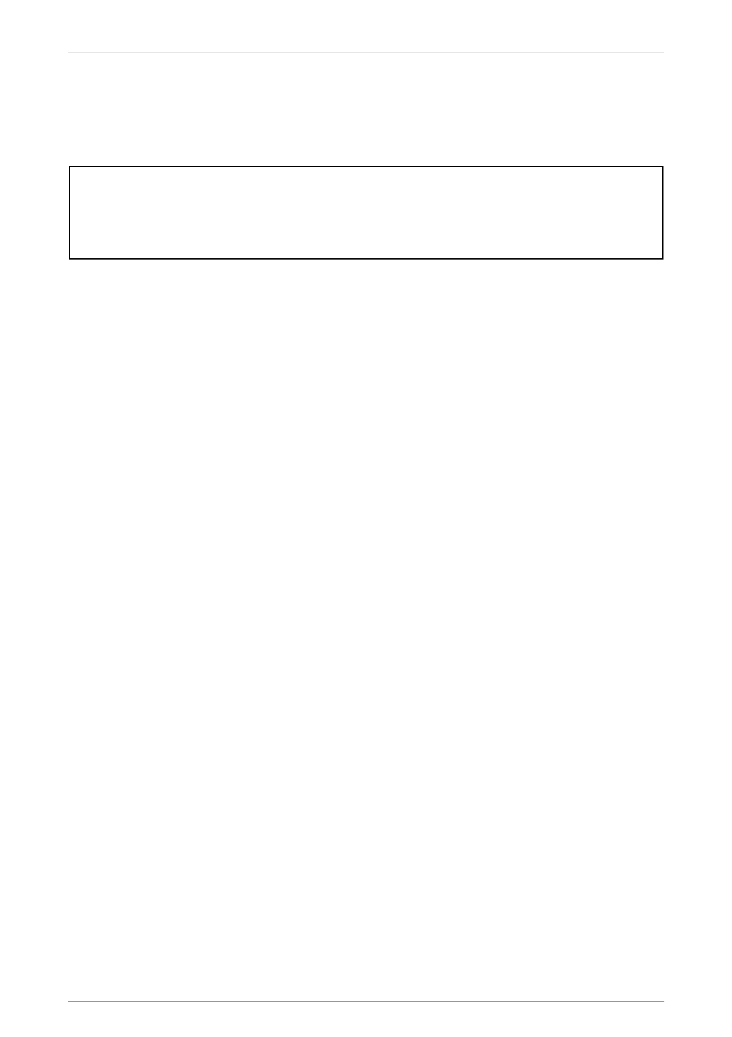
Rear Axle Page 4B –82
Page 4B–82
3.5 Differential Assembly – M86 Series
(Multi-Disc Type Limited Slip)
LT Section No: F502600
ATTENTION
The following fasteners MUST be replaced when performing this operation:
+
++
+ Ring gear bolts.
The overhaul procedures, ring gear and pinion positioning procedure are unique to the M86 Series rear axle assembly.
The tooth marking for the M86 Series limited slip differential are the same as for the standard type rear axle assembly
and the servicing of the internal components of the limited slip differential assembly is also unique.
NOTE:
For the differential assembly and pinion gear
removal procedure refer to 3.2 Rear Axle and
Differential Housing Assembly, Disassemble in
this Section.
NOTE:
The M86 Series differentials have unique parts
and are not interchangeable with the M78 Series
unit. The general overhaul procedures are also
different for both types.
The unique co mponents for the M86 Series differentials are:
• Differential case.
• Differential pinion thrust washers.
• Differential pinion shaft.
• Side gears.
• Concentric grooved discs.
• Clutch plates.
• Clutch plate retainers.
• Dished spacers.
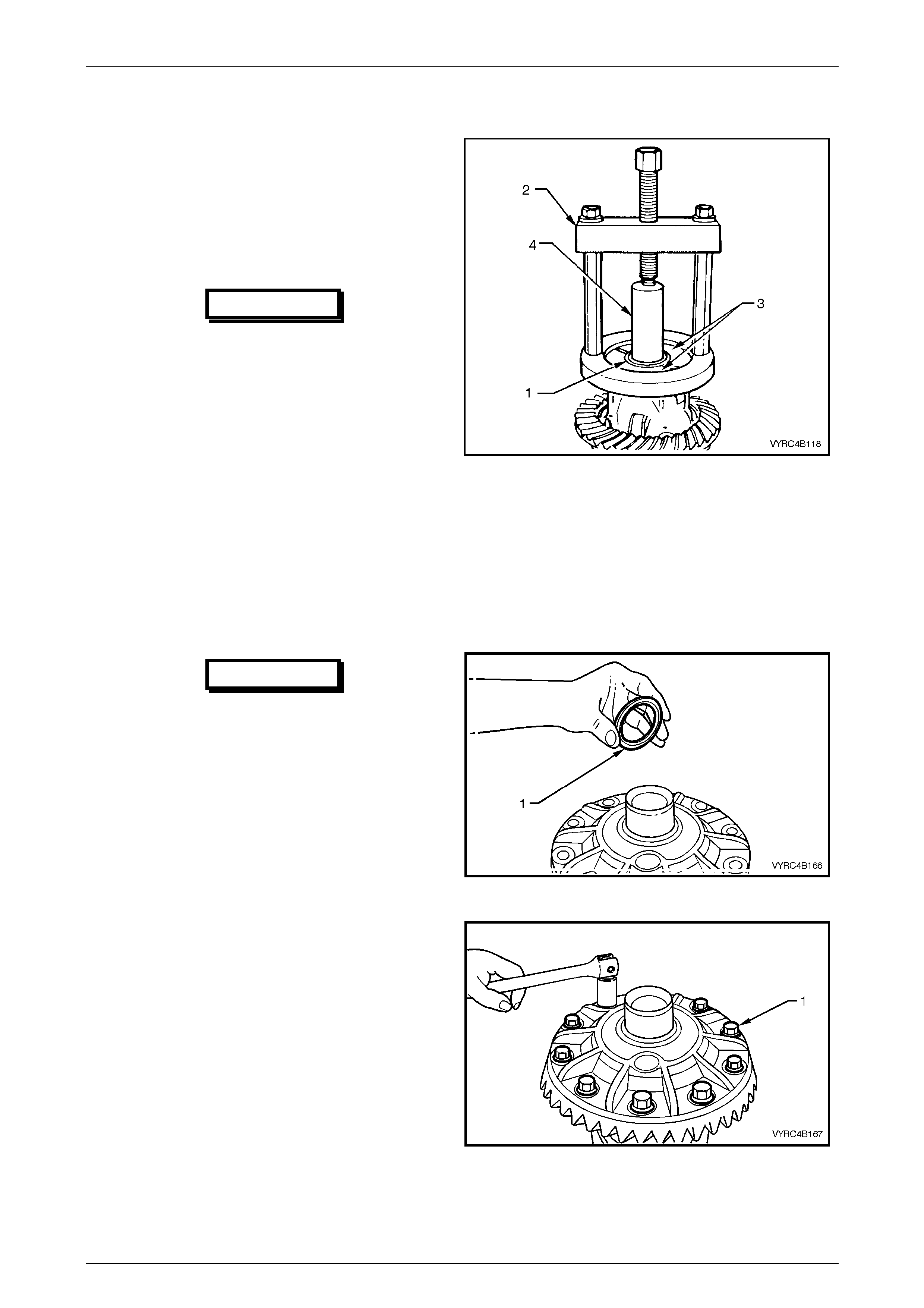
Rear Axle Page 4B –83
Page 4B–83
Disassemble
Before disassembling the differential case, inspect
differential side bearings for any signs of damage.
NOTE:
Both side bearings and their cups are matched
parts. If either bearing is to be replaced, its
matching cup must also be replaced.
IMPORTANT
The side bearings can be manufactured
by one of two manufacturers, Timken or
Koyo. When replacing the differential side
bearings, the two bearings and cups must
be of the same brand. The pinion bearings
may be of a different manufacture but
again; they must be a matched pair. The
reason for matched pairs of bearings is
that a different preload specification is
required for each brand.
1 If replacing side bearings (1), use Tool No. E1673MT
(2), adaptor’s Tool No. E1673N15 (3) and stepped
plug Tool No. E1673B16 (4) to remove side bearings
from differential case. Refer to Figure 4B-157.
Discard side bearings once they are removed. To
remove side-bearing cups, refer to 3.2 Rear Axle and
Differential Housing Assembly - Disassemble, Step 9
in this Section.
Figure 4B-157
IMPORTANT
The M86 Series Differential requires a
spacer to be installed on the ring gear
side of the differential case behind the
side bearing. This spacer must be
installed to enable the differential
assembly to carrier set-up procedure to
be carried out correctly.
2 If the spacer (1) has been removed, reinstall the
spacer onto the side-bearing journal closest to the
ring gear before proceeding to step 3.
Refer to Figure 4B-158 Figure 4B-158
3 Secure the differential case in a suitable vice
equipped with soft metal jaws.
4 Remove the ring gear attaching bolts (1) and discard
the bolts. Refer to Figure 4B-159.
NOTE:
The ring gear attaching bolts have a left-hand
thread and are identified by an 'L' on the bolt
head.
5 Remove the differential case from the vice.
Figure 4B-159
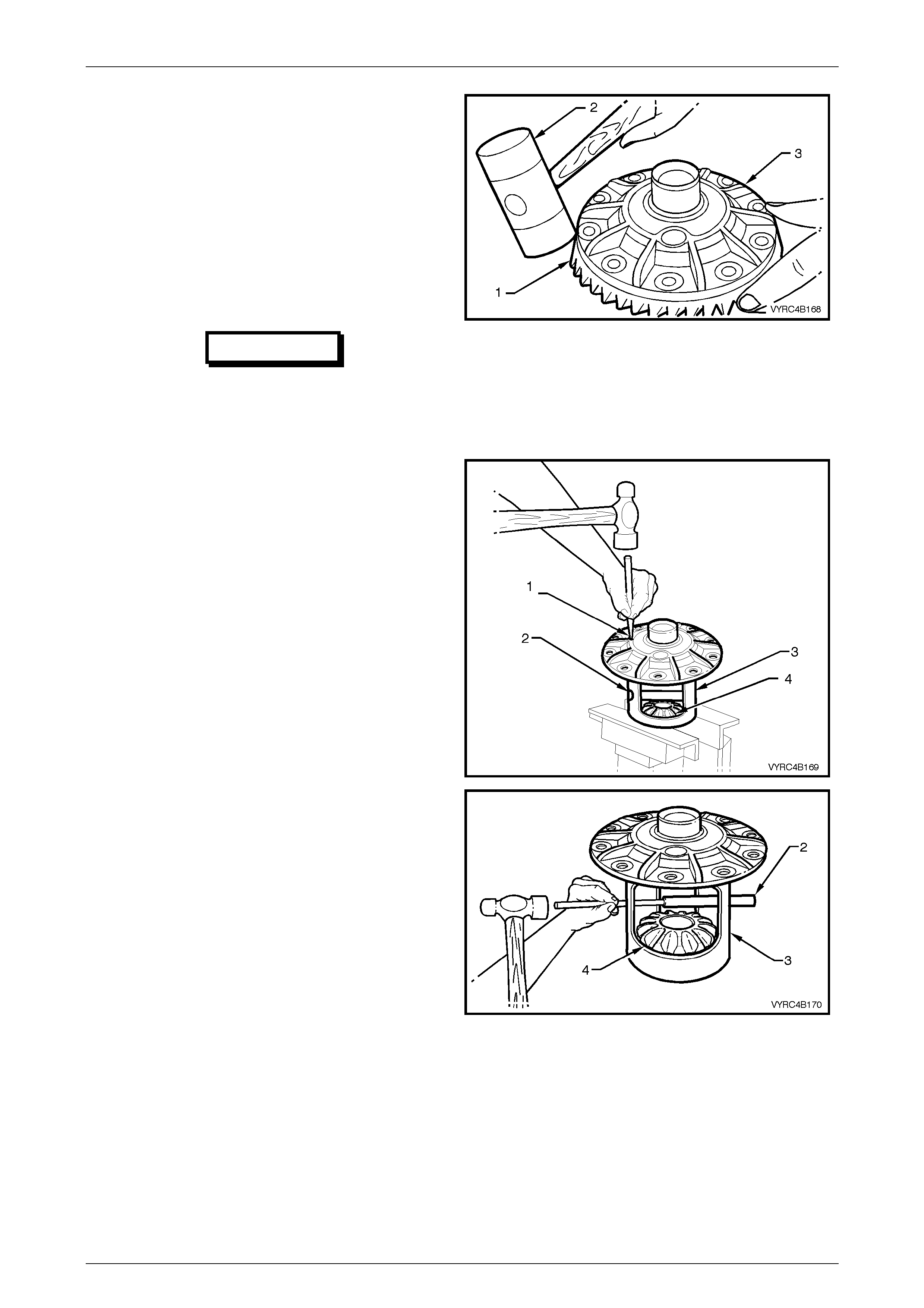
Rear Axle Page 4B –84
Page 4B–84
6 Place a piece of softwood, large enough to cover the
over all diameter of the ring gear on top of a suitable
workbench.
7 Place the differential case on top of the piece of
softwood wi th the ring gear attaching bolt holes facing
upward.
8 Remove the ring gear (1) by using a soft faced
hammer (2), tapping down on the ring gear while
simultaneously rotating the differential case (3) until
the ring gear is free from the case. The softwood will
protect the ring gear from damage during this step.
Refer to Figure 4B-185.
IMPORTANT
Do not use a screwdriver or any other
form of leverage to pry between the ring
gear and the mating face of the
differential case, as damage will occur.
Figure 4B-160
9 Secure the differential case in a suitable vice
equipped with soft metal jaws with the ring gear-
mating flange nearest the vice.
10 Using a suitable pin punch, remove the pinion gear
cross shaft retaining pin (1), from the pinion cross
shaft (2) and differential case (3).
11 Using a brass drift and hammer, remove the pinion
gear cross shaft (2), from the pinion gears (4) and
differential case (3).
Refer to Figure 4B-161.
NOTE:
The concentric grooved disc’s, clutch plates,
dished spacers and side gears are an integral
unit and must stay assembled to each other and
must not be interchanged during disassembly
Figure 4B-161
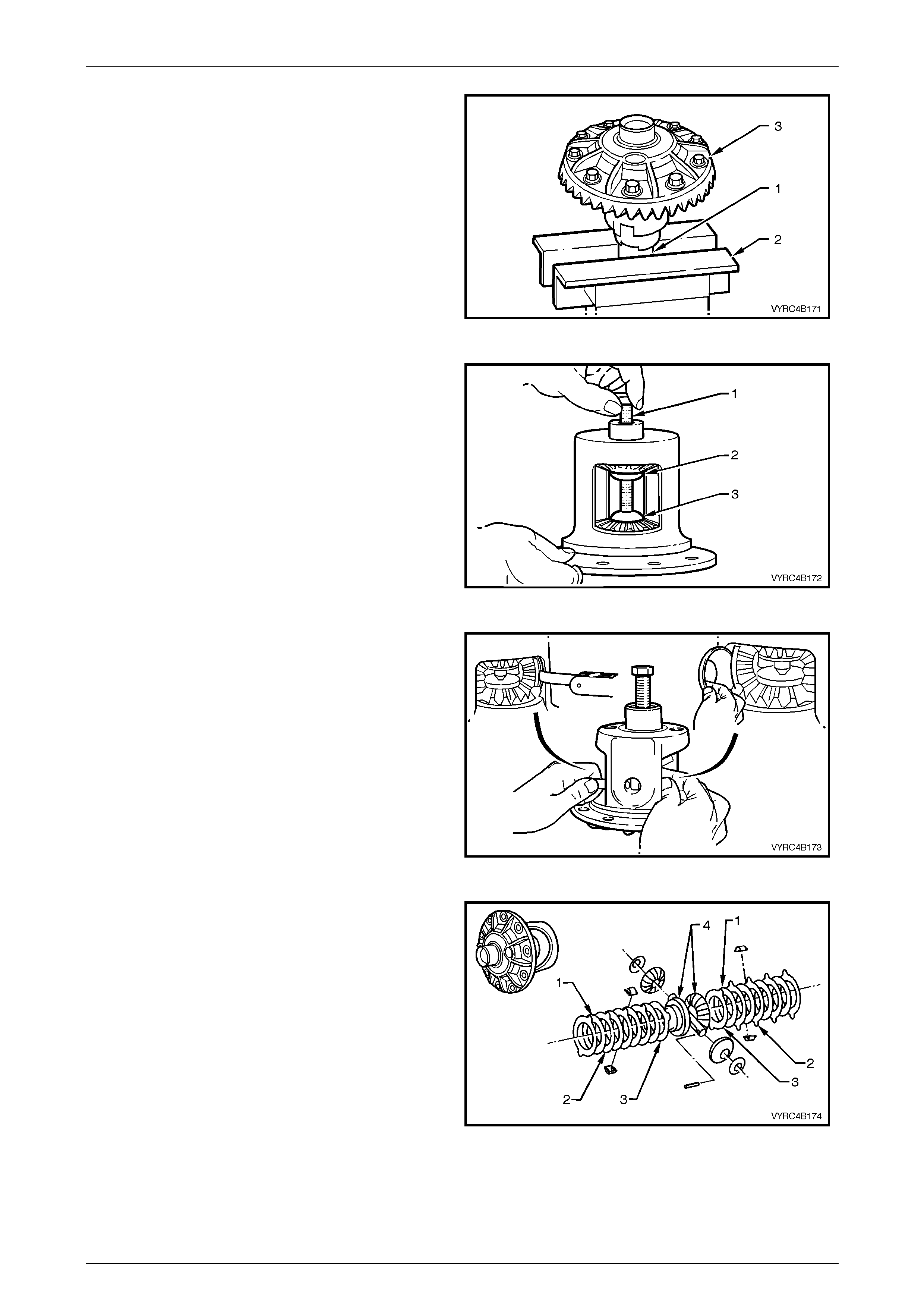
Rear Axle Page 4B –85
Page 4B–85
12 Clamp the left-hand ax le shaft (1) in a vice equipp ed
with soft jaw’s (2), with at least 85 mm from the
splined end ex posed then place the differential case
(3) onto the axle shaft spline, through the side gear
spline.
Refer to Figure 4B-162.
Figure 4B-162
13 Install forcing screw (1) in conjunction with threaded
screw cap (2) and plain cap (3), which are parts of
Tool No. C-4487. Refer to Figure 4B-163.
14 Turn the forcing screw until it becomes centred into
the plain cap.
15 Tighten the forcing screw until enough pressure is
applied to collapse the dished spacers of each side
gear, creating a small amount of clearance between
the teeth of the side gears and pinion gears.
Figure 4B-163
16 Using a 0.51mm feeler strip or equivalent, push the
pinion gear thrust washers out from behind each of
the pinion gears and out of the differential case. Refer
to Figure 4B-164.
NOTE:
Keep the pinion gears with their respective
thrust washers in sets. Mark each component
with a pen or similar, to ensure they are
reinstalled in their original position.
Figure 4B-164
17 To ensure that the concentric grooved disc’s (1),
clutch plates (2), dished spacers (3) and side gears
(4) are not interchanged during disassembly or
reassembly, mark each component and
corresponding side of the differential case with a pen
or similar. Refer to Figure 4B-165.
Figure 4B-165
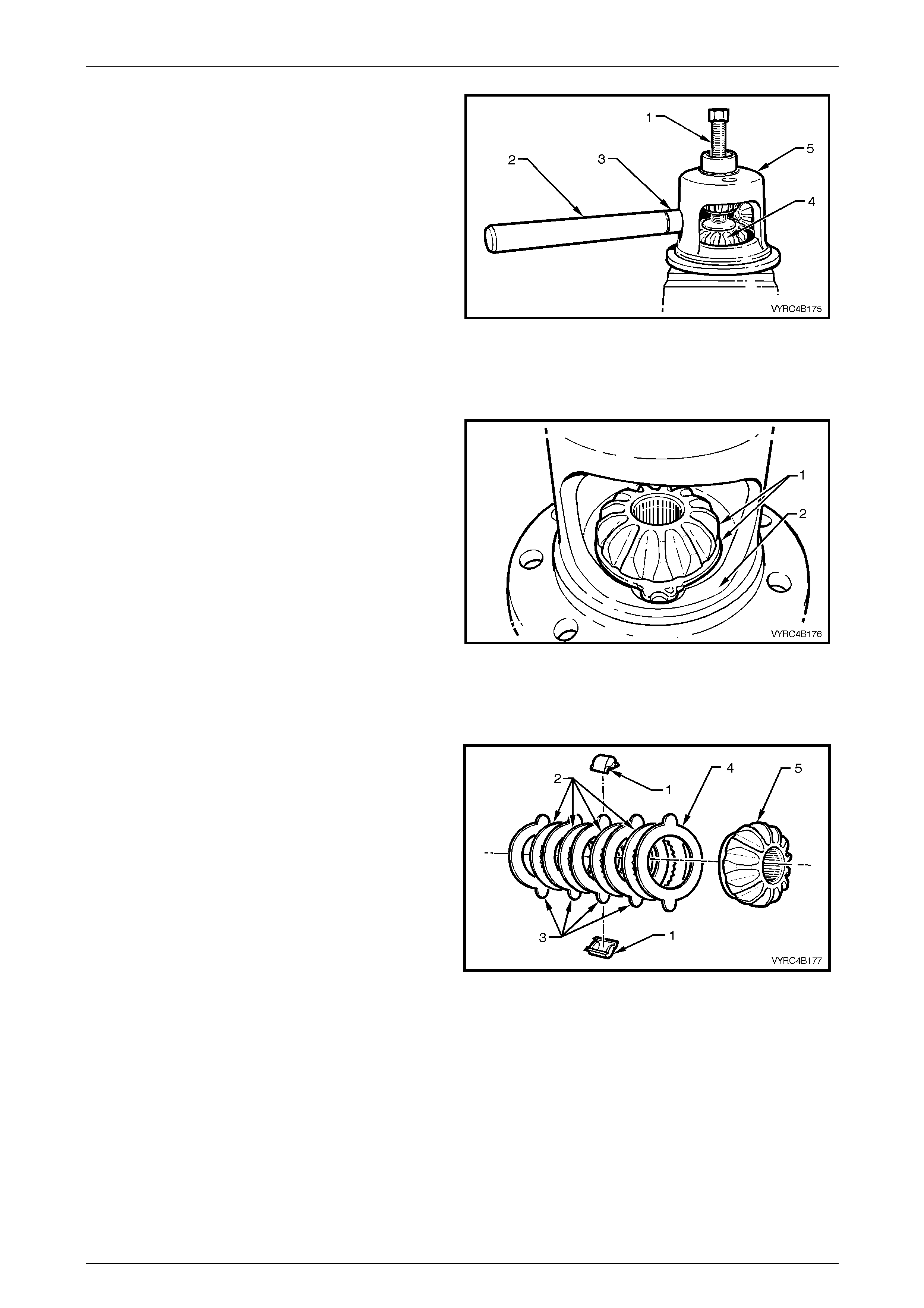
Rear Axle Page 4B –86
Page 4B–86
18 Relieve the pressure applied by the forcing screw (1)
19 Using the assist handle (2) in conjunction with the
handle distance piece (3) (which are part of Tool no.
C-4487), insert the tool combination into differential
side gear and rear axle shaft aperture.
20 Rotate the differential case (5) using the tool
combination in step 18, until the pinion gears can be
accessed.
21 Remove the pinion gears from the differential case.
Refer to Figure 4B-166.
NOTE:
Keep the pinion gears with their respective
thrust washers in sets. Mark each component
with a pen or similar, so they are reinstalled in
their original position.
Figure 4B-166
22 While supporting the upper side gear and clutch pack
with one hand, remove the forcing screw along with
the threaded screw cap and plain cap, which are
parts of Tool No. C-4487.
23 Remove the upper differential side gear and clutch
pack from the differential case.
24 Remove the lower differential side gear and clutch
pack (1) from the differential case (2). Refer to Figure
4B-167.
NOTE:
Keep the side gears and their respective clutch
packs in sets . Mark each component with a pen
or similar, so they are reinstalled in their original
position.
25 Remove the differential case and axle from the vice.
Figure 4B-167
26 Remove the clutch plate retainer’s (1) from each
clutch pack, then separate the concentric grooved
discs (2), cl utch plates (3), dished spacer (4) and side
gear (5) from each clutch pack. Refer to Figure 4B-
168.
NOTE:
Keep the side gears and their respective clutch
packs in sets . Mark each component with a pen
or similar, so they are reinstalled in their original
position.
Figure 4B-168

Rear Axle Page 4B –87
Page 4B–87
Inspect
All components should be thoroughly cleaned and dried, then inspected.
Differential Case
• Check the case for general soundness and pay particular attention to the following points:
• If the differential case side bearings have been removed, check the case journals for damage and that the seating
surfaces are free from dirt and burrs.
• The ring gear spigot and mounting face should be clean and free from dirt and burrs.
• The mating surfaces of the differential case should be clean and free from burrs.
• The thrust surfaces for the differential pinions should be examined for excessive wear.
• The clutch seats in the housing should be smooth and free from any excessive scoring.
• The land surface condition for each dished spacer in the case. Excessive wear or damage on the surface will require
case renewal.
• Inspect pinion gear cro ss shaft bores for ovality.
Differential Side Gears and Pinion Ge ars
• Examine all gear teet h for crac ks or hard conta ct mark s. The differential side gear splines should be check ed for
excessive wear, including the splines for the clutch plates. Wear on splines can contribute to excessive driveline
backlash. If damage or excessive wear is evident the complete set of side and pinion gears must be replaced.
• The differential pinion bores and thrust surfaces should be smooth and free from scores. Inspect all thrust washers
for cracks, nicks or burrs. Wear of thrust washers or thrust surfaces on gears can contribute to excessive driveline
backlash.
• Check the differential pinion gear cross shaft is not bent and that the surfaces on which the pinions run, are not
scored or worn.
Differential Concentric Grooved Disc’s, Clutch Plates, Retainers and Dished Spacers
• Examine all surfaces of the concentric grooved disc’s, clutch plates, retainers and dished spacers for cracks,
excessive wear or hard contact marks. If damage is evident replace the complete set of concentric grooved discs,
clutch plates, retainers and dished spacers for both sides.
Ring Gear and Pinion
• Inspect the gear teeth for scoring or damage.
Excessive shock loading, use of the incorrect lubricant
or insufficient “run in” before towing a heavy load,
usually causes scoring of the gear teeth. (Refer
MY2003 VY Series Cab Chassis Owner's Handbook).
Scored gears must be replaced.
• If on reassembly, a new gear set is to be installed,
ensure that the same matching numbers (A) appear on
both the pinion (1) and ring gear (2).
Refer to Figure 4B-169.
• The identification number (B) on the pinion end (1) is
used when setting the pinion depth, on reassembly.
Refer to Figure 4B-169.
• On the ring gear bolts clean the serrations under bolt
flanges.
Figure 4B-169
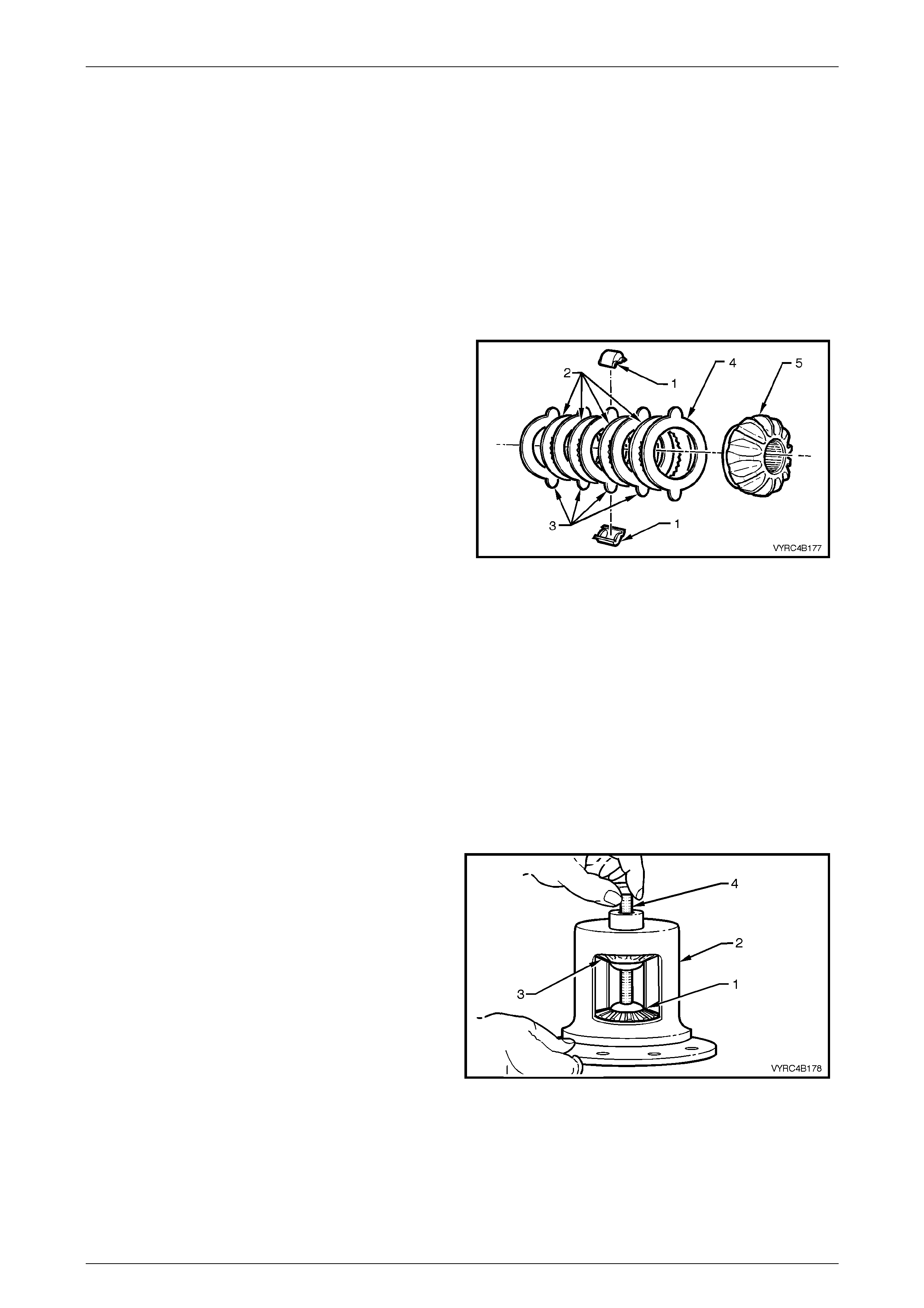
Rear Axle Page 4B –88
Page 4B–88
Bearings
• Bearing cups should have an even wear pattern and be free from flaking or pitting.
• Ensure the seating surfaces are clean and free from burrs or raised metal.
• The bearing assemblies should feel smooth when turned in the cups.
• The assembly should be free from loose particles.
• There should be no cracks present in the roller cages and the bores should show no evidence of flaking or pitting.
Refer to 4.4 Differential and Rear Axle Bearing Diagnosis in this Section, for identification of bearing failures.
Reassemble
1 Lubricate all gears, bearings, thrust washers and
pinion gear cross shaft with the recommended rear
axle lubricant before assembly. Refer to 2.2 Checking
Rear Axle Lubricant Level or 5 Specifications for the
recommend lubricant in this Section.
2 Reassemble the clutch plate retainer’s (1) the
concentric groov ed di sc s (2), clutc h plate s (3), dished
spacer (4) and side gear (5) from each clutch pack.
Refer to Figure 4B-170.
NOTE:
If the used components are to be reinstalled,
keep the side gears with their respective clutch
pack components in sets, so they are reinstalled
in their original position.
NOTE:
If new side or pinion gears are to be installed a
complete set of new gears must be used. Do
not mix new gears wi th used gears.
NOTE:
If new clutch plate retainers, concentric grooved
disc’s, clutch plates or dished spacers are to be
installed a complete set of new components
must be used. Do not mix new with used
components.
Figure 4B-170
3 Reinstall the differential case and axle into the vice.
4 Install the lower differential side gear and clutch pack
(1) into the differential case (2).
5 Install the upper differential side gear and clutch pack
(3) into the differential case (2) then support it with
one hand.
6 While supporting the upper side gear and clutch pack,
install the forcing screw along with the threaded
screw cap and plain cap (which are part of Tool No.
C-4487).
7 Tighten the forcing screw (4) by hand until enough
pressure is applied to support each side gear in
place. Refer to Figure 4B-171. Figure 4B-171

Rear Axle Page 4B –89
Page 4B–89
8 Install the pinion gears (1), 180° apart into the
differenti al case (2).
9 Using the assist handle (3) in conjunction with the
distance piece (4) (which are part of Tool No. C-
4487), insert the tool combination into the differential
side gear and rear axle shaft aperture (5).
10 Rotate the differential case using the tool combination
in step 9 until the bores of the pinion gears and the
bores in the di fferential case for the pinion shaft are
aligned.
11 Tighten the forcing screw (6) until enough pressure is
applied to collapse the dished spacers of each side
gear, creating a small amount of clearance between
the teeth of the side gears and the pinion gears.
Refer to Figure 4B-197.
Figure 4B-172
12 Using a 0.51 mm feeler strip (1) or equivalent to aid
installation, install the pinion gear thrust washers
between each of the pinion gears and the differential
case (2). Refer to Figure 4B-198.
NOTE:
If installing used components, keep the pinion
gears and their respective thrust washers in
sets, so they can be reinstalled in their original
position.
13 Relieve the pressure applied by the forcing screw.
Then remove the forcing screw along with the
threaded screw cap and plain cap (which are part of
Tool No. C-4487). Figure 4B-173
14 Position the pinion gear cross shaft into the
differenti al case. Ensure the pi nion gear, differential
case and retaining pin bores are aligned.
15 Using a brass drift and soft faced hammer, drive the
pinion gear cross shaft (1), into the pinion gears (2)
and differential case (3).
16 Using a suitable pin punch, drive the pinion gear
cross shaft retaining pin (4) into the pinion cross shaft
(1) and differential case (3). Refer to Figure 4B-174.
Figure 4B-174
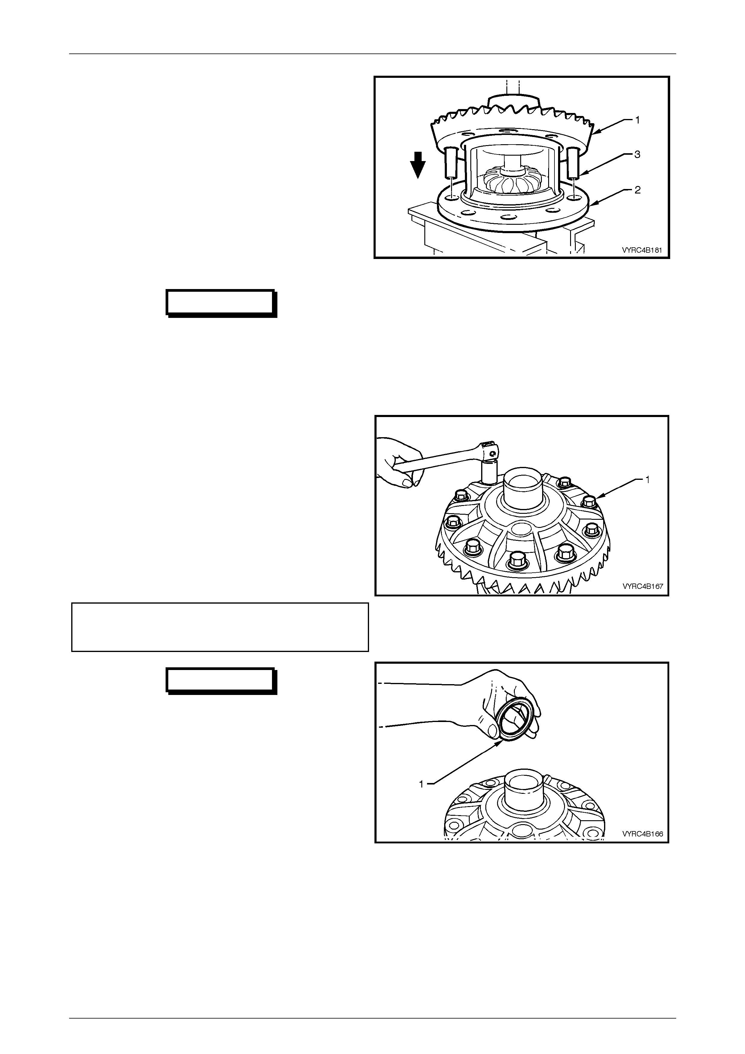
Rear Axle Page 4B –90
Page 4B–90
NOTE:
Use left-hand threaded guide pins (3) to pilot the
ring gear over differential case spigot.
17 Install two left-hand threaded guide pins (3) into two
opposing ring gear bolt holes. Refer to Figure
4B-175.
NOTE:
For ease of assembly, it may be necessary to
heat the ring gear on a hot plate (until it is hot to
the hand), prior to installing onto the differential
case cap.
IMPORTANT
On no account must a flame be used to
heat the ring gear.
18 Place the ring gear (1) into position on the differential
case (2) and install ring gear attaching bolts. Refer to
Figure 4B-175.
Figure 4B-175
NOTE:
Ring gear attaching bolts use a left-hand thread
and are identified by an 'L' on the bolt head.
19 Install the NEW ring gear attaching bolt s (1) evenly
until the gear face is flush with the differential case
spigot. Refer to Figure 4B-176.
20 Remove the left-hand threaded guide pins and install
the remaining two NEW ring gear attaching bolts.
21 Tighten all ring gear attaching bolts to the correct
torque specif ication.
(+) Ring gear to differential
case attaching bolt
torque specific atio n .................................. 125 – 150 Nm
Figure 4B-176
IMPORTANT
The M86 Series Differential requires a
spacer to be installed on the ring gear
side of the differential case behind the
side bearing. This spacer must be
installed to enable the differential
assembly to carrier set-up procedure to
be carried out correctly.
22 If the spacer (1) has been removed, reinstall the
spacer onto the side bearing journal closest to the
ring gear before proceeding to step 23.
Refer to Figure 4B-177 Figure 4B-177
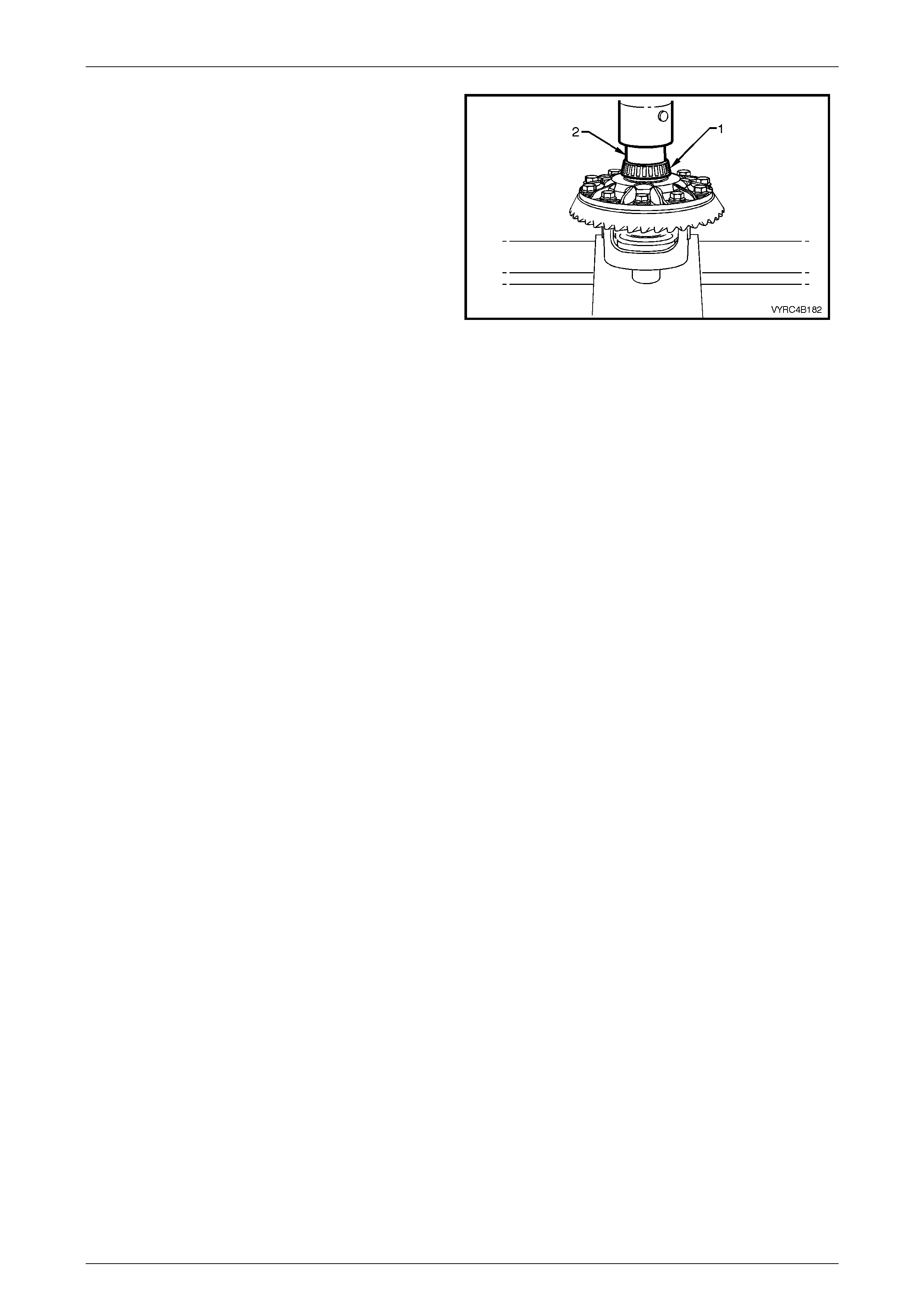
Rear Axle Page 4B –91
Page 4B–91
23 If installing new side bearings (1), use Tool No. 205-
545 (2) to press side bearings (1) onto the differential
case journals. Refer to Figure 4B-178.
24 Continue rear axle assembly, proceeding from
‘Differential Side Bearing Preload And Shim
Selection’, refer to 3.6 Differential Assembly
Adjustment and Installation Procedures – All Models
– Differential Side Bearing Preload And Shim
Selection in this Section.
Figure 4B-178
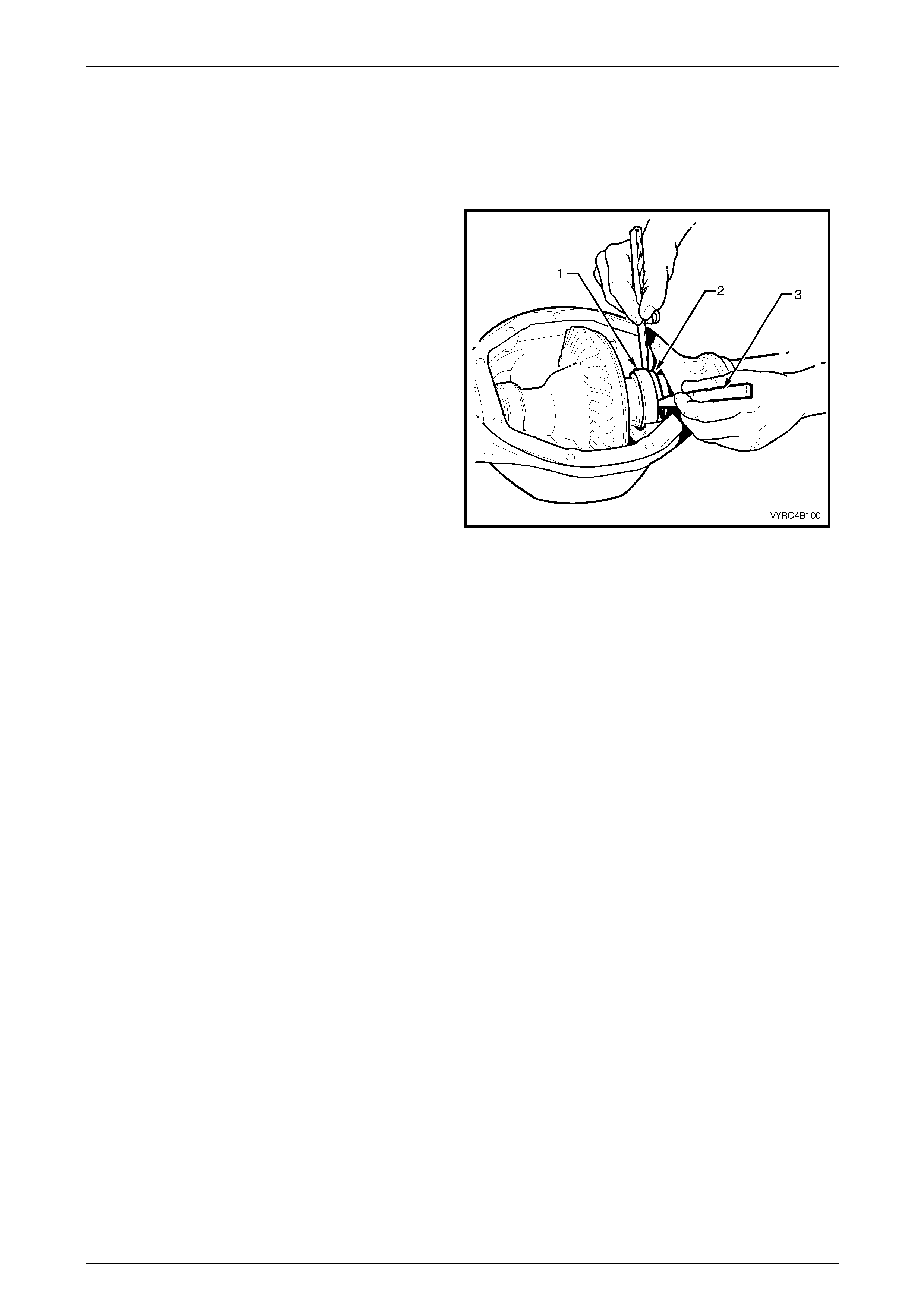
Rear Axle Page 4B –92
Page 4B–92
3.6 Differential Assembly Adjustment and
Installation Procedures – All Models
Differential Si de Bearing Preload And Shim Selection
1 Select any two differential case side bearing shim s,
placing one agains t each side bearing cup and install
the differential assembly in the differentia l carrier
housing without the aid of the spreading tool to
spread the carrier.
2 Push the differential case assembly hard to one side.
On the opposing side, measure the distance between
the differential case side bearing cup (1) and the shim
(2) using two, feeler gauge sets (3). Refer to Figure
4B-179.
3 With the feeler gauges still in place rotate the
differential case to seat the side bearings. Check that
the end float has not increased, if it has, remeasure
using the feeler gauges and record the measurement.
4 Remove the differential case assembly along with the
bearing cups and shims from the differential carrier
housing.
5 Measure the thickness of the two shims and record
the measurement.
6 To establish the thickness of shims and obtain the
correct preload of the side bearings required the
following met hod is appl ied :
a. Add the total thickness of the shims measured in
step 5 together with clearance measured using the
feeler gauges in step 3.
b. To preload the bearings and if installing new
bearings add 0.15 mm to the total measure ment.
Used bearings will require 0.10 mm to be added to
the total measurem ent.
7 The thickness selection of the two shims required
would be half the value of the total as calculated in
step 6. Refer to the following shim selection chart.
Figure 4B-179
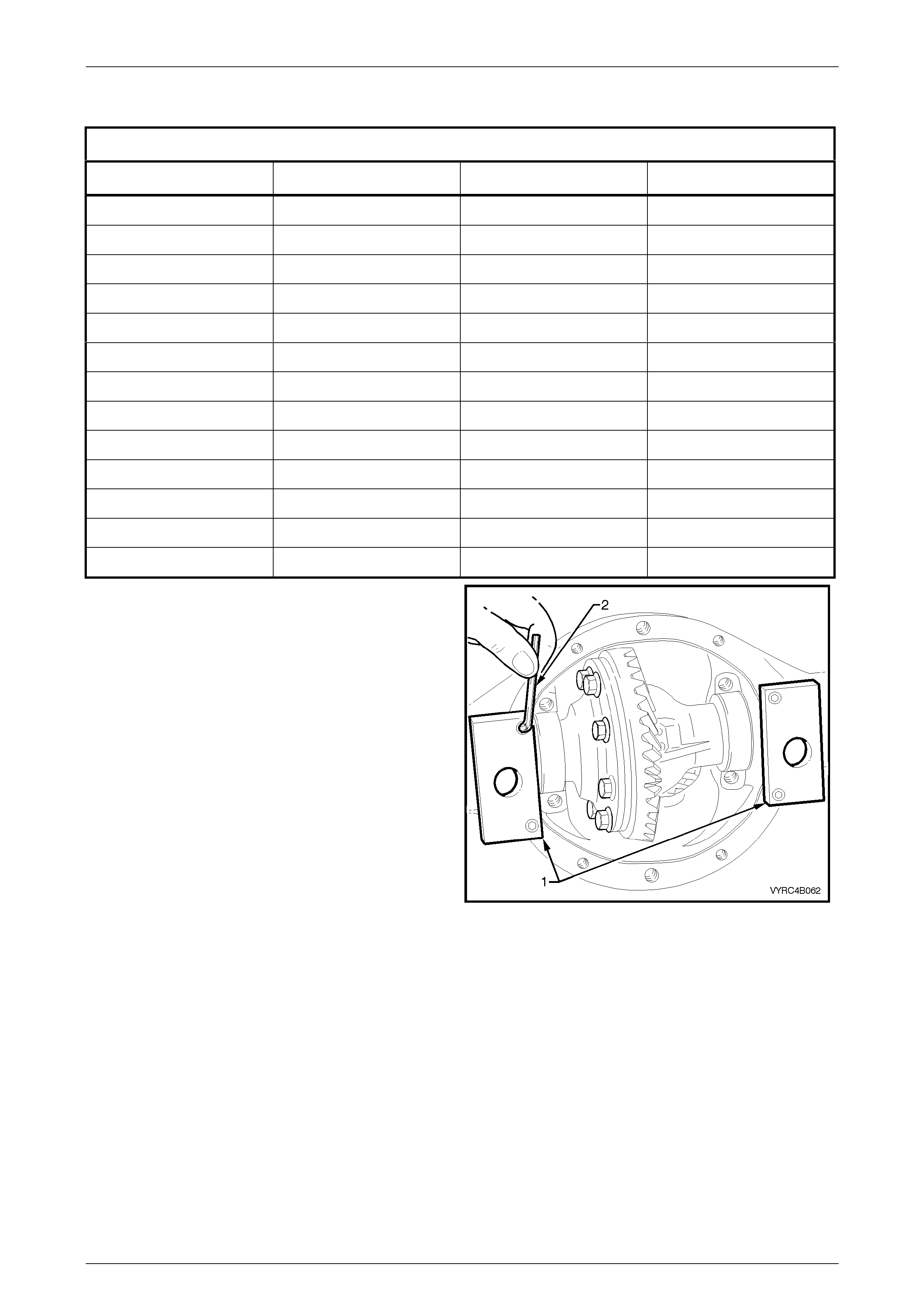
Rear Axle Page 4B –93
Page 4B–93
Side Bearing Preload Shim Selection Chart
Side Bearing Preload Shim Selection Chart
Part Number Shim Thickness Part Number Shim Thickness
92146534 4.60 92146547 5.12
92146535 4.64 92146548 5.16
92146536 4.68 92146549 5.20
92146537 4.72 92146550 5.24
92146538 4.78 92146551 5.28
92146539 4.80 92146552 5.32
92146540 4.84 92146553 5.36
92146541 4.88 92146554 5.40
92146542 4.92 92146555 5.44
92146543 4.96 92146556 5.48
92146544 5.00 92146557 5.52
92146545 5.04 92146558 5.56
92146546 5.08 92146559 5.60
8 Install the adaptors (1) of the differential spreading
Tool No. E9255 (2) to the di fferential carrier housing
using a 5mm Allen Key (3), refer to Figure 4B-180.
Figure 4B-180
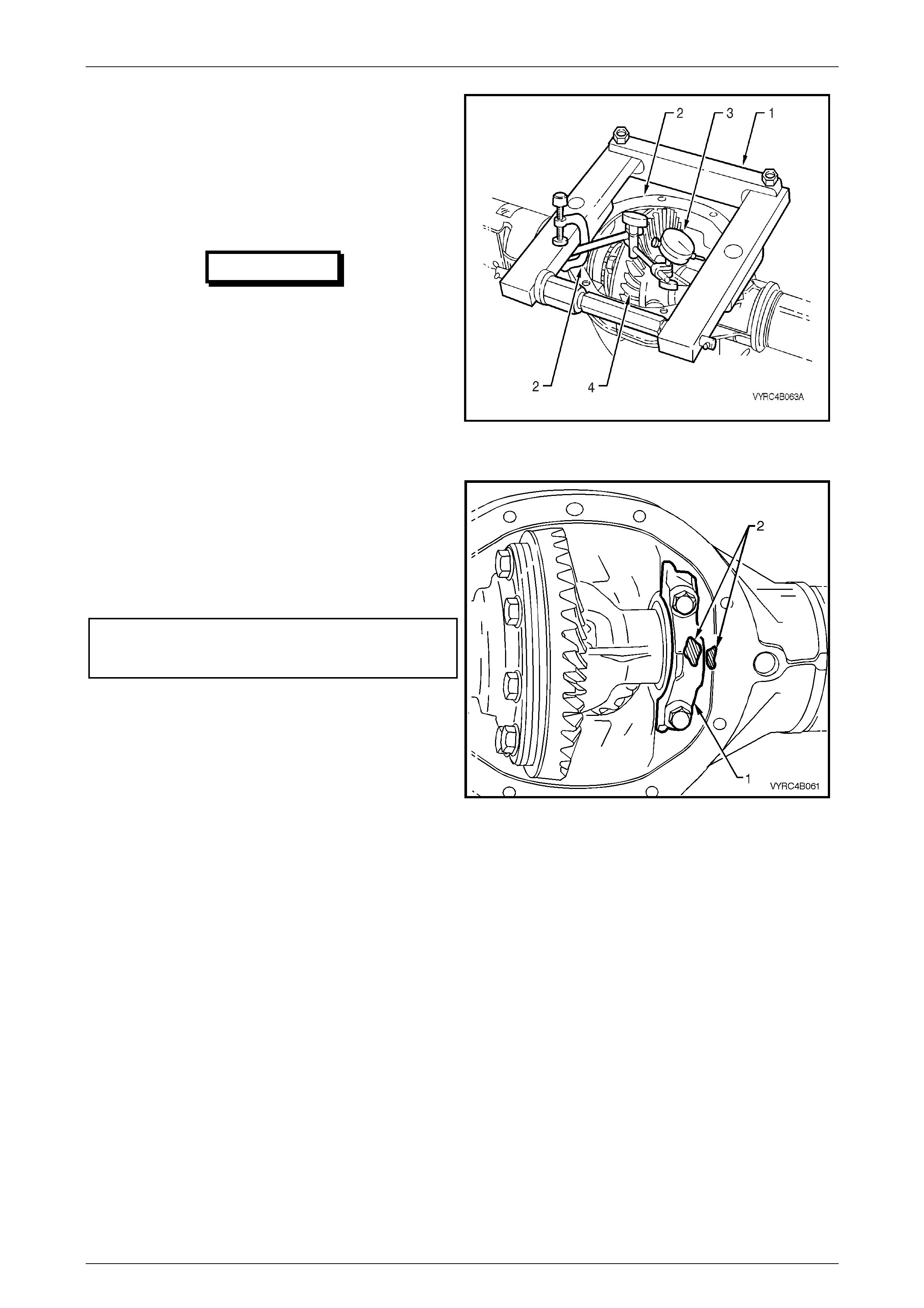
Rear Axle Page 4B –94
Page 4B–94
9 Install the differential spreading Tool No. (1) to the
differential carrier housing (2).
10 Install a dial indicator (3) to the differential spreading
Tool No. E9255 (1) and differential carrier housing
(2). Refer to Figure 4B-181.
11 Spread the differential carri er hous ing appr oximately
0.1 to 0.2 mm.
IMPORTANT
Under no circumstances is the differential
carrier to be spread more than 0.5 mm.
12 Install the differential case assembly (4) along with
the carrier side bearing cups and shims.
13 Release the force exerted by the spreading Tool No.
E9255 (1) and remove the tool along with the
adaptor’s from the differential carrier housing.
Figure 4B-181
14 Install the side bearing caps (1) and retaining bolts.
Ensure the original relationship markings (2) of the
side bearing caps are maintained so they are
reinstalled in their original location.
Refer to Figure 4B-182
15 Tighten the side bearing cap bolts to the correct
torque specif ication.
Side bearing cap to differential
carrier housing attaching bolt
torque specification ......................................48 – 60 Nm
Figure 4B-182
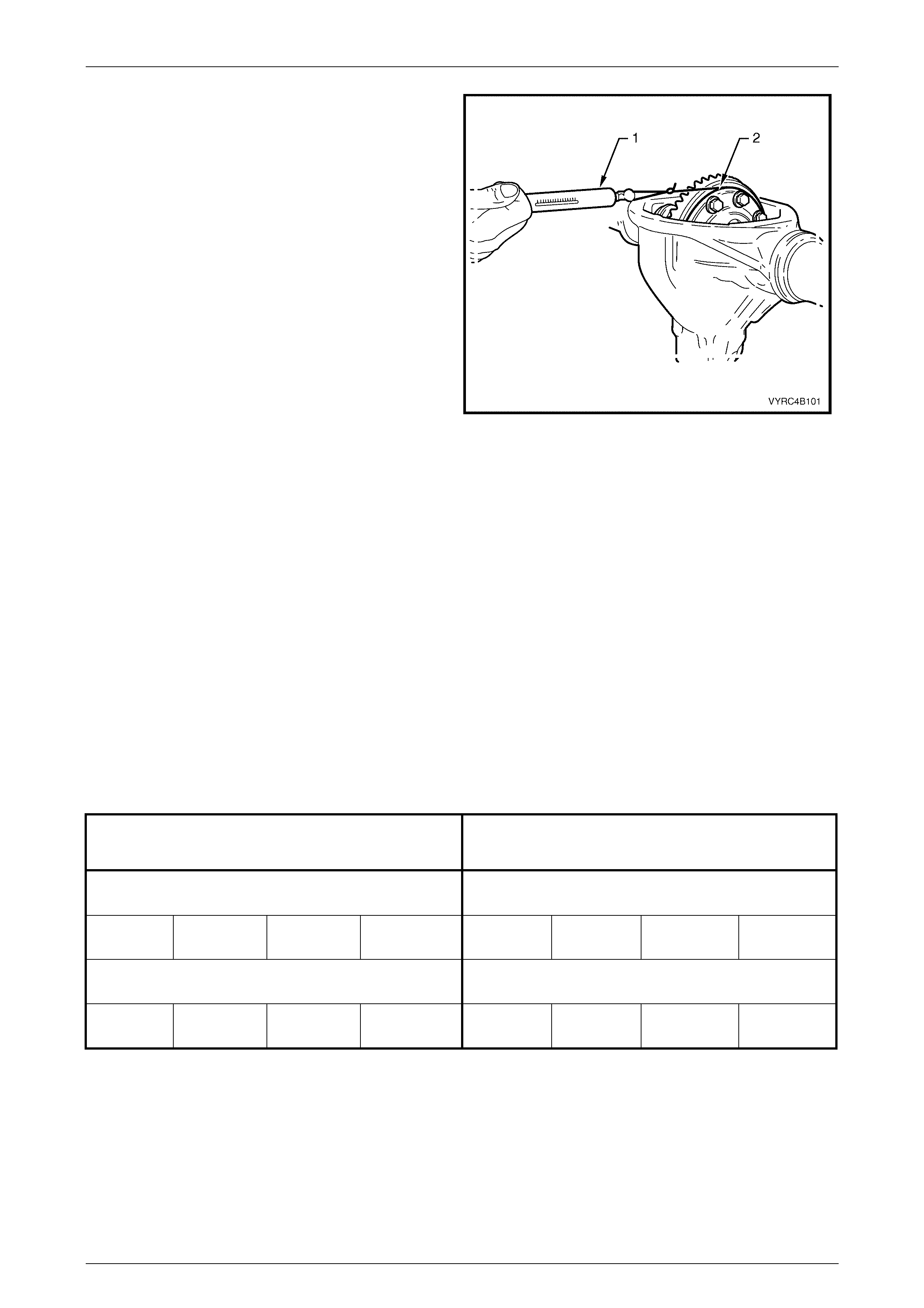
Rear Axle Page 4B –95
Page 4B–95
13 Rotate the differential case assembly several times to
ensure the side bearings are seated correctly.
14 Install a suitable piece of string to and around the
differential case flange near the ring gear.
Refer to Figure 4B-183.
15 Install a spring balance (1) to a piece of string
attached to the differential case flange (2). Check the
side bearing preload by pulling the spring balance at
a steady rate away from the differential case, while
observing the spring balance reading. The spring
balance reading must be within specification.
16 Re-install the differential spreading Tool No. E9255 to
the differential carrier housing.
17 Re-install a dial indicator to the differential spreading
Tool No. E9255 and differential carrier housing.
NOTE:
Under no circumstances is the differential
carrier to be spread more than 0.5 mm.
18 Spread the differential carri er hous ing appr oximately
0.1 to 0.2 mm.
19 If the side bearing preload is to specification, remove
the differential case along with the side bearing caps,
side bearing cups, shims and retaining bolts. Ensure
the original relationship of all components is
maintained so they are reinstalled in their original
location.
20 If the side bearing preload is not specification, repeat
steps 8 to 22. Side bearing shim s are available in
0.04mm incr eme nts .
21 To facilitate the pinion gear bearing preload
procedure, remove the differential case assembly
ensuring the relationship of the side bearing cones,
the preload shims and bearing caps is maintained.
Refer to 3.2 Rear Axle and Differential Housing
Assembly – Disassemble, steps 6 to 14 in this
Section.
Figure 4B-183
SIDE BEARING PRELOAD SPECIFICATION
M78 SERIES
SIDE BEARING PRELOAD SPECIFICATION
M86 SERIES
New Bearings New Bearings
Timken 15 - 35 N Koyo 8 - 24 N Timken 13 - 30 N Koyo 7 - 20 N
Used Bearings Used Bearings
Timken 8 - 18 N Koyo 5 - 13 N Timken 8 - 16 N Koyo 5 - 11 N
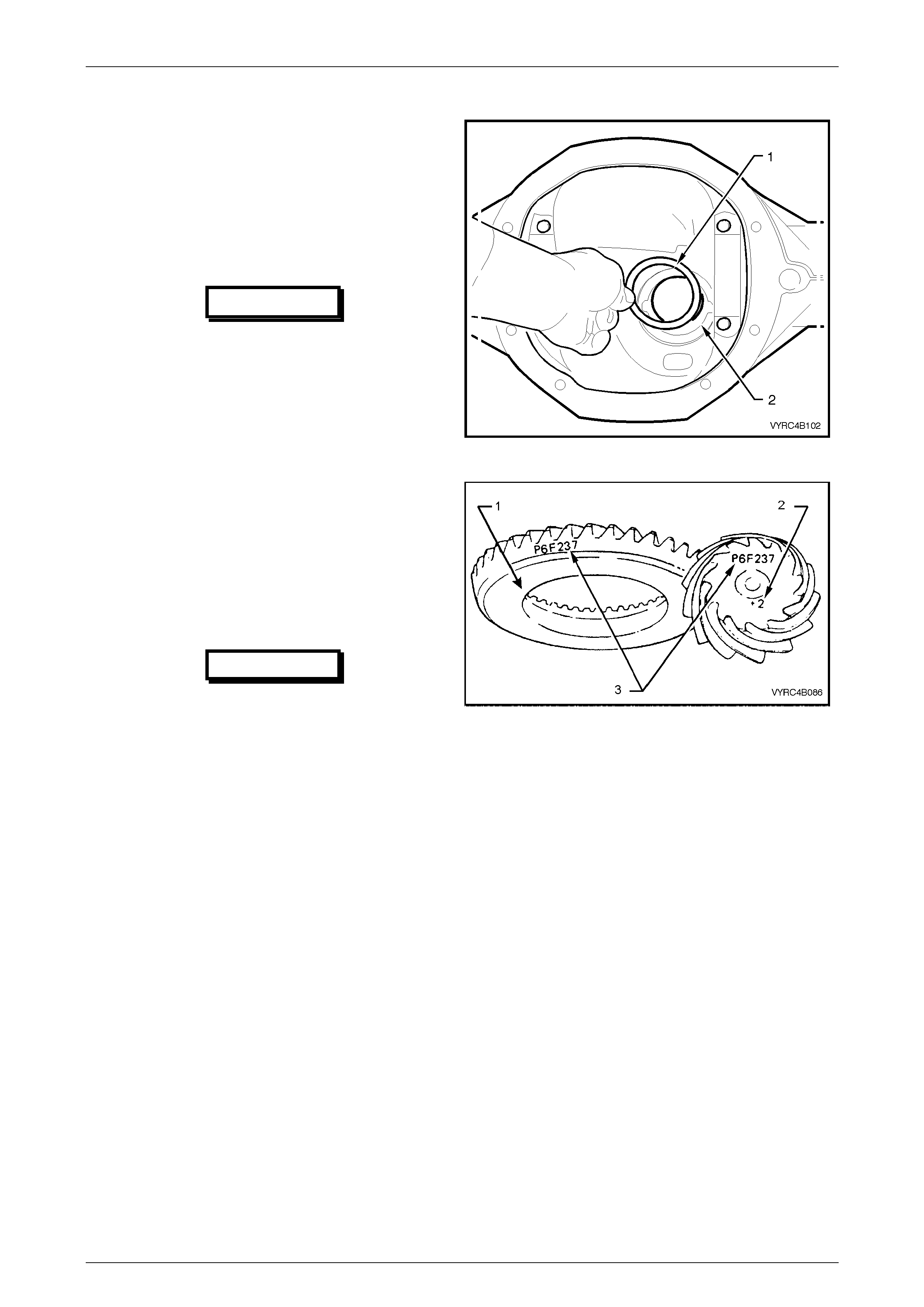
Rear Axle Page 4B –96
Page 4B–96
Hypoid Pinion Bearing Preload Shim Selection
The location of the pi nion positioning shim (1), is between
the rear pinion bearing cup and the carrier-housing pinion
bore (2). Refer to Figure 4B-184.
NOTE:
If the ring gear and pinion gear set or the rear
pinion bearing is replaced, the pinion depth
must be rechecked.
IMPORTANT
If a new ring gear and pinion gear set is
replaced, ensure that the same matching
numbers appear on the pinion gear and
the ring gear. Refer to Figure 4B-185
NOTE:
Use the specified lubricant only. Lubricants
other than that specified will affect the rotational
torque readings specified in the steps that
follow. Refer to 2.2 Checking Rear Axle
Lubricant Level in this Section.
NOTE:
Ensure that the rear pinion bearing that will be
used on final reassembly of the pinion is used
on the dummy pinion.
IMPORTANT
One of two manufacturers, Timken or
Koyo can manufacture the pinion
bearings. When replacing the differential
pinion bearings, the two bearings and
cups must be of the same brand. The
reason for matched pairs of bearings is
that a different preload specification is
required for each brand.
Figure 4B-184
Figure 4B-185
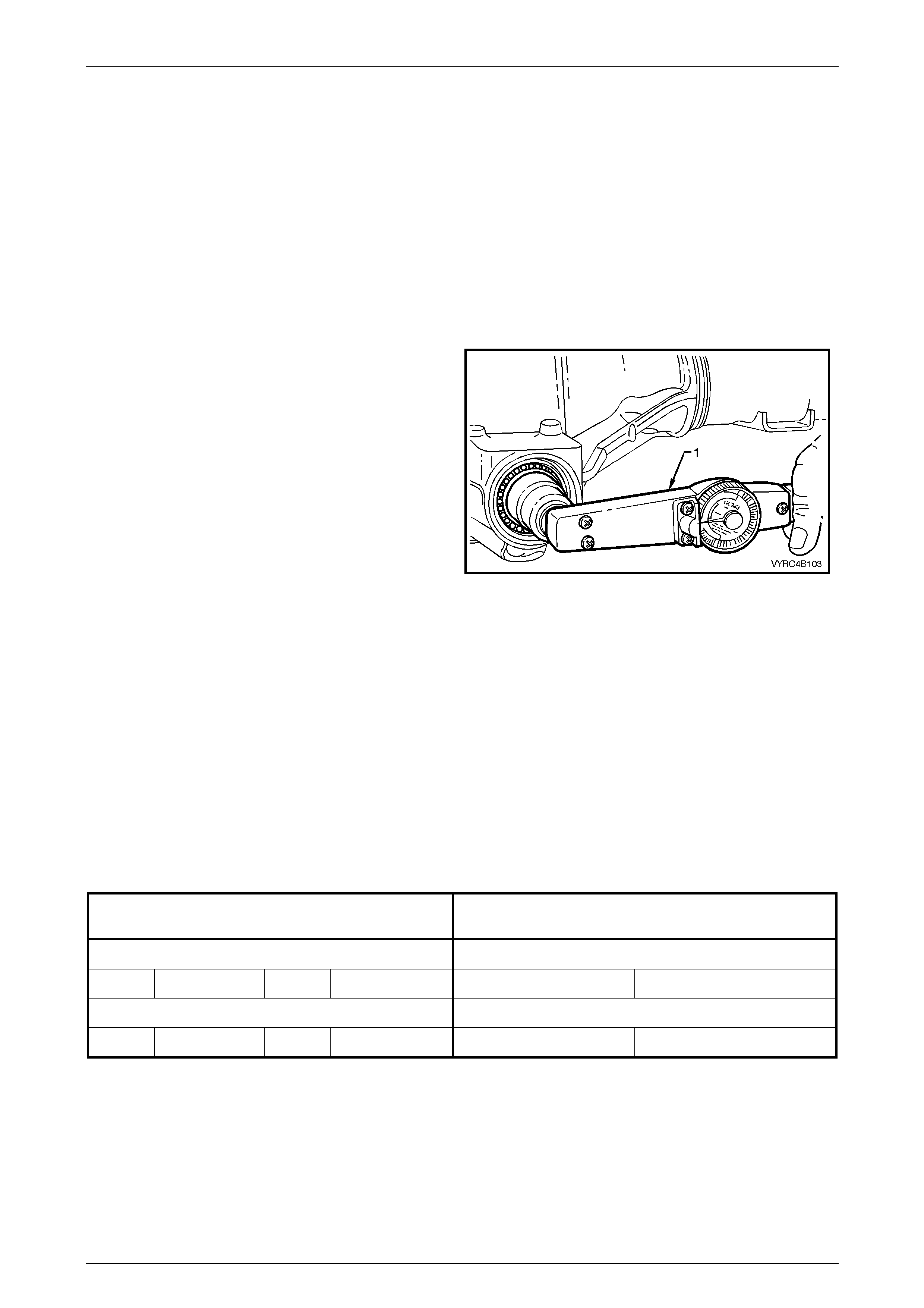
Rear Axle Page 4B –97
Page 4B–97
1 Inspect the pinion bearing cups for damage, nicks,
burrs or excessive wear.
2 If required install the front and rear pinion bearing cup
into the differential carrier-housing pinion bore. Refer
to 3.2 Rear Axle and Differential Housing Assembly –
Disassemble in this Section.
3 For M78 Series, install the distance spacer Tool No.
E9300-1 (part of Tool No. E9300A) onto the dummy
pinion.
For M86 Series, install the preload adaptor Tool No.
205-548 onto the dummy pinion.
4 Install the rear pinion bearing onto the dummy pinion
of the Pinion Height Gauge Set Tool No. E9300A.
5 Install the dummy pinion, rear pinion bearing, the front
pinion bearing along with the dummy pinion thrust
collar and nut.
6 Using the information provided in the dummy pinion
rotational torque specification chart, tighten the
dummy pinion nut until the specified rotational torque
is obtained. While tightening the dummy pinion nut,
rotate the dummy pinion back and forth to ensure that
the bearings sett le into the ir cups.
Refer to Figure 4B-186.
NOTE:
Pinion bearing preload is very important
because it retains the pinion in its correct
relationship to the ring gear.
NOTE:
Bearings that are installed with insufficient or no
preload, will, after a comparatively short period
of running, develop end play, causing noisy
operation on overrun and could be responsible
for scuffing of ring gear and pinion teeth.
NOTE:
Bearings that have excessive preload may
become pitted or flaked, resulting in premature
failure. It is therefore essential to ensure that the
bearings are preloaded to specified torque
specification.
Figure 4B-186
DUMMY PINION ROTATIONAL TORQUE
SPECIFICATION – M78 SERIES DUMMY PINION ROTATIONAL TORQUE
SPECIFICATION – M86 SERIES
New Bearings No Pinion Oil Seal Installed New Bearings No Pinion Oil Seal Installed
Timken 1.4 - 2.0 Nm Koyo 1.5 - 1.9 Nm Koyo 1.8 – 2.1 Nm
Used Bearings No Pinion Oil Seal Installed Used Bearings No Pinion Oil Seal Installed
Timken 0.7 - 1.2 Nm Koyo 0.7 - 1.2 Nm Koyo 0.8 - 1.3 Nm
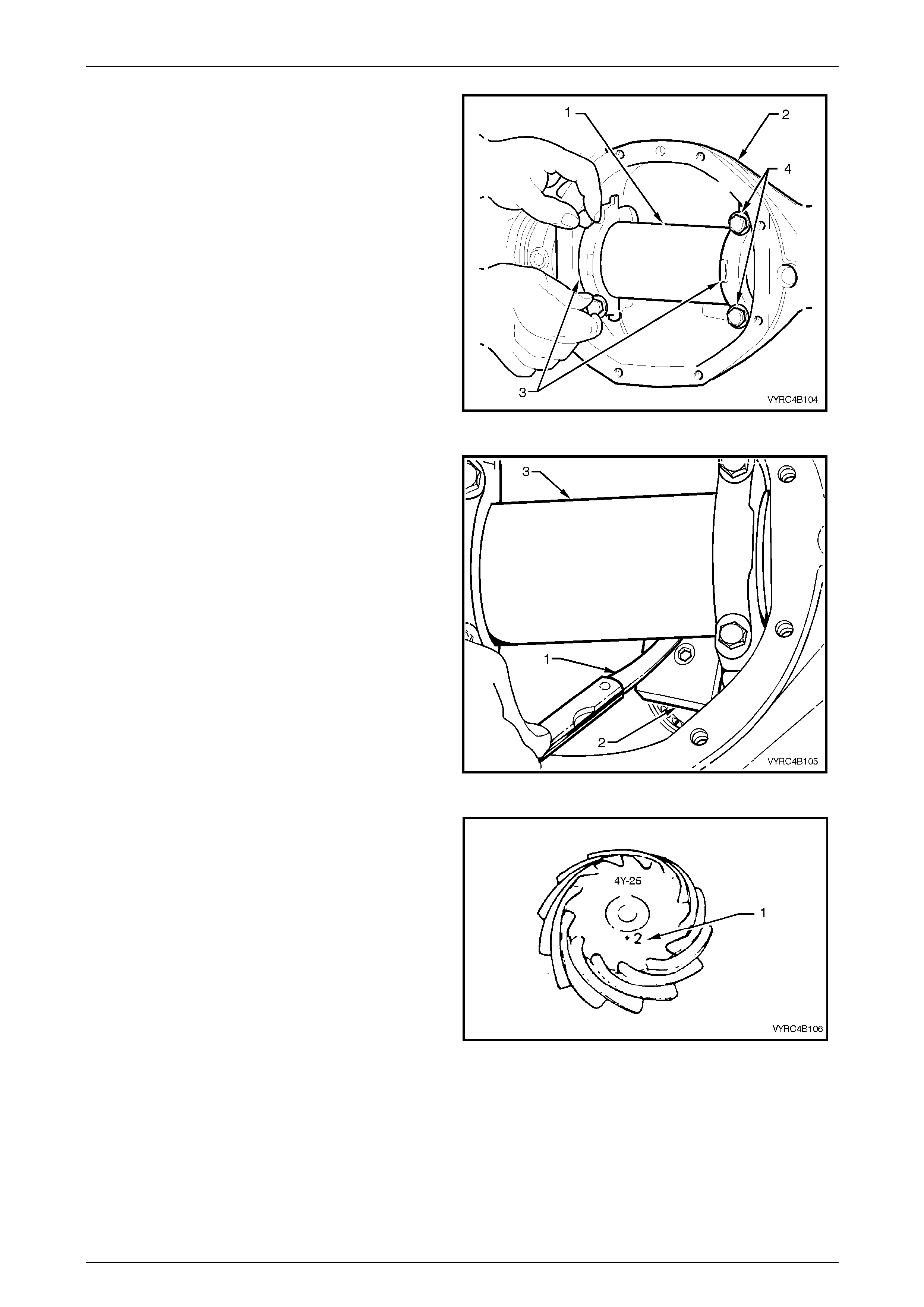
Rear Axle Page 4B –98
Page 4B–98
NOTE:
Ensure that arbor is free of burrs that may
damage bearing cups.
7 Position the arbor (1), part of Tool No. E9300A, into
the carrier assembly (2), install the side bearing
caps (3) and attaching bolts (4). Refer to Figure
4B-187.
8 Tighten the side-bear ing cap a ttach ing bol ts lightly.
Figure 4B-187
9 Measure with feeler gauges (1) and record the
clearance between the head of the dummy pinion
(2) and the arbor (3). Refer to Figure 4B-188.
Figure 4B-188
10 Look at the end of the pinion gear, etched on the
face is a drive pinion instal lati o n-marking figure.
Refer to Figure 4B-189.
a. A zero marking, e.g. 0, indicates that the shim
size for this particular carrier/pinion combination
is the correct size as measured in step 9. Refer
to the shim select ion tabl e bel ow.
b. A positive marking, e.g. +2, means that this
amount must be subtracted from the recorded
measurement obtained in step 9. Refer to the
shim selection table below.
c. A negative marking, e.g. -2, means that this
amount must be added to the recorded
measurement obtained in step 9. Refer to the
shim selection table below.
11 Remove the dummy pinion and arbor from the
differenti al carri er housi ng.
Figure 4B-189
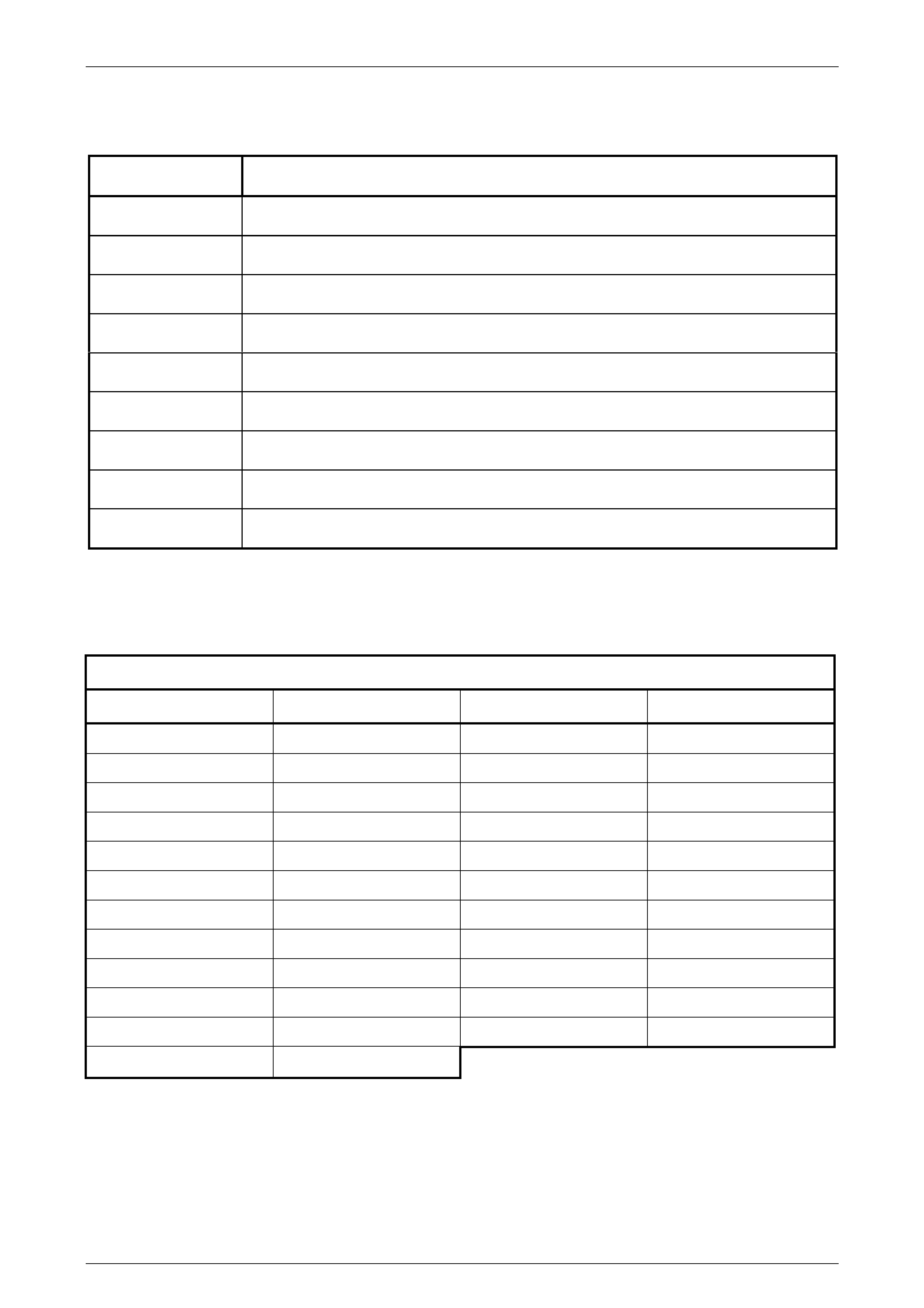
Rear Axle Page 4B –99
Page 4B–99
Hypoid Pinion Shim Selection Table
Using the following table as a guide select the desired shim stack to achieve the required pinion position.
PINION MARKING SHIM THICKNESS REQUIRED
-4 Add 0.10 mm to the measurement of Step 9
-3 Add 0.075 mm to the measurement of Step 9
-2 Add 0.050 mm to the measurement of Step 9
-1 Add 0.025 mm to the measurement of Step 9
0 As per the meas urement of Step 9
+1 Subtract 0.025 mm to the measurement of Step 9
+2 Subtract 0.050 mm to the measurement of Step 9
+3 Subtract 0.075 mm to the measurement of Step 9
+4 Subtract 0.10 mm to the measurement of Step 9
Hypoid Pinion Bearing Preload Shim Selection Chart
Using the following chart select the desired shim stack.
Hypoid Pinion Bearing Preload Shim Selection Chart
Part Number Shim Thickness Part Number Shim Thickness
92140342 .203 92140352 508
92140343 .229 92140353 .533
92140344 .254 92140354 .559
92140345 .279 92140355 .584
92140346 .305 92140356 .610
92146518 .330 92140357 .635
92146519 .356 92140358 .660
92140347 .381 92140359 .686
92140348 .406 92140360 .711
92140349 .432 92140361 .737
92140350 .457 92140362 .762
92140351 .483
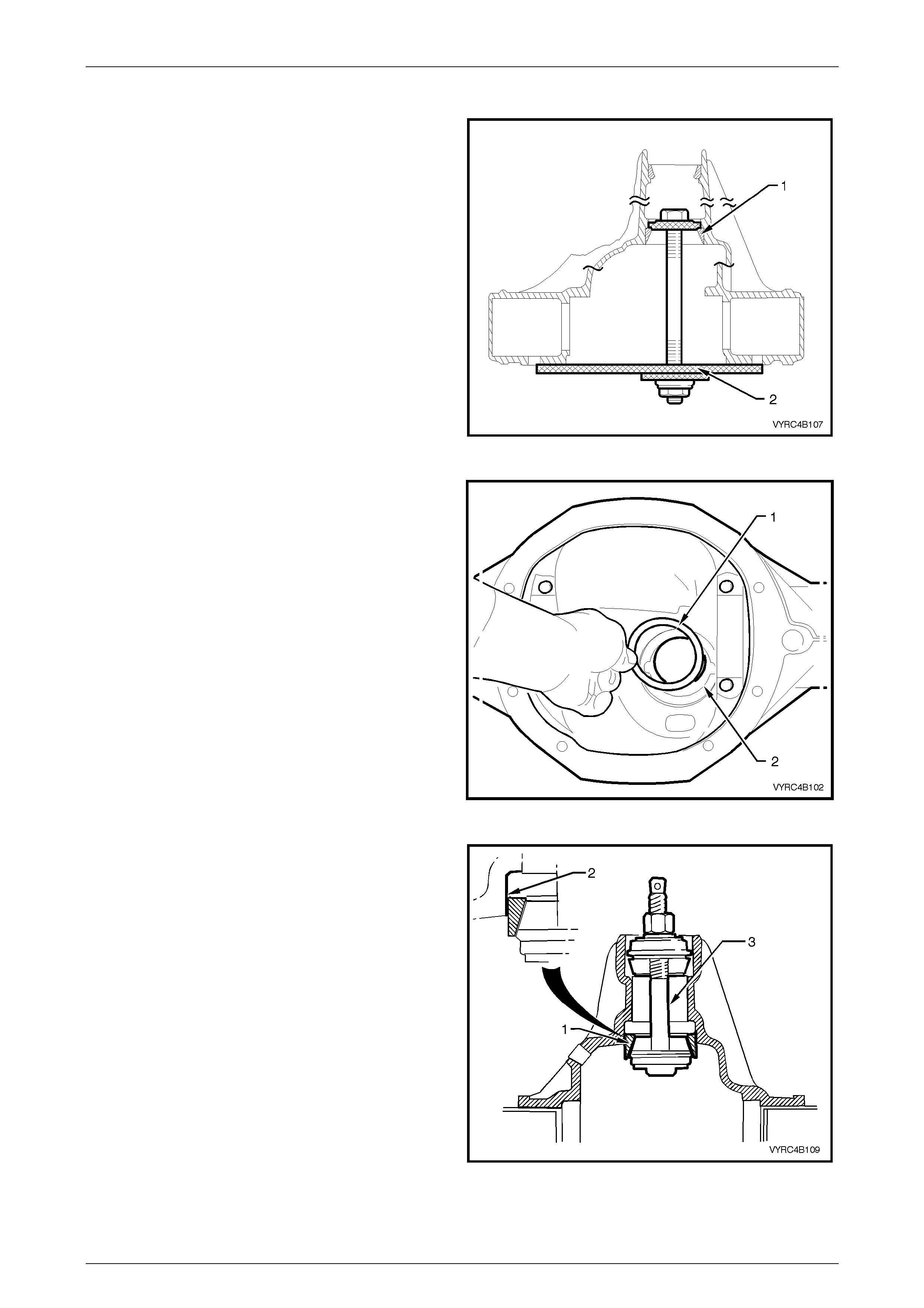
Rear Axle Page 4B –100
Page 4B–100
Pinion Installation
1 For M78 Series, remove the rear pinion-bearing cup
(1) from the differential carrier housing pinion bore
using Tool No. E9293 (2), refer to Figure 4B-190.
Refer to 3.2 Rear Axle and Differential Housing
Assembly – Disassemble in this Section.
2 For M86 Series, remove the rear pinion-bearing cup
(1) from the differential carrier housing pinion bore
using Tool No. E9293 (2) along with Tool No.
205-551, refer to Figure 4B-190. Refer to
3.2 Rear Axle and Differential Housing Assembly –
Disassemble in this Section.
3 Select the required pinion positioning shims required
as determined previously. Refer to 3.6 Rear Axle and
Differential Housing Assembly - Reassemble, Hypoid
Pinion Shim Selection in this Section.
Figure 4B-190
4 Install the pinion positioning shim/s (1) into the rear
pinion cup bore (2). Refer to Figure 4B-191.
Figure 4B-191
5 Reinstall the rear pinion-bearing cup (1) into the
differential carrier housing pinion bore:
a. For M78 Series, reinstall the rear pinion-bearing
cup (1) into the differential carrier housing pinion
bore (2) using Tool No. E9293, consisting of Tool
No. E9271 and E9293A (3), ensuring the bearing
cup is seated squarely in the bore. Refer to
Figure 4B-192.
b. For M86 Series, reinstall the rear pinion-bearing
cup (1) into the differential carrier housing pinion
bore (2) using Tool No. E9271 (3), part of Tool
No. E9293, along with adaptors Tool No. 205-552
ensuring the bear ing cup is seated squ arely in
the bore. Refer to Figure 4B-192.
Figure 4B-192
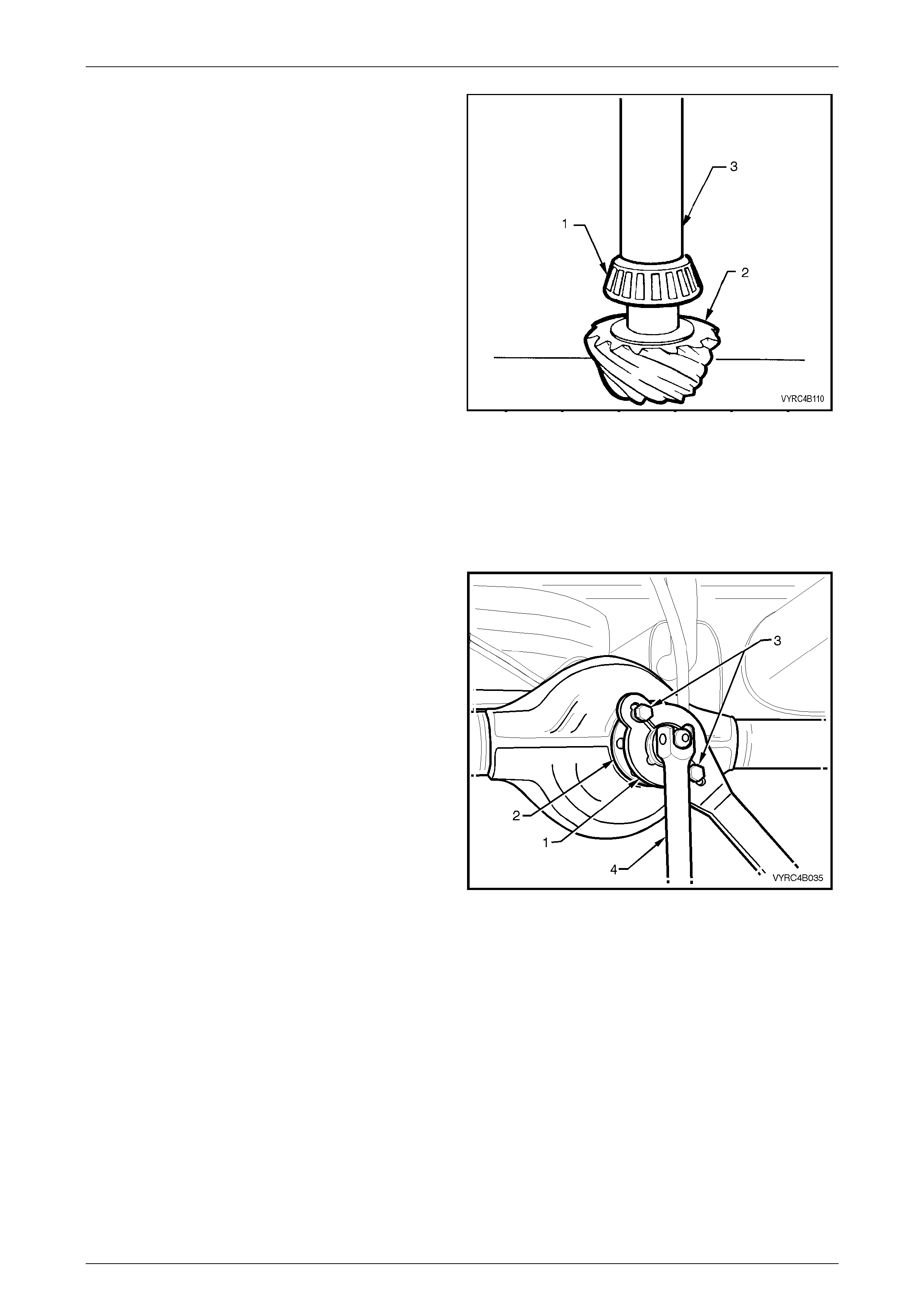
Rear Axle Page 4B –101
Page 4B–101
6 Install the rear pinion-bearing ra ce to the pinion gear:
a. For M78 Series, install the rear pinion-bearing
race (1) to the pinion gear (2), using Tool No.
E3C10AER (3). Refer to Figure 4B-193.
b. For M86 Series, install the rear pinion-bearing
race (1) to the pinion gear (2), using Tool No.
205-546 (3). Refer to Figure 4B-193.
NOTE:
To avoid possible damage to the pinion gear
teeth when pressing the bearing race on to the
pinion gear, ensure the press plates are
perfectly flat, free of burrs and foreign matter.
NOTE:
Ensure the rear pinion-bearing race is squarely
located on to the pinion gear and only press on
the inner race surface.
NOTE:
Lubricate the rear pinion bearing race and
pinion gear with the recommended lubricant
only. Refer to 2.2 Checking Rear Axle Lubricant
Level in this Section.
Figure 4B-193
7 Lubricate the rear pinion-bearing race to the pini on
gear and install the pinion gea r into the diff erent ial
carrier-housing pinion bore.
8 Lubricate the new collapsible pinion bearing spacer,
the front pinion-bearing race and the pinion flange
seal surface.
9 While supporting the pinion gear in the differential
carrier housing, install a new collapsible pinion
bearing spacer, the front pinion bearing race, the
pinion flange and the original pinion flange nut.
10 Using Tool No. J8614-11 (1) (part of Tool No. J8614-
01) with two suitable bolts (3) to hold the pinion flange
(2), tighten the pinion flange nut using a su itable
socket and bar (4) until the front pinion bearing starts
on the pinion gear shaft. Refer to Figure 4B-194.
11 Remove the pinion flange nut.
Figure 4B-194
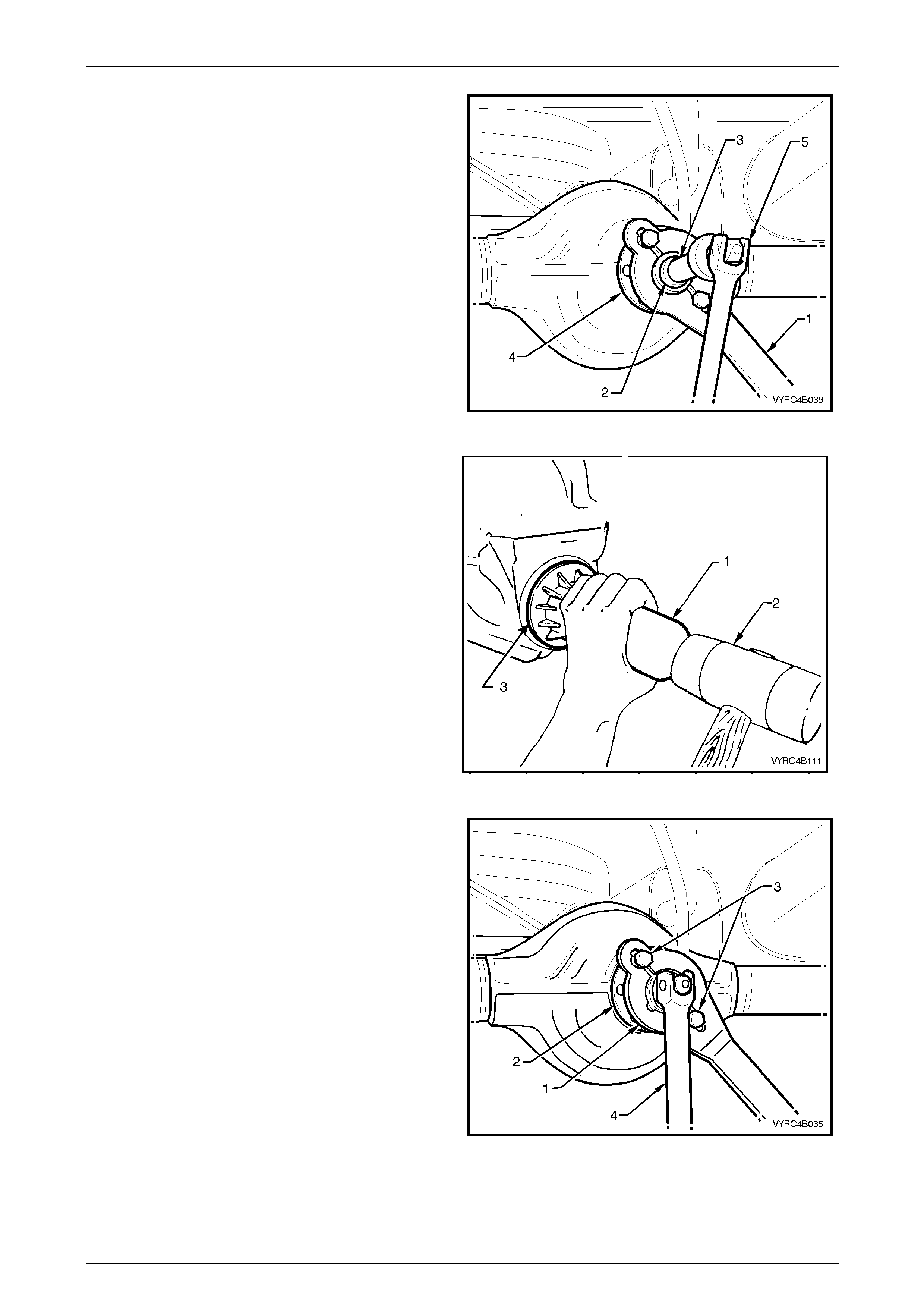
Rear Axle Page 4B –102
Page 4B–102
12 Using Tool No. J8614-11 (1), Tool No. J8614-2 (2)
and Tool No. J8614-3 (3) (part of Tool No. J8614-01)
with two suitable bolt’s, a suitable socket and bar (5),
remove the pinion flange. Refer to Figure 4B-195.
Figure 4B-195
13 Lubricate the pinion oil seal lips with the
recommended lubricant only . Refer to 2.2 Checking
Rear Axle Lubricant Level in this Section.
14 Lightly coat the outside of the oil seal shell with non-
hardening gasket cement.
15 Install the oil seal:
a. For M78 Series, use Tool No. E9055 (1) and a
soft-faced hammer (2) to install the oil seal (3)
into the differential carrier-housing pinion bore.
b. For M86 Series, use Tool No. 205-553 (1) and a
soft-faced hammer (2) to install the oil seal (3)
into the differential carrier-housing pinion bore.
16 Ensure the seal fits flush to 0.25 mm below the front
surface of the pinion bore. Refer to Figure 4B-196.
Figure 4B-196
17 Reinstall the pinion flange and a new pinion flange
nut.
18 Using Tool No. J8614-11 (1) (part of Tool No. J8614-
01) with two suitable bolts to hold the pinion flange
then with a suitable socket and bar gradually tighten
the pinion flange nut while rotating the pinion in both
directions to seat the bearings.
Refer to Figure 4B-197.
Figure 4B-197
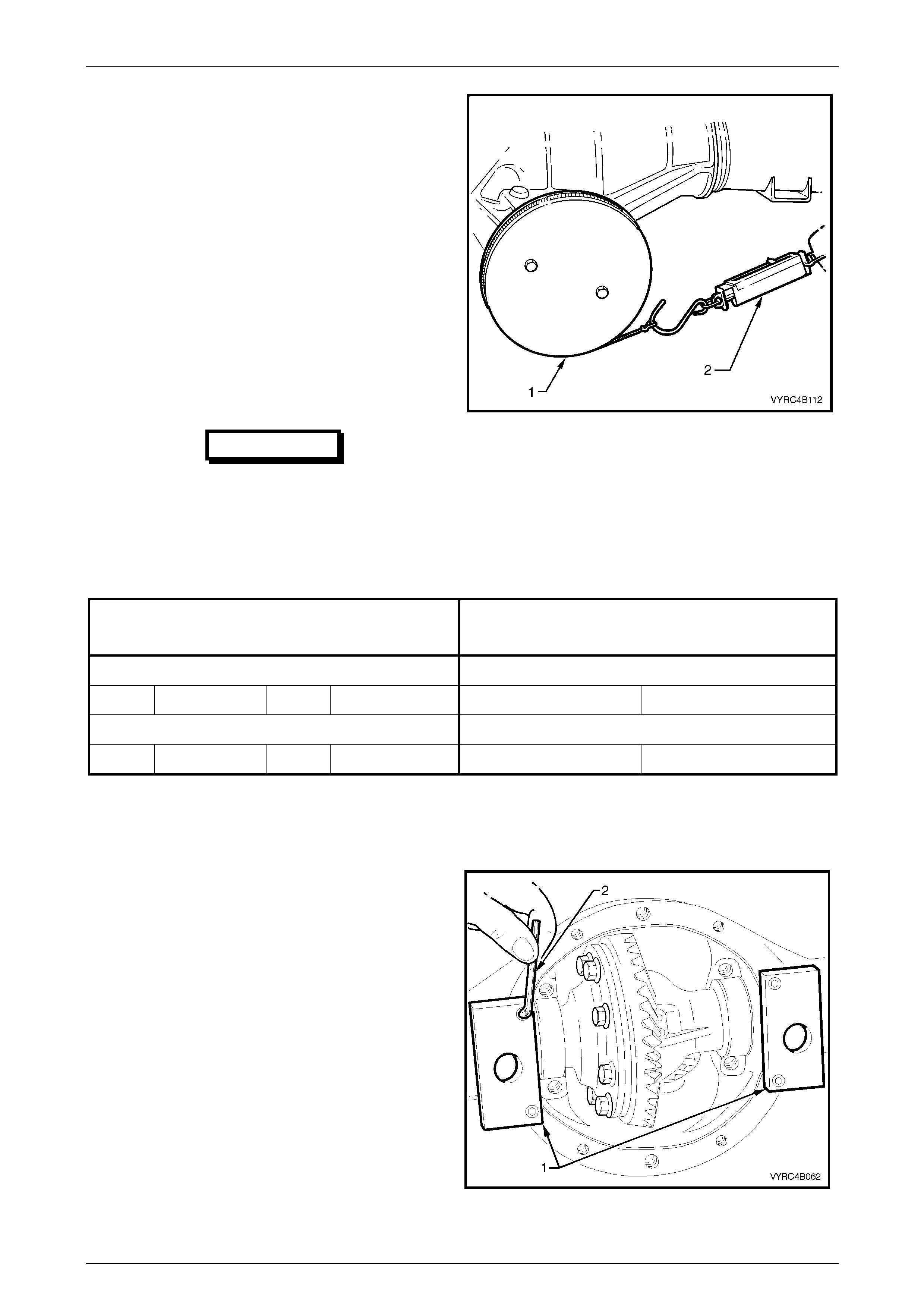
Rear Axle Page 4B –103
Page 4B–103
19 The pinion bearing preload will need to be checked
frequently by removing the pinion flange holding tool
then installing a pulley (1) and string along with a
spring balance (2) to the pinion flange.
Refer to 7 Special Tools in this Section for pulley
details.Refer to Figure 4B-198.
20 Using the spring balance, measure rotational torque.
21 Continue to tighten the nut until specified torque is
achieved
NOTE:
The torque figure is calculated by multiplying the
radius of the pulley by the spring balance
reading. i.e. If the pulley diameter is 152 mm,
the radius is 76 mm, which equals 0.076 m. The
spring balance reading is 25 N. Therefore, the
preload equals 0.076 m x 25 N = 1.9 Nm.
IMPORTANT
Should the retaining nut be over-tightened
and preload exceeded, it will be
necessary to remove the pinion from the
carrier and install a new collapsible
spacer. Under no circumstances must the
retaining nut be backed off to decrease
the preload reading.
Figure 4B-198
PINION ROTATIONAL TORQUE SPECIFICATION
M78 SERIES
PINION ROTATIONAL TORQUE SPECIFICATION
M86 SERIES
New Bearings Pinion Oil Se al Installed New Bearings Pinion Oil Se al Installed
Timken 1.4 - 2.0 Nm Koyo 1.5 - 1.9 Nm Koyo 1.9 – 2.3 Nm
Used Bearings Pinion Oil Seal Installed Used Bearings Pinion Oil Seal Installed
Timken 0.7 - 1.2 Nm Koyo 0.7 - 1.2 Nm Koyo 0.8 - 1.3 Nm
Differential Backlash Setting
1 Install the adaptors (1) of the differential spreading
Tool No. E9255 to the differential carrier housing
using a 5mm Allen Key (2). Refer to Figure 4B-199.
Figure 4B-199
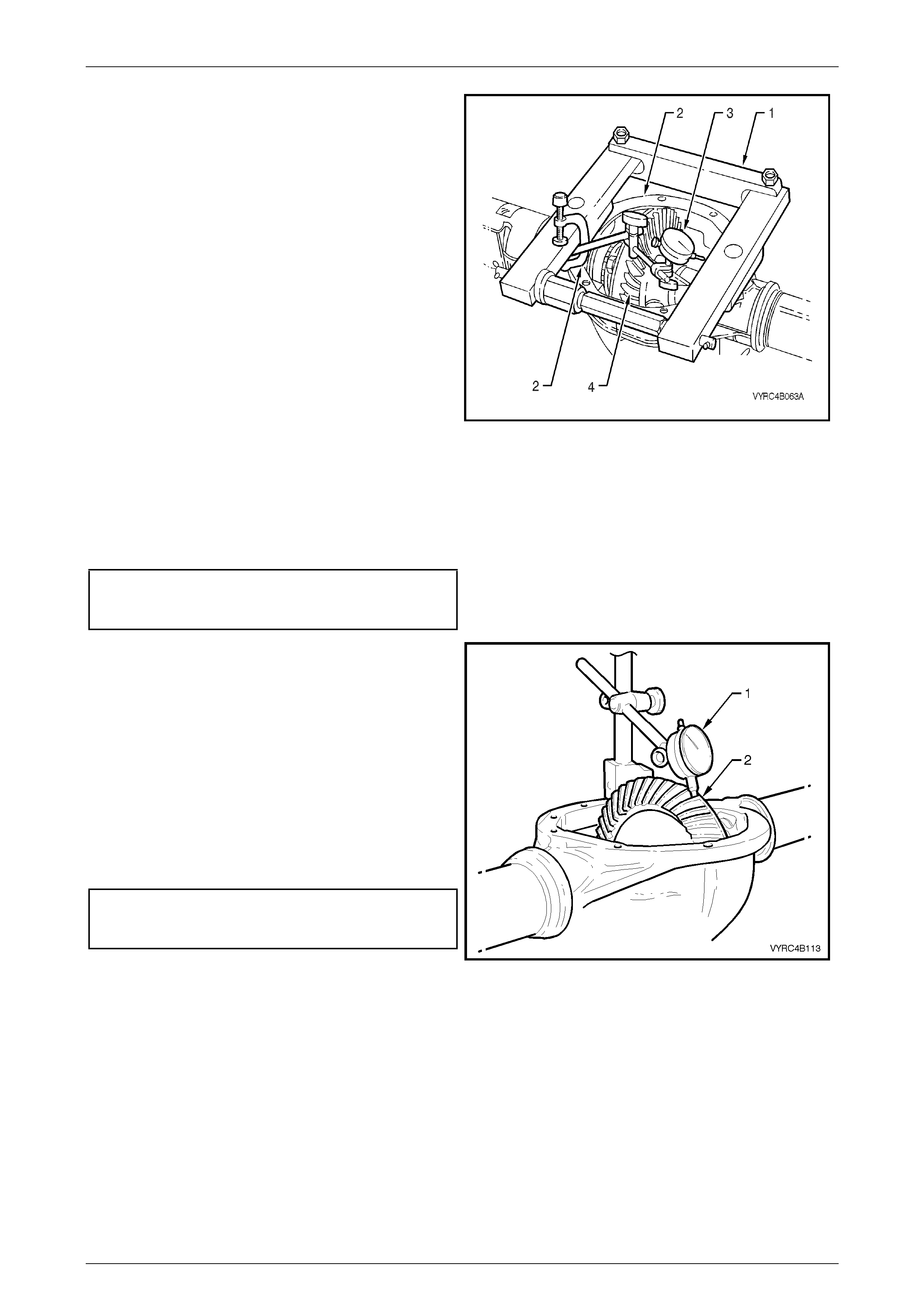
Rear Axle Page 4B –104
Page 4B–104
2 Install the differential spreading Tool No. E9255 and
the adaptor's (1) to the differential carrier housing (2),
refer to Figure 4B-199.
3 Install a dial indicator (3) to the differential spreading
Tool No. E9255 and differential carrier housing.
Refer to Figure 4B-200.
4 Spread the differential carri er hous ing appr oximately
0.1 to 0.2 mm.
NOTE:
Under no circumstances is the differential
carrier to be spread more than 0.5 mm.
5 Install the differential case assembly (4) along with
the carrier side bearing cups and shims.
6 Release the force exerted by the spreading Tool No.
E9255 and remove tool along with the adaptors from
the differential carrier housing.
7 Install the side bearing caps and retaining bolts.
Ensure the original relationship of the side bearing
caps is maintained so they are reinstalled in their
original locati on.
8 Tighten the side bearing cap bolts to the correct
torque specif ication.
Side bearing cap to differential
carrier housing attaching bolt
torque specification ......................................48 – 60 Nm
Figure 4B-200
9 Using a dial indicator (1) against the back face of a
ring gear tooth (2), measure the ring gear backlash by
rocking the ring gear back and forth. The backlash
measurement should be taken at four equally spaced
positions of the ring gear, refer to Figure 4B-201.
10 If backlash is insufficient, increase the size of the
shim on the pinion side of the ring gear and decrease
the size of the shim on the gear side by the same
amount, and repeat step 9.
11 If backlash is excessive, decrease the size of the
shim on the pinion side of the ring gear and increase
the size of the shim on the gear side by the same
amount, and repeat step 9.
Ring gear to
pinion gear backlash
specificat ion .................................0.10 mm – 0.18 mm
Figure 4B-201

Rear Axle Page 4B –105
Page 4B–105
Ring Gear and Pinion Contact Pattern
1 With the backlash correctly set, check the gear contact pattern as detailed in the following instructions.
2 Thoroughly clean the ring gear and the pinion teeth.
3 Paint the ring gear teeth lightly and evenly with the gear marking compound of a suitable consistency to produce a
contact patt ern.
4 Rotate the pinion through several revolutions in both directions while lightly loading the gear set. To load the gear
set, use a suitable bar to lever between the ring gear outer diameter and the differential carrier housing.
NOTE:
When rotating the pinion, ensure that no metal
swarf from contact with the rotating ring gear and
bar is allowed to enter the gear teeth.
5 Inspect the contact pattern produced by the above procedure.
6 After a satisfac tory contact pattern is produced, clean the ring gear and the pinion gear teeth and pour a liberal
quantity of the correct rear axle lubricant onto the gears and bearings. Turn the gear set to work the lubricant into
all surfaces.
Tooth Marking Terminology
The large end of the tooth is called the 'HEEL' and the small end the 'TOE', also the top of the tooth, which is above the
pitch line, is called the 'FACE' while the area below the pitch line is called the 'FLANK'. The clearance between the pinion
and ring gear teeth is referred to as 'BACKLASH'.
Contact pattern 'A' provides the ideal marking for quietness and long life. If the pattern shows a toe contact 'B', it
indicates not enough backlash. To correct, move the ring gear away from the pinion by increasing the size of the shim on
the pinion side of the ring gear while decreasing the opposite ring gear side shim by an equal amount.
If the pattern shows a heel contact 'C', it indicates too much backlash. To correct, move the ring gear towards the pinion
by increasing the size of the shim on the ring gear side and decreasing the size of the shim on the pinion side of the ring
gear by an equal amount.
NOTE:
Make adjustment, increasing and decreasing
shim thickness by 0.04 mm at a time. Check
contact with gear marking compound and
continue adjustment until tooth contact appears
as in 'A'. Backlash must remain within specified
limits.
To correct a pattern such as 'D', it will be necessary to install a thicker pinion positioning shim, refer to 3.6 Differential
Assembly Adjustment and Installation Procedures – All Models – Differential Side Bearing Preload and Shim Selection in
this Section.
A 0.025-mm thic ker shim is recommended as a starting point. Continued changes may be necessary to obtain the
correct setting. If the pattern shows a flank contact 'E', it indicates that the pinion is in too far. To correct, replace the
pinion shim with a 0.025-mm thinner shim and recheck contact pattern. Refer to 3.6 Differential Assembly Adjustment
and Installation Procedures – All Models – Hypoid Pinion Bearing Preload Shim Selection in this Section.
In making pinion position adjustments, be sure backlash is correct before testing contact pattern. Moving the pinion 'IN'
reduces backl ash and mov in g pini on 'O UT' increases bac kl a sh.
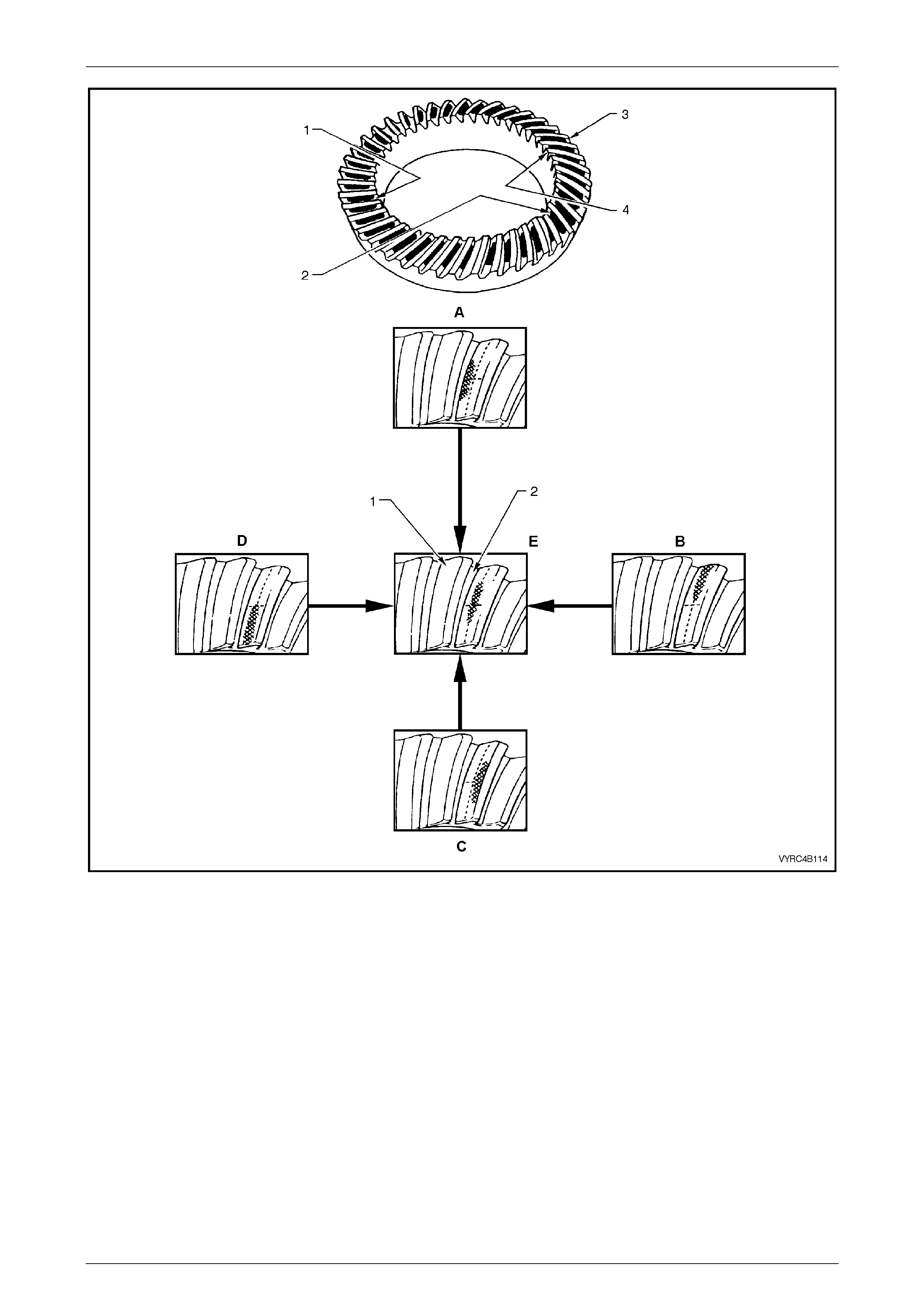
Rear Axle Page 4B –106
Page 4B–106
Figure 4B-202
Legend
1 Convex Side (Drive)
2 Concave Side (Coast)
3 Heel
4 Toe
A. Low Flank Contact - Decrease Pinion Shim
Thickness
B. Heel Contact - Decrease Backlash
C. High Face Contact - Increase Pinion Shim
Thickness
D. Toe Contact - Increase Backlash
E. Ideal Contact

Rear Axle Page 4B –107
Page 4B–107
Ideal Contact
Figure 4B-203
Legend
A. Drive Side
B. Coast Side
1. Face Width
2. Toe
3. Heel
Drive Side
• A central toe contact marking, lengthwise in position and slightly low contact in the profile position.
• Total length approximately 5/8th of the gear face width.
• There should be clearance of about 1 mm between the contact marking and the toe and along the top face angle
line.
Coast Side
• A centrally located marking, that is lengthwise in position and slightly high in the profile position.
• Total length approximately 5/8th of the gear face width.
• There should be clearance between the contact and the face angle line of the gear.
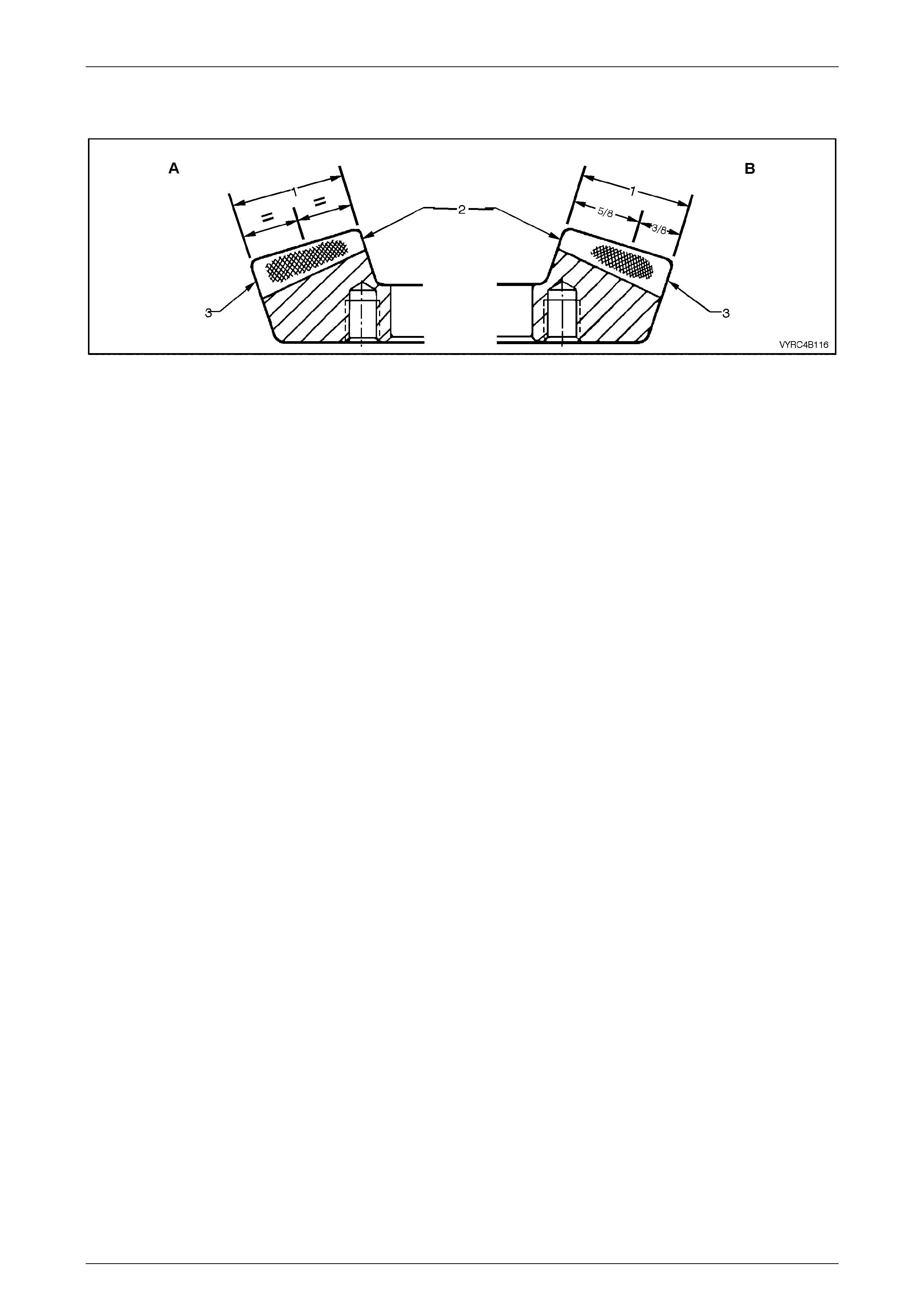
Rear Axle Page 4B –108
Page 4B–108
Acceptable Heel Contacts
Figure 4B-204
Legend
A. Drive Side
B. Coast Side
1. Face Width
2. Toe
3. Heel
Drive Side
• A central face contact marking, lengthwi se in position, is shown in Figure 4B-204. This represents the limit of
acceptability of the contact marking towards the heel.
• The marking should fade out at least 5 mm before the heel end.
• A central profile marking position is shown and is acceptable, although low contact marking is preferred.
Coast Side
• The centre of the contact marking is located at 5/8th of the face width from the toe and it does not approach the heel
end by less than 5 mm.
• A high contact marking, as shown in Figure 4B-204, is preferred for coast side contacts, which tend to be toward the
heel.
• A central profile marking position is acceptable, providing the pinion face angle edge lines do not appear low on the
gear.
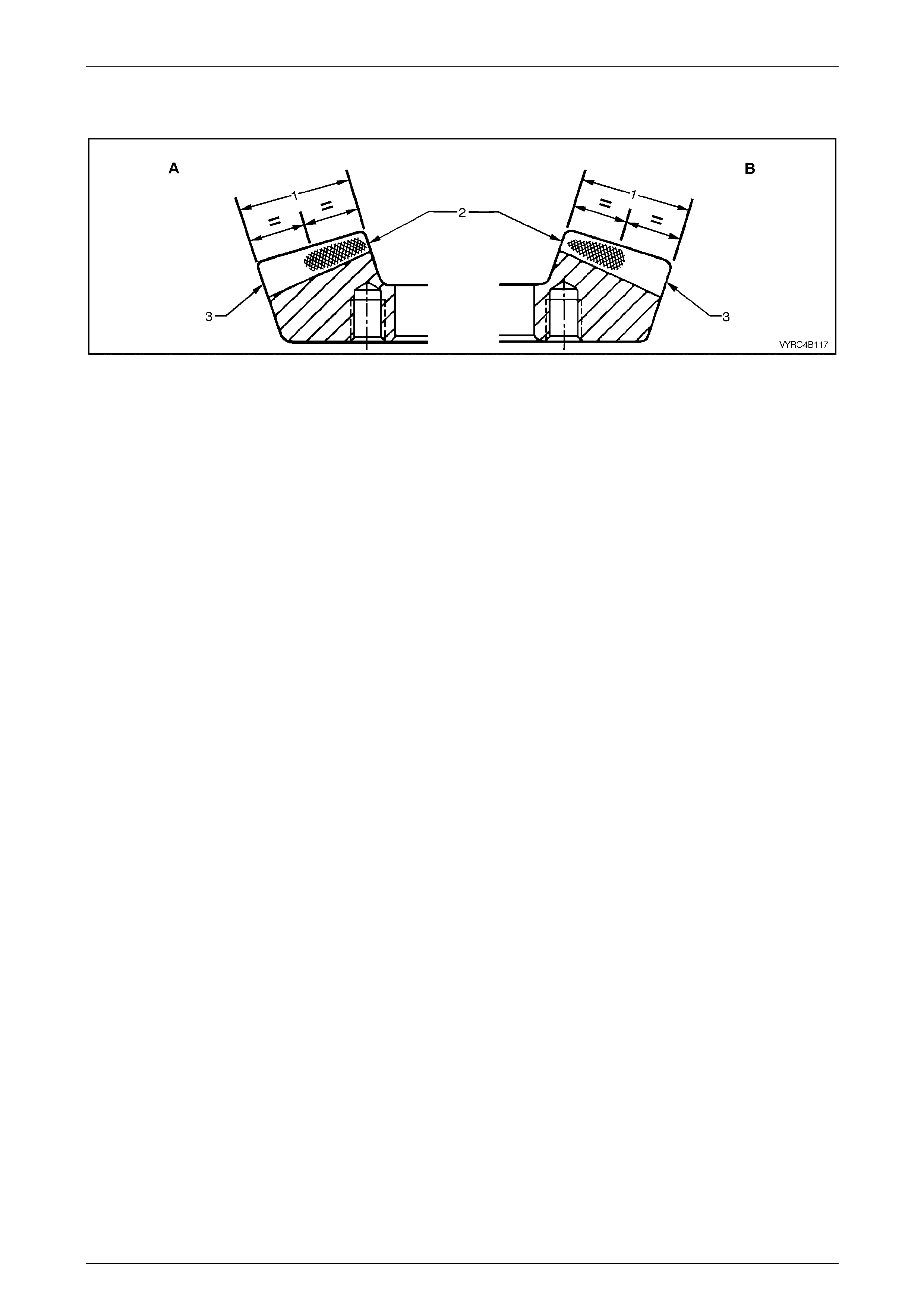
Rear Axle Page 4B –109
Page 4B–109
Acceptabl e Toe Contacts
Figure 4B-205
Legend
A. Drive Side
B. Coast Side
1. Face Width
2. Toe
3. Heel
Drive Side
• The contact markings begin almost at the toe end face and extend in length by approximately half the face width.
• A slightly low contact marking is shown in Figure 4B-158. This is preferable although a centrally located profile
position is acceptable.
Coast Side
• The contact marking being almost at the toe end face and may appear pointed as shown in Figure 4B-158. A square
end is equally acceptable.
• The total length of the contact marking is approximately 1/2 of the face width.
• A high profile marking position is desirable, although a central profile is acceptable.
Rear Axle Page 4B –110
Page 4B–110
4. Diagnosis
4.1 General Information
Rear axle assemblies are frequently considered noisy, when in reality, the noise is emanating from some other source.
i.e. tyres, front wheel bearings, rear wheel bearings, manual transmission rear bearings, engine noises, muffler roar,
automatic transmission or power steering pumps.
All rear axle assemblies have some slight humming noise. This will vary with the type of body construction, load and tyre
pressure.
Noise, which emanates from any one of thes e can quite easily be confused with a rear axle assembly noise and unless a
series of elimination tests are carried out to definitely confirm the real source of the noise, differential assemblies may be,
and often are, dismantled unnecessarily.
Although not infallible, the following diagnosis guide will assist in locating and defining the different characteristics of the
components, which could be responsible for a noise.
Road Test
Ensure that the rear axle assembly lubricant is correct and at the correct level. Drive at low speed until thoroughly
familiar with vehicle noises by which time the rear axle assembly should have warmed up. Accelerate gradually from the
lowest practical speed in a direct ratio gear (1:1) to 100 km/h, noting any noises and the speeds at which they occur.
Release the accelerator and without using the brakes, allow the vehicle to lose speed. Next, allow the vehicle to coast to
rest from 100 km/h with the transmission in neutral position. Any noises common to earlier tests may be eliminated as
rear axle assembly, gear noise, as the rear axle assembly is not under load under these conditions. Engine noise is
gauged by gradually accelerating the engine with the vehicle at rest.
Only drive at high speeds when it is legal and
safe to do so.
Tyre Noise
Tyre noise can easily be mistaken for rear axle assembly noise even though the noisy tyres may be operating on the
front wheels. Tyre noise can change with different road conditions, but rear axle assembly noise does not. Rear axle
assembly noise usually ceases when coasting with the transmission in neutral at speeds less than 50 km/h. Tyre noise
continues, but with a lower tone as vehicle speed is reduced.
Tyre noise should be eliminated first; driving on a grass surface is ideal to check against this condition. It should be noted
though, that dry grass can impose a fire hazard with the heat emanating from the catalytic converter and wet grass can
cause excessive wheel spin. Inflating tyres temporarily to high pressures will change the contact with the road and assist
in reducing tyre noise. Pressures up to 276 Kpa may be used temporarily.
Tyres which have the surface of the tread pattern worn with one end higher than the other (saw-tooth wear) are usually
noisy. Interchanging tyres can prove effective in reducing noise.
Front Wheel Bearings
Worn, brindled, chipped or incorrectly adjusted front wheel bearings will cause a noise, very similar to tyre noise. It is a
constant noise, does not vary on 'drive' or 'coast' and still persists when coas ting with the transmission in neutral. This
noise does not noticeably change on differing road surfaces to the same degree, as does tyre noise.
Although not so pronounced, front wheel bearing noise can also be compared to a road surface noise, which is produced
when the vehicle is travelling over a surface such as penetrated bitumen road.

Rear Axle Page 4B –111
Page 4B–111
Transmission Rear Bearing (Manual Transmission)
A rough or pitted rear transmission bearing, usually produces a very definite bearing noise and sets up a distinct
'whirring' condition, which is most audible when accelerating from slow speed under a high throttle opening and tends to
diminish as vehicle speed increases.
This noise is also prominent under a constant throttle opening, but disappears on over-run when coasting with the
transmission in neutral.
When driven in second gear, transmission noise can be amplified by lightly accelerating.
Backlash Clunk
Excessive clunk during acceleration and deceleration may be caused by:
• Worn differential pinion shafts.
• Excessiv e cleara nce between the inner axle shaft and the side gear splines.
• Excessive clearance between the side gear hub and the counter-bore in the case.
• Worn differential pinion and side gear teeth.
• Worn thrust washers.
• Excessive drive pinion and ring gear backlash.
Drive-Line Snap
A loose pinion flange may cause a snap on sudden start, forward or reverse. If loose, replace the nut, and or the flange.
Refer to 2.11 Pinion Flange in this Section.
This condition may also be caused by incorrect lubricant in the LSD. Drain and refill with correct lubricant.
Refer to 2.2 Checking Rear Axle Lubricant Level or 5 Specifications for the recommended lubricant in this Section.
Engine and Other Contributing Factors:
Noises, which emanate from the engine, transmission or muffler, are occasionally confused with rear axle assembly
noises.
To isolate these noises, first carefully note the approximate vehicle speed and conditions where the supposed rear axle
assembly noise is most pronounced. Then with the vehicle stationary and in a quiet place to avoid interfering noises
(depress the clutch pedal on vehicles with manual transmission) run the engine up and down slowly through the engine
speeds that correspond to the vehicle speeds at which the noise was prominent. Observe whether there is any similarity
to a rear axle assembly noise.
Vehicles with Manual Transmission:
With the transmission still in neutral, again run the engine at a similar speed while slowly letting the clutch engage, and
listen for noises from the transmission.
Muffler noises are usually readily identified, possibly an exception being when a muffler emits a high-pitched periodic
whistling noise, which could be confused with a bearing noise.

Rear Axle Page 4B –112
Page 4B–112
4.2 Final Drive Assembly Noise
Final drive assembly noises fall into two categories:
1 Gear related noises.
2 Bearing related noises.
Before testing for rear axle assembly noise, ensure that the lubricant is the correct type and at the correct level. Refer to
2.2 Checking Rear Axle Lubricant Level or 5 Specifications for the recommended lubricant in this Section.
Gear Related Noise
Ring Gear and Pinion Noise
Noise produced by the ring gear and pinion set is of a cyclic nature and generally shows up as a 'drive noise', 'coast
noise', or 'float noise'.
1 Drive noise is most pronounced on constant acceleration through the speed range of 50 to 90 km/h.
2 Coast noise is most pronounced when the vehicle is allowed to coast through the speed range from 90 to 50 km/h .
3 Float noise is most pronounced while the vehicle is kept at constant speed for periods between 50 to 90 km/h.
Rear axle assembly noise will always change when comparing 'drive' and 'coast' and will usually cease when coas ting
with transmission in neutral at speeds under 50 km/h.
Differential Side Gear and Pinion Noise
Noise produced by these gears occurs when there is excessive wear between the side gear hubs and the differential
case bores. This can cause a 'clunking' noise when the vehicle is driven at low speeds.
1 Noise produced due to excessive wear between the gear teeth will be most pronounced on turns.
Common Causes of Gear Related Noises
Low lubricant level or incorrect lubricant used. Refer to 2.2 Checking Rear Axle Lubricant Level or 5 Specifications for the
recommended lubricant in this Section.
Incorrect meshing of gear teeth (i.e. incorrect pinion positioning shim or backlash setting shims). Refer to 3.6 Differential
Assembly Adjustment and Installation Procedures – All Models in this Section.
1 Scored gear teeth: - usua lly the result of incorrect lubricant type or level.
2 End play in bearings.
3 Bruised or chipped teeth.
4 Excessive runout of pinion head or ring gear backlash.
5 Ring gear creeping on differential case resulting from ring gear bolts loosening - noise from this source usually
appears as a sharp metallic sound when shifting from reverse to first gear.
Bearing Related Noise
Differential Pinion Gear Bearings
Worn, rough or loose bearings will tend to aggravate and magnify drive, float and coast noise, and result in heavy,
irregular drive noise on constant acceleration and float, as well as an irregular noise on deceleration.
Pinion bearings , if rough or brinelled, will produce a continuous whine, which will persist when coasting with the
transmission in neutral, even to a low speed.
End play in the pinion bearings, even from natural wear, permits the pinion to feed back into the ring gear. This will cause
a noise on over-run.

Rear Axle Page 4B –113
Page 4B–113
Axle Shaft Bearings
Axle shaft bearings that are rough or pitted can be responsibl e for a growling noise, which on first impression could be
likened to a rear axle noise.
The noise, however, does not vary on 'drive' or 'coast' and still persists when coasting with transmission in neutral.
Frequently this noise can be readily identified by the sound being conveyed in an eccentric form. It can also be
intermittent as the noise may fade for a short period.
To confirm the diagnosis of a axle shaft bearing noise:
1 Support the rear of the vehicle on safety stands and remove both rear wheels and brake discs.
NOTE:
Mark the relationship of the road wheel to rear
axle shaft and the rear disc rotor to rear axle
shaft. Refer to 2.5 Rear Axle Shaft Wheel Studs
and 3.5 Rear Brake Disc – Brake Disc and Hub
Indexing Procedure.
2 Start the engine and, with top gear engaged, speed engine up to a fast idle.
3 If a stethoscope is available, it is ideal to compare the noise of one bearing against the other. To obtain the best
results with a stethoscope, keep the volume adjustment down low.
4 A difference in the noise of the drive shaft bearings can also be discerned by placing a steel-shafted screwdriver to
the ear, in close proximity to each bearing in turn. With practice, a noticeable difference in noise can, at most times,
be observed between a good and faulty bearing.
Differential Side Bearings
Side bearings will produce a constant grinding noise of a slower nature than pinion bearings (side bearing noise cannot
be determined by the diagnosis procedure for drive shaft bearing noise), but will be in the same frequency as axle shaft
bearings.
Common Causes of Bearing Related Noises
1 Low lubricant level or incorrect lubricant used. Refer to 2.2 Checking Rear Axle Lubricant Level or 5 Specifications
for the recommended lubricant in this Section.
2 Foreign matter in the lubricant. Refer to 2.3 Changing/Flushing Rear Axle Lubricant in this Section.
3 Incorrect preload sett ing.
4 Bearings incorrectly mounted e.g. dirt trapped behind abutment faces during assembly.

Rear Axle Page 4B –114
Page 4B–114
4.3 LSD Noise
If LSD stick-slip chatter is diagnosed, the differential carrier lubricant should be drained immediately after a run to warm
up the lubricant. This is to remove as much old lubricant and wear debris as possible. Refill carrier with the specified
lubricant (including separate LSD lubricant additive where specified) and re-evaluate LSD operation for a minimum of 20
Km. Chatter will usually disappear within this time.
Should chatter still occur, remove carrier and overhaul LSD. Refer to 3.4, Differential Assembly – M78 Series (Cone
Type Limited Slip) or 3.5, Differential Assembly – M86 Series (Multi-Disc Type Limited Slip) in this Section.

Rear Axle Page 4B –115
Page 4B–115
4.4 Differential and Rear Axle Bearing
Diagnosis
Factors When Diagnosing Bearing Condition
• General condit ion of all parts during disassembly and insp ect i on.
• Classify the failure with the aid of the following illustrations.
• Determine the cause.
• Make all repairs following the recommended procedures.
Rear Axle Page 4B –116
Page 4B–116
Bearing Condition Identification
Abrasive Roller Wear
Description:
Pattern on races and rollers caused by fine abrasives.
Correction:
1 Clean all parts and housings
2 Check the seals and bearings, replacing if leaking,
rough or noisy.
3 Flush and replace the lubricant.
Refer to 2.3, Changing/Flushing Rear Axle Lubricant
and 2.2, Checking Rear Axle Lubricant Level or
5, Specifications for the recommended lubricant in
this Section.
Figure 4B-206
Galling
Description:
Metal smears on roller ends due to overheating, lubricant
failure or overload.
Correction:
1 Replace bearing, che ck sea ls and che ck fo r proper
lubrication.
2 Flush and replace the lubricant.
Refer to 2.3, Changing/Flushing Rear Axle Lubricant
and 2.2, Checking Rear Axle Lubricant Level or
5, Specifications for the recommended lubricant in
this Section.
Figure 4B-207
Bent Cage
Description:
Cage damage due to improper handling or tool use.
Correction:
1 Replace bearing.
2 Flush and replace the lubricant.
Refer to 2.3, Changing/Flushing Rear Axle Lubricant
and 2.2, Checking Rear Axle Lubricant Level or
5, Specifications for the recommended lubricant in
this Section. Figure 4B-208
Rear Axle Page 4B –117
Page 4B–117
Abrasive St ep Wea r
Description:
Pattern on bearing ends caused by fine abrasives.
Correction:
1 Clean all parts and housings
2 Check the seals and bearings, replacing if leaking,
rough or noisy.
3 Flush and replace the lubricant.
Refer to 2.3, Changing/Flushing Rear Axle Lubricant
and 2.2, Checking Rear Axle Lubricant Level or
5, Specifications for the recommended lubricant in
this Section.
Figure 4B-209
Etching
Description:
Bearing surfaces appear grey or greyish-black in colour
with related etching away of material, usually at the roller
spacing.
Correction:
1 Replace the bearings.
2 Check the seals and check for proper lubrication.
3 Flush and replace the lubricant.
Refer to 2.3, Changing/Flushing Rear Axle Lubricant
and 2.2, Checking Rear Axle Lubricant Level or
5, Specifications for the recommended lubricant in
this Section.
Figure 4B-210
Bent Cage
Description:
Cage damage due to improper handling or use of tools.
Correction:
1 Replace the bearing.
2 Flush and replace the lubricant.
Refer to 2.3, Changing/Flushing Rear Axle Lubricant
and 2.2, Checking Rear Axle Lubricant Level or
5, Specifications for the recommended lubricant in
this Section. Figure 4B-211
Rear Axle Page 4B –118
Page 4B–118
Indentations
Description:
Surface depressions on the race and rollers caused by ha rd
particles of foreign mat eria l.
Correction:
1 Clean all parts and housing.
2 Check the seals and replace the bearings if rough
and noisy.
3 Flush and replace the lubricant.
Refer to 2.3, Changing/Flushing Rear Axle Lubricant
and 2.2, Checking Rear Axle Lubricant Level or
5, Specifications for the recommended lubricant in
this Section.
Figure 4B-212
Cage Wear
Description:
Wear around the outside diameter of the cage and the roller
pockets caused by abrasive materials and inefficient
lubrication.
Correction:
1 Replace the bearings.
2 Check the seals and check for proper lubrication.
3 Flush and replace the lubricant.
Refer to 2.3, Changing/Flushing Rear Axle Lubricant
and 2.2, Checking Rear Axle Lubricant Level or
5, Specifications for the recommended lubricant in
this Section.
Figure 4B-213
Misalignment
Description:
Outer race misalignment due to foreign object.
Correction:
1 Clean related parts and replace the bearing.
2 Make sure the races are properly seated.
3 Flush and replace the lubricant.
Refer to 2.3, Changing/Flushing Rear Axle Lubricant
and 2.2, Checking Rear Axle Lubricant Level or
5, Specifications for the recommended lubricant in
this Section.
Figure 4B-214
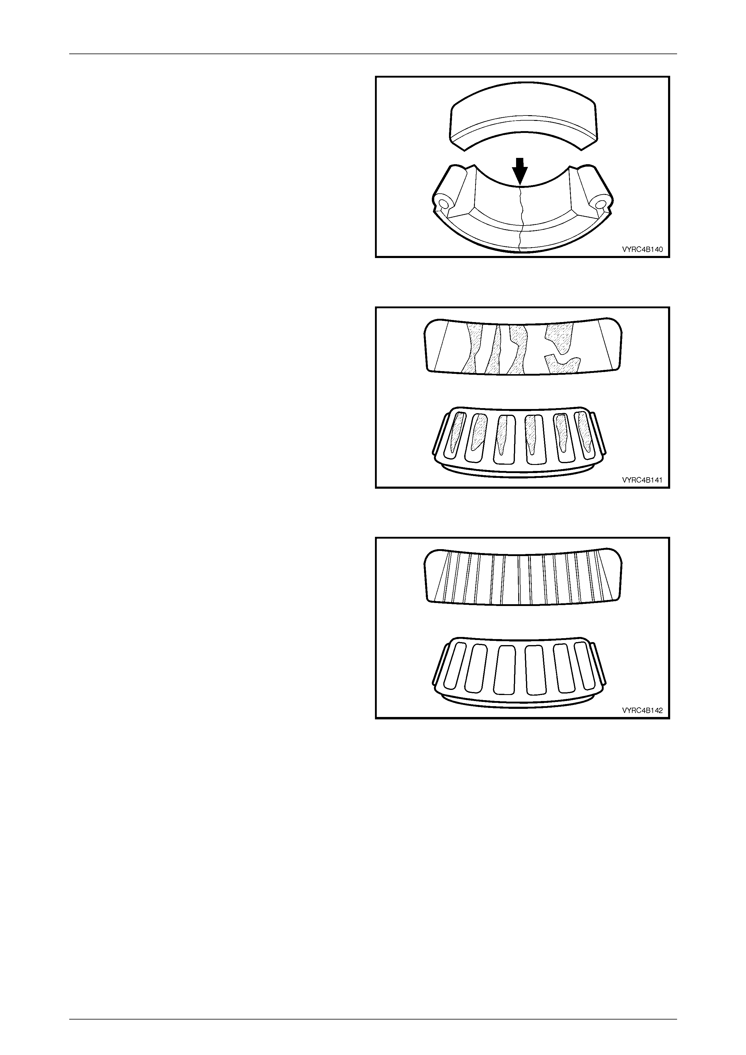
Rear Axle Page 4B –119
Page 4B–119
Cracked Inner Race
Description:
Race cracked due to improper fit, cocki ng or poor bearing
seats.
Correction:
1 Replace the bearings and correct the bearing seats.
2 Flush and replace the lubricant.
Refer to 2.3, Changing/Flushing Rear Axle Lubricant
and 2.2, Checking Rear Axle Lubricant Level or
5, Specifications for the recommended lubricant in
this Section. Figure 4B-215
Fatigue Spalling
Description:
Flaking of surface metal resulting from surface contact
fatigue.
Correction:
1 Replace the bearings and clean all related parts.
2 Flush and replace the lubricant.
Refer to 2.3, Changing/Flushing Rear Axle Lubricant
and 2.2, Checking Rear Axle Lubricant Level or
5, Specifications for the recommended lubricant in
this Section. Figure 4B-216
Brinelling
Description:
Surface indentations in the raceway caused by the rollers
either under impact, loading or vibration while the bearing is
not rotating.
Correction:
1 Replace the bearing if rough or noisy.
2 Flush and replace the lubricant.
Refer to 2.3, Changing/Flushing Rear Axle Lubricant
and 2.2, Checking Rear Axle Lubricant Level or
5, Specifications for the recommended lubricant in
this Section.
Figure 4B-217
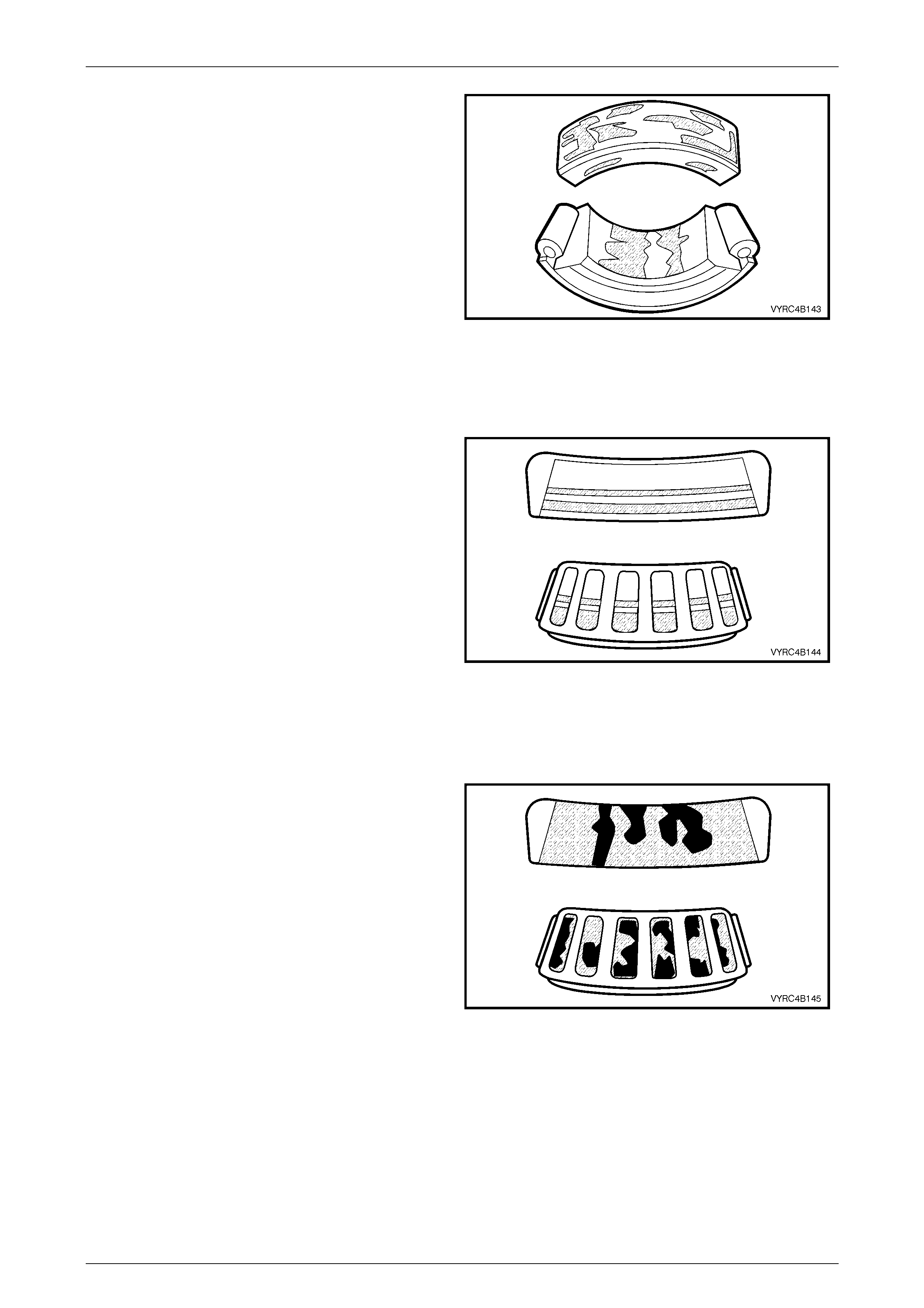
Rear Axle Page 4B –120
Page 4B–120
Frettage
Description:
Corrosion set up by relative movement of parts with no
lubrication.
Correction:
1 Replace the bearing.
2 Clean the related parts.
3 Check the seals and check for proper lubrication.
4 Flush and replace the lubricant.
Refer to 2.3, Changing/Flushing Rear Axle Lubricant
and 2.2, Checking Rear Axle Lubricant Level or
5, Specifications for the recommended lubricant in
this Section.
Figure 4B-218
Stain Discolouration
Description:
Discolouration can range from light brown to black, caused
by incorrect lubrication, moisture or high lubricant
temperature.
Correction:
1 Re-use the bearing if stains can be removed by light
polishing or if no evidence of overheating is observed.
2 Check the seals and related parts for damage.
3 Flush and replace the lubricant.
Refer to 2.3, Changing/Flushing Rear Axle Lubricant
and 2.2, Checking Rear Axle Lubricant Level or
5, Specifications for the recommended lubricant in
this Section.
Figure 4B-219
Heat Discolouration
Description:
Heat discolouration can range from faint yellow to dark
blue, resulting from overload or improper lubricant.
Excessive heat can cause softening of races or rollers.
To check for loss of temper on the races or the rollers, a
simple file test may be made. A file drawn over a tempered
part will grab and cut the metal, whereas a file drawn over a
hard part will glide readily with no metal cutting action.
Correction:
1 Replace the bearings if overheating damage is
indicated.
2 Check the seals and other parts.
3 Flush and replace the lubricant.
Refer to 2.3, Changing/Flushing Rear Axle Lubricant
and 2.2, Checking Rear Axle Lubricant Level or
5, Specifications for the recommended lubricant in
this Section.
Figure 4B-220
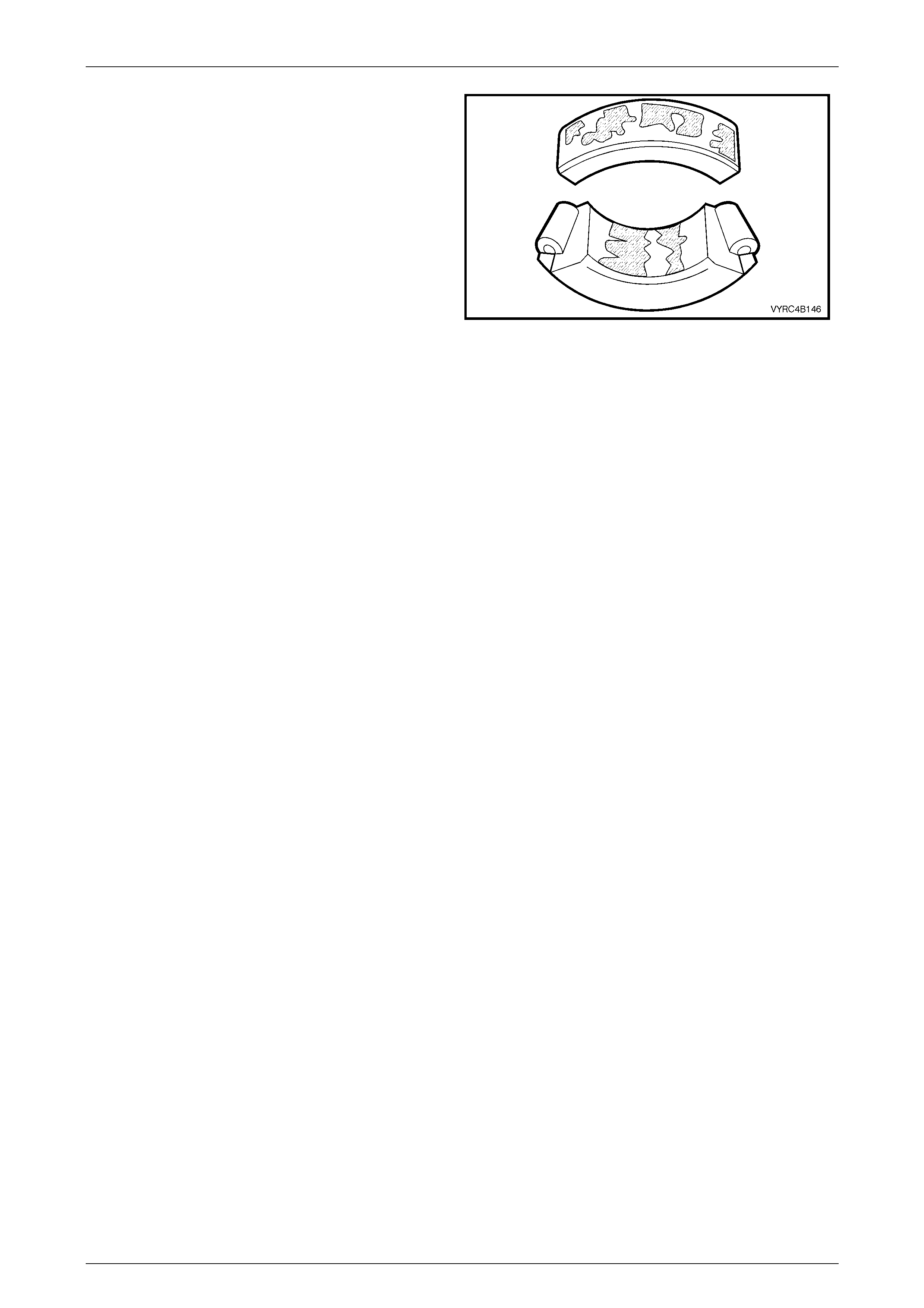
Rear Axle Page 4B –121
Page 4B–121
Smears
Description:
Smearing of metal due to slippage that can be caus ed by
poor fits, lubrication, overheating, overloads or handling
damage.
Correction:
1 Replace the bearings.
2 Clean the related parts and check for proper fit and
lubrication.
3 Flush and replace the lubricant.
Refer to 2.3, Changing/Flushing Rear Axle Lubricant
and 2.2, Checking Rear Axle Lubricant Level or
5, Specifications for the recommended lubricant in
this Section.
Figure 4B-221

Rear Axle Page 4B –122
Page 4B–122
5. Specifications
General
Rear Axle Assembly....................................... GEN III V8 – Dana/Spicer – SAA – M86 Series
....................................................................................V6 – Dana/Spicer – SAA – M78 Series
Axle Type........................................................................................................... Semi Floating
Housing Type............................................................................. Unitized Carrier Construction
Standard and LSD Axles
Gear Type.....................................................................................................................Hypoid
Gear Ratio (See I.D. label attached to the axle tube housing)..............V6 Automatic – 3.08 :1
...................................................................................................Gen III V8 Automatic – 3.07:1
.......................................................................................................Gen III V8 Manual – 3.46:1
No. of Teeth – Ring Gear....................................................................................... 3.08:1 – 40
............................................................................................................................... 3.07:1 – 43
............................................................................................................................... 3.46:1 – 45
No. of Teeth Drive Pinion Gear.............................................................................. 3.08:1 – 13
............................................................................................................................... 3.07:1 – 14
............................................................................................................................... 3.46:1 – 13
Lubricants
Total Rear Axle Lubricant Capacity............................................................................1.7 Litres
NOTE:
For rear axles with LSD the lubricant fill
comprises of 1.6 Litres of rear axle lubricant and
100 ml of LSD additive.
Rear Axle Lubricant Type................................................................Synthetic Hypoid Gear Oil
...................................................................................................Holden Specification HN2040
.................................................................................................................Or Mobilube SHC ID
LSD Additive........................................................................................................Stiraco 7098
Pre-lubricant as Specified in Text....................................................................Molybond HE50
.....................................................................................................Lithium Soap Ba sed Grease
Differential Gears
Type...................................................................................................................Straight Bevel
No. of Teeth Pinion Gears............................................................. M78 Series – 4 Pinion – 10
........................................................................................................ M86 Series – 2 Pinion – 9
No. of Teeth Side Gears ............................................................... M78 Series – 4 Pinion – 16
...................................................................................................... M86 Series – 2 Pinion – 13

Rear Axle Page 4B –123
Page 4B–123
Final Drive Pinion Gear Bearings
Bearing Type...................................................................................Adjustable Tapered Roller
Bearing Adjustment.....................................................................................Collapsible Spacer
Pinion Bearing Preload: Timken Koyo
N N
Dummy pinion - New bearings – M78 Series......................1.4 – 2.0 1.5 – 1.9
Dummy pinion - Used bearings – M78 Series.....................0.7 – 1.2 0.7 – 1.2
New with oil seal – M78 Series...........................................1.4 – 2.4 1.5 – 2.1
New without oil seal – M78 Series......................................1.4 – 2.0 1.4 – 1.9
Used with oil seal – M78 Series..........................................0.7 – 1.2 0.7 – 1.2
Used without oil seal – M78 Series.....................................0.7 – 1.2 0.7 – 1.2
Dummy pinion - New bearings – M86 Series......................N/A 1.5 – 1.9
Dummy pinion - Used bearings – M86 Series.....................N/A 0.7 – 1.2
New with oil seal – M86 Series...........................................N/A 1.9 – 2.3
New without oil seal – M86 Series ......................................N/A 1.8 – 2.1
Used with oil seal – M86 Series..........................................N/A 0.8 – 1.3
Used without oil seal – M86 Series.....................................N/A 0.8 – 1.3
Differential Carrier Side Bearings
Type................................................................................................Adjustable Ta pered Roller
Adjustment............................................................................Shim on each side of the carrier.
Side Bearing Preload: Timken Koyo
N N
New Bearings – M78 Series 15 – 35 .......................... 8.0 – 24
Used Bearings – M78 Series 8.0 – 18.......................... 5.0 – 13
New Bearings – M86 Series 13 – 30........................... 7.0 – 20
Used Bearings – M86 Series 8 – 16............................. 5.0 – 11
(Refer to text for measurement conditions).
Run-Out And End Float Specifications
Rear Axle End Float:
New Bearing......................................................... 0.02 – 0.30 mm (Total Indicated End Float)
Used Bearing..................................................0.75 mm (Maximum Total Indicated End Float)
Rear Axle Shaft Run-out ...................................0.12 mm (Maximum Total Indicated Run-Out)
Case Assembly (without ring gear attached)............................................0.05 mm (maximum)
Ring Gear Rear Face (assembled to case flange)...................................0.13 mm (maximum)
Backlash Specifications
Ring Gear to Drive Pinion ..............................................0.10 – 0.18 mm (at the tightest point)
LSD Torque Check
Torque Check Specification.........................................................................35 Nm (minimum)

Rear Axle Page 4B –124
Page 4B–124
ABS Sensor
Air Gap (non-adjustable)..................................................................................... 0.4 – 2.4 mm
Sealants and Thread Locking Compound
Rear Cover to Carrier Housing ......................................Loctite 587 ('Ultra Blue') or equivalent
Rear Axle Fasteners, Pinion Nut and Breather..............Loctite 262 or commercial equivalent
...................................................................................................to GM Specification 9985283.
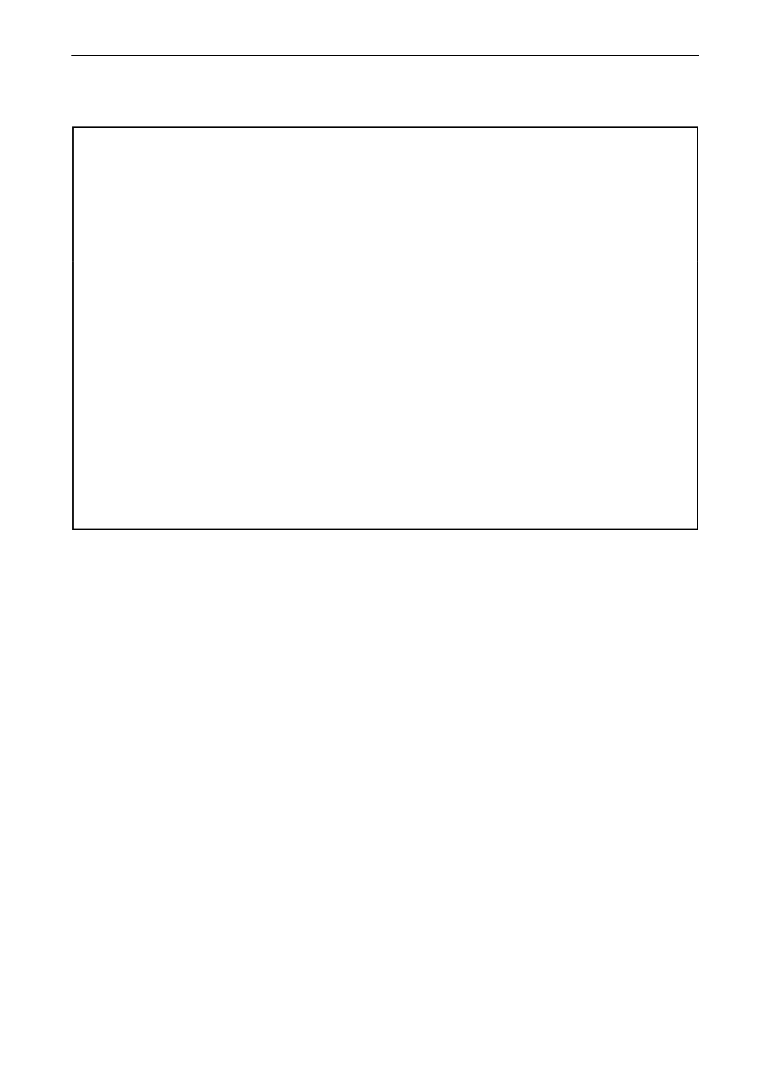
Rear Axle Page 4B –125
Page 4B–125
6. Torque Wrench Specifications
ATTENTION
All rear axle fasteners are important attaching parts as they affect the performance of vital components
and/or could result in major repair expense. Where specified in this Section, fasteners MUST be replaced with
parts of the same part number or a GM approved equivalent. Do not use fasteners of an inferior quality or
substitute design.
Torque values must be used as specified during reassembly to ensure proper retention of all steering
components.
Through out this Section, fastener torque wrench specifications may be accompanied with the following
Identification marks:
+
++
+ Fasteners must be replaced after loosening.
!
!!
! Vehicle must be at kerb height before final tightening.
6
66
6 Fasteners either have micro encapsulated sealant applied or incorporate a mechanical thread lock and
should only be re-used once. If in doubt, replacement is recommended.
If one of these identification marks is present alongside a fastener torque wrench specification, the
recommendation regarding that fastener must be adhered to.
Nm
Road Wheel Attaching Nut.................................................................110 – 140
Rear Axle Drain Plug .............................................................................23 – 31
Rear Axle Filler Plug..............................................................................23 – 31
6 Rear Brake Caliper to Rear Axle Anchor Plate Attaching Bolts.........70 – 100
6 Rear Axle Shaft Retainer Thrust Plate Attaching Bolts........................40 – 50
6 Rear ABS Wheel Speed Sensor Attaching Bolt ....................................6 – 14
+ Rear Leaf Spring and Retainer Plate ‘U’ Bolt Attaching Nuts......................85
6 Rear Leaf Spring Shackle Mounting Plate to Chassis Attaching Bolts........85
6 Rear Leaf Spring Eye Front Mounting Plate to Chassis Attaching Bolts .....85
+ ! Rear Shock Absorber Lower Mounting Attaching Bolt............................110
6 Rear Stabilizer Bar Mounting to Rear Axle Housing Attaching Bolt.....18 – 26
6 Rear Cover to Carrier Housing Attaching Bolts...................................23 – 31
6 Rear Brake Load Sensing Valve Linkage to Rear Axle Housing
Attaching Bolt.........................................................................................23 – 31
+ Ring Gear to Differential Case Attaching Bolts
(STD, Non LSD M78 Series)..............................................................130 – 145
+ Ring Gear to Differential Case Attaching Bolts
(LSD M78 Series)..............................................................................125 – 150
+ Ring Gear to Differential Case Attaching Bolts
(LSD M86 Series)..............................................................................125 – 150

Rear Axle Page 4B –126
Page 4B–126
Side Bearing Cap to Differential Carrier Housing Attaching Bolts
(M78 Series)..........................................................................................48 – 60
Side Bearing Cap to Differential Carrier Housing Attaching Bolts
(M86 Series)..........................................................................................48 – 60
+ Differential Case Cap to Cover Attaching Bolts
(LSD M78 Series)..................................................................................35 – 45
6 Propeller Shaft Constant Velocity Joint To Pinion Flange
Attaching Bolts.......................................................................................66 – 71
Breather To Differential Carrier Housing................................................11 – 16
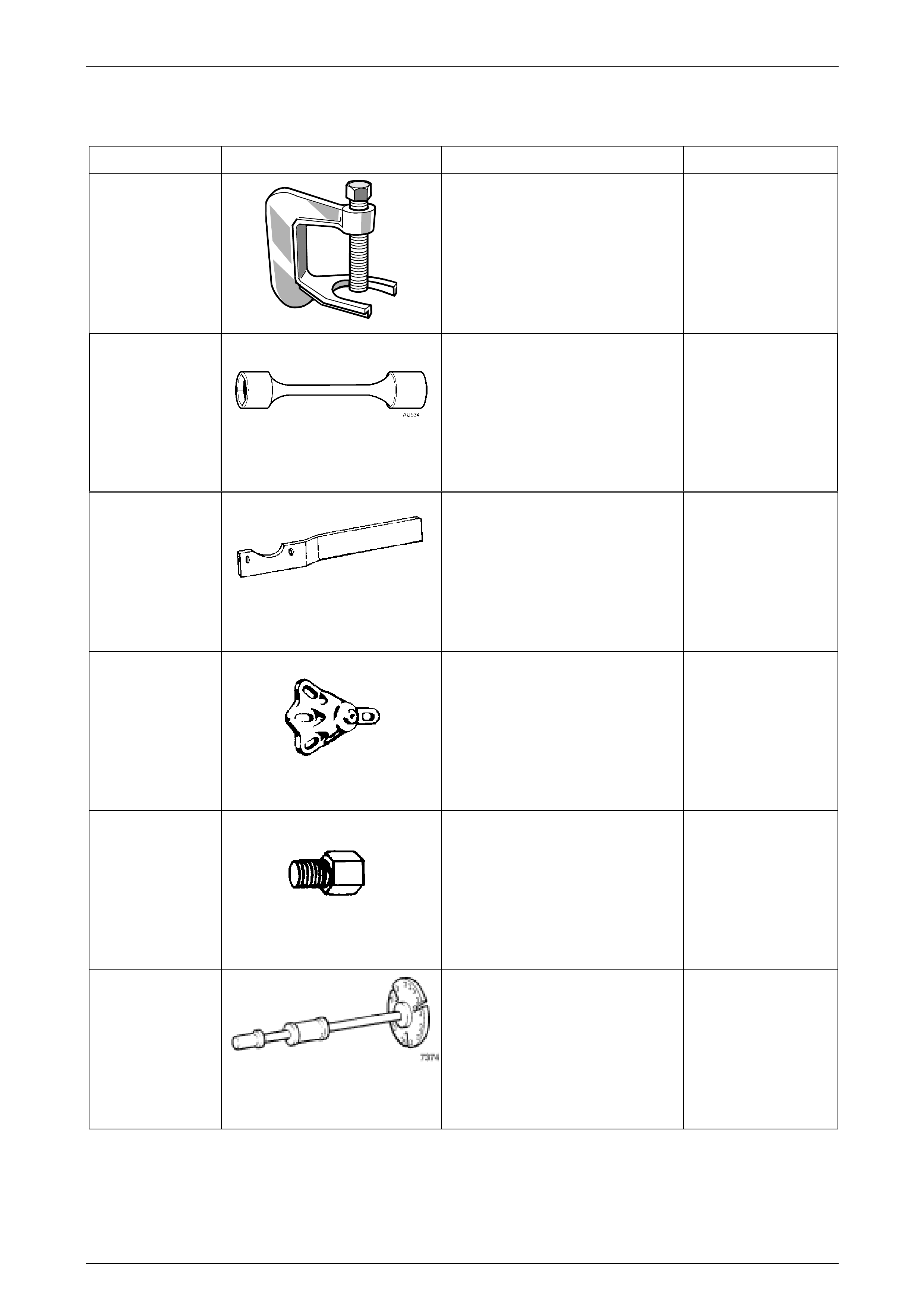
Rear Axle Page 4B –127
Page 4B–127
7. Special Tools
TOOL NUMBER ILLUSTRATION DESCRIPTION CLASSIFICATION
J24292-C
PRESS TOOL
Used to remove rear wheel studs
from the rear axle flange.
Previously released.
Unique
AU534
TOR QUE LIMITING SOCKET
Used in conjunction with an impact
gun to tighten wheel nuts.
Essential
KM468-B
HOLDING BAR
Used to stop the rear trunnion from
rotating.
Previously released.
Available
7208
REAR AXLE REMOVAL ADAPTOR
Used with E6662B for LSD torque
check.
Previously released.
Unique
E6662B
TORQUE WRENCH ADAPTOR
Used in conjunction with 7208 to
check breakaway torque of LSD
differential.
Previously released.
Unique
7374 SLIDE HAMMER & PLATE
Used to remove inner axle shafts
from the rear axle assembly.
Previously released.
Available

Rear Axle Page 4B –128
Page 4B–128
TOOL NUMBER ILLUSTRATION DESCRIPTION CLASSIFICATION
E9298
REAR AXLE BEARING REMOVER
AND INSTALLER
Used to remove and install the inner
bearing race from the rear axle
assembly.
Available
AU606
LEAF SPRING EYE BUSH
REMOVER AND INSTALLER
Used to remove and install the front
eye bush of the rear leaf spring
assembly.
Includes:
1 AU606-1 Centre Spiggot
2 AU606-2 Bush Remover
3 AU606-3 Bush Catcher
4 AU606-4 Bush Installer
Unique
AU607
ABS PULSE RING REMOVER AND
INSTALLER
Used to remove and install the ABS
pulse ring from the rear axle shaft.
Includes:
1 AU607-1 ABS Pulse Ring
Remover
2 AU607-2 ABS Pulse Ring
Installer
Unique
7136
REAR AXLE SHAFT BEARING
CUP REMOVER
Used to remove rear axle bearing
cup from the rear axle housing.
Used with 7374
Available
J8614-1
PINION FLANGE HOLDER AND
REMOVER
Used to hold and remove the pinion
flange from the rear axle assembly.
Includes:
1 J8614-11 Flange Holder
2 J8614-2 Adaptor
3 J8614-3 Forcing Screw
Previously released.
Unique
Rear Axle Page 4B –129
Page 4B–129
TOOL NUMBER ILLUSTRATION DESCRIPTION CLASSIFICATION
E308
SEAL REMOVER
Used as a universal seal remover.
Also released as 56750.
Previously released.
Available
E9055
M78 SERIES PINION OIL SEAL
INSTALLER
Used to install the pinion oil seal.
Also released as 17-010A.
Previously released.
Unique
205-553
M86 SERIES PINION OIL SEAL
INSTALLER
Used to install the pinion oil seal.
Unique
E9255
DIFFERENTIAL CARRIER
SPREADER AND ADAPTOR
PLATES
Used to remove and install the
differential assembly into the
differential carri er.
Previously released.
Unique
E9293
PINION BEARING CUP REMOVER
Previously released.
Unique
205-551
ADAPTOR – M86 SERIES PINION
BEARING CUP REMOVER
Used with remover E9293 to
remove pinion-bearing cups from
the differential case.
Unique
E9271
PINION BEARING CUP
INSTALLER
Used to install pinion-bearing cups
to the differential case.
Previously released.
Unique
Rear Axle Page 4B –130
Page 4B–130
TOOL NUMBER ILLUSTRATION DESCRIPTION CLASSIFICATION
205-552
ADAPTORS – M86 SERIES
PINION BEARING CUP
INSTALLER
Used with E9271 to install pinion-
bearing cups to the differential case.
Unique
E1673MT
BASIC PULLER
Used to remove and install the
differential side bearings and
remove the rear drive pinion
bearing.
Previously released.
Unique
E1673A15
ADAPTOR – M78 SERIES
Used with puller E1673MT to
remove the M78 Series rear pinion
bearing.
Previously released.
Unique
205-547
ADAPTOR – M86 SERIES
Used with puller E1673MT to
remove the M86 Series rear pinion
bearing.
Previously released.
Unique
E1673N15
ADAPTOR
Used with puller E1673MT and
stepped plug E1673B16 to remov e
the side bearings from the
differenti al cas e.
Previously released.
Unique
E1673B16
STEPPED PLUG
Used with puller E1673MT and
adaptors E1673A15/E1673N15 to
remove bearings from the rear axle
assembly.
Previously released.
Unique
205-545
SIDE BEARING INSTALLER
Used to install bearings to the
differenti al cas e.
Previously released.
Unique
Rear Axle Page 4B –131
Page 4B–131
TOOL NUMBER ILLUSTRATION DESCRIPTION CLASSIFICATION
C4487 DIFFERENTIAL SIDE GEAR AND
CLUTCH PACK REMOVER AND
INSTALLER – M86 SERIES
Used to remove and install the
differential side gears and clutch
packs.
Unique
E9300A PINION HEIGHT SETTING GAUGE
– M78 SERIES
Previously released as E9300, this
set now has an additional spacer to
be used on the 3,46:1 ratio, rear
axle assembly.
Previously released.
Unique
205-548 PINION HEIGHT SETTING GAUGE
– M86 SERIES
Used with E9300A.
Unique
E3C10AER
PINION REAR BEARING
REPLACER – M78 SERIES
Used to install the rear pinion
bearing during rear axle overhaul.
Previously released.
Unique
205-546
PINION REAR BEARING
REPLACER – M86 SERIES
Used to install the rear pinion
bearing during rear axle overhaul.
Previously released.
Unique
Dealer
Fabrication
PINION FLANGE PULLEY
1 Made from a 13 mm thick
piece of wood formed to 150
mm in diameter
2 Drill a 2 mm diameter hole to
accommodate a piece of
string
3 Drill two, 10 mm diameter
holes, 94 mm apart, centre to
centre
4 Drill a 50 mm diameter hole in
the centre of the pulley to
accommodate a socket
Unique

Rear Axle Page 4B –132
Page 4B–132
TOOL NUMBER ILLUSTRATION DESCRIPTION CLASSIFICATION
Dealer
Fabrication
DIAL INDICATOR MOUNTING
PLATE
1 Made from a 6 mm thick piece
of plate steel cut to 140 mm X
110 mm
2 At one of the 110-mm ends of
the steel plate, measure then
scribe 15 mm X 15 mm.
Repeat this for the
corresponding corner of the
steel plate as show n.
3 Witness-mark the centre of
the intersecting lin es as
shown.
4 Drill two, 12-mm diameter
holes, 75.5 mm apart, centre
to centre as shown.
Unique