
Propeller Shaft And Universal Joints Page 4C –1
Page 4C–1
Section 4C
Propeller Shaft and Universal Joints
ATTENTION
Before performing any Service Operation or other procedure described in this Section, refer to Section 00
CAUTIONS AND NOTES for correct workshop practices with regard to safety and/or property damage.
1 General Information............................................................................................................................... 2
2 Service Operations................................................................................................................................3
2.1 Propeller Shaft........................................................................................................................................................3
Remove ...................................................................................................................................................................4
Reinstall ..................................................................................................................................................................5
2.2 Rubber Coupling....................................................................................................................................................6
Remove ...................................................................................................................................................................6
Replace ...................................................................................................................................................................6
2.3 Centre Fixed Type Constant Velocity Joint, Rubber Boot and Dust Shield......................................................7
Remove ...................................................................................................................................................................7
Inspect.....................................................................................................................................................................9
Disassemble .........................................................................................................................................................10
Reassemble ..........................................................................................................................................................11
Reinstall ................................................................................................................................................................11
2.4 Centre Bearing Assembly....................................................................................................................................12
Remove .................................................................................................................................................................12
Replace .................................................................................................................................................................14
2.5 Rear Plunge Type Constant Velocity Joint ........................................................................................................16
Remove .................................................................................................................................................................16
Inspect...................................................................................................................................................................18
Disassemble .........................................................................................................................................................19
Reassemble ..........................................................................................................................................................20
Reinstall ................................................................................................................................................................20
3. Specifications....................................................................................................................................... 21
4. Torque Wrench Specifications........................................................................................................... 22
5. Special Tools........................................................................................................................................ 23

Propeller Shaft And Universal Joints Page 4C –2
Page 4C–2
1 General Information
The propeller shaft assembly as fitted to the MY 2003 VY Series, Cab Chassis Models is a two piece tubular design that
incorporat es the foll owing:
1 A rubber coupling at the front
2 A centre support bearing
3 A conventional fixed type constant velocity joint near the centre support bearing
4 A plunging type constant velocity joint at the rear.
For MY 2003 VY Series, Cab Chassis Models, a rubber coupling is fitted to the front of the propeller shaft and is bolted to
a slip yoke at the transmission.
The centre support bearing is a sealed ball bearing, mounted in a reinforced rubber cup that is supported in a cup guide
attached to a carrier, which in turn, is attached to the vehicle underbody brace by two bolts. The centre bearing is
lubricated for life and does not require any periodic lubrication.
Drive is transmitted between the two halves of the propeller shaft through a central conventional constant velocity joint
directly behind the centre bearing.
The central constant velocity jo int is of a fixed (non-plunging) type, located and secured to each of the two propeller shaft
halves by bolts and internal circlips. The cental conventional constant velocity joint is lubricated for life and does not
require any periodic lubrication
The plunge type, constant velocity joint at the rear of the propeller shaft is secured to the rear propeller shaft by an
internal circlip and bolted to the pinion drive flange on the front of the differential assembly. The plunging or sliding action
of this constant velocity joint allows for any variation in driveline length crea ted by the torque reaction or ride height
changes of the rear axle assembly during normal driving conditions. The plunge type, constant velocity joint is lubricated
for life and does not require any periodic lubrication.

Propeller Shaft And Universal Joints Page 4C –3
Page 4C–3
2 Service Operations
ATTENTION
All rear axle fasteners are important attaching parts as they affect the performance of vital components
and/or could result in major repair expense. Where specified in this Section, fasteners MUST be replaced with
parts of the same part number or a GM approved equivalent. Do not use fasteners of an inferior quality or
substitute design.
Torque values must be used as specified during reassembly to ensure proper retention of all steering
components.
Through out this Section, fastener torque wrench specifications may be accompanied with the following
Identification marks:
+
++
+ Fasteners must be replaced after loosening.
!
!!
! Vehicle must be at curb height before final tightening.
6
66
6 Fasteners either have micro encapsulated sealant applied or incorporate a mechanical thread lock and
should only be re-used once. If in doubt, replacement is recommended.
If one of these identification marks is present alongside a fastener torque wrench specification, the
recommendation regarding that fastener must be adhered to.
2.1 Propeller Shaft
LT Section No: F907100
ATTENTION
The following fasteners have either micro encapsulation or incorporate a mechanical thread lock and should
only be used once. If in doubt, replacement is recommended when performing this operation:
6 Rear constant velocity joint to rear axle pinion flange attaching bolt.
6 Centre support bearing carrier, which in turn to the vehicle underbody brace bolts
The following fasteners MUST be replaced when performing this operation:
+
++
+ Front rubber coupling to manual transmission mainshaft flange attaching nuts.
Propeller Shaft And Universal Joints Page 4C –4
Page 4C–4
Remove
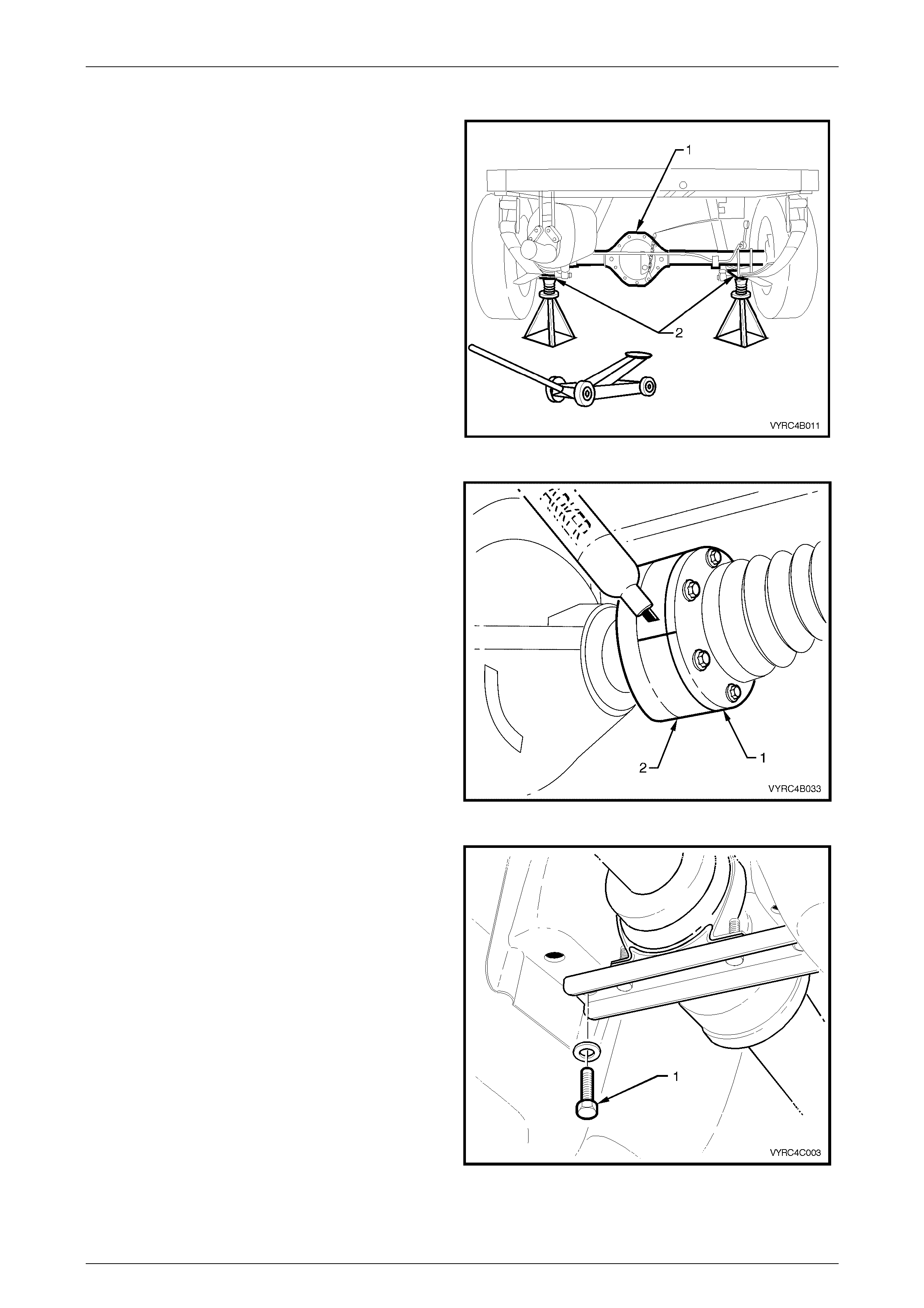
1 Using a floor jack under the centre of the rear axle
assembly (1), jack up the rear of the vehicle, then
place the safety stands under the rear leaf spring
retainer plates (2) on both sides to support the weight
of the vehicle as shown in Figure 4C-1.
Figure 4C-1
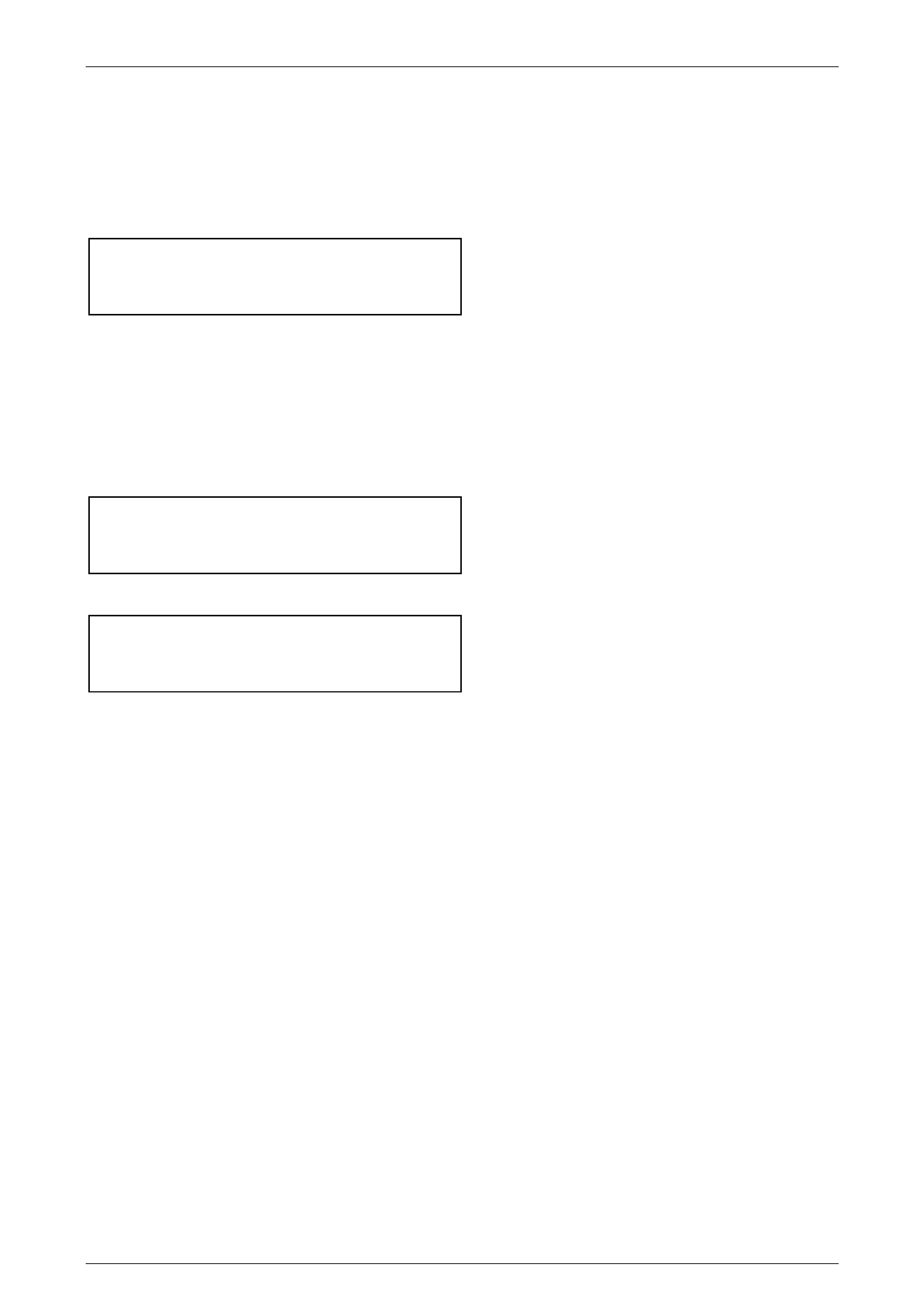
2 Use a suitable felt tipped marking pen to mark the
relationship of the rear constant velocity joint to the
rear axle pinion flange.
3 Apply the transmission in the ‘Park’ pos itio n
(automatic transmission) or in first gear (manual
transmission) and apply the park brake firmly.
4 Remove the propeller shaft rear constant velocity joint
(1) to rear axle pinion flange (2) attaching bolts.
Refer to Figure 4C-2.
NOTE:
When removing the rear constant velocity joint
from the rear axle pinion flange, take care not to
disturb the end cap of the constant velocity joint.
The end cap has a gasket to prevent
contamination by foreign material.
Figure 4C-2
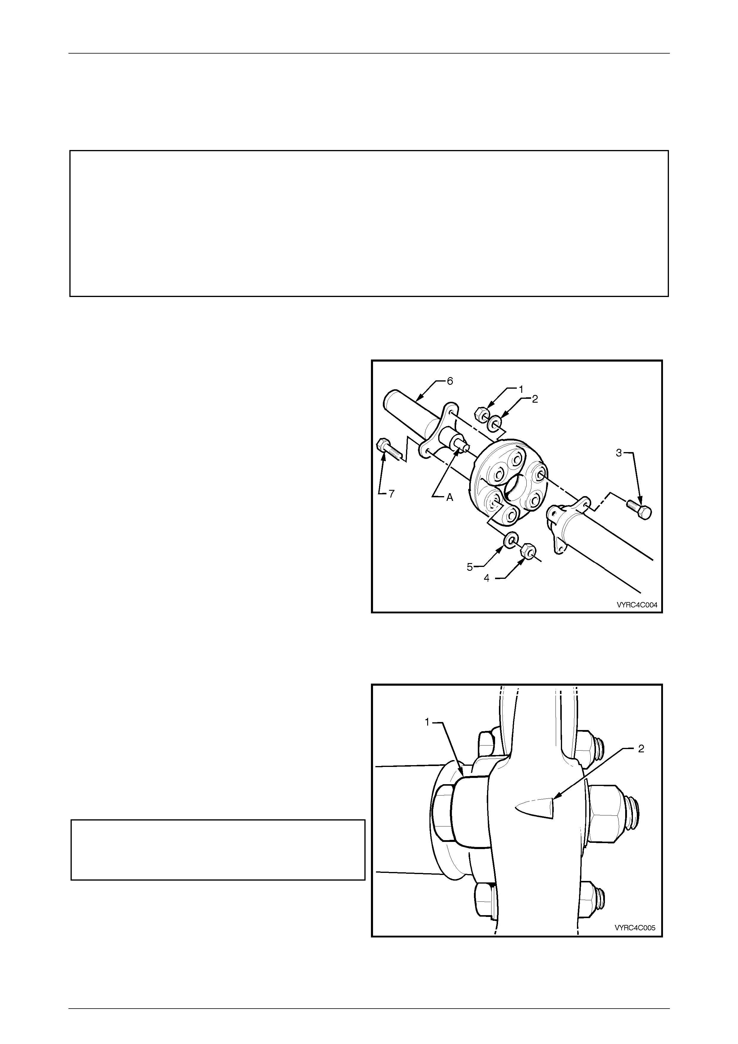
5 Remove the centre bearing carrier bracket attaching
bolts (1).
6 Place a suitable drain tray beneath the rear of the
transmission.
7 Remove the propeller shaft assembly from the
vehicle. Refer to Figure 4C-3.
8 Place a suitable plug into oil seal of the transmission
rear extension housing to prevent leakage and
contamination.
Figure 4C-3
Propeller Shaft And Universal Joints Page 4C –5
Page 4C–5
Reinstall
Reinstallation of the propeller shaft assembly is the reverse of the removal procedure noting the following points:
1 Use the relationship marks made on removal to align the propeller shaft rear constant velocity joint to the rear axle
pinion flange to the original position.
2 Install the centre bearing carrier bracket to vehicle underbody brace bolts and tighten to the correct torque
specification.
(6) Centre bearing carrier
bracket to vehicle underbody
brace attaching bolt
torque specific atio n .......................................20 – 35 N.m
3 Install the rear constant velocity joint to the rear axle pinion flange attaching bolts then using a cross pattern, draw
the constant velocity joint into the rear axle pinion flange until its all the way home. Tighten the bolts to the correct
torque specif ication.
NOTE:
Take care not to disturb the end cap of the
constant velocity joint. The end cap has a gasket
to prevent contamination by foreign material.
(6) Rear constant velocity joint
to the rear axle pinion flange
attaching bolt – v6
torque specification ..................................... 35 – 40 N.m
(6) Rear constant velocity joint
to the rear axle pinion flange
attaching bolt – Gen III V8
torque specification ...................................... 66 – 71 Nm
Propeller Shaft And Universal Joints Page 4C –6
Page 4C–6
2.2 Rubber Coupling
LT Section No: F908100
ATTENTION
The following fasteners have either micro encapsulation or incorporate a mechanical thread lock and should
only be used once. If in doubt, replacement is recommended when performing this operation:
The following fasteners MUST be replaced when performing this operation:
+ Front rubber coupling to transmission sliding yoke attaching nuts and bolts
Remove
1 Remove the propeller shaft. Refer to 2.1 Propeller
Shaft in this Section.
2 Using a back-up spanner on each of the three,
propeller shaft sliding yoke bolts (7), loos en then
remove the nuts (4) and washers (5). Discard the
removed bolts and nuts. Remove the sliding yoke
from the coupling.
3 Using a back-up spanner on each of the three,
propeller shaft to coupli ng bolts (3), loosen then
remove the nuts (1) and washers (2). Discard the
removed bolts and washers. Remove the coupling
from the front of the propeller shaft.
Refer to Figure 4C-4
Figure 4C-4
Replace
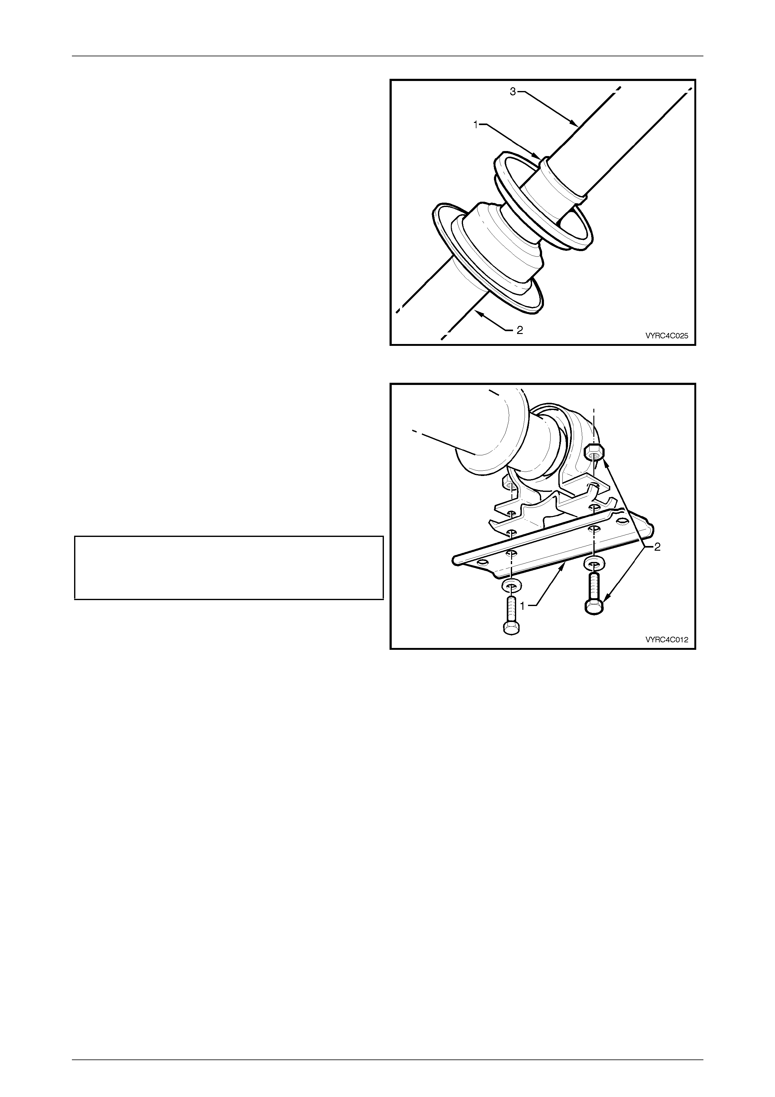
1 Install a replacement rubber c oupl ing onto the end of
the propeller shaft, aligning the holes in such a way
that the triangular shape (2) on the coupling ‘points’ to
the propeller shaft flange (1), as shown. Refer to
Figure 4C-5.
2 Install NEW bolts, washers and nuts to secure the
coupling to the propeller shaft flange and tighten to
the correct torque specification, using a back-up
spanner on the bolt head.
(+) Propeller shaft to
sliding yoke nut and bolt
torque specif ic atio n.............................................20 Nm, then
50° - 60° turn angle
3 Install the propeller shaft, as detailed in 2.1 Propeller
Shaft in this Section
Figure 4C-5
Propeller Shaft And Universal Joints Page 4C –7
Page 4C–7
2.3 Centre Fixed Type Constant Velocity
Joint, Rubber Boot and Dust Shield
LT Section No: F911100
ATTENTION
The following fasteners have either micro encapsulation or incorporate a mechanical thread lock and should
only be used once. If in doubt, replacement is recommended when performing this operation:
6 Constant velocity joint to rear propeller shaft attaching bolts.
Remove
1 Remove the propeller shaft. Refer to 2.1 Propeller
Shaft in this Section.
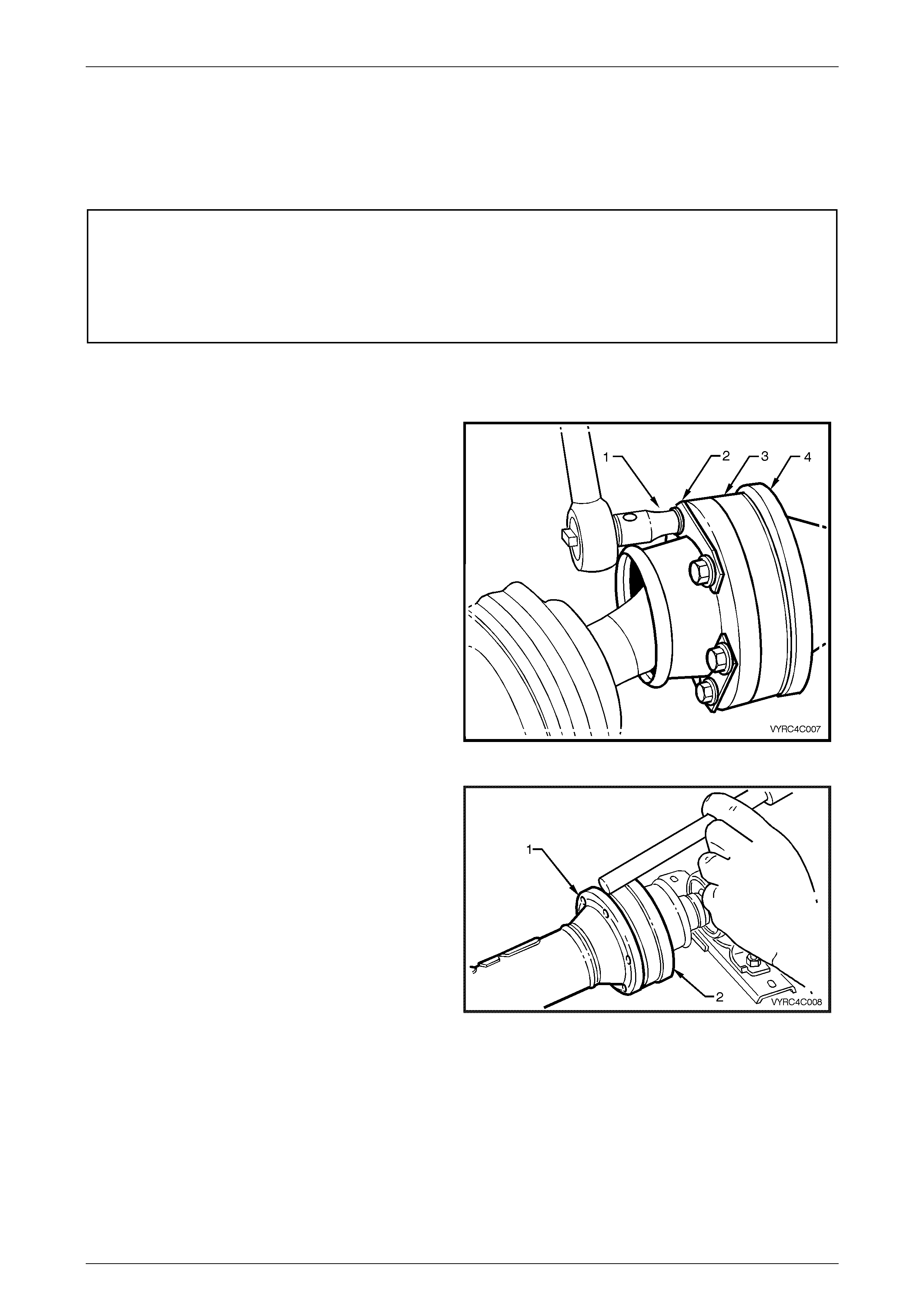
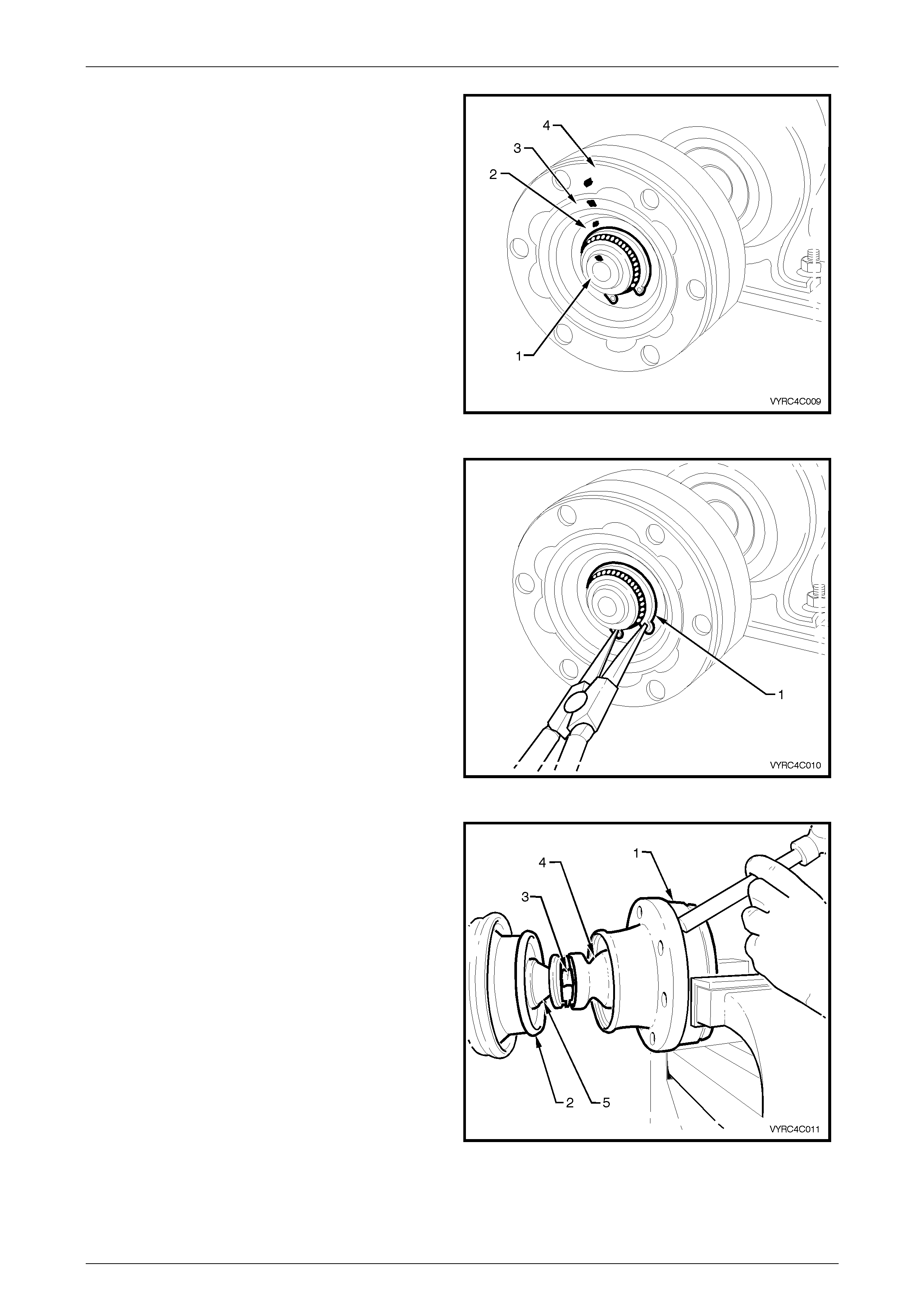
2 Loosen and remove the attaching bolts a suitable
socket (1), remove the locking plates (2) from the
constant velocity joint (3) and propeller shaft (4).
Refer to Figure 4C-6.
Figure 4C-6
3 Using a brass drift and hammer gently tap the
propeller shaft companion flange, evenly to separate
the constant velocity joint (2) from the propeller shaft
(1). Refer to Figure 4C-7.
4 Remove the gasket between the propeller shaft
companion flange and the constant velocity joint.
Figure 4C-7
Propeller Shaft And Universal Joints Page 4C –8
Page 4C–8
5 Make relationship ali gnm ent m arks by placin g a daub
of paint on the propeller shaft spindle (1), inner race
(2), ball guide (3) and outer race (4) as shown in
Figure 4C-8.
Figure 4C-8
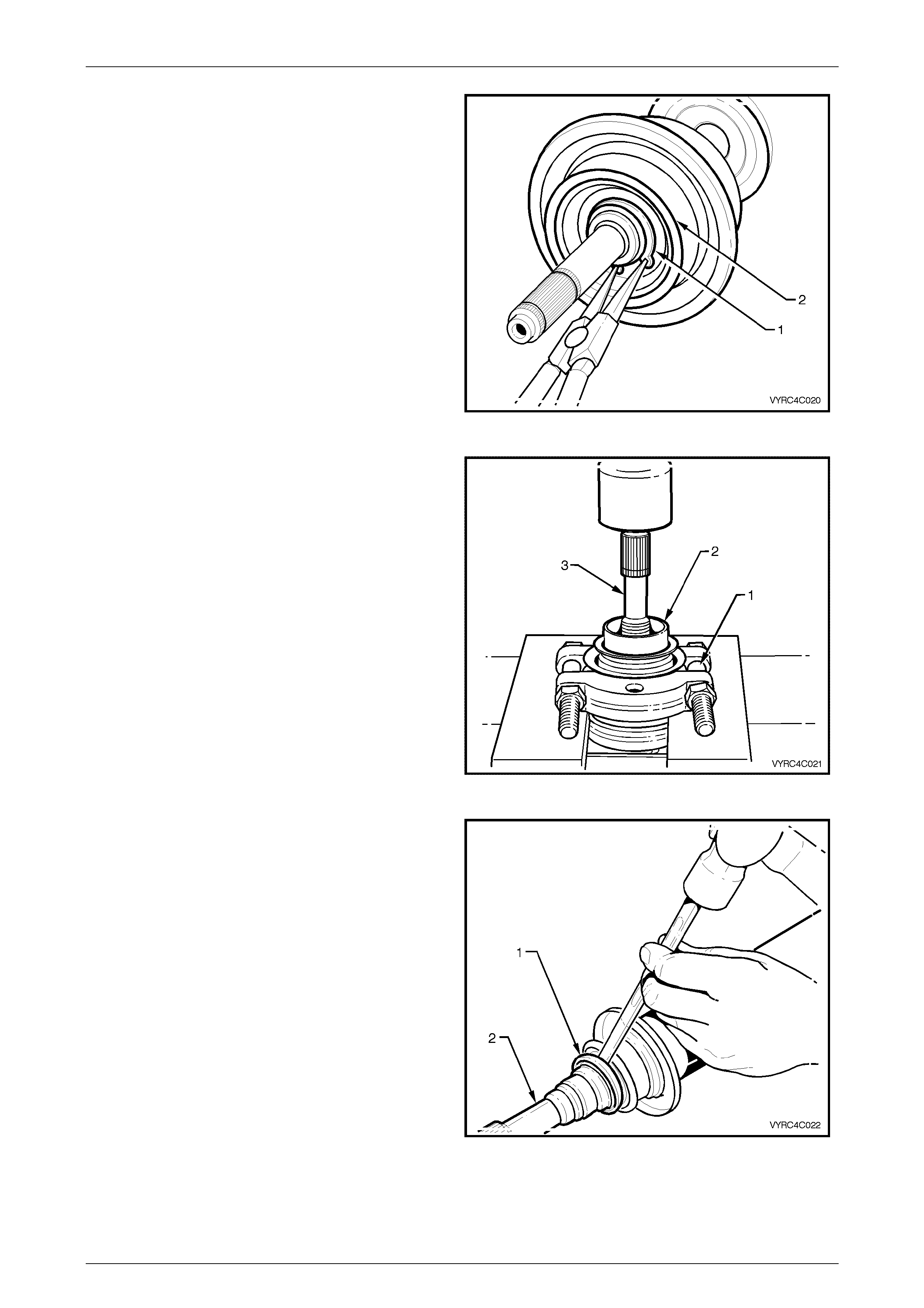
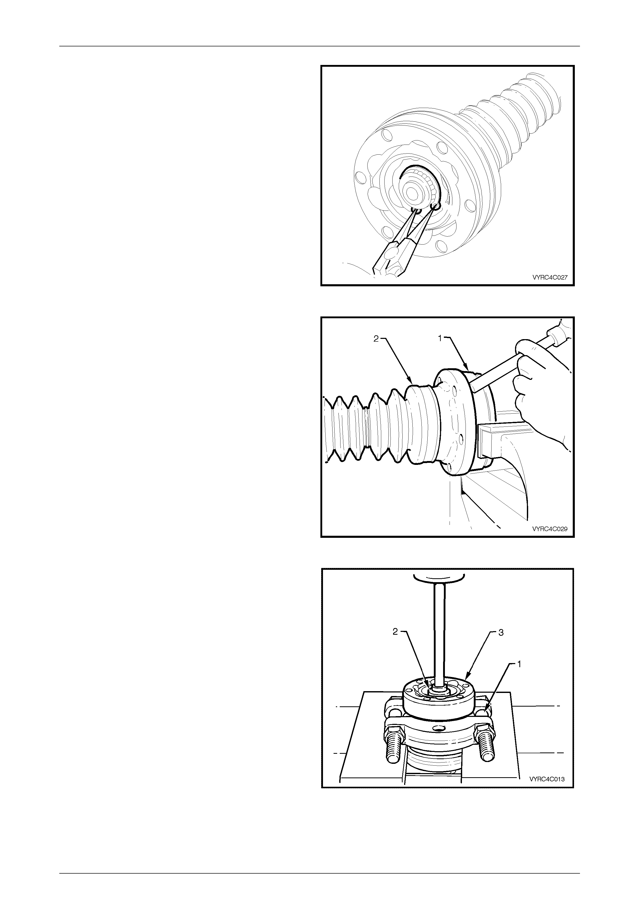
6 Using suitable circlip pliers, remove the constant
velocity joint, rear-retaining circlip (1) from the
propeller shaft spindle. Refer to Figure 4C-12
Figure 4C-9
7 Support the cons tant velocity joint body (1) in a vice
equipped with soft metal jaws. Using a brass drift and
hammer gently tap the dust cover and rubber boot
assembly (4) from the body of the constant velocity
joint.
8 Remove the retaining clip (3) attaching the rubber
boot (4) to the front propeller shaft spindle (5).
Refer to Figure 4C-10
9 Push the dust cover and rubber boot assembly back
toward the propeller shaft centre bearing.
Figure 4C-10

Propeller Shaft And Universal Joints Page 4C –9
Page 4C–9
10 Remove the centre bearing, support carrier strap (1)
along with the retaining nuts and bolts (2) from the
centre bearing. Refer to Figure 4C-11.
Figure 4C-11
11 Support the cons tant velocity joint body and out race
in a hydraulic press using pressing plates, Tool No
J22912-01 (1) and press the propeller shaft spindle
(2) from the constant velocity joint (3). Refer to Figure
4C-12.
12 Remove the dust shield and rubber boot assembly
(4). Refer to Figure 4C-10.
Figure 4C-12
Inspect
1 Inspect the grease in the joint for signs of
contamination by metal or dirt ingress. If
contamination is present then the constant velocity
joint will in all probability have suffered damage, and
sh ould be replaced
2 If on inspection contamination is not pres ent, clean
the joint by soaking it in a suitable cleaning solvent.
NOTE:
If there is severe pitting, galling, play between
the balls and the cage windows, cracking or
damage to the cage, pitting or galling or chips in
the raceways, replace the constant velocity
joint.
3 Inspect the internal components by tilting the inner
race to one side to expose each ball individually,
while observing the condition of each component.
Refer to Figure 4C-17. Figure 4C-13
Propeller Shaft And Universal Joints Page 4C –10
Page 4C–10
Disassemble
NOTE:
Disassembly of the constant velocity joint
beyond this point is not recommended. The
internal components are a precision fit and
during operation develop their own
characteristic wear patterns. Intermixing of
components could result in looseness, binding
and/or subsequent premature failure of the
constant velocity joint. If disassembly must be
attempted then each component of the joint
must be returned to its original orientation.
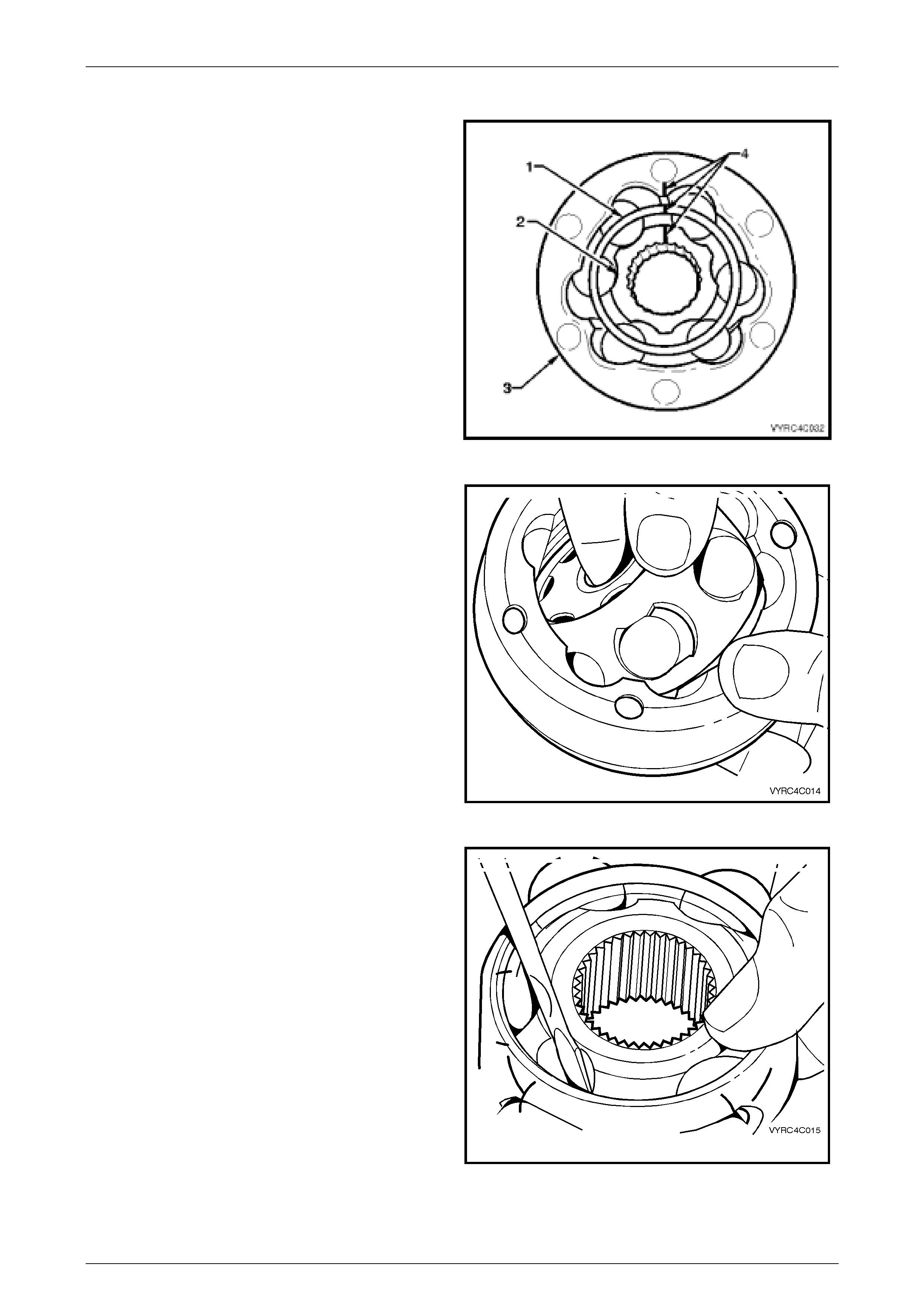
1 Ensure the aligning marks (4) made in step five of the
removal procedure are maintained at all times during
the following steps. Refer to Figure 4C-14.
2 Obtain a piece of wood or suitable tray with enough
divots in the surface to accommodate the balls of the
joint, marking one divot to indicate the ball closest to
the alignment marks to retain the original orientation
of each ball to joint. Figure 4C-14
3 Taking care not to dislodge any balls from the joint,
pivot the inner race and ball guide at 90º to the centre
line of the outer race and lift the inner race and ball
guide from the outer race. Refer to Fi gure 4C-15.
Figure 4C-15
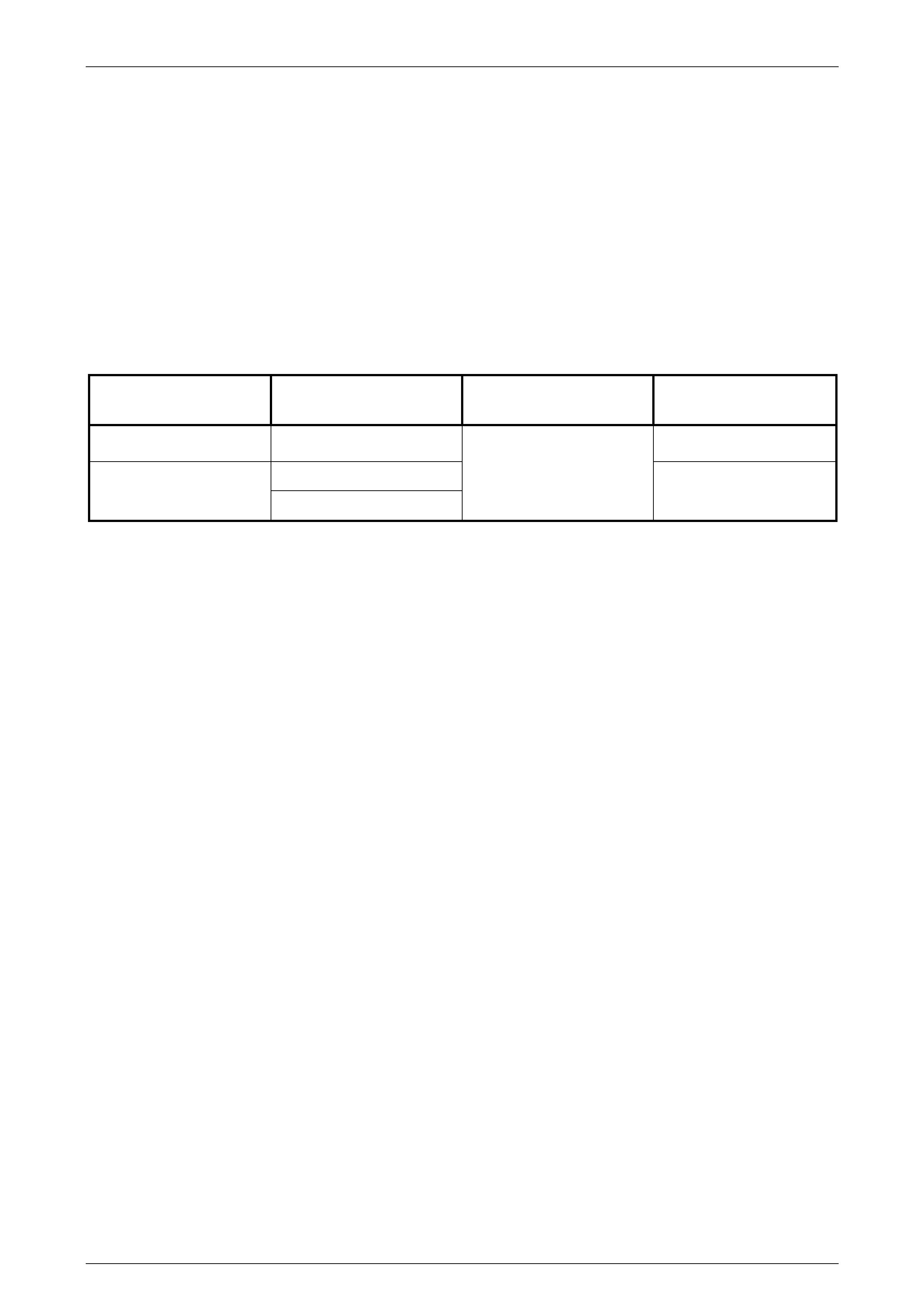
4 Using a screwdriver if required as a lever, remove
each ball in order from the ball guide and place the
balls on to the piece of wood or tray as detailed in
step two of the disassembly procedure. Refer to
Figure 4C-16.
5 Pivot the inner race 90º to the centre line of the ball
guide and lift the inner race from the ball guide.
Figure 4C-16
Propeller Shaft And Universal Joints Page 4C –11
Page 4C–11
Reassemble
The reassembly procedure for the constant velocity joint is the reverse of the disassembly procedure, noting the following
points:
1 Ensure all alignment marks are aligned to return all components to there original orientation.
2 Check the multi direction movement of the constant velocity joint for binding or restriction.
3 Pack the cons tant velocity joint with the recommended lubricating grease; refer to 3, Specifications in this Section.
4 Ensure the reassembled constant velocity joint is kept free from contamination until required for reinstallation to the
propeller shaft.
Reinstall
The installation procedure is the reverse of the removal procedure, noting the following points:
1 Ensure the cons tant velocity joint and associated parts are clean to ensure maximum life expectancy.
2 Inspect the dust shield and rubber boot assembly for cracks, tears or damage and replace if necessary then install
it to the front propeller shaft spindle.
3 Pack the cons tant velocity joint with the recommended lubricating grease, refer to 3, Specifications in this Section
or use the lubricating grease supplied in the repair kits available for the constant velocity joint, the dust shield and
rubber boot. Ensure the grease is worked in by hand onto all surfaces inside the joint.
4 Prior to pressing the constant velocity joint onto the front propeller shaft spindle, ensure all alignment marks are
aligned.
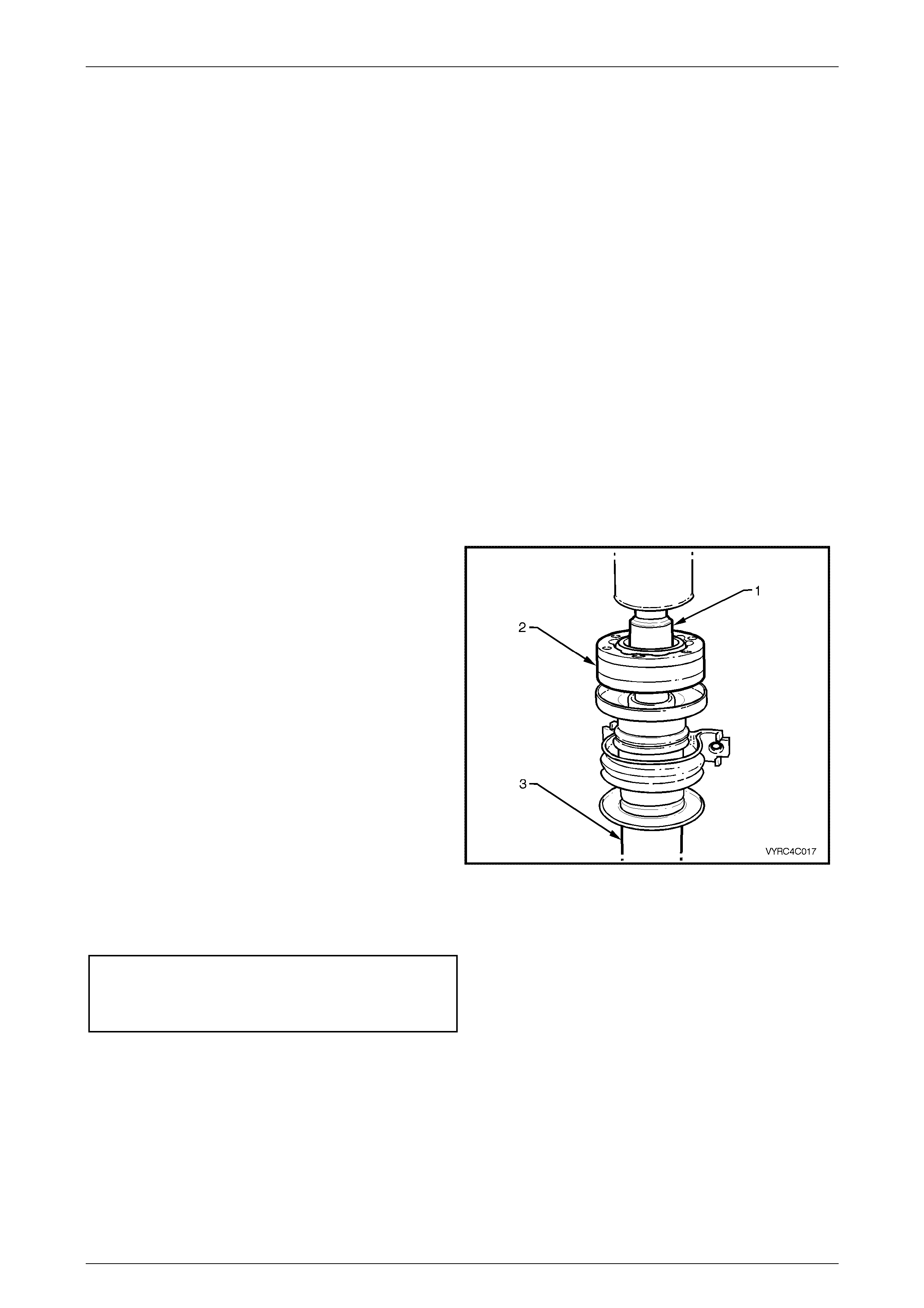
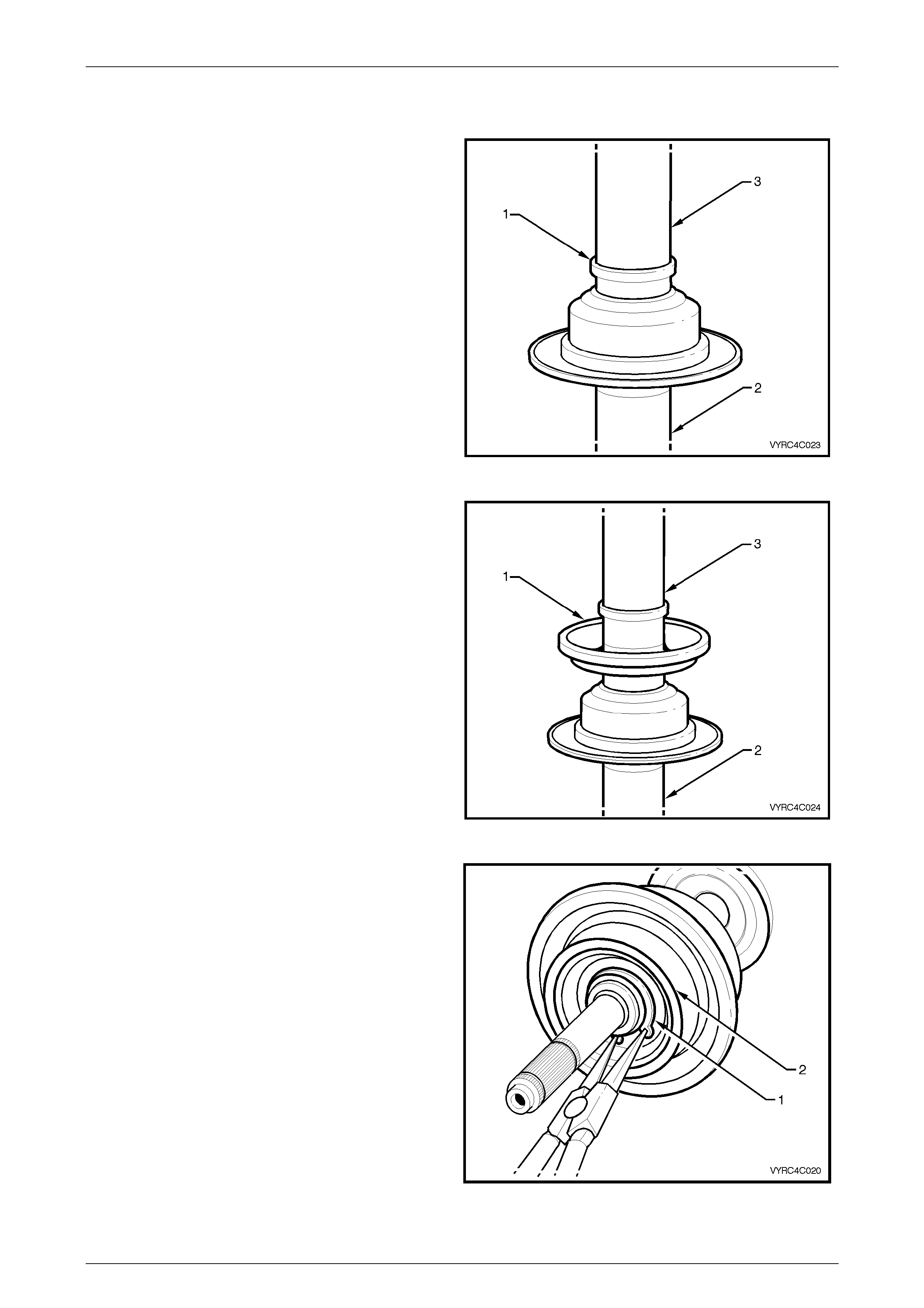
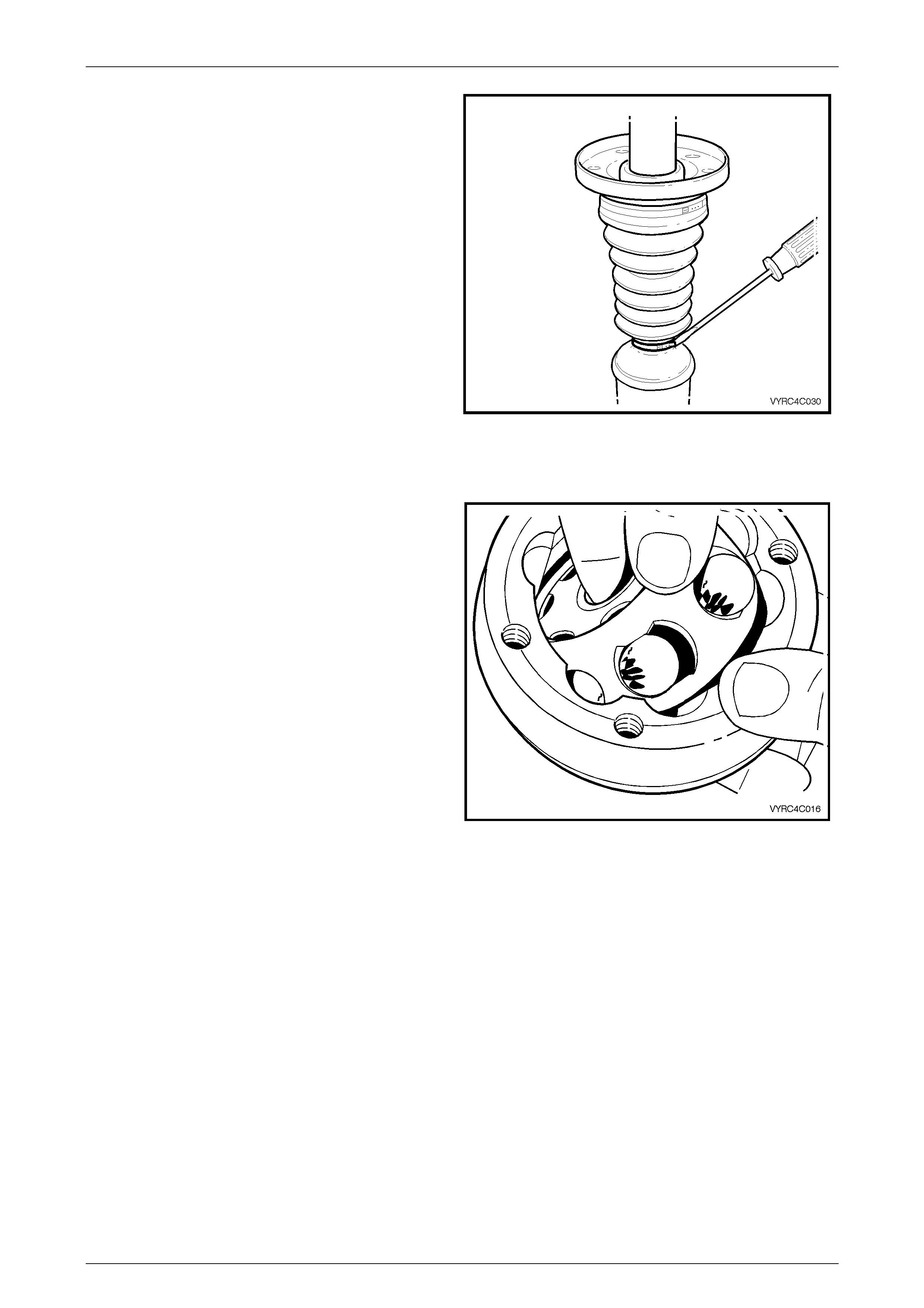
5 Using a suitable socket or tube (1), press the constant
velocity joint (2) onto the propeller shaft spindle (3)
while ensuring the socket or tube presses only on the
inner race of the joint only. Refer to Figure 4C-17.
6 Install the constant velocity joint retaining circlip to the
propeller shaft spin dle.
7 Ensure the mating surfaces of the constant velocity
joint, dust shield and rear propeller shaft companion
flange is clean.
8 Install a new gasket between the constant velocity
joint and the rear propeller shaft companion flange.
9 Apply a bead of the recommended sealant to the
mating surfac es of the dust shield and constant
velocity joint. For details on the sealant refer to
3 Specifications in this Section.
10 Install the rubber boot to propeller shaft spindle
retaining clip.
11 Install the constant velocity joint to rear propeller shaft
the attaching bolts and locking plates then tighten to
the correct torque specification.
(8) Constant velocity joint
to rear propelle r shaft
attaching bolts
torque specification ...................................... 32 – 36 Nm
12 Install the propeller shaft, as detailed in
2.1 Propeller Shaft in this Section.
Figure 4C-17
Propeller Shaft And Universal Joints Page 4C –12
Page 4C–12
2.4 Centre Bearing Assembly
LT Section No: F912100
Remove
NOTE:
The centre bearing cannot be removed from the
propeller shaft without causing damage to the
ball race and dust slinger. New parts must be
installed when the propeller shaft is being
reassembled.
1 Remove the propeller shaft. Refer to 2.1 Propeller
Shaft in this Section.
2 Remove the centre constant velocity joint, rubber boot
and dust shield. Refer to 2.3 Centre Constant Velocity
Joint Rubber Boot and Dust Shield in this Section.
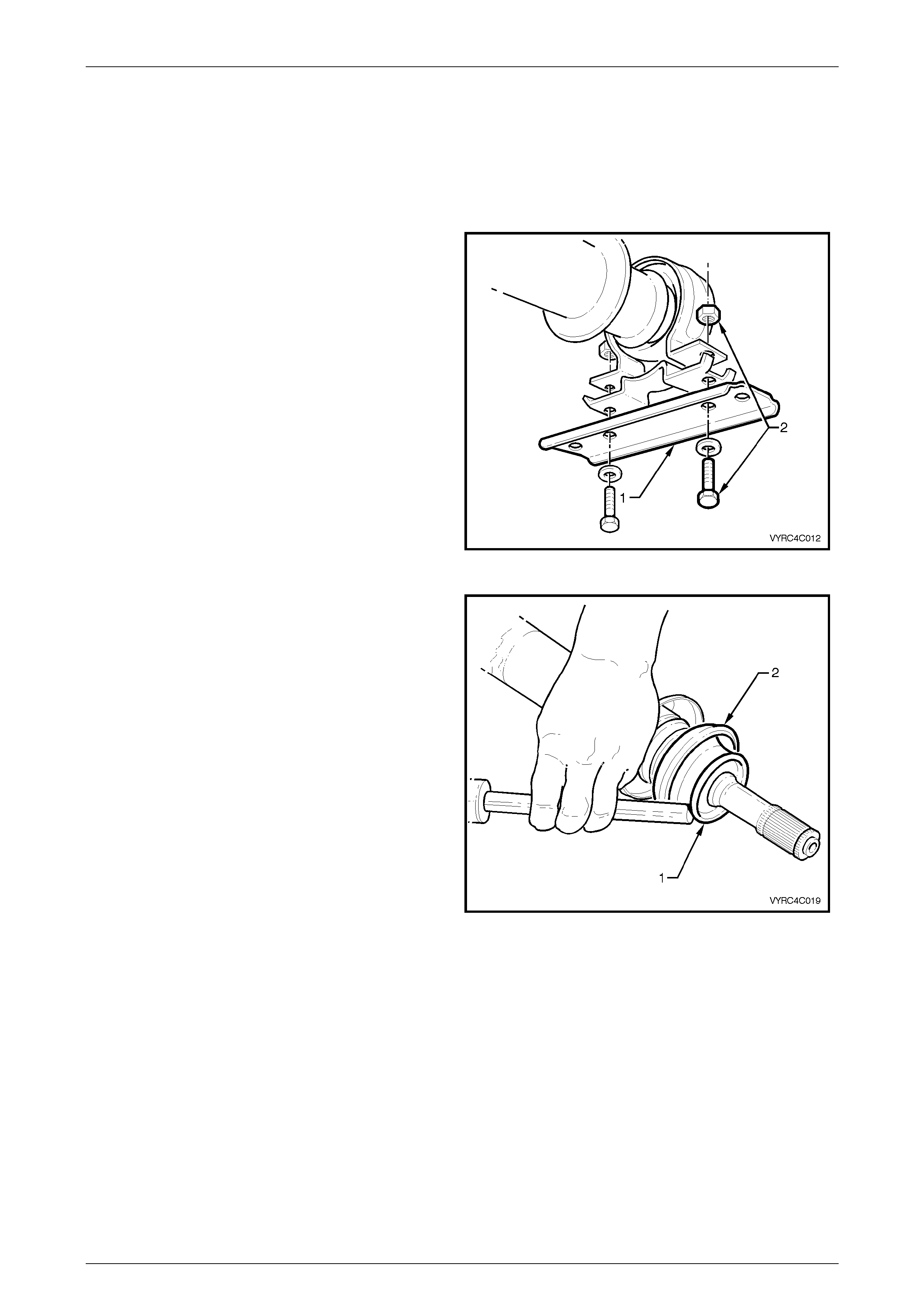
3 Remove the centre bearing upper carrier bracket (1)
to lower carrier bracket attaching bolts and nuts (2).
Refer to Figure 4C-18.
4 Separate and remove the two brackets from the
centre bearing. Figure 4C-18
NOTE:
The centre bearing rear slinger once removed,
must be discarded. A new part MUST be
installed when the propeller shaft is being
reassembled.
5 Using a hammer and suitable punch, remove the rear
slinger (1) by tapping the edge of the slinger evenly
away from the centre bearing (2).
Refer to Figure 4C-19.
Figure 4C-19
Propeller Shaft And Universal Joints Page 4C –13
Page 4C–13
6 Remove the retaining circlip (1) from the centre
bearing (2). Refer to Figure 4C-21.
Figure 4C-20
7 Using Tool No. J22912-01 (1) to support the centre
bearing (2) and in conjunctio n with suitable press
plates, press the centre bearing (2) from the propeller
shaft spindle (3). Refer to Figure 4C-21.
Figure 4C-21
NOTE:
The centre bearing front slinger once removed
must be discarded. A new part MUST be
installed when the propeller shaft is being
reassembled.
8 Using a hammer and suitable punch, remove the front
slinger (1) by tapping the edge of the slinger evenly
away from propeller shaft spindle (2).
Refer to Figure 4C-23.
Figure 4C-22
Propeller Shaft And Universal Joints Page 4C –14
Page 4C–14
Replace
1 Install a new front slinger (1) onto the propeller shaft
spindle (2) using a suitable tube (3). Refer to
Figure 4C-23.
Figure 4C-23
2 Install a new centre bearing (1) onto the propeller
shaft spindle (2) using a suitable tube (3). Refer to
Figure 4C-24
Figure 4C-24
3 Install a new retaining circlip (1) to the centre bearing
(2). Refer to Figure 4C-25.
Figure 4C-25
Propeller Shaft And Universal Joints Page 4C –15
Page 4C–15
NOTE:
Ensure the rear slinger is not installed too far
onto the propeller shaft spindle, as the slinger
and centre-bearing cup will rub.
4 Install a new rear slinger (1) onto the propeller shaft
spindle (2) using a suitable tube (3). Refer to
Figure 4C-26.
Figure 4C-26
9 Install the centre constant velocity joint, rubber boot
and dust shield. Refer to 2.3 Centre Constant Velocity
Joint, Rubber Boot And Dust Shield in this Section.
10 Install the centre bearing upper carrier bracket to
lower carrier bracket and support bracket (1)
attaching bolts and nuts (2). Refer to Figure 4C-27.
11 Tighten the centre bearing upper carrier bracket to
lower carrier bracket attaching bolts and nuts (2) to
the correct torque.
Centre bearing upper carrier
bracket to lower carrier
bracket attaching bolt.
Torque specification.....................................20 – 30 Nm
12 Install the propeller shaft. Refer to 2.1 Propeller Shaft
in this Section.
Figure 4C-27
Propeller Shaft And Universal Joints Page 4C –16
Page 4C–16
2.5 Rear Plunge Type Constant Velocity
Joint
LT Section No: F911100
ATTENTION
The following fasteners have either micro encapsulation or incorporate a mechanical thread lock and should
only be used once. If in doubt, replacement is recommended when performing this operation:
6 Constant velocity joint to rear propeller shaft attaching bolts.
Remove
1 Remove the propeller shaft. Refer to 2.1 Propeller
Shaft in this Section.
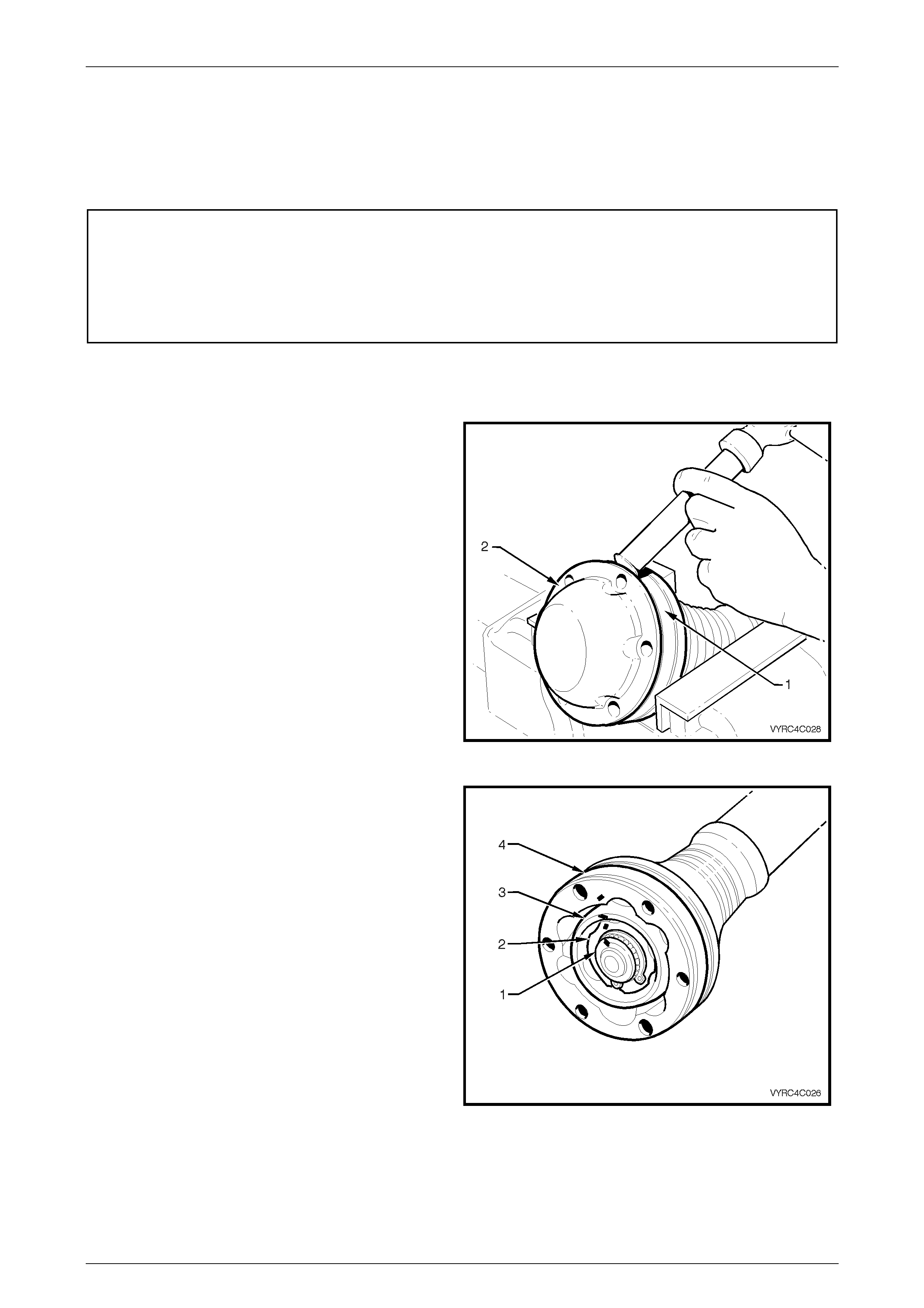
2 Support the cons tant velocity joint body (1) in a vice
equipped with soft metal jaws. Using a brass drift and
hammer gently tap the dust end cover (2) from the
body of the constant velocity joint.
Refer to Figure 4C-28
Figure 4C-28
3 Make relationship ali gnm ent m arks by placin g a daub
of paint on the propeller shaft spindle (1), inner race
(2), ball guide (3) and outer race (4) as shown in
Figure 4C-29.
Figure 4C-29
Propeller Shaft And Universal Joints Page 4C –17
Page 4C–17
4 Using suitable circlip pliers, remove the constant
velocity joint, rear-retaining circlip (1).
Refer to Figure 4C-30
Figure 4C-30
5 Using a brass drift and hammer gently tap the dust
cover and rubber boot assembly (2) from the body of
the constant velocity joint (1).
6 Push the dust cover and rubber boot assembly back
toward the propeller shaft centre bearing. Refer to
Figure 4C-31
Figure 4C-31
7 Support the cons tant velocity joint body and outer
race in a hydraulic press usi ng pressin g plate s, Tool
No J22912-01 (1) and press the propeller shaft
spindle (2) from the constant velocity joint (3).
Refer to Figure 4C-32
Figure 4C-32
Propeller Shaft And Universal Joints Page 4C –18
Page 4C–18
8 Remove the dust shield and rubber boot assembly.
Refer to Figure 4C-33.
Figure 4C-33
Inspect
1 Inspect the grease in the joint for signs of
contamination by metal or dirt ingress. If
contamination is present then the constant velocity
joint will in all probabi lity have suffer ed dam age and it
sh ould be replaced
2 If on inspection contamination is not pres ent, clean
the joint by soaking it in a suitable cleaning solvent.
NOTE:
If there is severe pitting, galling, play between
the balls and the cage windows, cracking or
damage to the cage, pitting or galling or chips in
the raceways, replace the constant velocity
joint.
3 Inspect the internal components by tilting the inner
race to one side to expose each ball individually,
while observing the condition of each component.
Refer to Figure 4C-34. Figure 4C-34

Propeller Shaft And Universal Joints Page 4C –19
Page 4C–19
Disassemble
NOTE:
Disassembly of the constant velocity joint
beyond this point is not recommended. The
internal components are a precision fit and
during operation develop their own
characteristic wear patterns. Intermixing of
components could result in looseness, binding
and/or subsequent premature failure of the
constant velocity joint. If disassembly must be
attempted then each component of the joint
must be returned to its original orientation.
1 Ensure the aligning marks (4) made in step four of the
removal procedure are maintained at all times during
next steps. Refer to Figure 4C-35.
2 Obtain a piece of wood or suitable tray with enough
divots in the surface to accommodate the balls of the
joint, marking one divot to indicate the ball closest to
the alignment marks to retain the original orientation
of each ball to joint. Figure 4C-35
3 Taking care not to dislodge any balls from the joint,
pivot the inner race and ball guide at 90º to the centre
line of the outer race and lift the inner race and ball
guide from the outer race. Refer to Fi gure 4C-36.
Figure 4C-36
4 Using a screwdriver if required as a lever, remove
each ball in order from the ball guide and place the
balls on to the previously obtain piece of wood or tray
as detailed in step two of the disassembly procedure.
Refer to Figure 4C-37.
5 Pivot the inner race 90º to the centre line of the ball
guide and lift the inner race from the ball guide.
Figure 4C-37

Propeller Shaft And Universal Joints Page 4C –20
Page 4C–20
Reassemble
The reassembly procedure for the constant velocity joint is the reverse of the disassembly procedure, noting the following
points:
1 Ensure all alignment marks are aligned to return all components to there original orientation.
2 Check the multi direction movement of the constant velocity joint for binding or restriction.
3 Check the plunge movement f or the consta nt velo city joint .
4 Pack the cons tant velocity joint with the recommended lubricating grease; refer to 3 Specifications in th is Section.
5 Ensure the reassembled constant velocity joint is kept free from contamination until required for reinstallation to the
propeller shaft.
Reinstall
The installation procedure is the reverse of the removal procedure, noting the following points:
1 Ensure the cons tant velocity joint and associated parts are clean to ensure maximum life expectancy.
2 Inspect the dust shield and rubber boot assembly for cracks, tears or damage and replace if necessary then install
it to the front propeller shaft spindle.
3 Pack the cons tant velocity joint with the recommended lubricating grease, refer to
3 Specifications in this Section or use the lubricating grease supplied in the repair kits available for the constant
velocity joint and, or the dust shield and rubber boot. Ensure the grease is worked in by hand onto all surfaces
inside the joint.
4 Prior to pressing the constant velocity joint onto the front propeller shaft spindle, ensure all alignment marks are
aligned to their original orientation.
5 Using a suitable socket or tube (1), press the constant
velocity joint (2) onto the propeller s h aft (3), spindle
while ensuring the socket or tube presses on the
inner race of the joint only. Refer to Figure 4C-38.
6 Install the constant velocity retaining ci rclip to the
propeller shaft spin dle.
7 Ensure the mating surfaces of the constant velocity
joint, dust shield and rubber boot assembly are clean.
8 Install a new gasket between the constant velocity
joint and the rear dust shield end cover.
9 Apply a bead of recommended sealant to the mating
surfaces of the dust shield and rubber boot assembly,
and constant velocity joint. For details on the sealant
refer to 3 Specifications in this Section.
10 Install the rubber boot to propeller shaft spindle
retaining clip.
11 Install the propeller shaft, as detailed in 2.1 Propeller
Shaft in this Section. Figure 4C-38
Propeller Shaft And Universal Joints Page 4C –21
Page 4C–21
3. Specifications
General
Propeller Shaft Assembly............................................................................ Spilt Configuration
Drive Connection to Transmission ....................................................................... Sliding Yoke
Centre Support Bearing ................................................ Rubber Encased Sealed Ball Bearing
Universal Type – Front...................................................................................Rubber Coupling
Universal Type – Centre .....................................................Constant Velocity – Non-Plunging
Universal Type – Rear ................................................................Constant Velocity – Plunging
Identification
ENGINE TRANSMISSION DRIVE
CONFIGURATION CODE
V6 Automatic JW
Manual
GEN III V8 Automatic
2WD JV
Lubricants
Constant Velocity Lubricant Capacity (Fixed Type)...............................................31.5g 6 2.5g
Constant Velocity Lubricant Capacity (Plunging Type) ...........................................210g 6 10g
Constant Velocity Lubricant Type..........................................................Available in 60g Tube,
......................................................................Part of the Boot Repair and Major Overhaul Kits
.............................................................................................. Refer to PartFinder® Information
Sealants and Thread Locking Compound
Constant Velocity Joint to Dust Shield ....................................................................Loctite 510
..............................................................(High Temperature Gasket Eliminator) or Equivalent.
Propeller Shaft and Joint Fasteners.................................................Locti te 242 or Equivalent.

Propeller Shaft And Universal Joints Page 4C –22
Page 4C–22
4. Torque Wrench Specifications
ATTENTION
All Propeller Shaft and Universal Joints fasteners are important attaching parts as they affect the
performance of vital components and/or could result in major repair expense. Where specified in this Section,
fasteners MUST be replaced with parts of the same part number or a GM approved equivalent. Do not use
fasteners of an inferior quality or substitute design.
Torque values must be used as specified during reassembly to ensure proper retention of all steering
components.
Through out this Section, fastener torque wrench specifications may be accompanied with the following
Identification marks:
+
++
+ Fasteners must be replaced after loosening.
6
66
6 Fasteners either have micro encapsulated sealant applied or incorporate a mechanical thread lock and
should only be re-used once. If in doubt, replacement is recommended.
If one of these identification marks is present alongside a fastener torque wrench specification, the
recommendation regarding that fastener must be adhered to.
Nm
6 Centre Bearing Carrier Bracket to Vehicle Underbody
Brace Attaching Bolts.............................................................................20 – 35
6 Centre Bearing Upper Carrier Bracket to Lower Carrier
Bracket Attaching Bolts And Nuts..........................................................20 – 30
6 Rear Constant Velocity Joint to Rear Axle Pinion Flange
Attaching Bolt – V6................................................................................35 – 40
6 Rear Constant Velocity Joint to Rear Axle Pinion Flange
Attaching Bolt – Gen III V8....................................................................66 – 71
6 Constant Velocity Joint to Rear Propeller Shaft Attaching
Bolts.......................................................................................................32 – 36
+ Front Rubber Coupling to Transmission Sliding Yoke
Attaching Nut And Bolt..........................................................................20, then
..........................................................................................50° – 60° Turn A ngle
Propeller Shaft And Universal Joints Page 4C –23
Page 4C–23
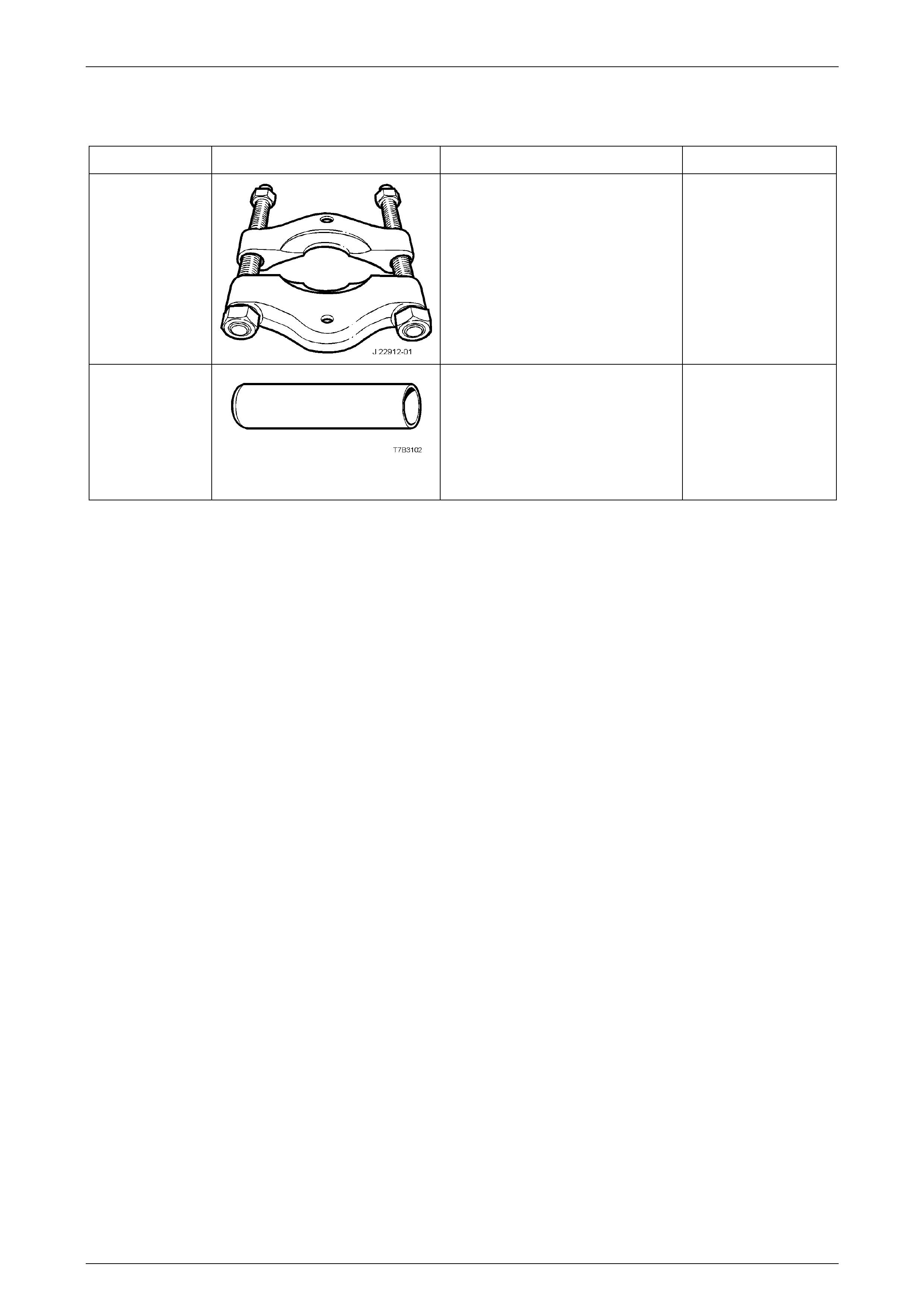
5. Special Tools
TOOL NUMBER ILLUSTRATION DESCRIPTION CLASSIFICATION
J22912-01
PRESS TOOL
Used to remove rear wheel studs
from the Propeller Shaft and
Universal Joints flange.
Previously released.
Available
E3C10AER
CENTRE BEARING REPLACER
Used to install the centre bearing
during Propeller Shaft and Universal
Joints overhau l.
Previously released.
Available