
Service An d Pa r k Br a king Syste m Page 5A –1
Page 5A–1
Section 5A
Service and Park Braking System
ATTENTION
Before performing any Service Operation or other procedure described in this Section, refer to Section 00
CAUTIONS AND NOTES for correct workshop practices with regard to safety and/or property damage.
1 General Information............................................................................................................................... 3
1.1 General Description ...............................................................................................................................................3
1.2 Brake Pipes and Hoses..........................................................................................................................................4
Description..............................................................................................................................................................4
1.3 Pressure Differential Spool Valve.........................................................................................................................5
Description..............................................................................................................................................................5
1.4 Load Sensing Proportioning Valve.......................................................................................................................6
Description..............................................................................................................................................................6
Operation ................................................................................................................................................................7
1.5 Rear Brake Backing Plates and ABS Sensors.....................................................................................................8
Description..............................................................................................................................................................8
2 Minor Service Operations..................................................................................................................... 9
2.1 Service Notes..........................................................................................................................................................9
General Information...............................................................................................................................................9
Important Items...................................................................................................................................................9
2.2 Rear Park Brake Cables.......................................................................................................................................11
Remove .................................................................................................................................................................11
Reinstall ................................................................................................................................................................12
2.3 Rear Caliper Brake Hose......................................................................................................................................13
Remove .................................................................................................................................................................13
Reinstall ................................................................................................................................................................13
2.4 Rear Brake Supply Hose......................................................................................................................................15
Remove .................................................................................................................................................................15
Reinstall ................................................................................................................................................................16
2.5 Load Sensing Proportioning Valve.....................................................................................................................17
Remove .................................................................................................................................................................17
Reinstall ................................................................................................................................................................19
3 Major Service Operations ................................................................................................................... 20
3.1 Service Notes........................................................................................................................................................20
General Information.............................................................................................................................................20
Important Items.................................................................................................................................................20
3.2 Master Cylinder ....................................................................................................................................................22
3.3 Brake Booster.......................................................................................................................................................23
3.4 Brake Caliper (Front and Rear) ...........................................................................................................................24
3.5 Front Brake Disc...................................................................................................................................................25
3.6 Rear Brake Disc....................................................................................................................................................26
3.7 Park Brake Lining Wear, Check ..........................................................................................................................27
3.8 Park Brake Shoe, Adjust ......................................................................................................................................28
3.9 Park Brake Shoe...................................................................................................................................................29
3.10 Front Disc Brake Shield.......................................................................................................................................30
3.11 Rear Disc Brake Backing Plate and Disc Shield................................................................................................31
Remove .................................................................................................................................................................31
Inspect...................................................................................................................................................................35
Reinstall ................................................................................................................................................................35
Techline
Techline
Techline

Service An d Pa r k Br a king Syste m Page 5A –2
Page 5A–2
4 Diagnosis.............................................................................................................................................. 37
4.1 Diagnosis Notes...................................................................................................................................................37
Diagnostic Table...................................................................................................................................................38
5 Specifications....................................................................................................................................... 39
6 Torque Wrench Specifications........................................................................................................... 41
7 Special Tools........................................................................................................................................ 43

Service An d Pa r k Br a king Syste m Page 5A –3
Page 5A–3
1 General Information
1.1 General Description
The service and park braking system as fitted to MY2003 VY Series Cab Chassis Models mainly carries over from
previous MY2003 VY Series Models, noting the following exceptions:
• The rear brake pipe along with the rear brake hose is new to accommodate the load sensing proportioning valve and
rigid live axle design.
• The master cylinder is equipped with a pressure differential spool valve instead of a proportioning valve.
• The rear brake load sensing proportioning valve is carry over from MY2003 VY Series Utility Models and is mounted
via a bracket along with attaching bolts directly to the chassis.
• The rear wheel ABS sensors are located in a dedicated aperture of each rear brake backing plate and are unique to
MY2003 VY Series Cab Chassis Models.
• The rear disc brake backing plates and shields are unique to MY2003 VY Series Cab Chassis Models.
• The park brake cables and routing are new to accommodate the rigid live rear axle design.
For further servicing details on the Service And Park Braking System not covered in this Section, as fitted to MY2003 VY
Series Cab Chassis Models, refer to Section 5A, Service and Park Braking System in the MY2003 VY and V2 Series
Service Information.
For further servicing details on the ABS Braking System not covered in this Section, as fitted to MY2003 VY Series Cab
Chassis Models, refer to Section 5B, ABS & ABS-TCS in the MY2003 VY and V2 Series Service Information.
Service An d Pa r k Br a king Syste m Page 5A –4
Page 5A–4
1.2 Brake Pipes and Hoses
Description
The front brake pipes used on MY2003 VY Series Cab Chassis Models, for both standard and ABS braking systems,
carry over from previous MY2003 VY Series Models
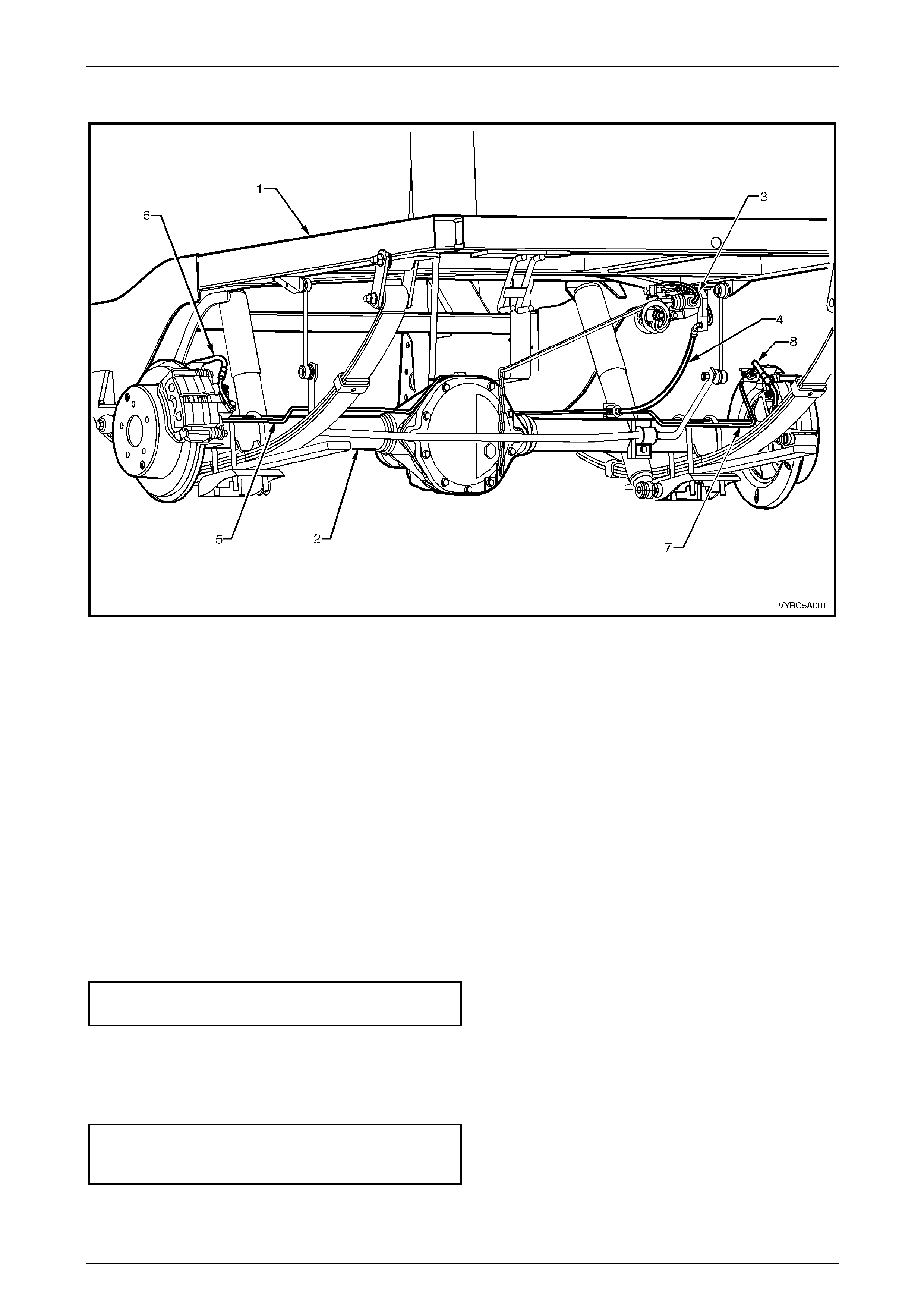
The rear brake pipes used on MY2003 VY Series Cab Chassis Models, regardless of the braking system fitted are
unique. The only differences being:
a. The rear brake hoses are new to accommodate the load sensing proportioning valve and the rigid live rear axle
design.
b. The rear brake pipes along are new to accommodate the load sensing proportioning valve and the rigid live rear axle
design.
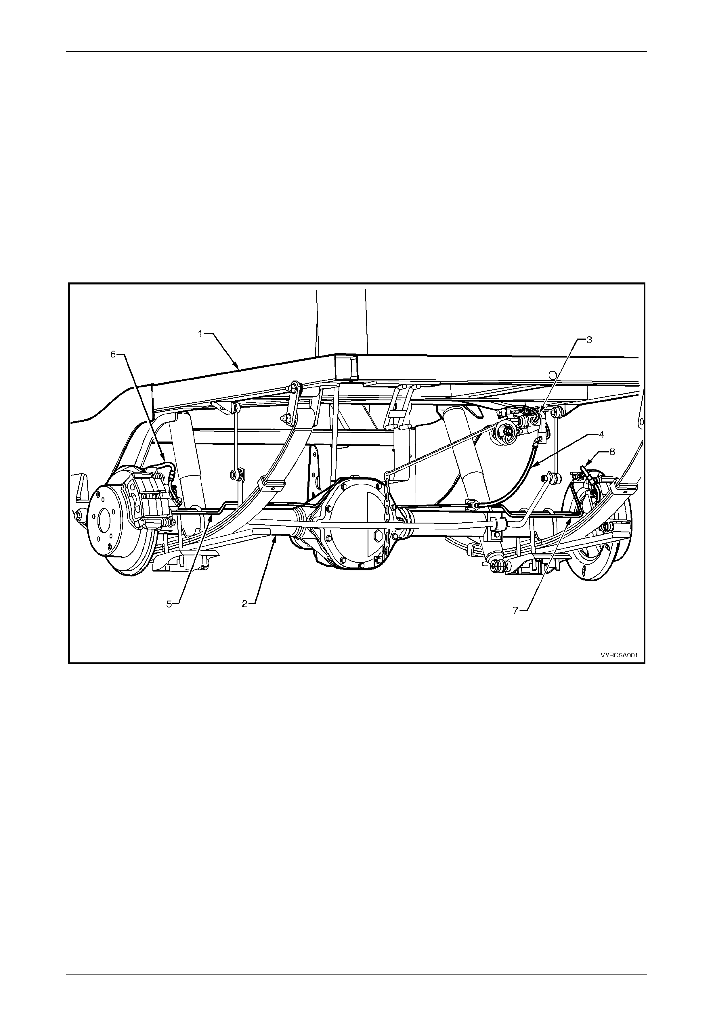
Figure 5A-1
Legend
1. Chassis Assembly
2. Rear Axle Assembly
3. Main Rear Brake Supply Pipe to Load Sensing
Proportioning Valve Supply Pipe
4. Main Rear Brake Supply Hose to Rear Axle Tee
Connection.
5. Rear Brake Caliper Supply Pipe – Left-Hand
6. Rear Brake Caliper Supply Hose – Left-Hand
7. Rear Brake Caliper Supply Pipe – Right-Hand
8. Rear Brake Caliper Supply Hose – Right-Hand
Service An d Pa r k Br a king Syste m Page 5A –5
Page 5A–5
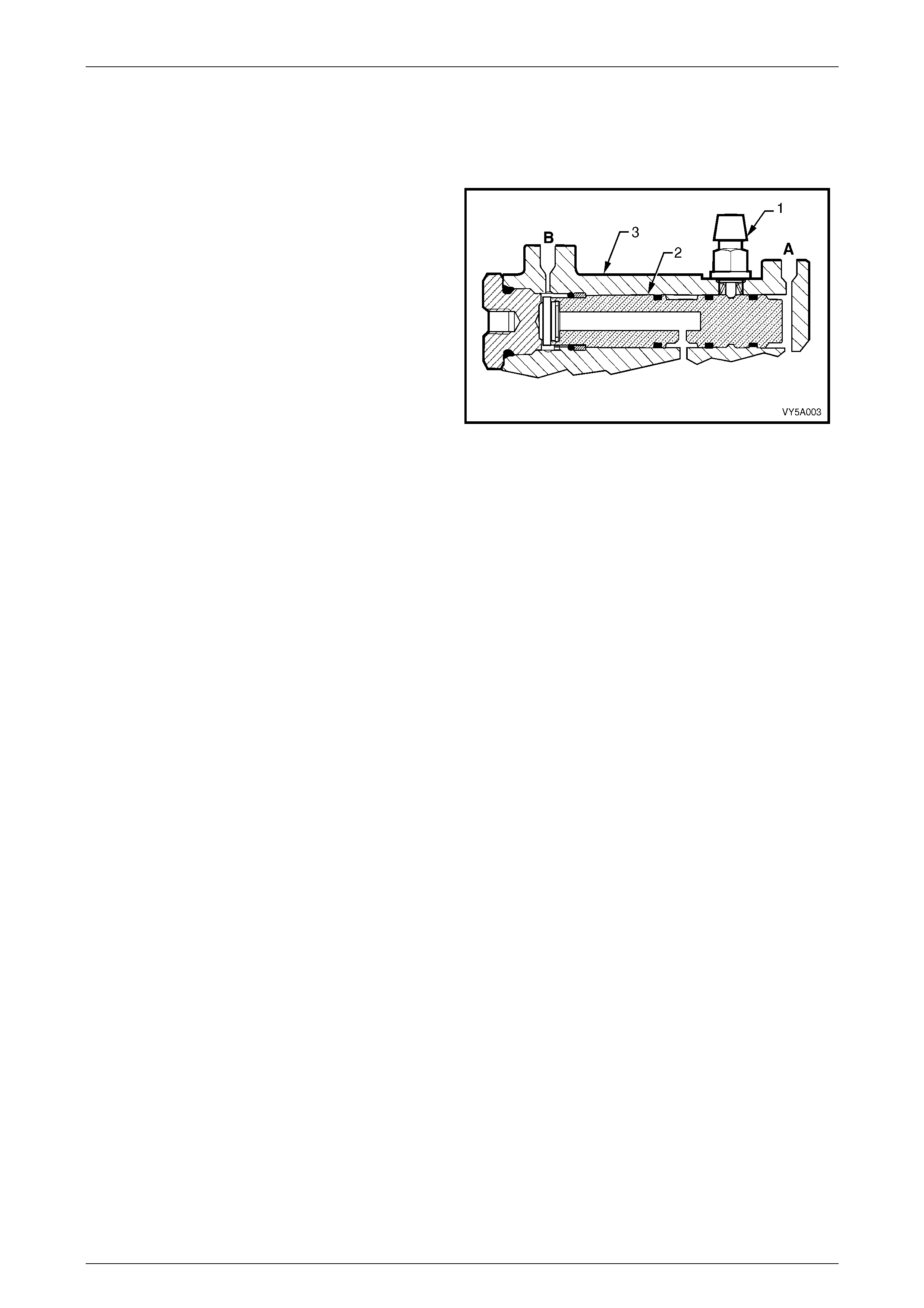
1.3 Pressure Differential Spool Valve
Description
The Master Cylinder as fitted to MY2003 VY Series Cab
Chassis Models is not fitted with a proportioning valve but
in all other aspects are similar to that fitted to other MY2003
VY Series Utility Models. Instead of a proportioning valve
MY2003 VY Series Cab Chassis Models have a differential
spool valve (2).
The brake fail warning light switch (1) is mounted in the
master cylinder body (3) with the spring-loaded plunger
located in a tapered groove in the centre of the spool valve.
With the spool in a centralised position, the switch contacts
remain open.
Should there be a loss of pressure in either the front (A) or
rear (B) brake system, when the brake pedal is applied, the
spool valve will move off centre, closing the switch contacts
and activating the warning light on the instrument panel.
After repairs have been made and the brake system has
been bled, the pressure in the front and rear brake systems
will equalise (when the brakes are applied), centralising the
spool and opening the contacts in the differential switch,
turning the brake warning light off.
Refer to Figure 5A-2.
Figure 5A-2
Service An d Pa r k Br a king Syste m Page 5A –6
Page 5A–6
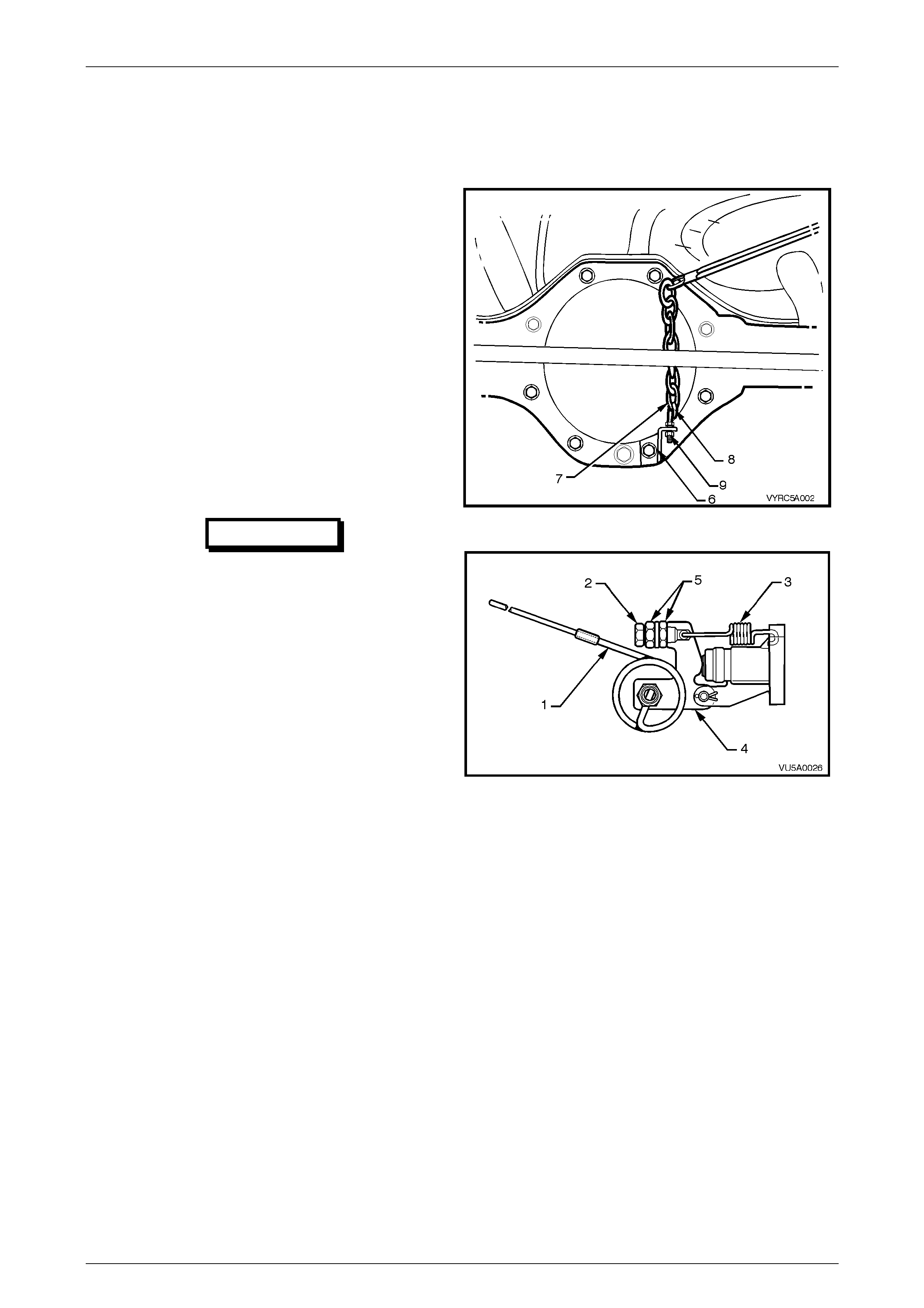
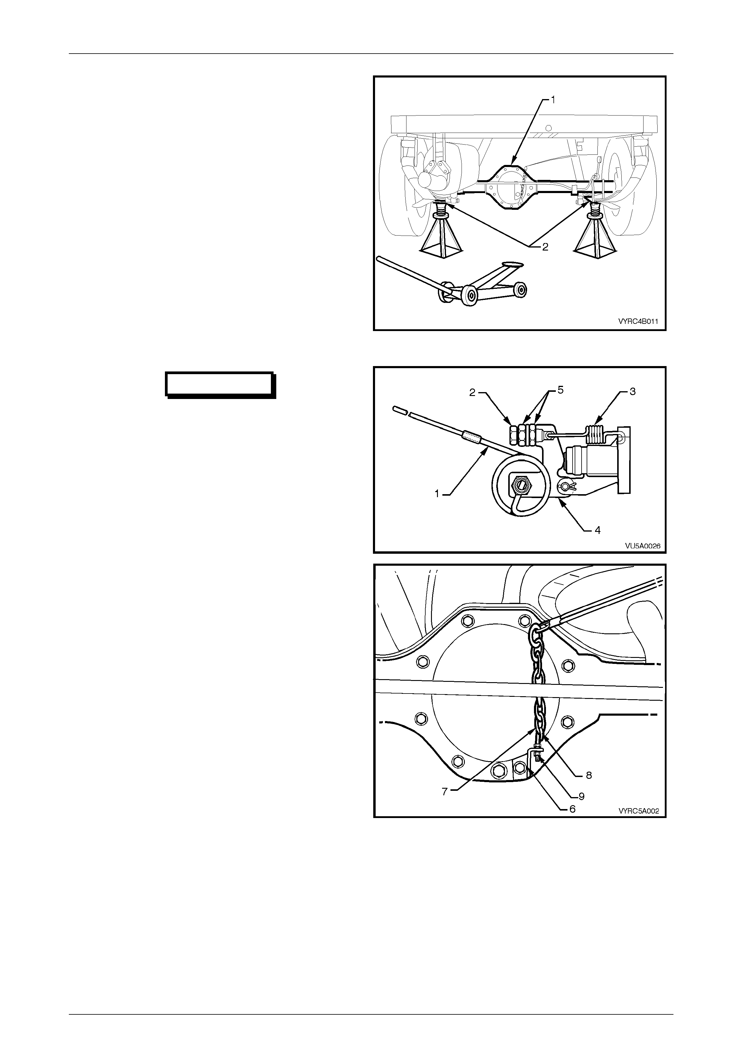
1.4 Load Sensing Proportioning Valve
Description
The load sensing proportioning valve is attached to the right
hand frame, above the rear axle assembly. The valve
torsion spring lever (1) is attached to the rear axle with a
bracket (6), chain (7), eyebolt (8) and nut (9). Refer to
Figure 5A-3.
The load sensing proportioning valve senses load by
monitoring the rear suspension ride height, to regulate the
pressure applied to the rear brake callipers. Maximum Pipe
pressure is supplied to the rear brakes when the vehicle is
fully laden, while lightly loaded conditions provide minimum
Pipe pressure; i.e. Pipe pressure varies in relation to the
weight of the load.
The static spring (3) exerts a force on the end of the spool
valve by means of a lever (4), while a torsion type sensing
spring (1) is attached to the rear axle via the chain,
modifying this applied force, depending on the axle load.
Refer to Figure 5A-3.
IMPORTANT
Under no circumstances is the static
spring tension adjusting screw (2) and
lock nuts (5) or the eyebolt (8) and chain
(7) on the rear axle, to be neither
disturbed nor adjusted.
Figure 5A-3
Figure 5A-4
Service An d Pa r k Br a king Syste m Page 5A –7
Page 5A–7
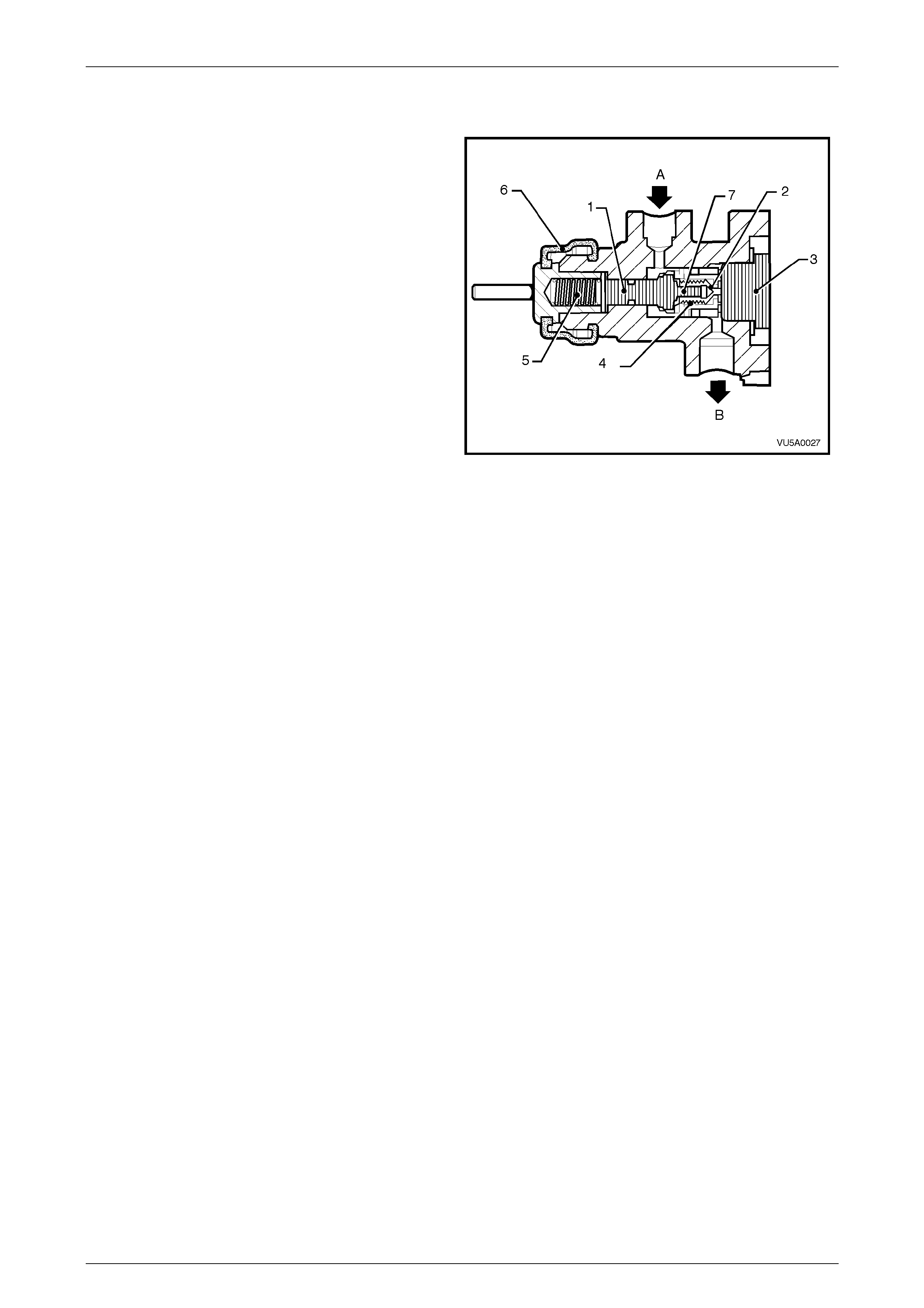
Operation
When the vehicle is unl aden or lightly loaded, the torsion
spring has the maximum effect and, together with the static
spring force, the total apply force on the plunger and load
sensing valve spool (1) is lowest. This apply force is able to
position the load sensing valve spool (1) to restrict the flow
of fluid through the outlet port (‘B’) to the rear brakes.
However, when the vehicle is loaded, the load sensing
valve spool is positioned so that fluid can flow unrestricted
through the inlet port (‘A’), through the spool sub-assembly,
around the poppet valve (7) and out via the spool sub
assembly sealing seat (2) and outlet port (‘B’) to the rear
wheel brake callipers.
When the brake pedal is released, inlet pressure drops,
allowing the higher pressure on the rear wheel side of the
sensing valve to force upon the poppet valve (7), such that
the brake fluid can flow almost unrestricted, back to the
master cylinder. Eventually, the load sensing valve spool
(1) is forced into its released position by the external spring
set up, to fully open the passage between the front and rear
circuit.
Refer to Figure 5A-5.
Figure 5A-5
Legend
1 Load sensing valve spool
2 Load sensing valve spool sealing seat
3 Load sensing valve end plug
4 Secondary spring
5 Primary spring
6 Load sensing valve boot
7 Load sensing valve poppet and valve
A Brake fluid inlet
B Brake fluid outlet
Service An d Pa r k Br a king Syste m Page 5A –8
Page 5A–8
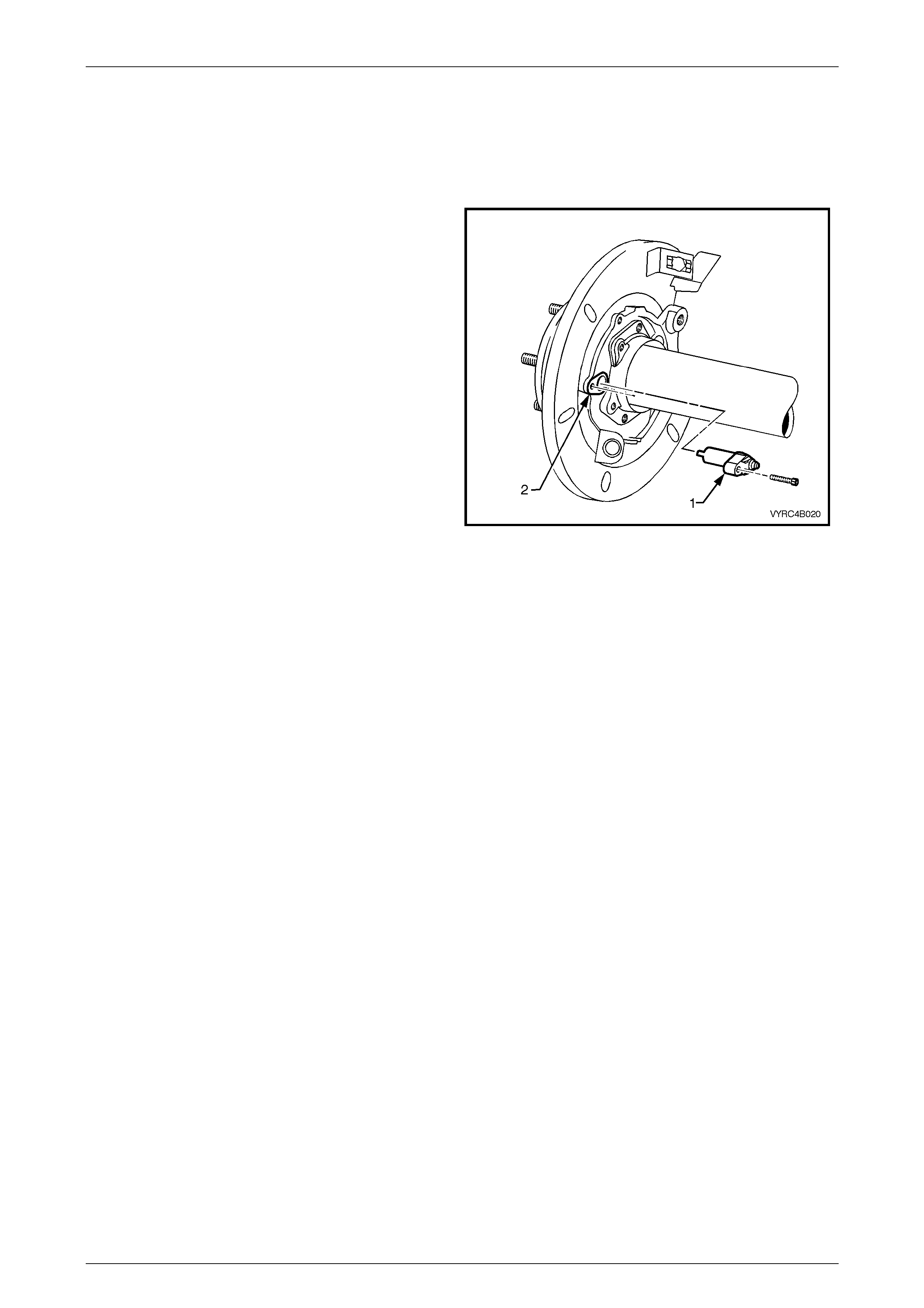
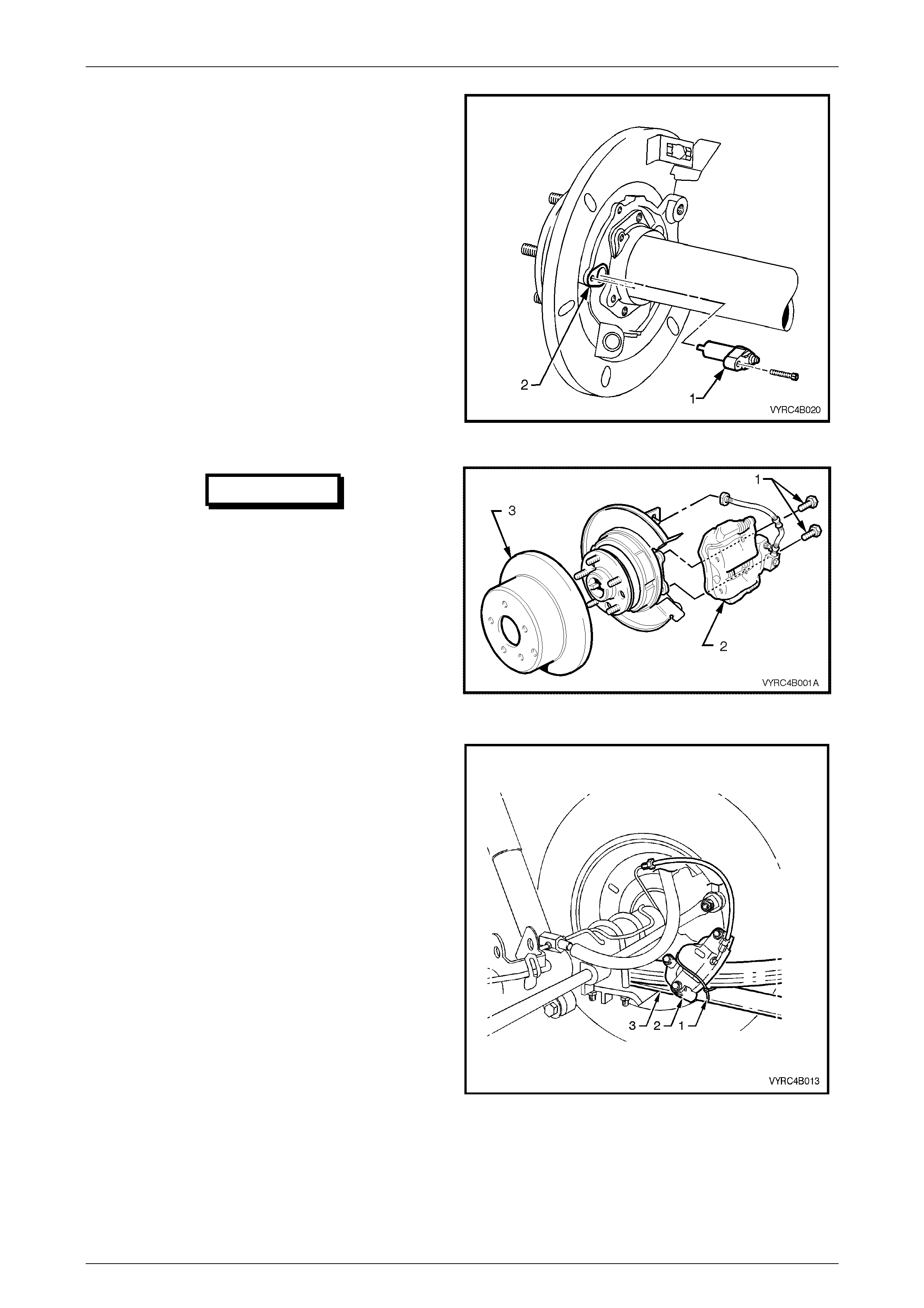
1.5 Rear Brake Backing Plates and ABS
Sensors
Description
The rear brake backing plate (2) is of cast iron construction
with a stone shield attached, providing a mounting support
for the rear brake caliper, rear brake caliper hydraulic
supply hose, parking brake, park brake cable and ABS
sensor (1). Refer to Figure 5A-6.
Figure 5A-6

Service An d Pa r k Br a king Syste m Page 5A –9
Page 5A–9
2 Minor Service Operations
ATTENTION
All rear axle fasteners are important attaching parts as they affect the performance of vital components
and/or could result in major repair expense. Where specified in this Section, fasteners MUST be replaced with
parts of the same part number or a GM approved equivalent. Do not use fasteners of an inferior quality or
substitute design.
Torque values must be used as specified during reassembly to ensure proper retention of all steering
components.
Through out this Section, fastener torque wrench specifications may be accompanied with the following
Identification marks:
+ Fasteners must be replaced after loosening.
!
!!
! Vehicle must be at kerb height before final tightening.
6
66
6 Fasteners either have micro encapsulated sealant applied or incorporate a mechanical thread lock and
should only be re-used once. If in doubt, replacement is recommended.
If one of these identification marks is present alongside a fastener torque wrench specification, the
recommendation regarding that fastener must be adhered to.
2.1 Service Notes
General Infor ma tion
The minor service operations, for the service and park braking system as fitted to MY2003 VY Series Cab Chassis
Models mainly carry over from previous MY2003 VY Series Models, noting the following exceptions:
• Rear park brake cables, refer to 2.2 Rear Park Brake Cables in this Section.
• Rear caliper brake hose, refer to 2.3 Rear Caliper Brake Hose in this Section.
• Rear brake hose, refer to 2.4 Rear Brake Hose in this Section.
• Load sensing proportioning valve, refer to 2.5 Load Sensing Proportioning Valve in this Section.
For further servicing details on the Service And Park Braking System not covered in this Section, as fitted to MY2003 VY
Series Cab Chassis Models, refer to Section 5A, Service and Park Braking System in the MY2003 VY and V2 Series
Service Information.
For further servicing details on the ABS Braking System not covered in this Section, as fitted to MY2003 VY Series Cab
Chassis Models, refer to Section 5B, ABS & ABS-TCS in the MY2003 VY and V2 Series Service Information.
Important Items
1 While Holden's wheel brake parts are not Asbestos based in their material composition, a danger exists that non-
genuine replacement parts may contain Asbestos.
a. Not only is it in the interests of personal safety but also the safe and reliable operation of the braking
system, that only genuine parts are used for replacement purposes.
b. Even so, when servicing wheel brake parts, do not create dust by grinding or sanding brake linings, by
cleaning wheel brake parts with a dry brush or with compressed air. Breathing in dust that may contain
Asbestos fibres can cause serious bodily harm over a protracted period of time.
c. A water dampened cloth or water based solution should be used to remove any dust on brake parts.
Equipment is commercially available to perform this washing function. These wet methods prevent
brake component fibres from becoming airborne.
Service An d Pa r k Br a king Syste m Page 5A –10
Page 5A–10
2 The polyglycol brake fluid used in MY2003 VY Series Cab Chassis Models is hydroscopic and absorbs moisture
from the air through the brake hoses etc. The boiling resistance of the fluid decreases as the moisture content
increases and so the possibility of a vapour lock under heavy braking conditions increases with the age of the fluid.
Therefore, for maximum brake effectiveness, a two yearly change of brake fluid is mandatory; refer to
Section 5A, 2.5 Brake Fluid, Change, in MY2003 VY and V2 Series Service Information.
3 To prevent the absorption of moisture from the air or other contamination, it is recommended that the brake fluid be
stored in small (500 ml) containers. Any surplus fluid remaining in a container after use must be discarded.
IMPORTANT
The only approved brake fluid is Super DOT 4
Plus and is available in 250 and 500 ml
containers. If pressure-bleeding equipment is
used, it must be of an approved type with a
diaphragm separating the brake fluid from the
air.
IMPORTANT
Brake fluid is extremely damaging to paint. If
fluid should accidentally come into contact
with a painted surface, immediately wash the
fluid from the paint and clean the painted
surface.
4 Whenever a road wheel and/or brake disc is removed from the vehicle, the relationship of the road wheel and the
disc to the hub MUST be marked with a felt tipped pen or similar, in order for those parts to be reinstalled in their
original positions. This is critical to maintain the brake disc and road wheel runout dimension to a minimum. Refer
to Section 10, Wheels and Tyres in the MY2003 VY and V2 Series Service Information for further details.
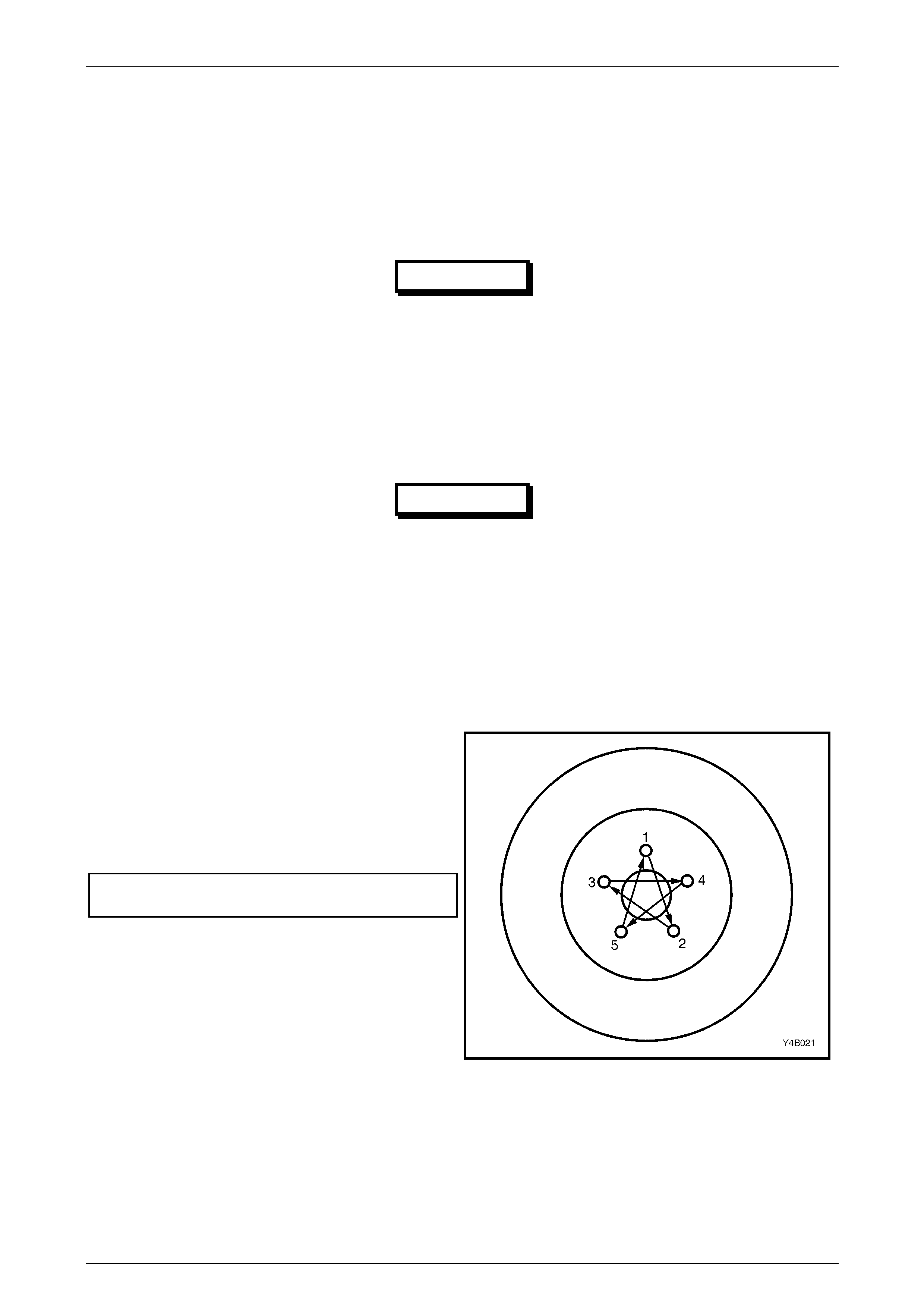
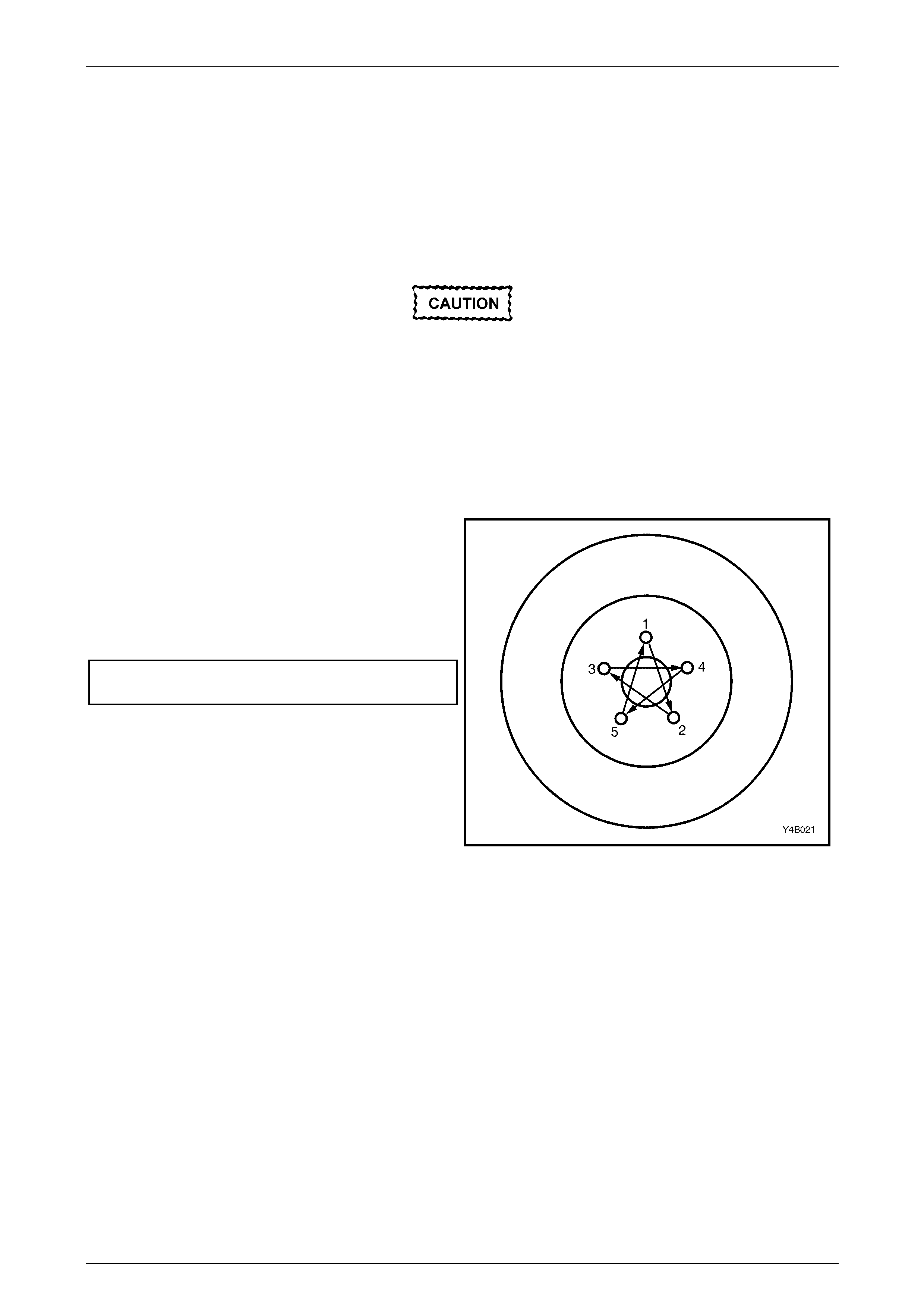
5 When reinstalling road wheels, do not use an impact
gun to tighten wheel nuts unless the impact gun is
fitted with a torque limiter socket (Tool No. AU534 or
a commercial equivalent). Failure to correctly tighten
wheel nuts to the correct torque specification and in
the correct order may result in a distorted brake disc,
leading to the development of brake shudder. Refer to
Figure 5A-7.
Road wheel attaching nut
torque specific atio n .................................. 110 – 140 Nm
NOTE:
For a complete description of the method used
to measure both brake disc and rear axle shaft
runout and correction, refer to Section
3.4 Front Brake Disc or 3.5 Rear Brake Disc, in
the MY2003 VY and V2 Series Service
Information.
Figure 5A-7
Service An d Pa r k Br a king Syste m Page 5A –11
Page 5A–11
2.2 Rear Park Brake Cables
LT Section No. – 04-675
Remove
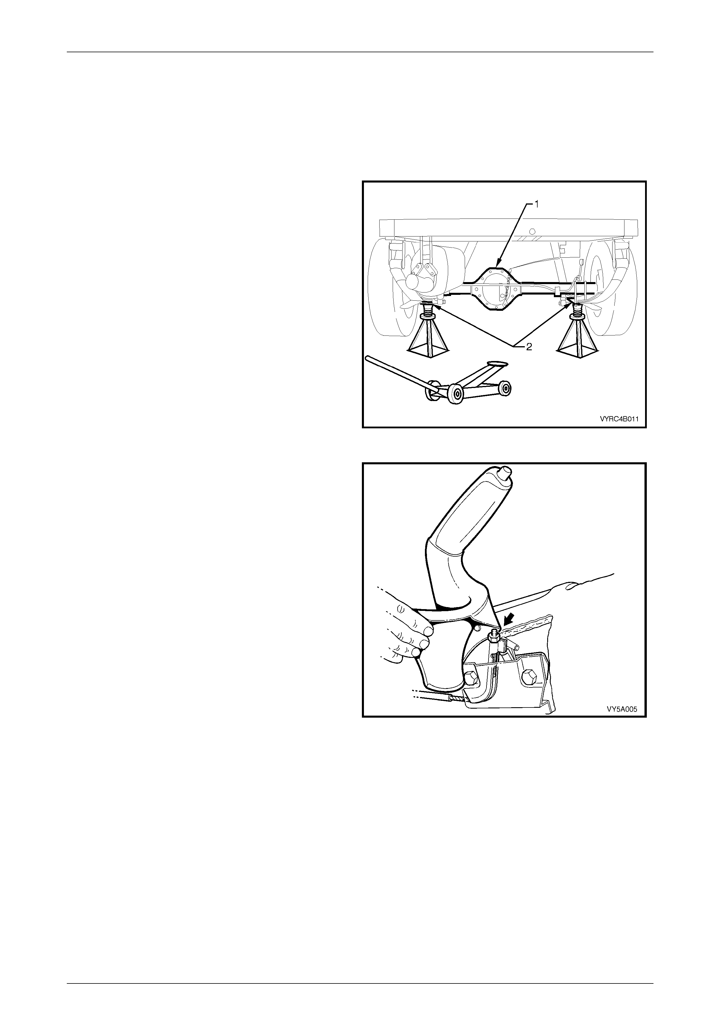
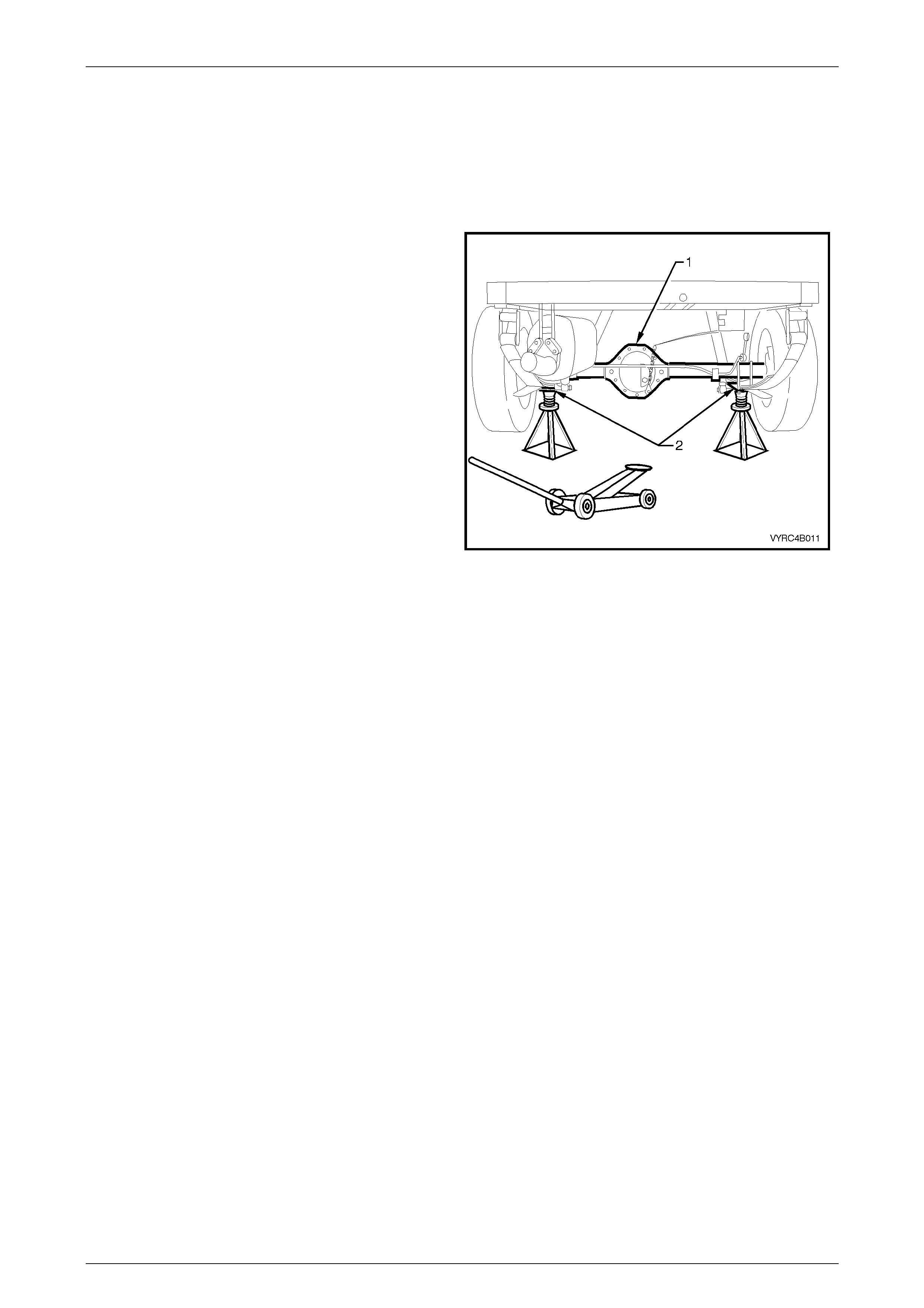
1 Using a floor jack under centre of rear axle (1), jack
up and support rear of vehicle on safety stands (2),
under the rear spring retainer brackets. Refer to
figure 5A-8.
Figure 5A-8
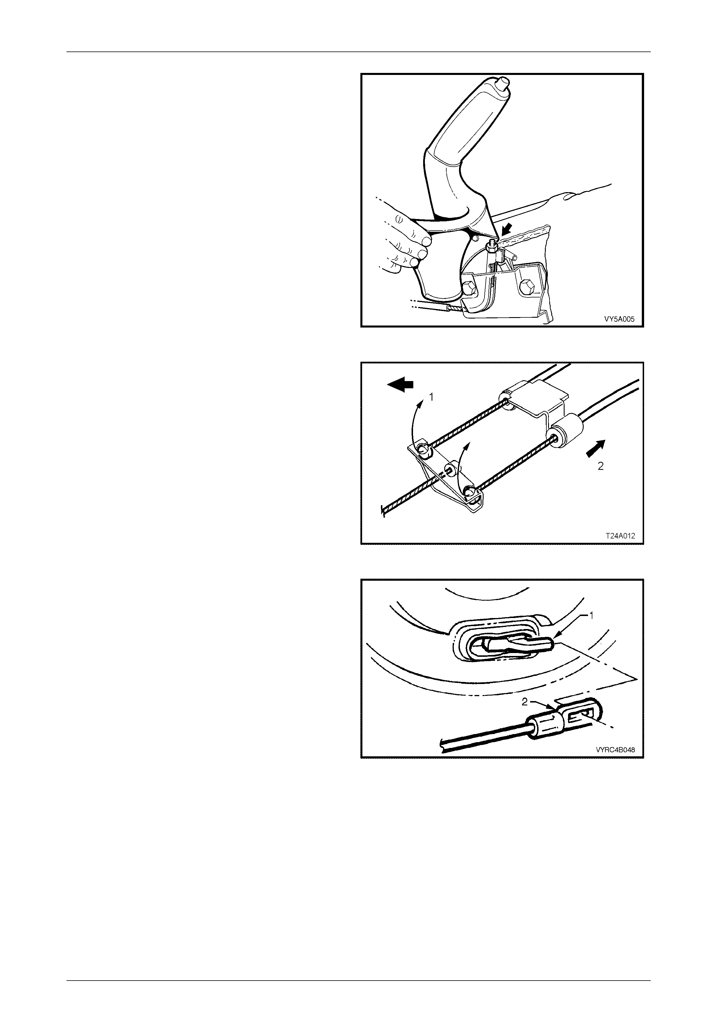
2 Release the park brake.
3 Using a deep reach socket, loosen the front cable-
adjusting nut (arrow) until the nut is almost removed.
Refer to figure 5A-9.
Figure 5A-9
Service An d Pa r k Br a king Syste m Page 5A –12
Page 5A–12
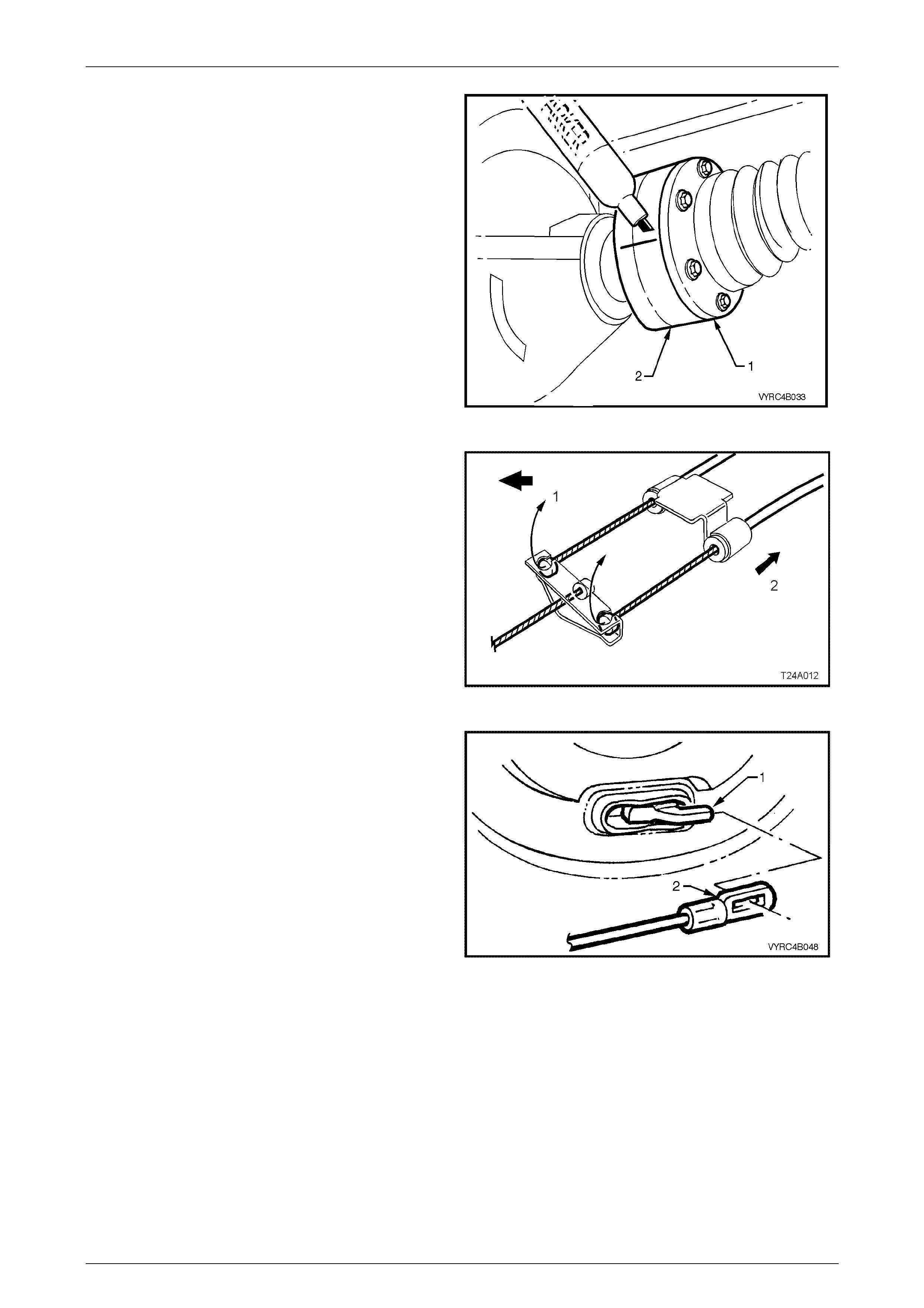
4 To provide sufficient access, it may be necessary to
remove the propeller shaft from the vehicle. Ensure
the relationship of the propeller shaft and rear axle
pinion flange is maintained. Refer to figure 5A-10.
Refer to Section 4C Propeller Shaft And Universal
Joints in this Service Information for the necessary
procedures.
Figure 5A-10
5 Remove the front of the rear inner cable/s, by first
wrapping a rag around the inner cable to protect it
from damage, then use pliers to pull the ball nipple
forward and up (1), to free the inner cable/s from the
equaliser bracket.
6 Pull the outer cable rearward (2) to release the outer
cable body from the vehicle underbody bracket. Refer
to figure 5A-11.
7 Disconnect the outer cable body from the chassis
frame cable bracket.
Figure 5A-11
8 Disconnect the inner cable rear clevis (2) from the
rear park brake, actuating lever (1) by gripping with
pliers and pivoting the cable rearwards. Refer to
figure 5A-12.
9 Pull the outer cable forward, out of the support
retainer/s and remove the cable/s from the vehicle.
Figure 5A-12
Reinstall
Reinstallation of the rear park brake cable/s is the reverse of the removal procedure, except for the following:
• Install the cable through the support retainers, and then fit the cable clevis to the park brake-actuating lever.
• Wrap a rag around the inner cable to protect it from damage, then use pliers to pull the ball end on the inner cable
forward to engage them into the equaliser bracket.
• If removed, reinstall the propeller shaft. Refer to Section 4C Propeller Shaft and Universal Joints, in this Service
Information.
• Adjust the park brake cable; refer to Section 5A, 2.2 Park Brake Cable, Adjust, in MY2003 VY and V2 Series Service
Information.
Service An d Pa r k Br a king Syste m Page 5A –13
Page 5A–13
2.3 Rear Caliper Brake Hose
LT Section No. – 04-750
ATTENTION
The following fasteners MUST have the vehicle at curb height before final tightening.
!
!!
! Road Wheel attaching nuts.
The following fasteners MUST be replaced w hen performing this operation:
+
++
+ Brake hose to brake caliper banjo bolt copper sealing washers.
Remove
1 Raise rear of vehicle and place on jack stands. Refer
to Sectio n 0A General Information in MY2003 VY
Series Cab Chassis Models Service Information for
the procedure.
2 Mark position of the road wheel relative to the hub
and remove the road wheel.
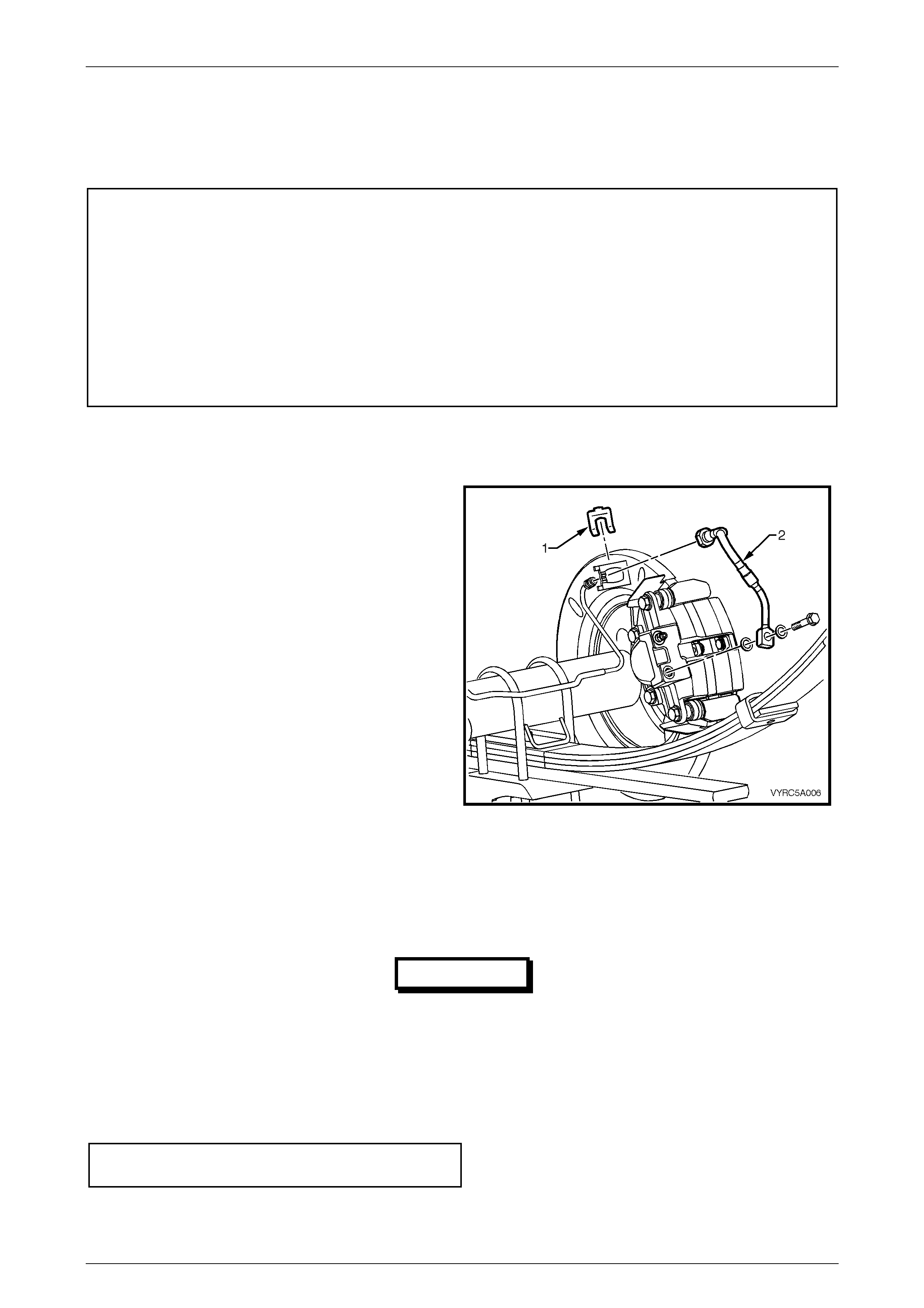
3 Thoroughly clean the connections at each end of the
brake hose (2).
4 While holding the hose (2) with a back-up spanner,
loosen then disconnect brake pipe from brake hose.
Plug the open end of the pipe.
5 Unclip the retainer (1) from the hose and withdraw the
hose from the bracket. Refer to figure 5A-13.
6 Unbolt and remove the brake hose from the caliper.
Figure 5A-13
Reinstall
1 Ensure the brake hose and the caliper matin g sur fac es are c lean and free of burrs.
IMPORTANT
When reinstalling the brake hose to the
caliper, ensure that only NEW (+
++
+) copper
sealing washers are installed.
2 Reconnect the brake hose to the caliper, ensuring that the locating peg aligns with the dimple in the caliper, then
install the NEW copper sealing washers, and then tighten the banjo bolt to specified torque.
Brake hose to caliper
torque specification ...................................... 32 – 37 Nm
3 Fit the hose correctly into the mounting plate bracket and reinstall the retainer. Check that the hose is not twisted.

Service An d Pa r k Br a king Syste m Page 5A –14
Page 5A–14
4 Remove the plug from the brake pipe and reconnect to the hose. While using a back-up spanner on the brake hose
to prevent twisting, tighten the pipe to the specified torque.
Brake pipe flare nut to hose
torque specification ...................................... 14 – 17 Nm
5 Bleed the brake/s; refer to Section 5A, 2.4 Brake System Bleed, in the MY2003 VY Series Service Information, for
the procedure.
6 Reinstall the road wheel, aligning the marks made on removal and lower the vehicle.
7 Tighten the road wheel attaching nuts to the specified torque, tightening in a star pattern, as described in
2.1 Service Notes, in this Section.
(!) Road wheel attaching nut
torque specific atio n .................................. 110 – 140 Nm
Service An d Pa r k Br a king Syste m Page 5A –15
Page 5A–15
2.4 Rear Brake Supply Hose
LT Section No. – 04-750
Remove
1 Using a floor jack under the centre of the rear axle
(1), jack up and support the rear of the vehicle on
safety stands (2), under the rear spring retainer
brackets. Refer to figure 5A-14.
2 Thoroughly clean the connections at each end of the
rear brake hose and pipe.
Figure 5A-14
3 Disconnect the rear brake pipe connection from the brake hose, while holding the hose fitting with a back-up
spanner.
4 Plug all pipe ends to prevent foreign material entry.
5 Unclip the retaining clip from the end of the hose and withdraw the hose from the bracket.
NOTE:
Refer to 2.3 Rear Caliper Brake Hose in this
Section for the procedure to remove the rear
caliper hoses.
Service An d Pa r k Br a king Syste m Page 5A –16
Page 5A–16
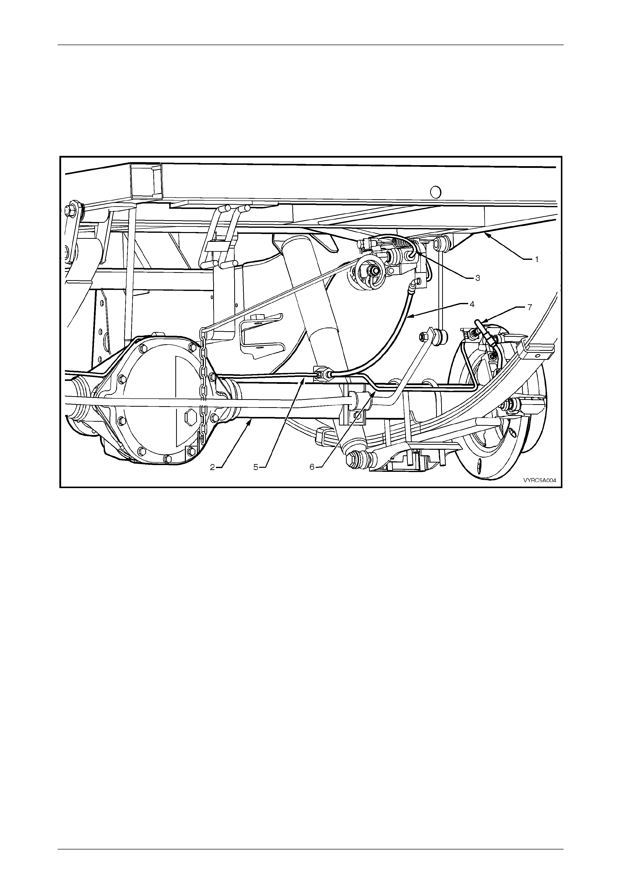
For the general layout of the rear brake pipes and hoses, refer to Figure 5A-15.
Figure 5A-15
Legend
1 Chassis Assembly
2 Rear Axle Assembly
3 Main Rear Brake Supply Pipe to Load Sensing
Proportioning Valve Supply Pipe
4 Main Rear Brake Supply Hose to Rear Axle Tee
Connection.
5 Rear Brake Caliper Supply Pipe – Left-Hand
6 Rear Brake Caliper Supply Hose – Left-Hand
7 Rear Brake Caliper Supply Pipe – Right-Hand
8 Rear Brake Caliper Supply Hose – Right-Hand
Reinstall
1 Remove plugs from brake pipes.
2 Ensure the brake hose ends and the pipe mating surfaces are clean and free of burrs.
3 Fit the end of the brake hose into the tee piece and tighten to the specified torque.
Brake hose to tee piece
torque specification ...................................... 14 – 17 Nm
4 Fit the other end of the brake hose into the mounting plate bracket and install the retaining clips.
5 Check that the brake hose is not twisted.
6 Tighten the remaining pipe nut to the specified torque.
Brake pipe flare nut
to brake hose
torque specification ...................................... 14 – 17 Nm
7 Bleed the brakes; refer to Section 5A, 2.4 Brake System Bleed, in the MY2003 VY Series Service Information.
8 Raise the vehicle; remove the jack stands, and then lower the vehicle to the ground.
Service An d Pa r k Br a king Syste m Page 5A –17
5A–17
2.5 Load Sensing Proportioning Valve
LT Section No. – H408500
Remove
Figure 5A-16
Legend
1 Chassis Assembly
2 Rear Axle Assembly
3 Main Rear Brake Supply Pipe To Load Sensing
Proportioning Valve Supply Pipe
4 Main Rear Brake Supply Hose to Rear Axle Tee
Connection.
5 Rear Brake Caliper Supply Pipe – LH
6 Rear Brake Caliper Supply Pipe – RH
7 Rear Brake Caliper Supply Hose – RH
Service An d Pa r k Br a king Syste m Page 5A –18
5A–18
1 Using a floor jack under centre of rear axle (1), jack
up and support rear of vehicle on safety stands (2),
under the rear spring retainer brackets. Refer to figure
5A-17.
Figure 5A-17
IMPORTANT
Under no circumstances is the static
spring tension adjusting screw (2) and
lock nuts (5) or the eyebolt (8) and chain
(7) on the rear axle, to be neither
disturbed nor adjusted
2 Thoroughly clean all pipe connections at the load
sensing proportioning valve.
3 Disconnect all pipe connections to the load sensing
proportioning valve.
4 Plug all connection points of the load sensing
proportioning valve along with the brake pipe ends to
prevent foreign material entry.
NOTE:
The static spring will have tension until the chain
and attaching bracket (6) is removed from the
rear axle cover and released slowly.
5 Remove the load sensing proportioning valve chain
bracket and attaching bolts (6) as one unit from the
rear axle cover. Refer to Figure 5A-18
Figure 5A-18
Service An d Pa r k Br a king Syste m Page 5A –19
5A–19
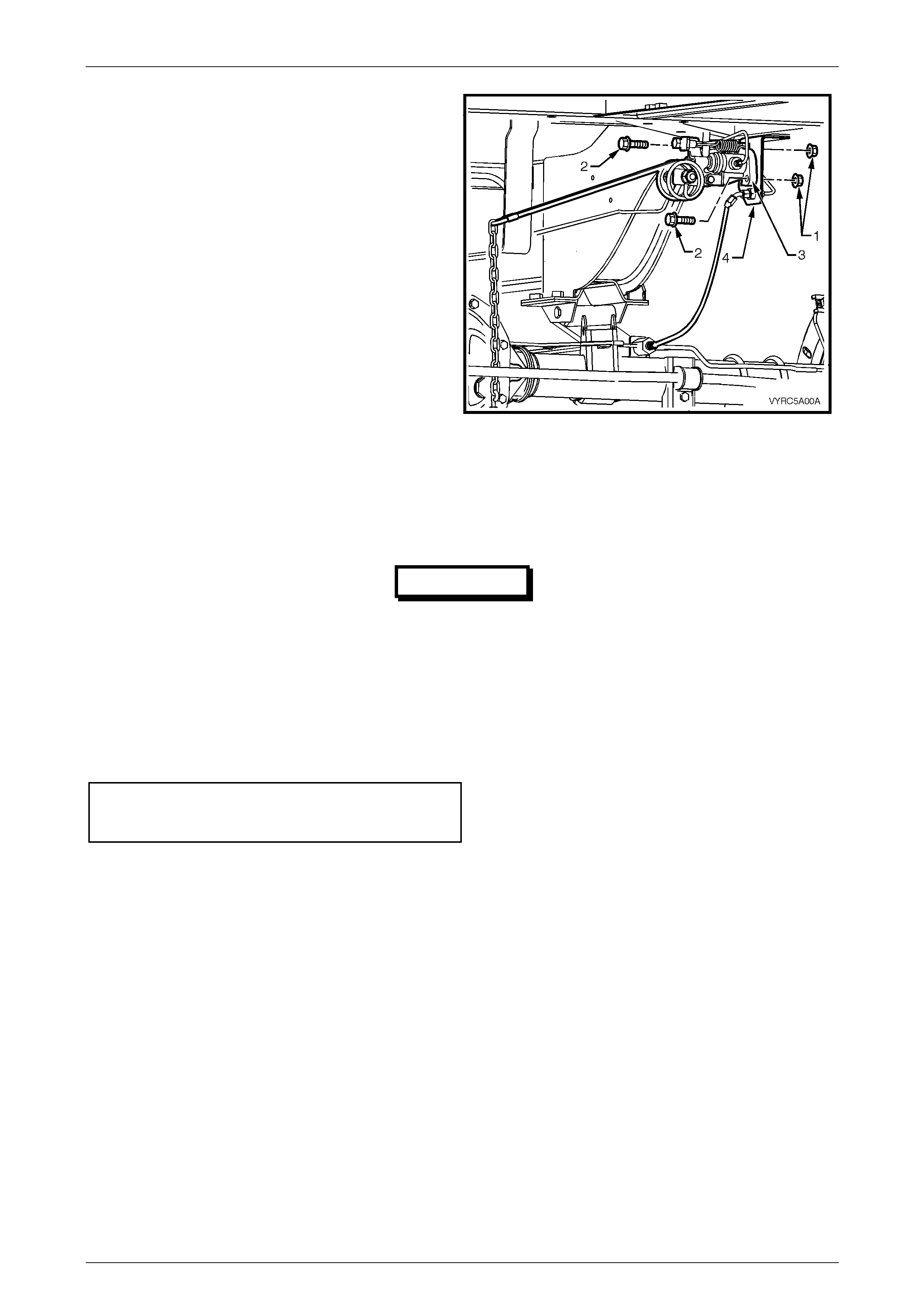
6 Remove the two retaining nuts (1) and bolts (2) along
with the load sensing proportioning valve assembly
(3) from the mounting bracket (4).
Refer to Figure 5A-19
Figure 5A-19
Reinstall
The installation procedure is the reverse of the removal procedure, noting the following:
IMPORTANT
Under no circumstances is the static spring
tension adjusting screw and lock nuts on the
load sensing proportioning valve or the
eyebolt and chain link to the rear axle, to be
neither disturbed nor adjusted
1 Position the load sensing proportioning valve onto the bracket, then install and secure the two bolts. Tighten the
bolts or nuts to the correct torque specification.
Load sensing proportioning valve
to bracket attaching nut & bolt
torque specification ...................................... 35 – 40 Nm
2 Ensure all pipes are secured and routed correctly, refer to Figure 5A-16.
3 Bleed brake/s; refer to Section 5A, 2.4 Brake System Bleed, in the MY2003 VY Series Service Information.

Service An d Pa r k Br a king Syste m Page 5A –20
5A–20
3. Major Service Operations
ATTENTION
All rear axle fasteners are important attaching parts as they affect the performance of vital components
and/or could result in major repair expense. Where specified in this Section, fasteners MUST be replaced with
parts of the same part number or a GM approved equivalent. Do not use fasteners of an inferior quality or
substitute design.
Torque values must be used as specified during reassembly to ensure proper retention of all steering
components.
Through out this Section, fastener torque wrench specifications may be accompanied with the following
Identification marks:
+ Fasteners must be replaced after loosening.
!
!!
! Vehicle must be at kerb height before final tightening.
6
66
6 Fasteners either have micro encapsulated sealant applied or incorporate a mechanical thread lock and
should only be re-used once. If in doubt, replacement is recommended.
If one of these identification marks is present alongside a fastener torque wrench specification, the
recommendation regarding that fastener must be adhered to.
3.1 Service Notes
General Infor ma tion
The major service operations, for the service and park braking system as fitted to MY2003 VY Series Cab Chassis
Models mainly carry over from previous MY2003 VY Series Models, noting the following exceptions:
• Master cylinder differential spool valve, refer to 3.2 Master Cylinder in this Section.
For further servicing details of the service and park braking system, as fitted to MY2003 VY Series Cab Chassis Models,
refer to Section 5A, Service And Park Braking System in the MY2003 VY and V2 Series Service Information.
For further servicing details of the ABS Braking System, as fitted to MY2003 VY Series Cab Chassis Models,
refer to Section 5B, ABS & ABS-TCS in the MY2003 VY and V2 Series Service Information.
Important Items
1 While Holden's wheel brake parts are not asbestos based in their material composition, a danger exists that non-
genuine parts replacement may contain asbestos.
a. Not only is it in the interests of personal safety but also the safe and reliable operation of the braking
system, that only genuine parts are used for replacement purposes.
b. Even so, when servicing wheel brake parts, do not create dust by grinding or sanding brake linings, by
cleaning wheel brake parts with a dry brush or with compressed air. Breathing in dust that may contain
asbestos fibres can cause serious bodily harm over a protracted period of time.
c. A water dampened cloth or water based solution should be used to remove any dust on brake parts.
Equipment is commercially available to perform this washing function. These wet methods prevent
brake component fibres from becoming airborne.
2 The polyglycol brake fluid used in MY2003 VY Series Cab Chassis Models vehicles is hygroscopic and absorbs
moisture from the air through the brake hoses etc. The boiling resistance of the fluid decreases as the moisture
content increases and so the possibility of a vapour lock under heavy braking conditions increases with the age of
the fluid. Therefore, for maximum brake effectiveness, a two yearly change of brake fluid is mandatory; refer to
Section 5A, 2.5 Brake Fluid, Change, in MY2003 VY and V2 Series Service Information.
Service An d Pa r k Br a king Syste m Page 5A –21
5A–21
3 To prevent the absorption of moisture from the air or other contamination, it is recommended that the brake fluid be
stored in small (500 ml) containers and that any surplus fluid remaining in a container after use is discarded.
NOTE:
The only approved brake fluid is Super DOT 4
Plus and is available in 250 and 500 ml
containers. If pressure-bleeding equipment is
used, it must be of an approved type with a
diaphragm separating the brake fluid from the air.
Brake fluid is extremely damaging to paint. If
fluid should accidentally come into contact
with a painted surface, immediately wash the
fluid from the paint and clean the painted
surface.
4 Whenever a road wheel and/or brake disc is removed from the vehicle, the relationship of the road wheel and the
disc to the hub MUST be marked with a felt tipped pen or similar, in order for those parts to be reinstalled in their
original positions. This is critical to maintain the brake disc and road wheel runout dimension to a minimum.
5 When reinstalling road wheels, do not use an impact
gun to tighten wheel nuts unless the impact gun is
fitted with a torque limiter socket (Tool No. AU534 or
a commercial equivalent). Failure to correctly tighten
wheel nuts to the correct torque specification and in
the correct order may result in a distorted brake disc,
leading to the development of brake shudder. Refer to
Figure 5A-20.
(!) Road wheel attaching nut
torque specific atio n .............................. 110 – 140 Nm
NOTE:
For a complete description of the method used
to measure both brake disc and trunnion
assembly runout and correction, refer to
Section 3.4 Front Brake Disc or 3.5 Rear Brake
Disc, in the MY2003 VY and V2 Series Service
Information.
Figure 5A-20

Service An d Pa r k Br a king Syste m Page 5A –22
5A–22
3.2 Master Cylinder
LT Section No. – 04-725
The master cylinder as fitted to MY2003 VY Series Cab Chassis Models carries over from previous MY2003 VY Series
Models. For further servicing details on the master cylinder refer to Section 5A, 3.1 Master Cylinder in MY2003 VY and
V2 Series Service Information.

Service An d Pa r k Br a king Syste m Page 5A –23
5A–23
3.3 Brake Booster
LT Section No. – 04-725
The brake booster as fitted to MY2003 VY Series Cab Chassis Models carries over from previous MY2003 VY Series
Models.
For further details on the brake booster as fitted to MY2003 VY Series Cab Chassis Models, refer to Section 5A, 3. 2
Brake Booster in the MY2003 VY and V2 Series Service Information.

Service An d Pa r k Br a king Syste m Page 5A –24
5A–24
3.4 Brake Caliper (Front and Rear)
LT Section No. – 04-750 and 04-825
The front and rear brake callipers as fitted to MY2003 VY Series Cab Chassis Models carries over from previous
MY2003 VY Series Utility Models with exception of the brake pad composition, which is unique.
For further details on the front brake caliper as fitted to MY2003 VY Series Cab Chassis Models, refer to S ect ion 5A, 3.3
Brake Caliper (Front & Rear) in the MY2003 VY and V2 Series Service Information.

Service An d Pa r k Br a king Syste m Page 5A –25
5A–25
3.5 Front Brake Disc
LT Section No. – 04-805
The front brake disc as fitted to MY2003 VY Series Cab Chassis Models carries over from previous MY2003 VY Series
Models.
For further details on the front brake disc as fitted to MY2003 VY Series Cab Chassis Models, refer to Section 5A, 3.4
Front Brake Disc in the MY2003 VY and V2 Series Service Information.

Service An d Pa r k Br a king Syste m Page 5A –26
5A–26
3.6 Rear Brake Disc
LT Section No. – 04-825
The rear brake disc as fitted to MY2003 VY Series Cab Chassis Models carries over from previous MY2003 VY Series
Models.
For further details on the rear brake disc as fitted to MY2003 VY Series Cab Chassis Models, refer to Section 5A, 3.5
Rear Brake Disc in the MY2003 VY and V2 Series Service Information.

Service An d Pa r k Br a king Syste m Page 5A –27
5A–27
3.7 Park Brake Lining Wear, Check
For further details on the park brake lining wear, check procedure for MY2003 VY Series Cab Chassis Models, refer to
Section 5A, 3.6 Park Brake Lining Wear, Check in the MY2003 VY and V2 Series Service Information.


Service An d Pa r k Br a king Syste m Page 5A –30
5A–30
3.10 Front Disc Brake Shield
LT Section No. – 04-805
The front disc brake shield as fitted to MY2003 VY Series Cab Chassis Models carries over from previous MY2003 VY
Series Models.
For further details on the front disc brake shield as fitted to MY2003 VY Series Cab Chassis Models, refer to Section 5A,
3.9 Front Disc Brake Shield in the MY2003 VY and V2 Series Service Information.
Service An d Pa r k Br a king Syste m Page 5A –31
5A–31
3.11 Rear Disc Brake Backing Plate and Disc
Shield
LT Section No. – 04-825
Remove
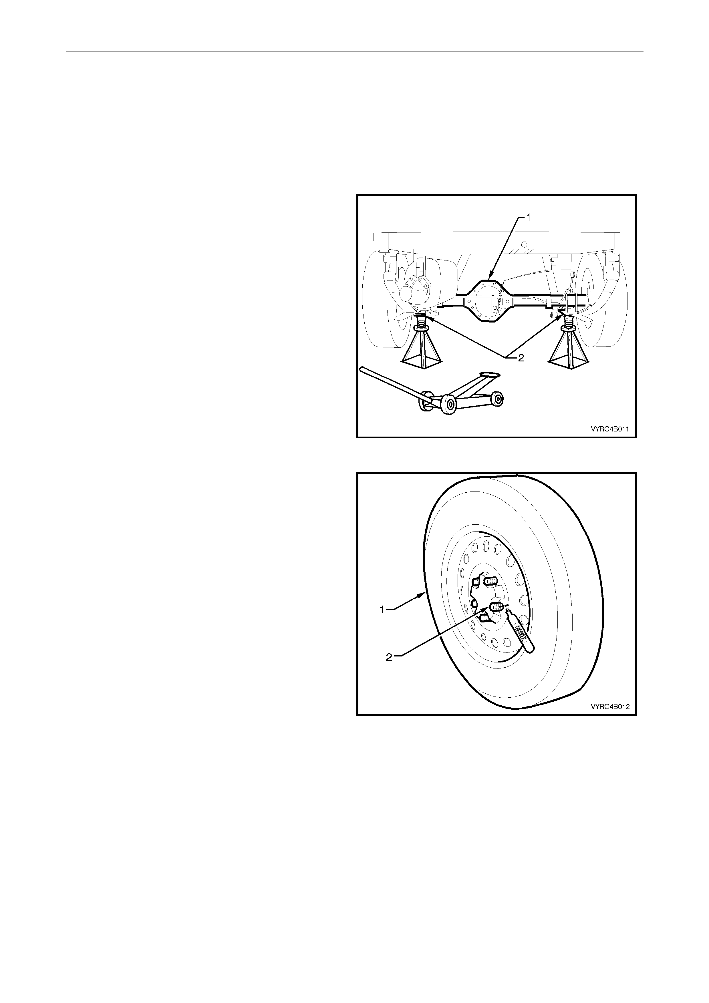
1 Using a floor jack under centre of the rear axle (1),
jack up and support the rear of the vehicle on safety
stands (2), under the rear spring retainer brackets.
Refer to figure 5A-21.
Figure 5A-21
2 Remove the rear wheel covers (steel wheels) or
wheel nut covers (alloy wheels).
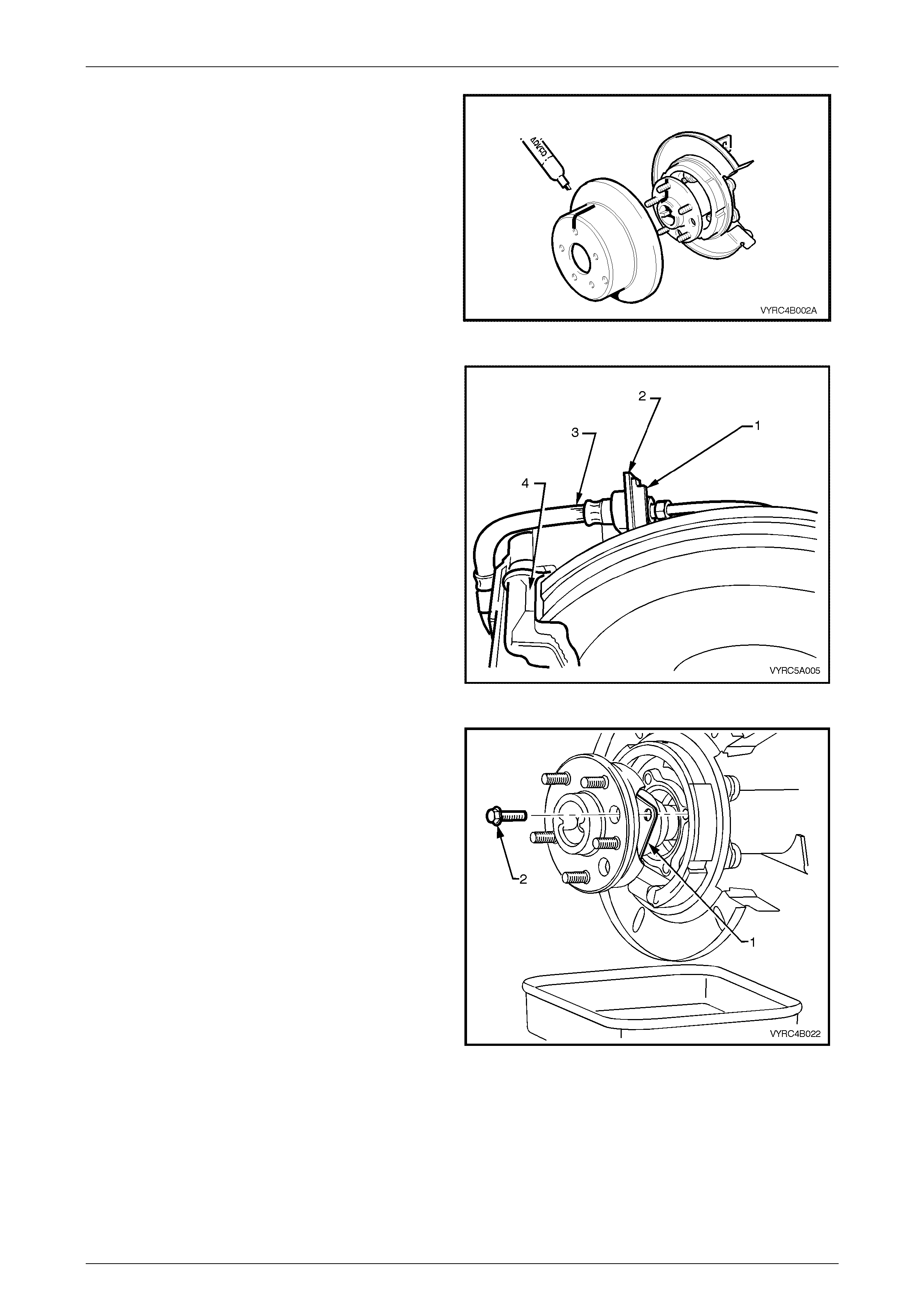
3 With a felt tipped or suitable marking pen, mark
relationship of wheel (1) to the rear axle wheel
retaining studs (2) as shown in Figure 5A-22 and
remove the road wheel.
Figure 5A-22
Service An d Pa r k Br a king Syste m Page 5A –32
5A–32
4 Release the park brake.
5 Using a deep socket, loosen the front cable-adjusting
nut (arrow) until the nut is almost removed. Refer to
figure 5A-23.
Figure 5A-23
6 Remove the front of the rear inner cable/s, by first
wrapping a rag around the inner cable to protect it
from damage, then use pliers to pull the ball nipple
forward and up (1), to free it from the equaliser
bracket. Refer to figure 5A-24.
Figure 5A-24
7 Disconnect the rear clevis (2) from the rear park
brake, actuating lever (1) by gripping with pliers and
pivoting the cable rearwards. Refer to figure 5A-25.
8 Pull the outer cable forward; out of the support
retainer and tie back the cable so it is clear of the
work area.
Figure 5A-25
Service An d Pa r k Br a king Syste m Page 5A –33
5A–33
7 Remove the ABS sensor (1) from the rear brake
backing plate (2) and tie the sensor away from the
plate to prevent accidental damage.
Refer to Figure 5A-26.
Figure 5A-26
IMPORTANT
Do not allow caliper to hang by brake
hose, as damage to the hose will occur.
8 Remove the rear brake caliper to rear axle anchor
plate attaching bolts (1), then remove the brake
caliper (2) from the disc rotor (3) as shown in
Figure 5A-27.
Figure 5A-27
9 Using tie wire (1), secure the caliper (2) to the top of
the rear leaf spring assembly (3) as shown in
Figure 5A-28.
Figure 5A-28
Service An d Pa r k Br a king Syste m Page 5A –34
5A–34
10 With a felt tipped or suitable marking pen, mark the
relationship of the brake disc rotor position to the rear
axle shaft assembly, then remove the brake disc rotor
from the rear axle shaft assembly as shown in
Figure 5A-30.
11 Remove the rear axle shaft assembly, refer to
Section 4B, 2.8 Rear Axle Shaft Assembly, Remove
in this Service Information.
Figure 5A-29
12 Thoroughly clean around the b rake hos e to pipe
connection at the backing plate. Disconnect the brake
pipe from the brake hose (3) at the backing plate
bracket (2) and remove the brake hose retaining clip
(1) as shown in Figure 5A-30.
Figure 5A-30
13 Remove the rear axle assembly and retainer plate
attaching bolts. Refer to Figure 5A-31. For the
procedure on removal of the rear axle shaft refer to
Section 4B, 2.8 Rear Axle Shaft Assembly in this
Service Information.
Figure 5A-31
Service An d Pa r k Br a king Syste m Page 5A –35
5A–35
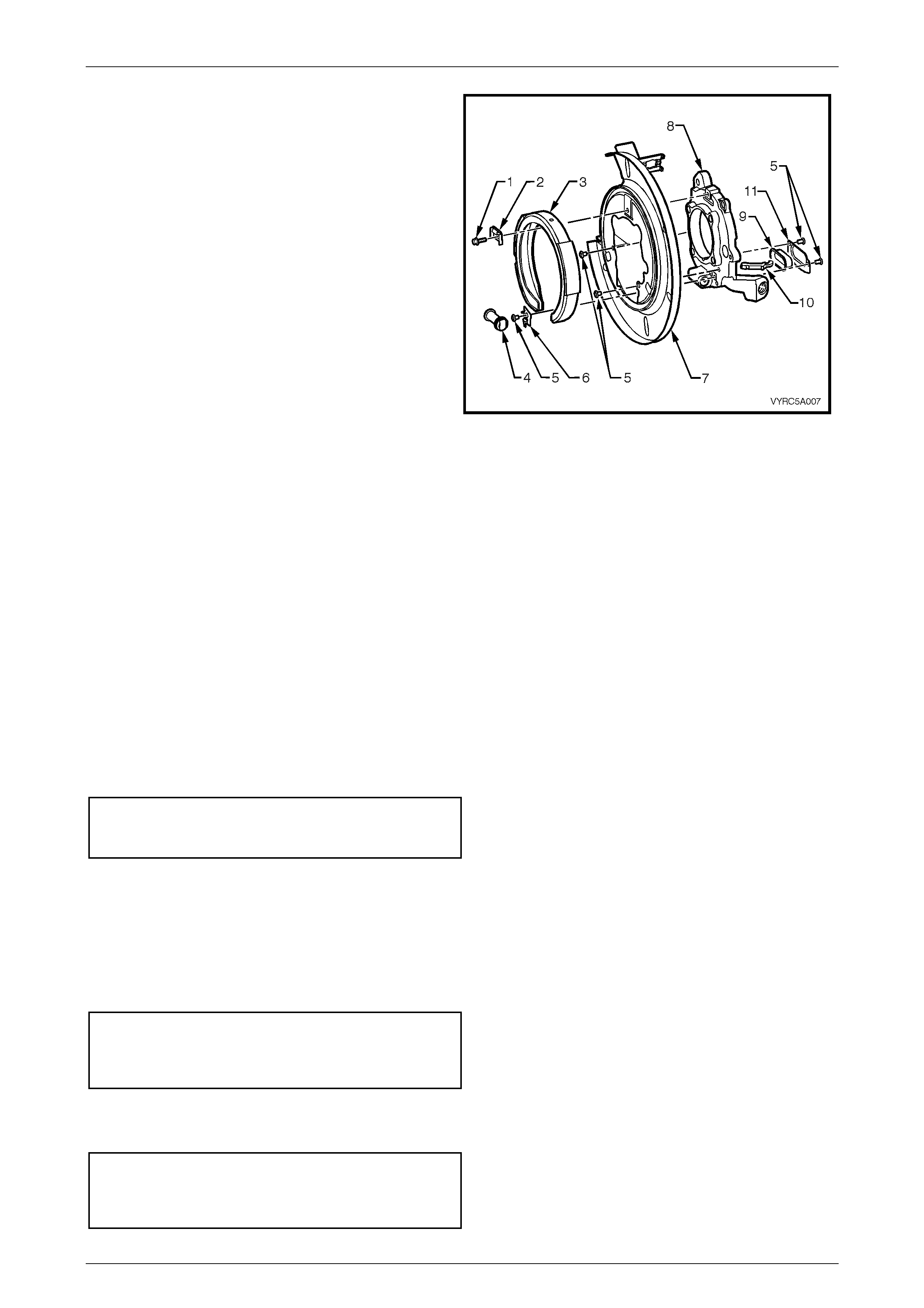
14 Wind the park brake shoe adjuster wheel (4) back into
the park brake actuator and cable support assembly
(8) relieve the tension from the brake shoe.
15 Remove the park brake shoe guide (2) and attaching
bolt (1).
16 Remove the park brake shoe (3) from the disc shield
backing plate assembly (7).
17 Remove the park brake actuator and cable support
assembly (8) along with the disc shield backing plate
assembly (7).
18 If replacing the disc shield backing plate (7), it will be
necessary to carefully support the park brake actuator
and cable support assembly (8) in a vice to remove
the disc shield attaching ri vets (5 ).
19 Disassemble the park brake actuator assembly (8)
ready for cleaning and inspection
Refer to Figure 5A-32. Figure 5A-32
Inspect
• Clean all compon ent s w ith a suitab le cle anin g solv ent and dry.
• Inspect all components for signs of wear or damage and replace parts where necessary.
Reinstall
Reinstall atio n of the park brak e and disc shi eld is the rev ers e to the removal procedures, noting the following:
1 Reassemble the park brake actuator assembly.
2 If removed, reinstall the disc brake shield and attaching rivets to the park brake actuator assembly.
3 Install the park brake actuator assembly to the rear axle housing.
4 Reinstall the rear axle shaft assembly along with the retaining thrust plate attaching bolts. For detail on the
procedure for reinstallation of the rear axle shaft refer to Section 4B, 2.8 Rear Axle Shaft Assembly in MY2003 VY
Series Cab Chassis Models Service Information. Tighten the rear axle shaft retaining thrust plate attaching bolts to
the correct torque specification.
(6) Retainer thrust plate
attaching bolt
torque specification ...................................... 40 – 50 Nm
5 Reinstall the park brake shoe. For further details on the park brake shoe as fitted to MY2003 VY Series Cab
Chassis Models, refer to Section 5A, 3.8 Park Brake Shoe in the MY2003 VY and V2 Series Service Information.
6 Reinstall the rear disc, aligning the marks made before removal and adjust the park brake shoe. For further details
on the park brake shoe, adjust procedure for MY2003 VY Series Cab Chassis Models, refer to Section 5A, 3.7 Park
Brake Shoe, Adjust in the MY2003 VY and V2 Series Service Information.
7 Install and tighten the rear brake caliper anchor plate to rear axle anchor plate attaching bolts to the correct torque
specification.
(6) Rear brake caliper anchor
plate to rear axle anchor plate
attaching bolt
torque specification .................................... 70 – 100 Nm
8 Install the rear brake caliper hose to disc shield and backing plate-retaining clip.
9 Install and tighten the rear brake pipe to rear caliper hose to the correct torque specification.
Rear brake caliper hose
to rear brake pipe
attaching flare nut
torque specification ...................................... 14 – 17 Nm

Service An d Pa r k Br a king Syste m Page 5A –36
5A–36
10 Bleed the brakes; refer to Section 5A, 2.4 Brake System Bleed, in in MY2003 VY and V2 Series Service Information
for the procedure.
11 Adjust the park brake cable; refer Section 5A, 2.2 Park Brake Cable, Adjust, in MY2003 VY and V2 Series Service
Information.
12 Reinstall the road wheel, aligning the marks made on removal and the lower vehicle.
13 Tighten the road wheel attaching nuts to the specified torque, tightening in a star pattern, as described in
2.1 Service Notes, in this Section.
(!) Road wheel attaching nut
torque specific atio n .................................. 110 – 140 Nm
Service An d Pa r k Br a king Syste m Page 5A –37
5A–37
4. Diagnosis
4.1 Diagnosis Notes
• The brake fluid used in MY2003 VY Series Cab Chassis Models is hygroscopic and absorbs moisture from the air
through the brake hoses etc.
• The boiling resistance of the fluid decreases as the moisture content increases and so the possibility of a vapour
lock under heavy braking conditions increases with the age of the fluid.
• For maximum brake effectiveness, a two yearly change of brake fluid is mandatory; refer to Section 5A, 2.5 Brake
Fluid, Change, in MY2003 VY and V2 Series Service Information.
IMPORTANT
The only approved brake fluid is Super DOT 4
Plus, which is available in 250 and 500 ml
containers. If pressure-bleeding equipment is
used, it must be of an approved type with a
diaphragm separating the brake fluid from the
air.
IMPORTANT
Brake fluid is extremely damaging to paint. If
fluid should accidentally come into contact
with a painted surface, immediately wash the
fluid from the paint and clean the painted
• The diagnostic table in this Section can be used as a tool to determine the probable causes of faults found in the
service and park braking system.
Techline

Service An d Pa r k Br a king Syste m Page 5A –38
5A–38
Diagnostic Table
SYMPTOM
X - Indicates Probable Cause
XX - Indicates a More Possible Cause
CAUSE
Excessive Brake Pedal Travel
Brake Pedal Travel Gradually Increases
Excessive Brake Pedal Effort
Excessive Braking Action
Brakes Slow to Respond
Brakes Slow to Release
Brakes Drag
Uneven Braking Action (Side to Side)
Uneven Braking Action (Front to Rear)
Scraping Noise from Brakes
Brakes Squeak During Appl ication
Brakes Squeal During a Stop
Brakes Chatter
Brakes Groan at End of Stop
Brake Tell-tale Lamp Glows During a Stop
Leaking Brake Pipe or Connection X X X
Leaking Caliper or Piston Pipe X X X X X
Leaking Master Cylinder X XX X
Air in Brake System XX X X
Contaminated or Improper Brake Fluid X X X X
Leaking Vacuum System XX X
Restricted Air Passage in Vacuum Booster X XX X
Damaged Vacuum Booster X X X X XX
Improperly Assembled Vacuum Booster Valving X X X X XX
Worn Out Disc Pads - R epl ace X X X X X X X X
Uneven Disc Pad Wear - Replace or Correct X X X X X XX X
Contaminated Disc Pad - Replace XX XX XX X X X X
Heat Spotted or Scored Brake Discs X X X X X XX X
Out-of-Parallel Brake Discs XX
Excessive Brake Disc Run-Out X
Brake Assembly Attachments - Mis sing or Loose X X X X X X X X
Restricted Brake Fluid Passage or Sticking Caliper
Piston X X X X X X X
Brake Pedal/Linkage Binding or Interference X X X XX
Improperly Adjusted Parking Brake X
Incorrect Front Wheel Alignment X XX
Incorrect Tyre Pressures X X
Wheel Bearing Clearance Excessive X X
Loose Front Suspension and/or Components X XX X X
Out-of-Balance Wheel Assemblies XX
Operator Riding Brake Pedal X X X X X X

Service An d Pa r k Br a king Syste m Page 5A –39
5A–39
4. Specifications
BRAKE FLUID
Type............................................................................................................ Super DOT 4 Plus
BRAKE BOOSTER
Make.................................................................................................................................PBR
Type..........................................................................................Tandem, Vacuum Suspended
MASTER CYLINDER
Make.................................................................................................................................PBR
Type............................................................................................................................Tandem
Bore Diameter (nominal)............................................................................................ 25.4 mm
Crack Point .................................................................................................................3.1 MPa
FRONT DISC
Type......................................................................................................................... Ventilated
Diameter (nominal).....................................................................................296 + 0.0 - 0.2 mm
Thickness.........................................................................................................28.0 ± 0.15 mm
Lateral Runout (maximum).......................................... 0.04 mm Total Indicated Run-out (TIR)
Minimum Disc Thickness, Requiring Replacement.................................................... 25.0 mm
FRONT CALIPER
Make.................................................................................................................................PBR
Type..............................................................................................Twin Piston, Sliding Caliper
Bore Diameter (Nominal) ................................................................................ 42.0 mm (each)
Front Disc Pad Material....................................................................... Organic, Non-Asbestos
Minimum Thickness Before Replacement....................................................................... 2 mm
REAR DISC
Type................................................................................................................................. Solid
Diameter (Nominal).................................................................................... 286 + 0.0 - 0.2 mm
Thickness....................................................................................................15.9 mm ± 0.2 mm
Lateral Runout (Maximum)......................................................................................... 0.05 mm
(Rate of change 0.03 mm in 30O rotation maximum.)
Minimum Disc Thickness, Requiring Replacement.................................................... 13.9 mm

Service An d Pa r k Br a king Syste m Page 5A –40
5A–40
REAR CALIPER
Make.................................................................................................................................PBR
Type........................................................................................... Single Piston, Sliding Caliper
Bore Diameter (Nominal) ........................................................................................... 40.5 mm
Rear Disc Pad Material....................................................................... Organic, Non-Asbestos
Minimum Thickness before Replacement....................................................................... 2 mm
PARK BRAKE
Make.................................................................................................................................PBR
Type...........................................................Banksia, Single Shoe, Cable And Lever Operated
Drum..............................................................................................Inner Surface of Rear Disc
Inside Diameter (Nominal) .......................................................................................... 190 mm
Maximum Out of Square (TIR With Disc Surface)...................................................... 0.05 mm
Maximum Out of Round............................................................................................. 0.08 mm
Park Brake Lining
Type.............................................................................................................................Bonded
Width............................................................................................................................. 25 mm
Thickness..................................................................................................................... 3.5 mm
Minimum Thickness Before Replacement.................................................................... 1.5 mm

Service An d Pa r k Br a king Syste m Page 5A –41
5A–41
5. Torque Wrench Specifications
ATTENTION
All Rear Suspension fasteners are important attaching parts as they affect the performance of vital
components and/or could result in major repair expense. Where specified in this Section, fasteners MUST be
replaced with parts of the same part number or a GM approved equivalent. Do not use fasteners of an inferior
quality or substitute design.
Torque values must be used as specified during reassembly to ensure proper retention of all steering
components.
Through out this Section, fastener torque wrench specifications may be accompanied with the following
Identification marks:
+
++
+ Fasteners must be replaced after loosening.
!
!!
! Vehicle must be at curb height before final tightening.
6
66
6 Fasteners either have micro encapsulated sealant applied or incorporate a mechanical thread lock and
should only be re-used once. If in doubt, replacement is recommended.
If one of these identification marks is present alongside a fastener torque wrench specification, the
recommendation regarding that fastener must be adhered to.
Nm
! Road Wheel Attaching Nut..............................................................110 – 140
6 Load Sensing Proportioning Valve to Bracket
Attaching Nut and Bolt...........................................................................35 – 40
6 Rear Axle Retaining Thrust Plate and Park Brake
Backing Plate Attaching Bolt..................................................................40 – 50
6 Rear Brake Caliper Anchor Plate to Rear Axle
Anchor Plate Attaching Bolt.................................................................70 – 100
6 Brake Booster Retaining Nut...............................................................20 – 25
6 Brake Caliper Guide Pin Bolt...............................................................30 – 34
Brake Differential Warning Switch ................................................................2.0
Brake Hose to Caliper Bolt (Front and Rear).........................................32 – 37
6 Brake Pedal Support Shaft Nut ..........................................................50 – 60
Brake Pipe to Brake Hose Flared Nut (All Positions).............................14 – 17
Brake Pipe to Load Sensing Proportioning Valve..................................11 – 16
Brake Pipe to Master Cylinder Flare Nut..................................................8 – 11
6 Front Brake Caliper Anchor Bolt................................................. 80 – 90, Plus
40° – 50° Turn Angle
6 Master Cylinder Attaching Nut.............................................................15 – 20
6 Master Cylinder to Bracket Bolt and Bracket to Tower Nut .................15 – 22
Master Cylinder End Plug......................................................................25 – 30

Service An d Pa r k Br a king Syste m Page 5A –42
5A–42
Master Cylinder Reservoir Retaining Screw........................................4.0 – 5.0
6 Park Brake Lever Bolt .........................................................................35 – 65
+ Steering Knuckle to Strut Attaching Bolts and Nuts:
Stage 1 ....................................................................................................85 Nm
Stage 2 ..................................................................................................100 Nm
Stage 3 ...................................................................................Turn through 90°
Service An d Pa r k Br a king Syste m Page 5A –43
5A–43
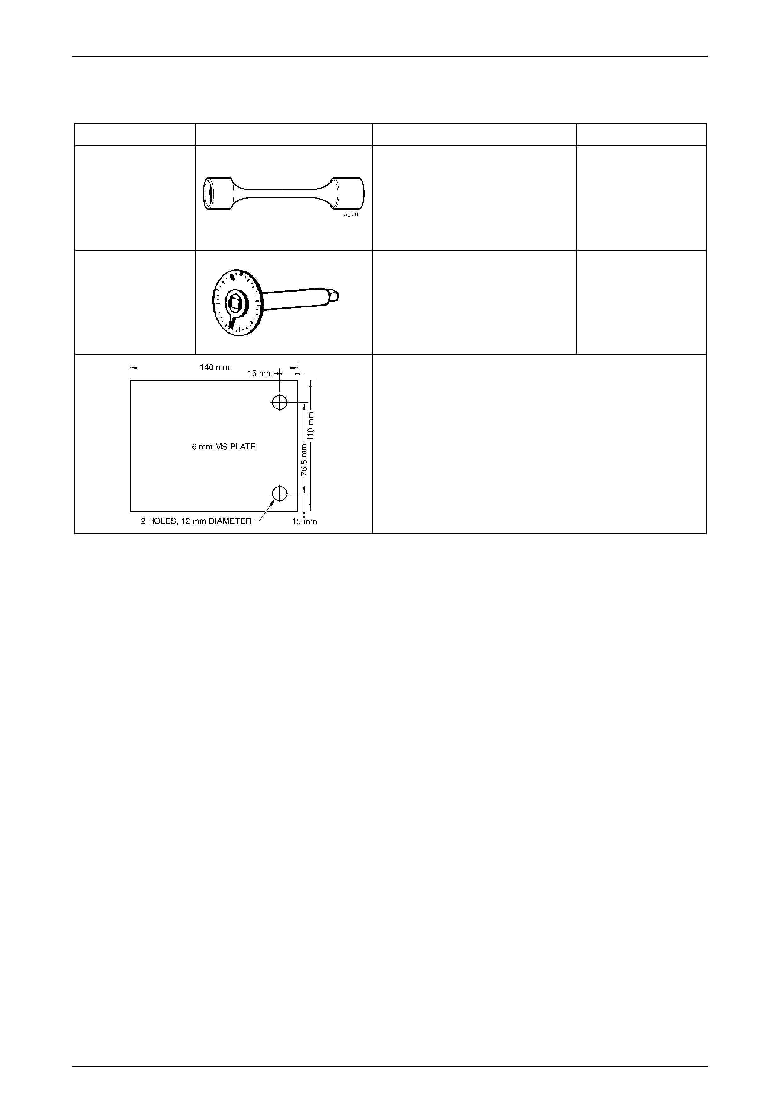
6. Special Tools
TOOL NUMBER ILLUSTRATION DESCRIPTION CLASSIFICATION
AU534
TOR QUE LIMITING SOCKET
Used in conjunction with an impact
gun to tighten wheel nuts.
Essential
E7115
ANGLE WRENCH
1. Previously released for 'J' and
'V' cars, as Tool No. 394.
2. Used to tighten component
fasteners when angle torque is
required.
Available
DIAL INDICATOR PLATE
Dealer fabric ated:
1. Fabricated from 6mm thick Mild Steel Plate.
2. If using the caliper bolts to attach the plate to the trunnion, a
17mm spacer will need to be installed on each bolt, prior to
installing.