
ABS Page 5B –1
Page 5B–1
Section 5B
ABS
ATTENTION
Before performing any Service Operation or other procedure described in this Section, refer to Section 00
CAUTIONS AND NOTES for correct workshop practices with regard to safety and/or property damage.
1 General Information............................................................................................................................... 2
1.1 General Description...............................................................................................................................................2
2 Service Operations................................................................................................................................5
2.1 Service Notes..........................................................................................................................................................5
General Information...............................................................................................................................................5
2.2 Rear Wheel Speed Sensor.....................................................................................................................................7
Remove ...................................................................................................................................................................7
Inspect.....................................................................................................................................................................8
Reinstall ..................................................................................................................................................................8
2.3 Rear ABS Pulse Ring.............................................................................................................................................9
Remove ...................................................................................................................................................................9
Install.....................................................................................................................................................................10
3 Specifications....................................................................................................................................... 11
4 Torque Wrench Specifications........................................................................................................... 12
5 Special Tools........................................................................................................................................ 13
Techline
Techline
Techline
Techline
Techline

ABS Page 5B –2
Page 5B–2
1 General Information
1.1 General Description
The Antilock Braking System (ABS) as fitted to MY2003 VY Series Cab Chassis Models, mainly carries over from
previous MY 2003 VY Series Utility Models, noting the following exceptions:
• The rear wheel ABS sensors along with associated wiring are new to accommodate the rigid live axle design and
are unique to MY2003 VY Series Cab Chassis Models.
• The rear wheel ABS sensors are located in a dedicated aperture of each rear brake backing plate. The rear disc
brake backing plates and shields are unique to MY2003 VY Series Cab Chassis Models. For further serving details
refer to Section 5A, Service And Park Braking System in MY2003 VY Series Cab Chassis Models Service
Information.
• MY2003 VY Series Cab Chassis Models equipped with ABS are not equipped with Traction Control Systems (TCS).
For further servicing details of the service and park braking system, as fitted to MY2003 VY Series Cab Chassis Models,
refer to Section 5A, Service And Park Braking System in the MY2003 VY Series Cab Chassis Models Service
Information.
For further servicing details of the ABS Braking System, as fitted to MY2003 VY Series Cab Chassis Models,
refer to Section 5B, ABS & ABS-TCS in the MY 2003 VY and V2 Series Service Information.
There is only one type of Antilock Braking System (ABS) fitted to MY2003 VY Series Cab Chassis Models (production
option JL9). On all MY2003 VY Series Cab Chassis Models fitted with ABS, the master cylinder has a screw-in blanking
plug installed into the lower of the two front brake outlets. Each front wheel hub also includes the wheel speed sensor as
part of the assembly. Internally toothed pulse rings are attached to each of the inner axle shaft flanges, which provide a
signal that is detected by indi vidual ABS wheel speed sensors located in the rear axle backing plate of each side.
At road speeds above approximately 6 km/h, the ABS is designed to control brake fluid pressure so that the wheels are
prevented from locking-up during braking, irrespective of the road conditions and tyre grip. The system starts to regulate
when one wheel is detected to be decelerating faster than the other wheels, tending to lock. The vehicle remains
steerable, even in the event of panic braking, for instance on bends or when swerving to avoid an obstacle.
The ABS, modulates braking pressure separately at each front wheel, with the rear wheels sharing a single ABS
modulated hydraulic circuit. This Antilock Braking System (ABS) is referred to as a three-channel system, as three
separate hydraulic brake circuits are used to achieve anti-lock braking function.
The Tech 2 diagnosti c scan tool is programmed to assist with MY2003 VY Series Cab Chassis Models, electrical
diagnosis and probl em so lv ing , includ ing ABS.
Tech 2, connects to the ABS or ABS/TCS serial data communication information via the Data Link Connector (DLC),
which is attached to the instrument panel lower trim, to the right of the steering column. For additional information on
DLC location and system diagnosis, refer to 3. ABS Diagnosis in this Section or Section 5B, ABS & ABS-TCS in MY
2003 VY and V2 Series Service Information.
For additional and more comprehensive information regarding Tech 2, refer to Section OC, 6 TECH 2 Diagnostics in
MY 2003 VY and V2 Series Service Information.
ABS Page 5B –3
Page 5B–3
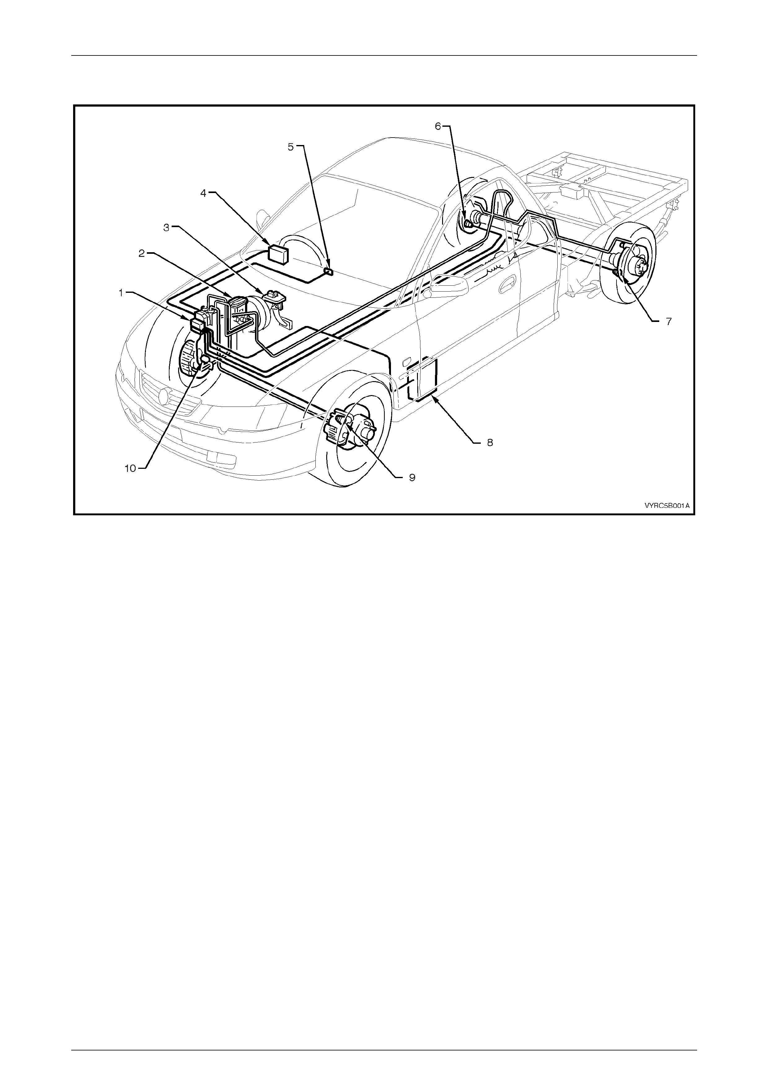
Typical Location for ABS Components Fitted to a Vehicle with V6 Engine.
Figure 5B-1
Legend
1 Hydraulic Modulator and Control Module
Assembly
2 Brake Master Cylinder
3 Stop Lamp Switch
4 Body Control Module (BCM)
5 ABS OFF Warning Lamp
6 Right-Hand Rear Wheel Speed Sensor
7 Left-Hand Rear Wheel Speed Sensor
8 Powertrain Control Module (PCM) – For ABS Only
9 Left-Hand Front Wheel Speed Sensor
10 Right-Hand Front Wheel Speed Sensor
ABS Page 5B –4
Page 5B–4
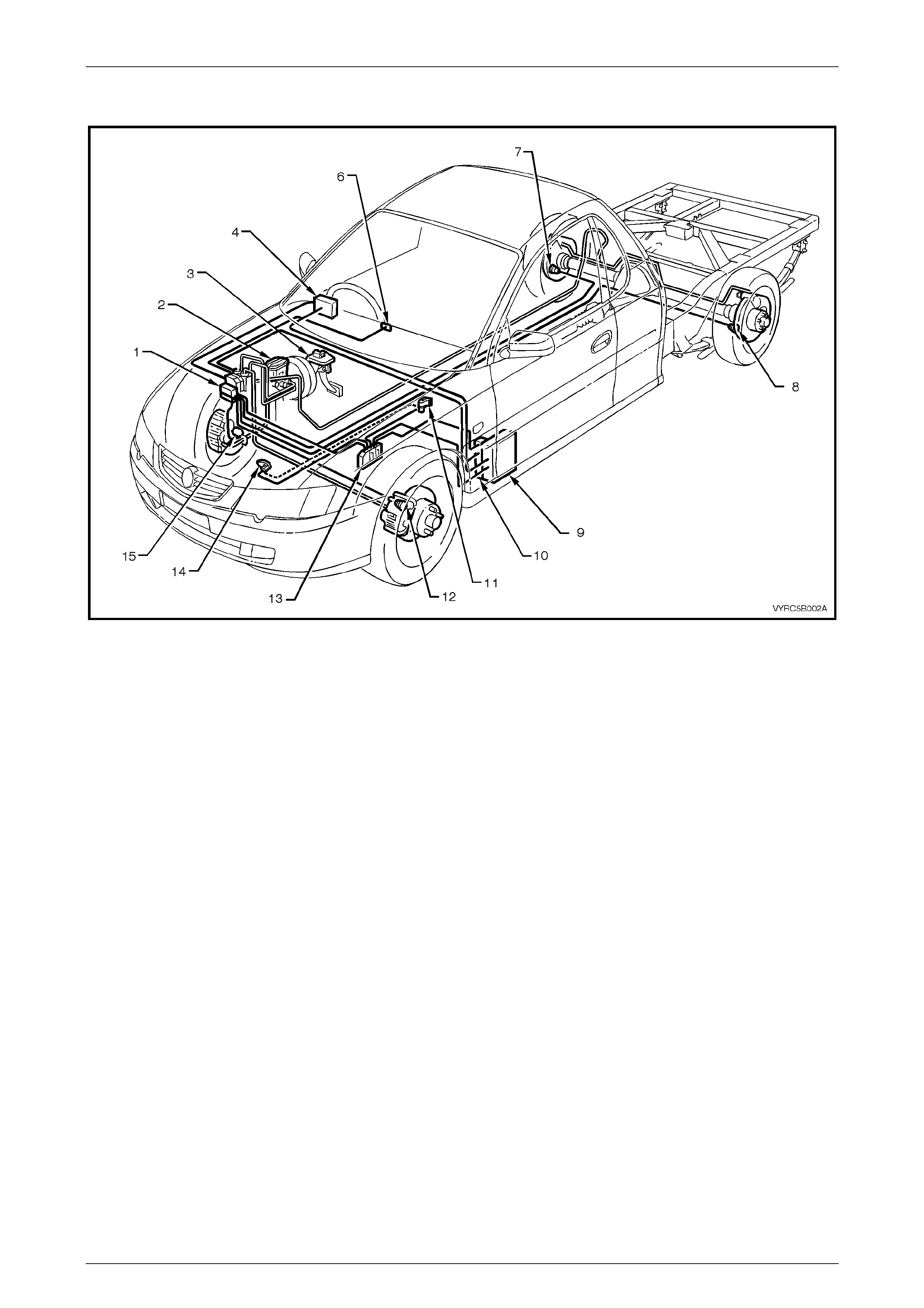
Typical Location for ABS Components fitted to a Vehicle with GEN III V8 Engine.
Figure 5B-2
Legend
1 Hydraulic Modulator and Control Module
Assembly
2 Brake Master Cylinder
3 Stop Lamp Switch
4 Body Control Module (BCM)
5 ABS OFF Warning Display
6 Traction Control On/Off Switch (in Console)
7 Right-Hand Rear Wheel Speed Sensor
8 Left-Hand Rear Wheel Speed Sensor
9 Powertrain Interface Module (PIM)
10 Throttle Relaxer (Actuator) Control Module
11 Throttle Relaxer (Ac tuator) Assembly
12 Left-Hand Front Wheel Speed Sensor
13 Powertrain Control Module (PCM) – For ABS/TCS
Only
14 Throttle Position Sensor (TP Sensor)
15 Right-Hand Front Wheel Speed Sensor

ABS Page 5B –5
Page 5B–5
2 Service Operations
ATTENTION
All rear axle fasteners are important attaching parts as they affect the performance of vital components
and/or could result in major repair expense. Where specified in this section, fasteners MUST be replaced with
parts of the same part number or a GM approved equivalent. Do not use fasteners of an inferior quality or
substitute design.
Torque values must be used as specified during reassembly to ensure proper retention of all steering
components.
Through out this section, fastener torque wrench specifications may be accompanied with the following
Identification marks:
+
++
+ Fasteners must be replaced after loosening.
!
!!
! Vehicle must be at curb height before final tightening.
6
66
6 Fasteners either have micro encapsulated sealant applied or incorporate a mechanical thread lock and
should only be re-used once. If in doubt, replacement is recommended.
If one of these identification marks is present alongside a fastener torque wrench specification, the
recommendation regarding that fastener must be adhered to.
2.1 Service Notes
General Informat io n
The service operations, for the Antilock Braking System (ABS) as fitted to MY2003 VY Series Cab Chassis Models
mainly carry over from previous MY2003 VY Series Models, noting the following:
• The rear wheel ABS sensors along with associated wiring are new to accommodate the rigid live axle design.
• The rear wheel ABS sensors are located in a dedicated aperture of each rear brake backing plate.
• The rear disc brake backing plates and shields are unique.
• A load sensing proportioning valve is fitted to MY2003 VY Series Cab Chas sis Models, refer to Section 5A, Service
And Park Braking System, 2.5 Load Sensing Proportioning Valve in this Service Information.
For further servicing details of the service and park braking system, as fitted to MY2003 VY Series Cab Chassis Models,
refer to Section 5A, Service And Park Braking System in the MY2003 VY Series Cab Chassis Models Service
Information.
For further servicing details of the ABS Braking System, as fitted to MY2003 VY Series Cab Chassis Models,
refer to Section 5B, ABS & ABS-TCS in the MY 2003 VY Series and V2 Series Service Information.
For additional servicing details on the ABS, reference can also be made to:
1 Section 3, Front Suspension in MY 2003 VY Series and V2 Series Service Information, for information relating to
front wheel bearing hub removal and/or reinstallation operations.
2 Section 4B, Rear Axle in this Service Information, for details of rear axle sensor related components.
3 General brake bleeding operations is described in Section 5A, Service And Park Braking Systems in this Service
Information.

ABS Page 5B –6
Page 5B–6
IMPORTANT
When bleeding operations are carried out,
that involve the ABS Hydraulic Control
Module, then specific procedures must be
followed that require the use of Tech 2. Refer
to Section 5B, ABS & ABS-TCS, 4.8 Tech 2
Test Modes And Screen Displays for ABS &
TCS Diagnosis in the MY2003 VY Series and
V2 Series Service Information.
The Tech 2 diagnostic scan tool is programmed to assist with MY 2003 VY Series Cab Chassis vehicle electrical
diagnosis and probl em so lv ing , includ ing ABS.
Tech 2 connects to the ABS serial data communication information via the Data Link Connector (DLC), attached to the
instrument panel lower trim, to the right of the steering column. For additional information on DLC location and system
diagnosis, refer to 4. ABS DIAGNOSIS in this Section. For additional and more comprehensive information regarding
Tech 2, refer to Section 5B, 4.8 Tech 2 Test Modes and Screen Displays For ABS & TCS Diagnosis in MY 2003 VY and
V2 Series Service Information.
ABS Page 5B –7
Page 5B–7
2.2 Rear Wheel Speed Sensor
LT Section No: H901400
ATTENTION
The following fasteners have either micro encapsulation or incorporate a mechanical thread lock and should
only be used once. If in doubt, replacement is recommended when performing this operation:
$ ABS wheel speed sensor-attaching bolt.
Remove
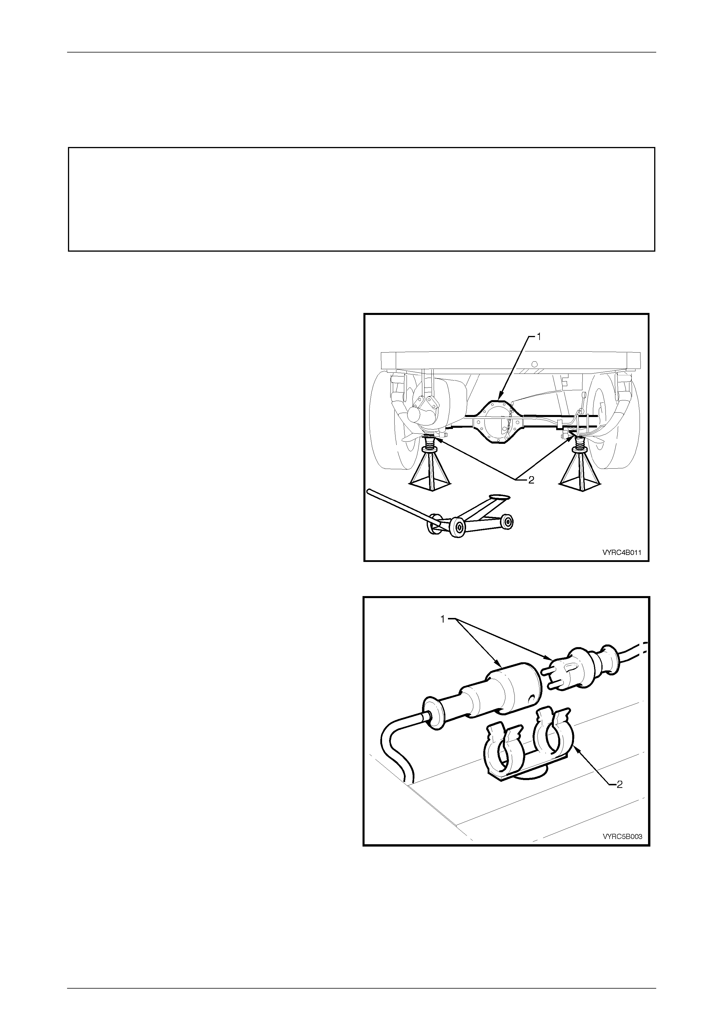
1 Using a floor jack under the centre of the rear axle
assembly (1), jack up the rear of the vehicle, then
place safety stands under the rear leaf spring retainer
plates (2) to support the weight of the vehicle as
shown in Figure 5B-3.
Figure 5B-3
2 Disconnect the rear ABS sensor wiring harness
connector (1) mounted on the chassis by a retaining
clip (2) as shown in Figure 5B-4.
Figure 5B-4
ABS Page 5B –8
Page 5B–8
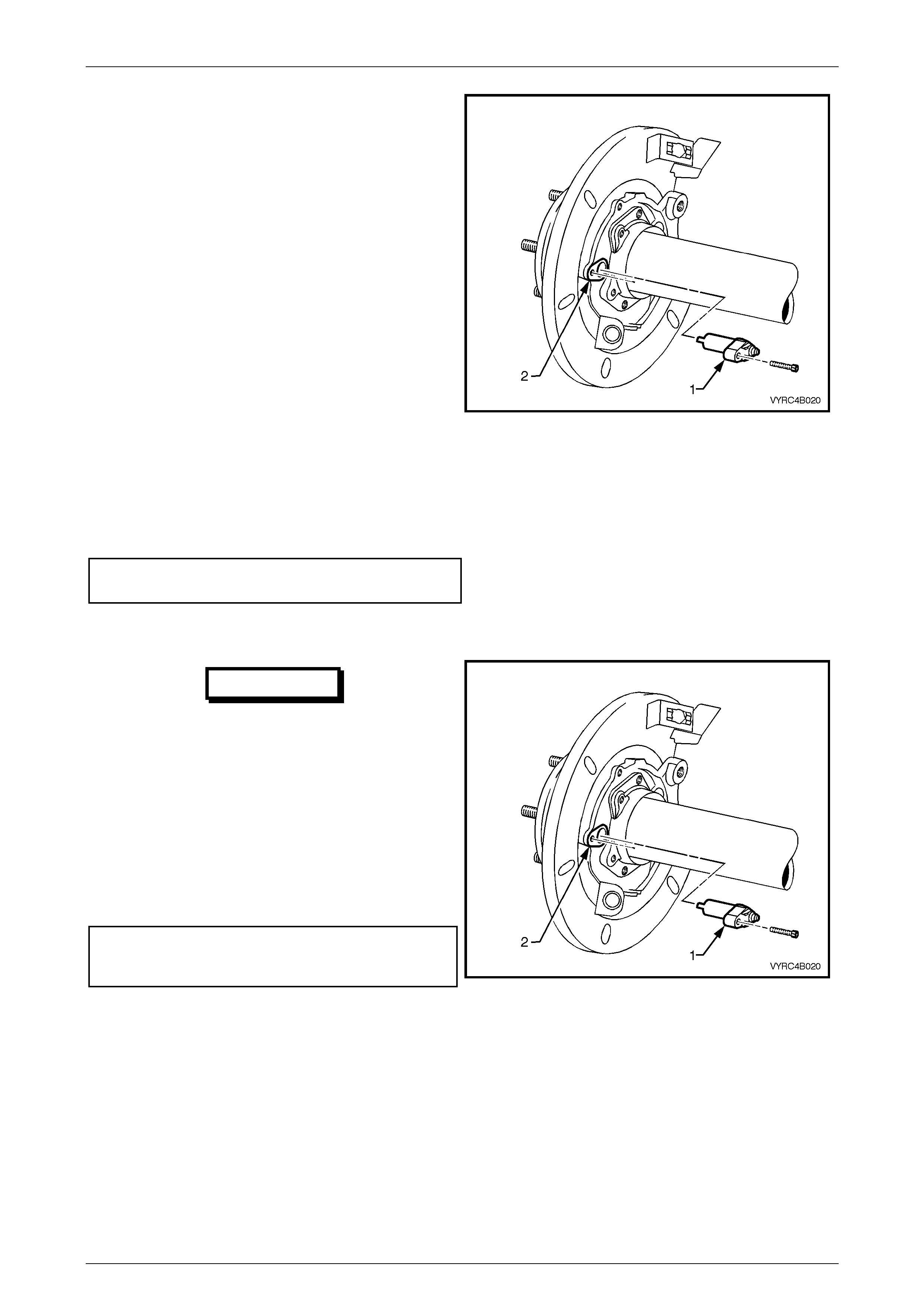
3 Remove the ABS wheel speed sensor (1) from the
rear axle housing ABS sensor aperture (2) as shown
in Figure 5B-5.
Figure 5B-5
Inspect
1 Clean and inspect the sensor for signs of damage and replace if required.
2 Check that the resistance of the sensor is to specification
Rear wheel ABS sensor
resistance..................................................1.6 KΩ ± 10%
Reinstall
IMPORTANT
A replacement wheel sensor must only be taken out its
packaging immediately before installing on the vehicle.
1 Reinstall the ABS wheel speed sensor (1) to the ABS
sensor aperture (2) and re-connect the sensor to the
wiring harness.
2 Install the ABS wheel speed sensor attaching bolt to
the rear axle housing.
3 Tighten the ABS wheel speed sensor attaching bolt to
the correct torque specification as shown in Figure
5B-6.
($) ABS wheel speed sensor
attaching bolt
torque specification ........................................ 6 – 14 Nm
Figure 5B-6
ABS Page 5B –9
Page 5B–9
2.3 Rear ABS Pulse Ring
LT Section No. – 05-400
Remove
1 Remove the rear axle shaft assembly from the
vehicle. For the removal procedure refer to
Section 4B, 2.8 Rear Axle Shaft Assembly in this
Service Information.
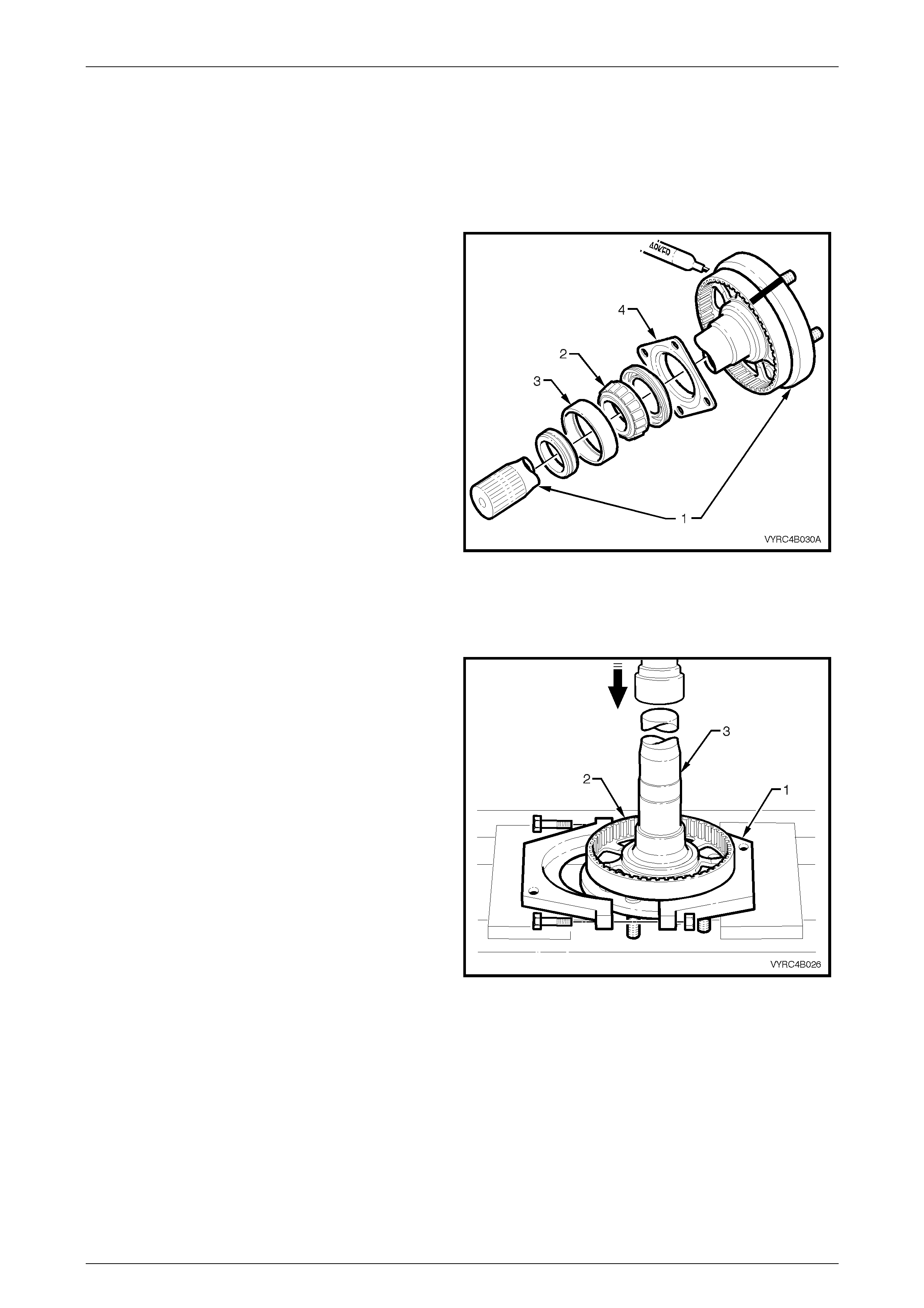
2 To remove the ABS pulse ring it is necessary to
remove the rear axle bearing retainer collar, bearing
cone (3), inner bearing race (2), oil seal and retainer
plate (4) from the rear axle shaft (1). Refer to Figure
5B-7. For the removal procedure refer to Section 4B,
2.8 Rear Axle Shaft Assembly in this Service
Information.
3 Use a felt tipped pen to scribe relationship marks on
the side of both the rear axle shaft flange and the
ABS pulse ring. Refer to Figure 5B-7.
NOTE:
The relationship marking of the axle shaft flange
and ABS pulse ring is necessary to align the
large hole in the axle shaft flange with an
opening between the webbing of the ABS pulse
ring to facilitate removal of the axle shaft
retainer plate attaching bolts. Refer to Figure
5B-7.
Figure 5B-7
4 Using Tool No. AU607-1 (1 ) a suitable hydraulic press
and support pl ates, remove the ABS pulse ring (2)
from rear axle shaft (3). For the removal procedure
refer to Section 4B, 2.8 Rear Axle Shaft Assembly in
this Service Information.
Figure 5B-8

ABS Page 5B –10
Page 5B–10
Install
Reinstallation of the ABS pulse ring, thrust retainer plate, oil seal, inner bearing race, and new retaining collar to the axle
shaft is the reversal of the removal procedure noting the following points.
NOTE:
If installing a new ABS pulse ring, ensure the
relationship mark scribed on the old pulse ring is
transferred to the new pulse ring. The relationship
marking of the axle shaft flange and ABS pulse
ring is necessary to align the large hole in the
axle shaft flange with an opening between the
webbing of the ABS pulse ring to facilitate
removal of the axle shaft retainer plate attaching
bolts.
IMPORTANT
The bearing retainer collar can only be used
once and must be replaced.
NOTE:
Before installation, pre-lubricate the inner seal
lips of the oil seal with Lithium No.2 Grease.
NOTE:
Care must be taken to ensure the bearing race
and retaining collar is fitted squarely during
installation.
NOTE:
Apply sufficient load to ensure the proper seating
of all components.

ABS Page 5B –11
Page 5B–11
3 Specifications
Rear Wheel Speed Sensors
Resistance.........................................................................................................1.6 KΩ ± 10%

ABS Page 5B –12
Page 5B–12
4 Torque Wrench Specifications
ATTENTION
All ABS fasteners are important attaching parts as they affect the performance of vital components and/or
could result in major repair expense. Where specified in this section, fasteners MUST be replaced with parts
of the same part number or a GM approved equivalent. Do not use fasteners of an inferior quality or
substitute design.
Torque values must be used as specified during reassembly to ensure proper retention of all ABS
components.
Through out this section, fastener torque wrench specifications may be accompanied with the following
Identification marks:
+
++
+ Fasteners must be replaced after loosening.
!
!!
! Vehicle must be at curb height before final tightening.
6
66
6 Fasteners either have micro encapsulated sealant applied or incorporate a mechanical thread lock and
should only be re-used once. If in doubt, replacement is recommended.
If one of these identification marks is present alongside a fastener torque wrench specification, the
recommendation regarding that fastener must be adhered to.
Nm
$ Rear Wheel Speed Sensor Attaching Bolt.............................................6 – 14
ABS Page 5B –13
Page 5B–13
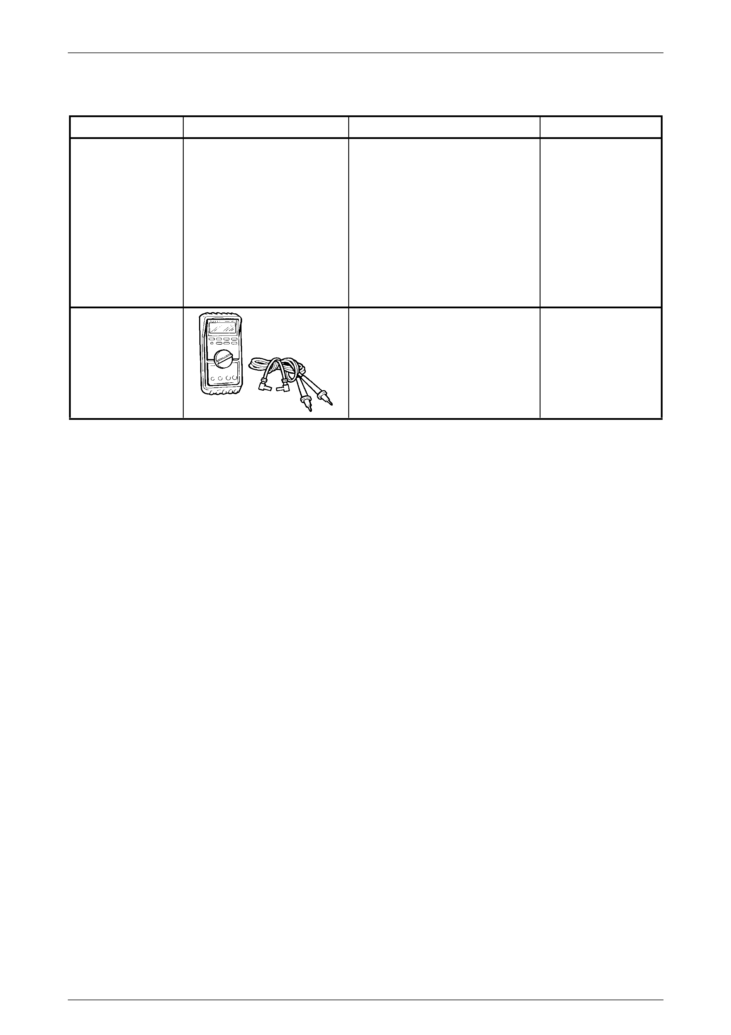
5 Special Tools
TOOL NUMBER ILLUSTRATION DESCRIPTION CLASSIFICATION
AU607 ABS PULSE RING REMOVER AND
INSTALLER
Used to remove and install the ABS
pulse ring from the rear axle shaft.
Includes:
1. AU607-1 ABS Pulse Ring
Remover
2. AU607-2 ABS Pulse Ring
Installer.
Unique
3588
DIGITAL MULTIMETER
Also Previously released as J39200
(or use commercial equivalent).
NOTE: The instrument must have
10 Megohms impedance and be
capable of reading frequencies.
Available