
Engine Cooling - GEN III V8 Engine Page 6B3–1
Page 6B3–1
Section 6B3
Engine Cooling - GEN III V8 Engine
ATTENTION
Before performing any Service Operation or other procedure described in this Section, refer to Section 00
CAUTIONS AND NOTES for correct workshop practices with regard to safety and/or property damage.
1 General Information............................................................................................................................... 2
1.1 General Description................................................................................................................................................2
Cooling Fans...........................................................................................................................................................2
Operation............................................................................................................................................................3
2 Service Operations................................................................................................................................8
3 Engine Cooling System Diagnosis ...................................................................................................... 9
4 Specifications....................................................................................................................................... 10
Small Engine Cooling Fan – (Left) ......................................................................................................................10
Large Engine Cooling Fan – (Right) ...................................................................................................................10
Techline

Engine Cooling - GEN III V8 Engine Page 6B3–2
Page 6B3–2
1 General Information
With the following exceptions, MY 2003 VY Series cab Chassis GEN III V8 cooling system information carries over from
MY 2003 VY Series vehicles. For information not contained within this Section, refer to Section 6B3, Engine Cooling -
GEN III V8 Engine in the VY and V2 Series Service Information.
• A unique series /parallel cooling fan circuit that includes an additional relay has been introduced.
• The cooling fans mounted behind the radiator are equipped with high power electric motors.
• The cooling fan wiring and connectors are unique.
1.1 General Description
Cooling Fans
The cooling system for the GEN III V8 engine, includes two, double speed, engine cooling fan motors, both of which,
drive fans with five asymmetrical blades. The larger, right fan is 342 mm in diameter and has a motor rated at 215 Watts
(nominal), while the smaller, left fan is 293 mm in diameter with a motor power rating of 215 Watts (nominal).
With 12 volts applied and the fans mounted to the radiator with a condenser fitted, the operating speeds are:
Stage 1 Stage 2
Large Fan 1200 ± 150 rpm 2400 ± 150 rpm
Small Fan 1700 ± 150 rpm 3000 ± 150 rpm
Figure 6B3-1

Engine Cooling - GEN III V8 Engine Page 6B3–3
Page 6B3–3
Legend (Figure 6B3-1)
1. Fan Shroud
2. Radiator
3. Fan Shroud Lower Support
4. Fan Shroud Upper Support/Locking Retainer
5. Small, Left Fan – 5 Blade, 293 mm Diameter
6. Small, Left Fan Motor – 215 Watt, Double Speed
7. Left Fan Motor Harness Connector (2 Terminal)
8. Left and Right Fan Motor Harness Connector (4
terminal)
9. Large, Right Fan – 5 Blade, 342 mm Diameter
10. Large, Right Fan Motor – 215 Watt, Double Speed
11. Oil Cooler, Lower Quick Connect Fitting (Auto. Trans
Only)
12. Oil Cooler, Upper Quick Connect Fitting (Auto. Trans
Only)
Operation
To achieve the dual speed requirement, the electrical circuit for the GEN III V8 cooling fans as fitted to MY 2003 VY
Series Cab Chassis Models incorporates an additional relay. This relay is required to switch from a series circuit during
stage 1 cooling fan operation, to a parallel circuit at stage 2 cooling fan operation. This new series/parallel cooling fan
switching arrangement has been introduced into MY2003 VY Series Cab Chassis Models to prevent contacts from
overload, as well as headlamp or instrument illumination from variations that would have occurred with the use of the
new larger fan motors and the existing 3/4 parallel switching arrangement used on MY2003 VY Series Sedan and
Wagon Models.
The positive terminals of the cooling fans are permanently connected to battery voltage, via fusible links F101 (both fans
at stage 1 and large fan at stage 2) and F107 (small fan at fan stage 2).
Engine Cooling - GEN III V8 Engine Page 6B3–4
Page 6B3–4
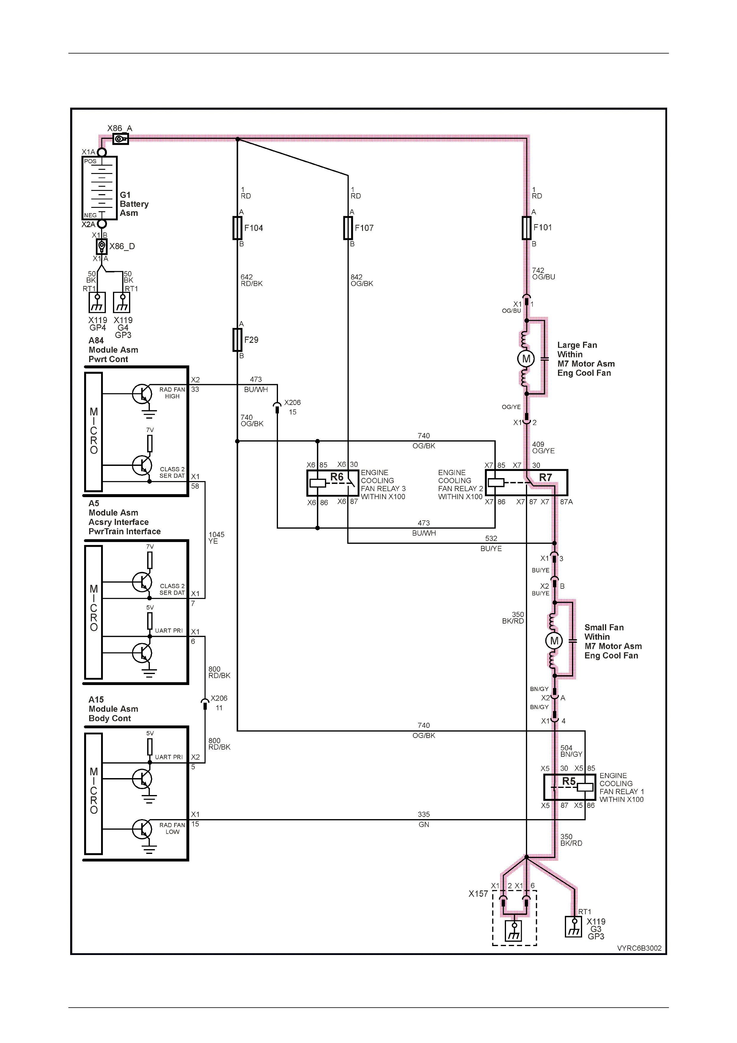
Stage One Fan Operation
Figure 6B3-2

Engine Cooling - GEN III V8 Engine Page 6B3–5
Page 6B3–5
The PCM determines when the engine cooling fans should operate at stage 1 (i.e. engine cooling fan relay 1 should be
energised), based on inputs from the A/C request signal, Engine Coolant Temperature (ECT) sensor and the Vehicle
Speed Sensor (VSS). The PCM will then send a message on the Class 2 serial data circuit to the PIM. The PIM will then
convert the PCM Class 2 message to a UART message and supply this UART message to the BCM, via a serial data
Normal Mode Message to the BCM on circuit 800 (Red/Black wire). This message will request the BCM to supply the
necessary ground signal for the engine cooling fan relay 1 (R5) to operate.
When engine cooling fan relay 1 is turned ON (energised), stage 1 fan operation is achieved by supplying battery voltage
(via fusible link F101) through the large, right cooling fan and relay 2 (R7), then on through the small, left cooling fan and
relay 1 (R5) to ground.
After the BCM provides the ground signal for the engine cooling fan relay 1, the BCM will send a message back to the
PIM confirming that the ground signal was commanded. A failure in this BCM response communication, will cause a PIM
DTC B2002 to set.
The engine cooling fan relay 1 (R5) will be turned ON when:
• The A/C request indicated (YES) and either:
• the vehicle speed is less than 30 km/h or;
• A/C pressure is greater than 1500 kPa or;
• The coolant temperature is greater than 98° C or;
• If the coolant temperature is greater than 113° C, when the ignition is switched off, the relay is energised for
approximately four minutes, this is known as Low Fan Run On, or;
• If an engine coolant temperature sensor fault is detected and a DTC such as DTC P0117, P0118, P1114 or P1115
is set.
The engine cooling fan relay 1 will be turned OFF when any of the following conditions have been met:
• An A/C request is not indicated (NO) and the coolant temperature is less than 95° C, or;
• An A/C request is indicated (YES) and the vehicle speed is greater than 50 km/h and A/C pressure is less than
1,170 kPa and the coolant temperature is less than 98° C.
Engine Cooling - GEN III V8 Engine Page 6B3–6
Page 6B3–6
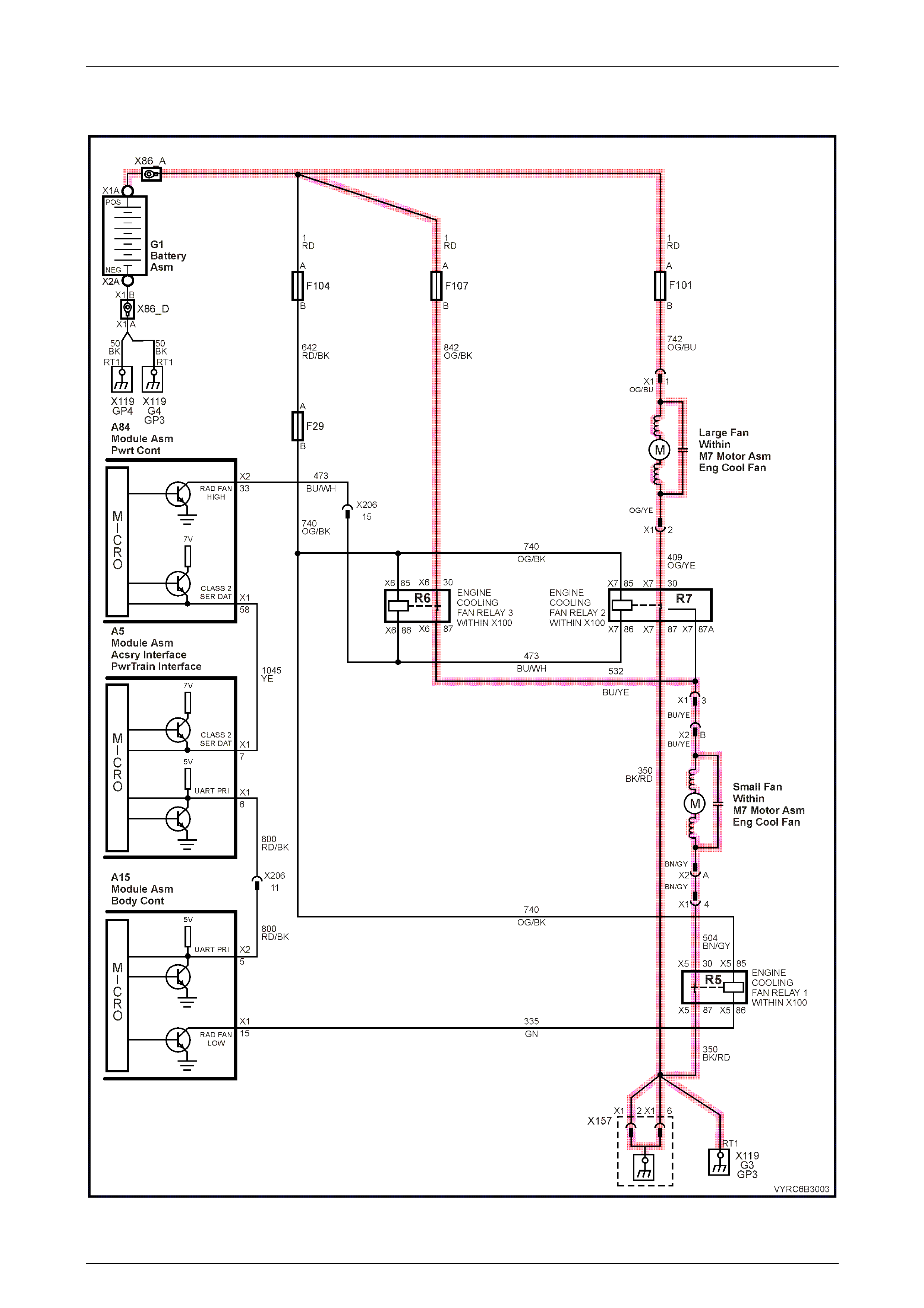
Stage Two Fan Operation
Figure 6B3-3

Engine Cooling - GEN III V8 Engine Page 6B3–7
Page 6B3–7
The switching of the engine cooling fans to stage 2 operation is controlled directly by the PCM. To achieve stage 2 fan
operation, the engine cooling fan relay 2 (R7) and engine cooling fan relay 3 (R6) are provided with a ground signal by
the PCM. When engine cooling fan relay 2 is turned ON (energised), it connects the negative terminal of the large, right
cooling fan directly to earth, taking the small, left cooling fan out of the circuit and consequently increasing the speed of
the large, right fan. When engine cooling fan relay 3 is turned ON (energised), it supplies battery voltage (via fusible link
F107) to the positive terminal of the small, left cooling fan, then through relay 1 (R5) to ground.
Cooling fan relay 3 (R6) is a standard four-pin type relay. During the change from stage 1 to stage 2 fan operation, the
left, small cooling fan is switched to maximum speed by supplying battery voltage via fusible link F107.
The PCM will only activate stage 2 fan operation, if the engine cooling fan relay 1 has been ON (energised) for two
seconds and the following conditions are satisfied:
• There is a BCM message response fault which will cause a PIM DTC B2002.
• An engine coolant temperature sensor fault is detected and a DTC such as DTC P0117, P0118, P1114 or P1115 is
set.
• Coolant temperature greater than 108° C.
• The A/C refrigerant pressure is greater than 2400 kPa.
If the engine cooling fan relay 1 was OFF when the criteria was met to activate engine cooling fan relay 2, stage 2 fan
operation will occur, 5 seconds after the engine cooling fan relay 1 is turned ON. If both engine cooling fan relays are
ON, the PCM will turn OFF engine cooling fan relay 2 when:
• The engine coolant temperature is less than 102° C.
• A/C request not indicated (NO).
• A/C request indicated (YES) and A/C pressure is less than 1900 kPa.
NOTE
Both cooling fans will be turned off if the vehicle
speed is greater than 104 km/h.
NOTE
The PCM determines operation of the two, two-
speed engine cooling fans based on A/C request,
A/C system pressure, engine coolant temperature
and vehicle speed signal inputs. For further
details of the engine cooling fan operation and
diagnosis of the system, refer to Section 6C3,
Powertrain Management – GEN III V8 Engine in
this Service Information.

Engine Cooling - GEN III V8 Engine Page 6B3–8
Page 6B3–8
2 Service Operations
With the following exceptions, MY 2003 VY Series Cab Chassis GEN III V8 cooling system carries over from MY 2003
VY Series vehicles. For service operation information not covered in this Section, refer to Section 6B3, 2. Service
Operations in the VY and V2 Series Service Information.
• The wiring connectors for the cooling fans have been revised.
NOTE
Although the wiring connectors for the cooling
fans has been revised, the service operations
remains unchanged from those provided in to
Section 6B3, 2. Service Operations in the MY
2003 VY and V2 Series Service Information.
For details about the revised wiring connectors,
refer to Section 6C3, Powertrain Management -
GEN III V8 Engine in this Service Information.

Engine Cooling - GEN III V8 Engine Page 6B3–9
Page 6B3–9
3 Engine Cooling S ystem
Diagnosis
With the following exceptions, MY 2003 VY Series Cab Chassis GEN III V8 cooling system carries over from MY 2003
VY Series vehicles. For diagnostic information not covered in this Section, refer to Section 6B3, 3. Engine Cooling
System Diagnosis in the VY and V2 Series Service Information.
• The cooling fans mounted behind the radiator are equipped with high power electric motors.
• The wiring to the cooling fan motors is unique.
• The cooling fan circ uit includes an additional relay.
NOTE
For information regarding the general diagnosis
of the mechanical portion of the engine cooling
system as fitted to MY2003 VY Series Cab
Chassis Models equipped with a GEN III V8
engine, refer to Section 6B3, 3. Engine Cooling
System Diagnosis in the VY Series and V2 Series
Service Information.
For information regarding the electrical diagnosis
of the engine cooling fan circuit as fitted to
MY2003 VY Series Cab Chassis Models
equipped with a GEN III V8 engine, refer to
Section 6C3, Powertrain Management - GEN III
V8 Engine in this Service Information.

Engine Cooling - GEN III V8 Engine Page 6B3–10
Page 6B3–10
4 Specifications
Small Engine Cooling Fan – (Left)
Fan
Type........................................................Asymmetrical spaced, curved blades with outer ring
Material................................. Nylon 6,6 (30% Glass Filled), with zinc coated metal hub insert
Number of Blades .................................................................................................................. 5
Diameter ..................................................................................................................... 293 mm
Fan Motor
Type .............................................................Dual speed, 4 brush wi th 4 permanent magnets
Housing............................................................Semi-sealed, zinc coated steel with drain hole
Direction of Rotation.......................................Counter-clockwise (as viewed from motor side)
Power....................................................................................................... 215 Watts (nominal)
Rotational Speed (Radiator and Condenser Installed)
Stage 1........................................................................................................... 1,700 ± 150 rpm
Stage 2........................................................................................................... 3,000 ± 150 rpm
Large Engine Cooling Fan – (Right)
Fan
Type........................................................Asymmetrical spaced, curved blades with outer ring
Material................................. Nylon 6,6 (30% Glass Filled), with zinc coated metal hub insert
Number of Blades .................................................................................................................. 5
Diameter ..................................................................................................................... 342 mm
Fan Motor
Type.............................................................. Dual speed, 4 brush with 4 permanent magnets
Housing............................................................Semi-sealed, zinc coated steel with drain hole
Direction of Rotation.......................................Counter-clockwise (as viewed from motor side)
Power....................................................................................................... 215 Watts (nominal)
Rotational Speed (with 12 volts applied, Radiator and Condenser Installed
Stage 1........................................................................................................... 1,200 ± 150 rpm
Stage 2........................................................................................................... 2,400 ± 150 rpm