
Powertrain Management – Gen III V8 Engine Page 6C3–1
Page 6C3–1
Section 6C3
Powertrain Management – Gen III V8 Engine
ATTENTION
Before performing any Service Operation or other procedure described in this Section, refer to Section 00
CAUTIONS AND NOTES for correct workshop practices with regard to safety and/or property damage.
1 General Information............................................................................................................................... 2
2 Diagnosis and Tech 2............................................................................................................................ 3
2.1 Diagnostic Tables...................................................................................................................................................4
GEN III V8 – DTC P0481 Cooling Fan High Speed Relay Control.......................................................................4
Circuit Description...............................................................................................................................................5
Conditions for Running the DTC.........................................................................................................................5
Conditions for Setting the DTC...........................................................................................................................5
Action Taken When the DTC Sets......................................................................................................................5
Conditions for Clearing the MIL/DTC..................................................................................................................5
Diagnostic Aids...................................................................................................................................................5
Test Description..................................................................................................................................................5
GEN III V8 PCM – DTC P0481 Cooling Fan High Speed Relay Control ............................................................6
2.2 Functional Checks .................................................................................................................................................9
GEN III V8 PCM – Engine Cooling Fan Control....................................................................................................9
Circuit Description.............................................................................................................................................10
Test Description................................................................................................................................................10
GEN III V8 PCM – Engine Cooling Fan Control................................................................................................11
3 Specifications....................................................................................................................................... 15
Engine Cooling.................................................................................................................................................15
Techline

Powertrain Management – Gen III V8 Engine Page 6C3–2
Page 6C3–2
1 General Information
With the following exceptions, MY 2003 VY Series Cab Chassis GEN III V8 Powertrain Management System general
information carries over from MY 2003 VY Series vehicles. For all GEN III V8 Powertrain Management System
information not contained within this Section, refer to Section 6C3-1 General Information – GEN III V8 Engine in the MY
2003 VY and V2 Series Service Information.
• A unique series /parallel cooling fan circuit that includes an additional relay has been introduced.
• The cooling fans mounted behind the radiator are equipped with high power electric motors.
• The cooling fan wiring and connector is unique.

Powertrain Management – Gen III V8 Engine Page 6C3–3
Page 6C3–3
2 Diagnosis an d Tech 2
With the following exceptions, MY 2003 VY Series Cab Chassis GEN III V8 Powertrain Management System diagnosis
and TECH 2 carries over from MY 2003 VY Series vehicles. For all GEN III V8 Powertrain Management System
diagnosis and TECH 2 information not contained within this Section, refer to Section 6C3-2 Diagnosis and Tech 2 - GEN
III V8 Engine in the MY 2003 VY and V2 Series Service Information.
• A unique series /parallel cooling fan circuit that includes an additional relay has been introduced.
• The cooling fans mounted behind the radiator are equipped with high power electric motors.
• The cooling fan wiring and connector is unique.
Powertrain Management – Gen III V8 Engine Page 6C3–4
Page 6C3–4
2.1 Diagnostic Tables
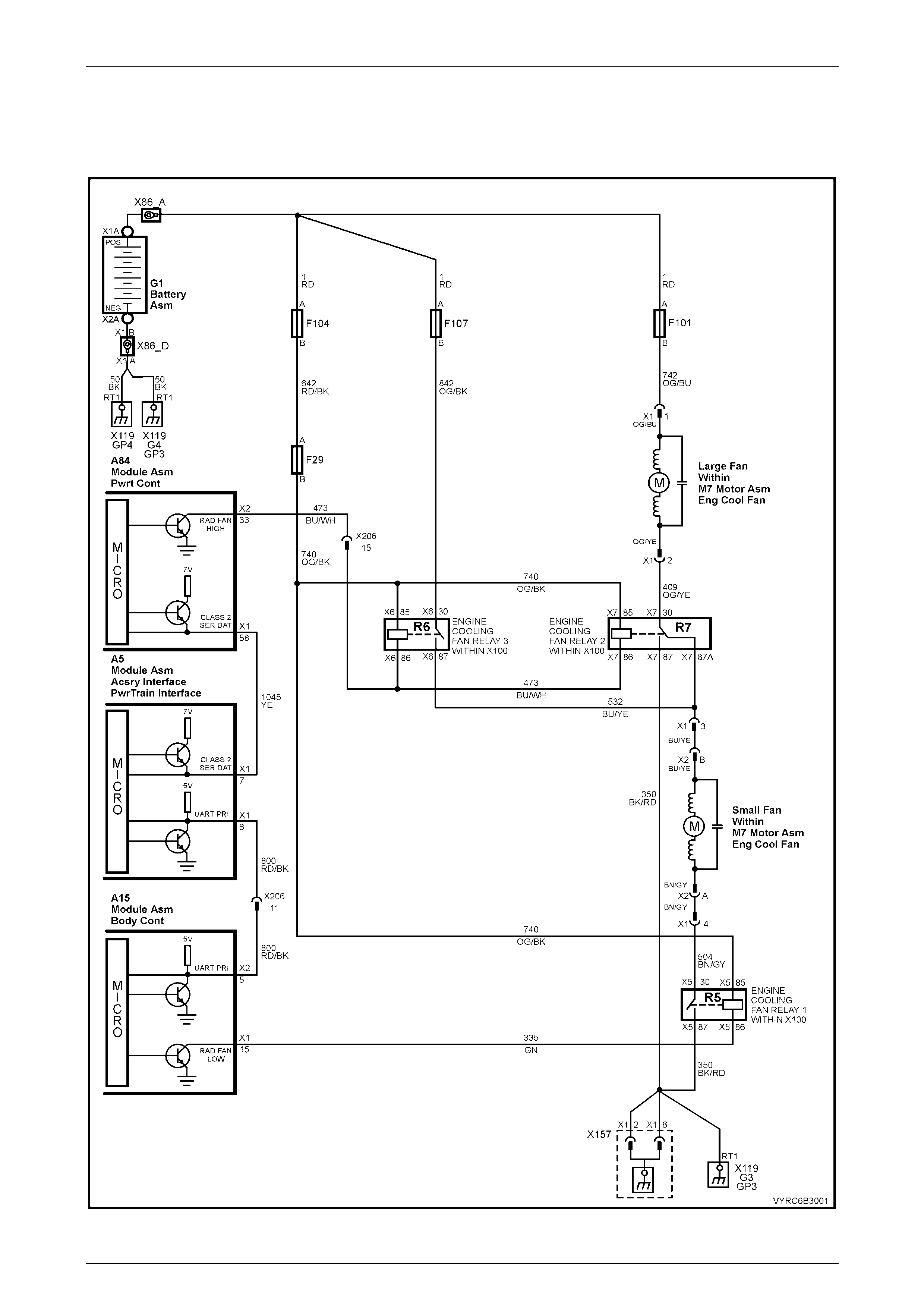
GEN III V8 – DTC P0481 Cooling Fan High Speed Relay Control
Figure 6C3-2A-1 – Cooling Fan Circuits

Powertrain Management – Gen III V8 Engine Page 6C3–5
Page 6C3–5
Circuit Description
Battery voltage is supplied directly to the cooling fan relay coils. The PCM controls the relay by grounding the control
circuit via an internal switch called a driver. The primary function of the driver is to supply the ground for the controlled
component. Each driver has a fault line which the PCM monitors. When the PCM commands a component ON, the
voltage of the control circuit should be low (near 0 volts). When the PCM commands the control circuit to a component
OFF, the voltage potential of the circuit should be high (near the battery voltage). If the fault detection circuit senses a
voltage other than what the PCM expected, the fault line status changes causing the DTC to set.
The relay controls the high current flow to the cooling fans. This allows the PCM driver to only have to control the
relatively low current used by the relay.
Conditions for Running the DTC
• The engine speed is greater than 600 RPM.
• The ignition voltage is between 6.0 and 16.0 volts.
Conditions for Setting the DTC
• The PCM detects that the commanded state of the driver and the actual state of the control circuit do not match.
• The conditions must be present for a minimum of 10 seconds.
Action Taken When the DTC Sets
• The PCM activates the Check Powertrain MIL when the diagnostic runs and fails.
• The PCM records the operating conditions at the time the diagnostic fails. The PCM stores this inform ation in the
Freeze Frame/Failure Records.
Conditions for Clearing the MIL/DTC
• The PCM deactivates the Check Powertrain MIL after the first ignition cycle that the di agnostic runs and does not
fail.
• A last test failed (current DTC) clears when the diagnostic runs and does not fail.
• Use Tech 2 to clear the MIL/DTC.
Diagnostic Aid s
Using the Freeze Frame/Failure Records data may aid in locating an intermittent condition. If you cannot duplicate the
DTC, the information include d in the Freeze Fram e/Fa ilure Record s data can aid in determi ning the dis t an ce trav elle d
since the DTC reported a pass and/or fail. Operate the vehicle within the same freeze frame conditions (RPM, load,
vehicle speed, temperature, etc.) that you observed. This will isolate when the DTC failed.
NOTE
For an intermittent, refer to Section 6C3-2B
Symptoms, in the MY 2003 VY and V2 Series
Service Information.
Test Description
NOTE
The number(s) below refer to the step number(s)
on the diagnostic table.
2/3. Listen for an audible click when the relay operates. Command both ON and OFF states. Repeat the commands if
necessary.
4. This check can detect a partially shorted coil which would cause excessive current flow. Leaving the circuit
energised for 2 minutes allows the coil to warm up. When warm, the coil may open (Amps drop to 0), or short (goes
above 0.75 Amps).
17. If you do not fi nd any trouble in the control circuit or the connection at the PCM, the PCM may be faulty.
Powertrain Management – Gen III V8 Engine Page 6C3–6
Page 6C3–6
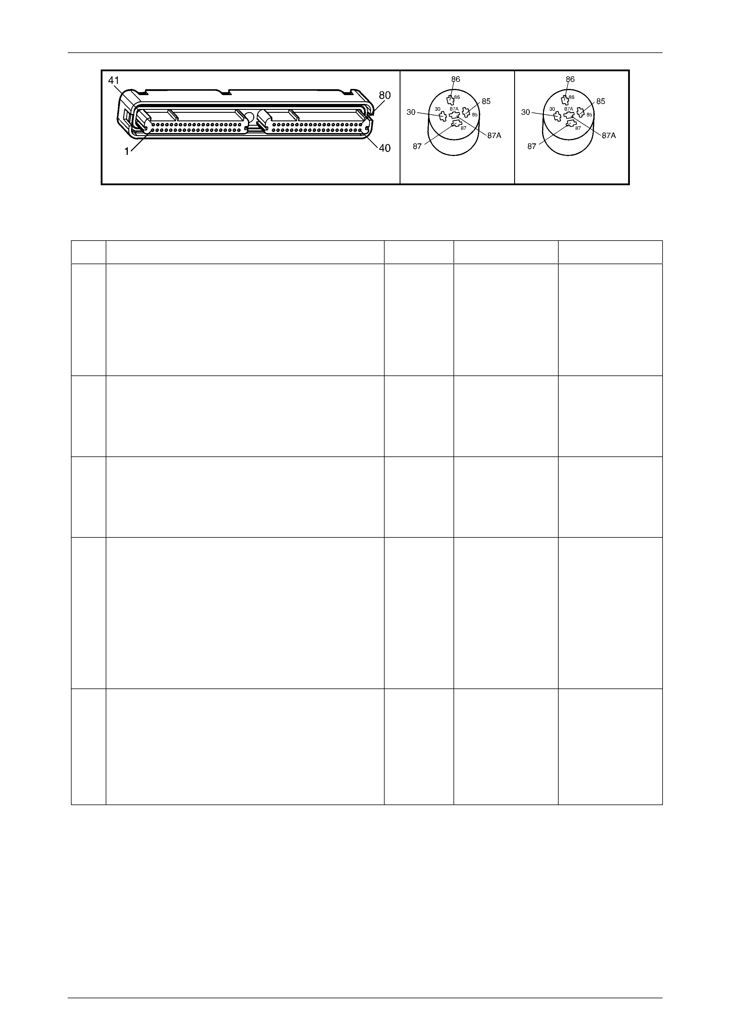
A84–X2 (RED) R5 (Part of X100) R6 (Part of X100)
Figure 6C3-2A-2
GEN III V8 PCM – DTC P0481 Cooling Fan High Speed Relay Control
Step Action Value(s) Yes No
1 Was the "On-Board Diagnostic" (OBD) System Check
performed? Go to Step 2 Perform the OBD
System Check, refer
to Section 6C3-2, 4.
Powertrain OBD
System Check in
the MY 2003 VY
and V2 Series
Service Informatio n
2 1. Ignition ON, engine OFF.
2. Command the cooling fan high speed relays ON
and OFF using Tech 2.
Does relay R5 turn ON and OFF when commanded?
Go to Step 3 Go to Step 6
3 1. Ignition ON, engine OFF.
2. Command the cooling fan high speed ON and
OFF using Tech 2.
Does relay R6 turn ON and OFF when commanded?
Go to Step 4 Go to Step 9
4 1. Ignition OFF.
2. Disconnect the PCM RED connector, A84-X2.
3. Ignition ON.
4. Measure current from the relay control circuit 473
in the PCM harness connector to ground for 2
minutes using a DMM on 10 Amp scale.
Does the current draw measure less than the specified
value (but not 0)?
0.75 Amp Go to
Diagnostic Aids Go to Step 5
5 1. Ignition OFF.
2. Disconnect the relay.
3. Measure the resistance, from the relay control
circuit 473 in the PCM harness connector, to
ground using a DMM.
Does the DMM display infinite resistance?
Go to Step 6 Go to Step 14

Powertrain Management – Gen III V8 Engine Page 6C3–7
Page 6C3–7
Step Action Value(s) Yes No
6 1. Ignition OFF.
2. Disconnect relay R7.
3. Connect a test lamp between the relay control
circuit 473 and the relay B+ supply circuit 740, at
the under hood fuse and relay electrical centre,
X100.
4. Ignition ON.
5. Command the relay ON and OFF using Tech 2.
Does the test lamp turn ON and OFF with each
command?
Go to Step 9 Go to Step 7
7 1. Probe the relay R7 B+ supply circuit 740 at the
under hood fuse and relay electrical centre, X100
with a test lamp connected to ground.
Is the test lamp ON?
Go to Step 8 Go to Step 15
8 1. Ignition OFF.
2. Reconnect relay R7.
3. Disconnect the PCM RED connector A84-X2.
4. Ignition ON.
5. Probe the relay control circuit 473 in the PCM
harness connector A83, terminal X2-33 with a
fused jumper wire connected to ground.
Does the relay operate?
Go to Step 13 Go to Step 14
9 1. Ignition OFF.
2. Disconnect relay R6.
3. Connect a test lamp between the relay control
circuit 473 and the relay B+ supply circuit 740, at
the under hood fuse and relay electrical centre,
X100.
4. Ignition ON.
5. Command the relay ON and OFF using Tech 2.
Does the test lamp turn ON and OFF with each
command?
Go to Step 12 Go to Step 10
10 1. Probe the relay R6 B+ supply circuit 740 at the
under hood fuse and relay electrical centre, X100
with a test lamp connected to ground.
Is the test lamp ON?
Go to Step 11 Go to Step 15
11 1. Ignition OFF.
2. Reconnect relay R6.
3. Disconnect the PCM RED connector A84-X2.
4. Ignition ON.
5. Probe the relay control circuit 473 in the PCM
harness connector A83, terminal X2-33 with a
fused jumper wire connected to ground.
Does the relay operate?
Go to Step 13 Go to Step 14
12 1. Check the connections at the relevant relay.
Did you find and correct the condition?
Go to Step 18 Go to Step 16

Powertrain Management – Gen III V8 Engine Page 6C3–8
Page 6C3–8
Step Action Value(s) Yes No
13 1. Check the connectio ns at the PCM .
Did you find and correct the condition?
Go to Step 18 Go to Step 17
14 1. Repair open or short to ground in the relevant
relay control circuit.
Is action complete?
Go to Step 18 –
15 1. Repair the relevant relay B+ supply circuit.
Is action complete?
Go to Step 18 –
16 1. Replace the relevant relay.
Is action complete?
Go to Step 18 –
17 1. Replace PCM. Refer to PCM Programming and
PCM/PIM/BCM Security Link Procedure, in 6C3-3
SERVICE OPERATIONS.
Is action complete?
Go to Step 18 –
18 1. Select the Diagnostic Trouble Code (DTC) option
and the Clear DTC Information option using Tech
2.
2. Idle the engine at the normal operating
temperature.
3. Select the Diagnostic Trouble Code (DTC) option,
the DTC Information option and the Failed This
Ignition option using Tech 2.
4. Operate the vehicle, within the Conditions for
Running the DTC, as specified in the supporting
text, if applicable.
Does Tech 2 indicate that this DTC reset?
Go to Step 2 Go to Step 19
19 1. Using Tech 2, check for any other DTCs.
Does Tech 2 display any DTCs that you have not
diagnosed?
Go to the applicable
DTC table System OK
Powertrain Management – Gen III V8 Engine Page 6C3–9
Page 6C3–9
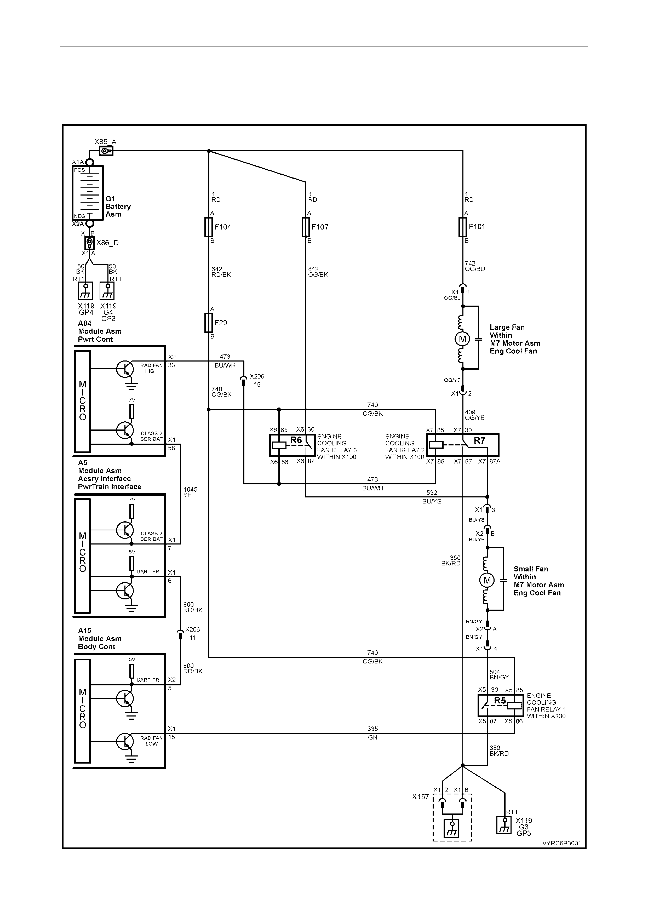
2.2 Functional Checks
GEN III V8 PCM – Engine Cooling Fan Control
Figure 6C3-2C-3 – Cooling Fan Circuits
Powertrain Management – Gen III V8 Engine Page 6C3–10
Page 6C3–10
Circuit Description
The GEN III V8 engine has two, two speed electric engine cooling fan motors which provide the primary means of
moving air through the radiator. The cooling fans are used to cool engine coolant flowing through the radiator and the
refrigerant flowing through the A/C condenser (where fitted).
The engine cooling fan stage 2 relays (R5 & R6) are controlled by the PCM. The PCM controls the ground path for the
engine cooling fan stage 2 relays.
The stage 1 operation of the engine cooling fans is controlled by the PCM through serial data communication to the
BCM. The BCM controls the ground path for the engine cooling fan stage 1 relay (R7).
All three relays in the cooling fan control circuit are us ed to control the ground paths to the electric motors that drive both
fans.
Stage 1 Engine Cooling Fan Operation
The engine cooling fan stage 1 relay is energised by the BCM. The PCM determines when to enable the engine cooling
fan stage 1 operation based on inputs from the A/C request signal, vehicle speed and engine coolant temperature. The
engine cooling stage 1 relay will be turned ON when:
A/C request indicated (YES) and;
Vehicle speed less than 30 km/h
OR
Coolant temperature is greater than a specified value and will remain on until coolant temperature reduces to a
predetermined value.
Stage 2 Engine Cooling Fan Operation
The engine cooling fan stage 2 operation is controlled by the PCM based on input from the Engine Coolant Temperature
Sensor (ECT) and the A/C Pressure Sensor. The PCM will only turn ON the stage 2 engine cooling fan relays if the stage
1 engine cooling fan relay has been switched ON and the following conditions are satisfied.
• There is a BCM message response fault, which will cause a DTC to set.
• An engine coolant temperature sensor failure is detected, such as DTC P0117, P0118, P1114, P1115.
• Coolant temperature greater than a specified value.
• A/C pressure greater than a specified value.
If the stage 1 cooling fan relay was OFF when the criteria was met to turn the stage 2 cooling fan ON, the cooling fan
stage 2 relays will operate 5 seconds after the stage 1 cooling fan. The A/C Refrigerant Pressure Sensor can also enable
the engine cooling fan stage 2 relays. The A/C Refrigerant Pressure Sensor will provide a signal to the PCM when A/C
pressure becomes too high; approximately 2,600 kPa.
For replacement of the cooling fan motor, refer to Section 6B3, 2.15 Cooling Fans and Shroud Assembly in the MY 2003
VY and V2 Series Service Information.
Test Description
NOTE
The number(s) below refer to the step number(s)
on the diagnostic table.
2. This entire diagnostic procedure must begin with a cold engine - at ambient air temperature. If the coolant is hot
when diagnosis is performed, replacement of good parts will result. The fans should not be running if engine
coolant temperature is less than 99° C and air conditioning is not ON.
3. Listen for an audible click when the relay operates. Command both ON and OFF states. Repeat the commands if
necessary.
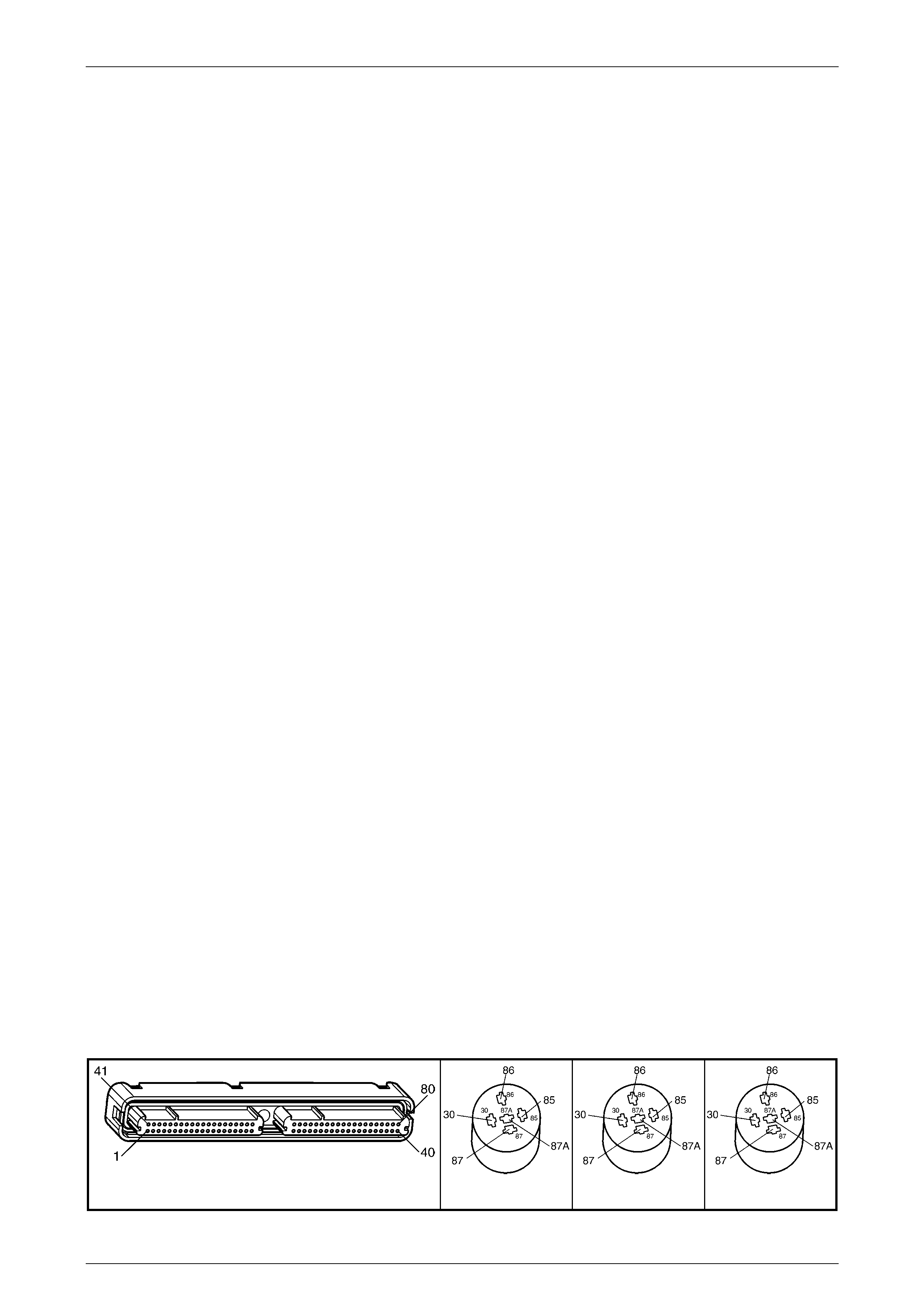
A84–X2 (RED) R5 (Part of X100) R6 (Part of X100) R7 (Part of X100)
Figure 6C3-2C-4

Powertrain Management – Gen III V8 Engine Page 6C3–11
Page 6C3–11
GEN III V8 PCM – Engine Cooling Fan Control
Step Action Value(s) Yes No
1 Was the "On-Board Diagnostic" (OBD) System Check
performed Go to Step 2 Perform the OBD
System Check, refer
to Section 6C3-2, 4.
Powertrain OBD
System Check
in the MY 2003 VY
and V2 Series
Service Informatio n.
2 1. Ignition ON, engine OFF.
2. Engine coolant temperature below 99° C.
Are both engine cooling fans running?
Go to Step 3 Go to Step 6
3 1. Ignition OFF
2. Remove cooling fan relay 1(R5).
3. Ignition ON
Are both fans still running?
Repair short to
ground in circuit 504
and re-check the
system.
Go to Step 4
4 1. Ignition OFF.
2. Check for short to ground in circuit 335.
Was a short to ground found?
Repair the short to
ground and re-
check the system .
Go to Step 5
5 1. Disconnect BCM connector A15-X1.
2. Ignition ON.
3. Using a test light connected to +12volts, probe
BCM connector A15-X1, terminal 15
(Orange/Black wire).
Is the test li ght ON?
Replace the BCM,
refer to Section 12J,
2.1 Body Control
Module in the MY
2003 VY and V2
Series Service
Information and re-
check the system
Replace cooling fan
relay 1(R5) and
recheck system.
6 1. Using Tech 2, select LOW FAN relay control.
2. Turn LOW FAN ON.
Do the cooling fans operate in stage 1 operation?
Go to Step 7 Go to Step 8
7 1. Using Tech 2, select HIGH FAN relay control.
2. Turn HIGH FAN ON.
Do the cooling fans operate in stage 2 operation?
System OK Go to Step 19
8 1. Ignition OFF.
2. Using a Digital Multi-Meter (DMM), measure the
voltage at terminal 1 (Orange/Blue wire) of the
engine cooling fan to main wiring harness
connector M7-X1.
Does the DDM display the spec ified voltage?
B+ Go to Step 9 Repair circuit 742
(Orange/Blue wire)
including fuse F101
and re-check the
system.
9 1. Using a DMM, measure the voltage at terminal 2
(Blue/Yellow wire) of the engine cooling fan to
main wiring harness connector M7-X1
Does the DDM display the spec ified voltage?
B+ Go to Step 10 Replace the right
(large) cooling fan
assembly, refer to
Section 6B3, 2.15
Cooling Fans and
Shroud Assembly
in the MY 2003 VY
and V2 Series
Service Informatio n
and re-check the
system.

Powertrain Management – Gen III V8 Engine Page 6C3–12
Page 6C3–12
Step Action Value(s) Yes No
10 1. Using a Digital Multi-Meter (DMM), measure the
voltage at terminal 3 (Orange/Yellow wire) of the
engine cooling fan to main wiring harness
connector M7-X1
Does the DDM display the spec ified voltage?
B+ Go to Step 13 Go to Step 11
11 1. Remove cooling fan relay 2 (R5).
2. Using a Digital Multi-Meter (DMM), check for
continuity in circuit 409 (Blue/Yellow wire)
Is circuit 409 OK?
Go to Step 12 Repair circuit 409
and re-check the
system.
12 1. Using a Digital Multi-Meter (DMM), check for
continuity in circuit 532 (Orange/Yellow wire)
Is circuit 532 OK?
Replace cooling fan
relay 2 (R7) and re-
check the system .
Repair circuit 532
and re-check the
system.
13 1. Using a Digital Multi-Meter (DMM), measure the
voltage at terminal 4 (Orange/Black wire) of the
engine cooling fan to main wiring harness
connector M7-X1
Does the DDM display the spec ified voltage?
B+ Go to Step 14 Replace the left
(small) cooling fan
assembly, refer to
Section 6B3, 2.15
Cooling Fans and
Shroud Assembly
in the MY 2003 VY
and V2 Series
Service Informatio n
and re-check the
system.
14 1. Remove cooling fan relay 1 (R5).
2. Using a DMM, check for continuity in circuit 504
(Orange/Black wire)
Is circuit 409 OK?
Go to Step 15 Repair circuit 504
and re-check the
system.
15 1. Using a DMM, check for continuity in circuit 350
(Black/Red wire)
Is circuit 350 OK?
Go to Step 16 Repair circuit 350
and re-check the
system.
16 1. Disconnect BCM connector A15-X1.
2. Using a suitable jumper wire, connect terminal 15,
circuit 335 (Orange/Black wire) to a suitable earth.
Do the cooling fans operate in stage 1 operation?
Replace the BCM,
refer to Section 12J,
2.1 Body Control
Module
in the MY 2003 VY
and V2 Series
Service Information
and re-check the
system
Go to Step 17.
17 1. Remove the engine cooling fan low speed relay.
2. Using a DMM, check for continuity in circuit 335
(Orange Black wire).
Is circuit 335 OK?
Go to Step 18 Repair circuit 335
and re-check the
system.
18 1. Using a DDM measure the voltage between the
relay B+ supply circuit 740 (terminal 86) and the
relay ground circuit 350 (terminal 87).
Does the DDM display the spec ified voltage?
B+ Replace cooling fan
relay 1 (R5) and re-
check sy ste m
Repair open circuit
or short to ground in
relay B+ supply
circuit (including
fuses F29 and
F104) and re-check
the system.
19 Do either of the cooling fans operate at high speed
during stage 2 operation? Go to Step 28 Go to Step 20.

Powertrain Management – Gen III V8 Engine Page 6C3–13
Page 6C3–13
Step Action Value(s) Yes No
20 1. Remove engine cooling fan relay 2 (R7).
2. Using a DMM, measure the voltage between the
relay B+ supply circuit 740 (terminal 86) and a
known good earth.
Does the DMM display the specified voltage?
B+ Go to Step 21 Repair open circuit
or short to ground in
the relay B+ circuit
740 (orange/black
wire) and proceed to
step 21.
21 1. Using a DMM, check for continuity in the ground
circuit 473 (blue/white wire) for engine cooling fan
relay 2 (R7).
Is circuit 473 OK?
Go to Step 22 Repair circuit 473
for engine cooling
fan relay 2 (R7) and
proceed to step 22
22 1. Using a DMM, check for continuity in the ground
circuit 350 (black/red wire).
Is circuit 350 OK?
Go to Step 27 Repair circuit 350
and proceed to step
23
23 1. Remove engine cooling fan relay 3 (R6).
2. Using a DMM, measure the voltage between the
relay B+ supply circuit 740 (terminal 86) and a
known good earth.
Does the DMM display the specified voltage?
B+ Go to Step 24 Repair open circuit
or short to ground in
the relay B+ circuit
740 (orange/black
wire) and re-check
the system.
24 1. Using a DMM, check for continuity in the
ground circuit 473 (blue/white wire) for engine cooling
fan relay 3 (R6).
Is circuit 473 OK?
Go to Step 25 Repair circuit 473
for relay (R6) and
re-check the
system.
25 1. Using a DMM, check for continuity in the
ground circuit 532 (orange/yellow wire) for engine
cooling fan relay 2 (R7).
Is circuit 350 OK?
Go to Step 26 Repair circuit 532
and re-check the
system
26 1. Using a DMM, measure the voltage between
the relay B+ supply circ uit 842 (terminal 30) and a
known good earth.
Does the DMM display the specified voltage?
B+ Go to Step 27 Repair open circuit
or short to ground in
the relay B+ circuit
842 (orange/black
wire), including fuse
F107 and re-check
the system.
27 1. Disconnect PCM connector A84-X2.
2. Using a suitable jumper wire, connect terminal 33,
circuit 473 (Orange/Black wire) to a suitable earth.
Do the cooling fans operate in stage 2 operation?
Replace the PCM,
refer to
Section 6C3-3, 2.1
Powertrain Control
Module
in the MY 2003 VY
and V2 Series
Service Information
and re-check the
system.
Replace engine
cooling fan relay 2
(R7) and engine
cooling fan relay 3
(R6) and re-check
the system.
28 Does the right (large) cooling fan operate at high speed
and the left (small) cooling fan switch off during stage 2
operation.
Go to Step 29 Go to Step 33
29 1. Remove engine cooling fan relay 3 (R6).
2. Using a DMM, measure the voltage between the
relay B+ supply circuit 740 (terminal 86) and a
known good earth.
Does the DMM display the specified voltage?
B+ Go to Step 30 Repair open circuit
or short to ground in
the relay B+ circuit
740 (orange/black
wire) and re-check
the system.

Powertrain Management – Gen III V8 Engine Page 6C3–14
Page 6C3–14
Step Action Value(s) Yes No
30 1. Using a DMM, check for continuity in the ground
circuit 473 (blue/white wire) for engine cooling fan
relay 3 (R6).
Is circuit 473 OK?
Go to Step 31 Repair circuit 473
for relay (R6) and
re-check the
system.
31 1. Using a DMM, check for continuity in the ground
circuit 532 (orange/yellow wire) for engine cooling
fan relay 2 (R7).
Is circuit 350 OK?
Go to Step 32 Repair circuit 532
and re-check the
system
32 1. Using a DMM, measure the voltage between the
relay B+ supply circuit 842 (terminal 30) and a
known good earth.
Does the DMM display the specified voltage?
B+ Replace cooling fan
relay 3 (R6) and re-
check the system .
Repair open circuit
or short to ground in
the relay B+ circuit
842 (orange/black
wire), including fuse
F107 and re-check
the system.
33 Does cooling fan relay 2 (R7) produce an audible click
when HIGH FAN ON is selected with TECH 2? Go to Step 37 Go to Step 34
34 1. Remove engine cooling fan relay 2 (R5).
2. Using a DMM, measure the voltage between the
relay B+ supply circuit 740 (terminal 86) and a
known good earth.
Does the DMM display the specified voltage?
B+ Go to Step 35 Repair open circuit
or short to ground in
the relay B+ circuit
740 (orange/black
wire) and recheck
the system.
35 1. Remove engine cooling fan relay 2 (R7).
2. Using a DMM, measure the voltage between the
relay B+ supply circuit 740 (terminal 86) and a
known good earth.
Does the DMM display the specified voltage?
B+ Go to Step 36 Repair open circuit
or short to ground in
the relay B+ circuit
740 (orange/black
wire) and re-check
the system.
36 1. Using a DMM, check for continuity in the ground
circuit 473 (blue/white wire) for engine cooling fan
relay 2 (R7).
Is circuit 473 OK?
Go to Step 37 Repair circuit 473
for engine cooling
fan relay 2 (R7) and
re-check the
system.
37 1. Using a DMM, check for continuity in the ground
circuit 350 (black/red wire).
Is circuit 350 OK?
Replace cooling fan
relay 3 (R6) and re-
check the system .
Repair circuit 350
and re-check the
system.

Powertrain Management – Gen III V8 Engine Page 6C3–15
Page 6C3–15
3 Specifications
Engine Cooling
Right Hand Side Electric Fan – Power.......................................................215 Watt (Nominal)
Fan Diameter.............................................................................................................. 342 mm
Left Hand Side Electric Fan – Power .........................................................215 Watt (Nominal)
Fan Diameter.............................................................................................................. 293 mm
NOTE
For more detailed specifications for the engine
cooling fans as fitted to the MY 2003 VY Series
Cab Chassis Models fitted with a GEN III V8
engine, refer to Section 6B3, 4. Specifications in
this Service Information.