
Emission Cont rol – GEN III V8 Engine Page 6E3–1
Page 6E3–1
Section 6E3
Emission Control – GEN III V8 Engine
ATTENTION
Before performing any Service Operation or other procedure described in this Section, refer to Section 00
WARNINGS, CAUTIONS AND NOTES for correct workshop practices with regard to safety and/or property
damage.
1 General Information............................................................................................................................... 2
1.1 Evaporative Emission Control ..............................................................................................................................2
2. Service Operations................................................................................................................................3
2.1 Evaporative Emission Control Canister...............................................................................................................3
Remove ...................................................................................................................................................................3
Reinstall ..................................................................................................................................................................5
3 Torque Wrench Specifications............................................................................................................. 6
Emission Cont rol – GEN III V8 Engine Page 6E3–2
Page 6E3–2
1 General Information
With the following exceptions, MY 2003 VY Series Cab Chassis Emission Control – GEN III V8 Engine information
carries over from MY 2003 VY Series vehicles. For information not contained within this Section, refer to Section 6E3
Emission Control – GEN III V8 Engine in the MY 2003 VY and V2 Series Service Information.
• Emission control canister mounting position.
• Canister vent line routeing.
1.1 Evaporative Emission Control
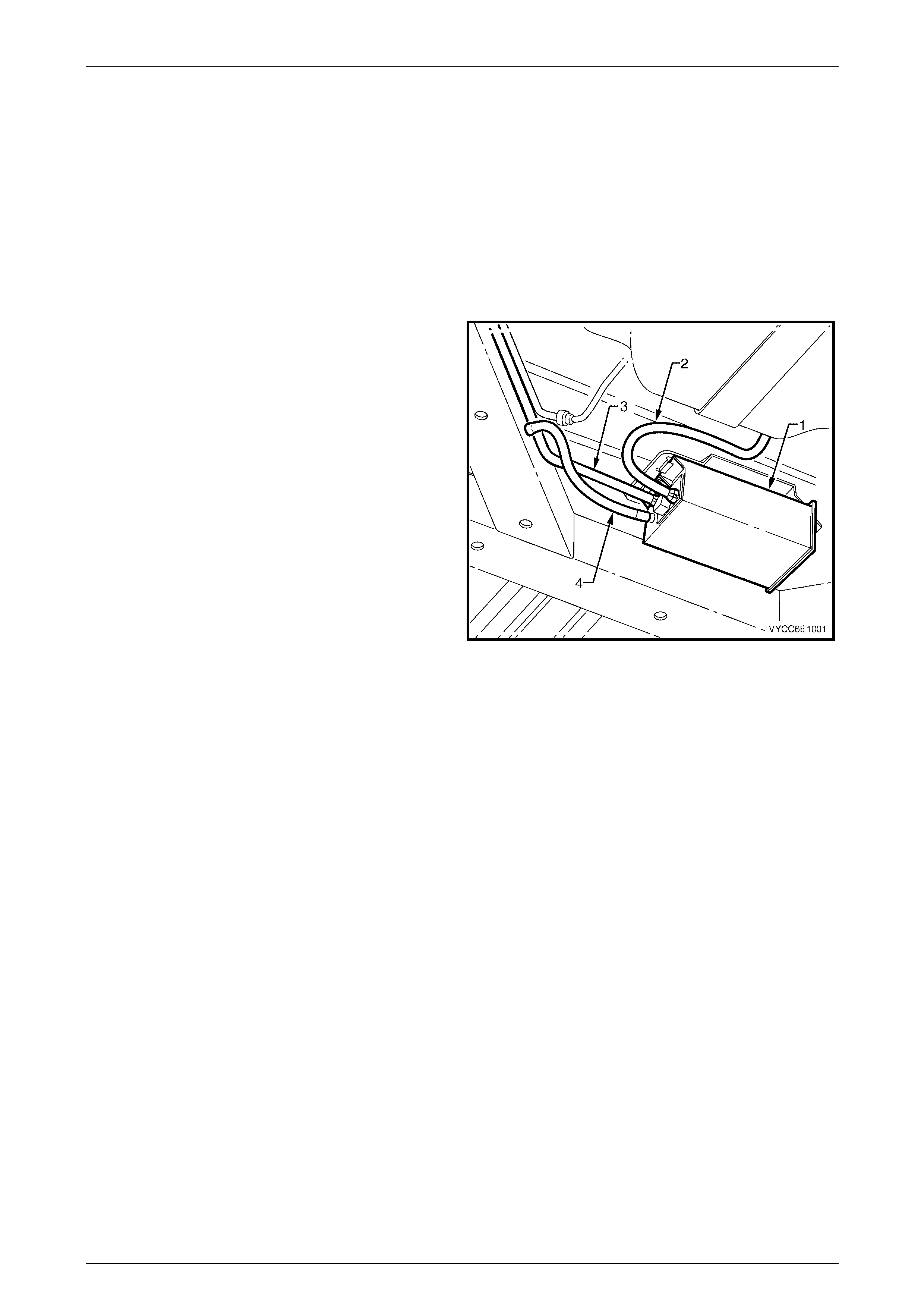
The evaporative emission control system used on this
vehicle is the activated carbon (charcoal) canister storage
method. This fuel vapour canister (1) is a three port design
and is mounted in a bracket underneath the vehicle.
The canister cannot be repaired and is servi ced only as an
assembly. Periodically check the canister at the time or
distance intervals specified in Section 0B Lubrication And
Service.
The canister is designed to store fuel tank vapour via the
tank vent line (2) and release it to the engine via the canister
purge line (3).
The canister vent line (4) is attached to the chassis.
Figure 6E3 – 1
Emission Cont rol – GEN III V8 Engine Page 6E3–3
Page 6E3–3
2. Service Operations
2.1 Evaporative Emission Control Canister
LT Section No. – 03-165
Remove
1 Hoist the vehicle, refer to Section 0A, 1.1 Hoist Pad Locations.
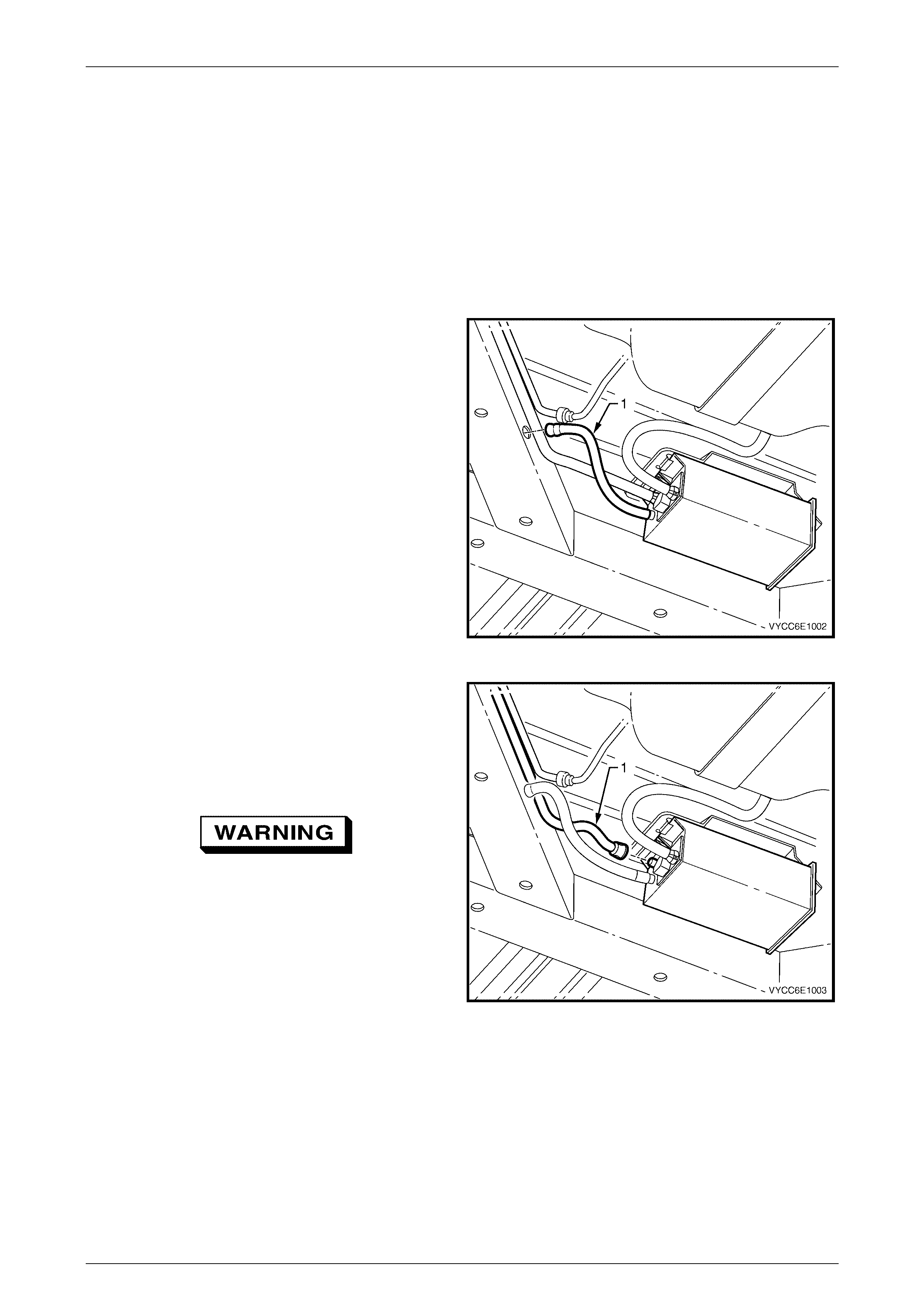
2 If required, remove the canister vent line (1) from the
chassis by pulling it out of the hole in the chassis.
Figure 6E3 – 2
3 Disconnect the canister purge line (1) by using the
following proc edur e:
a Grasp both sides of the quick-connect fitting.
Twist the connector 1/4 turn in each direction in
order to loosen any dirt within the quick-connect
fitting.
Wear safety glasses when using compressed
air.
b Using compressed air, blow any dirt out of the
quick connect fitting.
c To disconnect using special tool AU533, refer to
Section 8A1, 2.10 Quick-Connect Fittings in the
MY 2003 VY and V2 Series Service Information.
d To disconnect without using special tool AU533:
(1) Grasp the quick-connect fitting and push it
towards the canister.
(2) Squeeze the quick-connect fitting to
release the retaining tabs, then pull back
on the connector to remove the canister
purge line from the canister.
Figure 6E3 – 3
Emission Cont rol – GEN III V8 Engine Page 6E3–4
Page 6E3–4
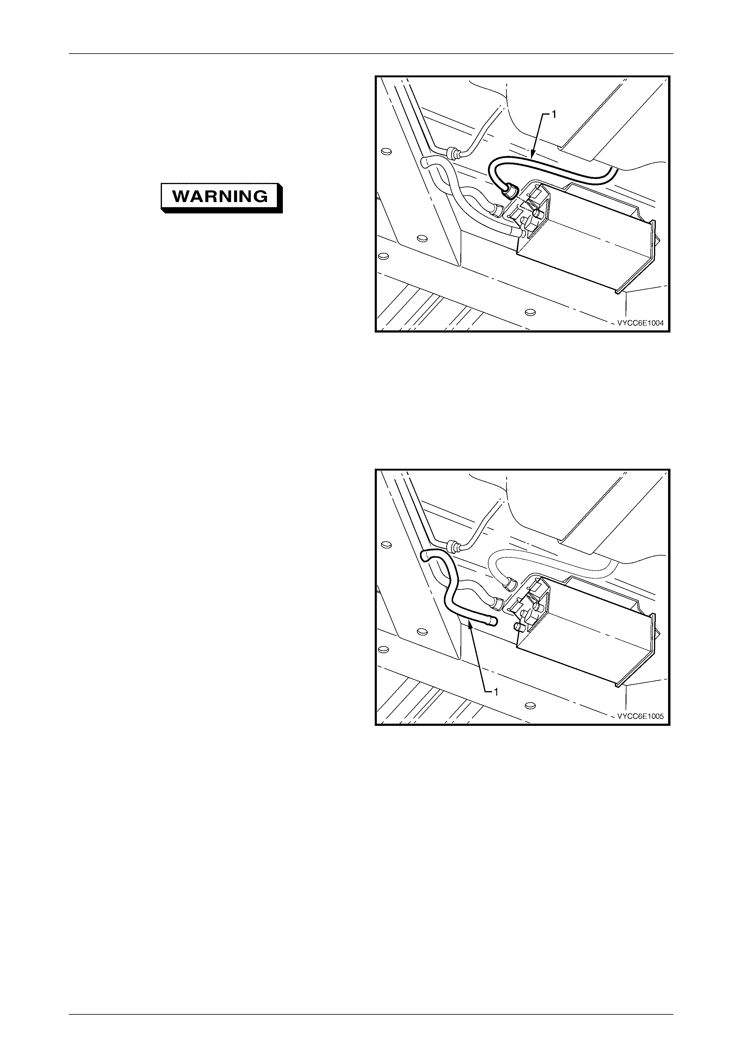
4 Disconnect the tank vent line (1) by using the following
procedure:
a Grasp both sides of the quick-connect fitting.
Twist the connector 1/4 turn in each direction in
order to loosen any dirt within the quick-connect
fitting.
Wear safety glasses when using compressed
air.
b Using compressed air, blow any dirt out of the
quick connect fitting.
c To disconnect using special tool AU533, refer to
Section 8A1, 2.10 Quick-Connect Fittings in the
MY 2003 VY and V2 Series Service Information.
d To disconnect without using special tool AU533:
(1) Grasp the quick-connect fitting and push it
towards the canister.
(2) Squeeze the quick-connect fitting to
release the retaining tabs, then pull back
on the connector to remove the canister
purge line from the canister.
Figure 6E3 – 4
5 Remove the canister vent line (1) from the canister by
twisting and pulling it off.
Figure 6E3 – 5
Emission Cont rol – GEN III V8 Engine Page 6E3–5
Page 6E3–5
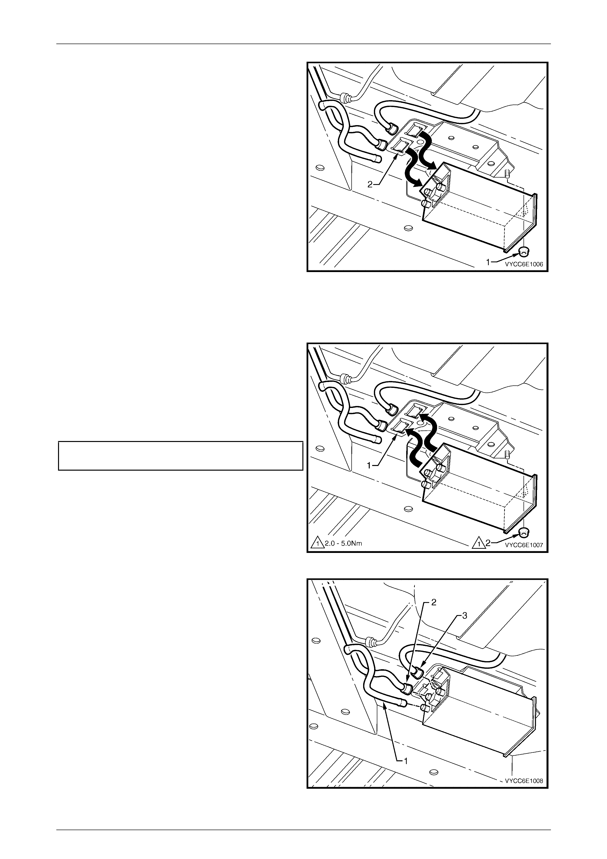
6 Remove the canister retaining nut (1).
7 Remove the canister from the retaining stud and then
slide the canister out of the retainer (2).
Figure 6E3 – 6
Reinstall
1 Hoist the vehicle, refer to Section 0A, 1.1 Hoist Pad Locations.
2 Reinstall the canister into the retainer (1) and over the
retaining stud.
3 Reinstall the canister retaining nut (2) and hand
tighten.
4 Push the canister toward centre of the vehicle and
tighten the canister retaining nut to the specified
torque.
Canister retaining nut
torque specification .....................................2.0 - 5.0 Nm
Figure 6E3 – 7
5 Reinstall the canist er vent lin e (1).
6 Align the canister purge line quick connector (2) with
the canister purge line port. Push the connector firmly
onto the port.
7 Align the tank vent line quick connector (3) with the
tank vent port. Push the connector firmly onto the port.
8 Once installed, pull on each quick connect to ensure
the connections are secure and locked in position.
Figure 6E3 – 8

Emission Cont rol – GEN III V8 Engine Page 6E3–6
Page 6E3–6
3 Torque Wrench Specifications
Canister Retaining Nut..................................................................2.0 – 5.0 N.m